
Semi-Automatic, Water-Cooled, MIG (GMAW) Welding Gun
30
Semi-Automatic, Water-Cooled, MIG (GMAW) Welding Gun Tregaskiss.com/TechnicalSupport 1-855-MIGWELD (644-9353) (US & Canada) +1-519-737-3000 (International) February 2022 TG008-1.2 Bernard ® T-Gun™ 450, 600 amp Semi-Automatic Water-Cooled MIG Gun OWNER'S MANUAL
-
Upload
khangminh22 -
Category
Documents
-
view
1 -
download
0
Transcript of Semi-Automatic, Water-Cooled, MIG (GMAW) Welding Gun

Semi-Automatic, Water-Cooled, MIG(GMAW) Welding Gun
Tregaskiss.com/TechnicalSupport1-855-MIGWELD (644-9353) (US & Canada)
+1-519-737-3000 (International)
February 2022 TG008-1.2
Bernard® T-Gun™ 450, 600 amp Semi-Automatic Water-Cooled MIG Gun
OWNER'S MANUAL

Thank You for Choosing BernardThank you for selecting a Bernard product. Before installing, compare the equipment received against the invoice to verify that the shipment is complete and undamaged. It is the responsibility of the purchaser to file all claims of damage or loss that may have occurred during transit with the carrier. The owner’s manual contains general information, instructions and maintenance to help better maintain your MIG gun or peripheral. Please read, understand and follow all safety precautions. While every precaution has been taken to assure the accuracy of this owner’s manual, Bernard assumes no responsibility for errors or omissions. Bernard assumes no liability for damages resulting from the use of information contained herein. The information presented in this owner’s manual is accurate to the best of our knowledge at the time of printing. Please reference Tregaskiss.com for updated material. For customer support and special applications, please call the Bernard Customer Service Department at 1-855-MIGWELD (644-9353) (US & Canada) or +1-519-737-3000 (International), fax 1-708-946-6726, or email at [email protected]. Our trained Customer Service Team is available between 8:00 a.m. and 5:30 p.m. EST, and will answer your product application or repair questions. Bernard manufactures premium semi-automatic (GMAW) and FCAW (flux-cored) welding guns, consumables, accessories and manual arc products. For more information on other Bernard products, contact your local Bernard distributor or visit us on the web at Tregaskiss.com.
Subject to Change – The information presented in this manual is accurate to the best of our knowledge at the time ofprinting. Please visit Tregaskiss.com for the most up-to-date information.Additional Material – For additional support materials such as spec sheets, troubleshooting information, how-toguides and videos, animations, online configurators and much more, please visit Tregaskiss.com.Scan this QR Code with your smart phone for immediate access to Tregaskiss.com/TechnicalSupport
TABLE OF CONTENTS
SECTION 1 — SAFETY PRECAUTIONS — READ BEFORE USING 11-1 Symbol Usage 1
1-2 Arc Welding Hazards 1
1-3 California Proposition 65 Warnings 3
1-4 Principal Safety Standards 3
1-5 EMF Information 3
SECTION 2 — CONSIGNES DE SÉCURITÉ — LIRE AVANT UTILISATION 42-1 Symboles utilisés 4
2-2 Dangers relatifs au soudage à l'arc 4
2-3 Proposition californienne 65 avertissements 6
2-4 Principales normes de sécurité 6
2-5 Informations relatives aux CEM 6
SECTION 3 — PRECAUCIONES DE SEGURIDAD — LEA ANTES DE USAR 73-1 Uso de símbolos 7
3-2 Peligros en soldadura de arco 7
3-3 Advertencias de la Proposición 65 del estado de California 9
3-4 Estándares principales de seguridad 9
3-5 Información sobre los campos electromagnéticos (EMF) 9
SECTION 4 — PRODUCT WARRANTY 104-1 Product Warranty 10
SECTION 5 — SPECIFICATIONS 115-1 Specifications 11
SECTION 6 — INSTALLATION 126-1 Installing Quick-Connect Block to Feeder 12
6-2 Installing Gun to Quick-Connect Block 13
6-3 Installing Power Pin to Gun 14
SECTION 7 — REPLACEMENT 157-1 Changing Consumables 15
7-2 Changing the Switch 16
7-3 Changing the Neck 17
7-4 Changing the Liner 18
7-5 Changing Cable Assembly 19
TG008-1.2 iii

SECTION 8 — TECHNICAL DATA 218-1 Neck Dimensions 21
SECTION 9 — PARTS LIST 229-1 450 amp Model 22
9-2 600 amp Model 23
SECTION 10 — TROUBLESHOOTING 2410-1 Troubleshooting Table 24
ADDITIONAL SUPPORT MATERIALS 26
iv TG008-1.2
Protect yourself and others from injury – read, follow, and save these important safety precautions and operating instructions.
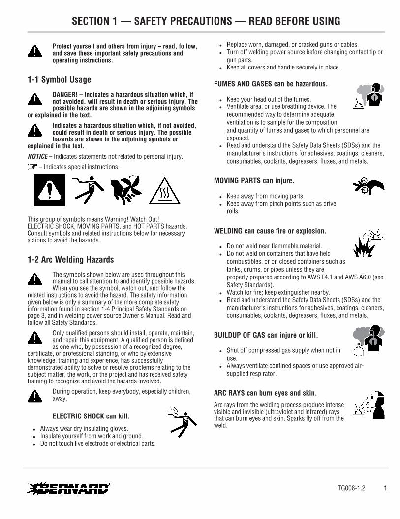
1-1 Symbol Usage
DANGER! – Indicates a hazardous situation which, if not avoided, will result in death or serious injury. The possible hazards are shown in the adjoining symbols
or explained in the text.Indicates a hazardous situation which, if not avoided, could result in death or serious injury. The possible hazards are shown in the adjoining symbols or
explained in the text.NOTICE – Indicates statements not related to personal injury.
– Indicates special instructions.
This group of symbols means Warning! Watch Out! ELECTRIC SHOCK, MOVING PARTS, and HOT PARTS hazards. Consult symbols and related instructions below for necessary actions to avoid the hazards.
1-2 Arc Welding Hazards
The symbols shown below are used throughout this manual to call attention to and identify possible hazards. When you see the symbol, watch out, and follow the
related instructions to avoid the hazard. The safety information given below is only a summary of the more complete safety information found in section 1-4 Principal Safety Standards on page 3, and in welding power source Owner's Manual. Read and follow all Safety Standards.
Only qualified persons should install, operate, maintain, and repair this equipment. A qualified person is defined as one who, by possession of a recognized degree,
certificate, or professional standing, or who by extensive knowledge, training and experience, has successfully demonstrated ability to solve or resolve problems relating to the subject matter, the work, or the project and has received safety training to recognize and avoid the hazards involved.
During operation, keep everybody, especially children, away.
ELECTRIC SHOCK can kill.
l Always wear dry insulating gloves. l Insulate yourself from work and ground. l Do not touch live electrode or electrical parts.
l Replace worn, damaged, or cracked guns or cables. l Turn off welding power source before changing contact tip or
gun parts. l Keep all covers and handle securely in place.
FUMES AND GASES can be hazardous.
l Keep your head out of the fumes. l Ventilate area, or use breathing device. The
recommended way to determine adequate ventilation is to sample for the composition and quantity of fumes and gases to which personnel are exposed.
l Read and understand the Safety Data Sheets (SDSs) and the manufacturer’s instructions for adhesives, coatings, cleaners, consumables, coolants, degreasers, fluxes, and metals.
MOVING PARTS can injure.
l Keep away from moving parts. l Keep away from pinch points such as drive
rolls.
WELDING can cause fire or explosion.
l Do not weld near flammable material. l Do not weld on containers that have held
combustibles, or on closed containers such as tanks, drums, or pipes unless they are properly prepared according to AWS F4.1 and AWS A6.0 (see Safety Standards).
l Watch for fire; keep extinguisher nearby. l Read and understand the Safety Data Sheets (SDSs) and the
manufacturer’s instructions for adhesives, coatings, cleaners, consumables, coolants, degreasers, fluxes, and metals.
BUILDUP OF GAS can injure or kill.
l Shut off compressed gas supply when not in use.
l Always ventilate confined spaces or use approved air-supplied respirator.
ARC RAYS can burn eyes and skin.Arc rays from the welding process produce intense visible and invisible (ultraviolet and infrared) rays that can burn eyes and skin. Sparks fly off from the weld.
TG008-1.2 1
SECTION 1 — SAFETY PRECAUTIONS — READ BEFORE USING
l Wear an approved welding helmet fitted with a proper shade of filter lenses to protect your face and eyes from arc rays and sparks when welding or watching (see ANSI Z49.1 and Z87.1 listed in Safety Standards).
l Wear approved safety glasses with side shields under your helmet.
l Use protective screens or barriers to protect others from flash, glare and sparks; warn others not to watch the arc.
l Wear body protection made from leather or flame-resistant clothing (FRC). Body protection includes oil-free clothing such as leather gloves, heavy shirt, cuffless trousers, high shoes, and a cap.
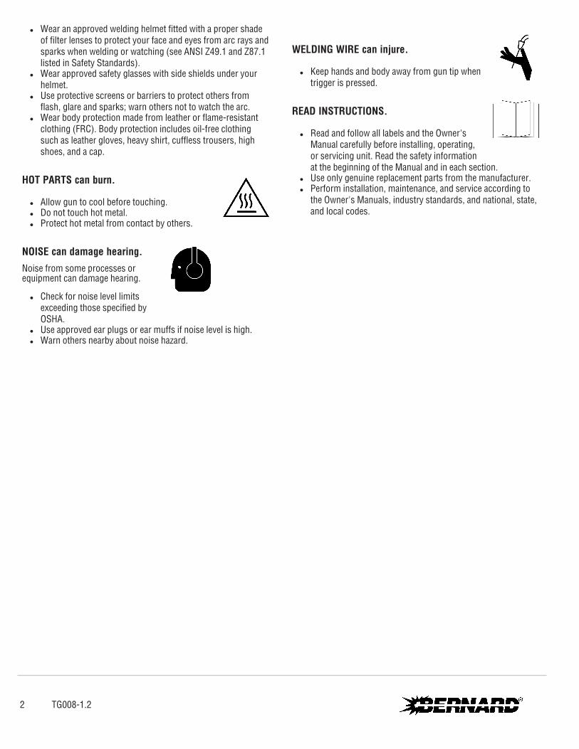
HOT PARTS can burn.
l Allow gun to cool before touching. l Do not touch hot metal. l Protect hot metal from contact by others.
NOISE can damage hearing.Noise from some processes or equipment can damage hearing.
l Check for noise level limits exceeding those specified by OSHA.
l Use approved ear plugs or ear muffs if noise level is high. l Warn others nearby about noise hazard.
WELDING WIRE can injure.
l Keep hands and body away from gun tip when trigger is pressed.
READ INSTRUCTIONS.
l Read and follow all labels and the Owner's Manual carefully before installing, operating, or servicing unit. Read the safety information at the beginning of the Manual and in each section.
l Use only genuine replacement parts from the manufacturer. l Perform installation, maintenance, and service according to
the Owner's Manuals, industry standards, and national, state, and local codes.
2 TG008-1.2
1-3 California Proposition 65 Warnings
WARNING: This product can expose you to chemicals including lead, which are known to the state of California to cause cancer and birth defects or other reproductive harm.
For more information, go to www.P65Warnings.ca.gov.
1-4 Principal Safety Standards
Safety in Welding, Cutting, and Allied Processes, American Welding Society standard ANSI Standard Z49.1. Website: www.aws.org.Safe Practice For Occupational And Educational Eye And Face Protection, ANSI Standard Z87.1, from American National Standards Institute. Website: www.ansi.org.Safe Practices for the Preparation of Containers and Piping for Welding and Cutting, American Welding Society Standard AWS F4.1. Website: www.aws.org.National Electrical Code, NFPA Standard 70 from National Fire Protection Association. Website: www.nfpa.org.Safe Handling of Compressed Gases in Cylinders, CGA Pamphlet P- 1 from Compressed Gas Association. Website: www.cganet.com.
Safety in Welding, Cutting, and Allied Processes, CSA Standard W117.2 from Canadian Standards Association. Website: www.csagroup.org.Standard for Fire Prevention During Welding, Cutting, and Other Hot Work, NFPA Standard 51B from National Fire Protection Association. Website: www.nfpa.org.OSHA, Occupational Safety and Health Standards for General Industry, Title 29, Code of Federal Regulations (CFR), Part 1910.177 Subpart N, Part 1910 Subpart Q, and Part 1926, Subpart J. Website: www.osha.gov.SR7 2022-01
1-5 EMF Information
Electric current flowing through any conductor causes localized electric and magnetic fields (EMF). The current from arc welding (and allied processes including spot welding, gouging, plasma arc cutting, and induction heating operations) creates an EMF field around the welding circuit. EMF fields may interfere with some medical implants, e.g. Pacemakers. Protective measures for persons wearing medical implants have to be taken. For example, restrict access for passersby or conduct individual risk assessment for welders. All welders should use the following procedures in order to minimize exposure to EMF fields from the welding circuit:
1. Keep cables close together by twisting or taping them, or using a cable cover.
2. Do not place your body between welding cables. Arrange cables to one side and away from the operator.
3. Do not coil or drape cables around your body. 4. Keep head and trunk as far away from the equipment in the
welding circuit as possible. 5. Connect work clamp to workpiece as close to the weld as
possible. 6. Do not work next to, sit or lean on the welding power source. 7. Do not weld whilst carrying the welding power source wire
feeder.
About Implanted Medical Devices:Implanted Medical Device wearers should consult their doctor and the device manufacturer before performing or going near arc welding, spot welding, gouging, plasma arc cutting, or induction heating operations. If cleared by your doctor, then following the above procedures is recommended.
TG008-1.2 3

Pour écarter les risques de blessure pour vous-même et pour autrui — lire, appliquer et ranger en lieu sûr ces consignes relatives aux précautions de sécurité et
au mode opératoire.
2-1 Symboles utilisés
DANGER! – Indique une situation dangereuse qui si on l’évite pas peut donner la mort ou des blessures graves. Les dangers possibles sont montrés par les
symboles joints ou sont expliqués dans le texte.Indique une situation dangereuse qui si on l’évite pas peutdonner la mort ou des blessures graves. Les dangers possiblessont montrés par les symboles
joints ou sont expliquésdans le texte.AVIS – Indique des déclarations pas en relation avec des blessures personnelles.
– Indique des instructions spécifiques.
Ce groupe de symboles veut dire Avertissement! Attention! DANGER DE CHOC ELECTRIQUE, PIECES EN MOUVEMENT, et PIECES CHAUDES. Reportez-vous aux symboles et aux directives cidessous afin de connaître les mesures à prendre pour éviter tout danger.
2-2 Dangers relatifs au soudage à l'arc
Les symboles donnés ci-après sont utilisés dans tout le ma- nuel pour attirer l’attention sur les dangers possibles et pour indiquer le type de danger dont il s’agit.
Quand on voit le symbole, prendre garde et suivre les directives corres- pondantes pour éviter le danger. Les consignes de sécurité présentées ci-après ne font que résumer l’information contenue dans les Normes de sécurité principales, et dans le Guide d’utilisation de la source de courant de soudage. Lire et suivre toutes les Normes de sécurité.
L'installation, l'utilisation, l'entretien et les réparations ne doivent être confiés qu'à des personnes qualifiées. Une personne qualifiée est définie comme celle qui, par la
possession d'un diplôme reconnu, d'un certificat ou d'un statut professionnel, ou qui, par une connaissance, une formation et une expérience approfondies, a démontré avec succès sa capacité à résoudre les problèmes liés à la tâche, le travail ou le projet et a reçu une formation en sécurité afin de reconnaître et d'éviter les risques inhérents.
Au cours de l'utilisation, tenir toute personne à l'écart et plus particulièrement les enfants.
UN CHOC ÉLECTRIQUE peut tuer.
l Porter toujours des gants secs et isolants. l S’isoler de la pièce et de la terre. l Ne jamais toucher une électrode ou des pièces électriques
sous tension. l Remplacer les pistolets ou câbles de soudage qui sont
endommagés, usés ou craquelés. l Mettre la soudeuse hors tension avant de remplacer un bec
contact ou des pièces de pistolet. l S’assurer que tous les couvercles et poignées sont
fermement assujettis.
LES FUMÉES ET LES GAZ peuvent être dangereux.
l Garder la tête hors des fumées. l Aérer la zone de travail ou porter un appareil
respiratoire. Pour déterminer la bonne ventilation, il est recommandé de procéder à un prélèvement pour la composition et la quantité de fumées et de gaz auxquels est exposé le personnel.
l Lire et comprendre les fiches de données de sécurité et les instructions du fabricant concernant les adhésifs, les revêtements, les nettoyants, les consommables, les produits de refroidissement, les dégraisseurs, les flux et les métaux.
Les PIÈCES MOBILES peuvent causer des blessures.
l Ne pas s’approcher des organes mobiles. l Ne pas s’approcher des points de coincement
tels que des rouleaux de commande.
Le SOUDAGE peut provoquer un incendie ou une explosion.
l Ne pas souder à proximité de matériaux inflammables
l Ne pas effectuer le soudage sur des conteneurs fermés tels que des réservoirs, tambours, ou conduites, à moins qu’ils n’aient été préparés correctement conformément à AWS F4.1 et AWS A6.0 (voir les Normes de Sécurité).
l Prendre garde aux incendies et toujours avoir un extincteur à proximité.
SECTION 2 — CONSIGNES DE SÉCURITÉ — LIRE AVANT UTILISATION
4 TG008-1.2
l Lire et comprendre les fiches de données de sécurité et les instructions du fabricant concernant les adhésifs, les revêtements, les nettoyants, les consommables, les produits de refroidissement, les dégraisseurs, les flux et les métaux.
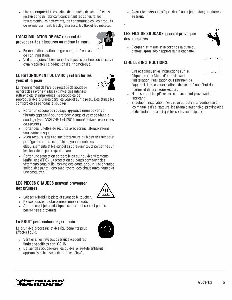
L'ACCUMULATION DE GAZ risquent de provoquer des blessures ou même la mort.
l Fermer l’alimentation du gaz comprimé en cas de non utilisation.
l Veiller toujours à bien aérer les espaces confinés ou se servir d’un respirateur d’adduction d’air homologué.
LE RAYONNEMENT DE L'ARC peut brûler les yeux et la peau.Le rayonnement de l’arc du procédé de soudage génère des rayons visibles et invisibles intenses (ultraviolets et infrarouges) susceptibles de provoquer des brûlures dans les yeux et sur la peau. Des étincelles sont projetées pendant le soudage.
l Porter un casque de soudage approuvé muni de verres filtrants approprié pour protéger visage et yeux pendant le soudage (voir ANSI Z49.1 et Z87.1 énuméré dans les normes de sécurité).
l Porter des lunettes de sécurité avec écrans latéraux même sous votre casque.
l Avoir recours à des écrans protecteurs ou à des rideaux pour protéger les autres contre les rayonnements les éblouissements et les étincelles ; prévenir toute personne sur les lieux de ne pas regarder l’arc.
l Porter une protection corporelle en cuir ou des vêtements ignifu- ges (FRC). La protection du corps comporte des vêtements sans huile, comme des gants de cuir, une chemise solide, des panta- lons sans revers, des chaussures hautes et une casquette.
LES PIÈCES CHAUDES peuvent provoquer des brûlures.
l Laisser refroidir le pistolet avant de le toucher. l Ne pas toucher d’objets métalliques chauds. l Abriter les objets métalliques contre tout contact par les
personnes à proximité.
Le BRUIT peut endommager l’ouie.Le bruit des processus et des équipements peut affecter l’ouïe.
l Vérifier si les niveaux de bruit excèdent les limites spécifiées par l’OSHA.
l Utiliser des bouche-oreilles ou des serre-tête antibruit approuvés si le niveau de bruit est élevé.
l Avertir les personnes à proximité au sujet du danger inhérent au bruit.
.
LES FILS DE SOUDAGE peuvent provoquer des blessures.
l Éloigner les mains et le corps de la buse du pistolet après avoir appuyé sur la gâchette.
LIRE LES INSTRUCTIONS.
l Lire et appliquer les instructions sur les étiquettes et le Mode d’emploi avant l’installation, l’utilisation ou l’entretien de l’appareil. Lire les informations de sécurité au début du manuel et dans chaque section.
l N’utiliser que les pièces de remplacement provenant du fabricant.
l Effectuer l’installation, l’entretien et toute intervention selon les manuels d’utilisateurs, les normes nationales, provinciales et de l’industrie, ainsi que les codes municipaux.
TG008-1.2 5

2-3 Proposition californienne 65 avertissements
AVERTISSEMENT – Ce produit peut vous exposer à des produits chimiques tels que le plomb, reconnus par l’État de
Californie comme cancérigènes et sources de malformations ou d’autres troubles de la reproduction
Pour plus d’informations, consulter www.P65Warnings.ca.gov.
2-4 Principales normes de sécurité
Safety in Welding, Cutting, and Allied Processes, American Welding Society standard ANSI Standard Z49.1. Website: www.aws.org.Safe Practice For Occupational And Educational Eye And Face Protection, ANSI Standard Z87.1, from American National Standards Institute. Website: www.ansi.org.Safe Practices for the Preparation of Containers and Piping for Welding and Cutting, American Welding Society Standard AWS F4.1 from Global Engineering Documents. Website: www.aws.org.National Electrical Code, NFPA Standard 70 from National Fire Protection Association. Website: www.nfpa.org.Safe Handling of Compressed Gases in Cylinders, CGA Pamphlet P- 1 from Compressed Gas Association. Website: www.cganet.com.
Safety in Welding, Cutting, and Allied Processes, CSA Standard W117.2 from Canadian Standards Association. Website: www.csagroup.org.Standard for Fire Prevention During Welding, Cutting, and Other Hot Work, NFPA Standard 51B from National Fire Protection Association. Website: www.nfpa.org.OSHA, Occupational Safety and Health Standards for General Industry, Title 29, Code of Federal Regulations (CFR), Part 1910.177 Subpart N, Part 1910 Subpart Q, and Part 1926, Subpart J. Website: www.osha.gov.SR7_fre 2022-01
2-5 Informations relatives aux CEM
Le courant électrique qui traverse tout conducteur génère des champs électromagnétiques (CEM) à certains endroits. Le courant issu d’un soudage à l’arc (et de procédés connexes, y compris le soudage par points, le gougeage, le découpage plasma et les opérations de chauffage par induction) crée un champ électromagnétique (CEM) autour du circuit de soudage. Les champs électromagnétiques produits peuvent causer interférence à certains implants médicaux, p. ex. les stimulateurs cardiaques. Des mesures de protection pour les porteurs d’implants médicaux doivent être prises: par exemple, des restrictions d’accès pour les passants ou une évaluation individuelle des risques pour les soudeurs. Tous les soudeurs doivent appliquer les procédures suivantes pour minimiser l’exposition aux CEM provenant du circuit de soudage:
1. Rassembler les câbles en les torsadant ou en les attachant avec du ruban adhésif ou avec une housse.
2. Ne pas se tenir au milieu des câbles de soudage. Disposer les câbles d’un côté et à distance de l’opérateur.
3. Ne pas courber et ne pas entourer les câbles autour de votre corps.
4. Maintenir la tête et le torse aussi loin que possible du matériel du circuit de soudage.
5. Connecter la pince sur la pièce aussi près que possible de la soudure.
6. Ne pas travailler à proximité d’une source de soudage, ni s’asseoir ou se pencher dessus.
7. Ne pas souder tout en portant la source de soudage ou le dévidoir.
En ce qui concerne les implants médicaux :Les porteurs d’implants doivent d’abord consulter leur médecin avant de s’approcher des opérations de soudage à l’arc, de soudage par points, de gougeage, du coupage plasma ou de chauffage par induction. Si le médecin approuve, il est recommandé de suivre les procédures précédentes.
6 TG008-1.2
Protéjase usted mismo y a otros contra lesiones — lea, cumpla y conserve estas importantes precauciones de seguridad e instrucciones de
utilización.
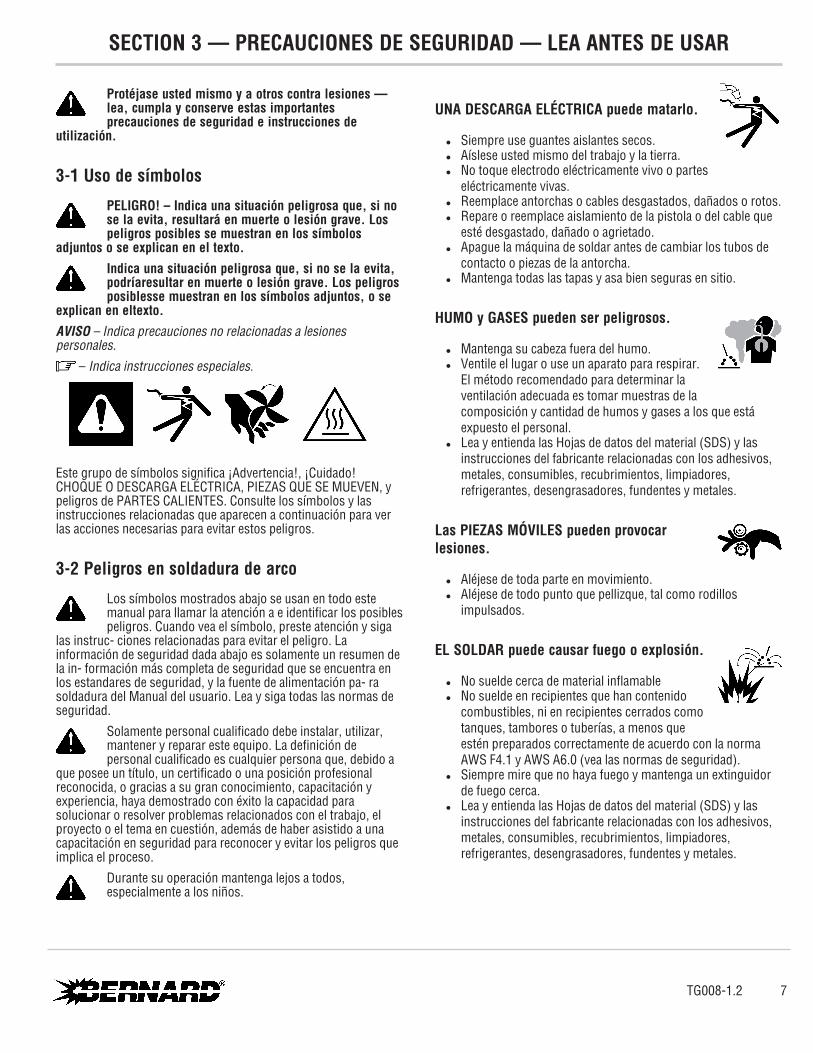
3-1 Uso de símbolos
PELIGRO! – Indica una situación peligrosa que, si no se la evita, resultará en muerte o lesión grave. Los peligros posibles se muestran en los símbolos
adjuntos o se explican en el texto.Indica una situación peligrosa que, si no se la evita, podríaresultar en muerte o lesión grave. Los peligros posiblesse muestran en los símbolos adjuntos, o se
explican en eltexto.AVISO – Indica precauciones no relacionadas a lesiones personales.
– Indica instrucciones especiales.
Este grupo de símbolos significa ¡Advertencia!, ¡Cuidado! CHOQUE O DESCARGA ELÉCTRICA, PIEZAS QUE SE MUEVEN, y peligros de PARTES CALIENTES. Consulte los símbolos y las instrucciones relacionadas que aparecen a continuación para ver las acciones necesarias para evitar estos peligros.
3-2 Peligros en soldadura de arco
Los símbolos mostrados abajo se usan en todo este manual para llamar la atención a e identificar los posibles peligros. Cuando vea el símbolo, preste atención y siga
las instruc- ciones relacionadas para evitar el peligro. La información de seguridad dada abajo es solamente un resumen de la in- formación más completa de seguridad que se encuentra en los estandares de seguridad, y la fuente de alimentación pa- ra soldadura del Manual del usuario. Lea y siga todas las normas de seguridad.
Solamente personal cualificado debe instalar, utilizar, mantener y reparar este equipo. La definición de personal cualificado es cualquier persona que, debido a
que posee un título, un certificado o una posición profesional reconocida, o gracias a su gran conocimiento, capacitación y experiencia, haya demostrado con éxito la capacidad para solucionar o resolver problemas relacionados con el trabajo, el proyecto o el tema en cuestión, además de haber asistido a una capacitación en seguridad para reconocer y evitar los peligros que implica el proceso.
Durante su operación mantenga lejos a todos, especialmente a los niños.
UNA DESCARGA ELÉCTRICA puede matarlo.
l Siempre use guantes aislantes secos. l Aíslese usted mismo del trabajo y la tierra. l No toque electrodo eléctricamente vivo o partes
eléctricamente vivas. l Reemplace antorchas o cables desgastados, dañados o rotos. l Repare o reemplace aislamiento de la pistola o del cable que
esté desgastado, dañado o agrietado. l Apague la máquina de soldar antes de cambiar los tubos de
contacto o piezas de la antorcha. l Mantenga todas las tapas y asa bien seguras en sitio.
HUMO y GASES pueden ser peligrosos.
l Mantenga su cabeza fuera del humo. l Ventile el lugar o use un aparato para respirar.
El método recomendado para determinar la ventilación adecuada es tomar muestras de la composición y cantidad de humos y gases a los que está expuesto el personal.
l Lea y entienda las Hojas de datos del material (SDS) y las instrucciones del fabricante relacionadas con los adhesivos, metales, consumibles, recubrimientos, limpiadores, refrigerantes, desengrasadores, fundentes y metales.
Las PIEZAS MÓVILES pueden provocar lesiones.
l Aléjese de toda parte en movimiento. l Aléjese de todo punto que pellizque, tal como rodillos
impulsados.
EL SOLDAR puede causar fuego o explosión.
l No suelde cerca de material inflamable l No suelde en recipientes que han contenido
combustibles, ni en recipientes cerrados como tanques, tambores o tuberías, a menos que estén preparados correctamente de acuerdo con la norma AWS F4.1 y AWS A6.0 (vea las normas de seguridad).
l Siempre mire que no haya fuego y mantenga un extinguidor de fuego cerca.
l Lea y entienda las Hojas de datos del material (SDS) y las instrucciones del fabricante relacionadas con los adhesivos, metales, consumibles, recubrimientos, limpiadores, refrigerantes, desengrasadores, fundentes y metales.
TG008-1.2 7
SECTION 3 — PRECAUCIONES DE SEGURIDAD — LEA ANTES DE USAR

EL AMONTONAMIENTO DE GAS puede enfermarle o matarle.
l Cierre el suministro de gas comprimido cuando no lo use.
l Siempre dé ventilación a espacios cerrados o use un respirador aprobado que reemplaza el aire.
LOS RAYOS DEL ARCO pueden quemar sus ojos y piel.Los rayos del arco de un proceso de suelda producen un calor intenso y rayos ultravioletas fuertes que pueden quemar los ojos y la piel. Las chispas se escapan de la soldadura.
l Use una careta para soldar aprobada equipada con un filtro de protección apropiado para proteger su cara y ojos de los rayos del arco y de las chispas mientras esté soldando o mirando. (véase los estándares de seguridad ANSI Z49.1 y Z87.1).
l Use anteojos de seguridad aprobados que tengan protección lateral.
l Use pantallas de protección o barreras para proteger a otros del destello, reflejos y chispas, alerte a otros que no miren el arco.
l Use protección para el cuerpo hecha de cuero o de prendas resis- tentes a las llamas (FRC). Entre la protección para el cuerpo se in- cluye la ropa sin aceite, como guantes de cuero, una camisa gruesa, pantalones sin vuelta, calzado alto y una gorra.
PARTES CALIENTES puedan causar quemaduras severas.
l Permita que la antorcha se enfríe antes de tocarla.
l No toque metal caliente. l Proteja a otros del contacto con el metal caliente.
EL RUIDO puede trastornar su oído.Ruido proveniente de algunos procesos o equipo puede dañar el oído.
l Chequee los límites del nivel del ruido si exceden aquellos especificados por OSHA.
l Use tapas para los oídos o cubiertas para los oídos si el nivel del ruido es demasiado alto.
l Advierta a otros que estén cerca acerca del peligro del ruido.
El ALAMBRE de SOLDAR puede causarle heridas.
l Mantenga las manos y el cuerpo lejos del tubo de contacto de la antorcha cuando se haya presionado el gatillo.
LEER INSTRUCCIONES.
l Lea y siga cuidadosamente las instrucciones contenidas en todas las etiquetas y en el Manual del usuario antes de instalar, utilizar o realizar tareas de mantenimiento en la unidad. Lea la información de seguridad incluida en la primera parte del manual y en cada sección.
l Utilice únicamente piezas de reemplazo legítimas del fabricante.
l Los trabajos de instalación y mantenimiento deben ser ejecutados de acuerdo con las instrucciones del manual del usuario, las normas del sector y los códigos nacionales, estatales y locales.
8 TG008-1.2

3-3 Advertencias de la Proposición 65 del estado de California
ADVERTENCIA: Este producto puede exponerlo a químicos, incluso plomo, que el estado de California conoce como
causantes de cáncer, defectos de nacimiento u otros daños reproductivos.
Para obtener más información, acceda a www.P65Warnings.ca.gov.
3-4 Estándares principales de seguridad
Safety in Welding, Cutting, and Allied Processes, American Welding Society standard ANSI Standard Z49.1. Website: www.aws.org.Safe Practice For Occupational And Educational Eye And Face Protection, ANSI Standard Z87.1, from American National Standards Institute. Website: www.ansi.org.Safe Practices for the Preparation of Containers and Piping for Welding and Cutting, American Welding Society Standard AWS F4.1 from Global Engineering Documents. Website: www.aws.org.National Electrical Code, NFPA Standard 70 from National Fire Protection Association. Website: www.nfpa.org.Safe Handling of Compressed Gases in Cylinders, CGA Pamphlet P- 1 from Compressed Gas Association. Website: www.cganet.com.
Safety in Welding, Cutting, and Allied Processes, CSA Standard W117.2 from Canadian Standards Association. Website: www.csagroup.org.Standard for Fire Prevention During Welding, Cutting, and Other Hot Work, NFPA Standard 51B from National Fire Protection Association. Website: www.nfpa.org.OSHA, Occupational Safety and Health Standards for General Industry, Title 29, Code of Federal Regulations (CFR), Part 1910.177 Subpart N, Part 1910 Subpart Q, and Part 1926, Subpart J. Website: www.osha.gov.SR7_spa 2022–01
3-5 Información sobre los campos electromagnéticos (EMF)
La corriente que fluye a través de un conductor genera campos eléctricos y magnéticos (EMF) localizados. La corriente del arco de soldadura (y otras técnicas afines como la soldadura por puntos, el ranurado, el corte por plasma y el calentamiento por inducción) genera un campo EMF alrededor del circuito de soldadura. Los campos EMF pueden interferir con algunos dispositivos médicos implantados como, por ejemplo, los marcapasos. Por lo tanto, se deben tomar medidas de protección para las personas que utilizan estos implantes médicos. Por ejemplo, aplique restricciones al acceso de personas que pasan por las cercanías o realice evaluaciones de riesgo individuales para los soldadores. Todos los soldadores deben seguir los procedimientos que se indican a continuación con el objeto de minimizar la exposición a los campos EMF generados por el circuito de soldadura:
1. Mantenga los cables juntos retorciéndolos entre sí o uniéndolos mediante cintas o una cubierta para cables.
2. No ubique su cuerpo entre los cables de soldadura. Disponga los cables a un lado y apártelos del operario.
3. No enrolle ni cuelgue los cables sobre su cuerpo.
4. Mantenga la cabeza y el tronco tan apartados del equipo del circuito de soldadura como le sea posible.
5. Conecte la pinza de masa en la pieza lo más cerca posible de la soldadura.
6. No trabaje cerca de la fuente de alimentación para soldadura, ni se siente o recueste sobre ella.
7. No suelde mientras transporta la fuente de alimentación o el alimentador de alambre.
Acerca de los aparatos médicos implantados:Las personas que usen aparatos médico implantados deben consultar con su médico y el fabricante del aparato antes de llevar a cabo o acercarse a soldadura de arco, soldadura de punto, ranurar, hacer corte por plasma, u operaciones de calentamiento por inducción. Si su doctor lo permite, entonces siga los procedimientos de arriba.
TG008-1.2 9

SECTION 4 — PRODUCT WARRANTY
4-1 Product Warranty
Limited WarrantyTregaskiss’ Products shall, from the date of original purchase (or, solely with respect to Low Stress Robotic Unicables packaged with any Tregaskiss® Robotic MIG Gun, from the date the product goes into production for its intended use) and for the period set forth below, be free from defects in material and workmanship. To obtain repair or replacement of any Product, the covered Product must be delivered, transportation pre-paid by Purchaser, to the address specified by Tregaskiss on its Returned Materials Authorization, with: (i) written proof of warranty coverage (e.g., Purchaser dated purchase order); (ii) serial number on product (if any); (iii) the Product’s installed location within Purchaser’s facility and usage of the Product; and (iv) written specification of any alleged defect(s). In the event the foregoing materials are not timely provided to Tregaskiss by claimant, warranty coverage will be determined by Tregaskiss, in its sole discretion. For the avoidance of doubt, the warranty period for any Product or part/component of any Product that is replaced or repaired by Tregaskiss under the foregoing warranty is not extended or renewed at the time of such replacement or repair. The Warranty against defects does not apply to: (1) consumable components or ordinary wear items; (2) products which are improperly altered, modified, stored, installed, operated, handled, used or neglected or use of the Products with equipment, components or parts not specified or supplied by Tregaskiss or contemplated under the Product documentation; or (3) Products which have not been operated, maintained, and repaired pursuant to Product documentation provided by Tregaskiss. Purchaser shall pay Tregaskiss for all warranty claim costs incurred by Tregaskiss (including inspection, labor, parts, testing, scrap and freight) due to warranty claims submitted by Purchaser which are not covered by Tregaskiss’ warranty.
l Bernard® BTB Semi-Automatic Air-Cooled MIG Guns: 1 year; Lifetime warranty on straight handles, straight handle switches, and rear strain relief
l Bernard® W-Gun™ and T-Gun™ Semi-Automatic Water-Cooled MIG Guns: 180 days
l Bernard® TGX® Chassis and Bernard TGX Ready To Weld MIG Guns: 90 days
l Tregaskiss® Robotic MIG Guns and Components: 1 year l Tregaskiss® Automatic MIG Guns: 1 year l Tregaskiss® TOUGH GUN® Reamer: 1 year
l When factory-equipped with lubricator: 2 years when factory-equipped with lubricator
l When (i) factory-equipped with lubricator and (ii) used exclusively with Tregaskiss® TOUGH GARD® Anti-Spatter Liquid: 3 years when both (i) and (ii)
l Tregaskiss® TOUGH GUN® Robotic Peripheral (Clutch, Sprayer, Wire Cutter, Arms): 1 year
l Tregaskiss® Low-Stress Robotic Unicables (LSR Unicables): 6 months
Service WarrantyTregaskiss warrants the Services shall conform to any mutually agreed upon specifications or statements of work. Purchaser’s sole remedy, and Tregaskiss’s sole liability, for a breach of the foregoing warranty is for Tregaskiss, at its option, to re-perform the Services or credit Purchaser’s account for such Services.Limitation of Liability and RemediesTREGASKISS WILL NOT BE LIABLE, AND PURCHASER WAIVES ALL CLAIMS AGAINST TREGASKISS FOR INDIRECT, INCIDENTAL, SPECIAL, PUNITIVE OR CONSEQUENTIAL DAMAGES, DOWN TIME, LOST PROFITS OR COMMERCIAL LOSSES, WHETHER OR NOT BASED UPON TREGASKISS’ NEGLIGENCE OR BREACH OF WARRANTY OR STRICT LIABILITY IN TORT OR ANY OTHER CAUSE OF ACTION. IN NO EVENT WILL TREGASKISS’ LIABILITY IN CONNECTION WITH THE AGREEMENT OR SALE OF TREGASKISS’ PRODUCTS OR SERVICES EXCEED THE PURCHASE PRICE OF THE SPECIFIC PRODUCTS OR SERVICES AS TO WHICH THE CLAIM IS MADE.
10 TG008-1.2
SECTION 5 — SPECIFICATIONS
5-1 Specifications
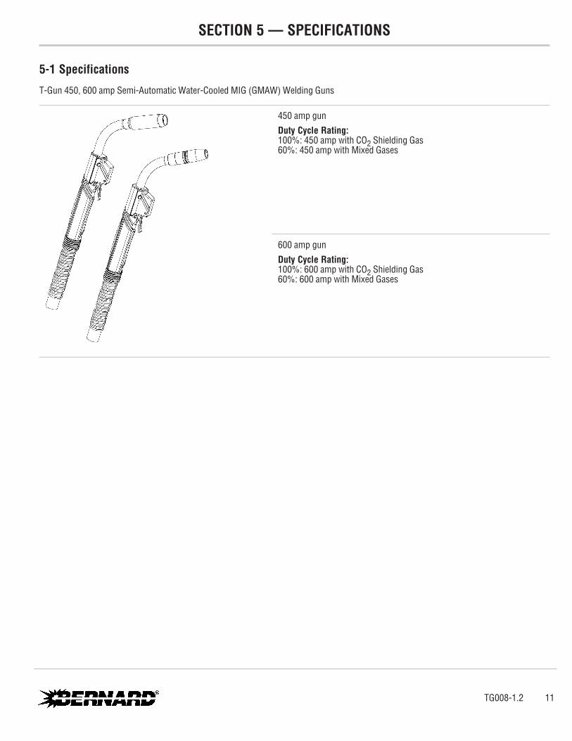
T-Gun 450, 600 amp Semi-Automatic Water-Cooled MIG (GMAW) Welding Guns
450 amp gunDuty Cycle Rating:100%: 450 amp with CO2 Shielding Gas60%: 450 amp with Mixed Gases
600 amp gunDuty Cycle Rating:100%: 600 amp with CO2 Shielding Gas60%: 600 amp with Mixed Gases
TG008-1.2 11

SECTION 6 — INSTALLATION
6-1 Installing Quick-Connect Block to Feeder
1. Insert the correct feeder adaptor liner for desired wire diameter (2 provided) flush with the threaded end of the feeder adaptor.
2. Tighten set screw.
3. Thread feeder adaptor into quick-connect block and tighten.
4. Position assembly into feeder adaptor and trim liner within 1/16" (1.6 mm) of the drive rolls and remove burrs if necessary.
5. Secure assembly into feeder.
6. Thread gas hose nipple into feeder gas fitting.
7. Connect power cable to 1/2" (13 mm) power bolt with appropriate lug.
8. Tighten all connections.
9. Feed welding wire through assembly by hand and tighten drive rolls.
Figure 6-A
Figure 6-B
12 TG008-1.2
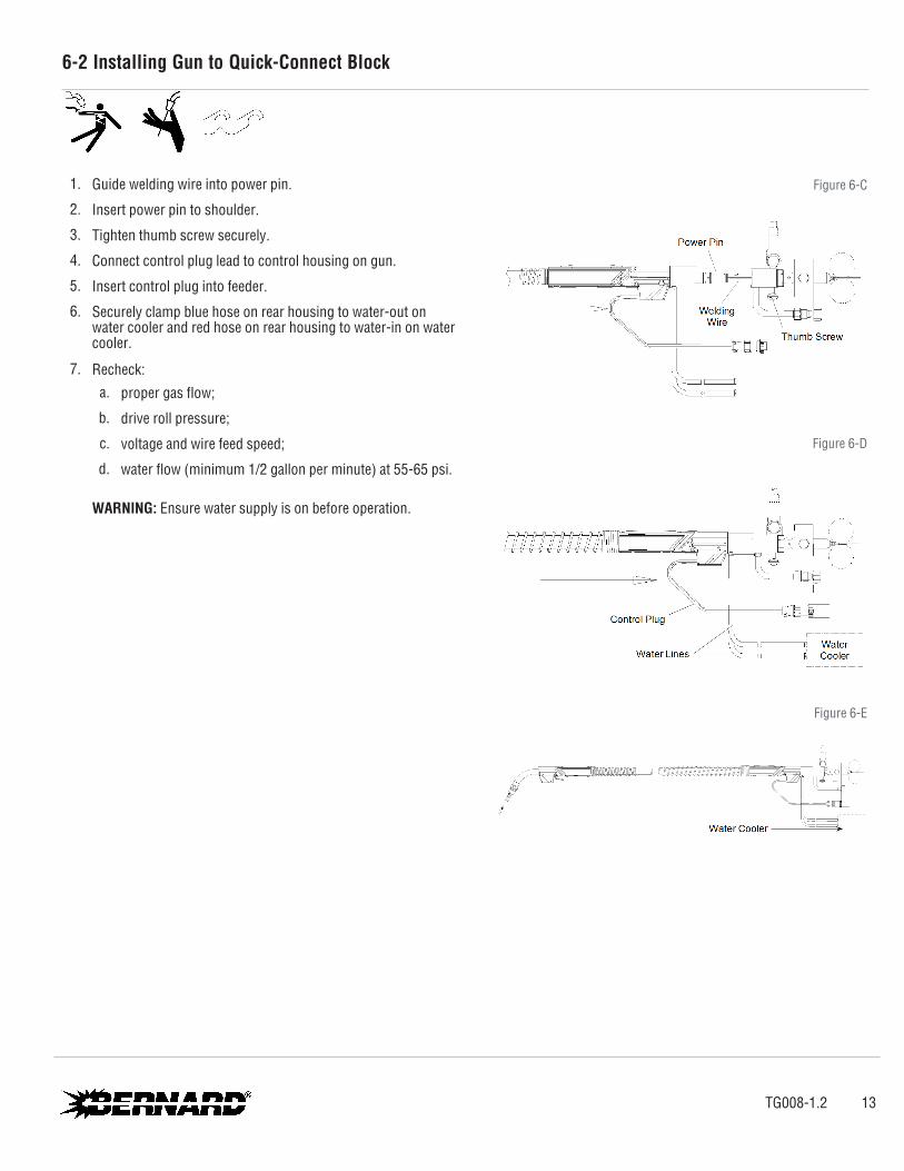
6-2 Installing Gun to Quick-Connect Block
1. Guide welding wire into power pin.
2. Insert power pin to shoulder.
3. Tighten thumb screw securely.
4. Connect control plug lead to control housing on gun.
5. Insert control plug into feeder.
6. Securely clamp blue hose on rear housing to water-out on water cooler and red hose on rear housing to water-in on water cooler.
7. Recheck: a. proper gas flow;
b. drive roll pressure;
c. voltage and wire feed speed;
d. water flow (minimum 1/2 gallon per minute) at 55-65 psi.
WARNING: Ensure water supply is on before operation.
Figure 6-C
Figure 6-D
Figure 6-E
TG008-1.2 13
6-3 Installing Power Pin to Gun
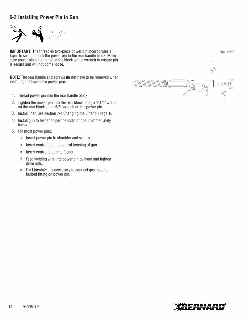
IMPORTANT: The thread-in two-piece power pin incorporates a taper to seat and lock the power pin to the rear handle block. Make sure power pin is tightened in the block with a wrench to ensure pin is secure and will not come loose. NOTE: The rear handle and screws do not have to be removed when installing the two-piece power pins.
1. Thread power pin into the rear handle block.
2. Tighten the power pin into the rear block using a 1-1/4" wrench on the rear block and a 5/8" wrench on the power pin.
3. Install liner. See section 7-4 Changing the Liner on page 18.
4. Install gun to feeder as per the instructions in immediately below.
5. For most power pins: a. Insert power pin to shoulder and secure.
b. Insert control plug to control housing of gun.
c. Insert control plug into feeder.
d. Feed welding wire into power pin by hand and tighten drive rolls.
e. For Lincoln® it is necessary to connect gas hose to barbed fitting on power pin.
Figure 6-F
14 TG008-1.2

SECTION 7 — REPLACEMENT
7-1 Changing Consumables
450 amp
600 amp
IMPORTANT:
l Neck insulator must be in place before welding to maintain insulation of neck armor.
l Be sure all parts are tightened well before welding.
l When using the heavy duty retaining head, make sure it is tightened with a 5/8" wrench to prevent overheating of contact tip.
l To prevent scoring on heavy duty retaining heads, do not use pliers.
A. Removal and Replacement 1. Pull slip-on nozzles off with a clockwise twisting motion.
2. When insulating nozzle, exposed insulator should nest inside neck insulator to ensure concentricity.
3. Neck insulators are positioned on the end of the neck with the large insulated counter bore facing the nozzle.
4. Replace nozzle retainer with deep counterbore toward the neck. Tighten until retainer and neck insulator are secure.
TG008-1.2 15
7-2 Changing the Switch
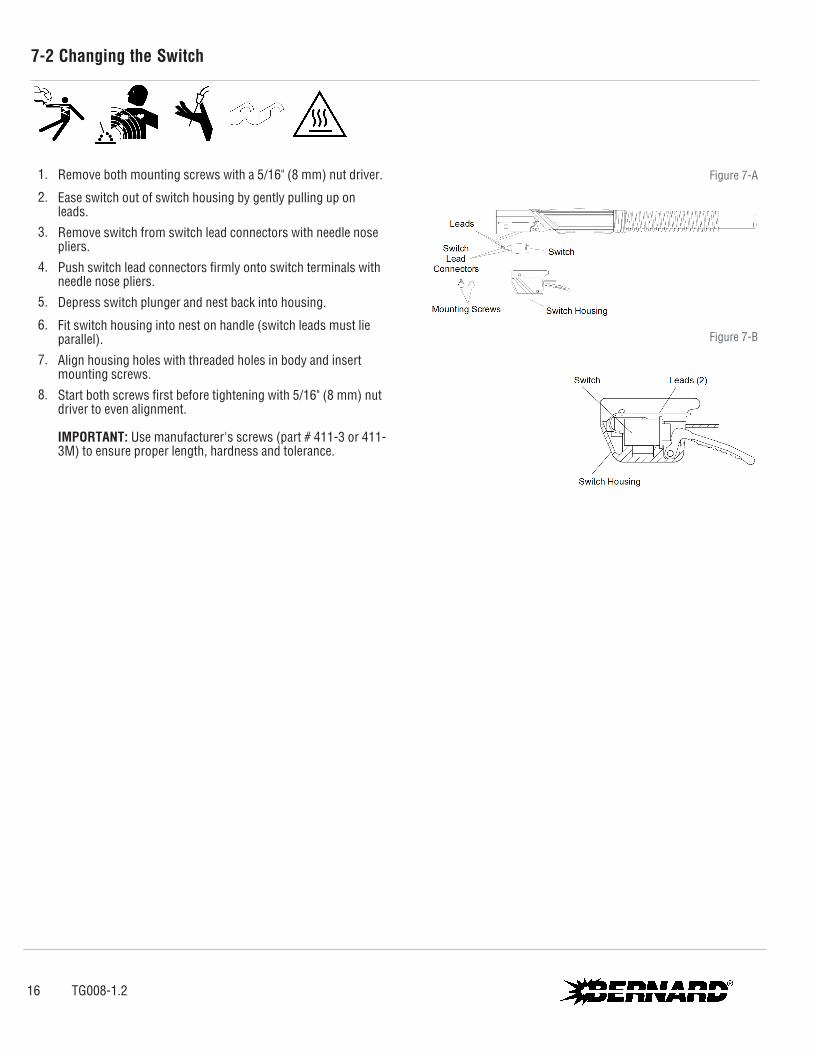
1. Remove both mounting screws with a 5/16" (8 mm) nut driver.
2. Ease switch out of switch housing by gently pulling up on leads.
3. Remove switch from switch lead connectors with needle nose pliers.
4. Push switch lead connectors firmly onto switch terminals with needle nose pliers.
5. Depress switch plunger and nest back into housing.
6. Fit switch housing into nest on handle (switch leads must lie parallel).
7. Align housing holes with threaded holes in body and insert mounting screws.
8. Start both screws first before tightening with 5/16" (8 mm) nut driver to even alignment.
IMPORTANT: Use manufacturer's screws (part # 411-3 or 411-3M) to ensure proper length, hardness and tolerance.
Figure 7-A
Figure 7-B
16 TG008-1.2
7-3 Changing the Neck
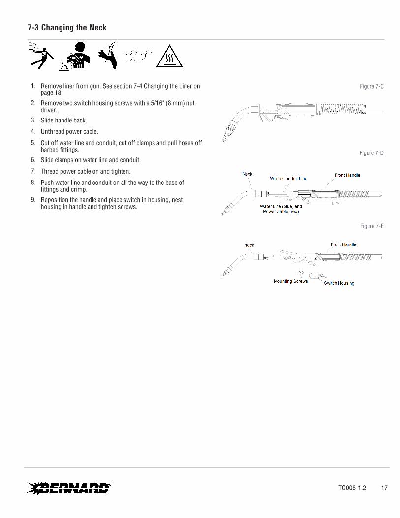
1. Remove liner from gun. See section 7-4 Changing the Liner on page 18.
2. Remove two switch housing screws with a 5/16" (8 mm) nut driver.
3. Slide handle back.
4. Unthread power cable.
5. Cut off water line and conduit, cut off clamps and pull hoses off barbed fittings.
6. Slide clamps on water line and conduit.
7. Thread power cable on and tighten.
8. Push water line and conduit on all the way to the base of fittings and crimp.
9. Reposition the handle and place switch in housing, nest housing in handle and tighten screws.
Figure 7-C
Figure 7-D
Figure 7-E
TG008-1.2 17
7-4 Changing the Liner
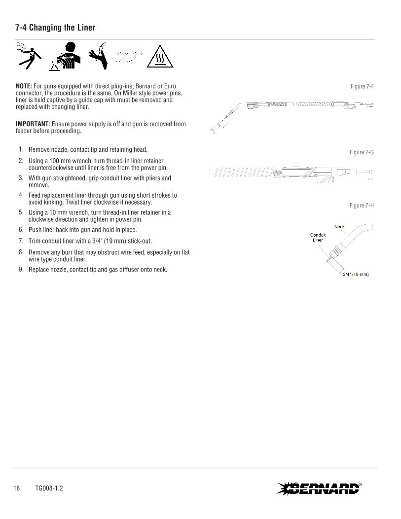
NOTE: For guns equipped with direct plug-ins, Bernard or Euro connector, the procedure is the same. On Miller style power pins, liner is held captive by a guide cap with must be removed and replaced with changing liner.
IMPORTANT: Ensure power supply is off and gun is removed from feeder before proceeding.
1. Remove nozzle, contact tip and retaining head.
2. Using a 100 mm wrench, turn thread-in liner retainer counterclockwise until liner is free from the power pin.
3. With gun straightened, grip conduit liner with pliers and remove.
4. Feed replacement liner through gun using short strokes to avoid kinking. Twist liner clockwise if necessary.
5. Using a 10 mm wrench, turn thread-in liner retainer in a clockwise direction and tighten in power pin.
6. Push liner back into gun and hold in place.
7. Trim conduit liner with a 3/4" (19 mm) stick-out.
8. Remove any burr that may obstruct wire feed, especially on flat wire type conduit liner.
9. Replace nozzle, contact tip and gas diffuser onto neck.
Figure 7-F
Figure 7-G
Figure 7-H
18 TG008-1.2
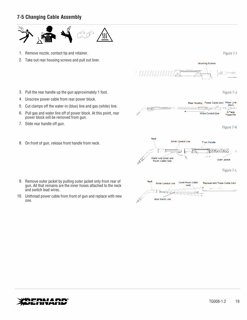
7-5 Changing Cable Assembly
1. Remove nozzle, contact tip and retainer.
2. Take out rear housing screws and pull out liner.
3. Pull the rear handle up the gun approximately 1 foot.
4. Unscrew power cable from rear power block.
5. Cut clamps off the water-in (blue) line and gas (white) line.
6. Pull gas and water line off of power block. At this point, rear power block will be removed from gun.
7. Slide rear handle off gun.
8. On front of gun, release front handle from neck.
9. Remove outer jacket by pulling outer jacket only from rear of gun. All that remains are the inner hoses attached to the neck and switch lead wires.
10. Unthread power cable from front of gun and replace with new one.
Figure 7-I
Figure 7-J
Figure 7-K
Figure 7-L
TG008-1.2 19

11. From rear of gun, slide front handle over hoses.
12. Tape hoses together at rear of gun.
13. Slide outer jacket over hoses from rear of gun.
14. Slide outer jacket under front handle and bring front handle up to neck, replace switch and switch housing, and secure. See section 7-2 Changing the Switch on page 16.
15. At rear of gun, slide rear handle up over outer jacket.
16. Attach rear power block to power cable.
17. Attach gas line and water line with new clamps and crimp to power block.
18. Slide rear handle to rear power block and secure with mounting screws.
19. Put liner through gun and tighten.
20. Install liner. See section 7-4 Changing the Liner on page 18.
Figure 7-M
Figure 7-N
Figure 7-O
Figure 7-P
20 TG008-1.2
SECTION 8 — TECHNICAL DATA
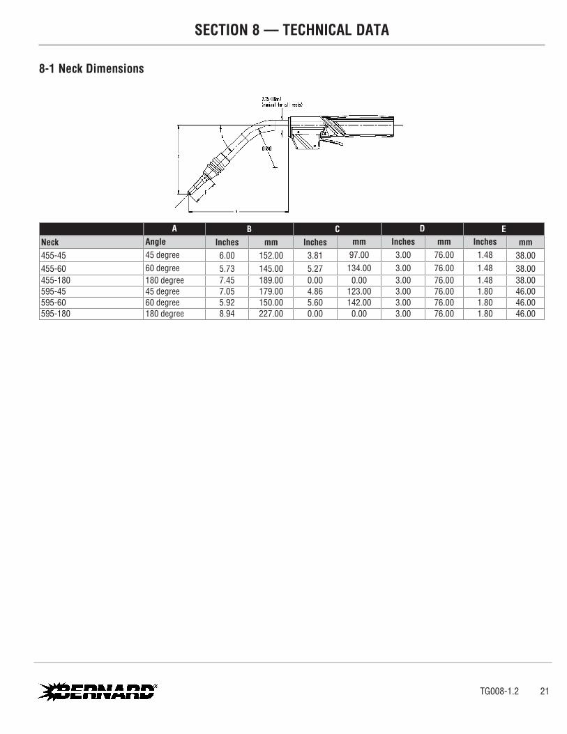
8-1 Neck Dimensions
A B C D ENeck Angle Inches mm Inches mm Inches mm Inches mm455-45 45 degree 6.00 152.00 3.81 97.00 3.00 76.00 1.48 38.00455-60 60 degree 5.73 145.00 5.27 134.00 3.00 76.00 1.48 38.00455-180 180 degree 7.45 189.00 0.00 0.00 3.00 76.00 1.48 38.00595-45 45 degree 7.05 179.00 4.86 123.00 3.00 76.00 1.80 46.00595-60 60 degree 5.92 150.00 5.60 142.00 3.00 76.00 1.80 46.00595-180 180 degree 8.94 227.00 0.00 0.00 3.00 76.00 1.80 46.00
TG008-1.2 21
SECTION 9 — PARTS LIST
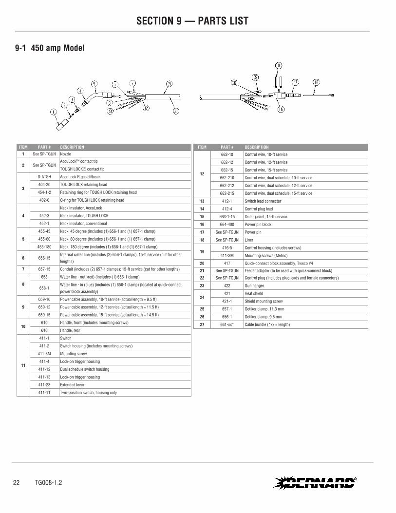
9-1 450 amp Model
ITEM PART # DESCRIPTION1 See SP-TGUN Nozzle
2 See SP-TGUNAccuLock™ contact tip
TOUGH LOCK® contact tip
3
D-ATSH AccuLock R gas diffuser
404-20 TOUGH LOCK retaining head
454-1-2 Retaining ring for TOUGH LOCK retaining head
402-6 O-ring for TOUGH LOCK retaining head
4
Neck insulator, AccuLock
452-3 Neck insulator, TOUGH LOCK
452-1 Neck insulator, conventional
5
455-45 Neck, 45 degree (includes (1) 656-1 and (1) 657-1 clamp)
455-60 Neck, 60 degree (includes (1) 656-1 and (1) 657-1 clamp)
455-180 Neck, 180 degree (includes (1) 656-1 and (1) 657-1 clamp)
6 656-15Internal water line (includes (2) 656-1 clamps); 15-ft service (cut for other
lengths)
7 657-15 Conduit (includes (2) 657-1 clamps); 15-ft service (cut for other lengths)
8
658 Water line - out )red) (includes (1) 656-1 clamp)
658-1Water line - in (blue) (includes (1) 656-1 clamp) (located at quick-connect
power block assembly)
9
659-10 Power cable assembly, 10-ft service (actual length = 9.5 ft)
659-12 Power cable assembly, 12-ft service (actual length = 11.5 ft)
659-15 Power cable assembly, 15-ft service (actual length = 14.5 ft)
10610 Handle, front (includes mounting screws)
610 Handle, rear
11
411-1 Switch
411-2 Switch housing (includes mounting screws)
411-3M Mounting screw
411-4 Lock-on trigger housing
411-12 Dual schedule switch housing
411-13 Lock-on trigger housing
411-23 Extended lever
411-11 Two-position switch, housing only
ITEM PART # DESCRIPTION
12
662-10 Control wire, 10-ft service
662-12 Control wire, 12-ft service
662-15 Control wire, 15-ft service
662-210 Control wire, dual schedule, 10-ft service
662-212 Control wire, dual schedule, 12-ft service
662-215 Control wire, dual schedule, 15-ft service
13 412-1 Switch lead connector
14 412-4 Control plug lead
15 663-1-15 Outer jacket, 15-ft service
16 664-400 Power pin block
17 See SP-TGUN Power pin
18 See SP-TGUN Liner
19416-5 Control housing (includes screws)
411-3M Mounting screws (Metric)
20 417 Quick-connect block assembly, Tweco #4
21 See SP-TGUN Feeder adaptor (to be used with quick-connect block)
22 See SP-TGUN Control plug (includes plug leads and female connectors)
23 422 Gun hanger
24421 Heat shield
421-1 Shield mounting screw
25 657-1 Oetiker clamp, 11.3 mm
26 656-1 Oetiker clamp, 9.5 mm
27 661-xx* Cable bundle (*xx = length)
22 TG008-1.2

9-2 600 amp Model
ITEM PART # DESCRIPTION1 See SP-TGUN Nozzle
2 See SP-TGUNAccuLock™ contact tip
TOUGH LOCK® contact tip
3
D-ATSH AccuLock R gas diffuser
404-20 TOUGH LOCK retaining head
454-1-2 Retaining ring for TOUGH LOCK retaining head
402-6 O-ring for TOUGH LOCK retaining head
4
595-45 Neck, 45 degree (includes 656-1 and (1) 657-1 clamp)
595-60 Neck, 60 degree (includes 656-1 and (1) 657-1 clamp)
595-180 Neck, 180 degree (includes 656-1 and (1) 657-1 clamp)
652-8 O-ring (small, qty. 2)
495-7 O-ring (large, qty. 4)
652-5 O-ring (qty. 3)
5 656-15Internal water line (includes (2) 656-1 clamps); 15-ft service (cut for other
lengths)
6 657-15 Conduit (includes (2) 657-1 clamps); 15-ft service (cut for other lengths)
7
658 Water line - out )red) (includes (1) 656-1 clamp)
658-1Water line - in (blue) (includes (1) 656-1 clamp) (located at quick-connect
power block assembly)
8
659-10 Power cable assembly, 10-ft service (actual length = 9.5 ft)
659-12 Power cable assembly, 12-ft service (actual length = 11.5 ft)
659-15 Power cable assembly, 15-ft service (actual length = 14.5 ft)
9610 Handle, front (includes mounting screws)
610 Handle, rear
10
411-1 Switch
411-2 Switch housing (includes mounting screws)
411-3M Mounting screw
411-4 Lock-on trigger housing
411-12 Dual schedule switch housing
411-13 Lock-on trigger housing
411-23 Extended lever
411-11 Two-position switch, housing only
ITEM PART # DESCRIPTION
11
662-10 Control wire, 10-ft service
662-12 Control wire, 12-ft service
662-15 Control wire, 15-ft service
662-210 Control wire, dual schedule, 10-ft service
662-212 Control wire, dual schedule, 12-ft service
662-215 Control wire, dual schedule, 15-ft service
12 412-1 Switch lead connector
13 412-4 Control plug lead
14 663-1-15 Outer jacket, 15-ft service
15 664-400 Power pin block
16 See SP-TGUN Power pin
17 See SP-TGUN Liner
18416-5 Control housing (includes screws)
411-3M Mounting screws (Metric)
19 417 Quick-connect block assembly, Tweco #4
20 See SP-TGUN Feeder adaptor (to be used with quick-connect block)
21 See SP-TGUN Control plug (includes plug leads and female connectors)
22 657-1 Oetiker clamp, 11.3 mm
23 656-1 Oetiker clamp, 9.5 mm
24 661-xx* Cable bundle (*xx = length)
TG008-1.2 23
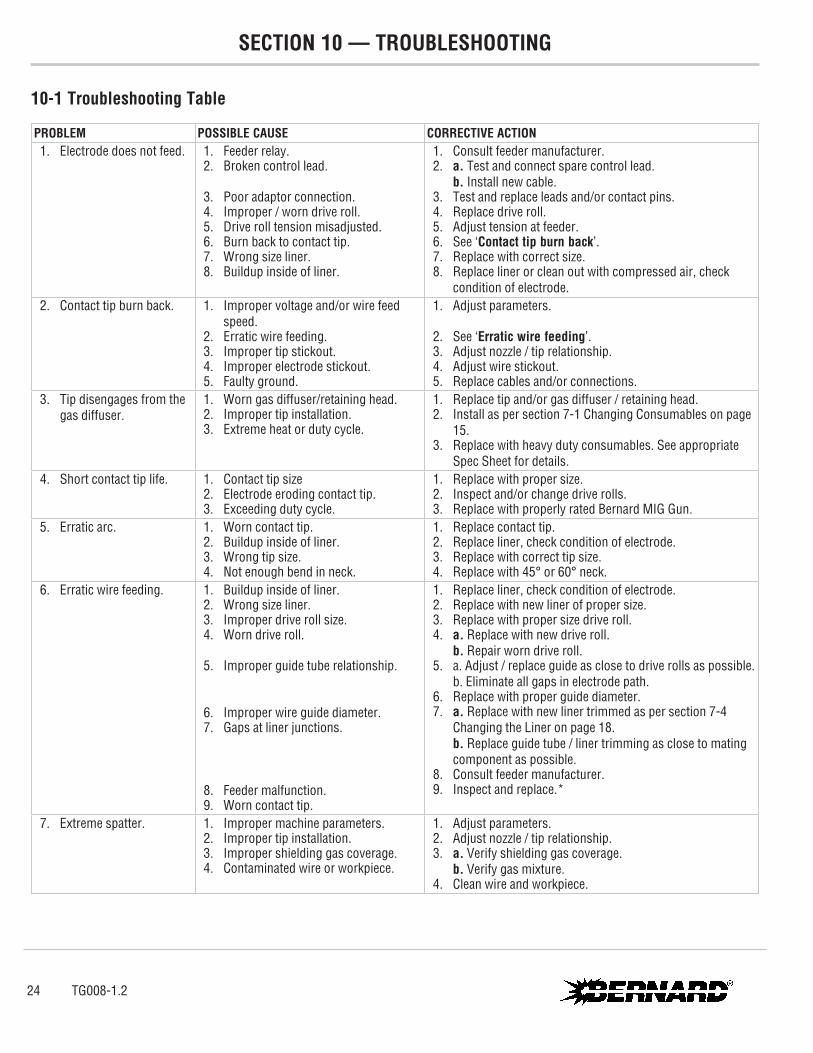
SECTION 10 — TROUBLESHOOTING
10-1 Troubleshooting Table
PROBLEM POSSIBLE CAUSE CORRECTIVE ACTION 1. Electrode does not feed. 1. Feeder relay.
2. Broken control lead.
3. Poor adaptor connection. 4. Improper / worn drive roll. 5. Drive roll tension misadjusted. 6. Burn back to contact tip. 7. Wrong size liner. 8. Buildup inside of liner.
1. Consult feeder manufacturer. 2. a. Test and connect spare control lead.
b. Install new cable. 3. Test and replace leads and/or contact pins. 4. Replace drive roll. 5. Adjust tension at feeder. 6. See ‘Contact tip burn back’. 7. Replace with correct size. 8. Replace liner or clean out with compressed air, check
condition of electrode. 2. Contact tip burn back. 1. Improper voltage and/or wire feed
speed. 2. Erratic wire feeding. 3. Improper tip stickout. 4. Improper electrode stickout. 5. Faulty ground.
1. Adjust parameters.
2. See ‘Erratic wire feeding’. 3. Adjust nozzle / tip relationship. 4. Adjust wire stickout. 5. Replace cables and/or connections.
3. Tip disengages from the gas diffuser.
1. Worn gas diffuser/retaining head. 2. Improper tip installation. 3. Extreme heat or duty cycle.
1. Replace tip and/or gas diffuser / retaining head. 2. Install as per section 7-1 Changing Consumables on page
15. 3. Replace with heavy duty consumables. See appropriate
Spec Sheet for details. 4. Short contact tip life. 1. Contact tip size
2. Electrode eroding contact tip. 3. Exceeding duty cycle.
1. Replace with proper size. 2. Inspect and/or change drive rolls. 3. Replace with properly rated Bernard MIG Gun.
5. Erratic arc. 1. Worn contact tip. 2. Buildup inside of liner. 3. Wrong tip size. 4. Not enough bend in neck.
1. Replace contact tip. 2. Replace liner, check condition of electrode. 3. Replace with correct tip size. 4. Replace with 45° or 60° neck.
6. Erratic wire feeding. 1. Buildup inside of liner. 2. Wrong size liner. 3. Improper drive roll size. 4. Worn drive roll.
5. Improper guide tube relationship.
6. Improper wire guide diameter. 7. Gaps at liner junctions.
8. Feeder malfunction. 9. Worn contact tip.
1. Replace liner, check condition of electrode. 2. Replace with new liner of proper size. 3. Replace with proper size drive roll. 4. a. Replace with new drive roll.
b. Repair worn drive roll. 5. a. Adjust / replace guide as close to drive rolls as possible.
b. Eliminate all gaps in electrode path. 6. Replace with proper guide diameter. 7. a. Replace with new liner trimmed as per section 7-4
Changing the Liner on page 18.b. Replace guide tube / liner trimming as close to mating component as possible.
8. Consult feeder manufacturer. 9. Inspect and replace.*
7. Extreme spatter. 1. Improper machine parameters. 2. Improper tip installation. 3. Improper shielding gas coverage. 4. Contaminated wire or workpiece.
1. Adjust parameters. 2. Adjust nozzle / tip relationship. 3. a. Verify shielding gas coverage.
b. Verify gas mixture. 4. Clean wire and workpiece.
24 TG008-1.2
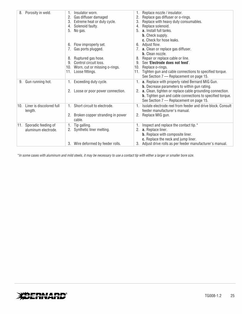
8. Porosity in weld. 1. Insulator worn. 2. Gas diffuser damaged 3. Extreme heat or duty cycle. 4. Solenoid faulty. 5. No gas.
6. Flow improperly set. 7. Gas ports plugged.
8. Ruptured gas hose. 9. Control circuit loss. 10. Worn, cut or missing o-rings. 11. Loose fittings.
1. Replace nozzle / insulator. 2. Replace gas diffuser or o-rings. 3. Replace with heavy duty consumables. 4. Replace solenoid. 5. a. Install full tanks.
b. Check supply.c. Check for hose leaks.
6. Adjust flow. 7. a. Clean or replace gas diffuser.
b. Clean nozzle. 8. Repair or replace cable or line. 9. See ‘Electrode does not feed’. 10. Replace o-rings. 11. Tighten gun and cable connections to specified torque.
See Section 7 — Replacement on page 15. 9. Gun running hot. 1. Exceeding duty cycle.
2. Loose or poor power connection.
1. a. Replace with properly rated Bernard MIG Gun.b. Decrease parameters to within gun rating.
2. a. Clean, tighten or replace cable grounding connection.b. Tighten gun and cable connections to specified torque. See Section 7 — Replacement on page 15.
10. Liner is discolored full length.
1. Short circuit to electrode.
2. Broken copper stranding in power cable.
1. Isolate electrode reel from feeder and drive block. Consult feeder manufacturer's manual.
2. Replace MIG gun.
11. Sporadic feeding of aluminum electrode.
1. Tip galling. 2. Synthetic liner melting.
3. Wire deformed by feeder rolls.
1. Inspect and replace the contact tip.* 2. a. Replace liner.
b. Replace with composite liner.c. Replace the neck and jump liner.
3. Adjust drive rolls as per feeder manufacturer's manual.
*In some cases with aluminum and mild steels, it may be necessary to use a contact tip with either a larger or smaller bore size.
TG008-1.2 25

ADDITIONAL SUPPORT MATERIALS
For additional support materials such as Spec Sheets, troubleshooting information, how-to guides and videos, animations, online configurators and much more, please visit Bernard. Scan the QR Code with your smart phone for immediate access to Tregaskiss.com/TechnicalSupport.
Scan to view the T-Gun™ Semi-Automatic Water-Cooled MIG Gun Owner’s Manual
Scan to view the TOUGH LOCK® Consumables Spec Sheet
Scan to view the AccuLock™ R Consumables Spec Sheetl
Scan to view additional Bernard® Owner's Manuals and Spec Sheets
BernardA Division of Miller Electric Mfg. LLC449 West Corning RoadBeecher, Illinois 60401 USA
Phone:
Fax:
1-855-MIGWELD (644-9353) (US & Canada)+1-519-737-3000 (International)
1-708-946-6726
For more information, visit us at Tregaskiss.com