Contact-Cooled Rotary Screw Air Compressors - Ingersoll Rand

INTERNATIONAL JOURNAL OF ENERGY RESEARCH, VOL. 19,761-789 (1995)
THE POTENTIAL FOR GAS-COOLED REACTOR DEVELOPMENT
R. Y . NUWAYHID
Depament of Mechanical Engineehg, American Uniuersiv of Beirut, Beirut, Lebanon
AND
A. J. H. GODDARD
Energy Systems Section, Depamnent of Mechanical Engineering, Imperial College, London, UK
SUMMARY
Gas-cooled reactors (GCR) are currently fighting for survival in a world now nearly completely committed to light water reactors (LWR). If some core nuclear design features could be simplified or improved while maintaining their already well-known safety attractions. GCRs would be able to compete better with other classes of reactors. This would be even more true if their economics could be improved by considering gas-cooled fast breeder designs. A serious study of these possibilities may conclude once and for all whether simple gas-cooled reactors of current technological standing can be designed. It is suggested that the next step could be a down-rated gas-cooled breeder using AGR component technology while available. A safety enforcing variant of this would admit some ‘diluent’ such as alumina into the core to act as an emergency transient heat sink as well as to increase the doppler coefficient.
KEY WORDS: gas-cooled reactors; core design potential; neutronics; safety; thermal cores; fast cores; diluted fast cores
1. INTRODUCTION/BACKGROUND The UK nuclear power programme is of particular interest, the UK being the only nation that had originally pursued an all gas-cooled/solid-moderated reactor design. Starting with the magnox design then progressing to the AGR, the UK finds itself having to finally consider the introduction of PWR designs - this is already under way with Sizewell B. Although existent AGRs are being improved, they stand to be the last stage in a very long process of development of gas-cooled reactor designs.
The reasons stated in the UK for replacement of AGR by PWR have been primarily economic and include: construction period, capital cost, plant availability, and plant lifetime. Some of these indicators which seem to favour PWR may be misleading. Planned construction periods for both types of reactor are similar but the Dungeness B case in the UK gives a bad impression for AGR. Industrial relations problems, in addition to prototype design features, led to the extremely long construction time for that particular reactor. Availability for AGR should theoretically be better than that of PWR if the stated design target of continuous refuelling at full power could be realized. This remains a major problem although advance has been made and refuelling at up to 70% power is possible. Past economic troubles aside, the AGR offers certain design advantages over the PWR notably on the safety side. During the coming years, the possibility exists of developing the gas-cooled design while practical experience is still available. Simplification of design must be a major task in the successful future development of AGR. Having been established as a viable option in the UK, the PWR will share with AGR electricity generation in the late 1990s and early 2000s. With the last of the Magnox reactors being decommissioned around 2020, the 5.3 GW, they generate must be replaced. If this capacity is provided by PWRs, then replacement of early AGRs and whether gas-cooled plants will disappear or continue to contribute to UK energy generation, will become an issue. While improving AGR itself has been a first priority, AGR
CCC 0363-907X/95/090761-29 0 1995 by John Wiley & Sons, Ltd.
Received 19 May 1994 Revhed 5 Jury 1994

762 GAS-COOLED REACTORS
derivative designs are a further possible step aiming at higher burnup while core design is simplified. Reactor power could be increased, if desired, with only the conventional equipment being the limiting factor. With regard to fuel rating, use of stainless-steel cladding imposes a limit on outlet coolant temperature of about 675°C and a natural next step could be the use of an all-ceramic core. With high temperature reactors (HTR) and 6-7% fuel enrichment, coolant outlet temperatures of about 750°C together with burnups of over 50 GWd/t are achievable. New fuel design and the extensive testing required, may, however, cause HTR acceptance to be a lengthy task.
If plutonium fuel was to become used extensively, as U-235 stocks deplete and recycling increases, then fast reactors would be the most efficient fuel users. Thus, as an alternative to HTR having greater fertile material utilization, the gas-cooled fast reactor (GCFR) is considered. It may be noted here that proliferation control would be improved by using fuel in a reactor rather than stockpiling it. Furthermore, owing to the continuing low rate of introduction of new thermal reactors and the absence of the general use of fuel recycle, there is an ongoing accumulation of plutonium discharged from thermal reactors. Together with the fact that fuel prices are low and the supply relatively plentiful, the whole motive for the introduction of breeder reactors may thus be questioned. The GCFR with its ‘harder’ neutron spectrum has a generally higher breeding gain than an equivalent LMFBR, this allows a GCFR to be designed with reduced rating while still maintaining a significantly high fuel utilization through breeding, although the capital costs are uncertain. On the other hand, a GCFR design based on present gas-cooled technology with low rating and reduced overall breeding is apparently attractive. With plutonium relatively plentiful, the higher core inventory may be tolerated on fuel cost grounds.
A design of GCFR using CO, coolant, as much current AGR component technology as possible, as well as enough flexibility to be later modified, is the ‘existing technology gas breeder reactor’ (ETGBR) (Kemmish, 1982). This concept has a relatively low rating, and this, among other aspects, gives it potentially lower generating costs than a ‘liquid metal fast breeder reactor’ (LMFBR). The design takes into account a reduced need for breeding through the existence of larger plutonium stocks. The diluted-ETGBR is a concept investigated which retains the ETGBR characteristics, but sparingly admits some ‘diluent’ or moderator into the core in part on safety grounds. The most convenient dilution method is integral block modules similar to the Fort St Vrain HTR design. This assures diluent block material endurance owing to frequent refuelling, but it may be difficult to machine blocks with small annuli. Other dilution methods include the mixed fuel/diluent rods subassembly design. A dispersion fuel surrounded by a ceramic cladding as in HTR is a further mode of dilution that removes the need for stainless-steel cladding and brings higher temperature and hence higher ratings. This concept applied to fast reactors remains a long-range design target.
Following recent nuclear accidents, safety has become the primary aspect in design. The ETGBR, being a relatively low-rated system, uses a lower coolant pressure and thus would suffer slower heat-up rates under accident situations. In common with other fast designs, ETGBR has long burnups with little excess reactivity present owing to the high conversion ratio. Lower control investment, the adoption of batchwise refuelling and simple refuelling apparatus are thus the case. The absence of moderator in ETGBR, however, makes clad integrity of greater importance owing to the higher power density. As in AGR, depressurization under accident conditions is considered to occur over a sufficiently long period owing to the prestressed concrete pressure vessel (PCPV). The diluted-ETGBR design introduced in this work is intended, among other aspects, to increase safety further by providing an in-core transient heat sink and to cause the doppler coefficient of reactivity to be more negative than for the basic ETGBR.
2. STUDY METHODS AND VALIDATION
Rather than using two neutronic codes, one for thermal and one for fast cores, it was decided to use a single neutronic code. The WIMS family of neutronic programs is well suited for thermal systems and has been fully validated for these, Both WIMS-D4 (Askew et uZ., 1966) and WIMS-E (Askew and Roth, 1982) were used extensively in this work. In addition, there has been evidence that WIMS actually predicts very

R. Y. NUWAYHID AND A. J. H. GODDARD 763
‘hard’ core neutronics better then some fast reactor codes such as COSMOS (Brissenden, 1975). Having said this, a problem lies in the suitability of WIMS for cores intermediate between very ‘hard’ and thermal. In the event, a study of the validity of the WIMS 1981 data library was done for the whole range of cores and found to overpredict reactivity and burnup for fast cores using mixed oxide fuel (MOX) (Nuwayhid, 1989). This was found to agree with the observations of Chawla et al. (1986) regarding voided water cores with relatively high enrichment and MOX fuel.
3. THE AGR DEVELOPMENT SCOPE
At the present, in the UK, AGR is subject to eventual replacement by PWR. The latter offering an apparent economic edge for reasons that are not entirely design-related (such as construction period and labour relations at the time of construction). Additionally, the small market penetration of AGR may be one factor giving it a higher capital cost. There are, however, some aspects of AGR design that warrant simplification and hence produce a cost saving.
Certain AGR nuclear design targets such as refuelling at full power have not been met, resulting in a lower annual load factor than for PWR. This is especially true with refuelling taking place at a mere 40% power for fear of stringer integrity. Recently, the new ‘stage-2’ single-sleeved channels have been introduced and refuelling at higher power is under way. In general on-load refuelling is complicated and requires special equipment. Simplification of design would replace this with batch refuelling. As far as burnup is concerned, 28 GWd/t could be expected from AGR in contrast to over 35 GWd/t for PWR. This limit is due to burnable poison ultimate requirement for fresh channel excess reactivity (Goode, 1984).
In introducing an AGR derivative reactor with simplified design, the following are considered: (1) retainment of CO, cooling since this is cheap and readily stored; (2) retainment of the PCPV to limit and slow down depressurization; (3) keeping the moderator separate from the coolant and retaining a core heat sink in the event of depressurization; (4) discarding the gas-baffle for simplicity and hence solving the problem of the positive moderator coefficient of reactivity; (5) introduction of single-length fuel rods and thus using a design of small height; (6) increase in core burnup to over 35 GWd/t with batch refuelling.
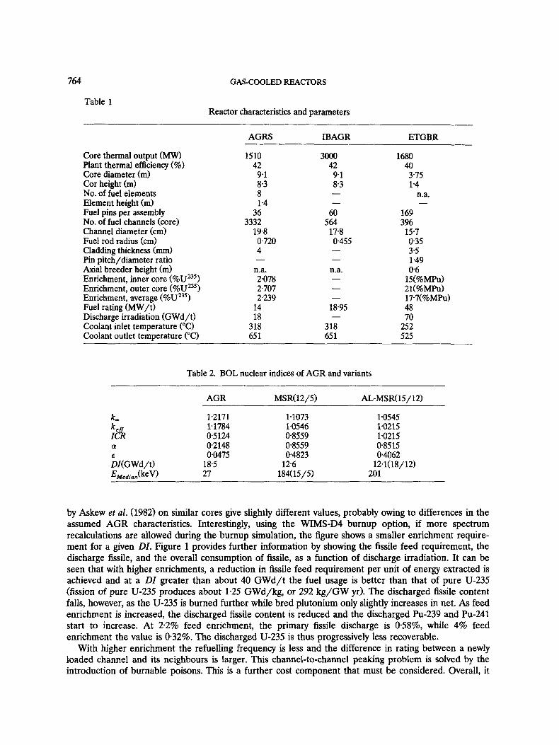
The fuel management scheme used by the standard AGR is a continuous or ‘just-critical’ one while on-load. Typical AGR characteristics are given in Table 1. Using WIMS-D4 with full leakage allowance, the standard AGR was calculated to have the nuclear indices shown in Table 2. At equilibrium where k,, is about 1.012 (datum), the conversion ratio is found to be 0.5871. Additionally, the equilibrium AGR temperature coefficient of reactivity (Tdk/dT) is found to be + 0.0546 for a worst-case simultaneous rise of 200°C for both fuel and moderator. It is clear that the overall coefficient is positive - an undesirable situation, tackled normally by providing separate (re-entrant) cooling to the moderator to slow down the effect relative to the fast-acting negative fuel temperature coefficient of reactivity.
3.1. Dewlopment and extension of AGR
A primary goal in AGR development must be extending the efficiency of extraction of energy from the fuel. A burnup close to the PWR figure of 35 GWd/t would be an ideal target. This, together with the higher availability due to on-load refuelling, would contribute to AGRs maintaining a lead over their rivals. In reality, extension of discharge irradiation ( D I ) is not so simple with burnable poison require- ment becoming both costly and difficult to implement without change to the present fuel design (i.e. toroids of Gd,O, poison wrapped around the fuel cluster within the grid and braces of each fuel element) (Goode, 1984). Further limits on burnup arise from cladding behaviour and the lack of fission gas plenums in the fuel pins.
Disregarding for the present all other limits, the extension of discharge irradiation may be simply accomplished by the use of higher enrichment feed fuel, assuming no change of fuel element geometry and heat transfer area. Figure 1 shows the necessary enrichments required for a given DI. Calculations
764 GAS-COOLED REACTORS
Table 1 Reactor characteristics and parameters
AGRS IBAGR ETGBR
Core thermal output (MW) Plant thermal efficiency (%) Core diameter (m) Cor height (m) No. of fuel elements Element height (m) Fuel pins per assembly No. of fuel channels (core) Channel diameter (crn) Fuel rod radius (cm) Cladding thickness (mm) Pin pitch/diameter ratio Axial breeder height (m) Enrichment, inner core (%UZ5) Enrichment, outer core (%Uu5) Enrichment, average (%UZ3’) Fuel rating (MW/t) Discharge irradiation (GWd/t) Coolant inlet temperature (“C) Coolant outlet temperature (“C)
1510 42
9.1 8.3 8 1 *4
36 3332
19.8 0.720 4
n.a. -
2078 2707 2239
14 18
318 65 1
3000 42
9 1 8.3
60 564
178 0.455 -
n.a. - - -
18.95
318 65 1
1680 40 3.75 1.4
n.a. -
169 396
15.7 0.35 3.5 1.49 0 6
15(%MPu) 21(%MPu) 17-7(%MPu) 48 70
252 525
Table 2. BOL nuclear indices of AGR and variants ~
AGR MSR(12/5) AL-MSR(15 / 12)
k, 1.2171 1.1784 0.5124 0.2148
€ 00475 DI(G Wd/t) 18.5 EMe,ian(keV) 27
:& 0
~
1.1073 1.0545 1.0546 1.0215 0.8559 1.0215 08559 0.8515 04823 0.4062
126 12.1(18/12) 184(15/5) 201
by Askew et al. (1982) on similar cores give slightly different values, probably owing to differences in the assumed AGR characteristics. Interestingly, using the WIMS-D4 burnup option, if more spectrum recalculations are allowed during the burnup simulation, the figure shows a smaller enrichment require- ment for a given DI. Figure 1 provides further information by showing the fissile feed requirement, the discharge fissile, and the overall consumption of fissile, as a function of discharge irradiation. It can be seen that with higher enrichments, a reduction in fissile feed requirement per unit of energy extracted is achieved and at a DI greater than about 40 GWd/t the fuel usage is better than that of pure U-235 (fission of pure U-235 produces about 1-25 GWd/kg, or 292 kg/GW yr). The discharged fissile content falls, however, as the U-235 is burned further while bred plutonium only slightly increases in net. As feed enrichment is increased, the discharged fissile content is reduced and the discharged Pu-239 and Pu-241 start to increase. At 2.2% feed enrichment, the primary fissile discharge is 0-58%, while 4% feed enrichment the value is 0.32%. The discharged U-235 is thus progressively less recoverable.
With higher enrichment the refuelling frequency is less and the difference in rating between a newly loaded channel and its neighbours is larger. This channel-to-channel peaking problem is solved by the introduction of burnable poisons. This is a further cost component that must be considered. Overall, it

R. Y. NUWAYHID AND A. J. H. GODDARD 765
10 20 30 40 50 60
Discharge Irradiation, GWd/t
( o ) Enrichment ( 0) F i s s i l e Feed ( 0 ) F i s s i l e Discharge ( m) Fissilc! Consumption
Figure 1. Enrichment requirement for AGR discharge irradiation
would appear that the AGR may be designed neutronically for considerably higher fuel use (DI), although above about 30 GWd/t fissile usage is almost independent of irradiation with more of the plutonium produced during the cycle being consumed. An additional upper limit on AGR burnup would then appear to be around 30 GWd/t. It is worth noting at this point that the overall positive temperature coefficient of reactivity for the AGR decreases with increasing enrichment. At 4.0% enrichment the coefficient is actually slightly negative.
If increased enrichment is considered in order to extend DI, the information in Figure 1 may be used to study the extension of the standard AGR refuelling interval. It can be seen that, in order to refuel one channel per week, an enrichment of about 3.1% is required, as opposed to the base case of two per week. This extension is beneficial from the availability point of view, although an investment in burnable poison would be required. As an exercise in possibilities, a batch refuelled AGR could be considered. A three-batch cycle refuelling every 624 days would give a reactivity penalty only half that of a single-batch scheme. For an enrichment similar to the base AGR value and a continuous-cycle DI (DIJ of 17.48 GWd/t, a three-batch scheme would achieve a DI of 11.14 GWd/t. In order to raise this value of DZ to around that of the continuous cycle, the feed enrichment would need to be about 2.65%.
With the stress in this work being, with the medium-term future in mind, on mixed plutonium-fuelled systems, it is interesting to see what Magnox discharged Pu (MPu) enrichments are required to fuel a standard AGR. Continuous-cycle being considered, it appears that to obtain the same initial keg as the U0,-AGR, an MPu enrichment of just under 2.9% is indicated (versus 2.2%). To obtain a discharge irradiation equal to the U0,-AGR, an enrichment of some 3.% to 4.0% is required. It should be noted here that, owing to the neutronic inertness of CO,, there is no need to consider the optimum moderator to fuel ratio effect in loss of coolant accidents (as must be considered with PWR). As far as doppler coefficients of reactivity are concerned, it appears a 2.9% MPu fuelled AGR has a less positive overall value. The simultaneous coefficient is found to be +0.0367 compared to the standard AGR value of + 0-0546.
3.2 The mixed-spectrum AGR derimtiw reactor
With routine production of plutonium from the burnup of current thermal reactors, it is possible to envisage a switch to plutonium fuelled cores. Using plutonium, superior neutronic efficiencies may be

766 GAS-COOLED REACTORS
obtained if the neutron spectrum is sufficiently ‘hard‘. If a fast reactor is not the immediate aim, then the possibility exists for a so-called ‘hybrid’ or ‘mixed-spectrum’ reactor (herein designated MSR). With these, the core contains zones in a fast spectrum mixed with zones in a relatively thermalized spectrum. When considering the possibility of using larger fuelled channel sizes (and more fuel rods) in an AGR derivative design, it is noted that the rods in the innermost part away from the moderator fall into a fast spectrum regime, while the outer rods are in a thermalized regime. This suggests the use of plutonium fuel, at least in the innermost zone. Such a design has been suggested by Askew as a development of current AGR design.
In order to keep refuelled units relatively small a hexagonal subassembly of 90 pins was the basic building block. A module was then made up of seven fuelled subassemblies surrounded by 12 hexagonal subassemblies containing pure graphite moderator. The channel volume ratio of moderator-to-fuel is about 2, giving an effective moderator-to-fuel volume ratio of 3.5. Pin sizes were taken to be similar to PWR at 11 mm diameter, while the stainless steel can was 3.5 mm thick. An MSR core was then made up from 37 modules in three rings giving a core diameter of 397 cm as shown in Figure 2. With the same fuel mass and power output as AGR, the resulting MSR was arbitrarily assigned a core height similar to AGR-800 cm. This led to a height to diameter ratio of near 2, which although not optimum, was nevertheless used for simplicity.
The specific fuel rating was thus similar to AGR at 14 MW/t, while the core power density increased to 15.25 MW/m3 owing to the smaller core diameter. With such a large fuelled zone in the module it is inescapable that there will be a large difference in the relative power production of the inner rings of
r :FUEL d: DILUENT
M~JR MODULE
Figure 2. The MSR module and three ring core
R. Y. NUWAYHID AND A. J. H. GODDARD 767
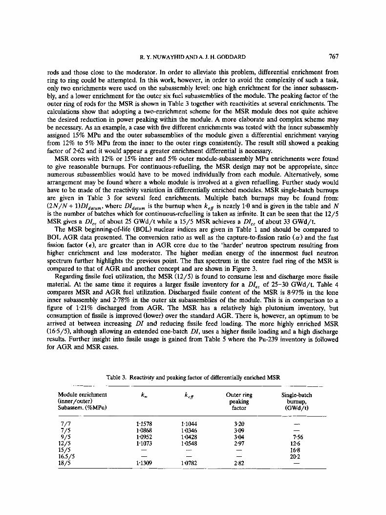
rods and those close to the moderator. In order to alleviate this problem, differential enrichment from ring to ring could be attempted. In this work, however, in order to avoid the complexity of such a task, only two enrichments were used on the subassembly level: one high enrichment for the inner subassem- bly, and a lower enrichment for the outer six fuel subassemblies of the module. The peaking factor of the outer ring of rods for the MSR is shown in Table 3 together with reactivities at several enrichments. The calculations show that adopting a two-enrichment scheme for the MSR module does not quite achieve the desired reduction in power peaking within the module. A more elaborate and complex scheme may be necessary. As an example, a case with five different enrichments was tested with the inner subassembly assigned 15% MPu and the outer subassemblies of the module given a differential enrichment varying from 12% to 5% MPu from the inner to the outer rings consistently. The result still showed a peaking factor of 2-62 and it would appear a greater enrichment differential is necessary.
MSR cores with 12% or 15% inner and 5% outer module-subassembly MPu enrichments were found to give reasonable burnups. For continuous-refuelling, the MSR design may not be appropriate, since numerous subassemblies would have to be moved individually from each module. Alternatively, some arrangement may be found where a whole module is involved at a given refuelling. Further study would have to be made of the reactivity variation in differentially enriched modules. MSR single-batch burnups are given in Table 3 for several feed enrichments. Multiple batch burnups may be found from: (2N/N + l)DI,,,,,, where DI,,,,, is the burnup when k,, is nearly 1.0 and is given in the table and N is the number of batches which for continuous-refuelling is taken as infinite. It can be seen that the 12/5 MSR gives a DI,, of about 25 GWd/t while a 15/5 MSR achieves a DZ,, of about 33 GWd/t.
The MSR beginning-of-life (BOL) nuclear indices are given in Table 1 and should be compared to BOL AGR data presented. The conversion ratio as well as the capture-to-fission ratio (a) and the fast fission factor (€1, are greater than in AGR core due to the ‘harder’ neutron spectrum resulting from higher enrichment and less moderator. The higher median energy of the innermost fuel neutron spectrum further highlights the previous point. The flux spectrum in the centre fuel ring of the MSR is compared to that of AGR and another concept and are shown in Figure 3.
Regarding fissile fuel utilization, the MSR (12/5) is found to consume less and discharge more fissile material. At the same time it requires a larger fissile inventory for a DI,, of 25-30 GWd/t. Table 4 compares MSR and AGR fuel utilization. Discharged fissile content of the MSR is 8.97% in the lone inner subassembly and 278% in the outer six subassemblies of the module. This is in comparison to a figure of 1.21% discharged from AGR. The MSR has a relatively high plutonium inventory, but consumption of fissile is improved (lower) over the standard AGR. There is, however, an optimum to be arrived at between increasing DI and reducing fissile feed loading. The more highly enriched MSR (165/5), although allowing an extended one-batch DI, uses a higher fissile loading and a high discharge results. Further insight into fissile usage is gained from Table 5 where the Pu-239 inventory is followed for AGR and MSR cases.
Table 3. Reactivity and peaking factor of differentially enriched MSR
k, k e f f Outer ring Single-batch burnup,
Module enrichment
Subassem. (%MPu) factor (GWd/t) (inner/outer) Peaking
- 1.1578 1.1044 320 1.0868 1.0346 3.09 1.0952 1.0428 3.04 756 1.1073 1.0548 297 126
16.8 202
- 7/7 7/5 9/5
12/5 15/5 16.5/5 18/5 1.1309 1.0782 282
- - - - - -
-

768 GAS-COOLED REACTORS
Energy, eV
Figure 3. Neutron flux spectra of AGR and variants
In general, the fissile fuel does not appear to be well utilized in the MSR. Indeed, compared with the standard AGR, MSRs operating on a one-batch cycle come to the end of their core lives with fissile contents typically of more than 65% of feed. This figure is improved if the one considers the outer subassemblies of the module which are at a lower enrichment. On a continuous cycle refuelling scheme, the 16.5/5 MSR would give 44% D/F on average and 27.5% for the outer subassemblies of the module, a much improved figure over the single-batch case mostly due to the greater DI. At the same time up to
Table 4. Fissile utilization of variants (kg/GW yr)
Feed ( F ) Discharge (D) Consumption (C) C / F
AGR(cc) MSR 12/5 (cc) MSR 16.5/5 (cc) MSR 16.5,'s (sb) Al-MSR 15/12 (sb)
IBAGR (sb) IBAGR (cc) ETGBR DETGBR-graphite DETGBR-alumina
Al-MSR 18/12 (sb)
436 596 508
1015 1060 2229 518 269 639
1024 1173
229 447 456 95 6 973
1876 286 82
598 889
1064
207 149 52 59 87
352 232 187 41
137 109
0.47 0.25 0.10 0.06 0.08 0.16 045 0.70 0064 0.134 0093
cc, continuous-cycle; sb, single-batch refuelling. DETGBRs at 198% MPu and V,,/V, = 2.
R. Y. NLJWAYHID AND A. J. H. GODDARD 769
Table 5. Pu-239 inventory change over life of MSR and AGR (kg per kg initial heavy metal)
Feed ( F ) Primary Bred Primary Burnup discharge discharge D/F(%) (GWd/t)
( D )
AGR 0.022 00058 00037 263 18.0 (cc) MSR, 12/5 00481 00377 00115 78.3 302 (cc)
MSR, 16.5/5 00534 00347 00139 65.0 201 (sb) MSR, 16.5/5 00534 00239 00213 44.0 403 (a)
50% of initial feed fissile material is bred during fuel life, compared to a figure of 17% for AGR. The AGR bred Pu-239, however, is possibly not recoverable, since it is less than 0.7%.
3.3 The alumina-moderated MSR
As an alternative to graphite, alumina moderation (or more appropriately ‘dilution’) was considered, the motive being the removal of concern about possible graphite ignition and COJgraphite reaction. Additionally, an inefficient moderator such as alumina would be expected to significantly suppress the module flux peaking problem and allow the possibility of simpler module-enrichment schemes, and possibly even one enrichment. This may offset somewhat the cost of expected higher enrichment required for such a core.
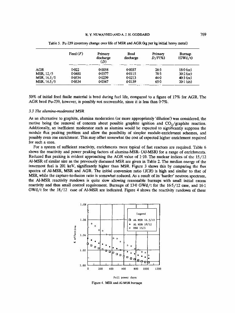
For a system of sufficient reactivity, enrichments more typical of fast reactors are required. Table 6 shows the reactivity and power peaking factors of alumina-MSR- (Al-MSR) for a range of enrichments. Reduced flux peaking is evident approaching the AGR value of 1.10. The nuclear indices of the 15/12 Al-MSR of similar size as the previously discussed MSR are given in Table 2. The median energy of the innermost fuel is 201 keV, significantly higher than MSR. Figure 3 shows this by comparing the flux spectra of Al-MSR, MSR and AGR. The initial conversion ratio (ICR) is high and similar to that of MSR, while the capture-to-fission ratio is somewhat reduced. As a result of its ‘harder’ neutron spectrum, the Al-MSR reactivity rundown is quite slow allowing reasonable burnups with small initial excess reactivity and thus small control requirement. Burnups of 13-0 GWd/t for the 16-5/12 case, and 16.1 GWd/t for the 18/12 case of Al-MSR are indicated. Figure 4 shows the reactivity rundown of these
1.08
1.06
Y > d LI
U
al ‘c
s
: 1.04
1.02
- 1.00’ ’ ’ ’ I ’ ’ I I - ’ ’
0 200 400 600 800 1000 1200
Full power days
Figure 4. MSR and Al-MSR burnups

770 GAS-COOLED REACTORS
cases compared to MSR. Fissile fuel usage appears to be not as good as for MSR. Table 4, previously referred to, shows fissile utilization for three enrichment cases of Al-MSR. High fissile requirement, together with relatively low DZ lead to the values shown. Low feed consumption, as well as significant breeding of fissile, contribute to high fissile discharge.
The temperature coefficients of reactivity for MSR and Al-MSR are worth noting. Table 7 gives these resolved into fuel and moderator coefficients. The fuel coefficients are seen to be always negative. The moderator coefficient for MSR seems to be less positive than for Al-MSR. It is worth noting that, contrary to AGR, the MSR has a negative moderator coefficient at BOL while for Al-MSR it is only slightly positive.
3.4 Direct AGR development
By direct is meant the least deviation from present AGR design. This would be the easiest and least costly development route. The new design would encompass performance extension, retention of the most of the AGR beneficial features and elimination of features that are complex or costly. Such a concept was introduced by Askew and Thorpe (1986) with the aim of increasing power output and eliminating moderator damage with extended burnup by replacing the integral fuel-moderator block together at refuelling.
The channel size of the integral-block-AGR (IBAGR) was kept the same as AGR, but fuel pins were reduced in diameter to limit centre temperatures. Additionally, the fuel mass per channel was retained at the AGR value and a 60-pin cluster thus emerges. Features of the IBAGR are given in Table 1 compared to the AGR as defined in this work. Together with the smaller clusters and thus more channels, a small increase in pressure from the AGR value of 40 bars to 47 bars, leads to a near doubling of power output. Gas velocity and core sue are kept at the standard AGR values. Power density, as a result, increases to nearly double that of AGR, giving increased graphite oxidation leading to the adoption of the integral fuel/moderator block design.
Table 6. Alumina-MSR enrichment search and peaking factors
Module enrichment k, (inner/outer) Subassem. (%MPu)
k,, Outer rods peaking
factor
15/9 0.9548 12/12 - 15/12 1.0545 16.5/12 1.0634 18/12 1.0715 14/14 -
09238 1-726 1.0103 1.0215 1.724 1.0310 1.0357 1.0736 1.729
-
- -
Outer rods power (%I
23.0
22.9 -
- -
230
Table 7. BOL temperature coefficients of reactivity, T dk/dT(K-’)
AGR MSR, Al-MSR, ETGBR DETGBR DETGBR GETGBR DETGBR 22% 15%/5% 165%/12% 165%MPu graphite alumina graphite alumina
V,/V, = 1, VD/VF = 1, V,/V, = 2 V,/V, = 2 18%MPu 18%MPu 197%MPu 197%MPu
Fuel Moderator t 432 x - 1.60 x + 3.70 x
Simultaneous t 4 5 6 x lo-’ - -
-1.74 X -235 X lo-* - 1.64 X lo-’ -5.42 X low3 -3.65 X lo-’ -306 X lo-’ -4.2 X lo-* -375 X lo-’ - - - - -
- - - - Overall t 2 5 8 X -395 X lo-’ -1.26 X lo-’ - - - - - -

R. Y. NUWAYHID AND A. J. H. GODDARD 771
The IBAGR used in these calculations differs slightly from that of Askew and Thorpe (1986). Greater graphite-to-fuel ratio is apparent owing to the use of sizes typical of Fort St Vrain HTR blocks in the latter. The present work retained closer match to standard AGR especially with regards to graphite-to-fuel ratio. Additionally, the fuel pins were taken to be solid for simplicity, thus giving greater fuel mass in the core. As it was, the nuclear performance parameters appeared to be only slightly sensitive to small variations in graphite block volume - a smaller cluster block radius of 18 cm in the present design gave hardly any change in k,, (BOL) and burnup.
The burnup behaviour of the IBAGR was studied with various enrichments; two cases were selected 2.9% and 4.0%. Burnups of 20 and 30.5 Gwd/t, single-batch BOL k,,s of 1.285 and 1.335, and three-batch BOL k,,s of 1.128 and 1.167 were found. It is clear that if continuous cycle refuelling could be adopted, DZs of about twice the single batch value would be obtained. However, high power densities, leading to graphite damage, rule out this option. A single-batch cycle may not be reasonable since it involves too large a control range. If a three batch refuelling scheme were adopted then, for the same burnup, the 2.9% and 4.0% cases would have batch cycle lengths of 1 year and 1.5 years respectively.
The fuel usage of the 2.9% IBAGR case is given in Table 4 considering both a one-batch scheme and a continuous-cycle scheme. It is seen that a reduction in fissile feed relative to AGR is obtained with the continuous-cycle case. The discharged fissile is low, indicating good usage, while the consumption of feed is 70% compared to the AGR’s 47%. For a single-batch IBAGR, disregarding limitations on control, the fissile usage is about the same as the standard AGR. The initial conversion ratio of the 2.9% enriched IBAGR is about the same as that for a standard AGR of the same enrichment. With burnup, however, the IBAGR shows a faster increase in conversion ratio - the ‘harder’ spectrum leading to greater fertile conversion.
4. THE GAS-COOLED FAST REACTOR
There is no doubt that the continued use of low-conversion thermal reactors is a waste of nuclear fuel resources. Breeder reactors must be the answer if fission power is to become a long-term contributor to energy production. As an alternative to LMFBR, the ‘gas-cooled fast reactor’ (GCFR) has been studied for over two decades but as yet no demonstration plant has been constructed. General Atomics was first to complete several studies on GCFR and its feasibility, starting in 1962. A significant milestone was the setting up, in the late 1960s of the European Gas-Breeder Reactor Association (GBRA) in order to carry out commercial size GCFR studies. Although a full design study was completed and designated the GBR-4 (GBRA, 1974), nothing significant emerged as a result, and GCFR remains to date a largely untested concept. Owing to maintained momentum for LMFBR, many demonstration plants have been build. In the case of GCFR, its position in the ‘shadow’ of LMFBR, the consequent lack of funds, and the then (late-1960s) untested nature of PCPV-type gas-cooled designs, all explain the untried status of GCFR.
As a fast reactor, the GCFR naturally has some similarities with the LMFBR. The two designs do, however, differ in many important aspects, and it was in order to alleviate some concerns associated with LMFBR that GCFR designs were considered. Fuel rating is a basic difference. In GCFR designs it tends to be lower than LMFBR because of the inferior coolant thermal properties. This implies a higher fuel inventory for the same output and a longer doubling time than might be expected from the anticipated high breeding ratio. Features of the GCFR that we discussed later tend to alleviate this problem.
In general a major advantage of gas cooling is the minimal neutron absorption and moderation in the coolant, compared with sodium, resulting in more neutrons being available for fission and for breeding in the harder neutron spectrum. This low coolant neutron absorption and scattering yields a system relatively insensitive to lattice size, giving the possibility of more open lattices and the avoidance of blockages in accidental situations. Enhanced neutron leakage does, however, need to be borne in mind. Mainly owing to its good thermal properties, helium cooling has been the preferred choice of GCFR, although other coolants such as CO, also have their advantages. Helium is chemically inert and this
772 GAS-COOLED REACTORS
removes any worry of material compatibility, for example the potential coolant reaction with water or moist air - a severe worry in LMFBR. Additionally, there is no need for an intermediate heat exchanger (as in LMFBR); which gives a saving in capital cost. Most gas coolants remain gaseous over all temperature ranges of significance; this removes the possiblity of abrupt changes in the heat removal capacity of the coolant due to phase change. An additional advantage is that the small inertia of the coolant means possible rapid start-up of the emergency circulation in accident situations. In the event of loss of coolant, the gas-cooled design with low-density coolants ensures, unlike LMFBR, little addition of reactivity to the core. Furthermore, the transparency of the gas coolant facilitates possible visible inspection of the reactor core.
In addition to the above inherent safety features there are some engineered protection features. A characteristic of gas-cooled systems is the use of a PCPV. This, owing to structure redundancy and small penetration sizes, has a significant role in slowing down the depressurization rate in the event of a possibly primary break. Natural circulation is guaranteed, in the event of forced circulation loss, by the adoption of upward flow. A separate cooling loop is available to remove shutdown heat in case of a depressurization accident. This cooling loop, the auxiliary core cooling system (ACCS), runs on indepen- dent diesel motors if required. The GCFR, of course, has some drawbacks as evidenced by its slow acceptance to date. These, however, are in no way any worse than, and should be less severe than, aspects of other reactor systems. Poor heat transfer to the gaseous coolant implies high fuel temperatures and necessary lower limits on the fuel rating as compared to LMFBR. The low heat transfer capacity of gas brings about the need for high-pressure operation. This is in turn enhances the potential severity of a depressurization event. Owing to the harder core neutron spectrum of GCFR, the vital doppler coefficient of reactivity is somewhat lower than in LMFBR. Several prescriptions have been proposed to alleviate this problem
4.1 The existing technology gas breeder reactor
The ‘existing technology gas breeder reactor’ (ETGBR) has been proposed as a possible way forward for gas-cooled reactor technology. The concept has arisen from considerations of competing economic and safety issues (Kemmish, 1982). It is based on the adaptation of AGR technology to a fast reactor, with the minimum of associated investment in research and development through, together with other aspects, the use of components, construction and operational technologies typified by AGR stations. Fuel element technology is related directly to LMFBR. Initially, a low-rated high-inventory core is proposed, which would be appropriate where a large thermal reactor programme and a small proportion of capacity represented by fast reactors is the case.
The lower fuel rating permits lower-pressure operation compared with the helium-cooled GBR-4. The heat transfer characteristics of CO, also permit lower-pressure operation. Additionally, there is evidence that with CO, cooling instead of helium, more heat can be removed in a transient situation involving loss of forced circulation and only natural circulation in a fully pressurized primary loop (Graton, 1981). Compared with AGR, removal of the need for moderator cooling means that re-entrant flow is eliminated, as is the need for coolant chemistry control. As in other fast reactors, the absence of moderator leads to a smaller core. A relaxation of AGR outlet temperature of 645°C was considered owing to the potentially higher damage rates in the ETGBR core. An outlet temperature of 525°C was selected and this allows the use of one material in the boiler. The core design of the ETGBR benefits from LMFBR designs and uses a similar hexagonal fuel assembly, fuel pins contain mixed oxide of typically about 20% PuO,. The initial choice for cladding is SS316 with later progress to 20/25 TiN or PE16 envisaged. The core of ETGBR as studied in the present work contains 397 subassemblies each holding 168 fuel rods. This reduction in subassembly size as chosen by the author represents an attempt to improve safety especially in anticipation of the so-called ‘diluted’ ETGBR designs to be introduced shortly. Table 1 gives the main design parameters of the standard ETGBR. Of interest is the large pin spacing which tends to minimize flow blockage accident situations as mentioned before. The fissile loading is high at 7.0 t/GW, compared with 2-6 and 4.0 t/GW, for LMFBR and GBR-4 respectively and is an economic sacrifice in favour of enhanced safety.

R. Y. NUWAYHID AND A. J. H. GODDARD 773
A significant difference between LMFBR and GCFR is the external pressure on the pin due to the gas coolant. With this load and without support for the cladding from fuel there would be danger of creep collapse during operation. Sealed pin pre-pressurization is the preferred solution to this problem, with helium used to provide a predetermined net external pressure over life. In contrast, in LMFBR there is significant internal pressure arising during irradiation. The cladding thickness chosen should be on the basis of acceptable stress in the event of depressurization. Another point worth mentioning here is that the inferior heat transfer to the coolant may be tackled by using roughened cladding surface designs, as in AGR.
In common with other fast reactor concepts, advantage is taken of the high neutron leakage rates. The core is thus surrounded by radial and axial blankets containing natural uranium. Again, as in other fast cores, the ETGBR can operate over long burnups with little excess reactivity present at any time. This feature is due to the high conversion ration of the core region and means control investment is lower than in thermal reactors. A batch refuelling scheme would naturally be used since the drop in reactivity is slow; however, it remains necessary to determine whether single-batch or multi-batch schemes are best. A two-batch scheme may be a reasonable compromise, offering minimum fuel disturbance and refuelling expenditure, while allowing a reasonable time before examination of the reactor, in the cold shutdown state, becomes necessary.
Calculations carried out in R-Z geometry using WIMS-E and its 1981 data library gave the already-mentioned overprediction in reactivity. Some calculations on the sensitivity of the reactivity were performed and showed no effect. The confirmation that the WIMS library is deficient in the treatment of energy self-shielding of some isotopes was reconfirmed (Nuwayhid, 1989). This is especially important for the high enrichment/high fuel loading ETGBR.
4.2 The diluted ETGBR mriant
Features of both thermal and fast gas-cooled cores have been discussed. Limitation of the thermal system have been pointed out and possible variants of intermediate design were presented. The idea was put forward that a fast system may be the way ahead but only if maximum use could be made of present thermal reactor component technology. However, the negative aspects of moving from AGR towards ETGBR must be noted and solutions be found. The major differences between the two may be attributed to the absence of moderator in ETGBR leading to loss of transient heat sink together with a less negative doppler coefficient. Additionally, arising from the fast reactor character, the power density is higher and the burnup is also higher.
The safety-related features of the AGR need to be retained where possible while, at the same time, the safety of the fully fast system needs augmentation where appropriate. Some degree of ‘dilution’, leading to an increase in the core thermal inertia, may be applied to the fast core. A diluent is defined as a non-fuel material that need not be a moderator but is required to have good thermal properties as well as radiation stability. The modes in which diluents may be introduced into the ETGBR core are various:
(a) Block dilution: building directly on the AGR concept of a fuel channel surrounded by a graphite block; the diluent is thus placed around the channel. The difference from AGR is that the fuel channel and the moderator block are integral and hexagonal in shape.
(b) Heterogeneous ETGBR: this concept is similar to the heterogeneous fast reactor design with in-core breeder subassemblies. A very low overall dilution (moderation) could be achieved and a design could include both diluted and undiluted core zones. Clearly there will be greater local heterogeneity in power production than in the previous dilution method.
(c) Diluent rods in subassembly: separate diluent pins are placed within the subassembly among the fuel pins. This leads to a larger subassembly for a given output and hence a larger core. This concept may be of special value if large diluent blocks might suffer from thermal stress problems.
(d) Dispersion type fuel in rods: the idea of a dispersion of fuel in either metal or ceramic matrixes is one which has received some attention; for example the ‘experimental berylium oxide reactor’ (EBOR) was helium-cooled, used UOz dispersed in Be0 and Hastelloy cladding (Stewart et al., 1968). For the

774 GAS-COOLED REACTORS
relatively high temperatures and burnups envisaged, fuel in a ceramic dispersion in preferred. The enrichment requirement for this form of dilution is expected to be higher than for other concepts.
5. BLOCK DILUTED ETGBR
The ‘block diluted’ ETGBR (DETGBR) concept involves effectively changing the wrapper zone of an ETGBR into a ‘diluent’, in a manner analogous to AGR and high-temperature reactor (HTR) concepts (Fort St Vrain design for example). A DETGBR subassembly is shown in Figure 5. The fuel channel containing 169 rods is 15-69 cm in diameter, formed in an hexagonal diluent block. The block size and hence the core size depends on the diluent to fuel volume ratio. The selection of 169 rods per channel was preferred, in this work, to the larger 371 rods per channel designs, in order to have a significant amount of diluent per fuel rod, to have closer proximity of diluent to more fuel rods and to minimize block mass. A first choice for diluent is graphite, owing to experience with its irradiation properties and its availability. However, possible exothermic burning in unforeseen temperature excursions with air ingress, interaction with CO, and possibly its far-too-good behaviour as a moderator make it less of a desirable choice for gas-cooled fast reactor designs. As an alternative worth studying, alumina (A1203) has a high volumetric thermal capacity, appears not to interface with CO, at temperatures of concern, and its quite effective as a moderator. Parasitic neutron absorption leads to higher enrichment with alumina designs. Other candidate diluents such as silicon carbide or silica have not been considered in this work.
5.1. Bare core lattice-cell calculations
Whole reactor neutronic calculations of both ETGBR and DETGBR using the multi-dimensional diffusion theory capability of WIMS-E/WSNAP fed with infinite-spectrum lattice-cell data generated via WIMS-D4 were performed. Bare cores, reflected single-zone cores, partially and fully blanketed cores
iper
Rods
u Figure 5. The ETGBR and DETGBR subassemblies

R. Y. NUWAYHID AND A. J. H. GODDARD 775
1
i 0.9
‘t +..\ ..... . .. .... . Graphite
---_ Alumina
2 3 4 5 0 I
DLLUENT TO FUEL RATIO Figure 6. Effective multiplication factor versus dilution for ETGBR and DETGBR at various enrichments
were all considered. In general, a lattice-cell one-dimensional model with leakage correction is found to be adequate for unreflected/unblanketed single-zone cores. Agreement between the two routes was within 1% in the change in the effective multiplication factor. This agreement starts to worsen as the cores fall into ‘harder’ spectra. This may be due to WIMS library shortfalls with respect to resonance data for the higher plutonium isotopes. As for ICR, the two methods produced 0.8180 and 0.8198 respectively, showing excellent agreement.
For comparative studies, using the WIMS-D4 one-dimensional lattice cell approximation of the bare core is both simple and accurate. Firstly, it is useful to compare alumina with graphite for a range of diluent-to-fuel volume ratios at several enrichments. With geometric bucklings used to correct approxi- mately for leakage effects, the system modelled becomes a one-zone unreflected core. Later an additional exercise would be a reassessment of the reactor with reflectors, blankets, or even multi-enrichments. The core height was fixed for all variants at 140 cm. The core radius was such that the amount of fuel was kept constant, implying the same number of subassemblies for all variants. For a 1670 MW, core, 396 Subassemblies are required. Figure 6 shows the reactivity versus dilution for both graphite and alumina diluted DETGBR. For a reasonable control margin, k,, at BOL was between 1-04 and 1.07.
As expected, while graphite is an efficient moderator, alumina is more of a parasitic absorber. This is clear from the high k,, for high graphite to fuel ratios. The dilution ratio (V, /J$) is only taken up to 5-0 to retain the ‘faster’ nature of the core. For comparative purposes the standard ETGBR was designed to have a BOL k,, of 1-057 and an initial conversion ratio of 0.818 at an enrichment of 165% MPu. For a similar BOL k,, of about 1.06 the DETGBR’s would require 18.12% enrichment with graphite and 19.28% with alumina, both for a V,/? of 2. It is seen that with graphite (a good moderator), less enrichment is needed and that the difference increases with increase in dilution. It can be verified that with graphite more fissions in Pu-239, fewer U-238 absorptions and more U-238 fast fissions take place. For the alumina DETGBR it can be seen that absorptions in non-fuel material is higher than for graphite of same vd/J$. At low vd/q ratios, however, the reverse becomes true and alumina dilution shows less non-fuel absorptions than graphite. This becomes the case below about V,/J$= 1.75. Apparently the parasitic behaviour of alumina is somewhat compensated by the increased ‘hardness’ of the neutron spectrum.

776 GAS-COOLED REACTORS
The ICR for different cases are shown in Figure 7 as a function of dilution ratio. An interesting observation is that for alumina dilution, as enrichments increase, there starts to appear an initial increase in ICR at low &/I$. After a dilution ratio of about 1-0 the ICR for alumina falls nearly linearly. For graphite this behaviour is not seen and ICR decreases with dilution. If low dilutions were possible from the point of view of the stated aim of this work regarding an increase in thermal capacity, then alumina would be the best choice. Figure 8 also shows k,, and ICR plotted together versus enrichment. Reactivity is seen to rise and conversion falls with increasing enrichment. The diluted cases shown are for the compromise choice of V,/I$ of 2.0. Alumina is clearly shown to give an ICR as high as or even superior to the standard undiluted ETGBR of the same enrichment (noting that alumina dilution requires at lease some 17% MPu enrichment to give a k,, of unity).
The neutron flux of the average graphite and alumina DETGBR subassembly for two values of V,/I$ is shown in Figure 9. In comparison with the standard ETGBR, the softening effect is apparent and alumina is obviously less of a moderator. When moderating annuli separate the subassemblies in thermal cores, it is expected that flux peaking will exist within the subassembly. In fast systems this should not be of significance, owing to lack of moderator. The outer fuel rods peaking factors (BOL) were found to be 1.003, 1.116, and 1.061 for the standard (165% enriched) ETGBR, the graphite DETGBR, and the alumina DETGBR (both at 19.77% enrichment and V,/I$ = 2) respectively. The alumina case, as might be expected, shows less peaking than the graphite case.
Burnup is to be maximized without violating materials constraints. Fast reactors, in general, are characterized by high conversion ratios and low rates of fall of k,, with time coupled to high fuel ratings. The standard ETGBR used in these calculations is rated at 1670 MW, and contains 34.9 tonnes of heavy metal, giving a fuel rating of 47.8 MW/t. The burnups of the standard ETGBR and both graphite and alumina DETGBRs are shown in Figure 10. It is seen that for the DETGBRs, with a V,/Vf of 2.0 the achievable burnups are reduced to values in the range of 50 to 60 GWd/t. This is compared to the standard ETGBR value of about 78 GWd/t.
With regards to fissile inventory change over life, the end-of-life (EOL) fissile content are high and possibly too high to reprocess in existing thermal processing plants (such as THORP which requires a 5% upper limit on fissile content). A dedicated fast reactor reprocessing plant is thus required, although the blankets may be reprocessed in THORP. A low feed enrichment of about 7% may be the solution, but at
0 ' r l u
m d
4 m
.rl u .* Y
Diluent t o Fuel Volume Ratio
Figure 7. Initial conversion ratio versus dilution for ETGBR and DETGBR at various enrichments

R. Y. NUWAYHID AND A. J. H. GODDARD
l a 6 7- \
1.5
1.4
1.3
1.2
1.1
1.0
0.9
0.8
0.7
-.*.- Alumina DETGUR --+-- G r a p h i t e DETGB
.,, 41
0.6 8 9 10 11 12 13 14 15 16 17 18 19
Enrichment,% PIagnox Pu
Figure 8. DETGBR conversion ratio and ktR versus enrichment for Vd/vf = 2 at BOL
777
1.2
1.1
1.0
m tm M 0
b- n
1.9 me
1.8
1.7
- ETCBR Base
------- Graphite D/F - 1 -.----Graphite D/F - 2
-Alumina D / F - 1 --w-Alumina D/F - 2
Energy, eV.
Figure 9. Neutron flu spectra of ETGBR and DETGBRs

778 GAS-COOLED REACTORS
0 1 4 28 42 56 70
Irradiation. GWd/t
Figure 10. ETGBR and DETGBR burnups
0 3 6 9 12 15
D i l u e n t to Fuel Volume Ratio
Figure 11. Heat capacity in non-fuel material per unit mass of all components of DETGBR subassembly

R. Y . NUWAYHID AND A. J. H. GODDARD 779
that level, for a critical system, it is necessary to use graphite and to reject alumina. A V,/? of about 20 is required, leading to a core more like an HTR. Table 4 shows the fissile utilization of the ETGBR and DETGBR variants compared to that of the previously discussed thermal cores.
The doppler coefficient of reactivity of the investigated ETGBR variants are compared in Table 7 separate from the previously presented thermal cores. The temperature ranges selected are 500 to lo00 and 1000 to 1500 K and are only representative and show the tendency for the coefficient to become more negative at higher temperatures. The advantage in doppler coefficient given by the softer spectrum of the DETGBRs is apparent. In the 1000-1500 K range, for example, the alumina DETGBR (19.77% enriched, V,/?= 2) has a coefficient nearly six times greater (more negative) than that of the standard ETGBR (16.5% enrichment). Interestingly, the doppler coefficients of the dETGBRs are more similar to those of thermal reactors.
5.2 Two-dimensional study
Reduced fuel requirement and hence the need for breeding in the current economic circumstances lead to the possibility of designing highly internally converting fast cores with reduced or totally eliminated blanketing. The WIMS schemes were thus utilized using the WIMS 1981 data library to note the effect of adding reflectors to bare cores of standard and diluted ETGBR. Lattice-cell data were generated by WIMS-D4 and fed to a WIMS-E/WSNAP R-2 geometry two-dimensional scheme. The effect of adding on reflectors to the bare cores is that the reflector reactivity worth is reduced significantly with the diluted ETGBR cores even though the enrichments are higher. Obviously this is due to greater loss of neutrons by non-fuel absorptions. The standard ETGBR has considerable leakage, resulting in both a waste in neutron economy and a requirement of an additional row of steel reflector assemblies. The single zone (no blanket) DETGBR is of interest to consider before adding on blankets. With DETGBR, neutron leakage is reduced significantly, especially when alumina is the diluent, and this may eliminate the need for extra reflectors.
The introduction of breeders peripherally serves the extra function of reducing neutron leakage from the core. Partial, either only axial or only radial, blankets can be considered based on a general economic decision regarding the extent of breeding required. Doing away with one blanket depends on neutron economy as well as engineering design. A radially blanketed case has the advantage of separate subassemblies for the breeders allowing them to have their independent in-core dwell periods in addition to individual access. On the other hand, an unblanketed axial direction may require additional steel reflectors to supress neutron leakage. Here, it may be interesting to note that in any event, if upward coolant flow is desired, then the additional steel weight may act as a core restraint. With radial blanketing of a single-zone core, some measure of power flattening is obtained. Power generated per assembly, by the way, does not differ much for graphite or alumina cases.
Axially blanketed ETGBR and DETGBR is another alternative for partial breeding. Here, however, both core and breeder fuel pellets are contained in the same fuel rod and are usually discharged together in the sole subassembly. A separate subassembly for breeder above the core would require extra restraint with upward flow and would be difficult to handle. An apparent advantage of axial blanketing is the flexibility offered - being as thin or thick as required above or below the core pellets in the rods. Also core leviation may be eased by use of heavy axial subassemblies. With axial breeders there is a small gain in reactivity, leading to a slightly greater burnup compared with the previous cases. The high reactivity worth of the axial blanket leads to increased power output of an axially blanketed ETGBR. Peaking factors are higher than for radially blanketed cases.
Full blanketing is considered if higher breeding ratios are desired. In general the best design today would not need full blanketing, although a flexible design allowing this to be swiftly incorporated would be useful. An added side-benefit of full blanketing is a reduction in reflector worth and thus reduced leakage and activation of the steel. As for burnup, with full blankets, the dwell times are slightly greater than the 2 years of the unblanketed or partially blanketed cases.
780 GAS-COOLED REACTORS
In general, whole-core studies lead to the following observations:
(a) A 2-year batch lifetime requires 1625% MPu enrichment with graphite, and 18% MPu with alumina dilution.
(b) For the alumina DETGBR (&/? = 2, 18%) the theoretical burnups are 40.9, 41-6, 43.7 and 44.2 GWd/t for the bare core, radially blanketed, axially blanketed and fully blanketed cases respectively.
(c) The initial conversion ratio of the graphite and alumina DETGBR are 0.749 and 0.753 and fall short of the standard ETGBR value of 0979.
(d) The breeding ratio of DETGBR, for some reason to be investigated, never reaches a value of 1.0, although it approaches this value as blankets are made thicker.
(el With 2-d WIMS-E whole cores considered, far longer burnups for reflected standard ETGBR are found, indicating a problem in using WIMS for very ‘hard’ cores.
6. THERMAL AND MATERIAL, ASPECTS
6.1. General safety considerations
In the light of the correctly renewed stress put on reactor safety, it is judicious to have a brief look at the possible transient behaviour of gas-cooled reactor variants. Hypothetical accidents are usually classified by the mismatch between heat production and removal, for example reactivity insertion causing excessive power production, and on the other hand, failure of the heat transport system hindering heat removal. Very broadly, accidents may be classified as ‘unprotected’ or ‘protected’, where the latter implies successful operation of the plant protection system (PPS).
Unprotected transients can be classed as either ‘transient over power’ (TOP), or ‘transient under- cooling’ (TUC). The first occurs when reactivity is inserted into the system at full power, while the second occurs where the power remains constant but coolant flow is lost. In both unprotected transients, the primary and secondary reactor shutdown systems are assumed to be unavailable. A third unprotected type of transient is a ‘loss of shutdown cooling’ (LOSC). Here, a total loss of core cooling occurs for an extended period following reactor shutdown. Unprotected transients may also be termed ‘beyond design basis accidents’ (BDBA), because a multitude of engineered safeguards are postulated to fail.
A selection of ‘protected’ transient initiators for gas-cooled reactors may be listed as follows:
(1) Breaks in feedwater system piping. (2) Increase/decrease in core heat removal. (3) Reactivity and power distribution anomalies. (4) Moisture ingress into primary coolant system. (5 ) Decrease in reactor cooland inventory. (6) Failure of normally operating auxiliary systems.
The particular case of decrease in reactor coolant inventory is important for GCFR since the ‘design basis depressurization accident’ (DBDA) is a manifestation of this. Coping with a depressurization event, which is also considered the ‘maximum credible depressurization accident’ (MCDA), is of vital impor- tance for gas-cooled reactors.
As is the practice with the AGR, the ETGBR design basis accident may be taken as a breached vessel with pressure falling exponentially with time. The time constant depends on the hole size, the volume of the vessel, and the physical properties of the gas. A simple equation to determine the depressurization time constant is (Lewis, 1977) T = lW/A,/T, where K is 0.3 for helium, 1-05 for CO,, I/ (litres) the core cavity volume, A (cm’) the rupture hole area, and T ( K ) the mean initial gas temperature. With roughly the same core cavity volume of 6.45 X lo6 litres, ETGBR and AGR depressurization time constants would basically depend on gas temperatures: 742 K for AGR and 661 K for ETGBR. For a breached gas

R. Y. NUWAYHID AND A. J. H. GODDARD 78 1
circulator penetration of 325 cm2 considered as the worst case, the time constants obtained are 765 and 810 seconds for AGR and ETGBR respectively. Kemmish (1982) adopts a time-constant of 900 seconds for ETGBR and argues that this value is conservative. For the GBR-4 design where the time-constant is reported to be 200 seconds, the previous values stated are definitely an improvement.
6.2 Thermal implication of ETGBR core dilution
The motive for much of this work is the provision of a material heat sink inside the core zone of the ETGBR. The ETGBR core is mainly composed of fuel (30%) and coolant (55%), with the remainder behind cladding and structural stainless steel. The thermal capacity is particularly low since the gas coolant, the largest component by volume, has little thermal inertia.
The additional heat sink (or diluent) considered is in the form of a material with a high volumetric heat capacity. Two materials stand out on this basis and on the basis of good structural integrity in the high-temperature, high-irradiation field of the reactor. These are graphite and alumina, which also have the advantage of being commonly available. Although graphite would absorb fewer of the available neutrons than would alumina, it is a more effective moderator, and would lead to a softer spectrum. This becomes an important feature if a breeding design is sought. Clearly, the diluent should be close to the fuel rod for good transient heat removal. A homogeneous fuel-diluent fuel rod would be ideal; however, this would give design complications with respect to neutronic economy as well as material aspects. A second means of introducing diluent into the core is a subassembly made of alternating and separate rods of fuel and diluent. It is presumed here that both graphite or alumina could easily be worked into rods of radius around 0-35 to 0.5 cm and would thus fit into the subassembly correctly. In this case, heat must be transferred between fuel and diluent by convection or radiation mechanisms. If only radiation transport is available, than this geometry gives good transfer interfaces. A third alternative would build on the AGR design, giving a diluent block which is hexagonal in shape with a fuelled coolant channel in the centre, much like the integral HTR design. The forming of such blocks is likely to be feasible with either graphite or alumina but clearly depends on the diluent annulus thickness. This design has a good portion of diluent in a location reasonably close to fuel rods, but radiation heat transport is obviously not as good as in the mixed diluent/fuel rod design. Only the outer rings of fuel rods have a good view of the cooler diluent annulus surface. Diluent inclusion in the core may be of benefit in both DBA and BDBA accident situations. In the case of DBE, the diluent provides, as described previously, an additional heat sink for the increasingly hot coolant in a situation where flow is rapidly falling. Although of very small probability of occurrence, a particular BDBA case is the LOSC event. With total loss of the cooling system (the main heat sinks are normally the boilers), and the system shutdown at full pressure, any heat transport takes place within the core and reflector regions only (within the core cavity). Diluent material presence would clearly slow down to some extent the core heat-up rate.
6.3 Thermal capacity considerations
A review of AGR literature will show that temperature transients are said to be slow owing to the large heat sink in the core: the graphite moderator. The safety benefits from a diluent would depend on the diluent quantity; this will depend on whether a fast or a thermal is desired. Alumina and graphite have been identified as two candidate materials among other possibilities, graphite being an excellent moderator and alumina having a larger specific heat per unit volume. In a full assessment, thermal conductivity, volumetric heat capacity, and fire behaviour all need to be considered. For example, with graphite the possibility of igniting exists while alumina does not ignite, at least not up to very high temperatures. Furthermore, if temperatures are raised, graphite reacts with CO, coolant. If specific heat capacity (joules/gram of non-fuel material/degree) is calculated for the AGR and compared with that for the ETGBR, it is apparent that it has about ten times the thermal capacity. However, in this work the aim is to increase the thermal capacity of ETGBR somewhat, without departing substantially from a fast spectrum. In Table 8 the AGR, ETGBR and the ‘mildly’ diluted ETGBR cases are compared in terms of heat capacity per unit height of core.

782 GAS-COOLED REACTORS
Table 8. Core heat capacities of AGR, ETGBR and diluted ETGBRs for V, /Y = 2
Total Total Non-fuel (J/deg) (J/deg/d (J/deg/d
AGR 1-41 X lo6 1-485 1.414 ETGBR 1.43 x 10⁵ 0375 0.145 DETGBR 2-69 x 105 0672 0452 DETGBR-alumina 3.55 x 10⁵ 0703 0529
It may be seen that a relatively small dilution of the ETGBR core can increase the thermal capacity available in non-fuel components of the core by some 300% and bring the diluted ETGBR core to above one-third of the AGR thermal capacity (considering alumina dilution). In fact, Figure 11 shows that for the lower diluent-to-fuel volume ratios, alumina cores have a higher thermal capacity than graphite cores. It is not until a vd/q ratio of about 5.0 is reached that graphite shows an advantage. This is due to a greater heat capacity of graphite per unit mass, when larger masses begin to dominate.
To make a link with neutronics, if the non-fuel specific heat capacity of the diluted lattices are plotted against conversion ratio, Figure 12 results. An inverse relationship is apparent. For a given conversion ratio, alumina gives, in general, a higher specific heat capacity. Reactivity, however, must be taken into account. It can be seen from the figure that, for 18% enrichment, for the same conversion ratio, only a small margin exists for an alumina-diluted core and then only at small dilution ratios. Hence, as noted in a previous section, an enrichment benefit favouring graphite and yielding longer burnup exists. Alumina, however, with 18% enrichment and vd/F of 2 may be a desirable possibility with higher specific heat capacity and similar neutronic conditions.
6.4 A reactor primaly circuit depressurization transient The value of diluent in the event of a depressurization can be examined in a simplified manner. A calculation employing only a few parameters can be used. The depressurization time constant and the
0.55 0.60 0.65 0.70 0.75 0.80
I n i t i a l Conversion Rntlo
Figure 12. Heat capacity versus conversion ratio for DETGBR
R. Y. NUWAYHID AND A. J. H. GODDARD 783
Time Following Start Of Depressurization (Sec.)
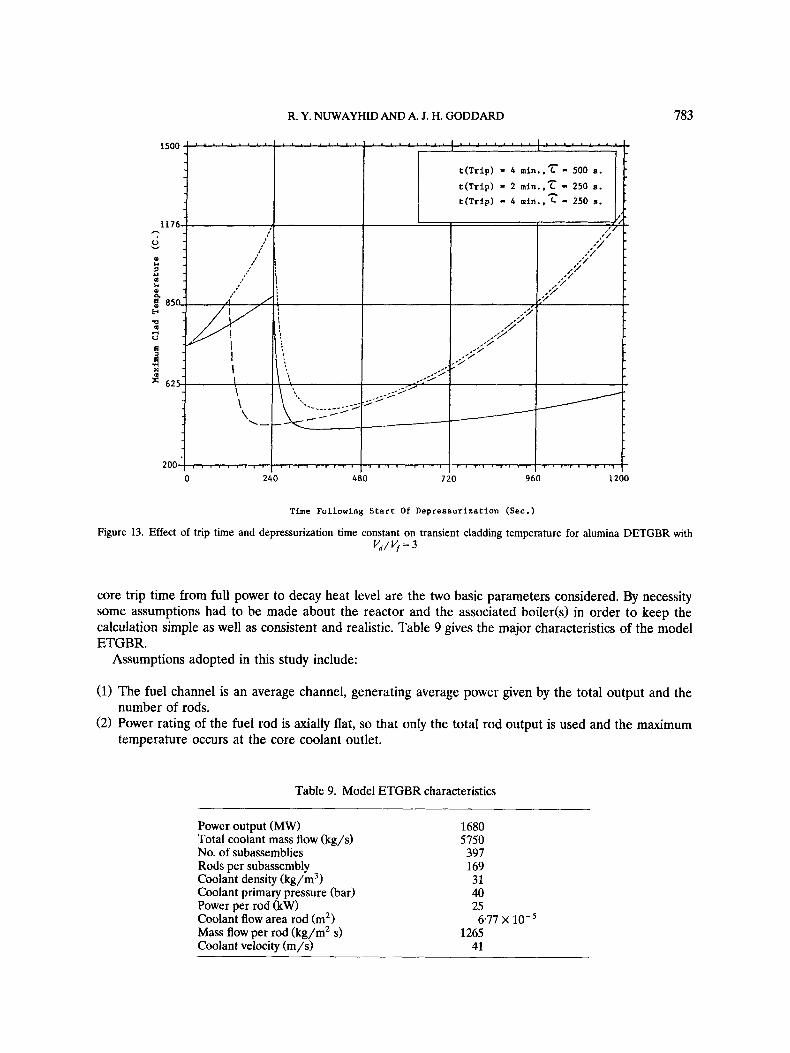
Figure 13. Effect of trip time and depressurization time constant on transient cladding temperature for alumina DETGBR with v,/q= 3
core trip time from full power to decay heat level are the two basic parameters considered. By necessity some assumptions had to be made about the reactor and the associated boiler(s) in order to keep the calculation simple as well as consistent and realistic. Table 9 gives the major characteristics of the model ETGBR.
Assumptions adopted in this study include:
(1) The fuel channel is an average channel, generating average power given by the total output and the
(2) Power rating of the fuel rod is axially flat, so that only the total rod output is used and the maximum number of rods.
temperature occurs at the core coolant outlet.
Table 9. Model ETGBR characteristics
Power output (MW) Total coolant mass flow (kg/s) No. of subassemblies Rods per subassembly Coolant density (kg/m3) Coolant primary pressure (bar) Power per rod (kW) Coolant flow area rod (mZ) Mass flow per rod (kg/m2 s) Coolant velocity (m/s)
1680 5750 397 169 31 40 25
1265 41
677 x 10-5

784 GAS-COOLED REACTORS
(3) The boiler has a fixed steam-side temperature, approximated as the stauration temperature at the
(4) No heat or pressure losses in the primary piping. (5) Pressure during depressurization behaves in a simple exponential fashion as Po exp( - t / ~ ) , where T
is the time constant for depressurization, taken as 500 seconds for the ETGBR and its diluted variants. This figure is a conservative re-estimate of the 900-second figure quoted earlier. Also, Po is the initial steady-state pressure.
(6 ) Coolant behaves as an ideal gas with constant specific heat. The flow rate during the transient is thus governed by the updated pressure and temperature only while the coolant velocity is taken as constant. Additionally average axial channel conditions are used.
(7) Each fuel pin is assigned a portion of the mass diluent per subassembly. So the geometry is more similar to a mixed diluent/fuel pin design with each fuel pin surrounded by six smeared diluent pins.
initial pressure conditions. Also, the boiler behaves as a simple heat exchanger.
Given these assumptions, a program was written to study the transient temperature response in a depressurization event, with full power changing to decay heating at a specified trip time. The program models the core, set up as an average fuel/diluent rod, linked to a simple boiler(s). The numerical method used is taken from the established TEACH-C program (Gosman et al., 1985) which models conduction in two dimensions.
With a short depressurization time constant, a rapid trip would be needed to keep cladding temperature below about 850°C (the cladding fault temperature). In Figure 13, for the alumina diluted case with Vd(? = 3, it is seen that with a delayed trip times at 4 minutes, and a T of 250 seconds, the maximum claddings temperature at 20 minutes from tansient initiation is 1200°C compared to 1500°C for the undiluted standard ETGBR case. If the trip were to take place earlier, at 2 minutes, the peak cladding temperature at 20 minutes would be reduced by only about 30°C. Thus the depressurization
DETGBR, D / F -31 1 t
0 1200
T i m e (Sees.)
Figure 14. Maximum cladding temperatures following depressurization with 7 = 500 s, and a trip time of 4 minutes

R. Y. NUWAYHID AND A. J. H. GODDARD 785
time-constant is seen to control the transient and in this case, with 7 taken to be 500 seconds, the maximum clad temperature at 20 minutes is limited to 500°C. With small dilutions used in DETGBR, some reduction of temperature rise is possible. Figure 14 shows this for alumina dilution cases V,/% of 1,2, and 3. The actual change is not very striking but does increase with time. For the b/J$ = 3 case, the cladding maximum temperature at 20 minutes is reduced by about 25°C. With all assumptions kept in mind, the dependence of temperature upon dilution is indicated.
6.5 Full depressurization with radiatiw transfer only
A limiting case is that where the only heat transfer possible from the fuel rod to the diluent (moderator) is by radiation. This represents a situation where the coolant is lost immediately in a hypothetical extreme depressurization transient. Although this is a highly improbable situation, it nevertheless gives additional insight into the value of non-fuel materials in proximity of the fuel.
The calculation is performed as in the previous case but using a modified version of the program simplified by the removal of convective heat transfer from the fuel rod. The geometry was as before and radiative emissivities where calculated for the given annular geometry. Figure 15 shows the change in the maximum cladding temperature following the tripping of the reactor. It is seen that an increase in diluent amount causes a significant reduction in the rate of rise of the maximum cladding temperature. Alumina, with its high heat capacity gives the slowest rise of temperature for a given amount of dilution. Alumina at a V,/q ratio of 2 is superior to graphite at the higher V,/vf of 3. With alumina at V , / y of 2 the maximum cladding temperature 5 minutes after the start of the transient is slightly in excess of lOWC, nearly 100°C lower than the case for graphite with a V,/vf of 3 after the same time elapsed. A possible alternative to alumina is silicon carbide (Sic), but it appears not to be as good a heat sink.
+ Graphite, D / F - 2 X Graphite, D / F - 3
+ Alumina, DIF - 2
0 30 60 90 120 150 180 210 240 270 300
Time (Sees . )
Figure 15. Maximum cladding temperature following total loss of cooland and heat transfer only by radiation

786
1.0
0.1
0.0
GAS-COOLED REACTORS
Pressure drop, - 22iS., Main Coolant Flow
Po- 41 bar
FRACTION OF STEADY STATE CONDITIONS
Channel SS power 4.76 MW
Neutron Power
Interstitial Flow
Flow at 1.2%.
I
10 100 1000
TIME (a.)
Figure 16. Realistic AGR depressurization transient scenario
6.6 AGR realistic depressurization case
In order to put the study on a realistic track, use was made of KINAGRAX (Ellis, ad.) which is a highly tested AGR kinetic code used in actual practice. The program was developed by the CEGB (now NE) and contains many features simulating actual AGR design and running and capable of simulating a realistic depressurization scenario. The results were provided by the CEGB (S. P. J. Jayatissa, 1988, personal communication). The modelled scenario is shown in Figure 16. One minute following the initiation of depressurization, the reactor trips from full power level. Pressure falls from an operating value of 41.4 bars with a time-constant of 221 seconds. Decay heat and residual neutron power are shown in the figure. With the main motors shut down initially, gas circulation coasts down as shown. At 685 seconds, the main motors are restarted and flow is then maintained at 1.2% of full flow.
Using KINAGRAX, it was possible to study the effect of reducing the main moderator volume on the temperature response of an AGR in the event of a depressurization transient. Thus, two reactor cases were studied: a standard AGR lattice and a hypothetical ‘half-AGR lattice. The half-AGR reactor was defined as one with only roughly half the amount of bulk moderator graphite per fuel channel. Fuel channel and associated sleeves were kept unaltered for simplicity. It is realized that this alteration leads to the need for higher fuel enrichment. WIMS-D4 was thus used to ascertain the required enrichment for a half-AGR: a value of about 4.0% U-235 was found to give a burnup of 18.6 GWd/t with a BOL k,, of 1.13.
Several modifications were introduced into the KINAGRAX default data for AGR to simulate the half-AGR case. Keeping all other parameters unchanged, the modifications introduced were as follows:
(1) The main moderator brick radius was altered from the AGR value of 22.75 cm to 18.7 cm, such that

R. Y. NUWAYHID AND A. J. H. GODDARD 787
300 I . ' ' ~ . ' ' ~ I ' . 1 ' ' ' ' - ' - - I . . " ' ' I oe 10' loz 10' 10 LO
Time (secs.)
Figure 17. Maximum cladding and moderator temperatures during depressurization for AGR and half-AGR
the main moderator area was halved and its inner radius kept at the AGR value of 13.5 cm. This ensured the constancy of wetted areas and heat transfer coefficients. The cross-sectional area of re-entrant flow between interstitial brick and main brick was changed due to the decrease in the outer radius of the main brick. The outer radius was reduced by 174% and a notional change in re-entrant flow area would in this proportion give a value of 100.38 cm'. The weight of the main brick per unit length of channel reduced to 822.4 kg for the half-AGR. It was decided against changing the parameters that include the effect of reactivity coefficients. Although the reduction of moderator causes a decrease in the reactivity of the lattice, the enrichment increase envisaged for the half-AGR may offset this somewhat. The proportions of heat generated in each ring of rods of the cluster were re-evaluated, based on a WIMS-D4 calculation of a half-AGR with increased enrichment giving roughly the same k,, (BOL) as the standard AGR.
6.7 HalfAGR transient response
The response of the half-AGR core to the depressurization scenario is shown in Figure 17. Also shown for comparison is the response of the AGR base case. The half-AGR has approximately the same maximum cladding temperature as the base AGR at the time the reactor trips (67 s). As the flow deteriorates the next peak occurs as the main motors are restarted to recover the flow to 1.2% of full flow (as established practice dictates). It is at this second peak that the decreased graphite amount leads to
788 GAS-COOLED REACTORS
higher maximum cladding temperature for the half-AGR case. The figure shows, however, that even for the half-AGR the post-trip maximum cladding temperature remains below 825°C. This peak occurs 685 seconds after transient initiation.
The moderator response is also shown in the previous figure. Initially, the half-AGR has a lower moderator temperature (310 versus 350°C) owing to increased interstitial flow area. After the reactor trips and as the flow rate progressively decreases, the half-AGR maximum moderator temperature rises faster than the base AGR does. Raising the flow rate to 1.2% at 685 seconds (when it had fallen to less than 0.3%) does not appear to significantly arrest the rise. Both the AGR and the half-AGR maximum moderator temperatures reach a value of 400°C approximately 17 minutes after the start of the transient. Only after this time does the half-AGR moderator temperature begin to significantly surpass that of the AGR. It is therefore apparent that the half-AGR case does not lead to unmanageable temperatures and gives ample time, just as in AGR, for operator intervention.
6.8 Material considerations
The selection of materials for a nuclear reactor is a very lengthy task and no attempt was made to study these. The materials used in this work, notably alumina, were considered to have good heat transfer properties and to be economically attractive. Alumina is said to have an 83% share in the European ceramic market (Davidge, 1987). Alumina does, though, have a low thermal conductivity (8 versus 84 W/m K for silicon carbide). It has a high density and a relatively high thermal expansion coefficient. Alumina may suffer up to 65% volume increase in intense neutron fluences (loz6 n/m2 > 0.1 MeV) at a temperature of 1100 K (Chard and Hurley, 1982). Thus, to be usable as a ediluent, alumina should be used in relatively small blocks to limit thermal stress due to its low thermal conductivity. Also, it should be replaced frequently to limit irradiation swelling problems.
7. SUMMARY AND CONCLUSIONS
With the aim of enhancing neutronic performance, the long-term development of the AGR was assumed to be towards achieving a fast spectrum reactor. Between the present AGR and the ultimate gas-cooled fast reactor lie a range of ‘intermediate’ designs: intermediate, not wholly in the sense of neutron spectrum, but also in terms of technological and economic criteria.
The AGR model was established and the main neutronic parameters were calculated satisfactorily. The flexibility of the AGR, being a gas-cooled reactor, was demonstrated by studying enrichment variation and the ensuing consequences. Departure from the geometric design of AGR was then studied by the introduction of the ‘mixed spectrum reactor’ (MSR) variants. With MSR two advantageous changes relative to AGR was possible: first, the use of large fuelled zones facilitated the use of mixed plutonium oxide in place of UO,; second, the graphite-to-fuel ratio is less, giving further spectrum ‘hardening’ and leading to higher conversion ratios. The MSR, however, suffered from two drawbacks: first, large fuel channel power peaking; second, possible difficulty in refuelling the complex fuel goemetry. A possible solution to the first drawback was explored by the use of alumina in place of graphite, resulting in the so-called AI-MSR. With alumina, at the expense of some increase in enrichment and simple enrichment zoning, the power peaking was eliminated. This was accomplished using only two enrichments, whereas for MSR, multiple differential enrichment was required. Another, simpler AGR derivative was suggested: the integral block, prismatic AGR. This is a direct derivative incorporating a moderator block design similar to HTR.
As a final state in gas-cooled reactor development, the ETGBR was presented as a breeder capable of fitting into the current economic and technical environment. With experience drawn from AGR, the ETGBR was modified to incorporate a diluent: a non-fuel in-core material acting as a transient heat sink. The diluted-ETGBR (DETGBR) concept was to have the following features:
(a) retain a sufficiently fast spectrum from breeding purposes and thus the amount of diluent is limited,
R. Y. NUWAYHID AND A. J. H. GODDARD 789
(b) to have enrichments not over 20% as an anti-proliferation limit, (c) burnup to be greater than for PWR (> 35 GWd/t) - in fact 47-8 MW/t fuel rating, up to 60
(d) replaceable diluent material at refuelling, leading to an integral block design (or mixed pin design), (e) a high internal conversion factor (> 0.75) but not necessarily a breeding ratio in excess of 1.10 -
towards this the partially blanketed DETGBR was highlighted, and (f) the diluent material was to have a high specific heat capacity, a high melting point, and was not to
interact chemically with CO, to any significant extent - alumina was considered to best meet these criteria although at some enrichment penalty.
GWd/t was realizable,
An additional value of this work is the comparison between the methods of WIMS-D4 and WIM-E, as well as their data libraries, and their applicability to increasingly ‘hard’ cores.
REFERENCES
Askew, J. R. and Roth M. J. (1982). ‘WIMS-E a scheme for neutronic calculations’, AEE-Winfrith Report AEEW-R1315. Askew, J. R. and Thorpe G. (1986). ‘Possible developments from the AGR, Nuclear Energy, 25, No. 1,41-46. Askew, J. R., Fayers, F. J. and Kemshell, P. B. (1966). ‘A general description of the lattice code WIMS‘, BNES, 5 , No. 4, 564. Askew, J. R., Griggs, M. A. and Hutton, J. L. (1986). ‘Development potential of the AGR’, Gas Cooled Reactors Today, BNES,
Brissenden, R. J. (1975). ‘The compatible open shop modular system COSMOS, Proc. American Nuclear SOC. Topical Meeting on
Chawla, R., Hsieh, H. M. and Halsall, M. J. (1986). ‘Effects of recent WIMS data library changes on calculational results for
Chard , F. W. and Hurley, G. F. (1982). ‘Neutron induced damage in MgO, AI,O, and MgAL,O, ceramics’, J. Nuclear Materials,
Davidge, R. W. (1987). ‘Engineering ceramics in heat engines’, Atom, May, p. 9. Dent, K. H., Pexton, A. F. Preston, I. M. H. and Southwood, J. R. M. (1982). ‘Status of gas-cooled reactors in the UK, Conf. on Gas
Ellis, J. (n.d.1 ‘KINAGRAX: a one-dimensional advanced gas-cooled reactor kinetic program, CEGB Report RD/C/NlO9,
GBRA (1974). The Gas Cooled Breeder Reacror - Economic Power wirh Breeding, Gas Breeder Reactor Association, Brussels,
Goode, A. B. (1984). ‘The fuel management of AGRS’, Nuclear Energy, 23, No. 3 , 149-160. Gosman, A. D., Launder, B. E. and Reece, G. J. (1985). ComputerAided Engineering, John Wiley, Chichester. Graton, C. P. (1981). ‘The gas-cooled fast reactor in 1981’, Nuclear Energy, 20, No. 4, 287-295. Kemmish, W. B., Quick M. V. and Hirst I. L. (19821, ‘The safety of CO, cooled breeder reactors based on existing gas cooled
Lewis, E. E. (1977). Nuclear Power Reactor Safety, John Wiley, Chichester, p. 402. Nuwayhid, R. Y. (1989). PhD thesis, Mechanical Engineering Department, Imperial College, London. Stewart, H. B., Rickard, C. L. and Melese, G. B. (1968). ‘Gas-cooled reactor technology’, Aduances in Nuclear Science and
London.
Computational Methods in Nuclear Engineering, Charleston, SC.
LWHCR lattices, Annals of Nuclear Enetgy, 13, 523.
NOS. 108 & 109,655-670.
Cooled Reactors Today, JBNES, London, p. 25.
JNPC/RKWP/P374.
Nuclear Engineering International, p. 566.
reactor technology’, Progress in Nuclear Energy, 10 (11, 1-17.
Technology, 4, 36.
Copyright © 2022 FDOKUMEN