Experimental investigation of a gas–solid rotating bed reactor with static geometry
8
Chemical Engineering and Processing 50 (2011) 77–84 Contents lists available at ScienceDirect Chemical Engineering and Processing: Process Intensification journal homepage: www.elsevier.com/locate/cep Experimental investigation of a gas–solid rotating bed reactor with static geometry Rahul P. Ekatpure a , Vaishali U. Suryawanshi a , Geraldine J. Heynderickx a,∗ , Axel de Broqueville b , Guy B. Marin a a Laboratory for Chemical Technology, Ghent University, Krijgslaan 281 (S5), B-9000 Ghent, Belgium b Allée du bois de Bercuit, 109, B 1390 Grez-Doiceau, Belgium article info Article history: Received 6 November 2009 Received in revised form 15 November 2010 Accepted 25 November 2010 Available online 1 December 2010 Keywords: Centrifugal force Gas–solid flow Rotating bed Stable flow Static geometry Tangential Vortex abstract Hydrodynamics of a gas–solid rotating bed reactor (RBR) in static geometry are investigated. Tangential injection of a gas at mass flow rate of 0.4–1 kg/s in a cylindrical vessel with a diameter of 0.54 m generates a rotating gas phase flow field. Introduction of solid particles in this field results into an annular dense gas–solid rotating bed. A stable annular gas–solid rotating bed without solids particles loss is achieved over a wide range of operating conditions. Goal of the presented work is to investigate, by means of experiments, the window for a stable operation of the gas–solid RBR, as a function of the solid particle diameter and density, the geometry of the RBR and the gas flow rate. If the solid particle diameter is comparable to tangential gas injection slot width, the establishment of a stable flow is delayed due to an increased slugging tendency. The upper limit of the solids content is found to decrease with decreasing solid particle diameter. Obtained experimental cold flow results are the initial steps in assessing the potentials of a RBR as an efficient gas–solid processing reactor from a process intensification point of view. © 2010 Elsevier B.V. All rights reserved. 1. Introduction Process intensification (PI) in chemical processes has gained considerable interest in recent years. The presented PI work uses centrifugal force to carry out multiphase operation, more specifi- cally the contacting of a gas and a solid phase. A centrifugal field can be induced in two ways: (a) rotating the operating vessel itself and (b) the tangential injection of a primary phase (gas or liquid) into a static vessel. The lack of rotating reactor parts makes the latter option the most attractive one. If the tangential injection of the pri- mary fluid is carried out at multiple positions on the circumference of a cylindrical vessel, a strong vortex in the fluid and a centrifugal force on the fluid are created in the vessel. This centrifugal force can be used to support a secondary phase (solid particles or liq- uid droplets) inside the static cylindrical vessel. The primary phase flows through the secondary phase towards the center of the vessel and is discharged through an outlet located on the vessel axis. By using gas as a primary phase and the solid particles as a sec- ondary phase, an annular rotating gas–solid bed in a cylindrical vessel is achieved. Such a rotating gas–solid bed offers a higher slip ∗ Corresponding author. Tel.: +32 92644516; fax: +32 92644999. E-mail address: [email protected] (G.J. Heynderickx). velocity (∼1–10 m/s) as compared to the gravitational field, accom- panied by a higher solids volume fraction (∼0.3–0.6). As compared to gravitational static fluidized beds, rotating beds offer advantages such as high throughput operation, uniform gas–solid contacting and enhanced heat and mass transfer, thus intensifying the pro- cess at particle scale as well as reactor scale [1]. As a result, a reactor with a rotating gas–solid flow can potentially be used for a number of processes such as combustion of nuclear fuels [2], drying [3–5], fast gas–solid catalytic reactions [6], fluidization of nano-sized par- ticles [7], granulation and coating of fine particles [8] and removal of NO x and soot from a diesel engine exhaust [9] and a number of HiGee applications [11–13]. The presented work is carried out in view of assessing the potential of gas–solid rotating beds as an efficient gas–solid contacting device to be used in the chemical pro- cess industry. As an initial step, a detailed fluid dynamic study of the gas–solid RBR behavior is carried out. A number of past fluid dynamic studies [10,15] has been dedi- cated to investigate the effect of different operating parameters on the performance of the RBR. The performance of the RBR can be evaluated by studying the behavior of some of its flow characteris- tics, such as pressure drop, P Total , bed void fraction, ε g , velocity of rotating solid particles, v s , minimum and maximum solids content, W s,min and W s,max , respectively, for stable operation. An increase in the solids content of the RBR will increase the RBR’s capacity to 0255-2701/$ – see front matter © 2010 Elsevier B.V. All rights reserved. doi:10.1016/j.cep.2010.11.010
-
Upload
independent -
Category
Documents
-
view
1 -
download
0
Transcript of Experimental investigation of a gas–solid rotating bed reactor with static geometry
Eg
RAa
b
a
ARR1AA
KCGRSSTV
1
cccb(aomofcufla
ov
0d
Chemical Engineering and Processing 50 (2011) 77–84
Contents lists available at ScienceDirect
Chemical Engineering and Processing:Process Intensification
journa l homepage: www.e lsev ier .com/ locate /cep
xperimental investigation of a gas–solid rotating bed reactor with staticeometry
ahul P. Ekatpurea, Vaishali U. Suryawanshia, Geraldine J. Heynderickxa,∗,xel de Broquevilleb, Guy B. Marina
Laboratory for Chemical Technology, Ghent University, Krijgslaan 281 (S5), B-9000 Ghent, BelgiumAllée du bois de Bercuit, 109, B 1390 Grez-Doiceau, Belgium
r t i c l e i n f o
rticle history:eceived 6 November 2009eceived in revised form5 November 2010ccepted 25 November 2010vailable online 1 December 2010
a b s t r a c t
Hydrodynamics of a gas–solid rotating bed reactor (RBR) in static geometry are investigated. Tangentialinjection of a gas at mass flow rate of 0.4–1 kg/s in a cylindrical vessel with a diameter of 0.54 m generatesa rotating gas phase flow field. Introduction of solid particles in this field results into an annular densegas–solid rotating bed. A stable annular gas–solid rotating bed without solids particles loss is achievedover a wide range of operating conditions. Goal of the presented work is to investigate, by means ofexperiments, the window for a stable operation of the gas–solid RBR, as a function of the solid particle
eywords:entrifugal forceas–solid flowotating bedtable flowtatic geometryangential
diameter and density, the geometry of the RBR and the gas flow rate. If the solid particle diameter iscomparable to tangential gas injection slot width, the establishment of a stable flow is delayed due to anincreased slugging tendency. The upper limit of the solids content is found to decrease with decreasingsolid particle diameter. Obtained experimental cold flow results are the initial steps in assessing thepotentials of a RBR as an efficient gas–solid processing reactor from a process intensification point ofview.
© 2010 Elsevier B.V. All rights reserved.
ortex. Introduction
Process intensification (PI) in chemical processes has gainedonsiderable interest in recent years. The presented PI work usesentrifugal force to carry out multiphase operation, more specifi-ally the contacting of a gas and a solid phase. A centrifugal field cane induced in two ways: (a) rotating the operating vessel itself andb) the tangential injection of a primary phase (gas or liquid) intostatic vessel. The lack of rotating reactor parts makes the latter
ption the most attractive one. If the tangential injection of the pri-ary fluid is carried out at multiple positions on the circumference
f a cylindrical vessel, a strong vortex in the fluid and a centrifugalorce on the fluid are created in the vessel. This centrifugal forcean be used to support a secondary phase (solid particles or liq-id droplets) inside the static cylindrical vessel. The primary phaseows through the secondary phase towards the center of the vessel
nd is discharged through an outlet located on the vessel axis.By using gas as a primary phase and the solid particles as a sec-ndary phase, an annular rotating gas–solid bed in a cylindricalessel is achieved. Such a rotating gas–solid bed offers a higher slip
∗ Corresponding author. Tel.: +32 92644516; fax: +32 92644999.E-mail address: [email protected] (G.J. Heynderickx).
255-2701/$ – see front matter © 2010 Elsevier B.V. All rights reserved.oi:10.1016/j.cep.2010.11.010
velocity (∼1–10 m/s) as compared to the gravitational field, accom-panied by a higher solids volume fraction (∼0.3–0.6). As comparedto gravitational static fluidized beds, rotating beds offer advantagessuch as high throughput operation, uniform gas–solid contactingand enhanced heat and mass transfer, thus intensifying the pro-cess at particle scale as well as reactor scale [1]. As a result, a reactorwith a rotating gas–solid flow can potentially be used for a numberof processes such as combustion of nuclear fuels [2], drying [3–5],fast gas–solid catalytic reactions [6], fluidization of nano-sized par-ticles [7], granulation and coating of fine particles [8] and removalof NOx and soot from a diesel engine exhaust [9] and a numberof HiGee applications [11–13]. The presented work is carried outin view of assessing the potential of gas–solid rotating beds as anefficient gas–solid contacting device to be used in the chemical pro-cess industry. As an initial step, a detailed fluid dynamic study ofthe gas–solid RBR behavior is carried out.
A number of past fluid dynamic studies [10,15] has been dedi-cated to investigate the effect of different operating parameters onthe performance of the RBR. The performance of the RBR can be
evaluated by studying the behavior of some of its flow characteris-tics, such as pressure drop, �PTotal, bed void fraction, εg, velocity ofrotating solid particles, vs, minimum and maximum solids content,Ws,min and Ws,max, respectively, for stable operation. An increasein the solids content of the RBR will increase the RBR’s capacity to
7 neerin
ppctgepi
gritriRoKwtsoteottrtstiftastrwbbriingotIcotsr
mocbgcgirwg
8 R.P. Ekatpure et al. / Chemical Engi
rocess a relatively higher content of solid particles. However, theressure drop will increase as well, resulting in higher processingosts. Moreover, a higher gas flow rate will be required to maintainhe centrifugal force of the rotating bed. An increase in the feedas flow rate will increase the slip velocity. The latter will furthernhance the heat and mass transfer in the RBR. However, the solidarticles rotation velocity will increase correspondingly, resulting
n possible attrition of the solid particles.Table 1 shows some of the past experimental studies on
as–solid RBRs in which gas is introduced tangentially into a staticeactor. It can be seen that most of these reactors have a diametern the range of 0.1–0.3 m. The 0.54 m diameter RBR configuration inhe present work thus is the experimental set-up with the largesteactor diameter so far. One of the main objectives of the past exper-mental studies has been to find the ‘optimal configuration’ of theBR. Kochetov et al. [10] defined the optimal configuration in termsf the pressure drop and the solid particles content. According toochetov et al. [10], the reactor configuration is said to be optimal,hen the RBR is able to operate at the highest solid particles con-
ent, and the lowest possible pressure drop. Kochetov et al. [10]tudied the effect of the reactor configuration, specially the effectf the ratio of the reactor length to the reactor diameter, LR/DR, andhe ratio of the central reactor outlet diameter to the reactor diam-ter, DE/DR, on the pressure drop and the maximum solids contentf the RBR. It was found that for an optimal configuration of the RBR,he ratio of the reactor length to the reactor diameter should be lesshan 0.5 [2,3] while the ratio of the reactor outlet diameter to theeactor diameter should be in the range of 0.3–0.5. Furthermore,he configuration of the tangential gas inlet distributor should beuch that the incoming gas flow is uniformly distributed all overhe periphery of the RBR while it provides a sufficiently high gasnjection velocity vg,inj and thus momentum. Kochetov et al. [10]ound that tangential gas inlet slots located in the bottommost posi-ion of a horizontal axis operated configuration only, resulted intohigher maximum solids content. The shape of the RBR end wall
ignificantly affects the structure of the vortex, thereby affectinghe solid particles flow field. For instance, for plane end walls theadial gas velocity is inversely proportional to the radial position [4]hereas for hyperbolic end walls the radial gas velocity is found to
e almost independent of the radial position. Thus in case of hyper-olic end walls, solid particles entrainment with the gas phase iseduced resulting into more stable flow [2,3]. Another approach toncrease the stability and the maximum solids content of the RBRs to reduce the strength of the vortex in the core region, that isear the central reactor outlet. Anderson et al. [2] used additionalas injection nozzles along the periphery of the centrally positionedutlet. Folsom et al. [16] used screens with a mesh size smaller thanhat of a single particle diameter at the central outlet of the reactor.n another approach, De Wilde and de Broqueville [14] inserted ahimney with single/multiple tangential slots at the central outletf the reactor to have more axial flow stability. Additional rota-ion of this chimney [18] resulted into a reduction of the amount ofolid particles entrainment with the gas via the centrally positionedeactor outlet.
Thus there has been some research on the effect of the geo-etrical configuration of the reactor and its operating conditions
n the performance of the RBR. However, there is still a lack of aomprehensive experimental study trying to take into account theroad variation in the number of operating conditions for the RBReometry under consideration. More specifically there are no suffi-ient data on the ‘window of stable operation’ of the RBR for given
eometrical conditions. In semi-batch mode of operation, the RBRs said to be under stable operation once the solid particles in theeactor are uniformly rotating along the periphery of the reactorithout channeling or slugging effects. Furthermore, no or negli-ible losses of solid particles should leave the reactor through the
g and Processing 50 (2011) 77–84
central outlet in the gas phase. For a gas–solid flow dominated by‘channeling effects’, the gas entering the RBR through the tangentialinlet slots forms annular channels. The solid particles are unable topenetrate these channels and separate channels of solid particlesare formed. Thus, both phases are moving along separate parallelpaths, resulting in an extremely non-uniform flow pattern [19]. Aslugging gas–solid flow pattern implies that both phases rotate inthe form of discrete chunks, referred to as ‘slugs’. The size of theseslugs is comparable to the characteristic dimension of the reac-tor. Thus both phases hardly meet, resulting in ‘bypassing’ and areduced performance of the reactor [19]. The main objective of thepresented work is to investigate this window of stable operation ofthe RBR as a function of various operating conditions, in particularthe diameter dp and density �p of the solid particles and the tangen-tial slot thickness IO. The investigation is carried out by means ofa highly flexible experimental set-up. Within the window of stableoperation, operating conditions, such as the gas mass flow rate GM,the solid particles content Ws, and the tangential inlet slot thick-ness IO, are studied to evaluate the corresponding pressure dropover the RBR.
2. Experimental work
2.1. Experimental set-up
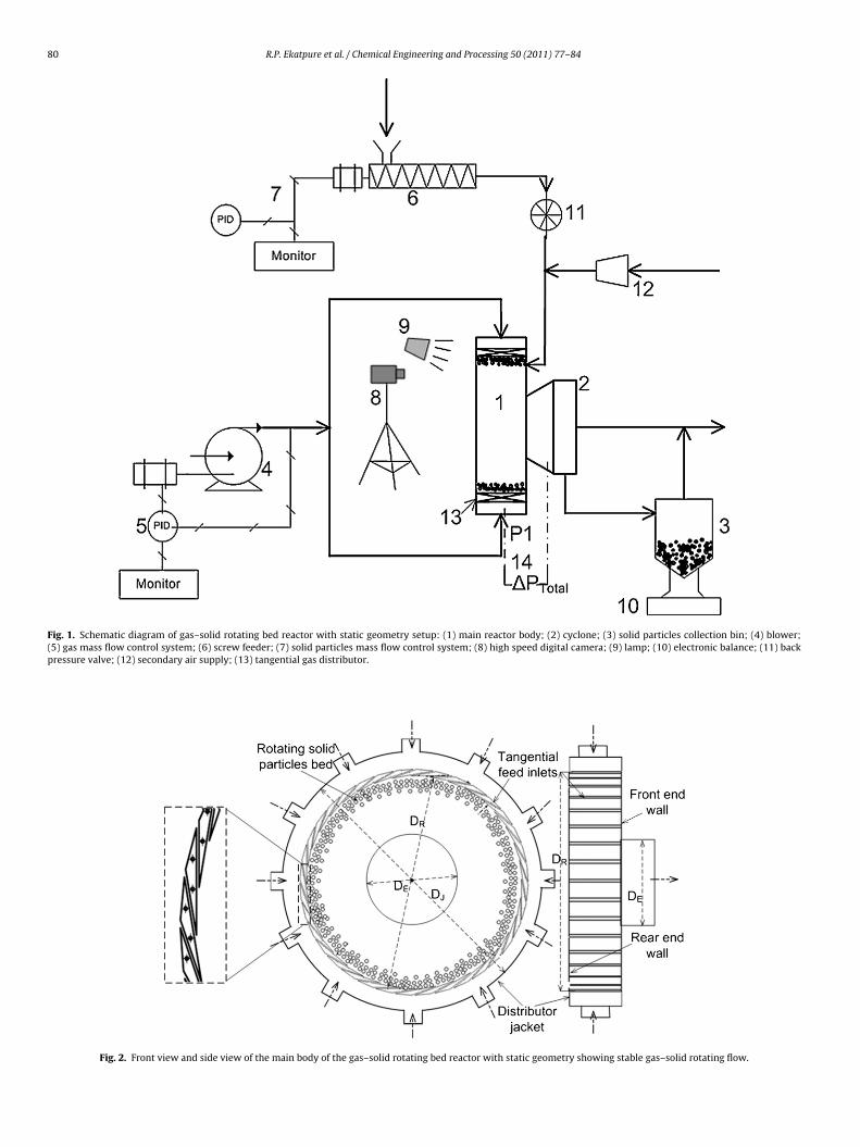
The schematic diagram of the cold-flow experimental set-upwith all components is shown in Fig. 1. The set-up consists of ablower for the supply of air, 4, a solid particles feeding device, 7, theRBR apparatus, 1, a cyclone, 2, a solid particles collection silo, 3 andan electronic balance, 10, for the weighing of the solids inventoryin the RBR. The main body of the RBR, as shown in Fig. 2, con-sists of two concentric cylinders, that is the air inlet jacket and theinner cylindrical reactor body with the central gas outlet. A blower-controlled mass flow of air enters into the jacket through a numberof inlets uniformly distributed over the jacket periphery. Table 2lists the geometrical configuration parameters of the present RBRset-up. Air from the reactor jacket is allowed to enter under a giveninjection angle into the inner cylindrical reactor body through anumber of tangential slots equally spaced over the entire periph-ery of the reactor. The width of the tangential gas injection slots canbe varied from 2 mm to 6 mm. The plane end walls of the reactorare made of polycarbonate glass (Makrolon®), allowing the visualobservation of the two-phase flow. The plane end wall with cen-tral gas outlet is considered as ‘front end wall (see Fig. 2)’ and theother one is treated as the rear end wall. High density polyethylene(HDPE) particles with a density of 950 kg/m3 are used in the experi-ments. Three different HDPE particle diameters have been used. Forcomparative purposes, the behavior of the fluid catalytic cracking(FCC) catalyst particles with a density of 1500 kg/m3 and averagediameter of 70 �m is investigated. Solid particles are fed from thevolumetric screw feeder to the main reactor body through an inletinclined at 30◦ towards the front end wall of the reactor (see Fig. 2).The solid particles flow rate from the screw feeder is regulated usinga controller and a sealing rotary valve to avoid back-pressure fromthe RBR.
2.2. Experimental procedure
All the experiments are performed in the semi-batch mode ofoperation under a horizontal axis of rotation. The range of operating
conditions is listed in Table 3. Initially, only gas continuously entersthe main reactor body through the jacket inlets and exits throughthe central opening of the main reactor body, in order to obtain asteady rotating gas flow. This gas outlet is an opening at the centerof the front end wall of the reactor (Fig. 2). A cyclone is connected to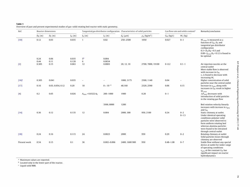
R.P.Ekatpure
etal./Chem
icalEngineeringand
Processing50 (2011) 77–84
79
Table 1Overview of past and present experimental studies of gas–solid rotating bed reactor with static geometry.
Ref. Reactor dimensions Tangential gas distributor configuration Characteristics of solid particles Gas flow rate and solids contenta Remarks/conclusion
DR (m) DE (m) LR (m) IN (m) IO (m) dp (�m) �p (kg/m3) GM (kg/s) Ws (kg)
[10] 0.12 0.03 0.035 1 0.02 250–2500 1050 0.027 0–1 Ws,max is measured as afunction of GM, DE andtangential gas distributorconfiguration0.3 < DE/DR < 0.5 and0.08 < IO,tot/DR < 0.12 is found tobe optimal
0.24 0.06 0.035 5b 0.0040.44 0.11 0.128 6 0.0034
[2] 0.305 0.15 0.063 12 0.0003 20, 12, 10 2700, 7000, 19100 0–0.2 0.1–1 Air injection nozzles at thecentral outletMore stable flow is observedwith increase in GM.
vs is found to decrease withincreasing Ws
[16]c 0.305 0.041 0.035 – – 1000, 3175 2500, 1140 0.04 – Higher concentration of solidparticles near the central outlet
[17] 0.16 0.03, 0.054, 0.12 0.20 18 8 × 10⁻⁴ 40,160 2320, 2590 0.06 0.15 Increase in vg,inj along withincreases in GM result in higherWs,max
[4] 0.2 0.05 0.026 Aslots = 0.0322 AR 200–1000 1900 0.28 0–1 �Ptotal decreases withintroduction of solid particlesin the rotating gas flow
3500, 8000 1200 Bed rotation velocity linearlyincreases with increase in vginj
and GM
[14] 0.36 0.12 0.135 12 0.004 2000, 300 950, 2100 0.24 0–2 Static chimney at outlet.0–1.5 Under identical operating
conditions polymer solidparticles were observed toform uniform rotating bedwhereas alumina particleswere found to be entrainedthrough central outlet
[18] 0.24 0.16 0.115 24 0.0023 2000 950 0.29 0–2 Rotating chimney at outletSolid particles losses throughchimney are observed
Present work 0.54 0.15 0.1 36 0.002–0.006 2400, 1600 900 950 0.48–1.08 0–7 Stable flow without any specialdevice at outlet for wider rangeof operating conditionsvg,inj at the constant GM hassignificant impact on reactorhydrodynamics
a Maximum values are reported.b Located only in the lower part of the reactor.c Liquid solid RBR.
80 R.P. Ekatpure et al. / Chemical Engineering and Processing 50 (2011) 77–84
Fig. 1. Schematic diagram of gas–solid rotating bed reactor with static geometry setup: (1) main reactor body; (2) cyclone; (3) solid particles collection bin; (4) blower;(5) gas mass flow control system; (6) screw feeder; (7) solid particles mass flow control system; (8) high speed digital camera; (9) lamp; (10) electronic balance; (11) backpressure valve; (12) secondary air supply; (13) tangential gas distributor.
Fig. 2. Front view and side view of the main body of the gas–solid rotating bed reactor with static geometry showing stable gas–solid rotating flow.
R.P. Ekatpure et al. / Chemical Engineering and Processing 50 (2011) 77–84 81
Table 2Geometrical specification of gas–solid rotating bed reactor with static geometry.
Geometrical variable Value Unit
Jacket diameter (DJ) 0.68 mMain reactor diameter (DR) 0.54 mExhaust diameter (DE) 0.15 mReactor length (LR) 0.10 mNumber of jacket inlets (IJ) 12 –Number of tangential inlet slots (IN) 36 –Diameter of each jacket inlet (dJ,inlet) 0.059 mDiameter of solid particles feeding (dsolids, inlet) 0.016 mWidth of tangential gas injection slot (IO) 0.002; 0.006 mLength of tangential gas injection slot (IO,L) 0.10 m
taiiart
sbepiAtetfc
btoltft(mtbiRpd
TRg
Injection angle (�) 10
he downstream of the gas outlet. Solid particles in the gas streamre separated from the gas in this cyclone. Clean gas is dischargednto the atmosphere. Next, the required amount of solid particless fed to the RBR using the screw feeder. The latter results into annnular rotating dense bed of solid particles. The stability of theotating annular gas–solid flow is the most critical aspect regardinghe performance of the RBR.
Depending upon the operating conditions, it takes only a feweconds to establish a stable uniform annular gas–solid rotatinged. Real time weighing of entrained solid particles during anxperiment is performed to correctly determine the amount of solidarticles in the reactor at each moment. The gas–solid flow behav-
or is studied using pressure measurements and visual observation.pressure probe (P1), 14 (as shown in Fig. 1) which is connected
o the pressure sensor is mounted on the wall of the jacket. At thend of an experiment, the solid particles in the RBR are removedhrough a solid particles outlet located at the lower part of theront end wall of the reactor and connected to the solid particlesollection silo.
In the present work, the flow behavior of the RBR is studiedy varying the tangential slot thickness and the particle diame-er. The tangential slot thickness represents a characteristic scalef the gas phase, while the particle diameter represents a simi-ar characteristic scale of the solid phase. A few results of varyinghe particle density are also discussed. Experiments are performedor a tangential slot thickness of 6 mm (resulting in a gas injec-ion velocity of 18–45 m/s) and a tangential slot thickness of 2 mmresulting in a gas injection velocity of 55–135 m/s). For a given gas
ass flow rate, the value of the centrifugal force in the RBR canhus be adapted by changing the gas velocity at the tangential sloty changing the tangential slot thickness. The corresponding min-
mum and maximum solids content, allowing a stable flow in theBR, are determined. Within this window of operation, the solidarticles content is varied and the corresponding pressure drop isetermined.
able 3ange of operating conditions for gas–solid rotating bed reactor with staticeometry.
Operating variable Value Unit
Air mass flow rate (GM) 0.48–1.2 kg/sSolid material HDPE FCC –Particle density (�p) 950, 1500 kg/m3
Particle size (dp) 2.4 mm1.6 mm0.9 0.07 mm mm
Outlet pressure (Pout) 101325 PaMass of solid particles in RBR (Ws) 0.5–7 kg
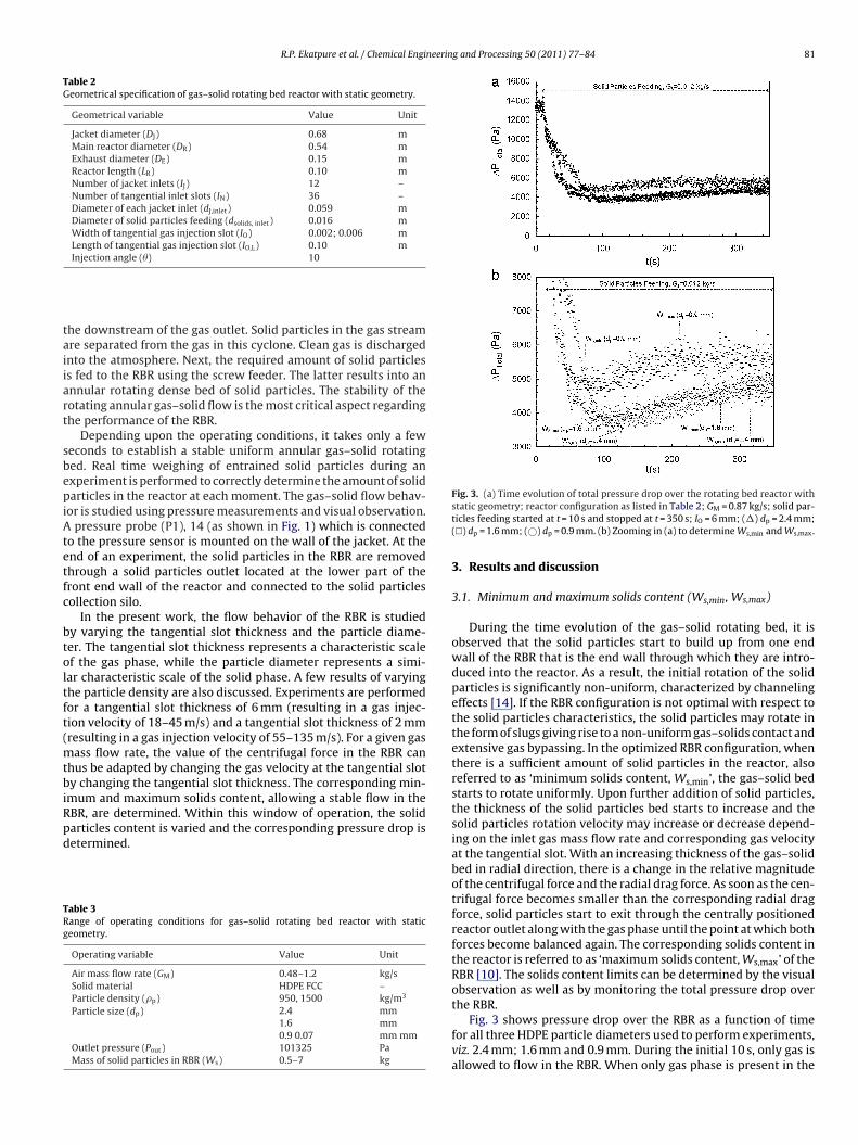
Fig. 3. (a) Time evolution of total pressure drop over the rotating bed reactor withstatic geometry; reactor configuration as listed in Table 2; GM = 0.87 kg/s; solid par-ticles feeding started at t = 10 s and stopped at t = 350 s; IO = 6 mm; (�) dp = 2.4 mm;(�) dp = 1.6 mm; (©) dp = 0.9 mm. (b) Zooming in (a) to determine Ws,min and Ws,max.
3. Results and discussion
3.1. Minimum and maximum solids content (Ws,min, Ws,max)
During the time evolution of the gas–solid rotating bed, it isobserved that the solid particles start to build up from one endwall of the RBR that is the end wall through which they are intro-duced into the reactor. As a result, the initial rotation of the solidparticles is significantly non-uniform, characterized by channelingeffects [14]. If the RBR configuration is not optimal with respect tothe solid particles characteristics, the solid particles may rotate inthe form of slugs giving rise to a non-uniform gas–solids contact andextensive gas bypassing. In the optimized RBR configuration, whenthere is a sufficient amount of solid particles in the reactor, alsoreferred to as ‘minimum solids content, Ws,min’, the gas–solid bedstarts to rotate uniformly. Upon further addition of solid particles,the thickness of the solid particles bed starts to increase and thesolid particles rotation velocity may increase or decrease depend-ing on the inlet gas mass flow rate and corresponding gas velocityat the tangential slot. With an increasing thickness of the gas–solidbed in radial direction, there is a change in the relative magnitudeof the centrifugal force and the radial drag force. As soon as the cen-trifugal force becomes smaller than the corresponding radial dragforce, solid particles start to exit through the centrally positionedreactor outlet along with the gas phase until the point at which bothforces become balanced again. The corresponding solids content inthe reactor is referred to as ‘maximum solids content, Ws,max’ of theRBR [10]. The solids content limits can be determined by the visualobservation as well as by monitoring the total pressure drop over
the RBR.Fig. 3 shows pressure drop over the RBR as a function of timefor all three HDPE particle diameters used to perform experiments,viz. 2.4 mm; 1.6 mm and 0.9 mm. During the initial 10 s, only gas isallowed to flow in the RBR. When only gas phase is present in the

8 neering and Processing 50 (2011) 77–84
Rp
v
crfrteo
ocspichvsgtotd
bdTstti
ttfflaiittobnapsadstdgttmopbtnd
2 R.P. Ekatpure et al. / Chemical Engi
BR it forms a Rankine vortex like structure. The motion of the gashase in such case can be described by:
gtrk = const (1)
In the peripheral region k ∼ 0.5–0.6 depending on the geometri-al configuration of RBR, while k ∼ (−1) in the central region of theeactor [20]. In principle, if k > 0.5, the centrifugal force increasesaster than the drag force, with decreasing radial position r. With aotating solid particles bed in the RBR, there will be a gas vortex inhe central core region of the RBR. Therefore, if solid particles arentrained into this vortex, they are likely to return to the free boardf the rotating bed, provided the vortex is large enough.
Next, the solid particle feeding is started at a mass flow rate Gs
f 0.012 kg/s. For all three particle diameters the solid particles areontinuously fed till t equals 350 s. From Fig. 3a it is clear that, asoon as the solid particles enter into the rotating gas flow field, theressure drop suddenly drops [4,19]. As the solid particles enter
nto the RBR, the flow field inside the cylindrical reactor changesompletely. The gas entering the RBR via the tangential inlet slotsas to impart momentum to the solid particles. As a result, theelocity of gas phase is reduced. Furthermore, the rotating layer ofolid particles acts like a distributor for the gas phase. As a result theas flow entering the RBR via a given tangential inlet is dispersed inhe presence of a rotating layer of solid particles. Thus the numberf rotations made by the gas phase is reduced in the presence ofhe rotating solid particles, resulting into a decrease in the pressurerop.
During the initial development of the gas–solid rotating bed, i.e.efore the establishment of stable bed, the decrease in the pressurerop is found to be inversely proportional to the particle diameter.his is due to the fact that, as the particle size decreases, the specificurface area of the particle increases, thereby causing more reduc-ion in the gas rotational speed. Thus, for larger particle diameters,he pressure drop over the RBR for a given solid particles contents higher before attaining the maximum solids content.
In the present experimental set-up, all gas injection slots havehe same length as the reactor length. On the other hand, solid par-icles are supplied from the solids feeder through an inlet at theront end wall of the RBR. When solid particles are thus allowed toow from the solid particles feeder into the rotating gas flow field,nnular channels are inevitably formed. A solid particles channels observed at the front end wall while an annular gas channels observed at the rear end wall of the RBR. Note that the cen-ral outlet is located in the front end wall of the RBR. For thewo larger particle diameter (2.4 mm and 1.6 mm) slugging is alsobserved during the initial development of the rotating gas–solided. When the particles content in the RBR is sufficiently high, theon-uniform flow effects, such as channeling and/or slugging, dis-ppear and a uniform stable flow is established. At this point theressure drop is minimum and the solid particles content corre-ponds to the minimum solids content. Each experiment is repeatedt least three times. A highly reproducible set of data is obtaineduring these experiments, with less than 3% error in the value of theolids content. Fig. 4 shows that, as the particle diameter increases,he minimum solids content increases. The stronger slugging ten-ency of larger particles may be at the origin of this behavior. Foriven operating conditions, the tangential slot thickness is foundo have an effect on the minimum solids content for a given par-icle diameter as well. As the tangential slot thickness decreases a
ore optimal distribution of the gas phase results into a reductionf the channeling phenomena. However, next to the channeling
henomena observed for all three particle diameters, the sluggingehavior has to be considered as well. When the tangential slothickness is reduced from 6 mm to 2 mm, the tangential slot thick-ess becomes of the same order of magnitude as the larger particleiameters (2.4 mm and 1.6 mm). As a result, the slugging behav-Fig. 4. Minimum solids content for various solid particle diameters; reactor con-figuration as listed in Table 2; GM = 0.75 kg/s; (©), IO = 6 mm, �p = 950 kg/m3; (�)IO = 2 mm, �p = 950 kg/m3; (♦) IO = 2 mm, �p = 1500 kg/m3.
ior of these large particles in the rotating annular gas–solid bedincreases and becomes more important than the channeling effect.As such, the minimum solids content increases with decreasing tan-gential slot thickness. However for the smaller particles (0.9 mm),the slugging behavior remains limited and the channeling effectremains the dominating effect. As a result, the minimum solidscontent decreases with decreasing tangential slot thickness.
When the FCC catalyst particles with a density 1500 kg/m3 areused, a highly unstable gas–solid bed is formed for a tangential slotthickness of 6 mm. A large solid particles entrainment is observed,resulting in a fast emptying of the reactor. This is mainly due tothe fact that the gas injection velocity is lower than 45 m/s at thegiven gas flow rate for a tangential slot thickness of 6 mm. However,when the tangential slot thickness is decreased to 2 mm, a stablebed of FCC catalyst particles is observed. The result of the minimumsolids content in case of FCC catalyst particles is shown in Fig. 4. Theobservations are in-line with the description of the channeling andthe characteristic dimension discussed in this section.
For a given gas mass flow rate, when the mass of solid parti-cles has increased beyond the minimum solids content, a stablegas–solid rotating bed can be observed. For a given solid particlecontent, the centrifugal force acting upon the rotating gas–solid bedis overcome by the radial drag force. As a result, the solid particlesget carried away with the gas flow through the central outlet untilboth centrifugal force and radial drag force become balanced again.The mass of solid particles in the RBR corresponding to these condi-tions is the maximum amount of solid particles that can be retainedby the RBR for the given gas mass flow rate and is referred as themaximum solids content of the RBR [10]. From Fig. 3b, showingthe time evolution of the pressure drop, the maximum solids con-tent can be determined for the different particle diameters. Whenthe solid particles content equals the maximum solids content, afurther feeding of solid particles does not result in a change ofthe pressure drop. The point in time at which the pressure dropbecomes constant corresponds with the point in time at which itis observed that the solid particles start to get entrained by thegas through the central outlet. Due to the gravity effect and thehorizontal axis of rotation of the reactor set-up, the solid particlesare mainly entrained through the top-most position of the centraloutlet.
Fig. 5 shows the maximum solids content for all the three par-ticle diameters as a function of the gas mass flow rate and the gas
injection velocity. For a given particle diameter and particle densityan increase in the gas mass flow rate, with a corresponding increasein the gas injection velocity results in a slight increase in the maxi-mum solids content. From a given gas mass flow rate, also referredto as ‘critical gas mass flow rate, GM,cr’, the maximum solids content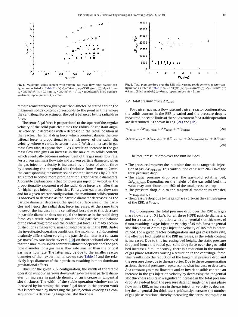
R.P. Ekatpure et al. / Chemical Engineering and Processing 50 (2011) 77–84 83
Fig. 5. Maximum solids content with varying gas mass flow rate; reactor con-fi�I
rmtf
vlttvmmwFtbtTApfaipchifoptdgttgdtg
oesits
slot thickness results in a significant increase in the total pressure
guration as listed in Table 2; (�) dp = 2.4 mm, �p = 950 kg/m3; (©) dp = 1.6 mm,p = 950 kg/m3; (�) 0.9 mm, �p = 950 kg/m3; (♦) �p = 1500 kg/m3; filled symbols,
O = 6 mm; (open symbols) IO = 2 mm.
emains constant for a given particle diameter. As stated earlier, theaximum solids content corresponds to the point in time where
he centrifugal force acting on the bed is balanced by the radial dragorce.
The centrifugal force is proportional to the square of the angularelocity of the solid particles times the radius. At constant angu-ar velocity, it decreases with a decrease in the radial position inhe reactor. The radial drag force, which counterbalances the cen-rifugal force, is proportional to the nth power of the radial slipelocity, where n varies between 1 and 2. With an increase in gasass flow rate, n approaches 2. As a result an increase in the gasass flow rate gives an increase in the maximum solids content,hich eventually becomes independent of the gas mass flow rate.
or a given gas mass flow rate and a given particle diameter, whenhe gas injection velocity is increased by a factor of about threey decreasing the tangential slot thickness from 6 mm to 2 mm,he corresponding maximum solids content increases by 20–50%.his effect becomes more prominent for larger particle diameters.possible explanation is that for lower gas injection velocities, the
roportionality exponent n of the radial drag force is smaller thanor higher gas injection velocities. For a given gas mass flow ratend for a given reactor configuration, the maximum solids contents observed to decrease as the particle diameter decreases. As thearticle diameter decreases, the specific surface area of the parti-les and hence the radial drag force increases. At the same timeowever the increase in the centrifugal force due to this decrease
n particle diameter does not equal the increase in the radial dragorce. As a result, when using smaller solid particles, the balancef the radial drag force and the centrifugal force is already accom-lished for a smaller total mass of solid particles in the RBR. Underhe investigated operating conditions, the maximum solids contentistinctly differs when varying the particle diameter at a constantas mass flow rate. Kochetov et al. [10], on the other hand, observedhat the maximum solids content is almost independent of the par-icle diameter for a gas mass flow rate smaller than the criticalas mass flow rate. The latter may be due to the smaller reactoriameter of their experimental set-up (see Table 1) and the rela-ively large diameter of their particles, resulting in more dominantravitational effects.
Thus, for the given RBR configuration, the width of the ‘stableperation window’ narrows down with a decrease in particle diam-ter, an increase in particle density or an increase in tangential
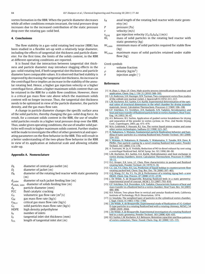
lot thickness. The width of the stable operation window can bencreased by increasing the centrifugal force. In the present workhis is performed by increasing the gas injection velocity as a con-equence of a decreasing tangential slot thickness.Fig. 6. Total pressure drop over the RBR with varying solids content; reactor con-figuration as listed in Table 2; GM = 0.9 kg/s; (�) dp = 2.4 mm; (©) dp = 1.6 mm; (�)0.9 mm; (filled symbols) IO = 6 mm; (open symbols) IO = 2 mm.
3.2. Total pressure drop (�Ptotal)
For a given gas mass flow rate and a given reactor configuration,the solids content in the RBR is varied and the pressure drop ismeasured, once the limits of the solids content for a stable operationare determined. As shown in Eqs. (2a) and (2b):
�Ptotal = �PRBR, main + �Poutlet + �Pcyclone (2a)
�PRBR, main = �Pinlet slots + �Pstatic, bed + �Ptangential, bed + �Pvortex
(2b)
The total pressure drop over the RBR includes,
• The pressure drop over the inlet slots due to the tangential injec-tion of gas, �Pinlet,slots. This contribution can rise to 20–30% of thetotal pressure drop.
• The static pressure drop over the gas–solid rotating bed,�Pstatic, bed. Depending on the height of the gas solid bed thisvalue may contribute up to 50% of the total pressure drop.
• The pressure drop due to the tangential momentum transfer,�Ptangential, bed.
• The pressure drop due to the gas phase vortex in the central regionof the RBR, �Pvortex.
Fig. 6 compares the total pressure drop over the RBR at a gasmass flow rate of 0.9 kg/s, for all three HDPE particle diameters,and for a reactor configuration with a tangential slot thickness of6 mm, resulting in a gas injection velocity of 35 m/s. For a tangentialslot thickness of 2 mm a gas injection velocity of 105 m/s is deter-mined. For a given reactor configuration and gas mass flow rate,the effective bed height in the RBR increases, as the solids contentis increased. Due to this increasing bed height, the static pressuredrop and hence the radial gas–solid drag force over the gas–solidbed increases. Simultaneously, there is a reduction in the numberof gas phase rotations causing a reduction in the centrifugal force.This results into the reduction of the tangential pressure drop andthe pressure drop due to the gas vortex. Due to these compensatingactions, the total pressure drop can somewhat increase or decrease.At a constant gas mass flow rate and an invariant solids content, anincrease in the gas injection velocity by decreasing the tangential
drop. As evident from the pressure data for single phase gas phaseflow in the RBR, an increase in the gas injection velocity by decreas-ing the tangential slot thickness significantly increases the numberof gas phase rotations, thereby increasing the pressure drop due to
8 neerin
vwid
4
biea
ngditlcbicnd
orsTtwaais
A
DDD
dddFGGGGHIII
[
[
[
[
[
[
[
[
[
4 R.P. Ekatpure et al. / Chemical Engi
ortex formation in the RBR. When the particle diameter decreaseshile all other conditions remain invariant, the total pressure drop
ncreases due to the increased contribution of the static pressurerop over the rotating gas–solid bed.
. Conclusions
The flow stability in a gas–solid rotating bed reactor (RBR) haseen studied in a flexible set-up with a relatively large diameter,
ncluding the effects of tangential slot thickness and particle diam-ter. For the first time, the limits of the solids content, in the RBRt different operating conditions are reported.
It is found that the interaction between tangential slot thick-ess and particle diameter may introduce slugging effects in theas–solid rotating bed, if both tangential slot thickness and particleiameter have comparable values. It is observed that bed stability is
mproved by decreasing the tangential slot thickness. An increase inhe centrifugal force implies an increase in the stability of the annu-ar rotating bed. Hence, a higher gas injection velocity or a higherentrifugal force, allows a higher maximum solids content that cane retained in the RBR for a stable flow condition. However, there
s a critical gas mass flow rate above which the maximum solidsontent will no longer increase. Thus, the tangential slot thicknesseeds to be optimized in view of the particle diameter, the particleensity, and the gas mass flow rate.
A change in particle diameter changes the specific surface areaf the solid particles, thereby changing the gas–solid drag force. Asesult, for a constant solids content in the RBR, the use of smallerolid particles results in a higher total pressure drop over the RBR.hus, under given operating conditions, the use of smaller solid par-icles will result in higher maximum solids content. Further studiesill be made to investigate the effect of other geometrical and oper-
ting parameters on the flow behavior in the RBR. This will result inbetter understanding of the two-phase flow behavior in the RBR
n view of its application at industrial scale and allowing reliablecale-up.
ppendix A. Nomenclature
E diameter of central gas outlet (m)J diameter of jacket (m)R diameter of the rotating bed reactor with static geometry
(m)J,inlet diameter of each jacket feeding line (m)solids, inlet diameter of solids feeding line (m)p particle diameter (mm)CC fluid catalytic crackingV volumetric gas flow rate (m3/s)M gas mass flow rate (kg/s)M,cr critical gas mass flow rate (kg/s)
S solid particles mass flow rate (kg/s)DPE high density polyethyleneN number of inletsO tangential inlet slot thickness (mm)O,L length of tangential inlet slot (m)
[
[
g and Processing 50 (2011) 77–84
LR axial length of the rotating bed reactor with static geom-etry (m)
P pressure (Pa)v velocity (m/s)vg,inj gas injection velocity (GV/IOINLR) (m/s)Ws mass of solid particles in the rotating bed reactor with
static geometry (kg)Ws,min minimum mass of solid particles required for stable flow
(kg)Ws,max maximum mass of solid particles retained under stable
flow (kg)
Greek symbolsε volume fraction� density (kg/m3)� injection angle (◦)
References
[1] H. Zhao, L. Shao, J.F. Chen, High-gravity process intensification technology andapplication, Chem. Eng. J. 156 (3) (2010) 588–593.
[2] L.A. Anderson, S.H. Hasinger, B.N. Turman, Two-component vortex flow studiesof the colloid core nuclear rocket, J. Spacecraft 9 (1972) 311–317.
[3] L.M. Kochetov, B.S. Sazhin, E.A. Karlik, Experimental determination of the opti-mal ratios of structural dimensions in the whirl chamber for drying granularmaterials, Invest. Calculation Thermochem. Processes 2 (1969) 106–108.
[4] E.P. Volchkov, V.I. Terekhov, A.N. Kaidanik, A.N. Yadykin, Aerodynamics andheat and mass transfer of fluidized particle beds in vortex chambers, Heat Trans.Eng. 14 (1993) 36–47.
[5] A.S. Belousov, B.S. Sazhin, Application of guided vortex breakdown for dryingand separation of the powder in vortex cyclone, in: Proc. 2nd Nordic DryingConf., Copenhagen, 2003, pp. 475–479.
[6] M.A. Goldshtik, F. Hussain, R.J. Yao, The vortex liquid piston engine and someother vortex technologies, Sadhana 22 (1998) 323–367.
[7] H. Nakamura, S. Watano, Fundamental particle fluidization behavior and han-dling of nano-particles in a rotating fluidized bed, Powder Technol. 183 (2008)324–332.
[8] S. Watano, H. Nakamura, K. Hamada, Y. Wakamatsu, Y. Tanabe, R.N. Dave, R.Pfeffer, Fine particle coating by a novel rotating fluidized bed coater, PowderTechnol. 141 (2004) 172–176.
[9] A. Tsutsumi, W. Ju, K. Yoshida, Reduction of NO in diesel exhaust by soot usinga centrifugal fluidized bed, AIChE Symp. Ser. 92 (1996) 86–90.
10] L.M. Kochetov, B.S. Sazhin, E.A. Karlik, Hydrodynamics and heat exchange invortex drying chambers, Invest. Calculation Thermochem. Processes 9 (1969)10–11.
11] D.G. Kroger, E.K. Levy, J.C. Chen, Flow characteristics in packed and fluidizedrotating beds, Powder Technol. 24 (1979) 9–18.
12] C.C. Lin, Y.S. Chen, H.S. Liu, Prediction of liquid holdup in countercurrent-flowrotating packed bed, Chem. Eng. Res. Des. 78 (2000) 397–403.
13] G.Q. Wang, Z.C. Xu, Y.L. Yu, J.B. Ji, Performance of a rotating zigzag bed—a newHIGEE, Chem. Eng. Process. 47 (2008) 2131–2139.
14] J. De Wilde, A. de Broqueville, Rotating fluidized beds in a static geometry:experimental proof of concept, AIChE J. 53 (2007) 793–810.
15] E.P. Volchkov, N.A. Dvornikov, A.N. Yadykin, Characteristic features of heat andmass transfer in a fluidized bed in a vortex chamber, Heat Trans. Res. 34 (2003)486–498.
16] B.A. Folsom, Two-phase flow in vertical and annular fluidized beds, CaliforniaInstitute of Technology, Ph.D. Dissertation, 1974.
17] J.J. Smulsky, The weighted layer of particles in the cylindrical vortex chamber,J. Appl. Chem. 8 (1983) 1782–1789.
18] J. De Wilde, A. de Broqueville, Experimental study of fluidization of 1G-Geldart
D-type particles in a rotating fluidized bed with a rotating chimney, AIChE J. 54(2008) 2029–2044.19] J. De Wilde, A. de Broqueville, Experimental investigation of a rotating fluidizedbed in a static geometry, Powder Technol. 183 (2008) 426–435.
20] B.S. Sazhin, L.M. Kochetov, A.S. Belousov, Retention capacities and flow patternsof vortex contactors, Theor. Found. Chem. Eng. 42 (2008) 125–135.