A Critical Analysis of Molten Salt Reactor (Msr) Safety Systems.
Upload
idahostateCategory
view
0download
0
PERSPECTIVE
Why the molten salt fast reactor (MSFR) is the “best” GenIV reactorDarryl D. Siemer
Nuclear Energy Department, Idaho State University, 921 S. 8th Ave Mail Stop 8060 Pocatello, ID 83209-8060, USA
Keywords
Breeder reactors, GEN IV reactor options,
molten salt fast reactor, nuclear renaissance,
thorium
Correspondence
Darryl D. Siemer, Nuclear Energy
Department, Idaho State University.
Tel: +1(208)524-2479;
E-mail: [email protected]
Funding Information
No funding information provided.
Received: 11 May 2014; Revised: 25
November 2014; Accepted: 18 December
2014
doi: 10.1002/ese3.59
Abstract
A simultaneously “nuclear”, permanent, and in-time solution to mankind’s
energy-related problems would require the relatively rapid manufacture of
10,000–30,000 genuinely sustainable, full-sized (~1 GWe) reactors. This “nuclear
renaissance” would have to be implemented with breeder reactors because
today’s commercial nuclear fuel cycle is unsustainable and based upon a fuel
(235U) that is intrinsically expensive and politically problematic. The purpose of
this paper is to point out why a simple/cheap “minimal reprocessing” imple-
mentation of the European Union’s (EU’s) molten salt fast reactor (MSFR)
concept represents the most promising way to implement that technical fix:
• It would be relatively simple/cheap to both build and operate,
• Its fuel cycle is genuinely sustainable (no fuel shortages “forever”),
• Radwaste management would also be relatively simple and cheap,
• Operation would neither generate nor require huge amounts of transuranic
(TRU) elements,
• The consequences of accidents (fuel spills, etc.) would be relatively benign,
• When steady state is achieved, the world would no longer need its uranium
enrichment facilities.
Its primary drawback is that it would require virtually everyone currently
involved with managing, researching, implementing, regulating, or “helping”
the USA’s nuclear power industry to embrace a massive paradigm shift.
Introduction
A simultaneously “nuclear”, permanent, and in-time solu-
tion to mankind’s energy-related problems1 would require
the relatively rapid manufacture of 10,000–30,0002 genu-
inely sustainable, full-sized (~1 GWe), not “modular”
(small) reactors. The reasons why such a “nuclear renais-
sance” would have to be implemented with breeder-type
reactors3 were identified by Alvin Weinberg and H. E.
Goeller four decades ago [1]; that is, because the fissile
consumed by today’s “converter” reactors (235U) com-
prises only ~0.2% of the world’s potential nuclear fuel
supply4 and is both expensive and politically problematic
to obtain,5 it is too costly to represent a truly sustainable
energy (fuel) source for everyone. Two years ago, a book
written by the managers of Argonne National Labora-
tory’s (ANLs) “Integral Fast Reactor” (IFR) program reit-
erated that message and described how the USA had gone
about developing/promoting a sustainable nuclear fuel
cycle based upon the conversion of 238U to 239Pu [2].
Unfortunately, that/their program was canceled two dec-
ades ago and none of the US Department of Energy
Office of Nuclear Energy’s (USDOE-NE’s) current
research priorities address the development of anything
capable of addressing the world’s long-term energy needs.
The rationale6 for why the US-initiated Generation IV
International Forum (GIF) program included molten salt
reactors (MSRs) among the six (now seven) advanced
reactor concepts7 identified for cooperative development
included: (1) they can8 be operated in ways that would
generate very little long-lived TRU waste; (2) their inven-
tories of fissile materials per unit of energy can be lower
than those of other reactors; (3) the dispersible inventory
[source term] of radionuclides within them can be less
than that of any other reactor; (4) both fuel and operat-
ing costs could be very low compared to solid-fuel reac-
ª 2015 The Author. Energy Science & Engineering published by the Society of Chemical Industry and John Wiley & Sons Ltd.
This is an open access article under the terms of the Creative Commons Attribution License, which permits use,
distribution and reproduction in any medium, provided the original work is properly cited.
1
tors; and (5) there are large economics-of-scale with the
potential to build very large reactors with extremely low
per-megawatt capital costs [3]. Unfortunately, despite the
fact that virtually all of the research revealing these char-
acteristics had been performed at the USA’s Oak Ridge
National Laboratory (ORNL)9 several decades earlier, the
USA decided to cede GEN–IV MSR development work to
its European collaborators in order to attempt another
revival of ANL’s Liquid Metal-cooled Fast Breeder Reac-
tor (LMFBR, a.k.a., IFR) program. Its latest version would
comprise a liquid metal-cooled, metal-fueled, fast-spec-
trum “burner” reactor (not a breeder – no 238U-contain-
ing blanket around the core) fed with TRU “waste”
(mostly 239Pu) extracted from spent commercial light
water reactor (LWR) fuel via a modified version of the
pyrochemical fuel reprocessing/waste treatment system
originally developed for the IFR. The resulting “sodium
fast reactors” (SFRs) were to have become the USA’s chief
contribution to the Global Nuclear Energy Partnership
(GNEP).
While critical reviews [4] soon led to a drastic downsiz-
ing of the USA’s GNEP/Advanced Fuel Cycle Initiative
NE research and development (R&D) programs [5], its
GIF collaborators/partners continued to support/fund
theirs, the most promising of which has turned out to be
the MSFR concept jointly developed/studied by research
teams in seven different counties +EURATOM+Russia.The remainder of this paper will seek to support my con-
tention that it represents the “best” (most practical/
cheap/clean/simple/safe) way to realize Weinberg/Geoller’s
technical fix for the consequences of a burgeoning human
population’s addiction to fossil fuels. That judgment is
based upon a comparison of sustainability, cost, and
waste management-related considerations.
Evolution of the Molten Salt BreederReactor
The first research performed to devise a molten salt
“power” (electricity-generating) reactor capable of gener-
ating as much fissile (233U) as it consumes is summed up
in chapters 11–17 of “Fluid Fueled Reactors”[6].
Figure 110 depicts ORNL’s “reference reactor” at the time
that book was written (1958). It consists of a roughly
spherical Hastelloy N “core” (or “reactor”) tank through
which the fissile-containing fuel salt stream (primarily233UF4 in a low-melting solvent comprised of a 2:1 mole-
wise mix of 7LiF and BeF2) is pumped, temporarily expe-
riences criticality which generates heat energy which is
then transferred to a second nonradioactive molten salt
stream via an external heat exchanger. The core tank is
situated within a larger “blanket” tank containing a simi-
larly molten blanket salt containing thorium (as ThF4)
that absorbs neutrons leaking though the core tank’s wall
(a.k.a., “barrier”) and is thereby transmuted to 233Pa. The
27-day half-life 233Pa then decays to generate fresh fissile
(233U) that is transferred back to the fuel salt stream. In
principle, it can operate indefinitely with no fuel other
than makeup thorium if it is close coupled to a chemical
reprocessing system capable of simultaneously transferring
the fissile generated in its blanket salt to the core and pre-
venting excessive fission product (FP) neutron poison11
build up without excessive loss of thorium and 7Li. How-
ever, ORNL’s calculations indicated that this configura-
tion could not achieve break-even fissile regeneration
(isobreeding) with a core tank large enough to generate a
worthwhile amount of power (>100 MWe) unless tho-
rium was also present in the fuel-side salt, which, in turn,
would raise seemingly insuperable “reprocessing issues”
due to its chemical similarities to rare earth element
(REE) FP neutron poisons. This, plus the fact that Her-
bert McPherson, formerly National Carbon’s foremost
graphite expert,12 had assumed management of ORNL’s
molten salt research program [7], shifted emphasis to
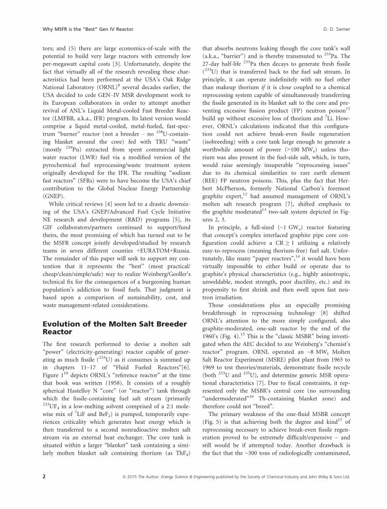
the graphite moderated13 two-salt system depicted in Fig-
ures 2, 3.
In principle, a full-sized (~1 GWe) reactor featuring
that concept’s complex interlaced graphite pipe core con-
figuration could achieve a CR ≥ 1 utilizing a relatively
easy-to-reprocess (meaning thorium-free) fuel salt. Unfor-
tunately, like many “paper reactors”,14 it would have been
virtually impossible to either build or operate due to
graphite’s physical characteristics (e.g., highly anisotropic,
unweldable, modest strength, poor ductility, etc.) and its
propensity to first shrink and then swell upon fast neu-
tron irradiation.
Those considerations plus an especially promising
breakthrough in reprocessing technology [8] shifted
ORNL’s attention to the more simply configured, also
graphite-moderated, one-salt reactor by the end of the
1960’s (Fig. 4).15 This is the “classic MSBR” being investi-
gated when the AEC decided to axe Weinberg’s “chemist’s
reactor” program. ORNL operated an ~8 MWt Molten
Salt Reactor Experiment (MSRE) pilot plant from 1965 to
1969 to test theories/materials, demonstrate fissile recycle
(both 233U and 235U), and determine generic MSR opera-
tional characteristics [7]. Due to fiscal constraints, it rep-
resented only the MSBR’s central core (no surrounding
“undermoderated”16 Th-containing blanket zone) and
therefore could not “breed”.
The primary weakness of the one-fluid MSBR concept
(Fig. 5) is that achieving both the degree and kind17 of
reprocessing necessary to achieve break-even fissile regen-
eration proved to be extremely difficult/expensive – and
still would be if attempted today. Another drawback is
the fact that the ~300 tons of radiologically contaminated,
2 ª 2015 The Author. Energy Science & Engineering published by the Society of Chemical Industry and John Wiley & Sons Ltd.
Why MSFR is the “Best” Gen IV Reactor D. D. Siemer

neutron-damaged graphite within its core would have to
be replaced every 3–4 years, which, in the absence of a
suitable repository, raises significant waste issues.
Consistent with GIF’s sustainability and safety18 goals
[9], ORNL’s classic MSBR concept gradually evolved in
the direction of unmoderated (no graphite) fast-spectrum
systems [10] and eventually (in 2008), the two-fluid
(blanket equipped) MSFR (Fig. 6) became the EURATOM
Consortium’s (EVOL’s) “reference” MSR.19 While most of
the previous studies of fast-spectrum MSRs had assumed
a chloride20 -based solvent salt in order to facilitate Pu
breeding [11], fertile-free TRU burning, or U-supported
TRU burning [12], EVOL’s leadership assumed a some-
what less fast fluoride salt-based system in order to capi-
talize upon ORNL’s extensive materials science and fuel
salt chemistry experience [13].
Finally, because it soon became apparent that both
CR and reactor durability21 would be improved by sur-
rounding its entire core region with blanket salt rather
than just along its sides, recent EVOL papers [14] often
describe optimized MSFRs that look much like ORNL’s
original sphere-within-sphere concept – compare Fig-
ures 7 and 1.22
Everything that the rest of this paper has to say about
what could be achieved with the EVOL’s reference MSFR
would also apply to such an optimized system.
Reasons Why the MSFR is the “Best”Gen IV Reactor
This section only addresses features relevant to its use as
a genuinely sustainable thorium-fueled reactor operated
to produce cheap, clean, electricity. References [15–17]give more detailed descriptions of both the reactor itself
and its characteristics if utilized as a waste treatment tech-
nology for LWR-derived TRU.
Section A-A
Siphon Drain
Fuel Line TOHeat Exchanger
0 1 2 3 4 5
Scale—Feet
Fuel Return
A A
Blanket Return
BreedingBlanket
Fuel ExpansionTank
Blanket ExpansionTank
BlanketPumpMotorFuel Pump
Motor
CoreMolten Salt
Fuel
Figure 1. Mid-1950’s ORNL unmoderated (no graphite) 2-fluid reactor (from chapter 17 of Ref. 6).
ª 2015 The Author. Energy Science & Engineering published by the Society of Chemical Industry and John Wiley & Sons Ltd. 3
D. D. Siemer Why MSFR is the “Best” Gen IV Reactor
The core of the reference MSFR is a right circular cyl-
inder with diameter equal to height (each 2.17 m), sur-
rounded axially by 1-m thick steel reflectors, and radially
by a 50-cm thick fertile blanket salt layer, a boron carbide
layer, and a steel neutron reflector. It is filled with the
fuel salt with no core internal structures. The fuel circu-
lates out of the core through 16 external loops each of
which includes a pump and heat exchanger. A geometri-
cally safe overflow tank accommodates salt expansion/
contraction due to temperature changes. A salt draining
system connected to the bottom of the core allows core
dumping to passively cooled criticality-safe tanks to facili-
tate maintenance or respond to emergencies. This system
includes freeze valves that would melt as soon as electric
power is lost or the salt seriously overheats. The entire
primary circuit, including the gas reprocessing unit,
would be contained within a secondary containment ves-
sel. Figure 5 is a schematic of the primary loop’s layout
and Table 1 summarizes its core parameters.
Its primary fuel salt circuit is connected to two others
which serve to keep the salt sufficiently free of the FP
“ash” that would otherwise scavenge/absorb too many
neutrons. The first of these would be a gas sparging sys-
tem like that utilized by ORNL’s MSRE pilot plant [7]. It
would add a small stream of helium bubbles to the salt
upstream of the heat exchanger (HX) pump(s) to strip-
out both gaseous and nonsoluble FP.23 A 30-second
extraction time is generally assumed for both, although,
in fact, extraction of nongaseous FPs will take somewhat
longer (a noble metal extraction time of several days
would have a limited impact on CR [19]). The second
clean up circuit is the “reprocessing” system that removes
intrinsically soluble (“salt seeking”) FPs (e.g., REE, alka-
line earths, alkalis, etc.) from the fuel salt either continu-
ously or batch-wise on a daily basis.
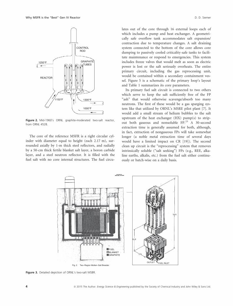
FUELBLANKETGRAPHITE
10 ft
2 ft
18 ft
OUTLET FUEL INLETFig. 2. Two–Region Molten–Salt Breeder.
Figure 3. Detailed depiction of ORNL’s two-salt MSBR.
CONTROLROD
GRAPHITETUBES
1250°F
REACTOR
1150°F 1300°F
1000°F
Figure 2. Mid-1960’s ORNL graphite-moderated two-salt reactor,
from ORNL 4528.
4 ª 2015 The Author. Energy Science & Engineering published by the Society of Chemical Industry and John Wiley & Sons Ltd.
Why MSFR is the “Best” Gen IV Reactor D. D. Siemer

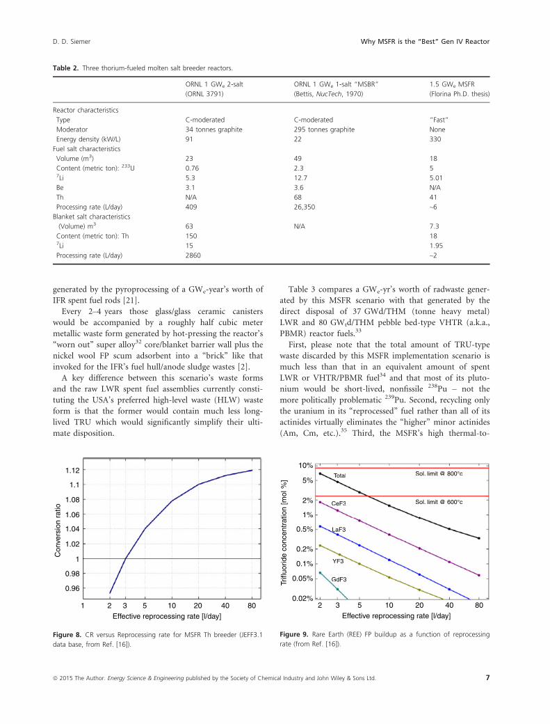
Low reprocessing requirement
This paper’s chief technical contribution to the state of
the art24 is that it points out that a sustainable (CR � 1)
MSFR fuel cycle would require so little salt-seeker
removal (see Figs. 8, 9) that doing such reprocessing is
unnecessary – everything but the uranium25 (primarily233U) in the fuel salt requiring that treatment could sim-
ply be discarded. The reasons for this include: (1) the
value of the nominally costly 7Li and Th in it would be
less than the cost of separating/recovering them; (2) dis-
carding TRU rather than recovering/recycling it would
minimize the generation of both Pu and minor actinides
(MA); (3) the total amount of radwaste generated would
be very low; and (4) the resulting much simplified fuel
cleanup process would be intrinsically safer to operate
and significantly reduce the cost of producing electricity.
Consequently, satisfying the reprocessing requirements
of a MSFR isobreeder would be much simpler, cheaper,
and safer than those of either ORNL’s classic MSBR or
any of the other potentially26 sustainable GEN IV.reactors
(SFR/IFR, LFR & GFR). It would also obviate one of the
primary drivers for the development of the too-simple
“deep burn”-type MSRs that might eventually pose more
problematic/costly radioactive waste management issues
than does today’s nuclear fuel cycle.27
Table 2 compares the MSFR to both of ORNL’s
graphite-moderated Th-breeders (Figs. 2–5). Note the dif-
ferences engendered by the shift to a faster neutron spec-
trum. A point not addressed by Table 2 is that a
moderated, one-salt MSBR’s 233Pa isolation/hold system
Reactor
Primarysalt pump
Off-gassystem
Coolant salt
Graphitemoderator
Heatexchanger
Fuel salt
Reactor
Critically safe,passively cooleddump tanks(Emergencycooling andshutdown)
Freezeplug
Purifiedsalt
Chemical processing(Colocated or off-site)
Figure 4. Current depiction of ORNL’s graphite-moderated one-salt
MSBR (from Ref. 3).
CONTROL ROD DRIVE
12 m9 m
REACTOR
PRIMARY SALT PUMP
STEAM GENERATOR
SECONDARYSALT PUMP
STEAMPIPING
FLOORLEVEL
HEAT EXCHANGERCATCH BASIN
FREEZE VALVE CELL
Red shows secondary containmentouter building is third level
DRAIN TANK
TOAIR-COOLEDRADIATORS
Figure 5. ORNL’s depiction of its one-salt MSBR (early 1970’s).
Table 1. MSFR core parameters [18].
Thermal/electric power 3000 MWt/1500 MWe
Core inlet/outlet temperatures 923/1023 K
Fuel salt volume 18 m3
Fraction of salt inside the core 50%
Number of loops for heat exchange 16
Flow rate 4.5 m3/sec
Salt velocity in pipes
assuming 0.3 m diameter
~4 m/sec
Blanket thickness 50 cm
Blanket salt volume 7.3 m3
Boron carbide layer thickness 20 cm
ª 2015 The Author. Energy Science & Engineering published by the Society of Chemical Industry and John Wiley & Sons Ltd. 5
D. D. Siemer Why MSFR is the “Best” Gen IV Reactor

creates an almost realistic “proliferation issue”.28 Another
is that graphite would likely enhance the corrosion rate of
the reactor’s metallic components [20].
Waste management-related advantages
Wastes generated by this particular MSFR implementation
scenario would consist of: (1) everything in the 6 L29 /
day of reprocessed fuel salt except uranium; (2) waste
generated by the reactor’s off gas cleanup and uranium
recycling systems; and (3) an occasional “worn out” reac-
tor core and/or blanket salt tank.
The first of these waste streams is simple to characterize
because at steady state, the reactor’s salt cleanup systems
must remove FP as fast as it is generated. Since 2 g mol of
FP are generated by the fissioning of each mole of fissile,
and 3 GWe worth of thermal energy at 200 mev/fission
requires the consumption of ~3.13 kg (13.4 g mol) of 233U
per day, this corresponds to ~26.8 g mol total FP/day. Since
roughly 15% of the FP will consist of inert gases and
another 15% will comprise noble metal scum, about 70%
or about 20 g mol (about 2 kg) of the FP will accompany
the ~1.6 kg of uranium, ~13 kg of thorium, ~1.5 kg of 7Li,
and ~7 kg of fluoride in the ~6 L of fuel salt being repro-
cessed every day. Everything but the uranium in it (about
2 kg) would be fed to a small on-site glass melter along
with an iron/aluminum pyrophosphate frit.
That waste would be combined/coprocessed with that
generated by the reactor’s off gas cleanup and uranium
recovering/recycling systems because they would all con-
sist of fluoride salts (mole-wise mostly those of the alkali
metals) that readily form durable phosphate-based glass/
glass ceramic waste form materials [21, 22]. The exact
composition of the latter two waste streams is unknown,
but since the MSFR’s offgas system is similar to that
described in ORNL 3791 [23], it is likely to comprise
~8 g mol of miscellaneous FP mixed with roughly 200 g
mol of NaF and ~9 mol of MgF2 per day.
Combined, a year’s worth of those wastes could contain
roughly 150,000 g mol of alkali metals, which, because they
generally limit the waste loading of radwaste-type glasses,30
correspond to the generation of ~4 m3 of repository-ready
glass/glass ceramic waste forms/GWe-year.31 This is far less
than the 35–45 m3 of glass-bonded sodalite (a.k.a., “cera-
mic waste form”) required to immobilize the salt-wastes
3.5 m
Gas reprocessing unit
Overflowtank
Fertileblanket(red)
Reflectors(magenta)
Draining systemBubble injector (yellow)
Fue
l hea
tex
chan
ger
Intermediatesalt
Bubbleseparator(yellow)
Reactorvessel
container
Core
Pump
ProtectionB4C (green)
Primary salt
Figure 6. Reference MSFR (circa 2009–2013, from Ref. 16).
Free surfaceFree surface
To drain tank
HEX(x 8)
PU
MP
Ref
lect
or
Figure 7. “Optimized” MSFR circa 2013 (from Ref. [14]).
6 ª 2015 The Author. Energy Science & Engineering published by the Society of Chemical Industry and John Wiley & Sons Ltd.
Why MSFR is the “Best” Gen IV Reactor D. D. Siemer
generated by the pyroprocessing of a GWe-year’s worth of
IFR spent fuel rods [21].
Every 2–4 years those glass/glass ceramic canisters
would be accompanied by a roughly half cubic meter
metallic waste form generated by hot-pressing the reactor’s
“worn out” super alloy32 core/blanket barrier wall plus the
nickel wool FP scum adsorbent into a “brick” like that
invoked for the IFR’s fuel hull/anode sludge wastes [2].
A key difference between this scenario’s waste forms
and the raw LWR spent fuel assemblies currently consti-
tuting the USA’s preferred high-level waste (HLW) waste
form is that the former would contain much less long-
lived TRU which would significantly simplify their ulti-
mate disposition.
Table 3 compares a GWe-yr’s worth of radwaste gener-
ated by this MSFR scenario with that generated by the
direct disposal of 37 GWd/THM (tonne heavy metal)
LWR and 80 GWtd/THM pebble bed-type VHTR (a.k.a.,
PBMR) reactor fuels.33
First, please note that the total amount of TRU-type
waste discarded by this MSFR implementation scenario is
much less than that in an equivalent amount of spent
LWR or VHTR/PBMR fuel34 and that most of its pluto-
nium would be short-lived, nonfissile 238Pu – not the
more politically problematic 239Pu. Second, recycling only
the uranium in its “reprocessed” fuel rather than all of its
actinides virtually eliminates the “higher” minor actinides
(Am, Cm, etc.).35 Third, the MSFR’s high thermal-to-
1.12
1.08
1.06
1.04
1.02
0.98
0.96
1 2Effective reprocessing rate [l/day]
Con
vers
ion
ratio
3 5 10 20 40 80
1
1.1
Figure 8. CR versus Reprocessing rate for MSFR Th breeder (JEFF3.1
data base, from Ref. [16]).
Table 2. Three thorium-fueled molten salt breeder reactors.
ORNL 1 GWe 2-salt
(ORNL 3791)
ORNL 1 GWe 1-salt “MSBR”
(Bettis, NucTech, 1970)
1.5 GWe MSFR
(Florina Ph.D. thesis)
Reactor characteristics
Type C-moderated C-moderated “Fast”
Moderator 34 tonnes graphite 295 tonnes graphite None
Energy density (kW/L) 91 22 330
Fuel salt characteristics
Volume (m3) 23 49 18
Content (metric ton): 233U 0.76 2.3 57Li 5.3 12.7 5.01
Be 3.1 3.6 N/A
Th N/A 68 41
Processing rate (L/day) 409 26,350 ~6
Blanket salt characteristics
(Volume) m3 63 N/A 7.3
Content (metric ton): Th 150 187Li 15 1.95
Processing rate (L/day) 2860 ~2
10%
0.5%
0.2%
0.1%
0.05%
0.02%2 3 5 10
Effective reprocessing rate [l/day]
GdF3
YF3
LaF3
CeF3
Total Sol. limit @ 800°c
Sol. limit @ 600°c
20 40 80
Trifl
uorid
e co
ncen
trat
ion
[mol
%] 5%
2%
1%
GdF3
YF3
LaF3
CeF3
Total Sol. limit @ 800°c
Sol. limit @ 600°c
Figure 9. Rare Earth (REE) FP buildup as a function of reprocessing
rate (from Ref. [16]).
ª 2015 The Author. Energy Science & Engineering published by the Society of Chemical Industry and John Wiley & Sons Ltd. 7
D. D. Siemer Why MSFR is the “Best” Gen IV Reactor

electrical power conversion efficiency translates to signifi-
cantly less FP/GWe.36 Finally, it would not generate many
tonnes of highly radioactive “spent” moderator per GWe-
year as would ORNL’s classic MSBR, US/Russian cold-war
“production reactors”, gas-cooled, graphite-moderated
reactors (acronyms include AVG, HTGR, VHTR, PBMR,
NGNP, etc.), the molten salt-cooled, solid-fueled,37 graph-
ite-moderated (FHR or PB-AHTR [24]) reactors that the
USA is currently helping China develop [25], or Trans-
atomicpower’s (TAP’s [26]) zirconium hydride-moderated
“Waste-Annihilating Molten Salt Reactor” (WAMSR).38
To date, the world’s graphite-moderated nuclear reactors
have generated roughly 250,000 tonnes [27] of radiologi-
cally contaminated graphite, most of which lingers in
“temporary” storage – any proposed nuclear fuel cycle that
would exacerbate this situation simply provides reflexive
anti-nukes with another rationale/excuse for not imple-
menting a nuclear renaissance.
Other cost-related advantages
There are a host of additional reasons why MSFRs should
be relatively cheap. Several are due to the characteristics
of their molten salt working fluids:
(1) Their low viscosity and high heat capacity means that
relatively small pumps and heat exchangers are
needed.
(2) Their extremely low vapor pressure at the reactor’s
working temperature means that its pipes, tanks, and
heat exchangers would not have to be as strong
(heavy/expensive) as those of LWRs or any sort of
gas-cooled reactor.
(3) Their ability to solubilize both fissile and fertile mate-
rials means that they obviate virtually all of the costs
(manufacture, shipping, loading, “shuffling”, unload-
ing, storage, dissolution, separation, refabrication,
more shipping, etc.) incurred with the solid fuels
invoked for all of the other GIF reactor candidates.
Another reason for a relatively low cost is that the
MSFR’s active core region is so small (3 m3/GWt) that it
should be possible to design an optimized version in which
components subject to especially high neutron flux (pri-
marily the tank wall(s) separating the blanket and fuel salt
streams) would be relatively simple to replace (this should
be a primary goal of future MSFR development work).
Because a 2-cm thick, 9 m3, spherical core tank would weigh
roughly 4 tonnes and the real-world price of the super alloy
[28] it is apt to be made of is roughly $5/kg,39 its cost should
be quite low.40 This is a vitally important point because a
system’s durability and affordability is as much determined
by its maintainability as by its frequency of failure.
Issues, Arguments, Quibbles, andExcuses
The “proliferation” problem
“Your scenario is impossible because its fissile isn’t dena-
tured.”
This assertion makes about as much sense as claiming
that it would be impossible to revive the USA’s space explo-
ration program because its current leadership would prefer
that any “new” technical initiative be powered with wind
turbines and conservation. First, since it tacitly assumes
that new reactors would be similar to today’s reactors (and
therefore subject to the same set of arbitrary, and appar-
ently politically immutable, man-made rules), it also tacitly
assumes that our descendants will always need the uranium
enrichment facilities that represent a far more realistic pro-
liferation threat than does the fissile material within nuclear
reactors. Second, diluting/denaturing the 233U in the
MSFR’s salt stream(s) with ~8 times as much 238U would:
(1) render its fuel cycle unsustainable (CR < 1) and there-
fore defeat one of the key reasons for implementing a
nuclear renaissance with them; (2) greatly complicate
operation rendering them more difficult/dangerous to run
Table 3. 1 GWe-year’s worth of LWR, PBMR, and this-scenario’s
MSFR wastes.
kg waste/GWe-year
TRU isotope MSFR LWR PBMR
Np
237 3.67 9.88 NA
238 0.003 NA1 NA
239 4.5E-4 NA NA
Pu
238 1.301 3.46 3.9
239 0.159 109.00 75.2
240 0.027 63.00 56.2
241 0.003 27.00 37.0
242 0.000 7.80 32.1
Am
241 0.002 0.98 NA
242 1.3E-6 0.01 NA
243 7.9E-5 1.95 NA
Cm
242 1.5E-4 0.50 NA
243 1.5E-05 0.01 NA
244 2.4E-5 0.50 NA
Total TRU kg 5.16 224 204
Other radwastes
FP 762 1154 952
U 0 ~20,000 ~12,000
“Hot” metallic ~700 ~3000 0
“Hot” moderator 0 0 377,000
1NA means that my source document did not mention that isotope.
8 ª 2015 The Author. Energy Science & Engineering published by the Society of Chemical Industry and John Wiley & Sons Ltd.
Why MSFR is the “Best” Gen IV Reactor D. D. Siemer

and increase their electricity’s cost; and (3) turn them into
just another large-scale TRU-type radwaste generator. The
fact remains that the US federal government – a signatory
and vociferous proponent of the Nuclear Non-Proliferation
Treaty – has been operating many HEU (Highly Enriched
Uranium)-fueled (mostly naval) reactors for decades and is
likely to continue to do so. There have been no “diversions”
of their fissile by terrorists and it is unrealistic to assume
that the fissile within nuclear reactors sited in any “First
World” country would be either. Like war, proliferation is a
political issue and its solution, if there is one, will be found
in that arena. It has nothing to do with civilian reactor
designs, which means that attempts to leverage it to claim
superiority for a particular GEN IV technology do no favor
to either nuclear power or humanity’s future prospects.
Materials related issues
“Your scenario is impossible because it discards ~1 kg of
isotopically pure 7Li per GWe-day and the USA doesn’t
possess lithium isotope separation capability.”
This argument ignores the fact that the USA generated
the ~half-tonne of “pure” 7Li required to operate ORNL’S
MSRE over fifty years ago. The reason why it has lost that
capability is that the process employed at that time was
“dirty” and it therefore became more convenient to out-
source the production of both 6Li and 7Li to other coun-
tries.41 Today, the USA possesses roughly twice as many
tax/ratepayers as it did then and could now take advan-
tage of the fact that China’s entrepreneurs could quickly
supply whatever is needed. To them 7Li would probably
be considered the byproduct because the more valuable
isotope would go to making better (lighter) Li-ion batter-
ies for the millions of Chinese-made electric cars rendered
practical by a cheap nuclear renaissance.
“The nickel–based alloys required to build your reactor are
damaged by neutrons, which means that we must wait until
someone discovers something better (unobtanium?).”
This is just another excuse for more foot-dragging
because the primary reason that the nuclear industry is
concerned about nickel embrittlement is that it weakens
thick-walled SS pipes/tanks that are supposed to withstand
1000–2200 psi pressure differentials for several decades. In
a MSFR, those pressure differentials would be far lower,42
which means that the reason for using nickel is that it ren-
ders metallic surfaces inert to fluoride/fluorine-induced
corrosion. Since corrosion is a surface phenomenon, it
would be reasonable to make the bulk of the core/blanket
barrier wall out of a probably cheaper, low nickel alloy and
plate its surfaces with a thin layer of pure Ni [29]. Another
comforting fact is that the ~15% nickel D9 stainless steel-
clad fuel utilized by ANL’s exhaustively studied IFR pilot
plant (EBR II) experienced similar neutron fluxes while
safely achieving burn ups of over 170 GWd/MTHM Ref.
[2, Table 6–1]. Additionally, since a properly designed
MSFR’s core tank wall could be replaced as often as wished,
it is unreasonable to assert that its durability constitutes a
show stopper. In any case, definitive answers to such ques-
tions can only be generated by open minds willing to sug-
gest/authorize/perform realistic tests.
“Molten salts are too corrosive/reactive/dangerous, etc.”
Dry fluoride ion-based salts (not hydrofluoric acid or
fluorine gas) are only corrosive to materials that are more
electropositive (reactive to fluorine) than are the metals (in
this case lithium and thorium) from which the cations
accompanying that fluoride were derived. Since most of the
materials used in/around nuclear reactors (steel, concrete,
etc.) are less electropositive (reactive) than is either elemen-
tal thorium or lithium, there is little/no driving force for
corrosion or any other sort of reaction if/when such contact
occurs. Spilled molten salt could cause a “burn” in the same
sense that hot cooking oil can but cannot actually burn (or
explode) as would an IFR/SFR’s molten sodium if it were
to contact air, water, or human sweat.43
“Since the startup of each new MSFR would require about
5 tonnes of fissile, wouldn’t it be impossibly expensive to
get a significant number of them built?”
Before describing several ways to address this ques-
tion,44 I should point out that the startup fuel of any of
the nuclear industry’s proposed full-sized (not “modu-
lar”), GEN III LWRs would also contain/require ~5 ton-
nes of “new” fissile (235U).
The first scenario is that assumed by most of the western
world’s NE R&D experts for any sort of fast reactor; that is,
that it/they would be both started up and run with TRU
“pyroprocessed” from spent LWR reactor fuel (e.g.,
GNEP). While that proposal is theoretically feasible and
serves a political purpose,45 such fuel would be far more
expensive and dangerous to use than is “fresh” 235UF4 and
thereby apt to stifle a US nuclear renaissance.46 Conse-
quently, I will not attempt to assign numbers to it.
My second scenario assumes that MSFRs would be
started with 235U (as ≥80% 235UF4) generated by a 20%
increase in the USA’s current investment in the uranium
enrichment “separative work units” (SWUs) utilized to
produce fuel for its ~100 existing LWRs. Since the nuclear
power industry’s spokespersons contend that its total fuel
costs (roughly 25% of which goes for enrichment) are
“low”,47 a temporary 20% increase in the USA’s total com-
mitment to enrichment should also constitute a “low” cost.
If we also consider that each MSFR is apt to generate some-
what more fissile than it consumes (I’ve assumed 4.5%, see
ª 2015 The Author. Energy Science & Engineering published by the Society of Chemical Industry and John Wiley & Sons Ltd. 9
D. D. Siemer Why MSFR is the “Best” Gen IV Reactor

Fig. 8), this scenario would double the USA’s total nuclear
power generating capacity (to ~200 GWe) in 24 years and
nearly quintuple it (to 487 GWe) by the end of this century.
My third scenario is similar but assumes that rather than
continue to keep the current LWR fleet running indefi-
nitely, five of them (oldest first) would be shut down dur-
ing each of the first 20 years and the SWU’s devoted to
feeding them applied to generating additional MSFR start
up fuel instead. After that, all of the SWUs currently used
to feed the USA’s LWRs (~1.25E+7/year) would be applied
to MSFR start up. This scheme would treble the USA’s
nuclear power generating capacity in 19 years and raise it
to ~1985 GWe by the end of the century.
Fourth, since the USA purportedly still possesses
~600 tonnes of cold war-generated, weapons grade HEU,
(http://www.pogo.org/blog/2014/08/20140825-no-more-
excuses-for-failing-to-downblend.html), let’s assume
that its decision makers decide to devote 500 tonnes of
it to MSFR startup over the next ten years48 (build
10 MSFRs per year) while decommissioning an equal
number of LWRs applying their SWUs to producing
additional MSFR startup fuel. This scheme would dou-
ble the USA’s nuclear power generating capacity within
9 years and raise it to 2017 GWe by 2100 AD.
Finally, during the cold war, the USA’s production
reactors generated roughly 100 tonnes of bomb-grade
plutonium (>90% 239Pu), much of which is currently
being stored in vaults at the Savannah River National
Laboratory. Such plutonium is a much better fissile (fuel)
than is the mix of TRU isotopes in spent LWR fuel and
available in a form (pure PuO2) that can be easily/cheaply
converted to PuF3. Utilizing it to start a small fleet of
MSFRs (~20) could simultaneously kick-start a USA
nuclear renaissance while rendering it useless for weapons
manufacture.49 . For example, if the USA were to start
five MSFRs with that Pu and shut down five of its oldest
LWRs for each of four years and then continue to shut
down another five LWRs per year during the next fifteen
utilizing their enrichment capacity to make more MSFR
startup fuel, its nuclear power generating capacity would
double in ~19 years and reach ~1673 GWe by 2100 AD –all accomplished with the same enrichment capacity used
to generate today’s 100 GWe’s worth of LWR power.
Any of the last three MSFR startup scenarios would
obviate the USA’s need/rationale/excuses for uranium
enrichment after ~2100 AD.
Mission-related questions
“Why not just build “advanced” LWRs instead? (corollary:
don’t we have enough uranium to just keep doing what
we’re familiar with?).”
This question tacitly assumes that our political leader-
ship will not choose to address climate change and the
consequences of fossil fuel depletion with nuclear power;
that is, that only a few new reactors will be built during
the next several decades.50 If that is the case then there is
indeed “plenty of uranium.” (Another drawback is that it
would be “burning our descendant’s seed corn”; that is,
when they finally do decide to switch to a sustainable
nuclear fuel cycle, the world won’t contain as much
“cheap” fissile to start it with.) However, if our leaders
do decide to face up to those problems, their fix will have
to be implemented with breeder-type reactors. The fol-
lowing ball-park calculation demonstrates the reason for
this:
• Current EIA estimates peg the world’s total current
energy use at ~500E+18 J/a
• Since a 1 GWe LWR has an thermal-to-electrical
energy conversion efficiency of about 33% and uses
about 200 metric tonnes (t) of raw uranium per
year. . .
• Jheat energy/t U = 1/0.33 9 1E + 9 J/s 9 3600 sec/h 9
24 h/d 9 365 y/a/200 tU = 4.73E + 14
• The uranium industry’s latest Redbook (http://
www.world-nuclear-news.org/ENF-U. . .07127.html)
states that “total identified U resources at a ‘reasonable’
(currently <$260/kg) price” is 7,096,600 tU.
• If the world’s total current energy needs were to be met
with today’s reactors fueled with “reasonably priced”
uranium, how long would it last?
• Since tonnes U/a = 500E + 18/4.73E + 14 = 1.06E + 6
Time ‘til gone = 7.096E + 6/1.06E + 6 = 6.71 years.
If the same Redbook’s 10,400,500 tU of “undiscovered
resources” (expected to exist based on existing geological
knowledge but requiring significant exploration to confirm
and define them) were to be found/used too, it could fuel
that scenario’s clean/green LWR-powered world for
another ~9.8 years.
The same report goes on to say that, “The increase in
the resource base is the result of concerted exploration
and development efforts. Some $2 billion was spent on
uranium exploration and mine development in 2010, a
22% increase on 2008 figures. . .” This means that even
with today’s still relatively concentrated uranium ores
(certainly with respect to seawater’s ~3 ppb U), extending
that industry’s “resource base” is currently costing its
customers a great deal of money.51
“Why is this/your MSFR implementation scenario especially
‘sustainable’?”
The answer is that “it represents a permanent solution
to humanity’s energy problems”. The following ball-park
calculation supports this contention52 :
10 ª 2015 The Author. Energy Science & Engineering published by the Society of Chemical Industry and John Wiley & Sons Ltd.
Why MSFR is the “Best” Gen IV Reactor D. D. Siemer
• @ ~2.7 g/cc, the mass of the Earth’s crustal landmass
(not under its oceans) to 1 km depth (i.e., “readily
accessible rock”) �4.2E + 17 tonnes
• Total fossil fuel (CHx) = ∑coal + shale kero-
gen + petroleum + natural gas) reserves �1638E +
9 tonnes (843 + 500 + 170 + 125 gigatonnes - recent
EIA estimates) – consequently, weight fraction CHx in
readily accessible rock is �3.9 ppm (1638E+9/4.2E+17)
• The combustion of one gram of “average” CHx gener-
ates ~37,000 joules of heat energy plus about 3 grams of
CO2
• Mankind’s current fossil fuel consumption rate (~500
exajoules/a) represents about 1% (or 500E+18/
(1638E+9*1E+6*37000)) of its total CHx reserves
• @ 12 ppm, thorium in the Earth’s crustal landmass
�4655 gigatonnes53
• @ 200 Mev/atom, the fission of one gram of 233U via
MSFR produces 8.3E+10 Joules of heat energy and no
“greenhouse” gases
• Since this scenario would discard ~80% of the Th,
• MSFR energy/fossil energy �1.3E+6 (1-0.8)*(4655/1638)*(8.3E+10/3.7E+4)
• Therefore, @ humanity’s current total energy demand,
“readily accessible” thorium could power us for
~1.3E+8 years (1.3E+6*1/about 1%).
By circa 1.3E+8 AD, the FP accompanying the
discarded thorium in most of this scenario’s waste
forms would have decayed thereby converting their
repository to an extremely rich (~24% Th and 3% 7Li)
ore body that could go on powering our descendants
for another half-billion years. After that has been con-
sumed, they could then begin to extract thorium from
the next kilometer-thick layer of the Earth’s crustal
landmass.
Conclusions
To summarize, a properly designed (readily maintainable)
MSFR isobreeder represents today’s “best” Gen IV option
because:
• Its compact size and simplicity relative to alternatives
invoking solid fuels and/or moderators (all of the other
GIF candidates) means that it should be relatively cheap
to both build and operate (less metal needed to fabri-
cate/maintain and no initial fuel fabrication, handling,
durability, shuffling, transport, reprocessing, or fuel re-
fabrication costs).
• Its fuel cycle is genuinely sustainable – no fuel shortages
“forever”.
• Radwaste management should be relatively simple/cheap.
• Operation would neither generate nor require huge
amounts of TRU.
• Its ~700°C operating temperature and high heat capacity
working fluid translates to higher electricity generation
efficiencies and more direct process heat applications.
• Its nonreactive, high-boiling, working fluid reduces
both the probability and consequences of accidents
(spills, etc.).
• When steady state is attained (~100 years) they would
obviate the need/rationale for either uranium enrich-
ment or uranium mining.
• Fueling them would generate far less environmental
impact (e.g., mine tailings, etc.) than would any of the
nonbreeder Gen IV reactor concepts.
This scenario’s primary drawback is that it would
require virtually everyone involved with researching,
implementing, regulating, or “helping” the USA’s nuclear
power industry to embrace a massive paradigm shift. The
reasons for this include:
• The nuclear industry’s current business model is already
profitable, firmly established, and primarily cost-plus54
which means that most of its leadership resists change.55
• The USA’s political system strongly caters to established
(moneyed) interests and has become virtually incapable
of addressing any politically sensitive and/or nonimme-
diate national problem (e.g., climate change) regardless
of how important it might be from a “technical” point
of view.56
• Its leadership has supported (via earmarks) a series of
long-winded, multi $billion, boondoggles (e.g., the
Savannah River Site’s MOx plant, LLNL’s “National
Ignition Facility”, SANDIA et. al.’s Yucca Mountain
studies, Hanford’s “Waste Treatment Plant”, the Idaho
National Laboratory’s “steam reformer”, etc.) that have
served to convince many people that any sort of US
nuclear renaissance is apt to be risky, environmentally
impactful, and prohibitively expensive.
• The leadership of the USA’s national laboratories is no
longer able to make tough decisions57 or authorize the
sorts of “messy” real-world experimentation required to
develop an unfamiliar reactor concept and then demon-
strate its viability (currently, if a proposed project can’t
be almost 100% proven/completed with “paper stud-
ies”, it won’t be undertaken). The Nuclear Regulatory
Commission possesses the same mindset.
• The leadership of most of the world’s environmental
organizations does not realize that a properly imple-
mented nuclear renaissance represents the most reason-
able way to serve their cause and therefore continue to
resist anything that might lead to one.
The most sensible way to implement a US nuclear
renaissance would be to build clusters of MSFRs (a total
of 1500–3000 GWe’s worth) both where today’s LWRs are
ª 2015 The Author. Energy Science & Engineering published by the Society of Chemical Industry and John Wiley & Sons Ltd. 11
D. D. Siemer Why MSFR is the “Best” Gen IV Reactor
located and at US DOE’s already radiologically compro-
mised nuclear facilities. These “power parks” would
include a centralized reprocessing/waste treatment facility
to recover useful materials (e.g., 99Mo,58 rhodium, and
palladium) from radwastes before they are vitrified. They
would be surrounded by energy intensive manufacturing
facilities (e.g., water desalination,59 aluminum, steel, fertil-
izer/synthetic fuel (most of which could be ammonia,
http://nh3fuelassociation.org/), titanium, lithium, rare
earths, cement plants. . .) which would provide millions of
high-quality jobs and thereby address other problems
generated by the USA’s post-Vietnam War policy shifts.
The USA currently spends about 300 times as much to
“maintain its nuclear deterrence” as it does on the
“Advanced Reactor Concept” R&D which could address
the root causes of conflict.60 At this point in time the MSFR
is just an especially reasonable paper reactor that wasn’t
“discovered” by the USA and is therefore unknown to its
political leadership and most of its nuclear engineers. How-
ever, since the EU has demonstrated that a nuclear renais-
sance implemented with them could likely address both
climate change and the otherwise inevitable social/eco-
nomic consequences of fossil fuel depletion in a uniquely
affordable and environmentally correct fashion, the people
responsible for implementing the USA’s NE R&D programs
should be encouraged/enabled to do the scientific research,
design work, and pilot plant testing necessary to turn it into
a practical (both maintainable and affordable) reactor.
Acknowledgments
I thank Kirk Sorensen, whose “energy from thorium”
blogsite reminded me of why I had decided to become a
scientist in the first place, and then provided the technical
information/tools required to pursue what’s become my
retirement hobby. Second, I thank Professor MaryLou
Dunzik-Gougar (NE ISU), who paid my registration fee
at the conference (GLOBAL 2013) where I first learned
about MSFR. Finally, I thank Carlo Fiorina, whose pre-
sentations at that conference revealed that the European
Union’s EVOL program had finally addressed the chief
weakness of Weinberg’s “chemist’s reactor” and then vol-
unteered to perform the calculations which “proved” it.
Conflict of Interest
None declared.
Notes
1Global warming/climate change, ocean acidification, air pollution,
biofuel-driven food cost escalation, water shortages/pollution, relent-
less cost of living increases, widespread poverty, and political
impasses up to and including outright war (see http://www.cna.org/
sites/default/files/MAB_2014.pdf).2The USA’s ~5% of the world’s population uses ~20% (~100 exajo-
ules/year) of its total energy: 100 exajoules/year corresponds to the
thermal energy output of ~1000 1 GWe nuclear reactors (or 5555 of
B&W‘s currently front-running “mPower” small modular reactor
(SMR) concept - see http://en.wikipedia.org/wiki/B%26W_mPower).3Conversion ratio (CR) � fissile generated/fissile consumed: if
CR < 1 the reactor is a “converter” (and also unsustainable); if
CR � 1.00, it’s an “isobreeder”; if CR > 1.00, it’s a “breeder”.4 235U/(all U+Th) � 0.002.5Witness the perpetual brouhaha generated by Iran’s uranium
enrichment facility.6Unstated reasons include the fact that molten salt breeder reactors
(MSBRs) are much better suited to “burning” thorium than is any
solid-fueled reactor. This is important because the earth’s crust con-
tains ~4 times as much thorium as uranium and its “combustion”
generates far less long-lived TRU waste.7The original six GIF candidates included three fast reactors (gas-
cooled [GFR], sodium cooled [SFR], and lead cooled [LFR]) and
three thermal reactors (graphite moderated/molten salt [MSR], gas
cooled/graphite moderated/very high temperature [VHTR], and
supercritical water-cooled/moderated [SCWR]). The seventh added
later is the subject of this paper, the molten salt fast reactor (MSFR).
See https://www.gen-4.org/gif/upload/docs/application/pdf/2014-06/
gif_2013_annual_report-final.pdf.8“Cans” and “coulds” are italicized because there are many ways to
implement MSRs, only some of which exhibit the characteristic in
question (see D. Holcomb et. al., “Fast Spectrum Molten Salt Reac-
tor Options”, ORNL/TM 2011/105 R (July 2011).9ORNL’s MSR/MSBR program cancellation in 1973 was accompanied
by the downsizing of its long-time Director, Alvin Weinberg (see Ref.
[1]). The reason stated for the AEC’s actions was that the USA “could
no longer afford” to support two breeder reactor programs (this is
ironic because in 1972, ANL’s LMFBR development work had cost
taxpayers 26 times as much ($123.2M/$4.8M) as had ORNL’s MSBR
program – see L. Cohen’s “The Technology Pork Barrel”, Brooking
Institution Press, 1991, p. 234). Overall, total US LMFBR R&D
spending has been ~150 times that devoted to MSR-related work.10“Two-fluid” rather than “two-salt” because most of ORNL’s MSBR
modeling work assumed that the reactor’s fuel salt would contain
thorium as well as fissile. Such systems are now generally called “1½salt” reactors. “Two-salt” is now generally reserved for reactor
concepts in which 100% of the thorium (and therefore fissile genera-
tion) is in the surrounding blanket.11“Poisons” are materials that scavenge/absorb neutrons that would
otherwise serve a useful purpose.12Dr. McPherson’s development of boron-free graphite (boron is a
powerful neutron poison) had previously rendered Hanford’s war-
winning 239Pu production reactors possible.13The technical reason for moderating a MSR’s core (with graphite,
zirconium hydride or BeO) is that doing so would increase fission
cross sections thereby allowing it to operate with a smaller fissile
inventory – a characteristic deemed to be of paramount importance
when ORNL was pursuing its MSR studies. One of the downsides
of moderation is the fact that parasitic neutron absorption cross
sections become much higher which means that far more “repro-
cessing” (greater degree of FP removal) is required to achieve
break-even fissile regeneration.14http://www.ecolo.org/documents/documents_in_english/Rickover.
pdf.15That breakthrough invoked a ~20 stage countercurrent extraction/
back extraction system utilizing a molten bismuth solvent containing
12 ª 2015 The Author. Energy Science & Engineering published by the Society of Chemical Industry and John Wiley & Sons Ltd.
Why MSFR is the “Best” Gen IV Reactor D. D. Siemer
an electrochemically generated metallic reductant (lithium and/or
thorium) to selectively recover key species (U, Th, REE, and Pa)
from a molten salt slipstream [8].16The periphery of the MSBR’s core possessed larger salt channels
than did its center (less graphite/cc) which would have simulta-
neously suppressed fission and enhanced conversion (breeding)
therein.17“Degree” because a great deal of reprocessing (>1200 L/day) would
have been required to achieve break-even fissile generation: “kind”
because that system would have to be able to remove 233 Pa (a read-
ily transmuted neutron poison), store it ex situ until it had decayed
to 233U, and then return it to the fuel salt loop. Two-fluid MSRs can
isobreed without a 233Pa isolation/hold system.18“Safer” because EVOL’s studies indicate that a MSFR would pos-
sess much larger negative temperature and void reactivity coefficients
than would the classic MSBR.19The basic concept was described over 50 years ago when US physi-
cists realized that an unmoderated MSBR would likely be simpler to
both build and operate. See L.G. Alexander, “MSFRs”, Proceedings of
Breeding Large Fast Reactors, ANL-6792 (1963). Unfortunately, it was
subsequently essentially forgotten until the EVOL’s MSR researchers
decided to resurrect it.20All else being equal, a chloride-based MSR is “faster” than its fluo-
ride analog because the halide atoms comprising ~two-thirds of
those present in either of their salt streams are heavier.21“Durability” because the blanket salt would intercept the fast-mov-
ing neutrons that would eventually damage the reference MSFR’s
axial reflectors.22The key difference between the MSFR and the 8-ft core diameter,
two-fluid reference reactor described in Chapter 14 of Ref. [6], is
that ORNL’s modelers chose to limit the latter’s maximum fuel-side
salt’s thorium concentration to 7 mole % because (to them) its fissile
inventory would become “excessive” above that figure (that was
before today’s centrifuges rendered HEU relatively “cheap”). The
addition of thorium to a MSR’s fuel salt “hardens” its core’s neutron
spectrum rendering it “faster”.23Xenon and krypton (roughly 16 wt% of all FP) comprise the
majority of inert gas FP. Nonsoluble FP comprise elements (e.g., Pd,
Ru, Re, Te, Ag, and Mo) too “noble” to exist as cations in its redox-
controlled fuel salt stream and which therefore tend to accumulate
as a metallic scum at the gas/liquid interface within the sparge gas
disengaging system where they could be adsorbed onto nickel
“wool”.24Descriptions of MSFR reprocessing systems still invariably invoke
>20 stage counter current liquid-–liquid extraction systems like those
assumed for ORNL’s MSBR; for example, see slide 50 of Ref. 15.25Uranium separation/recycling is the best-proven of the technologies
proposed/investigated for MSR salt clean-up [7]: elemental fluorine
bubbled through the molten salt – either blanket or fuel – selectively
oxidizes its uranium to gaseous UF6 that is then adsorbed upon a
cool filter comprised of NaF salt granules. It would then be trans-
ferred to a second molten fuel salt slip stream by heating that filter
and bubbling the re-evaporated UF6 through it along with sufficient
hydrogen gas to convert (reduce) it back to salt-soluble UF4.26“Potentially” because solid-fuel reprocessing/recycling schemes for
the LFR and GFR haven’t been worked out yet and that proposed
for the IFR is apt to be too expensive (see p. 124 of http://
www.pdfdrive.net/fast-reactor-development-in-the-united-states-e261
1848.html.)27A typical “deep burn” MSR scenario (e.g., ORNL/TM- 7207, avail-
able gratis at http://energyfromthorium.com/ornl-document-reposi-
tory/) invokes a huge (~320 tonnes of fuel salt containing both
thorium and 238U-denatured fissile in a BeF2/7LiF solvent moderated
with ~1200 ton of graphite) one-fluid reactor that is to be operated for
thirty years with no reprocessing other than gas sparging and noble
metal scum removal. Fresh fissile (typically 20% 235U enriched ura-
nium) is periodically added to compensate for the fact that although it
exhibits “high” conversion (~0.8), it can’t generate enough of its own
fissile (233U and 239Pu) to continue operating without it. At the end of
thirty years, everything including the graphite is to be “reprocessed” by
whoever owns it at that time. Other than “simplicity”, the chief driver/
rationale for this concept is greater proliferation resistance: imaginary
terrorists who have managed to “divert” some of its intensely radioac-
tive fuel salt would have to chemically isolate the uranium and/or plu-
tonium in it and implement an equally surreptitious/successful
isotopic separation process in order to generate bomb-grade fissile
(some decision makers and most anti-nukes seem to take such ridicu-
lous scenarios very seriously).28The reason for this is that the fissile generated in its 233Pa isola-
tion/hold tank would contain insufficient 232U to discourage imagi-
nary terrorists.29The assumed 6 liter/day reprocessing/discard rate is determined by
the fuel salt’s REE FP solubility limit (Fig. 9), not achieving a CR of
exactly 1.000 (see Fig. 6). Because there is still some uncertainty in233U’s fast neutron fission-to-capture ratio, a reprocessing/discard
rate of up to 9–10 L/per day might eventually prove to be necessary.30Alkali metals generate “non bonded” oxygen atoms in glasses
which lower their water leach resistance.31This figure assumes recycle of most of the fluorine as makeup
ThF47LiF, NaF, etc., see Ref. [22].
32The most promising super metal candidates tested to date are
Hastelloy EM 721 and HN80MTY.33This scenario’s MSFR TRU-waste generation figures were calculated
by Carlo Fiorina using an “extended-EQL3D” program and the
JEFF3.1 nuclear data base. LWR TRU-waste figures are based upon a
recent analysis of 37 GWd/MTU Fukishima fuel rods (ORNL
TM2010/286 http://info.ornl.gov/sites/publications/files/Pub27046.
pdf). HTGR Pu-waste/GWe figures were calculated from the data in
Julian Lebenhaft’s MS thesis (MIT 2001) http://hdl.handle.net/
1721.1/28288 which source did not mention/discuss the minor acti-
nides (MA).34And also less TRU waste than that apt to be generated by a sus-
tainable version of the SFR (IFR). The reason for this is that any U/
Pu based, solid-fueled breeder would build up a huge inventory of
TRU (typically 5–15 tonnes/GWe) which, in that case, would be con-
tained within ~100,000 steel-clad, sodium-containing, fuel pins all of
which would have to be repeatedly dissolved/reprocessed/refabricated
via an intrinsically “arty” batch-type pyrochemical process. The low
TRU loss figures (typically <0.1%) usually attributed to the IFR (by
far the most exhaustively studied of GIF’s proposed fast reactor fuel
cycles) ignores the fact that such low losses have never actually been
achieved: see slide 16 of http://energy.gov/sites/prod/files/NEA-
C_Rev5.pdf.35Actinide discard eliminates most MA precursors and most of that
which is produced would be burned to FP by this scenario’s combi-
nation of ~3000 day in-core residence time and extremely high neu-
tron flux (the MSFR is also a “deep burn” reactor).36The reasons for the MSFR’s superior heat-to-electrical conversion
efficiency are that it operates at a higher temperature than do either
LWRs (~300°C) or LMFBRs (~500°C) and would also likely be cou-
pled to more efficient turbines (supercritical CO2/Brayton instead of
steam/Rankine).37It is almost impossible (too expensive, difficult, and “dirty”) to
reprocess graphite-based solid reactor fuels, which means that it is
almost impossible to implement a genuinely sustainable nuclear
renaissance with reactors that require them.
ª 2015 The Author. Energy Science & Engineering published by the Society of Chemical Industry and John Wiley & Sons Ltd. 13
D. D. Siemer Why MSFR is the “Best” Gen IV Reactor
38Analysis of the numbers revealed by Ref. [26] suggests that
WAMSR’s core will contain about 47 tonnes of zirconium hydride
encased within metallic cladding subject to the same conditions that
a MSFR’s core tank wall would experience. If it also lasts for 4 years,
this translates to generating ~22 tonnes of a probably pyrophoric
metallic radwaste/GWe-year’s worth of WAMSR power.39GOOGLE “Hastelloy N” and peruse ALIBABA’s price quotes for
“large lots.”40that is, probably under $50,000 worth of super metal/replacement.
To put this into perspective, at 6 cents per kWhr, the electricity gen-
erated by the reference MSFR each day would be worth $2.16 mil-
lion.41The USA’s LWRs currently consume ~1000 kg of 7LiOH per year,
100% of which is imported. There is also currently very little
demand for the pure 6Li that some of its fusion bomb warhead
designs call for. Mole-wise, lithium is as common as chlorine in the
Earth’s crust and most of it is 7Li.42Peak pressure anywhere within a MSFR’s fuel salt system would be
<100 psi (6.8E5 Pa) [16].43Most of chapter 6 of James Mahaffey’s latest book, “Atomic Acci-
dents”, is devoted to the “events” –mostly sodium leaks and fires –that have plagued most of the world’s sodium cooled reactors.44Assumptions: (a) all scenarios begin immediately (2014); (b) each
LWR consumes 0.685 tonne of 235U per year (CR~0.4); (c) MSFR
CR = 1.045; (d) all of the reactors generate ~3 GWt (consume
~3.13 kg fissile/day); and, (e) enrichment of natural uranium to 80%235U rather than to 4.5% requires ~50% more SWUs (see http://
www.wise-uranium.org/nfcue.html).45The dry-cask storage of today’s huge backlog of spent LWR fuel is
a fully developed, genuinely safe, and affordable technology. On the
other hand, implementing a HLW repository for it (disposal) consti-
tutes a “transcientific” (political) problem which means that NE
R&D scientists/engineers can (and do) only “study” proposed solu-
tions such as GIF’s waste-burning reactor scenarios.46Since cost-related risk dominates decision making in the “Free
World”, its electrical utility CEO’s will be reluctant to employ reac-
tors that would commit them to utilizing a fabulously expensive,
tough-to-handle, low-quality fuel obtained via the “pyroprocessing”
(by whom?) of spent LWR fuel, and then continuously separating/
partially recombining/partially discarding everything (7Li, TRU, U,233Pa, Th, and misc. FP) in that fuel in order to operate them. As
had happened during the course of the USA’s “Clinch River”
LMFBR boondoggle, they are apt to believe that the adoption of an
unnecessarily complex nuclear fuel cycle is unlikely to benefit them
or their customers.47At $142/SWU, the enrichment cost of the fuel currently feeding the
USA’s LWRs adds ~$1.8 billion per year to its citizens’ utility bills
(http://www.eia.gov/uranium/marketing/).48DOE’s current management plan for that HEU is to down blend it
with natural or depleted uranium to render it less attractive to the
horde of imaginary terrorists seeking to “divert” fissile from the
USA’s civilian reactors. Its implementation would waste an already-
made $5 billion SWU investment.49DOE’s current management plan for that plutonium is to substi-
tute it for 235U in “mixed oxide fuel” (MOX) destined for use by the
USA’s civilian LWRs (http://www.huffingtonpost.com/project-on-
government-oversight/budget-for-mox-program-cu_b_2662552.html).
That progam is currently 300% over budget (expenditures to date, ~$7.7 billion), a decade behind schedule, and has sparked zero interest
from its proposed customers (MOX is far more radioactive than is
their usual fuel and would therefore require extensive changes).50It also tacitly assumes that the USA will neither choose to reindus-
trialize itself (windmills and solar panels are too unreliable to
power modern factories) nor address the root cause of climate
change in time to head off probable disaster (i.e., by circa 2100 AD,
see http://www.worldbank.org/en/topic/climatechange/publication/
turn-down-the-heat.)51To get some idea of what the uranium industry’s definition of
“reasonable” could become if the whole world were to try to power
itself with “advanced” LWRs, see. . . http://www.foe.org.au/anti-
nuclear/issues/oz/u/cartel.52Readers are encouraged to GOOGLE the figures used in my exam-
ples and repeat the calculations with whatever they come up with -
any reasonable set of different inputs will support the contentions.53This figure is ~190,000 times greater than that of the 235U in the
earth’s oceans.54Electrical utilities are natural monopolies regulated in a way that
guarantees a “reasonable” profit. The US Federal Government’s
employees (both direct and contractor) enjoy a similar monopoly on
NE R&D research requiring the use and/or generation of other than
trace levels of radionuclides and/or radiation.55“. . .nuclear engineering is to engineering as modern Islam is to reli-
gion”, (James Mahaffey, “Atomic Awakening: A New Look at the
History and Future of Nuclear Power,” Pegasus Books, June 2009,
p. XVI). This cultural characteristic plus a tight technical/academic
job market inhibits innovation by lower level employees.56For example, it is incapable of siting a HLW repository anywhere
within~640 million acres of federal land some of which (e.g., the
Nevada Test Site) is both otherwise useless and already contami-
nated.57In contrast, Admiral Rickover had an unambiguous mission com-
bined with both the will and technical talent required to make the
decisions required to keep his project on track. He could not have
succeeded if he had been either technically clueless or forced to
embrace “all of the above” (unfocused).58Any one of the MSFRs in those parks could supply 100% of the
world’s 99Mo requirement (it’s the radioisotope in the “cows” milked
to generate the 99Tc used for medical imaging). Because its produc-
tion has been outsourced to other countries, it now costs US
consumers ~$350 million/year.59Two 1.5 GWe MSFRs coupled to a reverse osmosis-based seawater
desalination plant could generate the ~5 million acre ft/year of water
required to revive California’s already climate change impacted agri-
culture industry. A few more of them might be able to save Texas’
cattle industry.60https://www.armscontrol.org/act/2012_06/Resolving_the_Ambiguity
_of_Nuclear_Weapons_Costs points out that DOE/NNSA currently
spends ~$6.9 billion/a to maintain the USA’s stockpile of nuclear
weapons & that total (DOD+DOE) nuclear weapons-related expendi-
tures are $20–40 billion/a. In 2014, total expenditures for “advanced
nuclear reactor concept R&D” were $0.12 billion.
References
1. Goeller, H. E., and A. M. Weinberg. 1976. The age of
substitutability. Science 191: 683–689, also available as
OSTI 5045860
2. Till, C., and Y. I. L. Yang. 2011. Plentiful energy: the
story of the integral fast reactor. Create Space 182–188.
3. Forsberg, C. A., P. F. Peterson, and H. H. Zhao. 2004. An
advanced molten salt reactor using high technology.
ICAPP 04, Pittsburg, PA, Je13-17.
4. 2008. Review of DOE’s nuclear energy research and
development program. Appendix A, NAP Press.
14 ª 2015 The Author. Energy Science & Engineering published by the Society of Chemical Industry and John Wiley & Sons Ltd.
Why MSFR is the “Best” Gen IV Reactor D. D. Siemer
5. Akerlund, I., and J. Freed. Nuclear energy renaissance set
to move on without US. Third Way, Available at http://
content.thirdway.org/publications/851/Third_Way_
Report_-_Nuclear_Energy_Renaissance_Set_to_Move_
Ahead_Without_U.S.pdf (A comprehensive description of
what has been happening with USA’s NE R&D programs)
(accessed 14 August 2014).
6. James, Lane (AEC). Fluid fuel reactors. Addison-Wesley
(1958) (this book can be accessed gratis at http://
energyfromthorium.com/ornl-document-repository/)
7. MacPherson, H. G. 1985. Molten salt reactor adventure.
Nucl. Sci. Eng. 90: 374–380.8. Whatley, M. E., L. E., McNeese, W. L., Carter, L. M.,
Ferris, and E. L., Nicholson. 1970. Engineering
development of the MSBR fuel cycle. Nucl. Appl. Technol.
8: 170–178. (can be accessed gratis at http://
energyfromthorium.com/ornl-document-repository/)
9. Mathieu, L., D. Heuer, R. Brissot, C. Garzenne, C. Le
Brun, Lecarpentier, et al. 2009. Possible configurations for
the TMSR and advantages of the fast non moderated
version. Nucl. Sci. Eng. 161:78–89.
10. Mathieu, L., D. Heuer, E. Merle-Lucotte, R. Brissot, C.
Le Brun, E. Liatard, et al. 2006. The thorium molten salt
reactor: moving on from the MSBR. Prog. Nucl. Energy
48:664–679.
11. Mourogov, A., and P. M. Bokov. 2006. Potentialities of the
fast spectrum molten salt reactor concept: REBUS-3700.
Energy Convers. Manage. 47:2761–2771.12. Ignatiev, V., O. Feynberg, I. Gnidoi, A. Merzlyakov, V.
Smirnov, A. Surenkov, et al. 2007. Progress in development
of Li,Be,Na/F Molten SaltActinide Recycler & Transmuter
Concept. Proc. ICAPP 2007, May 13–18, Nice, France.13. EVOL Project. 2012. Evaluation and viability of liquid fuel
fast reactor systems. Available at: http://www.li2c.upmc.fr/.
14. Aufiero, M., and O. Geoffrey. 2013. A few comments on
the MSFR safety and design optimization. EVOL Meeting,
Grenoble, France 26–28 June 2013.
15. E Merle-Lucotte. Introduction to the Physics of the MSFR.
Thorium Energy Conference 2013 (ThEC13) – Cern,
Geneva, Available at http://indico.cern.ch/getFile.py/access?
contribId=36&sessionId=9&resId=1&materialId=slides&
confId=222140 (accessed 9 Jan 2015).
16. Aufiero, M., et al. 2013. An extended version of the
SERPENT-2 Code to investigate fuel burnup and core
evolution in the molten salt fast reactor. J. Nucl. Mater.
441:473–486.
17. Fiorina, C. The molten salt fast reactor as a fast-spectrum
candidate for thorium implementation. Doctoral
dissertation, POLITECNICO DI MILANO, 2013, Available
at https://www.politesi.polimi.it/bitstream/10589/74324/1/
2013_03_PhD_Fiorina.pdf (accessed 9 Jan 2015).
18. Merle-Lucotte, E., D. Heuer, M. Allibert, M. Brovchenko,
N. Capellan, and V. Ghetta. 2011. Launching the thorium
fuel cycle with the molten salt fast reactor. Proc. ICAPP
2011, May 2–5, Nice, France.
19. Merle-Lucotte, E., D. Heuer, M. Allibert, V. Ghetta, and C.
Le Brun. 2008. Introduction to the physics of molten salt
reactors. Materials issues for generation IV systems. NATO
Sci. Peace Security Ser. B Phys. Biophys. 2008:501–521.
20. Olson, L. C. Materials corrosion in molten LiF-NaF-KF
eutectic salt. Section 2–8, Ph.D. Dissertation, UWM, 2009,
Available at http://allen.neep.wisc.edu/docs/dissertation-
olson-luke.pdf.
21. Siemer, D.. 2012. Improving the integral fast reactor’s
proposed salt waste management system. Nucl. Technol.
178:341–352.22. Siemer, D.. 2014. Molten salt breeder reactor (MSBR)
waste management. Nucl. Technol. 185:101–108.23. Scott, C. D., and W. L. Carter. Preliminary design study of
a continuous fluorination-vacuum distillation system for
regenerating fuel and fertile streams in a molten salt
breeder reactor. ORNL-3791, UC-80-ReactRt Technology,
TID-4500, 1966
24. Forsberg, C. W., P. F. Peterson, and R. A. Kochendarfer.
Design options for the advanced high temperature reactor.
Proceedings of ICAPP ‘08, Anaheim CA, Je 8-12, 2008.
25. Thorium-Fueled Molten Salt Reactors Weinberg
Foundation Je2013 p. 14, http://www.the-weinberg
-foundation.org/wp-content/uploads/2013/06/Thorium-
Fuelled-Molten-Salt-Reactors-Weinberg-
Foundation.pdf
26. TRANSATOMICPOWER. Technical white paper, V 1.01.
Available at http://transatomicpower.com/white_papers/
TAP_White_Paper.pdf (accessed March 2014).
27. Progress in radioactive graphite waste management. IAEA
TECDOC 1647, 2010 http://www-pub.iaea.org/MTCD/
Publications/PDF/te_1647_web.pdf
28. Serp, J., and H. Boussier. Molten salt reactor system 2009–
2012 status. Available at http://www.iaea.org/Nuclear
Power/Downloadable/Meetings/2013/2013-02-28-03-01-
INPRO-GIF/11.anzieu1.pdf (accessed 9 Jan 2015).
29. Olson, L. C. Materials Corrosion. (Ref 20, Section 4–8).
ª 2015 The Author. Energy Science & Engineering published by the Society of Chemical Industry and John Wiley & Sons Ltd. 15
D. D. Siemer Why MSFR is the “Best” Gen IV Reactor
Copyright © 2022 FDOKUMEN