
Clinch River Breeder Reactor Plant
522
AMENDMENT VI April 1976 5.1 EFFECTS OF OPERATION OF HEAT DISSIPATION-SYSTEM The CRBRP will employ a closed recirculating condenser'cooling system with heat dissipation via mechanical draft evaporative cooling.towers. 6 16 Potential environmental- concerns associated with heat dissipation system operation include discharge of a small fraction of the plant waste heat load through the cooling tower blowdown, withdrawal of makeup cooling water from the Clinch River, formation of water vapor plumes, drift deposition and noise. (Effects of chemicals present in the 'cooling tower blowdown ýare' disctusse6d in' S'ection 5.4.) 5.1.1 PLANT' THERMAL DISCHARGE. During normaloperati on, the CRBRP wil~l discharge w as:e heat t the Clinch River through the blowdown flow of the coo ing t-ower. :AS :,the cooling system i s of the. recirculating; type, the: amount of heat ddischavrged is very small -- less than -0.1 percent ýof the heat load rejected to the, ci rculati ng -.. water system by the condenser. 'A discharge plume study,, dis- cussed ini the Appendices: .to Section 10.3, has beeni developed to. examine the temperature distribution and plume -onfiguration .resulti:ng from pl ant thermal discharges. This study is based on physical thermal-hydraul:ic and mathematical modeling investigations performed by the University of•Iowa, Institute of Hydraulic Research (Iowa Institute The Iowa Institute's report of findings is presented in Appendix B to Section 10.3 5.1.1.1 MIXING CASES As the Clinch River is a .regulated stream controlled by TVA dams, condi- tions of flow and pool elevation uncommon to free flowing rivers are experienced. Consideration of these circumstances has resulted in the identification of both typical (average) and extreme (worst case) 5.1-1
-
Upload
khangminh22 -
Category
Documents
-
view
7 -
download
0
Transcript of Clinch River Breeder Reactor Plant

AMENDMENT VIApril 1976
5.1 EFFECTS OF OPERATION OF HEAT DISSIPATION-SYSTEM
The CRBRP will employ a closed recirculating condenser'cooling system
with heat dissipation via mechanical draft evaporative cooling.towers. 616Potential environmental- concerns associated with heat dissipation system
operation include discharge of a small fraction of the plant waste heat
load through the cooling tower blowdown, withdrawal of makeup cooling
water from the Clinch River, formation of water vapor plumes, drift
deposition and noise. (Effects of chemicals present in the 'cooling
tower blowdown ýare' disctusse6d in' S'ection 5.4.)
5.1.1 PLANT' THERMAL DISCHARGE.
During normaloperati on, the CRBRP wil~l discharge w as:e heat t the
Clinch River through the blowdown flow of the coo ing t-ower. :AS :,the
cooling system i s of the. recirculating; type, the: amount of heat ddischavrged
is very small -- less than -0.1 percent ýof the heat load rejected to the,
ci rculati ng -..water system by the condenser. 'A discharge plume study,, dis-
cussed ini the Appendices: .to Section 10.3, has beeni developed to. examine
the temperature distribution and plume -onfiguration .resulti:ng from pl ant
thermal discharges. This study is based on physical thermal-hydraul:ic and
mathematical modeling investigations performed by the University of•Iowa,
Institute of Hydraulic Research (Iowa Institute The Iowa Institute's
report of findings is presented in Appendix B to Section 10.3
5.1.1.1 MIXING CASES
As the Clinch River is a .regulated stream controlled by TVA dams, condi-
tions of flow and pool elevation uncommon to free flowing rivers are
experienced. Consideration of these circumstances has resulted in the
identification of both typical (average) and extreme (worst case)
5.1-1

AMENDMENT VIApril 1976
modeling events for the characterization of thermal discharge effects.
These cases are described in detail in Appendix A to Section 10.3 and
are summarized below:
1. Typical Winter Case -- average of river and discharge
parameter (pool elevation, flow rate, temperature, etc,)
values for January, February and March.
2. Typical Summer Case -- average of parameter values for
July, August and September.
3. Hypothetical Winter Extreme Case,, :-- arbitrary assumption
of simultaneous occurrence of minimum recorded river
water temperature and maximum air (wet 6bul1b) temperature
for same month (January) to produce a maximum initial
temperature differential (between,. cool i ng tower .,blowdown
and ambilent river).4. Hypothetical Summer Extreme Case, -- assumption of simul-
taneous occurrence of maximum recorded river water .
temperature and maximum air (wet ,bulb). temperature :for
same month (June) -to'produce a maximum water temperatu're'
in the river.
5. Extended No Flow Winter Extreme Case -- occurrence of
a prolonged period of zero river flow during the winter
months resulting from shutdown of Melton Hill Dam;, no
flow event'sufficiently long for quasi-steady state thermal
equilibrium conditions to be achieved. 6
6. Extended No Flow Summer Extreme Case -- prolonged
period of zero river flow occurring during the summer..
Numeric values for the key mixing parameters are given in Tablel0.3A-4
for the typical and hypothetical cases and Table lO.3A-lO for the extended
no flow cases.
5.1-2
AMEND. IXOCT. 1981
Hypothetical extreme cases are examined to-.determine plant? environmental,;.-.:performance under conditions more severe than those that would be anti-•
cipated during the lifetime of the facility. In addition to assumptions.
regarding air and water temperatures which tend to maximize thermal":
effects, the hypothetical extreme cases are assumed to occur during
periods of minimum river pool elevation and zero river flow to minimize
dilution potential. Evaluations of the two hypothetical extreme cases
provides upperbound estimates of adverse environmental impact Without
recourse to consideration. of the i nnumerabie, combi-nat-ions'of; mixiai.ngl1a: :.
conditions that, may be postul ated to ooccur., (Two. such!- cond;itioins- ,arethermal stratification.and flowreversal. The rationale for not ..inuding
these in the extreme case analysis is presented in Additi onalý.Worst
Case Considerations, Appendix A to Section 10.3.)
Extended periods of no flow in the Clinch River at the Site are considered..as a response to past operating experience.at Melton HillDam (see
Table 2.5-2). While prolonged periods of zero flow from the dam are 6
not anticipated in the future, the extended no:flow cases could potential'lybe limiting from an environmental perspective and,;are, therefoe, included"in the thermal plume analysis.
5.1.1.1.1 COOLING SYSTEM DESIGN EVOLUTION
The Amendment VI revisions to the ER (1976) include the identification:of.
new design parameters for the CRBRP cooling system which:have arisen as a 9
consequence of selection of the turbine-generator. At the time of the
environmental evaluation of the thermal effects of the plant discharge,.
a previous set of cooling system design values were in use. Comparisons
of system performance for both sets of values are presented in 6
Table lO.3A-I and Figure 10.3A-2. The differences in performance charac-
teristics are not substantial and indicate, by virtue of lower cold,
water (discharge) temperature and blowdown flowrate, a reduced level of
thermal impact for the 1976 cooling system-design. The staff of the j9
Iowa Institute has reviewed these design changes and determined that
5.1-3

AMEND. IXOCT. 1981
the differences between the 1976 values and those utilized by the physical J 9modeling studies are not signi~ficant (see Appendix I to Appendix lO.3B).
Accordingly, no attempt has been made to either re-perform the modeling
investigations or rewrite the environmental analysis presented in this
section. Note that the extended no flow analysis was conducted after
the adoption of the revised cooling system design parameters and, there-
fore, is based on the 1976 performance data. 9
To facilitate differentiation between values based,"on-'.the-:ol dIandain'' .1 96 i .
cooling tower performance data, numbers derived' from' the origina, data
(environmental analysis values in Table lO-3A-1 and Figu:re "O.3A•2)•are.
underlined in this section.
As an example of the effect of the 1976 cooling system design Values I 9on the environmental analysis, Table 5.1-1 has been modified to. i nc•ud, e
an estimate of, plume temperature reductions which -would occur if the:nel-nw
performance data are utilized. 19
Further refinements -in cooling tower design are incl]uded- 'in"'Amendmen';'t I .
(1980) revisions to .Section 3.4. The 1980 design data results'in increased
cooling tower blowdown temperatures and volumes on the order of 5% orless over the 1976 data (see Table lO.3A-l). This places the newest .9
design intermediate between the original and the 1976 design. Therefore,.
the impact analysis presented here is considered-to be still valid, al-..
though it i-s understood that small (less than 5%) increases 'in thesize
of.the extended no flow plumes would be expected.
In general, CRBRP thermal plumes will be characterized by temperature
increases above ambient and spatial extents of a smaller magnitude than 6
that described in this section. The environmental impact associated
.with these plumes will besimilarly reduced.
Another revision incorporated with Amendment 7 is the recessing of the I
discharge pipe into the river bank (see Figure 3.4-8). This wasP'done to
5.1-4

AtIEND. IXOCT. 1981.
ensure that the CRBRP single-port submerged discharge: structure does
not present a hazard to navigation on the river. The new placement
neither adversely affects the mixing of plant effluents in the river nor
produces any significant changes in the thermal and chemical plume for-
mations as projected by the Iowa Institute of Hydraulics modeling studies
(see Appendix III to-Appendix lO.3B). Accordingly, the validity of the
discharge plume analyses, as presented, is not compromised.
5.1.1.2 THERMAL PLUMES
Temperature distributions and geometric configurationsý of -thermalpl'umes.
anticipated to result in the Clinch River as a consequence of CRBRP
waste heat discharges- are described,in detail in Appendix lO'.3A. In.
general, these plumes may be characterized as modest in both temperature
rise and spatial extent. The plant effluent, whi-ch is released tO the
river through a submerged single port discharge, rapidly mixes fromtop
to bottom in the water column. Excess temperature is, accordingly,
quickly diluted so that the initial isothe"rms'which.may be identified'
.as encompassing measurable areas of the river are on the order of a
degree or two above ambient water temperatures.
7
6ý
5.1-4a

-I
INTENTIONALLY BLANK
. Iz

AMEND. IXOCT. 1981
Thermal plume development for.the typical and hypothetical. cases is
predicted on the basis of.the Iowa Institute, physical'model of the CRBRP
discharge as reported in:Appendix 1O.3B. The model'results are presented
in Figures 10.3A-4 through 10.3A-7. Maximum temperature rises-at the
river surface and bottom for the typical and hypothetical case plumes
are recorded .in Table 5.1-1. It should be noted that such temperature
differential maxima essentially occur at a single point and would not
extend over any noticeable area of the river. The isotherms predicted..
from the modeling study are superimposed on surface and bottom pl~an'-.view•s
of the Clinch River in the.vicinity of the di scharge point in Fig-
.ures 5.1-1 through 5.1-4. Areas of the river encompassed by these iso-
therms are identified in Tables 5.1-2 and 5.1-3 for the surface and river
bottom, respectively. Only for the hypothetical wi~nter extreme case i's
the full river width affected by temperatures in the order of one F degree
above ambient. For all other cases, regions of excess temperatures down
to one F degree are confined to the immediate area of the discharge point.
5.1.1.2.1 EXTENDED NO FLOW
Characterization of.the thermal plumes for extended no flow episodes
is based on a mathematical modeling study performed by :the Iowa Institute
and described in Appendix II to Appendix lO.3B. Recall that the most
recent (1980) cooling system design may result in plumes slightly (less
than 5%) larger than those described here.
Thermal plume development during extended periods of no river flow at
the Site is initiated with the shutdown of the Melton Hill Dam turbines
at which time the plume configurations depicted in Figures 5.1-1 and
5.1-2 are in evidence. With the cessation of flow at the discharge point,
these typical case plumes begin to spread out across the river surface
from the zone of near-field mixing. As this spreading proceeds, the
amount of ambient fluid available for entrainment in the discharge jet
diminishes and near-field dilution is reduced. Initially, plume temper-
ature rises; however, as the surface area encompassed by the plume in-
6
.9
6
9
6
5.1-5
AMEND. IXOCT. 1981
creases, heat loss. to the .atmosphere becomes an. i~mportant t ransport mech-r.anism. Eventually, with the:plumes -extending across the full -width of:
the channel for several miles up and downstream, a point is reached at
which the surface area occupied, is sufficiently large that the rate of 6
heat loss through surface cooling is equal to the rate of heat addition atthe discharge. A steady-state condition i~s thus attained and no further
9)
5.1-5a

AMIEND. IXOCT. 1981
increases in either temperature or spatial eXtent are realized. As the
plume exists as a buoyant surface layer of roughly one-third of pool
depth in thickness, ambient fluid flows beneath it throughout its length.
For the case of extended no flow in the winter, a steady-state condition
is reached in approxmately.5 days. At this point in time, the maximum
plume temperature rise is 3.4FO and is associated with a transitional
zone of several channel widths (600 ft. increments.). in .length which extends .
from the near-field mixing zone to .the point, of6 shore-to-•:shore spreading.
The maximum plume half-length is 1.O mkle and s f defined.ast..e distance
either up or downstream-from the discharge to t -heboundary.of the .iso- -
therm which represents one percent of the in itiaI Atemperatur ý-rise or:
0.034F'. As 0.034F. is not biologically .si.gni~ficant, the therma.l plumel
half-length may more appropriately be considered from-an environmental
viewpont to be the distance to the 0.5F° Isotherm or 0.7 mi;le -(see
Figure A-3, Appendix l0.3B). Isotherm boundaries for the Winter case
are depicted in Figure 5.1-5.
In the summer no flow case, the time to achieve steady-state conditions
is approximately 10 days. Maximum plume temperature rise in-the tran-
sitional zone is 1.3F° and the plume half-lengths *are 3.0 and 2.0 miles
for the one percent and 0.5F° isotherms, respectively. Isotherm bound-
aries are illustrated in Figure 5.1-6.
5.1.2 THERMAL STANDARDS FOR DISCHARGE TO CLINCH RIVER
The DRAFT NPOES Permit imposes the following thermal requirements on the
common plant discharge:
"The receiving water shall not exceed (1) a maximum water tem- 9
perature change of 3*C (5.4*F) relative to an upstream control
point, (2) a maximum temperature of 30..5*C (86.9*F) and (3) a
5.1-6

INTENTIONALLY BLANK

AMENDMENT XVIOCTOBER 1982
maximum, rate of change of 2Ct (3.6 0 F) per hour as measured outside the
mixing zone (6 6 ft from the point of discharge) at a depth of five feet
or mid-depth whic'h 'ever is less.,
9 16
An examination of the data presented in the Appendices to Section 10.3
and Figures 5.1-1 through 5.1-6 indicates that the CRBRP thermal dis-
charge will not produce temperature regimes in the Clinch River that would
exceed the above limits.• Temperatures .i n the p l um e's are with inn the
NPDES Permit requirementsi. Note ..that al•1 owanc e will be:. made for 'a
reasonable zone of mixing (see Appendix to Section 2.5); accordingiy,
tempe:rature measurements for co.mpliance certif ication purpo• se's would no I t
be expected to be taken in the emerging jet core i- e. prior toplume
surfacing.
Thermal discharges from the CRBRP wiIlI not affect the wate.r quality in
any. other state.
5.1.3 EFFECT OF-HEATED 'PLUM• ONWAQUATIC LIFE IN:THE .CL[INCH ýRIVER
I;
6 9 .
16t
Temperature affects all: organi,"sms.: Temperature not onlr.y :defines. the
distribution of organisms, but it is an important con-trol-ling factor in
reproduction and growthý The.range of temperatures at whi'chAl'ife can
exist is enormous; hoWever, most animals are confined to'a rangeof32
to 104 degrees F 0( to 40%C)(2) and even then, few species can survive
the entire range of these temperatures since their range-.of survival
temperatures is still smaller. Even small, 'well defined temperature
ranges for each species can be further subdivided. For example, an
adult aquatic species may survive at.temperatures between 35 to 90:degrees
F, but may spawn only at temperatures between 45 to 55 degrees F. Simi-
larly, the eggs may develop only at temperatures between 45 to 55 degrees
F. Since the survival of a species is dependent on completion of all
phases of the life cycle, failure of any one phase will result in re-
duced populations.
1 9
5.1-7

S,"AMENDMENT VIApril. 1976
An examination of the temperatures. at, which an. animal ýcan, developii houldfocus on the particular phase of the life cycle (spawning, egg.: or. larvaldevelopment, ..etc. ) which is.;the.least resist.nt.to thermhal.altera io.n.oits normal temperature regime. This type of information is exceedinglysparse and the complete thermal requirements are known for very few.organisms.
From analyses discussed' in the fol.lowing sections idtcan be concludedthat aquatic .1ife -in the Clinchw River would not be, ser-Io6us_;ly•yimpacte•d.• bthe thermal effluent from .the CR BR•P This- concl us4i n 'isbased onanumber of known facts and projected results which ae itemized 'for varioustypes of aquatic life as follows:
1. Fish - The temperature which fish prefer is dependent uponthe previous acclimation temperature-(previous.thermalhistory).. Fish not acc-limated to, yet exposedO .to,, higherLtemperatures would be expectied: to move away to lower t'ep-erature regions. Fish migrations will ot be imp,4e1ed,.i nthe v~icinitY of ,the:, Sit•e an•d, sp animg hba shoul not' bedisrupted because the 'thefral plume iwhich wi r"Iesult from-the cooling tower bl wdown for typicaland hypothetical-cases is relatively smallwhen .compared, to the.total cross-sectional area of. the ri, ve-r at: the: point of effluent, dis-charge.. During the extended no, flow case maximum surface,plume, temperature i s. predicted to be 3.4 F0 above-. ambient,:and to extend across .the river. This plume ..-wiill spread.over the: surface while there isw no river flow but: .the.lower two-thirds of the river depth wi.l I be at ambienttemperatures. Since the river surface is only severaldegrees above ambient -and ambient temperature existsbelow the surface, fish movement will not be. significantlyaffected by the thermal plume.
2. Benthos - Results of thermal-hydraulic modeling studies(Appendix-B to Section 10.3) indicate that the plant
6
5.1-8
AMENDMENT VIApril 1976
discharge willsSc'our". 'a 7'small area- off the river bottom",'-. :ý
less than 100 sqduare feet, and the thermal' pume, i.-therms ofý I td. 3IF degreesý above -ambi entriver m tp•-
eratures will impinge on less-than 0.01 acre'of the..bottom. For the: hypothetical winter extreme case, the
bottom area:b;ounded by. the 2.3 F degreeýisotherm :will
be 0.01 acre. -Thbugh 'temperatures on the bottom wi 1 .be.
greater"during .;the ext ended Cno: fl1ow` conditions•: a, :'s-imila.r,
area of the bottom wll i.1be. affected by th'e d4i.schag-e
plume.
3. Periphyton - Thermal discharges are not expected to.
cause'. changes in the periphyton communities froom'auito- .
tro6pic to heter6tro6phic' 'organisms in the immedi'ate -areaof ,ie,, dlSC ha:rge•,beeaus'e ,-the plant I ,effl uent miles•a•i.,
so'hatih i a'h o dsan~cefrom th-is~chargen~z',
SresUl tant :,tempe~ra:.t.ur e-ds are only 2 't"o 3 F.. egrees:- aboveamint ýtempr rs Use of coigtoe; s pr~dpds'ed;
or own ... re t. .i
peri phyton ýomuni 'ty.T!and. ' fto aidi-imain't irnginoma ."'autot.rophicheero't6phi a relati 6onhpsi: nthe 'Green:
(3)River. Even:.the extreme asesof ,extended. no.flw
• p6eriods should not. -significantly :aalater species ,composit ion
of thehehe periphyton community because the smallest.
tempera•ture rise occurs :in the summer'when bl'uegreen species
are naturallyfv•vored by highers.:ýsurer :temperatures;. iner
ambient temperaitures are low so' that even the 3.4: F ri se
in river temperature,*is still'within the thermal range of.
diatoms.
4. P'lanktonic.:species (phytoplankton' zooplankton, fish eggs:...-
and larvae)-:- Temperature increases in the plume are small
and within the thermal tolerance limits of the dominant
1~
6~i: i!:
5.1-9

AMENDMENT VIApril 1976
.. n -.n. Even.. '.
species of river plankton..Even underxextendedl no flow .conditti onsý,. the highest winter. pl;ume temperatures are.within the thermaltolerance .limits of the dominant species,and summer temperature increases are simi.lar to normal;:.. I
diurnal variations:. Plume volumes are.:,small when compared 6to thexriver..volume and..during .typical flow conditions,.only a small portion of the plankton population .will,experience a. short exposure to, the smal.l.-,temperature.,,increas.eassoc.iat.•.dwith theplume.
5.-01.3.1 THERMAL EFFECTS ::ON ..FI SH
Effects of temperature have been .reportedfor several of the, mo~re, conm6nospecies of fish collected at the Clinch River Site. -ists of fish col-lected. are :presented in Tables 5• -4 and 5..,.-5.Lethal :-tempeatur '6characteristics of .:sellec ted fi sh, wheree:,prevfu.QSm- acclimation..temeratures:were known, are.presented in Table 5. -6. Extensive.,iterature reviews.
of thermal .•iyrel.a~týi~onships ý.have ...been•j prepared inr,.ecentyears by..toutant.and Pfuderer, ()and.,Coutant: and... Goodyear.: ..: (5),While the data presented.in Table 5.1•-6 are.notexhaustive, they are considered adequate to
permit evaluation, of ..thermal ,,impacts onh fish;,fr~om -CRBRP-.bl-owdown. .Resul.tsfrom several experiements have been.reported:for.-some-. of the specijes.Differences in l.ethal :temperatures for.similar -acclimation:tempertures "may occur because-different..experimenters :conducted. the research underdifferent laboratory conditions, used different cr.iteria for determininglethal conditions, or used different populations of.a test.speci~es.Information. on preferred temperatures,, when fish were held at.differentacclimation temperatures, is presented in Table 5.1-7.
Lethal and preferred temperatures of fish species generally increase
significantly with an increase in accl.imation.temperatures. .. Data.inTable 5.1-6 suggest that, at least to an upper.limit where the acclima-tion temperature equals the lethal temperature., as acclimation tempera-ture increases, so does the temperature at which fish die. For example,
5.1-10

AMENDMENT VIApril 1976
bTuegill acclimated at 45 degrees F have a lethal temperature (where 50 per-
cent of the fish were observed to die in a 24-hour period) of 89 degreesF. Acclimation at 52 degrees F raises the lethal temperature to 95 de-
grees F and when acclimated at 79 degrees F the lethal temperature in-
creased to 103 degrees F. Data in Table 5.1-7 indicate that preferredtemperatures also increase as the acclimation temperature is increased.As shown in Table 5.1-7, carp acclimated at 50 degrees F, when offered. a,..
gradient of temperatures, preferred 61.3 degrees F; those acclimated at
77 degrees F preferred 87.8 degrees F. Bluegill and channel' catfish
acclimated at 48.2 degrees F preferred 67.3 degrees F, but temperature
preferences after acclimation at 75.2 degrees F increased to 88.22degreesF for bluegill and 84.9 degrees F for channel catfish..
For the typical summer case, the acclimation, temperature-would behat,
of the ambient river water temperature of 65.7 ,degrrees,,F. For example,
bluegill acclimated at 59 degrees F could possibly experience some lethaleffects at temperatures above 87.8 degrees F. Largemouth bass populaion
acclimated at 68 degrees F may experience 50 percent mortality .if in
90.7 degrees F water for several hours. However, these'lethal tempera-tures would only be experienced if these species were able -to position
themselves in the undiluted effluent at the discharge nozzle for anextended period of time. Such an occurrence is not likely to happenbecause the effluent exists the discharge nozzle as a high velocity
(>20 fps) jet and plume temperatures rapidly fall below the lethal levelscited, well before jet velocities are reduced to a point where fish
could remain within the developing plume. Under typical summer condi-
tions at approximately 18 feet from the discharge point, sufficient mixinghas been achieved so that maximum plume temperatures are less than 2 Fdegrees above ambient. Studies of game fish in Lake Monona in Wiscon-sin,(6) have shown that certain species of fish tend to position them-
selves in a discharge plume according to their temperature preferencesand would not be expected to approach the region of substantially undi-
luted temperature directly in front of the discharge nozzle.
5.1-11

AMEND. IXOCT. 1981
(7)
Bush(, estimating the effects of increased temperature on fish species'
in the Tennessee River, concluded that only 5 percent of the species,
mainly trout, would be lost from the river if the temperature increased
to 860 F. This temperature is several degrees higher than values that
will be experienced by fish in the thermal plume under the modeled river 6
condition. Since trout were not collected during the baseline survey and
plume temperatures will be well under 86 degrees F, it can be concluded
that discharge plumes in the area of the Site will not'alter ClinchhRiVer
fish populations.9
Preferred'temperatures presented in Table 5.1-7 were derived fromobýserva-
tions in which a range of temperatures were available to the fish. Without
exception, all of the preferred temperatures- reported in this tabl'e are
below the typical summer case blowdown temperature of 89.3 degrees F
(31.8 degreesC). On the basis of these data and the results of the
thermal regulation study,(6) it is expected that within the plume of the
CRBRP, fish would remain in or near their preferred temperatures. If the
temperature at the discharge were above the preferred temperature, it
would be expected that they would, move out of the plume into cooler waters.
It has recently been discovered that mature striped bass from the main
body of Watts Bar Lake are attracted to the cool temperatures of-the
Clinch River during the summer*(Section 2.7.2.5). These fish prefer
temperatures in the range of 64 to 71 degrees F (18-22 degrees C), center-
ing on 68 degrees F (20 degrees C)Q, 7 a 7 b'7c) and avoided temperatures
above 77 degrees F (26 degrees C). When the oxygenated epilimnion (sur-
face layer) in the main reservoir reaches 75 degrees F or more (around
mid-July), these fish move into the Clinch River,.where summer temperat-
ures during the baseline survey averaged 67-74 degrees F (19.8-23.3-de-
grees C). The fish stay in the river until falling temperatures allow
them to return to the reservoir in October. A preferred location in the
river is the west and south side of the channel from miles 15 to 17 (the
proposed CRBRP discharge is on the northeast bank at mile 1 6 ).(7a'7b'7c)
As discussed in previous paragraphs, typical summer thermal plume 9temperatures are less than 2 F degrees above ambient within 20 feet
of the discharge point, and temperatues exceeding ambient by more
5.1-12

• AMIEND. IXOCT. 1981
than 0.7 degrees F occur in less than 0.07 surface acres. -Under extreme-
ambient conditions, less than 0.02 acres would be more than 0.7: degreesF. F.
above ambient. These very small plumes would not have any effect on
striped bass use of the.Clinch River.
Only when an extended period of zero release from Melton Hill Dam,.(modeled
in Figure 5.1-6) occurs concurrently with extreme ambient temperatures
(74 degrees F or more), might the thermal discharge have., a smaljl dele-
terious-effect on striped bass. Under. these cniintesufc
one meter near the southwest bank of .ri.ver bmilee1 el6evatedeap- 9
proximately 1.3 F degree above ambJent. The 1I F degreei•s therm would
extend for over 3/4 mile in either direction, affectihng,,a-large area
preferred by striped bass. Thus, under these very uen'Uikely: wors.t caser'.:ý"
conditions, the top one meter of water in 1 1/2 to 2 mi 1les of the river, m'a
be avoided by-striped bass. Since these fish typically avoi s ethesurface(7a)waters during the day,7 the thermal effect suggested..hereight not
be experienced by the fish. It is therefore concluded.thatý the. .potential,
impact of the CRBRP thermal plume on striped bass use of the.Clinh•River-
as a coolwater refuge would be very small even under worst case conditions.
The critical points in this discussion are that, while the lethal temp-
eratures of-.some species will be exceeded by the maximum summer blow-
down temperature at the point of discharge: (1) discharge velocities6
will prevent fish from entering the area of lethal temperature; (2)
mixing will be rapid, hence thermal decay will be rapid; (3) the area of
initial mixing and temperature increase will be small and, hence, passage.
time through the zone by fish will be small; and (4) fish can and willavoid this mixing zone, as Neill and Magnuson 6 and Gammon(8).among
others, have shown. 6
5.1.3.1.1 MIGRATION
The thermal plume which enters the Clinch River is not expected to inter-
fere with the migration or movement of local fish. Only in the hypothet-
ical winter extreme and the unexpected extended no flow cases does the 6
5.l-12a

AME1IO. IXOCT. 19811
thermal plume, as indicated in Figures 5.1-3, 5.1-5 and 5.I-6 extend more
than 12 percent of the way across the river. A plume of'3 F6 or less
across the river should not interfere with normal migration patterns of
Clinch River fish because the plume will rise and only affect the sur-
face. Extreme conditions in which the 3 F degree and 1 F degree plumes j96
extend a significant distance across the channel should not produce a
barrier to fish populations because the warm water species identified
in the Clinch River would not be migrating under conditions'of winter
water temperature and summer no flow regimes associated with the devel op-
ment oftheseplumes. Seasonal factors which are, most important ino
controlling fish migrations .and breeding, are day-length, 'temperature and
river discharge. These three factors would be most favorable for theo
warm water species in the -Clinch River during typical spriig conditi ons
when only 10 percent of the river width would be affected by the I F
degree isotherm. Considerable river width is left under these: favorabl.e
migration conditions to allow fish movements. Those fish which do-en-"
counter the plume would be expected to move around it if preferred tempera-.
tures are exceeded.
5.1.3.1.2 SPAWNING
Spawning temperature data that are available for Clinch River fish species 9
in the vicinity of the Site are listed in Table 5.1-8. Additional. spawn-
ing data are presented in the Appendix to Section 2.7. Dominant fish
species in the Clinch River, as identified by the aquatic baseline survey,
spawn mainly in the spring and early summer. Most of the species col-
lected lay adhesive, demersal eggs which would only be affected by ele-
vated temperatures in the.small area where thermal plumes reach the bot- 19
tom. Average blowdown temperatures during the spawning months, as shown
in Table l0.3A-l, are 80.7 degrees F in April, 84.6 degrees F in May and 6
89.5 degrees F in June. Maximum temperatures at the discharge pipe in
April would probably not be great enough to prohibit spawning of blue-
gill and channel catfish right at the opening of the pipe if this were
5.1-13

AMEND. IXOCT. 1981
physically possible.: Blowdown temperatures .•of. 84.6- degrees.,F •i in- May are
above the reported spawning.temperatures. for-all the species in Table.
5.1-8, except channel catfish. June blowdown temperatures at the openjing.
of the discharge nozzle would be above the spawning-temperature of; most
fish. The large plumes, which develop during extended no flow con-
ditions, would not significantly affect fish eggs and larvae because 6plumes do not reach the bottom and there would be no current to carry , 9
9eggs and larvae into the plume..
Excess temperatures that would 1_have i thepotential to influnce .paning
areas wod be plume temperature :that i mpingen,the b•ottom.Maximum- m, ,
plume temperatures that would, be-experienced: :on a small-areaof ýthebottom, are indicated in Tab.le 5. T41-. These b6ttomUatemperatU.eare ,onl.1 -
2 'F: degrees. above ambient for typica-l summer conditi.ons-,and are,5,5F , Fderes bve ambient: for Witn.er. wor~st,6 cas cnions. Bottom
bounded by-. the 1, F degree. is'otherm, as 6s:hown ji n Table ý5" 1-3, is• les sthan.,.700 s:quare feet: under typ ical 1 rive r' conditions. The small- size •ofthe thermalily ,affected, bottOm areaý, ýas •;discus~sfed:.in sectiOndlO.3;h-- d
precl ude :,any adverse effects-, on,,fish s pawni ngsý -;+ Factors., as -discussed -
in Section 4.1.13.1.1. that ifnfluence fish miati aIso- contro1+
spawning activities so that. winter: hypoptheti.cal.-worst: case:, and extended,- 6no flow case conditions would not be experienced by .spawning: popuations..
As indicated in Section 2.7.2.5, there is some evidence indicating that-.sauger, an important game fish species, may spawn in the Clinch River in
the vicinity of ,the CRBRP Site.. Sauger in reproductive.condition have.,;
been collected in the vicinityofý CRM 14 to CRM 17 during• Ap'ril and early .May at water temperatures ,ranging from 53 to 58 degrees F (12 to.14.5 ,de-_
(8a)grees C). Based on temperature tolerance data ,for embryos,, spawning., 9may be possible up to 68 degrees• F (•20 degrees C),(8b) so increased.:
temperatures of a few degrees Farenheit should have no effect. The ther-mal plumes expected to occur in the spring have not been modeled, but
they are .not anticipated to be substantially different from the winter
and summer plumes presented in Appendix A to Section 10.3 (Section 14.6).
These plumes indicate a maximum of 0.06 acres (0.024 hectares) of river
5.1-14

AMENDMENT XVIOCTOBER 1982
surface affected by temperature rises .of 2.3 F degrees .or more.Therfore, spawning of sauger might .be-:-inhibited .o i•-Ifthefishstayed .in the immediate. vicinity. of -ithe; discharge, - whe're- thel-blowdown temperature could reach. 75-80 degrees F, Ifor an. ext~endedperiod of time. Sauger eggs at first adhere to the:substrate,but after hardening become non-adhesive .and drift with thecurrent. Modeled thermal plumes (Secton 14.6) indicate a maximumbottom area of less than 0.01 acres (0.004 hectares) to beelevated 2.3 F degrees or more above ambient. At water " .velocities sufficient to carry drifting eggs, transit thriough,
this smal. plume woulld occdr in- amattekr- of sOconds`, whih• "d-is-not 9•
expectecd to, -advebr sel y af fec h developing embro.Sang
habitat for sauger has been descrbed.as -sand.and graveloor,(8c)grravel to rubble shroais, although.fishcollected.-in the.
Clinch River tended to be in 15.to 20 feet of water ovexr.,aZ'bbottomof fine sand. and silt. (a) sand, to ,rubble bottoms-are.commonithe Clinch' River between river" ýmiles 14.4 and18.0 (Sectison
2.7.2.3.18 and Reference 8d4)., and. probably to Melton •Hil.l Dam..above river mile 23. Since ,less than :0..06;, acres of' sever almilesof similar river bottom may:beo-aiffected -by:-temperatures -;•ofýýý.ý.:3 2.,3-IFdegrees above ambi'ent, impact of the .thermal .discharge :,on.potential sauger -spawning is expected"to be negligible. Studiest.o determine the locations. of sauger spawning.-in."the vicinity' of 16the project site were initiated in March 1982 (See Section2..7.2.5).
Entrainment of fish eggs and larvae in the heated'.plume duringJuly and August when temperatures are highest, as shown- in" Table10..3A-1, is not expected to be a serious problem for the,following reasons: (1) the very small size of the plume andrapid thermal mixing, even during the hypothetical summer extremecase as shown in Figure 5.1-4; (2) the short time of entrainmentin the plume (if entrained); (3) the fact that most .of the-majorfish in the vicinity of the Site either lay adhesive eggs in _
5 .l-14a

AMENDMENT XVIOCTOBER 1982
well-defined nests or scatter semi-buoyant'. ",eggs. over the bottom-and therefore, fish eggs are not expected."to predomninatd in m the&plankton and few would be entrained; and (4) by July and August,many of the
5 .l-14b

INTENTIONALLY BLANK" 09

AMENDMENT VIApril 1976
young fish would :have 'developed to an actively swimmuning stage and thusshould be more capableof ýaVoidihng a heated plume.
5.1.3.2 THERMAL EFFECTS ON.BENTHOS
Benthic organisms are considered to be excellent indicators of environ-mental changes because of their relatively-long life cycle andimmobility.Environmental impacts on river 'bottom: comnimnnites by thermal disc-hargesmay include both scouring of bottom materials >and elevated- temperatures.Table 5.1-9 is a listing and classification of benthic macroinvertebratescollI ected f" th linch River Site. Relativ , abundance of ithose
benfthic, macrol nertebrate' species collected from March 1,974 through April1975 is presented :in' Table 5,.1-10.
No s ignificant effectof- the thermal plume-on the benthos in the ClinchRiver is expected:,because results, of the thermal-hydraulic modeling studydiscussed-:in Appendices'-to S'ection 10.3 indicate that scouring by theplume is limited 'to a small area. of the bottom, about 100 square feetas shown in Figure 5. 1-6 and Table 5.1-11, and typical bottom tempera-'tures. are:Ipredicted to':be, 1.'2 F degrees above ambient over less than 60.01 acre of the !bottom, Table 5.1-3. Int"the extended no 'flow'case thethermal plume will still 'only increase the. temperature of a small areaof the bottom. Daily ambient temperatur'evariation in the water'columnmay be as great as 2 to 3 F0 . The small area ýof the plume and thetemperatures which impinge on the bottom'during the extreme case shouldhave .an insignificant effect on the Clinch River benthos.
Data on macroinvertebrates collected in the Clinch River between miles
15.0 and 18.0 for March 1974 through AprilV1975 have been reviewed inSection 2.7.2.4.5. The benthic population is dominated by a variety of'chironomid larvae, oligochaetes and clams with a small number of mayfliesand caddisflies. Curry(9) has reviewed the distribution of chironomidlarvae and has presented data on the temperature ranges for severalspecies which have been collected in the Clinch River during the study
5.1-15

AMENDMENT VIApril 1976,
period. Such common genera of the Clinch River as Cricotopus, Crypto-chironomus, Glyptotendipes,:.-Paratendipes a nd Polypedilum, Tab.e, 5.1-10.,
have been reported from areas swith an ambient- temperatr•e4 g.r eeater than.89.6 .degrees F (32 0 C). Cricotopus and Polypedilum9 which are dominant
in terms of relative abundance, have been .reported from areass with a,temperature of 102.2 degrees F (39%C). The larvae of Cricotopus and,Paratendipes have been reported from water of .103..l.-degrees.F (39.5°C).(lO)Walshe's work on seven species of larval midge.flies shows, a range
of LD50 (the temperature which is lethal..to ,50..percent of a test group
of organisms.).: from 84 to 102. degrees F.
Few studies have been able to detect a:m major, .:iP.mpactof power plants on
river.,.benthos. Twenty-six species of Stonefliesjý, (Rlecop t• ra ) and mayflies
(Ephemeroptera) were taken above and belowa ..power pl;an•t onthe Severn
River in Great Britain.(l2) Mean weekly temperatures were 0.4 degrees Fto 7.2. degrees F. higher::.hbeIow- the ,plant ,and-naxpimUmiuctuation was
13.F degrees.,above -ambient. There was no evidencee of a decrease in. -abundance or size of organisms collected-below.-theplan•t.•,-outant
stud i-ed .the., riffle, fauna..aboveand ;below a power statiojon the.-upperDelaware ,RJiver.,•(l. 3) The studyshowed -thatthe Delawa re:Rkifver inverte-brate fauna, sampled chiefly, during suliemitmonths, had a tolerance limit
90 95(13)of 90'.to.:95 Aegrees F. A similar investigation was conducted above
and below. a heated discharge on the Schuylkill Philadelphia
The faun 1/4-mile below the discharge. was similar to,..that;.above:: it.,.Temperatures at, the downstream station often exceeded.95 degrees F. At
the CRBRP Site temperature increases of 2.5 F degrees would only be:.
expected to occur on a limited area of the bottom during:the hypothetical
winter extreme case. The highest predicted bottom temperature for the
winter case .wil.l be only 5.F degrees above .ambient. .These, predicted.,temperature values- are well within the thermal tol erance, range-, of species,collected in.the Clinch River.
Several general conclusiont can be drawn concerning theeffects of temp-
erature on benthic macroinvertebrates. Most species .can tolerate temp,-erature fluctuations of 10 degrees F without lethal effects provided
5.1-16

AMENDMENT VIApril 1976
some ultimate.upper •. nin cipi ent ýlethal,4 temperature isno exceeded. r:This.upper l;imit has not been idetermined:. but ;,fi"eld .Istudies I.ndu tediaoundpower plants suggest --that ,it i's -between 90 fand:95 degrees F forsomeriver systems.,, Highest blowdown temperature6 discharge, 89;--6 0 F,,' wi:ll;be below the proposed- upper temperature l imit-for ýýgroups -:-of macroin- 6: 1vertebrates in the area. of theSite .
It is unlikely that the thermal. plume will .have much effect .onthe Cli.nchRiver benthos because:;of the -small] areai igdand h
speci es in the i.imp'aq.ted area to the sma tl. ;empertur•e ein.as e Sc•i•rfingprod uced- by thUe dIscharge! ýýýs~t~ructu re wil 'remove _populations <in 'the:vr,nediate sCourarea but will no-t caus lnch Riversbenthic s n
community species ,.dominance.: .
5.1.3.3. THERM~AL1 Ef~T NPRIHTO'-• " la~ .. .ý . : •'c'• ;n i y .I -- he.. .h " . .. •t•h- '_t. "h .. •.. .,•" ;;
Only in the .mmediante.vicinityoi thermal .plume have _thel potenti~altAo: intf~luence ýthe,-,,.per,.ýip~hyt~on ,.speclesz of the,ý-.Clinch River;.and this cei not
the remainder of the ,%river:. In.h TVA •studie at th rPlant on the Green. River iv n Kentucky, before-'and after installation o.'fcooling towers, it was demonstrated'that the'cooling towers aide!d inrestoring normal autotrophic-heterotrophic relationships below the
plant.
Baseline aquatic, survey data from March 1974 through Apri 1.975. has shown.. i
that Chrysophyta, (mainly .diatoms) are the dominant, species inthe Clinch 6
River periphyton. Patrick's (15)study of the effect of temperatureincrease on diatom species has.,shown that proximity.of the_-temperature-_experienced to the upper, limit :of. tolerance is. more important in deter- .mining lethal conditions.than the actual interval of temperaturechange. She states that thermal tolerance is a. functiOn of a particular.rspecies' upper temperature.limit and its duration of exposure. :As the
5.1-17

AMENDMENT VIApril 1976
upper limit is :approached, dia~tom .rspecie exhibit a slowingnof division
rate and begin to :Zassume*a ,resting: state'.,r,:: .1,Three genera& of.dia.tomswhich
have been idenhtified ýas:.dominant in the6..Cl..inch Riverý community!, •Table ..2.7-69 and for which thema:l ;tolerance :limitS.havebeen studied are
Melosira, Synedra and. Gomphonema. .These }!species ;•have beenI reported by-
Wallace(15) to be able to withstand a temperature of:93.2.2,to 95 degrees -F,-
(34-35°C) for periods of several days duration..
Thermal plume effects.:'onhperiphyton speci•i es iiiwll, be minimal becauses:'Ithe..
u imiitfor therma "tolerance for' idiatomswo,.w0ulId on,.ly y be:experiienced.
afterv.ýeral days exposure. within: the immediat area f the dischargeduring- maximum blowdownat summer ratures, ;as shown in Figure 5.1-5.
Periphyton species attached to bottom substrates,'would Iexperien ce -l.ower-
temperatures than periphyton species at the discharge nozzle. In the
summer extended no flow case plume tempera tures iin theeiupper•'lýay -of
the river would be only 1.3.F 0 above ambient. Ecological factors .other
than temperature, such as.available substrate, 1i9ht and•cur6ent ,areimportant in controlling periphyton popul ati ons t andwil pro'bably.ý, .
have a more significant effect Conl•inchR.iver:. popuationsthan ,wil,
the small, rapidly:,-mixed.. di scharge. from .the CRBRP-
5.1.3.4 THERMAL: EFFECTS ON: PHYTOPLANKTON,:"-.: -
Large discharges of heated water can significantly alter the character
of phytoplankton communities, but the small discharge volumes and small
area of the plume inthe•Clinch River should not significantly: affect
the:Clinch.River phytoplankton community inWthe area of the Site.
The phytoplankton community identified byAthe monitoring program from..
March 1974 through April, 1975 i s dominated by diatom species with seasonal,.
increases'in the green and- blue-green:algae.. These .three classes..of
algae are important in a consideration of thermal discharges because
they have somewhat different temperature tolerances. Under experimental
6
.6
I6
5.1-18

AMENDMENT VIApril 1976
conditions diatoms dominate at temperaturess between`68 and 86 derees6 F,green algae between temperatures of 86 and 95 degrees F and blue-greenalgae at temperatures above' '95 "degrees F.('7) Shifts i 6 'a biuhnd'an• e frdomdiatoms to blue-greens would be a major change in the phytoplanktoncommunity because blue-green algae are considered nuisance species whichoften impart a disagreeable odor to the water and are a poor food sourcefor other organisms.
Patrick states that the results of several. studies show -that there -arefewer species in the heated discharges areas and that rethey a prre~re-sented by more indiViduals. 1 .) When the tempera-ture.: was ,grea.tier .tha•n.94.1 degrees F for three months during the s ifn blue.green algae occurred in the discharge oarea.. "siml'.i study -ascnductedon the Delaware River a.ta powerplant with a 'tempera tureise of
14.4 degrees. _F. DoWnfstrealmf temperatures s'e4•mnimcee.dd.94l degreeesF Tand no s'ignbif ia!nt differendeiS Wer"e fou nd in eih th" enir••sthe numers brt•p ."sof species between 'the K pstream and dowstram .areas.
Thermal discharges" from the CRBRP are not expected to 7cauSe anincresein blue-green .•algae dw~nstream from the plant-because th e axilm blo,- -
down temoeratur'e "of 89.6 degrees F will be reduce.'d r ap 1'didy bymxnafter discharge. 'Hy'pothIetical worst case winter condiiodns will be• a1 F degree plume extending4 across the: entire river. TherhigheSt temper&- 6ture for the.largest surface plume will.occur during an extended noflow period in the summer and will be only 1.3 F0 above ambient. "Ef-fluent effects on the composition and division rates of species in thephytoplankton community are not expected to be significant for the 1fol
lowing reasons:" (1) the plume volume is small when compared.to the volbumeof the river; (2) species, entrained in the plume will have -only shortexposures to increased temperatures; and (3) the increase in water temper-ature is small compared to. daily fluctuations in ambient temperatures.
5.1-19

AMENDMENT VIApril 1976
5.1.3.5 THERMAL EFFECTS ON ZOOPLANKTON. -..
The zooplankton population of the. Clinch River in the vicini:ty of the
CRBRP Site has been characterized in Section 2.7.4.3. This population
is composed of cladocerans, copepods and rotifers. Rotifers wre ,the
most abundant and diverse group with peak abundance in May and August.
Cladocerans were abundant in all the samples collected. Bobsmina
longirostris, with its greatest density in May. and June 1974 and April
1975, was one ,of the dominant cladocerans during the March974 through. .
April' 1975. samplIng period.;,
Thermal effects ca caus mortait of %zqooplantospcewhnaupr
lethal, temperature. limit -is maintained for a su ii týýeido a
cause popul~ati on: changes bPy i Increasi ,ng -the di Vis§io6n rate 'of s'elected• . . " _i .. ... .. . p l n t o n a., .. e. r ..;.[ :,:
species. Studies of a. power. plant ona Brifish Lake where plant.iscarge
i ncreased .winter ,water temperature 1 by 21 degrees Faand summer tmpera-
tures :by 10 degrees F thereby Acausing-;a hortizo 6al- tempeature gradient,
showed no significant difference in the species of-crustaceans or rotifeirs
col lected -from the warm and.cool Iparts of the lake6. Seasonal. changes,
from a winter dominance of :B.osmina to a su mmer, dominance.Dapn~a. and"...
Diaphanosoma took pl ace s i mult6neously i n...,both. the.. warm and cool.p.a.0,irts
of the 1ýp Lethal temp~erature results for vYariu .sceso
Daphnia ,(a cl'adoceran commonly .col l cted ; and simi l.ar,. tq. Bosmina).ranged
from 86 to 1.1. degrees F.. At the l atter, temperature, death occurred:
within one minute.(19)
Results.•of the effect-of temperature and food supply.on the rate of
reproduction have been reported for two species of rotifer which are
common.in the Clinch River. Polyarthra cochlearis was, abundant in.surface-
tows in September. Studies.of these speci.es .collected.:from.British,.
Lakes(20) suggest. that if rotifers are entrained in a-large, thermal
discharge plume for a sufficient period their reproductive rate may.
increase provided some lethal limit is not exceeded.
1169.=.
05.1-20

AMEND. IXOCT. 1981
In view of the lethal temperature tolerance of crustaceans, and the threecharacteristics of the plume summarized in Section 5.1.3.4, it is feltthat no significant thermal impact should occur to the zooplanktonpopulation.
5.1.4 POTENTIAL FISH MORTALITY AT INTAKE STRUCTURES
Fish mortality at intake structures is a function of many factors such'as: (1) intake velocity; (2) intake .sturcture design; (3) fish species ;(4) health of thefish.; and (5) season. Additional unknown factors makequantitiative and qualitative predictions of mortality from intakestructures difficult.
Several general remarks concerning the fish resources of the ,Clinch Riverat the Site can be made from aquatic baseline survey data collected fromMarch 1974 through January 1975. As discussed in Section 2.7.2.4.7, 6forage and rough fish dominate in both numbers and-biomass. The mostcommon forage fish are the threadfin shad and gizzard shad. Game fishmake up 12.4 percent of the total fish collected and include sauger,white bass and bluegill. Bluegills are the mostý abundant game fish., Nounique or rare and endangered fish species are known to inhabit thisportion of the Clinch River.
Extremely important among the factors which determine impingement ratesare intake velocity and intake structure design. Because the designand effects of intake structures are discussed in detail in Section 10.2,only salient and applicable features of this Section .will be presentedhere.
A perforated pipe intake system is depicted in Figure 10.2-4. As des-cribed in Section 3.4, the entire filtering function of the intake isaccomplished by perforated pipes submerged in the waterway several feetabove the bottom. The pipes will be positioned parallel to the flow
5.1 -21
AMEND. IXOCT. 1981
direction so that debris and fish are assisted past the intake by the
natural river currents. Two effects of the intake design will combine
to minimize fish entrapment: (1) fish encountering the pipe have clearescape paths in all directions except directly into the perforations
and (2) low approach velocities, as shown in Figure 10.2-15, and internal
sleeving to produce uniform velocity fields, as shown-in Figure 10.2-14,are incorporated into the perforated pipe intake design to enhance its
fish protection capabilities.
Significance of-fish impingement is determined by the impact t that- 1ossesmight have on the natural populations in the ClinchRiver in the vicinity
of the Site. Pounds of fish impinged per unit time and, more importantly,
the impact of this effect on the local fish populations cannot be
definitively determined at this time. However, with consideration of thedesign of, the intake structures, environmental impacts from fish mor-
talities at the intake structures should not be significant.
5.1.5 EFFECT OF CONDENSER PASSAGE (ENTRAINMENT) ON PLANKTON AND NEKTONICFORMS
Changes occur in the plankton, and larval fish population taken into the
plant and passed through the condenser system. Plankton is affected
directly by pressure difference and mechanical damage in pumping, changes
in temperature (both increases and decreases) and chemicals added during
plant operation.,
Effect of plant entrainment on the Clinch River planktonic population
is controlled by the CRBRP's cooling water demand. The design flow rate
of 9,000 gpm represents a maximum potential intake of 20.7 cfs. Com- 19parison of this to the average monthly discharges of the Clinch Riverfrom Melton Hill Dam, which varies from an average monthly summer dischargeof 5,066 cfs to an average monthly winter discharge of 6,772 cfs, showsthat the total intake represents less than 0.5 percent of the lowest
5.1-22

AMENDMENT VIIAugust.1976
total average flow. Hence, the potenftial quantity of plank fiheggs and larvae lost in transit through the plant will not be significant.
Estimates of the fish eggs and larvae which" may be entrained by the'CRBRP have been made during. the aquatiC'baseline survey. Res ul ts 'of --th issampling are shown in*Table 5.1-12. Eggs were'mostabundanit in col~lec-: .tions from mid-May, through early OUne-and were eVenly distribuited~ among•the transects. -Mostof the dom.i nant fi.sh:al- VheS Ste ay-adhesivedemersal eggs in s~hallow.:wa'ter-and t'h~sd :egglswulntnomlybentrained, Fi eld• •observ'ations's:. and sampling"results.do not indicate 'thatimportan tconcentrations of::eggs 'or Ilarvae. occur iýnthe aea of t,-.prop~osed. plant intake.-
Thouqh .entrainment may have only sublethal e, fectsonpl• anktno•rganisms;.the most conservative estimate of 100 percent entrainment mortality isconsidered in this section. Using this estimate the quanti ty of plank-ton loSt, Wou ld 'be propor tifonal tothei concentrat on: In the makeupj water.Based on thel; design flow presented -above, erainment would effect
<0.,5 percenteh of the popu0 l at athn. a;-any t ime dUring the year. This issuch a smal 1 portion.:of the' ;total population, 5i t- can be assumed thatentrainmeniht of plankton.;. fish eggs ; and larvae Ithroughh the conden ser wi-llhave negligible effects on the, river populations'.'
Additional information on the effects of entrainment are presented inSection 1.O2.4.1...
5.1.6 IMPACTS FROM INDUCED .CIRCULATION EFFECTS
Potential environmental effects resultingfrom themotion and displace-ment of water in conjunction with the operation:of power plant intake
7.
7
5.1-23
AMENDMENT XVIOCTOBER 1982
and discharge systems include scouring and sedimentation,
alteration of dissolved oxygen and nutrient contents and.
disruption of thermal stratification..
Scouring and sedimentation will not occur to any substantialdegree as a result of the water flows of, the CRBRP intake and
dischrge systems. Approach velocity of water, at 0.75 inch from
the surface of the perforated: pipe intake is .less than 0.2 fps,••
when both pipes are opera~ting. As the minimum distance fromIthe,
pipe surface to the river bot-tom.:is 5: feet and. 9 A-inches4, no>, -t 1.13induced movement of bottom materialr w1ill occur A11though .t• e ,
discharge structure is supprted on ,piles !and eleva ted abo. etheebottom, maximum discharge velocities: may exceed' 20 fpsas shown 16
in Table 10.3A-4, and some bottom scouring will cur:., Be,,hic
populations will be reduced in the small area of scouring but the
domina~nt benthic organisims i n the rive r community wi:lln-not-be
altered..
Initial scouqring •of bot tom material Imay 'suspend -o~rgaýnic pmater•:ial Pfrom sediments that will redu~ce dissolved oxygen and-incr-ease,se.:I
nutrient levels in a small area: downstream fr om ,the. discharge.
After the. initial, removal: -of bottom .sediment, scour.ing will ponlyY;
resuspend those ,sediments -that have. been transported into.the,,,
discharge area by the river and ,wil~l,, not cause alteration ýof,. the.::
downstream dissolved oxygen or nutrient content.
The Clinch River is regulated stream and experiences daily and>.
seasonal fluctuations in flow and pool elevation as a result of
the operational procedures of various upstream and' downstream TVAdams. The intake and discharge flows at full power (13.6 and 5.4
6 16cfs, respectively, based on Table 3.3-1) are small in relation to
the typical seasonal flows of the river. Further, the discharge:
5.1-24

AMENDMENTI XVIOCTýOBER•Rý982
5.1.7 IMPACT FROM STOPPING BLOWDOWN FLOW
Biocide system design will provide the capability for automatically
stopping the blowdown flow during chlorine applications and -for main-taining zero release from.the cooling tower basin .until the resi dual con-
centration has fallen to .14 mg/l. During normal plaht operation',such 116
stoppages of blowdown flow will occur several 'tmes'daily ranwi cau :.the thermal plumne' to 'dim inishKj in bohtprtr and-sp'aiai a-ex t6erit'during the interval preceding-: renewail. ýof the blowdo-W6 flow.
An environmental concern assoiciated with;'rapid changes in thermal pl ume'.temperatures and spatial extent.is the potential for thermal shock to
aquatic ife that-mayy' havebecome-acclimated to6 condtionswi;'rth-ihe
plume. Thermal shok. is generally associated.wi'ththe winter.monthswhen certai species are atracted by the war er pl ume. tepera tures.
Important parameters. to. bec"cons':i.deredihn evaluatingt:.t he•impactt to'aqu-atict'life from plume dissipation include the magnitude of ýthe' temperat ure .r , e
increase or decrease and extent of the plume.
Predicted thermal plumes for the CRBRP are-pre•ented in Figures 5'.I1-through 5.1-6. The maximum temperature rise of any :signiificantisizeisotherm occurs, in the winter extended no flow case,, Figure 5.1-5, when
the 3.4 F degree isotherm extends to: the other bank' of the river. The
heated water forms a layer at the surface so fish could position them-selves in theplume in terms of their .preferred temperature ranges.
6
Data from available literature on fish tolerance to abrupt temperature
changes indicates that no adverse effects will be produced by a 3.4 F
degree fluctuation in ambient Clinch River temperatures. (21,22) During
the extended no flow winter case, when the 3.4 F degree plume extends
across the river, plume temperature changes that will occur when blow-
down is stopped will be gradual and non-lethal. Further, the volume of
the Clinch River included within the typical and hypothetical thermalplumes is very small, as indicated in Tables 5.1-2 and 5.1-3. Temperature
5.1-25

AMENDMENT XVIOCTOBER 1982
increases of 1.5-F degrees are limited to 0.01 acre of the river surface.during typical case conditions and only in the-winter worst case: does 'thearea bounded by the 2.3 F degree isotherm increase to 0O..06 ac re :,.of, thAe, ,river surface. Consequently, stoppages of cooling system blowdown flowdo not present a hazard. to aquatic life in the thermal plume.,
Plant shutdowns for reactor refueling or SCRAM conditions will-also.result in termination of- the blowdown flow. However,-i as these operations. .involve a gradual reduction.in blowdown temPeratures ,rather than.anW ab.rupt;! ::, r
stoppage and."arle .not expected to be daily.occurrences, .there will beno -adverse impact. to aquatic life in the thermal•- l.p.umes.
5.1.8 EFFECTS OF HEAT DISSIPATION SYSTEM ON TERRESTRIAL ENV-.IRONMENT.
Potential effects : of the heat dissipationm systemson the, terrestr ialenvironment include .cooling ;tower pl ume formation,, ground, fog and i.ce,,drift and noise. A complete evaluation of the atmosphe4ricefects Of.. -the CRBRP mechanical draft weer, linear a•ray, is presented.in the Appendix to Section1-:lO_ I.1.
As discussed in Section 5.1.1.1, design parameter changes for the coolingsystem were. added to the ER -in Amendment XV.I Table 5.1-13, i.ncludes ,both .16
old and new design, features .for the cool ing.tower...
Review of the new modifications. in the .cooling system indicates: that.mosstofthe critical parameters used in the- evaluation .of potential atmosphericimpact associated with the operation of thecool.ing system changed. s1ight Iy,, 6in value. These critical parameters are heat rejection, total air flow,.evaporation rate, drift rate, number of concentrations and tower. size.In fact, moisture discharge in the form of vapor and drift have decreasedslightly in value.
It is anticipated that the net effect upon the potential atmospheric impactwould be to slightly reduce extent of visible plume, ground fogging andicing potential as well as the drift deposition rate.
5.1-26

AMENDMENT VI'.'April 1976
The changes in the magnitude of. the 'aforementioned. pariaM.-ters'a•s6•.iýt6d
with any potenti al impact of the cooling system amountion6ly toa fe "
percent and can be considered to be well within the. realm of'accuracy of
the calculations made. Therefore, it is felt 'that the originadl-ia anlysi s,
is still applicable to the :.slight, modifications made in the new des~i-gn`. -
Further experience indicates that the analysis conducted is- conservative
in nature.
6
5.1.8.1 VISIBLE PLUMES
Under certain meteorological. conditions, visible water vapor plumes willbe produced: by t!he mechcanica~l draft 'dWt tower Plumes aitt-•nii gi hS•
greater than 300 :fee`t are` predi'cted to ocu apoiaeY: 8 ecn~o
the-hours in a year. Plume length, as a fun ctionof stabiity cIass and
relaI&Vv e,!'humi d ity' isi given--i-n Ta blle 5 A1-14,. Th 4oget:fumes cur-
at 100 percent relat•ive humidity and under...st.b6§ ric t'cond o
Frequency distributi:nof .vis~ib1e 'plumes varies" 'wfithwind-diection and
is presented in Table l0.IA-6. Plumes will extend to the.northeast
(NNE-ENE) and southwestý (SSW-WSW) 'during 55 :percnt Of theyear', as
indicated in Table 2..8-18.
Visual impact from CRBRP cooling tower plumes :wil l be Alimited -by terrain,.,
cloud cover when it exists and low population density. The ýýSite.:vicinity..:
is characterized by a series of parallel ridges and valleys which will-
act as a natural barrier to uninterrupted observations of the full extent:-
of tower plumes. Areas frequented by the public, such as-:Interstate ý40,
Gallaher'Bridge, ORNL and Melton Hill Lake, are effectively: screened by,
these terrain features.• Natural cloud cover would be anticipated during"
the periods of high relative humidity and stable atmospheric conditions
that produce the longest.plumes. Presence. of cloud cover'would tend to-.
diminish the visual impact of cooling tower plumes. The region sur-,-
rounding the CRBRP is rural in character with a low population density.:
(less than 40 people/mi 2 within five miles of the Site), as indicated
5.1-27

AMENDMENT VIApril 1976
in Table 2.2-3.. :Therefore, the .number of Alocal r-esj dents whpo migh-t seethe plume wi.llz be small.
As the maximum.predicted visible plume lengths' do not extend -appreciably:beyond,10 miles, no significant :impact on the operations ofeither.Meadow Lake Air Park- (the closest sport airport, 10 miles SW.of .pl ant):of McGhee-Tyson Airport (the nearest commercial airport, 28 miles SE, of
.plant) are anticipated.
5.1.8.2 GROUND FOG AND ICE
Mechanical draft wet tower, plumes porigi nate' at 'ow • elevations and arechara'cterized- by a hgdereof i~nitial .turbulencead wbuynyThis high initial:. turbulence. and l.ow buoyancy combifneý .to -cause the plumeto approach.,ground lee1 uin eid of lOO'percenht, relte -hq td itand. :unst•ble •atmospheric conditions; r-efer to.'Tab•le i.lA-7for rthet.r
clarification. The result is formation of ground fog.. Ground fogpotential, for all directions.,from:,the-Site iisgiven in abe5.-5.
Fogging and.i icing become importarnt environmenta I,.-concernsil. iwhenh.. sens'it iiveareas such as highways, bridges and building complexes areaffected:.For the CRBRP Site vicinity, three such areas may be identified: Inter-state,40 at Caney Creeki Gallaher.Br~idge..and,-ORNL. 1Pedicted fogginghours due to tower operation for .these points. of interest are- presentediin Table 5.,1.-5. Also.,included.are hours:each year of natural fogging,which have been recorded, at the Oak Ridge.City Office. and -Mel-ton -HillDam. In comparison :to.the extent of natural fogging .typical for this..
regi on S the amount-of additional .fog that may: be .-contributed -by thecooling.tower 'is not signifi~cant.
Occurrences of fog along, the Cli-nch River wi.ll,.be limited, in anyone. .direction, to .values similar to those given in Table 5.1-16-for Gallaher:Bridge,.and 1-40 at Caney Creek. As natural fogging is common in thisregion, see Tables 2.6-9 and 2.6-10, and the volume of river traffic is
•. .N.
169
16
5.1-28

AMENDMENT VIApril 1976
small, see Table.2.2-15,"no s ign cant impacdt on the, Clinchiv r isý
anticipated due to cooiinhg towe;- inducedTfo
The major:portion of the potential grou'nd fog hohurs list•d in Taable' 5. -1:5will occur in the valleys northeast and'soutwest o fthe pl'ant. he
northeast section encompasses an AEC restricted areia and is largelyunoccupied. Poplar Springs Valley to the: southeas t contain s few settle-'ments and one minor roadway. Interstate 40,,' at 1t's Ijuncture with PoplarSprings Valley, is beyond the range of tower, inds "ced fogging.ndcd f ho urln. di •;• :- •
Approximately seven percent of the potential ground fog siurs-nd icated
in Table 15.1-15 Will occur at temperatures belo.free'enlg, a's shown inTable lO.1A-7. A thin layer of rime ice will form on objeacts w.ifth inthe fogging area during these periods.
5.1.8.3 DRIFT DEPOSITION
Duri'ng; the operatin.of the CRBRP me chani'cal draft- w•etcoli tower
dropl-ets f Qwater, which cortain cheminca isn drcbetrtions••imilar !to:the cool ing tower basin, W-ill b entrained In the'-. eha" sted.. air andcarried out of the tower. These water losses are known as drift•an•dn illbe deposited downWind of the plant under cer tai me•tdrologica,l condi-
tions. 'Drift rates are given as a percentageof the circulating -coolingwater flow and are estimated to be 0.05 percent for the CRBRP tower.As the current state of drift eliminator technology indicates that far
(23)lower drift rates are achievable, this value may be considered high.Predicted drift deposition for the CRBRP cooling tower is given in
Table 5.1-17.
Environmental concern relative to drift deposition include chemicalchanges to soils, salt damage to foliage and corrosion of structures.Impacts on soils, vegetation, fauna, groundwater and surface water areexamined in Section 5.4-6. Drift deposition will have no significanteffect on agriculture or structures because the concentrations of harmful
6.
... .j 6
16
5.1-29

AMENDMENT VIApril 1976
chemicals in the circulati ng water flow are very small., as.shownJ n
Table 5.4-5. For example, the chlori-de concentrations of. the.Clinch
River are relatively low and drift deposition:of chlorides in the compass
sector that will experience the highest amounts of. deposition, SSW, as-6shown in Table 5.1-17 are on -the order of two .lb/acre-.month or 10 Ib/ I 6
square foot-day. This amount of deposition is below.hthe levels of
chloride salts that are known to .damage the most s~ensitiveplants,(24)
as discussed in Section 5.4 Total.,dissolved solids :(,T ..,content of
circulating cooling ,water, assuming..,the conservatilve case of an average
makeup water TDS of 150 mg/l iss 375 mg/l.- JThis''anticipated TDS con-
centratio.n, in the CRBRP.. cool.i nj tower drift droplets iswith:in the
permissi.ble range establ ished by, the Publ.ic.Heal~th Service for drinking
water. (25)
5.1.8,.4 COOLING TOWER NOISE
Operation of the CRBRP mechanical draft wet, cooling tower will produce an,,.
approximatenoise level .of 68 dBA at a- distanceo,,6f 500..,feet. ,,.Aliliowing -forsound .attenuation from hemispherical spreadingand.atmosPheric absorption.,the sound level would be ýabout 55 -dBA -perpendicular to one of the ,openlouvered faces of thetower at a minimum;exclusion distance ,of 2,200 feet. 6
Noise Ievels wil l dimini sh toward the: ends -of the ,•tower:.A,: :, further reduc-'
tion of 2 dB to 5 dB will occur. because ýof, ground attenuati~on,, depending on
the season of the year. A sound level of 50 dBA:..to 53 dBA is less than .the
noise from the average room air conditioner on Iow fan speed. (25)
5.1-30

STABLE 5.1-1
MAXIMUM RIVER SURFACE AND BOTTOM TEMPERATURE DIFFERENTIALSRECORDED IN THERMAL-HYDRAULIC' MODEL OF DISCHARGE PLUME
9
TemperatureMoe.SugfaceatModeling Case . . .. _,__________. .(-;,:,).,...•.
A bove,-. Ambient*Bot,tomOF(C
Temperature ReductionAssociated WithNew Coding SystemPerformance Data
Typical Cases
Winter
Summer
1.92 (1 .07.)
1.27 (0.71)
C,,
CA)-I
?.33 (1:.29),
2.15 (l 1.9)
5.05-0,11
23
18
21
34
Hypothetical extreme cases
Winter" •""summer
4.7,7 (2.:..39)
0.. 79: (0.4)
*Temperature differences determined f.r6m• physcalmdel st'lhstit~ut•'( see: Figures I.3A-4.throgh lO.3A-7) . tud r "omedg.by 1th e ow
-'A~ )
4.4* 4~4
~
I ~444-4.
'I"
~~44
4 1 ~ ~:~

TABLE 5.1-2
SURFACE AREA OF CLINCH RIVER AFFECTED: BY THERMAL PLUMES*
Area• (,acres)Isotherms (F): -0.7 1.0 1.2 1.5 2.3
Mixing Conditions
Typi cal .Cases
Winter 0.05 0..01 0.01Sufmmr 0.07 0.02 <0.01.
Hypothetical Extreme CasesNJ Winter 3.92** - 0.06
Summer 0.02
*As determined from the iowa Institute physical mode.l s (sedTl- e :: 0.3A-5);**Estimated.balsed.:on extrapolati.on-.. o m i hplume- bona :riesto achieve closure. ..of..
k-Jz
41-
5-- :2
- . 4 , ?••:• .... . . . ; . •

TABLE 5.1-3
BOTTOM AREA OF CLINCH RIVER AFFECTED BY THERMAL PLUMES
Isotherms ..(F.') :-3 Oli7
Area- (acres)
1 11. 2 1.5 2.3.
Mixing Conditions
Typical Cases
Winter
Summeer
Hypothetical Extreme Cases
Winter
Summer
0.010.01 <0.01
-I
CA)(CA), 0.01
<O.01
0ýD
U,-
4k r''
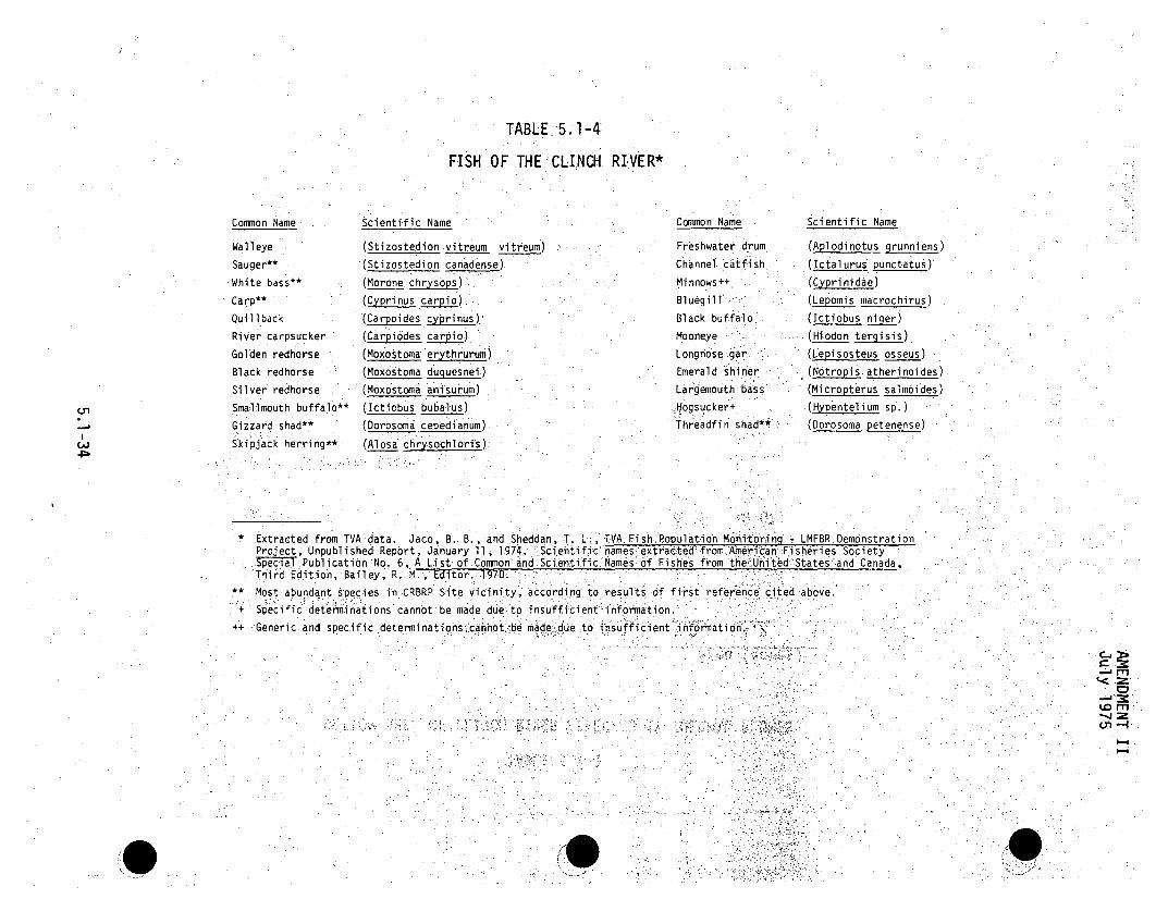
TABLE 5.1-4:
FISH OF THE CLINCH, RIVER*
Common Name:
Walleye
Sauger**
White bass**
Carp**
Quillback
River carpsucker
Golden redhorse
Black redhorse
Silver redhorse
Smallmouth buffalo**
Gizzard shad**
Skipjack herring**
Scientific Name
(Stizostedion vitreum vitreum)
(Stizostedion canadense)
(Morone chrysops "
(Cyprinus carpi•)
(Carpoides cy.rinus)
(Carpiodes carpio)
(Moxostoma: erythrurum)
(Moxostoma duquesnei)
(Moxostoma anisurum)
(Ictiobus bubalus)
(Dorosoma cepedianum).
(Alosa chrysochloris)
Common Name
Freshwater drum
Channel. catfish
Minnows++
Bluegill
Black buffalo
Mooneye
Longnose gar ,
Emerald shiner
Largemouth bass
,Hogsucker+
Threadfin shad**
Scientific Name
(Aplodin6tus grunniens)
(Ictalurus punctatus)
(Cyprinidae)
(Lepomis macrochirus)
(Ictiobus ni__r)
(Hiodon tergisis)
(Lepisosteus osseus)
.(Notropiý atherinoides)
(Micropterus salmoides)
(Hypentelium sp.)
(Dorosoma petenense),ý,
48
* .Extracted from TVA data. Jaco, B. B., and Sheddan, T. L;, TVA Fish. Populat.ion Monitoring w LMFBR Demonstration.Project, Unpubl i shed Report, JLanuary 11 i 1974 .Scientificý names extracted; from American.Fi sheries SocietySpecial Publication No. 6, A List of.:.Common And.Scienti.fic Names of ,Fishes from theU•niilted *States and Canada,Third Edition, Bailey, R. M.., Editor. 19705 ...
* Most abundant species in CRBRP Site Vicinity, according to results Of first reference cited above.+ Specific- determin'ations cannot be made due-to insuffici'ent•information.
++ Generic and specific determinationsýiicannothbe made due to insufficient infomation.
>
M
ko MJ=
Gn --i

AMENDMENT VIIAugust 1976
TABLE 5.1-5
ENUMERATION OF FISH SPECIES* COLLECTEDIN THE CLINCH RIVER - MARCH 28, 1974 - JANUARY 17, 1975
General.Category
Game
.Forage
Family Genus and Species
Centrarchidae Anmloplites rupestris
Lepomis auritus
Lepornis macrochirus
Lepomis megalotis.
Lepomis- microlophus.. cropterus punctul atus.
-- cropterus salmoides,
Pomoxis annularis
Percidae Perca flavescens
Stizostedion-'canadensePerclchthyidae Morone chrysops
Morone saxatilisAtherinldae Labidesthes sicculusClupeidae . Dorosoma cepedianum
Dorosoma petenenseCottidae Cottus.carol-inae.Cyprinidae." Hybop s storerlana
.. . Notemigonus cryso]eucas
Notropis ardens
Notropis atherinoidesPimephales notatus
Percidae Etheostoma 'blennioidesPercina caprodes
Catostomidae Carpiodes cyprinusHypentelium nigricans
Ictio5us bubalus
Moxostoma carinatun
Moxostoma duquesnel
Moxostoma erythrurumClupeidae Alosa chrysochlorisCyprinidae Cyprinus carpioHiodontidae HIodon tergisus
*Ictaluridae Ictalurus-punctatus
Sciaenidae Aplodinotus grunniens
Common Name
Rock bass
Redbreast sunfish
Bluegill
Longear. sunfish
Redear sunfish
Spotted.bass.'
Largemouth bassWhite crappie
Yellow perch
Sauger,:.White bass
*Striped bass
Brook silverside
Gizzard shad
Threadfin shad
Banded-sculpin.
Silver chubGolden-shiner
Rosefin shiner
Emerald. shiner
Bluntnose minnow
Gieenside4'dater
Logperch
Quillback carpsucker
Northern hogsucker
Smallmouth buffalo
River redhorse
Black redhorse
Golden redhorse
Skipjack herring
Carp
Mooneye
Channel catfish
Freshwater drum
TOTAL
Total No. No. CollectedCollected Electroshocking
13 13
5 4.
79 71
2,. 2
4 :4
14 14~
,20,1 193. .2
2
19 7
1 0
8 8
128 119
383 103
7 7
4 0
6 61 1
154 154
17 _171.* 1'
5 514 3
2 0
11 8
6 1
2 1
50 39
74 2
33 21
16 7
12 0
20 12
1,134 654
No. CollectedGill Netting
0
8
0
0
.0
0
17
.12
0
9.
280
0
4
"0-
0 ..
0
2
3
5
11
72
12
9
12
8
480
1,7
Rough
*Classification islbased on Bailey. R. M., et al,,A List of Common and Scientific Namesof Fishes from the United States andCanada,..third edition. American Fisheries Society Special Publication No. 6, Washington, 1970.
5.1-35

TABLE 5.1-6
ACCLIMATION AND LETHAL TEMPERATURES OF. SELECTED CLEINCH-RIVER FISH
AcclimationTemperature• (F:1I C)Genus and Species
Lepomis macrochirus
Cyprinus carpio
Ictalurus punctatus
Common Name
Bl uegil l 45525970767986•
(7.12)(11.1)
(15.0)(21. 1)(?24.41)(26.1)(30.0)
LetthalTemperature R
OF . . (... ).N
89. (31:.7)95 (35.0)
*87.8 (`31•. 0)101 .5 (38.6)97-99 (,36.1-37.2)103 (39-. 4)932 (34. 0)87.8-93.2 .(31.0-34.0)96.3 (35.7)
eferenceumber
26262726262827292926263030
Carp 68 (20.0)78.8 (26.0)U,
-a
CA.)
0~~Channel catfish
5 271. 6.,: 86
(7.2)
(30.).
919595
~>9,5.-
(32..8).(35.0'),
(.>35. 0)
Dorosoma cepedianum
Micropterus salmoides.
Gizzard shad
Largemouth bass-
77 (25.0).J77 (2t5.b0)
86 (3b0.4)
45 (7. 2)52 l (11.)'68 (,200)77. (25.0)
.77 "(2?5.0;.)•
'80 (26.7)6 i(30:0.1)1
94 (34. 3)"*~95 ý(35.,0)ý.96.6& (35.9)
.87 (30. 61)ý95 (35:)..90.5 (325). ""99_ -(37.2)94.1 (3.5)100-b102 (37. 8-38 .9)
975(36.4)
312731.27
2626312831.2831
*Lethal temperature refers to the temperature at Whi•ch mortality: was. frs't observed. !..Other lethaltemperatures are reported as LD50 - tempe a •• whih ihs .ethal. to .50-' percent of. a :'test group of.organisms. Duration of temperature trifal S::for LD.50 va`luesvariedrom10-43hours .
*. .. 0:= ; : • --i; --. .:. i ." ,. ' . . -

AMENDMENT IIJuly 1975
TABLE 5.1-7
PREFERRED TEMPERATURES OF SELECTED CLINCH RIVER FISH
AcclimationTemperature.0F (0C)
Mean PreferredTemperature
'OF (0-0ReferenceNumber.Common Name
Carp 50
59
68
77
•86
95
Channel catfish
Bluegill
42.8
48.2
53.6
64.4
75. 2
86.0
42.8
48.2
53.6
64.6
7•5.2
86.0
(10)(15)
(20)
(25)
(30)
(3.5)
(6)
(9)*
(12)
(18)
(24)
(30)
(6)
(9)(12)
(18)
(24)
(30)
61. 3I75.9
78.8
87.8
87.1,
90.1
66.00
68 ..7
67.8
73.2
84.986.9
65.7
67.3
75.0
84.6
88.2
89.1
( 116.3):0
(31.0)
(30-6)
(32.3)
(18A9)
(20.4)
.(22.9),.
(219.4)
(30.5)
(18.7)
(19.6)
(23.9)
(29..2)
(31.2)
(31.7)
32.:
33.
33
5.1-37

TABLE 5.1-8
SPAWNING TEMPERATURES OF SELECTED CLINCH RIVER FISH
Genus and Species Common Name Spawning Temperatures Reference Number
Lepomis macrochirus
Cyprinus carpio
Ictalurus punctatus
Dorosoma cepedianum
Micropterus salmoides
Percina caprodes
Ictiobus bubalus
Dorosoma petenense
Stizostedian canadense
Bluegill
Carp
Channel catfish
Gizzard.shad..
Largemouth bass
L ogperch
Smallmouth buffalo
Threadfin shad
Sauger
800 F (26.7 0 C.)•
60-;680 F (15.6 -20 0C)59qF (15 0 C)
70-85OF (21.1 - 29.4 0 C)
73.4 -84.2 0 F (23'- 29 0 C)ý
60.7 0 F (15.9 0C)
71.6, - 80.6 0F (22 - 270C)
57.2 - 69.89F (14- 210C)
62.6OF (170 C)
53-- 58 0 F (12- 174;5 0 C)
34
3536
35
37
36
36
38
39
8a
19
9
0)>I~n4P
'.0
9 1(9

:- .,TABLE .5.1-9
BENTHIC MACRO INVERTEBRATE SPECIES*:: COLLECTED.INI THE.CLINCH ,RIVER BY :ARTIFICIAL SUBSTRATES - JUNE 73, 1974
THROUGH MAY 28, 19715.
Phylum
Annelida
Class
01 igo-ae. a
Fami ly.
Lunmb r :cul ida:
Naididae
-Gen us •-and 'Species.
Lumbriculus s p.
'Naidium sp" .
P-,ri st in a sp;,Stylaria sp.
L imnodrilus sp..
0 Tubificidae
Arthropoda
.Crustacea
(Order . Copepoda)
(Suborder -Calanoida)
Di aptohi dae
Diaptomus sp.(Orde - C Iadocera)
Daphnidae
Daphnia sp.Sididae
Sida sp.
(Continued)
5.1-39

TABLE 5.1 c (Contlnued) i
Phylum Class SFamily. . 'Genus and peis,
Arthropoda
Insecta
(Order--.,. Diptera)" Ceratopogonidae
Pal pomy•ia I sp-
Chi ronpomidae
Chironomus. sp "".
Corynoneura sp..
Cricotopus, sp.
Cryptochi ronos.SP..
i~c roten dipes cf. neomodestU s
Dicrotendipes cf. nervosus,
DiCrotendipes p.ý
DiplTocl adtiuss spi.
Endo'chironomus sp.
Eukiefferiella .sp.
Glyiitotendipes sp.
.. leterotrissocladius sp.
Labrundinia sp.
Larsia sp.
Microcricotopus sp.
Micropsectra sp.
Orthocl adius sp.
Parachi ronomus sp.
Parametriocnemus sp.
Pentaneura sp.
Phaenopsectra sp.
(Continued)
5.1-40
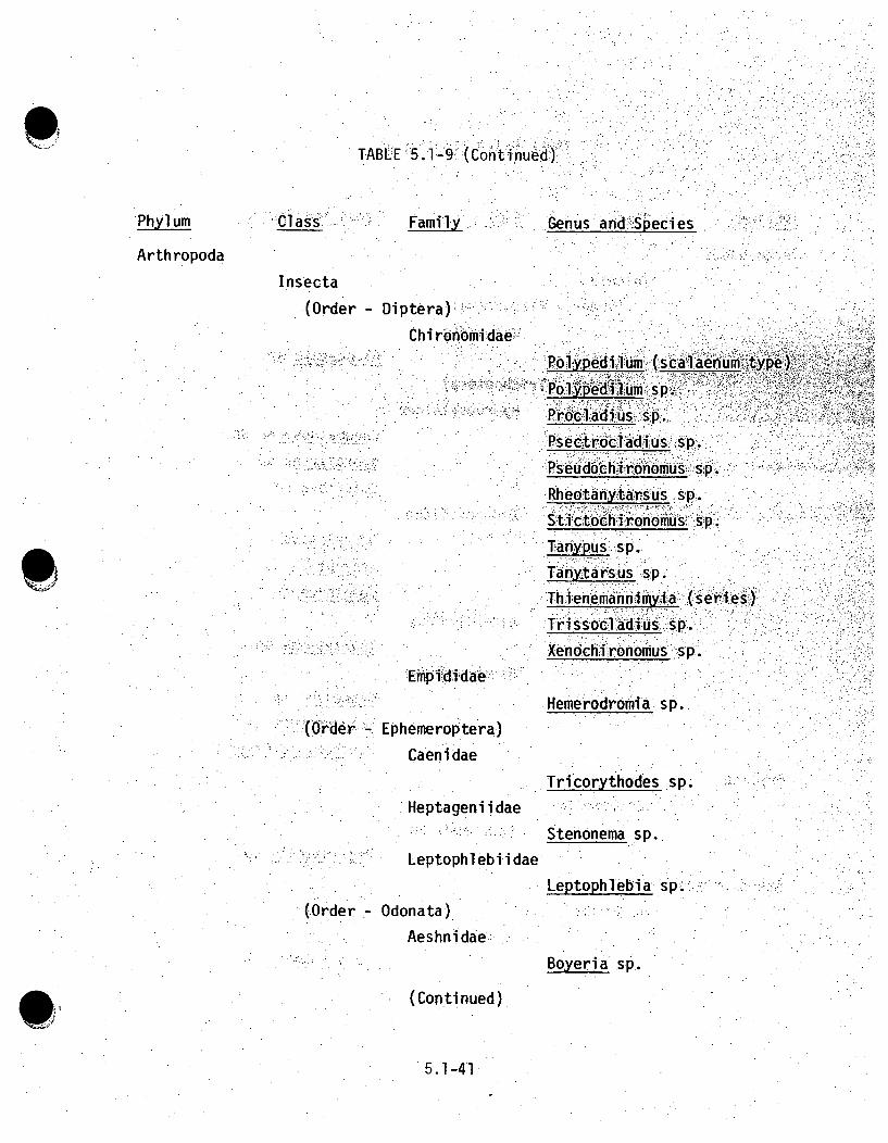
TABLE< 5. 1:4-9 (Cont i'nued)
Phylum Class. Family Genus and :Speci es
Arth ropoda
Insecta
(Order- Diptera)
E'I I
'Polypedilumý (scalaenu½ :type)
ýPolý.Uý6dl:m s p."
Procladiusýý,sp.'P.sectrocl:a~difus p.
Rheotafiytarsuds so"..titchi ronomus 'sp.,
Tanypus sp.
Tanytarsus s'p..'Thfenemannimyl~ai (series)
Tris~so~cladi us, :sp.
Xe~nochi~ronomus -sp.•1".: . 2 J
rwmp iuldiaeHemerodromia sp.
(Order Ephemeroptera)
Caenidae
Tricorythodes sp.
Heptageniidae
Leptophlebiidae
Stenonema sp.
Leptophlebia sp'..."
(Order - Odonata)
Aeshnidae
Boyeria sp..
(Continued)
5.1-41

TABLE 5.1-9 (cOntinued)"( n, iT n. d):. , .
Phylum Class Family Genus and,.Species
Arthropoda
Insecta
(Order -- Plecoptera)
Capn i.1dae,.:
Al 1o6capn ia s p.(O.rder, - Trichoptera)
Hydropsychidae
Cheumatopsyche sp..
Hydropsyche sp.
Smi cridea sp.Hydroptilidae
AAgrayl ea sp.
Hydropti a sp.9Oxyethira sp. .......
Leptoceridae
Athripsodes sp.Psychomyji i dae
Cyrnellus sp.
Polycentropus sp.
Psychomyiid Genus A
Bryozoa
Ectoprocta
Lophopodi dae
Pectinatella sp.Coelenterata.
Hydrozoa
Clavidae
Cordylophora sp.
(Continued)
5.1-42

TABLE 5.1-9 (Continued)
Phylum Class Family Genus and•Species
Coel enterata
Hydrozoa
Hydridae
:Hydra sp.Mol 1 usca
Gastropoda .
Ancylriidae
Ferrissi a ,sp.Planorbidae
Gyraulus. sýp.Pelecypoda ......
Corbicul idae
Corbic ula s . "Nematoda
Secernentea
Diplogasteridae
Diplogaster sp.
Nemertea
Prostoma rubrum
Platyhelminthes
Turbellarta
Planariidae
Curtisia sp..
Phagocata sp.
*Classi fi cati on of.macroinvertebrates i s based. primarily on Ward, H. B.and Whipple, G. C.., Fresh-Water Biology, second edition,'John Wiley &Sons, Inc., New York, 1959.
5.1-43

TABLE 5.1-10
RELATIVE ABUNDANCE OF BENTHIC MACROINVERTEBRATE SPECIES COLLECTED BY DREDGING ONWEACH
SAMPLING TRIP AT THE CLINCH RIVER FROMMARCH 25, 1974 THROUGH APRIL 16, 1975
Relative-Abundancej%
Species
ANNELIDA
Aeolosoma sp.
Branchiura sp.
Chaetogaster sp.
Limnodrilus sp.
Lumbriculus sp.
Naldium sp.
Nais sp.Tubifex Sp.
ARTHROPODA.Allocapnia sp.
Athrlpsodes sp.
Bizzia sp.
Calopsectra sp.
Cfieumatopsyche sp.Chrnmin•in sD..
Chironoius sp.
Cladotanytarsus sp.
Corynoneura sp.Cricotogus sp.
Cryptochirononus sp.
Cyrnellus "sp.Dicrotendipes sp.
Dubiýaphia sp.
Eýiococladius sp.
Eukiefferiella sp.Glyptotendipes sp.
Harnischia sp.
r~arch, Zband
March 29
1.0
2.0
41.6
Jun I . UAugust' 26iandJune 1 June 26 July 25 A' st2
September 25 November 21 January 14 April 16
0.1
8.5
8.4
10ý.9
27.?
0.5
13.8
.7.8
1.4
4.9
0.7
31.3
0.7
0.2
0.1
11;.6
0.2
4.8
0.7
19.6
0.4
1.2
1.0
*1.0
0.8
0.7
0.5
1 V.1
1.0
4.3
9.2
0.5
1.8
3.75.5
2.R
0.3
16,
3.2
0.2
0.50.2
0.9
0.70.9
1.2
0.3
0.31.0
2.4~
0.1
~0.5
0.1
0.1
0.7
0.5
0.3
1.8
5.01
0.3
0.7
0.2
1.3
8.9
0.20.6
1.4
0.1
0.3
0.1
.0.9
3.5
0.2
0.10.1l

TABLE 5.1-10 (Continued)
Relative Abundance (M)March 25 August I26
and andSpgecies March 29 June 1 June 26 July 25 August 28 September 25 November 21 January 14 April 16
ARTHROPODA (Continued)
Heterotrissocladius sp. - ... ........ ..... 0.2Hexaqenia sp. f1.0 -- 242 1.4 0.6 0.5 2.5 4.3 1.4Hya ella s ... ...... 0.2 ....."Hydropt la sp. - ..... 0.2 0.1Isotomurus sp. •- . .. ..... .. ... 0.2 ....Larsia sp.,. -0.1 ... ...... 0.1 0.2 --
Lirceus spD. ..... ....... 0 1 .0...(.71 Microcricotopus blcolor 1.0 .. ..
Microcricotopus sp. -- 2.0 1 1 2.3 0.3.. 0.1 --
Micropsectra sp. -- ... ..... 0 2 .. 0.2SMicrotendipes sp. -- 0.1 0.5 - . ... 03 0.5 --
Mystacides sp. -- 0.1 .....
Natarsia sp. .... ..... - 0.2
Neumania sp. .. .0.1Nilothauma sp. - 0.1 --
Orthocladius sp. -- 0.7 0.7 0.1yehir spa SD. -0.2 --
Pal•pogyia sp. -. 1.0 0.7Parachironomus sP. -. 01 2.1 0.2Paralauterborniella sp. 1.0 0.07 0.2Paratanytarsus sp. 1.0. .
Paratendipes sp. 2.0 0;6 -- 0.4Pentaneura sp. 7- ... 0.2 --
Phenopsectra SD. - 0.5,Polypedilum (scalaenum type) 17.8 . 4. 1 4.5 -- 6.1Polypedilum sD. -- 0.3 1.6 0,5- 0.2 0.3 3.9 0.2
Procladius sp. 0- .. 02 -- --

TABLE 5.1-10 (Continued)
Relative Abundance ()
U,n
ý4-
Species
ARTHROPODA (Continued)
Psectrocladius sp.
Pseudochironomus sP.
Psychomyiid Genus A
Rheotanytarsus sD.
Sialls SD.
Simulium sp.
Stenochironomus sp.
Stenonema, sp.
Stictochironomus sp.
Synclita sp.-Tanypus sp.Tanytarsus sp.
Tetragoneuria sp.Thiennemannimyvla sp.
Tribelos sp..Xenochironomus (Anceus group)
Xenochironomus sp.
COELENTERATA
Cordylophora sp.
Hydra Sp.
March Z5and
March 29
1.0
1. 0
AuguSt " Z.. IandJune 1 June 26 July25 Au~u~st 28
0.1
0.7
5.6
0.5
1.1
1.6
22
0.9
1.8
41
0.9
0,0.3
0.3
0.3
3.6
0.6
1.9
0.5:
0.5
0.5
0.1I
3.0
0.20.4
0.1
0.10.1
0.4
4.0
1.0
2.1
0.2
0.1
0.2
0.1
0.2
0.8
0.6
0.6
06
0.6
0.1
0.1
0.2
September.25 November. 21 January 14 April16
.-55.9 -- 0.5 31.41 31.6 3.7
MOLLUSCA
Corbicula sp.
quadrula sp.
Ferrissia sp.
Gyraulus sp.
26.7 14.:8 22 8 44.5
0.5
48.5 56.8
0.9
64.0,
0.3
42.1 65.3
,0.1
0

0
TABLE 5.1-10 (Continued)
March Z5and
Species March 29
Relative AbundanceAugust 26
and.y 25. August 28
AL
September 25 November 21 January 14June 1 June 26 Jul April 16.NEMATODA
Diplogaster sp.
NEMERTEA
'Prostoma rubrum
PLATYHELMINTHES
Curtisla. sp.
Ougesia sp.
Phagocata sp.
Number of organisms
-- .0.3 -- 0.9 0.6 0.5 0.1
1.0
-0.1
1.2 0.6
0.2 0.1
1.0
0.1
0.6
U,
101 744 184 218 309 428 914 1,218 1,247
*Colonial organisms present but not enumerated, so relative abundance -could not be. determined.

AMENDMENT IIJuly 1975
*rTABLE 5.1-11
BOTTOM AREA OF CLINCH RIVER AFFECTED BY SCOURING*
Area
.Mixing Conditions (ft2) (acres)
Typical Cases
Winter
Summer
71
85,
<0.ý01i
<O Ol, . S.'
Hypothetical Extreme Cases'
Winter
Summer.
5954
<0.1'
*Based on actual scouring of ,model flume bot.tomn matrial..Areas- computed assuming elli'ptical-shaped scourb hle..
9 .t, ' .
5.1-48

n
TABLE 5.1-12
FISH EGGS AND LARVAE.- STATIONARY NETTING*ENUMERATION PER FIELD TRIP - CLINCH RIVER;.
COLLECTED JUNE 17 - AUGUST 29, 1974
.Collection Date . June 17
Counted No.lm-
June 25-26No. - 3
Counted .No./.
July 12.No.
Counted N1
July 25No.
Counted. No.1w3
August 9No.-
'Counted.
August 29.
Counted No.1mEGGS
Fertilized 3 '.0.10 7 • <0.02 -I. : 0.01 1 .; < 0.01Unfertilized
LARVAE.
1 <0.01
13 L0.03.
IJ4==
*Samples were collected one foot above-the bottom using a 1,000 micron mesh,, one-hal.f meter diameter planktonnet with attached inside and outsideflow meters. For each sample the net• was placed in a stationary.position facing u-pstream for'ten'•minutes.:
(Continued,):
B -
,"4 ,t-

TABLE 5.1-12 (Continued)
FISH EGGS AND LARVAE - STATIONARY NETTING*
ENUMERATION - CLINCH RIVER
COLLECTED MARCH 28 - JUNE 2, 1974
Collection Date
EGGS
Fertilized
Unferti li zed
March 28No.
Counted No./m 3
April 18No.
Counted No./m.
May 1No.
Counted No./m 3
May 16No.
Counted No./m 3
June 2No.
Counted No./m3
1 <0.011 <0.01
1 0.01
5 0.02 106 0.481. <0.01
169 0.48
(./0
LARVAE
*Samples were collected one foot above thenet with attached inside and outside flowfacing upstream for 10 minutes.
bottom using:a O1 000 micron mesh, one-half meter diameter planktonmeters. For each sample the net was ýplaced *in a stationary position "

AMENDMENT XVIOCTOBER 1982
TABLE 5.1-13
OLD AND NEW DESIGN PARAMETERS FOR THE DO.LIING.:SYSTFE4
ParamtrOld gNt
Total No. of Towers
Total No. of Cells
Tower Size
Heat Rejection
Circulating Water
Flow Pate
Appra•ch to Wet Bulb
Range
Total Air Flow:
No. of Concentrations
Total •Dissdlved
Blowd (Annual Avg)
Drift (Annual Avg)
Evaporation (Annual Avg)
Makeup .(Annual Avg)
110
400 ft x.60 ft x 55 ft
2.650. X 109,.Btu/hr-
2121,0010gn1 ̀6
17.0 x 106 ft 3 /fnmn2.5
375:,mg/l27800 g
4240 gpm
7050 gp.n
2
10
247 ft x 76 ft x 41 ft
2.26 x 1o9 Btu/hr
212,200 gpin
11OF
21.340 F
16. x 106 -ft3/rni~n
2. 5;
'n2 61n
.2•:, 3'4,F-m :
106 '.x
3623 g
6 Willp
1.3
1131 ¼ !•i•::i:ji:ii !~•
S 116
0S;5.1-51

AMENDMENT I:IJ u ly 1975
TABLE 5. .- -.. .
MEAN LENGTH OF VISIBLE PLUME*-FOR CRBRP COOLING TOWER**
Stability Class
A
B
C,
D
EF
100
1.6,
3.:4
5.1
6.0
8.310.03
Relative Humidity:.:.(percent)
95 85
0.6 04
1.1 0.8
1.8 .: 1..3
3.7 2.9
5.5 5.0
8.0 6.9
75,
0.2
0.9
2.2
4 .1
6. 0)>
*PIume l ength in mil es
**From Table lOlIA-5
5.1-52

AMENDMENT IIJuly 1975
TABLE 5.1-15
GROUND FOG POTENTIAL FOR CRBRP COOLMING TOWER
Horizontal VisibilityThrough Fog
(miles)Ground Fog(hrs/yr)*
146<1/2
<1:/4
<I/I0
146
100
*Ground fog values from Table IO.1A-7
5.1 -53

TABLE 5.1-16
GROUND FOG FOR POINTS OF INTEREST INWCRBRP SITE .VICINITY
DistanceFromCRBRP
(miles)
DirectionFromCRBRP
HorizontalV is i'b6i .ityThrOugh Fog
(miles),
NaturallyOccurringGround Fog
(occurrences/yr)*
PredictedFoggingDue to
Cooling Tower(hrs/yr)**Point of Interest
Interstate 40 atCaney Creek
Gallaher Bridge
ORNL
1.1 SSE
1 .6 NW
0.,1
<1/2
<1/4<1/10.
<1/2
<1/4
<1/10
<1/4
<5/8<5/!16
0.1
0.10
0.8
0.8
0.7
.0 . ...
0.1
<O.1
4.5 NE
Melton Hill Dam 4.5
9.0
-E .11.9106
34.Oak Ridge City Office NE <1/4
0,-,*Ground fog values from Tables 2.6"0.and2.6--l.
**Ground fog values from Table lO.A-12,:l:
. , •',: -,. •,•,:

TABLE 5.1-17
DRIFT DEPOSITION FOR CRBRP COOLING TOWER*
Typical Drift Deposit'ion(lb/acre-month)
Direction from Site°N NNE NE ENEi E ESE,. SE SSE
34 84 43 59,-. 29 29. 13 6
Directi on from S;itte#6S SSW SW WSW W: WNW NW NNW
7 23(J1
c-TIc-Ti
Typical Drift Deposition(lb/acre-month)
26 89 42. 39 10 1`3
*Based. on Table :lO.lA-l16 With assumption of 375(equivalent to 150 6ng/,l TDS in Clinch Riv"r)
c irculati'ncooiing watermg/i TDS in
II
I
.1
0
~.om(.T1(
'-4

AMENDMENT IIJuly 1975
O~
SRA
SURFACE
I 2F*
- --- W4TERLEVEL Ar LOW.POOL ELEVAfl"i'73.5 FEET1M hLl.flowvelocity -
pool elevation-
r"
1.39 fps(736 ft MSL0.87 fps)*
DISCHARGE JET,
f l ow c 5 f5 csvel-1oc ity 156.9 fpstempý. diff. w 31.0OF0
*Prototype velocity based on hydraulic modelvelocity. Reflects physical limitations ofthe flume.
-. - . .t
* --- S. . I.'--------------------
BOTTOM:
12F% 0.9F
DISCHARGE POINT O0 100 2D6
SCALE OF FEET
- - , WATER LEVEL AT LOW-POOL ..EVATION (7559 FEE MSL).
Figure 5.1-1 TYPICAL CASE-WINTER (based on IowaInstitute physical model study)
5.1-56

AMENDMENT IIJuly 19_75
• ... ' . 7
I.- - .----- - S
- 5--- ..a.SURFACE
0.9 F°0', •..7 FO ' .!. . " .:.".?S
.... .. P O N 0 _ . . ... 20
RI VIE R"'
flow . 4777 cfsveloci;ty .. _ 0.63 fps•,(0.50 fps)*poo• elevation =741 ft I 7Sl
.*Prototype -velocityhbased on hydraulic model,velOc ity. Reflects physical 1 imitntiosof the • flume.
-.DISIAiRGE JET .
flopw 7f. .22 cfsvelocity -.. 20-~6 pstemp. diff. 2.F
BOTTOM
,06.7 F-
DISCHARGE POINT tO 100 200
SCALE OF FEET
WATER LEVEL AT LOW. POO .L ELEVATION,ý(7WFEETMSLX
Figure 5.1-2 TYPICAL CASE-SUMMER (based on Iowa Institutephysical model study)
5.1-517

AMENDMENT IIJuly 1975
.!
0;9 P
---------------
I - - : - ----- -- -------SURFACE
DICARE POINT
______ --- ATER:LEVEL AT LOW POOL ELEVATION (735 FEET. MSL).
flow =0Velocity ,a n (0.17 f ps)*.p ool el~evatio6n;'= '735 ft MSL.temper-ature: =. 33F
-- EXTRAPOLATION OF PLUME W IDTH GROWTH ;ASED7ON PHYSICALMODEL DATA.
. TI MATIONOF PLUMEDISTORATION DUE TO INTERACTION WITHOPPOSITE SHORE.,
DISCHARGE JET
flnw*Prototype velocity based -on hydrauli•c1 1,model. velocityvelocity. Ref~lects necessity of manintalining temp. diffia flume crossflow to permit the attainment ofSteady-state cond.it~ions,.<.,',,,
- 6.26 cfs=17.93 fps46 .8F 0 .
I-.
S- S-------------------
BOTTOM
2.3 F0
DISCHARGE POINT O." 160: 200
SCALE OF FEET
---- WATER LEVEL AT LOW POOL ELEVATION (735 FEET MSU
Figure 5.1-3 HYPOTHETICAL WORST CASE-WINTER (based on IowaInstitute physical model study)
5. 1-58

AMENDMENT IIJuly 1975
S URFA-
.SURFACE
0.7•--A
DISCHARGE POINT
WATER "LEV I i LOW POOL ELEVATION (735" ET MSL)"RIVER
flowvelocitypool elevationtemperature
,=
0o.(017 SfpS)*739ft MSL780,F
DISCHARGE!'J ET,,
fl ow m7. 3lý f Svelroci~ty r- 20, 94jipstemp. diff. * 11 .6F°
*Prototype velocity based on hydraulic modelvelocity. Reflects necessity of maintaininga flume crossflTow to permit the `attainmentof steadywstate conditions.
.. . ".
BOTTOM ,, + -- '
0.5 F0
0o+.9F,
DISCHARGE POINTo 100 200
SCALE OF FEET
WATER LEVEL AT LOW POOL ELEVATION (735 FEET MSL).
Figure 5.1-4 HYPOTHETICAL WORST CASE-SUMMER (based on IowaInstitute physical model study)
5.1-59

AMENDMENT VIIAugust 1976
I•.i.•••
PROPOSEDDISCHARGE,.
L ý7
,.PROPOSEDINTAKE
CRM I(
-- TRANSITION ZONE CANEY
0Figure 5.1-5 SURFACE ISOTHERMS FOR WINTER EXTENDED NO FLOW CASE
5.1-60

AMENDMENT VIIAugust 1976
+ CRM 18//
PROPOSEDINTAKE.....
IN A K . ... ..... .
PROPOSEDDISCHARGE
7
C(RM16\
-- TRANSITION :ZONE
CANEY CREEK
Figure 5.1-6 SURFACE ISOTHERMS FOR SUMMER EXTENDED NO FLOW CASE
5.1-61

100
o 80-LL
wIrý 70
0.
w50
:40
7
- -
wo - WOO
0,
0Pi
- AVERAGE 'MONTHLY TEMPERATURES OF'CLINCH R.VER" AT MELTON. HILLL DAM
MAXIMUM BLQWDOWN. TEMPERATUREFRO•. COOLING TOWERS UNDER FULLPOWER CONDITION
30
20
I I14
I I I 'I I ~ I I -I: I/!•
J F M A M J, J. A.MONTHS!
S .0 ~N D
Flgure 5.1-1 CLINCH,Figre5.17 LI CHRIVER TEMPERATURES ANýD 'BLQWDOWN TEMPERATURES

AMENDMENT IIJuly 1975
B-B
6
Lr • • eAA
10 6 4'
A A
t6
A-A
WINTER- TYPICAL
B-B
• •. n
L
SUMMER -TYPICAL
A
A-A
IiWINTER- WORST SUMMER- WORST
Figure 5.1-8 AREAS OF BOTTOM SCOURING (based on Iowa institutephysical model study)
5.1-63

i
p I•rI~
0•

r ~AMENDMENT X IJIIAPRIL 1982
5.2 RADIOLOGICAL IMPACT FROM ROUTINE OPERATION
This section includes both :,the Radiological impact onebiota other
than man and the* Radiological impact. on man which had previously
been discussed-separately in Sections 5.2,and 5.3, respectively,.,The radiological .impact from routine; releases, previously
discussed in Section 144.4, is. also presented .in..this section.
5.2.1 EXPOSUR HW S
Extensive waste;. trea&tment- sytem included, in "the CRBR-P,- design.~
will lassuwre t-hat ",th eamqunts. .... ri*oaci'ity-released to the.
environs during normal -operation of t I ,plant -,,will b-eas low, as',reasonably achievable, Potential doses to man, and biota othe,
than man, from both external and int'e6r1nal source-have been
estimated for routine releases.and ;a-r-e prpesen ted iFn this Section.-,
5.2.1.1 EXPOSURE PATHWAYS FOR ORGANISMS .OTHER THAN, MAN
13These pathways originate with either '.liquid or ous effluent
release and result in doses from external and internal routes.External pathways include submersion in air, .and•,water and
exposure to soil ,and.sediment. Internal-:exposure results from,
the ingestion of food or water and the inhalation ,of air. The.
primary exposure pathways for organisms.other than.man .are shown
in Figure 5.2-1.
Doses to aquatic organisms .from radionuclidesdeposited
internally are generally of greater magnitudel than the doses, theyreceive -from external sources of radiation., .Radionuclides are
incorporated into tissues of aquatic organisms.either through the
assimilation of food or through the direct penetration of.dermal
tissue. External radiation exposures to aquatic organisms aredue primarily to radioactivity in solution or associated with
suspended particulates. Benthos receive an additional external
5.2-1

AMENDMENT XVJULY 1982
dose from radionuclides adsorbed onto or concentrated in the
benthic substrate.
Internal doses to terrestrial animals are generally of greater
magnitude than the doses they receive from external, sources.
These internal exposures result primarily from radionuclidesingested with food and water and from the inhalation of airborne
radioactivity. Terrestrial organisms and plants receive an.external exposure from submersion in air containing .
concentrations of radionuclides. Radionuclide concentrations in
soil and vegetation, due to deposition from the &a mosph ere andto
radionuclides entering through the water supply- are minor
contributors -to the external dose.` An addi tional,:external
exposure is attributable to direct radiation from radioactivity 13
contained within the plant. .
5.2.1.2 EXPOSURE PATHWAYS TO MAN
The most significant exposure pathways to man are diagrammed in 9.Figure 5.2-2.
5.2.1.2.1 LIQUID EFFLUENTS
Radiation exposures from liquid effluents generally arise-from
recreational activities or dietary intake. External exposures
occur as a result of swimming, boating, and fishing in waters
containing radioactivity; and persons involved in shorelineactivities may be exposed from radionuclides accumulated in
sediment. These external doses are proportional to radionuclide 115concentrations in water and sediment. Internal doses result from
the ingestion of water, the consumption of fish that contain
radionuclides, and ingestion of waterfowl which feed on aquatic
organisms. Swimmers receive an internal dose from tritium
accumulated in the body as a result of exchange processes.
5.2-2
5.2.1.3 ENDANGERED OR THREATENED SPECIES
Unusual vegetation present within 10 miles of the Site which may be exposedto radioactivity released from the CRBRP includes a nearly pure stand ofsassafras near the DOSAR (Dosimetry Application Research Facility) reactorat X-lO and a stand of eastern red cedar near the University of TennesseeAgricultural Farm. Also within 10 miles are 40 acres of plants used for bio-logical research located on Jones Island and the University of TennesseeArboretuum
5.2-2a

I!

AMENDMENT XlIIAPRIL; 1982:? .
5.2.1.2.2 GASEOUS EFFLUENTS
Individuals are exposed to gaseous effluents via the followingpathways: (1) external radiation.from radioactivity in the airand on the ground; .(2) inhalation; (3) ingestion of beef,vegetables, and milk; and (4) tritium transpiration. No otheradditional exposure pathway has been identified which would. ..contribute ten percent or.. more ýto ei-1her individpualo opulation
doses'.
External air exposures are evaluated at points tof potential
maximum exposure (i.e., points at the site boundary and, sectr o
peaks given in Table 5.2-1). 'ExteOrnal. sk-in exposure, 5otal bodyexposure and the ,internal -dosefrom trittiumare calcu.ated at thesite boundary and sector peak locations.,
The contribution -to the -internal dose -,f rom tit ium includesinhal ation, milk ingestion. .(with. cow, assýumed •to obta-n•in 100% offeed from pasture), beef ingestion and vegetable :ingestion.
It is assumed that enough fresh vegetables are produced at each
residence to provide for annual consumption by all members&of•.I
that household. Data on annual meat production are not availablefor a 50-mile radius from the plant center. It is .assumed thatenough milk and meat is produced in each sector annulus to supplythe needs of that region. The CRBRP population distribution isgiven in Table 5.2-2.
13
5.2-3

AMENDMENT XVJULY 1982
5.2.1.2.3 DIRECT RADIATION
The shielding design criteria for the CRBRP specifies that,
during normal operation, the dose rate at the surface of ,that
part of the containment vessel which is above grade will be no
more than 0.2 mrem/hr. An estimated 90 percent of .the
containment building that is above grade is shielded from the
Site boundary by buildings and is enclosed by the Reactor.
Confinement Structure consisting of four feet of concrete.
Radwaste tanks are :housed in-buildings protected'dwith' concrete ' 115walls. In addition, sodium storage tanks, .the Radioactive, Argon 13
Processing System (RAPS) and the Cell Atmosphere Processing
System (CAPS) are located below grade.'
As described in Section 3.2, the probabil-ity of radioactive,sodium leaking from the primary to the intermediate loop of the
Heat Transport System is very small.
Because of the'above design and shielding:-characteristics.,v' direct
radiation doses -at the site boundary are;calculated to be much
less than 1% of natural background. Theref-ore, th'ese doses :have
not been included in the summary tables.
5.2.2 RADIOACTIVITY IN THE ENVIRONMENT
5.2.2.1 LIQUID EFFLUENTS
Estimated average annual quantities of radionuclides released in
liquid effluents are listed in Section 3.5. The assumption ,is
made that aquatic biota are exposed to radionuclide
concentrations in the river near the liquid effluent discharge
port. These concentrations are calculated assuming one part of
liquid effluent is diluted by nineteen equal parts of river
water. The average blowdown rate from the plant is assumed to be
2,306 gallons per minute. To calculate the exposure to man, the
5.2-4

AMENDMENT-X I IIAPRIL 1982
assumption is made that, the. liqUiid effluents. from the plant, aremixed with 1/5 of .the.-river flow in :the.sec ti-onr of the Clinch,River between the CRBRP anid -th e: ClinchRibver mouth. Water from:
the Clinch River is assumed 'to. be mixed with.i/5.o the TennesseeRiver flow. for a 10 mile -reach of -the:Tennessee River starting atthe mouth of the Clinch River, Downstream from this section ofthe river, the efifluent. is -assum6ed to be mixed -into the entireTennessee River flow. Dilution of the radionuclide.
concentrations in the..Clinch and Te nnessee RI.,veriV -ex's: i-s. calculatedusing mean :flow data. (se eTa:b 5.2-3). The resulting ave.rage,.
annual: concent rations of radionuclides which would be contributedby: the CRBRP pl anRt :at: lhe Clinch and Tennessee
Rivers are listed %.in. Table 5 -.2-;4. For compa.rison purposes,
average annual radionucliAde"6 concent•rat•ons, 9 in thfie plant ef.fluent
prior to mixing; in the Clinch River are also listed-.
As discussed in Sectibon 2.5, the: area of.,the Clinkch.River "13encompassing the point of the CRBRP discharge acts as a
groundwater sink. "Therefore. exposure to liquid containments.;
through: seepage into: aquifers is highly 'unlikebly.,
The assumptions and equations used to calculate the cumulative:.buildup of radionuclides in sediment are listed in NRC RegulatoryGuide 1.109.
5.2.2.2 GASEOUS EFFLUENTS
Calculations of atmospheric transport, dispersion, and ground.deposition are based on the straight-line airflow model discussedin NRC Regulatory-Guide 1.111 (Revision 1, July 1977). Becauseof the small magnitude-of doses predicted from routine operationof the facility, it was not considered appropriate to use a.moresophisticated model. Therefore terrain correction factors asapplied in Section 2.6 were not used. in this assessment. Allreleases are assumed to be continuous.
5.2-5

AMENDMENTAXIIIAPRIL 19821z
the .. •t.a 6,t
All gaseous .releases.. from the pan are trated as,,ground&-level.releases,. The..joint frequency distr i-bution (JFD) used :in theassessment may. be foundin Section".2.6-.2.2 (Tables 2.6-5 through."
.2 .6-11).
Air concentrations.and deposition rates were. calculatedconsidering: radioactive decay and buildup during transit. Plumedepletion was calculated-.using -the figures provided in Regulatory
Guide 1,111'
Estimates of normal ized .concentration (X/Q) and normalized
deposition rates (D/Q) :for .releases from the plant• at pointswhere potential dose pathway-s exist are listed in Tables. 55.-2-1and 5.2-6.
5.2.3 DOSE RATE ESTIMATES FOR BIOTA OTHER ITHANMAN
Analyses for the following representative organisms anBdpathways
are ,performed to determine the .potential .radiological- .impact:: ofthe CRBRP.
U.:
Aquatic Organisms - externpl
- external
- internal
Terrestrial
Vertebrates - external
- external
- external
- internal
exposure from water
exposure from sediment
exposure
exposure from airexposure from ground or water
exposure from direct radiation
exposure from ingestion or inhalation
exposure from air
exposure from ground
exposure from direct radiation
Plants - external
- external
- external 9

AMENDMENT XVIOCTOBER 1982
Because of the complexity of biological functions and theinterrelationships betweeD organisms and their-environment,simplified dose models have been developed to predict dosesresulting from the more siýriificant exposure pathways.Conservative assumptions are chosen because these, models cannot.predict the detailed variainces of a system and because theresults of an analysis cannot be applied equally .to all membersof a population. A brief outline of the models, methbods of.calculation, and basic'. z:isF.t.n'ptioi-s is provided', in this- sectio-nh:..,Dose estimates are base d on the average annua.l-act..iviteoradionuclides expected to be r~eleas•ed during norm-alt r- O.."ope•ration ofthe, C-RBRP (Section 3.5) .
5•.2.3.1 LIQUID EFFLUENTS
The assumption is made that aqua-tic biota. are exp6sed: tor~adionuclide con cen traIti.o .ns in the . r"i'ver near t.e••iquid eff:lentdischarge port. Dilution in the river near the plant i;'!i:-'calculated using an average plant blowdown rateo ' 2327 igpm. and1
mixing wi.th nineteen parts, r iver water. Ave-raye"abnnual-radionucliýde" concentrations in' the' plant eff luentprior t~o mixingin the Clinch River are listed in Table 5.2-4.
5.2-7

AMENDMENT XIII
APRIL, 1982TERRESTRIAL VERTEBRATES
Waterfowl and muskrats feed on aquatic plants which concentratetrace elements to a greater extent than do fish andinvertebrates.1 Therefore, maximum potential internal dose
estimates.for terrestrial mammals-are computed for muskrats withdiets consisting entirely of green algae from algal massesgrowing near the water discharge structure. This same analysisis also performed for ducks as a pathway to man. Equation.5.2-1is used for estimating the annual inhterhal total..body dose.todUcks and muskrats.
3D1 -" Ii fwi• i ep-XT
D 1 . 1 w ( - exp(-kXT))/Ai , mrad (5.2-1)
where 13
51.2 x 10³ (1.6 x 10- 8 g-rad/meV) .(3.20 x 10⁹ dis/Ci-d)(103 mrad/rad),
Ii = 330 g/d X -C i x. F x 365 d,)Ci, .Cwi = water concentratiQonjCi/g.,Fp. = concentration factor for aquatic plants, dimensionless,.i = fractional uptake, dimensionless,
E. effective energy absorbed per disintegrationof the ithradionuclide including daughter products, MeV/dis,
2i = effective decay constant, days-1,T = 1,825 days,
m = 1,000 g.
The duck and muskrat are assumed to have a mass of 1,000 g, aneffective radius of 10 cm, and a daily. intake of 330 g of
5.2-8

AMENDMENT XVJULY 1982
green algae. Long-lived radionuclides such as Cs-137 can deliver
signif icant portions of: the ýtotal :dose commitment long after the:
time of ingestion. ýTherefore, .a life span of. five years is
assumed for the integration.interval T. In- the'absence of data
applicable specifically to ducks and muskrats, International
Commission on Radiological Protection (ICRP). data2 are used for.the fractional uptake-and for the biological half-life of parent
radionuclides. The use of human data-for biological half-lives
is considered to be ,conservative because warm-blooded vertebrates.•.
smaller than man exhibit more rapid elimination rates. 3 .
The- duck and ,muskrat are assumed- toi:.be exposed, continuusy by,
full immersion in the water. External dose rates are estimated
using the equation:
R. = 51.2 x 10³ CwiEii.: mrad/d,1C
(5s•2.22)'!.
where I-i 13
E. = average eff ect-ive .ener gy emitted iby. the, ithradionuclide per disintegration,. MeV/dis.
Doses to this hypothetical mammal (muskrat) are given in:, Table
5.2-9.
AQUATIC PLANTS, INVERTEBRATES, AND FISH
Radioactivity desposited -internally in tthese organisms is
estimated by multiplying the average water concentration.
contributed from the CRBRP .releases in the Clinch River near the
point of discharge by the applicable concentration
5.2-9

AMENDMENT XIIIAPRIL 1982
factorsl, 3, 4, 12, 13 listed .in Table 5.,2-7. Internal doses are.estimated (Table 5.2-8) ..for, organisms:having ýeffective radii .of.3 cm and 30 cm. In the absence of.detailed knowledge of. the:dynamic behavior of radioactive •daughter products that areproduced internally, all daughter-products are assumed to.-bebound permanently in the organisms; and every daughter in a decaychain is assumed to decay at an equilibrium disintegration, rateequal to the disintegration rate of the parent nuclide. Theannual dose from ith radionuclide is calculated using the.equation-:
@7
•D. = 51.2 x 10 .C f.,E x 365, mrad/yr1 ~~fi ( 5.2•-3)•-
13where
Cf,. I
F. =
6i
radioactivity concentration -in the organismCwi x Fi, pCi/g,concentration factor, dimensionless.effective energy absorbed per disintegration of theith radionuclide ,including-daughter productý,.A.Mev/diOs.
9External doses for organisms immersed in water (Table 5.217) arecalculated ,using Equation. 5.2-2.. Benthic. organisms such ý.:asmussels, worms, and fish eggs receive additional external dosesfrom radioactivity associated with bottom sediments. Accurateprediction of the accumulation of radioactivity •insediment andthe resultant doses to benthic organisms requires detailedknowledge of a number.of factors, including mineralogy, particlesize, exchangeable calcium in.the.sediment, channel,
ý5.2-10

AMENDMENT XVJULY 1982
geometry, waterflow patterns, chemical form of the.radiocompounds,.and behavioral.-characteristics of the-o drgaisIn the absence of this detailed knowledge, external ýdoses from:.radioactivity. associated with bottom sediment are calculated""'assuming a 4-7f geometry for beta doses and a 2-If geometry. for .gamma doses.
5.2.3.2 GASEOUS EFFLUENTS
In the evaluation of the potential impact of gaseous effluents onterrestrial organisms, biota are,assumed. t :bel'cated at thepoint of maximum offsite exposure. External doses to terrestrialorganisms from air submersion I and •ground. contamn•,ationare 13estimated- using dose afactors derved-for humans..It isassumed
that total, body. dose factors for humans ar-e applicable ýto --
terrestrial vertebrates and.. that ski-n dose ,factors. -...fo6r h umans are. ".
applicable.. to terrestrkial: plants, and ,small fauna.
Internal. exposures vary. for each•,type ofd. organism a tissue.
For this: estimate, bi ota. :are assumed to be "lcat edat the ,oi ntof maximum offsite exposure. The equation used, to, cal:cu:late theannual total body dose to an animal from the inhalation and.ingestion exposure pathway is:
D. = (C x DF + x DFgi), mrad/yr (5.2-4)1. ai ai) (where
Cai =average.air concentration, PCi/cm3
Cgi = average ground 'concentration, uCi/m2 . h5DFai = dose factor for inhalation, mrad per.year per uCi/cm3,DFgi = dose factor for ingestion, mrad per year per pCi/m2 . f5
5.2-11

AMENDMENT XIIIAPRIL 1982
Dose estimates for biota which could result from CRBRP plant
released radioactivity are listed in Table..5.2-9. These.!
estimated doses are less than the dose l1imits: :established for,
occupational workers in the 'nuclear industry. 5 ' 6 in the I"BEIR"._ •
report, 7 it is stated that "... probably no0othertliving
organisms are very much more radiosensitive than.man, so that. if
man as an individual is protected, then other organisms as
populations would be most unlikely to suffer harm."
5.2.4 DOSE RATE ESTIMATES FOR MAN
5.2.4.1 LIQUID PATHWAYS
•Estimated average annual 'activities of radionuclidesre'leas'edin.•
liquid -ffluents are--listed in hSect ion- 3. 5. DA ta lizstd&in Tabe
5.2-5 for potable water supply systems 17 and appropriate -3
ingestion dose factors 11,12,13 are combined to - ca icula te d6o 6s
commitments from the ingestion of -Tenhessee River water (Table
5.2.10). Dilution of the radionuclide concentrations in the
Clinch and 'Tennessee- Riverss is cacul-ated !•Using flow • data- list-ed
in: Table 5.2-3. The plant effluenitis assumed to 'be mixed••with--
one-fifth of the Clinch River, flbw in the': rea ch between theý,CRBRP
plant and the river mouth. Water: from the ClinchJ River is
9
5.2-12
AMENDMENT XIIIAPRIL 1982
. W
assumed to mixW ith 1/5 of the Tennessee River flow in, ai 10 milereach of the Tennessee Rive.r stari rting at,,ý the"mouth` of the Clinch
Rivr. Beondths ect ion, mixing: inote nti re TennesseeRiver. Bey~ond.-t h ig S. ... t io:,.m, in:
River flow is, assumed.
Fish harvest data1 4 ' 15.provided in.Table 5.2-11'are used to
calculate population doses resulting. from: the ingestion offish. 1 , 2,11,. 12, 13 Maximum expected." populatiomnand individualdoses resulting.from fish consumption are presented in Table.5.2-10. The types o.:qf fish in the , Cl"inch and Tennessee ýRivrs-a-ediscussedin Section 2.7.
Data1 6 provided in Table 5.2--12 and appropri ate dose..factors 1 13 are used to calculate population do1ses..es
resulting from recreation activiti, es 'on or near t h'e Tennessee
River. Maximum individual doses for abve-water .use'f the .riverare estima~tied for a."f isbherman .exposed" fo6-r 100 :days per year at- 5hours per day. The maximum individual doses for in-wateractivities are estimated for a person who swims 500 hours per.year at a location in the riverjust ,below the CRB-RP site.Maximum tritiium, doses' _to. a :"'swimmer are calculated forcontinuous immersion forj5 months in the Clinch River just -belo:w
the CRBRP site. The visitation data listed in Table 5..2-11 weredeveloped by multiplying the actual above-water, in-water, andshoreline visits to each, stream reach, by the average length ofstay (in hours) along each reach and then dividing the resultanttotal visitor hours by the assumed lengths of stay.. This processof extrapolation does .not change the total visitor-hour valuesfor each reach but simply puts the recreation use data in acomparable and suitable form for application of dosimetricanalyses.
13
5.2-13 -

AMENDMENT XIIIAPRIL 1982
An individual adult is assumed to participate in shorelineactivities for 500 hours per year. Populatibn doses canebe
calculated using the recreational data provided in.- Tablee 5.2-12
and assuming an average recreational visit lasts 5 hours. Themaximum annual individual and population doses expected from theuse of the Clinch and the Tennessee Rivers for water sportsduring operation of the CRBRP are shown in Table 5.2-10.
It is assumed that the maximum exposed individual consumes oneduck each year which has been contaminated as outlined in Section
5.2.3.1. The predicted doses are given in-Table 5.2-10.
5.2.4.2 GASEOUS PATHWAYS
Doses are calculated using the dose factors and methodologycontained in NRC Regulatory Guide 1.109 with certain exceptionsas follows:
1. Inhalation doses. are based on average individualinhalation rates 8 of 1,400; 5,500• 8,000;6 and8,100
m3/year for infant, child, teen., and. adult respectively..
2... Doses to air are calculated using average beta and gammaenergies per decay from the TVA nuclide data library.
3. The milk ingestion pathway has been modeled to includethe assumption of 100% pasture grazing by milk animals.
5.2-14

AMENDMENT XIIIAPRIL 1982
4. The stored vegetable and beef ingestion pathways have:"been modeled to reflect more accurat6ely the actualýdietary characteristics of individuals. For storedvegetables the assumpion is- made that home grown stored•vegetables are consumed when fresh vegetables are notavailable, i.e., during the 9 months of fall, winter, andspring. Rather than use.a constant storage period of 6,0•-days, radioactive decay is accounted for explicitlyduring the. 275-day consumption period. The radioactivedecay corretion is calculated by:
2215275275 A 13
This replaces the term exp A-Ai th) in equation C-7 ofRegulatory -guide 1.109.
5. The beef consumption pathways can be divide"dd into 6eithercommercial sales or holme use patihwa-ys. Do se ci 'e' . t"i. • ,are made. for individu-als consuming meoat prodced for'h•o'e'
use.
4 *> 4
5.2-15

AMENDMENT XVJULY 1982
The normal processing route is for. an individual to.. [slaughter the beef animal, package and f reez e the meat,.
and then consume the meat during the next 3-month,-'. period.:..
Radioactive decay is calculated during.the -month periodby
90• .. i.. 1 - exp( • 90)-"90 ' -exp(-A t)dt = 1 -e - • 90)
o i 90
This term is multiplied into equation.. C-14 ý.in'-Regul"atory
Guide 1.109. If the beef animals are sold comme'rcial:y,then individuals would not beexposed-,conti•nously tpb.meat containing radioactivitiy from the same far m. It is13
expected that this pathway will not cause significantindividual exposures.
Calculations of wet deposition based on a washout model andrecommendations of Engelmann 9 indicate that wet deposition is not,a significant portion :of total deposition. All doses related todeposition pathways (ground. exposure and food ingestion). areestimated using dry deposition.
The basic data for individual and population dose calculations
are contained in Tables 5.2-1 and 5.2-2. Included are distancesand elevations at the site boundary and
9}
5.2-16

AMENDMENT XIIIAPRIL 1982
sector peaks; and population distribution and.n, maximum elevations.,Populationi" doses were. based' on. S. population. di'stributifon of:
'. •Category " ý6 o S(;A.)* F1 • .i6! ... ion.• . ."- '" :i
Infant A<2 .034
Child 2<A(13 .211Teen 13-A<19 .134
Adult 19<A .621
se g.••omeone w s am . ..inl
soen h sexa~ctly tw years ol., is4 a: child.
Tables 5.2-13 and 5.2-14 provide the, .dos686.es eti-mted•.for
individua~ls and the, resi~deent, pouato wihi -s mie fth
plant site.
5.2.4.3 DOSES VIA EXPOSURE TO RADIOACTIVE MATERIALS', IN TRANSIT
5.2.4.3. 1 NEW FUEL.
Dose estimates have been made based upon transportation of fuel .and blanket assemblies to the plant from the Hanford Si te. These- tiedoses have been calculated based upon NUREG-0170( 1 0 ).
5..2-17

AMENDMENTXIIIAPRI L 1982
Assuming an average of 14 shi ments of frreh fuel. or the coreand axial blankets: per year ,and 12,.shipments, of* fresh, fuel forthe inner and radial blankets per year .over a. distance of 2500.miles: per: shipment,I the.annual dose to: the general. public isestimated andpresented in Table 5.2-15.
5.2.4.3.2 IRRADIATED FUEL
P.opulation doses from• transport of irradiated fuel 'to. fuel.reprocessing ..plahts, have also.", been estlimated based upon NUREG.Q170 10 with shipment.*by rail..Assuming1.4 shipments per year f.orSPent fuel plus axial blank~et. assemblies and. 12.Shipments perYear for. inner and; radial bl.ankets .assemblies&. and a transi.t.distanceeof 2500 miles, for, each.shipment, p a
13presented in.Table 5.2-15 was calculated..
5.2.4.3.3 RADIOACTIVE WASTES
Approximately one-,hundred eighty-one (181) 55-gallon drums ofsolidified liquid wastes will be shipped from the Site to anNRC-licensed burial ground each year. An estimated 1:12 drums ofnon-compactible solids and 28 drums. of compactible solids :willalso be shipped from the Site each year. An estimated fourshipments per year will be made for irradiated control assembliesand radial shield assemblies. The estimated population dose tothe general population would be 0.43 man-rem/yr, as shown inTable 5.2-15. These estimates assume a shipping distance of 2500miles per shipment.
5.2-18

AMENDMENT XVJULY 1982
5.2.5 SUMMARY. OF ANNUAL RADIATION DOSES
The radiological impact to regional population groups in. the year2020 from the normal.: operation of the CRBRP:,.are estimated. Table5.2-15 summarizes these population doses. The total body dosefrom background to individuals within the United States ranges 13from approximately 100 mrem to 250 mrem per year.-. The annualtotal body dose due to background for a. population .of 921,2i00persons expected to live within a 50-mile radius o 0f:. :the.CRBRP 4in.the year 2020. is calculated tobe approximately 128,968 man-remassuming ,140 mnrem/yea-r/individual,.: ,.:By comfparison,ý the same~popul ati on,.. wil receive a •total body-dose&,ofpoximately 0.03man-'rem fr-om'effluents relea'sed, fxoi"i'e OhRBRAP.. Based on heseresults, it "is concluded tfhat te no6'rm al6 oe r a t i'oi ofi the CR'BRP,will present. minimal risk to the heal'th and saf,.ety of the public. .
pJ.
5.2-19

TABLE 5.2-1
DATA ON POINTS OF INTEREST NEAR THE CRBRP
POINT SECTOR
l.
0o
123.456789
1011121314151617181920212223242526272829303132
LANDLANDLANDLANDLANDLANDLANDLANDLANDLANDLANDLANDLANDLANDLANDLAND
SITESITESITESITESITESITESITESITESITESITE'SITESITESITESITESITESITE
BOUNDARYBOUNDARYBOUNDARYBOUNDARYBOUNDARYBOUNDARYBOUNDARYBOUNDARYBOUNDARYBOUNDARYBOUNDARYBOUNDARYBOUNDARYBOUNDARYBOUNDARYBOUNDARY
NNNENEENEEESESESSESSSWSWWSWWWNWNWNNWNNNENEENEEESESESSESSSWSWWSWWWNWNWNNW
DISTANCE(M)
2060.2440.880.820.820.980.
1200.820.700.670.670.700.
750'.810.1820.
1000,.
1900..,
6500.•6500•.
1700o.2700 •3300.-
1000.1200.
1300.-27-00.1400!.
1400.12006
6900.;
ELEVATION*
87.87.-5.
20.2.
-5.
-23.-23.-23.-23.-23.-23.-23.-23.-23.93.
l!3.93.123.166.9•9.
93.
75.93.
105.93.69.75.69.93.81.
CH.O1OVER-Q'
(s/.43Zin3).1. 0 1 E6-66.'43 Eý'6 -075.06 E-068.3.3-E-069.696E-067.45E-06
3.839E-06
5 6 561-066s. 66606 ::
1.106-05
9.77E6-061. 80E-05
9.16 E-072.7 8•-07
3•.206E-•06-l 1716-'06
q.7iE-O704.14*-06
ý2.409E-'06
9.o95E6-07.
5-.25E-66
D-OVER-Q**
1. 31 E0 98.11E-101.25E-081. 80E-08I 1.46E-081.*42E-086.206-097 • 35E-098.04E-099.3 86-09
1-.34E-081 .'7 16-0 81. 57E-088.38E-091-.316-081.10E-081i... 516Z-09
1.24E-094.20E-1051. 3 9E-104.45E-092.65E-091 .146-095.316E-09
3 3.33E-093-.17E-091..34E-09S5:.536-095.6 8E-09i 4.41E-093.02E-10
• 4 .0 96-10
133SECTORSECTORSECTORSECTORSECTORSECTORSECTORSECTORSECTORSECTORSECTORSECTORSECTORSECTORSECTORSECTOR
PEAKPEAKPEAKPEAKPEAKPEAKPEAKPEAKPEAKPEAKPEAKPEAKPEAKPEAKPEAKPEAK
1.1
reference with respect to plant grade (Plant grade has.'been eýtab1'ished at 816feet above meansea level)
* normalized air concentrations and depbsition rates were generated" using a c•.ns'tantwind direction model and the joint frequency distribu'tiohs of meteorological datagiven in Section 2.6.2.2 (Tables 265 through '2'.6-11)•
ko-NJ
0 9

0TABLE 5.2-2
CRBR .P - POPULATION DIS¶IRIBUTION A IND-SBD)R ELEV ATIONS, (Yeaýr20)*
SEMOIR**
N
NNE
NE
SEESESESSE
waww
1305.
0..0.0.
2050.20.0.0.•0..
10.30.
20.10...30.10.
POPULATION WITHIN E-•I-SESTOR: ELM2414. 03 63 242
0.Q00.
20.80.030.30.30.70.40.
100..80.
150.100.
30.0.
0.
0.70.
50.60.70.
100.100.
120.210.0.0.
0.
30.170.170.170.
150.
100:.130.170.130.10.10.
0.
00.
:0.
.40.150.
70.210.200'.110.170.410.620.
50.:40.
100.
4ENT12070. 24140.
21Qb0. 3600.
8300. 31000,
590'. 56200,
500.. 210060..3400. 33000150066. 7600.-
11500:. 4700.
1300'. 400900'. 5200(.'
5500. .6.600. 8700.34001.. 600:.1400. 2100.
900. 3700.
40234.
1100.-4000';,
1-241"00..125800.73200;.
4700.
10500~.o,2900.,
4000...1600.2100.1800.1300.
.4300...20700.
10400.4-4600.29500.
5500.2400.2500.4300.6100.
4900'.22500.3400.3300.4100.
72420.-
'8400.
7400.:5500.14900.22200.'
5700.2400.5700.
4300.12700.11700.
5600.4700.3700.8200.3700.
0"1
13MAXIMUM MEVATIONS ABOVE• •Ak'GRADE (Meters)SECTOR** 1305. 2414. 4023. 5633. -7'242;.- '. 1207 0. 24140., 40234. 56327. 72420.
N
NNEENEEESESESSES
.SWw
NwI
56.38.-26.
20.62.50.-5.
:75.99."
99.14.
81."69.
38.26.
93.93.38.
99.99.93.
117..105.
87..93,.93* 62.
56.44.44.50.
69.93.56.56.38.87.:
123.123.;"93.'105.,111.
81.:38.38.14.
99. 93. 239. 727. 635. 514.93. 99. .56. 696. 818. . 605.
123. 123. 117. 117. 148. 239.117i.. 166. 87. 148. 148. 392.117. 1 117. 56, 148. 635."99.. 99 87' . 56. 209. 818.' 75. 133 . 8'7 148. 575. 1245ý.105'. 123. 87.' 14817,. / 148 '1062'. •:
13 .1'1'7" -6 87.. 2091.3 "361.ý99. 1-i30. '87.1 18'. '67.5.
1. 105. 87.' ,117. 87.. 87.87. 87.87. 7 23 9~'. 61
62. 87. 87. V33. V453.' ' 635.93. , 93. 987. 422. 453. 361.87. . -117.. -209-. -514. 514 :,270'.56. .. .93. 2. 696. . - 696. 300.
0:and-.10-50.mi1sf~ t MWOB site for- the 'yearý A2020-iare take'n
.Ethe ant bite to the center of the sector annulus,
.. . . V ', • .•
... .•:•• •,•,,:::• <,::•!,•¶ V '1,';> ,:,:-: • •.•,-.::.? . .; :!: :••-% •: • ,r:• ::i:' ,, :.•'
514.666.666.,483.
*696.
1428.1306..1336.•
k51456.,
- 270".
529.361.544.300.239.
•from ..* Resident population..sdipst.bution 0-IlER tables2.2-2E-and 2,2-3E
**Distace, i3n meter's!-, rcui the::center a~ 'c 'W-4

AMENDMENT XI IIPkRIL 19821:TABLE 5.2-3
MEAN RIVER FLOW.
Locaption*(River .,ýMile)
568. 0:..
50 60'.4 0:500.0::,
46 9 .:469.,0
423 2.0:423: .0.,36:1•.0
344:.0.344..03'39.0339.~0
3313.02ý,84 A,
284.026.4:::.0
256.022:5.0225.ý0:.189 ..0
136 .0136.0110'.0.110.00100.0
•6 7.0..67.0
4:.04:.00.0-O
. .45.801;-:..M a .P -.. W!, O :•
20,50 02745,5001.-28 ',8 00;:
34 4:,.200-35,1 00
3 :5i2:,800 :.
3 "9,70040., 500.4 0 ,'80 041,80 0:41 ,8004 2 -7 600o:42,80045 ,200
5. 0 , 00
.51,100'52,1::O0053,500ý5'4 ,0155,600%56 ,0
62,'700
64 3,510 00:6,000
-64, 700:648.00
13
River mile locations are for the Clinch ""Tennessee River System. (River mle5850.7 iS. at CRBRP sitee.) A repeated river mile location.indicatestinflow,.
5.2-22

e
TABLE 5.2-4
AVERAGE RADIONUCLIDE CONCENTRATIONS IN.WATERS FROM CRBRP.:RELEASES (,Ci/ml)
(ii
!,
N,
NUCLIDE
H-3Na-22.Na-24Cr-51:Mn-54Co-58Co-6 6Fe-59Sr-.89Sr-90
Y- 90
Y-91Zr-95Nb-95Mo-99Ru-103Ru-106Rb-106-Ag-illSb-125Te-127mTe-127Te-12,9mTe-129Te-132.
1-1311-132
Cs-134.Cs-136Cs-137Ba-140La-140Ce-141Ce-i43Pr-14,3Ce-144
PLANT EFFLUENTAT DIFFUSER
2.85E-941.48E:146.74E-161.69E-13i .27E-121 .i4E-1l
3.24E-12'8.18E-143.39E-15
.. . 61E-152.61E-15:L .ooE-158.32E-13
1 .29E-16-1.099E-121.722E-141i..72 E-145 .6.71E-i76 .0,E- 16
7J.1OE-157J.1OE-152.06E-14.1 .32E-14
T . 09E- 1431.96E-131.1.2E-14
I. 98E- 14
7..37E-135 .5.4•E- 135.•95E-132'. 30 E-i5i:.4,7E-1 53 .78E- 51.73E-15
CLINCH RIVERBELOW- CRBRP
1 .46E-11
2 :.29E-162..89E-17
9.:07E-166 .50EIL55 .90E-141 v.66E-14
4131-17i1.33E-17
5 . 22E-18,4 .;3:4E-154.314E-15
1-.0.7E-185.7-4E"158:-.78E-178.7,8E"173 .47,E19
... 3:". li7E-l73..,67E-97,
1 . 09 E-; 16
8. 45 E-t17.2 3 19 E-•i 52 .61E-16110 .E-i16
3. .77E-153.13E-l$53.1'3E-151;.,22E-172.0 OE-172.60E-178.8 9E-~18,
TENNESSEE RIVER.ABOVE KINGSTON:.
3.60E-125 .66E-17
8.51E"192 .14E-161 .6:0E-151i. 43E-14410-E-i 15
1-1. .0E-164.2_9E-418',.,3 .30E-1,8107 30E-181; .26E- 18 .
1l .0.51E-f5,
I 63E-19I.37E-152 17-E4 17 .2.17,E-i177.6E- 19-
8.497E.18893EI8 -,2' 59E-47'1 .ý6 6 E-1 7l.38E-17 K
5.00E-161 42E-i72'.72E-172:49E-17
6~.98E-167.51E-162.-90.E-18.1- 87 E-1 84 .7 8E-1 82. 1 9E-l 8
TENNESSEE RIVERBELOW KINGSTON:
5.27E-138.26E-18
2 2.90 E-17
2.33E7162.04E-15;5.99E-16,
•!. 45E-17
6 %03E-194.83E-19•4.83 E-191 .-78QE- 19
•1.49E-161 . 56E--161 .12E-201. 90E-16.3.15E-183.415E-180.0o1 .12E-191 i.'29E- 18
1 28E-183 56 E-182:.2 8E-18•1:. 05SE-lB.
51.63E-171.08 E-183.97E-i83 .13E-18i .36E-168.66E-17
9.75 E-173 .9,8E- 195 i90E-20"6.18E-193..8E-191
13
;arn
M,
'-4
S - N Q~ -

TABLE 5.2-4 (continued)
AVERAGE RADICtNUCLIE. C)NCNTI.ATIONS IN WATERS FRC14 CRBR RELEASES W.C~iMl)
NUCLIDE
Prowl44Nd-147Pm7-147Da-155Ta-i 82Pii-238Pu,-239.Pu-240,Pu-241Pu-242.Np-23.Np-2.319Amn-24.1Am-242Am-243,Qm 242Qn-243Qn-244
TC-99rn
D-129.Ba-137maý-147
PLANT EFFLUENTAT. DIFFUSER
3.86E-16:4.36E-168.86E-475.43E-13.1.30E-163.45E-175.08-173.71E5159.81E'18
0.04.08E-181.34E-171.40E-195.321-199.40E-181.31E-192..73E-185.08E-151. 41 E-161 .09E-+120.07.37E-130.0
MLINHi RIVER
8. 80E-162.22E-182 .22E-184 A54E-4192.80&-156 .60E-19:1.76E-192.59E-191.89E-175 .00E-200.03 .48E-206.81E-200.00.04.82E-200.01 .39E5-20
0.00000io0.0
0,.0
TENNESSEE RIVER
2.19E-18:4.87Mi9.•5.500419.
6.85E-161 .63E-19
4.356-206.41E-2o4.68B-181.2420',0.00.01X69E•200.00.01.185-200.00.06.41E,18.1.78E•19
0.09.33E4160.0 .."" " "
'TENNESEERIVERBELCW;KINGSIM
3.1 8E-195.89E-20B.0.4E-20..1'o•2. Mr-1 .63E,-209.84E-172.395-200.00.06.84E-1•90.00.00.00.0.
0.00.00.00.00.0-I •84E-181.235-201.915-16
i .36E-16•O0.
13
!J,
An entry of 0.0 indicates ýa concentration of less l .tan 1-x :10..,2 •..AC .
co-4
-- 4
/

0BLE 5.2-5
P07MLE WATER SUPPL1IES DIX)STREAM FIR!4 'IHE tLNQH RIME -BREEDER MAPC=D PLAN4T lPCJE)Cr (r~ef 17)
Public Water Suuoly Location, (T ..) 2020 Porulatlon Served
(RMPP Discharge 585.7 (a) . .Bear Creek Water .Supply 584.2 (b) 5,600
.Kingston Steam Plant 572.3 (c), 790Kingston 568.2 7,900Harriman 561.2 (c) 6,800Camp John Knox 553,0 420Watts Bar Resort 529.9 300aton 503.8 12,3001
ICI America, Inc (VAAP) 473A.0 2,000C.F. Industries 473.0 900E.I. DuPont, Co. 470.5 4,000Chattanooga 465.3 610,700South Pittsburg 418.0 4,400Bridge Port 413.6 3,400Widows Creek Steam Plant 407.6 500Mead Paper Board. 405.2 500Scottsboro "385.8 38,700Sand Mountain Water Authority 382.1 18,600,Christian Youth Camp 368.2 125
•' Guntersville 358.0 14,900 13• N.E. Morgan Co. Water &Fire 334.5 41500U' Huntsville 334.2 168,600
Redstone Arsenal 330.2 10,000Decatur 306.0 84'600U.S. Plywood-Champion Paper 283.0 500Wheeler Dam 274.9 50Muscle Shoals 25906 14,100TVA-NFDC 259.5 21700Sheffield. 254.3. 21,100Colbert Steam Plant 245.0. 520Cherokee 239.3 31,90U.S. Steel AGRIChemicals, Inc. 238.7 350Hardin County Water District 206.8:- 2,400Tri-County Utility District 193.5 1,900-Clifton 158.0 1,100
.Foote Mineral Canpany 101.9 170New Johnsonville 100.5 6,100Camden " 160.4 13,300..."Johnsonvile Steam Plant 100.0 . 375E.I. DuPont Co. 98.5. 900_
• - i . .• • 0., =,7 4'
• ° - ." . "..-'' •. i. ii•'• •..• •' • •i• ?• -. • .-:• - "" ' ' :' ...

TABLE 5.2-5 (continued)
POTABLE WATE IR.SJPPLIES 11DCN STREAM FRT4¶HE .FCLINQ RIVE BR-E REAC1TOR: PLANTýT PROJ.ECr.; (ref 17)
Public Water Supply Location (TRM) 2020 Population Served
Consolidated. Aluminum Corp.;Inland .Container Corporation-Bass Bay ResortJohnathan Creek Water DistrictNorth Marshall Water DistrictGrand RiversB.F. Goodrich Chemical. Co.AIR(fl CarbideAiRb AlloysAir Products and ChemicalsPaducah. . ...
•95.6594.5
39.3
23.617.817.416.8
...16.70.,1
700..250.1201'
.4,300i.9.,100•
6501:600106 ..
592510
69,800
13
Li
(a)(b)
(d)
Clinch River. Mile (CRM) 16.0:CRM 14.5Water intake on the Emory River, a..tributary of the Clinch River. Included to account for thepossibility: of water from the Clinch River backing up-theE0ry River.:
70 M
o-I-'i
C. 9

TABLE 5.2-6
a~Rp - NIU4ALIzEDaO*x'mATIoNs AND D~rwiTioN RW~ AT wc'Irm Pnuxe
AVEWES MWAJL CHI-OJUI-Q VA~LUES (s/r 3 )
SETOR* 1305. 2414. 4023. 5633.
NWNENE
ESEESESSEBSSwSq
wIwwwq
2.03E-61.61E-62.76E-64.09E-64.76E-64.89E-63.40E-62.80E-62.39E-62.39E-62.88E-64.19E-66.528-64.62E-68.66E-66.69E-6
8.100-76.52E-71.09E-61.64E-61.938-61.99E-61.40E-61.14E-69.79E-79.63E-71.16E-61.698-62.61E-61.87E-6
3.50E-62.69E-6
4.075-73.29E-75.36E-7'8.10E-79.71E-79.93E-76.93E-75.69E-74.81E-74.80B-75.79E-78.48E-71.34E-69.62E-71.825-61.388-6
2.60E-72.10E-73.37E-75.13E-76.20E-76.31E-74.40E-73.62E-73.03E-73*05,-73.68E-75.40E-78.66E-76.23E-71.188-68.93E-7
7242.
1.87 ,-71.514-72.408-73.665,-7
4. 468 -74.52&-73.145-7
2.598-72.165-72.16E872.645-73.88t-76.27E-74.51E-78.605-76.4658-7
12070. 24140. 40234. 56327. 72420.
9.51E-87.738-81.200-71.85E-72.27E-72.29E-71.59E-71.311-71.08&-71.10E-71.348E-71.975-73.24E-72 .34-74.48E-73.34E-7
3.8,7-83'.15E-84,.805-87.r43-8
9.,27E-89.28E486. 43 E-85.3358-84 .33E-84.47 E-85.41E-87.995E--81.345r79.675,81.87E-71. 38-7
2.01P-81.64E-a82.46E-83.83&-84.828-84.81&-83.335-82.76&-82.235482 3315-82.80E584 .15•-87 .015-85.08E-89.83&L87.22 98
1.31E-81.07E-81.605-82.498-83.158--83M48-82.175-81.e80-8
1.45E-81 *518-8
1.835-•8
2,7058"4 .60583 134E-8
6 485-8
9.53E-97.83E-91.16E-91.81E-82.30E-82.29E-81.58E-81.31E-81.055-81.10E-81.33E-81.97E-83.37E-82.44E-84.75E-83.47E-8
13
AVMAGE ANMANJ D-OJER-Q VALUES (I/rý2)
SECTOVR*
NNNENEENEEESESESSES
w
1305.
2.78E-92.29E-96.58E-98.44E-96.83E-98.90E-95.41E-93.44E-92.910-93.15E-94.51E-96.19E-96.36E-93.85E-96.12E-97.14E-9
2414.
1.00E-98.2685-102.378-93.04E-92.46E-93.216-91.95E-91.24E-91.05E-91.14E-91.63E-92.23E-92.30E-91. 39E-92 .215-92 .58E-9
4023.
4.16E-103.42E-109.845-101.26E-91.02E-91.33E-98.108-105.158-10,4.35E-104.72E-106.74E-109.26H-109.52E-105.76E-109.155-101.075-9
5633. 7242. 12070. 24140. 4023,4. :56327.
2.30E-10 1.465-101.89E-1 1.200-105.43E-10 3.465ý106.97E-10 4.ý43-105.64E-10 3.595-107.35E-10 4.685104.47E-10 2.84E-10
'2ý.855E-10 1.81E-102.40E-10 1.53E-102.608-10 1.661-103.72E-10 2.37-l105.115-10 3.25E-105.26-10 3.34F,10ý3.185-10 2.025105.055-10 3.21E-105.908-10 3.755-10
6.025-114.95t-111.42E-10-1.83E-101.48E5-101.93E-101.175r-107.45E-116.295-116 .82E-119.75E-111.34E-101.38E-108.32E-111.32E-101.54E5-10
1.84E-111.525-114.35E-115.59E-114.52E-115-.895-113.58.5-112.2•n-111.92E-112.095r-112.~98E-114.10E-114 .21E5-112.555j-114.05E-114.735-11
7.515-126.185-121i.785-11
2:28071l1.84E-11'2.40E-111.46E-119.30F,127 484E-128.515-12
1.22E-111.67E-11i1.72E-111.04E-111.65E-111.93E-11
4.075r-12:3.35E-129.62E-121.23E-119.99E-121.30E-117 .92E-125.04E-124.25E-124.61E-126.595-129.06E-129.31E-125.63E-128.95E-121.04E-11
72420.
2.475-122.p035-125.845-12
'7.500-12'6.,07F-127.91,--124.81E-123.065-122.585-122.8105-124.005-125.50.5-125 .655-123.42E-12'5.435-126.34E-12
115
i-r
00
* Distance in meters from the center of the plant site to the center of the sector annulus+ Normalized air ooncentrations and deposition rates were generated usinga•:acnstantwind direction model
frequency distributions of meteorological data given in Section 2.6.2.2 (Tables 2.6-5 through 2.6-11)and the joint

TABLE 5.2-7
ODNCMNI1WION FACTORS FUR PQUATIC OFAN~ISMS
00
H-3C-14
Na--22Na-24
P-3 2K-;40
Cr-51Mn-54Mn-56Fe-55Fe-59Co-57Co-56Co-60Ni-65Cu-64Zn-65Zn-69mZri-69Br-82Br-83Br-84Br-85Kr-83mKr-85inKr-851M~-861-,-88Pb-89Sr-89.Sr-90sr-91Sr-91Sr-93Y-90Y-91MY-41Y-92Y-93,
RADIOLOGICHALF-LIFE
4.48E32.09S69.50126.33E-11.43E14.60E1.12.78813.03E21.07&-19.50E24.56M12.71E27.13E81.92E31.075-15.318-12.45E25.750-13.96E-21.481.00E-12.21E-22.080-37.75E-21.83E-13.93E31.87E.1.246-21.07&-25.27EI1.01844.038-11.13E-15.56B-32.673.47B-25.88811.478-14.290-1
FIm1
1.004.55E31i.00g1.00E21.OOE52 .50E32.00824.0082
4.00E21.00E21.00E23 . 65M.2.081.4.7581.1.;00E2:5.0081.1.42M31.14817.92U-14.20824.20E24.20E24;20E21.001.001.00"2.00E3,2.00E3
1'.0481.2.9781.1.208-1
339D-21.675-32.50E12.50M12'.5081.2.50E3.2.501%
1.00.9 .09E32: ' 00E22.00E2
8.33822.oo08
1.40E5
3 .20E33 .20131.93021.75E21.9982
4.,ook9.6183
5.44823.948]3 .33823 .U33823.33E2
1.001.001.001.00831.00831.00E3:
4 .0083
3.2 .12M832.11E21.00831.00831.00831.00831 .008 3
1.004.55E35.00E2
5.0082S5.00E5
6.70E24.00E833.50843.50E41.00831.008E36.20836 .20E86 .2083
5.00821.00E32.00942.00E42 600E45.o0085.0081.5.0081.5.0061.00-1.001.001.00E3
3.00833.0083
5.0083••E5.-00 •5.00E3
RADIO!QCLIDE: CONCENTRATION FACTORS
;o m
4-4
0

TABLE 5.2-7 (Continued)
ODNCaNATION FACiRS 'FOR :FQUATIC ORGANISMS
le'_ý,
?I
2r-95Zr-97MD-795wNb-9.514-97mNb-97Mo-99TC-99fi*i-99.
PRu-i03Ru-i 06Rh-i 03m
P1-i 06Ag-illAg-il Om
.&S-124.Sb-l25SlD-127Te-L2M
Te- i2vTL-1297
Te-129..
T Le-132Tei341-1291-13 01-4311-43 21-433,P-134.1-13 5
Xe-133m.
Xe-133mXe-135m
RADICO4GICHALF-LIFE
(DAYS)6.55E17.085-3.753.50E16.251-45.005-22.782.52E-i7.74W'9.93&-33. 96EI3.68E23.96E-21..483.46E-47.482.53E26.02E1J9.9682
3.805.80EM1-.09E23ý' 92E-i3.41E84.778-21.251.725-23.24 -2.928-26.2iEm5.178-i8 .05.9..42B-28.46E&-.3.61B-22:.788-i2J265.2711.089-233.034'
RADIOMXIDE aCONCENTRAON FACTORPS
3.33
3 .333,3.00E4
3.00843.00E4
1.00m11.,50811.5.04.1.50EI1.0081a
1.00K1i.ooa1•.0o8
2.002.00I1.001.00I. i. 001400
4tOOE2
,4 ý .`OOE2J
4.16082.4z L ,OOE2
4. 00.2
:4.008
4.0082
5.- ,00811. .:;708 .•
=.4.458.-
•• 2•;.29E81
1.741i,9;0
1;Qo
• .i•0o01. ' .'00 :S•01o.0
6.70.6.701.•0082 -I.Q0821.00o21:'.008E21:.00o
5ý005.005'.00E-3;00E23.00o23.0082'.•
7i.69E2
7.:69E21.00E11.00O11.00o1f•.,do-o
1.60E3
1.0083
i..0.03-1i:.00.•
1.00E31.800828.o028.00E28-.00E2
1.00E3400 E.L
200k.
4:iOOE,:
2.008322 .0082
- bkOým2.0082
.5OEl1.50E31.50*3
1.00EZ3tl•'OOE2.
2.00k:
1.00W
.i.2,,:00E3~i
1.0083100-
1:•:.008o3~•2 .. : 0082.'-.2.0..0r8O2•.
1-4
' '
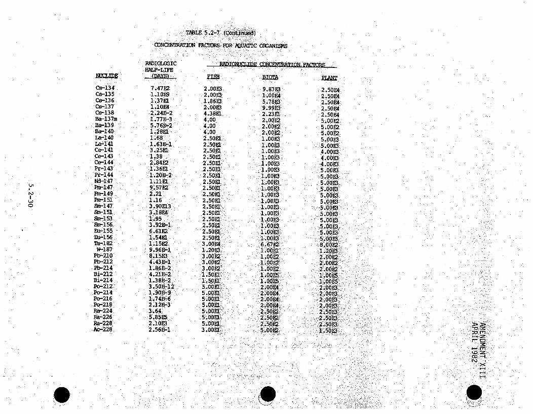
TABLE, 5.2-7 (Continued)
'cONENpwAION EACIORS FOR AQUATIC OFGANIS8MS
IN
C
Cs-134Cs-135Cs-136Cs-137Cs-138Ba-137mBa-139Ba-i 40La-140La-141Ce-141Ce-i 43Ce-144Pr-i43Pr-144Nc-147Pm-1 47Pm-149Pm-i 51
SM-1 47Sm-153
Sn-i56.
Eu-156Ta'182W-187
Pbý-20Pb-2i!Pb-214Bi-212B i214
.Po-2i2Po-216Po-218
Ra--224Pa-226Ra--228-•Ac-228:
RADIOGICHALF-LIFE
7.47E21.iOEo1.37E11.10E42 .24E--2i.77E-3
5.76E-2i.28MaiM681.63E-i3.25E1.
1.382.84E2:
1.20b-2
9.57E2'2.21'.1.163.90EU33.i8E4' ý1953 .92E-16..6E2'"
1.15E29.96B-ýI8.15E3i-4.43E-I
1.86 5 -2 -
i.38B-23 .50-i2:
.1.90E-9.§
2.12E-33.;641!5.85952.1OE32.56B-1
2.00E3 .8E2.00E3. 1.00M,I 86M35.8EMOM0E 9.99ES3
4.3.8EI, :2423d.4.00' 2*00E2.4.00 MOM.E4.00- :21.0E0E22.50EJ. 1.00M3.2.5081 1 i00E3.21.5o!a i 0 OE 3.2.50Efl. diliOF2.50E1 -i.0E
2.50E1' -1.00H3
2.50ka 1.00E1
2.50%L i.0E3.2.50KLi.0E
2.5O~a 6003
2.50EV 1.00E3
2.50E1:: 1.00M2.50kE1l I._00,E -3
2 .50k... 0E33.00E46.67M2
3.0E2 i0E3 'E2 66i.09E
5.OOEI.2i0EC
5.00E1 :.0AOE4;.50OE 2.50OEC
M.OM, 2:.0694
5OO~a2.50E2-
3 .00.m" 500E2
2 .50E42.50 E4ý2.50E42.50F42.50E45.00E2ý5.00E25.00E2
5.00E3-:400M:
40.oE3.4.00E3- 5.0o0E3
5.00o3.
50OE3
5.001031,
.....5,.OOE2,• .
5.2:0013"
" . OOE..•: .o :" i::5.09 E35. ..' -8:. 0012:.(o 'i;:
2.oo00' : i.002'• •-:siOOE3
.2 5'0 EP3-2600E3.
2.50E3.. •,2:.50o13w !
.2 .• . 50... E3:-.:.. .
RAIlIcIDE POIE~TAION FACTIORS
;0 m7Z
r- CD
00
N)

STABLE 5.2-7 (Continued)
CONCENTRATION FACTORS FOR AQUATIC ORGANISMS
Th-228Th-23 0Th-232Th-234
U-234U-238
Np-238Np-239Pu-238Pu-239Pu-240Pu-241Pu-242Am-241Am-242Am-243Cm-242Cm-243Cm-244
RADIOLOG ICHALF-LIFEI DAYS)_
6.99E22.81E75.20E122.41E18.91E71.60E122.122.353.21E48.91E62.40E65.48E31.41E81.58E56.68E-12.70 E61.63E21.02E46.54E3
FTSB
3.00 El
3- 00 El2.002.001.*00 El1.OOE1,1.00El3.503.503.503.503.502.50El2.50.El
2. * 50 ElI2.5 OEl2 * 50EI
2.50El
BIOTA
5.00E25.00E25. 00 E25. 00E26 .00E16.00E1
4.. 0 0E24. 00E21.0 0E21400E2
1- o 00 E21. 0.E21D00E2
14*00E31. 00 E31. OOE3
i .0 tiE31 . 0'0 E3,
RADIONUCLIDE CONCENTRATION FACTORS -
PLAN
1.50E31 . 50 E31.50E31.50E35.00E-15.00E-13 . 00 E23.00E23.50E23.50E23.50E23.50 E23.*50 E25.00E35. 00E35. *00E3
5.00E35,00E35.00E3
I3
-. J
115
13
k-rn
00or
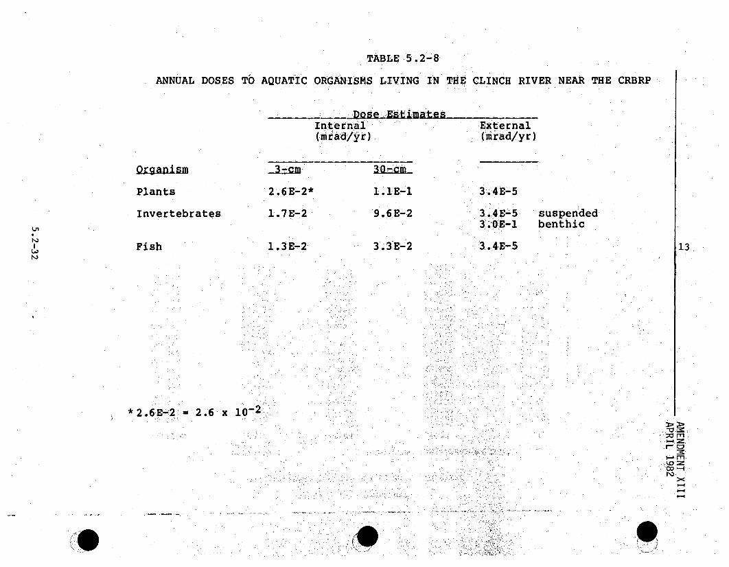
TABLE 5.2-8
ANNUAL DOSES TO AQUATIC ORGANISMS LIVING IN THE CLINCH RIVER NEAR THE CRBRP
DoseEstima tesInter nal(mrad/yr)
External(mrad/yr)
Qor.an im
Plants 2 .6E-2*
1.7E-.2
1.3E-2
1.lE-I
9 0 6E-2
3.3E-2
3.4E-5
U,
Invertebrates
Fish
3.4E-5 suspended30.0E- benthic
3.4 E- 5 13
*2.6E-12' = 2.6 x 10¹²
1-4
0 C.

pTABL4E 5.12o-9:
TOQ TERRESTRIAL ORGANISMS- NEAR THE-: CRBRP: SITEANNUAL DOSES
Terrestrial Mammal
Gaseous Pathway
Liquid Pathway
Total
Plants
Internal
0.00-6
0.027
0.033
Externa
0., i.069.
<0:..00l
0. 070
Total
0.075
0.027
0.10
1.41 .4
1.oc,

TABLE 5.2-10.
ANNUAL DOSE TO MAN FROM LIQUID EFFLUENT RELEASES
I.
I. Ingestiona. Water
Individual at Nearestpublic supplyPopulation
b. FishMaximum IndividualPopulation
c. DuckMaximum Individual
II. External
a. Immersion
Maximum IndividualPopulation
b. Above.-waterMaximum IndividualPopulation
c. Shoreline
Maximum IndividualPopulation
III. Total*
a. Maximum Individualb. Population
1.3E-6
5.5E-5
1 .4E-52.6E-4
1.7E-.4
2.2E-43.8E-4
2.6E-6
1.O0 E-4
1.6 E- 4
.2.6E-3
3.6E-5
2.3E-42.8E-3
Thvroi4
4...E-6
9.9E-5
1•8E-52.6E-4
1.1E-4
l. 7E-44.3 E-4
'Tota1-of Skin
3•3E-65.4E-5
1.3E-52 1.4E-4
5.7E-8
4. * E-85.4 E- 8
3 .5E- 5
6 ,.2E-5
1 .6 E-:43.6E-4
1.3E-6 mrem
5.4E-5 man.rem
1.3E-5 mrem2.4E-4 man-rem
1.1E-4 mrem/duck
4.8E-7 mrem3.4E-7 man-rem
4.5E-7 mrem4.25-7 man-rem
4.lE-5"mrem.
7.3E-.5 man-rem
1.7E-4- mrem3.7E-4 man-rem
* total organ doses. include total body component due to external radiation-
* 0

AMENDMENT. XIIIAPRIL 1982
TABL 5.2-11
2020 CLicN .AND, ,TeNSE RiV FIS HPS VFT A (14,15)v:sT. m
Reach(TMO
17.4,-0.O (CRM)568-528
528-471
471-425
425-349
3494-275
275 259
2594207
207-165
165-121
121-7676-22
Cocumercial Harvest.. (lbs/acre). Sport HarvestAubsgLý ie
23.8
23.8
23.8
23.8
23.J 823.8
23.823.8
23.8
23.8
234.8
23.8
64.9
64.9
64.9
64.9
64.9
64.9
64.964.9
64ý.9
64.9
64.9
64.9
Area.
2,100
26,100
34,900
10,900
67,8o. 800'.'67, 1000
4$.,,000
43,600
16,0,.00
16•,•000.48,100
80i,200
1. 'I= Tennessee River Mile. CIRM = Clinch River Mile
5.2-35

TABLE,5.2-12
USE OF CLINCH AND.1TENNESSEE. RIVER STE I200FOR RECREM~IONAL PURQES:(REF. 16)
Reach Above Water* In-7Water* shorel~ine#*
LJn
0'
17.4-0,0 (CRM) 2 .0E5** :::2.0E5 -:2,0 .568-528 2.0E 2.0• 2,0EB
528-471 3.4ME. :6.595- 3 1JE6471-425 1,2E5 -A2E.64 .5425-349 6.4E6 M62E6 5.6 ..349-275 3. 6ES 6.9E5 3.2E6275-259 1.5E6 2.915 1,4E6259-207 1.5E6 3 015 1.8E6207-165 2.215 1.7TF 1.9Ei165-121 4.7E5 3.8E4 4.3E121-76 8.8E5 5.61E5 1:.0E`776-22 8.7E6 6,3E6 1 .2E8
• These are the number of visits assuming five hours Pervisit. The actual estimateshave different:times per visit for:, each activity and reach of river.
•* 2.0E5 = 2.0 x 10.
co-I1-4
I.

AMENDMENT XVJULY 1982
TABLE 5.2-13
CRBRP - INDIVIDUAL DOSES FROM GASEOUS EFFLUENTS
Noble Gas x2
Gamma air dose Max. Exp.l
Beta air dose Max. Exp.l
Total Body Max. Exp.1
.Skin Max. Exp.l
0.076 mrad/yr
1.4 mrad/yr
0.069: mrD/yr
0.55 mre/yrý
~15
- leý --- w4v"=--Ný
Tritium Max. Exp.l 5.3-E-`4 mrem/yr
.15.
Breakdown of Particulate Exposures - Total 1Bo dy". fmrýeilr)
Vegetable Ingestion 2.6E-4 1,9E-•4.
Beef Ingestion 2.7E-5 54.8E-5'
Inhalation 8.3E-5 .. 1. 68E-4
Ground Contamination 1,6E-5 1.".. 6E-5
Milk Ingestion 1.4E-4 8.4E-5
Total 5.3E-4 5.0E-4
1. Maximum exposure point is at 820 meters in the NWsector.
13
5.2-37
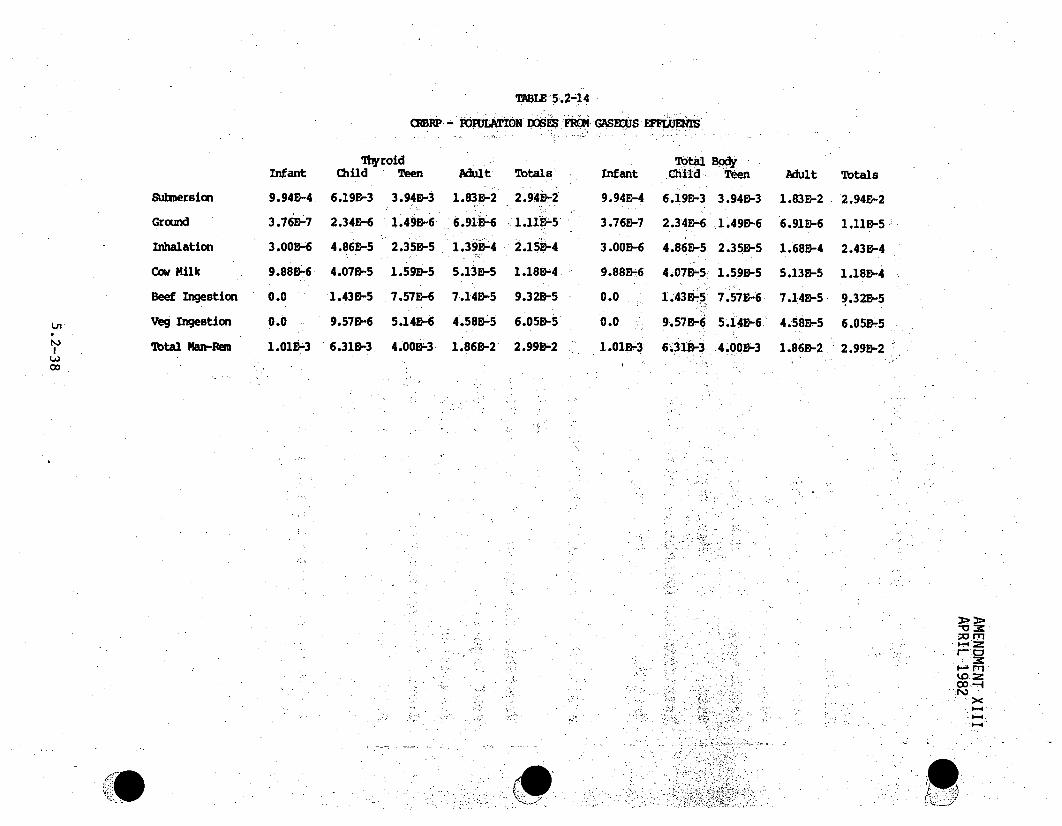
TAB-E 5.2-14
-o POffLM!IN DO SWS FROM4 GASBOlJS U : LJJENMI
Submersion
Ground
Inhalation
Cow Milk
Beef Ingestion
Veg Ingestion
Total Mwt-Rem
Infant
9.94E-4
3.76B-7
3.005-6
9.88B-6
0.0
0.0
1.01E3
ThyroidChild Teen
6.19E-3 3.94E-3
2.345-6 1.495-6
4.860-5 2.35E-5
4.070-5 1.590-5
1.435-5 7.57D-6
9.570-6 5.140-6
6.31D-3 4.005-3
Adult
1.835-2
6.915-6
1.390-4
5.135-5
7.14E-5
4.585-5
1.869-2
Totals
2 .945-21.11•55
2.15E--4
1.18B54
9.32B-5
6.050-5
2.99D-2
Infant
9.94E-4
3.76E-7
3.000-6
9.88136
0.0
0.0
1.015-3
7btal BodyChi-ld Teen
6.19•-3 3.940-3
2.34E-6 1.49B-6
4.86R-5 2.35B-5
4.07B-5 1.59&-5
1.435-5 7.57E-6
9.575-6 5.145-6.
6.319-3 4.00B-3
Adult
1.83E-2
6.91E-6
1.685-4
5.135-5
7.14D-5
4.585-5
1.860-2
Totals
2.940-2
1.11E-5 -
2.435-4
1.185-4
9.32B-5
6.056-5
2.995-200/1
1-4ko =
'o-4W
je

AMENDMENT XVJULY 1982
TABLE 5.2-15
SUMMARY OF ANNUAL RADIATION DOSES TO POPULATION FROM CRBRP
Thyroid(man-rxz!yr)
I. Internal
Ingestion (water)(fish)(milk)-)(meat)(vege tables )
Inhalation
I I. External
In-water sports
Above-water sports
Shor eline activities
Submersion in air
Ground contamination
III. Transportation ofradioactive material
Unirradiated fuel
Irradiated fuel
Wastes
Total
9.9E*9-52..6 E- 41028E-49038I-5601 E- 5
2. 01 8-A
5.4,8-8
6.2E-5
2.9E-2
1.18-5
Total Body,
5. 4E8-52:4E-41.2 E- 49.3E-5
5.78-8.
548E-8
6.2E-5
2.9E-2
1. 18E-5
13
115
0.45
0.92
0.43
1.83
0.45
0.92
0.43
1.83
5.2-39

Aquatic Aquatic ,n-Ttonerrestra Ie s stonInvertebrates P~lants Veterae Plants
Vertebrateste13
0-
Imersion andIngestion Ingestion
Figure 5.2-1
EXPOSURE PATHWAYS TO ORGANISMS OTHERTHAN MAN-,MAN 13.
I--4I-4
N)

S 9 0
on
- ~F~igu~re~ 5.2-:2"".
EXPOSURE PATAYS TO -NA,
St
co--A 'r
N-4O-.-

INTENTIONALLY BLANK
9)
.•
AMENDMENT XLIIIAPRIL 1982 .
5.3 RADIOLOGICAL IMPACT ON MAN
This section has been combined with Section 5.2 in AmendmentXIII.
Pages 5.3-2 through 5.3-22 deleted by Amendment XIIIV13
5.3-1

9)INTENTIONALLY BLANK
1 1 ý le ,ý)
AMENDMENT V.1IIFebruary 1977
The maximum permissibl e whole body, burden for tritium, is. 66:ý. timest hat:(0)afor Cs-i37, 3j and the. maximum permissible drinki ngwater,,. concentration . 18
is 150 times that of Cs-l 37i"- The reduced. hazard f tri ti.um. results
from the fact that .its disintegration.,energy is the -lowest:. of any
radionuclide (a maximum energy of 0.018 MeV- and an average energy. of-b -b t ~(4): fti
0.006 MeV)" and decay is solely by. beta emission. Because of.this,
it poses no external radiation hazard to organisms. Secondly itis-released to the environment almost excl usively in the form of tritiated
water.. As:. such, n' an aquatic system, the dilution bynormal, water, -
molecules is einomous, producing an exceedingly low specific activity
(ratio of radioactive molecules of a compound to total molecules of,
the compound).
More signi ficantly, tritiated water behaves like normal water in any,
organism It'is quickly and uniformly distributed throughout the body,
following. ,.ingestion.5) Furthermore, it is rapidly excreted with a,
biological half-life of only 12 d-ays in man. Some tritium atoms i .,1
e xchang Ie wi th s table hydrogen atoms of biochemical compounds in bodytissues:.; Thus, -chronic exposure to tritiated water results ina s mall1,
'(6)percent age/ of organicalily bound tritium in body tissues.s S Suchorgani callybound trijtiu normally is distributedirather evenly in the
body,. not.selectivel.Y concentrated:Jin any.tissues".
As shown in Table 5.3A-2 Appendix to Sections.2 and5.3 the bi~oaccum- 8
ulation. factor for tri.tium,.for al:l organisms-is one. Therefore, algae,
crustacea., m ollusks and fish liv Vinhg j n the Clinch River will attaiin b.ody
concentrations, ,of .:tritlum no hiigher than the river water.concentration.
Undue concern as to genetic effects has been occasioned ,when it.waSlearned that:,tritium may be incorporated into DNA moleculesin bodyI
cells. Several key experiments have been performed to evaluate the
relative radiobiological effects of tritium in cells as water and as a:
portion of DNA (introduced as tritiated thymidine).(8g9) Bond summarizes
5.3-3

AMlENDI'IENT VIIIFebr uary 1977
the results: "All experiments of this type -to date, on: somatic and..genetic effects in mammals, showed ap'proximately the'sa'me-degree. of, bio-logi~cal .ffect whethero"r not -the t•r•i ti um was. incorporated into:DNA;i.e., the tr itiu*m-:showed no additional, effect by virtue of its h;avin .1gbeen inc rporated i1 nto,. DNA
5.3.1.2. LIQUI:D EXPOSURE PATHWAYS
. (
V
A discussion of.the pathways by which radioactivity can be r.eleased tothe Cl inch. Ri ve'r can 'be` fou nd in Section 3.5. The pathways whereby .the:publ:ic will be'exposed to the low-level radioactivity released 'to theClinch River anre dtermined by the various, public ses made of the riverwater. In Section 2.2.3, it was noted that no public water supplieslocated downstream of the CRBRP Site withdraw surface water from theCl inch River "to6'.tsupplfmeit thee ground'water drinking supply. An. i-ndOustrialwater supply is, ttaken approximately. 1.5 mifles downstream from the.:.Site...As discussed •in Sec'ti on. 2.5, the 'area of the Clinch River encompassin••.gthe point of the.CRBRP liqu~id discharge acts as a groundwater sink.Therefore, expbosTre'"fto l•iquid -contaminants through seepage into. a qu~idffer s .usedas sources of dirinki n.water i•.-very unlikely.
8
hii _u ei ,.. ' f .. :hi . .:- . oa.! i ' g -anRecreational uses of the C.linch Rver Incldude-fishing boating andswimming. Public: exposure to radioacti vity in t C t Clih River: duri ngi n- sth liricht. ti~l. tuihg .. e
fishing and boating activities would generally be. restrictedto theextremely: small1 amiount of radiation escaping from a small areaýý of the;river surface. The oSest swimming area is located approximately one
mile upstream .of the point of liquid effluent di'scharge.I e Therefore,undernormal circumstances, immersion in 'efflUent water shouldnot be animportant exposure pathway. Uptake of radioactivity from a contaminated,,-aquatic environment is possible through increasing trophic levels
beginning with phytoplankton (such as algae) which in turn are assimi-lated by zooplankton, small fish and larger fish.
5.3-4
AMENDMENT. VIIIFebruary 1977.
Since there is no. usage of the Cl-inch Ri Ver water for irrigation. of
crops, the only pathway for radiation. exposure of the publ ic throughthe aquatic food chain is the consumption of fish caught:by sport fisher '.
men in the general vicinity of the blowdown.4ischarge. No other aquatic "biota is considered edible in this area., The Corbicula clam, used forhuman consumption in some parts of the world, .can be found in the .Clinch River. However, it is used primarily as bait and is. not generally.
part of the local diet.( 1 O) No quantitative data is currently avail6ableon the amount of fish caught from this region by sport f:;s'her-mehn fr:"human consumption..ll Approximately 100 tons, of non-gameý 'fi"ssh are-taken•annually from Watts Bar Reservoir by commercial I sfishemen. (12)~ 6a breakdown on the utilization of the catch is not available.
Doses are presented.for :relatively significant liquid exposure pathwaysthat exist. These include external doses received while swimming, boating
and fishing and interinal doses from ingestion of fish. However', it must-be pointed out that. these doses are not expected :under norma:l c"irci•umstance~se•..:due to the sma 1:radioactive pIume associated with the CRBRP liquiddischarge design. Concentrations of liquid effluents in the Clinch River.beyond 60 feet f om :thepoint of most nsances are at near
ambient level s... Therefore, drinking water taken from 'the ClAnch. Rie'•moe.than .60"feet~"iwnstream of the point of discharge will noti"conain
measurable amounts of.radioacti.vity and no significant internal dosescan be. expected. Asi.discussed in Section 5.3.1.2, the doses Callcul.ated.for exposure to liquid effluents are not expected under normal conditIons'. 8
5.3.1.3 DIRECT RADIATION FROM FACILITY
The shielding. design criteria for the CRBRP specifies that, during normaloperation, the dose rate at the surface of that part of the containmentvessel which is above grade will be no more than 0.2 mr/hr. 'An estimated'90 percent of the containment building that is above grade is shielded'from the Site boundary by buildings and is enclosed by the ReactorConfinement Structure consisting of four feet.of concrete. 8
5.3-5

Amendment XIIýJanuary 1982
Radwaste tankslare.housed in buildings.protected with concretewalls. In addition:, sodium storage tanks, the Radioactive.ArgonProcessing System (RAPS) and the Cell Atmosphere ProcessingSystem .(CAPS) are:located.below grade.
As described in Section 3.2, the probability of radi~oactivesodium leaking from the primary to the intermediate loop of the.Heat Transport system is very. small. Therefore, it is assumed....that the only radioactive contaminant in the stxre~am ils tritiAum,.-a low energy beta-emitter (0.006 :MeV) which presents no dire-,pctradiation hazard.
5.3.1.4 TRANSPORTATION OF RADIOACTIVE MATERIALS
5.3.1.4.1 NEW FUEL
Transfer. of non-irradiated fuel between.fuel-fabrication plants,and. the CRBRP Site will result in a small external dose to thegeneral population along the -routes and to the personnel.involved in the shipping process -(see Section 3.8 for details.,.concerning transportation of core fuel). The. core fuel will be' 6
fabricated at DOES s Secure Automated Facility being built..:at thei 12.DOE Hanford Site in the State of Washington. Theblanket fuelwill be fabricated at an existing commercial facility.
5.3.1.4.2 IRRADIATED FUEL
Transfer of irradiated fuel. from the CRBRP to a fuelreprocessing plant will expose the general public along the,route and the shippers to direct radiation. The irradiated fuel,assemblies at the CRBRP will be loaded into shielded casks.. 8These casks are DOT,-NRC approved shipping containers fortransportation of spent fuel assemblies (see Section 3.8 for 6
5.3-6

Amendment XIIJanuary 1982
details concerning transportation of irradiated fuel). The
spent fuel from the CRBRP will be transported to a yet to be
determined facility for interim storage and reprocessing. Since 12the actual Government facility has not yet been selected, the
transportation impacts in Section 3.8 assume a distant facility.
5.3.1.4.3 RADIOACTIVE WASTES
Transportation of the radioactive wastes can also present a i.
radiation hazard to the general public and shippers en11ýhippers Secon,,
3.8 describes the type of radioactive waste package to be 8
shipped off-site for disposal. The CRBRP will use an
NRC-licensed burial site for disposal of all packaged
radioactive waste. As yet, the location of this site has not
been determined.
5.3.2 DOSE RATE ESTIMATES
5.3.2.1 DOSES FROM AIRBORNE EXPOSURES
Doses received from exposure to gaseous effluents from the CRBRP
were evaluated using equations .1 through 11 presented in theAppendix to Sections 5.2 and 5.3. Maximum external whole body
and skin doses at the site boundary were calculated using thehighest annual average V/Q which occurs at the Site boundary.
Using a method similar to the method used in Section 5.2.2.1 to 8
obtain the maximum t/Q at the exclusion boundary, the maximum
site boundary X/Q was found to occur in the northwest sector.Site boundary distance occurs in this sector at 2500 feet from
5.3-7

Amendment XIIJanuary 1982
-5the plant and the annual average value for X:/Q:of 5.;10- X-103sec/m3 was obtained by interpolating the data in Table 2.6-39
for this radial distance. Values of 0..023 mrem/yr and 0.073 8mrem/yr gamma whole body dose-rate and beta plus gamma skin doserates were obtained at this location assuming no protection frombuildings or clothing.
As can be seen in Table 5.3A-1 of the Appendix to Sections 5i.2and 5.3, all of the radioisotopes present in the gaseous
efftluent contribute to ,an external gamma dose except Argon-39and tritium which decays by -beta -emission .only. On the basis of 8the population distribution expected near
B
5.3-7a

AMEND!IENT: V.I II ..February 1977
the end of plant life in 2010,,presented in.Table 2.2-12, and the annual
gamma dose.distribution within 50 miles of the Site as determined by the.
annual. average values of x/Q, presented in Table 2.6-39, the external popu-
lation dose (whole body) from CRBRP atmospheric releases, is estimated to be
0.027 man-rem/yr. It should be noted that the dose to personnel exposed 8
to CRB.RP atmospheric releases at the nearby Oak.Ridge Gaseous Diffusion
Plant. and Oak Ridge National Laboratory does not impact the total dose
to the population.
A comparison of the external dose resulting: from the :opera'tion of the
CRBRP to the dose received from natural radioactivity assists in..evali-.
ating the impact of the CRBRP. Near the plant sit-e the average annual ,
dose -from naturally occurring external sources of radiation is approxi- :mately 100 mrem, as discussed in Section 2.8. Therefore, on the :basis
of projected popul~ation for 2010,0 the population dose .wi thin 50 mile s6
of the CRBRP from naturally occurring radioactivity is- estimatoed to: be,
98,700 man-rem/yr. The calculated contribution from the CRB:RP (which is
based on conservative assumptions) is 0.00004 percent of thepopulation j 8dose from naturally occurring radioactivmi.ty..
Internal doses *via the *various exposure pathways to gaseous effluents .
(inhalation and ingestion of milk, vegetables and meat) will be due almost
exclusively to the presence of tritium. The noble gases are relatively
inert and result in practically no internal.exposure. These doses are
.presented in Table 5.3-1.
The growing season for leafy vegetables in the Eastern Tennessee region:
is assumed to be 90 days. All other variables used in the calculation
of dose from ingestion of leafy vegetables, such as.total daily intake
and-yield per unit area of cultivated land:, are provided in Table 5,3A-13 18
5.3-8

INTENTIONALLY .B.LANK

AMlENDMIENT V I IIFebruary , 1977.
.of the- appendix to Sections 5.'2 :ahd5.3. Maximum dose't6oanindividualfrom- eating vegetation contaminated. with as eous,-.fa.llu tis-3.5 x 10⁻²mrem/yr.
Average effective grazing.area of beef: cattleý and dai ry cows is assumedto be 45 2 .m Assuming.ý that ..'.100, -percent. of the ,triti um. ingested is evenlydistributed within -the-"imeat:" and theaverage weight -,of -a ýsteer is-. 5001 kg,the. total cumul ative fractiOnoftritium tansferred&per kg'of beef is-S0/500 k g or. 0002/kg.. Ithough isomie'-grains prd u-edQ. U O ide oY Ie.
immediate area are used, to s.uO pple'msent their diet, daliry cows on the farmnearest the CRBRP Site are. a1lowed tdo greaze ts'id• ;-l !d6ar.'IrIund:, .Therefore, it was assumed that 100 percent of the annual diet-of bothcows and -cattle: comes, from ýthe :_,ffiel-ds in order t 6o 0btin.ma.inium doSe
rates. Al l other, var.iables, -•such, as todtal• dai ly intake- ýtof bee~f or milkand elapsed time-, between .;butcheri.ng An .in.gstion, '-re '...prov I ided in .Table5.3A-13of the.AppendixtoiSec.,ons 5.2.and 5,3..
I 8
Maximum total annual whoIe ibodyinternal doseafrom-exposure togaseous.effluents to the hypothetical individual who eats:only leafy vegetables-.grown in *the closest home §gaden 't the1 Site, eats 'bonlythe.meat from,beef cattl e..grazing in: the closest-field to the Sjzite, drinks, one literof mi I kper-day taken onl-yfrom-heclo sest know farm -to -the Site with dairyI8cows and lives -inthe closest ýhouse to the. Site is 0.56 nire/r hestimated annual internal dose from• natural radiation to •.an ind.ividual is18 mrem/yr•.(4) Therefore, the maximum internal- dose toý an individualfrom exposure to ,CRBRP gaseous effluents is approximately 1.3 percent of 18his internal:.dose, from. natural:ly: occurring ,radiation .. External andinternal doses: resulting from exposure to daughter products of gaseous,eff]uents.. have been included in the dose evaluations. ".
Depth of the reservoir.from which water is taken for the industrialfacility downstream of the plant site was conservatively calculated as4.8:m based on winter low water pool conditions as given in Section 2.5.1.4. 8It was assumed that 0.5 days are required for processing the ClinchRiver water into potable water. Internal whole body dose to persons
5.3-9

AMENDMENT VIII:February 1.977
body dose to. persons drinking water at the industriia.l facil is: calcuI.ated.with the assumption that totaldailyy intakeduring.an,•ight hour-work-ing day-• i 1s ,0c.." Per iodof oexposureis 260 days .per year. A dilutio factor
for gaseous releasesto Ithe ri:ver due to-flow of fresh:water. •into.the reser.-iIvoir and •flow of contaminatedwater out of the reservoir during, typical.,.summer conditions (4,777 cfs) s 0. 09. Therefore,•maximum whl body ."internal dose to an individual from ingestion of water is.0. O.022 mrem/yr.Based on an average. daily worker population of .4,600, the: man-rremý-due to :ingestion o drinking. water . at. th eOc..RGP .".iiga.:i vt•y. fro falloutof: airborne-:effxluent-is calculated to be 0.01 man-rem.yr.:..'.::ý"i0.5 ?.3.22 :1DOsES FROM EXPOSURE TO:TII,.QUID EFFLUENTS "Doses rece i ved -from exposu re :to. the liquid effluents release-dfromthe
CRBRP were calculated, using,.equations 18 toa27 found :Jinthe;Appendix toSections,.5.2 and 5.3,e. AdilutI.o-fact•or of20was assuifdb-asebAte n -th 48analysis that under typical. summer•` conditions :}the .,concentration of.radio-nuclides in the discharge plume are reduced toý5.0 percentand initial ' 8levels within-less than6. 6feet of ;the.'discharge-poit-. .' --
Due to lack& of definitive data., 'no credit is'taken for-remdva' of ativity.from the water.through adsorptiont'on solids and-sedimenltati, i.y depo-sition in the biomass,or by.processing within water treatmnt systems.Dose rates via the various exposure pathways to liquid effiuents are'-presented in Table 5.3-2.
5.3-10
AMENDMENT VIIIFebruary 1977
Evaluation :of dose via. exposure to shoreline..deposits. (river sediment)assumes an exposure time to 500 hr/yr. Times of.exposure for swimming(immersion) of 100 hrs/yr and above-water activities' (boating, fishingand skiing) of 600 hrs/yr were assumed. Time between release of the iso-, 8tope and exposure is assumed to be 0.5 days. Expected total body gamma
5.3-1 Oa

' AMENDMENT VIIIFebruary 1977
and beta skin doses from all i sotopes-. toan individual from btheabove (sources are: 7.2 x 10- mrem/yr.and 8_9.x x 0 mrem/yr, respectively. :-These 8:
doses are.,much lessAthan onenth. ofý a percent of naa.turalba'ckgroun
radiation and-:are eSsenialyXundetectable. A breakdown ofthe.dose.-contribution from each pathwayi s p.rsented:-inTable5.3-2."
so t ll•, b•: .e 5. 3 '..
Population doses for exposure fromiJmmersi on. in, water and- from above-water
activities were- calculated, :assuming:...
1. 90 persons (as projectedin- Section 2.2 for. the year.01),were immersed for100 hrs/Yr. (see Table 5.3A-13 of the . .
Appendix, to: Sections_ 5.2in~d -54);~~nd -
2. 45-persons. ..spent. 600 hr/yr .in:above-water.actvlti...O0 .':hrs/yr boati-ng an'ds5,OhrS/yr.ishiig).
Tota I popul ati. on dose from all aquat- i c activities is 3.7 x -8O . ma .n- rem/yr. 18
Doses to humans from ingestion of aquatic foods (50 g of fish/day) were
evaluatedý using the bioaccumulation factors listed in Table 5.3A.12 of 18
the Appendix to Section 5.2 and.5.3 _and are tabulated in Table 5.3-2.
Most of the whole body internal dose results.from ingestion of tritium.
The, population dose from. ingestion.of aquatic foods, based .ona aily-:
catch of 23,000 grams, is, 3.9x l0• man-rem/yr. It is as•med' ta.:50 percent of the catch is edible and .the equivalent f 2,300 persons: .
would be supplied by this harvest:based on an average daily consumption Jof 5 grams/day. An. additional pathway to humans is the ingestion of small 8
game Such as a raccoon or duck .which may have fed on fish from the ClinchRiver. In view of the low doses resulting from ingestion of aquatic foods,
no significant exposure via this pathway can be expected.
Plutonium isotopes are present in low concentrations in the] CRBRP".liquid.
effluent.described in Section 3.5..5 Although fairly high concentration
factors have been evidenced by.,lower trophic level. species (2,600. for..
zooplankton and 1,600 for phytoplankton in sea water off the
5.3-11

AMENDIMENT VII IFebruary 1977
(15)southernm:•Cal-ifornia coast) ,the l1ower concentrat ionfactors in fish(-4) indicaite: some' possib le.discriminationtakes place at th higher
trophic levels. Furthermore, the concentration Whi.ch does occur in fi shoccurs principally in nonedible portion's such as •bone.(:6) Thus, itappears that•• biological. concentrati on does not ,occur. to;a very:,la~rge .extent in edible aquatic food, products. Furthermore, the fractionaluptake.by ingestion for humans is extremely low. (0.003%)(2) thus pro-vi ding .an additional. safetya margi n .•for: :tthi s .pathway.
Total' dose eto the bone. from the pluto:ium isotopes vi inges tti of50'g"'ams. offish per day is 5. •2,x 17 9mrem/yr. This dose i.. O2 pe-.cent of the total dose to the• .bne •(2.9.x,.l .mrem/yr) resut ifngf'romexposure to all radioisotopes in the CRBRP::.liquid effluent. The esti-mated4 :total e'dose the bone fronatural radiati7on is 87 .mremiyr.( ."Therefore, the-dose contributions from plutonium isotopes and from a~l lradioi sotopes: in the. liquid ef.flu ent a reI e very much'smaller 'than the .dose from naItural sources. No.'detectable bhealth effects can be expected'as a. result of these, low doses:.,l8 P9) Population doses to bonelviaexposure to plutonium andto..al-l. ra'dioactiv iquid effluentsar.eesti'mated:to be 1.2 x 0 man-rem/yrand man6rem/yr, respqec-.tively. Assumptions for estimation' -of the poipulation dose- ari•e an. a-verageintake of five g Uram of fish:per day anda daily catch of 23,060'0 gi : ramsof.which 50 percent is edible.
A potenti ally important daughter prodduct resiulting f"rom decay of theplutoniumisotopes present in the. liquid 'e"effluent is Ami-241, which mayalso contribute to bone dose principally throughalpha-emission. An esti -
mate of the build-up concentration: of Am,-241 as a result of.radioactiive!decay of Pu-241 is presented in Table 5.3-3. As can be seen in:Table 5.3-3,secular equi'l ibrium will not be reached.. until 30 to:80 years after, i:ni tialrelease of the parent. .Dose conversion factors, mrem/yr per ".Ci /cc.,: forexposure via ingestion of water to- Ain-241 are 5.0 x.l07 for whole ody,
8
8
J.8
5.3-12
Amendment XIIJanuary 1982
6.0 x 10⁸ for bone, 5.0 x 10⁷ for the ,GIiTract and 3.8 x1 i8 for j4the kidney. Dose conversion factors for exposure via ingestion
of Am-241 are not significantly higher than those dose
conversion factors for the plutonium isotopes presented in Table
5.3A-5 of the Appendix to Sections 5.2 and 5.3. Therefore,
doses from exposure to americium are not expected to be
significant and will be less than the minimal dose from the
plutonium isotopes.
5.3.2.3 DOSE FROM EXPOSURE TO DIRECT RADIATION FROM THE
FACILITY
Because the containment building is 90 percent shielded by
buildings constructed of concrete walls and because the four 8
feet of concrete from the confinement structure has not been
accounted for in the analysis, the population dose from direct
radiation presented in Table 5.3-4 is highly conservative. The
dose is calculated with the assumption that the radiation field
is caused by an isotropic point source at the center of
containment having an energy of 3.0 MeV. The inverse square law
was used to calculate the dose at several points beyond the-
Site. Build-up and attenuation in air was accounted for in the,_ 8
calculations. Sky-shine was not considered since the closest
point to the center of containment is not shielded by additional
buildings.
The calculated dose rate to an individual (0.6 mrem/yr at the8
Site boundary) is 0.6 percent of the external dose received from
natural radiation in the Eastern Tennessee region.
5.3-13
Amendment XIIJanuary 1982
5.3.2.4 DOSES VIA EXPOSURE TO: RADIOACTIVE :MATERIALS; ýIN TRANSIT
5.3.2.4 ,i NEW FUEL
Dose estimates have been made based upon transportation of fuel-and blanket assemblies to the plant from the.Hanford Site. 12.These doses have been calculated based upon NUREG-O70( 2 0 ).
*
5.3-13a
Amendment XIIJanuary 1982
Assuming an average of 14 shipments of fresh fuel for the core 6 9.:and axial.blankets per year and 12 shipments of fresh fuel for
the inner and radial blankets per year over. a distance :of 2500,miles per shipment, annual doses to the general public areestimated and presented in Table 5.3-5.
5.3.2.4.2 IRRADIATED FUEL
Population doses from transport of irradiated fuel to fuel.reprocessing plants have also been estimated based upon NUREG"
:0170 with shipment by rail., Assuming 14 shipments per year for 19:spent fuel plus axial blanket assemblies and. 12 shipments peryear for inner and radial blankets assemblies and a transit. "2distance of 500 miles for each shipment, the population doses
presented in Table .5.3-6 were calculated.
ý•5.3.2.4.3 RADIOACTIVE WASTES
:Approximately one-hundred thirty-five (135). 55-gallon drums:Of I o.. solidified liquid wastes will .be shipped from the Site to an.NRCicens burial ground each year. An estimated 112 drums of,.
non-compactible solids and 28 drums of compactible will alsotbe 9I.shipped from the Site each year. An estimated four shipments
.per year.will be.made for irradiated control assemblies andradial shield assemblies. The estimated population doses to thegePneral population would be 0.165 man-rem/yr, as shown in Table5.3-6. These estimates assume a shipping distance of 500 milesper shipment.
.5.3.3 SUMMARY OF DOSE RATE ESTIMATES ANDý EVALUATION
OF RADIOLOGICAL IMPACT ON MAN
A summary of expected doses resulting from exposure to the CRBRPis presented in Table 5.3-7. Both individual and populationdoses are projected.
5.3-14

INTENTIONALLY BLANK

AMENDMENT VIII: February. 1977 '
These:doses, are belieVed to reflect the "as .low as r easonablyV chieableva
philosophy appl'ied' to• light water.reactors. The-limiting external dose isfrom exposure to direct radiationi, from the plant. As di'scussed! in: the text,this dose was. calculated using very. conservative..assumptions and will. un-doubtedly be much lower under normal operating. condditions... Total .indjiv.iduadose from all *expos.ure:. pathways is only 1.0 percent of the. total exposure ,I8from natural: radiation. Therefore, it i s -concludedt-jihat:. the CRBRP! wil I.:.have ,no detectable effect- upon the general populati on residing near theplant sie i te
5. 3-1:5
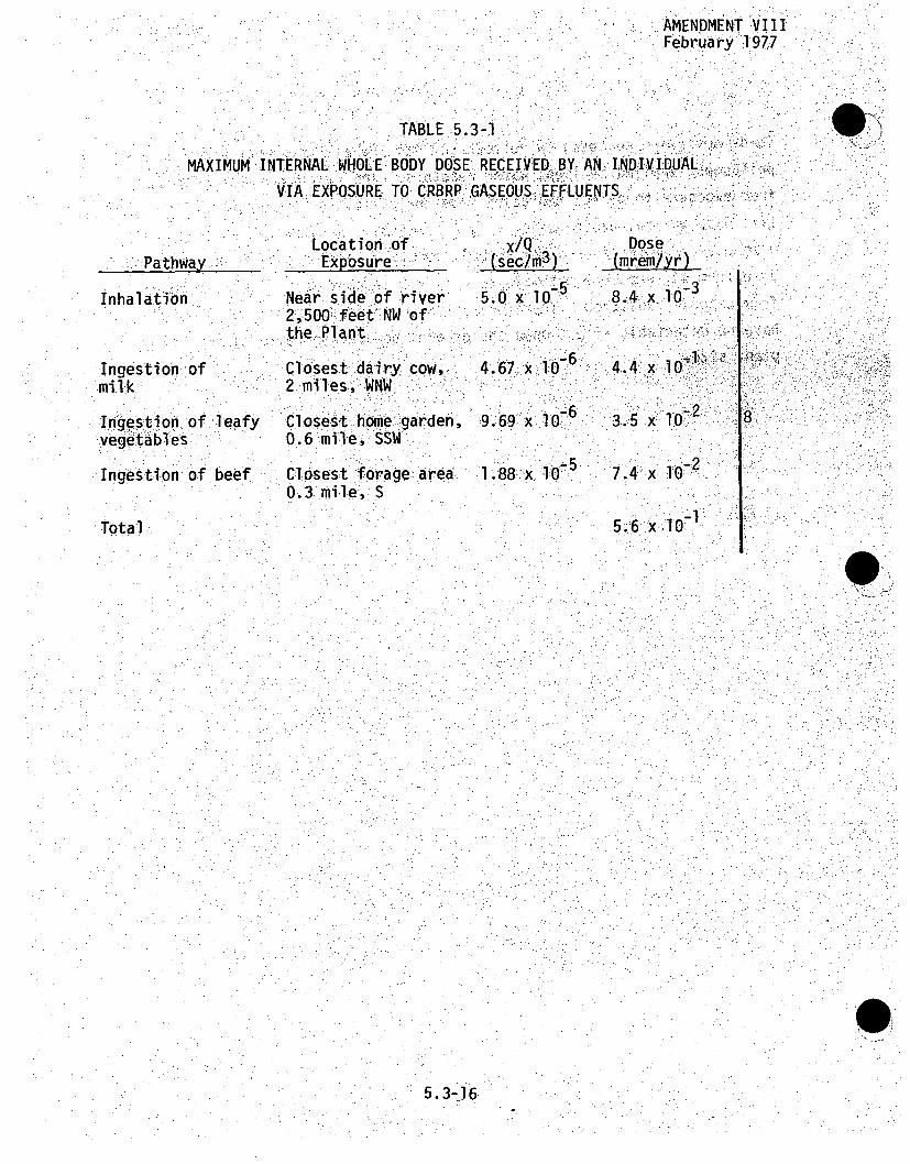
AMENDMENT VIIIFebrua ry :197.7
TABLE 5.3-1
MAXIMUM INTERNAL-WHOLE BODY DOSE RECEIVED BY, AN .INDII A.DUALVIA EXPOSURE TO.CRBRP: ..GASEOUS- .EFFLUENTS.`.
.- ::
Pathway
Inhalatibn.
'Ingestion ,ofmil1k.
Ingest ion of leafy
vegetables
Ingestion of beef
Location'ofExposure
NeAr side of river2:,•500: •feet iNW.of"
the PTlant,
Closest dairy cow ,2.miles, WNW
Closest home garden,06. mile, SSW
Cllosest forage: area0.3 mile, S
... .x/Q .: ..,•
5.0 x 10
4.67 x: 106
9.69 x 1.o067
I..88-x :l:O-.5
Dose ....',_(mrem/y) "
4.4i"3 .. x•:iO ::.ii
7.4 x 10⁻²
5.6,::x 101
I8
Total
9
5.3-36

February 1977
TABLE 5.3-2
DOSE,- RATES RECE-iVED•BY ANI:: INDIVi DUAL0 LV IAEXPOSURE TOCRBRP LOQUIDIEFFLUENTS-
mrem/yr
Pathway
Total BodyGamma
Total Skin
Whole BodyInternal
ContaminatedRiVer Sedimen
7.:20,x i'0 8
8.48 x 10'8
..I~mmersi1on
A1.62• x l6-
2:.. 0 •-.x 10,7
Above-WaterAtti.vities
4.-87, .
Ingestion ofAquati~c Tood
'A4,
~ 2~
6.-04 x 10l . 69 x .**
1.69,) 10 -Z
Bone"4'
GlITract
Thyroid(Adult)
2 00.- x .10-
61.511. x:10 7
35.
7÷8
Kidney
5.3-17

AMENDMENT VISApril 1976
TABLE 5.3-3
BUILD-UP ACTIVITY OF- AM1-241 FROM:-PU"24.-REEAsEDI
FROQM CRBPLQI RADWAS-TE.-,.SYSTEM*
No.. '.of YearsAfter Pu-241 is
Initially :Released
80
1.200
Activity .Am-241
" 1 7 . , .i" ... ۥ '
2.11 x1
5.38 x 10
-1.23.6 x 1014
.3.66 x 1O'14 -
U
6 !:
*Initial activity:of Pu-241 is 4.76 x.l10 14 OCi/cc
" L.i- , ,•k"
5.3-18

TABLE 5.3-4
ESTIMATED RADIATION DOSE TO
DIRECT RADIATION FROM
THE PUBIC VIA
THE CRBRP
DistanceFrom Pl ant
(miles:)
S0.4
0.6
1.0
2.0
3.0.
5.0
EstimatedDose:%.Rate
6.3 -x iO.
,2l'.6 x 1O0
7..6 x 10o-
2..8x 10-10
.6.8 lO-17x
5: miles of Site =Population Dose within0.02 man-rem/year
t.3-19

Amendment XIIJanuary 1982
.ITABLE 5.3-5
1'IMATED MTRL¶DA BCVY DOSES M1 1EGNIAPOBLIC, FRCM SHIPPI1W UIRITRAIATEDMATR~J ¶10CRP SITE
Materiaj*
Fresh fuelRa dial blanket:-
.TtalMiles.Pe, Year
Man-r=ns Received Per YearGeneral.• PopR~lation .. .. .
30',r:000 .0.007
Fr`esh fuelCore and a4al blanket
12
T¶otal 01.769
pese P•akages meet all DOT limits on external dose:-rates
Sf.
9
5.3-20

Amendmenit XIIJanuary 1982'
TABLE 5.3-6
BSTMATE. EXTERNAL TOTAL BOIDY DOSES T[O 7P'E G34M"AL.P-UBLIC FROM4 SHIPPINGK IRR~ADIATED MAPTERIALS. FFR4 'THE: CRBRP SITE
M~aterial:
Spent fuelCore and axial blanketIRadial blanket
Radwaste
Total
TotalMiles Per Year
Man-reins Received Per YearGeneralPopulation
7,0006,000
10,000
-9105G90. 12
, 3 60"
5.3-21

TABLE 5.3-7
SUJWARY OF INDIVIDUAL AND 1POPULATION DOSES
FRCM EXPOSJRE TO. THE CRBRP
IndividualExternal Internal
Total Body Whole. Body(mremi/v
.... ponuation*.External Internal
Total Body Whole Body(man-rem/vrlExposurePah y
Gaseous Effluents
Liquid Effluents
Direct Radiation
Transportation ofFuel and Radwaste
Total
Percent of NaturalRadiation**
2.3 x 10⁻²
7.2 x 10⁻⁷
6.3 x I0-I
6.5 x 10⁻¹
6.5 x 10-l
5.6 x 10⁻¹
1.9 x 10.2
5.8 x 1071
3.2 x 100
2.7 x 10⁻²
3.7 x 10
2.0 x 10⁻²
1.1 x 100
1.1 x .100
1.1 x lOO
3.9 x 1073
-33.9 x. 10
2.2 x 10⁻⁵
8
1.2
DI
*Population is 987,314 as projected ..for, 2010.in Section 2.2.
#*External natural background for: Eastern Tennessee is 100 mrefyr.. Internal natural background is -18 mrleyr.
+This value is very conservatively :calculated since it .does not" include: allo(Mde, for shielding provided by the four-foot thick
concrete confinetent structure. 18
Cý
-H
S

:GASES •EE ED L 1.U .D I F E. TO!!
WASHOUT OF. AIBON CAE ANDHT.T SO L,
..O •V I
..LF R.O T
• ..INH.L...ON
r: . W . " . . . .: .• - • . : : . .i : . i . .! . :; : .. iAcTvER ANDSEDIMENT
DOM STI R . . . . ir1 . . . . • -• • . . . " :. L Q I $ .E E S D T
P• NATIVE FO kTOD. : PLNKO PLANTS,. ".
... .. , .
PEE .
•CTLHG LARGEE :.SMALL [.... • ': :i •[[•••j• •[••• ••':-• • FISH.•H I K E ET s.- . .. . . .V. .T E ..
Fgr53-IPRODUTSNTIAL RADWASESYTE G G S. .A.I! :; . ! .! ; . : . : : .'.j .: .7 • " • • • .: . . T • •i!> ji• !•!i !: • k. .: ••
ETC.)":
... . : ýP', ENT._ RAMT.O EXP SUR PA HW Y TO MAN. FROM: .THE:. ...... -R.""!. .. . .

AMENDMENT XVIOCTOBER 1982
5.4 EFFECTS OF CHEMICAL AND BIOCIDEý DISCHARGES
The Clinch River.will be the .source of makeup water ,ýfor -the CRBRP:and also will be.the recipient of discharges from the plant.River water is presently used for industrial and public watersupplies, livestock watering and recreation, including-whole body'contact as noted in Section 2.2. •To-properily'maintain andpreserve all water uses, the CRBRP is designed to prevent the-occurrence of sign ificant; a dve r se impact one% water iq ual1ity ,as a-result of -chemical and, bioc;ide oijschrge.
As described in Section 3.6, Chemical and Biocf-de Wastes,- a•il' 1chemical effluent streamsw'il be~combined- pr-iorto ,..discharge to,,the river. Dischaxge's,ýwiilbeixe wth te,.-river: by, the comfmonpl ant d is ch a r ge, d i ffser. The c oling owers are desi gne d to.discharge a blowdown that will,. conptain, only a2.5•f•:ldconcentration of chemicals already present. in the Clinch Riv~e-rx:-The ,contribution from other plantwaste streams wil-l be arelatively .insignificant additiont. the blodown•, concentration. 6The ..ef-fluents' discharge to the rier.wili havea iminmum of 14
fold reduction, in co'ncentratio white mixi ng zone. Therapid dilution achieved by thei,14;-fo! di, reduction .: in :,effluentconcentration will limit the incremental concentrations to smallareas and approach the ambient water quality levels well withinthe mixing zone.
Only small amounts of trace metals are expected to be in thedischarge. For conservatism, no distinction has been made of theelements' state or form. It is considered that all forms areequally available to the biota. In actuality, this is not trueas discriminatory limits are determined by the state or form ofthe element as presented to an organism. A study will beconducted, indicated in EPA's proposed NPDES permit conditions,to both qualitatively and quantitatively establish the form orstate of a trace metal such as copper. There are no planned uses
5 .4-1.. -

AMENDMENT XVIOCTOBER 1982
of any materials that would result in normal discharge of'"added-trace metals to the aquatic environment... An acid feed system hasbeen provided to treat the cooling tower water with sulfuric-:oacid. Its use would adjust pH for control of scaling and to:ensure that the blowdown is in compliance with the NPDES permit..limits. The CRBRP will not use corrosion inhibitors in thecirculating water. The biocide system designi provides %thecapability of automatically stopping, the cooling tower blowdownhflow if the chlorine is excessive.- Excessive chlorine< ,.concentration is a concentrationAthat. exceeds 0•.14 -mg/L atý any.time.
Considering the present water •uses.of the Clinch River, Tables5.4--I through .5.4-5 contain lists: of the U.,S.-"Envi ronmentalProtection Agency:: (EPA): rnegulations :for dr inking water, ý,the EPAand State of Tennessee surface water criteria for public watersupplies, guides for evalu ating the-quality of water usedby
livestock, trace element tolerancesz for .irrigation water and EPAand State criteria for freshwater aquatic life. water quaitycriteria of the State of Tennessee are listed inthe Appendix to
Section 2.5i. The permissible:concentrations of free chlorine for,new sources are listed in Table 5.4-6.
16
9ý
9
@319
5.4-la

AMEND. IXOCT. 1981
This section contains an evaluation of the anticipated-effects that chemi -
cal and biocide discharges may have on the water quality of the Clinch-,
River.
5.4.1 IMPACTS OF CHEMICAL DISCHARGES ON SURFACE WATER
Discharges from the CRBRP will enter. the Clinch River through a submerged
single port discharge system, as described in.Sections 3.4. and 10.3 and
illustrated in Figure 3.4-8.
Water quality of the Clinch River at.theCRBRP Site is described i n.
detail in Section 2.7.2, Aquatic: Ecology. Average and maximum valuesfor some chemical constituents in the Clinch River, as found Ain Athefiel
surveys .conducted during 1974-1975 -are listed in Table 56.4-7 and, in.this section, serve as a&:reference for anypo ssi'ble impact fromthe CRBRP.
A discharge plume study, discussed in the Appendices to Section 10:.3, has'
been-developed to examine plume formation i n. the Cl i nch:.Rilver r esultii ng 0,
from plant discharges of waste heat and chemicalIs. This s.tud•y- is .based.
on physical and mathematical modeling.studies of.the thermal component: of
the cooling: tower blowdown flow performed by the 6University •of Iowa,
Institute of Hydraulic Research (Iowa Institute). The Iowa Institute's
report of findings is presented in Appendix B of. Section 10.3. The
analysis of chemical discharge effects is developed from the results of
the thermal study as described in the Chemical Mixing section of Appen-
dix A to Section 10.3.
:6
ý6
Average and maximum values of the important chemical parameters found in
the discharge used in the chemical model are listed in Table 5.4-8. Values.
based on modifications of cooling system design are identical to these except
for sodium (which increased 15-20%),,.sulfate.(which increased 5-10%) and
total solids (1-5% increase), as seen in Table 3.6-I. These increases
have an insignificant effect on impjact as discussed below.
9
5.4-2

INATEN-T-IONALLY- BLAN Kt

AMEND. IXOCT. 1981.
5.4.1.1 MIXING CASES
As .the Clinch River is a regulated stream controlled by TVA dams' condi.-tions of flow and pool elevation uncommon to free flowing rivers are
5.4-2a

AMENDMENT VIApril 1976
experienced. Consideration of these circumstances has resulted in. the
identification of both typical (average) and extreme (worst case) modeling
events for the characterization of chemical discharge effects. These.
cases are described in detail in Appendix A to Section 10.3 and are
summarized below:
1. Typical Winter Case -- average of river and discharge
parameter (pool elevation, flow rate, temperature, etc.)
values for January, February and March.
2. Typical Summer Case -- average of parameter values for
July, August and September.
3. Short Duration No-Flow Extreme Cases -- periods of up to
several days during which the portion of the river in the
Site vicinity is essntially a quiescent body of water;
evaluated for the mixing parameter conditions associated
with the thermal.hypothetical extreme cases for winter
(January) and summer (June); chemicals assumed to be
discharged at their maximum concentrations (see .6'
Table 10.3A-2).
4. Extended No-Flow Extreme Cases-- no flow episodes based
on historical occurrences of prolonged zero flow at the
Site (see Table 1.0.3A-3), which are not :anticipated to
occur in the future; evaluated for the mixing parameter
conditions associated with the typical winter and
summer cases; chemicals assumed to be discharged at 6
their average concentrations (see Table 3.6-1).
Numerical values for the key parameters for each of the mixing cases
cited above are given in Table lO.3A-4 for the typical and short duration 6Ij6no flow cases and Table l0.3A-lO for the extended no flow cases.
Extreme cases are examined to determine plant environmental performance
under conditions more severe than those that would be anticipated during
the lifetime of the facility. The worst case analyses provide conservative 6 "
5.4-3
AMEND. IXOCT. 1981
estimates of adverse environmental impact. Evaluation of the no flow
extreme cases documents anticipated environmental performance without
recourse to consideration of the innumerable combinations of mixing
conditions that may be postulated to occur. (Two such conditions are
thermal stratification and flow reversal. The rationale for not including
these in the extreme case analysis is presented in-Additional, Worst Case
Considerations, Appendix A to Section 10.3).
5.4.1.1.1 COOLING SYSTEM DESIGN EVOLUTION
The Amendment VI- revisions to the ER include the identiicationo f 1976
design parameters for the CRBRP cooling system whiich have arisen •as a.,
consequence of selection of the turbi'ne-generator. At thetime of the
environmental evaluation for the typical and short duration no flow,
mixi ng cases, a previous set of cooling system des-ign va:lues weqrp in- use'.
Comparisons of system performance for both sets of values a~re presented
in Table lO.3A-1 and Figure 10.3A-2. The differences in performance:
characteristics are not substantial and indicate, by vijrtue of lowerý
water discharge temperature and blowdown flow rate, a reduced level
of environmental impact for the 1976 cooling system design. The
staff of the Iowa Institute has reviewed these design changes and
determined that the differences between the 1976 values and those utilized
in the physical modeling studies are not significant (see Appendix I
to Appendix lO.3B). Accordingly, no attempt has been made to either
reperform the modeling investigations or rewrite the environmental
analysis presented in this section.
As the reduction in cooling tower blowdown flowrate has altered the
relative contributions of the various plant effluent streams to the
total discharge, chemical concentrations for certain constituents have
changed. The concentrations utilized in the environmental analyses are
given in Table 10.3A-2. Reference to Table 3.6-1 provides a means of
comparing the two sets of concentration values.
'U
19
6
5.4-4

AMEND. IXOCT. 1981
The mathematical modeling.effort to describe chemical-pl.ume formnatiionduring extended no-flow events was undertaken .after the -revisions tothe cooling system were adopted; accordingly, this analysis is basedon the new cooling tower performance data presented in Section 3.4.
Further modifications to the cooling system in 1980 resulted in no changeof chemical concentrations in the discharge, although total volume in-.-creased slightly. This increase (< 5%) does not significantly affectthe impact analyses presented here.
To. facilitate ,di fferentiation between values. .based on ,fthe Originial andrevised cooling tower performance data, numbers derived6from -:6the. ori ginaldata (Environmental Analysis values in Table lO.3A-l andP Fig6uelO.3A-2)are underlined in this section.
6
,9i
6.,••
9)6,•
5.4-4a

AMEND. IXkOCT. 1981
Another revision incorporated with Amendment VII is the recessing of thedischarge pipe into the river bank (see Figure 3.4-8). This was done toensure that the CRBRP single-port submerged discharge structure does notpresent a hazard to navigation on the river. The new placement neitheradversely affects the mixing of plant effluents in the river nor produces 7any significant changes in the thermal and chemical plume formations asprojected by the Iowa Institute of Hydraulics modeling studies (see Ap-pendix III to Appendix 10.3B). Accordingly, the v.alidity of the dischargeplume analyses, as presented, is notcompromi-sed.•
5.4- 1.2 CHEMICAL PLUMES "
5.4.1.2.1 TYPICAL CASES
Chemical constituents of the blowdown for a typical winter condition willbe detectable within the effluent shown in Figure 5.4-1. Surface areasaffected by the chemical plumes and the expected increases in concentra-tions in these areas of the Clinch River are •1sted in Table 5.4-9. Theincrease in chemical constituents within the plume wiiil beapproximatelyfive percent of the difference between the. ambient and the blowdown con-centrations over a surface area of 0.l0.acre. Areas of approximateIy0.01 and 0.05 acre, respectively, will experience increases of four and
9.three percent of the difference between the ambient and the blowdown con-centrations. Maximum chemical increases are within the applicable Stateand Federal Criteria; therefore, adverse conditions are not expected tooccur in the Clinch River under these mixing conditions.
Chemical constituents of the blowdown for the typical summer case willbe detectable within the effluent shown in Figure 5.4-2. Surface areasaffected by the chemical plumes and the expected increases in concentra-tions in these areas of the Clinch River are listed in Table 5.4-9. Theincrease in chemical constituents of the plume will be approximatelyfive percent of. the difference between the ambient and the initial blow-down concentration over a surface area of less than 0.01 acres. Themaximum chemical increases within this zone should be small, and within
5.4-5

AMEND. IXOCT. 1981
the applicable State and Federal standards; therefore, adverse conditions,:- I
are not expected to occur in the Clinch River under .these mixing conditions.
Use of the Clinch River from CRM 15 to CRM 17 by striped bass as a. summer
refuge (Section 2.7.2.5) produces the possibility of extended exposure
of these fish to the chemical plume. The plume concentration of dis-
charged chemicals will fall to less than five percent of the difference
between ambient and initial blowdown concentration within a surface area.,
of 0.01 acres, and to less than three percent within 0.07 surface acres
(Table 5.4-9) very close to the discharge (Figure-5.4-2). Since ,the
striped bass appear to spend most of their time well away from. this
small areaA'B'C) the potential for adverse effects of chronic
exposure to the CRBRP chemical discharge is negligible.
5.4.1.2.2 SHORT DURATION NO FLOW EXTREME CASES
Short periods of zero flow past the Site occur as a result of peaking 9power operation of the Melton Hill Dam turbines. As a means of assessing
the environmental performance of the CRBRP during such no flow ,events,
two extreme cases are postulated for which the combinations of key
mixing parameters (pool elevation, discharge flow, etc.) chosen tend to.
minimize the potential for dilution in the river. The mixing parameters
for these two cases are the same as those for the hypothetical winter
and summer thermal extreme cases (see Table 10.3A-4).
Surface area affected by the chemical plumes and increases in chemical
concentrations for the short duration no flow extreme cases are tabulated
in Table 5.4-9 and are graphically depicted in Figures 5.4-3 and 5.4-4. .6
The highest increase in chemical concentrations is associated with the
summer extreme case. Under these mixing conditions, an area of 0.02 acre
could experience chemical concentration increases of six percent above
the difference between the initial blowdown and the levels in ambient
river water. Chemical concentrations anticipated within this 0.02 acre
area for the various plant effluent constituents under both average and 'maximum discharge levels are listed in Table 5.4-8. 6
5.4-6

AMENDMENT XVIOCTOBER 1982
Examination of Table 5.4-8 indicates that even under theseextreme mixing conditions, the water within the six percentisopleth still generally meets the drinking water quality.regulations, the water quality criteria for surface waters in the
State of Tenessee and required criteria for freshwater aquaticlife. Effluents from the CRBRP are expected to be consistentwith applicable criteria and standards prior to reaching thenearest potable water intake downstream of the site (the ORGDPintake at CRM 14.4).
6.
9
16
5.4-6a -

_--9-!)!
INTENTIONALLY BLANK

AMENDMENT VIApril 1976
5.4.1.2.3 EXTENDED.NO FLOW CASES
Since the closure of Melton Hill Dam in 1963, there have been threeperiods of zero release that have lasted for over one week. On eachoccasion, these were associated with biological control programsI on thereservoir. Since such programs are coordinated with.,other'uses of the
waterway, extended periods of zero release are not,.expected in the future.
However, the.anticipated environmenta'l. .effects of prolonged no flow epi-
sodes are discussed, in Appendix••A to Section 10.3 and summarized below.
During periods of no flowi lasting beyond the time interval required toachieve steady-state thermal conditions (5 and. 10 dayss for the winter
and summer cases, respectively), sections of the Clinch River extending1.0 mi-ler in. winter and 3;.0 "mil es in•Summer',up and downstream of the dis-charge point will be subjected-to chemical l'evels above ambient values.For those chemical cons tituents-which, a6re detectable in the CRBRP dis-charge, the concentrations in the river,produced during no flow episodes-of up to 29 days duration are given in-Table 5.4-10. The values presentedin this table are based on the compu~ta.tional ',approach described underChemical Plumes in the SUPPLEMENTARY ANALYSIS OF NO FLOW EVENTS sectionof Appendix l0O3A. Basically, this.l-approach, conserva~ti~velya:,assumes that:all of the discharged chemicals will ,-be contained within- that ,sltretch of 6the river occupied by the thermal plume.. Additional~ly, it is assumed
that chemicals will migrate outward fr-om.the discharge point to the plumeleading edge and then transverse this ,distance in the :opposite direction .as part of the return flow of ambient water to the discharge., Consequently.ý,a cycling process is established through which the.emerging chemical.plume experiences incremental concentration increases once each cycle assprogressively higher than ambient chemical levels become the dilutingfluid for the discharge jet. For the summer no flow case, the plumehalf-length is sufficiently large that recirculation of dischargedchemicals occurs at the plant intake. This factor is accounted for inthe computations.
5.4-7

AMENDMENT XVIOCTOBER 1982
Comparison of the concentrations given in Table 5.4-10 with the U.S.
Environmental Protection Agency's drinking water limits (Table 5.4-1),.
the permissible surface water criteria for public water supplies
(Table 5.4-2) and the aquatic life water quality criteria (Table 5.4-5) 9
indicates that, for most of the chemical constituents in the plant dis-
charge, these limits will not be exceeded during periods of extended no 6
flow. The only consituents for which compliance is not indicated are
iron and manganese (above permissible surface water criteria) andýcopper 9(above aquatic life criterion)., For iron..and manganese the reason-for
non-conformity is not:theplIant discharge per s e: but -rather :the. exi stence
of ambient river levels at or-above the cited criteria: Although copper
levels would exceed criteria in these cases, the, likelAihood .ofextended
no-flow periods is remote...
As the U.S. EPA's and State criteria are compl ed ýwith: for: all applitcabl]e 9
discharged chemicals, no adverse impact would be anticipated on thedownstreamK-25 potabl~ewater-intake from either:thewinter or summer-
extended no flow plumes.
5.4.2 EFFECTS FROM:BIOC-IDES:ON .SURFACE:WATERS
Chlorine, in the form of sodium hypochlorite, will be-used as the biocide•
to control biological growth withinthe cooling system. An intermittent
mode of application will be'employed consistent with the requirements of
40 CFR 423 which limitrchlorine discharges to two hours per day, as noted
in Table 5.4-6. The biocide system design provides the capability-of
automatically stopping the cooling tower blowdown flow if the chlorine
concentration is excessive. Excessive chlorine concentration is a con-
centration that exceeds .14 mg/l at any timei 19 916
Once discharged to the river, residual chlorine will be diluted by ambient
river water in accordance with the information presented in Appendix A to
Section 10.3. Further dissipation of chlorine will result from oxidation
and complexation. However, as a conservative assumption, no credit is
taken from either of these two processes in the calculations of plume
concentrations presented below.
5.4-8

AMENDMENT VIApril 1976.
Based on an ambient river chlorine concentrati-on of zero (from Table 5.4-7),,the resulting maximum residual chlorine.concentrations -produced in the'river for both the typical winter and summer mixing cases will•:be0.01 mg/l for the highest concentration isopleth identified in Table 5.4-9.This chlorine level will be associated with river surface areas ofapproximately 0.01 acre for .each case. During short duration .no flowconditions, the maximum chlorine level within the highest concentrationisopleth will be 0.03 mg/l for the summer case. The surface area ofthe river affected -at this concentration is 0.•02 acre.
The values cited above for thetyp-cal andhshort duration no flow:,•lming.,cases are termed maximum concentrations because residual chlorine willnot be discharged on a continuous basis. Whi le these-va luels:will.beapproached during the two hour period of release, chlorine concentrationsin the chemical plumes identified• i•n; Fi gues 5 _ '4through5'4-4 wil ,
begin to dissipate once its :dis charge is terminated. After severalhours, i t may be anti ci pated, that: thee chlorine res idual within the.-Ipltimesl .
will be completely dissipated.
During an extended period of zero river flow past the Site, the concen-trations of chlorine in..the winter,.:and summer plumesare:as given inTable 5.4-10. It must be noted, however, that these valiues, are based onmthe assumptions of continuous discharge and no dissipation in the plume.Consequently, the actual chlorine levels anticipated would be substantiallylower.
The following. conclusions may be drawn concerning the' environmentalimpact of chlorine discharges:
1. Considering the conservatism of the calculations andthe intermittent mode of application, chlorine Ievel.s
-within the chemical plumes would not be expected 'to'exceed:the water quality criterion for C12 identified'in Table 5.4-5.
6
6
5
T6
5.4-9

02. No, significant adverse *impact' onthe :aquatic life in:the river is anticipated to result .,from plant- cchl o ri nedischarges.
A potential environmental "concern for aquatic life in the river is theformation of chloramines from-the free chlorine.;and ammonia. Chloraminescan be formed according to..the following reactions:-..
HH ..(monoc raminN21+HC10 H H.0 % +-NHC1 (bIchlrane
NHCI 2 + HC1O •H 2 0 + NI 3 (trichloramie):
The formation ý of. monoch l:oramineý ?i.s instantaneous, andtAkes preedence
over the other two :possible chloramines. The sdurc-e of amimmoniudm ic(ins .(NH•) could beý anyammonium salts -:or.ammonia &1in .,water: - •-
NH3 + H20 NH4 + OH
The source of the hypoch,lorite:,ionss (C ) could..be hyoch1orite.orchlorine as .it reacts: in.water::
Cl2 + H2 0 .HC0 - HCT.
Chloramines are relatively more stable than chlorine, have' about halfthe oxidation potential. of chlorine .and :are.toxic toraquatclife.
Effluent streams containing chlorine.. are combined ,with other planteffluents con-taining ammonia prior to being discharged. Ammonia sourcesare the 8,000 gpd of the sewage effluents with. an ammonia-N concentrationof 0.5 mg/l as shown in Table 3.7-1 and the decomposition product.ofhydrazine from the auxiliary steam generator (when operating) of 480 gpd
5.4-10
AMENDMENT.VIApril 1976ý
with an ammona-N concentration ,of 0.5 mg/i. In addition, the Clinch
River in 1974-1975, contained an average of 0.28 mg/l and a maximum of
1.00 mgil of ammonia-N as shown in Table 5.4-7.
.The small concentrations of .Ch~ioramines formed or the excess residua
chlorine are not expected to persist in the-water due to three main
reasons: "(1) the nonchlorinated: circulating Waters, probably contain
bacteria which ýwill dissipa~te one portion ((2) .another portion'wi b1 ,b-e
lost by evaporation; and. (3) another portion wil: re acot with reducing
agents ,found in the waters such as S=, Fe++ and Mn++, Thus, itý iS not
expected that chloramines or excess chlorine will persist at significant
-levels in the river. Given that zero free'chlorine is present in the
Clinch River water (Table 5.4-7), the ambient concentration of chloramines
may also be considered to be zero. Assuming that the total discharged '6
chl-orine (no dissipation or;oxidation) is complexed with :the available
ammonia, estimates of chloramine concentrations are the following:
1. 0.015 mg/i of chloramine in the five. percent isopleth
for the typic al winter condition;
2. O.015 mg/l of chloramine in the five percent i~sopleth
for the typical summer condition;
3. 0.018Omg/l of chloramine:in the six percent-isopleth
for the summer short duration no flow extreme case; and
4. 0.079 mg/l of chloramine in the winter extended no 16
flow plume.
Concentrations given above are below reported acutely toxic levels. (2)Y 1While long terms exposure of an amphipod and one minnow species (15 and
21iweeks, respectively) at concentrations greater than 0.0034 and
0.0165 mg/l, respectively, have shown some sublethal effects such as a
reduction in the number of young amphipods and minnow eggs produced,(2)
the intermittent nature of chlorine discharges effectively precludes the
potential for chronic exposure of organisms in the plumes to sublethal
chlorine concentrations. Consequently, the chloramine concentrations
.5.4-11

AMEND.. IXOCT. 1981
that may be produced from CRBRP residual chlorine discharges are not 16 :expected to. present .significant hazards to the aquatic. ecosystem.
Another potential environmental concern for aquatic life and human health
is the formation in the river of trihalomethanes (THMs). These substances
can be formed by the reaction of chlorine with natural humic and fulvic
acids .which are probably present in. the Clinch River.( 2 a) In addition,
some algae, tannic acids and nitrogen-containing compounds have alsolbeen.(2b, 2c)shown to produce THMs on chlorination. '2 The United States Envi ron-:PA)• iha, ia ma r~y ,•• i ng ai~~ii, a~er. , •! • i•
mental Protection Agency (EPA) has promulgated I Priary Drinkin
regulations setting a Maximum Contaminant Level"(MCL) for THMs: :of.O1 mg/
which should not be exceeded in finished drinking water (see Tablle 5.4-1)...,
Organic precursors of THMs, in particular humic and fulvic acids, are likely
to occur in the Clinch River, although no specific informatiohn i.s•:. aivai labl•e"on the concentrations of these substances. Pretreatment of sanitary -
wastes by aeration and settling prior to chlorination will reduce the or-:
ganic levels in the sanitary effluent and remove some THM precursors.
Considering the low level of chlorine in the.wastewater, TH' concentra-
tions in excess of MCL levels are not expected in the Clinch River dfis-
charge and should have no effect at the nearest potable'water intake:,: "
1.5 miles .downstream. Even so, the sanitary discharge will be monitored
for these substances in both the construction and operation phases...
• 5.4.3 EFFECTS FROM OIL AND STORED CHEMICALS ON SURFACE WATER
Oil and chemicals will be required for operation of the CRBRP and will
.be stored.on -site. Section 7.2 contains a list of the quantities to be
stored and the methods of storage. Both oil and chemicals are poten-.
tially hazardous to aquatic biota as well as biomass.
1: , -% . , ,i . ... 0
5.4-12

AMENDMENT XVIOCTOBER 1982
Oil will be stored in accordance with the EnvironmentalProtection Agency Regulations on Oil Pollution Prevention (3)
which will minimize the potential impacts of oil contamination onthe local surface and groundwater systems. Chemicals will bestored in accordance with the Environmental Protection Agency
Proposed Hazardous Substance Pollution PreventionRegulations.(3a) A list of the on-site chemical storage tanks I1
and a description of the Secondary Containment Systems are.:found.in Section 7.2. No environmental impact is anticipated unde-r
normal conditions form the stored chemicals.
Storm water collected from the permanent parking facility is sent,
via the storm drainage system to a runoff treatment pond for i ;settlement. Runoff treatment pond effluents are filtered andreleased from a controlled pond discharge and are transported tothe Clinch River via existing natural water courses. A portableoil skimmer will be available should a visible oil slick appearon the surface of the runoff treatment pond. Any collected oil, i : 1:1:5
would be disposed of off-site by a licensed contractor.
5.4.4 EFFECTS ON GROUNDWATER
A total of 110 wells and springs are located within a 2-mileradius of the Site. Nearly all of the wells are of limitedcapacity and serve as small domestic wells as shown in Figure2.5 -i2. All of these wells are located to the south of the
Clinch River which services as a "barrier" between the Site andthese wells. There are no wells or springs on the Site. Within
a 20-mile radius of the Site there are 13 public water suppliestlthat use groundwater as listed in Table 2.2-14.
5.4-12a

. r)
INTENTIIONALLY BLANK

Amendment XIJanuary, 1982
Determination of any possible impact on the local groundwater:quality and quantity is of great environmental concern. The localgroundwater system, as described in Section 2.5, could be affected.by plant operation in five ways: (1) contamination from liquid orsolid wastes, such as holding ponds, sanitary lagoons or solid wastedisposal areas; (2) seepage from contaminated bodies of surface,water; (3) deposition from cooling tower drift; (4) accidentalleakage from storage facilities of chemicals and fuel; and (5)depletion of the water source by over-withdrawal. However,, the,CRBRP will be designed so that none of these will affect the local. ,, •
groundwater.
As described in Sections 3.6 and 3.7, the fac, i ity wyill_ have no:.liquid or solid sanitary waste disposal areas on the Site. The.sludge from the extended aeration package will be. trucked off-site 8
for disposal. Recharge to the aquifers is through surface soils andjoints in the rock strata. Discharge from aquifers is through soil
and rock joints, and the Clinch River is a groundwater sink :intowhich the discharge from the aquifers flow.ý Cooling tower drift-will have no effect on groundwater, shown in Section 5.4.-6.;5.
Storage facilities of chemicals and oil will be constructed toprevent leaks and spills to the surrounding soils. The plant willnot use groundwater for industrial or drinking purposes. Thus, theoperation of the CRBRP is not anticipated to have any impact on the
quality or quantity of the local groundwater system.
5.4.5 EFFECTSFROM COOLING TOWER DRIFT
Drift from the CRBRP cooling towers will become deposited in the sur-roinding vicinity. Whether this deposited material will have any im-
pact on the local soils, vegetation or waters of the Clinch River is ofenvironmental concern. Calculated drift depositions are given in
5.4-13

AMENDMENT VIApril 1976,
Table I0.IA-16 of-the Appendix to Section 10.1, andtserve as thebasils' for•
evaluating any impacts on the local terrestrial and aquatic e'cosys tem.
Aneendment VI revisions to the ER include new design parameters, for theCRBRP cooling system. Table 5.1-13 includes both old and new design fea-
tures for the cooling tower. A review of these changes indicates that
most of the critical parameters (evaporation rate, drift rate); have decreasedslightly in value. It is anticipated that the net e.ffect upon potential
atmospheric impact would be to slightly reduce the extent of visible plume,ground fogging and .icing potential as well as the drift dep'os ition rate..
The changes in the magnitude of the critical parameters associated-w,-ith . 6any potential impact of the- cooling system amount onlt y to"a fWfe. pe,6rentht'.and can be considered to be well within the realm of accuracy oýf: theacal-culation made.. Therefore, it is felt that the original analysis based upon :the original design parameters is still applicable to the' sli:ght' modifica-.tionmade in the new design. Since the original analysiS in AppendixO, 1.of the ER is considered to' be :on the coinse-rvative side, di ft depositionvalues were not computed for the new cooling .systemde'sign .
5.4.5.1 CHEMICAL-COMPOSITION'OF DRIFT'
Examination of Table:5.4-7 which lists the composition of the Clinch Riverwaters that will serve as makeup water for the cooling towers and will bethe source of the drift, indicates that th~emajor anionic constituents ofthis river are bicarbonate ions and the major cations are calcium and mag-nesium. The drift will probablypconsist mainly of calcium and magnesiumcarbonates, some calcium and magnesium sulfates and smaller quantities ofsodium and potassium chloride. The drift-will also contain 2.5 fold ofthe trace element .concentration of these waters.
5.4-14
AMENDMENT VI.April 1976
5.4.5.2 -IMPACT ON SOIL
An examination of Table l0.lA-16 in the Appendix to Section 10.1:i tndi-cates that the maximum drift deposition from .the me-chanical1:' idraaft. wetcooling tower with linear array will be: 88.75 lb/acre-month of total dis-,.solved solids. BecauSe8 most of this depos~ited materi'al ýýwjill --be: calIcium-.'and magnesium carbonate, no, impact- on -the l1 ocals o i s'iant i ipated.
Calcul ations of drift. 1deposit•io t f om typica'l' i 000'.We-naturalanmechanicar dr aftcooi• ing towe s,:' utl ngs1 t , Water;sh'ave demonstra et ;that t-there -are n significant impacts-on soils. Thus, the'-minorquantities. of soditumand potassium chloride, less than three percentby6wigh ofthe 'ttl dsolved ~solids c~tetJte RR r t
calcifm-ifae ro thrie-water 4441 ý.be.,,too 'small- ~to cau$,e Any.signifi-cant .mac.n,,esis.b`
-Re~garding -ther 4'acumlation' of drift depojs-ziiisoer long'~periods-' 'of ti efield loss p meser.-,tdata for'a ~few~eiements;,have .'been, documented. ":Fi'1&dlos at anbebetexpressed -.as'-the~ time requixred~for one-ha lof %the
dep .osi ted-' materi~al to b& .weath'er-e& ýaway,,aýid"-i s-aIcal ield:the, chemical. '.half',lie or the reported:,elements :in the rvr aesrotu,,agnsand others ,: the chemi'cal half!-life time ranged. betweentwo _.tft•oie " :-.• (5 ,6 ,7 ) - . . . - : ' .... . . . . . . .weeks. Fi eld loss of mercury -from bare soils is-, repor-ted to: be:
from 2 to 11 percent in .thrdee days, •and between, 35 .tor 40 percentf'i,• in •-.;. /11 ays, ( which suggests aýhalSf-1 ife of approximately ,;,ý-two weeks for,:.-.mercuryr on soil.q1r 4q
Assuming a half-life:'of-four weeks for the traceelIementsdepos'ited'w'iththe drift,ý each. ;trace'element: containing an average-concentrat-ion :of .0.01 ppm in the- water' wi'll."comprise; 0.007 :,percentý of :the .maximum depos"i,•ted
drift, reported in lb/acre-month in the Appendi.x. to:SSec'ton.1-0.1. -:The:mechanical draft wet cooling tower, linear array, will deposit up.to700 feet from the cooling towers a maximum of 0.006 lb/acre-month
6'
--, . .• - 34•
6 . .
5.4-15

l'AMENDMENT VIApril 19.76
(4.5 x lO-9 lb-ft 2 -day) of each of these .elements..' .•Maximum deposits::
of this magnitude should not have any significant impact on the.'local. soils.
5.4.5.3 :IMPACTr ON VEGETATION
Typical drift from .coo~ling towers may _affect' vegetation._ in two-main ways:
(1) any effect on ;the local soils may: affect thevegetation .:these, ,.soil ssupport; and (2) deposits on leaves may reduce photosynthesis and/or
cause. burns- too theseý eaVes. Both :poss i~bl e,,imaspa:cts a-e of feironme na
concern;" ,,howeverr, ý,,th e:.dr-i-ft :•from .ýhe .CRBRP GBRoiing towers-Will ý,"not cause.
either-of 'these imactsý.`
As described in Seccttion .5.4..5 2, the 'CRBRP •cooling towers are •- tiexpno xectedto have :any impact :on '.theý local soilS. ,Thus the Vegetationuppo t''
by these soils should not be affected either.. . o, fhed if I b e-
composed of calcium or magnesium carbonate, which is essent,.ialIy onhe ofthe !mai~n componen,s':,of cal•careous ;i-soils. D:rift: o'fsuch compo"iionýt;_d_not, cause bu rns to: leaves -,-,and t-he,:small -:quantitytha till 4be: deopostd
on. green leaves will reucei the rate of o p•-•Pho'tOs6yn,[,thesis by a -smal I amount(an amount that ,•;canw r:be&! comparablet o du The frequent ral ns,
,in this:. area. will wash -down these small quantities and no sgn.•icant-
accumulations Wi:ll .occur. -
Sodium. chloride! i s -known: to ..cause burns to pl-ants. kowever,- the:,.small
amount to -be found in the .dr'ift fromi the: CRBRP..cool~ing towers.I s notexpected to cause any damage. Examination.of Table 5.4-5-indicates thatapproximately three percent of the drift will be.composed of chlorided
salts. Jhus•,: from the.mechanical draft'wet tower-with linear array.amaximum of'2.7. blacre-month of chl-or.ide:-saltsý will ..be:, dep osited:. -Such.smaqll quantities. of. chloride sal ts. are. not-expected, to.-.,:cause damage .epven
to the most sensitive plants.6- .
:il.6
05.4-16

5.4.5.4 IMPACT ON FAUNA
Impact on soils or vegetation could have an impact on the local wildlife.However, since no impact on the local soils or on the vegetation iS antici-,pated, no impact on the local fauna is expected.
5.4.5.5 IMPACTý ON GROUNDWATER
Since the local aquifers are mai n ly recharged.: through the surface. area, anyimpactý on the local soils .couid iresuit' in impacts of the local groundwater;system.. However since the drift deposition from the CRBRP cooling towersis not expected to contaminate: the soils,.no impact on the local ground-water should occur.
5. 4.-.5.6 IMPACT ON THE WATERS OF THE CLINCH RIVER
.Whether drift deposits will affect the water. qualityP of the Cl-inch Ri ver.is of environmental concern. Assuming that the maximum deposited drift:
shown in the Appendix to Section 10.1, enters approximately three miles:.of 'the :river, during the worst possible no-flow conditions of one month,.the increases in concentrations of total dissolved solids at the end ofsuch a month will be approximately 3 mg/l for the mechanical draft wetcooling tower with the linear array. Such small increases should not,have any impact on the aquatic community of the Clinch River or anyimpacts on the present water usage of the river.
Another possible source of water contamination that could be attributedto the cooling tower drift is runoff from drift deposits on the localsoils. However, no such runoffs are anticipated, as explained in.Sec-tion 5.4.6.2; thus, no contamination of the Clinch River water qualityfrom this source should occur.
5. 4-1 7

AMEND. IXOCT. 1981
TABLE 5..4-1
U.S. ENVIRONMENTAL PROTECTION AGENCY NATIONALJINTERIM PRIMARY( 10 ) AND
-SECONDARY(:Oa) DRINKING WATER REGULATIONS
Substance
Arsenic
Barium
Cadmi umr
Chloride
Chromifunm
Color
Copper
Endrin
Fluoride
Iron
Lead
Lindane '
ManganesIe
Mercury.
Methyl ene-Bi ue
Activated Substances
Methoxychl or
Nitrates (as Nitrogen)
Selenium
Silver
Sul fate
Total Dissolved Solids
Toxaphene
Total trihal omethanes
Zinc
2,4-D
2,4,5 TP (Silvex)
National InterimPrimary Drinking Water
Regulations*
0.05 mg/l
l.O mg/I
0.Ol mg/i
SecondaryDrinking WaterRegulations*
250 mg/i,
0.05 mg/l
0.0002 mg/l
0.05 mg/i
0.004 mg/i
0.002 mg/i
15 unitts
15 mg/1
1 mg/i
0.3 mg:/
~N
O.05 mg/i9
0. 5 mg/i
0.1 mg/l
10 mg/1.0.01 mg/l
0.05 mg/i
250 mg/l
500 mg/i
0. 005 mg/il
0. 1 mg/l
0. 1 mg/l
0. 01 mg/l
•5 mg/l
9,*Primary regulations set health-related, limits; secondary set limits to.control other attributes of drinking water, such as taste, odor, etc.
5.4-78

AMEND. IXOCT. 1981
TABLE 5.4-2
SURFACE WATER CRITERIA FOR DOMESTIC WATER SUPPLIES* 19
Constituent orCharacteristic-
Arsenic*"
Bari um**
Boron**
Cadmium**
Chromium,** hexavalent
trivalent
Color**
Copper**
Cyanide6
Iron
Lead**
Manganese**MercUryA*
Nickel
Nitrates plus nitrates**
pH (range)
Phenol
Seleni um**Silver**
Sulfate and chloride**
Total dissolved solids**(filterable residue)
Zinc**
OilY and-grease
.Coliform
2,4,5-TP**
:Criteria
zero; 0.022 pg/l+1.0 mg/I
1.0Omg/i
0o.01!mg/.i
0.05 :mg/i
170 pg/i
75 color units
1.0O mg/i
0..2 mg/i
0.3 3mg/il
0O.05 mg/i
0.05. mg/i
0. 144 pg/i0.0134 mg/i
10 mg/i (as N)
6-9 units
0.3 mg/l
0.:01 mg/i
0.05 mg/-i
250 mg/i
250 mg/i
9
9
-9
.19
5 .mg/l
Vir tually absent
1,000 colonies per iO ml, geometric mean. 95,000 colonies per 100 ml maximum
0.01 mg/i
(Continued)
5.4-19
AMEND. IXOCT. 1981
TABLE5A4-2 (Continued)
Constituent.orCharacteristic Criteria:
T9.2"4-D**
Endrin**
Lindane**
Methoxychlor**
Toxaphene**
0.3 pg/l-
0.001 pg/l
0.004 mg/l
0.1 mg/l
zero,. 0.:0071 -ýpg/l+
* The more stringent of appl-icable.Federa-l(lilla) or State~lb)water quality criteria.
** The defined treatment process has little effect on thisconstituent.
+ The first value is the abso-lute. safe level for carcdinogens.The second valrue represents the -concentration calculated tocause-one additional cancer per 100,000 individuals. "
.9
9
5.4-20

AMENDMENT IIJuly 1975
TABLE 5. 4-3,:
GUIDES FOR EVALUATING THE QUALITYI OF WATT R_!DUSED'. B"Y' LIVESTOCK-I
Threshold':Concentration*
• (mgli •Quality Factor
Total Dissolved Solids (TDS)
Cadmium
CalciumMagnesium"
Sodium
Arsenic
Bicarbonate
Chloride
Fluoride
N itrate
Nitrite
Sulfate
Range of pH
2,500
56
250
None500"
6.50 8. 5
-Limi~ti~ngConcentrati on**
5,000,
So60
066' ::Non'e,
1,.000
5.6, 9.0
.*Threshold values represent concentrations at.which poultry or sensiitiveanimals might show slight effects from prol onged use of such water.Lower concentrations are of little or no concern.
**Limiting concentrations based on interim criteria, South Africa.Animals in lactation or production might show definite adverse reactions.
.+Total magnesium compounds plus sodium sulfate should not exceed 50 per-cent of the total dissolved solids.
5.4-21

AMENDMENT IIJuly 1975
TABLE. 5.4-4
TRACE.ELEMENT TOLERANCES FORIRRIGATIONWATER,13,
El emeht
Aluminum
Arsenic
be rylli um
Boron
Cadmium
Chromieum
Ciobal tCopperLead"•"
.Li thium'Manganese:
Molybdenum
Nickel
Selenium
Vanadi un.
Zn,.c
For Water. UsedCon:tinuously.on Al1lz So,i.l s• (mg/l): : "
oo1.0
0.5
0.35
0.005
5.:0.0.2
5.0 0,
0.0,05=:0.5
10.0
:For Short-Term Useon Fine :Textured
Sois Only- (mg/il)-':::
20.0
2: 1 0,:0 :10.0
1.20A2.0.
)0. 05.
.10.0
50ý
# 1 : •:•:£'•.:':::.: :!
5.4-22

AMEND. IXOCT. 1981
TABLE 5.04-5
CRITERIA FOR WATER QUALITY: FRESHWATER CONSTITUENTSFOR AQUATIC LIFE ?9
Parameter
pH
Alkalinity
.NH3
Di •ssolved ,Oxygen
Gases, .totaldissolved
Be
Cd
Cr (hexavalent)
Cu
FePb
Hg
Ni
SeAg
H2S21
Zn
CN
Oil and Grease
Aldrin
Chilordane
.Criterion* .
6.5 - 8.5 .. units.
Not less than 20 mg/l
0.:02. mg/ un-ionized ammonia.
1't'j0 ': pg/i, pg/i; sal"monids
'5.0g/
1.10% ;of saturation at exi sti ng T-atmosphericpressure
ll pg/l insoft water, 1.1:. pg/l in hard water
0.025 :pg/l (24-hour average),** 3.0 pg/l (maximum),**
0.29 9pg/1 (24-hour average), 21 pg/l (maxiimum) .
5.6 pg/l (24-hour average), 22 pg/l (maximum)**
1.0 mg/I
3.8 pg/i (24-hour average),** 170 pg/l (maximum)**
O.00057. :pg/i (24-hour average), 0.0017 pg/i (maximum)
96 Pg/i (24-hour average),** 1800 pg/l (maximum)**
35 pg/i (24-hour average), 260 pg/i (maximum)
0.01 of 96-hour LC50 for sensitive residentspecies.+ Approximately 1.5 mg/l for fatheadminnows.
2 pg/i47 pg/l (24-hour average), 320 pg/l (maximum)**
3.5 pg/i (24-hour average), 52 pg/i (maximum)
1. No visible oil on surface2. No deleterious amounts in sediment3. <0.01 of 96-hour LC50 of several sensitive
species in flow-through tests.+
0..003 pg/l
0.0043 pg/I (24-hour average), 2.4 pg/i (maximum)
'9
(Continued)
5.4-23

AMEND. IXocCT. 1981
TABLE 5.4-5: (C6ntinued)
Parameter
Demeton
Dieldrinr
Endosul fan
Endrin
Guthi on
Heptachlor
Li ndaneMalathion
Methoxychl or
Mirex
Parathion
Toxaphene
Phthalate Esters
PolychlorinatedBiphenyls (PCB)
Color'
Turbidity
Coliform (fecal)
Suspended. Solids
:..-,Criterion.
0. 1 pg/l
0.0019 pg/l (24-hour average), 2.5 pg/l (maximum)
0.056 pg/l (24-hour average), 0.22 pg/l (maximum)
0.0023 pg/l (24-hour average), 0.18 pg/i (maximum)
0.01 Pg/iT
0.0038 pg/ o(24-hour averageg), :O52 pg/l (maximum)
0.08 pg/i (24-hour average.),ge 2,.0 ,pg/• (maximum),
0.1 pg/l
0.03 pg/i
0.001. pg/i
0.04 pg/-i•
0.013 pg/i (24-hour average), 1.6 pg/i (maximum)
3 pg/i (24-hour average-), 910 pg/l (maximum)
0.014 pg/l (24-hour average)
<10% increase in seasonal ly established normal
<10% increase in seasonally established normaI
1,000 colonies per 100 ml, geometric mean5.,000 colonies per 100 ml, maximum
<10% increase in seasonally established normal
:9
Il
* Feera~ll~la)(1ib)The more stringent of applicable Federa ' or State waterquality criteria.
** Assumes total hardness 100 mg/l (as.CaCO3 ).+ LC50s= lethal concentration to 50% of the tested.animals.
5.4-24

AMENDMENT XVIOCTOBER 1982
TABLE 5.4-6
PERMISSIBLE CHLORINE CONCENTRATIONS: IN CRBRP EFFLUENTS* 116
Effluent
Free available
chl or ine
Inst.
0'w 5 mg/il
Average
16
*CRBRP dratt NPDES Permit~16
5.4-25
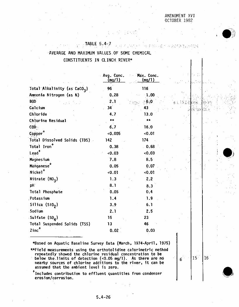
AMENDMENT XVIOCTOBER 1982
I.)
TABLE 5.4-7
AVERAGE AND MAXIMUM VALUES OF SOME CHEMICAL
CONSTITUENTS IN CLINCHRIVER*
Total Alkalinity (as CaCO3 )
Amnonla Nitrogen (as N)
BOD
Calcium
Chloride
Chlorine Residual
COD'-Copper+
Total Dissolved Solids (TDS)
Total Iron+
Lead"
Magnesium
Manganese+
Nickel+
Nitrate (NO3 )
pH
Total Phosphate
,Potassium
Silica (SI02)
Sodium,
.Sulfate (SO4 )
Total Suspended Solids (TSS)+Zinc
Av?. Conc.(mg/1)
96
0.28
2.1
34
4.7
6.7
<0.005
142
0.38
<0.037.8
0.05
<0.01
1.3
8.1
0.05
1.4
3.9
2.1
15
13
0.02
Max. Conc.(mg/1)
116
1.00
6.043
13.0**
16.0
<0.01
174
0.68
<0.03
8.5
0.07
<0.01
2.2
8.30.4
1.9
6.1
2.5
23
46
0.03
4
.
*Based on Aquatic Baseline Survey Data (March, 1974-April, 1975)
**Field measurements using the orthotolidine calorimetric methodrepeatedly showed the chlorine residual concentration to bebelow the~limits of detection (<0.05 mg/l). As there are nonearby sources of chlorine additions to the river, it can beassumed that the ambient level is zero.
+Includes contribution to effluent quantities from condensererosion/corrosion.
6 15 16
S•
5.4-26
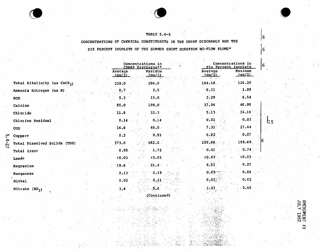
9TABLE 5.4-8
CONCENTRATIONS OF CHEMICAL CONSTITUENTS IN THE CRBRP
SIX PERCENT ISOPLETH OF THE SUMMER SHORT DURATION
DISCHARGE AND THE
NO-FLOW PLUME*
6
66°
Total Alkalinity (as CaCO3 )
Ammonia Nitrogen (as N)
BOD
Calcium
Chloride
Chlorine Residual
COD
•" Copper+
Total Dissolved Solids (TDS)
Total Iron+
Lead+
Magnesium
Manganese
Nickel
Nitrate (NO3 )
Concentrations inliCRBRP Dishare**.
Average Maximium
239.0 286.0
0.7 2..5
5.3 15.0
85.0 108.0
11.8 32.3
0.14 o0.14
16.8 40.0
0.2 0.93
373.0 582.0
0.95 1.72
<0.03 <0.03
19.6 21.4
0.13 0.18,
0.02 0.11
Concentrations insix Percent Isopleth
Ave-rage- Maximum
104.58, 126.200.31 1.09
2".29 6.54
37.06 46.90
5.13: 14.16
0.01 . 0.03
7.31 17.44
0.02 0.07
15 5.86 198.48,
0-.41 0.74
(0.03 <0.03
8.51 9.27
0.05 .0.08
0.01 • 0.02
1.43 2.40
115
6
3.4
(-continued)
C-,:>C=-rC
r.- M

TABLE 5-.4-8 (Continued)16
Concentrations i~n
eraqq Maximum
. Concentrations in.Six: Percent Isopleth'Average .Maximum.i.:.-(mg/li) •. (mg/i)
pH
Total Phosphate
Potassium
Silica (SiO2 )
Sodium
Sulfate (SO4 )
Total Suspended Solids (TSS)
Zinc+
6.5 '- 8.5
0.14
3.59.8 ---
48
33
O, 05
6.5 - 8.5
1.04.8
-1-5.3
107.3
106
114
0;. 08
0.06
1.53
4.25
2.77
16.98
-1.4.20
ý0.02
0.44
2.07
6. 65
8.79
27.98
50.080.03
co
.j6
*Based on.Iowa Institute physical model study**From Table. 10.3A-2+Includes contribution to effluent quant.ities ro mcondenser. erosion/co'rrsion.'.
6
-0 .
1,;
9

AMENDMENT VIApril 1976
TABLE 5.4-9
SURFACE AREA AFFECTED BY CHEMICAL PLUMES ANDINCREASES IN CHEMICAL CONCENTRATIONS*
[6
ChemicalIsopl ethI**
Mixing ConditionsArea(acres)
I6Typical Cases
Winter
Summer
Extreme Case-Short Duration NoWFlow
Winter
Summer
345
345
.0.0110.01
0.070.02
<O.Ol
25
46
3~.92+0.06
0.0170.02
*Based on Iowa Institute physical model study**Percent difference between initial blowdown and ambient
concentrations in river+Estimated, based on extrapolations of model plume bound-aries to achieve closure of 0.9 'F isotherm (see Fig-ures 10.3A-6 and lO.3A-l0).
6
9;5.4-29

TABLE 5.4-10
CONCENTRATION OF DISCHARGED CHEMICALS IN THE EXTENDED NO FLOW PLUMES
Total Alkalinity
Ammonia Nitrogen (as N)
BOD
Calcium
Chloride
Chlorine Residual
COD
Copper
Total Dissolved Solids (TDS)
Total Iron
Lead
Magnesium
Manganese
Nickel
Nitrate
pH
Total Phosphate
Potassium
Silica (SiO2 )
Sodium
Sulfate
Total Suspended Solids (TSS)
Zinc
AverageAmbient River:Concentration*
(mg/1)
96
0.28
2.1
34
4.7
6.7
<0.005
142
0.38
<0.03
7.8
0.05
<0.01
1.3
7.9
0.05
1.4
3.9
2.115
13
0. 02
Average -Plant DischargeConcentrat i on*(mOg/1) ..
239
0.70
5.3
85
11.8
0.2
16.8
0.20
377
0.95
<0.03
19.6
0.13
0.02
3.4
6.5-8.5
0.14
3.5
9.8.
15.0
150
330.05
Extended No Flow Maximum Plume ConcentrationsWinter Case . Summer. Case
@ End. of [@End of @,End of @ End of15 Days 30 Days 18 Days. l1 Days(mg/T) LýL±L. (mg/l) ý(mg/i)
117 135 106 . 107
0.34 0.39 0.31 0.31
2.6 3.0 2.3 2.3
41 47 37 38
5.7 6.6 5.2 5.30.03 0005 0.01 0.01
8.2 9.5 7.4 7.5
0.03 0.05 0.02 0.02
176 205 158 1600.46 0.53 0.42: 0.43
<0.03 <0.03 <0.03 <0.039.5 11.0 8.6 8.7
0.06 0.07 0.06 0.06
0.01 0.01 0.01 0.01-1.6 9.9 1.4 -.5
6.5-8.5 6.5-8.5 6.5-8.5 6.5-8.50.06 0.07 0.06 0.061.7 2.0 1;5 1.6
4.8 . 5.5 4;3' 4.4
4,0 .5.6 3.0 - 3.0
20 24 17 1816 18 14 140.02 0.02 0.02 0.02
6
16
*From Table 5.4-7
**Field measurements using ther.orthotolidine calorimetric method repeatedly. showed .the- chlorine .residual concentration :tobe below the limits of detection (<0.05 mg/l).; As: there are-ýno nearby :sources'of cchlorine additionsi to the river, itcan be assumed that the ambient level is::zero...
+Continuous discharge assumd
C:).
15

AMENDMENT VIApril 1976
% %
SURFACE
4%
... ..... EAVRE AETPO I N T 0 :- L V O 3
•--~~~~~~~ W •"r/_. " ATE L•EVEL ,ATr LOW POOLELIEVA•" O•<:TTION 735FEET MSLflowvelocitypool eevatio ,n
1.39 fps (0.87 fps)*736 ft MSL -DISCHARGE ýJETS
2f 1ow - ý5ý.57l;c-:velocity. = 15.*96 fpstemp. diff. 31 . OF*PrToIotype velocity based on hydraulicmodel
velocity. Reflects physical limitat.ios ofthe flume.
. .
BOTTOM
40/2o 3%
DISCHARGE POINT 0 100 200
SCALE OF FEET
- "- - WATER LEVEL AT LDW POOL ELEVATION (735 F1EIET MSL ).
Figure 5.4-1 CHEMICAL PLUMES FOR TYPICAL CASE-WINTER(Based on Iowa Institute physical model study)
16
5.4-311

AMENDMENT VIApril 1976
SURFACE4%
- --- •-5%
DISCHARGE POINT 0 100 200
SCALE OF FEET
- -WATER LEVEL At LOWý POOL ELEVATiON. (735 FEE .T MSL).RIVER
flow - 4777 cfsvelocity'.1 = 0.63 fps (0.50 fps)*pool elevation 741' ýft MSL
*Prototype velocity based on hydraulic model
velocity. Reflects physical limitations'of the flume,
DISCHARGE JET
flow = 7.22 cfsvelocity = 20.68 fpstemp. diff. - 23.6F°
9;.......-.. --.- ----.
BOTTOM
o 3%
DISCHARGE POINT o 10 200
SCAL'E OF FEET
. WATER LEVEL AT LOW POOL ELEVTI1N (735 FEET MSL).
Figure 5.4-2 CHEMICAL PLUMES FOR TYPICAL CASE-SUMMER(Based on Iowa Institute physical model study) 6
5.4-32

AMENDMENT VIApril 1976
... ,.
I ISURFACE
5Q/I
1/5v
DISCHARGE 0.. . 0 200
2
RIVER
flow ... ..velocity .pool elevalti ontemperatu-ure
-o.01:: (0.1 7 fps)*-7-35 ft MSL=.330.F .
--- WATER LEVEL AT LOW POOL ELEVA ION (735 FEET MSL).
EXTRAPOLATION OFPLUME WIDTH GROWTH BASD N PHYSICAL
MOOELOA. - • S:"' N HYSICAL
- ETIATiON-OF:PLUM.Eý ~DISTORATION DUE TO INTERACTION WltHýOPIPOSITE SkHOE:.
DISCHARGE JET
moelflow - 6.26, cfs'm Odef v elocti ty = 17.93 fps,.
t&ain ing' temp.. ~diff. ý= 461 .8FOiment of
*Prototype velocity based on hydraulicvelocity. Reflects necessity of.,miinia flume crossflow to permit the attaiiSteady-state- conditions.
BOTTOM50/%
DISCHARGE POINT o 100 200
SCALE OF-FEET
.... UtTER.LEVEL A1 LOW POOL ELEVATION (735 FEET MSI.)
Figure 5.4-3 CHEMICAL PLUMES FOR SHORT DURATION NO FLOW: (HypotheticalWinter Worst Case - Thermal Mixing)(Based on Iowa Institute physical model study) I 6
5.4-33

AMENDMENT VIApril 1976
SURFACE..
SURFACE
60/6
DISCHARGE ýPllN.I
RIVER
"fltow .vel oc ity-pool "-elevation-temperatu;re =
0 (0.17 fPs)*'739 "ftMSL••78 F
0 0,0; 200
SCALE:OF FEET
---- WATER-LEVEL AT:LOW POOL. ELEVATION (735 FEET MSL).
DISCHARGE JET
flowtm di l.31 .cfsvel1oc ity 20.'94 :fpstem~p. diff.. 7. 1 6F'
.*Prototype velocity .ased on hydrauLic model'"veOlocity. Reflects necessity ofmintaininga flume crossflow to 6permit the 'attairnment,of steady-state conditions.
~~~- - - - - - ------- "-'- *' . a :
BOTTOM • ._, ..l , l4%/ . .
DISCHARGE POINTO 100 200
WA CAR LEV AOF FEET L " ( E .
... WarER LE'VEL AT. LOW P OOL E.,EVTION (735 FEE"T.MS).
Figure 5.4-4 CHEMICAL PLUMES FOR SHORT DURATION NO.FLOW :(HypotheticalSummer Worst: Case - Thermal Mixing)(Based on Iowa Institute physical model study) I 6 0
5.4-34

AMEND. IXOCT. 1981
5.5 EFFECTS OF SANITARY AND OTHER WASTE DISCHARGES
In this section effects from sanitary wastes on the Clinch River aswell
as effects from gaseous effluents from the emergency diesel generator
and the diesel fire pump are discussed and evaluated.
5.5.1 EFFECTS FROM SANITARY WASTES
Sanitary wastes are described in Section 3.:7. These-, wa:stes,•comparable
to normal domestic sanitary-.was t.e,.-wi,.ll-: enter a: Sewage D Di Sp:os6aSlA System
consisting•of an extended aeration -package treatfmenthplant. The operatingperiod (permanent) plant will include a slow sand filter that wi-•• be
installed following the CRBRP. construction pe:riod...
9i
The sanitary system for the :construction period i-s desi-gned for ,a peak.-"
manning of 2,450 persons. Maximum daily sanitary wastewater design flow-:will be 61,250 gallons, or 25 gal/person/day. During construction, a uni,,-tof 13,000 gal/day and a large unit of 52,000 gal/day Capacity will be 8
installed to give a total treatment capacity oif 65,;000 gal/day.
The average daily sanitary wastewater flow during normal 'operatiton willb@7,000 gallons. This is based upon 200 plant personnel, or 35 gal/
person/day for normal plant:operation. Present projected number of plant
personnel is .179 persons with a peak manning of 300 men anticipated for8annual-shutdown. The permanent plant design flow of 13,000 gallons per
day will be adequate for this loading.
9.
5.5-1

AMENDMENT XIIIAPRIL 1982
waste systems will be designed in accordance with the Tennessee -
Department of Public Health Design' criteria'.(1, 2 ) Treated
effluent discharges will meet NPDES Permit limits.
Cooling tower blowdown is approximately 2,650 gpm or 5.9 cfs in
the summer and approximately 1,955 gpm or 4.3 cfs in winter.9
Sanitary effluents during normal operation at full load will
become diluted by the cooling tower blowdown 530 fold in the
summer and 390 fold in the winter. The small concentration of
pollutants (listed in Table 3.7-1) in the sanitary effluent Wil l.
become further diluted in the Clinch River waters (6,772 cfs, ,
average winter flow and 4,339 cfs average spring f1ow0). The.
concentration of pollutants in the sanitary effuent before
dilution will meet the NPDES Permit discharge criteria and are
not anticipated to have any effect on the water quality of the
Clinch River or on its aquatic biota at the mixing zone or obeyod
it, even for the worst case of no-flow conditions discussed in
Section 5-.4.
Sludge from the sewage treatment facility (the aeration package)
will be trucked off-site by a contractor for ultimate disposal,
as discussed in Section 3.7.
5.5.2 EFFECTS FROM GASEOUS EMISSIONS FROM EMERGENCY DIESEL
GENERATOR AND DIESEL FIRE PUMP
Emission rates of gaseous pollutants from the emergency diesel
generator units (quantity-3) and the diesel fire pumps
(quantity-2) are given in Table 3.7-2. Emission regulations for
the State of Tennessee for NOx apply only if the total heat input
to all the units exceeds 250 million Btu per hour.( 5 ) Heat input
is 159.11 million Btu/hr; thus, these diesel units are not
regulated for NOx emissions. Emission regulations for Roane
.1
;113
13
5.5-2
AMENDMENT XIIIAPRIL 1982
County limit SO emissions to 5.0 pounds of SO2 per million Btuper hour heat input.(6) Emissions of SO2 are 0.547 pounds permillion Btu per hour heat' input and comply with the standards'.Particulate standards limit emissions to 0.13 pounds per millionBtu per hour heat input for total plant size of 159 million Btuheat input.( 7 ) Emissions of .particulate matter as found in Table5.5-1 are 0.0076 pounds per million Btu per hour and-com:plywiththe standards. Carbon monoxide emissions for stationary sourcesare not regulated. The limit placed on organic compoundemissions will be determined at the time of the permitapplication review by the Technical -Sec~retairy of -tehe Tennese••Department of Public Health; Divis'ion of. 'Air Pollutio"nControl. (8) Because the emissi0on rates of.the gaseou's ,pollu'tantsare within the limits cited in the governing regulations and-thel 1source of these gaseous emissions i's t.he emergency equipmentwhich operates infrequently, the gaseous emissions do notconstitute any hazard to the local environment.
5.5-3

TABLE 5.5-1
PRDVIIO .L-PR fIN E-DUBM-2QGIN S-0liLTIc
o,
1. Quantity
2. Test
a. 'Frequency, per Unit
b. Duration, per Unit
3. Fuel. consumption rate,
gal/hr
4. Heat input, 106 Btu/hr
(Fuel Heating Value, of
130,000 Btu/gal)
5. Maximum emission rates of
pollutants released to
atmosphere:
a. Particulates, lbs/hr
(lbs/106 Btu/hr)
b. Sulfur dioxide (SO 2 )lbs/hr
(lbs/10 6 Btu/hr)
DIVISION 1.& 2DIESEL GENERATOR.
2
1 start test per
month & at least
1 full loading test
every 18 months
2 hours & 24 hours,
respectively
1,012
1
Same as Division
1 & 2 DG dnits
Same as Division
1 & 2 DG units
187.22
DIVISION 3DIESEL GENERATOR- DIESEL FIRE
2
1 startitest
per week
30 min.
26.2
13.
131 .4
1
(0.0076)
.71.8
(0.5ý47)
24.31
0 .185•@.o0076):•
(0-. 47)•:0ý. 5-4•7):
3.4
0 026
(0.0:076)
:1 .87
(0.547)
;0., ,r
co-
--®r

TABLE 5.5-1(C6ntinued)
MNM L2ARAERSA EXHAUST EFFLUETS FROM . .• .
DIVISION 1. &. 2DIESEL GENERATOR
DIVISION 3DIESEL GENERATOR DIESEL FIRE
__PUMPS.
!1
U,
5. (Continued)
c. Nitrogen oxides (NOx),ibs/hr
(lbs/106 Btu/hr)d. Organic compounds, lbs/hr
(lbs/106 Btu/hr)e. Carbon- monoxide. (CO),lbs/hr
(lbs/10 6 Btu/hr)
402 74.37
(3.06)
7
(0.053)
(o,1o9)
(3.06)
1. 195,
(0.05$3)i
2.66.4
(0.169),
10.45
(3.07)
0.182
(0.053)
0.374(0.11:0)
13
IN) >

..i l
I NTENTI ONAILLY •BLANK 0 •
• .i,..

5.6 EFFECTS OF OPERATION AND MAINTENANCE OF THE TRANSMiSS-ION SYSTEM
No significant adverse environmental impacts are expected to occurduring,.normal operation"of .the transmission lines. Maintenance of theright-of-way (ROW),will involve regular.,cleari ng, operations which willcause a disturbance to plant and animal :communities, within the cor--ridor.
5.6.1 -ELECTRI CAL EFFECTS:
--Electrical effects such as corona, audi~ble noise. radio and, teleeVisijon:interference, ozone producti on anideliectrdostast€ic inaduction mayberassociated with the operation of transmission lines-. These effectsand the associatedl environmental impacts ,-are dis cussed' itn:ý the fo.lTlowi~ngSubsections.'.
• 7.
5.6.1.1 VISIBLE LIGHT
Corona- has been.-, des cribed.asa.luminous•discharge cused .by the ionization
of the-aii in:.. the vicihityof a cndutOr It is a.partia.breakdownof .the dielectri c cons tant:.of the, air_,-ý, caus ed. by abi c0ncen'tration _ofelectrical stresses at the edge of an electrode in an electrical-. field.or by increased- stress.. across a low. .dielectric €, strength :,material inseri es -w:ith other:: insulated materials. Electric corona. alongý a, trans-.mission.:,line conductor.- occurs when the-potential of., the conductor inair is ,,raised:.Ato .such•: .a: val.ue:. •that the: dielectric strengt-h of thesurrounding- ai:r.:is-exceeded-. Coronamanifestsitself by:. bluish.tuftsor streamers :appearing around the, conductor particularly where.abrasions,"•-foreign. parti cl es and- sharp points, .are, located along. the conductor. Underfair-weather conditions,"corona will not be visible along the 161-kVlines. Under foul weather conditions and on a'dark night-, a glow:maybe visible. Corona, however, will be minimal :and will cause no adverse:environmental effects or inconvenience.
ti -
5.6-1

5.6.1.21 AUDIBLE.NOISE.
.Audible noise is measured with. an acoustical..sound level meter (SLM)•.
During fair weather, audible noise emanating from. transmission: lines
of any voltage ýis .not usually measurable:.above normal ambient sounds.
During inclement .weather and. unusual 1.atmospheric. conditions, .a light
humming may be heard directly under transmission lines. In its operating
experience thus far, TVA has not experienced problems with audible-noise-
from either the 161-kV or the 500-kV transmission"'in-.i•sno'•,nbprobl:ems:-_•-"
are expected with this transmission iine.
5.6.1.3 RADIO AND TELEVISION .•INTERFERENCE ..
Measurements of. radio ..noise (RN) were ,made inthe>vi~cinity oflseve~ral•,
161-kV transmission lines on the TVA sys tem more than a year before the..first 500-kV line was. energized. As the. 500-kV network began to .grow.,-
a fairly comprehensive' RN measurement program was initti-ated •and& .sinced-•-•, '-.
that beginning, measurements have been made beneath and near every- 500-kV
trans mi l in pconstructed-y!TVA- cAuse- oefmvtheowPnoise' lvs
found initially, thel possib i ity of problems with161-kV lines ....dis-
counted and few::subsequent measurements were made,..
.During all of TVA's; radio noise,ý program,, -the -selection::of measuring si tes,,,
instrumentation and -measuring-techniques' have conformed to:the recommenda-
tions of the. IEEE Radio Noise' Subcommittee.. Measurements•. at a lateral.,-,
distance of.50 feet from a point:-directly beneath the outer .ýphase •.and
at a frequency near 1.0megahertz (MHz-), the approximate-center of the,.
broadcast band, are preferred, Noise-meters should have. ,quasipeak (QP.)
detector -characteristics.': The. units usual!y. preferred&.-for, expressingl RN
are decibels above one microvolt per meter (dB above,1.0:OvV/m); thisJis -
also frequently used to express field intensity of-a broadcast-radio
signal. The average of a substantial number of measurements, taken 50
feet from typical 161-kV lines, is about 29 dB-above 1.0 ipV/m during
fair weather.
5.6-2
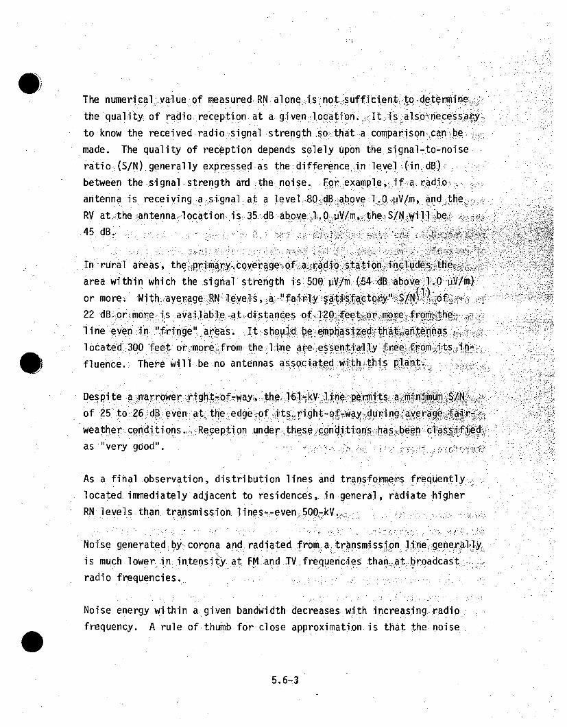
The numerical.:,valueof measured-RN alone.,,.i~s.,'hnot'.•.sufficiento t9.,det6mi neh.the quali ty of radio ,reception a a given locationt.a I is Iasohecessary.,
to know the received radio signal strength so;.,that a comparison,., canp, bemade. The quality of reception depends solely upon the signal-to-noiseratio (S/N) generally expressed.as the: difference in level. (,in .dB),!
between the .si gnal strength and the :noi se., For: example.,.if a.radio,antenna is..receiving a, signal: at a level .80 dB,-above 1.0O.iV/m, and. theRV at-ýthe antenna,-I ocation, is, 35. ,dB above1.. 0,;V/m, the-S/N-:lwill be
.dB,.
Inrra res teprm yycoerage of a radio station, includes the,area within which the signal- strength is 500. ,v;/m (54 dB above 1..O vV/m)or more., With.average RN levels-, a fN` •a'fairy.atisacto'.."/N.: of...22 dBý-or-more :is avail abe1 'at.distances of-120. fee tor more. fron-the-
lnevni"fringe" 'areas. I t, s houl]d' be- e~mph-a:sie thaatnalocated 300-feet or 4more. ,f-rom the-, lIine are.,eSsentiaily free fromnits i-fluence.;• There Will be no antennas associa4ted ,wi th. thi~s plant•...
Despite a, narr owe r ýrigqht ~f -W4y, t he0 16lk Inte ýpermits a minimum, I-Nof 25 to 26 dB even. atteedge ~of .fts, right-of-way dUring average f ai.r-,wea ther .condi.ti ons. :.-.:.Re ce pti on unde r--., these cnditionsd , has-been classii•edas "very good" .
As a final observation, distribution lines and transformeers f requently,located- immediately adjacent to residences, in general, radiate higherRN levels than transmiss-ion lines--even ,50Q4kV..
Noi~se generated by corona and radiated from a transmission lIhnegenerallyis much lower in: intensity at FM and ,TV frequencies than at Abroadcast..radio frequencies...
Noise energy within a given bandwidth decreases with increasing, radio ,frequency. A rule of thumb for close approximation is:that the noise.
5.6-3

level (in microvolts perý meter) varies inversely as the frequency. For
example, if measured RN is -100 pV/m at a freqeuency!1.0 MHz, it would be
approximately 10 pV/m.at 10MHz--a drop of 30 dB.
,This relationship has been borne out by measurements which indicate that
the noise levels directly.under a transmission line at television
frequencies are usually comparable with ambient level's'. .Numerically-,...
these levels fall-in the range between 0`.;`` "and2. 0 r at" .. 0V M ..... e h
referenced to the same bandwidth as the L.O MHz readings,. With theaid
of portable TV receivers, it has been demonstrated that noise from thetransmission, line has .no noticeable effect'oen.reception.
.e co -' .. ..s .. . -
In other parts of the country, it has b f... d t hat•'s i t htti a• - TV-`interfe-rence i s •oetime*s radiated fromextra-high voltagepoer"'li-nes.
duri ng seVe snow torms or.r iciing conditi"ns. Severe s toms or im..ig'.cond.itions o•uso infrequently i:h the ara eof: the•',.RBRP tat tis.
potential probe!m isalmost no n6existeht.
The proposed':'transmiss~i6n. l'ines are locadted ý.,in ..a..ecl uded area:w'frthe ogeeral public except for the tap poi nt n -the' Vi iciA n"ity y' idf W ih ft
Wing Road No" rsidences or bsnesses`ar-e c et the p--propsed-linetherefore, there will be no effect.-, .
5.6.1.4 OZONE PRODUCTION
Under some conditions, ozone may be produced in`small? am:ounts! from corona
discharges (ionization of the air) in the operation of transmission linesand substations,'particularly at the"higher voltages. Though.it":' beif
harmful if breathed in. suffiCient concentratiohs over prolonge dperiods,-
it is not considered to be injurious to vegetation, animals and-'humans'
unless concentrations exceed about 50 ppb. Preliminary studies conducted
by Oak Ridge National Laboratory indicate that concentration directly
beneath transmission lines may approach 1 to 2 ppb.(2)
5.6-4

Extensi ve fiel d tests to detect ozone i n. the vi cinity of, 765r-kV li'ines,' . " " :were conducted by the Battelle Memorial Institute under a variety of.-- "l (3) "" l
meteorol ogical condi ti ons . . FrOm these .tests-, it was', concludedt•that."nosignificant adverse."effects-, onlvegetation.,, animals-_.or humans are. to be .expected from levels of ozone that may be produced.in.the-- operation..-of.•.;"
transmission facilities at voltages up to 765-kV.
In view of the design and construction standards employed by TVA inbulig its, transmiso failtes ;co~rona discharges a re minimalo"
nonexi stent• Ac'cordin'igly, any, o•one which coul: possi:blybe. g.nerated"
by, theýý proposed -transmis~s~ion 1 nOinew1l6l14k-V nfomi~nal Vol tage)' woul d beenvi.ronmennta:lly',in'conSequen•tial a•nd..harmless" to• vegetatio, aiais and
h Lman's I
5.6; 1 5 ELECTROST•A I C INDUCTION
High-voltage..lin6es.: and equi pment stermi.nas can, un dercerta'inconditions
High-voltage power lines and equipment operating in close-proximity to- /
telephone and signaling -equipment can produce' undesirabl~e" effects on:,the'!communication ci~rcuits through induced voltages.. For the-proposed-trans-'-mission ine, conn ctions, there- are nonearby communications facilities,
fences o-r otherungrounded objectsthat wil be affected. Si:nce thereb.are no .residences or' businesses close to' the proposed lneu radio ortelevision interference is not considered tobe a problem.
5.6-5

5.6.2 MAINTENANCE EFFECTS eThe right-of-way. (ROW) will be. inspected annually, by_ heljicopter,-;. and by.!=.
ground: patrol when necessary, to insure that- the equipment::.i~s in ,a safe_'.and reliable condition.
5.6.2.1 VEGETATION
Vegetation in :the ROW,.wi.l•l•be .alowedt•ot reach a•"axjmum i•ei ght .of 115-"feet, the-highest allTw abl e: . , .ae-.1k.ficatibns;.- Corri dor ;vege~t.ati•on. til,il therelfore;lirobab• --cutT back •,
every four.: to ffive- years,. .Cl~earitngý-,i s-;:done ,-bya-.,-.far~m.,:m tracetori..wth a: -bushhog attachment. This treatment will leave a-standi:ng cover of .proximately one foot in height. A TVA field supervisor makes the deci-
sion and instructs the clearing crew frmn on.s.e'ci"i... ethbd t.. -•"ob •"used. Protective vegetation will be retained al;ong the, streambanks tomminmi.:ze.'s il tat ýzifon. Outsi de.:..of the: ROW', tr~ees, or limbs in danger, offallin acros a ine 1win be.t tr.inme d orremor v edr C"'"ng. operations.,.with ;ithel. objective o•f,. maintai ning, :he&rb aceous:,,and .esih rub cover an•. :repressingtree- growith.-,,w:ill ll...inh-i~biý,t:.naturall, -plant s~uccess4o•na•long the ROW. Each'.clearing operation wi.l, destroy. ;•the, .ipl~ant:, g.rowthwhiich> has occurred sincethe last clearing and will have a significant effect.
5.6.2.2 WILDLIFE:
As. the plant communi.ties .J n the. ROW:change. fronm low; herbaceous: to is-hrubbycover with the invasion of, local plant species, the animal-species whichuse the ROW, wil Ialso change. The growth of-,shrubs, and saplingswill
.'......~-ng -.
provide a diverse habitat,,..more suitable for rthe many specci-es consiidered
edge species, as discussed in Section 2.7. Songbirds, especially, showan increase in number as natural succession alters the corridor vegeta-,tion.. Increased plant growth means more food and cover available to suchspecies-as deer, rabbits and woodchucks, among others. As the corridor
5.6-6

AMENbmENT XVJULY 1982
cover changes from grassland to heavy bus-h, such species as thebobwhite quail will decline in numbers. Clearing .will return thearea to shrubby habitat areas. This cycle willcontinue as lnongas the area is maintained by regular clearing operations.
The presence of 85-foot high transmissicin towers, approximately15 feet taller than the bordering forest, is not expected to,effect the Canada goose migration across -the CRBRP site.
5.6.2.3 ACCESS ROADS
Existing area roads will suffice for ma'intenance work; themajority of these roads are presently s ur fAcedw'Vi th graveI,regularly maintained and restricted to th'e'public. Any ruttingcaused by mnaintenance'vehi'cles on these roa~d9:w'ill ̀ be r'epaired' by.ýgrading and reseedingý or g•ave6ing as necessary. Some routinemaintenance work or emergency work wil require wvehcuati lr :t'raVf-,f ic.on-the ROW. Rutting will5 be repaire-,d by-hand" or'mcie an dandrainage disturbed will be restored.
5.6.2.4 AESTHETICS
Visual impacts considered during plant operation included viewsof the site, containment building, and cleared transmission linecorridors. The CRBRP site will be visible from various vantagepoints near the plant site. Both the site and the containmentbuilding will be visible from portions of both 1-40 and S.R. 58.Both the site and the containment building will be visible fromrecreation sites 1 and 2 listed on Table 2.2-8. The 'site will 15not be visible from any housing development within the study areabut will be easily seen from many of the single-family homes fromacross the Clinch River. Neither the containment building northe plant site will be visible from any significantly offsitehistorical site or structure within the study area.
5.6-7 -

AMENDMENT XVJULY 1982-,.
Cleared rights-of.-way can also have a profound visual impacton,"the environment. Usually this impact is most noticeable-when thei.-
lines pass through scenic, recreational or historical areas orwhere the public is afforded extensive views of .the facilities.Only a short expanse of the proposed corridor is visible fromWhite Wing Road and it is visible for only a few seconds to i15
motorists, as discussed in Section 4.2,. Although a newly cleared,.
transmission line is.not generally an aesthetically .pleasing'..
sight, public viewing of corridors in. this ýcondition will be
insigniific-ant in terms of .time and, amount of` line, obseral
Natural buffers of vegetation -wiill be maintained were publicviewing of such maintenance conditions would be osibl-e. Theremainder of the proposed trans ities are, out of
sight of public view as access to the ROW is controlled by locked
gates..,at: all times In 'sýmmary, aesthetic impac;ts: during plantoperation are considered il nsignficant because ,,of the limited 15
amount .of time when either the .site, conta~iment° buil:din, ..ortransmission line cqrridors, are, visible. to the observers d g-uring
each year.
*1
5.6-8

AMENDMENT XVIOCTOBER 19826/
5.7 OTHER.EFFECTS OF PLANT -OPERATION,,
Operation of the CRBRP should- institute no!_::changes in 'land use.
not already abrogated during ,the constructionphase..Comparisonof the construction phase to the. operational phase :should, infact, result in relief of some:of .the.man-induced:stresses due *tosignificant reductions in the mbtion and noise .:of' heavy .equipmentand vehicular traffic at .the plant site. Stabilization ,_of ,.routing should res ult: in greater-. tolerance o,6f. -the. :.i-nstallaltion,03n-bythe terrestrial population•:- .;The .effect. s o't pnt "" ration are,-discussed in Sections 5.1 th rough 5..- Becau seeo'fthe plantdesign and..the.- distance ,.of the Site from: otherinddstrial orpower plants in the, area (ORGDP is three.milesnorth-nrthwest)the CRBRP should not have significant; thermal or radioactive 1.6waste: interaction -with effluents releasediby other plants. n'thearea. No wastes from, the ,.plant are ant~ic ipate, ,to, ,bei.& di sp-os ed- of,by:means. other than those discussed in-Sections 5.2.through .5.
5.7.1... FUEL CYCLE R.VISION .,6
The CRBRP.. f ue icyclpe jincclu des-. mixed oxi'd e ,(MOXY) f:ue fabrication,blanket element, f abricat ion, reprocesssin.g, . rmanaglemenht' ,of' the-wastes generated, by facili.ties in the fuel' cycle. and
transportation of wastes and-,products among the.: various"facilities.,; Some of the facili-ties requi•red to support. the CRBRPfuel cycle are not yet available.- Notable.examples are a fuel 14:reprocessing- plant c.apabl.e. .of. ha.dling':,CRBRP: fuel:, and a --feder a.l .repository for radioactive waste disposal. The:.environmental: , t16impacts estimated herein use existing information regarding themost likely design,of these facilities for_ those, that, are not yetavailable. -This assessment also assumes that, appropria~te,facilities will be available in, time, tosupport~the CRBRP fuelcycle such that interim measures like. away- from .reactor fuel
* storage and product storage: are not required.-
5.7-1

AMENDMENT XVIOCTOBER 1982
A simplified schematic diagram of the CRBRP fuel cycle is shown
in Figure 5.7-1. The mass flow parameters are characteristic of
those for the CRBRP under pseudo-average equilibrium-cycle "
conditions (where the cycle-to-cycle variations in-the batch.
CRBRP fuel management have been averaged out).. At equilibrium,
approximately.0.9- MT of plutonium and.l MT of depleted uranium
are fabricated into mixed-oxide fuel and blanket'assemblies per
year.. One half of one percent heavymetal has been assumed to be
unrecoverable in the fabrication process. In thed react0r-'zcore,
.irradiation at 9.75 MW(th): for 27 4•k equivalent-,fful.poý day&-
•de st r.oy s approximately _,.28& .MT of plutoniumtn,ý.ad O0 d,0 T o u r ani, um
per year through fission and nuclear transmutationh.,r..eactio6ns.:-:- :
0.27 MT of fission product isotopes are 'produced:dpe'r. year.-
Because of the breeding characteristics of the -CRBRP, plutonium
is both .produced and destroyed in the core and• th• di s bcharge ,fU el
and blankets .-contain approximately 1.0:0MT of plutonium. This
spent fuel is-chemically repr-ocessed, where .once,. ag&in 1/2%V of..
-the heavy metal isotopes are assumed to be unrecoverable.
.Fission products, irradiated structural materla d•a o -ther wastesare shipped to a waste disposal facility. The recovered,
plutonium (0.99 MT/year)-, and' perhaps the uranium as'swell, is
recycled as fresh fuel input to the' fuel fabricationifacilities•.
The net gain of approximately 0.10 MT of plutonium per year can
be stored for later use'. The contribution of the plant fuel
cycle to.the environmental impacts is in Table-5.7-1, "CRBRP
Summary of Environmental Considerations for Fuel Cycle." Below
is a description of the facilities and-methods used to estimate
the Table 5.7-1 impacts.-
DOE will supply plutonium to 'startup and operate CRBRP during'the
five-year demonstration period. :The plutonium will come from
existing DOE inventories,.processed domestic- nuclear power
reactor spent fuel and, if necessary, foreign sources. A-
simplified schematic diagram of the CRBRP fuel cycle with Pu
recycle is given in the Appendix to Section 5.7 (Section 14.4A).
116
j1-6 "-!
14
:16*
116
16 @
5.7-2:.

AMENDMENT XVIOCTOBER 1982
No impacts are included in the estimate in Table 5.7-1 for
production of this material. These impacts 'have been-addressed
in other environmental impact documents..
Table 5.7-1 includes estimates of environmental impacts from
reprocessing of CRBRP spent fuel, including oxide conversion.
Reprocessing of CRBRP spent fuel would produce adequate plutonium
to fuel the CRBRP.
The DOE-supplied.plutonium may require conversio to an oxide
form at a yet to be determined facility' prior, toif uel
fabrication. Oxide conversion is planned as a step at thereprocessing plant. The ,impacts of conversion: atre boundeýd. by.the
impacts of operating the- reprocessing, plant given.in Table 5.7-I.
5.7.1.1 CRBRP FUEL FABRICATION
14Fabrication of the mixed oxide core fuel is planned to :be
performed at the Secure Automated Fabrica~tion (SAF) , lihne!, ,to be
installed in the, Fuels and .Materials. Examina~tionFailiy ,F
at DOE's Hanford reservation-. CRBRP fuel fabrication Vwilrequire about 65 percent of the SAF line operational schedule., .(15,
of every 24 months). The data presented in Table 5.7-1 for mixedoxide fuel fabrication are based on the impacts in DOE/EA-0116.ý-.."Environmental Assessment for the Fuels and Materials Examination
Facility," July 1980, and supplement. (6),,(7)
The Secure Automated Fabrication (SAF) Program has as itsobjective to develop and demonstrate an advanced manufacturing
line (SAF) for plutonium oxide breeder reactor fuel pins. This
line will be the source of fuel for the FFTF and the CRBRP. TheSAF line will utilize technology that focuses on improved safetyfeatures for plant operating personnel, the public, and the
environment.
5.7-3
Amendment XIVMay 1982
Fabrication of fuel on the SAF line in the fully automated and
remotely operated mode results in the following important
advances over current manual fuel fabricaton technology:
o Reduced radiation exposure to plant personnel
o Reduced access to Special Nuclear Materials (SNM)
o Improved containment.of SNM
o Near real-time accountability of SNM
o Improved product cost and quality
o Increased protection of .the.public and the envirOnment:from.fxditi,
radiation or contamination,. .
The basic fabrication process includes receiving and,'assaying.
nuclear ceramic powders, blending of the p.owders, pe1leti'zing and
sintering the powders into fuel pellets, and loading these
pellets into finished fuel pins. The SAF line will:include
necessary support systems for nondestructive assay, SNMaccountability, rapid chemical analysis, waste and scrap Shandling, maintenance, and material handling. All. processing 14
equipment and support systems will be combined, to form, .an-,interdependent, fully integrated,. automated and remotely .operait'ed
fuel fabrication system.
Prior to introduction of feed materials to the fabrication line,
an analysis and characterization of the feed will be performed.
As the feed material progresses, automatic measurements of the
quantity of SNM will be conducted and recorded in the process
control and safeguards computers.to maintain a continuous record
for process monitoring.and for safeguards and accountability
purposes.
The SAF line is designed to minimize the spread of contamination
and the threat of diversion. Process enclosures are designed for
01
5.7-4

Amendment XIVMay 1982
each subsystem. Glove ports and windows will be incorporated to
allow for "hands-on" maintenance. All containment structures.
will have built-in shielding, and the process equipment will.
incorporate supplemental shielding as necessary to meet radiation
exposure criteria.
SAF equipment is within contamination control enclosures
physically located behind isolation walls that function as a
secondary confinement barrier. Plant operating pprsonnel ..are
normally located in an operating corridor that isoon stheite
side of the isolation wall or in the. operations .computer tcente.r
where all process operations are monitored and coordinated.
Under normal operating conditions, plant personnel located' int
operating corridor can control and monitor the performance of
process equipment. There will be no penetrations in theisolation walls that would provide direct access to the process
equipment by the operators. Under abnormal conditions, theoperator can utilize local controls that can be activated to
control operation of the process equipment. while visuallymonitoring its performance. If tooling changes must be made or "
when routine maintenance must be performed that requires the
presence of an operator at the working face of the containment,*
.the fuel material will be removed from the equipment as necessaryto maintain personnel exposure limits and to minimize SNM access.
The mechanical assembly of the welded fuel pins produced by the
SAF line into fuel assemblies will be performed in Building 308on the Hanford Reservation. This is an existing, multi-purpose,
plutonium facility that is safeguarded as described in 5.7.1.5.The first four cores of the FFTF were assembled into driver fuel
assemblies here. The CRBRP assembly operation will produce no
gaseous, solid or liquid radioactive or toxic effluents and will
have no significant environmental impact.
5.7-5
AMENDMENT XVIOCTOBER 1982
Uranium dioxide feed material for the SAF line will be obtained
by having existing UF6 at DOE's diffusion plants converted at a
to be determined commercial facility, For the purpose of
estimating environmental impacts in Table 5.7-I, conversion is
assumed to take place at the blanket fuel fabrication facility.
The total uranium conversion capacity required to support the
CRBRP fuel cycle, including blanket fabrication, on an annual
average basis is lIMT.
Blanket fuel fabrication for the CRBRP will lbe carried out ata a
yet to be selected commercial 'facility. An average: of
approximately 70 blanket fuel assemblies will ýe required per
year. There will be about 100 kg of uranium per assembly. Thus,,
a conservative throughput of about 7.5 MT/yr of uranium is
assumed. For the purpose of estimating the environmental impacts
in Table 5.7-1, the impacts of the model U02 fuel fabrication
facility in WASH-1248 were apportioned to a 7.5 metric ton/year
throughput.
14
5.7.1.2 CRBRP FUEL REPROCESSING
Demonstration of technology for reprocessing and ricycle of LMFB.R
fuels is planned to begin a few years after the planned initial
criticality of the CRBRP. The Department of Energy plans to
demonstrate technology for commercial reprocessing of LMFBR fuels
by reprocessing of CRBRP (and other) fuels in the Developmental
Reprocessing Plant (DRP) (formerly called the Hot Experimental
Facility). There has been some preliminary conceptual design of
the DRP, sufficient for preliminary environmental analysis which 116
indicates that such a facility can be operated within existing
and proposed environmental guidelines( 8 ). A description of the
DRP design follows.
5.7-6

Amendment XIVMay 1982
Study and plans to date for the DRP have focused on a new stand-Salone facility at a new site. However, some preliminary thoughthas been given to constructing a "breeder head-end" (fuel receiptand storage, shearing, dissolution, feed clarification, firstcycle solvent extraction, and waste processing) at an existingreprocessing plant, (e.g. at Savannah River, Hanford orBarnwell). Final decision on a "stand-alone," "breeder
head-end," or alternative DRP will consider cost, :envirohmental:impact, impact on existing reproce'ssing plantporm' and
importance of a reliable' de-monstra6t:i~o~n"ý...
Reprocessing capacity for the DRP* has been, set ati about_ 1/2-11ýmetric ton of heavy metal (MTHM) per d ay This capacirty IiS`a
compromise between the minimum that will permit scale-up- to. aproducti~on-s8cal-e o.pera;6t'ýio'n -w-it.h- rebaso'na ble' assur~-an~ce-; ofr sluccess,;v
and the maximum that will petmit a meanihgful.• emnstratoibn ofreliable reprocessing systems with the limited quantities ofLMFBR type fuels that will be available during the demonstration • 14period. In order to provide: economdicdal", operat~ioýnduritng: the6early periods of operation and in orderto 'have affull:reprocessing load to provide an adequate demonstration of"operability (300 day-per-year operation is contemplated),reprocessing of LMFBR fuels will be supplemented by reprocessingof LWR fuels in the DRP.
The DRP design is based on the following philosophy:
o The DRP will be a U.S. Government owned developmental fuelreprocessing demonstration facility
o Public-and worker health and safety are of fundamental
concern
5.7-7

AMENDMENT XVIOCTOBER 1982
o Safety and safeguards-related features will be designed
and will be .constructed and operated in accordance with
industrial standards applicable to nonreactor nuclear". .
facilities, Nationally recognized codes such as the ASME,
ANSI, and similar codes will be followed.- The NRC
Regulatory Guides, which provide guidelines in meeting
those requirements, will be utilized.
o The DRP will be operated and maintained within the
constraints of 10 CFR 20 for rad~ioactive effluents -and
personnel exposure, and of .40 CFR 190 ,for environmental-f;
standards for exposure of the general public to LWR
generated radioactive material. The DRP is also designed l •
to guidelines equivalent to the 1l0 CFR1i00 accidentalrelease limits for power reactors. Nonradioactive
effluents will meet applicable .state and local air and
water quality standards. In addition, the ALARA principle 14
will be applied to this facility and its. emissions.
o The DRP will be a developmental facility., Opeirating
flexibility, including the ability to change equipment, is'
needed to meet U.S. Government program objectives.,
DRP Support Facilities. The DRP conceptual design includes all 116
of the facilities and services necessary for routine operation
and maintenance of fuel storage and processing activities. The
services include water supply, sanitary waste disposal,
electrical supply, steam and compressed gas supply, access roads,
rail spurs, etc. Support facilities include on-site maintenance
shops, mockup areas, laboratory and routine analytical services,
cooling services, warehouses, and offices. For reference the
following capabilities have been included in the DRP conceptual 16
design.
5.7-8

AMENDMENT XVIOCTOBER 1982
DRP Fuel-Receiving and Storage The DRP is :capable of :receivingand storing currently conceived types of spent 6xi'de fuel.assemblies from plutonium breeder reactors as well as from light- Ii6water reactors. The specific reactors and fuels'that the DRPcurrently has capability for reprocessing are listed in Table5.7-2.
The DRP is capable of receiving fuel assemblies that have cooleda minimum of 150 days. For purposes of cal cud'latin gtransportation impact however, the spent fuel and blanket wasassumed to be shipped after 1600 days, whidh i s co'nserva.,tive.
DRP Fuel Shipping Cask Handling The DRP is '.capable of f (1)unloading casks that have been shippe'd' by" either truck or- rail,(2) removing road dirt and external surface contamination. fromcasks upon receipt, and (3) decontaminating case ks prior to.shipment from the DRP. The DRRP is capa:ble of r emving fue• fromall of the casks which will be used to ship fuel from thereactors listed in Table 5.7-2.
Capability is also provided to identify i:fuei as'semblliess f orverification and inventory control, and to assay fuel'assemblies
.. for fissile material content.
DRP Fuel Storage A water-filled pool is provided with capacityto store enough fuel for 100 days of operations at 0.5 MT/daycapacity with CRBRP-type fuel assemblies. The storage facilityhas provisions for detecting, handling, and canning (ifnecessary) suspect or known failed-fuel assemblies.
5.7-9 -

AMENDMENT XVIOCTOBER 1982
DRP Cask Maintenance. The capability to perform limitedmaintenance operations on shipping casks .is 'provided. Thiscapability is limited to removal and disposal-of contaminated 16coolant .from casks and canisters; decontaminating the internalsurfaces of casks; and limited repair of cask internals andexternals.
DRP Fuel Reprocessing. The reprocessing facility initially
provides, equipment to reprocess fuel assemblies containinguranium,. plutonium, and radioactive fission.products, clad ineither stainless steel or zirconium al'loy. .The.processfunctions, as shown in Figure 5.7-2 are:
o Fuel receiving, cleaning, non-destruct ive assay and_ 16
storage
o Mechanical processing and shearing
O Dissolution, feed clarification, and feed adjustment .
o Solvent extraction for purification of uranium and-plutonium,
o Uranium oxide production
116o Plutonium oxide production
o Reagent makeup and distribution
o Rework of off-specification process liquids
o Waste concentration and solidification
o Off gas treatment 16
o Recovery and recycle of water and nitric acid
5.7-10

AMENDMENT XVIOCTOBER 1982
DRP Type of Process. Separation of the fission products from. the-fissile and fertile material .is based upon liquid-liquid solventextraction. The conventional Purex process, modified as rquired.for specific nuclear. fuels, is the basic process. The Purexprocess utilizes a tributylphosphate, (TBP) extractant in.a normalparaffinic hydrocarbon (NPH) solvent. The uranium and plutoniumproducts are converted to oxides in a form to be-used directly in.,fuel fabrication.
Storage capacity for all oxide :products .is provided f or`, 1.00 ,0"`days•"of operation at the maximum production ratefbor:"the two"ox. iproducts stated above. Capacity to store liquid produt•sý.-:•i,-,.;..i.-.'-..:i;-. .temporarily for 30 days of operation is also prov did. Tedesign for storage and shipment of uranium and pluton"iumis :imiiaccordance with the requirements of 10 CFR 70,10.CFlR 73, andapplicable Department of Energy Orders. 14
DRP Process Liquid Recycle and Disposition. Contaminated-wa•ter 116and acid used in the processes will be recovered, purified, andrecycled tothe extent practical., Water additions to the process,will thus be minimized, and excess water will be.decontaminatedprior to release from the stack as a vapor. Radioactivity limitsin the vaporized water are consistent with the design objectivesfor fission product emission. There are no radioactive liquidreleases.
5.7-11

AMENDMENT XVIOCTOBER 1982
DRP Waste and Effluents. The DRP will be capable of being j16.
operated and maintained within the environmental constraints •imposed by Federal, state, and local regulations. 'This
specifically includes consideration of the provisions of
10 CFR 20 and 40 CFR 190 for routine operations, and 10 CFR 100for accident conditions. Consistent with these regulations,
effluent control systems were designed to provide overall plantconfinement factors when processing typical breeder reactor fuelas shown in Table 5.7-3. The annual effluent releases from the.DRP. as a result of processing CRBRP fuel after 150 days of deday
are also shown in Table 5.7-3.
DRP Waste Manaaement Systems. The high-level. liquid waste syst-e6m. 116.
is designed to accommodate the wastes 6 resulting, from the iquid 14
reprocessing of 150 metric tons per year of heavy metal. The
liquid waste storage capacity is designed for two years' 16
processing capacity, concentrated to 200 gallons per metric tonof heavy metal.
High-level liquid wastes are concentrated, solidified, and,
packaged for subsequent transfer to a Federal repositoryaccordance with the requirements of Appendix F, 10 CFR 50.
?16
5.7-12
AMENDMENT XVIOCTOBER 1982
Transuranic wastes and radioactive metal scrap. originating fromft.1 616.
the fuel, blanket and shield assemblies, process operations, :Iand
nonrepairable in-cell equipment will be consolidated and packaged:
for shipment to a Federal repository.
The overall size, weight, capacity, etc., of waste shipping casks
to be handled by the DRP are not yet established.
Nonprocess, potentially contaminated wastes, such as change.,;room'
showers, sink effluents, and f ire-protection water discharg.g, s" :-i
are routed to a collection-system f"or monit.oring (andprocessing
if-required) to as s ure ,,com!pliantce', with th ffunt, releas'e
requirements. All liquid wastes discharged to the environment 14
will meet Federal and Statei :req~uirementýs.
All solid wastes that are potentially contaminated are iin'spec -.
processed or packaged, as required, and low. level wastes .wl- be 116,.shipped to a suitable burial, site.
Combustible wastes, including .waste. prreess, organi s, arre tria:ed
by a suitable combustion process-to :reduceti;hemt;o a nocom I
bustible material for disposal.. The: remaini-ng, wastes.,willbe
packaged as required and sent. to a suitable disposal,site.
Environmental Impacts
The fuel reprocessing plant-.presented in the PFES (WASH-1535) was
assumed to have a processing capability of five metric tons ofýý
heavy metal (uranium plus plutonium) per day, which would permit
the plant to serve about eighty LMFBR power plants, each having a
capacity of 1000MWe.
5.7-13-

AMENDMENT XVIOCTOBER 1982
Environmental impact and public health effects, due to
radiological emissions that would result from normal as well
abnormal (accidents) operations of the DRP, having a' throughput
capacity of 1/2 metric tons of heavy metal per day, will be
significantly less than those impacts from the much larger
icapacity reprocessing plant (five metric tons per day) described
in the PFES. However, impacts on a unit capacity basis (i.e.,
per We) would be essentially the same as those given in the
PFES.
For the purpose of estimating, atmospheric radi0logical releases
from reprocessing: CRBRP." 'fue'ýl•l,,,, ga s:e6outs r-ad ioact i'v vee • f fluen ts were
calculated by applyingl: the conf inement factors osf the modelreprocessing plant in WASH-1535 to the averige annual CRBRP fuel 14source term (see Table 5.7-3). For comparison, we have also
estimated the environmental 'impacts which would r'esult where the
CRBRP spent fuel reprocessed in,1 the 'Development Reprocessing
Plant (DRP).
"Table 5.7-3 shows that:the radiological releases from
reprocessing CRBRP fuel "in:: the DRP are similar: tO'-'those-for the
model reprocessing plant.' The bounding :reprocessing impacts,.
those from the DRP, are included in Table 5.7-1. Other effluents
from the reprocessing plant, provided in Table 5.7-1, were
estimated by apportioning the effluents of the model plant in
WASH-1535 to the 12 metric ton/year throughput required forCRBRP, These are expected to bound the actual CRBRP reprocessing
impacts regardless of what reprocessing alternative is eventually
used. 'I16
5 1./5.7.-14 -

AMENDMENT XVIOCTOBER 1982
5.7.1.3 RADIOACTIVE WASTES.FROM THE CRBRP FUEL CYCLE
Radioactive wastes are a by-product of the CRBRP fuel cycle.Table 5.7-4 summarizes the types, quantities, key constituents,••,
and disposition of the wastes from the CRBRP fuel cycle. Table5.7-5 compares the quantities of wastes expected to be producedin the CRBRP fuel cycle with those of the once-through and
uranium-only recycle fuel cycles for LWR's. The followingdiscusses the waste generated at each step in the fuel cycle and
the environmental impacts from disposing of these wastes.'
Adequate supplies of ,depleted'ur aniunm in the form of ý'UF 6 Farecurrently available at DOE enrichment plants to supply material
for the CRBRP indef initely. The depleted UF6 ;.i's ýe, over fioi
production of enriched uranium for LWR's. No increment al wa.s e.-.generation nor 'environmental impacts are attiibutedb tthe CRRPk 14for production of this material.
Operation of the CRBRP does not require the use of enri•che'd
uranium for 'fuel ma~terial. This is an importa~nt •differencebetweenithe LWR fuel, c'icle and the CRBRP fuel cycle.6 As such,the CRBRP fuel cycle generates no radioactive wastes norenvironmental impacts from uranium production or enrichment.
,.Conversion of depleted UF6 to UO2 for CRBRP blankets is plannedto be performed at the blanket fuel fabrication facility. Asnoted in section 5.7.1.1, both UO2 for blanket fabrication andfor fabrication of core fuel would be converted in this facility. 116
During UF6 conversion, CaF 2 will be formed. This is the mostsignificant waste generated at the blanket fuel fabrication
plant.
The CaF 2 will be contaminated with about 0.01ACi/gm of uranium.The 11 MT/year of CaF 2 generated by the CRBRP fuel cycle is based6
5.7-15

AMENDMENT XVIOCTOBER 1982
on the production rate of one metric ton for each metric, ton ofuranium processed as given in section 3.2.5, NUREG-0116(9). The.
CaF2 is expected to be disposed of at the blanket fabrication
facility in bulk form, Based on the solubility of CaF 2 , any
uranium leached out would be present in the leachate at
.concentrations of about 10-3 of MPC, which is so low as to be
insignificant as a potential radiation hazard (see WASH-1248,
page E-16).
Operation of the SAF line is expected to produce about 20.. of
transuranic contaminated wastes per year (6). As CRBRP requir~es.
about 65.percent of the SAF line capacityi about 1310 m3 oftransuranic wastes will be generated from fabrication of thet
annual CRBRP core fuel. These wastes will be contaminated withal
uranium, plutonium, and daughter products to levels in excess of _
10 nanocuries per gram. The CRBRP wastes will be partially
compacted and packaged into about 145, 55 gallon drums annually.
The transuranic wastes generated from operationo:of the SAFline 1
will be transported to an existing DOE transuranic waste-storageqq
site on the Hanford Reservation. Environmental impacts fxromoperation of the Hanford Reservation are addressed in ERDA-1538,:..
"Waste Management Operations, Hanford Reservation," December1975. CRBRP transuranic waste (about 30 m3 annually) will be a 116
3small addition to over 155,000 m3 of transuranic waste already instorage at the Hanford facility and will result in aninsignificant incremental environmental impact compared with the,totality of Hanford waste management.
As the LWR fuel cycle does not involve plutonium recycle, as yet,
a key difference between the LWR and CRBRP fuel cycle is the
generation of transuranic contaminated wastes from fuel
fabrication. This difference is evident from Table 5.7-5. For-the purpose of estimating the environmental impacts from this
5.7-16

Amendment XIVMay 1982
unique CRBRP fuel cycle waste stream, it was assumed that thesewastes would be ultimately disposed of-in a. Federal resposit0ry.The environmental impacts from disposing of about 85,000 m3 of..
transuranic waste in the proposed Waste Isolation Pilot Plant(10)
were apportioned to the 130 m3 annual generation rate for CRBRP,
and included in Table 5.7-1.
Wastes generated at the CRBR plant are addressed in section 3-.5'.,Low-level wastes from the plant will be transported to a shallowland burial site for disposal. .An :estilmate ofthe. environmental
impacts from disposal, of, these wastes ,s 'basedf ;on n -secti•On A.47,.3.4'. '.
of NUREG-0116 ( 9 ) . Dilsposal- of this:waste wil JreqUire the: ,.
commitment of about 01.006- acres of land..annual,:lyI..,•: As i-ndicat.ed,"
in the reference, the routine atmospheriic- xeffluentýS :'f~r-om -difspotstl"l ""
of low-level wastes are insignificant.
Appropriate. fuel reprocessing capabi:lrity is expected. to :be 14available in time to support the CRBRP fuel cycle. ;No-need -tosupplement the approximately 4 yeatrs, of,, spent• fuebl: stoagecapacity at CRBRP with ,awayý from reactor•:stor`age isanticiped.,
Thus, no wastes are identified from operation of such a facility
to support the CRBRP fuel cycle.
The types and quantities of waste in Table 5.7-5 from
reprocessing were estimated based on the conceptual DRP design,The DRP, is expected to generate about 25 m3 of miscellaneouslow-level wastes annually in support of' the CRBRP fuel cycle.These wastes will be generated from fuel storage, handling and'
cleaning operations prior to reprocessing. The key contaminantsare short lived fission and activation products with a totalactivity level typically of lOCi/m 3 . The low-level wastes willcontain less than 10 nanocuries per gram of transuranic
contaminants.
5.7-17

AMENDMENT XVIOCTOBER 1982
For the purpose of estimating environmental impacts,: it is
assumed that the low-level wastes will be fixed in concrete,
packed in about 120, 55 gallon drums annually, and shipped to a
shallow land burial facility for disposal. Based on the analysis
in section 4.7.3 of NUREG-0116, the reprocessing plant low-level
wastes will require the commitment of approximately 0.0025 acres
of land annually and result in insignificant routine atmospheric
effluents.
Metal scrap waste is generated at the DRP consisting of hulls.. and
hardware from fuel element and in-vessel component disasslembly.
and nonrlepairable in-cell equipment. The bulk Of th-is waste,
that from fuel element disassembly, will be contaminated .with
about 0.05 percent of residual fueL material and& with activati-on
products formed during irradiation. The metal scrap is expected
to have a total activity of about 4 X 10⁵ Ci/m3 . For the purpo0se 14
of estimating environmental impacts, the metal scrap is assumed
to be partially compacted, packaged into about 102, 10 inch 0diameter by 10 feet high stainless, steel cylinder-s annually a nd
shipped to a Federal repository for disposal. .
Operation of the DRP also produces some transuranic contaminated
wastes. Essentially all wastes produced from operation of the
plant, except for fuel storage and handling, are assumed to be
contaminated with greater than 10 nanocuries per gram of
transuranics as well as fission and activation products. These36 3wastes range from 1000 Ci/m to 106 Ci/m3 in total activity. For
the purpose of estimating environmental impacts, these wastes are
assumed to be fixed in concrete, packaged in 50, 55 gallon drums
annually, and shipped to.a federal repository for, disposal.
Approximately 1 m3 of solidified high-level waste is expected to 116
be generated from reprocessing CRBRP fuel on an annual average
5.7-18

Amendment XVIOctober 1982
basis. The high-level waste will be fixed in a matrix withý a'.very low leach rate (such as borosilicate glass)' and pacK"g d 'g-1in12-inch diameter by 10 feet long stainless steel cylinders:; f ordisposal at a Federal repository. When overpacked for disposal,these cylinders occupy about 0.55 m3 each. About six cylindersof high-level waste will be produced annually from CRBRP fuel 14reprocessing. The volume for disposal is, therefore, -about3.3 m3 annually. A typical 2000 acre (800 hectare) repository:could contain about 100,000 such .cylinder%•r•
The key constituents of' CRBRP: high-leve •w;aste areinTable5.7-6. These were assumed -to contain- 10,% ,oof.- the tr"':itiumrn 0.:,5%, ofthe uranium and plutonium, and all of the on-'oV a1l f1s"•• -•• nproducts and other transuranic elements. The fuel was co.n-servatively assumed to be. reprocessed. 150 'day s tar r'ea.to -discharge and the waste is stored: as a liquid until -i"soflirf•ication 1 year after discharge-froma the reactor. ,.
NUREG-0116 estimates the environmental ifmpact!s fcrfm dis l ofthe ,transuranic'and'-high-level wastes froni re-pocessing pRe:ntfuel in a uranium only recycle mode. For his. NRC..study,.... t '" 6plutonium produced in the LWR is. assumed to :be6.dispose;.dof"'withthe high-level wastes in a geologic repository. The constituents.of this high-level waste are shown for comparison to thosegenerated from, reprocessing CRBRP fuel in Table 5"o7-6. 'Theseconstituents were assumed to contain all of the non-volatile 116fission products and transuranic elements, 0.5 percent of theuranium and all of the plutonium for spent fuel 1 year afterreactor discharge given in NUREG-0116, Appendix A.
It is evident from Table 5.7-6 that most CRBRP high-level wasteconstituents are enveloped by the constituents of LWR high-levelwastes from U-only recycle. There are two exceptions. Cm-242 j16has a relatively short half life and can be expected to decay tonegligible levels before any significant release would beanticipated from the waste package. The second is 116
5.7-19

AMENDMENT XVIOCTOBER 1982
Am-241. Am-241 is a daughter product of the much shorter-,half-life Pu-241, of which the LWR waste has much more than. thaatu
from CRBRP. As such, the Am-241 in LWR wastes will surpassl. that'
in CRBRP wastes in less than 1 year, The environmental impalctsa
of disposal of CRBRP high-level wastes are therefore expected to
be similar to those from the LWR high-level wastes given: in
NUREG-0116.
1~)
Similarly, the environmental impacts from geologic disposal of
transuranic contaminated and metal scrap waste • f:ro0m LWR fuel-, •:•:<•• . ii
reprocessing envelope the impacts from disposal o f simi IlarCRB•RiP
wastes. The impacts included, in Table 5 f7-1 for.: geolo1qgi•c•cdisposal of fuel reprocessing plant wastes are those ca6cula at.ed dul e
in section 4.4 of NUREG 0116.
The DRP does not •vent all off the Kr,-85.85' and 1-129 in the CRBRP
spent fuel to the, atmosphere. Instead, -Kr-85 is captured ,iand.
implanted in a metal (nickel-lanthanum .alloy) matrix by a:
sputtering process. (i1) The metal matrix containing the kryptOn
is loaded into 9 inch diameter by :65 :inch- high •ste.el cyliide-6ts,6Approximately one cylinder will -be generated:for eve'ry'28 year1s
of CRBRP operation. . These cylinders are' expected to be disposed:-'
of at a federal geologic repository.
1-129 will be fixed in concrete as barium iodate and packaged in.-
about 0.05, 55 gallon drums annually. This waste stream will-be,
sent to a Federal repository for disposal.
J6
5.7-20

AMENDMENT XVIOCTOBER 1982
For the purpose of estimating 'th4e environmental:impa"cts 0-of. waste.management in Table 5.7-1, the captured Kr-85 is assumed to beretained with in • the me tal-ma trix fo-r a period;: of 100 years,.After this time, the remaining. krypton (about 5•5 curies) is
assumed to escape to the atmos'phere. 16
Disposal of the very long half-iife (1.72 .07 years) but• lowspecific activity 1-129 should not result in- a signi icantincremen tal :environment a-l impact- over, those", es tiXmatedfomdisposal of other wastes in the Federa:•lrep••itory.
The- nonradiologica- enIir-n.tal effct s of the shipment" ofmaterials from the CRBRP fuel cycle are similar to thosecharacteristic of the trrucking :indust.ry in .:-g.eneral. The CRBRPfuel cycle and., wast.e transpor!tation, h:as I<been estimated to add450,000 mileds of transpor~tati-on,, inicluding theý return shipmentsof empty casksashipping containers," and proytectiveovrpacks.
Based upon NUREG-0116, the emiss'ioins:!I from: transportattion. are.presented in Table .5.7-1.
14,:
0
5.7-21 -

AMENDMENT XVIOCTOBER 1982
5.7.1.4 DOSES FROM CRBRP FUEL CYCLE
Doses from Facility Operations. CRBRP core fuel fabrication. is.planned for the SAF line. TheSAF line, is a portion of the FMEF.For the purpose of estimating atmospheric. releases and doses fromCRBRP core fuel fabrication, those resulting from operation ofthe entire FMEF were conservatively used. ..Actual releases and.doses due .to CRBRP.core fuel fabrication would be a portion.of.
those from the SAF line, which are a. portion -of those.-, from. FMEFoperation.
Routine iatmospheric rel~eases iof •plutnium-from:FMEF.ý.ar e g9ien%,in
the following table.
Annual Release. (6It)o~i
IsotoDe C'Ci/vr) '0Osit1ion tA) " 14
Pu-236 2.0xlO 9 8X10 6.Pu-4 3 x1. 0.5PU-2389 2.2xl'0 72.Pu-240 2.2x10- 6 20.
Pu-241 3.0xl0- 6. .Pu-242 3.0x10" 1.5
These releases are based on the above isotopic composition,
release factors (from the SAF line) of 10-, and release factors-of 1.25xi0-8* (for 3 HEPA filters in series, where each HEPAfilter would have a separate tested efficiency of 99.95%). Theplutonium throughput used was 4 MT/yr, the total FMEF capacity.There are no liquid radioactivity releases associated with SAFline operation.
*This is a consgrvative assumption. Actual release factors wouldrange from 10 to 1.25 x 10 .
5.7-22

Amendment XIVMay 1982
Routine atmospheric releases of uranium (total FMEF throughput-of6.0 MT/yr of uranium) and other-, radionuclides from the :SAF line'.were calculated on essentially the same basis and are given.below. Note that although depleted uranium is expected to beused for CRBRP fuel, natural uranium was conservatively used forthose calculations.
Annual Relepsejir Isotopicl...SCi/yr) .. . Composition (%)
U-232 ". -3Pa'234 5 4-5xlU-234 -"12 07U-7215, Z. 5 x 1 0,107:u-r 23.6..U-23:8 5* 4 x1,01 99'.27
Th-231 <7 '5X 1
Th- 2.34 < 5 44x101 1Pa-234 <5.4x1:0 1 1
-
Accidental. releases of radioactivity and-resulting consequences 14
are given in Reference 7.
The FMEF annual 50-year dose commitments 'o maximum individduals .and the general! population within 50 -miles: ofk, the FMEF .are eaSfollows:
MaximumIndividual Population*
Organ Dose (millirem) Dose6. (Man-rem)Whole Body 1.5x10- 4.6xi0"Thyroid 2.2x10⁻⁴ 9.0xl0-4Lung 2.9xl0- 1.ixl10Bone 9.5x10⁻³ 4.0x10⁻²Liver 5.3x 10 2.Ixl0
5.7-23

Amendment XIVMay. 1982
.Natural background and medical !exposures would :give~ anannual.
average exposure to individuals of about 150omiilirem. Theannual whole body populati on -dosesdue to natural radi activitywould be about 25,000 man-rem for the -year 2000 populati'onwithin
50 miles .of the FMEF.
Blanket fuel fabrication for the CRBRP will-be carried out at: ayet-to-be selected commercial facility. "For purposes of thisassessment, it is assumed that the commercial facility selectedwill have three stages of HEPA f ilters (with. an: efficiency of99.ý.9% per stage), yielding an oveirall1 confinement factor of 109 .Atmospheric releases for blanket fuel fabrication calculated onthis basis are given in the follow.ing t.able.
Annual Relea~se~(Ci/yr}::
L4
U-234
U-2355
U-236
U-23 8
Th-231
Th-234
Pa-234
3 .2 x' 107
2.5xI0'9
<3.2x1O01 1
<2 .5xlo ,9
<2.5xlO-9
Is
5.7-24

Amendment XVIOctober 1982
The releases are based on a 7.5 MT/yr throughput and isotopic
composition of 0.2% U-235 and 99.8% U-238, This 7.5 MT/yr.
throughput is less than 1% of the annual throughput of: the model
fuel fabrication plant described in WASH-1248 (900 MT/yr), which
could handle the fuel fabrication requirements of 26 light water
reactors annually. Thus, CRBRP blanket fuel fabrication
environmental impacts, on an annual basis, would be about 1/4 ofthe comparable impacts normalized to the model LWR fuel
requirement given in WASH-1248.
The 7.5 MT/yr throughput provides the CRBRP radial 'blankdet
requirements. Although not fabricated into fuel krods at theblanket fabrication fac ility, an ,addtional /yof uran..,ium
dioxide would be converted from UF6! to' UO2 at this faciliy to
supply the core fuel and axial blanket reqdirements. Th, total
Uo2 conversion throughput ,,would therefore ,be 11 1.•MT annually.14
The higher required .capaity: for .U02 -conversion .would Jincr,"eae
the land used, the gaseous release of F, the liquid chemical,
releases, and the liquid radiological releases of the blankext
fuel fabrication facility.. These-impaictslin-Tabiýe5,w-ere-7' .,:,ý":
calculated to be 1/3 of. the comparable :impacts :-normalized to6 t. he,.
model LWR fuel requirement givenin WASH-1248.•
116.The 50-year dose commitments to maximum individuals and the
general population within 50 miles of the model LMFBR fuelreprocessing plant in WASH-1535 for atmospheric releases given inTable 5.7-3 would be as follows per year of reprocessing of CRBRP
fuel: 116
Whole BodyThyroidLungBoneLiver
MaximumIndividual
Dose (millirem)0.060.870.100.150.08
PopulationDose (Man-rem)
1.019.01.022.331.38
5.7-25

Amendment XVIOctober 1982
Natural background exposures would give an annual. averageexposure to individuals in the vicinity of the model plant site.iof about 102 millirem.,( 1 2 ) The annual whole body population dosedue to natural radioactivity for. the population within a 50 mileradius of the model plant is estimated to be l.02x105 (anrm. )
It should be noted that there would be no liquid releases ofradioactivity from the model plant. The C-14 released would/produce a world-wide population dose commitment, over all ,time,•of 37 man-rem, based on a constant world population of 6x10 9
people. (13)
The doses associated with -reprocessing spent CRBRP fuel in theDRP were calculated assuming the model fuel reprocessing plant....site described in WASH-1535. Conservative confinement factors
were chosen to estimate radioactivityý releases. Table ý5.7-3gives information on confinement factors and atmospheric releasesof radioactivity associated with reprocessing CRBRP fuel in theDRP.
14
,1:16The 50-year dose commitments :to maximum individuals and .the.general population within 50 miles of the DRP at the model -LMFBRfuel reprocessing plant site for these atmospheric releases :would.&be as follows:
I
MaximumIndividual
Dose (rmillirem)Population
Dose (Man-,rem)
Whole BodyThyroidLungBoneLiver
0.063.90.100.150.08
1.0181.21.022.331.38
5.7-26

AMENDMENT XVIOCTOBER 1982
Natural background exposures would give, an. annuall. average, :
exposure to individuals .in the vicinity of the .model- plant site,of about 102 millirem. (2) The annual ..whole body population dosedue to natural radioactivity for the .population within a 50 mile
(•12)radius of the DRP is estimated to be 102,0,00 man-rem.
It should be noted that there would be no liquid releases ofradioactivity from the DRP. The C-14 released, would produce a
world-wide population dose commitment, over all time, of 3.7x10man-rem, based on a constant. world population of 6xl0-
fpe opl ex, o(
Note that ..the DRP doses differ onl slighl,.,from, those.r;esutingifrom the model reproce~ssing plant, primaril.y dueA".to, use. of- :different conqfinement factors for.C-14 and1-I209-
Impacts from high level waste product. solidifica.tion, a4re included: 14within the total impact from operation of the.reprocessingf aci ity
Doses ,from Transportation Impacts., from transportation of new corle,assemblies (based on 84/yr of fuel and 72/yr of blanket)..toCRBRP, from operation of CRBRP and from transportation of spent;core assemblies from CRBRP are identified in Section 5.3.__
This dose impact conservatively assumes that no partial shipments•occur, and that all shipments contain 6 assemblies. Hence, thenumber of assemblies assumed in calculating the radiation 116impact is greater than that described in Section 3.8.
The transportation of irradiated fuel assemblies by rail, asdescribed in Section 3.8, has been selected over shipment bytruck as a result of a cost/benefit analysis. The comparison hasbeen made between a multiple-assembly, rail-car transported caskand a single-assembly, truck transported cask. Shipment using asingle-assembly, truck-transported cask was eliminated from
5.7-27

Amendment XIVMay 1982
consideration due to the higher number of shipments required. ,j
This higher number of shipments increased (i:)ý the ope'.ationalcosts of mating' the cask both to CRBRP and to-the fu•L-
reprocessor, (2) the radiation exposure to the personnel handling
the cask at both the CRBRP and the fuel reprocessing site, and
(3) the transportation radiation exposure. Furthermore, weight*limitations imposed on a truck, with resultant-limits on shield
thicknesses, would require decay of the irradiated fuel
assemblies beyond 100 days.
The doses from transportation of wastes, from ireprocessihIg are
given in Table 5.7-7.
Thel tran6suranfic wastes from oore afuelx fabica t-on ae to .e 14
stored at the DOE's Harford Reser vation. Transportat"Cion from lh~efuel fabrication plant to the wastei manageiment•-site -•cuts W•br a
route completely within the Hanford Reservation. As there are no,permanent inhabitants along this route, there will:be o6'nl yminimal "public exposure f:rom this t'ransprtaibn phase. However,
to be conservative, doses from transportation of the transuranic:.
wastes from the core fuel fabricator to a repository have been
calculated and are presented in Table,5.7-7'.
The calculational approach identified in NUREG'0170 was used'to
determine the population doses due to all different phases of the
fuel cycle. The assumptions made for these calculations are as
follows:
i~i'• 9
5.7-28 -

Amendment XIVMay 1982
Shipment of. New Fuel from Fabricator by Truck (SST)
HighPopulation
Areas
Med.Population
LowPopulation
,Areas,Shipment Parameters
Average Speed. (MPH)
Population Drnsity(person/mil e).
Fraction of distancetraveled
One way trafficper hr.
30 50 55
15 ..101,000 2,000
0.9'O'0:.:05 0 .05
7 3, 0'00 •800 50014
Additional Assumptions:
o Fuel/food stops in population areas.of. 200/mile2 ,4 hr/day.
o 14 shipments/year,' 2500 miles.
o. Shielding of new'fuel gives same external dose. as fo'spent fuel shipping cask.: Dose Rate::.Fa'ctor - KR.=:10.0 Four lane traffic exists only in high population zones.This contributes 2% of high-population traffic.
o Shipment duration 2.5 days.
5.7-29-

Amendment XIVMay 1982
Shipment of New Blanket" from Fabricatork, by "Tru•k
High Med. 'LowPopulation Population Population
Shipment Pa~rameters " ra Area
Average Speed (MPH) 30 50 55
Population D~nsity(person/mile) 10,000 2,000 15
Fraction of distancetraveled 0.05 0.05 '0. :90"
One way traffic-per hr. -3,000 .800 500
Additional Assumptions: 14
o All stops in low population*areassfor rest.'
o Fuel/food stops in med-population areas, 1 hr/day
o 14 hr/day lay over
o 12 shipments/yeatr, 2500 miles
o Dose Rate. Factor K=10
o Four lane traffic exists only in high-population zones.This contributes 2% of high-population zones.
o Shipment duration 5 days
5 Oi7-30'

Amendment XIVMay 1982
Shipment of TRU.from Fuel Fabrication Plant by.Truck.
..High Med. LowPopulation Population Population
.Shipment Parameters Ae Ara Arg. :,
Average Speed (MPH) 30 50 55.
Population D nsity.(person/mile ) 10,000 2,000 15
Fraction of distancetraveled 0.05 0.05 0.90 . "
One way trafficper hr. 3,000 8N00 50.0
14:
Additional Assumptions:
o All stops in low population areas for rest.
o Fuel/food stops in med-population areas,: I-hr/0day
o 14 hr/day layover
o 5 shipments/year, 2500 miles
o Dose Rate Factor K=10 3
o Four lane traffic exists only in high population zones.This contributes 2% of high-population traffic.
o Shipment duration 5 days.
5.7-31
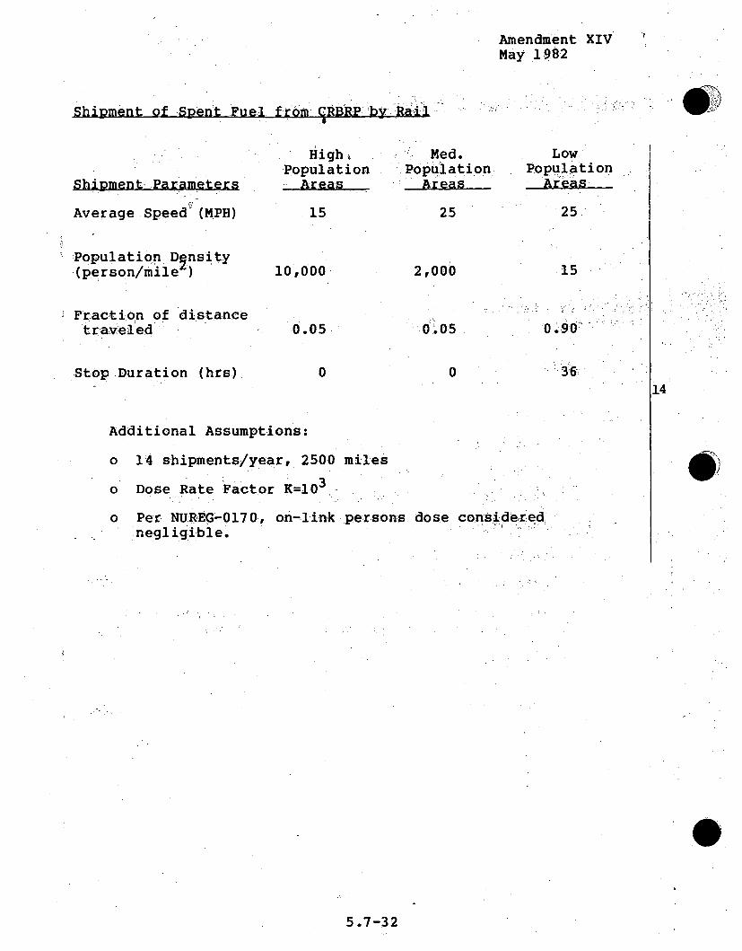
Amendment XIVMay 1982
@9Shipment of Spent Fuel from CRBRP by:Ra'il
High,Population
Areas
Med.Population
LowPopulation
Shipment, Parameters
Average Speed (MPH)
Population Dgnsity.(person/mile )
Fraction of distancetraveled
Stop Duration (hrs).
15 25
10,000
0.05
2,000
0 05
25
15
0.90
36:0 0
14
Additional Assumptions:
o 14 shipments/year, 250.0 miles
o Dose Rate Factor K=10 3
o Per NUREG-0170, on-link ýpersons dose considered.negligible.
0)
5.7-32

Amendment XIVMay 1982,
Shipment of Scent Blanket from CRBR-by Rail
HighPopulation
Area
Med.Population
LowPopulation
Shipment Parameters
Average Speed (MPH)
Population Dgnsity(person/mile.),
Fraction of distancetraveled
Stop Duration (hrs)
15 25 25
15.10,000 2,000
0.05 0.05 "0.90o 14
0 0 36
Additional. Assumptions:
o 12 shipments/year, 2500 miles
o Dose Rate Factor.- no credit taken for seduction in sourcestrength compared to spent fuel.ý (K-l )
o Per NUR 0170, on-linkpersons dose.conSideredo,negligible.
5..7-33

Amendment XIVMay 1982
Shipment of Irradiated Control. andAssemblies from CRBRP by1Rail
..Rqn4nnya h 1. =-:ý. R'A &111ýý-I ~h.t~i'ti U)
HighPopulation•Areas
.-Med.,.Population
LowPopulation
Shipment Parameters
Average Speed (MPH)
Population Density(person/mile4)
Fraction of distancetraveled
Stop Duration (hrs)
15
10-,000.
0.05
25
2,000
0.i05
25
15
0.90
; 36
14
0 0
Additional Assumptions:
o 4.5 shipments/year, 2500- miles
o Dose Rate Factor- K=10
o Per NUREG-0170, on-link persons -dose consi'der ednegligible.
5.7-34

Amendment XIVMay 1982,
Shipment of PuO from.Reprocessing D1:)1ni-: N•t; •rlPl&-
Med.
Shipment"Parameters
Average Speed (MPH)
Population D~nsity.(person/mile.)
Fraction of distancetraveled
One way trafficper hr.
High:Population
30
Me(].Population
50
.LOW,1.Population
55
100,000 2,000 ..15
0.05
3000800
090.
500
Additional Assumptions:
o Fuel/food stops in populatidn aredas of 20•/ ile 2 , 4 hr/day
o 14 -shipments/yr, 3000 mi es
o Dose Rate Factor"Kl-1:"
o Four lane-traffic exists only in high population zones.This contributes 2% of high-population tra.ffic.
o Shipment duration 3 days
5.7-3-5

Amendment. XIVMay 19.82
N
W2Shipment •of HLW• f•omReprocesingPant. by- Rai.
S.HighPoptulation,
Med.'Population
LowPopulation
Shipment .Parameters-
Average Speed (MPH)
Population D nsity(person/mile )
Fraction of distancetravel'ed
StopDuration (hrs)
15
10,000
25
24600
0.0•5
25'
15
0.05 0 90.
3'60 0
Additional Assumptions:
o .3 shipments/year, 2500 miles
o Assume 36 hour layover in train yards, 65 person/mile2
'i14
5.7-36

Amendment XIVMay 1982
Shipm~ent of TRU andAMe]:lSca foQjsn_5• • .•.'
High Med. LowPopulation Population Population
Average Speed (MPH) 30 50 55
Population D nsity(person/mile ) - 10,000 2,000 15
Fraction of distancetraveled '0.05 0.05 0.90
One way traffic 14per hr.: 3000410 800 500 -
Additional Assumptions.
" 24 shipment/y'ea'r ,. -2500 miles--
o Dose ýRate_ Fa'cto'r -K=,10 3
o 7 containers/shipment for TRU, 6 conta:iners/h6 hipment ft rmetal scrap
o All stops in low population areas for rest..
o Fuel/food stops in med-population ar.eas, 1 hr./day
o 14 hrs/day layover
o Four lane traffic exists only in high population zones.This contributes 2% of high-population, traffic.
o Shipment duration 5 days
5.7-37.-

Amendment XIVMay 1982
Shipment of LLW from RedrocessinqPlant by Truck
High Med. Low.Population Population Population
Shipment Parameters Areas 'Ar Areas
Average Speed (MPH) 30 50 55
Population Dsnsity(person/mile) 10,000 2:,000 15:..
Fraction of distancetraveled:: 0.05 0.005 0 90 .
One way trafficper hr. 3000 :. 800 .500
.14Additional Assumptions:
o All stops in low population.areas for rest
o Fuel/food stops in med-population .areas, .1 hr/day.
.o 14 hr/day layover. .
o 2 shipments/year, 2500 miles
o Dose Rate Factor K1 -'03
o Four lane traffic exists only-in high population zones.This contributes 2% of high-population traffic.
o Shipment duration 5 days
o 882 ft 3 of material/year @ 0.3 Ci/ft 3
o 60 drums per. truck
5..7-38

Amendment XIVMay 1982
Doses to maximum individuals were calculated for the two
different modes of transportation, truck and rail shipment. For
truck shipments, the maximum allowable dose in the cab of an
exclusive-use truck is. 2 mrem/hr. The dose rate at 3 feet from
the surface of a cask containing spent fuel is 10 mrem/hr.
Assuming a crew member spends 9 hrs. per day in the truck cab and
1/2 hr. per day inspecting the shipment, the dose is calculatedper trip as:
(trip/yr) (day/trip) [(9 hrs/day) (2 mrem/hr)+(0.5 hr/day)(10 mrem/hr)]
For rail. shipment, it is assumed that the -maximum. individual 14
would be a person in the yard where the train stops for restg.
Assuming this person was three feet fromrthe cask for the f 'ul l,duration of the stop, the maximum individual dose would be.
calculated as:
(10 mrem/hr) (stop duration)
The results of the calculations .are. presentedý in! Table 5.7w-7.
5.7-39

Amendment XIVMay 1982
5.7.1.5 SAFEGUARDS AND SECURITY
The principal fuel :cycle oPerations th'at:will: support: the CRBRP'
are fabrication of mixed-oxide fuel for' t e reactor'core,
fabrication'of.depleted uranium fuel for theý radial'blanket, "reprocessing of spent fuel, transportation between the faciliities
and storage or disposal of radioactive wastes. Thesafeguards/security measures to be employed at the supporting-
facilities and during transportation are individually described.
The`CRBRP must meet NRC requirements specified in the Code of
Federa Regul"ations, 1OCFRM 50, 70 ad' 73. Each l• censee s:
required to submit written plans and procedures for meeting% theserequirements to NRC. Upon apprhoval, thse becomie conditions of
the specific license.
It is assumed that the mixed-bxide fuel for the CRBRP will be
fabricated: in DOE facilities and, thespent fuel will be.
reprocessed -in-a DOE facility, subj~ect to the safeguards/security 14requirem nts .specified in DOE Or~ders sid56310z, 5631 ak-and 56i342.* 'PuO2
and'.fresh mixed-oxide fuel will be transported using DOE's SafeSecure Transport System,.
The objectives of both NRC and DOE are "to provide high assurance
that activities involving special nuclear material are notinimical to the common defense and security and do not constitutean unreasonable risk to the public health and safety." In10CFR73.1(a), NRC describes, in broad terms, design basis threatsfor:sabotage, theft and diversion. Performance requirements are
further explained in 10CFR73.25 and.45.'
.*Safeguards for the CRBRP itself are described in Section 13.7 ofthe CRBRP PSAR
5.7-40

Amendment XIV.May 1982
DOE material control, accounting, and. physical protection. aIr'e-required by the Energy Reorganization Act. of 197.4 to pr'ovidesafeguards and security comparabl.e to that required _by .NRC. DOEOrder 5632.2, paragraph 5 states:. "Policy and Objectives:.... It .isthe DOE policy to physically protect all special nuclear materi-al.against theft. This order is designed to facilitate effectivesafeguards and security systems through graded,performance-evaluated physical protection requirements forspecial nuclear material. The minimum standards have been, so,designed as to sat isfy, the policyrqient thAtte
effectiveness of nuclear safegua rds -and security.,s ssttem iný DOE.
activities provide comparablee ef fectivene'ss with that .requjir;eo-d o f
licensees by the Nuclear Regulatory Commission".
DOE facility operators, like NRC .licensees-, are req"ui red .,tomaintain updated safeguards and security prý,ocepduzres ýmanual&.'s.:These procedures and actual performance are reviewed and
monitored by DOE safeguards and security personnel. Desi.gn basdsiis ,s 14threats are useful for the drafting. of. procedures, andf6or .
preliminary assessment of performance. DOE,"conducts on-gi.ng "studies of potential adver~sary motivations, characteristics, andcapabilities and supports a substantial: prog~ram of..resear.ch on,,,-
and implementation of safeguards/security techniques and ofassessment methodology.
Material access and vital areas are located within buildings..of-substantial construction. Except during processing, fuel.containing plutonium is to be stored in vaults or vault-likerooms. The buildings that contain material access and vital. .areas are located within a protected area that is surrounded by-
two chain-link fences, surmounted with barbed wire. The.entrances for personnel and vehicles to the protected area are
under the control and supervision of security personnel in a
5.7-41

Amendment XIVMay 1982
hardened security post. A second hardened security post islocated within the protected area. Outside the fence and the'
protected area is an isolation zone, so that activities.'outsideof the fence can be observed, and a controlled area that is
posted as Government Property. The protected and isolation zoneare provided with intrusion detectors, lights, and CCTV or other
means to detect intruders. .
DOE employees will have "QU clearances. Contractor empoyeeswill have "L" or "Q" clearances,- depending on task assignments
andrsponsibilities.- Only ýauthorized5 personnl ::are "to be
permitted to enter the protected area and only thOSe having
assignments within material access or vital areas can: enter them.Persons, vehicles and packages entering the protected and inner
areas are to be searched for contraband and similarly, onleaving, for concealed SNM.
Redundant communications are provided between'the securityp: posts,
security personnel on assignment elsewhere, and wi-th off-site.security Iforces. At the DOE facilities under construction, 'tere
will be other DOE or contractor secur-ity personnel, as wei11 as:local law enforcement agency and state police personnel, nearby.
The material control and accounting systems for the proposed
mixed-oxide fuel fabrication and reprocessing facilities willexploit the latest advances in remotely controlled, automated
processing and near-real-time accounting techniquesýin theinterest of quality control, safety, radiation protection, and
safeguards.ý Personnel will only have access to the fuels whenfeeding materials into the process or loading out the products or
when small samples are handled for chemical analysis. Specialprocedures and surveillance will be employed to deter and detect
diversion (exit searches provide redundancy). The on-linenondestructive assay instrumentation will provide timely
5.7-42

Amendment XIVMay 1982
detection of any abrupt. or more protrac~ted, loss of SNM. Itemssuch as containers of PuO2 or fresh or spent 'fuelas'seblies willhave identifying symbols. Seals will be employed wher'eeappropriate. Process lines will be shut down and cleaned'out forphysical inventories periodically, at which time any nuclearmaterial, which may remain as "hold-up" in the equipment, will beconfirmed by NDA measurements.
Fabrication of CRBRP Fuel
Two general types of fuel will be employ•e&dý,'d•ri•efuel`Ve.r fl rods.which contain plutonium in mixed-oxide' pe'.l':lle;'ts: :i:n- 'the cent : ,er .,section and depleted uranium-oxide' pellets, inboth end 'ectikons:and the blanket rods containing• only depleted, uraniuimn-ox,..
pellets. The former will be f.abrzicated; :at, DOE fac: lities 6on t4heHanford, Washington reservation. The laitter wi'•ll'f.abridted 14;
at commercial facilities. Safeguards conerns:pertain o.n.ly tothe fuel rods and fuel assemblies whic'clonrt•ain miilxe •dd-oxide. e(MOX) .
The DOE supplied plutonium may requ.ire conversio•n to
stoichiometric plutonium dioxide (PuO2 ) in an as yet!,undeterminedDOE facility. A candidate facility for PuO2 conversion isthePurex Reprocessing facility at the 200 East site of the Hanfor'dreservation.
The PuO2 will be mechanically blended with uranium-dioxide (UO2 ) ,and processed. into pellets. The pellets will be inserted intofuel rods and the rods will be sealed and examined in the SecureAutomated Fabrication (SAF) line, which is located within theFuel and Materials Examination Facility (FMEF).
5.7-43
AMENDMENT XVIOCTOBER 1982
The finished MOX fuel rods are to be transported to a thirdfacility, the Fuel Development Laboratory (Building 308), wherethe rods may be examined by NDA, and mechanical operations wi llbe performed to produce fuel assemblies.
The contract guard forces at all of the Hanford sites are managed
by the Rockwell Hanford contractor. The whole reservation isposted Government Property. Guard posts and patrols communicate
with each other and with the security office in the DOE Richland,.Operations Office, so that reactions to threats will be.,efficiently coordinated.
Significant amounts of SNM are frequently transported betweenbuildings and between the security areas,. Such transferis are.,
made in dedicated vehicles with armed patrol escorts to meet orexceed the security requirements of DOE Order 5,563-2.., •.
Since the exact location and design of the conversionprocess arre
not determined at thistime, the material control accouning
activities can only be described generically. Like the pellet
fabrication equipment, which has' been designed and is underconstruction, the chemical conversion stages and calcine oven
116,
j4:
5.7-44

Amendment XIVMay 19.82
will be designed for remote: -operation and control :and.equipped.with instrumentation for unit process material accounting.whenever operators have access to the materials, they. will".beaccompanied by material control and health physics .personnel.:.The feed and -products will be measured by weight, and:sampleswill be analyzed for SNM concentration. Feed, product, scrap and.waste will also be measured by.non-destructive analysis (NDA).
Probably the process area will be treated as. one material balancearea with an item: control storage vault for-. items, not beingprocessed. The equipment will be shut down and dcleaned" 'outperiodically for physical inventory. .
Items (feed, product, scrap). will be counted and verified b NDA .as frequently as may be desired. The on line unit process:.:,.accountancy data and bulk/chemical analysis data ywi: 'll be.,continuously fed to a computer and ana&lyzed for abrupt and:.protracted losses. For an annual throughput of 1500 kg.or :less:-.of plutonium, the daily throughput would be about 5 :kg,. 1
An of ten quoted study ( of 1975,• based on. achievabemeasurement accuracies and frequent draindowns, .rather than:the.use of on-line NDA, suggested that -the limit of. error. of the.material unaccounted for (LEMUF) should be approximately:
LEMUF
% of throuhDput t.kilograms.
1 week 1.5% 0.5 kg1 month 0.5 0.7 kg6 months 0.3 2.25 .kg1 year 0.2 3 kg
5.7-45

Amendment XIVMay 1982
Many simulated studies of the DYMAC systemf and-,experience :att asomewhat similar instrumented process at Los Alamos, 'sduggest thatthe shorter time sensitivities for loss or diversionmayberather more sensitive than this.
The fabrication of CRBRP Mixed Oxide (MOX) fuel is planned forthe Secure Automated Fabrication (SAF) line'which will beinstalled in the Fuels and Materials Examination Facility.Welded fuel pins from the SAF line will then be assembled intofuel assemblies in Building 308 at DOE's Hanford ReservAtion'.
The SAF process line will be fully automated from 'the'blending of
powders through the sintering and ecamination of pellets, andequipped with sensors so that material balances can be drawnabout individual processes and for the whole material balancearea every day. Whenever operators have access to the materials,they will be accompanied by material control and'health physicspersonnel.
14It is planned to analyze the PuO2 containers received from theconversion faciity using a calorimeter and a gamma-ray neutronIninstrument.. FiniShed rods will be scanned, using activeinterrogation, to measure the plutonium content and the• locationand quality of the MOX pellets. Scrap and waste containers willbe measured by NDA. Samples of the PuO2 feed, intermediateproducts, pellets and recoverable scrap will also be measured byweight and analysis of samples. The equipment will be shut downand cleaned out for physical inventory periodically. At thattime. the plutonium which remains trapped in the pipes andvessels will be analyzed by NDA survey instruments.
The previously referenced study( 1 4 ) predicted sensitivities toloss or diversion for a MOX fuel fabrication facility which arevery
5.7-46

Amendment XIVMay 1982
similar to those given previously for a conversion facility."Again, simulation studies and experience .with DYMAC at-a similarprocess area at Los Alamos suggest that.the short andintermediate time (1 day to 1month) :sensitivity.of the .systembeing installed at the SAP line should be somewhat superior tothis. Actual measurement data and material balance calculationsfor an operating MOX fuel fabrication facility indicate that theLEMUF for one year of operation was 0.2% or. less of the annualthroughput. This suggests the capability to detect diveirsion,of 3 kg of plutonium in-one yea-rý. J
The.SAF line will incorporate proy is ions, for safeuardsandaccountability of SNM throughout the fabrication process.4 Thefollowing features will be included:v. / ...
14- One Material Balance Area (MBA)OMwil; be established-on the,70-ft. level of FMEF contaiinng .the;SAF, line...
- The SAF Line MBA shal~l generate da*atat1 s the quantityof SNM received into the MBAvshipped f rom the MBA orremaining in the MBA. All SNM.entering and leaving the MBAshall be measured by both the shipper and receiver.r, unless theSNM is in a container sealed witbh a Tamper Indicating Deviice(TID).
SNM will be carefully characterized before it enters the SAFLine MBA. SNM will travel through the processing operationsusing item identification and weight as the primaryaccountability measurements.
In instances where weight and item identification do-.notsufficiently identify the SNM (i.e., scrap and waste),nondestructive examination of the material will be required,
*1.
5.7-47
Amendment XIVMay 1982
Unit Process Accountability areas (UPAA s) w'ill 1be established
around each processing step within the SAF Line MBA.Generally, these will coincide with boundaries established forthe purpose of criticality control.
- All SNM entering and leaving-UPAAs will be measured. When SNMleaving a UPAA enters another UPAA through a common point,only a single measurement is required.
- Dataý on all SNM movement within the SAF Lin A Will beavailable such that a material balance can be drawn around,,each- ýUYPAA within 24 hours
Transportation of Fresh MOX Fuel
Under contract With Project Management Corporation for thei .CRBRP,DOE maintains ownership of the fuel: for the'. initial core andfirst four reloads, and is responsible for delivery of the fuel 4to the plant. Since October 1976, DOE;:has required' that. allshipments ofý more than 2two kilo'grams of pluitonidm ourhanium-233,or five. kilograms of uranium,-235 in high-enriched uranium, shouldbe made in Safe Secure Transport vehicles with armed escorts andmonitored by the DOE radio-communication system. The vehiclesare similar to those being used for secure transport of nuclearweapons, and provide a level of assurance in excess of thatassociated with commercial shipment (10CFR 73..25 - .37). TheCRBRP f.resh fuel shipments will use the DOE system, whichincludes the following security measures:.-
I. The fresh fuel will be carried in a special penetration-resistant vehicle. The vehicle includes active and passivebarriers to protect the cargo, crew compartment armor, andmeans to immobilize the vehicle.
5.7-48

Amendment XIVMay 1982
2. The cargo vehicle itself contains two reliable and
trustworthy armed couriers (both drivers) and will be
accompanied by a minimum of one escort vehicle carrying three
additional armed couriers (all drivers).
3. Couriers are carefully selected for reliability,
trustworthiness and physical fitness, and are specially
trained, equipped, and armed.
4. Shipments are under the direct controll of a central
dispatcher. A system for redundant, all-weather
communication between shipments anywhere in the continental
United States and the dispatcher is in operation. It
provides for 2-way communicat•ios, and for emergency
signaling under duress. Communication is by means of an 14
array of widely-spaced' transmitter-receiverstations
connected by land lines to the central dispatcher, withautomatic switching andacknowledgement. Both escort and
cargo vehicles can communicate with the dispatcher, and
routine reports a're submitted at frequent intervals.
5. Specific standing arrangements are in effect with state
police and certain other local law-enforcement agencies to:..
provide timely response in emergencies. Studies have been
made to determine expected response times at various
locations; operations have been geared to realistic
response-time estimates. Liaison is maintained with other
Federal agencies to facilitate further support in extreme
emergencies.
5.7-49

Amendment XIVMay 1982
Zpam Ful Tr. ..jtti6
Irradiated (spent) fuel removed from CRBRP represents a smallincremental risk over other fuel cycle operations. The spentfuel is hot, both radiologically and thermally, and thereforerequires special equipment for even the simplest handling "operations. The material is highly unattractive as a target fordiversion, since chemical and mechanical operations requi•. rn gexpensive complex facilities and equipment :ar errequiredtoreduceit to a usable form. Spent fuel assemblies wouldl betranstporedanhd pr"otec ted in large casks weighing many tons. Irradiated f uel
assemblies would be contained in a removable canister inrserted! in.the cask. The fuel casks, Will be designed to be transported on a100-ton capacity railroad flatcar. The cask/car combinat:ioin willbe designed in accordance with DOT and NRC regulations,, whichinclude provision for crash protection and .passive .. Oling.capability. Specific elements which will serve- to iprotct, the'.spent CRBRP fuel while in transit in the, cask include mu-lt:iple 1-4heavy steel shells, a thick, dense gamma (radiation) shiel:d:,:;., aliquid jacket and sacrificial impact absorbers. These protectionelements, while designed to enable the irradiated fuel to pwithstand crash, also provide substantial protection againstsabotage.
Even though the CRBRP casks would be very massive and difficulttargets for sabotage, the threat of sabotage still exists.- Th~ediversion of CRBRP spent fuel for conversion of its plutonium toweapons-grade material is not considered a likely scenario sincecomplex, chemical and mechanical equipment and facilitizes wouldbe required for this, conversion.
Casks designed to carry LWR spent fuel have been shown throughexperiment to provide significant protection from credible, 4intentional destructive acts. Experiments have shown that thesecasks do limit consequences of intentional acts to levels
r% -7-rfl

Amendment XIVMay 1982
considerably less than those that had been estimated using
conservative engineering judgment and to levels that are less
than the consequences of the explosive blast associated with the
intentional act, itself.
It is likely that the CRBRP spent fuel casks will .be even more
massive and difficult to penetrate than LWR casks. In any case,
since the spent fuel will be owned and shipped by the. Department
of Energy, the CRBRP spent fuel shipments will. be subjecttt6-
physical protection requirements equival-nt to those of "the.NRC
found in 1OCFR73..37. The purpose of these requirements is,, tominimize the chances of a successful, intentional destructi•ve:act.
:14
Because of the low concentration of plutonium +and urani6um inradioactive wastes, wastes are not considered attractive.fordiversion purposes. However, there are certain inherent
safeguards features within radioactive was.te handlilng andmanagement procedures.
High level radioactive waste (HLW) will be stored within thephysical security bounds of the reprocessing plant prior toshipment. Due to the relatively high radioactivity and thermalgeneration associated with HLW, transport to a repository will beaccomplished in a similar fashion to spent fuel. At therepository, the physical security of the site as well as theremote location of the wastes deep underground should effectivelydeter diversion. Similarly, transuranic and low level wasteswill be packaged in DOT approved shipping containers andtransported from points of origin to disposal facilities, wherethey will be handled within exisiting physical security systems.
5.7-51

AMENDMENT XVIOCTOBER 1982
Chemical Reprocessing
The safeguards provisions of the reprocessing facilidty are
expected to be similar to those for the model facility in
WASH-1535 or those included in the design of the Developmental 116
Reprocessing Plant (DRP) described below.
The safeguards system for the DRP will provide both physical
protection and nuclear material control and accounting
capabilities to satisfy Federal (NRC and DOE) regulatory
requirements. In addition to traditlibhal safegual rds
capabilities, the system will provide for the pro te ct.ion ahd
control of classified matter and information, and the DRP ý plant,
and property (i.e., Government property). The system includes
mechanisms and provisions for deterrence, detection, delay,
communications, assessment, accounting, control, and"response as:
required to meet the above regulations plus anticipated future
requirements. The DRP physical protection system includes
security zones, facility architectural and design qfeatur"es,
personnel and vehicle access control, intrusion dete t"io and
assessment, automated alarm reportirng, surveillance,
communications, and computer security.
Physical security zones include an isolation zone, a'protected
zone, a hardened area, no access areas, material accessý areas,
vital areas and limited access areas. The isolation zone is an
open area surrounding the protected zone except where support
facilities for personnel/vehicle/rail egress and ingress control
are provided. It will ensure that only authorized entry is made
to the protected zone and will detect unauthorized entry
attempts. This zone will be bounded by two chain link fences and
will be clear of all objects that could conceal or shield an
individual.
5.7-52

Amendment XIVMay 1982
The isolation zone will be equipped with intrusion: detectionhequipment and closed-circuit television (CCTV) to allow rapid
reviewing and assessment of this'zone. This zone.also has avehicle barrier, exterior to.the outer of the two zone fences,'
designed to prevent forced entry with automobiles or lighttrucks.
The protected zone is the area totally enclosed by the isolation:
zone that contains the Process Building (the. hakdenedProc•rspe,Building shell included),:• the ..open 'area :-betwee•nhe.Pr•ces
Building and •the •isolat6ion- •zone -boundary fe-c ,ýnd~any-otlher-2 .
support structuresý within.. th aesurndd by'teiolaJo
zone. w.
The protected zone is-further subdivided-by the -hardened area.The -hardened area is :the portion of the Process-Builing encods'ed
within a. tornado missi-l<.e-barrti.er;. : ThiS :•incl"u-des :the; h-ar-dened 14
shell of the main Process Building and .te :,hardened contrcenters. Normal and routine entry is restri-cted' through ahardened guard-.stat~ion,..at-..atthe -.har-dened .she ll perimeteir..
The facility architectural and design- featur:es assure 8, that:
signif icant quantities of SNM aare "physical'ly separated from 6lipersonnel during normal operations,. and access, control to the,:-security areas is provided.. The natural phenomena barrier thatencloses -most of. the Process Building- is a major barrier of the
safeguards system. The limited number of entrances to thishardened area controls access to the Process Building.
The •entry-control system will allow.surveillance, monitoring andcontrol of personnel, vehicles and materials to and from the
5.7 m-53.: -

Amendment XIVMay 1982
controlled zone, the protected 'zone, the: Process Building, and''
the hardened areas. Vehicle inspection portals exist. at entries
to the protected zone to allow search of vehicles prior to entry'
and upon exit. Personnel- access portals exist at entry and exit
ways of security areas..
A defense-in-depth concept for physical security depends on the
use of electronic devices to detect intruders at each level of
defense. Alarms given by the .system are both audibleý and- visual"
and all are received at the, safegýuards..: control .center and th":
secondary alarm station. The intrusion, detection.Stem consi ""
of exterior and interior intrusion detectors and:CC7TVcameraS ,
secure signal transmission, alarm assessment and display
equipment-and alarm and CCTV recordingequipment". This system
will be used to detect unauthoriz~edý entry into the. controllý-Iedzone, .isolation zone,, and protected zone. Int eri;or, aljrmsWill
annunciate in the conti nuouslny-manned safeguards control center'• .14
and at the secondary alarm station..
To ensure immediate reporting. and ,asslessment- .of possiblpeiatýtzempts'p-t / i
at intrusion, the intrusion' detection sensors and key-card access
control system will report through a computer-iniftitated .
automatic-alarm switching system.2 Thisý system includes 'the
computer, intrusion detection devices, key-card alarms, response
.action instructions and outline maps with closed-circuit
tel~evisi.on (CCTV) surveillance and .alarm: assessment system
display.:
Security surveillance of activities and processes involving
special nuclear materials and/or impacting.on security of these
5.7-54

Amendment XIVMay 1982
processes is a fully integrated safeguards system. Primary formsof surveillance used in the DRP will include:
- Guard force (fixed, vehicular and foot patrols)
- Management and supervisory observation.
Closed-circuit television (CCTV) surveillance, monitoredand managed at the safeguards control centerz(SCC).. and the,.:secondary alarm stati on (SAS).
Full-time surveillance is employedfor security barrierfencelines, the isolation zone clearred areas and entry/exit-ways,through primary barriers..
The communications network for the, DRPphysimcalprotection systemwill allow rapid and continuous communiication among on-siteSecurity force personnel and between on-site and off-site 14response forces. Off-site communications needs are met usingtelephones for routine commun~ications and a radio link foremergency communications. Similarly, a radio communicationsystem consisting of base stations, mobile radios and hand-1.carried portable transceivers will meet qn-site communication,needs under most conditions.
Since the efficiency and effectiveness of the entry control and:intrusion detection systems depend on automatic data processing,computer security will have a high priority in the overallsafeguards system. Access to the computer facilities (the SCC -orSAS) requires a key-card reader and digital code operated lockingsystem. Safeguards computer transmission lines will be underconstant line supervision and all panel boxes, connectors, etc.,will be affixed with tamper-indicating devices or switches.
5.7--55 -

Amendment XIVMay 1982
In addition to physical security, the DRP Safeguards system
includes material control and accounting capabilities. Both'
passive and active material control features are included..
Passive material control is accomplished by placing barriers or
impediments between SNM and an inside adversary. All significant:
quantities of SNM are processed and stored in remotely operated
cells which limit direct personnel access during routine
operation. Activematerial control is accomplished by monitoring
cell penetrations from sensitive p rocess equipmenrt to occupied
areas for the presence of nuclear ýmaitetr`iIs.
The DRP material accounting system.wi be beased on a series of
Material Balance Areas (MBA). The MBA is an idehtifiable 'physical area around which accurate SNM balances cah be "
performed. The material balance areas will consist of a small
pbol to store 'spent fuel assemblies, the chemical separation 1. ' "14
equi.pment area, storage vessels for the' ureanium and pluton~ium
nitrate products of the' extraction-purification stages, the
chemical processing equipment used' to convert plutonium nitrate
to plutonium oxide, product storage vault and the analytical
laboratory.
All of the process equipment will be contained within massive
shielding, operated under remote control, and with provision for
remote repair and maintenance. Material control is achieved
primarily by this containment. Where spent fuel, products or
samples are handled, guards and/or materials control personnelwill provide continuous surveillance. In addition, personnel and
packages entering or leaving the operations areas will be subjectto.search for contraband and nuclear materials.
5.7-56

Amendment XIVMay 1982
Material accounting will be on a near-real-time basis. Spentfuel assemblies will be accounted for as discrete, numbereditems. After disassembly and dissolution of the pellets, anaccurate measurement will be made of the volume of solution, the
concentration of uranium and plutonium in the solution, and theisotopic compositions of both. For process control andaccounting, the quantities of uranium and plutonium in theprocess vessels and intermediate buffer vessels will becontinuously monitored. Intermediate nitrate products. oxideproducts and all waste streams!will be measuxred.
Spent fuel assemblies are received and accounted for on an itemidentity basis. The plutonium content is booked at the valuescalculated by reactor operations'until assemblies are dissolvedand the actual U and Pu amounts are determined on the basis ofsolution volume and U and Pu concentration. PuO2 products aremeasured by bulk and by concentration when the product containers, .are filled. The plutonium in product containers can Ialso bemeasured reasonably accurately by:NDA. 14
The chemical reprocessing and conversion processes willincorporate precise bulk/analytical measurements at the input,transfer and product output points. Combinations of NDA. processsinstrumentation. flow indicators and chemical analysis of samples.from between process stages will provide the information fornear-real-time accounting on a unit-process basis. The U and Pucontent of wastes will be measured in various ways, e.g., NDA ofhulls, bulk/sample analysis of hot liquid wastes, alpha countingfor discharged reagents, etc. These measures will provide fortimely detection of loss or diversion.
Based on their reprocessing plant experience and knowledge oftraditional material accounting and measurements. McSweeney.et al( 1 4 ) estimated in 1975 that the LEMUF could be expected tobe about 1.4 percent of the throughput for 1 week, 0.8 percentfor 1 month. 0.75 percent for 6 months and 0.7 percent for 1 year.
5.7-57

Amendment XIVMay 1982
Since then there have been several developments which shouldimprove the sensitivity, and which would be employed at. the DRP.One is to improve the measurement of the volume of solution inthe major liquid accountability vessels by design of the vesselsthemselves and by the use of modern instrumentation to measurebubbler pressures and to analyze this data with on-linecomputers. Such systems have been installed and used in theUnited States and Japan. The systematic error in suchmeasurements should be 0.1 percent or less. The most difficult ..chemical concentration measurement has been that ofl the U and Puconcentration of the highly radioactive solution- in the inputaccountability vessel. There have been signifi t advances inthe quality.of analysis of such samples for concentration and forthe isotopic composition of the U andlPu,-. 16 Expewrence with•.,near-real-time accounting techniques at the Tokai Reprocessing9Plant in Japan and in "cold runs" at the AGNS, BarnweIl, -. C.
facility give confidence that the combination- of improvedinput-output measurements with unit-process monitoring, real-timecomputer data analysis, and process simulation shouldsubstantially improve on the sensitivity for detection of shorter 14or longer tetm loses._
The LEMUF on 900 kg of Pu would be about 7 kg of plutoniumifor6 months, using the McSweeney estimate. The improved, measurementcapabilities, along with improved data analysis methods, suggest'that the short term and longer term diversion sensitivitiesshould be substantially better than the 1975 estimates.Ellis(17) concluded that 5-day balances should have a limit oferror (LE) of 2 percent. Over a period of a year, the randomerrors of individual measurements cancel out and the importantfactors are the systematic errors involved in calibrations of theaccountability vessels and the accuracy of the standards used forsample analysis. It is anticipated that annual LEMUF would besubstantially smaller than the McSweeney estimate.
5.7-58

Amendment XIVMay 1982
It should be noted that it:would !be very difficult .for anydomestic adversary to divert.any plutonium from the remotelyoperated, remotely maintained equipment or the storage'.areas inthis facility. The near-real-time accounting system may haveimportance for international. safeguards. For domestic purposes,the measuring and accounting system is more .important forefficient operations. It serves to provide assurance :that, thephysical isolation'and protection systems continue to function:effectively.
The 6-month or annual inventory balances.ando erfrr alinjitsreferred to assume .the shutdown and cleanout of, theentirei' sytemat 6 month or 1 year intervals.. Atsuch a time., allmara1,that it is possible to, remove, is transferredý to: essels w•hereit
can be accurately measured. Some ýof :tbhe nucle4ar -•materdital, wilrema in •on :the suriface of pipes a ,nd tanks 7and in Vc.1ecs. -• Tis-"hold-up" could be-..:of the:.ord6er of O.1.-, percenht ofthroug.pu.:
Safeguards CoWUs
The incremental, cost of.safegua~rdingý ýthe ffac~i•lit••ies•• in' the '•l•u"cycle, apportioned to reflect the part of the facility operations".•i•;dedicated to the CRBRP fuel cycle, are shown in Table 5.7-8.Costs are.included.,for safegua-rding-facili-ties for 'fuel'fabrication, fuel reprocessing, the CRBRP plant,. andtransportation of..special nuclear materials ý.(SNM). among thefacilities. :Both initial investment :and annual operating:: costs'are given.in constant FY 1982 dollars. It.is evident from thetotals in Table 5.7-8 that the costs of safeguarding SNM in theCRBRP fuel cycle are a small.portion of the total facility costs.
14
5.7-5"9 -•
Amendment XIVMay 1982
Costs are given separately for physical security of' the'facilities,: the materials: control and, accounting (MC&A),
provisions, and the guard forces. Physial. security costsinclude such things as perimeter and' entry controls, videosurveillance and internal security:systems. MC&A costs are thoseincremental costs of upgrading normal process control andmonitoring instrumentation for safeguards application, non-securesoftware and communications systems, and the maintenance thereof..The guard force costs include salaries, benefits, overhead and'equipment. The assumptions and bases for these costs aredescribed below for.,.each facility. - .
Fuei •Fabrication
The CRBRP fuel pins are planned ;to be fabrticated at the secureAu-tomat~ed. Fabri cat'ion (ISA•F) li~ne, l oca~ted •wit~hi~n .'the Fu~eis :•-a~n~dil" 1 4
Materials Examination :acility: (FMEF) -at -DOEsHanfordReservation. The: resulting fuel pins will be transported 'a- short e2distance o~n the Hanford'site to the3.0:8 Building where they areý- formed into final, fuel asSemblies.The safeguards provisions at these 'facilIti-.esb are 'descri-bed:i,above..
The SAF line is an addition to the FMEF.., Only the incrementalcosts for securing the SAF line are attributable to the :,CRBRPfuel cycle. The SAF line will share the FMEF perimeter security,'system, •guard force center, display ,consoles.', guard forces,,, etc.
0>
5.7-60

Amendment XIVMay 1982
The initial costs of installing the SAF physical security system
include:
$0.5M - entry control portals, hand geometry controls, keycard controlled doors, map displays, TV monitors,alarm processors, TV switchers, video recordingequipment, electrically locked doors, sensors andclosed circuit TV cameras.
$0.4M - installation of the above equipment- software development.
$i. IM .:./
The annual cost of operating the SAF physical'seurity L system
is estimated at 15 percent of the hardware costs for repair rahnd' rmaintýenance, plus' one addIt-io"nail. guard per shift"t~hat r6equ•i-red-for FMEF. The: gard fbc'e operates on a 5- :• ' ~11-4.,shi~ft: ý6pe ration.. Therefo re.- th~e:i :addit-Toi'oa~l guiaxrd` pedt-o sih~f t,-....:...
is expected to cost $250,000 per year. The annual. cost- forrepair and' maintenance A's 'e;sti1m a';te d t o total $ 16500
The initial investment for the SAF MC&A system is estimated.as:
$0.5M - computer
$I.OM - software development$0.5M- upgraded measurement capability for safeguards purposes$2.OM
5.7-61

Amendment XIVMay 1982
The annual cost of operating the SAf, MC.&A ;system assumes oneshift operation, except the sintering furnace will continuouslyoperate.
$150K -. repair and maintenance at 15 percent$150K - computer software improvement
$200K - 2 supervisors.
$480K - 8 technicians
$ O&K- analytical services..$1080K
'As the CRBRP fuel cycle utiilizes about 65 percent of SAF•soperational schedule, only that portion of the bove costs areiPnluded in Table 5.7-8.
The 308BUldng is located dwithi the340 a.rea at iDbs..Hanf oprdreservation.i: Based ,on discussions w-ith the-Hanford, nqgineeringand Developm`ent..Laboiratory-staff that operate..h 3,08- Building,
the physical securdity,; system costs for the 300)area are: a)in.tial investment - $7.5 million, b)2 annual repair and,maintenance expense at 15 percent of. the hardware cost -. $1.1fmilli:on ,.. and c): annual guarOd 4force expense . $3,.2: mill io-ni. The
.300 area is manned by a staff of 70 guards..
Support of the CRBRPfuel cycle requi.res about 20%V-of the ý3.00
area activities, and only that portion of ,the-securi-ty' costs areincluded in Table 5.7-8. The 20% figure is based on. the. 308Building, being about 1/3, of the major facilities in the 300 a-rearequiring physical security (inaddition to the 324 and 325Buildings) and that CRBRP fuel cycle support requires about 65%of the fuel assembly capacity of Building 308.
The 308 Building MC&A system accounts for discrete, numbereditems only. No liquid or powder process steps are involved andno volume, density or concentration measurements are
5.7-62

Amendment XIVMay 1982
required. As such, no costs are estimated for upgradedmeasurement capability. The initial investment for the308 Building MC&A system is estimated at $0.5 million for MC&A ',equipment.
The annual cost of operating the 308 Building MC&A system isestimated as follows:
$75K - repair and maintenance at 15 percent of hardware$100K - 1 MC&A supervisor
- 3 MC&A technicians,..
$355K
Support of the CRBRP fuel cycle requires about 65 percent of the308 Building fuel assembly capacity, and only that portion of theMC&A costs are included in Table 5.7-8.
The total fuel fabrication safeguards system costs, in Table *5.78 14are'a summation of the appropriate portions of the; costs for theSAF and 308 Building. A.
Reprocessing
The safeguards provisions for the reprocessing plant where CRBRPfuel is eventually processed will be similar to those descirbed"earlier for the DRP. Only very preliminary design information isavailable for the DRP. Detailed estimates of the DRP costs,including the safeguards provisions, have not been made. Thefollowing estimates of the costs of the DRP safeguards provisionsare the best now available.
The initial cost of the DRP physical security system is expectedto cost about $35 million. Maintenance and repair of this systemis expected to cost approximately $1.5 million annually. Theguard force is expected to consist of about 75 personnel at anannual cost of about $3.5 million.
5.7-63 -

Amendment XIVMay 1982
The DRP MC&A system is estimated to cost $15 million initially.Operation and maintenance of this system is estimated to cost $5:million annually.
Support of the CRBRP fuel cycle will require about 8 percent ofthe DRP 150 tonne annual capacity. Thus, 8 percent of the abovecosts are included in Table -5.7-8.
The CRBRP safeguards provisions are described in PSAR Section13.7. The following is a breakdown of the physical securitysystem costs.
In itial Maintenance'
anid Operat ing
Electronic Security System $ 1.80 M(includes CCTV, alarms,computers, access controlelectronics)
Gate House (less access 0.42 Mcontrol electronics) andCentral Alarm:Station
Fencing and Related Items 0.19 MSuch As Sewer PipeGrating and Derailers
Electrical (wiring, conduit, 1.33 Muninterruptible power supply,batteries)
Communications
$ 3.86 M
$ 90 K
.8K
-4 K
66 K
$174 K
5.7-64

Amendment XIVMay 1982
Accountability of.fissile and fertile material is inherentin .the:design of the CRBRP refueling system for reasons other thansecurity. After inspection. at receipt, the assemblies are notvisually identified.again.until shipment of the. irradiated-assemblies. The assemblies are mechanically.identified prior. to:,insertion into the core and subsequent to removal from the coreas part of the refueling controls. All movements of .fuel:within:.the plant are monitored and/or recorded on the.refueling systemcomputer for inventory purposes and to insure proper.configuration changes. No incremental costr is assumed forsafeguards accountability at the ,plant....
The CRBRP security force consists ..of:.
1 - Unit Chief.
1 - Operations Captain1 -Administration Captain 141 - Training Officer
5 - Shift Supervis.ors5 - Alarm System Monitors
55 - Public Safety Officers- Clerk-Typists
7.2. Personnel
The initial investment of hiring, training and equipping thisforce is estimated to cost $47,000. The bulk of the securityforce will be onsite when the fuel arrives, approximately 9months prior to fuel loading. The cost of guards during the yearprior.,to criticality is estimated at $1.1 million. From the yearof criticality onward, the guard force is estimated to cost about$2.1 million annually.
5.7-.65 -..,-

Amendment XIVMay 1982
Transportation.
The number of:shipments per year -for the diffefrent materials inthe CRBRP fuel cycle: are given:on Table 5.7-7. Specialsafeguards measures are provided for the shipment of fresh fuel,'Pu0 2 , spent fuel and spent blanket assemblies. The othermaterials transported within the CRBRP fuel cycle do not containsufficient quantities of SNM to warrant. special safeguards:,measures.
Tr anspo rtation :of new fuel and PuO6is p usi DEs- Safesecure Transport ý(SST) system. As th'is syst'.emLw-illi- :h'a-ve--...sufficient capacity and communications capability- toaccommodateCRB•RP transportation. requi rements, no iniktial investmen• :Costsare anticipated. Operating costs for SST shipments are estimated
to cost $18,0G00 per 2500 mile shipment, round:trip.'
Transportation of spent -fuel and spent bllainkeit ýassemblies requi're.two escorts and appropriate communications: devticeas. 'Theincremental cost per. escort for these provsisionsis estimated tobe $50,000 -per year•.
The safeguards cost of transportation within the CRBRP fuel cycleis summarized below:
Annual
Ma t..exi.. Shipments/Yr. Cost/Shipment S _.PuO2 14 18,000 6: 252,000Fresh Fuelý 14.: 18,000 252,000•Spent Fuel 14 N/A 100,000Spent Blankets 12 N/A 1
$704,000
•5.7-66 ý

AMENDMENT XVIOCTOBER 1982
CRBRP Fuel Cycle - Socioeconomic Impacts
Fuel fabrication and fuel reprocessing are two key elembent's ofthe fuel cycle for the CRBRP. Sihce o•t6h activities i.nvo.veutilization of facilities separate f.rom ;the CRBRP, a generalizedassessment of their potential socioeconomic impact is
appropriate. Both of these facilities are intended'to support/-:the DOE Liquid Metal Fast Breeder. Program by demonstrating', thosetechnolo'giesi and :6ýt.o -serve'the CRBRP duin its oprtn.
The Sec6ure Aut om~ate-d Fabrication , facility will be bui~lt aspar t. of. the Fuel s .a~nMaterasI-.Exantion Facili:ty (FMEF)-which
is currently under constructo o n 0DOEIs Hanford Reservation near
Richladd Vsingon Consic~~dtion f the SAF faci ity wi 11:taka~bout. 20 month s 'and. h ave'a peak, employment of about ~250 persons.
Emlomet, at full operaltion will be about 100. Currently,employment at ti is about 10,000, and the
popsulation of uhe metroplitan Richland area uis abIzout 125'000.
Give n the smenal magnite oh the project and its work force andthe relatively lrel population of the Richland area, there arendeo adverse socioeconomic impacts expected from construction or'operationhe loathe facility The humber of construction workersmov ing -ihno the area iftany, would be a small fraction of thepe ak work force and Hwaouldnotbe expected to cause a strain onservices in such- an urbanizoe 'area.
The Developmental RercsigPankDP ol eproes lgtwater reactor fuel' in addition to6 se rv ing th e" breedri -progqr-am" -,byýdemonstrating reprocessing te'chnloiogy -and -by. rxep rocessing CRBR P.,
fuel. The location for the DRP has not been'selec'ted althoughthe likelihood is great th~at it will be a federally own -ed site.The Oak Ridge and Hanford Reservations are both underconsideration. Construction of the facility is curren tly
14,
5.7-67 -
AMENDMENT XVIOCTOBER 1982
scheduled to begin in late 1.987 and be completed by 1996. The
peak construction force is -projected to be about 3',700:and the.full operations work force about 750. A, significant proportion
of the work force would be expected-to move into the areand.
'create the potential for a temporary strain.on community services
and facilities. A projection of the magnitude of any influx
cannot be made until a site is selected. However, over a decade
of surveys of TVA nuclear. plant construction forces in rural
areas indicate .,that between 20:_,pericen~t and:.+40, percent, of• th•e wor•
force could be expected-to inmigrate. The-likelihood for a s~uiiu~ i lss ikly f t~:z~a~c~iit s~~ti a relati'ely
uranzed area , I) :.te ,RPwe re:, b u i 1t ~on ~the Oak
Ridge..Reservation, significant impacts wou-ldnt .bec~~us of he vaiiabi~it. oflQ~l laor Pandthe, capacity of a
urbanized a.ea,'.,s servieeis and facilities, to absorb-additional,
tmoary pouain Sic te, CRRP con9tr uc~t ion,, f orce ,ýwbuld
beý d~ecreasinrg. as *teDPconst~ruction forkce isý increasing, the
,potential for cumulative . impaqcsts should notý .be gr.eat.
Based .on TVA""s expe rien~ce,. Pa. higher prIoporion.of.theoperations
work.force would into.th1e, alant :a r~ea,, compared totthat for
the construction force. However, the actual number of inmoving
workers and dependents .would still be relatively small., Also,
the construction force should be decreasing while the operationsforce is increasing. Thus, any increases in the capacity of
local services and facilities to accommodate construction moverswould be available to accommodate operations movers. After a,
site is selected, a more detailed analysis of potential
construction and operations impacts will be conducted as part of
the facility's Environmental Impact Statement..
14
5.7-68

Amendment XIVMay 1982
5.7.2 POWER PLANT OPERATIONAL NOISE AND IMPACT
The CRBRP will contain a large number of sound sources, most of,
which will be well enclosed in thick concrete structures and,ý
will, thus, pose no noise problems. There are, however, several.
external sources of noise whose effect on the •surrounding area is,
described in this section. Estimated ambient noise. level,
predicted CRBRP noise levels and impact assessment are discussed
in subsequent subsections.
5.7.2.1 ESTIMATED AMBIENT NOISE LEVEL 6
The area on and around the plant site has an ambi6ent noise leevel
characteristic of a sparsely populat1ed, rural area. The only
consistent source of non-natural noise is traffic on Interstatew..
40 which is about 1-1/4 miles from the. center of the CRBRP site,at its closest approach. At the nearest dweling to the CRBRP
Site center, trucks passing on the interstate highway can beheard, but not cars. Based on measurements made in other similar
rural areas, the average A-weighted ambient noise level is
estimated to be 40-45 dBA. Traffic on the interstate is beli evedto be a major contributor to the ambient noise level.
5.7-6.9

Amendment XIVMay 1982
5.7.2.2 PREDICTED NOISE LEVELS
The major sources of noise from the plant site will be themechanical draft cooling towers, the turbine generator buildingand the main power output transformer. Arrangement of main, plantstructures'*is shown :in Figure 2.1-4, and the location of these.structures on the Site is shown in Figure 2.1-3. Cooling towersound levels were determined from published references (also seeSection 5.1.8.4). The transformer sound level.estimates werebased on the National Electri cal Manufacturer s .,Assoqiiat ion.: -INEMAvýK)",transformer ratings. The s6und- leve•t from the turbine-generator-building were based on estimates of the internal machinery noiseSleel corrected: for the transm"ssison loss of the metal panelwall s.
The radiated noise levels were determined by assuming that thetotal sound pow.er emitted. by the plant, suitably corrected fordirectivity (geometry, location and obrienta tion), is radiatedhemispherically from "the center of the plant site. The sound.levels in the surrounding area were6 calculated by summing thecontribution from each of the sources at each point of interest.Corrections were made for the shielding effect of the plant onthe cooling tower noise and of the turbine-generator building onthe transformer noise.
A correction for the molecular absorption of sound in air alsohas been included.(i) The magnitude of this correction wasdetermined by assuming a sound spectrum for the cooling towernoise.(2) Because most of the area surrounding the plant site isand will remain heavily wooded,. a correction for the groundattenuation was estimated and included in the calculated sound
5.7-70 -

Amendment XIVMay 1982
levels. A significant change in the-ground attenuation isanticipated with a seasnal -change from summer t. winter becauseof the loss of foliage from the woods.
The nearest dwellings to the CRBRP Site are located approximately3,100 feet south-southwest Of the plant site and approximately3,200 feet west-southwest of the plant site. Both dwellings areat an elevation of about 8010 feet MSL, one on each side of PoplarSprings Creek. The predicted sound level, due to normal plantoperation alone, at both of these :,l6ocationsis'42 "dBA 'in the,summer and 45 dBA in theý winter..
At radial distances greater than several thousandifeet•, contoursof equal sound level are ai6st circular. At.aadiaone mile from the plant site center the predicted summer noiselevel from the plant is 37 dBA; the corrdespondingpraedictedwinter level from the plant is 41. dBA. bient leelsmay ibdehigher than. these-values par6ticular for r I oca•t :io nearerInterst-ate 40.,The one-le conto and theli ýtwonb narbt d
dwellings :are shown in"Figure 5.7-3.
5.7.2.3: IMPACT OF,.OPERATIONAL NOISE"
The U.S. Department of Housing and Urban Devel'opment ( 4 ) hasprovided outdoor noise exposure guidelines for non-aircraftnoise. Three categories of external noise exposure are defined'.The categories and their respective noise limits are listed in.Table 5.7-9.
Since the noise from the power plant is essentially constant, the"acceptable" category corresponds to sound levels below 65 dBAy
5.7-71

Amendment XIVMay 1982
the "normally unacceptable".category levels between .65,and 75 dBA.-Tand the "unacceptable" category corresponds to levels above.75 dBA.
,Based on the predicted6levels and contours described. in Section5.7.2.2, the population distribution from Table 2.2-2F and the.peak resident and transient population from Table2.2-"9 and]Figure 2.2-7F, there will be no exposure of the.permanent
populationor• of the transient population including nearby..recreation areas to noise levels above 65 dB.A..
At manhy locations, particularly a recreation aaat CaLney.Creek",the ambient noise from the interstate highway 4wi~ll exceedýthenoise produced by the plant.
The State of Tennessee and Roane County do not have .anyregulations or zoning restrictions relate.d to that are
applicable to the CRBRP Site-. The City-of Oak Ridge.-.has'a. zoning.ordinance(5) which specifies that sound shall not exceed khedecibel levels given in Table 5.7-10 .when adjacent to the useslisted. The ordinance does not indicate-.whe•ther•the. sound levellimits are linear or A-weighted sound levels. The specifiedlevels are assumed to be A-weighted values since the A-weig~hting,
simulates the response of the human ear and is thus used in mostsuch ordinances.
5.7-72

Amendment XIVMay 1982
To the north, the CRBRP Site propeprty line adjoins the ClinchRiver Consolidated Industrial Pa~r.k. The sound level contour.shown in Figure 5.7-3 shows that-.the sound level at this propertyline will be significantly less:than the specified limit in Table5.7-10. The remainder of. the area adjoining the Site is rural incharacter and separated from the.SitIe by the Clinch River. TheOak Ridge ordinance does not specifically address this type ofarea. However, based on the predicted noise levels', the impact,of. the noise produced by-the plant .on the surroundingýa'reawillbe ne-gligible.'
6
5.7,-73

TABLE: 5.:7-1
CRBRP - SUMMARY OF ENVIRNME:NtAL, NSIDERATIONS FOR FUEL CYQE
Fuel Fabrication.Mixed Oxide UranhiumDioxide***(Core Fuel) (Blank t)Natural Resource Use
Waste~n~i Total
0,
4~.
Temporarily CcmittedUndisturbed AreaDisturbed Area
Permanently Ccumitted
Water (aallons/day)
Discharged to air
Discharged to water bodies
Discharged to ground
Total Water
Fossil Fuel
Electrical Energy (MW-hr/yr)
Equivalent Coal (MTr/yr)
ChemicalsGases* (MT/yr)
SOX
Hydrocarbons
GO
Particulates
F
0.07+0.05+0.01
10.0-9.01.0
1.3
,2.3
1.0x10³
7.5xi02
7.5x10²
9.0x10³ **
3.6x10³ **
133
35.2.
0.36
0.86
35.2
1.3x10⁴
1 .3X104
4.2x1 02
1.6x10²
1..OxlO3
13X'103
2.7x10²
2.2x10³
2.47Xi103
5.3x10 2
2,.0x102
1,2 7x1. 3
1 .3xl04
2.95x10³
l..72k104
9.9x10 3
5 .26xi03
* 116
.116
11.379.051.01
2.3
5.8
1.5
1.5X10⁻²
3.8x10⁻²
"x 0l.7:k10 :, ý
0.4
3.,
4 6xo'7 1-.2
9' 9.1xk0 2 1-5.4- ~~~~5 :lx O{3• -i-/ 6 !-
a13 - 62.7x"2
6,. 6...:.•• . .,.
-77xl0
140
56.1i
1.98
10.5
35.99
1.7x1673
CDr~
CO =1
9N

9 0TABLE 5.7-1 (Continued)
Fuel Urai 1io i de_Mixed Oxide. UrainiumfiDioxidei***Lfflents
L•igiia (MT/yr)
H2S04
HNO 3
NH3
FP0
3-PO4 (after degrading)B"J2/0giCAl (Curies/yr).
Airborne
Pu-236
Pu-238
Pu-239
Pu-240
Pu-241
Pu-242
U-232
U-234
U-235
Cm-242
Cm-244
WasteReprocessing**** a ent rn.TlaiDQotation
1.0x10'-
1.0xlO-i
1 .0x l 0- 21.0x10⁻³
12.0x10⁻⁹
2 .OxlO0-
3.4xlo-6
2.2x10⁻⁶
2.2xO1-6
3 .x10-4
3 .0x10-9
5.8x10⁻¹ 1
2.5x10⁻¹²
7.7+
2.8
1.4 +
3 .2x01O1~
1 .0x1071
7.8
2.8
1.4
1 .0xi- 2
1 .0XI0"
14.1 .36 xl0T9
28 . 4 5xl'0-52-.14x10'•5
2.2 5.5x 10-
6'..22xlo-1-1 '
1 62xt10 9
7. 8'4x 10 1 1
5.42x10⁻⁴
7.16xl0"7
3 36x 10 9
8.8x1O05
2.3 4x10⁵
2.25xo0-3
5.OxlO0
6 .22x1011
1.68xi0-9
1.13x10⁻¹⁰
5.42x04
7.16X10⁻⁷
NQIi

TABLE 5.7-1 (Continued)
Fuel Fabrication _ .Mixed Oxide Uranium iDioxide***(_Core Fueli Bakt _ Waste
Reprocessing* ** * Nnaflguzen
C)'
Radiological (Curies/yr)
Airborne
U-236
U-238
Th-228
Th-231
Th-234
Am-241
Np-237
Pa-234
H-3
Kr-85
C-i 4.
1-129
1-131
Ru-103
Ru-106
Cs-134
Cs-137
Rn-220
Rn-222
Particulate FissionProducts
5 .4x10T1
2 .5x10'12
5.4x101 'l
5 .4x101 1l
2.5x1079
3.2x101 '
2 .5xl109
2.5xl109
i.58x10-I 0
7.36x10 9
1.20x10⁻¹ 2
7 .84xi0f 1 2
2 .36x10r 1 0
2 .06xl10 5
2.08x-10-1 0
7.36xzo7 o
5.51xI03
4.7 5xl,0
1.44x101
3.26x10⁴
3.61X10⁻²
1.84x10⁻³
7.09xI073
5 .60x10• 5
1.6 0x10 4
6.16,x1045
6 .8x106
,5 .5x101
3.4x1074
9.2x1co3
1 :1x1C:3
1 .58X10-1 6
9.9xlO-9
1.20x10⁻¹ 2
4.23x10⁻¹ 1
2.79xl,09
2.06xlO-5
2.0 x1o0o°
3.29xiO 9
5.51xl03
4.8 ox10 3
z1.44*xlO
3.26x 1.0-43 .- 10-2
3.61xlO-
1 .8 4x10'3
7 .09x10,3
5.660x10' 5
8..2xl0
1 3172kL67
14
W9)
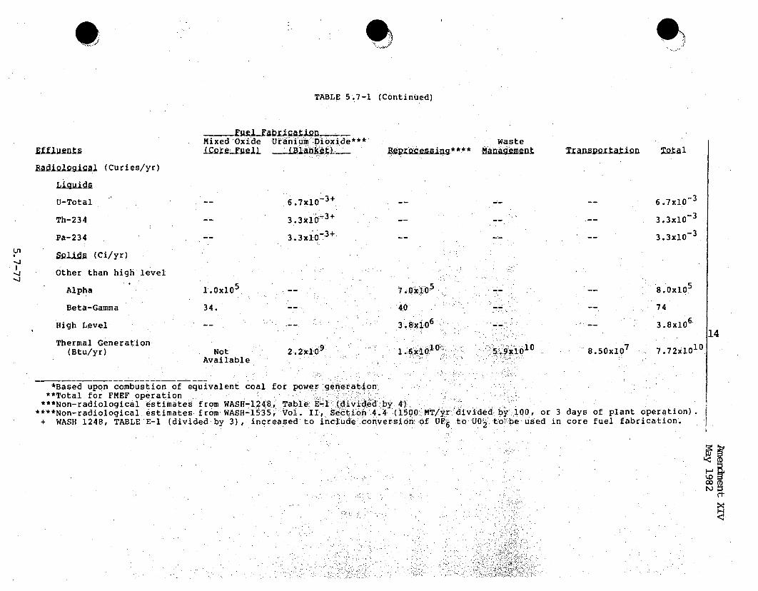
OV
TABLE 5.7-1 (Continued)
i edxuel Uabniua i ie__Mixed Oxide Utanlu~mý-Dib~xide***Waste
H1AD iSznefl"oce n*s*** TKA"Lwrk&lign To~alEAiDsgiJal (Curies/yr)
U-Total
Th-234
Pa-234
Sotid a (Ci/yr)Other than high level
6 .7xlo03 +
3 .3x10_3 +
3.3x10o.3 +
6.7xl0-3
3.3x10_3
3.3xi0-3
Alpha
Beta-Gamma
High Level
Thermal Generation(Btu/yr)
1.0x10⁵
34. 40
3.6 x10⁶
l.6ýX101 0
8.0x10⁵
74
3.8x10⁶
14Not
Available2.2XI09
5 . 9X10¹⁰ 8.50x10⁷
7.72xlo1°
*Based upon combustion of equivalent coal for power generation**Total for FMEF operation
***Non-radiological estimates from WASH-1248, Table E-l (divided by 4)****Non-radiological estimates from WASH-1535, Vol. II, Section 4.4 (1500 MT/yr divided by:,.100, or 3 days of plant operation).+ WASH 1248, TABLE E-I (divided by 3), increased to include conversion of UF6 to U0.2 to-be used in core fuel fabrication.
x
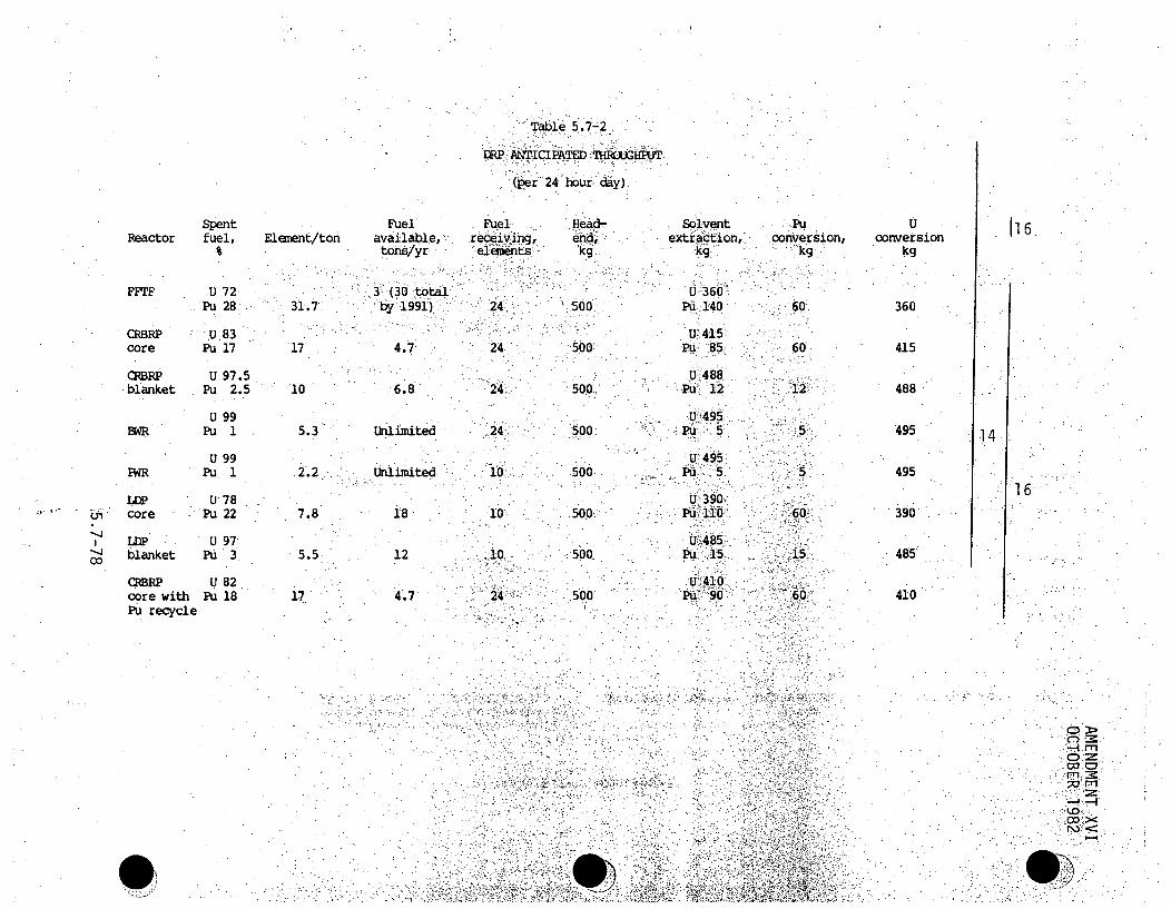
Table 5.7-2
DRP ANTICIPATED :•'I1-IRHPUT
(er 2,4. .Ibur: day).
SpentReactor fuel,
FFF U 72Pu 28
CRBRP U83core Pu 17
(RBRP U 97.5blanket Pu 2.5
U. 99BWR Pu 1
U 99NWR Pu 1
0U78core Pu 22
LDP U 97blanket Pu 3
CRBRP U 82core with Pu 18Pu recycle
FuelElement/ton available,
tons/yr
31.7: by 1991)
17 4.7
10 6.8
5.3 Unlimited
2.2 Uhlimited
7.8 18-
5.5 12
17 4.7
Fuelrecei.ing,ee24ents
24
24
24
10.
24
Head-end,
,500,
'500.
500:
500.
500
500'
:::500
Solventextraction,'
U'360,Pu•. 1140
U•415
U 488Pu 12
U 495
Pu 5
U 306Pu 110
Pu 15
Pu 90
Pu.conversion,
"kg.
60'
:60
12
5
15
60
uconversion
kg
360
415
488
495
495
390
485
410
116
14
16
00
A *~ C
-JwI~
C "C~'~~CC~'
* 0>

0
TABLE 5.7-3
Atmospheric Releases from. Reprocessing CRBRP Spent Fuel
Model Reprocessihng DRP
R~ignu~cli-fe
H-3C-14Kr-85Sr-901-1291-131Ru-l03Ru-106U-232
.U-234U-235U-236U-238Pu-236Pu-238Pu-23 9Pu-240Pu-241Pu-242Cs-134Cs-137Th-228Th-231Th-234Am-241Np-237Pa-23-4.Cm-242Cm-244
• .150 days after,ORIGEN co'de.
•* 200 ppm N in fu
Input _ Confinement
5.5lxl03 11.44x101 *.*io4.75x10'4 12
,3.70xl 1 NO3.26x1 1 1x0-3.61x101 10-41.84x1 6 10~7.09x10⁶ - 10,31lx102l 51f1.018 12x101 5xl08
3:92xl0O 5X108,7.9 1x 5k-10,3. 68 - -5i'1Y
3.07 2 il0,9
1.69x10⁵ .2jef6.427xl104 il4.40xC10 2k1,0~5.10x1 6 -219 .9.40xM01 2i'09
2.80x10⁵ I xl-.9
799 i65 5x1l0-5 98xld03 x
3:992xl~rP2.ý,51X" b.9~3 *68 '5-O
2:71X10 6 - cpX~l358x 103 5X10
Release.
5 .51-x101 .44 k 1074 .75x,10?7 .4x10
5
3 .26'k10 5.,3.6, l -lO.3
7,.'04xl;07 -1 1
1,.58' O1' 07
7.36xO1 "5'x-~0
2ý5 5.6x10~
12'7 44-1 0
7 3b6x10 I-2 6 10
7T -611 0
5 42xl&~75.41.L10
C~onfinem ent
1
Releasei cizy-Kl
5 .51x103
1 .44x10-34.75x10 57.4xlO-43.26x10⁻²³ .61x10 -
-3l.•84x10"3
7.09xlO 116 .22x10-1.62x10,7.84xi,- 101 .58x10- 0
71.36x-10- 9
1.53x10-8.45X10 52. 14x10 5
2.20x10-
:14
2.55:k'2xi109 4.70x5 x-1 0 5.60x5 il 09 1 .60X
S5k101,.7 .84x5x1 9 ý 7.36x2
5' 10, 2.06.x:
~'5x07 7.36x25X10-9 5..42.x2
:5"- 7 .16x.
code; -actinide~s,-calculated with
105
10-18
10 4
10-1
.scharge,; fission ro t -,. u1 ,,ed with- •RLBD
1Ž
1~~~.
.~
rt

Table 5.7-4
RadioactiVe Wastes fromte BRFel'ce
0,
C)
Ania4 eeration.F Waste/Form Containers Volume-ifr' #. of cbhairs
Fuel Reprocessing Plant
LoW-Level concrete/drums 25/120..
Misc. f..u concrete/drums 10/50
Metal Scrap• metal/cylinders 14/102
High-Level glass/cylinders - 3.3/6
Kr-85 metal matrix/cylinders 0'01/0.035"
1-129 concrete/drums 0. .01/0.05
Core Fuel Fabrication Plant
TRU solid/drums 130/145
Blanket Fuel Fabrication Plant ".
LUN~abl 11 MP.
CRBR Plant
Lim solid-nconcrete/drumsq 67/321
*Volume stated is prior to icompa ction.
Key tonstituents
,Produictis '10' i1
7Fissio :Products- &
'Fuel' Material.2
-Fd-- xli3xssid ý& aqtiyatioý
Fission Produats,:IJU 1-.5 x 10, Ci/m3
K in we al trix
Barium Iodatl
uraniuý.0;luCi/gý
Fission,,. acivat•.-on,pr6 Ucts
<l0 C/m3," !i:! :':i" - .•: ,•
Dispol ition
Shallow landburial
Repoisitory.
Reposi.tory
Repository
Repo sitory
Repository
Store at,Hanford
COisite ;dislposal
Shallow. landburia
14
[=C.
1:6 -4I
0

f a
Table 5.7-5-
: -.16 e•'IWR*. , o.]0 MWe LWR*i
F2 Chem Waste -- 92 95LF.,Sludae. Chem -41 35
UF6 Conversion (dry)(wet)
Enrichment.
Fuel Fabrication
Reactor
Spent Fuel Storage
PuelReprocessing
CzCa
Cwasa
Low-Level Misc.
CaF 2 , Misc.
TRU
:•LoW-Leve•l- - -/<i
Low-Level-
Low-Level Misc.
High-Level
Misc. TRUand Scrap
Pl•t•onium
KIr-85 Cylinders
1-12 9 Cylinders
28
ll (MT)
.-i . 13 0 ..
-25
-3.3
24,
0.01
29
6320
<3
30
29
< 1-
S .44.
6••
14
* NUREG-0116, Table 3.3
. ,.'
C'>I ~-~- 'I-.'
(D
%ýO_4Co
rt
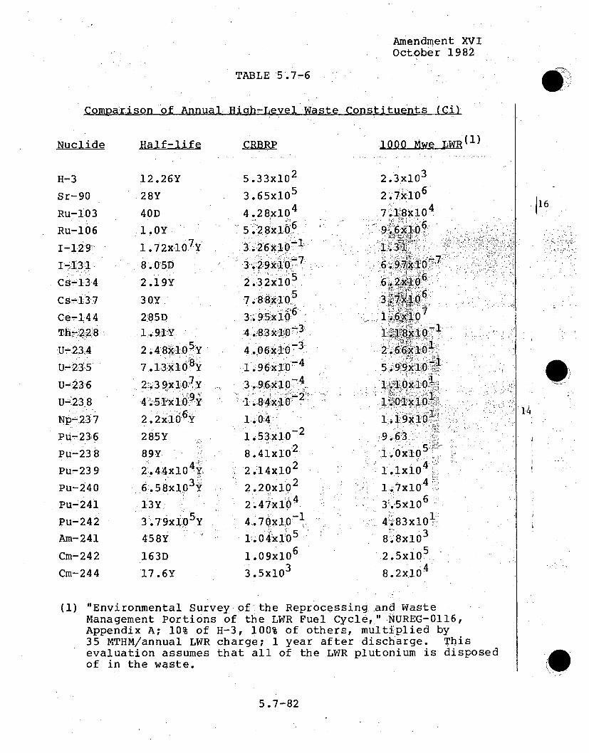
Amendment XVIOctober 1982
TABLE 5.7-6
r('~nmr=*r, nn nf Annii I Hiah-Level Waste Constituents (Ci)
Nuclide
H-3
Sr-90
Ru-103
Ru-106
1-129
1 -1.311
Cs-134Cs-13:7
Ce-144Th*-!22-Z8
U-23,4
U-23 5
U-236U-;238
Np-237
PU-236
Pu-23 8
Pu-23 9
Pu-240
Pu-241
Pu-242
Am-241
Cm-242
Cm-244
Half-life
12.26Y
2 8Y
40D1.0Y
1 .72x10 7 Y
8.015D
30Y
2!85D1'.91"Y
2 .48x10 5 Y
7.913 xl 08Y
2:,.3 9-k1-0:1,Y
4C.51`x 160•Y
2.2:xI0i6 Y
285Y
89Y2 1.44xl0 4Y::
6.58x10³ Y
13Y
3.79x 10 5Y458Y
163D
17.6Y
CRBRP 1000 Mwe LWR(I)
.5 .33xi0 2
3.65x10⁵
4 .28x104
5 ';'286xi 66.3 .26:x 10
2.3 2x10o
3'.95x 10:4,83•x0"3
4 .06x1O0 3
-43.,96x10D'
1.041 .53x10- 2
.28.41x10
2.14x10
2.20x10²
2.47xI0 4
4 7-x 10 -014
10.0 4x15
1 .09x10 6
3 .5xlo3
2.3x10³
2.7x 06
.•A.. :,-l; .3 .-1
7 .1 ...x104 .
9.62k10
7 -7
6.4 5xlO
41. 83x10
Lý7 10
8`ixlo629.6568xi0
8.9'8x10³
9.68.02x1 0,
16
14
(1) "Environmental Survey of the Reprocessing and WasteManagement Portions of the LWR Fuel Cycle," NUREG-0116,Appendix A; 10% of H-3, 100% of others, multiplied by35 MTHM/annual LWR charge; 1 year after discharge. Thisevaluation assumes that all of the LWR plutonium is disposedof in the waste.
5.7-82

Amendment XIVMay 1982
Table 5.7-7
Transportation Radiological Impact
Fuel Cycle Shipment/ Distance Pop. Dose Max. Individual Dose*Elmemnt- _yr (Mi1L (PeQrg s o-Hem) (Ram)
New Fuel 14 2500 0.449 1.4.0New Blanket 12 2500 0.0065 0.01 3Plant Radwaste 8 2500 0. 43 0 0.878Spent Fuel 14 2500 0.489 0.160Spent Blanket 12 2500 0.43,2 0:.160IrradiatedControl, RRS 4.5 2500 <00.001 0.004
PuO2 14 3000 0.536 1.64Reproc. Radwaste
4HLW 3 2500 0.0817 0.360TRU & Metal 24 2500 1.296 2.640Scrap
LLW 2 2500 0.109 0.220Fuel Fabricator
Radwaste
TRU 5 2500 0.270 0.550
*To transportation workers
5.7-83

TABLE 5.7-.8CREEP Eue"yc1 i4jirity Costs By Plant Type
($ in: millions)
SPlantCapital. -Annual br-aing
,Fuel abricaign Plant _BRprocssing PlntCa~ital &nnUi Oprati
Physical Security System
Material Control and Accounting
Security Force
3.86 0.17
2.27
2.2
1.6
3.8
0.9
2.0
2.8
1.2
4.0
.0•. 12
0.4
0L28
3.91 0.8 14
o1<
rtl
W,

Amendment XIVMay 1982
HUD'S SITE ACCEPTABILITY STANDARD (Ref. 4)
Acceptable
Day-night averagesound level (in decibels)
Not exceeding 65 dB(I)
Above 65 dB but not exceed-ing 75 dB
Special approvals andrequirements
None
NormallyUnacceptable Special Approvals
EnvironmentalReview (3)Attenuation (4)
Special a Appr ovalsEnvironmentalReview (3)Attenuation (5)
(2)
14
Unacceptable Above 75 dB (2)
Notes (1) Acceptable threshold may be shifted to 70 dB in specialcircumstances pursuant to 51.105(a).
(2) See 51.104(b) for requirements(3) See 51.104(b) for requirements(4) 5 dB additional attenuation required for sites above 65 dlbut not exceeding 70 dB and 10 dB additional attenuation•
required for sites above 70dB but not exceeding 75db (SeeSection 51.104(a)).(5) Attenuation measures to be submitted to the Assistant
Secretary for CPO for approval on a case-by-case basis.
3B
5.7-85

Amendment XIVMay 1982
TABLE 5.7-10
CITY OF OAK RIDGE NOISE LIMITS 5 )
Sound Level, dB
50
55
60
65
75
60
Adjacent Uses
All Residential Districts
Neighborhood BusinessDistrict
General Business District
Industrial District
Major Street
Secondary ResidentialStreet
Where Measured
Common Lot Line
Common Lot Line
Common Lot Line
Common Lot Line
Lot Line atStreet
At Street LotýLine
114
5.7-86

Amendment XIVMAy, 1982
FIGURE 5.7- I
CRBRP EQUILIBRIUM FUEL CYCLE
PLUTONIUM AND URANIUVI MASS FLOW
(MT/year, average)
1~2
assumed
5.7- 87

TO
co torFriA' TOCCNAHLT NS !AALcPL'RP()01e wAST r srAF
CONCUNTRATION MINX. INPI)IIII11.~~ A.YC [ .VO I(] I F
NO. I SOLVFNI llCCEWGInN
CLEANUP ."RI MOVAI.-
NO. 7 SOLVENT 2 • : :;,, & Y LE ý -'AUON U
PLUTONIUM W+PuCIP TXALATNCLEANUP Pu PAR TITIN CONCENTRATION PRECIPITATION
AND CALCINATION >
... . . :URANIUM NITR ATE I:=INIFrlIM I1.W "' i W 0 -: C: I" :-U, 00 mgCCe,!:
C11L ERATION .1-C " - -: PRECIPITATION PLUTONIUM IN "
A ,TO. r, ANDCALCINATION OXIE
I O Rq ANIC W A %tFr-' ANn : '-!h::e i .i• • l.
INA TI vIi .i n ORANIOM
-f w .ýtiI • -- -R A N I U M
OIFCAS% II L "XIDE
STAC KFIGURE 5~72 FUEL, REPR " ESS ". S. i X 'l i ~ ~~FIGU RE 5.7-2." r"•" ::+" • ... ... F" ""
o i l,. . . . . ' -'::,..••

AMENDMENT XIVMAY 1982
.14EEt4E
WI
-OWE LLINV.F ARM UNIT
.* CEMETERY
VAWOOOLAND.
U INDUSTRIAL AREA, SCALE OF MILESS
6Figure 5.7-3'. One-Mile CRBRP Sound Level Contour and Nearest Dwellings
5.7-89-

AMENDMENT XIIIAPRIL 1982'
5.8 RESOURCES COMMITTED
The commitment of resources ascribed to the construction of theCRBRP was discussed in Section 4.3. This section is concernedwith the commitment of. resources during the expected life of theplant. Commitments of the various types of resources are not allof equal consequence. During operation of the plant, resources.are utilized in amounts that, relative to their generalavailability, will not constitute an ir~revers-ible :or,irretrievable commitment..
5.8.1 COMMITMENT OF LAND RESOURCES
Approximately 135 acres of primarily forested land area (on-siteplus off-site) have been ..committed ori pemanent pltant: :fac•i it ies 1l3and the transmission corridor for the CRBP and its relatedfacilities. This commitment, however, does not represent ,a.:measurable fraction of the productive forest ,res, ources.of thheregion. The commitment Of 135 acres is only. 0.;,2,7 :percent of thetotal acreage within a five-mile radius of the plant."
The Site has little agricultural potential due to. the poorsuitability of the soil and has been designated as:an area forindustrial development as discussed in Section 2.7. Should it bedesirable at the end of the facility's expected life, the landcan be returned to a condition suitable for future industrialdevelopment. Decommissioning and dismantling of the facility arediscussed in Section 5.9.
No further alteration or destruction of wildlife habitats shouldoccur during plant operation.
5.8.2 COMMITMENT OF WATER RESOURCES
One of the major resources committed during plant operation willbe water from the Clinch River. Flow rate of the river varies
5.8-1

AMENDMENT XVIOCTOBER 1982
from an average low flow of 4339 cfs in the spring, to an average 1i10i 1.high flow of 6,772 cfs in the winter. For maximum power Ioperation, the anticipated av`eragelwater makeuprequi rement is13.6 cfs. An average of 5.4 cfs will be-eretlurned to the river, : I.and approximately 8.3 cfs will be consumed during plantoperation. -The consumptive use of 8.3. cfs is.only 0.15% of theannual average Clinch River flow rate of about 5,380 cfs. The I 10amount of'water lost to theý atmosphere through evaporation is notactually an irretrievable loss, however, as ,the ewatereventuallwill be :returned to the .earth as precipitation. -
Considering aquatic life as a resource, the loss of fish,zooplankton,• benthos, macrophytes and the like will be a,commitment of resoujr~cesb directly attributable to operation of theCRBRP. Dischargeis to the Clinch River will be continuouslymonitored to pre-vent introduction of deleterious effects to- theaqua~tic life by exceissive temperature, chemicals or turbulei~ce. 19Aipreconstruction survey conducted on the Clinch River willestablish areference framework for assessing the degree to whichthis resource is'commi tted.
5.8.3 COMMITMENT OF' FUEL RESOURCES
Initial fuel assembly loading. of the Clinch River Breeder' Reactor I•will consist• of approximately 5.2 Metric Tons (MT)' of uranium.andplutonium metal in a 36-inch h:igh, core.' The fuel consists of osintered mixed-oxide pellets of PuO2 and U~s encapsulated in the1
sealed stainless steel tubing (rods). Plutonium enrichment is33.2 weight percent. In later cycles- the plUtoniumenrichment
will be approximately 33 weight percent. Each of 'the 156 fuelsubassemblie_. in the reactor 'core contains 217 fue'l rods. Thereactor core fuel contains 20.7 MT of stainless steel. 115
5.8-2

Amendment XVIOctober 1982
The isotopic composition of the feed plutonium metal in the coreis 0.1 percent Pu-238, 86.0 percent Pu-,239, l1.7 percent:.Pu-240.,2.0 per-cent Pu-'241 and O,ý2 Percent Pu-24:2. The isotopic split issimilar to FFTF-grade .plutonium.
An additional 25.2 MT of. depleted uranium metal is committed in ]14the inner radial and axial blankets. Inner and radial blankets,consisting of 208 assemblies, each containing 61, ,rods,. contain'4 1421.0:MT°of depleted uranium metal and 26.i8MT of'stainless steel.Each of the two axial blankets., which are an integral part of thefuel assemblies, contains 2.1,MT of depleted uranium metal.
An estimated 2427 fuel assemblies and: 2106 blanket assemblies 1i4will be committed, dur.ing the 30-year life of the plant. Operated.on the once-through fuel cycle, the total requirement of theplant cquld, be as high as 27 MT of plutonium metal, 332 MT of
14.uranium and ,595 MT of stainless steel over 30 years. However, itis expected- that the burned fuel will be recycled to the plantafter reprocessing and refabrica~tion so that the actual heavy 9metal commitment to the plant from virgin ore (natural' uranium)will be, only a fraction of the aforementioned values.
If one assumes recycle with CRBRP operating by itself, requiringone f ul 1 core loa d in the, reactor and an additional reload cor-in reprocessing and fabrication, :then- the commitment from'resources is only on the order of 3.5.MT of plutonium plus58.0 MT of uranium.
The isotopic composition for the caspe where CRBRP spent fuel i'sreprocessed and recovered Pu is, recycled as feed is discussed in, 6the appendix to Section 5.7 (Section 14.4A).
5.8-3
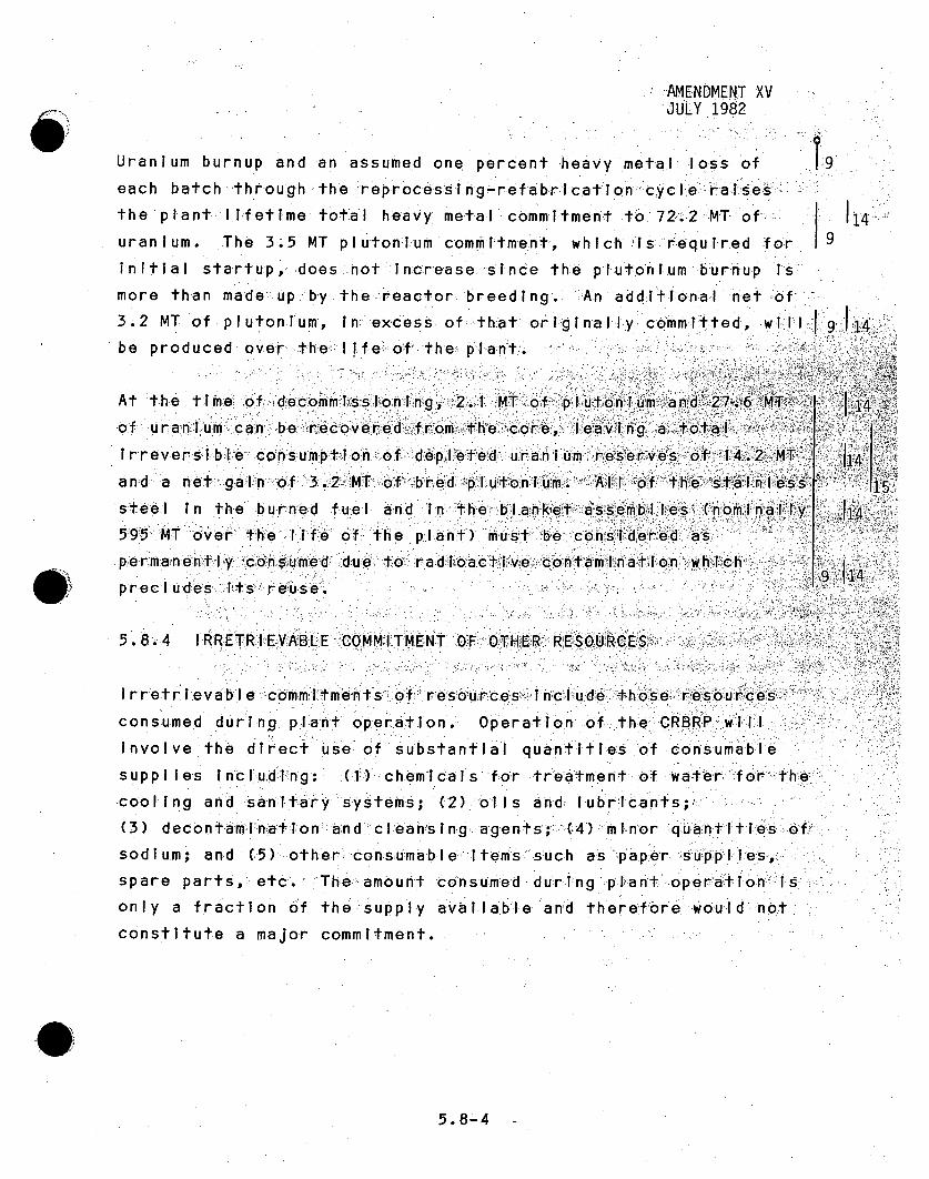
AMENDMENT XVJULY 1982
79.Uranium burnup and an assumed one percent heavy metal loss ofeach batch through the reprocessing-refabrica.tion Icyclerasesthe plant.IIsfetime total heavy metal commitment to 72.2 MT ofuranium. The 3.5 MT plutonium commitment, which is required forinitial sta.rtup, does not Increase sInce the plutonium burnup is
9
more than made up by the .reactor breedlng. An additional net of "3.2 MT of plutonlum, in. excess of:.that origInally committed, w1 I Ibe produced over- the: If e of th e plant:..
At the time: "of decommissioning, 2.1 MT of pl utonium and ý27 .6 MT,:of u ran1i um can be recovered from the core, leaving a totalirrever~sible consumption of depleted uranium reserves of 14.2 MTand: a net g a In of -3.2 _MT of bred plutonium. All of the stainless-steel in the burned fuel and In the blanket assemb.les (nominal.ly595 MT over the life of the plant) must be considered asp erm alnently consumed due to r ad•ioa ctive contamination whichprecl ud'es Its re~use.
5.8,.i4 IRRRETRIEVABLE COMMITMENT OF OTHER RESOURCES
I rretr i.eva bl e ýcomm.itmen tts-,, of r es ourc es•-, I n'c lu de those resourcesconsumed during plant operation. Operation of t-he CRBRP willinvolve the direct use of substantial quant Ities of consumablesupplies Inc I'ud.ng: Cl(1) chemicals for treatment of water' for- thecooling and ..sanitIary systems; (2) oils and- lubricants;,(3) decontam:i~nlation and cl~eanhsin~g agents;: (4)'minor quantitiesofsodium; and (5) other consumable," items suc~h as paper SUpplies,
spare parts, etc. The.amount consumed during p lPan.t oper~aI'on-isonly a fraction of the supply avaIlabl-e and therefore would notconstitute a major commitment.
9
114
14
1i4
1141 .5
ý114
9 J14
5.8-4 -

Amend. YDec. 1981
5.9 DECOMMISSIONING AND DISMANTLING ," '
The Clinch River Breeder Reactor.Pl~ant (CRBRP), i s .being designedfora
30-year operating li fe, thereby' placing :the plant,'.s. :final operatiohnat
about the.-year'-2020, assuming no.; premature: termination.. At .that time, 9.a detai~led plan to% decommission wJll be:: prepared for approval. by the
appropriate 1.icensing.agency with criteria comparable to..Regulatory.
Guide 1.86, -"Termination. of Operating. Licenses.::for •Nuclear Reactors". :A
number of alternative approaches wil 1.-.:be .eval-1utaed i.i(n :ter~mi nating" the
operating 1 icense of:the•: plantq; the appro ach c
of the rEmainin por poftem 'S.tn i an readverse.manner .than
c tinueredoperatio of he•thn•th od have.:, Length.of.'operating history ': ......-
afternoe, o initi act iat , we In ot signi f.1-icantly affect the approach
chsenua .izaTh obnasl cnd sewngei6tion wil proatid-e for• prt ctieon of thepublic
safety and wil be enavi armentally h ssuitabe.
App wdechoces of exprmieno din decommAissinin crctorhs is available fiom
the ýAEC civili 1an po'we'r' program and ýciVilifan reactrs 18 These experi-'
ences rangei from removacl of fuel aid- mior deontamination to total re-
oval inldn some surade structures. None' of the approaches to
datehave pre.sen ted safe or environmental tprblems of substantative
difference dthanthoseswhiochn havos curred durineg inMal operation of a
plant.
The land commfitted to the-CRBRP.pl antt, b uildings., inside the ý,seicIuri~ty.
fence, occupies8. acres as seen on, F~igure 2.1!-r4. 'The sludge-lagoon''r
equalization bas i n,: sewagei treatmentt ppiant and river waterpu Mp hiouse.,
occupy an ad~ditional-2.7 acres. outside the securityt fence. -Dependitng-
upon :the, chosen. plan., ýthe termination :.of the plant could :commit. up, to:
11.3 acres of-the Site'..: Its tewiorthy. that the. 1less,.extens~i.ve11approaches to termination do not irretrievably commit the Site;.that-Is,
should a decision be reached at some date after termination that justi-
fication exists to reduce the land commitment, the cost of recover versus
the initial decommissioning cost would be negligible. If the decision
5.9-1
were made' to dispose of theCRBRP by partial or total demolition, disposal.site resources would be committed.-
0
5.9-la

INTENTIONALLY BLANK
@r

Based on estimated 1000 MWe LWR decommissioning costs, (9)the costs.,forothe CRBRP decommissioning are expected to range from about one.to five" Per-cent of the original capital investment for-the plant. This level of costis not significant when compared to the total. of the lifetime fuel and :capital costs.
The environmenta-l. impact of decommissioning i s not expected to be signif-icant. EnvirOnmental impacts associated. with consltructi~on and d .operat ion.of. :the pl I l havealready occurred. After the rem•oval of i rradi.at.ed,
,and unirradiated f uel' from the Site,~ the possibility of adverse envir~on,-mental impacts will be. vi~rtuall1y eliminated. ,Radi~oa ct iv ity release~s and,waste heat disch'airges would, be c €onsi de rab , ly- less than those that occurredduri~n~goperation, of; te pan. It is - anticipated tAhat- os ndceic-
discharge impacts .would bals 1 beless-th~an -those atssoci ated with const.ru c-L,tion an: d -operation. DecomrmnisSilon ing mayIivl the•s ment of .al ,con--t-aminaited o tr irdiatesd: mate ria A off'siteJ for entombmenht.
A? ~
A~
In ::summary, -the oteminati of operation and decommissioning of the CRBRPcan ;be. accompl ished with complete s afe ty-poiin for the general publicand the Workers at a reasonabIe cos t and: in: an ýen]vitronmental ly accepe•t.biC•manner.
5.9.2

6.0 EFFLUENT AND ENVIRONMENTAL MEASUREMENTS AND MONITORING PROGRAMS
The purpose of the effluent and environmental measurements and monitoring
programs is: (1) to establish a baseline (reference) framework of infor-
mation on the environment in the vicinity of the Clinch River Breeder
Reactor Plant (CRBRP) and (2) to assess the effects on the environment
resulting from construction and operation of the CRBRP. Specific aspects
of the environment to be monitored in varying degrees of detail 'are physi-
cal and chemical parameters, and radiological, terrestrial., Iiimnological
and fisheries components. Information relating to geol ogy and soils.,
land use and demographic surveys is also included.
Many details of the environmental monitoring program are closely related
to final plant design; therefore, present monitoring program plans are
tentative. When final details of the plant design are available, the
respective components of the monitoring program will be reeval uated and
modified accordingly.
As agbasis for designing the environmental, monitoring program,a number
of, potential environmental impacts Which often are a result of construc-
tion and operation of nuclear power generating facilities have been iiden-
tifiled. The monitoring program will be reviewed periodically and various
elements may be added, altered or'deleted if further study and data
collection indicate a need to consider different or additional.impacts.
A quality assurance program will verify the adequacy of the sampling
procedures and various analyses.
The programs discussed in this section are divided into the following
categories: (1) preoperational (including preconstruction and construction
periods) and (2) operational.
6.0-1

AIEND. IXOCT. 1981
6.1 APPLICANT'S PREOPERATIONAL ENVIRONMENTAL PROGRAM
The preoperational environmental monitoring program serves to establishbaseline data for ecological, radiological, meteorological and waterquality conditions in the vicinity of the CRBRP prior to start of con-
6struction and operation, and to assess the environmental impact of con-structj.on.. The aquatic and terrestrial baseline monitoring programsdiscussed in this section were conducted from March 1974 through May 1975to gather information required for Section 2.7 for. identification ofimportant ecological characteristics of the Site area. TVA. conductedapreconstruction monitoring program during. 1975-1978. Informatibn
9ýfrom these monitoring programs .will be used.to..provide background infor-mation for impact assessment during plant construction. Once constructionbegins, the TVA program and one to be instituted by Stone and-WebsterEngi-neeri~ng Corporation (SWEC), the construction contractor, will monitor
those areas which may be affected by construction activities.
6.1.1 SURFACE WATERS
6.1.1.1 BASELINE MONITORINGK PROGRAM.
Most of the.previous aquatic studies of the. Cl~inch River. were conductedin the early 1960's or earlier. With reference to the Clinch River inthe vicinity, of the Site, two factors suggested collection of current
.data: (1) the tendency for most rivers in the United States to. change.chemically, and therefore ecologically, because of ever-increasingcontributions of nutrients and other chemicals from man's activitiesand (2) the installation in 1963 of Melton Hill Dam at Clinch Rivermile.23.1. Also, many of the previous aquatic:studies of the Clinch
.River were concerned with qualification ("naming") and not quantifica-.tion ("counting") of data.
6.1-1

AiEND. IXOCT. 1981
In order to have a current picture of the ClinchRiver aquatic environ-
ment in the vicinity of the Site, an aquatic baseline program was
conducted from March 1974 through May 1975 to supply information pre- 9
viously not available and to update existing information. The purpose of
this program was to identify and characterize: (1) physical and chemical
parameters; (2) existing biological communities; and (3) endangered
species, if any, and their spawning habits. This program was used to
identify the important ecological parameters in the Site area which-might
reasonably be expected to be affected by the CRBRP.
Selection of locations for the sampling transects in the ClinCh River
used-in this program was. determined, largely by a considerat~i6n'-of those
areas of. the plant which will have the greatest potent-ial for-impiact
during:plant construction and operation. These sampling transects are
shown in Figure 6.1-1. Basically, the major aquatic impacts may .occur 9ý
at three areas: (1) at the plant intake; (2) in the circul:atory coofling
water system; and (3) in the vicinity influenced by the plant discharge.
..Based on these considerations, Transects 1 and 5 Were 'establi.shed- as
control areas. Transect 1-should be compl.etely free.of .any mechanical,
chemical or thermal effects from'the plant, whereas TIr ansect 51:might. .
show•some slight effects. Transects.2 and 3 were placed at the-mobths -9.1
of Caney and Poplar Springs Creeks, respectively. These transects
were established to help determine to what extent, biologically, chemi-
.cally. and physically these creeks may modify the main river.. Transect• 4:
by its close proximity to the downstream path of the proposed plant dis-"
charge, would be a key sampling area in evaluating .the effects.of the 9.
discharge. Specific sampling stations for the variety of parameters
surveyed are shown in Figures 6.1-2 through 6.1-9.
The arrangementlof sampling stations was based around the general plan of
having three stations numbered 3, 5 and 7, along each transect. Locations
of these three stations were as follows: Station 5 was located in the
.middle of the river; Station 3 was located halfway between the center 9
6.1-2

AMEND. IXOCT. 1981
station and the right shore; and Station 7 was located halfway betweenthe. center station and the left shore. Right.and left shores wereoriented as facing downstream. This general station plan is used in
tables and figures pertaining to the following, parameters:
I. Biological Communities
bacteria (Figure 6.1-2)
phytoplankton (Figure 6.1-2)
zooplankton tows (Figure 6.1-2)
zooplankton pumping (Figure 6.1-2).
fish eggs and larvae (Figure 6.1-.8)
2. Physical and Chemical Parameters
routine lab analyses (Figure 6.1-2)
-additional analyses (Figure 6.1-9).
For benthos dredging, physical and chemical field measurements and sedi--'
ment analyses, the three-station plan per transect was utilized :atTransects 1, 4 and 5 as shown in Figure 6.1-4.. However, at Transects -2
and 3, Station 7 was located closer to shore, immediately at the mouths 191of Caney and Poplar Springs Creek, respectively.
Sampling locations for periphyton, benthos artificial substrates.,,macro-
phytes, fish population and fish food preference did not comply with thegeneral three station plan. For periphyton sampling, floating samplers
were placed approximately 30 feet-from the right shore at Transects 1, 4 .9and 5 as shown in Figure 6.1-3. Placement of nearshore benthos artif.icia]
substrates at.Transects 1, 4 and 5 was 30 to 50 feet from.the right shore:as shown in Figure 6.1-5 and was also dependent upon the water depth. 9
Mid-river benthos.artificial substrates were placed 50 to 100 feet from
the right shore at Transects 1, 4 and 5. Collection of macrophytesextended approximately 200 feet both up and downstream of each transect 19
and along left and right shores as shown in Figure 6.1-6. Sampling for
6.1-3

AMEND. IXOCT. 1981
fish population and fish food preference was done by:set.ting.150 foot 9
gill nets perpendicular to both shores at Transects I and 5. On the
right side of the river at Transect 4, one gill net was set perpendicular
to the shore and another gill net was set along the north'shore of the
mid-river sand bar perpendicular to the right side of the river. On
the right side of the river at Transects 2 and 3, gill nets were .set 49perpendicular to the right shore; on the left side of the river, onalternate field trips, gill nets were set either directly across the ]9
mouths of Caney and Poplar Springs Creeks or perpendicular to the.left
shore. Figure 6.1-7 illustrates the locations-of these sampling,
stations.
The sampling schedule for the aquatic baseline program is shown in
Table 6.1-1. Since the first major sampling trip was not initiated
until March 1974, the data for the month of January were collected9
in 1975. Sampling methods, frequency and analysis procedures and loca-
tion of sampling stations for each parameter are presented in
Table 6.1-2. A summary of the total number of samples collected
and analyzed during the year survey is indicated in Table 6.1 -3..
•6.1.1.1.1 PHYSICAL AND CHEMICAL PARAMETERS
Bathymetry
Bottom profiling of the study area was done using a recording fatho-
meter. Thirty river transects (left to right shore as facing down-
stream) we're made on February 27, 1974. Thirty additional transects
were made on June 4, 1974. Bathymetric charts and cross-sectional
profiles for the areas in the vicinity of the intake and discharge
,have been prepared from data collected during field trips. The
bathymetric charts, Figures 2.5-5 and 2.5-6, and the cross-sectional
profiles, Figures 2.5-7 and 2.5-8, are in Section 2.5, Hydrology.
L I,
6.1-4

AMEND. IXOCT 1981
River Height
Water level -of the Clinch River' in the. study area. i.s highly variabolebecause of various .operations of dams in the vicinity; therefore,..measurement of water levels was incorporated into the regular fieldmeasurement and sampling schedule. A stadia staff, from which water• level could be measured, was. established along the north shore atapproximately CRM 16.0 and 16.5. Markings in feet and inches -onthe staffs were correlated.:by. surveying to the known eleva•ion of781 feet (bench mark CD81 inear.Hensl eyCemete'y) on February 24, 1974.
Water levels were-:recorded several times during. each Aay.,o-f- a field
Field Measurements
Field, measurements were taken nine times during-the study period i.:.naccordance with the baseline program: sampl ingý schedule shown in.Table 6.1•-1. Locations of.-the samp l-i-ng. stations used eýfor fielpdmeasurements are shown in Figure 6.1-4.
Measurements indicated as "surface"' were taken one foot bel ow thewater surface and those as "bottom" were one foot-above the river-bottom. Measurements made in profile were made one foot below thewater surface, then at one meter intervals until one foot above the:bottom.
In addition tothe 15 regular, sampling stations. shown i-n FoigureZ 6.1-4field measurements were made on May 29, 1974, at single stationswithin Caney and Poplar Springs Creeks. Location of each of thesestations was 50 to 60 yards from the mouth of each creek.
6.1-5 , 7

Amendment IX
Routine Laboratory Analyses..
Twenty-three physical and chemical parameters sampled nine.times, 9
during the study period and analyzed in the laboratory are listed in
Table 6.1-2.
Surface water samples were taken at three locati.ons, shown in9
Figure 6.1-2, nine times duringithe survey period.in accordance.-
with the schedule in Table 6.1-L. Sampling frequency: methods '
and analysis procedures are shown in Table 6.1-i2*. ý-Wate•rlsampl-es.
were 'preserved. in accordancel.with 'EPA'recommehndedprkedu'ei aid
analysis for perishable items was started within six to eight-hoursi 9
from the time of collection.
AdditionalAnalyses
Chemical analyses for 29. additional parameters,, listed in Table 6.:1-2,
part ,C, were done in the -laboratory. Water samples; for these addi-
tional analyses were collected in March and September, 1974,-atthe
single location shown in Figure 6.1-9.
For each parameter a single analysis was made from a surface water 19
sample. The methods used for analysis and for expressing results
are indicated in Table 6.1-2. Water samples were preserved in ac- 9
cordance with EPA recommended procedures,(1) and analysis for
perishable items was started within six to eight hours after col- 9,
lection of water samples.
6 ..1-6

AMEND. IXOCT:. 1981
Sediment Analyses
Analyses.of sediment,. in' terms of particle size cpmposition and,.,..
total volatile (organic) solid content, were done six times
during the survey period.in accordance with the survey samplingSchedule indicated in Table 6.1-1 and at the 15 locations shown inFigure 6.1-4. Each sample was a composite of two Ponar dredge hauls..per.station.
On March 25, 1974, five additional composite samples :represet'iqgthe five sampling transects were taken. Each composite .(transect)
9sample consisted of one Ponar grab collected at each of three statcionsand composited. Samples were sieved (0.25 in. mesh) in the fi eld- 6and kept cold until returned to the laboratory. Samples were analyzedfor total phosphate and heavy metal content.
On April 16, 1975, threeýmore composite samples, collected as above,were taken at Transects 1, 4 and 5. These samples were analyzedfor total phosphate., heavy metals, other trace metals, polychloriinated.,...
biphenyls, and several insecticides.
Sediment sampling frequency, methods and analysis procedures are.indicated• in Table 6.1-2. A summary of the number of samples col7- 79:lected for the year survey is shown in Table 6.1-3.
6.1.I1.2 ECOLOGICAL PARAMETERS
..Bacteria
Bacterial composition:of river water often reflects the response ofthe decomposer community to organic materials from agricultural,industrial and domestic sources. This bacterial utilization oforganic material for energy plays an important role in the energy
flow of a river ecosystem.
6.1-7 -.

AMEND. IXOCT. 1981
Enumeration of bacteria by the "standard. plate count".is. used todetermine the bacterial density of watersi.2 C 6Coliform bacteria.
occurring in a river are, often Used as an indicator :of sanitary
water quality. -Fecal coliforms in water specifically indicate fecal
.,C.
6. l-7a

AMEND. IXOCT. 1981
waste contamination by warm-blooded animals.• 37 Non-fecal coliformscommonly occur in the soil, on plants and insects, in old sewage and
(4),in waters polluted in the past. Coliform bacteria in a: riverrespond uniquely to changes in water level. In a clean riverýthenumber of coliforms per unit volume of water tends to increase witha rise in water level, but in a river polluted by sewage, coliformconcentrations decrease because of dilution.(5)
The. presence of fecal. st~reptococcus bacteria in water is also indica-tive of fecal contamination Pby warm-blooded animals. Although levelsof acceptability ,for these. bacteria :have not been -.established byState or Federal.agencies, they.have beenused i4n conjunction withfecal coliform level s to determine the specific natureý of the contri-
(3)buting sources.
In human feces, fecal coliforms markedly outnumber fecal stretococciwhile in the feces of mosticommon farm animals the opposite is true.Consequently, waters which .show a.higher fecal, coliform'count thanfecal streptococcus:, most li:kely .contain,-.wastes of _:human ,origin. Theratio (fecal. coliform/fecal streptococcus) in this case-tends .tobe si.gnificantly.greater than two-. When..waters show a hig her-fecalIstreptococcus count than fecal coliform, it most likely containswastes of animals, particularly livestock origin. Ratios are lessthan one in such instances. Interpretation of-these ratios must becautiously done because of such influencing factors as age and pH ofýthe water.
Surface water samples for bacterial analysis were collected-atthe three locations indicated in Figure 6.1-2. Single samples fromeach of these stations were collected nine times during the 9survey period on a'schedule as indicated in Table 6.1-1. Samplingfrequency, methods and analsis procedures are shown in Table 6.1-2;total number of samples analyzed are shown in Table 6.1-3. 19
6.1 -8

AMEND. IXOCT. 1981
Analysis includes determination of standard plate, total coliform, I 9fecal coliform and fecal streptococcus bacteria counts. Inoculationsfor bacterial analysis were done within 24 hours of sample j9collection. Physical, and chemical water measurements and samplingwere done concurrently with the water'sampling for bacteria. I9Phytoplankton
Phytoplankton forms an important link in the flow..of nutrients and-energy in many aquatic ecosystems,. Because of theimportanceof
phytoplankters as primary producers, iAtis necessary to determinetheir composition and abundance. Phytoplankters.:may also be soignifi-cantas indicator organisms in polluti'onstudies (especiaally organic
pollution). In most aquatic ecosystems, the dominant groups of fresh-water phytoplankton consist of diatoms, green and blue-green algae.
The proportional distribution of-these groups may be' considered asindicative of the relative health of a-water body. While..the propor-.tions of these groups may norma1.ly fluc-tuate greatly wi~th: the season,,:the dominance and diversity of diatoms and green algae i's usuallyconsidered as "healthy,"; whereas, the increased abundance of blue-.green algae is often considered as an indication of increased poliJu-
tion or-ecosystem imbalance. In larger rivers, however, the indicator(5)value of phytoplankton may be limited. In moving water, the
origin of the phytoplankton may be unknown:.
At each of the three locations shown in Figure 6.1-2-, four one-litersurface water samples were collected. Two of, the one-liter sampleswere fixed in five-percent formalin and were used for phytoplanktonidentification and enumeration using settling. tubes to concentratethe organisms and a Sedgwick-Rafter cell for counting. The twoother one-liter samples were kept cold and in the dark until theywere filtered later in the same day. Biomass estimation was done
using
6.1-9

AMEND. IXOCT. 1981
chlorophyll a analysis on these fi-ltered (0.45 membrane fil-ters)
samples.. Residue on the filters was kept cold and in the'dark unti 1lreturned to the laboratory.' Chlorophyll a, b and c analyses were
done using extraction with 90 percent acetone and the.trichromatic
procedure..(6) Pheophytin a content ratio was measured by determining 19
optical density 663 ratios before and after acidification.( 6 ) The
pheophytin a content ratio enables determination of the physiological
condition of the phytopl'ankton by comparison of chlorophyll.'a and
its degradation product pheophytin a. Phys'ical.and 'chemi"cal Wate.measurements and.sampling were done'on the 'same dayas the phyto-
plankton sampling. Sampling for phytoplIankto6nwas 'done ni ne: time•s" ..-,during the survey period. Total number of sampl es colIected fo6r. the
survey is indicated in Table 6. -3. Sampling frequencyI methods: and:;
analysis procedures are shown in Table 6.1-2. The diversity index
.employed was the"Shannon-Wiener species diversity index.
Zooplankton-
Zooplankters, as-primary consumers, constitute.a di stinc-6t an:d, -im -pr. -
tant part of an aquatic ecosystem. They are an impor•tant trophi"c
link between primary producers (phytoplankton) and carnivores:(fi•sh)..
Zooplankters can be entrained by the cooling system of a'power plant..
They may also act as indicators of water quality. Sampling for,
zoopiankton needs to take.into account not only the seasonal develop-
ment but also the possible vertical distribution.of this group.
Location of the three zooplankton sampling stations used in
this survey is indicated in Figure,6.1-2. Sampling was, done
nine times during the course of this survey following the schedule-
shown in Table 6.1-1. Total number of samples collected
during the survey are shown in Table 6.1-3.
6.1-10

AMEND. IXOCT.. 198.1
Sampling was done with a plankton net towed vertically on all ..,oc-,
casions and horizontally at the surface beginnJing in September 1974.
A submersible pump was also'used from March through July 1974. 9
Sampling methods, frequency and analysis procedures are listed in
Table 6.1-2.
Two samples were taken at each station by the towing methods; each
sample consisting of a single tow. In the vertical (bottom_
to surface) towing a No. 20 (0.076 mm mesh) one-hal.f meter diameterplankton net, with attached inside,and outs'ide flow meters,, wasused;
the same equipment was used ifor horizontal surface :tows. .9
Three composite samples were taken at each station.by pumping; each
composite sample consisted oftwo2-minute pumpings taken..atC the
surface,-middle and bottom (one foot from the bottom) ýof the ,water.
col~umn. The rate of pumping was 14.8 gallons per. minute,; t.h e refore•.
approximately 59.2 gallons (224 liters) were pumped for each, 4-minute
composite sample. By pumping, a. specific portionof the-water
column can be sampled,. Drawbacks to this procedure are that only-laSsmal..1 volume of water is sampled, :some -zoopiankton. forms are d' eroyed
mechanically and larger zooplankters. may acti~vely-evade thepump..
Vertical towing is a more effective sampl ing.-procedure in.that•.
approximately 100 times more water is sampled;. however, the :depth,
from which zooplankters are collected cannot-be ascertained .by this
method. Because of the rough bottom of the Clinch River horizontal
bottom tows were not feasible. A decision was made after four field.
trips to eliminate sampling by pumping, based an comparative analysis
of the two methods, and to substitute horizontal surface tows.. 19
Zooplankton were first narcotized with a one-percent neosynephrin
then fixed in five-percent formalin. Enumeration was done by strip
counts using a Sedgwick-Rafter counting chamber.( 2 ) Composite ..
biomass estimates were obtained by measurement of the lengths (9
of zooplankters'and conversion to.biomass by comparison with works
6.1-11

AMEND. IXOCT. 1981
in the literature, or..by determiining the :diimens!ions of the organ isms.and converting these to biomass. The diversityindex employedhere was the Shannon-Wiener index. Measurement and sampling of the,
6.1-11a

AMEND. IXOCT. 1981
physical and chemical water parameters.was done on theW same day, as f9the sampling for zooplankton.
Periphyton
Periphyton is variously defined by different authors. In a broad
sense the periphyton community can be considered as the "entire
assemblage of organisms (mostly microscopic) on submerged objects
in aquatic environments; such organisms do not penetrate into the
substrate and may or may not be sess~ile".( 7 ) Photosynthetic compod-
nents of this community include many species of algae' ,that colonize
nearly every type of substrate available in a river.
Periphyton can also be a very good indicator of water quality.
Diatom composition( 8 .9) and biomass-chlorophyll ratio of periphyton
have previously been used for this purpose.( 8 ' 9 'I 0 ' 1 I' 12 ) Auto-
trophic index values greater than 100 may be a.good indication of
organic pollution. The ratio of periphyton chloophyll"a and
biomass has been mentioned as an indicator.of therma'l; addition to
the aquatic ecosystem. 100)..
In the present baseline program, periphyton was sampl:ed at the
three locations shown in Figure 6.1-3. Seven major periphyton. 9
samplings were done during the survey period according to the
schedule shown in Table 6.1-1, with the total number of samples
collected and analyzed as shown in Table 6.1-3. 9:
Because of the fluctuating water levels at the study.area, surface-
floating periphyton samplers were used. Design of the samplers.
was similar to that used by TVA.(IO) Eachsampler was kept buoyant
by two styrofoam floats.and had five or six plexiglass plates mounted 92on a submerged bracket. Each plate had an exposure area of 144 cm
and was maintained in a vertical position 18 inches below the floats
6..1-12
AM4END. IXOCT.. 1981
(water surface),. Twosamplers were maintained approximately 50 yardsapart at each of the .three sampling stations; sampling wasgdone.
primarily from one sampler with the other sampler acting as. a "ý:back-up" in :the event the first sampler was lost. After an exposure
period of two to four weeks the plexiglass plates coated.with perin.kh, +rn I. nrnrl.ann "inrli- A,,1 i~lnl12 ÷i. hI,-wc In.+ nn i-r 2nl rin
9
4j9
the dark; upon return to the laboratory. they were kept in a :freezer 9
until they-were analyzed.
Prior to June: 18, 1974 periphyton analySis prOcedure used in the
baseline study-was as:. follows: .
1. Two plates from -each stati.on.were ousedfor identifi-f .cation :.and enumeration of pilphyton' organisiaS. At',
first, freezi.ng:'and. p]acement of p.l" at.e"s'. in five-.perc.en:,t,.
formalin were used'. as. a p~res ervat ion' tec`h'nhiq•u• •lateronly the five-percent. formal.Ji*n, preservationwas: con-tinued. Items of:analysi-s are Tli~s~ted.. in.:Table 6..-1-2.Acid digestion was used for diatom iidentifIdation. "The Shannon-Wiener-diversity i:ndex.was empIloyed.
2. Two. plates. from each Station we:re. used. for ,deter•-mination of biomass-chlorophylTl .ratio.s. This was.done in the following manner:
a. Periphyton was.scraped from a plate With a-neoprene poli ceman and washed with a 95-percentsolution of alcohol. Residue was then placedin 75 ml of 95-percent ethyl alcohol and refrig-.erated in the dark for 48 hours. The samplewas then filtered through.a 0.45.pm glass filter-;the filter and residue then placed in a crucible;
b. volume of filtrate was adjusted to 100 ml bydilution or evaporation, and optical density
'9'.':!
6.1-13
AMEND. IXOCT. 1981.
of the filtrate determined.. for .chl~orophy.l.1 a .and.: Apheophytin a. using the trichromatic method;
c. Ash-free-dry weight of the residue on the filterin the crucible was determined;(6) and
d. Autotrophic index was calculated -using theEPA formula: (5)
Ash-freel'. Wgt -(mg/rn),Autotrophic Index .2Chlorophyll a. (mg/r)
Starting With June 18, 1974, periphyton analy'sis-was. as foll ows:
J. Two plates from -each station-. were us~ed,for ,identi:f-i-cation, enumeration and species di~versity Jn the samemanner as described previously;
2. Peri phyton-was scraped from two; platesý from. a station -and ash-free dry weight determinations were made; 6 -: 9
3. Periphyton. was scraped"from two other .plate-s from mthe same station and chlorophyl a, b, c :ahdpheophytin a. determi nations were made .and autotrophi c.index was determined. Procedures Used we:re, Aidenticalto those described by the EPA: 6' except that grindingof periphyton was not done; and
4. Autotrophic index was calculated using .the%- EPA 6 )formula as previously mentioned.
6.1-14

Benthos (Macroinvertebrates)
All animals and plants.living in or. upon the bottom. of a lake, riveror ocean are collectively termed as benthos. Macroinvertebrates-constitute the animal portion of the benthos which are ccapable ofbeing detected With the unaided eye. The major groups constituting.freshwater benthic macroinvertebrates are insects, annel.ids,"crusta••ceans,=mollusks, flatworms and roundworms. B6cause benthic macro--i':invertebratesý, >by their diet, 'can be c.ass ified as omnivores,_ car-nivores or herbivores,, they .are nfot able to be placed- atany onetrophic :level.(6) This group constitutes a key I ink in... the food-d webof fish.
Benthic macroinvertebrates are good indicators in ann aquatict eco-system because of their limited mobility, slow turnover.rateS anddifferential tolerances to environmental stresses. This group hasbeen divided by the EPA( 6 ) intO. tolerant, facultative and'intoleranhtmembers on the basis of tolerances to decomposable organic wastes,.Presence of even a few intolerant members ata particular location,can be a significant indica.tion of low organic waste content ofthat area. Collection of benthic macroinvertebrates from the bottomby dredging, when possible, is a good sampling technique. However,in making comparisons between different sampling locations it mustbe kept in mind that..the composition, abundance and distribution ofthese organisms is very much dependent on bottom type (particlesize, organic content), water depth and water velocity.(6) Becauseof the uniformity of sampler substrate, the use of suspended artifi-cial substrate samplers is extremely useful in making water quality.comparisons among different areas, especially if the bottom cannotbe effectively penetrated by a sampling dredge. However, artificialsubstrates are selective and do not necessarily reflect the actualbottom community.
6.1-15

AMEND. .XOCT.,1981.
Sampl ing for benthicmacroinvertebrates, in 1the present baseline, .
program was done by dredging and by use of artificiali substrates. ( 9Locations of dredging and artificial substrate sampiing stations are
indicated in Figures 6.1-4 and 6.1-5, respectively.. Sampl.ing schedule -
for the survey is shown in Table 6.1-1 and the total number of samples
collected and. analysed as shown in Table 6.1-3. Sampling 9
frequency, methods and analysis procedures. used -are shown.in..
Table 6.1 -2.
:Dredging.i was: done using.a 9, :x 9". x.9" Ponar dredge. Four grabs- were 9
taken at each location; two for, identiicat-i.on and% enumeration 9
of organisms and two for biomass determination.; Volumeý of each grab'.
was recorded and the entire sample placed: in jars and preserved 9
4with 10-percent formalin. At the laboratory the samples were sieved..
using a number 30.:sieve (0.52 mm mesh) and sorted organisms :ploaced
i,n 70-percent ethanol. Identificat.ion of organisms was done and
results expressed as number organisms/meter2 and_ number of
organisms/l iter. Composite biomass *was determined by measurement of
blotted weights. and ash-free dry weight. (6) Biomass of mollusk s was
determined separately, from that of alll other organisms because
molluscan biomass .(primarily the Asiatic clam,,. Corbicula man-ilensis)
was considerably greater than that of all other organisms. Sampling 9
using artificial substrates was done at a mid-channel and a 9:
near-shore location at each of the three transects shown in
Figure 6.1-5. Samplers .were of the Hester-Dendy type(13) consist-
ing of multiple, hardboard plates. Each sampler was maintained
one to. two feet above the river bottom by use of a cinder block
and a styrofoam float for a six-week exposure period. Analysis
procedures for identification, enumeration and composite biomass
determinations were basically the same as those used for the
dredged samples. 9
Prior to June 4, 1974, a single sampler was placed at each sampling
location. The plates used were evenly spaced, were square cut and 0
6.1-16

AMEND. IX:OCT. 1981
each sampler hada .total exposure area,of.0..0939"m,7. ,1identificatidon .and enumeration :of.organisms was-done: from one -half of:the platesand biomass determination from the remainingiplates of the same:..samples.,Because the rods supporting the plates in each samplerwere of nylon, they could not:withstand:current velocity., As.:aresult of supporting rod-breakage most. of the samplers put out priorto June 4 were .lost.
After June .4. 1,974 metal rods were .subst~ituted .:,for nylhon," rods andflotation was 'reduced; thus, .the problem, of. s.ampler los's, _w as. rectified.Plates were variously spaced and had: a circular cut so 'that-. the en-.:.tire sampler could be placed i.n a jar with preservative. Tota~l.exposure area of one sampler was 0.092 m . Two. sampl ers ýwere 9placed at each location; one was used for identification;and enumer-ation of organisms and the other for biomass determinati-on-.
Corbicula clamswere found to be plentiful in the study area, andappear 1.9to constitue the major part of the benthic inacroinveOrtebrateb-biomass inthis part of the river. Because of their abundance and possibl-eimpor-tance to the.ecology of the survey site, additional attention was•paid to them. Corbicula is of special importance to CRBRP becauseit is a pest which has caused clogging problems in the circulating
(14)cooling water systems at TVA steam plants. Larvae entrained with"in the cooling system cause clogging by attaching and growing in thesystem. To determine the potential clogging problem, extensive Cor-bicula population data were collected in the area of the Site. Lengths 19of all clams collected were measured to determine clam spawning periodsand present population structures in the Clinch River at the Site.
Macrophytes
Macrophytes are multi-cellular.aquatic plants whose cells are dif-ferentiated into specialized tissue. They range in size from micro-scopic to massive forms and in species composition from mosses to
6.1-17

MNEND. IXOCT. 1981
flowering plants.- Macrophyte commUnities,.occU.irnaturailly in the'
majýor.ity pofaquatic ecosystems.and a.:variety.of .community.`types '
:exist due to various environmental cond'itions which may affect.'.
plant growth. Some.of these influencing environmental- conditions
are nutrients, substrate, water velocity, temperature and light. In'studies of macrophyte communities, emphasis is usually placed primarily
on the herbaceous plants.
Use.. of the macrophyte community as an i'ndicato.r, of water _qualityhas
receimved: Very little attention. However, such pollu~tion •.facto rs: a ssiudge deposits, turbidity, inorganic andorganic-nutrients and
herbicidal compounds may stimulate or prevent the growth of macro-(6)"phytes. (6)
During the baseline program,*extensive search and sampling" ,j9
for macrophytes was carried out along both shores, approximately 19
200 feet upstream and downstream of the five ,transects indicated
in Figure 6.1-6. Sampling for macrophytes was.done
three times during the survey period according to the schedule
shown in Table 6.1-1. In Table 6.1-3 the total number of samples
collected has been left blank because the occurrence of
macrophytes was expected to be a variable factor. The density
of growth encountered was in fact so low that quantitative 9
sampling was not performed.
During. the March field trip, river water level was low and much of
the shoreline was exposed. This enabled a rather thorough investi-
gation for macrophytes to be carried out. Search for macrophytes was
done by visual inspection of shoreline, wading and raking by hand
and occasional dredging using the Ponar dredge. During the May and
.July field trips water level was high. Search for macrophytes during 9
these field trips was carried out by wading and raking at about one-
third of the stations and by raking from a boat at the other stations.
6.1-18

AfIEND. IXOCT. 1 981.
No precise quantitative sampling was .done during these trips because
macrophyte growth was almost non-existent. Only an occasional strand
of Eurasian water milfoil, liverwort (Scaponia sp.) or occasional
moss growth (Fontinalis) on submerged branches were found. 9
Q
9
Fish Populations (Adult and Juvenile)
Fish represent the highest trophic level in most-aquatic ecosystems
and as such hold a conspicuous position as indicators of the general
condition of the ecosystem. Environmental stresses on lower trophic
levels may eventually be reflected in the fish population structure.
In some situations fish may be more sensitive to pollutants than loweranimals and plants.
6.1-19

AMEND. IXOCT. 1981
Methods of collecting f ish are often selective with respect tospecies and size of,':idividuals. In most methods of capture, the
fish collected represent.only a very small portion of the total
population because of behavioral differences among the fish species.
These differences may exist in accordance with sex, size, habits
and time of day or season.
Sampling of fish in the present baseline program .was done by
electroshocking and'gi l1 netting at approximately the locations
ind.icated in Figure 6.1-7. Sampli'ng schedule is:-listed in T`b.le 6'.1-1
and the number of samples which were collected during-the year
study can be found in Table 6.1-3. An outline:of sampling frequency,
methods and analysis procedures is presented in Table 6.1-2.
Gill netting was done using nets 150 feet long and six feet high; eachnet contained six panels with bar mesh sizes of 3/4, 1, 1-1/4, 1-1/2,
2 and 3 inches. During a fi.eld trip all nets %were set at.each location
for one to two hours or:overnight (12 to 14 hours). Nets were usually
attached to shore and set perpendicuzlar to the shore. In the :casel of:
Transect 4 one net'was attached to the mid-river sand bar and set
perpendicular to the shore in the direction of the north shore. At.
the sampling stations immediately at the mouths of Caney and Poplar,
Springs Creeks the nets were sometimes set directly across the mouths
of .the creeks.
Electroshocking was done :using a 240 Volt (3,-000 Watt)AC generator..
AC current was converted to pulsating DC by a.half-wave rectifying
bridge. Sampling for a station consisted of electroshocking approx-
imately 300 feet upstream and downstream from the locations indicated
in Figure 6.1-7.
Analysis of captured fish included species composition, relative
species abundance, percentage of game, rough and forage fish and
I1=9
9.ý
9
6.1-20

AMEND. IXOCT. 1981
determination if, any "fish.:'found belong to the endangered :species' cate-.gory. Species. diversity.was computed. Length (standard length) andweight measurements were'made on all fish immediately aftercapture.
Additional attention was given to the following seven speciesof fish: Stizostedion canadense (sauger), Morone chrysops (whitebass), Alosa chrysochloris (skipjack herring), Dorosoma .ceedianum(gizzard .shad), Dorosoma petenense (threadfin shad), Cypri nus carpio 9(carp)ý and Ictiobus bubalus (smal lmouth: buffalot,)."' In6 a TVA -.(15,)survey of fish at the bas.el-ine program site, these seven specieswere found to be considerably more abundant than, all other specieswhich were collected and identified. The.sauger,.andwhite bass are
highly prized game fish by fishermen in the area.
From the length and weight measurements a condition"factor."K", as.an estimate of the state of health or well-being, was calculated for 9;each of the seven species. K is calculated from the equation:i 6 )
5 3K W 10 /L
where,
W = Weight in grams
L = Standard length in millimeters
Length by age growth curves were determined for these seven 9species using best fit curves. Age determinations, including back-calculations, were made for 30 fish of each of these species. 9Information derived from this analysis was used to describe the.growth and condition of each of these populations.
Fish Eggs and Larvae
By condenser entrainment and exposure to thermal effluents of a powerplant, heat-sensitive fish eggs and larvae may be destroyed and fish
6.1-21
AMEND. IXOCT.." 1981
populations.of, an-area thus impacted. It Jis. important"toknow-iffish
eggs and larvae are-present in the region.of-the power plant intake
structure or in an area.that would be :influenced by an appreciable
thermal plume. Proper assessment of fish eggs and.larvae requires
frequent, quantitative sampling during and immediately after the generalspawning season. Quantitative sampling is difficult because many of
the fish eggs are attached to the bottom or shores of a river and maybe very• spptty in distribution.
Locations of the five samp ing;statifons at which f-i s:h eggs and larvae
.were .collected are shown in-.Figure: 6.1-8. These ..samples.were
collected bi-weekly from May through August as indicated in
Table 6.1-1. Total number. of samples col lected dur!ing:the9
period of the survey is shown in Table :6.1-3.
•Fish. eggs andl l.arvae:.samples were colleted at.:each station:by ' '
netting ahd by pumpin:g. Net samples were collected using a .1/2-met er
diameter, 1,000 p.mesh ichthyoplankton netp.laced.::in,a stationary-up.-
stream position one to two feet above the bottom."Samplingtime was
1O minutes at each station with flow volumes rrecording using.TSK meters
attached to the inside and outside of net frame. Pump samples were.col-.9
lected using a submersible pump placed one-to two feet above the bottom.
Pumping was done for 10 minutes at each station at'the rate of 48 gallonsper minute. Pumped water was strained also through an ichthyoplankton 9-
net. All fish eggs and larvae samples were placed in polyethylene con-
tainers and preserved in 10-percent formalin. Analysis procedures
for collected samples are indicated in Table 6.1-2.
Fish Stomach Contents 6
Food preference of fish, as determined by analysis of stomach content,
gives an indication of which organisms in the aquatic ecosystem are
6.1-22

AMEND:., IX•OCT. 1:981•
important foods for the fish.. Organisms: such as: phytoplan kton,.-, zo'oplankton, periphyton, macrophyton and benthos are often found in•stomach analysis of fish.
Sampling frequency for'fish stomach contents is-given in Table.6.1.1.ý.-Ten sampling.locations where fish used for stomach analysis.'..were captured are shown in Figure 6.1-7. Both gill netting and•electroshocking were used as methods of fish capture. As 'noted -nTable 6.1-3, individuals of each of the seven most abundant .species were collected for stomach :analysis,. A ll fis•hi Were injecý,,-:,':!ted with 100-percent formalin in the peritoneal cavity in the fieldand kept frozen.
In the laboratory theentire alimentary canal of each fish was thendissected and preserved in 70-percent alcohol. During examinat-idons' ofthe alimentary canal, any extraneous fat, liver and pyloric caeca,were trimmed away from the stomach and the weight of the stomachdetermined. An incision was made which completely cifrcumscrfb•d;thestomach., and.the percent fullness of the stomach estimated. Afterall food items had been picked from the walls of the stomach,, .the netweight of stomach contents was determined by the difference be-tween gross weights before and after removal of food items. When thecase .arose where no food was found in the stomach, the alimentarycanal then was further dissected and the intestinal region examinedfor food items. All food items were then identified to the most spe-cific taxon practical and counted; the percent abundance was calculated.
Species Diversity
Diversity indices are mathematical expressions which describe communitystructure and permit the summarization of large amounts of information'
(17),about numbers and kinds of organisms. Diversity is also related tocommunity stability, since a community with a highly diverse assemblage:
[6
19
[9:
6.1-23

OCT 1. 18,1,
of-organisms., .possesses more potential,. tr.ophic, pathways angT- whichdensity-dependent populatilon control mechanisms can operate.'
A variety of.different. diversity indices have been suggested by ecol- I.-
ogists interested in. community structure. These indices, differ i.the-assumptions made about the relative abundance of speci es .-innatural communities, in their sensitivity to. change in-communi tystructure and.their degree of independence of sample size.
Of the variety of! diversity indexes availabl.e, the, on•e: T9selected for use in this study was' the information theOry.funion". 9derived independently by both Shannon and Wiener and defi ned by"
(18) dthe. :equation:
H =-• p log p
where,
H = Measure of diversity information content of. samip]e".
pi_= Decimal fraction of total individuals belonging to -.
the i species
This: diversity index has been widely used in the past by numerous.authors (17,19,20,21) However,. this index assumes that.a random -sample
is *taken from an infinitely large population and that all the species.in the community.population are represented in the sample. 2 2 .
Although the Shannon-Wiener index is perhaps the most common diversity*index currently in use, as indicated by the literature, some concernhas arisen that it is not as-widely applicable to field dataas it seems..(22,23) Reevaluation of this index is currently beingundertaken by a variety of investigators to either confirm its. validityor to propose a more suitable index to be utilized in conjunction withfield collections.
6.1-24

AMENDMENT XVIOCTOBER 1982
6.1.1.2 PRECONSTRUCTION-CONSTRUCTION AQUATIC ENVIRONMENTAL*MONITORING PROGRAM
Preconstruction effects monitoring was initiated in March 1975. 9This program was based primarily on a continuation of many of thefeatures of the comprehensive baseline aquatic monitoring program 6conducted'during the period March 1974 through May 1975, which is.
.9discussed in detail in Section 6.1.1.1.
The initial preconstruction program, -which was conducted:, during&the period March 1975 through October 1975, included th e,-,monitoring of ClinchýRiver water qual~ity, phytoplankt6n-periphyton, zooplankton, and benthic macroinvertebrate .communities. Also, special surveys were conducted..,.to monito -t..,impact of runoff from the site on Clinch River water qualitY'.The composite program is summarized in tabular form in. Tabl,,,ee"'6.1-4 and the sampling stations are shown in Figures 6.1-9a and6.l-9b.
The preconstruction monitoring program was reviewed and revised9in January 1976 to reflect a more comprehensive site-specific ,: 6,monitoring program. This program was not designed to be acontinuation of the baseline monitoring program or as a
9preoperational monitoring program, but was based on the knowledgeand experience of TVA's technical staff with respect to the,hydrodynamic and aquatic conditions of the Clinch River in thevicinity of the site and the results of the Aquatic Baseline 6Monitoring Report, Section 2.7. This site-specific monitoring 9program is summarized in tabular form in Table 6.1-4a and thesampling stations are shown in Figures 6.1-9a and 6.1-9c.
In January 1978, ERDA (now DOE) requested that all aquaticmonitoring at the site be discontinued except for the peripheralstorm water runoff, which was to continue through October 1978.
Initially, preconstruction monitoring was to be followed byconstruction effects monitoring once site preparation was
6.1-25

AMENDMENT XVIOCTOBER 1982
started. Data from construction effects monitoring.were to becompared with preconstruction data to assess -effects..Zof siltation
and increased turbidity related to runoff and construction of
instream facilities (i.e., intake, discharge, and barge-unloading
facility).
In accordance with an agreement with the Environmental ProtectionAgency (EPA) and the State of Tennessee, in lieu of an instreammonitoring plan for assessing construction effects, ýBestManagement Practices (BMP) will be applied ,for sediment and
erosion control in order to reduce impacts to, the aqua~ti~c
environment. ) BMP for this wastewater will consist of 16
sedimentation control ponds large enough to contain the runoffresulting from a 10 year, 24-hour storm event and slow sand
filtration to remove finer particles. Filtering capability willbe designed to limit discharge from these basins into the dlinch
River to 50 mg/l TSS. Therefore, construction monitoring will 10concentrate on monitoring performance of these treatment systems .as required by the NPDES Permit. In addition, all constructionactivities associated with instream facilities will be within
enclosures, thus minimizing siltation in immediate and downstreamareas.
As needed, instream construction will be scheduled to avoid
periods of fish spawning in this area of the Clinch River. Astudy to locate sauger spawning areas in the vicinity of the
project has been initiated such that potential constructionimpacts to suitable spawning areas can be minimized.
A preoperational monitoring program will be designed and
implemented two years prior to scheduled date of initial fuelloading as required by the NPDES Permit. This program will be 619 116based on the details of the final plant design and the existingenvironmental conditions at the time the program is to beimplemented.
6.1-25a

AMENDMENT XVIOCTOBER 1982
Physical, chemical, and biological water quality data collectedl .by TVA duzjj)the preconstruction monitoring progr'am areavailable and on file in the TVA'sWater Quality :Branchoffices.
6.1.1.2.1 MONITORING PROGRAM DESCRIPTION
This section outlines the monitoring .program performed from+March1975 through October 1978, summarized in Tables 6.1-4 and 6.1-4a.
RiyRg~ Sul~strateQ
Single sediment samples were collected at CRM 1-4.4, CRM 15.4, CRM17.9, and CRM 19.0 on a monthly basis from March'to October 1975and on a seasonal basis in 1976 (March, May, July-, September) and1977 (March, May, and July). A Pona~r dredge was used'tocollectthe samples 2 3 gdiment particle size composition wasdetermined.
6 .1-25b-

INTENTIONALLY. BLANK 9

AMEND. IXOCT. 1981
Physical and Chemical Parameters
Instream monitoring stations were located at CRM's (Clinch RiverMiles)
23.1 (1975 only), 19.0 and .17.9, upstream from the Site and at CRM's 15.4
and 14.4, both downstream from the Site. Samples were collected monthly 9
from March through October 1975, and January and March through October 6
during 1976-1977. All'water quality sampling conducted during these
surveys was coordinated with and conducted concurrently with-the limno-, •
logical preconstruction monitoring program.
Samples were also collected at the mouths of Caney Creek, Pop0lpaý.Or Spri.ngs:,
Creek, Grassy Creek and a tributary at CRM 14.6, monthly from March .- 9
through October 1975.
Samples collected during the general water quality (and& biVl1bgi'caV--sup-.
port) surveys were analyzed for temperature, dissolved oxygen; pH,
conductance, alkalinity, nitrogens (organic, ammonia and nitrite plus
nitrate), phosphorus (total and filterable), chemical oxygen demand,.,
total organic carbon, solids (dissolved and suspended), turbidity and
color (true and apparent). At all.stati'ons, the temperature,
dissolved oxygen, pH and conductance data were collected at depths of
0.3, 1, 1.5, 3, 5'and 6 m; all other parameters werecollected at 1, 3 9
and 5 m depths. In addition to the analysis above, during 1975 and the
months of January, April, July and October of 1976 and 1977, biochemical
oxygen demand, fecal coliform (surface samples only), sulfate, silica,
chlorides, cadmium, chromium, copper, lead, mercury, nickel, zinc, iron 6
(total and filterable), sodium, potassium, calcium, magnesium and T9
manganese (total and filterable) were analysed. Soluble organic carbon
was also measured in 1975.
Perimeter monitoring was also conducted in the creeks and sloughs that
drain the construction area. Sample collections were made monthly from 9
March 1975 through October 1978 and supplemented by additional sample
collections during selected periods of heavy rainfall (0.3 inch or more
6.1-26

AMENDMENT XVIOCTOBER 1982
per hour or 1.0 inch or more over a 24-hour period). Samples
collected during this portion of the monitor-ing program were
analyzed for pH, suspended solids and turbidity.
Sample collection and analysis procedures. for all Water quality
phases of the preconstruction monitoring program were in6
accordance with the ".Handbook. of, Standard Proceduresfor, the.
Collection of Water Samples..(lR) and "Handbook, of Standard..,..
Laboratory Operating Procedures,".(24)
Ecological Parameters.
19.
19
T .1:6 "
Fish and Fish Habitat
Construction activities potentially present two. malin, typesof:
aquatic impacts: long-term commitments of small areas of
aquatic habitat due to instream construction andshort-term
increase in turbidity and localizedsiltation.
Acreages of aquatic habitat lost due to construction:
(dredging or filling.) of intake, discharge and barge
facilities will be documented..
Because of the potential for sauger to spawn in the vicinity
of the CRBRP site, a study to identify sauger spawning areas
in the reach of the Clinch River between CRM 9.0 and Melton
Hill Dam (CRM 23.1) was initiated in March 1982.
:6
16
16
6.1-27

AMENDMENT XVIOCTOBER 1982
Limnological
The results of the baseline aquatic monitoring program
previously described and summarized in Section 2.7, reflect a
comprehensive baseline assessment of the limnological
communities in the vicinity of the Site. The number of
monitoring stations and the sampling frequency in the..
preconstruction program were considerably reduced from that
of the baseline assessments. Primary emphasis, waspl- aedon
those portions of the aquatic community that reside::in t hie-'potential impact areas,(i.e., the benthos) ratherý tha'n
detailed enumeration of that portion of the aquatic community
(plankton) which simply pass through the potential impact
area.
Artificial benthos substrates (in triplicate) were placed at
four stations located at. CRM19.0., 17.9, 15.4 and 14.4,. .
monthly from March through October 1975 and during the months
of May, July, September and November of 1976 and 1977. These
substrates were retrieved following an approximate two-month
exposure and enumerated to determine benthos fauna, biomass,
numbers and species diversity.
The benthic communities were further monitored by the
collection of ten replicate Ponar dredge samples at each of
the four stations during the months of March, May, July and
September for the years 1976 and 1977. These samples were
I 9
6
19*
6.1-28
AMENDMENT-XVIOCTOBER 1982
enumerated to determine benthos biomass, numbers and'speie..diversity. 6
T'16Zooplankton and periphyton samples were also collected- duri ng,1975. These were analyzed for taxo'nomic compositioh',diversity (zooplanktOn), biomass (periphyton) and 'autotrophi ic',,
index (periphyton). 1. ,• . :, ..•, .16,
6.1.1.2.2 RESULTS OF PRECONSTRUCTION MON-ITORINdG:PROGRAM "
The results of the preconstruction-monýitoriýng. program,a' suspend hin 1977, are described in detail in Reference 23a, an•d aresummarized beloW.
clinch River Substrate
The substratum in the area of the CRBRP is predominantly coarse- o'with the majority of the sediment being cJ~assifiedd-!as':- .rock'y.,
6 .1-28a

AIEND. :IXOCT. 1981
The sediments collected in 1975 indicated a similarity between CRM. 14.4
and CRM 17.9. They also indicated a similarity between CRM 15.4 and
CRM 19.0. However, in 1976 and 1977 the similarity between these stations
was not as definable and was attributed to the collection of sediment
samples at different locations.
Clinch River Water Quality
Observed temperatures in the Clinch River were well below the State of
Tennessee standard of 30.5°C. The river was well mixedwith the-rmal
gradients normally below 1.C. During periods of reverse flow warmer.
water from Poplar Spri:ngs Creek appears to fl'ow upstream elievating riv i
water temperatures.
Dissolved oxygen concentrations of the Clinch River were greater .than or
equal to 5.0 mg/l. The water was well mixed in the vertical di rection, 9
-with dissolved\oxygen gradients normally less than 0.5 mg/l. Isolated
low concentrations of dissolved oxygen, ranging from 3.2 to 4.7 mg/],
were measured at Melton Hiill Dam tailrace. But there appears to be-
sufficient reaeration capacity in the river to increas'e levels to
5.0 mg/l within a short distance. Dissolved oxygen percent saturation
levels did not indicate any areas of unusual oxygen production which
would be attributed to widespread photosynthetic activity or areas of
serious reduction in dissolved oxygen concentrtions.
Measured concentrations of nutrients, most metals, and sanitary-chemical
constituents were normally low. Elevated concentrations of mercury and
COD were observed on isolated occasions. Concentrations of iron and
manganese were above levels identified for finished drinking water. The
water is considered to be moderately hard.
During rainfall events the river contained high total coliform densities.
The high nonfecal ratio would indicate that the source of the bacteria
is soil and vegetation.
6.1-28b -

AMENDMENT XVIOCTOBER 1982
Site Stormwater Runoff Water Ouality'
Rainfall intensity rather than the total amount of rainfall had: a-"
more significant impact on physical water quality in the
drainageways. Surveys performed in conjunction with periods of
intense rainfall resulted in the highest levels of suspended
solids and turbidity measured in the drainage ways.- An
evaluation of suspended solids and turbidity data show that the-
observed values varied considerably and didnot plot as a normal
distribution.
In 1975 five special rainfall surveys of the Clinch Riv"eer were"
performed. Neither the total amount of rainfall nor rainf all.
intensity could be clearly correlated to Clinch River physical
water quality due to time delays between the rainfallý ev~ent's:and
surveys. In addition, a determination of whether the site was
the source of the suspended solids and turbidity coul d.not be 9
made. Therefore, the data resulting from this activity are
useful only for background determinations in the Clinc6 h -Riveer
after rainfall events. It is clearly shown by this evaluation
that (1) rainfall intensity is significant to storimwater runoff
quality, and (2) the timing of stormwater runoff surveys is 16
critical.
IT, 6
Benthic Macroinvertebrates
The data obtained both by artificial substrates and by Ponar
dredges indicated a macroinvertebrate population that is not very
diverse and also low in numbers. In general, the fauna collected
indicate a habitat that is substantially "rocky" in nature. This
term implies a range from gravel to pebble sized substrate.
6 .1-28c

ArtEND."IXOCT. 1981
The taxa collected dijffered extensively: from.i those reported in the baseline study (Section:2.7). However, this was attributed to diffe~rentstation locations and habitat types..
Biomass and quantitative estimates indicate a selectivity for artificialsubstrates by non-molluscan macroinvertebrates.
Phytoplankton
The most common phytoplankton generajfoundt: ýthroughoUt the-s'ampling-reach, -were Melosira, Synedra. Step hanodiscus Chlamydomous,: Senedesmus,
Dactylococcopis, Anacystis, and.Trachelomonas. Generally theo Chrysophytes.were dominant mostly during the spring, the Chlorophyta durfing the summer,and the Cyanophytes during the fall.
Numbers of phytoplankton generally start increas.ing during May with the -largest peaks occurring in October. Highest concentrations were over3,700,000 cells/k at CRM 14.4 during October.- Concentrations of less than100,000 cells/I only occurred during March at CRM's17.9: and 19.0.
Chlorophyll a and productivity rates generally followed the same,pattern, especially with relatively lower values during the months ofMarch, April, and May of each year during the monitoring period. May was.an exceptional month during 1977 for productivity rates with higher than.usual values. The comparisons of 1976 and 1977 productivity rates showsimilarity with normal annual variations caused by seasonal temperatureand turbidity differences in the water.
All three phytoplankton parameters (standing crop, chlorophyll a, andproductivity) indicated a patchy distribution primarily controlled by acontinuous moving flow pattern of the Clinch River with increases observed
6.1-28d

AMEND.. IXOC.1981.
downstream from CRM 19.0 as the water mass.velocity decreased:.and. the,. .:retention time became longer. Productivity was•also greater .in thechannel areas than in'the overbank areas for surface area measurements...due to deeper waters, but similar for per unit area.measurements..
Periphyton.
The data indicated that Chrysophytes (diatoms.) were the dominant-algal.
group. at each station. They also indicated that the genus Achnanthes --comprised the- majority of the Chrysophyta and as. such, a, majori.ty •f,the entire periphyton community. at times. The .autotrophitc, i, ndex data,..-were highly variable both.temporally and spatially.
Zooplankton
Samples revealed a diverse and abundant fauna throughout the study area.with seasonality a major influencing factor on species occurrence andabundance. Rotifers were the predominant zooplankton at, all .stations
with the exception of April when the Cladocera were the dominant group.
Seasonal effects on rotifers are quite dramatic with large abundancesoccurring in 1975 during the months of May and October for some speciesand May, August, and September for others. Five species were primarilyresponsible for rotifer abundance throughout the year.
One species of Cladocera, Bosmina longirostris, was found-on all samplingdates and was the dominant Cladoceran at most stations throughout theyear.
Diversity indices changed seasonally.
There were no dramatic differences between the four stations withrespect to the zooplankton population.
6.1-28e

AMENDMENT XVIOCTOBER 1982
6.1.2 GROUNDWATER
A network of six manually sampled groundwater observation •wells •
was established on the site early in 1973, as shown in Figure
6.1-10. Monthly observations of water levels have been made 6
sincq May 1973; pe.riodic water-level observations will continue 9
throughout the life of the plant. In addition, a monitor well
equipped with an automatic sampling device was installed in
October 1975, in one of the main areas of groundwater mowement .
from the plant to the river (Figure i6.1-10):. Wa t'er le s'elsr
measured in this well on the same schedu le aas the oth:er Lax.-wells.-, Aweekly composite of periodic samples is available from s•lhswel •3 ,9
During the preconstruction monitor•i•g.prto0g.r9am (1h76-7
composite 9roundwater samples were analyzeadfor chemical quality 9
on a. quarterly basis. These samples ýw4er- e ;analyze7d frth•• the",-
following parameters: temperatuxre, p , ,condu cti.vi'ty, aka•iin•ity,81total dissolved solids, phosphorus (soluble and total), c6ppýe!rk,
nickel, -zinc, chromium, boron, sodium, sulfa'te,, mangajn.e-e,
cadmium, and lead. During the life tof the plant, chtemical
quality Analyses for the listed parameters will be: made -on a,
quarterly basis on composite samples from the monitor :we'l.
6.1.2.1 PRECONSTRUCTION GROUNDWATER QUALITY MONITORING RESULTS
An evaluation of all groundwater data showed a quality variation
with differing sampling techniques. The sampling technique
utilized for the nonpumped observation wells did not allow for
the removal of the standing water in the casing and resulted in
contaminated samples. The source of contamination would most 9
likely be solids entering the casing from the host formation and
corrosion of the metal casing. Additionally, acidification of a
contaminated sample to a pH of 2.0 would dissolve suspended
solids in the water and solubilize most metals contained in these
solids. These solids normally would not be present in a sample
obtained from a well properly flushed prior to sampling.
6.1-29

0
INTENTIONALLY BLANK
VV \VV V
V V
V >4
9
K.

AMENDMENT XVIOCTOBER, 1982
Therefore, the data obtained from the unpumped wells did not 'properly represent the quality of water in the formaion at th'eSite.
An evaluation of the data obtained from the pumped well showedthat at the site groundwater quality was good. Concentrations ofdissolved solids were low, averaging 230 mg/l. Concentrations of 9analyzed nutrients and metals were normally low and on manyoccasions below detectable limits..
. . . . .0 : i
6 .1-29a

AMENDMENT XVIOCTOBER 1982
6.1.3 AIR
co6.1.3.1 METEOROLOGY
Meteorological data for the CRBRP area are referenced in Section 116
2.6 and include data extracted from local and regional
climatological records; hourly wind direction, wind speed and
stability data from the CRBRP on-site permanent meteorological
tower (110-meter), and information on severe weather phenomena. I9 •1i1 16
Local climatological data are drawn from thelNati6nal Weatherh
Service records, primarily for Knoxville and Oak Ridge, 1'i6
Tennessee, and from TVA fog observation stations along-Melton
Hill Lake on Clinch River upstream from the Site. Regional
information on low-leel inversion frequency, mixing depths, wind
speed, and air pollution potential is taken from publications byHosler( 2 5 ) and Holzworth( 2 6 " 2 7 ).
~16Hourly dry-bulb temperature and dew point data for 1970 thru 1973
from the Bull Run meteorological facility (15 miles northeast of
the Site and based at 1,042 feet MSL).were used to obtain the
results in Section 5.1, Effects of Operation of Heat Dissipation
System.
Tornado occurrence statistics are taken from publications by the
NOAA Climatologist for Tennessee (28,29) Tornado occurrence
probability at the Site is calculated by Thom's method and based
on his frequency data( 3 0 ). Information on hail damage potential
at the Site is based on Changnon(31) Extreme rainfall for j9
periods ranging from 5 minutes to 24 hours are from Knoxville
records (32) Historical data on glaze storms are from the U.S.
Army Technical Report EP-1O5( 3 3 ) and information on passage of
tropical cyclones through the eastern Tennessee area is drawn
from a U.S. Department of Commerce publication on North Atlantic
hurricanes (34) 110
(
6.1-30
AMENDMENT, XVIOCTOBER 1982
6.1.3.1.1 TEMPORARY MONITORING SYSTEM
Collection of on-site meteorological data at the temporary
meteorological facility (Fig. 6.1-12) located about one-fourth
mile west-southwest of the plant reactor site began on APril 11,
1973 and ended March 2, 1978. Data were collected by the r16
"Pulse-0-Matic" system during the period April 11, 1973 to June
21, 1977. Data were collected by the "Nova" System during the :'16
period February 11, 1976 to March 2, 1978." The facility was alsoequipped with backup analog strip-chart recorders for both wind
and temperature data. Data from the 200-foot tower (based at 772
ft. MSL) initially .included temperature, wind direction, and wind
speed at the 757 and 200-foot levels and temperature difference
(delta-T) between"these two levels. The 75- and 200-foot levels
were selected as representative heights for identifying thelow-level wind and stability patterns over the heavily wooded,
irregular terrain. Had the general sit e aIrea been relatively
level and without heavy timber, 33 feet and 150 feet aboveground,
would:have been considered the more representative levels assuggested in Regulatory Guide 1.23 and based on past
meteorological experience,
A number of modifications were made to the temporary 8 9
meteorological facility during the period of operation.
A hygrothermograph was installed in May 197.3. In April 1974, dry
bulb temperature, wind speed and wind direction sensors were
added at the 33-foot level. Also at this time the delta-T system
was converted to a direct measurement system between the. 75- and.
200-foot levels.
As of February 11, 1976, an additional data acquisition system 116
was installed. This system utilized a Nova minicomputer to. 19.
collect the meteorological data for further analysis. The . 19
Pulse-O-Matic system was left in operation to assure optimum data
6.1-31

AMENDMENT XVIOCTOBER 1982-
recovery. At the same time, the temperature system was upgraded 8so that the 33-foot temperature couldbe included in delta-T7
measurements within the accuracy requirement of NRC Regulatory,'Guide 1.23.
A dew-point system based on an optical, dew-point sensor wasinstalled at the 33-foot level and became operational in May1976.
6.1.3.1.2 PERMANENT MONITORING SYSTEM 19The terrain on and around the CRBRP site is complex and wooded. 1i 6In order to provide for assurance that requirements foracceptable exposure under all meteorological conditions would besatisfied, two meteorological sites were selected: a 110-metertower at site B (800 ft. MSL) and a 10-meter pole (852 ft. MSL) j16at site A. 'The locations for these sites are indicated on Figure
6.1-12. Collection of onsite meteorological data by a NOVASystem began on February 16, 1977, and was suspended after March6, 1978. On March 25, 1982, monitoring at both sites was
1,6restarted. Measurements obtained at site B are those normallycarried out at the permanent meteorological facility supportingthe operation of TVA nuclear plants. Measurements at site A are 116wind direction and wind speed only. Planned construction 116activities are not expected to conflict with meteorologicalmeasurements at the permanent locations.
The instrumentation at site A consists of wind speed and winddirection sensors at 10 meters. Site B is instrumented for (1) 6wind speed and wind direction at 10, 60 and 110 meters; (2) 9.temperature at 10,. 60, and 110 meters; (3) dew point at 10meters; and (4) solar radiation, and rainfall at 1 meter.
The data collection and processing high speed digital computer
system is located at site B with the 10-meter wind measurements 9at site A telemetered to site B for processing.
6.1-32

AMENDMENT XVIOCTOBER 1982
The following is a more detailed description of themeteorological sensors used and-their levels on themeteorological tower.
Site. A
19
Sensor Height (Meters) Description
Wind Direction
Wind Speed
10
10
Climet Instruments, Inc. Model012-i0*, horizontal only;calibrated range, electrical,07,53910, me chanical, 0-3600continuous::data recordingrange, 0-5400,, linearity0.5 percent; :accuracy ±30;damping ratio.0.6 standard.Starting threshold, 0.75 mph.
Climet Instrumentis., Inc.•,Model 011l*; startingthres holod, 0.6 mph; operatingrange, 0-110 ..mph, calibratedrange, 0,6-90 mph; datarecor~ding range, 0-99.9 mph~;accuracy with ' in +1 percent or0.15 mph, whichever is. grea~terfrom 0.6 to 90 mph.
Site B
Wind Direction 10, 60 and 110 Climet Instruments, Inc.012-10*, horizontalonly; calibrated range,electrical, 0-5390,mechanical, 0-3600,continuous; data recordingrange, 0-5400; linearity± 0.5 percent; percent±30; damping ratio 0.6standard. Starting threshold0.75 mph.
* A replacement sensor of a different manufacturer or model willmeet or exceed NRC Regulatory Guide 1.23.
( 9
6.1-32a

AMENDMENT XVIOCTOBER 1982
Wind Speed 10, 60 and 110
TL~mpera~tUre** 10, 60 and 110
Cljimet Instruments, Inc. Model011Pl*,; starting threshold, 0.6
mp;operating range, 0-110mph; calibrated range, 0.6-90mph#; data recording range,
0-99.9 mph; accuracy within±1_ percent or 0.15 mph,whichever is greater fran, 0.6to 90 mph.
Aerodet (ARI Industries, Inc.)Model R-.22.3-E100*; 100 ohms, RMD(Platinum Wire ResistanceTemrperature Detector); mounted-in motorfan aspirated solar-radiation shield, ClirnetInstruments, Inc., Model 016-1,at the 60- and 110-meter levelsand Model 016-2 at the 10-"meterlevel. Data recording range,
-9.0 F o 99.90F; RT11)accuracy
manufacturer or miodel wiiill meet or
11618
116
* A replacement sensor of a different
exceed NRC Regulato Guide 1.23'. 9~**Temperature difference (A.T) is calculated in the mini-computer, from
the .temrature values. providedy .these sensors.
(06 .1-32b

AMENDMENT XVIOCTOBER 1982
DescriptionHeight, (Meters)
Temperature (Continued)
Dew Point 10
Solar Radiation 1
+0.060 F; aspirated: shieldmaximum radiation error,00 F to +0.2o-F.:
M & G, Inc., Model 220Dew-point Hygrometer*;thermo-electrically, cooledstainless • steel mirrorcooled to dew point,optically sensed, con-trolled to the dew point;mirror surface temperaturesensed by a platinum RTD;sensor range, -50OF to+1 40 OF; data recordingrange 00 F to lO.OF;accuracy ±0.5 0 F; sensi-ti•nvity, ±f01 0F.
Epply Laboratories, 1800MoPyranaeter, Model 8-48*;calibrated range 0 to 2gm-cal •t2 reoindi;linearity ± percent from,rg0 to 2 gm-cal 2 ininh ;response time 4 seconds,;-:'cosine response, ±2percent fr+_ 100 to 900;,sensitivity, near 7.5 myper gm-calh. a 2 ln
* typical output, 0-114:my.
Belfort Instrument Co.Model 5915-l2* springweighing and potentio-meter output type; cal-
* ibrated range 0 to 9.9inches; data recordingrange 0 to 9.99 inches;accuracy +ý_0.5%(+0.06 inch);ý sensitivity,0.01 inch.
ý8
16
116
116
Rainfall 1
*A replacement sensor of a different manufacturer or model will meetor exceed NRC Regulatory Guide 1.23.
6 .1-32c

AMENDMENT XVIOCTOBER 1982
Data Acquisition System
The mini-computer controlled data acquisition system is- located'
in the Environmental Data Station at site B and consists of the
signal conditioners, read-relay scanner, DVM (analog voltage and
ohms to digital converter), mini-computer (NOVA 1200 by Data
General Corporation) with 32K words of memory, high speed paper
tape reader, ASR33 teletypewriter with paper-tape punch, and
various interface and telemetry devices. The system at site A
includes a signal conditioner and interface and telemetry
equipment to transmit datal o the site B system.. Allmeteorological sensor •outputs are measured periodically during
each hour, controlled and printed out by the site B data system.
Strip-chart recorders are provided for wind speed and direction
at both sites. Horizontal wind direction is read each five
seconds (720 per hour); wind speed and solar radiation are read
each 15 seconds (240 per hour); temperature and dew point are
read each minute (60 per hour); rainfall, and wind sensor supply
voltaqe is read each hour.
9
[116
116
116
116
[16
116 ....
Sigma-Y (horizontal), the standard deviation of the wind
direction fluctuations, is calculated for every 5-minute 116interval, using the respective horizontal wind-sensor output
values (720 per hour). Sigma-Y values computed from the standard 116
statistical formula:
O'y =/[IX2 -(jX)2/N]/(N-])
where X = the instantaneous wind direction and N = the number of 8
valid readings during the 5-minute interval. The twelve 5-minute
values are then used to compute the 1-hour average value,
average (1 hour) = 1 + 2 + . .r 1 2 )/12.
6 .1-32d
116

AMENDMENT XVIOCTOBER 1982
Prevailing horizontal wind direction for each hour is computed:,asi 16the average direction in the. 23-degreezsector (among 360overlapping sectors) that has:. the highest number of validreadings during, the hour.
The data collected on punched paper tapes are transferred offsite 8to magnetic tapes for validation, storage, and use in analysis ofonsite meteorological conditions.
The following is a descriptionmof th.e major componentsof, the . 9data acquisition system.
Wind Translator -- Climet Company Model,025-2is,.a soliid statesignal conditioner with integral power supplies.with afrequency-to-voltage wind. speed. signal converter and a winlddirection signal amplifier. Signal outputs,, are 010 ma tostrip-chart recorder and 0-4.8v to the DVM input.
The following is a description of the data collection-,hardware:..utilized in the mini-computer data. acquisition system at theCRBRP site.
NOVA 1200 Minicomputer -- the Nova 1200 is a general purposecomputer system with a 16 bit word length. It executesarithmetic and logical instructions within 1 cycle time of 1350nanoseconds. The central processor is the control unit for theentire system: It controls all peripheral input-output (I/O)equipment, performs all arithmetic, logical, and data-handlingoperations, and sequences the program. It is connected to thememory bus and to the peripheral equipment by an I/O bus. Thememory has a maximum capacity of 32,768 words.
6 .1-32e

AMENDMENT XVIOCTOBER 1982
High-Speed Paper Tape Reader -- Data General's high speed paper
tape reader:, model 6013 photoelectrically reads one inch wide,
eight channel, fanfold perforated mylar or paper tape. at- speeds
up to 400 characters per second. The reader is interfaced-,to }the
Nova 1200 computer by the reader I/O control, a part of the basic
I/O control board.
33 ASR Teletypewriter -- The automatic Send-Receive 9
Teletypewriter is an electromechanical device• that provides I/O J-6
terminal facilities for the mini-computer'. The -reader senses':the
code punched in tape which can then be transmitted to the system
computer. The unit prints messages and data on paper (hardcopy)
and the tape punch perforates paper tape.
Computer Interface .. The computer interface is the .interface
equipment between the Nova computer and the remainders:: of, :the da~ta 116acquisition system., The basic computer interface furnishes ,:
computer control signals and/or data input from the following:
(1) TTY Power- On. Control; (2) Battery Real-Time Clock;,(3)
Computer Interface Front Panel Axuiliary, Real-Time. Clock,; (4)
DEVICE 40--Control HSDL; and (5) DEVICE 60--DVM/MET Type II.
Battery Real-Time-Clock -- The BRTC, (Battery Real-Time Clock),
is an alternate system clock. Its purpose is to provide a time
reference for the computer in the event of a system power
failure. The BRTC is powered by a 12 VDC "gel cell"-battery.
System 120 VAC powers ,an AC "float" charger which holds the
battery voltage constant and powers the unit under normal
operation. Should a system power failure occur, the battery
supplies the unit power until system power is restored. When a
return of system power occurs, the computer's clock is updated
with the BRTC's time including seconds, minutes, and hours.
Battery life without charging is approximately 45 hours.
6 .1-32f

AMENDMENT.XV XIIOCTOBER 1982
DVM!MET, Tvpe II -- The purpose of the .DVM/MET Type II is to
acquire meteorological: data .6upon ,,computer request. The DVM/MET
is interfaced to a Hewlett-Packar HP' 3405B programmable
multifunction meter (DVM). The DVM/MET is capable of measuring<
various meteorological parameters which .are definable .by either.:
an analog input or a 4-wire resistance measurement. The measured
parameter is displayed digitally on the DVM display readouts ,and
9,
in binary iogic levels at tne aigitai output JacK...
The DVM./MET.parameter computer' cont ld adressing is by, means,
of.a parallel di~gital •'mUx:, poit•.ad•dess and two DVM prgra S'
words. The DVM/MET l-o•:gi'c :•pr 'ovis•des:• •th -t-igger signal to the DViMie ,
Data from the DVM is sent -to the. compu•t.er in• twoý 6 16-bit, words.
Digital -Voltmeter - The Hew-lett-Packa rdmodel 3405B
Multifunction Meter is :a fivle-digit integrateddigital"
voltmeter/ohmmeter. A .dual-slope integratinng technique and ful 1i.
guarded measurement circuitry provide
02.
6 .l-32fa

INTENTIONALLY BLANK

AMEND. IXOCT. 1981
excellent immunity from noise and common-mode voltages. DC measurementis basic to the instrument, with the ohms function added by'optional
plug-in assembly.
Five dc. ranges from 100 mV to 1000 V full scale provides 15 measurements
per second, with 20 percent overranging on all ranges. A one iiV resolu-
tion is achieved on the 100 mV range. An input resistance of greaterthan 1010 ohms is achieved on the 100 mV through 10 V ranges, and 1Omegohms on the 100 V and 1000 V ranges.
The Ohms Option has a six range capabiltiy of 100 Q to lO MQ fu ll scal ewith 20 percent overranging on all ranges. A 1 mQ sensitivity is offeredon the 100 Q range which has the maximum 1 mA signal current. A four-
terminal technique allows measurements without lead resistance errorson non-Ratio. 9
Other options added to the Standard instrument are Digital Output, Re-mote Control and Rear Input. Digital output provides a digital-outputof the measurement data, function, range, polarity, limit-test decisionsýand some timing signals. Remote Control allows complete control of theinstrument with coded voltages or switch closures to ground. Rear Inputsupplements the front panel terminals.
Recorder -- The servo/riter recorder is a self-balancing potentiometric
strip-,chart recorder, for accurate recording of dc signals. The signalinput leads are floating aboveground and the circuit makes use of a
guard shield to accurately record signals that have ac longitudinal anddc common-mode interference. The recorder uses a low-pass input filter
to provide transverse interference rejection.
The electronic circuitry is solid state, including a photoconductive
chopper. A zener reference unit is standard on all servo/riter IIrecorders. The flushmount recorder is designed to fit a standard 19-inchrack without special adapters and is available in one to six channels
with many options and accessories.
6.1-32g

AMEND., IXOCT,. 1981
System Accuracies
The system is designed so that the data meet or exceed the accuracy
requirements of Regulatory Guide 1.23, More detailed information on totalsystem and system component accuracies are given in the station manual, which
will be updated as necessary (rather than the following discussion) to
reflect system component and accuracy estimate changes, Replacement com-
ponents will be compatible with the total system and will be chosen so
that the total system accuracy will meet or exceed Regulatory Guide 1.23
specifications.
Wind Speed Error
Component
Sensor, + 1% of truevalue or + 0.15 mph,whichever is greater
Translator, linear-ity plu~s d.rift, to-tal error
DVM, total error,full scale
Software, totalerror, ful-l scale
Units:Wind Speed:
mph10
+ 0.15
+ 0.21
+ 0.03
0
+ 0.39
+ 0.26
+ 0.5
mph mph30 100
+ 0:.30 + 1.00
+ 0.21 ..21I
+ 0.03 + 0:.03
0-1 0
+ 0.54 + 1.24
+ 0.37 + 1.02
+ 0.5 + 0.5
9
Total maximum error
Root sum square error
Regulatory Guide 1.23 specification
The instantaneous error for wind speed measurements, assuming the individual
component errors are additive and independent (root sum square error):, is
within the Regulatory Guide 1.23 specifications for all, wind speeds less.
than 45 mph.
The error of time averaged wind speeds will be less than the instantaneous
root sum square error (this statement is applicable for all other parameters
6.1-32h
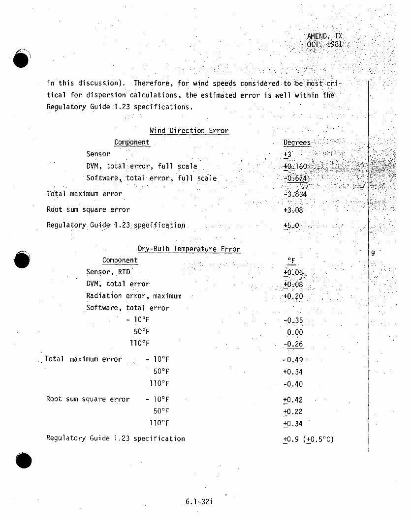
AMEND. IX
OCT. 19•1
in this discussion). Therefore, for wind speeds considered to;T bel ýmost* ýcri-tical for dispersion calculations, the estimated error is well within theRegulatory Guide 1.23 specifications.
Wind Direction Error
Component
SensorDVM, total :error, full scaleSoftware, total error, fuTl scalle
Total maximum error
Root sum square error
Regulatory. Guide:l .23.specification
Dry-Bulb Temperature ErrorComponent
Sensor, RTDDVM, total error
Radiation error, maximumSoftware, total, error
_ 10OF
500F
llOOF
.. Total maximum error - 1O°F
50OF
llO°F
Root sum square error - 10OF50°F110°F
Degrees'
+3
+0160>
-8;834
+3.08-
9.PF
+0.06+0.•08
+0.20
-.0.35
o..00o
-0.26
-0.49
40.. 34
-0.40
+0.42
+0.22
+0.34Regulatory Guide 1.23 specification +0.9 (+0.5°C)
6.1-32i

AMENDMENT XVIOCTOBER 1982
Vertical Temperature Difference Error
Component
Sensor 1
Sensor 2
DV01 (Sensor 1 reading)DVM. (Sensor 2 reading)
Radiation
Software
oF+0. 06+0.06"
+0.08
+0.08
0.0
Total maximum error
Root sum square error
+0.28
+0.14
+0.18 (+O.l°C)Regulatory Guide 1.23 specification
The assumption is made that the radiation and software- error-s,
are identical for both sensors and therefore cancel;
Dewpoint Temperature Error
9
Component
Sensor EG &G Model 440
Mirror contamination
Loss of water. in sample lines
Sample line contamination
Pressure change correction
Frost point conversion (dewpoints
below 32°F)
DVtM, total error, full scale
Software, total error
Total maximum error
Root sum square error
Regulatory Guide 1.23 specification
O F ,
+0ý. 7
+0.3-0.2+O.1
+0.1
+0.05
+0.04
0.0
+1 .29
+0.80
116
+0.90 (+0.5 0C)
0Refer to Table 6.1-6 for data sample rates and scaling calculations.
6.1-32j
Amend. IXOct. 1981
Pages,.6. 1-32k throqugh6.1-32m are deletedin .Amendment IX
6.1-32k -

AMENDMENT XVIOCTOBER .1982
Instrument Servicing. Maintenace and Calibration
The permanent meteorological facility is serviced by engineeringaides, instrument technicians, or engineers. Maintenance andcalibrations are performed by instrument technicians, electricalengineering associates, or electrical engineers. Prior to plantoperation, operational checks of the system will be made twiceweekly or more frequently as necessary to achieve the required 90percent recovery of data. The calibration status of each
component of the meteorological facility (sensors, recorders,
electronics, DVM, data logger, etc.) is checked and the componentfield calibrated or removed and replaced by a laboratorycalibrated component, at least every six months. More frequent
calibration intervals for individual components may be specifiedin the station manual, on the basis of the operational history ofthat component type, in order to ensure the maximum practicable
recovery rate. Detailed, standardized procedures are included inthe station manual and/or the laboratory calibration proceduresdocument.
6.1.3.2 MODELS
The mathematical model used to estimate atmospheric dilutionfactors (X/Q values) for gaseous effluets released from the
CRBRP is give in Section 2.6.7. Models used to assess reactoraccidents are covered in Section 2.6.6.
116
116
116
6
t116S
f 8
96.1-33

6.1.4 LAND
6.1.4.1 GEOLOGY AND SOILS
The purpose of the foundation investigations and related geological studies,at the Clinch River Site was to develop the regional and Site geology,establish the sub-surface geological profile, select the optimum location.and bearing elevation for the Category I structures and determine the
static and dynamic foundation desIgn .<parameters for the supporting rockmatrix.:
6.1..4.1.1 REGIONAL INVESTIGATION PROGRAM
A regional investigation, program was conducted which encompassed the areawithin a 200-mil Teo-radius of the Site, with major emphasis placed on the
Valley and Ridge Physiographic Province. This investi gati.on containedthe following elements:
1. Literature review - a comprehensive review of availabledata incl uding published andunpub ished reports and maps
and interviews with recognized authorities, was made to.evaluate the geologic conditions of the region and Site,;
2. Aerial photographic studies - these studies included
thermal imagery, infra-red, color and black and white
stereography;
3. U.S.G.S. topographic map studies - maps of the regionwere reviewed and surface features which were possibleindicators of anomalous sub-surface activity were noted
for subsequent investigation; and
4. Field Reconnaissance - planning and investigation of specificsurface features considered pertinent to the development andunderstanding of the regional geology was performed.
6.1-34

AMEND. IXOCT. 1981
6.1.4.1.2 SITE INVESTIGATION PROGRAM
A Site investigation program was conducted consisting of the following
primary elements: seismic refraction survey, core borings, surfacereconnaissance and mapping, geophysical logging, terrace borrow and
residual soil investigation, test grouting program and laboratory testing. 9
A seismic refraction survey was conducted at the Site covering approxi-
mately 6,940 linear feet. This survey permitted preliminary evaluation
of the sub-surface conditions based on measurements of compressional"
wave velocities of the in-situ material. Conditions investigated inclu- "4
ded depths to the various sub-surface horizons and the presence of.1
seismic discontinuities.,
The total investigative program for Category I structures consisted of 9
129 borings of which 66 were directed to defining the Site geology,
checking-pbtential anomalies in the seismic refraction data, under-
standing the nature, extent and significance of sinkholes which.have0.occurred in the limestone formations occurring at the Site and selecting
the optimum location and bearing elevation-for the Nuclear Island.
Sixty-three borings were included in the final investigation phase
which permitted' the detailed evaluation of foundation design parameters
at the selected location of the structures.
Borings were advanced utilizing truck-mounted rotary drills and
samples were obtained from both the soil and rock strata. In ¶9
general, the holes were drilled four inches in diameter through the
overburden soils to the top of rock, with standard penetration test
samples being taken at five foot intervals. This penetration test
consists of driving a sampling device into the undisturbed soil under
standard conditions - the sampler size, distance driven and energy used
are all predetermined. The resistance to penetration encountered by the
sampler was used to determine pertinent engineering properties. In rock,
6.1-35

AMEND. IXOCT. j1981
continuous, NX, NQ and:HQ-sized .core was iextracted .fromthe boirings:by rotating a conventional discharge diamond-studded bit.mounted .don.either an NX, double-tubed, swivel-type"core barrel .or an.NQ or :HQ 9wire line core barrel. The core was geologically logged,: which'
included a description of the rock based on visual examination,degree-.of weathering, presence and orientation of joints and partings and anyanomalous features.
To aid in the determination of the Site geology-, detailed mapping,. o.f,exposed rock outcrops was conducted by fi el-d, geolOgists. Among•thefeatures noted were rock types, degree of weathering, orientationof.strike and dip, location of sinkholes and lines of demarcation betweenthe different rock units. A Site geological map was subsequently pre--.
.pared from this data.
Selected borings were logged for natural gamma-ray emission, electricalresistivity and spontaneous potential, to assist in identification andconfirmation of lithologic changes. Borings were also logged by ad-ditional in-hole techniques, which consisted of gamma density determina- 9tions, caliper measurements and compressional wave velocity measurements.Separate cross-hole andi up-hole seismic surveys were conducted to permitthe determination of various in-situ dynamic rock properties.
Residual soils and terrace deposits encountered at the Site were inves-tigated by means of backhoe trenches, soil sampling and testing toevaluate their potential use as sources of borrow material. Bulk sampleswere obtained from test pits, protected against loss of moisture andretained for laboratory testing.
A test grouting program was conducted on the west side of the NuclearIsland to confirm the adequacy of the bearing capability of the founda-tion rocks. The program was performed in an area where the Unit ALimestone is-overlain by the shallowest depth of siltstone and conse- 9!
quently was considered to be most susceptible to development of solution-ing within the bearing influence of the Category I structures.
6.1-36
AMEND IX
OCT. .1981 !
A comprehensive .laboratory testing program was conducted oh soil and
rock samples obtained, from. tes t pits and core borings•to .determine.the
engineering properties of-these materials. These prope rties included.:
unit weight, moisture content, compactibility, compressibility, strength
and chemical composition.
. ,.•, .i: ••i:i•i,: ~9• ,
O~
6.1-36a

AMEND. IXOCT. 1981
6.1.4.1.3 RESULTS OF INVESTIGATION
Results of the investigation program are summarized below:
1. The Site is covered by a mantle of residual clay andweathered rock derived from the decomposition of theunderlying parent formations which generally occur atshallow depths and consist of sedimentary rocks of Ordo-vician age. Deformation of the rock strata occurred
during the Paleozoic Era (more than 230 million yearsago) .and are nowti ted tothe southeas-tait ah." angleof about 30 degrees. The Chickamaug'aForma-tioncon:•.
sisting of interbedded limestones and,. siltstonescomprises the foundation.bedrock in the general vicin-ity of the plant, structures.
2. -An upper siltstone band approximat•ely'400- -'eetý inhorizontal width was selected .as t•he -opt.imumibearling•-
stratum for the Nuclear Islandbased on,.shal'low.depth of weathering, inherent -.resistanceto;ýodevel.op.-...ment of solution activity. and satisfactory.enginee ing..characteristics.
3. There is no geological evidence for any capable fault-
ing within 200 miles of the Clinch River BreederReactor Plant Site.
4. In conformance with relationships accepted by theNuclear Regulatory Commission (NRC) for nuclear power
plants located in the Southern.Appalachian TectonicProvince, and as directed by NRC, the maximum.hori-zontal ground motion for the Safe Shutdown Earthquake
(SSE) was established at 0.25 g.
5. Instability of foundation material is not considereda problem.
8
6.1-37

Amend. XDec. 1931
6.1.4.2 LAND USE AND DEMOGRAPHIC SURVEYS
There are two steps in presenting the population data in the circle and
sector format:
1. Distribution of the 1980 population into sectors.
2. Projection of the population for 1990, 2000, 2010, 2020, and 2030.
Although the two steps link together, they have separate approaches.
6.1.4.2.1 DISTRIBUTION OF THE 1980 POPULATION-
The preliminary results of the 1980 U. S. Census of Population were used
in the existing population estimate and placed in the appropriate sectors
within the circle. The circle format is an intersection of rays and radius
circles centered at the reactor. There are 16 rays, each 22-1/2 degrees
apart. One of the sectors created by two rays is centered on. North such
that the rays are 11-1/4 degrees east or west of. North. Radius circles
are at distances of 1, 2, 3, 4, 5, 10, 20, 30, 40, and 50 miles. There
are 160 separate sectors in the circle. Figures 2.2-1 and 2.2-2 are .
example.s of the population circles.
S10
0
The 1980 population was allocated to the population wheel
aerial photography for the area within 5-miles of the site
Census County Division maps (CCD) for the area from 5-
the site.
sector using
and using
to 50-miles of
0- TO 5-MILE ALLOCATION OF POPULATION
The 1980 population within 5-miles of the site was estimated by counting
structures, identified on an aerial photograph, which fell within a
population wheel sector. The steps were as follows:
06.1-38

Janlu a r 1982
o A mosaic of aerial p hoto9 raph:y was prepared. Th ei p hphotogr arp•hy
was at a scale of 1 inch equals 1,000 feet. Aerial
photographs were taken on February 25, 1981
o A clear overlay with the circle and sector figure Inscribed
on It was placed over the mosaic. The center -of the figure
was placed on the reactor site.
o Within each sector, structures-:which were houses or':,'
apartments were Identified and counted. Apartm ents were
distinguished from houses by Ide~ntifyIng apartment p0arkikng.
lots from the photographs followed by a field check to 1.0
identify the -actual number of apartments when necessary. In
cases where the structure could not be Identif ied, it was
assumed that the structure w.as a dwel I Ing.
o Using the 1980 Pr.el ImInary Pop~u..latlion and Housing unit
Counts., 34a an average number of persons per housing unit w.as•- i
obtained for Roane and Loudon Cou~nties.
•o The persons per houslnq unit calculated above was.applied to
the structures- counted.
This procedure prov Ided a sector by sector estimate of the people
within 5-miles of the Site.
5- TO 50-MILE ALL0CATIONI4-OF POPULATION
The allocation of population between 5- and 50-miles of the sitewas performed using Census County Division (CCD) maps (CCD's) andassuming that the population Is, geographically, evenlydistributed within the county divisions'. The steps in theallocation process were:
6 .1 -38a

Amendment X]J a nuva:ry 4 19,82.
oObtain the CCD maps. The 1980 maps were unavaJiab at tnhe,
time of the study. As a consequence, 1970 CC.D maps wereused. The Bureau of the Census reported that only Knox
County of the study area counties had changes from 1970 to1980 In the CCD boundaries. 3 4 b These changes were IIincorporated Into the CCD map.
o A composite of the CCD maps of Tennessee, North CarolInma, andKentucky was prepared.
o The circle and sector figure was placed on the COD composite
map.
o The areal proportion of a Census County Division or town
which lies In a sector Is calculated.*
o The 1980 population for the CCD o r town Is multiplied by theproportion calculated above. This process is repeated foreach CCD or town which lies totally or partially within awheel sector.
o The sector population estimates are calculated by summing theseparate CCD or town estimates.
This method's assumption that the population is evenlydistributed over the area of the CCD or town Is realistic forTennessee. Except for national parks and national forests,. thestate has a relatively dense rural population.
6.1.4.2.2 POPULATION PROJECTIONS
Population projections for the study area for 1990, 2000, 2010,2020, and 2030 were generated using the Greenberg and Krueckeberg
*The Census County Division maps provides boundaries for thecounty, Its county divisions, towns of 100 or more persons, andunincorporated towns of 2,500-persons or more. For each ofthese entities, the census provides a population estimate.
6.1-38b

Amendment XIlJanuary, 1 982
ratio-trend methodology.~ I n this methodology, U.S&. Cenls~us11
Bureau Projecti.ons34d corrected for the 1980 census per.formance
were used as controlled totals. Projections for Tennessee,
Kentucky, and North Carolina were available only to year 2 0 0 0.34e i
Historical data, the ratio-trend methodology, and the U.S.
control totals were used to extend these projectio'ns to 2010,
2020, and 2030.
State projections were "stepped-down" to couhntyy and census civ il
d Iv Is Ion (CCD) levels., Rat ios of c~ou nty, to state populations* 1were obta ined from t+he Tennes'se~e 'Sta t e P1,a n n ing 0ffice34f or b ythe ratio-trend methodo.logy us ing historlcal data for Kentucky
and North Carolina. Census civil divi.sion projrectlons were"stepped-down" from the county level us ing CCCD to lounty ratios
obtained from the Tennessee State PlannIng Office or by the
ratio-trend methodology.
6.I -38c "

INTENTIONALLY BLANK

AMENDMENT XV,JULY 1982
6.1.4.3 ECOLOGICAL MONITORING . 5
The terrestrial monitoring program is designedto evaluatetheimpact of operational and construction activities on thestructure and function of the terrestrial ecosystem.
6.1.4.3.1 BASELINE STUDIES
A terrestrial baseline study program was conducted on the ClinchRiver Site to document preexisting conditions and stresses and toide~ntify food chains. Preexisting conditions and stresses arethose,,:,presently existing on the Site, ,whether naturally occuringor man-made.
Purpose of the- base~line lstudy prooghra wasto evaluatebothqualitatively and quantitatively, the specific aspects of theterrestrial environment that will be affected by the constructionof the breeder reactor facility. Three major study objectiveshave been identified:.
1. Evaluation of the biotic components of areas subject toconstruction activity for the plant and associated
facilities .and assessment of possible environmentaleffects of plant construction and operation;
2. Observation of seasonal fluctuations in the biologicaldiversity represented within the Site area; and
3. Identification of significant parameters to be measuredor.monitored in later studies which will provide a moreprecise estimate of real and potential impact.
6.1-39
AMEND. IXOCT. 1981
The study period included seasonal surveys, shown in Table6.1-5, 'Which Sbegan in the winter of 1974 and ended with the completion of the fall
survey of 1975.
A two-day reconnaissance field survey was conducted August"27,and 28,1
1980 to evaluate site changes since the 1974 baseline surveys and to
sample a shortleaf pine plantation that was established in 1976.ý Re-
sults of this reconnaissance survey are reported in Section 2.7.
6.1.4.3.2 METHOD FOR ACQUIRING BASELINE DATA - SITE AND ENV RONS
Terrestrial ecology field investigations of the CiAnch River Site incl1 uded
four seasonal surveys conducted during 1974 as indicated in Table 6.1-5.
Investigations involved floristic, vegetation, mammal, avifauna and her-
petofauna evaluations in 12 communities as discussed be low and in Sec-
tion 2.7. Vegetation types and sampling communities-are shown in
Figure 2.7-6. Vegetation sampling plot locations, mammal sampling grids:
and transects and avifauna quantitative transects are shown in :Figures
2.7-7, 2.7-A and 2.7-B, respectively. Sampled communities 'were chosen:'ý`..
to include major forest cover types on the site to adequately character-*ize the site. Sampled communities included mixed hardwood, successional
pine, pine plantation, cedar-pine and hardwood-cedar-pine-forest cover
types. In addition to surveys on plots, general observations of flora,
migratory wildlife and herpetofauna were made when traveling from one 9
sampling location to another, systematically driving site roads in early
morning and late evening times and searching in suitable habitat. Simul-
taneous surveys were conducted whenever possible.
The floristic sampling program was designed to determine the presence or
absence of plant species that were either listed as rare or that were
eligible for listing as threatened or endangered by the U.S. Fish and
Wildlife Service. Discussions with Dr. A. J. Sharp of the University of
Tennessee had indicated that flora of the Site area was poorly known so
an intensive specimen collection and preservation program was conducted.
Mounted specimens were deposited at the University of Tennessee Herbarium. (S
6.1-40

AM.END. IOCT.: 198.1
Vegetative sampling, in coordi nation with• the fl oristic sampling program,
was designed tol(a) determine the presence or.absence of plant species
in various forest types, especially rare or. potentially threatened or
endangered species, (b) provide data to compute density, cover, fre-
quency and abundance of ground.cover and shrub species and (c)..provide :
data to, compute importance values, annual growth increments and. succes-
sional trends for tree species. Merchantable tree volume and management'
procedures were available from Oak- Ridge National Laboratory,(ORNL).
Substantial timber acreages on the- Site -were thinned or harvested to .
control forest diseases and pests, during.:and..: fol.-ow'ing, the, f.iield. samp ling.program. The ORNL forest management program is described briefly in
Section 2.7.,
Wildlife surveys were conducted as indicated in Table 6.1-5 with.samp ling...
locations indicated in Figures 2,.7-A and 2:7ýB. Special attention was
given to fauna that were either listed or eligible for listing as .rare,
threatened or endangered. On-going wildlife studies, at nearby ORNL .
were utilized as indicated in Section.2.7.
'Mammal live-trapping grids and snap--.trapping tr.ansects were establishe
so that traps could be located at the same stations during each :'Survey..."
Sherman live traps (50 per grid) were placed in grids covering.approxi-
mately one acre. Household snap traps (50 per transect) were spaced,.at
approximately 20 foot intervals along .a marked transect line. A wooden.
surveyors stake was placed at each trap station in the grid and at each-
end of the transect. Traps were baited with a mixture of peanut butter..
and lard to attract both herbivorous and carnivorous small mammals. Each
trap was visited in the early morning for five consecutive days. Cap-
tured animals were examined to determine age (adult or juvenile), sex,
reproductive condition and overall condition. Live captured animals were
toe clipped for identification purposes and released. General site
searches were also conducted for tracks, scats and other evidence of mam-
mal presence. An early morning and late evening survey was conducted
during each survey period. During the summer survey, an .endangered bat
expert searched known site caves for the presence of bat species, mist-
6.l-40a
AMEND.: IXOCT. 1981.'
netted in likely bat habitat along.Grassy Creeand the Clinch RiCver
and searched for other site caves. Results of mammal surveys.are
discussed in Section 2.7.1.
Avifauna surveys incl~uded both quantitative and.qualitative investiga-
tions. Quantitative avifauna s'urveys were. conducted for seven days in.
late May to early June and in mid-December using a modified Em!en tech-
nique discussed i:n Section 2.7.1. Sampling transects and stations are
indicated iný Figure 2.7-B. Breeding populations were- estimated'.fromq the:late spring:; survey, while winter resident populations were estimated
from the December: survey. Migratory and resiident spec'iesin .Other
habitats and-on the sampl~ing transects were eval-uated during al.1 four.
seasonal surveys.
Systemati c searches were conducted for herpetofauna. species 1,in likely
habitat throughout the site durilng late spring and summer surveys.
Herpetofauna aestivate during the dry,. hot fall: and.hibernate.during the
winter. and are not consistently observable.
6.1.4.3.3 METHODS FOR ACQUIRING BASELINE.DATA. - TRANSMISSION LINE RIGHTSOF WAY
Communities along the transmission corridor were visually examined and
the various types identified and described. A summary of the community,
descriptions, major species observed and species expected may be found
in Section 2.7.
6.1.4.3.4 CONSTRUCTION MONITORING
Construction impacts can be thought of as primary and secondary. Primary
impacts include modification .and alteration of habitat by blasting, .drill- 69I
ing, excavating and clearing. These impacts will occur during develop-
ment of access corridors (roads, railroads and transmission lines),
clearing and excavation for all construction (intake and discharge areas,
holding ponds, cooling towers and other buildings), noise and vibrations S
6.1-41

AMEND.. I X-OCT. 1981
from construction equipment, exhaust.emissions, atmospheric pparti cul ates,
fuel leaks and spills, mud and activity of men and machines. Associated
with these primary impacts are secondary impacts such as increases in
housing developments, trailer courts, energy use, recreation and use of
recreation facilities (camping, hunting, boating, hiking, etc.), house--,
hold pets and transportation of all types (automobile, truck, rail'road,
barge and air).
Monitoring for primary construction impacts onnthe Sitewill concentrate
on vegetation and vertebrate parameters. Primary and secondary construc-
tion impacts that will occur regionally (other than on-slite) will be
related to construction of power lines and other changes in land use.
When power line corridors are developed, habitats will be ,alter'ed,,.land
cover will change and species composition will change. The majoriimpacts
associated with the power lines will be to. decidubous and coniferous
forest communities and the biota associated with them.
A draft program for on-site environmental monitoring during construction
has been prepared by Stone & Webster.(35) Critical ecological elements
will be identified from baseline survey data, and the. plant construction.9
manager will be provided with maps and photographs of the locations of
these critical elements so that they may-be avoided during construction.
Semi-annual inspections of species and community locations will be per-
formed to monitor the status of the critical elements.
6.1.5 RADIOLOGICAL SURVEYS
Preoperational radiation levels at the Site and environs are discussed
in Section 2.8.- The preconstruction-construction environmental radio-
logical monitoring program described here has the objective of establish-
ing the extent to which construction activities in the Clinch River
disturb the existing bottom sediment, resuspending part of it in the
river. This is important at this plant site because radionuclides have
been released to the environment in this area by other facilities for
approximately 30 years. Full development of the preoperational-
operational radiological monitoring program is given in Section 6.2.
6.1-42

AMEND.SIXOCT. 1981
6.1.5.1 PRECONSTRUCTION-CONSTRUCTION, PHASE ENVIRONMENTAL- RADIATION .'MONITORING PROGRAM
The purpose of this monitoring, program is to determine the. effect of con-
struction activities on the reservoir environment. To achieve this, a
routine program was initiated in 1975 for monitoring radioactivity levels
in ground and surface waters and in bottom sediment in the vicinity of
the CRBRP. This program was discontinued in December 1977. The
construction monitoring program will resume 6.months prior to start ofconstruction. Approximately two years prionrto plant operation, it will
.be replaced by a more extensive .preoperational-operational .monitoring-
program.
All samples were analyzed in TVA's Radioanalytical Laboratory in.Muscle
Shoals, Alabama. Gross alpha and gross beta content were determined.
by use of a low background proportional counter. Total- alpha content, was..
determined by alpha counting heavy metals separated along with strontium.
Gamma-emitting radionuclides were identified and quantified by gamma
spectral analyspis employing a Ge (Li.) detector. All sediment.samples .9.
were dried, pulverized, and thoroughly mixed prior to analysis.
Sediment sampling began in March 1975. Samples were taken quarterly
by TVA's Water Quality and Ecology Branch at Clinch River Miles (CRM)
14.4, 15.4, 17.9, 19.0, and 24.0 (Figure 6.1-11). Replicate samples
were taken from the right overbanks (horizontal location -- 99 percent
from the left bank looking in a downstream direction) at CRM's 14.4,
15.4, 17.9, and 19.0 and midchannel at CRM 24.0 by Ponar dredge hauls.
River water samples were taken automatically by a sequential-type sampling
device at CRM's 14.4, 15.4, 18.6, and 23.1. The sampler at CRM 14.4 was
located immediately upstream of the Department of Energy (DOE) potable
water intake and is considered representative of the raw potable water
.supply.
6.1-42a

AMEND.1 'IXýOCT.. 1981
The samplers were placed in operation in October-1975, andr'theinitialsamples were collected in..November. Composite samples from 'each lIocation,"were forwarded monthly to the radiological laboratory for ana'ysis.
Ground water monitoring was also begun in October 1975, with the f irst"sample being taken in November. The same type of automatic sampler used..in the river water monitoring was. employed at a well located down gradientfrom the proposed plant site (Figure 6.1-10). Water from this well. .wascollected automatically and forwarded monthly to the radiologica'laboratory for analysis.
The results obtained in these monitoring studies and in nthree short-t rmspecial studies indicate that radioactivity levels in the bottom sedi'men6tvary widely with the depth from which the sample is taken, with theriver mile cross section, and with time at specific locations4. 3 6
Radioactivity levels found in the over-bank regions near the proposed 9locations of the barge unloading facility, the water intake, and thedischarge site were not significantly different from background Ievel S...found in the Tennessee River. However, samples of sedimentary material6 . .deposited farther off the. bank showed radioactivity levels up -to:, 10:0-times these levels.
Other than gross beta concentrations approximately three to five timesbackground and tritium concentrations approximately 10times background(measured at Melton Hill Dam), no significant radioactivity levels werefound in the water from the Clinch River. Although initial indicationsare that dredging operations in the river will not produce significantincreases in the radioactivity concentrations in the river water due tothe resuspension of radionuclides in. the bottom sediment, further samplingwill be conducted during dredging in order to determine if this is true.
6.1-43

TABLE 6.1-1
CLINCH RIVER AQUATIC BASELINE SURVEY SAMPLING"SCHEDULE
1974 1975M *A M J J A S 0 W- 0 J F M A M
Biological Parameters
Bacteria X X x x x x x
Phytoplankton X X X X X X X X X
Zooplankton (tows) X X -X X X X X X X
Zooplankton (pumping) X X X X*
Periphyton X X X X X X- X
Benthos (dredging) X X X X X X X X X
Benthos (artificial substrate) X** X•* X** X X X X X X
Macrophytes X X X
Fish Populations X X X X X x X X
Fish Eggs and Larvae X+. X+ X+ X+ X+ X+
Fish Stomach Contents X X. X X X x X
Physical and Chemical Parameters 9Field Measurements X X X X X X X X. X
Routine Lab. Analyses X X X X X X X X X
Additional Analyses X X
Sediment Analyses
Particle Size and.Organic Content X x x x X
Heavy Metal Content X X
Total Phosphate Content X X
• Trace Elements " . X
Polychlorinated Biphenyls (PCB's) X
Insecticides X
* Pump sampling-was discontinuedlafter-this trip.
• Most samplers were damaged in river..
+ Once every two weeks. 'eC-)-
cmo3

STABLE 6.1-2
SAMPLING METHODS FOR THE CLINCH RIVER•AQUATIC BASELINE SURVEY
Parameter Sampling/Frequency Sampling Method Analyses Sampling LocationBIOLOGICAL
BacteriaStandard plate count Once each month in surface collection (1) concentration expressed Figure 6.1-2-Total coliform count March, May-Sept. and (one foot below. surface) as colonies/lOO mlFecal coliform count Nov. (1974); and Jan.. using sterilized'glass (2) analyses according toFecal strep, count and April (1975) containers "Standard Methods"*
Phytoplankton Once each month during (1) Vani Dorn-bottle (1) identification.to' the Figure 6.1-2March, May-Sept. and (2) surface collection specific level', whenNov. (1975);.and Jan. practi.ca..and April (1975) (2) number/liter
(3) speci es diversity(4) percent co mppo-i'tion--major groups(5) biomass (chlorophyll. ameth6d including measurementof chio:robphyll •b,,,•'c-'and'pheophytin a conite-n rati O)
Zooplankton tows Once each month during (1) vertical tows, (1) identification to.the' Figure 6.1-2
March, May-Sept. and (2) 0.5 meter diameter, speci fci l-]evel, wien,, practica INov. (1974); and Jan. 0.7 6 p mesh plankt6n net (2) ndmber/literand April (1975) with TSK-outside-and (3) species. diversity
inside flow meters (4) coposite' bi.cmasSý (volume by(3) horizontal Surface tows displ.mene r.-e•t.iesurement ofbeginning in-September cell 'pepn di ng on abuhdlnce)
Zooplankton Once each month during (1) submersible pumP (1) identificationh- to the Figure 6. 1-2pumping March, May, June and (2) filtered. through a specific level which practicalJuly (1974) O.76p mesh plankton net (2) number/1 iter(3) surface; mid: and (3) specievsdversity .bottom collections (4) co Lm e"sbio .e - b ('volume by
di'splacement•or measurement ofcells dependi ng 'on abundance)
Periphyton Once each month during (1) plexiglass-slides.on (1) identification to the Figure 6. 1-31May, June, Aug., and floating. racks` .e specif i c l evel1 whenpractical,Oct. (1974); and Jan. (2) 2-4 week exposure period . of species of all groups of algaeand May (1975) (2) species di versity
(3) autotrophic index
19
19
(C0ontinued)(00

TABLE .6.1-2 (Continued.)
Parameter Sampling/Frequency Sampling Method.. Analyses. .. Sampling-Location
Benthos dredging Once each month during Ponar dredge (.) identification to the Figure 6.1-4March, May-Sept. and (specific level, when practicalNov. (1974).; and Jan. (2) number/mn and number/literand April (1975) (3) sizeranges of .larger mollusks
(4) species diversity5 .(5) composte.. bomass .(blotted wet
weilgh . an s f.ee. dry'weight.)
Benthos artificial Once each month during (1) hardboard, .multi-plate (1) identificati6n.to the Figure.6. 15substrate March, May-Sept. and sampler suspended 1 to 2 feet specific level, when practical
Nov. (1974); and Jan. above bottom (2) number/rm2
and May (1975) (3) species diversity(4) composite biomass (blottedwet weigHt:and'a"h 'free dry weight)
Macrophytes Once each month during (-1) collection by hand (1) identification to the Figure 6.1-.6March, May and July (2) quantitative-sampling specific level, when,.practical
within-quadrates if sub- (2) cdmposite::bi.mass (blotted wetstantial growth encountered weight and ash Ifree dry'weight)
(3) consltructiohn~of-vegetation mapif .substantial roth eencountered
Fish populations Once each month during (1) electo'shocking' (1) species 6o psition Figure 6.1-7March, May-Sept. and (2) gill nets (2)-relative species abundanceNov. (1974); and Jan. (3) scale.collection of 7 .(3) .percentage.:,game,..rough .and.and April (1975) most abundant species forage fish - .
.(4) ýspecies diversity(5) A-!hnth and :jight de ter-minations(•6)-condition facfor'-of 7 mosta b unAd'ant ý s.p eci e~s:(7) 61nt by a`4e"-gro~th, curvesof 7most 4abuIndan i es
Fish eggs and Once every two weeks (1) stationary*" 'bottom l,O0p .(1) density it nunih er/m). Figure 6.1-8larvae during March through ichtyaopan twnet with TSK (2)stagefdeve•open••"•. . e
August. inside and outside f,low,,meters: (3).'s',ec•iesiideritfjction,(2) pumpng submersie whenf•pacticaPump 1to 2 feet from bottom
9
9
19
C-)n
+M0
(-Con tinued )
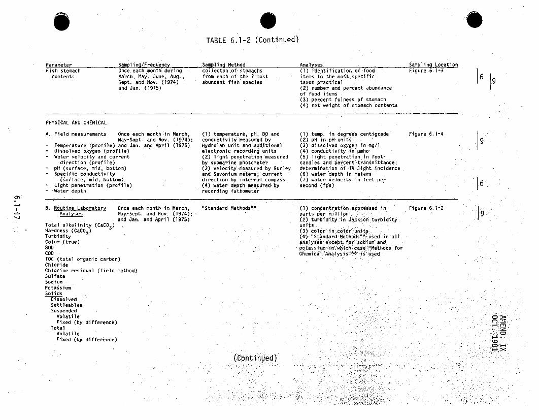
S
TABLE 6.1-2 (Continued)
Parameter Sampling/Frequency .. Sampling Method . Analyses Sampling LocationFish stomach Once each .month during col.lecton ,of stomachs (1) identification of food Figure 6.1-7contents March, May, June, Aug., from each of the 7.molst items to the mo'st.specificSept. and Nov. (1974) abundant fish species taxon practicaland Jan. (1975) (2) number and percent abundance
of food items(3) percent fulness of stomach(4) net weight of stomach contents
PHYSICAL AND CHEMICAL
A. Field measurements Ohce each month in March, (1) temperature, pH, DO and (1) temp. in degrees centigrade Figure 6.1-4May-Sept. and Nov. (•1974); conductivity measured by (2) pH in.pH units- Temperature (profile) and Jan. and April (1975) Hydrolab unit and additional (3) dissolved oxygen in.mg/l- Dissolved oxygen (profile) electronic recording units (4) conductivity.i.npmho- Water velocity and current (2) light penetration measured (5) light penetration.in.foot-direction (profile) by submarine photometer candles and percent transmittance;
pH (surface, mid, bottom) (3) velocity measured by Gurley determination of 1%.-light incidence- Specific conductivity and Savonium meters; current (6) water depth in meters(surface, mid, bottom) direction by interna~lcompass (7) water velocity in feet per- Light penetration (profile) (4) water depth measured by second (fps)
- 'Water depth recording fathometer
J69
9
[6
B. Routine LaboratoryAnalyses
Once each month in March,May-Sept. and Nov. (1974);and Jan. and April (1975)
"Standard Methods"*
Total alkalinity (CaCO 3 )Hardness (CaCO 3 )TurbidityColor *(true)BODCODTOC (total organic carbon)ChlorideChlorine residual (field method)SulfateSodiumPotassiumSolids
DissolvedSettleablesSuspended
VolatileFixed (by difference)
TotalVolatileFixed (by difference)
(1) concentration expressed inparts per milli on(2) turbidity.in Jackso.nturbidity_units'
•(3) color in color units...(4) 'Stindard-Methods"•*'used in allanalyses except for sodium andpotass ium -In whichcase '"Methods forChemicali Ana:lysis** isu.. sed
Figure 6.1-2
rriM
(Cnti inued)

TABLE 6.1-2 (Continued)
Parameter Sampling/Frequency. Sampling Method. Analyses Sampling Location
NitrogenNO2NO2
NH 3
3Phosphate
Total - POOrtho - PO4
C. Additional Analyses Once during March and "Standard Methods"* Analyses were done using Figure 6.1-9Chlorine demand Sept. 1974 "Standard Methods' •exceptFluoride for: (a) mercury, molybdenumNitrogen gas and nickel in which case-Silicate "Methods for Chem ical Analy-• Calcium sis"" was used (b") nitrogenMagnesium gas in which case-the-Van. "Molybdenum Slyke method+ wa..usedSelenium .Cc) selenium.ifniwhich:caseTin "Proposed Tentative Methd",+"
-Alumium was usedManganeseZincCopperMercurySilverArsenicCadmiumChroni umLeadNickelCobaltIron (total)Organic compounds
CyanideDetergents-surfactants (MBAS)Oil and grease (solvent extraction)Phthalate esters
PesticidesOrganochlorines (insecticide)Atrazine (herbicide)2-4-D (herbicide)
19
:1.9
19
.,9
C)
'.00
(Continued)

6
TABLE 6.1-2 (Continued)
Parameter Sampling/Frequency Sampling Method Analyses Sampling Location
SEDIMENT
Particle size and Once each month during collection by dredge (1) particle size deter- Figure 6.1-4total volatile March, May, July and minationas in "Shore(organic) solid Sept. (1974); and Jan. Protection"Vcontent and April (1975) (2)-total volatile solid
content by combustionaccording to "StandardMethods"*
Total Phosphate Content Once at the beginning of collection by dredge acidification, then Five compositeHeavy Metal Content the study and once at procedure as in "Standard samples in 1974,
the end of the study Methods"* for metal analysis. three compositeMolybdenum March 1974 and April 1975 samples in 1975.Selenium with each sampleTin consisting of theAluminum three samplingManganese stations perZinc transect.Copper Figure 6.1-4: inMercury 1974; TransectsSilver 1, 4 and 5 inArsenic 1975CadmiumChromiumLeadNickelCobaltIron (total)
Trace Elements Once in April 1975 collection by dredge (1) metals: acidification, Three compositePolychlorinated Biphenyls then procedure.as.in samples With eachInsecticides "Standa•r•dMethods"* sample consisting
(2) otherI "Standard "Methods"* of three samplingBeryllium or Methods for, Chemical stations perFluor.ide Analysis'.**.. Transect 1, 4
•Mangesium and 5.AntimonyVanadiumBromineBismuthCalciumStrontiumPotassiumSodiumNiobium
9
9
9q
I-..
Co.-'
(Continued)

TABLE 6.1-2 (Continued)
Parameter Sampl•ing/Frequency Sampling Method Anal yses Sampling Location
SilicaTitaniumZirconi umBari umLithiumScandiumGermaniumPCB'sChlordane (a and y)DDEDDDDDT
Standard Methods for the Examination of Water and .Waste Water, American Public Health Association, Washington, D.C., 1971.
** Methods for Chemical Analysis of Water and Wastes,-EPA, Water Quality Office, Analytical Quality Control Laboratory,Cincinnati, Ohio, 1971.
+ Van Slyke, Donald 0., and Neil, J. H., Journal of Biological Chemistry, 61:523, 1924.
++ Proposed Tentative Method of Test for Selenium in Water, American Society of Testing Materials, November 1970.
V Shore Protection, Planning and Design, Technical Report No. 4, U.S. Army Corps of Engineers, 1966.
.... -- . rri-i
.00@

TABLE 6.1-3
CLINCH RIVER - SUMMARY OF AQUATIC BASELINE SURVEY PROGRAM
Number of Stations/Transects Transect.Parameter
BIOLOGICAL
Bacteria
Phytoplankton
Zooplankton (vertical tows)Zooplankton (Pumping)
Zooplankton (surface tows)Periphyton
Samples/StationTotal No.
Field Visits Samples
3
3
3
3
3
3
1 4 parameters
.1 4 (2 for identification; 2 for Chlopophylldetermination*)
I.
2
3 (each a composite of 2 pumpings)2
Benthos (dredging)
Benthos (artificialsubstrates)
Macrophytes
Fish Population
Fish Eggs & Larvae
3
5
5
5
5
I1 6+ (2 for identification; 4 forautotrophic index)-
2 (each of composite of 2.dredges)(1 composite sample for identification;1 composite sample for biomass)
2 (1 sample for identification;1 sample for biomass)
2 --
2 1 (for identification, length and weight)2 30 scale.readings (fish),,where.possible, of
each of the 7 most abundant species .takenfrom fish-collectedoVer the 9 field traips
1 2 (1 sample by collecting net; 1 sample bypumping)
2 Variable, depending on numbers of sevenmost abundant species collected
9
9
9
4 a*
,4a*
7
9
9
3
9
108
108
54
36
24
126
270
108++
90
210 fish maximum
9.
19ýC:
.12 120
Fish Food Pref.
PHYSICAL AND CHEMICAL
Field Measurements
Routine Lab. Analyses
Additional Analyses
SEDIMENT
Particle Size and.Organic Content
Total Phosphate ContentHeavy Metal ContentTotal. Phosphate ContentTrace ElementsPCB'sInsecticides
95
31
3 7 parameters
23 parameters
29 parameters
9
9
2
6
945
621
58
5 3 1
Five composite samples with each sample consisting of.threesub-samples per transect. -.- . .
Three composite samples consisting of three subsamplesper transect
9019::.
I 5
,9
6 additional samples were taken. on May 29, 1974 for chilorophyll analysis because of early .problems encountered An.previouschlorophyll analysis procedures.- Pumped samples were discontinued after July .1974 srfac tows, were s tu;ed be
+ 10 additional samples were taken for identificationaýnd autotrophic index analysis because of early problems encountered.in analysis++ Total number of samples less than indicated.a$s' a result of•.damage of samplers prior to-June 1, 974- 19CO.

TABLE 6.1-4
PRECONSTRUCTION AQUATIC (NONFISH"- NONRAiDIOLOGICAL) ENVIRONMENTAL MONITORING PROGRAM
CLINCH RIVER BREEDER REACTORPLANT SITE
(Monthly March Through October: 1975)
Physical-Chemical
Station Horizontal'Location Location
PhytoplanktonStormwater and
In Situ2
Laboratory3
Runoff4
Coliform3
Chlorophyll.(meters) (meters) (meters) (meters)
Biological
Autotrophic-Heterotrophic
Submarine (Indices)Photometer Zooplankton6 (Periphyton)
7.
(meters)
Benthos(Artificial BenthosSubstrate) 8
(Dredge)9
CRM 23.1CRM 19.0CRM 17.9
CRM. 15.4
CRM 14.4Caney Creek 0.01(CRM 16.91)Poplar SpringsCreek 0.01(CRM 16.2L)Grassey Creek 0.01(CRM 14.5R)Tributary 0.01(CnM 1.4.60
2050so
5,25,75;9550
5,25,75,955050
50
0.3;-11.5,3,5,60.3,1,1.5,3,5,6
0.3,1,1.5,3.,5,6
0.3,1,1.5,3,5,6
1,3,51,3,5
1,3,5
1,3,5
XXXXXXXX
x
1,3,5 . 0.1,1,3,51,3,5 0.1,1,3,5
0.1,1,3,50.1,1,3,5
X
X.
X
XX
X
X
.1,3,5 0.1,1,3,5 0.1,1,3,5
1,3,5 0.1,1,3,5 0.1,1,3,5
XX
XIC
XX.
X
X.
9
50
50
IPercent from the left bank, facing the downstream direction.2Measurements made In situ for dissolved oxygen, pH, temperature, and conductivity.3Measurements made for alkalinity (field), solids, colors, turbidity, coliform, BOD,.COD, Carbon (TOC and SOC), nitrogens, phorphorus,.Fe, Na,K, Ca, Mg, Cl, S04 , Si0 2 , Cd, Cr, 'Cu, Mn, Pb, Hg, Ni, and Zn.4Samples collected at surface for pH (field), turbidity, and suspended solids determination. Additional samples collected in March, May, June,September, and October during rainfall events.
SPhytoplankton collected for cell enumeration and percentage comp'osition by major taionomic group.. Chlorophyll a estimate of biomass standingcrop.
6Zooplankton sampled by vertical tows for species identification and composite:ibomass determination.7Artificial periphyton substrates (4-week exposure) for autotrophic.index and percentage composition of major taxonomic groups.
SArtificial substrates for benthos, samples used to quantify biomassn'sumbers; a 'd diversity.9Dredge for benthos and particle size analysis, samplesused to quantify biomass, numbers, diversity, and substrate type
-irn
9 90-

AMEND. IXOCT. 1981
TABLE 6.144a
PRECONSTRUCTION AQUATIC (NONFISH-NONRADIOLOGICAL) ENVIRONMENTAL MONITORINGPROGRAM CLINCH RIVER BREEDER REACTOR PLANT SITE
(1976-1978)
Station HorizontalLocation Location'
....... Physical-Chemical .....Primary
Fecal ProductivityIn Situ
2 General3 Comprehensive
4 Coliforms
4 (In Situ C1.
4)5
Meters Meters Meters Meters Meters
SubmarinePhotometer
5
Met e rs
Benthos(Artificial BenthosSubstrates)
6(Dredje)7
CR1 19.-0
CR1 17.9
CRM1 15.4
CRH, 14.4
509550
59550
59550
595
0.3,1,1.5,3,5,6(0;3,1,1.5,3)8(0.3,1,1.5,3)80.3,1,1.5,3,5,6(0.3,1, 1.5, 3)8
(0.3,1:,1.5,3),0.3,1,1.5i3,5,6(0.3,1,1,5,3)8(0.3,1,1.5,3)8
1,3.5
1,3,5
1,3,5
1,3,5 0.1 0.1,1,3,5 0.1,1,3,5
0.1,1,3 0.1,1,30.1,1,3 0.1,1,3,50.1,1,3,5 0.1,1,3,5
0.1,1,3 .0.1,1,30.1,1,3 0.1,1,3''
0.1 0.1,1.,3,5 0.1,1,3,5
0.1,1,3 0.1,1,30.1,1,3 0.1,1,3
X
X
X
X
x
x
1,3,5
PeripheralStormwater
Runoff
CRM 15.5CRM:15.95CRM 16.10CR11 16.50
Groundwater
Well A-58lTll E-60We!ll R-62Weýll G-68Well A-70Well N-70Well-A
Auto Sampled
0.490.10.22.4
Slo
SSS
xlXiXX
XX
9
X
'Percent from the left bank, facing the downstream direction.2Measurements made in situ for dissolved oxygen, pH, temperature, and conductivity once during months of January, and March through October.3Measurements made for alkalinity (field), nitrogens, phosphorus, COD, TOC, solids, turbidity, and colors once during months of Januaryand March through October.4Measurements made for BOD, fecal coliform, Cd, Ca, Cl, Cr, Cu, Fe, Pb, Mg, Mn, Hg, Ni, K, Si0 2 , Na, SO4 , and Zn once during monthsof January, April, July, and October.
5Primary productivity (in situ C1 4 uptake) and submarine photometer (percent light perbiastion) measurements made once during monthsof March through October.
6Artificial Substrates for Benthos - two month exposures. Placed in during months of March, May, July, and September andremoved' in May, July, September, and November. Samples used to quantify biomass, numbers, and diversity.7Dredge for Benthos and particle size anlaysis once during months of March, May, July, and September. Samples used to quantifybiomass, numbers, diversity, and substrate type.
elnitiated in June 1977.3Kilometers from mouth of drainage ways all located at 100 percent from left bank, facing the downstream direction.0Samples analyzed for pH and temperature in the field, and suspended solids and turbidity in the laboratory. Sampling initiatedin June .1976 on a monthly basis.
"1
Samples analyzed for pH and temperature in the field and conductivity, alkalinity, P, solids, Na, SO4 , B, Cd, Cr, Cu, Pb, M Ni,and Zn in the laboratory. Sampling initiated in June 1976 on a quarterly basis.
6 .1-51a .

TABLE 6.1-5
CLINCH RIVER SITE TERRESTRIAL BASELINE SURVEY SUMMARY
Parameters
F loristicSurvey
VegetativeGround Cover
Sampl i ngFrequency
S ampI i ngMethod
SamplingLocati on Statistics and Analyses
Monthly surveys(March throughSeptember)
Three surveys(Spring, summerand fall)
Woody.Vegetation
One survey(Summer)
General floristicsurvey.
Point-centeredcircular 0.001 acrequadrats
Nested circularplots (0.1, 0.05and 0.05 acre) fortrees, saplings andwoody understory,respectively.
Live trapping andsnap trapping ofsmall mammals.Direct observationand secondary signssuch as dens, scatsand tracks.
Entire site
Twelvecommunities
Presence or absence ofspecies in varioushabitat types.
Identifi cati on of groundcover and shrubs. Calcula-tions to determine relativefrequency, density andimportance values.
Identification of overstoryspecies. Calculations todetermine relative density,basal area and frequency.and importance Values.
Twel vecommunities
6
MammalSurvey
Four times peryear (March, May,August. andNovember
5 grids and Species identification, viigor,7 transects sex-, weight, species fluctuation
and habitat preference. ' Cal•cula-•tions. todetermine relati..vepopulation estimates or trapni ght ..i ndices.
(Continued)
7z M
M~~
S0

riTAB LE 6.11-5 (Continued)
S.
SamplingFrequencyParameters
AvifaunaSurvey
HerpetofaunaýSurvey.
SamplingMethod,
ASamplingLocati on Statistics and Analyses
Quantitative•(Late May and-•m m.d- December).• Qual1it :at ,i-Ve -
,:(March, May.August and..:.Nvember)
Two s~urvey•s:(late.spring andmid-summer)
Direct' observations,calls and. -songs whil!econtducti ng walki. ngs surveys durin mfgra-tory eriods a nd
sy~stematic Obser-vations on perm ".anenttransects.
Direct observ~ations
..Eleven ..communi 7- . Speciess sea*sý0nonal .utilization',;".."-tiJes and.edge' . .::.annual:• uctua•tions •jrel.,ativeaeas ab und ane :• .speci es diversity
-.• .:• :•. : ,. .."ofi~ resi..•. i d en tsi.,... : !ii . ;:..•• •. . •. . . . ...
Gen er al sear•offtentiOre si
ch Species idente relative abu
c,
tificatlon andndance.
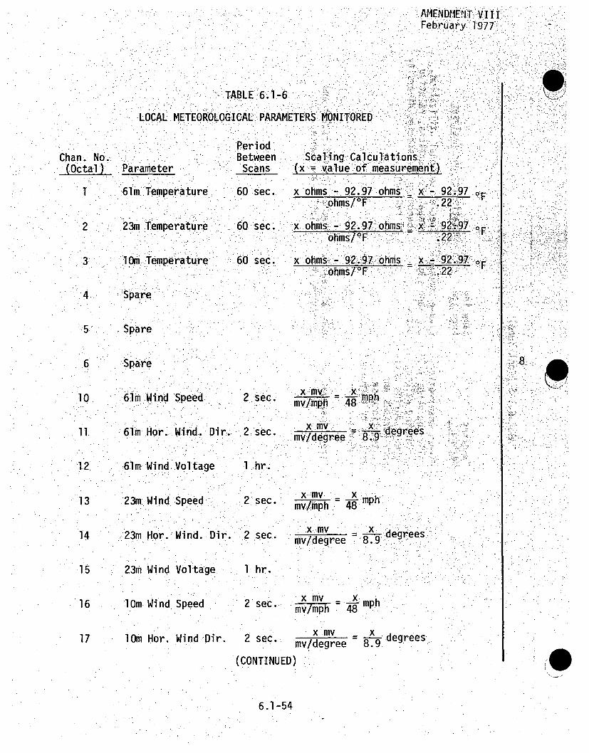
AMENDME.!IT.V IIIFebr•uary', 1977:
Chan. No.,(Octal)
:2
3
4
6
10
1.2
13
14
15
16
17
F
(
jl
.4
TAB.LE 6.1-67LOCAL METEOROLOGICAL PARAMETERS :MONITORED.
Period
Between Scaling Cakculations, :;Parameter Scans (x .alue.of measuremenl).
1im.Temperature 60 sec.: xohms " 92•97 ohms•'., x-. 92..-97<ohms/0F .2
23m Temperature ,60 sec. x x:ohms. - 92:.97.:ohms,.- x 2:97
Oi miTemperature: 60 sec. x ohms.- V92.97T.ohms. _x.92"."97
ohm/.•. - ..223pare
Spare
-Spare
61m..Wind Speed
61m Horiw. Wind.l
61 m Wind Voltag
23m-Wind Speed
23m Hor. Wind.
23m Wind Voltag
lOm Wind Speed
lOm Hor. Wind D
Dir..
e
Dir.
e.
2 sec.
.2 sec.
1 hr..
2 %sec.
-2 sec..
1 hr.
2 sec.
2 sec.
(CONTINUED
N
N
x .mv . ,L.-xL, •• =:";:::;:"•
-I ., degreesnv/degree t, •8.;•9-
x mvW xmv/mph 4m
xmv y =• -degrees:mv/degree . g
x mv _ xmv/mph 48
mv/degree 8.9 degrees)
6.1-54
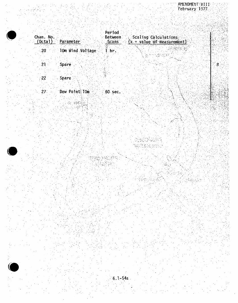
AMENDMENT -.V.I I IFebruaýry 1:977:
Chan. No.(Octail) :Parameter.
. Period.. Between": .-"i:•Scans".
1~+•:.••: hr,. ..
Scaling Calcu1lations .(x .Value of measurement) .
.20 1 m W ind .Vo lta ge
21 Spare
22 Spare.
27T .Dew. Po in t, Wm 60 sec.,
8
6. 1- 54a
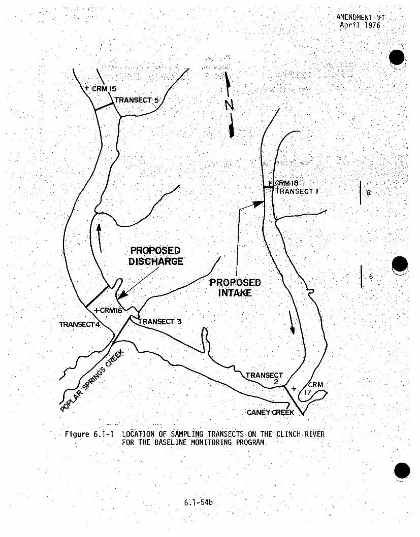
:AMENDMENT; VI.. April. 1976
I 6
I p6
Figure 6.,1- LOCATION OF SAMPLING TRANSECTS. ON. THE CLINCH RIVERFOR THE BASELINE MONITORING: PROGRAM
6.1-54b

AMENDMENT VIapril 1976
6
1 6
Figure 6.1-2 LOCATION OF SAMPLING STATIONS FOR ZOOPLANKTON(PUMPING AND TOWING), PHYTOPLANKTON AND WATERSAMPLES FOR .PHYSICAL ANDCHEMICAL ROUTINE LABORA-TORY ANALYSES AND BACTERIOLOGICAL ANALYSES FORTHE BASELINE MONITORING PROGRAM
6.1-55

AMENDMENT VIApril 1976
0
Figure 6.1-3 PERIPHYTON SAMPLERS LOCATED APPROXIMATELY 30 FEETFROM RIGHT SHORE FOR THE BASELINE MONITORING PROGRAM
6.1-56

AMENDMENT VIApril 1976
Figure 6.1-4 SAMPLING LOCATIONS FOR (A) BENTHOS BY DREDGING,(B) PHYSICAL AND CHEMICAL FIELD MEASUREMENTS,(C) SEDIMENTS, FOR THE BASELINE MONITORING PROGRAM
6.1-57

AMENDMENT VIApril 1976
0
6:
K
Figure 6.1-5 NEARSHORE BENTHIC ARTIFICIAL SUBSTRATES ARE LOCATED30 TO 50 FEET FROM RIGHT SHORE. MID-RIVER SUBSTRATESARE LOCATED 50 TO 100 FEET FROM RIGHT SHORE, FOR THEBASELINE MONITORING PROGRAM
6.1-58

:AMEND. IxOCT. 1981
Figure 6.1-6 SAMPLING LOCATIONS FOR MACROPHYTES. SAMPLINGWAS DONE. APPROXIMATELY 200 FEET BOTH UP AND
DOWNSTREAM TO THE TRANSECTS INDICATED.FOR THEBASELINE MONITORING PROGRAM
Y9
6.1-59 .-
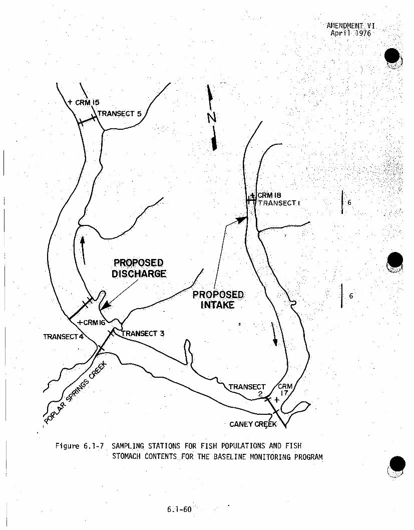
AMENDMENT,:VIApril 1976
I: 6
I6
Figure 6.1-7 SAMPLING .STATIONS FOR FISH POPULATIONS AND FISH:STOMACH CONTENTS.FOR THE BASELINE MONITORING PROGRAM
6.1-60

AMENDMENT VIApril 1976
-. j"'6 i
j6.!
Figure 6.1-8 LOCATION OF SAMPLING STATIONS FOR THE COLLECTION OFFISH EGGS AND LARVAE FOR THE BASELINE MONITORINGPROGRAM
6.1-61

AMENDMENT VIApril 1976
K
16
Figure 6.1-9 SAMPLING LOCATION FOR PHYSICAL AND CHEMICAL ADDITIONALANALYSES FOR THE BASELINE MONITORING PROGRAM
6.1-62

N.
0o- SAMPLING STATIONS.
QR. NATIONALLABORATORY
-A
il9
PROPOSEDI NT1AKE
PROPOSEDDISCHARGE
-SCALE0 2 MILES
I-..
FIGURE 6.1-9a SAMPLING LOCATIONS FOR WATER QUALITY AN- A.QUATIC. BOLOG!I ALMONITORING CLI NCH RI1VER"BREEDER REACTOR PLANT PRECO NSTRUCTINONm-CONSTRUCTION: PHASE -(l 975-1li977)
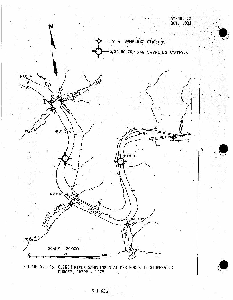
AMENlD. I KX;SOCT. 1,981.
S5o0 ,, SAMPLING.: STATIONS
5i 25, 50, 75,950% SAMPLING STATIONS
9 p o'
SCALE 1:24000
Q .. 2 I MILE
FIGURE 6.1-9bADCLINCH RIVER SAMPLING STATIONS FOR SITE STORMWATER
RUNOFF, CRBRP - 1975
6.1-62b

AIIEND. IXOCT. 1981
S.. . ... ACCESS ROAD
MILE
9
N
/ SCALE 1:24000 ',-" / I MILE
FIGURE 6 .1-9c PERIPHERAL SAMPLING STATIONS FOR SITE STORMWATER RUNOFF,
CRBRP - (1976-1978)
6.1-62c

AMEND. IXOCT. 1981
9
19& Manually sampled observation wells
FIGURE 6.1-10 LOCATION OF GROUND WATER OBSERVATION WELLS, CRBRP(1976-1977)
6.1-63
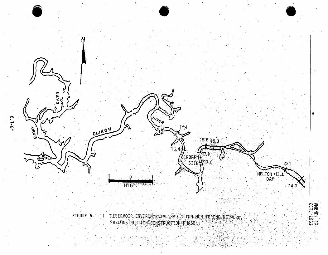
. 0 S
,N
9
T
23.1
1 .sMELtON HlL
DAM2
FIGURE 6.1-11 RESERVOIR ENFVIRONMENTAL-RADIATION MONITORiNG N TWiR K,-0RCOST'RUCT ION- CONSTRUCTION PHASE:

, ~~AMEND~IENT V/II.I...:.; . .. . ~ ~F e b m r a ,r y .I] 7 • . : "• '9 77i!: : . •
law.. .
0 - ) ••U.ation
_ _ .( " "AK :.-• .
TEMPORRY MEEOROLG SIAL
TEMPORAY METEOROLOGICAL
SCALE O8.EE
. --" - "'S !••" '•* •:-' ....0
SCL OF. FEET
6.1-65

AMENDMENT XIIIAPRIL 1982.
6.2 APPLICANT'S PROPOSED OPERATIONAL..MONITORING. PROGRAM-'
The oper.ational monitoring program :outlined here:,will .:moni-tor. thepostulated impacts resulting fropm operation ,of _ýthe facil i ty.ý- - The:program covers radi~ological, chemical, thermal, meteorologicaland ecological considerations. in some cases the operational, "program is merely an extension of the preoperational :program.However, the.operational program may be modified as,. a result of0•information gained during either. the preoperational, oroperational :phase of the program. In some cases :mor'e specificoperationalr :monitoring will be per fo"rmed n orderIto assess theimpact of a particular aspect of plant' operation such asoperation of cooling towers..
6.2.1 RADIOLOGICAL MONITORING
6.2.1.1i PLANT 'EFFLUENT MONITORING SYSTEMS
6.2.1.1.1 GASEOUS EFFLUENTS
The radioactive, effluent monitoring system will. be desi gned'tosample and/or continuously monitor and record radiation levelsand concentrations of radioactivity from thirty-four (34) exhaustpoints (thirty-two building ventilation and two equipment 13exhaust) from which radioactive gaseous releases may emanate; onelocated in the Intermediate Bay (SGB-IB),.nine located near thetop of the Reactor Confinement Building (RCB), dome, two Iocated I9 [13in the Reactor Service Building (RSB)., one located in theRadwaste Area (Bay) (RWA), one located in the Plant ServiceBuilding (PSB) , fourteen in the Turbine Generator Building (TGB)and six located .in the Steam Generator Building (SGB) . (13
6.2ý1

AMENDMENTXIIIAPRIL 1982
Continuous monitoring. will be.,perfo.rmed at' those 'exhaust- poi-ntswhich-conceivably undergo a significant increase.'in detectable:,..levels of radioactivity. The.remaining. exhausts 'will:-be samlped.'periodically, on an as-necessary .ba.sis,:..
The exhaust plenum located in the Intermediate Bay (IB) receivesventilation exhaust air from the Steam Generator BuildingIntermediate Bay (SBGIB) area. A continuous air monitor, (CAM)will be provided to detect gaseous activity in the efftluent.stream. The air sample will be obtai..ed'isokinetically :fromthe
exhaust,, on a continuous basis. Sampled air.will.first flowthrough a particulate filter which.will be viewed for beta.,activity, then through an iodine retention element forradioiodine detection, and finally through a 47 geometryshielded chamber for gas detection.
The exhaust plenum located on. -the Radwaste, Building' receivesventilation exhaust air from the Radwaste Area. A continuous airmonitor (CAM)will'be provided to detect pa rticulate and "aseus.
activity in the effluent stream. The air sample will be obtainedisokinetica~lly from the exhaust, on a. continuous ýbasis..,
The two Reactor:Service Building (RSB) exhausts will becontinuously monitored for radioactivity releases. Exhaustplenums located on the RSB roof which receive. ventilation' exhaustfrom the RCB and exhaust from the RSB via' RSB clean-up filtrationunits will be continuously monitored for particulate, gaseous,..and radioiodine activity in the effluent stream..
9 .
p
113
113
6.2-la

AMENDMENT XIIIAPRIL 1982
The exhaust plenum located:near the top of the RCB dome,. wh'ich
receives exhaust from the containment clean-upand annulus
pressure maintenance and filtration system (located in the RSB) ,
will be continuously monitored for particulate, radioiodine'
gaseous, and plutonium activity in the effluent stream.
The eight exhausts located at the top of the RCB dome'for the RCB
annulus cooling air become potential radioactivity release points:.
only in the event of very low probability ac.cidnts beyond'the
design basis (Thermal Margin Beyond the Design Base, Scenario).
The annulus air cooling system may be required to be initiated 24
to 36 hours after the accident. No on line radioactivity monitor
will be provided for these exhausts and off site/emergency
monitoring techniques will be adopted.
The six Steam Generator Building (SGB) exhausts receive 9 113
ventilation-exhausts from the individual steam generator cells.Each exhaust will be sampled for tritium activity using silica-
gel dessicants; and analysis of samples will be performed by
liquid scintillation techniques. The exhaust sample flow through
the silica-gel column will be maintained constant by a regulated
pump assembly.
The twelve (12) exhaust fans in the Turbine Generator Building
(TGB) receive ventilation exclusively from the various TGB
operating areas and could potentially contain some tritium
activity. This potential contribution would not alter the values
reported for BOP gaseous tritium release. The condenser vacuum
pump discharge is connected to the exhaust duct serving the lube
oil areas of the TGB.
6.2-lb

AMENDMENT XIIIAPRI. 1982
A continuous gas sample will be ýwithdrawn, from each.of the qdeaerator exhaust, and turbine, steam, packing .exhaustor,.';' intoth.:Ih~e-3tritium samplers. The samplers will becomprised aof a silicageldessicant column for determination of tritium activity, in order 13to indicate unacceptable tritium diffusion into the steam-generators. The sample will be analyzed using liquidscintillation techniques in the counting room.
In addition, the other TGB areas will be periodically grab-sampled and samples* will. be analyzed f.or. tr tiurn activity.
The exhaust in .the, Plant Ser:vice,. Building, (ýPSB,.). receives"ventilation from the combined laboratqry. Samples wll be .,9collected isokinetically bya particulate (and: iodine-, if.required), filter and analyzed for isotopic content in the:counting room.
The recorded activity levels,.., based on Counting Room" analysis andirecorded, effluent flow rates out.'of th e vents, _p-prvidearcrof airborne activity release., Continuous moni'tori.ng.-i pro.viides: ,•ahn--.- . iindication of of f-normal conditions or changes .,in release,..l.evels,::ý.warranting a manual sample and-counting room analysis..,.The -.reportingof effluent radioactivity released will. be consistent,with the guidelines established in Regulatory.Guide 1.21.Detailed descriptions of the continuous monitoring/sampling.equipment are given in Table.6.2-5, "Continuous EffluentMonitoring/Sampling".
6 ,2-2

AMEND. IXOCT. 1981
The three Steam Generator Building (SGB) exhausts receive ventilation,,.
exhausts from the individual steam generator cells. Each exhaust willl. Ibeesampled for tritium activity using silica-gel dessi:cants; and analysis ,of samples will be performed by liquid scintillation techniques.
The exhaust sample flow through the silica-gel column will be maintainedconstant by a regulated pump assembly.
The exhaust fans in the Turbine Generator Building-(TGB) recei ve ventila.,a-7tion from the various TGB operating areas.. These exhaust points' :il Jal so •be sampled for tritium activity. A continuous gass.sample will be WIthdrawn
from each of the condenser vacuum pump airs, deaerator exhausts, and .turbine steam packing exhauster airs into tritium samplers comprised aof ,
silica gal dessicant column for determination of tritium activityin order to indicate unacceptable tritium diffusion in the steam generators..The sample will be analyzed using liquid scintillation techniques ifn' thecounting room.
9
In addition, the other TGB areas will be periodicaTly grab sampled and
samples will be analyzed for tritium activity.
The exhaust in the Plant Service Building (PSB) receives ventilati~onfrom the combined laboratory. Samples will be collected isokinetically
by a particulate (and iodine if required) filter and analyzed for isotopiccontent in the counting room.
The recorded activity levels, based on Counting Room analysis and
recorded effluent flow rates out of the vents, provide a record of airborne
activity release. Continuous.monitoring provides an indication of off-nor-
mal conditions or changes in release levels, warranting a manual sample andcounting room analysis. The reporting of effluent radioactivity releasedwill be consistent with the guidelines established in Regulatory Guide 1.21.
Detailed descriptions of the continuous monitoring/sampling equipment aregiven in Table 6.2-5, "Continuous Effluent Monitoring/Sampling".
6.2-2

INTENTIONALLY, BLANK

AMEND.. IXOCT. :1981
6.2.1.1.2 LIQUID DISCHARGE POINTS
The location. of the plant liquid effluent di:scharge into the Cli-nch
River is shown in Figure 3.4-9. The plant discharge consists of efflu-
ents from the Liquid Radwaste Disposal System, Waste Water Disposal
System, and Sewage Disposal System, all diluted by the cooling tower
blowdown.
Effluents from the."Liquid Radwaste.Disposal System are discharged.into
the cooling.tower blowdown. A liquid radioactivity detector wil.l con-
tinuously monitor, record, and control the activity released from the
radwaste system to the cooling tower blowdown stream. The blowdown flow
rate avail able for liquid waste dilution and compliance with applicablefederal regulations will be considered in establishing ,a high radiation
set-point for this monitor. A high radiation signal will automatically
close the isolation
6.2-2a
I 9
4
9

AMEND;.. IXOCT:. 1981.
valve in the radwaste discharge line and'trigger an alarm in the co•fr•o'room.
Frequent composite samples of the common plant discharge, taken downstreamof the radioactive liquid input, .will be taken for radionuclide determin-
ation, including tritium. The problem associated with continuous monitor-ing of low level beta activity of tritium in water.is recognized;-,
therefore, a composite sample will be taken and analyzied in the labora-tory.
Building storm drains are normally non-radioactive .andA, wil1 not be.monitored, but will be periodically sampled for radioactivity analysis.
6.2.1.2 ENVIRONMENTAL RADIOLOGICAL MONITORING
Preoperati~onal-operational environmental radiological surveillance pro-grams proposed for the CRBRP are described in this; section,. The types ofsamples to be collected, sampling locations, frequency, and the analyses
ý9
4
6
6.2-2b

.AMEND. IXOCT. 1981:
to be performed on each sample are discussed. The discussion al-soincludes rationale for the choice of sampli ng .locations, types- of: samplesto be collected and the. collection frequency.
The detection capabilities for environmental sample analyses will be.presented:in the.FSAR. The nominal•:lower limit of detection (LLD), forthe Various analytical.,. techniques -will l.: be. based on. the method di scussed.,in HASL-300.(1). Nominal: LLD values are; expected" to approximate theý valuesrecommended in Regulatory ..Guide.8; however, the LLDs. wil .vary de-
pending oh the actfvities .of .: the var ious components 4in the .sam. --s
6.2.1..2.1 PREOPERATIONAL-OPERATIONALPHASE ENVIRONMENTAL RAD-I ATION,MONITORING PROGRAM- GENERAL•
The preoperational environmental radiological monitoring progr amhas tieobjective of establishing a baseline of data on the distribut-ionh of •back- 9 .ground radioactivity in the area near the CRBRP. With this background'information and that obtained from the pr6econstruction-construction pro-gram, it will then be possible to determine, after the pl'ant becomesoperational., the earliest possible indications of the accumulation or.buildup of radionuclides attributable to plant operation. During the
life of the plant this accumulation should not exist in quantities greaterthan trace amounts. The preoperational environmental radiological monitoring''
program will be initiated approximately two years prior to plant operation.,
The environmental monitoring program outlined in this section is basedon current regulatory guidelines and monitoring philosophy. At such timeas any monitoring program is implemented, it may be revised to reflectchanges in regulatory requirements and monitoring philosophy.
9
6.2-3
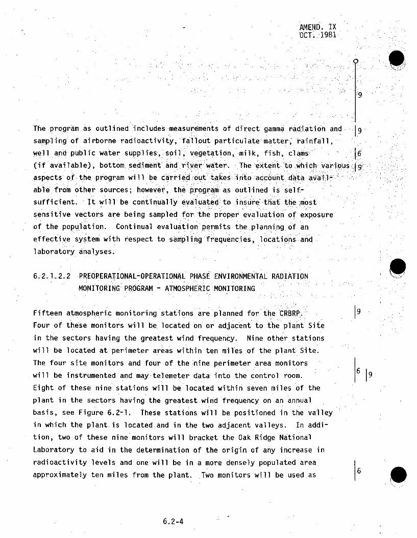
AMEND. IXOCT. 1981
:9
The program as outlined includes measurements of direct gamma radi.ation and.9:
sampling of airborne radioactivity, fallout particulate matter, rainfall ,
well and public water supplies, soil, vegetation, -milk,. fish, clams: 6(if available), bottom sediment and. river water... The extentf to which .variouý s9
aspects of the program will be :carr~iled o.ut:takes; into a-ccount data, avail,-..
able from other sources; however,. the' program as outlined is self-
sufficient. It will be continually eva-luated'to insure-that the most
sensitive vectors are being sampled for the proper evaluation of exposure
of the population. Continual evaluation permits the planning of an
effective systeM with respect to sampling frequencies, locations and
laboratory analyses.
6.2.1.2.2 PREOPERATIONAL-OPERATIONAL PHASE ENVIRONMENTAL RADIATION
MONITORING PROGRAM - ATMOSPHERIC MONITORING
Fifteen atmospheric monitoring stations are planned for the CRBRP.,"
Four of these monitors will be located on or adjacent to the plant Site
in the sectors having the greatest wind frequency. Nine other stations
will be located at perimeter areas within ten miles of the plant Site.
The four site monitors and four of the nine perimeter area monitors
will be instrumented and may-telemeter data into the control room. 69
Eight of these nine stations will be located within seven miles of the
plant i.n the sectors having the greatest wind frequency on an annual
basis, see Figure 6.2-1. These stations will be positioned in the valley
in which the plant is located and in the two adjacent valleys. In addi-
tion, two of these nine monitors will bracket the Oak Ridge National
Laboratory to aid in the determination of the origin of any increase in
radioactivity levels and one will be in a more densely populated area
approximately ten miles from the plant. Two monitors will be used as1 0
6.2-4

AMEND. IXOCT. 1981
control or baseline stations. Samples of air, rainwater and heavy,..par-.
ticle fallout.will be collected -routinely as indicated in Table..6.-2!7.1.-
The atmosphere~around.the CRBRP will be sampled f.or tritium. A sampling
apparatus will be incorporated into the four local monitors and one of
the remote monitoring stations.
6.2.1. 2.3 PREOPERATIONAL-OPERATIONAL PHASE-ENVIRONMENTAL RADIATIONMONITORING PROGRAM - TERRESTRIAL MONITORING
Samples of milk, vegetation, pasturage grass, soil, ,well water,;,drfnkiing.•
water supplies and food crops wil,! be collected within a ten-milp1e
radius of the plant. Envi.ronmental gamma radiation levels -willbe
measured utilizing thermoluminescent dosimeters near -the, plant boundaries.
and at each off-site.atmospheric monitoring station. At least.two .dosi-
-meters will be placed at the locations of highest predictged ground:level
concentrations. All.dos~imeters will be left in the ffield for three months.
Milk.from dairy farms near, the.plant will be sampled on a monthly.,,.basis..
After the.:plant begins operation, samples of fresh milk will, be obtainedat least once every two weeks (during.the seasons when cows producing.
1311cont nmilk for human consumption are on pasture) and analyzed for i content.
Vegetation (grass, weeds, leaves, etc.) and soil samples will be collected
quarterly from the vicinity of the atmospheric monitoring stations. The,same rationale used for locating the atmospheric monitors is applicable
to this program. The sampling and analysis schedule-is shown-in
Table 6.2-1.
Pasturage grass will be collected quarterly from the dairy farms. This
vector would be. the first indicator in the food chain to man through
animal. . If a statistically significant increase above the natural back-
ground established during the preoperational monitoring program is detected,
the program will be expanded to include other vectors in the food chain
such as beef cattle.
6
96
A9
19
6
6.2-5

AMEND. IXOCT. 1
Well water in the vicinity of6 rthe plbnt 'will- be sampled monthly
and automatic water.samplers will be inhstalled on :all pOtabil. s urfce..Ace
Water supply. intakes withih 10 miles downstream frodfi.th a plnt. TIhdi
Samples will be analyzid monthly. Fo"ddcrops grdwn by- Ubsisgt&ri ..
.farmers in the area will be 9Afiled during the growing seasdn.
6.2.1-.2.4 PREOPERATIONAL-OPERATiONAL PHASE ENVIRONMENTAL RADiAtIONMONITORING PROGRAM - RESERVOIR MONITORING
Samples will be collected from five river stations in Watts .B0 andMelton Hill Reservdidrs. All samples exceptreservoirwtrwillbe
collected semi-annually. Reservoir water samples will b•e••oleced
by automatic sequential-type samplers and analyzed monthly.
The stations will be located Approximately as indicated i FiiiVi 6.2-2
near Clinch River Miles (CRM) 14.4, 15.4, 17.9, 18.6, and 24.0 Pr:oposed
discharge point for the CRBRP is at approximatelyy CR04 16.; Sampl~es c61
lected for radiological analysis will include water from four stations
and fish from two stations. Bottom fauna (Asiatic clamis) And sediment
samples will be taken semi-annually from fourý stati.ons" when' suffifcient
quantities are available. Further sampling i nformaton"can be found In
•.Tables 6.2-1 and 6.2-2.
Gamma, gross alpha and gross beta activity will be determined in water,
sediment, clams and fish. Whole fish, .the shells of clams, and sedi-
ment samples will be analyzed for strontium and plutonium. Water
samples will bewanalyzedfor tritium. The activity of at
least ten gamma-emitting radionuclides will be determined with a multil-
channel gamma spectrometer. This program will sample those vectors which
906
9
9S
[9
6.2-6

• JAMED..IXOCT. 1981
• -.•-0 .t .
wi 1:I :give the, first indication of inc.reased radioactivity, levels-in .the"envi ronment. If stati.stical y ignifiCant increases 'above natural pre
operational., background are% seen in those vectors being samp.led, consider-
ation wimll then :be given. toexpansion of the. sampl i ng program to inc.lude.: .
:other biological parameters.
Consideration has been given to sampl.ing waterfowl; .however, about "95..pe.r-cent of ducks hunted., in eastern Tennessee are migratory, moving great
cen of du. .k. migrat .:o-r..
distances in ýthe: winter and spring. It. would ,be impossible, to m a ke an .
accurate determination :of the parti cular .source of radionuclidesýjf.ond-
in mi gratory, waterfowl. Therefore, it. ,seems more logical to sample
other vectors in the environment which the waterfowl might inhabit for
short periods of time.
Water
Water samples will be collected for determination of radioacti•ity
from four stations. Samples will be collected by automatic water"
samplers with composite samples analyzed mdnthly.
6
Fish
Radiological monitoring will be accomplished by analyses of
.samples of adult-fish taken from the Clinch River above and
Melton Hill Dam.
compositebe. plo w " t..ebelow ..
Nopermanent sampling stations have been established within each
reservoir because of the movement of fish species within the reservoirs.
6.2-7

AMEND. IXOCT. 1981
This movement has been determined by TVA data"from the BrownsFerry NuclearPlihtntpreope'rational moni toring program.' Samples of
a predomisnate commerci.al:' and- game species, to be-determinediin.the
CRBRP -preoperation.a, s'Iurvey, wil.lI be. coll-lected, semi-annuaýl:y and: anal-9
yzed for gamma, gross alpha and gross beta activity:. Concentrations
.of Sr,-89,. Sr-90..and: Pu w:ill be determined on a commercial species.
Sufficient amounts of each species of fish will be collected i n each..
reservoilr to yi.eld a composi~te ssampTe containing from 250 to. 300 grams
oven-dry weight for analytical purposes. The. compositesampleswi l.l contain approximately the same quantity of fls from ec of...... im * he.smlqa ,iy f fIe s~hý r~om••a~i: 6: ,; .. , ,the fish. For,: each composite a subsample ofma:terial will.be drawn
for counting.
,9
Sediment
Deposited sediment samples: will be collected semi-annually from 6
Ponar dredge hauls when sufficient quantities are available. Gamma;,
gross alpha and gross beta:activity, and Sr-89, Sr-90 and Pu content
will be determined in samples collected from four stations. Each 6
sample-will be a composite obtained by combining equal volumes of
sediment from at least three dredge-hauls collected from each station
at a single point.
6.2-8

AMEND. IXOCT. 1981
Asiatic Clams
Asiatic clams may be collected frOm in-place bimonitoring units at f9four stations. The in-place bimonitoring units .are used, tdoidentify 16the source of radionuclides released to the river. These samples,
will be analyzed for gamma, gross alpha and gross beta activity.
The Sr-89, Sr-90 and Pu content will be determined on the shells
only.
Drinking Water Supply. Mondi-oring
Drinking water supplies, such as small surface,: streams and wells,.9
will be sampled and analyzed. Groundwater .will be obtained from atleast two wells located near the plant. All public water supplieswithi'nten miles downstream of the .plant d-isch a-rge will be.sampled
automatically and. analyzed monthly for gross. beta, gross alpha, 6tritium and at least ten specific gamma-emitting radionucljides,. and
quarterly for Pu.
Quality Control
A-quality control program will be established-and administered-by
TVA. TVA has similar programs in effect with the Tennessee Depart-
ment of Public Health Radiological Laboratory and the Eastern
Environmental Radiation Facility, Environmental Protection Agency.,
Montgomery, Alabama. Samples of air, water, milk-.and soil col- 6
lected around the plant will be submitted for analysis. Results
will be exchanged for comparison.
6.2.1.2.5 PREOPERATIONAL-OPERATIONAL PHASE ENVIRONMENTAL RADIATIONMONITORING PROGRAM- GROUNDWATER
The types of sampling, sampling frequency and radiation parametersdescribed for the automatically sampled well in Section 6.1.5.1 will 6continue throughout the plant life. A monthly composite sample will be 18
6.2-9

AMENDMENT VIIIFebruary 19.77
analyzed for gross alpha, gross beta and tritium activities. . :8
If any significant increase in grosss alpha or. gross beta activity is
detected, an analysis will be made to identify the specific radionuclide.
6.2.2 CHEMICAL EFFLUENT MONITORING
All point source discharges originating from the plant. during the
operating phase will be monitored in accordance with the terms of the
operational NPDES permit. Applicable effluent limitations and relatedmonitoring programs, including frequency and parameter .coverage will be
separately identified for each such discharge in the permit.
Instream water quality monitoring programs will be implemented as neces-6
sary to correspond with the requirements of the operational7 NPDES.ý per-
mit(2) and the results of the preoperational monitoring.program. The
preoperational monitoring program, which will be implemented two years
prior to the initiation of fuel loading, will be designed to reflect
both the best information available regarding final plant design and
the environmental conditions existing at the time it is to be implemented.
6.2.3 THERMAL EFFLUENT MONITORING
The thermal effluent temperature monitoring program, as presently envi- I 6sioned, will consist of stream temperature monitors situated upstream
and downstream of the discharge to the-Clinch River which is located at
river mile 16.0. By taking into consideration the results of effluent
dispersion studies described in the Appendix to Section 10.3, an estimate
of the number and location of the monitors can be made at this time.
There will be a total of four monitors used for thermal effluent monitoring.
Two will be placed upstream of the discharge just below the location of
the intake at CRM 17.6 and the other two will be placed approximately
one-half mile downstream of the discharge. The exact locations will be
made after further considerations of river bottom topography, influent 0tributaries and barge channel locations.
6.2-10

AMENDMENT VIIIFebruary 1977
In all cases, multiple.-temperature sensors wil.l 1be located in the verti-
cal at. •each monitoring location. Sensors will be mounted at the one-half
foot, two and one-half foot and five-foot depths and at other depths
depending upon the channel depth at the monitor location. The monitoring
system wi:l 1 be designed to -operate .durinng:. periods. of both normal and
reverse flow conditions in the Clinch .River.
The water temperature monitoring system will be automatically scanned
by radiotelemetryilandkdata will be transm itted to the plant fort storage
on paper tape and subsequent transfer to automatic data processingsys-
tems. Selected key,, water temperature data used for plant operational
control will be relayed directly to.the plant control room.
This program.wfll be designed to ensure compliance with the-thermal
standards of the State of TennesseeWater Quait C ontrol Board.i - 6
This program will be subject to review and revision as appropriate to
ensure compliance with the terms of the operational, NPDES permit?).
6.2.4 METEOROLOGICAL MONITORING
After fuel loading begins, and continuing throughout, te operation of
the plant., the permanent meteorological! facility will provide the. basefor prediction of dispersion in., the event of an accidental, releaseof _ 8
radioactive gaseous materials. Selected meteorological data,-along
with other environmental data. will be remoted from the meteorological
facility to the reactor control room for operational display.
6.2-11

ArIEND1iENT VIIIFebruary I7177
The operational meteorological program will be a continuation of the 8
permanent preoperational program. A detailed description of this program
is included in section '6.1.3.•o :ý f -ý (e m and'. i'• •
A program for:observation of fogging and icing (rime and glaze) will be.
initiated in the vicinity of. the Site during the plant construction0
phase. Fog observed in the immediate vicinity of the Site will be 8
compared ito ýthat observed at the 'TVA fog orbservation station established
in early 1964 at the Melton Hill Dam.,"located about 4.5 miles to "the-
east (upri vere).
6.2.5 ECOLOGICAL MONITORING.
This program is designed to. evaluate the impact of plant operation on
the structure: and ýfuncti'on of the terrestrial and aquatic ecosystems.
6.2.5. MONITORINGOF MOISTURE IMPACTS '
Operation of a cooling tower will result in water vapor, rel eases to,-the..
atmosphere. In nearby plant communities the moisture regime may be
altered resulti-ng ,in, es-s SOil moisture stress: ,and hi gh6er irelativehumidity in the canopy. If changes in the wateer budget occur due tocoo ing "tower operation, the following, effects may be noted:
I. Incidence of plant ddiseases which depend on moist conditions
may increase;
2. Growth rates of plant species favored by moist conditions
may increase; and
6.2-12

SP cmay .,chan e tin in great
;densi-ty _-or frequiency..of niepes repodig t~ rmost 'condiý-
ti ons.
Elements of the final plant design and studi es-atCother faciities will'
indicate whether monitoring of these effects is necessary at the CRBRP.
The fol-lowing is, an.outliine .for ,such .a, studyi, if :ýi t i s,.•,needed-.
Moistuireindice~s for vegeta'tion pl ots, wi11 b e calculIa ted by -using rela-ý
tive humi4jdity, soil moisture stress and.a1ir temperature data. -'l•ots .
wil.l 'bei ýlocated ,proportio nal ly to.the''wi•dro. or where .gni.f.ican t
iminemntisexpetd This wil bcoriated wi~th meteorological
monitoring
P.lant•,Adiisease-:i•; nicide nce willý be determ ned by v.-examilnati,- ofn vegetation
by a plant pathologist once eachyear-during.tie peak period.of expected
disease occurrence. Transects will be permanent y-established •to-enabl
the subsequent evaluation of the same area.
Annual growth rates- of selected- ,plant. species will be .determined by mea-
suring ring i ncrement,, onyv hardwood ,trees and., ring andq• height increment oon.,
coni fer. trees., Species will be chosen wi ch a relatjively common to
the Site. Growth measurements will be made on0jtbhesame. pl"Tots for which
moisture indices are developed.
Plant ::community :characteristics,.of herbs, seedlings and- .sapl ings (DBH ")
will be determined by treating each plot as a. stand and determi ni ng:
importance values for-species annual~ly during the monitoringI period..
6.2.5.2 MONITORING OF ICING DAMAGE:
During cold weather, operation of cooling towers may result in formation
of ice (rime or glaze) on exposed vegetation. In turn, some vegetation
may be damaged or destroyed.
6.2-13

If major. icingl occurs,, aerial photography,'wi-l.i'bezu•sedP tOestalish the
extent r of ::t he accumu~l~ation."-and -damage..: Plo ts will ,be subsequently
established in the affected area and periodically evaluated.:,-.-
6.2.5.3 -.MONITORJI.NG. -OF DRIFT IMPACT.
During operation, chemical constituents, incoolitng water will ,:be dis.-
charged as drift along with water vapor. Normal constituents of-watermay-b&e concentratedbecause of evaporation ýosses andother.chemical,",
con st it.u ents, may i-'be. ;present •;because th eyar'e .usedd during thelai• toperatLi•Tn. "cc,' umulation.-of-chemrcal -consti tientsonweaves,,nd-nsol.
may ifncrease :Uptake and may,- inextreme cases, cause8 necrosis of •,eaf,
tissue. Chemical constituents may be .retained in -the soil or ffiay:, b~e-:t-r;r- - .cycled by plants and animals on the Site. Elements of f inal, plant de-. .
stig•' a:nd' •des at o•th r -faciliies will llnditcate .wheher montor. in-of theSe.effects is neces:sary at the•: CRBRP. The: followingis•ianoutline
of' such -a, s'ttu.dy. if.. it' is nee4ded.
Soil and litter samples will be obtained on each plot once each year in
Augus 'for'deteination of chemical" constitents.. Litter:, saimples will1beý; a 'composi te of •the 01 and 02 horizons;Which are defined:in the
Walker Branch Watershed Study. (4, 5 ) Surface soil samples one..cm` thiclký :'
will be compared to preoperational data.
Subsoil samples from 10 cm depth (2 cm thick) will also be Obtained andcompo'sited. Vegetation samples will be obtained on each plotduring:--•
August of each year to determine chemical constituents.' At each plot
location individuals will be selected and marked for sampling. Leaves
obtained will be composited by plot and by species. These samples willbe coordinated with other monitoring programs such as radiological, etc.,
where possible.
6.2-14

AMENDMENT VIApril 1976•
Individuals of (1) seed-eating reside-ntmiit ýanl'•, !(2)ý insect-eating resi-dent ma mmals and' (3) forage-eati ng-resident mammals- wil:l be collectedfor determination' of ch~emical constituents., Samplies- .wi ll 1 be collected'once each year in autumn and will be obtainedin the vicitiityýof ýthýecooling towers.
Materials to be sampled and number of samples to1, be obtainedannuallyare given in Table 6.2-4". Soil and vegetation. samplingwil. l be•attemptedduring relati vely dry periods,
6. 2.:5ý.4 LIMNO0LOG*ICAL. MONI'TORING"
An instream limnological monitoring program w*ll be impl!emented ,..as..necessary to correspond with the requirements of the operati.dnal'-:NPDES.:-
(2),permit and:the results of the preoperational monitoring p'riograml-f. The-prieoperatfional monit'hioring.program, whichwill beimplemented two years 6prior to the in-iitiatin•ofnf'ul loading,,will bedes'igned-to refl1ect ,-both the .best information avai lable0eregarding1final'pl~ant designi'andthe environmentalcondi'tions exis ! the t ! isý to be implemented.'
6.2.5.5 MONITORING OF CIRCULATINGWATER -IMPACTS 16Operation of the circulating cooling water System'will result in four
main categories of nonradiological impact: heated waterý'discharges,i mpi ngement of organisms on intake 'structures, entrainment'of biota, anddischarge of chemicals. Final plant'design'details may modify~thedpro-grams detailed in the following subsections. Most of the monitoringwill be done in the area near the plant where any impacts should bemost pronounced. No reservoir-wide monitoring is contemplated.
The monitoring program will show the changes in the distribution of fishin response to heated water. Certain species of fish may be attractedto heated water during winter or repelled during summer; hence, speciescomposition may change while numbers remain relatively constant. Sampling
6.2-15

AMENDMENT VIApril 1976
for species composition and numerical .abundance,.. wi ll be .concentrated in'the overbank areas •influenced by, the.,heated discharge. Other effects of
heated water can,-be, hypothesi.zed; however,.these. effectsý would, be less,, ..
obvious than changes in the distribution. of fish. Monitoring of these "
more subtle effects is not planned.
Because of the de.sign of the ..perforated pipe...intake, structure-,. no,, impinge-
ment. monitoring w.il~l be.done.. Larva!.fishentrainment monitoring .may
be done by sampling along.the condenser lines although such.sampl!ing-, is
usual ly difficul t. If such..sampl-es cannot be -.taken,- ýentrainment losses-
wil l be monitored by.comparison of samples taken:-upstream and downstream
from the plant.
6.2.5. 5..1 FISH
Operation of power.pl.ants :may, producethree ,main, categories of nonradiol•og-
ical impacts on fish:-. ,ýtthermal '-effects,,, impingement off,:poS•larval. fi sh o *the perforated,... pipe intake and entraitnmen of eggs and arval fish. The
majority o-of, fi s h sampling will be con ducted,. in.. the. area., nea.r the plant
where any impacts should be most pronounced. Preoperational monitoring
will begin two years prior to pplant operation and .will :establiish base-
line data for comparison with operational data. Preoperational monitoring
procedures are di scussed.,below :,,and, operational monitoring will fol low
generally ,these.same procedures. Sampling methods may bechanged (pre- . 6
operational and operational monitoring) when field sampling experience
and/or data analysis indicate the necessity,
6.2.5.5.2 HEATED DISCHARGES
This phase of the monitoring program is designed to show any changes in
the distributions, species composition and abundance of fish in the.
immediate vicinity of the plant that result from.responses to heated
water. Sampling will be concentrated in the area immediately downstream
of the discharge which should be most influenced by heated water
6.2-16

AMENDMENT VIApril 1976
(preoperational-operational and upstream-downstream comparisons wi I Ibe made).
Changes in the distributions of postlarval fish will be assessed byrotenone sampling, gill netting, hoop netting and -electrofishing. Samplingwill be conducted at three stations: (1) a :control i upstream from theproposed discharge, (2) inmmed i ate ly below the discharge and (3) approxi-mately one mil e downstream. Netting and electrofishing samples will betaken monthly to provide seasonal: measurements at the three stations.Rotenone samples will be taken once a year .during the lat I e summer orearly fall if suitable locations are found in close proximity to the site.
Fish collected wil1I be :identi'fi ed -to -species,` counted, and indivivduallengths and Weights recorded for selected species. Where large numbersof a single species are collected, subsample methods :may, :be utiliized.
6.2.5.5.3 ENTRAINMENT (FISH EGGS AND LARVAE)
The objective of this monitoring program is to provide a data base fromwhich an impact assessment of condenser and thfermal plume entra inmen t,can be accomplished. Estimatednumbers of larval fish entrained will becompared to the estimated total larval population passing theplant. In.,addition, the relative impact of entrainment on each species will beassessed by comparisons of estimated entrainment losses of each speciesversus estimated abundance or standing stock of adults and juveniles ofthe same species in this area of the Clinch River. Localized impacts .onresident species living near the plant will also be studied.
Entrainment will be assessed by weekly sampling during the approximatetime period March 15 - September 15 and preoperational sampling will pro-vide information on the abundance, species composition and distribution offish eggs and larvae in the vicinity of the plant.
6 .2-16a

AMENDMENT VIApril 1976
Samples will be taken at three reservoir-transects: (1) near the plant
intake, (2) near the plant discharge and (3) downstream of the plant
discharge. Three stations will be sampled along each transect: a sta-
tion at each shoreline and a midtransect (midchannel) station. Also,
samples will be taken along the shoreline at four stations in boththe
Poplar Springs Creek and Caney Creek embayments. Both day and night
reservoir (river channel) samples will be taken-at the transect locations.
Embayment samples will be taken at night.
Samples will be col lected at each reservoir: transect locationusing a 1 m,
square, 505 micron mesh ichthyoplankton net. :Depth-discrete samples
will be taken..at surface and bottom at each:of the reservoir stations;
and, where depth allows, a discrete midlevel, sample will be taken.
Passive, stationary samples will be taken at each level during periods
of high flow; and active moving samples will.be taken during periods of
low flow. At least 100 m3 of water wi-ll: be strained by each sample. 6
Flow will, be recorded using a:T.S.K.: No., 313. flowmeter mounted:in the
center of the net.
Collections of fish eggs and larvae at the stations in Poplar Springs
Creek and Caney Creek embayments willbe, taken. using:a Model 120TP3-l
Homelite trash pump. Pump, samples will be strained .through a 505 micron
mesh net. Samples will be taken at a boat speed, of roughly 0.3 m/s;
a 10-minute sample will strain approximately 10 m3 of water. The intake
hose will be manipulated to sample the entire water column at each
station.,
Samples will be preserved in the field in 10 percent formalin and returned
to the laboratory for sorting, enumeration, mensuration and identification
to the lowest possible taxon.
6.2-16b
6.2.5.5.4 IMPINGEMENT
Because the perforated pipe intake structure of the CRBRP'is designed tominimize impingement and is located approximatelynine feet deep inusually swift water, no regularly scheduled impingement monitoring isplanned. Periodic observations of the intake structure may be conductedby divers.
6.2-17
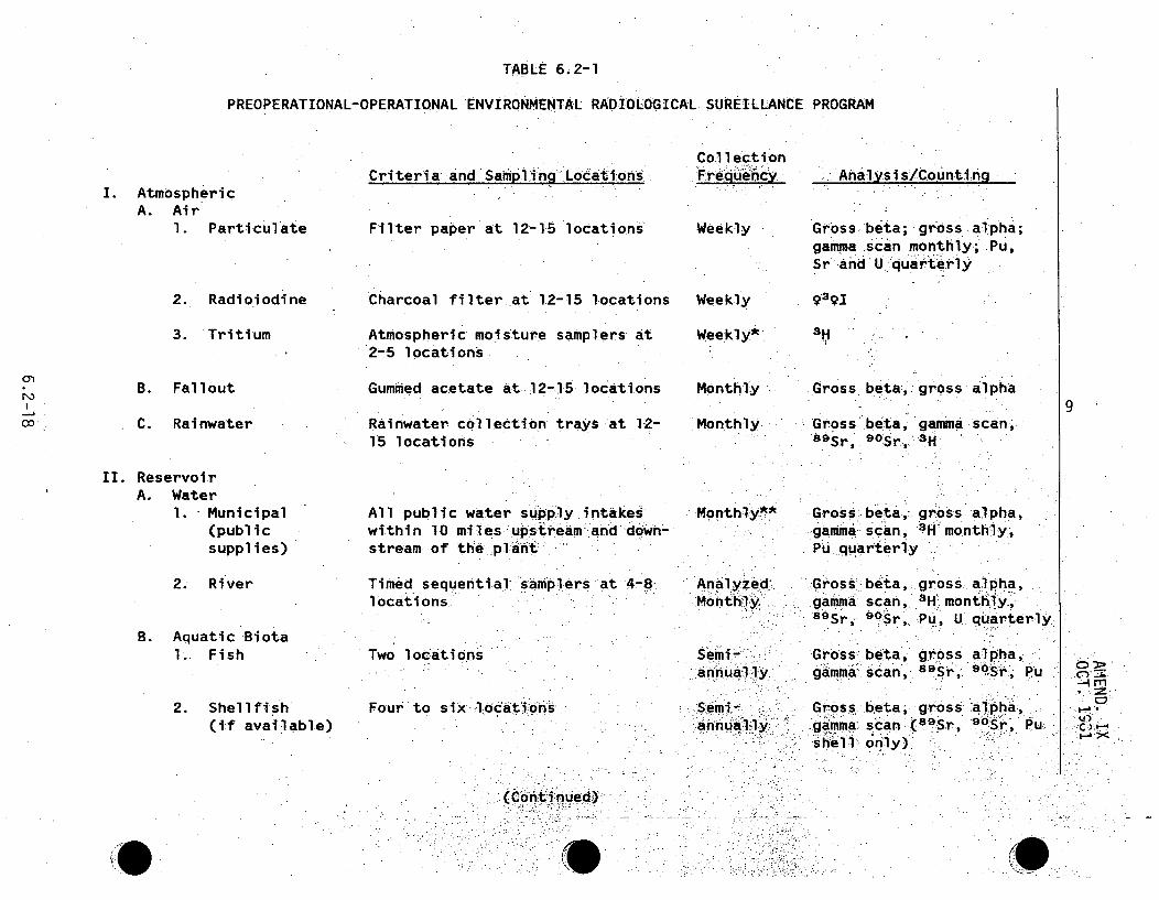
TABLE 6.2-1
PREOPERATIONAL-OPERATIONAL ENVIRONMENTAL RADIOLOGICAL SUREILLANCE PROGRAM
Criteria and SamDtifna LocatitfonsI. Atmospheric
A. Air1. Particulate
Col l ectiobnFrequ ncy
Weekly
Analysi s/Counti na
Filter paper at 12-15 locations Gross: beta; .gross alpha;gamma .scan monthly.; Pu,sr and U quarter •ly
2. Radioiodine
3. Tritium
Charcoal filter-at 12-15 locations
Atmospheric moisture samplers at2"5 locations
Gummed acetate at .12-15 locations
Rainwater collection trays at 12-15 locations
Weekly
Weekly*
Monthly
Monthly
9391
3H
B. Fallout
C. Rainwater
Gross beta,, gross alpha
Gross beta, gamma scan,oSrt,
9 0Sr, 3H
9
II. ReservoirA. Water
I. Municipal(publicsupplies)
All public water supply, intakeswithin 10 miles upstream and down-stream of the plant
Timed sequential -samplers at 4-8locations.
Monthlyl* Gross beta,ý gross alpha,gamma scan, 4H monthly-,Pu quarterly
2. River
B. Aquatic Biota1. Fish
2. Shellfish(if available)
AnalyzedMonth1iy
annually',;-
Gross beta,gamma, scan,89Sr, 9 OSr,,
gross alpha,3H monthly,'Pu, U quarterly
Two locations
Four to six locao'n'*,s-
Gross- beta,. gross alpha,gamma scan,. 8 Sr" ....St, Pu
Gross beta;, gross aIpha,gamma scan (8 9 Sr,, 9 rt Pu.shell only).
C7)annually.._.
(Conti nued)`
0!

S STABLE 6.2-1 (Continued)
S
C. Sediment
III. TerrestrialA. Soil
B. Vegetation1. Pasturage
grass
2. Grass
3. Food crops
C. Milk
D. Well water
N)
CO
Criteria and Sampling.Locations
Four to six locations
Atmospheric monitoring locations
Selected dairy farms within1O0mile radius of plant
Collected at atmospheric moni-toring stations
Within 10-mile radius of plant
Selected dairy farms .within 10-mile radius of plant
Selected farms wi-th:in,5_miles. ofplant and 1-5 wel'ls %r, site
TLD's on site and- attatmosphericmonitors
CollectionFrequency
Senii-annually
Annuallly
Quarterly
Quarterly
Annually
Monthly-'
Monthly
Quarterly
Analysis/Counting
Gross beta, gross alpha,gamma scan, 8 9 sr, 908r, Pu
Gross beta, gross alpha,,gamma scan, Pu, U
Gross beta, gross alpha,gamma scan, 8 9Sr,- "90 Sr, Pu
Same as pasturage grass
Gross beta, gross alpha,gamma scan, 8 9 S-r,) 9 °r, Pu
Gamma scan, 8 9Sr, 9 °S-r, 311
Gross-beta, .gross alpha,gamma scan monthly,, Pu"quarterly
Dose determination
9
E. Direct radiation
* Every other week during preoperational monitoring.* All public water supplies within 10.miles downstream. of the plant will be
automatically and analyzed monthly.
+ After the plant begins operation milk samples will be taken at least onceanalysis when cows are on pasture.
col lected
every two weeks for 131I
AMz
CO -N

AMEND. IXOCT. 1981
'TABLE',6.2-ý2
RESERVOIR WATER AND BIOLOGICAL SAMPLINQ, SCHEDULE (RADIOLOGICAL).
CLINCH RIVER BREEDER REACTOR:PLANT, WATTS:BAR AND
MELTON HILL RESERVOIRS
Stationor CRM
14.4
ReservoirWater*
1
l
AsiaticClams**
1
1
1
Sediment
1
.1I
Fish+
1 5.4
17.9
18.6
24.0
I;61
1 1 I
* Timed -sequential samples,, analyzed monthly
** If available
+ Fish samples will be taken from t;he Clinch River above andbelow.Mel ton. Hil~l Dam.
.6.2-19

AMEND. IXOCT. 1981
Information origi.nally Contai~nedin Table 6.2-3 has been incorporated
into Table 6.2-1
in Amendment IX
6.2-20
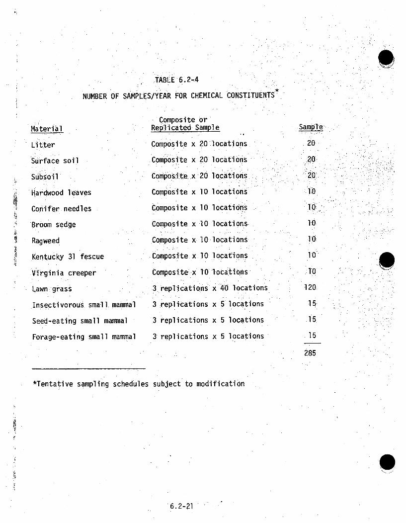
STABLE 6.2-4
NUMBER OF SAMPLES/YEAR FOR CHEMICAL CONSTITUENTS'
Material
Litter
Surface soil
Subsoil
Hardwood leaves
Conifer needles
Broom sedge
Ragweed
Kentucky 31 fescue
.Virginia creeper
Lawn grass
Insectivorous small. mammal
Seed-eating small. mammal
Forage-eating small mammal
Composite orReplicated Sample
Composite x 20 locations
Composite x 20 locations
Composite x 20 locations
Composite x 10 locations
Composite x 10 locations
Composite x 10 locations
Composite x 10 locations
Composite x. 10 locations
Composite, x 10 locations
3 replications x 40 locations
3 replications x 5 locations
.3 replications x 5 locations
3 replications x 5 locations
20l
220
10
10610
10
10
10
120.
15.
15
285
S
*Tentative sampling schedules subject to modification
6.2-21

S 9
TABLE 6.2-5
CONTINUOUS EFFLUENT MONITORING/SAMPLING
Description Bldg. Elev.Monitor
TypeDetector Sensitivity
Type -... Ci;/cc
Scint. 10-6 Kr8 5
Remarks..
Raps and Caps Exhaust
Radwaste Ventilation Exhaust
RCB Ventilation Exhaust
Steam Generator Loop Cells(3)
Turbine. Generator BuildingVentilation
Decontamination AreaVentilation
Hot Lab and Counting RoomVentilation
Plant Discharge Canal
SBG-IB Exhaust
RSB 884'. Gaseous.
RSB 867' Particulate
Gaseous
RSB 861' Particulate
Gaseous
Radioiodine
SGB 806' TritiumSampl6er
TGB 915' TritiummSampl r
PSB 830'. ParticulateSamp-ler.
PSB 830'••P `6i5ula:te
YRD 830' Composite
Samp leer-.
SGB 836': Gaseous
Scint.Scint.
iO10 Cs13 7
_ -6 r85.
Scint. 1010 Cs137
Scint. 10A6 Kr8
(Continuous)
Sample :Analyzed in CountingRoom, by Liquid ScintillationTechniques (Sample)
sirSple Analyzed in Counting:R6omt bLiquid ScintillationTechniques (Sample)
Siamnple Anal:yzed in Counting'Ro•om,-!Using lProportional Counterýa'ndSOIetroscopy System (Sample)
roc _- :..Y amp 01 ..
Sample Analyzed, in Counting.-Room-. Us.g.-- .oportion. Cou.nter-" .. dSectroscopy System. , .amp,.
S~ample Anal yzed. in CoUntin~R obinUsing Propor tioa. Cut
.arid ,' SpcrscpiyseIarifrlY
(Continuous)*
-(Continuous)
9
.lm
Scint.
•:
0-6Kr 85
(Con tinoed4.

TABLE 6,2-5 (Continued)
Description Bldg.RSB9Annulus Filter
Discharge (A) 861'
(B) 840'
RCB Annulus/TMBDB
Effluent (A)
EElev.
861.'
840'
Monitor:Type.
Particulate
Gaseous
Radioiod.ine
Detector Sensitivity• Type . ,PCi/cc
ýRSB 840' Particulate
Gaseous
Radioiddine
Remarks
Annulus Filter
Inl~et.(A) 861'
S (B) 840'
RSB Clean Up Filter
Discharge (A) 816'
(B) 794'
RCB Annulus/THBDB
Effluent (B)
RSB 861
840'
Particulate
Gaseous
Radioiodine
RSB 816' Particulate
794' Gaseous
Radioiodine
RSB 861' Particulate
Gaseous,
Radio6odine
Scint.
Scint.
Scint.
Scint.
Scint.
Scint.
Scint.
Scint.
Scint.
Scint.
Scint.Scint.
Scinlt.
Scint.
: Sci~nt.
scint.:S c int.
10100 Cs1 3 7
1O-6 Kr•8
I1.0 10 1131
10-10- cs137
106 .Kr85
10-10 1i31
10-10 C.S13 7
lO-6 Kr85
lo-l0 iI 3 1
1010 cs 1 3 7
106 Kr8 5
10o10 1 131
10W,10 137
1-o6 Kr85
10 ý10 1 131
(Continuous).9
(Continuous)
(Continuous)•
(Conti nuous)
(Continuous)
RCB Annulus/TMBDB Effluent
Pu Activity (A) 861'
(B) 840'
RSB 861'
840'
PlutoniUm 162 P 239
- : ,Conii nuous)
106 Kr•8 6(Continous)
C)
--.im
-.0*
J.' <RSB Exhaust RSB 840' Gaseous:,.42 ',•:• . .,

AMEND.1 IXoCT.: 1981 '
NORIRIS 0 1
CLINTON
9
0
LEGEND:
0-Local Air Monitor (LAM)
0 -Perimeter Air Monitor (PAM)o-Remote Air Monitor .(RAM) 1.
ORGDP-Oak Ridge Gaseous Diffusion Plant SCALE OF MILES
ORNL - Oak Ridge National Laboratory•ORIP - Oak Ridge Industrial Park
NOTE: The following samples are collected at each monitoring site:Air Particulates RainwaterRadioiodine. Soil 1Heavy Particles VegetationFallout -
Figure 6.2-.]. ATMOSPHERIC AND TERRESTRIAL MONITORING NETWORK FOR CRBRP
6.2-24 "

• •F: OAK RI 8
1 .4 AR.
,9 5
•LEGEND • -i!I• i.:•
CORPORATE DAM.•
SCA LE O F M IL E S TO LE OI .. .. . TO 1-4 0
F g r 6 . - E S R I R M O N I T O R IN G ý N E T W O R K ,ý.00•-COa

AMEND. IXOCT. 1981
6.3 RELATED ENVIRONMENTAL MEASUREMENTS AND MONITORING P.ROGRAMS
Various biological,.,,water, air,' radiological and:ecological programs-arein process in the general area of the CRBRP. Some Of these prd.rams,- arebeing conducted by the Oak Ridge National Laboratory operated by UnionCarbi'de Corporation for the Energy Research and Development Administration.The scope and nature of these programs are outlined in the ORNL AnnualProgress Report( 1 ) and the ERDA Environmental Monitoring Report., 2
The TVA Water Quality Branch maintains a network of routine water qualitymonitoring stations throughout the Tennessee Valley. Close'stof thesestations to the CRBRP Site is at CRM 23.1 (Melton Hill Dam. tailrace).Grab samples are taken weekly. for temperature and dissolved.oxygenconcentration.
Other temperature and dissolved oxygen sampling stations in the general.area of theCRBRP Site include TRM 529.,9 (Watts Bar".Dam taiIrace), TRM.602.3 (Fort Loudoun Dam tailrace) and CRM 79.8 (Norris Dam tailrace). 6
ý9
The U. S. GeologicalSurvey has a water quality monitoring station.atTRM 529.9 (Watts Bar Damtailrace) which complements TVA's program.Temperature, conductivity and streamflow are measured and recorded con-tinuously. Monthly grab samples are collected and analyzed for chemicaland biological parameters. Quarterly grab samples are also collectedand analyzed for additional parameters.
6.3-1•_: •

AM.ENDMENT VIApril1 1976;
A monthly compositesamle s .coll "ected at the Unin C rb.ide water i takeMP!~e a:! !::e n a W.at .RM 593.3. .;Company tion wi th
theTennesse~e Wa ter .QuaIi ty Control :Divisi on.
ý6.3-2-

Amendment VIIAugust 1976
NRC QUESTIONS ABOUT SECTION 7
NRC Letter November 19, 1974 -Giambusso
Item 000.16 (7.1) - Amendment I,Item
Item
I tem
ItemItem
Item
Itemr
I tern
Item
060.1000.2.
000.3
000.4
000.5
000..6
000.7
.000.8
000 .9
(7.1).
(7.1)
(7.1)
(7.1)(7.1I)
(7.1)(:7.1:)
(.7.1)
(7.1)
,.Amendment
-_Amendment
Amendment
Amendment
-Amendment
-Amendment
-. Amendment
- Amendment
- Amendment
II.,
II,
II
II,
.11,
II,
II,
II,
II,
Part
Part
Part
Part
Part
Part
Part
Part
Part
Part
I ,
I,
I,
I,
I,
I,
I',
I,
I.,
I,
pages
pages
pages
pages
pages
pages
pages
pages
pages
pages
Al-2 and 3
A1.-2 and 3
AII-4 to 6
AII-7"and 8
AII-9 .and 10
AII1-1l and 12
AII,1 3 to 15-
ýAI 1-16 to ; 1
:AII.20 and. 2.
ATI-22 and 23Item 000..10 (7) - Amendment II, Part I, pages AII-24 and 25Item O00.1 (7.1) - Amendment II, Part I pages AII-26.and 27Item 000.1.2 (7.1) -Amendment II, Part I, pages AII-28 to 32Item 000.13 (7.1) - Amendment I, Part I, pages AII-33 and 34Item 000.14 (7) - Amendment II, Part I, pages AII-35 to 37Item 000.15 (7.1) - Amendment II, Pa rt I, pages AII,-38: and '39
NRC Letter June 11i, 1975.- Speis- Amendment IV, Part Ii, page AIV.-,3NRC Letter June 27., 1975- Dicker"
Item
I tern
Item
.Item
I tem
I tem
I tem
I tem
I tem
Item
I tem
I tem
I tem
I tem
I tem
.000.17
000. 18
000.119
000.20
000.21
000.22
000.2..
000.24
000.25000.260.00. 26,
000.27
000.28
000.29
000.30
000.31
(7.1. 2:2.1)
(7.1.2L3)-
(7.1. 2. 3. 3)
(7.1. 2.4)
(7.1.2.5.1)
(7.1.2.5.1)
(7.1.21.5 .2)
(7.1. 2. 6..I)
(7.1.2.6)(7,1.2,.8.1)
(7.1.2.8.2)
(7.1) - Amen
(7.1) - Amer
(7.1) -Amen
(.7.1) - Amen
7 Amendment IV, Part -I,. page AIV-8.Amendment IV, Part I, page AIV-9-. Amendment IV, Part I, page AIV-19•0Amendment IV, Part I, page AIV-11
Amendment IV, Part I, pages AIV-12 and. 13" Amendment IV, Part I, page AIV-14-Amendment IV, Part I, page AIV-15 t AIV--Amendment IV, Part I, page AIV-20Amendment IV, Part I, pages AIV-21 and 22
Amendment IV, Part I, pages AIV-23 and 24Amendment IV, Part I, pages AIV 25 to 28Adment IV, Part I, pages AIV 29 to 36
ndment IV, Part I, pages AIV-37 and 38idment IV, Part I, pages AIV-39 to 42ndment IV, Part I, pages AIV-43 to 45.
19 7

Amendment XIJanuary, 1982
7.1 PLANT ACCIDENTS
Eight classes of postulated accidents are examined in this section.
The NRC, in Regulatory Guide 4.2, has defined a spectrum of accident 8
classes with potential impact ranging from trivial to serious for
light water reactors. To the extent possible, Regulatory Guide 4.2
was used for selecting and classifying postulated accidents for the
CRBRP. T8
Consequences of most of'the postulate7daccidents: are dependent on
the activity levels of the primary sodium coolant and/or the :-reactor
cover gas system. The CRBRP design basis for these activity leVels
is continuous plant operatiQn with one percen't fai led fuel.However, the maximum expected fuel failureurateis lower by a factorof 10. Consequences of the postulated accidents were determ1inedbased on continuous plant operation with 0.5 percent failed fuel.Use of this value provides an adequate measure of potentialradiological impact, without introducing undue conservatism.
Atmospheric dispersion was based on the assumption of `ground levelrelease. This type of release assumption results in higherconcentrations at the Site boundary compared to elevated releasesand thus provides a conservative assessment of environmental impact.
For each postulated accident, the environmental consequences areevaluated in terms of the maximum individual whole body and organdoses at the nearest Site boundary. Doses at a nUmber of otherdownwind distances of interest are also. presented. An estimate ofthe whole body population dose resulting from each accident is made.A summary of all the individual doses computed for each accident, aswell as the appropriate 10 CFR 20 and 10 CFR 100 limits for]
comparison, are provided in Tables 7.1-5 to 7.1-12. Population dose18)
estimates are summarized in Table 7.1-13.
7.1i-4'1

AmerdKment XIJanuary, 1982
7.1.1 COMPUTATIONAL MODELS"
7.1.1.1 METEOROLOGY
Diffusion calculations for the accident analyses were performed
using the meteorological data provided in Section 2.6. Astatistical analysis of dilution factors (x/Q) computed from hourly_
on-site data was, performed to define the 50 percent. probabi'l 1..Q
values as a function of downwind, distance from the. -pant. hese
values represent median atmospheric dilution t onditions dilution "
will be poorer (less dispersion) 50 percent of. .the time and :better
(more dispersion) 50 percent of the time. The x/Q's as a function 8
of downwind distance from the plant are listed in Table 7.1-1.
Use of these 50 percent x/Q values, representative of the median
atmospheric dilution conditions, is consistent with the realistic
approach to the evaluation of accidents as required for
Environmental. Reports.
7.1.1.2 DOSE CALCULATIONAL.METHODOLOGY
For each of the accidents evaluated, the following doses were
considered: , •. ..
o Whole.body. dose =.Sum of the external-whole body gamma dose
and.the. whole.body. dose from the inhalation of radioactive
material;
..o, Lung, dose;.
o Bone dose;
o Thyroid dose; and
o Population dose
(0
7.1-2.1

Amendment XIJanuary, 1982
Not all of the accidents evaluated resulted in releases leading tobone, lung or thyroid'doses. The radionuclides released for each,accident determined which of the doses itemized above were non-zero.
Doses were based on an exposure time equal to the duration of theaccident. Doses to an individual (whole body, lung, bone andthyroid) were computed at each of the following locations:
1. 2,200 feet, minimum exclusion distance;2. 0.6 miles, nearest residence;3. 1 mile, nearest recreational area;
•4. 2.5 miles,. low population: zone. radius 85. 4 miles, nearest dairIy;
6. 7 miles, nearest population center >2,500 (Kingston);7. 21 miless, nearest population. center >100,000 (Knoxvill1e);
and8. 50 miles.
Whole body gamma dose was computed based on a semi-infini iespherical cloud model as follVows:..
D = 0.25 (x/Q) E (A). (E )i
where,
Dy= Whole body gamma dose, rem=.Average gamma energy of isotope, i, pe; disintegration,
MeV, Table 7.1-2(A) = Activity of isotope, i, released to the environment,
over time. interval considered, Curies"/Q= Dilution factor appropriate for time interval and
downwind distance, sec/m3 , Table 7.1-1.
7.1-3
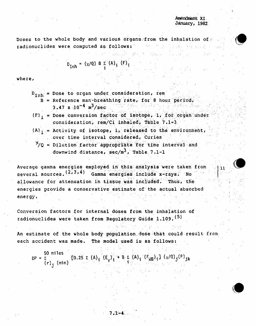
Anierximent XI,January, 1982
Doses to the whole body and various organs;-from the inhalation of_.
radionuclides were.computed as.follows::::'
Dinh = (x/Q) B E (A). (F).
where,
DInh =Dose to organ under consideration, rem
B = Reference man-breathing.rate, for 8. hou~r peri'od.
3.47 x -i0' m3 /sec
(F) Dose conversion .factor-of isotopei, fo norgan:undebr
consideration, r em/C i inhaled, Table 7.1-3
(A). = Activity of isotope, i ,: released to the environment,
over time interval onsidered, Curies
I,/Q Dilution factor appropriatei f-or time interval and
downwind distance, sec/m3 , Table 7.1-1
Average gamma energies employed in this,: analysis -were taken from
several sources.(2,3,4) Gamma energies incl1ud•e x-rays; No
allowance for attenuation in tissue wasincluded. "Thus, the
energies provide a conservative estimate of the actual absorbed
energy.
Conversion factors for internal doses from the inhalation of
radionuclides were taken from Regulatory Guide 1.109.(5)
An estimate of the whole body population dose .that could result from
each accident was made. The model used is as follows:
50 milesDP = [0.25 Z. (A)i (E )ii+ B i (A)i (F WB)i- (X/Q)j(P)'k
tr). (min) - "
(S
7.1-4t

Amendment XIJanuary, 1982
. where,
(.
DP =.Whole body population dose, man-rem= Dilution factor appropriate for time interval and
downwind distance (r)j, sec/m3
(A)i = Activity of isotope, i, released to environment overtime interval considered, Curies
(E")i = Average gamma energy of isotope, i, per disintegration,MeV
B = Reference man breathing rate, 3.47 x i0 4 3/secFWB)i = Whole body dose conversion Ifactor.of isotope, i,
rem/Ci inhaled(P)jk = •Population in radial increment ,r to. rx j+and, azimu~thhal
sector k(r)j = Downwind distance: at midpoint of radal increment
r. to.r+1
(
The model for calculation of: whol:e body population- dose includesboth the contribution of the internal 'whole lb blodydose due toinhalation of radioactive material :and the exte.ral gamma dose.
To provide an- estimate of .the maximum and minimum po[pulation dosethat could result from each accident,, depending on the winddirection during the accident, two azimuthal sectors were used inthe evaluation. The maximum population dose was determined assumingthat the wind was persistent (constant direction) for the ;durationof the accident and towards the E,.the sector with the highest
S(•L/Q) Pj" Minimum population dose was determined by assumingwind persistence towards the NNW, the selctor.with the lowest.
j (*/Q)j (P) jk" A measure of the lprobability that either of thesesituations .exists is the respective annual average wind frequency,.(f)ok for each sector. Both the minimumland maximum populationdoses are based on sector centerline doses and thus are conservativesince meandering of the wind within the sector is neglected.
Ii' 1.
S
7.1-5

Amendment XIJanuary, 1:982
Wind frequency and population distribution, per radial increment- for.both the E and NNW sectors are shown in Table 7.1.4. The5O percentX/Q values defined at the midpoint of each radial increment areincluded in Table 7.1-1. Population distribution' is the projecteddistribution for census year 2010.
j11~
7.1.1.3 SODIUM FIRE ANALYSIS
The pressure-temperature history of inerted cells followingpostulated sodium spills is computed using the SOFIRE II and.SPRAY-3computer codes. SOFIRE II and SPRAY-3 calculations have beencompared favorably to experimental results.'(6) Two versions of -SOFIRE II have been written to simulate fires in a singlecontainment volume and in an interconnected double cell' Inair-filled cells, the pressure-temperature histories are calculatedusing the SPRAY-3B and SPCA codes.
111
Time behavior of aerosols generated during sodium combustion wascomputed using the HAA-3- computer. code:. 7 ) The code provides forboth one and two compartment modeling. Effects of Brownianagglomeration, gravitational agglomeration, settling, wall Platingand leakage are included in the program. In addition to predictinga number of time-dependent parameters descriptive of the aerosol,the program computes, as a function of time, the plated, settled,suspended and leaked masses. The latter is of particular interestin determining potential environmental impact resulting from
postulated sodium spills.
7.1.2 ACCIDENT ANALYSES
7.1.2.1 ACCIDENT 1.0 - TRIVIAL INCIDENTS
These incidents are included and evaluated in Sections 5.2 and 5.3under routine releases in accordance with Regulatory Guide 4.2.
8(9
7.1-6

Amendment XIJanuary, 1982
7.1.2.2 ACCIDENT 2.0 - SMALL RELEASES OUTSIDE CONTAINMENT
To demonstrate the minimal environmental impact resulting from small
tritium releases outside containment, two postulated releases are
evaluated in the following sections.,
7.1.2.2.1 ACCIDENT 2.1 -TRITIUM RELEASE THROUGH SGAHRS VENT ii
CONTROL VALVES
The event which would result in the largest release of: stea-m',from,.,
the Steam Generator System (SGS) due to operation of the, Steam "I
Generator Auxiliary Heat Removal System (SGAHRS) Vent Control.Valveshas been identified as the :loss of"the' main condenser during full.
power operation. Design basis frequency for the loss of main
condenser is 10 over the life of the plant. However,it.is expected
that the actual frequency is lower than the design basis.
Following the postulated loss of a main condenser, heat removal
would be accomplished by venting the steam in the SGS to. the
atmosphere through.the SGAHRS. Vent Conttrol .Valves. Venting . Iiicontinues until the heat load is reduced to 45 MWT at which time
(-1.0 hour) the SGAHRS is capable of removing heat in a closed loop ] 11
fashion. For the accident postulated. release of all the availablei,_.
steam/water in the SGS-and the normal feedwater deaerator tank is
assumed, This assumption is a conservative estimate of the maximum
water volume released during steam venting.
Approximately 353,000 pounds of water is assumed to be released to • ll
the atmosphere. The only radioactive material present in the water 6.1
is tritium which has entered the system by diffusion through the
heat exchanger tubes in the steam generators and superheaters. The
7.1-7

Amendment XIJanuary, 1982
calculated level of tritium in the SGS, at the end of plant life (30years) is 0.62 ACi/g resulting in a tritium release to theatmosphere of 99 Curies during :the steam dump.
11
Maximum off-site whole body dose from this postulated release is
5.50 mrem. Doses at specific downwind distances and estimates of 84 ]4the potential population dose are provided in Tables 7.1-.5 to
7.1-13.
7.1.2.2.2 ACCIDENT 2.2 - CONDENSATE STORAGE TANK LEAK.
For this accident, a leak in a condensate storage tank containingtritiated water was postulated. The following conservative,..assumptions and conditions were used to evaluate potential
environmental impact;
1. The condensate has attained the same equilibrium tritiumconcentration as is found in the steam generator
(0.62•ci/cc)2. The storage tank releases water via a valve leak at a rate,
of 10 gpm to a drain which empties directly into the river,
and:
3. The flow rate of the Clinch River at the point of discharge
is 4,339 cfs (Low flow -spring average).
This postulated accident leads to a release rate of 23.5 mCi/minuteto the river and a downstream concentration of 3.18 x 10⁻⁶,ACi/cc oftritium. This concentration is about three orders of magnitudebelow the limits set forth in 10: CFR 20, Appendix B and will be oflimited duration; as such, no adverse environmental impact would
result from this postulated leak.
11!
*11
11
(0l
7.1-8
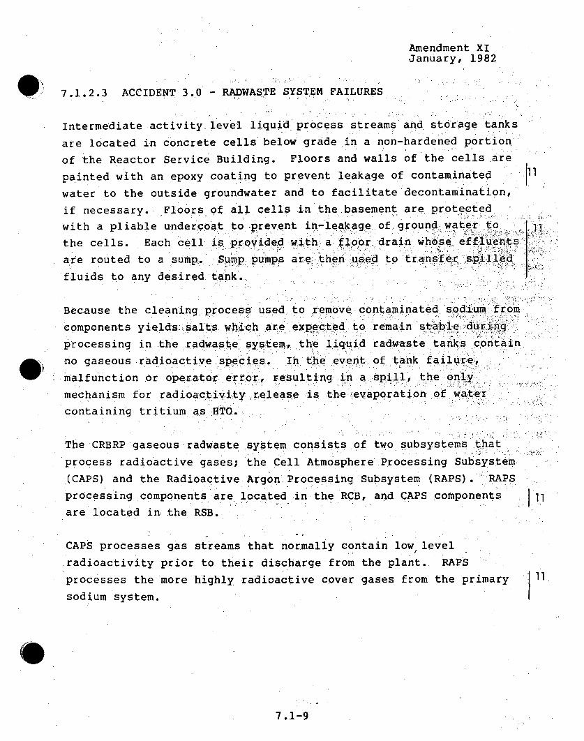
Amendment XIJanuary, 1982
7.1.2.3 ACCIDENT 3.0 - RADWASTE SYSTEM FAILURES
Intermediate activity level liquid process streams and storage tanksare located in concrete cells below grade in a non-hardened portionof the Reactor Service Building. Floors and walls of the cells arepainted with an epoxy coating to prevent leakage of contaminatedwater to the outside groundwater and to facilitate'decontamination,if necessary. Floors of all cells in the basement are protectedwith a pliable undercoat to prevent in-leakage of, ground water tothe cells. Each cell is provided withI a floor- drain whose effluentsare routed to a sump. Sump pumps are: then used to tr.ans fer srp.illed1 :fluids to any desired tank...
Because the cleaning process used to remove contaminated sodium fromcomponents yields .salts which are expected to remain stabl e:.,. du•.u ri•ngprocessing in the radwastie system, the liquid radwaste tanks containno gaseous radioactive species. In the event of tank failurez,.malfunction or operator. error, resulting in a spill, the onlymechanism for radioactivity release is the ,evaporation of wat~ercontaining tritium as HTO.
The CRBRP gaseous radwaste system consists of two subsystems thatprocess radioactive gases; the Cell Atmosphere Processing Subsystem.(CAPS) and the Radioactive Argon Processing Subsystem (RAPS).:'%RAPSprocessing components are located in the RCB, and CAPS components ).1are located in the RSB.
CAPS processes gas streams that normally contain low levelradioactivity prior to their discharge from the plant. RAPSprocesses the more highly radioactive cover gases from the primary j 11sodium system.
7.1-9

Amendment XIJanuary, 1982
Because RAPS receives and processes gases of much higher activity
levels than CAPS its process c6mponents are located 'in the RCB•.
Rupture of the Noble Gas Storage Vessel (NGSV) is included in the
accidents in the subsequent sections since it is the limiting
gaseous radwaste system accident.
7.1.2.3.1 ACCIDENT 3.1 - LIQUID SYSTEM TANK-MALFUNCTION
A malfunction or equipment leakage of a liquid storage'tank
releasing 25 percent of the average inventory of the tank is•
postulated. The liquid release, 5,000 gallons of water, wouldw-
contain 13,000 uCi of tritium as HTO..*' The flo6or6 area of the; c~ell•
housing the storage tank is 1,0.00 square feet and theý cell volume is-,
39,000 cubic feet. Spilled fluid would be transferred to an
unfaulted tank by a sump pump, designed for a flowv caacityof5
gpm. Time required for spill cleanup- is 1.7 hours. Evaporation
rate of the liquid tritium during the time period when the liqui'd is;,.being pumped into an unfaulted tank was assumed to be constant.
Rate of tritium evaporation was comput using the experimenal
results of Horton, et al. (8) The total tritium release from the 8
pool by evaporation during the 1.7 hour cleanup time is'25 )Ci.
Direct release of the evaporated tritium to the atmosphere via.-thel6Reactor Service Building ventilation system was assumed. .
The maximum off-site whole body dose resulting from this event is .
1.4xl0"6 mrem. Doses at specific downwind distances, based on 16
exposure for the duration of the accident, are presented in Tablesl
7.1-5 through 7.1-12. Estimates of the potential population dose .8
are presented in Table 7.1-13.
7.1-10

Amendment XIJanuary, 1982
As the above analysis indicates, a realistic assessment of thispostulated fault results in exposure orders of magnitude less than10 CFR 20 limits. To further demonstrate the minimal environmental hl
impact of this postulated event, an upper bound limit to potential
off-site exposure was computed by unrealistically assuming that thetotal HTO inventory, 13,000 ,uCi, of the spilled fluid was evaporated
and released directly to the atmosphere. In this case, the maximumwhole body dose would be.7.2x10- 4 mrem. Even for this upper-boundunrealistic evaluation, the doses are well below 10 CFR 20 limits. 1. 1.
7.1.2.3.2 ACCIDENT 3.2 - LIQUID SYSTEM TANK FAILURE
This event is similar to ACCIDENT 3.1 except complete release, 100percent, of the average inventory of the tank is postulated. Inthis case, 20,000 gallons of water containing 50,000 .,Ci of liquid
HTO. are assumed spilled. Spill cleanup time is 6.7 hours. The
total tritium evaporated during this time is 95 ,uCi. Direct. release.6of the evaporated tritium to thep atmosphere through the Reactor IService Building ventilation system was assumed.
The maximum off-site whole body dose resulting from this event is.,5xlo- 6 mrem. Summaries of the whole body doses at specific downwind61distances, based on exposure for. the duration of the accident, are
presented in Tables 7.1-5 through 7.1-12. Estimates of thepotential population dose are presented in Table 7.1-13. j8
As was done for ACCIDENT 3.1, an upper bound limit to off-site
exposure was computed for this event by assuming completeevaporation and release of the 50,000 ,uCi of HTO contained in the I6 1spilled fluid. This was done only to demonstrate the minimal
environmental impact of this unlikely fault because the assumptionof complete tritium release as vapor is unrealistic. Even for thisworst case assessment, the resultant whole body dose, 2.8x10- 3 mrem,1618
is well below 10 CFR 20 limits. il
7.1-11
Amendment XIJanuary, 1982
7.1.2.3.3 ACCIDENT 3.3 -RUPTURE OF THE RAPS NOBLE GAS STORAGE
VESSEL
The RAPS noble gas storage vessel (NGSV) normally containsradioactive gas which is off-loaded annually from the RAPS ..
cryostill. It contains mainly argon (including argon-39) but alsokrypton and xenon isotopes, both stable'and radioactive. The gas isbled slowly from the vessel into CAPS'so that its pressure normallydecreases over the annual period. Akrupture of this vessel or ofassociated piping and components-could release radioactive gas at
above-ambient pressure into the NGSV cell. Although such a ruptureis not expected, it is assumed to occur. For the purpose "of theaccident analysis, it is conservatively assumed that the reactor hasbeen operating sufficiently long with gaseous, ,issiori produc'ts.fIrom0.5% failed fuel for steady-state isotopic composition to exist inthe cover gas system and that 1 years' accumulation'by the -cryoi••lof noble gas isotopes, under that condition, 'has been off-load~ed to :
the NGSV. Furthermore, it is assumed that some unspecifiedmaintenance operation has required that the new fresh cryostii t il -charge also be off-loaded to the storage v`esselI this in quicksequence, so that the storage vessel contains two charges and isapproximately at maximum pressure.
Assuming the vessel (260 actual cubic feet volume) is at 1atmosphere pressure absolute before the two cryostill off-loadings
(1.5 cubic feet of liquid argon each), it will contain 2640 scf ofgas prior to the accident.
7.1-12

Amendment XIJanuary, 1982
Following the assumed storage vessel rupture,, the.NGSV cell H&Vradiation monitor will sense the presence of radioactivity, sound analarm, and initiate a signal which will cause the cell vent line toclose. The cell (whose net volume is 3560Wactual cubic feet includ-ing the vessel volume) pressure willthen increase to 9.8 psig,assuming instant temperature equilibration to ambient. The initialradioactivity inventory and amount leaked to the environment areshown in Table 7.1-15.
The accident scenario assumes the RAPS NGSV cell leaks at a rate....... 11!consistent with its design leak rate of 1%/day at 3 psig. This is areasonable assumption since the cell will be periodically tested to,,insure that its design leak rate is met.
The off-site doses are further limited by the low leakage rate ofthe RCB, which is assumed to isolate immediately following theevent. The design leak rate of the RCB is 0.l%/day at 10 psigq.Also, for the analysis, a constant 1 psig containment pressure wasassumed. This 1 psig pressure is a conservative allowance forbuilding heatup following containment isolation.
The maximum off-site whole body dose resulting from this event is7.71xi0-I mrem. Summaries of the whole body doses at specificdownwind distances, based on exposure for the duration of theaccident, are presented in Tables 7.1-5 through 7.1-12. Estimatesof the potential population dose are presented in Table 7.1-13. Asthese Tables indicate, large margins exist between the potentialdoses and the applicable regulatory limits. It is concluded thatthe postulated Noble Gas Storage Vessel rupture will not result inunacceptable environmental consequences.
7.1-13

Amendment XIJanuary, 1982
To further demonstrate the minimal environmental impact of this_
postulated event, an upper bound limit to potential off-,site
exposures was computed by also assuming that the NGSV cell is not aleakage barrier, which is an extremely conservative assumption. For
this assumption, the radioactivity is assumed to be released
directly to the RCB. The off-site doses still are limited by the
low leakage rate of the RCB, which is assumed to isolate immediately
following the event.
The maximum off-site whole body dose resulting from this exaggerated
event is 4.46 mrem.
7.1.2.4 ACCIDENT 4.0 - SODIUM FIRES DURING MAINTENANCE
Postulated sodium fires could possibly result in the dispersion of
some radioactive materials to the atmosphere. Fires involving
primary sodium coolant are of most concern since this sodiumcirculates through the reactor core and accumulates radioactivity,
due to neutron activation and entrainment of fission products
leaking from defective fuel. Postulated fires involving sodium used
in the Ex-Vessel Storage Tank (EVST) cooling system could alsoresult in radiological releases. The EVST sodium is essentially
non-,radioactive at the beginning of plant life. However, during
refueling a small quantity of primary sodium is transferred to theEVST along with each irradiated assembly, resulting in a slowbuildup of radioactivity in the EVST sodium.
Accidents discussed in this section involve postulated sodium spills
during maintenance. Detailed maintenance procedures for the CRBRP
are not yet completely defined. However, recognizing the potential
hazard associated with postulated sodium fires, a set of design
guidelines have
7.1-14

Amendment XIJanuary, 1982
been established to limit' the consequences of postul.at'ed "'sodium i• ! iýi•=•ii.fireas during maintenance by imiting residua~l sodi'um ciionhtent* eandequipment being maintained as fo l0lws: .... ..
1. The maximum inventory of primary sodium in an open,de-inerted cell, able to communicate with theenvironment, shall not exceed 130 pounds;
2. The maximum allowable spill of EVST sodium in an•openi,de-inerted EVST: cooling system cell ýs hall& notexceed 250' .pounds.
If during maintenance inside containment, the potent6il exists.for a postulated primary sodium•spillexceeig10o
an open de-inerted cell, the RCB/RSB Hatch will be closed,insuring containment integrity. Large sodium spills insidecontainment during maintenance and large sodium spills duri'ngoperation are extremely unlikely events and are discussed inACCIDENT 8.0.
To determine the potential radiological impact of sodium• firesduring maintenance, two accidents,t one invo lving primary sodiumand the other EVST sodium, have been postulated. Consequences ofthese fires, presented in the following sections, have beenconservatively evaluated taking no credit for the- fire protectionsystems, fallout of combustion products during transit downwind,or aerosol plateout and settling within buildings.
7.1.2.4.1 ACCIDENT 4.1 - FAILURE OF EX-CONTAINMENT PRIMARYSODIUM DRAIN PIPING DURING MAINTENANCE
The ex-containment primary sodium storage vessels are located ina cell on the lowest level of the Intermediate Bay of the SteamGenerator Building (SGB). Vessels are connected to process
70.-11

Amendment XIJanuary, 1982
systems within containment by fill and drain headers... Headers
are valved off at the containment penetrations.. During normal,.
plant operation the vessels are essentially empty; the drain 1.
lines are also expected to be empty. It is postulated that the
storage vessel cell is opened by pulling a plug in the cell
ceiling and is entered for tank inspection. The cell atmosphere
is then open to the atmosphere of the Intermediate Bay of the SGB
above the cell.. Maximum potential sodium spill under theseconditions is limited to 130 pounds* and for the postulated:-
accident it is assumed that this quantity of, sodium is
instantaneously spilled to the cell floor. Although postulated,
it should be noted that a spill of this magnitude is not expected
because operational procedures dictate that the system will be
drained before permitting access.
It is assumed that the cell: is opened for inspection or
maintenance after the sodium has undergone radioactive decay for10 days. Actual decay time before entry to the cell is expectedto be longer, It is further assumed that the accident occurs.
near the end of plant life (30 years) when the activity of the
sodium has reached its peak. The radioactive content of the
sodium under these conditions is shown in Table 7.1-18....
The radiological impact of this postulated spill was determined
as follows:
1. Complete combustion of the spilled sodium is assumed tooccur in less than 2 hours. It-is assumed that 27% of
the burned sodium is released from the surface of the ii
*For purposes of this analysis, it is postulated that the drain
piping between the containment isolation valve and the storage
vessels is filled and the drain piping ruptures at the worst
location. -0
7.1-16

Amendment XIJanuary, .1982
burning pool to the cell atmosphere( 1 0 ). This krsultst Tin the release of 47 pounds of Na2 o aerosol contaidning35 pounds of sodium.
2. Radioisotope concentrations in the aerosol areproportional by elemental weight to the initialconcentrations in the sodium;
3. The aerosol• is released directly to the atmospherve.vathe Steam Generator Building ventilation s•t q.t.. .
4. Radioactive decay during the accident is neglectedý; and.,
5. No credit for plate out or settling of the aer6sol in theIntermediate Bay of theSGB or in the"veatilatio•n.s"'stwas taken.
Rapid combustion (< 2 hours)ý of:the .spilled sodium rxesults.because it was assumed that the...spilled sodium spreadst..eve•n-lýy. IT..over the entire floor area (2,40.0 ft 2 ) of the storage tankr ce'll.'This assumption results in the: maximum possible sodium pool areaand therefore, the maximum burning rate. A more realisticassumption would be a much smaller :pool in the vicinity of thepostulated leak and consequently, a slower burning rate.
Using the above assumptions, the total Na2 aerosol -released tothe atmosphere is 47 pounds. The mpaximum off-site whole body 8dose is 2.37 x 10⁻² rem. Doses at specific downwind distances 8 1and estimates of the population dose are provided in Tables 7.1-5through 7.1-13.
7.1-17

Amendment XIJanuary, 1982
7.1.2.4.2 ACCIDENT 4.2 - FAILURE OF THE EX-VESSEL STORAGE TANK
(EVST) SODIUM COOLING SYSTEM DURING MAINTENANCE
There are three EVST sodium cooling circuits, two normal anda
backup. The normal cooling circuits are used alternately to coolsodium circulated to and from the Ex-Vessel Storage Tank (EVST).
Each circuit is located in a separate cell, inerted with nitrogen .
during circuit operation. For the accident postulated it isassumed that a normal cooling circuit cell is de-inerted ,topermit personnel access for maintenance. During maintenancerthe-.-
sodium loop will be isolated from the EVSTand will be drained 6:
prior to opening the cell. Consequently, a major spill invol ing A Ta siphoning of the EVST, as described in ACCIDENT •.41, is not
considered a credible event when the cell is de-inerted and open...
A shielded door or plug, approximately seven feet h-igh bythreefeet wide, is openedpermitting the cell aitmiospherie to.
communicate with the atmosphere of the Reactor Service Building. 11
For the purpose of the analysis it is assumed that the loop isnot drained, and during this time, a leak in the isol0ated ;so.d ium
loOp is assumed to occur. The. maximum potiential sodlium pSil•l
under these conditions is 250 pounds and for the postulated
accident it is assumed that this quantity of sodium is 6.instantaneously spilled to the cell floor. Although postulated,it should be noted that a spill of this magnitude is not expectedbecause the system will be drained before de-inerting the cell.
For conservatism it was assumed that the postulated spill occursnear the end of plant life when the EVST sodium activity has
reached its maximum value. It was further assumed, for
conservatism, that the postulated accident occurs shortly after
7.1-18

Amendment XIJanuary,'1982
initiating of a ref.fuel•.ing operation before *Na-24,t r ansfer r ed tothe EVST along with irradiaited assemblieS, has -had sufficient-time to decay. The EVST sodiummactivity content for this
condition is shown in Table 7.1-19. 8
The radiologicali impact of this postulated spill was determined. jIas follows:.
1. Spilled sodium burns. releasing Na-2 0 aerosol,_. It.. is,assumed that complete sodium combusdionocurs'-in-lessthan 2 hou-rs resultinhg- in-he:release of 91 pounds. of
re ,ea L• :9 . .ulh . ', .. ,:,•
Na2 0 aerosol containing %68 pounds of sodium;.
2. Radioisotope concentrations in the aerosol are e1proportional by elemeintaI weight to the initialconcentrations in the sodium;
3. The aerosol is released directly to the atmosphere via•._.the Reactor Service Building vent-ilation system; o . •
4. Radioactive decay during the accident is neglected;,and
5. No credit for plateout or settling of the aerosol in-theReactor Service Building or in the ventilation systemwas taken.
Rapid combustion (< 2 hours) of the spilled sodium resultsbecause it was assumed that the spilled sodium spreads evenlyover the entire floor area (280 ft 2 ) of the cell. Thisassumption results in the maximum possible sodium pool area andtherefore, the maximum burning rate. A more realistic assumptionwould be a much smaller pool in. the vicinity of the postulatedleak and consequently, a slower burning rate.
7.1-19

Amendment XIJanuary 1982
The total Na 2 .0 aerosol released: to...the atmosphere is91 pounds.
The maximum off-site whole :ý body:.dose. is.•5:x, i-3 remi. Doses 4 8 11
at specific downwindý' distances and estimates of"the, population
dose are provided: ini ,.Tables';7.1-5 through7.l13 -
7.1.2.5 ACCIDENT 5.0 - FISSION PRODUCTS TO PRIMARY AND:SECONDARY SYSTEMS
Environmental consequences of plant operation with claddingdefects (failed fuel) were considered in Sections 5,2 and 5.3-:of "-this report. The assesssment !was conducted.. realistically :assuming continuous plant operation. wtith, 0.1V pe~rcent failed: fue.1.The environmental impact of tritium,:produced in the: reactor .core.during normal operation, and diffused through the fuel andcontrol rod cladding to the primary and secondary systems to thesteam generator, was also considexred in Sections 5.2 and 5.3.
Environmental consequences of transient-induced fuel failures
coupled with a steam generator leak are typically addressed inlight-water reactor environmental reports. However, the designof the CRBRP Heat Transport System (HTS) is such thatradioactivity released to the primary coolant is-effectivelyisolated from the steam generators. Primary sodium coolantremoves heat from the reactor core and blanket and transfers thisheat to the intermediate sodium through the Intermediate HeatExchanger (IHX). Primary sodium then returns to the reactorvessel. In the intermediate system, sodium, heated in the IHX,is circulated to the Steam Generator (SG) where: its heat istransferred to a water-steam mixture which drives a conventionalturbine-generator unit. This configuration provides a doublebarrier, the IHX and SG tube wall/tube sheets between the primarysodium and the steam system. In addition to the double barrierinherent in the HTS design, the operating pressure of theintermediate sodium is slightly higher than, that of the primary
7.1-20

Amendment ,XIJanuary, 1982
sodium. As a result, leakage of primary:sodium into th-eiintermediate system is avoided ,ifu er reducing th•: pssibilityof radioactivity release .through the Steda`m' Generator,.
Significant fuel failures resulting from off-design transientsare not anticipated in the CRBRP. As discussed above, evenifsome unexpected fuel failures are postulated, release ofradioactivity through the steam generator is avoided.Environmental release of radioactivity following 'a postulatedfuel failure would be limited to noble gasz leak;age. The releaseof noble gases through this system during no~rimal op' peorat ýon with0.1 percent failed fuel was considered in Section' 5.2 and 5.3.A postulated fuel failure would result in an incremental surge ofnoble gas activity into the reactor cover gas space,. This surge-of activity would be subject to normal prociessing andleakage'.Potential environmental impact of this event is discussed in the-following section.
18
The possibility of non-radioactive intermediate sodium .interacting with water/steam via a Steam Generator tube rupturehas also been investigated. Environmental consequences of thisevent are discussed below.
7.1.2.5.1 ACCIDENT 5.1 - OFF-DESIGN TRANSIENTS THAT INDUCE FUELFAILURES ABOVE THOSE EXPECTED
Significant fuel failures resulting from off-design transients arenot anticipated in the CRBRP. However,, potential environmentalýconsequences associated with a postulated transient-induced fuelfailure have been evaluated. The evaluation is based on thefollowing assumptions:
1. 0.02 percent of the end-of-cycle equilibrium coreinventory of noble gases and halogens instantaneouslyreleased to the primary coolant;
7.1-21
Amendment. XIJauryf, 1.982.
2. Cover gas and primary .pcoolant..activity prior to the
postuated.transient based on continuous: operation with,
0.5 percent failed fuel-1;- and
3. Normal operation of CAPS and RAPS prior to and following
the postulated transient.
Assuming no decay time for the noble gases as they rise throughthe sodium coolant, this postulated accident results in aninstantaneous release of noble gases to. the. reactor cover gas
volume. Because of. the strong chemical affinity of liquid sodiumfor halogens,,, release of halogens from solution tothe. cover, gas
can be neglected. Radioactive argon, neon and t-r*itium
concentrations in the reactor cover gas are-.unaiffected by this
postulated...f ault. These.. isotopes .principally arise from neutron
activation and no additional activity from these. isotopes will be.introduced to the reactor cover gas. as a result. of the postulated.accident. Therefore, the postulated accident results in anincremental surge of radioactive xenon anhd .krypton to the reactor
cover gas.
Normal steady-state radioactive cover gas invento-ry forcontinuous operation with 0.5 percent failed fuel, due to.xenon
and krypton, totals 19,500 Curies. The postulated surge of xenon 8and krypton into the cover gas adds 37,100 Curies. Total cover
gas radioactive inventory due to xenon and krypton immediately
following the postulated transient is,. therefore, 56,600 Curies. I11This surge activity, as well as .the normal steady-state activity,
is subject to normal processing and cleanup through RAPS and. is.also subject to normal cover gas leakage.
6@
7.1-22
AteXndent XIJanuary, 1982
The accident was evaluted in terms of the total excess cover gas
activity released to the environment as. a result of the transientcompared to that normally released', assuming continuous-'plantoperation with 0.5 percent failed fuel. Excess activity leakage ,wijl continue until the cover gas system returns to its normalsteady-state condition. The inventory of each xenon and krypton
isotope will asymptotically approach a steady-state condition.For the evaluation, the recovery time required for the inventoryof each isotope to reach a value-within one percent of its
steady-state value' was dettermined. The recovery time 'for' each
isotope is depend'ent on: the isotope's half-life, the purge rateof the reactor cover gas to RAPS and the decontamination .factor
for the isotope in RAPS'. t.... : The -longest recovery time for any of
the xenon or krypton isotopes is 15 hours (for Kr-85).Total excess cover gas leakage-during Ate 15-hour recovery time
is only 0.0014 Curies (see Table 7.1-17). More than 75 percent
of this activity leaks in the first two hoursfollowing the
postulated transient. Major leakl paths from the cove system
are reactor head seal leakage and, 'leakage of recycle 'cover gas
through buffer seals in the reactor head. For' conservatism, no
delay factors in the movement of: gases to-or through these sea•ls
were included in the analysis. Delays in gas movement throughthese seals resulting in radioactive decay and reduced releasesare expected. Further, all seal leakage was assumed releaseddirectly to the atmosphere via the Reactor Containment Buildingventiiation system.
The maximum off-site whole body dose from this postulated *4 8 8accident is 8.4 x 10⁻⁵ mrem. Doses at specific downwinddistances and estimates of the potential population dose areprovided in Tables 7.1-5 through 7.1-13.
7.1-23

AMENDMENT XV 9JULY 1982
7.1.2.5.2 ACCIDENT 5.2 - STEAM GENERATOR TUBE AILURE
The steam generator modules are designed and will be manufactured
to the highest quality, industrial standards.. Furthermore, a 116115
broad base DOE development program supported the desi.gn and
manufacture of the CRBRP units and the water-sodium boundar.y has
been designed and will be fabricate~d to have a high degree of
integrIty. Consequently, probab,.i ty ,of failjlure ,of the eboundary
is expected to be small. However, over t he pAl, ant. lifetime, tIhe.
possibilbty of leaks of water into sodium must be considered. to,
address this potential condition, the steam generators are.
continuously monitored by a leak detection system which providesearly detection of water-to-sodium leaks to allow subsequent
operator corrective action to I1mit theIr consequences while they
are still. small.
The water-to-sodium leak detection system Is designed to alert
the operator to the existence of a leak rate as small as
approximately 2 x 10⁻⁵ lb. water/sec. For initial leak. s izes
which can be real istically expected (up to,,about 10-2 lb.
water/sec.) the alarm is given in. sufficient time for the
operator to take action to prevent a significant increase of the
leak rate.
For these small leaks, the reactor will be shut down followed by
a controlled cooldown and depressurization of the affected steam
generator. The affected IHTS loop would then be drained to allow
repair of the steam generator. However, as a limiting case it is
assumed that the leak indication is such that the operator elects
to manually scram the reactor and isolate and blowdown all three
steam generator modules in the affected loop. The operator would
then drain the affected IHTS loop resulting in flow stoppage in
the loop. 1.
7.1-24
AMENDMENT XVJULY 1982
Under these conditions, the radiological release will beInsignificant even If It is assumed that this event occursfollowing operation with the maximum undetected Intermediate-to-primary sodium leak rate. Leakage of primary sodium Into1 theIHTS Is prevented by pressurizing the IHTS such that a pressuredifferential across the IHX (intermedlate-.to-primary) of at Feast10 psi exists during plant operation. This pressure differentialcould be lost during the sodium dumping process and It. Ispos.sible that small quantities of primary sodium could enter theIHTS. Leak rates of approximately 6 gp~h will be defected duringnormal operation and, therefore, only a small amount of primarysodium could be Introduced into the IHTS during the pump coastdown. Thls small amount of primary soduIum*'wou-ld mix with theIntermediate sodium and either remain In the no n-drai nabIe.sections of the IHTS, steam generators, and IHX, or be drained tothe sodium dump tank. Over-pressurization of this tank isprevented by either the equalization line or the preUssure reliefvalve. The gases vented through this system will be the ln.ertgas displaced by the sodium entering the dump tank. No sodiumwill be released In this process and, accordingly, there are noassociated radiological consequences with this event.
There Is a small probability that a leak may progress rapidlyInto the intermediate size range (greater than 0.1 lb/sec ofwater) before operator corrective actions could be Implemented.In this event, the expansion tank vent line duplex rupture diskassembly will burst. Sodium flow through the disc assemblieswill Initiate automatic isolation and blowdown of the water andsteam from the steam generator modules In the affected loop.
In the unlikely event that a larger leak occurs, the sodium/water reaction (SWR) will generate sodium compounds as well ashydrogen gas. To provide protection for this event with Its 15
7. 1-24a"

AMENDMENT• XVJULY.-1982
attendant hydrogen gas generation, each of the three heat
transport loops include rupture disks and a Sodium/Water Reacti on
Pressure Relief Subsystem (SWRPRS) which acts as an overpressureý
protection system and also stores SWR products.
The operation of the SWRPRS Is initiated by the rupturing of one
or more of the duplex rupture dIsk assembldies These assemb Ies
are located adjacent to the superheater sodium inlet nozzle, and
each evaporator sodium outlet nozzle. A rupture releases sodium
into the SWRPRS piping and the reaction products separator ta•nks.•
Following this sodium is a mixture of sodium, solid reaction
products and gaseous hydrogen. Within The reaction products
separator tanks, separation of the liquid sodium and solid
reaction products from the gases takes place. The gases are
exhausted through an atmospheric seal, to the flare stack and
Igniter, which Ignites any combustible hydrogen/air mixture as. it
discharges to the atmosphere.
When the pressure In the Isolated evaporators and superheater has
been reduced to 300 psig, the plant operator then controls the
opening of four sets of double Isolation valves in the affected
IHTS loop, which Initiates draining of the residual sodium in the
affected loop to the sodium tank. The other two loops, which
were not subjected to a large sodium/water reaction, will then
provide for shutdown heat removal. In this manner the reactor
decay heat and the primary and intermediate sodium systems'
sensible heat will be removed.
The SWRPRS is designed to accommodate steam generator leaks whose
consequences cannot be limited by operator action. The design
basis leak (DBL) for the system Is a postulated equivalent
double-ended guillotine break (EDEG) of a single tube that is
followed by two additional EDEG tube failures. The basis for the oselection of DBL is presented In detail In PSAR Section 5.5.3.6. 1 .
7. 1-24b

AMEN~DMENT -XV
As a result of this postulated DBL, approximately 669 pon ds.oreaction products and -entrained, sodium would be :carriedt,,i.nto thereaction products separator tank Where 'the gaseous products ar:e "separated and vented. During the short time period (2-8 seconds)while the SWRPRS is venti.ng to the atmosphere during the dbesign,basis leak (DBL) and the SGS is blowing down, smai ia mo.u-nts-primary sodium might leak Into the In~termemd-Ia te. sodaI iukm. oweve- , rth I s sod I um wQu ld not be transported to' the ser f."e.tYduring the period of time that this steam ssybei~ng blown down., due to the length o~f the piping between the IHXand the superheater inlet and the reduced sodium flows dudr)i.ngthis event. Therefore, no allowance has been made for venting of
it5ii15pr Im~ary sodlVum.to. the amspee
.. . ..0""' .• .•i• L':., ,:.
7.1-24c -

AMENDMENT XIIIAPRIL 1982
The dose resulting from the Tritium within the IHTS sodium that!
is released with the reaction products.has been evaluated. The
Tritium concentration in the Steam Generator.System at the end.of
plant life (30 years) is 0.62'uCi/g -and the'Tritium .doncentratio•n
in the IHTS sodium is 0.13 uCi/g for a hydrogen background level
in the IHTS of 200 ppb of hydrogen. During a DBL, 204 pounds of!
water combines with 465 pounds of sodium and the conservative
assumption is made that all the sodium-water reaction products.
are discharged to the atmosphere.
Depressurization of the isolated loop by opening the Pow•"er el•ief
Valves will result in the release of all water/steam in the.'loop
to the atmosphere. The total mass released is 5,040 pounds.
Using the end of life (30 years) tritium concentration, 0.62
:uCi/g for the steam system, the total tritium release through thePower Relief Valves for this postulated accident is 1.417 Curies.
Thus, the total radioactivity released to the atmosphere as a
result of the postulated steam generator tube failure is 1.50Curies of tritium, 0.083 released through SWRPRS and 1.417
released through the Power Relief Valves.
113
J8
", . •.
The maximum off-site whole body dose for this postulated release
is 8.3 x 10⁻² mrem. Doses at specific downwind distances and 14estimates of the potential population dose are provided in Tables 8
7.1-5 through 7.1-13.
7.1.2.6 ACCIDENT 6.0 - REFUELING ACCIDENTS
In accordance with Regulatory Guide 4.2, the refueling accident
evaluations used in connection with light-water reactor
environmental reports are generally analyses of radioactivity
releases caused by dropping a spent fuel bundle into the open
reactor vessel or the open spent fuel storage pool, dropping a
07.1-25

AmndKment XI,January, 1982
heavy object onto the -core when the reactor head is removed, for:refueling or onto theopen :spent fuell: storage pool and droppingof an open laded spent4 fuel shipping cask. These incident's, aremechanistically related to the fuel handling system for-light-water reactor plants. The refueling system to be used onthe CRBRP does not use an open reactor vessel, an open fuelstorage pool or a removable reactor head. Hence, the CRBRPrefueling system is not realistically subject to these same kindsof accidents. r
An alternative set of three postulated events, ,morerepresentative of the CRBRP refueling system, •has been defined..These events, selected after careful review of the.CRBRP• ....refueling procedure, represent the most Severe radioactivityreleases associated with postulated refueling system faulits.Each postulated fault, although none of them is expected to occurduring the life of the plant, was evaluated and then potentialradiological consequences determined.
The three postulated faults, discussed fully in the followingsections, are:
1. Spent fuel cladding failure while in the Ex-VesselTransfer Machine (EVTM) resulting in the release of onepercent of the noble gases and iodines contained in theirradiated assembly to the interior of. the EVTM;
2. This event is similar to (1) above except that the totalinventory, 100 percent, of the noble gases and iodinescontained in the irradiated assembly, are assumedreleased to the interior of the EVTM. This representsan extremely conservative upper limit; and
7.1-26

hwixdment XIJanuary, 1982.
3. Inadvertent .opening of a floor valve while, a', reactor.. ..
port plug:is removed.. Complete release of the
radioactive reactor cover gas through the .resulting
opening is assumed..,
7.1.2.6•.1 ACCIDENT 6.1 .- SPENT FUEL CLADDING FAILURE-IN EVTM.
-. ONE PERCENT.NOBLE GAS AND IODINE RELEASE,
The earliest scheduled time for the handling of any fuel assembly, "
with the EVTM is 8 days after shutdown (based on anticipated, -fuel
handling efficiency). At that time, the noble.gas and iodine.
fission product inventories of. an average powered fuel assembly,
based on end-of-cycle equilibrium core (peak fission product8
inventories), are shown in•Table 7.1-20.
The postulated accident is the instantaneous release of one
percent of the noble gases and iodines from the fuel assembly.to
the interior of the EVTM. This representsa, possible consequence
of a loss of cooling of the EVTM cold wall.
Radioactive gases released to the EVTM interior can then slowly'
diffuse through the seals of the EVTM to the Reactor Containment
Building (RCB)/Reactor Service Building (RSB) atmosphere. During
refueling the large equipment hatch connecting the RCBand RSB is
open. Based on the 47 cubic feet of EVTM gas space being filled
with reactor cover gas prior to the fuel cladding.failures, the o
isotopic concentrations of the noble gases and iodines within the
EVTM immediately following the assumed one percent release are 18shown in Table 7.1-21,
All seals in the EVTM.are double seals. All dynamic or movable-
seals are, in addition, supplied with a pressurized buffer gas.
between the seals that is monitored for leakage. Thus, leakage
7 .1-27

Amendment xiJanuary, 1982
of EVTM gases due to physical defects in the seals is unlikely.. ".ý.'
The mechanism for leakage through .these seaIs is by, di ffusion. othe material (radioactive gases in particular) through theelastomer. Based on the EVTM seal materials, dimensions,'operating temperature and the experimentally determined seal..permeation rates, (9), the diffusion rate for the radioactive I"isotopes released to the EVTM interior was determined. Iodineisotopes were included in the list because it was assumedpossible for bubbles caused by the release of fission gas to risie:through the sodium and be released inside the VTM- without. thesodium totally absorbing the iodine. Since no permeatidn data,for iodine through the elastomer seals are available, the sealpermeability for iodine was taken to be the same as for xenon.
However, it is expected that the permeation will actually be muchlower since iodine may react with the elastomer. This wouldeffectively prevent its release.
Diffusion rates and isotopic concentrations were used' to compute .leakage rates from the EVTM for each isotope; these are shown in rTable 7.1-22.
Leakage rates itemized in the table are initial leakage rates at 118 days after reactor shutdown. Actual activity leakage of theisotopes decreases subsequently with time, based on, theirradioactivity decay constants.
The normal time required to transfer spent fuel from the reactorvessel to the EVTM and from the EVTM to the ex-vessel storagetank is approximately one hour. In the event of the postulatedaccident considered here, within three hours after the initiationof the accident the EVTM would be moved to a location where thereleased radioactive gases would be purged to the gas cleanupsystem. This purging operation could be conducted at either the
7.1-28

Amendment XIJahuary, 1982
reactor vessel or.. the ex-vessel ostorage tank. Normally -theEVTM
is not purged.: However, following, the: postulated accident, a
purge would be provided to achieve rapid cleanup.' The purge
results in an exponential removal factor in.addition to the"
leakage rates and radioactive decay.
Using the leakage rates itemized in Table 7.1-22, release of
radioactivity from the EVTM to the RCB/RSB atmosphere was
determined assuming that the EVTM is connected.to a purging line
and the radioactivity is purged in eight hours, No credit is
taken for the reduced leakage rate .during purging. Offsite
exposure was conservatively computed assuming the RCB and RSB.
ventilation systems continue to exhaust to the atmosphere,.
Actually, both systems are designed to reduce the exhaust flow
rate upon detecting high activity in the exhaust.
The maximum off-site whole body dose is 2.13 x 10⁻² mrem.
Summaries of potential doses from this event at specific downwind
distances are provided in Tables 7.1-5 through 7.1-12., Estimates
of the potential population dose are provided in Table 7.1-13.
8 pI.'
j8 f:.TI, A
8 i
8 ,
7.1.2.6.2 .ACCIDENT 6.2 - SPENT FUEL CLADDING FAILUREIN THE EVTM*
- 100 PERCENT NOBLE GAS AND IODINE RELEASE
This postulated acccident is identical to ACCIDENT 6.1, except
the total inventory, 100 percent, of the noble gases and iodines
contained in the spent.fuel assembly is assumed to be released
instantaneously to the interior of the EVTM. This assumed
release represents an extremely conservative upper limit.
Initial isotopic concentrations in.the EVTM and the initial
activity leakage rates from the EVTM for this assumed release are
itemized in Tables 7.1-21 and 7.1-22, respectively. Again,
.111
18
(0
7.1-29

•mement XIJanuary, 1982
conservatively assuming continuous ventilation exhaust,• totheatmosphere, the maximum off-site whole body dose is-2.13 mrem.Doses at specific downwind distances and estimates !':of thepotential population dose are provided in Tables 7.1-5 through
7.1-13.
7.1.2.6.3 ACCIDENT 6.3 - INADVERTENT OPENING OF AFLOOR VALVE.WHILE A REACTOR PORT PLUG IS REMOVED
During refueling a port plug is removed from the, reac6tor vesselhead to allow transfer of fuel and other core ass6emblies between
the, reactor vessel and refueling machines. Radiation "hie e • ding:.:
and isolation of the reactor cover gas from theconta.imentatmosphere is provided by a Floor Valve (FV) mounted over•• thetransfer port prior to port ,plug removal. When the FV 'is- in::position over the transfer port, without a refueling machine
mated and sealed to its upper surface, the FV is closed andsealed providing containment between the reactor cover gas and`..
the containment atmosphere. With a ref ueling' machine ('EVTM 'for.ýrexample) mounted and sealed to the upper surface of te ýFV, te.valve is opened to permit transfer of core components between thereactor vessel and the refueling machine. Inadvertent opening ofthe FV when it is not mated and sealed to a refueling machine isprevented by proper sequencing of refueling actions, electrical'interlocks, and disconnection of the electrical power cable fromthe EVTM to the motor that opens the floor valve. However, toassess the radiological consequences resulting from theinadvertent opening of a FV, this event is arbitrarilypostulated.
The earliest time for normal port plug removal is 30 hours aftershutdown (based on anticipated refueling preparation efficiency)The reactor cover gas inventory, at this time, is shown in Table j8
7.1-23.
7.1-30

Amndet xiJanuary, 1982
With the port plug removed and the FV inadvertently opened, the
majority of this activity would remain in the reactor vessel
because of Argon's high density and the low cover. gas pressure.
For evaluation purposes all the reactor cover gas activity was
assumed to be released instantaneously to the RCB/RSB atmosphere.
(During refueling the large equipment hatch connecting the RCB
and RSB is open.) To determine off-site radiological exposure it
was further assumed that the RCB and RSB exhaust systems vent
this activity directly to the atmosphere.
The maximum off-site whole body dose is 1.08 mrem. Summar iesý f :4 8 '11
potential doses at specific downwind distances are provided in
Tables 7.1-5 through 7.1-12. Estimates of the potential- ..
population dose are provided in Table 7.1-13.
7.1.2.7 ACCIDENT 7.0 - SPENT FUEL HANDLING ACCIDENTS.
As discussed in Section 7.1.2.6, REFUELING ACCIDENTS, the designof the CRBRP refueling system does not employ an open fuel.'
storage pool. Therefore, dropping a fuel assembly into a fuel
storage pool or dropping a heavy object onto a fuel rack in a
fuel storage pool, postulated events normally evaluated in
light-water reactor environmental reports, are not realistic
occurrences in the CRBRP.
Inadvertent dropping of a loaded spent fuel shipping cask during
fuel handling is considered to be a hypothetical event. The
radiological consequences of this postulated event are discussed
in the following section.
7.1.2.7.1 ACCIDENT 7.1 - SPENT FUEL SHIPPING CASK DROP
The spent fuel shipping cask is normally raised and lowered in
the 72-foot-deep cask access shaft using the Reactor Service
Building bridge crane, which is a double-reeved crane with two (
7.1-31

Amendment. xiJanuary',
independent hooks, each capabl eof ýsupporting. the. entire spent
fuel shipping. cask. lad. Failure 'of one wll not .result inca6sk
drop. With a:.double failur'e needed to initiate a' dOp nd& ohandling frequency (about 20 times a year), it is not" expectedthat inadvertent dro pping o."f a spent, .fuel. shipping askin the
cask access shaft will occur, As a precaution against a releaseof radioactive material in the event a drop should occur,however, the cask is designed to withstand a 30-foot drop o ntoanunyielding surface without leakage. This is sufficice'nt to6:. me"`,iet'the requirement of 10 CFR 71. (A 72-foot drop onto" he :h corete
floor is less severe than the design drop.) 'Neve~rtheless, f or .purposes of accident analysis, it is postulated that a bcask drop,occurs which results in loss of cask integrity. The radiological
consequences are evaluated using the source given in Table7.1-24, which is based on the following conditions.
1. The fission gas inventory from one fully loaded spen'tfuel cask (80-days cooling) is assumed released "i!n. to theinner containment of the cask. It leaks at the designhleak rate of the inner containment seals to the RSB, "andthen to the atmosphere via the RSB ventilation system.No credit is taken for outer containment seals.
2. The cask holds nine assemblies (six fuel assemblies andthree blanket assemblies).
The maximum, off-site whole body dose resulting from thispostulated failure is 2.830 x 10⁻⁴ mrem. Summaries of potential 4 8doses from this event at specific downwind distances are providedin Tables 7.1-5 through 7.1-12. Estimates of the potentialpopulation dose are provided in Table 7.1-13.
7.1-32

Amendment XIJanuary, 1982
7.1.2.8 ACCIDENT 8.0 - ACCIDENT INITIATION EVEN'TS CONSDERED IN
DESIGN BASIS. EVALUATION IN THE SAFETY ANALYSIS REPORT
7.1.2.8.1 ACCIDENT 8.1 - PRIMARY SODIUM IN-CONTAINMENT STORAGE
TANK FAILURE DURING MAINTENANCE
The primary sodium in-containment storage tank is located below
the containment operating deck in a normally inerted cell. Cell
volume is approximately 45,000 cubic feet and the floor area
beneath the tank is 850 square feet. Cell walls are concretei
nominally six feet thick. Interior surfaces of the cell are
protected with Engineered Safety Feature steel liners.78
During normal operation, the drain tank is essentially empty and
the cell atmosphere is inerted.In the event that major plant
maintenance requires complete draining of one of the primary
loops, the storage tank will be used to store the sodium coolant.
Maximum volume of sodium stored in the tank will be 35,000
gallons and the sodium temperature will be maintained at
approximately 40 0 degrees F. The cell atmosphere will remain
inerted.
Prior to deinerting and entry into the tank cell for maintenance
of cell equipment, the cell will be prepared in order to reduce
radiation exposure to maintenance personnel. The preparation
will include allowing the Na-24 to decay and draining the sodium
in the tank to a minimum level (<500 gal). Any sodium in excess
of this minimum level will be transferred to an ex-containment
storage tank. The off-site doses for a storage tank failure
following deinerting for maintenance as stated above, are
enveloped by the following evaluation which characterizes an
accident which conservatively assumes failure of the storage tank
when full. For the accident evaluation it was assumed that the
primary sodium stored in the tank has decayed for 10 days after
reactor shutdown. It was
11,
11
9
7.1-33

Amendmnent X-IJanuary, 198 2,
further assumed that th"-he ."accident: oiccuir's7 'neýaWr th":.e en,,.-d.of plant:.
life (30 years) when the p.rimary sodium coolant activity hasreached its peak val ue. Radioactivity contentA o"f: the sodium for
these conditions is shown in Table 7.1 -1•..8
This source term would result in personnel. radiation exposurein.
excess of CRBRP ALARA guidelines and therefore prohibits .
personnel entry. However, the. calculations"6f this "acident.ha,.
been performed based .upon not, draining the tank. • ,
After de-inertingc the cell" atmosphere-, mannihed ziac•cess to the cel.
is via a 21 ft shielded door. The. evaluationlass!umes that the
cell environme nt connectis .d-i -.Ir ectly' wit the upperi "c'o'ntainmentatmosphere via a hypothetical Passageway equi7valentin area to
the cell door. At this time the total tank capa•cityi, 35,000
gallons, is assumed instantaneously drained to the cell flo0or..
The radiological impact of this postulated event'7 was.dete rmind
as follows:
1. Spilled sodium burns, releasing Na2 0 as aerosol;
2. Radioisotope concentrations in the aerosol are
proportional by., elemental weight to the initial
concentrations in'the sodium;
3. Radioactive decay during the accident is conservatively
,neglected;8
4. The RCB ventilation system is automatically shut down,,
isolating containment from the outside atmosphere. j8
5. Leakage from the RCB to the confinement annulus was
computed based on the design leak rate of the RCB (0.1%
vol/day at 10 psig) and the containment overpressure due
to sodium burning; and
7-1 -AA
A~mendment XJanuary,, 1982
6. Release from the confinement annulus to the environment i.would be through the annulus filtration system.
GESOFIRE analyses of the postulated :spill and resultant fire
indicate a peak containment pressure of approximately 0.8 psig.'
This peak pressure occurs about 40 hours following the postulated
spill. Containment pressure then decreases to 0 psig
approximately 75 hours after the start of the fire. The long.duration of the accident results since no credit for fire
fighting action was taken..
8
~ 11
V.
t-Using the pressure/time history computed by GESOFIRE, HAA-3
analyses were used to. determine the behavior of the aerosol
generated during sodium combustion. The results of the :analysis
indicate a total release of 3.4 kg of Na2 0 aerosol, containing2.5 kg of sodium, to the atmosphere over the 140-hour
overpressure period.
The maximum off-site whole body dose is 3.7 x 10⁻³ rem. Doses atspecific downwind distances and estimates of the population dosse:!.are provided in Tables 7.1-5 through 7.1-13.
8li
11
7.1.2.8.2 ACCIDENT 8.2 - LARGE PRIMARY COOLANT SODIUM SPILLDURING OPERATION•
A large spill of primary sodium into an inerted Heat TransportSystem (HTS) cell during operation is arbitrarily postulated for
purposes of this evaluation. For evaluation of cell integrity,an upper bound limit of approximately 35,000 gallons of primary I8 1ii
7.1-35
Amendment ,XIJanu'ary, 19 8'2.
sodium at 1015: deg'rees. F: :is; arbiitrar•ly assumed dscharged th:HTS cell. 'It:' is .further: conservatiely .asstumed? ýthat' the pr!.lrarysodium has r.eached its peak activity. level- at :the .end.of :pian.tlife (30 years) and that no decay of sodium activity has .,occtuirred-prior to the spill.
During operation the HTS cell :is inerted ýand closed :to. the..,uppercontainment atmosphere. The RCB/RSB.Hatch is closed, insuringcontainment integrity. The HTS cell walls.are concrete,,inominally six feet thick, and all i•nerior surfa ces, of t.the.c11are, steel lined., .. ' .
The radiological impact of this postulated .event was: det-ermi% %ned-.,,, .as follows:
1. Sodium: reacts with the available oxygen, intthe iner-tedHTS cell 2% he esultant fire releases- Na"Oas0 8an: aerosol;
2. Radioisotope concentrations in the aerosol areproportional'by -elemental weight to the•. initial..concentrations in the. sodium;-,
3. Radioactive decay during the accident is conservativelyneglected;,
4. Twenty seven (27). percent. of the airborne aerosols areassumed to be instantaneously released to the upper 1.containment atmosphere.
7.1-36
Amendment. XT.January, :1982
5. -Leakage.from.the -RCB-;to the. confinement:annulus, 1wa.s
completed based on the des'ign leak rateof the.RcB (0.1%
vol/day'-at, 10-psig): and- the .containment pressure, due:, to.sod~ium' burning." i-"-:. .... -• . :..-. .- :ii- :. .
6. Fallout (cloud depletion) of radioactive material during
downwind transit is conservatively neglected...
SPRAY analysis of the pos~tulated-spill and ,resultant:.. fire
indicates, a: peak cell ýpkressr-e. of4 1.4psig., ,:'.This. peak .pressure, 8 .
occurs about -five minutes after. the beginning of the postul.ated .:
spill. The sodium combustion rate decreases to zero within 2
hours.
SPRAY and HAA-3 analyses were used to determine the time. behavior
of the aerosol generated during sodium burning. The analyses
indicate that, if no measures are taken to mitigate sodium
burning, approximately 3.6 grams of Na20 would leak over a 3I0-day 18
period..
The maximum off-site whole body dose is -3.26 x 10"5 rem.: Doses 4 8 11
at specific downwind distances and estimates-of the population
dose are provided in Tables 7.1-5 through 7.1-13.
7.1.2.8.3 ACCIDENT 8.3 - GROSS FAILURE OF EX-CONTAINMENT
PRIMARY SODIUM STORAGE TANK
The ex-containment-primary-sodium storage tanks are located in a 18
cell on the lowest level of the Intermediate Bay of the Steam
Generator Building. The tanks will be used to store primary
sodium only in the event maintenance requires drainage of a a
large volume of reactor vessel sodium. The accident postulated
is an assumed failure which results in the complete spill of the 4
.contained sodium to the cell floor. This postulated accident is
extremely unlikely.
7.1-37: ý.
Amendment xiJanuary, 1982
For conservatism, the postulated accident is assumed to.0 occur
near the end of plant life (30.,years) .when the,. radioactive
content of'the primary sodium has reached its peak. Itis
further assumed that the sodium has undergone radioactive decay
for 10 days prior to charging the tank. The actual decay time is
expected to be longer to allow for complete Na-24 decay. The
radioactive content of the sodium for these conditions is shown I8in Table 7.1-18.
When an ex-containment sodium tank is full, -accessi tothe- tank
cell is prohibited and the celli's clxosed. The cell floor ,areaL•
is approximately 2,400 square feet. The floor of the cell is, I,protected with a steel catch. pan, 3/8-inch thick, which extends'
vertically upward to a minimum height' such that the m'aximum,potential sodium spill can be safely contained within the steel-
lined volume.
The postulated accident results in the spill of 45,000 gallons*
(-300,000 lbs.) of 400 degrees F sodium to the cell floorý... Thisspill represents 100 percent of the contained volume in one of
the two storage vessels in the cell and is an extremelyconservative upper bound. The postulatedspill covers the entirefl
floor of the cell.8
The radiological impact of this postulated spill was determined
as follows:
1. Spilled sodium reacts with the available oxygen in the
cell (inerted, 2% 02), burns and releases Na2 0 as 4aerosol;
S7.1-3 8 -

Amendment XIJanuary, 1982
2. Radioisotope concentrations: in 'the :aerosol; are,
proportional by elemental.-weight -tothe initial
concentrations in, the sodium;.
3. Radioactive decay during the accident is conservatively
neglected;'
4. Leakage of aerosol from the cell to the Intermediate Bay-
of the Steam Generator Building (SGB)-was computed based
on a design cell leak rate of 0.6 percent !voday at
3.9 psig, and the cell overpressure duelto sodium
burning;
5. It was conservatively assumed that -the, SGB ventila.tion
system continues to operate for the duration of the
accident and that all aerosol leaked 'to the SGB vents
directly to the atmosphere; and
6. No credit' for plateout, or settling of the aerosol, in the,
SGBventilation system was..taken
11~
11
Iii
Sodium •fire analyses indicate a peak; cell pressure of 4.0.psi-g
approximately 10 minutes after the postulated spill. The, cell J ,
pressure then decreases to atmospheric pressure roughly eight 8
days after the spill. SOFIRE II and:HAA-3 analyses were used to
determine the time behavior of the aerosol generated during
sodium burning. With the conservative assumption of continuous
SGB venting, approximately 0.i kg of Na20 aerosol would be: 8 41
released to the atmosphere over the eight-day overpressure
period.
The maximum off-site whole body dose is 4.2 x 10⁻⁵ rem. Doses at4 Illspecific downwind distances and estimates of the population dose
are provided in Tables 7.1-5 through 7.1-13.
(9
7.1-39
Amendment XIJanuary, 1982
7.1.2.8.4 ACCIDENT. 81.4 - RUPTURE OF THE EX-VESSEL STORAGE TANK
SODIUM COOLING SYSTEM DURING OPERATION
There are three Ex-Vessel Storage Tank (EVST) sodium coolingcircuits, two normal and a backup. The normal cooling circuits
are used alternately to cool sodium circulated to and from the,6EVST. Each is located, in a separate cell adjacent to the EVST,.The pump suction line for each normal cooling circuit exits,- from,.the EVST at an elevation above the normal sodium level in the,"'',
tank. There is an internal downcomer within the EVST which.ýextends down below the sodium*. level., An. isolation-vale. i e in, the."pump suction line is located approximately at the tank outlet -
elevation.
The postulated accident is a ruptur-e of the pumpsuction line inthe operating normal cooling circuitý. In the event of- thispostulated accident, the other normal cooling circuit would bebrought on line to permit continued EVST cooling. The rupture is
assumed to occur at the low point of the pump suction line, 'resulting in the siphoning of sodium down'to the level of -theinternal downcomer within the EVST. This postulated ruptureresults in the maximum.possible quantity of sodium discharged 161
from the system during operation. Approximately 7,500 gallons
(-57,000 lbs.) of 475%degree F sodium would be spilled into thecell. For conservatism, it is assumed that the accident occursnear the end of the plant life (30 years) and shortly after arefueling operation when the EVST sodium activity has reached its
peak. Radioactive content of the EVST sodium under theseconditions is shown in Table 7.1-19. 1
The maximum spill postulated would require a simultaneous majorpiping failure plus failure of the remotely operated isolationvalve. As such, the accident postulated is extremely unlikelyand is not expected to occur over the life of the plant.
7 .1-40

Amendment, xiJanuary,."1982
During operation:, the sodium, cooling, :circuit cellis.,nerted (2%
02) and closed. - Interior 'surf aces-ofth cellare prot•cted with 8
a steel liner approximately 3/8-inch :thick. Cell walls ar e,
nominally two-foot thick concrete... The free volume of.the cell
is approximately 14,960 cubic, fe'et and the cell: floor.-area is 680 l
square feet.
The radiological impact of this posttulated event was determined
as follows:':
1. Sodiums reacts- with thel av~alilablie ,,oxygen i. n P t-he i inerted
cell( 2% 02 The resultant! "fire .releases Na2' as
aerosol;
2. Radioisotope concent-rati.ons. in.nthe aerosolare ai
proportional by elemental wei4ght to the inittial•
concentrations in the sodium';
3. Radioactive decay during the,.accident is conservatively.
neglected;
4. Leakage of airborne aerosol from the cell to the Reactor
Service Building (RSB) was computed based on a design 1
cell leak rate of 0.36 percent vol/day at 12 psig;
5. It was conservatively assumed that the RSB ventilation
system continues to operate for the duration of the
accident and that the aerosol leaked to the RSB vents
directly to the atmosphere; and
6. No credit for plateout.or settling of the aerosol in the
RSB ventilation system was taken.
SOFIRE II analyses of-the postulated.spill and resultant fire
indicate.a peak cell pressure of 3.78 psig. This peak pressure
occurs two hours following the postulated spill. The cell
7 .1-41

Amendment XIJanuary, 1982
pressure then decreases: to approximately-1.44 ps~ig *after. 96.hours. 8 iAfter one day,, the.burning 'rate 'is less than 10-6 lb/hr t 2 ,.and
only 56 pounds' of the spilled s:odium has reacted, with. the'.
available oxygen in the cell.
SOFIRE II and HAA-3 analyses were used to determine the time
behavior of the aerosol generated during sodium burning. With
the conservative assumption of continuous RSB venting, 2.,0 grams
of Na2 0 would be released to the atmosphere. Total release time. .
is four days.
An accident in the backup cooling circuit would be'less- severeý,
than the one described above, since this is a "raised."circuit
which prevents a major spill involving siphoning of the EVST.The total amount of.sodium that could be spilled from the backup
cooling circuit is -35,000 lbs.
The maximum off-site whole body dose is 4.3x10 4 mrem. Doses at'specific downwind distances and estimates of the population dose: :
are provided in Tables 7.1-15 through 7.1-13.
7.1.2.8.5 ACCIDENT"8.5 - LARGE STEAM LINE BREAK
The consequence of a large steam line break has been analyzed forrupture of the main steam line between the main steam line
isolation valves and the manifold which joins the three main
steam lines. For this case the superheater isolation valves
close in each loop and reactor trip occurs on high steam-
feedwater ratio. After the isolation valves close, the system isdepressurized and the sensible and decay heat from the core is
removed by operation of the pressure relief valves until the heat
load reaches 45 MWT at which time the SGAHRS is capable of
removing the heat without venting.
Main steam line rupture is a transient emergency event for which
the plant is designed. Thus, no other system in the plant will
7 .1-42

Amendment XIJanuary, ,19.82.
experience conditions :which exceed the design specif icaions andno other plant damagewill result. The only •radiologicalconsequence of the failure will be thearelease of a large amountpof steam-water. which contains a low concentration of tritium.,**The level of tritium in the steam system at end of plant life: (30 Iiyears) is 0.62 uCi/cc'.
The amount of water released as a result of a main steam linebreak is approximately 312,000 pounds. Of this amount, about . 1.j9,000 pounds are released from the pipe break before theisolation valves close and 303,000 pounds are vented from thePower Relief Valves to remove heat from the system. This 303,000:pounds of water will contain 85 Curies of tritium which will bereleased over a 5.7 hour period.
The maximum off-site whole body dose is 4.7 mrem. Doses at 4 I]specific downwind distances and estimates of the potentialpopulation dose are provided in Tables 7.1-5 through 7.1-13. 8
7.1.3 SUMMARY OF PLANT ACCIDENT DOSES
Potential doses for each postulated accident at a number ofdownwind distances of interest are summarized in Tables 7.1-5 8through 7.1-12. This summary indicates that all potential dosesI..fall well within the limits of 10 CFR 100. A large margin also , i1exists between the potential doses and the 10 CFR 20 limits.
The whole body population dose for each accident is shown inTable 7.1-13. This dose includes both the external gamma doseand the internal whole body dose due to inhalation of radioactivematerial. Two whole body population doses were estimated foreach accident. The maximum prediction assumes that the windpersists towards the E for the duration of the accident, while I ]]
7.1-43

Aiernxment XI.January, 1982
the minimum estimate assumes wind persistence towards the NNW forthe duration of the accident. These two directions correspond,
respectively, to the most and least; populated ,azimuthal sectors,based on the projected population distributi-on for the year 2010.
7.1-44

Amendment XIJanury,198
TABLE 7 .1-1
ATMOSPHERIC DILUTION FACTORS50 PERCENT PROBABILITY x/v VAuEs (Sec/m 3 )*
Distance
0.42
0.5
0.6
0.7
1.0
1.5
2.0
2.5
3.0
3.5
4.0
4.5
5.0
7.0
7.5
9.0
10.0
15.0
20.0
21.0
25.0
35.0
45.0
50.0
1 .O1E73
8.25E-4
7 .16E-4
6.19E-4
4.29E-42 .81E-4
2 .0 8E-4
1 .59E-4
1.26E-4
1 .03 E-4
8.69E-5
7 .49E-5
6.58E-5
4.21E-5
3 .90E-5
3 .07E-5
2.73E-5
1.70E-5
1.21E-5
1 .14E-5
9.26E-6
6 .43E-6
4.88E-6
4.32E-6
1.55E-4
1:.27E-4
1.,07E-4
9.29E-5
6.51E-5
4.310E-5
3 .03E-5
2.30E-5
1 .83E-5
1.49E-51 .24E-5
1 .09E-5
9.46E-6
6.04E-6
5.57E-6
4.44E-6
3 .99E-6
2.46E-6
1 .76E-6
1 .66E-6
1 .34E-6
9.33E-7
7 .60E-7
6.25E-7
1.23E-4
9.28E-5
6.91E-5
5.43E-5
2.70E-5
1.07E-5
5 .61E-6
3 .58E-6
2.58E-6
1, 96E-6
1 .55E"6
1.26E-6
1.06E-6
5.87E-7
5.28E-7
4.27E-7
3 .77E-7
2.28E-7
1.56E-7
1 .47E-7
1.17E-7
7 .98E-8
5.89E-8
5.16E-8
7 .69E-55.7 8E-5
4.30E,-5
3 .36E-5
I. 67E- 56.6 9E-6
3 .5E 06
2.29E-6
1 .60E-6
1 .19E-6
9.3 5E-7
7 .66E-7
6.42E-7
3 .66.E-7
3 .30E-7
2.65E-7
2.31E-7
1 .36E-7
9.47E-8
8,91E-8
7 .22E-8
4 .89E-8
3 .71E-8
3 .29E-8
-9.0 6-E- 5
6 .76.E-5
'5.'02E-53 .93•E-5:
1.93 &-5
7.73,E-76Z
4.06E-6
2.,60E-6
1 .85E-6
1 .40E-6
1.11E-6
9.0 6E-7
7 .64E-7
4.32E-7
3 .88E-7
3 .10E-7
2.72E-7
1.63 E-7
1.14E-7
1 .07E-7
8.67E-8
5.82E-8
4.37E-8
3 .90E-8
II
*See Section 2.6
7.1-45

I
TABLE 7.1-2
AVERAGE ENERGY-PER DISINTEGRATION
Isotope
H-3
C-14
Na-22
Na-24
Ne-23
Ar-39
Ar-41
Mn-54
Co-58
Co-60
Kr-83m
Kr-85m
Kr-85
Kr-87
Kr-88
Sr-89
Sr.-90
Y-90
Y-91
Zr-95
Nb-95
Ru-103
Ru- 106
Sb-125
Te- 129m
Te-129
Te- 132
Beta
(MjeV)
0.006
0. 0520. ,1.82
0.463
1.460
0,188
0.406
0.00021
0.0237
0. 105ý.0..036.
0.277
0.230
1.324
0.376
0.4880. 182
0.930
0.515
o. 130
0.0532
0.077
0.013
0.335
0.621
0.407
0.10
(Continued)
Gamma(Me )
0
0
2.195
4.123
0.11600
1 .280
0.835
0.977
2.51
0.00248:
0. 158
0.002
0.793
1 .950
0.0000820.0
0.0
0. 0036
0.725
0.765
0.474
0.0
0.121
0.0414
0.108
0.216
7.1-46

AMENDMENT VIIIFebruary: 1977
TABLE 7.1-2 (Continued)
Isotope
1-131
I-I 32
Xe-1 31m
Xe-1 33m
Xe-i 33
Xe-I 35m
Xe-i 35
Xe-138
Cs-134
Cs-i 36
Cs-137
Ba-140
La-140
Ce-1 41
Ce-1i44
Pr-143
Nd-147
Pm- 147
Beta(MeV)
0.197
0.448
0.143
0. i 89
0. 1 35
0.095
0. 316
0.612
0.166
0.139
0.246
0.284
0.397
0.315
0.101
0.310
0.335
0.070
Gamma(MeV)
0.3712.40
0. 02
0.045
0.432
0.247
1.183
1 .59
2.23
0.563
0.236
2.12
0. 0695
0. 0163
0.0
0.122
0.0
8
'9
7.1-47

Amezixbent xi
TABLE 7.1-3
INHALATION DOSE.CONVERSION FACTORS, F.
rem/Ci Inhaled*
LIsQtQp!Lung •QflR
H,-3
Na,-22
Na-2 4
Mn-54
Co-58
Co-60
Sr-.89
Sr-90
Y-90Y-91
Zr-95
Nb-95
Ru-103
Ru-106
Sb-125Te-129m
Te-1 29
Te-132
1-131
1-132
1-133
1-134
1-135
1 .581.30•
1.28
1.75
1116
7.46
1.75
1.20
2.12
2.13
2.21
6.31
6.31
1.18
2.18
1 .45
2.42
3.60
.E2
E4
E3
E5
E5
E5E5
E6
E4
E5
E5
E4
E4
E6
E5
E5
E2
E4
1.30 :E4
1.28 E3
,1 58
1 .1301. 28
E2
E4E3
3 .01.24
2. 1
5.78
1.34
1.76
11991
8.64
6.67
1 .22
6.22
3.25
3.15
1.45
1.08
8.06
3.35
E4
E7,
EA
E4
E3
E2
E3
E3
E3
E-3
El
E3
E2
E3
El
E2
1'.5,8 E2
1.28 E34
7 .,871 E2
2 .5'9 E2
1.185 E3.
.1.09 E37..62 ,ES
1.55 .E3
2.91 E3
5.26 E28.23 :El
1.09 E3
1.58 'E31.98 E2
1.55 E-32.02 El
2.56 E3
1.45 E2
5.65 E2
7.69 El
3.21 E2
6.75
4.30
4.87
2.37
1.49
1.43
2.69
3.73
5.60
E2
E-3
El
E6
E4
E5
E3
E4
*From NUREG-0172
7.1-48

Amendment XIlJanuary 982
TABLE 7.1-3. (Continued)
INHALATION DOSE dCONVERSION. FACTORS, F.
rem/Ci Inhaled*
Isot~gpe
Lung Thygoid
Cs-13 4
Cs-136
CS-137
Ba-1 40
La-1 40
Ce-141
Ce-144
Pr-143
Pr-144
Nd-147
Pm-147
Pu-23 8
Pu-23 9
Pu-240
Pu-241
Pu-242"
1.22
1.50
9.40
1.59
1.70
4.52
9.72
3.51
1.27
2.76
6.60
1.82
1.72
1.72
1.52
1.65
E4
E3
E3
E5
E4
E4
E5
E4
E2
E4
E4
E8
E8
E8
E5
E8
4.66:4.88
5.98
4 .88
4.30
2.49
4.29
1.17
3.76
6.59
8.37
2,74
3.19
3.18
6:.41
2 .95
E4
E3
E4
E3
EP
E3E5
E3
EE2
E4
E9
E9
E9.
E7
E9
1.38••Z2•i5.3.5E4. E
3.21 E2
.5.73.,
5.80': 6 E-'l.1.91. !E-:4•
3.19 iE3
6.90 E7
7.7 5 VE7'-`,:;
7.73 E7
1.29 E6
7.46 E7
*From NUREG-0172
60
7 .1-49
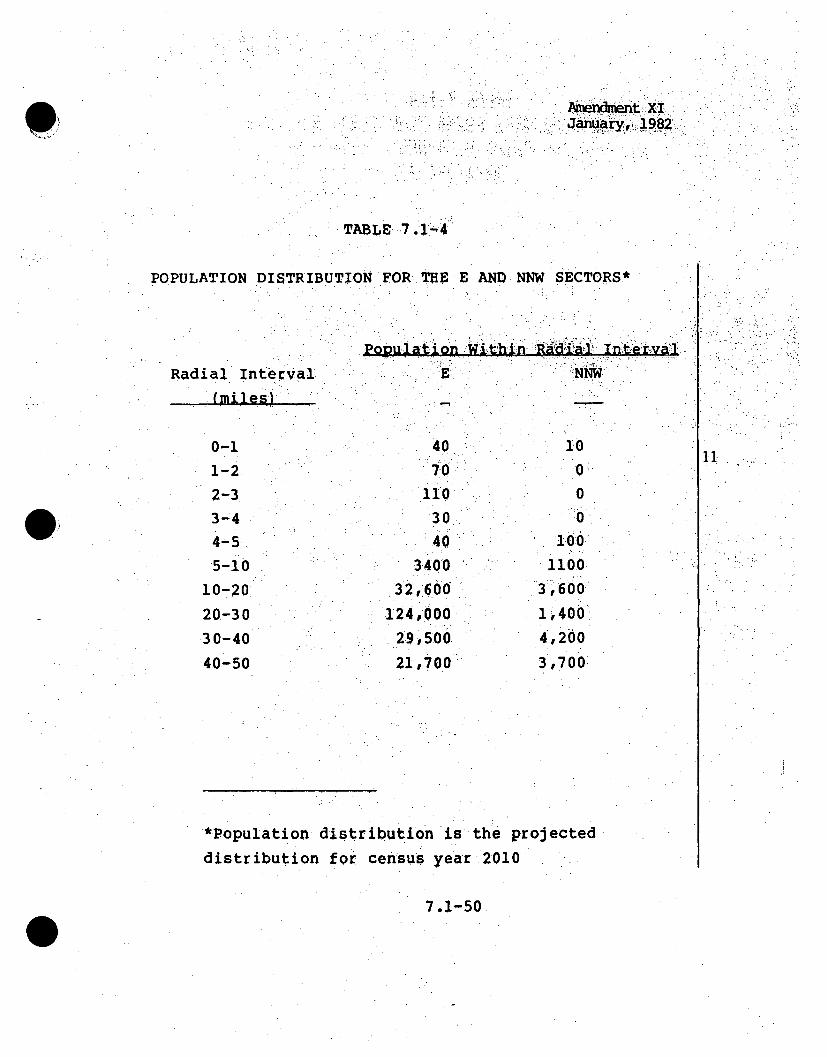
AmendmentXI1
TABLE..7 o.1-4
POPULATION DISTRIBUTION FOR THE E AND NNW SECTORS*
Radial Interval(miles)
0-11-2. . .
2-33-44-5•
5-10
10-20
20-30•30-40
40-50
P~ppttio~Withn R~~a~ Nterv'
7-0.110
30
403400.
32,ro0
124,o00299, 500
21,700
J~u
0'.
0
1i00
1100
.3,600
1,400!
4,2o0
3,700:
.11 .
.*Population distribution is the projecteddistribution for census year r.2010
7.1-50

Amendment XIJanuary, 1982
TABLE 7.1,-5
SUMMARY' OF POTENTIAL DOSES FROM PLANT
MINIMUM EXCLUSION DISTANCE - 2200
torero/event
ACCIDENTS
FEET*
ACCIDENT WHOLE BODY BONE LUNG THYROID
.2.1
3.1
3.2
3.3
4.1
4.2
5.1
5.2
6.1.6.2
6.3
7.1
8.1
8.2
8.8.3
8.4
8.5
10CFR20
(Imrem/yr)
10CFR100
(mrem/event)
5.50 0.
1.37E-6 0.
5.18E-6 0.
7.71E-1 0.
2-:.37E1 3.15E2
8.75 2.36E2
8.40E-5 0
1.30E-2 0.2.13E'2 2.06E'2
2.13 2,06
1.,08 0.
21.83E-4 3.11.E-4
3.68. 4.9321
3.26E-2 2..69--2
4k.22E-2 5.63E-1.
4.29E-4 1.1-6E-2•4.71 0.. -" ."
5.00E2
2.50E4 1.50E5**
5.50
1.37E-65 .18E-6
5.92- 21 07.E1.
1 .16E1l
1 .30E-2
S...46E-5
1 .4.6E-3
1 .98E-2.2.86E-6
2.77
1 .03E-2
3 .16E-2
5.67E-4
,4.71
7.50E4**
5.501 .37E-6
5 .18E-6
8..74•EI
7 .45
0.
1 .30E-2
91.6.4
9.64E2'
1 .88E-4
.1 .42E-1
1 .37El
1.89E-2
1.56E-1
3.65E-4
4.71
1.50E3
3 .OOE5
Hc9
*Shortest distance from containment to the far bank of the Clinch River
(Far bank is site, boundaxry) 111**.Not covered in 10CFR100; iised as •guideline Values
7.1-51

Amendment XIJanuary, 1982
TABLE 7.1-6
SUMMARY OF POTE:NT`IAL' DOSES FROM PLANT -ACCIDENTS
DOWNWIND DISTANCE- o 6 MILE*-mr(•m/event
ACCIDENT
2.13.1
3.2
3.3
4.1
4.2
5.1
5.2
6.1
6.2
6.3
7.18.1
8.2
8.3
8.4
8.5
10CFR20
(mrem/yr)
10CFR100
(mrem/event)
WHOLE BODY
3.-90
9 .71E-73 .67E-6
5.47E-11.68E1
6.20
5.96E-59.22E-3
1 .51E9-2
1.51
7 .66E-1
24.1E-4
2.61
2.31E-22.99E-2
3,04E-4
3.34
5.00E2
2.50E4
BONE
O
0.
0.0.,
2.23E2
1 67E2
0.0.
1. 46E-21.46
0.
2 ZOZ0 -4
3.49EM
1.69E-2
3. 99E-1
8.22E-3
0.
i. 50 E5
3.909.71E-7
3.67E-6
4.19E- 21 .125E1
B .-2 2
1-.4 9E-6
9.22 E-31 .04•E- 5
1.0 4E-3
1 .40E-2
2.03E-61.96
7'.32E-3
2.24E-2
4 .02E-4
3.34
7 .50E4
LUNG THYROID:.
3.90 .•
9.71E-7
3-.67E-6
0.
6.20 El
9.22E-3
6.83
6. 83 E2
1.01E-1
9.69
1 .304E-2•
1 .11E-1
2.59E-4
3.34
1.50E3
3.00E5
*1.1
*Nearest Residence
7
7.1-52-

Amendment XIJanuary, 1982
oTABLE-3.1-7
SUMMARY, O POTEN¶T!AL DOSES -FROM. PLANT ACCIDENTSDOWNWIND, ]DISTACE- 1.. MILE*
. ,mremo/event
ACCIDENT
2.1
3.13.2
3.3
4.1
A4.2
5.1
5.2
6.1
6.2
6.37 .1
8.1
8.2
8 .38.4
8.5
1OCFR20
(mreem/yr)
10CFR100
WHOLE BODY BONE LUNG THYROID
2.34
5.82E-7
2 .20E-6
3 .28E-1
1.01E1
3.72
3.57E-5
5.53E-3
9.05E-3
9 .05E-1
A4.59E-11 . 20E-4
1.56
1 .38E-2
1.79E-2
1.82E-42.00
5 .00E2
2.50E4
0.
.0.0.
0.1.3 34E2
1.,00 E20,0.
8.7 6E-I
0.
1. *32'E- 42,09E1
1,0O1E-2
2.3.9E-I
4 .93 E-3
0.
1•.50 E5
2.34
5.82E-7
2D .20E-62 2.51E-2
*7.52
,-:4 193
8,932E-7
5.53E-3
6 .21.E-66 .21 E-4
8 .42E-31.9 22E-6
4 .3 9E-3
1,34 E- 2
2.41E-4
2.00
7-.50E4
2.34
5.82E-7
2 .-20E- 60.
3 .170.
5 .53E-3
4.,10
4 .10E2
7.9:9E-5
6 .04,E- 2
5.81
8 .04E-3
6.63E-72
1.55E-42.00
1 .50E3
3.00 E5
11
(mrem/event)
*Nearest Recreational Area
7.1-53

Am endment XIJanuary, 1982
SU MA1Y 'OF POTENT.IAL DOSES FROWPL-ANT ACCIDENTS
DOWNWN ITNE .MLS
mem/event
ACCIDENT WHOLE BODY BONE LUNG THYROID .
2.1
3.1
3.2
3;.3
4.1
4.2
5.1
5.26.1"
6.26.3
7.1
8.18.2
8.3
8.48.5
10CFR20
(mremr/yr)
10CFR100
-(mrem/event
8.64E-1.
2.16E-7
8.15E-:7
I .21E-J.I. 211E,3 .72
1 .37
1 .32E- 5
2.04E-3
3 .34E-3:
3 . 07-1
1. 70E-I
'4..44,E-5
• . 90.F..
5 .13E-3
6.63E-3
6.74E-5
7 .39E-1
5 .00E2
2.50E4
0.
0.
0.
0,4 .9 • ..
3 .7...-.
00
3 .234E-1
0.
7 .76
3 ,75E-38 ,84E•-2
8 . • 8 :4 -..
1 .82E-3
1 .,50E5
8.64,E-1
2 •.-6E-7
:2•29E- 438.11E-3
.:i 4 ;:9;E-37:9 .36E-3
1:. 63 E-3
4.96E-38.90E-5
2 .29E-4
7.3 9E-3
7 .50E-
.6 4 E-1.
ý2.16E-7
8.15E-7
.0.1 .37 E1
1.1704E• <
2 .04! E- 3J~15,1
1 .51E-•,2
2.1598
2.45&E-2i,
5.73 E- 5
7.3 9E-1
1 .50E3
3 .00E5
11
*Low Population Zone (LPZ)
7.1-54 -

Aniendmenit XI.Janua~ry, 1-982
SUMMARY. OF'.TNIA OE .FQ~P.N CIDNS
ýDowNWIND D.ISTANCE,~4~LS
#lprei'/ve ,nt
ACCIDENT
2.1
3.2
3. 3
4-.2-
2:
63.1
6¸.3
7.1
:8.1•8.2 ,
8.3,
8.4
8.5-
1 OCFR20-
(mrem/yr)
10CFR100
(mrem/event)
WHOLE BODY
4 .4.73E-I
1, 1..:i8 97, 7
1 .12E-67
4,46,E-76.1-63Er2
2.04•.9z2
7 .53.E-
7.22,80E-6
:1.63E'3•
1 .83El-J
.9.2.5E-2
.2..;413,E- 53.17.E-1
28 0 E- 3
.3. 63-E-3
3.69E-5.,
4.05E-I
5.00E2
2,,50E4
BONE. LUNG
.0
0.
0,
0.
0.
1,. TTE; .3i:
0,
4.242..05,, 3.4.845E-2
9, M 8E-41
0.
1. 501E5•
' .. 4 ..73E-1
1... .. 1.,:8E-,74 .46E-7
5-09E-3
1-52
9:98E!71
I. 7. 0E-!1 . •2 4, E-..
2 .,.46E-7
2 .38E-1
8.8.. 8.8 E- 4
2..72E-3
49881E-5
4l.05E-I
7,50E4
4-.738E-1
1 .18E-7
4.46E-7
7,.52
6 041E .-•10 . .....
11.2E- 3
8.29EI-
8 .2 ZE- 2i1.22E-2z~i
1 . 6,3E-3'
1 .3 4E-2.
3 .14E-5:
4.05E-i
1.50E3
3 .ooES
THYROID.
*11~
9
*Nearest Dairy
7.1-55

Amendment XI.January, 1982
TAB'49;*1.1~-1O.
SU MMA R'Y O-F POTEN4TIAL POSES rOMPAT~CIET
S7 DOWNWIND"DISTANCE 7 MILES'D ..'. .i mrem E nt' . .
ACCIDENT WHOLE BODY BONE LUNG THYROID'
2.1
3 .1
3.2
3•.3
4.1
4.2
.5.1
5..2
6.1
6.2
6.3
7T.18.18.2
8.38.4
8.5
10CFR20
(mrem/yr)10CF RI00
(mrem/event)
2 .31E-1
5.71E-8
2 .116E-7
9 .95EI-13 .68E•I.
3 .53E-6
5.46E 4
8 .95.E-48.95E-2
4.54E-2
1.19E-5
1 .53E-1,31.36E-3
1. .77E-3
1.80E-5
I .98E-1
5.00E2
2 .50E4
0.
0.
0.
0.
1 32E1
9.91000.
!84 6.5-E-4
8.65,E-20.
3-.31E•5
2.059.92E-4
2 .3 6E-2
4.87E-4
0.
1. soE5
22.31E-15 •.71E'8
2 •.i6E-7
2 ."47E-37 63E7-7
41.87E- 3
5 .84E-8 4
5 . - .E- . 4.6 ..I3E-7
6.13 E- 5
8 .3 2E-4.
1 .20E-7
1 .15E-I
4 .30E-4
1 .33E-3
2 .38E-5
I .98E-1
7 .50E4
2,31E-1
5 .7-1TE- 8'-
.2.16E-7'
'0.
3.67
5 .465E-4, "
4. 05E-
71.90E"6
5 .•9.'62-3
5.7 OE-1
7.89E94
6.55-E--3
1.53E-5
1 . 98 E-1
1.50E3
3 .00E5
Ii
*Nearest Population Center > 2500 .(Kingston)
7.1-56 -

I•Amendment XILJanuary,•, 1982
SUM"MARY-OF POTENTIAL SES FROM PL. I T ACCIDENTS
DOWNWIND. DISTC -21MES
mrei/event
ACCIDENT
2.1
3.1
3.2
3..3
4.14.2
5.15•.2
6.1
6.2
6.3
8.1
8.2
8.3
8.4
8.5
10CFR20
(mrem/yr)
10CFR100:
(mrem/year)
WHOLE:BODY BONE LUNPG THYROID
6.0 5E-2
1.55E-8
5. 85E 8
8 .70E-32, 1 6!E-I
9.63 E-2
9.24E-7
1 43E-42.3,4V!•42.314E-2
2..6.834E-42
1.19E- 2
3 ,lIE-6
4.16E-23:.68 E- 4
4 .64E-4
4.72E-6
5 .18E-2
5 .00E2
2.50E4
O.
0.,
3q47 .:
2.60
0.
0.
2 .27E- 4
2,27E-2
3.424,-6
5.56 E-,2 .69E-46.19E-3
1.28 E--4
1.60E5
6.05E-2
1 .55E-8
58 E -8
"1.95E-J.
1 ..61E-71 .1 E-- 5
3..15E--8
3 .13E-21 .J7E-4
3.4 8E-46 6"24E-6
5.18E-2
7 .50E4
6.05E- 2
1, 55E- 8
.5 .85 E- 8
0.
9,61E-l
81.20PE-2
1 .4 3E-'4
1 . 06E- 1
1 .06E1-
2.07-E- 6
1 .5,6E3
1 .54-E- 1
2 .14E -'A
1 .7.2E-3:
4..02 E--6.
5 .18E-'2'
1 .50E3
3 .. OE5
*1*1
~c9
*Nearest Population Center >i100,000 (Knoxville)
K ...
7.1-57

Amendment XIJanuary, 198'2
TABLJE 7.1-12
SUMMARY OF POTENTIAL DOSES FROM PLANT ACCIDENT
DOWNWIND DISTANCE M50 MILES
mrem/event
ACCIDENT
2.13.1
3.2
3.3
4.1
4.25.1
5.2
6.1
6.2
6.3
7.18.1
8.2
8.38.4
8.5
1OCFR20
(mrem/yr)
1OCFRI00
(mrem/event)
WHOLE BODY
2 .20 E- 2
5.86.E-92.22 E-8
3 3.30E-39.48E-2
3.50E-2
3 .36E-7
5,020E-58.52E-5
8.52E-3
4.32E-3
i .13E-6
1.57E-2
1.39E-4
1.69E-4
1.7U2-6
1.88E-2
5,00E2
2.50E4
BONE LUNG THYROID
0.
0
0.21.26
9 p.44E-1
0.0.•
8.24 E- 5
8. .24Ei-3
0.1 .24E-6
2. ii E-1I1.102 E- 4
2.25E-3
4.64E-5
0.
1 .50E5
2.20E-2
5.86E-9
2. 22 E- 8
.2.5 3E- 4
7 .08E- 24.64E-2
8.4!0•E,9
5 .20E•- 55 .84E-8
5.84E-6
7.92E-5
1.14E-8
1.18E-2
1.42E-5
1 .26E-4
2.27E-6
1.88E-2
7 .50E4
2.20E-2
5.86 E-9
2 .22E-8
0.
3 .50E-1
2.98E-2
5.238E-5.
3 .86E,23.86
7.52E-7
5 .68E-4
5.85E-2
8.10 E- 5:
6.24E-4
1 .46E-6
1 .88E-2
1 .50E3
3 .00E5
7.1-58 -

Amendment XIJanuary, 1982
SUMMARY OF POTENTIAL WHOLE IODg POPULATION POSES.".OM.PLANT
.ACCIDENTS-Whole Body PopU]at.9rn ose .. "..
Minimum. Estimate4Man-er~n) .. ,..
Maximum Estimate
(Man-rem).Accident Number
2 .1
3.1
3.2
3.3
3.4
4.1
4.2
5.1
5.2
6.1
6.2
6.3.7.1
8.1
8.2
8.3
8.4
.8. 5
1 .41EI
3 .52E-8
. .33E-7
1. 98E-21. 67E-2
6.0 9E-3
3 .3 4E- 4
5.47E- 45.47E-2
2 .77E-2
7 .27E-69.46 E- 2
8.38 E- 4
1.08E-3
1 210EE51 .21 E71
1 .75E+04 .35E-7
1. 65E16
2.45E-1
2 0E-17 . 537-22.78
2. 67'E"5
4 .13 E-36"" 77Eý-3
6.77E 1
3 .43E-1
8.99 E- 5" 1,17.
.1.54E'.'" 1.34E-2
" 1,36E-
,104
(.
7.1-59

TABLE 7.1-14
HAS BEEN DELETED
7.1-60
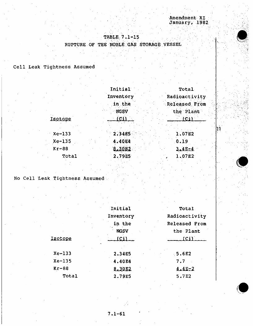
Amendment XIJanuary, 1982
TABLE. 7,1-15RUPTURE OF THE ,NOBLE GAS STORAGE VESSEL
Cell Leak Tightness Assumed
InitialInventory
in theNGSV
Total
Radioactivity
Releasedl Fromthe Plant
!. 07E20i9
14.07E2
11Xe-133Xe-135
Kr-88Total
2.34 54940 E4
2.7 9E5
No Cell Leak Tightness Assumed
InitialInventory
ip theNGSV
Total
Radioactivity
Released Fromthe Plant
-.. g iL _laQ~p-=
Xe~-133
Xe-135
Kr-88
Total
2.34E54.40E4
2.79E5
5.6E2
7.7
5.7E2
7.1-61

TABLE 7.1-16
HAS BEEN,. DELETED
7.1-62

mend~wiit XT
~AB E. 74-17,TOTAL EXCESS: COVE G f LEAK GP.
FOR KCCIPPNTý 5,1
Xe135~'
5 43
43.3
7.1-63

Amendment XIJan.ary, 1982
TABLE 7 1•-118 ::
RADIOACTIE CONTENT- OFPRIOKRY SODIUM -COOLANT*
A Ci/gm
Days After Shutdown
Na-24Na-22
Cs-137
Cs-136
Cs-134
Sb-1251-131
Te-132
1-132
Te-129M
Te-129
Sr-89Sr-90
Y-90
Y-91
Zr-95
Nb-95
Ru-103
Ru-106
Rh-106
Sb-127
Te-127M
Te-127
Ba-140
Q2.943 . 49
83, 442,.1
'5.,35
.24124.8
16.7
.359* ~359
.055.034.034
.0156
.0292
.0292
.0415
.0287.10287
1.82
.104
.124
.0327
ý4.3 2E-1
34 6
.5:,2 5E. .5.25
2.40E-1
14'05E1
2,08E-11.98•
2. 93E-1
2.-93E-11-4.80E-2
3.40E-2.
3.4 OE-21.•40E-2
2.60E-2
2.60E-,2
3.50E,,2
2.80E-2
2.80E-2
2.93E-1
9.80E-2
9.80E-2
1.90E-2
[11
7.1-64

menc i!ent XiJanuary, 1982,
.10 V np18 (cort inved!)
RAD I; CIVltt COTE FRIRYOIUCOL1 t
A Ci/gm
Davs After Shutdown
La-1.40
Ce-141
Ce-144.. Pr-144
Pr-143
Nd-147
Pm-147
Pu-238
Pu-239
Pu-240
Pu-241
Pu-242
Np-238
Np-239
Am-241
Am-24 2m
Am-242
Am 243
Cm-242
Cm-243
Cm-244
H-3
Rb -86
0:O22jk
0Q2 2
.028
# 123
7 019E-3
8.23-
2..6.E-4
7.95E-6
1.66E-4
2*34
1.00
1. !1. 900E-2
3.1O-2
2.820 Eý2
2.320E-2
51•70E-2
7.00E -3
1• 320E-2
8. 00;E-3
.23&E-32.30E-1
5.9&E-69oOOE-8
4.12E-4-.
8.20E-4
3.23Eý--5
3.23 E-5
1.32E-5
5.75.E 4
7.95.E-6
2.34 .
.11~I
.69
*30 years of plant operation, 0.5 percent fatled fuel
7,1-65
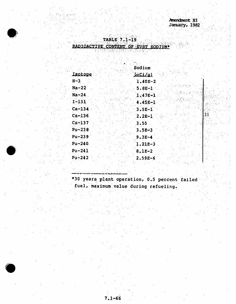
hwidmentuXIJanury,1982
ýTABILE 7.1-19..2OA •.V .. :QP. • . .: • •• . X*
Nall2
1s-130
Cs-137.Pu-23.8
Pu-239
Pu-~240
Pu-241.
Puq-24 2
Sodium
A54 E-'1,
-1. 55-
3.5E-3
9,3E-'4
121E-3
*8.. 1E- 2
I I
*30 years plant operation, 0.5 percent failed
fuel, maximum value during, refueling.
7. 166

January, 198
FUE .L A-5SE]OLY RO409iE.E GA$ AND IODINE INVWENTOR.IES
A - flAV.Q AV-P;?RR g~tlqrnowm -
91-1
Kr-85m
Kr-85
1-130
1-131
1-132I-133
1-135
Xe-131mXe-133m
Xe-13 3
Xe-135mXe-135
.Ihv~ehtpry
607EO2
9.14
14*29E4
12 #148-
2, 3 3: Do
4'4 hr..
10.76 ytr.
6hr.S.J7 :d. "
2.4 h.,i-26.~ o hrl.
6.58 hr.
i11.8 d.
2.26 d.
5-27 d.
15.7 mTn.
9,14 hr.
Li
7 .1.-67
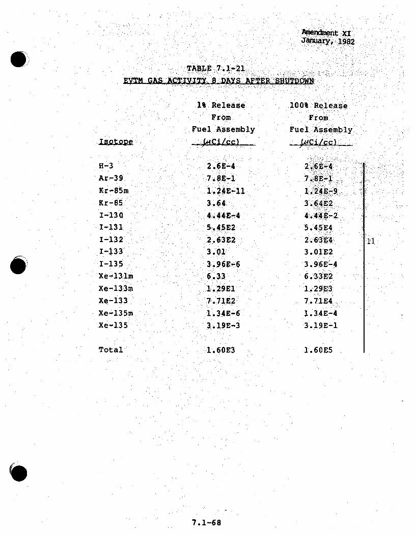
Amendment xiJanuary, 1982
EVM ps, AcT¶zIz~17f A -DAYS 6 TER spJDW
1 Release.
From
Fuel Assembly
100% RelIea-se
:From,
F~uel A,:ssemb'ly.
4~i/ cl-
H-3
Ar-39
Kr-85m
Kr-85
1-130
1-131
1-132I-.•331-135
Xe13.5
Xe-13i3m
Xe-133
Xe-135m
Xe-135
7 SE- 1
3,04:
3.1,
7'.71192
31. 19E" 3
2.ý6E-41ý.
1,24E-9
3.64E2
4.44E- 2
5o45E4
2. 63E4.1
3.01E2
3.96E"-46.3,3E26 1.429.4
7-.7IE4 ..
1.34EE-4
3 ..19E-I
1.60E5
*1I*1
Total 1.60E3
7.1-68

Amendment •XIJanuary;, 1.198'2 -
TABlLE 7.1-22INITIAL LEAKAGE RATE• THROUGH EV'rM iS'EALS ITO RCB/RSBo IATMOSPH•ERE- ' ~19
H-3Ar-•39
gr-85m
Kr- 85
1-130
1-;132
1-133
1-135
xe'131m
Xe-133m
Xe-135m
Xe-135m
Total
1% Re[•easeFr om
FU el ;.:ABs-emblIy
2.-36•E-14
6 .48E-1
7 • 07 E'3
9.3 1"E•9
3,049E- 2
3 .04El2
3.1!5E-9
•7 ,S0E-6.
3.77
100% Release•From
Fuel Assembly
.. i C~.iQsLi.
6.928E1l
3.04. -4
l.2 81E2".
93 15E-7.
7 .50E-4
3.77E2
'11I
7.1-•69•

Amendent xiJanuary,' 982
TABLE 7.1-23.
REACTOoR QVR GAS 3INVENTORY 30•:HOURS AFTER.: SHUTDOWN
Inventory
ýH-3 3 .4E-3Ar-39 10.0Xe-13lm 0.11Xe-133m .0,,23Xe-133 4.2 11Xe-135m 8.0Xe-135 2.5
Total 25.0
7.1-70
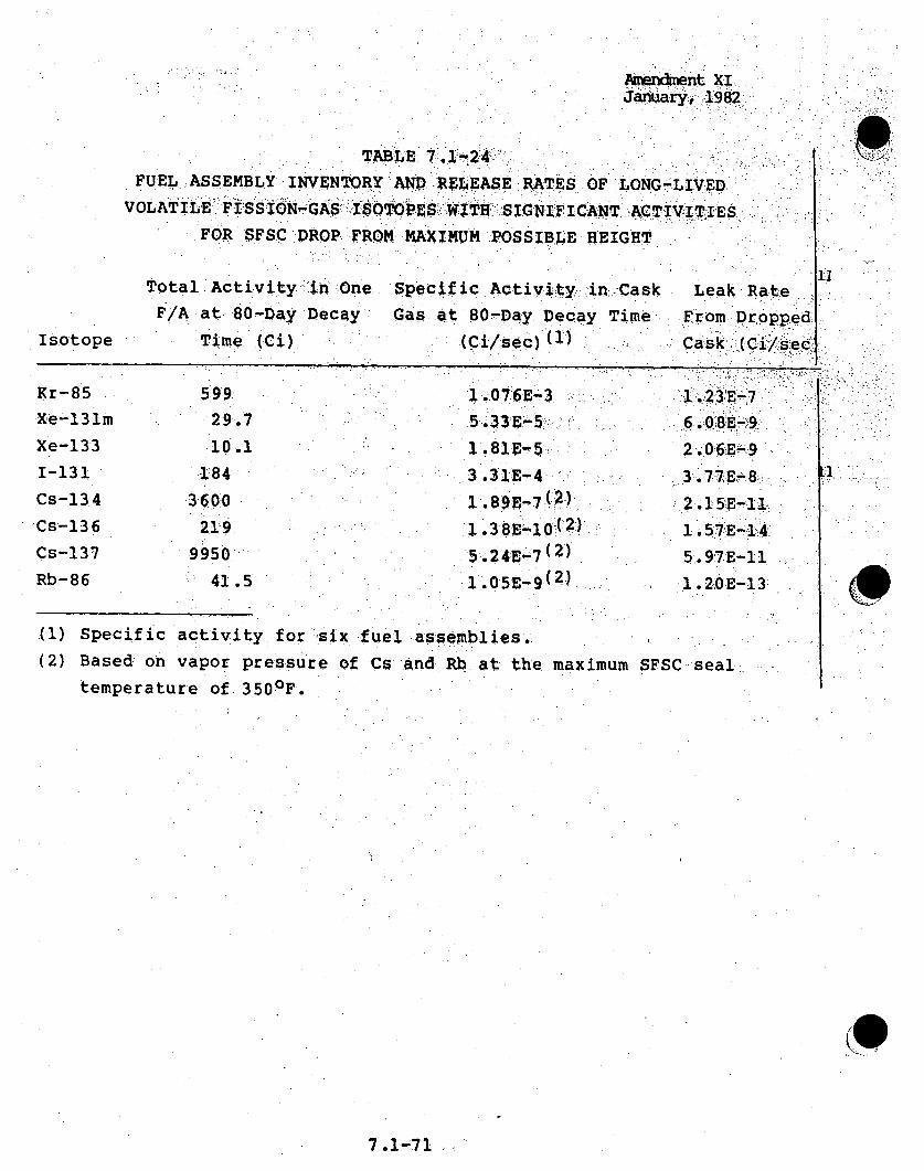
" " m"n•ment XI!Januar, 192
TABLE" 7124-
FUEL ASSEMBLY INVENTORY ANPD RELEASE R•TESý OF LONG-LIVED,
VOLATILE FISSION-G AS:I:SOTOPES ITH SIGNIFICANT AC TIVTIES
FOR SFSC ORoP FROM MAXI4MUM POSSIBLE HEIGHT
Total Activity "in .One Specific Activi--ty, in,;CaskF/A at 80-Day Decay Gas at 80-Day Decay Time
Time (Ci) (Ci/sec)(
iiLeak Rate.
From DroppedCask, ( C i/sec:i
IsotopeI
Kr-85
Xe-131m
Xe-133
1-131
Cs-134
Cs-136
Cs-137
Rb-86
59929.,7
10.1
1843600
219
9950
41.5
3 .31P-4
1 .189E-11 2)
1.324E 7( 2).
1.015E .-9 2)
1 5.2E-74
5.9:7E-111 .2<OE-1 3
1I
(1) Specific activity for six fuel assemblies.
(2) Based on vapor pressure of Cs andRb at the maximum SFSC seal
temperature of 350 0 F.
(0
7.1-71

Amendment XIJanuary, 1982
7.2 OTHER ACCIDENTS
Accidents of a non-radioactive nature have been postulated •for
all areas where potentially hazardous chemicals are stored. Inalmost all cases, the chemicals are concentrated acids and basesalthough some other materials present special problems. Itshould be noted that chlorine gas will not be present on-sitebecause sodium hypochlorite will be utilized for cleaning 1iipurposes in place of chlorine..,:
7.2.1 FIRES AND EXPLOSIONS
Minimum environmental impact is' expected from fires andexplosions. The only significant explosion hazard exists in thehydrogen gas storage area, l0cated. outi side' oppo6siite the, 'soudtheast 1corner of the Maintenance'Shop Warehouse. The total volume of.hydrogen stored on site will be 28,000 scf. An explosion-will 4not produce any hazardous gases or any significant damage to Lnearby buildings; thus, such an explosion will 'have no effect on.the environment.
The largest potential source of fire is from the two emergency 4diesel fuel storage tanks, located below grade:adjacent to theDiesel Generator Building. Elevation of the tanks is 796:feet+ 3 feet base, with plant grade at 815 feet MSL. As this fuel isstored below grade, the chance of an accident is -reduced. Thereýis also a concrete mat positioned below the tank. Any leakage is,collected in a sump and periodically pumped to the surfacethrough a pipe. The leakage will then: be collected andtransported off-site by a licensed contractor. There is no ilenvironmental impact anticipated as a result of leakage from thistank.
1"l
7.2-1

Juy1982
A list of chemical storage tanks is provided in Table 7.2-1. , . oiiof the chemicals, hydrazine.and liqukd ammonia, qir seclconsideration. Hydrazine, in pure form,-presents an inhalationhazard and is potentially explosive. The hydrazine on the Sitewill be stored as a 35 percent solution; in this form it is not*volatile, so both problems are eliminated. Liquid ammoniavaporizes upon release and therefore, presents an inhalationhazard. It willbe stored in a separate room with its ownventilation system; any leakage will be released to the exhaustof the Turbine Generator Building and diluted0 there. 'Ammoniafires are not possible below a temperature of 16,500...degrees. F( 1)so further protection is not necessary. Neither:hydrazine norammonia will have an impact on the Site and the surrounding area.
In the:Nuclear Island, thepstulated accidentscould involve " 1cryogenic materials or DOWTHERM..There are two' cryogenicmaterials, liquid .nitrogen and liquid argon, located in theReactor Service Building: . (RSB). Any leakage will!. quqic.klyevaporate and..the ventilation system will be designed such thatconcern over such releases is eliminated. - 11
The Nuclear Island of the CRBRP will utilize a limited amount ofDOWTHERM in several secondary cooling loops for cooling the Fuel 6Handling Cells and Primary: Sodium. Cold Traps. In, thisapplication, Dowtherm serves-as an intermediate.cooling mediumfor.separating the sodium associated with the Fuel Handling Cellsand Primary Cold traps from the chilled water used as primaryheat exchanging medium. The entire Dowtherm inventory will becontained in closed piping, systems; no Dowtherm will be stored inthe Nuclear Island.- .
Each cooling line containing Dowtherm will utilize remote shutoffvalves positioned on the lines to isolate and limit any leakages
7.2-2

Amendment XIJanury,198Z
that might be postulated to occur. In addition, the 0cooling."
lines will be sloped to assure collection into, small-pools .,alnd ..reduction in surface area of any leakages.
Fire prevention measures will provide additional guarantees -that
postulated leakage of Dowtherm will be limited and accommodated.
7,2.1.1 SODIUM: FIRES - NON-RADIOLOGICAL EFFECTS
Sodium fires may occur at the CRBR-P' Plant. Thman caombusa- oni. 'products of sodium are Na2 .. Na2 O2 , NaOHý., Nai and aCO. '.Su•.'
compounds as Na 2 0 and NaOH could be relteased ih e atmosphe• r '
as a smoke plume originating. from a sodium.fire.
Several sources( 1 5 ) have identified the cu.rre tl:y aclct' ie ... 8.
guideline for human exposure to NaOH as 'the threshold f limi:: t" a-luer-
(TLV) of two milligrams per cubic meter of air recommende'd•:, by -the-"i'" .
American Congress of Governmental Industrial' Hygienis (ACGIH. .8
A threshold limit value is defined as an eight-hour time-weqighte:d"
average concentration level under .which continuous. exposure wi-
not adversely affect an average human for an integrated exposure :
over a working lifetime .
Because of the .high affinity of sodium oxide (Na2o) for water, it8
is reasonable to assume that sufficient contact with atmospheric
moisture would have occurred when the airborne'plume reaches the
Site boundary to allow the sodium oxide to convert to other
chemical forms such as sodium hydroxide or carbonate.' The
assessment presented assumes the hydroxide form is present at the
site boundary. Laboratory experiments have suggested a value of-80 mg/m 3 as a limit for unprotected short-term exposure to sodium
hydroxide ( 5 ).
7.2-3

Amendment XIJaaUar, -1982:
Evaluation of the three most limiting potential sodium fire
accidents occurring at the CRBRP in terms o•f'expected•eodium
hydroxide releases and associated.concentration levels at"the
closest Site boundary are presented in Table'7.:2-2.
Cases considered in the overall evaluation include both
radioactive and non-radioactive sodium releases, Site-boundary-,
NaOH concentrations calculated for the non-limiting postulated
accidents are quite low, ranging in 'magnitude 'from- about 6-:i
mg//m3 to about 10-8 mg/mr3 . These levels are well below.the
.suggested TLV of. 2.,0 mg/in3 The. highert NaOH concentratio'n ývaluesestimated for the shorter time duration accidentsgiven in Table
7.2-2 are also at tolerable levels, as is seen by mpaison
'the short term exposure suggested limit ranges for' short durati'on
events. Specifically, potential Accidents 4.1 and 8'. bothhave
expected sodium hydroxide levels of about 1.7 mTgI/m 3 for durations
of two minutes each, and Accident 5.2 has an expected
concentration level of 8.0 mg/m 3 -for a 15-second duration.
The chemical form of the sodium combustion product before
reaching the Site boundary can be expected to be in a less toxic,-*
carbonate form due to reaction with carbon dioxide"in the
atmosphere. A method has been developed for predicting.this
conversion. 6) For the time scale involved before a postulated
release would reach the Site boundary, essentially complete
conversion to the carbonate form would be expected. I"n addition,•
the travel from release to arrival at the Site boundary is-.
expected to involve some fallout of the cloud. A depletion
factor of 100 has been applied for sodium hydroxide in its
transit from release to arrival at the Site boundary. This
factor will conservatively account for the expected chemical
conversion and fallout effects and has been applied to the:
non-radiological impacts of sodium releases.
7.2-4
Amendment XIJanury,19842
Expected off-site sodium hydroxide concentrations resulting from 8the potential accidents, such as those evaluated in- Table 7.2-2,are considered to be compatible with the suggested long term andshort term exposure limit guidelines. There is expected to be nolong-term adverse impacts to off-site public based upon theassumed releases of sodium combustion products at CRBRP.
7.2.2 OIL AND HAZARDOUS MATERIAL SPILLS
Minimal environmental impact is:expecte.d from spills of oil andhazardous materials. In the Balance of Plant (BOP), consequences 11of accidents such as tank rupture or leakage are controlled bysecondary containment systems. Secondary containment, sufficientto contain the capacity of the largest single tank...in thedrainage system shall be provided for all on-site tankscontaining potentially hazardous materials. When the tankstorage is outside, the capacity of the secondary containmentwill be increased to allow for the additional accumulation of .liquid from rainfall.
In the Nuclear Island, acid and caustic will be stored in theRadwaste Area of the RSB. The cells storing these tanks aredesigned to handle the leakage and are equipped with drains tothe collection tank in the Radwaste System. No environmentaleffects are anticipated due to any accidental release from thesetanks. A list of chemical storage tanks is provided in Table7.2-1.
As was discussed in Section 7.2.1, the largest potential sourceof an oil spill is from the two emergency diesel fuel storagetanks. These tanks are located below grade and anchored to areinforced concrete mat which is founded on and surrounded by

Amendment XIJanuary, 1982
compacted :Class A backfill. This mat will serve as a catchment inthe event wthat an oil leak occurs in either- o'1f:' the two ta~nks. ',,Anypercolated rainfall runoff or tank leakage will be collected din ia-sump and periodically pumped to the surface through a pipe. Anyleakage will be collected and transported offsite by a licensedcontractor. There is no environmental impact anticipated as aresult of leakage of these tanks. -'Lube -oil is stored in a singletank in the Turbine Generator Building. This tank is comprised of 2compartments; 10,000 gallons each. Secondary containment,sufficient to contain the capacity of the entire tank is providedwithin the building. Switchyartdand itransformer yard equipment 11
containing oil, i.e., tranSformers, cirrcUit breakers, and theneutral ground reactor, will have secondary containment systemscapable of handling and containing any oil spills associated -with,this equipment without adverse environmental impact. A list of oill.storage facilities is provided in Table 7.2-3.
All outside fill stations are provided with secondary containment inthe form of a sloped concrete pad, capable of holding the largesttank truck served at that station. If a spill should occur, thematerial will be contained at the fill station until it can bedisposed of offsite by a licensed contractor.
, £9
7.2-5a

Amendment XI
TABLE 7'.2" i
CRBRP Chemical Storage, Tanks.
.LOCATIOH MAX. STORAGE ST-ORAGE: VESSEL
Turbine Generator Building
Sulfuric Acid
Sodium Hydroxide
Ammonium Hydroxide
Hydrazine
Circulating Water Pumphouse
Sulfuric Acid
Sodium Hypochlorite
Radwaste Area of Reactor
Service Building
5,500 gal.
5,$,500, gal.
3,300 gal.
TBD
1 tanký,
1 tank
55 gal. rdum;
12,000 gal.
15,000. gal. ea.
1 tank
2 tanks
-i1
Sulfuric Acid
Sodium Hydroxide
150 gal.
2,500 gal.
150 gal.
I tank
2 tanks
Waste Disposal Bldg.
Sulfuric Acid
Sodium Hydroxide
Aluminum Sulfate
(Alum)
4,000 gal.
4'.000 gal.
TBD
1 tank
1 tank
Paper Bag
7 .2-6

TABLE 7.2-2
ESTIMATED* SODIUM HYDROXIDE RELEASES FOR REPRESENTATIVE POTENTIAL FIRE ACCIDENTS
Accident No.**
4.1
Descri pti on
Failure of ex-containmentprimary sodium drain pipeduring maintenance
Steam generator tube rupture
Duration,
2 minutes.
15 seconds
Aver~age'Concentration;
.(mg7m3
1 .73
PeakConcentrati on. '_(mg/m 3 )
2.54
4 85.2
8.1
7.953 x1 ' 7
Primary sodium in-containment 145 hoursdrain tank failure duringmaintenance
76.3 x 1O_
*Estimated sodium hydroxide levels at the closest Site boundary
**Refer to accident numbering in Section 7.1
f8
m~C~~
-H
hO
-. 4-4'-4
4
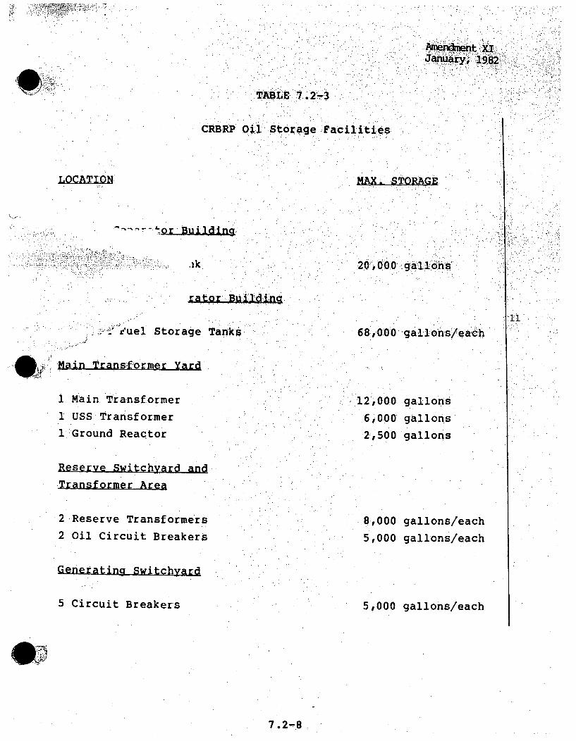
:AmI endnieht XIJanuary, 1982:
TABLE T aiite
CRBRP Oil Sorage Facilitie's
L~CATLQ1I MAX. STORAGE
20,000 gallons
raltor; BuIIlding
11i'uel Storage Tanks 68,000 gallons/eac•h
. Main Transformer Yard
1 Main.Transformer
1 USS Transformer
1 Ground Reactor
Reserve Switchyard and
Transformer Area
2Reserve Transformers
2 Oil Circuit Breakers
Generating Switchyard
5 Circuit Breakers
12,000 gallons6,000 gallons
2,500 gallons
8,000 gallons/each
5,000 gallons/each
5,000 gallons/each
7.2-8