"Reactor Safety Research Programs," quarterly progress rept ...
205
NUREG 'o 0688 BNL-NUREG S0978 0 h i i, r il si ij ii ?. I ; |. . REACTOR SAFETY RESEARCH PROGRAMS j 4 4 I< 11 !j H !| QUARTERLY PROGRESS REPORT h tI !' OCTOBER 1 - DECEMBER 31, 1978 ;. f. ; v $ {} i, li |1 s-t i 'i ! h, $ Date Published - March 1979 , $ i- i- ( U !> =: I! o ;; .t . | n I' ;; ni r, m e ,I fH W CLEla E M W E R 00 M.p, ,;, n n , a t t ; E n ; ;,i C a ,, Rk lI' [ k) . 1 1 ey t bi i j ,' , _ , , . . _. ! .ah~u3 . *i 1 ;j j j , - - ,<, t ,-1 - > ti i} r '? }i i, [{ ' |_ ._ . .__._ ____,.__ _...,_ _,,_ _..- ._, t____._ .. . _ . m . . . . . .._~___,:-... _..._.--~~.~a ,v } ta, . r t) D Q 9 * b D
-
Upload
khangminh22 -
Category
Documents
-
view
1 -
download
0
Transcript of "Reactor Safety Research Programs," quarterly progress rept ...

NUREG 'o 0688
BNL-NUREG S0978
0hi i,r
ilsiijii?.
I
; |..
REACTOR SAFETY RESEARCH PROGRAMSj4
4I<11!jH
!| QUARTERLY PROGRESS REPORT
htI!' OCTOBER 1 - DECEMBER 31, 1978;.f. ;v$
{}i,li|1s-t
i
'i!
h, $ Date Published - March 1979,
$i-
i- (U!>=:I!o;;.t. |n
I'
;; ni r, m e ,I fH W CLEla E M W E R 00 M.p, ,;, n n , a t t ; E n ; ;,i C a,,
Rk lI' [k) . 1 1 eyt
bii
j,'
, _ , , . . _.! .ah~u3 .*i 1;j j j , -
-
,<,
t ,-1 ->
ti i} r
'? }ii, [{
'|_ ._ . .__._ ____,.__ _...,_ _,,_ _..- ._,t____._ .. . _ . m . . . . . .._~___,:-... _..._.--~~.~a
,v } ta,.
r
t) D Q 9 * b D

NUREG/CR - C688BNL-NUREG - 50978R-1.4,5,7,8
REACTOR SAFETY RESEARCH PROGRAMS
QUARTERLY PROGRESS REPOR1-
OCTOBER 1 - DECEMBER 31, 1978
HERBERT J. C. K0uTS, DEPARTMENT CHAIRMAN
WALTER Y. KATO, ASSOCIATE CHAIRMAN FOR REACTOR SAFETY
Principal Investigators:
Ashok K. Agrawal Cesar SastreRalph J. Cerbone Donald G. SchweitzerOwen C. Jones, Jr. Daniel van Rooyen
Compiled by: Anthony J. Romano
Manuscript Completed - February 1979
DEPARTMENT OF NUCLEAR ENERGY
BROOKHAVEN IIATIONAL LABORATORY ~, ASSOCIATED UNIVERSITIES, INC.
UPTON, NEW YORK 11973
Prepared for theReactor Safety Pesearch Division
Office of Nuclear Regulatory ResearchU.S. Nuclear Regulatory Commiscion
Contract t'o. EY-76-C-02-001bFIN Nos.
A-3014 A-3024A-3015 A-3041A-3016 A-3045
A-3203
4 / ;/ IsJ

fl0TICE
This report was prepared as an account of work sponsored byan agency of the United States Government. t;either the
United States Government nor any agency thereof, or any oftheir employees, makes any warranty, expressed or implied,or assumes any legal liability or responsibility for anythird party's use, or the results of such use, of any in-formation, apparatus, product or process disclosed in thisreport, or represents that is use by such third party wouldnot infringe privately owned rights.
The views expressed in this report are not necessarily thoseof the U.S. i;uclear Regulatory Commission.
Available fromU.S. fluclear Regulatory Comission
Washington, D.C. 20555
/ / ') i ,| iAvailable from4 'T;ational Technical Information Service '
Springfield, Virginia 22161

FOREWORD
The Reactor Safety Researr.h Programs Quarterly Progress Report de-
critJes current activities and technical progress in the programs at
Brookhaven National Laboratory sponsored by the USNRC Reactor Safety
Research Division. The projects reported each quarter are the following:
Gas Reactoi Safety Evaluation, THOR Code Development, Code Review, SSC
Code Development, LMFBR and LWR Safety Experiments, Fast Reactor Safety
Code Validation and Stre'; Corrosion Cracking PWR Steam Generator Tubing.
This report is the ninth of a series of quarterly reports which com-
bines the reports of the individual orojects mentioned above. The previous
reports, BNL-NfJREG-50624, BNL-NUREG-50661, BNL-NUREG-50683, BNL-NUREG-50747
B1L-NUREG-50785, BNL-NUREG-50820, BNL-NUREG-50883 and BNL-NUhEG-50931 have
covered the periods October 1, 1976 through December 31, 1978.
|} | ') !. |

Tj@LE_OF_ CONTENTS _
Pace
FOREWORD iii
I. HTGR SAFETY EVALUAlION 1
Sunrary 1
1. Fission Product Release and Transport 4
1.1 The Release and Transport of Fission Productsfrom Therrelly Failed HTGR Fuel 4
1.2 The Reaction of Csl with HTGR Materials 7
1.3 High Temperat';re Mass Spectrometer 12
1.4 Aerosol Formation from Graphite at High Terperature 16
1.5 Experirental Studies of Core Heatup Phenomena 20
1.6 High Terperature Vaporization Studies of HTGR FuelComponents and Fission Products 21
1.7 Interaction of Cesium and Tellurium with FusedQuartz 23
Publications 2:
References 24
2. Materials , Chemis try, and Instrumenta tion 26
2.1 Faticue of Structural Materials 26
2.2 Creen Pupture Properties of Primary Circuit
Structural Materials in Air and Helium 37
2.3 Ef fect of Fission Product Interactions on theMechanical Properties of HTGR Metals 45
2.4 Materials Test Lcop 48
2.5 Large Scale Graphite Oxidation Loop 48
2.6 Felium Irpurities Loop 49
2.7 Chardtterizaticn of ?GX Grouhitt 50
k
T AAL E_ _0 F_ CON _T Ef(T S_
FOREWORD
I. HTGR SAFETY EVALUATION
Summary
1. Fission Product Pelease and Transport
1.1 The Release and Transport of Fission Productsfrom Thermally Fa led HTGR Fuel
1.2 The Reaction of Csl with HTGR Materials
1.~ High Temperature Mass Spectroraeter
1.4 Aerosol Formation from Graphite at High Temperature
1.5 Experirental Studies of Core Heatup Phenowna
1.6 High Temperature Vaporization Studies of HTGR FuelComponents and Fission Products
1.7 Interaction of Cesium and Tellurium with FusedQuartz
Publications
Re fe ren ces
2. Ma terials , Chemistry, and Instrumenta tion
2.1 Fatique of Structural Materials
2.2 Creep Pupture Properties of Primary CircuitStructural Materials in Air and Helium
2.3 Effect of Fission Product Interactions on theMechanical Properties of HTGR Metals
2.4 Materials Test Loop
2.5 Large Scale Graphite Oxidation Loop
2.6 Helium Impurities Loop
2.7 Characterization of PGX Graohite
kY b vr

Page
? :, Instrurwntation and Control Systems 58
Publications SP
Peferences 60
3. Structural Evalu.itinn 62
3.1 Core Seismic 62
3.? Develornrnt of OSC3D Con:puter Code 65
Publications 70
4. Analytical 71
4.1 HTGR Code Library 71
4.? Containment Vesr,el Gas Dynanics 71
4.3 Fission Products 79
4.4 A Study of Flarrability under the Influence ofLaroe Ignition Sources 82
Publication, 82
Reference < 83
II. L"FCP SAFETY EVALUATION 84
Surr try 84
1. Fast Reactor As>esseent - Accident Sequence Studies 86
1.1 Hydrodynanic Characteristics of Two-Phase DispersedSyste: s 86
1.2 Liquid Dispersion in Internally Heated Coiling Pools 89
1.3 Boilino Pools with Internal Heat Generation 96
Pe fe rences 101
3. SSC Code Developcent 102
3.1 SSC-L Code 102
3.2 SSC-P CoJe 131
3.3 55C-5 Code 134
.f 4 JEvi
Page
Publications 136
Peferences 136
4. SSC Code Validation 137
4.1 Intercomparison of SSC-L with IANUS 137
4.2 Analysis of Thernohydraulic Experiments 144
4.3 Intercomparison of SSL-L with BRENDA 144
P u'1 ' i c a ti on s 150..
Peferences 150
III. LIGHT WATER REACTOR SAFETY 151
Summary 151
1. Light Water Reactor 'hermal/ Hydraulic DevelopmentProgran 153
1.1 Analytical Madeitng 153
1.2 Test Sections and Seal Development 153
1.3 Global Densitometer 154
1.4 Flashing Experiments 154
References 173
2. THOR Code Development 174
2.1 Component Modeling 176
2.2 Process Modeling 176
2.3 System Modeling 179
2.4 Developmental Verification 180
2.5 Nuterical and Analytical Modeling of the N-zoneStability Problem 182
References 187
4. Stress Corrosion Cracking of PWr. Steam Generator Tubing 188
4.1 Laboratory and Apparatus 188
a.2 Results 188
vii
479 146

I
1. HTGR SAFETY EVALUATION
S1mMARY
Rel. ase of tission pr oduc t s from thermally failed TRISO coated UC2 part-teles duriny a t enpe ra t ure ramp experinent up to 2600 C established that Csl was
not present. However, fission products cesium and iodine were found to be pres-ent in srveral chentcal forns. The cesion deposited at t empe r at ure s >1000 C,
while the todine band lay at 200-450 C
Low flow experiments ver t fied the formation of Cr,Cr04 from Csl i n exper"inents with air and chronian alloys. Dissociation of CsI was also found to oc-cor with air only; the reaction appears to be f acilit ated by the presence ofcarbon steel.
Cs3 -graphite sys t en. preliminary resultsWork has been initiated on the 0
indicate that Cs30 is readily reduced by graphite to forn CO and Cs . Work onthis syst en will continue within the t empe rat ur e capabilities of the presentfurnace
H451 graphit. s am p l e s have been heated to 1600 C in both dry 2nd humidtfledhelium. The sample weight loss and the particle size dist ribut ion of the aer-oul evalved during heating in dry helium have been measureG Most of the san-pli w~icht loss was found to occur during the initial heating period coincident-1) with the highest particle concentrations. proloneed heating in pure heliumdia n>t ' ant ribut e appreciahly to the overall weight loss. The pa r t i c '. e s evolv-ed initiall, are very small (0.02-0.03 ;m diameter) and ext remely monoaisperserhis finding is conststent wtth a format ion nechani sn involving eva parat ion andcon!-nsation processes.
Subsequent heating of a s am p l t to a 'ower temperature after outgassing indry helium !id not pr od uc e an i n t t. i a l h u r t of particles. The introduction ofwater vapor into the carrier gas consistently produced large quant it ies of CN.At h i ch t emperat ore and h igh wat e r va po r concentration, much coarser g raph it eaerosols were observed. Such particles are the result of destructive oxidationand ar+ forned by physical iegradation processes.
The attachment of fission products to Aitken nuclei could be o f great in-
part ance durine a reactor temperature excursion since they are in t he best pos-sibl. form to e s c a pe deposttton.
A batch of 50 BISO coated Th02 fuel part ic le s was heated to 2560"C for Ihour to d e t e rm i ne whother failure was likely for temperatures belos the nelting
% failures were observed. This strongly indicates that in-point o f ThC3ternal pressurization within the particles, caused by CD formation when theItquid carbide is fo rmo d , is the principal cause o f f uel failure
A wet chemi st ry t echnique has been developed to measure the nalybdenna con-centration gradients in H451 graphite exposed to liquid Mo2C Compared totechniques used to date there is a significant increase in the detectton ofmolybdenum and a decrease in the amount of scatter in the data.
479 147

,
A progrm,has been initiatef to obt ai n va por i nat i on dat a up to 1000"U onuil .it ial f i s s i .in [.rinluc t s , s i l i c <in ..ir h i de .ind u r .in i sin .i n d thorion i>xide .ind
carhides in the pre ence of c.r a ;,h i t e This progran wilI h. -loselv coardin.e.o!
wi t h the <or. he.it up progren.
%, .it t ack h.i s so f .t r been observed on tused quart ? .i t 740"C fran 1500 h o u r *.
( lO'N atn.). At t .ic k h.a s01 exposure t in cesium va po r at very low pre suresbeen observed on tus.ul quart. at 800'C from exp is ori for 1900 hour, to tellurion
v .i ps i r at a pre ssur e o: 10-5 aln.
I onc t erm hi gh y:1 taligue t est ing proceciled on incolay XOOH and Hastel-
lov X. The new dat a tend to confirm t h.it .i t verv lone test time, the oxidation
of sp :imens expased to a s i mulat ed HTGR he li um e n v i r o nme n t become sul ficient lv
s infli f iC ant es) C .t ti s t' .i it * c r e'.i S t' in ( 114' f .it i nin' s t i t* ng t li . At l iin ge t t1"D's the
hen. f ic i a l e f fe:t s of the brlium environment di< appear and the f .it i nne st rengt h s
of the 7 na t e r i a l s in helion decrease to those obt a i nmi in air tests. Th e rm a l l y
aged s pe:: inens have been t est ed this p..tod. For an aging t i ne of 1000 hours in
H D;R helton Incolov 800H shows .i drop in strength of thout 7 0 '.'. c om p.i r ed to non-
acol ma t e r i a l . On the other h.ind , Hast elloy X is not a f fec t ed hv this aging
t r cat ment ,
f r ee p-r u pt or. testing of Incolov 800H an1 Hastelloy X is cont i nui ng in air
.in ! in a simulated HIER heltum environment. The st res s-rupt ure p r o pe r t i e of
c!?rht!" !aw-:.o oios sni a t (, 4 ,% ( 1.' 0 0 " F ) ire milar far E 'h. ' . - .
er rupt ure strengths wer. observed for Incolov HOOH at M 0 '' C (1400"F). However,
the :reep strengths of Incoloy 800H were nat a t fec t ed by the env i ronnen t s atbot h t enpe r a t ur e s s t u lied . For H.is t e l l oy X, 41tyhtly lower st res s-rupt ure
s t rone t hs we r. observed when tested in helium at 760"C (1400"F) ani .i t 8 71 'C(1600"F). The c reep st rengt hs ct H.is t e l l oy X t e st ed at either of t he temper-
. -n ta he nn.i f f ec t ed hv e nv i r o na"n taturcs s t u ! t e 1,
The first yi ou, of exposures of HTGR .il l ov s to the simulated itssion
prodo:t s 1 7, Tey, ani Csl at e l ev.it ed t emperat ures has been completed.was observel on the sample < and n.istSignititant tission product de po s i t t on
showe l eviden:. of orrosion when exami ned wi t h the sc anni on e lec t ron mic r o-ope Bend tests have been c om p l e t ed and met.illographic s t ud i e s a r. procer-
.ii np
The Ma t e r i .il s Test Loop functioned rout i ne l v dur i ng t h. quar t e r except for
an lK hour m i t .ig. cause i hv a regionwide power failure no ir the end of the l
n. in t h period. This was the first shutdown since the MTL was put into <ervice 18
nooths .ig o . Ouring the <pi ir t e r the performan:. of the loop exc.eded tts own re-
or d from any previous r e po r t inn period.
A studs was i n i t i at ed to Jevelop an opt ina l destyn for a 1.i r g e scale graph-
it. oxidatton l oo p . Such a loop would e x pos. 10 i nc h d i .ime t e r graphit. ..i a p l *
t.. he1iu, .i t 1 Hun" F a nd .it 50 itnosphere The impuritv 1 eve' l - w,iuld b. n.in1-
tored an1 ontrolled and the overal1 design 1: pred i c.it ed on .i E depl et t on in
w.i t e r v a po r on :en t r.it i on as the heltun traverse, the s.e,pl. A q uot .it i on for
an ene i nee r ii 'esini of the heltun :i rculat or w.i s obt a i ned from Wchani al
A ~~ Q 4 * 1lj / 3'
._

3
Technolo. Inc (S130,0u0). A budy.etary est inat e for the f ab r i cat ior. , s; obly,testinc and d e l ivt r'. of the circulator, notor, exciter, controls, etc. vas alsoreceived ( % 0.000).
Thi Helium Inpurit les 1.oop was used to 4tudy the thermodynamics of reac-tions involviim helium inpurit ies with the retort material. A model has beentornulated which is consistent with experimental observations in the fulls oxi-dized and fully reduced conditions of the loop invest igat ed so far, lxperimentsto determine hydrogen diffusion rates through the boutMaries of the loop haveimen perforned and the results have been correlated.
'l h e l!elium Afterglow Monitor has arrived from I.ASI. and is currently beingrepaired. Additional instrumentation was ordered for the " quartz" loop and in-frared absorption detectors were purchased to monitor water vapor levels in theloops.
Irregularities have been observed in the effects of burnoff and flow rateon tin oxidation rate o: PGX graphite, The oxidation rate of one spet in<n was
observed to decrease with long tern exposure to H;0 + H7 (Pg /pg 10) in lie=
while the reaction rates of other specimens continuously increasNl with increas-inc flew rate Generally, however, the behavior of specimens toward long termexposure to H,0/II; m l> t u re: and to variable flow rate was as expected.
Some evidence is provided which indicates that removal of iron fron graph-h!"h < ," centration of the i p"rit"rrmt !- f ac i l i t :'' -! b'* - ' '
',' o effect of conpressive prestress on the ultinate compressive strength ofocidized PGX graphite has been found. Specimens were prcstressed up to 0.75 cand oxidized up to W burnoff in a He atmosphere containing 22 11: 0+ 2 0 % 11 ;
omaintained at 680 C.
Small scale depressurization experimei's have thus far shown little or noeffect of container vessel shape on overall nixing behavior. Binary gas sam-plino for sene selected runs confirm mixirg behavior that has been observedvisualls Mathematical modeling of ranid cepressurizations witoin the small
-
scale experimental model using the RICE code is continuing Numerical problenshave been identified and reans for modifying the code are being investigated.
The ORIGEN code has been used to calculate the fission product inventoriesrenerated in HEU and MEU 11ssile fuel particles. These have been compared withthe results of GA-Al3886 and GA-A14980 and reasonable agreenent is obtained for
the najor fission products
l'abrication of the three-dimensional vibrations test rig has been conpleted,and shake tests of three-dinensional block arrays will connence shortly. Anevaluation of the forces induced in the core elements during a seismic event has
been undertaken. The OSCVERT code is being used for this analS als The develop-
"ent, debugginc, and proof-testing of the OSC3D code continues.
b. . , r,

4
1. Fission Product Release and Transport
1.1 'I b e Release an1 Transport of Fission Products from Thernally- ~ ~ ~ ~ ~ - ' ~Failed firGR
gu;I|Tv.8 Growcock, s. Aronson, R. p. TaylorT
The st ioly o f t he chemical states of fisston product s released from ther-mally failed ilTGR fuel was continued. The thermochromatographic technique em-played (Castleman, lH 7) was modtfted to permit invest t rat ton of relat ivelynon-volatile s pe c i e s , as de.,c r i b ed in the previous quarterly progress report(Gromock, 1978). Iloweve r , the design of the h i gh t empe r a t ure region, wherein
the fu'l p art ic les are inductively heated, proved unsat i s f ac t ory. Diffusion ofreleased fission produc t s out of the graphite susceptor into the surroundingcarboa black insulation precluded detailed analysis of the data.
An expertment d,staned to alleviate this problem was conducted this pastqua r t er . A tantalun tuhe, kindl y donat ed by C L Smi t h o f Gene ra l At oni c Co . ,
was used as an inner liner far the F14 51 gr aphit e susceptor; it ran the lenet h ofthe high tenperature region (2;00"C-H M C) and ext en irl several c e nt ime' e r s int o
the low teuperatur. region (800'C-25 C). The t ant alum was exp cted La serve as
a barrter for t h. Iow levels of fission prod u'_ t s released f r em the H '. 51 graphit ecrucible po s i t t oned w t t h i n its walls The graphite susc. 'r was ke pt to serve
physteal barrier to impurities in the cachon black insi;ation that woeldas atend to nt/cate through the t ant alum into the fission product s t r e ar A t a pe redji> t nt het wee n the h t );h a nd low t emperat ure regions pr ovided a ga s ttyht fit to
prevent back diffusion of fission product gases fron the low temperature regioninto th. carbon black insulatton. The cructble was also nodified to ensure thatthe particles did not move during heating. An H451 graphite plug was placed incont ac t with the cructhle to serve os a target for the opt teal pyroneter. A pv-rex trap, designed to fit the 0.6 3 cm slit of the gamma detector, was packedwith activated charcoal and maintained at -196 C; it was attached to the extttube of the low temperature region via a greaseless joint. The ext ended pr e p-aratorv procedure used previously for packing the reactor was followed.
Three TRISO-coated UC7 part ic les , prevtously trradiated at GA, were re-irradtated in the BNL HFBR (nominal flux 'l 010 nbutrons/cn -sec) for I hour2
to regene r it e short lived radtonuclides; this has an instgnifteant effect on the
fuel particle fission product inventory, yet is an effective method for tegningmany o f t he elements of interest. As to the previous experiment, only quartzwan used in the low t empe r at ur. region. Airco high purity He was passed over a
nettering furnace at 150 cn3/mtn. to redo:e n, and H,0 t o 0.1 p pnv . Thecructble was heated to 1700 C over a period of several hours, then t aken up t o
2500"C at a rate of 200 C/ hour. The ganna ac t iv i t y o f t he particles was mont-
tored directly; although the ganna ac t ivi t y decreased cont inuously with increas-ina t emperat ur e (apparent ly an art i f ac t ), fuel particle failure could be notedby a sudden drop in canna activity. Failure of all 1 particles dii not occur at
so the t empe ra t ure r am p wa s continued until they did fail at an apparent2500 C,
target temperature of 2600 C
The activated charcoal trap showed considerable act tvit y at low gamma ener-gtes. Very low levels were observed abov. 80 kev, however. The 512 kev trans-itton, arising fran 85Kr, gave a maxinun act tvit y of 20 counts /lO ntn.
p- , -t.
. a

5
( h a:k c r ound 2-5 caunt s/10 nt n. )
Sinn interest has been focused on the chemical foru.s of fisstan productsrs ani I. the activities of I37Cs and Ill i along the thermochromatographw"rv measur"d. The results ar" plotted in Figures 1.1 and 1.2. The absence ofdefinite peaks for the 2 r lionuclides in the t enperat ure range 500-650 C (55-75cm) i nd i c at e s that no Cs1 was pr e sent . This is consistent with the results fromthe first experiment with unreirradiated fuel particles (Growcock, 1478) inwhich no leposition below IOOO"C was observed. However, thts is contrary toL a me exp.:tattons (+.g Gotznann, 1974). Elemental ftssion produ:t inventory.stimates give a weight ratto o f c e s t un to todine of 10/1 (Skalyo, 1978), i."ES' of the cestu, may be chentcally bound to the todine The sensit ivity of theGe(Lt) detector to 137Cs is better than 0.0l? so there is little doubt aboutthe result. Eq uilibri um c alc ulat t ons for the dissociation of CsI(g) nonomrr
10-4 at 2500"C, wtitle aItve K 5 x s l i gh t 1:, lower value is obtained forgqthe diner (Feber, 1977). Given that the parttal pressure of Cs! is suf ficient lylow, a s igni fi c ant amount of decomposit ion of Csl can be anttetpated.
The : om p l e x 137Cs spectrum (Figure 1.1) was not e x ree c t ed . A t empe ra . e
p r.i f i l e of the high temperature region was a t t "mpt ed in a 'ry run pr or to it-wrt ion of t he fuel parttcles, using a W/2C ke t hei macco pl e The target temp-erature was 'ncreased t, ' iO C ' ' , while the het zone in the low temperature re-
clan was ke pt at 800 C At hizh target tenperatures (31500 C) the t h e rmoc o u p l ebr un to cive realings thit were considerably lowr than the optical pyrometeralurs. Owever, the pr o f i l e e st ab li shed up to that po i n t left no doubt that
below 25 cm the temperature was >1000 C. Dissection of the h tgh t emperat ure
region showed that all the activity beyond the " heated region" was confined tothe tantalon t ub e It was noted that the t ube became welded to the 'raphit esus:rptor. The ganna spectrum of the t ub e was al so obt ai ned for comparison withFi gure 1.1. It ts essentially identical to Ftgure 1.1, but the shoulders at15-17 cm and 22-24 cn are absent. Further analysis of the gamma spectrum isdesirable
nepositton of todine at 200 to 450 C (Figure 1.2) was not conpletely unex-pected. Previous the rmochromat ographic work wi t h irradiatra netallic fuelsheated to lower t"mperatures than employed here showed that 2 distinct toatnepeak s wore f o rned in the above mentioned temperature range (Castlenan, 1970).The authors interpreted the peaks to be physically adsarbed urantum todidecompounis. In our work Ta is present also, which night form volat ile todides.The quartz t ube in the region 200*-450 C is currently being divided into 1sections and prepared for neutron activation analysis to ascertain thetd"ntitles of the deposits.
The next experiment will i nc o r po r a t e a carbon steel liner in the l ow t emp-e rat ur- region to examine its ef fect on fission product depos it ton. A few fur-ther minor modi ficat ions of the apparatus are planned.
, - r\/p- / &,
't ! . J

h
H 0 0 4.; r ,
! A
is no -
i,
, e,0 41..
'
I 5000|. ' , r
u
4000I>-* 6
'vi.- |
,$ 3000|i i
-
2000' HE ATE D [,
l Rf GiON *w 9 .
|000} *g
\** CHUC6tRE '*
L ' ' W'^ **** i 1-C0 5 10 3 ?O ?S
P OSI T iCN, c m
Figure 1.1. Ih posi t ion profile of I 4 '' C 3, released from thermally tailed~1RISO l'C particles Substrate is Ta maintained in a temperature gradientot .' e > 0 0 C to 1000'C
900r r r]900e i T r i i 1- t * 1 '
! l
8004 x160|-
g 1800c- x y
E 700 N !40' 70 0 oe 'N | }/ .
*
\) GCO 12 0- [ ]600 |p'sc,
. x ,,o ' O0- N jbOO ti;
! IN j 0
400- 80'- N 1400 !!J'
t - ts I_ j'l -.v3 |
N 300 O'- 300--- 60w x-F-
~ 200- 40- 1200! N|i 1
' x ilOO20'- /'- -
100- .k% , . - .- m.[,_ y. r. 4 ._.m.1! \t
g: ,5,o
2 35 45 $5 65 75 85 95 105 115 |2b 135145POSITION, cm
Figure 1.2. liepos i t i on profiles of I ' '' C: and I'l l released from thermallyl'alled TRISn UC p.i r icles Substrate is t us ed < pia r t z n;ii n t a i ne<t in at e:;.pe ra t u r e grafien' of 800 C to 2 ') C
'
|t I ', -
<-
< )/ \ ;L
/
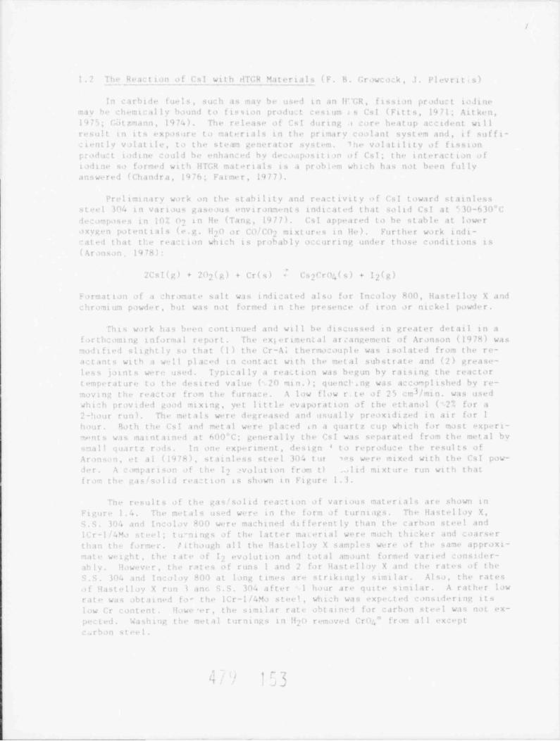
!.2 The Reaction of Cs! wi t h dTGR Mat er i a l s (F. B. Growcock, J. Plevrit s)
In carbide fuels, such as nav be used i n a n li"GR , fission product to finen iv be ch. mic al l y bound to fiuston product cesium <s Csl (Fitts, 1471; Ai t ke n,
1775; G3tznann, 1974). The release of Csl during a core heat up accident wtllresult in its exposure to natertals to the primary coalant sy s t em anii, i f su f f t-: lent ly volat ile, to the steam generator system. 1he volatility of fissionpod uc t todine could be enhanc ed by deco.aposit i an o f CsI; the interaction ofi o li ne so f ormed wi t h H rGR mat e r i al s is a problen which has not been fully
answered (Chanfra, 1976; Fatmer, 1977).
Preliminary wark on the st ability and react ivit y o f Csl toward stainlesss t. el 304 in various gaseous environments indicated that solid CsI at 630-630*C
lecomposes in 10; 07 in He (Tann, 1977). Cs1 appeared to be stable at loweroxyg"n potenttals (e.g H0 or CO/ Coy mixtures3 in He). Further work indt-atel that tl.e reaciton which is probably occurring under those condittons is
(Aranson, 1978):
'
2CsI(g) + Cr(s) - C32C r n4 ( s ) f+ 202(g) 2 E)+ 1
sormation of a chromat, salt w as indicated also for Incoloy 800, Hastelloy X andchromium powd-r, but was not forned in the presence of iron or nickel powder.
This work has been cont i nued and wil l be discussed in greater detail in a
forthcoming informal r e po r t . The exiertmental arcangement of Aronson (19 78) wasmoitfied s l t aht l , so that (1) the Cr-Al t he rnoc ou pl e was tsalated from the re-
actants with a woll placed in contact with the netal s ub s t r a t e an1 (2) crease-
less joints w-re used. Typtcally a reaction was begun by raising the reactortemperature to the destred value ( 20 ntn.); quencF.ng was accomplished by re-moving the reactor from the furnace A low flow r.te of 25 cal / min. was usedwht:h provided good mixing, yet little ev a po ra t t on o f t he ethanol (- 21 for a
degreased and usually preoxtdized in air for I2-hour run). The metals werehour. Both the Cs1 and metal were placed in a quartz c u p wh i c h for mos t expert-vnts was maintained at 600 C, generally the Csf was separated from the metal bysmall quartz rads. In one experiment, design to reprodu:e the results ofi
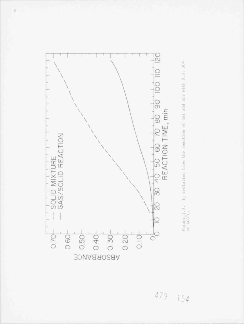
Aronsan, et al (1978), stainless steel 304 t ur ws were mixed with the CsI pow-
Jer. A comparison of the 12 avolution from tl . lid mixture run with thatfro- the gas / solid reactton is shown in Figure 1.3.
The result s of the gas / solid reaction o f var ious matertals are shown in
F i g.o r e 1.4 The n~tals used w"re in the form of turntags. The Hastelloy X,
i.S. 304 and Incolov 800 were machined di f ferent ly than the carnon steel andICr-l/4Ma ste el; tu nings of the latter matertal were much thicker and coarserthan tho f o r m" r /1though all the Hastelloy X sampl"s were of the same approxt-
mate weight, the rat + of 12 evolution and total amaunt formed varied consider-ab l s However, the rates of runs I and 2 for Hast elloy X and the rates of t he
S.S. 304 a n<l In:oloy 800 at long times are strikingly similar. Also, the rates
o f Hast olloy X run 3 anc. 9.S. 304 a f ter 1 hour are quite sintlar. A rather lowrate was obtain"d fo- the ICr-1/4Mo steel, wh ic h wa s expected considerton its
low Cr content. Hawe er, the similar rate obtainci for carbon st. l was not ex-
pNted. Washing the metal turntogs i n !! 0 removed Cro " from all except2 s.rban steel.
y '/ l '~ 3u Ja
F
Oj i ji i i i ' i ii
_ - N\
-
\_ aO
-
\ = :,':- \ - o g_
\ O\ --
;
\~
m
-
\~ O
m ?- \ - ,_C
'
\_
\_ OE 3m _ _
_ g - g c
\ _ Os g_
Z x rN-- O - Hs W_ F \
- W O e
Oz 2O N
hF_gW \ - O g
_o m g g<s -
Ho x W c-X- N - O Z a-J'- 1 O -T ex
N iW-o \ @ t-]w \ ;
-
O <t \ _.~WO b\- ~
- , -u
_I - O E8n'- -
C#I i l j ioi i i i i i
O O O O O O O oN_ W o e r0 N -
O O O o o o O
3DNV8BOS8V
4 7 ') 134

c)
-
4', ' A % . t - . s't-
'^
44 i
W{' g *%,
,q , _ ;crrr,, ,. -
, ,
ui.. % . vt -
Nac t on (4 CsI (g / imd ai r wi th sa ri or.sr .i a1 $t t>oo
i i i i I i i I' ' 1 I
'|
' Ii
_' _
uJ O.40-
o- .:z '
4 0.30 HASTELLOY X '.-
.j -
/
8 0.20- INCOLOY 800x
'-
/-
CD -
-'
4 o|o -
,,,,.- -
'/
-
-
/l i Il iI i I i I i i iI i l I i.
O 10 20 30 40 50 60 70 80 90 100 110 120__
REACTION TIME, min
Fine.e 1.5. I; evolution from the reaction of CsI(g) and air with stackr :'J im as "+ Hautellov X and !nen!nu uno at 600'c
| 1,sG

10
1.o n g inlo: tion pe r i o.!s we r . noted ior .a l i the runs, incloding t h.it wi t h uit
tal, .in lne t .i l . N.i indo:t t on perlod was not ed for the Csl + N3 run with no meno etiect w.s s observed when Ihe ilow r .it e w.i c iucte.1 sed by XlO; however, the.ib s o r b.or i was too low to say with a s s ur.in :e that it w as 5 ent. A hino ilowrate run wi t h H.is t e l l oy X showed that di ! t u s i on.il flow was probabl y t h. ause of
the long i nduc t t on pe r i od < in f .ic t , the e x pe r i me n t a l conditions .i r e such t h.it
t, in the r e.ic t o r is virtu.ilIv < on s t .in t , so t h.it equilibriun is :loselvP
a p p r o.ic hed . Thus, .i given value for the rat e of 1 7 evo l ut t on corresponds to .i~
value of Pg, in t | .e reactor which is onlv .i little lower than itsequ i l i h r i um' v.il ne
in the Csl + N7 run w. i " quit. low, probably onThe r at e of 1 7 evo lut iont he order of the e x pe r ime n t .il unc e r t .ii n t y . A ;imilar run wi t h lie in pl .ic e of
Ny gave .i n absorbance of 0.015 at 2 hours, compared wi t h 0.02 0 for the Nyrun. An almost identical rate was obt ai ned wi t h fla s t el lov X, Csl i n<! 2 . O *. H,0
2fI H2 in Ib' 1, i k e w i s e , .i run wi t h llast e l loy X, Cs! .i n d N7 c .t v e .t h ou t the+
s .in e result .i s tI e run withaut me t .il .
The e x pe r i nent wi t h Csl + air in the absence af net al n.i v e rise to a low
r ;t e , but definitelv hagher t h.in the e x pe r i me n t .i i unce r( .t i n t y . Thi- t- con-,istent wi t h the .itbon steel resolt. The resolts from the 2 exper: ment s.
i nd i c at e :t .i r e.l? t s o n , other t h.in the .i t o r eme n t i one d f o rma t 100 of Csf r(9 .may occur eetween Csl an ! 03 The c.irbon steel (Fe70 3) mii v simply be an
a :t ive s ur f.ici u po n wh i c h the reac t ion is f ac t i t t ated , i.e a c at a lys t .
Tang, et al (1977) observed no decompos t t t on of Cs1 on quart > cxpased tolui O, in th- However, the re.ac t t on temperature was Iower, 4 7 5-5 50"C , f ut -therdre, these workers were looking for qu.ili t at t ve etfects Anot her .i r g umen tigatost the present results is the .i p pa r e n t absence of a v i .ib l e reaction. For-
mation of oxt le s appears to be cont raindicat ed on thermodynamic grounds. Ex-
per iment .il evidene. s u p po r t s this: the pH of the solution obt .i n ned from washing, o m. turnings w.i s identical to t h.i t of dist illed H 0 It was e x pec t ed t h.it7
11 0 if it had been generated. A n.iss balance ofCs o would form Cs0H in 7s y
the react t on is c ur rent l v bei ng done wit h Hasrelloy X mid carbon steel. X-rav
diffraction of the surface lavers of a reacted c .i r bon steel sample will also bedone t.i he1p ident i f v the cesium spectes presume! to be on its s ur f.ic e
Tne almost equivalent rat e s of 1 2 evolutton observed for the high chro-mtu, steel t ur ni ng ;amples in Figure 1.4 are also produced with stock s.im p l e ,
Sections of 1/2 inch Hastelloy X and Incolov XOO rod were exposed to Csl + airat 600'C, the results are shown in Figur. 1.5 Since these allovs c on t .ii n 4:ni-l ir amount s o f Cr (221 for Hast ell ov X and 2 0 ', for Incolov H00 and S.S .304),
differences in the slopes of the curv"s may be attributable to different activesur f ace areas or di t ie rent Cr act ivtt ies produced by the variation in alloving
ous t t t uen t s .
In Figure 1.6 the effect of reheating on the rate of 1 7 evolution fromH.is t e l l ov X and Incolov 800 turnings is t i last rat e l. Similar induction effect-.i r e observed for the 2 he.i t s wi t h each specimen. The rate of I? cvolut ionu po n reheatina Incolov 800 is somewhat lower than in the ortninal b e.i t - the r at e,
of 1 ,,,t...7 . , , ,, r . . i . . a t i m , nast.11ov v is con s i d e rab l y lower than in the, , ,
[t ,/ . CIs[01

I1
- .,,
)_ _ _ - . . . ,or
- _ _ -e r y.o: o t -a-,
/,/ , ,-'
!*
. c ., u ,'
~ . . .-? / /
'
>, ,'.
; -s*,
,
[j'/
,
.s * ,,*,
e- r $s 1. . . .
. , . . ,
?wi Am* .N ta t . e a
Figure 1.6. The effect of reheating on the rate of 1; evolution during thereaction of CsI(g) and air with llastelloy X and Incoloy 800 at 600'C.
i i TTTTITTTTTTTTTTl{TiTTnTTTTiO.90 h
r 10 8 0 F- 1
L a650 *C -]O.70'r
21w "
W C COL iF -
'-
0050".F so r
m 040 r- 1m .
< p I -i0' 3 0 * - 3 -i
L 600*C JO.2 O L- I d*
_
O. I O t - -1r 1L-
_ rm _t _LL1 ' I L1 1 1 1111L 1_L1 J .! _1 L10 20 30 40 50 60 70 80 90100 |10 120130140
REACTION TIME , min
Figure 1.7. The effect of temperature on the rate of 1 7 evolution duringthe reaction of CsI(g) and air with Hastelloy X.
4|/I.I
1
. i 1.' t u a l heit, Hearttvittes at high chrasin, .illovs . ia v h. exp. ted .o .h.
. n in t h.- ab enc. of thernil :v-!ine, it spal1ine i- nor.uis. with time,,teniti: ant. At t h. high oxvren pots uttals on.ol in thi- .t u l v , o xiila t i on at .il lt n. u Mr onstituent- o. ors. Thus, r ea :t t on oi Cr (a :t u.illv Urjn 3) toiv C , c : o., tepl. t es the .enoont at available chronium, resultine in a .n-
t i n o. .u .1 s <hcreis'ne a -: t a v i t S , ir r . The p.ir t i a l pressore of 1 7 abov. t he
4 tle n t 1 V t}t'cr.'.i5. .i l s t) t il na i n t .il ri . q t l i I t h e i t f"sjo '1" n n'i s t t i1P
th e i 1. t i' t en - at or, on the r.it e of Ii ev,51 u t i o n i- s h,iwn in Fi e u r.
l7 'ir H a s t e l 1. iv X s p. imens at % 0-700"C At h50'C .in ! /00'C the ett.?I of.
oluti in i- quit. obvious ! r in the :urva-d. :r..isine *'C r on the iate i.
'1 7 .
tur. .it th. plot s. Usl 's ina l t e a at t he ,. . .1 pe r .i t u r e s , but t h. rea~tivit' ofc,1(c) should not he a t 14 .: t cil . Va po r prersur. waaur.~nts vi el 1 i n t e r po l .it edv.i l ue .i t h00, 650 .ind 100"C ot 0.l?, 0.54 and . 5 torr, r . s p. ivolv (scheer,
1Jh?I; r. ent cals :l at t ons viel.1 0.07o, D.U1 an<l 0.;u torr at t h. ..r". temper-
atur.>, of whi:h ;: is Ihe din"r, C 67 1; ( Febe r , 19171 'I b . ia x i m m
ibserved rate are in the .ippr o x i ma t e r at 1 1:4.0:c. 0 where the st or e of run W.i at h00 'C has b. . n u s ".! t e. r the onp.ir i son ; this w. i s one iderel valii since it
periormed in ed i .it e l , prior to the 650' and 700'C runs The vapor pr e s or.w is
evolutton rat.r at t o .i t h00"C ta that .i t 650'C is quit e ;intlar ta the 1 7
r' . i l t i ) . I h s. T. l .it L V e f.il.- o h t . i t h . * ,1 .i t /IM I 'll 1- not i li h .* s J. i lie wl I ti Its F.l.itIV.
oold lealv.i p ir pr e ssure lhiwev. r , a brict i n lu:t ion pe r i o ! is observeil, which t
r.ip i .i l v than with the ither runs. Ad d i t t ona l l s ,to i lowerine at .'U r no r.ther. nav h. onsiderable s c.it t e r in t he rates of 1 7 evolutton (rat. at MD' C
'
varie.1 hv an. tron the mean).
Forther wrk is pl .innml in order to est th !i sh the equilihrtum o n s t .in t andr ea :t ion k inettes for the proce se observed.
1. 3 Mi ch Temperat ure M.i s s S p+ c t r ome t e r (S- Nicolost, I. N. Fane, 11 . Nunk. lwi t z )
S r () .in d S r 0 / g r.iph i t . syst ens have been s t udl ed within the t enpe r at ure c .i p a -it our m.i s s s pec t r one t e r system. Since Srn is of suc h except t onalbilitles i
t h e rn i I vn.im i c stabtlity, the CD hackground pressure in the HfGR should oxidtz.
t he tisston produ't Sr t i) S r n wh i c h h.is an ex t reme l v 1, i w v .i po r pr e s su r. Thepr. ,ence of e.raphit. n,i v alter this equt1ihrium tbrough the pos s t h i . f ormat t on
of a stranttun ar hi h phase or adsorbed strontion. Such a consequence nichtenhance th.' r e l e a s.- of fission produ:t s t r ont i nm. Our aim w is to det e rmi ne t he
suscept ibi l i t y of Sri) to reduc t i on hv n r.iph i t e r. sul t i nc in the evo lu t ion of
el.nental s t ront i um vapor.
In t h. previous q u.ir t e r , prelinin.irv work was performm! on the va p ir i vat t on
of pur. Srn t o de t e rm i ne i f our a pp. ira t u s onld c. o to high enough t enpe r a t ur . to
,ib s e r v. .i st o s ign il anf to deterntne the Mr 0 frannentar'on pattern in t he nas
3 p. - t r om e t e r toni7er. The information on Sro trannen; non is nee le i for the
i n t . r pr e t .it ton of result s from the ;r ti/y r .iph i t e s y s t en . preliminary result s oh-
Srn < liners This observa-s e rv m! t h.it the '.i po r over pur. Sr0 may contain c".
tion was of interest ti os since the vapor pressure of S r n h il been determined
n . , - vi / b
t/ '. JU
.mes,--- mwanarm-a3 .-ar u-a u .-=======- - wr.ss.,
13
only by a I.a ne mii r vaporizattoa netnod wt.re the malecular s pe c ? -s in the va po r
.ere not identifred. The v a r>a r pr e s s ure was the cl' u:ated on the a s t unpt i.
that the vapor was pr ed oci n i.P l y nonome r Sra. Tnot, the presenc+ of d ine r s
would alter th" calculations.
How %rr, our observat ion o f St o dimers wa ,. only tentative W" wo e notab l. '. o nae ni.':sr isotop abundarce measur.mem s due tc the high l ackg round;1gnal present. To over o,e the background a t f fi cult les , the technique of a
chopped nal.:ular heam coupled with rhase senstttve detecttoo was deemed neces-sary. A n,ile ular beam chopper, macnetically .oupitd to an ext e rnal motor wass
designe l and constructed. Since a synchronous rotor was presently not access-thle, a variable s peed mot or wi t h poor speed control was used. With difftculty,we have obtained some degree of success with t hi s not or . The chopper referenceto th" lock-it ampitfter is supplied by a phatoltode activated by a light bean' hat is chopped by holes drilled in t he notar output shaft. Wtth this apparatuswe were able to achieve superb background rejectton and a reasonably good massspectrum of the stanal from our Sr0 s a le Ian intensity and isotope rattomeasur, ents show that our proposed (Sro)+2 s pe c i e s were actually pb+ andour nroposed (Srn)+ species were really PS++ Chemical analysis showed that
level of 20 ppm. An a t t empt to bot 1our Sr0 s ampi. cantained impurity Pb at ao f f this metalite lead at high temperatur+ resulted in the destruction of thef u r n a ': e at 1130 C af ter approximately one hour. Although some basic c omponent sfa- a htch temperature furnace were available, funds were not released for thes onst'ro: tion of such a furnace Thus, a new furnace, similar in desten to th"old one was constructed and has a temperature limit at ton of approximately1n00 C Our st udies of Srn were concluded by heating a nixture o f Sr0 andgraphite (.07 gram graphite and .00 gram Sro) to 835 C Th ansence of any ob-servable Sr hearing species indicates that at thts t empe r a t ur e , Sr0 is not sin-ni ficant ly reduced bv Cto Sr. Given the temperature limitation of our presentfurnace, we are unable to continue these st udies of Sr0 systems.
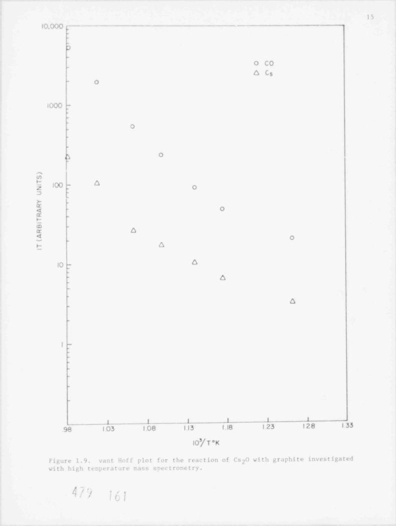
Similar work has been initiated on the Cs20/ graphite syst em with the atmo f mea sur t ne the t h e rnod y n am i c ac t iv t ty o f Cs20 in the presense of graphite.
A Cs20 graphite atxture (.4 gram rs, .nl .09 gran graphite) was stud-ted in the temperature range of 790-1020 Figure 1.8 shows observed values of
3IT (proportional to pa rt ial pressure) for LO and Cs vs. 10 /T. Assuming therelevant reactton ta be
1
C(s) 2Cs(g) + C0(g)Cs20(s,') + =
the t emper at ure dependence of the quantity:
>
p- pCs CO
K1 *7 7C s ,0 t
,
was stofied and the results are sh>wn to he N s' PCO and the act ivit ies areassumed to be unity. The ?H calculated from our data at IOOO'K are 159.6kcal/nole Based u pon data from the .I ANA F t ab le s (19 71) for Cs, CO, and C; and
from the Bure au of Mtn"s Bulletin 542 for Cs20(s,,) the !H o f t hi s reactton
'1 7 ntj ) |a_bG.
bh m=5emman

iC' r- ---
y ,f
-
i
i
\\
I C' ~
\
\
s)
#IO
hi
\\
\\
of -
\
5 \8 \
b K/ -1
\ O
\
\\\
io* _ g
\
o
10' -
\\ o
r/ LI?L
L
,
IC' -- -J ---_.l.__.___.1_ .._i____ _3____ _g_
'98 103 108 13 i is ,23 , 7g ,33
IO'/T *w+
Figure 1.8. Intensities of CO+ and Cs as a f unc t ion o f t e:r.pe ra ture for the
C,raphite CO(g) + 2Cs(p,).reaction Cs O (:; ) + =
3.
<pn r <4/') i GJ
15
10.000 _
-
_
D_
O CO_
o Cs- O
1000 --
_
'
O_
-
_
Oo_
mu)
$ 100 - O oa -
_
>-
$_
- Ox _
b(n _ oT4 O
b O
O10 7_
- 6_
_
o_
_
I T_
_
_
_
_
-
_
i i I I i I
.98 1.03 1.08 1.13 f .18 123 128 1.33
IO'/ T * K
Figure 1.9. vant liof f plot for the reaction of Cs20 with graphite investigatedwith high temperature nass socctrometry.
k '| '''t !C\*'

16
is calculat ed to be only 7 7. 2 3 k c a l / mo l e The discrepancy may be due to theestient furnace, we are unable to continue these st udies o f Sr0 systems.nat e of *H for Cs70(s, ) and/or the effect of adsorption of Cs by graphite.
In t h ,- lat t er case the syst em to be constdered is:
1
CS2P(s, ) C(s) = 2CS(adsorb) C0(g)+ +
2CS(adsorb) 2CS(g)
In this case, the measured f.H te f.H } and 2 /J12, and the ?JI7 nay he concen-t rat ton dependent. Addittonally, in Figure 1.9, the deviat ion from linearity atthe lower t enpe rat ures is probably due to a change in heat capacit y coupled wit hincreastna contrthuttons from background (since the mass spectrum was taken inthe D.C node due to intermittent electrante problems with the lock-in anpl i-fier). Work on this system will continue by varying the stoichiometry and byconsidering the effect o f c e s i um adsorpt ion by graphit e
1.4 Aerosol Formation from Graphite at High Temperature (I. Tang,H. Munkelwitz, S. Nicolost)
Work continued on measuring the rate and extent of aerosol formation fromcore graphite sanples heated to 1600 C in bot h d ry and humid t fied heli um. Dur-ing the report quarter, enphasts was placed on the wetght loss of H451 graphit especimens heat ed in dry helium as a f unc t ion o f t emperat ure and heating dura-tion. The pa rt ic le size distributton of the aerosol evolved during heating indt y heli um was also established by sampling with a diffusion battery.
W!w n a new H451 graphit e specimen was first heated in dry holtum, conden-sat ton nuc le t (CN) were invariably evolved. Init ial CN concent rat ions wereals ys in excess of 107 CN/cm3 even at t empe rat ures below red herit , and
gradually decreased with time to a much lower concentration level. Increasingthe t enperat ure again produced a sharp increase i n CN concent rat ion, which thentapered off when the t em pe ra t ur e was ke p t constant. Figure 1.10 shows the CNconcentralton change as a function of time for one graphite specimen heated atthre, different temperatures in dry heliun.
At the end at each constant t em pe ra t ur e 9eriod, the sample was cooled downand weighed. The results of sanple w.> t gh t loss as a function of sample t enpe r a-
ture a n.1 heatinn duratton are given i n 'l a b l e 1.1. Al t hough the results are pre-l imi nary a,d qui t e limited, they indicate that at each sample t empe ra t ur e , nost
o f t he samp e loss occurred during the initial heating pertad when the aerosoli
concentration was highest. prolonged heating at the same temperature did notcontribute apprectably to the overall weight loss.
The particles evolved durtne the initial degassing period were very smallani nat detectable using the linht sc at t e ri ng instrument for parttele size de-termination. Consequently, a Sinclair type diffusion battery was employed toobtain the size dist ribut ton of the<> condensation nuclei. The principle andapplication of this instrument have been described elsewhere.(Sinclair, 1972:1975). In the present work, an iterative method was employed to derive theparticle size informatton from the percent penet rat ion dat a measured sequen-tialls at each hattery port. The fitting of the data was done on the BNL CDC
,,
k// 5'"

t
(i.
h+ 4 f+ .+ 44 + q +$+ 4+ p++ e ++ g+ + , 4+ + *+
+ -+ ++ t+ (++ , ++,o+ ++ 4 ++ + < ++ - e
+ s. s s++ +,+ .++ . ++ ++. + .- [ ++ + -+t . e 4t + ++ * ++t a
++~t . +-+ %=-+--* 3 i#++.+ >++-.4 p++ + p.++-%%- -
4+-e--4,.- e.++W-+-- +++-+-$*4++---6 . + $., 9 449 + q p++e ++
T' '4'*- ++ + g- * 9 4 $
+ * * ++ t-+ e +, . + +,-e 4+, F. + ++ +i t*+ 6
0 Y + 8 + e t++ + tf.* + (++ 4 =++6 +++ f*++ ++* 4*+ + y + ++t
'
4+ +$ 4 g. & + f $< t e+ -
+ .- ++ ' * *. + . -+ ++. . .. ,++., ,+ + . m9 + t , .
t. , . ..+ . A . m.4+ .,- , ++ + , + te -
t + , . - + 9+ 6
. --e
.+- &++.+ + 6 +--+- .F+++-+- - + - H+-+-e.+f
* * ' ' ' -T F "si M W ""' 7 "'" ~ *# +++ - + 9-+++
6,. 9+ ++ ++ ++ + 6 I- t + 4 P +* . ++ ., .+. * .
t. i*+ $. *$ . 4 9 9 &.$eJE .be
. . .t ., . .- .+ -. + + ~ + o
- - . . - - + . . .., + . . . -
+ %s,++ . A 4.+ . . , , + ~+ +.s.. t. y+++
.++ +++ - w >
6+ e , t t*+ .
,/ e-.+ &
)+ 4+ f$+t < p.+..,r". -
99 ++ - 4 &++ 4
.F.4 +
,
+ ++++....+++o... . h+t +++ 6 t
H,
+4 ... . . . + - + + + .tt & )++ . t * - + . + t. ++ + + F.
* , + - + + - + . .+ + + - + - <
'
b.
64 9 t. i 6 f+ + + . +t + 4 6 + 't+4 t.t - ,to t &*+ . .-.+ . 4.+ . + -** t t+ 4 .t-
+ -
++4e, . + +-+ -
+ > < < +++ + + 9.
(# -t++ H+ , t++' -
T+'+ t**+*+t++ 9 p++ t $t* + 9 e t ++ y U + + 9 4.
f++ * t 4. . .
t+ &*+ ++ + . . + + + e ++++ + + - + + r+-+ . 4.++ e+ - H + . - - . . . m.+-+ , -+-++ - . , .
# 6 +- + t++ 6 + + , f+++ t++ + 6 6
h9 e & + + + > + + + +6 (++ ++ + > +
-4p+ 6 +
' ^ '+ v++ . a e f+t & ++ + ++ t &*+ tIIb 6 be+ 4 . + a -p++ + $4 + t *+ + $++
. . - - >+-. . , - - , 4+. M +++i L+.-,+
6
,F. - W +, + + ++ .+t+ +
t+++ -
++ + t& . t t.*, *r + . ++e +. - g - +++ + +++ . +t , , ++ + + t
* + c4 ++ + + H+ .
,,
+ * * + 6+++ +F.+ +++ + .+. + + + 6 . +p
,
. -. - -+.e4 . 7 - + - + + +- h=4-+-+-+ e+ 6 )+++ +
.++ +--+ + 4 p.+ + 4 + t ++++ * 6 y@ + 9- + 4
,,* - ,t ++ + + . e f++6 - ' ; 3 + + -+,p 6+ ++ + + t* + ++++ ' + ' -+
4+6 + . ',&f f . . . . + (J + - - -
E-
M W &+ ,-. + + + +g + ++ + s .+-- e- 3m k-.
+ f* ' - ' + '** E 4 ,i- U b.'+44 , -8, b & - b- - &. -- l. 'W.4 | 4 '. J z _ " _., W''-., -- - -' W4.; sN3.T.e o -w
,
m _'+ t 'e' 4
L .++ + p+-
m. .
g}. e %.o - . . , ,- - -++__ _ e <oet . I
- @ H+ +4-
+ v. +++ , , c. w- eh+.--+-
p.++ ,.+ * m-+-+ %+-.+-.4-.. + . . . -
+k++ * f .'* + e
t+ >N 9++ + -+ *+ ++ .- +- + 0
+ y+++. ++ * e 6 . t . * + * ++ + 6& + t. +++ f++$ ++ . + ++f* 6 +++ g + - + - + 4 yk*p.* 6
++ . U + + t -O ~F6
+ + . - - , - .~++ 4 + *+ *
C* ++ e F+-+-. i*
*.- Ott t+ . ++ + +y.+ e ++ 6 g=
" * *p* * t++ * + + e+.+ t 6 t e t 7 f 4 t+ t ke..t k .a++ &+ + 4 p , +.-. ++ . + + , e 3w * * + . +
. - + _ . .t.+.+-+ .. ---
'
+ ++ + . - + + . + + + 6 eg - + . . . . *".*++++-t--4
+ . w+ yy H-++-+-f+ ^
4JI $ f + ++ -4 + . - +++ 6 9 4 ++ + 4 + * +ha p+4 +t . + p ++ t gg
..&i + + H+ * -
. +-(... . . ++ . . .+ .+. ca > s. , +.+ . ++ + , > + + .++ , , , . . . +,-t-t.a.--.
4..
e mig e e e-m' M *- ++ + te +,,
D'um d e w +W gw e e e + - + M Wh e.P+N4+4>w p.$$ +m> W M.> +++ + + - + +++ . - .\
+ , s-+.++ e*+ +++ ., - . * + + ++ + + 4 + + + H9-9+ e- 9 +++ -+ t++ $--+ + + 9 t-- +
>+ p+++.+ +e-o. + - + - . +-.k++-p.+-+--. 4 .++,-+--o.-- .
t+- + e .++ + +- + - + - t+ 6 ++ + -+-++ 6 + +++ ++ e + t $- 'f
F. 4 - *++ $++6 -+ e pM ha t + t .e+ e- +++ + -+ < +s no s e +++ + - + - o *
, - + , . +++ --.
6. ..++ + 9 ++
y ,+ +-. . +.. . , + + . - - -, .e.. . L. } * -
h+ ++. .
h.4 $ 4 + t F4+ . w w++$9 ++ + + *t (* $ f+ 9 4 ++ H+ -
- I$4 $+9 9 ++ 9 + $ h+ 4 + &* t + , .+ .P +. g
_ -. ~ . . , . ,+44+Y...+.- - .++-.-+p. . + . .6..++-+ .w+-
+ - ,, .
,
h +, h*A . .+ +- r. , . . + ..+ .[
, +s > + aP* + ++ t. * t, 4 + & & + 6q$+. *
+. + a =+ + t-+ e & *+- -* .- *t &* ++ , , "
-
n+-o.. + - + . . . e--.
6+ + +.- . <
t+ -
+ j/ . f. t+ &-+ + ,+t.y,t, -
.v . +.4+.69+ t-+ +
+ + .. ..4- ->+ + . - .. . +H. &
++ ,6& $++t + t 6 ) 4 4 &.4 - - "
4 .+ . F++* - ph+- +- + +. # +-+-+-e <W-.-+---. --h+==--e" +9 4 + t ++ t+ ++ t
>.+4..$++ 4 +W*~ 6- v+ +t , +, 4 , 4+4 p
+ . + r , s p. t -+" ,~44
ge g+ t , + .+- - ~-
ao s, e = - , e e - m = + y
b- -
_
h ' a l D I l l E''l 'O Fd^
,f C ~4UPCj
s
a-.
..-w
L4
-
m.--
g .P-"'
, /< ;3 5'
I.''g .,e,
r4i1 . < . 4; b F i - >- r ' q N e ,N+a 1 ;n p, l. , n3 > -
:j-
-; 1 - r. h,,j. a .e.3
k),- i.i
, y . f . 3> <a a, r, g . ' . ' .
. , .' i P' t,
-
4 3 ,~ -J . n og u ya ys- ,
f/ -
< . 1+r
, /

IM
Ta_ble 1_. 1_
%nn1rv of Sanple Wright I,o s s D it a
Temperature lie a t i ng Duratton Weight 1.o s s
Atmosphere "C Minutes percent
Dry ih' 123'6 290 0.16Dry lio 1421 180 0.[|
Dr y lie 1516 180 0.I7Dry lie 1210 100
Drv I!" 1401) l10 0.67*Drv lie 1600 100
"fdt'Al S A ght loss dortny the entire heating period at the s pec i f t edtenperatures.
1600 computer. Ftgure 1.1l shows the parttcle size dist r t hut ton of the aerosolevolved during the first 15 mi nut es of heating in dry helium at 1010"C Thistypical size spectrum indicat es .i n e xt r eme l y nonod i s pe r se ae rosol that is con-
;i s t ent with a form.ition mechanism involving ev a po r a t t o n an ! condensat ton pro-
c"sses (l.aMe r , 1950). In the present s y s t em , the par t ic le d i .ime t e r s were tound
to varv fron 0.01 to 0.03.m. Elect ron mic roscopic examinatton of the p.i r t i c l e sc.ill ec t ed on copper grids w t t h ci thermal prec t pi t .it or showei that these parti-
cles were quir. unstahl. in the electron beam. Some of the particles ev a po r.it ed
quick!v, leaving behtnd a rectdue It is postulated that these parttc1., areforred mainly from the volatilized residual hinter material remaining in thegraphite even after graphi t i rat ton at high t empe r a t ure s (Ttugey, 1972).
A consi4lerable amount of out gassing dat a ha u been r e po r t e d for a variet y of
craphit es (Eveleston, 1955; Asher, 1960; Redmond, 1960; Blakely, 1964). How-ever, in all of these previous investtgations only the gas content o f graphit eh .i s been nea sur m! by hea t i ng s .in p l e in vacuum and collecting the non-a
iondensible rase. for analysis. Ty pic a l l y , the evolved gases consist o f hj ,li o , Say, N7 and hydrocarbons (low molecular weights). No at -fu, FOy, 7
t empt w.i s ma le by any of t he previous i nvest igat ors to look for the part iculat e
matter that was .il so release l wit h the g.i s c ou s species. In fact, the techniques.mployed by these i nvest igat or s would not have been capable o f moni t or i ng aero-%>ls si t h. part c!< "mitted in vacuum would simpiy col 1.et on the walls ofthe ve sel. Redmond and Walker (1960) did a material balance and found that theevolved gases _ ou l il a: ount for only 50% of the sampl. weight los, They no-
ticml that considerable mat e r t .il was col lec t e'l on the cool walls of the de sor p -
tion chanber. An emission s pec t ros:opi c analysts i nd ic ar eil that this d e po s i t
w.i s ' 61m p. i s e <l m.l l n l V inf s l I i C 4)n , iron .i nd m a gne s t tim .
Once a graphite sample was out ga ss. at a htyher t em pe r a t u r e , an! subse-
quently heated at a lawer t empe rat ur e , there was either no change or a reduc t ion
in CN ount rate, de pen <li n g u po n the degree of outy,assine lloweve r , addi t t on of
wat er vapor int. the carrier gas invariably proloced a brief hurst of CN. Elec-
bh

19
'Gu g s
-
e o !> g
,; - -,
,. -
s
e
u ,0 - -
-
---
.--
-
a. - -
.
25 ,. -
- -
U ( ti
0.001 0.01 01 1U
U.i r t I c , D i . i:m t c r ,
Fi; :ri 1,11. i' ir t i c l e ilze dis t ri niit ion of :in .ie ros ol evolved diiring d e ;.is s i n;' zi t 1010"C
d79, 1, v/. cs.

(t
tr in ni ros ipi- e x 1-11.ia t i o n s .i! th- p.i r t i l l, a l l . t .ul trs n o x i d a t t ..n experi-
W. * r . ' s t .ih I . , .< > l i il n. i t e ' r i ,1 1. Tli . . "ii jih ili>v|ni t t i : } <* sq! !. e'.i3'.I t ti .I t t II. .e
wi, n t i r. l s ditterent fr."1 1 h.it if t h. ,o t t t i l+ inittiul <!u r i ne .< 'iss ing.
(' ! . cis, tin . > l i si p,ir t i a 1 w. r . f.it: si h' |hysi.41 1. Jr.id.it iini i)! the . . t "; p l .in i r. ri! t .it . .s h .i u s t t V e o<t !.i t 1 in . .\ t hich I . pe r a t ur . 'n.1 water v a p. i r .in-
e u t r .it 1, n s , ni h .ia r : er c r.iph i t e i .ir t 1 1 wei. .ihs e r ve ! > Dr.'ak .itt t he
!i e.i t .o! :ir en .inl !. p.i s i t il .ine the ..in p l i n e t uh. 1 a li m t is the t'N inin t e r .,
Iar.. p.i r t i : l . weIe nat i n' I ude } in Ihe !at.Ih. .
tif ftssion j rinlu :t - to A i t k.'n no:let ti, he .>f great innir-Th. .it t a : h" o n tt in :. In a r. a : t .ir . i : 1. l e n t , sin:. the d p,i ;it i.ui ist t h. t i 41 in pr.nlu t<.
w i,111 hi on t I il liot hv ti de p is i t i on b eh.iv i < )r of I h. host a.r,iri l- The At t k. n
n u 1. i .it. !!iii2n]t t.i r . '"1 isi t r . in t h. .it niis phe r e as thev .ir. l.irge enouph !o
h av. I .iw i!! t t : ,iin o r t i i : i e n '. . an! vet .ir. nall en uich ! it h.ive a ver v low set-tIinv ve1 : 1 t ', inn to r t b. I n f I uen :. in f g r .tv i t v . Fi s s t iin pr.ido:t s , theretare, .i t -
. nu lei ar. In the hi it p. i s s i b l . form t ii e v a p4 <'e po s i t i o n .t i h.'d t.i the
l.1 Experinental S t u 11 e s ist (hir e llea t o p p h e n ot"e n a (P 900, (: l'ne b e r g , R.S.t h.i t i n i , C 4.i s t r e , 71 ( 4;hw.1L ur)
The e x pe r t ra'n t .il filGR Gire lh .it u p p r o e r .i"1 w.i s d ev 1 s eil t> oh t .il q d.i t .i on the
b..hivi<>r <it tnel, ! i s s t iin prodo:ts, on t r.> l r o ! n.i t e r i i l s and graphit, durine
h /p it het i .il, n o nn" .:h a n i s t . a;;i lent s in li FGR systens where t em pe r.it ur e s ar.
,raphil. sublimatton revine ( Man"C ) . Very few.i s s ii m ol t.i r .in s up to the '
i' x pe r inen t il l it .i .i r i .o r r e n t l ', av a i l .ih l. iin the phy s i c .il .i n. l chentcal Inter-
< .ir. nat e r i a l s sii t h.it fuel .in i c r.iph i t e lit t .p r i t v anila t i,so s h e t we e n i he s.
! inst,ui pr nhift nigr.itton rates .i r e e x t r ene l s di f fi i! t to quantliv. Ir. i t t a lwirk in this pr i m r .in has i nv o l s "<f re l at a ve l. sinple types of i n t e r a c t 1.)n s he-tween criphit. .ind fue1, on t r.il r oil .in 1 c e r t .i t n fission pr oilo t spectes. Thts
i. onsi.for.o! ne .saarv to obt ai n bisi_ i nt ei aa t t on dat a be for, more complex anil
p r i.t o t y p t ex per iment s ir. i n i t l a t e.! . Work is curr.ntly pr oe ve<!i ne on n.ilvb-
.!coun nieratt u, in H '+ S 1 graphit. ani he:it u p o f BI SO .ind FRISO oat e i fuel part-,
icles t') Jetermine their thernal stahtitty.
l . 'i . 1 Fue1 p.i r t t 1 Tr s t i ne
A bat ch of in Bimi < > a t ed Ttin y p a r t i ': l e , (Run 10578) wa< pl.ic d in asnall a p prit cro: th|. m.id e fron !i/+ S l g raph i t e and he a t e.! in t h. i nilo : t i on fur-
na :. at .in i n i t i ci l rat. o f .ih ou t 2ndn'C/h to a t em pe r a t ur- of 2 %0"C The pa r t -
ic! i w-r. n i: n t a i neil at thi' t empe r a t u r e for I hour .i t t e r which t h. power was
s w i t :: h e l o f t in t the fuel allowml to cool nat ur al lv.
This experiment was ile s i g ned to det e nine whether slyni f t r a.' fuel particl.tit u r .- w eil.1 <> c ur for t enpe r a t ure belirw t he neltine point of t he l i .pii d
I }l(' . ( 2 6 5 f) '(' ) . AlI w,i r k t si it.i t ,a i n l i ._ ci t e s L lici t t h.' pr i ti i p.i l f.t i l ia r.- n. r-li a -fli sn s .'nt.! ti'i t lie f.i p l d .*Vil l ti! i iin il l (?il W!i l C li f t ) T "I s w} } e . r . t lie i)X 1 !e i ti.* l 1s! . *ili! ' e 'il (i t lie l i gli t d m .i r h i <| sa .l..' airill ng ti t }ie li> l li:wl ng r e '.i f I 1 tin :
I II( b. + '. ( 'l h(') (l1q.) 2 ('t )+
rh, ni p r. ,ur. builds up to a value high enocch to r u pt ur. the pvr ol v t i t arE n
1r I-a
k - ()/ / I V V,

21
_oatings ani the 1tquii tuel e s c a p, s
Ort :iled scanntne electron microscope studies re maled na t rac+ of cracksor hole, in the carbon coat ines which confirms that failure is inleed inttiatedby i nt er nal gas pressor. Yrchanisms of failure h av e been described in previousreports
1.5.2 Malvhdenun Migration in H '4 51 Graphite
Work is progresstng on the molybdenum dt t fus ion experiments. Run 420?8, inwhich Mo2C was heated to 3000*C for 8 hours to a H451 eraphite su scept or , hasbeen analvzed ustne a wet chemical technique First, the graphite susceptor iscut into slices of known thickness; then the individual slices are drted, weigh-
accomplished by exposing the sample to an oxvnen...i and asheci. The ashing is
pla<ma i n ,ide an LFE Corportton Model 102 low temperature a,her. This pro:es'leaves a restfue of inorgante ash which cont ain the trioxide o f mo lybdenum andthe oxides of other metals which nay have be n present in the graphite This
N4 0H so'utton and the ab-residue is then dissolvel in a known amount o f 10; 4sorption spectrum is taken with a Beckman Model 26 ult raviolet spectrophotom-eter, using 50 mm pat hleneth qua r t z cuvet t es. The absorption intensity at 230nm (+ 10,000 liters /nole-cm) is t he n compa red wi t h that of soluttons of Mon;of known concentration. Data po i n t s we r e obiatned from a distance o f 5 mm from
the nelt (21 ppn) to 55 mm from the nelt (3 ppn). Th e Ma diffusion profile isshown in Figur. 1.12. The wet chemical results are in general agreement vtththe results obt ain d os tne the proton nteroprobe
:l t s , however, have not been absolut ely quant i fied an1The mteroprobe .
the technique shows cons:derable sc at t e r among the data toints The scatternight indicate that Mo is micrattng pre ferent t ally along the grain boundartes inthe graphite The small been diameter of the microprobe would enhance thiseff.ct and give rise to apparent scat t er in the data.
The X-ray fluorescence technique t nif i c a t e s Ma concent rat ions about 3 orderso f nann t t u f e greater for identical distances from the Mo2C melt. It ts nowbelieved that the X-ray fluorescence results, btained from an offsite labora-torv, are questionable and a new evaluation of this technique is required.
An analysts of the wet chemical results is in progress to obtain estimatesof the diffusion rates of molybdenum in graphite
1.6 H1; b Temperat ure Vaporizarton Studies of HTGR Fuel Components and FissionProducts (S. Aronson - Brooklyo College)
Data dealing with the physical and chemical react ions as soc t at ed wt t h the
consequen^rs of core heatuo in llTGR e nv i r onme n t s are sparse. I n f o rma t i on isneeled on the vaportzation and diffusion behavior of the fue1, coa'ings andfission praducts an! on the interaction of these various chenical s ub s t a nc e s
with each orbor and with graphite We plan to obt ain va pori zat ion dat a up to
300n T ou s inul at ed fission products, stlicon carbide, and urantum and thortumoxtdes and cacht;!es in the presence o f graphi t e. This program will be closelyoordinated with an<! will provide base data for the core heat op program in thet
f '7 qy (j, /
,
4/ / ,

:
'
CEi *
S 20 - \ -
Z9F-
, < \.~.
fI5- \ -'"'
Z y"
ut 'c' u *xm z N@ ' O- \ -
! \m e- . -
o . .m i
>j * +.
o2 O
O 10 20 30 40 50 60DISTANCE FROM THE MELT (mm)
DIFFUSION. OF Mo INTO H451 GRAPHITE. An H451 GR APHITESUSCEPTOR CONTAINING Mo2 C WAS INDUCTIVELY HE ATEDTO 3000 C FOR 8 HOURS. THE RESULTS ARE FROM A WETCHEM! CAL AN ALYSIS OF RUN 42078.
; _ m. : 1.
23
IITG R Safety Group at BNL
The program will in'.olve several interconnected components:
1. An experinental study wtll be nade of th" gas pressures (primarilv CO
and CO3) generated by mtxtures o f graphit e , Th02 or UO2, sic and one ormore simulated fission product suc h as Sr, Zr, Mo, Cs and Ce This st ud y shoul d
field information useful in elucidating the nature of t he interactions o f UO2or ThD iurl with ftssion products at high temperatures. The experimentaldata wtll be compa red wit h whateve r i n forma t ion is availabl+ in the literature
on the syst.ns investtgatged. The QUIL computer code developed at LASL andimplenented at BNL will be extensively used in these calculat tons.
2. M.asurement of the va po r pressure and heat o f va por t zat ion of a stnple
simulated fission product mixed with graphite will be made in cases wh e r e thisbasic in for ma t i on is useful in making calculations concerning the mtxed fission
product systen. The ef fectiveness of di f ferent experimental techorques formaking vapor pressure measurements at h i gh t empe r a t ure s will be compared during
this s t iid y .
3. Fuel failure mechanisms which have been proposed (Smith. 1474;Lindemer, 1974) will be reexamined. The phenomena of kernel ntgrat ion, fission
product uas pressure, the interactton of fission products wtth the 9' o layer andCo-CO2 di f fus ton and CO decomposit ion will be considered on the basis of thenost recent data av a i l ab le in the literature and generated through the program
described above
1.7 Int era c t ion o f Ces t um and Tellurtun With Fused Quartz (S. Aronson, J. Klahr
- Brooklyn College)
A long term test was begun on the interactton of fused quartz with cesiumv a po r . The t enpe rat ure of the liquid cesium reservoir is 40 C corresponding toa costun "apor pressure of 10-8 atn. The tenperature of the fused quartz tuberanges from 40 C in the vic tnity of the cesium reservoir to 740 C at the centerof the furnace No attack was observed vi sually a f ter 1500 hours of exposureA second capsule has been assenbled which consists of a stainless steel t ub e
fused quartz tube The stainless steel t ub e which holds thesealed inside acesion reservoir ad jacent to its one closed end, extends from the cesium reser-"oir to within 2 inches of the other end of 'he fused quartz tube. The pu puof this arrangement is to concentrate the attack of the c e s i um va po r o n the
fused quartz region in the hot zon' in the center of the furnace It has b"enre po r t ed (Milste :d , 1966) that cestum does not react with stainless steel. Thecestum reservotr will be heated to 100 C (10-6 atm.) for the first test ofthis type
It has been observed that telluctum attacks fused quartz (see Section 2.3).Two fused quartz tebes containing tellurtun powder have been prepared. Long
term tests will be run in whi:h the t empe rat ure of the tellurium reservoirswill be 400 C (10-6 atn ) and 300 C (104 atm.), r e s pe c t i v e l y .
4 - -l' l' ' i 1
-1i o n .t J)

,,,
pluu T (' AT I nNs. .
(;R( GQ CK , F. B., et al,, "Thermiwbron.itographic Investigations of Fi ss i u.
Produ t Transport and Chemistry," BNI.-NUR EG -2 5 3 31, in Proc. I! . S . -la pa n Semi n.iron HTGR Sa fet y Technolov,, Fuji, Japan, November 24-?5, 1978, Vol. I.
m .0 , P et .il., "Very Htch T."aporatur. Behavior of HfGR Core M.i t e r i a l s ,",
BNI.-N''RF G-2 5 5 2 3, in Proc. U . S . -J.i pa n Semi n.i r on HfGR Sa f et y Techno logy , Fu}i,I.i p, n , November 24-25, 1978, Vol. 1II.
MU NK E I.W I T7 , H. R. and NICOLOSI, S. L " Aerosol Fo rma t i on from CoriTANG, I.', ,,
G r.iph i t . Heated in Dry and Motsi lle l i um ," BNL-NUREG-2 513 0, in Proc U.S.-Japan
'uninar on li rG R Sa fet y Technoloev , Fuji, Japan, November 24-25, 1978, Vol. I.
R E F_E R E N C F_S_ _ _ _ _
A ! T E E ', , E A., EVANS, S. K. and RUBIN, B. F. in Behavior and Chemical State ofIrradiated Cerante Fuels, IAEA, Vienna, 1974, pp. 269-85.
AR c )SS O N , S., et al., "'lbr Interaction of Csl with High Chromiun Alloys in the
Presence of fixygen," J. Inorg Nucl. Chem., in pr e s s .
in Proc US/UK Meetine on th"ASHER, R. C "The Degassing of Graphite,",
Compatthilttv Problens of Gas-Cooled Reactors, DRNL, February 24-26, 1960,FID-7597, p. 504.
B LAK F l.Y , J. P. ani n'E RH01.S E R , I. G " Outgassing Behavior of EGCR Moderator,
Gr a ph i t e ," <)RNL-1560, 1964.
C A S I 1.E MA ', , A. W., Jr. and TANG, I. N., Nuc!. Sei. Fue 29, 159 (1467); J. Inorg
No: 1. Chen. 32 , 1U57 (1970).
CHA'mRA, D., " React t on of Primary Circuit Met al with Volatile Ftssion Productsan.1 Inpur i t ie s in a Gas-Cooled Reactor - A Review and Guidelin" fo r Safety Re-search," BNI, Internal Memo, 2/17/76, ilTGR-MF-29
E(;GI.F S fi d , E. R., et a l , "t ;r a ph i t e ou t g.is s i ng ," NAA-SR-Meno-1240, January 2i,i a ' , ~,
FARMER, F. R., Ed., Nuclear Reactor Safety, Acadente Pr e- s, New York, 19/7.
IEBER, R. C " The rma lvnami c Dat:1 for Selected Gas Impor t t les in the Primary,
Coolant of High Temperat ur. Gas Cooled Reactors, April 1977, Los Alanos': tentii1. Laharat ory , LA-NI' REG-66 3 5.
FIFTS, 4 B., l> )N G , E. L and LEl'INAKER, J. M., ORNL-TM-13MS, 19 71.
Gof7MANN, n. and OHSE, R, W., Behavior an<t Cheatcal St at e of Irradiated Ceramic
Fuel:, IAEA, Vienna, 1974, pp. 255-6X.
4 / f) i
'4 i / i

oc>
G R l r4 COCK , F. B., et al., "Ftssion Product Release from HTGR Fuels," in ReactorSafety R"s" arch Proerans Quarterly Progress Report, July 1 -S e pt embe r '3 0 , 1978,
Braokhaven National Laboratory, BN L-N L'R EG - 5 04 31, December 197X.
LAMER, K., IN., F. C. Y. a nd '4I LSON , I. B., "The Methods of Forming,'
Det e:t t ne ani Measuring the Size and Concentration o f Liquid Aerosols in theS i z.. Rane, of 0.01 to 0.25 um D i am e t e r , " J . Collotd Sct. 5, 471 (1950).
LINDEMER, T. B. and d e N OR D'4 AL L , H. J., "An Analvsts of Chemica! Failure ofCoated in3 and other Oxide Fuels in the HTGR," ORNL-4926, 1974.'
MILSTEAD, C E, and Z I'M'4 A LT , L R., "Cestum Plateout on Stainless and CarbonStoels, GAMD-7525, 1466
REDMoND, J. P- and '4AL k:E R , P. L Jr., " Gas Content of Graphites," Nature 186,,
72 (1960).
FCH ?. R . M. D. and FI NE , J., J. Chem. thys. 36, 1647 (1462).
SINCLAIR, D., "A Po r t ib l e Diffusion Battery; It s Application to M"asuring
Aeros;l Size Characteristics," Anor. Ind. Hyg, Assn. J. 33, 729 (1972).
SINCLAIR, D., et al . , " Experiment al Ve r t ficat ion of Di f fusion Battery Theory,"
presented at the 6 At h Annua l Meet i ng of the Air Pollution Control Association,B>ston, Mass., June 15-20, 1975
'M A LYD , J., Jr., " Fission Fr aenent s and A- t iu it t an Pr Ac t r in EOL Ft o l
Erti les," RNL I n t e r na 1 Memo, 4/12/78, HTGR-MF-61.i
SMITH, C L " Fuel P,i r t icle Behavtor t'nde r Nornal and Transient Conlitions,",
GA-Al2471, 1974
TANG, I. ' . . , et al , "A Studv of Fisston Product Transport an.1 De po s i t t on I's i ng
Thermochrom.itography," Proc. J a pa n-l' . S . Seminar on HTGR Safety Technolo g,Bro < shaven National I. abo r a t o r y , September l i-l h , 1777, B'; L-N !'R E G - i N 6 X 9
TINCEY, (; L and MORGAN, W. C, " Graphite for H-Itun-Coolmi Rectors -ARefiew," R N'.it - 16 8 7 , Battelle Pacific ;o r t h we s t Laboratories, Richland,
'4ashington, 1972.
.
.'T ,/.. .
_f ,
I i

'h
M .1 ( e r 1.1 l . , l' hen i s t r V , .lu | I n s t E 113 > n t .i t i s i n'
Iht' orifram over- t he ev.iluat 1*in of f.nir uln ' .i t e i u t. at uterials:i| | 1 1 i l n ' r i .1 l ' , (2) : T .I t Il 1 t t ' ' f3) PCR\ .in 3 (/) .1 ! I I . ' r n. i t . ' r 1,1 } ' IO-( lI ' 4,
~ ; . o 1. . ! i n ( .) at. >nt ro l r ail n.il e r t a l ' a n.1 t he rm.il barrier i n s u l .it t on . At thisnphasis cent ere ! on ne t .i l s . The ob je ' t t v. of thet i n. i i . w, - er, t h. n i jor ,
,
l: 11.111; review availabl+ ru t e r t a l s d.it a po r t : nent to H TGR .afetv,w. i r k ar. t.i r
1,! c n t i ! . .ir. is wh 'r e i n f sir ':.it n on l' spirci or 'in.t v.i i l .ih l , a n,I t ii de;1gn .in.! I n-
1| 1 i! ' e'X; i T 1 P 'Ill s t i) v i * | si il 'i t .I wl1 i f Il WIIl pi' r 11 ( .l.' i n r .1 I . .i s 4 e s s "i n I s t it he
: i l. it r ut e r i il s r e l a t .ol ..i t e t v ; rah!,ms.
. _ _ _M a t _e r i a l.'(P Noo, .I. Chew, R 4 ihat i n i ). f S t r o ? t u r a.l2.! F.it i c ue o_ _ _ __
fi rt on t .it i e iie is fsict se! "uitils on the hich :vc !e f .it I c neTh- J ur rent ei i
en po n. n t s siih li : t oil ta r a ;,1 d 1 v iis 111.itinea litat e the beh.tv i or istr4 1" t ,5 , s
I.st: .i r e . .in d u : t ri i n air .in t .i > 1 mil .it eil H IT R h e l i u- env i r onr * >n tstr. .
on ic r load introl at .i liny rate at 40 He
'. 1.1 In 'eltum Hich C, 1 i'a t s e ne T. , tine
- ari currentiv hetne ev a l ua t ed . ~1 h . , i mu l .i t eilIncslov HNnH a n11 H a s t e l l i i .''. H atn. C ( 1, .' OH f t.R h ! t it , en v i r.in ent antains '. O ,atn Hoo, 2(H) .i t n . H7,
a t '" CH .ind l ') .i t n . .it nli Air tests are als. heinn 'arried .uit to check3t h. .tte Jts .1! h e l t ii P' against a s nitwa s t a n,la r d i . n v i r ii n"le n t . (hent s t r i e .>f t h e' '
t.i t e r 1.il s ar. Jiten ow:'
_ . . . _ _ . . F.e (It lie r 5( l' S S1 S1 (r Ni Mt1.--
In: il.i M i n ni |l . ') 5 M () . nn 3 0.67 U.4h l ') . h ! 12.1 7 NA F il . 0.65 Co
(Ht. HHl.'7A) 0.41 Ti
O.N Al
!!a s t e l l .i X (1.11 0.021 0.008 U.50 0.41 20.67 Hal. 8.M ld.66 ',10 Co
Tut . - J MIq ) 4.55 w
il F .T 11. i t a n .1 1 i ''l. All 011 ' t' n t f .i t t i)n s in we > 1 e,Il l. j ie ' .ttil,*
I.o n , ter- t .'s t were outinued durine this r e po r t i n c pe r t o ! but ontv a small
.c u nit it of t i t t on.i! i n f . T r ":. i t 1. i n h is been ,,ht.iinm' Figur es 2.1 .i ni t s hi>w the' '
.''>t,ii e'.! t -.1 ! .1 f .i | . i [ ,1 '
I n il iv " (1D 9 s h ,iw w I n rinis 1 t eut beh.tv ii r fi) r t he I w<i 1 est t n[9'r .i t ii r e s . Ati
. .# 4 ( l J tii) ' F 1 t h e r e- 1s I 'l.'tr i nili .i t 1 on t It.it t he he'l 1 in e 71 r iinm arit ,, t v e .i'
.
'
I . N. ' r ! i t i ,',11 ' w t r e n e, l h , /1? !l/ MPi ($I3 ks1 ) versMS 3$7.4 MI1 (34.5 ksi) tiir
air. it N)'t' ( 1400'F), h . ,we "r, t h. .t i r nv i r onm e n t ives .i s ub s t a n t t .il l y lower
! . l t 1 i 1. ' s I re'n e t h . Fi) r 'vl+ t i) ! .i i } tir t- (N{) l||per ! }|.I n } 17 t lie r e Na'i 1 Iil
h. a t n& n : for t h. hel t i n 'orv. ta show .i n .i- el erat i ne <!c c r . .t v io the ta-
t!. iie .Ir.nJth w t t it tir.
[n ! li. .is. i) ! H.t s t # * 1 l )s X ( F 13 iir * ') ! h. .ul l v Ie'st' ' 1 r r 1 i il sult i n t he''
s i n ti l ,l t .'.] !I Il R !! t' } l :17 i ' l1 V 1 r < i n'9 ' * il l we > r i .i t X 71 ( Eilt [ } }' silt)rtt*r t l' st t IP
*t I

27
o T T IITTITI7TTITTTil I I ilTTiy I i l ilTTli i I IITTTIT T TTTTITT[ I I TTTITT
50._ct
;2 . AIR TEST
$o3OOHe649 C o -
(1200 F) 40 6d .C J*w ~ y.: m760 ,C x n _ 30$ 200-(1400 F) N N F-o *W N oe . - 20 0Z Z
TEST TERMIN ATED i-- IOO p- TEST PROCEEDING 10$$ ---
r Iw W
b O ' ' " "' ' '' " "I ' ' " " "! ' ''id _1_ m nl i ituild iii'u" ob2 3 4 5 6 7 8 9 4< 10 0 10 10 10 0 10 10
CYCLES TO FAILURE, N fEFFECT OF A HELIUM ENVIRONMENT ON THE HIGH -CYCLE FATIGUE OF INCOLOY-800H
'' t :u re .1
- T TTITTTC T' FT TTTipTTT{TTITTIl{ T T TTTTI{T~ TTIITQ TI ITTP 10 0 oQ xC HELIUM AIR
80 ]6600-
6 /r o e BNLORNL fa *g
m ;- my q 60 $400 -r pm 760 C (1400 F)q, mx
200- " '
*-
5 8 71 C (1600 F) ' '20 $
' ''o
w Wh
i bd u umid_1 1 Hui 1 lun d L Lillud 1 til lid-- 1 1111115 1 1111 E O<O2 | t,3 |o4 105 106 107 108 10910
CYCLES TO FAlLURE , Nr
THE EFFECT OF A HELIUM ENVIRONMENT ON THEH!GH - C YCLE FATIGUE STRE NGT H OF H ASTE LLOY-X
I'i e u r e 2.2
k ,? ' 1 ~ zIis

!S
he11un cive .i htyher i at ig ue ,t rengt h on p.i r e d ta the .i t : e nv i r anne n t . Ilowev e r ,K.i t t .* r .Ip pr o x i PLit e ' y 10 :vcles t he t wa urves u anve r g. and the f at i gue
onparable,trengths he 'm e
r in e ex pl an.it i on of the e nv i r o nme n t .il eft,ct is that air vive lower fativuestrengths b. anse o f t he rapid for mat t on of an oxid, scale At the higher stre '!. els this scale ' racks easily ant leads to early t .it i n ue failuri Evidenc to
support this madel was y ts en res ent ly bv 400 ( 10 M ) .
In th. ase of helium tested s pec i mens the ox t'h scal. tarms much more slow-Is unis .i t the lancer test times wi l l surface oxidatton 1. ,i . i to .in a : cel e ra t ed
< ! . - c r . ' .1 ' i li str ngth .i s sli )wn in F i giir i- 2.1.
a. ihe 6.'* 9 '' C ( 12OI)" F ) d ;i t .i for Incolov 800H shown in Figure 2.1 are n.it'
< on s i <. t e n t with the proposed oxide embrittlement madel, it is possibli that thelow i>x i dat ion rates .i t this lower temperature do not 'aov a sufficientlv thicks
or britti, al+ to give a pr.inon n o rd o f f. : t . Hence, some other nochanisms s ouldh. controlling the f.it i gue strength of Incalov 800H at 649"C (l2OO'F).
S im, no t a l l ogr.iph i c observations h.ive been male of the mi c rost ruc t ure of .i
t.ittgue1 Hastellav X specimen (MHF-lh) which was tested in air .i t 7h0"C (140TF)at an alt ernat ing stress o f 2 M. . Mpa (34.0 ksi). The s pe t r en failed atter 5 5x 10h cv:les. The scanning electron micrograph in Ftrure 3 shows a thin, ir-'
revu1ar oxide sc.il. whtch was shown ta he rich in chromiom. Inmedi at e 1 y beneat hthe scal, the metal appears to be filled with small pores, which could he areas1i om whtch small prec1 pit at es h.ive been etched out. Carhtde> of the MC typena r. often observed to be present in this area. It is belteved that this is anarei where the chemical composition h -i s been signi ficant l y changed from th.starttog value because of the di f f usion of metallic elements into, ani also outot, thi s: ale recion. At 871"C (1600*F) th13 area has been observed to undernor. c r y s t il l i .:.it t on and the prec i pi t at ion of additional phase,
ho ne.it h this laver, .i second recion is observed which consists of et ched
pl .ine s lviny p.i r.i l l e l to the surface These are slip planes which were formed hssurface nr t n li ng wht:h zurred in the pr epa rat t on of the specimen. Duriny the.
on the slipf at t rue proc.ss a se'ond phase, most likelv M2 6, prec t pt t at esplanes an! this gives ris. to the irregular etchine ch a r.ic t e r t s t i c s
Fleure 2.4 shows the typ., of 'arbides wh i ch ih velop dur i ne fattrue testing'l h e cil l parti:le at the gra t n bounda r i e:, . ire likelv to b. Ny ;Cs wh.reisthe fine pr ec i pi t at e s within the grains .i r e probably of t h- "nC pr ine t y p.
f l.vma n , 1972). Two type of l a ry. carbide pirticles are observed which are dis-t i nnui sh.ih !. bv their color as observed with the scanning electron microscope(SEM). Th. nost 'ommon is licht grav in olor and the other is me li um grav. Th.difference in contrast is brought about by the " .i t om i s number o f t. t This is"
a u s mi by th. larver n umb e r s of seconlary el. trans which are ge n e r.it e l when the
SEY e l. 7 t ron be.r imptones on e lement s of high .i t om i c number. Since thesean t.ir y r!.'trans are r e s pon s i b l e for i na e , formation, phases ontaininy larges.-
tr,i ttons of he.tv v e i er ent s are licht er in color. The 1.i r n. licht grav arbid.
.i r r thus likels to h. MnC (Lv,in, 1972) anl many are pr obab l v pr i n.i r v arbido
pr- ent after the i ni t i al heat t rea t i ny o! the sp.:imens Mil l e r M,,C pa r t i-
.
't / / I '

29
.
Ni P1 a te
E f ?. W . h k Yq& p A - ;T s h. = g -. b; &.g. g5 .h Y r h W :t.-7:A %s. r.c o m p g' N y, , ,,
,6.,.,} r'4 7 *. -% A . , ' . ?? , * $ -- . . ' . ~ - . . ~ . . -O",-/
. 7. - _w
. . q '. . . 7 :-., q . .--m., , . . - . .-~.*-
~ m 4 s Q, 3 . .....,,-",Y_ z._... m
' ' . .h. - *- M. ? . _ . : _ mt -Ch,g * . . ~ .__
n e ~ 12*-8 - _3_. : M ': \ O t. . . ' '.~ n. ~ ,= .
-~;7- ,,.J W , %~ m . D. . . . < '*-C.*
.. .
. . ~ ~"
_ . -- ;. ~ ,'. [ ,;_ *,:'.,.. - -. . , . . , . _ . . . .
. :.% '.:~
-..~*-- .-2. _
. .. [ | . ~ ~| C. -.-'<T-i.
u.'~
---. 7 e i 7,g ,3- *+,
, i; .*
.s. . * ~ . . ,**. s . %( , ' . g-. ,,_, . ._
y -'..- .
N.-
, * . .. .. .. . .N.
,s ; y,. , ; ' .33.. .( . . , *s :. - a- .
. (e. ,,
. ,. . . p.q . . . y,~t: . .
-..-,-; s - s.- .. i.
>
.
-~y ; j ' %. ,_ .'. ". y u--A J , .|,' , - % -.
's,
s ...d. . . . Zs .R. a :- 5 - - . . . . - < ,' *
Figure 2.3. Scanning electron micrograph of Hastelloy-Xspecimen (MHF-16) fatigue tested in air at 760 C (1400 F)at an alternating stress of 234.4 MPa (34.0 ksi). Cyclingrate was 40 Hz and c'.cles to failure were 5.5 x 10'.Magnification 10L9X.
- N . c.,./)i ,,. M C Prime. ;" " N ,;I. 1. ','s . --
.
6 ..
./. %.. .
.,, a ' ' ,; :;
~
_.%.
'Q . ' , . ,s es , -}}- _.
- .
J2.g y g .- - . ,y;(' --. -_./ r. .: ;,. ,
; .. .'
- \. ,. .
'
s p: -.
.( s ,k. . . '. .
..,. - .t . ,,- - -
, .~ .. .. . . - - . - ..
...g.c,_, ,
.u.. L.. ..
. '\5. 'g ' , *
, .-
,
3- . .
,7 , ,, .=a.
C C
e - 23 6 Ys ,"23 6/ M ' .',"?,-
.
~-
e. . , .,
7t^.,_ P 9.C
, -.
u,,- 4-...
i ry_A..., . ..o s .c 'ba. . . , , . . . .
..s.s,
-.. . i. . , .
,
;g . ., r ... ..
3m . ,y..- : ..
.
.. ; , . , . . . - /. s : : , .2 :. s.: n-r - - ,.:..nn
..r-, -:-
8 n : ,,.<2 . r , ,,. -.
,,3~ p ,.;; . s..
. . :. : ; - - *,
Figure 2.4. Scanning electron micrograph showing variouscarbides present in Haste 11oy-X specimen (MHF-16) fatiguedin air at 76n C (1400 F) at an alternating stress of 234.4
MPa (34.0 ksi). Cycling rate was 40 Hz and cycles to failurewere 5.5 x 10 '' . Magnification 1000X.
4
f, /. v) -- k~t .// J

in
ieles auld have formed fram the %C prime described above The modiun eravph a v is also t lunigh t to be a :arbide It seems to .ilways exist in close asso-
1ation with the M r, oi: en as atta:hed particl. (Figure 2.4). Fr equent I v ,gMC, as shown in Figure 2.5.the darker carbide is observed to transtorn int o 6
Voc leat t on points .i r e .t > mal 1 parti 1., on the sur f.ic e of the a rb t +
Probably th. darker "a. aide is M33 6 since it has been shown to _onmonlyC
exi st in this temperature range (Decker, 1969).
S. m. approximat+ measureneats h:tv e to be m.i d e at the chemical c am p. > , i t i o n sof v.arious carbides shown in Figure 2.6 and the results are given in Table 2.1.
Carhide p.i r t t c l e . A, C and D are reIattvely c1ose io c om po s i t i on whIch is consis-
M C "I MC prime Carbide B,tent with their tentative ident i ficalion as 6 h
howevet is are.it l y d i f f e rent and, c on p ci r e d to the ot he r c a rb t ile s , is fount to be,
dett: icnt in Ma and Nr. ' ts is shown more clearly wi t h t he scanning electron
micros: ope /microprobe (SEMM) s c .i n s ytven in Figure 2.7.
2.l 7 HiJ,h Cvcle Fatigue of Al1oys Aged in an HTGR H"ltum Env i r o nme n t
Hatches ei Incoloy HOOH .i n 1 Hastelloy X have been t he rma l l y a n . ul i n t hehel: r 'ovtr,nment de se r t hmi in the previous sec t ton in order to determine howlona term corrosion affects fattene st rengt h. By preaging spe tmens in simplefurna:es prior to testing, considerable nachine time ir saved since the specimensare not exposed wi t h i n the fatigue unit itself.
Fi Vilt e's 2.8 .i nd 2.9 sll 1W pit * l k mi n.li V d.it a ish t a i ne'd f *)r 3 OI)() h t >Iir .lR t 'd s pt'C 1 -
nons. Comparisans are na b with unaged specimens t est ed in air anl in hrltum.The are i Incoloy HOOH shaws a decrease in fattgue s t rengt h of approximately 20pe r c e n t compared to n'1a ged na t e r i a l t est ed in helium. However, the st rengt h i1
utill on s i.le rab l y higher than un n ed m.i t e r i a l tested in air. In the case of
Ha s t e l l < >y X anel and unaged specimens t est ed in the helium environment show verysimilar fatigue strengths For the shorter test times air gives 1 wer f.it i g ue
s t r e n e. t h s but, at lonyer tines (Ng 108) the air and helium fatigue
comparablesirengths ar.
preliminarv work hasTo del ne the effects of thermal agine in helton someincoloy h00H s i e .. i ne n (MNF-144) which was preaged for 1000he 'n 'trried out on an
hours at 760'C (1400'F) prior to testinn in helion. 'I b e s p+ z i men wa s cycled .i t'. 0 Hz at .i n alt ernat i on st res s af 158.6 MPa (21.0 ksi). Failure < >c c ur r ed af t erS.5 x 105 veles. The t r a c t or r.iph in Figure 2.10 shows that crack propagation
is :or s in a un t form n. inner similar to that for u n ci .'," ! n.i t e r i a l , However, higher
matnifIcalion exani n it t on shows that in the Stage !I crack prisp in it ion region .i
;>rch ih ! v li r iiiigh t .ibijii t li y! i n e' pr. : 1 p i t .it iiin is p r o's e Il t ( F 1 g tir o' 2.11). This w.i s
the thermal .m i ng process and a t t em p t s will be made shirtly to determine theM -I t 31 r e ilf L !!! s t)h i s +
A [tri)M.)ilII e'il i)X ltle' se,ile was ! : r" e acl t)V t }|f' 1),i o g J)fi):t*is .i!1 | f.l? i gtle' ? v --
I l 'ly Itt se t iignifiCanl s pa l l al tini t1 < >C cil r .I N sh+)WO 1n Fi Pure 2.12 The etalir w il at e l v henrath the scale a p pe.i r s to be emb r i t t l ed as shown by s ub s c.ll .?rlJkang i n i l i 11 *Sl dll r i n: [.il i glit ( Fi grir. 2. I 3 ) . This * * f f. c t is niit iitisi rvi il in
t i n ? , 5 " ! "1. s t * * r i i l . A<ld i t t ona l ex,r i n.i t i sin s .i r e h e'i n s' C ti r l eil ilt1! t i) s i n i i r "1 t ll.' e
ti!) s o' r V.] t i iln s .
I{(t i N

31
-n w ~ , g am -p -~ v myh .A g # .
,1, r
_> 't ' ) **,a
i ? *e- a *
*, 4 ,% y-
)* A A*2 , 4,
A .ba - ~ s
9 *
A~4
ip $*4 'A y ,,
*9s *5
r %- yr -
'6"e.. i
%MC r -
I-t 6 ,g w . e,.m+3 M C
. s> + .r. - - - ~'''- ~ -
.._
',23 6 6a - >
.
a . , y *'<V"
# g.% * *
,f.' %
_
N4 "^% ~
a* , , y
,*,
e Ag , %. - q .v e e_ m
4*
, #, ,
+-*+ t. s
*, *
~>,
~'"*
.. * .. n s x, ,, 9 # s wqt..
,.p . 4 46 <, *4- , 3 y
-
. %.g, x 9. 1 E. - a .+$ %a.
s -. . s
Figure 2.5. Scanning electron micrograph showing gray
carbide phase in Hastelloy-X (probabfy M;3C.-gtransformingto McC during f a tigue testing at 760 C (1400 F) at analternating stress of 234.4 MPa (34.0 ksi). Cycling ratewas 40 liz and cyles to failure were 5.5 x 10⁶Magnificati a 6000X.
gr ~---,,-y .$. p , . -.,
.* . .
-
,..q - w ,py, ; '.a; .s _~~ u. w- ><'
,
f-,. . (y[ g ; *c' .* . .\ , j!. ;. .; -
t%w 1 ~ < > ..*%..,.,
s,o _ /g -
fCarbideD ? .? I'pA. ....,
-. M, ?.,. g u .L. --. s. , . . ,r .. .. s--
'' t,
s- . c. , . ; g%. ,,.. 9. s.. . . s.yw %K " . . , - ". - L.
,
-
C ' 47 .A - Carbide C - '-._1
i}.i S k}'Ih ^ '_' '' s .s ~ , - - -. . . ' {' '
,''
t.?.', j '
'~ Carbide B '
- L. * -
f.. ._- ~ k.-_ h,.. [.
i *r7' y~ w ac .s. . < ..,
w Q % ' _ks., m '* ...
5% 2;-|^- :4* *(' C4 a, Y / . s .f.1.% . .L . A s
. n . ; g . . 4. e .. , .7 .~ - (; y ,: . a q -- w . - .f .s-.
-: a,...-,. ..
'
. ,
. f s.'s %. . 3 E .,.- - 4 S c . V.. ,..
.3 . * ; i; , - .J g 3 *- m,
.. , . .
.
1*f f ..i g . ' * ,, og3 -%-hr.,p N .7yc. y--- -. . ;; 7 1 .g t , ;---
h w, t h.tce- ., , _.1.7 - .A:: ' ; . .;h. I
Figure 2.6. Identification of carbides in llastelloy-Xo o
specimen (M!iF- 16 ) f; igued in air at 760 C (1400 F) at ana lt er.'a t ing s tress of 2 34.4 MPa (34.0 ksi). Cycling rate
was 40 Hz and cycle < to failure were 5.5 x 10'Magnification 1000X
n -
4I /' O) J_,.

aBJ
Table 2.1
Approximat e Compos.ttons of Carbides in a Hastellay X Fatigue SpectnenIII obtained by S c a n r. i n,'Electron Mi c ro sc ope /Mic ro probe Analyzer
Concentration (wt. percent )__
M._ C ( 3 ) Carbide A(4) Carbide B(5) Carbide C(6) Carbide D(6) in Allov(7)Element_
Ave.'
Nt 21 22 6 26 -- 48.1Fe 7 7 5 10 -- 18.7Cr 14 14 58 15 -- 20.7Mo 62 65 30 43 37 8.9W 6 7 2 4 -- 0.6Co 1 ---- ----- ----- -- 2.1Mn 0.2 0.1 0.2 0.3 -- 0.5Si 2 2 0.01 0.01 -- 0.4C ---- ---- -- -- ----- -- 0.1173
-!y NOTES:
(1) Spectmen tested ct 760''C (1400 F) at an alternating stress of 234.4 MPa (34.0 ksi). Cycline rate was40 Hz and f ail ure occurred a f ter 5.5 x 10⁶ cycles."
! (2) Approximate concontration of an element obtained from the expression: (X-ray counts from carbit ountsO f r om raa t r i x ) X average concentration of elenent in alloy.
(3) Values for M C c arbide in control s pec t nen heat treated at 1176 C (2150 F) for 0.5 hour followed by6wa t'e r quench.
(4) MC type6(5) Probably M23 6 type,C
(6) Probably M C prime type6(7) Alloy vendor annlysts.
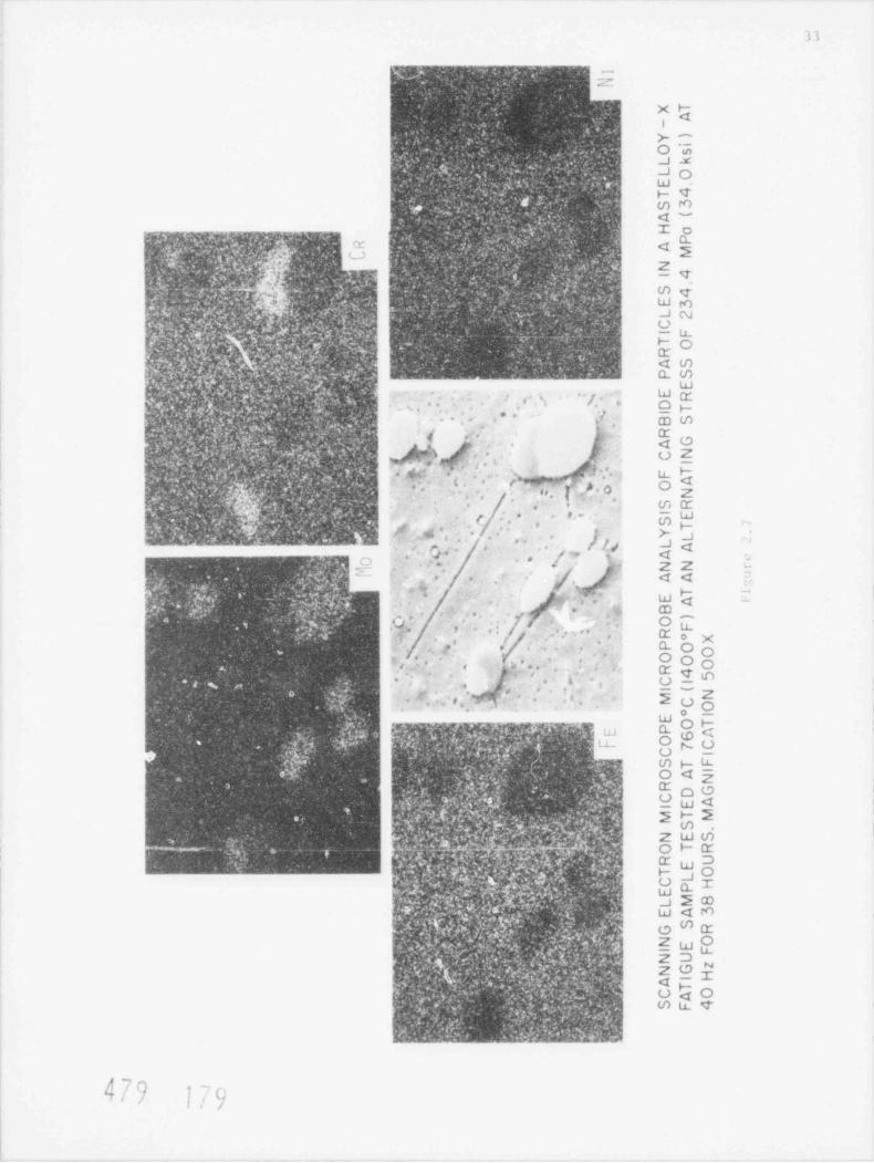
33
W ..,**V* W }0't 7. t C W - " , ~ - - -J, . ..,a#v + . j, ' ' i t/. U : .. % f[J , N- i5t,
9 9",')$mv;4
; Y :' '|? ?!|cJ k2 f ' [ .fF p,.
s ,i . , . '% . m i. 2 -Q. q<
y'.4 *N .
. .5i,
I,d'p |,' % &hi g ''eg*:*,.-e c
4 N ;%,>c .s.W . sp m >_ -;s 3
As o ..Yi .s... e J " ." % =~iMkQ#'
f
k b4 _-
Ye 0/M. 4 .,h h +. &r ,k -A
]$wTw.. J
G. h ..,;.s @n. $a w
~ ~. MJ %?4.My.qhN% ," s+)g * H qg*M, nW CU WC
.e M & %@fc,&.f N w .Oni J % Js m - @*M<-p[i; P /: % G4?A T o
fM Oj>M@b 0Mih G $m%j , . % w,,. s,,ya 'Nyp %x g.N '. W<gW"., ' Q.t% K Wj % M*pWt K ''t"g M W T*ilt -Vi 'N <18 MM n "DNA9% Mp 2
n d M a ys .w qm ,n z._ q.c f U ,Q[hq[t);< i P d'Fa..
; e. .
Ify'M $",Qd@WDhwfW 'Mh'M1%< ?
wun$g e.-i.$.w .R(Ug%y ($n$.m$..mq?v$I?.Wi&'#'"".m n n &:0*. , ,
h jAhM 1 3rn 61ym n 0MD[)AI ' b.$ dNKQk W hd. - PQT E
!Q('$ d8iM,$ftkM-N*[y$ N, "@$f',w ' 2NS shS. N 9 u.,
f$M MEM M @4 M$wW Swm h & Mj eo;p*.:A::%eAm%F@tem &qh,.ae'y Qfp# me we mum z emf sgg yg&wnsg'ggghd emt
v%g}nw . gtywp.: . . y,g..m g.Ay.a w.w;J s w x%y|+4+W *$ M M W.e,;,r:.
.
9* d(f,.rn +?; m b m) k-
. 7-|, *,'.M.f gA .
e , ,
U O && *
, ..W. Sy@% - 7-Omr m * * *s,' CD W
(hh V,%. f)g. 3|;V.a ,I sr
- rs e .%h. .a Q %$'.T fn*
Ty' r -. ? , ;,G I g' ,ag4% 4 Qf.,%. p@iG O ,R;# W K. m?.Q Q,4.}. .h. ,./. - o z_
yL p ,
&&._' :!s 'yUr$ .w3 c . .!. .
ee. . m 1y rsD, f q p L- A s o,e.%vY *%' * ''* U- p,
Ym+:/g%f' g& %&'d f.,& };)n v tp.h. ntf t's,.,p.es*9"# . 4w m s p ra * s. , of. > , o
..
W;t. <:: u.?y' M& v.%$Yy%jv:Mex,N. . myq c9?E Qg W* U. zs ** ww,
.
rdyg,.jp,p[ n/J.J.sg N 4A; n'v W W ' W'~ n;;.i
. t ( ,e e.- - wn .. -k hg.
, s.; * / * >- a<
wL % art d.h e, Mi4lh * haa s ~, / /j Jq,
,, ' % ,* *
.
,
n- ~
- f Q ?s -* | z2 f<
m-. -w-.
' . , . -.<< ~
' W' , ||25%,ujj '' . " ,.y ,. @ f5 a'W",; * *
'
W:,c % ||k - -9ym W whem^- ;' & ~~- W< -
C;Q ' *n:c ; 9 ,Qf;n.1 x 9 /*(D
. ,t r ,4 . . .;
, 4 r ' *
'f 9
.~- -
,- |. - c my3, : x,.. ... a_ o ,,
,
,. . . . ow -
. O* * * ot- n - s a. p ;. .,. Tqn
pdy; g- + _ -
,,y
j .-|, o::. J'
.
e *. zw;n yO*,., .9 -
,
3,*
O-
p(, g -* or.
1i
< x {a . "a+ a - o wk,,c.pp:y:c /em ;. m A n ; LJ&,.; . s 3 o soo-
t+ - .+.y;u J o:
/,
yn a ff: 4 t gu Am m y u_y >
f.;pmeev.g$ - Ee q o4-ev.e
3'
'' t,
' ojf g ~*[%a r yt,.W+Ayt >jyV.f.'- &}, ~ . . -. * - - % mg % V .R g@
L4 k v&n v%.w. wQ* &.4 +. 4;yv. g e Zwmo
{ 3@Q/g%s .~f,WAM, %,&r,.f t r%,Dr % % $w%w@i"$4i,e
-.~j y@y nu.. % a.;& W4v pi ~ c. , M sv+ 9yg~<-w ' q: :pJ%e ge wg ve y 7 m-
~ NC ~-
*, - M T D-
y
%. wp GJ O~
a w}'8.yaw.
@QIr8 # * 7J.4(.b g ' ~3''NNpd d J 2 CD!. A
p 'g4P[j%gW' +y+t3 W<0M p .tq A, . Q Q (n gf,p e! - . ? , x a pgra .w+.
e , ~W 'Qf '-! qm, i . z os w,, . 4 _w u_x .
y*:L . .u! w&% ZDc- .s
5-* g f Rf
h Uro 0~.,t g e. a, t a _ m u< y.
4 .,41 -w e - y ..
pf* : y?.s. ym P.4g XKQM;',,,,
G. 3,.% 'b*
Q3 sf-O b+,EN a40s.;.') b b/d53
479 1N'I o /

a'Jt
6 'F- [ ' i ett ..Y
B / t. .~&' TI''f .eit Y
t , > 'l ' T E [ * aw
_ ..
-
- 4d.
-
As
a
3 wd>
.g_ ,s
s-- s ,w
,,
s .i"[ S T t ', , L . .v t P. T - _a4 , 6 ,
1;tm t .'r P+ . 4 , , ,i e m r- w, s
P
;9I t r' i l '4 , pJim C ', p
'
1
4 e 7 9. O'#
. Y' L [ '3 IC t '. ' W ! , *,
.f t 5JH 2' 'ttF. ( of Lv , nit ** fHL ut u ;_ y '. . L Fa7 [ .F *, ,
I L 2 t!!'t' 3 .i-,
6 'l"'[:s P H[ t :t Y4
D 't[ 4- 1 -/ i > f. * F ) 'E S T E T*
HE L oY*
;'4 A :;t f. TE STc f Aik ''
-
e
d g
n
43p.
'' Ob
vrbl"
Ed"
m- 3 '') +-
_ ~ , _ ' ' - v
R.~
%
~
~'
x. y.i_
>x % w._ gr- /0 /-
7 y. 4>. w'
e
e1 d';* * P*[ [ 'V I(* kEJv N'' b Yk b6I Cf.'e 4 ) ,u
r un H, acuena : ,. o . - H, .
'('' ( II'F .I' , ,p
(; g ) ' 'O' '-* *4
CYCLES r0 F Att ukt . N,
f6F{~ . & ? H6 W VA 'e ; , H F. L ' V i; w T >+ [ H IH i.Y C. L E IAI S J[ .' F H A$ T { L L <)y nATH'*t' ~
'f j J t i t' e ' - 'I
,A '.
180

u L'1;
X0
) 0F g 5
n0i n
g 2 mf:gM}- - , ~
k $ -,
1,M g% I . i, & |k4o
1;. se
,. ' , 0 t o.5 *g e 4 aCi*
;u3 NT :- h 1 n t
g{}m.}% )
yY,
tn y.1nH iC t 7 i
t ( r0 a
. m D'+@'.g
2f'' &m N
.,~, : ' n e6 c[rgh5sV ..
. )QS s| i 0 l f
;~ Q. ..
- ; /
(g* h"-. 0 d0 at i
y[J.
n8 e6 a n,A e o - g7 n g
;m 1" y e s t3,
v g i ya a) ayh *s t o t i Mq
QwP A p;v, h, b.-
al yat sg s.,
9, ( : , 1 t ol ak.
+i ,9 %n.4~' , s.* i cl s7- -
4,& p'md w.e,# p,6it/
w$.y&[^'#,w:$:s/}1 r H 6. i
u i ,s m 0 '0p n ar
:e i I mu u .- t
f hr,eqi- ,e, c r oi3 1. y e n ehl 2
- .,. ygf<_J, _ -
g .
4s,4. y;d' . r ah e( x, p t 0h
. |?t.- p,~ . f 0 a5
- f. t N . y a.,,
eo) 0 R P.+4' ; " pp\ n 4 3 GM57,
<, ,N - :
.. .g pi e9 T?. ,
% O' ,.'e F c1 s. , . t. -. a - o6+ *- .
. .
. f F f n8
wk' +r,$"p. *'Qr: a
- r e e s F
C .r -,..c
a ,L N .,%. rN i 5 ff, . .
uM m 1 N. 1
7 ?C, j.1 s( ud- <
.
v,]c.s.y;N' ,,mk%,;Ys, '
;, ? , h.. f' -
i ef ,z
f. g\ w 2 e nl t o)-I < i
r.\. s .
e umh e s; s
.N',. ..% in. .- u c cR e0
. ~. %
n$ W. %.yN,rt i t s0
-
?y . ' y.&'s,.3 g. 'L.
' -.jj 4. g aeGd r4
. 6' .f - ,v i r pT nt 1' o ' .. Ff sH as(- 3r
Xi JF g I
o ng 3a31 .| i} n0i n.i 3| , 4:
-
. - i 0 t o'n p.j 1 -
t4
,? y 4 aC iq
- - r "0n tod 1,
; y- l e( a- o*,% ,;f
+ ' fj,f|?og e6 c
/ ,/ tf ,c aC t 7 i;-
n o l f,?g f ) 6 an
-
fn"Je I ,. 0 at i
.s/; j/- r
g nl 7 n g.i - |'-
.r1'k aa a) a
6,'e s Mmt i,
f r at s,
,oe aks g, h s .
Y* ' n h t r m05..',' . * -
. p u u 0a) oi3 1'
~ ,
-
r4 hl 2. g9 e( x, ]~ *
o1 0hy' /n h' L
m , 7,
0 a5' t, * -
cF0 RP-
*. aN3 CM5
m~-.'< - ' '" rM T-
_F( rH6 of -
,
o i
; -,k_*
<nf n3,!e i5 }
,. " ' . 0 mm 1."
~ * - 1 i ud-, ?' ci ef ;O f ,
.* . a.2 el t o)
p e s F,
f . 4 .
r t s0esh es
-
uH R e0g0 Gd r4
. . i 0T nt 1p yjf F 8 l a s(l
** n% ._- -
- .

:_
4 v q , j n-''7T '' . ' ' A , ,, j . Q ( , ,f-r % ,7
er: W mr ~3 x; '.e ; , r~'~ 'i-> -
., ,..
,
5, _ a . j , ,, - * T . aa"', , y j< /g 1 . [ Q ', ~ Pf * . , * * 3 ,<&; 'e5(h &
f. %}}i).Q %'} ; ,
3* _/- || ' '/
1. .
, tcMy
*Q M<~d a . v ~ ,&y ;,,-- e):7 p,,%,\~ m-
~' . .% <#- ,
b + ,{; ;yD y(* q@f pf f._.M, , 1."s,i ~s ~ ' * *
s- _ .Ni mi % , , . *.: A
:~.
I '.
t 'e ":S , . ., -; Je * Qggy W - J s.-
,. Frac tu rt I*y . p yp.' 4 /....s,' . - - +m f y,y._.. - %. f
p4 . -c .Ns ,e- ~. ,. ., y I r MI v, aurface5: . . . - _
, -+.
~ . ~ ,, __,A.--.- . v- ,-
_ ,sa. d, 7 s; y;,,p.,y ,- ,* . m . *
- - r ., s ,. -w-y e i;;_-r, , < ; ,s
-,< a..
* ( 3-- , ; y,4, + r ,, ,., .
t g,.-, *
, . ./
3'- .%.- % ,~ .~
,,
[ \ 4y .M . -- ,,4
c -~ ..,{ L.- . _ . _,- .*4 . , -~
, J ',, ,*)
. ,- -
- -,. e . , .,. ,.s.,'s'
''
...,". N 'n_. ,.s A s .,% ,r . s
-
.v.-. . .
.,'. .-
,
% . _ .v -s% _. .- ., t F. v
.. s.494
/--3* jvy . -n,
. 2 ,
,_ % ,#- s
j'%,j.- v 3 . t jf g
. . & t.o -- Vyn .a ,, ,s -n .
-- - > _ ,. , 5 .,,5 .. t8g,.. . - 3.j* ~' ..~ n .c
-R %y ,Y e'.N -
, , .
. - /, * '. b r ,1,-
r 4-
. , g ,g [g .g' ,h, ~p%% W, [* . ,.
e",.-~ . .. . ,,,I
._
g#. .*
}*.
'q.xi f-~ , - . . ,
. A;$ aw- :-.4 ,.w.-.* -x. p -- -. :. _,.. } .m :q p </ s .
.!'ys of u y*, ,
} '[ ) ' & n[ 4~.*m-w ' -: :. . x. . - .k
a
%', -), .. *w a 9
a
~j: Nn?Q["~ ~.,., p ~ 3 c.; |3 ;,
%,^ I,
' ,n.y' m y ' Q M id 4 .,
. 'w. ; D-y- .::~.g . _- v..
kwgw ... I..
.. , . ,,.-g . _ . -
,; -; % , n ,. ,, 9
< . f.w, e. %'o gym ,,
&~.y_ f[:, - . ." ~} }}" '# ? e ~L ',. 3 < f. ,.3 -* { [4.
. .
5 *e,, , y'.-
ya.-., .
. - . . , - . . p ,s '
, ,
.:s A . g' <w j *.c.3 --
,g4 .e g Scale-
s~.. v * ' <' :. ,r ,i,e.- 3-.
_ , , , ,, . ...- .- , m a. & . , ,i s -._.i1 e
4.4
rip e 2.12. Scale spallation on surface Ficurc 2.11. Subscale cracKir ; near theof a. Incalcy-800H specimen ( "; F- 19 4 ) surface of an Incoloy-500H specimen ( >' a - 1 % )thermally aueu in HIGR helium for 3000 thermalls aged in HICI helium for 3000 huurs
o o 0 -,aurs at 760 C (1400 F) and tested in at 760 C (1400~F) anj tested in Hit; helitmHIG helium at an alternatiny stress- of at an alternatine stress of 158.6 ''a (23.0
o o o155.6 MPa (2 3.0 ksi) at 760'C (1400'F); ksi) at 760 C (1400 F); is 5.3 10-.,is 5.5 x 101 Magnif nation
i'
100X. Maeaification 600x

37
r ee' Rupture Properties of Primarv Circuit Structural Materials in Air and> >r
H.1ium (J. Chow. P Soo)
HTCH primary c om panen t s are ina esstble for r e p l a c e me n t andM ans of t i
Sn ta last for the iesicn life af the reactor. Therefore, the lann t erm struc-tarat int +gr.ts af these c onponen t s is an im po r t a n t safetv consideration. In an
!! [t' R the pr1%iri : t r a tiil n i t +'i l a l s ar" t* x p')s ed ta hi l i tin with tapurities sil:li a s
water which is oresent due to water influx fra , the steam eenerators. In thish a s. af our pragram, an elevated tenperatur. testinn effort has been estab-lished to s t u i; the lone tern mechanical behavtor of some arttt al alloys in aprat at ypi: HfGR helium environnent.
The helium envtronment for the nechanical testinn is he'ng supplted from theSterials Test Laap (KrL) and contsts of helium wit h 40 atm. H70, 200 .atn.
47, 4n .atn. ro, 10 .atn. C03 ani 20 .ata. CHs. It is believed that thts" wet" envtrannent simulates that which could ext st in an operatine HTGR.
At the precent time, 20 lever arn creep rupt ure units are b e i n >> used t. test
HTm' utertals. nortne the last cuarter, 11 test units were run with heltun re-tarts ani the balance o f t he units were used for in-air t est s.
The reep test i ag progran has 'een concent rat ed on Hast elloy X which is thethermal %rrier cover plat, mat-rtal in the highest temperature zones and onIncal 4 9nhH which ts w i d e l '. used in the canst ruct ton of the steam cenerator.
"atrrials fraa canner tal heats of these 2 alloys hetna tested are gtven tnwere purchased in the fo rm of 1/2 tn h diam-4 tan 2.1, Rat h o f t he s, alloys
eter rods
Prior to :i 1tnine af the test specimens the Incoloy MOOH alloys was solu-tien treated bv wat ine to ll40'C (2100 F) and water quenched. The Hastelloy X
sp+;tnens werr heatri ta l l76'c (2150 F) for 1/2 hour and water quenched. In
order to elini nat + heat-to-heat variations the in-atr and in-helium te st spect-nens w re made fr n single re ference heats.
2.2.1 Incolov 8004
Creep capture t stina af Incolay 9004 at 649 C (1200 F) and 760'C (1400'F)i n the simulated HTGR helium environnent and in air ts continuing. The updated
st ress-rupt ure curves and creen rate curves are shawn in Ftgure 2.14 and Figure2.15, respectively. Th" lines are drawn through the in-atr test data which are
represented by soltd paints. The tn-helium tests are represented by open tr-
:les. Also shown are the ntnimum expected values obtained from Code Case 1592 ofthe A ert:an Society of ve hantcal Engtneers (ASME) Boiler and Pressure VesselC id e
In -leure 2.14 the in-air rupture test data paints are only slightly abovet h. Code Case 1592 extz:ted ntnimum. For Incaloy 8004, the streneth is highlydepe n!"nt upon the carbon cont ent . Stace 'Se heat o f Incolov ROOH thit w- art
testina _)ntains 0.05 w/o C it is at the lower limit ef the H <rade
n -/'I/ -
* .m ,rI < %/I EJ

38
,, , , r , , , y,
INCOLOY 800HSOLUTION ANNE AL E D - 2IOO * F ( l i s, ) *C) .
12 00 *F ( 6 49 *C )26 28 43 4g . p n:,% -_~ * n -._ e 29 36~.f o ,_e j -._ _ .13 H -,O' ' ' -< a
I - S''
' ' /*x*4 00 *F ( 7 6 0 *C )' C O D E'C A S E - I S 'f 2
-1- ' -v, ,8 42 g
[] O ." ~ a g*2.. AT 12OO *F (64 3 * C) a
EX PECTED MIN + MUM 69 ju- '45-5 - %. ..Vi 40 '* < % ~~
'
"
u>s- 4
e -I N - A ' R ' COD E C ASE - 159?r > HE LIUM EiPE CTED MINIMUM
AT 1400 o r ( 760 *C) i
e,i
2 3 060 10 10 10 " 10
RUPTURE TIM E ( hr )
S T F<ESS RUPTUR E FR CPER TIES INCOLOY 800H 'E STE D AT I/OO"F (64 3 *C) AND 1400 *F ( 700 *C 1IN AIR AND IN .4TGR HE LIUM
Figure 2.14
, , , , r11 ,
,
INCOLOY BOOHS OL U TIO N AN N E ALE O - 2tOO 'F(ii43 C .
.
276-.*~ /vy-"
~ a .- , - 12OO*F(649 'C )i l 5 8 a%.u- <e
., , ,
*.-.-- | ;~
o m1g,m, i :.J' - o
__.~~~-fw~~~, i a:1-
*)~~
;*
_ _ __ * 1400 *F ( 760*r) 3,3 $.
e - IN - AIR
-IN -HE LIUM
.]ii i i t
|J* 9' 10'' 10~ 10~
CHEEo R A T E M/in PER HOUR)
t 4 E E P S T R E N C.T H S O F INCOLOY HOO H AT 12OO *F (643*C) A *. 4 0 0 * F ( 7 6 0 *C ) TESTED IN AIRAND iN HTGR a t t i '_ ' '
Figure 2.15
Or,
fy ] ') \u n

39
. y3y .r~>mm 9 -en m e-]= 4 v % p:;_p ? . _ yip.- j y
<-
W'uCp,W,n.<, <; a3- 8 w.,.a, y
. nw 't y~ ,
m-- , .a
- n.
S V v ,r + di,
42 E,h | &jp .t,q.7,p.e ; .-y .,a .';' y< h. v v .
*+, M w
C - D, : u t,p ih ,M.,.q:'s qTs
gg Dm'''s-p y, yTe
O .. ;*,'
7 y ., s ' , , , *; . 4'%.xy 1D<
V. c ., .<" : Q'g.||% [N- DOte '/ c 1, 7 'W''v -
h" v _k # J : '~ f TI;% ',
a,
w',ngn- Q;m:"
t ;~ ) m,
~ ;;; 4 F O %~ % W O'-[
- q%m*T.Jj r. Q' s/ ,ri4 We,.
4
, ,, W4 Tmsq.3 .,[fi y'h * f '
.,,. - kih t &| ^ # A 8
y 4 % -o ,A - v / W ,s)2;M Wi m 1%M (n [+ ,
g. .r ; a m';.r.T k _ ga. %, p*r,5
.,
wq , I pXI
..w - 3 ; .g i-%-- , Op g %.. , y . %
@ u_ O-
~
' p K 3,[, % $4%g??f j g. . , qC,
g.f'g g 7G4/ dgj,
's- _v . . .' a- . >
WO [ (-JOD m' ' - n
-
-1 O&nr"V 4 .,' ' ,
MZ r@f 7, y ' .- :y:w~mm mm
" y.'] Z1o
l. ~ 1 gi::.9;f /.;;' ] ['b N ' Mpp ~
f p.f. ? g'. .m.
y L * _ ; m -De, , d _ K+. y,'..
,- n
'L;
- W y ; g;]. 4. . . q,,..: w _f ' q;;i;.r<r % Yd , Q <,, ,No .,.4 u_ T -;. -Mww : e w o ,, '-
n{ q,%*gt|%'y ,,sp .:~ - ..; %;_ y' . y u-;,.
' ph ;y+. ;q;WW.e.i'f MWDQ ' Vd . d W } ~ n v y;3.g. m U-
' - '
- F' >v :-
>.t
4 wyaJ; , p'
+ --
s w.# ' - -133 . ; _ ' ;,c A - | c.?. :
>..,.4? Wy- y ,, , 3.s, a ::o y ~ 1.:e & i ' -P - >- O
.- .A9 2 m; _ "#&L3, *3 yy g;g|sp &<
JwO?: %; *,
y 3 A. . . . <1m. u g w? ~ p; s q '-r .
g - f ~ %. -.. Z (n m( ,' : y,:,r ,Q-Q g, Q| . : . , pc;g- e
M q ,wVq ,.Q,. D- - k. . T ; /, , ; , e, 4. ,,, ,q SG <'h'
_- .~
.y o J m.". 'w- Wmmf '].''f.m,;- p.Y, jf ~~Q ~ xp,un@h ,fr, CD ~ H
.- w ,, x ( x ,; p %gG
4,, o m;n n > -~vc ,
-s , i k | V WZq%; =by. 6- -4 . .p b.. ;:, f. . s, s nu},e Mrs %g..* v.
^
s., t sy w.. . ;p q , . ,,+ f,+J.h n, ,.
a : e-.
23 3 _
| - O ^u Zip, - _ mr,> . s 4.;;.y% .,;.
1g w
|W Y ~,;, e }|, ~ ,L ^ - b'z:y -
;- ,.~ 9___ O ,
~' 0; a. g~ hg4 1..
..PJr,AT, y t. q, ' M -'
2 O 'Dw , W4 mk :4 {. * y.':y A:m;U.,e|.W ' i
-e . .g. o. L ,y v, <w=p s. p-h t a.v. 7
-u*. ;n L y ky j , Zg--.
_ ,a 2%g o . . _ ,.
O~ZU
w=~~' , ,p) F0o. ! sep 9,
t . }h ~- >--< q u g, . ww- .y
d@ #yk,,f, %. &g Sc_&A. R,-J,, H,
.,,r '. . a' . /. oq-
,d g j.. ;, , 9.% :% h. z_ o.
* 'I "
,. "x U gA. . - %p., ;g3.
r ..
t. . as E , zW*3*[: .s ,~r,_ J, s * ~-n.c_ a zy;d,
1,
' ,, idi ; W~.1 ' "' 4 (nk:(/* .:f - @ 'if. d . [ 3-/u , .
s,
Q2, 3 .; 'q M Q !tJ.
C/ g- - c mH*'
E , 3.. : g* .V t W. ,d bh
o . ,. r ~ s a. x.s #.-.{# .,
k.- 4r ~
f' . h<8';W|f'$|'',}g;'!; ( f.
y% Q .
N@ fy V-M
'S}|*@yq@Cw $ j j f Q~|y P >. i )
['j% V [h (1
- - , g.|,
N ". s vvw. c6 .
5. t y .J;< ;- 1; ||. -~n y h b,a-
-
-
t ,, so . - <'
. ., g,b.h O ( } . g',.. . .. -[?) '.84E. t\ ? 4
g$,,(.r - ~~ . ;a., . - .-ss,
-
u Q { Q. .. 495 ' it u.FN ,rp;s% . (e,- " u
.L . %|'2snMiad]-
& .
+
[, 'r '| 1 6..
l' U)
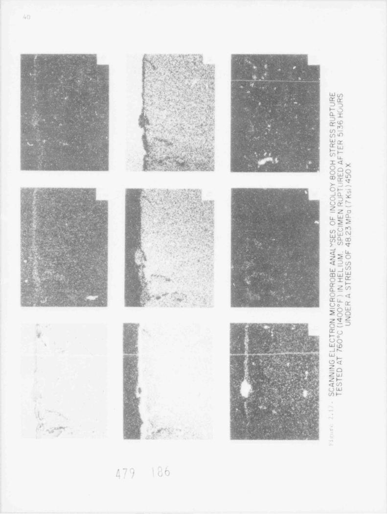
W
m. ,. y -- ;~ -mm ~, .y . 3 ,9 w >q p.-w.~~ ~ ~
S,?;,N'?}f.Jyh..;Q..>;..- &
(... m|
~
1
f ~q.4. m n w, ba n,
gM, c, s,, .c . ;,
.. .
t .
u *,1. y.m
x -5 a6 -' . ~ - asy , ) a. , . c p' W.,
, s. ' S 4 f ,,, *'J ,.ns; ! Q, '1 j * * '0 **f., s.- . . r'* N ' " . -
3.,i ,6" *
.h.,.
s I ,* y , , <: .
< , -,'
.t,,*.+ t
4 F (g {'.Q.' T..y+5 , (
^j.Q > { y. %. { ,,P j,
3 , s .. ,,e 3
{ f , .y. ' y .< . .; . / < ;s;'.k | j Ums s- .- e.g.., . .
3 );w ' Ui'.n q,s. Q .s ,| %|.h.,e~
|% a T T- f l'*
p . -r - .* ; fl..
:, .J D --), , j 'J+ , h ] }.j { J r. , ,. , ,'
,> [ 1 I%% . 65 - ". sg
|? -,v " %.y
jf!/< ~ ,' Aw F c .~ ( w ;:y.jg5- U .jg- t e Em p Di. | T h k . _,h.' , , , , 4 , L) R S:. C#W,- * e-r s 1 * * v. r0* y rb;r .x7.p- ,e,, a- g. gi ' m-p
4 y. ,,
'f c a 1 w\: + m e3,1 s , ,
y,Up $., o s* e.. , % e.x.
.k.. - )# j '. i Wg'. i
[ <?- t
,y . .' , 9, .G *
4 Tc-
[ w,
pu, $|,s . ,w"aw' w !'% sJ , . j n ; s, E t ' *an . , ; }
n;$(NM:H [ .D+py
'br~ 1%pr a
i O - j I<x'
gwc___.w . tamme L_ _ _ ma o aw T>- D ,4
,
#w.reem.,% y . . . ,' OH 7f. ' '' - k ! g; x .%a.y m-w ->m
m' 4,
-' y w, .y.7
.Jen .- g.
' (c_. | o g .N,I OD*- I i [ ['''.Q./.i g ;.'!I M f$kTd.;
'
. w. m , v o ,.s,. v;>
a; 7 m .- ;
3. -
p j i G*s ;g ,' - y, c ';/~. g'.-[;! 6 ; -Zo.
*r a & Zr '
. 'Cw,.q , . . .r : * ,s:p st Uya
s . . > 1 (. . k, -- w. ._ . - ' ."4 , e :. -y -
. . . . '
s. . -]
'
f. ;, < - ;f ,I . Nc ) 6 s t. ,, o 2 <=;-+ .,. ; g . , , r - 7. r
-
[^t. 3 e;
d, . ,. 'l| g7 ' ',^[,_- .f ym
w. ,
e ,-
. .J .9. ._' _- na - Qm CD,
. 3,
- m, , i, { q(. >.',_.p. S. *. t, a y.We, m. .
, .
P'k* N ' #f] M*''_ .s
c~z '. '.3- zeo
'y ' g
v .. . . ,, c .t , ' ,h .
.-t .< : . . s' .< g li-
g, --, 't; w >, w m% .- g.,
t: _ ,. . ,i. 4. : . h 'd : .
h)'n $a-b I VS * # #'
,. 4; 4 @*
,. : a. j. - r ) g, q WdJv. .s. , < g
u-. .j y
4. .L_N r . 3 3 ? %,.,.E- +g ort- CD W.
w&.
w , c-_
, . _m q t.
s- .s+.i - - - ( g sr
' " < ' ,[ 'N ( ZaW.
., 4"; " ), ' < s
m a .t -%. . ++',s' ;[ ^h . I 3 O 4[ -
% ..s ,
%.Jhwi Mw :..a.b wM' w ,, r 1 T u_,% ,
Um w' - .-~~~,J U". w
2 0 0ZqZ
,
3.. ;y? * y msyvany~~.q. pq o -- Dfei N(%y. 'rf ] [g-
y e.. .n !s : t = ms &o
Q.M . ,t s - t-p % e|J 00t t. * * . * r-
s : .- p 1 we5 ', d b C[:idAMN3-NbN dN
v% peyntg%>*h >$g($&j5*fMF' W?9- g.? iM.aN ~> .
- y ;, a4]- f, A , # ! f);g"h L U','p[QL ,W h'l- / ) .' -~., !Q6> U* So
p 7
mygmy%yg Zw0 a w+%pt 1 m. Zs(V:g g , w%w.Q,# p
o (f)Q . f. pb g :. qa ; & nw qrh .j
.
[- 'qc mgjQ;:a~p@ed'%;e
w wgq ew wpy; ,,: a ,, wk. jLy ot x, t.e.3; ,
< w. . , :.:p~,s.-- .. 8 ~, 't % 4' c; S -.w
~
+ t'c' ' Mi' '7 \.
-, _ D
I-
y -
' > Y r % ,' ,?_ t's+n
,
.,f Q *%,
, v. -
4 7 ,
w. ,,
.
,.. ,
- ~.g \ g 4
'' . ,m- f:
f, . 3_' , , . y ,
' ' ~ . , :*~Jmww d~
e x. : ,-: - a> :- , . 4ud-e.i w%4a hde.Ah/ 6 I
,_
%' W e
-
M
n / g1 !OO

!14
At 649 C (1200'F), for test time up to about 7000 hours, there appears to be~
no differen:e in rupt ure strengths for the two environments. However, at 760 C
( l '+ 0 n ' F ) , twa ru pt ure points at !628 and 5176 hours lie slightly below the in-airtest line The duc t ili t i es of t he spectmens, shown in t erms of percentage elon-
,ation in parentheses next to the dat a potnts, dc not seem to be detrimentallya f f, : t e i h ,. the helton environment.
Lone term tests at 644 C (1200 F) stressed at 82. 7 t o 124 MPa (12.0 to 18.0ksi) are under wav hath in air and in helium environments. Sone of these tests
hav. none beyond 10,000 hours o f test ing Lona term tests at 760*C (1400 F)stressed at 34.5 ani 41.4 MPa (5.0 and 6.0 ksi) are also under way.
Fraure 2.15 utves the creep s t r e n;' t h s obtatned for Incoloy 800H at 649 C
(120i *F) and 760'C (1400 F). There is no apparent di f ference in the nintnum
:reep rate for the atr an! heltum test environments. It is po s s ib l e that the
small surface-to-volume ratio used in the test specimens would require a longe rt.,t time in order to show environmentally induced differences in properties,
a c ompar i son has been made of 2 Incoloy 800H specimens tested in air andh.-I t un at 760 C (1400"F). The stress levele were comparable but the helium spec-1ren was exposed to the test e nv i r o nme n t for 3136 hours wh e r e a s the air specimenwas exposed to only 2604 hours. Nevertheless, there were basic s imilarit ies intheir cor ros ion behav ior wh ich a r shown in Figures 2.16 and 2.17, and summartzed
telow:
The predominant oxtdr was that of chrontun but titaniun oxide was alsoclearly observed in the bulk of tho scale
top of the chromium andMancanese oxide seems to fo rm a thin layer on
titantun oxtdes.
Aluminum and siltcon are also oxtdtzed. However, it is not certain
wh +> t h e r these elements are oxtdized in t he same lo:ation as the chromtumor some other area, below the chronium.
Mancanes<, chromium, alumtnum and silicon are also oxidized along
intervranular recions.
The oxidation of magnar se, :hronton and t i t an t on results in theformat ! on of a zone beneat h the oxide scale which i s deplet ed o f t hese
elenents.
2.2.2 Haste lloy X
2.18 presents the s t re s s-r u pt ure data for Hasteiloy X at 760"CFi mr"
(140n*F) and H71"C (1600'F). At bot h of these temperatures, the in-helium testr.o i n t s either lie on the line wht:h is drawn through the air test po i n t s or
sliehtls below. This indicat es a detrimental e f fec t of test ing in hellun on the
r u r,t u r. strength. The most convincing data that illustrate the environnental
+ i t. : t .s r . th+ twa tests per formed at 871'C ('n00 F) at a stress o f 41.4 MPa
h 7O7Iu/
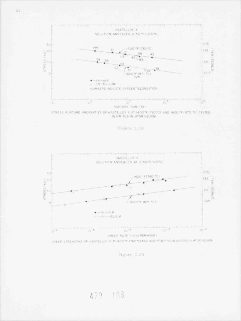
/24
i i 7 r r IT T , i r e t i i tz,
> <
H AST E L L OY X ,
' SO LU TION ANN L AL F D 215 0 *F (ll 76 *C )
1276a. O ''44 I400 *f ( 760 *C ) J,13 8si
7,20'~ ' e~ Q g o
49 42 | .
wem ?* N ,__ I11 5 4|
-
59 gg 0 83 '-|u-, ' ~- o
o IO - e m,' ) t,uv3
y ' , ,( - 'gg j
W
62 A* rs
* -16 ) *F (8 /1 I 3 4 '>
,025 4
| e - IN - Al R j-I N - HELIUM |
:
NUVBE RS INDIC AT E PERCENT ELONGATION
i a i a i i ti i i i i 1 i .
10 10 iO 10 10*3 4
RUP T URE TIME ( hr)
STRF*n RUPTUHE PROPE RTIE S OF H AS TELLOY X AT 1400 *F ( 760 *C) AND 1600 *F ( 8 72 *C) T ESTEDIN AIR AND IN HTGR HELIUM
l'i gu r e 2.13
7 1 - , , , ,.;1 , 1,,;
|HASTELLOY X*
SO L U TION AN N E A L E D AT 2150 *F (Il76 *C)'
1
1
30 12761400 " F ( 760 * C ) |
/ ~ . -- . . - - - 4 |38 -o- gg; e i a
: f -e- y- -,'e
__ w-.
-'
,S;*" "_ / 'O
_--9-- 69 MO lg*w -- o - u
,-* acr >-
_ ce ' /w <nv,
f 600 *F (8 71 *C) ' 343r, - - - * ~ '
-n'..
a
e - lN - AI R
IN - ilEL I U M
i i i , 4 4 t i t
(g ' 10' 5 10 10 '3 'N'- -4
C Rf E P R ATE ( inri, PER HOUR )
CRE E D STRENSTHS GF H ASTE LLOY X AT i400 *F ( 760*CI AND !600 *Fi8 7 t *Cl iN /* R AND IN H TGR Hf t LUM
fi gttrt' 2. 2I)
[4 9

43
..m . >hNNb.m M OM&%nn. r'ege r == y rwe-.y.n+ y Nw'~ wiv-*N
%a
:;., g-.
, g 9.. .f
N.* *,-
, .'
'..q.S-*,e s.
, , '. . /%,*,. 1 - ', *- )y4 -N. . . *v"' p + /'
* ,p. y ,.. t . _
., . . ..- 4h *, , , ,,
,$ . +. - ,. s .
d( |
h ? Y I , *'h , * *, , ' . , . ' * * *
, . *
+q j. /*.. 1, J. .' ' . v' ''[i' $
*N%- * s .3 ' N .\ * * ',' ,5C*/''
* * -+ s4,
, .
4., r. . " - :.\,.i...s.+ .
.,,
:.:*, . .~ .* ,. -, ,- ~. . ~ . . , \,o
.
. > . - g . . . . ,w.* ,>- e,, s**' p . .
/ ' 's, .* M'~
\,4 . *
~ '' * ''
**.9 * Q [V " p . .j .C , y & j - f .. , '2 -K.* ). * n -. o.*-. J.\ ,y o% , , . t .. (. . .~ * ~ . . ,; x,
. . o. o.
-. .
[ .'] 7,]; s . . [ ,-. ' N. $ * ' 7- '.'* *'
,
e. - - . A...i*.- -.
-$,. .
., p*, ,.! .g. ,.i' ,,-'^J.- .s.s .'
>, ,*;;V d.'* ,
,,y./.
, s ',,' .
,1y . . ., , ,, ..-
..,, s,, . .
(A)
-
.v ,'eme.-=s% :.;.. -^~ Q n. m&p_ 4s.: v - :
? Y h,,
o
[ . ' . ', .af. ..
-w-
.. . 3.%T,C wF a.- .
, +~ '
. . . .. / ', -:,,,'q*.. *~
,
-, , * '- .. s. , ,,
-
1.a -
. ., o_..
s ?~~ s. . .- --'
' - 2,' ' - .,
- ,e. . .
*t - . ,. . * - --.
c.s u .. ~
* . / ,
-.
~ .. , ' ,-.,
,
e, s=
3 ,. .* * *
.. *f . - J ..e ' :. - *,
3 j . . ..,
*.. , a v,
~,- m-
.. ca
4 I' *
<' ,, ,
'
. - .** ,.
,. .. s-^
z.
, , . . ,. .
(B)
Figure 2.19. llan telloy X creep specimens fractured at 871 C (1600 F),41.4 Mpa (6.0 ksi); (A) ruptured in air after 554 3 hours, (B) ruptured inHIGR heliur after 29M6 hours. The air specinen had a thicker oxide scaleand showed more interr,ranular precipitation in the natrix. The alloy
depl e t esi vone is thicker in the specimen tested in helium. Ma t; . 500X.
e

44
,
/ s1A r*n 1ry,
ii 1e LA .,M -4 ;g. 13y - a vm r>
& h -#7
f J3m$$rh*3
'
->
w,, - . ~w ; ; .=
t,. A,4 - .,y. a
':> , ;i . a -
4-v . c_ . _ . ,.>
" d}?r t'
.
'$ {r'
= ~p e-*
'
/. e p~Ns. f a c.
a O ''
>-4..
,C
hNe-4
Y 4
W CCE
E'i.
.- uC ILC.JC,
M 1O
a ~
~
C .s3-
ttN -
'f.
p*v==
z r$ U C1| .-
C *I nb.u| , ) aa
.
f: gg n
Ce u
h,*+
- o, ! C~.
Q 3 ' #[-
~, s. .k} I Lf '. * ~ ~L
w" *
w~.-.$ s'&z
.
|~4Q *'Wj,
_.,t
I4.d A 4d) $"? .EV1y b. u__ '
~s
s -. ,., wi w H 9
p.=e '.A.
- ' N' , _%"
%(g .] 9_u
s
% '?.1,) -.$ (j
, .' c,
l ' 04 EF3 u47
~., ''s sb "
C "L -m -c .- |
477 100

45
(6.0 kst). The air test f atled af ter 5543 hours whereos the helium test rupt ured
after 2986 hours. However, the d uc t i l it ie s were very statlar, 38' for t he air
test and 197 for the heltum test.
4 test at 871"C (1600'F) in helium stressed to 27.56Durine thts quarter,MPa (4.0 ksi) f rac t ured a f t e r only 166 5 hour s . This test was neant to be a longt e rt , evaluation of the effect of the heltum e nv i r o nne n t and projected to last
15,000 to 20,000 hours. The specimen broke wit h 2 5% eloneat ion and only 14"redu; tion of iroa. Metallograr,ht; studies on the spectmen are under way to seeif the ause of t he premat ure failure can be established. Also, this test will
be repeatel.
Fi c u r. 2.19 shows met al lograph t: sections for the 2 s pec tme ns de sc ribed
above The oxide layers on both specimens seen to be qutte adherent; however,the one for the atr test ts tht:ker and showed more cracking along the gaugeleneth. This could be because the oxtde is inherently more brittle ar because atht:ker layer cracks no r. readily under stress. The alloy depleted zone appearsto be thicker and there is less arain boundary precipitatton in the spe:inentested in heltun. As in the case of Incolay 800H, continuine metallographt: andscannine electron at:raprobe st udie s on additional spectmen; are being nade toestabitsh the influence of the 2 e nv i ronme n t s on the morpholony o f the oxtde
scal, and subsurface etcrost ruct ure o f Hast elloy X.
Figure 2.20 shows the mininun creep rate data fo r Hastelloy X. Por tests
lastina up to 9000 hours at 760 C (1400 R) and up to 7000 hoors at 8 71 ' Cno di f ferences in re- have been observed for the two environnents.(th00 F),
Long term tests a 360 C (1400 F) under stresses of 50.0 and 55.1 MPa (10.0and 8.0 kst) and at A: C (1600*F) under stress of 34.5 ard 27.6 MPa (5.0 and 4.0kst) are under way.
2.3 Effect of Fission Product Interactions on the Mechantcal Propert ies o f HTGRMetals (S. Aronson, J. Chow, P. Soo)
This program was initiated to de t e rm i ne the e f fect of long term (31000hours) expasure o f HTGR alloys (Type 304 stainless steel, Hastellay X, Incolay
800, Inconel 71A) to iodine, tellurtum, c e s t un todide and cestun under condittons
similar to those occ urrine during normal HTGR operatton. Exposures have been
_ onpl e ted on 5 croups of samples. I n fo rma t i on on the test conditions is given in
Table 7.2.
The test apsules used in the first 4 tests are shown, after exposure, tn
ataure 2.21. The fused quartz Lu5e in Test 3, for example, contains from left torieht a fuse l quart z rucible containing tellurium powder, a magnet encapsulat edin fused quartz, a quartz holder with the 4 ne t .:1 samples, a fused quartz cro-
a wcond quar t z en-151 holitna a ntakel-ntckel oxide mtxture and, ftnally,capsulated ia g ne t . Parts of the fused quartz t ub e s in Tests 2 and 4 be:aml o u'h with a loss of-transparen:v indt:ating that tellurtum attacks rused quart z
( s e, wction 1.7)
A
4 |' J' 1 :|/

/, 6
Table 7.2
Exposure of HTGR Allovs to Sinul at ml h s , t on Profocts
inssion Prmf uc t Temperature ofTe , t 4tmulated Vc p)r Pressure Mrt a l Sampl e s Exposure TimeNo. iission Product (atn.) C (hours)
1 CsI l0-5 790 18 %2 Te, 10-5 770 19921 cs} 10-5 730 1825(1)4 Te9 10-5 800 1850(l)5 I, 10-3 800 1173
m )TE : (1) This capsule :ontains a N t -Ni o m, i x t ur e maintained at 800 C to give an---
oxvgen part t al pressure of 10-l '+ a t m .
All the metal samples in the 5 tests we r e strongly corroded. In Test 5, thei o li ne sourc. was completely used up in attacking the metal sanples. A heavyd e po s i t or reddish-black crystals was found at a location in the luar t z t ube at
which the temperatur. was matntained at 200-300 C It is apparent that netaltolides were va po r t ;.ed from the met al samples and condensed at this locat ion.
These :rystals have been collected and submitted for chemical and X-raydiffraction analysts.
The scannine ele tron micretraphs in Figure 2.22 show preliminary dataobtained from ra ps u l o No. 2 i n wh ich Ty pe 304 stainless steel, Incoloy 800,Ha st ell ov X and In:onel 718 were exposed at an averane t empe r a t ure of 7 70'C t o
tellurium vapor at a partial pressure of about 10-5 atmospheres. The surfacesinitially polished t hrough 600 grit silicon carbide papers and finallyshown w"re
polished on "Microcut 600 prit soft" paper lubricated with kerosene
For the Type 304 stainless steel, Incoloy 800 c.nd Hastelloy X there is alary. amount of s ur f.ic e de pos t t r on wh i ch is easily spalled away i f handled .
Henrath the deposited layer the ortgtnal metal sur f aces are ident i fiable by thepolishing scratches. In the case o f Type 304 stainless steel, however, theredoes appear to be sinntficantiv more corroston of the rae t a l ani the pilishtngmarks are not usually observed. Thts is an ant ic i pat ed result since this
material is usually the least resistant to co rosion of the 4 materialsevaluated.
There is also a sign.ftcant 6cposition of small particles on t op of the
de po s i t ed lavers for the 3 materials. These take the form of fin" granulard e po s i t s or whisi<er type growt h s .
Inconel /18 behave s di f ferent lv from the fi rs t 3 natertals insofar asgeneral deposition of corroston products is not seen. The polished sur f ace
maintains high integrity but there is localtzed corroston as shown in Figure2 ??-
Work has recently been completed on bend to ts on the above samples and onothers exposed to di f ferent fission trodu:t s pe c i e s . Me t ei l l o r r a ph i c analyseswill be :ar r ted out during the next q ua r t e r l y period an! will be described in the
next report.
n^., ,. ,
|1- ,

47
* %)- m.s .
$.?hf?'Nf y*1 .rs-' h j _,
.,
n. a , r.* .* ,. ..'..| w .- u
' 9h -f'*J, - k',#.
,4,^,sa O
ks% J
/,
ey e.,'~ .%. '
= C5g *~ ''4.h~',
n, Cm
.
' s' ' ,, %*'.A . y,
, , ,
J , yg~v*'' w s-~xu
-
'% - s s,,,
.4., .yj. .% q' A e * - f ., ,, , f ~ ' ;o
' o
O c<
-. , ' < . *, + .
* * f [ * g %; s' y*'",''',', CO.
4
> $ , > \ '. A 1,4 - sv- ' rs c.,1g'.
'* . . R ,f 4 yl s ' ,* h. * .t*.- ,.y' ab %
,',M , G'e r' .f 4 . i t* p
.' ...- . L. "..g '1 . ~ _ Q e **** - O ,a.
-
J e *
.p 'Q ) @]I* > %g. ~ .' e*.
DN [$S + >
yt* - A * :er ' . * ? *s ,_J:
' 7#
kh'IyM*| k w, , .
a '#
*' .s, '
b .'N M@q,.'I ,aO c-
* g ^%v * q. % L . . s , p. - . . ~ ~p%ti . N ,p 4J%
, ~. .
y< g ,;. 9, efp a.*s*^
(',-
%f ,. ,. . r. . t.. y* Q, ,
*
d*' - 'e*Q.; y , r. - ,
I ,, - p~
,' ' M. . . ., h. * * ' C.
C~.- 4 . / ,) - a. col M' 7. f .n, a . V p .,
w , .
4 = ,f , M. 'g ' , <9;- e8. g > cq %1 i s% .Oe 1 w , y~.' C .s ,
,Ay;, i.'.>J, .,
,y, 'cb . e ' fE
.4
htc +y~ ,y A9,
m; i'vr 6 3| ( M { f f:
,,;; ' '' . , , J'A, f' 4-
W|W ._ c.Q_ Y y ;~
7.*]?/''.&|hk : ==q *,
, , .
*
'.,
s ,'
(,J., ~.-
9.<A , g. ,.
g ' I *(* , . ~ -~ ,.e> w .= '< , . .
m ,,fp'. '-s-
y W M,44 .+T,f rg'''' *>' 4
k > c*'S c-
' )(*#g- <595 o u p.'a y). .f % ' |i. .'? *s .
N, $*, s.h *a . v .,, A , ,\ ?, ' b _'p'',*.
z.s { .
e.,e T~.a 1
-, .s .,,4 v~
+ fo* ? . k. .-nr > t Y e. g' sg' d A . 4.. s .,
t c A ca<y!1,
.. h, ,,}- ,4 ' . W g;, - gj J C. Z#~'.
5e w X, .c.,_.,,.,.,
f, f w(*#- n,.'~.'*
,- , c d .+g,,,,';' j _
}' $^
N O{ , . - - - E" . , . ,'
/ (
:.A.i & gu.r 3 .4y .L' ,y's.? . ,e ! s
' .(', . / k. ,) m. '
- , -
[g g,(} ,
-
*< ~,, , x
n ... ., , e o, 14 ; 4 <
} wQ,>.QT; &,r- &| r,. *' A , f w,,% -/. p ;* @;,l'|** f' Y.s.) ,k +,* y~.- s.(
...n .
' 3., Y"fIYh; m , .a # . m- . ,
=044 g..- d. r. C . f .1 6 '|. L
*@-
A
pf Q:' .h.y.Y',0.I ,i .j&yJ.;m ~,sq . m&.t,%,h.h +f.m* s|f ?'.?v,.1.] q.) + y;~$'_h'|'k. -, 3
q .. k V .4 . Ag i-a. , % ';; yay -Q'
8.
, .. . . n. . ' '-b i'Yh 7
fy a, -... n-s.
s "-|i: ' M:~;. .. - Q i,J.,*r'r1-
w t., ,4 . ~
n?* ,P&T.h! n|Q(% s,w, u/,. )(g, , e ' '.* ,,)#' , ,.
.. ~: p ;n * a: h,:'$Ob' /:.
.-..
=.O'' ., ^.' * -
. ,,, . \.4' a':. > 4 ' TQ
3 e '. / '# ' .'- d 'g .w v
f''f' * = b , .Y-
, W ,,s< ry ! * *: * , /* $.; * 3 ~
%j i I* \' J' ks t*v '. *y f )< .,'Q,d.. .g* 6 -
.,*
S. 'M'e 4,' "* ;'[ - '
r.$'"$f.. a)* '
.pr# L 5w 'j
0 ~ ' v . - ~ j '' y > ~~ . 's , s'- --M= f / ,. oos
A!' & y'" 7 * 0 *,' ,'f ~ %,b
*' yf.D tn &,p ~o{? r.o C
. \,; r | QO-- '',.,e*
V: - . , ,.y N; A'"Y*R im''
'h ,'|w~ ^.
' v:
4}h';f. f'#.g - ..J,Q:,i; * ' ' * 4:
*
. w' * , .,'.9
V. t ', '. V }, c.g
s~~~~
*^ C2 i'-||~,| %..
~ ', , , . ' ~. ,,u . ~ z,,i.<.. w'. * - x
g>a . qn ,,j J . t; . % . , , ,9 . . e *g .c .,' t '.: "s ~. <;.
%. | } 4 /,r</.':\ m . /. y,,r, ~.,<4o c
i '(',, 8Sr. . s/ . -f'
p. ''-
~- M (.f i ' ,. ,w~sC't,,%pt,..qm.4z,[email protected]..#D.w,~?
y V - =p r S.,y, ; yf 6 [#.,,
u .~. , . <:' |I . c ,z.a ./ . a. n . - - - ,L- :,
'y < ,s - ~ ' ' ,.a '
?. , % w@M W h @W''Gy3 x. &' W -;L,f W, G. W-O.de Y' ; a-
$|, ifC.
Qn .~W, . w', , ' L. c-
=ti e
. s <,
y j gS Y. +p p1, * - ,f, . + ' , **'V.=.a i ,, . c.4 . Av...n l . '' >" ,A.3 ,g.
.w ,s.ipig.' [ p. 9 g e{, {,egJ.e'' ' ' ' ' ' -
- 'n, N ,'
+5.-
i~4 | 'e) 1G~
I /

'. y
2.i Miterials Test Loop (L Epel)
The "iterials *. t Lo' L) f unc t ioned r o u t i n e l :, ductng the last quarter,
.uoplying h. l i trn wi led amannt s i mp'ir i t t e s to 3 hi gh c vc li f at t ruenachin~s, 11 creep t r u i .i : u d i ie s , and I agtm ret ort s. Tae only noteworthvin tlent 'i u r i n,, t h. 3 nonth intetval was a regionwidi t.o uer failure that maused
th- first int errupt ton in steadv o ne . .t ion sinci startup l 1/2 vears ago. Thet o t 11 octh of time that the vfl was shut down was approxinately 18 hours and it
a .f j u s t d to desien 1- els within an hour or ' a f t er startup.
'l h . MTL hehavior du r i n, thts quarter ts summartzed in Ta b l e 7.3, which showsthe 3 nonth average, and standard Geviations of each of the 5 controlled importtyoncentrations toertner with the desired levels of each. As or be seinsro tton of this tanle, the averoye inpur i t y levels were quite close to theb, ten mocent rat 'ans and the stan.fard deviations were also reasonablv snall,
ex:rr rhaps fo r hv irage n, even there, however, t h. coe f ficient o f variat ion
wac just 22.5
Tabie 2.3
Inpuritv Concentrattons in the MTL (ppn)
inpurtt, Destred Averac. Staniard Deviatton
C.1 T h . ) n D i i ) '' 1 ' I ' } () Il.0 2.Nt
f.1 r h o n Monox t d t- 41) 39.8 3.3HvJrocen 2N IU 44.8-
wthane 20 14.1 2.4
Uter /apor 40 42.3 6.0
2.) Large Scale Graphite oxidation Loop (L Epel)
Work has begun to desien a t a re. x, 1, grapntt, o<tdation ioap to be usedinitialls for expostne 10 inch dtavter PGX samples to high t empe r a t ur e , hichpressur., ontaninated heltum. tie c .i u s e t 'a " na}or capital e q u i pm e n t iten is the
circulating pump and notor, a yo;tation for an engineering design of a helium: t r :ul. t ar w<s req ue s t e.! fro % chanical Te:hnolocv, Inc. o f La t ham , New Yor;<.Also, a h ul- t figure for fahricatton, assen51y, testing and deltvery of thetinal eleutco cir:ulator (including nator, exciter, : etrols, etc.) was req ue s t e i .The ncineerine desten effort, which waald be approxinatelv 6 months lom , was%rinated to ost :ih o u t $130,000 on a cost plus fixe ! fe, h.sts. The hudcetarye s t i nit , far the circulator-mator assembly stands at 9660,0iM. These figuresar ;l y to a :tr:ulator havin, the fo l l owi ng charactertstics:
Inlet Pressor. 7M psianutlet Pressure 76 0 psia
Inlet Tem riturr 1000'FF1ow (at i n 1. ' _andittons) 600 ft 3 heliun/n1n.
In arlor to .!"selap the umt econan t c il tie s t ' n , i variations the nominal.
4 ** Vhi, f)# k

49
.on figerat ton are being constdered in the design study. These vartattons wt11ne ce ssit at e di f ferences tn other c apit al equt pnent items such as electrical
heaters, i> eat exchangers, piping, etc. but may lead to a less expensive overallsyst e than the " nominal" one based on the circulator spectficatiors given aboveIn all of tne designs the test sec t ion condi t ions are assumed to be the same,
namely 1800 F heltun at 735 pst, expertencing a 5% reduct ion i n wa t e r va po roncent atton as tt passes over the graphite specimen. These conditions resuit
in th. followine calculated helium flow rates fo r the nominal case and its 3Vartattons:
Pum p Pump Pun p
Inlet Press. Inlet Temp. Inlet Flow
Case pia F c fn
Ln.nal (Case 1) 735 1000 600Case 2 735 200 270
m 1000 2270case 3Case 4 '"7'
-
Each of these variations will be cons idered separat e ly in the st udy to de' e rmtnet h, optimal economic de s u n far the graphite oxidat.on Lu p ,
2.6 iie l i um Inpurities Loop (L Epel)
The Heltun Inpurities Loop (HIL) has been run during the quarter to gainfurth-r insight into the thermodynamtes and kinetics o f chemical reactions ofheltun importties with the alloy which comprises the retorts. Additional ex-
periments were pe r formed to study the diffustor rate o f hydrogen through thewalls of the loop and to obtatn a preliminary idea of absorption and desorptionrates o f h vd rouen in the metal walls.
The He ' t um A f t e r g l ow Mo n i t o r , developed at LASL, has arrived at Bh and workhas started on repairtng the vacuum systen. A quart z pl at e that rests betweenthe " glow tube" and the nono 3roneter was found to be c racked and a new one is
being made
d Gr the " quartzAdditional instrumentation has been ordeied far the HIL anso t h a :. experiments can proceed in both systens s imu lt a ne y. Als,, in-loop"
frared absorption detectors have been purchased to replace the anametrtcs"'
no i s t ur + monttors, the latter having been found to be unreliabl<
More spectftcally, the metallurgical condition of the HIL under oxiiizineand reductng atmospheres is becoming better undersood. The H3/H 0 ratios3
observed when water is present in the loop are ent irely consist ent with a nodel-a f c h r on t um , iron and nickel oxidation which asserts that the chroniun and thenickel oxide activities are nuch less than unity at eq u i l i b r i um . It happens that
at the retort temperature of the HIL the free energy of formation of tron oxideso that it is the compe t i t ion bet wee nnume ric ally c loseand .if water vapar are
tron and hydroern that determines the measured H /H O rt tos. "nder these2 2essent ially complet ely oxtdized wuile nickel is innune toconditions chroniun is
any free oxygen in the system (Epel, 1978).
4nn 15t>

. _ _ - - . - - . - -
)
;i n i I .i r l V , wh. i t h. H I 1. i s 1n a V. t v r edii '.ol 4t .i t e , t < > I l .iw i nc h v.)i.ici nterine, th. Hy/H7 r.it t o s ,telI t u t or > lit i on tron which interenz. .in h.0
dr iwn ,,n orninc wht:h i n. s t i t ue n t - of t h. stainless st.el retirt% .ir. still
ix t d i / e.! .in<l nich .ir. nat. The t he r nad vnami < .t the s s s t en to. 6 . r wi t h tie
'ih rvei 4 > / Hy,i r it i o inpl1 that t h. Jhtse n t u, r en.i i n s o x 1.11/ e I whi1 the
ent iail s ampl et e 1 v riolu :ed durinc h v f r < wen 1irinn 9in?e ' b r ien t umirin i- i
.ixi.h wt iI not c. i v . n; i!- oys,en to fil (the trce e n e r .: v h inc. is po s i t i s . for
t !i i - .1' tis >ft), t fl. 5 h s. r s . '!*l tin Ve r s i sill is i t 'Il t.) ( '' l ) t'i! l ti di lic .i I I i 11 I.' ' t I t ili,o s t h. i d i s pr o p.> r t i o n.i t i on rea : t t on . This exo : t at t on w.i s in t t rme I hv the
"L i s s ti .i l .i!! i ,iisti.. in t li e 1111. Wh. n it w. l '. I li .I 1. cl e i ' . il s t .i t .
Ili n ' i x)i r 1 e li t .i l >!i i r V .i t t i ili s I ti t 11 H I l. .i r . in s i S t . fit wi! h tII. t"liiilvn.1'11i
pr.oit tions it equiliht inn on.ii t i on s .i r . a s wneil , at least for t h. hi/hly oxi-di. si and hichlv redure t s y s t en A s y s t . m.it i metha' .if pr e.li . t i n e the oxili/-
otinc p1itenttal of v.ir i ou s in-inc, r.olo : i ne, . i r b u r i r. i n g , d. arhurtzinc, or i
porits amb initions t- heine st u11. ! (i;ui r v , 1%0; hi a , in M ) . It a se I t -
n s i s r ent , preIi tive n,id e I an he ve ne rat ed , ho w.o er, it wil1 stii1 > 1, appls
t.' . .pii l t h r i e rr on<i t t i on s . 'I h e s i net i- of vartons pro esses in t he H1' nomiturther s t o.! s
,o u experiments .ii med at e s t ina t i ne hvoroten dittustan r.i t . through the
onpletel. i'h e t i o. behavior of hvdronen on: ent ra t tiin inH I I. h.ninda r ii woi .
the n I I. tallawin, t u s s i v. inj.:tions of h v i r i.:e n wa' obsersed .i t normal H i h < >pe r -
atinc o nil i t i ,,n ' for two leve's at II;> on cent rat i on an order of m.n:.li t u h. a-
part Roth t. sts re sul t +ol in expon ntial de iv wi t h tine of the h v.i r oc e n in the
ill I. t'. li. I t I i v. . i c r c i i n ;: at t b >n.' a n sit hi> r wi t h i n ab.)it t 5"
'I h e q n.i r t . 1. n ip h i s been use! il ir i ne the quirter ta t uve s t I g.it e t h. pass 1-
biliti of torninn tr.. cathan nonoxi!. with .i nechants, .her t h.in d i s p r .> po r -tonation. T he r mlvne t allv it is possibl. to oxilize the ch ro,i u n in stain 1. ,s.
,t.el h. x pa s a r. to ait<> f o r r. a ' t .ih l e o x ! .l. anl tree carbon. At 1000 K, t h.t. nw rat ur, t .h. r e.i ' t t o n 'one in the loop, the st in t.irit trm e n c r e. v c h.i n n for
t h. r..i: tion JUr. + 3ni Cr m 3 + W is -62.R kilocalori. I~ h e s t inda rd fr..
e n. r - : h ;' n c for t h. oxidat t on of iron and ni-kel hv carbon non o x i t h ar. post-
ttv. Assuminc unit acttviti s for al1 af the .o1idt in the abov. r. .i c t t on , the
,,,uted t i n il Un pr. ,or. is 2/ .i t n . Thi- is verv -los. t.. the final Fo pr e s-
suri 4,h s e r vi ot in the quar!e linip after it w is -h.ir; ed i ni t t .il l v wi t n 7 t in O atm.
ile p l * > t . 'il , i 11 -Ili4 r. win n.1 hili l il'l J ti t ('! i i)r (it lie r i n jit!T i t i . s .i s ! h. (l) h. "1.-
.li atit t h.it t he r.uct1.>n s h,iwn ahove as the <>ne i nvils.l.
' ('h t r ;1 c t e r i / a t n iin af pf;X (;ra; h i t e (F B 1;ri>ws ick , M. F t is , J. lie i s e r ,#: l'nche r e )
Dur i n - thi< q ua r t e r , the st u lv of P(;X araph:te in the f o l l owi nc .i rca s w. i -
int i nue !: oxidation kinett: r.wival of i r in f ri n i m pur. ,: r i p h i t . an1 ett. t,
.!,i t i il .)n li l t i n.i t . e1J r + s s 1 s . s t r. ric Tli.- s t ii l s .it ci <- t r.iri s ;~ i r t .i tit i<
.!i ' . l t . il f. J. * r ,i t li r . ll .1 % ni t ve t t i tii iti. l t. .i jire i r . i t i t 's )ii s t r 11 ? t i si!) j )li l s . iti
wil1 ,i.it !>< 11- J il s .il. A > t a l l .i r s t .it u s exista t ii r .I s t ti !\ .)n t lo- ette?t- inf
,pressiv. stress, on o x i d a t 1. ' n r it . .i nl ultinate tensi l. .in !t en s 11 anti )
.n;>r. ,tv.- s t r e 'n / t h ' it f IM;X .' r J J ,li l t . 'I l i i * I> k ari)s. i r .'n pr.1 int e i.J1- @)Tb
1.in. at iN. .n th.- et1 t .if tensil. ,tri on the t> x i ila t i ,in r.it. <>t 41 ( N
r.tIdi i t .'s i (;r iiw .5 : t. , [ q 19.1 ) ; .1 I t h iii c h nii .- t!< :I w. I ' t.iun l f r.in t li i s a nti ist he r
f ~ rjt/ 1,6. ,--.m
*JEM. W _M--

I I I I I I I I I-
_
c 700 C 735 C 778 Cg 0.10 -
j-
O x _ v v v _
c oE O.08 -
-
N! ' 'N-
_
S w I \_
F<-0.06 - /~
, x -
; ,/ -1 - %
/ \'' -z O.04 -
"pO !_
i-
F- 'o 0.02 -
4g _ _
E O ' ' ' '
I.O 2.0 3.0 4.0 5.0 6.0 7.0 8.0 9.010.0
% BURNOFF
Figure 2.23. The effect of burnoff on the oxidation rate of a PUX graphitespecimen containing 100 ppm iron in He containing 0.63 il i) + 6.37 !!;
i

,
3
- o ,. n e, n, o e o *. n ,1 ,
;>\+:
5 . e o c. 5 c. n ;.o
<.. N
e u w, - i4
,, i 9,
I L '\ 'oa 4 ',,,[ '" ?-' n . p , , - i,
,
'I O if/' - ~ *
a- , <
o c d- '*,
1 ,
**--, ..
OCv, - , - . -
,_,;*. 7 7*
o c.. = - .4,
I
oc' '
i
4 [j C bCo I ,' ) ) l f . ."),
rt o w 9t.TE.cm b 'r
l' i r,u r e '.24. 'I h e eftect of flow rate on the oxid.it ion r.i t e of a PGX uriphitecontaining 100 ppm fron.
,C 1 T' I I I I T T T-
E O 20 - ^ 0. 6 3 *4 H O + 6 3 % H /%^ ~2 2& * A O 63 % H O /2E. 0 16 -
-
O l2L -
Z O08*-o_
-
r" 0 04-< # . - 4 - au=* t
,W -w-
~~
4 0 800 12 0 600 003FLOW R ATE, cm / min
Fisure 2.25. Ihe effect ot flow rate on the ox i d.i t i on rate of a l'G X craphite,
'?ecimen c on t ,ii n i na 400 ppn iron.
|t, " m ]DQf

53
| i 1 T I i_
_
O.07- -
.E ~
q-
E O.0 6 - -
e - -E- 0.05L I
s - 1w_
$ O.04 -_
z --
9 0.03 --
C -_
-
$ O.02 --
* ~
o a 0.63% H O + 6.3 % H~
2 20.01 ~
e a 0.63% H O ]_ 2
I 1 I I I I I i 1
400 800 I200 1600 20003FLOW RATE,cm / min
Figure 2.26. The effect of flow rate on the oxidation rate of a l'GX granhi te
ipecimen containing 1000 ppm iron.
i r i r i r_ 3
0 18- -
0 16 -
I~~
rc
?$ O aI 3,
LI I /g O iOp -
"I~ ~1
z 008- 4
9 [ / JC [ ^ O 63 % H O + 8 3 % H ,1008 C d0 06- 2 2
h / * * O 6 3 % H 0, 1000 C2O C4- 4
L JO O2h -l
'Jr
ibb ~~@ ba 120D I6'CQ 2000-FLOW RATE, cm3 min/
Figure 2.27. The effect of flow rate on the oxidation rate of a II4 51 graphi tespecimen.
blQ ] 's QNI / | | |
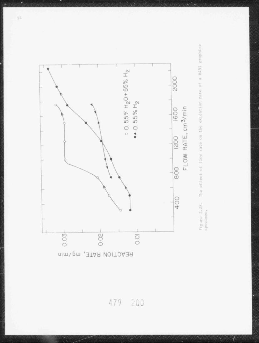
., .
.
. _ _ _ _ . - _ _ - _ _ . _ _ _ . . . - _ . . _ . . ..
} t
.
.
=eG
] | | | ! ra
N - $-_
I =
O c
$ O.- to
- O_.
=
o N .
+ E'O -
- N w a
\ I I O .E 5s 8 O E -3o
- to to to s :
\ C C -"EO O - j
_o
O 4 *
* O W 8o O F-- m4 2,
- cr ;
_ 3 s- O C
_JO LL E
_O-
-
co y:+
_ ._
aa,
g_ O
4 fio
a c
- g .{-
.x ...- .
j l l ! ! l * 7'| _
to m -
O O OO O O
uiw / Bw '31V8 NOllDV38
479 200
MW

55
.inilar - t u. f i . i ( Muh as :hewsk i , lu 76 ani Threwer, 1977), the re sul t s tron the
ar i gi n il st uh ( K r e f e l .i , 1973) are po t e n t t a l l v sientficant enough o that ane xh ms t is, investtration ." ens wirthwht1
Twi new t .i sk s were l iii."1 this <|ua r t e r : inv. s t iv at t on o f PGX craphitest rengt h 1 >s s in n.in-o x 1 li z i ng gas inin environm nts and the e f f ect a of tensile
ani snpressive pre s t rr s se s .in oxilatton rat e .in i ultimite tensile and
inpr'ssive strenvths inf PGX c r.iph i t .
J . 7.1 (W1 lati in Mineti; of PG= Graphit.>
Ih. el'..t .if h ur n.if f on t he oxidation rate of an axial PGX graphite, p. : i r en obt a t mot from the nidlencth (ML) o f BNL log 2 w.i s determined by
t h e r n o g r a v i ne t r '. Th+ sp. inen was shown to ontain '100 ppo iron by Massbauers p. t r i s : a p v . It was exposed to 0.63i
2 6. F H7 in He at a total flowHO +l/ntn. Data w.> r e obtained at increments of 0. 0 C hornoff. Ther at . .it lWO n
r. uits ar. shown in F i gu r. ? 2 3. the oxidation rate is observed to de c rea si
wi t h tu'reastne burn 1if f up to 107 over the t empe r.it ure span 700-178"G. This
result is outrars t ii pr ev i iu s observations wherein the oxi da t i.in rate increased
wi t h hornot f (Grow:oi, 1977). The effe:t of hornoff on reaction rate has of t enh. e n at t r i bu t .ol to the process of pa r . development. However, it ts difficult toexplain th" lat a in Fi g ur. 2 . .' 3 in these terms. Workers at General Atomic have,.m . > - aston, ob t a i n."1 r e s u l t ., sintlar to the abov. , wh i c h they ascrthe to slow
alurptton of h v.t r o ge n onto active sites (CA, 1978). This phenomenon has beenih rve i hv the say workers wi t h H 3 2 7 ani H451 c r.iph i' e s . An a l t e rna t tv.
is the slow redu:t ton of cat alyt ically act ive metal oxide inpur i t le s .<planatton.
Insutttcient i n f.irma t i.in at this tinn precludes further discussion of the
phen renon. It should be noted also that the oxidation rate dat a in Figure 2.23
y h '. h t t w. erratic beh.iv i . i r . This is consi st ent wi t h previous observations of
os tilatorv rate behavior dortur the o xidat t on o f PGX eraphite
Th. ett.:t of flow rate on the oxi lat t on rate of PGX graphite was also
i nv. * i r a t o.1 t he rm.ie r u inet r t c a l 1 s The re sul t s are given tn Figores 2.24 to.
'.26 for s p. : trens ont aint ne '100 ppn to >1000 ppn tren. Sint tar ly obt a t nedplots f. > r Hiil graphite specimens are shown in Figure 2.27 and 2.28. Althourh
t uth curves a r. f r .i wu throu"h the data, no functtonal relat tonshi p is assumed.
Th. :u rv e s g"n cat e l wi t h .i ide.f H7 were obtained after those without aided
H7 m arrows initcate t h. direction in which the flow rate was changed.
% l ar s, hyst e res t s observed for . a me of t h. runs w is not expected. Thesufficiently ntch f l owov" rill trenfs, however, follow the presumption that at a
rate the rat e of wetcht loss should approrch a onstant value c o r r e s pon.li ne to a
ne/ licibl. redo:tton 1. t he rec t ant concent rat ion. The curves with added H2d i s pl a s" i in F t cur. '.24, however, show the same ktni of Lreni as that ohtainedwith hornoft in Figure 7 23. The os:illatory behavtor noted previauslv a pp..a r s
in t h. run without adde lH7 in Figure 2.26. All the PGX graphite runs were.tain"! with sp.:im.ns at relattvely 1 a rg. hornoffs ( 5*), wh e r e a s the HiS1
H () run with the first.r.ithtt. runs were .>h t a i ne l at b orn,it f s i>f 'l? The 7
H431 sp. t" n ( Fi rur. .' . ? 7 ) showe I two .ib r uit increases in th- react ion rat.
'iur'. .if t he experiment, which we :annot explain. Th. runs with th.Jurin/ th. .
ond H 'i i l sp.: tr en ( Fi gu r. 2 . ') M ) gave rise to a continuousl' increasing.
,~ n ,n1# i 1
./ V h#

Sf 3
iixi<!.it ti n T.lt*- bith incr.astn: f l .iw rat. Again, w. - <ir. wi l li.ni t . x lil .in.i t i in .i
Much an etfeet has, however, been observed hv others (Blakelv, 1965 and Burnette,IllM) for ATJ and Hi27 graphites, re sp c t tvely. The curv+ with .olded H7 inF1,ure ' 28 ts higher than th- curve gen rat e l in the absence of idded ih .This appears to b. ontrars to the ex pec t e l inhibitory effect of II; . Howev"r,ne a s ur. e n t s obtained at 1750 en 3/nin. at the end of the experiment gaverea: tion rat es at 0.0315 ne/ min, with .iiled H; compared to 0.0406 to theabwnce of adled Hy. Th. apparent d i s c r e pan ^ v of the an probab l y he, curve, 2
ascribe'l to the e f t. :t of burnaff.
2.7 2 R e' :ov a l of Iron from Inpur. Gr.iph i t e s
,ples at pGX artphite containtne 'l00 p m tron were ground anl sieved to'
in n dian~tet pa r t t :l e s , honageneou s l y b lended wi t h reduce! iron powder of
sintlar siz. an.1 pressed into 1/4 in:h tht:k pe l l e t s . It was foun<! that exposure
to 0.1 torr 1 7 in lie at 750"C for 24 hours was sotftcient to decreise the trononc en t r.it t on in a 407 iran s pe c lae n ta L100 p pn , wh i I e that of a 10 tran
spe inen was decreased to O.l' anl that of a 0.2* tron spectnen was decreased to0.l* The increastne di f t teul t y in renoving tron from spicinens containingprogressive 1y lower a:: aunt s of aron can he at t r tbut e ! to the poteutial for
forming a lamellar _ompound of graphite, iron an! iodine An unknown s pe c t r onwas clearly o5 served after exposure of t he 0 2? iron s pec t ne n to I2, while it
lefinitely absent in the c .i s e of the 40; tron specinen. In s p. : i,o n swas
ontaining large amounts of iron, the atom ratto C/Fr may be so low as topre :lud. t h. C-C handine ne e s s.i r v to fora a lamellar onpound. Adoittonally,renoval of iron is factittate! as the reaction progresses due to the openporosity brought about by removal of the tron; this ef fect is expected to becomepronouncel :i t high concentrations of iron.
The difficulty in re produ: t un t he unknown s pec t r um wi t h i ron-r t ch s pec imen s
l e ils to difticulty in ident t f tc al ton of the specie, X-rav di f f ract ion usuallv
requires a sample which is concentrated to >5* Conseq uent iv , nethods are brine
sought to separat. graphite fro- the supposAdly lamellar onpound. It shauld bepublished re por t s of the existence o f gr aphi t e -t ron-noted that there are no
todine lamellar :onpounis, wh e r e a s i xt ens tve documentatton is av a i l ab le on
fluorine and chlorine oopounis.
2.7.1 Th. E f fe:t a f Dxidat t on on the U l t imat e Conpressive St rengt h o f pGX
Graphite
A new tlow systen has been designed to study the effect of hornoft on theult imat e c mpressive s t rengt h o f graph i t e s. It is hoped that a similar designan he us.d in the 5 foot lone, 4 inch 1.D. t uh t furnaa whose arrival is
.Iw11t("!.
r1yht c v l i nd r i c.il I,5 inah dianeter tine 1.0 toch lengt h graph i t eThre i
spect~ ns are suspended en1-Lo-en1 1na toch quartz tube wtthtn a resistance'
furnace A preheater r.i t s e s the t empe r a t ure of the gas to the i nlet furna e
t empe ra t ur. Flow rate as high is 50 liters /ntn. can be acconmodated before thet empe r at ur e pro t t i. along the specinens is signi ficant ly a f fec t ed. Axial vbspecimens fron HNb loc 2 have been foun i to have reictivitt. at 1. : a s t an order'
o f n ie ni t u !. c r e.it e r than those used previousiv from p," h log 1 (Grow:ock, 1978h).
To ntnini/. .conlarv r..a r t t on s ani <onversion of H,0, r" action t em pe r.it ur e s
4 j ') Y?

S7
,,artls b. l i m i t mi t.> 90%:will n. .
Preliminary oxtJations hav. been dano on sesoral s pe :inens at 850"C using
0.7? H2 in H- I n s p+ ; t t o n of the specimens revealei the absen:eis.07' Hy) +
it larve pit , inferi, t h e- a p pe a r to exhibit un i forn surface burnoff. Export-H n con eu rations, withnt- will be tone at si ural t en orat ures and 2
4, / H f ) - 10-:0. Reaction rate will be monitorri by intermittent analyses oft h. product cases via gas hramatoaraphy. Weight ani compressive st rength of
,>xilized specimens wi ll be d e t e rm i n e d . One serte, of specinens will be machtnmito 2 tim"s " 1." ( e x p. c t mi di f fusion length) and subsequently compression t e s t ml .
Efte:t o f Hi gh Temp"r at ur e Exp1 sure of PGX Graphite to Non-Ox id i zi ng GisesJ ' 4
I.o s s of bulk nat e ri a l dortne the oxidat ton o f PGX graphit e under presuned
.f i f f u s ion-l imi t ed condi t t ons my occur via warmholing Alternatively, oxtdtzedre t .i l l i - Impuritte ,i t s t r t h ot e l in the bulk of the graphite may be reduced by the
:ra phi! + an ! H3/Co yielding HO an f CO2, wh i c h c a n oxidize the graphite2
itself. Further loss o' nulk mat et t al may occur from the desorption o f Co and
DQ. Exper ment s are now unter way to test these possibilities.
The first series of experiments invilve ax t al MI. PGX gr aphi t e r pe c i ne n s f r on
hNI. loe 2. Th r e. sizrs of right cyltndrical specimens are being used: 0.75 inchli meter times 1.5 toch length, 1.5 in:h diameter time- 3.0 inch length and 3.0in h di amet e- tires 3.0 inch length. These are exposed .o a static puri f ted He
nv i r onme n t at 900-1000'C until the H2/Cn/Caj part tal pressures are constant;the sp.:imen weteht loss is determined followed by neasurenent o f ult imat eompressiv. a t reng t h. In some cases s pe c ime n s are exposed to several cycles of
q ue n :!. i n e , air reftll, avacuation, helium refill and heating. Specimens wtll he
.+ oi an! compre ,ston t< mi at the on t of the exprr tment . In the secondw
o r t .- s o' experinents the proc , lore will be ident ical, but H2/He Lixt ures willbe sub s t t t ut ed for pur. He
A n ini folded acoon statioi designed for :10-6 torr has been built for
interfa:ine the r">.< ors to a , ass s pe c t r one t e r . Th< lat ter ts to be usmi foroperational and has b e e n no d t f i ed for theseall 'as analyses. It ic r e
exp"riments. Results shauld be forthcoming soon.
?,7.' Th. Effect of Compressive Prestresses on the Ult imat e Compressive Strengthoi P';X G r.i ph i t e
The impetus for this s t o;f y : ine from the unpublishr! wark of Imat ani Rasakio f JARI (1978). The, prestressel samples o f H32 7 grah t t e under compression up
'30'C the reaction rate of ,to n.9 x and oxidi ed the sp :tmens in air. At +
are st re ss"l sp timen was several times gr .ater than that o f vi rgin nat ori a l;how" er, the effect +:ame less pronoun.ed with increasing temperatur. anditsap;earei above 590 C Annealing at 1000* C a f t e r prestressing did not chang +
this r"sult, thaugh annealine at 2000'C e limi nat ed the e f f +-c t .
HOCon:ern about this effect in HTCR eraphites exposed to He containtne 2
a sintlar stuiv with PGX graphite However, theani H2 importtles has promptedlow r"a :t iv i t y ofh20 tonpared to air pre cludes using reaction t empe rat ure s
i

') S
below 60CC in short term expe r tment s . Since the interest ites in the effect ofprestrees on st rengt h , oxidation rate is not betng neasured in prelintnary tests,only uittmate compressive strength, -c.
Currently, 0.75 inch diameter times 1.5 tnch length right cylindrical axialML specimens from BNL log 2 are being exposed to prestresses up to 0.75 q at0.1 in./ min. Total dimensional changes observed ar" several tenths of one
percent. The specimens are oxidized (in the chemic al reaction controlled regime)
2 20? H7 in He flowing at 300 cml/ min. Five s pe c im e n sat 6 70' C wt t h 2 *: 11 0 +are oxidized at once in the same t ube furnace, these are periodically renoved,weighed and re po s i t t oned in the opposite order to average out any temperature
and 110 conversion e f fec t s. The results to date are s h o wn in Figurer, r a l i e n t 72 . '. 9 '!o effect from prestresstng PGX graphite up to 0.75 -c ts observed. It
should also be noted that no e f fect of prestre.4 sing on the average rate o f we i gh t
loss has been observed either. Measurements up to 10% burnoff will be 'btainedsoon.
2.8 Instrumentation and Control Systens (G. Uneberg)
The Nuclide Corporation nass spectrometer was installed at BNL t his quarter.Acceptance testing has been completed and modifications to the inlet system areund"r way A lo's o f pow r to the mass spectrometer during an out agi in Decembercaised pump oils to be backstreamed into the instrument This caused some delayin the planned i nc or po r a t i on of the mass s pec t rome t e r into the graphite oxtdation
program.
Future re por t ng on the nass s pec t romet e r wil l hence fort h be de sc ribed in
the sectton on graphit, oxtdatton.
PUBLICATIONS
ARONSON, S., et al., "Effect of Fisston Product Interacttons on the Coriaston andMechanical Properties of HTGR Alloys," BNL-NUREG-25325, in Proc. o f U. S . -J a pa nSe1.inar on HTCR Sa fet y Technology, Fujt, Japan, Novenber 24-25, 1978, Vol. III.
CHOW, J. G Y., Son, P. and EPEL, L., " Creep and Fatigue o f Inco loy-800H in aHigh Temperature Gas Cooled Reactor (HTGR) He l i un Env i ronme nt ," in Allov_E00,Pro- of the Pe t t e n International Conference, The ';e t h e r l a n d s , March 1"78,
Nort h :8011and Publishing Co., 1979, pp. 331-36
CHnW, J. G Y., SOO, P- and SABATINI, R., "The Ef fect of a Heliun Environnent onthe Mechanical Properties o f HIGR Primary System Metals," BNL-Nf' REG-2 5 32 6, in
Proc. of U.S.-Japan Semi na r 0- dTGR Sa fet y Technology , Fuji, Japan, November2 '. - 2 5 , 1978, Vol. III.
EPFL, L G and SCl!WE I TZER , D. G, "Cheatcal Reactions in the lie l t um Impurities
Icnip," BNL-NPREG-25324, in Proc. o f U . S . -J a pa n Seminar on HTGR Sa fet yTechnolouv, Fuji, Japan, November 24-25, 1978, Vol. II.
GR on' COCK , F. B. and SKALYn, J., Jr., " Role o f I purit y Iron in the Oxidation ofPGX Graphite," Anerican Ceramic Societ. 31st Pactftc Coast Regicnal Meeting,San Direo, Cali for ni a , Oc t obe r 2 5-2 7, 1978 (c opy o f pa per appears in
1_ q9

I I I I I I I I
o NON - ST RESSED6,0004- A PRE-STRESSED TO O.25 c
~
.s c~,e o PRE-STRESSED TO O.75 cc
-
~-
cmu,
5,000 - -
'-no.
- ont?
_ _
N
4,000 - -
_ _
3,000 I I I I I I I i i
O 2 4 6 8 10
% BURNOFF
Figure 2.29. The effect of burnoff on the ultimate compressive strength of
prestressed PGX graphite.
$

_ _ _ ______ ____ _ __ ___ _ ____ __ _ __ _ ____ ___ ___ _ _ _._ _ _ _._ _ _ __. _ _ _
M)
F.t c h i n fiirn.lt t inize nt r un Energie, F'i v s i k , M.it hema t i k Gnh't ) .
G R OWcn(T , F. B et al , " Graphite Ox lif a t i on hv Motstur.," BNI.-N PR EG-2 512 7, in,
Pr.>c .)f I' > - - la pa n 'ie ni na r on llTGR Sa f et y Technolovy, Fuji, .Ia pa n , Nov er.h e r'
'4-25, 19 7X , Vol. II.
S(ni, P an<! CIR G , I. Y., " Correlation .if Low-CS21 and lii nh-Cyc l. Fatigue Data'
t>r Solution Anneale.! Incolov-800," in Ailov H00, Pro: of the Pet t en Int e r-national conferenci, 'l h e *etherlands, March 19 M , North Holland Publishing Co.,,
1979, pp. 169-74.
Son, P and CHOW, J. G Y., "Co r r. l a t i on o f Ili gh Cp l e and Low Cycle Fatigue Dat afor 40 . HIGR 4t ruc t ural Me t a l s ," BNL-NPREG-25113, in Proc of the U. S . .l .i p in*minar on HfGR 9a fet y Technolov' , Fo} Japan, November 24-25, 1978, Vol. III.,
900, P- .i n d C H OW , J. G Y., "Thi Effect of Mean Tensile 4tre,<es on the Highcve l. Fatigue of n enched and Tempered Typ. 422 St ainl. ss Steel,"o
BNI -NP REG-2 513 2, in Proc. U.S.-iapan 9eninar on HTGR 9a f et v Te 'hnolonv, Fuji,Japan, November 24-25, 1978, Vol. III.
REFERENCES
BLAVELY, J. P- an1 DVERHDLZER, L G., Carbon _3 . 269 (1965).
Bl'R NET T E , R. D., private communtcatton.
DEU ER. R. F., " S t r e n g t h e n t n y, Mechanisms in Nickel Ba se S u pe r a l l oy s ," presentedat The St.el Strenetheniny Mechanism Sympostum, Zurich, Switzerland, May 5 and6, 1969
EPEL, L G and SCHWEITZER, D. G., "Chenical Reactions in the Heliun ImpuritiesLoo p ," BNL-NI' REG-2 512 4, Proc. of t he U.S.-Japan Seminar on llTGR S a f e t,v_Technolovv, Fujt, Japan, November 24-25, 1978, Vol. II.
GROWCOCK, F. B. anf CHOW, J. G Y., " Tensile St ress Corrosion of IITGR Graphites,"Brookhaven National Laboratory Informal Report, BNL-NnREG-24672, July, 19 78a .
GROWCOCK, F. 3., "Ch ir.ic t e r i za t t on and Oxidat ion Ki net ics o f PGX Gr iph t t e ," in
Reactor Safet y Research Programs Quarterly Progrrss Report, July 1-Sept wrll, 1977, Brookhaven National Eaboratory, BNL-N'iREG-50 74 7, Dec embe r 1977.
GROWCOCK, F. B., SKALYO, I., Jr. And STEMP, L-, "The oxidat ton Ki net ic s o f PGXGraphil.," in Reactor Safety Rt search Programs Guarterly Provress Report, AprilI-June 30, 1978, Brookhaven National Laboratory, BN L 'NI' REG - 5 0H M 1, August 197Hb.
GtlRY, R. W., " Composition o f At mos phe re s Inert to He.it ed Ca r bo n Steel," T ansAIME, Vol, 188 pp. 671-87, April 1950.
HTGR G"neri: Technolovy Programs Fuels and Core Development, Ouarterly Provressa Report for the period endine August ll, 1978, September, 1978 General Atomic2i Company, GA-Al509), PC 7 7..
k
.
i 'J bl; 4 / ./ LJJ4
>-

61
IMAI, H. and SASAKI, Y., Japan Atomic Energy Research Institute, Tokat-mura,I b.i r.ik i-k e n , Japan 114-11, privat + ornmunication, December 10, 1978
K R E F F. L D , R., LIS<ENHIIL, C an,i KARCHER, w' . , lith Etennial Conf. On Carbon,
1973, GatItnburg, Tennessee, ORNL-CONF-730601, Kl'B AS CH EW SK I , proltainaryr e p'i r t , KFA, Julich, Fed. R e pub l i c of Germany, October 22, 1976
LY :AN, T., Editor, Metals Handbook, 8th Ed., Vol. 7, Aer. Soc. for Metals, 1972,p. 163.
NODA, T, et a l . , "The rmodynami c Analyses r impure Helium for HTGR Materialo
Testing," Proc. of U.S.-Japan Seminar n STGR Sa fet y Technology, Fuji, Japan,Nov. ,ber 24-25, 1918.
Son, P- CHOW, I. G, Y, and TIEFEL, T., " Fatigue o f St ru:t ura l Mat er tals ," in
Reactor Safety Research Prograns Quarterly Progress Report, April 1-June 30,197K, BN L-Ni'R EG-5 0M 8 3 , August 1978, p . 41.
T H R n'.U. R , P- A., "St udi es of Mechanical Properti. >nd Irradiation Damage
Nuc leat ion of HTGR Graphite," Pennsylvania St 'niversity, Proeress Report,February 1, 1976 - Januarv 31, 1977, ERDA Contr No. EY-76-5-02-2712.
n n *[A -4/q GU,

-
_ _ _ _ _ _ . _ _ . _ _ _ . _ _ _ __._ _ _ _ _ _ _ _ _ _ _ _ ___
6J
1. 9tructural Evaluation
1.1 Core Seis nic (l. Curreri, M. Subudhi, 11 . Goradia, P Bezler, h hasker,
L Reich)
Construction of the three-dinensional vibrations test rig has been com-
pleted. The cross-sectional design of the apparatus is ;fnilar to that of thevertical array test rig Iloweve r , the three-dimensional aspects of the new
de-ign increase the complexity of the devices used to adjust dimensions that.
are to be varied. Test inn with t he new rig w''' cormence shortly.
Two-dinensional analvtical and test st uo t e:, have established the general
dvnanic iharacteristics of vertical block arrays. This inc lude: the conclu-; ions reported in the last quarterly on the effects of a vertical preload and,irultaneous horizontal and vertical c3 '!' tions. Continuing these 4tudies,
we are present ly pert orning an evaluat ion the force: developed in a verti-a seisnic excit ion. The results will per it ancal block array subjected to
a ,se: scent of the structural integrity cf th re blocks and the relative in-portance of the clearance paraneters used in the nodel.
A vertical block arrty consistiny of three colonns with nine blocks percolunn was used in the analysis Each of the t went y-seven block:- has the three
' degrc. ,of triedom consistent with the OSCVERT nodel. Clearance was providedbetween adjacent columns as well as between the colunns and side walls. Eachblock has as>ociated with it tourteen spring ga p e l er.en t s , two each per ifde,three each for the base and top surfaces, and four associated with the base and
'
top 's u r f a c e dowel pins 'l h e sizo of the array is alnost half of the size ofthe u x i nua array we anticipate evaluating in a complete analysis (seven col-
: unas of n i r. . blocks each). Progran output includes a time hist m v trace ofeach of the sprin> forces for each block, thereby enabling a detailed asse: s-,
- nent of the block force dynanics.
The Line excitation in the horizontal direction was decomposed from the
spectral plot shown in Figure 3.1. On this tigure the asterisk ,vmbols depictthe target spec t rur- while the numeral 1 ind ica t e: the spectrum of tbr accept-able t ime decompos i t ion obt ain: : atter thrie iterations with the SiPEAR CodeTwo separate analyse- were nade with the excitation be:ng only vertical in onerun and only horizontal in the second.
For each run the duration of the event was one second. Printouts of force
were .ude for every 0.01 seconds For the horizontal excitation run, the com-
put er usage was 180 seconds.
Vert ical excitation wn found to produce only vertically actiny forces ofuller .aynitude t h:in than induced by the horizontal excitation. Typical
force tire histor. traces generated in the horizontal run are shown in Figures
1.Ja and 3.Jh Figure 3.Ja depicts the force .cting on the botten surface dowelpin of the second block t re: the top of the right-nost colunn. Figure 3.2b de-
pict' the force actiny on the upper dowel pin of that b l o c_ k , We aie continuingso as to report the naximum forces on each blockto refine the autput craphi"s
tor anv ext it at ion
@ -'( i ,p |i , '
1 . LJ v

63
.01 .10 1 00 10.00
010 +.............*..l..+...................+...................+* 1012 . .. .
* I015 .. .
*. l018 .. .
.* I022 .. .
026 0 * 1. . . .
.032 N * I. . . .
038 0 * 1. . . ,
046 A * I. . ..
056 M *l. . ..
068 P o. .. ,
083 E al., .
100 0 +...................+.. ...............+.*1................+,
.121 . . *. .
*l.147 * *. .
.118 . . *. .
215 N . . o. .
.P61 A . . o. .
.316 T o. . . .
.383 U . . o. .
464 R . . o. .
562 A . . o. .
681 L lo. .. .
ol8PS . . ..
1.000 +...................+...................+.................o +
1.212 . . . o.
1.468 P . . o. .
1.118 E , . . o .
2.154 R o.. .,
P . (> 1 0 1 o.. ..
3.162 0 ol. . .
1. R '41 0 la. . .
4 , t- <+ 2 . . o. .
S.6/3 . . . o .
6.813 . . o. .
Io8.P54 * . .. .
10.000 S +...................+...................+...........o.......+al17.115 E . .. .
14.618 C ol. . . .
17.1H3 0 *1* ** .
. . . o 1Pl.544 N .
P6.102 0 1. . . *.
'i l . 6 P 3 5 * 1. . . .
*138.'112 * e. .
]o46.416 e. . .
]o56.PM4 e. . .
" 168.129 . . . .
1*nP.C40 . . * .
ICO.000 +...................+...........*.......+...I...............+
Figure 3 .1. Spectrun - horizontal excitation
. - . ,,,
f /

_ _ _ _ _ _ _ _ _ _ . _ _ _ _ _ . _ _ _ _ _ _ _ _ . . . . . . . . . . . . . . . . . . _ . . . . _ . . . . . . . . . . . _ _ _ _ _ _ . . . _ _ _ _ _ _ . . _ . . _ . . . . . _
_
64
-
_-
fL}EP,
'" I [,-
2
| . , , ,
.si,/ , _ j, ggf.o 44 29 .43 .7
I lik ( '31 CTus< C,(l' *
C)'I iu.
"
7-
__
$*".*
.
R
2
~
Figure 3.2a. Botton surface dowel pin force
_
h,
1 : l-
Gi.,
~;
-v/ f h'
. . . , ,
~ ~ n ~ f .es 1.mu ,'3, j't1E I Sf C 1o .i4 .29 .41 .s?
,
iu;(Y' *
Chf3u.
8:,
C
".7
eaw I
Ic
.'irure .2b. Upper surface dowel pin force4
a - n a
4/9 2,0r
.. . _ _ _ _ _ _

65
3.. In veloftent of OSC3D Computer _ Code,
The develepnent, deburging, and proof-test ing o f t he program OSC3D con-tinues The analytical st udy is directed towards an investigation of thenonlinear response of the reactor core blocks in the event of a seismic occur-rence The cor puter code is developed for a specific nathematical rodel whichrepresents a vertical arrangement of layers of blocks as shown in Figure 3.3.1his compriset a " block nodule" of core elenents which would be obtained bycutting a cylindrical portion consisting of seven fuel blocks per layer. It
is anticipated that a number of such codules properly ar ranged could representthe entire core. Hence, the predicted response of t his module would exhibitthe response characteristics of the core.
The basic block element employed is a finite discrete tass having fivedegrees of freedet, rotations about the vertical axis being excluded. Thegoverning equations for each nass contain terns frem the inertia effect, therestoring forces, and the surrounding wall input forces. This program sets upfive second order ordinary differential equations for each mass, which are fur-ther broken into ten first order ODE's. The GEAR, cul t is t ep integration pack-
age for stiff ODE, i r, used for solving these equations.
A basic force algorithm is written for vertical force and f or b,rizontalplane forces for a typical layer of blocks. Each layer of seven hexagenalblocks is arranged with one in the center surrounded by the remaining six. Theentire module is contained in an eighteen-faced constraint wall. The wall canmove with any :. s s i gn e d input history.
In any horizonta1 layer, as shown in Figure 3.4, t he re are sixty separatesurfaces for potential contact between two adjacent surfaces. Wh en s uc h c on-tact occurs, the blocks involved experience a compressive force between them.Since this force is equal nnd cpposite in nature, it need not be calculatedtwice for individual surface points of contact whenever two ad j acent blocks areinvolved. Each block face is situlated by two gapped-restoring elements at-tached at the top and bottom ends of the block. These rest oring elements arearranged among the seven blocks in such a way that for any layer there existt h i r t :. independent interelement forces to be calculated at each end of theblock. In the case of vertical forces, each block has six vertical restoringelements at the six corner points. It should be noted that each restoring ele-cent has gap eierents in the spring and exhibits only compressive action.
The presently operational version of the code is suitable for systerswithout dowel pins. For such systecs, the results obtained with OSC3D werecompared with those obtained from the two-ditensional code OSCVEPT. As maybe inferred from Figuro 3.4, a wall motion on the flat side of a one layer,three-dimensional model may be simulated with a one layer, tw o--d im en s i on a lmedel of three blocks subjected ta horizontal excitation. 1 hat is, block ele-
rwnts 3, 7, and 6 of the three-dimensional model should exhibit nearly the :arerespense rotiens of the three c](nents of the two-dimensional codel.
The results obtained for juct such comparative runs are shom in Figure 3. 5.For th: w runs, the input forcing function was horizontal sinusoidal wall motion
,- , .
L

_ .__ _ _____._._ _______________
4 )
.u. shown in the upper curve. As can be seen from the lower c u rve s , the re-
sponse c har.ic t e r i s t ics are in<leed ;imilar. The s l i p,h t differences between
the response motions are felt to be due to the coupl iny, t ha t occurs from ele-cents 1, 2, 4, aini i in the three-dimensional array. 'lhe nat ure of the :pacial'
couplinn that resultc for horizontal and vertical excitatie" for both siny.lelayer and multilayer systems are under consideration for future studies.
ti /, ,, '). ').
'. . .

67
\ /
'
N / ''
3kbl/
<\- /x 'N -
/-
\-x 'N /
-/
<\'N''\- /
/-
m!Figure 3.3. A block module of four layers
479 213

-
68
' I
5 L + ib -sa
NMhA 73 ,
<
37 L is# Q s 5 ,6 2
N'( YY6
! 2*4 s .ii z ,
'
hiy', .
ey
F'gure 3.4. I!arizontal arrangement of blocks with restor!ng elements
A T( ,
4 / ')< s
J;4
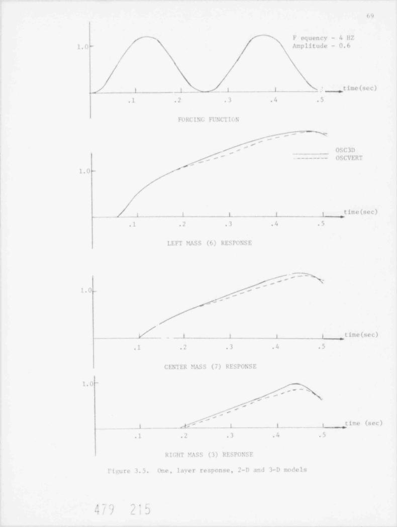
69
F equency - 411Z'-
1.0 - Acplitude - 0.6
1 i _ _ _1 ,time (sec)
.1 .2 .3 .4 .5
FORCING FTNCT IGN
-
-,
Y'
OSC3D-
' --------- OSCVERT-
1.0 -
time (sec)1 I i t t
.1 .2 .3 4 .5
LEFT MASS (6) RESPONSE
'',- ~
''1.0 - ,-
'
,-
_l t i i time (sec)
.1 .2 .3 .4 .5
CENTER MASS (7) RESPONSE
1.0 -
,~'
-,
/'
-
/
time (sec)'
_ _ _ _ _1 A' i J i
.1 .2 .3 .4 .5
RIGilT EASS (3) RESPONSE
l' inure 3.5. one, layer response, 2-D and 3-D models
, n . .
3 / ') / |bIt

_ _ _ _ . _ _ _ _ _ _ _ _ _ _ _ _ _ _ _ _ . . . _ _ . . . . . . . . . . . .
10
l' UP, L 1 C AT I ON''
The following is a list of publications during the current reporting periodf rom this activity:
liEZl.1:R , P., CURRERI, J., "IITGR Core Model Response to Simultaneous llorizontaland Vertical Excitations," Presented at the U.S.-Japan Seminar on llTGF SafetyTechnology, Volume IV, Fuji, Japan, Novenber 24-25, 1978
479 216
. _ _ _ - - _ _ _ _ _ _ -

71
4. Analvttcal
4.I li rC R Ce le Library
The LARC-2 code from Los Alamos is being converted to run at BNL ani shouldsho rt ly. However, at this time the plottine capahtlitiesbe available for use
have been deleted ani it will take more time to rewrite that section of the codefor the RNL plotters.
The new version of the Los Alamos code CHAP has been received at BNL and_oiverston work has begun. However, we understand from LASL that this is not afinal form of t he code and that sections are te be replaced in the near futureIn add t t ion, two modules of the code are not </ailable from LASL as yet. We
far, extra:ted the updated LASAN subset code f rom CHAP and conve rt edhave, so
sat ts f actorily (apart from one feat ure ) on the BNL system. The com-that to runplete CHAP code will not fit on the RNL system and it may be necessary to waituntil LASL releases the overlaid verston of the code be fore work can continue atRNL,
Table 4.1 ts a list ing o f our HTGR Safety Code Library to date.
4.2 Containment Vessel Gas Dynantes O. Hoccio)-a
Dortna this period the project work has cont inued on both analyt ical andexperimental investigation of containment ve s sel re s ponse to sudden depres-surtzattons.
The experimental program and test apparatus, described in the January 1978quarterly (Baccto, 1978a), has stressed the fo l l owi n g during this r e po r t i ng pert-
od:
Effects on model containment vessel size on the overall mixing process.Ef fect s of the jet tmpingement region geometry on the overall mixingprocess (region 2 in Figure 4.7 in above cited reference).Gas compos t t ton mea surement s.
To date, gaseous discharge within four containment vessel configurat ions havebeen observed, vtz:
CV #1: 18 in. d i ame t e r /18 i n . high bell jar
CV d2: 18 in. diameter /30 in. high bell jar
CV dl: 18 in, diameter /18 in. hiv.h cylindrical c h ' .nb e r
CV d4: 12 in. diameter /12 in. high cylindrical ciamber.
I'nd e r similar test condit ions visual observations made in the above four chan-bers, when selectively compared, were used to study the following ef fect s:
1,g
'i !

.
il
1.Table 4
lilGR Sa f e t y Code 1. i b r a r y
C Function_P i t g r an: -tatus Proprietarv_ _
Gnir r OP NP Corrects data on INDF/h t:ipe
I.I S I F C UP !. P List- d.i t .i fria INDF/B tcp.,
PIGEL UP NP Sin i pu l.i t e s data on INDF/B tape.
LSDFB2 OP NP Cenverts data on 1.NDF/B tape to binary.
l'IM ;E OF NP Pi c;..s i e s thettal c roe , section transfer arrays
GAND2 OF NP Prt ;ates fine gr ou'> fast, resonance, andthernal cross s.ec t ions from FNDIB2 binary
tapes.
sections fronG1E2 OP !;P Pi e pa re:, fine y,roup fast e r et >
LNDFl:2 binary tapes
MAFE OP NP t'r el a r cs fine group fast cros< seetion tape
f r om GFE? for spect rur codet .
WlEG OP NP Preparet fine group theinal cross sectfon tapefrom GAND2 or FLANGE for spectrum codes.
PRINT UP NP 1:e a d s the fast cross section tape produced by
? tAK E .
S PR I!rl OP NP R(ads the theiral cross .;ec t ion tape produced.
by WTFG. ;..
GGC4 UP NP Prepares broad group cror s sections from "AKEand WTfG tapes.
broad y,roup cror< sections fromIN!LRP OP NP Pr e par s
!!ICx0X output data tapet
1-DX OP NP Performs one-dimensional, diffusion theory,'
,teady state calculations.-- . - . . _ . _ . . .. . - - - - _ . - . . . . - - _ -. . .- . - - - - -----
_
In the proces, of being converted to the CDC 7600."
C =
OP = Operatienal on the BNL CDC 7600 :,y s t e: under Scope 2.Recently received from General Att :ic Co. or Argonne Code Center.R =
P General Aton,ic Co. proprietary code.=
proprietary code.Not censidered to be aNP =
In the proce;< of deve lo p: .en _ at br ookhaven Nat ional I..ibo ra t o r y. -B =
Fet ent ly ret elved fro los Alarm Nei ntific I. abo ra t or y .'
L =
! Inu t ivi.
|t / Q[' e d(-
-
-
/ j
. . .
-
j
_ . . . . ._ ,_ _ _ _._ _ _ _ _

73
Table 4.1 Cont'd.
Prograq__ _S t a t u s. I r op_r i e t a ry Punction
l' EV E n- 7 OP NP Pe r f o rm s one-dimensional, diffusion theory,burnup and reload calculations.
TE"CO-7 OP NP Computes r eac t or ter..pera t ure coe f f ic ien t s frominput cros. seetion data.
k l.00 S T- 7 OP NP Performs zero-dirensional reactor kineticscalculations.
GAKIT OP SP Performs one-ditensional reactor kineticsca1culations.
1%'I G L OF NP Performs two-dimensional light uter reactorkinetics calculations.
TAC-2D GP NP Performs two-dimensional, transient conductionanalyses.
Fl.A C OP NP Calculates steady state flow distributions inarbitrary networks with heat a d d i t i o r. .
POME OP P Calculates stealy state flow distributions andfuel and coolant temperatures in a gascooled reactor.
PREPRO OP P Prepares input data and source code revisionsfor RECA code.
RECA I P Calculates time dependent flow distributionsand fuel and coolant temperatures in theprimary system.
COECON OP P Computes the temperature history and fissionproduct redistribution following a loss ofall convective cooling of the core.
SORSD OP P Cemputes the release of volat ile fissionproducts from on llICR core during thermaltranslents.
(,0 P 1',40 OP SP Anal;zet the steady state graphite butnoff andthe pricary circuit levels of impurities.
OXIDE-3 OP P Analyzes the transient response of the llTGRfuel and r. ode ra t o r to an oxidizing environment.
c. A " P I. E OP SP Propagates uncertainties in probability dis-tributions by ''on t e Carlo technique.
AT4/ n/ ,, * n/1/'
=
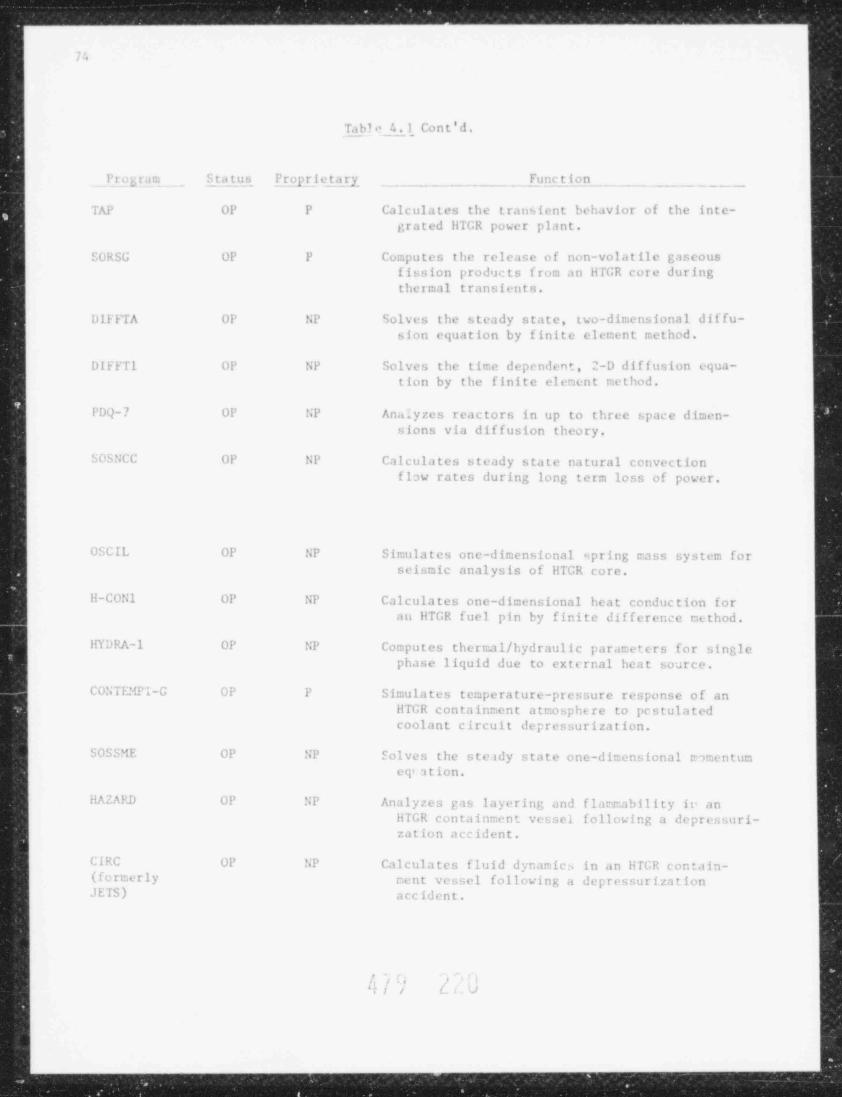
_ _ . _ _ _ _ . _ _ _ _ _ _ _ _ _ _ _ _ _ _ _ _ . _ _ _ _ _ _ _
7.
Ta bl +' 4.1 Co n t ' d .
P r o c r a r. Status P r op_r i e t.a ry Function
TAP OP P Calculates the transient behavior of the inte-grated llTGR power plant.
SURSG OP P Computes the release of non-volatile gaseousfission products f rom an lifGR core duringthermal transients.
,. DIFFTA OF NP Solves the steady state, two-dimensional diffu-sion equation by finite elenent cethod.
DIFFTl OP NP Solves the time dependent, 2-D dif f usion equa-tion by the finite element rethod.
'
PDQ-7 OP NP Analyzes reactors in up to three space dimen-sions via diffusion theory.
SOSNCC OP NP Calculates steady state natural convectionflow rates during long term loss of power.
"
OSCIL OP NP Simulates one-dicensional spring tass system forseismic analysis of IITGR core.
II-CON 1 OP NP Calculates one-dicensional heat conduction for~
au llTGR fuel pin by finite difference nethod.
IIYDPA-1 OP NP Computes thermal / hydraulic parateters for singlephase liquid due to external heat source.
CONTFlU'l-G OF P Simulates temperature-pressure response of an1
llTGR conta inment atmosphere to pcstulated; coolant circuit depressurization.
SOSSME OP NP Eolves the ste ady state one-dimensional mmentun. eq'ation.
IIAZARD OP NP Analyzes pas layering and flatrability ie an[ liTGR containment vessel following a depressuri-
zat ion accident.
CIRC OP NP Calculates fluid dynanics in an li fGR con ta in-- ( f o rte r l y cent vessel following a depressurization
JETS) accident.
.-
'L
L . /(# ' /'ii i iiG
B
L
a
-.1"
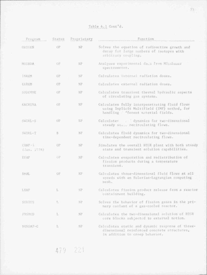
73
_Ta b_1 e _4_._l, Co n t ' d .
Prf gam _ Status. Prpgrietary Function
ORIGEN OP NP Eolves the equation of radioactive growth anddecay for large nurbers of isotopes witha r bit r ar y ( uupling.
"U5HDA OP NP Analyzes experir. ental da,; from E baut rspectrometer.
I N R Fl! OP '; P Calculates i n t e r r.a l radiation doses.
LX REM OP ';P Calculates external radiation doses.
S U D F3"iE OP NP Calculates transient thermal hydraulic aspectsof circulating pis systems.
EACHINA OP NP Cal culates fully interpenet ra ting fluid flowsusing Implicit Mul t i field (1}!F) tethod , for
handling 'ferent material fields.
SWIRL-S OP NP Calculatec dynamics for two-dicensionalsteady st.__ rec irculating flows.
SWIRL-T B NP Calculates fluid dynamics for two-dirensionaltime-dependent recirculatint; flews.
CilAP - 1 OP NP Simulates the overall HIGR plant with both steady
(.T a n . l'17 h ) state and transient solution capabilities.
EVAP UP NP Calculates evaporation and redistribution offission products during a temperaturetransient.
RAAL OP NP Calculates three-dinensional fluid flows at allspeeds with an Eulerian-Lagrangian computingtesh.
LEAF L NP Calculates fission product release from a reactorcontainrent building.
SUV10S '. NP Solves the behavior of fission gases in the pri-nary coolant of a gas-cooled reactor.
FYbMUD L NP Calculates the two-dir.ensional solution of HTGRcore blocks subject. d to external totion.
SONSAP-C L NP Calculates static and dynamic response of three-dimensional reinforced concrete structures,in addition to creep behav20r.
,' )
4-{o} i I..
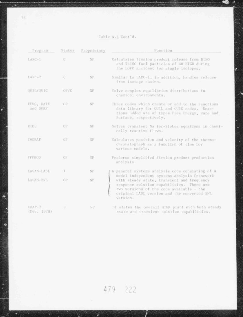
,- . ..
~ vKm marw, a -"'W M --
Io,
'l a b l e 4.1 Cent'd.
Pr og r .im Status Proprietary Punction
I.A R C - 1 C NP Cal cul a t e:, fi ; ion croduct release frun HISO
.ind 'I R I SO fuel p.itticles of an HIGi; duriny,
the 1.01 C a c c i d en t for sinyle i sot ope:,
I p: r - ? C NP simi1ar to IAPC-1< in .ubli t i on, b.i n !1 c:, rele n.e,
fron. isotope c a.i i n s .
yl' l I./ t .N I C UP/C NP c olve c er.p li x e<pii l i b r i nn distributions in
chenical environu nts.
Fl :G, RA l !- UP NP ihree c od, , wh i c h c r e.i t e or ;n!d to t h,' reactions.in i : .l' R F data l ibt a r y f or Ql'!!, and gl'IC coiin Peac-.
tiens .olded are of t ype: Free Encryy, Fate andSurface, respectively.
RICE UP Sl Solves t r. ins ient Na ler-Stokes er;uations in chemi-cally reutive f: iw s .
'l LNG F UP NP Calculates posititn and velocity of the t he rn:o-ch ro::a t or,raph a s functicn of t ir e for
v.t r i ou s r.o d e l s .
ElIknD UP NP Perforn., s i r:p l i f l ed fission product production
analysis.
I .A S A S -I.A SI. I SP ' A genera l syst er: analysis code consisting of ar:odel independent systems ancilysis f r in.ewo rk
I.A S A ', - B N L OP NP with steady state, transient and frequency
} response solution capabilities There aretwo versions of the code available - theoriginal I.ASI. ve r s ion and the converted BNL
version.
CHAP-2 C NP ;i alates tht ovorall lilGR plant with both steady(liec l 'J / 8 ) state and trai ;ient solution capabilitie:2
4Q ) ') '~)/ u. t L
. ....._ _ __ _ _ __ _ _ .
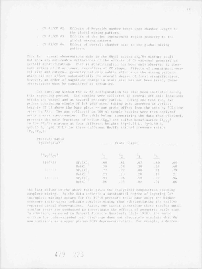
77
n' nl/CV #2: Effects of Reynolds nonher based upon ch.r,her lengt h tathe global mixine pat t er n.
rv n]/CV #3: Eff.:ts of the jet 1, p i rw "me n t region geometry to theglobal ntxtng pat t ern.
C' +1/CV d4: Effect of overall chamber size to the global ntxtnepat t ern.
Thus ta visual obwrvat ions na f e in the NH Cl ser4!cd SFs/He nt xt ure could3
nat shas any noticeable differences of the et fe :t s of CV ext er n il geometry onoverall s t rat i f t cat ion. Th . i t is st rat i ficat ton has been only observed at pres-
sure ratios of 10 or lower, regardless o f CV shape Ef fect s o f < a n t a t on e n t -ves-1 size and ext ern .I geome t ry h a.i only subtle ef fect s on the ntxing pattern
which dii not affeet sub s t ant t al ly the overal1 degree of final st rat i f tcat t on.
However, an order o f naenit ude change in scale size has not been tried, theseobservations must be considered as t ent at tve
Gas sampline within the CV d2 tonfiguratton has also been i ni t iat ed dur t ngthis re por t i n e period. Gas samples w"re collected at several off axt, locationswithin the vessel and at several pressure rattos. During one test run, twoprobes consisting sanply of 1/8 toch steel tuhtng were inserted at vartoushetghts (T 1. ) above the base plate -- one probe offset from the axis by 50%, theot he r hv 7;( The gas collected in 100 mi sample bottles were then analyzedostne a mass s pe c t r ome t e r . The table below, summarizing the data thus obt ai ned ,
presents the male fractions of helium ( X g,. ) and sul f ur hexa fluoride (Xgyg)in the < F /He ntxture at four di f fereat heights ( i = 0. 7 5 I. , 2*0 50 I >6
3=0. 2 5 L, 4 = 0.10 1. ) for three different He/SF6 initial pressure ratios(Pgy/pcy):
Pressure Ratto(psta/pstaT - Probe Hetcht
(P !PRV CV 1 2 3 4
(lM/5) SF, ( X ) , 60 .61 .67 .60 60,
Hr(X) .N .38 .30 .39 40SF,(X)3 .77 .77 .80 81 .79'
Hr(X) .23 .20 .20 .19 .21SF.(X), ,93 .% .s 4 ,99 .94( '
He(X) 06 .03 02 .61 .06
The last colo,n in the above table gis. s the analytical c ompos it ion assuming<onplete nixing As the data inlicate a s ub s t i,nt i a l d" gree of lavering (orincomplete at xtng) occurs for the 30/10 pressure ratto case only; the higherpressure ratto caws initcate c om p l e t . nixing thus sub s t ant i at ing the earlier
re por t ed vi su.il observat t ons. Again, one c.innot generali;+ these results ontilsint iar tests are conducted to investtrate the e f fect s of gronotric s c a '. e s i ze-
In afdition, as n o. ed in Gen"ral ?_omic's Quarterly (July 1978), the sonicortftce (or underexpand"d jot) discharge d or , not admpia t e l y simulate what GAn ow + tvisions as a upper pleno, PCRV depressurization. For exampl e , a depre s-
3 e# >Lf, | 'f L c_ )7/ /

- - - ,. - ,,
.
8''
7X
surizatton through a s t e.tn generator oncrete penetration plin: (flow restrictor
area of 100 in. ) is envi s ione l as an annular jet of heli um e xh tus t i ng into,
and filling, the minir tnent al space between the top of the pCRV and returlinyplatiorn ani then. Issutna into the CV .is an isobartc jet or plume tbrough thea n nu l ci r nr .it t ny in th" refueling p l .it f o rm . Resistance ta the helinm flow ts
- .ind by the ring around the c onc ret e plug containing,calsprov.ded by the onevathe t en lans which ext end t o t m lower face of the PCR7- Thus, although thesmall sc al+ tests do not c ar re s pond wi t h what GA now considers for upper plenun
pCRV gas release, it can indeed provide meaningful qua li t at ive, and with addi-ttonal i n s t r one n t a t i on , quant it at ive data on the mixing trocesses within en-
c losed env i rons. In ired , the not ion of an isobarit jet dischar,e through therefueling rel at f orn floor appears to lend more credence to the pos s ih t l i t y o f ga s
lavering due to a reduction of the ef fect s of jet imp t ngeme nt with the upperlevels of the CV on the overall nixine processes. Enhanc e l nonent on and kinet t eenergy losses through flow restrictors, omega seals, and steam generator top capg. onet r y b r i ng s the buoyant forces, through the graltent Rtchardson number, into
pr edomi n in:e at an earlier stage of the overall dischtrer process.
In this context, wo r k is continuing with the small scale e x pe r ine ri s ta
pr> vide a data base for the evaluatnon and/or re f i nemen t of the R ICE co'le( !!o c a t o , 197hb). The RICE code is prescotly being used to nunorically simulate<br flow pr o c e s se s that occ ur within the small scal. e x p. r t me n t s . Many factors
in the solution algorithm, governing equations, and code structure nost be con-sidered. Presently a e imple eddy vi scosit y law t s being used in the code Themain thrust in t i'e s e initial calculations will be to i nve s t ig a t e the effects on
how the time advan:ed pressure is calculated. Presently, the continuity andcouplel together and solved implicitly using the equationm nentan equat tons are
of st at e to relate the time advanced pressure to the time advanced density.Af t er which, the energy and species cont ino t t y equations are solved explicitly.This treatment, t he re fore , assumes that changes in the fluid pressure in each
computattonal cell are due primarily to density changes a n,1 that pressut echanges iue to changes in internal energy, t empe r at ur e , and gas . oncent rat ion
a r. relatively small. Thus, considertne the multispecies ideal gas equation ofstate, i.e , y
p= RT ! Y /W.1 i
. =1
in whi:h R is the gas const ant , W ,lecular weight of species 1, Y. ,1 i
is th. mass fraction (p /. ), and T th global densi t y and t enpe rat ure , thet
t i- .!eanced pressure (t=n+1"t) can be formally expressed as:
(jp " (.I - ,n)n+1- "( p) (,n+1 - , nn ) +p= p + >
N n,p n&l+ i ( u) (Y - Yn)i i
i=1 i
~ -) ft m q't ( !. '?T|
Y

79
In the : ode at present only the ftrst twa terms in the above expression are usedwhe e ( ?P/ ~ c) is taken as the square of acal sound speed. Thus, pressure vart-ations due to internal ene rgy and compos t t ian are accounted for subsequent tothe explicit solutton of the energy and species continuity equations.
Preltninary expertenc" using the RICE co.fe has been pre sent ed e lsewhe re( hoc c i o , 1978b and Boccio, 1978c). Work is now continuing to experimentallyverify the code and t o i n c o r po r a t e into tt the twa equat ion t urbulent kinetteenergy analysts.
4.3 Fission Products ( .I . Skalyo, Jr.)
Various fuel cycles are being considered for HTGRs as discussed by Baxt er ,et al (1978). In e f fec t , the HTGR concept ap; ears to be adaptable to the vari-aus fuel cyc les which a e betna considered fo r purposes of non proli ferat ionan i/or conservation of urantum resources. The fisston product inventory for theHTGR at any time is dependent on the particular fuel cycle, due to the varying23% content tn the fut 1 wtth its resultant product ion and burning o f 239Po.To study the major di f ferences in fission product inventory that occur due todtfferent fuel cycles, the ORIGEN code (Bell, 1973) has been used.
It ts a simple one energy group code wherein the fast and resonance fluxesa r- taken as fixed ratios of the thermal flux. The input data fo r the code ist here fore simple to prepare and the results that are obtained are useful formost pur po se s . This approach can be c om pa r ed to the more accurate GA method-ology of utilizing 9 ene rgy groups in the GARG0YLE (Todt, 1969) code The re-sultant calculattonal complexity requires a more complete knawledge of the fl uxspectrum which would requtre an extensive neutronic analysis.
In addition to scoping studies of fission product inventortes, the code is
>xe cted t, find use in the analysis of fission product experiments being per-formed on fuel kernels in our experimental program. Some of the experimentsinvolve the t em pe r a t u r e induced failure of trradiated fuel kernels wh i c h h av e
been retrradiated for short times in the Brookhaven Htgh Flux Ream Reactor.
The code results for a sample problen on an LWR fuel loading gave excellentagreement with the nRNL IBM-360 output; thus verifying proper conversion of theprogram. A calculatton was then carr ted out using the ORIGEN HTCR Library toevaluate fission product inventory on an average spent fuel element for the HEUfuel cycle and the MEH fuel cycle, The result s of an inventory at a ttne potnt180 days following discharge from the core can be compared to the extensivelists calculated by GA in the r e po r t s GA-A13886 (Hamiltor., 1976) and GA-A14980(Zane, 1978). These two reports appear to be aimed at fuel reprecesstng and
pe riod o f s tor age The ORIGEN cole allows ushence give inventories following amore control over the out put to analyze the fission product decay at short Lines(mi nut e s and hours) following shutdown. This output is of direct use foracetdent studies.
17O c' . . .%
4r/ /

I [ .* ' 5 '. '
= Y -
--Q1.'09$4SW2h| NZ%WM& W; ,r'., i.$ $p$ MSN$$WSSN; ; X.<W %WO8 J _A L ' f ' ' # ',q ' j'.',. Z . , . .,4 ' . ' f '' . . . . e. 4 , JJ
'
.
:- r,
-
='"ad'
g +,
%
dh l l) . !I L !' ti' ,tli f i ii a l J. 'i r l i : l e $ in .i n i .*r,lp. i liii i t h f 11|r ! ii. 1 .>l. .=iit .ir.
b ass: wi 's) ont ai n 6.IX, 7'9, .' 16, anI S4 g r cr , of 2 Y*lf, 23SU, 2h', andl-i '3"l', re,p..ttvelv, .. n l the fort 11 p.i r t i z l e s .>ntain up to 8546 nrans of3 >3>lh Thi' l o.i ii n e was . nput t ml to the (WI( M ' ode anl run at 'on s t cin t powerg
f vear r. ! ca t e i _ ': le of 1I nonths up an ! one un! h d. )wn . The poweri er a tour-- was ca r i vil until the h".t v s metal burnup of tim fissile tuol .m nant ed to 7 0 . E' ' ,
to n>rnalin to the same bornup assumed hv GA. l b. procedur. ives a 7 . T' h e civ v'u .' .i l h 'ir n tli> ilt l ll . t. li a r i t r'i ; t lli s l' inC )!)sistt':1! wit}l t lie' (; A e V.i l ila t t iin i11
.I ..l' fhe URIGEN ode deterninmi .i thernal fli !sr ..a z h tinc period of theilculatton. A r. .il r u l at t i n usine the evaluatM thermal tluxes as input was
-
t h. n lon. with the OR I t :E N ode on a fuel l oa.li n c onsistinv of th" fisstl.mat" rial .ilone_--
2P fissil. uranium particles give a :hentcal elenental ont ent shown ini-7
) olo,n of Table .+.? at 180 davs followine discharg., t h. GA- Al lH% resul t s arei
-4 ,hown alunn 2. N results .i p pe a r to be in mod agreenent for the najar-
A fi s i .n f ram ent s a n. ' #iuld riv. .id.upia t . results fo r most s; opine stuilies. ItJip is noted th.t GA-All8W6 prmlic t s that there is no r. " a ni! less Pu t han (RIGEN2 f r "li c TF is nav be, in p.i r t , the result of using the 1973 (>RIGEN dato It-,
3 tra.s ai b r a .n t% 1975 ENDF/B-IV l i 'rary and also, in part, due to the sin-aq plittr i fi :trun a s s irr d in ORII;EN=,
ew-
-!' _ il u ul at t on was don" sinilariv to the HEU cal:n on. Here, 2,14 14
* e'q''' h o d ura n t tin in n d 3.405 Re 2 3.'Th ci r e i n .i f ii.> l el. .>nt initial-4 R, -
E lv I tie vor is chosen t, obtain a heavv netal hornop of 25.57 in the fis-.o_n s -r. -los aad 1.1 in the fertile particles. The GA-Al4980 r e po r t was not
f av.it! m;e when th"se calculattons wore nade The ftssil. input loaitnr of 2.143s athitrarilv scaled bs 0.66 of the given input l o aili n e (1.55 kn) in the-]
g r r rir t . This scal. f ic t or t, an approximat. 'o r re :t ion for what app.ars to he
3 an i n .: . i n s i s t e n : v in the airi. and d i s :h.i r e, mass of GA-A14480 The scale fac-t30 W.i s : li11 s e an ( i) pe= t .i sis u ji.t r t s.> n witit t h, init i iit i> f GA- A 14 4."(1, V ,l'ine II.
_
'l The URIGEN and GA-Al4980 results are shawn in _olonns 3 an! of Tahl, /+ . 7 ,'
+'I
r, 'ivelv. Acain, tho CA-Al49X0 results prelict more l' a n.i less pu thanf iN I f ;1 ' Jir.' l i : t s . T h.. re n iil t 3 for the MEl' c .i s e .i r e a1 s ) .ic cia ra t . e ni n i c, h fo r nostpur -,
R1U! nor et t i. */ t o'i s deftrien:les in the tre id of t he li s a.:re rne n t s betworns iii no s 3 in i . is the inparison for Ru Th+ trend of olunns a nd J+ (both GA'
alculations) in th. etcinit- o f Ru w. i u l d sr. > init' ate li s:repan c v. Thei
'
n.ij.ir sllsir. i)I t ilr 17fl *r.l* t il t ill [ sir R tl is i': es) }41 / r iin s i) f b)Rii; t h.ag# !UURi ts shielded in th. na t o -de a',1it'"r is J"riv i fran activatton since
: h.i t n hv I"ki . '! h . pr,'du i t t iin <>f IINRi1 hv -1 ' ci v i) f IIN 'I nii s t. ile pe n lIIWi f i s s i .>n / t "l d < > f 3.'4 x 10⁻⁶ for 39Pu or 2,lH x 10-7 for6 .ui a
'I ( his. 19 7+3 ). At this p, .nt, one nost a s s rw that GA-A149hD is t,>.) high'
n it: p r e ,11 stf I U'IRu on 'e n t r a t ii>n h' at I ".i s t .i n order - ) f n i c. n t t i ld .; ):1
s _ r. - _1 1 d.m m h-n at m .a in m11 n z1 o,- m m. od. t,.
uk. pro li :t i ons n"ede l hs our experinontal s t ud y at retrradiate! f u. l parti-:les. 4rk on the i n c o r po r a t i o n of th. 197; ENhF/B-IV data l i b r.i r y into ther
o . - .st.'
i ,
.e -
], .) fj ...v
i
i
.I I
ll
: >J I?
,m . a .b ; ' / . y p x. J. . ~ 2 ; , y _i'Q., y. g. g . ; ? .s g ,; . y p.;s, q.; y ;f ,',3 ;,7 93 9 3,.p
, .; . . ' . . ,; .
'

81
Table 4.2
Element Con:"ntrations (grams per fuel element)
Element 1 2 3 4
cm 8.64-01 9.48-02 4.64+00 9.97-01Am 8.44-01 2.23-01 9.19+00 2.55+00Pu 3.50+01 1.04+01 1.39+02 4.86+0!Np 2.63+01 1.41+01 1.10+01 8.56+00U l.88+02 2.20+02 1.59+03 1.85+03Pa 1.16-05 9.80-06 9.21-06 1.30-06Th 1.91-05 4.87-05 1.64-05 3.32-02A: 6.56-10 2.85-10 3.34-10 2.06-14Ra 2.26-09 1.09-09 6.54-10 5.26-11Fr 5.73-17 1.33-16 3.33-17 5.70-18Rn 3.40-13 1.63-13 6.54-14 8.22-15At 4.35-21 1.38-20 2.66-21 6.27-22Po 4.62-15 3.41-11 2.47-15 3.70-08Gd 5.61+00 2.12+00 2.59+00 1.63+00Eu 2.72+00 1.58400 3.22+00 1.61+00Sm 1.07+01 9.40+00 1.15+01 8.23+00Pm 3.86-01 1.12+00 1.12+00 1.54+00Nd 7.25+01 7.23+01 5.92+01 5.31+01Pr 2.08+01 2.05+01 1.86+01 1.52+01Ce 5.51+01 4.75+01 4.47+01 3.59+01La 2.14+01 2.12+01 1.88+01 1.60+01Ra 2.70+01 2.56+01 2.18+0! 1.98+01Cs 3.96+01 4.46+01 4.20+01 3.89+01Xe 8.93+01 8.98+0! 8.03+01 6.39+01I 3.13+00 2.43+00 4.23+00 2.05+00Te /.96+00 6.00+00 9.08+00 5.48+00Sb 1.25-01 1.46-01 2.71-01 1.99-01Sn 3.92-01 1.04-01 7.02-01 5.45-01In 2.42-03 3.80-03 1.29-02 1.02-02Cd 5.22-01 2.30-01 1.82+00 5.38-01Ag 9.78-02 5.21-02 9.15-01 7.67-01Pd 1.20+01 9.07+00 2.34+01 1.59+01Rh 1.54+00 2.96+00 4.64+00 4.52+00Ru 3.12+01 3.15+01 3.55+01 i.70+02
Tc 1.19+01 1.30+01 1.23+01 1.05+01Ma 5.80+01 6.12+01 5.08+01 4.53+01Nb 5.50-02 6.31-02 3.26-01 2.35-01Zr 7.09+01 6.48+01 5.28+01 4.98+01Y 1.0l+01 1. 04 +01 6.53+00 5.89+00Sr 1.89+01 2.11+01 1.22+01 1.30+01Rb 7.24+00 1.21+01 4.65+00 3. 8 4 +00
Kr 7. 8 5 + 00 9.82+00 ; 'l+00 6.09+00.
Br 2.46-01 4.33-01 2.19-01 3.01-01Se 9.85-01 1.05+00 7.58-01 7.51-01
a - m14 | c, - -1

82
Table 4.2 (Cont'd.)
1. ORIGEN results for HEU fuel element (only fissile particles).
2. GA-A13886 results for HEU fuel element (only fisstle particles).3. ORIGEN results for MEU fuel element (only fissile particles).
4. GA-A14980 results for MEU fuel element (on!' fissile pa-ticles).
4.4 A Study of Flammability l'nder the Influence o f Larne Ignition Sources (R.A. Strehlow, K. R. Siv t e r - Unive rsity o f Il lino t s )
During this quarter, assembly and shakedown of the combustion chamberI i nt e rna l d imens ion s : diameter of 43.2 (17 inches) and height o f 182.9 cm ( 72
inches}} system was completed and the first series of combustion tests tn simplemethane-air atxtures were made The results of this work will be reported in a
M.S. thesis presently be.ng prepared. A descrtption of the design, assembly,and init ial operat ton of the experimental apparatus (including the initialmethane-air flammabilit y t e ;t s) is pub l i s h ed separately as a M.S. Thesis,
prepared by Paul Bailey (1978).
Briefly, the ranges of conditions investigated in these initial tests were
1. Methane volumetric concentrations trom 0 t o 5.9 % -2. Stoichiometrte nethane-air ignition po cke t s (polyethylene plastic bags)
with volunes from 0.13 5 t o 0.66 ft 3 renresent ingignition pocket-to-chamber volume ratios o f 0.014 t o 0.069.
3. Vertical locations of the ignition pocket (relative to the bottom ofthe chanber) from 30 to 152 cm (1 to 5 feet).
The ignition pocke t s were i g n i. t ed remately with a low intensity electric arc.
The most signi ficant result from these initial tests was the excellentagreenent found with the Cubbage and Marshall (1972) data for nothane-ai rmixtures. This agreement serves to validate the present expertmental setup.
With the completion of these inittal tests, the program will now move intothe inve st igat ion o f more complex mixtures with the addit ion of carbon monoxideand hydrogen fuels. Parallel studies of convent ional flammability limits(carried out in the 2-inch diameter flammabili ty t ube ) and the ef fect s o f large
stoichtometric tanition pockets (c arried out in the combustion chamber willbeatn early in the next r e por t ing period.
PUBLICATIONS
BnCCIO, J. L., et al., "HTGR Depres s urizat ion Analysi s ," BNL-NUREG-25334, 'n
Proc. l' . S . -J a pa n Semi na r on HTGR Sa fet y Technology , Fuji, Japan, November24-25, 1978, Vol. I.
SASTRE, G., "HTGR Acctdent Delineation," BNL-NUREG-25329, in Proc. U.S.-Japan
Seminar on HTGR Sa fe t y Technology , Fujt, Japan, November 24-25, 1978, Vol. I.
j
83
.R_E F E R E N C E S
BAXTER, A. M., MERRILL, M. 11 . and DAHLBERG, R. C., "The l's e of Non-Proli ferat ionFuel Cycles in the HTGR," GA-A15049, October 1978.
BELL, M. J., "0RIGEN-The ORNL Isotope Gene ra t ion and De plet ion Cod e ," ORNL-462 8,May 1973.
BOCCIO, J. L, SKALYO, J. and TAKAHASHI, H. , "HTGR De pres surizat ion - SmallScale Model Expertments," in Reactor Safety Research Programs QuarterlyPrearess Report, January 1 - March 31, 1978, Brookhaven National Laboratory,BNL-NUREG-50820, May 1978a.
BOCCIO, J. L., " Containment Vessel Gas Dynamics - A Global Approach," in ReactorSafety aesearch Programs Quarterly Progress Report, July 1 - S e p t emb e r 31,1978, Brookhaven National Laboratory, BNL-NUREG-50931, December 1978b.
BnCCIO, J. L, et al. "HTGR Depressurization Analysis," presented at Japan-U.S.Seminar on I.TGR Safetf Technology, November 22-24, 1978, Fuji, Japan,BNL-NUREG-25334, November 1978c.
CUBBACE, P. A. and MARSHALL, M. R., " Pressure Generated i n Combu s t io n Ch anb e r sby the Ignition of Air-Gas Mixtures," 1. Chem. E. Sympostum Series No. 33,1972, p. 24.
HAMILTON, C. J., et al., "HTCR Spent Fue l Compos it ion and Fue l Element BlockFlow," GA-A13886, July 1976.
ROSE, P- F. and BURROWS, T. W., "EMDF/B Fission Product Decay Data,"BNL-NCS-50545, August 1976.
TODT, F. W., " GARGOYLE II - An In fi nit e Medium Fuel Cycle Analysis Code withFuel and Poison Searches," GA-9477, May 1969.
ZANE, G, G EORG H I Ol' , D. L and EVERLINE, C. J., "LHTGR MEU Sper.t Fuel ElementDe fi ni t ions and Block Flows," GA-A14980, August 1978.
'

y , , \ - , -
,
Hi
|
1
1
II. l.M! im SM I TY !X AIJ' AT I t t
SI " .; RJ
In the .nliabat ic ye injection ;inulation experfrents, the test set up,a- c. mlet el ani installed- Presstne d rop and vo id fraction measurenentswe r, taien in the test colunn wi t h hot t on w injection. The resolt:, 1or the
averv e po il old traction and for t he flow reg ir.e transitions are comparedwith del: existinc in the l it erature
An ana!vt ical mdel we developed to describe the transient dispersioncharac te ris t ic: of fuel-sttel hoiling pool svsters under decas heating condi-ti<nn, with houndarv heat losse. With this vdel, the pressure-temperature
h i s t o r :. of the ho i l i n> pool syste: are cer :put ed , as well as the spatial dis-trihution ot 'c o i d fraction. Typical result 3 for tl average ; teel "apor irac-tion f or a tvoical pool are presented. The pool averape steel vapor volumef rac t ien indicate the <treng inpact of the vapor region heat sink on thehuilup proce:
Ihe experinental apparatus for the measurement of local heat transfer co-etticients to inclined walls in a hoiline pool was upgraded. i'.x pe r i ne n t s were
o o o<nducted at wall annle: or W, 75 and 60 In addition, average pool void( ,
f rac t ien c easurement : were performed, and general observations on the poolcharac t er ist it and flew r e c i t.e s are also reported.
II,e Super 9 s t e: Ced. (SSC) deve; arment progran censists of three ser ie::d e < > S C-I. , SSC-p, anu SSC-S. Durin; t b is quart er, the SSC-I. code we*
uwd to analvae a flew coastdown transient in ClGRP t o 1800 seconds All com-putations were performed using the twelve-channel data set. This calculationto i 1785 cpi seconds on CDC-7tmo eachine, which is ;lightls les than the ; inn-
lat ion tire Major finding: fren this calculation are (a) The interassembly
tlow redistribution is a very signif icant tactor in af t ect in; the naximur sodiumt e: perature, (b) The hot channel temperature in blanket assenhly for the F0ECtuel i :- higher th in that in the tuel channel, (c) A ninimun of five channels rayhe used in > 1 mulat in: in-c.;e response, (d) 'r|h e n the in t e ra s s er.b l y flow redis-
t r ibut ien i: artitit 'al' suppressed, the hot channel blanket temperature willi xct el ediur boiling ?cint for an extended peried of tine
ine effect- of uncertainties on deca'. heat and the scram delav-time wereenanined as a part o. t h. run natrix calculations
.i pipe rupture calculatien was also ;itulated. For the case of "ran delay-
n.Ci se ond, sodium in the peak channel was calculated te , tart hoilinetir, *,
another n./ second. Thi' calculation is bein/ continued to se.. if and when'
bo i l it , .n N terminated
the , tear ye: erator controllers were wr i t t e: Seme s i:rp l i t i c a-" ole l ' *i '
t i < in calculatioeal chme were also nule other PPS/PG 4 t en' have beeni
pro rara ,' acd int er t a< ee wi t h the SSU-I. code Fe- eral test runs were also
nde
?)M l
,
~ , w
.ad__7 :M

85
Eod i un pump characteristics were e::t ended t o include both the HAN and IIVNcurves durin, steadv-state calculations.
Ihe $SC-L code was exported to Babcock and Wilcox,
The SSC-P code init ializat ion was completed- Input data and individualmodule- were uperaded and modified. The steadv-state predictions by the SSC-Pc i .d e are, in ,;e n e ra l , consistent with known and e:'pec t ed PHENI) operating val-.
"od e l equa t ions describint transient p r ima r: ny s t( m hydraulics for theues.
hot pool concept have been formulated.
The SSC-S cede eftort was concentrated in definine various tasks and sub-tasks in the work plan. Li t erat ure _ arch was also conducted for the in-vesselredel to be used in the code
Ihe SSC Validat ion work during this quarter covered a number of areas. IN-
terci .parison between SSC and IX,::S cont inued . The FFTF primary loop spec if ica-tion and ;imulation was conpleted and co::parisens between SSC and IMwS indicateceneral ,;o od 4;reeme n t . The draft report on the eviluation ot FFTF instrunenta-tien vis-a-vie code validation requirements has undergone extensive review andr e v i:; ion . i' i n a l l y , results of the SSC- BRENDA comp arisons have been completed andreported-
,
d 9
-
LJ
'N ''
I 'N P"' |
w w smaur- - w w_ _ ,x=
M (,
l. F.i s t P m tor Assesument - Accident Sequence 9tudie: (0, C. .liin e s , .f r .a nil % Ale t.it )
!.1 Hvirodynamie Ch.ir ac t er i s t ii of Fwo- Pl u s e Dispersed Mstew(T. Ginsberg, .I. .i. !tir ry , and .I. C Chen, behich l'niver s i t y)
The purpose of t his task is to studs the hyd ro,!yn am i c dispercive
ihavinr ot :. w o - p h a s e pools under conditions prototypic of t ran si t ion p h e, ew i<h nt circu tances Adiahitic injection sinulation experiments arecarriid out with fluid-pair sv< _ns which bracket the hvdrodynamic para-me t e r , of fuel-steel boil inn syst ems .
1,1.1 I:xpe r imen t a l Invest i erit ions
'i h e ad iabat i< gas iniectinn apparatus (Ginsberv 1971a) was conpleted
ind inctalled. Ihis test facilits was designed to provide a two-phase,c i s-l i,p: i d , pool flow c o n t i p,u ra t i on in which to simulate the charac t er i st ic sof voluw-heated hollinn pools G. i s is supplied from the hottom of the
alumn t hrouch a porous plate The immediate objective of the expe r inent s
with thi- arparatur is to evaluate the disturbance introduced to the flow1ield hv i yl ind rical obstruc t ions to the flow (Ginsbero 1978h). 'l h e s e
the useful1 ness of proposed experiments withresolt3 uilI he uso! to asse: '
co l ore-d i n t r ibut ed gas injection.
lhe as embled gas injection column together with 3-ray >ource anddetec*or holders anl traversing apparatus are shown in Figs (1.1) and (1.2).F1 pre (1.1) shows the column, pressure tap: and connecting lines, and theair supply uni fo ld . 'I b e axial and t ransvert traversing methanisna are
il 30 shown in F i <. < (l.1) and (l.2), Figure (1.1) shows the flow control
in.1 mn i t o r p.in e l : On the Icft are air flew rotameters. On t he right side
th pre .o re port, selector v;1ves, the pressure transducer, and the liquidukeup rotameter < are shown (; -aintain uniform liquid inventory withdry let c ir ryover) . A porous plate is located in the base of the column.Fa z. i' hubbl eil t hrough t he plate
Prelininary pressure drop and void fraction measurements h ive been nidei: the test colurn A pornun steel plate, 1/8-inch thick wit h 10 porosit)
(will filter %' of particles whose d ir et ers are greater than 10 .) wac usedin these experiments Pemil t s are presented in Figs. (1,4 ) and (1.3). 'I b e
st ra !v-s t a t e mixture r omen t u: equation is ut ilized to obtain the void
frutfon In the ab<rnce of scelera t ion ef f ec t s, this e rp i i t i o n is
dp4=: M(l - i) (1,1)
is t ht a v. i a l distance, the 1iqui! density, theehere p the pre ;sure,' s, ,>
v . e l er it i nn of cravitc, and a the local zoid fraction.
In t hew hottor injection huhblim column iests, it is prohahls a reedm sumption (t o be zerified later with the r-ray cold mea surement s) that the
A ( , -'
){

87
;( ; %W: \# es -.
es- h q
'&" f.pr -
'
4, A--y-<-. I!
i
}*
,.
-
5- , D.
| || A , ,
45 D y 'ba wa??, Y.h L .. ., , 4)-s r-.
Q -(: .<>q.-g<
m
%ji ,
F hg"I . f u
i j I'l ,_ q 'w' - < - g ,7
" /gj-v .j - bi
.
> ;8 .. m ,
A'i / h
- ; t ila .. e \., u
g d. 4 y' ~
r EL' ~- a- ..
~ n. -.-sti c
[''
pw;. . ';- * L- '. =
h }s U("% *f}1?|Y :v , ..,..9 '-
|]"}e rt
.
t; 3 ,. - 1st') *,
.h<Yb y L^c?.i .s -
.dM ';.m.=r
JJ 1 zw* cg e
' DE .i,
[ w,% ,.. m..f, }w m /!r
, e- q* --
( -- [E. V:;ar ph i >
1-
,
~y ' % . =i$-
c :o%. 3J- s
' F '., }g s,
( ' 7' %_ ( ,a. . _ . .
.
t @ -
#
~
.j , . *qQ ti;
['; %.a.,c C m'l.6*,-.yr3 )g. , ..
- s -..
~.;
' ' /%., 1
%QQ{" ^N+ i Q y-'N
~ %'' p-q' ' N% , ' (i2'
Ax ,7-e,.'
_. , '-I 'i
_ _ - L.
Figure (1.1) - Photograph of Gas Inj ec tion Test Colunn (BNL Neg. No 1-533 79).
4 -#
^| 6 ?( .j b'

'1
W }i ~] x '\C 1 a [G 7*,
'
9 WsCa -=
e) i'\f , , {A ' %3~7 7
qs ~,N;'
,
s%Tl/ i'. t ,); I; N' V t ,
~, ,
-
.
tt -> < Xfgj /.;,.
, / , ,< - 3r
.,c / ,yf, , s/,
/v[ ; '*'7+ ~ , _ , - s.
i te,76 .- %'
/5- . i.
y ,.
fc,/y}/ ; ./m9-~.,%-Q W..
w ._
x/, *_
rr +nea -.
Y| R '\ 'T, n,
gfmm u ,.
p f f} a g y :j } f R h y P n :f p-
w \. u n y; w~: .
a u.w.-e - w, ue
iiot. < 1. n - 1 r. m. r ., i n . Ap p.i r.a . om. 1-;c.- m ., ,
p q r -- ++d = PK'g+-
;- tn .
-f ..
;726 .
4
x . yi. .. . pse +i.|3 ,&? W g'- 4
f
U U ( Y s'' ,,
tj,f t ; , ;a y,n:,339 5; f }-- R _
:dpa w , tu
tw; & u .g! ) . 1 y w42 p g - m y ,;t[ . . y!,
a .n_, q.yLOt:
c. .> r---
c. % ; b. w-- # c e,.nu - 1.
1;% ".fC9 ,.[ p.,., , Q j.pwi : p q t .-
- -
!y ai \ .
;m(A . m ,.. y 4L t, Tusu . rA . ,
# 1 q.
m,h{,-
4
~4%g ;;y- __
b-Q
If;yf?$v.( Y $.k< f: - ?, Y+ I- a[$*{gW: ,h,.$,j_ f;h j
- - - ~ 9fm .
Y&p- :% .n. . -
.
9 _yfrg,g % 1.
y-3 e_
j{2: , , . . -.- ,
er ~ _l :P, , . .< % , ..v-" r=: 9* f3* s t&t
'; ' f,, t, h. -g - -.g ..
%..N^
[ -- j ..' . . ..
%i, n ,- - % - , .
;f y'
.
, ?" ''
das M.a is - w. J.- n a wx us .'_ -,
t .h m M?)
' '( ! , i- ( i!It, <! ! r ' 1: l Ii l-:i'l- ''t)
A ~- /' '

89
area-averaged void fraction is independent of position. Equation (1,1)then, i< integrated to g iv e
P-P7 x) -x * ,
(or P X) ( 1, 2)= =
,;g(1 't)H Ho o
where H is the liquid height with no nas injection and the subscript 'l'o
denotes a reference pressure tap location. The ,eriments were carried ou't;
for H 0. 3 m over a range of gas injection with dimensionless=
superficial vapor velocities j /U up to 1.5, where U is the bubble riseg > *
velocity in a infinite medium. For each j / l', , an average void fraction wasgcomputed using a lineat least-squares anal ysis of t he pressure data. Thev'id fraction r~sults are shown in Fig. (1.4). Presented with the data arepredictions based upon bubbly flow, and churn-turbulent flow, drift-fluxnodels (C is the distribution parameter). These results indicate:
o
(i) The b %1y flow model is a good representation of the data
for F.nall j / l' _ . ':hile bubbly flows we . observed up to j / l' , . 17 ,>=
the data departs from the bubbly (C 1) nodel before a flow- o
transition is abruptly observed, f- is hypotnesized that thedeparture is due to the onset of ;o-dimensional flow within the
column.
(ii) A transition from bubbly to churn flow was observed in therange of j /U between 0.4 and 0.7, This is apparent in
Fie. (1.4), and was also observed visually.
(iii) The Zuber-Findlay (Zuber 1965) churn-turbulent drift flux1.2 does not adequ tely represent themodel with C =
data in the churn fl ow regime.
The computed least-squares void fractions were then used in Eq. (1.2)and, the dimensionless pressure data are shown in Fig. (1.5). E xp r e s s ed in-his forn, the pressure data should be linear with x and independenc of voidfraction. T. - results lend support to this contention.
l.- Licuid Dispersion in Internallv lhg t ed Boilinp Pcols (T. Ginsberg;.i. C, Chen, I.chigh l'n i .)
The objectises of t his task are to conduct experimente and performanalvsis to s t u:13 the dispersive characteristics of internally heatedbo i l in: pools. Experiments using icternal heat generation are used tosimulate nuclear heatine, and the t wt -phase boiling characteristics arestudied in open an! closed boilin~ systems with boundary heat losses,
f | '; q- 7a-
<
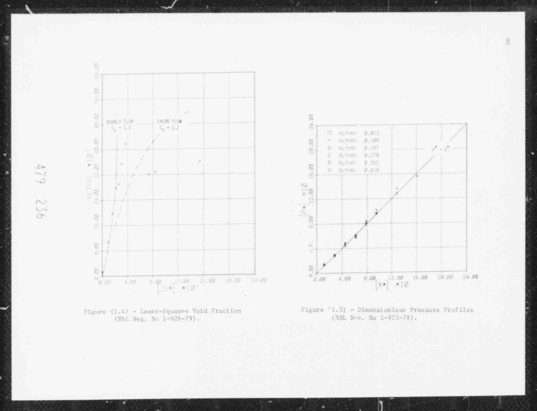
., . ... . .
eo
e
,
.
/
e"
- h ELY FL N CN ', F lt'W ___i~~ l /1.2 E" - 1." C
't,
-g
/ /:3 /4> r1f .
,
! ! // o - , : F: ?.;/4.- - ~ !
/. Wi . ; , ,**/ g_~ - .
- I ,c ,a : f >;s i'
f
, ,
,f=/ I
'
r.. ' p /. M'
|"
. ,,, " ' rt re c.4:H ! .
,
s.,. - . - . . . . -- .
-t e- - - .
/".
-- --
4 J~ '
! ,e !1ca,
-,
/-es/on
IT ,'. ._ _ . _ _ _ _ . _ _ _ . _ - _ . . - . - - - - ec _ _ _ _ _ - . _ _ - - - ,-- . -
/'- _-
G~1 : 'i
| | q**/ ' -- ;_ |&.
,, . . , . .___
7 /__ _ _ . - . . - - - .
-
d ,
- - _ . _
W I
| | | |4 I l
r
!, /. 4. ,$ _ _ - .
, f' /. - . . - - .I . .- c ,
9'/
,
if / !:1 ,-
'/.ca [.ca ,12.?J 1E.0J 22 J 24 ?C' ~
,l' | 8.20[X * J * 13--
. , ' ,. , ., -.' ' , ,
.. ,
Figure (1.4) - Least-Squares Void Fraction Figure 'l.5) - Dimensionless Pressure Profiles
(BNL Neg. No 1-926-79). O NL Ne e. . No 1-925-79).
. . . _ . E

91
! . ' .1 Analstica1 In est igat ions
Armiments have been proposed which suggest that at decav-heating rateslown t, 1 percent of steady-state Il!F BR power density, boiling pools et,teei ind molten oxide fuel are self-dispersive. Available evidence fronexperiments with simulation fluid systems, heated electrically and withnicrowave die 1cetrit heating, succest that if ihe energy availahIe to t h.steel for vaporization is of decay he at ing ,agnituue, then there is a strongpotential for dispersal of the nixture to the linit s of the volume ava i l ab l eto it (Ginsbern 1078;
losed boiline pool syst em wi t h boundary heat losses, however, the:n a i
enc re,v available ar "aporization may be significantly less than the decayt
heatine rate, as a result of sensible heating and boundary losses (Dhir.
tu/n). ine potential for f o g! diepersal may he arcatly dininished whent he: ef f ect s are correctls madeled..
An analvtical model has been developed which discribes the transientdispersion c ha t a, crist ics of fuel-steel boiling pool systems under decayhea t i nr cond i t ions, with boundary heat losses. In addition to pressure-terperature histories af boiling pool systems, the spatial distribution ofsteel apor (void fraction) and nolten fluid are ermputed. I.oc a l heatlosses anJ sensible heatine are included in the noiel for the capor gener-ation rate in the material balance equations.
A sc hema t ic d iagram of a closed volume-heated Noi! r svstem is shownin Fig. (l.h). The pool is assumed bounJed on all steen by stable tuel
crusts (Fa u sk e 1977). Nlten fuel (heat source) and steel (vapor source)are assumed homogeneously mixed at the steel sataration temperature. Themixture is treated as an effective single-component, volume-heated, two-phase equilibrium boilina s7 stem. 'Ibe rmodynamic p roper t ie s are appropri-
atels weighted.
In ceteral, a pool would not boil up to fill the available volume. Thestem, therefore, was <! ! v i d ed {see Fin. (1.6)] for purposes of identifi-'
cution >f heat transfer mechanisms into an upper centinuous steel vaporrecien an: the two-phase olten mixture. It was a ssumed t ha t the mode of
heat transfer in the apor cone is steel condensation limited (Rohsenow197?, Gerstmann !%7) an' .i ', olten EO boil up-enhanc ed na t ura l circulation
limited (Greene 1 9 7 ~' ) (to vertical boundaries) or boilup-enhancer! conduction
limitel (!L a e r 1977) (downwar! direction) in the molten m i :. t u r e recion.
Ad !it innal assumptions are
(i) Th< t im eale for decav-heating transients are con-n
trollo! b' thermal inert ia. Flow i.nortia and r: inematic
civt t ransport time scales are small compareJ to t h.the m11 time ocale,
(ii) One-di~enniunal drift flux nodeline is an adequatede: eriptinn of the 1iquid-vapor volil leanmics.
4 %
/
' ' | 1 , ,//~J/

y_____--
92
(iii) 1he entir, pool content: are at uniform temperature
As a consequence of the fIrst two assumptions, a quasi-stcadv, < > n e-im nsional drift flux model war formulated. Ws' and ener.v balan e
equations were formulated to characterize the transi( nt t hmedyn imi cbehavior of the system, lhe rapor source term is computed on a tran ienthisis and incorporates the effects of sensible heatinc and boundary i >:se: .
'i vn i c il result < are presented in Fir. (1.7) a n.i .able ( 1, ? ) for .i pool
no<. para ~eters are defined in Table (1.1). The heat t r insf er rate (b ) toP3
10"''/ n ~ K , repre-the boun.! aries of the two-phase molten recion was taken as:ta t in of rates pred ic t ed by the correlations of Greene (1977) and Baker%
(1977), the condensa t inn rate at the steel vapor rc,;i on boun !a r i e: ishichly uncertain due to the p r e :,e n c e of noncondensibles anJ also possibiv of
Fo , 1iqui! tiin from splashine ot chuming 1iquid. Ihi3 heat transfera
t reat ed paramet r ica ll S.rate, therefore, was
Prelininars results for the pool-averate steel vapor vo l um f r: tio-
, ,
indliat, the strong impact of t he vapor recion heat :nk on the .nii.
1he itronter the steel cond ens:it ion ra t e , for a given 1'wer input,p ro c e < ,.
the creater the po t en t_ta l for the two-phase nixture to fill the a ailable
mlume lin!icated h4 qA ,:,, 0.7 in Fit (1.7)]. The reason for t tir behavior=
i- represented in Table ( 1. ' ) . Nst of the available energ' >ource is
consumed in sensible heat ing, indicating nearly an ad iab..t i s constant-,
/alume heating process wit h lit t le attendant vaporization. As the conden-u t fiin rate increases, the rate of pre: surization decreases, les ener ' isa q,: cl in sensible heat ad lit ion, and more enercy become: avaf!c le forupariz.ition. T!,e dispersal proces is thus enhar eeJ a s the pot ent ial for
* ''iin !"ns it ion increase < For condensation rates create- than 2 10 - K,s
the ca l ~ul at ions indicate that the two-ph1se nixt ure woold disperse to the
limitt of the available volume. For the e stem of interest, unimpedel ; teel< ,
o n. ! c n c tion rates of 10' ''/m'K a r e preoicted with the r.e t hod < of Rohsenowi
( 19 7 ' ') and Gerstmann (1967). The potenttal for dispersal to the 1 i ". i t of
the ecailable olo e i', therefore, conceivable
T h.. t r i n s i e n t- pool dispersal no.le l calculations i n.!i ca t e
(i) I h* potenttal exists for disp.rs.i. n+ FO ., steel'
oa l s to the 1 imit s of the availthle volme unIercde c a '. h e a t i n ,' conditions llowt cer, onl; tr.vtioni
of t h. available decay heat source is useful fornipo r i /.a t ion a nd fuel dispersal.
(iii ". i l l p r e s m r i / a t i o n rat. isf 0.1 atm/' are charac->
t erist ic of t rans! t ic n th i s. ' closei-noal ae identi4, alitions
f|4 f .)
. . . . . . .. . . . . _ . . . _ . _ _ _ _ _ _ _ _ _ - - -

i
i
4%N,
W
N1l- -
C 1. 0 --
;-
4 ,, REFLUX DROPS r< | /
{ Io,
.- - _ - _ , _ _
. 5 . 1.am~z/ * * . 9 0 8 ' h, /h Uz
rran (L- H )/ L=
STEEL g ,pPEFLUX [ |VAPOR *
, , . , , .' f''MREGION ... ) _ _ _ _ _ _ _ _ _ _ _ _ _ _ _ _ _ _ _ _ _
<,., ,
. m -dL 0 0.6 ~
1'0* *t * .. .
C -* 0 O4 **. (~ -*ou T ~- -
0uT,.
>. /. . * . ,; -
/
", .. ** w 0.5. * w /* **
-/ .: so4 -.
* * - VA POR W. ) ,. .p+O F L U_X__
f _H
-
yo * yI N T E R N A L :M ~f cHEAT ; UC C 8 < 'o i
GE NER AT ION $",
>< 0.2 - 0.1 q|
D - Jo l
I,Oa
1
0 -- - l I I'
O 2 4 6 8 10
TIME (s)
Figure (1.6) - Schematic of Closed Boiling Figure ( 1. 7) - Predicted Transient Stee] VaporSystem With Boundary Heat Losses F ra c t io ns (Bh1 Neg. No 1-838-79),(BNL 5eg No 1-837-79).
eW

94
TABLE (1.1) - BOILING POOL PARAMETERS
Composition: Holten Omide fuel anc Steel
s'o o l blaneter (D): 1.0 n:
}001 Ca v it y lic i p h t (L): 1.0 m
rollanged 1.tquid Irvel (H ): 0.) e
Mass traction Fuel: 0.67F
Intt!al Poo Temperatu.e: 3093 K
Ik, u,,d a r v T r 2,n e r a t u r e : WIV
icwcr pe n s i t y : 8 percent or steady stare It'J E R power density
_ _ _ _
TABLE (1.2) - CALLUL/.TIONAL RESULTS
Vapor Co.ndensat* n Pitbsurization Vaporization SensibleC.,c f f i t l e n t hete Ltc 1, rating Rate
b /b ( Air: a) Q . A l,/ 0 Q /Q* L t h, SIN 5 GtNv p
_ _ _ __ ._..______ _ _ _ . _ _ - - - - _ . _ _ _ _ _ _ _ . _ _ _ _ _ _ _ . _ _ _ _ _ _ _ _ _ _ _ _ _ _____ _ _ _
O,1 . I'h t .( )) . sH 5*
O.5 .0HS 019 .j/o<
1.0 .082 .017 , #41'
2.0 .019 075 . E ',4
2.5 .078 . (ci 4 .P?5
- - _ _ - _ - . _ _ - - _ - - _ - - - _ . - _ - _ - . _ _ _ _ . . _ _ _ _ . _ _ - - . _ _ _ _ .___.. __
k
/ L4/ -
95
(iii) The most significant parameter affecting thedispersal process is the magnitude of the vaporcondensation heat sink. There is also muchuncertainty in this parameter.
Nomenc1ature
D pool diameter
g acceleration of gravity
h two-phase mixture heat transfer rate
h vapor condensation rate
H height of two-phase mixture
11 collapsed liquid level
L height of available pool volume
p pressure
,- -
P dimensionless pressure : (p - p7 )/ [o g (1 - 0 )l1 ]7
P)reference pressure
0 .heat generation rate
()S ENS'"* ' "E "U
Q,g steel vaporization rate
U, bubble t..rminal rise velocity
x axial coordinate
*i dimensionless axial coord inate [ r (x - x ) /11 ]
1 o
x re f erenc e axial position7
a area-averaged void fraction [Eq. (1)]
I average vapor volume fraction in mixture [T(H - H )/ll]g
__
maximum vapor volumc fraction [ (L - H )/L)t ..
u. .A A o
c, liquid specific gravity
k ,I ') csI'?_,

-
..
31 %
.a
4-
--
J"J
1.1 Rolline pools h'i t h Interngl Ikat Generation (G. A. Green. ans!=aal C. E. Schwarz)-1a[ The purpose of this task is to study and characterize local boundary
heat losses and void distributions in volume-heated boiling pools at power,-' levels characteristic of pAHR cond it ions in an Ufl' B R . Experimentation underJ o o o
: hoi 1ing conditions has begun at wa11 a n e,1 e s of 90 75 and 60 Measure-, , .
y ments are being nade of local heat transfer, as well as pool-average void
3 fractinn.J-=
1. 2.1 1:xpe r imen t a l Appara us_o
A
J| Apparatus upgrade has been completed. Nonuniform flow patterns in the
f coolant flow have been eliminated. The coolant flow rate has been increased= to 1.5-5. npm. This has the effect of reducine the resistana to heat-m
a transfer in the coolant to a negligible level.
"_ l.1.2 Measurement of 1.ocal Heat Transfer Coefficient4_
_i In the only previous investigation of local boundary heat flux fromoIu e-boi1ing pools (Gustavson 1977), the 1oca1 boundary f1ux was measured_! s
] by calorimetric measurements through isolated coolant channels in a test5 will, and the surface temperature was calculated by extrapolating an int e-
4 rior t empera ture across an electrical insulating teflon sheat, In thisI
J ru n n e r the .ocal (seement-averaged) heat transfer coetficient could be
] reasured in up to nine lannels.
317 In the present i nvest iga t ion, the local heat flux and surface temper-
1L ature are directly measured with no area averaging and no extrapolation o!
- temperature across an insulating layer. Gold-plated nicrothermocouples are4 installed at 19 se;, ara t e front-anJ-back locat ons, flush-mounted with the
j front and hack surf aces of an electrically insulating horon nitride test
si wall, which is in direct contact with the boiling pool. Once stealy-state
j conlitions are determined in the pool and test wall, the ouput of each- thermocouple, which arc individu,lly o librated to within + 0.1 C, is time-
integrateJ to determine the average temperature at each location. Simul-
-] taneousiv, the standard deviat ion of the thermocouple reading is recalcu-_
lat( l at each sample. The tinal data is stored on magnetic tape. The local;M heat transfer coefficfent trom the volume-boiling pool is detined asa;
'--_
kIb,( Tfront(x) - T- back(x))_
h(x) =
-('I - 1 . (x))- - -( 1,,1 )
a, .
pool iront~,
4
lii7
-
* where h (x) is the local convective heat transfer coet'Icient, k is theB.,
< test wall t hermal con luc t ivit y, a is the test wall thickness, Tfront(x),h T,w ,x(x), and T are the pool-side local surface te perature, back-side3 pool3 local surf ace temperature, and bulk pool temperature, respectivel) In this
>
_
ninner, the proble < assoc iat ed wi t h calor imet ry, temperature ext rapola t ion,;
l
-
S d ar e/ 9, olo'
,. u e=_= - w
-
i.s
dl
;
A . . . ___...___ _ - - - - - --

97
ml cont r t Imt t r msf"r resit tar << art av o l ti ed . ' pie of the local,
<!i st r i!n t ian o f heat t ransf er coef ficient vs. depth for run number 9013 is
; resented in Fir- (l.K).-
! , 3.1 Measurement et Poi > 1 -Av era r. Void Frac t ion
li e averaae coid fraction is necessary for calculation of the bo il i n eheat transfer correlation (Greene 1977), as well as for calculations of poolA nami t s, n-utronics, and multiphase solidificitinn (Greene 1978). Theaverne void fraction is defined as
-
H -HB o
(1.4)=1 g
B
where 7 is the averape void fraction, H is the boiling pool heicht, and Hg
is the static pool height at the saturation temperature. This is necessarysir e t he densi ty of the nonhoiling pool and thus the nonhoiling depth, H ,
are a function of the peal temperature. In the experiments, H and Il areyo o
deternined with a traversable voltage probe. The probe is lowered to boththe static anl boiling pool until the circuit is closed and the voltmeterindi<ates pool m!tage. In t his fashion, an objective determination of theflue: ultina pool surface is possible. The net power correspondin;? to theeva pt rative and goiling losses is calculated from the net flow rate of waternecessarv to reple:.ish t hese losses from the pool. This flow rate isdete mined t hreugh a constant level weir to whL c the gross flow ra t e iscast ced ani the overflow flow rate is subtracted to vield the net makeupflow rate. This flow rate is converted to a net m!uwtric pawer an( isp re sc r t es' in dimensionless form as the dimensionles, superficial Japorcele <1tv, j / r, ,
't it
U H
j /U (1.5)=
v fg
data for average void fraction vs. superficial vapor velocity is pre-i
,ted in F e (1.9),e
1. 1. + Cenera1 nbservations
Durir, the period the pool is in the bubbly flow regime, the pool isN erved to be comprised of two distinct regions, a bubbly boilin' region ontop an ! an essentially sincle-phase nonnoiling region at the bott.- As thenet M i!in, power is increased, the thickness of the nonbailing ter 4
dec r >a se:, rh. bubbly flow regime pool is observed to swell, indicatine aser ;i t ivit of the pool boiling behavior 01 void fraction to fluctuations orcharres in the net bo i l in y, power and/or heat losses to the noundaries. As
~ /*
' | .j ) 1
'I / _L }

_ . _ _ _ . _ . . _ _ _ _ . _ . . . . . . . _ . . . . . . . . . . . . . . . . . . . . . . . . . . . . . . . _ . . . . . . . _ . _ . . . . _ . . _ _ . _ _ _ _ _ _ _ _ _ _ _ _ _ _ _ _ _ _
98
i '/0LUMETRIC BOILING POOL 00~o~@
N'"
'RUN NUMSEF S2:3| TOTAL POWER (KW) 17.3!
g@ AVERAGE VOIO FRACTION 0.21!
C) d POWER DENSITY (CAL /CH 3 S: 0.0;
$" ANGLE OF INCLINATIONIDEG1 3.0;' INITIAL POOL DEPTH (CM1 26.3
d@4! BOILING POOL DEPTH (CM) 33.0
v> SUPERFICI AL VAPOR VELOCITY 0.42N
N | | i ! |
I | ! | i@i i
=. , ,
i i ig g,N | | | | |
J i'
cm | 1 i
i. 'I .jU '. 3z
i_e
! | | | !F--Z i | |i
3 i |uJ @ |,
, a | | i~.
U' 'N
- s j'
|u_ aw \ ,
uj o I is j,
IQ 2 _."UC 1 I 3 3 |
|
|8 2 3
|1rm _,
| | ! I
,
uoma ,
zcrwo ;
G li
F-- d i i i i i
c 0.00 5.00 10.00 15.00 20.00 25.00 30.009 DEPTH (CM1_
Figure (1.81 - I.ocal distribution of boundary beat transfer coefficientfron volum boiling pool, bubbly flow regime (Run No. 9011),(B NI. Ne g . No 1-1383-79),
d 7 f1 - r i7/ / 9f/

99
0.8 ; i
BUBBLY =
FLOW
O.6 -
10-
XXoi-o4 X
LL
o 0.4 --
5 *
>w
X Xg<cc *w x>< LEGEND
+O.2 = + 90 RUN++ x 75 RUNe
o 60 RUN,
XX
++
+
+I I
0'0O.4 0.8 I.2 I.6 2.0
DIMENSIONLESS SUPERFICIAL VAPORVELOCITY, jgm /um
Figure (1.9 ) - Average void fraction vs. dimensionless superficial vaporzelocity for bubbly flow regir.e in volume boiling pools.(BNL Neg, No 1-1296-79).
k , (I 7 ..
,'J

_ _ _ _ _ _ _ _ _ _ _ _ _ _ _ _ _ _ _ . . _ . . _ . _ _ _ _ . _ _ _ _ _ _ _ . _ _ . _ . _
100
the rser i n c r e:n a : the pool is observed to undergo flow regine transition,
te .1 churn-turbulent type flow reaine la which boiling penetrate: all thew.! to the bottom of the pool. This t ransit ion appears to occur at a value
of 1 'F. In the neighborhood o f unit y in ar'reenent with observations of
Ginsber' (1975) or subansen51s 1ike reonetries. Add it innal experimental
c' tid <n e is nece :ary to contirn this
I; ' a boilin, 10, pool at the followine conditions,
!! - 10 cmo
- - 10~ nn / cr:V
h. - h J+ cal /enit
l' - 2.'. cn/sr
. ,,,3
1 /F would equal unit y for 0 0. 5 cal /c a /sec. This correspond.. t.,
' Boll
l e- thin .1 percent full power for CP. B R type core, indicating < na t for,
P A!!!! 'nditions, one would expect f .i c : oiling fuel pool to exceed the bubbly-c hu r: *,rhulent transition by a w'de nargin for the majority of the accident
and the pool to exhibit churn-turbulent hydrodynamic behavior.sequ 1
qe ,-
4/9 GtD
- .- . . _ _ _ _ . . _ _ _ _ _ _ _ _

101
R1T!.El ' T
" .i n E, R., et al., " Post Accident Heat Remv a l Te c h n a l o r. , " ANI./ IL\S,
77-2 (1977).
DHlk, V,, et al., " Role of Heat Transfer and Other Variables on FuelConpaction and Recr it ical it y," Int. Meeting 'n F. i s t Reactor Safetv
and Kela t et! Physic s, CONF-761001, 1172 (October 1976).
FAUSKF, H. E., " Assessment of iccident Energetics in I_'ll fik Core DisruptiveAccidents," ';u c l . Enr. & Des., _2 , 19 (1977).+
G E R S TSi:, , , .I . and GRIFFITH, P., "I min ir Filn C,ndenstaiton on the Underside
of Horizontal and Inclined Surfaces," Int. .I. !leat a nd 'ta ss Transf er, M,%7 (1 % 7 ) .
Gl:,9 BERG, T., et al., "Peactor Safety Research Pro grams -- Oaarterly ProgressReport: April - June, 1978", BNL-NUREG-50785 (February 1978).
GINSBERG, T., 10SES, O. C. .IR . , and CHF',, .I. C., " Volume-Heated Boiling PoolFlew isc hav i o r and /pplication to Transition Phase Accilent Conditions,"ENS /ANS Topical 'teeting on Nuclear Power Reactor Safety, Brussels, Belgium(October 1978).
GK EFNE, G. A., JONES, O. C. JR., and SClR?ARZ, C. E., "Thermo-?luid Mechanicsof Volure-Heated Ho l ling Pool s," Proceed ings o f the Third PAHP InformationExchance, ANL-79-10, ENL-NiREG-50759 ('avember 1977).
GNTAVSON, '. R., CHEN, J. C ,, , and KA.'. IM I , M. 9., " Heat Transfer Character-istics of I n t e r na l l', Heated no11ing Pools," BNL-NPREG-50722 (September1977).
RDHS LNms , 'n . '!., " Film Condensation of Liquid Metals," Trans. CS'fi , 1, 5-
(Ma rc h 1972).
ZUBE", ' . . and FT'DLAY, I. A., " Aver._ge Vo l u~.e t r i c Concentration in Two-Phase
Flow Systems," AS" 1. Heat Trinsfer, SJ, 453 (1965).
k|} Oj/ ,
~ r

. - _ _ _ _ _ _ _ _ _ _ _ _ . _ _ _ _ . . . . . _ . .,
>,
*"I 10' .sg
v,3 | E
3. SSC Code Development (A. K. Agrawal) h_l '
i E-"
5 mE
Ta
7 The Super Y stem Code (SSC) Development program deals with the develop- Ib- rent of a n .uiva nced t h e rmo h yd ra u l i c code to simulate transients in LMFHRs. -
] I"/ During this reporting 1.>riod, work on three codes in the S M series was per- r
-+
? t o rme d . These coJes a re (1) SSC-L f o r simul at ing short-term t rans ient s in i-
g loop-type LMFBRs, (2) SSC-P is analogous to SSR L except that it is appli- I-#
i cable to pool-type d e s i e,n s , and ( 3) SSC-S for l ong - t e rm (shutdown) transients-
[occurriny in either loup- or pool-type LMFBRs. Reference is made to the nre-~ '
v i .>u s q ua r t e r l y progr ss report (Agrawal, 197Ma) for a sur try ot accomplish- [_$ rm n t s prior to the start of the current period. -
S-
_d 1.I _S S_C- L _ Cod e- (J. G. Guppy)__g
-
W_{ 3.1.! e l ow Coastdown Transient in CRBRp (J. G. Guppy and A. K. Agrawal)
mI
f \ tlow coastdown transient to natural circulation was run for the CRBRp. ..
4 The reactor was assumed to ope ra t e at t ul l powe r (9 75 %) prior to the loss- [-) ot electric power (LOEP) at time zero. The reactor was scrammed at U.7 5 E-
tater. The three heat transport systems in CRBRP are represented by ane "-
M- equivalent loop. The pr ima ry loop consiots of the piping trom the vessel .
:p outlet to pump, puup to i n t e rme d i a t e heat exc ha nge r , i n t e rme d i a t e heat ex- _
cha nge r to check valve, and finally piping from the check valve to vessel in-i.
Y let. All core parameters used are for the eni of equilibrium cyc le (EUEC).
g These are taken to be the nominal design values as givea in the CRBRP PSAR. Ir
C .
5 Results are presented for twa nodels of the reactor core (1) a four z
a twelve cha.nel representation. A channel inchannel representat ion and ( 2) a
assembly. The channel is characterized by a -
. SSC-L represents at least oneset at parameters such as the power generation, coolant flow rate a n.i the hy-
f d ra ul ic diameter. These parameters can then he chosen such that t' e assem- ;b l y-ave rageJ c ond i t io n3 are represented. Alternately, the channel can repre-
"
' peak' or ' hot' channel in that assembly by adjusting power and-
sent either a: 1 ow cha r ic t e riza t ions. In the selection of channels f or an S SC-L s imu l a--tion, the grouping of assemblies can proceed along two general lines, i.e.,
.ic cord i t s to (1) similar hydraulic characteristics or (2) ;imilar t he rma l rg-
( powe r ) characteristics. In this study, the assemblies were grouped by by-4draulit characteristics.
,In the four channel representation of the reactor core, the tirst channel -
'
models the peak fuel assembly explicitly. The actual orit icing pattern, -
based on its location in the core, is used. The powe r ge ne ra t ion and flowas's, nment to this channel 1, chosen to explicitly represent e i t he r an ave r-g
g ace charnel in the peak tuel assembly, or a ' hot' channel. Because a channel
5 in SSrHL represents at least one assembly, all of t h.- 217 pins in Channel 1
powe r and flow conditions. The second channel re-.a rc ope ra t i ng at the same2(
presents the ' average' of the remaining 197 tuel assemblie . An equivalent [d '
l o r i t ic i ng pattern for this channel was de t ined . Ut the remaining two chan-,
-h nels, the third models all ( 15ii) of the radial blanket assembl:es which sur-# roun:! the core, a nd the fourth models all of the primary and second iry4
6-
^%=%
.I i
~ s
3 4/9 66:
3 .
N .
y6
w e sr---- _ _ _ _ - - - ._=,.w #

ida
control systens assemblies. As SSC-L specifically takes into account a by-pass chan wl all unassigned flow and/or power is assigned to this channel.Th+ radial shield assemblies are lunped with the bypass channel in this sam-ple problem. Alternately, the radial shield assemblies can also be repre-ented by another channel.
For the second model o f the CRBRp core (the twelve channel case), the se-lection of channels were based on the expl ic i t representation of each of thenine ori fic+ zones ( f ive orifice zones for fue! assemblies and four orificezones for blanket assenblies), one ' hot' channel each n the fuel and blanketi
assemblies and the last channel to model all primary and secondary controlassemblies. Thus, the t we l ve charnels are:
e Channel 1 - Hot channel in tuol assemb l y ( same as Channel 1 in thefour channel model),
e Channels 2 through 6 - Ave ra ye fuel assembly in each of the five fuelorifice zones,
e channel 7 - Hot channe'. in radial blanket assenblv,
e Channels 8 through 11 - Average radial blanket assembly in each of thefour blanket orifice zones, and
e channel 12 - Ave rage channel representing all primary and secondarycontrol assemblies (same as Channel 4 in the four channel model).
The transient investigated here is a loss of electric power (LDEP) eventfrom f t.1 1 power and ful1 flow conditions. Ali pumping powo r ( inc lud ing ponynotor power) is assumed lost at time t =0 and the loop flow rates then coastdown to natural circulation conditions. The scram rods are inserted at 0.75 s.
As nentionrd eari.er, in addition to the explicit treatment o f the ori-fice zone, oth f r deter,inist ic uncertainties can be applied to a particalarchannel to make it represent either the av e r n.~ e pin in a peak assembly or thehot channel. Fur the four channel model, results will be presented for twocombinations: Channel l representing either an average pin in the peak fuelassembly or a hot fuel channel. The specifications for the hot channel areobtained hs app 1ving direct and statistical contributions to a r. average pinin the reak fu"1 assen ly. Direct contributions are ncluded from facterssuch as uncertainty in (1) powor level measurement and control system dead-band, (2) inlet flow maldistribution, (3) flow maldistribution within anassembly. The statistical contributions are 3-- uncertainties from factorssuch as temperature variation, nuclear data, fissile fuel maldistribution,and coolant flow area. For the twelve channel in-core model, results for
only one con f im , .on are presented. In this case, Channels I and 7 repre-sent the hot fuel and blanket channels, respectively.
479 ?fuT /
10 '.
To dmtonstrat. the effect of the in t e ra ssembl y t raar ient flow redistri-butinn model on the in-vessel coolant temperatures, the 1.0Ep event for these
representations was run with and without this flow redistributiorthree torecalculation beine computed. When the flow is artifically not allowed to re-d i st ribut e (a physically unreal situation), the fraction of total flow as-airned to each channel is mainta 1ed constant (equal to the init ial value)
~
tbrourhout the t r an s ici.t . The fraction of total coolant flow in a ci.7nneldurine transient is explicitly computcJ when the flow r e<li s t r ibut ion andel is
turned 'on.' This model couples the coolant flow in a channel with all otherthannels through common pressure po;nts in t h. lower and upper reaccor plena.Thus, the coolant flow in a channel is d e t e rm i ned by the h e a t i n e. r .t e and
trictional losses in that channel, as well as the flow rat in all otherchannels.
The resolts of the LnEp eve it for six different cases wilI be presented.These six cases are s urm r i z ed in Table 3.1. These case numbers are referredto on subsequent graphs and in che discussion o f resul t s . Th e initial( s t ead y- s t a t e) power and flow frac t ions assigned to each channel as well asthe type of assembly and number of assemblies represented by each channel fore c. c h case are indicated in Table 3.2. pre-transient or stealy state valuesfor power, flow rates and temperature rise data that may be derived from ourchann.I power and flow fractions are niven in Table 3.1. The 1inear power iathe average channel represents the total power generated in eith,r fuel orblanket zone per unit heirbt. The term 'reak power' denotes power peakiny inthe axial direction.
In all cases, the primary loop flow rate responded ti s typiiied byFigure 3.1, As seen, the flow rate decreases rapidly initially, until thepump rotor stops at around h0 seconds. A small undershoot occurs at whichtin. the flow rate reaches a ninimum. As the onset of nat ural circulation isreached, the flow rate increases sl ight l y be fo- establishing a fairly con-stant value
in Firure 3.2, the responses of the no rma l i zed flow ratt (W aa m el(t)/W, ynng1(0)) in e ich o f the four channels as well as the normalized totalflow rate (W fE)/W t o t a l(0 ) are shown for Case 1. One can see that, whentotalthe transient interassembly flow redistribution is calculated, the nornalizedflow rates distribute themselves around the total flow rate Thi hotterchannels tend to suck more flow at the expense of the cooler channel s . An ef-tect <>f this transient redistribution of core flow will be to ' fl at t en ' ra-dial temperature profile across the core Th i s tenrerature flattening hasbeen observed in EBR-II natural circulation tests. Other results of thetour-channel representation are included in an i n f o rm a l report (Guppv, 1078).
The response cf the CRBRp for the flow coastdown transient ta s alsostudied using a more detailed in-core representation. As noted earlier, theentire core was modeled by twelve < annels The specific power and flowcharacterizations, prior to initiating transient, for varions channels arenoted in Tab l . 3.2. For the cases reported in here, an explicit treatment ofhot fuel (Channel 1) and hot blanker (Channel 7) channels was done with antwit hout in t r ra s semb l y flow red i st ribut ion , Cases 5 av.d 6, respectively. As
!
! /! 7 g 7E't / . (J
- & - . - --- - __ - - -

105
Ta bl e 3.1
Identification of Cases Run for CRBRP LOJD Event
_ _ .
,i t ,
! Number of j Flow*
in-core | Channel 1 Channel 7 RedistributionCase ! Channels j Pepresents Represents Calcu'.at.ons
, ,
| |1 4 Average pin N/A On4
,
in peak fuel, ,
| a s sembly. ,
! | |
2 4 ! Average pin | N/A ! Offin peak fuel li
assembly f'
I3 a Hot fuel N/A
-
On,
channel,
4 4 Hot fuel N/A Off4
c h '. n n e l
I ,
5 12 Hot fuel Hot blanket On,
channel channel
6 12 | Hot fuel Hot blanket Offchannol channel
_ __ __
N/A - not applicable
A 'i r) ca1r

E106 g-
.
-
i
Table 3.2 ==
Initial Channel Power and Flov Fractionsfor the Various Cases
:_
_
r-
; Power Fraction */ Flow Fraction **/ Assembly Type and Number ***for
Channel
Number ; Cases 1,2 Cases 3,4 Cases 5,6| -
ri
b' i
0.0067/0.0033/F-1 0.0067/0.0033 /F-11 : 0. 0060/ 0. 0046 / F-1 i
2 0.883 /0.736 /F-197 0.8823/0.7873/F-197 0.3325/0.2996 /F-653 ; 0.104 /0.135 /B-150 0.104 /0.135 /B-150 0.3473/0.3035 /F-78 ;4 0.007 /0.060 /C-19 0.007 /0.060 /C-19 0.1398/0.12 31 / F-36 [5 0.0446/0.0390 /F-12
-
| 0.0181/C.0171 /F-66 6
| '
7 0.0020/0.00076/B-1
8 0.0192/0.n485 /B-36
9 0.0183/0.0376 /B-30
10 0.0413/0.03134/B-41
11 0.0232/0.0168 /B-42
_2 0.0070/0.060 /C-10~
Bypass - /0.0144/ Bypass - /0.0144/ Bypass - /0.0144 / Bypass-
=
* Power fraction is initial fraction of 964 MW.** Flow fraction is initial fraction of 5224 kg/s.
~
***F= Fuel assembly, B= Blanket assenbiy, C= Control assembly.
=
-
m
-
m
479 252
-- --

107
Table 3.3
Steady-State Power, Flow and Terperature Rise Datafor the Various tases
f fuel Assembly Blanket Assembly || Pa rameter[_ _
|
'
i'
| Linear Power in Average Channel (kW/m) 20.95 6.74
Peak Power in Average Channel (kW/m)[ 26.60 12.61i
Peak Power in Peak Assembly (kW/m)| 35.55 --
iPeak Po.,er in Hot Channel (LW/m) 39.70 36.37
,
|
Coola:t Flow in Average Channel !per Assembly (kg/s) 20.56 4.70
Coolant Flow in Peak Assenbly
per Assembly (kg/s) 24.03 --
Coolant Flow in Hot Channelper Assembly (kg/s) 17.24 3.97
|
Temperature Rise in Average Channel (K) 164.0 112.3
Temperature Rise in Peak Assembly (K) | 190.3 --
Temperature Rise in Hot Channel (K) 296.2 383.6i _
f^nt ] ') r ,
!~ v |}

:3
1
'
0.e23
tnev
E. i
PEOL
eht0
4 r. w2 o
f
p
- ooL
yi = ) r
s am(
i
e rm P
i
T hc0 a, e 6 e
1
ni
e+a
,a R
wo
l
F
10
,s
8 3
erug
i
F
ia
. - _ ~
" i 0. . - . '
cg o, 0 4g r 6I
w ND 5 3 m'1 oEC
1 .
niG NU.~&s

B-
+-..
N | Total1TJ )
i ------ Channel 1I-
E - - - Channel 2 |-
cv ,It. ~ , 3 D '[ - Channel 3 '
tr; eI
iChannel 4 !
-
1 e
I-
'.'
._
mG)N.-
-muLo . . .. 9
-- - - - . , , . , -
g , " , ,, ,. . . -. -. ~.- ~. .O.,,,,,-._3
-m...-...--....-.........------ -
l*
. *. . . *
......** * . . . . . . . . . . . . . . . . . . . . . . . . . . . . . . . . . . . . . . . .i
, , . . . -< , . . . . . .
0 80 160 240 320
Tine (s)
Figure 3.E. Normalized In-Vessel Flow Rates for Case 1.
-
Ow

, g.. . - s -' s
, - s, s;.%g * sj, ,p 3. p...; - y , y;: g. . q ; i . - g. s s - >. s, + , , ; jg . y ,_. 3,.,c. , .
llf)
inficat.J 1r rab l- 3.2, Channel 1 for Cases 5 ani 6 corresponds indenticallvto G.un.e l I for Caws 1 and 4 (i.e hot fuel thannel). The power an.! tlow-
,
rat. of t h+ rm;ainir, fuel asienblies are assign"d to five fuel assemblics( on. t ir each OkBRp tuel ori t ic e zone), lhe power and f l1>w rat. of the blan-Let asse -blics 3 r. assicned to a hot blanket clia n ne l representation and tat . ,u r r. ' 'i i n i n e blank"t asumblie fone f or each CRBRp bl inket orifice zone)c
in Case < 5 sni 6.
'I h e influence of the no r, de t a i l ed mie l on th. raximum hot fuel channelutium t enp" r a t ur. is shom in Fiyure 3.1 tor this I DFP even t , The maximums
coolant tent"ratures in the bot channel (Channel 1) for cases 3 and 5 (i.e.,
for a tour and twel,"-channel representation) are displa.ed in this fivureAs seen. the difforence between the two cases is almast neclivihl. (less than5 V at :ixinun), since the pow"r in channel 1 is identical for t h. two
taws, the differeaces in t erg e r a t u r e arr due to the small difterences inchann"1 tlow r a t .- An .nportant conclusion that can be drawn here is thatt he prediction of the hot fu I channel temperature is not sensitive to thede c r. , af detailed representation of the remaining fuel assemblies.
A hot thannel in blanket assemblv was also nadeled with the t we l ve chan-nel representation of the actor core For the end-o f-e g o i l i b r i um cycle(i(+C) con iit ions u s.<i in th+ present study, along with the hot channel char-acterization, the toolant temperatures in this channel (Channel 7) are high-est in the core at s t e a d '. state Durin/ the LnEP transient, the computedmaxinun sodion t empe ra t m for the hot blanket channel are shown in Figure ? ,4 .s
Results are shown for both with and without flow redistribution cases (Cases; a n,i 6, re s pec t ive l y) , Ute that the maximun coolant tenperature exceedst he sat urat ion temperature (~1200 M) by 80 K when interassembly flow redis-tribution is suppressed. The naxinun coolant temperature in the hot blanketchannel is tound to be less than 1150 K when the coolant flow is allowed tored i s t ribut , during transients.
The c <'r pu t i n s t in. on the BNL CDC-7600 mach ine for Case I is 3 3 '+ C P U sec-<)nd s for lhfi seconds of sinulation time, or a ratio of CPU time to sinula-tton t i n.' <>t less than 1.0. For the t we l ve- c h an n e l case, the ratio of CPU
t i:v t<i sinulation tim was less than two.
N !nr findings of t he* calculations for this LO F P e vent are
I, Th. interasserbly flow redistribution in the reactor core is the mostsienificant factor in affecting the maximum sodium temperature
? The hot channe 1 s oil i on t r.perature for bcth the fuel and blanket
onsiderably lower than that obtained by scaliw upessenSlies arethe corresponting averaer channel temperature by appropriat time-
invari.at hot channel factors.
3. The hot channel solium tenp-rature is not sens it ive to the degree ofdetailed representation of other aswmblie'
r) 9 i
4 ~I ;/ .Dy
/.. J V

2-
|
-
5
d0 n* .2 a3
3
%sesa
% f ,C
r% o
f
Nl
en
0 rN I, 4 a
2 hC
N l
es J
F
g t3 5 I. o
) HN e e s
s s ( na a i
N C C em e
- i r~
I.
- 0 T u- 6 t- 1 a
rep
-meT
/T.
mu
i
d- o
S
mum
0 iI . 8 x
aM
3
I.3
erugi
F
. - *
. - 'n
0
0 0 00 0 00 9 81
g ?a%ugE4 EaegO-- L
hNoy
.v 1 !
eLN'

u---.---------- . - , . . . . . . - - - _ m - - , - . m _ m _- -
111
II -
cI o
n - -,
I a,c o rso .. o- o n -
| &J *e ge a L c
n a a\ *e B er3
L *F .c+1 '3 u
\ m Q v- Lu
\- -
-Q 2 oL O c
\- c
2 % eo c
\ - u u+ a
o o a
\ .C _C . O ou a m a*e-. .e g
\ :c 2 av v ,
\coa e+1
\ o a om m =
\n m --
o u e- -
\ a mi v Q
\l Li e a
\ .t: um n
. _ _ m t-- Lg o a
N C2
\ Lt- m
u ,,
\ c camg ---o to
\ oom
\ c8\
a aEon
N .. o x Lo ., O~ '"\
\
\ i
\ ..m
aL,en-
u.
! |-* I ; .-O
, c- o oC- /a o oC') ( s (3H < M c-4
(3) aanpaadJai untpos

-
113
4. A ninimum of live-channel representation (e .g one channel each to,
mie l e x p l i c i t i :, the hot channel in fuel and blanket assenblics, onechannel cath to mi de l remaining fuel and blanket assemblies and a
control rmi channel in addition to a hypass channel) of the reactorc ore it required for adequate prediction of the hot channel temper-ature' Addit ior.a l c } anne l s ray be utilized for a more c ompl e t ereactor core temperature mappiny
5. With the in t era s s+ mb l y flow red ist ribut ion effect included, the
naximur hot channel sodium t+nperatures in the fuel and the blanketassenblies are about 1015 K and 1150 K respectivolv. Sodiumsaturation t en pe ra t ure is about 1200 V
6 Jhen the interassembly flow redistribution is artifically suppressed,the maxinun Fat channel sodiun temperatures in the fuel and the blan-ket asserblies would he about 1125 K and 1300 K, re spec t ive ly. It
should he noted that i ,r this calculation, the sodium boilinn calcu-lations were not nade
7. The nultiple timestep schere (MTS) used in the SSC-b code pe rmi t s anefficient usare of the computing nachine on a CDC-7600 machino, theratio of cpu to prob!"m time for most cases is less than two.
3.1.2 Ftfect of Decay Feat and Scram-Delay Time (K E. St. John)
'I h r flow coastdown transient to natural circulation in CRBRp was run for
a number o f cases in which the decay heat values and the scran time-delayswe r. varied. 'I h r scran delay-time is defined as the time elapsed between theinitiation of transient and the scram rod inse rt ion . A run matrix was cre-at i d to attempt paranetric st ud ies on the combined effect o f sc ran delay-timean-! decay heatine rates. A total of 15 runs were conducted in which fivedifferent stran delay-times were 0.125, 0.375, 0.625, 0.875, and 1.875 sec-on.i s from "br start of t he transient simulation. The simulated decay heatlevels we r.
1. 1259 of t he noninal value of fission products decay heating1102 of the nominal value of t ransuranics decay heatinv
2 Inni of the nominal value for fission product and transuranic decayheating
1. 757 of the nominal value of fission praduct decay heating9 0 ': of the nomincl value of transuranic decay beating
The results obtained from the run matrix were within the rance expected.In terms of the coolant tenperature at the top of the averag. fuel channel,it is found that t he first peak is depend"nt on scran times but is insensi-t is. :o decay heatine levels. The second peak is strongly dependent on thoa m, heatiny rat"s. Figur. 3.5 shows the .'ffect of scran time For thesam value o f decav heat ing rates the difference in the peak temperature was56 V Firure. 3.6 show the effect of the level of decay heatiny
4 - r s
J . |t '.; ( y (j1
T
.
- --

- - .
114
ooo >tn -n n
uoeM<
olI o -
! NoO '
oeaoLoo
o -:o
s
LOM C
w .-
m oN Lcc a
o oo eu~
Loo oE ~@ n.
E.-
F- oe F-X wto P
- m o eo (N O Co - - -
o oE o - to o
N ora \L oo E c
h i","
oX O Era R- "
- r-
o _ 8 L)o <
cu w >E
--
ra o; L oom og E
9:E *
o- u- u2 r- m
Wo
sN\ U
N 8 o's %
*o wTo- o
.cF-
o ino
M\ -ox e a
La
s' Nor
o
u__ - og
CO C95 CO C26 C0 068 CO 079 00 CCG 00 09L 00 0?L( 'A l Banibd2dW31
,,, .- .
4// / D ')
. . _ _ _ _ _ _ _ _ _ - _ _ _ __
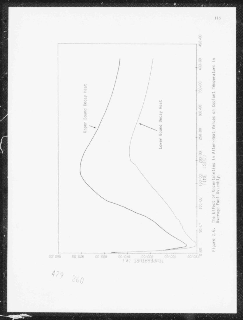
. . _ . _ _ . _ _ _ _ _ _ _ _ _ _ . _ _ _ _ _ _ . _ _ . _ _ _ _ _ _ _ _ _ . _ _ _ _ _ _ . _ _ _ _ _ _ _ _ _ . _ _ _ _ . _ . _ _ _ . _ _ _ _
115
oO
O
d:)
o Co e
o o(3 g" a
amLo
o %ka a
* o += W -
'o>e -u u o'9 C o
o o uI o
D CC x lo oaa m ''o u eC3 o oo ae
oa o s
ca o m- L1 O
L N ro i3 Lo oJ u
%o <'oy" C.ou -
N LtJ*tn
- .o-aC
OL "O ho,JL u-
o- Lo
N-- u] H O E
v -C eae
N <wo-
9 eO aao ouo o- % o
% Cn\ LJ m} L
s eaw .c >\ w<
c-
'1"
N "3 *
N m\ oN L
s
s O e
,_ma r_ L<
oC T C95 00 DE DD Cia 00 079 CD 002 00 C9L 00 02L
IVl 3hRldd3dW3]
s~h/U ,.
' / j
,/ p I
'ud
^
_ . _ _ _ . . _ , ,

- & --
11<
i.l.i ' . nli on Ib i l l i n, (R. P .i re and T. C. Nepser)7
A , i n :le-hubble m >de l for sodium boiling in the reactor core has twen
.h sc r i bed pre /iously ( Ag r.r a l , 197Hb). The boiling coth has been int e rt aced
with the isticial version ol SSU L and some of the prelininary result- fornil um Niiling are being presented in this secti<>n. The d it a are taken for
t he Clinch River Breeder Re.ictor.
The cor. of the Clinch River Breede r Reac t o r modeled by channels. .
( < :a s e 1 of Table 3 . .' ) . The f i rst chane (217) pins represents the aver.ye.
pin in t he p. . a k as<cmbly and the second channel consist- ot alI rena i n i ng 19/
.e . ,blies. The third and t ourt h channel' model rad i .t l blanket and controlsembli.m, res; ect ive l y. Bv pa s s channel i- also considered in the. ttm as
>d e l as .i sep.itate hannel.t
For the present ,tudy, pipe rupture transient is selected. 1he breaka
area i. t i .e um. e the pi;e area (u.2M m' ) . This represents a double endedpipe break. Fl .e location ot rupture is t aken at the inlet end of the reac ti>rvessel. The pipe break is initiatet at h second, and pump t rips at U.125second. The reactor scram is delayed surh th.t control rods become ettective
,at 0.75 secani. The applied reac t ivi t y is varied linearly from N at U./5
: seemi to -M a t 2.75 seconit. The preliminary result- cf sodiu1 boiling is, repre: ented in Figure 1.7. f o rma t i on ani collapse ot v.i r i ou s hubbles'
se.n to continue for a lonner pcriod. This calculation is being continued- to se it and when boiling is t e rm i na t ed .
. 1.1.4 Stean Gene rat o r Cont rol System (W. h. Weaver III):
Durins t he last quarter, inlividual models were developed ot various c e-i
_
r>c n t s in the steam ge ne ra t i n: system which are controlled by the Plant Pro-tt ct.o0 5 ,t em (PPS) or t he Plant Control System (PCS). These elements in-clude, (1) turbiae, (2) turbine hype , system, (1) steam generator pressure
_
reliet sv tem, (' ) ma i n feedwater system, a nd ( 5 ) auxiliary teedwater cy tem.!! !Nrin thi- ;ua rt e r , a unified model of these controlled elements was devel-i
oped. The unitied model was made possible by the fact that all of the ele-i mot s a re controlled bs varying the positions of valve'. The i cedwa t e r sys-
| also controlled by ea ry i ng the feedwater pump speeds.t. ,
e
{ T.:e unitled mode 1 is of the t o rm
!I
g W(t) f(V(t), P(t), (g(t)) (l.1)=
; wherei
E
W(t) time dependent flow rate at interface between controlledi =
element ani steam generating systen,
j P(t) time dependent pressut. at inter! ace hetween controlled=
1 element and steam generatiny <'ste:.,ii
I t.(t) time dependent parameters descr!bing e i er en t , andh *
J ( 'c ,P.t .) = gene ra l non-linear tunctJonI
&
r} r1 m s'j ,e L., \j 'l J
!
l,3
'| f.f .~ [ ' .q * .|

-- - - -
"- l.8 i i i i i i i i
TOP OF'a
BLANKET SODIUM BOILING IN CHANNEL IS I6n['
- - - - ~ - - -
< UPPER INTERFACE
E ,4 __
HIS2LJ |,2 -
-
I
l.0 ~
' LOWER INTERFACE
' ' ' ' ' ' '0.8I.2 1.4 1.6 1.8 2.0 2.2 2.4 2.6 2.8 3.0
TIME, s
Figure 3.7. Bubble Formation Durirq a Pipe Rupture Transient with Reactor Scram.
b
. _ ___- -.-

_ _ . _ _ _ . _ _ . _ _ _ . _ _ _ _ _ _ _ - - _ _
118__
--
ft) ar. the controlled variables such as valve position orThe p cn i m e t e r s tipu ,p speed. In ord.r to utili7" the unif:ed nodel in the innl i c i t solutionalgorithm for the steam venerator, the flow rate at the in:erfcce between the
- centrolled element and the steam generator at t he advanced time Wk+1, must beexpr.ssed as a linear functinn of the chanye .n the pressure at the interfacebe t ween the controlled clerent and th. st am generator during the timestep
- ', Pk+! Th i s relation is obtained by c.panding the non-linear function-
f(W, P, tj) in a first order Taylor expansion which zields'k k_
k k .f k&1 k .fk+;)1(W P i + 1P -W' 'k+1 i ,P W'
( 3. . )2-
W -
'f kl1 - --
l jAtk+1
are suppliedwhere the calues of the parameters at the advanced t ine , t i ,
by the control system. The f o rm of the general non-linear function f(W, P,u.)1
- will be elven for the various eierents._
Turbine
The turbine consists of the turbine control valve and the turbine bladecascade A quasi-static, sinele mass velocity flow nodel i ., assuned so that&
the ilow rate in the turbine can be d e t e rm i ned from the sun of the pressure
drops from the turbine inlet to the condenser,__
!.P ,.I. J P .E P(.
( 3. DP .B
+ =+\,I.
where-
P, pressure at inlet of t urbine control valv.,=
*P.
pressure drop in turbine contral valve,.
=
_
pressure drop in turbine blade cascade, andJP =
_
pressure in condenser.P =
-
Assuminc that the flow in blade cascade is choked, the pressure at the inlet_ of the first stave of th. blaA cascade can be written as-
P !.P + P =K W (3.4)=
Ti T C T1 H-
wh e r..
pressure loss coefficient, andK =
n - flow rat. in turbine,IT
The t urb i n. control valve is assumed to be a linear cantrol valv. and the-
f l.sw rat. in the 'alve riven by the valve capacitv equation for saturated-
stean (considine 197:4a) (the correction for s t ., a, superheat is verv small),,
_
-
WTB .,
- C(S) - (l,3)
- KP (Y. - H.1J.nY ).-
t
-
-
4/, GUJ'
_
_
-

119
-,
f.PN (3.6)Y,= 1.63
1 PIB
w; . c r.-
r(S) position dependent valve capacity,=
S - C(l)=
normalized valve position,S =
r(l) capacity of fully open valve, and=
F = constant.
Tnis f o rr' of the valve capacity equation covers the region of both choked anduncioked flow in the valve
Subs'ituting for the pressure drop across the valve and r e a r r a n y, i n g , we
obtcin
3
TB (Y - 0.148Y ) (3.7)S K PW =
T TTE T V,T
'P -K W
TB fl TB1.63 and (3.8)Y =
,
T PTB
i- a canstant.7
This re:ation has the form of the unified nodel with one parameter, S theT,turbine control valve position.
Turbine Pypass System
11. e terbine bypass is used to control the pressure in the stean headerwh-never the turbine control valve closes during a loss of load on the tur-bine, and consists of the turbine bypass control valve which is attachedd irec t ly to the steam hsader and the piping connecting the valve outlet tothe condenser. The model is similar to the turbine except that the pressuredrop in the piping is given by
-2"p = y'BP w (3.9)'P,B BP
where
|, P = pr.'ssure op in bypass piping,r'p3
pressur. oss coefficient, andK =
gp
flow ! ate in bypan.'a- =gp
e~cL, i. ',i 1, , ,c
U$w

Y; .r. / . ?.]%. | . .a Y L W. '. : :....$..:... .| ,,?:'r '. . T .'.'-
1M
Ih. hvpas: valve is also mb led as a linear valv., with the flow rate thru.
t h. "a|v. d e t e rr i n e d from the valv. capac it y equation for saturated stean.
'I b e f i n.il r sult is
S K P (Y - 0. !! b Y ( 3.10)W = #
3P BP V,BP 11 BP BP
__ _ _ .. ,
P -K W11 LP BP
Y-
.h3) ( 3.11)gp p11where
,= normalized position of bypass valv.,'
F ,= constant, and
pressure in stean header.P =
'his relation has the form of the unified model with one pa r anc t e r , S the- BP,
norn.ilized hvpass valve positior.
Pressure Relief Systen
'I b e pressure relief systen consists of pressere relief valves which ex-haust directly to the atmosphere 'T h e valves are nodeled as linear valvesani are nedeled in exactly the same mannrr as for the turbine control and' inc hvpas< valves. The flow rat, in the pressure re l i e f sys t en is given
sS K P (Y
PR PR V,PR A PR - O . ! !,8YPR) (3.12)'. =,-
_ - ,p _ p--- 2 TM-- (3.13)
A .\1.63Y =
p pA
wher.
normalized position o' pressure relief valve,S =,
K, prescure relief valve constant,=
P, pressure at locatton in stean .venerator where valve is=
"located, and
atmospherir pressure=
'I b i < relation has the torn of the unifi..d nod.l with one parareter, SUN,
th.' nor: a l i zed pressure relief valve position.
, i c-. c R\ - e
i . U
. . . . . . . . _ _ _ _ _ _ _ _ _ _ _ _ _ _ _ _ _ _
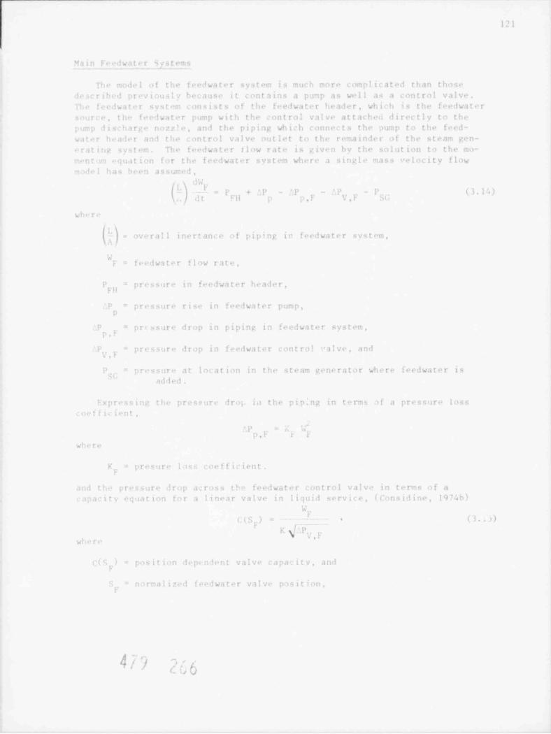
121
M:i i n F. .,!wa t e r Mystems
lh. nodel of the feedwater systen is much :" ore c om pl i c a t ml than those
rir crib.,1 previoust) because it contains a pump as well as a control valvelb. f.edwater system consists of t he f r eeiwa t e r header, which is the f eedwa t e r
sourc. th- t re !wa t er pump with the control valve attacheu directly to th.,
;o: p lischars. nozz'. and the piping wh ich connec t s the pump to the feed-. ,
water h. .a'le r an! t h.' control valv. outlet to the remainder of the steam gen-
eratiro ss,t. The teedwater rlow rate is given hv the solution to the mo-
entin ..q ua t i on for thr feedwater system where a singl. mass erlocity flow- .!e l has been assumed,
d'x
(,1F
dt FH p p,F _.y - p% ( ) , I ', )p + 'p _ f,p-
- =
V,F
wh. r,
oserall inertance of piping ir feed wa t e r system,=
xfeedwater flow rate,F =
p pressure in feedwa t e r heade r ,=
pressur. rise in f eed wa t e r pump,o =p
'p..
pr.ssure drop in piping in f e edwa t e r system,=
p , r-
'P pressure drop in fredwater contro! mlve, and=
. F.s
P pressur, at location in the steam venerator where feedwa t e r is=
SU added.
Expressine the pressure drop ia the pip.ng in t " rm af a pressure losscoetficient,
''P' = . >
p,F r F
where
F ., precure los' coefficient,=
r
anl tho pressure drop across tN fe rd wa t e r control v a l v.- in t e rn s of a
apacits equation for a linear valve in liquid service, (Considine, 1974b)'d , .
r (3,OC(S.) = - *
F
K g/JP.,ygw ~.re
Cls ) position dep.nlent valve capacity, and=
F
. = n , rm a l i z e d f e ed wa t e r valve position,
A'.| *h / *
-4 / f. ;a '

- - . _ - - - - - - _ _ _ _ _ _ _ . - - - - - - - - - -
122
the flow rate in the feedwater system c in be written as1 y.-
k+1).-1 k+1k+1 k+1
K + | | - P-P + '. P - W
F F S K SGt l|k+1 |
p |
. , . .
+_ \ r V,F/ _ - -
- (1.16)' .k & i - W, & *tF l- 1.
.
A.where
f..edwa t e r control valve constant,y'y,y =
1he feedwater header pressure is assumed to be a user input c,nstant and theflow squared term is written as,
k+1 ' k k+1W |-, =W. W (3.17)
F F.
so that the f e ed wa t e r flow rate can be expressed in the form of the unifiel
model as,'. t i k+1 k+1 k + 11W + P + f.P - P
k+1 F- --( 1./ A) l FH Ii SG I' (1.lH)W = --
1-,, '. t }F k
- - - - - -
(I./A)Il - UV' F K
+
4,
V , F. SFp _
k&1with two parameters, S the feedwater control valve position, and ^P thep, . P
,
feedwater pump pressure rise
The pressir- rise across the f eed wa t e r pump can be found from the homolo-yous pump haracteri st ics for the f eed wa t e r pump in t e rm s of the fredwaterflow rate and f e ed wa t e r pump speed.
The pump speed is deternined from the momentum equation for the rot at ingnass consistiny of pump impeller, shaft, and motor armator,,
d'
= < - i ( .. ) - - by(,,W) (3. t vI _
at n
,nere
1 = moment of inertia of rotatiny, mass,
annular sperJ of pur?,=
= notor torque,m
. J .) frictional torque, and
.t
,( ,W) hyd raal ic torque=
The motor torque is yenerated by the drive motor and computed by the pumpcontroll,r. The punp speed is f oun<i implicitly from the momentum equation byexpan.iiny the torques in first o rde r Taylor e x pa r.s ion s , to give
k+1 k kt!k) (i.20)- A & b (W -W
P l'
4 j ') L D ]Ic s, '

123
where
k+1 k k1 -1
A = } 1-
. - 1
E, and (3.21)n. .tp.t f hv. 4I
.ihv
B -'"
P. (3.22)'" f , ['lg'. t ,
I s. L
The pump pressure rise is then given by
kM gg ( k+1 k+1)iP =
P
-
k k k i k+1 ill, g il(w W ) + ;ll (o k)
k k(W +1 -W) ( 3. 2 3)-w +=
17..,,
n s_
where the homologous pump head characterist ic H ( .a ,Wk+1) has been ex-. k+1
pressed in tems of the known values at the beginning of the time step bymeans of a first order Taylor expansion. The pump speed is eliminated fromthis r~1ation to give,
k k+1 kf.P
+1=C +D (W -W) (3.24)
P P P
where
- -
k k illand (3.25)C =0 g 11 +-A .
Lp,
p_
- -
+ h; (3.26)D g d=-
p , p u ;h _
The pump pressure rise is then substituted into the equation for the feed-water flow rate, Equation (3.18), which yields,
k kW +1 A,+B. f. P +,1 (3.27)=
1., F F SG
wher>
k 't_
". t - k+1 k,
D + P - +CW l'^ A .:- - -- LP
-f' and (3.28)A- .
k k - K + - -- -h
litI -W
{D(L/A) p F F K S_ V F F-
/r iit.! , p.-oJ

-
.______________;
1 2 '.
'. t'
_
(I./A)(l. '4)4 -
( ' I II.t i e 1 f
,
|D - W+ 1 -
1 - (I /M ;, F ,T g S. _jt
1his relation an h. us.ol directiy since it is a linear r.lation and has thetorn of th. unifimi to i- l with two parameters, S., the fee' water control
y
valve p4 c i t ion , and the feedwater pump d r ive notor torque Th e s e t w. >
pa r ar t e r < are iomputml hs the pFS/PCS s uh r< oit i ne s .
J,uxiliarv - - - . - _ -SystenF edwater. ---- - - -
T he auxiliary f eedwat er systen i< m.id e l mi in exactly the s co" . anner as
the ;ain t.edwater systet i hw e ' . o r , the auxiliarv f. miwater punp <ay be a
t urb ine driven pump rather than a motor driv"n punp, in which cas.- the drive
m or torque is replaced bs the turbine torque The auxiliary .+dwater tur-Lin, is ned e l m! in the ano manner as the nain turbine
1.1.5 S t . . cn Tables Simplifications (W. L Weaver III and G J. van Tuvle)
Th. st.an tables rout ine s comput, the various transport properties, con-
duc t iv i t y , specific heat, v i st >s i t y , surface tension, ett as well as the,
fluid densit y an i tenperature as a function of pressure and "nthalpy for thewater and steam phas. A check was made ;n each propert y subroutine to ver-it that th.- enthalpy and pressur. i r. p u t into the subroutine for a liquid
p r.m r t v u-re in the liquid recion ani vice versa. If the input properties
u re in tlo wr onc phase region, an error essage wa< cenerate1 an! the pro-m rt v c < mput e 1 at the saturation line far the phase recion specified by tio
property routin. Their chm ks aro v"ry t in + consunine because of t h .- large
n u4 e r of tin. that the property routines are called duriny each time ', ,
cuc! we r + rm!.nolant since the a ": e check was being nade to de t e rn in. which
pr> ports r1>ut i ne was to be c a l l.o! . The checks in the iniividual propertyr .siit i ne s b av. b. "n renoved.
Th.. therm hviraulic p r o;+ r t i e s , dens it y an l t+ ,perature, w. . r . calculatel
h; a :a't r subroutine which in t e rn i nm! the phase r e c. i o n from the input pres-,ur, and enthalp: and < i l l e.1 the inlividual property suhroutines, lhe calcu-
ne de1 during th- c < >nput a t i on of the sur-onlyilti.4n of the t+mperatur, is
t a r. heat fluxe, in th. heat exchangers so that the raster routine was nodi-!t. c onput . the *.nperatur. only when n e led . The r m> val of th. check
sn th- 1se recion hv the iniividual propert. routine a n11 by clininatine the,
tran-ous calculation of the fluid t empe rat ure s r" duce! the CPU tin. per.
! ,tophv a factor o f ap pr ox i:mit e l y 3, from 4 m see per nad. per t i ent ep
to 1'n se per node per t i r. etep.
Fun-ti. al fit stean tables, as provided by 1. Av.., w"re c i ed.o! inti>
' tion subprovrans form. These tables have a wider rang. iif applicabilits'
'
: Lan the stecn tables rurrentl; in the SSr-h packar an! hecause of a quirk,
i le o t h.- Itin c t 5 on s , l a '. p T ()v I'!. a ( . ' ". p u t a l l i) n fi l d'Iv an t av.1i llt. lisai. (i fr i t i ..d < >ii t s iil+a ', w. l 1. L,t h f t:n c t i on '; an.1 f: ac t ii3n d.rivativ.s li a v . h ..n- r
t h. W ;u c r a v + H. iwe r, he ause o f other projeuts of h icher priority, the
new s t can tabl. hav+ not been tul1y inpl. ented an! tested in Nh at thi'' 1 T" .
|r~j ('ffl i .~ \;'1 I i
. . . .._.,.._____._ _ _ _ _ _ -
125
3.1.6 Plant Prote ction and Control Systen (M. Vhatib-Rahbar and F S.Srinivasan)
Itu w a r 'r during this quarter was di ected toward dehnerine and testine ort h. c< ab . nist PPS/PCe and tiu- S S C- 1. nodel, In a !d i t ion , a neetine was held
with the ic l ea r R e y u l a t o r '. Comnission s t a t f membe r s to discuss the procrar'
on PP5 /PFS and some of the preliminary results.
Ee' eral operational transients have been simulated to c h e c .( the inter-' i < i n e b. t w a n the PPS/PCS model and the remainder of the c o<ie As an ex-.n p l . , traesient results for a 10' ramp chane. in load denand in 40 s areshown in Ficures 3.n th rou g h 3.13.
F l y u r. 3.8 shows tie t ransient .reing tun.tien as a l unc t ii n o. t i :: . It.
is ,hserved the load demani is reducc i fron 100' to 407 in 40 s and held con-
stant there ifter. The response at t h.- individual controllers ar. seen tront h. .." ml roi pas i t ion ( Firure 3.0) ani motor torque (Figure 3.111 tineresponse- causine a reduction in the reactor power level (Firur+ 3.10), pumps p. .si fiicure 3.11) and therehv the s o ti ie- flow rat. (Firure 3.12),
Ficur. 3.13 shows the CPU comparison for this transient and it is oh-servri tiat th. PPS/ PES runnine tim is quit, reasonable as compare d to ther. ,t or the code
1.1 ' Ucat Transport Svst. (I, K "adni and E. G Cazzoli)
Pu .p ~haracteristics were extendel to include both the PAN and Hn curvesdurinc s ..Fiv-state calculations. Co r re s pon ii n g chanres we r e also made tot he head p a l yni cial equatien to b. solved for pump speed. Pipo break compo-tatiens we r. inproved thr ough t n. inclusion of an iteration logic to obtain a
m rx ed let lischare. velocity at the start of the transient.t
In Jun. 10 M , a topical report desc ribine the sodium pump nodel in SSC-I.( 5' min i lo?h) was prepared and publishel. A few errors had von. onnoticed inTah!cs A.I and A. II of the re; ort. These tables listed the complet, punph .ad .in.! t arque ci.a rat t e r i s t ic coefficients. The errors have bi en renovedand t he orr.nted 'ahleu ar. repr3ducc i in this report as Tabl. 1.4s
3.1.' C;o!. U pd.i t . (R. J. Vennett)
.\ nuh-tantial pre,e n ine effort was required during t': i s quarter to in-
odifications were required to theit, t he PP5/ PUS s ys t em inta S S C - 1. vi o r; e
transient input realer a n .1 data nanae. ent routines to handle the data fore 'w lules.tb
::r i t this c ua rt e r a series of chances were ,a d. to the codc to aid pro-ra- de'n,.ine ani to i: pro the output tapabilitirs.
4 ~ <c4ij }. l' i- _ ,
i1Q

_ _ _ _ _ _ _ _ _ _ _ . . . . .. .
1/ (, 2
.
.
100.0
Gm
Ea 90.0 -
EdLiJca
eoa
1
0.0 40.0
TIME (s)
Fiqure 3.8. Transient forcino Function
479 27i

127
1
,
t
t
~
r i i r ' ' 'i>b oo ;4 o,
, , .1 ,
Fractional Withdrawa. Of the Primary Control Rod (Fine Regulating Rod).Figure 3.9. 1
k/) '
')c' c

_ _ _ _ _ _ _ _ _ _ _ _ _ _ _ _ . . _ . _ . . . . . . . . . . .
128
E
:-.
i.*
. e,
' . . ',
. . ,
. 'i.;
-I'
.
.
4f..
i i i
Ej oure 3,10 7 f;eutron Flux Anplitude.gAl) L'J,

* __"_" " _" _" _M _ M M M M M - ~'""_"_ M W L M .-
129
: .
' 1 I i i iI
:q n,,
iigure 3.11. Drive Motor Fractional Torque.
k/)_
1'c
-
_ _ _ _ _ _ _ _ . . . . . . . .
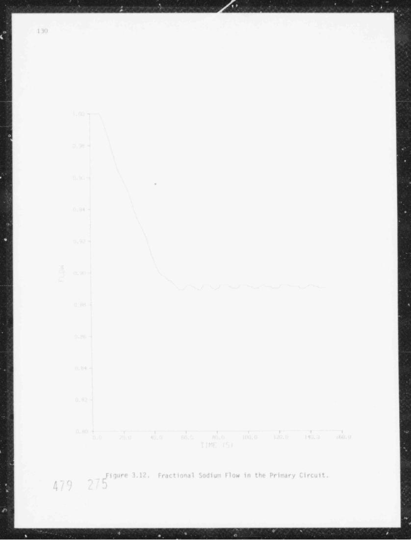
,. - , e \- , , ,
u--- v -_
1 l')
.
I i i ! i l
tf- 1
Fi qure 3.12. Fract ional Sodiuri Flow in the Prinary Circuit.- nF
if | ri 3') ,
. . . _ . . . . . . . _ _ _ _ _ _ _ _ _ _ _

_ ___ _ _ _ . _ _ _ _ . . . . . .
131-
-
_
_
.1
;_
.40
1
|I 1,EG E N__D
-
o - I,00P llYDR AULICS
n- o = 1,00P EN ERG Y-
= I N - V ESSEl, FU El,'o
4 + = I N - V ESSEl, CODI. A NT; ,=pps-pcs~'
o = INPUT / OUTPUT' 50 -4- \
'
\1 \
\-- - _____g
_
~-
4 . , - . _ _ -, 5 ,s - .___.__#-_
- ,.
'y~- n ,
_b '
/ 'N'\'
N ' ~ ~ -/
- ~; ~
20 - -^E--
.:3 .r
: 1- L)t
! 15 --
- (x .
; \_--r ~ ~ ' - < - __- _/
i 10 - ' ' - ~
,
-.
_a
I N.'
_
S-i
$3-
'-_
o n ------ r T- 1 i , , , ,
o 20 40 60 80 100 120 140 160
SIMULATION TlME (S)2
d.
; / - c1 I/ V' Figure 3.13. Comparisons of Computer Running Tine./
-
' O-i.
3
+
- a
_.
- - - - - - . - - . . _ - . . . . . . . ..

_ _ _ _ _ _ _ _ _ _ _ _ _ _ _ . _ _ _ _ _ _ _ _ _ __ _ _ _ _ __ _ __ _ __ _ _ __ _ __._. _ _ _ _ ___ _ _ _ _._._.
lu
( - | |c |'; |J |~l . | I |r. | !c-> |r ! '^ | | 1
_., .-
^
,
I-
, ,
/ |- ''
. , . ,ed 8 d
|;n ,n _ ,J. ,,~y , ,. _.
I- r t- O _;* +; ,_..f 1- .
,,.-
iu , .' -- - .- -r ^ O
_ | .
> ,-a - ,, - c ,-
1 |
.
m _, n_
| | | |i
I - | ,
1-
i.
_-,_
| - ",a .- .,- g,
.-- ..
|-
,-
a '. - i -,- e .-
,I- I
# -
,.- , , -
,-. ,. .
, . , ,,__. u -
-:..
\ -: - , , --.
u u | -- .-
-, . ~= .- . _ .-
u- r s -'
I
"
_ ..-
~
%. ;,, ,J c'_
| ' ~t, ,_ ,-: ,- : ;_ Q C i~ C _s --
.. _ - .
|
| | | |
1 "U .P
| - i
~
i - -
!
. - +>..
-,_
._ ._,; p..
..- .
es-, - -
_-s-
_= s .,
--.
_ i,_
-
:,- , - ..
; a. - --.
-J :: -- .h : :
~c. r,,
..
' w a-,x
"g,
-g, . . - ^j *- I~
~,,> ,- .- _,
I.
-
l
, - ,, -. s . _, c ,, a u-|
-
.
. ~- -
-
| 1 | | | | 1 1I I I
.
i
i . ,) . .
5 ,: ': ". ;' m es ^; m- . .c ..: u~
- :.. - ,,-
1 c. -n -r .a m 'z: -
-e; 'e:. -, .
---.;
-,, - o ..' ,
- en
-i . - . h.
..
=,.:, . s. o a,, 1- .m
-~. _ . . . . , , -, -
u, , ", ',.
y *;,
- ~ -c s, e-
-- -_ _, = - .o m- O-_-
- a a a o -
: '. i I I I I
, . -
t i or~.
-.~ ., .. j :C .n FJ -*
I ''. ~
'_; ,. - -
'-.'-,- *
__I
.-
| . I;''
,-* *: .y ,n -
E' sa - -" g,
,,: .: . ,- :. t_,-- m i-
-- 'i
,, .
g. ,-
i'_ . .:-:
-
cJ -*,- .-
.-- - -; rj
| g - &'~ O ~
e,\ ~
.*a -r - - i.-i
v ,j ,- ,- -
9 ,, s , ; 9 ai
m +. eJ mi; ..9 , c c c c o e o u- 6 --- -
1 -| \ |. -
s
: .-8n-. ~ , ng cm .
e
| .,
u-,. -; ,e ,y- 's, .y-
-.
.:; c_ , _ , *
~1- _._ o -s s
.- ,_- -
:
,..
, - , " ---
,, .,,
. .g '.n* * * ,; ,. |-~, . J
.: .: i,. , , ..
=~
g' ,,;a.- -
.-.
- = = -.
:s .-
-,e,
1- . .- ,-
s . . -_ I c: c 0 0 d a c c o a o
-2J ]. . ,
I I I,
-~;*i *
|c*
.-L. , /' C |)
r-
.
t
_- ms = - T. /. Ii ~
/t.
-
-.-., - - ^
- -M
e i v ,, '
j [-- h f-. " _ .|
,s -> .s .-sm - t I ' . m . e ~ .+ - = m -, f W</ /, f, .f- -em e-m
< > d > > < < >, - H|-
1> < > <o,,-
[ = = = = =~ -- - -;- - -i
.m> ,, v - - - - - - --- -i
i >' e . . g er, .s. ." ': | 'J *T '' '-- I',,
/i |/
-,7
") I jr,j'),
LI
.. .. . . . _ _ _ _ _ . . _ _ _ _ . _ _ _ _ _ _ _ _ _ . _ _ _ _ _

133
1.2 CW P (I, K u: !ai)c_ _ _ _ _ .
1.'.1 Initialization (I. M. Madni a n .1 S. F. Carter)
suc ce s s f ul l y de-Durine this r e ;,o r t i n e p e r i o d , the stralv-state code was
Luc ."! and a converred solution was obtained. Input data and individualn id u l + w" r . apa r a<!"d a n <i modified. 'I h e stc<, -state results are now, in,.noral, consistent with known and expecte<l 1; :lX operatine values Sone ofthe '3difications a r.. drseribed helow.
la vel calculat ions
writ +, tron stat ic balanc.Far the hot pool drui. we can
c(Z - 7 ) ( 3, 30)P P +=
.n tas il llP Xin
g(Z - Z ) ( 3, 31)P P +=r
Xu .e C CP Xu
quhtractinc Equation (1.31) from Equation (3.30) and rearranging yields
~
'. P . .-
(Z - Z ) - 3+ Z/' C ( 3,32 'Z =
CP , 11 lil' Xin y, ~C Xo
Knowing 2 ' P.. a nd IHX elevations, th+ cold pool level Z is calculatedg ;, , CPtrm Equation ( 1. 3 2 ) . Px comprises both the lasses due to friction,turniro area expansion and cont rac t ion e f fec t s , as well as the gravity gain,
as th, coolant nove' downward in the IHX. With this definition, the codecalculates a lavel difference batween pools equal to 66.405 cn. The volumeo f cove r cas is obtained simply as
( 7. 111,) Ahe tank - Z.P)A (3.31)+ (Zcas tank - ZV =
L c;
where A ^. a re , respectively, the areas of hot pool and cold pool inh '<
contact with the cover cas.
Check Valve_
The check valve equation during steady-state has been nadified to
E P ,I,= '+.g ?. Z , \. (3. 34)'
L L,CP
The extra torn de sc r ibes vravity loss or gain in tho valve It will be
oro if th+ alve is pl acod hor ; zont ally ( through user-input 17.g,) ,
< ,
# '| }
t U
,, , .. - , ,. , .. .,
- w- - . -
1 l 's
lw p s
For the PHENIX primar- pumps, tin- specific s p" e:1, N.,, is calculated as!S.w(S.I. un i t s) , and for the secondary pumps, N 36.67. Since the pumpnmle l i, WC-l. is based on data for N '3 ; , no chanres are proposed for the=
3
charactr 'stic coetficients
External Bypass
lhe c o le rwiels external bypass flew, a small f ract ion of the tot al pumpflow that leaks town from the core inlot plenum and up ho t we en the outerhaf fle a n,i the tank wall. With known core flow and hypass fraction, the codecalculates the loss coefficient accounting for all losses in the externalhypass as
BI, = BP - y ZBPo). /(WBl' | WBp') ( 3. n)(AP lKt c
V is held constant during transient conputations.gg
Cold pool
The expression for pressure drop in the cold pool has a term added to ac-<ount for losses occurring as the fluid turns upward in the annulus towardspump inlet. The annulus is present in the PHENIX design and nay or may noth. pr.<ent in other designs. It s purpose seems to be to minimia the impactof cold pool stratification (during lHX under-cooling events) on the inlettemperature to the core
Barrier Heat Transfer
A study was made to evaluate the sensitivity of barrier overall heattransfer coefficients to temperature, e.p., l'ha to T and T and an op-gp,t inn has been aided to the code that allows the user to specify Uq .indU ..n hypassing UBRRIU :1 t oge t he r . These coefficit ats would then remainc ,
constant during transient computations.
3.2.? Transi"nt (f. K. Madni and E. G. < zzoli)
Madel equations de sc ribing t ran s i"n t primar, system hydraulics for thehot pool concept 'a a v e been f o rmu l a t ed . The equations, logic, pa rame t e r de-finitions and nam",, etc., have been set up f ir proyramming More PUENIXdata relevant to transient computations is uryently needed.
3.1 SSC-S Code (W. L. Weaver III)
1.1.1 Identification of Areas of Developmental Effort (W. 1. Weaver III andG I. Van Toyle)
one accomplishment during this qua rt e r wa s to separate the various tasksand suhtasks outlined in the work plan for the ..l e v e l o pme n t of the SSC-S Code(Weaver, 1978) into two main areas of e f fo rt . These two areas are the
. . i
| t-,

.
._ _ _ _ _ . _ _ _ _ _ _ _ _
135
in-vessel portions of the plant and the balance of plant. The two areas arenatural divisions because of the geometric ar rangement of the plant which isreflected in the calculaticaal aspects of the simulation. As a result of theidentification of major areas of effort, personnel have been assigned primeresponsibility for these areas of the developmental effort.
3.3.2 In-Vessel Model (G. J. Van Tuyle)
The in-vessel model to be used in SSC-S was given preliminary consider-ation. Discussions with Professor John E. Meyer of M.I.T. revealed the pos-s ibility o f s ign i f ic an t inter-assembly rad ial heat transfer in EP' '', under
certain flow condit ions . Consideration of this and other modeling effortsindicate possible advantages in loading S-type module into the extant SSC-Lpackage, rather than creating a stand-alone SSC-S.
3.3.3 Auxiliary Feedwater System (W. L Weaver III)
The second milestone in the development of the SSC-S code was satisfiedduring the quarter with the development of a model of the auxiliary feedwatersystem. This system will be needed to replace the fluid !ost by the steamgenerating system whenever the reactor generated decay heat as well as theheat t rans fer red from the system components to the sodium coolant is diss i-pated to the atmosphere by venting of the steam generated in the steam gener-ator. The constant enthalpy auxiliary feedwater will be supplied from alarge water tank. The hydraulic model of the auxiliary f e ed wa t e r systemwhich was developed for the SSC-L code and wh ich is described in this quar-terly report will be utilized in the SSC-S code to calculate the auxiliaryf eedwa t e r flow rate. If the auxiliary feedwater pump is a turbine drivenpump, rather than elect r ically d riven pump, the drive motor torque in thepump speec. equation will be replaced by the turbine torque. The turbinetorque will be calculated from the homologous torque curves for the turbineas a function of turbine speed and turbine flow rate where flow rate thru theauxiliary turbine will be computed in the same nanner as the flow rate in themain turbine
4/) ^,,
s
*
COh
______

. _ _ _ _ __ _ ___. _ _ _ _ _
1 36
Pt'BI.I CATIONS :
1he followine is a 1ist of publit. tions durine the current r e po r t i n y,
p riod t re this activity:
AGRAWAT, A. K., et al , "l's e r s ' Manual for the SSC-L Code," BrookhavenNational Laboratorv, BN L-NI'R FG- 5 0 41 '. ( Ot tober 1478),
Gt'PPY , J. G cir.d AGR AWAL , A. K., "SSC-L Simulation of System 1ransients in,
URBRP," Brookhaven Nat innal 1.aborators, BNL-N t'RFG-2 5100 (November 6978).
(.U P PY , J. G and ACRAWAL, A. K., Con f i rma t o ry S imul a t i on of Sa f et y and O pe r--,
ational Transients in I.MFBR Systems," Paper presented at the InternationalM+etine on Nuclear Power Reactor sa fe t y , October 16-14, 1978, Brussels,elyium.e
M E Y l- R , J. E " S em.' Physical and Num>rical Considerations for the SSC-S,
Cod. Brookhaven National Laboratory, B N L-N t'R EG- 50 413 (November 197R)."
'T. JOHN, K. E AGRAWAL, A. K a nd Gi'PPY , J. G,, "A Comparison Between SSC-L,,
and BRENDA System Codes," Brookhaven National laboratory, BNL-NPREG-25044(October 1978).
R E i/ F R E N C E S
AGRAWAL, A. K., et al., (1478a), "SSC Code Developnent" in Reactor Sa fe t yResearch Programs nuarterly Progress Report, July 1-September 30, 1078,Brookhaven National Laboratory, N L'R EG / C R-0 5 013 , BNL-N L' REG-50 4 3 ) , pp.!!8-137 (November 1978).
Gt'P PY , J. G and ACRAWAL, A. K,, (1978), "SSC-L Simulation of System,
Transients i' CRBRP," Brookhaven National Laboratory, BN L-NI'R EG-2 510 0(November 1978).
WFAVER, W !. III, and AGRAWAL, A. K., (lu73), "A Work Plan for the Develop-ent of SSC-S," Brookhaven National Laboratorv, BNL-NI'R EG-2 4 60 9, ( Inne
147M).
CON 9IDINE, D. M, (ed.), (IG74a), Process Instruments and Controls Handbook,L Graw-Hill, pp. 10-4K.
niNSIDINF, D. N., (ed.), (1974b), Process Inst rument s and Controls ILind book ,
M c G r a w- H i l l , pp. 19-47
e 4p

137
4. SSC Code Valif' tion (A. K. Arrawal and R. J. Cerbone)
Th e SSC Validation work during this quarter covers the following areas
4.1 Intercomparison of SSC-L and IANUS
4.2 Analyses o f The rmohyd raul ic Experiments
4.3 In t e rcompar i son o f SSC-L wi th BRENDA
4.1 Irgercomparison of SSC-L with IANUS (J. W. Yane)
Comparison between SSC-L (Agrawal 1978a) and I ANL'S (Wolfe, 1976) contin-ued as part of the preparation for the pre-an aly . i s o f the pre-operationalt-sts to be conducted as part of the FFTF startup program. Since thesetests, coupled to the planned nat"~' circulation tests, w i .1 play a iominantrole in the SSC Verification program, it was essential that this work proceed
quickly as possible. During this quartar, simulation and partial testingas
for the primary loop of FFTF was completed. The loss of electric power fo l-lowed by scram was calculated using SSC-L and IANUS. Comparisons between theresults obtained with each code are reasonably close, differences remain tobe resolved.
4.1.1 S3C Mode'iog o. FFTF
Ir o rd e r to provide a consistent bas is o f c ompari son with IANUS, onlythree channels were used. These are a hot channel, average channel and abypass channel. Recall that IANUS is a single channel code while SSC 's amulti-channel code One fuol assembly was selected to represent the " Sotchannel" and the remaininx 75 assemblies are grouoed together :.s the"averare" ch'nnel. Th e power ratio of the hot to average channel is taken1.592 while the flow ratio is 0.892. The ratios were d e t e r.a i n ed such thatthe SSC-L calculated enthalpy agreed with tha IANUS ca'culation using a 1.79hot channel factor. The selection of the SSC channels is given in Table 4.1where approximate;y 82! of the coolant flow passes through the fuel subassem-blies wh ich genera te about 95' of the total power. The bypass channel thenincludes all other coolant paths in the core. It is char.cterized by theremainder of total flow and power values.
Table 4.1
Selecti'n of Channels for SSC-L Analysis
humber of Fraction FractionAssemblies of Flow of Power
Hot Channel 1 0.009625 0.01986
Average Channel 75 0.80935 0.93207
Bypass Channel -- 0.181025 0.0'4807
't /A'9 "O'
.'. C

13x
.l.1 Steady State calculations
In o rde r to provide a consistent basis of c om pa r i non between . ANUS and
S S f :- L , a g re :i t deal of ef t ort wa s devot ed to preparing the input da t i. The
input data then unde rwe n t f ur the r checking provided by the steady sta.e com-p;,risons hetwen the two code: The input data requirements f or SSC-L a re.
ditterent from IANUS, because of the degree of detail available in SrC-L towde! the reactor. In addition, the two codes have vastly ditfert at codestructures. All the input data used in SSC-L we re obt ained from cesiga andoperation intormation used in the IANUS (Wolfe, 1970) Code. Lose coeffi-cients in the loop system were computed according to the correla. ions ;ivenby Wolt.. ( l 'J 7 n ) . Using the input data, a steady-state condition was e s t a b-
lished for the SSC-L c ode . Com pa r i eo n for the ste ady state t herm 4 yd raulic s
indicates good agreement netween the two codes. The pump performan.2 pres-,
sure drop and t em pe ra t ur t rise of the coolant in va rious component < are shownin Table 4.2. The overall good agreement lends coniidence in the consistencyof tl e input data for t he p r ima ry heat t ra ns po r t loop.
Table 4.2
Comparison of Steady-State Coola n c DynamicsPreu.cted by S SC-L and IANUS
_ _ __ _ _ _ ,
IANUS SSC-L_ _ __.
? ump
Head, m 146.9 147.4rpm 1088.5 1090.6p, psi 17^,9 170.6
Q, gpm 14304.8 14353.1
Pressure Drop
Vessel 134.5 1 34 .4IHX* 9.27 9.27Check \alve+ 9.53 9.55'i e s s e l to Pump 1. O '4 1.0SPump to Vessel 35.4 33.1
Temperature Risc, K
Vessel 143.5 141.7Core Hot C) anne 1 J95.I 293.1Core Ave. Channel 164./ 163.3IPX (Primarv) 143.3 143.8THX (Second. v) 143.3 1 '+ 2 . 6
* Included in Pump to Vessel Pressure Drop E4.1.3 Transic nt Calculations
fue transient flew and power a.e the most important variables affectingthe transient t he rmo b yd r a u l i c behavior of the entire plant. Hence, it wasessentla1 that the transient p>wer and flow used tv SSC-L a nd IANUS agrer
n ', ,7
5 ~! ) (u)I t

nr --w--- sw ---,ms,m-w- a =-
139_
5T2i5 t-igu e 4.1 snows c om pa r i so n o between the two codos in predicting t he tran-
f* sient flow and r wer due to the pump coas tdown and sc ram. Comparisons of thea t rans ient flow indicate good agreerent up to about 150 ceconds. It should be3 noted that so far the immediate heat transport loop :nd the DHX have not been
.odeled. These will have a major impact on the over.11 calculations beyond,p-J sav, one hundred seconds. The transient flow computation includes not onlyS the pump model but also includes the hyd raulics of the entire primary loop
and vessel. Thus, the good agreement indicates consistency between the two
_codes f o r comput ing the hydraulics in the two codes. Agreement between tal-culated transient powers, however, was obtained by adjusting the scram rodreactivity insertion rate in SSC-L to match the fission power response to
} that obtained with IANUS. From the good greement obtaint d for the steady-; state conditions coupled to the good agreement on transient f low and powe r, aI basis f or comparison of the transient computations has been demonstrated.RII
SSC-L predicted coolant t empe ra t ures a t the top of the active fuel region*ar both the hot and average channel art .hown in Figure 4.1. It should bepointed out that, through the verifi ation effort, certain bugs we re discov-ered in the SSC-L code . In the pres qt calculations, the transient effect ofthe associated hexcan structure was r. amputed.'
;
Figures 4.3 and 4.4 illustrate uetailed comparisons of the transientI c oo la n t t em pe ra t u r e of the hot anJ ave rage channel, recrectively. There a re
differences between the shape of the temperature curves as predicted by SSC-Lj and IANUS. A bmader peak developed at a la t e r t ime in the transient is cat-
colated bv-e
- S S C- L . The difference may be the int eraction with f uel rod and
; structure. It is noted, once again, that the lack of IHTS and DHX in the
i present SSC-L calculations makes more direc* comparison between the two codes'
ditficult.
.-2 ir addition to the coolant dynamics in ti e ve ssel , t ransient results of
7 other components were also examined. For ex<mple, in tl.e study of IHX per-; f o rm a n c e , it .ia s found that the transient t er me ra t ure distribution strongly# depends on the number of nodes used in the el. A detailed sensitivityI study of the IHX should, therefore, be per d._
-I 4.1.. Conclusion from Analyses to Date+
? Code ve ri f icat ion is a continuing process in which experience from the
h verification process is fed back into the c,de development. The intercom-
[ parison of SSC-L and I AN' S ir predicting the steady s tate and t ra ns i e n t res-
{ ponse of FFTF is only a first step in the SSC-L verification process. The: conclusions to be drawn from these c om pa r i s o ns to date ce:
1. SSC-1 and I ANUS prediction of FFTF hydraulics are in good agreement.
[ There is overall consistency between the two codes.
i
f ?. B-th codes predict essentially the same steady state primary loopk operitir. conditions.
o
$ 3. Bath code, predict essentially the same t em pe ra t ur e distributions in
2 the prini:y loop.:'.
o
i A'~. . /'s | }y
d cv96
a
,
,h
|
} <r i .< G ' & L.. _ :;. . ..s W r *y.. ---.

1M)
1.0 i i i i i i i
O.9 ---
*IANUS
0.8 ---
A SSC (FLOW)* SSC (POWER)
0.7 --
0. 6 ---
o
O. 5 --
0. 4 ---
0.3 ---
F LOW7e0.2 -- -
h
O.1 -
jPOWER = % _e ie . _ _; _S E ,_
O ' ' ' ' ' '
O 20 40 60 80 10 0 120 140 160
TIME (s)
F i ;pi r e ' l. Co ':p.s r i: so:, o t~ Jr:in s i en t F l ot, ;ind Power+,
l'r ed Ic t cil by 1ANF5 cind SSC-l.
k') {

.
_
g~
.0 *
.
4 n i
_ - - ' .x-- o2
'
i
g
I
NI 2
-
e '0 n*
l
e2 uF .
0 e
I LI 0 v ''.
i
2 t
c.E A .
N 0 f ' , ,oN i 8I
A 1p
L oT
_ E H 0 e.
N C h '_ '
. 6 t
_I N 1
'
. A E ta
' .
H G e ' .0 -
l.C A r4 )s u '.
R 1
( at
T E re .
. O V 0E p
.m
.
|H A e e
.
2M.
T. 1.
. I
. T. tn
. 0 e~
. i.
.- I 0. .,. s
" .
_n1
ar
_ T
__ |
0 d ,
e8 t '
_ ci
-
_ |
I
6.
d.e
0 rP
L .
-C '
S
_ 0 S '.
_ | 4_
2 -_
_*
4 ,
. |I 0 :
.
e.
2'
.
r. u ,
ni
.-
- - ~~ [- _ -O-
0 0 00 0 0 ,
0 9 81 /. .
r
<cuO2wFr _ -M$
= ~, 3 >Ovn C O'
1= | ,41- _3 i19l h11!E l - i* |Jd ! !s <
i ; :

_ _ _ _ - - _ _ _ _ _ _ _ _ _ -- _ _ _ __ _ - ____ _ _ _ _ __ _ _ _ _ _ _ _ _ _ _ _ _ _ _ __
142
- O
I I l l I I T O) sn;
-eL
$o 4
a _- o "
-
N e >.
< -cm 8",
J u6*
=
g uy C u
o o zs-
m _ o 83m N 05
.h w-
m- =<n ~ a.
" en c.cO du
- w - o y s_D -
2 ,8z _.
cmct F- ~. g
, . .-O a
O s #.- - O
- c--
caO C
-
.s s%1e. ~C
__- - o o-
.s e
- r
- , - 'T
". g'
>_
i i - 3; i 1-O O o oo .
o oO O O O O ON Z O Q w N
: (>1) B En1VB3d'M31
E
..
m
(_I !=
_ e-ism- , - - , - , - - - -ii-i mi u- --.- i- i----a m ---.-iii----.----m --------um -----.-------------.--imummmimumme--mm_--- - - - . - -

. _ _ _ _ _ _ _ _ _ _ _ _ _ _ _ . . _ . . . . . .. .. .. . . . . . . . . _ . _ . _ . _ . _ . . _ _ _ _ _ _ _ _ _ _ _ _ . _ _ _ _ .
143
O sO e4 -
I I I g ;im
6m-b IM
O su- ta ea
N $C-
ovU CC
=u L.
:
J m O E7l o O_ 55_
0 Z N m .u,mm 4 a-
m - Fe* '
.
) to gm -
O2 Bd- tn _ a-
- i- 8,=w=
Qd >
| H
U ut.c UO m<
_ - O - ---
_
= =.O O:r, H
*H
m ,= . =CvE3
O ato
a
4
I I L OI
,
O O O O O OO O O O O ON_
- O O O N_
(Y\ 38n1V83dlN31
| 479 ? ' 6'I!
-
'S , ** ' , -
. . .'-
,., g g .m s'
' 'g*- ,.4" y , de * [ D' F'_ ( , * 6 T, N ' ' g* .
'' ** g , ',. ,. y. ,< , . ,- t, .. 4 _= 9, ' =- 4" ,
- . - - , .. .- . :.. . . .
.

_ ______________ _ ___
141,
' . . In the transient analyses, t empe ra t ure time profiles from both codesagree. However, the SSC predicted peak temperature is approxi-mately 50 K lowe r a nd occurs about 59 seconds later into thetrcusient. This dif f erent e could be due to a number of reasons.Pe rha p s the two most s ign i f ic an t ones are (1) the lack of IHTS and
DHX r: ode l s and (2) the heat loss to structure in the fuel assemblies.
4.2 Analysis of The rmohyd raulic Experiments (D. Ma jumd ir and H. Ludewig)
4.2.1 FFTF Instrumentation
the report on the adequacy of FFTF instruments to provide relevart datafor SSC-L ve ri t ica t ion las undergone extensive review and revision. A draftreport will be issued by Februa ry 15, 1979.
i.3 Intercomparison of SSC-L with BRENDA (K. E. St. John, A. K. Agrawaland J. G. Guppy)
A set if calculations was perf ormed with the SSC-L code (Agrawal, 1978a)so that a direct comparison of results obtained from the BRENDA code(Het rick , 1978) could be made. The transient chosen was a step insertion ofIIN of positive reactivity at time t 0 in the Clinch River Breeder Reactor=
Plant. This plant was assumed to be ope ra t ing a t nominal steady state designconditions ( f ull-powe r and full-flow) with the fuel at the end of equilibriumcycle conditions. The SSC-L results were reported during the last progressreport (Agrawal, 1978b). Their comparisons wit h BRENDA is reported here.More details are included in a separate report (St. John, 1978).
The transient simulated i- the step addition of 10c of positive reactiv-ity in CRLRP. The only reactivity feedback mechanism utilized for t h i s c om-pa ri son wa s the Doppler ef;ect. Table 4.3 gives summary of the key steady-a
state parameters used by the two codes. Figure 4.5 shows a c ompa ri son of thecomputed fission power. In both cases, the actual power is norma l i zed t o itsvalue at time t 0. In the case of BRENDA, this curve also represents=
n o rm a l i z ed reactor power. The reactor powei from SSC-L can be obtained byadding tl e contribution from fission products, which remairs essentially un-changed, to tl"_ fission t e rn , as shown in the previous sections.
'.6 shows the primary sodium flow rate in each of the three physi-Figure +
cal loops present in CRBRP. Both codes predict the same shape of the plantslightly higher (0.227) value for theresponse, BRENDA, howcver predicts a
whole curve. This is a consequence of a slight ruus-match at steady-state.'l h e shape of the curve is due to change in sodium density. As the reactorpower increases, the temperature of the sodium leavind the vessel i nc rease s ,hence, the sodium density decreases.
Figure i . 7 a nd 4.8 show the prima ry sodium t em pe ra t ure s at the talet and
outlet of the i nte rmediate heat exchanger, respectively. The BRENDA codeprediction is slightly highe r than SSC-L as a result of slight difference inthe pre-transient values.
1qgp - <
N | )3 (Y/
_ _ _ _ _ _ _ _ _ . , _ -

--
145
Table 4.3
su=arv A Key Steady-St. ate Parameters Used to Characterize CRBRP
i
PARA'1ETERS SSC-L BRE;DA
!
-'Fewer per Steam Generater, ' F.i 325 325
!I;umbe r (.1 Loops 3 3
i
Reactor Power, MW 968.4 975.06t
i
Flow Rates
Prin.iry Sodium per Loop, kg/s 1741.3 1745.0,
Intermediate Sodium per Loop, kg/s 1610.2 161'. 0
Feedwater pet Loop, kg/s 139.68 ' 140.6,
Turbine Steam, kg/s '19.04 421.8,
i
!
Ter.:p e ra t u r e s :
Re.ic to r Inlet, K 655|
661
).
Reactor Outlet, R 801 ( 808,
) I
bT ] '/' ^"r-> .c;U,
,
----. _ _ _ _ _ _ -

- ----------mm--.-s-- i- ---um- - - - - - - - - - - - - - , , - - - ----i---
I
146
__ _ _ . _ _ _ . _ _ _ _ _ . . _.
. . oN
OZttJ J* N yy -
CD V)u@x0n.
$ .- oLn Ce-4 O
r-
dWr-
ti.
TJ
M UNr-gr-
3-
S 2o R oC3 -
.M*,
ew
LO
e
. Om - g\
U..** @)b *r> -4 LA.
| f*C| Luw *:.: -- o-
m54
dtLbut/3
[ ;- M --
itlaC3-< .g
. .- - , , , , ,
g
m ca o oe -4 O
O. o*
Fd F $ e=== g
Ell:0d t;0ISSIJ
4 ], Q 'c , )'o ri

- - - _ _ __ _
147
o% -- o
nJ
$ -- aoo
*{ _J
oZ btu o acY. v) o1 -- g e
~ca
x cr3o-
x --"-
Ear-
uom n
N D* -- o3 2 'a
>- 5t.c.
W -* w
5 ".- al 'c
L.o 2(L) O
O r-U) * -- in a;.64
n.t LJ
b ")U
| _. $ --
-<.111L)
oe a
F r --i -e : ! - - ooo o oWDJ V ONm s s
r- A r-4 r-4
3as/fq ' gol.J
b{ f C) i G)4 /(
' mm - - - - - - _ _ - , . . _ .

148
- ---. _ _ . _ _ _ _ _ _ _ _ _ _ __
k.-C.)
N
'5GZ OA It1 w _ gZ w .
OT ce-
X:rew
.O <>10 r3ri
CL'3+1OL
$ . Dn.t.
6 0v1 !-
. i
ld 3
1 __ () **O t- ov4 tn
NL(Q
1.:an
O-.,o .b
V-4
I-rr' -tIt1U,2 y (3 O
gi;
- u' 3c,
-r--g11i).CfJ
| -- T*--
,_
tilL.)
C7ce
3[ } i J- - - - - j. __ ____ ._ g aL-
<> <3 c3 t,tt i3 to N(Q (O rw rs
.}dI! f. [d.!(!' f1.e
< - ?t '; r. ,
i ') '
_ . . _ . . .. .. .. .. .. _ _ . __

_
149
--_ _ _ _ _ _ _ . _ _ _ _ . _ _ _ _ .
O'A .O
N43O
4 r-
C's *'
Z 3ItJ O gM W - 5cn (n cg +>
co
OO L
1 -LD 3a +>
dLOCLw
A _.. s --
OE -
nr-
F- Ow
O hA _.o L
7~s-
LCL
% _. CD
7. CCJ
CJy
3m a11J r-
$ % 'a f.;
. Om
n.c tu
y --*h [U
'd r,g _C
__
!. a
'1 LL1-i LJ
'/ C3a
t
i . o< -- [ _{ r --| | ro a o oN w as otw w w W
M 3 kib [b 3 d''dl1s
b ~I Q m c ,,'' ' d,4
gn :

- _ _ . _ _ _ _ _ _ - _ _ _ _ _ _ _ _ _ _ . _ _ . _ _ _ - ._
150
The two codes, BRENDA and ',SC-1., produced results which in almost allcompared well. The response of the plant predicted by the codes iscases
i d e r. t i c a l in shape, though shi f t ed slightly in absolute value, af the par-
aneter being compared. The difference in the absolut e values is due toslight difference in steady ntate values.
PUBLICATIDNS:
The following is a list of publications during the current reportingperiod from this activity:
S T . J f W !, , K. E., AG R Aa' A L , A. K and GUI'PY , J. G "A Camparison Between SSC-L, ,
and BRENDA System rodes," Brookhaven National Laborantry, BNL-NURFG-25099(nctober 1978).
YANG, J. W., " Comparative Studies o f FFTF Uppe r-Plenum Mixiny and Stratifi-ation," Trans, An. Nuc1, Soc Vol. 30, p. 535 (1478).(
YANG, J. W., " Comparative Studies on LMFBR Systens Codes: Part 2, FFTFUpper-Plenum Mixing and Stratification," Brookhaven National Laboratory,BNL-NPREG-24856-R (October 1978).
REFERENCES
ACRAWAL, A. K., et al , (1978a), "An Advanced Thermohydraulic simulationrode for Transients in LMFBRs (SSC-L Code)," Brookhaven National Labor-atory, BNL-NPREG-50773 ( Feb ri.a r y 19/8).
AGRAWAL, A. K., et al., (1978b), "SSr Code Validation" in Reactor Sa f et yResearch Programs Quarterly Proyress Report, July 1-September 10, 1978,Brookhaven National Laboratory, NUREC/CR-05013, B N L- NI' R FG- 50911,pp. 11H-149 (November 1978).
HFIRICK, D. L and S0WER, G W., (1978), "BRENDA, A Dynamic Simulator for,
Sodium-Cooled Fast Reactor Power Plant," NPREC/CR-0244 (July 1978).
ST. Jf m! , K E., AGRAWAL, A. K., and GUPPY, J. G., (1978), "A ComparisonB. ' w e n SSC-L and BRENDA System codes," Bcookhaven National Laboratory,BNI.- "RFG-25094 (October 1978).
WOI10 , C F,, (1976), "IANUS - A p p l i c e. t i on Information, WARD-FPC-1253( Propr iet ary), Rev. 1, (Mav 19 7 M
--
.,
. _ . . . . . . _ _ _ _ . _ _ _ _ _ _ _ _ _ .

m- m---- - , ,--
151
III. LIGitT WATER REACTOR SAFETY
M ""Ak';
& I n t e r in M i l es t < :'e Report on t he analyt ical work tt nodel the nonequi-
1ib.it vapor c.ene ra t i en in ilashing ilows was c o: m l e t ed . The results comparewelI ith the experimental data of Reucreux for void fractions below 0.3.nF ations on the <' of the u po r generation as related to mas * flux seen, i
oppo ,it e to 't- :-known relations observed for vapor condensation inte ,
qu;ersonic nozzle-
A cecond se' of f l a sh i n; experiments were pe r f o rmed w it h TS-2. In thest
in add it ion to the pressure distributions along the nozzle, photographic<
, - itions et the flashing regines at the exit of the test section were alsoorded. The data reported show that the reproduc ibilit y of the results is<
cerv ce s' . In these series of tests, we also studied the effec's of the .ari-
eut flew parameters, i.e., inlet pressure, inlct subcooling, nass flux, and exitpr ,u r e or condensing tank pressure on the pressure distributions und flashingr e e, i n e !
In one set of experiments, the onset of flashing was moved upstrean of thethroat. The pressure distributions recorded under this condition are represen-
a supercritical flow in the nozzle,tative C
Ti . single channel y densitemeter with the traversing mechanism was in-atz.lled and debugged in preparat ion of the void fraction distribution measure-nent>
Improvenents have been made in the TW W description of the quench front ve-locity to better natch both low pressure and high pressure minimum stable filmboiling temperatare, The THOR input description was improved and a new pseudo-restart capability was added. THOR calcul it ions of the Seniscale downcomerlewe: plenur assenhly behavior were extended showing good comparison with coreand break flews but much larver voiding in the lower plenun than actually mea-:,c r ed . Cent inua t ion of the effort to resolve the nurerical instability in theN-zone hydraulics mdule revealed that the incemplete and complete linearizat-tion retheds produced e wentialh the same results. Reformulation with smoothtransitions in drift flux across flow regine boundaries without the need for
descr ipt ion 01 derivatives at the boundaries was unde rt aken, q
e -
This is the first quarterls report for the second fiscal year of the RSR 9procrar- C mplete data are included in the first annual report which is to be [Virsued in the near future f
.' S
In the experimental area, add it ional slow strainina systems are !einn con-'
,tructed and the tenaile speciren design has been noditied. Pressurized capsule Hspeci" ens are beine fabricated and will provide a stress pattern ;inilar tn a ;
d en t eti tube >-
4, _.
Five heats of material have shewn crackinu at the two highest tenperatures S.tnd resuits at U S"C a re expected "oen, judriny f rm curves through the first 5'.
~
points. ?Jf p:
$..a.: y
4-L'' orif ^*
'..y.'. sb "
/
u-9-
O.g . ' .j * ''
q' ' ' ,. N [ $ . g - .a d ,e ' , s ,,_ g 8 * , ,# i.*g.* A . *

,\- , - , . -
v- ,- , , , e
152
o'I h e slow straining test has produced i n t e r y, r a n u l .1 r c racking .it 365 C,
e o oi'.5 C and 325 C. A test is current 1v in progres, at 290 C with a strain rate
10-8 .sec-Iof 5 x
Controlled potential tests at 36Y'C have reduced the time to f ailurt of'0 nV to 160 V ne,;at i ve to the open circuit potential.specimens held at +
Specic' ens have been cracked under a cyclic load in 365"C pure water wit hf r..quene ies of 10-3 liz , 10-2 11 2 and 10-1 lb
q p -7479 cn
. . . . . _ _ _ . . . . . _ . _ _ _ _ _ _ _ _ . . _ , - _ _ ___

- _-_ _wwup__ _ - -_-w _ _wa -
1S3
1, I. i c h t later I:eactor T he rna l / livd ra u l ii Development Procram (! . Abuaf andO. C. Jones, Jr.)
1.1 An t ivt i cal "ad el ing (B.J.C. Wu)
1.1.1 O fect: of Pressure Chann
An Interim 'tilestone Report on t he analytical work (Saha 1977a,b,c,d.up! Tu 197S) to model the nonequilibrium vapor generation in ilashing flows
, been cenpletel. Results of comparison of this model with the experi-*
<att of neocreux (1974) indicate that:
(a) the :odel workea we ll for void fractions below about 0. 7,above this value, it seemei to underestimate the "apor,eneration rate,
(b) higher superheat "alues--or higher (p - p), t l'e
di:terence between the saturation and actual liquid,ressures--were reached at the point of net vapor gen-,
eration CWG ) for l ow ma ss fluxes, and vice versa, and
ic) the " rate constant" r , which is proportional to t l.e
cube root of the bubble concentration and incorporatesthe constant factors in the heat transfer coetficientan! interfacla1 area density function used, was founito increase wi t h the mass flux.
Kesult (b) inplies that the salue of superheat at !NG decreases wi th in-creasine depressurization rate, which is proportional to the cube of theus flux. This trend, also observed by Seynhaeve (1976), is opposite tot b. we11-known eritical supercooling vs. cool in;; ra te relationship firstno ice 1 b: Oswatitsch (1942) for supersonic nozzle flaws with vapor conden-;a t f on. I t' C. is taken to be a measure of the bubble concentration, then
risults (c) an! (b) ind ica t e that a greater number of bubbles are producedwhen net apor teneration occurs at a low superheat value. This seems tosu mest that the controllins driving; pot ent ial for bubble produc t ion my netbe t he liquid superheat, in contrast to the case of nozzle fl ws with,n len sa t ion , where vapor supercooling plays a dominant role, la the pasti
quarter, work was initiated to investigate p^ssible mechanisms of bubh!efornation in which the rate-limiting step is the detachment fro: surfacesites an1 entrainment in the flow rather than the P,rowth to the criticalsize o monly assumeil in nucleation t heories.
1, ' {est Sec t fiins and Seal Development (W .I. Leunhardt and J. H. Klein)
'l e s t Sect ion ? (TS-2) w,9 operated in tl e flashing facilit' during ruch>f t hi s quarter with temperatures reaching 150"C and flow rates up to mig
nin. The test section operated without any problens, and tho : lightdeferotion, reported last quarter (I conhard t 1978), renained unchanged.After s r.e invest ira t ion, it was determined that the deformation occurre?
f j -) /9d(o
ti ) ,
- - - - - - . - - . . . - . . . - . _ _ .

_ _ _ _ _ _ _ _ _ _ _ . _ . . . .
15 '.
bec a u se of inadequate allowance for t herma l expansion between the testsec t ion and t he gamma der iteneter traversing mechanisn, a situation whichhas been corrected.
Development of the probe seal for TE-3 has resulted in the followingconclusions
a) W suitable ma t er ia l ap;' ears to exist to allow an
inflatable /deflatable seal design to function.Therefore, this design concept has been abandoned.
b) of the nine design concepts examined in detail, sixhave also been rejected due to lack of suitablenaterials.
c) A static seal design concept is currently being pursued,which does not appear to have th same drawbe,cks as theprevious concepts. A suitab' e .s t fixture is being
constructed for further evaluation of this design.
1.3 Global De~ ' tor e t er (W. J. Leonhardt and N. Abuaf)
The single channel gamma densitometer has been made operational and hasbeen installed on TS-2 Currently, calibration runs are being performed.
The observations regarding neutron activation of a Scandium impuritydescribed in the previous quarterly report ha e now been confirmed byHarwell (1sotope Sales Division). This is appirently the first time suchobservations have been made. On this basis, an ultra-purified Thuliumsource material was obtained from Iowa State i'niversity and has been foundthrough our activation analysis to possess a 700 fold reduction in theScandium levels compared with material of our other suppliers. It is theScandiur which causes the 1.12 MeV radiation which in turn requires exces-sive shield ing. There is some uncertainty as to the source of the Scandiumsince both two independent vendors and Harwell reported pre-radiationcontamination levels of less than 0.5 ppm Scandium. Post irradiation levelsif 80 ppm were found at IWL and confirmed independently by Harwell.Ftrther testing is being undertaken to insure no further difficulties appearat higher source intensities (longer activation times).
1.4 Flashine 1:xpt riment s (G. A. 7. imme r , B.J.C. Wu, W. J. LeonhardtJ. H. Klein, and N. Abuaf)
A second set of flashing experiments were performed, and pressuredistribut ions along the converging diverging nozzle were recorded. In
addition to the pressure measurements, the flashing regimes, under a varietyof irlet conditions and flow rates, werr also recorded photographically bymeans of a flash and a still camera arrangement located downstream of the
test section outlet. A list of the runs performed with their inlet condi-tions and nass flow rat, are presented in Table (1.1). The typical effectsobserved are summarize < b low.
c m,,
!
. . . . . . . _. ._ .

i-
i . .
. . . . _ ____ .
Yd_.-t.-
.
--i--a7
-
1
b_
2
"?-
'i ' f.)
e
-i"
1 Alill' I
i ( .'e=d C~ ~,n S l'M't\ RY OF EX1 t RIME!G AI. CONDITIONS
1 O-3 _ _ . . _ _ . . _ _ _ . _ . . _ _ _ _ . . _ . _ _ . _ . _ _ . - _ _ __ _ _ _ _ . . ___ _ . _ _ _ _ . . _ _ . .
5 A. Col.D & litrf CAllBkAT h >N B. F I A bH ING t. AF IR IM E N I S
g("6) G Mg/m secp, ( k i'a ) T ("r) G Mg/m sec kua N p (kPa) T ( C) G Mg/m see Run No p (k i'a ) THun Nog
i''
1 ----- ---- ---- 20 278.5 9 tt . 3 4.90 48 185.5 99.8 3.042 369.7 26.4 1.56 21 39).O 100.6 b.01 49 144.1 99.4 '~7
--a 3 388.2 26.8 3.13 22 169.6 100.2 3.04 50 140.0 99.9
4 160.0 27.2 4.71 23 130.3 99.4 1.81 51 ----- - - - - ---
d 5 349.7 27.6 6.28 24 I t,0 . 0 98.0 3.05 52 '39 4. 4 121.5 4.45
j 6 679.5 27.7 7.01 25 246.8 97.4 4.52 53 399.9 123.6 4.4)
m 7 088.5 2/.3 6.30 26 380.1 97.8 6.02 54 553.0 123.5 5.90
2 8 692.6 26.9 4.7) 27 326.1 130.0 2.95 55 295.8 123.8 2.99
3 9 696.0 27.1 3.1] 28 555.4 131.7 5.90 56 261.3 123.5 2.20
i 10 708.4 27 0 1,56 29 488.2 123.5 5.77 57 2 t,2 . 0 123.2 2.01-d 11 685.7 27.7 6.26 30 315.1 125.1 4.47 58 257.2 123.1 2. 9'l 1629.2 29.2 7.01 31 ----- ----- ---- 59 257.2 123.) 2.9%
@ 13 1027.9 29.4 7.88 35 287.5 99.4 4.96 60 266.8 126.1 2.9014 315.3 23.0 6.25 37 295.8 100.3 4.94 61 261.3 124.2 2.95"
i 15 146.3 22.9 4.74 38 117.2 100.3 2.05 61 769.5 148.5 5.8116 364.2 66.3 3.08 19 136.5 100.5 2.25 64 626.0 148.8 4.36
17 3t,5. 5 64.1 1.56 40 167.5 100.3 3.02 65 --- - - - - ----
g IB ----- ---- ---- 41 249.6 100.2 4.54 66 525.4 148.8 2. w).
# 19 336.0 94.4 5.49 42 193.7 99.6 3.79 67 503.3 149.2 2.1832 326.4 11.6 4.71 43 286.8 100.2 4.97 68 39 3. 0 143.9 1.21
,
| ~) 114.0 11.9 6.29 44 28).4 99.9 4.50 69 396.4 144.6 1.19t.
14 313.9 12.3 3.15 45 324.1 100.1 4.97
--| 16 292.0 69.0 3.08 46 ----- 100.2 3.79q
|62 697.8 148.6 2.29 47 ----- - --- ----
.U-
l
|
|I-
||wu
a
1

. _ _ _ _ _ _ _ _ _ _ _ - _ -
156
1, . 1 P.epro luo i b il it y S t uJ ien
To conpare our present results to the results obtained in the first setat m:rerinents, reporte1 in the last quarterly (Abuaf 197M), and to checkthe repeatability of the data, several runs were perforned at nearly identi-al inlet conditions and flow rates. Figure (1.1) shows the conparison
N t ween t he pressure distributions obtained in the two sets of experinents
100 C, and nass flux of 1.03 x 10 kg/m sec.tor p. 16i kPa, T= =
In in ,3
e also perforned at a bicher nass riux .5 x 10 ke/n"sec11perinents wer +
l'33',E and p 196 kPa. Ficure (1,2) depicts the pressurea n<! T ==
in in
.iist ribut ions for these latter cases, i.e., Exps. 52 and 53. The results at*hese mass fluxes are reproducible to within less than 2 percent:
1,4 .' Effeet of "ack Pressure on the Flashinr Regine,
'lashine was init iated wit h the condensing tank liquid level (def inedas the location of the free surface below the top of the tank) equal tozero, i . e ,, , an alnest solid loop condition (Fir 1.3, Exp 33). Decreasine
t he conaensine tank liquid lesel, i.e., increasing the size of the steancavity in the condensine tank changed the flashing conditions and thepressure d is t r ibut ions dr Tst ically (Exp. 37) although the flow rate and
inlet con.!itions were held constant The photographic observations or theree: rerinents are p r e s e r.t ( d in Fic. (1.4), one o b se rv e s that for flashine
under an almost sol id sys ten, the bubble sizes forned are ninute and theirnunber density is very larte (Fic. 1 . '. a ) . lacrolsinw the mpor bubble atthe conlensine tank increases the vapor get i a as seen in Fie (1.4b) an!( 1, :. c ) . However, this drastic difference in appearance observed betw erExp. 3 7 and 4 3 (Fin. 1.4b and 1. + c ) does not noticeably affect the pressur+distributions is seen in Fic. (1, 3 ) .
1 1 Param tr!c Effects.
The effects of the flev paranetert, inlet pressure p. inlet tenpera-In,
ture T and nass flux on the flashing regines and pressure distributions
were alsn investicated. Figures (1.5), (1.6), (1./), (1.8), (1.9), and
(1,10) present the results for the cases where p and T. were kept con-in in
stant, and the m.a s s flux was caried. Ficures (1.5) and (1.6) (Exp. f+9 and
70) correspon1 to the onset of flasning in the nozzle. The pressure distri-bution in the convercing part follows very closely the single phase cal 1-bration. Downstrean of the throit, tFe Japor generation presents itsell asa diciation in the pressure distribution. This is followed by a suddenpressure increase caused b: the sudden collapse of the bubbles and a pres-tre recovery t ypica l o+ single phase flows. In Fig. (1.6), we see the'
phn orr e te observations for these two cases. The appearance of bubblesse cw d to be internittent in Exp. 50, but this fact was not observed in thepres > :re wasurmnt Jue tn our long averagin; t in . Fi2nre (1.7) repre-
C100'C and uss fluxes of2X4 kPa, 'I .sents similar rew :lts for p. ==
1n .. 1n
10 here, with higher mass fluxes, tne97 10 (!ip 1) ani +.50 s4 s
-n ,
4. 9 -,1,/ -
. . . , , . , , . . . . - - . - - - - . - - - - - - - - - . - - . - - - -
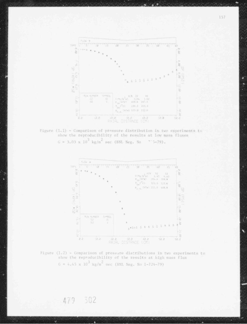
_ _ _ _ . _ _ _ _ _ ___
157
, , - -. ._____ _-. -
-,-s---,-, m n v ,,,.,r,,.---,w , , ,
L s. t e. e, ,
, . . . y,,*
.9
,
9, -
s,
S.
5, , -:
s'
s. .> -
. >
.
- - c. s .
P e, 3i,
'+o v.t
4 i 1- .3r
* .4 ) I w ,(
'1.
Figure ( 1.1) - Comparison of prossure distribution in two experiments toshow the reproduc ibility of the results at low mass fluxes
3 ?G= 3.03 x 10 k g / n'' see (BNL Neg. ':0 'i-79).
'
_
- - _ _ __ _-----
- '
- - - - - , , , , . , - . ,,. .
L t. 4 to
. ,,' .s s u. ,
. , ,, , ,,3r, , o. r,,
*- ,,<Si: : $. .o -
*i, , , F,b4
9
s
. ._
. - ,
rm
__ . _ . ,. _ _ . . - - .
_
. <
' ' ' '>s s > >, ,,
. _ . _ . . __ __ ___
. , ,
Figure (1.2) - Comparison of pressare distributions in two experiments toshow the reproducibility of the results at high mass flux
G= 4 .',5 x 10 kg/m sec (RNL Neg, ':0 1-724-79)
479 ~02;
_ _ _ _ _ _ _ _ _ _ .. . . ..

||'
I , 1| |
"41 q q , - | ,p ..
--NJummumammes -
-
%dx
__
,
T T
a . , ,, ,
, .- , . ,
.
. . ., ''.
.,,
9y
fl
_
!*
r.,
O .,
>t
' -
> ..
E r)
- a._
'' - *
-a ,i e + t t + ,
_ __g
. - <,< , ,_ . _
ITN 35 37 43'g ,,
. C(Mg/t's) 4.96 4.94 4.47p.in(kPa) 287.5 295.8 286.8.
T (OC) 99.4 100.1 100 's in' p,t.t.(kPa) 249.4 169.7 119.S
_ . _ . _ _ ,.___ _ . _ _ , .__ __ _ _ _ _ _ ___
i i . . . - . . . , ,, , ,,
. . , ,
f
Figure (1.3) - Pressure distributions shewing the effect of condensine tank back pressure for identicalnozzle inlet condittens (BSL Sep 50 i-728-79),
.., _
. . . . . ..

gJar m v e r - - w w = m' - s - e h - 2="wwemmusu _
1W
p - ~~ .- ~y .,
V :~,4]
<
m,2 =;, -
| ' '
y,,.
p.+ ' :p ty,,;
., c ,* s eq . . - <,
. ; < f beQ,Q,;srQ.''}i,)as
. *[_n'| %fJ:,,'
i,^
'a ,;i j . g~ ~' _
j; . +q p q.vp y y.. %. , .
fp6% D %,
- $' N( 4c. :t. .y[ @ [y};f
'
.-
. \g . e. j er,
,
s
.
, . ,|
Y g;f w |gyg&CdG: ^ . ')'- s '
_y
WN. .. ,$_ ef ic-
V?! .
= ' j Q V i' -5% : ~x3 :,, . .;g . :m;p35-s;m .
. , . n w .w 4g%gi '![e #1?[[-..
.- . ., [ . Y /%.;, ' '' '
'
.s,- ,. ,
A.RUN NO. 35 B RUN NO. 37
.if""] j;7ie
s, ,
b [
,w,
e r
.
. -d -%
p$
4.
# ,%x,
s~L w,s v..,y,,.=.r: _
-v1 . --,- s.
,
~%.s. s
A gA1 ' ' ,.c SCALE 1:1,
.. ,
a
C RUN NO. < 3
Fi cut < (l.4) - Pinn o.'.ra ph i c ob se rv.it io n s for the e: perinenta t nd i t io,t<
present l in F i :. ( 1.1) ( R SI. > l-919-79).'
.,
i - - . , ,A i (
Jt,
) .)
n 6'MA%KgEG4%%w'|h2 tiler _

r , , .. , , ,
. --. ._ . .
m -
-'
1>
4 --
:n
-.
_
_ .
- -
-- - --i
- _ _ ~ _-
- - _ _,
.
a. -~_ .s
-. ---
--..- ...,_ - , _ _ _._,_,----.--
,
.2- _. ,
_
-, . , -- . - .. . ,,
, >__
_=- -
- .m., ;, - ., , _
- ,
..,
.
1.
< - .,..
-- - .z .
.- - _ .>
- .
- .:,-
. - .,. ...
- s .*
, ,
+n= -
'
- .+
.
1 + 1e ,
_.- _
_ s. .
; . ..
3 -- o* ,a ,.- *
.~s. -
- a. .,
_J _
^ C 37_j = o+
vie ,
m
-, v .
.m " -a
.- m
_y s a .
._,- s -
..-
-
m- -~
-
~ . 9_,. a,- -
Nf Q 9 0
~
_ - -.m o ,
''-
,-
3 m ,:s
__
-. - . , _ , .
7-
- ,s,
, c .,
nh3 .- ,
- s- _
- .N.;
.- ;~i s, varg s v v a ._~ !._ . _.
-
m, ,,-m n l, .,, ,, o 3u-.
- - >; <- r;
'im
;,--
G (y. /m s .)N , , .,
i n (k"n., '3 )1.-- .-.0.,. ;..
- ,140.J -,2 - ~
.
a
d T C C) 99,4 %,oinm . -
- P ., P,a)101.0 Ini.0 ; .
- t ..c.C 4
m.. , - -
.*.
'I 7 e 7 q q q g
u,, c-.. .- -..e c. .. ... .,
m; -- s -- c s n-' ra k W b
% g >=,,,,s .
;- \ . L d . v ,v _ g v
fIL A f t' il 3) - EIICCl if -"d ! , flux en pressure distribuliONS (OT Identical nP2:le ;nict conditigns._ MilC D .i re CloHo to the c; ,e t g[ { } 3 s }) i n ,, in g };g ggg , ., g { . ,
_a
M-11 -
du
u
M
]
mu
M",
9wn
f a e e ,
-,
-*
'
e-

musu r .nn,. - -,--- -a- _--- ,_
-
._
4 1
d
3
e
SC A L E 1:1*
-
M
-se- , . . - - , -
-
,e ] . (~g_ _
, Ny,
] f O%[..8'S ];- m;n'_ i :~.
,
-- / ,r's. m;
b \ '- rg-g;"'%s_,
| % %c+" * * N'h J, ~ /// . ' .-\1 { N/ ''
-
,'
- \,p ; '*f ) .yp . ,
I ilf (d- 1 | -f, g'
t. p,
it j B s . it s d 't -|'] pa.' ,is ] -b g- o .<
,4in j , 1 mc
t- 1y. ' fff -'
\ [. C .+ A :
1 9;h' ? ] (- % \, . W. <
s
tu >
} ( \ It '
e# } Q\ *g%:p4f}'j-- 5|* -
$-
% 'b'
y- .
3 w,w_ s74 .
f. \\ *,
s, ',.
[ eA .
;/ j t ' ?g'
. Q ^j_,
' '
^ RUN NO.49 RUN NO.49.
- -n-,n_n , ,.n _ - ,m,, nnn 7.,,,,_m.,.wn,_na. pg -..,.
,
f l ", i'
!.. n. 4 1 _ : -,'
- ] _ ~ jz; ~ " _;
-
(; , _ jf"'"~ d''. '
, f x .f .y -. ;#
-
I,
jp!; Yr
i[o) h[ t, a N
4 a|f oq a 3
n, .s.
3
++b ;e , ,
i; i m m c.Il>
ed, il -)r
! i -i n q -|yps y- JL- nt-<
t. ; -}! -
,
:eg|,,1
%n %=._:--x9 1 t g ;
h. Ng,.y%1 i6 ,a. % m:/ ~;,p- 1 a N-
>
] gg - ,
-A ~' [q)'k-#'
f- % --
j ! - 1.s,- ~ a -
4 v1j,, _ m._ _ . . ~t_m_
| RUN NO 50 RUN NO.50ia
[ _,
-
3
$4
31
!4 '
1
i
~ ^ .:
N
Ydd2hE16adaMuR2MhT2iGkhltWL6Cs!M MMdLKdEiBi2GHEGidT

.. 9,: : ' ?i 4 ; e
,.7.-.
..s-- . .s- -
: ,z. '. - :v... .. , _
.
S
&
i lh2_.
1
-1
A
-ntlachine appear- more p r o n m i n c ~.i , and the pressure down s t r e.im o ! the t h r< >a t3
1 1ppea r- to .r, en. i i n constant. Figure (1.8) d e p i c t .' a sinflar G-variatinn for3
121 e and p. .?hn kPa, from onset of flashine ( F. x p . 31) atj i T, - v
_i n in,
.nl 10 %r. sc< to violent ''ashine at '.95 x 10 kg/m see (Exp. hl).,
-J ihe photneraphic obse' 'ations fo* Exps. and (21 are present ed in Fir.'
4; (1.u)..I
_'lj the ne>* >ct of figures represent the etfect of the nor le inletj t e nera t ure while a const. int inlet s ub c oo l i n p, is 'aintaim l b' a corres-j p>ndin: uriation at the inlet nre' sure Figure (1.10) rept 'nt s thesei risult- tor Ep hl (T. = l '. 4 '"( 12 3. 5"C,501.'l ' spa) Exp. % (T.p = =
,
-; in ir in,
! ih LPa) whi!e the u; f'' is _.20 10 kg/n'sec for the experi-, * in' ' s
-
a-i n nti! c on.! i t i on s clnse to the m set of flashine lhe photographi. obser-- ut it'ns for !xps 19 a n.! % are pre sented in Fig (1,11). Om observes thata
the c ! ! c. t of inlet t perat ure i, m il as long as the inlet pressure isad j uc t e.i +'r const ant sub noling at the inlet. T!.e sane ol'serva t ion w i l l be
; ulid for the followinn results Fir,ures (1.12), ( 1.1 ! ) , ( 1.1 ". ) show
d ,inflar reqults for progr essivel) hi t he r r:a sy fluxes, and Fit (1.15) showph > t o cr.iph ic h ervations f,r Exp. >i an i 52 (Fir. 1.15).
#- A s!Icht urfatfan of the inlet pressure is observed to have an etiect
Th t he pres < tre distributions and t l ashin;; r e r, i r:e s for the s a r.e inlet,
j t . 7 era t u re- a n,! un' fluxes. This dependenc e and sensi t iv it y se e: > ti be-,a v re pronm a d at low uss fluxes: Fic. (!.16) presents the iesults for3
_1 0 37
_
> li (1, 1/1, W (;, C . ' , 8) ') x ]O p p / m' s. i , p - ' u ty kp t) , t nj [xp, 38^
=
In, in
10) k;/risec, and p.ti
123.I r, G 2.9h_(; . - 25/.2 kP 1) . Figute=- < =
_in in
_] (1.11) 'or I ?2 and M and Fig. (1.lM) for Exps O, 31, and c3 show>,,
] ,rriep^ndinels raller lit f eri oces in the pressure dist ributien as a resoltj "I til l e' ear ia t fine: in p. .
j l '1
_1
g 1,... 'l a sh lin' 1pstree of the Ebro t tS
5 In alI the e:.pe r inen t : pr,sentud above, flashinn nienrred in the_j ii init- of th throat. Pc chanrine ind controlline the flow conditions, we-! ere able to ,htain almost sa t i.ra t ' 'n cc,nl i t i on s at the inlet of the t est"I
. tion. The pre < :o re distrihation recorded nader this conli tien i pre-<e-_y
nte' i: 'f; (1.10). Flashine started aroun1 pressure .ap 41 1, (l~> n'up trer at the thrcat) where the distribution ueviates fror t h. s i n e,l e
.
-
- ph i' a l i b r.i t i on. Ihe 'ontinaou- pressure lecrease in the convergine, ass
.) wel1 as the divergine sectfont o: the noz:le, is renini: < ent of the super-j e r i ? ! il 'l< in mpersonie lo n i. > In cla' ul c a s d v n . nn i c . , the onset ot<
j : l a th i: wn it h is aci onp:1ni eJ wi t h a st rene dev ia t ion in the po sure,
j : .t r i H t ' ,n a s io ared to *'e ,incle ph calihratlen, is depi,ted in_J
1
] -- - -_.--..--..
s
} 4te t hat it t h. . tw> exp. rim nts, the ondensinr tank pri >ure al'o
S (F p. ><) to 251 M P.i (Exp. >;).'
j urie fr< it . *
1.
,
! h 5I /2 s / avJ
:
ab
wA_=
' - --- .
. ~;j ef., ,- - -, .

. . . . . .. . .. _.. . _ _ _ _ . _ _ _ . _ _ _ _ _ _ _ _ _ _ _ _ .
1 (> 3
- ,
,. ..
',
' , e.,'
s- ,
. .
. e ,,. , .
,
,
)
.
, , , > > , , .,
- ...
a.
.
. . - .
.' z ez= =
,
I i ru ri- 'l.7) - Et f eet o f na .s > tlux on the p re : -; u r e dist ribution in the~
test wc t i on ( B SI. ',e g . No 1-723-79).
_
- ,
. . _.
. .
. . , . ., ,
, , , > > > :.
>. ,
. .
1
- ,
*.
.
' - - . , ,.
e
N
' ,:, 1.
r 'o s i,i 4,
ligure (1.S) - Et t ect of tr.t ss flux en t ile pressure distribution in the
t e st section (BNI. Neg No 1-722-/9),
if ' ,.t < j .
, ,,' s) /
_
"
. - - - - - . - - __.._ . _ . ..

upm wwxxy.Nx<.ppmy s3,1w.wr=:Arv?am
. .
, - , * , - . - - - , _ 7 [. .
- -n--.,-=-
j/ ! ;9D=@. .< -
k,)'-, ,l ".
, ; pcs%&s, ,q.n.g
,_ m~ . . w- . . 1 (a- . -< >s, - <3<.,
*/ - .
,,
>> Ay'%o% .
j se 1
,@-e \? ,., Oi
.,,
| n / N.I|
- f. T T g _
- /o2-'
4
- ''.
:7-N{g: [. c .] ks:' . ,
~
)Y V /A;
DJ*
v c y y pf: ,
y\ I ''
-
. . . .
,0.g'?<j "c3'
,\',, 'y'
\s.y %~_ma8; \s
-
j,,
N ., //
. _ _ _ '- . _ _- /Zm
RUN NO.57 RUN NO.57
|
|' *< r e
., . . . . . .
..N ^*1e-4 ~
"L f,f ''-
c.,_
s 7; .- x.-a. .
s.,. i
///1 N;| ,,
.i in,4 ' v-.\ ;,; .; O
D..
j |{ l A'
.7 q- 1
3; 4 ' A, //r ' x. '
S h;m,, , .[,1; ? i
eA 4'
'Nw ' & _- ,
f) % 4 . -p<: Nw . me
f~ -_ . o_ t m ~
%.'
,
SC ALE 1: 1a .. ,
RUN NO. 61
,, ,
I
a ~*
s7
|> |
v

9 P' F '| |
' E
' h IHIP W
g..
--
-
"I
-!i-1
-}j - ._ _
_ _ _ . _ _ _ _ _-
_ _ _ - -- -
d ~~-
23 __
sg-n.
;, c; ., . ; .-> - - 7,-1
s; - , _
. ._ c< -c __ -, - ._ , . ._ _.
3 _
- ;'IF'
I lE s'_
,3 .
.| -. .,
y |'
. *
] - . . .-
=4L,:
.
+-
..- r p.
E*
.
,-
a. . - -
t-|
~ ', ,
(] W g -
"
d- ',- r'
x .- g gA
- - - |-
'! . ',-
x ___ :- _ -
t_,
L>
-
A_. .-
,. _ . -
3 " 2-
.e " -1-$
- _. .. h _ _,3- s A
m - - _ o-
i- - - -
. , . _ _,
m-- .
~,
--
3 . . -
5- ,.- m
(|i.
3
m_.+ -
.- .
ks~> * . ;
, N- ,
8 - c,_ . ,
9 .e .
:v;._ c> c , .-4 .
_N _ _ . _ _ -
RUF 56 30 - . ~ " y''; ~ - - - , ,, ,
, , , > . eC(Mg/i s)2 -J'' ' . 18 ..on . . . 5. . .g
j 77 ~ p, :- .
in(kPa) ". 0 3 . 3 261.3 100.5--*~-
1
'"" s^..
- *i n ("C)T 149.2 123.5 116.5 )
.,
2 P # 230 8 II2 0 -
fe.t. ya-
(...
. _ . _ _ , . _ _ _ _ _ . _ _ _ _ - _ _ _ - - _ _ - . - _ _ _ _ _ _ _ __ _ _ _ . _ . . .,
h;, , , ,
"_ . . . <. .., , ,
_ . .,, ,, , , , p. . .. _< . . ._
.- s, . - .-c. - - -..
s --
.
_.( -
.> rs 4 a - -w -
kt-
t . -
"-
,F i >:u r e (1.10) - F.f f e c t of nozzle inlet temperature e7 the pressure distribution i n the test
: section (BNL Nen. No 1-726-79),i
--
m W) y$ u
"
*'
'
'8 * ' .', *e /
,
,.#.
.* *. * ' . j* - ,' .' , 7 * . 'e'.
- ' ', . : ' - . f , . ,.

_
3y:rr>;8:o:e,wy>Sry.v.mpxtyyyh_;ssyyyppymmmst , . y_ ,
?j ,
,
.'.1
,
2
4
SCALE 1:1a,
:'~ " \ '
-
' '%
.ms c; %' nd;%,., 4+ $3ets8.. --- -
'
v
o\.
a s |p$fm,
, .
f ||b -||( \'' '
: o' ~: a s,,a p3 $, ,
,
.
tj ''
y c, . s -.
,
- ~ :: .s,.
I :%%# $ '
$6
f M, aO C
7- a.. <
|v
r RUN NO.56 RUN NO. 56v.m
_f-a
NNN s
3k!| , $\ ~
,,P-M - - - - - - -vq
'3 {{h1 " y '
:f .v ^% ,1' %[.' ' _ ''
-g ,,
.. .
.
,1 \. ''}
t' /- 7, %'\1 l ;j
+. ;.
'
i
/,1
. \1-
1 :-
. ., , .
y>> -
. ., < ,
' s-; ~
(g' 4 Tj*_
(.'' '-,
-
e
.\.i e .j. .*.f . -\g /' p %
*^,
~h [ N / .d 'Ai r.
7 ':~ f G |
.
a d __. k_ _ ,nh._.,i
: RUN NO. 39 RUN NO. 39'- 1 .' ti.
r P i' i i : _. # 'l,
-:
,~q :'l.
, v
?
*- " r w J ," .y.- ..-.. *~
' *'

c , . , . ,, -
m. as so m w -m mw - 2__ =_- w w m >_-#
167
%
.
c.i* **....,,. ,
... . .
- . ,.,. ,
,
. ,,
= > e,
..
=, ,.
,a*, .
...
,w
- ,
w a j 4
.. .,
r,.<,, 4 ;, e
,r,, ,
.
.
, ,,t
iigure (1.12) - !.f f ec t of nozzle inlet teuperature on the pressured i st r ibu t ion in the nozzle (BNL Neg. No 1-721-79).
__
--
- +. .
. .
' ....,*.,
.
.
..
.-
. .
. ,
'' . . s s. ; ' ',
.
L
- . ,,, ,
je4
i t
, ,, .
%
1
Figure ( 1.1 1) - Effect of nozzle inlet temperature on the prassured is t ribut ion in the nozzle (B!a. Neg. No 1-720-79).
i
b '. o )L. i ..,
* / *)
a
. mM UM.

, op.F .I, , ,. , z i< ,,, ; e ? | :'; , } ( ;, .. ..., -_-_ ,
I I,3
r' tr ,-
f[r .l j.)I'I
.,
O (.I O
3 g* Meg <p ( 8 E 1
. . , ., , , . . ,
IIJ j } $ M' * , g
| t LL' &c , .
I ' .1f'
'
"$s &,
1 -3
f ~1 < ' f) f*,y ]
's + c~-*,
' ew -f *
\,* .- .S
. >n| ,) -rj e . :
6- |'
1 .-- - a , , - --
1 ' "If{ . a - ~ ca
I
1_ ; -
t ~ ' '
_
p,
, m + ( N-
i u,
k" |.
+.
.f,-
c_-*_ . i
t (t> n. 1<,d
. f) (1) . [ -
c.,-*
\-f: c'", rb ~
(y, '*f .f- ;
. . ./:.
# #j - , v v . y) '' L
L - || - ..
;-,
\I. !ljt fs (~ i- f.
. , . . .
! f 1 Cj
')4 -;
n- 'i c\
, ,'.'+. ; ;
) u) o+,* I (
- .('') %
I j 3''
'
#,
-e tt jf
r s,
I *b 7_'
I. | . ] [
lI s( .
Mi a . I, ~
h J * * u
I, - "
~u
|(\
c: =. .
,,
~toj , ,1 ,
),
j > ! .r
> l -i
j g ' u) ;es-
,
CT ~ <*
, * .y c 4Y
. ) . tw
f |,f ~~0 t 's
# 1[} '4#.
|-
i- > x,
K ',
't " - -<, s j
~ . m_
j'
i i,,t a ~ U
{ ), / . / ., (3 7] j;4'
g. . .. ,
M g?) L K: : - --,
, -
t=
[ )$ ~ t iI j ~ 4 -
f'T ; } .) -
'
%*'s} n d w

+ - .E,
3 e., .1 ,-
.
SCALE 1:1
s.
_- ,- - - ,.__
, ,.
$ml. #
' ~' -
o(
-
,rg .. . *, k;&& <v -|tu s i o
51: | h[ bh5;&$,|w ,
' :p,
t - h, )_h ['j m..|' ; ftf, ., g y++.'.f~J ' .; ;
.
,$.ad f' n %e. t t| .
m .~ rt _-~.a.: ,
, #r. .gx , 4 .
,
, s ' , 4W'
-
i > ;> 6 *
- s % ,, ", ^W < k. -D Q og
't.:'1 '' ~ <
q ;.m -
.; %,U.*, .
4+ - . n.,-,.7> i,-; - ,.
'. /, ;j %'* ,a .> ym- >s, d*., ,
2 .., j - m_ f, s . _..
8'
-
:q ' . . %' - , - c . ;. -
t- 4' q3
=;
'
3
*,
, , ..
..( ,gw ' d e%. g ce t , e .
g% . ' , J E. .- 1k DB;k,,% m- 7 #A E pm. 4~"'h: i
. ,\ ,- -f v-.;
g., m -- M )- f,)g . ; i g.^
\s .bj . Q " El-'
-\,N @ --m- F..A - 4
da ,T -- %," - o'e
_ .a% .$ V .g j -
,
.w- _ --
RUN NO.55 RUN NO. 55
y . - . , . _ . . . , r,-
. m: - .-
. : ( 3, , Q .. ~ ~ J2 6 ?' w .sntT fAA .: c i g & +4 1n, -o .4
.
Q Q. p y :.u -w-.. - a .
: . %h',,:: & c v&a .pg. i. r thMQ { e . ; ,'g7-
:%,.,3 ^, .g; f ., ,,f.,
> ,p)%g-,4 Q 2. . , ,;,4..,
s A :< .s.- F *sy+ ' n'p y* jg.if( y ;%:.
,.g, ,
-3 ,e . -Q t. h yat- s ,
. ,s a t ~ ._: (( > m.
- 7^f:1, %~
g 'n&, &. :W. r%p 2,y::a .s:.
~ K u -.
i . u ng c . u - w -,
.: i m . . .w. y y ".,Y.
f. y; , -:. :.s-c .we - ., ,,w,.-
| gj, vi p : 4,.. %. 31 W,V f.ca r 's. Jk~4 %- g \*.
.,
h ,,, e> . r eg rn.h.g'.;p, -
s ---- nu;-
[v . o , e.
Q-{m ~|.cD Rf';% * , q qkab i t; . . . lfi
~ta3 x :
~ ^* ''
{ zh| < < -
g!/'%w yR'
ct . w ,' s a wm . - A' 4 .
s.,-v ;C ,!'s,;' s ;; ~. ; , + s .e1 - - up4,':N.g .n, ,m w gu s, g-E"af 4, . . ., p . s
<n .
,
m v';. < |e+ r .!-
.:w- x ; .. ) .tp*_q.~ . -,a Q z k e .;.%4x - %, y. '
+ g . , . D;j '. g , s'
', n; .} 5 f=a,
' t;%g,4 '; / z 1 n' ge- ' 'q, - +s ,
s k. Ap'_ I'4'
k. - 4 ,g A,7 , * -3
-s j
*'*'-b.
.% s , p ' m : 4.r _, .. , .
,y 9 s\vu , - 'W.Qu - h _ ./o. 2... % +a
mi - 'wa''' -# t.:
RUN NO. 52 RUN NO. 52.
-
' ~1 , I t
',
g ( h , _- -
N
l"
.
_

- i ,
', -
5
}/}
d
1
iH
. .
-
. r
. . , * - ..
u
-- .
= >, ,
.
..
4
',
i,, '
*e6f
, -
'9 . .
i., 6,
l' .I
T F
-.
o, ,, ,,
l' i c.u r e (1.16) - F. i f t e t of nozzle inlet pressure at constant subcoolinp
on the pressure di ;trib it ions in the test section ( b';I. ?;eg . ?;o1-719-79).
- ,- , , _
*(
. . ,*
..
.
. . . -' :
e
. **
-
. ,
3 +, .'1'
.-* *, , , , , . * -
.
. ..
s -
.s
> .
.t. .
. _ _ _ . _ - .-_. .
-E E
I i gu ri- (1.17) - Effect of nozzle inlet pressure at c on:>t an t subconlin;
on the pressure distributions in the test sect ion (l;?;I. ?;eg ';n
1-718-79).
i - tb- < a' ,.
4// J l [t'y

-- _ _ _ ._ - ,w
; k
r171 r
1
E-;E-
P_
n----
_- r. , -
, ,. , , -
f A E
. ..-
,--
. =. . i, ,
.4 , , ,.
* l. . I p-
k'*i 1 1.,e
- , , .... . , . _
._
. .-,.
_
s -
=*
w
i-
;- a s ; i s4 4 4 e .,
..
_
_
E-
k-
_
.
Finure (1.18) - Effect of nezzle inlet pressure at constant s ub co ol i n g_
,
on the pressure distributions in the test section (BNL Neg. No1-717 7')) .
-
_
.
L-
~
~ _ _ _ _ _ _ _ _ _ __ - - -.-
- , , , , ,-.-,n, , , , , , , ,,,,n-n--,.-,. _ _ _'
.- . ii. ,
'. _s _-..... . ..
-. ,
. . ..
-
.
-
.. ,
--_
-
.-- rs n _- =
,N * ! 11~
,^
as *, 3,, > , ,
) . , , .-
,,* * ' '
-
i_,, .) n a. .
.-- - _. . . .
-. .. ,
,
- --
-
. :- . . . - - - - - - -. --. - .
'. : .: _
' '
-. _
_
;-
Figure (1.19) - Pressure distributions in the test sec tion wnil e the --
flashing onset is upstream of the nozzle throat (BNL Neg No1 -716-7 t)) . k
yi==_
r
t
.9 -.
g=
/ 9., *
/ ,~ '.*-7
- Eki
e,-
E
U Hm mm

A, ._
I b- r; 17/ m- g_i r
-
-
| L; ! f r. (1,20). '! h i r. pressure distribution plot nonfirmensionalized with the r-
inlet kinetic enernv of t he flow proviles a very accurate was of deterr.iningi
] the onset a: vcipo r ;:ene ra t l o n .- h-^
. -
M -
n-
a Fa1 -
11
1 ;
. L-'
- 8-
,
A -
nm
"Je _
-
ei
-
_
1 .- , - - .
. - - - -.
i ,. .. .,
j_
. .- -. , .. a _ _ -
.
. ,
L =
n-
n
.b-
h_ 1 -3
-
s_
i a1
4* ai
n
S : a= -
11 _
* "Ta a *n u a -
h,~
- - . . __ _ _ _ .
S -
i.
K % F
: , . 1.i> _
|' ,, . n
i, . -
, ., :a- - _
_
r.g- -
-
. . . . ,. ,. . , ,.
e_
-
) '
,
, -
1
* -
DP/25 C , inFigure (1.20) - Nondimensional pressure distribution hP, =
In
the test section, s ile the flashing onset is upstream of th-.'; noz le throat. (No BNL : e e, . No).
_'u -
s|
=
-
=
-
3
4
_
-, / <I
,M
4/ ./ J i V3
$-
.
-
m-, - - - - - . - - - - - - - - - - -
Y ~ { . -| , , y - .c. g p ; :, - | . ,,. S ,,w . . ,
'
I- ., -| 4...' . f .._, ___
173
--
M
U!T['f!.C'
aLUA! , ' , , " Pea tor S if et Pese ar c h I r. ,cr ams : Quarterly ?rneress Report for f
t h. perin! Tuly-m pterher 1978," ; MIc:;iT FG-5 0911, p.160 (;978'. _
[. I rO !.it '' r [ , ani V i !. I !, , .I. 11. , "Re.t. tor Ritetv Pesearch Procrans: Quarterly --
Pr< arcs P. sport for t h. periot! .J u l y- F ( ptember '975," B!;!c!, UE FG-5 09 31, p .1 5 '+_
'
(197u).'
: ! ; ncli, V .. , "Vntt!ensitionserscheinuncen in Fhersrhalldusen," Z. anceu.(m a
'! i t n . %<h. ->2, 1 ( 19 '+ 2 ) . bpi-! nr:rm , 9, , "Fontribution a l'Etud. des debits critique: en ecoulement
<!i ph isique clu-vapeur," PhD. Th. sis, University Scientifique et 'ted i ca l e {de Gren,ble, Fr.ince (1974).
IPA, P., "Re.mtor Safety Rese.1rch Programs: Quartcrly Frogress Report fortla perim! T. inn irv ': treh 14 7 7, " B!;I.-!.T RI.G- i f 6 61, p . 144 ( 1 '! / ;
AH i, P., "%n t or %i'et: Pesearch Prne, rams: Quarterly Progress 'eport for _]tlo perind ip t i 1 - iu'. 19 7 / , " BN1.-!:UREG-5 06 8 'i , p. 145 (1977b).
m,
Al! A , P., "Peactor Safety Rmearch Programs: Quar.crly Progress Report fori he perini fulc- ,tember 19 7 ~/ , C1.-NFREG-50747, p. 169 (1977').
--'ila, P., "R e.ic t o r hafety Ker ' arch Programs: Quarterly Procress Report for
the p e r i o.1 Oc t obe r- De c embe r 1977, P/;I -!,U RI G- 5 0 7 3 5, p. 169 (1977d). -
,
'T'i!!!!A Fi f , T. !f . , GInT, !!. M., and FI'I T'I E , A. A., " ;onequilibr ium Ef f ec t s on aF. r i t i c . i l Flow IUtes at I.ow Qualitfes," paper presented at the S peialists' ;'cetine ne Iransient Two-Phase Flow, Toronto, August 3-4, 1976 OECD
o - l e, enerev Acencv Connitte on the cafets of !;uelear Installations.__
a9, M.1.F., "!:cac t or "ifets Resear c h Progra :s : quarterly Prearess Report for -
the perial.Tulv-Lepterher 1978," !P;I.-!!UR EG-5 07 1, p .15 3 (14 78 ) . j
E_
E
_
==
M
-w-
_
m
M-
']_-
M
-
-
-
I4 s.
y Q _
. ,7s. _-
5m
,,,,
-a
_
b.mmA m -3

---- _e = _--as -_--- surugwsowsiumvratsastym3 sty 31twym- 'u
174
- .
2. THOR CODE DEVELOF. LENT ( 'd . Wulff, P. Saha, and O.C. Jones, Jr.)
The seneral objectives of the THOR Code Development Program is to producean advanced computer code for the prediction of accident-induced thermohydrau-lie transients in water-cooled nuclear reactors.
Th e primary objectives are:
1. The model should include the effects of thormal nonequilibrium, as well asunequal velocities between the vapor and liquid phases.
2. The reactor components should be modeled to include the spec ific charac-teristics af each component.
1. Th e axi;l variation of the transient fission power must be modeled.
4. The program should include the capability for an initial steady-state com-potation.
5. The code structure should be mod u l ar , permitting its application to dif-forent system configurations, as well as providing for ready improvement ofindividual component and process subroutines.
6 The code should be executing rapidly, for instance, for frequent applica-tion in parametric studies.
Th e objectives itemized above and their implementation represent a sig-ni ficant and major departure from all other previous or currently developedthermal hyd raulic codes such as RELAP or TRAC. These are invariably discretepaameter codes written a round a standardized unit ce ll to which the appropri-ate base-level field equations are direc tly applied in generally semi-implic itnumerical forms. Thus, once the numerical scheme has been identi fied and
coded, simple calculations follow almost immediately. Additional levels ofsophistication may then be added as is deemed necessary to appropriately de-scribe the geometry and processes involved.
A single component may require many numerical cells to adequately describeits thermohydraulic behavior. On the other hand, THOR represents a single com-ponent as a single, lumped, integral entity where considerable detail, even onthe most basic, simplistic level, is required. The modeler is thus able totake advantage of simplifications inherent in the individual component to ade-quately describe the behavior of each as a single eitity. In addition, wheremultiple flow regimes may exist within a component, ae mod e l e r can ac c omod a t eF
these in his development while still allowing the module to shed complicacy asthe number of regimea decreases. Thus, the equivalence of a variable fine meshgriJ is achieved in principle, on a component-wide basis, without the associ-ated complicacy.
Another major difference is the built-in .ibilit y of THOR components tohandle in fact to track, sharp discontinuities in hyJraulic or thermal behav-ior. Thus, a demarcation between a region of all vapor and a high density two-phase mixture, such as occurs in the pressurizer, accumulator, core and steam
-t i
4 ., ,9 31/
.;. y = p r ;mv q ,7 m y p y y ( y gy .. :: v

OXh$ b M Y s. d d 4 h] 4 4 b r r b ,*b h . hV ! ' :P "*k WN |>
r
175
, nerator, is autor,tically accounted for through appropriate logic, coupledwith correc* application of the lumped zone an1 shock balance equations.1 racking of regin interfaces in general and of mixture levels are i c:po r t a n tfor ';grtximating flow paraneters e fectively by profile functions, and fortou, lint the hyd ra ulic s with fuel element conduction during the re flood period.
An extremely important feature of lumped parameter modeling with re g i meinterface tracking is that the boundary conditions at every conputational cellare continuous with respect to time, even when sharp disconiinuities (levels)pass through stationary ( E.u lt r i a n ) component interfaces. " iis is accomplishedwith the application of moving regime boundaries which serve simultaneously asboundaries of computational ce ll s (W. Wulff, 1978) with appropriate creation orfestruction of zones as required. Discontinuous boundary conditions on a1.u l e r i a n finite difference m~sh grid frequently produce computational instabil-ities.
Une ma jor shor t-te rm disadvanta ge exists, however, when comparing Til0Rwith other codes. While codes being developed using a disc rete cell descrip-tion can begin to calculate almost immediately and further developed by inten-sive efforts at i mp rove:.r n c s , little can be accomplished with the THOR systembeyond simple calculations until the complete component module descriptionshave been devel' Nilowing complete spatial integration of the field equa-tions. This requ thorough analysis of the component resulting in differ-ent systems of differential and algebraic equations for each component, differ-ent nemerical descriptions, and different problems with accuracy, convergence,and stability. The "up-front" investment prior to first credible results isthus seen to be considerable in contrast with other codes. Once developed,however, the payoff potential is expected to be much more rapidly realized.
To achieve these objectives, individual lumped parameter models have beendeveloped for the components of the reactor system. Discrete-parameter model-ing is being used far predictir.g the choked f l iw through the break during aI.o s s of Coolant Accident. A semi-implicit integration scheme is being employedfor the or finary and partial differential equat ions of lumped and discrete pa-rameter modeline., respectively.
Wark toward achieving the above objectives has been described in previousquart erly progress repor t s (e.g. Wulff, Saba, and Jones, 1978), particularlythe formulation of lumped parameter models for nonhomogeneous no ne qu i l i b r i ur.flow in reactor components, pr _ess models for vapor drift in gravity-dominatedflow channels, nonequilibrium mass transfer for cond nsation and evaporation, anadel for critical break flow, and a model for one-dimensional neutron kinet-ics. The THUR-1 code structure has been completed, and all pWR reactor compo-nent nodules are interfaced with the operatine system. Developmental serifica-tion of component subas s embl ie s has begun in T110R-1 with considerable success.
progress achieved during the re por t ing period from October 1 throughDecember 1978 is presented below.
,~0c. ,
'/
- - _ _ _ _ _ . .

"M3pF v %*mWFMPMkPNVAg;rcMppewgh_
--ij .
g 1/6
- :_
-
1.1 Corpunent Modeling?
-
2.1.1 Core, Steam Generator and Pressurizer Subassemblies (J. Jo,E J.M. Kaufman, R. Krasny, S. Lekach, C. Huger, and P. Saha)J
_.a
j Vork on these subassenblies continued as required when problems were en-
's countered in system calculations. All were upgraded to be compatible with the
_j improsed operating systen input routines.'
2.1.2 liiscrete Heated Channel (J.M. Kaufman and S.V. Lekach),
3n
@ Work is being done on a discrete heated channel with wall heat conduction.-}_
1his will then provide a bench mark to test the lumped parameter model forbeing applied to the Com-core. Presently the discrete heated channel model isy
7 bustion Eng,ineering blowdown problen. A satisfactory steady state has been
_
reached and investigation of the transient is now taking place.J!-a
_.i 2.2 Proc <ss Modelingi
h- 2.2.1 Quench Front Propagation Velocity (W. Wulff):
i
overview
The code module for the prediction of the quench front propagat ion veloc-as desc ribed in Volume 2 of t he TF9 '-l (PWR) report (W. Wulff,ity
y 0.C. Jone<, Jr. et al. 1978) has been tested by comparing the code predictions- with exp cimental data ( A.W. Bent .t et 31. 1966). The experimental data were'
* obtained with a falling quench front on the outside of an electrically heated,- hollow tube, and in stean-water w . e ms in the pressure range fron 7 to 70 bar.
as a fu nc t ion4 The data were used to assess th< qieuch front velocity prediction
-] of pressure. The results of the comparison are shown in Figure 2.1.i
7.iummary of Primary Results;
0;
9 The system pressure affects the quench front T ropagation velocit y throughthe dependence of fluid properties and of the heat transfer coefficient on-,
) pressure. Th e heat transfer coe f f ic ient h (Tg) as a function of the clad sur-
m fac *emperature is expressed in terms of thr(e key temperatures and three cor-
-) responding heat transfer coefficients. These are the aturation temperature T m9 the temperature Tg, at the critical heat flux, the minimum stabic film boilingg temperature T and the heat t ransfer coe f fi tent s h hCHF and hygpgyg g , ip,
tor s i n ,; l e phase flow, critical heat flux and minimum stable film boiling, re-3
] spectively. Of these six key parameters, the minimum stable fi!.m boiling tem-function of pressure p is the most dif ficult one to pre-a perature Tygg(p) as a
_ dict. T affects the prediction of the quench front propag st ion velocit yyggj primarily t h rough the calculation of the heat transfer coefficient hcup at
critical heat flux (lshii, 1975)i
K (I)(hCHF)o 1J h =
.R CHFy'I--p-
i-
!
1
-
.1
o,
r r"
3_
i um um iimum - mmmmmm-- immmmmm_ m--m _-

,. . . ,. . . .-
, _ . _ _ _ _ _ _ _ _ _ . _ _ _ _ _ _ . _ . . _ _ _ _ _ _ _ _ _ _ _ _ _ _ _ _ _ _ _ _ _ . _ _ _ _ _ _ _ _ , . . _
'm_qi'
177-
-
.
. .-
-
. .
w
.. ;
F,
r_ . _
'. -
_
;-_;
'. Figure 2.1 Su=ary of q2ent front
p ropagation results; ,
'
. ,, v.. _
_ . . Er
'| i:='
;. .,
, ..
-
-,
m . ;. ,v.. ' -
-.. , . -, .
~
TE
,2 c .
-
P''where K 1+ O.05 (r -T + 1.1 (T -T ) (2)-
1 .h gS F.B sat)=
sat i,
V tg -
_. .
He r. (hggy) is the standard burnout heat transfer coe f fic ient. The synbols ,
c and h represent dencity, specific heat, and latent heat of evaparation,-
,
respectively. Subscripts in.1 v designate liquid and vapor, respectivety. -
. . . ,
LTh r .> e methods have been used to predict Tgggg(p). Firstly, the method _
given by Henry (1974) was found to produce good values of T fer low .-_33pgpr ssures between 1 and 2 bar but excessi.vely high values at higher pressures.A few select values of the fluid-clai contact temperature (TMSFB) which is , -
,
slic,htly below fugg , are presented in the following table to show that themininum stable tilm boiling temperature T as c pu*ed a f ter Henry (1974) -
-
ofwaterkFBMe x c e e <i s the critical t e npe r a t . ire 374 C for relatively low E=
pressure . _
.. _.
Cantact Temperature at Mininum Stable Film Boiline_
(Henrv, 1974).
-
P (Tggyg>(bar) ( C)
' -
,
1 18410 6 '. 9 E20 921 _
_
"-40 1,219
_
70 1, 31 6 .
_
r-
Ihis ethol has been discarded. _
-
8O
'T
.) .
, -
V
_
. ._
--

musupr,y3er1LrnwArxa .Jrmrw%rLr!=rwn.r/ms9n.rsme_# a#mn g y__-
1
_,_
17b--
GThe second methol used was given by Andreoni and is described in Volume 2 5-
,, f the THOR-1 (PWR) report (W. Wulff, O.C. Jones, Jr. et al., 1}78): .-
;-
%k)_' E(. c
E (H I'l " ; F B = I - T.-k) FMS t (6 c
. w --
WLr=
64 7. 2"K - 0. 2 34"K/ha r ( 2 21. 2 h ir - p] (4) (i =
m, ,.__~
-
H e r.. k stands for the thermal conductivity and the subscript w designates gclad properties. These expressions yield values f or Tygyg which are too high '_
values according to Eq. (2) are too Eat low pressures, and consequently, the K ihigh as well. Therefore, this method has also been discarded. L
-.
Bennett et al. (1966) inferred the minimun stable film boiling temperature t-
from the quench experiments and tabulated the results. A polynomial curve fit -'
through the tabulated data yields for stainless steel tubes I_r-
* * * o515.5 + p (111.35+p (-49.7 + 7.35 p )) K (5)
-
T = ,
MSI B LE
(p-5 bar)/20 bar. This e xp re s s i on gives values in agreement with _where p* =
pool boiling data at low pressures but values slightly larger than the results _
fron Equation 3 at high pressures. Equation 5 has been used to calculate the-
--
results in Figure 2.1. {_
The mi n i rmm stable fiin boilir.3 temperature TMsyg enters also thecalculation of the mean thermal boundary layer thickness e in the c l a ti . Two _-nethods have been employed to estimate this mean thickness Firstly, a cubic
~
.
profile was used for the lateral temperature distribution T(y) in the clad. -
This cubic profile satisfies {3
at v= .T/)y =0'
.
, >
0 (6) {' T / '' y ' =*
T=T'
w,&r for < s =
s
'T/?v = 5 /k (T - '1 , ) Iat v =0: * ,- c w o a e
where Ty designated the downstream wall temperature, To designates the mean g.wsurface temperat ure T sat ' T o <T w , +u, and s stands for the clad thickness. The i_
c ub ic profile vields for Ms the thickness t-
sE
( n /i- ) (T -T) / (T - T ) (7) >' =
w c w,4 o o -
and for Os it yields the back wall temperature T(s). The application of .
Equatior. T is sensitive to the choice of the average film coefficient h e ""the mean su r f ace temperature T .
g
Y
. . . _ . . - - - - -

V 77'7M""?79%TMM TMM.c
o
J
179.
8A se ael >>tho.1 has been usei carlier by Ishii (1975) wno set
<
(8)'
CHF) / (1 - T ill,)(T - T .t =_ ' , ' ' M. B L-
' u 'w,e>
.
f Her. t, ani u re p re s en t the thermal diffusivity of the clad material, the
/ , puttering length ani the quench front propagation velocity u, respectively.!',ing the simplifici analysis of Ishii (1975) one can compute an estimate of u
'
ani evaluate according to Equation 8. liowever, better estimates forand e
the penetration thickness are
' 12 n for sudden change of surfa.e temperature, and (9)=
fo i for suddenly imposed, fixed surface heat flux. (10)' =
,
e
?
'Equations 7 and 10 yield approximately the same penetration thicknesses if T =T
func CHFg
is chosen but the trend of quench front propagation velocity o(T,, g,) as a
tion of wall temperature agrees better with experimental data if I*qiations 9and 10 are used. Equations 7 and 10, however, give velocities u which arecreater than xperimentally obtatued velocities. Therefore, Equation 9 wasused to proiuce the comparison in Figure 2.1.
y Future Efforts:4
The data conpartson is to be extended to the regime of thermally thin cladwalls which is important for low propagation velocities and high wall tempera-tures.
'.1 System Modeline
2.1.1 Discrete Parameter Model (S.V. Lekach)
During the past quarter the discrete parameter model, including choking,v c) basis for the solution vector at eve ry node((, p ,wae converted trom a g,
(!g,, p, G c) vector solction. The conversion is done in a subroutineto a m,
producing an exact ecoversic prior to the differencing.
2 . 3 . .' THOR Operating System (S.V. I.ekach),
The set of linear algebraic equations produced by the different modules ina standard, FORTRAN-written, linear equationI' H O R can now be solved by either
solver (GELG) or by two CDC COMPASS language-written routines (DEC/ SOL). Theroutines are set up such that no change in THOR coding is required. TheDEC/ SOL set is so optimized that it is capable of reducing the typical systemconputation times by 40-80%
\s,.
't / Q' ' I 3 ~,
' .)
_ _ _ _ _ . . _ . _ _ . .
'.l.3 Input he ,c r i pt i on '~. Vrasny)
A u s e r -< > r i e n t e-i input r >ut i ne was inctalled into the syster. The code nowr e+1s th.- input information from an input file In addition, another routine.
pseudo-re s t a r t file which conforns to the i n pu t file.m written to output aparticularfornit. It is intenfel that this capability ca be used to save a
t of straiy-stat. data for use in startine at it rary transients from they i vri c < >nd i t ions . Iluwe ve r , this facility cannuc N usei for a genuine tran-
information ( e . y, . der ~/atives) is not saved.sient restart because sc i
' . :. Dev..lopmental '. o r i f i c a t i on_
' . '. 1 USNRC StandarJ proble"1 Na. 8 ( D. I . Carber and C.J. Ruger)
Dering the present quarter e '. f o r t has been directed at obtaining the
s t ea fy stat. for t h. entire systen configured to represent Standard Problem No.general " shake-out"Ibi' exercise utilizes 30 THOR conponents and serves as a
ut t h. THnR system and components. A number of problems have been identifiedanl torrected.
The steady-state computation be; ins with the systen variables initialized,the pressurizer decoupled from the main system body, and a fixed pressure drop;epresenting the pump. A constant heat transfer coe f f ic ient is currently being
use i in the steam generator. The time step size is initially small, the com-conmence, wit h ever increasing time step sizes. When the system haspotation
relaxel so,ewhat, the homologous curve pump nodel replaces the fixed pressuredrop punp representation. This system using the pump motor control curve wilt
stealy-state asymptote. When t h: system with purp is relaxed and con-attain aditiens arouni the surge lin' are a reasonabl+- tatch, the pressurtzer is con-n e c t e .1 to the system. Problems which are presently being addres sed arise atlow flow rates in the pressurizer and when sub-cooled liquid flows into thepressurizer. Tha CPU time per t im. step for the entire system has been foundto be approxinatelv 0.8 seconds / step.
2 . '. 2 D.>wnc on a r / Low ( Plenun Subassr <ly ( l' . S . Rohatgi, L. Slatest, and.
P. Sahl).
| The work on downconer subasscably c<nsisting of two cold leg pipes, down-
| co- r, ani lower plenum was continued. The composite profile functions in th-downcm e r udel were s1icht13 changed to at:ount for flow reversal mare accu-'
-
r a t e l :. . This inprov. ent allowed the computation to proceed to 40 seconds oft ran sient . The details of this subassemblv and the boundary conditions usedhan hi en lescribed in the previous quarterly. Some of the results are shown in
F t cu r. 2.'to 2.4. Figures 2.2 and 2. 3 show the comparison between experinen-,
t il us c tlow r a t e :, at the junction of lower plenum anJ core, a,d at the break
with the credictel values ani it is good. Howe ,er, the comparison 'f averar.in t h. lower plenum with the experimentally obtain.d density by a -in-density
el. iiavonal N an is not very ood. The model predicts the soiding mch tooThi- <ould N explaine! by the hom aene;us nodel ter the lower plenu:si , ..
_
1
~^ *| A 7O r /,vy .j qe ;_"
-K: .! %Ky y y y y y. ,** y L j K 4 *f.: Qts ; , , 'K , f

_- -< --- ww ww =_w
18iI O.0 i i i i
C ---- E X PE RIME N TAL VA LU E STP-8E 1 HOR. PREDICTION
~
G STE ADY STAT E VALUEg5.06 1g
<x
''3 i
o ',~
$ C.O -- ,L, :::= : _T - :.: -
,
/ \/D /m<2
z - 5.0 -
-.
)wToo
_| QQ _ _ . .l _ _ _ _ _. - _I_ l I
O.0 10.0 20.0 30.0 40.0 50.0TIME A F TER RUPTURE, s
r c ur e. '' i s flew rate at t hi .inc t i on of the lower olenum and core' ' '
20.0; I r i I
C 2s ---- E X PE RIME NTA L S r P-8'' THOR. PREDICTION
-7 -s
I 5.0 '- k G STE ADY ST ATE VALUE.
w'
\i
V4 iT '
I O.0-
g i
|ao h,
s'3 .,_; -<
' ,i ,.x ,3~ s _ _. . .s ', J
's ,, N . s /m 5.0 - i
\ ,. _ , N'
< (, s
' ~ ~ ~ - - --
N O.08w
,
m|*
| 1 L I '
_ s 0 --
0.0 10.0 20.0 30.0 40.0 50.0~~
TIME A FT ER RUPTURE , s
! i cur, '1 % f i m, in borLen cold hg 1.01 from th. '< e s s e l
'/ %- , -
M

_a _ - _ - _-
_3 _
3j 1000l'i i i i
"j E ---- EX PE PIME NTAL VALU E STP-8 -
j 1 T H 0 rl . P R E DICTIO N -
d e ST E ADY ST ATE V ALUE*
f 750rij~g
'< -s
--
_.
y'N-3-,
@ 6 % 'g3: z sw s4 w \ \ _
-- O 500 - \\ - !-
\- !=- 2 N 3= a --
- 7 \ \^ ;-.
- w \ \
j J '\ \ --
_
3 n. 250 - \ \~ g-
-i :i, uq- a- r_
w -m-sm
: 3: \r \' -
Y E_;i , _1
a o.0 -
= 0.0 10 20 30 40 50 -
-
3, TIME AF TE R RUPTURE ,s '
-
j P i ,:u re 2.4 lhnsity in the lower plenum as predicted bv THOR and as r
_measured bv a diagonal densitometer beam. -
_-
r=
; -
_
J As is seen from Figur" .'.2 the flow is coming into the lower plenum at core -
* inlet, and an absence of drift will mean that the vapor velocity is larger than i-43 it should he Th i s , coupled with the reverse effect at the junction of the {4 lower p l e n um and downtomer, increases the voiding in the lower plenum. L,1 r
___ _ .______ ____l_ytical_ Modeling of the N-zone Stability P _ roble _m E_Nume r ii a l and AnaE 2.5__ =_
-- =Dm previous quarterly (Eisenhart, 1978) gave an overview to the current E.
_- ideas on the mathematical problems involved in the N-zone stability question of--
a 'l HOR h e a t e d channel, During thi, quart >r a new set .f d i f ference analogues ;we derived and is currently beire implemented into an experimental stand alone -
program. Also, a ditferent approach (continuity across the zone interfaces) to E
was also pursued. Diis la*er approach is a modification -
_Q the physical modellingpreviously attempted with the ex pec t a t ion o f c i rc umven t ing the di f fic ul---y of one
F{ ties encountered and eliminating the need of detailed knowledge of drift neari tio- int er f ace
--
&->-Y C^
-
2 .1 A New Finite Differencing (L.D. E isenh a rt ) -
f-w
g A semi-iuslicit technique requires some level of approximation to obtain !-* linearization in order to formulate a linear coefficient matrix at each ting I
-A.. . E-
- ;tep. Ih e m. s t common technique is the linear Taylor approximation: r;i E
f(t ) dt ) f(t )g(t ) + f(t ) g(t - f(t ) g(t ) (11) 5', ,
i'l i+1 j+1 } i j+1 j j Eh i
r-.
- ;
w-
E-
Fgt
hJ
6g *- e
. h[ / ) , [| Q-
[- ru -
n|
'
F
'. r- [~$ [- e

L. _ _
~, v ' s,-* Iyd.A. v i. e. ~ , . . ; % g '.;i [ ; _ _ _ _*_ _ w . % a. , . .
183
alternatively noted
f ';j (U)+ fI - *j+1 sj+1 j+1 Kj jAj+1 - j
However, Equat ion 12 has been less unierstood when f (or g) is a derivative of abasic variable, e.g. position, enthalpy, or flow. Earlier THOR work used theless than linear approximation of Equation 11.
A /A I
- ' c.&l _- "i+1 ~ i J+1 - A~i+1 j | (13)/g.
t } it ; .1 .t j(
E<piat ion 11can be derived i ron Equat ion 12 with the addition of two nare avaump-tions:
A
In +1/I-g. - = U(t) (14).t )
( j ) 6t
A. ,
J '"(A.&l - A.) /?t (13)h) .'t ) )
Ignoring the terms in assumption a) will lead to a difference scheme that, re -gretfully, is of order n (const.) rather than (AL). I f, instead assumptionis relaxed, Equation 13is replaced by
.A A -A A - A.__ l* l. _l+l 3 3 J - I.4t ''j t l it '' j At
- / ', j + 1 _ "j) (N2 o + .,<.
_ \ j
A set of multizone heated channel finite difference equations was thenderived using Equations 12 and 16 rather than Equations 12 and 13 as was done pre-viously. Although, this should enhance the approximatico properties of theliseretized ODE's in the system, it does nothing to relax the stiffness of theassociated algebraic conditions. S p e c i f i e r.11 y , the interface equation re lat ingthe jump in meuentum given by
G - G = /' l l'. k (17)21-1 21-2 \ 21-1 21-2I
differencing nethod since the den s i t y (.' ) is nat aunehmged by this newis
prinary variable. In either cise, the difference a na logue to Equatica 17 is
i+1 /. j + 1 - 'j j p .j- i s . ,, (18':. t . C;1-1 - G .i + 1 .
j=
. ,. . . f ,.1- 1 _i-3 _ .1-2 . 1 1
It was noted that in other differencing schemes the rst order timeditference Equation l ~> i s assumed to be the derivative at some point t .* whe re
*is chosen as the nidpoint. Alternatively, fquat ion 15t t, (tj g. I's u a l l y t ijIt re pi .ti t J Uy
A.+1 - A. /At. (19)1/2 i. +
I 1*,>.
=
1 .1 1:e _
-
a;o'
Ja
4
il
|Nf? _||$; bh'| &'f.?y,},.i.[.*( ?[-f f f .f.A,gW j;.[,4.[_hJU '.j? 'I

, ,- -
, , , y , , ; .
===-wrJnrwaruwger.x.airr trautruw-uns us%rw 9h5ihd W Wit 1MEudLMM W W 14|*yUM.M4LdlANL6% WA 'ELTE P.AW L,
1 K '.
W he r +. f(t) = dA(t)/dt in order to expiess all terms .i s variables evaluated at
the listrete time points t.. Thus is given trivially byf.+11, 1I
j; 5t~ ^j+1 - ^j - I) (2W! =
l
lhe only extra con.f i t i on necessary is f ( = f(o)) . But this i- also trivialg
since all transients re initiated from som steady state t ition where f ro' "
Substituting Equation 20 into Equation 12 gives
, ,
^j+1 - N.MI M I # Aj j - H I (2I)'i + 1 j+1 j+1 j EM i j j
_1 .1
which is directly usable in a c mi-inplic it scheme when f(t) is the firstderivative of a function A(t).
Anain, I set of tinite differroce equations was derived now usingEquat ious 12 and 16. Ilowevec, due to the assumption of Equation 19 even thea l ,,e b r a i c balance equations such as the momentun jump across the movinginterface
--
"2i-1 - ' l i .' i "21-1 - "21-2 where "e dZ/dt (22)-
-
were also changed. After some nodest algebra, we obtain Equation 23.
.t - (. j +1 ) .,,.#/.l&l j
- p Zj j+1
Jp,,.
, _j ,
_
= - ci j j Uj ' (23)p 2Z + a. t21-1 21-2 I i i
--
it aoul.1 he noted that as it 0 the effect of this assumption (i.e. the place-ment of point in time of(A. -A.)/ft. denoted by Equat ion 19 t Sis assumption
N phfsically expected.Equat ion 14 noe s to zero as This behavior in the limit of
^tj -* O is the same as the behavior of the previous schemes (e.g. Equation 18)..
Howevor, for small but positive ,1 t as is truly encountered in computations,jr ae stittness of the equations shoilld be altered. These difference equationsare currently being implemented into an existing small test program. Theirinpact will be analyzed and reported during the next quarter. Also, some ad-justo ent s to the instantaneous linear profile assumptions will also be inves-tigated.
2.5.2 Continuous Drift Flux Madel (J.H. Jo)
It seem that one of the possible sources at instability in the basicphysi al model is tho jump equations that account for the discontinuous changeof certain variables, particularly t' drift flux, across an inter f ace. There-fore, it was hypothesized that one might be able to alleviate this difficulty
m._q,
't
, h //t
s .
h.NestaX EhPYFLME..JeWWMMESU-mewd9 .

_ _ _ _ _ _ _ _ _ _ _ _ _ _ . . _ _ _ _ _ _ _ _ _ . . . _ _ . _ . . _ _ _ . _ _ . _ _ . _ _ _ _ . . _ . _ _ _ _ . . _ . _ _ _ _ _ _ . _ _ _ . _ .
155
"[- e * q t ) .'I t n i M 1 s c (Jill t! lie .l v o j il t t} . 211s a p p r o.lt li 15 S 1"11 1.t r to1i t i: e In. ' T I t' (' li6 ,
. <.r :es! p r. r i . u s l '. ( L. u c c i 1977) ro pt th it v g, j derivatives a r+ not re-t h .i t ,
quir l. D'i' ap; roac t, asson s .i continuous change or .j across th : interfacewh i l e ti. l i ne.ir profil. of c still requires uniforn ..j within the flow re-ct" b r.sultant listribution in a flow recine is s h o wn in Figure 2.5.,.
)
An a t t + mpt was r a ,1, to r"tormulate the int eg ra r mi lump equations based on this
<! i s t r i b u t iiin . 'n e terms involvirw v . can now b.- inteerated as follows. First,', )
_"2- 4
6',
-,
1 .
,) g , ( '4)
(1iy,
.
1-c1
<
v.ich r.pr. ent< no chang - tron the original formulation. Also, using theproz!uc t rule, (33)
, .,- , . . , ,m,,,,
h. ) k ;' - . (h-h ) - v (h-h ) ,; , " dZ1~ '
'(1/- )I(h-h > d,
, - c.)i -%
7
which nay be rearr.inged to yirld (since 1 /. . is 1inear),.. ,,
,/., .). -
. (h h ) - II[3I7 (h-n ) d i'. ( M> )n1.i < ,q,
_,.;
"2
ds !l Vh|n 9
!V- i
91 I |I
Ivg_g
Z LO Z, 2
.r i c u r , 2 ~, Drift tlux din t r ibut ion in o ilew r e ,' i n e
?
p .
5 /. .
" . , ,1
E--- ~ li--
-__-L._-

18 # ,
t; and t,,, we then haveIn t e rm s of the lay *r thickness
.Z+1, Z, .
7"i(1/;>)
v (h-h,) dZ(h-h,).,
= ' , gj.Zym ; - ,
_
<. l- Z
1
J ,- v , .Z ,,-
'' ~v (h-h ) dZ* c,vgj (h-h ) dZ (27)+ ,
n) a-_
Z ; +> ; Z,-c,
, ,, independently approach to zero, the firat and third terms withinAu ,
the iraciets vanish since the integrands are finite and the second term, sinceand v are considere 1 cons uint in (Z +e Z -c2), becomes,g 2
,Z,>,_
( h- h ,, ) dZlim v, g}'
3 ,. , o '. Z + ,: 1,
- i
(28)
(<h> - h,) (Z -Z )<,1 v=
. 2 1gj,
The resultant expression f t' integration is
'
< . ,i t
--1 .
't,).)2 i h .,-h . ) - -- ( p ., v ,,,1(h-h,,) dZ = (p , vv, ,gj i . to t g)o gm tm .. ;,
'
,
[a
II ' ) (29)(Z,-Z1)(<h>-h- c v > ,gj _,
> < .- m-
which miv be compared with the discontiaucus result given in Volume 3 of theIHOR-1 (PWR) report (W. Wulff, O.C. Jones, J r. et al., 1978). It is seen thatthe two differ in that the new expression involver the difference of v . at
Ellboth ends while the old one treats them as identica_.
(\-.~
[; / 9 )Ju
. . . . _ . _ _ . . . . . . . _ . _ _ _ _ _ _ _ _ _ _

vI'- 1._fg *,jg'sp ..., '_ +v y' * /-
187
In the process, t h. s .c . assumptions were used for the linear 1/. Frofile anduniform h v etc. within the reyine, , .,
y;, ,
ilmi1ar1y;
d'_c, ?,
1"
1 ,(;/4
. . J -)n (. c v ) d? dZ= c i - .c v, w,/c; ym g: , y;.,
1 ,1'I
,' ,
-(l/. )- e v .c. (z _zy (3g),
- ..
'Ih . imp!ication is that integration has boen completed without the disconti-nuit y at gj across the interface while preserving the uniform vyj and thev
r.sult does not depend on the arbitrary slo,e across interface- liowe s > r , itwas later foun! that this approach noes not provide mass consersation acrossth. flow regime (mass is still conserved across int er f aces , though), becauselinear protile of c requires uniform v . not on!v withinboth bouniaries as wi l . e1 - the flow regime but at
'
REFERENuFS
BENNETT, A.W. et al., (19664 The Wetting af Hot Surfaces by Water in a SteamEnvironment at High Pressure, A E R E- R 51 ; f, , 1966.
EISENHART, L (19/8) THOR Code Development, Reactor Safet y Research Programs ,Quarterly Progress Report, July 1 - September 30, 1978, BNL-NUREG-50931,1978.
HFNRY, R.E. (1974) A Correlation for Minimum Film Boiling Temperature, AiCheSym po s i tun Series, Vol, 70, Nr. 138, pp. 81-90, 1974.
ISHil, M. (1975) Study on Emergency Core Cooling, J. British Nuclear EnergvSociety, Vol, 14, No. 1, pp. 237-242, 1975.
WI' L F F , W. JONE S , O .C . , Jr. et a l .. , (1978) THOR-1 (PWR) Code for Pred ic t ing
the Th e rm a l Hydraulic Behavior of Nuclear Reactor Systems, Voi. 2, Vol. 3,Process Mod el i n g and Verification, Informa1' Report, BNL-NUREG-24760, 1978.
~
RI'GE R , C (1977) THOR Code Development, Reactor Sa fet y Research Programs ,Duarterly Prog re s s Report, July 1 - Sept. 20, 1978, B NL-NL'RL G- 5 0 9 31, 1978.
/ O' %1 ~,
. _ _ _ _ _ _ _ _ _ _ _ _ _ _ _ _ _ _ _ _ _ _ _ _ . _ _ _ . . _ _ _ .

i ., - , , , ,i. , , . , ,
m e - . m res .amra winuva m.sww wwwin. mwtar w - .sw wn - mmenisenervurm-ws-riumvw,,imimum--rmer-m
l-
S t r c< Corrosion C r.ic k ing nt PWR Rtea Gene ra t o r Tub in g. . .
(D van Smyen)
'. . I !.a bo r a t o r s a n ! App a r a t u s
As reported in the last quarterly report, all e r,u i pme n t 13- installed
i,pi r a t ing, but results have prmpted u< to bu il d ad<iit io na l test'
. some of the test protedure: Specifically, rore' mi1' ic ;mi modify .
,1. , , train rate t.stine is planned, the constant s t re- rethod vas in-pri m!, an! ; l ow ; t ra i n ,pecimens were added to clininite the n._ ed toi l-I t t e n t ubim .
'lin one low s train .ipparat us that has been operatina provided someve r; u,eful infornation for :aterial which may be experiencing < ond it ions
> i::i l a r to active d( ntine. 'lhis testing, e s p ec i a l l :, at the l owe r t empe r-ature where very low , train rates are needed to inluce c ra c h i.. c,, requires
.i tair13 long exposure tine 1herefore, to exanine a sufficient numberut .iterials anl test conditions, it has bt c <re nec e wa ry to build addi-
t ion il , l ow ;traininr equipment. The second unit will be co: .pleted bef ore
%rch am! c orpoue nt s for the t hird unit have been ordered.
'Ihere ha been < r. e concern rey,arding the amount of cold working th.
,pecirens receivel as a result of flattening the tube sections l e f o re.utt ne into plate tensile pieces Tensile specimens have been preparedfron the tube wetions without any rolling and special grips h av e beenJ es igne,! to hold the semicircular ends. These specimens will be tested
an! co pared to the plate type which have been u sed to dnte, to ensurethit t hi , licht degree of cold work did not influence the c oncl' i ions
J r.iwn .
Cipsule: (Fig. 1) have been de.;igned and fabricated to provid< a>pecinen with a ; tress pattern sinilar to that of a dented tube Theseap .u l e. cili be placed in an anteclave and the stres in the gaugei et ion will be controllel by the ditference of the vapor pressure of< e :,olution anJ the c a., pressure in the tube. The gas pressu re i:.s i @th. Lubc will be held cons ta nt to ;inulat e a cond it ion whe re dent ing
han -; t e p p e d o r the pressure will be slowly increased to provide the con-tinuousls increasing strain a tube would exper ienc e in an act ive dent ing
ondition. Tine to failure will also be recorded bv a centacting aressuret
..iuce tonitorina the i n t er na l pic ,ur e rit i o test is being lone to < a r. arm
to the "di f f er ent stres typer" i t et , in the proposed schedu of the re-i ' .1 r c !
& alt,'
fable 1 shows the !ive heats, of pre'uction type material, that have
cra l is' heth .it in i'C anl l '. 5 0 C . The espo,ure tim of the l'-b e n d speci-
r, at s/ ?C i< now Jo weeka and we are expecting to see s m..e result <
Mrt ly11 r. that t i 41 vers 4
y:7- .,
4/n _i . -'
N aWet e . . .

_m%3;!rw-mh:phmmapax wy,.wwercr umv.;zyp7mw.awsduwastwww , ,g
l '. y-
_4_
.
t
- : he pr.zious report l i st n! the ' , content of r. i t e r i a l s which have -g ,
"3 r u L d a' M end Ehe results of ana h sis on the h e a t :, which have.,a
ryked h. i v e noa heen receivej .ind the r es ul t s are sunnarized init i'= "
f ; . L li ). Ibi- 1- a ver; snall ,anp l in, for a: decisions on the effect< a
hi * it <an he ; en t h.i t the free .) content of the uncracked<u ,,,
.. i t e i i il- m '' t o 6hl hi,;he r than the I; lo we s t cracking r.a t e r i a l .3 'ue data w.ll be obtaleed with N2,
n cu r ces for heat "4 in D.I<i f ,;u re i' a f .en i l ', ut stres, -; t r a i
1 Hs> with a , train Nte .if 10-7 -l. It can be seen fron Table 3seci
rad p mpay ' t on rate diminiae3 with terperature to the=t h.i t t he t
extent t ha t vers ' it t le l a t e r g.r m u l a r SCC neurs at 12 ?C with a
; train rate of 10-l -l The 125"E t e ., t was repeatid with a ; trains."1
; rate <>l lir" sec, and Finure shewn the comp i ri son of the two strainH ~l 13 now iniite .\ test .it 3 4' L wit h a . train rate of 10 sec
pro :re ,
Controlled r ot en t i.il .t e-l i e s are coat inulic with heat US in 3h5"C.
. nlat e ! p r i m a r :. cat er . Fi., ef the six speciren: in the series have9 m sw , iiwn m celerated c .ic k i: .iu n npared to l'-be n Is at the un.
. iter >al in D 1 H n. ihe i, :1 ,peciren still uncracked (nee Table 4)y
1: une heine held 200 d cath 3Jic to the corrosion potential. A pointt interest i <- that the :pecir.en at tue open circuit po t e nt ia l ciscked;
{ in 44 to '. i l a :, wherrar t his n.1 t e r i i l c.e n e r a l l y cracks in 10 weeks inc, D.I. water. During the test, opecir en ; which have tracked are replaced
j with u. -w specimen: to determine the catter in failuri tine. The first
y riplacement :,p e c i te n to crack was in t h< -120 ni position. This wast h. f ir st opecinen to cr.ck in the init ia l series, hwever, as shewn ii.,
i.ih l e c, the d it t erence in failure time is quite large.-,g
(:on s t a n t ;t re. test' on a series of 5 C-ring specimer fron ,
i in t are in procri. The 4 c c inen: are stressed to 13N y .s . ad - -
''.
,- exposed to M "C D.I wate.. There has been no indication of failure a'week:a t t e r- , .,
%1
Cvelic load t.t' using a s i nu so id a l w:ive fo~ an ! a stres eti 110 to IW~ of t h. teld ;t reny,t h have showr ac ce le ra t ed c r ic king of
i t hi- plite tensile iren< Table 5 . hews t h. i t a lthoe t'ae trequ nc',,,
wa: e.iried tron 10 N' to 10-2 lla and 10-1 H+ the tir .o failure re--'
$ :.l i n ed r o l i t i v e l '. ie .t a nt at 13 to 15 das The next seri of testing,.
[ will e:.p l o re the eft. ot i nc re.uca l o a,' range usin, the same wave forr*
3 and :requen<ie . .\ l : it i: nec es .a r; to fins out if cw lic stres' will :,
.t:'se crackine in :.i t e r i 11 : t h.i t do it f.l i l .ls i'-be nd s and after t re mit-'.
'n! .i t 7 III) II, Wi;it !! i n c r t >.i se ! r('s i i t .l!.c c to NCC.A6
Ji
] ;1
3'$
-
I.
..
| .. _,
.!,
b;
i4
-lB
y - -
' - Es m.me n

; ..'. i. n - - f_,. ,
.
~ s.p. , . , ,~c ,g .g ei ,s.
1 <.u
1 L P t.C I B'! ' i nI I.FD I?. D.I. H n
;it ir. o ,p ec imer ! Heat ! 1 c e, t i T i ra 1ih .t <
'
' . > Iype i 1reatrent i I c" ,i | to F.i i l u r .| |( | (. !
[ ' _ _ L _"C)__ y _ _'aryq)_.___jiI Tube U-bend As i< c c e i v . J Mi | 2 to 4>
I ti-'
<;-6 | 365 | . to 4" " " " "
!I o-8 l 3s5 O to 2 l" " " " "' ,
+ picklea 1 3s3 | 2 cc, e |l_3 |' " " " " "
>
+ Pit k ir ! 365 I O to 2 |! l-4 I' " " " " " '
.'| 15-in.1r H, i 1775"E ! 365 | 6 to H I10-4 |
" " "'
g3 .; 16 5 ! n to 2 In' 6! ! 33,3 | Jn n .. n n n ..n,
| As Rnelved ! 3 '. 5 l 10 t o 12J . 0-10 I " " "
I |'
1_7 I | + Pickled I %5 12 t o 14" " " " "*
| 1 l |As h e c e iv e,1 365 10 to 120-6 j Tube U-bend | ;|.
165 10 to 12 i'. 0-7' " " " " "
|' " " " " " ,45 12 to 14l_3 + Pickled j4 .
|4 1-4 + Pickled ' 345 6 to K" " " " "
j
I 5 0-1 Tube U-bend k Received '65 x to 10 i
| %5 10 to 12 |I | 0- " " " " ">
| 3 | 0-6 I 365 16 to 45 l" " " " "
| o-7 36 5 16 to 18 !'
->" " " " "
5 1-1 + Pickled 365 F to 10 |" " " " "
| 345 l' to 14 l" " "> (bl4 As Feceived5 1-7 + Pi :k led i 345 10 to 12 |" " " "
l <, 1-B + Pitkled 34 5 14 t o 16 I" " " " "
|| 0 co 2| 6 0-1 Tube U-te nd As Received (unannealed) 365
'
| |6 th! 36 5 0 0 2" " " " " "
j
6 C7 5 C8 C-Rings * 365 0 to 2" " "|
6 C9 s C10 C-Rings ** 365 0 to 2" " "
6 Cll & C12 C-Rings * 345 0 to 2" " "
" " "6 Cl 3 6 Cl4 C-hings** 345 0 to 2
" " "h 6 Cl,C2 6 C ~l C-Rings * 290 0 to 9
6 C4,C5 & C6 C-Riags** 290 0 *o 9" " "
Y 10 1-1 Tube U-bend As Rece ived + P ic k led 365 z to 4
In 1-2 365 0 to 2" " " " " " "
I " " " " " " " 34 5 6 to 810 l_s
f" " " " " " "'
10 1-6 345 2 to 4
11 0-2 Tube U-bend As Rec"ived 365 32 to 14
11 1-1 + Pickled 365 2 to 4" " " ' "
11 1-2 + Pickled 365 4 to 6" " " " "
11 1-5 345 12 to 14" " " " " " "
0-1 Tube U-bend A, Received (cold workni) 3b5 0 to 2'
|
| 12 0-2 36 5 () to 2" " " " " " "
' " " ' " " " '-| o- 3 365 0 to 2
| 12" " " "
12 Cl & C2 C-Rings * 36 5 0 to 2" " " "
' 12 C1 5 C4 C-Rings ** 36; O to 2" " " "
12 C10 C-Rings * 34 5 4 to 6
12 Cll & Cl2 C-Rings ** 345 to 6" " " "
.--L_____ _ _ _ _ _ _ _ _ . _ _ _ _ _ _ _ _ _ _
*StresseI to ; ', i . S .
** Stressed to 110$ Y.S..
4
4, '
- - . _. . . . _ . . . . . _ _ _ _ _ _ . _ _ _ _ _ _ _ . _ . _ _ _ _

. - - __
191
TABLE 2 Nitrogen Cont ( nt and Average Failure
Times of Inconel 600
! Av. Fa ilure Time
; Wt 7N of U-bend in 3650C'
2~~
llea t fr ~ ~ ~ FI H I Free DIHO'
| |!
| 2 (REEKS)1i
I
|_''068 .0042 2.22
,
I4 0030 0052 11,
t
| 5 0034 .0044 12.6I
!i
'. 10 0063 | 0047 2I
f 11 ! 00S9 | .0021 4|i
|
I, 3 .0073 .0067 No Cracks AfterI 20 wks.
13 0058 0082
_
P
! I 'l : ''
Js
~~ TLw m mm. m .vavaA-
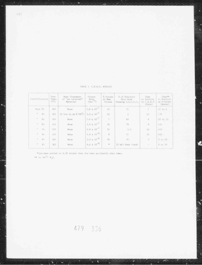
. _ . _ . . . . . . _ . _ . _ . . _ _ . . _ _ _ . . _ . _ . _ . _ _ _ . _ . . _ _ _ _ _ _ _ _ . _ _ _ _ _ _ _ _
l9'
I ASI.F i C . E . R .T . R ** W LT S
-_ _ _ _ _ _ _ _ __._____ _.__ . _ _ _ . . .--- __ - - -
I lest i Heat Treatment Strain i Strain | 1 of Fracture Tinw Time ** .Il r. t i l i < 4 t i 1..n Temp.I of "as r ec e i ved"
Rate ~ ) Stresa S how i ng I.G,a.C.L. in C.F.R.T. as U-bendsat Max. | Face Area to Failure to Fa11, ire !
f(OL) Material (Sec(Days) | (Weeks)'
- _ - . . _ _ _ _- - - _..-_- - . a -..._I H e .i t #2 365 None 2.8 x 10~ 10 71 1 ( to 4'
|
f #2 36 5 20 bra i n A r @ 7 00"C 3.0 x 10~ 12 2 12 'lh
#4 I t. 5 None 7,6 x 10~ 7 60 6 10 to 11I
i #4 )4i None 1.0 m 10~ 16 19 M >l6I
| 125 None 2.9 x 19~ 12 1.5 16 >10**
#4 125 None ).9 x 10' 8 51 12 >10 ,s
#5 365 None 2,0 x 10 ^ 34 41. M to Ik~
'
~
10 mil deep crack - ,8 to 1485 36 5 Nonc 6.4 x 10 ' *
II_... . _ . 'I
- -- - _a-_-__- - . _ - - _ - _ _ - . _ . _ _ . .--a
* 5;w t 1: ten pulled to 6.5% strain then the test acc1Jently s hu t d wo
** In 16 5"C H ,0,
I
I
;, -, --, ,t *
NJi
;.-
R
3=au
i
- - . _ _ _ _ _ _ . _ . . . .

_
,. - - ._ _ _ -
_a
k-
193au,
_i4J
.--
. .a
J-1
4i TABLE 4 SCC Results of the Controllel Potential Tests
-s
=] After the 7th 4-diy Exposure
1 -
;3 Time at i
| Contralled i! Potential 1
i
! Specimen Potential * Results (days)I
Al-d i
.a |d :1-1 Open circuit IGC** in the 9th exposure 364- t
'y i 2-1 -46 mV ICC in the 5th exposure 20t
1
] "3-1 -80 mV IGC in the 6th exposure 24
1
j :S-1 -120 mV ICC in the 2nd expo;u re 8|
4 1_ '5-1 i -160 mV IGC in the 4th exposure 16
i,
il |46-1 | -200 mV No cracking
m- u4-2 , -120 mV IGC in the 11th exposure 361
6 I
! l,
9*iApp roxir: _e values except "6 case
7"
**[ Intergranular Cracking1
'
&
b-
-
J.
1
-
:
n
t4|
-|,
'
4/9%
! , ~ . .,
!, <#) . ,/,
sd_
'4a
.
4
1
Js-
f a? f ,!'- ? Y ',$~'. Y 4&~|' ,* .,*

_
- - _ _ - -
1%
1 /m l . I . -> C clit 1.. >. nl T e u t s at m 3'C in D.I. it ,o.
| l' r e q u e n c y lbsultsTest
j T -~ ~
| -1j dl 10 I!z i) fa iled af te r 12 mel cycles
| | 2) IGC*I 1) 17. ' ina t i oni
I
22 10- Hz 1) f a i l e,! .it t e r 11570 cycl es
| 2) IC'3) 18. 7'|, elongation!;
1
0' 1 10- liz ! 1) failed af te r 1295 cycles
2) IGC
3) 18.47, elongation
-- - . _ - - - - - -
* I n t e rg ra no l a a Cracking.
,1 ]- ()- . ) ('))
~.
i / ) %)
E 7 __ asC2.:' M1DEsh7k2DdgiE9W5Macc2GBaists--

..
'p- m NP-% + m% _ _T_ _wuJur.At219rumfrENh-MM_,
195
Gas Inletf ----M lds g-
._\ .
N t{
h,N !!l
h~1/ J f-7p v
i
i
!
.H73"od x .773"idlube Spe ci men -sN
I
\xs\A !
'
|
/
.00MM" t h. c'r .
wall fl gau ;e |se c t ion
3.5"
!>
I; (1 5/8"od s 1 3/8"id
Oute r Jacke t /; ,
t
4 !
I I
1i ,
! I: >
I'
i !i ,
I l
| I
! ,I i
1 Ai A A Y
'4 1 3 / 3" D i a _ . y,
Fi, 1 Pressuri zed Capsulo Specimen,
%
' f 6/
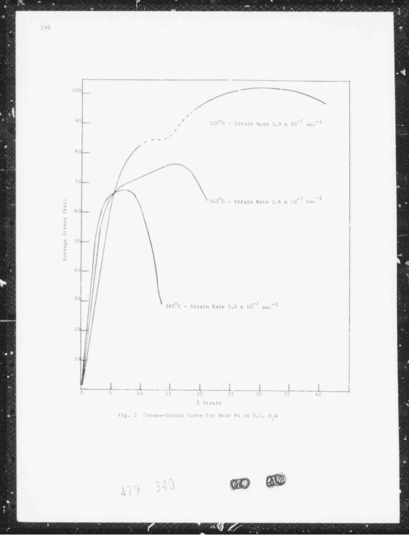
1%
100 ' ~
</
'# r'. / o -7 -t3 20 C - S t ra in Ra te 2.9 x 10 sec,
; /
/.~-
,
;
hC~
-
7 (: -
o _7 -1C 345 C - Strain Rate 2.6 x 10 secz$ 6r:_
$i
0g 502
$<
40_
30_365 C - Strain Rate 3.0 x 10~ -1
sec
20
'10_
f
I
0 5_. I
_. 15 20 25 30 35 40
I l ! l | |10
% Strain
Fig. 2 f t r es s-S t ra in "u rv e for Heat d4 in D.I. HQ
m
{
m m ier -
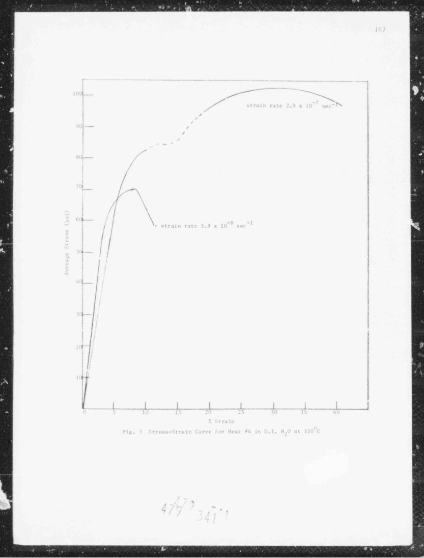
mm-_-_ - %wusssamr= -- ve-x-. .
197
m ~~+o-www _
I n< i
strain rate 2.9 x 10' -Nsec
//
~
/
'f i i - y
/--ej
--
,
8a!_ -
I:
I7(g_
,
C7 f:( I' -8 -l~ - strain rate 3.9 x 10 sec
:id
.. ~r
94 -.,
20 8"
r
.?" ,lc
'0 |,
.I
U7
i
f
;\k !-!
il'
In *
I
l I l | I I l | In 5 10 15 lu 25 30 3) 40
Y Strain
Fig. 3 Stress-Strain Corve for Heat #4 in D.I. H o at 320"Cj
..
r=
' ,.
' ,f * . ' '
^
4/] , ', ' 1 |,
.,ri ,.
Y.
,-_ ____-x