Annual Operating Rept 1978.
172
Sa 2.wq >~ala So~>g P8K, < f3 llDLE3 PRKl RL% ANNUAL REPORT OF CHANGES K) STATION FACILITIES AND PRCCEIXJRES R. E. GINNA NUCLEAR KNER PLtÃZ~ UNIT NO. 1 DOCKEZ NO. 50-244 LICENSE NO. DPR-18 1978 NEmyy@ F/L fg @@0 ttg)g . ~ '7 9 0905 0
-
Upload
khangminh22 -
Category
Documents
-
view
1 -
download
0
Transcript of Annual Operating Rept 1978.

Sa 2.wq
>~ala So~>g
P8K, < f3 llDLE3 PRKlRL%
ANNUAL REPORT OF CHANGES K) STATION FACILITIES AND PRCCEIXJRES
R. E. GINNA NUCLEAR KNER PLtÃZ~ UNIT NO. 1
DOCKEZ NO. 50-244
LICENSE NO. DPR-18
1978
NEmyy@F/Lfg @@0 ttg)g
. ~'79 0905 0
ANNUAL REPORT OF CHANGES 1Q STATICN FACILITIES AND PROCEIXJRES
R. E. GINNA NUCLEAR KNER PLANT, UNIT NO. 1
DOCKET N). 50-244
LICENSE NO. KPR-18
1978
Sc.2%9>8-si-6mo~os<4~$


PCN 4 78 Procedure a Title Meetin g 78
Ol
02
05
04
03
06
22
27
31
17
QC-1502, Nonconformance Reports
QC-1701, Quality Assurance Records
QC-401, Control of Procurement Documents forPurchased Material, Parts, Components andServices
ET-19, Test of Accoustical Leak MonitoringSystem for Ginna Safety Injection Piping
PZ-2.3, Safeguard Valve Operation
A-30. 2, Plant Procedure Classification Review,Approval and Distribution Requirements
M-55.5, Full Length Rod Control System DriveMechanism Operating Coils Polarity Check
M-51.4 Performance Check of Latch Mechanism forRelay LC-171CX
EM-197, Repair of Weld on "B" Charging PumpDischarge Line to Relief Valve 284
A-52.4, Control of Limiting Conditions forOperating Equipment
M-ll.4.4, Charging Pump Varidrive Belt Renevaland Installation
02
02
02
03
03
03
04
04
05
06
07
07
21
32
,23
29
14
18
~ EM-19 Inspection and Maintenance on 14" PrattButterfly Valve —Operator Only —Valve 4562(Containment Recirculation System —CoolingWater Return Line)
M-18.2, Waste Evaporator Feed Tank Float ValveMaintenance
E-l.l, Safety Injection System Actuation
A-50.11.3, Fire Watch/Escort Training
A-50.11.4, General Employee Fire Training
A-50.3, Preventive Maintenance Program
0-6-7-1, Plant Alarm Panels Test
0-6.4, Core Quadrant Power Tilt Calculation
07
07
07
07
07
07
07
07

l1
1
P

PCN I 78 Procedure 6 Title Meetin I 78
15 0-6.1 Plant Operation with S/G Tube Leak Indi-cation
07
24
28
S-3.2G, Transfer of Boric Concentrates
SC-3.17.1, Planning Conduct and Evaluation ofa Fire Emergency DrillQC-401, Control of Procurement Documents forPurchased Material, Parts, Components andServices
07
07
07
19
34
RSSP-2.3, Emergency D/G Annual Trip Testing
O-l. 1C, Pre-Critical Technical Specif icationCheck Sheet
07
07
12 (g-1021, Calibration and Control of Test +uip-ment
07
08 GS-21.0, Site Access Control (Security) andPersonnel Identification
07
33
35
36
09
37
40
41
26
A-61, Method of Evaluation for Reporting Require-ments in Basic Components Under 10 CFR 21
M-55.5, Full Length Rod Control System Drive Mechan-ism Operating Coils Polarity Check
GS-31. 0, Door Alarm System
GS-20.0, Classification of Ginna Station PhotoID Cards and Non-Photo Badges
PT-4, Residual Heat Removal Loop Annual HydroTest of Law Pressure Piping
CP-44.2, General Reinstate Procedure for N-44
PT-16, Auxiliary Feedwater System
M-ll.4.9, Charging Pump Varidrive Belt Removaland Installation
07
07
07
07
07
08
08
08
39
43
SC-1.12B, Station Call List
M-37.16A, Manually Cperated Grinnell DiaphragmValve Maintenance
08
08

PCN 0 78 Procedure & Title Meetin 578
30
47
48
46
79
None
None
None
RSSP-12, Testing of Primary and Secondary ReliefValves on Test Stand
RD-9, Preparing Waste for Shipment or Storage
RD-10, Shipping Radioactive Material
0-5.2, Load Increases
0-1.1C,'re-Critical Technical Specif icationCheck Sheet
SM 78 1458 g Auxiliary Building Holding FrameFilterSM 78-1845, Guide Stud Storage Rack
SM 78-1865, "A" Steam Generator Air MoverRestraint
08
08
08
08
09
10
10
10
None
None
None
81
62 & 65
63
64
51
42
45
77
SM 78-1480, Auxiliary Reactor Coolant PumpHandrails
SM 78-1464, Volume Control Tank Level(Accumulator Level)
SM 78-2160, GSM 7 Pipe Supports
S-25.4, Processing Water from Either S/G
S-4.5, Sluicing Water Condensate Polishing~ Demineralizer Spent Resin to Shipping Cask
CP-930.0, Calib. and/or Maint of Spray AdditiveTank Inlet Flow Transmitter Loop
CP-424.3, Calib. and/or Maint. of PressurizerLiquid Temp. Indicator TI-424
HP 4.3, Work Permit Use
PC-18.3, Determination of Chloride ky SpecificIon Electrode
S-27.294/296/392A, Isolation Procedure for AOV-294,AOV-296 or
AOV-392'P-12.6,
Issuance, Proper Use and Return of Respira-tors
10
10
10
10
10
10
10
10
10
10
10
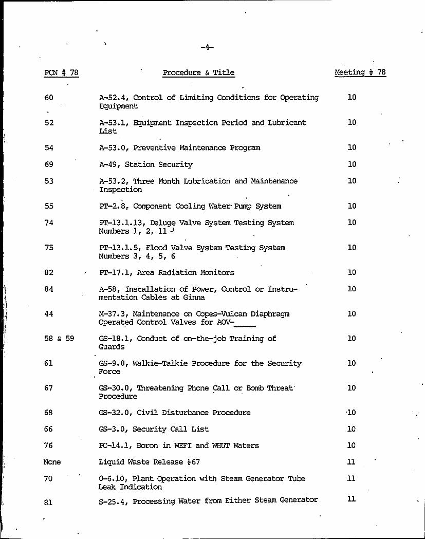
PCN 5 78 Procedure 6 Title Meetin 5 78
60
52
A-52.4, Control of Limiting Conditions for OperatingEquipment
A-53.1, Equipment Inspection Period and LubricantList
10
10
54 A-53.0, Preventive Maintenance Program
69 A-49, Station Security
10
10
53
55
74
75
82
84
A-53.2, three &anth Lubrication and MaintenanceInspection
PT-2.8, Component Cooling Water Pump System
PT-13.1.13, Deluge Valve System Testing SystemNumbers 1, 2, 11 ~
PI'-13.1.5, Flood Valve System Testing SystemNumbers 3, 4, 5, 6
PT-17.1, Area Radiation Monitors
A-58, Installation of Power, Control or Instru-mentation Cables at Ginna
10
10
10
10
10
10
44
58 a 59
M-37. 3, Maintenance on Copes-Vulcan DiaphragmOperated Control Valves for AOV-
GS-18.1, Conduct of cn-the-job Training ofGuards
10
10
61 GS-9.0, Walkie-Talkie Procedure for the SecurityForce
10
67 GS-30.0, 'Ihreatening Phone Call or BombThreat'rocedure
10
68
66
76
None
70
81
GS-32. 0, Civil Disturbance Procedure
GS-3.0, Security Call List
PC-14.1, Boron in WEFI and WHVZ Waters
Liquid Waste Release 567
0-6.10, Plant Operation with Steam Generator TubeLeak Indication
S-25.4, Processing Water from Either Steam Generator
10
10
10
PCN I 78 Procedure a Title Meetin I 78
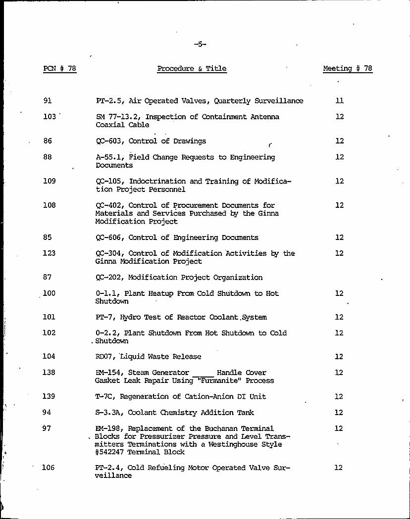
91
103
'Z-2. 5, Air Operated Valves, Quarterly Surveillance
SN 77-13.2, Inspection of Containment AntennaCoaxial Cable
12
88
109
108
85
123
87
100
Q=-603, Control of Drawings
A-55.1, Field Change Requests to EngineeringDocuments
(g-105, Indoctrination and Training of Modifica-tion Project Personnel
QC-402, Control of Procurement Documents forMaterials and Services Purchased by the GinnaModification Project
QC-606, Control of Engineering Documents
QC-304, Control of Modification Activities by theGinna Modification Project
9 -202, Modification Project Organization
0-1.1, Plant Heatup From Cold Shutdown to HotShutdown
12
12
12
12
12
12
12
101
102
PZ-7, Hydro Test of Reactor Coolant, System
0-2.2, Plant Shutdown From Hot Shutdown to Cold. Shutdown
12
12
104
138
139
94
97
106
RD07, Liquid Waste Release
EH-154, Steam Generator Handle CoverGasket Leak Repair Using "Furmanite" Process
T-7C, Regeneration of Cation-Anion DI Unit
S-3.3A, Coolant Chemistry Addition Tank
EM-198, Replacement of the Buchanan TerminalBlocks for Pressurizer Pressure and Level Trans-mitters Terminations with a Westinghouse StyleN542247 Terminal Block
PZ-2.4, Cold Refueling Motor Operated Valve Sur-veillance
12
12
12
12
12
12
PCN ¹ 78 Procedure 6 Title Meetin ¹ 78
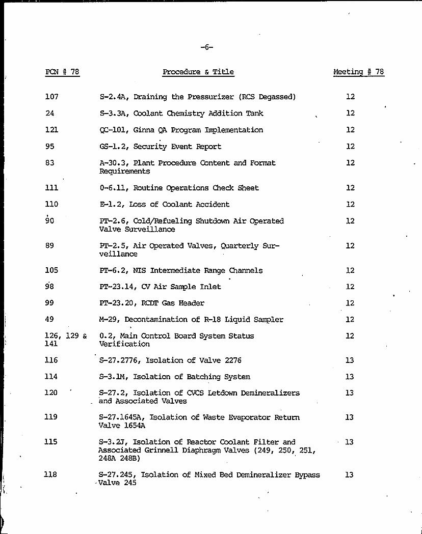
107
24
121
95
83
110
90
S-2.4A, Draining the Pressurizer (RCS Degassed)
S-3.3A, Coolant Chemistry Addition Tank
W-101, Ginna QA Program Implementation
GS-l. 2, Security Event Report
A-30.3, Plant Procedure Content and FormatRequirements
0-6.11, Routine Operations Check Sheet
E-1.2, Zass of Coolant Accident
PT-2. 6, Cold/Refueling Shutdown Air OperatedValve Surveillance
12
12
12
12
12
12
12
89 PZ-2.5, Air Operated Valves, Quarterly Sur-veillance
12
105
98
99
49
PT-6. 2, NIS Intermediate Range Channels
PT-23.14, CV Air Sample Inlet
PT-23.20, BC'as Header
M-29, Decontamination of R-18 Liquid Sampler
12
12
12
12
126, 129 & 0.2, Main Control Board System Status141 Verification
12
114
120
119
S-27.2776, Isolation of Valve 2276
S-3.1M, Isolation of Batching System
S-27.2, Isolation of CVCS Letdawn Demineralizersand Associated Valves
S-27.164SA, Isolation of Waste Evaporator ReturnValve 1654A
13
13
13
13
115
118
S-3.2J, Isolation of Reactor Coolant Filter andAssociated Grinnell Diaphragm Valves (249, 250, 251,248A 248B)
S-27.245, Isolation of Mixed Bed Demineralizer BypassValve 245
13
13

Procedure a Title Meetin I 78
S-27.1610B, Isolation of Demineralizer DrainValve 1610B
13
153 GS-26.1, Unoccupied Vital Area Key Control andAccountability
13
132
131
S-3.1G, Isolating, Flushing and Draining the"A" Boric Acid Storage Tank for Major ValveTank or Piping Maintenance and Inspection
0-2.2, Plant Shutdown for Hot Shutdown to GoldShutdown
13
130
128
127
0-2.4, Plant Shutdown from Hot Shutdown to ColdShutdown During Blackout
0-5.1, Load Reductions
0-5.2, Load Increases
13
0-6.9, Operating Limits for Ginna Station Trans-mission
13
149 M-37.3.2, AOV-296, Auxiliary Spray to PressurizerMaintenance
13
155
140
148
M-37.3.1, Maintenance Isolation Procedure for V-294Charging Line to Cold Leg Loop "B"
S-3.4, Boron Recycle Process Operation
HP-3.1, Exposure Reports to Individuals andNRC
13
13
152
151
136
HP-8. 4, Radioactive Source Inventory
PT-2.3.1, Post Accident Charcoal Filter Damgers
M-53, Containment Air Locks Inspection
13
13
135 M-40. 7, Steam Generator, Snubber Maintenance Snubber5
144 M-37.2, Maintenance of Pressurizer Relief ValveGuards
13
162
161
GS-21.2, Unoccupied Vital Area Access Control
GS-5.0, Security Guard General Instructions
13
13

Ii
1
PCN 0 78 Procedure a Title Meetin 5 78
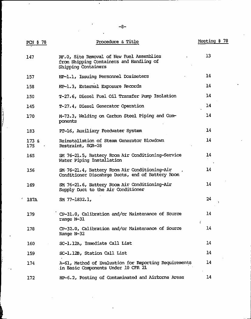
147
157
158
150
145
170
183
173 a175
165
156
169
187A
RF.O, Site Removal of New Fuel Assembliesfrom Shipping Containers and Handling ofShipping Containers
HP-1.1, Issuing Personnel Dosimeters
HP-1.3, External Exposure Records
T-27.6, Diesel Fuel Oil Transfer Pump Isolation
T-27.4, Diesel Generator Operation
M-73.3, Welding on Carbon Steel Piping and Com-ponents
PT-16, Auxiliary Feedwater System
Reinstallation of Steam Generator BlowdownRestraint, SGB-28
SM 76-21.5, Battery Room Air Conditioning-ServiceWater Piping Installation
SM 76-21.4, Battery Room A'ir Conditioning-AirConditioner Discahrge Ducts, end of Battery Room
SM 76-21. 6, Battery Room Air Conditioning-AirSupply Duct to the Air Conditioner
SM 77-1832. 1,
13
14
14
14
14
14
14
14
14
14
24
179
178
160
159
174
172
CP-31.0, Calibration and/or Maintenance of Sourcerange N-31
CP-32.0, Calibration and/or Maintenance of SourceRange N-32
SC-1.12A, Immediate Call List
SC-1.12B, Station Call List
A-61, Method of Evaluation for Reporting Requirementsin Basic Corrponents Under 10 CFR 21
HP-6.2, Posting of Contaminated and Airborne Areas
14
14
14
14
14
14

PCN 5 78 Procedure 6 Title Meetin 5 78
181
180
166
189
78
167
176
CP-31.3, Calibration of Source Range N-31
CP-32.3, Calibration of Source Range N-32
PC-l.l, Analysis Schedule and Limits PrimaryCoolant
A-54.3, Open Flame, Welding and Grinding Permit
SM 77-1057.1, Relaocation of the Charging PumpFilter Vent
M-48.3, Isolation and Restoration of Bus e15
T-35F, Steam to Auxiliary Building, Screen Houseor Diesel Generators and Oil Room
14
14
14
15
15
15
184 T-31.8, Turbine Generator Bearing Drain Vapor Extractor 15Vent-Hydrogen Loss Calculation
93
113
HP-12.2, Medical Check, Fitting and Training ofPersonnel Using Respirators
M-11.4.6, Charging Pump Stuffing Box Maintenance
15
15
112 M-11.4.7, Charging Pump Stuffing Box Assembly Inspection 15and Maintenance
197 M-37.IA, Repacking of Pressurizer Spray Valves 43IA and 15431B
192
190
191
188
195
194
193
154
. M-37.16B, Isolation of Batching System GrinnelDiaphragm Valves
M-37.16N, Repair of Demineralizer Drain Valve 1610B
M-37.16P, Repair of Valve 2276
GS-5.0, Security Guard General Instructions
GS-28, Inspection of Personnel, Vehicle and Packages
, GS-21.0, Site Access Control (Security) and PersonnelIdentification
GS-41. 0, Employee Screening Program
QC-304, Control of Modification Activities by theGinna Modification Project
15
15
15
15
15
15
15
15

-10-
PCN I 78 Procedure & Title Meetin 5 78
194 a230
GS-21..0, Site Access Control (Security) and PersonnelIdentification
16
231 GS-5.0, Security Guard General Instructions 16
177 A-60.3, Calibration Survey Program for Instrumentation/ 16Equipment of Safety Related Components
186
205
206
204
RSSP-15.7, Inservice Inspection Hydro Test of Class BSafety Related Piping
.M-37.16Q, Isolation of CVCS Letdmm Demineralizers andAssociated Grinnell Diaphragm Valves
M-37.16K, V-245 (Mixed Bed Demineralizer Bypass Valve)Isolation Draining and Restoration to Service
M-37.16G, Isolation of Waste Evaporator Return Valve1654A
16
17
17
17
203
257
250
249
238
M-37.16F, Isolation of Reactor Coolant Filter andAssociated Grinnell Diaphragm .Valves
T-27.2, lB Emergency Deisel Generator Pre-StartAlignment
SM 76-21.5, Battery Room Air Conditioning ServiceWater Piping Installation
QCIP-15, Visual Inspection During Hydro-Static andSystem Pressure Testing
GS-21.0, Site Access Control (Security) and PersonnelIdentification
17
17
17
17
17
220
228
223
221
235
210
211
PT-2.7, Service Water System
GS-26.0, Security Key and Lock Controls
HP-9.1, Steam Generator Blowdawn Activity
RD-3, Plant Vent Iodine and Particulate Releas'e-Sampling and Analysis
A-l, Radiation Control Manual
AR/C-3, Accumulator IA Level
~C-4, Accumulator 1B Level
17
17
17
17
17
17
17

j'
l

-11-
PCN O 78 Procedure & Title Meetin 0 78
207 AR/E-27, NIS Power Range Single Channel Lo RangeAlert
17
213
208
214
209
215
AR/D-20, Pressurizer Lo Pressure
~~15, Reactor Coolant Lo Flow UndervoltageUnderfrequency Zaop A
~M23, Reactor Coolant Lo Flow UndervoltageUnderfrequency Loop B
AR/D-10, NIS Power Range Lo Range Reactor Trip
~~19, Pressurizer Lo Pressure and Level
17
17
17
17
17
200
201
M-73.3, Welding on Carbon Steel Piping or Components 17
M-73.2, Welding on Stainless Steel Piping or Components 17
243
242
237
QCIP-3, Receiving Inspection of New Fuel
QCIP-2, Pre-closure Core Verification'S-31.1,Coor Alarm Assessment and Response —High
Radiation Areas
19
19
19
185 PR-7, Protective Relay Calibration and Trip Test 512ATransformer, 34KV and 4KV Bus Relaying
19
262 SM 76-21.6, Battery Room Air Conditioning —Air Supply 19Duct to the Air Conditioner
297
300
292
PT-7, Hydro Test of Reactor Coolant System
SM 76-21. 4, Battery Room Air Conditioning —AirConditioner Discharge Duct South End of Battery Room
S-3.4B, Gas Stripper Startup
19
19
19
266 CP-2.3, Rod Position Indication System "Shutdown" Bank 19Hot Shutdown Alignment
266 CP-2.3.1, Rod Position Indication System "Shutdown"Bank at Power Alignment
19
~ 289 A-30.2, Plant Procedure Classification, Review Approval 19and Distribution Requirements
264 GS-20.0, Classification oj Ginna Station PhotoID Cards and Non-Photo Bactges
19

-12-
PCN N 78 Procedure a Title Meetin N 78
251
240
A-17, Plant Operations Review Committee Operating2rocedure
4
A-30.3, Plant Procedure Content and Format Requirements 19
288
270
A-50.11.3, Firewatch/Escort Training
CP-2.5.0, Bod Position Indication System "A" BankHot Shutdown Alignment
19
19
269 CP-'2.4.1, Rod Position Indication System "Part Length" 19Bank at Power Alignment
268
265
299
259
258
279
CP-2.4.0, Rod Position Indication System "Part Length"Bank at Hot Shutdown Alignment
CP-2.0, Calibration and/or Maintenance of the RodPosition Indication System
PT-17.1, Area Radiation Honitors Rl-R9
PT-13, Fire Pump Operation and System Alignment
SC-3.15.15, Emergency Fire equipment LockerInventory and Inspection
CP-2.10, Rod Position Indication System MaintenanceCalibration Check.
19
19
19
19
19
19
296
256
CPO. 2, Rotameter Calibration
RF-8.4, Fuel and Core Component Mvement in theSpent Fuel Pit
19
19
305 RSSP-6.0, Containment Integrated Leakage Rate Test 19
283 PT-16, Auxiliary Feedwater System 20
343
344
A-30.2, Plant Procedure Classification, Review, Approval 20and Distribution Requirements
A-.30.3, Plant Procedure Content and Format Requirements 20
310
329
SC-3.15.6, Fire Hose Reel Inspection
A-60.1, Ginna Station Technical Specif icationSurveillance Program
20
20
-13-
PCN I 78 Procedure a Title Meetin I 78
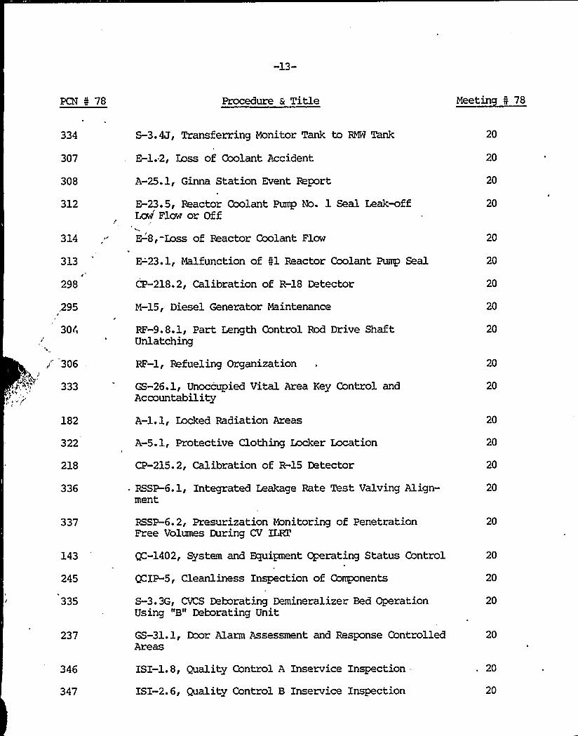
334
307
308
312
314
313
298
395
30Ci
306
182
322
218
336
337
143
245
335
237
S-3.4J, Transferring Monitor Tank to RMÃ Tank
E-1.2, Loss of Coolant Accident
A-25.1,, Ginna Station Event Report
E-23.5, Reactor Coolant Pump No. 1 Seal Leak-offLmr Flow or Off
('-8,-Loss of Reactor Coolant Flow
E-23.1, Malfunction of Il Reactor Coolant Pump Seal
CP-218.2, Calibration of R-18 Detector
M-15, Diesel Generator Maintenance
RF-9.8.1, Part Length Control Rod Drive ShaftUnlatching
RF-l, Refueling Organization
GS-26.1, Unoccupied Vital Area Key Control andAccountability
A-l.l, Locked Radiation Areas
A-5.1, Protective Clothing LockerLocat'P-215.2,
Calibration of R-15 Detector
RSSP-6.1, Integrated Leakage Rate Test Valving Align-ment
RSSP-6.2, Presurization Monitoring of PenetrationFree Volumes During CV ILRT
QC-1402, System and Equipnent Operating Status Control
QCIP-5, Cleanliness Inspection of Components
S-3.3G, CVCS Deborating Demineralizer Bed OperationUsing "B" Deborating Unit
GS-31.1, Door Alarm Assessment and Response Controlled
20
20
20
20
20
20
20
20
20
20
20
20
20
20
20
20
20
20
20
20
346
347
ISI-1.8, Quality Control A Inservice Inspection
ISI-2.6, Quality Control B Inservice Inspection
20
20

,S,y
'r.~
ir
t
pig

'-14-
PCN N 78 Procedure 6 Title Meetin N 78
348
241
244
246
247
234
239
229
395
362
363
ISI-3. 5, High Energy Inservice Inspection
QCIP-1, Quality Control Inspection Procedure SteamGenerator (Primary Side) Preclosure Inspection
QCIP-4, Quality Control Inspection Procedure ReceivingInspection of NG-6 Type Relays
QCIP-9, Quality Control Inspection Procedure PressurizerPreclosure Cleanliness Inspection
QCIP-13, Quality Control Inspection Procedure MaterialReceiving Inspection of Chemicals and Radio-ChemicalLaboratory Supplies
RSSP-13.6, Inservice Inspection Hydro Test of Class "C"Safety Related Piping (Auxiliary Feedwater PumpsDischarge Piping)
RSSP-15.8, Inservice Inspection Hydro Test of Class "B"Safety Related Piping (Charging Pump Suction excludingVCT)
SM 76-16.1, Eddy Current Wiring Conduits
Rl-200, Replacement or Rework of Solenoid Valvesfor CV Purge Exhaust Valve 5879
S-2.5A, Burping the Reactor Goolant Drain Tank (To BeOpened to Atmosphere)
. S-2.5B, Restoring Reactor Coolant Drain Tank to ServiceAfter Maintenance
20
20
20
20
20
20
20
20
21
21
21
364 S-4.2.10, Burping the Pressurizer Relief Tank andReactor Goolant Drain Tank and Isolating from theVent Header
21
361
353
SM 76-17.2, Screen House Intake Heater Cable Tray
SM 76-21.5, Battery Room Air Conditioning —ServiceWater Piping Installation
21
21

-15-
PCN 5 78 Procedure & Title Meetin " 78
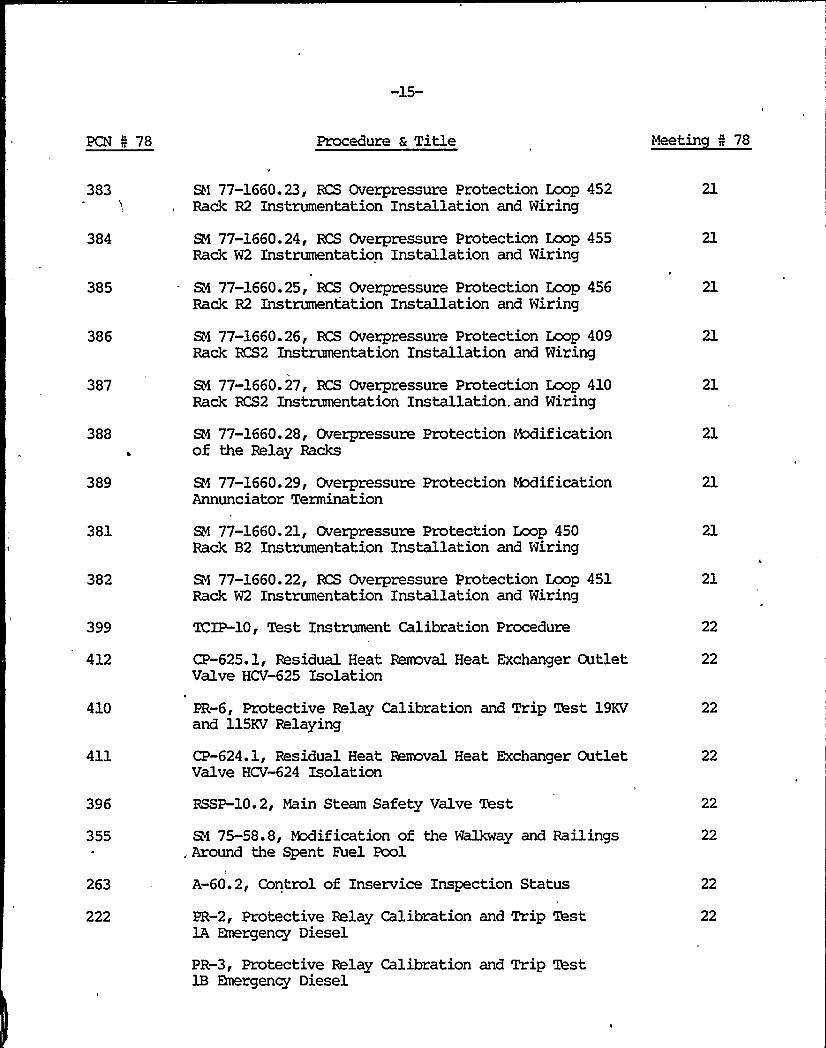
383
384
385
386
387
388
389
381
382
399
412
SN 77-1660.23, RCS Overpressure Protection Loop 452Rack R2 Instrumentation Installation and Wiring
SN 77-1660.24, RCS Overpressure Protection Loop 455Rack=W2 Instrumentation Installation and Wiring
B4 77-1660.25, RCS Overpressure Protection Loop 456Rack R2 Instrumentation Installation and Wiring
&1 77-1660.26, RCS Overpressure Protection Loop 409Rack RCS2 Instrumentation Installation and Wiring
SM 77-1660.27, RCS Overpressure Protection Loop 410Rack RCS2 Instrumentation Installation.and Wiring
SM 77-1660. 28, Overpressure Protection Rxlificationof the Relay Racks
SN 77-1660.29, Overpressure Protection Rx3ificationAnnunciator Termination
SN 77 1660 21 g Overpressure Protection Loop 450Rack B2 Instrumentation Installation and Wiring
SM 77-1660.22, RCS Overpressure Protection Loop 451Rack W2 Instrumentation Installation and Wiring
'lCIP-10, Test Instrument Calibration Procedure
CP-625.1, Residual Heat Reaaval Heat Exchanger OutletValve HCV-625 Isolation
21
21
21
21
21
21
21
22
22
410
411
396
355
263
222
PR-6, Protective Relay Calibration and Trip Test 19KVand 115KV Relaying
CP-624.1, Residual Heat Removal Heat Exchanger OutletValve HCV-624 Isolation
RSSP-10.2, Main Steam Safety Valve Test
S1 75-58.8, Modification of the Walkway and Railings, Around the Spent Fuel Pool
A-60.2, Control of Inservice Inspection Status
PR-2, Protective Relay Calibration and Trip Test1A Emergency Diesel
PR-3, Protective Relay Calibration and Trip Test1B Emergency Diesel
22
22
22
22
22
22

-16-
PCN N 78 Procedure a Title Meetin N 78
372
374
373
293
294
403
406
413
400
332
345
380
356
354
353
342
349
341
338
340
CP-2019.0, Turbine Driven Au-iliary Feeawater PungDischarge Pressure Loop 2019
CP-2030.0, 1B Wtor Driven Auxiliary Feedwater PumpDischarge Pressure Loop 2030
CP-2029.0, 3A Motor Driven Auxiliary Feedwater PumpDischarge Pressure Loop 2029
M-15.3, Diesel Fuel Oil Transfer Pump Maintenance
M-15.4, Diesel Startup Air Compressor Maintenance
M-40.7, Steam Generator Snubber Maintenance
A-53.2, three anth Lubrication and MaintenanceInspection
A-35, Prime Mover Holding and Markup Requirements
RF-8.1, Step ky Step Fuel Loading and Maps
GS-12.0, Security Guard Actions During a Fire
GS-31.0, Door Alarm System'I
GS-21.0, Site Access Control (Security) and PersonnelIdentification
GS-28.0, Search of Personnel, Vehicles and Packages
. PT-5.20, ~ss instrumentation Reactor ProtectionChannel Trip Test (Channel 2)
RSSP-15.7, Inservice Inspection Hydro Test of Class "B"Safety Related Piping (Charging Pumps Discharge Piping)
RSSP-12, Testing of Primary and Secondary ReliefValves on Test Stand
Fire Pump Ceration and System Alignment
SC-1.12A, Inmdiate Call List
HP-4.1, Controlled Area Entry
SC-1.12B, Station Call List
CP-209, Calibration of Area 8onitors, TA-62Detectors (Rl-R9)
22
22
22
22
22
22
22
22
22
22
22
22
22
22
22
22
22
22
22
22
22
-17-
PCN 5 78 Procedure & Title Meetin 5 78
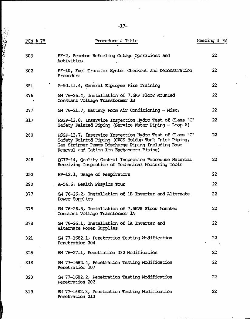
303
302
RF-2, Reactor Refueling Outage Operations andActivities
RF-10, Fuel Transfer System Checkout and DemonstrationProcedure
22
22
351
376
277
A-50.11.4, General Employee Fire Training
SM 76-26.4, Installation of 7.5KV Floor MountedConstant Voltage Transformer lB
SN 76-21.7, Battery Room Air Conditioning —Misc.
22
22
22
317
260
RSSP-13.8, Inservice Inspection Hydro Test ofSafety Related Piping (Service Water Piping-
RSSP-13.7, Inservice Inspection Hydro Test ofSafety Related Piping (CVCS Holdup Tank InletGas Stripper Pumps Discharge Piping IncludingRemoval and Cation Ion Exchangers Piping)
Class IICI1
Loop A)
Class "C"Piping,Base
22
22
248
252
290
377
375
378
321
325
318
320
319
QCIP-14, Quality Control Inspection Procedure MaterialReceiving Inspection of Mechanical Measuring Tools
HP-12.1, Usage of Respirators
A-54.6, Health Phsyics Tour
SN 76-26.2, Installation of 1B Inverter and AlternatePower Supplies
SN 76-26.3, Installation of 7.5KVS Floor WuntedConstant Voltage Transformer 1A
SN 76-26.1, Installation of 1A Inverter andAlternate Power Supplies
SM 77-1682.1, Penetration Testing ModificationPenetration 304
SN 76-27.1, Penetration 332 Modification
SN 77-1682.4, Penetration Testing ModificationPenetration 107
SN 77-1682.2, Penetration Testing ReificationPenetration 202
SM 77-1682.3, Penetration Testing ModificationPenetration 210
22
22
22
22
22
22
22
22
22
22
22

-18-
PCN I 78 Procedure a Title Meetin I 78
394
291
425
426
409
SM 77-1660.2, Overpressurization Mechanical Package
B4 76-01.1, Safeguard Buses DC Control Voltage bhnitor
SN 77-1660. 10, RCS, Overpressurization ProtectionElectrical Conduit and Wiring
RI 77-2.10, DI Water Containment IsolationElectrical Conduit and Wiring
SM 78-2273.1, Armor Plate on the East Wall of theControl Room
22
22
22
22
22
408
398
Rl 77-1836.1, Turbine Building Pressurization andSecurity Wall
B4 77-02.1, DI Water to Containment ModificationMechanical
22
22
359
327
438
447
RSSP-15.9, Inservice Inspection Hydro Test of Class "B"Safety Realted Piping (Service Water Loop B)
SM 78-1048.1, Accumulator Relief Modification
M-52.3, Incore Thimbles Cleaning
A-17, Plant Operations Review Committee OperatingProcedure
24
24
24
420 ISI-3.5, High Energy Inservice Inspection 24
434 6 446 SM 77-1057.1, Relocation of the Chargine Pump Filter Vent 24
421 a 431 BI 77-1660.28, Overpressure Protection Modificationof the Relay Backs
24
433
440
441
417
414
443
M-73.3, Welding on Carbon Steel Piping or Components
S-2.5A, Burping RCVZ (To Be Opened to Atmosphere)
S-2.3B, Burping the Pressurizer Relief Tank (To beOpened to Atmosphere)
S-2.3B, Burping the Pressurizer Relief Tank (To beOpened to Atmosphere)
TCIP-9, Test Instrument Calibration Procedure
S-2.4A, Draining the Pressurizer (RCS Degassed)
24
24
24
24
24
24

k
1
i

PCN 5 78 Procedure 6 Title Meetin 5 78
418 6 437 S-2.5A, Burping Reactor Coolant Drain Tank 24
432
405
407
404
397
402
459
458
463
462
464
350
M-65.0,. Main Steam Line Weld Repairs (Outside ofContainrent)
SN 78-1875.1, "A" Feedwater Venturi Monorail
SN 78-1480.1, ".A" RCP Ladder and Handrail Installation
SM 77-1474.1, RCP Seal Bypass Modification
SN 75-14, Boric Acid Batch Tank Recirculation Pipingand Supports
SN 78-1485.1, Dillon Cell Storage Frame
SN 77-1660.2, Overpressurization Mechanical Package
SN 77-02.1, Demineralized Water to ContainmentModification Mechanical
RD-6, Gas Decay Tank Releases
M-ll.8B, Reactor Coolant Pump —Seal Injection andService Mechanical
SN 77-1623.1, Charging Pump Mnorails
SC-3.15.16, Fire Protection System Inspections andTests
24
25
25
25
25
25
25
25
358
366
367i
368
369
370
371
255
CP-70.5, Test Gauge Calibration Procedure
. CP-617.0, Component Cooling Water Pumps DischargePressure PIC-617
CP-628.0, RHR Loop Reactor Coolant Test Bypass Flow
CP-2033.0, Service Water Flow From "3A" Vent CoolerFlowmeter FIA-2033
CP-2034.0, Service Water Flow From "lB" Vent CoolerFlowmeter FIA-2034
CP-2035.00 Service Water Flow From "lC" Vent CoolerFlowmeter FIA-2035
CP-2036.0, Service Water Flow Frcm "1D" Vent CoolerFlowmeter FIA-2036
HP-10.7, Flow Calibration of Low Volume Air Samplers
26
26
26
26
26
26
26

-20-
PCN 4 78 Procedure 6 Title Meetin 5 78
323
448
449
435
454
450
457
456
424
428
429
430
445
427
444
439
202
PR-7.2, Protective Relay Calibration and Trip Test512B Transformer 34KV Relaying
A-19, Change in Written Procedures
RSSP-6.1, Integrated Leakage Rate Test ValvingAlignment
RSSP-6. 0, Containment Integrated Leakage Rate Test
M-37.24A, Main Steam Safety Valve Maintenance Valve No.
M-37.24A, Main Steam Safety Valve Maintenance Valve No.
SM 77-1660.28, Overpressure Protection Modification ofthe Relay Racks
S-4.1U, Velocity Flush of R-18
A-35, Prime Hover Holding and Markup Requirements
ISI-1.8, Quality Group A Inservice Inspection
ISI-2.6, Quality Group B Inservice Inspection
ISI-3.5, High Energy Inservice Inspection
O-l. 1C, Pre-Critical Technical Specif ications CheckSheet
HP-12.4, Fitting and Testing of Respirators
A-52.4, Control of Limiting Conditions for OperatingEquipment
GS-41. 0, Employee Screening Program
, A-58, Installation of Power, Control or InstrunentationCables at Ginna Station
26
26
26
26
26
26
26
26
26
26
26
26
26
442
360
451
469
505
A-54. 4, Empty Engineer Responsibilities
M-43.15, Installation of Steam Generator Manway Insert
SM 76-28.1, Flange Installation on Main FeedwaterFlow Venturis —Ginna Station Feedwater Line
&1 78-1845.1, Guide Stud Storage Racks
SM 78-2160.1, GSM-7 Pipe Supports
26
26
27
27
-21-
PCN I 78 Procedure & Title Meetin 5 78
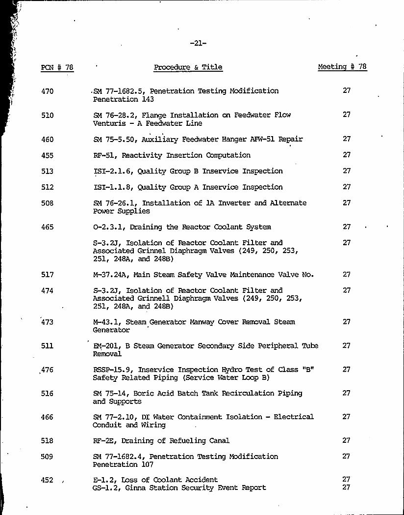
470
510
460
455
513
512
508
465
517
474
473
511
476
516
466
518
509
452
SM 77-1682.5, Penetration Testing ModificationPenetration 143
SM 76-28.2, Flange Installation on Feedwater FlowVenturis —A Feedwater Line
SM 75-5.50, Auxiliary Feedwater Hanger APW-51 Repair
RF-51, Reactivity Insertion Computation
ISI-2.1.6, Quality Group B Inservice Inspection
ISI-1.1.8, Quality Group A Inservice Inspection
SM 76-26.1, Installation of 1A Inverter and.AlternatePower Supplies
0-2.3.1, Draining the Reactor Coolant System
S-3.2J, Isolation of Reactor Coolant Filter andAssociated Grinnel Diaphragm Valves (249, 250, 253,251, 248A, and 248B)
M-37.24A, Main Steam Safety Valve Maintenance Valve No.
S-3.2J, Isolation of Reactor Coolant Filter andAssociated Grinnell Diaphragm Valves (249, 250, 253,251, 248A, and 248B)
M-43.1, Steam Generator Manway Cover Rermval SteamGenerator
EN-201, B Steam Generator Secondary Side Peripheral TubeRemoval
RSSP-15.9, Inservice Inspection Hydro Test of Class "B"Safety Related Piping (Service Water Loop B)
SM 75-14, Boric Acid Batch Tank Recirculation Pipingand Supports
SM 77-2.10, DI Water Containment Isolation —ElectricalConduit and Wiring
RF-2E, Draining of Refueling Canal
SM 77-1682.4, Penetration Testing ModificationPenetration 107
E-1.2, Zoss of Coolant AccidentGS-1.2, Ginna Station Security Event Report
27
27
27
27
27
27
27
27
27
27
27
27
27
27
27
27
27
27
2727

)g 4
t
'\
?

-22-
PCN 5 78 Procedure & Title Meetin 5 78
548
542
558
559 a 546
521
520
520
552
551
561
554
SM 76-26.2, Installation of 1B Inverter and AlternatePawer Supplies
A-54.3, Open Flame, Welding and Grinding Permit
S-27.209, Isolation of CVCS Relief Valve 209
RSSP-13.8, Inservice Inspection Hydro Test of Class "C"
Safety Related Piping (Service Water Piping —Loop A)P
RSSP-15.8, Inservice Inspection Hydro Test of Class "B"'afetyRelated Piping (Charging Pump Suction Excluding
VCT)
RF-10, Fuel Transfer System Checkout and DemonstrationProcedures
M-11.8.3, Reactor Coolant Pump Seal Inspection andService Mechanical
B4 77-1057.1, Relocation of the Charging Pump FilterVent
RSSP-14.8, ISI Hydro Test of Class "C" Safety RelatedPiping (Service Water Piping — Loop A)
M-38.5; 1B Constant Voltage Transformer Maintenance
RSSP-12, Tiesting of Primary and Secondary Relief Valveson Test Stand
GS-21.0, Site Access Control (Security) and PersonnelIdentification
28
28
28
28
28
28
28
28
28
28
28
28
553
562
S-27.209, CVCS Relief Valve 209 Isolation
S-27.1, Volume Control Tank Grinnell Diaphragm ValvesIsolation
28
28
545
550
A-50.6, R.'. Ginna Operator Requalification Program
M-ll.8A, Reactor Coolant Pump 5 Removal from Servicefor Pump Maintenance
28
28
471 S-2.1B, Reactor Coolant Pumps —Isolation for Naintenance 28
522
515
, PZ-2.5, Air Operated Valves, Quarterly Surveillance
A-36, Station Holding Rules
28
28

'k
A
P)
/

-23-
PCN 4 78 Procedure 6 Title Meetin 5 78
543
519
316
507
472
330
540
538
541
539
532
533
CP-429.7, Pressurizer Pressure Bistable PC-429A
M-15.5, lA Deisel Startup Air Compressor Maintenance
QC-1403, Inspection and Test Status Control
0-2.3.1, Draining the Reactor Coolant System
M-15.6, 1B Deisel Fuel Oil Transfer Pump Maintenance
0-6.4, Core Quadrant Power Tilt Calculation
CP-410.0, Reactor Coolant Temperature Gold Leg"410B" Calibration and/or. Maintenance
CP-409, Reactor Coolant Termperature Cold Leg"409B" Calibration and/or Maintenance
CP-410.3, Reactor Coolant Temperature Cold LegBistable TC-410A/B
CP09.3, Reactor Coolant Temperature Cold LegBistable TC-409A/B
CP-455.0, N2 Accumulator Pressure Low Loop 455
CP-455.'1, N2 Accumulator Pressure Lear Zoop 455Transmitter
28
28
28
28
28
28
28
28
28
28
28
28
534
535
536
CP-455.2, N2 Accumulator Pressure Low Loop 455. Bistable Power Supply and Indicator
CP-456.0, N2 Accumulator Pressure Low Xaop 456
CP-456.1, N2 Accumulator Pressure Lcm Eaop 456Transmitter
28
28
28
537
531
526
527
528
CP-456.2, N2 Accumulator Pressure Low Eoop 456Bistable Power Supply and Indicator
CP-452.2, Overpressure Protection Loop 452 PowerSupply and Bistable
CP-451. 0, Overpressure Protection Loop 451
CP-451.1, Overpressure Protection Loop 451 Transmitter
CP-451.2, Overpressure Protection Loop 451 Power Supplyand Bistable
28
28
28
28
28

V
I
-24-
PCN N 78 Procedure & Title Meetin N 78
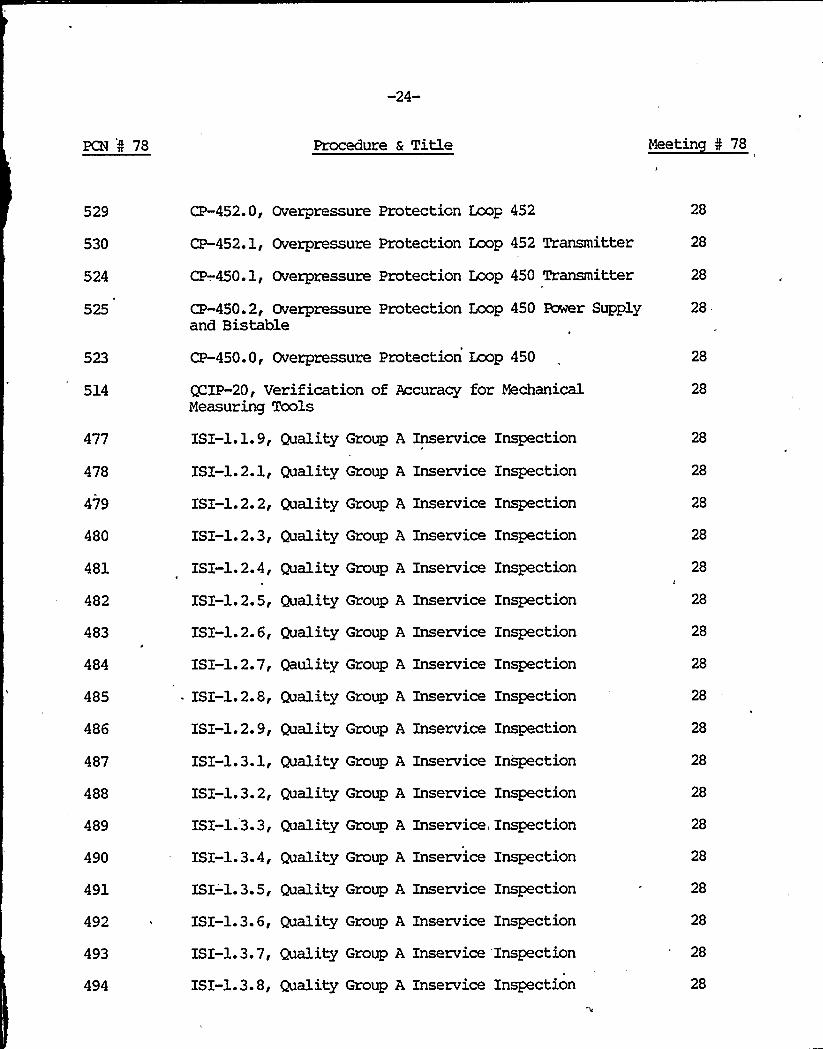
529
530
524
525
514
477
478
479
480
481
482
483
484
485
486
487
488
489
490
CP-452.0, Overpressure Protection Loop 452
CP-452.1, Overpressure Protection Loop 452 Transmitter
CP-.450.1, Overpressure Protection Loop 450 Transmitter
CP-450.2, Overpressure Protection Loop 450 Ewer Supplyand Bistable
CP-450.0, Overpressure Protection Loop 450
QCIP-20, Verification of Accuracy for MechanicalMeasuring Tools
ISI-1.1.9, Quality Group A Inservice Inspection
ISX-1.2.1, Quality Group A Inservice Inspection
ISI-1.2. 2, Quality Group A Inservice Inspection
ISI-1.2.3, Quality Group A Inservice Inspection
ISX-1.2.4, Quality Group A Inservice Inspection
ISI-1.2.5, Quality Group A Inservice Inspection
ISI-l.2.6, Quality Group A Inservice Inspection
ISI-1.2.7, Qaulity Group A Inservice Inspection
~ ISI-1.2.8, Quality Group A Inservice Inspection
ISI-1.2.9, Quality Group A Inservice Inspection
ISI-1.3.1, Quality Group A Inservice Inspection
ISI-1.3. 2, Quality Group A Inservice Inspection
ISI-1.3.3, Quality Group A Inservice, Inspection
ISI-1.3.4, Quality Group A Inservice Inspection
28
28
28.
28
28
28
28
28
28
28
28
28
28
28
28
28
28
28
28
491 ISI-'1.3.5, Quality Group A Inservice Inspection
492 ~ ISI-1.3.6, Quality Group A Inservice Xnspection
28
28
493
494
ISI-l.3.7, Quality Group A Inservice Inspection
ISX-1.3. 8, Quality Group A Inservice Inspection
28
28

-25-
PCN 5 78 Procedure 6 Title Meetin 5 78
495
496
497
498
499
500
501
502
503
504
597
557
565
ISI-1.3.9, Quality Group A Inservice Inspection
ISI-1.4.1, Quality Group A Inservice Inspection
ISI-1.4.2, Quality Group A Inservice Inspection
ISI-1.4.3, Quality Group A Inservice Inspection
ISI-1.4.4, Quality Group A Inservice Inspection
ISI-1.4.5, Quality Group A Inservice Inspection
ISI-1.4.6, Quality Group A Inservice Inspection
ISI-1.4.7, Quality Group A Inservice Inspection
ISX-1.4.8, Quality Group A Inservice Inspection
ISI-1.4.9, Quality Group A Inservice Inspection
A-54.6, Health Physics Tour
EM-202, Safety Injection Sequence Timing RelayReplacement
SM 76-01.2, Cable Installation for the DC ControlFuses
SN 77-1660.15, Instrumentation Tie-Ins for RCS
Overpressurization
28
28
28
28
28
28
28
28
28
28
28
29
29
29
544 SN 78-1865.1, Steam Generator "A" Air Mver Installation 29
603
604
S-27.348B, Valve 348B Isolation
EN-201, "B" Steam Generator Secondary Side PeripheralTube Removal
30
30
608 S-3. 1K, 1A Boric Acid Transfer Pump Isolation/RestOration 30
574 SM 77-1682. 2, Penetration Testing lkx3ification-Penetration 202
30
579
598
566
SM 77-1682.3, Penetration Testing Modification—.Penetration 210
RF-51, Reactivity Insertion Computation
PT-2.10.2, RHR System Core Deluge Check Valves 853Aand 853B
30
30
30

-26-
PCN 5 78 Procedure & Title Meetin N 78
564 .
569
N-32.1, KS-25, CG-50 and DB-75 Circuit BreakerMaintenance and Overcurrent Trip Device Test and/orReplacement
SM 75-5.40, Standby Auxiliary Feedwater Rework InsideContainment
30
30
576 M-37.2.1, Inspection and Repair of Hain Steam CheckValves
30
575
572
580
601
A-54.6, Health Physics Tour
A-30.3, Plant Procedure Content and Format Requirements
A-13, Maintenance Record Requirements
A-l, Radiation Control Manual
30
30
30
30
609 A-30.2, Plant Procedure Classification, Review, Approval 30and Distribution Requirements
584
611
610
SM 78-1873.1, Pressurizer Jib Crane
Rl 77-1660.11, RCS Overpressurization Protection—Electrical Terminations in the Control, Room and in theField
EM-203, Repair of Valve 4738 —Service Water to MotorCoolers
31
31
31
643 ~ S-27.2, Isolation of CVCS Letdown Demineralizers andAssociated Valves
31
642
617
621
613
582
581
605
M-37.46, Reactor Compartment Cooler Service WaterOutlet Valve 4758 Maintenance and Inspection
GS-10.1, Security Guard Action During a LocalRadiation Emergency
QC-1701, Quality Assurance Records
RF-2D, Filling the Refueling Canal
CP-950.3, Containment Pressure Transmitter PT-950
CP-949.3, Containment Pressure Transmitter PT-949
M-43. 24.1, Inspection of Steam Generator SecondarySide Upper Internals
31
31
31
31
31
31
31

-27-
PCN I 78 Procedure & Title Meetin I 78
602
600
583
570
560
563
591
PZ-2.7, Service Water System
S-27.887, Safety Injection Relief Valve 887 Isolation
T-17J, Generator Bearing Drain Vapor Extractor—Normal Lineup and Operation
PZ-7, Hydro Test of Reactor Coolant System
PT-22.10, Mechanlical Manifold "C" Leak Rate Test
SC-1.12B, Station Call List
PZ-23.45, Containment Isolation Va1ve Leak Rate TestingLeakage Test Instrumentation
31
31
31
31
31
31
31
593 PZ-23.51A, Containment Isolation Valve Leak Rate Testing 31"A" Hydrogen Recombiner (Pilot and Hain)
594
595
589
587
622
624
620
590
592
596
567
PZ-23.S1B, Containment Isolation Valve Leak Rate Testing"B" Hydrogen Recombiner (Pilot and Main)
PZ-23.51C, Containment Isolation Valve Leak Rate Testing"A" and "B" Hydrogen Recombiner Oxygen Makeup
~23.23, Containment Isolation Valve Leak Rate TestingSump "A" Discharge
PT-23.22, Containment Isolation Valve Leak Rate TestingRCDZ Discharge
l
A-20, Control Room ItsA-25.1, Ginna Station Event Reports
S-14.1, Radiation Honitoring and Related SystemsDaily Plot Hequirements
PT-23.29, Containment Isolation Valve Leak Rate TestingDemineralized Water
PZ-23.46, Containment Isolation Valve Leak Rate TestingNitrogen to Accumulators
PZ-23A, Containment Isolation Valve Test ConnectionBoundary Control
M-ll.27, Corrtponent Cooling Pump Inspection andMaintenance
31
31
31
31
31
31
31
31
31
31
31
-28-
PCN I 78 Procedure a Title Meetin I 78
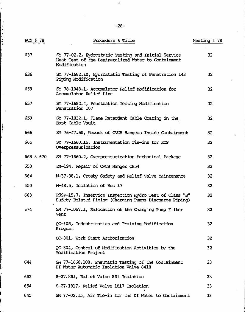
637
636
658
SN 77-02.2, Hydrostatic Testing and Initial ServiceL'eat Test of the Deraineralized Water to ContainmentModification
SN 77-1682.10, Hydrostatic Testing of Penetration 143Piping Modification
SN 78-1048.1, Accumulator Relief Rx3ification forAccumulator Relief Line
32
32
32
657 SM 77-1682.4, Penetration Testing ModificationPenetration 107
32
659
666
665
668 & 670
650
664
650
663
674
644
653
654
645
SN 77-1832.1, Flame Retardant Cable Coating in theEast Cable Vault
SN 75-47.50, Rework of CVCS Hangers Inside Containment
SM 77-1660.15, Instrumentation Tie-ins for RCSOverpressurization
SN 77-1660. 2, Overpressurization Mechanical Package
EM-194, Repair of CVCS Hanger CH54
N-37.38.1, Crosby Safety and Relief Valve Maintenance
N-48.5, Isolation of Bus 17
RSSP-15.7, Inservice Inspection Hydro Test of Class "B"Safety Related Piping (Charging Pumps Discharge Piping)
SN 77-1057.1, Relocation of the Charging Pump FilterVent
QC-105, Indoctrination and Training ModificationProgram
QC-301, Work Start Authorization
QC-304, Control of Modification Activities by theModification Project
SN 77-1660.100, Pneumatic Testing of the ContainmentDI Water Automatic Isolation Valve 8418
S-27.861, Relief Valve 861 Isolation
S-27.1817, Relief Valve 1817 Isolation
SN 77-02.15, Air Tie-in for the DI Water to Containment
32
32
32
32
32
32
32
32
32
32
32
32
33
33
33
33
-29-
PCN I 78 Procedure & Title Meeting I 78
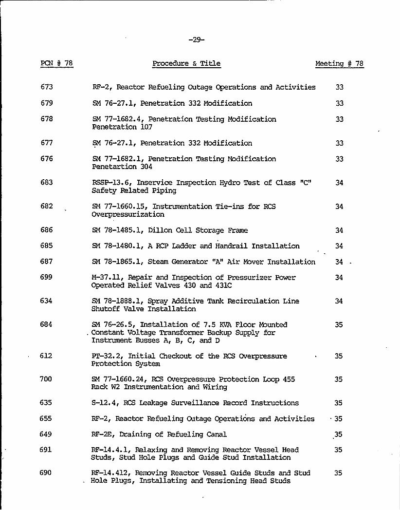
673
679
678
677
676
683
682
686
685
687
699
634
684
612
700
RF-2, Reactor Refueling Outage Operations and Activities
SM 76-27.1, Penetration 332 Modification
SM 77-1682.4, Penetration Testing ModificationPenetration 107
SM 76-27.1, Penetration 332 Modification
Rl 77-1682.1, Penetration Testing ModificationPenetartion 304
RSSP-13.6, Inservice Inspection Hydro Test of Class "C"Safety Related Piping
SM 77-1660.15, Instrumentation Tie-ins for RCSOverpressurization
SM 78-1485.1, Dillon Cell Storage Frame
SN 78-1480.1, A RCP Ladder and Handrail Installation
SN 78-1865.1, Steam Generator "A" Air Mover Installation
M-37.11, Repair and Inspection of Pressurizer PowerOperated Relief Valves 430 and 431C
SN 78-1888.1, Spray Additive Tank Recirculation LineShutoff Valve Installation
SN 76-26.5, Installation of 7.5 KVA Floor Munted. Constant Voltage Transformer Backup Supply for
Instrument Busses A, B, C, and D
PT 32.2, Initial Checkout of the KS OverpressureProtection System
SN 77-1660.24, KS Overpressure Protection Loop 455Rack W2 Instrumentation and Wiring
33
33
33
33
33
34
34
34
34
34
34
34
35
35
35
635
655
S-12.4, RCS Leakage Surveillance Record Instructions 35
RF-2, Reactor Refueling Outage Operations and Activities 35
649
691
690
RF-2E, Draining of Refueling Canal
RF-14.4.1, Relaxing and Removing Reactor Vessel HeadStuds, Stud Hole Plugs and Guide Stud Installation
RF-14.412, Removing Reactor Vessel Guide Studs and StudHole Plugs, Installating and Tensioning Head Studs
35
35
35

-30-
PCN 4 78 Procedure & Title Meetin N 78
688
706
697
627
647
648
662
675
672
HP-4.1, Controlled Area Entry
S-SA, Component Cooling Water System Startup andNormal Opeation Valve Alignment
M-47.1, Inspection of Pressurizer Internals
M-44.2, Isolation and Restoration of Motor ControlCenter 1A
CP-924.0, Calibration and/or Maintenance of SafetyInjection Flow Loop "B"
CP-925.0, Calibration and/or Maintenance of SafetyInjection Flaw laop "A"
BSSP-15.7, Inservice Inspection Hydro Test of Class "B"Safety Related Piping (Charging Piping)
S-4.5.9, Letdown Deborating DI (A or B) ResinReplacement
GS-17.0, Accountability of Personnel During EmergencyConditions
35
35
35
35
35
35
35
35
35
660
669
GS-31.0, Door Alarm System 35
RF-2; Reactor Refueling Outage Operations and Activities 35
707
705
704
671
RF-8. 2, Fuel Handling Instruction Pre-Loading andPeriodic Valve Test
0-1.1B, Establishing Containment Integrity
RF-2B, Recpired Valve Line-.Up for Reactor Head Removal
HP-4.3, Work Permit Use
35
35
35
35
628
629,
623
0-2.5, Plant Shutdown from Hot Shutdawn to Cold Shutdown 35When Condenser Steam Dump is Unavailable
0-2.4, Plant Shutdown from Hot Shutdown to Cold Shutdown 35During Blackout
0-2.2, Plant Shutdawn fram Hot Shutdown to Cold Condition 35
696 PT-16, Auxiliary Feedwater System 35

-31-
PCN 5 78 Procedure a Title Meetin I 78
694
695
693
692
703
PT-2.7, Service Water System
PT-3, Containment Spray Pumps and NaOH AdditiveSystem
PZ-2.2, Residual Heat Removal System
PT-2.1, Safety Injection System Pumps
PT-2. 4, Cold/Refueling Motor Operated ValveSurveillance
35
35
35
35
651
702
701
698
315
640
RSSP-1.1, Valve Interlock Verification ResidualHeat Removal System
RSSP-3.0, Verification of Emergency StartLogic Auxiliary Feedwater Pumps
PT-2. 5, Air Operated Valves —Quarterly Surveillance
SC-3, Fire Emergency Plan
QC-1003, Control of Inservice Inspection Activities
QC-103, Periodic Review of Quality Control Procedure
35
35
35
35
35
35
638 a 639 QC-201, Ginna Quality Control Organization
.QC-303, Control of System Modification Activities
35
35
652'20
S-3.1N, Isolation of Miscellaneous Valves in theBoric Acid Storage Tank Room
SM 77-1682. 2, Penetration Testing ModificationPenetration 202
36
36
714
710
SM 75-14, Boric Acid Batch Tank Recirculation Pipingand Supports
&I 76-28.2, Flange Installation on Feedwater FlowVenturis A Feedwater Line
36
36
721
711
713
CP-455.0, N2 Accumulator Pressure Low Loop 45S
S-3.2A, Charging and Volume Control Systen Pre-StartupAlignment
P-8, Precautions, Limitations and Setpoints WasteDisposal System
36
36
36

-32-
PCN 0 78 Procedure a Title Meetin 4 78
715 S-13A, RHR System Lineup for Safety Injection 36
709 S-3.1K, lA Boric Acid Transfer Pump Isolation/Restoration 36
723
722
767
EM-155, Safeguard Rack Relays VI and/or CI Replacement
M-81, Safeguard Rack Ventillation and ContainmentIsolation Relays Replacement
A-54.6, Health Physic's Tour
S-2.3B, Burping the Pressurizer Relief Tank with N2(Not to ke Opened the Atmosphere)
36
36
37A
774 M-40.1, Hydraulic Snubber Unit Removal and Reinstallatio 37AProcedure
766'24
725
726
727
728
RF-2, Reactor Refueling Outage Operations and Activities
ISI-2.1.7, Quality Group B Inservice Inspection
ISI-2.1.8, Quality Group B Inservice Inspection
ISI-2.1.9, Quality Group B Inservice Inspection
ISI-2.2.1, Quality Group B Inservice Inspection
ISI-2.2. 2, Quality Group B Inservice Inspection
37A
37
37
37
37
37
729
730
ISI-2.2. 3, Quality Group
ISI-2. 2. 4, Quality Group
B Inservice Inspection
B Inservice Inspection
37
37
731
732
733
734
735
736
737
738
739
ISI-2.2.55 Quality Group B Inservice Inspection
ISI-2.2.6, Quality Group B Inservice Inspection
ISI-2.2.7, Quality Group B Inservice Inspection
ISI-2.2.8, Quality Group B Inservice Inspection
ISI-2.2. 9, Quality Group B Inservice Inspection
ISI-2.3.1, Quality Group B Inservice Inspection
ISI.3.22 Quality Group B Inservice Inspection
ISI-2.3.3, Quality Group B Inservice Inspection
ISI-2.3.4, Quality Group B Inservice Inspection
37
37
37
37
37
37
37
37
37
-33-
PCN I 78 Procedure 6 Title Meetin I 78
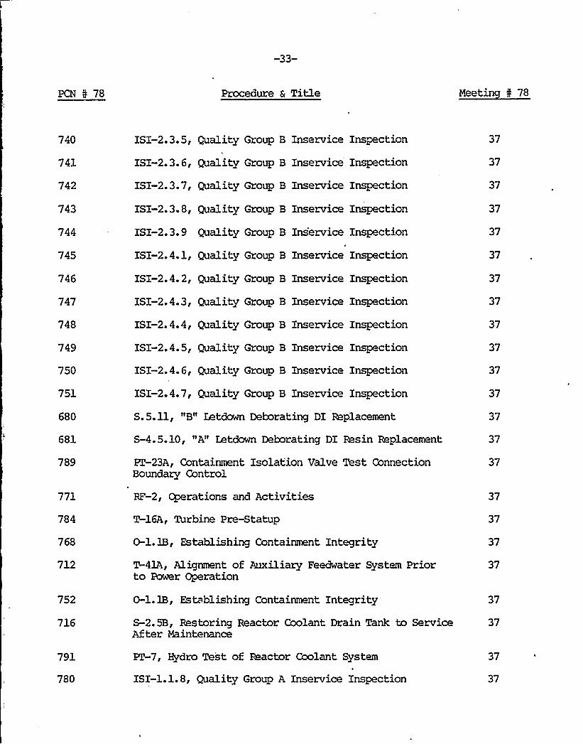
740
741
742
743
744
745
746
747
748
749
750
751
680
681
789
771
784
768
712
752
716
791
780
ISI-2.3.5, Quality Group B Inservice Inspection
ISI-2.3.6, Quality Group B Inservice Inspection
ISI-2.3.7, Quality Group B Inservice Inspection
ISI-2.3.8, Quality Group B Inservice Inspection
ISI-2.3. 9 Quality Group B Inservice Inspection
ISI-2.4.1, Quality Group B Inservice Inspection
ISI-2.4.2, Quality Group B Inservice Inspection
ISI-2.4.3, Quality Group B Inservice Inspection
ISI-2.4.4, Quality Group B Inservice Inspection
ISI-2.4.5, Quality Group B Inservice Inspection
ISI-2.4. 6, Quality Group B Inservice Inspection
ISI-2.4.7, Quality Group B Inservice Inspection
S.5.11, "B" Letdown Deborating DI Replacement
S-4.5.10, "A" Letdown Deborating DI Resin Replacement
PT-23A, Containment Isolation Valve Test ConnectionBoundary Control
RF-2, Operations and Activities
T-16A, Turbine Pre-Statup
O-l. 1B, Establishing Containment Integrity
T-41A, Alignment of Auxiliary Feedwater System Priorto Power Operation
O-l. 1B, Establishing Containment Integrity
S-2.5B, Restoring Reactor Coolant Drain Tank to ServiceAfter Maintenance
PZ-7, Hydro Test of Reactor Coolant System
ISI-1.1.8, Quality Group A Inservice Inspection
37
37
37
37
37
37
37
37
37
37
37
37
37
37
37
37
37
37
37
37
37
37
37

-34-
PCN -5 78 Procedure & Title Meetin I 78
782
781
ISI-3.1.5, High Energy Inservice Inspection
ISI.1.6, Quality Group B Inservice Inspection
37
37
785 PT-13.1.1, Protomatic Deluge Valve System Testing Systen 37Number 7, 8, 9, 10
787
777
795
794
793
718
778
769
788
770
753
708
779
717
790,
783
PZ-7, Hydro Test of Reactor Coolant System
ET-23.3, Containment Isolation Valves Leak Bate TestingMakeup Water to Pressurizer Relief Tank Line
FT-32.2, Initial Checkout of the RCS OverpressureProtection System
ISI-1.1.9, Quality Group A Inservice Inspection
0-6.2, Main Control Board System Status Verification
M-7.3, Boric Acid Concentrates and Ion Exchanger FilterReplacement
M-48.3, Isolation and Restoration of Bus 115
PC-1.3, Daily Chemistry Analysis Results
HP-11.2, Iodine in Air-Charcoal Cartridge Method
ISI-3.1.5, High Energy Inservice Inspection
A-52.2, Control of Locked Valve Operation
A-36, Station Holding Rules
0-2.3.1, Draining the Reactor Coolant System
T-34A, Generator Seal Oil System Startup
M-40.8, Functional Testing of Hydraulic Snubbers
R1-201, "B" Steam Generator Secondary Side PeripheralTube Removal
37
37
37
37
37
37
37
37
37
37
37
37
37
37
37
37
786
796
799
RSSP-13.8.1, Hydro Test of Loop A Underground ServiceWater Piping
EM 204 I Seal Welding MOV-700 RHR from Loop A
&1 76-01.1, Safeguard Buses DC Control Voltage Mnitor
38
38
38

-35-
PCN 5 78 Procedure a Title Meetin 5 78
800
830
831
840
841
842
899
RSSP-1.4, Valve Interlock Verification - ReactorCoolant System
PT-32.2, Initial Checkout of the RCS OverpressureProtection System
0-1.2, Plant from Hot Shutdcam to Steady Load
S-29.1, Prealignment of the Reactor Vessel OverpressureProtection System N2 Supply System
S-29.2, Charging the Reactor Vessel OverpressureProtection System Accumulators With N2
0-7, Alignment and Operation of the Reactor VesselOverpressure Protection System
EN-204, Seal Welding MOV-700 RHR "A" Loop
38
38
38
39
39
39
39
883 0-2.5, Plant Shutdown from Hot Shutdown to Cold Shutdown 39When Condenser Steam Dump is Unavailable
792
839
O-l.l, Plant Heatup from Cold Shutdown to Hot Shutdown
O-l.l, Plant Heatup from Cold Shutdown to Hot Shutdown
39
39
838 0-2.2, Plant Shutdown from Hot Shutdown to Gold Condition 39
837
834
836
0-2.3, Plant at Gold Shutdown
Filling and Venting the Reactor Coolant System
Plant Blackout from Hot Shutdown to Cold ShutdownDuring Blackout
39
39
39
835 0-2.5, Plant Shutdown from Hot Shutdown to Cold Shutdown 39When Condenser Steam Dump is Unavailable
888
896
897
898
887
844
A-l.1, Locked Radiation Areas
QC-1404, Test Status Control
O-l.2.2, Critical Rod Position Calculation
0-3.1, Boron Concentration for the Hot Xenon FreeShutdown Margin
ISI-4.1. 5, High Energy Inservice Inspection
&1 75-14, Boric Acid Batch Tank Recirculation Pipingand Supports
39
39
39
39
40
40
-36-
PCN 4 78 Procedure & Title Meetin I 78
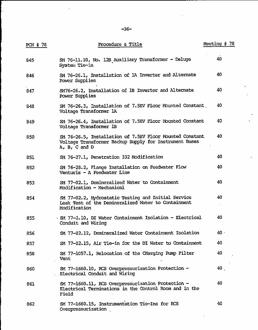
845
846
847
SN 76-11.10, No. 12B Auxiliary Transformer — DelugeSystem Tie-in
SM 76-26.1, Installation of 1A Inverter and AlternatePower Supplies
I
SN76-26.2, Installation of 18 Inverter and AlternatePower Supplies
40
40
40
848
849
850
SN 76-26.3, Installation of 7.5KV Floor Mounted Constant 40Voltage Transformer 1A
SN 76-26.4, Installation of 7.5KV Floor Mounted Constant 40Voltage Transformer 1B
SN 76-26.5, Installation of 7.5KV Floor Haunted Constant 40Voltage Transformer Backup Supply for Instrument BusesA, B, C and D
851
852
853
854
855
856
857
858
RI 76-27.1, Penetration 332 Modification
SN 76-28.2, Flange Installation on Feedwater FlowVenturis —A Feedwater Line
RI 77-02.1, Demineralized Water to ContainmentModification —Mechanical
SN 77-02.2, Hydrostatic Testing and Initial ServiceLeak Test of the Demineralized Water to ContainmentModification
SM 77-2.10, DI Water Containment Isolation —ElectricalConduit and Wiring
SN 77-02. 12, Demineralized Water Containment Isolation
SN 77-02.15, Air Tie-in for the DI Water to Containment
SM 77-1057.1, Relocation of the CHarging Pump FilterVent
40
40
40
40
40
40
40
40
860
861
862
SN 77-1660.10, RCS Overpressurization Protection—Electrical Conduit and Wiring
SN 77-1660.11, RCS Overpressurization Protection—Electrical Terminations in the Control Room and in theField
SN 77-1660.15, Instrumentation Tie-Ins for RCS
Overpressurization
40
40
40

-37-
PCN 5 78 Procedure & Title Meetin I 78
863
864
865
866
867
868
869
870
871
872
873
874
875'I
876
877
878
879
887
SN 77-1660.21, BCS Overpressure Protection Loop 450Rack B2 Instrumentation Installation and Wiring
SM 77-1660.22, RCS Overpressure Protection Loop 451Rack W2 Instrumentation Installation and Wiring
SN 77-1660.23, KS Overpressure Protection Lcop 452Rack R2 Instrumentation Installation and Wiring
SN 77-1660.24, BCS Overpressure Protection Loop 455Rack W2 Instrumentation Installation and Wiring
SN 77-1660.25, RCS Overpressure Protection Loop 456Rack R2 Instrumentation Installation and Wiring
SN 77-1660.26, BCS Overpressure Protection Loop 409Rack RCS2 Instrumentation Installation and Wiring
SM 77-1660.27, KS Ovezpressure Protection Loop 410Rack RCS2 Instrumentation Installation and Wiring
SN 77-1660. 28, Overpressure Protection Rx3ificationof .the Belay Backs
SN 77-1660.29, Overpressure Protection Rx3ificationAnnunciator Wiring
SN 77-1682.1, Penetration Testing ModificationPenetration 304
SN 77-1682.2, Penetration Testing ModificationPenetration 202
B4 77-1682.3, Penetration Testing Rx3ificationPenetration 210
SM 77-1832.1, Flame Retardant Cable Coating in theEast Cable Vault
SN 77-1480.1, "A" RCP Ladder and Handrail Installation
SM 78-1485.1, Dillon Cell Storage Frame
SM 78-1865.1, Steam Generator "A" Air Mover Installation
Rf 78-1890.1, Feedwater Line Drain Valves Before theContainment Check Valves
ISI-4.1.5, High Energy Inservice Inspection
40
40
40
40
40
40
40
40
40
'40
40
40
40
40
40
40
40
40

-38-
PCN 5 78 Procedure a Title Neetin 5 78
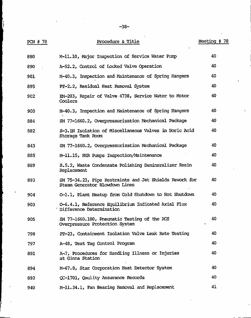
880
890
901
895
902
M-ll.10, Major Inspection of Service Water Pump
A-52.2,'ontrol of Locked Valve Operation
N-40.3, Inspection and Maintenance of Spring Hangers
PZ-2.2, Residual Heat Removal System
EK-203, Repair of Valve 4738, Service Water to MtorCoolers
40
40
40
40
40
900
884
882
843
885
889
893
904
903
M-40.3, Inspection and Naintenance of Spring Hangers
SM 77-1660.2, Overpressurization Mechanical Package
S-3.1N Isolation of Miscellaneous Valves in Boric AcidStorage Tank Boom
SM 77-1660.2, Overpressurization Mechanical Package
M-ll.15, RHR Pumps Inspection/Maintenance
S.5.2, Waste Condensate Polishing Demineralizer ResinReplacement
Ri 75-34.23, Pipe Restraints and Jet Shields Rework forSteam Generator Blowdown Lines
O-l.l, Plant Heatup from Cold Shutdown to Hot Shutdown
0-6.4.1, Reference ~ilibrium Indicated Axial FluxDifference Determination
40
40
40
40
40
40
40
40
40
905
798
797
891
SN 77-1660.100, Pneumatic Testing of the KSOverpressure Protection System
PT-23, Containment Isolation Valve Leak Rate Testing
A-48, Test Tag Control Program
A-.7, Procedures for Handling Illness or Injuriesat Ginna Station
40
40
40
40
894
892
940
M-67.8, Star Corporation Heat Detector System
QC-1701, Qaulity Assurance Records
M-ll.34.1, Fan Bearing Reaaval and Replacement
40
40
41
PCN 4 78 Procedure a Title Meetin 5 78
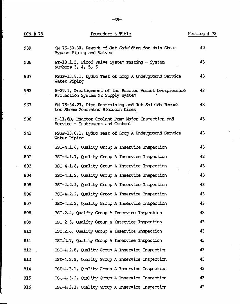
989
938
937
953
967
SM 75-50.30, Rework of Jet Shielding for Main SteamBypass Piping and Valves
ET-13.1.5, Flood Valve System Testing —SystemNumbers 3, 4, 5, 6
RSSP-13.8.1, Hydro Test of Loop A Underground ServiceWater Piping
S-29.1, Prealignment of the Reactor Vessel OverpressureProtection System N2 Supply System
SM 75-34.23, Pipe Restraining and Jet Shields Reworkfor Steam Generator Blowdown Lines
42
43
43
43
43
906 M-ll.8D, Reactor Coolant Pump iWjor Inspection andService — Instrument and Control
43
941
801
802
803
804
805
806
807
808
809
810
811
812
813
814
815
816
RSSP-13.8.1, Hydro Test of Loop A Underground ServiceWater Piping
ISI-4.1.6, Quality Group A Inservice Inspection
ISI-4.1.7, Quality Group A Inservice Inspection
ISI-4.1.8, Qaulity Group A Inservice Inspection
ISI-4.1.9, Quality Group A Inservice Inspection
ISI-4.2.1, Quality Group A Inservice Inspection
ISI-4.2. 2, Quality Gruop A Inservice Inspection
ISI-4.2.3, Quality Group A Inservice Inspection
ISI.2.4, Quality Group A Inservice Inspection
ISI.2.5, Quality Group A Inservice Xnspection
ISI.2.6, Quality Group A Inservice Inspection
ISI.2.7, Quality Group A Inserviee Inspection
ISI-4.2. 8, Quality Group A Inservice Inspection
ISX-.4.2. 9, Quality Group A Inservice Inspection
ISI-4.3.1, Quality Group A Inservice Inspection
ISX-4.3. 2, Quality Group A Inservice Inspection
ISI-4.3.3, Quality Group A Inservice Inspection
43
43
43
43
43
43
43
43
43
43
43
43
43
43
-40-
PCN 4 78 Procedure 6 Title Meetin 5 78
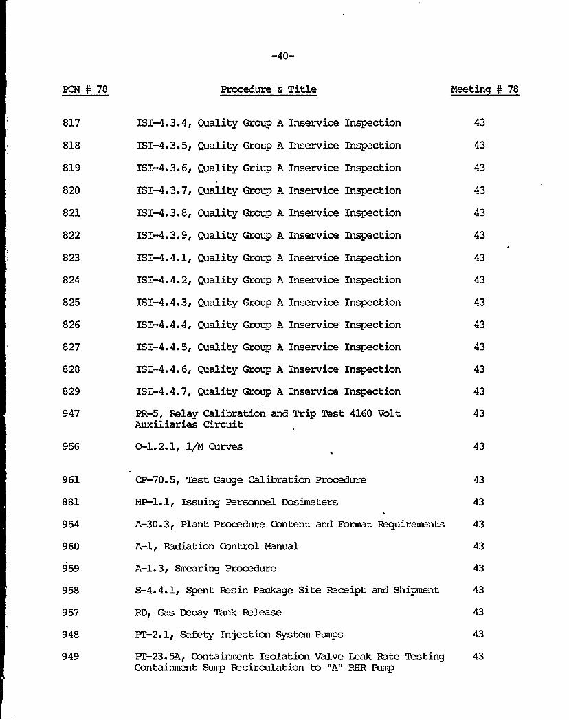
817
818
819
820
821
822
823
824
825
826
827
828
829
947
956
ISI-4.3.4, Quality Group A Inservice Inspection
ISX-4.3.5, Quality Group A Inservice Inspection
ISI-4.3.6, Quality Griup A Inservice Inspection
ISI-4.3.7, Quality Group A Inservice Inspection
ISX-4.3.8, Quality Group A Inservice Inspection
ISX-4.3.9, Quality Group A Inservice Inspection
ISX-4.4.1, Quality Group A Inservice Inspection
ISI-4.4.2, Quality Group A Inservice Inspection
ISI-4.4.3, Quality Group A Inservice Inspection
ISI-4.4.4, Quality Group A Inservice Inspection
ISI-4.4. 5, Quality Group A Inservice Inspection
ISX-4.4.6, Quality Group A Inservice Inspection
ISX-4.4.7, Quality Group A Inservice Inspection
PR-5, Relay Calibration and Trip Test 4160 VoltAuxiliaries Circuit
0-1.2.1, 1/M Curves
43
43
43
43
43
43
43
43
43
43
43
43
43
43
43
961
881
CP-70. 5, Test Gauge Calibration Procedure
HP-1.1, Issuing Personnel Dosimeters
43
43
954 A-30.3, Plant Procedure Content and Format Requirements 43
960
959
958
957
948
A-l, Radiation Control Manual
A-l.3, Smearing Procedure
S-4.4.1, Spent Resin Package Site Receipt and Shipment
RD, Gas Decay Tank Release
PT-2.1, Safety Injection System Pumps
43
43
43
43
949 PZ-23.5A, Containment Isolation Valve Leak Rate Testing 43Containment Sump Recirculation to "A" RHR Pump

-41-
PCN 5 78 'Procedure a Title Meetin 0 78
950 PT-23.5B, Contain7ent Isolation Valve Leak Rate Testing 43Containment Sump Recirculation to "B" RHR Pump
324,
939
993
944
946
945
SC-3.12, Plan for Recovery from Fire
M-67. 3, Flood Valve System Maintenance —SystemNumbers 3, 4, 5, 6
O-l.2. 2, Critical Rod Position Calculation
GS-26.1, Unoccupied Vital Area Key Control andAccountability
GS-10.0, Security Personnel Actions During a RadiationEmergency
GS-17.0, Accountability of Personnel During EmergencyCondition
43
43
43
43
43
43
943 GS-30.0, threatening Phone Call or Bomb Threat Procedure 43
993
1024
1023
907
908
909
910
911
912
913
914
915
916
PT-34.6, At Power Physics Testing
CP-502.1, Calibration of 1A Emergency Diesel KilowattMeters
CP-502.2, Calibration of lB Emergency Diesel KilowattMeters
ISI-3.1. 5A, Quality Group C Inservice Inspection
ISI-3.1. 6, Quality Group C Inservice Inspection
ISI-3.1.7, Quality Group C Inservice Inspection
ISI-3.1.8, Quality Group C Inservice Inspection
ISI-3.1. 9 Quality Group C Inservice Inspection
ISI-3.2.1, Quality Group C Inservice Inspection
ISI-3.2.2, Quality Group C Inservice Inspection
ISI-3.2.3, Quality Group C. Inservice Inspection
ISI-3.2.4, Quality Group C Inservice Inspection
ISI-3.2.5, Quality Group C Inservice Inspection
44
44
44
45
45
45
45
45
45
45
44


-42-
PCN I 78 Procedure a Title Meetin I 78
917
918
919
920
921
922
923
924
925
926
927
928
929
930
931
932
933
934
935
1027
1030
1021
1019
997
1001
ISI-3.2.6, Quality Group C Inservice Inspection
XSI-3.2.7, Quality Group C Inservice Inspection
ISX-3.2.8, Quality Group C Inservice Inspection
ISI-3.2.9, Quality Group C Xnservice Inspection
ISI-3.3.1, Quality Group C Inservice Inspection
ISI-3.3.2, Quality Group C Inservice Inspection
ISI-3.3.3, Quality Group C Inservice Inspection
ISI-3.3.4, Quality Group C Inservice Inspection
ISI-3.3.5, Quality Group C Inservice Inspection
XSI-3.3.7, Quality Group C Inservice Inspection
ISI-3.3.8, Quality Group C Inservice Inspection
XSI-3.3.9, Quality Group C Inservice Inspection
ISI-3.4.1, Quality Group C Inservice Inspection
ISI-3.4.2, Quality Group C Inservice Inspection
ISI-3.4.3, Quality Group C Inservice Inspection
ISI-3.4.4, Quality Group C Inservice Inspection
ISI-3.4.5, Quality Group C Inservice Inspection
ISI-3.4.6, Quality Group C Inservice Inspection
ISI-3.4.7, Quality Group C Inservice Inspection
0-1.3, Reactor Startup for Training
0-1.2, Plant from Hot Shutdown to Steady Load
PZ-16, Auxiliary Feedwater System
O-l.l, Plant Heatup from Cold Shutdown to Hot Shutdown
SM 75-34.23, Pipe Restraints and Jet Shields Rework forSteam Generator Blowdown Lines
PZ-6.2, NIS Intermediate Range Channels Channel No.
45
45
45
45
45
45
45
45
45
45
45
45
45
45
45
45
45
45
45
45
45

-43-
PCN I 78 Procedure & Title Meetin I 78
1013
1004
951
952
M-37.38.1, Crosby Safety and Relief Valve Maintenance
M-73.3, Welding on Carbon Steel Piping and Components
S-27.5.3, RCS Loop Sample Valves Isolation
S-27.5.2, Pressurizer Lie@id Space Sample IsolationValves
45
45
45
968
943
974
969
970
971
972
859
1034
1033
1026
E-39.0, Fire at Facility
E-39.1, Containment Vessel Fire
E-39. 2, Relay/Computer Room Fire
E-39.3, Grinnell Deluge System Fire
E-39.4, Smoke Detector Area Fire
E-39. 5, Sprinkler System Fire
E-39.6, Auxiliary Building/Controlled Area Fire
SM 77-1660.2, Overpressurization Mechanical Package
SM 78-1873.1, Pressurizer Jib Crane
SM 78-1888.1, Spray Additive Recirculation Line ShutoffValve Installation
SM 77-02.11, Electric Terminations at Valve 8418 andin Control Room for DI Water to Containment
45
45
45
45
45
45
45
45
45
45
45
1000
999
0-2.4, Plant Shutdown from Hot Shutdwon to Cold Shutdown 45During Blackout
0-2.2, Plant Shutdown from Hot Shutdown to Gold Condition 4S
1015 ET-6.3.3, Power Range Nuclear Instrumentation SystemChannel 43
45
1014
1016
1017
PZ-6.3.4, Power Range Nuclear Instrumentation SystemChannel 44
PZ-6.3.2, Power Range Nuclear Instrumentation SystemChannel 42
PT-6.3.1, Power Range Nuclear Instrumentation SystemChannel 41
45
45
45

-44-
PCN 4 78 Procedure a Title Meetin I 78
1008
1007
942
1006
1010
1009
1002
1005
PZ-6.1, Source Range NIS
ET.2, NIS Intermediate Range
A-1.2, Air Sampling Procedure
CP-128.3, Charging Line Flow Transmitter FT-128 andLocal Indicator FI-128A
A-2.6, Incore Flux Map Data. Reduction and Review
S-12.4, RCS Leakage Surveillance Record Instructions
A-36, Station Holding Rules
CP-128.0, Calibration and/or Maintenance of ChangingLine Flow Channel "128"
45
45
45
45
45
45
45
1012
1020
309
1052
1092
1036
1059
CP-628, RHR Loop Reactor Coolant Test Bypass Flow
SM 75-58.8, Modification of Walkway and RailingsAround the Spent Fuel Pool
SC-3.14.2, Fire Department and Fire Brigade Drill0-6.9, Opeating Limits for Ginna Station Transmission
&I 76-16.1, Eddy Current Wiring Conduits
0-2.1, Normal Shutdown to Hot Shutdown
PZ. 4, 'Excore/Incore Recalibration
45
45
46
46
46
46
1056 SM 77-1498.1, Zaw Power Steam Generator Feedwater ~s 46Control Reification
1055
1053
1044
Rl 78-1048.1, Accumulator Relief Rx3ification forAccumulator Relief Line
SM 76-01.2, Cable Installation for the DC ControlFuse Honitor System
SM 75-41.31, Condensate Polishing System Control BoardOperational Check
46
46
46
1089 a 1043 SM 75-5.40, Standby Auxiliary Feedwater Rework InsideContainment
46
1087 SM 75-34.23, Pipe Restraints and Jet Shields Reworkfor Steam Generator Blowdown Lines
46

PCN I 78
-45-
Procedure a Title Meetin I 78
1083
1042 & 1088 SM 75-5.50 Aux'Aux'.iary Feedwater Hanger AEW-51 Repair
SM 75-58.8, Modification of the Walkwo e ay and Railings
1084 . SM 75-50.30, Rework of Jet Shield'nSM ze mg on Main Steam 46
1085 SM 75-48.30, Rework of the Auxilia'y Feedwater Crossover 46
1086
1050
1049
1041
1040
1028
1048
1054
990
1058
1057
1119
1123
1108
1107
1097
1099
SM 75-47.30 Re, Rework of CVCS Hangers Inside Containment
M-38.3 , 1B Inveiter Maintenance o Reor pair
M 38 ' ia, L~ Inverter Maintenance o Reor paar
M-38.4, 1A Constant Voltaor Repair
ge Transformer Maintenance
M-38.5, 1B Constant Voltaor Repair
ge Transformer Maintenance
0-1.1C, Pre-Critical TechnicalSheet
x ~~cification Check
9 -2701, Quality Assurance Records
0-7 Al 'Alignment and Operation of theOverpressure Prot t 'cion System
e Reactor Vessel
, GS-26.1, Unocc iedup'ital Area Key Control andccountability
T-26, 125 VoI lt DC and Station Battery System
PT-17.3Source
7.3, RMS Channel Response to Po tabr le Radiation
M-11.8K, Reactor Coolant Pump Mototor Minor Inspection
S-17B, Addition of 50% NaOHaOH to the Spray additive Tank
TICP-.l , Test Instrument Calibration Procedure
TICP-2, Test Instrument Calibration Procedure
PT-13.1.9, Halon System Testing and'or(Resetting) Comput Roommpu er Room and Relay Room
PT-13.l. 3 Deluge Valve System Testing Numbe rs 1, 2, ll
46
46
46
46
46
46
46
46
48'8
48
48
48
48


PCN I 78 Procedure 6 Title Meetin I 78
1098
1100
PZ-13.1.7, Alarm Valve System Testing System Numbers12, 13 Warehouse
PZ-13.l.l, Protomatic Deluge Valve System Testing System 48Numbers 7, 8, 9, 10
1122
1121
1156
1155
1117
1116
1115
1114
1110
1113
1112
1101
1102
1109
1118
1126
1120
955
1011
963
M-43.21, Steam Generator Final Cleanup and Inspection
M-47.1, Inspection of Pressurizer Internals
CP-32.3, Calibration of Source Range N-32
CP-31.3, Calibration of Source Range N-31
CP-44.2, General Reinstate Procedure for N-44
CP-44.1, General Defeat Procedure for N-44
CP-43.2, General Reinstate Procedure for N-43
CP-43.1, General Defeat Procedure for N-43
CP-41.2, General Reinstate Procedure for N-41
CP-41.1, .General Defeat Procedure for N-41
CP-42.2, Reinstate Power Range Channel 42
CP-42.1, General Defeat Procedure for N-42,
0-5.1, Zoad Reductions
0-5. 2, Zoad Increases
0-6.7, Weekly Alarm Status Check
0-2.4, Plant Shutdown from Hot Shutdown to ColdShutdown During Blackout
HP-5.1, Area Radiation Surveys
SM 78-2160.1, GSM 7 Pipe Supports
A-50.12, Emergency Plan Training Program
ISI-6.0, Inservice Leakage Inspection of QualityGroup C Systems
ISI-5, Eddy Current Testing of Series 44 Steam GeneratorTubes
48
48
48
48
48
48
48
48
48
48
48
48
48
48
48
48
48
48
49
49

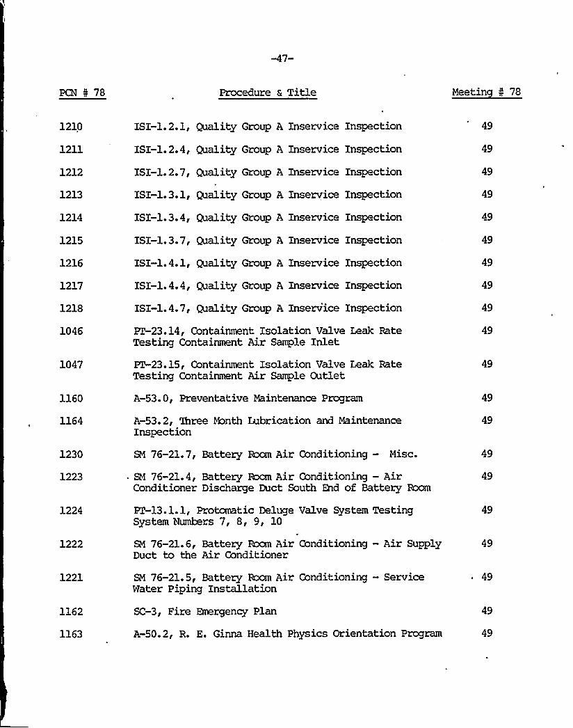
PCN 5 78 Procedure & Title Meetin 4 78
1210
1211
1212
1213
1214
1215
1216
1217
1218
1046
1047
1160
1164
1230
1223
1224
1222
ISI-1.2.1, Quality Group A Inservice Inspection
ISI-l.2.4, Quality Group A Inservice Inspection
ISI-1.2.7, Quality Group A Inservice Inspection
ISI-1.3.1, Quality Group A Inseryice Inspection
ISI-1.3.4, Quality Group A Inservice Inspection
ISI-1.3.7, Quality Group A Inservice Inspection
ISI-1.4.1, Quality Group A Inservice Inspection
ISI-1.4.4, Quality Group A Inservice Inspection
ISI-1.4.7, Quality Group A Inservice Inspection
PZ-23.14, Containment Isolation Valve Leak RateTesting Containment Air Sample Inlet
PT-23.15, Containment Isolation Valve Leak RateTesting Containment Air Sample Outlet
A-53. 0, Preventative Maintenance Program
A-53.2, three bhnth Lubrication and MaintenanceInspection
SM 76-21.7, Battery Room Air Conditioning — Misc.
SM 76-21.4, Battery Rocm Air Conditioning —AirConditioner Discharge Duct South End of Battery Room
PT-13.1.1, Protomatic Deluge Valve System TestingSystem Numbers 7, 8, 9, 10
SM 76-21.6, Battery Rocm Air Conditioning —Air SupplyDuct to the Air Conditioner
49
49
49
49
49
49
49
49
49
49
49
49
49
49
49
49
1221
1162
1163
SM 76-21. 5, Battery Bcxm Air Conditioning —ServiceWater Piping Installation
SC-3, Fire Emergency Plan
A-50.2, R. E. Ginna Health Physics Orientation Program
49
49
49

-48-
PCN 5 78 Procedure a Title Meetin I 78
1161
1121
1165
964
1153
1151
SM 75.24, MSZ Jet, Shielding Installation Rework
M-47.1, Inspection of Pressurizer Internals
ET-l, Rod Control System
M-43.8 Eddy Current Testing of Series 44 SteamGenerator Tubes
M-64.1, Periodic Surveillance and Minor Maintenanceof Limitorque Rotor Operated Safeguard Valves
M-37.53, RHR Core Deluge Valve 852A, and 852B Isolationand Packing
49
49
49
49
49
49
1152 M-37.55, Spray Additive Tank Discharge Valves HCV-836A/B 49Inspection and Maintenance
1150
1149
1148
M-37.51, Component Cooling Water Surge Tank Local VentValve RCV-017 Repair and Inspection
M-37.50, MOV-721 RHR to "B" Zoop Maintenance andInspection
M-37.49, Level Control Valve from "B" RCS Loop LCV-427Maintenance and Inspection
49
49
49
1147 M-37.48, Component Cooling From RC Pumps MOV-759 and/or 49MVT-759B Isolation and Maintenance
1146 M-37.47, RHR Pump Suction MOV-851A or MOV-851BMaintenance and Inspection
49
1145
1144
M-37.42, MOV-813 and/or MOV-814 Isolation and Maintenance 49
M-37.40, Maintneance cn Wtor Driven Auxiliary Feedwater 49Pumps Discharge Valves —MCV-.4007 or MOV-4008
1154
1143
1142
1141
M-64.2, Limitorque Valve Operator Maintenance andInspection
M-37.36.4, Nuclear Sample System Air OperatedValve Maintenance
M-37.35, Valves 3504 and 3505; Main Steamto Turbine Driven Auxiliary Feed PumpMaintenance
M-37.19, Removal of Limitorque Motorsand/or Repacking of Gate Valves 860,A,B.C,GD
49
49
49
49

PCN 4 78 Procedure & Title
1140
1139
1138
1137
1136
M-37.16J, Inspection and Maintenanceof the Rotor Drive Auxiliary Feed PumpRecirculation Control Valve
N-37.15.1, Inspection and Maintenance of48" Butterfly Valve, Model R-lA8 ValveOperator
M-37.15, Replacing or adjusting Rubber SeatSeat in Purge Supply and Exhaust Valves
N-37.10, Grinnell Diaphragm Valves, Air-Operated, Maintenance
M-37.3, Maintenance on Copes-VulcanDiaphragm Operated Control Valves forAOV
49
49
49
49
49
1131
1129
1128
1127
1134
1132
1135
1133
1130
None
1242
, 1288
M-ll.10, Major Inspection of Service WaterPump
M-ll.14, Inspection and Maintenance ofIngersol Rand Pumps
N-37.0, Repacking of Air Mtor OperatedValves
M-11.15, RHR Pumps Inspection/Maintenance
M-11.5B, Major Mechanical Inspection of theAuxiliary Feed Pumps for Pump
N-ll.5K, Turbine Driven Auxiliary FeedwaterPump Major or Mechanical Inspection
M-11.5C, Minor Mechanical Inspection of theAuxiliary Feed imps for PumpN-11.5E, Pipefitters Inspectxon of NctorDriven Auxiliary Feed Pump for Pump
M-ll.12.1, Safety Injection Pump, MechanicalInaction,A-54.6, Health Physics 'Ibur —week of 6/12/78
ET-16, Auxilairy Feedwater System
S-4.4, Spent Resin Removal to ShippingCasks
49
49
49
49
49
49
49
49
50
50

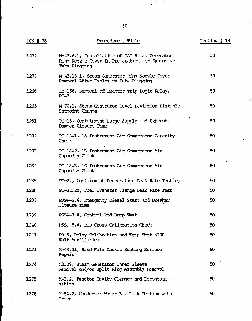
-50-
PCN 0 78 Procedure a Title Meetin 5 78
1272
1273
1266
1265
1231
1232
M-43.6.1, Installation of "A" Steam GeneratorRing Nozzle Cover In Preparation for ExplosiveTube Plugging
M-43.13.1, Steam Generator Ring Nozzle CoverRemoval After Explosive Tube Plugging
EM-156, Removal of Reactor Trip Itic Relay,RT-3
M-70.1, Steam Generator Level Deviation BistableSetpoint Change
PZ-15, Containment Purge Supply and ExhaustDamper Closure Time
ET-18.1, lA Instrument Air Compressor CapacityCheck
50
50
50
50
50
50
1233
1234
1235
1236
1237
ET-18.2, 1B Instrument Air Compressor AirCapacity Check
PT-18.3, 1C Instrument Air Compressor AirCapacity Check
ET-22, Containment Penetration Leak Rate Testing
PZ 22.22, Fuel Transfer Flange Leak Rate Test
RSSP-2.6, Emergency Diesel Start and Breaker.Closure Time
50
50
50
50
50
1239
1240
1241
1271
1274
1275
1276
RSSP-7.0, Control Rod Drop Test
RSSP-8.0, RTD Cross Calibration Check
PR-5, Relay Calibration and Trip Test 4160Volt Auxiliaries
M-43.31, Hand Hold Gasket Seating SurfaceRepair
M3.29, Steam Generator Inner SleeveRemoval and/or Split Ring Assembly Removal
M-3.2, Reactor Cavity Cleanup and Decontami-nation
M-54.2, Condenser Water Box Leak Testing withFreon
50
50
50
50
50
50
50

-51-
PCN I 78 Procedure & Title Meeting I 78
1277 M-43.27, Steam Generator Secondary SideHandhole Cover Removal
50
1278 M-43.28, Steam Generator SEcondary SideManway Cover Removal
50
1270 M-18.1, Drum Preparation for Waste EvaporatorBottoms
50
1281
1207
M-43. 26, Installation of Steam GeneratorSecondary Manway Cover
S-3.3D, CVCS Cation Demineralizer Bed Opera-tions Using "A" Dekorating D. I. Unit
50
50
1206
1205
S-3.3F, Reactor Coolant System pH Control
S-3.4I, Recirculation of Monitor Tank fornArs or nBss Moni
50
50
1204 S-3.4K, Releasing Monitor Tank to DischargeCanal
50
1203 S-3.4M, b$onitor Tank Recirculation throughEvaporator D. I.
50
1202 S-3.4N, Calculations for Boron RecycleProcess Using 2 HVZ's
50
1201
1200
S-3.4P, Transferring Concentrates fromBoric Acid Evaporator Feed Tank to WasteEvaporator Feed Tank for Drumming
S-3.4R, Transfer of any CVCS HUZ to AnotherCVCS HVZ
50
50
1198
1197
S-3.4T, Regeneration of the Boric AcidEvaporator "B" Condensate D. I.S-3.5, Deborating Demineralizer "B" Regen-eration
50
50
1196 S-4.1F, Waste Condensate Polisher Recircu-lation
50
1195 S-4.1L, Reverse Osmosis Unit Startup andShutdown
50
1194 S-4.1N, Transfer Waste Holdup Tank to "A"Monitor Tank
50

-52-
PCN I 78 Procedure a Title Meetin I 78
1193 S-4.1R, Transfer of Chemical Drain Tank toReverse Csmosis Feed Tank
50
1192
1191
1190
1189
1188
1187
1186
1185
S-4.1S, Alternating Waste Evaporator Cart-ridge Demineralizers
S-.4.1T, Alternating Waste Evaporator Conden-sate Polishing Demineralizers
S-4.1U, Velocity Flush of R-18
S-4.1Y, Laundry Tank Release Using ChemicalDrain Pump
S-4.5. 2, Waste Condensate Polishing Deminer-alizer Resin Replacement
S-4.5.4, Boron Recycle Base Reneval D. I.Resin Replacement
S-4.5.5, Boron Recycle Cation D. I., ResinReplacement
S-4.5.6, Spent Fuel Pit, D. I. Resin Replace-ment
50
50
50
50
50
50
50
50
1184
1183
1182
1181
,1199
1180
1179
1178
1177
S-4.5.7, Letdown Mixed Bed D. I. Resin Replace-ment
S-4.5.8, Eetdown Cation D. I. Resin Re-placement
S-5, Nuclear Sample Room Sampling System
S-8, Component Cooling system
S-3.4S, Regeneration of the Boric AcidEvaporator "A" Condensate D. I.S-9J, Blending to EST
S-9K, Transferring Water From Monitor Tankto Spent Fuel Pit
S-9L, Batching Boric Acid and Transferring,to Spent Fuel Pit
S-9M, Adding Reactor Makeup Water to SpentFuel Pit
50
50
50
50
'050
50
50

-53-
PCN I 78 Procedure 6 Title Meetin 5 78
1176
1175
1209
1208
1174
1173
1172
1171
1170
1169
S-10.1, Part Length Rod Control
S-14.2, Determination of the Percent ofTech. Spec. Limits for Radioactive Release
S-3.2C,. Placing and Removing from Service"B" Hot Leg Charing Valve 392A
S-3.3C, H2 or 02 Removal from Primary Systemby Bumping VCT with N2
S-16.3, Vent N2 from the "A" Accumulator
S-16.4, Vent N2 from the "B" Accumulator
S-16.9, Charging of the "A" Accumulator withNitrogen
S-16.10, Charging of the "B" Accumulator withNitrogen
S-16.13, Water Makeup to the Accumulator
S-23.5, Post Accident Charcoal Filter Opera-tion
50
50
50
50
50
50
50
50
50
50
1168
1167
1267
,1260
1259
1258
1257
1018
'1229
1247
1226
S-25. 5, Steam Generator Radioactive Release
S-26.4, Computor Rod Postion Alarm Program
M-57.1, Power Range NIS Detector Replacement
E-29.1, Zass of Normal Feedwater (Not Recover-erable)
E-26.4, Mrbine Trip Without Reactor Trip
E-16.2, High Iodine 1313 in the Plant Vent .
E-13.1, Power Range NIS Malfunction (PR 41,42, 43, 44)
A-l, Radiation Control Manual
HP-6.2, Posting of Contaminated and AirkarneAreas
0-2.1, Normal Shutdown to Hot Shutdown
PT-2.3.1, Post Accident Charcoal FilterDmtpers
50
50
50
50
50
50
50
50
50
50
50

-54-
PCN N 78 Procedure 6 Title Meeting N 78
1269
1227
1264
1262
1268
1263
1286
1246
1245
1244
1248
1249
1250
HP-1.1, Issuing Personnel Dosimeters
HP-1.3, External Exposure Records
M-18, Acid Cleaning of Waste Evaporator
HP-4.3, Work Permit Use
T-7E, Water Treatment-Carbon Filter Backwash
S-4.1D, Drumming Waste Evaporator Bottoms
A.C.-1701, Quality Assurance Records
0-1.2, Plant From Hot Shutdown to Steady Load
0-1.3, Reactor Startup for Training
PZ-34.0, Startup Physics Test Program
PZ-23.16A, Containment Isolation Valve LeakRate Testing "A" Steam Generator Blowdown
PZ-23.16B, Containment Isolation Valve LeakRate Testing "B" Steam Generator Blowdown
PZ 23.17A, Containment Isolation Valve LeakRate Testing Containment Pressure SensingTransmitter PT-945 and PT-946
50
50
50
50
50
50
50
50
50
52
52
52
1251 PZ-23.17B, Containment Isolation Valve LeakRate Testing Containment Pressure SensingTransmitter PT-947 and PT-948
52
1252 ET-23.17C, Containment Isolation Valve LeakRate Testing Containment Pressure SensingTransmitter PT-949 and PT-950
52
1255
1256
1253
1254
PZ-23.18B, Containment Isolation Valve LeakRate Testing "B" Containment Spray Header
ET-23.19, Containment Isolation Valve LeakRate Testing Safety Injection System
ET-23.20, Containment Isolation Valve LeakRate Testing R., C. D. T. Gas Header
PZ-23.21, Containment Isolation Valve LeakRate Testing R. C. D. T. Gas Analyzer
52
52
52
52

1

-55-
PCN I 78 Procedure a Title Meetin I 78
719
1293
1287
1283
1279
1285
1317
1318
1328
1315
1329
1295 .
1348
1347
1343
1032
1323
1322
1342
1341
M-37.57, Containment D. I. Check Valve 8419Mainteannce
&~~9.1, Manipulator Crane
RF-2A, Requirements for Reactor Head Removal
RF-8.1, Step-by-Step Fuel Loading and Maps
M-15.1, "A" or "B" Diesel Generator RemovalFrom Service
M-15.3.1, 1A Diesel Generator Solenoid Valves5907 and/or 5907A Maintenance
HP.3, Air Ejector Gas Sampling
HP-9.2, Primary to Secondary Leakage Detectionand Measurement
PZ-3, Containment Spray Pumps NaOHAdditive System
M-18, Acid Cleaning of Waste Evaporator
0-6.9, Operating Limits for Ginna StationTransmission
S-9M, Adding Reactor Makeup Water to SpentFuel Pit
. W-1701, Quality Assurance Records
0-6.11, Routine Operations Check Sheet
= A 37 1 I System Modification Requirements
A-50.9.2, Non-Licensed Staff RetrainingProgram
GS-31.0, Ecor Alarm System
GS-28.0, Inspection of Personnel Vehicles andPackages
A-37.0, Conduct of Operations for Safety-Related Evaluations as related to Facilityor Rxiifications, Special Tests, Experiments
A-50.2, R. E. Ginna Health Physics OrientationProgram,
52
52
52
52
52
52
52
52
52
52
52
53
53
53
53
53
53
53
53

PCN 5 78 Procedure a Title Meetin 5 78
1340 PC-18.3, Determination of Chloride kp Speci-fic Ion Electrode
53
1330 '-40.1, Hydraulic Snubber Reaaval and Rein-.stallation Procedure
53
1324
1326
1325
1354
1355
1356
1357
1358
1359
1360
1361
1362
1363
1364
1366
1368
1367
XT-34.1, Initial Criticality and ARO BoronConcentration
M-40.8, Functional Testing of HydraulicSnubbers
RSSP-12, Testing of Primary and SecondaryRelief Valves in Test Stand
AR-AA-'2, AVT Water Treatment Panel Trouble
AR-AA-4, Standby Auxiliary Feedwater HVACTrouble
AR-AA-5, Standby Auxiliary Feedwater PumpCAR C or D Trip
AR-AA-6, KS Overpressurization Army'InhibitLoop "A" Select
AR-AA-7, RCS Overpressurization Arrq/InhibitLoop "B" Select
AR-AA-9, Condensate Booster Pump Pressuriza-tion Trip
AR-AA-10, Condensate Booster Pump Trip
AR-AA-14, N2 Accumulator, V-801A Tow Pressure
AR-AA-15, N Accumulator, V-801B Imr Pressure
AR-AA-22, KS Overpressurization ProtectionHigh Pressure Train "A"
AR-AA-23, RCS Overpressurization ProtectionHigh Pressure Train "B"
AR-AA-25, Condensate System Low Pressure
AR-AA-29, Condensate +stem Low Pressure Drop
AR-AA-30, Condensate Booster Pump LowSuction Pressure
53
53
53
55
55
55
55
55
55
55
55
55
55
55
55


-57-
PCN I 78 Procedure a Title Meetin I 78
1365
1332
1333
1331
1385
1386
. 1387
1388
1389
1390
1391
1392
1336
1337
1338
1339
1370
AR-AA-31, RCS Overpressurization ProtectionHigh Pressure Train "C"
NC-1, A List of Sample Chemical Parametersand Sampling Schedule
HP-7.3, Calibration of Alpha Survey Instruments
GS-41, Photography at Ginna Station
SC-3.17.3, Fire Brigade Drill Records
SC-3.17.1, Planning, Conduct and Evaluationof a Fire Emergency DrillSC-1.10, Planning Conduct and Evaluationof a Radiation Emergency DrillA-50.11.4, General Employee Fire Txaining
A-S0.11.2, Fire Department Familiarization
A-50.11.1, Fire Brigade Training
A-50.11.0, Fire Fighting Organization andTraining Program
A-50.7, Emergency Coordinator Training Program
PZ-6.3.1, Power Range Nuclear InstrumentationSystem, Channel 41
PZ-6.3.2, "System, Channel 42
PT-6.3.3, Power Range Nuclear InstrumentationSystem, Channel 43
PT-6.3.4, Power Range Nuclear InstrumentationSystem, Channel 44
M-ll.8C, Reactor Coolant Pump Major Inspec-tion in Service Electrical
55
55
55
55
55
55
55
55
55
55
55
55
55
1371 M-ll.8B, Reactor Coolant Pump Seal Inspec-tion and Service Mechanical
55
1383 A-30.2, Plant Procedure Classification, Review,Approval and Distribution Requirements
55

-58-
PCN I 78 Procedure & Title Meetin I 78
1372
1377
1345
1335
1369
1373
1374
1376
1378
1384
1393
1382
1381.
A-30.3, Plant Procedure Content and FormatRequirements
AR-F-2, Alarm Response Procedure
PL'-2.1, Safety Injection System Pumps
SC-1.12B, Station Call List
A-60.3, Calibration Surveillance Program forInstrumentation ~ignent or Safety-RelatedComponents
M-15.1, "A" or "B" Diesel Generator RemovalFrom Service
M-15.3.2, Diesel Generator, FLSI, Fuel OilLevel Switch High Maintenance
M-18, Acid Cleaning of Waste Evaporatork
S-4.1C, Liquid Waste Process Operation andShutdown
S-7B, Reactor Coolant Low Pressure Purification
0-6.11, Routine Operations Check Sheet
PT-2.10, Check Valve Exercising Test Requirements-Cold/Refueling Shutdown
RSSP-l. 5, Valve Interlock Verification FeedwaterIsolation
55
55
55
55
55
55
55
55
55
55
55
55
1349
13SO
1351
1352
1353
1402
1442
WC-7, Chloride Determination
WC-6, Potentiometric Determination of Boron
WC-S, Ammonia and Organic Nitrogen Determination
WC-3, Anal inity Determination
WC-4, Amelia Determination ky Direct Nessleriza-tion
EM-205, Turbine Runback Relay in RPI SystemReplacement
EM-186, CR-9 Relay in RPI System Replacement
56
56
56
56
56
56


-59-
PCN 5 78 Procedure a Title Meetin 5 78
1417 M-44.10, Isolation of MCC 1K and Restoring toService
1418
1419
1420
M-31, Stator Replacement for Part-Length ControlRod Drive System
M-37.18E, ~ction and Repair of AuxiliaryBuilding Sump Pump Discharge Check Valves
M-37.18F, Inspection and Repair of 1AAuxiliary Building Sump Tank Pump DischargeCheck Valve
56
56
56
1421
1422
1423
1424
M-37. 43, Accumulator Drain Valves 844A and844B Inspection and Repair
M-37.27.1, Testing and Replacement of 1BSteam Generator Blowdawn Sample IsolationValves CV-77 *5736) or Manual Valve 5734
M-ll.26.1, Heater Drain Pump Mechanical SealInspection and Maintenance
M-11.26, Heater Drain Pump Inspection andMaintenance
56
56
56
1425
1426
1427
1428
M-1125, Main Feedwater Pump ~ed IncreaseInspection and Maintenance
M-11. 23, worthington Double-Helical RotaryPump Inspection and Maintenance
M-ll.24, Main Feed Pump Inspection andMaintenance
M-ll.28, Rotary Air Samples Inspection andMaintenance
56
56
56
56
1429
1430
1431
1432
1433
M-S3.1, Containment Air Loc3cs Door GasketReplacement
M-53.2, Containment Air Lock equalizing ValveCleaning and Inspection
M-37.16M, Isolation of V-356 for Maintenance
M-37.18D, Check Valve 1713 Isolation N2 toR.C.D.T.
M-37.20, Inspection and Repair of Main SteamIsolation Valves
56
56
56
56
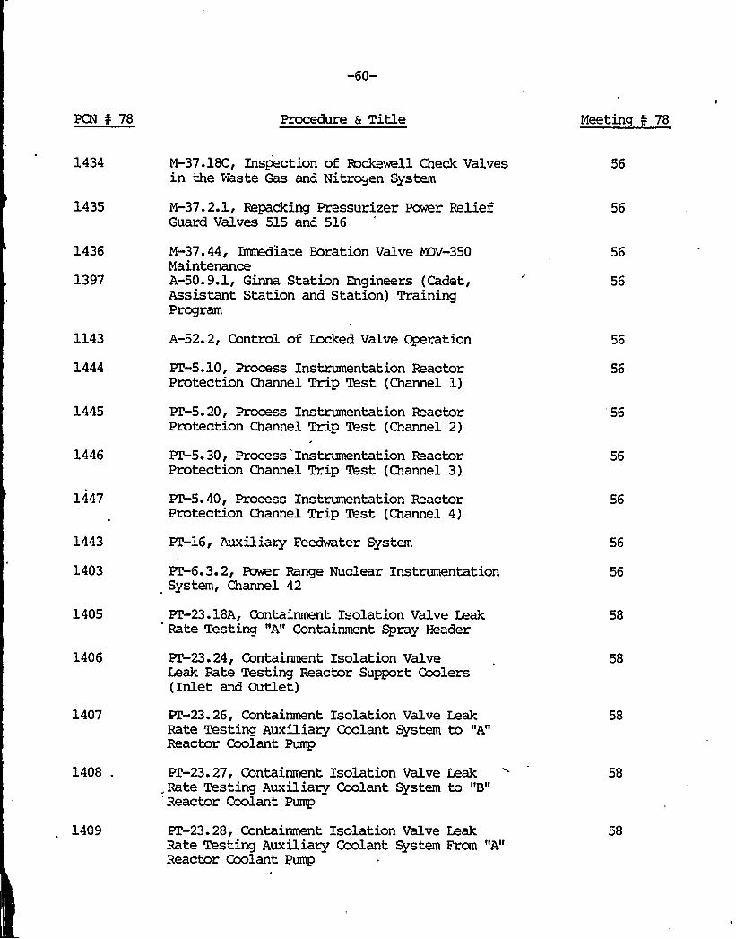
PCN 5 78 Procedure a Title Meetin 5 78
1434
1435
1436
1397
1143
1444
1445
1446
1447
1443
1403
1405
1406
1407
1408 .
1409
M-37.18C, Inspection of Rockewell Check Valvesin the Waste Gas and Nitrcxjen System
M-37.2.1, Repacking Pressurizer Power ReliefGuard Valves 515 and 516
M-37.44, Immediate Boration Valve MDV-350MaintenanceA-50.9.1, Ginna Station Engineers (Cadet,Assistant Station and Station) TrainingProgram
A-52.2, Control of Locked Valve Operation
KT-5.10, Process Instrumentation ReactorProtection Channel Trip Test (Channel 1)
FZ-5. 20, Process Instrumentation ReactorProtection Channel Trip Test (Channel 2)
PZ-5. 30, Process Instrumentation ReactorProtection Channel Trip Test (Channel 3)
PT-5.40, Process Instrumentation ReactorProtection Channel Trip Test (Channel 4)
KT-16, Auxiliary Feedwater System
KT-6.3. 2, Power Range Nuclear InstrumentationSystem, Channel 42
PZ-23.18A, Containment Isolation Valve LeakRate Testing "A" Containment Spray Header
PZ-23.24, Containment Isolation ValveLeak Rate Testing Reactor Support Goolers(Inlet and Outlet)
PZ-23.26, Containment Isolation Valve LeakRate Testing Auxiliary Coolant System to "A"Reactor Coolant Pump
PT-23.27, Containment Isolation Va1ve Leak.Rate Testing Auxiliary Coolant System to "B"Reactor Coolant Pump
PZ-23.28, Containment Isolation Valve LeakRate Testing Auxiliary Coolant System Frcm "A"Reactor Coolant Pump
56
56
56
56
56
56
'56
56
56
56
58
58
58
58
58

-61-
PCN 5 78 Procedure 6 Title Meetin 5 78
1410
1411
1455
1450
1449
1451
PZ-23.29, Containment Isolation Valve LeakRate Testing Auxiliary Coolant System From"B" Reactor Coolant Pump
PT-23.30, Containment Isolation Valve LeakRate Testing Auxiliary Coolant System ExcessLetdown (Supply and Return)
A-30.3, Plant Procedure Content and ForematRequirements
AR-K31, Fire System Alarm Panel
M-71. 2, Module Rework/Test Procedure
0-6.2, Main Control Board System StatusVerification
58
58
58
58
58
58
1456
1438
ET-2. 2, Residual Heat Removal System
RSSP-6. 0, Containment Integrated LeakageRate Test
58
58
1334 M-40, Surveillance and Maintenance of HydraulicSnubbers
58
1475 S-7C, Transferring and Purification of ERSTWater Frcm RWST to SFP
58
1489
1496
HP-12.3, Selection of Respirators
HP-7.5, Pocket Dosimeter Accuracy and Leak'est
59
59
1501
1500
1494
P-3, Precautions, Limitations, and Setpoints
P-3 Chemical and Volume Control System
HP-1. 2, External Exposure Limits
M-40, Surveillance and Maintenance of HydraulicSnubbers
59
59
59
1495
1491
1483
S-15.1, Flux Mapping Normal Procedure
AR-F-10, Pressurizer Low Pressure Alarm
0-6.6, Correcting Measured Boron Concen-tration to Reference Full Power ExpectedBoron Concentration
59
59
59


-71-
PCN 4 78 Procedure a Title Meetin I 78
1704
1705
1613
1614
1615
h
1666
I'708
1747
1728
1729
1785
1787
1783
1782
1781
1780
1778
1777
-- 1776
CP-80.2, Calibration Procedure for InsideMicnxLeters
CP-80.3, Calibration Procedure for Venier Calipers
PZ-13.4.7, Protomatic Deluge Valve System TestingSystem
XT-13.4.8, Protomatic Deluge Valve System Testing'ystem I8
KT-13.4.9, Protomatic Deluge Valve System TestingSystem
, PZ-13.4.10, Protomatic Deluge Valve System TestingSystem 510
S-4.1.22, Waste Evaporator Feed Tank Pump IsolationRestoration
ET-13.1.12, Containment Post-Accident (Recirc)and/or Auxiliary Filter RPD Testing
PZ-23.36, Containment Isolation Valve Leak RateTesting, Purge Exhibit
RSSP-8. 0, RTD Cross Calibration Check
GS-28.1, Electronic Seatch Ekpipment Testing
E-1.2, Loos of Coolant Accident
CP-37.2, law Voltage Power Supply NQ-402Adjustments
CP-35. 3, Intermediate Raneg N-35 Calibration
CP-35.4, Intermediate Range N-35 Bistable RelayDrivers Calibration
CP-36.0, Intermediate Range Channel N-36Calibration and/or Maintenance
CP-36.2 N-36, General Reinstate Procedure
CP-36.3, Intermediate Range N-36 Calibration
CP-36.4, Intermediate Range N-36 Bistable RelayDrivers Calibration
69
69
69
69
69
69
69
69
69
69
69
69


-72-
PCN I 78 Procedure 6 Title Meetin I 78
1775
1774
1773
1772
1771
1770
1769
1768
1767
1766
CP-37.0, Calibration and/or Maintenance of.Comparator Drawer N-37
CP-37.1, Zaw Voltage Polar Supply NQ-401Adjustments
CP-37.3, Low Voltage Power Supply NQ-403Adjustments
CP-37.4, Calibration of Level Trip Bistable RelayDriver NC-401
CP-38.0, Calibration and/or Maintenance ofDetector Current Gomparator Drawer
CP-38.1, Calibration and/or Maintenanoe of PowerSupply NQ-601
CP-38.2, Calibration and/or Maintenance of PowerSupply NQ-602
CP-38. 3, Calibration and/or Maintenance ofAveraging Circuit NM601
CP-38. 4, Calibration and/or Mainenance ofAveraging Circuit %1602
CP-40.0, Calibration and/or Maintenance ofDelta Flux Controllers CHannel 4
69
69
69
69
69
69
69
1765
1764
1763
1754
CP-ill.ll, Reactor Nakeup Water Flow Power SupplyFQ-ill
CP-209.3, Nx3el HFM-3, Hand and Foot MonitorCalibration
CP-210.0, Calibration and/or Maintenance 5KSChannel R-10A or R-10B
CP-212. 0, Calibration and/or Maintenance of MSChannel R-12
69
69
69
69
1750
1730
1732
CP-213.0, Calibration and/or Maintenance of %ISChannel R-13
CP-35. 2, General Reinstate Procedure
CP-40.0, Calibration and/or Maintenance of DeltaFlux Controllers Channel 4
69
69
69

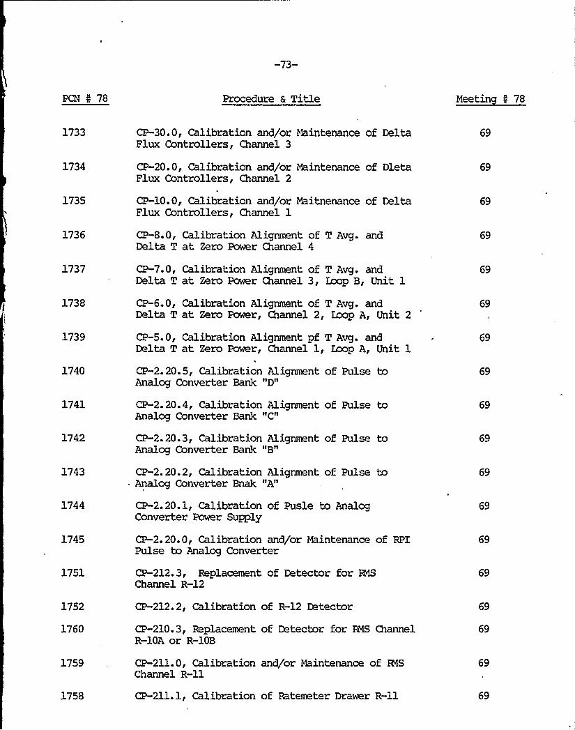
-73-
PCN I 78 Procedure 6 Title Meetin I 78
1733
1734
1735
1736
1737
1738
1739
1740
1741
1742
1743
1744
1745
1751
1752
1760
CP-30.0, Calibration and/or Maintenance of DeltaFlux Controllers, Channel 3
CP-20.0, Calibration and/or Maintenance of DletaFlux Controllers, Channel 2
CP-10.0, Calibration and/or Maitnenance of DeltaFlux Controllers, Channel 1
CP-8.0, Calibration Alignment of T Avg. andDelta T at Zero Power Channel 4
CP-7.0, Calibration Alignment of T Avg. andDelta T at Zero Power Channel 3, Zaop B, Unit 1
CP-6.0, Calibration Alignment of T Avg. andDelta T at Zero Power, Channel 2, Zaop A, Unit 2
CP-5.0, Calibration Alignment pf T Avg. andDelta T at Zero Power, Channel 1, Zaop A, Unit 1
CP-2.20.5, Calibration Alignment of Pulse toAnalog Converter Bank
CP-2.20.4, Calibration Alignment of Pulse toAnalog Converter Bank "C"
CP-2.20.3, Calibration Alignment of Pulse toAna1og Converter Bank "B"
CP-2.20.2, Calibration Alignment of Pulse toAnalog Converter Bnak "A"
CP-2.20.1, Calibration of Pusle to AnalogConverter Power Supply
CP-2.20.0, Calibration and/or Maintenance of RPIPulse to Analog Converter
CP-212.3, Replacement of Detector for BNSChannel R-12
CP-212.2, Calibration of R-12 Detector
CP-210.3, Replacement of Detector for RMS ChannelR-10A or R-10B
69
69
69
69
69
69
69
69
69
69
1759
1758
CP-211.0, Calibration and/or Maintenance of RESChannel R-llCP-211.1, Calibration of Ratemeter Drawer R-ll 69

-74-
PCN I 78 Procedure a Title Neetin I 78
1757
1756
CP-211.2, Calibration of R-11 Detector
CP-211.3, Replacement of Detector forR'%hannel.R-ll
69
69
1755 CP-211.4, Check of Flew Control Systen for R-lland R-12
69
1762 CP-210.1, Calibration of Bate Meter Drawer R-10Aor R-10B
69
1761
1779
1731
1753
1701
1905
1906
1907
2022
1788
1789
1790
1791
CP-210.2, Calibration of R-10A or R-10B Detectors
CP-36.1, N-36, General Defeat
CP-35.1, N-35, General Defeat
CP-212.1, Calibration of Batemeter Drawer R-12
Rl 76-17.3, Screen House Intake Heater Cable TrayRework
EM-207, Replacing Splices and Splice Sleevesfor Pressurizer Level and Pressure Channels
B4-208, Containment Recirculation Fan Splices
220209, YDV-852A and 852B Splices
9 IP-30, Visual Examination of Supports
CP-220.3, Replacement of Detector for R1SChannel R-20
CP-220.2, Calibration of R-20 Detector
CP-220.1, Calibration of Batemeter Drawer R-20
CP-220. 0, Calibration and/or Maintenance of EBSChannel R-20
69
69
69
71
71
71
71
72
72
72
72
72
1792
1793
1794
1795
CP-219.3, Replacement of Detector for RMS Channel-R-19
CP-219.2, Calibration of R-19 Detector
CP-219.1, Calibration of Batemeter Drawer R-19
CP.-219.0, CAlibration and/or Maintenance of MSChannel R-19
72
72
72
72
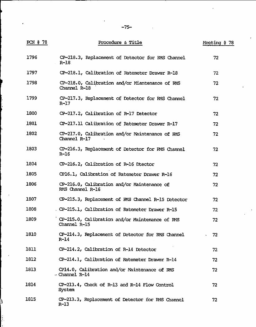
-75-
PCN 5 78 Procedure a Title Meetin N 78
1796
1797
1798
CP-218.3, Replacement of Detector for EHS ChannelR-18
CP-218.1, Calibration of Batemeter Drawer R-18
CP-218.0, Calibration and/or Miantenance of Et1SChannel R-18
72
72
72
1799
1800
1801
1802
CP-217.3, Replacement of Detector for EBS ChannelR-17
CP-217.2, Calibration of R-17 Detector
CP-217.11 Calibration of Ratemeter Drawer R-17
CP-217.0, Calibration and/or Maintenance of NSChannel R-17
72
72
72
72
1803
1804
1805
1806
CP-216.3, Replacement of Detector for RNS ChannelR-16
CP-216.2, Calibration of R-16 Dtector
CP16.1, Calibration of Batemeter Drawer R-16
CP-216.0, Calibration and/or Maintenance ofRMS Channel R-16
72
72
72
72
1807
1808
1809
1810
1811
1812
1813
1814
1815
CP-215.3, Replacement of RIS Channel R-15 Detector
CP-215.1, Calibration of Batemeter Drawer R-15
CP-215.0, Calibration and/or Maintenance of MSChannel R-15
CP-214.3, Replacement of Detector for R4S ChannelR-14
CP-214.2, Calibration of R-14 Detector
CP-214.1, Calibration of Ratemeter Drawer R-14
CP14.0, Calibration and/or Maintenance of %IS" Channel R-14
CP-213.4, Check of R-13 and R-14 Flow ControlSystem
CP-213.3, Replacement of Detector for RMS ChannelR-13
72
72
72
72
72
72
72
72
72

P
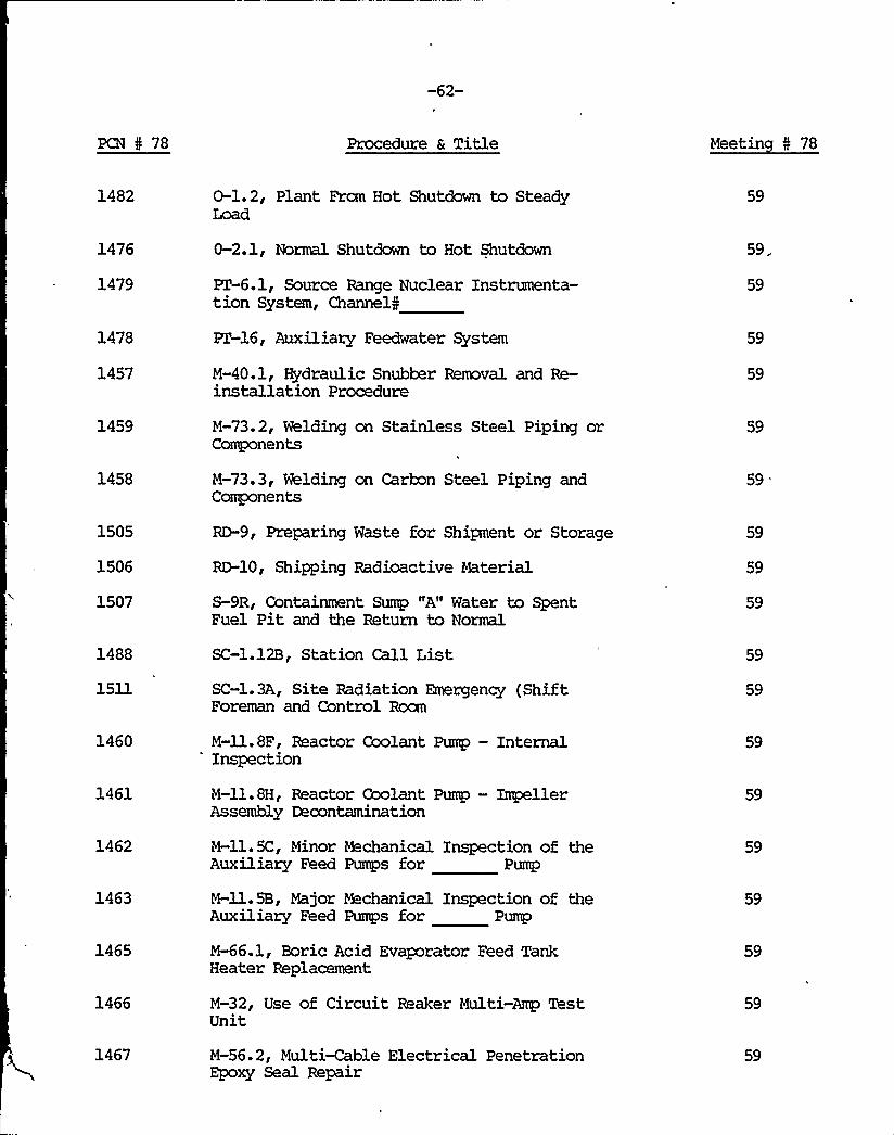
-62-
PCN 4 78 Procedure a Title Meetin I 78
1482
1476
1479
1478
1457
0-1.2, Plant From Hot Shutdown to SteadyLoad
0-2.1, Normal Shutdown to Hot Shutdown
PT-6.1, Source Range Nuclear Instrumenta-tion System, Channels
PZ-16, Auxiliary Feedwater System
M-40.1, Hydraulic Snubber Removal and Re-installation Procedure
59
59.-
59
59
59
1459
1458
1505
1506
1507
1488
1511
M-73.2, Welding on Stainless Steel Piping orComponents
M-73.3, Welding on Carbon Steel Piping andComponents
RD-9, Preparing Waste for Shipment or Storage
RD-10, Shipping Radioactive Material
S-9R, Containment Sump "A" Water to SpentFuel Pit and the Return to Normal
SC-1.12B, Station Call List
SC-1.3A, Site Radiation Emergency (ShiftForeman and Control Rocm
59
59
59
59
59
59
59
1460
1461
1462
1463
1465
1466
1467
M-ll.8F, Reactor Coolant Pump —InternalInspection
M-ll.8H, Reactor Coolant Pump — ImpellerAssembly Decontamination
M-ll.5C, Minor Mechanical Inspection of theAuxiliary Feed Pumps for Pump
M-ll.5B, Major Wchanical Inspection of theAuxiliary Feed Pumps for Pump
M-66.1, Boric Acid Evaporator Feed TankHeater Replacement
M-32, Use of Circuit Reaker Multi-Amp TestUnit
M-56.2, Multi-Cable Electrical PenetrationEpoxy Seal Repair
59
59
59
59
59
59
59

PCN I 78 Procedure a Title Meetin I 78
1468
1469
1470
1471
1474
M-51.2, D. C. Voltage Monitor Relays forSafeguard rains
M-71.1, Bistable 431B for Pressure ControllerPRV-431C Replacement
M-72.1, Replacement Primary Zoo RPDp
EM-154, Steam Generator, Handhole CoverGasket Leak Repair Using "Furmanite" Process
M-43.1.1, Steam Generator Insert RemovalSteam Generator
59
59
59
59
1472
1473
M-16.1, Service Water Discharge Header ForTurbine Building Isolation
M-43. 20A IIAI'team Generator Secondary SidePressure Test
59
59
1065 A-2. 1 ReFuel
~ f Re ce iving, Inventory and Sh ipn t fen o 59
1497CheckPL'-31, Safeguard Pump Bearing Temperature 59
1490 HP-7.4ments
, Calibration of Neutron Surve In tey s ru- 59
1352
1508
1509
1549
1562
1558
WC-3, Alkalinity Determination
SC-l. 7F , Emergency Radiation bhnitoringOff-Site Survey Team N9F
SC-1.7H , Emergency Radiation bbnitorinOff-Site Survey Team N9H
A-50.12, Emergency Plan Training Program
InstA-60.3, Calibration Surveillance Program f
trumentation/equipment of Safet Rel edram or
y at Components
FixPZ-13.1.0, Testing and/or Maintenan f th'd Fire Detection and Extinguishi
ceo e
System1ng
59
60
60
60
60
60
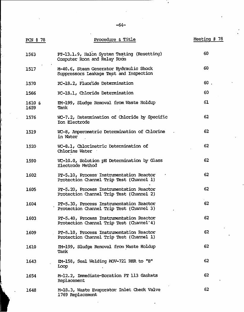
PCN I 78 Procedure 6 Title Meetin I 78
1563
1517
1570
1566
1610 61659
1576
1519
1520
1590
ET-13.1.9, Halon System Testing (Resetting)Computer Room and Relay Room
M-40. 6, Steam Generator Hydraulic ShockSuppressors Leakage Test and Inspection
EC-.18. 2, Fluoride Determination
PC-18.1, Chloride Determination
RI-199, Sludge Removal from Waste HoldupTank
NC-7.2, Determination of Chloride ky SpecificIon Electrode
WC-8, Amperometric Determination of Chlorinein Water
WC-8.1, Chlorimetric Determination ofChlorine Water
WC-10.0, Solution pH Determination ky GlassElectrode Method
60
60
60
60
61
62
62
62
62
1602
1605
1604
1603
1609
1610
ET-5.10, Process Instrumentation ReactorProtection Channel Trip Test (Channel 1)
ET-5. 20, Process Instrumentation ReactorProtection Channel'rip Test (Channel 2)
ET-5.30, Process Instrumentation ReactorProtection Channel Trip Test (Channel 3)
ET-5.40, Process Instrumentation ReactorProtection Channel Trip Test (Channel*4)
ET-5.10, Process Instrumentation ReactorProtection Channel Trip Xhst (Channel 1)
EM-199, Sludge Removal from Waste HoldupTank
62
62
62
62
1643
1654
1648
EM-158, Seal Welding MOV-721 RHR to "B"Loop
M-12. 2, Inmdiate-Boration ET 113 GasketsReplacement
M-18.3, Waste Evaporator Inlet Check Valve1769 Replacement
62
62
62

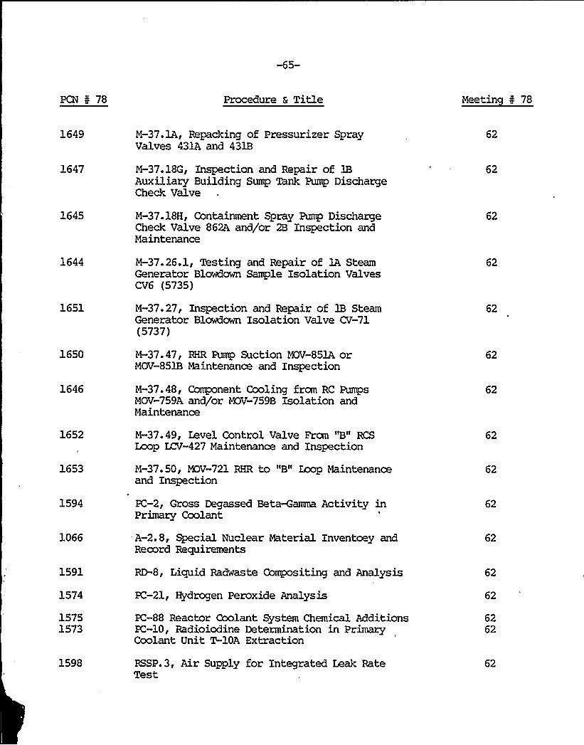
-65-
PCN 5 78 Procedure 6 Title Meetin 0 78
1649
1647
1645
M-37.1A, Repacking of Pressurizer SprayValves 431A and 431B
M-37.18G, Inspection and Repair of 1BAuxiliary Building Sump Tank Pump DischargeCheck Valve
M-37.18H, Containment Spray Pump DischargeCheck Valve 862A and/or 2B Inspection andMaintenance
62
62
1644
1651
1650
1646
M-37.26.1, Testing and Repair of 1A SteamGenerator Blowdown Sample Isolation ValvesCV6 (5735)
M-37.27, Inspection and Repair of 3B SteamGenerator Blowdown Isolation Valve CV-71(5737)
M-37.47, RHR Pump Suction MOV-851A orMOV-851B Maintenance and Inspection
M-37.48, Component Cooling from RC PumpsMOV-759A and/or MOV-759B Isolation andMaintenance
62
62
62
62
1652
1653
1594
1066
1591
1574
15751573
1598
M-37.49, Level Control Valve From "B" RCSLoop ZCV-427 Maintenance and Inspection
M-37.50, MOV-721 RHR to "B" Loop Maintenanceand Inspection
PC-2, Gross Degassed Beta-Gamma Activity inPrimary Coolant
A-2.8, Special Nuclear Materia1 Inventoey andRecord Requirements
RD-8, Liquid Radwaste Compositing and Analysis
PC-21, Hydrogen Peroxide Analysis
PC-88 Reactor Coolant System Chemical AdditionsXC-10, Radioiodine Determination in PrimaryCoolant Unit T-10A Extraction
RSSP.3, Air Supply for Integrated Leak RateTest
62
62
62
62
62
62
6262
62

-66-
PCN N 78 Procedure 6 Title Meetin N 78
1597
1592
1642
1513
1512
1608
1595
1607
1606
1572
1611
1577
1578
1596
1612
Hone
None
None
None
1695
RSSP-7.3, Reactor Trip logic Relays Drop OutT>i&s
PC-5, Gamma Isotopic Analysis of DegassedPrimary Coolant
RI-157, Repair of Piping Leak on the B. A.Concentrates Holding Tank Pump Discharge
KT-23.25, Containment Isolation Valve LeakRate Testing Purge Supply
Pl'-23.36, Containment Isolation Valve LeakRate Testing Purge Exhaust
HP-4.3, Work Permit Use
HP-12.2, Medical Check, Fitting and Trainingof Personnel Using Respirators
HP-12.5, Maintenance of Respirators
M-53.1, Containment Air Lodges Gasket Re-placement
0.4.1, equilibrium Indicated Axial FluxDifference Determination
0-6.11, Routeine Operations Check List
PC-18.3, Determination of Chloride by SpecificIon Electrode
PI'-2.2, Residual Heat removal System
A-l.l, Locked Radiation Areas
A30.3, Plant Procedure Content and FormatRequirements
GS-1.2, Ginna Station Security Event Report(2) 8/12/78 and 8/18/78
A-54. 4, Duty Engineer Responsibilities8/14/78
A-54.6, Health Physics Tour 8/148
0-6.7, Weekly Alarm Status Check 8/7/78
S-27.348A, Valve 348A, Isolation
62
62
62
62
62
62
62
62
62
62
62
62
62
62
62
65

-67-
PCN I 78 Procedure a Title Meet'in 5 78
1499
1699
1660
1661
1665
1698
1697
1696
1666
1690
PZ-13.1.10, Smoke Detector System Testing
A-30.3, Plant Procedure Content and FormatRetirements
E-l.l, Safety injection System Actuation
E-l.2, Loss of Coolant Accident
E-16.1, High Activity Radiation RonitoringSystem
PZ 6.3.1, Power Range Nuclear InstrumentationSystem, Channel 41
PT-6. 2, N.I.S. Intermediate Range Channels
PZ-6.3. 2, Power Range Nuclear Instrumentation.System Channel 42
M-ll.SB, Major bhchanical Inspection of theAuxiliary Feed Pumps
RF-52, Inspection Procedure for Exxon Nuclear FuelAssemblies at R. E. Ginna
66
66
66
1686
1691
1579
1580
1581
1978
1583
1584
SC-1.12B, Station Call List
HP-12.6, Issuance, Prayer Use and Return ofRespirators
, ET-23.44, Containment Isolation Valve LeakrateTesting Leakage/Test Depressurization
PT-23.45, Containment Isolation Valve LeakrateTesting Leakage Test/Instrumentation
PT-23.48, ll
Testing Deadweight Tester
PT-23. 49, ContainmentTesting Construction Fire Service Water
PT-23 50A ll ll ll ll
Testing Containment Post Accident Air Sample(Clean Int. Building)
PZ-23.50B, Containment Isolation Valve Leak rateTesting Containment Post Accident Air Sample(Controlled Int. Building)
66
66
66
66
66
66

-68-
PCN I 78 Procedure 6 Title Meetin I 78
1585
1586
1587
1588
1514
1515
1516
1551
1552
1553
1554
1555
PT-23. 50C, II If II
Testing Containnent Post Accident Air Salrple(Auxiliary Building)
PT-23 o 51A, If II I'I
Testing "A" Hydrogen Recombiner (Pilot and Main)
PT-23. 51B, If tl If II
Testing "B" Hydrogen Recombiner (Pilot and Main)
PZ 23 51CI If If II
Testing "A" and "B" Hydrogen Recombiner OxygenMakeup
PT 23 34 tf If It
Testing Depressurization at Power
PZ-23.33,Testing Service Air
ET-23. 32,Testing Instrument Air
PZ-23.43, II n If
Testing Leakage Test Supply Header
ET-23. 42, I'I II II
Testing Leakage Test Depressurization
PZ-23.40, Containment Isolation Valve LeakrateTesting Auxiliary Steam Supply and CondensateReturn
PZ-23.39, Containment Isolation Valve LeakrateTesting Demineralized Water
PT-23.46, Containment Isolation Valve LeakrateTesting Nitrogen to Accumulators
66
66
66
66
66
66
66
66
1556 PT-23.22, "Testing R. C. D. T. Discharge
1557 pg 23 23 If II II II
Testing Sump "A"66
1617
1618
PT-22, Containment
PT-22. 1, Hquipnent
Penetration Leakrate Testing
Hatch Door Seal Leakrate Test 66

-69-
PCN O 78 Procedure a Title Meetin I 78
1619
1620
PZ-22.2, Personnel Hatch Door Seal Leakrate Test
PZ-22.3, Persnel Hatch Between Door VolumeLeakrate Test
66
1621 ~22.4, shipment Hatch Between Door VolumeLeakrate Test
66
1622
1623
1624
1625
PZ-'22.5, Personnel Hatch Canopy Leakrate Test
PZ-22. 6, equipment Hatch
PZ 22.7, Hcpipment Hatch 0-Ring
PZ-22. 8t Mechanical Manifold "A"
66
66
66
1626
1627
1628
,1629
1630
1631
1632
ET-22. 9,
ET-22.10,
PZ-22.11,
PZ-22.12,
PT-22.13,
PT-22.14,
PT-22.15,
II IIBtt II
IICII II
ItEII ft
IIFII ll
IIQII II
IIHI'I II
II1 tl If
66
66
66
66
1633
1634
1635
1636
PT-22.16, Mechanical Manifold "J" Leakrate Test
'Z-22.17, II tfKfl It II
PZ-22.18 Electrical Manifold IX, Leakrate Test
PT-22.19, II II Ngl It If
66
66
66
1637 PZ-22.20, Illl tl 'I 66
1638
1639
1640
1673
1672
PT-22. 21, Mechanical Manifold "L" Leakrate Test
PZ22..22, Fuel Transfer Flange Leakrate Test
PZ-23, Containment Isolation Valve Leakrate Testing
M-73.3, Welding on Carbon Steel Piping or Components
M-73.2, Welding on Stainless Steel Piping orComponents
66
66
66
66
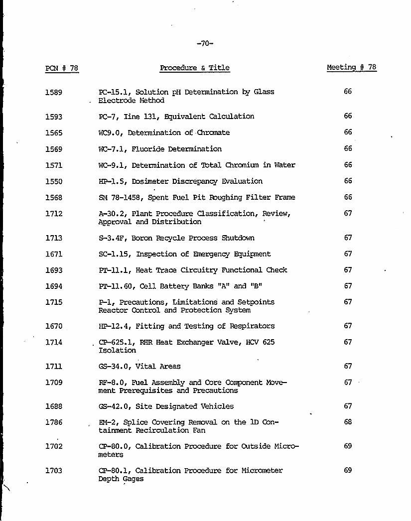
PCN 0 78
-70-
Procedure a Title Meetin I 78
1589
1593
1565
1569
1571
1550
1568
1712
1713
1671
1693
1694
1715
1670
1714
PC-15. 1 , Solution pH Determination ~ GlElectrode Method
ion ass
PC-7, Iine 131, equivalentCalculat'C9.
.0, Determination of Chromate
NC-7.1, Fluoride Determination
WC-9.1, Determination of Total Chromium in Water
HP-l. 5.5, Dosimeter Discrepancy Evaluation
RI 78-1458 nt, Spe Fuel Pat Roughing Filter Frame0
A-30.2, Plant Procedure Clas f''pprovaland Distribution
S-3.4F Bo, Boron Recycle Process Shutdown
SC-1.15, In ct'pe ion of Emergency Ekpipment
PT-ll.l, Heat Traceace Circuitry Functional Check
PZ-ll. 60, Cell Battery Banks "A" and "B"
imitations and SetpointsP-l, PrecautionsL'acr Control and Protection System
HP-12.4, Fitti'ng and Testing of Respirators
Heat Exchanger Valve, HCV 625
66
66
67
67
67
67
1711
1709
1688
1786
1702
1703
GS-34.0, Vital Areas
RF-S.O, Fuel Assembly and Core Co nentment Prerequisites and Prean Precautions
GS-42.0, Site Designated Vehicles
EM-2 1'
Sp ice Covering Removal on the lDtainment Recirculation Fan
e Con-
CP-80.0Cal'eters
ibratxon Procedure for Outs'dr i e Micro-
'on Procedure for MicrometerCP-80.1, Calibration
67
67
67
69

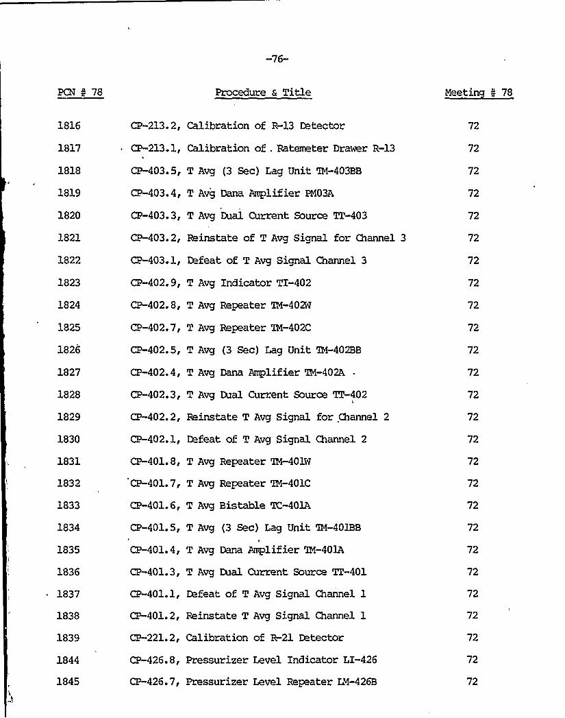
PCN 5 78 Procedure a Title Meetin 4 78
1816
1817
1818
1819
1820
1821
1822
1823
1824
1825
1826
1827
1828
1829
1830
1831
1832
1833
CP-213.2, Calibration of R-13 Detector
CP-213.1, Calibration of . Ratemeter Drawer R-13
CP-403.5, T Avg (3 Sec) Lag Unit IN-403BB
CP-403.4, T Avg Dana Amplifier PN03A
CP-403.3, T Avg Dual Current Source TT-403
CP-403.2, Reinstate of T Avg Signal for Channel 3
CP-403.1, Defeat of T Avg Signal Channel 3
CP-402.9, T Avg Indicator TI-402
CP-402.8, T Avg Repeater 'IN-402W
CP-402.7, T Avg Repeater 'IN-402C
CP-402.5, T Avg (3 Sec) Lag Unit 'IN-402BB
CP-402.4, T Avg Dana Amplifier IN-402A-
CP-402.3, T Avg Dual Current Source TT-402
CP-402.2, Reinstate T Avg Signal for Channel 2
CP-402.1, Defeat of T Avg Signal Channel 2
CP-401.8, T Avg Repeater IN-401W
CP-401.7, T Avg Repeater 'IN-401C
CP-401.6, T Avg Bistable TC-401A
72
72
72
72
72
72
72
72
72
72
72
72
72
72
72
1834
1835
CP-401. 5,
CP-401.4,
T Avg (3 Sec) Lag Unit 'IN-401BB
T Avg Dana Amplifier 'IN-401A
72
72
1836
1837
1838
1839
1844
1845
CP-401.3, T Avg Dual Current Source TZ-401
CP-401.1, Defeat of T Avg Signal Channel 1
CP-401.2, Reinstate T Avg Signal Channel 1
CP-221.2, Calibration of R-21 Detector
CP-426.8, Pressurizer Level Indicator LI-426
CP-426.7, Pressurizer Level Repeater LN-426B
72
72
72
72

-77-
PCN I 78 Procedure 6 Title Meetin 4 78
1846
1847
1848
1849
1850
1851
CP-426.6, Pressurizer Level Repeater LM-426A
CP-426.5,'ressurizer Level Bistable LC-426A/B
CP-426.4, Pressurizer Level Power Supply LQ-426
CP-426.2, General Reinstate 426 Pressurizer Level
CP-426.1, General Defeat Procedure 426 PressurizerLevel
CP-426.0, Calibration and/or Maintenance of 426Pressurizer Level Channel
72
72
72
72
72
72
1852
1853
1854
1855
1856
1857
1858
1859
1860
1861
1862
1863
1864
1865
CP-416.7, Reactor Coolant Flow Indicator FI416
CP-416.6, Reactor Coolant Flow Repeater FM-416
CP-416.5, Reactor Coolant Flow Bistable FC-416
CP-416.4, Reactor Coolant Flow Power SupplyFQ-416
CP-416.2, General Reinstate Procedure of ReactorCoolant Flow Channel 416
CP-416.1, General Defeat Procedure of ReactorCoolant Flow Channel 416
CP-416.0, Calibration and/or Maintenance ofReactor Coolant Flow Channel 416
CP-415.7, Reactor Coolant FLow Indicator FI-415
CP-415.6, Reactor Coolant Flow Repeater B4-415
CP-415.5, Reactor Coolant Flow Bistable EC-415
CP-415.4, Reactor Coolant FLow Power SupplyFQ15
CP-415. 2, General Reinstate Procedure for ReactorCoolant Flow Channel 415
CP-415.1, General Defeat Procedure of ReactorCoolant Flow Channel 415
CP-415.0, Calibration and/or Maintenance ofReactor Coolant Flow Channel 415
72
72
72
72
72
72
72
72
72
72
72
72
72
72

-78-
PCN N 78 Procedure a Title Meetin 5 78
1866
1867
CP-414.6, Reactor Coolant Flow Repeater Fill-414
CP-414.5 Reactor Coolant Bistable Flow FC-414
72
72
1868
1869
CP-414.4, Reactor Coolant Flow Power. SupplyFQ14
CP-414.2, General Reinstate Procedure of ReactorCoolant Flow Channel 414
72
72
1870
1871
CP-414.1, General Defeat Procedure of ReactorCoolant Flow Channel 414
CP-414.0, Calibration and/or Maintenance ofReactor Coolant Flow Channel 414
72
72
1872
1873
1874
1875
1876
CP-413.7, Reactor Coolant Flow Indicator FI-413
CP-413. 6, Reactor Coolant Flow Repeater Fill-413
CP-413.5, Reactor Coolant Flow Bistable PC-413
CP-413.4, Reactor Coolant Flow Polar SupplyFQ13
CP-413.2, General Reinstate Procedure ReactorCoolant FLow Channel 413
72
72
72
72
72
1877 CP-413. 1, General Defeat Procedure ReactorCoolant Flow Channel 413
72
1878 CP-413.0, Calibration and/or Maintenance ofReactor Coolant Flow Channel 413
72
1879
1880
1881
1882
1883
CP-412.7, Reactor Coolant FLow Indicator FI-412
CP-412.6, Reactor Coolant Flow Repeater EH-412
CP-412.5, Reactor Coolant Flow Bistable EC-412
CP-412.4, Reactor Coolant Flow Power SupplyFQ-412
CP-412.2, General Reinstate Procedure ReactorCoolant Flow Channel 412
72
72
72
72
72
1884
1885
CP-412.1, General Defeat Procedure Reactor CoolantFlow Channel 412
CP-412.0, Calibration and/or Maintenance of ReactorCoolant Flow Channel 412
72
72

-79-
PCN 5 78 Procedure a Title Meetin N 78
1886
1887
1888
1889
1890
CP-411.7, Reactor Coolant Flow Indicator FI-411
CP-411. 6, Reactor Coolant Flow Repeater ETC-411
CP-411.5, Reactor Coolant Bistable EC-411
CP-411.4, Reactor Coolant Flow Power SupplyFQ-411
CP-411. 2, General Reinstate Procedure of ReactorCoolant Flow Channel 411
72
72
72
72
72
1891
1892
1893
1894
1895
1896
1897
1898
1899
1900
1901
1902
1903
1904
1909
1910
1911
CP-411.1, General Defeat Procedure of ReactorCoolant Flow Channel 411
CP-411. 0, Calibration and/or Maintenance ofReactor Coolant Flow Channel 411
CP-406.10.1, Defeat of Dleta T Setpoint 1 Channel 2
CP-404.9, T Avg Indicator TI-404
CP-404.8, T Avg Repeater 1H-404W
CP-404.7, T Avg Repeater TM 404C
CP-404.5, T Avg (3 Sec) Lag Unit KM-404BB
CP-404.4, T Avg Dana Amplifier 'IR-404A
CP-404.3, T Avg Dual Current Source TZ-404
CP-404.2, Reinstate of T Avg Signal forChannel 4
CP-404.1, Defeat of T Avg Signal Channel 4
CP-403.8, T Avg Repeater 'BI-403W
CP-403.7, T Avg Repeater XK-403C
CP-403.6, T Avg Bistable XC-403A
CP-463.7, Steam Generator Level Repeater LM-463B
CP-463.6, Steam Generator Level Bistable LC-463E
CP-463.5, Steam Generator Level BistableLC-463C/D
72
72
72
72
72
72
72
72
72
72
72
72
72
72
72
72
72
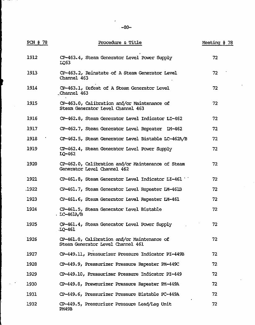
-80-
PCN N 78 Procedure & Title Meetin N 78
1912
1913
CP-463.4, Steam Generator Level Pomr SupplyLQ63
CP-463.2, Reinstate of A Steam Generator LevelChannel 463
72
72
1914
1915
1916
1917
1918
1919
1920
CP-463.1, Defeat of A Steam Generator Level..Channel 463
CP-463.0, Calibration and/or Maintenance ofSteam Generator Level Channel 463
CP-462.8, Steam Generator Level Indicator LI-462
CP-462.7, Steam Generator Level Repeater EM-462
CP-462.5, Steam Generator Level Bistable LC-462A/B
CP-462.4, Steam Generator Level Power Supply~462CP-462.0, Calibration and/or Maintenance of SteamGenerator Level Channel 462
72
72
72
72
72
72
72
1921
.1922
1923
1924
1925
1926
1927
1928
1929
1930
1931
1932
CP-461.8, Steam Generator Level Indicator LI-461
'P-461.7,Steam Generator Level Repeater ZZ-461B
CP-461.6, Steam Generator Level Repeater LM-461
CP-461.5, Steam Generator Level BistableLC-461A/B
CP-461.4, Steam Generator Level Power Supply,LQ-461
CP-461.0, Calibration and/or Maintenance ofSteam Generator Level Channel 461
CP-449.11, Pressurizer Pressure Indicator PI-449B
CP-449. 9, Pressurizer Pressure Repeater PM-449C
CP-449.10, Pressurizer Pressure Indicator PI-449
CP-449.8, Prewsurizer Pressure Repeater EM-449A
CP-449.6, Pressurizer Pressure Bistable PC-449A
CP-449.5, Pressurizer Pressure Lead/Lag UnitPM49B
72
72
72
72
72
72
72
72
72
72
72
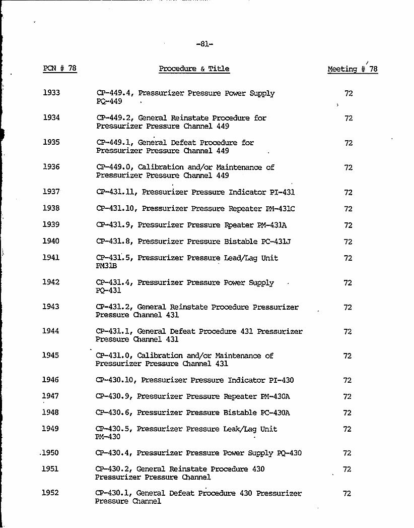
-81-
PCN N 78 Procedure a Titlei
Meetin N 78
1933 CP-449.4, Pressurizer Pressure Power SupplyP~449
72
1934 CP-449. 2, General Reinstate Procedure forPressurizer Pressure Channel 449
72
1935 CP-449.1, General Defeat Procedure forPressurizer Pressure Channel 449
72
1936 CP-449.0, Calibration and/or Maintenance ofPressurizer Pressure Channel 449
72
1937
1938
1939
1940
CP-431.11, Pressurizer Pressure Indicator PI-431
CP-431.10, Pressurizer Pressure Repeater P4-431C
CP-431.9, Pressurizer Pressure Rpeater PM-431A
CP-431.8, Pressurizer Pressure Bistable PC-431J
72
72
72
72
1941 CP-431. 5, Pressurizer Pressure Lead/Lag UnitPM31B
72
1942 CP-431. 4, Pressurizer Pressure Power Supplyrg-431
72
1943 CP-431. 2, General Reinstate Procedure PressurizerPressure Channel 431
72
1944 CP-431.1, General Defeat Procedure 431 PressurizerPressure Channel 431
72
1945 CP-431.0, Calibration and/or Maintenance ofPressurizer Pressure Channel 431
72
1946
1947
1948
CP-430.10, Pressurizer Pressure Indicator PI-430
CP-430.9, Pressurizer Pressure Repeater PM-430A
CP-430.6, Pressurizer Pressure Bistable PC-430A
72
72
72
1949 CP-430.5, Pressurizer Pressure Leak/Zag UnitPM-430
72
.1950 CP-430. 4, Pressurizer Pressure Power Supply PQ-430 72
1951 CP-430.2, General Reinstate Procedure 430Pressurizer Pressure Channel
72
1952 CP-430.1, General Defeat Procedure 430 PressurizerPressure Channel
72

-82-
PCN N 78 Procedure & Title Meetin 5 78
1953 CP-430.0, Calibration and/or Maintenance of 430Pressurizer Pressure cannel
72
1954
1955
1956
1957
1958
CP-429.9, Pressurizer Pressure Bistable PC-429E
CP-429.6, Pressurizer Pressure Bistable PC-429A
CP-429.5, Pressurizer Pressure Lead/Lag PM-429B
CP-429.4, Pressurizer Pressure Power Supply
CP-429. 0 Caiibration and/or Maintenance ofPressurizer Pressure Channel 429
72
72
72
72
72
1959 CP-428.0, Calibration and/or Maintenance of Pressurizer 72Pressure Channel 428
1960
1961
1962
1963
1964
1965
1966
1967
1968
1969
CP-427. 7, Pressurizer Level Indicator LI-427
CP-427. 6, Pressurizer Level Bistable LC-427A/C
CP-427.5, Pressurizer Level Bistable LC-427A/C
CP-427.4, Pressurizer Level Power Supply ZQ-427
CP-427.0, Calibration and/or Maitnenance ofPressurizer Level Channel 427
CP-427.1, Defeat of 427 Pressurizer Level
CP-427.2, Reinstate 427 Pressurizer Level
CP-428.1, Defeat of 428 Pressurizer Level
CP-428.2, Reinstate 428 Pressurizer Level
CP-429. 2, General Reinstate Procedure ofPressurizer Pressure Channel 429
72
72
72
72
72
72
72
72
72
72
1970 CP-429.1, General Defeat Procedure ofPressurizer Pressure Channel 429
72
1987
1988
1989
1990
CP-466.4, Feedwater Flow Power Supply FQ-466
CP-466.2, Reinstate of A Feedwater Flow Channel 466
CP-466.1, Defeat of A Feedwater Flow Channel 466
CP-466.0, Calibration and/or Maintenance of FeedwaterFlow Channel 466
72
72
72
72

-83-
PCN 5 78 Procedure a Title Meetin N 78
1991
1992
1993
1995
1996
1997
1998
1999
2000
2001
2002
2003
2004
2005
2006
2007
2008
2009
2010
1982
1984
1985
1840
CP-465.11, Steam Flow Recorder FR-465
CP-465.10, Steam Flow Indicator FI-465
CP-465.9, Steam Flow Repeater PR-465D
CP-465.8, Steam Flow Repeater ER-465C
CP-465.7, Steam Flow Square Root Extractor PR-465B
CP-465.6, Steam Flow Multiplier/Divider FM-465A
CP-465.5, Steam Flow Bistable FC-465A
CP-465.4, Steam Flow Power Supply FQ-465
CP-465.2, Reinstate of A Steam Flow Channel 465
CP-465.1, Defeat of A Steam Flow Channe; 465
CP-464. 9, Steam Flow Repeater FN-464D
CP-464.8, Steam Flow Repeater EN-464C
CP-464.7, Steam Flow Square Root ExtractprFM-464B
CP-464. 5, Steam Flow Bistable FC-464A
CP-464.4, Steam Flow Power Supply FQ-464
~ CP-464.2, Reinstate 'of A Steam Flow Channel 464
CP-464.1, Defeat of A Steam Flow Channel 464
CP-463.8, Steam Generator Level Indicator LI0463
CP-466.5, Feedwater Flow Square Root ExtractorFM-466A
PZ-28, Control Room Air Handling Unit EfficiencyTest of HEPA and Charcoal Filter Banks in theAccident Axle
PT-29.1, Auxiliary Building HEPA and CharcoalFilter Efficiency 'I@st
ET-29.2, Controlled Access HEPA and Charcoal FilterEfficiency 'Ihst
PC-7, Iodine 131 Calculation
72
72
72
72
72
72
72
72
72
72
72
72
72
72
72
72
72
72
72
72
72
72
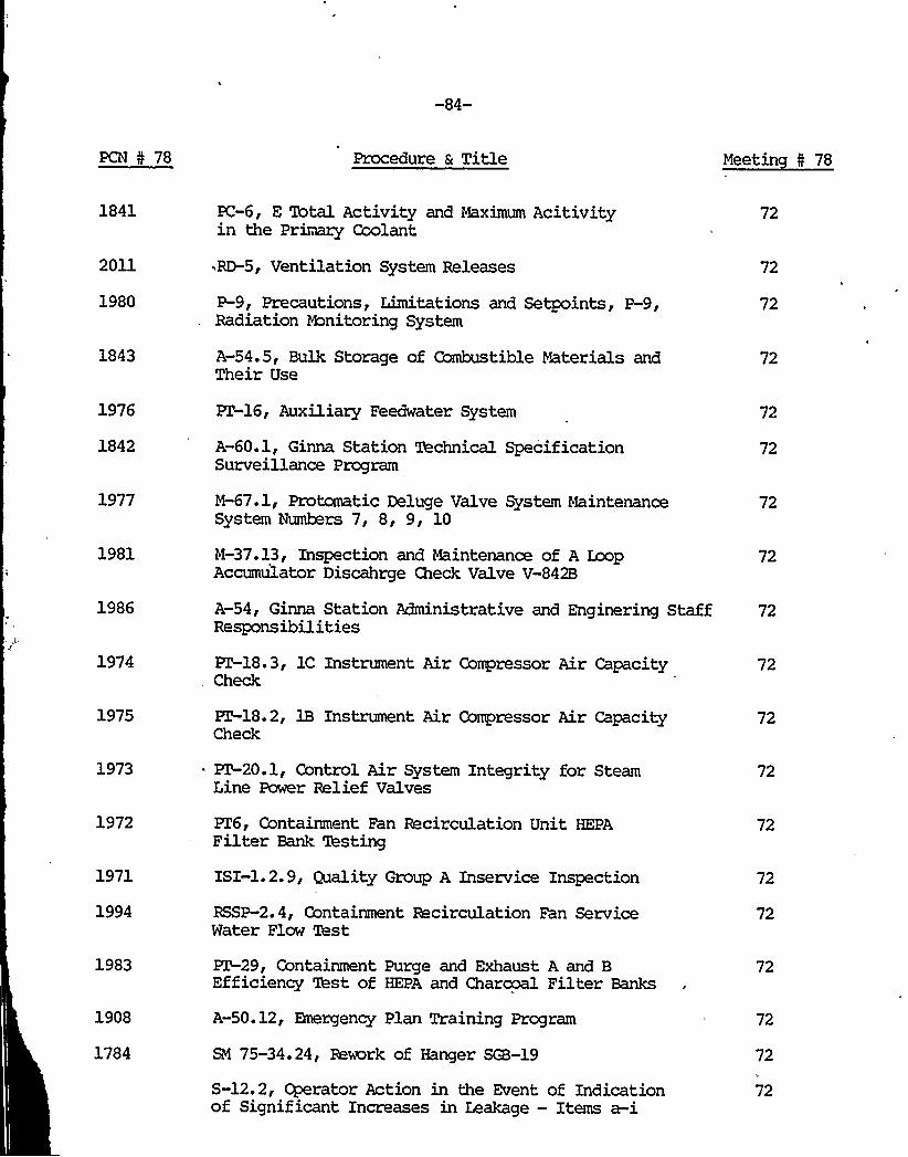
-84-
PCN N 78 Procedure 6 Title Meetin N 78
1841
2011
1980
1843
PC-6, E Total Activity and Maximum Acitivityin the Primary Coolant
RD-5, Ventilation System Releases
P 9g Precautions, Limitations and Setpoints, P-9gRadiation Honitoring System
A-54.5, Bulk Storage of Ccanbustible Materials andTheir Use
72
72
72
72
1976
1842
1977
1981
FT-16, Auxiliary Feedwater System
A-60.1, Ginna Station Technical SpecificationSurveillance Program
M-67.1, Protomatic Deluge Valve System MaintenanceSystem Numbers 7, 8, 9, 10
M-37.13, Inspection and Maintenance of A loopAccumulator Discahrge Check Valve V-842B
72
72
72
72
1986 A-54, Ginna Station Administrative and Enginering Staff 72Responsibilities
1974 PT-18.3, 1C Instrument Air Gompressor Air CapacityCheck
72
1975
1973
1972
1971
1994
1983
1908
1784
~18.2, 1B Instrument Air Gompressor Air CapacityCheck
PT-20.1, Control Air System Integrity for SteamLine Power Relief Valves
PZ6, Containment Fan Recirculation Unit HEPAFilter Bank 'lbsting
ISI-1.2.9, Quality Group A Inservice Inspection
RSSP-2. 4, Containment Recirculation Fan ServiceMater Flow Test
XT-29, Containment Purge and Exhaust A and BEfficiency Xhst of HEPA and Charcoal Filter Banks
A-50.12, Emergency Plan Training Program
SM 75-34.24, Rework of Hanger SGB-19
S-12.2, Operator Action in the Event of Indicationof Significant Increases in Leakage — Items a-i
72
72
72
72
72
72
72
72
72

-85-
PC@ 4 78 Procedure & Title Meetin N 78
2039
2040
2019
2014
2015
2016
2017
2018
2020
2038
A-20, Control Room Logs
A-3, Containment Access
SC-1.12C, Specialized Call List
SC-l, Radiation Emergency Plan
SC-l. 7E, Emergency Radiation monitoring On-SiteSurvey Team 59E
SC-1.7G, Emergency Radiation monitoring On-SiteSurvey Team 59G
SC-1.3B, Site Radiation Emergency (EmergencyCoordinator and Survey Center Assignees)
SC-1.15, Inspection of Bnergency equipment
SC-l. 11A, Immediate Re-entry
CP-429. 2, General Reinstate Procedures ofPressurizer Pressure Channel 429
73
73
73
73
73
73
73
73
73
73
2024 CP-430.1, General Defeat Procedure 430Pressurizer Pressure Channel
73
2026
2027
CP-429.1, General Defeat Procedure ofPressurizer Pressure Channel 429
CP-429.2, General Reinstate Procedure ofPressurizer Pressure Channel 429
73
73
2028
2029
CP-449.1, General Defeat Procedure forPressurizer Pressure Channel 449
CP-449.2, General Reinstate Procedure forPressurizer Pressure Channel 449
73
73
2030
2031
CP-431.1, General Defeat Procedure 431Pressurizer Pressure Channel
CP-431. 2, General Reinstate Procedure PressurizerChannel 431
73
73
2043
2042
2044 .
HP-12.1, Usage of Respirators
HP-12.4, Fitting and Testing of Respirators
HP-12.2, Medical Check Fitting and Training ofPersonnel Using Respirators
73
73
73
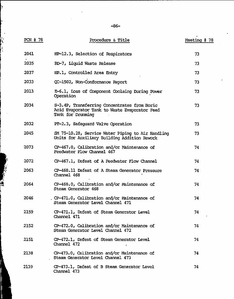
-86-
PCN I 78 Procedure 6 Title Meetin 5 78
2041
2035
2037
2033
2013
2034
2032
2045
2073
HP-12.3, Selection of Respirators
RD-7, Liquid Waste Release
HP.1, Controlled Area Entry
QC-1502, Non-Conformance Report
E-6.1, Loss of Component Coolaing During PowerOperation
S-3.4P, Transferring Concentrates frcm BoricAcid Evaporator Tank to Waste Evaporator FeedTank for Dnzraning
PT-2. 3, Safeguard Valve Operation
SN 75-10.28, Service Water Piping to Air HandlingUnits for Auxiliary Building Addition Remrk
CP-467.0, Calibration and/or Maintenance ofFeedwater Flow Channel 467
73
73
73
73
73
73
73
73
74
2072
2063
2064
CP-467.1, Defeat of A Feedwater Flow Channel
CP-468.11 Defeat of A Steam Generator PressureChannel 468
CP-468.0, Calibration and/or Maintenance ofSteam Generator 468
74
74
74
2046 CP-471. 0, Calibration and/or Maintenance ofSteam Generator Level Channel 471
74
2159
2152
2151
2138
2139
CP-471.1, Defeat of Steam Generator LevelChannel 471
CP-472.0, Calibration and/or Maintenance ofSteam Generator Level Channel 472
CP-472.1, Defeat of Steam Generator LevelChannel 472
CP-473.0, Calibration and/or Maintenance ofSteam Generator Level Channel 473
CP-473.1, Defeat of B Steam Generator LevelChannel 473
74
74
74
74
74


-87-
PCN I 78 Procedure a Title Meetin I 78
2133
2124
2113
CP-474.1, Defeat of B Steam Flow Channel 474
CP-475.0, Calibration and/or Maintenance of SteamFlow Channel 475
CP-476.0, Calibration and/or Maintenance of BFeedwater Flow Channel 476
74
74
74
2112 CP-477.0, Calibration and/or Maintenance ofFeedwater Flow Channel 477
2103
2123
CP-477.1, D feat of B Feedwater Flow Channel 4
CP-475.1, General Defeat Procedure Steam FlowChannel 475
74
74
2055
2091
2162
2161
2084
2168
2163
2164
2165
2077
2166
2086
2087
2088
2089
2167
CP-469.1, Defeat of A Steam Generator PressureChannel 469
S-1BB Shutdown of Rx3 Drive Motor Generator Sets
HP-12.6, Issuance, Proper Use and Return ofRespirators
HP.3, Work Permit Use
ISI-4.1.6, High Energy Inservice Inspection
QC-1701, Quality Assurance Records
E-1.2, Zass of Coolant Accident
E-1.3, Steam Line Break Accident
E-1. 4, Steam Generator Tube Rupture Accident
SC-1.12B, Station Call List
ET-6.1, Source Range Nuclear InstrumentationSystem
PT-2.3, Safeguard Valve Operation
PZ-2.4, Gold/Refueling MOV's Surveillance
PZ-2.5, AOV's Quarterly Surveillance
PZ-2.6, Gold/Refueling AOV's Surveillance
ET-30, Containment Spray Nozzle Check of A & BRings
74
74
74
74
74
74
74
74
74
74
74
74
74
74
74

-88-
PCN 5 78 Procedure & Title Meetin N 78
2090
2048
PZ-16.1, Auxiliary Feedwater System Flow Balance
EM-. 210, Auxiliary Building Main Crane Replacementof Driver Axle
74
74
2180
2160
2083
2190
2191
2192
RI-211, Replacing Splices and Splice Sleeves forPressurizer Level and Pressure Channels
S-3A, Startup of Rxl Drive Wtor Generator Sets
EN-190, Repair of Auxiliary Feedwater Hanger,FNH-39
M-40.4, Visual Leakage Inspection of High EnergyPiping
E-4.1, Safeguard Buses Low Voltage Condition
E-9, ?leakage Into the Component Cooling Loop
E-23.2, Malfunction of N2 Reactor Coolant PumpSeal
74
74
74
74
76
2193 E-23.3, Malfunction of N3 Reactor Coolant PumpSeal
2194
2195
2196
2197
2198
2188
2021
2187
2185
E-23.4, Zass of Reactor Coolant Pump SealInjection Supply
E-26.1, Erergency Shutdown Resulting from aReactor Trip from 8.5% Power or Less
E-26.2, Emergency Shutdown Resulting from aReactor Trip When Between 50% and 8.5% Power
E-31, Automatic Turbine Load Runback
E-36, orator Actions to be Taken in the Eventof Alarm Conditions on the Turbine Vibration Instruments
M-40.6, Steam Generator Hydraulic Shock SuppressorsLeakage Test and Inspection
SC-1.12A, Immediate Call List
S-15.3, Incore Wvable Detector Alignment
A-54.3, Cpen Flame, Welding and Grinding Permit
76
76
76
76
76
76
76
76
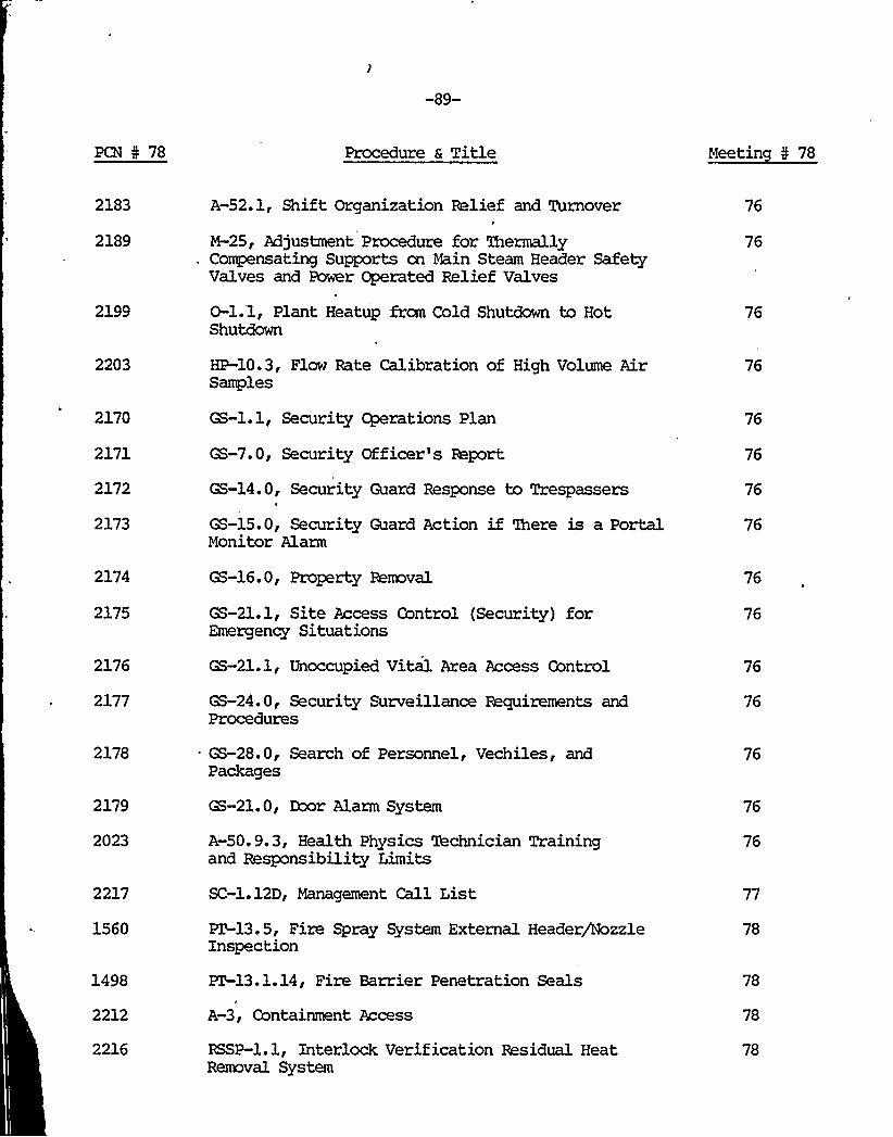
-89-
PCN 4 78 Procedure a Title Meetin 5 78
2183
2189
2199
A-52.1, Shift Organization Relief and Turnover
M-25, Adjustment Procedure for thermallyCompensating Supports cn Main Steam Header SafetyValves and Power Operated Relief Valves
O-l.l, Plant Heatup from Cold Shutdown to HotShutdown
76
76
2203
2170
2171
2172
2173
HP-10.3, Flow Rate Calibration of High Volume AirSamples
GS-l.l, Security Cgerations Plan
GS-7.0, Security Officer's Report
GS-14.0, Security Guard Response to Trespassers
GS-15.0, Security Guard Action if There is a PortalMonitor Alarm
76
76
2174
2175
2176
2177
2178
2179
2023
2217
1560
1498
2212
2216
GS-16.0, Property Removal
GS-21.1, Site Access Control (Security) forEmergency Situations
GS-21.1, Unoccupied Vital Area Access Control
GS-24. 0, Security Surveillance Requirements andProcedures
GS-28.0, Search of Personnel, Vechiles, andPackages
GS-21. 0, Door Alarm System
A-50.9.3, Health Physics Technician Trainingand Responsibility Limits
SC-1.12D, Management Call List
XT-13. 5, Fire Spray System External Header/NozzleInspection
PT-13.1.14, Fire Barrier Penetration Seals
A-3, Containment Access
RSSP-l. 1, Interlock Verification Residual HeatRemoval System
76
76
76
76
76
76
76
77
78
,78
78
78
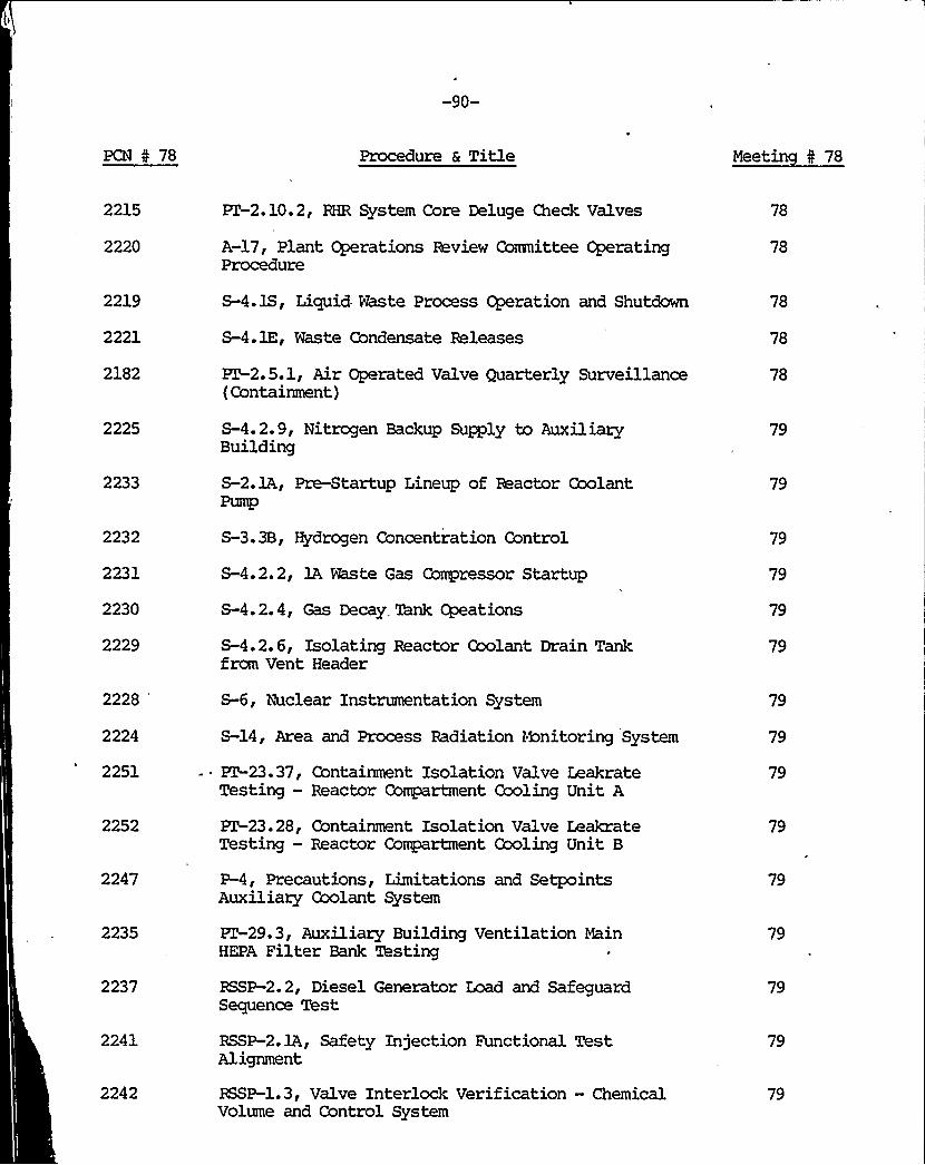
-90-
PCN I 78 Procedure & Title Meetin I 78
2215
2220
ET-2.10.2, RHR System Core Deluge Check Valves
A-17, Plant Operations Review Committee OperatingProcedure
78
78
2219
2221
2182
2225
2233
2232
2231
2230
2229
S-4.1S, Lictuid Waste Process Operation and Shutdown
S-4. 1E, Waste Condensate Releases
PT-2.5.1, Air Operated Valve Quarterly Surveillance(Containment)
S-4.2.9, Nitrogen Backup Supply to AuxiliaryBuilding
S-2. 1A, Pre-Startup Lineup of Reactor CoolantPump
S-3. 3B, Hydrogen Concentration Control
S-4.2.2, 1A Waste Gas Compressor Startup
S-4.2.4, Gas Decay. Tank Opeations
S-4.2.6, Isolating Reactor Coolant Drain Tankfrom Vent Header
78
78
78
79
79
79
79
79
79
2228
'224
2251
2252
2247
2235
2237
2241
2242
S-6, Nuclear Instrumentation System
S-14, Area and Process Radiation Monitoring System
- ~ KT-23.37, Containment Isolation Valve LeakrateTesting —Reactor Compartment Cooling Unit A
PT-23.28, Containment Isolation Valve LeakrateTesting —Reactor Compartment Cooling Unit B
P-4, Precautions, Limitations and SetpointsAuxiliary Coolant System
PZ-29.3, Auxiliary Building Ventilation MainHEPA Filter Bank 'lhsting
RSSP-2. 2, Diesel Generator Load and SafeguardSequence Test
RSSP-2.1A, Safety Injection Functional TestAlignment
RSSP-1. 3, Valve Interlock Verification —ChemicalVolume and Control System
79
79
79
79
79
79
79
79
79

-91-
PCN 5 78 Procedure s Title Meetin 5 78
2261 EM-190, Repair of Auxiliary Feedwater Hanger,FNH-39
79
2262
2263
2264
2265
2269
2254
EM-206, Spl-ice Covering Removal on the 1DContainment Recirculation Fan
EM-207, Replacing Splices and Splice Sleeves forPressure Level and Pressure Channels
EM-208, Containment Recirculation Fan Splices
EM-209, MOV-852A and 952B Splices
HP-8.4, RAdioactive Source Inventory
S-15. 2, Flux Mapping Emergency and CalibrationProcedure
79
79
79
79
79
79
2250
2255
2256
2257
2259
2260
2249
2248
2270
2271
2244
2245
2234
2236
PZ-31, Safeguard Pump Bearing Temperature Check
PZ-2.1, Safety Injection System Pumps
~2. 2, Residual Heat Reaaval System
PT-2.7, Service Water System
PT-3, Containment Spray Pumps and NaOH Additive.System
PT-16, Auxiliary Feedwater System
. A-60.3, Calibration Surveillance Program forInstrumentatio@+uipnent of Safety Related Components
M-45. 4, Safeguard Motors Inspection
HP-12.6, Issuance Proper Use and Return ofRespirators
SM 75-7.25, HVAC Backfits Rework
RF-2, Reactor Refueling .Outage Cgerations andActivities
SC-1.12B, Station Call List
A-54.6, Health Physics Tour
ET 9, Undervoltage and Underfrequency Protection11A and 11B 4160 Volt Buses
79
79
79
79
79
79
79
79
79
79
79
79
79

-92-
PCN I 78 Procedure & Title Meetin I 78
2238
2239
2240
2243
2252
2267
RSSP-13.1, Hydro cn CVCS Class C SafetyRelated Piping, Part 1
RSSP-13.2, Hydro on CVCS Class C Sagety BelatedPiping, Part 2
BSSP-14.1, Condenser Steam Dump Interlock ZoicTest
RSSP-1. 2, Valve Interlock Verification —SafetyInjection System
PT-13.1.1, Protomatic Deluge Valve System TestingSystem Numbers 7, 8, 9, 10
CP-70.6, West Pyrometer Calibration or MaintenanceSerial No.
79
79
79
79
79
79
2213
1655
2200
2202
1477
2246
2268
2137
2306
2303
2302
2312
2315
HP-1.6, Neutron Exposure
M-73.4, Welding of Carbon Steel Piping or Componentsto Stainless Steel Piping or Components
WC.1, Bed+en DU-2 Calibration Procedure
SC-3.16.15, Charging of Air Pak CylindersCompressor or Cascade Method
SM 75-50.31, Jet Shielding Rework, Main Steamand Feedwater
M-40.8, Functional Testing of Hydraulic Snubbers
9 -1601, Corrective Action
EM-212, Repair of Boric Acid Cation DI Bad>washDrain Valve V-1163
0-6.11, Routine ~rations Check
A-52.8, Ginna Station Curve Book Directions
HP.5, Pocket Dosimeters Accuracy/Leak Rate Test
PZ-6.3.1, Polar Range Nuclear InstrumentationSystem, Channel 41
PZ-6.3.2, Power Range Nuclear InstrumentationSystem, Channel 42
79
79
79
79
79
79
79
80
81
81
81
81
81


-93-
PCN I 78 Procedure & Title Neetin I 78
2314
2313
2310
2309
2323
2266
2036
2324
2327
2328
2304
2331
PT.3. 3, Power Range Nuclear InstrumentationSystem, Channel 43
PT.3.4, Power Range Nuceear InstrumentationSystem, Channel 44
N-38.4, lA Constant Voltage Transformer Maintenance
'P-250.6,Calibration and/or Maintenance ofWind Speed Voltage Signal Conditioner
PT-13.4.10, Protomatic Deluge Valve System TestingSystem 510A (412A Transformer)
PZ-2.5.2, Air Operated Valves, QuarterlySurveillances (Valves 112B and 112C)
KT-35, Welding Rod Oven 'Ihermmeters
PZ-13.4.10A, Protomatic Deluge Valve SystemTesting System 10A (512A Transformer)
S-4.5.4, Boron Recycle Base Removal DI ResinReplacement
S-4.5.5, Boron Recycle Cation DI Resin Replacement
O-l.2. 2, Critical Rod Position Calculation
SC-13.15.15, Emergency Fire shipment LockerInventory and Inspection
81
81
81
81
81
81
81
81
81
81
81
2369 M-38. 9,Repair
Battery Charger Maintenance and/or 82
2333
2326
2359
2316
2373
2329
2353
2354
A-20, Control Room Zags
N-56.1, Placement of Ceramic Fiber PenetrationSeals
RD-2, Containment Purge Releases
T-32C, Velocity Flush of the Fire Water System
T-32C, Velocity Flush of the Fire Water System
HP. 2, Self-Reading Dosimeter Use
PC-22, Hydrazine Determination
PC-15. 2, Specif ic Conductance
83
83
83
83
83
, 83
83
83

-94-
PCN 5 78 Procedure 6 Title Meetin 5 78
2357
2367
2360
2358
PC-13, Dissolved Oxygen Determination
CP-250. 7, Calibration and/or Maintenance ofSynchro to DC Converter
A-l.1, Locked Radiation Areas
K',-l.l, Primary Coolant Anaylsis Schedule andLimits
83
83
83
83
2347
2273
2273
2339
2342
2343
2344
2361
2345
M-37.38.1, Crosby Safety and Relief ValveMaintenance for Valve No.
A-30. 2, Plant Procedure Classif ication, Review,Approval and Distribution Requirements
A-30.3, Plant Procedure Content and FormatRequirements
RD-6, Gas Decay Tank Releases
CP-424.1, Calibration and/or Maintenance ofPressurizer Liquid Temperature +I Converter
CP-425. 3, Calibration and/or Maintenance ofPressurizer Vapor Temperature Indicator TI-425
CP-425.1, Calibration and/or Maintenance ofPressurizer Vapor Temperature +I Concerter
PC-16, Solids Determination
ZN-211, Replacing Splices and Splice Sleeves forPressurizer Level and Pressure Channels
83
83
83
83
83
83
83
83
83
2346
2335
2236
2330
2372
2305
ZM-212, Review of B. A. Recycle Cation DIBackwash Drain Valve 1163
QCIP-21, Shipping Package LL-50-100 Inspection
QCIP-22, Shipping Package HN-100 Series 1Inspection
WC-2. 0, Metrohm E-415 Titractor Calibration
&I 75-5.43, Final Reowrk for Standby AuxiliaryFeedwater
A-30.3, Plant Procedure Content and FormatRequirements
83
83
83
83
83
84

-95-
PCN I 78 Procedure a Title Meetin I 78
2463
2456
2457
2458
2459
2451
2452
2453
2454
2375
2383
2382
2381
2378
2379
2380
2377
2376
2386
2394
SM 75-5.38, Standby Auxiliary Feedwater SystemOperational Testing
CP-103. 0, Calibration and/or Maintenance ofBoric Acid Temperature Controller TIC-103
CP-104.0, Calibration and/or Maitenance ofBoric Acid Tank ~rature Indicator TI-104
CP-105.0, Calibration and/or Maintenance ofBoric Acid Tank lhmgerature Indicator TI-105
CP-107.0, Calibration and/or Maintenance of BoricAcid Tank ~rature Controller TCI-107
S-4.4.1, Spent Resin Package —Site Receipt andShigrent
RD-10, Shipping Radioactive Material
A-50.10, Operator Incident Review
0-2.1, Normal Shutdown to Hot Shutdown
RD-S, Waste Water Composite Calculations
HP-4.1, Controlled Area Entry
A-3, Containment Access
Pl.3.1, Power Range Instrumentation SystemChannel 41ET.3. 2, Power Range Instrumentation SystemChannel 42
PT-6.3.3, Power Range Instrumentation SystemChannel 43
PX 6.3. 4 Power Range Instrumentation SystemChannel 44
RF-8.1, Step by Step Fuel Loading and Maps
SC-1.12B, Station Call List
CP-934. 1, Accumulator Level Transmitter LT-934
CP-920.1, Placing of Refueling Water StorageTank Level Channel 920 Out of Service
84
84
84
84
84
84
84
84
84
84
84
84
84
84
84
84
84
84

-96-
PCN N 78 Procedure 6 Title Meetin N 78
2413
2434
2441
2448
2348
2322
2341
2364
2362
2351
2355
2356
2363
CP-485.1, Defeat of Turbine First Stage PressureChannel 485
CP-482.1, Defeat of A Steam Generator PressureChannel 482
CP-479.1, Defeat of B Steam Gnerator PressureChannel 479
CP-478.1, Defeat of B Steam Generator PressureChannel 478
HP-7.7, Calibration of Beta Survey Instruments
M-43.16.1, Steam Generator Tube Sheet Photo-Mapping
PC-1.4, Operation of Gamma Analyser
WC-3. 1, Sodium Sulfate Determination
WC-3. 2, Solids Determination
WC-3. 3, Hardness Determination
WC-10.1, Specif ic Conductance
WC-12.0, Dissolved Oxygen Determination
WC 12 1 g Dissolved Oxygen Determination AZIDEMethod
84
84
84
84
84
84
84
84
84
84
84
84
84
2352
2350
2365
2366
2349
2384
2385
2387
W-13.0, Hydrazine Determination
NC-13.1, Free Hydroxide Determination
WC-13. 2, Silica Determination
WC-13. 3, Phosphate Determination
WC-14.0, Oil and Grease Determination
QC-801, PDR Control of Accepted Materials,Parts 85 and Components
CP-934.3, Accumulator Level ~ Indicator LI-934
CP-934.2, Accumulator Level Bistable LC-934
CP-920.7, Hefueling Water Storage Tank LevelIndicator LI-920
84
84
84
84
84
86
86

,I
a.J

-97-
PCN I 78 Procedure & Title Meetin " 78
2389 CP-920.6, Refueling Water Storage Tank Level3istable LC-920C
86
2390
2391
2392
2393
CP-920.5, Refueling Water Storage Tank LevelBistable LC-9203/B
CP-920.4, Refueling Water Stroage Tank LevelPower Supply LQ-920
CP-921.0, Calibration and/or Maintenance P~urefor Refueling Water Storage Tank Level Indicating Alarm
CP-920.2, Placing of Refueling Water Storage TankLevel Channel 920 In Service
86
86
86
2395 CP-626.9, Residual Heat Removal Flow ChannelController FC-626A
86
2396
2398
CP-626. 8, Residual Heat Removal Flaw Channel
CP26.7, Residual Heat Removal Flow IndicatorFI-626
86
86
2399
2400
2401
2402
2403
2404
CP-626. 6, Residual Heat Removla Flow SquareRoot Extractor 2K-626
CP-701Turbine Driven Auxiliary Feedwater PumpOil Pressure Regulator Adjustment
CP-626.5, Residual Heat Removal Flow ChannelBistable PC-626B
CP-626. 4, Residual Heat Removal Power SupplyFQ-626
CP-486.2, Reinstate carbine First Stage PressureChannel 486
CP-486.9, Turbnie First Stage Pressure IndicatorPI-4
86
86
86
86
86
86
2405
2406
2407
CP-486.1, General Defeat Procedure Channel 486First Stage Pressure
CP-486.8, Turbine First Stage Pressure TransmitterRepeater M-486A
CP-486.7, Turbine First Stage Pressure BistablePC-486B
86
86
86

OTHER CHANGES, TESTS AND EXPERIMENTS

-98-
PCN 0 78 Procedure & Title Meetin N 78
2408 CP-486.6.6, Turbine First Sl'age Pressure I—'nitPM-486B
.,~se
2409
2411
CP-486.5PC-486~C
.5, TUrbine First Stage Pressure B'ablis e
CP-486.4.4, Turbine First Stage Pressure PowerSupply PQ-486
86
2412
2414
2415
CP-485.9,PI-485CP-485.8,
CP-485.7,PM-485A
Turbine First Stage Pressure Indicator
Turbine First Stage Pressure Repeater PM-485B
Turbine First Stage Pressure Re tpea er 86
2416PC-485CCP-485.6, Turbine First Stage Pressure B'ablis e 86
2417
2418
2419
2420
2421
2422
CP-485.5PC-48~
, Turbine First Stage Pressure B'ablis e
CP-485.4 , Turbine First Stage Pressure PowerSupply PQ-485
CP-483.9, Steam Generator Pressure IndicatorPI-483 and PI-483B
CP-4PM-483C
83.8, Steam Generator Pressure Re tpea er
~ CP-483..7, Steam Generator Pressure Repe tPM-483B
pea er
CP-483. 6 S.PC-483A
, Steam Generator Pressure Bistabl PC8e 3A
86
86
86
86
86
2423 CP-483.5, Steam Generator Pressure Lead~~"Unit PM-483A
a g~g 86
2424
2425
2426
CP-483.4, Steam Generator Pressure PowerSupply PQ-483
Channel 483CP-483.2, Reinstate of B Steam Generator Pror essure
CP-482. 9, Steam Generator Pressure IndicatorPI-482A and Remote PI-4828
86
86

-99-
PCN 5 78 Procedure 6 Title Meetin I 78
2427 CP-478.8, Steam Generator Pressure RepeaterPM-478C
86
2428 CP-483.1, Defeat of B Steam Generator PressureChannel 483
86
2429 CP-482.7, Steam Cinerator Pressure RepeaterPM-482B
86
2430 CP-482. 6, Steam Generator Pressure BistablePC-482A
86
2431 CP-482.5, Steam Generator Pressure Lead/LagUnit PM-482A
2432
2433
CP-482.4, Steam Generator Pressure PowerSupply PQ-482
CP-482.3, Steam Generator Pressure TransmitterPT-482
86
86
2435 CP-479. 8, Steam Generator Pressure IndicatorPI-479
2436 CP-479.7, Steam Generator Pressure RepeaterPM-479B
2437 CP-479.6, Steam Generator Pressure BistablePC-479A
86
2438 CP-479. 5, Steam Generator Pressure Lead/LagUnit PM-479A
86
2439
2440
CP-479.4, Steam Generator Pressure PowerSupply FQ-479
CP-479.2, Reinstate of B Steam Generator PressureChannel 479
86
2442 CP-478.10, Steam Generator Pressure IndicatorPI-478
86
2443 CP-478.8, Steam Generator Pressure RepeaterPi<1-478C
86
2444
2446
CP-478.7, Steam Generator Pressure RepeaterPM-478B
CP-478.6, Steam Generator Pressure BistablePC-478A
86
86

-100-
PCN I 78
2447
Procedure & Title
CP-478.5, Steam Generator Pressure Lead/LagUnit Pi4-478A
Meetin I 78
86
2449
2448
CP-478.4, Steam Generator Pressure Power SupplyPQ-478
CP-478.1, Def at of B Steam Generator PressureChannel 478
2441 CP-479.1, Defeat of B Steam Generator PressureChannel 479
2434
2413
2394
CP-482.1, D feat of A Steam Generator PressureChannel 482
CP-485.1, Defeat of Turbine First Stage PressureChannel 485
CP-920.1, Placing of Refueling Water Storage TankLevel Channel 920 Out of Service
86
86
86
2386
2450
2445
2410
2397
2388
CP-934.1, Accumulator Level Transmitter LT-934
CP-478.0, Calibration and/or Maintenance of SteamGenerator Pressure Channel 478
CP-479.0, Calibration and/or Maintenance ofSteam Generator Pressure Channel 479
CP.-486. 0, Calibration and/or Maintenance ofTurbine First Stage Pressure Channel 486
CP-920.0, Calibration and/or Maintenance of920 Refueling Water Storage Tank Level Channel
CP-934.0, Calibration and/or Maintenance P~ure ofAccumulator Level Channel 934
86
86
86
86
86
86
2485
2464
2340
2370
2374
2362
Rl 75-5.39, Standby Auxiliary Feedwater +stemRework
RI 75-14.1, Batch Tank Recirculation Heat TraceInstallation
M-2.2, Calibration of Specific Ion Electrodes
M-38.8, lA Battery Charger Maintenance or Repair
WC-14.1, Oil Film Thickness Determination
WC-3.2, Solids Determination
86
86
86
86
86
86

(~

-101-
PCN 5 78 Procedure a Title Meetin N 78
2461
2462
M-43.0, Steam Generator Maintenance Test andRepair Procedures
M-43.16, Steam Generator Explosive Tube PluggingSteam Generator
86
86
2467
2483
2484
2371
2085
2334
2471
2307
2492
2493
2494
2496
2495
2497
2486
2487
HP-7.5, Pocket Dosimeter/Accuracy and Leak T st
XT-13. 5, Fire Spray System External Header/h7ozzleInspection
ET-2.9. 2, Accumulator Discharge Check ValvesQuarterly Exercising
SC-3.3.3, Fire Brigade Recall List
SC-3.15.6, Fire Hose Reel Assembly Inspection
S-12.4, RCS Leakage Surveillance RecordInstructions
S-12. 4, RCS Leakage Surveillance RecordInstructions
~13.1.9, Halon System Testing (Resetting)Computer Room and Relay Bxxn
SC-3.3.1, Immediate Fire Notification
SC-3. 15. 2, Fire Protection shipment Impairment
SC-3.16. 6, Operating Instructions —Fusible LinkSprinkler System
SC-3.16.7, Operating Instructions, AutomaticDeluge System
SC-3.16. 8, Operating Instructions, ManualDeluge Systems
SC-3.16. 9, Operating Instructions, Halon 1301Systems
PP-20.1, Control Air System Integrity forSteam Line Pawer Relief Valve
PZ-5.10, Process Instrumentation ReactorProtection Channel Trip Test (Channel 1)
86
86
86
86
87
87
87
87
87
87
87
87
87
87

-102-
PCN I 78 Procedure & Title Meetin I 78
2488
2489
2490
2472
2479
2538
2537
2543
2512
2525
2526
2527
2517
2518
2519
2520
2521
2499
2540
ET-5. 20, Process Instrumentation ReactorProtection Channel Trip Test (Channel 2)
FZ-5. 30, Process Instrumentation ReactorProtection Channel Trip Test (Channel 3)
ZT-5. 40, Process Instrumentation ReactorProtection Channel Trip Vest (Channel 4)
PT-13.7, Fire Hose Reel Assembly Inspection
A-30.3, Plant Procedure Content and FormatRetirements
HP-l. 1, Issuing Personnel Dosimeters
HP-l. 3, External Exposure Records
HP-2.2, Whole Body Counter Operation
HP-11.4, High Volume Air Sampling
AR/Fl, High Condenser Pressure or Lossof Both Recirculating Water Pumps
AR/H, High Condenser Pressure
AR/K-17, Zaw Vacuum Trip
PT-23.17A, Containment Isolation Valve LeakRate Testing Containment Pressure Sensing
~ Transmitterr PT45 and PZ 946
PZ-23.17B, Containment Isolation Valve LeakRate Testing Containment Pressure SensingTransmitter, PT 947 and PZ48
FT-23.17C, Ctainment Isolation Valve LeakRate Testing Containment Pressure SensingTransmitter, PT49 and PT50
PZ 23.19, Containemtn Isolation Valve Leak, Rate Testing Safety. Injection System
PT3.21, Containment Isolation Leak RateTesting RCDZ to Gas Anaylser
S-27. 365A, V-365A Isolation
0-6, Cperation and Process Nonitoring
87
87
87
87
88
88
88
88
88
88
88
88
88
88
88
88
88
88
88

-103-
PCN 5 78 Procedure a Title Meetin I 78
2513
2500
2501
2514
2544
2522
2531
2532
2533
2524
2535
2536
2542
2523
2535
'2515
RD-1.3, Tritium in Containment Air Sampling. and Analysis
RD-3, Plant Vent Iodine and ParticulateReleases Sampling and Anylysis
RD-6, Gas Decay 'ink Releases
RD-12, Tritium in Air Sampling and Analysis
GS-8.0, Detex Tours ky Security Guards
CP-134.0, Zetdown Line Flaw Iaop 134Calibration and/or Maintenance
CP-501.1, Voltmeter Calibration for 480VCircuit Bus 513
CP-S01.2, Voltmeter Calibration for 480VCircuit Bus 315
CP-501.3, Voltmeter Calibration for 480VCircuit Bus 114 (Safeguard)
CP-501.4, Voltmeter Calibration for 480VCircuit Bus 117
CP-501.5, Voltmeter Calibration for 480VCircuit Bus 116 Safeguard Device NN
CP-501.6, Voltmeter Calibration for 480VCircuit Bus 118 (Safeguard)
CP-2030.0, 1B Mtor Driven Auxiliary FeedwaterPump Discharge Pressure Loop 2030
PC-13, Dissolved Oxygen Determination
PC-1.4, Cperation of Gamma Analyzer
PC-l.l, Analysis Schedule and Limits, PrimaryCoolant
88
88
88
88
88
88
88
88
88
88
88
88
88
88
88
88
2473 6 2455 A-l, Radiation Control Manual 88
2528
2529
T-6.1, Regeneration of the Condensate PolishingMixed Bed Demineralizer Unit
T-6.2, Air Bump and Rinse Cleaning of theCondensate Polishing Mixed Bed Demineralizer Units
88
88

-104-
PCN 4 78 Procedure a Title Meetin O 78
2516
2503
2504
2505
2506
2475
2476
2477
2482
2637
2636
2633
2632
2629
2628
2627
2626
T-6.1, Regeneration of the CondensatePolishing Mixed Bed Demineralizer Unit
PV-6.3. 1, Power Range Nuclear InstrumentationSystem, Channel 41
PZ-6.3. 2, Power Range Nuclear InstrumentationSystem, Channel 42
PZ 6.3.3, Power Range Nuclear InstrumentationSystem, Channel 43
PZ-6.3. 4, Power Range Nuclear InstrumentationSystem, Channel 44
PT-13.4.12, Alarm Valve System Testing FireSystem 512, Turbine Island Sprinkler
PZ-13.4.13, Alarm Valve System Testing FireSystem f13 Service Building Sprinkler
PZ-13.4.15, Alarm Valve System Testing, FireSystem 515 Warehouse
Rl 74-28.1, Installation of i~cup Linesto Condensate Storage Tanks
CP-2093.3, Atmospheric Relief Valve 1B(CV-57) Control Pressure Switch 2093
CP-2093. 2, General Reinstate Procedure 2093Ahnospheric Relief Valve 1B (CV-57) Control
CP-2092.3, Atmosheric Relief Valve 1A (CV-56)Control Pressure Switch 2092
CP-2092.2, General Reinstate 2092Atmospheric Relief Valve 1A (CV-56) Control
CP-950.7, Containment Pressure IndicatorPI-950
CP-950.6, Containment Pressure RepeaterPM-950
CP-950. 5, Containment Pressure BistablePC-950k/8
CP-950.4, Containment Pressure Power SupplyPQ-950
88
88
88
88
88
88
88
88
88
90
90
90
90
90
90
90
90


-105-
PCN N 78 Procedure a Title Meetin g 78
2625 " CP-950. 3, Containment Pressure TransmitterPT-950
90
2624
2621
2620
2619
2618
2617
2616
2613
2612
2611
2610
2609
2608
2605
2604
CP-950. 22 Reinstate of B-3 ContainmentPressure Channel 950
CP-949. 7, Containment Pressure IndicatorPI-949
CP-949. 6, Containment Pressure RepeaterPM-949
CP-949. 5, Containment Pressure BistablePC-949A/8
CP-949. 4, Containment Pressure Power SupplyPQ-949
CP-949.3, Containment Pressure TransmitterPT-949
CP-949. 2, Reinstate of B-1 ContainemntPressure Channel 949
CP-948.7, Containment Pressure IndicatorPI-948
CP-948.6, Containment Pressure RepeaterPM-948
CP-948. 5, Containment Pressure BistablePC-94~
CP-948.4, Containment Pressure Power SupplyPQ-948
CP-948. 3, Containment Pressure TransmitterPT-948
CP-948. 2, Reinstate of B-2 ContainmeytPressure Channel 948
CP-947.7, Containment Pressure IndicatorPI-947
CP-947. 6, Containment Pressure RepeaterPN-947
90
90
90
90
90
90
90
90
90
90
90
90
90
90
90
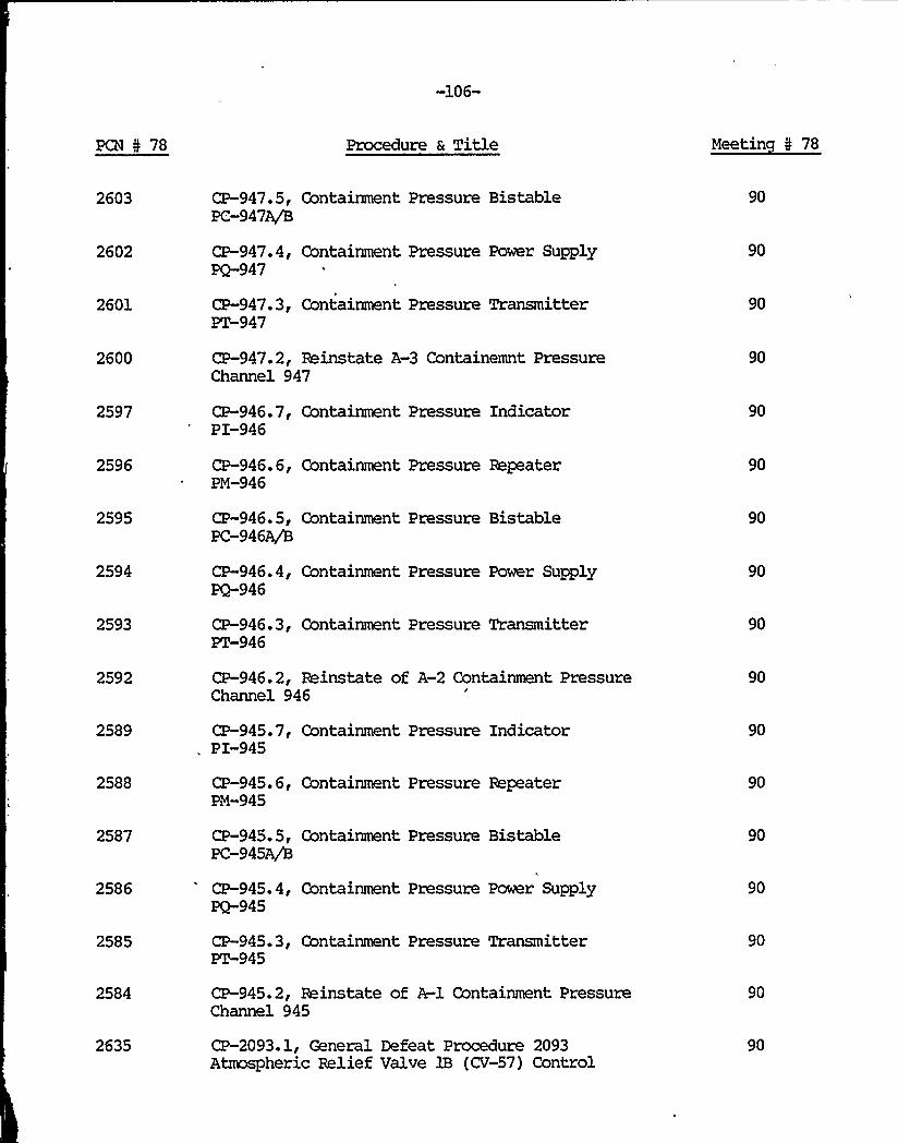
-106-
PCN I 78 Procedure 6 Title Meetin I 78
2603
2602
2601
2600
CP-947.5, Gontainment Pressure BistablePC-947~
CP-947. 4, Containment Pressure Power SupplyPQ-947
CP-947. 3, Containment Pressure TransmitterPT-947
CP-947.2, Reinstate A-3 Containemnt PressureChannel 947
90
90
90
90
2597 CP-946. 7, Containment Pressure IndicatorPI-946
90
2596
2595
2594
2593
2592
2589
2588
2587
2586
2585
2584
2635
CP-946. 6, Containment Pressure RepeaterPM-946
CP-946. 5, Gontainment Pressure BistablePC-946A/8
CP-946.4, Containment Pressure Power SupplyPQ-946
CP-946. 3, Containment Pressure Transmitter~946
CP-946.2, Reinstate of A-2 Containment PressureChannel 946
CP-945. 7, Containment Pressure IndicatorPI-945
CP-945. 6, Containment Pressure RepeaterPM-945
CP-945. 5, Containment Pressure BistablePC-945A/B
CP-945.4, Containment Pressure Power SupplyPQ-945
CP-945. 3, Containment Pressure TransmitterPT-945
CP-945.2, Reinstate of A-1 Containment PressureChannel 945
CP-2093.1, General Defeat Procedure 2093Atmospheric Relief Valve 1B (CV-57) Control
90
90
90
90
90
90
90
90
90
90
90
90


-107-
PCN N 78 Procedure & Title Meetin N 78
2631
2623
2615
2607
CP-2092.1, General Defeat Procedure 2092. Atriaspheric Relief Valve,lA (CV-56) Control
CP-950.1, Defeat of B-3 Containment PressureChannel 950
CP-949.1, Defeat of B-1 Containment PressureChannel 949
CP-948.1, Defeat of B-2 Containment PressureChannel 948
90
90
90
90
2599
2591
2583
2582
2581
CP-947.1, Defeat of A-3 Containment PressureChannel 947
CP-946.1, Defeat of A-2 Containment PressureChannel 946
CP-945.1, Defeat of A-1 Containment PressureChannel 945
CP-945. 0, Calibration and/or Maintenance ofContainment Pressure Channel 945
CP-941.4, Accumulator Pressure Local IndicatorPI-941
90
90
90
90
90
2580
'579
2578
CP-941.3, Accumulator Pressure BistablePC-94~
CP-941.2, Accumulator Pressure Power SupplyPQ-941
CP-941. 1, Accumulator Pressure TransmitterPT-941
90
90
90
2576 CP-940. 4, Accumulator Pressure ~Indicator PI-940
90
2575
2574
CP-940.3,PC-940~
CP-940.2,PQ-940
Accumulator Pressure Bistable
Accumulator Pressure Power Supply
90
90
2573 CP-940.1, Accumulator Pressure TransmitterPT-940
90

1

-108-
PCN N 78 Procedure a Title Meetin N 78
2571 CP-939. 3, Accumulator Level IndicatorLI-939
90
2570
2569
CP-939. 2, Accumulaotr Level BistableLC-939A/8
CP-939.1, Accumulator Level TransmitterLT-939
90
90
2567 CP-938. 3, Accumulator Level IndicatorLI-938
90
2566
2565
CP-938. 2, Accumulator Level BistableLC-938A/B
CP-938. 1, Accumulator Level TransmitterLT-938
90
90
2563 CP-937. 4, Accumulator Pressure IndicatorPI-937
90
2562
2561
2560
CP-937.3, Accumulator Pressure BistablePC-937~
CP-937. 2, Accumulator Pressure Power SupplyPQ-937
CP-937.1, Accumulator Pressure TransmitterPT-937
90
90
90
2558 CP-936.4, Zoop A Accumulator Pressure LocalIndicator
90
2557
2556
2555
2553
2552
2551
CP-936. 3, Accumulator Pressure ChannelBistable PC-936Ajh
CP-936.2, Accumulator Pressure Power SupplyPQ-936
CP-936.1, Accumulator Pressure TransmitterPT-936
CP-935.3, Accumulator Level Indicator LI35
CP-935. 2, Accumulator Level BistableLC-935~
CP-935. 1, Accumulator Level TransmitterLT-935
90
90
90
90
90
90

-109-
PCN I 78 Procedure a Title Meetin I 78
2630
2634
2622
CP-2092.0, Calibration and/or Maintenance of2092 Atmospheric Belief Valve 1A (CV-56) Control
CP-2093.0, Calibration and/or Maintenance of2093 Atmospheric Relief Valve 1B (CV-57) Control
CP-950.0, Calibration and/or Maintenance ofContainment Pressure Channel 950
90
90
90
2614 CP-949.0, Calibration and/or Maintenance ofContainment Pressure Channel 949
90
2590 CP-946.0, Calibration and/or Maintenance ofContainment Pressure Channel 946
90
2598 CP-947.0, Calibration and/or Maintenance of-Containment Pressure Channel 947
90
2606
2550
CP-948.0, Calibration and/or Maintenance ofContainment Pressure Chanenl 948
CP-93S.0, Calibration and/or Maintenance ofAccumulator Level Channel 935
90
90
2554 CP-936.0, Calibration and/or Maintenance ofAccumulator Pressure Channel 936
90
2559
2564
CP-937.0, Calibration and/or Maintenance ofAccumulator Pressure Channel 937
CP-938.0, Calibration and/or Maintenance ofAccumulator Level Channel 938
90
90
2568 CP-939.0, Calibration and/or Maintenance ofAccumulator Level Channel 939
90
2572 CP-940.0, Calibration and/or Maintenance ofAccumulator Pressure Channel 940
90
2577 CP-941.0, Calibration and/or Maintenance ofAccumulator Pressure Channel 941
90
2546
2639
2646
CP-920. 0, Calibration and/or Maintenance 920Refueling Water Storage Tank Level
SC-1.12B, Station Call List
S-12.4, BCS Leakage Surveillance RecordInstructions
90
90
90
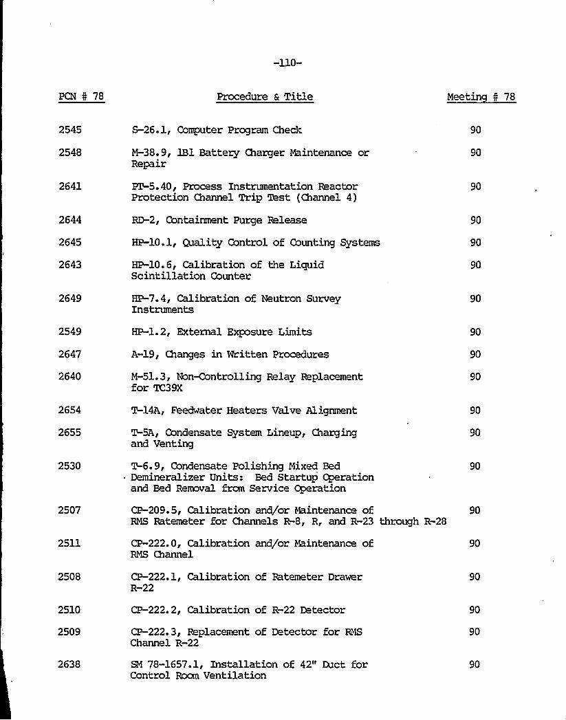
-110-
PCN 4 78 Procedure a Title Meetin 4 78
2545
2548
2641
2644
2645
2643
S-26.1, Gomputer Program Check
M-38.9, 1B1 Battery Charger Maintenance orRepair
PT-5. 40, Process Instrumentation ReactorProtection Channel Trip Test (Channel 4)
RD-2, Containment Purge Release
HP-10.1, Quality Control of Counting Systems
HP-10.6, Calibration of the LiquidScintillation Counter
90
90
90
90
90
90
2649
2549
2647
2640
2654
2655
2530
2507
2511
2508
2510
2509
2638
HP-7.4, Calibration of Neutron SurveyInstruments
HP-1.2, External Exposure Limits
A-19, Changes in Written Procedures
M-51.3, Non-Controlling Relay Replacementfor K',39X
T-14A, Feedwater Heaters Valve Alignment
T-5A, Condensate System Lineup, Chargingand Venting
T-6.9, Condensate Polishing Mixed BedDemineralizer Units: Bed Startup Operationand Bed Removal frcm Service Operation
CP-209.5, Calibration and/or Maintenance ofRMS Ratemeter for Channels R-8, R, and R-23 through R-28
CP-222.0, Calibration and/or Maintenance ofRMS Channel
CP-222.1, Calibration of Ratemeter DrawerR-22
CP-222.2, Calibration of R-22 Detector
CP-222.3, Replacement of Detector for R4SChannel R-22
SM 78-1657.1, Installation of 42" Duct forControl Room Ventilation
90
90
90
90
90
90
90
90
90
90
90
90
90


PCN 5 78
f
Procedure a Title Meetin N 78
2671 M-ll.4.10, Charging Pump Gear ReducerInspection
91
2704 PZ-2. 5, Air Operated Valves, QuarterlySurveillance
93
All of the above items were reviewed by the Committee with respect to theTechnical Specifications and the Committee has determined that no TechnicalSpecification changes or violations were involved in the changes and there areno unresolved safety questions.

-112-
S stem Modification SM 77-1449
System Modification SM 77-1449, Diesel Fire Pump Heater. This rxx3ificationinvolved installation of a water heater on the Diesel driven Fire Pump.
A Safety Evaluation was performed and it was determined that the possibilityof an accident is not increased. A change in the Plant Operating TechnicalSpecifications is not necessary.
S stem Modification SM 75-9.24
System Modification SM 75-9.24, EST Jet Shielding Installation Rework. Thisprocedure included the steps necessary to rework the jet shields near theRefueling Water Storage Tank for GSM-14.
A Safety Evaluation was performed and it was determined that the possibilityof an accident is not increased. A change in the Plant Operating TechnicalSpecifications is not necessary.
S stem Modification SM 77-1474
System Modification SM 77-1474, RC Pump Seal Bypass. This mxlificationincluded the relocation of the RC Pump Seal Bypass lines as recommended kyWestinghouse.
A Safety Evaluation was performed .and it was determined that the possibilityof an accident is not increased. A change in the Plant Operating Technical-Specifications is not necessary.
S stem Modification SM 75-47.30
System Modification 75-47.30, Rework of CVCS Hangers Inside Containment. Thisprocedure involved the reworking of the CVCS Hangers for GSM-3.
A Safety Evaluation was performed and it was determined that the possibilityof an accident is not increased. A change in the Plant Operating TechnicalSpecifications is mt recessary.
S stem Modification SM 75-5.40
System Modification SM 75-5.40, Standby Auxiliary Feedwater System. ReworkInside Containment. This procedure involved reworking of the pipe supports onthe 3" Standby Auxiliary Feedwater Piping, in mnjunction with: procedureSM-75-5.24.
A Safety Evaluation was performed and it was determined that the possibilityof an accident is not increased. A change in the Plant Operating TechnicalSpecifications is not racessazy.

-113-
S stem Modification SM 77-1498.1
System Modification SM 77-1498.1, Low Power S/G Peedwater Bypass ControlModification. This procedure included modifying the feedwater bypass valvecontrol circuitry for low power steam generator level control.
A Safety Evaluation was performed and it was determined that the possibilityof an accident is not increased. A change in the Plant Operating TechnicalSpecif ications is not necessary.
S stem Modification SM 78-1485
System Modification SM 78-1485, Dillon Load Cell Stand. This rmdificationinvolved installation of the Dillon Load Cell Stand.
A Safety Evaluation was performed and it was determined that the possibilityof an accident is not increased. A change in the Plant Operating TechnicalSpecif ications is not rmcessary.
S stem Modification SM 78-1845
System i%ddification SM 78-1845, Guide Stud Storage Rack. This edificationinvolved installation of a new Guide Stud Storage Rack in the reactor cavity.
A Safety Evaluation was performed and it was determined that the possibilityof an accident is not increased. A change in the Plant ~rating TechnicalSpecifications is not recessary.
S stem Modification SM 78-1865
System Modification 78-'1865, "A" Steam Generator Air &ver Restraint. Thismodification involved installation of an "A" Steam Generator Air MoverRestraint.
A Safety Evaluation was performed and it was determined that the possibilityof an accident is not increased. A change in the Plant ~rating TechnicalSpecifications is not necessary.
S stem Modification SM 78-1480
System Modification SM 78-1480, "A" Reactor Coolant Pump Handrails. Thismodification involved the installation of the "A" Reactor Coolnat PumpHandrails
A Safety Evaluation was performed and it was determined that the possibilityof an accident is not increased. A change in the Plant Operating TechnicalSpecifications is not necessary.

/I
I
/
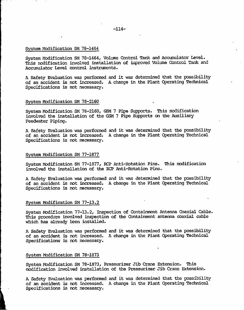
-114-
S stem Modification SM 78-1464
System Nodification SN 78-1464, Volume Control Tank and Accumulator Level.This nodification involved installation of h ~roved Volte Control Tank andAccumulator Level control instruments.
A Safety Evaluation was performed and it was determined that the possibilityof an accident is not incre'ased. A change in the Plant Operating TechnicalSpecif ications is not necessary.
S stem Modification SM 78-2160
System Modification SM 78-2160, GSM 7 Pipe Supports. This rxxlificationinvolved the installation of the GSM 7 Pipe Supports on the AuxiliaryFeedwater Piping.
A Safety Evaluation was performed and it was determined that the possibilityof an accident is not increased. A change in the Plant Operating TechnicalSpecifications is not necessary.
S stem Modification SM 77-1877
System Modification SM 77-1877, RCP Anti-Rotation Pins. This mxiificationinvolved the installation of the RCP Anti-Rotation Pins.
A Safety Evaluation was performed and it was determined that the possibilityof an accident is not increased. A change in the Plant Operating TechnicalSpecifications is not necessary.
S stem Modification SM 77-13.2
System Modification 77-13.2, Inspection of Containment Antenna Coaxial Cable.This procedure involved inspection of the Containment antenna maxial cablewhich has already been installed.
A Safety Evaluation was performed and it was determined that the possibilityof an accident is not increased. A change in the Plant Operating TechnicalSpecifications is not necessary.
S stem Modification SM 78-1873
System Modification SN 78-1873, Pressurizer Jib Crane Extension. Thismodification involved installation of the Pressurizer Jib Crane Extension.
A Safety Evaluation was performed and it was determined that the possibilityof an accident is not increased. A change in the Plant Cperating TechnicalSpecifications is not necessary.
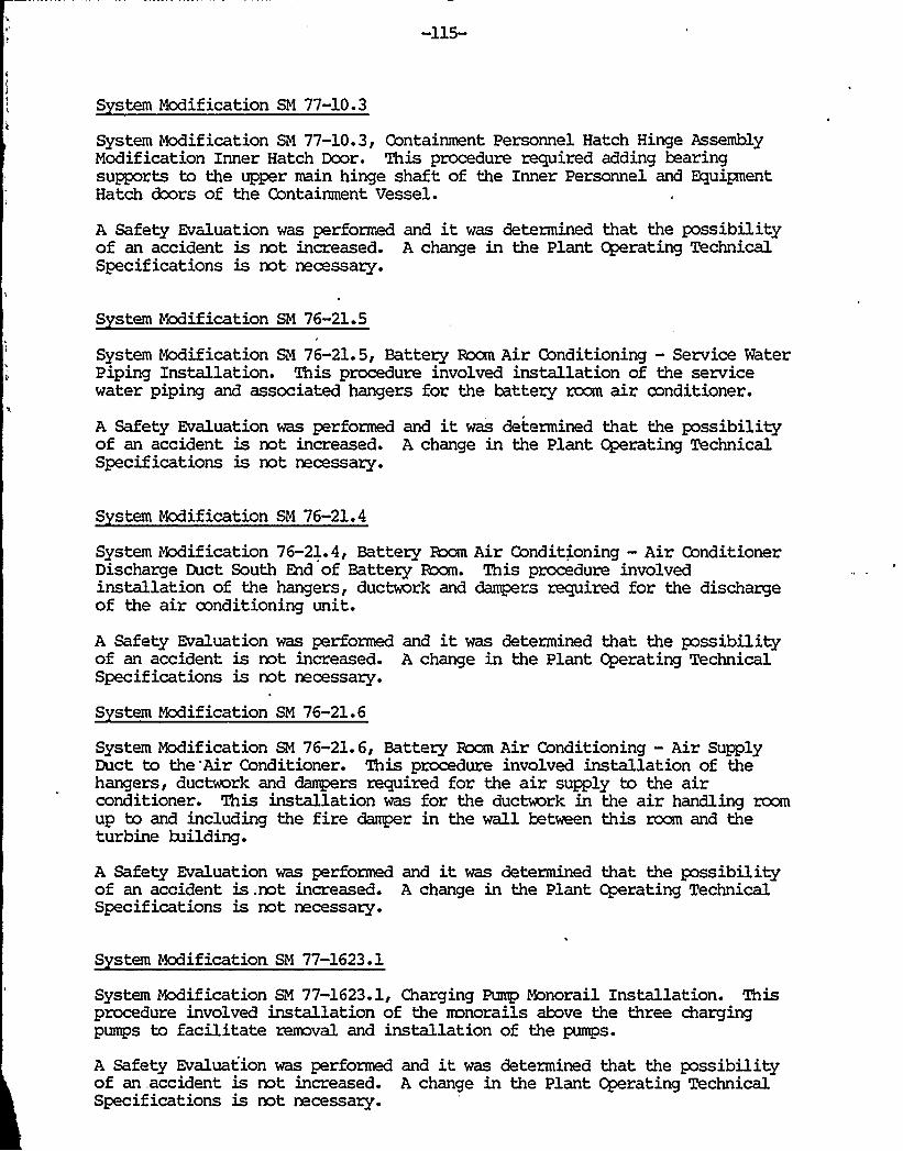
-115-
S stem Modification SM 77-10.3
System Modification SM 77-10.3, Containment Personnel Hatch Hinge AssemblyModification Inner Hatch Door. This procedure required adding bearingsupports to the upper main hinge shaft of the Inner Personnel and EquipmentHatch dcors of the Containment Vessel.
A Safety Evaluation was performed and it was determined that the possibilityof an accident is not increased. A change in the Plant Operating TechnicalSpecifications is not necessaxy.
S stem Modification SM 76-21.5
System Modification SM 76-21.5, Battexy Room Air Conditioning —Service WaterPiping Installation. This procedure involved installation of the servicewater piping and associated hangers for the battexy room air conditioner.
A Safety Evaluation was performed and it was determined that the possibilityof an accident is not increased. A change in the Plant Operating TechnicalSpecifications is not necessaxy.
S stem Modification SM 76-21.4
System Modification 76-21.4, Battery Rxm Air Conditioning —Air ConditionerDischarge Duct South End of Battery Room. This procedure involvedinstallation of the hangers, ductwork and danpers required for the dischargeof the air conditioning unit.
A Safety Evaluation was performed and it was determined that the possibilityof an accident is not increased. A change in the Plant ~rating TechnicalSpecifications is not necessaxy.
S stem Modification SM 76-21.6
System Modification SM 76-21.6, Battexy Room Air Conditioning —Air SupplyDuct to the'Air Conditioner. This procedure involved installation of thehangers, ductwork and dampers required for the air supply to the airconditioner. This installation was for the ductwork in the air handling roomup to and including the fire damper in the wall between this room and theturbine building.
A Safety Evaluation was performed and it was determined that the possibilityof an accident is .not increased. A change in the Plant Cperating TechnicalSpecifications is not necessary.
S stem Modification. SM 77-1623.1
System Modification SM 77-1623.1, Charging Pump Monorail Installation. Thisprocedure involved installation of the mnorails above the three chargingpumps to facilitate removal and installation of the pumps.
A Safety Evaluation was performed and it was determined that the possibilityof an, accident is not increased. A change in the Plant Operating TechnicalSpecif ications is not necessary.

-116-
S stem Modification SM 77-1832A.lI
System Modification SM 77-1832A.1, Circuit Separation Fuse Installation. Thisprocedure involved installation of fuses to protect electrical circuits frcmadjacent fires.
A Safety Evaluation was performed and it was determined that the possibilityof an accident is mt increased. A change in the Plant Operating TechnicalSpecifications is not necessary.
S stem Modification SM 77-1057.1
System Modification SM 77-1057.1, Relocation of the Charging Pump Filter Vent.This procedure involved the relocation of the charging pump filter vent fromthe inlet side of the 3" hypos valve to the discharge side.
A Safety Evaluation was performed and it was determined that the possibilityof an accident is not increased. A change in the Plant Operating TechnicalSpecifications is not necessary.
S stem Mcdification SM 78-1048
System Modification 78-1048, Accumulator Relief, WR 1048. This rmdificationinvolved installation of a new hanger on relief lines from the accumulators.
A Safety Evaluation was performed and it was determined that the possibilityof an accident is not increased. A change in the Plant Cperating TechnicalSpecifications is not necessary.
S stem Modification SM 77-1660.23
System Modification SM 77-1660.23, RCS Overpressure Protection Loop 452 HackR2 Instrumentation Installation and Wiring. This procedure included theinstallation and wiring of the 452 loop power supply, alarm, test points,lights and test switches in the R2 protection rack.
A Safety Evaluation was performed and it was determined that the possibilityof an accident is not increased. A change in the Plant Operating TechnicalSpecifications is not necessary.
S stem Modification SM 77-1660.24
System Modification SM 77-1660.24, RCS Overpressure Protection Loop 455 HackW2 Instrumentation Installation and Wiring. 'Ihis procedure included theinstallation and wiring of the 455 loop power supply, alarm, test point, testswitch and light in the W2 protection rack.
A Safety Evaluation was performed and it was determined that the possibilityof an accident is not increased. A change in the Plant Operating TechnicalSpecifications is not necessary.

-117-
S stem Modification SM 77-1660.25
System Modification SM 77-1660.25, KS Overpressure Protection Loop 456 RackR2 Instrumentation Installation and Wiring. This procedure included theinstallation and wiring of the 456 loop power supply, alarm, test point, testswitch and light in the R2 protection rack.
A Safety Evaluation was performed and it was determined that the possibilityof an accident is not increased. A change in the Plant Operating TechnicalSpecif ications is not necessary.
S stem Modification SM 77-1660.26
System Modification SM 77-1660.26, BCS Overpressure Protection Loop 409 RackRCS 2 Instrumentation Installation and Wiring. This procedure included theinstallation and wiring of the 409 loop alarm bistable in the RCS 2 rack.
A Safety Evaluation was performed and it was determined that the possibilityof an accident is not increased. A change in the Plant Operating TechnicalSpecifications is not necessary.
S stem Modification SM 77-1660.27
System Modification 77-1660.27, RCS Ovexpressure Protection Loop 410 Rack KS2 Instrumentation Installation and Wiring. This procedure included theinstallation and wiring of the 410 loop alarm bistable in the KS 2 rack.
A Safety Evaluation was performed and it was determined that the possibilityof an accident is not increased. A change in the Plant Operating TechnicalSpecifications is not necessary.
S stem Modification SM 77-1660.28
System Modification SM 77-1660.28, KS Overpressure Protection Modification ofthe Relay Racks. This procedure included the installation and wiring of therealy racks to be used for the overpressure protection rrodification.
A Safety Evaluation was performed and it was determined that the possibilityof an accident is not increased. A change in the Plant Operating TechnicalSpecifications is mt necessary.
S stem Modification SM 77-1660.29
System Modification R4 77-1660.29, BCS Overpressure Protection bkx3ificationAnnunciator Termination. This procedure included the installation and wiringof the annunciators which will be used for the overpressure protectionmodification.
A Safety Evaluation was performed and it was determined that the possibilityof an accident is not increased. A change in the Plant ~rating TechnicalSpecifications is mt necessary.

-118-
S stem Modification SM 77-1660.21
System Modification SM 77-1660.21, RCS Overpressure Protection Loop 450 RackB2 Instrumentation Installation and Wiring. This procedure included theinstallation and wiring of the 450 lcop power supply, alarm, test point, testswitch and light in the B2 protection rack.
A Safety Evaluation was performed and it was determined that the possibilityof an accident is not increased. A change in the Plant Operating TechnicalSpecifications is not necessary.
S stem Modification SM 77-1660.22
System bkxlification SM 77-1660.22, KS Overpressure Protection Loop 451 RackW2 Instrumentation Installation and Wiring. This procedure included theinstallation and wiring of the 451 loop power supply, alarm, test points,lights and test switches in the W2 proctection rack.
A Safety Evaluation was performed and it was determined that the possibilityof an accident is not increased. A change in the Plant Operating TechnicalSpecifications is not necessary.
S stem Modification SM 76-26.4
System Modification 76-26.4, Installation of 7.5 KVA Floor Wunted ConstantVoltage Transformer 1B. This procedure involved replacing the existingconstant voltage transformer with new solid state controls unit using existinginstalled wiring.
A Safety Evaluation was performed and it was determined that the possibilityof an accident is not increased. A change in the Plant Operating Techriical
" Specifications is not necessary.
S stem Modification SM 76-21.7
System Modification SM 76-21.7, Battery Room Air Conditioning —Miscellaneous.This procedure involved pouring the concrete pad, installing dampers andmaking necessary wiring connections.
A Safety Evaluation was performed and it was determined that the possibilityof an accident is not increased. A change in the Plant Operating TechnicalSpecif ications is not necessary.
S stem Modification SM 76-26.2
System Modification SM 76.26.2, Installation of 1B Inverter and AlternatePower Supplies. This procedure involved replacing the existing inverter andmanual transfer alternate power supply with a new solid state inverter/staticswitch, automatic transfer to C.V.T. alternate power supply (and maintenancesupply to instrument Bus 1B, if applicable).
A Safety Evaluation was performed and it was determined that the possibilityof an accident is not increased. A change in the Plant ~rating TechnicalSpecifications is mt necessary.

-119-
S stem Modification SM 76-26.3
System Modification SM 76-26.3, Installation of 7.5 KVS Flow Mounted Constant,Voltage Transformer 1A. This procedure involved replacing the existingconstant voltage transformer with new solid state controls unit using existinginstalled wiring.
A Safety Evaluation was performed and it was determined that the possibilityof an'accident is not increased. A change:in the Plant Operating TechnicalSpecif ications is not. necessary.
S stem Modification SM 76-26.1
System Modification SN 76-26.1, Installation of 1A Inverter and AlternatePower Supplies. This procedure involved replacing the existing inverter andmanual transformer alternate power supply with a new solid stateinverter/static switch, automatic transfer to C.V.T. alternate power supply(and maintenance supply to Instrument Bus lA, if applicable).
A Safety Evaluation was performed and it was determined that the possibilityof an accident is not increased. A change in the Plant Operating TechnicalSpecifications is not necessary.
S stem Modification SM 77-1682.1
System Modification 77-1682.1, Penetration Testing Rxlification —Penetration304. This procedure involved the installation of hanger PA 401 and necessarypiping modifications on Penetration 304.
A Safety Evaluation was performed and it was determined that the possibilityof an accident is not increased. A change in the Plant Operating TechnicalSpecifications is not necessary.
S stem Modification-SM 76-27.1
System Modification SM 76-27.1, Penetration 332 Modification. 'his procedureinvolved installing hanger PA 401 and necessary piping mx3ifications onPenetration 332.
A Safety Evaluation was performed and it was determined that the possibilityof an accident is not increased. A change in the Plant Cperating TechnicalSpecifications is not necessary.
S stem Modification SM 76-11.10f.
System Modification SM 76.11.10, No. 12B Auxiliary Transformer Deluge SystemTie-In. This procedure involved installing the tie-in to the "B" DelugeHeader for the No. 12 Auxiliary Transformer deluge system. 'Ibis tie-inincludes the elbow, the "6" pipe, the blind flanged 6" x 4" x 6" tee and the4" gate valve.
A Safety Evaluation was performed and it was determined that the possibilityof an accident is not increased. A change in the Plant Operating TechnicalSpecifications is not necessary.
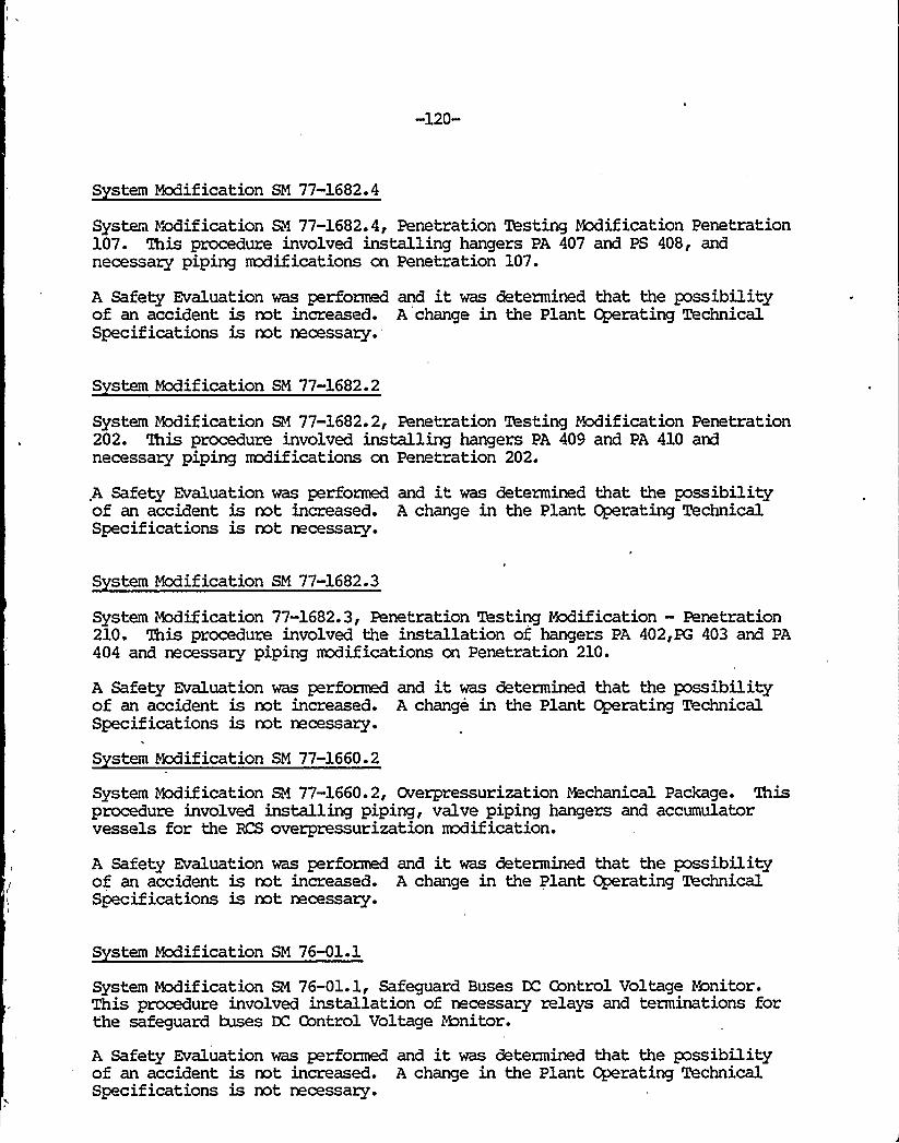
-120-
S stem Modification SM 77-1682.4
System edification R4 77-1682.4, Penetration Testing Modification Penetration107. This procedure involved installing hangers PA 407 and PS 408, andnecessary piping nadifications on Penetration 107.
A Safety Evaluation was performed and it was determined that the possibilityof an accident is mt increased. A change in the Plant Operating TechnicalSpecifications is not necessary.
S stem Modification SM 77-1682.2
System Modification SM 77-1682.2, Penetration Testing Modification Penetration202. This procedure involved installing hangers PA 409 and PA 410 andnecessary piping rmdifications on Penetration 202.
A Safety Evaluation was performed and it was determined that the possibilityof an accident is not increased. A change in the Plant Operating TechnicalSpecifications is not necessary.
S stem Modification SM 77-1682.3
System edification 77-1682.3, Penetration Testing Modification —Penetration210. This procedure involved the installation of hangers PA 402,PG 403 and PA404 and necessary piping modifications on Penetration 210.
A Safety Evaluation was performed and it was determined that the possibilityof an accident is not increased. A change in the Plant Operating TechnicalSpecifications is not necessary.
S stem Modification SM 77-1660.2
System Modification SM 77-1660.2, Overpressurization Mechanical Package. Thisprocedure involved installing piping, valve piping hangers and accumulatorvessels for the RCS overpressurization modification.
A Safety Evaluation was performed and it was determined that the possibilityof an accident is not increased., A change in the Plant Operating TechnicalSpecif ications is not accessary.
S stem Modification SM 76-01.1
System Modification SM 76-01.1, Safeguard Buses DC Gontrol Voltage Ronitor.This procedure involved installation of necessary relays and terminations forthe safeguard buses DC Control Voltage 8onitor.
A Safety Evaluation was performed and it was determined that the possibilityof an accident is not increased. A change in the Plant Operating TechnicalSpecifications is not necessary.


-121-
S stem Modification SM 77-1660.10
System Modification SM 77-1660.10, RCS Overpressurization ProtectionElectrical Conduit and Wiring. This procedure involved installation andfabrication of mnduit, conduit supports and wire/cable .excluding terminationsfor RCS Overpressurization Protection. System.
A Safety Evaluation was performed and it was determined that the possibilityof an accident is not increased. A change in the Plant Operating TechnicalSpecifications is mt necessary.
S stem Modification SM 77-2.10
System Modification SM 77-2.10, D.I. Water Containment Isolation —ElectricalConduit and Wiring. This procedured involved fabrication and installation ofconduit, conduit supports and wire/cable excluding terminations for the D.I.Water Containment Isolation Valve.
A Safety Evaluation was performed and it was determined that the possibilityof an accident is mt increased. A change in the Plant Operating TechnicalSpecifications is mt necessary.
S stem Modification SM 78-2273.1
System Modification 78-2273.1, Armor Plate on the East Wall of the ControlRoom. This procedure involved the installing anger plate and necessarystructural steel on the east wall of the Control Rocm.
A Safety Evaluation was performed and it was determined that the possibilityof an accident is not increased. A change in the Plant Operating TechnicalSpecif ications is not rmcessary.
S stem Modification SM 77-02.1
System Modification SM 77-02.1, D.I. Water to Contaiment i%ddificationMechanical. This procedure involved installing valves, piping and pipinghangers on the demineralized water line going to Containment.
A Safety Evaluation was performed and it was determined that the possibilityof an accident is not increased. A change in the Plant Operating TechnicalSpecif ications is not necessary.
S stem Mcdification SM 78-1048.1
System Modification SM 78-1048.1, Accumulator Relief Modification. Thisprocedure involved installation of a new hanger on the 1" relief line fromboth accumulators and cut off the relief valve discharge lines before theelbow.
A Safety Evaluation was performed and it was determined that the possibilityof an accident is mt increased. A change in the Plant Cperating TechnicalSpecifications is not recessary.

-122-
S stem Modification SM 78-2273
System Modification SM 78-2273, Armor Plate —East Wall of Control Room.This reification involved installation of armor plate on the East Wall of theControl Room.
A Safety Evaluation was per'formed and it was determined that the possibilityof an accident is not increased. A change in the Plant Operating TechnicalSpecifications is not necessary.
S stem Modification SM 78-1875.1
System Modification SM 78-1875.1, "A" Feedwater Venturi Monorail. Thisprocedure involved fabrication and erection of a nnnorail above the "A"Feedwater Venturi.
A Safety Evaluation was performed and it was determined that the possibilityof an accident is not increased. A change in the Plant Operating TechnicalSpecifications is not accessary.
S stem Mcdification SM 78-1480.1
System Modification 78-1480.1, "A" RCP Ladder and Handrail Installation.This procedure involved erection of handrails, ladders and miscellaneous steelby the "A" Reactor Coolant Pump.
A Safety Evaluation was performed and it was determined that the possibilityof an accident is not increased. A change in the Plant Operating TechnicalSpecifications is not necessary.
S stem Modification SM 78-1890.1
System Modification SM 78-1890.1, Feedwater Line Drain Valves Before theContainment Check Valves. This rxxlification involved the installation of adrain line and valve on each feedwater line before vlaves 3992 and 3993.
A Safety Evaluation was performed and it was determined that the possibilityof an accident is not increased. A change in the Plant Cperating TechnicalSpecifications is not necessary.
S stem Modification SM 77-1474.1
System Modification SM 77-1474.1, RCP Seal Bypass Modification. Thisprocedure involved relocating the 41 Seal ~s piping and necessary hangerson the Reactor Coolant Pumps.
A Safety Evaluation was performed and it was determined that the possibilityof an accident is not increased. A change in the Plant Operating TechnicalSpecifications is not necessary.

-123-
S stem Modification SM 75-14
System Modification SM 75-14, Boric Acid Batch Tank Recirculation Piping andSupports. '1%is modification involved installing the necessary piping, valvesand hangers to allow the transfer of boric acid from either storage tank tothe batch tank.
A Safety Evaluation was performed and it was determined that the possibilityof an accident is not increased. A change in the Plant Operating TechnicalSpecifications is not necessary.
S stem Modification SM 78-1485.1
System Modification SM 78-1485.1, Dillon Cell Storage Frame. 'Ibis procedureinvolved the fabrication and installation of platform aadifications for theDillon Cell Storage frame.
A Safety Evaluation was performed and it was determined 'that the possibilityof an accident is=not increased. A change in the Plant Cgerating TechnicalSpecifications is not necessary.
S stem Modification SM 78-1845.1
System Modification 78-1845.1, Guide Stud Storage Racks. This procedureinvolved the fabrication and installation of the Guide Stud Storage Racks onthe wall of the Refueling Cavity.
A Safety Evaluation was performed and it was determined that the possibilityof an accident is not increased. A change in the Plant Operating TechnicalSpecifications is not necessary.
S stem Modification SM 78-2160.1
System Modification SM 78-2160.1, GSM-7 Pipe Supports. This rxdificationinvolved the fabrication and installation of the GSM-7 Pipe Supports on theAuxiliary Feedwater Piping.
A Safety Evaluation was performed and it was determined that the possibilityof an accident is not increased. A change in the Plant Operating TechnicalSpecifications is not necessary.
S stem Modification SM 76-28.2
System Modification SM 76-28.2, Flange Installation on Feedwater Flow Venturis— "A" Feedwater,Line. This procedure involved installation of flangesupstream and downstream of the main feedwater flow venturis on the "A"Feedwater line.
A Safety Evaluation was performed and it was determined that the possibilityof an accident is not increased. A change in the Plant Operating TechnicalSpecifications is not necessary.

-124-
S stem Modification SM 75-5.50
System Modification SM 75-5.50, Auxiliary Feedwater Hanger AEN-51 Repair.This procedure involved repairing Hanger AEW-51, including rermval of someexisting structural rremkers and replacement with new materials.
A Safety Evaluation was performed and it was determined that the possibilityof an accident is not increased. A change in the Plant Operating TechnicalSpecif ications is not necessary.
S stem Modification SM 76-01.2
System Modification SM 76-01.2, Cable Installation for the DC Control Fuses.This procedure involved installation of the cable for the D.C. Control Fusesexcluding terminations.
A Safety Evaluation was performed and it was determined that the possibilityof an accident is not increased. A change in the Plant Operating TechnicalSpecif ications is not necessary.
S stem Modification SM 77-1660.15
System edification 77-1660.15, Instrumentation Tie-Ins for RCSOverpressurization. This procedure involved miscellaneous instrumentationinstallation on the new RCS overpressurization N2 piping to describe the stepsnecessary to make the tie-.in to the instrument air in mntainment and todescribe the steps necessary to make the tie-ins for the new loop pressuretransmitters onto the exis'ting flow transmitter takeoffs.
A Safety Evaluation was performed and it was determined that the possibilityof an accident is not increased. A change in the Plant Operating TechnicalSpecifications is not necessary.
S stem Mcdification SM 78-1865'.1
System Modification SM 78-1865.1, Steam Generator "A" Air lUver Installation.This procedure involved fabrication and installation of the air naver holdingframe.
A Safety Evaluation was performed and it was determined that the possibilityof an accident is not increased. A change in the Plant Cperating TechnicalSpecifications is not necessary.
S stem Modification SM 78-1873.1
System Modification SM 78-1873.1, Pressurizer Jib Crane. This procedureinvolved fabrication and installation of the Pressurizer Jib Crane Extension.
A Safety Evaluation was performed and it was determined that the possibilityof an accident is not increased. A change in the Plant Operating TechnicalSpecifications is not necessary.

fr

-125-
S stem Modification SM 77-1660.11
System Modification SM 77-1660.11, RCS Overpressurization Protection—Electrical Terminations in the Control Room and in the Field. This procedureinvolved instructions necessary to make, cable terminations on new eguipnentinstalled in the field and on new equip"ent installed in the Control Room.This does not include terminations in the racks.
A Safety Evaluation was performed and it was determined that the possibilityof an accident is not increased. A change in the Plant Operating TechnicalSpecifications is not necessary.
S stem Modification SM 77-02.2
System Modification SM 77-02.2, Hydrostatic Testing and Initial Service LeakTest of the Demineralized Water to Gontainment Modification. Wis prooedureinvolved testing the new piping installed using SM 77-02.1.
A Safety Evaluation was performed and it was determined that the possibilityof an accident is not increased. A change in the Plant Operating TechnicalSpecifications is not necessary.
S stem Modification SN 77-1682.10
System Modification 77-1682.10, Hydrostatic Testing of Penetration 143 PipingModification.. This procedure involved testing the piping mxiificationsinstalled using SM 77-1682.5.
A Safety Evaluation was performed and it was determined that the possibilityof an accident is not increased. A change in the Plant Operating TechnicalSpecifications is not necessary.
S stem Modification SM 77-02.12
System Nodification SM 77-02.12, Cemineraalized Water Containment Isolation.This procedure involved rmunting relay C14X, install rack wiring in SIA2 andSIB2 racks, and terminate field wires at SIA2 and SIB2 racks.
A Safety Evaluation was performed and it was determined that the possibilityof an accident is not increased. A change in the Plant Operating TechnicalSpecifications is not necessary.
S stem Modification SM 77-1660.100
System Nodification SN 77-1660.100, Pneumatic Testing of the KS OverpressureProtection System. This procedure involved performing pneumatic tests on theRCS oyerpressure protection system.
A Safety Evaluation was performed and it was determined that the possibilityof an accident is not increased. A change in the Plant Operating TechnicalSpecifications is not necessary.

C
f

-126-
S stem Modification SM 77-02.20
System Modification SM 77-02.20, Checkout Testing of the Containment DI WaterAutomatic Isolation Valve 8418. This procedure involved verifying properoperation and installation of valve 8418.
A Safety Evaluation was performed and it was determined that the possibilityof an accident is not increased. A change in the Plant Cgerating TechnicalSpecifications is not necessary.
S stem Modification SM 77-02.15
System Modification SM 77-02.15, Air Tie-In for the DI Water to Containment.This procedure involved tying in the instrument air for Valve 8418.
A Safety Evaluation was performed and it was determined that the possibilityof an accident is not increased. A change in the Plant Operating TechnicalSpecifications is not necessary.
S stem Modification SM 77-02.11
System Modification 77-02.11, Electric Termination of Valve 8414 and in theControl Room for DI Water to Containment. This procedure involved making theelectrical terminations at the Containment DI Automatic Isolation Valve 8418and to describe the steps necessary to install necessary switch and lights inthe control board and make necessary terminations. This does not includeterminations covered kp B4 77-02.12.
A Safety Evaluation was performed and it was determined that the possibilityof an accident is not increased. A change in the Plant Operating TechnicalSpecif ications is rmt necessary.
S stem Modification SM 78-1888.1
System Modification SM 78-1888.1, Spray Additive Tank Recirc. Line ShutoffValve Installation. This procedure involved installation of a shutoff valveand nipple on an existing plug connection for the spray additive tank recirc.line.
A Safety Evaluation was performed and it was determined that the possibilityof an accident is not increased. A change in the Plant Operating TechnicalSpecifications is not necessary.
S stem Modification SM 76-26.5
System Modification SM 76-26.5, Installation of 7.5 KVA Floor Munted ConstantVoltage Transformer Backup Supply for Instrument Buses A-B-C a D. Thisprocedure involved replacing the existing transformer with new solid statecontrols unit using the existing installed wiring.
A Safety Evaluation was performed and it was determined that the possibilityof an accident is not increased. A change in the Plant Operating TechnicalSpecifications is not necessary.

l)
II
I
-127-
S stem Modification SM 75-50.30
System Modification SM 75-50.30, Rework of Jet Shielding for Main Steam BypassPiping and Valves. This procedure involved rework of the jet shielding forthe main steam ~s piping and valves.
A Safety Evaluation was performed and it was determined that the possibilityof an accident is not increased. A change in the Plant Operating TechnicalSpecifications is not necessary.
S stem Modification SM 77-1030.1
System Modification SM 77-1020.1, Neutralizing Tank Modification. Thisprocedure involved allowing recirculation mde of the neutralizing tank pumpand to prevent discharge from the neutralizing tank when there is a pH alarmfrom the retention tank.
A Safety Evaluation was performed and it was determined that the possibilityof an accident is not increased. A change in the Plant Operating TechnicalSpecifications is not necessary.
S stem Modification SM 77-1449.1
System Modification 77-1449.1, Diesel Fire Pump Heater. This procedureinvolved installing an engine coolant heater and an engine coolant filter tothe Diesel Fire Pump.
A Safety Evaluation was performed and it was determined that the possibilityof an accident is not increased. A change in the Plant Operating, TechnicalSpecifications is not necessary.
S stem Modification SM 78-1458.1
System Modification SM 78-1458.1, Spent Fuel Pit Roughing Filter Frame.This procedure involved the installation of spent fuel pit roughing filterframes.
A Safety Evaluation was performed and it was determined that the possibilityof an accident is not increased. A change in the Plant Operating TechnicalSpecifications is not necessary.
S stem Modification SM 77-1405.1
System Modification SM 77-1405.1, Installation of Conduit for Security System.This procedure involved installation of conduit for the Security System andprovided a procedure to control Q.A. aspects of the rredification.
A Safety Evaluation was performed and it was determined that the possibilityof an accident is not increased. A change in the Plant Operating TechnicalSpecifications is not necessary.


-128-
S stem Modification SM 76-17.3
System Modification SM 76-17.3, Screenhouse Intake Heater Cable Tray Rework.This procedure involved installation rework of Hilti Fastenings to NuclearSafety-Related structural steel by a power actuated fastening tool perNCR~78-57
A Safety Evaluation was performed and it was determined that the possibilityof an accident is not increased. A change in the Plant Operating TechnicalSpecif ications is not. necessary.
S stem Modification SM 76-18.1
System Modification SM 76-18.1, Waste Condensate Pumps, Monitor Tank Pump andLaundry Pump Rotor Controller Nx3ification. This procedure involvedmodifications to ensure that a liquid release is terminated if R-18 Monitordetects high activity.
A Safety Evaluation was performed and it was determined that the possibilityof an accident is not increased. A change in the Plant Operating TechnicalSpecifications is not necessary.
S stem Modification SM 77-2110.1
System Nxlification 77-2110.1, Chem Lab D.I. Storage Tank Cable Routing. Thisprocedure involved providing tank level indication at the D.I. Plant ControlPanel.
A Safety Evaluation was performed and it was determined that the possibilityof an accident is not increased. A change in the Plant ~rating TechnicalSpecifications is not necessary.
S stem Modification SM 75-50.31
System Modification SM 75-50.31, Jet Shielding Rework, Main Steam andFeedwater. This procedure involved documenting the work required to correctopen items from NCR~77-139. These were incomplete items from SM 75-50.21for GSM-8.
A Safety Evaluation was performed and it was determined that the possibilityof an accident is not increased. A change in the Plant Operating TechnicalSpecifications is not necessary.
S stem Modification SM 77-1836.3
System Modification RI 77-1836.3, Relocation of Hangers SWXH 38 and 39. Thisprocedure involved relocating Service Water Hangers BFJH 38 and 39.
A Safety Evaluation was performed and it was determined that the possibilityof an accident is- not increased. A change in the Plant Operating TechnicalSpecif ications is not necessary.

-129-
S stem Modification SM 76-11.21
System Modification SM 76-11.21, 12B Transformer Grinnel Valve Alteration.This procedure involved altering the position of Grinnel Multi-matic ValveModel A-4 for. the 12B Auxiliary Transformer Deluge System so that lockingwater is on the inlet side of the O.S. a Y. Valve.
A Safety Evaluation was performed and it was determined that the possibilityof an accident is not increased. A change in the Plant Operating TechnicalSpecifications is not necessary.
S stem Modification SM 75-5.43
System Modification SM 75-5.43, Final Rework for Standby Auxiliary Feedwater.This procedure involved resolving all known remaining deficiencies associatedwith the installation of GSM-16, Standby Auxiliary Feedwater System. Also,this describes the rework necessary to completely resolve NCR~77-131.
A Safety Evaluation was performed and it was determined that the possibilityof an accident is not increased. A change in the Plant Operating TechnicalSpecif ications is not necessary.
S stem Modification SM 75-14.1
System Modification 75-14.1, Batch Tank Recirculation Heat Trace Installation.This procedure involved installation of a permanent heat trace on the BoricAcid Batch Tank Recirculation Piping.
A Safety Evalu'ation was performed and it was determined that the possibilityof an accident is not increased. A change in the Plant Operating TechnicalSpecif ications is not necessary.
S stem Modification SN 74-28.1
System Modification SN 74-28.1, Installation of Makeup Lines to CondensateStorage Tanks. This procedure involved installation and return to service ofthe new makeup line for the Condensate Storage Tank.
A Safety Evaluation was performed and it was determined that the possibilityof an accident is not increased. A change in the Plant Operating TechnicalSpecifications is not necessary.
S stem Modification SM 78-1657.1
,System i~ification .SN 78-1657.1, Installation of 42" Duct for Control RoomVentilation. This procedure involved fabrication of hangers and installationof the 42" duct for Control Rocm Ventilation.
A Safety Evaluation was performed and it was determined that the possibilityof an accident is not increased. A change in the Plant Operating TechnicalSpecifications is not necessary.
-130-
S stem Modification SM 77-1663.1
System Modification SN 77-1663.1, Spent Fuel Pit Wall Temperature hhnitor.This procedure involved installation of a temperature nanitor for the SpentFuel Pit/Refueling Canal Wall.
A Safety Evaluation was performed and it was determined that the possibilityof an accident is not increased. A change in the Plant Operating TechnicalSpecif ications is not necessary.