Ham Radio Magazine 1978
134
ham radio magazine AUGUST 1978 frequency-locked vfo locating TVI high-resolution frequency synthesizer noise-figure measurements RTTY keyboard and much more. . .
-
Upload
khangminh22 -
Category
Documents
-
view
2 -
download
0
Transcript of Ham Radio Magazine 1978

ham radio
magazine
AUGUST 1978
frequency-locked vfo
locating TVI
high-resolution frequency synthesizer
noise-figure measurements
RTTY keyboard
and much more. . .

At Henry Radio. w e a re proud that amateurs no t on1 in t he United S ta tes bu t throughout the free world l o o l t o u s a s their p reeminent supplier of finecommunications equipment. For fifty years this has been our principal business and it still is. Most a m a t e u r s don ' t fully unders tand , however. t h e manner in which we have grown and grown s o that every year we are better equipped t o provide a genuine ser- vice t o the world amateur fraternity and a t the s ame t ime extend our unique blend of responsible.expert ser- vice t o many e lec t ron ic se rv ices in addi t ion t o t h e amateurs. Our tree has indeed grown many new and sturdy branches. Yes. a s alwavs we distribute all the available high quality amateur equipment. In addition, we manufacture a full line of linear amplifiers that have become world famous for uality and reliability. These have provided the s tan- d a r l of reference in amateur radio for many years and are widely employed by commercial and government users. More recently our tube a m lifiers have been sup- plemented by a broad line of soEd s ta te amplifiers for the HF, VHF and UHF bands. Many of these am lifiers are ty e accepted by the FCC for business. ~ u b \ c ser- vice, {CC and marine two-way service.
Ou t of this program has grown a n entire new operation providing high qualit FM handhelds. mobiles and fixed station transceivers Yor all these services. Moreover, a s a n off-shoot of our vacuum tube amplifier pro ram we 3, now supply R.F. power generators t o industry. T ese are used a s plasma generators in thin film plating and other exotic scientific processes.
What does all th i s mean t o ou r m o s t important cus - tomers. the amateur radio operators of the world. Simply this. As Henry Radio grows these sturdy new branches o n o u r t ree of e lec t ron ic exper t i se , we cont inua l ly strengthen our ability t o help the amateurs of the world satisfy their communications requirements. As always, we offer expert. responsible assistance, the kind ama- teurs need and want. Wherever you live in the world, we invite you t o turn t o Henry Radio, the pioneer in ser- vice t o the amateur radio fraternity.
11240 W. Olympic Blvd.. Los Angeles. Calil. 90064 2131477-6701 931 N. Euclid. Anaheim. Calil. 92801 7141772-9200 Butler, Missouri 64730 8161679-3127

if you've got a calling for far-reach- (and $39.95 for the 75-meter add- ing action, have we got a number on kit). at your Swan dealer. for you! fppfj And by all means, use your Swan
Swan's 4010V: precision engi- Credit Card. neered for 40-20-15-10 meters. I I C------------------------
1 1 4 1 X h 1"" ? X U >.',I :u: 2"4 HRFUI ' I N O
I I Please rush ful l specs lor Swan's I
*pol "SWR r u m <liq=fyj I I with slim-[ine traps, this 4-band I 0 4 0 l O V 4.band trap vertical antenna I : 7 5 AK 75-meter ~ t t
I vertical offers advanced light- I
I I weight construction with heavy I N a m e - I
weight performance. I I I )
7 I 7 15 7 2 : Address I
1 0 PRWN~:NCY 4010V's fine-tuned to handle I I
I
2000 PEP. With a typical VSWR of : citv I
? z ~ ~ ~
I 1.5: 1 at resonance. I I I State- Zip I
5 I designed-yet : FREE! Personalfzed call-letter plaque 1 fully simple to set up. 21 rm x 4" with stand. I
No-hassle installation. The 2 1 ' Im no charge I
I / I
,,a I l l ,,, 2 5 l a ) 1 1 1 1 vertical comes in short, easy to Please send my 1 I R I 0 1 1 1 N I > plaque imprinted I
assemble lengths. Complete with i with my station call : mounting hardware. You're up I . I
I and running in record time. H A M W I
L------------------------d
Expandable too. No trick a t all to stretch your reach into 75
I I 11 0 > / I .'I : 0 S b v i ~ l V
!, , , , , meters, with the optional Swar ELECTRONIC:
.a -,rlir,d,nrr ,,I L 1,1111 < OII..1?.1II""
I "I"I8, li, > 75 AK Kit. I05 Airport Road. Oceanside. CA 9201
Just $79.95 for an outstandir wan's conl~nusng comm8tmcnt to produel improvemc..
4-band trap vertical, the 4010V may affect speczfncationr and prier wathout nottce


ham
magazine
contents 10 10-GHz transceiver
Klaus H. Hirschelmann, DJ700
17 frequency-lock loop J. Crawford MacKeand, WA3ZKZ
24 locating TVI caused by metallic rectification John E. Pitts, W6BD
30 seven-element forty-meter quad Paul Kiesel, K7CW
34 high-resolution frequency synthesizer William E. Coleman, N4ES
40 automatic noise-figure measurements Robert S. Stein, W6NBI
56 electronic R l T Y keyboard Lewis A. Stapp, W0PHY
60 improved grounding for the 1296-MHz microstrip filter H. Paul Shuch, N6TX
66 simple monitor for accurate reports on two-meter fm Edward R. Spadoni, WlRHN
70 single-tone decoders Steve S. Kraman, WA2UMY
75 electronic bias switching for the Henry 2K4 and 3KA Michael James, WlCBY
4 a second look 6 letters 128 advertisers index 84 new products 101 flea market 8 presstop 116 ham mart 126 reader service 80 ham notebook 40 repair bench
august 1978 3

:ond look Jim Fisk
In recent months there has been rising concern about the possible harmful effects to living tissue due to heating by radio-frequency energy at 10 MHz and above. The weekly CBS TV news maga- zine, 60 Minutes, devoted a segment to this topic several months ago, numerous "rf radiation" stories have been published in newspapers and magazines, and now there is a best-selling book on the subject: The Zapping of America, by Paul Brodeur. Although much of Brodeur's book is devoted to what he calls the "deadly risk of microwave radiation" and its "cover-up" by the government, he apparently doesn't know the difference between high-power radar or TV transmitters and high-fre- quency amateur and CB equipment. He would have you believe that little or no research has been done on the dangers of electromagnetic radiation; if your neighbors believe hirn, you may find your radio activities squelched by local citizens who are afraid of being "zapped" by your amateur trans- mitting equipment.
Contrary to what Brodeur says, microwave engineers have been aware of rf radiation hazards for 30 years or more, and the scientific community has spent thousands of man h~ours investigating its effects and establishing safety standards. It is known, for example, that the internal body organs are susceptible to damage from heating caused by high-power radio energy in the range from 150 to 1200 MHz, and that the eye is especially prone to damage from radiation above 1000 MHz. More im- portantly, it is known that power levels which cause damage are much higher than those found in the average ham shack. Kilowatt transmitters on the amateur uhf bands (432 MHz and above) are poten- tially hazardous, but if they are completely shielded they are not dangerous to your health. On the lower frequencies there is practically no danger, even if you're running 2000 watts PEP.
Based on present knowledge, which is extensive, various government agencies have established rf radiation safety standards with recommended exposure limits referred to as Radiation Protection Guide Numbers (RPGN). The accepted RPGN value is 10 milliwatts per square centimeter of body area, the standard set by the Occupational Safety and Health Administration (O!SHA). Although there are some scientists who disagree with this standard, most agree that r f power levels one-half the OSHA standard (5 mWlcm2) have little effect on the human body, and practically no one objects to a standard of 1 mWlcm2. Note that this is based on continuous exposure.
If your transmitter is well shielded, and you use coaxial transmission line, the! only possible danger is radiation from your antenna. Assuming a kilowatt linear with 65% efficiency and no feedline loss places about 650 watts at the antenna; what is the minimum safe distance? This depends on the directivity of your antenna, but for a half-wavelength dipole it equates to a distance of about 3 meters (10 feet) for a power density of 5 mWlcm2. If you're running less than a kilowatt, of course, the safe distance is less. Since most amateur dipoles are installed at least 8 meters (25 feet) above the ground, they obviously pose no radiation threat.
What about multi-element Yagi beams and stacked arrays? Since most of the power is concen- trated in front of the beam, there is little danger above or below the antenna. Even with 650 watts in- put, the beam must have at least 15 dBd gain before the power density reaches 5 mWlcm2 in the center of the forward lobe, 10 meters (30 feet) in front of the antenna. Few arnateur antennas have this much gain, and those that do are used on uhf where it's impossible to generate 650 watts into the antenna and stay within the legal power limit.
On the high-frequency bands, if your beam is on a tower at least 10 meters (30 feet) high and not pointed into a building less than 10 meters away, there is absolutely no hazard at legalamateur power levels. Keep this in mind if you start getting grief from your neighbors.
Jim Fisk, WIHR editor-in-chief
4 august 1978

ICOM's New IC-Z8Q
lCOM introduces its new 2 meter mobile radio with the detachable microprocessor control head, the IC- 280. Bright, easy to read LED'S and a new style meter grace the brushed aluminum "new look" front panel of the detachable control head, which provides mem- ory and frequency control for the remotely mountable main section.
The IC-280 comes as one radio to be mounted in the normal manner: bu t asan option. the entire front one
when power is turned off at the front panel switch. IC-280 retains its programmed memories; and w power is completely removed from the radio, e600 KHz splits are still maintained!
Frequency coverage of the IC-280 is in excess of the 2 meter band; and the new band plan (144.5-145.5 MHz repeaters) can easil be accommodated, since it was included in the IC-;80*s initial planning by the ICOM design team.
the hen the
third of the radio detacheiand mounts by its optional bracket puk you up to the and the main body tucks neatly art engineering. The away out of sight. Now you can innovations in large mount your 2 meter mobile radio in places that seemed really tight good sensitivity at before. filters are crystal
IF and ceramic in With the microprocessor head ing narrow band IC-280 can store three frequenci y and tomorrow's your choice, which are selected by a four ating conditions. position front panel switch. These frequen- construction with cies are retained in the IC-280's memory for tuning provides full as long as power is applied to the radio. Even r across the full 2
M ICOM daddkmtb d FCC .p.cUtc.tlo~ Ibm- .aa(alu m l r l e a
Cam- OF-C- 14390-1Q I l M H x 0 0 p n a p C o n d l a n a Tm- - IOC a 6 0 ~ ( 1 4 T b I U ) . F l . h t y F n a conlmums OF-mqSt.bUlhr f l 5 K& O M a d u b m Typ FM 1-1 OAntmrv 1rnpd.w. 50 ohmlvnbalamd UP- R -qummt DC 13 W ~ 1 5 % Inqatwegarnd) OCunmlCbnh Banmlmnp 2 W H I IIOWI 12ALallWI Rr- 0630AaIm*aud)o ovfpll 0450slSQLONvllhmuprdnSirr Y)mmlhlx156mmlvlr22Rmmldl UWdghl appox 2 2 K q O P a v o O h w ! IOWHI IWLo 0 Modvla~nSynern P k C Mar Frequency Dorlstlan .'.KHz nSplmvsOulpl mure than60 dB hrlowcankr OMCrnphune Impdance 600 ohm.dpamk a .-l~mel r d e n r a w marha. IhcSM 2 LIRec~MngS@em Dovhlc u r p n M o d r u 1 l l n f ~ r m d h * Frsqu,no/ IS 111 695MHa 2nd 455Knz ~ l s m u ~ ~ y 1 uv a15 +Nm an,^^ am bpnn ~ ~ d l e . u p p ~ u u n w n ~ f ~ y 20 dB 11 b uv a b 0 SrlntMy Ikrfhan .7'>KHrat 6dR leuthan t I5KH2at 60 dA IlAud8oOuwt Morvfhnn 15W I lAudbOuwflmprdam 8 o h
ICOM WEST, INC. ICOM EAST, INC. ICOM CANADA Sultc? 3 Sutle 307 7087 V~clor~d Dr~ve 13256 Northrup Way 3331 Towerwwd Drive Vancouver B C V5P 3Y9 Bellevue. Wash. 98005 D a l l a s . Texas 75234 C a n a d a (206) 747-9020 (214) 620-2780 (604) 321-1833

microstripline impedance
ments The above discussion is derived
directly from a consideration of the field cell concept and of field maps for the transmission lines. I t also follows that a line of any shape can be either calculated from a map or measured very simply with an ohm- meter and resistance paper as described on page 492 of Electromag- n e t i c ~ bv J . D. Kraus and K. R .
Dear HR: Carver (McGraw-Hill, New York, The formula W1HR deduced for 1973).
microstr ip impedance i n the John Kraus, W8JK December, 1977, issue is interesting Director, The Ohio State because it can be rewritten in the University Radio Observatory following way:
z = -.- 376'7 ohms (1) f i w+h
where Z = stripline impedance (ohms)
h = height of stripline w = width of stripline
(in same units as h) E, = relative permittivity of
dielectric
The number 376.7 ohms (per square) is the intrinsic impedance of free space which by coincidence is nearly equal to 1207r.
If there were no fringing of the electric field at the edges of the stripline the characteristic impedance of the line would be given exactly by
= --- 376' ah ohms (2) 4F w
In eq. 1 the w+h in the denom- inator takes account of the fringing effect by considering that the stripline is effectively wider than its actual width w by the amount of the height h. As the ratio of the width to height becomes larger, the effect of the fringing becomes less significant and for a very wide stripline its character- istic impedance would approach that of eq. 2.
bandspreading techniques Dear HR:
I read with interest Mr. Leonard Anderson's excellent article on band- spreading techniques in February, 1977, ham radio. I would like to pro- pose an alternate to his standard capacitor. By using a 3-wire guarded circuit, as shown in fig. 1, the cable
I I
y r + 1 L - - - - - - - - -
METAL ENCLOSURE
length will not cause the standard to read in error. This is due to the shield of the coax acting as a shield be- tween the two leads from the capa- citor. This method is used quite fre- quently by GenRad and other com- panies when measuring very accurate capacitance values. The main dis- advantage of the guard circuit is that the capacitor must be isolated from ground.
Robert Heider, W E J O Glendale, Missouri
antenna noise bridges Dear HR:
I found the recent article on RX noise bridge measurements very in- teresting. As the developer of the original antenna noise bridge I would like to point out that two basic models were developed. The TE701 used a similar output circuit to the one shown in the article and worked well to over 100 MHz. The Model TE702 used a variation and worked to over 250 MHz. The bridge circuit was as follows:
51 OHM
UNKWWN
RECEIVER
CAPACITOR
Note that the transformer does not need to be accurately center tapped and that it can be bifilar wound. Also, with a 100-ohm variable pot the cali- bration range is zero to infinity. To make a reactance bridge, place a fixed capacitor across the unknown terminal and a variable capacitor across the reference resistor. With less effort a lot more accuracy is available with this network over a wider frequency range.
Ted Hart, W5QJR" Richardson, Texas
'W5QJR is the inventor of the Antenna Noise Bridge, and holds the patent on this very useful device. Readers who are interested can obtain copies of the patent (number 3,531,717, dated September 29, 1970) for 50 cents from the Commissioner of Patents. Washington, DC 20231. Editor
(Continued on page 82.1
6 august 1978


CB'S THREAT TO 220 MHZ is far from dead, as indicated by an in-depth study just pub- lished by the FCC. "Alternatives for Future Personal Radio Services" is a two-volume set produced by the Commission's Office of Plans and Policy following a 20-month study by the Personal Radio Planning Group. After weighing all possible factors, the study concludes that 220-225 and the 900-MHz land mobile reserve bands are the best spots for a new CB service, and economics, performance, timing, and possible medical considerations all lean toward 220 MHz.
One Factor That Shouldn't be overlooked is that this study was done when Carlos Roberts headed the Office of Plans and Policy - and he's now head of the Safety and Special Ser- vices Bureau which includes Personal Radio Services (Amateur Radio and CB) among its Divisions.
THE FCC'S BAN ON 10-METER LINEARS was upheld in June by the Commissioners by a 5-1 vote despite a significant shift in FCC staff support. This time the Safety and Special Services Bureau joined the Chief Engineer's office in opposing the ban on legitimate Amateur linears, but the Field Bureau stated they found the ban to be very effective and the Commissioners went along.
AMATEUR RADIO WASN'T involved in FCC's discussion of interconnects (Docket 20846) in June, but the tone of the meeting was that commercial systems resembling Amateur autopatch repeaters were "dangerously close" to being common carriers and would be undergoing care- ful scrutiny in the near future. The implications for Amateur Radio are far from clear at this time, but Amateur repeater users and operators alike would be wise to be very care- ful in the operation of their systems.
AMATEURS REQUESTING CALLSIGNS not currently available (1x2s for Extras or "counterpart" 1x3s for oldtimers switching call areas, for example) may find themselves stuck with a new callsign they really didn't want. So many Amateurs have been making improper requests that it's caused a serious backlog, about 8500 at last count. So, in the future, such ap- ~licants won't be asked whether thev want one of the new callsiens. instead of what they'd " . ;equested, but will simply be issue2 one.
Amateurs Who Upgrade must request a callsign change in the FCC Field Office at the time of the exam - later requests for a new callsign (except by Extras) will be returned with- out action.
FCC'S EX PARTE COMMUNICATIONS rules, which severely limit Connnission people's ability to discuss pending Notices of Proposed Rule Making, is now the subject of a Notice of Inquiry (~eneral Docket 78-167). -Until it acts on-that NOI, the ~&nmission has adopted an interim policy requiring outsiders planning to discuss a pending issue with the Com- mission to submit beforehand a memo for the record describing what they plan to discuss (according to current interpretations, the limitations on informal discussions do not apply to Petitions for Rule Making or Notices of Inquiry).
Comments On The NO1 are due August 9, and Reply Comments by August 23.
"MEDIUM BANDWIDTH" ATV on 10 meters has been okayed by the FCC for a two-year test period starting June 16. The five stations receiving the Special Temporary Authority will be permitted the use of A5 or F5 with a maximum bandwidth of 35 kHz from 29.0 to 29.3 MHz. The five involved are WgNTP, W3EFG. W@LMD, W6MXV, and WB9LVI - the STA was in response to a request from the ARRL.
THE PROPOSED REVISION OF THE 1934 Communications Act unveiled in June held no sur- prises for Amateur Radio, though it would abolish the FCC in favor of a "Communications kegulatory Commission" and delegate frequency allocation to the "National Telecomuni- cations Agency." The only obvious effect on Amateurs would be the increase in license terms to 10 years, and reintroduction of license fees. Passage of the revised act is a long way off, however.
ALIEN AMATEURS SEEKING permission to operate in the United States should now send their Form 610-A applications direct to Gettysburg (FCC, Box 1020, Gettysburg, Pennsylvania 17325) instead of to Washington as in the past. Part 97.305 (b) of the Rules has just been revised to permit the change, which accelerates processing.
420-450 MHz BAND USERS may be in for severe interference problems when the Air Force's "PAVE PAWS" radar goes into operation in the next year or so. The very-long-range system has an average ERP of about a billion watts, and one estimate says that when it's aimed at the moon the reflected signal would illuminate an entire hemisphere of the earth with a 10-20 microvolt signal. The main beam could also burn up a receiver front end 15 km away.
First Operational Site for PAVE PAWS is Cape Cod (Massachusetts) and a second installa- tion is slated for Beale Air Force Base in California. PAVE PAWS has the potential for doing real damage to the Amateur satellite program as well as other weak-signal work on the 70 cm band. Both AMSAT and the ARRL are carefully studying the problem.
8 august 1978

Don't be. Fooled f Not all dealers are Kenwood dealers. ..and
all dealers who cany Kenwood products are not Authorized Kenwood dealers. But when
you see this plaque you'll know you're in the right place. Only an Authorized Kenwood dealer offers factory trained service technicians and sales personnel, an extensive stock of spare parts and a direct line of communications with factory technicians. He offers the complete Kenwood line ... the finest line of Amateur Radio equipment available. Kenwood is unique in the industry. offering seminars for its dealers' personnel. bringing the latest information from the factory to the people you deal with. This is just one more example of the ways in which Kenwood has become the Pacesetter of Amateur Radio. When you buy Kenwood ...y ou buy the best ALABAMA, Long's Electronlcs, Blrmlngham . ALASKA, Rellable Electmnlcs, Anchorage - ARI- ZONA, Power Communlcatfons, Phoenlx . CALIFORNIA, Ham Radlo Outlet. Burlingame - Ham Radlo Outlet. Van Nuys - Ham Radlo Outlet, Anahelm - Henry Radlo Company. Anaheim - Henry Radlo, Incorporated. Los Angeles - Webster Radlo. Fresno . COLORADO, CW Electronlcs. Denver
IOWA, HI Inc., Counc~l Bluffs FLORIDA, Amateur Electronlc Supply, Orlando - Amateur Radlo Center, Miami - Grlce Electronlcs, Pensacola HAWAII, Lafayette Radlo Company, Honolulu
ILLINOIS, Erickson Communlcatlons, Chicago - Klaus Radlo, Peoria INDIANA, Graham Elec- tronics. lndianaoolls - Hoosier Electronlcs, Terre Haute - Kryder Electronlcs. Fort Wayne KAN- SAS. ~bsoc la tdd Radlo, Overland Park LOUISIANA. Digital Electronlcs. New Orleans. MAINE. Craig Radlo Company, Portsmouth MARYLAND. Electronlc lntematlonal Senlce. Wheaton Pmtesslonal Electronlcs. Baltimore. MASSACHUSETTS, Tufts Electronics, Medford MICHIGAN. Electronlc Dlstributon, t;luskegon- adl lo Supply and Englneerlng, Clawson. MINNESOTA, Elec- tronic Center, Minneapolis. MISSOURI. Ham Radlo Center. St. Lou6 - Henry Radlo Company,
Butler - Midcom Electronlcs, St. Louis . MONTANA. Conley Radlo Center. Billings. NEBRASKA, Communlcatlons Center. Lincoln. NEW MEXICO, Electronlc Module. Hobbs NEW YORK. Adlron- dack Radio Supply. Amsterdam - Harrison Radlo, Farmingdale NORTH CAROLINA. Freck Radio Supply, Asheville - Vickem Electronlcs. Durham . OHIO. Amateur Electronlc Supply, Wickliffe - Srepco Electronlcs, Dayton . OKLAHOMA, Denlck Electronlcs. Broken Arrow - Radlo, Incor- porated, Tulsa . OREGON, Portland Radlo, Medford - Portland Radlo, Portland. PENNSYLVANIA. Electronlc Exchange. Souderlon - Hamtronlcs, Trevose - JRS Dlstrtbuton. York . SOUTH CARO- LINA, Accutek. Incorporated. Greenville SOUTH DAKOTA. Burghardt Amateur Center, Water- town . TENNESSEE. Amateur Radlo Supply of Nashville, Madison - Sere-Rose and Spencer. Memphis . TEXAS, AGL Electronlcs, Dallas - Douglas Electronlcs, Corpus Chr~st~ - Electronlcs Center. Dallas - Madison Electronlcs, Houston. UTAH, Manwlll Supply Company. Salt Lake Clty
WASHINGTON. Amateur Radio Supply Company. Seattle - ABC Communlcatlons, Seattle . WISCONSIN. Amateur Electronic Supply. M~lwaukee. As or May 31, 1978
TRIO-KENWOOD COMMUNICATIONS INC. 1111 WEST WALNUT/COMPTON. CA 90220
b

10-G Hz transceiver for amateur microwave
communications
Construction of a complete 10-GHz
Gunnplexer transceiver with 30-MHz i-f and
automatic frequency control
A little over a year ago Microwave Associates in- troduced a new component for amateurs which greatly simplifies the construction of a 10-GHz trans- ceiver for operators who are interested in microwave communications but don't have experience with
This article was translated from German by Konrad 8enz. Micrwave Associates. Inc.. Burlington. Massachusetts01803
microwave construction techniques. Without special knowledge or an extensive test setup amateurs can now use a Microwave Associates MA-87127 Gunn- plexer to operate on the 3 cm (10 GHz) amateur band. No special mechanical work is required. The Gunnplexer is a complete transceiver which consists of a varactor-tuned Gunn diode rf source, a ferrite circulator which decouples the transmit and receive functions, and a Schottky mixer diode for the receiver signal.' A diagram of the basic Gunnplexer system is shown in fig. 1; a block diagram of the complete transceiver is shown in fig. 2.
The Gunn diode oscillator requires a regulated 10 Vdc source which is capable of supplying 200 mA. The rf output power is approximately 20 mW;* a 17 dB gain horn antenna is available from Microwave Associates. The frequency of the Gunn diode can be tuned with the built-in varactor diode over a frequen- cy range of 60 MHz minimum (100 MHz typical). The required varactor bias is + 1 volt to +20 volts and should be controlled by a good quality multi-turn po- tentiometer.
The Gunnplexer can be easily frequency modulat- ed with a small modulating voltage (mV range) which is superimposed on the varactor's dc bias supply. Since a very small modulating voltage is required, the
'Three models ere available: the 15mW MA-87127-1, the 25mW MA- 87127-2. and the 40mW MA-87127-3. Units are stocked by Glen White- house, Newbury Drive, Amherst. New Hampshire 03031, and in Europe by Microwave Associates, Munich.
By Klaus H. Hirschelmann, DJ700, Reger Strasse 4,6500 Mainz 31, West Germany
10 august 1978

amplification factor of a single-transistor microphone amplifier is sufficient.
i-f amplifier To complete the 10-GHz transceiver, an i-f ampli-
fier is required. Because the antenna and Gunnplexer and its antennas are normally physically separated from the operating position (for roof or tower mount- ing), an i-f amplifier with a low noise figure should be connected directly to the Gunnplexer's mixer diode. A noise figure of 1.5 dB or less and a good imped- ance match (Z=200 ohms at 30 MHz) is requried to obtain an overall system noise figure of 12 dB or bet- ter. With careful design, a system noise figure of less than 10 dB can be achieved.
The coaxial connection between the i-f preampli- fier and the post amplifierlreceiver at the operating position is not critical; a proven design is presented later in this article. When considering the noise figure of a Gunnplexer system it's important to remember that the receiver has no preselection so the two receiver sidebands (carrier plus and minus the i-f) contribute equally to the overall noise figure.
Standardization of a single i-f system is essential for the operation of a 10-GHz system among a large group of amateur microwave enthusiasts. A 100-
Const~ct lon of t h e M M H z receiver dwigned by OJ700. At the bottom left is the mosfet input stage, followed by the 40.7 MHz local oscillator and mixer, TDAlDd7 fm i-f strip, and TAA611 audio power amplifier. The two potentiometers are for squelch and audio gain.
POWER SVPPLV -
t 1 0 VOLTS
WORN ANTENNA "' V I l l C T O R I - F OUTPUI
DC VOLTAGE 1 1 ' 2 0 0 OWUS AND AT 3 0 Y W z I
YODULATION + I TO ' 2 0 VOLTS
fig. 1. Basic Gunnplexer system showing the varactor-tuned Gunn-diode oscillator, ferrite circulator, and Schottky mixer diode. A portion of the rf power from the oscillator is coupled to the mixer through the circulator. The i-f output impedance at 30 MHz is 200 ohms; a 4:l transformer is r e quired to provide a good match to 50 ohms (see fig. 2).
MHz i-f has been recommended by several German amateurs,2 but this is useful only if communications between two fixed stations is all that you want. The result is a full duplex system without transmit-receive switching where the Gunn oscillator operates simul- taneously as a receiver local oscillator and frequency- modulated transmitter. Each partner operates at a different frequency, which results in the intermediate frequency as shown in fig. 3.
In most cases, however, amateurs want to contact as many other 10-GHz stations as possible. This re- quires that each station must be able to transmit and receive on either frequency. Since the varactor diode provides a maximum frequency tuning range of only 60 MHz, the use of a 100-MHz i-f would require me- chanical tuning of the Gunn oscillator. Mechanical tuning of the Gunnplexer provides a tuning range of rt 100 MHz minimum, but this would unduly compli- cate a two-way communications set-up. By choosing a 30-MHz i-f, however, you can switch frequencies with a simple voltage change on the varactor diode.
In the Rhein-Main area in West Germany various Gunnplexers are operated at 10350 MHz (transmit) with + 4 volts of varactor bias; with + 10 volts on the varactor the transmit frequency is 30 MHz higher at 10380 MHz. If an operator knows whether the other station is using the lower (10350 MHz) or higher (10380 MHz) frequency, it is only necessary to tune the receiver over a small range of frequencies.
The instability of the self-oscillating Gunn diode re- quires wideband frequency modulation; a transmit bandwidth of 75 kHz and an i-f bandwidth of 200 kHz gives satisfactory results.
august 1978 11

fig. 3. Duplex operation of the 10- GHz Gunnplexer system, showing the oscillator frequencies for 100- MA87127
MHz and 30-MHz intermediate fre- quencies. As discussed in the text, a 30-MHz i-f is preferred because of the 60-MHz tuning range provid- ed by the varactor: the use of a 100-MHz i - f w o u l d requ i re mechanical tuning of the Gunn- MODULATOR
plexer.
i-f post-amplifier
The 30-MHz i-f post-amplifier and receiver shown in fig. 4 was developed by the Zweite Deutsches Fernsehen amateur group. More than f i f t y of these receivers have been built and used on the air, and all operate well.*
The first 30-MHz amplifier stage uses a dual-gate BF900 MOSFET transistor (similar to the RCA 40673). The self-oscillating mixer is based on a Siemens S042P IC and translates the 30-MHz input signal down to the 10.7-MHz i-f. The parallel tuned circuit
'Kits to build your own 30-MHz post-amplifier are available from Elektronik Laden, Wilhelm-Mellies-Strasse 88, D4930 Detmold 18, West Germany; the price is 89 DM ($45) postpaid.
(L1 -C1) resonates at 40.7 MHz, the frequency of the third-overtone crystal. Without inductor L1 in the cir- cuit the oscillator has a tendency to run at the crys- tal's fundamental at approximately 13.56 MHz; this can result in unwanted modulation products (13.56f 10.7=24.26MHz).
The Murata SFWlO.7MA ceramic filter determines the i-f response characteristics of the receiver; the 3 dB bandwidth is 220 f 40 kHz. The Siemens TDA1047 IC, which was developed for f m broadcast radios, is used as an amplifier and fm demodulator; it has ex- cellent limiter capabilities and includes a built-in squelch circuit - its symmetry guarantees trouble- free operation.
An S-meter is connected to pin 14 of the TDA1047
r - - - - - - - - - - - - - - - - - - - - - - - - - - - - - - -
I I
REMOTE TUNING~ INSTALLATION SQUELCH S-METER METER.
ANTENNA
r - - - - - - - -I I j o y REGULdrOR +12V t 1 2 V
I
OSCILLATOR
I I I I
I I AUDIO AMPL IF lER
L - - - - - - - - I I I I
I I I I S P I R .
12 W august 1978
I fig. 2. Block diagram of the complete I
10-GHz Gunnplexer transceiver I
described by DJ700. I n Germany I
these transceivers have been used to , provide reliable communications up I
3 0 -MHz RECEIVER L - - - - - - - - - - - - - - - - - - - I
b MOD AMP
I
I I
~MKROPHONE
I 4 to 180 km (108 miles) or more. The 4:1 l + I 2 V L transformer consists of 18 turns I 1 -, P +12V slightly twisted no. 28 (0.3 mm) wire I 11 t 2 0 v
on an Amidon T50-6 toroid core; I
I I
I
l r 4 F C I remove the protective diode installed I
REGULATION I
across the mixer output before con- I I necting the transformer. L - - - - - - - - - - - - - - - - - - - - - - - - - - - - - - J
G U N N P L E X E R M I X E R 4
O U T P U T
* T H E S E P A R T S ARE ON P C BOARDS N O W .
r - - - - - - - -
I I
I I I I I
I I
S O U E L C H ADJUST
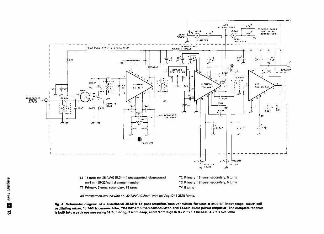
L1 15 turns no. 28 AWG (0.3mm) unsupported, closewound T2 Primary, 18 turns; secondary, 5 turns
on 4 mm (5132 inch) diameter mandrel T3 Primary, 18 turns; secondary, 5 turns
T I Primary, 3 turns; secondary, 18 turns T4 8 turns
All transformers wound with no. 32 AWG (0.2mm) wire on Vogt 041 -2520 forms.
fig. 4. Schematic diagram of a broadband 30-MHz i-f post-amplifierlreceiver which features a MOSFET input stage, S042P self- oscillating mixer, 10.7-MHz ceramic filter, TDA1047 amplifier/demodulator. and TAA611 audio power amplifier. The complete receiver is built into a package measuring 14.7 cm long, 7.4 cm deep, and 2.9 cm high (5.8 x 2.9 x 1.1 inches). A kit is available.

manufacturer specifies a drift of -350 kHz per OC
Layout of DJ3KM's 10-GHz Gunnplexer system, as set up for display at a German club meeting. The 30-MHz receiver is mounted on the front panel, under the speaker; the avc cir- cuitry is built on a small board mounted next to the Gunn- plexer. An ac power supply for the system is in the right foreground (photo by DBJPR).
amplifier/demodulator. This is a big help when align- ing antennas for maximum received signal. The in- herent noise of the TDA1047 produces a small current through the S-meter which can be nulled out by adjustment of the 4700-ohm ZERO ADJUST potenti- ometer. The output at pin 5 of the TDA1047 is a fre- quency-dependent dc voltage which can be con- nected to a carrier meter and/or an AFC circuit for the Gunnplexer ( f ig . 51. The Fairchi ld SGS TAA611B12 (or Texas Instruments 76001 ) serves as an audio power amplifier.
The frequency stability of the Gunnplexer is impor- tant for successful two-way communication; the
maximum. When the Gunnplexer is first turned on, the oscillator will drift a few MHz as the Gunn diode warms up, so the 220-kHz i-f bandwidth requires continuous tuning of the oscillator. The Gunnplexer also continues to drift slightly after the initial warm- up period. A simple solution to this problem is to compensate for the drift of the free-running oscillator by changing the operating frequency of the station at the other end of the link.
The AFC circuit shown in f ig. 5 uses the frequency-dependent voltage available from the i-f post-amplifier, as discussed previously. During two- way communications only one operator has his AFC circuit switched on; the Gunnplexer at the other end of the link is allowed to run free. A three-position switch is used because the frequency change might be up or down (center position is AFC OFF). The coupling between the AFC circuit and the Gunn- plexer determines the system's holding range.
performance The successful operation of various 10-GHz ama-
teur stations in the Rhein-Main area, operating with the equipment described here, has proved the sys- tem's feasibility and reliability. The use of 17-dB horn antennas at both ends of the link allows communica- tions up to 60 km (35 miles) or more. The 3-dB beamwidth of the horn antenna is approximately 30 degrees, so antenna alignment is not particularly critical.
Some stations are using home-built 23 dB horn antennas or 2 meter (6 foot) parabolic reflectors, so there have been many 10-GHz contacts in the range
fig. 5. AFC voltage for the 10-GHz Gunnplexer transceiver is derived from the frequency-dependent voltage available from the30-MHz receiver Ifig. 4). The value of resistor R1 (approximately 330 ohms) must be determined experimentally so that 1 volt is measured at TPl.
14 august 1978

QSL card used by DJ3KM showing his 10-GHz Gunnplexer and 30-MHz i-f receiver.
of 100 to 200 kilometers (60-120 miles). Since a pair and compass is a new challenge and hobby for many of Gunnplexers with these high-gain antennas has a calculated systems range of at least 400 km (240 miles), we could work over distances greater than 200 kilometers (120 miles) if we could find a non- obstructed path that long.
When setting up the Gunnplexers it's helpful to have a secondary link on 144 or 432 MHz, but many contacts have been achieved without it. The opera- tion of a microwave transceiver with the aid of a map
amateurs in Germany. Activity on 10 GHz in Europe has now reached the
point that a 10-GHz bandplan has been approved by amateur groups in Germany, Holland, and Switzer- land. In addition to providing space for communica- tions between individual amateurs, the bandplan accommodates beacons, repeaters, and narrowband modes (CW, RTTY, SSTV, and single sideband).
Trial runs with higher gain antennas, narrower i-f bandwidths, and phase-locked loop circuitry for frequency stability are presently going on (reference 3, which describes a phase-locked Gunnplexer system devised by WAGEXV, is available from Microwave Associates).
I would especially like to thank DJGRW, DJ3KM. DK2DRX, DJ8QL, and DJ8CY for their help in the construction and planning of this equipment.
references 1. J. R. Fisk. WIHR, "Solid-State Microwave RF Generators." hem radio, April. 1977. page 10. 2. B. Heubush. DCBCS. Dr. Ing. A. Hock. DCBMT, and H. Knauf, DCBCY. "Ein Sende-Empfanger fur das 10-GHz Band," UKW Berichre. Autumn.
A + 10 volt regulated power supply recommended for use 1976. page 184: Winter, 1976, page245; and Spring. 1977. page47. with the 10 GHz Gunnplexer transceiver. The BC107B tran- 3. C. Swedblom, WA6EXV. "ROCLOC Gunnplexer Stabilization System."
sistors may be replaced by any small-signal NPN silicon available from Microwave Associates, Inc., South Avenue. Burlington.
transistors such as the 2N4124. The MJ2956 may be replaced Massachusetts 01803.
by a 2N3789 or similar 10 amp PNP device. ham radio
august 1978 15

"FRONT END" BY MICROWAVE ASSOCIATES
Featum Low Cost
PRACTICAL High Sensitivity
RANGE Integrated Assembly CONSIDERATIONS Electronically Tunable The actual usable range is a High Reliability function of characteristics such as
Low Operating Voltage output power, frequency stability and noise figure. Generally, it's desirable
to deviate the FM signal so that the
THE GUNNPLDCER SYSTEM available IF bandwidthis completely filled.
The graph in Figure 1 below indicates the maximum achievable range vs. IF bandwidth at threshold with
The fascination of amateur microwave application is unique. threshold defined as the beginning of intelligible speech. Higher First of all, microwave systems have an 'exotic' ring to them. gain antennas will obviously greatly increase range. Until the appearance of the Gunnplexer, getting into micro waves required either a six foot rack of surplus gear or a friend on the inside of a microwave hardware supply company. The Gunnplexer has changed all of that; you can hold the whole WHY A GUNNPLEXER? Amateur thing in the palm of your hand and you don't need any friends in microwave cornmunlcation 1s fascinating and challenging. Now the microwave business (in fact it may be better if you don't with the revolutionary MICROWAVE ASSOCIATES Gunnplexer have any prior microwave knowledge because the Gunnplexer front end this exotic form of communications is available to vir- pretty much throws away the book on standard microwave tually anyone. And at an unbelievably low cost! design practices!) An equal fascination is the wide band capability of the micro- IM wave region. The 10 GHz assignment, for example, has spec- trum-space for 11 1 simultaneous video (4.5 MHz wide) chan- nels. Try that even using SSTV in the 20 meter assignment. The bottom line on microwaves is simply that it will do much - more communicating than you might first suspect. o
u
0 Z Q
C 10- ASSUMPTIONS
X 4
5 NOISF F I G n n s
DESCRIPTION The MA-8,127 series of fre- m Po 1 5 m W w 2 ANTENNA GAINS l l d B
quency modulated transcelver "front ends" using Gunn oscilla- P
tors and Schottky mixer dlodes has been specially designed to operate in the amateur 10.0 to 10.5 GHz band. The rear portion of the unit consists of a Gunn oscillator which
F R E O . 1 0 2 5 G H 1
L t ~ ~ OF SKHT CDNDITIONI
I O ~ B SIGNAL TO NOISE IN IF IF II THAICHOI DI
I I directly converts DC to RF energy. The oscillator is delivered
1 l o r n , IMKUI ~ H H , ~n uwr
pre-set at 10.250 GHz (oscillators pre-set to other frequencies ( 6 B A N D W ~ O T ~
are available on special order 10.0 - 10.4 GHz). Mechanical FIGURE 1 tuning is available to shift the center frequency + 100 MHz. A tuning varactor is mounted close to the Gunn diode which will MA-87141-1 2 Complete Gunnplexer trans- deviate the fundamental frequency typically 60 MHz when the ceivers (MA-87127-1, 1 smw typical and 2 proper tuning voltage is applied. FM, including both audio and video, can be applied to the tuning varactor input. The receiver horn antennas MA-86551, 17dB) just 99.95 noise figure is approximately 12 d~ depending on auxiliary PIUS $2.00 shipping and handling. equipment used. A ferrite circulator has been integrated into the waveguide mount to isolate the transmitter and receiver Rush Your Order by Calling (603) 673.7724. functions. Or send for our FREE Detailed Information
Package.
PI WAY VISA and Master Charge Orders Welcomed
COMMU NICATIONS The primary appli- cation of the Gunnplexer "front end" is for 2-way communica- tions. Two units, one a transmitter and the other a receiver down converter, are used with their carrier frequencies off-set to pro vide a reasonable IF (30 MHz or higher). Applications range from
HITEHOUSE & co. linking remote receivers to VHF repeaters, transmitting color
G . R W 10 Newbury, Amherst, NH 03031
video, linking homemade computers, full duplex mountain top DXing or over water duct DXing. A separate power supply and simple FM modulator must be provided; the MA-86551 (17 dB) Exclusive distributor to Hams for MICROWAVE ASSOCIATES horn antenna (shown here) is suggested. products in the U.S. and Canada.
16 august 1978 More Details? CHECK-OFF Page 126

frequency-lock loop
Oscillator stability can be improved
by applying this simple
but effective f requency-lock loop
One of the main considerations in the design of radio communications systems is frequency stability. The objectives in the amateur radio service, how- ever, are often quite different from those of other hf services. Amateurs have band allocations, while most other users have spot frequencies to work on, and consequently the vfo is usually our preferred pri- mary frequency source. There are three basic fre- quency generation techniques in common use at the present time. The vfo is the oldest, offering simplicity and the very real asset of continuous tuning, but it is difficult to achieve high stability, especially in the long term. The crystal-controlled oscillator is also simple and very stable, but offers little flexibility, although such variations as the vxo and the "Rock- Mixer" have offered some help in this direction. Finally, there is the synthesizer, based on the phase- locked loop. At the expense of some complexity, this method offers excellent stability and can be very flex- ible. However, it is inherently a noncontinuously- tuned device, and, therefore, not as well suited to amateur applications - especially on the hf bands.
The vfo, in all respects except stability, offers what we need. It seems a pity to throw away all the results of the continuing development which have made the vfo as good a piece of equipment as it is, and start all
over again with the synthesizer. On the other hand, the approach I have taken with the frequency-lock loop (FLL) takes advantage of the positive points of the vfo and adds to it the stability of the crystal oscil- lator. Moreover, you can readily add an FLL as an outboard unit to an existing vfo without major modi- fication to your equipment.
1 basic principles If you have a good frequency counter with a read-
out down to 1 Hz, you can, by manual tuning adjust- ments made suitably often, keep the vfo on the required frequency indefinitely. The stability in the medium to long term is that of the counter's clock. The function of the FLL is to automate this operation.
The frequency-lock loop consists of a simplified counter with a crystal derived clock, an error detec- tor and latch circuit, a filter section, and a controlled reactance to compensate for drift in the vfo tank cir- cuit. The error detector may be compared with the operator's recognition of a significant change in fre- quency, the filter his decision on the magnitude of the correction, and the controlled reactance the ac- tion of his hand on the vfo tuning knob.
counter The purpose of the counter in the FLL system is
not to display frequency, but to control it. And, as there is no reason to operate in the decimal or BCD modes, the simple binary counter is used. Comparing the FLL with the manual control, it should be obvious that there is no need to consider the most significant digits of the count. It is hoped that the vfo will not drift so much that the tens and hundreds of kHz would ever change, and surely not the MHz! So, for compensation of drift instabilities, only a small por- tion of a counter is required, and that can be in binary form.
The gate period is also of fundamental importance.
By Crawford MacKeand, WA3ZKZ , 115 South Spring Valley Road, Greenville, Delaware 19807
august 1978 17
OSCILLATOR I
PREAMP 0 "cc0 - -Ihh - INPUT 1 0 0
OFREOUENCY 2 2 k S I
1 6 Your - - - JOO* + 1 0 0
- !3
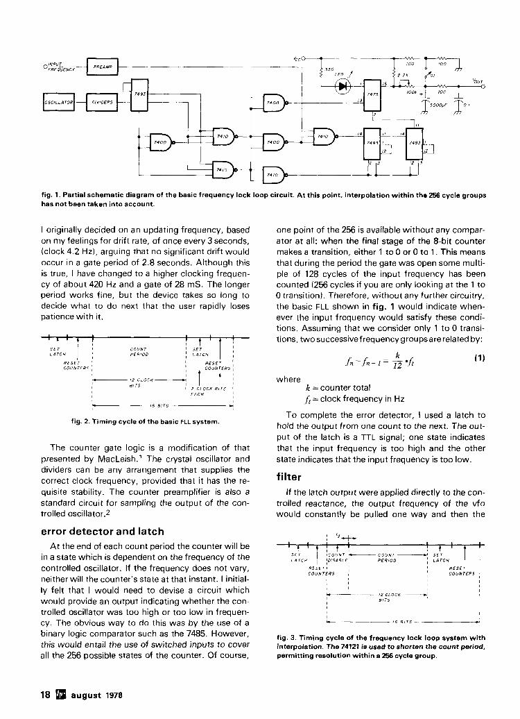
fig. 1. Partial schematic diagram of the basic frequency lock loop circuit. At this point, interpolation within the 256 cycle groups has not been taken into account.
I originally decided on an updating frequency, based on my feelings for drift rate, of once every 3 seconds, (clock 4.2 Hz), arguing that no significant drift would occur in a gate period of 2.8 seconds. Although this is true, I have changed to a higher clocking frequen- cy of about 420 Hz and a gate of 28 mS. The longer period works fine, but the device takes so long to decide what to do next that the user rapidly loses patience with it.
S E r C O U N J
P E R I O D
R E S E T ' C O U k T E R S I
I R E S E T ' I C O U N T E R S !
'- i 2 CLOCK 8 1 T S
I 1 2 CLOCK B I T S 1 ; 1
E A C H I
I 16 B I T S CI
fig. 2. Timing cycle of the basic FLL system.
The counter gate logic is a modification of that presented by MacLeish.1 The crystal oscillator and dividers can be any arrangement that supplies the correct clock frequency, provided that it has the re- quisite stability. The counter preamplifier is also a standard circuit for sampling the output of the con- trolled oscillator.2
error detector and latch At the end of each count period the counter will be
in a state which is dependent on the frequency of the controlled oscillator. If the frequency does not vary, neither will the counter's state at that instant. I initial- ly felt that I would need to devise a circuit which would provide an output indicating whether the con- trolled oscillator was too high or too low in frequen- cy. The obvious way to do this was by the use of a binary logic comparator such as the 7485. However, this would entail the use of switched inputs to cover all the 256 possible states of the counter. Of course,
one point of the 256 is available without any compar- ator at all: when the final stage of the 8-bit counter makes a transition, either 1 to 0 or 0 to 1. This means that during the period the gate was open some multi- ple of 128 cycles of the input frequency has been counted (256 cycles if you are only looking at the 1 to 0 transition). Therefore, without any further circuitry, the basic FLL shown in fig. 1 would indicate when- ever the input frequency would satisfy these condi- tions. Assuming that we consider only 1 to 0 transi- tions, twosuccessivefrequency groupsare related by:
where k =counter total
f , = clock frequency in Hz
To complete the error detector, I used a latch to hold the output from one count to the next. The out- put of the latch is a TTL signal; one state indicates that the input frequency is too high and the other state indicates that the input frequency is too low.
filter If the latch output were applied directly to the con-
trolled reactance, the output frequency of the vfo would constantly be pulled one way and then the
I I I I 1
+ C O U N T - C O U N T ------d S E T I
P E R I O D I L A T C H
R E S E T 1 R E S E T I
C O U N T E R S , 1 C O U N T E R S ' I I
I I I I I I I
12 CLOCK N, I
B I T S I I I
fig. 3. Timing cycle of the frequency lock loop system with interpolation. The 74121 is used to shorten the count period. permitting resolution within a 256 cycle group.
18 august 1978

TIME- MINUTES CONTROL VOLTAGE
fig. 5. Oscillator drift with, and without, the frequency lock loop system. The range of the correction voltage is shown at the right.
other. However, the mean frequency would be cor- rect. Intuitively, it seems that some smoothing is required. The FLL is very similar to a "bang-bang" servo, and can be readily stabilized by a first order fil- ter or integrator composed of a single RC stage. The optimum filter is probably worth some investigation; nonlinear circuitry may also offer some advantages (a possible approach is described in reference 5).
The filter time constant tf should be long enough
to reduce the f m on the vfo to an acceptable amount, and yet not so long as to make the balancing time ex- cessive. My experiments in this area seem to indi- cate that somewhere in the region of 50 to 100 sec- onds is a good starting point.
voltage-controlled reactance The obvious choice for the controlled tuning reac-
tance is a voltage-variable capacitor diode (varactor
august 1978 19

fig. 6. Circuit board layout for the frequency lock loop. Shown above is the back side of the board, with most of the interconnecting wiring; drawing on next page shows the top side of the board and the parts placement diagram. Although not included in fig. 5, this board contains an additional 7490 which is one of the input dividers from the oscillator. Also not shown in fig. 5 are the numerous O.l-pF bypass capacitors in- cluded on the board.
or varicap). Its application is dependent on the interpolation design of the vfo which is to be stabilized. The filter output has a useful range of about + 1.5 to 3.5 V dc, although it would be a simple matter to include an op amp if a greater swing were required. The varicap should be connected to the oscillator tank so that it produces, with this voltage range, a frequency varia- tion greater than the drift which is to be corrected.
In my Hammarlund HQ215 receiver I have been
The basic FLL of fig. 1 will stabilize a vfo at dis- crete fixed frequencies, based on a fixed count peri- od determined by the counter clock. The first method of interpolation I considered was that of varying the clock-oscillator frequency, using a vxo as the clock oscillator. W i th this arrangement I found that
able to stabilize the high-frequency oscillator by Afa/fa = Afx/fx (2) coupling into a diode frequency shifter, which is pro- where vided for resetting the calibration when changing fa is the basic clock oscillator frequency modes from USB to CW to LSB. Many transceivers Af, is the change produced by pulling the have RIT circuits which provide similar access to the . ... -
V A U oscillator tank, while most transmitters and vfos can easily be modified as if you were providing for FSK A fx is the resulting change
operation. f, is the controlled frequency
20 august 1978

This places another constraint on the design, in that A f, must be at least as large asf,, - fn - I , the dif- ference between successive discrete stabilizing fre- quencies. But A fa is limited by the design of the vxo. Because of this factor, and also the decreased stabili- ty of a vxo compared with a regular crystal oscillator, this method was set aside fo r future con- sideration in favor of an alternative which permitted the use of a fixed-clock frequency.
The basic timing cycle is shown in fig. 2. It should be obvious that if the total counting period could be varied, by at least the time required to count one group of 256 cycles, then the problem of interpola- tion would be solved. A non-retriggerable one-shot multivibrator is used to create a noncounting period.
The new timing diagram incorporating the interpo- lating one-shot is shown in fig. 3; the schematic dia- gram shown in fig. 4.
operation The lock switch, S1, is initially set to FREE. In this
position the oscillator will be at its nominal calibrated frequency, because R1 and R2 have forced the tun-
ing voltage to its center value. The LED indicator will show the latch's output state. As the oscillator is tuned across its operating range, the LED will cycle on and off every time the frequency changes by
f n - f n - 1 . If we now choose an operating frequency, the
interpolation control is adjusted until the LED flickers, showing that the FLL is ready to lock. The lock point may be either at a 1 to 0 or a 0 to 1 transition as the freqency increases. At this point S1 is moved to either LOCK A or LOCK 8. You will know if you've selected the wrong one because the oscillator will rapidly drive off frequency. Initially it is useful to establish a rule such as: clockwise rotation of pot, lights the LED, S1 to LOCK A. After this is estab- lished, when you select S1, you're on frequency to stay. Minor frequency adjustments can be made with the potentiometer.
A steady flashing of the LED is a good indication of continuing operation. Meter M1 is valuable in the lock mode to show how far you have drifted and how much corrective capacity you have left. While in the FREE position, it can be used to show which lock
august 1978 21

the emllmt antenna in town gives you the b@mt performance! Since the first Larsen Antenna was introduced some 15 yearsago, this basic fact has not changed: Larsen Mobile Antennas are designed and built to outperform. With the introduction of the Larsen exclusive KOlrod whip, this superior performance lsafact more than ever.
We're not going to confuse you with details on metallurgy, radiation resistance, plating systems and all that. Instead we suggest that you make this simple test: Take any antenna other than a Larsen . . .one with a regular unplated 17-7 PH stainless steel (.1001.050) tapered whip. Apply agood husky signal to i t . . . 100 watts, for, say, a full minute. Then, power off, feel the antenna. Careful! Burn blisters aren't pleasant. Next.. . try a Larsen KOlrod Antenna. Put it to the same test.
Amazing isn't it! That's our story. Heat means power.. . power that isn't radiated.. . power you shouldn't throw away. With the Larsen Kiilrod, power goes into communicating instead of heating theantenna. That's why you can HEAR the difference.
Larsen Antennas are available to fit ail styles of mounts and to cover Amateur frequencies from 6 meters through 450 MHz. Write for complete catalog and list of dealers nearest you. -
11611 NE50lhAve P.O. Box 1686 Vancouver. WA 98663 Phone: 2061573.2722
In Canada write to: Canadian Larsen Electronics. Ltd. 1340 Clark Drive Vancouver. B.C. V5L 3K9 Phone: 6041254-4936
" CI
I ," Kiilrod is a Registere
P Trademark of Larsen Electronics. Inc.
1
position to use and also which way to move the inter- polation pot.
performance In this system almost all of the stability is derived
from the cn/stalclock, with theremainder determined by the RC product in the interpolator. Using the con- stants discussed, on 80 meters, this amounts to one group out of about 400. In other words, during the total gate period, about 400 groups of 256 cycles are passed, and therefore, only one four-hundredth of the period is dependent on the one-shot's stability. If this is as good as 0.1 per cent, the overall stability is close to one part i n 400 000. There is, however, an interesting series of trade-offs between the various constants and values selected. A short-gate period makes the job o f the filter easier and reduces the f m effect caused by ripple on the control voltage. A long-gate period, on the other hand, makes the unit difficult t o use, but reduces the dependence of the overall stability on the one-shot. Having decided on the gate period, the frequency difference fn - fn _ I is a function of the total count k. I f fn - jn - , is too small, jumping from one stable point t o another could presumably occur.
There are a number of points which can be further refined if greater stability were required, but I have found, for instance, that the present design has made it possible to operate unattended on 3600 kHz RTTY autostart, where a stability of _+ 10 Hz is desired. M y actual achieved stability, as shown in f ig. 5, is closer t o f 5 Hz, which seems to indicate lit- tle drift in the one-shot.
conclusion The frequency-lock loop provides a simple and
effective way of improving the stability of a vfo, effectively competing with a crystal oscillator. Equip- ment modifications are minimal and can be largely outboard. The components of the FLL itself are all TTL, readily available and inexpensive, while the con- trol system is easy t o use and has no tricky compo- nents or adjustments. Construction follows normal TTL practice and the simple double-sided layout shown in f ig. 6 is suggested for the main board.
references 1. Kenneth MacLeish, WlE0/7. "A Frequency Counter for the Amateur Station." OST. October. 1970, page20. 2. Jerry Hall. KlPLP and Charles Watts. WA6GVC. "Learning towork with Integrated Circuits, Par1 8," OST. October. 1976. page 22. 3. Dr. Arthur D. DeLagrange, "Lock onto Frequency." Elecrronic Design, June2l. 1977. 4. Ulrich L. Rohde. DJ2LR. "The Frequency Counter as a Synthesizer." hamradto, September. 1977. page44 5. John C. West. "Servomechanisms." Textbook of Servomechanisms. English Universities Press. London. England. 1953.
ham radio
22 august 1978

RTTY Can Be Easy! Have You Wondered . . .
What Owning a RTTY Station Would be Like? Have You Thought. . .
About Finding Out but Didn't Know Who to Ask?
M..-- __=_-_= -
[mi ASK THE GUYS AT HAL!
0111 \.IIC.~ ,lnd w3r\11rc, s ~ l f l will I,c. ~ . I P ~ V t o , l \s~st ~ I I I Answers to common RTTY questions are f<,iiturcd 111 votlr c-lio~c-c of R ITY i~i~c~~pnic~rit..inswc~r (luc+t~~)nb 111 the, c-c'ntcBr folrf 111 otlr nrw ,Iln,itt,tlr radlo cnt,ilog. I RTTY I I S S I S I ~ I ~ I r l n d Such quest~ons as "What do 1 nrvd?': "How do I hook ,I~IW. In ddd111r111. 1111 HAl-,jmcltr~ur RTTY cclu~pnic*nt II up''". and "Wh,it f r rq~~c~nc~rs do I trse?" are d~s- ni,intl.ll.; (-,in I,(- ~iurc. f i~~wd for $10.00 c..~cli lor ,111 cussed. Trchnic,rl polnts concerntng RTTY p~~lses. i ~ i I I I I L I I I ~ to f ~ r p 1 r 1 of t i FSK <ind AFSK. and high lone5 vs low-tones are 111111 1 covc~red.
HAL COMMUNICATIONS CORP. Box 365 Urb,>na, Ill ino~s 61801 2 17-367 7373
For our Eurolx+ln cus to rn~~rs we HAL equlpniPnt
1(14 1111.1 XI c I . 11.,111111~1., I I t l,>!..,~~l~ 3 , I~#..<~TW t ' r # r ~ w t ~ . k S ~ ~ ! ~ ~ ~ ~ ~ ~ 1 I . t o ~ l ~ ~ t 1 k6.c1,.#, H.ulo~# 511.1, h c.1 I I~IxI<~!~
\
More Details? CHECK-OFF Page 126 august 1978 23

TVI locator Locating and correcting the source of N I is per- haps one of the most difficult tasks facing a radio amateur, one which must be performed methodically if satsifactory results are to be obtained. Much has been learned and written about transmitter harmonic radiation and TV receiver overload, but often very lit- tle is said about another prevalent and frustrating source of TV trouble, nonlinear rectification TVI.
Rectification TVI is caused by poor or intermittent contact between two conductors in the radiation field of a transmitting antenna. No amount of filter- ing or shielding at either the transmitter or TV set will correct the problem, since the interference is gener- ated in the TV spectrum as direct harmonics of the transmitter's fundamental frequency.
In January, 1953, a fine article by Mack Seybold, W2RYI, was published in QST,' but I have seen nothing of a concrete nature on this particular prob- lem since that time.
how do I know I have it Rectification TVI can be suspected when suddenly
there is TVI on one or more channels where there was none before, and no changes have been made in transmitter operation. Any metallic discontinuity can cause rectification TVl. In 1947, when I was living in a small town and in the days before the blessings of TV, my next-door neighbor said he heard voices coming from his bathtub drain. Another neighbor heard voices coming from her electric kitchen range. Both voices were caused by detection of my 75- meter a-m kilowatt rig. These two phenomena, no doubt, were caused by rectification.
The strength of the TVl will depend on the efficien- cy of the rectifier, the length of the "antenna" con-
nected to the nonlinearity, the distance from the transmitting antenna, and the transmitter output power. Two signals on widely separated frequencies can also combine to produce a signal at a third fre- quency - the faithful 2 A f B, or intermodulation products. For example, if two hams live near each other, and one is on 21 MHz and the other on 28 MHz, interference can be caused on channel 4 (2x21 + 28= 70 MHz) or channel 5 (2x28+ 21 = 77 MHz), or both, if a nonlinear discontinuity exists in the area. These two signals, of course, will exist only when both stations are transmitting. Also, each sig- nal alone can cause TVI on channel 2 (28x21, channel 3 (21x31, and channel 6 (28x3 and 21x4).
Visible TVl can be caused by an interfering signal as weak as 40 dB below the video carrier, depending on the frequency of the interference. A 1000 pV vid- eo signal, which is an adequate signal, can be inter- fered with by a 10 pV harmonic. If the amateur trans- mitter is running one-kW input, this does not leave much margin for harmonic generation.
All 14-MHz harmonics through the sixth can cause trouble, but the greatest problem is caused by the odd harmonics, the third and fifth. Table 1 shows the harmonic relationships of the 14, 21, and 28 MHz amateur bands with respect to the TV channels. The worst interference is caused at or near the video carrier, 1.25 MHz above the lower TV channel edge. With all stations usingcolor, however, a particularly vicious interference is caused by a harmonic falling on or near the color subcarrier frequency, 4.8 MHz above the lower TV channel edge.
By John E. Pitts, WGBD, 1068 Eden Bower Lane, Redwood City, California 94061
24 august 1978

This effect was noted at WGBD on channel 4 when operating near 14.2 MHz. The interference appeared as wide diagonal color (rainbow type) bars on the screen. The fifth harmonic of the fundamental fell within 200 kHz of the color subcarrier at 70.8 MHz. Operation in the CW portion below 14.1 MHz caused no interference. Substitution measurements with a calibrated signal generator showed that color bars were caused by an interfering signal at 71.0 MHz with a signal strength of less than 300 pV. The desired channel 4 signal was 1500 pV. The cause was eventually traced to rectification TVI and was located by the methods presented here.
the fix for the hex The harmonic chaser used in this hex-pedition (an
expedition to find the hex) is simple to construct, easy to use, and will rapidly locate the source of the harmonic radiation. I t is also, by today's standards at least, inexpensive. In this instance, the whole system was constructed and tested and the TVI source found in one weekend, so the work involved in the project is not great.
table 1. Amateur-band harmonic relationships to low- frequency TV channels. All frequencies are in MHz.
fundamental 28 21 14 harmonic TVfrequency TVchannel
harmonics frequency band number
2 4 56 54-60 2 3 63 60 - 66 3
5 70 66 - 72 4 76 - 82 5
3 4 6 84 82 - 88 6
Since the harmonic strength will be a relative measurement, a narrow-band receiver, tuned to the harmonic frequency, will be used. The easiest ap- proach is to use a TV tuner whose i-f output is in an amateur band. This allows the selective station re- ceiver to become the i-f amplifier and detector.
There are generally two types of tuners used for re- placement purposes, the turret type and the wafer type. Due to the coil arrangement of the wafer-type tuner, it is unsuited for this purpose because the tun- er's oscillator frequency must be changed. The most easily modified is the turret type, because the coils
4 N l / SARKES- rARZ IAN M F T - I TUNER \
CHZ-13
I ADDED POWER SUPPLY - UHF
(NOT USED)
I F OUT
OFF
fig. 1. Schematic diagram of the Sarkes-Tarzian tuner and power supply. The coil marked CC is tuned for maximum signal into the receiver. You should not use more than about 60 cm (2 feet) of cable between the tuner and the receiver, otherwise the tuner may not cover the desired output frequency range.
august 1978 25

for each channel are mounted on an easily removable bar. Present-day tuners have an i-f of 41.25 to 47.25 MHz, out of the range of most ham receivers. The widest high-frequency amateur band is 28 to 29.7 MHz. Therefore, the oscillator frequency needs to be lowered only about 10 to 12 MHz to produce an i-f output at29.0 MHz.
The tuner used is a replacement type, Sarkes- Tarzian MFT-1 preset replacement tuner (see fig. 1). I t is housed, with a small power supply, in an LMB 12.7 x 11.4 x 19.1 cm (5 x 4-112 x 7-112 inch) W-2F chassis cabinet. Except for the tuner and cabi- net, which cost about $27, all parts came from the junk box. Purchasing everything, and with a little horse trading and typical ham ingenuity, the entire cost should not exceed $40.
construction The original cut-and-try coil modification was per-
formed using a frequency counter. A counter is not absolutely necessary, but if one is available, the job is much easier. If not, a reasonably accurate grid-dip oscillator (GDO) can help set the tuner's oscillator to the required frequencies. The oscillator was tuned to the high side of the desired signal because it did not want to oscillate on the low side. Therefore, as shown in table 2, the 10-meter receiver tunes back- wards.
The only coil to be rewound is in the oscillator, the coil with the fine-tuning screw slug. Remove the snap-off shield from the tuner chassis. The channels to be modified are 2 through 6, since 7 and above are
Interior view of the tuner section. Loop-antenna input con- nector is at the left rear, i-f output jack to the receiver in the center, and audio from the receiver is at the extreme right. The 4:l balun, to match the 75-ohm line to the 300-ohm in- put, can be seen just below the type-F connector.
not normally subject to rectification TVI. Channel 5 doesn't have to be modified, since no discrete ama- teur-band harmonic normally falls in this channel. Citizens band harmonics, however, do fall in channel 5.
Rotate the shaft until the bar with the greatest number of coil turns (channels 2 through 6), starting with the bar adjacent to the uhf strip, can be pulled out with the long-nose pliers. The uhf strip has no oscillator coil. The bars are easily removable, but use caution, as they can be broken. Pull at the pressure- finger point, the end with the tuning screw.
Remove all turns from the oscillator coil and clean the soldered portion of the contacts. Use care not to get solder on the switch contact portion of the termi- nals. Rewind the coils as shown in table 2; number 28 (0.32mm) AWG or number 30 (0.25mm) AWG enameled wire can be used. Wind on the number of turns indicated for each channel, observing the same winding direction as used on the other coils on the bar. Wind the turns close-wound, starting at the slug end. If necessary, the turns can be spaced later for the proper frequency range. Unscrew the fine-tuning screw about five turns out from full in. This will provide adjustment range later for the oscil- lator. Screwing the slug into the coil raises the oscil- lator frequency, and therefore raises the intermediate frequency to which the receiver is tuned. After each coil is rewound, return the bar to its original position in the turret to prevent mixing their positions.
Install and wire the power supply, jacks, and split- ting filter as shown in fig. 1. Jacks and power supply may be whatever you have on hand in the junk box. Plate voltage for the tuner may be anything between 110 and 140 volts dc. The bias voltage is obtained from a rectifier on the 6-volt ac filament winding. The values shown for the resistors give a minimum of - 0.8 volt and a maximum of about - 4 volts. Normal operation is at full negative, but, if desired, the bias may be permanently set at - 3 volts by selection of appropriate resistor values.
Install the tuner in the cabinet, mounting it with screws and spacers to the panel. Three of the front holes (near the shaft) will conveniently accept a 6-32 (M3.5) tap or a number 6 sheet-metal screw. For ease of fine-tuning adjustment, a piece of lucite (Plexiglas) - cut to 5.7 cm (2-1 14 inches) in diameter by a circle cutter - forms a good control wheel, sim- ilar to the fine-tuning control on a TV set. The center hole is sized for a force fit on the fine-tuning shaft, which is 9.5 mm (318 inch) in diameter. Mark the plastic shaft and then cut it to length with a hacksaw, afterwhich the fine-tuning wheel may be forced onto the shaft.
Mark the length required on the selector shaft, cut it with a hacksaw, and smoothwith a file. Rotate the
26 august 1978

SCREWS AND NUTS SO 239 (UHF1 (PPLACESI COAX JACK
LOOP ANTENNA
BNC
SPLITTING FILTER
fig. 2. Diagram of the loop antenna and splitting filter. The filter is constructed in a small box, such as an LMB-M-00. The capacitor at the top of the loop is a 50-pF compression trimmer and is used to tune the loop to the desired frequency.
shaft with pliers so the uhf strip is in its operating position, then mount a skirt-type knob with the indi- cator mark toward the bottom of the panel. Channel 2 will be at the first position to the left of bottom as the turret knob is rotated clockwise.
loop antenna The loop is constructed of two 25-cm (10-inch)
lengths of number 10 (2.6 mm) AWG wire formed in- to a loop about 18.5 cm (7-114 inches) in diameter
(see fig. 2). The base of the loop is fastened to the shell of an SO239 uhf jack, with screws and nuts holding two soldering lugs onto which the loop wires are soldered.
A 50-pF trimmer is soldered to the wires at the top of the loop. A piece of number 12 (2 mm) AWG or number 14 (1.6 mm) AWG copper wire is soldered to the inner terminal of the SO239 jack, formed to the contour of the loop with 6- to 9-mm (114-to-318- inch) separation, and soldered to the loop 13 cm (5 inches) up its circumference.
Using appropriate connectors and a very small metal box, the splitting filter is constructed for the earphone or telephone connection at the base of the loop. When connecting the filter to the antenna, ob- serve the connections shown in the figure. If con- nected backwards, the loop will work, but no sound will be heard in the phones.
tuning Connect the tuner and station receiver together as
shown in fig. 3. Temporarily connect the harmonic- producing network (fig. 4) between the tuner and transmitter output. Place the tuner on channel 2; tune the receiver to 29 MHz and the transmitter to 28.000 MHz or 14.000 MHz. Only very low output is necessary, just enough to make the diode conduct, producing harmonics. Turn the transmitter on, and also the receiver bfo. Veryslowly, rotate the fine-tun- ing control until the transmitter harmonic at 56 MHz is heard. Verify this frequency by using the GDO as a signal generator. If no signal is heard, tune the re- ceiver between 28 and 30 MHz and adjust the fine- tuning control until the 56 MHz harmonic is received. Do not confuse the desired signal with the funda- mental or second harmonic of the transmitter output, bypassed around the tuner. Then jockey the receiver tuning and fine-tuning control on the tuner until the second harmonic of 28 MHz or the fourth harmonic' of 14 MHz (56 MHz) is at 29 MHz on the receiver. Look up the signal frequencies for the various TV channel video and sound carriers in table 2. If chan- nel 2 exists in your area, it can easily be heard when an antenna is connected to the tuner input and the
table2. LO coil winding and i-f frequency output data for TV tuner modification. All frequencies are in MHz.
LO coil receiver dial number LO TV video TV sound frequency
channel of turns frequency receiver i-f receiver i-f 31 30 29 28 27 26 25
august 1978 27

receiver is tuned to the indicated i-f frequency. In my test set-up, a 3 pV signal on any of the converted TV channels could easily be heard in the receiver.
Repeat the tuning procedure for the other chan- nels and amateur bands according to the table. Note that the video or sound carrier can be used as check points if they're within the tuning range of the station receiver. I use my old Hammarlund HQ129X. The vid- eo carrier is a strong signal with 15.75 kHz sidebands extending several hundred kHz each side. The sound carrier has distorted modulation, since i t is fm.
The loop is connected to the tuner via a conven- ient length of RG-58 or RG-59 cable equipped with suitable connectors. The most inexpensive connec- tors are F-type, used for TV cable connections. In my case, in order to reach the source of the rectification, 60 meters (200 feet) of cable was required. If you use F-type connectors, note that they are designed for coax with a solid center conductor.
The loop antenna operates as a radio direction
finder to locate the source of signal rectification causing generation of harmonics. In order to hear the effect of loop rotation on the signal, the audio output of the receiver is sent via the coax cable to head- phones or a telephone carried by the loop-antenna operator. While slowly rotating the loop about its vertical axis, a distinct null, about 2 or 3 degrees wide, is easily heard.
Although a loop is normally bidirectional, in this case, due to the tapped feed point, it exhibits about 10 dB of front-to-back ratio when properly tuned. With the operator looking through the loop, he is fac- ing the signal when the deepest null is heard with the feed tap on the left side of the loop. Rotating the loop about its horizontal axis will indicate, by a deep- er null, the angle of elevation of the incoming signal. For maximum directivity, the trimmer capacitor must be tunned for maximum signal at the frequency of in- terest.
Loop operation can be verified by tuning it and the
LOOP
COAX ADAPTER AN0 COUPLINGS - h
HARMONIC PROBE AS REWIRED
R e 5 8 OR R G 5 9 LENGTH AS REOUIRED WITH
APPROPRlArE
&- FILTER \ h
6 -12 VOLT RL#-BATTERY FOR TELEPHONES
fig. 3. Interconnection diagram of the loop, tuner, and receiver. The earphone and microphone of each handset are connected in series. The battery is not required if the earphones alone are used.
28 august 1978

10 VOLTS MAXIMUM 7mi;1; erator control the signal level with the receiver's rf
gain control. When nearing the interference source, or when using the probe as a "sniffer" for harmonics
TRANSMITTER 75 TO TUNER
14.21.OR28MHZ DUMMY INPUT radiating from equipment, a coax plug fitted with a IN341 OR S I M I ~ A R few centimeters of stiff wire will serve as a probe
antenna. OIOOE WILL C L l P A T % O 5 VOLT
Due to the attenuated response of the loop anten- na at the normal amateur frequencies, a highpass fil-
fig. 4. Schematic diagram of the harmonic-producing net- ter of the TV type was not found necessay. If one is work. This circuit is used to produce harmonics to calibrate the tuner and receiver. A maximum of 2 watts should be
used, it must be located after the splitting filter in the
applied. tuner, or the telephone extension will not work.
where to look receiver to a W station and observing the effect of rotation. This test may be invalid if many echoes exist from pipes, ducts, or other large metal surfaces. This same effect must be considered when looking for TVI.
finding the hex Set up the equipment as shown in the block dia-
gram, fig. 3. Tune the TV set to the channel having interference. Turn on the transmitter and verify that it is causing interference, then turn the tuner to the same channel. Use only sufficient transmitter power to cause TVI. Tune the receiver to 29 MHz and find the harmonic. Note that table 2 is based on the low- er edge of the 14-, 21-, and 28-MHz bands. Also note that the receiver, used as an i-f amplifier, tunes back- wards. For example, if 21 MHz interferes with chan- nel 3, the third harmonic is at 63 MHz and is tuned on the receiver at 29 MHz. If the transmitter is tuned to 21.3 MHz, the third harmonic is at 63.9 MHz and will fall at an i-f frequency of 28.1 MHz on the receiv- er dial.
Set the receiver controls for CW operation, and tune the harmonic so that its detected audio frequen- cy is about 1 kHz. It will be necessary to retune the receiver from time to time since the oscillator will drift slightly. Therefore, an operator should be at the receiver for periodic tuning, and to key the transmit- ter on request. If two telephone handsets or opera- tor's headsets are available, constant communication between the antenna and receiver operators is pos- sible.
Go outside the house and take a preliminary bear- ing on the interference source. Note the direction (a rough sketch or map may be helpful). Go to a second location and take a second bearing. In all but the most elusive cases of interference, two or three bear- ings will suffice. Rotating the loop axis vertically, rather than horizontally, will indicate the elevation of the source above ground level.
Under certain conditions, it may be advantageous to turn off the receiver agc and have the receiver op-
Many things can cause a rectification-harmonic problem. Some of these are rain gutters, down- spouts, roof flashing (the metal under shingles), cor- roded TV antennas, rusty TV masts, poor (unsol- dered) splices in TV feedlines (or in the station anten- na system both transmitting and receiving), poor electrical conduit joints and other metal junctions of this nature, all transistorized equipment, intercoms, pipes, telephones, concrete reinforcing bars - the list is almost endless. Any two touching pieces of metal more than a few centimeters long in the field of the transmitting antenna are suspect. The obvious solution to the problem is to permanently bond the two pieces, or, if no electrical continuity is neces- sary, to permanently insulate them.
Three cases have been found and corrected at my location, galvanized-tin roof flashing and corroded TV antennas on two adjacent houses being the cause. In the latter case, good relations have always been maintained with the neighbors, so no problem existed in correcting the situation. In fact, one case resulted in a very nice Christmas gift as an expression of gratitude. The tin flashing problem was fixed by permanently connecting the two pieces with sheet metal screws and anti-corrosive grease, permanent separation being impractical. The corroded TV an- tennas were scraped clean at the connection points and then painted with an anti-corrosive grease.
About eight years ago, long before this equipment was built, I found a source of rectification in my own TV antenna so severe that a 75-watt transmitter on 3.5 MHz feeding a dummy load caused TVI. A friend and I found the cause, wholly by accident, after a prolonged search. With the equipment described here, it would have been found in minutes. Now that you have the tools, good hunting, and may all your hexes be easy ones.
reference 1. Mack Seybold, "Harmonic Radiation from External Nonlinear Systems," OST, January, 1953. page 11.
ham radio
august 1978 29

I a dream realized: the ultimate antenna array
A 7-element quad on 40 meters?
You'd better believe it! Here's an account
of how one DXer solved the problem
of big antennas
Most of us at one time or another have fantasized about having the ultimate array: the antenna to make you king of the band; the supergain bone crusher. Usually these dreams are dashed away by the reality of circumstances, but sometimes someone will suc- ceed in getting one of these monsters up. Although, generally, this supreme achievement will go unno- ticed by most, the rewards of the labor are still col- lected in abundance by the ambitious amateur who undertakes the challenge and succeeds.
The following account isn't meant to be a con- struction project but is presented with the hope that some of the ideas will convince others that, first, you don't need a lot of money to build a large array; and, second, some dreams can come true with a little applied ingenuity.
how it all began Having been one of those few fortunates who've
had the pleasure of operating at a large multi-multi station during DX contests, I've become appreciative of the merits of high-gain antennas. One day in early 1973 1 was discussing various antennas with Jerry, WA7KYZ, when the subject of 40-meter arrays came up. Since 40 meters is generally considered to be the transition between wire dipoles and rotatable beams, we decided to experiment with some high-gain fixed- wire antennas on that band. Fortunately, we had a sizable piece of land on which to work. This property was dotted with 46-meter (150-foot)-high Douglas fir trees.
initial attempts The first antenna we tried was a full-size four-sec-
tion 8JK beam. On paper it looked really simple, but it turned out to be a real monster. We had to resort to using 2.6 mm (no. 10) copper-plated steel wire for the elements and 17-foot-long 1x6s (5 meters x 25 x
By Paul Kiesel, K7CW, 3522 N .E. 115th Street, Seattle, Washington 98125
30 august 1978

152 mm) for the spreaders. We finally got the thing up in the air by pulling up the ends with a pickup truck.
The antenna worked reasonably well. It seemed to have a low angle of radiation, as it was supposed to, and it definitely had gain. But it pelformed well in only two directions. It had a very narrow beamwidth. Additionally, we had a problem that we hadn't con- templated: we had to keep untangling the open-wire feedlines. Also, we had to use a transmatch, which made things even more cumbersome. The antenna eventually came down when an ambitious ten-year- old neighbor untied one of the support ropes at the base of the tree. We had mixed feelings about the array's demise.
the grand experiment We fiddle-fumbled around for some time before
we came up with the ultimate solution, the utopian array. It was to be a multi-element delta-loop quad. We decided to go with seven elements aimed at Europe. Every amateur in Washington state who works DX knows that the European path is the toughest nut to crack, because we have to battle the northern auroral zone. The east-coast guys have the same problem working into Japan. So we had to have a lot of gain; however, we didn't want to nar- row the pattern of the array too much. We could have put three times as many elements on the thing,
2 6 mrn (NO 101 COPPER-PLATED
,-- /<*- REFLECTOR
since the supporting wire was 137 meters (450 feet) long! We couldn't use the 2.6-mm (no. 10) wire far all the elements and support because it would have made the antenna much too heavy, so we used 0.8- mm (no. 20) brass wire for the elements. Sounds
TREE SUPPORT
\ ,\ 7 7 .& ELE;NTs
TO EUROPE
\\% TO SHACK 3 ELEMENTS TO CARIBBEAN/
s o u r n AMERICA,/ SHACK
4 ELEMENTS TO V K I I L lREEdT TREE SUPPORT
fig. 2. The ultimate antenna farm, which includes three switchable monster arrays covering Oceania, Europe, and South America, including the long path to the Orient.
flimsy, all right, but it works fine for a temporary effort. We really lucked out on the element wire. I picked up 1220 meters (4000 feet) of it at a surplus place for $4.00. We used 9 kg (20-lb) nylon fishing line to pull out the corners of the loops. Jerry picked up some 75-ohm coax remnants from the local cable television company, so we used some of this for the feedline.
up she goes
LIGHT NYLaV
WEffiHT OC COAX 9 10 120 LBJ NYLON FISHING LINE TO PULL CORNERS OF
/ \\ \SEE DETAIL \
fig. 1. Details of the driven element for the 7-element, 40-meter delta-loop quad anten- na. High Douglas fir trees provided the sup-
U14X T O STA rlON LL NYLON CORD SUPPORTING COAX
ports. Handbook data were used for loop MP JACKET AROUND
dimensions and ele- ment spacing, which was 0.2 wavelength.
W The vswr was meas- ured at 1.5. DETAIL OF FEED POINT
Now, back to the support wire. Our two support trees were 137 meters (450 feet) apart. We couldn't afford polypropylene or similar rope, so we decided to use some of the 2.6-mm (no. 10) wire left over from the 8JK project. We used no insulators to sep- arate the loops from the support wire as they were unnecessary. As soon as the array was secured, we checked the swr to find that it was only about 1.5:1. We used 0.2-wavelength spacing between elements and the customary formula for loop dimensions. We kept all directors the same size. We found that the ar- ray would sway freely but not excessively with the breeze.
I wanted to photograph our antenna for posterity, but this proved impossible. All that was visible in the photos was a 137-meter-long (450 feet) wire, two trees, and a piece of coax reaching up into the air and seemingly terminating into nothing. There are defi- nite possibilities here for those who need to display as little antenna as possible.
august 1978 31

It took Jerry, my brother, John (K7TU, ex- WA70TT), and me about a day and a half to build the antenna from scratch. As we secured each ele- ment, we pulled up the support wire a bit. We used a small butane torch to solder the loops to the support- ing wire. To support the coax so it wouldn't pull the loop out of shape, we ran a nylon cord down from the supporting wire to the feed point (fig. 1).
performance I only use published gain figures as a ballpark
method for deciding what kinds of array to consider, and I never tried to measure the gain of this antenna with respect to another antenna because of the many variables involved. My method of evaluation is to just get on the air and see how well the array works by communicating.
With the antenna connected to the rig, we tuned through the CW band and came across several UAls and UA3s. (Remember - this was on the 40-meter band.) Their signals were so weak the S-meter didn't move, but all were solid copy. The only other signals on the band were some rag-chewing W6s. It doesn't sound too impressive until I mention that this first check was carried out at 12 o'clock noon.
A couple hours later we were able to work into Europe with consistent S4-S6 signals using only a barefoot T4X exciter. Later on that evening we were getting consistent 599 reports from all over Europe. The Europeans we worked were all solid copy. Our antenna was turning out to be a great performer.
further experiments When we found out how well our antenna was
performing, we decided to erect three more of similar type. We had enough material to erect three ele- ments centered on the CaribbeanISouth America region, four elements on Japan, and four elements on the VKIZLlEurope long path (fig. 2). By now we knew how to go about constructing the antennas, and the three new ones only took another day to erect. Upon trying them out we found that all three new antennas performed very well also.
sidelights At this point a small anecdote relative to our
antennas is appropriate. Soon after we got the four arrays up I was stringing JAs at about 9 o'clock in the evening when Gordy, W S F A (now WFU) , broke in. He wanted to know how well I was hearing Japan. I told him that signals were moderate. This revelation must have surprised him, because he asked me what kind of antenna I had. I told him I was using a Celement quad and that it was working quite well. Upon being asked by him if I could rotate my
quad, I replied that I could and told him to stand by. At that point I paused and flipped the antenna switch over to the European 7-element job, which just hap- pened to be pointing directly at him. I hit the key again and asked him how it sounded. I won't repeat his reply here. And, quite frankly, his signals came up so much with the switch of antennas that their strength almost blasted me right out of my chair. Whew!
As flimsy as the antennas appeared, they proved to be very durable. They remained erect through sev- eral storms and during both weekends of the CQ WW DX Contest. In fact they were still in the air when the location had to be vacated a couple of months later.
Although we couldn't use the antennas on a per- manent basis, they were still well worth the effort. I'll never forget how much fun it was to tell the Euro- peans on 40 meters; "The antenna here is a 7-ele- ment quad."
ham radio
"Since you're afraid of heights I was sort of hoping for a brother to help with my antenna."
32 august 1978
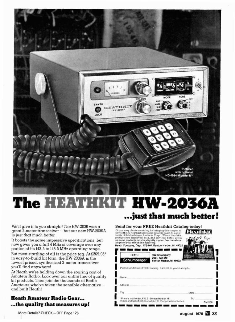
...j ust that much better! We'll give it to you straight! The HW-2036 was a Send for your FREE Heathkit Cataloa todav! " great 2-meter transceiver - but our new HW-2036A ~;;~;,;~~;~;;;;,;;;~;~~a~;~;~;;~;;~;,;;~~;;~ is iust that much better. l u n t l s o l S c h l u m h e t q e r P ~ d ~ r ? s C o ~ p WheteP--*-b . . r,c",.,-.,
products oredlsplayed, sold, and se&ced. Retoll prices : on someproductri may be sltghlly h~gher. See the whtle It boasts the same impressive specifications, but Fgeaol your lelephonedi,~lo~, now gives you a full 4 MHz of coverage over any Heath Company. o e p ~ . t zdro . Benton Hafoor, MI 48022
portion of its 143.5 to 148.5 MHz operating range. I
But most startling of all is the price tag. At $269.95' H.nhCanp.n~ in easy-to-build kit form, the HW-2036A is the h p t . 1 ~ 2 . ~ 0
Bentm H 8 r b o r . U I ~
1 lowest priced, synthesized 2-meter transceiver you'll find anywhere!
I I Pleaqe sendme my FREE Calalog I amnot on yourmallmg llsl
At Heath we're holding down the soaring cost of I
Amateur Radio. Look over our entire line of quality I Name - . - - - __ - kit products. Then join the thousands of Radio
I Amateurs who've taken the sensible alternative - I Address --- - - - - - - - - - -
and built Heath! I
Slale ___-- i Heath Amateur Radio Gear... 1 'Prtce IS mall order. FO B Benton Harbor. MI z t p ~ _ --
PrlCe5 and Spec~I~CallOn~ s ~ b ~ e c l 10 change wllhoul nottce I ... the quality !ha! measures up! L -----m-m----m AM.366 4
More Details? CHECK-OFF Page 126 august 1978 33

I higher frequency resolution for an h f synthesizer 1 supplies correction pulses to the VCO, through a low-
pass filter, at a frequency equal to the reference fre-
A unique method for obtaining
10-Hz increments from an hf synthesizer
using a dual vco system
The advent of l ow cost phase-locked-loop fre- quency synthesizers has had considerable impact on vhf amateur radio equipment. Unfortunately, the fre- quency synthesizer is most adaptable to channelized systems, consisting of a finite number of discrete operating frequencies. Typical high-frequency ama- teur activity consists of tuning an analog-oscillator controlled radio to a clear frequency and making a call. To answer such a call, with single-sideband equipment, you must tune to within 50 Hzof the orig- inating station's frequency for near natural voice reproduction. This means that a practical, synthe- sized, hf ssb transceiver must be capable of continu- ously tuning in 100 Hz steps, and requires an internal, loop-reference frequency of 100 Hz in a conventional configuration. The loop filter cut-off frequency re- quired to effectively eliminate reference frequency sidebands from the synthesizer's output increases the loop lock-up time to several seconds after each frequency change. The ideal amateur CW receiver, equipped with narrowband i-f or audio filters, must be continuously tunable in 10-Hz steps, and this would have ten times longer lock-up time between frequency changes.
This article briefly describes a less common approach to an hf synthesizer which offers 10-Hz fre- quency steps from a 10000 Hz reference, and there- fore offers 1000 times faster recovery after frequency excursions. In addition, less rugged mechanical con- struction of system oscillators is possible because of loop correction of low-frequency fm due to vibration.
Fig. 1 is a functional block diagram of a conven- tional PLL frequency synthesizer. The phase detector
quency, until the vco is locked at a frequency equal to N times the reference frequency. A lower refer- ence frequency requires a lower filter cutoff for a given attenuation of the ac component of the refer- ence frequency. The filter is part of the closed loop and its response determines the maximum rate of vco frequency correction.
Fig. 2 is a functional block diagram of a two-part synthesizer, offering 10-Hz steps with the advan- tages of a 10 kHz reference frequency. Note the use of two reference frequencies, 10.000 kHz and 9.990 kHz. The output frequency is actually the difference frequency between two phase-locked oscillators. To change the output frequency by 10 Hz, we move the first oscillator 10.00 kHz; next, we move oscillator number two 9.99 kHz in the same direction. The dif- ference between the oscillators' frequencies has only changed 10 Hz.
In the following example, I have made provisions for high-side LO injection in a super-heterodyne application, employing a 9.0 MHz i-f system. Also, sample calculations are shown for bfolcarrier fre- quencies of 8998.5 kHz for lower sideband and 9001.5 kHz for upper sideband (remember the side- band inversion with high-side local oscillator injec- tion). The actual operating carrier frequency is programmed in BCD into the circuit's adders. Func- tionally, the circuit is divided into two major sections. Section two covers a range of approximately 50 to 60 MHz, with section one covering approximately 59 to 99 MHz.
To run section two at approximately 50 MHz, a divide ratio (programmed vco 2 offset) of 5005 is ini- tially chosen for divider 2. To the resulting frequency
REFERENCE 0 I PHASE OE T€C TOR PROGRAMMABLE O/YIOER
I fig. 1. Block diagram of a conventional PLL synthesizer.
- By William E. Coleman, N4ES, E-Sys- tems/ECI Division, Box 12248, MS 11, St. Petersburg, Florida 33733
34 august 1978

(49999.95 kHz) is added the bfo frequencies of 8998.5 kHz and 9001.5 kHz, producing the initial vco 1 frequency. This procedure allows us to calculate the final required programmed offsets for dividers 1 and 2 (fig. 3).
Therefore, for a programmed operating frequency of 00000.00 kHz, divider 1 must divide by 6744 for lower sideband, and 6045 for upper sideband as shown in fig. I . Vco 1 will then operate a t 67440 kHz for LSB and 60450 kHz for USB (fig. 4).
And, for a programmed operating frequency of 00000.00 kHz, divider 2 will divide by 5850 for LSB and 5150 for USB. Vco 2 will operate at 58441.5 kHz for LSB, and 51448.5 kHz for USB (fig. 5).
With a sample operating frequency of 14307.96 kHz USB programmed into the synthesizer's data input, divider 1 would divide by 8271. Vco 1 would
/MA GP I u DUMP 5 0 I
ESTABLISHING VCO START?NG FREOUENCIES AND I -F Of FSET
5 0 0 5 4 9 , 9 9 9 9 5 h H z 4 9 . 9 9 9 95hHz r 9 99bHz + 8 , 9 9 8 SOLHI + 9 . 0 0 1 5 O W z
4 9 , 9 9 9 9ShHz 5 8 . 9 9 8 4 5*H, 5 9 0 0 1 45kH2
VCO 2 I N i r i l L L Y SELECTED I N i T i A i VCO I 158 iNiTiAL VCOi U S 8
FREOUENCI FREOUENCY FREQUENCY
fig. 3. The initial frequency for vco 2 is determined by assuming there is no programmed input frequency 100,000.00 kHz). For the vco to be at its proper lower fre- quency limit, the divider would have to have an initial divide factor of 5005, producing a 49999.95 kHz output. Vco number 1 will also start with the same frequency, except with the added offset required for either LSB or USB.
operate at 82710 kHz (fig. 6A). Divider 2 would divide by 5946, and vco 2 would operate at 59400.54 kHz (figs. 66 and 6C).
The i-f offset is implemented by separating the divide cycle of each programmable divide chain into
MIXER I7
----0 9 -39 MHz OUTPUT (DIFFERENCE)
LOOP AMPLIFIER
A N 0 FILTER
1 PROGRAMMABLE DfVIDER 1 I
OFFSET SELECT
" r r ADDER AOOER MODCR ADDER
t f I t I
LOOPAMPLIFIER
A N 0 FILTER 0- - - - - - - - - - - - - - - - - - - - - - -
9 99 h I 0 REFERENCE I I ]'-[-I-- OSCILLATOR -
PROGRAMMABLE DIVIDER 2
1 1 I
I I I I I 1 1
BCD -- l o o h H z I D kH, 1 kHz 1 0 0 H z I 0 Hz
DATA
8 C D SWl iCHES OR UP/OOWN COUNTER WITH READOUT
OFFSE 7 SELECT
fig. 2. Functional block diagram of a high frequency synthesizer capable of 10-Hz steps. with a 10-kHz reference.
august 1978 5 35
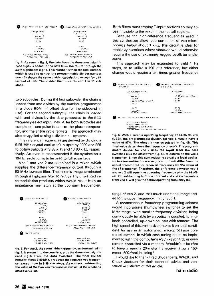
0 C i i i CULATING DIVIDER I I S B PRESET
6 7 4 4 r IOlHr
6 7 . 4 4 0 h H z
VCO I PROGRAMMEO O F F S F I F R E O U E N C I FOR L S 8
0 CALCULATING D I V I D E R I U S 8 PRESET
w "' i5903 + I 4 5 - 6 0 4 5
6 0 4 5 r lokHz
6 0 , 4 5 0 k H 1
vco I PROGRAMMED O F F S E r FREOUENCY FOR U S 8
Both filters must employ T-input sections so they ap- pear invisible to the mixer in their cutoff regions.
Because the high-reference frequencies used in this synthesizer allow loop correction of vco micro- phonics below about 1 kHz, this circuit is ideal for mobile applications where vibration would otherwise require the use of extremely rugged oscillator enclo- sures.
fig. 4. As seen in fig. 2, the data from the three most signifi- This approach may be expanded to yield 1 Hz cant digits is added to the data from the fourth through the sixth significant digits. This number is then the final number steps, or to utilize a 100 kqz reference, but either
which is used to control the programmable divider number change would require a ten times greater frequency one. (B) shows the same divider calculation, except for uSB
instead of LSB. The divider then controls vco 1 in 10 kHz steps. E X A M P L E OPERATING FREQUENCY EXAMPLE OPERATING FREOUENCY
two subcycles. During the first subcycle, the chain is loaded from and divides by the number programmed in a diode ROM (i-f offset data for the sideband in use). For the second subcycle, the chain is loaded with and divides by the data presented to the BCD frequency-select input lines. After both subcycles are completed, one pulse is sent to the phase compara- tor, and the entire cycle repeats. This approach may also be applied to single-divider PLL systems.
The reference frequencies are derived by dividing a 9.99-MHz crystal oscillator's output by 1000 and 999 to obtain outputs at 9.99 kHz and 10.00 kHz, respec- tively. An oven is recommended if the synthesizer's 10-Hz resolution is to be used to full advantage.
Vco 1 and vco 2 are combined in a mixer, which supplies the difference-frequency output through a %-MHz lowpass filter. The mixer is image terminated through a highpass filter to reduce any unwanted in- termodulation products which would result from an impedance mismatch at the vco sum frequencies.
D I V I D E R 2 i S 8 PRESET @ DIVIDER 2 U S 8 PRESET
5 9 , 0 0 1 45kH1
7-
, ~~
VCO 2 PROGRAMMED OFFSET VCO 2 PROGRAMMED OFFSET
FREOUENCY F O R L S 8 FREQUENCY FOR U S 8
@ OFFSET CHECK
fig. 5. For vco 2, the same initial frequency, as determined in fig. 3, is preset into the counters, plus the three most signifi- cant digits from the data switches. The final divider number, times 9.99 kHz, produces the required vco frequen- cy. except now in 9.99 kHz steps. As a check, subtracting the value of the two vco frequencies will equal the sideband offset value (C).
@ E X A M P L E OPERATING FREOUENCY CHECX
fig. 6. With a sample operating frequency of 14,307.96 kHz (USBI, the programmable divider, for vco 1. would have a value of 8271. The offset is that calculated in fig. 48. This final value determines the frequency of vco 1. The program- mable divider for vco 2 uses the input from the data switches plus the offset from fig. 5B to determine the vco's frequency. Since this synthesizer is actually a local oscilla- tor in a transmitter or receiver, its output will differ from the actual transmitted (or receiver) frequency by the value of the i-f frequency. Therefore, the difference between vco 1 and vco 2 will equal the operating frequency plus the i-f off- set. Or, subtracting both the i-f offset and vco 2's frequency from vco 1, will give the actual operating frequency (C).
range of vco 2, and that much additional range add- ed to the upper frequency limit of vco 1.
A recommended frequency programming scheme would incorporate thumbwheel switches to set the MHz range, with smaller frequency divisions being continuously tunable by an optically coupled, tuning- knob-controlled, up-down counter with readout. The high speed of this synthesizer makes it an ideal candi- date for use in an automated, microprocessor con- trolled station, in which case tuning could be imple- mented with the computer's ASCII keyboard, or even remote controlled via a modem. Wouldn't it be nice to have a remote 20-meter transceiver atop a 150- meter (500-foot) building?
I would like to thank Fred Studenberg, W4CK, and Chuck Jackson for their technical advice and con- structive criticism of this article.
ham radio
36 august 1978

w n - SPECIFICATIONS
\ V W A 1.1 Rnonancal. 1 5 1 GasildBI B 5 -... 1m*nc. 50 Ohms Surtra Area 1%. F t I
FIB Ratlo ldEl 20 25 Wnnd Loadnw Boom 10 0 , r Length]. 7' x !R'W at 80 mph No. Elemenn 4 Ausmblad Wsqht ~ o n w s t Element l F t l 26'7" lLbr Approx.1 Tvrntnq Rd ius IFt 1 16'4" Sh#pp#no Wawhl M n t 01.rnrcar 2' 0 11 lLbs Appro. I Boom OIMLI~I 2" 0 D Matchlnq Method Band MHz 14 2 1 28 Only One Frrd Lln. Rsq Mal#mum Power lnpvl 4 K w SHIPS BY U.P.S.I!!
I
Delivers outstanding
.. . maximum front-to-back. An added fea- ,- ...,. "a
ture i s the separate 10 meter reflector for correct monoband spacing. Add to this the rugged boom to element mounting,
9 . . ,. . >, , ,, , heavy cluty taper swaged elements, and , . . , 15 *-. - sy.2 ....... ,... .. ,
you have -.,. .. For b r t inslmll.toon q=*c .. ; ,rip TrRFp use Walron's M T 6 1
61 If. Crankap T o w r and WR.500 Rotor.
. . . space efficient, high performing, cost . ,,,,,, d,B,l,,: ,o*Cmn.-~ya -." ......,
effective new tribander. Wolron'r BN-50-A n
, . . , , , . ,
. . - a 1 WV-I. WBILSOP! \/ERBICAL TRAP AMTEWMA t ~'-, ! . + * - 4 . . . ? . . ,. . ! No bandswitching necessary with this vertical. An excellent low
i ? \ * Y . : J cost DX antenna with an electrical quarter wavelength on each
~ O M ~ . Y O W ~ I band and low angle radiation. Advanced design provides low SWR and exceptionally flat response across full width of each band. Featured is the Wilson large diameter High-Q traps which will maintain resonant points with varying temperatures and humidi- ty. Easily assembled, the WV-1 is supplied with base mount . .
~ O ~ E T O ~ - - W V - I bracket to attach to vent pipe or to mast driven in the ground. ! i ! / I The new WV-1 Antenna is value priced . . . and ships via UPS!
SPECIFICATIONS Input Impedance: 50 ohms Powerhandling capability: Legal Limit Two High-Q Traps with large diameter coils Low Angle Radiatiorl Omnidirectional performance Taper Swaged Alumi- num Tubing Automatic Bandswitching Mast Bracket furn- ished SWR: 1.1 :1 on all Bands 1%'' O.D. heavy wall aluminum rubina Does not reauire auvinq Overall length: 19' 8".
.- " - (h,m,rtur /f(xluf 1 1 Ihr r\rofr
4288 SO. POLARIS AVENUE . LAS VEGAS, NEVADA 89103 1702) 739-1931 TELEX 684522

XL, - DRAKE UV-3 multi-band
De\!gncd,?nd nianul,i( lured 111 t h ~ . U.S.A.
Model 1346 Drake UV-3 (144-220-440) . . . . . .$795.00 Model 1344 Drake UV-3 (144-440) . . . . . . . . . .$695.00 Model 1343 Drake UV-3 (144-220) . . . . . . . . . .$695.00 Model 1345 Drake UV-3 (220-440). . . . . . . . . .$695.00 Model 1340 Drake UV-3 (144) . . . . . . . . . . . . . .$595.00 Model 1359 Drake UV-3E (144-430)'
(Models above include factory installed modules for bands as listed, standard dynamic mike, and mobile mounting bracket.)
'This model tuned for European fm bands See your dealer for price details.
Add-on modules expand band coverage of models which may have been purchased in a single band or two band configuration. Prices include factory installation which is necessary to meet FCC receiver certification requirements.
Model 1504 Drake PS-3 AC Power Supply. . . . .$ 89.95 Mode11525 Drake1525EM Encoding Mike.. . .$ 49.95 Model 1330 UMK-3 Remote Trunk-Mount Ki t . .$ 69.95
NOTE: Certain of the above models will be avallable before others. Check with your dealer for specific availability.

synthesized fm system
For the serious amateur who.. . - considers fm a vital part of a total communication system - needs multi-band coverage in a single transceiver - needs to continuously scan-monitor a priority amateur repeater dedicated
to public service, weather, or DX alerts - needs extra programmed channels for quick selection, in addition
to the synthesizer . . . The Drake UV-3 provides it all!
Continuous priority channel scan Remote trunk operation (optional) Four extra diode-programmed channels on each band All three bands in a single bandswitched unit, or start with basic models and add extra band-modules later
Non-standard offsets available for each band
The Priority Channel Scan You can diode-program your prior- ity channel in one of the fixed channel positions. I t can be con-
tinuously monitored from any other synthesized or fixed chan- nel. If you're operating on the priority channel, or another pro- grammed fixed channel, you can scan-monitor any synthesizer fre- quency you choose.
The Extra Diode- Programmed Channels
You can diode-program up to four fixed channels, with their offsets, for each band. This feature allows super-quick selection of favorite channels. The five-kHz synthe-
sizer operates independently of these programmed channels. And best of all, soldering is not neces- sary for programming. The pro- gram board has special sockets mounted on i t for direct insertion of diodes. We even provide the diodes.
Remote Trunk Mount Kit The control panel of every UV-3 removes for installation in the UMK-3 Remote Kit. This provides for safety, as well as easy installa- tion in small cars where under- dash space is limited.
Write for a fully illustrated brochure on the Drake W-3 System.
540 Richard St.. Miamisburg, Ohio 45342 R. L. DRAKE COMPANY wm, 61. 8M.UZI . LIex: 288.011
Western Sales and Service Center. 2020 Western Street. Las Vegas. Nevada 89102 7021382-9470
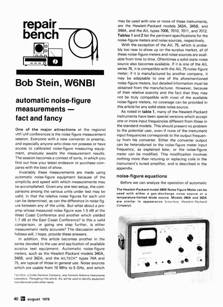
may be used with one or more of these instruments, are the Hewlett-Packard models 343A, 3458. and 349A, and the AIL types 7006, 7010, 7011, and 7012. Tables 1 and 2 list the pertinent specifications for the noise-figure meters and noise sources, respectively.
With the exception of the AIL 75, which is proba- bly too new to show up on the surplus market, all of these noise-figure meters and noise sources are avail- able from time to time. Oftentimes a solid-state noise source also becomes available. If it is one of the AIL series 76, it is compatible with the AIL 75 noise-figure meter; if it is manufactured by another company, it
Bob Stein, W6NBI . . .
may be adaptable to one of the aforementioned noise-figure meters, but detailed information must be obtained from the manufacturer. However, because of their relative scarcity and the fact that they may not be truly compatible with most of the available
automatic noise-figure noise-figure meters, no coverage can be provided in
measurements - this article for any solid-state noise source. As noted in table 1, many of the Hewlett-Packard
fact and fancy One of the major attractions at the regional vhfluhf conferences is the noise figure measurement session. Everyone with a new converter or preamp, and especially anyone who does not possess or have access to calibrated noise-figure measuring equip- ment, anxiously awaits the measurement results. The session becomes a contest of sorts, in which you find out how your latest endeavor or purchase com- pares with the best of show.
Invariably these measurements are made using automatic noise-figure equipment because of the simplicity and speed with which measurements may be accomplished. Given any one test setup, the com- parisons among the various units under test may be valid, in that the relative noise figures for each unit can be determined, as can the difference in noise fig- ure between any of the units. But what about a pre- amp whose measured noise figure was 1.5 dB at the West Coast Conference and another which yielded 1.7 dB at the East Coast Conference? Is this a valid comparison, or going one step further, is either measurement really accurate? The discussion which follows will, I hope, provide these answers.
In addition, this article becomes another in the series devoted to the use and application of available surplus test equipment. Automatic noise-figure meters, such as the Hewlett-Packard models 340A, 3408, and 342A, and the AILTECH' types 74A and 75, are typical of those in general use. Noise sources which are usable from 10 MHz to 5 GHz, and which
'AILTECH, a Cutler-Hammer Company, was fonnerly Airborne Instruments Laboratory. Throughout this article. AIL will be used to identify equipment manufactured under elther name.
instruments have been special versions which accept one or more input frequencies different from those in the standard models. This should present no problem to the potential user, even if none of the instrument input frequencies corresponds to the output frequen- cy from his converter. Either the converter output can be heterodyned to the noise-figure meter input frequency, as explained later, or the noise-figure meter can be modified. This modification involves nothing more than retuning or replacing coils in the instrument's tuned amplifier, and is described in the appendix.
noise-figure equations Before we can analyze the operation of automatic
The Hewlen-Packard model 3408 Noise Figure Meter can be used with either a gas-discharge noise source or a temperature-limited diode source. Models 340A and 342A are similar in appearance (courresy Hewlett-Packard Company).
40 august 1978

noise-figure meters, it is necessary to understand the mathematical definition of noise figure insofar as i t applies to the noise-figure meter. I will skip the basic mathematical derivation, since this has been covered extensively in references 1 through 5. Instead, I will start with a mathematical definition of noise figure and proceed to derive the relationships which permit the automatic noise-figure meter to function.
To eliminate any confusion between noise figure expressed as a numerical ratio and the logarithmic equivalent expressed in dB, I will limit the use of the term noise figure (NF) ,to the logarithmic version and call the numerical ratio noise factor (F).
The noise factor of a receiver is defined as the in- put signal-to-noise power ratio divided by the output signal-to-noise power ratio, and is expressed as
output power when the noise source is on as Nz, the output signal power, So, can be expressed as
S0=N2- Nl (3)
and since No = Nl
Rewriting eq. 1 by substituting eqs. 2 and 5, we get
Converting eq. 6 to the equivalent noise figure, where NF= 10 log F,
where Si is the input signal power, N, is the noise power at the input, So is the output signal power, and No is the output noise power.
If a broadband noise source is used at the receiver Since the first term in eq. 7 is the logarithmic input equivalent of eq. 2, i t is equal to the excess noise
ratio ( E N R ) , in dB, of the noise source. Therefore (2) eq. 7 can be rewritten
where EN = excess noise power (generally ex-
pressed in dB, but the equivalent NF=ENR-lo log (8)
numeric ratio in this case) The ratio N2/N1 is often designated the Y-factor, T2 = equivalent absolute temPeratU"e of so that an equivalent expression for eq. 8 is
noise source when on, in O K
NF=ENR- 1Olog ( Y - 1)
If we designate the output power from the receiver Thus we have arrived at an expression for noise when the noise source is off as N1, and the receiver figure in which the only variable is Y when a noise
table 1. Automatic noise-figure meter specifications. input frequencies bandwidth
model NF ranges and accuracy (MHz) (MHz)
Hewlett-Packard 0-15 dB: f 0.5 dB "30.60 1 (min.) 340A. B 3-30 dB: f 0.5 dB from 10-25 dB
f l.OdB from 3-10 dB f 1 .O dB from 25-30 dB
Hewlett-Packard Same as 340A, B "30.60, 75, 105.200 1 (min.1 342A
AIL 74A 0-25 dB: f 0.5 dB ""One of the following: 23-36 dB: f 1 .O dB 10, tunable 20-60 2
30 6 30, tunable 40-180 2 60 6
AIL 75 0-15dB: f 0.15dB from0-3 dB 30 (other options 5 (min.) f 0.25 dB from 3-6 dB available)
3-18dB: f 0.15dB frorn3-6dB f 0.25 dB from 6-9 dB
6-21 dB: f 0.15dB from 6-9 dB f 0.25 dB from 9-12 dB
12-27dB: f 0.5dB from 12-18dB 18-33dB: f 1.0dB
'Standard input frequencies are listed; many special models were manufactured with one or more different input frequencies. "*Depends on i-f amplifier installed in noise-figure meter.
sensitivity agc range (dBml (dB)
-60 50
august 1978 41

ON N ~ I ~ ~ noise source (via its power supply) on and off at a SOURCE OFF low audio-frequency rate. As shown in fig. 2, the
noise source is gated on and approximately one-
ON ON quarter cycle thereafter the tuned amplifier is gated
T ~ ~ E D on and the agc gate is opened. During this "on" time AMPLIFIER OFF
the receiver output, N2, consists of the amplified power from the noise source plus the amplified
N2 STANDARD REFERENCE 1,111111111111111~11 -- -- - ---- - -- receiver noise. This is used to establish a standard reference level through agc action.
AMPLIFIED RECEIVER
After the noise source is gated off, the amplifier is OU TPU r again gated on, as is the meter integrator. During this
AGC
GATE I OPEN
METER INTEGRAlOR GATE
fig. 2. Operational effect of the switching circuit in the automatic noise-figure meter.
source of known ENR is used. Furthermore, since Y is the ratio of N 2 / N 1 , we need only measure this ratio, without regard to absolute power levels, in order to obtain the receiver noise figure.
automatic noise-figure meters Now that we have a simplified noise-figure equa-
tion, let us investigate the actual method by which noise figure is measured automatically. Fig. 1 shows a simplified block diagram of a typical Hewlett- Packard noise-figure meter. The external noise source and receiver under test are included in the dia- gram so as to close the loop.
The noise source, powered by the noise-figure meter, is connected to the antenna input of the receiver under test, and the i-f output from the receiver is connected to the input of the noise-figure meter. A switching circuit in the noise-figure meter gates the tuned amplifier, meter integrator, agc, and
time the receiver output, N I , consists only of the am- plified receiver and input termination noise, which is detected and integrated, and applied to the meter. Since the noise-source ENR is known, and N2 is always amplified to a standard reference level, the only variable in eq. 8 is the metered value of N I . The meter can therefore be calibrated to display noise fig- ure directly, as a function of N I .
The tuned amplifier is gated on for only one-half of the noise-source on and off periods in order to be certain that the output from the noise source has reached its maximum level or has fallen to its quies- cent level.
The AIL noise-figure meters function in a similar manner, although there are differences in the actual circuits used to achieve the resulting indication.
noise sources Although both coaxial and waveguide noise
sources are available for use with automatic noise- figure meters, this discussion will be limited to the coaxial types, since waveguides presently have limited amateur use.
The Hewlett-Packard model 343A VHF Noise Source provides a wideband noise spectrum from 10 to 600 MHz and has a source impedance of 50 ohms. It generates an excess noise ratio of 5.2 to 6.6 dB, depending on the measurement frequency, at its specified current of 3.31 mA; refer to table 2. The noise source employs a special temperature-limited
- - - - - - - - - - - - - - - - - -- - - - - - - - - - - - - - - - - - - - - - - - - - AUrOMAT/C NOfSE NGURE HErER
1 I Y E TER 1
REC€lVER UNDER
I TUNED SQUARE L AW - VIDCO f i - 1 - 4 AMP
METER I DETECTOR INTEGRATOR I
I 1 I
fig. 1. Simplified block diagram of the Hewlett-Packard model 340A or 3408 Noise Figure Meter.
42 august 1978

vacuum-tube diode (similar to the Sylvania 5722) whose plate and filament voltages are supplied by the Hewlett-Packard M A , 3408, or 342A noise-fig- ure meter. The noise output of a saturated tempera- ture-limited diode is a function of plate current, which is set to an established value by means of a control on the noise-figure meter.
The Hewlett-Packard model 3458 IF Noise Source produces an excess noise ratio of 5.2 dB from any one of four switch-selected source impedances: 50, 100, 200, or 400 ohms. Since tuned circuits within the noise source limit its spectrum to either 30 or 60
. MHz, also switch-selected, it has limited amateur application and can be dismissed without further dis- cussion.
Also usable with any of the Hewlett-Packard noise-figure meters are several 5722 noise generators whose construction has been described in references 6 through 8. It should be noted that most, if not all, of these hornebrew noise sources suffer from imped- ance mismatch problems when used above 400 MHz. However, it is possible to build a noise source which compares favorably with the Hewlett-Packard 343A to at least 450 MHz; its construction will be described in a future article.
For receiver frequencies above 450 MHz, a noise source using a gas-discharge tube is generally used. Coaxial noise sources of this type may also be used at frequencies as low as 200 MHz. The Hewlett-Pack- ard model 349A UHF Noise Source and the AIL Type 7010, 7011, and 7012 Coaxial Noise Generators all employ an argon-filled gas-discharge tube coaxially mounted in a helical transmission line. These noise
The Hewlett-Packerd model 343A VHF Noise Source utilizes a temperature-limited diode, and can be used from 10 to600 MHz (courtesy Hewleft-Packard Company).
table 2. Coaxial noise-source specifications. frequency
model range (MHz1 excess noise ratio [dB) Hewlett-Packard 10-600 5.2f 0.2 from 10-30 MHz 343A 5.5i0.25at 100MHz
5.8f 0.3 at 200 MHz 6.05f 0.3 at 300 MHz 6.3i0.3at 400 MHz 6.5 i 0.5at 500 MHz 6.6f 0.5 at 600 MHz
Hewlett-Packard 30 or 60. 5.2 3458 switch
selected
Hewlett-Packard 400-4000 14.6 f 0.6 at 220 MHz 349A lusable to 15.6f0.6 from400-1000 MHz
2001 15.7? 0.5from 1-4 GHz
AIL 7006 10-250 15.2f 0.5
AIL7010.7011 200-2600 15.2 f 0.3
sources produce excess noise ratios of 15.2 to 15.7 dB over their specified frequency ranges, as shown in table 2.
A simplified diagram of a coaxial gas-discharge tube noise generator is shown in fig. 3. The tube is alternately turned on and off by the switched power supply in the noise-figure meter. When a high-volt- age pulse is applied between the anode and cathode of the tube, the argon gas ionizes and noise is gener- ated. The noise is coupled into the helix and appears at the two coaxial connectors. One connector is used
operating current ImA)
3.31
output vswr
10-400 MHz: 1.2 max. 400-600 MHz: 1.3 max.
50,100.200or400ohm(f 4%) source impedance, switch selected
200-2600 MHz: 1.35 max. fired 1.5 max. unfired
2.6-3.0 GHz: 1.5 max. fired 1.5 max. unfired
3.0-4.0 GHz: 2.0 max. fired 3.0 max. unfired
1.2 max.
1.15 (nominal) fired 1.3 (nominal) unfired
1.5 (nominal) fired 2.0 (nominal1 unfired
august 1978 43

fig. 3. Simplified diagram of e gas-discharge tube noise source. One connector is used for the noise output; the other must be terminated by a precision 50-ohm load.
for the noise output, while the other must be termi- nated by a precision =-ohm load.
connecting the noise source to the noise-figure meter
Obviously each manufacturer supplies noise sources which are compatible with his own noise-fig- ure meters. There is nothing, however, other than the problem of physically interconnecting the source and noise-figure meter, which precludes using one manufacturer's gas-discharge source with another's noise-figure meter.
The same interchangeability is not true for diode noise sources. The AIL type 7006 noise diode can be used only with the AIL 74A noise-figure meter, and the Hewlett-Packard diode noise sources can only be used with the Hewlett-Packard noise-figure meters. But, as previously mentioned, there are several 5722 noise generators which can also be used with the Hewlett-Packard noise-figure meters.
All of the Hewlett-Packard noise-figure meters dis- cussed in this article originally included an intercon- necting cable for that manufacturer's gas-discharge noise sources. Unfortunately, the cable is invariably missing when the instrument reaches your local sur- plus emporium. On the other hand, the interconnec- tions are rather simple, so that with the information which follows, you should be able to solve all of your interface problems.
To connect the Hewlett-Packard 349A coaxial (or any of the Hewlett-Packard 347-series waveguide) gas-discharge noise source to any Hewlett-Packard noise-figure meter, a 6-foot (1.8-meter) type 340-16A cable was originally furnished. You can buy a re-
fig. 4. Interconnecting cable for use between a Hewlett- Packard 349A or 347-series noise source and a Hewiett- Packard 340A. 3408. or 342A noise-figure meter. The cable length should be limited to about 2 meters (6 feet).
placement directly from Hewlett-Packard, but the price was $100 the last time I checked. A good alter- native is to make your own cable, as shown in fig. 4.
If you want to connect a Hewlett-Packard gas-dis- charge source to either the AIL 74A or 75 noise-fig- ure meter, it will be necessary to modify the captive cables on the AIL instrument, asfollows."
1. Cut the high- and low-voltage cables at a point at least 20 inches (51 cm) back from the connector ends.
The AILTECH type 75 Pmclslon Automatic Noise Figure Indl- cator is the latest and most versatile instrument of its kind on the market. I t can be supplied for use with both gas- discharge and solid-state noise sources, or for use with the latter type only lcourresy AILTECHI.
2. Wire the cables from the noise-figure meter as shown in fig. 5A.
3. Wire the cable ends with the connectors at- tached as shown in fig. 5B.
The instrument cables, now terminated in a single multipin connector, will plug into the connector on the Hewlett-Packard noise source. An AIL noise source can still be used by connecting the multipin connector on the instrument cables to the mating connector on the now separate cable assembly shown in fig. 58, thereby restoring the original con- figuration.
Fig. 6 shows the cabling needed to connect an AIL 7010, 701 1, or 7012 noise source to any of the Hew- len-Packard noise-figure meters. The high-voltage connector required to mate with the anode connec- tor on the AIL 7010 or 7012 is not available except as a part of the AIL 7003 cable set. Therefore it must be fabricated by using brass tubing of the appropriate size and suitable high-voltage insulating material
'Taken from AIL Application Engineering Bulletin 70-15. dated August. 1961.
44 august 1978

(teflon, polystyrene, etc.) between the inner high- voltage and outer ground conductors. WARNING: the anode lead and connector must be insulated for up to 5 kV; USE EXTREME CARE.
The Hewlett-Packard 343A and 3458 noise sources each have a captive cable and connector to mate with the Hewlett-Packard 3408 and 342A noise-figure meters. If you intend to use any of the previously referenced 5722 noise generators, the appropriate connector wiring is shown in fig. 7. The 5722 filament draws between 1.5 and 2 amperes, so
The Hswlett-Packard model 349A UHF Noise Source is e gas-discharge type using an argon-filled tube. Its usable range is 200 M H z to 4 GHz (courresy Hewleff-Packard Companyl.
be sure to use wire that is large enough to minimize the voltage drop between the tube and the noise-fig- ure meter.
Connecting any of the commercial or homebuilt diode noise sources to the Hewlett-Packard 340A noise-figure meter requires somewhat more discus- sion. The diode panel connector on the 340A was ori- ginally a 3-pin connector, rather than the 5-pin Can- non WK-5-31s connector used on the later 3408 and 342A models. (It was intended to mate with the long obsolete 345A noise source. I However, Hewlett- Packard Service Note 340A-1A' described how to replace the old 3-pin connector with the later 5-pin connector, and virtually everyone who had a 340A made the change. In fact, I have never seen an instrument with the old connector still in place.
If a new connector has been installed and you are going to use a homebuilt 5722-type noise source, the wiring information in fig. 7 applies. If the old connec- tor is still on the instrument, you will have to be lucky enough to find a mating connector or else change
'Available from Hewlett-Packard Company. 1820 Embarcadero Road. Palo Alto. California 94303.
fig. 5. Modification of the AIL 74A or 75 noise-source cables which will permit use of Hewlett-Packard 349A or 347-series noise sources. (After AIL Application Bulletin 70-15. August 1961).
the connector on the instrument. The filament con- nections on the old 3-pin connector are pins 1 and 2; pin 3 connects to ground.
The Hewlett-Packard 343A noise source can only be used with the 340A if the 5-pin connector has been installed. Before trying to use it, however, check the internal wiring to the connector to be sure that there is a connection to pin 4. If there is no wire on pin 4, run one from that pin to the black center- tap lead of transformer T101. (The transformer may be identified by tracing the leads from pins 1 and 2 of the connector, which are wired to the green and yellow leads, respectively, of TI01 .)
measurement techniques We can now discuss the procedures and tech-
niques of measuring noise figure with an automatic noise-figure meter. Because the actual operating procedures vary, depending on the instrument being used, no attempt will be made to describe the de- tailed operational steps. These appear in the instruc- tion manual for the specific instrument, available from the manufacturer at nominal cost. In general, operation of the noise-figure meter consists of the following steps:
1. Connecting the receiver under test as shown in fig. 8. For the purposes of this discussion, the term "receiver" means any receiver or portion thereof (such as a converter, mixer, etc.) which provides an output signal at the input frequency of the noise-figure meter.
NOlSI 4OURCC N T M D D T
'GC PT I1C - //I. .- ill A Y P I I N O I 80 -YC I 'C I
fig. 6. Interconnecting cable for use between an AIL 7010, 7011, or 7012 noise source and a Hewlett-Packard 340A. 3408. or 342A noise-figure meter.
august 1978 45

OU JPU 7
fig. 7. Wiring a homebuilt 5722-tube noise source to permit its use with a Hewlett-Packard 3408 or 342A noise-figure meter. See the text for additional information applicable to the Hewlett-Packard 340A.
2. Energizing the noise-figure meter and establish- ing the fixed agc reference level.
3. Setting the noise-source operating current.
4. Calibrating the noise-figure meter to the noise- source ENR. (This step is not applicable to Hew- lett-Packard noise-figure meters. )
5. Reading the receiver noise figure on the meter, and correcting for noise-source characteristics and/or loss-pad attenuation.
Although this generalized procedure sounds almost too simple to be true, it is just about as easy in practice. Any adjustments on the receiver can be made while it is under test by merely tuning for the best noise figure. Compare that to measuring noise figure by the manual twice-power method!
Let us now examine fig. 8 block by block. Most important, there should be a direct connection be- tween the noise-source output connector and the loss pad, and between the pad and the receiver. This means no cables, and a minimum of adapters.
The use of a loss pad between the noise source and the receiver is an absolute necessity when using a gas-discharge source, and is highly recommended for diode noise sources. One of the disadvantages of gas-discharge noise sources is that they require a high-voltage ionizing pulse, typically several kilo- volts. Because of capacitive coupling between the tube and the helix, this pulse appears as a spike in the noise output. Although the pulse is attenuated, the amplitude of the spike may still be several volts, which may be enough to destroy your expensive low- noise transistor. Therefore, a 6- to 10-dB pad must always be used with a solid-state receiver to attenu-
fig. 8. Measuring noise figure with the automatic noise- figure meter. The use of the loss pad and variable attenuator are discussed in the text.
ate the spike. Even with a 10-dB pad, there may be sufficient spike voltage to destroy certain GaAs fets. A solid-state noise source should be used to check devices of this type.
The use of a loss pad with a diode noise source is not absolutely essential, but can minimize several problems. First of all, most receivers (remember the general use of this term) do not present a 50-ohm in- put when optimized for a noise match. Because the rated ENR of a noise source is based on a %-ohm load, there will be an indeterminate mismatch loss if the receiver vswr is greater than 1.0:1. A 3- to 6-dB pad will not eliminate the mismatch loss, but may re- duce it somewhat.
A second reason for using a loss pad is to ensure a %-ohm source impedance for the receiver, since the vswr of the noise source also is not a perfect 1 .O: 1.
I RECEIVER UflDER T€S7 I I
S/CN/1L
SOURCE rl . - - - - - - - -
fig. 9. Using an external mixer and signal source to convert the receiver output frequency to that of the noise-figure meter input. The "receiver under test" corresponds to the equivalent block in fig. 8.
Any tendency of the receiver to "take off" when looking into an impedance of other than 50 ohms will be reduced by use of a pad.
Both of these reasons apply equally to gas-dis- charge noise sources, but are automatically realized by the absolute necessity of using a loss pad to pro- tect the receiver. In either case, the attenuation of the pad must be known to a fair degree of accuracy; remember that the loss, in dB, must be subtracted from the reading obtained on the noise-figure meter, since any loss ahead of a receiver adds algebraically to the receiver noise figure.
In addition to providing an output at a frequency which is compatible with the noise-figure meter, the receiver must also provide enough gain to amplify the noise input to a level which exceeds the sensitivi- ty of the noise-figure meter. However, the difference in the receiver output levels with the noise source on and off must not exceed the agc range of the instru- ment and overload it. This means that the output from the receiver, when the noise source is off, should be only slightly above the sensitivity level of the noise-figure meter. This can be determined by
46 august 1978
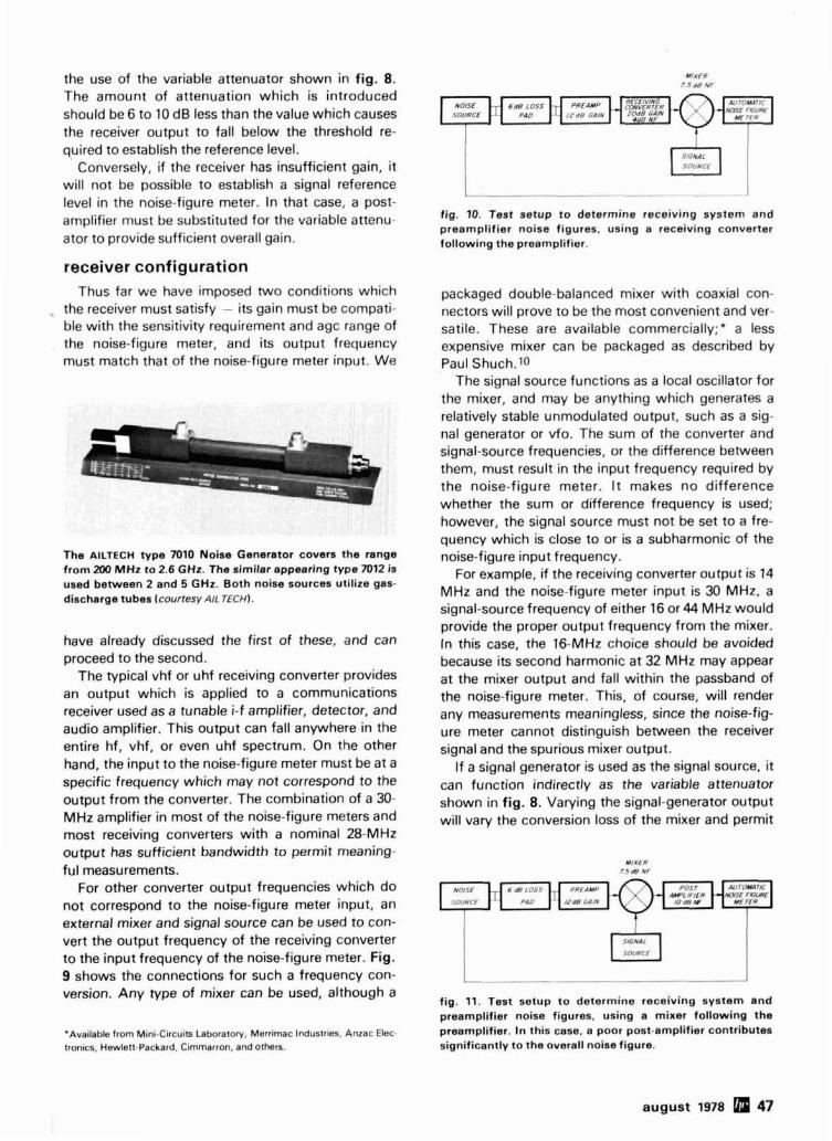
the use of the variable attenuator shown in fig. 8. The amount of attenuation which is introduced should be 6 to 10 dB less than the value which causes the receiver output to fall below the threshold re- quired to establish the reference level.
Conversely, if the receiver has insufficient gain, it will not be possible to establish a signal reference level in the noise-figure meter. In that case, a post- amplifier must be substituted for the variable attenu- ator to provide sufficient overall gain.
receiver configuration Thus far we have im~osed two conditions which
the receiver must satisfy - its gain must be compati- ble with the sensitivity requirement and agc range of the noise-figure meter, and its output frequency must match that of the noise-figure meter input. We
The AILTECH type 7010 Noise Generator covers the range from 200 MHz to 2.6 GHz. The similar appearing type 7012 is used between 2 and 5 GHz. Both noise sources utilize gas- discharge tubes (courtesy AIL TECH).
have already discussed the first of these, and can proceed to the second.
The typical vhf or uhf receiving converter provides an output which is applied to a communications receiver used as a tunable i-f amplifier, detector, and audio amplifier. This output can fall anywhere in the entire hf, vhf, or even uhf spectrum. On the other hand, the input to the noise-figure meter must be at a specific frequency which may not correspond to the output from the converter. The combination of a 30- MHz amplifier in most of the noise-figure meters and most receiving converters with a nominal 28-MHz output has sufficient bandwidth to permit meaning- ful measurements.
For other converter output frequencies which do not correspond to the noise-figure meter input, an external mixer and signal source can be used to con- vert the output frequency of the receiving converter to the input frequency of the noise-figure meter. Fig. 9 shows the connections for such a frequency con- version. Any type of mixer can be used, although a
'Availabk, from Mini-Circuits Laboratory, Merrimac Industries. Anzac Elec. tronics. Hewlelt-Packard. Cimmarron, and othen.
fig. 10. Test setup to determine receiving system and preamplifier noise figures, using a receiving converter following the preamplifier.
packaged double-balanced mixer with coaxial con- nectors will prove to be the most convenient and ver- satile. These are available commercially;" a less expensive mixer can be packaged as described by Paul Shuch.10
The signal source functions as a local oscillator for the mixer, and may be anything which generates a relatively stable unmodulated output, such as a sig- nal generator or vfo. The sum of the converter and signal-source frequencies, or the difference between them, must result in the input frequency required by the noise-figure meter. I t makes no difference whether the sum or difference frequency is used; however, the signal source must not be set to a fre- quency which is close to or is a subharmonic of the noise-figure input frequency.
For example, if the receiving converter output is 14 MHz and the noise-figure meter input is 30 MHz, a signal-source frequency of either 16 or 44 MHz would provide the proper output frequency from the mixer. In this case, the 16-MHz choice should be avoided because its second harmonic at 32 MHz may appear at the mixer output and fall within the passband of the noise-figure meter. This, of course, will render any measurements meaningless, since the noise-fig- ure meter cannot distinguish between the receiver signal and the spurious mixer output.
If a signal generator is used as the signal source. it can function indirectly as the variable attenuator shown in fig. 8. Varying the signal-generator output will vary the conversion loss of the mixer and permit
fig. 11. Test setup to determine receiving system and preamplifier noise figures. using a mixer following the preamplifier. In this case, a poor post-amplifier contributes significantly to the overall noise figure.
august 1978 47

INTERSTAGE LOSS (dB) + ~ ( N D STAGE NOISE FIGURE (dB)
fig. 12. The system noise figure (NF,N) can be found from these curves when the first- and second-stage noise figures. first-stage gain, and interstage losses are known (courtesy Daico Industries, lnc. 1.
control of the mixer output level. A post-amplifier has been shown in fig. 9 because the receiving con- verter gain, less the mixer conversion loss, will gener- ally be insufficient to provide the necessary signal level into the noise-figure meter. This post-amplifier can be any type, such as a surplus i-f strip or a broad- band amplifier, which will amplify the desired mixer output frequency. The mixer image frequency will be rejected by the tuned amplifier in the noise-figure meter.
The configuration shown in fig. 9 will result in valid noise figures only if the gain of the receiving converter is 20 dB or more. If the converter gain is less than 20 dB, the indicated noise figure will be worse than the actual noise figure because of the noise contribution of the external mixer. The actual noise figure must then be calculated, as explained later.
preamplifiers In order to measure the noise figure of a preampli-
fier, the test setup of either fig. 8 or fig. 9 is used, with the preamp inserted between the loss pad and the receiver. To prevent any possible instability of either the preamp or the converter, in the event that either is not unconditionally stable, it is wise to use an additional loss pad between the preamp and the converter, directly at the converter input. This pad should provide about 3 dB loss; the exact value is not critical nor need it be known accurately. Its effect will be incorporated into the measured noise figure of the
receiver (without the preamp), since this measure- ment is necessary to calculate the true noise figure of the preamp, as explained in the following section. If only an overall system noise figure is of interest, then the second loss pad should not be used.
A major consideration in the measurement of pre- amp noise figure is that of image response and the effect of filters on that response. It is mentioned here as a preliminary precaution only, and will be covered in detail under the heading image response error.
cascaded stages
The overall noise figure of any receiver depends primarily on the noise figure of the first stage. How- ever, the noise generated by succeeding stages will contribute to the overall noise figure and, if the gain of the first stage is not over 20 dB or so, have a sig- nificant effect. Since low-noise preamps seldom have gains in excess of 15 dB, taking the noise con- tribution of the following stages into account is of major importance in determining the preamp noise figure.
The general equation for the noise factor of networks in cascade is
where F, = system noise figure
FI, F2, F j = noise factor of first, second, third stages
fig. 13. Excess noise ratios for Hewlett-Packard and AIL coaxial noise sources which utilize gas-discharge tubes. The curve for the Hewlett-Packard 349A is subject to the ENR tolerances listed in table 2; those for the AIL noise sources are typical and take into account the gas-tube-variations and hot-cold insertion losses.
48 august 1978

GI, Gz= power-gain ratio of first, second stages
The system noise figure, NF,, is derived from the expression
NF, = 1Olog F, (11)
It can be seen from eq. 10 that the numerical value of the second and succeeding terms is a function of the first-stage gain; the higher the gain, the lower will be the values of those terms. If all stages are active amplifiers, only the second-stage noise will be of importance, and only the first two terms of eq. 10 need be used in the calculation. However, if any of the early stages in the receiver has a gain of 1 or less (e.g., mixers and loss pads), three or even four terms of the equation may have to be taken into account.
As an example, refer to the test setup shown in fig. 10. Assume that the preamp gain (Al) and the converter gain (Az) have been measured at 12 dB and 20 dB respectively; the measured converter noise fig- ure ( NF2) is 4 dB; and the measured mixer noise fig- ure (NF~) is 7.5 dB. The system noise figure indicated on the noise-figure meter is 8.65 dB. What is the pre- amp noise figure (NFI)?
First, we must subtract 6 dB from the noise-figure meter reading, since that is the increase in noise fig- ure caused by the 6-dB pad. Therefore the actual system noise figure (NF,) is 2.65 dB. Second, we must convert the noise figures and gains (in dB) to noise factors and numerical gain ratios, as follows:
N F s - 2.65- Fs = antilog - - antilog ---- - 1.841 10 10
NF2 - 4 Fz = antilog - - antilogn = 2.512 10
NF3 - 7.5 F3 = antilog - - antdogm = 5.623 10
Al - 12 GI = antilog - - antilog - = 15.849 10 10
A2 - 20 Gz = antilog - - antilog - = 100 10 10
By rearranging eqs. 10 and 11, and substituting the above values,
? a a 0 a Q Q a a o ON a 8 Ri , U1 V , h O r n ? g $ $ 2 2 yl
FREOUENCY - /W
fig. 14. Diode current required by the Hewlett-Packard 343A VHF Noise Source to maintain a nominally constant 5.2-dB excess noise ratio (curve by J. R. Reisert, WIJR).
It can be seen from inspection of the above exam- ple that the third term is insignificant and can be ig- nored. However, suppose that the configuration shown in fig. 11 is being used to check out the same preamp, using the same mixer and a post-amplifier with a measured noise figure of 10 dB. Now the mix- er is the second stage, so that Fz = 5.623. Since, in a stage having a gain of less than 1, the noise figure is equal to the loss, the converse must be true. There- fore, the mixer loss ratio is also 5.623, making the gain (Gzl the reciprocal of 5.623, or 0.178. The post- amp noise figure of 10 dB results in F j being equal to 10 (the antilog of 10 divided by 10). In this case, the receiver noise figure reading on the noise-figure meter is 13.2 dB. Subtracting 6 dB for the loss pad, we obtain an actual noise figure (NF,) of 7.2 dB, or a noise factor (F,) of 5.248.
Again substituting the measured noise factors and gain ratios in eq. 12, we arrive at the following:
This is approximately the same noise figure as was calculated in the previous example, taking into account rounded-off numbers. Note that in this case the third term of the equation contributes significant- ly to the overall system noise figure, which leads to the conclusion that a low-noise post-amplifier should always follow a mixer when there is only one stage of amplification ahead of the mixer. If the post-amplifier noise figure were reduced to 1.0 dB, the system
august 1978 49

fig. 15. Noise. rejection.
5 I 0 15 2 0
RECEIVER IMAGE REJECTION fdBi
.figure error as a function of receiver image
noise figure would improve from 7.2 to 3.3 dB. To paraphrase many textbooks, the calculation of this improvement is left as an exercise to the reader.
An interesting graphical representation of the rela- tionships expressed in eq. 12 is shown in fig. 12. If the various stage noise figures, gains, and losses are known in dB, the difference between the system and first-stage noise figures can be read as 4 directly from the curves, which is added to the known first- stage noise figure to obtain the system noise figure.
For instance, let's use the same preamp and mixer, and the 1-dB post-amplifier from the preceding ex- ample. The first-stage gain plus noise figure is 14.4 dB, and the interstage (mixer) loss plus second-stage (post-amplifier) gain is 8.5 dB. The curves of fig. 12 show that A is 0.9 dB at the intersection of these two
values. Thus, the system noise figure is equal to the preamp noise figure plus 0.9 dB, or 3.3 dB.
noise-source ENR corrections In our discussion of the noise-figure equations
which govern the operation of automatic noise-figure meters, we established that the only variable in eq. 8 was the ratio N 2 / N I , and that the ENR term in that equation was a fixed value determined by the noise source. I t follows, therefore, that the noise-figure meter calibration must be based on a known or pre- determined ENR.
In the case of the AIL noise-figure meters, the operating procedures entail calibrating the instru- ment to the ENR of the noise source. For the AIL 7006 diode noise source used with the AIL 74A noise- figure meter, the ENR is 15.2+0.5 dB when the diode current is set to 33.1 mA. If a gas-discharge noise source is to be used with either the AIL 74A or 75 noise-figure meter, the instrument is calibrated for the ENR of the source at the frequency of measure- ment. Fig. 13 shows typical values for the AIL noise sources and the nominal ENR for the Hewlett-Pack- ard 349A for frequencies between 200 and 5000 MHz.
The meter scales of the Hewlett-Packard 340A, 340B, and 342A noise-figure meters are based on a fixed ENR of 5.2 dB from a diode noise source and a fixed ENR of 15.2 dB from a gas-discharge noise source. There is no adjustment for other values of ENR; if the noise-source ENR is different from the value upon which the calibration is based, a correc- tion factor must be applied to the noise-figure read- ing. If the ENR exceeds the noise-figure meter cali- bration design value, the "excess" ENR must be added to the noise-figure readings. If the ENR is less than the calibration design value, the difference be-
372 NOISE TO 432 MHl 432 AUTOUdTIC MyPiTM --- No/SE FIGURE
MHz
1 402MH1 j
L I I
0 FI, TCRS UStD AT INPUT AND OUTPUr OF PREAMP 0 NO FILTERS USED AT INPUT OR OUTPUT OF PREAMP
@ m r m USED ONLY AT OUTPUT OF PREAMP
L I @FILTER USED ONLY AT INPUT OF PREAMP
fig. 16. Simplified test setups for noise-figure measurements, using an untuned pre-amp and bandpass filters. The positions of the filters in each test setup are different. All configurations, except that at D, yield valid system noise figures.
50 august 1978

tween the two values must be subtracted from the noise-figure readings.
An examination of table 2 reveals that the only noise sources which match either of the Hewlett- Packard design values are the Hewlett-Packard 343A, only when used below 30 MHz, and the Hew- lett-Packard 3458, which has little amateur applica- tion. This means that whenever the 343A is used above 30 MHz, the indicated noise figure must be in- creased by the difference between 5.2 dB and the noise-source ENR at the frequency of use. If the measurements were being made at 400 MHz, for in- stance, the indicated noise figure would be too low, requiring a corrective addition of 1.1 dB to the meter reading.
Fortunately, in the case of the 343A, there is a sim- pler method which allows use of the noise-figure meter readings without correction. This involves reducing the diode current from its specified 3.31- mA value to one which maintains a nominally cons- tant 5.2-dB ENR. Fig. 14 is a plot of the diode current versus frequency, which provides this com- pensation.
Varying the current in a gas-discharge noise source has little effect on its ENR, typically only 0.005 dB /mA. Therefore, the Hewlett-Packard noise-figure meter readings must be corrected if the noise-source ENR is not 15.2 dB at the frequency of measurement. See fig. 13 to determine the differ- ence between the ENR and 15.2 dB; remember that the difference is added to the noise-figure readings if the ENR exceeds 15.2 dB, and is subtracted if the ENR is less than 15.2 dB.
If measurements are being made with a Hewlett- Packard noise-figure meter at one or only a few fre- quencies, as is the usual case for amateur receivers, the need for making corrections to the noise-figure readings can be eliminated by the use of a selected loss pad. The graduations on the two scales of the Hewlett-Packard instrument meters correspond, dif- fering by exactly 10 dB. Therefore, if the noise- source ENR were exactly 15.2 dB, and a precision 10-dB pad were used between it and the receiver under test, the noise figure could be read directly on the meter diode scale, which is based on an ENR of 5.2 dB. Since the noise-source ENR is not 15.2 dB, a pad must be selected so that its loss is algebraically equal to the difference between 5.2 dB and the ENR shown in fig. 13. Thus for the 349A noise source, the use of a 10.35-dB pad at 432 MHz, or a 9.5-dB pad at 220 MHz, will allow direct readout of noise figure on the diode scale of the noise-figure meter.
image-response error Noise figure, as we have been using the term, is
more correctly designated as the single-sideband noise figure. This has nothing to do with ssb as a
MEASURED NOISE FIGURE {dB)
fig. 17. Noise-figure corrections, as a function of termina- tion temperature, for a typical gas-discharge noise source f courtesy AIL TECH).
method of modulation; i t refers to the fact that any superheterodyne receiver has both a signal and an image sideband (channel), and that we are interested in measuring the noise figure in only a single (the sig- nal) sideband.
The image response of a system consisting of wideband amplifiers followed by a heterodyne receiver (converter) can be an important factor when measuring noise figure. The image-channel signal adds to the signal-channel signal and results in a measured noise figure which is lower than the true noise figure. The noise-figure error is a function of the receiver gain at the signal and image frequencies, as expressed by the following equation:
ErrorNF (dB) = 10 log ( I + - ) (13)
where Gi is the image-channel gain ratio and G, is the signal-channel gain ratio. I t can be seen that, for
august 1978 51

MEASURED NOISE FIGURE /METER READING)-/dB)
fig. 18. Temperature corrections for the Hewlett-Packard model 343A VHF Noise Source (courtesy Hewleft-Packard Company).
equal signal- and image-channel gains, the error will be equal to 10 log 2, or 3 dB.
Fig. 15 is a graphical representation of eq. 13, and shows the amount by which the measured noise fig- ure must be increased. I t is apparent that the noise- figure error is negligible if the receiver image rejection is greater than 20 dB. However, the corrections, especially when measuring low noise figures, can be significant at image rejections under 20 dB.
Which brings us back to the measurement of low- noise preamp noise figure. The prevailing concept in the design of low-noise amplifiers is to have untuned input and output circuits, and to rely on a separate high-Q filter ahead of the preamp to discriminate against unwanted signals. This is a valid design con- cept, but may lead to serious errors in the measure- ment of noise figure, especially at the aforemen- tioned vhf Iuhf conferences.
Fig. 16 illustrates, in simplified form, the four pos- sible configurations of measuring preamp noise fig- ure, using a receiving converter and a noise-figure meter with a 30-MHz input. In the examples shown, measurements are to be made at 432 MHz, and both the noise source and the preamp are assumed to be flat from 372 to 432 MHz. The bandpass filters can be of any type - tuned circuits, cavities, stub tuners, etc. - and may actually be part of the input or out- put circuits of any of the individual blocks. However, the absence of a filter indicates that it does not exist, either separately or as a part of any circuit; thus, in fig. 16B, the preamp has no filter in either its input or
output circuit, and the converter has no filter at its input. The converter output circuit has no effect on this discussion, and is assumed to be tuned to 30 MHz.
In fig. 16A, bandpass filters at the input and out- put of the preamp limit the overall system response to 432 MHz. This is the normal communications con- figuration, and yields valid noise-figure measure- ments. In fig. 16B, both filters have been eliminated, so that the preamp accepts noise inputs from 372 to 432 MHz and, in addition, contributes its internal noise over the same frequency range. Since the con- verter produces a 30-MHz output from the noise power at both 372 and 432 MHz equal to 2N2/2N1, the ratio remains the same as from one channel only, resulting in a valid noise figure.
Fig. 16C shows a test configuration in which a fil- ter is used only between the preamp and the conver- ter. It can be seen from the frequencies indicated on that diagram that only the 432-MHz noise signal reaches the converter, so that it too is a valid method of measuring noise figure. (It is equivalent to using an untuned preamp with a normal, tuned-input con- verter. )
In fig. 16D, the filter position has been changed from the output to the input of the preamp. Notice that in this arrangement the noise input to the pre- amp is limited to 432 MHz. However, this amplified noise plus the internal noise generated by the preamp at both 372 and 432 MHz are converted to the 30- MHz input of the noise-figure meter. Therefore, the noise-figure reading will be erroneous. The conclu- sions to be drawn from this discussion are that mean- ingful noise figures will be obtained if no filters are used, or if a filter is used following the preamp, but in no case should a filter be used ahead of the preamp without an equivalent filter at the output.
temperature error In the derivation of the noise-figure equations, To
is equal, by definition, to 290°K and represents the noise temperature of the noise source when de-ener- gized. I t is therefore apparent that if the noise source is at a temperature other than 290°K (17OC or 62.6OF1, an error will be introduced. Although such errors are of relatively small magnitude, especially over a limited ambient temperature range, it may be necessary to take them into account when measur- ing very low noise figures. Fig. 17 shows the noise- figure correction, as a function of measured noise figure and temperature, for a typical gas-discharge noise source. It can be seen that if a noise-figure measurement of 2.0 dB were made in a room where the temperature was 80°F (approximately 27OC or 300°K), a correction of -0.1 dB should be made,
52 abP august 1978

making the corrected noise figure 1.9 dB. Extended system by considering that noise power follows the use of a gas-discharge noise source also raises the power-transfer laws. A typical plot of error limits for cold temperature, so that the source should be al- a receiver swr of 2: 1 is shown in fig. 19; the actual er- lowed to cool down to room ambient when accurate ror can fall anywhere between the limits indicated. measurements are required.
The temperature-correction curves for the Hew- transmission-line (insertion loss) error lett-Packard 343A diode noise source appear in fig. 18. Since the diode heat will cause the termination temperature inside the noise-source housing to be somewhat higher than the ambient, this factor should be taken into account when establishing a corrected noise figure.
Noise power obeys all power-transfer laws, but because noise is random in phase, mismatches cause ambiguous errors rather than known power losses. Because an automatic noise-figure meter measures the ratio N 2 / N I , a mismatch affecting both of these powers haS no effect on accuracy, since the ratio re- mains unchanged.
The major consideration in matching involves the excess noise power available from the noise source. The ENR of any of the noise sources discussed in this article, excluding the Hewlett-Packard 3456, is based on developing the noise power in a 50-ohm resistive load. If the load is not 50 ohms, the ENR will
This error is a function of the coupling of the gas- discharge tube to the helical transmission line (see fig. 3) and the attenuation of the transmission line, and always reduces the noise-source ENR. In fig. 13, this error has been taken into account in deter- mining the excess noise ratios of the AIL noise sources. It has not been considered in the ENR curve for the Hewlett-Packard 349A, but according to the published data, the error is less than 0.25 dB. This is well within the ENR tolerances specified in table 2.
cumulative errors If all errors are in decibels, they accumulate addi-
tively. Therefore, the total possible measurement er- ror will be the sum of the following:
1. Noise-figure meter accuracy
2. Noise-source accuracy, corrected for frequency
be indeterminate. 3. Receiver image-response error The mismatch error must be calculated for each
4. Temperature error
fig. 19. Typical errors for several possible conditions of measured at two different times on two different test mismatch between the noise source and receiver (courtesy setups is meaningless. Furthermore, the accuracies Hewlett-Packard Company). of such measurements, especially outside of a labor-
5. Mismatch error
L6 6. Transmission-line (insertion-loss) error, if a gas-
-. 1.4 discharge noise source is used. s 1 2
$ LlMIrlNG ERROR
RECFIVER SWR=CV This is an imposing list, and could total well over
5 o.8 SOURCE S W ~ . I . ~ 1.5 dB if all errors were of the same algebraic sign. 2 0.6 a SOURCE
swR 1 However, many of these errors will cancel because of
$ 0.4 1.2:1
opposite signs, and generally the accuracy of the test
i? O2
/ . / : I 5 ; / . 0 5 : / G; equipment is far better than the limits of its specifics-
$ I. I : I $ h tions. Nevertheless, these possibilities of error are 0 2 very real and cannot be ignored except for cornpara-
9 1 . 2 I 2 -0.4 tive measurements using the same equipment at one 0
-0.6 particular time. And even then, the mismatch errors 3 s -08 'IMinNG between the noise source and the different receivers % RECNVER SWR=m
3 - 1.0 s ~ U ~ ~ ~ SWR=/.Z under test still exist. - 1.2
- 14 summary - 16 We have seen how automatic noise-figure meas-
august 1978 [rm 53
- 1 8 1 1 1 1 1 1 1 1 1 1 1
I I I I I t I I
I I I I ~ I 1 I I I ! i3 urements are accomplished, and have discussed
-2 o their limitations and areas of inaccuracy. We can LIMITING NEGATIVE ERROR REGARDLESS OFMATCH therefore answer the questions posed at the begin-
0 2 4 6 8 I0 I2 14 I6 I8 2 0 2 2 24 2 6 ning of this article. A difference of 0.2 dB, or even MEASURED NOISE FIGURE - I ~ B ) 0.5 dB, in the noise figures of two different preamps

atory environment, are subject to rigorous examina- tion. This is not a criticism of those amateurs who spend many hours at vhfluhf conferences perform- ing the tests; they know the limitations of their methods and equipment. Rather i t is meant to warn those who accept noise figures as gospel that such is not the case.
The same warning applies equally to the "typical noise figure" specifications on some transistor data sheets. Unless an accurately calibrated hot-cold noise source is used to determine the noise figure of the device land I personally know of cases where this was not done), the published figures may be no more accurate than you or I could obtain with surplus equipment - caveat emptor.
The automatic noise-figure meter can also be used to measure noise figure by the twice-power or Y-factor methods. However, since this article was intended to cover only the automatic mode of meas- urement, no attempt has been made to discuss man- ual operation. Gain measurements may also be made, in a clever application described by Paul Shuch.11
I sincerely hope that this article has taken some of the mystery out of automatic noise-figure measure- ments. More important, I hope that it will dispel any idea that you know your receiver or preamp noise figure to within a tenth of a dB.
appendix
To change the input frequency of a Hewlett-Packard noise-figure meter, only the frequency-determining circuits in the instrument's tuned amplifier need be changed to the desired frequency. If the new frequency is relatively close to one already established in the instrument, i t may be possible to make the change merely by retun- ing the variable inductors in the tuned circuits. Otherwise, the coils will have to be modified or replaced.
The Hewlett-Packard models 340A and 3408 employ a four- stage tuned amplifier. The front-panel input frequency switch selects one of two coils in each stage of the amplifier. In the stand- ard models, these coils and their inductance ranges are as follows:
input frequency inductance
IMHz) model 340A model 340B (PHI 30 L1. L3, L5, L7 L6, L8, L10, L12 1.2 - 1.75 60 U9L4,L6,L8 L5.L7,L9,L11 0.27~0.41
Regardless of whether the standard model, having the above in- put frequencies, or a special model having different input frequen- cies, is involved, the coil designations will be the same.
The coils resonate with approximately 20 pF. If the existing coils have sufficient inductance range to permit retuning, the procedure is simple. Set the METER FUNCTION switch to NOISE FIGURE and turn the INF CALIBRATION potentiometer fully clockwise. Then, us- ing a signal generator, feed an unmodulated signal at the new fre- quency into the input of the noise-figure meter. Keep the signal level low enough so that the meter is never at full scale, and adjust the appropriate coils for maximum meter reading. If the meter reaches full scale, reduce the input signal before continuing the adjustments.
If new coils are required for the desired input frequency, select
four adjustable coils whose mid-range inductance will resonate with 20 pF at the new frequency. Coils in the Miller 4300 series or Cambion 556-3338 series will replace those in the instrument without any mechanical modifications. After replacing the existing coils in the noise-figure meter with the new ones, retune the amplifier as described above. If the new frequency is 30 MHz or lower, a 3300-ohm composition resistor can be connected across each coil to broaden the amplifier response.
The Hewlett-Packard model 342A has provisions for five input frequencies. Instead of switched coils throughout the tuned amplifier, a fixed-tuned 30-MHz i-f amplifier is used in conjunction with a mixer and local oscillator circuit, which heterodynes four of the five input frequencies to 30 MHz. The fifth input frequency is 30 MHz, which is fed through the mixer with the oscillator disabled.
In the standard model 342A, the following coils and frequencies are used in the mixer-oscillator circuit:
input frequency
(MHz1 mixer coil 30 -
60 L10 10.32-0.55pH) 70 L9 10.32 - 0.465~H1
105 L8(0.156-0.228rHI 200 L7 (0.0392-0.0412pHI
oscillator frequency
oscillator coil (MHz1 1100-ohm res~storl -
L14 10.156 -0.228pHl 90 L13 10.156-0.228~H) 100 L12 (0.32-0.465pHl 75 L11 10.057-0.063rHl 170
Special versions of the 342A will have one or more input frequen- cies which differ from those listed above. Therefore the coil inductances may also be different, but the designations will be the same.
To change any of the input frequencies except the 30-MHz in- put, either retune the coils associated with the input switch posi- tion to be changed, or use new adjustable coils whose mid-range inductance will resonate with 14 pF at the required frequencies. The mixer coil obviously must be tuned to the input frequency. The oscillator coil must be tuned to a frequency which is 30 MHz above or below the input frequency; be sure that the oscillator frequency and its harmonics are well removed from the 30-MHz intermediate frequency.
Set the local oscillator on frequency by means of a frequency counter or a dip oscillator. Then adjust the oscillator and mixer coils (but not the coils in the i-f stages) as previously described for the model 340A or 3408, using a signal generator at the new input fre- quency.
references 1. "An Automatic Noise Figure Meter For Improving Microwave Device Performance." Hewlett-Packard Journal. Vol. 9, No. 5, Hewlett-Packard Company, Palo Alto, California, January, 1958. 2. "Noise Figure Primer," Application Note 57,Hewlett-Packard Company, Palo Alto, California, January, 1965. 3. James R. Fisk, WlDTY, "Receiver Noise Figure, Sensitivity and Dynamic Range - What the Numbers Mean," ham radio, October, 1975, page 8. 4. Benjamin L. Lowe, K4VOWlWA5UVM. "Hot and Cold Resistors As UHF Noise Sources," OST, September, 1976, page 32. 5. Charles E. Swedblom. WA6EXV. "Receiver Noise - Theory & Mesure- ment," unpublished. 6. Joseph H. Huie, KZPEY. "A VHF Noise Generator," OST, February. 1964, page 23. 7. Ronald E. Guentzler, WEBBB, "Noise Generators," OST, March, 1972, page 44. 8. Louis N. Anciaux, WBGNMT. "Accurate Noise-Figure Measurements for VHF," ham radio, June, 1972, page 36. 9. Hank Olson, WGGXN, and Gene Lehman, WAGJZN, "Noise Generators for 420 Mc. and Up," QST, February, 1964, page 33. 10. H. Paul Shuch, WAGUAM, "Circuit Packaging for UHF Double- Balanced Mixers." ham radio, September, 1977, page 41. 11. H. Paul Shuch, NGTX, "Calculating Preamplifier Gain from Noise- Figure Measurements," ham radio, November, 1977, page 30.
ham radio
54 august 1978


electronic teleprinter keyboard
This novel electronic keyboard
uses toroids and a pulse generator
to create the correct marklspace coding
This project grew out of a desire to design an elec- tronic Teletype keyboard which would permit handi- capped people to communicate with others. I took an initial design suggested by Ed Brown, WBEPV, determined that it was feasible, and developed the circuit shown in this article. The keyboard itself would generally have to be custom designed for each particular individual; for amateur use any surplus keyboard with a simple, closing-type contact will be sufficient.
circuit description The heart of the circuit is a set of eight shift regis-
ters, composed of four 7474 ICs (see fig. 1). During static conditions, the 6 outputs of the shift registers are all high, forcing the 7430 NAND gate low. This low disables the clock, while also enabling the pulse generator. When a particular key is actuated [key line taken low), the pulse generator is discharged through the respective cores. For example, if the Y line went low, the pulse generator would be dis- charged through cores TI, T3, T5, T6 and 77. The pulse from each core sets its respective shift register, causing the output to go low. Now that one of the inputs of the 7430 has been driven low, its output will change states, both enabling the clock and disabling the pulse generator.
Prior to the change in the 7430, the magnet driver was held in a mark condition by the action of U2.
By L. A. Stapp, WQPHY, 2903 Ash Street, Hays, Kansas 67601
56 august 1978

With both inputs to U2A now low, U2 pin 8 will go high, forcing the magnet driver into the space condi- tion. Since the clock has now been enabled, it will put out a pulse after 21 ms, moving the contents of the shift register down one increment. Each low state, on the Q, line, will create a mark, while a high forms a space.
With the clock free running, as long as there is a low into U1, the shift register will receive pulses and move the data one increment for each clock pulse. After 8 shift operations, the registers will be clear and their high outputs will cause U1 to change states again, completing the character.
construction Building this electronic keyboard is extremely
straight-forward with the use of TTL circuitry.' Before operation, R5 should be adjusted with U1 pin 8 high, to provide 1.6 volts on pin 6 of the NE555. If
'A copy of the circuit board layout and parts placement diagram isavailable by sending a self-addressed, stamped envelope to ham radio. Greenville. New Hampshire 03048.
M A G N E T S AND LOOP SUPPLY
CLOCK '
LOOP CURRENT
4 0 0 A D J U S T
l 2 0 V + 2 0 0
4 1 /j7 IOV
+
fig. 2. This power supply will provide voltages for both the keyboard plus the Teletype loop. The transformer is a Stancor 8626.
the keyboard is to be used at 60 words per minute, R1 should be adjusted so the 555 oscillates at 45 Hz; for 75 words per minute, use 61 Hz.
ham radio
P U L S E G E N E R A T O R
CLOCK
8'
fig. 1. Schematic diagram of the electronic keyboard. Each toroid is an Indiana General CF-102. 0-6. wound with a 10-turn primary. The wires from the pulse generator are fed through the appropriate core to form the mark periods for each character.
august 1978 57


improved grounding for the
1296-MHz microstrip filter
Construction techniques for improving
the performance of the three-pole
1296-MHz bandpass microstripline filter
The 1296-MHz microstripline bandpass filter I discussed in a previous article has allowed dozens of uhf experimenters to "clean up their act" on the 23- cm band.' As shown in fig. 1, the filter consisted of three top-coupled parallel-resonant circuits with grounded microstripline inductors. The filter is easy to assemble and tune, but several amateurs who have built it experienced difficulties caused by erratic stripline grounding. The new design presented here eliminates those difficulties and provides lower inser- tion loss and steeper skirts that will not tend to degrade as the filter is used.
The grounding of the microstriplines in the original design was accomplished by wrapping a thin brass or copper strap around the edge of the PC board, sol- dering it to the stripline on one side of the board and the groundplane on the other. Although this method of grounding worked well in the prototypes, the stripline inductance is a function of the placement of the grounding strap. Furthermore, the strap's place- ment on the edge of the board makes it extremely susceptible to physical damage, especially when installing or removing the filter board from its box. A third difficulty with wraparound grounding is that it forces the end of the microstripline inductor to ex- tend to the edge of the board, where stray coupling can cause the tuning of the filter to change when the unit is placed inside an enclosure.
All of these difficulties can be easily eliminated by placing the grounded end of the microstripline induc- tors somewhat away from the edge of the board and drilling through the board for the installation of a grounding wire or post. With the ground connection running through (rather than around) the board, its mechanical integrity is assured, and the groundstrap inductance is more nearly constant from one filter to the next, especially if the diameter of the grounding wire or post is specified.
By H. Paul Shuch, NGTX, Microcomm, 14908 Sandy Lane, San Jose, California 95124
60 august 1978

Although a short length of number 18 (1.0 mm) tinned copper wire makes an acceptable through- board ground connection, maximum grounding ef- fectiveness and mechanical integrity, I have found, can be achieved by installing small electronic eyelets through the board, setting them with a press, and soldering both sides. The eyelets I use are made of thin brass, measuring 0.47 inch (1.2 mm) diameter by 0.093 inch (2.5 mm) long. They look something like tiny rivets. The eyelets are available from a number of vendors" and can be easily set using a center-punch (or sharp nail) and hammer.
- grounding the trimmer capacitors Another area of difficulty encountered by several
readers is the grounding of the piston trimmer capa- citors. The capacitors I originally used were designed for chassis mounting, so it was necessary to modify
1 A
3.POLE F ILTER
C1 -C3 1.5-pF ceramic piston trimmer (Triko 202-08M or equivalent1
C, Stray coupling capacitance between stator ends of trimmer capacitors
J1, J2 SMA or equivalent microstripline launchers (E.F. Johnson 142-0298-001 or similar)
L1, L2. Microstripline inductor, 0.5" (13 mml long, 0.1 "(2.5 mml W wide, spaced 0.3' (7.5 mm) center to center. Bonom
ends strapped to ground plane with thin copper strap
XI, X2 50-ohm microstripline, 0.1" (2.5 mml wide, any length. Centerline tapped to L1 and L2 0.2" (5 rnmt from grounded end
fig. 1. Threepole microstripline bendpass filter, which will tune the range from 1100 to 1500 MHz. Full-size printed-circuit layout for this filter is shown In fig. 2.
them for circuit-board use by adding a bus-wire loop around the terminal nearest the adjusting screw (see fig. 4 of reference 1). It would have been better to use a trimmer specifically designed for PC use, with legs installed for grounding the rotor end through the circuit board. One such capacitor is the R-Triko 202-
'One acceptable eyelet ia pan number F-4793-6, available from Internation- al Eyelets. Inc.. 528 Sanln Barbara Street, Santa Barbara, CA 93101.
fig. 2. Full-size printed-circuit layout for the three- pole 1296-MHz bandpass filter. Etched on double- clad 1/16" 11.5 mml fiberglass-epoxy circuit board: the unetched side serves as a ground plane.
08M. a German ceramic piston trimmer available in the required l-to-5-pF range." I find filters using this capacitor easier to tune up, although I caution the builder against repeated adjustments because the tuning mechanism loses spring tension and becomes erratic after a couple dozen adjustments. The best procedure is to set the filter on frequency once, and then place a dot of nail polish, epoxy paint, or Loctite on the tuning screw as a reminder to leave it alone!
assembling the modified filter Fig. 2 is a full-size printed circuit layout for the 3-
pole bandpass filter, modified for through-board grounding. The board should be etched from double- clad 1116-inch (1.5-mml fiberalass-e~oxv ~rinted-cir- . . cuit stock, with one side left inetched to serve as a ground plane. The board should be drilled in the same manner as the template in fig. 3 and the three eyelets installed at the bottom end of the microstrip- lines.$ Don't forget to remove a bit of ground plane
fig. 3. Full-sizs dtilllng template for the bandpass filter board.
'These capacitors are available in the United States through Stenner- Trush. Inc., 67 Albany Street. Cazenovia, NY 13035.
tCompletelv etched, drilled, and plated prinred circuit bards. with the three eyelets installed, are available for 54.50 postpaid within the U.S. and Canada. $5.00 elsewhere. from Microcomm, 14908 Sandy Lane. San Jose, CA 95124. Completely assembled, tuned. and tested filters are also avail- able. Send a stamped. sen-addressed envelope for details.
august 1978 61

fig. 4. Effect of the bandpass filter on a 1296-MHz local oscillator chain. Spectrum display at top shows the various spurious outputs of a poorly designed LO. Spectrum at bot- tom is the result of passing the LO signal through a three- pole bandpass filter of fig. 1. The worst remaining spurious component is suppressed 25 dB. (Both displays: dc - 1.8 GHz sweep; horizontal scale. 200 MHzldivision; vertical scale. 5 dB/division.)
metallization from around the center-pin holes for the input and output coaxial connectors so the signal isn't grounded out. A 118-inch (3-mm) twist drill,
work analyzer. The response curve for the modified filter design shows slightly reduced insertion loss (on the order of 0.5 dB) and slightly steeper skirts. Per- haps the most realistic indication of filter perform- ance is not its swept response, but the filter's behavior in an actual system. Fig. 4 shows the effect of installing the bandpass filter behind an extremely spurious local oscillator chain. Note that the numer- ous spurious components are all significantly sup- pressed, with the worst remaining spur reduced from -5 dB to about -25 dB, relative to the desired output.
Fig. 5 shows the results when the filter is used to clean up the output of a previously published trans- mit balanced mixer.2 Notice that the i-f feedthrough signal and its harmonics, the LO feedthrough, the
fig. 5. Effect of the three-pole bandpass filter on the output of a 1296-MHz transmit mixer. Spectrum display at top shows the output from a singly balanced diode mixer: visi- ble spurious components include the desired signal and image, some LO feedthrough, a vary strong component of the i-f injection, and its second and third harmonics, and transmit intermods (resulting from these harmonics mixing with the LO signal). With the three-pole bandpaas filter installed in thesystem, the spectrum (bottom photo) shows that all spurious outputs have been attenuated by more than 25 dB. (Both displays: dc - 1.8 GHz sweep; horizontal scale, 200 MHzldivision: vertical scale, 5 dB1division.)
used as a deburring tool, works well for this oper- ation.
Connectors J1 and J2 are installed next, soldering the center pin to the input and output microstrip- lines, and running a bead of solder around the con- nector body on the ground-plane side of the board. The trimmer capacitors are installed last. If you use the recommended Triko trimmer, be sure to bend the two mounting legs nearest the adjusting screw down against the ground plane before soldering. The photograph of the completed filter will assist you in assembly.
filter performance Reference 1 included a swept response curve for
the original bandpass filter, as measured on a net-
62 august 1978

C1 1-9 pF piston trimmer (Triko203-09M or equivalent) J l , J2 SMA coaxial connector (E.F. Johnson 142-0298-001
C2, C3 1-5pF pistion trimmer lTriko201-01M or equivalent) or similar)
CRl Step recovery diode IH-P 5082-01801 L1, L2 Microstripline inductors (see fig. 21
' fig. 6. Circuit and construction details for a local-oscillator multiplier which provides 0.5 m W at 1200 MHz from a 5 m W 400- MHz drive signal. This circuit uses the same printed-circuit layout as the bandpess filter (see fig. 21. Output spectrum of this circuit is shown in fig. 7.
image signal, and the intermodulation products are recovery diode, as shown in the spectrum analyzer all suppressed below the dynamic range of the spec- display of fig. 7. When driven by the 5-to-10 mW sig- trum analyzer. nal from my uhf LO chain, this multiplier provides
local-oscillator multiplier about 0.5 m W of third-harmonic output. his power level can be easilv buffered in a 1296-MHz ~reamo.4 , .
In a previous article I described a diode multiplier applied to a 3-pole filter for additional spurious rejec- for developing local-oscillator injection for a 1296- tion, and used to drive the LO port of a transmit or MHz converter.3 As this multiplier used a microstrip- receive balanced mixer. line output filter, i t seemed reasonable to assemble a I should point out that the circuit of fig. 6 provides similar multiplier on the bandpass filter PC board, no dc return for the anode side of the multiplier thus allowing one PC artwork to do the job of iwo. diode. A dc return is necessary for the diode to prop- The circuit, which makes a rather nice low-level trip- erly develop self-bias; in my system this dc path is ler, is shown in fig. 6. Note that the microstripline provided at the output of the uhf LO. If the driving previously associated with the first filter pole is now stage does not offer dc continuity to ground, it will used to support the multiplier diode and its input be necessary to install a dc return circuit on the multi- matching circuit. Do not install a grounding eyelet on plier board. This can be most readily accomplished this first stripline if you are building the multiplier! by adding a small (0.33-pH) rf choke to ground at the The other two filtering poles help reject the many location normally occupied by the first trimmer other harmonic components generated by the step- capacitor when this board is used as a filter.
fig. 7. Output spectrum of the 400-MHz to 1200-MHz LO Summary multiplier. Note that the tripler circuit provides some degree The printed-circuit layout can be used to fabricate of filtering of the400-. 800-. and 1600-MHz components from high-quality bandpass filters and diode multipliers for the step recovery diode.
the amateur 23-cm band. The designs are based upon previous articles, but the addition of through- board eyelet grounding significantly improves per- formance and reliability. Further details on construc- tion, tune-up and testing, and system application are discussed in reference 1.
references 1. H. Paul Shuch. WAGUAM, "Microstripline Bandpass Filters for 1296 MHz." ham radio. December. 1975, page 46. 2. H. Paul Shuch, WAGUAM, "Rat-race Balanced Mixer for 1296 MHz." ham radio. July. 1977, page33. 3. H. Paul Shuch. WAGUAM. "Easy-lo-build SSB Transceiver for 1296 MHz."hemradio. September. 7974. wge8. 4. H. Paul Shuch, WAGUAM, "Low-cost 1296MHz Preamplifier," ham radio, October. 1975. page42.
ham radio
august 1978 63

STILL THE SAME FINE, TIME PROVEN RIG. BUT NOW WITH THE SIMPLE ADDITION OF A PLUG-IN CRYSTAL,
THE TS-700SP WILL BE ABLE TO UTILIZE THE NEW REPEATER SUB-BAND (144.5 to 145.5 MHz)
STILL FEATURES ALL OF THE FINE AlTRlBUTES OF THE TS-700s: A DIGITAL FREQUENCY DISPLAY, RECEIVER
PRE-AMP, VOX, SEMI-BREAK IN, AND CW SIDETONE. OF COURSE, IT'S ALL MODE, 144-148 MHz, VFO
CONTROLLED.. .AND KENWOOD QUALITY THROUGHOUT.
Features: 4 MHz band coverage (1 4 4 to 148 MHz) Automatic repeater offset capability on all FCC
authorized repeater subbands including 144.5 - 145.5 MHz Simply dial receive frequency and radio does the rest. . .simplex, repeater. or reverse. Same features on any of 11 crystal positions-Trans- mit/Receive capability on 44 channels with 11 crystals Operates all modes: SSB (upper and lower), FM, AM and CW Digital readout with "Kenwood Blue" digits Receiver pre-amp Built-in VOX Semi break-in on CW . CW sidetone All solid-state - AC and DC capab~lity. 10 watts RF out- put on SSB. FM. CW ' 3 watts on AM * 1 watt FM low-power switch 0 25 pV for 10 dB (S+N)/N SSB/CW sensitivity 0.4 pV for 2 0 dB quiet~ng FM sensitivity. 10 watts RF output on SSB. FM, CW 3 watts on AM 1 wan FM low-power switch 0.25 pV for 10 dB (S+N)/N SSB/CW sensit~vity m0.4 FV for 20 dB quieting FM sensitivity.
The TS-700SP shown with the matching VFO-700s and SP-70. Also shown is Kenwood's new MC-30 noise cancelling hand held microphone. HS-4 headphone set and the MC-50 dynamic microphone.

Even without the digital display, Kenwood's TS-820 provides extremely sensitive and accurate tuning, plus all of the electronic and mechantcal advantages found only In the TS-820s. Its reliability has been proven through thousands of hours of use under all environmental conditions. The TS-820 stands out from all the other rigs on the band. Its adjustable RF speech processor. utilizing a 455 kHz circuit to provide qutck-time- constant compression, will get your message through the pile ups. RF negative feedback is applled from
YOU can still the final to the driver to improve linearity, and thlrd-order products are at least -35 dB. Harmonic spurious emissions are less than - 40 dB and other buy One of the world's spu,, are I ~ S S than -60 RF input power 200 W PEP on SSB. 160 W DC on CW, and 100 best mtransceivers w DC on FSK. Receiver sensttiv~ty is better than 0.25 pV for 10 dB S/N. The TS-820 IS known for its superb recetvcr selectivity, and ~ t s famous IF for under $I,OOO sh f t . eastly . ellrn~nates . . heavy aRM. That's why the
I Ts-820 VFO-820s SP-820 versat~hty on rece~ve and two aud~o onputs
TRIO-KENWOOD COMMUNICATIONS INC. 1 1 1 1 WEST WALNUT ICOMPTON, CA 90220

simple scope monitor for vhf fm
In the dark about those signal reports
on two meters? This easy monitoring system
pays off in increased versatility
Adding an inexpensive oscilloscope to your fm transceiver will make your base station much more versatile. You'll have a signal monitor capable of measuring ( + 0 - ) carrier frequency, peak-deviation modulation, per cent noise quieting, and Touch- Tone signal levels. You'll be able to tweak transmit crystals in other rigs (great for netting CD-MARS members on frequency) and much more. Now blow the dust off your old scope and put it to good use - or give the test scope a dual function, as I did.
fm signal reports How often have you heard, "You're 40 per cent
quieting but Q5 copy," and wondered how the op- erator on the other end arrived at the 40 per cent figure? He must have been good at guessing, had a super trained ear, or maybe trying to be friendly.
When I became interested in two-meter fm I was very much confused with per cent quieting signal re- ports (especially if I had to give one). The transceiver I used was an ICOM IC20 and it did have a relative strength S-meter. While working simplex, whatever the meter indicated would be the report I gave. How- ever, working through repeaters presented a whole new ball game. Unlike simplex, repeaters may come slamming into your location, but the signal on the in- put side may be quite weak. Under such circum- stances the S-meter reading is invalid for a report,
but a monitor scope would immediately show the per cent noise quieting into the machine. One day while working on a circuit and using my old ElCO model 460 scope, I saw the light for a per cent quiet- ing indicator.
operation After examining the IC20 schematic for a good sig-
nal pickoff point, I decided the best place would be at the output of '.he discriminator stage (at TP3) and ahead of the audio control circuit (see fig. 1).
T O 4 U O l O C O N T R O L
C I R C U I T
fig. 1. Pickoff point in a typical amateur 2-meter transceiver for connecting a monitor scope. In this case it's at TP3 in the popular ICOM model IC20. The pickoff point should be made at the receiver discriminator output. but ahead of the audio con- trol circuit.
Several advantages would be obtained by doing this: 1) I'd see the noise figure as it appeared, un- affected by audio and squelch-control settings; 2) I'd see peak deviation (modulation); 3) by connect- ing directly from the discriminator output to my scope's dc vertical input I'd be able to measure the dc voltage produced by the received-signal carrier. Most fm transceivers (or receivers) have a test point at the location mentioned for alignment purposes. Your manual or schematic should indicate if this point is available.
1 connection Modification and wiring of the transceiver was
simple (fig. 1). Connection to the outside world was made using a small-diameter, single-conductor, shielded cable from the discriminator circuit to a
By Ed Spadoni, WIRHN, 91 Tower Street, Ded ham, Massachusetts 02026
66 august 1978

rear-panel-mounted phono connector (Radio Shack No. 274-346) designated J4 in fig. I . The shield was wired to J4 ground lug only. Next my scope was connected through a suitable length of shielded cable, with a male phono plug on the end, to mate with J4.
calibration Scope control settings will vary depending on the
types of scope used. My ElCO 460 control settings were as follows: Vertical attenuator in the DC-XI position, horizontal sweep at 100 Hz, and sync on INTERNAL. With the transceiver tuned to an inactive channel, adjust the vertical gain for 51 mm (2 in.) p-p noise level (f ig. 2). The noise as seen on the scope indicates the total passband of the rig's receiv- ing section. My IC20 has a passband of better than 16 kHz, which allows me to see signals + 8 kHz from the passband center with reasonable accuracy. A t present I can read 1 kHz =2.5-mm or 0.1-in. division on the scope with good linearity to f 8 kHz.
It's essential to have your receiver properly aligned and your receiving crystals adjusted to the passband center. If you're synthesized, be sure the receive oscillator is also properly adjusted. I've found that a very convenient frequency reference source is a re- peater output signal. By tuning in several machines you can see if things are properly adjusted by noting if the repeater signals are located in the passband center. If not, a little trimming must be done.
Working someone with a synthesized or vfo rig can prove very helpful in determining the linear por- tion of your receiver and its frequency limits. After determining the useful reading range of your trans- ceiver-scope combination, you should be able to read signals to f 1 kHz of your receiver passband center.
using your scope
Here are some samples of the more important waveforms observed while monitoring both simplex and repeater signals.
fig. 2. Scope presentation for calibration. Peak-to-peak noise should occupy the entire scope face, which represents the total passband of the receiver on noise.
1. 100 per cent noise quieting signal, either simplex or repeater, with a pause in modulation:
+ - I
l o o ' / . N O I S E Q U I E T I N G 1 0 L - - - L
( S C O P E B A S E L I N E ) J I r n r n ( Z 1 N )
R E F
2. 50 per cent noise quieting signal, either simplex or repeater, with a pause in modulation:
- - - - - -
5 0 % N O I S E Q U I E T I N G -7
3. Normal signal showing deviation (modulation). Most transceivers and repeaters have their deviation set for a nominal peak of 5 kHz:
( T Y P I C A L F M D E V I A T I O N 1 I I 1
E A C H 2 5 m m 1 0 . 1 I N 1 O N V E R T I C A L S C A L E E Q U A L S l l H I
4. 100 per cent quieting repeater signal received at your location with a weak and noisy input signal. Horizontal sweep adjusted for expanded one or two speech waveforms:
( S P E E C H W A V E F O R M E X P A N D E D 1 I
5. Repeaters normally produce equal swings of de- viation, in both up and down directions, with most input signals. If a new station comes into the ma- chine and produces the pattern shown below, this means that the new signal's carrier frequency is off and higher than the repeater passband center. The opposite would be true with a low-frequency carrier signal into the machine:
august 1978 67

0 - 51mm 12mch) REF
I
! NOTE. INPUT SIGNAL-CARRIER FREWENCY HIGH I_
6. Hum accompanying signal. Frequency and ratio of hum to modulation can be determined. Hum fre- quency is referenced to 60 Hz.
Per cent of hum = hump-p XI&,: deviation p-p
I S l m m 12 I N I
R E F
- - HUM ON C A R R I E R AS S E E N DURING P A U S E I N M O D U L A T I O N I
7. Power supply whine accompanying the received- signal carrier has a constant amplitude and fre- quency. Mobile alternator whine is similar, except the amplitude and frequency will change as the ve- hicle is accelerated or decelerated. Whine appears as a high-frequency modulated carrier with or without voice modulation:
- - C A R R I E R DURING A PAUSE I N M O D U L A T I O N I
8. Upper-channel interference from a strong simplex or repeater station. Many hams have experienced this condition and termed it (in error) intermodula- tion. Lower-channel interference is similar, except that the baseline would appear on the lower side of the passband with audio transients shooting upward:
+ -
0 - S l m m I 2 I N . ) R E F
9. Checking and adjusting Touch-Tone signals. Preferably, use a simplex channel and have the op- erator close-talk into the microphone at a normal voice level. (Note the peak deviation.) Next, have the operator switch in the TTP, push buttons 1 and 2 or 1 and 4, and observe the peak amplitude. Peak deviation and amplitude should be the same for both; if not, adjust TTP output level. Then have the opera- tor push all buttons to see if all levels are the same. When a single button is pressed a dual frequency is generated and is a normal function for a TTP, as shown below. Each button produces its own set of different frequencies:
+ - I 0 - - - J l m m l 2 l N l
R E F
- - I
10. Frequency measuring. Using a scope with your transceiver gives you a limited-range frequency meter, allowing you to read up to + 8 kHz per chan- nel on 2 meters. The range is restricted only by the passband capability of your transceiver.
+ - C M R I M 4hH1 H I W I CARRIER aY
0 - -.- FREOUENCY AND I
EOUAL TO 5 l m n I 2 I N I
RECNVER READOUT REF
I
final comments You can leave the scope in the circuit without
affecting transceiver performance. If you have sepa- rate receive-transmit capability, the scope can also be used to monitor your own transmitted signal. The waveforms illustrated are those most often encoun- tered and are therefore the most important.
Scopes aren't difficult to come by. Try surplus houses, auctions, or build one from a kit. A monitor scope beats the cost of frequency counters and you see much more. Making this simple modification to your radio and adding a scope will allow you to keep watch over other rigs (your hand-held; repeater output), especially the transmitted signals. The com- bination becomes unbeatable when used with syn- thesized transceivers or those w i th f 5-kHz offset or with transceivers having a VFO and I-kHz readout.
ham radio
68 august 1978


single-tone decoder for vhf fm
Design and construction of a false-free device
using a single tone to alert you
on two-meter fm
A single-tone decoder is adequate for many appli- cations on vhf fm, but very little practical information on these devices has been published. Several years ago K20AW described the use of a 741 op amp as a carrier-operated relay (COR) and tone decoder,' but I didn't know what a COR was at that time. So I read the part about the tone decoder, and within 15 min- utes I was at the junk box struggling to put a reason- able fascimile together to see whether or not all that was claimed for this circuit was true. The claims were that the decoder would not trigger on noise, speech, or even singing but would activate immediately in response to the chosen tone. Beyond that, the de- coder bandwidth was not supposed to get any broader as the input amplitude increased. Also, the decoder was not supposed to trigger on the selected tone if that tone were accompanied by any other tone or noise.
This article describes a single-tone decoder with hints on how to set it up. It has the advantage of be- ing free from falsing while coming on quickly enough to stop a scanner on the frequency where the tone was transmitted. An appropriate encoder, small enough to fit in most hand-held transceivers, is also described.
In those days I had two CB hand-held transceivers with built-in tone encoders for mutual noise making on 11 meters. I wanted to use the decoder (if it work- ed) with these units. Fortunately I had all I needed on hand to make the circuit on a perf board. When I was finished, lo and behold, it worked! It was so selective that it wouldn't false, even on channel 11 with the band open; when my tone came through, the decod- er came right on.
I put it all together in a box with a speaker and some jacks and used it that way for several years un- til I got on 2-meter fm. I then discovered some prob- lems and shortcomings that needed solutions. Over the years I came up with a modified circuit that filled my needs and has been working well ever since. Be- fore going any further, let me explain why I used a single-tone decoder rather than Touch Tones, se- quential tones, or some other type of selective de- coding device. It's not really the decoder but the en- coder that makes the difference. A stable, single- tone encoder can be easily and inexpensively built to fit into a hand-held transceiver, and that's exactly
I what I did.
operation The radio is on at all times and tuned to a repeater
frequency, but a relay directs the audio to a 10-ohm, 2-watt resistor and the decoder input. When the de- sired tone is received the audio is directed through a 7-second timer to both a local and an extension speaker. (The extension speaker, in my case, is lo- cated in the kitchen.) After seven seconds the unit resets, and the audio is removed from the speakers. My wife (the technician in the house) then goes to the shack and operates a toggle switch that defeats the decoder, disconnects the extension speaker, and supplies the audio at a conversational level to the
By Steve S. Kraman, MD, WAZUMY, 29018 Candlelight Way, Lexington, Kentucky 40502
70 august 1978


fig. 1. Original circuit of the single-tone decoder, which forms the basis of the modified system. (From 73, July, 1972.1
local speaker. After two-way communications are completed, the same switch returns the unit to nor- mal operations. Nothing need be disconnected from the rig at any time.
The original circuit is reproduced here (fig. 1) to demonstrate its operation. I'll dispense with a detail- ed description of how the decoder works. Briefly, the incoming signal is separated into two components - the desired component and all others. The two volt- ages so derived are rectified and fed respectively to the positive and negative inputs of the 741 op amp. The voltage at the positive input must exceed that at the negative input for the 741 to turn on. The band- width is set by R7, which determines the op amp bias. (A complete description of the circuit can be found in the original article.)l
modified decoder Fig. 2 shows the modified circuit. C1, the fre-
quency-determining capacitor, is replaced by seven
capacitors and a seven-pole, single-throw switch on a 14-pin DIP. (This is only a convenience to allow easy frequency change.)
choosing capacitors Be sure to use only NPO capacitors for C1; that is,
capacitors whose values do not change with tem- perature, otherwise you may find, as I did, that on warm or cool days the decoder will not respond to your tone. A drift of only a few hertz can prevent the decoder from working. If you're not sure of your capacitors but have access to a capacitance bridge, connect the chosen capacitor across the bridge, take a reading, and then cool the capacitor with freeze mist and take a second reading. If the change is more than slight (say about 10 per cent), don't use it. You'll find that most disk ceramics will change value by as much as 50 per cent under these conditions. Mylar or tantalum capacitors are usually good.
My unit is set up to decode frequencies between 300-600 Hz using a 150-pH toroid; an 88-pH toroid, as originally described, is fine. Experiment with val- ues of C1 to see where you are and work up or down from there. If you have a low-band rig, connect the audio output to the decoder and use the crystal cali- brator to generate a test signal. Of course, an audio signal generator may be used, but remember that the amplitude must be similar to that of an audio power amplifier since these are the conditions under which the decoder was designed to work.
adjustment and tests If the decoder doesn't operate at first, test the fre-
quency determining components by placing a dc voltmeter across the 741 positive and negative in- puts. Sweep an audio-frequency generator over as
OPrIONAL SCANNER
I N M r r / m
X THESE 7 CAPAC/TORS ARE NPO,
VALUES ARE APPROX/MArF
fig. 2. Modified decoder featuring easy frequency change using 7 NPO capacitors and a 7-pole, single-throw switch on a 14-pin dual in-line package. Unit decodes frequencies from 300-600 Hz. The universal 741 op amp does the work; bandwidth is set by resistor R7.
72 august 1978

wide a band as possible. The voltage will peak at one frequency and .remain negative i t all ithers. Play around with the bandwidth while you are doing this. , The 555 timer is set to keep the speakers on for about seven seconds, but you can substitute a pot for R2 to give different lengths of time.
The meter across K1 is used to adjust the encoder to the decoder frequency. The meter will read high- est at the decoder's most sensitive frequency. The meter is also useful for quick checks and adjust- ments. Almost any sensitive meter can be used with the appropriate series resistor to keep it in range. I used a tape recorder VU meter.
encoder I tried several circuits as an encoder, but by far the
best is the "Twin-T Oscillator" taken from the Radio Amateur's VHF Manual. While the output ampli- tude is low and must be fed into the transmitter mike input, the frequency is completely independent of the supply voltage over its operating range. When NPO capacitors are used, a very stable source of os- cillation results, which is mandatory if the encoder- decorder pair are to work reliably. It's best to set up the encoder with an oscilloscope to try to achieve a near-perfect sine wave. Other waveforms contain harmonics, which will tend to desensitize the de- coder. Keep this in mind when you operate through a repeater. The repeater's audio shaping, or your own overdeviation, may cause tone distortion.
suggested improvements This unit has worked well for several years, but,
for still further usefulness, the following may be done. A scanning board can be added to the receiver and connected so that the decoder, when coming on, will inhibit the scanner and lock the receiver onto the tone frequency. This may be accomplished by a second 555 timer set to lock on for about one min- ute. The manual defeat switch would also inhibit the scanner. This setup will allow you to use whichever repeater or simplex frequency is most convenient at the time, especially if your favorite repeater happens to be down just when you want to make the call. The decoder can be used in this way because it triggers almost instantly on the appropriate tone. Other sin- gleitone decoders using the 567 chip require a pro- longed tone to achieve freedom from falsing. A scan- ner would pass by too fast to decode the tone in this case. Other modifications will come to mind I'm sure. I hope you find this project useful and fun.
reference 1. Peter Stark. KZOAW. "741 Op Amp COR and Tone Decoder Circuits." 73, July, 1972. page83.
ham radio
, I with exclusive Dual-Speed Control!
I
For antennas up to 10.7 sq. ft. of wind load area. Mast support bracket design permits easy centering and offers a positive drive no-slip option. Automatic brake action cushions stops to reduce inertia stresses. Unique control unit features DUAL-SPEED rotation with one five-position switch. SPECIFICATIONS: Max. wind load bending moment-10,000 in..lbs. (side-thrust overturning); Starting torque - 400 in.- Ibs.; Hardened steel drive gears; Bearings -100-%" diam- eter (hardened); Meter - D'Arsonval, taut band (back- lighted). There's much, much more - so get the whole story! ,--------------------
HD-73 HEAVY-DUTY ROTATOR
' I Mail this coupon for complete details! I I
Send me complete details on the new HD-73! me the name of my nearest dealer!
I NAME i I I
I ADDRESS I I
STATE ZIP I I
A NORTH AMERICAN PHILIPS COMPANV I I o ,om m. ~ 8 , ~ . ~o I-
I
august 1978 73

When the FCC acted
Important news FAST for all Amateurs. If it's news a b z f ~ m a t e u r Radio,
HR Report brings it to you faster than any other source!
52 Weekly Issues $20.00 ORDER TOLL FREE
Ma~led F~ rs t Class every Friday
800-258-5353 br REPORT GREENVILLE. NH 03048

electronic bias switching for the
Henry 2K4 and 3KA linear amplifiers
Easy modifications you can make
to these popular linears to increase efficiency in CW and ssb modes
Two excellent articles have appeared in the ama- teur literature dealing with electronic bias switching (EBS) for high-power linear amplifiers.l.2 Why elec- tronic bias switching? It's a great saver of tube life. It reduces tube dissipation, ambient noise, and your power bill. EBS, in general, is a way to make your amplifier operate more efficiently in whatever mode you choose, ssb or CW.
The EBS method described here may be used by those amateurs interested in CW only operation or by those using ssb with or without signal processing. Using the basic circuits described in references 1 and 2, a very efficient EBS circuit can be built into the popular Henry 2K4 or 3KA linear amplifier. The cir- cuit can be adapted to your home-brew linear with a little ingenuity.
Henry rf decks First of all, for those not knowing it, the rf decks in
the 2K4 and the 3KA amplifiers are almost identical. The only difference is the use of wider-spaced load- ing variable capacitors in the 3KA (two 350 pF in- stead of two 500 pF, plus three additional 100-pF, 5-
kV doorknob fixed capacitors). A 2K4 rf deck can easily be modified to a 3KA rf deck by simply chang- ing these components. Of course, the 3KA uses higher plate voltage (3.6 instead of 2.8 kV). A 2K4 can be driven to 2 kW PEP with 100 watts rf, while the 3KA needs at least 150 watts of rf drive to run at its full rated output.
The EBS circuit will not be dealt with in detail. The referenced articles discuss the principles of operation of the circuit. The circuit components can be mount- ed on the aluminum panel covering the compartment that houses the swr bridge, zener diode, etc.
TIIT FILAMENT
fig. 1. The bias and transmit-receive switching circuits in the Henry 2K4/3KA linear amplifiers. Dashed line (upper right) shows a 50k resistor added to the circuit through a + 50-100- volt power supply to effect complete amplifier cutoff during receive mode.
Fig. 1 shows the original bias plus transmitlreceive switching circuit as used in the 2K4 and 3KA ampli- fiers. During receive, R21 is switched into the cath- ode circuit, whereby the tube is biased to a point very near cutoff. Simply adding a 50-k resistor (fig. I ) and connecting it to a + 100-volt supply (50-150 V) will improve the circuit; the tube will then be completely cut off during reception ( + 100 volts on the cathode).
By Michael James, W1CBY
august 1978 75

improved bias circuit dition; that is, without the EBS circuit. It also allows you to check tube idling current.
Fig. 2 shows the EBS circuit as developed Operation on ssb especially for the 2K4 and 3KA linears. R1 through R4 are well over-dimensioned resistors (in wattage), Using signal processing. One general disadvan- where a parallel combination is used for added safety tage of running a great amount of clipping (10-20 dB) (if one resistor opens, the system will still function on is the objectionable background noise that may oc- the remaining resistor). These resistors can be cur between words, especially if you have some mounted on the bottom side of the cover plate. The noisy fans or if room acoustics are not the best. Darlington transistor and the thyristor can be bolted First it's essential that, when using speech proces-
LIO C 5 2 RI -
220 MICA
2 W
fig. 2. The electronic bias system circuit that can be added to the Henry 2K413KA linear amplifiers - an easy way to improve operation on CW or on ssb modes with or without signal processing.
to the plate using mica washers. All other compo- nents should be wired point-to-point on wiring strips. The rf choke (2.5 mH) in the integrator circuit be- tween the Darlington transistor collector and base was necessary to prevent rf from getting into the base circuit and being rectified. This was the case with one particular unit in which the circuit func- tioned even without rf applied to the diode rectifier from the exciter input. Installing the rf choke cured the problem.
operation on cw
sing, you speak very closely to the microphone (lips almost touching). When doing so the amount of clip- ping permissible with a processor such as the Magnum Six, Comdel, Vomax, DX engineering, or Datong, in a noisy shack, is determined by the ac- ceptable signal-to-background noise ratio. An ac- ceptable ratio is -25 dB. This means that, if your average power output with the processor, on a steady, stretched-out "Aaaa;" is 1 kW (on your out- put meter), the background noise should be no more than 3.2 watts on the same output meter (that is, 25 dB down from 1000 watts). Adjustment procedure:
If you're a CW-only man, the time constants on the make and break side of the switch can be made 1. Switch off the EBS circuit by closing S1. much shorter. Change the 0.47-pF capacitor to 2. Tune up the amplifier in the normal way. 0.047-uF and the 20-nF to 2 nF. This will turn the am- - - r~
plifier on and off much faster and still further reduce 3. Adjust the clipping level in the prescribed way, tube dissipation between dots and dashes. Closing but certainly no iurther than to the point where S1 allows you to run the amplifier in its original con- the background noise, as indicated on your
76 august 1978

wattmeter, is at least 25 dB down from your steady "Aaa. . ." (3.2 watts versus 1000 watts).
4. Open S1, without changing any setting to your transmitter or processor. If the background noise (at -25 dB or better) trips the EBS circuit (mean-
'
ing that if you see the background on the scope or output meter, or i f your plate meter does not drop to zero) then the EBS-circuit input sensitivity is too high. Increase the value of the 22k resistor un- til you find a value where the background noise just does not trip the EBS circuit. This value should be such that a drive of a little higher than -25 dB (say 5 watts or -23 dB in our example) turns on the EBS circuit.
If, when first switching on the EBS circuit, your - 25-dB background noise does not trip the EBS cir- cuit, reduce the value of R9 (22k), and determine the value where a - 25-dB signal will not trip the EBS cir- cuit, while a - 23 dB signal does.
Once you've determined the correct value of R9, you've not only installed a good working power saver but have achieved totalelimination of all bothersome background noise, while running 15 or 20 dB of processing in a noisy environment. Nobody (especially the locals) will hear the blowers and accuse you of running excessive power!
Ssb using n o signal processing. Using the EBS circuit with a value of R9 as determined above but driven by a nonprocessed ssb drive signal will result in too-low sensitivity of the input circuit. This will cause the circuit to switch on syllables. The result will be a distorted signal (similar to a vox dropping in and out while you talk because of too-short vox delay).
To work properly, the value of R 9 must be decreased until switching does not occur between syllables. The best way to find out is to listen to your own signal using headphones and adjust R9 until the breaking up on syllables disappears. A value of 1.5 - 3.3k seems to be a good starting value.
If you want the EBS circuit to be fully flexible for both ssb modes (processed and nonprocessed ssb drive signals), a small switch (S2) or relay can be installed, which switches a second resistor in parallel with R9 to reduce its value when operating with a nonprocessed drive signal.
references 1. Maw Gonsior. W6VFR. "Electronic Bias Switching for Linear Amplifi- ers," ham radio, March. 1975, page 50. 2. J. A. Bryant. W4UX. "Electronic Bias Switching for RF Power Amplifi- ers." OST. May, 1974. page36.
bibliography 1. John A. Devoldere. ON4UN. "Improved Performance from the Drake R4-B and T4XB." CO. March. 1976.
ham radio
The Microwave Module line of linear transverters.
Use your present HF equipment on 144 or 432 MHz. These units are not the least expensive on the market . . . we believe they are the finest!
The standard IF is28 to 30 MHz. However. we will provlde50 to 54 MHz or 144 to 148 MHz upon request. All units are covered by a full one yearguarantee.
M MT 432128s 5259.85 MMT 144/28S 5198.95
Receiving converters avallable for 2 meters, 432 and 1296 MHz. Writa lor complets catalog.
POWER SUPPLIES 28 Volt, 18 Amp Regulated Power Supplies (llOV In) $75.00 12 Volt, 18 Amp Regulated Power Supplies (1 10V in) 385.00 Duel 3WV D.C. 1 amp fully metered $85.00
RECEIVERS Colllna 851F.1. 2 to 30 MHz in 100 cycle steps. digital tuning. USBILSBIISB. Stability: 1 part in I@. Completely remote con- trolled, with all racks, connectors, control head. $1400.00 R.3881515 - Collins 0.54 to 31 MHz $375.00 R.390A - 0.54 to 31 MHz, overhauledcomplete $595.00 Astrocom SR201.30-300 MHz, all solid state $450.00 RACAL Model 6217A. 980 kHz. 32 MHz, All Solid State. takes about 3 inches of rack space, digital tunlng $1600.00 LTV GI11 Panoramic Recvr includes CRT display. 100150 MHz with converters. W ~ l l make a fine spectrum analyzer. $150.00
, I= a , TMR.5 with front end plug.ins to cover 105-140 MHzand 200-260 MHz. $250.00 .; . . ' : 2200 to 2300 MHz available.
j&tt:& We have complete documentation for all TMR-5 series including plug-ins.
CEI type 415. 60-250 MHz. all solid state, modular constr.. xtal controlled, 4 channels. Incredible value. 385.00 635V.1 Collins Preselector band pass Flllera - They'ra backl 2 to 30 MHz. 1 kHz steps, with copy of manual and rack and con. nector. $275.00 SX-115 lrnmaculate with speakerand manual. $450.00 ANWRR2. 2.30 MHz, synthesized or continuous tuning, com- pletely bench checked. $600.00
TEST EQUIPMENT URM.25H Sig. Gen., 10 kHz to 50 MHz calibrated ettenuator.
$195.00 TS4181U Sig. Qen. - 900 to 2200 MHz $175.00 Jerrold 707P Sweep Gen. main frame wlth D51 detector. $125.00 Bird 6835 Terminatlon Wattmeter complete RF Assy. - NEW1 1.2 KW. 600 watts. 120 watts full scale. You add oil and meter.
$95.00 SPECIAL: Mlcromatch in-line wattmeters, complete guts. less meters. good to 500 MHz. You add 50pA meter. Removed from equipment. $24.95 HP400DR AudioVTVM -NEW $125.00 Solartron DA410 Transfer Function Analyzer with manual.
$475.00 Welnschel6951 Power Attenuators, 30 watt avo.. 10KW peak.
$65.00 HP704D Dual directional coupler, 200-500 MHz. $100.00
TRANSCEIVERS Collins KWTB(YURC32 - 2-30 MHz. 1 kHz steps, complete xcvr, 500 watt PEP output, 500 wall CW output. AM capability. Complete and running. $1850.00 PRC 47 Transceiver, 2 to 11.999 MHz, synthesized, 1 kHz steps, 100 watts PEP. AMICWISSBIRTTY. Built.in antenna tuner.
$200.00 or with CV-2455 5235.00 RTTY Converter CV.245YPRC.47 Built.in loop supply (80 mA or 20 mA) - requires rcvr audio and 24 volts. It's also an AFSK
$65.00 Standard TIT pad mounted in a sturdy steel case Incl. 2 volume pots 8 1 push button labeled
Stereo". Also has 2 phone jacks for headphones. micro- phone, etc. Will make a fine
,,,*8$,,-", tU,"#m~' - Dlsc-cAP, 143.1 REYNOLDS ST. 1-1 [e AUGUSTA, GA. 30902 404-722-1 121 Ga. Residents . add State Sales Tax. Unfortunately, DISC-Cap c a n only service U. S. customers.
august 1978 n

7 DSI INSTRUMENTS INC. DS/ I Be the one who's on FREQUENCY!! . . . With your DSI Counter. .save the shop cost of tweaking xtals.
know your frequency.. .from 160 meters through 450 MHz. Now DSI offers the most counter for your dollar. Latest state-of-the-art technology.. .DSI advanced LSI design far exceeds outdated TTL. Go with the leader. . .buy a DSI FREQUENCY counter and SAVE TIME & MONEY!!
MODEL 3500 $149.95 Includes TCXO + 1 PPM
MADE IN USA-Faclon, assembled-2 HI Burn-ln Tssl 6 Cal#bralnon . B ~ n l l #n WMHI Prescaler wl lh RF Preamp-No1 an addon . 7 Large B r ~ h l - ' h tnch LEO Readouts R ~ s o I u I ~ o ~ - I O H Z Non.Prescaled 100H1 Prescaled. 1 sec Gale ACCURACY r 1 PPM * one count t 1 PPM par slx months Imm65.F lo85.F SENSITIVITY-50 MvRms 150 lo 250MHz lOOMv rib 450MHz Gale Tlme Ltphl-Aulomallc Decomal Polnl Placement Aulomat~c Leaalnp Zero Blanhlnp When No Inpul S~pnal IS Present NO RF connect~on Requlred with Suppl~ed Antenna SO230 Conneclors Supplled lor Olrect Prow Input AC or DC Opanllon-115 VAC YU80 HI 8.5V to 13.5 VDC O 3fJOma Comprehensive Owners Manual w l l h Complete Schemalocs Size 2 718"H r B"W x 5' Deep
MODEL 3600A $199.95 Includes oven timebase f .5 PPM
MADE IN USA-Faclory Assembled-8 HI 6urn.m Tesl 6 Calnbratlon Bull1 In WMHI Plescaler 6 RF Preamp-Nol and adaon . 8 Large Brlghl-In lnch LEO Readouls TWO Seleclable Gale T~mes- I see (i 1 sec 1WHl l o BOOMHI . Accuracy r 5 PPM + one counl + 1 PPM psr sir months lrom M'F l o 1W.F Senslllrlly-IOMvRms 150 to 2MMHz MMv @ 450MHz . Gale lrme (i Oven Llphl-Aulomatlc Dec~mal Polnl Placement . Aulomaloc Leadmnp Zero Blanhbng-When No lnpul Slgnal IS present No Dlrecl RF Connection Required-Wllh Suppl~ed Antennn SO239 HII onput 50H1 l o 75MHz-SO239 Low I l0Mn1 l o BOOMHz AC or DC Opar&llon 115 VAC MIMI Hz 8 5V to 13 5VDC @ 400ma 50Hz l o WMHI Scne or Square Wave lnpul FCC Carllllabla-Desipnea lor Ihe Prolesslonal Smice Technlclan ResoIu1~on 1 HI Non.Prescaled lOHz PrescalW @ 1 sec Gale
PERFORMANCE YOU CAN COUNT ON 1. PPM OVER TEMPERATURE RANGE W i t h a s p e c . o f * 1 PPM o v e r 50'F t o 100°F. y o u r w o r s t e r r o r
o v e r t e m p e r a t u r e w o u l d b e * 145Hz, w h e n m e a s u r i n g 145 MHz. T h i s is t h e most i m p o r t a n t s p e c i f i - c a t i o n f o r a n y f r e q u e n c y c o u n t e r b e c a u s e t e m p e r a t u r e v a r i a t i o n o f o n l y a f e w d e g r e e s c o u l d h a v e a
I d r a s t i c e f f e c t on t h e a c c u r a c y o f y o u r c o u n t e r .
I 2. PPM LONG TERM W i t h a s p e c . o f 2 1 PPM p e r s i x m o n t h s , y o u r a d d i t i o n a l e r r o r w o u l d o n l y b e 145Hz w h e n m e a s u r i n g 145MHz, s i x m o n t h s a f t e r c a l i b r a t i o n .
I 3. LAST DIGIT ERROR A l l c o u n t e r s h a v e an e r r o r in t h e l a s t d i g i t , i f t h e l a s t d i g i t should r e a d a 5 i t c o u l d b e a 4, 5 o r 6. W h e n y o u h a v e 10 Hz r e s o l u t i o n ( l as t digit r e p r e s e n t s t e n s o f Hz) y o u r a d d i t i o n a l e r r o r w i l l b e i 10 Hz.
4. TOTAL ERROR T h e o v e r a l l e r r o r o f a c o u n t e r is t h e s u m o f t h e e r r o r d u e t o t e m p e r a t u r e va r i a t i on . l a s t d i g i t e r r o r and long t e r m er ror . A s i m p l e t 1 P P M s p e c . w i t h no m e n t i o n o f t e m p e r a t u r e o r a g e i n g c o u l d c o n c e a l a m u c h l a r g e r o v e r a l l i n a c c u r a c y . E x a m p l e : * 1 P P M a t 75'F is * 145Hz a t 145MHz, b u t t h e s a m e c o u n t e r m i g h t b e i n e r r o r 1 KHz o r m o r e a t o n l y 85'F.
I VISIT US AT YOUR NEXT HAMVENTION Dal las , TX, June 17-18 G r e e n s b o r o , NC, July 29-30 ..................................................................................
S e e Y o u r Local D e a l e r or
Call Toll Free (800) 854.2049 DSI Instruments Inc. NO EXTRA COSTS
FREE Shlpp lng anywhere i n U.S.A. N a m e ............................ Address
: S t r o n g e s t w a r r a n t y in t h e c o u n t e r f ie ld . : Ci t y S t a t e d i p Code : ONE YEAR P a r t s and Labor o Please send more in format lon o n your l u l l l i ne o f ins t ruments S a t i s f a c t i o n G u a r a n t e e d . ............................ Check Enc losed C.O.D.
Please charge my: 0 Bank Americard V isa Master Charge A E D e n n l s R o m a c k W A 6 0 Y 1 Card W Exp. Date VP M a r k e t i n g , D S I Signature
Sales Tax and Ca l i Co l lec t (714) 5654402 Ronson Road No. G, San Diego, CA 92717

DSI INSTRUMENTS INC.
DSI INTRODUCES 1 J THE FIRST FULL LlNE OF FREQUENCY COUNTER ACCESSORIES I
Performance You Can Count On I DON'T SCRAP THAT OLD FREQUENCY COUNTER I SUPER PRE-AMP
a10 MV @ 150 MHz & 250 MHz *50 MV @ 450 MHz *INCLUDES 115VAC SUPPLY .OPERATES ON 8-12 VDC *RUGGED CAST ALUMINUM CASE .READY TO USE ON ANY COUNTER
600 MHz PRESCALEW BY 10 WlTH BUILT IN PREAMP
MODEL PS-600
15 DB PRE-AMPLIFIER 20 MHz TO 800 MHz
RTTY-PL-AUDIO AUDIO SCALER
0x10, x 100 MULTIPLIER 0.01 Hz RESOLUTION WlTH 1 SEC GATE TIME 020 MV SENSITIVITY 10 Hz to 10 KHz .HI Z IMPUT 1 MEG OHM .A MUST FOR PL REEDS, RTTY AND LOW AUDIO WORK WHERE ACCURACY IS MANDATORY
MODEL AS-100X
*OUTSTANDING AS A PROBE AMPLIFIER .INCREASE SENSITIVITY OF A COUNTER WlTH 100 MV to 12 MVTYP.
*INCLUDES 115VAC SUPPLY .OPERATES ON 8.2-13.5 VDC *RUGGED CAST ALUMINUM CASE
- -
MODEL P A 4 0 0
PROTECT YOUR COUNTER T-TAP
160 METERS TO 450 MHz .POWER LEVELS - 1 WATT TO 250 WATTS .USE IN LlNE WlTH TRANSCEIVER .LOW LOW LOSS *PROVIDES LEVEL OUTPUT TO COUNTER AT ALL POWER LEVELS
.USE IN LlNE WlTH DUMMY LOAD OR ANTENNA
.RUGGED CAST ALUMINUM CASE
MODEL T-100
I ALL UNITS ARE FACTORY ASSEMBLED, TESTED AND CARRY A FULL 1 YEAR WARRANTY.
SEE YOUR LOCAL DEALER
L OR CALL TOLL FREE (800) 854-2049
California Residents add 6% State Sales Tax and Call Collect (714) 565.8402
7914 Ronson Road No. G, San Diego, CA 92111 More Details? CHECK-OFF Page 126
A august 1918 79

4 tebook
rejuvenating transmitting tubes with thoriated-tungsten filaments
Many amateur high-powered linear amplifiers are designed around the popular Eimac family of tubes, such as the 4-250A, 4-1000A, and the 3-5002. All these tubes use thoriated- tungsten filaments. All other things being equal, the life of these tubes depends on the filament, which should be treated with care if you expect your tubes to last.
Filament emission is a complex process. As the chemical composi- tion of the filament changes, the electron emission changes. As soon as the tube is turned on, it starts to lose electron emission, which finally drops below a value determined to be the "end-of-life" point. This pro- cess generally takes several thou- sand hours.
Once the end-of-life point is reached, the filament's chemical composition is so changed that noth- ing can be done by the user to restore the filament emission. The tube is then said to be "decarburized." The ditungsten carbide on the filament surface has thus evaporated or has combined with residual gas, and the carbide surface layer on the filament IS gone.
Theoretically, it's estimated that a four per cent increase in filament volt- age will result in a 20K increase in temperature, a 20 per cent increase in peak emission, and a 50 per cent decrease in life because of filament carbon loss. This, of course, also
works the other way. For a small decrease in temperature and peak emission, life of the filament carbide layer, and hence the tube, can be in- creased substantially.
For the Eimac 4-1000A and other tubes of this filament voltage, broad- cast stations run the tube at 7.2 volts instead of 7.5 volts. The reason is extended life. The 3-5002 filament should be run at 4.8 volts instead of 5.0 volts, and so on. The filament voltage should be checked with a 1 per cent meter to achieve these values.
If the tube filament is contami- nated, or if electron emission is other- wise inhibited (perhaps a grid has been overheated and has liberated gas, or filament chemistry has been upset by running the filament at a very /ow voltage), the tube can be rejuvenated by increasing the fila- ment voltage by about 15 per cent and running it for a time at this over- voltage (filament power only; no other voltages on the tube elements). This filament overvoltage action will cause emission material in the fila- ment to "boil" out from the filament interior and form a new emissive surface.
The "cooking" time depends on the filament condition - the time may be only a few minutes or it may be longer. The only way to tell is to test the tube at intervals for emission. If the tube has been cooked properly, and the filament is in the right condi- tion chemically to begin with, normal electron emission will be restored.
If you have a power tetrode or triode tube that has lost filament-
emission (evidenced by decreased power output), it's certainly worth a try to get the tube back to near-new condition. Make sure that you meter the "cooking" circuit properly and that adequate cooling for the tube envelope and filament connectors is allowed.
These large tetrodes are expensive to replace, and you haven't anything to lose by cooking the filament of one that's lost emission. However, don't expect miracles. If your linear has used tubes, you probably don't know the history of the tube's operation and the cause of filament emission loss. If's worth a try, though, and you may be pleasantly surprised.
Alf Wilson, W6NIF
audio rolloff Many people find that their ex-
ternal Touch-Tone* encoder will not access some systems. Many times, this is not the fault of the radio or the encoder, but actually the interface between the two units. What often occurs is that the signal from the encoder is connected into the audio input. Most radios incor- porate a small-value capacitor (0.001 to 0.0033 pF is typical) between the microphone input and the first audio IC. This capacitor rolls off the low frequencies from the Touch- Tone en- coder, yet passes the high frequen- cies relatively unattenuated.
One possible solution to this prob- lem is to change the value of the in- put capacitor to 0.1 pF. If this is not practical, another remedy would be to directly inject the signal from the encoder into the input of the first audio IC. In this case, connect a 0.01 pF capacitor between the encoder and the IC. The capacitor should be mounted as close to the circuit board as possible to preclude any problems with rf getting into the audio stage.
Joe Olivera
Touch-Tone is a registered trademark of the Ameri- can Telephone and Telegraph Company.
80 august 1978

tester for 6146 tubes Since many popular exciters and
transceivers use 6146 tubes, and since it is not easy to find a tube test- er to accommodate this tube, there is a need for a simple tester to evaluate the condition of 6146 transmitting tubes. This is particularly important when speech processors are used - they tend to raise the average power input, thus shortening tube life. The circuit shown in fig. 1 uses junk box parts, but will provide a very accepta- ble 6146 tube tester.
In this tester an ac bias for the grid is provided from the filament wind- ing. It must be polarized. It must be
programmable accessory for electronic keyers
Since completing the program- mable accessory for electronic keyers, August, 1975, ham radio, I've struggled to get it operational with my WB4VVF keyer,l achieving only intermittent success. The prob- lem has always centered around the memory address and the READ/ WRITE control line.
As I've discovered, the READ/
READ a
WRITE line of the memories does not have to be synchronously pulsed with the address locations, merely taking the RIW line to + 5 volts during the READ is sufficient.
1. James Garrett, WB4VVF. "The WB4VVF Accu- Keyer," QST, August, 1973, page 19.
polarized properly, i.e., the grid must more as indicated on the meter. Note be going positive as the plate is going that this meter indication is the aver- positive. To check this, reverse the age of half-wave rectified current. filament connections. Choose the Tubes providing 90 mA or less should
fig. 1. Simple tester for --- transmitting tubes is easily built from junk-box parts.
one which yields the greatest plate current. The tester is then ready for use.
A good tube will draw 115 mA or
Therefore, since it turned out that the clock pulse from 02's collector will directly drive U9A, both U8 and U l l A are no longer required. The READ/WRITE switching is still done with S3 as seen in fig. 2.
Another problem was that the out- put pulse from U11 B was fast enough to feedthrough the first binary count- er in U12 and trigger the second binary counter simultaneously. This prevented full address of the memor- ies. Bypassing pin 4 of U11 B with a 1000 pF capacitor cured the problem.
Since programmable memory aa dress was not required, 7493s were substituted for 74193s. Additionally, sockets must be changed from 16 pin to 14 pin. The 7493 is somewhat cheaper and more available from sup- pliers.
John M. Korns, KSWGNIWBUSL
be discarded or, at most, kept for emergency spares. The tester is also useful for balancing pairs of tubes.
Gary Liegel, W6KNE
simple frequency counter
The frequency counter described by K4JIU in February, 1978, ham radio, page 30, has proven to be a simple, but useful, design. Unfor- tunately, after building the counter on the board supplied by Mr. Borde- Ion, the counter wouldn't operate above about 30 MHz on the 50-MHz range, or above 300 MHz on the 500- MHz range. Discussions with the author indicated that the problem probably revolved around the wave- form presented to the 7208. The In- tersil data sheet stated that the opti- mum input waveform should have a 50 per cent duty cycle. This is the case in the 5-MHz range. But, when using the 74196 prescaler, the QD output has an 80 per cent duty cycle.
One possible cure is to use the Qc output from the 74196 to drive the counter. This will give a duty cycle of 60 per cent. This change also requires that the nonscaled 5- MHz input be loaded through Data Input C instead of Data lnput D. The change is accomplished by cutting the foil runs at pins 12 and 13 of U3 and using pieces of insulated wire to connect the foils to pins 2 and 3 respectively. After the change, there will be no connections to pins 12 or 13.
Carroll Hamlet, W2QBR
august 1978 81

phasing networks
ALL-PASS
PHASE OIFFERENCE (EOUAL AMPLITUDE1
ALL-PASS
A * nts The Q of both filters is chosen to be 0.2252. w , of all-pass filter 1 is 2a (428 Hz); w o of all-pass filter 2 is 2 n (2104 Hz).
I PHASE TRANSFER OF FILTER NO I 36vk FUASE TRANSFER OF FILTER NO 2
Dear HR: In regard to VK2ZTB's article sum- Note that even though the phase
marizing ssb phase shift networks in shift of each filter changes with fre- the January, 1978, issue, several quency, the phase difference be- comments are in order. First, a review of the many existing broadband audio phase-shift networks is fine, but the underlying theory common to each vout =
Vin should also be presented.
In general, the type of networks
cluded in the article (VK2ZTB1s fig. 11 uses op amps, but there are no RC networks in the feedback path). Why not use the more state-of-the-art active filter approach? One realization of this type of circuit uses t w o Steffen all-pass filters.
The general transfer function for the Steffen circuit is:
employed are called all-pass filters (the attenuation is constant, and the tween the two outputs is 90 degrees The resulting audio phase shift phase changes montoroically with over a wide band of frequencies. network for ssb generation (300 to respect to frequency, over the entire No active filter examples were in- 3000 Hz) is as follows: frequency band of interest). All-pass filter characteristics:
ATTENUATION
W T W T NO I r n K
LOW..
FREOUENCl f, FREWENCV SCALE)
W INPUT- + - w 2 - j o w + w , ~
Q 0 Vinput - W 2 + j 2 W + 0 0 2
Q W T W T NO 2
where w = 2 j and w , and Q are constants.
I f t w o all-pass filters are con- structed with the proper Q and W ,
(for each), an audio phase shifter for ssb generation results. This is done as follows:
Tom Apel, WBSYEM Madison, Wisconsin
82 august 1978

What's on Ybur Mind???
Whether you're planning a complete new station or merely thinking about replacing some old coax cable, we at Clegg will be delighted to discuss it with you--at our expensel
We stock almost anything you're apt to need, whether you are equipping a station from
0 scratch-or adding some crystals toyour HT Our lab Some of the product l~nes we stock in depth:
and service facilities are second to none. And ifyou're lCOM DRAKE KLM YAESU shopping for price we offer a modest discount schedule based on your total purchase. MICROWAVE MODULES MFJ MOSLEY
HUSTLER ANTENNA SPECIALISTS B&W
TOLL FREE 1-(g00)-233-0250 DENTRON ALPHA IETO) CDE MAGNUS IN PA CALL COLLECT (71 7) 299-7221 CLEGG
Call TOLL FREE for a copy of our Current Illustrated Catalog orjust to discuss "What's on Your Mind"l
CMq Communications Corn. - 191 1 Olde Homestead ~ a n e
Greenfield Industrial Park East Lancaster, PA 17601
More Details? CHECK-OFF Page 126 august 1978 83

products For l iterature on any o f the new products , use o u r Check-Off service o n page 126.
EM1 Power Purifier Pack Now you can obtain a three-in-one
package that will eliminate over 90 per cent of your mobile electrical- noise problems. Called the Power Purifier Pack, the kit from Marine Technology includes a power-line fil- ter for use between the battery and your transceiver or other equipment; an alternator filter to reduce or elimi- nate alternator whine; and an ignition filter to clean up noise from that source.
The EMI-ACE, while not offered as part of the kit, can be obtained sepa- rately for use with fuel pumps, wind- shield wiper motors, cooling or heat- ing blowers, and the like. The ACE may not be necessary in all cases.
For more information on the EM1 Power Purifier Pack and other Marine Technology products, wri te t o Marine Technology, 2780 Temple Avenue, Long Beach, California 90806; or use ad check on page
new Heath wattmeter Heath Company, the world's larg-
est manufacturer of electronic kits, has released a new wide-band Bi- directional Wattmeter. Called the IM- 4190 (or SM-4190 in an assembled version), it is a self-contained unit that measures transmitted radio power up to 300 watts and reflected power up to 30 watts. It covers the 100-MHz to 1-GHz spectrum, and is an ideal tool for two-way radio serv-
ice and repair, or for the amateur- radio enthusiast.
The IM-4190 is capable of with- standing full power overloads on its lower scales without damage to the meter movement. A single 9-volt battery powers the IM-4190, so it may be used while portable. N-type coaxial connectors are used for low insertion loss. Adaptors are included for use with UHF-type connectors.
The IM-4190 kit retails for $114.95 and the SM-4190 assembled version $195.00 (mail order from Benton Harbor). For more information on the IMISM-4190, write Heath Company, Department 350-630, Benton Harbor, Michigan 49022.
VIZ wattmeters
The Test lnstruments Group of VIZ Manufacturing Company has introduced t w o new easy-to-use wattmeters that are ideal for testing vhf, fm, and even uhf transmitters as well as popular high-frequency and CB units.
The WV-551A dummy-load rf watt- meter has a broad frequency range - from 1.9 to 512 MHz. I ts power range is 0.5 to 15 watts with full-scale accuracy better than 5 per cent. Input impedance is 50 ohms, and vswr is less than 1.15:l at 500 MHz. It is simple to use: the transmitter output line is connected directly to the unit and readings are taken from the scale on a taut-band meter. The user price for the WV-551A is $60.
The WV-552A in-line rf wattmeter is a dual unit used to measure both forward and reflected power - especially useful in matching and ad- justing antennas, or for tuning trans- mitters for maximum output. Read- ings are taken from the two easy-to- read meters.
Measurements with the WV-552A are possible over three selectable fre- quency ranges: 20-40 MHz, 40-100 MHz, and 100-230 MHz. The meter's power ranges are 0-20 watts and 5-100 watts (forward), and 0-5 watts and 1-20 watts (reflected); full-scale accuracy is better than 5 per cent. The vswr is less than 1.15: 1 over the entire frequency range, and input impedance is 50 ohms.
Both wattmeters are supplied with type M connectors; M-to-N and M-to-BNC adapters are available.
The user-price is $150. For further information and data sheets, contact Bob Liska, VIZ Test lnstruments Group, VIZ Manufacturing Com- pany, 335 East Price Street, Phila- delphia, Pennsylvania 19144; tele- phone (21 5) 844-2626.
Palomar Electronics hand-held transceiver
The new Palomar Mini-l VHF-FM transceiver is about the same height as a dollar bill - yet it's a giant in performance. The transmitter output is one watt, with a total of 18 chan- nels available in the 144-148-MHz band. The channels are obtained by using up-down split, down-up split, or simplex, all with only six crystals.
With the Auto-Patch option, the Palomar Mini-l can access a repeater and communicate through the tele- phone system as well.
Dimensions of the Palomar Mini-l are 152 mm high by 67 mm wide by 46 mm deep. Its compact size makes it exceptionally convenient as a means of portable communications.
84 august 1978 More Details? CHECK-OFF Page 126

For more information about the Palomar Mini- l VHF transceiver, write to Palomar Electronics, 655 Opper Street, Escondido, California 92025. .
Hamtronics converters Hamtronics, Inc., announces a
new series of low-cost vhf and uhf converters for use in receiving Oscar and other exciting signals on your present high-frequency receiver. At prices of $34.95 for the kit (or $54.95 wired and tested), they're quite a bargain for the enjoyment you'll get from listening to the ever-increasing activity on these bands.
The converters are small in size: only 7 x 11 x 2.5 cm (2-314 x 4-1 12 x 1 in). They can be constructed and tested in only a few hours. Built-in test points make alignment simple. The converters feature new high-Q coils, compartmental shielding, and ferrite-bead decoupling.
Any 2-MHz segment in the vhf and uhf range can be covered, using the 10-meter band on your existing re- ceiver. Standard models are listed below, and other rf and i-f ranges are available on special order at the same price. An attractive extruded alumi- num case kit is available as an option for $12.95 additional.
standard converters for 28-30 MHz i-f
model input range C50 50-52 MHz
C144 144-146 MHz C145 145-147 MHz C146 146-148 MHz
CllO Any 2 MHz of aircraft band
C220 Any 2 MHz of 220-MHz band
C432-2 432434 MHz
C432-5 435437 MHz C432-7 427.25 (61.25 MHz i-f)
C432-9 439.25 (61.25 MHz i-f)
To order, or to request a free 40- page ca ta log o n vh f and u h f transmitters, receivers, preamps, and accessories, call 716-663-9254; or write Hamtronics, Inc., 182F Belmont Rd., Rochester, New York 14612.
More Details? CHECK-OFF Page 126 august 1978 85 -
CUSHCRAFT IS THE FM ANTENNA COMPANY.
Cushcraff manufactures the world's most complete 11ne of quality antennas for amateur VFH-FM repeater service lncludlng h ~ g h - g a ~ n multl-element vertlcal beams, stacked arrays, 518-wavelength moblle wh~ps, half-wavelength Rlngo" vertcals, and the world-famous Rlngo Ranger". whlch features stacked vertical half-wavelength elements for 4 5 dBd o m n ~ d ~ r e c t ~ o n a l gain Whether your favor~te repeater is next door or across the state, Cushcraft has a VHF-FM antenna whlch 1s exactly engineered t o your needs
--
"
I I
J1B 9
f
UPS SHIPPABLE
dii!icn In Stock With Dealers World Wide P O Box 4680. Monchester, N H 03108
,-J
-7. - r i o r I 01, 518 wave M )t ,~ 6 R~r~go lcunger.

I All Palomar E n g i n m podwts are msde in U.S.A. S i n n , 1965. manuladunn, of Amalwr Radio equipment only.
Learn the truth about your antenna.
Find its resonant frequency. Adjust it to your operating frequency quickly and easily.
I f there is one place in your station where you cannot risk uncertain results it is in your antenna.
The Palomar Engineers R-X Noise Bridge tells you i f your antenna is resonant or not and, i f i t is not, whether it is too long or too short. All this in one measurement reading. And i t works just as well with ham-band-only receivers as with general coverage equipment because it gives perfect null readings even when the antenna is not resonant. It gives resistance and reactance readings on dipoles, inverted Vees, quads, beams multiband trap dipoles and verticals. No station is complete without this up-to-date instrument. Why work in the dark? Your SWR meter or your resistance noise bridge tells you only half the story. Get the instrument that really works, the Palomar Engineers R-X Noise Bridge.Use it to check your antennas from1 to 100 MHz. And use it in your shack to adjust resonant frequencies of both series and parallel tuned circuits. Works better than a dip meter and costs a lot less. Send for our free brochure.
The price is $49.95 and we deliver postpaid anywhere in the U.S. and Canada. California residents add sales tax.
Italy write i2VTT, P.O. Box 37, 22063 Cantu. Elsewhere send $52.00 (U.S.) for air parcel post delivery worldwide.
Fully guaranteed by the originator of the R-X Noise Bridge. ORDER YOURS NOW!
artwork transfer film for PC boards
Printed Circuit Products Company, of Helena, Montana, has produced a f i lm that can be used t o pick up art- work f rom printed pages and used for e tch ing sensit ized board. Called PCP Type-A, the fi lm is easy to use. A protective backing is peeled off, then the clear f i lm is pressed in place over the desired artwork. A blunt in- strument is used t o burnish the fi lm into f irm contact with the paper, and t o remove all air bubbles. The combi- nation is soaked in water until the paper softens and can be removed by rubbing, leaving t he "print" o n the film.
After the f i lm has dried, the art- work is ready for use. Simply apply it over the surface of any sensitized pc board material in the normal manner, and expose, develop, and etch your own printed circuits.
The Type-A f i lm eliminates the many photographic processes that usually accompany transferring art- work from the printed page t o a form useful in etching boards. Note, how- ever, t ha t t he a r twork does n o t change form in the process - it re- mains either negative or positive, just as it is printed.
PCP Type-A fi lm can also be used t o create custom decals for your equipment, relabel meter faces, dials, or panels. For more information and prices, write t o Printed Circuit Products Company, P.O. Box 4034. Helena, Montana 59601.
Touch-Call encoder Standard Communications has an-
nounced the availability of their new TT-1A Touch-Call encoder which can be mounted o n the front o f SCC Model C146A, C730L, and C830L hand-held transceivers. The unit uses t he dual- tone mul t ip le frequency (DTMF) system t o enable the user t o place remote telephone calls, obtain access t o repeater systems, activate decoders in other transceivers, or t o
86 augus t 1978 More Details? CHECK-OFF Page 126

operations. The tones generated are compati-
ble with. both the Bell and RCC radio- telephone requirements. The unit is solid state and generates two simulta- neous audio tones between 600 and 1700 Hz. The digitally synthesized fre- quencies generated are nonharmonic and provide high immunity to falsing. The TT-1A requires 7.5 to 15 Vdc for operation, which is obtained from the battery pack in the hand-helds. These encoders may be used with the com- mercialversions of SCC's hand-helds, which cover450 to 512 MHz or 148 to 174 MHz and the amateur radio 144 to 148 MHz model. See your Stan- dard dealer or write Standard Com- munications Corporation, P.O. Box 92151, Los Angeles, California 90009.
Multicore Solder products
engineered for the most discriminating amateur. For the amateur who demands top performance in a multibond Yogi beam there's the incomparable ATB-34 three-bond beam for broadband, high-gain coverage on 10. 15 and 20 meters. And for the Amateur with limited antenna space
and budget who wants reliable, multibond Multicore Solders, a leading world- radio communications there are three Cushcraft
wide supplier to aerospace, elec- multibond verticals to choose from: the three- tronic, and industrial manufacturers band AN-3 for 10. 15 and 20; the four-bond has introduced a line of selected, AN-4 for 10.15.20 and 40 meters: and the AN-5
professional-quality solders and for low VSWR five-bond performance from 80 through 10 meters.
soldering accessories specifically packaged for the technician, service man, home owner, hobbiest, and do- it-yourselfer. Included in the product line are multiple-core wire solders in a variety of alloys and/or flux formula- tions, solid wire solder, solder creams, an emergency solder, flux pastes, and a line of desoldering wick.
Cushcraft high-frequency antennas are quality ,,, Four tk,,-d
engineered for top performance; they are often imitated. but never duplicated.
UPS SHIWMLE 6- In Stock WRh Dealers World Wlde P.O. Box 4680, Manchester. N. H. 03108
More Details? CHECK-OFF Page 126 august 1978 81

We're Pmud of Our Flock!
ALL MODELS AND TABLE I ELEMENTS IN STOCK.
'. WE ALSO CARRY OTHER BlRD PRODUCTS.. . WRITE! "* :;. p, NEW PRICE $1 25.00 -
MODEL 43
AUTHORIZED BlRD DISTRIBUTOR - DEALER INOUlRlES INVITED.
We are also Dealers for HIDLAN IN'r H N A ~ I o ~ , , , 0
SALES TAX 4% TO VIRGINIA RESIDENTS ONLY SPECIALISTS IN HANDLING FOREIGN ORDERS
ELECTRONIC EQUIPMENT BANK, INC. S18H MILL STREET. VIENNA, VA 22180 CALL COLLECT70M3&3511
Among the different solder alloys offered are those for electronic, general-purpose electrical, and a number of nonelectrical applications including sheet-metal work, plumb- ing, aluminum, and even a solder specifically formulated for stainless steel and silver jewelry.
The packaging for each of the pro- ducts has been carefully designed to provide the user with a functional and practical choice, depending on the quantity he plans to use as well as storage requirements. All packaging is printed with complete application and instructional data, and is color coded according to alloy for quick identification. Complete information on all these products is available from Multicore Solders, Westbury, New York 11 590.
Whitehouse parts catalog
A new cataloa is available from G. - R. Whitehouse 8 Co. of Amherst, New Hampshire. It lists many of the parts for amateur projects which have been described in ham radio, Ham Radio Horizons, and other ama- teur literature.
A scan through the pages reveals such items as a kit of parts for noise bridges, transmatches, and com- puting swr indicators. There are sev- eral pages of individual component listings, such as toroid coils, ferrite beads and rods, and an assortment of cores for the experimenter.
A number of Barker Et Williamson items are carried by Whitehouse, including coaxial switches, air-wound coils, multi-band plate circuits for high-power final amplifiers, and at- tenuators and filters.
The catalog shows a good selec- tion of variable capacitors, including those made by E. F. Johnson, James Millen, and some Cardwell and Ham- marlund types. Another section dis- plays Jackson Brothers dials and drives, James Millen knobs and shaft couplers, and aluminum cases.
I Advanced Electronic A ~ ~ l i c a t i o n s , In=. P O B0x216O.Lynnwood.Wa~h~ngtan98036 1

There is also a large section listing the J. W. Miller inductors and the Cush- craft line of antennas and acces- sories.
To obtain your copy of this free catalog, write to G. R. Whitehouse 8 Co., 16 Newbury Drive, Amherst, New Ham~shire 03031.
MAX-100 frequency counter
A new state-of-the-art LSI count- ing technology has enabled Conti- nental Specialties Corporation to of- fer a competent frequency counter at a very good price. The counter, called MAX-100, delivers an accurate 8- digit display of frequencies from 20 Hz t o 100 MHz. The crystal-con- trolled timebase features 3 ppm (parts per million) accuracy, and the count- er updates the display every second.
The counter input includes a pre- amplifier which allows it to work with as little as 30 mV of signal. Diodes protect the input up to 200 Volts. Although it is a low-profile unit, the MAX-100 features large, bright, 15-mm (0.6-in.) digits. No range switch is necessary, because the least significant digit always represents 1 Hz. Leading zeroes are blanked, and over-range signals cause the most significant digit to flash.
The MAX-100 can be operated on internal alkaline or nickel-cadmium cells; or from automotive or 115Vac power by using a battery charger or eliminator. All 8 digits flash to indi- cate a low battery condition, which permits extended battery life.
The input impedanceof the counter is 1 megohm, shunted by 56 pF. Sine- wave sensitivity is rated at 30 mV RMS from 10 Hz to 50 MHz, 100 mV RMS to 80 MHz, and 300 mV RMS above. A number of accessories are
More Details? CHECK-OFF Page 126
CUSHCRAFT IS THE VHF-UHF ANTENNA COMPANY. Cushcroft preclslon englneered VHF/UHF Y a g ~ beams hove become the standard of comporlslon the world over for SSB a n d CW operation on 6 meters through 432 MHz Bullt by sk~lled craftsmen from the best ava~lable moterlals these beams represent that rare comb~na t~on of h ~ g h electrical performance rugged construct~on. a n d durabll~ty *- / *%, , *
august 1978 89
'.-I ' a 2 Met- Yag~
%T /
w e
% . \' LA
Y-*- 3 P \ 0- ii -1 ,>.-
9: 20 Element DX ARw
L Quo5 i\rrnv Cushcrafl s wade vanehr of VHFIUHF
Beoms includes an antenna fa evw Cushcroft s Quad Arrays for 144 220 amateur act~v~ly above 50 MHz whethei and 432 MHz use four motched local rogchewlng or long haul over the- I l-elemeflt Cushcroft Yogls and ore hor~zon DX All models have been the ult~mate In a hlgh-performonce carefully opt~mtzed for maxlmum
Yagl array These arrays have been forward gatn w!th hlgh front tobock caretully englneered for rnaxlmum ratto The heavy wall tmght hard drawn forward galn h~gh front tebock rotlo alumlnurn m m s and elements are and brwd hequency response All comblned wlth heavy formed alumlnum
brackets and plated rnount~ng antennas prov~de a low VSWR match hurdware for long opetatlng lhfe and to %-ohm coax~ol feedl~ne SUNIVOI ~n severe weather
UPS SHIPPABLE 6- In Stock With Dealers World Wide PO Box 4680. Manchester. N H 03108
Handymen! Hobbyists! i DO-IT-YOURSELFERS! Let Kester Solder aid you in your home repairs or hobbies. For that household item that needs repairing - a radio, TV, model train, jewelry, appliances, minor electrical repairs, plumbing, etc. - Save money - repair it yourself. Soldering with Kester is a simple, inexpensive way to permanently join two metals.
When you Solder go "First Class" -use Kester Solder.
For valuable soldering information send self-addressed stamped envelope to Kester for a FREE Copy of "Soldering Simplified".
KESTER SOLDER \ Litton 4 2 0 1 WRIGHTWOOD A V E N U E I C H I C A G O , I L L I N O I S 6 0 6 3 9
available, including a battery chargerleliminator, tap-offs, a whip antenna, and a carrying case.
The MAX-100 is accurate enough for most professional field service applications; with a suggested price of $134.95, it's economical enough for personal or educational use. For further information contact Conti- nental Specialties Corporation, 44 Kendall Street, New Haven, Con- necticut 06509.
&= f3nEfjuS $600 PRICE BARRIER
with the all-new
~merican-made DT R- I hf transceiver
500 Hz & 1 kHz VOX and PTT.. . Active Audio Filters Standard
ICOM programmable vhf marine radio
ICOM has announced a new addi- tion to its Marine VHF radio line by introducing the ICOM M25D - simi- lar in appearance and features to ICOM's popular 25-channel M25. A key advantage of the ICOM M25D is its 25-channel diode-programmable system. The diode matrix in the M25D can be "programmed and re- programmed" to any 25 of the com- mercial, pleasure, or international Marine VHF channels, thus eliminat- ing the need to buy expensive cry- stals when additional channels are required.
ICOM enjoys an industry-wide reputation for producing one of the most thoroughly sealed and weather- protected Marine VHF units on the market. Like the M25, the M25D fea- tures a unique single-piece, molded- aluminum-base construction, incor- porating a series of O-ring seals and gaskets around the switches and case covers to provide the maximum protection of the internal electrical components. The speaker is protect- ed from rain and moisture by a tough, water-resistant membrane. The transceiver also features safety mem- ory to channel 16, automatic start on 16, pushbutton selection for both weather and channel 16, a locking mounting system, a 5-watt audio sys- tem, an automatic nighttime dimmer system, and a provision for external speakers.
The ICOM M25D, like the M25, is FCC certified under both Parts 81
Digital Readout.. .
90 august 1978 Mc
TOO GOOD to be seen
'ti1 AUGUST No Final Shutdown
I re Details? CHECK-OFF Page 126
Standard! works into any load!
Other Features H 10 - 160M full coverage H 2.3 kHz 8-pole SSB filter H Noise blanker
All Solid State H 9 MHz i-l H 25 kHz calibrator
Plug-in boards W RIT 2 5 kHz
Semi-break-in CW with sidetone
ORDER NOW for August Delivery $59Q50
AC Power Supply S990°
Hams Serving Hams Since 1939
ELECTRONIC DISTRIBUTORS, INC. 1960 PECK STREET MUSKEGON, MICHIGAN 49441 TELEPHONE (616) 726-3196 TELEX 22-841 1

and 83, as well as Canadian DOC cer- tified for pleasure vessels and com- pulsorily equipped commercial ves- sels. Learn more about the ICOM M25D by writing for a free brochure to: l c o m - ~ a s t , Suite 307, 3331 Towerwood, Dallas, Texas 75234; or in the western U.S., Icom-West, Inc., 13256 Northrup Way, Suite 3, Bellevue, Washington 98005.
CW speaker system
Skytec is offering a loudspeaker unit designed expressly for CW. Em- ploying a unique, acoustic-chamber resonator, the Skytec CW-1 com- bines good single-frequency selectiv- ity with a nice tone shaping charac- teristic.
By filtering right at the audio out- put, the unit suppresses hum, hiss, ringing, and miscellaneous noises left in the audio by most communications receivers. The CW-1 adds a remark- able degree of selectivity to any CW receiver, and it gives the best of re- ceivers the most pleasant, "just right" bandpass for long contacts, net operating, and band scanning.
Priced at $19.95, the 8.9 x 16.55 cm (3-112 x 6-112 inch), 0.9 kg (2 pound) unit is shipped with a connecting cable. A front switch provides for by- passing the audio to the regular sta- tion speaker for other than CW recep- tion. Skytec's ordering address is Box 535, Talmage, California 95481, or for more information contact J im Bowles, WGDLQ, at 707-462-6882.
FEATURES
T2 L Logic Maximum offset versatility -easily programmed to any IF and transmitter offset between 100 KHz and 30 MHz in wen 100 KHz increments. Jumper wire programmable for most common TX multiplying ratios All frequencies locked to one master crystal oscillator. 2 pole output filter on receive line. I Virtually no measurable difference in spurious outputs from crystal. Lockup time typically 150 milliseconds. Easily interfaced to most rigs. Transmit offsets are digitally programmed on a diode matrix, and can range from 100 KHz to l0MHz. I
No additional componentsare necessary!
SYNTHESIZER I1
A 2 meter frequency synthesizer. Freauency Is adjustable in 5 K H z steps f r o m 140.00 M H z t o 149.995 M H z w i t h I ts digi tal readout t h u m b wheel switching.
SPECIFICATIONS
Frequency: 140.000 - 149.995 M H z 8 Trensmit offsets: Simplex. +600 KHz.
- 6 0 0 K H z p lus 3 addit ional f ie ld programmable offsets.
1 Output : 3 vo l ts t o s 5 0 load Inpu t voltage: 11 - 1 8 V D C a t .900 arnps Size: 8 " long x 5 5 " w ide x 2%" high
20.32CM x 13.97CM x 5.71 5CM Complete k i t including a l l electronics. crystal, t h u m b wheel switch, cabinet, etc. '
SYNTHESIZER 220
Comparable w i t h v i r tua l ly a l l 2 2 0 trans- celvers; Clegg, Midland. Cobra, e t c ..... , Frequency is ad iunable i n 5 K H z steps ' f r o m 220.00 M H z t o 225.00 M H z w i t h its digi tal readout t h u m b wheel switching.
SPECIFICATIONS
Frequency: 2 2 0 - 225 M H z Transmit offsets: Simplex, +1.6 MHz. - 1.6 M H z p lus 3 addit ionel field programmable offsets. Ou tpu t : 3 vo l ts t o a 5 0 load. Inpu t voltage: 11 - 1 8 V D C a t . 900 , amps Size. 8" long x 5%" w ide x 2%" h igh
20.32CM x 13.97CM x 5.715CM Complete k i t including a l l electronics. crystal, t h u m b wheel switch, cabinet. etc.
I I
Shlpping weight - 2 Ib. 4 or.
Price fo r either unit: Kit - $169.95, Wired & tested - $239.95 :
atma " . ,-. . . .. c engineering vlSA
l),risic,n oJ' /~rf>w,! td! l / . / t ~ c ~ r , ~ r t j < ~ s c',>rp, I 1 320 WATER STREET / RINGHAMTON, N.1 ' . 13901 1 Phone 607-723-9574 Pricrs and specifications sl~biecr to cllanpe ndrlro~rr n o t i n . I Export prices sli.hr1.v higher.
More Details? CHECK-OFF Page 126 august 1978 91

i auantities of aualitv i - 3 SOYLTHIWO 10 MAKE LICE EA9.I: We carry
A P , . . I . ,L" tor 0, 3, . I 4 p,r, and ,i. ptn ICS Gold plo!t. l * I V I * g act1011 91uldl "8"s lor $ C O P PtObeS. at," rnrnorns ICs lrom aochets w11hou1 damage
I Model TC-14 (14 pln): $4.54; M&l TC.10 118 plnl:
I $4 75 Wr a130 carrv In* A C E 2011: br..dbo.rdlnp 1111 twlln 1,032 Salder1ss.i plug ~n !lo uo~n l c i l p a r ~ v ~ In! only $24.85.
SIIICO~DUCTOIIS POI rnc I EXPEIIIYEWTEII
I LV 2; i 4hl FMtSC,R IF a s l ~ t o r ~ D I P l L M ~ ~ L ~ ~ t ~ u a r e i t i ~ . ~ n g t e o ~ ~ l l l a t ~ r ( r n l n l d I p ) LMCl.7 PLL tone ~~e~oder lm ln ld ip l U A P ) ~ DIP auaopouer amp I FET ' Dual NJFET V H F I U H F ~ ~ P .
I p a c k a g e
FET.2 NJFET VHFlUHFampSlmllar I0 lo2N4416
GI03 Power tvensl8lOrlmulv2NJ)55) I I IIC 1111w.1woII.
- - #2NRFl lS4.9q 2 GHz power lranslttw Pd
3 msx J sw. Poul mlnlmum I OW Ptn 310 mW CIIIC~R~LV 30.- Stmllar I 0 RCA 2NY70
e2NRF2 ($5.95) 2 GHI power translator W 8 7W P o ~ l 2 5W P#n JW mW slltclencv 3 3 1 I Slm#lRr to RCA TA8407
W2NRF3 (ls05) 2 GHI power Iranslslo, Pd 2 lW Povl 55W Pen 125W eltlclancy 33.. StmlIar to n c n 2 ~ 6 2 6 9
I2NRFI (17 2 GHZ power I ran~ls lor W I mi pout 7 sw Pin IIW atl<clencv U% FSCIOW
sslarlao Drlme 2N82118
uncLccmo~Ic SPECIAL: LSATHEI DICE CUP. s2.so I! ? i ~ e v ~ I blmk !lash or cornmunlcata, but I! s br)duIy tord8ce players Lbmitadguantlty This ~ s n o l B lohe'
I I ms-mo ISK cowvmsmm ~m Trim 111 con~slns 8 uPD4l8 1 x 1 6 ~ dynamic memories and lnstrucllons on conrsnlno your 4K
a l s m m . bul our k l l 1. a l y SiDol
I TRSBO I 0 a I6K mschlns You could pay up 10 $200 I
YES. WE HAVE COMPONENTS.. .not Just some components. elther, but a truly widarange selection. From resistors to
hobbyist Items, befom you do any shop ping check with u s . . . you'll be glad you
i sophisticated ICs to experimenter and I
did. I
the W6TOG* RECEIVER MODIFICATION KIT
INCREASES S E L E m TS5M WT . . . . . . . . $27.50 IMPROVES SENSITIVITY TS520S KIT . . . . . . . 32.91 LOWERS INTERNAL NOISE TS.820 & X M S WT . . .%.XI COMBATS BLOCKING FROM LOCAL SIGNAL FT-101 SERIES KIT . . 32..50 IMPROVES NOISE BLANKER OPFRATION FR.101 SFHIESKIT . . ?A50 I
EXPLICIT INSTRUCnONS MAKE MODIFICATION A CINCH I * W I L KNOWN DXer WITH OW37 3W COUNTRIES CONFlRMED I
IT'S MAGIC-IT'S "MAGICOM" PROCESSOR MODIFICATION KIT
IMPROVES AUDIO PUNCH IMPROVES PROCESSED SPEECH QUAUW
ConverisTS.820 speech proresor hnrn RF compremr to RF c h p
I The "MAGICOM RF pnxessor module p r d e s up to 6db increase in output with s m h ckan. non-dislorid aurlio and more p.netmtlon for those pile.ups. Plice $27 :dl I
ENDORSED BY W6TOG AND BIG GUN DXera WORLD WIDE A
uhf mobile antennas
A line of 5 d B gain u M mobile an- tennas covering the 314 meter (420 MHz) frequency range and featuring simplified field tuning requirements has been introduced by Antenna In- corporated of Cleveland, Ohio.
Most 420 MHz antennas require the whip to be cut from the top and bonom for exact tuning. The Anten- na Incorporated antennas feature a top sleeve which slides to adjust the upper portion of the whip, so only the bonom portion of the antenna needs to be cut for tuning.
These uhf antennas feature plated stainless-steel whips to make the an- tenna more conductive for reduced power loss, stainless-steel shock springs, and 17 feet (5 meters) of coaxial cable. They are available in 100- and 150-wan versions; the 150- wan models are supplied with Anten- na Incorporated's high-power cable which has electrical characteristics similar to RG-8/U but in a size similar to RG-591U.
These antennas are available in a variety of mounting configurations, including hole mount, trunk-lip mount, cowl mount, and a mount which adapts to existing Motorola mounts. The 100-wan versions also are available with a spring-clip gutter mount.
"The simplified tuning process means there is less chance for error
92 august 1978 More Details? CHECK-OFF Page 126

when the antenna is field-cut to exact frequencies," sales manager Fried- berg said. "Add to this the variety of mounting configurations we offer, and these antennas are the fastest and simplest antennas to install."
Further information on the new antennas, and the complete line of Antenna Incorporated communica- tions antennas and accessories, is available from Antenna Incorporated, 26301 Richmond Road, Cleveland, Ohio 44146.
MFJ rf noise bridge MFJ Enterprises has a new rf
noise bridge, model MFJ-202, which allows quick adjustment, for maxi- mum performance, of any antenna, whether a single or multiband dipole, inverted vee, beam, vertical mobile whip, or random-wire system. It in- dicates resonant frequency, radiation resistance, and reactance of these antennas, and also whether to short- en or lengthen the antenna for mini- mum swr over any portion of a band.
The MFJ rf noise bridge has a re- sistance range of 250 ohms and a wide capacitance range of f 150 pF for reactance measurements. Includ- ed is a unique range-extender that shunts large unknown impedances down to within the measuring range of the noise bridge. In addition to measuring antenna characteristics, the noise bridge can be used t o tune transmatches, adjust tuned cir- cuits, and measure inductance and therf impedanceof amplifiers, baluns, transformers, and other r f circuits. It can also be used to determine elec- trical length, velocity factor, and im- pedance of coax cable. With a trans- match and dummy load, it can syn- thesize rf impedances for test pur- poses.
MFJ provides a 30-day money back trial period and a one year uncon- ditional warranty.
The MFJ-202 RF Noise Bridge is available from MFJ Enterprises for $49.95 plus $2.00 shipping and han- dling. To order call toll free 800-647- 8660 or mail order to MFJ Enter- prises, P.O. Box 494, Mississippi State, Mississippi 39762.
AMATEUR RADIO AWARDS htads wer w ~nmrnattonal awards. lncludlno aoollcallon I~SI~UCIIIMS and valuable DX Inform. tlon 18ipayes 1973 L RS-AW Sonbound $4.95
AMATEUR RADIO TECHNIQUES AS an ercellenl ldm and source bmk 10 help supplemcnl handbook ~nlorma t!on lnls new 61h ea l tm conlalns 10% m r e pages and wer 750 dlagramr 336 pages ic 1978
RS-RTC Softbound 57.95
TEST EQUIPMENT FOR THE RADIO AMATEUR Nw chap l~ ls on w a m t e r s and pmer supptles make thls cmpletely updatsd wrskon the llnesl test equlpmant Wok avadabte anywhen 135 pagas fi 1978
RS-TRA Hardbound $9.50
VHF-UHF MANUAL 11 it s a h 30 MHz lhla book cwers 11 - ~n svwr deta!ll Basrs space cmunlca l lons mrro- w a r n antennas FM and plenty more 400 pages fc 1976
RS-VH Hardbound $13.95
RADIO DATA REFERENCE BOOK 80th Amateurs and englnc%!rs wlll lully appreclale Ihe excellent Iechnb l auallty ot lhls l!nereterence 189pages r 1977
RS-DF Hardbound $6.95
Available only from HRCB and
selected dealers.
Greenville, NH 03048
NBFM MANUAL Here's FM ~ h e m and oractice a! Ila wst along wtlh many unlqus usetul~clrcuns W pages a 1974 Softbound Regularly 13 25 U RS-FM Nm* $2.50
TELEPRINTER HANDBOOK MOSI complete urrv handbw- eve, p~blsheo FL I nlormdton on popwar papa 0, nlerr and auxt ,an POL Dmenl as we* as lhmw mamen. ance, ad(usrmen1 and repal; 0 RS-TP
360 pages c 1973 Hardbound $17.95
RADIO COMMUNICATIONS HANDBOOKS From l v a s lo semsonduclors and propagallon lo pawllr sup piles, lhese nandbwks are wrhaps the most complsle ever ,ramhim" ""-- -."- Vol I 4bOpage~ Q1976 W l h M $18 50 Vol 2 320pages Cc11977 Hardmound $16 50
RS-RCHIZ Bath only $29.95
OSCAR -AMATEUR RADIO SATELLITES Truly a worldwide h s l seller, Inks comprehensive Wok ex- plains w e m h ~ n g about OSCAR trmn concept lo aclual use Chans. dlagramr. and pnolos 191 pages ' 1977
RS-0 Softbound $8.50
A GUIDE TO AMATEUR RADIO R W ~ h t w r Radm newcomers ul ln baslc lnformallon on recelmrs. trans. mttters and antennas It alw exptalns how to oataln a Elllash amateur license 1 I 8 paper 8 1 978 13 RS-GAR SoHbound 53.95
RSGB MEMBERSHIP AND RADIO COMMUNICA- TION (A monlhl ~ournal) Become a member ol he tamus ado SDLBIY 01 Ereat Entam and yw II recewe Radm Corn. munlcat~on - a great magazlne lo stimulate yovr technlwl ana conrtrucllon !ntemst Alm rwlews propaOallon pre d~cltons new pmducts unlqua aduenlemsnls and much more' 12 tssues (Includes RSGB rmmbarrhlpl U RS-RC 515.50
More Details? CHECK-OFF P a g e 126 august 1978 !B 93

( REPEATER USERS - stay in ouch - with DSI 1 ( UNIVERSAL TOUCH-TONEB ENCODERS-
The Data Signal TTP Series of keyboard encoders is used to nenerate the standard 12 or 16 DTMF dinits. The encoders provide fully automatic transmitter keying and feature a delayed Transmit Ready light, an interdignt tlmer, and a built- #n aud~o monitar. Features also ~nclude al l solid.state. crvstal- controlled, d~g!tally.synthesired tones and an optlonai iniernal mount Automatic Number Identifier (ANI). TTP-I (12.dlgit) TTP.2 ( Ibdig i t )
MODEL DTM - Comoletelv self-contained miniature encoder far hand.heid portabies. Only 5/16" thick. Three wire c o n nectlon. Automatic PTT keyin optional. With our choice of keyboards. Price DTM - 139.0%. DTM-PTT - $44.00. .Touch-Tone is a rsglstered trade name of AT&T.
SUB-MINIATURE ENCODERS
MODEL SME - Smallest available Touch Tone Encoder. Thin. only .05" thick, keyboard mounts d~rectly to front of hand- held portable, while sub-miniature tone module fits inside. Th!s keyboard allows use of battery chargers. Price $29.00. wlth your choice of keyboards. SME (less keyboard) $24.00
AUTOPATCH - Ready to go!
i?omplete Autopatch fac#l~ty that requlres only a repeater and a telephone Ime. Features ~nclude snngledlg~t access/ disconnect. dnrect dtal~ng from mobole or hand held radtos. adjustable ampilfoers for transmltter and telephone aud~o. and tone.burst transponder for acknowledgement of patch dlr- connect. RAP-200 P. C. Card RAP-200R Rack Mount
2403 COMMERCE LANE Be sure to ask about
ALBANY, GEORGIA 3 1707, 912-883-4703 our new keyers and CW m e m o r y f o r CW buffs.
I pL KILOWATT LINEAR AMPLIFIER
TPL p r o u d l y presents the first t rue power 114KW SSBIAM. FM or CW solid state
The2002 ullllzes the lalest slate of the art engineering including rnlcro. strip circutlq and modular constructlon. The three llnal tranalatorr combtne to produce 250W when drnven by 15W or more at 13.8VDC.
POWER INPUT. HARMONIC ATTENTUATION: 5-20W Carrier FM or CW All Harmonics Anenuated 20W PEP maximum SSB or AM 60 dB or Greater
POWER OUTPUT: CURRENT DRAIN: 200-250W carrier FM or CW FM-40 Amps @ 250W 3WW PEP SS8 or AM SSB-30 Amps @ 300W PEP
FREQUENCY RANGE: DUTY CYCLE: 144 to 148 MHz' FM 50% @ 150W 33% @ 250W will owram wth slight SSB 6Wa @ 150W SOX @ 250W
degradation at 142 150 MHz. Model 2002 U79.00
can be ordered lor repeater application for additional information contact
- 1324 W. 135TH S T . GARDENA. CA 90247 (213) 538.9814
Canad.: Lsnbrooh Industrler. Lta.. 1145Bsllamy Rd..Sc~rbarouph.onlar~o M i H 7n5 E x m : EMEC Inc.. 2350Soutn JOth Avenue. Hallandale. Flortea33009
You can't go wrong with a Mobile 2. With 518 wave ready, all w e left out was a high price.
Now available in both 518 and 114 wavelengths, rhe Mobile 2 antennas are great for 2 meters. 220 MHz or 440 MHz bands.
The original Mobile 2 mounts to your m ~ n k lid. The Mobile 2 magnetic grabs on almost anywtiert~. and stays put. Even when passing hig tn~cks .
Both antennas come with all cable. connectors and hardware in one package.
Either way, you can't go wrong with a Kantronics Mobile 2.
trunk
I KZKANTRONICS The Lightweight Champs.
I 12(12 F.ari 23rd Shwt Inwrence. Kanqnr WW1 Phone 913 R42 7745 WP accept Vim. Mn\ter Cllarge, r k k and m o ~ l <xdor
More Details? CHECK-OFF Page 126

This new instrument has taken a giant step in front of the multitude of counters now available. The Opto-8000.1 boasts a combination of fea- tures and specifications not found in units cost- ing several times its price. Accuracy of k0.1 PPM or better - Guaranteed - with a factory-adjusted, sealed TCXO (Temperature Compensated Xtal Oscillator). Even kits re- quire no adjustment for guaranteed accu- racy! Built-in, selectable-step attenuator, rug- ged and attractive, black anodized aluminum case (.090" thick aluminum) with tilt bail. 50 Ohm and 1 Megohm inputs, both with amplifier circuits for super sensitivity and both diode/overload protected. Front panel in- cludes "Lead Zero Blanking Control" and a gate period indicator LED. AC and DC power cords with plugs included. \
SPECIFICATIONS: l ime Base--TCXO 50.1 PPM GUARANTEED! Frequency Range--10 Hz to 600 MHz Resolution-1 Hz to 60 MHz: 10 Hz to 600 MHz Decimal Point-Automatic All IC's socketed (kits and factory-wired) Display-4 digit LED Gate limes--1 second and 1/10 second Selectable lnput Attenuation-XI. X10. XlOO lnput Connectors Type -BNC Approximate Size--3'R x 7'/?"W x 6lh"d Approximate Weight-2% pounds Cabinet--black anodized aluminum (.090 thickness) lnput Power-9-15 VDC. 115 VAC 50160 Hz
or internal batleries OPTO-8000.1 Factory Wired $299.95 OPTO-8000.1K Kit $249.95
ACCESSORIES: Battery-Pack Option-Internal Ni-Cad Batteries and charging unit
$19.95 Probes: P-100--DC Probe, may also be used with scope $13.95
P-101-LO-Pass Probe, very useful at audio. frequencies $16.95
P-102-High lmpedence Probe, ideal general purpose usage $16.95
VHF RF Pick-Up Antenna-Rubber Duck w/BNC #Duck-4H $12.50 Right Angle BNC adapter #RA-BNC $ 2.95
FGSO - Opto-8000 Conversion Kits: Owners of FC-50 counters with XPSL-650 Prescaler can use this kit to convert their units to the Opto-8000 style case, indud- ing most of the features.
FC-50 - 0pt0-8000 K I $59.95 'FC-50 - Opto-8000F Factory Update $99.95 FC-50 - 0~1~-8000.1 (wJTCXO) Kit $109.95
'FC-50 - Opto-8000.1F Factory Update $149.95 'Units returned for factory update must be completely as-
OPTOELEC'lRONICS, INC. sembled and operational 5821 NE 14 Avenue Ft. Lauderdale. FL 33334 TERMS: Orders to U.S. and Canada, add 5% to maximum of $10.00 per uder
Phones: (305) 771-2050 771-2051 for shipping, handling and insurance. To all other countries, add 10% o( total or- der Florida residents add 4% state tax. C.O.D. fee: $1.00. Personal checks must
Phoneorders acceped6days. until 7 p.m. clear before merchandse IS shipped.

- I
3 @-%F P P I 1
I I
' - ,--L
HRCB's new LOG BOOK IS here - and ~t IS unquestionably the flnest one you'll ever p- use. 80 blg, dovblaslded pages of clear. leglbly ruled stock, all splralbound to Ile flat for easy wrltlng. More than 2000 entr~es give you twice the space for less money than the log book you are probably uslng now. Order yours today! 8-318 " x 10-718 ", 80 pages.
adto S r orm P I d
rn ONLY $150 each '!Fp,''lg, ,T s h ~ p postpaid -
ookstore Send check, money order or charge card Information:
number f r o m lo-- Ham Radio's Communications 1; Bookstore, Greenville, NH 03048

TEN-TEC CENTURY 21 GOES DIGITAL! THE VFO. Common to receiver and transmitter. Century 21, the exciting 70-watt, 5-band CW transceiver Permeability tuned. Linear scale on model 570;
that surprised eveyone with its super performance and low 5-5.5 MHz basic frequency is crystal-mixed to the desired cost, has another surprise for you. A second model with frequency so bandspread and stability are the same on digital readout (and a mod kit for those who would like to aU bands (crystals included for 3.5. 7, 14, 21, and convert their dial model). Both Models 570 and 574 have 28-28.5 MHz segment of the 10 meter band). the same unique circuity that has won raves from everyone - both have the same fine features: *Direct Frequency Readout (Model 574: 5 red LED digits. 0.3" high. accurate to nearest 1 kHz. Model 570: marked In 5 kHz increments from 0-500 kHz. MHz markings for each band displayed. tuning rate typically 17 kHz per tuning knob turn.
Full Break-In Full Band Coverage on 3. 5. 7. 14.21 MHz Bands. 1 MHz on 28 MHz Band 70 Watts Input Total Solid-State Receives SSB and CW Receiver Sensitivity 1 PV Instant Band Change. No Tune-up Offset Receiver Tuning 3-Position Selectivity Adjustable Sidetone Level
Linear Crystal-Mixed VFO Overload Protection Built-In AC Power Supply Black & Gray Styling HWD: 6%" . 12%" r 1 2 . 15% Ibs. Matching Accessories
THE RECEIVER. Double-Direct-Conversion. Easy tuning. Just select the frequency and set the audio level. Excellent cross-modulation characteristics. Offset tuning so you can tune either side of zero beat to reduce QRM. Front panel control selects one of 3 selectivity curves: 2.5 kHz for SSB reception, 1 kHz for normal CW, and 500 Hz for when the QRM gets rough. Plus separate AF and RF controls, headphone jack, and built-in speaker.
THE TRANSMITER. Total sdid-state. Push-pull Class C final amplifier. Individual low-pass filters are switched into the antenna line to reduce unwanted radiations, minimize TVI. No tune-up needed when changing frequencies or bands. And full break-in allows incoming signals to be heard between transmitted characters. Now CW is real conversation!
THE POWER SUPPLY. Built-in. AC operated, and regulated. Monitors current demand, shuts down automatically when necessay for protection. Lighted input current meter shows proper Drive setting.
MATCHING ACCESSORIES. Model 277 Antenna Tuner/SWR Meter. Model 670 Electronic Keyer, 6-50 wpm, self-completing characters. Model 276 Cabbrator for markers at every 25 and 100 kHz. Model 273 Cystal for 28.5-29 MHz. Model 1170 12 VDC Circuit Breaker for mobile operation of models 574 and 570.
574 Century 21 Digital Transceiver $399.00 570 Centurv 21 Non-Diaital Transceiver $299.00 277 ~ n t e n & ~ u n e r / ~ ' d h Meter i 85.00 . .
670 Century 2i Keyer 276 Century 21 Calibrator 273 Crvstal for 28.5-29 MHz 274 ~i$ta l Mod. Kit for Model 570 $ 90.00 1170 DC Circuit Breaker $ 8.75
See both Centuy 21 surprises at your TEN-TEC dealer - or write for full details.
- Qrmdl
TEN -TEC , Mc. lmf SEVIERYILLE . J . , . ( ~ ~ , ~ . . l i l l N ~ I X ~ ~ V ~ T E N N E S S E E . a i l kt., ,I, 17862 ,..L
THE SECOIM)

MODEL 500 MHz ~ [ ~ l ~ o ~ [ I CTR-2A & l C i H z
l.. ,. ' I 1 sec. 150 MHz / I The New Model CTR-2A Serles Counters are designed and bul l t t o the highest standards
t o fu l f i l l the needs of commercial communlcatlons. englneerlng labs and serious experl- mentors. Wlth en accuracy of + .00005% (oven option1 theCTR-2A can handle the most I
Handy Logging Are Spinner Handle Available
are: 2x4": shaft X0x3 ' ' --. - " " ' ~bde l TC2: Sktrt 2.1/8":
Knob 1.518" TC 2 - S8.00 Model TC3: S k ~ r t 3":
~ m l t - i n VHF:UHF Prescaler Oven Cont ' ro l led C r i r t a l ( ~ p i i o n a l ) A u t o m a t i c Dp Placement 2.5 pprn T C X O Std. t 2 p p m Select ib le Gate T imes - 1 & 1 sec.
500 MHz K i t CTR-2A-5OOK . . . . 500 MHz Assembled CTR.ZA-5OOA l G H 2 K i t CTR-2A-1000K . . l G H z Assembled CTR-2A-1000A
OPTIONS.. . . 02) Oven Crystal $49.95 05) 10 sec. 031 .43" LED 10.00 061 Period 04) 12 V-DC 10.00 07) Handle
DA\/ IS ELECTRONICS 636 Sheridan Dr..
T ime Base $ 5.00 15.00 10.00
Tona.. N Y 14150 716
THEY WORK AS GOOD AS

HOLDER TYPES F-609 F-605
fl-4 +---I
406 - ,236 1_
m 3 2 U -I/-Po~IL - 1 C 050 din -- k 083 din H M I U
HCl7lU T 316 m.x
LUO lnternatlonal Cryslal Manufacturing Co., Inc.
guarantees every crystal against defective materials and workmanship lor an unllmlted tlme, when used In
-4ea equipment for whlch they were specifically made.
CRYSTAL TYPES (GP) for "General Purpose" applications (CS) for "Commercial' equipment (HA) for "High Accuracy" close temperature
tolerance requ~rements International Crystals are available from 70 KHz to 160 MHz in a wide variety of holders.
WRITE FOR INFORMATION
INTERNATIONALCRYSTAL MFG. CO., INC. 10 North Lee. Oklahoma City. Oklahoma 73102
405/236-3741

100 august 1978 More Details? CHECK-OFF Page 126
MADISON ELECTRONICS SUPPLY, INC.
1508 McKlNNEY HOUSTON, TEXAS 77002 71 3/85&0288 Nitas 713497.5683
NEW! EXCITING! BREAKTHROUGH! DRAKE TR-7 TRANSCEIVER & ACC.
.r- \7.,wz 2
TR-7 $886.00 TR-7 81 OR-7 DIGITAL R/O $1 072.00 .PS-7 POWER SUPPLY $1 66.00
CALL FOR QUOTES ON: YAESU KENWOOD
FT901 DM TS820S FT625 TS520S FT225 TR7400A
ALDA, AMCOMM, ETO ALPHA TEMPO VHF ONE PLUS
00 omn1 j ANTENNAS
MODEL OJA.146
TWO METER AMATEUR BAND 146-148MHz
. NO GROUND PLANE REQUIRED . USE FIXED. MOBILE. OR PORTABLE 5dB GAIN OVER ISOTROPIC IN MOST MOBILE APPLICATIONS OVERALL LENGTH: LESS THAN 64 INCHES COLLAPSIBLE TO 22 INCHES. MAY BE PACKED IN SUITCASE FOR THOSE OUT.OF-TOWN TRIPS STEEL WHIP AND ADAPTER INCLUDED FOR MOBILE AND FIXED APPLICATIONS VSWR: LESS THAN 1.2:l
PRICE $29.95 UPS P,.~.I~
220 MHz - $27.95 450 MHz - $27.95
AMATEUR BEAMS- I" stock - FlNCO A62 612m $61 .OO TELREX TB5 EM $395.00
CALL FOR FAST QUOTES SPECIAL ORDERS WELCOME
TERMS: All prtces FOB Houston Pr~ces sublecl to change w~lhout notlce All Items Guaranleed. Some llems sublect l o prlor sale Send letlsrhead lo r Amateur dealers price Its1 Texas rescdents add 5% lax. Please add postags es~~mate.
KLM: Antennas. Linears. Accessories All In Stock. FREE balun w12 meter base antenna
BIRD43 Watlrneter plus slugs, in stock, prepaid freight. BENCHER Layer paddles In stock . . . . . . . $39.95: chromeS49.95 MIDLAND 23-136 dual meter, reads SWR and relative POWER
handles 1 kW from 3-150MHz .. . . . . . . . . . . . . . . . . . . . ,521.95 . . . . . . . . . . . . . . . . . . . . . . . . . . . . . . . . DRAKE TR.7 Call for Ouota
TELE.TOWER: 40' wlbreakover ....................... .5299 55'wlbreakover ................................... $399
.......................... MICROWAVE MODULES. in stock F 9 R TONNA antennas: 144ll6el. .................... $55.95
..................................... 9/19 OSCAR $53.00 .................................. JANEL Presrnps In stock
TECHNICAL BOOKS: ARRL. Sams, TAB. TI, Rlder, Radlo Pub.. Callbook. Cowan. TEPABCO, many others.. ............ call
HAM X ROTOR (New Model) Turns 28 sq. ft. of antenna. L~s t $325. In stock. ........................... Your Prlce $249
CDE HAM.111.. .................................... $129.00 SWAN METERS: WM6200VHF Wattmeter ............. $49.95
SWR 3 Mobile .................................... $9.95 ............................... TELEX HEADSETS: In stock
CETRON572B ..................................... $27.95 ADEL nibbling tool,t8.45; puncht3.50 CABLE Y32". Gstrand, sofbdrawn guy cable. For mast or light
tower. 3( fool. BELDEN COAX CABLE: 9888 double shield ROB foam coax, 100% braid, suitable for direct bury 3Qt 11.. 8237 RGB 21( (1. 8214 R G ~ foam 2% 11.. &648 awlre rotor cable IW 11.. 8210 72 ohm kw twinlead $191100 11.. 8235 300 ohm kw twinlead $12/100 (I.. Amphenol PL-259, sllverplated 5%. UG175 adapter 19(. PL-258 dbl female $1.00. BNC female chassis mount 5% ea; MICRO RG-WU same size as RG-59. 2 KW PEP @ 30 MHz 1 w (1.
....... BELDEN 14 gaugecop. stranded antenna wlre. W100 H. ........... TIMES 112'foam herdllne W f t . conn.clom $15 en.
.................... KESTER SOLDER 1 Ib. W40, ,062.. $6.50 LEADER - AmaleurTest Equip. - 10% off list. MALLORY 2.5A11000 PIV epoxy diode. ............... .lQtu. .W1 MFD20KVCAP.. . .............................. .$1.95 GE recelvlng lubes. ........................... .50% off llst
................................... GE6146B.8950 S7.95ea.
THIS MONTH'S SPECIAL ............... BEARCAT 21 0. $249
SAY Electronic Power Supplies Completely Regulated 13.8 to 20 volts dc, variable. Separate volt and amp meters. Dual protection against over voltage and over current.
4 amp ................ $59.95 ................ 8 amp $109.95
20 amp ................ $1 59.95
16 ELEMENTS - F9FT - 144 MHz
.. -~ . The 'Tonna' You've been hearing about /~ 1441146 MHz SWR 51.2:1
17.8dBi Wt. 4.4 kg. 50 ohms Horiz.lVert.
length 6.4 m. FIB ratio 22 dB Side lobe attenuation >60 d~
Horizontal aperture 2 x 16" ( - 3dB) Vertical aperture 2 x 17" ( - 3dB)
$55.95
MADISON ELECTRONICS SUPPLY, INC.
1508 McKINNEY HOUSTON, TEXAS 77002 71 3858.0268 Nltes 713497-5683

n TELETYPEWRITER PARTS. gears, manuals, s u ~ ~ l i e s , tools, toroids. SASE list. ~ y ~ e t r o n i c s , Box 8873, Ft. Lauderdale, FL. 33310. N4TT Buy parts, late machines.
EXCLUSIVELY HAM TELETYPE 24th year. RTTY Journal, articles, news, DX, VHF, classified ads. Sample 35e. $3.50 per year. 1155 Arden Drive. Encinitas, Calif. 92024.
MANUALS for most ham gear made 193711970. Send only 250 coin for list of manuals, postpaid. HI, Inc., Box H864, Council Bluffs, lowa51501. - QSL FORWARDING SERVICE - 30 cards per dollar. Write: QSL Express. 30 Lockwood Lane, West Chester. PA. 19380.
NEW ITEMS Sigma Relay - Factory new 18 ohm coil. 6 Vdc nominal coil voltage @ 60 mA. S.P.O.T. 3 amp con- tacts 115 Vac or 28 Vdc rating. We find this relay will pull-in as low as 1.5 volts. A real jewel. HAM RADIO HORIZONS, a super new magazine for the
Beginner, the Novice and anyone interested in Amateur Radio.. . What it's all about, How to get started, The fun
RATES Non-commercial ads 10C Per of ham radio. l ips all here and just $10.00 per year. word; commercial ads 60C per word both HURRY! HURRY! Ham Radio HOIRZONS, Greenville, NH
payable in advance. No cash discounts or o3O48. - agency commissions allowed. MOBILE IGNITION SHIELDING provides more range
HAMFESTS Sponsored by n o n - p r o f i t with no noise. Available most engines. Many other sup-
organizations receive one free Flea ~~~k~~ pression accessories. Literature, Estes Engineering, 930 Marine Dr., Port Angeles, WA 93862.
ad ( s u b i e c t to our ed i t i na ) . R e p e a t inser- -
$1.25 ea.
SMOKE DETECTOR ,. -\ Protect your family -
' home - and business. ka,)~hese U .L. Approved. ALL
/ METAL units were remov- ed from large apartment complex being torn down. 115 Volt AC input. Sensitivity to smoke is 2% per ft. max. Paint may be scratched but all units tested before shipment. Buy now - Don't delay longer. $8.95 ea. ppd.
Transformer: 115V AC Primary, Secon- dary 17-0-17V @ 7 Amps. We tested and find good for 10 Amps intermittent duty. Ideal for 2M rigs! $8.00 ea. ppd.
-. . tions o f hamfest ads pay the non- commercial rate.
COPY No special layout or ar- rangements available. Material should be typewritten or clearly printed ( n o t all capitals) and must include f u l l name and address. We reserve the right to reject un- suitable copy. Ham Radio cannot check each advertiser and thus cannot be held responsible f o r claims made. Liability f o r correctness o f material l imited to cor- rected ad in next available issue
DEADLINE 15th o f second preceding month.
SEND MATERIAL TO: Flea Market, Ham Radio, Greenville, N.H. 03048.
HAPPY BIRTHDAY! Now ten years fighting TVI. The RSO low pass filter. For brochure write: Taylor Communica- tions Manufacturing Company. Box 126. Agincourt, Ontario, Canada MIS 384.
DRAKE B LINE: T4XB, R48, MS-4, AC-4 PS; Mint, with manuals. Sell as complete station only, $750 firm. Prefer you examine and pick up, but will ship your cost. Jim Gray, WIXU, P.O. Box 186, Peterborough, N.H. 03458, or 603-924-6759 evenings.
WANTED: Davco DR.30 receiver, working or not. Please state priceand condition in first letter. Also interested in accessory power supplylspeaker unit for the DR-30. Jim Fisk, WlHR, 25 Main Street, Greenville, N.H. 03048. H igh-gain 8 wa t t
audio amp. 20 mV will drive it to 8 watts out. Rectif iers and filter cap on the board. Size approx. 3" x 4" x 3" high. All you need is 24-0-24 volts ac. Of course we supply schematic. $3.25 ppd.
WANTED: HF Transmitter, Drake preferred. Paul, WAIJXX, 3535 California Ave., Pgh., PA 15212.
- HP.140XA MINT lOOKC Cal $100. HT-32A New Tubes $150. DenTron 8010AT Tuner $45. Half Done Accu- Memory $15. Power Tubes 4-400, 4CX 250,4X150,2C39, Etc. 455 Kc Panoramic display $40. B8K 2050 rf sig gen new $50. Motor Driven Roller Inductor $20. Stephen Johnson, NZFT, 2011 Ferry Ave., Apt. 1-2, Camden, NJ 08104. (609)962-8418.
CREATIVE QSL CARDS - New designs. Send 500. receive catalog, samples. WlLKlNS CREATIVE PRINT- ING, Box 787-2. Atascadero, CA 93422.
SO239 Coax Fittings. . . . . . . . .50c ea. PL259 Coax Fittings . . . . . . . . .50c ea.
ATRONICS Code Reader. Model CRlO1, mint condition. Flrst certified check or M.O. $140 takes it. WDBMRC, 3960 N.M. - 30, Gladwin. Michigan 48624.
ELECTRONIC BARGAINS, CLOSEOUTS, SURPLUS! Parts, equipment, stereo, Industrial, educational. Amaz- ing values! Fascinating Items unavailable in stores or catalogs anywhere. Unusual FREE catalog. ETCO-012, Box 762, Plattsburgh, N.Y. 12901. SURPLUS WANTED.
88 mHy unpotted toroids 5 for $3.50 CERTIFICATE for proven two-way radio contacts with Amateurs in all ten USA call areas. Award suitable to frame and proven achievements added on request. SASE brings TAD data sheet from WGLS, 2814 Empire, Bur- bank. CA 91504.
400 MW Zener diodes. Factory new - full leads. All 5% 3.3 volts, 5.1 volts, 9.1 volts, 11 volts.
10c ea. or 100 for $8.00
1N914-IN4148 Type diodes - full leads. 10c ea. or 100 for $8.00
CUSTOM printed and photo QSL's, very economical; free samples. Stamp appreciated. Stu, KZRPZ, Box 412, Rocky Point, NY 11778. (516) 744-6260.
CANADIANS: 1,000,000 surplus electronic parts. Hun- dreds of fantastic bargains! Good deals on Yaesu 8 Icom. Free catalog. ETCO.HR. 183G Hymus Blvd., Pointe Claire, Quebec H9R 1E9. TELETYPE EQUIPMENT for beginners and experienced
operators. RTTY machines, parts, supplies. Beginner's special: Model 15 Prlnter and demodulator $139.00. Dozen black ribbons $6.50; case 40 rolls 11H6 perf. tape $17.50 FOB. Atlantic Surplus Sales, 3730 Nautilus Ave., Brooklyn, N. Y. 11224. Tel: (212) 372-0349.
THE "CADILLAC" of QSL's! Samples: $1.00 (Refun- dab le ) - W5YI, Box 11171-D; Ga r l and , Texas 75040.
UNLIMITED VHFIUHF EQUIPMENT Is at Radios UNl imi ted. From transverters t o special ized transceivers, from mobile whips to E-M-E arrays. Plus all accessories. Authorized dealer for top manufacturers. (Also all your needs from 160 to 10) RUN in, write or phone - Radios UNlimited, 1760 Easton Avenue, Somerset, New Jersey 06873.201-4694599 - Hours 1 to 8 Mon-Frl; 10 to 8 Sat.
M in i -Togg le . DPDT Cutler- Hammer wire-wrap terminals but can also be soldered. Gold plated. A very high quality unit. Hard- ware supplied. $1.50 ea. ppd. THE NEW RTTY Beginners Handbook now available, Box
RY, Cardiff. CA92024 $4.50 postpaid. - HP.434A calorimeter, complete with cabinet, book. Inop- erative $130. Alden RJ4 19" weather-FAX machine, com- plete; cheaper than replacement parts. $85.30300 MHz commercial antenna preamp (3 bends remotely switched) transistor with separate power supplies for each amplifier $80. SELLERS, 4002 Columbus, Norfolk, VA 23504. - BUY.SELL.TRADE. Send $1.00 for catalog. Give name, address and call letters. Complete stock of major brands new and reconditioned equipment. Call for best deals. We buy Collins, Drake, Swan, etc. SSB 8 FM. Associated Radio, 8012 Conser, Overland Park, KS 66204. 913381-5900.
Foreign Subscription Agents for Ham Radio Magazine
Ham Radio Austria Ham Radlo Holland Karin Usber MRL Ectronlcs Posttach 2454 Postbus 88 0.7850 Loerrach NL-2204 Delft West Germany Holland
Ham Radio Belplum Stereoho~se BrusseIse~teenweg 416
Ham Radio Italy 0-9218Genl
STE. Via Maniaga 15
eelglum 1-201 34 Mllano Italy
Ham Radio Canada BOX 114. Goderlch Ontario. Canada N7A 3Y5
Ham Radlo Sw!tzerland Karln Ueber
Ham Radio Europe Posttach 2454
BOX 444 0.7850 Losrrach S-194 04 Upplands Vasby West Germany
Sweden
Ham Radlo France Ham Radlo UK Chrl3llane Mlchel P 0 BOX 63, Harrow F.89117 Parly Middlesex HA38HS. France England
Ham Rad~o Germany Karin Ueber Holland Radio P09t fa~h 2454 143Greenway 0.7850 Loarrach Greenslde. Johannesburg West Germany ~epublic of South Africa
Computer Grade Capacitor. 5100 mfd @ 50 volts. Size: 2" dia. x 2-1/4" high. $1.90 ea. ppd.
MA1003 Clock Module $18.95
ALL ITEMS PPD USA SEND STAMP FOR LIST OF BARGAINS
PA RESIDENTS ADD 6% SALES TAX FONE 412-863-7006
TELONIC Slim Lowpass filter, 0.4 dB at 450 MHz; $11 2620 prepald. Accurate 29.8 dB coupling signal sampler at 432 MHz. use two for FWDIREF power. Like micromatch 313N, 3002000 MHz. $15 each prepaid with data sheets. SELLERS. 4002 Columbus. Norfolk. VA 23504.
12690 ROUTE 30 WORTH WUWTIWCWW. PA. 15642 VFO WANTED. Prefer 5.0 to 5.5 mc. Stable, attractive,
repairable. Yost, 70 Mt. Pleasant, Stratford. CTO6497.
august 1978 101 More Details? CHECK-OFF Page 126

flea market
PO BOX 3023 I R l v l ~ a ~ ~ ~ r s * . FLO~IOA 33404 I
P*<-F,BHC-F " *F~r , " * ' .C RG. A O - 7 .
,,G-.IIU ~ 1 . 0 0 .L.258 , , . , O UG 17s 1 . 2 5
- - - - -
ELECTRONIC EOUIPMENT HOTLINE IS a new classlfned advertlslng newsletler for buylnq and SelllnQ prole$. slonal lndustrlal and 5urplus electronic equipment. Subscrlptlons SGlyear, ads 5001word Prepubllcatlon of- fer $1 of1 subscr~plnons and 20% o l l all ads postmarked by October 1. 1978 Eleclronlc Equ~pment Holltne. P O Box 4768. PanoramaCity. CA 91402
-
nla crus rrrr
p I I N C H I 1 A $ 1 . 1 0 L INCH I . r r s ? . 5 0
MOLEX PINS - 2 0 0 5 , , 9 5
l o O D ! ', I! 5 7 . 9 5
j u u e a60 LED5 2 0 i r FOP . , . D O
100 E L FOP S 7 . 0 5
L0RAN.C RF Ironl-end 6 Preamp boards. See '73. May 1978. SASE: R. W. Burhans. 161 Grosvenor St.. Athens.
(6;-ca 50-239 1 'i lq,->?,Q <,,,<
10/e,(1.00 MIS,.%ITCII
: i M JE3055 . ,,,,, 1 . "P"
" l l . 5 < #
.I ohm Frvr warr
H: 51' I , r
5/LI.O0
WANTED: Hallicrafler SX115 and Heath CWlSSB Illtars. Andre. VEZBBT. 456 Route 138. St. Aupustin. Q u e k . Canada GOA 3EO.
-
MARLIN P JONES 6 ASSOCIATES
PORTA PAK theaccessory that makes your moblle really portable. $87.50 and U18.W. Dealer Inquires lnvlted. P.O. Box 67,Somers. Wlsc. 53171.
-- R l l Y - NS1A PLL demodulator WIT $24.95 pod. Price advanceelfecllve Sept. 1st. SASE lor Inlo. Nal Stlnnette Electronlcs. Tavares, FL 32778.
-- HAM RADIO HORIZONS, a super new mapazlne for the Beginner, the Novlce and anyone Interested In Amateur Radlo.. . What 11's all about. How to pel staned. The fun 01 ham radio. It's all here and Just $10 W per year. HURRY! HURRY! Ham Radlo HOIRZONS, Greenvllle. NH 03048. - FREE CATALOG of new merchandise. Reslstors. capa~llors. IC's. semlconduclors, and more. Send to: Key Electronlcs. Box 3506H. Scheneclady. New York 12203.
WANTED: Measurements 59 prld dlpper. Also Interested In HF and UHF tuning heads. Jlm Flsk. WlHR, Ham Radlo. Greenvllle. NH 03048.
BLK TEST EOUIPMENT. Free catalog. F r w shlpplng. Omosaur dlscounls. Spacelron-CH. 948 PIOSP~CI. Elm. hurst. IL60126. - MOTOROLA HT2M. HTZW, and Pageboy service and modlllcatlons performed at reasonable rates. WA4FRV 16041 32Cb4439. evenings. - AUTHORIZED DEALER for DenTron. KLM. Larsen. Bear. cat, elc . B ~ Q Catalog ZQl.962-4663 Namld Emctronncs. 61 Be 01 Road. R ngwood. N J 07456
RECONDITIONED TEST EOUIPMENT for aale. Catalw $50. Walter. 2697 Nickel. San Pablo. Ca. 94606.
-- TELETYPEWRITER PARTS WANTED: lor all machines manufactured by: Kllenschmldt Corp.. Teletype Corp. and Mile. Any quantity, top prlCBS psld send llst for my quote. Phbl Rlckson. W4LNW. Rt. 6. Box 1103G2, Brwksville. FI.33512.
VERY ln.tu.~wl.lngl Next3 Issues $1. "The Ham Trsdef'. Sycamore, lL60178.
OSL CARDS 5 M t 0 400 Illustratlonr. eampla. Bowman Prlnllnp. Dept HR, 743 Haward. St Louls. MO63130
- - - -
HOMEBREWERS: Stamp brlnps component 1181. CPO Surplus. Box 189. Bra~ntrw. Mass. 02184. - WE MAY NOT HAVE a toll-lree number, but we'll save you moreSIS In !he long run! Thls month's apeclal: CDE Ham.lll HeavyDuty rotor lor only $114.95, prepaid anywhere in the Conllnenlal United Stales! We are also factory.authorlzed dealers for Yaesu. Drake. Kenwood. Ten-Tec. ICOM. OenTron. and many more For the best deal around on the HF or VHFpear of your choice. wrlte or call US today lor our low quote. Try our personal, friendly Hwsler service and become one 01 our many happy and sallsfled customers. HOOSIER ELEC. TRONICS. P.O. Box 2001. Terre Haute, Indiana 47802. (81212381456. - WANTED - Millen id's 455 kc and la kc - M61455 u61160 several needed. Also schematic for Misers Dream Rec. Owen Lauphlln. 1310 Pinecrest Dr.. Fern. dale. MI 48220.
AUTHORIZED DISTRIBUTOR F9FT Antennas. Microwave Modules, RIW Products' new tandem reflec. tor, 19 element, 432 MHz Yap1 - Radio Cllnlc - NZMB (lormerly WA281T) 212-327-4952.
ANTENNA: All ham bands (60 thru 1 4 $25 postpaid U.S.A. (CA residents add Sl.50 sales l u ) Rudy Plak. PO. Box 966. San Marcos. CA 92069.
- SCANADAPTER - scan up to 10 channels o l any recelverllranscelver. variable scan rate, manual advance. and 7 sepment readout. Only 129.85 wlred. Pulse genera- tors. hlph gain Instrument amps, more. Free Ilterature. Tek Devjces. Box 19154. Honolulu. HI 96817.
T w o E l e m e n t s $139 00 Ex t ra E l e n i e n t s $99.00
Pr~ce is F.O.B. Transcona INCLUDES U.S. Customs Duty
KIT COMPLETE WITH
*BALUN KIT +BOOM WHERE
WINNER 01' MANITOBA DESIGN INSTITUTE
AWARD OF EXCELLENCE Buy two elements now - a third and fotrrth may be added hter with little effort. Enjoy up io 8 db forward gain on DX. with a 25 dh back to front ratio and excellent side discrin~ination. Get maximr~m stnrcttrral strength with low weight , using our "Tridetic" a m .
I GEM QUAD PRODUCTS LTD. I B o x 53
Transcona Manitoba C a n a d a R2C 225
Tel. (204) 866-3338
4CX150 4CX1000 4-65 4-250 4CX250 4CX1500 4-125A 4-400 4CX300A 4CX3000 4-1000 4CX350A 4CX5000 304TL
4CX10.000 5CX1500
Other tubes and Klystrons 8190 wwnted. SH last month for other ilems available.
The Ted Dames Comoanv . - 308 H ~ c k o r y St. Arlington. N.J. 07032 (201) 998-4246 Evenings (201) 998.6475
TEST EQUIPMENT All cqulprnmt l~s t r r l 4s opcral#onal and
uncond~l~on.llly quar.,nlrrd Monrr bark t l no1 5 , ~ I ~ s l ~ ~ t I PrbrrS I n i l ~ d arv FOB Monroe
H P I r n B 4 5 0 k ~ z gen pu r scope . . . . . . . .S?IS HP170A(USMl40) 30mHzscope w i l h
r e g horiz. dua l l r a c e v e r l p luqs . . . . . 475 HP175A50mHz s c o p e w ~ l h r e 0
h o r ~ r , dua l t race v e r l pluqs . . . . . . . . ,565 Quanlech 303 Wave Anal . . . . . . . . . . . . . 445 Tek565 Dua l b c a m l0mHz scope
l cssp lug Ins (3scr tes) . . . . . . . . . . . . . . .625 TekS85 8OMHz qcn pu r scope less
p l u q ~ n . . . . . . . . . . . . . . . . . . . . . . . . . . . . 645 URM75 Stand Sig Gen IOkHz 50MHz
c a l ~ b a l t n . . . . . . . . . . . . . . . . . . . . . . . . . . ,225 For complclc Ifslot all lcrt equapmml
\ ~ n d ~lrtmped. svll d d d r c ~ s ~ t l C~YLI IOP~~
G R A Y Electronics P . O . B o x 9 4 1 , Monroe, Mich. 48161
Spec naltz,nq ,n ui r t l lrst rqujpmcnl
102 august 1978 ore Details? CHECK-OFF Page 126

' CommunicationsCenter Communications Center 443 N 48th Street
Lincoln, Nebraska 68504 I west 1072 N. Rancho Drive
In Nebraska Call (402)466-8402 Las Vegas, Nevada 89 706 In Nevada Call 1702 )647-3 1 14
Antenna Sale!
Regular Special l l HY-GAIN ,$~~v
TH6-DXX Super Thunderb~rd $249.95 $209.95 B .- ,a&/'
TH3-MK3 3 ele. 10, 15, 20 Mtr. beam 199.95 / y5/p
169.95 ' '
Hy-Quad 2 ele. Quad 10, 15, 20 Mtr. 219.95 189.95 ' 47
* pAL TRA
TH3-Jr. 3 ele. 10, 15, 20 Mtr. beam 144.50 129.95 18 HT Hy-Tower 10-80 Mtr. Vert~cal 279.95 14AVQ/WB 10-40 Mtr. Trap Vertical 67.00
239.95 MOSLEY CL-36 57.00
18AVTfWB 10-80 Mtr. Trap Vertical 97.00 84.95 203 3 ele. 2 Mtr. beam 12.95 205 5 ele. 2 Mtr. beam 16.95 208 8 ele. 2 Mtr. beam 19.95 214 14 ele. 2 Mtr. beam 26.95
MOSLEY Class~c 33 3 ele. 10, 15, 20 Mtr. beam 232.50 189.95 Classic 36 6 ele. 10, 15, 20 Mtr. beam 310.65 249.95 TA-33 3 ele. 10, 15, 20 Mtr. beam 206.50 169.95 TA-36 6 ele. 10, 15, 20 Mtr. beam 335.25 279.95 TA-33 Jr. 3 ele. 10, 15, 20 Mtr. beam 151.85 129.95 TA-40KR 40 Mtr. add on 92.25 74.95
CUSHCRAFT ATB-34 4 ele. 10, 15, 20 Mtr. beam 259.95 209.95 ARX-2 2 Mtr. R~ngo Ranger 36.95 32.95 A147-20T 2 Mtr. Twlst 59.95 52.95 A144-10T 10 ele. Twist 2 Mtr. 39.95 32.95 A144-20T 20 ele. Twlst 2 Mtr. 59.95 52.95
HUSTLER 4BTV 10-40 Mtr. Trap Vertical 99.95 82.95 RM-75 75 Meter Resonator 1 5.50 13.50 RM-75s 75 Meter Super Resonator 30.00 26.50 G6-144-A 6 db. 2 Mtr. Base Colinear 67.55 57.95
W l LSON System One 5 ele. 10, 15, 20 Mtr. beam 274.95 239.95 System Two 4 ele. 10, 15, 20 Mtr. beam 219.95 189.95
CDE ROTORS Ham Ill $1 25.00 T2X Tall Tw~ster $249.00 CD-44 $1 05.00
I ~ H T W e carry all major brands of ham radios A T DISCOUNT PRICES
Yaesu - Kenwood - Drake- ICOM- Dentron -- Ten-Tec - Swan - Tempo - Midland - E.T.O. - Wilson
More Details? CHECK-OFF Page 126 august 1978 103
Would You Like to
Become One of the Hams at Heath?
For over two decades now, Heathkit amateur radio products have held a well-earned reputation for high quality at low cost, with service- ability built into the design. That reputation has been earned be- cause every Heathkit amateur ra- dio product is designed by RF engineers who are active in all facets of amateur radio. They know and understand the ham's need for high performance at a f f o r d -
able prices.
If you're a communications equipment design engineer, we have a rare opportunity for you to take on project responsibility designing major amateur radio products for your fellow hams. Along with good salary and bene- fits, it 's a personally rewarding job. Ask any Heath Communications Group engineer.. .there's nothing quite like the satisfaction of having designed a piece of equip- ment that you know is being used by amateurs throughout the world.
If you'd like to become a member of our amateur radio design team, if y o u ' d like to have the satisfac- tion of knowing you designed the rig that the OM on the other end of the QSO is so proud of - if y o u ' d like to become one of the hams at Heath -then w e ' d like you to contact us. We're looking for graduate EE's who have spe- cialized in HF and VHF Communi- cations equipment design, with from one to four years of practical, proven design experience behind them. If this is the kind of oppor- tunity you've been looking for, send your resume and salary his- tory to Ken Smith, Professional Employment, at:
HEATH COMPANY BENTON HARBOR, MICHIGAN 49022
I HEATH I
An Equal Opporrunity Employer MI F I 0
flea market RECEIVE PARTS LISTS regularly for S4lyr. Surplus Parts, P.O. Box 7057. Norfolk, VA 23509.
WANT UP.TO-DATE INFORMATION? Radio-Hobbyist Newsletter issued every 2 weeks. Only $5.00 year. W5YI, BOX 1171-D. Garland. Texas 75040.
U deals are the best! Try me and see for Yaesu. Drake. KLM, Swan. Cushcraft, DenTron, VHF Eng. ICOM, CDE, Hustler, Wilson and more. Call, see or write WQEZ, Bob Smith Electronics, RFD 3, Hwy 169 8 7, Fort Dodge, IA 50501. (515) 5763886.
TRAVEL-PAK QSL KIT - Send call and 254; receive your call sample kit in return. Samco. Box 203, Wynantskill, NY 12198.
THE MEASUREMENT SHOP has usedlreconditioned test eaumment at sensible orices: cataloo. 2 West 22nd . . st., Baitimore, MD 21218.
RADIO MUSEUM NOW OPEN. Free admission. 15,000 pieces of equipment from 1850 telegraph instruments to amateur and commercial transmitters of the 1920s. Ama- teur station WPAN. Write for information: Antique Wire- less Assn., Main St., Holcomb, NY 14469.
AMATEUR MICROPROCESSOR EXPERIMENTERS: 10 MHz * 20 ppm Coldweld crystals. 1 ppmlyr. 32 pF. Co 6 pF. $4.25 ea. postpaid. Savoy Electronics. Inc.. P.O. Box 5727, Ft. Lauderdale. FL 33310.305-563.1333.
Coming Events ALASKA: ARRL Convention. Anchorage. August 26.27. Write: ARRL Alaska Convention 78, Anchorage ARC, PO Box 1987, Anchorage, AK 99510.
WlMU (Wyoming, Idaho, Montana. Utah) The 46th Annual WlMU Hamfest is scheduled for August 4.5, and 6.1978 at Mack's Inn, Idaho; 25 miles South of West Yellowstone, Montana. Talk-in 146.34194 and 3935. Ad- vance registration: $6.00 for adults and $2.00 for children, before July 25th, 1978. Latelregular reglstra- tlon: $7.00 and $2.50. SPECIAL PRIZE DRAWING FOR PRE-REGISTRATION. Please send pre-registration to: WlMU Harnfest, 3645 Vaughn Street, ldaho Fails, ldaho 83401. Phone (208) 522.9568.
ILLINOIS: Fox River Radio League Hamfest Sunday. August 27, 1978 Kane County Fairgrounds Exhibition Hall, St. Charles. 8:00 AM - 5:00 PM. Commercial exhibits 8 sales, used equipment market, raffle drawing; 1st prize: Kenwood TS-520 S Transceiver; 2nd prize: Midland 13-500 Transceiver. Door prizes. Motorhome camping. Admission - Raffle Tlckets: $1.50 advance; $2.00 gate. For information & Tickets Contact: Don Berridge WBQPAC - 2303 Deerfield Way, Geneva. IL 60134. Telephone: (312) 232-0093. Talk-in frequency - 146.94 Simplex (7:00 AM to 3:00 PM).
NEW JERSEY - The 550 Amateur Radio Club annual flea market Saturday, August 26. 1978 9:00 AM to 5:W PM American Legion Hall, Oak Street, Oakland, NJ. Ad- mission $1.00, tables $3.00, tailgate $2.00. Talk-in WRZAHD 147.491146.49 or simplex 146.52. Dealers in- vited. Refreshments. For information or table reserva- tions, write 550 ARC, P.O. Box 364, Oakland, NJ 07436, attention Mark Kirschner - WAZHLE(201) 337-3259.
IOWA: 75 Meter Net's annual Potluck picnic and hamfest Sunday, August 20. Riverside Park, Marshalltown. Awards and prizes. Lovelle Pedersen. WBUFF Sec.
INDIANA: The Delaware Amateur Radio Assocation hamfest 8:00 AM until 5:00 PM.. Saturday. August 12. Springwater Park, east of Muncie on Country Club Road. Hourly prize drawings from 10:OO AM until 4:00 PM, grand prize drawing at 4:00 PM. Flea markellno charge. Talk-in on 146.25.85 or 146.52 simplex. Tickets $1.50 ad- vance, $2.00 gate. Send check and SASE to: P.O. Box 3021. Muncie, IN 47302.
SPECIAL EVENT: Miss America Pageant, Atlantic City. N.J. Station K2BR. Dates: Sept. 1 to 10,1978; Approx. fre- quencies: CW: 3555, 7055, 14055, 21055; Phone: 3935, 7235, 14280, 21380; Novice: 3730, 7130, 21130. QSL to K2BR. Operation from Atlantic City Convention Hall. Traffic to and from Contestants will be welcome. This station is sponsored by the Southern Counties Amateur Radio Associatlon.
MICHIGAN: Hamfest! Aug. 6, Saline Fairgrounds - table and trunk sales. food. prizes. Talk-In 146,37197 and 146.52. General info, advance tickets, table reservations - wrlte Arrow. Box 1572. Ann Arbor. MI 48106.
famous W2AUpp Balun 1
CABLE :; ;oA"y. ;, 2";; tp: ";" &,.,. , : : : : : . , : : : . . : , : , : . . szg . . . . . . . . . . . . . . ROMAIU: m1r.nd.d cnn1.r. 1 W . 1.U
. . . . . . . . . . . . . . Ram. 2 n. ~1~1.259 on a s h and.. 5~
31::;:::W3::::",:::::::.::.::::::.. :: :z Ram, 12 11, w l ~ u a o on each end,. . . . . . . . . . . . . 1.u man. so 11 w l ~ u s o on eac4 end.. . . . . . . . . . . 7 ~ 4
. . . . . . . . . aUV WIRE s ~ l l 0 l ~ 1 I ~ . 1W 11.. 4 . n . . COPPER WIRE I : I :M"Dm~ed. td2~P~. : : : : . : : Y Z I
1 INSULATORS 1 ...... . . . . . . . AIRPLANE alyle, ~orc~111n In*.. *I. 2 1b 21s .N . . . . W O BONE style, por~elaln In*.. vt .2 Ib. 11 1.2s
. . . . . . . NAIL KNOB etyle, atand 011 Ins.. wt. 3 Ib. I / 1.20 . . . . nV OAlN wl55 cenler tntulator, wt. 1.5 lb. 5.9s nr OAlN c@ac em tns pal,, *I, 1 lb . . . . t b s W L E V dlpvla center Imulalor. wI t Ib. 4.2s
CONNECTORS and ADAPTORS I :L& THt TeFaFCl;; .m;.: . . . . . . . . . . . . . . . . . 2 10, $1'64
~ 0 1 7 < ~ d l p t s R 0 5 ~ t o P L 2 S O . . . . . : ' .... " . . 2 i o r 2 UQl7l. Adapb RQYl to PL250 . . . . . . . 2 lor .U
. . . . . . . . . . . . . . W. UHF double lamale .N . . . . . . . . . . W-*P, UHF douMe male conn. 1.-
WSS. 00 drp. UHF e l h conn. . . . . . . . . . . . . . . . 2.10 . . . . . . . . . . . . . . . . uamu. BNC malo lor ROB 1.4,
LEI, "u","F'Yr"?',"2%6, "''9, .N . . . . . . . . 2.10 UQ19. AdapU UHF lemale !a BNC male . . . . 2 . U uat7a. ~ a p t s BNC female to UHF male . . . . . . . . . . . . 1.19
We have the worlds largest selec- tion of synthesizers for receivers, transmitters and transceivers. For complete details see our 113 page ad in the April 1976 issue of this m a g a z i n e or call or write for addi- tional information. Phone orders accepted between 9 AM and 4 PM EDT. (212) 468-2720
VANGUARD LABS 196-23 JAMAICA AVENUE
HOLLIS, N. Y. 11423
104 august 1978 More Details? CHECK-OFF Page 126


CB General CB standard Communication 2 meter Industry Scanners Marine VHF Amateur Bands Micro processor
crystals
Serld 10 I I J ~ our latesl catalog Wrrre or phone lor more delaris
2400 Crystal Drlve - Ft. Myers. Flor~da 33901 I I all phones (813) 936-2397
TRANSFORMERS ,
6.3V. 1 amp shielded
6' - Elk - 501. ca. 4/$1.50 ppd. 8 - Gray - 6 0 s . ea. 4/$1.90 ppd.
EDGEVIEW METERS 250 ,,a 'S' METERS NEW - $2.65 en. 3/$7.25 ppd.
rn. weinnhenker e l e c l r o n ~ c s p e c ~ a l l i e s - B O X 353. I R W I N . PA 15642
\
DON'T KEEP A GOOD ANTENNA DOWN
, , , . I , , , ,. I. ,,, I. . d l , . l ,
w ( I , Y , W ~ R ~ ~ * ~ ~ ~ Int,.nn.! ,I ,I r , , i * i . , r y ~ tm 1 x 1 1 3 nrx 1 imvnxw~,i... ,.am .,,.,. I
THE JOYSTICK VFA IWIUbe lrm am) qmv?,. klx .IIII(V lllll~.Ollc. 11-I harmallc hoc ~~Lllrn m a6 h-nli llil tI!rsI 1(1 ~ + M b l i AN -on a" BC 6 sw, ' O m i o l 0 * n n q , - n a l l I l ~ o l m P Y F A , " u a dMl"pm ( ~ ~ t l ~ r n umc, onr -lpstr nr
SYSTEM 'A' $64.00 250W P E P &I~~R.crenngonly
SYSTEM 'J'S110.00 5mw P E P ~i~~ ~nlprOw o F O ~ ~ O C -in
h n~ml m-I rnlr*.l ,I ...n ~r.m % urt.,ni ...lrh lo t w k e m ~ 7 I w-, M . , I , I , , ~ . Z A ~ ~ ~ ~ . ~ ~ ~ ~ r ~ ~ ~ n ~ , ~ ~ w ~ ~ r ~ ~ n n yRIR*mnn r,7,u.,x., i!,",vi,r,rh,.r,L,r a,,,n,,, AUY,*WC.~"
Mas!mcnlm. V?%l R~c*rarn<.ail u c l n h IP ar* lu Dlirhln-
PARTRIDGE (HR) ELECTRONICS LTD
OJCED B m W s l a l r ~ . l c n l . E n g b ~ J Y F ~ TCI 0843 62535
J
106 august 1978 More Details? CHECK-OFF Page 126

-
More Details? CHECK-OFF Page 126 august 1978 107

A complete line of QUALITY 50 thru 450 MHz TRANSMITTER AND RECEIVER KITS. Only two boards for a complete receiver. 4 pole crystal f i l ter is stan- dard. Use w i t h our CHAN- NELIZER or your crystals. Priced from $69.95. Matching transmitter strips. Easy con- struction, clean spectrum, TWO WATTS output, unsurpassed audio quality and built in TONE PAD INTERFACE. Priced from $29.95.
SYNTHESIZER KITS from 50 to 450 MHz. Prices start at $119.95.
Now available in KIT FORM - GLB Model 200 MINI-SIZER.
Fits any HT. Only 3.5 mA current drain. K i t price $159.95 Wlred and tested. $239.95 Send for FREE 16 page catalog.
We welcome Mastercharge or V I S A
GLB ELECTRONICS 1952 C l ~ n t o n St., B u f f a l o . N. Y. 14206
Tr is tao isn't just a t rade name... it's a m a n cal led Lou, a n d he's been designing towers f o r hams al l h is l i f e ... t h e pioneer. That 's w h y Tr is tao towers above all. A n d because h e k n o w s hams, h e engineers qua l i t y a t pr ices y o u can a f ford . F r o m Mini-Masts t o t h e giants, i t 's T O W E R POWER al l t h e w a y w i t h Tr istao.
W R I T E R I G H T N O W F O R FULL SPECS a n d dealer nearest you. P R O M P T D E L I V E R Y .
flea market NEW YDRK: MI Beacon ARC 5th Annual Hamfest. Satur. day. August I l l th. 9AM l o 5PM at Stewart Fleld. Newburgh Talk.," 37197 and 52 Admlsslon, $1; sellers. $2: under 12 Iree. Additional information: Ron Perry. WAZCGA. RD 1.Glen Ave. Fishkill. N.Y. 12524.
VIRGINIA: 2nd Annual Bristol ARC Hamfest. August 19 end 20, New Washington County Fair Grounds. Route 11. Abingdon. Admission S1.W. flea market $2.00 extra. Talk.in 01.61 end 07.67. For info send SASE l o WD4ECF Lowry Rouse. 77 Bordwlne Rd.. Bristol. VA 24201. (703) 6693086.
OHIO: 42nd Annual Clnclnnatl Hamfest - Sunday. September 17. 1978 at Strlckar's Grove on State Route 128, one mile wesl o l Ross (Venlce) Ohlo. Exhibits. Prizes. Good Food. Relreshments, Flea Market (radio related products only) MUSIC. Good Fellowship. Hidden Transmitter Hunt and Sensational Air Show. No increase in cost. same as last year - $7.50 in advance. For further Information: Lillian Abbott. KBCKI. 1424 Main Street. Cincmnati. Ohio 45210.
MINNESOTA: St. Cloud Radio Club Hamfest. Sunday. August 13. Sauk Rapids Municlpal Park. Free camping and overnight parking at Lions Park. 1 mlle from munlclpal park. Check in - 10:W AM. Door prlzes. Talk- In on 34/94 and 3925. For funher info - Bill Zins. WAmTO. Rt.4'4. St. Cloud. MN 56301.(612) W3428.
PENNSYLVANIA: 23rd Annual York County Hamtesl. September 3 U.S. 30 Dragway at Thomasville Alrpon, 10 mlles west of York. 8:W AM l o 430 PM. Regislrallon S3.W. XYLS and children free. Tallgate S1.W per space extra. Talk-in 146.37..97. 146.52..52. 147.93.33. Fiy.ins to site. Self-contained campers. Display tables under roof by advance reglslration. Cafeteria. Contact Leroy Frey. K3POR. 170 S. Albemarle St.. York. PA 17403. (71'7) 854.1203. - INDIANA: Tlppecanca ARA Hamfest. Sunday. Augusl20. Tlppecanca County Fairgrounds. Lafayette. 18th Street at Teal Road (Indiana Highway 251. Flea market setups after 6:W PM Saturday. August 19. Camping on grounds. limited elecfriclly. Friday through Sunday night. Malor pre.registration and attendance prizes. Tickets 52.00 - mall or gate. Talk.in 146.13.73 repealer and 146.94 simplex. SASE to Blll Bayley, WASZDI. 1021 Beck Lane. Lafayelte. IN 47905before August 10.
INDIANA: Tioga Amateur Radio Society's Ham Radlo Cruise Day. Sunday. August 27. Lake Freeman. Monlicel- lo. Decks open at 1:W PM. 2 Cruises - 2:W PM and 4:W PM. Marine Moblie. Special cenificales and QSL's. Ad- vance tickets $2.00 - at dock $2.50. SASE Byron Robblns. WD9EXI. Sec'y. 571 South Blufl St.. Monlicello. IN 47960.
KENTUCKY: The Lexington Bluegrass Amateur Radlo Club Annual Hamfest Aug. 13th starling 8:W AM. al the Nallonal Guard Armory near Bluegrass Field. Talk-in on ,161.76. Large indoor exhibit area. paved outdoor fleamarket. Major prizes, forums, refreshments, tree parklng. Advance tickets 12.50, W.Wat door. Fleamarket space $1.00 extra. For Information: Paul Heflin. WA4PAB. 434 Potomac Dr.. Lexington. KY 40503. Phone: (606) 2780646.
WEST VIROINU: Jackson County ARC'S 2nd Annual Hamfesl. West Virginia FFA.FHA Conlerence Center. Ripley. Sunday. August 13. Just off Interstate 77 at Ripley. For ~nfonal ion: Roben D. Morris. WABCTO. JCARC. 628 Church St. South. Ripley. West Virginia 25271.
NEW JERSEY: South Jersey Radio Assn Hamfest ia Sept. 10.1978 rain or shine at Ellisburg Shopping Center. Chew Hfll N.J. at intersection of roules 41 and 70. Fam- ily registration $2.00 Tailgating S3.W. Flea market, auc. tion. 8 activities. Many prizes. Taik.in 52. Contact KZKA. Box 2736. Cherry Hill. N.J. 08002. Tel: (BM)) 4266032 for info.
HAMFESTERS 44TH ANNUAL PICNIC AND HAMFEST. Sunday, August 13. 1978 at Sanla Fe Park. 91st and Wolf Road. Willow Springs. Illlnois. Southwest suburb of ChlcaQo. Exhlblls for OM'S and XYL's. FAMOUS SWAP- PERS ROW. Tickats at gate $2.03. Advance $1.50. For Hamlest info or Advance Tickets (send check or money order - SASE appreciated) to Bob Hayes W9KXW. 18931 Cedar Ave.. Country Club Hills. IL60477. - ILLINOIS: The Sangamon Valley Radio Club of Sprlnp- field. Third Annual Hamfest Sunday. September 24th. Sangamon County Fairgrounds in New Berlin. 16 miles wesl of Springfield. Hear Hugh Vandegrlft WA4WME talk on the Clipperton DX.pedlllonl Various exhibits, kids activities and food. Camping. First Prize - Bearcal 210; Tlckets: 31.50 advance. S2.W at gate. Information - Al KCIQFR: Tickets - Carole WBSOWR. write CIO 1025 S. Sixth. Springfield, Illinois 62703.
COLLINS & MORE Ham Gear
Collins 180S1 Antenna tuner $295 Collins 31284 Sta. Cntl. rd. exc. $250 Collins 31285' Vfo ~ o n s h l e . by g d $495 Collins 31285: Vfo Console. new, orig. box
$795 Collins 32S3. Transmitter, rnd.. exc. $850 Collins 75538, H a m receiver. vy g d $695 Collins 75A4. H a m receiver. vy g d $425 Collins 5151, 2.3OMHz rcur Specla1 Collins R-388/51J3 receiver vy g d $425 Hammar lund SP-600JX, rchr $395 Collins CP.1 Crystal Pack 1195 Racal 6217E. .5-30MHz receiver Special New R390A rcvr avail. Call fo r quote. Collins 32S3A Transmitter, md., new.
orig. box $1495 Collins 31284 Console, rnd., new, o r~g .
box $325 Collins 30S1 Llnear. wing, excellent $1695 Collins 30S1 Linear, round, excellent $1995 National NCL 2000.2kW Linear, exc. $550
Test Gear Boonton Radio 225A 10.500MHz s i c
l ike new %6 Boonton Electronics 91CA rf voltmeter, n o
probe $225 Gertsch FM.9 freq./dev. meter $795 HP-2OOCD wide-range oscil lator $175 HP-202H 54-216MHz AM/FM sig. gen. $695 HP-6080 10420MHz sig. gen. $550 Power Designs
f 605. 6VDC. 5WmA. lab. p / s $60 #1210. 12VDC. 10A. lab. p /s $95
Measurements Mod. 658. LF sig. gen. 260A Q-meter, exc. fig Model 80. 2.400 MHz sig. gen. $350
We stork good, used equipment from Collins, Drake, Heath and other nlanufaclurerr. Hundreds of test items also available. Call for specific re- quiremcnlr, or
write for free catalog.
DAMES COMMUNICATION SYSTEMS 201-998-4256
10 S C H U Y L E R AVENUE NORTH ARLINGTON, N. J. 07032
~ l l u i p m e n t sold cheeked and realigned
The unique. one of a kind, peru,nalizvd "A.R.O. UNITY RING".
Your caU letter*. Your identity. Made just for you. Group Ill. WIl2I < I \\I321 < h .~nd \\iILi.H< <le,#,:npd thn hri~uttlul 10 K.mr.81 <;I>I~ r ~ n a ht.<.+ow .,I .bur prdc an Amrtrur R.BJIO \\k.lr thl< rlna 1.1 cl#\!incllun. prr.onal- ozwl ~ 8 t h ytwr o l l I r t i r r~ and s\,rnh~lv~ne the rn..,, md prclud fratc~m~tv a11 Atn.,trur I<d~ltn WP I~VII<, YOU I<% VIL tor It111 rc>lvr hnrhurc and irrc rcurahlr ring w v r
\,,~LI~X.I,,," "' ''''''h' ?'lh LIIIIC Nwk. N Y. 11362
G R O W I N G H A M D E A L E R
Fea lu r~ng . YaesLr. ICOM. Drake. Atlas, Den. Tron. Ten-Tec. Swan. Regency. Standard. Tempo KLM Hy-Gain Mosley Larsen. ~ ~ d l a n b . w l~sbn . ~ o u t h & s t Tech broducts. We Serwre Cverylhing wc sell' Write or tall for qaole. YOU WON'T BE DISAPPOINTED.
We Are just a few mtnuleI 011 the NYS Thruw.1~ (1-90) - Fr i l 37
re Details? CHECK-OFF Page 126 108 august 1978


THIS IS IT
M O D E L 4431 T H R U L I N E ~
RF DIRECTIONAL WATTMETER with VARIABLE RF
SIGNAL SAMPLER - BUILT IN
AUTMORIZED DISTRIaUTOR
WEEl a s s o c i a t e s
115 BELLARMINE ROCHESTER, MI 48063
CALL TOLL FREE 800 - 521-2333
IN MICHIGAN 313 - 375 0420
432 Yagis I
IF YOUR ABOUT 4:
E SERIOUS 32 ...
1st PLACE - EAST COAST VHF SOCIETY' 1977 ANTENNA GAIN CONTEST
19 ELEMENTS. TANDEM-REFLECTOR.
12-MHz BANDWIDTH. 432.MHz CF
INTEGRAL BALUN. M n TYPE N
ALL ELEMENTS INSULATED FROM BOOM- NO GAIN LOSS FROM WEATHERING1
HANDLES FULL KILOWATT CW
13FT SELF-SUPWRTING BOOM
SURVIVES 85MPH WINDS
flea market FLORIDA. Five Flags ARA's Annual Ham.A.Rama. September 3. University o l West Florida lleld house. Pensacola. Write: FFARA. P.O. Box 17343, Pensacola, FL 32522. - OHIO: Unlon County ARC Hamfest. Sunday. August 27, Plain City Fairgrounds. Plaln City. Tickets: $1.50 ab vance. $2.00 at door. Refreshments, free flea market. free overnight camplng Saturday, inslde tables lor dealers. Talk.in on 146.52. For info: Gene Kirby. W8WN. Sec'y. 13613 U.S. 38. Marysville. OH 43040. SASE please.
MINNESOTA: Csntral Stales VHF Contest. August 17. 18. 19 and 20, 1978 at the Mldway Motor Lodge. Rochester. Minnesota. Antenna galn measurements. speakers, entenainmenl, banquet. and prlzes, plus much more that you cannot altord lo miss! Send registration immediately lo: Terry Van Benschoten. WWB. 2326 NW 11th Avenue. Rochester. Mlnnesota 55901. For motel resewations call (507) 2898866: for information. call Ed. (507) 2883% (home) or (507) 2883090 (work): and Terry (507) 2891496 (home) or (507) 2885588 (work). Central States VHF NET Sunday nlghl8:30 Central time on 3818 kHz. Rochester repeateron 146.82122
FLORIDA: Jacksonvllle Hamlest. August 5th and 6th at the Jacksonvllle Beach Municipal Audllorlum. Doors open 8:00 AM Advanced registration $2.50. lables 15.00. Ladles and children with registered amateur admitted free. Actlvitles include commercial exhlbits. ARRL lorum. OCWA meellng. DX forum, antenna forum. microcomputer seminar and much more that you must see lo babeve! For more Inlormation, write: Jacksonvllle Hamfest Assoclatlon. 911 Rio St. Johns Dr.. Jackson. ville. Florida 3221 1. Telephone(904 744.9501.
ILLINOIS: Sixteenth Annual OSO Pany, sponsored by RAMS: 18002 Aupusl5th lo23002 August 6th. 1978wlth a rest period from 06W l o I2WZ August 6th. Frequen- cles: CW - about 60 kHz from low end of each band: Phone - about 3975. 7275. 14275. 21375 and 28875. Novice: about 25 kHz from low end of each Novice band. especially on half hour. Write: RAMS - K9CJU. 3620 N. Oleander Ave.. Chicago, Illinois 60634.
CALIFORNIANS: Microcomputer Net on WR6ACV (146.28188) MI. Oao. Sunday nights at 9:00. Listen for N6HF. Beginners welcome.
OHIO: Cleveland Hamfest; come lor the lun on Ssptember 9th lrom B:W AM l o 6:00 PM at County Fairgrounds. Berea. Ohio. Talk.ln on 148.52 slmplex. $2 admission. Write lo: Cleveland Hamlest Associatlon. PO. Box 2721 1. Cleveland. OH 44127.
- - -
LANSING. MI CMARC Swapshop. Ocl. 1. 1978. Grand Ledge High School. Prlzes - Food - Tables. CMARC Box 10073, Lansing, MI 48901. - MISSOURI: The Saint Charles Amateur Radlo Club's Third Annual SCARC HAMFEST. August 27th. Wentzville Community Club. Wentzvllle, on Interstate 70. 25 miles West o l Saint Louis. Talk.in on 34194 and 07167. Refreshments, kids games. FREE bingo. Prlzes. Admis. sion: $1.00 per carload. For Information contact: SCARC. P.O. Box 1429.Saint Charles. Mlssourl63301. . ILLINOIS: Rocklord ARA Hamfest and ARRL Slate Con. vention. September 10. 1978. Wlnnebago County Fairgrounds. Pecatonlca I 0 miles west of Rockford on U.S. 20. Large Inside and outslde display areas; inslde tables available $3. Snack barllree camping (electrical hookup $4). Prizes, microcomputer seminar. ARRL technical discusscon. OSCAR presentation, contest talk. Midwest Country Muslns meeting, many others. Come one. come all for FUN. Talk-In on 146.01161 and 146.52 simplex. Tickets $1.50 advance. $2 at door. SASE to Rockford County Amateur Radio Associatlon, P.O. Box 1744. Rocklord, llllnois61110
Stolen Equipment STOLEN FROM AIRLINE BAGGAGE, probably ellher In MinneapollslSt. Paul or San Francisco. Wilson WE-800 sln 12521811 wlth 10 while "no brand NI.Cad batteries inslde, flex antenna wilh UHF ell connector and UHF to BNC connector, Also homebullt battery charger with 723 IC. Mitt Nodacker. WA7TFE. Box 2832. Pocalello. ID 83201.
STOLEN EQUIPMENT: 1. KLM 1 0 wall ampllfler, no I.D. 2. Black Heath 2036 wlth Mlcoder and several obvlous modiflcallons: hl.low power selector on squelch knob. varlable power on Internal palentlometer. RCA plug replaced wilh SO.239. Social Security No. 350.301717 etched in foil on transmitter board. Dane1 Dorsett. K9JKZ. Kankakee Area Career Center. Rt. 2. Road TOOW, Bourbonnals. ILMlsl4.
BARBER TONE ENCODER
FEATURES:
Crystal Controlled . Digitally Synthesized Toner. @ 8 ' Low Curnnt Drain o S CMOS Logic.
RFI Immune
16-Eulton Tactile Feedback Keyboard.
Will Interface to Transceivers Using Dynamic Microphones with Only Two Wires.
Provisions for T h m Wire Interface A n Provided.
Cold-Plated Keyboard Contacts Provided for Max- imum Reliability. . Opcratinq Voltage Range 9.18VDC.
Size: 2.1" x 2.1" x ,250'' Without Caw. 2.1" x 2.1" x ,312" Wilh Caw. . 2" Square Velcro Available fw Conwnient Mounting - Dashboard - Sun Virw - Radio - elc.
Tone Encoder 6.00 Case 2.00 Velcro .so
NEW ! GOLDLINE AMP - 2M 1-4 Watts In, 7-25 Watts Out ... . . . $46.50
Olaia Rrvidents Add 4.5% Saler Tax
Scnd Chcck or Money Order To:
WREN CO. 8630 WINTON RD.
CINCINNATI, OHlO 45231
I s r - - - - ~
ldCutiu.' rn,.rr. and : 3 , . .vorr. U S " ~ - H e.11 "III.(.\ rvrr on U S M8l#ti!ry sur- p l u s espec8dllr on Col lns equlprnenl or parts WP pay lrelght Call collect now for our hlgh otter 201 440-8787.
SPACE ELECTRONICS CO. dlv ol Mtlllary Elrr.tron8cs Corp
35 Rula Court. S Hackensack. N.J. 07606
Fnqycncy Count, Power Supplin Pnscalers Ampl~hrrs Markcr 6. Peakil Frequency
Generators Slaqtdards Catalog
Box 410 (Pump Fairland, OK 74343
Model HM-4 Has 5 I6 1: lhrenn Fils Molorola $ 1 1 9 ICOM ICZI '1 andslandard 1464 57.00 Model HM-5. Same as above. bul ~8th PL 259 connectw S7.W Model HM-228. %me rnlh TNC connec- lor lor Wlwn 1405 S11.W odd HM-227. m e , b u ~ wtn BNC con. nectar termlnshon 111.00 Model HM-221. Wrlh F conneclor lor Wllsnn 1402 L Temm $lO.W
110 august 1978 More Details? CHECK-OFF Page 126

look closely at the new MT-3000A. You've never seen anything like it.
first tuner. With rapid growth in condominiums and hous- ing developments, we have new problems that require new solutions.
DenTron decided to rethink the tuner and what its to- tal capabilities should be.
The MT-3000A i s a capsulized solution to many prob- lems. It incorporates 4 unique features to give you the most versatile antenna tuner ever built.
First, as a rugged antenna tuner the MT.3000A easily handles a full 3KW pep. It is continuous tuning 1.8.30mc. It matches evervthinq between 160 and 10 meters. -
Second, the MT-3000A has built-in dual watt meters.
Third, it has a built-in 50ohm dummy load for proper exciter adjustment.
Fourth, the antenna selector switch; (a) enables you to by-pass the tuner direct; (b) select the dummy load or 5 other antenna svsterns, including random wire or balanced
The compact size alone of the MT-3000A (5%" a 14" x 14") makes it revolutionary. Combine that with i t s four built-in accessories and we're sure you'll agree that the MT- 3000A is one of the most innovative and exciting instru- ments offered for amateur use.
At $349.50 the MT-3000A i s not inexpensive. But i t i s less than you'd expect to pay for each of these accesso- ries separately.
As unique as this tuner is, there are many things i t shares with al l DenTron products. I t is built with the same meticulous attention to detail and American craftsmanship that is synonymous with DenTron.
After seeing the outstanding MT-3000A, wouldn't you rather have your problems solved by DenTron?
2 l w E m PaCwDv Ivm&raOI*o 44087
feed. Rod10 Co . Inc (216)A25-373

by
@ # K.V.G. I CRYSTAL FILTERS and DISCRIMINATORS 9.0 MHz FILTERS
I XF9.A 7.5 kHz SSB TX $33.55 XF9.B 2.4 kHz SSB RX/TX $47.75 XF9.C 3.75 kHz AM $51.40 Export XF9.D 5.0 kHz AM $51.40 XF9-E 12.0 kHz NDFM s51,40 Inquiries X F ~ - M 0.5 kHz CW (4 pole) $35.95 Invited XF9.NB 0.5 kHz CW 18 aole) $63.95 I . - - . - 9.0 MHz CRYSTALS (Hc25/u) XF900 9000.0 kHz Carrier $4.15 XF901 8998.5 kHz USE $4.15 XF902 9001.5 kHz LSB $4.15 XF903 8999.0 kHz BFO $4.15 FO5 HcZ5/u Socket Chassis .50 F-06 Hc25/u Socket P.C. Board .SO
Shipping $1.50
per filter
1 VARACTOR TRIPLERS I
I The low cost easy way to operate on the 432 MHz and 12% MHz bands. For OSCAR i, mode 8, drive the MMv432 family varactor lripler with our 2 meter transmitter. The wldeband varatlor tripierr cover the full 2 ~ j b 3 2 band without retuning. NO power supply required for varaclor trlplers; efficiency approximately 5096. Three models available at 432, two at 1296.
Model Max Drive
MMv432 30 W $65.95
MMv432M 50 W $85.95
MMv432H 70 W $125.95 - -- MMv1296 20 W $75.95
MMv1296H 35 W $99.95
1 RECEIVE CONVERTERS 4-C.C.
-- MODELS FOR ALL BANDS 50 MHz
THRU 1296 MHz. LOW NOISE OP.
TlONS AT 432 MHz.
STANDARD IF. 10M. IF OPTIONS 6M & 2M 1 POWER 12V D.C. Shipping $2.50 MMc144 N. F. 2.8 dB typ. MMc432 N. F. 3.8 dB typ. MMc438/AN Ch2 or Ch3 I F MMc1296 N. F. 8.5 dB t ~ o . . . ANTENNAS (FOB co~coao, VIA UPS) 144-148 MHz J-SLOTS 8 OVER 8 HORIZONTAL POL. +12.3 dBd D8/2M $45.95 / 8 BY 8 VERTICAL POL. 08/2M-VERT. $53.95 8 ~1 8 TWIST 8XY/2M $47.65 '
420-450 MHz
MULTIBEAMS
48 EL. GAIN +15.7 dBd 70/MBM48 $49.95 88 EL. GAIN +18.5 dBd 70/MBM88 $73.50
UHF LOOP YAGlS 26 LOOPS GAIN +20 dBi 1250-1340 MHz 1296-LY 556.95
I 1650-1750 MHz 1691-LY -- 163.95 Smd Mr (2 slamps) for full details of KVG crystal producls and all your VHF & UHF equipment rrquiremrnls. Pre-Selector Fillel; Amplifiers SSB Transvcrten Varaclor Trl lers Crystal Fillers FM Transwrters Decade re-lcalerr Frequency Mcters VHF Converters Antennas Oa~llator Crystals UHF Converlers
Spectrum :ernational, Inc.
Post Office Box 1084
New Low Price! 2 Meter Portable
G.E. MASTR PR 36 132-150 MHz - 5 Watts
ALL SOLID STATE with Ni-Cad Battery Rea.
Vehicular Charger 4EP63A (sold only w ~ t h LI-$~s. A.C. Charger (subject to availability). ........... .... $25- Speaker/Mike Type EM36 ....................... $1 5.
SATURDAY SEPT. 9th, 1978 8:00 AM to 6:00 PM
COUNTY FAIRGROUNDS Berea, Ohio
Admission: $2.00 Check-In on 146.52
For more info, Write to: Cleveland Hamfest Assoc.
P.O. Box 2721 1 Cleveland, Ohio 44127
112 august 1978 More Details? CHECK -OFF Page 126

DIODESIZENERS IN914 1 oov lOmA .05 1 N4005 600v 1 A .08 IN4007 lOOOv 1 A .15 IN4148 7 5v 10nlA .05 1 N4733 5. lv 1 W Zener .25 1 N753A 6 . 2 ~ 500 mW Zener .25 1 N758A 1 ov .25 1N759A 12v .25 1 N5243 13v .25 1 N5244B 14v .25 1 N52458 15v .25
SOCKETSIBRIDGES 8-pin pcb .20 ww .35
14-pin pcb .20 ww .40 16-pin pcb .20 ww .40 18-pin pcb .25 ww .75 22-pin pcb 35 ww .95 24-pin pcb .35 ww .95 28-pin pcb .45 ww 1.25 40-pin pcb .50 ww 1.25 Molex pins .O1 To-3 Sockets .25 2 Amp Bridge 100-prv '95
25 Amp Bridge 200-prv 1.95
TRANSISTORS, LEDS, etc. 2N2222 NPN 12N2222 Plastic . lo) .15 2N2907 PNP .15 2N3906 PNP (Plastic - Unmarked) .10 2N3904 NPN (Plastic - Unmarked) .10 2N3054 NPN .35 2N3055 NPN 15A 60v .50 TI P I 25 PNP Darlington .35
D.L.747 7 seg 518" High com-anode 1.95 LED Green, Red. Clear, Yellow .15
MAN72 7 seg com-anode (Redl 1.25 MAN3610 7 seg com-anode (Orange) 1.25
MAN74A 7 seg com-cathode (Red) MAN82A 7 seg com-anode (Yellow) 1.25
1.50 FND359 7segcom-cathode(Red1 1.25
C MOS 4000 .15 400 1 .15 4002 .20 4004 3.95 4006 .95 4007 .20 4008 .75 4009 .35 401 0 .35 401 1 .20 401 2 .20 401 3 .40 401 4 .75 401 5 .75 401 6 .35 401 7 .75 401 8 .75 401 9 .35
74H72 .35 74H101 .75 74H103 .55 74H106 .95
74 LOO .25 74L02 .20 74 LO3 .25 74 LO4 .30 74L10 .20 74L20 .35 74 L30 .4 5 74L47 1.95 74L51 .4 5 74L55 .65 74L72 .4 5 74L73 .40 74L74 .45
4020 .85 402 1 .75 4022 .75 4023 .20 4024 .75 4025 .20 4026 1.95 4027 .35 4028 .75 4030 .35 4033 1.50 4034 2.45 4035 .75 4040 .75 4041 .69 4042 .65 4043 .50 4044 .65 4046 1.25 4049 .45 4050 .45 4066 .55
4069174C04 .25 407 1 .25 4081 .30 4082 .30
MC 14409 14.50 MC 14419 4.85
451 1 .95 74C151 1.90
9000 SERIES
7400 .10 7401 .15 7402 .15 7403 .15 7404 .10 7405 .25 7406 .25 7407 .55 7408 .15 7409 .15 7410 .15 741 1 .25 741 2 .25 741 3 .25 741 4 .75 741 6 .25 7417 .40 7420 .15
74S133 .40 74S140 .55 74S151 .30 748 1 53 .35 7481 57 .75 7481 58 .30 74S194 1.05 748257 (81 23) 1.05
74LSOO .20 74LS01 .20 74 LS02 .20 74 LS04 .20 74LS05 .25 74LS08 .25 74LS09 .25 74LS10 .25 74LSl l .25
7426 .25 7427 .25 7430 .15 7432 .20 7437 .20 7438 .20 7440 .20 744 1 1.15 7442 .45 7443 .45 7444 .45 7445 .65 7446 .70
7473 .25 7474 .30 7475 .35 7476 .40 7480 .55 7481 .75 7483 .75 7485 .55 7486 .25 7489 1.05 7490 .45 7491 .70 7492 .45 7493 .35 7494 .75 7495 .60 7496 .80 74100 1.15
- T T L - 741 76 .85 74180 .55 74181 2.25 74182 .75 74190 1.25 74191 .95 74 192 .75 74193 .85 74 1 94 .95 74 195 .95 74196 .95 74 197 .95 74198 1.45 74221 1.00 74367 .75
75108A .35 75491 .50 1
741 07 .25 741 21 .35 741 22 .55 741 23 .35 741 25 .45 741 26 .35 74132 .75 74141 .90 741 50 .85 741 51 .65 741 53 .75 741 54 .95 741 56 .70
LM75451 .65 NE555 .35 NE556 .85
LM380~ -14 PIN) .95 LM709 (8.14 PI ~ 1 . 2 5 LM711 .45
7447 .70 1 74157 .65
LM340T18 .95 LM340T24 .95 LM340K12 1.25
9301 .85 95H03 1.10 9309 .35 9601 .20 9322 .65 9602 .45
74LS20 .20 74 LS2 1 .25 74LS22 .25 74LS32 .25 74LS37 .25 74 LS38 .35 74LS40 .30 74 LS42 .65 74LS51 .35 74LS74 .35 74LS86 .35 74 LS90 .55 74 LS93 .55
75492 .50 74L75 .55 1 74L93 .55
7448 .50 7450 .25 7451 .25 7453 .20 7454 .25 7460 .40 7470 .45 7472 .40
LM318 (Mini) 1.75 LM320K5(7905)1.65 LM320K12 1.65
MICRO'S, RAMS, CPU'S, E-PROMS
74LS107 .40 74LS123 1.00 74LS151 .75 74 LS153 .75 74LS157 .75 74LS164 1.00 74LS193 .95 74 LS367 .75 74LS368 .65
74H00 .15 74H01 .20 74H04 .20 74H05 .20 74H08 .35 74H10 .35 7 4 H l l .25 74H15 .45 74 H 20 .25 74H21 .25 74H22 .40 74H30 .20 74H40 .25 74 H 50 .25 74H51 .25 74 H 52 .15 74H53J .25 74H55 .20
74161 .55 741 63 .85 741 64 .60 74165 1.10 74166 1.25 741 75 .80
NE565 .95
748188 3.00 1702A 4.50 MM5314 3.00 MM5316 3.50 2102-1 1.45 2102L-1 1.75 2114 9.50 TR1602B 3.95 TMS 4044- 9.95
8080 8.95 8212 2-95
74L123 .85
74SOO .35 74S02 .35 74803 .25 74S04 .25 74805 .35 74508 .35 74S10 .35 74Sl l .35 74S20 .25 74840 .20 74S50 .20 74851 .25 74564 .15 74874 .35 748112 .60 7481 14 .65
MCT2 .95 LM723 .40 LM725N 2.50 LM739 1.50 LM741 (8-14) .25 LM747 1.10 LM1307 1.25 LM1458 .65 LM3900 .50
INTEGRATED CIRCUITS UNLIMITED 8214 8.95 8224 3.25 8228 6.00 8251 8.50 8255 10.50 8T13 1.50 8123 1.50 8T24 2.00 8197 1.00 21078-4 4.95 2708 9.50 Z80 0 8.50
LINEARS, REGULATORS, etc. LM340K15 1.25 LM340K18 1.25 LM340K24 1.25 78L05 .75 78L12 .75 78L15 .75 78M05 .75 LM373 2.95
8038 3.95 LM201 .75 LM301 .45 LM308 (Mini) .95 LM309H .65 LM309K (340~-5)85 LM310 .85 LM31 1 D [ ~ l n l ) .75
NE566 NE567 1.25 .95
LM320T5 1.65 LM320T12 1.65 LM320T15 1.65 LM324N 1.25 LM339 .75 7805 ( 3 4 0 ~ 5 ) .95 LM340T12 .95 LM340T15 .95
7889 Clairemont Mesa Boulevard, San Diego, California 921 11 (7 14) 278-4394 (Calif. Res.) SPECIAL
DISCOUNTS All orders shipped prepaid No minimum Total Order Deduct Open accounts invited COD orders accepted $35 - $99 10%
Discounts available at OEM Quantities California Residents add 6% Sales Tax $loo - $300 15% All IC's PrimeIGuaranteed. Al l orders shipped same day received. $301 - $1 000 20%
24 H O U ~ Toll Free Phone 1-800- 854221 1 American Express 1 BankAmericard I Visa 1 Mastercharge

NEW TOLL FREE PHONE 800-528-141 7 NOW phone in your orders no charge (minimum phone order $15.00) Or mail in your order - no minimum on mail orders
NEW LOW PRICES - FOR FACTORY PRIME PARTS We DO NOT sell surplus, retests or other low quality parts. Make up your order from this AD and our current catalog and phone it in today - Operators on duty 9 AM to 6 PM MST.
PRIME TTL CMOS VOLTAGE LINEARS PRICE PRICE REGULATORS PRICE
ASSORTED 7400 .14 CD4001 .23 PRICE LM 301AN .35 SPECIALS
SUPER 7402 .18 CD4010 .45 7805 .94 LM 307N .35 7404 .18 CD4011 .23 7806 .94 LM311N
PRICE BUY 7410 .18 ~ ~ 4 0 1 3 .39 7808 .94 LM 324N 40673 .99 TOUCH TONE 7413 .30 ~ ~ 4 0 1 6 .4f1 7812 -94 LM 3 8 0 ~ 1.25 MPF102 .35 ENCODER KIT 7420 .18 CD4017 .70 7815 .94 LM381N 1.79 9 5 ~ 9 0 9.50 7432 .25 CD4020 .90 7824 .94 LM 386N .99 Only $23.95 7441 .79 CD4023 .23 7905 .94 NE/LM 566CN .75 lCgO 15.50 ~ n c l u d ~ ~ : 7447 .59 CD4024 .75 7906 .94 NElLM 567 .99 7207A 5.75 . Digitran Keypad 7473 .35 C04029 .90 7908 .94 LM 3900 7474 .35 CD4044 .70 7912 .94 LM 3909
.65 7208 15.95
.75 5.24288 Integrated Circuit 7485 .65 CD4046 1.25 7915 .94 ......*...
7490 .39 CD4049 .45 7924 .94 NE555TlMER ,35 Crystal 6.95 C'ystal 7492 .39 CD4050 .......... Circuit Board '45 Mix or Match any 7493 .39 CD4051 .70 74121 .35 CD4069 .23
10 of above 741 OPAMP .35 All Small Parts
74123 .45 CD4071 .23 lor $8.95
74154 .79 CD4081 .23 ....a+
74161 .79 C04511 .95 CIRCUIT SPECIALISTS CO.
74176 .70 CD4518 .85 LM317T only 2.75 BOX 3047, SCOTTSDALE, AZ 85257
741 77 .70 MC 14409 9.95 Popular 723 4 5 P lease a d d 5De f o r s h i p p i n g 74192 .69 MC 14410 9.28 LM309K 1.25 Par ts b y p h o n e - c a l l (1) 800-528-1417 I t ' s FREE! 74193 .69 MC 14419 3.26 A s p e c i a l new n u m b e r - f o r a s p e c i a l service.
Finally! Superior 8-Pole CW Selectivity for Drake TR-4, TR4C, T R 4 Cw 3% lli rl M,. B U 1 " 2 .l - M, Cut, O I U UII.rlrlr .ln 8-u CI,,,,w ,""- Tr7.C- 6 t . n 8% Ya we .I em. . , n m MI az -~AM, EF > S O ~ rlmm n l r h .nl nunrrm us rtom NATIONWIDE At Last! Superior 8-Pole CW Selectivity for Kenwood TS-820 UlhlMLL LO\< iW S H i < i l > O 510M11701101SE I W Hr a? dO. lYI H r dOm
NALYSIS SERVICE DHolOGn
',,ll ""L> *-,.r rlrir I,.... ,,.n*., "CSBC 6nol. CII l.ll.. "..m ,I a0 I<. .I Mn. .*, IXirlHru, *loll Lr ,rlB llmm specially-treated hqh-0 crystals. FOR ALL LEGAL AMATEUR
600 Hz 6-Pole First-IF Filter for Drake R4C ShrrwoodEngirwmingInc. TRANSMITTERS. I/ .. ">" .n y,.. *, ll.. / . 1 1 , ,..., , ,,,.,..,, ,.
I..iu.a.. 1*o . . r ( r l w ul.rt,.,i, L I I . .~~~~. , . ,IU. I.l.*l"ll'*l",lll ,,,>," t,,,m ,101.1, m., I.r. u.ourd,l,..-l.l.bl. .rand,r I,il., Ul.lnln ,I,.ln.,," yq.Ilan. I.W,,,.r,llll,n. 1268 South Ogden St. ... . i,... 1. ..I* ..,,,. '. . .,.. .... \ , ,, ..,.. l . " ,,..,,,, :. U O S I *' "3. ".ore m,..,.~u.ln~m,.<mulul.l,o".od-,,, ,.., la" Ba,nm ...,,,, lqI,I ,... nd"", Denver, Colo. 80210 I \ ,(..I ,,.., .", ,.,..... . * ,.,.,.,, /... C F M U ' I om I" "",""ld ," 8- ...d .*.. . " , lC lW 1" ... rn o R " , i , l , "
. . , . ,, , , . '250° cr-a 1 ~ l m ~.t...*.~m~,~ s u m (303) 722-2257 125 Hz 8-Pole Second-IF Filter for Drake R-4C Money back 1 1 not satisfied st.~,.tirlm~,nlt*,~l< m u r . $ u*a,cullaau ~ ~ ~ . . ~ t ~ ~ ~ r ~ a ~ , , ~ ~ ~ , ~ ~ ~ , ~,,..~ua "W,., i,nr*ll Nw ron.ll!ion, On .A"! .m .,,,,,. ll,l.l 0 , 1 UOI . " 4 - 1 1 III." ..Xl,"
Add $3 p o order rhlpptny,
1111.1. Pu,, .d.,11"1," 11, llCC lil.i... r,ln .ul,s I,#, .... .I" n., ,+ll,.ntl I." $6 over*ar ulr
De&r Inquiries W o m e

I -- T a u RANDOM WIRE ANTENNA TUNER I All band operation (160-10 metew) wlth any random length of wlre. 200 watt output pcwer cnlmbnblllty-all1 work with
I virtually any troliscelver. Ideal for port- able or home qxration. C i t for apurt- mcnts and hotcl nx)mu-dmply run a wlre Inside, nut a window, or nnyplace
Emdent tomtd induetor for : 4-1 /4" x2-318'' xS",and negH-
gible Iow.Bi~llt-Inneon tune-up indicator. S( )-279 cnnnector. Atlractive hnbrvr linlshecl enclosi~re. I only T t i t OKIGINAL Kdndorn W~re Antenna Tuner In u \ e by arnateurq for 6 year\ 1
SST T-2 ULTRA TUNER Tunes out SWR on any cnuc fed antenna au well au random wires. \Vorks great on all bandm (80-10 meters) with any tranuceiver mnnlng up to 200 watts power output
In- usable bandwidth ofany antennaTt~nesmrt SWRon mobile whlpu fmm lnslde your car.
Uaer, emclent torold induetor and cipedally made capadtors for small U17C 5-1/4" x 2-1/4" x 2-1/2". Rumerl yet cnmpaet. NegHglhle Hne I m . Attsactlve bmnze nnlshed enclnuilre. SO-Z39 cnax mnneetors are uued for tmnsniittcr Input nnd enax fed antenm. Convenient blndlng pwts ure pn~vloiul For random wlre and ground connections.
SST T-3 Mobile Impedance Transformer Mntches 52 ohm comx to the lower Impedance ofa moblle whlp or vertical. 12-poc;ltion swltch wlth tap spread between 3 and 52 ohms. t%madband from 1-30 b W . \\'Ill work wlth virtually any Lranueelver-:300 mutt output power capablllty. 50-279 mnnednw. Tomid indudnr for umall size: 2-:3/4" x 2 x 2-1/4". Attractive bbn)rvr flnlsh.
I GUARANTEE - - -
AII S S ~ . ' p d c t s are guaranteed for 1 year. ~n~I( i ( i i t ioI~ they niny be returned wlthln 10 &yu for a full rchlrrd ( Irm ' shipping) If y r a n not satisfled for any reawn. Ilc'ase aohl *2 For uhlpplnp; and handllnp;. Calif. residents, plcnse aclol sales tax. (%)I) orders OK hy phone.
only $29.95 $4149.95 wire mil tested
SST A-1 VHF AmpMer Kit 1 watt Input gives you 15 watt. onrtput ammu the entire 2 meter hancl withnut re-tuning. This easy-bhrlld kit (appn~x. 1/2 hr. assembly) ~ncludes evenrthlng wnt need for a complete ampllner. All t r l p qitalily a)mp)ncnts. Comoatiblc with all 1-3 wan 2-meter transceivers. Short and ;- pn~tectecl-not tiamagetl by hlgh S\\W
Klt i n c l u ~ : Etched and drllled G-10 epoxy rnlder plated board. 1 teat sink and mnuntlng hardware. NI components- Including pre-wcmnd coils. Top qoalltv T H \ V RI: p w e r tmmistnr. (i~mplcte assembly Instruetion with detalls on a canicr oqxmtcd T/R switch.
More Details? CHECK-OFF Page 126 august 1978 115

Ham Radio's guide to help you find your local I
- --- -
116 august 1978
MARC'S CENTRAL EQUIPMENT CO., INC.
18451 W. DIXIE HIGHWAY NORTH MIAMI BEACH, FL 33160 305-932-1818 See Marc, WD4AAS, for complete Amateur Sales & Service.
RAY'S AMATEUR RADIO 1590 US HIGHWAY 19 SO. CLEARWATER, FL 33516 813-535-1416 West coast's only dealer: Drake, Icom, Cushcraft, Hustler.
///inois
AUREUS ELECTRONICS, INC. 1415 N. EAGLE STREET NAPERVILLE, IL 60540 312-420-8629 "Amateur Excellence"
ERICKSON COMMUNICATIONS, INC. 5935 NORTH MILWAUKEE AVE. CHICAGO, IL 60646 312-631-5181 Hours: 9:30-5:30 Mon, Tues, Wed, Fri; 9:30-9:00 Thurs; 9:OO-3:00 Sat.
SPECTRONICS, INC. 1009 GARFIELD STREET OAK PARK, IL 60304 312-848-6777 Chicagoland's Amateur Radio leader.
Indiana
HOOSIER ELECTRONICS, INC. P. 0. BOX 2001 TERRE HAUTE, IN 47802 812-238-1456 Ham Headquarters of the Midwest. Store in Meadows Shopping Center.
KRYDER ELECTRONICS GEORGETOWN NORTH SHOPPING CENTER 2810 MAPLECREST RD. FORT WAYNE, IN 46815 2 19-484-4946 We service what we sell. 10-9 T, TH, F; 10-5 W, SAT.
Alabama
LONG'S ELECTRONICS 2808 7TH AVENUE SOUTH BIRMINGHAM, AL 35202 800-633-3410 Call us Toll Free to place your order
Alaska
RELIABLE ELECTRONICS 3306 COPE STREET ANCHORAGE, AK 99503 907-279-5100 Kenwood, Yaesu, DenTron, Wilson, Atlas, ICOM, Rohn, Tri-Ex.
Arizona
HAM SHACK 4506 A NORTH 16TH STREET PHOENIX, AZ 85016 602-279-HAMS Sewing all amateurs from beginner t o expert.
KRYDER ELECTRONICS 5520 NORTH 7TH AVENUE NORTH 7TH AVE. SHOPPING CTR. PHOENIX, AZ 85013 602-249-3739 We service what we sell.
POWER COMMUNICATIONS 6012 NORTH 27th AVE. PHOENIX, AZ 85017 602-242-6030 Arizona's #1 Ham Store. Kenwood, Drake, ICOM & more.
QSA 599 AMATEUR RADIO CENTER 11 SOUTH MORRIS STREET MESA, AZ 85202 602-833-805 1 Eimac Distributor. New & Used Equipment, Parts - Surplus too!
California
C & A ELECTRONIC ENTERPRISES 22010 S. WlLMlNGTON AVE. SUITE 105 P. 0. BOX 5232 CARSON, CA 90745 2 13-834.5868 Not the Biggest, but the Best - since 1962.
HAM RADIO OUTLET 999 HOWARD AVENUE BURLINGAME, CA 94010 41 5-342-5757 Visit our stores in Van Nuys and Anaheim.
QUEMENT ELECTRONICS 1000 SO. BASCOM AVENUE SAN JOSE, CA 95128 408-998-5900 Serving the world's Radio Amateurs since 1933.
TOWER ELECTRONICS CORP. 24001 ALICIA PARKWAY MISSION VIEJO, CA 92675 7 14-768-8900 Authorized Yaesu Sales & Service. Mail orders welcome.
C O ~ O B ~ O
MILE-HI COMMUNICATIONS, INC. 1970 SOUTH NAVAJO DENVER, CO 80223 303-936-7108 Rocky Mountain's newest ham store. Lee Tingle K@LT.
Connecticut
AUDIOTRONICS INC. 18 ISAAC STREET NORWALK, CT 06850 203-838-4877 The Northeast's fastest growing Ham Dept. dedicated to service.
Florida
AGL ELECTRONICS, INC. 1800-8 DREW ST. CLEARWATER, FL 33515 813-461-HAMS West Coast's only full service Amateur Radio Store.
AMATEUR RADIO CENTER, INC. 2805 N.E. 2ND AVENUE MIAMI, FL 33137 305-573-8383 The place for great dependable names in Ham Radio.

Amateur Radio Dealer
august 1978 117
lo wa
BOB SMITH ELECTRONICS RFD #3, HIGHWAY 169 and 7 FT. DODGE, IA 50501 515-576-3886 For an EZ deal.
Kansas ASSOCIATED RADIO 8012 CONSER P. 0. B. 4327 OVERLAND PARK, KS 66204 913-381-5901 Amateur Radio's Top Dealer. Buy - Sell - Trade
Kentucky
COHOON AMATEUR SUPPLY HIGHWAY 475 TRENTON, KY 42286 502-886.4535 Yaesu, Ten-Tec, Tempo, DenTron. Our service is the BEST.
Maryland
THE COMM CENTER, INC. 9624 FT. MEADE ROAD LAUREL PLAZA RT. 198 LAUREL, MD 20810 301 -792-0600 R.L. Drake, Ten-Tec, Icorn, Wilson, Tempo, DenTron, Mosley, Cushcraft
PROFESSIONAL ELECTRONICS CO., INC.
1710 JOAN AVENUE BALTIMORE, MD 21234 301-661-2123 A professional place for amateurs. Service-sales-design.
Massachusetts TUFTS RADIO ELECTRONICS 209 MYSTIC AVENUE MEDFORD, MA 02155 617-395-8280 New England's friendliest ham store.
Michigan
ELECTRONIC DISTRIBUTORS 1960 PECK STREET MUSKEGON, MI 49441 616-726-3196 Dealer for all major amateur radio product lines.
RADlO SUPPLY & ENGINEERING 1207 WEST 14 MILE ROAD CLAWSON, MI 48017 313-435.5660 10001 Chalmers, Detroit, MI 48213, 313-371 -9050.
Minn eso ta
ELECTRONIC CENTER, INC. 127 THIRD AVENUE NORTH MINNEAPOLIS, MN 55401 612-371-5240 ECI is still your best buy.
PAL ELECTRONICS INC. 3452 FREMONT AVE. NORTH MINNEAPOLIS, MN 55412 612-521-4662 The Midwest's Fastest Growing Ham Dealer.
Missouri
MIDCOM ELECTRONICS, INC. 2506 SO. BRENTWOOD BLVD. ST. LOUIS, MO 63144 314-961-9990 At Midcom you can try before you buy!
Nebraska
COMMUNICATIONS CENTER, INC. 443 NORTH 48 ST. LINCOLN, NE 68504 800-228-4097 Kenwood, Yaesu, Drake and more at discount prices.
Nevada
COMMUNICATIONS CENTER WEST 1072 RANCHO DRIVE LAS VEGAS, NV 89106 800-634-6227 Kenwood, Yaesu, Drake and more at discount prices.
New Hampshire
EVANS RADIO, INC. BOX 893, RT. 3 A BOW JUNCTION CONCORD, NH 03301 603-224-9961 Icom, DenTron & Yaesu dealer. We service what we sell.
New Jersey
ATKINSON & SMITH, INC. 17 LEWIS ST. EATONTOWN, NJ 07724 201-542-2447 Ham suppl~es since "55".
RADIOS UNLIMITED 1760 EASTON AVENUE SOMERSET, NJ 08873 201-469-4599 New Jersey's newest complete Amateur Radio center
THE BARGAIN BROTHERS 216 SCOTCH ROAD GLEN ROC SHOPPING CTR. WEST TRENTON, NJ 06828 609-883-2050 A rrlillion parts - lowest prices anywhere. Call us!
New Mexico
ELECTRONIC MODULE 601 N. TURNER HOBBS, NM 88240 505-397-3012 Yaesu, Kenwood, Swan, DenTron, Tempo, Atlas, Wilson, Cushcraft
New York
ADIRONDACK RADlO SUPPLY, INC. 185 W. MAIN STREET AMSTERDAM, NY 12010 518-842-8350 Yaesu dealer for the Northeast.
GRAND CENTRAL RADlO 124 EAST 4 4 STREET NEW YORK, NY 10017 2 12-682-3869 Drake, Atlas, Ten-Tec, Midland, Hy-Gain, Mosley in stock
HAM-BONE RADIO 3206 ERIE BLVD. EAST SYRACUSE, NY 13214 3 15-446-2266 We deal, we trade, all major brands!
RADlO WORLD ONEIDA COUNTY AIRPORT TERMINAL BLDG. ORISKANY, NY 13424 315-337-2622 New & Used ham equipment. See Warren K21XN or Bob WA2MSH.

Ohio
AMATEUR RADIO SALES & SERVICE INC.
2187 E. LIVINGSTON AVE. COLUMBUS, OH 43209 614-236-1625 Antennas for all services.
UNIVERSAL AMATEUR RADIO, INC. 1280 AlDA DRIVE REYNOLDSBURG, (COLUMBUS) OH
43068 614.866-HAMS Drake. Yaesu. Ten.Tec. KDK, Wilson, DenTron, Tempo, Sigma.
Oklahoma
RADIO STORE, INC. 2102 SOUTHWEST 59th ST. (AT 59th & S. PENNSYLVANIA) OKLAHOMA CITY, OK 73119 405-682.2929 New and used equipment - parts and supply.
Oregon
PORTMND RADIO SUPPLY CO. 1234 S.W. STARK STREET PORTLAND, OREGON 97205 503-228.8647 Second location. 1133 S. Riverside Avenue, Medford, OR 97501.
HAMTRONICS, DIV. OF TREVOSE ELECT. 4033 BROWNSVILLE ROAD TREVOSE, PA 19047 215.357.1400 Same location for 25 years.
Tennessee GERMANTOWN AMATEUR SUPPLY 3203 SUMMER AVE. MEMPHIS, TN 38112 800-238-6168 No monkey business. Call Toll Free.
Texas AGL ELECTRONICS 3068 FOREST LANE, SUITE 309 DALLAS. TX 75234 214-24116414 (within Texas) Out.of.State, Call our tolbfree number 800-527-7418.
HARDIN ELECTRONICS 5635 E. ROSEDALE FT. WORTH, TX 76112 817-461-9761 - - -
Your Full Line Authorized Yaesu Dealer.
Wisconsin AMATEUR
ELECTRONIC SUPPLY, INC. 4828 WEST FOND du LAC AVENUE MILWAUKEE. WI 53216 414-444-4200 Open Mon & Fri 9-9, Tues, Wed. Thurs, 9-5:30, Sat, 9.3.
Washington Pennsylvania AMATEUR RADIO SUPPLY CO.
6213 1 3 ~ ~ AVENUE SOUTH
ARTCO ELECTRONICS SEATTLE. WA 98108
302 WYOMING AVENUE 206.767-3222
KINGSTON, PA 18704 F~rst in Ham Radio in Washington
717-288.8585 Northwest Bird Distributor
The largest variety of semiconduc- tors in Northeastern Pennsylvania
ELECTRONIC EXCHANGE 136 N. MAIN STREET SOUDERTON, PA 18964 215.723-1200 New & Used Amateur Radio sales and service.
"HAM" BUERGER, INC. 68 N. YORK ROAD WILLOW GROVE, PA 19090 21 5.659-5900 Delaware Valley's Fastest Growing Amateur Radio Store
I ALUMA I Ham 1,: Model JOWERS 1 140
HIGHEST QUALITY
MADE IN ALUMINUM
+ TELESCOPING (CRANK UP)
+ GUYED + TILT OVER MODELS
QUALITY MADE
COMMUNICATIONS
MANY MODELS MFG.
Towers to 100 feet. Specials designed & made. See dealer or send for free catalog.
NEW ELECTRONIC PARTS IC'S -TRANSISTORS-PROTOBOARDS - RESISTORS CAPACITORS - DIODES - SWITCHES - COYNECTORS VOLTAGE REGULATORS - CABINETS - HEAT S I N K S FUSES L MUCH M O R E - - S T A M P bR116S CATALOG
SPECIALS KEYBOARD ENCLOSURES A TWO S IZES W D I PRICE
14 8.3 3 $1520' 14 IL3 3 $1650'
BLUE BASE SPECIFY WHITE 011 BLACl l TO?
I Don't be absurd, buy a BIRD! . . . from your Bird distributor I
I MODEL 43
#>. 5, T.'b
A L L I T E M S A N D ELEMENTS O R D I N A R I L Y IN STOCK
Prepaid Shipment in C o n t i n e n t a l U S A O n l v
118 fl august 1978 More Details? CHECK-OFF Page 126

(Permission is granted to copy this page.)
SAN D IEGO COUNTY A M A T E U R RADIO COU N C I L , I N C SPONSORS THE
A N D THE
QCWA NAI ' IONAL- C O N V E N r I ' I O N
SEPTEMBER SAN DIEGO 22-23-24 TOWN 8 COUNTRY CONVENTION CENTER
........................................................................................................................ 1978 ARRL NATIONAL CONVENTION, SAN DIEGO, CALIF. SEPT. 22-24,1978
REGISTRATION DATA FORM (Please print or type) ( MAKE NAME BADGES AS BELOW I NAME ............................... CALL ........ I CALL
NAME
........... I - - . - - - - - - - . STREET ............................................ . - - - - - - - I I ........... ........... ........ CITY ...................... .STATE ....... ZIP. ......... 1
Each Person--Number ADVANCE REGISTRATION WITH BANQUET (Ladies & Regular). ........... $1 9.00 ....... U ADVANCE REGISTRATION ONLY ...................................... $6.00.. ..... u ADVANCE REGISTRATION BANQUET ONLY.. ........................... $1 3.00 ....... u
...... REGISTRATION ONLY-AFTER SEPT. 15,1978. ......................... $7.00. U
...... BANQUET ONLY-AFTER SEPT. 15,1978 .............................. $1 4.00 .u LADIES LUNCHEON (None sold at door; Minimum 200). ................... $8.00.. ..... U CHECKIMONEY ORDER ENCLOSED FOR $ . . . . . . . . . . . IN PAYMENT FOR TOTAL OF ABOVE ......... .............................................................................................................................. MAKE PAYABLE TO: SANDARC TALK HOTEL RESERVATIONS: CONTACT, MAIL TO: SANDARC TOWN & COUNTRY HOTEL P.O. BOX 563 500 HOTEL CIRCLE POWAY, CA 92064 SAN DIEGO, CA 92108 (714) 291 -7131
NOTES: Only a limited number of banquet tickets will be sold at the door. Be sure to state you are at- tending the ARRL Convention when requesting hotel reservations. Cut off date for guaranteed reser- vations i s Sept. 7, 1978. Please check your preference for breakfast Sunday, Sept. 24; /DX/ QCWA/WCARS/FM/MARS/TRAFFIC/WPSS. Breakfast tickets will be sold Sat., Sept. 23 in the registration area. Breakfasts and prices will be controlled by the sponsoring group. Breakfasts held will depend on sponsors and your interest. Requests for refunds must be postmarked prior to Sept. 15, 1978.
GENERAL CHAIRMAN: Sam Dear, KGBWT, 1 3031 Papago Dr., Poway, CA 92064 (714)566-7893
More Details? CHECK-OFF Page 126 august 1978 119

LOO^ at these Summer Specials COMPLETE KITS: CONSISTING OF ATTENTION RADIO CLUBS EVERY ESSENTIAL PART NEEDED For club or group prolects. r uesl FREE TO MAKE YOUR COUNTER COM. jn~ormt~on aboul ow n Is8uNrs on PLETE. HAL-6OOA 7 -D IGIT any 01 Ine HALlRONlX klls D~sco(rnls
COUNTER WlTH FREOUENCY range lrom 10 25%. dependmg upon Ihe quanltly neeued
RANGE OF ZERO TO 600 MHz. We are erper~encec on supplytng has I"
FEATURES TWO INPUTS: ONE volume quantrlles 10 schools. Iabora- Iofles. clubs dnd cOmmon.~nleresl
FOR HlGH FREOUENCY. AUTO- MATICZERO SUPPRESSION. TlME BASE IS 1 0 SEC OR .1 SEC GATE WlTH OPTIONAL I 0 SEC GATE AVAILABLE. ACCURACY * .001%. UTILIZES 10.MHZ CRYS-
COMPLETE KIT. .. $h.. . $129 HAL-TRONIX DELUXE 12-BUTTON TOUCH- TONE ENCODER KIT u~llfz~ng !he new
HAL-3OOA 7-DIGIT COUNTER ICl l l i l O b C I I I U l'r0~16el both VISUAL ANO Ailill0 ~adlcalmns' Comes wtth 81s
WITH FREOUENCY RANGE OF own IWO tone anodired alumtnum cab#- ZERO TO 300 MHz. FEATURES net Mcasurer only 2% 1 3%" Com-
plete wllh loutn Tone pad. board. TWO INPUTS' ONE FOR LOW FRE- crys~al E ~ I P and all necessary compo- OUENCY ANDONE FOR HlGH FRE. nents lo Ilnlsh Ihe kt1 . . . . . . . . . . . . . . . OUENCY; AUTOMATIC ZERO SUP.
PRICED I T . l a 9 5 t o r lhose who w ~ h to mount the enccder
PRESSION. TIME BASE IS 1 .O SEC ~n a nnna held un~t. Ihe PC board meas- OR .I SEC GATE WlTH OPTIONAL ures any 9 / 1 6 i 1%" Thls parllal k11
10 SEC GATE AVAILABLE. ACCU- with PC board. CvSlaI. chtp and com- ponents
............... RACY 2 .001%. UTILIZES 10. PRICED AT. $14.95 MHz CRYSTAL 5 PPM.
.. COMPLETE KIT. .. $d. $109 PRE-SCALER KITS H A L 3M)PRE ...... .S19.95
HAL-SOA 8-DIGIT COUNTER WlTH (Pre-drtlled GI0 board and all components)
FREOUENCY RANGE OF ZERO TO H A L 3 0 0 AlPRE ..... $29.95 50 MHz OR BETTER. AUTOMATIC (Same as above bul with prsampl ...... DECIMAL POINT. ZERO SUPPRES. H A L 800 PRE .$34.95 SlON UPON DEMAND. FEATURES tPre drilled GI0 board and all
components] TWO INPUTS: ONE FOR LOW FRE- H A L 6 0 0 AlPRE .... .S39.95 OUENCY INPUT. AND ONE ON (Sanl~ JS above buI with preamp) PANEL FOR USE WlTH ANY IN. TERNALLY MOUNTED HALTRONIX PRE-SCALER FOR WHICH PROVI- PRE-BUILT SlONS HAVE ALREADY BEEN MADE. 1 .0 SEC AND .1 SEC TIME
COUNTERS AVAILABLE ....... GATES. ACCURACY 2 . 0 0 1 % . H A L . W O A . . S!kB.W ......... UTILIZES 10-MHz CRYSTAL 5 HAL-3OOA $199.00 ........ PPM. HAL.5OA.. $199.00
ALLOW 4 TO 6 W E K DELIVERY [IN COMPLETE KIT. . . $)Zd .. $109 PRERUI~TUNITS
HAL-TRONIX PO BOX 1101, SOUTHGATE, MI 48195
"HAL" PHONE (313) 285.1782
H A m & Z ~ SHIWlN61NFORMATlON: ORDERS OVER $15 00 WILL BE SHIPPED POSTPAID EXCEPl ON ITEMS WHERE ADDITIONAL CHARGES ARE REOUESTED ON OROCRS LESS THAN 11500 PLEASE INCLUOE ADDITIONAL $1 OU FOR HANDLING AND MAlllNG CHARGES SEND SASE FOU tRE[ FLYER -
I n the past when your YAESU or KENWOOD dealer sald the CW crystal filter tor your set was optbnal you had a choice Buy one o l his standard units - or do wilhoul.
NO LONGER! Now FOX.TANG0 no1 only ollers lilters simllar In bandwidth to those sup- plied by your set's manulaclurer, but alsosharp elght-pole. 250 Hz band. w ~ d t h lillers w ~ l h superlor Shape lactors a l an unbealable prlce - some srmllar unlts are belng adven~sed tor $ loo ! And even so, they are no1 as sharp.
BUT THAT'S NOT ALL Yaesu's CW Ilners tor the FT.101. FR-101 and FT-301 Series have a bandwidlh o l600 Hz. Most hams feel 600 Hz is too wide for today's condl. tlons bul that's nor the only reason they find the going rough when Ihe band 1s crowded: Not only are our fillers 8-pole, bul lhey have a superlor Shape lactor and 500 Hz bandwidth. Wide enough lor lunlng ease, yet Sharp and selective enough to cut through all but the heavlest ORM. And tor the Kenwood CW enlhusiast FOX-TANGO now otters. In addltlon l o Ihe snarp e~gnt.pole 750 hr untls lor the IS -520 R.599. and the IS-820 Ser~es new e qht pole 400 Hz lllters wlln characlerlsllcs suDerlor to lhose 01 Ihe regular Kenwood 500 Hz unlls
SOME REAL OPTIONS But talk about FREEDOM OF CHOICEl Inexpensive. eas~ly tnslalled diode- s w ~ t c h ~ n g boards are now available lor all the atmve sets w h ~ c h perrnlt the addltlon ol up l o two crystal lllters In add~tlon l o those lor w h ~ c h Ihe manu. lacturer provldes space For example. 11 you have no CW tllter at presenl or are lust buylng your sel (whlch never comes wlth the I l l lei lactowln- stalled) you can select ellher of our superlor unlts secure In the knowl- edge thal you can add the olher later 11 you wlsn Or 11 y o ~ r r ~ g a ready nas a slandara CW l~ l ter Installea you can aad our sharp unll so thal ellher can be switch-selected olten uslng exlstlng front panel conlrols. Jusl ~magine! Nail your rare DX with the slandard-lype llller and cut out the crud and crowd with the I l lpo l a swllch. Now thal 's OPERATING!
HOW WE DO IT Some hams have wondered how we can ofter superior fillers a l such a low prlce. And lhey are super~or, not Only on the basls of laboratory tests but according to members ot the lnlernatlonal Fox-Tango Club who have used them In their r lgs tor many months. The answer to the "low price" ques- (Ion IS that these l~ l t e rs are made lor us in Japan by a concern wilh almost a quarter-century of experience In the des~gn and production 01 lhese unlts, among others, tor use in the best-known and most respected brands o l t m ~ h amateur and commerc~al gear. I n the past thew tiiters were sold exclusively to set manutacturers. Now they are belng ollered al refall tor the t ~ r s t llme - and at lntroduetoy prices - lhrough our organlzatlon only.
GET YOURS NOW AND BEAT THE INFLATIONARY SPIRAL! Our F l lhn an uM on a Ymq-bxk Gumnm 81sn.
FOX-TANGO CORP. Box 159448, W. P a l m Beach, FL 33406
DIODE SWITCHING BOARDS permtleasymuntlng Iwllhoul dr~lllng) 01 up lo Iwo crystal l8llerr 01 any lype In addmon lo lhose lor whlch the manulaclurer provides space These boards wlll accommmate any 01 Ihe llllers Itsled below and other l w s planned lor Ihe lulure They Include one slagr 01 ampllllcallon lo CompenPle tor ltlter lnsenlon losses 11 deslrea Compiele lnslrucllons SF'ECIFY .%I rrllh r h k h b a r d 11 lo bt urmd $15 wllh purchase 01 an) l~ller $20 w8lhoul ltllel Alrmall Ppd US 6 Canada Overseas add S 1
I enclose $ Check Money Order I Cash (Makechecks payable IoFTC)
I preter l o charge my Name
VISA Master Charge
Accwnt NO. Address
Expiration date: City
MC 4 digi l no. State Zip
\ Florida residents add 4% Sales Tax.
More Details? CHECK-OFF Page 126

se rnexpensrve recyc
Frequency Schemes Available: VX2-4 28-30 ~ 144-146 r Other frequency VX2-5 28-29 = 145-146 l i ranges ovoiloble VX2-6 26-28 = 144-146 on special order
MODEL RANGE *Easy to align with built-in test points 2M LINEAR POWER AMPLIFIERS: W-LO 26-88 MHz P9-HI 88-172 MHz P9-220 172-230 MHz
MODEL RANGE SSB, CW,& F M activityon your present HF receiver. either one
-ONLY $34.95 including crystal
M a RF RANGE (MHZ) I-F RANGE MooEL RF RANGE (MHz) I-F RANGE C432-2 432-434 C432-5 435-437(OSCAR) 28-30 C432-7 427.25
RIJILD UI'YOUR O W N GEAR FOR OSCAR CW C432-9 439.25
OPERATION, FM REPEATERS, CONTROL LINKS Speciol Other if h rf ranges ovoiloble ---------------------------------------
*~,ofessional Sounding Audio *Free 01 Spurs A9 Extruded Alum Care/Connectors $12.95 *Completely Stable 08uilt-in Testing Aids
O C A L L OR WRITE N O W C A T A L O G OR T O PLA
T20 Trlpler/Driver Kit. Use with T40 for operation on 432-450 MHz band... .. .. ..... ... 519.95 Q P H O N E 716-663-9254 . (Anmeri
service evenine and weekends fa your u vmience. Perm -5 eastern ti
d u s e c r e d i t c o . - , -.-. d., chec..,
T80 RF POWER AMPLIFIER MODULES FOR ABOVE .No tuning .VSM Protected .Wired ond Tested .Rated for Continuous Duty - Great for Repeaters
I! FOR FCEI CE ORDE
ke Ave;
'ALL-MODE VHF' amplifiers
\ 1
FOR BASE STATION & REPEATER USE
MOOEL I N P U T OUTPUT PRICE
V130 2540W 110-130W $389 1.5W 110-IMW $419
V135 5lOW 110-IMW 5419 Vl8O B15W 180.2M)W $525
Universal 19. Rack Mount
All units: Harmonics exceed - 60 dB specification of FCC R 8 0 20777
a 143-149 MHz No Tuning i"r 115or230VAC h A M - F M - C W - S S B h 60dB Spurious
Low Harmonics a Fully Protected Output h Heavy Duty a Internal TIR Switch Q No Power Supply Needed, a U.S. Manufactured h Illuminated Panel Meter h 19"Rack Panel Option h + 13.5Vl3 Amp Socket a Size8-112x 13 x7"H
FCC type accepted models under Parts 89.91, and 93 avallable.
Only two things are needed lo put this power house on the air with your handytalky or mobile transceiver: a two foot piece of coaxial cable and a 115 or 230 volt AC outlet. That's ail. You do not need anything else. The mobile transceiver can be powered direclly from the accessory socket located in the rear panel of the RFPL amplifier. It puts out + 13.5 volts at 3 amperes. This is sufficient for powering most 15 watt transceivers. -~ -
Q --' 1'- . . .O. DEALER INQUIRIES INVITED
- RF POWER LABS, INC.
- M R 11013 118thPIaceNE . K~rhlsnd.Washonplon 98033 . Tslaohone 1206l822-I251 . TELEXNo 32-1042 LaKS
I
DIPOLE, /ANTENNA CONNECTOR I ( W 9 U E I W p l l d,pola ronneclor has con. SO 21V SmLef nloleed lnto I0a.r ,,,,rn p,a\,,r 0 0 " to ilr<.o, CO.. PI :19 D ~ U N 00 lrrOllnr D . I D C ~ I ? Lelw
I,,,,,,,:. ,dl" Il,\,l"t f,,. n. , I , ~ I Y < ~ ~ I r.,,.l.,nlc..il A, "a", O"rl.,r o. w.95 p>trn.d* Cuniorlllor, #nlul.llo#% 11S.99.
BUDWIG MFG. CO. PO 80.47". amo on^. CA 920.5
WEATHER MAPS. PRESS! The Fax A,,. Clear on our lull swr . 118~112" wide)
precision-machined, chrome plated Available at selected rlr?nlf.rs or send $39.95
brass frames ($49.95 lor chrome model) plus $200shipping andhandling. Money-back guarantee.
Heavy steel base has black. textured finish (chrome plated base optional)
WORLD PREFIX MAP - Full color. 40" x 28". shows prelrres on each country . . . OX zones.
RADIO AMATEURS GREAT CIRCLE CHART OF THE WORLD - from the center of the United States! Full color. 30" x 25". lmstmg Great Clr.
Franctsco S Los Angelcs.
RADIO AMATEURS MAP OF NORTH AMERICA! Full color. 30" r 25" - includes Central Amer. Ica and the Caribbean to the equator, showing
Low distortion
Input 8-18 VDC unregulated Ax.6 1
Rugged, plastk encased wah Price $19.95 leads
Adjustable frequency Freq set at (98-250 HZ), Lower 02eJ&ra available
BROAD UNE OF
122 august 1978 More Details? CHECK-OFF Page 126

Here's an important new book from The Ham Radio Publishing Group. And to make it even more exciting, there is a very substantial pre- publication savings. "Radio Angels" depicts the heroic, glorious efforts of Amateurs around the world serving their fellow man during the times of distress. 160 pages of daring rescues, emer-
Often there are no signals op- eratlng out of the South Pole "It became necessaty lo transport because of electrical storms the Injured . Radto Amateurs and the aurora boreal~s. were d~spatched quickly to area "The~r winter will go on until hospitals to form rad~o lhnks w~th the September and there's no command center. They later pro- way of getting them out," said ceeded through downed trees and Guritz. dangerous power lines to Cedarv~lle
lo establtsh communications from there."
". . . don't know our location." the volce said. ". . . suffering from complete mental, phys~cal and nervous exhaustion . . .adrift in high seas for three days."
Great Gift Idea! Be thoughtful. Give your friends (non- Amateurs too!) a copy of this super new book
$ adio's - a
ommunications
ookstore I - Send
Get yours at this srxcial
w reducbd price -7 -- n
7r 1, .a.
., warn PaPo's dommunica?ions D m :stcV2
Greenville, New Hampshire 03048

RTTY for ALL Systems-, I
\- ELECTROCOM@ "SERIES 4 0 0 FREQUENCY SHIFT CONVERTERS
Professionally engineered for outstand~ng systems is assured by matched fllters. pre- performance, stabil~ty. and reliability. the cision linear detectors, baud rate selector. Electrocom* Models 400 and 402 add new bias compensation, and semi-d~vers~ty clr- dimens~ons of compatlb~lity between rad~o cuitry. Operation is enhanced by a CRT and teletypewriter systems. Manufacturedto monitor, autostart with sol~d-state motor highest quality standards-an Electrocom switching, anllspace, markhold. ElAlMlL tradit~on for nearly two decades-these untts output voltages. and a constant current loop are ideal for mtlitary, government, commer- supply. In addillon, varlous optlons are clal, clvll defense and amateur applications. available including rack mounting and polar The Model 400 front panel d~g~fa l knob accu- current output. rately selects sh~fts up lo 1000 Hz.. while two Wrrfe or call us lor complere product de- such knobs on the Model 402 ~ndependently la~ls and specrlrcal~ons. Learn why Electro- set the mark and space frequenc~es. Both c o m "400 Converters are deslgned not models may also be preset w~thany lone palr only for today's communlcatlon envlron- between 1000 and 3200 Hz. ment, bul ult~mately to lulftll RTTY requlre-
Optimum performance with FSK or AFSK ments for years to come.
7th ANNUAL ( HAMBURG INTERNAllONAL HAMTEST PRESENTS
- 1 SEPTEMBER 16th - 9 A.M. - 5 P.M.
ERIE COUNTY FAIRGROUNDS BUFFALO, N.Y. Speakers - Big Prizes - Ladies' Programs - Major Manufacturers - R.V. Hookups - lndoorl Outdoor flea Markets - ToIk In On 51 6 31/91 - Off N.Y.S. I.90at Elit 57
0e1a111. H 1.H Cornrnmm. 10404 Caruaa Or~ve. N laa In F d s , N.Y. 14304 - 0909 116-291.0539 116-813-3984
s (607) 739-01 87 s s $
i VACZW DRAKE s s : CALL US FOR OUR "CASH-AND-CARRY" PRICE s
s s s s IN-STOCK ITEMS SHIPPED UPS WITHIN 24 HOURS s s s $ PHONE: TUES..FRI. 10.5 WALK-IN: SATURDAYS ONLY 12.4 s s s s OTHER HOURS BY APPOINTMENT ONLY s f f >
C F P COMMUNICATIONS $ I""] S s s S 211 NORTH MAIN STREET S - HORSEHEADS. N. Y. 14845 f PHONE: 607.7390187
b
PCP" TYPE:fl ::;Kc
I
SEE POPULAR ELECTRONICS FEB '78 ISSUE!
11,1,,1,,.<.".,l, *iC* P V l l l l l I.,.,," ,,l,.. ..,,1, ,l,.,lll 110. . A l l it., ,.,,, l " t l ~ , . IIII,I.,' LA. tl,.", "3.d 1. .I,. WII.~,,,, ..,, , I.c., I..., ..,I 4...1, .rC"I 1,..1..., drrrl, L .Ihl
IKIIS Avn8laOlej
Small Pkg. 6pcs 4x6 $5.49 Med.Pkg. 4pcs 6x9 $6.95 Large Pkg. 3pcs 9x12 $7.95
I ,,I"IiI Cl"C"ll ,IIDYrll LO pcp P O 10, 40,.
11,111 "1 1s.1
I
$)'BTIETTToTRLF -t I AVIONICS FOR
HAM PILOTS I I Free catalogue describes high tech- 1 1 nology, low cost avionics a n d test I
equipment offered in kit form. Product I line includes audio panel. aircraft band 1
two-channel transceiver, digital chro- 1 nometer, navigation and communi- I cations test equipment, bench power 1 I supply, and more. Shoot us the coupon I for details. Name
I I Address I I 0. state- ZIP /
-1-11) $ '~adio Systems
/ Technology, Inc. $ - RR5. GRASSVALLEY.CA95945
If possible lei us know lour lo SIX weeks before you move and we will make sure your HAM RADIO Magaz~ne arrlves on schedule Just remove the malllng label from t h ~ s magazlne and a l f~x below Then complete your new address (or any other correct~ons) In Ihe space provtded and we'll take care of the rest
ham Allow 4-6 weeks for
Maqazlne correction.
~reenvt lk , NH 03048 Thanks for helping us to serve you better.
r--\ r - - '
I I a,
5 I AFFIX ", I I LABEL 1 1 I HERE I

I ~erjency Scanner
-
al l 5 bands. peration. at ion.
SAVE '40 $8985 LIST-'129.95
1,000's OF CRYSTALS 0 m H 2 5 C Case Scanner Monitor 010.7 Amateur Ham -2 Meter, CB, Standard
1 to 9 10 to 49 50 ud up
'3.70 $3.00 '2.50
I A L L 5 B A N D OPERATION - ONLY ONE FOR ALL M A K E S A M A T E U R H F TRANS- N E A T S M A L L ANTENNA. FOR CONGESTED M I T T E R S - TRANSRECEIVERS - GUARAN- H O U S I N G AND A P A R T M E N T DWELLERS! TEED FOR 2 000 W A T T S PEP. POWER. L IGHT. NEAT - A L M O S T l N v l s l B L E l FOR NOVICE AND ALL CLASS AMATEURSI I I
7
C O M P L E T E Ready to put up 4 t h 30 11. Dacron end support cords1 Wt. 3 Ib. .. 1 " X Y M O L D E D RESONANT T R A P S - just swl tch your 1r.nsmltIsr t o del l red band lor EXCELLENT PERFORMANCE1 N O TUNERS OR B A L U N S NEEDED1 CAN BE LlSEO I N ATTICS. T O P S O F BUILDINGS. INVERTED Vs I N M I N I M U M SPACE. N O CENTER SUPPORT NEEDED N O HAYWIRE H O U S E APPEARANCE COMPLETELY ASSEMBLED. NO lunlng - c u t t ~ n g - ro~der~& - mearurlng - J U S T HANG IT. AND U S E IT! S W R I S 1.2 A T RESONANCE T H O U S A N D S I N U S E - E A S I E S T I N S T A L L A T I O N 1 I I 80-40-20.15-10 mete. bands---1021t. wnh 9 0 1 1 R G 5 8 U coax -connector -Model 9 9 8 B U . . . S 4 9 . 9 5
40-20-15-10 meter bands---54 I t . wlth 90 I t . R G 5 8 U coax -connector -Model 1 0 0 l B U . . . . S 4 8 . 9 5 20.15-10 matar bands--- 2611. w l th 90 11. R G 5 8 U coax - connector -Model 1 0 0 7 B U . . . . . . 8 4 7 . 9 5 I I ;in. s5oo (C.rh. cL.. mo.) and pay postm.n balance plus COD postage OR SEND FULL PRICE 1 ..., .~
F O R P O S T PAID D E L L I N U S A (Canada 1s S 5 . 0 0 extra) or order by M A I L OR PHONE w l th Bank- Amcrlcard V I S A - M A S T E R CHARGE - OR A M EXP. G l rc numberand er. da1c.Ph 1 - 3 0 8 - 2 3 6 - 5 3 3 3 week day.. W e ship In 2 - 3 days. I N F L A T I O N ? PRICES M A Y I N C R E A S E - S A V E - ORDER NOW! INFO. A V A I L A B L E FROM. W E S T E R N E L E C T R O N I C S Dept. A H - 8 Ko.rnay. Nobr.ska. 6 8 8 4 7
-1 ELECTRONICS '
1'1 J . ' * ,,,,,,ow,,, mw-0
' I I
sttnlcr i \ t [ ! > ~ u t l !hc S,LL,IIILC uf l k ~ w P c r l ' ~ ~ r ~ ~ ~ . ~ n ~ ~ ~ ~
"Check t h ~ lealures we have that some other l o w cost counters don't have."
.All Mew1 Cabinac S e n l i l ~ v ~ l v 1 O M V m 6 0 MHz . C ~ m p l e f e l ~ AUIO Decmmal Point - 8 ~ i g i r .4" L E O Display 01 15V or 12V Opefat~on .Selecrible Gate Timer ! I wc & .1 secl .Input Cable Included .push ~ " t t o n controur B u ~ l t ~n Prearnv lopt8onall .12V Input Jack .Gale Lmghl OCrvstal Time Bare I1 p p m after cal I
7208K GO0 MHz K f t . . . $149 9 5 7208A Artemhled $19995
OPTIONS 011 portable W ~ N I c a d Ballerv !Built I" Charper1 021 crystal Oven I1 porn 0 lo 60%) $39 9 5 031 Handle
( 1041 Bull1 ~n Preamp 10 M V I3 150 M H ?
\ m%mfin DAVIS ELECTRONICS 636 Sher~dan Dr.Tonawanda, NY 14150 7 l b 874 5848

AherTisers l/ check-off
. . . for literature. in a hurry -- we'll rush your name to the companies whose names you "check-off" Place y o u r c h e c k m a r k in t h e s p a c e e t w e e n n a m e a n d n u m b e r . Ex: Ham Radio . /234
INDEX
AR Tach . - 687 Inleg . CircuiU - 518 Adv . Elect . In1 . Clysml - 066
ADPI - 677 Jameeo - 333 Alliance - 7 M Jan - 067 A l u m - 58) Jones - 626
CFP - 022 CW E k l . -5 f3 Clrcuot Spac . - 026 Clwa - 027
Long's - 468 Lvle -373 MFJ-082 Mad- ' marl^ Tech - 698
vv .
Clevebnd Hamf-I '
Cornmuntcalionr Cenler . 534
Comm . Spec . - 333 con1 . Spec . - 340 Cmla l Banking - 573 Curhcralt - 035 DSI 6% D a m Comm . - 551 D a m . Ted - 324 Data Sngnel - 270 Davna Elec - 332 DenTron - 259 -
Dsc-Cap - 449 Drake - 039 E.T.O. ' Electrocom - 6E3 Elec Dlnr . - M4 -
Elec . E q u ~ . Bank - 288
For Tango - 657 GLB - 552 Gem Oued - 295 Godbout - 647 Grav - 055 Gregory Group 111 m i Gull - 635
Hamburg In1 . Hsrntesl '
Ham Csnlar - 491 HRCB - 150 HR Mawane - 150 HR Rewrl - 206 Hamlran r. - 246 Haslh - m Henry - 062 HyGain - CW lcom - 065
-
Palornsr Elec - 673 Palomar Eng . - 093 ParIraage - 433 PC.P - WJ RF P-r Labs - 802 RIW 679 -
Callboar - lUi Rndlo Sys Tach - Radio World ' Ramsev - 442 S F A R S 640 ~ -
SST - 375 San Dlego ARC ' shewood - 435 Skylec - 7 M Slep - 232 S ~ a c e - 107
Spectrum In, . - lM Slandard Comm . - 109 Swan 111
Ten-Tac ' The Comm Cenlar - 834 Tortao - 118 Unmveoel A . R S - €63 VHF Eng . - 121 VIZ - 596 Vanguard '
-
Weslern ' Whlcehouss - 378 Wilson - 123 Wren - 702 Yaesu - 127
.Pleas CO~UCI lhii adwnciat direct* .
Limit 15 inquiries per request .
August. 1978 Please use before September 30. 1978.
Tear Otl and mail l o
H A M RAOlO MABAZINE . "check off Gr.envilla. N . H . W
NAME .......................................
CALL ..................
STREET .......
STATE .. . . . . . . . . . . . . . . . . .ZIP
126 august 1978
.
....
... .......- . . . . .... i :'- .. ;., 4 .:=..- ..
.- ..- ... .---- ._.- ..-- ..... ~ A a '
nothing There's I like it
RAOlO A M A T E U R callbook Respected worldwide as the only complete authority for radio amateur QSL and QTH information .
The U.S. Callbook has over 300, 000 W & K listings . It lists calls, license classes, names and addresses plus the many valuable back-up charts and references you come to ex- pect from the Callbook . Specialize in DX? Then you're looking for the Foreign Call- book with almost 300, 000 calls, names and addresses of amateurs outside of the USA .
U.S. Callbook $14.95
Foreign Callbook $13.95
Order from your favorite electron . lcs dealer or direct from the pub . Iisher . Al l direct orders add $1.50 f o r
shipping . Illinois residents add 5% Sales Tax .
RAOlO A M A T E U R
Lake Bluff . 111 . 6 W 4
*
AR T-hnkal Pmdusu . Inc . . . . . . . . . . . . . . . . . . . . . . . . . . 98 ..................... A M r r s d Elscmnlc A-tiorr 98
AIlbnceMfg . C-rn . . . . . . . . . . . . . . . . . . . . . . . . . . . 73 . . . . . . . . . . . . . . . . . . . . . . . . . . . . . . . . . . A l u m 1-r CO 110
A l b n t K S u W s% . . . . . . . . . . . . . . . . . . . . . . . . . . . . . . 122 .................................... AlbsRedao 68
R H Baumn%*.Co ............................. S) 8sncha.Inc . . . . . . . . . . . . . . . . . . . . . . . . . . . . . . . . . . . . . 122
. .................................. Budww Mlp CO 122 ....................................... Bulls! 107
. . . . . . . . . . . . . . . . . . . . . . . . . . . . . C F P C ~ m w n i C . l i m 124 CW Elan- S a b C m m n y . . . . . . . . . . . . . . . . . . . . . . . S) C*rcult Spscml'bu . . . . . . . . . . . . . . . . . . . . . . . . . . . . . . . . 114 Clew . . . . . . . . . . . . . . . . . . . . . . . . . . . . . . . . . . . . . . .
. . . . . . . . . . . . . . . . . . . . . . . . . . . . . . . . ClasUnd Ham(-1 112 Communra t imCn tn . . . . . . . . . . . . . . . . . . . . . . . . . . . . la
....................... Cmmunwt imSpscls l*o 58, 59 . . . . . . . . . . . . . . . . . . . . . . . . . . . Clysml Banking Ssrvrs 125
Cushcraf, . . . . . . . . . . . . . . . . . . . . . . . . 86.81.89 DSI In8twmnu . . . . . . . . . . . . . . . . . . . . . . . . . . . . . . . . 78.79
. . . . . . . . . . . . . . . . . . . . D a m C m r m n l a n o n S m t a 108 0amas.T ed . . . . . . . . . . . . . . . . . . . . . . . . . . . . . . . . . . . . 102
. . . . . . . . . . . . . . . . . . . . . . . . . . . . . . . . . . . D a l s S l p ~ I I m 34 DavnElsclr- . . . . . . . . . . . . . . . . . . . . . . . . . . . . . . 98.125 . . . . . . . . . . . . . . . . . . . . . . . . DnnTronRadmC~m(yny 7 111
. . . . . . . . . . . . . . . . . . . . . . . . . . . . . . . . . . . DIIC.C.D n DrskeCo .. R . 1 . . . . . . . . . . . . . . . . . . . . . . . . . . . . . . . . . a . 39 Ehrhorn TechndopkaIOpnl im . . . . . . . . . . . . . . . . . . . . 127 Elael ramlndustra . . . . . . . . . . . . . . . . . . . . . . . . . . . . . . 124 Eleclron8~ D s l n b u l ~ . . . . . . . . . . . . . . . . . . . . . . . . . . . . 90 Ekt rons Equlpmnt Bank . . . . . . . . . . . . . . . . . . . . . . . . F o x T ~ ~ o C O - ~ I ~n . . . . . . . . . . . . . . . . . . . . . . . . . . . . 120 GLB . . . . . . . . . . . . . . . . . . . . . . . . . . . . . . . 108
. . . . . . . . . . . . . . . . . . . . . . . . . . . . . . GarnOuadPloducn 102 G o d b a u l E & t r ~ n ~ ~ . . . . . . . . . . . . . . . . . . . . . . . . . . . . . . 92
. . . . . . . . . . . . . . . . . . . . . . . . . . . . . . . . . Gtsv Elaclrmscr 102 . . . . . . . . . . . . . . . . . . . . . . . . . . . . . . . Gregory Electronow 112
. . . . . . . . . . . . . . . . . . . . . . . . . . . Grwo Ill S a b C-ny 108 G I E o n . . . . . . . . . . . . . . . . . . . . . . . . . . . . . . 101 Hal Cummun#cationCw . . . . . . . . . . . . . . . . . . . . . . . . . . 23 Hal-Tronn . . . . . . . . . . . . . . . . . . . . . . . . . . . . . . . . 120 ~ a r n b ~ r p l n ~ m t i - 1 Hard-I . . . . . . . . . . . . . . . . . . . . . . 124 HemRadmCsnt a . . . . . . . . . . . . . . . . . . . . . . . . . . . . . . 125
. . . . . Ham Radno'sCwnrmnkatim B&#lom 53.98.119. I73 . . . . . . . . . . . . . . . . . . . . . . . . . . . . Ham Redm Meez im 124
HamRad~oRepm . . . . . . . . . . . . . . . . . . . . . . . . . . . . . . . 74 . . . . . . . . . . . . . . . . . . . . . . . . . . . . . . . . Hamlronla Inc 121 . . . . . . . . . . . . . . . . . . . . . . . . . . . . . . . Haalh Compny ?3 104 . . . . . . . . . . . . . . . . . . . . . . . . Haory Radto St- Covar I1
. . . . . . . . . . . . . . . . . . . . . . . . . . Hy Gsrn Eleclrmna 105 l c m . . . . . . . . . . . . . . . . . . . . . . . . . . . . . . . 5
. . . . . . . . . . . . . . . . . . . . . . Integrated C i r ~ ~ n U n l i m i 113 I n l e r ~ l l ~ l d l CmmI . . . . . . . . . . . . . . . . . . . . . . . . . . . . . . 99
. . . . . . . . . . . . . . . . . . . . . . . . . . . . . . . Jo-o Eklroncs lal . . . . . . . . . . . . . . . . . . . . . . . . . . . . . . . . . . . JsnCwrab 106
. . . . . . . . . . . . . . . . . . . . . . . . . . . . Jo- Marlan P b- 102 . . . . . . . . . . . . . . . . . . . . . . . . . . . . . . . . . . . . K - E n t ~ n abl 110
. . . . . . . . . . . . . . . . . . . . . . . . . . . . . . . . . . M F J E n t s w m 2 . . . . . . . . . . . . . . . . . . . . . . . Madwon EleclronkSupdy l W 118 . . . . . . . . . . . . . . . . . . . . . . . . . . . . . . . NuDamEIecnmi~ 118
Optoaktrono ca . . . . . . . . . . . . . . . . . . . . . . . . . . . . . . . . . . 95 Pslomr E k l r w o l C m . . . . . . . . . . . . . . . . . . . . . . . . . . . 55 Palomr Erg&-. . . . . . . . . . . . . . . . . . . . . . . . . . . . . . 85 Psnrldm iHRI E w t m IE. . . . . . . . . . . . . . . . . . . . . . . . . . . 106
. . . . . . . . . . . . . . . . . . . . . . . . . Printed CIICUII Ptodu ~ 0 . . 124 . . . . . . . . . . . . . . . . . . . . . . . . . . . . RF Pwar Lobs In'
. . . . . . . . . . . . . . . . . . . . . . . . . . . . RIW Pnoducm 110 . . . . . . . . . . . . . . . . . . . . . . RsdnoAma! surCallboar 1P.125
. . . . . . . . . . . . . . . . . . . . Rsdm S-lerm Tschndw. I m 124 . . . . . . . . . . . . . . . . . . . . . . . . . . Rndlo World 103
Ra- Electronics . . . . . . . . . . . . . . . . . . . . . . . . . . . . 11 . . . . . . . . . . . . . . . . . . . . . . . S F ~ m t s u r RadioServim 92
. . . . . . . . . . . . . . . . . . . . . . . . . . . . SST ~lectront *i 115 . . . . . . . . . . . . . . . . . . . . . . . . . . SanDaego ARC BS
. . . . . . . . . . . . . . . . . . . . . . . . . s h s w o o d ~ n g t m n g 114 . . . . . . . . . . . . . . . . . . . . . . . . . . . . SbpElec!ranbcs 104 . . . . . . . . . . . . . . . . . . . . . . . . . . . . . . . . . S p c e E k l r o n ~ a 110 . . . . . . . . . . . . . . . . . . Spectronoa 98 1M 110.114. 122
. . . . . . . . . . . . . . . . . . . . . Spscl. urn 1nmr,",1- I 112 . . . . . . . . . . . . . . . . . . . . . . . . . SwsnElscwontcs 1
TPLComrmn8cac i as . . . . . . . . . . . . . . . . . . . . . . . . . . . . . 94 Ten Tec . . . . . . . . . . . . . . . . . . . . . . . 97
. . . . . . . . . . . . . . . . . . . . . . . . . . . . . . . TheCmmCanlsr 114 TII~UOTOW(I v . . . . . . . . . . . . . . . . . . . . . . . . . . . . . . . . . . . 108
. . . . . . . . . . . . . . . . . . . U n t v e ~ I A m t m r RadioSw~ce tm 106 . . . . . . . . . . . . . . . . . VHF Engmaanng Div ol Blownlsn 91 Vanguard La ta . . . . . . . . . . . . . . . . . . . . . . . . . . . 1 M
. . . . . . . . . . . . . . . . . . . . . . . . Vmuln. Eamc Dmnon C m lV . . . . . . . . . . . . . . . . . . . . . . . . . . . . . Webaler Auamte$ 110 . . . . . . . . . . . . . . . . . . . . . . . . . . . . Walmchenka 106
Wn ls#n Eleclronlu . . . . . . . . . . . . . . . . . . . . . . . . . . 125 . . . . . . . . . . . . . . . . . . . . . . . . . . . . Wh~tshouae G R b Co 16
. . . . . . . . . . . . . . . . . . . . . . . . . . . . . Wll, onElscson~o 37 . . . . . . . . . . . . . . . . . . . . . . . . . . . . . wrsncomp"" 110
. . . . . . . . . . . . . . . . . . . . . . . . . Y a m Elactron!~ Corp C m Ill
More Details? CHECK-OFF Page 126

More Details? CHECK-OFF Page 126 august 1918 127
THE NEW A LPHAs ARE HERE! FOUR RUGGED NEW BEAUTIES.. . EACH IN A CLASS BY ITSELF!
I MAXIMUM LEGAL POWER.. . SIX TIMES THE WARRANTY! combines the great conveniences of no- ALPHA STYLE T~ top it off, your new ALPHA is pro- tune-up operation and lull CW break-in.
There are lots of so-called "Maximum tected by ETO's exclusive 18 month Another brings ALPHA POWER to 6 Legal Powerw linear amplifiers on the factory warranty - six times as long as meters.
market. Why is i t that so many knowi. the industry-standard 90 days! Now that TRADITIONAL ALPHA edgeable amateurs, alter checking out does tell a story. (and often owning) the others, ultimately EVEN BETTER THAN GREAT
ENGINEERING choose an ALPHA? AND CRAFTSMANSHIP.
For one thing. "maximum legal power" ALPHAs OF THE PAST! We've retained the robust compo-
These new ALPHAs are even better nents and basic circuitry that compiled begin tell the whole than their famed ALPHA 761374 series such an amazing record of freedom from Nearly all manufacturers' ratings implic- itly assume an amateur service duty predecessors . . . Believe i t or not! major failures in the ALPHA 76 and '374.
cycle much less than Even the The pleasure of owning and using a WhY tamper with success?
terms -continuousm and ~ ~ ~ 0 % ~ duty new ALPHA is enhanced by the ruggedly We think the new ALPHAS set a stan. have been so debased in recent years as handsome new metal work . . . refined dard for style. But the real beauty of to be meaningless unless explicitly de. metering and push-button control every ALPHA linear amplifier is i s e fined. ~h~ consequence, too often, is a systems. . . improved bandpass circuits the cabinet - where engineering and power transformer or tube going up in ~n the no-tune-up models. One version craftsmanship tell the whole story of smoke during a long operating period. ALPHA superiority.
Every ALPHA amplifier is unequivocally rated to run a full 1000 watts of continu- ous. average DC power input. in any mode, with No Time Limit (NTL). You could leave your ALPHA (a jy ALPHA) all day with a brick on the key, at a kilowatt input (or at 2KW PEP input, two tone SSB) without hurting it. In fact, you could leave it for weeks: last year we ran a standard ALPHA 76 keydown at a kilo- watt for 18days without ill effect. That's , ALPHA POWER!
ALPHA -Sure you can buy a cheaper linear.. . But is that m y what you want?
Ehrhorn Tec bgical Oper s, Inc. D.O. Box 708 - Canon City, Colorado81212 . (303) 275-1613
a ALPHA I VOMAX
'peech processing in a 'lass by . . . power", low
distortion, and ease of use, it has no equal. Shown with optional AC power adapter.
The new ALPHA 76A series is FCC typeaccepted and available now. For details, descriptive literature, and fast service on an even-greater new ALPHA, contact your dealer or write to ETO direct.
And ask for a copy of our free guide. "EVERYTHING YOU ALWAYS WANTED TO KNOW ABOUT (COMPARING) LIN. EARS. . . BUT DIDN'T KNOW WHOM TO ASK,w

-
SWAN WM-3000 SWAN WMMPOO SWR SWAN WMPOOA precision PEAKIRMS and power meter through-line wattmeter wattmeter Reads 20 and 200 watt scales
Designed for mobile operation and Includes expanded VSWR scale Read forward or reflected power with illuminated for night operation Direc- Reads PEP or RMS values Direc- maximumaccuracyfrom3.5to30MHz tional coupler measuring method tional Coupler permits reading of
RMS readingsavailable with theflick Impedance 50 ohms Power range: forwardor reflectedpowerfrorn50-150 of a switch Four scalesfrom9to2000 0-20 watts and 200 watts in the second MHz Requires 117 VAC in peak watts. Requires 117VACpowersource. range VSWR 1:l - 3 1 . reading position.
87.95 Call for yours today. 45.95 Call for yours today. 87.95 Call for yours today.
Remember, you can call TOLL-FREE: 1-800-633-3410 in U.S.A. or call 1-800-292-8668 in Alabama to place your order. Store hours: 9:00 AM ti1 530 PM, Monday through Friday.
MAIL ORDERS: P.O. BOX 11347 BIRMINGHAM. AL 35202 STREET ADDRESS: 2808 7TH AVENUE. SOUTH BIRMINGHAM. ALABAMA 35233
128 august 1978 More Details? CHECK-OFF Page 128

ted two- ahead.
.meter Ci See It a
y and r Write
atlle tra t output I I:-- --1
IXer, the t your d
I memo! oday, 01
n comp twenty-t~ve wan for our 1978 full IIIIP MIIIIUY.
puts th ,-I--.
Power consumption: AC uecelve 30 V nsmlt 160 VA at full output Recelve 1.2 Amps Tmnsmlt 6.5 Amps nm O x 125mm (H)x 315mm (D)
we~snr: nn~roximatehr 9 ka
Genetal Frequency Range: 144-145 MHz, 145-146 MHz, 146-147 MHz,
147-148 MHz Frequency Readout: Dlgital readout to 100 Hz, analog dlsplay
resolution better than 1 KHz. Modes of Operation: LSB, USB. CW, AM, Frequency Stablllty: Within 100 Hz during I l after !
warmup. Not morethan20 Hz with 1, ,. .,,., .,..,,, .,..ation. Intt IF= 10.7 MHz; 2nd lF=455 An Re
FM any 30min n w ~ 11.- .,#
- Receive jensitivity
rnl . .. lute perloc .1*s..a .rsrI,
U.JJ U V IUI L W O U
AM 1.0 UV f01 n Selectivity: SSBlCV KHz at 6du aown
4.1 KHz at 60dB down 12 KHz at 6dB down 28 KHz at 60dB down
I Z
ermedlate tenna Imr peater Spl
P I Y C ~ .
Frequen dance: ! lit: 600 KH 1
cies: let 50 ohms L
z lnstallec
KHz.
,tlonal Inbalance 1,any spli IHz with 01
".,I.I wer Requl
DC 13
rements: 1.8 Volts. I
. ... mage Res spurious I
AC 100H 1011 17/200/234 Volts legatlve ground
ener than : Better tt
Pr~ce And Spec~t~cat~ons Subject To Change W~lhout Noltce Or Obl~gatron
1 Pj~~-ar oa." .bold "..,.,...*-"1

ElMIIC tubes win a place in Rockwell-Collins'
HF-80 systems. RockweU-Collins chooses EIMAC For more information on what makes
tubes again. these and other EIMAC tubes so special, con- . To power their new HF-80 family of 1 to tact Varian, EIMAC Division, 301 Industrial
10 kW hf single sideband radio equipment, Way, San Carlos, California 94070. Telephone
Rockwell-Collins needed tubes as well- (415) 592-1221.0r contact any of
constructed and reliable as the HF-80 system the more than 30 Varian Electron
itself. That's why they went with EIMAC, the Device Group Sales Offices
way they have for every hf system they've throughout the world.
built since 1958.
The deciding factors- EIMAC's quality, backup, availability and customer acceptance.
The new HF-80 equipment ranges from operator-attended re- ceivers and transmitters to fully automated, re- motely located comrnunica- tions stations. The HF-80 is used worldwide in business, mili- tary and general government com- munications. So Rockwell-Collins needed tubes with worldwide availability and tech- nical back-up. EIMAC's proven customer acceptance and well-established reliability were more pluses.
The HF-80 uses EIMAC's 4CX1500B at 1 kW, 4CX5000A at 3 kW, and 4CX15000A at 10 kW with EIMAC's 4CX350A as drivers.

Send for your copy of the world's largest selection of quality electronic products in easy-to-build, money- saving kit form! Nearly 400 kits in all - all with Heath's world-famous assembly manuals that take you step-by-step from unpacking to final
fill in card and mail today
Please rush me my personal copy of the new Heathkit catalog. I am not on your ma~l ing l19l.
Name
Address
Clly Slate
PC-128 ZIP
HAM RADIO DepL 122430
d for
~omplet~descriptions end fications of nearly 400
electronic kits * I v. J including:
stereo compo- nents; auto, marine and
, alreralt aceer- aories; dlgltal
clocks and lather ienls:
we -' Instrun
Arr ' F coll