CHIRP Ham Radio Programming Software - SPARC
52
CHIRP Ham Radio Programming Software Mike Willden KG7IGS El Presidente, SPARC
-
Upload
khangminh22 -
Category
Documents
-
view
0 -
download
0
Transcript of CHIRP Ham Radio Programming Software - SPARC

CHIRP Ham Radio Programming Software
Mike Willden
KG7IGS
El Presidente, SPARC

http://chirp.danplanet.com/projects/chirp/wiki/Home
Supported File Formats • Comma Separated Values (.csv) • Comma Separated Values generated by RT Systems
(.csv) • EVE for Yaesu VX-5 (.eve) • Kenwood HMK format (.hmk) • Kenwood commercial ITM format (.itm) • Icom Data Files (.icf) • ARRL TravelPlus (.tpe) • VX5 Commander Files (.vx5) • VX7 Commander Files (.vx7)

Supported Radio Models
• AnyTone
• AT-5888UV Also includes the Intek HR-2040 Also includes the Polmar DB-50M Also includes the Powerwerx DB-750
• Alinco • DR-03T • DR-06T • DR135T • DR235T • DR435T • DJ596T • DJ175T
• Baofeng/Pofung • F-11 (in daily builds) • UV-3R • UV-5R and variants
(in daily builds) • UV-6 (in daily builds) • UV-82/82L/82X (in
daily builds) Also includes the GT-5
• UV-82C (in daily builds)
• UV-82HP/82DX/82HX (in daily builds)
• UV-B5/B6 Also includes the BF-V85
• BF-666S/777S/888S Also includes the GT-1
• BF-F8HP (in daily builds) Also includes the BF-A58 Also includes the BF-F9V2+ Also includes the GT-3TP Also includes the UV-5RTP Also includes the UV-5R7W
• Baojie
• BJ-UV55 • BJ-9900 (in daily
builds)
• Feidaxin • (in daily builds) FD-
150A • FD-160A • FD-268A • FD-268B • FD-288A • FD-288B • FD-450A • FD-460A
• Icom • IC-80AD • IC-2820H • ID-800H • ID-880H
• IC-208H • IC-2200H • IC-91/92AD • IC-V/U82 • ID-RPx000V/RP2x • IC-2100H • IC-2720H • IC-T70 • IC-T7H • IC-T8A • IC-Q7A • IC-W32A • IC-746 • IC-7200 • IC-7000 • ID-31A • ID-51A
• Intek • KT-980HP (in daily
builds)
• Jetstream • JT220M • JT270M (in daily
builds)
• Kenwood • TH-D7A/G • TH-D72 • TH-F6A • TH-F7E • TH-G71A • TH-K2 • TK-260/270/272/278 • TK-
260G/270G/272G/278G
• TK-360/370/372/378 • TK-760/762/768 • TK-760G/762G/768G • TK-860/862/868 • TK-860G/862G/868G • TK-
7102/8102/7108/8108
• TM-271A • TM-281A • TM-D700 • TM-D710 • TM-G707 • TM-V7A • TM-V71A
• KYD • NC-630A
• Leixen • VV-898 (in daily
builds)
• Puxing
• PX-2R (UHF) • PX-777
• Retevis • H-777 (use Baofeng
BF-888) • RT-B6 (use Baofeng
UV-B5)
• Sainsonic • AP510 20141215
firmware (in daily builds)
• TYT • TH-UV3R • TH-UVF1 • TH-9000 (in daily
builds) • TH-9800 (in daily
builds)
• Yaesu • FT-1D (in daily builds) • FT-60R • FT-90R • FT-817/ND • FT-857/D • FT-897 • FT-1802M • FT-2800M • FT-1900R/2900M (in
daily builds) • FT-7800R/7900R • FT-8800R • FT-8900R • FTM-350R
• VX-170 (in daily builds)
• VX-2R • VX-3R • VX-5R • VX-6R • VX-7R • VX-8R
• Wouxun • KG-
UVD1P/UV2D/UV3D • KG-UV6D/UV6X • KG-UV8D

Required Hardware
• You’ll need a PC, MAC, or Ubuntu Linux based PC to run CHIRP
• You’ll also need a USB programming cable. They are branded with several names, but are generally all cross compatible:

PC Setup • Verify the USB
programming cable is connected, the driver is working, and the device shows up in device manager (indicating which serial port you need to look for it on: In this case COM4)

Beginners Guide
• Note that .csv and .chirp files may also be opened and edited directly, but you will not be able to upload directly from those file types to any of the radios. – You must always download from a
radio (or open an image of it) first and then Import the contents of your CSV or .chirp file into chirp before uploading.

Before you begin…
• Before you begin to use CHIRP with your radio, it is important to understand the two different modes of operation. Each radio falls into one of two categories:

Chirp Interface

Upon importing from a programmed radio you’ll see:

Most radios have 127 presets:

Basic Procedure for Programming
Step 1: Download contents from the radio Start CHIRP and Click the Radio menu and
choose “Download From Radio”. There will be a series of prompts

Basic Procedure for Programming
Step 1: Download contents from the radio 1. Select the serial port you intend to use
from the drop down menu 2. Select the correct Vendor and (if
necessary) the appropriate Model 3. Click OK to start the download process.
I. Clone-mode radios will display a progress bar indicating how much of the image has been downloaded.
II. Live-mode radios will immediately jump to the memory editor and begin to populate it with memories as they are downloaded from the radio.

Note about Common Errors:
• Unable To Communicate: Check that radio is powered on and USB connector is firmly seated
• Incorrect ‘Model’ selected, go back and select a different model number
• Incorrect Firmware: This means you cannot make a direct clone of two radios, but will have to import from the source radio, then copy values over to the destination radio.
• Unsupported Firmware: Your radio isn’t supported at this time. Double check the list of supported radios, request support from CHIRP

Note about Yaesu Radios
• There are series of additional steps that must be followed in order for Yaesu radios to be properly cloned:
• The above process is still accurate, but keep in mind the following: – Download Default Configuration: The radio should already be in clone-
mode before clicking the OK button to initiate the download. – After clicking the OK button, you should press the button on your
radio that initiates the clone transmission. This is usually indicated on the screen by Clone TX or similar.
– Upload Configuration Changes: Like the download procedure, the upload procedure must follow a particular sequence. Make sure that your radio is already in clone mode and it is already waiting for an incoming clone transmission. This is usually indicated on the screen by Clone Wait or Clone RX.

Basic Procedure for Programming
=
• Cloning process has completed! • Step 2: Make changes • Once you have the radio contents displayed in the memory editor, you can
proceed to make your changes. This may include manual edits or importing memories from other sources. If you are using a clone-mode radio, you may wish to save a .img file of your radio asa “before and after” you make your changes. Live mode radio users will have their changes immediately take effect in the radio and do not need to proceed to Step 3.
• Step 3: Upload changes back to the radio (For clone-mode radios only!) • Once you have made all the edits you need to make, you should upload
your image back to the radio. With your image open, go to the Radio menu and choose Upload To Radio. The Vendor and Model are already known, so all you need to do is choose a serial port.

Other Operations
Exporting To A Generic File • If you wish to save memories from an existing radio out to a generic file that can
be imported into other radios or edited by hand, use the Export function in the menu.
• Start CHIRP and download a temporary image from your source radio • Use the “Export” function and choose a .csv or .chirp file format to save your
radio's contents • Choose some or all of the memories to export
Importing From Another File • If you have an image from another radio (even another type), you can import that
into an image or live-mode radio using the Import function in the menu. • Start CHIRP and download a temporary image of your target radio • Use the Import function to choose a source file (CSV, CHIRP, .img, or .icf) • Choose some or all of the memories to import • Upload the changed image back to your target radio

Understanding CHIRP’s Columns
• The meaning of each column in the channel editor: In most cases, the default value for a column can be used if you don't know what the meaning of the column is.
• Users unfamiliar with programming radios are encouraged to: – Enable Hide Unused Fields
mode in the View menu. – Also, enabling Smart Tone
Modes in the same location can be rather helpful for reducing confusion.
Memory Tab

Loc This is the location or "channel number" of the
memory. The range of values in this field are defined by your radio.

Frequency
• This defines the receive frequency of the channel in Megahertz. If Duplex is set to None (no repeater offset) then it is also the transmit frequency of the channel.

Name • This is the alphanumeric label for the memory, as
displayed on the front panel. The length and valid characters are defined by what the radio is capable of supporting, but generally is limited to 7 characters, and generally can only be set using software:

Continuous Tone-Coded Squelch System (CTCSS)
• In telecommunications, Continuous Tone-Coded Squelch System or CTCSS is a circuit that is used to reduce the annoyance of listening to other users on a shared two-way radio communications channel. It is sometimes referred to as tone squelch or sub-channel since it has the effect of creating multiple virtual channels which are all using the same radio frequency. It does this by superimposing an extra audio tone over the voice transmission on a channel which can be heard by the radio circuitry but not by the human ear. Where more than one group of users is on the same radio frequency (called co-channel users), CTCSS circuitry mutes those users who are using a different CTCSS tone or no CTCSS.
• Radios in a professional two-way radio system using CTCSS always transmit their own tone code whenever the transmit button is pressed (the tone is transmitted at a low level simultaneously with the voice). This is called CTCSS encoding and continuously superimposes any one of 32, or as many as 50 (depending on which "standard" is used) precise, very low distortion, low-pitched audio tones on the transmitted signal, ranging from 67 to 257 Hz. The tones are usually referred to as sub-audible tones. In USA licensed systems, Federal Communications Commission rules require CTCSS users on shared channels to disable their receiver's CTCSS to check if co-channel users are talking before transmitting.??
• As a simple example, suppose a two-way radio frequency is shared by a pizza delivery service and a landscape maintenance service. Conventional radios without CTCSS would hear all transmissions from both groups. The landscapers would have to listen to the pizza shop. The pizza shop would have to hear about landscape customer complaints. If both installed CTCSS, units from each group would only hear radios from their own group. This is supposed to reduce missed messages and the distraction of unnecessary radio chatter. Note that in the example above there are only two co-channel users. In dense two-way radio environments a large number of groups may be present on a single radio channel. A disadvantage of using CTCSS in shared frequencies is that since users cannot hear transmissions from other groups, they may assume that the frequency is open when it is not and transmit simultaneously with another user, thus accidentally overriding or interfering with the other group's transmission. For example, in the above situation a landscaper might be communicating with another landscaper. Meanwhile, a pizza delivery driver—not hearing any transmissions—assumes that the frequency is clear and calls his dispatch office. Depending on several factors (locations, power, etc.), the two simultaneous transmissions could easily interfere with each other—resulting in one or both not being clearly understood. The more separate groups that share a single frequency and the more frequently that they transmit, the more likely that this accidental interference will occur. Radios with a "Busy Channel Lockout" feature will prevent transmitting in this case.

Tone Mode • This sets the mode used to transmit or receive squelch tones (or related selective-
calling technologies). The following explains what the options mean: – (None): No tone or code is transmitted, receive squelch is open or carrier-triggered. – Tone: A single CTCSS tone is transmitted, receive squelch is open or carrier-triggered. The tone
used is that which is set in the Tone column. – TSQL: A single CTCSS tone is transmitted, receive squelch is tone-coded to the same tone. The
tone used is that which is set in the ToneSql column. – DTCS: A single DTCS/DCS code is transmitted, receive squelch is digitally tone-coded to the
same code. The code used is that which is set in the DTCS Code column. – Cross: A complex arrangement of squelch technologies is in use. See the definition of the
Cross Mode column for details.

Tone • This sets the CTCSS tone to be transmitted if
the Tone Mode is set to Tone.

ToneSql
• This sets the CTCSS tone to be transmitted and used for receiver squelch if the Tone Mode is set to TSQL.

DTCS Code
• This sets the DTCS code to be transmitted and used for receiver squelch if the Tone Mode is set to DTCS. In Cross mode it has additional meanings

DTCS Rx Code • This sets the DTCS code to be used for receiver
squelch (if the radio supports this capability) and Tone Mode is set to Cross (see description of Cross Mode for more details).

DTCS Pol • This sets the DTCS polarity of the transmitted code and
the code used for the receive squelch any time DTCS is used for transmit or receive squelch. The first character pertains to the transmit polarity and the second pertains to receive polarity. The corresponding character is N for normal or R for reversed (aka "inverted") polarity.

Cross Mode • This field controls the squelch behavior of the channel when the Tone Mode is set to Cross. Each value consists of two technologies separated by an
arrow (->). The value to the left of the arrow controls the selective-call method used on transmit, while the one to the right of the arrow controls the receive squelch. The possible values are: – Tone: CTCSS tones are used. Transmit tone is taken from the Tone column, receive tone from the ToneSql column. – DTCS: DTCS/DCS codes are used. Transmit code is taken from the DTCS Code column, receive code from the DTCS Rx Code column. – <blank>: Indicates that no method is used for this, either transmit or receive.
• The Cross Mode field allows addressing more commercial modes of squelch operation, such as using different tones or codes for transmit and receive. For example: – Tone->Tone: This means use the Tone value for transmit tone, and the ToneSql value for receive squelch – Tone->DTCS: This means use the Tone value for transmit tone, and the DTCS Rx Code value for receive squelch – DTCS->Tone: This means use the DTCS Code value for transmit code, and the ToneSql value for receive squelch – ->Tone: This means do not transmit a Tone or DTCS Code, but use the ToneSql value for receive squelch – ->DTCS: This means do not transmit a Tone or DTCS Code, but use the DTCS Rx Code value for receive squelch – DTCS->: This means use the DTCS Code value for transmit code, and receive squelch is open or carrier-triggered – DTCS->DTCS: This means use the DTCS Code value for transmit code, and the DTCS Rx Code value for receive squelch

Duplex • This sets the duplex mode of the channel. If set to (None) then the transmit and
receive frequencies are the same. If set to either +* or *- (plus or minus) then the transmit frequency will be either above or below (respectively) the receive frequency by the value of the Offset field.
• If the duplex is set to split then the Offset field should contain the absolute transmit frequency to be used (if the radio supports this capability).
• If the duplex is set to off then transmission on this channel will be disabled (which is required if you intend to listen to channels outside the FCC allocated amateur band, such as public safety channels in the 155MHZ range).
• Note that for simplex channels, this should be set to (None) and repeater channels should have this set to either +,-, or split.

Offset • This sets the amount of difference between the transmit and
receive frequencies used for the channel if Duplex is not (None) or off (in which case it is ignored).
• If the Duplex is set to a shift direction, then the Offset field should be set to the amount (in Megahertz) above or below the receive frequency to shift to find the transmit frequency.
• If Duplex is set to split then the Offset field should be set to an absolute transmit frequency.

Mode • This controls the transmit and receive mode of the channel. The following
lists the common values and their meanings: – FM: "Wide" FM for two-way communications (i.e. 5 kHz deviation) – NFM: "Narrow" FM for two-way communications (i.e. 2.5 kHz deviation) – WFM: "Wide" FM for broadcast communications (i.e. ~100 kHz deviation) – AM: "Narrow" AM for two-way communications (i.e. aircraft band in the US) – DV: Icom's digital D-STAR mode

Tune Step
• The tuning step used to channelize the receive frequency.

Power • Used to select which power level the radio transmits on
(Low/High or Low/Medium/High) – Actual power varies by radio but cold be 1w/5w or 1w/4w/7w – If your radio is capable of transmitting on non-licensed bands,
make sure you do not exceed the legal transmit power levels of those bands!

Skip • The scan skip mode for the channel. The
values and their meanings are:
• S: Skip this channel during scan
• P: This channel is a priority

Understanding the “Settings” Tab Sub-Menus Settings Menu: Basic Settings
• I like to use certain of these basic settings, allowing me to view both the name and frequency of a channel I’m on when using a two channel display for example.
• Carrier Squelch Level-
• Battery Saver-
• Timeout timer-

Settings Menu: Advanced Settings • It is highly advisable to uncheck
“RESET menu” so that you cannot inadvertently wipe your radio from the keypad.
• Dual Watch allows your radio to listen to Channel A and B at the same time; make sure both channels aren’t set to the same frequency if this is enabled.
• FM Radio should be enabled, allowing you to listen to FM stations between 87.1 to 107.9 MHz FM. – VOX Sensitivity- Voice-On
Switching should not be used with HAM radios.
– Dual Watch- Allows the radio to “listen” to two channels simultaneously, such as the receive AND transmit frequencies of a repeater

Settings Menu: Advanced Settings
• Scan Resume –
– Busy Channel Lockout:
– Squelch Tail Eliminate:
– STE Repeater Delay:

Settings Menu: Other Settings • Set VHF/UHF limits to FCC
Values: – For 2m:
• 144 – 148 MHZ
– For 70cm:
• 420 to 450 MHz
• The international versions of some radios operate outside of these ranges, such as the Baofeng: – Are advertised to operate from
136-172MHZ and 400-520MHZ.
– Major No-No to use “international” band allocations within the USA!
– The one possible exception is if you program your radio to “receive only” on the local public safety/Marine frequencies in the 150-170MHZ range.

Settings Menu: Work Mode Settings

Settings Menu: FM Radio Preset • I like to have my FM
Radio Preset to 102.7MHz, KSL News Radio since I primarily keep radios on hand for emergencies. .

Settings Menu: DTMF Settings
• In case you are using a repeater that is tied to the local telephone system…
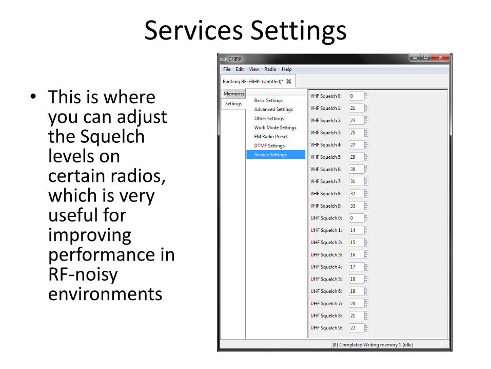
Services Settings
• This is where you can adjust the Squelch levels on certain radios, which is very useful for improving performance in RF-noisy environments

Fixing poor squelch levels on Baofeng radios
• The slightest whisper of a modem, router or switch still opens up the squelch, whatever the setting. But thanks to the efforts of the CHIRP development team, you can now change this.

Adjusting Squelch
CHIRP will let you decide when the squelch opens up – either when receiving a tiny noisy signal, or when a repeater around the corner starts transmitting.
As you can see you can set a personal threshold for every individual squelch level (1-9), and enter different settings for VHF and UHF.
The higher the number, the more signal you need to open up the squelch.

RepeaterBook.com

SPARC 70cm REPEATER – SLC Airport
– 448.050 MHZ (Tx)
– Negative Offset (443.050 MHz Rx)
– 100Hz Tone (to open the squelch on the receiver)
• ~50 Watts Effective Isentropic Radiated Power (EIRP)
• ~15-20 miles line of sight with a flexible whip antenna and a 7 watt handheld transceiver

DCARC Repeaters – Antelope Island
• 70cm
– 447.200 MHZ (Tx)
– Negative Offset (442.200 MHz Rx)
– No PL tone
• 2m
– 147.040 MHZ (Tx)
– Positive Offset of 600kHz (147.640 MHz Rx)
– 123Hz PL Tone
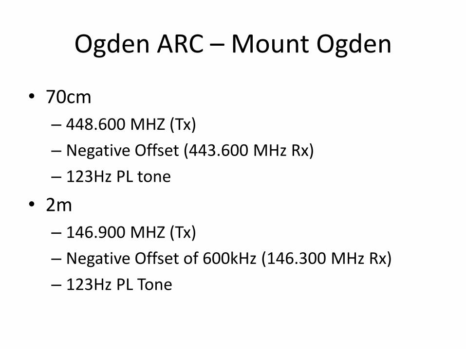
Ogden ARC – Mount Ogden
• 70cm
– 448.600 MHZ (Tx)
– Negative Offset (443.600 MHz Rx)
– 123Hz PL tone
• 2m
– 146.900 MHZ (Tx)
– Negative Offset of 600kHz (146.300 MHz Rx)
– 123Hz PL Tone

Intermountain Intertie
• There are many repeaters out there, but the “Intermountain Intertie” is a repeater network running from southern Idaho/Wyoming (Montanna/Colorado) down into northern Arizona/Nevada (sometimes into California). Using this repeater network requires you to select the repeater you are nearest, but it is an amazingly effective way to communicate long range without an HF radio.
• When using networked repeaters such as this, please be courteous of others that may be wanting to use the system, frequently leaving time for breaks, and limiting QSOs to no more than 10 minutes during the heavier usage times - and it is uncouth to monopolize the system at any time. Keep in mind that it takes a good portion of a second for all of the various links to 'turn around' so be sure to pause for several seconds when you allow for breaks, and key up for about a second before you say your first word.
• This system is extensive, and using it is sufficiently involved that I won’t go into it here, but know that it is out there! If you are so inclined, dial it up and just listen in. You can learn a LOT about radio just from listening.
• http://utahvhfs.org/snowlink.html

Intertie Map
• This is a simplified map of Utah coverage:

Happy Chirping!