High resolution chirp transform spectrometer
15
Experimental Astronomy (2004) 18: 77–91 DOI: 10.1007/s10686-005-9004-3 C Springer 2006 THE HIGH RESOLUTION CHIRP TRANSFORM SPECTROMETER FOR THE SOFIA-GREAT INSTRUMENT G. VILLANUEVA ∗ and P. HARTOGH Max-Planck-Institut f¨ ur Sonnensystemforschung, Max-Planck-Str. 3, 37191 Katlenburg-Lindau, Germany ( ∗ author for correspondence, e-mail: [email protected]) (Received 25 May 2005; accepted 5 October 2005) Abstract. In this paper, we present the design of a high resolution Chirp Transform Spectrometer (CTS) which is part of the GREAT (German REceiver for Astronomy at Terahertz frequencies) instru- ment onboard SOFIA, the Stratospheric Observatory For Infrared Astronomy. The new spectrometer will provide unique spectral resolving power and linearity response, since the analog Fourier trans- form performed by the CTS spectrometer was improved through a new design, that we call “Adaptive Digital Chirp Processor (ADCP)”. The principle behind the ADCP consists on digitally generating the dispersive signal which adapts to the compressor dispersive properties, achieving maximum spec- tral resolution and higher dynamic range. Excellent test results have been obtained such as a white noise dynamic range of 30 dB, and a spectral resolution (FWHM) of 41.68 kHz which would mean if analyzing signals with the high frequency band receiver on the GREAT instrument (4.7 THz) a spectral resolving power (λ/λ) higher than 10 8 . Keywords: Radio Astronomy, High Resolution Spectroscopy, Chirp Transform Spectrometer, Radiometers, Heterodyne Instrumentation. 1. Introduction The newly developed spectrometer will have access to an extensive region of the far- IR and submillimeter region through the dual heterodyne receiver, GREAT, with a low-frequency band at 1.6–1.9 THz (188–158 μm), a mid-frequency band centered on the cosmologically relevant 1-0 transition of deuterated molecular hydrogen (HD) at 2.6 THz (115 μm), and a high-frequency band located in the far-IR region targeting the 4.7 THz (63 μm) fine-structure transition of atomic oxygen (Guesten et al., 2003). One interesting aspect of the configuration of the backend spectrom- eters in SOFIA is that they will share different frontend receivers, since it has been discussed to share spectrometers between GREAT and the American receiver CASIMIR (CAltech Submillimeter Interstellar Medium Investigations Receiver). CASIMIR is a submillimeter heterodyne receiver covering the spectral range from 500 GHz (0.6 mm) to 2000 GHz (150 μm) (Zmuidzinas and Edgar, 1999). The coverage of such broad frequency bands, combined with the remarkable improvement in sensitivity if compared to ground-based observatories by flying at
-
Upload
independent -
Category
Documents
-
view
3 -
download
0
Transcript of High resolution chirp transform spectrometer
Experimental Astronomy (2004) 18: 77–91DOI: 10.1007/s10686-005-9004-3 C© Springer 2006
THE HIGH RESOLUTION CHIRP TRANSFORM SPECTROMETER
FOR THE SOFIA-GREAT INSTRUMENT
G. VILLANUEVA∗ and P. HARTOGHMax-Planck-Institut fur Sonnensystemforschung, Max-Planck-Str. 3,
37191 Katlenburg-Lindau, Germany(∗author for correspondence, e-mail: [email protected])
(Received 25 May 2005; accepted 5 October 2005)
Abstract. In this paper, we present the design of a high resolution Chirp Transform Spectrometer(CTS) which is part of the GREAT (German REceiver for Astronomy at Terahertz frequencies) instru-ment onboard SOFIA, the Stratospheric Observatory For Infrared Astronomy. The new spectrometerwill provide unique spectral resolving power and linearity response, since the analog Fourier trans-form performed by the CTS spectrometer was improved through a new design, that we call “AdaptiveDigital Chirp Processor (ADCP)”. The principle behind the ADCP consists on digitally generatingthe dispersive signal which adapts to the compressor dispersive properties, achieving maximum spec-tral resolution and higher dynamic range. Excellent test results have been obtained such as a whitenoise dynamic range of 30 dB, and a spectral resolution (FWHM) of 41.68 kHz which would meanif analyzing signals with the high frequency band receiver on the GREAT instrument (4.7 THz) aspectral resolving power (λ/�λ) higher than 108.
Keywords: Radio Astronomy, High Resolution Spectroscopy, Chirp Transform Spectrometer,Radiometers, Heterodyne Instrumentation.
1. Introduction
The newly developed spectrometer will have access to an extensive region of the far-IR and submillimeter region through the dual heterodyne receiver, GREAT, with alow-frequency band at 1.6–1.9 THz (188–158 μm), a mid-frequency band centeredon the cosmologically relevant 1-0 transition of deuterated molecular hydrogen(HD) at 2.6 THz (115 μm), and a high-frequency band located in the far-IR regiontargeting the 4.7 THz (63 μm) fine-structure transition of atomic oxygen (Guestenet al., 2003). One interesting aspect of the configuration of the backend spectrom-eters in SOFIA is that they will share different frontend receivers, since it hasbeen discussed to share spectrometers between GREAT and the American receiverCASIMIR (CAltech Submillimeter Interstellar Medium Investigations Receiver).CASIMIR is a submillimeter heterodyne receiver covering the spectral range from500 GHz (0.6 mm) to 2000 GHz (150 μm) (Zmuidzinas and Edgar, 1999).
The coverage of such broad frequency bands, combined with the remarkableimprovement in sensitivity if compared to ground-based observatories by flying at

78 G. VILLANUEVA AND P. HARTOGH
15 km with SOFIA, offers the possibility to detect a large number of molecules.In particular, the high resolving power provided by CTS will be a unique tool toremotely sense planetary atmospheres, obtaining circulation information (winds,temperatures) and vertical profiles of minor spices as retrieved from the highlyresolved spectral lines.
CTSs have a history of nearly two decades of successful groundbased, airborneand space missions, and are considered reliable instruments with high resolutionand dynamic range. The first heterodyne spectroscopy with a CTS has been per-formed in the middle of the eighties by detecting the 142 GHz rotational transitionof ozone in the Earth middle atmosphere (Hartogh and Hartmann, 1990; Hartoghand Jarchow, 1994/5), followed by submillimeter measurements of halogen bear-ing species (HC1 and CIO) and ozone from a jet aircraft in the early ninetiesduring the EASOE (European Artic Stratospheric Ozone Experiment) (Nett et al.,1992; Crewell et al., 1994; Wehr et al., 1995). Since the early nineties continuousground-based measurements of water vapor (22/183.6 GHz) and ozone (142 GHz)have been performed. This unique database was crucial in our understanding ofthe annual and inter-annual variation of the Earth middle atmospheric water vapor(Hartogh, 2000; Seele and Hartogh, 1999), the building mechanism of noctilucentclouds (NLCs) (von Zahn et al., 2004), the relationship between brightness andfrequency of NLCs, the advection of air during a stratospheric warming (Seele andHartogh, 2000) and the middle mesosphere maximum of ozone (Hartogh et al.,2004). Furthermore, upon the integration of a CTS spectrometer into the HeinrichHertz Submillimeter Telescope (HHSMT) at Mt. Graham, it has been applied to ad-dress a wide range of topics of modern astrophysics (Villanueva, 2004; Hofstadteret al., 1999), from questions about comets, planetary atmospheres and the interstel-lar medium in the galaxy, to investigations related to the early Universe. Recently,a CTS provided high quality spectra of comet 2002 T7 (LINEAR) and the Earthfrom the Microwave Instrument for the Rosetta Orbiter (MIRO), the first deep spacemission carrying a submillimeter heterodyne instrument (Beaudin et al., 1998).
The instrument’s principle is based on the chirp transform (Darlington, 1964;Klauder et al., 1960), a form of an analog Fourier transform using pulse-compression techniques from the Radar systems, in where two dispersive elements(an expander and a compressor) are arranged in order to perform the frequency/timeconversion. A more specific description of the transform performed in the newlydeveloped instrument can be found in Villanueva (2004). The dispersive elementsare SAW (Surface Acoustic Wave) filters, which have as impulse response a chirpsignal or a linear frequency modulated signal. These dispersive properties are im-plemented on the SAW filter as microscopic structures on the surface of a crystalbase, and consequently these are strongly sensitive to micro-scale mechanical de-formations and to the thermal expansion of the underneath substrate. The dispersivematching between the expander and the compressor constrains the properties of thetransform. For that purpose, we have studied and developed a new design called“Adaptive Digital Chirp Processor (ADCP)”. The principle behind the ADCP is to

THE HIGH RESOLUTION CHIRP TRANSFORM SPECTROMETER 79
incorporate the dispersive properties of the compressor into a digital system thatproduces the optimum matching expander waveform. The benefits of the arrange-ment are various, and the main are: high and constant spectral resolution over thewhole band as the expander-compressor dispersive matching is optimized, and highdynamic range as the out-coming chirp waveform has a large signal-to-noise-ratio(SNR).
After the discussion of the system design aspects in the next section, laboratorymeasurements are presented in detail thereafter. In that section the reader willfind the instrument’s characterization, i.e. spectral resolution, dynamic range, non-linearity of the frequency scale and the overall stability. Allan-variance tests wereused to retrieve the radiometric performance of the instrument by quantifying theamplitude (or gain) instrument’s stability, while iterative processes with laboratorysources were used to quantify the instrument’s white noise dynamic range andspectral properties. Some test results, taken with a running prototype integratedat the HHSMT telescope, are shown to demonstrate the scientific potential of theinstrument for studying narrow and broad spectral features on different astronomicalobjects. A summary of the scientific capabilities with SOFIA-GREAT-CTS and thetest results impact on the construction of the instrument are then given in the finalsection.
2. Instrument Description
The instrument was intended and developed to be a complete stand-alone unit. Thismeans an instrument which is able to distinguish the spectral information from theinput signal, to digitally acquire it, pre-process it, and calibrate it; and which is alsoable to provide standard interfaces for its controlling by the telescope’s operationssystem. The signal processing stages of the spectrometer can be summarized infour blocks: (1) the digital chirp generator, (2) the radio-frequency unit with theSAW compressors, (3) the data-acquisition with pre-processing modules and (4)the storage, calibration and final interface integrated in an embedded computer.The expander signal with dispersive characteristics matching those of the SAWcompressor is generated by the digital chirp generator or ADCP. This signal hasinitially a bandwidth of 143 MHz centered around 550 MHz and a dispersiontime of 44 μs. By means of the non-linear properties of an amplifying chain incompression, the signal is afterwards tripled in frequency (spectrally expanded)leading to an expander signal centered around 1650 MHz with a bandwidth of 430MHz. The compressor SAW filter centered at 450 MHz has half the bandwidth anddispersion time, and hence a time-bandwidth-product of 4700. When mixing theexpander signal with the input signal of 2100 MHz, the resulting signal centeredat 450 MHz is convolved with the compressor impulse response as shown on theinstrument’s block diagram on Figure 1. The output of the filter in the time domainrepresents the analog spectrum of the input signal, mapped on a 22 μs time interval.

80 G. VILLANUEVA AND P. HARTOGH
Due to the intrinsic properties of the chirp transform, the duty cycle of an expander-compressor arrangement is only 50%. This means that the arrangement takes a timeof 44 μs to perform a transform, however, it produces only half the time of usefulspectral information. For that purpose, two arrangements are combined through acommutator with a switching period of 22 μs.
The combined signal of the two branches is later down-converted to the base-band, and the real and imaginary components of the transform are retrieved bymixing the signal with a complex (a + ib) source. Both complex components aresampled with a set of 8 high data-rate analog to digital converters (ADC) anddigitally analyzed by an ad-hoc developed pre-processor integrated in an ASIC(application-specific integrated circuit) chip with very low power consumption.The pre-processor computes the power from the complex spectrum, and handlesthe synchronization signals needed to control the timing of the two branches. Thepre-processed spectral information is then transferred to an embedded computer,through a specifically developed ISA-ASIC interface that communicates with thepre-processor and reads the integrated data.
3. Characterization
3.1. DYNAMIC RANGE
Three effects constrain the instrument’s dynamic range: the high insertion loss of theSAW devices (more than 40 dB), the noise and interferences introduced during theRF signal processing, and the compression point of the different passive and activecomponents. The maximum signal in the RF part is the one which drives the mainmixer (+10 dBm) while the lowest is the output of the SAW device (−50 dBm).This large level difference entails a complex level handling and represents a com-plicated issue when evolving the signal from these extreme cases. In addition, aproper matching should exist between the dynamic range of the RF unit and the data-acquisition block in order to obtain the most of the setup. The high SNR of 40 dB ofthe digitally expander signal, however, allows a higher flexibility in the level han-dling and leads to a significant improvement in the overall instrument’s dynamicrange. The successive mixing and amplification processes degrade this level to avalue of 38 dB at the input of the SAW compressors. The fact that the electromag-netic wave is transformed to a mechanical or acoustic wave introduces several lossesand herewith a reduction of the SNR. After the convolution process performed bythe SAW filters, the white noise SNR is degraded to a value in the range of ∼35 dB,which is consistent with the afterwards described measurements of dynamicrange.
For the retrieval of the instrument’s dynamic range, a high accuracy RF stepattenuator with ±0.01 dB error (considering its internal calibration table at 2.1 GHz)and a +10 dBm output power noise source with 1.5 dB flatness over the selected

THE HIGH RESOLUTION CHIRP TRANSFORM SPECTROMETER 81
Figure 1. The high frequency signals from the telescope and the signal references are fed via pre-optics, such as the polarization splitter and the diplexers for local oscillator injection, to the mixers.The mixers together with the first low noise amplifiers are mounted inside a cryostat. The detectedsignal coming from the receivers is pre-processed and down-converted to the center frequency ofthe spectrometers via the IF-LO unit. This signal is then distributed by the patching/coupling unitto the backend instruments. The collaborating institutions are the Max Planck Institut fuer Radioas-tronomie (MPIfR), the Max-Planck-Institut fur Sonnesystemforschung (MPS), the Kolner Observato-rium fur SubMillimeter Astronomie (KOSMA), and the Deutsches Zentrum fur Luft- und Raumfahrt(DLR).
range (2.0–2.2 GHz) were used. The measurement consisted of 60 iterations with1 dB steps, an integration time of 1 second per position and a total measurementtime (including overheads) of 70 seconds. The results in Figure 3 show a ±1 dBdynamic range of 30 dB and a ±0.1 dB dynamic range of 18 dB with an optimuminput power level of −35 dBm.
3.2. STABILITY
The stability of the instrument is an important parameter as the instrument is nor-mally used to detect weak signals through long integration times. The radiometerformula is valid as long as the characteristics of the instruments are constant duringthe observation time between two calibrations. In order to quantify the stabilityof astronomical equipment, Allan variance measurements are normally used (e.g.

82 G. VILLANUEVA AND P. HARTOGH
Figure 2. Diagram describing the configuration of the SOFIA-GREAT-CTS spectrometer (onebranch). The chirp signal coming from the chirp generator is filtered, tripled and sent to be mixed withthe incoming RF signal. The mixing product is convolved by the SAW compressor and according to aprecise timing scheme, is then combined with the other branch through a switch. Both components ofthe chirp transformation (real and imaginary) are filtered and amplified. This complex signal is thenfed to the analog to digital converters and digitally transferred to the embedded computer through anad-hoc developed interface.
Schieder and Kramer, 2001). After the minimum of the variance (described asa time) the internal fluctuations of the instrument are stronger than the integratedwhite noise. The drift behavior of the instrument is mainly driven by variations withtemperature of the high gain amplifiers used in the RF signal processing. Thus, thefirst step for any significant stability improvement is to temperature stabilize theCTS. This was achieved by dividing the dissipation regions of the instrument ina convective and a radiative region. For the most power consuming components,being the case of the electronic circuitry and the power supply, the forced air flow

THE HIGH RESOLUTION CHIRP TRANSFORM SPECTROMETER 83
Figure 3. Dynamic range measurement. (Left) Relation between output power counts per cycle andinput power in dBm, when considering a white noise signal for the 2.0–2.2 GHz region. (Right)Deviation from linearity in dB derived from a linear fit of the curve on the left.
Figure 4. Allan variance measurement for channel 3750 of the spectrometer. (Left) Evolution of thecounts per cycle for 22000 measurements with an integration time per data point of 1.5 seconds.(Right) Allan variance analysis of the measured intensity variability
in the spectrometer (and thus the convective dissipation process) is organized toaffect mainly these regions.
The RF components on the other hand are thermally isolated since their dis-sipation is relatively small and therefore designed to be mainly radiative. Theinstrument’s radiometric performance was determined using a noise module asinput signal source and the instrument located in a non-controlled thermal en-vironment. After 30 minutes of warming-up time, 22000 spectra with an inte-

84 G. VILLANUEVA AND P. HARTOGH
gration time of 1.5 seconds each were obtained. The results of the Allan anal-ysis are shown in Figure 4, with a σ 2 noise following the radiometric formula(σ 2 = 〈s(t)〉2/(t · BF1)) until the minimum of the variance (TA), being t the inte-gration time and BF1 the power response function of the frequency channel to amonochromatic input signal. After TA, the thermally induced gain variations startto dominate, leading to an increase of σ 2 with a logarithmic slope of ∼ 2.0, whichcorresponds to a noise spectrum like S( f ) ∝ 1/ f 3, typical of radio-astronomicalequipment (Schieder and Kramer, 2001). This analysis provides then three impor-tant characterization parameters of the instrument, (a) the minimum of the Allanvariance (σ 2
A) is located at k = 340 which represents an Allan variance time of510 seconds, (b) BF1 representing the noise equivalent spectral resolution, and (c)the drift behavior of the instrument at large integration times. Another quantitywhich describes the instrument’s stability can be derived by means by the spec-troscopic Allan variance, which represents the variance of the relative fluctuationsof two independent spectrometer channels as a function of integration time. Sincethe main sources of drift in the instrument are the amplifiers, temperature vari-ations do not lead to a differential equalization of the signal and therefore thespectrometer channels do not drift independently of each other. This is consis-tent with our measurements of the spectroscopic stability, given that there was nominimum in the spectroscopic Allan variance performed on our dataset of morethan 9 hours.
In the case of the instrument’s long time frequency stability, variations in the dis-persive properties of the expander and/or compressor would lead to a displacementof the center position of the channels. This is especially the case of the compressorswhich are extremely sensitive to micro-scale mechanical deformations and to thethermal expansion of the underneath substrate of the SAW filters. Hence, the SAWdevices were embedded in polystyrene, and thermally isolated by several layers ofa thin polymide film. The low thermal conductivity of polystyrene and the highthermal isolation provided by the polymide film and the external aluminium struc-ture led to a high isolation, up to 40 times stronger than a non-isolated environment.The temperature inside the chamber is regulated at 40 ◦C above the average externaltemperature in order to provide superior thermal control to the heating device. Bymeasuring the center channel position at different environmental temperatures witha low-phase-noise signal generator as input, a frequency stability of 550 Hz/◦C wasretrieved.
3.3. SPECTRAL RESOLUTION
The spectral resolution is one of the most important characteristics of the ChirpTransform Spectrometer and represents a design parameter. In theory, the spec-tral resolution of the instrument is defined by the common dispersion time (Tc);however, a non-proper dispersive matching between the compressor and the ex-pander would lead to a worsening of the resolution. Even though the SAW devices

THE HIGH RESOLUTION CHIRP TRANSFORM SPECTROMETER 85
Figure 5. (Left) Measurement of spectral resolution as retrieved from the left and right HWHM. Themeasurement consists of providing a sinewave test signal to the instrument, which when measuredwith an oversampling mode of 8 eight points per channel spacing, leads to a measured spectrumwith a resolution of 3.6 kHz. The location of the maximum and the neighbor half maximum pointsare retrieved from the high resolution data. (Right) Measurement of the instrument’s spectral scalelinearity.
used in SOFIA-GREAT-CTS are of extremely good quality (phase error less than3◦ rms), they show quantitatively high differences in their chirp-rate. In the caseof the analog CTS (Hartogh, 1989) with two SAW filters used as expander, thematching of the complete setup of 6 filters (2×[2 expander + 1 compressor]) iseven more complex and represents an important design constraint. With the newdesign, the spectral resolution can be importantly improved since only the matchingbetween the two compressors is required, and the ADCP processor generates thetwo “adapted” expander signals.
The response of the spectrometer to a sinewave is a sinc function with the firstzero crossing in the frequency domain at 1/Tc. Hence, the FWHM (Full Width HalfMaximum) of its power spectrum would be 0.88 of the distance between the max-imum and the first zero crossing. In our case with a dispersion time of 22 μs, thiswould mean a theoretical FWHM of 41.06 kHz. This value is in close agreementwith the average measured spectral resolution of 41.68 kHz as retrieved from therelative HWHM (Half-Width-Half-Maximum) to the right and to the left shownin Figure 5. This demonstrates an optimum match between the digitally generatedexpander chirp and the SAW filter dispersive and would mean in the context ofSOFIA-GREAT at 4.7 THz, a spectral resolving power higher than λ/�λ = 108.Deviations in the spectral scale linearity were further retrieved using an inter-leaved spectral measurement of 8 points per sampled channel, obtaining values lessthan ±10% of the spectral FWHM for the complete operational bandwidth of theinstrument.
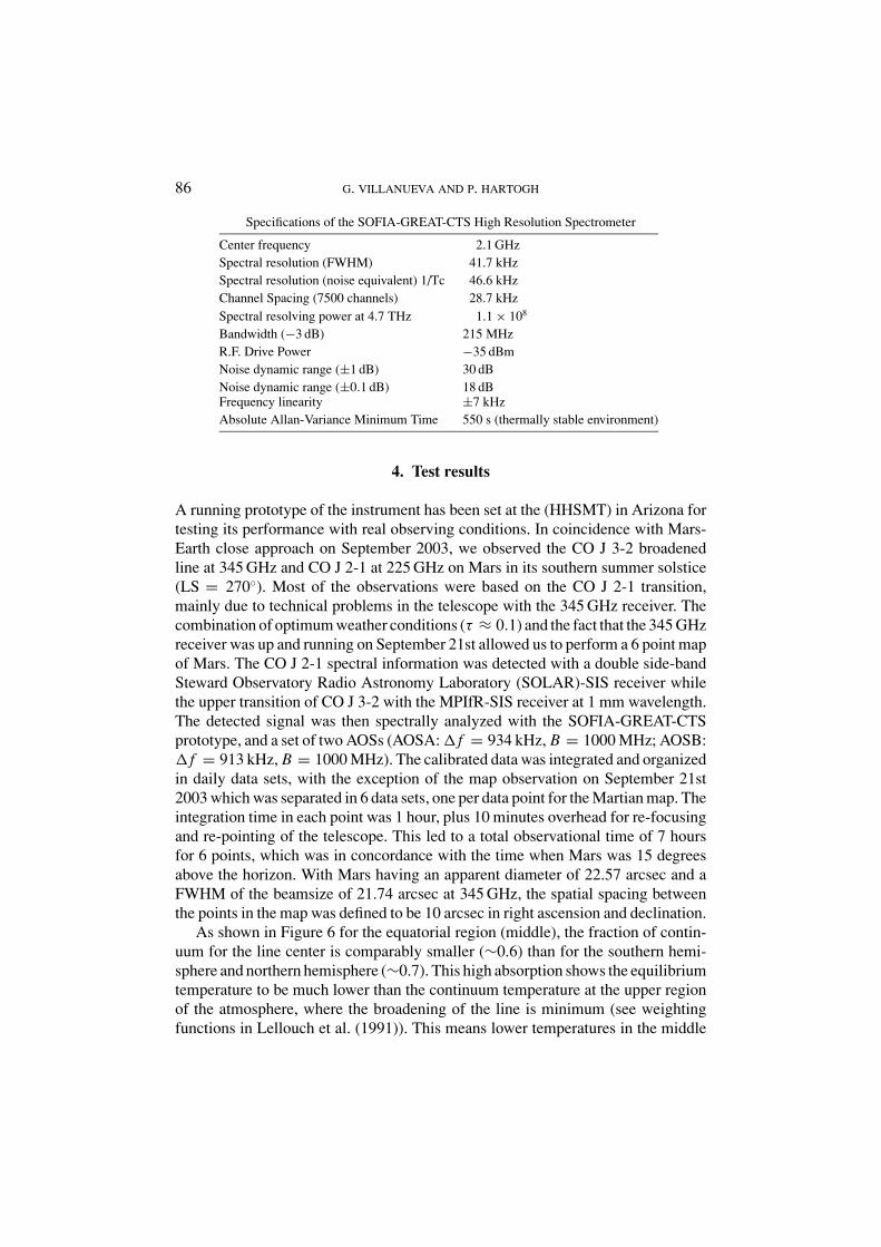
86 G. VILLANUEVA AND P. HARTOGH
Specifications of the SOFIA-GREAT-CTS High Resolution Spectrometer
Center frequency 2.1 GHzSpectral resolution (FWHM) 41.7 kHzSpectral resolution (noise equivalent) 1/Tc 46.6 kHzChannel Spacing (7500 channels) 28.7 kHzSpectral resolving power at 4.7 THz 1.1 × 10⁸
Bandwidth (−3 dB) 215 MHzR.F. Drive Power −35 dBmNoise dynamic range (±1 dB) 30 dBNoise dynamic range (±0.1 dB) 18 dBFrequency linearity ±7 kHzAbsolute Allan-Variance Minimum Time 550 s (thermally stable environment)
4. Test results
A running prototype of the instrument has been set at the (HHSMT) in Arizona fortesting its performance with real observing conditions. In coincidence with Mars-Earth close approach on September 2003, we observed the CO J 3-2 broadenedline at 345 GHz and CO J 2-1 at 225 GHz on Mars in its southern summer solstice(LS = 270◦). Most of the observations were based on the CO J 2-1 transition,mainly due to technical problems in the telescope with the 345 GHz receiver. Thecombination of optimum weather conditions (τ ≈ 0.1) and the fact that the 345 GHzreceiver was up and running on September 21st allowed us to perform a 6 point mapof Mars. The CO J 2-1 spectral information was detected with a double side-bandSteward Observatory Radio Astronomy Laboratory (SOLAR)-SIS receiver whilethe upper transition of CO J 3-2 with the MPIfR-SIS receiver at 1 mm wavelength.The detected signal was then spectrally analyzed with the SOFIA-GREAT-CTSprototype, and a set of two AOSs (AOSA: � f = 934 kHz, B = 1000 MHz; AOSB:� f = 913 kHz, B = 1000 MHz). The calibrated data was integrated and organizedin daily data sets, with the exception of the map observation on September 21st2003 which was separated in 6 data sets, one per data point for the Martian map. Theintegration time in each point was 1 hour, plus 10 minutes overhead for re-focusingand re-pointing of the telescope. This led to a total observational time of 7 hoursfor 6 points, which was in concordance with the time when Mars was 15 degreesabove the horizon. With Mars having an apparent diameter of 22.57 arcsec and aFWHM of the beamsize of 21.74 arcsec at 345 GHz, the spatial spacing betweenthe points in the map was defined to be 10 arcsec in right ascension and declination.
As shown in Figure 6 for the equatorial region (middle), the fraction of contin-uum for the line center is comparably smaller (∼0.6) than for the southern hemi-sphere and northern hemisphere (∼0.7). This high absorption shows the equilibriumtemperature to be much lower than the continuum temperature at the upper regionof the atmosphere, where the broadening of the line is minimum (see weightingfunctions in Lellouch et al. (1991)). This means lower temperatures in the middle

THE HIGH RESOLUTION CHIRP TRANSFORM SPECTROMETER 87
Figure 6. Observations of the Martian CO J 3-2 broadened spectral line with a SOFIA-GREAT-CTSprototype at the HHSMT telescope. The integration time is one hour per point and the observationswere taken with right ascension and declination offsets of ±10 arcsec for the 6 different global points.The location of the observational beam with respect to the Martian disk is shown in gray.
atmosphere for the equatorial region and a colder lower atmosphere for the win-ter hemisphere, which is consistent with our global simulations as obtained withthe MAOAM-GCM (Martian Atmosphere Observation And Modeling – GeneralCirculation Model) (see Villanueva, 2004).
The instrument’s high spectral resolution was also used to study the fine structureof cometary emission lines. The selected object was the periodic comet Encke/2Pwhich has a small period of 3.3 years and was not particularly bright during theobservational period, with an optical brightness of ∼7. Dynamically old cometslike Encke frequently show dust jets or fans which are believed to be driven by theremaining active regions on an otherwise already rather inactive nucleus.
This outgassing phenomenon leads to asymmetries in the line profile, whichcan only be measured with a high spectral resolving power instrument such asthe newly developed CTS spectrometer. With a similar frontend-backend setup as

88 G. VILLANUEVA AND P. HARTOGH
Figure 7. Observational summary for detections with S/N ratios higher than 3 on comet Encke onNovember 2003. The comet was particularly weak and the data was spectrally smoothed for increasingthe S/N ratio. The HCN (3-2) observations have a velocity resolution of 0.2587 km s−1 while the HCN(4-3) observations of 0.3880 km s−1. Each spectrum represents a complete observational day withintegration times in the range of 3 and 6 hours.
the one previously described for Mars, the HCN J 3-2 spectral information wasmeasured with the SOLAR-SIS receiver while the upper transition of HCN J 4-3and H2CO with the MPIfR-SIS receiver at 1 mm wavelength. An interesting aspectthat we have seen in our dataset is a relative displacement of the emission line ofHCN as a function of the position angle. This feature can be presumably explained

THE HIGH RESOLUTION CHIRP TRANSFORM SPECTROMETER 89
by considering that most of the molecules come from a single active region, which isactivated by the direct solar insolation. In other words, we should expect differentrelative velocity displacements at different position angles, following −vjet cos(PA) where vjet is the outflow velocity of the active region and PA the positionangle (Sun-Comet-Telescope angle). This is consistent with our observations asshown in Figure 7 because firstly at November 19th with PA = 85◦, the measuredspectrum of HCN J 4-3 showed a slight blue-shifted displacement. In the followingdays, the line then became increasingly red-shifted (PA > 90◦) in a monotonicmanner. We could then conclude that on comet Encke, the outgassing phenomenais far from being isotropic and is mainly driven by a single solar related activeregion. Even though comet Encke was not particularly active, the performance ofthe instrument for studying narrow line features under real observing conditionswas nicely demonstrated.
5. Conclusions
The test results have shown that the new concept of the adaptive dispersion forCTS instruments is suitable for the study of broad and narrow lines from differentastronomical objects, and upon its integration at the SOFIA observatory, it will bea unique tool for addressing high resolution spectrometric observations of a vastregion of the far-IR and submillimeter region.
The optimum matching between the dispersive properties of the compressorand digital expander led to a notable spectral response, with a high spectral reso-lution and a frequency residual nonlinearity below 0.2 of a channel over the entirebandwidth. In addition, the fact that the expander signal is digitally generated repre-sented a significant improvement in the instrument linearity response with a whitenoise dynamic range of 30 dB, and therefore the CTS does not show any systematicerrors even for observations with strong continuum backgrounds.
The existing constraints in volume, mass and power consumption for the SOFIAmission posed a true challenge in the instrument’s temperature stabilization. Thisis a critical parameter on the spectral stability and radiometric performance of theCTS since both, the SAW compressors and the high gain amplifiers, are particularlysensitive to variations in the environmental temperature. However, the successfullyimplemented stability design with 3 isolated thermal regions and 3 different dissipa-tive regimes was a decisive factor for the high stability found in the Allan-varianceplots.
Although the presented concept is already a rather stable compact solution of abackend, new design considerations for a second generation of CTS would possiblyincrease the Allan-variance time to values higher than 800 seconds. This can beachieved by introducing thermal pads in the RF unit with a thermal response invertedto that of the devices involved in the signal processing. In addition, with the evolutionand optimization of the digital synthesizers as part of the ADCP, we expect to

90 G. VILLANUEVA AND P. HARTOGH
maximize the bandwidth and in terms of space applications to minimize the powerconsumption of the instrument.
Acknowledgements
The authors would like to thank Dr. C. Jarchow for numerous stimulation discus-sions, and E. Steinmetz and P. Borner for experimental hardware and softwaresupport. The observations were possible thanks to the support and assistance of thescientific and operational team at the HHSMT telescope in Arizona, USA.
References
Beaudin, G., Gulkis, S., Frerking, M., Hartogh, P., Allen, M., Bockelee-Morvan, D., Crovisier, J.,Despois, D., Encrenaz, P., Encrenaz, T., Germain, B., Hofstadter, M., Ip, W., Janssen, J., Lellouch,E., Mann, I., Muhleman, D., Rauer, H., Schloerb, F.P., Spilker, T.: In Mallat, J., Raisanen, A.,Tuovinen, J. (eds.) Proceedings of the 2nd ESA Workshop on Millimetre Wave Technologyand Applications: Antennas, Circuits and Systems, pp. 43–48, ESA WPP-149, ESA Publ. Div.,ESPOO, Finland (1998)
Crewell, S., Kunzi, K., Nett, H., Wehr, T., Hartogh, P.: Geophys. Res. Lett. 21, 1267 (1994)Darlington, S.: Bell Syst. Tech. J. 43, 339 (1964)Guesten, R., Camara, I., Hartogh, P., Huebers, H.W., Graf, U.U., Jacobs, K., Kasemann, C., Roeser,
H.P., Schieder, R.T., Schnieder, G., Sievertz, O., Stutzki, J., Villanueva, G., Wagner, A., van derWal, P., Wunsch, A.: Proceedings of the SPIE 4857, 56 (2003)
Hartogh, P.: Messung der 142 GHz Emissionslinie des atmospharischen Ozons, PhD thesis, Universityof Goettingen (1989)
Hartogh, P., Hartmann, G.K.: Meas. Sci. Technol. (1), 592 (1990)Hartogh, P., Jarchow, C.: In Stein, T.I. (ed.) Proc. IGARSS’94 on Surface and Atmospheric Remote
Sensing: Technologies, Data Analysis and Interpretation, Pasadena, Vol. III, pp. 3–5, Publ. Ser-vices IEEE, Piscataway, NJ (1994)
Hartogh, P., Jarchow, C.: Global process monitoring and remote sensing of Ocean and Sea Ice,EUROPTO-series, 2586 pp. 188–195, SPIE, Bellingham (1995)
Hartogh, P.: In Kley, D., J.M.R. III, Phillips, C. (eds.) Stratospheric processes and their role in climate(A project of the WMO/ICSU/IOC World Climate Research Programme): SPARC Assessment ofUpper Tropospheric and Stratospheric Water Vapour, vol. WCRP-113, pp. 45–46, SPARC Office,BP 3, 91371 Verrieres le Buisson Cedex, France (2000)
Hartogh, P., Jarchow, C., Sonnemann, G.R., Grygalashvyly, M.: J. Geophys. Res. 109 (2004)Hofstadter, M.D., Hartogh, P., McMullin, J.P., Martin, R.N., Jarchow, C., Peters, W.: Earth, Moon
and Planets 78, 53 (1999)Klauder, J.R., Price, A.C., Darlington S., Albersheim, W.J.: Bell Syst. Tech. J. 39, 745 (1960)Lellouch, E., Encrenaz, T., Phillips, T., Falgarone, E., Billebaud, F.: Planetary and Space Science 39,
209 (1991) (ISSN 0032-0633)Nett, H., Crewell, S., Hartogh, P., Kunzi, K.: In Proceedings of the International Symposium on
Environmental Sensing, vol. 1715 of SPIE, Optical Methods in Atmospheric Chemistry, pp.468–475, Berlin, 22–26 June 1992 (1993)
Schieder, R., Kramer, C.: A&A 373, 746 (2001)Seele, C., Hartogh, P.: Geophys. Res. Lett. 26(11), 1517 (1999)

THE HIGH RESOLUTION CHIRP TRANSFORM SPECTROMETER 91
Seele, C., Hartogh, P.: Geophysical Research Letters 27, 3309 (2000)von Zahn, U., Baumgarten, G., Berger, U., Fiedler, J., Hartogh, P.: Atmos. Chem. Phys. 4, 2449 (2004)Villanueva, G.: Albert-Ludwigs-Universitat zu Freiburg, PhD thesis (2004)Wehr, T., Crewell, S., Kunzi, K., Langen, J., Nett, H., Urban, J., Hartogh, P.: J. Geophys. Res. 100,
20957 (1995)Zmuidzinas, J., Edgar, M.: Caltech Submillimeter Interstellar Medium Investigations Receiver, SOFI-
APADR – Preliminary Airworthiness Design Review document (1999)