Fujitsu SPARC M12-2/M12-2S Service Manual
560
Fujitsu SPARC M12-2/M12-2S Service Manual Manual Code: C120-0019-14EN June 2021
-
Upload
khangminh22 -
Category
Documents
-
view
0 -
download
0
Transcript of Fujitsu SPARC M12-2/M12-2S Service Manual
Fujitsu SPARC M12-2/M12-2S Service Manual
Manual Code: C120-0019-14EN June 2021

Copyright
©
2017,
2021,
Fujitsu
Limited.
All
rights
reserved.
Oracle and/or its affiliates provided technical input and review on portions of this material.
Oracle and/or its affiliates and Fujitsu Limited each own or control intellectual property rights relating to products and technology described in this document, and such products,
technology
and
this
document
are
protected
by
copyright
laws,
patents,
and
other
intellectual
property
laws
and
international
treaties.
This document and the product and technology to which it pertains are distributed under licenses restricting their use, copying, distribution, and decompilation. No part of such
product or technology, or of this document, may be reproduced in any form by any means without prior written authorization of Oracle and/or its affiliates and Fujitsu Limited, and
their applicable licensors, if any. The furnishings of this document to you does not give you any rights or licenses, express or implied, with respect to the product or technology to
which it pertains, and this document does not contain or represent any commitment of any kind on the part of Oracle or Fujitsu Limited or any affiliate of either of them.
This
document
and
the
product
and
technology
described
in
this
document
may
incorporate
third-party
intellectual
property
copyrighted
by
and/or
licensed
from
the
suppliers
to
Oracle and/or its affiliates and Fujitsu Limited, including software and font technology.
Per the terms of the GPL or LGPL, a copy of the source code governed by the GPL or LGPL, as applicable, is available upon request by the End User. Please contact Oracle and/or its
affiliates
or
Fujitsu
Limited.
This
distribution
may
include
materials
developed
by
third
parties.
Parts
of
the
product
may
be
derived
from
Berkeley
BSD
systems,
licensed
from
the
University
of
California.
UNIX is a registered trademark of The Open Group.
Oracle and Java are registered trademarks of Oracle and/or its affiliates.
Fujitsu
and
the
Fujitsu
logo
are
registered
trademarks
of
Fujitsu
Limited.
SPARC
Enterprise,
SPARC64,
SPARC64
logo
and
all
SPARC
trademarks
are
trademarks
or
registered
trademarks
of
SPARC
International,
Inc.
in
the
United
States
and
other
countries and used under license.
Other names may be trademarks of their respective owners.
If this is software or related documentation that is delivered to the U.S. Government or anyone licensing it on behalf of the U.S. Government, the following notice is applicable:
U.S. GOVERNMENT END USERS: Oracle programs, including any operating system, integrated software, any programs installed on the hardware, and/or documentation, delivered
to U.S. Government end users are "commercial computer software" pursuant to the applicable Federal Acquisition Regulation and agency-specific supplemental regulations. As such,
use, duplication, disclosure, modification, and adaptation of the programs, including any operating system, integrated software, any programs installed on the hardware, and/or
documentation, shall be subject to license terms and license restrictions applicable to the programs. No other rights are granted to the U.S. Government.
Disclaimer:
The
only
warranties
granted
by
Oracle
and
Fujitsu
Limited,
and/or
any
affiliate
in
connection
with
this
document
or
any
product
or
technology
described
herein
are
those
expressly set forth in the license agreement pursuant to which the product or technology is provided.
EXCEPT AS EXPRESSLY SET FORTH IN SUCH AGREEMENT, ORACLE OR FUJITSU LIMITED, AND/OR THEIR AFFILIATES MAKE NO REPRESENTATIONS OR
WARRANTIES OF ANY KIND (EXPRESS OR IMPLIED) REGARDING SUCH PRODUCT OR TECHNOLOGY OR THIS DOCUMENT, WHICH ARE ALL PROVIDED AS IS, AND
ALL EXPRESS OR IMPLIED CONDITIONS, REPRESENTATIONS AND WARRANTIES, INCLUDING WITHOUT LIMITATION ANY IMPLIED WARRANTY OF
MERCHANTABILITY, FITNESS FOR A PARTICULAR PURPOSE OR NONINFRINGEMENT, ARE DISCLAIMED, EXCEPT TO THE EXTENT THAT SUCH DISCLAIMERS ARE
HELD TO BE LEGALLY INVALID. Unless otherwise expressly set forth in such agreement, to the extent allowed by applicable law, in no event shall Oracle or Fujitsu Limited,
and/or any of their affiliates have any liability to any third party under any legal theory for any loss of revenues or profits, loss of use or data, or business interruptions, or for any
indirect, special, incidental or consequential damages, even if advised of the possibility of such damages.
DOCUMENTATION
IS
PROVIDED
"AS
IS"
AND
ALL
EXPRESS
OR
IMPLIED
CONDITIONS,
REPRESENTATIONS
AND
WARRANTIES,
INCLUDING
ANY
IMPLIED
WARRANTY OF MERCHANTABILITY, FITNESS FOR A PARTICULAR PURPOSE OR NON-INFRINGEMENT, ARE DISCLAIMED, EXCEPT TO THE EXTENT THAT SUCH
DISCLAIMERS ARE HELD TO BE LEGALLY INVALID.
Copyright
©
2017,
2021,
Fujitsu
Limited.
Tous
droits
réservés.
Oracle et/ou ses affiliés ont fourni et vérifié des données techniques de certaines parties de ce composant.
Oracle et/ou ses affiliés et Fujitsu Limited détiennent et contrôlent chacun des droits de propriété intellectuelle relatifs aux produits et technologies décrits dans ce document. De
même,
ces
produits,
technologies
et
ce
document
sont
protégés
par
des
lois
sur
le
droit
d’auteur,
des
brevets,
et
d'autres
lois
sur
la
propriété
intellectuelle
et
des
traités
internationaux.
Ce document, le produit et les technologies afférents sont exclusivement distribués avec des licences qui en restreignent l'utilisation, la copie, la distribution et la décompilation.
Aucune partie de ce produit, de ces technologies ou de ce document ne peut être reproduite sous quelque forme que ce soit, par quelque moyen que ce soit, sans l'autorisation écrite
préalable d'Oracle et/ou ses affiliés et de Fujitsu Limited, et de leurs éventuels concédants de licence. Ce document, bien qu'il vous ait été fourni, ne vous confère aucun droit et
aucune licence, exprès ou tacites, concernant le produit ou la technologie auxquels il se rapporte. Par ailleurs, il ne contient ni ne représente aucun engagement, de quelque type que
ce soit, de la part d'Oracle ou de Fujitsu Limited, ou des sociétés affiliées de l'une ou l'autre entité.
Ce
document,
ainsi
que
les
produits
et
technologies
qu'il
décrit,
peuvent
inclure
des
droits
de
propriété
intellectuelle
de
parties
tierces
protégés
par
le
droit
d’auteur
et/ou
cédés
sous
licence par des fournisseurs à Oracle et/ou ses sociétés affiliées et Fujitsu Limited, y compris des logiciels et des technologies relatives aux polices de caractères.
Conformément
aux
conditions
de
la
licence
GPL
ou
LGPL,
une
copie
du
code
source
régi
par
la
licence
GPL
ou
LGPL,
selon
le
cas,
est
disponible
sur
demande
par
l'Utilisateur
Final.
Veuillez contacter Oracle et/ou ses affiliés ou Fujitsu Limited. Cette distribution peut comprendre des composants développés par des parties tierces. Des parties de ce produit
pourront être dérivées des systèmes Berkeley BSD licenciés par l'Université de Californie.
UNIX est une marque déposée de The OpenGroup.
Oracle et Java sont des marques déposées d'Oracle Corporation et/ou de ses affiliés.
Fujitsu
et
le
logo
Fujitsu
sont
des
marques
déposées
de
Fujitsu
Limited.
SPARC
Enterprise,
SPARC64,
le
logo
SPARC64
et
toutes
les
marques
SPARC
sont
utilisées
sous
licence
et
sont
des
marques
déposées
de
SPARC
International,
Inc.,
aux
Etats-Unis
et
dans d'autres pays.
Tout autre nom mentionné peut correspondre à des marques appartenant à leurs propriétaires respectifs.
Si ce logiciel, ou la documentation qui l'accompagne, est concédé sous licence au Gouvernement des Etats-Unis, ou à toute entité qui délivre la licence de ce logiciel ou l'utilise pour le
compte
du
Gouvernement
des
Etats-Unis,
la
notice
suivante
s'applique
:
U.S. GOVERNMENT END USERS: Oracle programs, including any operating system, integrated software, any programs installed on the hardware, and/or documentation, delivered
to U.S. Government end users are "commercial computer software" pursuant to the applicable Federal Acquisition Regulation and agency-specific supplemental regulations. As such,
use, duplication, disclosure, modification, and adaptation of the programs, including any operating system, integrated software, any programs installed on the hardware, and/or
documentation, shall be subject to license terms and license restrictions applicable to the programs. No other rights are granted to the U.S. Government.
Avis
de
non-responsabilité
:
les
seules
garanties
octroyées
par
Oracle
et
Fujitsu
Limited
et/ou
toute
société
affiliée
de
l'une
ou
l'autre
entité
en
rapport
avec
ce
document
ou
tout
produit ou toute technologie décrits dans les présentes correspondent aux garanties expressément stipulées dans le contrat de licence régissant le produit ou la technologie fournis.
SAUF
MENTION
CONTRAIRE
EXPRESSEMENT
STIPULEE
AU
DIT
CONTRAT,
ORACLE
OU
FUJITSU
LIMITED
ET/OU
LES
SOCIETES
AFFILIEES
A
L'UNE
OU
L'AUTRE
ENTITE DECLINENT TOUT ENGAGEMENT OU GARANTIE, QUELLE QU'EN SOIT LA NATURE (EXPRESSE OU IMPLICITE) CONCERNANT CE PRODUIT, CETTE
TECHNOLOGIE OU CE DOCUMENT, LESQUELS SONT FOURNIS EN L'ETAT. EN OUTRE, TOUTES LES CONDITIONS, DECLARATIONS ET GARANTIES EXPRESSES OU
TACITES, Y COMPRIS NOTAMMENT TOUTE GARANTIE IMPLICITE RELATIVE A LA QUALITE MARCHANDE, A L'APTITUDE A UNE UTILISATION PARTICULIERE OU A
L'ABSENCE DE CONTREFACON, SONT EXCLUES, DANS LA MESURE AUTORISEE PAR LA LOI APPLICABLE. Sauf mention contraire expressément stipulée dans ce contrat,
dans la mesure autorisée par la loi applicable, en aucun cas Oracle ou Fujitsu Limited et/ou l'une ou l'autre de leurs sociétés affiliées ne sauraient être tenues responsables envers une
quelconque partie tierce, sous quelque théorie juridique que ce soit, de tout manque à gagner ou de perte de profit, de problèmes d'utilisation ou de perte de données, ou
d'interruptions d'activités, ou de tout dommage indirect, spécial, secondaire ou consécutif, même si ces entités ont été préalablement informées d'une telle éventualité.
LA DOCUMENTATION EST FOURNIE "EN L'ETAT" ET TOUTE AUTRE CONDITION, DECLARATION ET GARANTIE, EXPRESSE OU TACITE, EST FORMELLEMENT
EXCLUE,
DANS
LA
MESURE
AUTORISEE
PAR
LA
LOI
EN
VIGUEUR,
Y
COMPRIS
NOTAMMENT
TOUTE
GARANTIE
IMPLICITE
RELATIVE
A
LA
QUALITE
MARCHANDE,
A
L'APTITUDE
A
UNE
UTILISATION
PARTICULIERE OU
A
L'ABSENCE
DE
CONTREFACON.

Contents
Preface xix
Chapter 1 Before Starting Maintenance Work 1
1.1 Warning/Caution Indications 1
1.2 Labels 2
1.2.1 Warning Labels 2
1.2.2 Standard Label 3
1.2.3 System Nameplate Label 4
1.3 RFID Tag 5
1.4 Safety Precautions 5
1.5 Precautions on Static Electricity 6
1.6 Other Precautions 8
1.7 Emergency Power-Off 9
1.8 Tools Required for Maintenance 10
Chapter 2 Understanding the System Units 11
2.1 Understanding the Names and Locations of the Units 11
2.1.1 Units Accessible From the Front 12
2.1.2 Units Accessible From the Rear 13
2.1.3 Internal Units 14
2.2 Checking the Memory Configuration Rules 15
2.2.1 Memory Installation Rules 16
2.2.2 Checking Memory Information 21
iii

2.3 Understanding the OPNL Functions 22
2.3.1 OPNL Display Function 24
2.3.2 OPNL Control Function 24
2.4 Understanding the LED Indications 26
2.4.1 OPNL LEDs 26
2.4.2 System Locator 28
2.4.3 LEDs of Each Unit 29
2.5 Understanding the Types of Cable 36
2.5.1 Types of Cable 36
2.5.2 Ports for Cable Connections 36
Chapter 3 Understanding the Types of Maintenance 39
3.1 Types of Maintenance 40
3.2 Types of Maintenance Applicable to the SPARC M12-2 43
3.2.1 Types of Maintenance for FRU Replacement (SPARC M12-2)
43
3.2.2 Types of Maintenance for FRU Addition (SPARC M12-2) 45
3.2.3 Types of Maintenance for FRU Removal (SPARC M12-2) 46
3.3 Types of Maintenance Applicable to the SPARC M12-2S (1BB
Configuration) 48
3.3.1 Types of Maintenance for FRU Replacement (SPARC M12-2S in
the 1BB Configuration) 48
3.3.2 Types of Maintenance for FRU Addition (SPARC M12-2S in the
1BB Configuration) 50
3.3.3 Types of Maintenance for FRU Removal (SPARC M12-2S in the
1BB Configuration) 53
3.4 Types of Maintenance Applicable to the SPARC M12-2S (Multiple-BB
Configuration) 55
3.4.1 Types of Maintenance for FRU Replacement (SPARC M12-2S in
a Multiple-BB Configuration) 55
3.4.2 Types of Maintenance for FRU Addition (SPARC M12-2S in the
Multiple-BB Configuration) 60
Fujitsu
SPARC
M12-2/M12-2S
Service
Manual ・ June 2021iv

3.4.3 Types of Maintenance for FRU Removal (SPARC M12-2S in the
Multiple-BB Configuration) 64
Chapter 4 FRU Replacement Workflows 69
4.1 Active/Hot Replacement Workflows 69
4.1.1 Active/Hot Replacement Workflow of the XSCFU 70
4.1.2 Active/Hot Replacement Workflow of a PCIe Card 71
4.1.3 Active/Hot Replacement Workflow of the Power Supply Unit
(PSU) 72
4.1.4 Active/Hot Replacement Workflow of the FANU 72
4.1.5 Active/Hot Replacement Workflow of the HDD/SSD 73
4.1.6 Active/Hot Replacement Workflow of the PCI Expansion Unit
74
4.2 Active/Cold Replacement Workflows 76
4.2.1 Active/Cold Replacement Workflow of the XSCFU 76
4.2.2 Active/Cold Replacement Workflow of a PCIe Card 78
4.2.3 Active/Cold Replacement Workflow of the PSU 79
4.2.4 Active/Cold Replacement Workflow of the FANU 81
4.2.5 Active/Cold Replacement Workflow of the FANBPU 82
4.2.6 Active/Cold Replacement Workflow of the HDD/SSD 83
4.2.7 Active/Cold Replacement Workflow of the HDDBPU 85
4.2.8 Active/Cold Replacement Workflow of the OPNL 86
4.2.9 Active/Cold Replacement Workflow of the CMU 87
4.2.10 Active/Cold Replacement Workflow of Memory 89
4.2.11 Active/Cold Replacement Workflow of the BPU 90
4.2.12 Active/Cold Replacement Workflow of the PSUBP 91
4.2.13 Active/Cold Replacement Workflow of the PCI Expansion Unit
93
4.2.14 Active/Cold Replacement Workflow of the XSCF DUAL
Control Cable 94
4.2.15 Active/Cold Replacement Workflow of the XSCF BB Control
Cable 96
Contents v

4.3 Inactive/Hot Replacement Workflows 97
4.3.1 Inactive/Hot Replacement Workflow of the XSCFU 97
4.3.2 Inactive/Hot Replacement Workflow of a PCIe Card 98
4.3.3 Inactive/Hot Replacement Workflow of the PSU 99
4.3.4 Inactive/Hot Replacement Workflow of the FANU 100
4.3.5 Inactive/Hot Replacement Workflow of the HDD/SSD 101
4.3.6 Inactive/Hot Replacement Workflow of the PCI Expansion Unit
102
4.4 Inactive/Cold Replacement Workflows 103
4.4.1 Inactive/Cold Replacement Workflow of the XSCFU 104
4.4.2 Inactive/Cold Replacement Workflow of a PCIe Card 106
4.4.3 Inactive/Cold Replacement Workflow of the PSU 107
4.4.4 Inactive/Cold Replacement Workflow of the FANU 108
4.4.5 Inactive/Cold Replacement Workflow of the FANBPU 109
4.4.6 Inactive/Cold Replacement Workflow of the HDD/SSD 110
4.4.7 Inactive/Cold Replacement Workflow of the HDDBPU 112
4.4.8 Inactive/Cold Replacement Workflow of the OPNL 113
4.4.9 Inactive/Cold Replacement Workflow of the CMU 114
4.4.10 Inactive/Cold Replacement Workflow of Memory 115
4.4.11 Inactive/Cold Replacement Workflow of the BPU 116
4.4.12 Inactive/Cold Replacement Workflow of the PSUBP 117
4.4.13 Inactive/Cold Replacement Workflow of the Crossbar Cable
119
4.4.14 Inactive/Cold Replacement Workflow of the XBU 120
4.4.15 Inactive/Cold Replacement Workflow of the PCI Expansion
Unit 121
4.4.16 Inactive/Cold Replacement Workflow of the XSCF DUAL
Control Cable 122
4.4.17 Inactive/Cold Replacement Workflow of the XSCF BB Control
Cable 123
4.5 System-Stopped/Hot Replacement Workflows 125
Fujitsu
SPARC
M12-2/M12-2S
Service
Manual ・ June 2021vi

4.5.1 System-Stopped/Hot Replacement Workflow of the XSCFU 125
4.5.2 System-Stopped/Hot Replacement Workflow of a PCIe Card
126
4.5.3 System-Stopped/Hot Replacement Workflow of the PSU 127
4.5.4 System-Stopped/Hot Replacement Workflow of the FANU 128
4.5.5 System-Stopped/Hot Replacement Workflow of the HDD/SSD
129
4.5.6 System-Stopped/Hot Replacement Workflow of the PCI
Expansion Unit 130
4.6 System-Stopped/Cold Replacement Workflows 131
4.6.1 System-Stopped/Cold Replacement Workflow of the XSCFU 132
4.6.2 System-Stopped/Cold Replacement Workflow of a PCIe Card
133
4.6.3 System-Stopped/Cold Replacement Workflow of the PSU 134
4.6.4 System-Stopped/Cold Replacement Workflow of the FANU 135
4.6.5 System-Stopped/Cold Replacement Workflow of the FANBPU
136
4.6.6 System-Stopped/Cold Replacement Workflow of the HDD/SSD
137
4.6.7 System-Stopped/Cold Replacement Workflow of the HDDBPU
138
4.6.8 System-Stopped/Cold Replacement Workflow of the OPNL 139
4.6.9 System-Stopped/Cold Replacement Workflow of the CMU 140
4.6.10 System-Stopped/Cold Replacement Workflow of Memory 141
4.6.11 System-Stopped/Cold Replacement Workflow of the BPU 142
4.6.12 System-Stopped/Cold Replacement Workflow of the PSUBP
143
4.6.13 System-Stopped/Cold Replacement Workflow of the Crossbar
Cable 144
4.6.14 System-Stopped/Cold Replacement Workflow of the XBU 145
Contents vii

4.6.15 System-Stopped/Cold Replacement Workflow of the XSCF
DUAL Control Cable 146
4.6.16 System-Stopped/Cold Replacement Workflow of the XSCF BB
Control Cable 147
4.6.17 System-Stopped/Cold Replacement Workflow of the PCI
Expansion Unit 148
Chapter 5 FRU Addition Workflows 151
5.1 Active/Hot Addition Workflows 151
5.1.1 Active/Hot Addition Workflow of a PCIe Card 152
5.1.2 Active/Hot Addition Workflow of the HDD/SSD 152
5.1.3 Active/Hot Addition Workflow of the PCI Expansion Unit 153
5.2 Active/Cold Addition Workflows 154
5.2.1 Active/Cold Addition Workflow of a PCIe Card 155
5.2.2 Active/Cold Addition Workflow of the HDD/SSD 156
5.2.3 Active/Cold Addition Workflow of the CMUU 158
5.2.4 Active/Cold Addition Workflow of Memory 159
5.2.5 Active/Cold Addition Workflow of the PCI Expansion Unit 161
5.2.6 Active/Cold Addition Workflow of the SPARC M12-2S 162
5.3 Inactive/Hot Addition Workflows 164
5.3.1 Inactive/Hot Addition Workflow of a PCIe Card 164
5.3.2 Inactive/Hot Addition Workflow of the HDD/SSD 165
5.3.3 Inactive/Hot Addition Workflow of the PCI Expansion Unit
166
5.4 Inactive/Cold Addition Workflows 167
5.4.1 Inactive/Cold Addition Workflow of a PCIe Card 168
5.4.2 Inactive/Cold Addition Workflow of the HDD/SSD 169
5.4.3 Inactive/Cold Addition Workflow of the CMUU 170
5.4.4 Inactive/Cold Addition Workflow of Memory 172
5.4.5 Inactive/Cold Addition Workflow of the PCI Expansion Unit
174
5.4.6 Inactive/Cold Addition Workflow of the SPARC M12-2S 175
Fujitsu
SPARC
M12-2/M12-2S
Service
Manual ・ June 2021viii

5.5 System-Stopped/Hot Addition Workflows 176
5.5.1 System-Stopped/Hot Addition Workflow of a PCIe Card 177
5.5.2 System-Stopped/Hot Addition Workflow of the HDD/SSD 177
5.5.3 System-Stopped/Hot Addition Workflow of the PCI Expansion
Unit 178
5.6 System-Stopped/Cold Addition Workflows 180
5.6.1 System-Stopped/Cold Addition Workflow of a PCIe Card 180
5.6.2 System-Stopped/Cold Addition Workflow of the HDD/SSD 181
5.6.3 System-Stopped/Cold Addition Workflow of the CMUU 182
5.6.4 System-Stopped/Cold Addition Workflow of Memory 183
5.6.5 System-Stopped/Cold Addition Workflow of the PCI Expansion
Unit 184
5.6.6 System-Stopped/Cold Addition Workflow of the SPARC M12-2S
186
Chapter 6 FRU Removal Workflows 189
6.1 Active/Hot Removal Workflows 189
6.1.1 Active/Hot Removal Workflow of a PCIe Card 190
6.1.2 Active/Hot Removal Workflow of the HDD/SSD 191
6.1.3 Active/Hot Removal Workflow of the PCI Expansion Unit 191
6.2 Active/Cold Removal Workflows 192
6.2.1 Active/Cold Removal Workflow of a PCIe Card 193
6.2.2 Active/Cold Removal Workflow of the HDD/SSD 195
6.2.3 Active/Cold Removal Workflow of the CMUU 196
6.2.4 Active/Cold Removal Workflow of Memory 198
6.2.5 Active/Cold Removal Workflow of the PCI Expansion Unit 199
6.2.6 Active/Cold Removal Workflow of the SPARC M12-2S 201
6.3 Inactive/Hot Removal Workflows 202
6.3.1 Inactive/Hot Removal Workflow of a PCIe Card 203
6.3.2 Inactive/Hot Removal Workflow of the HDD/SSD 204
6.3.3 Inactive/Hot Removal Workflow of the PCI Expansion Unit 205
6.4 Inactive/Cold Removal Workflows 206
Contents ix

6.4.1 Inactive/Cold Removal Workflow of a PCIe Card 207
6.4.2 Inactive/Cold Removal Workflow of the HDD/SSD 208
6.4.3 Inactive/Cold Removal Workflow of the CMUU 209
6.4.4 Inactive/Cold Removal Workflow of Memory 211
6.4.5 Inactive/Cold Removal Workflow of the PCI Expansion Unit
212
6.4.6 Inactive/Cold Removal Workflow of the SPARC M12-2S 214
6.5 System-Stopped/Hot Removal Workflows 215
6.5.1 System-Stopped/Hot Removal Workflow of a PCIe Card 215
6.5.2 System-Stopped/Hot Removal Workflow of the HDD/SSD 216
6.5.3 System-Stopped/Hot Removal Workflow of the PCI Expansion
Unit 217
6.6 System-Stopped/Cold Removal Workflows 219
6.6.1 System-Stopped/Cold Removal Workflow of a PCIe Card 219
6.6.2 System-Stopped/Cold Removal Workflow of the HDD/SSD 221
6.6.3 System-Stopped/Cold Removal Workflow of the CMUU 222
6.6.4 System-Stopped/Cold Removal Workflow of Memory 223
6.6.5 System-Stopped/Cold Removal Workflow of the PCI Expansion
Unit 224
6.6.6 System-Stopped/Cold Removal Workflow of the SPARC M12-2S
226
Chapter 7 FRU Maintenance Precautions 227
7.1 Precautions for FRU Replacement 227
7.2 Precautions for FRU Expansion 230
7.3 Precautions for FRU Reduction 232
Chapter 8 Preparation for Maintenance 235
8.1 Checking the System Configuration 235
8.1.1 Checking Logical Domain Configuration Information 235
8.1.2 Checking Hardware 236
8.1.3 Checking the XCP Firmware Version 241
8.1.4 Checking the Software Version 243
Fujitsu
SPARC
M12-2/M12-2S
Service
Manual ・ June 2021x

8.1.5 Checking the Operation Status of Physical Partitions 245
8.1.6 Checking FRU Information 245
8.2 Troubleshooting 248
8.2.1 Confirming Whether There is a Fault 248
8.2.2 Identifying a Fault 249
8.2.3 Gathering XSCF Log Information 258
Chapter 9 Releasing FRUs From the System 261
9.1 Saving Setting Information 261
9.1.1 Saving Logical Domain Configuration Information 262
9.1.2 Saving XSCF Settings Information 263
9.2 Checking the Operation Status and Resource Usage Status of Oracle
Solaris 265
9.2.1 Checking the Operation Status of Physical Partitions and Logical
Domains 265
9.2.2 Checking the Assignment Status of I/O Devices 267
9.2.3 Checking the Usage of the HDD/SSD 269
9.3 Releasing I/O Resources From a Logical Domain 271
9.3.1 Dynamically Releasing Virtual I/O From a Logical Domain 273
9.3.2 Dynamically Releasing the SR-IOV Virtual Function From a
Logical Domain 275
9.3.3 Dynamically Releasing the PCIe Endpoint From a Logical
Domain 277
9.3.4 Dynamically Releasing the Root Complex From a Logical
Domain 279
9.3.5 Statically Releasing the SR-IOV Virtual Function From a Logical
Domain 281
9.3.6 Statically Releasing the PCIe Endpoint From a Logical Domain
284
9.3.7 Statically Releasing the Root Complex From a Logical Domain
286
9.4 Enabling the Removal of Hardware 288
Contents xi

9.4.1 Dynamically Releasing a PCIe Card From a Logical Domain
288
9.4.2 Dynamically Releasing the HDD/SSD From a Logical Domain
290
9.4.3 Dynamically Releasing the SPARC M12-2S From the Physical
Partition 294
9.5 Stopping the System 305
9.5.1 Stopping a Specific Physical Partition 305
9.5.2 Stopping All Physical Partitions 307
9.6 Releasing FRUs From the System 310
9.6.1 Releasing the SPARC M12-2S From the Building Block
Configuration 311
9.6.2 Releasing the FANU 313
9.6.3 Releasing the PSU 314
9.6.4 Releasing the XSCFU 316
9.7 Removing the SPARC M12-2S 318
9.8 Accessing a FRU 320
9.8.1 Lowering the Cable Support 320
9.8.2 Removing the Power Cords 322
9.8.3 Removing the Front Cover 323
Chapter 10 Setting Up the System 325
10.1 Preparing Hardware 325
10.1.1 Installing a Power Cord 325
10.1.2 Securing the Cable Support 326
10.1.3 Installing the Front Cover 328
10.2 Restoring Setting Information 329
10.2.1 Restoring the Logical Domain System Configuration 329
10.2.2 Restoring XSCF Settings Information 331
10.3 Adding the SPARC M12-2S to a Building Block Configuration 333
10.4 Incorporating a FRU Into the System 338
Fujitsu
SPARC
M12-2/M12-2S
Service
Manual ・ June 2021xii

10.4.1 Incorporating the SPARC M12-2S Into a Building Block
Configuration 338
10.4.2 Incorporating the FANU 340
10.4.3 Incorporating the PSU 342
10.4.4 Incorporating the XSCFU 343
10.5 Diagnosing a Replacement FRU 346
10.5.1 Diagnosing the SPARC M12 Hardware 346
10.5.2 Diagnosing the XBU and Crossbar Cable 350
10.5.3 Checking the FRU Status After Maintenance 351
10.6 Incorporating the SPARC M12-2S or an I/O Device Into the PPAR
354
10.6.1 Incorporating the SPARC M12-2S Into the Physical Partition
Using PPAR DR 354
10.6.2 Incorporating an I/O Device Into the Physical Partition by
Using the Hot Plug Function 357
10.7 Incorporating I/O Resources Into a Logical Domain 360
10.7.1 Incorporating the Root Complex Into the Control Domain or
Root Domain 360
10.7.2 Incorporating the Root Complex Into the Stopped Root Domain
362
10.7.3 Incorporating the PCIe Endpoint Into the Logical Domain 363
10.7.4 Incorporating the SR-IOV Virtual Function 364
10.7.5 Incorporating Virtual I/O Devices Into a Logical Domain 367
10.8 Powering on a Physical Partition 368
10.9 Starting the System 369
10.9.1 Starting the System With an XSCF Command 369
10.9.2 Starting the System From the OPNL 370
Chapter 11 Maintaining the XSCF Unit 373
11.1 Maintenance Precautions 373
11.2 Location of the XSCFU 374
11.3 Before Maintenance on the XSCFU 374
Contents xiii

11.4 Removing the XSCFU 375
11.5 Switching an SD Card 378
11.5.1 Removing an SD Card 378
11.5.2 Installing an SD Card 379
11.6 Installing the XSCFU 380
Chapter 12 Maintaining PCIe Cards 383
12.1 Locations of PCIe Cards 383
12.2 Before Maintenance on a PCIe Card 386
12.3 Removing a PCIe Card 387
12.3.1 Enabling the Removal of a PCIe Card 387
12.3.2 Removing a PCIe Card or PCIe Card Filler 389
12.4 Installing a PCIe Card 391
12.4.1 Installing a PCIe Card or PCIe Card Filler 391
12.4.2 Incorporating a PCIe Card Into the System 394
Chapter 13 Maintaining the Power Supply Units 397
13.1 Locations of PSUs 397
13.2 Before Maintenance on a PSU 398
13.3 Removing a PSU 398
13.4 Installing a PSU 400
Chapter 14 Maintaining the Fan Units and Fan Backplane Unit 403
14.1 Locations of the FANUs and FANBPU 403
14.2 Before Maintenance on a FANU or the FANBPU 404
14.3 Removing a FANU or the FANBPU 405
14.3.1 Removing a FANU 405
14.3.2 Removing the FANBPU 406
14.4 Installing a FANU or the FANBPU 408
14.4.1 Installing the FANBPU 408
14.4.2 Installing a FANU 409
Chapter 15 Maintaining Internal Storage 413
15.1 Locations of HDDs/SSDs 413
15.2 Before Maintenance on an HDD/SSD 414
Fujitsu
SPARC
M12-2/M12-2S
Service
Manual ・ June 2021xiv
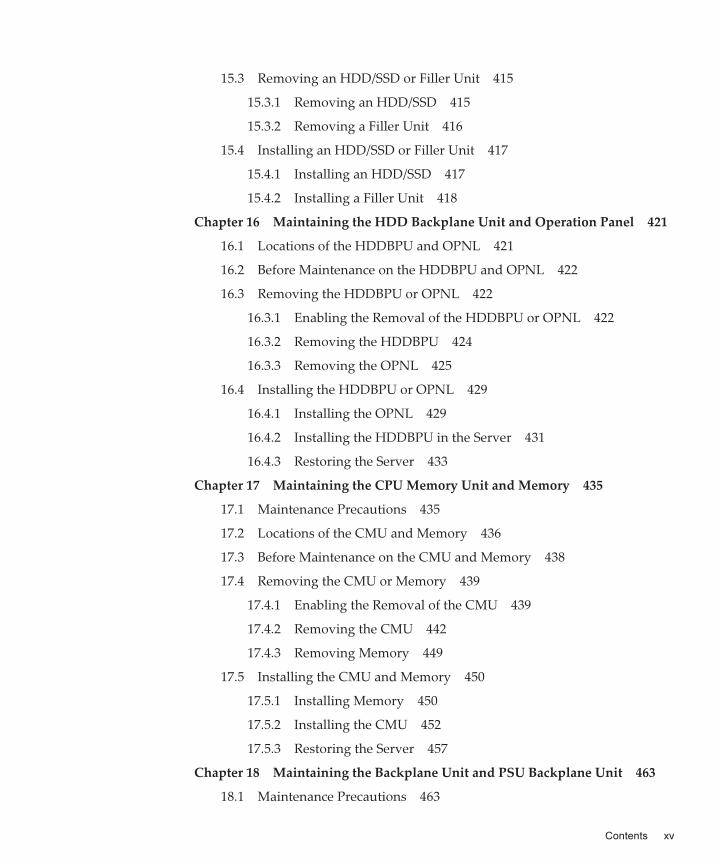
15.3 Removing an HDD/SSD or Filler Unit 415
15.3.1 Removing an HDD/SSD 415
15.3.2 Removing a Filler Unit 416
15.4 Installing an HDD/SSD or Filler Unit 417
15.4.1 Installing an HDD/SSD 417
15.4.2 Installing a Filler Unit 418
Chapter 16 Maintaining the HDD Backplane Unit and Operation Panel 421
16.1 Locations of the HDDBPU and OPNL 421
16.2 Before Maintenance on the HDDBPU and OPNL 422
16.3 Removing the HDDBPU or OPNL 422
16.3.1 Enabling the Removal of the HDDBPU or OPNL 422
16.3.2 Removing the HDDBPU 424
16.3.3 Removing the OPNL 425
16.4 Installing the HDDBPU or OPNL 429
16.4.1 Installing the OPNL 429
16.4.2 Installing the HDDBPU in the Server 431
16.4.3 Restoring the Server 433
Chapter 17 Maintaining the CPU Memory Unit and Memory 435
17.1 Maintenance Precautions 435
17.2 Locations of the CMU and Memory 436
17.3 Before Maintenance on the CMU and Memory 438
17.4 Removing the CMU or Memory 439
17.4.1 Enabling the Removal of the CMU 439
17.4.2 Removing the CMU 442
17.4.3 Removing Memory 449
17.5 Installing the CMU and Memory 450
17.5.1 Installing Memory 450
17.5.2 Installing the CMU 452
17.5.3 Restoring the Server 457
Chapter 18 Maintaining the Backplane Unit and PSU Backplane Unit 463
18.1 Maintenance Precautions 463
Contents xv

18.2 Locations of the BPU and PSUBP 464
18.3 Before Maintenance on the BPU and PSUBP 465
18.4 Removing the BPU and PSUBP 465
18.4.1 Enabling the Removal of the BPU 465
18.4.2 Removing the BPU 471
18.4.3 Removing the PSUBP From the BPU 472
18.5 Installing the BPU and PSUBP 474
18.5.1 Installing the PSUBP in the BPU 475
18.5.2 Installing the BPU 478
18.5.3 Restoring the Server 479
Chapter 19 Maintaining the Crossbar Cable 489
19.1 Ports for Crossbar Cable Connection 489
19.2 Before Maintenance on the Crossbar Cable 491
19.3 Removing the Crossbar Cable 491
19.4 Installing the Crossbar Cable 496
Chapter 20 Maintaining the Crossbar Unit 501
20.1 Locations of the XBU 501
20.2 Before Maintenance on an XBU 502
20.3 Removing an XBU 502
20.4 Installing an XBU 505
Chapter 21 Maintaining the XSCF DUAL Control Cable 509
21.1 XSCF DUAL Control Port 509
21.2 Before Maintenance on the XSCF DUAL Control Cable 511
21.3 Removing the XSCF DUAL Control Cable 511
21.4 Installing the XSCF DUAL Control Cable 514
Chapter 22 Maintaining the XSCF BB Control Cable 517
22.1 XSCF BB Control Port 517
22.2 Before Maintenance on the XSCF BB Control Cable 518
22.3 Removing the XSCF BB Control Cable 519
22.4 Installing the XSCF BB Control Cable 522
Fujitsu
SPARC
M12-2/M12-2S
Service
Manual ・ June 2021xvi

Appendix A Lists of Cable Connections in a Building Block Configuration
525
Appendix B External Interface Specifications 529
B.1 Serial Port 529
B.1.1 Wire Connection Chart for Serial Cables 530
B.2 USB Port 530
B.3 SAS Port 531
B.4 RESET Switch 531
Appendix C Removing the Lithium Battery 533
C.1 Location of the Lithium Battery 533
C.2 Removing the Lithium Battery 534
Index 535
Contents xvii

Fujitsu
SPARC
M12-2/M12-2S
Service
Manual ・ June 2021xviii

Preface
This document describes the maintenance procedures for the Oracle or Fujitsu SPARC M12.The document can also be used as a disassembly procedure for disposal or recycling.The maintenance work should be performed by service engineers and/or field engineers.
Fujitsu SPARC M12 is sold as SPARC M12 by Fujitsu in Japan.Fujitsu SPARC M12 and SPARC M12 are identical products.
AudienceThis document is intended for trained technicians and authorized service personnel who have been instructed on the hazards within the equipment and are qualified to remove and replace hardware. They may be called service engineers or field engineers.
Related
DocumentationAll documents for your server are available online at the following locations.■ Sun Oracle software-related documents (Oracle Solaris, etc.)
https://docs.oracle.com/en/
■ Fujitsu documentsGlobal site
https://www.fujitsu.com/global/products/computing/servers/unix/sparc/downloads/manuals/
Japanese site
https://www.fujitsu.com/jp/products/computing/servers/unix/sparc/downloads/manual/
xix

Documentation Related to the SPARC M12
Manual Names (*1)
Fujitsu SPARC M12 Product Notes
Fujitsu SPARC M12 Quick Guide
Fujitsu SPARC M12 Getting Started Guide (*2)
Fujitsu SPARC M12 and Fujitsu M10/SPARC M10 Important Legal and Safety Information (*2)
Fujitsu SPARC M12 and Fujitsu M10/SPARC M10 Safety and Compliance Guide
Software License Conditions for Fujitsu SPARC M12 and Fujitsu M10/SPARC M10
Fujitsu SPARC M12 and Fujitsu M10/SPARC M10 Security Guide
Fujitsu SPARC Servers/SPARC Enterprise/PRIMEQUEST Common Installation Planning Manual
Fujitsu SPARC M12-1 Installation Guide
Fujitsu SPARC M12-2 Installation Guide
Fujitsu SPARC M12-2S Installation Guide
Fujitsu SPARC M12 PCI Card Installation Guide
Fujitsu SPARC M12 and Fujitsu M10/SPARC M10 System Operation and Administration Guide
Fujitsu SPARC M12 and Fujitsu M10/SPARC M10 Domain Configuration Guide
Fujitsu SPARC M12 and Fujitsu M10/SPARC M10 RCIL User Guide (*3)
Fujitsu SPARC M12 and Fujitsu M10/SPARC M10 XSCF Reference Manual
Fujitsu SPARC M12 and Fujitsu M10/SPARC M10 XSCF MIB and Trap Lists
Fujitsu SPARC M12-1 Service Manual
Fujitsu SPARC M12-2/M12-2S Service Manual
Crossbar Box for Fujitsu SPARC M12 and Fujitsu M10/SPARC M10 Service Manual
PCI Expansion Unit for Fujitsu SPARC M12 and Fujitsu M10/SPARC M10 Service Manual
Fujitsu SPARC M12 and Fujitsu M10/SPARC M10 Glossary
External USB-DVD Drive user guide
*1 The listed manuals are subject to change without notice.*2 Printed manuals are provided with the product.*3 This document applies specifically to the SPARC M12/M10 and FUJITSU ETERNUS disk storage system.
The following table lists documents related to SPARC M12 systems.
Notes
on
SafetyRead the following documents thoroughly before using or handling the SPARC M12.■ Fujitsu SPARC M12 and Fujitsu M10/SPARC M10 Important Legal and Safety
Information
Fujitsu
SPARC
M12-2/M12-2S
Service
Manual ・ June 2021xx

Font/Symbol Meaning Example
AaBbCc123 What you type, when contrasted with on-screen computer output.
This font is used to indicate an example of command input.
XSCF>
adduser
jsmith
AaBbCc123 The names of commands, files, and directories; on-screen computer output.
This font is used to indicate an example of command output in the frame.
XSCF>
showuser
-P
User
Name:
jsmith
Privileges:
useradm
auditadm
Italic Indicates the name of a reference manual. See the Fujitsu SPARC M12-2S Installation Guide.
" " Indicates the names of chapters, sections, items, buttons, or menus.
See "Chapter 2 Network Connection."
■ Fujitsu SPARC M12 and Fujitsu M10/SPARC M10 Safety and Compliance Guide
Text
ConventionsThis manual uses the following fonts and symbols to express specific types of information.
Command
Syntax
in
the
Text
While the XSCF commands have a section number of (8) or (1), it is omitted from the text.For details on the commands, see the Fujitsu SPARC M12 and Fujitsu M10/SPARC M10 XSCF Reference Manual.
Syntax
of
the
Command-Line
Interface
(CLI)The command syntax is as follows:■ A variable that requires the input of a value is in Italics.
■ An optional element is enclosed in [].
■ A group of options for an optional keyword is enclosed in [] and delimited by |.
Preface xxi

Document
FeedbackIf you have any comments or requests regarding this document, please take a moment to share them with us. Along with the manual code, manual title, and page number, state your points specifically at one of the following websites:■ Global site
https://www.fujitsu.com/global/contact/
■ Japanese sitehttps://www.fujitsu.com/jp/products/computing/servers/unix/sparc/contact/
Fujitsu
SPARC
M12-2/M12-2S
Service
Manual ・ June 2021xxii

Warning - "WARNING" indicates a potential hazard that could result in death or serious personal injury if the user does not perform the procedure correctly.
Caution - "CAUTION" indicates a potential hazard that could result in minor or moderate personal injury if the user does not perform the procedure correctly. This also indicates that damage to the unit itself or other property may occur if the user does not perform the procedure correctly.
Chapter
1
Before
Starting
Maintenance
Work
This chapter describes the safety precautions that must be observed before the start of any maintenance work, and the tools required for the maintenance work.
Check the following items to ensure that the work is done correctly:
■ Warning/Caution Indications
■ Labels
■ RFID Tag
■ Safety Precautions
■ Precautions on Static Electricity
■ Other Precautions
■ Emergency Power-Off
■ Tools Required for Maintenance
1.1 Warning/Caution
IndicationsThis manual uses the following conventions to indicate warning and alert messages, which are intended to prevent injury to the user and others as well as damage to property.
1

Caution - Never peel off the labels.
1.2 LabelsThis section describes the labels affixed on the SPARC M12-2/M12-2S.The labels affixed on the SPARC M12-2/M12-2S unit identify the operation panel as "OPNLU", whereas this manual identifies it as "OPNL".
1.2.1 Warning
Labels
Warning labels are affixed on the top and rear of the SPARC M12-2/M12-2S (Figure 1-1). When performing maintenance work, observe the instructions given in the warning label affixed on the top of the SPARC M12-2/M12-2S. The warning label affixed on the rear of the SPARC M12-2/M12-2S describes the power requirements.The designs of the warning labels may differ depending on when the product is purchased.
Figure
1-1 Locations of Warning Labels
Fujitsu
SPARC
M12-2/M12-2S
Service
Manual ・ June 20212

1.2.2 Standard
Label
The standard label is affixed in the center of the right side of the SPARC M12-2/M12-2S chassis as seen from the front (Figure 1-2). The standard label describes the standards for which certification has been obtained.■ Safety: UL/cUL and BIS
■ Radio wave: VCCI, FCC, ICES, and KCC
■ Safety and radio wave: CE, BSMI, EAC, and RCM
Figure
1-2 Location of the Standard Label
For the latest information on the standards for which certification has been obtained, see the Fujitsu SPARC M12 and Fujitsu M10/SPARC M10 Safety and Compliance Guide. The design of the standard label may differ depending on when the product is purchased.
Chapter
1
Before
Starting
Maintenance
Work 3

1.2.3 System
Nameplate
Label
The system nameplate label is affixed in the rear of the right side of the SPARC M12-2/M12-2S chassis as seen from the front (Figure 1-3). The system nameplate label describes the model number, serial number, manufacture date, rated voltage/current, number of phases, power supply frequency, and weight.The design of the system nameplate label may differ depending on when the product is purchased.
Figure
1-3 Location of the System Nameplate Label
Fujitsu
SPARC
M12-2/M12-2S
Service
Manual ・ June 20214

Note - The content of the RFID tag shown here may differ from that of the actually affixedone.
Caution - Observe the following precautions to protect yourself when performing maintenance.
1.3 RFID
TagThe RFID tag is fixed to the chassis (Figure 1-4). The RFID tag carries an assert ID.
Figure
1-4 Location of the RFID Tag
1.4 Safety
Precautions
■ Observe all the stated precautions, warnings, and instructions provided on the
Chapter
1
Before
Starting
Maintenance
Work 5

Caution - Observe the precautions related to electrostatic discharge (ESD) as described in Table 1-1 to ensure the safety of personnel and the system.
SPARC M12-2/M12-2S.
■ Do not insert any foreign object into the openings of the SPARC M12-2/M12-2S. Any object that touches high-voltage circuitry or causes a unit to short circuit may cause a fire or electric shock.
Safety
precautions
when
working
with
electricity
■ Confirm that the voltage and frequency of your input power match the electrical rating described on the system nameplate label affixed on the server.
■ Wear a wrist strap when handling the internal storage (HDD/SSD), CPU memory unit (upper/lower), memory, or other printed circuit boards.
■ Use grounded power outlets.
■ Do not attempt to make any mechanical or electrical modifications. Fujitsu Limited shall not be responsible for regulatory compliance of a modified SPARC M12-2/M12-2S.
Safety
precautions
regarding
racks
■ The rack must be fixed to the floor, ceiling, or nearest frame.
■ The quakeresistant options kit may be supplied with the rack. The use of the quakeresistant options kit prevents the rack from falling over during the installation or maintenance of the SPARC M12-2/M12-2S.
■ In the following case, a safety evaluation must be performed by a field engineer before installation or maintenance.- When the quakeresistant options kit is not supplied and the rack is not fixed to
the floor with bolts: Check safety such as whether the rack may fall.
■ When mounting multiple SPARC M12-2/M12-2S units in the rack, see "Planning and Preparing for System Installation" in the Installation Guide for your server.
1.5 Precautions
on
Static
Electricity
Fujitsu
SPARC
M12-2/M12-2S
Service
Manual ・ June 20216

Table
1-1 Precautions on ESD
Item Precaution
Wrist strap Wear an antistatic wrist strap when handling printed boards and units containing electronic components.
ESD mat An approved ESD mat provides protection from static damage when used with a wrist strap. The mat also acts as a cushion to protect the small parts that are attached to printed circuit boards.
Antistatic bag/ESD safe packaging box
After removing a printed circuit board or unit, place it in the antistatic bag or ESD safe packaging box.
Caution - Do not connect the wrist strap clip to the ESD mat. Connecting the wrist strap clip to the chassis ensures that the operator and units have the same electrical potential, thus eliminating the danger of static damage.
A
B
How
to
use
a
wrist
strap
Wear a wrist strap in such a way that the inner metal surface (A in Figure 1-5) of the wrist strap band is in contact with your skin. Connect the clip (B in Figure 1-5) directly to the chassis.
Figure
1-5 Wrist Strap Connection Destinations
Chapter
1
Before
Starting
Maintenance
Work 7

Caution - Observe the precautions shown below to ensure the safety of the system.
1.6 Other
Precautions
■ The printed circuit boards in the SPARC M12-2/M12-2S can be easily damaged by static electricity. To prevent damage to the printed circuit boards, wear a wrist strap, and connect it to the chassis prior to starting maintenance.
■ When mounting any unit in the SPARC M12-2/M12-2S, check the connectors beforehand to confirm that none of the pins are bent and that all the pins are neatly arranged in lines. If a unit is mounted with a bent pin in a connector, the SPARC M12-2/M12-2S may be damaged. When mounting a component, perform the work carefully so as not to bend any pins.
■ If excessive force is applied to a CPU memory unit, the units mounted on printed circuit boards may be damaged. When handling a CPU memory unit, observe the following precautions.- Hold the CPU memory unit by the metal frame.
- When holding the CPU memory unit, keep it horizontal until you lay it on the cushioned ESD mat.
- The CPU memory unit consists of printed circuit boards connected with thin connection pins. Therefore, do not place the CPU memory unit on a hard surface.
- Be careful not to damage the components located on either side of the CPU memory unit.
■ The heat sinks can be damaged by incorrect handling. Do not touch the heat sinks while replacing or removing a CPU memory unit. If a heat sink is disconnected or otherwise damaged, obtain a replacement CPU memory unit. When storing or carrying a CPU memory unit, ensure that the heat sinks are sufficiently protected.
■ When removing a cable such as a LAN cable, if you cannot reach the latch lock of the connector, use a flathead screwdriver, etc. to push the latch and release the cable. If you use force to remove the cable, the LAN port of the CPU memory unit or the PCI Express card may be damaged.
■ Do not use any power cords other than those specified.
■ Check the appearance of the products before starting work. When unpacking them, confirm that no unit is deformed, no connector is damaged, and there are no other such defects.Do not mount the products that have a defect in the appearance. Mounting a product that has a defect in appearance may damage the SPARC M12-2/M12-2S.
Fujitsu
SPARC
M12-2/M12-2S
Service
Manual ・ June 20218

Caution - In an emergency (such as smoke or flames coming from the SPARC M12-2/M12-2S), immediately stop using the unit and turn off the power supply. Give top priority to fire prevention, even if the system is in operation.
1.7 Emergency
Power-OffThis section describes the procedure for powering off the system in an emergency.
After removing the cable clamps from the power cords, remove the power cords from the power supply unit.
1. Release the tab of the cable clamp (A in Figure 1-6).
Figure
1-6 Releasing a Cable Clamp
2. Remove the power cords from all the power supply units.
Chapter
1
Before
Starting
Maintenance
Work 9

Table
1-2 Maintenance Tools
Item Use
Phillips screwdriver (No. 2) For removing or installing screws
Wrist strap For static grounding
ESD mat For static grounding
SAS-2 Integrated RAID ConfigurationUtility (*1)
For maintenance on hardware RAID volumes
*1 For details on how to obtain SAS-2 Integrated RAID Configuration Utility (SAS2IRCU) (referred to below as
the SAS2IRCU utility) and the user guide, see "Obtaining SAS-2 Integrated RAID Configuration Utility" in the
latest version of the Fujitsu SPARC M12 Product Notes.
Figure
1-7 Removing a Power Cord
1.8 Tools
Required
for
MaintenanceTable 1-2 lists the tools required for FRU maintenance.
Fujitsu
SPARC
M12-2/M12-2S
Service
Manual ・ June 202110

Chapter
2
Understanding
the
System
Units
This chapter describes the units mounted in the SPARC M12.
Before starting any maintenance work, you need to confirm and fully understand the configurations of the units mounted in the SPARC M12-2/M12-2S as well as the LED indications.
■ Understanding the Names and Locations of the Units
■ Checking the Memory Configuration Rules
■ Understanding the OPNL Functions
■ Understanding the LED Indications
■ Understanding the Types of Cable
2.1 Understanding
the
Names
and
Locations
of
the
UnitsThis section describes the names and locations of the units mounted in the SPARC M12.
11

(1)
(2)
(4)
(3)
(5)
Location No. Unit
1 Fan unit (FANU)
2 Fan backplane unit (FANBPU)
3 Internal storage (HDD) (*1)
4 HDD backplane unit (HDDBPU)
5 Operation panel (OPNL)
*1 Represents both a hard disk drive and an SSD unless otherwise noted.
2.1.1 Units
Accessible
From
the
Front
Figure 2-1 shows the types and mounting locations of units accessible from the front.
Figure
2-1 Units Accessible From the Front
Shown in parentheses is an abbreviated name. Hereinafter, each component is represented by its abbreviated name.
You can access the FANU after removing the front cover from the SPARC M12-2/M12-2S.
You can access the HDDBPU after removing the FANBPU from the SPARC M12-2/M12-2S.
You can access the OPNL after removing the HDD from the HDDBPU and then removing the HDDBPU from the SPARC M12-2/M12-2S.
Fujitsu
SPARC
M12-2/M12-2S
Service
Manual ・ June 202112

(1)
(2)
(3)
(4)
(6)
(7)
(5)
Location No. Unit
1 Power supply unit (PSU)
2 XSCF unit (XSCFU)
3 PCIe card cassette (PCICS)
4 Crossbar unit (XBU) (*1)
5 XSCF DUAL control port
6 XSCF BB control port
7 Port for crossbar cable connection
*1 This unit is mounted only in the SPARC M12-2S. In the case of the SPARC M12-2, you can mount the PCICS,
which can house up to three PCIe cards.
2.1.2 Units
Accessible
From
the
Rear
Figure 2-2 shows the types and mounting locations of units accessible from the rear.
Figure
2-2 Units Accessible From the Rear
Shown in parentheses is an abbreviated name. Hereinafter, each component is represented by its abbreviated name.
Chapter
2
Understanding
the
System
Units 13

(1)
(3)
(4)
(2)
Location No. Unit
1 CPU memory unit lower (CMUL) (*2)
2 CPU memory unit upper (CMUU) (*1) (*2)
3 Backplane unit (BPU)
4 PSU backplane unit (PSUBPU)
*1 When purchased with no CMUU mounted, the SPARC M12-2/M12-2S has a CMU filler unit mounted.
*2 The CMUL and the CMUU together are collectively called the CMU.
2.1.3 Internal
Units
Figure 2-3 shows the types and mounting locations of internal units.
Figure
2-3 Internal Units
Fujitsu
SPARC
M12-2/M12-2S
Service
Manual ・ June 202114

(1)
(3) (3)
(2)
(3) (3)
Location No. Unit
1 CPU memory unit lower (CMUL)
2 CPU memory unit upper (CMUU)
3 Memory (MEM)
Note - You cannot replace the CPU alone.
Shown in parentheses is an abbreviated name. Hereinafter, each component is represented by its abbreviated name.
Figure 2-4 shows the CMUL and CMUU removed from the SPARC M12-2/M12-2S.
You can access the CMUL after removing the FANBPU, HDDBPU, and PCICS.
You can access the CMUU after removing the FANBPU and HDDBPU.
In the case of the SPARC M12-2S, you can access both the CMUU and CMUL after removing the XBU.
Figure
2-4 CMU Removed From the Server
Shown in parentheses is an abbreviated name. Hereinafter, each component is represented by its abbreviated name.
2.2 Checking
the
Memory
Configuration
RulesThis section describes the memory installation rules and the method for checking memory information.
Chapter
2
Understanding
the
System
Units 15

Table
2-1 Memory Module Combinations in the SPARC M12-2/M12-2S (16 Memory Slots)
Memory Group
A B
(a) 64 GB memory module 8 GB DIMM x 8 -
8 GB DIMM x 8 8 GB DIMM x 8
(b) 128 GB memory module 16 GB DIMM x 8 -
16 GB DIMM x 8 16 GB DIMM x 8
(c) 256 GB memory module 32 GB DIMM x 8 -
32 GB DIMM x 8 32 GB DIMM x 8
(d) 512 GB memory module 64 GB DIMM x 8 -
64 GB DIMM x 8 64 GB DIMM x 8
Mix of (a) and (b) 8 GB DIMM x 8 16 GB DIMM x 8
16 GB DIMM x 8 8 GB DIMM x 8
Mix of (a) and (c) 8 GB DIMM x 8 32 GB DIMM x 8
32 GB DIMM x 8 8 GB DIMM x 8
Mix of (b) and (c) 16 GB DIMM x 8 32 GB DIMM x 8
32 GB DIMM x 8 16 GB DIMM x 8
Mix of (c) and (d) 32 GB DIMM x 8 64 GB DIMM x 8
2.2.1 Memory
Installation
Rules
Install memory according to the following rules.■ Install the memory in units of eight modules.
■ All of the memory installed in a unit of eight modules must be of the same capacity, rank, and type.
■ Within the same system, you can install memory modules of different capacities. However, the memory installed in the DIMM slots under each CMU (CMUL or CMUU) must be a combination of memory modules shown in Table 2-1 and Table 2-2.
■ When installing memory modules for the CMU in the SPARC M12-2/M12-2S (16 memory slots), install memory group A and then memory group B.
■ When installing memory modules of different capacities for the CMU in the SPARC M12-2/M12-2S (24 memory slots), install memory group A, memory group B, and memory group C in this order, from largest to smallest capacity.
■ For the SPARC M12-2S in a multiple-BB configuration, install at least one set of memory modules (eight dual inline memory modules (DIMMs)) in each chassis.
■ To mount a 64 GB DIMM, see "Notes on Memory" in the latest version of the Fujitsu SPARC M12 Product Notes.
Fujitsu
SPARC
M12-2/M12-2S
Service
Manual ・ June 202116

Table
2-1 Memory Module Combinations in the SPARC M12-2/M12-2S (16 Memory Slots) (continued)
Memory Group
A B
64 GB DIMM x 8 32 GB DIMM x 8
- : Empty
Table
2-2 Memory Module Combinations in the SPARC M12-2/M12-2S (24 Memory Slots)
Memory Group
A B C
(b) 128 GB memory module 16 GB DIMM x 8 - -
16 GB DIMM x 8 16 GB DIMM x 8 -
16 GB DIMM x 8 16 GB DIMM x 8 16 GB DIMM x 8
(c) 256 GB memory module 32 GB DIMM x 8 - -
32 GB DIMM x 8 32 GB DIMM x 8 -
32 GB DIMM x 8 32 GB DIMM x 8 32 GB DIMM x 8
(d) 512 GB memory module 64 GB DIMM x 8 - -
64 GB DIMM x 8 64 GB DIMM x 8 -
64 GB DIMM x 8 64 GB DIMM x 8 64 GB DIMM x 8
Mix of (b) and (c) 32 GB DIMM x 8 16 GB DIMM x 8 -
32 GB DIMM x 8 16 GB DIMM x 8 16 GB DIMM x 8
32 GB DIMM x 8 32 GB DIMM x 8 16 GB DIMM x 8
Mix of (c) and (d) 64 GB DIMM x 8 32 GB DIMM x 8 -
64 GB DIMM x 8 32 GB DIMM x 8 32 GB DIMM x 8
64 GB DIMM x 8 64 GB DIMM x 8 32 GB DIMM x 8
-: Empty
When
configuring
memory
mirroring
In addition to the above installation rules, observe the rules below as well when you configure memory mirroring.■ Configure a mirroring pair as a unit of eight modules by combining two sets of
memory, with four modules per set. (See Figure 2-5 and Figure 2-6.)
■ For memory groups A and B of each CPU in the SPARC M12-2/M12-2S (16 memory slots), install memory modules that are all of the same capacity and rank.
■ For memory groups A, B, and C of each CPU in the SPARC M12-2/M12-2S (24 memory slots), install memory modules that are all of the same capacity and rank.
■ Set the memory mirror mode for each CPU or CMU.
Chapter
2
Understanding
the
System
Units 17

ME
M#0
0BM
EM
#00A
ME
M#0
1BM
EM
#01A
ME
M#0
4BM
EM
#04A
ME
M#0
5BM
EM
#05A
FRONT
REAR
CMUL
CPU#0
ME
M#0
0BM
EM
#00A
ME
M#0
1BM
EM
#01A
ME
M#0
4BM
EM
#04A
ME
M#0
5BM
EM
#05A
ME
M#02A
ME
M#02B
ME
M#03A
ME
M#03B
ME
M#06A
ME
M#06B
ME
M#07A
ME
M#07B
ME
M#02A
ME
M#02B
ME
M#03A
ME
M#03B
ME
M#06A
ME
M#06B
ME
M#07A
ME
M#07B
FRONT
REAR
CMUU
CPU#0
Mirroring Mirroring
Mirroring Mirroring
a
c
b
d
Memory
Installation
Locations
and
Memory
Installation
Patterns
Figure 2-5 and Figure 2-6 show all the memory installation locations, where a to f indicate memory installed in units of eight modules. Also, Table 2-3, Table 2-4, Table 2-5, Table 2-6, Table 2-7, and Table 2-8 list memory installation configurations. The memory installation locations vary depending on the number of mounted CMUs.When expanding or reducing memory, see the figures and tables.
Figure
2-5 Memory Installation Locations in the SPARC M12-2/M12-2S (16
Memory Slots)
Fujitsu
SPARC
M12-2/M12-2S
Service
Manual ・ June 202118

ME
M#0
0BM
EM
#00C
ME
M#0
0A
ME
M#0
1BM
EM
#01C
ME
M#0
1A
ME
M#0
4BM
EM
#04C
ME
M#0
4A
ME
M#0
5BM
EM
#05C
ME
M#0
5AM
EM
#02BM
EM
#02C
ME
M#02A
ME
M#03B
ME
M#03C
ME
M#03A
ME
M#06B
ME
M#06C
ME
M#06A
ME
M#07B
ME
M#07C
ME
M#07A
FRONT
REAR
CMUU
CPU
MirroringMirroring
ME
M#0
0BM
EM
#00C
ME
M#0
0A
ME
M#0
1BM
EM
#01C
ME
M#0
1A
ME
M#0
4BM
EM
#04C
ME
M#0
4A
ME
M#0
5BM
EM
#05C
ME
M#0
5AM
EM
#02BM
EM
#02C
ME
M#02A
ME
M#03B
ME
M#03C
ME
M#03A
ME
M#06B
ME
M#06C
ME
M#06A
ME
M#07B
ME
M#07C
ME
M#07A
FRONT
REAR
CMUL
CPU
MirroringMirroring
d
b
f
c
a
e
Table
2-3 Memory Installation Patterns (CMUL Only) in the SPARC M12-2/M12-2S (16
Memory Slots)
Memory Module Count Installed Memory
8 a in Figure 2-5 -
16 a in Figure 2-5 c in Figure 2-5
Figure
2-6 Memory Installation Locations in the SPARC M12-2/M12-2S (24
Memory Slots)
When
only
the
CMUL
is
mounted
Chapter
2
Understanding
the
System
Units 19

Table
2-4 Memory Installation Patterns (CMUL Only) in the SPARC M12-2/M12-2S (24
Memory Slots)
Memory Module Count Installed Memory
8 a in Figure 2-6 - -
16 a in Figure 2-6 c in Figure 2-6 -
24 a in Figure 2-6 c in Figure 2-6 e in Figure 2-6
Table
2-5 Memory Installation Patterns (CMUL and CMUU) in the SPARC M12-2/M12-2S (16 Memory Slots)
Memory Module Count Installed Memory
8 a in Figure 2-5 - - -
16 a in Figure 2-5 b in Figure 2-5 - -
24 a in Figure 2-5 b in Figure 2-5 c in Figure 2-5 -
32 a in Figure 2-5 b in Figure 2-5 c in Figure 2-5 d in Figure 2-5
Table
2-6 Memory Installation Patterns (CMUL and CMUU) in the SPARC M12-2/M12-2S (24 Memory Slots)
Memory Module
Count
Installed Memory
8 a in Figure 2-6
- - - - -
16 a in Figure 2-6
b in Figure 2-6
- - - -
24 a in Figure 2-6
b in Figure 2-6
c in Figure 2-6
- - -
32 a in Figure 2-6
b in Figure 2-6
c in Figure 2-6
d in Figure 2-6
- -
40 a in Figure 2-6
b in Figure 2-6
c in Figure 2-6
d in Figure 2-6
e in Figure 2-6
-
48 a in Figure 2-6
b in Figure 2-6
c in Figure 2-6
d in Figure 2-6
e in Figure 2-6
f in Figure 2-6
When
the
CMUL
and
CMUU
are
mounted
When
adding
a
CMUU
When installing memory by adding a CMUU to a chassis in which only the CMUL is mounted, you do not need to remove the memory installed in the CMUL.Install memory using an installation configuration from Table 2-7/Table 2-8 or Table 2-5/Table 2-6.
Fujitsu
SPARC
M12-2/M12-2S
Service
Manual ・ June 202120

Table
2-7 Memory Installation Patterns (CMUU Added) in the SPARC M12-2/M12-2S (16 Memory Slots)
Memory Module Count Installed Memory
8 a in Figure 2-5 - - -
16 a in Figure 2-5 c in Figure 2-5 - -
24 a in Figure 2-5 c in Figure 2-5 b in Figure 2-5 -
32 a in Figure 2-5 c in Figure 2-5 b in Figure 2-5 d in Figure 2-5
Table
2-8 Memory Installation Patterns (CMUU Added) in the SPARC M12-2/M12-2S (24 Memory Slots)
Memory Module
Count
Installed Memory
8 a in Figure 2-6
- - - - -
16 a in Figure 2-6
b in Figure 2-6
- - - -
24 a in Figure 2-6
b in Figure 2-6
c in Figure 2-6
- - -
32 a in Figure 2-6
b in Figure 2-6
c in Figure 2-6
d in Figure 2-6
- -
40 a in Figure 2-6
b in Figure 2-6
c in Figure 2-6
d in Figure 2-6
e in Figure 2-6
-
48 a in Figure 2-6
b in Figure 2-6
c in Figure 2-6
d in Figure 2-6
e in Figure 2-6
f in Figure 2-6
XSCF>
showhardconf
SPARC
M12-2S;
+
Serial:PZ51649002;
Operator_Panel_Switch:Service;
+
System_Power:On;
System_Phase:Cabinet
Power
On;
Partition#0
PPAR_Status:Running;
BB#00
Status:Normal;
Role:Master;
Ver:3015h;
Serial:PZ51649002;
+
FRU-Part-Number:CA20369-B17X
005AC/7341758
;
+
Power_Supply_System:
;
+
Memory_Size:256
GB;
CMUL
Status:Normal;
Ver:2101h;
Serial:PP164804GG
;
+
FRU-Part-Number:CA07855-D301
A5
/7341541
;
+
Memory_Size:128
GB;
Type:
C
;
2.2.2 Checking
Memory
Information
Check the type and size of memory by using the showhardconf command of the XSCF firmware.
1. Log in to the XSCF shell.
2. Execute the showhardconf command.
[Command execution example]
Chapter
2
Understanding
the
System
Units 21

CPU#0
Status:Normal;
Ver:4242h;
Serial:00070051;
+
Freq:4.250
GHz;
Type:0x30;
+
Core:12;
Strand:8;
MEM#00A
Status:Normal;
+
Code:ce8002M393A2K40BB1-CRC
00-31C04E6E;
+
Type:83;
Size:16
GB;
(Omitted)
CMUU
Status:Normal;
Ver:2101h;
Serial:PP164804GN
;
+
FRU-Part-Number:CA07855-D451
A4
/7341568
;
+
Memory_Size:128
GB;
Type:
C
;
CPU#0
Status:Normal;
Ver:4242h;
Serial:00070043;
+
Freq:4.250
GHz;
Type:0x30;
+
Core:12;
Strand:8;
MEM#00A
Status:Normal;
+
Code:ce8002M393A2K40BB1-CRC
00-31C04EF7;
+
Type:83;
Size:16
GB;
(Omitted)
XBU#0
Status:Normal;
Ver:1101h;
Serial:PP164601DU
;
+
FRU-Part-Number:CA20369-B18X
004AB/7341570
;
+
Type:
C
;
XBU#1
Status:Normal;
Ver:1101h;
Serial:PP164601DV
;
+
FRU-Part-Number:CA20369-B18X
004AB/7341570
;
+
Type:
C
;
XSCFU
Status:Normal;
Ver:0101h;
Serial:PP164603JA
;
+
FRU-Part-Number:CA20369-B08X
006AC/7341765
;
+
Type:
A
;
(Omitted)
XSCF>
Memory slot
Capacity and rank
81: R-DIMM ( 8 GB 1 Rank)83: R-DIMM (16 GB 1 Rank)85: R-DIMM (32 GB 2 Rank)87: R-DIMM (64 GB 4 Rank)91: R-DIMM (64 GB 2 Rank)
MEM#00A Status:Normal;
+ Code:ce8002M393A2K40BB1-CRC 00-31C04E6E;
+ Type:83; Size:16 GB;
Figure
2-7 How to Interpret the Memory Information
2.3 Understanding
the
OPNL
FunctionsThis section describes the functions of the OPNL mounted on the SPARC M12-2/
Fujitsu
SPARC
M12-2/M12-2S
Service
Manual ・ June 202122

Note - In a building block configuration, the functions of the Mode switch and POWERswitch are disabled on the OPNL except for the master XSCF.
Note - In a building block configuration where the crossbar boxes are connected, all theOPNL functions are enabled only for the OPNL of the crossbar box used as the master XSCF.
(1)
(4)
(2)
(3)
(5) (6)
Location No. LED/Switch
1 POWER LED
2 XSCF STANDBY LED
3 CHECK LED
4 BB-ID switch (only on SPARC M12-2S)
5 Mode switch
6 Power switch
Table
2-9 Functions of the OPNL LEDs and Switches
OPNL
LED/SwitchFunctional Overview
POWER LED Indicates the run/stop status of the SPARC M12-2/M12-2S.
XSCF STANDBY LED Indicates the XSCF status of the system.
CHECK LED Indicates any abnormality of the SPARC M12-2/M12-2S.
M12-2S.
The OPNL is mounted at the lower right as seen from the front of the panel (see Figure 2-1).
The OPNL provides the display and control functions of the system. The field engineer and system administrator can control the operation mode or start/stop of the system while checking the LEDs indicating the system operation status.
Figure
2-8 OPNL
Table 2-9 lists the functions of the OPNL LEDs and switches.
Chapter
2
Understanding
the
System
Units 23

Table
2-9 Functions of the OPNL LEDs and Switches (continued)
OPNL
LED/SwitchFunctional Overview
BB-ID switch (*1) Sets the identifier of the SPARC M12-2S.
Mode switch (*2)(*3) Sets the system operation mode.
Power switch (*2) Starts/Stops the system.
*1 The SPARC M12-2 has no BB-ID switch. The BB-ID is fixed to 0.
*2 In the building block configuration, this switch can be operated only with the SPARC M12-2S of the master
XSCF.
*3 Set the same operation mode for both the SPARC M12-2S of the master XSCF and that of the standby XSCF. If
the operation mode is different, an asterisk (*) is displayed next to the unit names in the output result of the
showhardconf or showstatus command.
Table
2-10 BB-ID Switch Operation Methods
Operation Description
Pressing the + side The BB-ID number increases by 1.
Pressing the - side The BB-ID number decreases by 1.
2.3.1 OPNL
Display
Function
The OPNL displays the following status and information with the three LED indicators shown as (1) to (3) in Figure 2-8. For details, see "2.4.1 OPNL LEDs."■ General system status
■ System error warning
■ System error location
2.3.2 OPNL
Control
Function
The OPNL allows you to perform the following operations with the three switches shown as (4) to (6) in Figure 2-8.■ BB-ID switch
Sets the identifier of the SPARC M12-2S in a building block configuration.
■ Mode switch (slide switch)Sets the operation mode of the SPARC M12-2/M12-2S either to Locked or Service.
■ Power switchStarts or stops the system.
Use the BB-ID switch to set the BB-ID number of the SPARC M12-2S. Set a number from 00 to 15 as the BB-ID number. Table 2-10 lists the BB-ID switch operation methods.
Use the mode switch to set the operation mode for the system.
Fujitsu
SPARC
M12-2/M12-2S
Service
Manual ・ June 202124

Table
2-11 System Operation Modes
Icon Operation Mode Description
Locked mode - Pressing of the POWER switch Starts the system.- Break signal Depends on the operation mode (break_signal) set for the
physical partition (*1).
Service mode - Pressing of the POWER switchStops the system when done for 4 seconds or more.- Break signalValid regardless of the operation mode (break_signal) set for the physical partition (*1).
*1 Use the setpparmode command to set the operation mode for the physical partition. For details, see the Fujitsu
SPARC M12 and Fujitsu M10/SPARC M10 XSCF Reference Manual of the XCP version used.
Table
2-12 Functions of the Power Switch
Icon POWER
Switch
Pressing
Time
Operation
Mode
Description
1 second or more and less than 4 seconds
Locked mode
The system starts when it is stopped.If a power-on wait time and warm-up time for the air conditioning facilities are set in the XSCF, the power-on time and warm-up completion wait time for the air conditioning facilities are omitted.
The operation is invalid when the system is in operation.The system does not react if the POWER switch is pressed.
Service mode
The operation is invalid, regardless of the operation status of the system.The system does not react if the POWER switch is pressed.
There are two system operation modes, Locked and Service. The mode can be switched as appropriate for the system status.Set the Locked mode when the system is in operation and the Service mode for system maintenance.In a building block configuration where two or more SPARC M12-2S units are connected, set the same operation mode for both the SPARC M12-2S unit of the master XSCF and that of the standby XSCF.
Table 2-11 describes the major differences in system operations between the operation modes. For information on system operations other than those described in Table 2-11, see "Chapter 13 Switching to Locked Mode/Service Mode" in the Fujitsu SPARC M12 and Fujitsu M10/SPARC M10 System Operation and Administration Guide.
Use the POWER switch to start or stop the system.The system starts or stops differently depending on how the POWER switch is pressed and the system operation mode.
Table 2-12 describes how the system starts or stops differently depending on how the POWER switch is pressed.
Chapter
2
Understanding
the
System
Units 25

Table
2-12 Functions of the Power Switch (continued)
Icon POWER
Switch
Pressing
Time
Operation
Mode
Description
4 seconds or more
Locked mode
The system starts when it is stopped.
The operation is invalid in any case other than when the system is stopped.The system does not react if the POWER switch is pressed.
Service mode
The system starts when it is stopped.If a power-on completion wait time and warm-up completion wait time for the air conditioning facilities are set in the XSCF, the wait times are omitted.
When the system is in operation, the shutdown process is performed to stop the system.
When the system is being started, the system startup process is canceled to stop the system.
The operation is invalid when the system is being stopped.The system does not react if the POWER switch is pressed.
*1 If the system has been started, it means that at least one physical partition has been powered on.
2.4 Understanding
the
LED
IndicationsThis section describes the functions of the LEDs mounted on the SPARC M12.
The LEDs are provided on the OPNL, system locator, and units. If hardware detects an error, an LED lets you identify the unit that contains the part suspected to be faulty.
2.4.1 OPNL
LEDs
The three OPNL LEDs shown in Figure 2-9 indicate the operation status of the entire system.
In addition, you can check the system status by the combination of LEDs that are on, blinking, or off.
Table 2-13 lists the system operation status indicated by the LEDs, and Table 2-14 lists the system status indicated by the combination of LEDs.
Fujitsu
SPARC
M12-2/M12-2S
Service
Manual ・ June 202126

(1)
(2)
(3)
Table
2-13 System Operation Status Indicated by LEDs
Location
No.
Icon Name Color Description
1 POWER Green Indicates the operation status of the system including the target SPARC M12-2/M12-2S.- On: The system is running.- Off: The system is stopped.- Blinking: The system is being stopped.
2 XSCF STANDBY
Green Indicates the status of the XSCF for the entire system or for each SPARC M12-2/M12-2S.- On: The XSCF is running.- Off: The XSCF is stopped.
(This includes the state where it is disconnected from the building block configuration and stopped.)
- Blinking: The XSCF is being started.
3 CHECK Amber Indicates the operation status of the SPARC M12-2/M12-2S.- On: Hardware has detected an error.- Off: The target SPARC M12-2/M12-2S is
operating normally. Or no power is being supplied.
- Blinking: SPARC M12-2/M12-2S specified when the XSCF command instructing the blinking was executed. This (locator) is used to identify the location of the SPARC M12-2/M12-2S requiring maintenance.
Figure
2-9 OPNL LEDs
Chapter
2
Understanding
the
System
Units 27

Table
2-14 System Status Indicated by the Combination of LEDs
LED State Description
POWER XSCF
STANDBY
CHECK
Off Off Off The power is disconnected.
Off Off On The XSCF has detected an error before system start or after system stop.
Off Blinking Off The XSCF is being initialized.
Off On Off The XSCF is in the standby state.Or the system is waiting for power-on of the air conditioning facilities (in the data center).
On On Off Warm-up standby processing is in progress. After the end of this processing, the system starts up.Or the system startup processing is in progress.Or the system is in operation.
On On On Although the system is operating normally, an error has been detected.
Blinking On Off System stop processing is in progress. The FANU stops after the processing ends.
2.4.2 System
Locator
The field engineer or system administrator can identify which SPARC M12-2/M12-2S needs maintenance, by looking at the CHECK LED (A in Figure 2-10) on the rear of the SPARC M12-2/M12-2S. The CHECK LED is called the system locator and has the same function as CHECK on the OPNL.
Note that it is also used as the CHECK LED of the CMUL.If this LED is on, check the operation status and error information of the corresponding SPARC M12-2/M12-2S to determine whether it is on as a system locator indication or to indicate a CMUL error.
Fujitsu
SPARC
M12-2/M12-2S
Service
Manual ・ June 202128

A
Table
2-15 Status of the System Locator
Icon Name Color Description
CHECK Amber Indicates the operation status of the SPARC M12-2/M12-2S.- On: Hardware has detected an error.- Off: The target SPARC M12-2/M12-2S is operating
normally. Or no power is being supplied.- Blinking: SPARC M12-2/M12-2S specified when the
XSCF command instructing the blinking was executed. This (locator) is used to identify the location of the SPARC M12-2/M12-2S requiring maintenance.
Figure
2-10 Location of the System Locator
2.4.3 LEDs
of
Each
Unit
The SPARC M12 units have LEDs mounted on them. If a unit detects a hardware error, identify that unit by using the LED and perform maintenance work.
This section shows the LEDs on each unit and their states.
Chapter
2
Understanding
the
System
Units 29

(1) (2) (3)
(4) (5) (4) (5)
Table
2-16 XSCFU LEDs and Their States
Location
No.
Name Color State Description
1 READY Green On The XSCF is running.
Blinking The XSCF is being started.
- Off The XSCF is stopped.(This includes the state where it has been disconnected from the building block configuration and is stopped.)
2 CHECK Amber On A hardware error has occurred in the XSCFU.(It is normal if the LED goes on for several seconds and then goes off immediately after the power on.)
Blinking Component that requires maintenance(This function is also called a locator.)
- Off The XSCFU is in the normal state. Or no power is being supplied.
3 MASTER(SPARC M12-2S only)
Green On The XSCF is operating as the master XSCF.
Blinking The standby XSCF is switching over to the master XSCF.
- Off The XSCF is being started. Or the XSCF is operating as the standby or slave XSCF.
XSCFU
Figure
2-11 LED Locations on the XSCFU
Fujitsu
SPARC
M12-2/M12-2S
Service
Manual ・ June 202130

Table
2-17 XSCF-LAN Port LEDs and Their States
Location
No.
Name Color State Description
4 ACT Green Blinking Indicates that data transmission/reception is ongoing.
- Off Indicates that data transmission/reception is not ongoing.
5 LINK SPEED Amber On Indicates that the communication speed is 1 Gbps.
Green On Indicates that the communication speed is 100 Mbps.
- Off Indicates that the communication speed is 10 Mbps.
(1) (2) (1) (2) (1) (2) (1) (2)
Table
2-18 CMU (On-Board LAN Port) LEDs and Their States
Location
No.
Name Color State Description
1 LINK SPEED Green On Indicates that the communication speed is 10 Gbps.
Amber On Indicates that the communication speed is 1 Gbps.
- Off Indicates that the communication speed is 100 Mbps.
2 ACT Green Blinking Indicates that data transmission/reception is ongoing.
- Off Indicates that data transmission/reception is not ongoing.
CMU
(on-board
LAN
port)
Figure
2-12 LED Locations on the CMU (On-Board LAN Ports)
Chapter
2
Understanding
the
System
Units 31

(1) (1) (1) (1)
Table
2-19 FANU LEDs and Their States
Location
No.
Name Color State Description
1 CHECK Amber On Indicates that an error has occurred.
Blinking Indicates that the unit (locator) requires maintenance.
- Off Indicates the normal state.
FANU
Figure
2-13 LED Locations on the FANU
Fujitsu
SPARC
M12-2/M12-2S
Service
Manual ・ June 202132

(1)
Table
2-20 PSU LEDs and Their States
Location
No.
Name Color State Description
1 CHECK Green On The input power is on, and power is being supplied normally.
Blinking The power supply to this PSU is off.
Amber On A hardware error has occurred.The input power to this PSU is turned off in redundant operation.
Blinking A hardware error has occurred, but this PSU is operating.
- Off Indicates that power is not being supplied.
PSU
Figure
2-14 LED Locations on the PSU
Chapter
2
Understanding
the
System
Units 33

(2)
(1)
Table
2-21 PCIe Card Slot LEDs and Their States
Location
No.
Name Color State Description
1 POWER Green On Indicates that power is being supplied.
- Off Indicates that power is not being supplied.
2 ATTENTION Amber On Indicates that an error has occurred.
Blinking Indicates that the unit (locator) requires maintenance.
- Off Indicates the normal state.
PCIe
card
slot
Figure
2-15 LED Locations of the PCIe Card Slots
Fujitsu
SPARC
M12-2/M12-2S
Service
Manual ・ June 202134

(1) (2)
Table
2-22 HDD/SSD LEDs and Their States
Location
No.
Name Color State Description
1 READY Green Blinking Indicates that the disk is being accessed. This LED is normally on, but it blinks while the disk is being accessed.While the LED is blinking, maintenance such as removal of the disk cannot be performed.
- Off Indicates that maintenance such as removal of the disk can be performed.
2 CHECK Amber On Indicates that an error has occurred.
Blinking Indicates that the unit (locator) requires maintenance.
- Off Indicates the normal state.
HDD/SSD
Figure
2-16 LED Locations on the HDD/SSD
Chapter
2
Understanding
the
System
Units 35

2.5 Understanding
the
Types
of
CableThis section describes the types of cables used to connect multiple SPARC M12-2S units or to connect a crossbar box to a SPARC M12-2S unit in a building block configuration, as well as their port locations.
The types and number of cables used vary depending on the number of SPARC M12-2S units in the building block configuration.
2.5.1 Types
of
Cable
In a building block configuration, use the following cables for connection:■ Crossbar cable
Use either crossbar cables (optical) or crossbar cables (electrical) exclusively for the connections of the XBU mounted in each SPARC M12-2S. Use only crossbar cables (optical) for the connections between a crossbar box and the XBU in the SPARC M12-2S. Cables simply described as "crossbar cables" in this manual refer to both crossbar cables (optical) and crossbar cables (electrical).
■ XSCF BB control cableThis cable is used to connect XSCFs mounted in different SPARC M12-2S units or to connect a crossbar box and the XSCF of a SPARC M12-2S unit.
■ XSCF DUAL control cableThis cable is used to connect the master XSCF to a standby XSCF to duplicate the XSCF.
Each cable has an attached tag used for maintenance notes and management.
2.5.2 Ports
for
Cable
Connections
Figure 2-17 shows the locations of the SPARC M12-2S ports for cable connections. For the cable maintenance procedures, see the following chapters:■ Chapter 19 Maintaining the Crossbar Cable
■ Chapter 20 Maintaining the Crossbar Unit
■ Chapter 21 Maintaining the XSCF DUAL Control Cable
■ Chapter 22 Maintaining the XSCF BB Control Cable
Fujitsu
SPARC
M12-2/M12-2S
Service
Manual ・ June 202136

(2)
(3)
(1)
Location No. Port
1 XSCF DUAL control port
2 XSCF BB control port
3 Port for crossbar cable connection
Figure
2-17 Locations of the Ports for Cable Connections
Chapter
2
Understanding
the
System
Units 37

Fujitsu
SPARC
M12-2/M12-2S
Service
Manual ・ June 202138

Table
3-1 Definitions of Terms
Term Definition
Physical partition requiringmaintenance
Physical partition to which the SPARC M12-2/M12-2S belongs that has the FRU requiring maintenance mounted in it
SPARC M12-2/M12-2S requiringmaintenance
SPARC M12-2/M12-2S chassis with the FRU requiring maintenance mounted in it
BB configuration Building block configurationA configuration consisting of one SPARC M12-2S unit is referred to as the 1BB configuration. A configuration consisting of two SPARC M12-2S units is referred to as the 2BB configuration. And a configuration consisting of multiple SPARC M12-2S units is referred to as the multiple-BB configuration.
Chapter
3
Understanding
the
Types
of
Maintenance
There are several types of maintenance on the field replaceable units (FRUs) of the SPARC M12.
This chapter first describes the types of maintenance and then describes, by model, which types of maintenance are applicable to each FRU. The maintenance work procedure varies depending on the type of maintenance. Before starting maintenance work, fully understand the features of each type of maintenance so as to determine the type to apply.
■ Types of Maintenance
■ Types of Maintenance Applicable to the SPARC M12-2
■ Types of Maintenance Applicable to the SPARC M12-2S (1BB Configuration)
■ Types of Maintenance Applicable to the SPARC M12-2S (Multiple-BB Configuration)
For specific work procedures corresponding to the types of maintenance, see "Chapter 4 FRU Replacement Workflows," "Chapter 5 FRU Addition Workflows," and "Chapter 6 FRU Removal Workflows."
Table 3-1 defines the terms used in this and subsequent chapters.
39

3.1 Types
of
MaintenanceThe types of FRU maintenance are classified according to the operation status of the physical partition (PPAR) and the hot/cold status of the SPARC M12-2/M12-2S.
Classification
by
physical
partition
(PPAR)
operation
status
The types of maintenance have the following three classifications according to the operation status of the physical partition (PPAR) to which the FRU requiring maintenance belongs:■ Active maintenance
Maintenance is performed on a FRU while the physical partition to which the FRU belongs is operating.
■ Inactive maintenanceMaintenance is performed on a FRU while the physical partition to which the FRU belongs is stopped.
Inactive maintenance applies to a system with two or more partitions in a multiple-BB configuration only.
Therefore, regarding the SPARC M12-2 and also the SPARC M12-2S with the 1BB configuration, the type of maintenance performed with the physical partition stopped is system-stopped maintenance, not inactive maintenance.
■ System-Stopped maintenanceMaintenance is performed with all physical partitions stopped.
Classification
by
the
hot/cold
status
of
the
SPARC
M12-2/M12-2S
Maintenance is classified into the following two types according to the hot/cold status of the SPARC M12-2/M12-2S that has the FRU requiring maintenance mounted in it:■ Hot maintenance
Maintenance is performed when the SPARC M12-2/M12-2S that has the FRU requiring maintenance mounted in it is in the hot state.
■ Cold maintenanceMaintenance is performed when the SPARC M12-2/M12-2S that has the FRU requiring maintenance mounted in it is in the cold state.
By combining the above classifications, the six types of maintenance shown in Table 3-2 are available for the SPARC M12-2/M12-2S.
Fujitsu
SPARC
M12-2/M12-2S
Service
Manual ・ June 202140

Table
3-2 Types of Maintenance
PPAR Operation Status Hot/Cold Status of SPARC M12
Chassis
With Mounted FRU Requiring
Maintenance
Type of Maintenance
The PPAR to which the FRUrequiring maintenance belongs isoperating.
Hot Active/Hot maintenance
Cold Active/Cold maintenance
The PPAR to which the FRUrequiring maintenance belongs isstopped.
Hot Inactive/Hot maintenance
Cold Inactive/Cold maintenance
All PPARs in the system are stopped. Hot System-Stopped/Hot maintenance
Cold System-Stopped/Cold maintenance
Table
3-3 Characteristics of Each Type of Maintenance
Type of Maintenance System Availability Time Required for
Maintenance
Difficulty Level of
Maintenance Work
Active/Hot maintenance Higher Shorter Higher
Active/Cold maintenance | | |
Inactive/Hot maintenance | | |
Inactive/Cold maintenance | | |
System-Stopped/Hotmaintenance
| | |
System-Stopped/Coldmaintenance
Lower Longer Lower
Use the maintenance menu when performing maintenance work.However, system-stopped/cold maintenance has the following two types of maintenance work:■ Maintenance using the maintenance menu when only the SPARC M12-2S
requiring maintenance is in the cold state
■ Maintenance without using the maintenance menu when every SPARC M12-2/M12-2S is in the cold state
Table 3-3 lists the characteristics of each type of maintenance viewed from three aspects: system availability, the time required for maintenance, and the difficulty level of maintenance work.
Table 3-4 shows the applicability of each type of maintenance according to the model and system configuration.
Chapter
3
Understanding
the
Types
of
Maintenance 41

Table
3-4 Applicability of Types of Maintenance by Model/Configuration
-:
Not
applicable
Model or Configuration Active Maintenance Inactive Maintenance System-Stopped
Maintenance
Hot Cold Hot Cold Hot Cold
SPARC M12-2 OK - - - OK OK
SPARC M12-2S (1 BB configuration) OK - - - OK OK
SPARC M12-2S (multiple-BBconfiguration)
OK OK OK OK OK OK
However, the types of maintenance actually applicable are narrowed down depending on the FRU requiring maintenance and the purpose of maintenance (replacement, expansion, or reduction). For details, see the section below corresponding to your model and configuration:■ For the SPARC M12-2
See "3.2 Types of Maintenance Applicable to the SPARC M12-2."
■ For the SPARC M12-2S in the 1BB configurationSee "3.3 Types of Maintenance Applicable to the SPARC M12-2S (1BB Configuration)."
■ For the SPARC M12-2S in a multiple-BB configurationSee "3.4 Types of Maintenance Applicable to the SPARC M12-2S (Multiple-BB Configuration)."
Fujitsu
SPARC
M12-2/M12-2S
Service
Manual ・ June 202142

Table
3-5 Applicable Types of Maintenance in FRU Replacement for the SPARC M12-2
-:
Not
applicable
FRU Active Replacement Inactive Replacement System-Stopped
Replacement
Hot Cold Hot Cold Hot Cold
XSCFU - - - - - OK
PCIe card OK (*1) - - - OK OK
PSU OK (*2) - - - OK OK
FANU OK (*2) - - - OK OK
FANBPU - - - - - OK
HDD/SSD OK (*3) - - - OK OK
HDDBPU - - - - - OK
OPNL - - - - - OK
CMU - - - - - OK
Memory - - - - - OK
BPU - - - - - OK
PSUBP - - - - - OK
PCI expansion unit (chassis) OK - - - OK OK
*1 Maintenance is performed using the SR-IOV function, dynamic reconfiguration function for PCIe devices, and
PCI Hot Plug function.
*2 This is possible only if the target FRU is in a redundant configuration.
*3 This is possible only for the mirror volumes (RAID1 and RAID1E) when the HDD/SSD used as the boot device
is being replaced.
3.2 Types
of
Maintenance
Applicable
to
the
SPARC
M12-2This section describes the types of maintenance applicable to each FRU of the SPARC M12-2, according to the particular purpose of maintenance.
Inactive maintenance is not available for the SPARC M12-2. Inactive maintenance is possible only in systems that use the SPARC M12-2S in a building block configuration.
3.2.1 Types
of
Maintenance
for
FRU
Replacement
(SPARC
M12-2)
Table 3-5 lists the replaceable FRUs in the SPARC M12-2 and the applicable types of maintenance in the replacement of each FRU.
Chapter
3
Understanding
the
Types
of
Maintenance 43

Hot
Cold
Running
Stopped
Normal
Faulty
Oracle Solaris
FRU FRU
SPARC M12-2
(1) Removal of the faulty FRU
(2) Installation of the replacement FRU
SPARC M12-2
Oracle Solaris
FRU FRU
Hot
Cold
Running
Stopped
Normal
Faulty
(1) Removal of the faulty FRU
(2) Installation of the replacement FRU
Oracle Solaris
FRU FRU
SPARC M12-2 Hot
Cold
Running
Stopped
Normal
Faulty
(1) Removal of the faulty FRU
(2) Installation of the replacement FRU
Active/Hot
replacement
Figure 3-1 shows the state of the system during active/hot replacement in the SPARC M12-2.
Figure
3-1 Active/Hot Replacement in the SPARC M12-2
System-Stopped/Hot
replacement
Figure 3-2 shows the state of the system during system-stopped/hot replacement in the SPARC M12-2.
Figure
3-2 System-Stopped/Hot Replacement in the SPARC M12-2
System-Stopped/Cold
replacement
Figure 3-3 shows the state of the system during system-stopped/cold replacement in the SPARC M12-2.
Figure
3-3 System-Stopped/Cold Replacement in the SPARC M12-2
Fujitsu
SPARC
M12-2/M12-2S
Service
Manual ・ June 202144

Table
3-6 Applicable Types of Maintenance in FRU Addition to the SPARC M12-2
-:
Not
applicable
FRU Active Addition Inactive Addition System-Stopped
Addition
Hot Cold Hot Cold Hot Cold
PCIe card OK - - - OK OK
HDD/SSD OK - - - OK OK
CMUU - - - - - OK
Memory - - - - - OK
PCI expansion unit (chassis) OK - - - OK OK
SPARC M12-2
Oracle Solaris
Hot
Cold
Running
StoppedFRU
Installation of the FRU
3.2.2 Types
of
Maintenance
for
FRU
Addition
(SPARC
M12-2)
Table 3-6 lists the FRUs that can be added to the SPARC M12-2 and the applicable types of maintenance in the addition of each FRU.
Active/Hot
addition
Figure 3-4 shows the state of the system during active/hot addition in the SPARC M12-2.
Figure
3-4 Active/Hot Addition in the SPARC M12-2
System-Stopped/Hot
addition
Figure 3-5 shows the state of the system during system-stopped/hot addition in the SPARC M12-2.
Chapter
3
Understanding
the
Types
of
Maintenance 45

Oracle Solaris
FRU
SPARC M12-2 Hot
Cold
Running
StoppedInstallation of the FRU
Oracle Solaris
FRU
SPARC M12-2 Hot
Cold
Running
StoppedInstallation of the FRU
Table
3-7 Applicable Types of Maintenance in FRU Removal from the SPARC M12-2
-:
Not
applicable
FRU Active Removal Inactive Removal System-Stopped
Removal
Hot Cold Hot Cold Hot Cold
PCIe card OK - - - OK OK
HDD/SSD OK - - - OK OK
CMUU - - - - - OK
Memory - - - - - OK
PCI expansion unit (chassis) OK - - - OK OK
Figure
3-5 System-Stopped/Hot Addition in the SPARC M12-2
System-Stopped/Cold
addition
Figure 3-6 shows the state of the system during system-stopped/cold addition in the SPARC M12-2.
Figure
3-6 System-Stopped/Cold Addition in the SPARC M12-2
3.2.3 Types
of
Maintenance
for
FRU
Removal
(SPARC
M12-2)
Table 3-7 lists the FRUs that can be removed from the SPARC M12-2 and the applicable types of maintenance in the removal of each FRU.
Fujitsu
SPARC
M12-2/M12-2S
Service
Manual ・ June 202146

Oracle Solaris
FRU
SPARC M12-2 Hot
Cold
Running
StoppedRemoval of the FRU
Oracle Solaris
FRU
SPARC M12-2 Hot
Cold
Running
StoppedRemoval of the FRU
Oracle Solaris
FRU
SPARC M12-2 Hot
Cold
Running
StoppedRemoval of the FRU
Active/Hot
removal
Figure 3-7 shows the state of the system during active/hot removal in the SPARC M12-2.
Figure
3-7 Active/Hot Removal in the SPARC M12-2
System-Stopped/Hot
removal
Figure 3-8 shows the state of the system during system-stopped/hot removal in the SPARC M12-2.
Figure
3-8 System-Stopped/Hot Removal in the SPARC M12-2
System-Stopped/Cold
removal
Figure 3-9 shows the state of the system during system-stopped/cold removal in the SPARC M12-2.
Figure
3-9 System-Stopped/Cold Removal in the SPARC M12-2
Chapter
3
Understanding
the
Types
of
Maintenance 47

Table
3-8 Applicable Types of Maintenance in FRU Replacement for the SPARC M12-2S
(1BB Configuration)
-:
Not
applicable
FRU Active Replacement Inactive Replacement System-Stopped
Replacement
Hot Cold Hot Cold Hot Cold
XSCFU - - - - - OK
PCIe card OK (*1) - - - OK OK
PSU OK (*2) - - - OK OK
FANU OK (*2) - - - OK OK
FANBPU - - - - - OK
HDD/SSD OK (*3) - - - OK OK
HDDBPU - - - - - OK
OPNL - - - - - OK
CMU - - - - - OK
Memory - - - - - OK
BPU - - - - - OK
PSUBP - - - - - OK
XBU - - - - - OK
PCI expansion unit (chassis) OK - - - OK OK
*1 Maintenance is performed using the SR-IOV function, dynamic reconfiguration function for PCIe devices, and
PCI Hot Plug function.
*2 This is possible only if the target FRU is in a redundant configuration.
*3 This is possible only for the mirror volumes (RAID1 and RAID1E) when the HDD/SSD used as the boot device
is being replaced.
3.3 Types
of
Maintenance
Applicable
to
the
SPARC
M12-2S
(1BB
Configuration)This section describes the types of maintenance applicable to each FRU in the SPARC M12-2S in the 1BB configuration, according to the particular purpose of maintenance.
3.3.1 Types
of
Maintenance
for
FRU
Replacement
(SPARC
M12-2S
in
the
1BB
Configuration)
Table 3-8 lists the replaceable FRUs in the SPARC M12-2S (1BB configuration) and the applicable types of maintenance in the replacement of each FRU.
Fujitsu
SPARC
M12-2/M12-2S
Service
Manual ・ June 202148

PPAR#00
Oracle Solaris
FRU FRU
SPARC M12-2S
Hot
Cold
Running
Stopped
Normal
Faulty
(1) Removal of the faulty FRU
(2) Installation of the replacement FRU
PPAR#00
Oracle Solaris
FRU FRU
SPARC M12-2S
Hot
Cold
Running
Stopped
Normal
Faulty
(1) Removal of the faulty FRU
(2) Installation of the replacement FRU
Active/Hot
replacement
Figure 3-10 shows the state of the system during active/hot replacement on the SPARC M12-2S (1BB configuration).
Figure
3-10 Active/Hot Replacement in the SPARC M12-2S (1BB Configuration)
System-Stopped/Hot
replacement
Figure 3-11 shows the state of the system during system-stopped/hot replacement in the SPARC M12-2S (1BB configuration).
Figure
3-11 System-Stopped/Hot Replacement in the SPARC M12-2S (1BB
Configuration)
System-Stopped/Cold
replacement
Figure 3-12 shows the state of the system during system-stopped/cold replacement in the SPARC M12-2S (1BB configuration).
Chapter
3
Understanding
the
Types
of
Maintenance 49

PPAR#00
Oracle Solaris
FRU FRU
SPARC M12-2S
Hot
Cold
Running
Stopped
Normal
Faulty
(1) Removal of the faulty FRU
(2) Installation of the replacement FRU
Table
3-9 Applicable Types of Maintenance in FRU Addition to the SPARC M12-2S (1BB Configuration)
-:
Not
applicable
FRU Active Addition Inactive Addition System-Stopped Addition
Hot Cold Hot Cold Hot Cold
PCIe card OK - - - OK OK
HDD/SSD OK - - - OK OK
CMUU - - - - - OK
Memory - - - - - OK
PCI expansion unit(chassis)
OK - - - OK OK
SPARC M12-2S (*1) - OK (*2) - OK (*3) - OK (*4)
*1 The XSCF DUAL control cable, XSCF BB control cable, and crossbar cable need to be connected.
*2 When adding a SPARC M12-2S unit by using the PPAR DR function for the physical partition where Oracle Solaris is operating on the
existing SPARC M12-2S (1BB configuration)
*3 When adding a SPARC M12-2S unit into a physical partition different from the physical partition where Oracle Solaris is operating on
the existing SPARC M12-2S (1BB configuration)
*4 When adding a SPARC M12-2S unit when the existing physical partition is stopped
Figure
3-12 System-Stopped/Cold Replacement in the SPARC M12-2S (1BB
Configuration)
3.3.2 Types
of
Maintenance
for
FRU
Addition
(SPARC
M12-2S
in
the
1BB
Configuration)
Table 3-9 lists the FRUs that can be added to the SPARC M12-2S (1BB configuration) and the applicable types of maintenance in the addition of each FRU.
Active/Hot
addition
Figure 3-13 shows the state of the system during active/hot addition in the SPARC M12-2S (1BB configuration).
Fujitsu
SPARC
M12-2/M12-2S
Service
Manual ・ June 202150

PPAR#00
Oracle Solaris
FRU
SPARC M12-2S
Hot
Cold
Running
StoppedInstallation of the FRU
Building block configuration
PPAR#00
BB-ID#00SPARC M12-2S
Oracle Solaris
BB-ID#01SPARC M12-2S
Hot
Running
Stopped
Cold
Addition of the SPARC M12-2S
PPAR#00
BB-ID#00
OracleSolaris
PPAR#01
Building block configuration
BB-ID#01SPARC M12-2S
Addition of the SPARC M12-2S
SPARC M12-2S
Hot
Cold
Running
Stopped
Figure
3-13 Active/Hot Addition in the SPARC M12-2S (1BB Configuration)
Active/Cold
addition
Figure 3-14 shows the state of the system during active/cold addition in the SPARC M12-2S (1BB configuration).
Figure
3-14 Active/Cold Addition in the SPARC M12-2S (1BB Configuration)
Inactive/Cold
addition
Figure 3-15 shows the state of the system during inactive/cold addition in the SPARC M12-2S (1BB configuration).
Figure
3-15 Inactive/Cold Addition in the SPARC M12-2S (1BB Configuration)
System-Stopped/Hot
addition
Figure 3-16 shows the state of the system during system-stopped/hot addition in the
Chapter
3
Understanding
the
Types
of
Maintenance 51

PPAR#00
Oracle Solaris
FRU
SPARC M12-2S
Hot
Cold
Running
StoppedInstallation of the FRU
PPAR#00PPAR#00
BB-ID#00SPARC M12-2S
FRU
Installation of the FRU
FRU
Oracle Solaris
Hot
Running
Stopped
Cold
PPAR#00
BB-ID#00SPARC M12-2S
BB-ID#01SPARC M12-2S
Oracle Solaris
Hot
Running
Stopped
Cold
Addition of the SPARC M12-2S
Building block configuration
SPARC M12-2S (1BB configuration).
Figure
3-16 System-Stopped/Hot Addition in the SPARC M12-2S (1BB
Configuration)
System-Stopped/Cold
addition
Figure 3-17 to Figure 3-21 show the state of the system during system-stopped/cold addition in the SPARC M12-2S (1BB configuration).
Figure
3-17 System-Stopped/Cold Addition in the SPARC M12-2S (1BB
Configuration) (1)
Figure
3-18 System-Stopped/Cold Addition in the SPARC M12-2S (1BB
Configuration) (2)
Fujitsu
SPARC
M12-2/M12-2S
Service
Manual ・ June 202152

PPAR#01PPAR#00
BB-ID#00SPARC M12-2S
BB-ID#01SPARC M12-2S
Oracle Solaris
Building block configuration Hot
Running
Stopped
Cold
Addition of the SPARC M12-2S
PPAR#00
BB-ID#00SPARC M12-2S
BB-ID#01SPARC M12-2S
Oracle Solaris
Building block configuration Hot
Running
Stopped
Cold
Addition of the SPARC M12-2S
Building block configuration
PPAR#01PPAR#00
BB-ID#00SPARC M12-2S
BB-ID#01SPARC M12-2S
Addition of the SPARC M12-2SOracle
Solaris
Hot
Running
Stopped
Cold
Figure
3-19 System-Stopped/Cold Addition in the SPARC M12-2S (1BB
Configuration) (3)
Figure
3-20 System-Stopped/Cold Addition in the SPARC M12-2S (1BB
Configuration) (4)
Figure
3-21 System-Stopped/Cold Addition in the SPARC M12-2S (1BB
Configuration) (5)
3.3.3 Types
of
Maintenance
for
FRU
Removal
(SPARC
M12-2S
in
the
1BB
Configuration)
Table 3-10 lists the FRUs that can be removed from the SPARC M12-2S (1BB configuration) and the applicable types of maintenance in the removal of each FRU.
Chapter
3
Understanding
the
Types
of
Maintenance 53

Table
3-10 Applicable Types of Maintenance in FRU Removal for the SPARC M12-2S
(1BB Configuration)
-:
Not
applicable
FRU Active Removal Inactive Removal System-Stopped
Removal
Hot Cold Hot Cold Hot Cold
PCIe card OK - - - OK OK
HDD/SSD OK - - - OK OK
CMUU - - - - - OK
Memory - - - - - OK
PCI expansion unit (chassis) OK - - - OK OK
PPAR#00
Oracle Solaris
FRU
SPARC M12-2S
Hot
Cold
Running
StoppedRemoval of the FRU
PPAR#00
Oracle Solaris
FRU
SPARC M12-2S
Hot
Cold
Running
StoppedRemoval of the FRU
Active/Hot
removal
Figure 3-22 shows the state of the system during active/hot removal in the SPARC M12-2S (1BB configuration).
Figure
3-22 Active/Hot Removal in the SPARC M12-2S (1BB Configuration)
System-Stopped/Hot
removal
Figure 3-23 shows the state of the system during system-stopped/hot removal in the SPARC M12-2S (1BB configuration).
Figure
3-23 System-Stopped/Hot Removal in the SPARC M12-2S (1BB
Configuration)
Fujitsu
SPARC
M12-2/M12-2S
Service
Manual ・ June 202154

PPAR#00
Oracle Solaris
FRU
SPARC M12-2S
Hot
Cold
Running
StoppedRemoval of the FRU
System-Stopped/Cold
removal
Figure 3-24 shows the state of the system during system-stopped/cold removal in the SPARC M12-2S (1BB configuration).
Figure
3-24 System-Stopped/Cold Removal in the SPARC M12-2S (1BB
Configuration)
3.4 Types
of
Maintenance
Applicable
to
the
SPARC
M12-2S
(Multiple-BB
Configuration)This section describes the types of maintenance applicable to each FRU in the SPARC M12-2S in the multiple-BB configuration, according to the particular purpose of maintenance.
3.4.1 Types
of
Maintenance
for
FRU
Replacement
(SPARC
M12-2S
in
a
Multiple-BB
Configuration)
Table 3-11 lists the replaceable FRUs in the SPARC M12-2S (multiple-BB configuration) and the applicable types of maintenance in the replacement of each FRU.
Chapter
3
Understanding
the
Types
of
Maintenance 55

Table
3-11 Applicable Types of Maintenance in FRU Replacement for the SPARC M12-2S
(Multiple-BB Configuration)
-:
Not
applicable
FRU Active Replacement Inactive Replacement System-Stopped
Replacement
Hot Cold (*1) Hot Cold (*1) Hot Cold
XSCFU OK OK (*2) OK OK (*3) OK OK (*4) (*5)
PCIe card OK (*6) OK OK OK OK OK (*4)
PSU OK (*7) OK OK OK OK OK (*4)
FANU OK (*7) OK OK OK OK OK (*4)
FANBPU - OK - OK - OK (*4)
HDD/SSD OK (*8) OK OK OK OK OK (*4)
HDDBPU - OK - OK - OK (*4)
OPNL - OK - OK - OK (*4)
CMU - OK - OK - OK (*4)
Memory - OK - OK - OK (*4)
BPU - OK - OK - OK (*4)
PSUBP - OK - OK - OK (*4)
XBU - - - OK - OK (*4)
Crossbar cable - - - OK - OK (*9)
XSCF DUAL control cable - OK (*10)
- OK (*10)
- OK (*9)
XSCF BB control cable - OK (*10)
- OK (*10)
- OK (*9)
PCI expansion unit (chassis) OK (*6) OK OK OK OK OK
*1 The replacefru(8) command is used for maintenance. For this purpose, select BB in the maintenance menu.
*2 If the XSCFU requiring maintenance is not running, perform active/hot replacement.
*3 If the XSCFU requiring maintenance is not running, perform inactive/hot replacement.
*4 The replacefru(8) command is used for maintenance. For this purpose, select BB in the maintenance menu.
Alternatively, without using the replacefru(8) command, you can replace a FRU after placing every SPARC
M12-2S in the building block configuration into the cold state.
*5 If the XSCFU requiring maintenance is not running, perform system-stopped/hot replacement. Alternatively,
place every SPARC M12-2S in the building block configuration into the cold state, and replace the XSCFU.
*6 Maintenance is performed using the SR-IOV function, dynamic reconfiguration function for PCIe devices, and
PCI Hot Plug function.
*7 This is possible only if the target FRU is in a redundant configuration.
*8 This is possible only for the mirror volumes (RAID1 and RAID1E) when the HDD/SSD used as the boot device
is being replaced.
*9 The FRU can be replaced only when every SPARC M12-2S in the building block configuration is in the cold
state.
*10 The XSCF DUAL control cable or XSCF BB control cable requiring replacement is connected to the XSCFU. If
the READY LED of the XSCFU is off, place every SPARC M12-2S in the building block configuration into the cold
state, and replace the cable.
Fujitsu
SPARC
M12-2/M12-2S
Service
Manual ・ June 202156

BB-ID#01
PPAR#00
BB-ID#00
FRU
FRU
Oracle Solaris
SPARC M12-2S SPARC M12-2S
Hot
Cold
Running
Stopped
Normal
Faulty(1) Removal of the
faulty FRU(2) Installation of the
replacement FRU
BB-ID#00 BB-ID#01
Oracle Solaris
FRU
BB-ID#00
PPAR#00 (Before replacement)
BB-ID#00
FRU
BB-ID#01
Oracle Solaris
FRU
FRU
SPARC M12-2S SPARC M12-2S
SPARC M12-2S SPARC M12-2S
SPARC M12-2S
Hot
Cold
Running
Stopped
Normal
Faulty
(1) Releasing of the SPARC M12-2S (PPAR DR)
(2) Removal of the faulty FRU
(3) Installation of the replacement FRU
(4) Incorporation of the SPARC M12-2S (PPAR DR)
PPAR#00 (After replacement)
Active/Hot
replacement
Figure 3-25 shows the state of the system during active/hot replacement on the SPARC M12-2S (multiple-BB configuration).
Figure
3-25 Active/Hot Replacement in the SPARC M12-2S (Multiple-BB
Configuration)
Active/Cold
replacement
Figure 3-26 shows the state of the system during active/cold replacement on the SPARC M12-2S (multiple-BB configuration).
Figure
3-26 Active/Cold Replacement in the SPARC M12-2S (Multiple-BB
Configuration)
Inactive/Hot
replacement
Figure 3-27 shows the state of the system during inactive/hot replacement on the SPARC M12-2S (multiple-BB configuration).
Chapter
3
Understanding
the
Types
of
Maintenance 57

PPAR#00
BB-ID#00
OracleSolaris
PPAR#01
BB-ID#01 BB-ID#02
Oracle Solaris
FRU
FRU
SPARC M12-2S SPARC M12-2S SPARC M12-2S
Hot
Cold
Running
Stopped
Normal
Faulty(1) Removal of the faulty FRU
(2) Installation of the replacement FRU
PPAR#00
BB-ID#00
OracleSolaris
PPAR#01
BB-ID#01 BB-ID#02
Oracle Solaris
FRU
BB-ID#00
FRU
FRU
PPAR#00 (Before replacement)
BB-ID#00
OracleSolaris
PPAR#01
BB-ID#01 BB-ID#02
Oracle Solaris
FRU
OracleSolaris
SPARC M12-2S
SPARC M12-2S SPARC M12-2S SPARC M12-2S
SPARC M12-2S SPARC M12-2S SPARC M12-2S
Hot
Cold
Running
Stopped
Normal
Faulty
(1) Releasing of the SPARC M12-2S
(2) Removal of the faulty FRU
(3) Installation of the replacement FRU
(4) Incorporation of the SPARC M12-2S
(After replacement)
Figure
3-27 Inactive/Hot Replacement in the SPARC M12-2S (Multiple-BB
Configuration)
Inactive/Cold
replacement
Figure 3-28 shows the state of the system during inactive/cold replacement on the SPARC M12-2S (multiple-BB configuration).
Figure
3-28 Inactive/Cold Replacement in the SPARC M12-2S (Multiple-BB
Configuration)
System-Stopped/Hot
replacement
Figure 3-29 shows the state of the system during system-stopped/hot replacement in the SPARC M12-2S (multiple-BB configuration).
Fujitsu
SPARC
M12-2/M12-2S
Service
Manual ・ June 202158

PPAR#00
BB-ID#00
OracleSolaris
PPAR#01
BB-ID#01 BB-ID#02
Oracle Solaris
FRU
FRU
SPARC M12-2S SPARC M12-2S SPARC M12-2S
Hot
Cold
Running
Stopped
Normal
Faulty(1) Removal of the faulty FRU (2) Installation of the
replacement FRU
BB-ID#01 BB-ID#02BB-ID#00
PPAR#00
OracleSolaris
PPAR#01
Oracle Solaris
FRU
FRU
SPARC M12-2S SPARC M12-2S SPARC M12-2S
Hot
Cold
Running
Stopped
Normal
Faulty(1) Removal of the faulty FRU (2) Installation of the
replacement FRU
Building block configuration
PPAR#00
BB-ID#00SPARC M12-2S
FRU
Oracle Solaris
Normal
Faulty
PPAR#01
BB-ID#01SPARC M12-2S
BB-ID#02SPARC M12-2S
Oracle Solaris
FRU
Hot
Running
Stopped
Cold
(1) Removal of the replacement FRU (2) Installation of the replacement FRU
Figure
3-29 System-Stopped/Hot Replacement in the SPARC M12-2S (Multiple-
BB Configuration)
System-Stopped/Cold
replacement
Figure 3-30 and Figure 3-31 show the state of the system during system-stopped/cold replacement in the SPARC M12-2S (multiple-BB configuration).
Figure
3-30 System-Stopped/Cold Replacement in the SPARC M12-2S (Multiple-
BB Configuration) (1)
Figure
3-31 System-Stopped/Cold Replacement in the SPARC M12-2S (Multiple-
BB Configuration) (2)
Chapter
3
Understanding
the
Types
of
Maintenance 59

Table
3-12 Applicable Types of Maintenance in FRU Addition to the SPARC M12-2S
(Multiple-BB Configuration)
-:
Not
applicable
FRU Active Addition Inactive Addition System-Stopped
Addition
Hot Cold Hot Cold Hot Cold
PCIe card OK OK OK OK OK OK
HDD/SSD OK OK OK OK OK OK
CMUU - OK - OK - OK
Memory - OK - OK - OK
PCI expansion unit (chassis) OK OK OK OK OK OK
SPARC M12-2S (*1) - OK - OK - OK
*1 The XSCF DUAL control cable, XSCF BB control cable, and crossbar cable need to be connected.
PPAR#00
BB-ID#00 BB-ID#01
Oracle Solaris
FRU
SPARC M12-2S SPARC M12-2S
Running
Stopped
Cold
Hot
Installation of the FRU
3.4.2 Types
of
Maintenance
for
FRU
Addition
(SPARC
M12-2S
in
the
Multiple-BB
Configuration)
Table 3-12 lists the FRUs that can be added to the SPARC M12-2S (multiple-BB configuration) and the applicable types of maintenance in the addition of each FRU.
Active/Hot
addition
Figure 3-32 shows the state of the system during active/hot addition in the SPARC M12-2S (multiple-BB configuration).
Figure
3-32 Active/Hot Addition in the SPARC M12-2S (Multiple-BB Configuration)
Active/Cold
addition
Figure 3-33 and Figure 3-34 show the state of the system during active/cold addition in the SPARC M12-2S (multiple-BB configuration).
Fujitsu
SPARC
M12-2/M12-2S
Service
Manual ・ June 202160

PPAR#00 (After addition)
BB-ID#00 BB-ID#01
Oracle Solaris
FRU
BB-ID#01
PPAR#00 (Before addition)
BB-ID#00 BB-ID#01
Oracle Solaris
FRU
SPARC M12-2S SPARC M12-2S
SPARC M12-2S SPARC M12-2S
SPARC M12-2S
Hot
Cold
Running
Stopped
(1) Releasing of the SPARC M12-2S (PPAR DR)
(2) Installation of the FRU
(3) Incorporation of the SPARC M12-2S (PPAR DR)
PPAR#00
BB-ID#00SPARC M12-2S
BB-ID#01SPARC M12-2S
BB-ID#02SPARC M12-2S
Oracle Solaris
Hot
Running
Stopped
ColdAddition of the SPARC M12-2S
PPAR#00
BB-ID#00
OracleSolaris
PPAR#01
BB-ID#01
OracleSolaris
FRU
SPARC M12-2S SPARC M12-2SRunning
Stopped
Cold
HotBuilding block configuration
Installation of the FRU
Figure
3-33 Active/Cold Addition in the SPARC M12-2S (Multiple-BB Configuration)
(1)
Figure
3-34 Active/Cold Addition in the SPARC M12-2S (Multiple-BB Configuration)
(2)
Inactive/Hot
addition
Figure 3-35 shows the state of the system during inactive/hot addition in the SPARC M12-2S (multiple-BB configuration).
Figure
3-35 Inactive/Hot Addition in the SPARC M12-2S (Multiple-BB
Configuration)
Chapter
3
Understanding
the
Types
of
Maintenance 61

PPAR#00
BB-ID#00
OracleSolaris
PPAR#01
BB-ID#01
OracleSolaris
FRU
BB-ID#01
FRU
PPAR#00
BB-ID#00
OracleSolaris
PPAR#01(Before addition)
BB-ID#01
OracleSolaris
SPARC M12-2S SPARC M12-2S
SPARC M12-2S SPARC M12-2S
SPARC M12-2S
Running
Stopped
Cold
HotBuilding block configuration
Building block configuration(After addition)
(1) Releasing of the SPARC M12-2S
(2) Installation of the FRU
(3) Incorporation of the SPARC M12-2S
PPAR#01PPAR#00
BB-ID#00SPARC M12-2S
BB-ID#01SPARC M12-2S
BB-ID#02SPARC M12-2S
Oracle Solaris
Oracle Solaris
Building block configuration Hot
Running
Stopped
Cold
Addition of the SPARC M12-2S
Inactive/Cold
addition
Figure 3-36 and Figure 3-37 show the state of the system during inactive/cold addition in the SPARC M12-2S (multiple-BB configuration).
Figure
3-36 Inactive/Cold Addition in the SPARC M12-2S (Multiple-BB
Configuration) (1)
Figure
3-37 Inactive/Cold Addition in the SPARC M12-2S (Multiple-BB
Configuration) (2)
System-Stopped/Hot
addition
Figure 3-38 shows the state of the system during system-stopped/hot addition in the SPARC M12-2S (multiple-BB configuration).
Fujitsu
SPARC
M12-2/M12-2S
Service
Manual ・ June 202162

BB-ID#01BB-ID#00
PPAR#00 PPAR#01
Oracle SolarisOracleSolaris
FRU
Installation of the FRU
SPARC M12-2S SPARC M12-2SRunning
Stopped
Cold
HotBuilding block configuration
BB-ID#01BB-ID#00
PPAR#00 PPAR#01
Oracle SolarisOracleSolaris
FRU
Installation of the FRU
BB-ID#02SPARC M12-2S SPARC M12-2S SPARC M12-2S
Running
Stopped
Cold
HotBuilding block configuration
Addition of the SPARC M12-2S
PPAR#01PPAR#00
BB-ID#00SPARC M12-2S
BB-ID#01SPARC M12-2S
BB-ID#02SPARC M12-2S
Oracle Solaris
Oracle Solaris
Running
Stopped
Cold
HotBuilding block configuration
Addition of the SPARC M12-2S
Figure
3-38 System-Stopped/Hot Addition in the SPARC M12-2S (Multiple-BB
Configuration)
System-Stopped/Cold
addition
Figure 3-39 and Figure 3-40 show the state of the system during system-stopped/cold addition in the SPARC M12-2S (multiple-BB configuration).
Figure
3-39 System-Stopped/Cold Addition in the SPARC M12-2S (Multiple-BB
Configuration) (1)
Figure
3-40 System-Stopped/Cold Addition in the SPARC M12-2S (Multiple-BB
Configuration) (2)
Chapter
3
Understanding
the
Types
of
Maintenance 63

Table
3-13 Applicable Types of Maintenance in FRU Removal for the SPARC M12-2S (Multiple-BB
Configuration)
-:
Not
applicable
FRU Active Removal Inactive Removal System-Stopped Removal
Hot Cold Hot Cold Hot Cold
HDD/SSD OK OK OK OK OK OK
PCIe card OK OK OK OK OK OK
CMUU - OK - OK - OK
Memory - OK - OK - OK
PCI expansion unit(chassis)
OK OK OK OK OK OK
SPARC M12-2S (*1) - OK (*2) - OK (*2) - OK (*2)
*1 The XSCF DUAL control cable, XSCF BB control cable, and crossbar cable need to be connected.
*2 Use the initbb command to remove a SPARC M12-2S when every connected SPARC M12-2S is in the hot state. After the SPARC
M12-2S initialized by the initbb command enters the cold state, remove it from the system.
BB-ID#00
PPAR#00 PPAR#01
BB-ID#01
OracleSolaris
BB-ID#02
FRU
Removal of the FRU
Oracle Solaris
SPARC M12-2S SPARC M12-2S SPARC M12-2SRunning
Stopped
Cold
HotBuilding block configuration
3.4.3 Types
of
Maintenance
for
FRU
Removal
(SPARC
M12-2S
in
the
Multiple-BB
Configuration)
Table 3-13 lists the FRUs that can be removed from the SPARC M12-2S (multiple-BB configuration) and the applicable types of maintenance in the removal of each FRU.
Active/Hot
removal
Figure 3-41 shows the state of the system during active/hot removal in the SPARC M12-2S (multiple-BB configuration).
Figure
3-41 Active/Hot Removal in the SPARC M12-2S (Multiple-BB Configuration)
Active/Cold
removal
Figure 3-42 and Figure 3-43 show the state of the system during active/cold removal in the SPARC M12-2S (multiple-BB configuration).
Fujitsu
SPARC
M12-2/M12-2S
Service
Manual ・ June 202164

PPAR#00 (After removal)
BB-ID#00 BB-ID#01
Oracle Solaris
BB-ID#01
PPAR#00 (Before removal)
BB-ID#00 BB-ID#01
Oracle Solaris
FRU
FRU
SPARC M12-2S SPARC M12-2S
SPARC M12-2S SPARC M12-2S
SPARC M12-2S
(1) Releasing of the SPARC M12-2S (PPAR DR)
Hot
Cold
Running
Stopped
(2) Removal of the FRU
(3) Incorporation of the SPARC M12-2S (PPAR DR)
PPAR#00
BB-ID#00SPARC M12-2S
BB-ID#01SPARC M12-2S
BB-ID#01SPARC M12-2S
Oracle Solaris
Building block configuration Hot
Running
Stopped
Cold
Removal of the SPARC M12-2S
Figure
3-42 Active/Cold Removal in the SPARC M12-2S (Multiple-BB Configuration)
(1)
Figure
3-43 Active/Cold Removal in the SPARC M12-2S (Multiple-BB Configuration)
(2)
Inactive/Hot
removal
Figure 3-44 shows the state of the system during inactive/hot removal in the SPARC M12-2S (multiple-BB configuration).
Chapter
3
Understanding
the
Types
of
Maintenance 65

BB-ID#00
PPAR#00 PPAR#01
BB-ID#01
OracleSolaris
BB-ID#02
FRU
Removal of the FRU
Oracle Solaris
SPARC M12-2S SPARC M12-2S SPARC M12-2SRunning
Stopped
Cold
HotBuilding block configuration
PPAR#00
BB-ID#00
Building block configuration
OracleSolaris
PPAR#01
BB-ID#01
OracleSolaris
BB-ID#01
FRU
PPAR#00
BB-ID#00
Building block configuration
OracleSolaris
PPAR#01
BB-ID#01
OracleSolaris
FRU
SPARC M12-2S SPARC M12-2S
SPARC M12-2S SPARC M12-2S
SPARC M12-2S
Hot
Cold
Running
Stopped
(Before removal)
(After removal)
(1) Releasing of the SPARC M12-2S
(2) Removal of the FRU
(3) Incorporation of the SPARC M12-2S
Figure
3-44 Inactive/Hot Removal in the SPARC M12-2S (Multiple-BB
Configuration)
Inactive/Cold
removal
Figure 3-45 and Figure 3-46 show the state of the system during inactive/cold removal in the SPARC M12-2S (multiple-BB configuration).
Figure
3-45 Inactive/Cold Removal in the SPARC M12-2S (Multiple-BB
Configuration) (1)
Fujitsu
SPARC
M12-2/M12-2S
Service
Manual ・ June 202166

PPAR#01PPAR#00BB-ID#00SPARC M12-2S
BB-ID#01SPARC M12-2S
Oracle Solaris
BB-ID#02SPARC M12-2S
BB-ID#02SPARC M12-2S
Oracle Solaris
Building block configuration Hot
Running
Stopped
Cold
Removal of the SPARC M12-2S
BB-ID#01BB-ID#00
PPAR#00 PPAR#01
OracleSolaris
FRU
Removal of the FRU
BB-ID#02
Oracle Solaris
SPARC M12-2S SPARC M12-2S SPARC M12-2SBB-ID#02SPARC M12-2S
Running
Stopped
Cold
Hot
Removal of the SPARC M12-2S
Building block configuration
Figure
3-46 Inactive/Cold Removal in the SPARC M12-2S (Multiple-BB
Configuration) (2)
System-Stopped/Cold
removal
Figure 3-47 shows the state of the system during system-stopped/cold removal in the SPARC M12-2S (multiple-BB configuration).
Figure
3-47 System-Stopped/Cold Removal in the SPARC M12-2S (Multiple-BB
Configuration)
Chapter
3
Understanding
the
Types
of
Maintenance 67

Fujitsu
SPARC
M12-2/M12-2S
Service
Manual ・ June 202168

Chapter
4
FRU
Replacement
Workflows
This chapter describes replacement workflows by type of maintenance for FRUs and the PCI expansion unit mounted to the SPARC M12-2/M12-2S.See "Chapter 8 Preparation for Maintenance" before starting maintenance. Check the system configuration to confirm whether there is a fault.For the installation and removal procedures of each FRU, see Chapter 11 and subsequent chapters.
For the replacement procedure for the FRUs mounted in the PCI expansion unit, see the PCI Expansion Unit for Fujitsu SPARC M12 and Fujitsu M10/SPARC M10 Service Manual.
■ Active/Hot Replacement Workflows
■ Active/Cold Replacement Workflows
■ Inactive/Hot Replacement Workflows
■ Inactive/Cold Replacement Workflows
■ System-Stopped/Hot Replacement Workflows
■ System-Stopped/Cold Replacement Workflows
4.1 Active/Hot
Replacement
WorkflowsThis section describes the workflows for active/hot replacement of the FRUs mounted in the SPARC M12-2/M12-2S.
Before performing replacement work, be sure to check the notes on maintenance work in the Fujitsu SPARC M12 Product Notes of the XCP version used.
Each of the following sections puts together the order of work and the tasks for each FRU into a table. For details on each task, see the reference shown in the table.
The following FRUs are subject to active/hot replacement:■ XSCFU
■ PCIe card
69

Table
4-1 Active/Hot Replacement Procedure of the XSCFU
Work
Order
Task Reference
1 Checking the operating condition of the system
"9.2.1 Checking the Operation Status of Physical Partitions and Logical Domains"
2 Confirming the XSCFU to be replaced "8.2 Troubleshooting"
3 Confirming that the XSCFU to be replaced is the standby or slave XSCF and is currently replaceable (*1)
"Table 2-16 XSCFU LEDs and Their States"
4 Releasing the XSCFU from the SPARC M12-2S
"9.6.4 Releasing the XSCFU"
5 Removing the XSCFU from the SPARC M12-2S
"11.4 Removing the XSCFU"
6 Switching the SD card (*2) "11.5 Switching an SD Card"
7 Mounting the XSCFU in the SPARC M12-2S "11.6 Installing the XSCFU"
8 Incorporating the XSCFU into the SPARC M12-2S
"10.4.4 Incorporating the XSCFU"
9 Confirming that there is no problem with the replacement XSCFU
"10.5.3 Checking the FRU Status After Maintenance"
10 Checking the operating condition of the system
"9.2.1 Checking the Operation Status of Physical Partitions and Logical Domains"
*1 Before replacing the XSCFU, confirm that the READY LED of the XSCFU is lit in green or off.
If the READY LED of the XSCFU is blinking, wait until the LED stays lit or is turned off.
*2 If the SD card installed in the maintenance part will be used, this work is not required.
■ PSU
■ FANU
■ HDD/SSD
■ PCI expansion unit
4.1.1 Active/Hot
Replacement
Workflow
of
the
XSCFU
You can perform active/hot replacement of the XSCFU in the following configuration:■ Building block configuration connecting two or more SPARC M12-2S units
Before replacing the XSCFU, see "Precautions for XSCFU and PSUBP replacement" in "7.1 Precautions for FRU Replacement."
Table 4-1 shows the workflow for active/hot replacement of the XSCFU.
Fujitsu
SPARC
M12-2/M12-2S
Service
Manual ・ June 202170

Table
4-2 Active/Hot Replacement Procedure of a PCIe Card
Work
Order
Task Reference
1 Checking the operating condition of the system and the I/O device usage status
"9.2 Checking the Operation Status and Resource Usage Status of Oracle Solaris"
2 Releasing the assignment of the PCIe card "9.3 Releasing I/O Resources From a Logical Domain"
3 Enabling the removal of the faulty PCIe card from the system
"9.4 Enabling the Removal of Hardware"
4 Removing the faulty PCIe card from the SPARC M12-2/M12-2S
"12.3.1 Enabling the Removal of a PCIe Card"
5 Removing the PCIe card from the PCICS "12.3.2 Removing a PCIe Card or PCIe Card Filler"
6 Installing the replacement PCIe card in the PCICS to install it in the SPARC M12-2/M12-2S
"12.4.1 Installing a PCIe Card or PCIe Card Filler"
7 Incorporating the replacement PCIe card into the system
"10.6.2 Incorporating an I/O Device Into the Physical Partition by Using the Hot Plug Function"
8 Confirming that there is no problem with the replacement PCIe card
"10.5.3 Checking the FRU Status After Maintenance"
9 Restoring logical domains "10.7 Incorporating I/O Resources Into a Logical Domain"
Note - Active/Hot replacement of the link card connected to the PCI expansion unit includesthe work of incorporating the link card into the system. At that time, remove all the PCIecards mounted in the PCI expansion unit.
4.1.2 Active/Hot
Replacement
Workflow
of
a
PCIe
Card
This section describes the workflow for active/hot replacement of a PCIe card. The same workflow applies when you perform active/hot replacement for a PCIe card mounted in the PCI expansion unit.
Before replacing the PCIe card, see "Precautions for PCIe card replacement" in "7.1
Precautions for FRU Replacement." When replacing a link card connected to the PCI expansion unit, see the precautions for link card replacement in "4.2.1 Precautions for Replacement" in the PCI Expansion Unit for Fujitsu SPARC M12 and Fujitsu M10/SPARC M10 Service Manual.
Table 4-2 shows the workflow for active/hot replacement of a PCIe card using the PCI Hot Plug function.
Chapter
4
FRU
Replacement
Workflows 71

Table
4-3 Active/Hot Replacement Procedure of the PSU
Work
Order
Task Reference
1 Checking the operating condition of the system
"9.2.1 Checking the Operation Status of Physical Partitions and Logical Domains"
2 Confirming the PSU to be replaced "8.2 Troubleshooting"
3 Releasing the faulty PSU from the system "9.6.3 Releasing the PSU"
4 Removing the power cord of the faulty PSU, and removing the PSU from the SPARC M12-2/M12-2S
"13.3 Removing a PSU"
5 Installing a PSU in the SPARC M12-2/M12-2S, and installing the power cord on the PSU
"13.4 Installing a PSU"
6 Incorporating the PSU into the System "10.4.3 Incorporating the PSU"
7 Confirming that there is no problem with the replacement PSU
"10.5.3 Checking the FRU Status After Maintenance"
4.1.3 Active/Hot
Replacement
Workflow
of
the
Power
Supply
Unit
(PSU)
You can perform active/hot replacement only when the PSU has a redundant configuration.
Before replacing the PSU, see "Precautions for PSU replacement" in "7.1 Precautions for FRU Replacement."
Table 4-3 shows the workflow for active/hot replacement of the PSU.
4.1.4 Active/Hot
Replacement
Workflow
of
the
FANU
You can perform active/hot replacement only when the FANU has a redundant configuration.
Before replacing the FANU, see "Precautions for FANU replacement" in "7.1
Precautions for FRU Replacement."
Table 4-4 shows the workflow for active/hot replacement of the FANU.
Fujitsu
SPARC
M12-2/M12-2S
Service
Manual ・ June 202172

Table
4-4 Active/Hot Replacement Procedure of the FANU
Work
Order
Task Reference
1 Checking the operating condition of the system
"9.2.1 Checking the Operation Status of Physical Partitions and Logical Domains"
2 Releasing the faulty FANU from the system
"9.6.2 Releasing the FANU"
3 Removing the FANU from the SPARC M12-2/M12-2S
"14.3.1 Removing a FANU"
4 Installing the FANU in the SPARC M12-2/M12-2S
"14.4.2 Installing a FANU"
5 Incorporating the FANU into the system "10.4.2 Incorporating the FANU"
6 Confirming that there is no problem with the replacement FANU
"10.5.3 Checking the FRU Status After Maintenance"
Table
4-5 Active/Hot Replacement Procedure of the HDD/SSD
Work
Order
Task Reference
1 Checking the operating condition of the system and the I/O device usage status
"9.2 Checking the Operation Status and Resource Usage Status of Oracle Solaris"
2 Releasing the faulty HDD/SSD from the system
"9.4.2 Dynamically Releasing the HDD/SSD From a Logical Domain"
3 Removing the HDD/SSD from the SPARC M12-2/M12-2S
"15.3.1 Removing an HDD/SSD"
4 Installing an HDD/SSD in the SPARC M12-2/M12-2S
"15.4.1 Installing an HDD/SSD"
5 Incorporating the replacement HDD/SSD into the system
"10.6.2 Incorporating an I/O Device Into the Physical Partition by Using the Hot Plug Function"
6 Confirming that there is no problem with the replacement HDD/SSD
"10.5.3 Checking the FRU Status After Maintenance"
4.1.5 Active/Hot
Replacement
Workflow
of
the
HDD/SSD
If the HDD/SSD to be replaced has a mirror volume configuration, see "Active/Hot Replacement Workflow of the HDD/SSD With a Mirror Volume Configuration."
Before replacing the HDD/SSD, see "Precautions for HDD/SSD replacement" in "7.1
Precautions for FRU Replacement."
Table 4-5 shows the workflow for active/hot replacement of the HDD/SSD.
Chapter
4
FRU
Replacement
Workflows 73

Table
4-6 Active/Hot Replacement Procedure of the HDD/SSD With a Mirror Volume
Configuration
Work
Order
Task Reference
1 Identifying the mounting location of the faulty HDD/SSD
"14.2.9 Checking for a Failed Disk Drive" in the Fujitsu SPARC M12 and Fujitsu M10/SPARC M10 System Operation and Administration Guide
2 Removing the HDD/SSD from the SPARC M12-2/M12-2S
"15.3.1 Removing an HDD/SSD"
3 Installing an HDD/SSD in the SPARC M12-2/M12-2S
"15.4.1 Installing an HDD/SSD"
4 Incorporating the replacement HDD/SSD into the system
"14.2.10 Replacing a Failed Disk Drive" in the Fujitsu SPARC M12 and Fujitsu M10/SPARC M10 System Operation and Administration Guide
5 Confirming that there is no problem with the replacement HDD/SSD
"10.5.3 Checking the FRU Status After Maintenance"
Active/Hot
Replacement
Workflow
of
the
HDD/SSD
With
a
Mirror
Volume
Configuration
The workflow assumes the mirror volume is configured by the hardware RAID function of the SPARC M12. If the mirror volume is configured by software RAID, enable the removal of the HDD/SSD and then replace it. For details, see the manual for the software being used.
Table 4-6 shows the workflow for active/hot replacement of the HDD/SSD with a mirror volume configuration.
4.1.6 Active/Hot
Replacement
Workflow
of
the
PCI
Expansion
Unit
Table 4-7 shows the workflow for active/hot replacement of a FRU in a PCI expansion unit.Table 4-7 describes the procedure for replacing a FRU while the power cords of the PCI expansion unit are disconnected.For the work of active/hot replacement of a PCIe card mounted in a PCI expansion unit, see "4.1.2 Active/Hot Replacement Workflow of a PCIe Card."For replacement procedures for FRUs (power supply unit and fan unit) that can be replaced while the power cords of the PCI expansion unit are connected, see "7.1.1
Hot Replacement" in the PCI Expansion Unit for Fujitsu SPARC M12 and Fujitsu M10/SPARC M10 Service Manual.
Fujitsu
SPARC
M12-2/M12-2S
Service
Manual ・ June 202174

Table
4-7 Active/Hot Replacement Procedure of a PCI Expansion Unit
Work
Order
Task Reference
1 Checking the operating condition of the system and the I/O device usage status
"9.2 Checking the Operation Status and Resource Usage Status of Oracle Solaris"
2 Releasing the assignment of PCIe cards mounted in the PCI expansion unit
"9.3 Releasing I/O Resources From a Logical Domain"
3 Enabling the removal of all the PCIe cards mounted in the PCI expansion unit from the system
"9.4 Enabling the Removal of Hardware"
4 Removing all the PCIe cards mounted in the PCI expansion unit
"8.3 Removing a PCI Express Card" in the PCI Expansion Unit for Fujitsu SPARC M12 and Fujitsu M10/SPARC M10 Service Manual
5 Enabling the removal of the link card connected to the PCI expansion unit from the system
"9.4 Enabling the Removal of Hardware"
6 Removing the link card from the SPARC M12-2/M12-2S
"12.3.1 Enabling the Removal of a PCIe Card"
7 Removing the FRUs in the faulty PCI expansion unit
PCI Expansion Unit for Fujitsu SPARC M12 and Fujitsu M10/SPARC M10 Service Manual
8 Installing a FRU in the PCI expansion unit PCI Expansion Unit for Fujitsu SPARC M12 and Fujitsu M10/SPARC M10 Service Manual
9 Incorporating the link card into the system (*1)
"10.6.2 Incorporating an I/O Device Into the Physical Partition by Using the Hot Plug Function"
10 Installing all the PCIe cards that were mounted in the PCI expansion unit
"8.4 Installing a PCI Express Card" in the PCI Expansion Unit for Fujitsu SPARC M12 and Fujitsu M10/SPARC M10 Service Manual
11 Incorporating all the PCIe cards installed in the PCI expansion unit into the system
"10.6.2 Incorporating an I/O Device Into the Physical Partition by Using the Hot Plug Function"
12 Confirming that there is no problem with the replacement PCI expansion unit
"10.5.3 Checking the FRU Status After Maintenance"
13 Restoring logical domains "10.7 Incorporating I/O Resources Into a Logical Domain"
*1 The direct I/O function needs to be disabled. Remove all the PCIe cards mounted in the PCI expansion unit
when incorporating the link card into the system.
Chapter
4
FRU
Replacement
Workflows 75

4.2 Active/Cold
Replacement
WorkflowsThis section describes the workflows for active/cold replacement of the FRUs mounted in the SPARC M12-2S.
Since physical partition (PPAR) DR is used for active/cold replacement, you can perform it only in a configuration connecting two or more SPARC M12-2S units to a physical partition.
To use PPAR DR, see the precautions at the beginning of "9.4.3 Dynamically Releasing the SPARC M12-2S From the Physical Partition," and confirm that the system configuration allows the use of PPAR DR.
Before performing replacement work, be sure to check the notes on maintenance work in the Fujitsu SPARC M12 Product Notes of the XCP version used.
Each of the following sections puts together the order of work and the tasks for each FRU into a table. For details on each task, see the reference shown in the table.
The following FRUs are subject to active/cold replacement:■ XSCFU
■ PCIe card
■ PSU
■ FANU
■ FANBPU
■ HDD/SSD
■ HDDBPU
■ OPNL
■ CMU
■ Memory
■ BPU
■ PSUBP
■ PCI expansion unit
■ XSCF DUAL control cable
■ XSCF BB control cable
4.2.1 Active/Cold
Replacement
Workflow
of
the
XSCFU
You can perform active/cold replacement of the XSCFU in the following configuration:■ Configuration connecting two or more SPARC M12-2S units to a physical partition
Before replacing the XSCFU, see "Precautions for XSCFU and PSUBP replacement" in "7.1 Precautions for FRU Replacement."
Fujitsu
SPARC
M12-2/M12-2S
Service
Manual ・ June 202176

Table
4-8 Active/Cold Replacement Procedure of the XSCFU
Work
Order
Task Reference
1 Checking the operating condition of the system and the I/O device usage status
"9.2 Checking the Operation Status and Resource Usage Status of Oracle Solaris"
2 Confirming the XSCFU to be replaced "8.2 Troubleshooting"
3 Confirming that the XSCFU to be replaced is the standby or slave XSCF and is currently replaceable (*1)
"Table 2-16 XSCFU LEDs and Their States"
4 Checking the logical domain assignment status of CPU resources mounted in the SPARC M12-2S requiring maintenance
"3.2.4 Checking the Assignment Status of Resources" in the Fujitsu SPARC M12 and Fujitsu M10/SPARC M10 Domain Configuration Guide
5 Checking the logical domain assignment status of memory resources mounted in the SPARC M12-2S requiring maintenance
"3.2.4 Checking the Assignment Status of Resources" in the Fujitsu SPARC M12 and Fujitsu M10/SPARC M10 Domain Configuration Guide
6 Releasing I/O resources of the SPARC M12-2S requiring maintenance from a logical domain
"9.3 Releasing I/O Resources From a Logical Domain"
7 Releasing the SPARC M12-2S requiring maintenance from the physical partition
"9.4.3 Dynamically Releasing the SPARC M12-2S From the Physical Partition"
8 Releasing the SPARC M12-2S requiring maintenance from the building block configuration
"9.6.1 Releasing the SPARC M12-2S From the Building Block Configuration"
9 Placing the SPARC M12-2S requiring maintenance into the cold state
"9.8.2 Removing the Power Cords"
10 Removing the XSCFU from the SPARC M12-2S
"11.4 Removing the XSCFU"
11 Switching the SD card (*2) "11.5 Switching an SD Card"
12 Installing the XSCFU in the SPARC M12-2S (*3)
"11.6 Installing the XSCFU"
13 Placing the SPARC M12-2S that required maintenance into the hot state
"10.1.1 Installing a Power Cord"
14 Incorporating the SPARC M12-2S that required maintenance into the building block configuration
"10.4.1 Incorporating the SPARC M12-2S Into a Building Block Configuration"
15 Confirming that there is no problem with the replacement XSCFU
"10.5.3 Checking the FRU Status After Maintenance"
16 Incorporating the SPARC M12-2S that required maintenance into the physical partition
"10.6.1 Incorporating the SPARC M12-2S Into the Physical Partition Using PPAR DR"
Table 4-8 shows the workflow for active/cold replacement of the XSCFU.
Chapter
4
FRU
Replacement
Workflows 77

Table
4-8 Active/Cold Replacement Procedure of the XSCFU (continued)
Work
Order
Task Reference
17 Incorporating I/O resources of the SPARC M12-2S requiring maintenance into a logical domain
"10.7 Incorporating I/O Resources Into a Logical Domain"
18 Checking the operating condition of the system and the I/O device usage status
"9.2 Checking the Operation Status and Resource Usage Status of Oracle Solaris"
*1 If the XSCFU requiring maintenance is not running, perform active/hot replacement.
*2 If the SD card installed in the maintenance part will be used, this work is not required.
*3 This unit and the PSUBP cannot be replaced at the same time.
Table
4-9 Active/Cold Replacement Procedure of a PCIe Card
Work
Order
Task Reference
1 Checking the operating condition of the system and the I/O device usage status
"9.2 Checking the Operation Status and Resource Usage Status of Oracle Solaris"
2 Checking the logical domain assignment status of CPU resources mounted in the SPARC M12-2S requiring maintenance
"3.2.4 Checking the Assignment Status of Resources" in the Fujitsu SPARC M12 and Fujitsu M10/SPARC M10 Domain Configuration Guide
3 Checking the logical domain assignment status of memory resources mounted in the SPARC M12-2S requiring maintenance
"3.2.4 Checking the Assignment Status of Resources" in the Fujitsu SPARC M12 and Fujitsu M10/SPARC M10 Domain Configuration Guide
4 Releasing I/O resources of the SPARC M12-2S requiring maintenance from a logical domain
"9.3 Releasing I/O Resources From a Logical Domain"
5 Releasing the SPARC M12-2S requiring maintenance from the physical partition
"9.4.3 Dynamically Releasing the SPARC M12-2S From the Physical Partition"
6 Releasing the SPARC M12-2S requiring maintenance from the building block configuration
"9.6.1 Releasing the SPARC M12-2S From the Building Block Configuration"
7 Placing the SPARC M12-2S requiring maintenance into the cold state
"9.8.2 Removing the Power Cords"
4.2.2 Active/Cold
Replacement
Workflow
of
a
PCIe
Card
You can perform active/cold replacement of a PCIe card in the following configuration:■ Configuration connecting two or more SPARC M12-2S units to a physical partition
Before replacing the PCIe card, see "Precautions for PCIe card replacement" in "7.1
Precautions for FRU Replacement."
Table 4-9 shows the workflow for active/cold replacement of a PCIe card.
Fujitsu
SPARC
M12-2/M12-2S
Service
Manual ・ June 202178

Table
4-9 Active/Cold Replacement Procedure of a PCIe Card (continued)
Work
Order
Task Reference
8 Removing the faulty PCIe card from the SPARC M12-2S
"12.3.1 Enabling the Removal of a PCIe Card"
9 Removing the faulty PCIe card from the PCICS
"12.3.2 Removing a PCIe Card or PCIe Card Filler"
10 Installing the replacement PCIe card in the PCICS to install it in the SPARC M12-2S or PCI expansion unit
"12.4.1 Installing a PCIe Card or PCIe Card Filler"
11 Placing the SPARC M12-2S that required maintenance into the hot state
"10.1.1 Installing a Power Cord"
12 Incorporating the SPARC M12-2S that required maintenance into the building block configuration
"10.4.1 Incorporating the SPARC M12-2S Into a Building Block Configuration"
13 Diagnosing the SPARC M12-2S requiring maintenance
"10.5.1 Diagnosing the SPARC M12 Hardware"
14 Confirming that there is no problem with the replacement PCIe card
"10.5.3 Checking the FRU Status After Maintenance"
15 Incorporating the SPARC M12-2S that required maintenance into the physical partition
"10.6.1 Incorporating the SPARC M12-2S Into the Physical Partition Using PPAR DR"
16 Incorporating I/O resources of the SPARC M12-2S requiring maintenance into a logical domain
"10.7 Incorporating I/O Resources Into a Logical Domain"
17 Checking the operating condition of the system and the I/O device usage status
"9.2 Checking the Operation Status and Resource Usage Status of Oracle Solaris"
4.2.3 Active/Cold
Replacement
Workflow
of
the
PSU
You can perform active/cold replacement of the PSU in the following configuration:■ Configuration connecting two or more SPARC M12-2S units to a physical partition
Before replacing the PSU, see "Precautions for PSU replacement" in "7.1 Precautions for FRU Replacement."
Table 4-10 shows the workflow for active/cold replacement of the PSU.
Chapter
4
FRU
Replacement
Workflows 79

Table
4-10 Active/Cold Replacement Procedure of the PSU
Work
Order
Task Reference
1 Checking the operating condition of the system and the I/O device usage status
"9.2 Checking the Operation Status and Resource Usage Status of Oracle Solaris"
2 Checking the logical domain assignment status of CPU resources mounted in the SPARC M12-2S requiring maintenance
"3.2.4 Checking the Assignment Status of Resources" in the Fujitsu SPARC M12 and Fujitsu M10/SPARC M10 Domain Configuration Guide
3 Checking the logical domain assignment status of memory resources mounted in the SPARC M12-2S requiring maintenance
"3.2.4 Checking the Assignment Status of Resources" in the Fujitsu SPARC M12 and Fujitsu M10/SPARC M10 Domain Configuration Guide
4 Releasing I/O resources of the SPARC M12-2S requiring maintenance from a logical domain
"9.3 Releasing I/O Resources From a Logical Domain"
5 Releasing the SPARC M12-2S requiring maintenance from the physical partition
"9.4.3 Dynamically Releasing the SPARC M12-2S From the Physical Partition"
6 Releasing the SPARC M12-2S requiring maintenance from the building block configuration
"9.6.1 Releasing the SPARC M12-2S From the Building Block Configuration"
7 Placing the SPARC M12-2S requiring maintenance into the cold state
"9.8.2 Removing the Power Cords"
8 Removing the PSU from the SPARC M12-2S "13.3 Removing a PSU"
9 Installing a PSU in the SPARC M12-2S "13.4 Installing a PSU"
10 Placing the SPARC M12-2S that required maintenance into the hot state
"10.1.1 Installing a Power Cord"
11 Incorporating the SPARC M12-2S that required maintenance into the building block configuration
"10.4.1 Incorporating the SPARC M12-2S Into a Building Block Configuration"
12 Confirming that there is no problem with the replacement PSU
"10.5.3 Checking the FRU Status After Maintenance"
13 Incorporating the SPARC M12-2S that required maintenance into the physical partition
"10.6.1 Incorporating the SPARC M12-2S Into the Physical Partition Using PPAR DR"
14 Incorporating I/O resources of the SPARC M12-2S requiring maintenance into a logical domain
"10.7 Incorporating I/O Resources Into a Logical Domain"
15 Checking the operating condition of the system and the I/O device usage status
"9.2 Checking the Operation Status and Resource Usage Status of Oracle Solaris"
Fujitsu
SPARC
M12-2/M12-2S
Service
Manual ・ June 202180

Table
4-11 Active/Cold Replacement Procedure of the FANU
Work
Order
Task Reference
1 Checking the operating condition of the system and the I/O device usage status
"9.2 Checking the Operation Status and Resource Usage Status of Oracle Solaris"
2 Checking the logical domain assignment status of CPU resources mounted in the SPARC M12-2S requiring maintenance
"3.2.4 Checking the Assignment Status of Resources" in the Fujitsu SPARC M12 and Fujitsu M10/SPARC M10 Domain Configuration Guide
3 Checking the logical domain assignment status of memory resources mounted in the SPARC M12-2S requiring maintenance
"3.2.4 Checking the Assignment Status of Resources" in the Fujitsu SPARC M12 and Fujitsu M10/SPARC M10 Domain Configuration Guide
4 Releasing I/O resources of the SPARC M12-2S requiring maintenance from a logical domain
"9.3 Releasing I/O Resources From a Logical Domain"
5 Releasing the SPARC M12-2S requiring maintenance from the physical partition
"9.4.3 Dynamically Releasing the SPARC M12-2S From the Physical Partition"
6 Releasing the SPARC M12-2S requiring maintenance from the building block configuration
"9.6.1 Releasing the SPARC M12-2S From the Building Block Configuration"
7 Placing the SPARC M12-2S requiring maintenance into the cold state
"9.8.2 Removing the Power Cords"
8 Removing the FANU from the SPARC M12-2S
"14.3.1 Removing a FANU"
9 Installing the FANU in the SPARC M12-2S "14.4.2 Installing a FANU"
10 Placing the SPARC M12-2S that required maintenance into the hot state
"10.1.1 Installing a Power Cord"
11 Incorporating the SPARC M12-2S that required maintenance into the building block configuration
"10.4.1 Incorporating the SPARC M12-2S Into a Building Block Configuration"
12 Confirming that there is no problem with the replacement FANU
"10.5.3 Checking the FRU Status After Maintenance"
4.2.4 Active/Cold
Replacement
Workflow
of
the
FANU
You can perform active/cold replacement of the FANU in the following configuration:■ Configuration connecting two or more SPARC M12-2S units to a physical partition
Before replacing the FANU, see "Precautions for FANU replacement" in "7.1
Precautions for FRU Replacement."
Table 4-11 shows the workflow for active/cold replacement of the FANU.
Chapter
4
FRU
Replacement
Workflows 81

Table
4-11 Active/Cold Replacement Procedure of the FANU (continued)
Work
Order
Task Reference
13 Incorporating the SPARC M12-2S that required maintenance into the physical partition
"10.6.1 Incorporating the SPARC M12-2S Into the Physical Partition Using PPAR DR"
14 Incorporating I/O resources of the SPARC M12-2S requiring maintenance into a logical domain
"10.7 Incorporating I/O Resources Into a Logical Domain"
15 Checking the operating condition of the system and the I/O device usage status
"9.2 Checking the Operation Status and Resource Usage Status of Oracle Solaris"
Table
4-12 Active/Cold Replacement Procedure of the FANBPU
Work
Order
Task Reference
1 Checking the operating condition of the system and the I/O device usage status
"9.2 Checking the Operation Status and Resource Usage Status of Oracle Solaris"
2 Checking the logical domain assignment status of CPU resources mounted in the SPARC M12-2S requiring maintenance
"3.2.4 Checking the Assignment Status of Resources" in the Fujitsu SPARC M12 and Fujitsu M10/SPARC M10 Domain Configuration Guide
3 Checking the logical domain assignment status of memory resources mounted in the SPARC M12-2S requiring maintenance
"3.2.4 Checking the Assignment Status of Resources" in the Fujitsu SPARC M12 and Fujitsu M10/SPARC M10 Domain Configuration Guide
4 Releasing I/O resources of the SPARC M12-2S requiring maintenance from a logical domain
"9.3 Releasing I/O Resources From a Logical Domain"
5 Releasing the SPARC M12-2S requiring maintenance from the physical partition
"9.4.3 Dynamically Releasing the SPARC M12-2S From the Physical Partition"
4.2.5 Active/Cold
Replacement
Workflow
of
the
FANBPU
You can perform active/cold replacement of the FANBPU in the following configuration:■ Configuration connecting two or more SPARC M12-2S units to a physical partition
Before replacing the FANBPU, see "Precautions for FANBPU replacement" in "7.1
Precautions for FRU Replacement."
Table 4-12 shows the workflow for active/cold replacement of the FANBPU.
Fujitsu
SPARC
M12-2/M12-2S
Service
Manual ・ June 202182

Table
4-12 Active/Cold Replacement Procedure of the FANBPU (continued)
Work
Order
Task Reference
6 Releasing the SPARC M12-2S requiring maintenance from the building block configuration
"9.6.1 Releasing the SPARC M12-2S From the Building Block Configuration"
7 Placing the SPARC M12-2S requiring maintenance into the cold state, and removing the FANBPU from the SPARC M12-2S
"9.8.2 Removing the Power Cords""14.3 Removing a FANU or the FANBPU"
8 Installing the FANBPU in the SPARC M12-2S, and placing the SPARC M12-2S that required maintenance into the hot state
"14.4 Installing a FANU or the FANBPU"
9 Incorporating the SPARC M12-2S that required maintenance into the building block configuration
"10.4.1 Incorporating the SPARC M12-2S Into a Building Block Configuration"
10 Confirming that there is no problem with the replacement FANBPU
"10.5.3 Checking the FRU Status After Maintenance"
11 Incorporating the SPARC M12-2S that required maintenance into the physical partition
"10.6.1 Incorporating the SPARC M12-2S Into the Physical Partition Using PPAR DR"
12 Incorporating I/O resources of the SPARC M12-2S requiring maintenance into a logical domain
"10.7 Incorporating I/O Resources Into a Logical Domain"
13 Checking the operating condition of the system and the I/O device usage status
"9.2 Checking the Operation Status and Resource Usage Status of Oracle Solaris"
4.2.6 Active/Cold
Replacement
Workflow
of
the
HDD/SSD
You can perform active/cold replacement of the HDD/SSD in the following configuration:■ Configuration connecting two or more SPARC M12-2S units to a physical partition
Before replacing the HDD/SSD, see "Precautions for HDD/SSD replacement" in "7.1
Precautions for FRU Replacement."
Table 4-13 shows the workflow for active/cold replacement of the HDD/SSD.
Chapter
4
FRU
Replacement
Workflows 83

Table
4-13 Active/Cold Replacement Procedure of the HDD/SSD
Work
Order
Task Reference
1 Checking the operating condition of the system and the I/O device usage status
"9.2 Checking the Operation Status and Resource Usage Status of Oracle Solaris"
2 Checking the logical domain assignment status of CPU resources mounted in the SPARC M12-2S requiring maintenance
"3.2.4 Checking the Assignment Status of Resources" in the Fujitsu SPARC M12 and Fujitsu M10/SPARC M10 Domain Configuration Guide
3 Checking the logical domain assignment status of memory resources mounted in the SPARC M12-2S requiring maintenance
"3.2.4 Checking the Assignment Status of Resources" in the Fujitsu SPARC M12 and Fujitsu M10/SPARC M10 Domain Configuration Guide
4 Releasing I/O resources of the SPARC M12-2S requiring maintenance from a logical domain
"9.3 Releasing I/O Resources From a Logical Domain"
5 Releasing the SPARC M12-2S requiring maintenance from the physical partition
"9.4.3 Dynamically Releasing the SPARC M12-2S From the Physical Partition"
6 Releasing the SPARC M12-2S requiring maintenance from the building block configuration
"9.6.1 Releasing the SPARC M12-2S From the Building Block Configuration"
7 Placing the SPARC M12-2S requiring maintenance into the cold state
"9.8.2 Removing the Power Cords"
8 Removing the HDD/SSD from the SPARC M12-2S
"15.3.1 Removing an HDD/SSD"
9 Installing an HDD/SSD in the SPARC M12-2S
"15.4.1 Installing an HDD/SSD"
10 Placing the SPARC M12-2S that required maintenance into the hot state
"10.1.1 Installing a Power Cord"
11 Incorporating the SPARC M12-2S that required maintenance into the building block configuration
"10.4.1 Incorporating the SPARC M12-2S Into a Building Block Configuration"
12 Diagnosing the SPARC M12-2S requiring maintenance
"10.5.1 Diagnosing the SPARC M12 Hardware"
13 Confirming that there is no problem with the replacement HDD/SSD
"10.5.3 Checking the FRU Status After Maintenance"
14 Incorporating the SPARC M12-2S that required maintenance into the physical partition
"10.6.1 Incorporating the SPARC M12-2S Into the Physical Partition Using PPAR DR"
15 Incorporating I/O resources of the SPARC M12-2S requiring maintenance into a logical domain
"10.7 Incorporating I/O Resources Into a Logical Domain"
16 Checking the operating condition of the system and the I/O device usage status
"9.2 Checking the Operation Status and Resource Usage Status of Oracle Solaris"
Fujitsu
SPARC
M12-2/M12-2S
Service
Manual ・ June 202184

Table
4-14 Active/Cold Replacement Procedure of the HDDBPU
Work
Order
Task Reference
1 Checking the operating condition of the system and the I/O device usage status
"9.2 Checking the Operation Status and Resource Usage Status of Oracle Solaris"
2 Checking the logical domain assignment status of CPU resources mounted in the SPARC M12-2S requiring maintenance
"3.2.4 Checking the Assignment Status of Resources" in the Fujitsu SPARC M12 and Fujitsu M10/SPARC M10 Domain Configuration Guide
3 Checking the logical domain assignment status of memory resources mounted in the SPARC M12-2S requiring maintenance
"3.2.4 Checking the Assignment Status of Resources" in the Fujitsu SPARC M12 and Fujitsu M10/SPARC M10 Domain Configuration Guide
4 Releasing I/O resources of the SPARC M12-2S requiring maintenance from a logical domain
"9.3 Releasing I/O Resources From a Logical Domain"
5 Releasing the SPARC M12-2S requiring maintenance from the physical partition
"9.4.3 Dynamically Releasing the SPARC M12-2S From the Physical Partition"
6 Releasing the SPARC M12-2S requiring maintenance from the building block configuration
"9.6.1 Releasing the SPARC M12-2S From the Building Block Configuration"
7 Placing the SPARC M12-2S requiring maintenance into the cold state, and removing the HDDBPU from the SPARC M12-2S
"16.3 Removing the HDDBPU or OPNL"
8 Installing the HDDBPU in the SPARC M12-2S, and placing the SPARC M12-2S that required maintenance into the hot state
"16.4 Installing the HDDBPU or OPNL"
9 Incorporating the SPARC M12-2S that required maintenance into the building block configuration
"10.4.1 Incorporating the SPARC M12-2S Into a Building Block Configuration"
10 Diagnosing the SPARC M12-2S requiring maintenance
"10.5.1 Diagnosing the SPARC M12 Hardware"
11 Confirming that there is no problem with the replacement HDDBPU
"10.5.3 Checking the FRU Status After Maintenance"
4.2.7 Active/Cold
Replacement
Workflow
of
the
HDDBPU
You can perform active/cold replacement of the HDDBPU in the following configuration:■ Configuration connecting two or more SPARC M12-2S units to a physical partition
Table 4-14 shows the workflow for active/cold replacement of the HDDBPU.
Chapter
4
FRU
Replacement
Workflows 85

Table
4-14 Active/Cold Replacement Procedure of the HDDBPU (continued)
Work
Order
Task Reference
12 Incorporating the SPARC M12-2S that required maintenance into the physical partition
"10.6.1 Incorporating the SPARC M12-2S Into the Physical Partition Using PPAR DR"
13 Incorporating I/O resources of the SPARC M12-2S requiring maintenance into a logical domain
"10.7 Incorporating I/O Resources Into a Logical Domain"
14 Checking the operating condition of the system and the I/O device usage status
"9.2 Checking the Operation Status and Resource Usage Status of Oracle Solaris"
Table
4-15 Active/Cold Replacement Procedure of the OPNL
Work
Order
Task Reference
1 Checking the operating condition of the system and the I/O device usage status
"9.2 Checking the Operation Status and Resource Usage Status of Oracle Solaris"
2 Checking the logical domain assignment status of CPU resources mounted in the SPARC M12-2S requiring maintenance
"3.2.4 Checking the Assignment Status of Resources" in the Fujitsu SPARC M12 and Fujitsu M10/SPARC M10 Domain Configuration Guide
3 Checking the logical domain assignment status of memory resources mounted in the SPARC M12-2S requiring maintenance
"3.2.4 Checking the Assignment Status of Resources" in the Fujitsu SPARC M12 and Fujitsu M10/SPARC M10 Domain Configuration Guide
4 Releasing I/O resources of the SPARC M12-2S requiring maintenance from a logical domain
"9.3 Releasing I/O Resources From a Logical Domain"
5 Releasing the SPARC M12-2S requiring maintenance from the physical partition
"9.4.3 Dynamically Releasing the SPARC M12-2S From the Physical Partition"
6 Releasing the SPARC M12-2S requiring maintenance from the building block configuration
"9.6.1 Releasing the SPARC M12-2S From the Building Block Configuration"
4.2.8 Active/Cold
Replacement
Workflow
of
the
OPNL
You can perform active/cold replacement of the OPNL in the following configuration:■ Configuration connecting two or more SPARC M12-2S units to a physical partition
Before replacing the OPNL, see "Precautions for OPNL replacement" in "7.1
Precautions for FRU Replacement."
Table 4-15 shows the workflow for active/cold replacement of the OPNL.
Fujitsu
SPARC
M12-2/M12-2S
Service
Manual ・ June 202186

Table
4-15 Active/Cold Replacement Procedure of the OPNL (continued)
Work
Order
Task Reference
7 Placing the SPARC M12-2S requiring maintenance into the cold state, and removing the OPNL from the SPARC M12-2S
"16.3 Removing the HDDBPU or OPNL"
8 Installing the OPNL on the SPARC M12-2S, and placing the SPARC M12-2S that required maintenance into the hot state (*1)
"16.4 Installing the HDDBPU or OPNL"
9 Incorporating the SPARC M12-2S that required maintenance into the building block configuration
"10.4.1 Incorporating the SPARC M12-2S Into a Building Block Configuration"
10 Confirming that there is no problem with the replacement OPNL
"10.5.3 Checking the FRU Status After Maintenance"
11 Incorporating the SPARC M12-2S that required maintenance into the physical partition
"10.6.1 Incorporating the SPARC M12-2S Into the Physical Partition Using PPAR DR"
12 Incorporating I/O resources of the SPARC M12-2S requiring maintenance into a logical domain
"10.7 Incorporating I/O Resources Into a Logical Domain"
13 Checking the operating condition of the system and the I/O device usage status
"9.2 Checking the Operation Status and Resource Usage Status of Oracle Solaris"
*1 Confirm that the set BB-ID is the same as that of the faulty OPNL.
Table
4-16 Active/Cold Replacement Procedure of the CMU
Work
Order
Task Reference
1 Checking the operating condition of the system and the I/O device usage status
"9.2 Checking the Operation Status and Resource Usage Status of Oracle Solaris"
2 Checking the logical domain assignment status of CPU resources mounted in the SPARC M12-2S requiring maintenance
"3.2.4 Checking the Assignment Status of Resources" in the Fujitsu SPARC M12 and Fujitsu M10/SPARC M10 Domain Configuration Guide
4.2.9 Active/Cold
Replacement
Workflow
of
the
CMU
You can perform active/cold replacement of the CMU in the following configuration:■ Configuration connecting two or more SPARC M12-2S units to a physical partition
Before replacing the CMU, see "Precautions for CMU and memory replacement" in "7.1 Precautions for FRU Replacement."
Table 4-16 shows the workflow for active/cold replacement of the CMU.
Chapter
4
FRU
Replacement
Workflows 87

Table
4-16 Active/Cold Replacement Procedure of the CMU (continued)
Work
Order
Task Reference
3 Checking the logical domain assignment status of memory resources mounted in the SPARC M12-2S requiring maintenance
"3.2.4 Checking the Assignment Status of Resources" in the Fujitsu SPARC M12 and Fujitsu M10/SPARC M10 Domain Configuration Guide
4 Releasing I/O resources of the SPARC M12-2S requiring maintenance from a logical domain
"9.3 Releasing I/O Resources From a Logical Domain"
5 Releasing the SPARC M12-2S requiring maintenance from the physical partition
"9.4.3 Dynamically Releasing the SPARC M12-2S From the Physical Partition"
6 Releasing the SPARC M12-2S requiring maintenance from the building block configuration
"9.6.1 Releasing the SPARC M12-2S From the Building Block Configuration"
7 Placing the SPARC M12-2S requiring maintenance into the cold state, and removing the CMU from the SPARC M12-2S
"17.4 Removing the CMU or Memory"
8 Installing the CMU in the SPARC M12-2S, and placing the SPARC M12-2S that required maintenance into the hot state
"17.5 Installing the CMU and Memory"
9 Incorporating the SPARC M12-2S that required maintenance into the building block configuration
"10.4.1 Incorporating the SPARC M12-2S Into a Building Block Configuration"
10 Diagnosing the SPARC M12-2S with the replacement CMU (*2)
"10.5.1 Diagnosing the SPARC M12 Hardware"
11 Diagnosing the XBU and crossbar cable of the SPARC M12-2S with the replacement CMU
"10.5.2 Diagnosing the XBU and Crossbar Cable"
12 Confirming that there is no problem with the replacement CMU
"10.5.3 Checking the FRU Status After Maintenance"
13 Incorporating the SPARC M12-2S that required maintenance into the physical partition
"10.6.1 Incorporating the SPARC M12-2S Into the Physical Partition Using PPAR DR"
14 Incorporating I/O resources of the SPARC M12-2S requiring maintenance into a logical domain (*1)
"10.7 Incorporating I/O Resources Into a Logical Domain"
15 Checking the operating condition of the system and the I/O device usage status
"9.2 Checking the Operation Status and Resource Usage Status of Oracle Solaris"
*1 If the replaced CMUL had the hardware RAID setting enabled, enable the setting again.
*2 If the replaced CMU was in a SPARC M12-2S with no PCIe cards mounted, no diagnosis is necessary (because
diagnosis was performed in the previous step).
Fujitsu
SPARC
M12-2/M12-2S
Service
Manual ・ June 202188

Table
4-17 Active/Cold Replacement Procedure of Memory
Work
Order
Task Reference
1 Checking the operating condition of the system and the I/O device usage status
"9.2 Checking the Operation Status and Resource Usage Status of Oracle Solaris"
2 Checking the logical domain assignment status of CPU resources mounted in the SPARC M12-2S requiring maintenance
"3.2.4 Checking the Assignment Status of Resources" in the Fujitsu SPARC M12 and Fujitsu M10/SPARC M10 Domain Configuration Guide
3 Checking the logical domain assignment status of memory resources mounted in the SPARC M12-2S requiring maintenance
"3.2.4 Checking the Assignment Status of Resources" in the Fujitsu SPARC M12 and Fujitsu M10/SPARC M10 Domain Configuration Guide
4 Releasing I/O resources of the SPARC M12-2S requiring maintenance from a logical domain
"9.3 Releasing I/O Resources From a Logical Domain"
5 Releasing the SPARC M12-2S requiring maintenance from the physical partition
"9.4.3 Dynamically Releasing the SPARC M12-2S From the Physical Partition"
6 Releasing the SPARC M12-2S requiring maintenance from the building block configuration
"9.6.1 Releasing the SPARC M12-2S From the Building Block Configuration"
7 Placing the SPARC M12-2S requiring maintenance into the cold state, and removing memory from the SPARC M12-2S
"17.4 Removing the CMU or Memory"
8 Installing memory in the SPARC M12-2S, and placing the SPARC M12-2S that required maintenance into the hot state (*1)
"17.5 Installing the CMU and Memory"
9 Incorporating the SPARC M12-2S that required maintenance into the building block configuration
"10.4.1 Incorporating the SPARC M12-2S Into a Building Block Configuration"
10 Diagnosing the SPARC M12-2S with the replacement memory (*2)
"10.5.1 Diagnosing the SPARC M12 Hardware"
11 Diagnosing the XBU and crossbar cable of the SPARC M12-2S with the replacement memory
"10.5.2 Diagnosing the XBU and Crossbar Cable"
4.2.10 Active/Cold
Replacement
Workflow
of
Memory
You can perform active/cold replacement of memory in the following configuration:■ Configuration connecting two or more SPARC M12-2S units to a physical partition
Before replacing the memory, see "Precautions for CMU and memory replacement" in "7.1 Precautions for FRU Replacement."
Table 4-17 shows the workflow for active/cold replacement of memory.
Chapter
4
FRU
Replacement
Workflows 89

Table
4-17 Active/Cold Replacement Procedure of Memory (continued)
Work
Order
Task Reference
12 Confirming that there is no problem with the replacement memory
"10.5.3 Checking the FRU Status After Maintenance"
13 Incorporating the SPARC M12-2S that required maintenance into the physical partition
"10.6.1 Incorporating the SPARC M12-2S Into the Physical Partition Using PPAR DR"
14 Incorporating I/O resources of the SPARC M12-2S requiring maintenance into a logical domain
"10.7 Incorporating I/O Resources Into a Logical Domain"
15 Checking the operating condition of the system and the I/O device usage status
"9.2 Checking the Operation Status and Resource Usage Status of Oracle Solaris"
*1 Install memory of the same type and at the same location as those of the faulty memory.
*2 If the replaced memory was in a SPARC M12-2S with no PCIe cards mounted, no diagnosis is necessary
(because diagnosis was performed in the previous step).
Table
4-18 Active/Cold Replacement Procedure of the BPU
Work
Order
Task Reference
1 Checking the operating condition of the system and the I/O device usage status
"9.2 Checking the Operation Status and Resource Usage Status of Oracle Solaris"
2 Checking the logical domain assignment status of CPU resources mounted in the SPARC M12-2S requiring maintenance
"3.2.4 Checking the Assignment Status of Resources" in the Fujitsu SPARC M12 and Fujitsu M10/SPARC M10 Domain Configuration Guide
3 Checking the logical domain assignment status of memory resources mounted in the SPARC M12-2S requiring maintenance
"3.2.4 Checking the Assignment Status of Resources" in the Fujitsu SPARC M12 and Fujitsu M10/SPARC M10 Domain Configuration Guide
4 Releasing I/O resources of the SPARC M12-2S requiring maintenance from a logical domain
"9.3 Releasing I/O Resources From a Logical Domain"
5 Releasing the SPARC M12-2S requiring maintenance from the physical partition
"9.4.3 Dynamically Releasing the SPARC M12-2S From the Physical Partition"
4.2.11 Active/Cold
Replacement
Workflow
of
the
BPU
You can perform active/cold replacement of the BPU in the following configuration:■ Configuration connecting two or more SPARC M12-2S units to a physical partition
Table 4-18 shows the workflow for active/cold replacement of the BPU.
Fujitsu
SPARC
M12-2/M12-2S
Service
Manual ・ June 202190

Table
4-18 Active/Cold Replacement Procedure of the BPU (continued)
Work
Order
Task Reference
6 Releasing the SPARC M12-2S requiring maintenance from the building block configuration
"9.6.1 Releasing the SPARC M12-2S From the Building Block Configuration"
7 Placing the SPARC M12-2S requiring maintenance into the cold state, and removing the BPU from the SPARC M12-2S
"18.4 Removing the BPU and PSUBP"
8 Installing the BPU in the SPARC M12-2S, and placing the SPARC M12-2S that required maintenance into the hot state
"18.5 Installing the BPU and PSUBP"
9 Incorporating the SPARC M12-2S that required maintenance into the building block configuration
"10.4.1 Incorporating the SPARC M12-2S Into a Building Block Configuration"
10 Diagnosing the SPARC M12-2S requiring maintenance (*1)
"10.5.1 Diagnosing the SPARC M12 Hardware"
11 Diagnosing the XBU and crossbar cable of the SPARC M12-2S requiring maintenance
"10.5.2 Diagnosing the XBU and Crossbar Cable"
12 Confirming that there is no problem with the replacement BPU
"10.5.3 Checking the FRU Status After Maintenance"
13 Incorporating the SPARC M12-2S that required maintenance into the physical partition
"10.6.1 Incorporating the SPARC M12-2S Into the Physical Partition Using PPAR DR"
14 Incorporating I/O resources of the SPARC M12-2S requiring maintenance into a logical domain
"10.7 Incorporating I/O Resources Into a Logical Domain"
15 Checking the operating condition of the system and the I/O device usage status
"9.2 Checking the Operation Status and Resource Usage Status of Oracle Solaris"
*1 If the replaced BPU was in a SPARC M12-2S with no PCIe cards mounted, no diagnosis is necessary (because
diagnosis was performed in the previous step).
4.2.12 Active/Cold
Replacement
Workflow
of
the
PSUBP
You can perform active/cold replacement of the PSUBP in the following configuration:■ Configuration connecting two or more SPARC M12-2S units to a physical partition
Table 4-19 shows the workflow for active/cold replacement of the PSUBP.
Chapter
4
FRU
Replacement
Workflows 91

Table
4-19 Active/Cold Replacement Procedure of the PSUBP
Work
Order
Task Reference
1 Checking the operating condition of the system and the I/O device usage status
"9.2 Checking the Operation Status and Resource Usage Status of Oracle Solaris"
2 Checking the logical domain assignment status of CPU resources mounted in the SPARC M12-2S requiring maintenance
"3.2.4 Checking the Assignment Status of Resources" in the Fujitsu SPARC M12 and Fujitsu M10/SPARC M10 Domain Configuration Guide
3 Checking the logical domain assignment status of memory resources mounted in the SPARC M12-2S requiring maintenance
"3.2.4 Checking the Assignment Status of Resources" in the Fujitsu SPARC M12 and Fujitsu M10/SPARC M10 Domain Configuration Guide
4 Releasing I/O resources of the SPARC M12-2S requiring maintenance from a logical domain
"9.3 Releasing I/O Resources From a Logical Domain"
5 Releasing the SPARC M12-2S requiring maintenance from the physical partition
"9.4.3 Dynamically Releasing the SPARC M12-2S From the Physical Partition"
6 Releasing the SPARC M12-2S requiring maintenance from the building block configuration
"9.6.1 Releasing the SPARC M12-2S From the Building Block Configuration"
7 Placing the SPARC M12-2S requiring maintenance into the cold state, and removing the PSUBP from the SPARC M12-2S
"18.4 Removing the BPU and PSUBP"
8 Installing the PSUBP in the SPARC M12-2S, and placing the SPARC M12-2S that required maintenance into the hot state (*1)
"18.5 Installing the BPU and PSUBP"
9 Incorporating the SPARC M12-2S that required maintenance into the building block configuration
"10.4.1 Incorporating the SPARC M12-2S Into a Building Block Configuration"
10 Diagnosing the SPARC M12-2S requiring maintenance (*2)
"10.5.1 Diagnosing the SPARC M12 Hardware"
11 Diagnosing the XBU and crossbar cable of the SPARC M12-2S requiring maintenance
"10.5.2 Diagnosing the XBU and Crossbar Cable"
12 Confirming that there is no problem with the replacement PSUBP
"10.5.3 Checking the FRU Status After Maintenance"
13 Incorporating the SPARC M12-2S that required maintenance into the physical partition
"10.6.1 Incorporating the SPARC M12-2S Into the Physical Partition Using PPAR DR"
14 Incorporating I/O resources of the SPARC M12-2S requiring maintenance into a logical domain
"10.7 Incorporating I/O Resources Into a Logical Domain"
Fujitsu
SPARC
M12-2/M12-2S
Service
Manual ・ June 202192

Table
4-19 Active/Cold Replacement Procedure of the PSUBP (continued)
Work
Order
Task Reference
15 Checking the operating condition of the system and the I/O device usage status
"9.2 Checking the Operation Status and Resource Usage Status of Oracle Solaris"
*1 This unit and the XSCFU cannot be replaced at the same time.
*2 If the replaced PSUBP was in a SPARC M12-2S with no PCIe cards mounted, no diagnosis is necessary
(because diagnosis was performed in the previous step).
Table
4-20 Active/Cold Replacement Procedure of a PCI Expansion Unit
Work
Order
Task Reference
1 Checking the operating condition of the system and the I/O device usage status
"9.2 Checking the Operation Status and Resource Usage Status of Oracle Solaris"
2 Checking the logical domain assignment status of CPU resources mounted in the SPARC M12-2S requiring maintenance
"3.2.4 Checking the Assignment Status of Resources" in the Fujitsu SPARC M12 and Fujitsu M10/SPARC M10 Domain Configuration Guide
3 Checking the logical domain assignment status of memory resources mounted in the SPARC M12-2S requiring maintenance
"3.2.4 Checking the Assignment Status of Resources" in the Fujitsu SPARC M12 and Fujitsu M10/SPARC M10 Domain Configuration Guide
4 Releasing I/O resources of the SPARC M12-2S requiring maintenance from a logical domain
"9.3 Releasing I/O Resources From a Logical Domain"
5 Releasing the SPARC M12-2S requiring maintenance from the physical partition
"9.4.3 Dynamically Releasing the SPARC M12-2S From the Physical Partition"
6 Releasing the SPARC M12-2S requiring maintenance from the building block configuration
"9.6.1 Releasing the SPARC M12-2S From the Building Block Configuration"
4.2.13 Active/Cold
Replacement
Workflow
of
the
PCI
Expansion
Unit
You can perform active/cold replacement of a PCI expansion unit in the following configuration:■ Configuration connecting two or more SPARC M12-2S units to a physical partition
Table 4-20 shows the workflow for active/cold replacement of a PCI expansion unit.Table 4-20 describes the procedure for replacing a FRU while the power cords of the PCI expansion unit are disconnected.For replacement procedures for FRUs while the power cords of the PCI expansion unit are connected, see "7.1.1 Hot Replacement" in the PCI Expansion Unit for Fujitsu SPARC M12 and Fujitsu M10/SPARC M10 Service Manual.
Chapter
4
FRU
Replacement
Workflows 93

Table
4-20 Active/Cold Replacement Procedure of a PCI Expansion Unit (continued)
Work
Order
Task Reference
7 Placing the SPARC M12-2S requiring maintenance into the cold state
"9.8.2 Removing the Power Cords"
8 Removing the FRUs in the faulty PCI expansion unit
PCI Expansion Unit for Fujitsu SPARC M12 and Fujitsu M10/SPARC M10 Service Manual
9 Installing a FRU in the PCI expansion unit PCI Expansion Unit for Fujitsu SPARC M12 and Fujitsu M10/SPARC M10 Service Manual
10 Placing the SPARC M12-2S that required maintenance into the hot state
"10.1.1 Installing a Power Cord"
11 Incorporating the SPARC M12-2S that required maintenance into the building block configuration
"10.4.1 Incorporating the SPARC M12-2S Into a Building Block Configuration"
12 Diagnosing the SPARC M12-2S requiring maintenance
"10.5.1 Diagnosing the SPARC M12 Hardware"
13 Confirming that there is no problem with the replacement PCI expansion unit
"10.5.3 Checking the FRU Status After Maintenance"
14 Incorporating the SPARC M12-2S that required maintenance into the physical partition (*1)
"10.6.1 Incorporating the SPARC M12-2S Into the Physical Partition Using PPAR DR"
15 Incorporating I/O resources of the SPARC M12-2S requiring maintenance into a logical domain
"10.7 Incorporating I/O Resources Into a Logical Domain"
16 Checking the operating condition of the system and the I/O device usage status
"9.2 Checking the Operation Status and Resource Usage Status of Oracle Solaris"
*1 Remove all the PCIe cards mounted in the PCI expansion unit when incorporating the SPARC M12-2S into the
physical partition.
4.2.14 Active/Cold
Replacement
Workflow
of
the
XSCF
DUAL
Control
Cable
You can perform active/cold replacement of the XSCF DUAL control cable in the following configuration:■ Configuration connecting two or more SPARC M12-2S units to a physical partition
Table 4-21 shows the workflow for active/cold replacement of the XSCF DUAL control cable.
Fujitsu
SPARC
M12-2/M12-2S
Service
Manual ・ June 202194

Table
4-21 Active/Cold Replacement Procedure of the XSCF DUAL Control Cable
Work
Order
Task Reference
1 Checking the operating condition of the system and the I/O device usage status
"9.2 Checking the Operation Status and Resource Usage Status of Oracle Solaris"
2 Checking the logical domain assignment status of CPU resources mounted in the SPARC M12-2S requiring maintenance
"3.2.4 Checking the Assignment Status of Resources" in the Fujitsu SPARC M12 and Fujitsu M10/SPARC M10 Domain Configuration Guide
3 Checking the logical domain assignment status of memory resources mounted in the SPARC M12-2S requiring maintenance
"3.2.4 Checking the Assignment Status of Resources" in the Fujitsu SPARC M12 and Fujitsu M10/SPARC M10 Domain Configuration Guide
4 Releasing I/O resources of the SPARC M12-2S requiring maintenance from a logical domain
"9.3 Releasing I/O Resources From a Logical Domain"
5 Releasing the SPARC M12-2S requiring maintenance from the physical partition
"9.4.3 Dynamically Releasing the SPARC M12-2S From the Physical Partition"
6 Releasing the SPARC M12-2S requiring maintenance from the building block configuration
"9.6.1 Releasing the SPARC M12-2S From the Building Block Configuration"
7 Placing the SPARC M12-2S requiring maintenance into the cold state, and removing the XSCF DUAL control cable from the SPARC M12-2S
"21.3 Removing the XSCF DUAL Control Cable"
8 Installing the XSCF DUAL control cable on the SPARC M12-2S, and placing the SPARC M12-2S that required maintenance into the hot state
"21.4 Installing the XSCF DUAL Control Cable"
9 Incorporating the SPARC M12-2S that required maintenance into the building block configuration
"10.4.1 Incorporating the SPARC M12-2S Into a Building Block Configuration"
10 Confirming that there is no problem with the replacement XSCF DUAL control cable
"10.5.3 Checking the FRU Status After Maintenance"
11 Incorporating the SPARC M12-2S that required maintenance into the physical partition
"10.6.1 Incorporating the SPARC M12-2S Into the Physical Partition Using PPAR DR"
12 Incorporating I/O resources of the SPARC M12-2S requiring maintenance into a logical domain
"10.7 Incorporating I/O Resources Into a Logical Domain"
13 Checking the operating condition of the system and the I/O device usage status
"9.2 Checking the Operation Status and Resource Usage Status of Oracle Solaris"
Chapter
4
FRU
Replacement
Workflows 95

Table
4-22 Active/Cold Replacement Procedure of the XSCF BB Control Cable
Work
Order
Task Reference
1 Checking the operating condition of the system and the I/O device usage status
"9.2 Checking the Operation Status and Resource Usage Status of Oracle Solaris"
2 Checking the logical domain assignment status of CPU resources mounted in the SPARC M12-2S requiring maintenance
"3.2.4 Checking the Assignment Status of Resources" in the Fujitsu SPARC M12 and Fujitsu M10/SPARC M10 Domain Configuration Guide
3 Checking the logical domain assignment status of memory resources mounted in the SPARC M12-2S requiring maintenance
"3.2.4 Checking the Assignment Status of Resources" in the Fujitsu SPARC M12 and Fujitsu M10/SPARC M10 Domain Configuration Guide
4 Releasing I/O resources of the SPARC M12-2S requiring maintenance from a logical domain
"9.3 Releasing I/O Resources From a Logical Domain"
5 Releasing the SPARC M12-2S requiring maintenance from the physical partition
"9.4.3 Dynamically Releasing the SPARC M12-2S From the Physical Partition"
6 Releasing the SPARC M12-2S requiring maintenance from the building block configuration
"9.6.1 Releasing the SPARC M12-2S From the Building Block Configuration"
7 Placing the SPARC M12-2S requiring maintenance into the cold state, and removing the XSCF BB control cable from the SPARC M12-2S
"22.3 Removing the XSCF BB Control Cable"
8 Installing the XSCF BB control cable on the SPARC M12-2S, and placing the SPARC M12-2S that required maintenance into the hot state
"22.4 Installing the XSCF BB Control Cable"
9 Incorporating the SPARC M12-2S that required maintenance into the building block configuration
"10.4.1 Incorporating the SPARC M12-2S Into a Building Block Configuration"
10 Confirming that there is no problem with the replacement XSCF BB control cable
"10.5.3 Checking the FRU Status After Maintenance"
4.2.15 Active/Cold
Replacement
Workflow
of
the
XSCF
BB
Control
Cable
You can perform active/cold replacement of the XSCF BB control cable in the following configuration:■ Configuration connecting two or more SPARC M12-2S units to a physical partition
Table 4-22 shows the workflow for active/cold replacement of the XSCF BB control cable.
Fujitsu
SPARC
M12-2/M12-2S
Service
Manual ・ June 202196

Table
4-22 Active/Cold Replacement Procedure of the XSCF BB Control Cable (continued)
Work
Order
Task Reference
11 Incorporating the SPARC M12-2S that required maintenance into the physical partition
"10.6.1 Incorporating the SPARC M12-2S Into the Physical Partition Using PPAR DR"
12 Incorporating I/O resources of the SPARC M12-2S requiring maintenance into a logical domain
"10.7 Incorporating I/O Resources Into a Logical Domain"
13 Checking the operating condition of the system and the I/O device usage status
"9.2 Checking the Operation Status and Resource Usage Status of Oracle Solaris"
4.3 Inactive/Hot
Replacement
WorkflowsThis section describes the workflows for active/hot replacement of the FRUs mounted in the SPARC M12-2S.
You can perform inactive/hot replacement only in the following configuration:■ Building block configuration where two or more physical partitions are operating
Before performing replacement work, be sure to check the notes on maintenance work in the Fujitsu SPARC M12 Product Notes of the XCP version used.
Each of the following sections puts together the order of work and the tasks for each FRU into a table. For details on each task, see the reference shown in the table.
The following FRUs are subject to inactive/hot replacement:■ XSCFU
■ PCIe card
■ PSU
■ FANU
■ HDD/SSD
■ PCI expansion unit
4.3.1 Inactive/Hot
Replacement
Workflow
of
the
XSCFU
You can perform inactive/hot replacement of the XSCFU in the following configuration:■ Building block configuration where two or more physical partitions are operating
Before replacing the XSCFU, see "Precautions for XSCFU and PSUBP replacement" in "7.1 Precautions for FRU Replacement."
Table 4-23 shows the workflow for inactive/hot replacement of the XSCFU.
Chapter
4
FRU
Replacement
Workflows 97

Table
4-23 Inactive/Hot Replacement Procedure of the XSCFU
Work
Order
Task Reference
1 Checking the operating condition of the system
"9.2.1 Checking the Operation Status of Physical Partitions and Logical Domains"
2 Confirming the XSCFU to be replaced "8.2 Troubleshooting"
3 Confirming that the XSCFU to be replaced is the standby or slave XSCF and is currently replaceable (*1)
"Table 2-16 XSCFU LEDs and Their States"
4 Powering off the physical partition containing the SPARC M12-2S that houses the FRU requiring maintenance
"9.5.1 Stopping a Specific Physical Partition"
5 Switching the mode switch on the OPNL to Service
"2.3.2 OPNL Control Function"
6 Releasing the XSCFU from the SPARC M12-2S
"9.6.4 Releasing the XSCFU"
7 Removing the XSCFU from the SPARC M12-2S
"11.4 Removing the XSCFU"
8 Switching the SD card (*2) "11.5 Switching an SD Card"
9 Installing the XSCFU in the SPARC M12-2S "11.6 Installing the XSCFU"
10 Incorporating the XSCFU into the SPARC M12-2S
"10.4.4 Incorporating the XSCFU"
11 Confirming that there is no problem with the replacement XSCFU
"10.5.3 Checking the FRU Status After Maintenance"
12 Switching the mode switch on the OPNL to Locked, and powering on the physical partition containing the SPARC M12-2S that has undergone maintenance
"10.8 Powering on a Physical Partition"
13 Checking the operating condition of the system
"9.2.1 Checking the Operation Status of Physical Partitions and Logical Domains"
*1 Before replacing the XSCFU, confirm that the READY LED of the XSCFU is lit in green or off. If the READY
LED of the XSCFU is blinking, wait until the LED stays lit or is turned off.
- If the XSCFU requiring replacement is not running when the physical partition containing the XSCFU is
powered on, perform active/hot replacement.
- If the physical partition containing the XSCFU requiring replacement is powered off, you can perform hot
replacement of the XSCFU even when it is not running. In that case, proceed to step 5.
*2 If the SD card installed in the maintenance part will be used, this work is not required.
4.3.2 Inactive/Hot
Replacement
Workflow
of
a
PCIe
Card
You can perform inactive/hot replacement of a PCIe card in the following configuration:■ Building block configuration where two or more physical partitions are operating
Before replacing the PCIe card, see "Precautions for PCIe card replacement" in "7.1
Precautions for FRU Replacement."
Fujitsu
SPARC
M12-2/M12-2S
Service
Manual ・ June 202198

Table
4-24 Inactive/Hot Replacement Procedure of a PCIe Card
Work
Order
Task Reference
1 Checking the operating condition of the system
"9.2.1 Checking the Operation Status of Physical Partitions and Logical Domains"
2 Confirming the PCIe card to be replaced "8.2 Troubleshooting"
3 Checking the operation status of the SPARC M12-2S that houses the PCIe card to be replaced
"Table 2-21 PCIe Card Slot LEDs and Their States"
4 Powering off the physical partition containing the SPARC M12-2S that houses the FRU requiring maintenance
"9.5.1 Stopping a Specific Physical Partition"
5 Switching the mode switch on the OPNL to Service
"2.3.2 OPNL Control Function"
6 Removing the faulty PCIe card from the SPARC M12-2S
"12.3.1 Enabling the Removal of a PCIe Card"
7 Removing the faulty PCIe card from the PCICS
"12.3.2 Removing a PCIe Card or PCIe Card Filler"
8 Installing the replacement PCIe card in the PCICS to install it in the SPARC M12-2S
"12.4.1 Installing a PCIe Card or PCIe Card Filler"
9 Powering on the physical partition containing the SPARC M12-2S that underwent maintenance
"10.8 Powering on a Physical Partition" (*1)
10 Confirming that there is no problem with the replacement PCIe card
"10.5.3 Checking the FRU Status After Maintenance"
11 Switching the mode switch on the OPNL to Locked
"2.3.2 OPNL Control Function"
12 Checking the operating condition of the system
"9.2.1 Checking the Operation Status of Physical Partitions and Logical Domains"
*1 Do not switch the mode switch on the OPNL to Locked at this point.
Table 4-24 shows the workflow for inactive/hot replacement of a PCIe card.
4.3.3 Inactive/Hot
Replacement
Workflow
of
the
PSU
You can perform inactive/hot replacement of the PSU in the following configuration:■ Building block configuration where two or more physical partitions are operating
Before replacing the PSU, see "Precautions for PSU replacement" in "7.1 Precautions for FRU Replacement."
Table 4-25 shows the workflow for inactive/hot replacement of the PSU.
Chapter
4
FRU
Replacement
Workflows 99

Table
4-25 Inactive/Hot Replacement Procedure of the PSU
Work
Order
Task Reference
1 Checking the operating condition of the system
"9.2.1 Checking the Operation Status of Physical Partitions and Logical Domains"
2 Confirming the PSU to be replaced "8.2 Troubleshooting"
3 Checking the operation status of the SPARC M12-2S that houses the PSU to be replaced
"Table 2-20 PSU LEDs and Their States"
4 Powering off the physical partition containing the SPARC M12-2S that houses the FRU requiring maintenance
"9.5.1 Stopping a Specific Physical Partition"
5 Switching the mode switch on the OPNL to Service
"2.3.2 OPNL Control Function"
6 Releasing the PSU from the SPARC M12-2S "9.6.3 Releasing the PSU"
7 Removing the PSU from the SPARC M12-2S "13.3 Removing a PSU"
8 Installing a PSU in the SPARC M12-2S "13.4 Installing a PSU"
9 Incorporating the PSU into the SPARC M12-2S
"10.4.3 Incorporating the PSU"
10 Confirming that there is no problem with the replacement PSU
"10.5.3 Checking the FRU Status After Maintenance"
11 Switching the mode switch on the OPNL to Locked, and powering on the physical partition containing the SPARC M12-2S that has undergone maintenance
"10.8 Powering on a Physical Partition"
12 Checking the operating condition of the system
"9.2.1 Checking the Operation Status of Physical Partitions and Logical Domains"
4.3.4 Inactive/Hot
Replacement
Workflow
of
the
FANU
You can perform inactive/hot replacement of the FANU in the following configuration:■ Building block configuration where two or more physical partitions are operating
Before replacing the FANU, see "Precautions for FANU replacement" in "7.1
Precautions for FRU Replacement."
Table 4-26 shows the workflow for inactive/hot replacement of the FANU.
Fujitsu
SPARC
M12-2/M12-2S
Service
Manual ・ June 2021100

Table
4-26 Inactive/Hot Replacement Procedure of the FANU
Work
Order
Task Reference
1 Checking the operating condition of the system
"9.2.1 Checking the Operation Status of Physical Partitions and Logical Domains"
2 Confirming the FANU to be replaced "8.2 Troubleshooting"
3 Checking the operation status of the SPARC M12-2S that houses the FANU to be replaced
"Table 2-19 FANU LEDs and Their States"
4 Powering off the physical partition containing the SPARC M12-2S that houses the FRU requiring maintenance
"9.5.1 Stopping a Specific Physical Partition"
5 Switching the mode switch on the OPNL to Service
"2.3.2 OPNL Control Function"
6 Releasing the FANU from the SPARC M12-2S
"9.6.2 Releasing the FANU"
7 Removing the FANU from the SPARC M12-2S
"14.3.1 Removing a FANU"
8 Installing the FANU in the SPARC M12-2S "14.4.2 Installing a FANU"
9 Incorporating the FANU into the SPARC M12-2S
"10.4.2 Incorporating the FANU"
10 Confirming that there is no problem with the replacement FANU
"10.5.3 Checking the FRU Status After Maintenance"
11 Switching the mode switch on the OPNL to Locked, and powering on the physical partition containing the SPARC M12-2S that has undergone maintenance
"10.8 Powering on a Physical Partition"
12 Checking the operating condition of the system
"9.2.1 Checking the Operation Status of Physical Partitions and Logical Domains"
4.3.5 Inactive/Hot
Replacement
Workflow
of
the
HDD/SSD
You can perform inactive/hot replacement of the HDD/SSD in the following configuration:■ Building block configuration where two or more physical partitions are operating
Before replacing the HDD/SSD, see "Precautions for HDD/SSD replacement" in "7.1
Precautions for FRU Replacement."
Table 4-27 shows the workflow for inactive/hot replacement of the HDD/SSD.
Chapter
4
FRU
Replacement
Workflows 101

Table
4-27 Inactive/Hot Replacement Procedure of the HDD/SSD
Work
Order
Task Reference
1 Checking the operating condition of the system
"9.2.1 Checking the Operation Status of Physical Partitions and Logical Domains"
2 Confirming the HDD/SSD to be replaced "8.2 Troubleshooting"
3 Checking the operation status of the SPARC M12-2S that houses the HDD/SSD to be replaced
"Table 2-22 HDD/SSD LEDs and Their States"
4 Powering off the physical partition containing the SPARC M12-2S that houses the HDD/SSD requiring maintenance
"9.5.1 Stopping a Specific Physical Partition"
5 Switching the mode switch on the OPNL to Service
"2.3.2 OPNL Control Function"
6 Removing the HDD/SSD from the SPARC M12-2S
"15.3.1 Removing an HDD/SSD"
7 Installing an HDD/SSD in the SPARC M12-2S
"15.4.1 Installing an HDD/SSD"
8 Powering on the physical partition containing the SPARC M12-2S that underwent maintenance
"10.8 Powering on a Physical Partition" (*1)
9 Confirming that there is no problem with the replacement HDD/SSD
"10.5.3 Checking the FRU Status After Maintenance"
10 Switching the mode switch on the OPNL to Locked
"2.3.2 OPNL Control Function"
11 Checking the operating condition of the system
"9.2.1 Checking the Operation Status of Physical Partitions and Logical Domains"
*1 Do not switch the mode switch on the OPNL to Locked at this point.
4.3.6 Inactive/Hot
Replacement
Workflow
of
the
PCI
Expansion
Unit
You can perform inactive/hot replacement of a PCI expansion unit in the following configuration:■ Building block configuration where two or more physical partitions are operating
Table 4-28 shows the workflow for inactive/hot replacement of a PCI expansion unit.Table 4-28 describes the procedure for replacing a FRU while the power cords of the PCI expansion unit are disconnected.For replacement procedures for FRUs while the power cords of the PCI expansion unit are connected, see "7.1.1 Hot Replacement" in the PCI Expansion Unit for Fujitsu SPARC M12 and Fujitsu M10/SPARC M10 Service Manual.
Fujitsu
SPARC
M12-2/M12-2S
Service
Manual ・ June 2021102

Table
4-28 Inactive/Hot Replacement Procedure of a PCI Expansion Unit
Work
Order
Task Reference
1 Checking the operating condition of the system
"9.2.1 Checking the Operation Status of Physical Partitions and Logical Domains"
2 Confirming the PCI expansion unit to be replaced
"8.2 Troubleshooting"
3 Checking the operation status of the SPARC M12-2S connected to the PCI expansion unit to be replaced
PCI Expansion Unit for Fujitsu SPARC M12 and Fujitsu M10/SPARC M10 Service Manual
4 Powering off the physical partition containing the SPARC M12-2S connected to the PCI expansion unit requiring maintenance
"9.5.1 Stopping a Specific Physical Partition"
5 Switching the mode switch on the OPNL to Service
"2.3.2 OPNL Control Function"
6 Removing the FRUs in the faulty PCI expansion unit
PCI Expansion Unit for Fujitsu SPARC M12 and Fujitsu M10/SPARC M10 Service Manual
7 Installing a FRU in the PCI expansion unit PCI Expansion Unit for Fujitsu SPARC M12 and Fujitsu M10/SPARC M10 Service Manual
8 Powering on the physical partition containing the SPARC M12-2S that underwent maintenance
"10.8 Powering on a Physical Partition" (*1)
9 Confirming that there is no problem with the replacement PCI expansion unit
"10.5.3 Checking the FRU Status After Maintenance"
10 Switching the mode switch on the OPNL to Locked
"2.3.2 OPNL Control Function"
11 Checking the operating condition of the system
"9.2.1 Checking the Operation Status of Physical Partitions and Logical Domains"
*1 Do not switch the mode switch on the OPNL to Locked at this point.
4.4 Inactive/Cold
Replacement
WorkflowsThis section describes the workflows for inactive/cold replacement of the FRUs mounted in the SPARC M12-2S.
You can perform inactive/cold replacement only in the following system configurations:■ Building block configuration where two or more physical partitions are operating
Before performing replacement work, be sure to check the notes on maintenance work in the Fujitsu SPARC M12 Product Notes of the XCP version used.
Chapter
4
FRU
Replacement
Workflows 103

Table
4-29 Inactive/Cold Replacement Procedure of the XSCFU
Work
Order
Task Reference
1 Checking the operating condition of the system
"9.2.1 Checking the Operation Status of Physical Partitions and Logical Domains"
2 Confirming the XSCFU to be replaced "8.2 Troubleshooting"
Each of the following sections puts together the order of work and the tasks for each FRU into a table. For details on each task, see the reference shown in the table.
The following FRUs are subject to inactive/cold replacement:■ XSCFU
■ PCIe card
■ PSU
■ FANU
■ FANBPU
■ HDD/SSD
■ HDDBPU
■ OPNL
■ CMU
■ Memory
■ BPU
■ PSUBP
■ Crossbar cable
■ XBU
■ PCI expansion unit
■ XSCF DUAL control cable
■ XSCF BB control cable
4.4.1 Inactive/Cold
Replacement
Workflow
of
the
XSCFU
You can perform inactive/cold replacement of the XSCFU in the following configuration:■ Building block configuration where two or more physical partitions are operating
Before replacing the XSCFU, see "Precautions for XSCFU and PSUBP replacement" in "7.1 Precautions for FRU Replacement."
Table 4-29 shows the workflow for inactive/cold replacement of the XSCFU.
Fujitsu
SPARC
M12-2/M12-2S
Service
Manual ・ June 2021104

Table
4-29 Inactive/Cold Replacement Procedure of the XSCFU (continued)
Work
Order
Task Reference
3 Confirming that the XSCFU to be replaced is the standby or slave XSCF and is currently replaceable (*1)
"Table 2-16 XSCFU LEDs and Their States"
4 Powering off the physical partition containing the SPARC M12-2S that houses the XSCFU to be replaced
"9.5.1 Stopping a Specific Physical Partition"
5 Switching the mode switch on the OPNL to Service
"2.3.2 OPNL Control Function"
6 Releasing the SPARC M12-2S requiring maintenance from the building block configuration
"9.6.1 Releasing the SPARC M12-2S From the Building Block Configuration"
7 Placing the SPARC M12-2S requiring maintenance into the cold state
"9.8.2 Removing the Power Cords"
8 Removing the XSCFU from the SPARC M12-2S
"11.4 Removing the XSCFU"
9 Switching the SD card (*2) "11.5 Switching an SD Card"
10 Installing the XSCFU in the SPARC M12-2S "11.6 Installing the XSCFU"
11 Placing the SPARC M12-2S that required maintenance into the hot state
"10.1.1 Installing a Power Cord"
12 Incorporating the SPARC M12-2S that required maintenance into the building block configuration
"10.4.1 Incorporating the SPARC M12-2S Into a Building Block Configuration"
13 Confirming that there is no problem with the replacement XSCFU
"10.5.3 Checking the FRU Status After Maintenance"
14 Switching the mode switch on the OPNL to Locked, and powering on the physical partition containing the SPARC M12-2S that has undergone maintenance
"10.8 Powering on a Physical Partition"
15 Checking the operating condition of the system
"9.2.1 Checking the Operation Status of Physical Partitions and Logical Domains"
*1 Before replacing the XSCFU, confirm that the READY LED of the XSCFU is lit in green or off. If the READY
LED of the XSCFU is blinking, wait until the LED stays lit or is turned off.
- If the XSCFU requiring replacement is not running when the physical partition containing the XSCFU is
powered on, perform active/hot replacement.
- If the physical partition containing the XSCFU requiring replacement is powered off, you can perform hot
replacement of the XSCFU even when it is not running. In that case, proceed to step 5.
*2 If the SD card installed in the maintenance part will be used, this work is not required.
Chapter
4
FRU
Replacement
Workflows 105

Table
4-30 Inactive/Cold Replacement Procedure of a PCIe Card
Work
Order
Task Reference
1 Checking the operating condition of the system
"9.2.1 Checking the Operation Status of Physical Partitions and Logical Domains"
2 Confirming the PCIe card to be replaced "8.2 Troubleshooting"
3 Checking the operation status of the SPARC M12-2S that houses the PCIe card to be replaced
PCI Expansion Unit for Fujitsu SPARC M12 and Fujitsu M10/SPARC M10 Service Manual
4 Powering off the physical partition containing the SPARC M12-2S that houses the PCIe card requiring maintenance
"9.5.1 Stopping a Specific Physical Partition"
5 Switching the mode switch on the OPNL to Service
"2.3.2 OPNL Control Function"
6 Releasing the SPARC M12-2S requiring maintenance from the building block configuration
"9.6.1 Releasing the SPARC M12-2S From the Building Block Configuration"
7 Placing the SPARC M12-2S requiring maintenance into the cold state
"9.8.2 Removing the Power Cords"
8 Removing the faulty PCIe card from the SPARC M12-2S
"12.3.1 Enabling the Removal of a PCIe Card"
9 Removing the faulty PCIe card from the PCICS
"12.3.2 Removing a PCIe Card or PCIe Card Filler"
10 Installing the replacement PCIe card in the PCICS to install it in the SPARC M12-2S
"12.4.1 Installing a PCIe Card or PCIe Card Filler"
11 Placing the SPARC M12-2S that required maintenance into the hot state
"10.1.1 Installing a Power Cord"
12 Incorporating the SPARC M12-2S that required maintenance into the building block configuration
"10.4.1 Incorporating the SPARC M12-2S Into a Building Block Configuration"
13 Diagnosing the SPARC M12-2S requiring maintenance
"10.5.1 Diagnosing the SPARC M12 Hardware"
4.4.2 Inactive/Cold
Replacement
Workflow
of
a
PCIe
Card
You can perform inactive/cold replacement of a PCIe card in the following configuration:■ Building block configuration where two or more physical partitions are operating
Before replacing the PCIe card, see "Precautions for PCIe card replacement" in "7.1
Precautions for FRU Replacement."
Table 4-30 shows the workflow for inactive/cold replacement of a PCIe card.
Fujitsu
SPARC
M12-2/M12-2S
Service
Manual ・ June 2021106

Table
4-30 Inactive/Cold Replacement Procedure of a PCIe Card (continued)
Work
Order
Task Reference
14 Powering on the physical partition containing the SPARC M12-2S that underwent maintenance
"10.8 Powering on a Physical Partition" (*1)
15 Confirming that there is no problem with the replacement PCIe card
"10.5.3 Checking the FRU Status After Maintenance"
16 Switching the mode switch on the OPNL to Locked
"2.3.2 OPNL Control Function"
17 Checking the operating condition of the system
"9.2.1 Checking the Operation Status of Physical Partitions and Logical Domains"
*1 Do not switch the mode switch on the OPNL to Locked at this point.
Table
4-31 Inactive/Cold Replacement Procedure of the PSU
Work
Order
Task Reference
1 Checking the operating condition of the system
"9.2.1 Checking the Operation Status of Physical Partitions and Logical Domains"
2 Confirming the PSU to be replaced "8.2 Troubleshooting"
3 Checking the operation status of the SPARC M12-2S that houses the PSU to be replaced
"Table 2-20 PSU LEDs and Their States"
4 Powering off the physical partition containing the SPARC M12-2S that houses the FRU requiring maintenance
"9.5.1 Stopping a Specific Physical Partition"
5 Switching the mode switch on the OPNL to Service
"2.3.2 OPNL Control Function"
6 Releasing the SPARC M12-2S requiring maintenance from the building block configuration
"9.6.1 Releasing the SPARC M12-2S From the Building Block Configuration"
7 Placing the SPARC M12-2S requiring maintenance into the cold state
"9.8.2 Removing the Power Cords"
8 Removing the PSU from the SPARC M12-2S "13.3 Removing a PSU"
4.4.3 Inactive/Cold
Replacement
Workflow
of
the
PSU
You can perform inactive/cold replacement of the PSU in the following configuration:■ Building block configuration where two or more physical partitions are operating
Before replacing the PSU, see "Precautions for PSU replacement" in "7.1 Precautions for FRU Replacement."
Table 4-31 shows the workflow for inactive/cold replacement of the PSU.
Chapter
4
FRU
Replacement
Workflows 107

Table
4-31 Inactive/Cold Replacement Procedure of the PSU (continued)
Work
Order
Task Reference
9 Installing a PSU in the SPARC M12-2S, and placing the SPARC M12-2S that required maintenance into the hot state
"13.4 Installing a PSU""10.1.1 Installing a Power Cord"
10 Incorporating the SPARC M12-2S that required maintenance into the building block configuration
"10.4.1 Incorporating the SPARC M12-2S Into a Building Block Configuration"
11 Confirming that there is no problem with the replacement PSU
"10.5.3 Checking the FRU Status After Maintenance"
12 Switching the mode switch on the OPNL to Locked, and powering on the physical partition containing the SPARC M12-2S that has undergone maintenance
"10.8 Powering on a Physical Partition"
13 Checking the operating condition of the system
"9.2.1 Checking the Operation Status of Physical Partitions and Logical Domains"
Table
4-32 Inactive/Cold Replacement Procedure of the FANU
Work
Order
Task Reference
1 Checking the operating condition of the system
"9.2.1 Checking the Operation Status of Physical Partitions and Logical Domains"
2 Confirming the FANU to be replaced "8.2 Troubleshooting"
3 Checking the operation status of the SPARC M12-2S that houses the FANU to be replaced
"Figure 2-13 LED Locations on the FANU"
4 Powering off the physical partition containing the SPARC M12-2S that houses the FRU requiring maintenance
"9.5.1 Stopping a Specific Physical Partition"
5 Switching the mode switch on the OPNL to Service
"2.3.2 OPNL Control Function"
6 Releasing the SPARC M12-2S requiring maintenance from the building block configuration
"9.6.1 Releasing the SPARC M12-2S From the Building Block Configuration"
4.4.4 Inactive/Cold
Replacement
Workflow
of
the
FANU
You can perform inactive/cold replacement of the FANU in the following configuration:■ Building block configuration where two or more physical partitions are operating
Before replacing the FANU, see "Precautions for FANU replacement" in "7.1
Precautions for FRU Replacement."
Table 4-32 shows the workflow for inactive/cold replacement of the FANU.
Fujitsu
SPARC
M12-2/M12-2S
Service
Manual ・ June 2021108

Table
4-32 Inactive/Cold Replacement Procedure of the FANU (continued)
Work
Order
Task Reference
7 Placing the SPARC M12-2S requiring maintenance into the cold state
"9.8.2 Removing the Power Cords"
8 Removing the FANU from the SPARC M12-2S
"14.3.1 Removing a FANU"
9 Installing the FANU in the SPARC M12-2S, and placing the SPARC M12-2S that required maintenance into the hot state
"14.4.2 Installing a FANU"
10 Incorporating the SPARC M12-2S that required maintenance into the building block configuration
"10.4.1 Incorporating the SPARC M12-2S Into a Building Block Configuration"
11 Confirming that there is no problem with the replacement FANU
"10.5.3 Checking the FRU Status After Maintenance"
12 Switching the mode switch on the OPNL to Locked, and powering on the physical partition containing the SPARC M12-2S that has undergone maintenance
"10.8 Powering on a Physical Partition"
13 Checking the operating condition of the system
"9.2.1 Checking the Operation Status of Physical Partitions and Logical Domains"
Table
4-33 Inactive/Cold Replacement Procedure of the FANBPU
Work
Order
Task Reference
1 Checking the operating condition of the system
"9.2.1 Checking the Operation Status of Physical Partitions and Logical Domains"
2 Confirming the FANBPU to be replaced "8.2 Troubleshooting"
3 Checking the operation status of the SPARC M12-2S that houses the FANBPU to be replaced
"8.1.2 Checking Hardware"
4.4.5 Inactive/Cold
Replacement
Workflow
of
the
FANBPU
You can perform inactive/cold replacement of the FANBPU in the following configuration:■ Building block configuration where two or more physical partitions are operating
Before replacing the FANBPU, see "Precautions for FANBPU replacement" in "7.1
Precautions for FRU Replacement."
Table 4-33 shows the workflow for inactive/cold replacement of the FANBPU.
Chapter
4
FRU
Replacement
Workflows 109

Table
4-33 Inactive/Cold Replacement Procedure of the FANBPU (continued)
Work
Order
Task Reference
4 Powering off the physical partition containing the SPARC M12-2S that houses the FANBPU requiring maintenance
"9.5.1 Stopping a Specific Physical Partition"
5 Switching the mode switch on the OPNL to Service
"2.3.2 OPNL Control Function"
6 Releasing the SPARC M12-2S requiring maintenance from the building block configuration
"9.6.1 Releasing the SPARC M12-2S From the Building Block Configuration"
7 Placing the SPARC M12-2S requiring maintenance into the cold state
"9.8.2 Removing the Power Cords"
8 Removing the FANBPU from the SPARC M12-2S
"14.3 Removing a FANU or the FANBPU"
9 Installing the FANBPU in the SPARC M12-2S, and placing the SPARC M12-2S that required maintenance into the hot state
"14.4 Installing a FANU or the FANBPU"
10 Incorporating the SPARC M12-2S that required maintenance into the building block configuration
"10.4.1 Incorporating the SPARC M12-2S Into a Building Block Configuration"
11 Confirming that there is no problem with the replacement FANBPU
"10.5.3 Checking the FRU Status After Maintenance"
12 Switching the mode switch on the OPNL to Locked, and powering on the physical partition containing the SPARC M12-2S that has undergone maintenance
"10.8 Powering on a Physical Partition"
13 Checking the operating condition of the system
"9.2.1 Checking the Operation Status of Physical Partitions and Logical Domains"
4.4.6 Inactive/Cold
Replacement
Workflow
of
the
HDD/SSD
You can perform inactive/cold replacement of the HDD/SSD in the following configuration:■ Building block configuration where two or more physical partitions are operating
Before replacing the HDD/SSD, see "Precautions for HDD/SSD replacement" in "7.1
Precautions for FRU Replacement."
Table 4-34 shows the workflow for inactive/cold replacement of the HDD/SSD.
Fujitsu
SPARC
M12-2/M12-2S
Service
Manual ・ June 2021110

Table
4-34 Inactive/Cold Replacement Procedure of the HDD/SSD
Work
Order
Task Reference
1 Checking the operating condition of the system
"9.2.1 Checking the Operation Status of Physical Partitions and Logical Domains"
2 Confirming the HDD/SSD to be replaced "8.2 Troubleshooting"
3 Checking the operation status of the SPARC M12-2S that houses the HDD/SSD to be replaced
"Figure 2-16 LED Locations on the HDD/SSD"
4 Powering off the physical partition containing the SPARC M12-2S that houses the HDD/SSD requiring maintenance
"9.5.1 Stopping a Specific Physical Partition"
5 Switching the mode switch on the OPNL to Service
"2.3.2 OPNL Control Function"
6 Releasing the SPARC M12-2S requiring maintenance from the building block configuration
"9.6.1 Releasing the SPARC M12-2S From the Building Block Configuration"
7 Placing the SPARC M12-2S requiring maintenance into the cold state
"9.8.2 Removing the Power Cords"
8 Removing the HDD/SSD from the SPARC M12-2S
"15.3.1 Removing an HDD/SSD"
9 Installing an HDD/SSD in the SPARC M12-2S
"15.4.1 Installing an HDD/SSD"
10 Placing the SPARC M12-2S that required maintenance into the hot state
"10.1.1 Installing a Power Cord"
11 Incorporating the SPARC M12-2S that required maintenance into the building block configuration
"10.4.1 Incorporating the SPARC M12-2S Into a Building Block Configuration"
12 Diagnosing the SPARC M12-2S requiring maintenance
"10.5.1 Diagnosing the SPARC M12 Hardware"
13 Powering on the physical partition containing the SPARC M12-2S that underwent maintenance
"10.8 Powering on a Physical Partition" (*1)
14 Confirming that there is no problem with the replacement HDD/SSD
"10.5.3 Checking the FRU Status After Maintenance"
15 Switching the mode switch on the OPNL to Locked
"2.3.2 OPNL Control Function"
16 Checking the operating condition of the system
"9.2.1 Checking the Operation Status of Physical Partitions and Logical Domains"
*1 Do not switch the mode switch on the OPNL to Locked at this point.
Chapter
4
FRU
Replacement
Workflows 111

Table
4-35 Inactive/Cold Replacement Procedure of the HDDBPU
Work
Order
Task Reference
1 Checking the operating condition of the system
"9.2.1 Checking the Operation Status of Physical Partitions and Logical Domains"
2 Confirming the HDDBPU to be replaced "8.2 Troubleshooting"
3 Checking the operation status of the SPARC M12-2S that houses the HDDBPU to be replaced
"8.1.2 Checking Hardware"
4 Powering off the physical partition containing the SPARC M12-2S that houses the HDDBPU requiring maintenance
"9.5.1 Stopping a Specific Physical Partition"
5 Switching the mode switch on the OPNL to Service
"2.3.2 OPNL Control Function"
6 Releasing the SPARC M12-2S requiring maintenance from the building block configuration
"9.6.1 Releasing the SPARC M12-2S From the Building Block Configuration"
7 Placing the SPARC M12-2S requiring maintenance into the cold state, and removing the HDDBPU from the SPARC M12-2S
"16.3 Removing the HDDBPU or OPNL"
8 Installing the HDDBPU in the SPARC M12-2S, and placing the SPARC M12-2S into the hot state
"16.4 Installing the HDDBPU or OPNL"
9 Incorporating the SPARC M12-2S that required maintenance into the building block configuration
"10.4.1 Incorporating the SPARC M12-2S Into a Building Block Configuration"
10 Confirming that there is no problem with the replacement HDDBPU
"10.5.3 Checking the FRU Status After Maintenance"
11 Switching the mode switch on the OPNL to Locked, and powering on the physical partition containing the SPARC M12-2S that has undergone maintenance
"10.8 Powering on a Physical Partition"
12 Checking the operating condition of the system
"9.2.1 Checking the Operation Status of Physical Partitions and Logical Domains"
4.4.7 Inactive/Cold
Replacement
Workflow
of
the
HDDBPU
You can perform inactive/cold replacement of the HDDBPU in the following configuration:■ Building block configuration where two or more physical partitions are operating
Table 4-35 shows the workflow for inactive/cold replacement of the HDDBPU.
Fujitsu
SPARC
M12-2/M12-2S
Service
Manual ・ June 2021112

Table
4-36 Inactive/Cold Replacement Procedure of the OPNL
Work
Order
Task Reference
1 Checking the operating condition of the system
"9.2.1 Checking the Operation Status of Physical Partitions and Logical Domains"
2 Confirming the OPNL to be replaced "8.2 Troubleshooting"
3 Checking the operation status of the SPARC M12-2S that houses the OPNL to be replaced
"2.4 Understanding the LED Indications"
4 Powering off the physical partition containing the SPARC M12-2S that houses the OPNL requiring maintenance
"9.5.1 Stopping a Specific Physical Partition"
5 Switching the mode switch on the OPNL to Service
"2.3.2 OPNL Control Function"
6 Releasing the SPARC M12-2S requiring maintenance from the building block configuration
"9.6.1 Releasing the SPARC M12-2S From the Building Block Configuration"
7 Placing the SPARC M12-2S requiring maintenance into the cold state, and removing the OPNL from the SPARC M12-2S
"16.3 Removing the HDDBPU or OPNL"
8 Installing the OPNL on the SPARC M12-2S, and placing the SPARC M12-2S into the hot state
"16.4 Installing the HDDBPU or OPNL"
9 Incorporating the SPARC M12-2S that required maintenance into the building block configuration
"10.4.1 Incorporating the SPARC M12-2S Into a Building Block Configuration"
10 Confirming that there is no problem with the replacement OPNL
"10.5.3 Checking the FRU Status After Maintenance"
11 Switching the mode switch on the OPNL to Locked, and powering on the physical partition containing the SPARC M12-2S that has undergone maintenance
"10.8 Powering on a Physical Partition"
12 Checking the operating condition of the system
"9.2.1 Checking the Operation Status of Physical Partitions and Logical Domains"
4.4.8 Inactive/Cold
Replacement
Workflow
of
the
OPNL
You can perform inactive/cold replacement of the OPNL in the following configuration:■ Building block configuration where two or more physical partitions are operating
Before replacing the OPNL, see "Precautions for OPNL replacement" in "7.1
Precautions for FRU Replacement."
Table 4-36 shows the workflow for inactive/cold replacement of the OPNL.
Chapter
4
FRU
Replacement
Workflows 113

Table
4-37 Inactive/Cold Replacement Procedure of the CMU
Work
Order
Task Reference
1 Checking the operating condition of the system
"9.2.1 Checking the Operation Status of Physical Partitions and Logical Domains"
2 Confirming the CMU to be replaced "8.2 Troubleshooting"
3 Checking the operation status of the SPARC M12-2S that houses the CMU to be replaced
"2.4.2 System Locator"
4 Powering off the physical partition containing the SPARC M12-2S that houses the CMU requiring maintenance
"9.5.1 Stopping a Specific Physical Partition"
5 Switching the mode switch on the OPNL to Service
"2.3.2 OPNL Control Function"
6 Releasing the SPARC M12-2S requiring maintenance from the building block configuration
"9.6.1 Releasing the SPARC M12-2S From the Building Block Configuration"
7 Placing the SPARC M12-2S requiring maintenance into the cold state, and removing the CMU from the SPARC M12-2S
"17.4 Removing the CMU or Memory"
8 Installing the CMU in the SPARC M12-2S, and placing the SPARC M12-2S that required maintenance into the hot state
"17.5 Installing the CMU and Memory"
9 Incorporating the SPARC M12-2S that required maintenance into the building block configuration
"10.4.1 Incorporating the SPARC M12-2S Into a Building Block Configuration"
10 Diagnosing the SPARC M12-2S requiring maintenance (*2)
"10.5.1 Diagnosing the SPARC M12 Hardware"
11 Diagnosing the XBU and crossbar cable of the SPARC M12-2S requiring maintenance
"10.5.2 Diagnosing the XBU and Crossbar Cable"
12 Confirming that there is no problem with the replacement CMU
"10.5.3 Checking the FRU Status After Maintenance"
4.4.9 Inactive/Cold
Replacement
Workflow
of
the
CMU
You can perform inactive/cold replacement of the CMU in the following configuration:■ Building block configuration where two or more physical partitions are operating
Before replacing the CMU, see "Precautions for CMU and memory replacement" in "7.1 Precautions for FRU Replacement."
Table 4-37 shows the workflow for inactive/cold replacement of the CMU.
Fujitsu
SPARC
M12-2/M12-2S
Service
Manual ・ June 2021114

Table
4-37 Inactive/Cold Replacement Procedure of the CMU (continued)
Work
Order
Task Reference
13 Switching the mode switch on the OPNL to Locked, and powering on the physical partition containing the SPARC M12-2S that has undergone maintenance
"10.8 Powering on a Physical Partition"
14 Checking the operating condition of the system
"9.2.1 Checking the Operation Status of Physical Partitions and Logical Domains"
*1 If you replaced a CMU that uses the hardware RAID function, enable the hardware RAID function before
starting Oracle Solaris.
*2 If the replaced CMU was in a SPARC M12-2S with no PCIe cards mounted, no diagnosis is necessary (because
diagnosis was performed in the previous step).
Table
4-38 Inactive/Cold Replacement Procedure of Memory
Work
Order
Task Reference
1 Checking the operating condition of the system
"9.2.1 Checking the Operation Status of Physical Partitions and Logical Domains"
2 Confirming the memory to be replaced "8.2 Troubleshooting"
3 Checking the operation status of the SPARC M12-2S that houses the memory to be replaced
"2.2.2 Checking Memory Information"
4 Powering off the physical partition containing the SPARC M12-2S that houses the memory requiring maintenance
"9.5.1 Stopping a Specific Physical Partition"
5 Switching the mode switch on the OPNL to Service
"2.3.2 OPNL Control Function"
6 Releasing the SPARC M12-2S requiring maintenance from the building block configuration
"9.6.1 Releasing the SPARC M12-2S From the Building Block Configuration"
7 Placing the SPARC M12-2S requiring maintenance into the cold state, and removing memory from the SPARC M12-2S
"17.4 Removing the CMU or Memory"
4.4.10 Inactive/Cold
Replacement
Workflow
of
Memory
You can perform inactive/cold replacement of memory in the following configuration:■ Building block configuration where two or more physical partitions are operating
Before replacing the memory, see "Precautions for CMU and memory replacement" in "7.1 Precautions for FRU Replacement."
Table 4-38 shows the workflow for inactive/cold replacement of memory.
Chapter
4
FRU
Replacement
Workflows 115

Table
4-38 Inactive/Cold Replacement Procedure of Memory (continued)
Work
Order
Task Reference
8 Installing memory in the SPARC M12-2S, and placing the SPARC M12-2S that required maintenance into the hot state
"17.5 Installing the CMU and Memory"
9 Incorporating the SPARC M12-2S that required maintenance into the building block configuration
"10.4.1 Incorporating the SPARC M12-2S Into a Building Block Configuration"
10 Diagnosing the SPARC M12-2S requiring maintenance (*1)
"10.5.1 Diagnosing the SPARC M12 Hardware"
11 Diagnosing the XBU and crossbar cable of the SPARC M12-2S requiring maintenance
"10.5.2 Diagnosing the XBU and Crossbar Cable"
12 Confirming that there is no problem with the replacement memory
"10.5.3 Checking the FRU Status After Maintenance"
13 Switching the mode switch on the OPNL to Locked, and powering on the physical partition containing the SPARC M12-2S that has undergone maintenance
"10.8 Powering on a Physical Partition"
14 Checking the operating condition of the system
"9.2.1 Checking the Operation Status of Physical Partitions and Logical Domains"
*1 If the replaced memory was in a SPARC M12-2S with no PCIe cards mounted, no diagnosis is necessary
(because diagnosis was performed in the previous step).
Table
4-39 Inactive/Cold Replacement Procedure of the BPU
Work
Order
Task Reference
1 Checking the operating condition of the system
"9.2.1 Checking the Operation Status of Physical Partitions and Logical Domains"
2 Confirming the BPU to be replaced "8.2 Troubleshooting"
3 Checking the operation status of the SPARC M12-2S that houses the BPU to be replaced
"8.1.2 Checking Hardware"
4 Powering off the physical partition containing the SPARC M12-2S that houses the BPU requiring maintenance
"9.5.1 Stopping a Specific Physical Partition"
4.4.11 Inactive/Cold
Replacement
Workflow
of
the
BPU
You can perform inactive/cold replacement of the BPU in the following configuration:■ Building block configuration where two or more physical partitions are operating
Table 4-39 shows the workflow for inactive/cold replacement of the BPU.
Fujitsu
SPARC
M12-2/M12-2S
Service
Manual ・ June 2021116

Table
4-39 Inactive/Cold Replacement Procedure of the BPU (continued)
Work
Order
Task Reference
5 Switching the mode switch on the OPNL to Service
"2.3.2 OPNL Control Function"
6 Releasing the SPARC M12-2S requiring maintenance from the building block configuration
"9.6.1 Releasing the SPARC M12-2S From the Building Block Configuration"
7 Placing the SPARC M12-2S requiring maintenance into the cold state, and removing the BPU from the SPARC M12-2S
"18.4 Removing the BPU and PSUBP"
8 Installing the BPU in the SPARC M12-2S, and placing the SPARC M12-2S that required maintenance into the hot state
"18.5 Installing the BPU and PSUBP"
9 Incorporating the SPARC M12-2S that required maintenance into the building block configuration
"10.4.1 Incorporating the SPARC M12-2S Into a Building Block Configuration"
10 Diagnosing the SPARC M12-2S requiring maintenance (*1)
"10.5.1 Diagnosing the SPARC M12 Hardware"
11 Diagnosing the XBU and crossbar cable of the SPARC M12-2S requiring maintenance
"10.5.2 Diagnosing the XBU and Crossbar Cable"
12 Confirming that there is no problem with the replacement BPU
"10.5.3 Checking the FRU Status After Maintenance"
13 Switching the mode switch on the OPNL to Locked, and powering on the physical partition containing the SPARC M12-2S that has undergone maintenance
"10.8 Powering on a Physical Partition"
14 Checking the operating condition of the system
"9.2.1 Checking the Operation Status of Physical Partitions and Logical Domains"
*1 If the replaced BPU was in a SPARC M12-2S with no PCIe cards mounted, no diagnosis is necessary (because
diagnosis was performed in the previous step).
4.4.12 Inactive/Cold
Replacement
Workflow
of
the
PSUBP
You can perform inactive/cold replacement of the PSUBP in the following configuration:■ Building block configuration where two or more physical partitions are operating
Table 4-40 shows the workflow for inactive/cold replacement of the PSUBP.
Chapter
4
FRU
Replacement
Workflows 117

Table
4-40 Inactive/Cold Replacement Procedure of the PSUBP
Work
Order
Task Reference
1 Checking the operating condition of the system
"9.2.1 Checking the Operation Status of Physical Partitions and Logical Domains"
2 Confirming the PSUBP to be replaced "8.2 Troubleshooting"
3 Checking the operation status of the SPARC M12-2S that houses the PSUBP to be replaced
"8.1.2 Checking Hardware"
4 Powering off the physical partition containing the SPARC M12-2S that houses the PSUBP requiring maintenance
"9.5.1 Stopping a Specific Physical Partition"
5 Switching the mode switch on the OPNL to Service
"2.3.2 OPNL Control Function"
6 Releasing the SPARC M12-2S requiring maintenance from the building block configuration
"9.6.1 Releasing the SPARC M12-2S From the Building Block Configuration"
7 Placing the SPARC M12-2S requiring maintenance into the cold state, and removing the PSUBP from the SPARC M12-2S
"18.4 Removing the BPU and PSUBP"
8 Installing the PSUBP in the SPARC M12-2S, and placing the SPARC M12-2S that required maintenance into the hot state
"18.5 Installing the BPU and PSUBP"
9 Incorporating the SPARC M12-2S that required maintenance into the building block configuration
"10.4.1 Incorporating the SPARC M12-2S Into a Building Block Configuration"
10 Diagnosing the SPARC M12-2S requiring maintenance (*1)
"10.5.1 Diagnosing the SPARC M12 Hardware"
11 Diagnosing the XBU and crossbar cable of the SPARC M12-2S requiring maintenance
"10.5.2 Diagnosing the XBU and Crossbar Cable"
12 Confirming that there is no problem with the replacement PSUBP
"10.5.3 Checking the FRU Status After Maintenance"
13 Switching the mode switch on the OPNL to Locked, and powering on the physical partition containing the SPARC M12-2S that has undergone maintenance
"10.8 Powering on a Physical Partition"
14 Checking the operating condition of the system
"9.2.1 Checking the Operation Status of Physical Partitions and Logical Domains"
*1 If the replaced PSUBP was in a SPARC M12-2S with no PCIe cards mounted, no diagnosis is necessary
(because diagnosis was performed in the previous step).
Fujitsu
SPARC
M12-2/M12-2S
Service
Manual ・ June 2021118

Table
4-41 Inactive/Cold Replacement Procedure of the Crossbar Cable
Work
Order
Task Reference
1 Checking the operating condition of the system
"9.2.1 Checking the Operation Status of Physical Partitions and Logical Domains"
2 Confirming the crossbar cable to be replaced
"8.2 Troubleshooting"
3 Checking the operation status of the SPARC M12-2S that is connected to the crossbar cable to be replaced
"10.5.2 Diagnosing the XBU and Crossbar Cable"
4 Powering off the physical partition containing the SPARC M12-2S that is connected to the crossbar cable requiring maintenance
"9.5.1 Stopping a Specific Physical Partition"
5 Switching the mode switch on the OPNL to Service
"2.3.2 OPNL Control Function"
6 Releasing the SPARC M12-2S requiring maintenance from the building block configuration
"9.6.1 Releasing the SPARC M12-2S From the Building Block Configuration"
7 Placing the SPARC M12-2S requiring maintenance into the cold state, and removing the crossbar cable from the SPARC M12-2S
"19.3 Removing the Crossbar Cable"
8 Installing the crossbar cable on the SPARC M12-2S, and placing the SPARC M12-2S that required maintenance into the hot state
"19.4 Installing the Crossbar Cable"
9 Incorporating the SPARC M12-2S that required maintenance into the building block configuration
"10.4.1 Incorporating the SPARC M12-2S Into a Building Block Configuration"
10 Diagnosing the crossbar cable "10.5.2 Diagnosing the XBU and Crossbar Cable"
11 Confirming that there is no problem with the replacement crossbar cable
"10.5.3 Checking the FRU Status After Maintenance"
4.4.13 Inactive/Cold
Replacement
Workflow
of
the
Crossbar
Cable
You can perform inactive/cold replacement of the crossbar cable in the following configuration:■ Building block configuration where two or more physical partitions are operating
Table 4-41 shows the workflow for inactive/cold replacement of the crossbar cable.
Chapter
4
FRU
Replacement
Workflows 119

Table
4-41 Inactive/Cold Replacement Procedure of the Crossbar Cable (continued)
Work
Order
Task Reference
12 Switching the mode switch on the OPNL to Locked, and powering on the physical partition containing the SPARC M12-2S that has undergone maintenance
"10.8 Powering on a Physical Partition"
13 Checking the operating condition of the system
"9.2.1 Checking the Operation Status of Physical Partitions and Logical Domains"
Table
4-42 Inactive/Cold Replacement Procedure of the XBU
Work
Order
Task Reference
1 Checking the operating condition of the system
"9.2.1 Checking the Operation Status of Physical Partitions and Logical Domains"
2 Confirming the XBU to be replaced "8.2 Troubleshooting"
3 Checking the operation status of the SPARC M12-2S that houses the XBU to be replaced
"8.1.2 Checking Hardware"
4 Powering off the physical partition containing the SPARC M12-2S that houses the XBU requiring maintenance
"9.5.1 Stopping a Specific Physical Partition"
5 Switching the mode switch on the OPNL to Service
"2.3.2 OPNL Control Function"
6 Releasing the SPARC M12-2S requiring maintenance from the building block configuration
"9.6.1 Releasing the SPARC M12-2S From the Building Block Configuration"
7 Placing the SPARC M12-2S requiring maintenance into the cold state, and removing the XBU from the SPARC M12-2S
"20.3 Removing an XBU"
8 Installing the XBU in the SPARC M12-2S, and placing the SPARC M12-2S that required maintenance into the hot state
"20.4 Installing an XBU"
9 Incorporating the SPARC M12-2S that required maintenance into the building block configuration
"10.4.1 Incorporating the SPARC M12-2S Into a Building Block Configuration"
4.4.14 Inactive/Cold
Replacement
Workflow
of
the
XBU
You can perform inactive/cold replacement of the XBU in the following configuration:■ Building block configuration where two or more physical partitions are operating
Table 4-42 shows the workflow for inactive/cold replacement of the XBU.
Fujitsu
SPARC
M12-2/M12-2S
Service
Manual ・ June 2021120

Table
4-42 Inactive/Cold Replacement Procedure of the XBU (continued)
Work
Order
Task Reference
10 Diagnosing the XBU and crossbar cable of the SPARC M12-2S requiring maintenance
"10.5.2 Diagnosing the XBU and Crossbar Cable"
11 Confirming that there is no problem with the replacement XBU
"10.5.3 Checking the FRU Status After Maintenance"
12 Switching the mode switch on the OPNL to Locked, and powering on the physical partition containing the SPARC M12-2S that has undergone maintenance
"10.8 Powering on a Physical Partition"
13 Checking the operating condition of the system
"9.2.1 Checking the Operation Status of Physical Partitions and Logical Domains"
Table
4-43 Inactive/Cold Replacement Procedure of a PCI Expansion Unit
Work
Order
Task Reference
1 Checking the operating condition of the system
"9.2.1 Checking the Operation Status of Physical Partitions and Logical Domains"
2 Confirming the PCI expansion unit to be replaced
"8.2 Troubleshooting"
3 Checking the operation status of the SPARC M12-2S connected to the PCI expansion unit to be replaced
PCI Expansion Unit for Fujitsu SPARC M12 and Fujitsu M10/SPARC M10 Service Manual
4 Powering off the physical partition containing the SPARC M12-2S connected to the PCI expansion unit requiring maintenance
"9.5.1 Stopping a Specific Physical Partition"
4.4.15 Inactive/Cold
Replacement
Workflow
of
the
PCI
Expansion
Unit
You can perform inactive/cold replacement of a PCI expansion unit in the following configuration:■ Building block configuration where two or more physical partitions are operating
Table 4-43 shows the workflow for inactive/cold replacement of a PCI expansion unit.Table 4-43 describes the procedure for replacing a FRU while the power cords of the PCI expansion unit are disconnected.For replacement procedures for FRUs while the power cords of the PCI expansion unit are connected, see "7.1.1 Hot Replacement" in the PCI Expansion Unit for Fujitsu SPARC M12 and Fujitsu M10/SPARC M10 Service Manual.
Chapter
4
FRU
Replacement
Workflows 121

Table
4-43 Inactive/Cold Replacement Procedure of a PCI Expansion Unit (continued)
Work
Order
Task Reference
5 Switching the mode switch on the OPNL to Service
"2.3.2 OPNL Control Function"
6 Releasing the SPARC M12-2S requiring maintenance from the building block configuration
"9.6.1 Releasing the SPARC M12-2S From the Building Block Configuration"
7 Removing the FRUs in the faulty PCI expansion unit
PCI Expansion Unit for Fujitsu SPARC M12 and Fujitsu M10/SPARC M10 Service Manual
8 Installing a FRU in the PCI expansion unit PCI Expansion Unit for Fujitsu SPARC M12 and Fujitsu M10/SPARC M10 Service Manual
9 Incorporating the SPARC M12-2S that required maintenance into the building block configuration
"10.4.1 Incorporating the SPARC M12-2S Into a Building Block Configuration"
10 Diagnosing the SPARC M12-2S requiring maintenance
"10.5.1 Diagnosing the SPARC M12 Hardware"
11 Powering on the physical partition containing the SPARC M12-2S that underwent maintenance
"10.8 Powering on a Physical Partition" (*1)
12 Confirming that there is no problem with the replacement PCI expansion unit
"10.5.3 Checking the FRU Status After Maintenance"
13 Switching the mode switch on the OPNL to Locked
"2.3.2 OPNL Control Function"
14 Checking the operating condition of the system
"9.2.1 Checking the Operation Status of Physical Partitions and Logical Domains"
*1 Do not switch the mode switch on the OPNL to Locked at this point.
4.4.16 Inactive/Cold
Replacement
Workflow
of
the
XSCF
DUAL
Control
Cable
You can perform inactive/cold replacement of the XSCF DUAL control cable in the following configuration:■ Building block configuration where two or more physical partitions are operating
Table 4-44 shows the workflow for inactive/cold replacement of the XSCF DUAL control cable.
Fujitsu
SPARC
M12-2/M12-2S
Service
Manual ・ June 2021122

Table
4-44 Inactive/Cold Replacement Procedure of the XSCF DUAL Control Cable
Work
Order
Task Reference
1 Checking the operating condition of the system
"9.2.1 Checking the Operation Status of Physical Partitions and Logical Domains"
2 Confirming the XSCF DUAL control cable to be replaced
"8.2 Troubleshooting"
3 Checking the operation status of the SPARC M12-2S connected to the XSCF DUAL control cable to be replaced
"8.1.2 Checking Hardware"
4 Powering off the physical partition containing the SPARC M12-2S connected to the XSCF DUAL control cable requiring maintenance
"9.5.1 Stopping a Specific Physical Partition"
5 Switching the mode switch on the OPNL to Service
"2.3.2 OPNL Control Function"
6 Releasing the SPARC M12-2S requiring maintenance from the building block configuration
"9.6.1 Releasing the SPARC M12-2S From the Building Block Configuration"
7 Placing the SPARC M12-2S requiring maintenance into the cold state, and removing the XSCF DUAL control cable from the SPARC M12-2S
"21.3 Removing the XSCF DUAL Control Cable"
8 Installing the XSCF DUAL control cable, which is a maintenance part, on the SPARC M12-2S, and placing the SPARC M12-2S that required maintenance into the hot state
"21.4 Installing the XSCF DUAL Control Cable"
9 Incorporating the SPARC M12-2S that required maintenance into the building block configuration
"10.4.1 Incorporating the SPARC M12-2S Into a Building Block Configuration"
10 Confirming that there is no problem with the replacement XSCF DUAL control cable
"10.5.3 Checking the FRU Status After Maintenance"
11 Switching the mode switch on the OPNL to Locked, and powering on the physical partition containing the SPARC M12-2S that has undergone maintenance
"10.8 Powering on a Physical Partition"
12 Checking the operating condition of the system
"9.2.1 Checking the Operation Status of Physical Partitions and Logical Domains"
4.4.17 Inactive/Cold
Replacement
Workflow
of
the
XSCF
BB
Control
Cable
You can perform inactive/cold replacement of the XSCF BB control cable in the
Chapter
4
FRU
Replacement
Workflows 123

Table
4-45 Inactive/Cold Replacement Procedure of the XSCF BB Control Cable
Work
Order
Task Reference
1 Checking the operating condition of the system
"9.2.1 Checking the Operation Status of Physical Partitions and Logical Domains"
2 Confirming the XSCF BB control cable to be replaced
"8.2 Troubleshooting"
3 Checking the operation status of the SPARC M12-2S connected to the XSCF BB control cable to be replaced
"8.1.2 Checking Hardware"
4 Powering off the physical partition containing the SPARC M12-2S connected to the XSCF BB control cable requiring maintenance
"9.5.1 Stopping a Specific Physical Partition"
5 Switching the mode switch on the OPNL to Service
"2.3.2 OPNL Control Function"
6 Releasing the SPARC M12-2S requiring maintenance from the building block configuration
"9.6.1 Releasing the SPARC M12-2S From the Building Block Configuration"
7 Placing the SPARC M12-2S requiring maintenance into the cold state, and removing the XSCF BB control cable from the SPARC M12-2S
"22.3 Removing the XSCF BB Control Cable"
8 Installing the XSCF BB control cable, which is a maintenance part, on the SPARC M12-2S, and placing the SPARC M12-2S that required maintenance into the hot state
"22.4 Installing the XSCF BB Control Cable"
9 Incorporating the SPARC M12-2S that required maintenance into the building block configuration
"10.4.1 Incorporating the SPARC M12-2S Into a Building Block Configuration"
10 Confirming that there is no problem with the replacement XSCF BB control cable
"10.5.3 Checking the FRU Status After Maintenance"
11 Switching the mode switch on the OPNL to Locked, and powering on the physical partition containing the SPARC M12-2S that has undergone maintenance
"10.8 Powering on a Physical Partition"
12 Checking the operating condition of the system
"9.2.1 Checking the Operation Status of Physical Partitions and Logical Domains"
following configuration:■ Building block configuration where two or more physical partitions are operating
Table 4-45 shows the workflow for inactive/cold replacement of the XSCF BB control cable.
Fujitsu
SPARC
M12-2/M12-2S
Service
Manual ・ June 2021124

Table
4-46 System-Stopped/Hot Replacement Procedure of the XSCFU
Work
Order
Task Reference
1 Checking the operating condition of the system
"9.2.1 Checking the Operation Status of Physical Partitions and Logical Domains"
2 Confirming the XSCFU to be replaced "8.2 Troubleshooting"
3 Confirming that the XSCFU to be replaced is the standby or slave XSCF and is currently replaceable (*1)
"Table 2-16 XSCFU LEDs and Their States"
4 Stopping all physical partitions "9.5.2 Stopping All Physical Partitions"
4.5 System-Stopped/Hot
Replacement
WorkflowsThis section describes the workflows for system-stopped/hot replacement of the FRUs mounted in the SPARC M12.
Before performing replacement work, be sure to check the notes on maintenance work in the Fujitsu SPARC M12 Product Notes of the XCP version used.
Each of the following sections puts together the order of work and the tasks for each FRU into a table. For details on each task, see the reference shown in the table.
The following FRUs are subject to system-stopped/hot replacement:■ XSCFU
■ PCIe card
■ PSU
■ FANU
■ HDD/SSD
■ PCI expansion unit
4.5.1 System-Stopped/Hot
Replacement
Workflow
of
the
XSCFU
You can perform system-stopped/hot replacement of the XSCFU in the following configuration:■ Building block configuration connecting two or more SPARC M12-2S units
Before replacing the XSCFU, see "Precautions for XSCFU and PSUBP replacement" in "7.1 Precautions for FRU Replacement."
Table 4-46 shows the workflow for system-stopped/hot replacement of the XSCFU.
Chapter
4
FRU
Replacement
Workflows 125

Table
4-46 System-Stopped/Hot Replacement Procedure of the XSCFU (continued)
Work
Order
Task Reference
5 Switching the mode switch on the OPNL to Service
"2.3.2 OPNL Control Function"
6 Releasing the XSCFU from the SPARC M12-2S
"9.6.4 Releasing the XSCFU"
7 Removing the XSCFU from the SPARC M12-2S
"11.4 Removing the XSCFU"
8 Switching the SD card (*2) "11.5 Switching an SD Card"
9 Installing the XSCFU in the SPARC M12-2S "11.6 Installing the XSCFU"
10 Incorporating the XSCFU into the SPARC M12-2S
"10.4.4 Incorporating the XSCFU"
11 Confirming that there is no problem with the replacement XSCFU
"10.5.3 Checking the FRU Status After Maintenance"
12 Switching the mode switch on the OPNL to Locked
"2.3.2 OPNL Control Function"
13 Powering on the physical partitions "10.9.1 Starting the System With an XSCF Command"
14 Checking the operating condition of the system
"9.2.1 Checking the Operation Status of Physical Partitions and Logical Domains"
*1 Before replacing the XSCFU, confirm that the READY LED of the XSCFU is lit in green or off. If the READY
LED of the XSCFU is blinking, wait until the LED stays lit or is turned off.
- If the XSCFU requiring replacement is not running when the physical partition containing the XSCFU is
powered on, perform active/hot replacement.
- If the physical partition containing the XSCFU requiring replacement is powered off, you can perform hot
replacement of the XSCFU even when it is not running. In that case, proceed to step 5.
*2 If the SD card installed in the maintenance part will be used, this work is not required.
Table
4-47 System-Stopped/Hot Replacement Procedure of a PCIe Card
Work
Order
Task Reference
1 Checking the operating condition of the system
"9.2.1 Checking the Operation Status of Physical Partitions and Logical Domains"
2 Confirming the PCIe card to be replaced "8.2 Troubleshooting"
4.5.2 System-Stopped/Hot
Replacement
Workflow
of
a
PCIe
Card
Before replacing the PCIe card, see "Precautions for PCIe card replacement" in "7.1
Precautions for FRU Replacement."
Table 4-47 shows the workflow for system-stopped/hot replacement of a PCIe card.
Fujitsu
SPARC
M12-2/M12-2S
Service
Manual ・ June 2021126

Table
4-47 System-Stopped/Hot Replacement Procedure of a PCIe Card (continued)
Work
Order
Task Reference
3 Checking the operation status of the SPARC M12-2/M12-2S that houses the PCIe card to be replaced
"Table 2-21 PCIe Card Slot LEDs and Their States"
4 Stopping all physical partitions "9.5.2 Stopping All Physical Partitions"
5 Switching the mode switch on the OPNL to Service
"2.3.2 OPNL Control Function"
6 Removing the faulty PCIe card from the SPARC M12-2/M12-2S
"12.3.1 Enabling the Removal of a PCIe Card"
7 Removing the faulty PCIe card from the PCICS
"12.3.2 Removing a PCIe Card or PCIe Card Filler"
8 Installing the replacement PCIe card in the PCICS to install it in the SPARC M12-2/M12-2S
"12.4.1 Installing a PCIe Card or PCIe Card Filler"
9 Powering on the physical partitions "10.9.1 Starting the System With an XSCF Command"
10 Confirming that there is no problem with the replacement PCIe card
"10.5.3 Checking the FRU Status After Maintenance"
11 Switching the mode switch on the OPNL to Locked
"2.3.2 OPNL Control Function"
12 Checking the operating condition of the system
"9.2.1 Checking the Operation Status of Physical Partitions and Logical Domains"
Table
4-48 System-Stopped/Hot Replacement Procedure of the PSU
Work
Order
Task Reference
1 Checking the operating condition of the system
"9.2.1 Checking the Operation Status of Physical Partitions and Logical Domains"
2 Confirming the PSU to be replaced "8.2 Troubleshooting"
3 Checking the operation status of the SPARC M12-2/M12-2S that houses the PSU to be replaced
"Table 2-20 PSU LEDs and Their States"
4.5.3 System-Stopped/Hot
Replacement
Workflow
of
the
PSU
Before replacing the PSU, see "Precautions for PSU replacement" in "7.1 Precautions for FRU Replacement."
Table 4-48 shows the workflow for system-stopped/hot replacement of the PSU.
Chapter
4
FRU
Replacement
Workflows 127

Table
4-48 System-Stopped/Hot Replacement Procedure of the PSU (continued)
Work
Order
Task Reference
4 Stopping all physical partitions "9.5.2 Stopping All Physical Partitions"
5 Switching the mode switch on the OPNL to Service
"2.3.2 OPNL Control Function"
6 Releasing the PSU from the SPARC M12-2/M12-2S
"9.6.3 Releasing the PSU"
7 Removing the PSU from the SPARC M12-2/M12-2S
"13.3 Removing a PSU"
8 Installing a PSU in the SPARC M12-2/M12-2S
"13.4 Installing a PSU"
9 Incorporating the PSU into the SPARC M12-2/M12-2S
"10.4.3 Incorporating the PSU"
10 Confirming that there is no problem with the replacement PSU
"10.5.3 Checking the FRU Status After Maintenance"
11 Switching the mode switch on the OPNL to Locked
"2.3.2 OPNL Control Function"
12 Powering on the physical partitions "10.9.1 Starting the System With an XSCF Command"
13 Checking the operating condition of the system
"9.2.1 Checking the Operation Status of Physical Partitions and Logical Domains"
Table
4-49 System-Stopped/Hot Replacement Procedure of the FANU
Work
Order
Task Reference
1 Checking the operating condition of the system
"9.2.1 Checking the Operation Status of Physical Partitions and Logical Domains"
2 Confirming the FANU to be replaced "8.2 Troubleshooting"
3 Checking the operation status of the SPARC M12-2/M12-2S that houses the FANU to be replaced
"Table 2-19 FANU LEDs and Their States"
4 Stopping all physical partitions "9.5.2 Stopping All Physical Partitions"
4.5.4 System-Stopped/Hot
Replacement
Workflow
of
the
FANU
Before replacing the FANU, see "Precautions for FANU replacement" in "7.1
Precautions for FRU Replacement."
Table 4-49 shows the workflow for system-stopped/hot replacement of the FANU.
Fujitsu
SPARC
M12-2/M12-2S
Service
Manual ・ June 2021128

Table
4-49 System-Stopped/Hot Replacement Procedure of the FANU (continued)
Work
Order
Task Reference
5 Switching the mode switch on the OPNL to Service
"2.3.2 OPNL Control Function"
6 Releasing the FANU from the SPARC M12-2/M12-2S
"9.6.2 Releasing the FANU"
7 Removing the FANU from the SPARC M12-2/M12-2S
"14.3.1 Removing a FANU"
8 Installing the FANU in the SPARC M12-2/M12-2S
"14.4.2 Installing a FANU"
9 Incorporating the FANU into the SPARC M12-2/M12-2S
"10.4.2 Incorporating the FANU"
10 Confirming that there is no problem with the replacement FANU
"10.5.3 Checking the FRU Status After Maintenance"
11 Switching the mode switch on the OPNL to Locked
"2.3.2 OPNL Control Function"
12 Powering on the physical partitions "10.9.1 Starting the System With an XSCF Command"
13 Checking the operating condition of the system
"9.2.1 Checking the Operation Status of Physical Partitions and Logical Domains"
Table
4-50 System-Stopped/Hot Replacement Procedure of the HDD/SSD
Work
Order
Task Reference
1 Checking the operating condition of the system
"9.2.1 Checking the Operation Status of Physical Partitions and Logical Domains"
2 Confirming the HDD/SSD to be replaced "8.2 Troubleshooting"
3 Checking the operation status of the SPARC M12-2/M12-2S that houses the HDD/SSD to be replaced
"Table 2-22 HDD/SSD LEDs and Their States"
4 Stopping all physical partitions "9.5.2 Stopping All Physical Partitions"
5 Switching the mode switch on the OPNL to Service
"2.3.2 OPNL Control Function"
4.5.5 System-Stopped/Hot
Replacement
Workflow
of
the
HDD/SSD
Before replacing the HDD/SSD, see "Precautions for HDD/SSD replacement" in "7.1
Precautions for FRU Replacement."
Table 4-50 shows the workflow for system-stopped/hot replacement of the HDD/SSD.
Chapter
4
FRU
Replacement
Workflows 129

Table
4-50 System-Stopped/Hot Replacement Procedure of the HDD/SSD (continued)
Work
Order
Task Reference
6 Removing the HDD/SSD from the SPARC M12-2/M12-2S
"15.3.1 Removing an HDD/SSD"
7 Installing an HDD/SSD in the SPARC M12-2/M12-2S
"15.4.1 Installing an HDD/SSD"
8 Powering on the physical partitions "10.9.1 Starting the System With an XSCF Command"
9 Confirming that there is no problem with the replacement HDD/SSD
"10.5.3 Checking the FRU Status After Maintenance"
10 Switching the mode switch on the OPNL to Locked
"2.3.2 OPNL Control Function"
11 Checking the operating condition of the system
"9.2.1 Checking the Operation Status of Physical Partitions and Logical Domains"
Table
4-51 System-Stopped/Hot Replacement Procedure of a PCI Expansion Unit
Work
Order
Task Reference
1 Checking the operating condition of the system
"9.2.1 Checking the Operation Status of Physical Partitions and Logical Domains"
2 Confirming the PCI expansion unit to be replaced
"8.2 Troubleshooting"
3 Checking the operation status of the SPARC M12-2/M12-2S connected to the PCI expansion unit to be replaced
PCI Expansion Unit for Fujitsu SPARC M12 and Fujitsu M10/SPARC M10 Service Manual
4 Stopping all physical partitions "9.5.2 Stopping All Physical Partitions"
5 Switching the mode switch on the OPNL to Service
"2.3.2 OPNL Control Function"
6 Removing the FRUs in the faulty PCI expansion unit
PCI Expansion Unit for Fujitsu SPARC M12 and Fujitsu M10/SPARC M10 Service Manual
4.5.6 System-Stopped/Hot
Replacement
Workflow
of
the
PCI
Expansion
Unit
Table 4-51 shows the workflow for system-stopped/hot replacement of a PCI expansion unit.Table 4-51 describes the procedure for replacing a FRU while the power cords of the PCI expansion unit are disconnected.For replacement procedures for FRUs while the power cords of the PCI expansion unit are connected, see "7.1.1 Hot Replacement" in the PCI Expansion Unit for Fujitsu SPARC M12 and Fujitsu M10/SPARC M10 Service Manual.
Fujitsu
SPARC
M12-2/M12-2S
Service
Manual ・ June 2021130

Table
4-51 System-Stopped/Hot Replacement Procedure of a PCI Expansion Unit
(continued)
Work
Order
Task Reference
7 Installing a FRU in the PCI expansion unit PCI Expansion Unit for Fujitsu SPARC M12 and Fujitsu M10/SPARC M10 Service Manual
8 Powering on the physical partitions "10.9.1 Starting the System With an XSCF Command"
9 Confirming that there is no problem with the replacement PCI expansion unit
"10.5.3 Checking the FRU Status After Maintenance"
10 Switching the mode switch on the OPNL to Locked
"2.3.2 OPNL Control Function"
11 Checking the operating condition of the system
"9.2.1 Checking the Operation Status of Physical Partitions and Logical Domains"
4.6 System-Stopped/Cold
Replacement
WorkflowsThis section describes the workflows for system-stopped/cold replacement of the FRUs mounted in the SPARC M12-2/M12-2S.The described procedures are performed after all the SPARC M12-2/M12-2S units are placed in the cold state, without using the maintenance menu.Note that, in a building block configuration, you can perform maintenance using the maintenance menu when only the SPARC M12-2S requiring maintenance is in the cold state. For work procedures with the maintenance menu, see "4.4 Inactive/Cold Replacement Workflows."The XSCF DUAL and XSCF BB control cables cannot be maintained by using the maintenance menu.
Before performing replacement work, be sure to check the notes on maintenance work in the Fujitsu SPARC M12 Product Notes of the XCP version used.
Each of the following sections puts together the order of work and the tasks for each FRU into a table. For details on each task, see the reference shown in the table.
The following FRUs are subject to system-stopped/cold replacement:■ XSCFU
■ PCIe card
■ PSU
■ FANU
■ FANBPU
Chapter
4
FRU
Replacement
Workflows 131

Table
4-52 System-Stopped/Cold Replacement Procedure of the XSCFU
Work
Order
Task Reference
1 Checking the operating condition of the system
"9.2.1 Checking the Operation Status of Physical Partitions and Logical Domains"
2 Confirming the XSCFU to be replaced "8.2 Troubleshooting"
3 Confirming that the XSCFU to be replaced is the standby or slave XSCF and is currently replaceable (*1)
"Table 2-16 XSCFU LEDs and Their States"
4 Stopping all physical partitions "9.5.2 Stopping All Physical Partitions"
5 Switching the mode switch on the OPNL to Service
"2.3.2 OPNL Control Function"
6 Removing the power cords of all the SPARC M12-2/M12-2S units
"9.8.2 Removing the Power Cords"
7 Removing the XSCFU from the SPARC M12-2/M12-2S
"11.4 Removing the XSCFU"
8 Switching the SD card (*2) "11.5 Switching an SD Card"
9 Installing the XSCFU in the SPARC M12-2/M12-2S
"11.6 Installing the XSCFU"
■ HDD/SSD
■ HDDBPU
■ OPNL
■ CMU
■ Memory
■ BPU
■ PSUBP
■ Crossbar cable
■ XBU
■ XSCF DUAL control cable
■ XSCF BB control cable
■ PCI expansion unit
4.6.1 System-Stopped/Cold
Replacement
Workflow
of
the
XSCFU
Before replacing the XSCFU, see "Precautions for XSCFU and PSUBP replacement" in "7.1 Precautions for FRU Replacement."
Table 4-52 shows the workflow for system-stopped/cold replacement of the XSCFU.
Fujitsu
SPARC
M12-2/M12-2S
Service
Manual ・ June 2021132

Table
4-52 System-Stopped/Cold Replacement Procedure of the XSCFU (continued)
Work
Order
Task Reference
10 Installing the power cords on all the SPARC M12-2/M12-2S units
"10.1.1 Installing a Power Cord"
11 Diagnosing all the SPARC M12-2/M12-2S units
"10.5.1 Diagnosing the SPARC M12 Hardware"
12 Confirming that there is no problem with the replacement XSCFU
"10.5.3 Checking the FRU Status After Maintenance"
13 Switching the mode switch on the OPNL to Locked
"2.3.2 OPNL Control Function"
14 Powering on the physical partitions "10.9.1 Starting the System With an XSCF Command"
15 Checking the operating condition of the system
"9.2.1 Checking the Operation Status of Physical Partitions and Logical Domains"
*1 Before replacing the XSCFU, confirm that the READY LED of the XSCFU is lit in green or off. If the READY
LED of the XSCFU is blinking, wait until the LED stays lit or is turned off.
- If the XSCFU requiring replacement is not running when the physical partition containing the XSCFU is
powered on, perform active/hot replacement.
- If the physical partition containing the XSCFU requiring replacement is off, you can replace the XSCFU even
when it is not running. In that case, proceed to step 5.
*2 If the SD card installed in the maintenance part will be used, this work is not required.
Table
4-53 System-Stopped/Cold Replacement Procedure of a PCIe Card
Work
Order
Task Reference
1 Checking the operating condition of the system
"9.2.1 Checking the Operation Status of Physical Partitions and Logical Domains"
2 Confirming the PCIe card to be replaced "8.2 Troubleshooting"
3 Checking the operation status of the SPARC M12-2/M12-2S that houses the PCIe card to be replaced
"Table 2-21 PCIe Card Slot LEDs and Their States"
4 Stopping all physical partitions "9.5.2 Stopping All Physical Partitions"
5 Switching the mode switch on the OPNL to Service
"2.3.2 OPNL Control Function"
4.6.2 System-Stopped/Cold
Replacement
Workflow
of
a
PCIe
Card
Before replacing the PCIe card, see "Precautions for PCIe card replacement" in "7.1
Precautions for FRU Replacement."
Table 4-53 shows the workflow for system-stopped/cold replacement of a PCIe card.
Chapter
4
FRU
Replacement
Workflows 133

Table
4-53 System-Stopped/Cold Replacement Procedure of a PCIe Card (continued)
Work
Order
Task Reference
6 Removing the power cords of all the SPARC M12-2/M12-2S units
"9.8.2 Removing the Power Cords"
7 Removing the faulty PCIe card from the SPARC M12-2/M12-2S
"12.3.1 Enabling the Removal of a PCIe Card"
8 Removing the faulty PCIe card from the PCICS
"12.3.2 Removing a PCIe Card or PCIe Card Filler"
9 Installing the replacement PCIe card in the PCICS to install it in the SPARC M12-2/M12-2S or PCI expansion unit
"12.4.1 Installing a PCIe Card or PCIe Card Filler"
10 Installing the power cords on all the SPARC M12-2/M12-2S units
"10.1.1 Installing a Power Cord"
11 Diagnosing all the SPARC M12-2/M12-2S units
"10.5.1 Diagnosing the SPARC M12 Hardware"
12 Confirming that there is no problem with the replacement PCIe card
"10.5.3 Checking the FRU Status After Maintenance"
13 Switching the mode switch on the OPNL to Locked
"2.3.2 OPNL Control Function"
14 Powering on the physical partitions "10.9.1 Starting the System With an XSCF Command"
15 Checking the operating condition of the system
"9.2.1 Checking the Operation Status of Physical Partitions and Logical Domains"
Table
4-54 System-Stopped/Cold Replacement Procedure of the PSU
Work
Order
Task Reference
1 Checking the operating condition of the system
"9.2.1 Checking the Operation Status of Physical Partitions and Logical Domains"
2 Checking the PSU of the SPARC M12-2/M12-2S
"8.2 Troubleshooting"
3 Checking the operation status of the SPARC M12-2/M12-2S that houses the PSU to be replaced
"Table 2-20 PSU LEDs and Their States"
4.6.3 System-Stopped/Cold
Replacement
Workflow
of
the
PSU
Before replacing the PSU, see "Precautions for PSU replacement" in "7.1 Precautions for FRU Replacement."
Table 4-54 shows the workflow for system-stopped/cold replacement of the PSU.
Fujitsu
SPARC
M12-2/M12-2S
Service
Manual ・ June 2021134

Table
4-54 System-Stopped/Cold Replacement Procedure of the PSU (continued)
Work
Order
Task Reference
4 Stopping all physical partitions "9.5.2 Stopping All Physical Partitions"
5 Switching the mode switch on the OPNL to Service
"2.3.2 OPNL Control Function"
6 Removing the power cords of all the SPARC M12-2/M12-2S units
"9.8.2 Removing the Power Cords"
7 Removing the PSU from the SPARC M12-2/M12-2S
"13.3 Removing a PSU"
8 Installing a PSU in the SPARC M12-2/M12-2S
"13.4 Installing a PSU"
9 Installing the power cords on all the SPARC M12-2/M12-2S units
"10.1.1 Installing a Power Cord"
10 Diagnosing all the SPARC M12-2/M12-2S units
"10.5.1 Diagnosing the SPARC M12 Hardware"
11 Confirming that there is no problem with the replacement PSU
"10.5.3 Checking the FRU Status After Maintenance"
12 Switching the mode switch on the OPNL to Locked
"2.3.2 OPNL Control Function"
13 Powering on the physical partitions "10.9.1 Starting the System With an XSCF Command"
14 Checking the operating condition of the system
"9.2.1 Checking the Operation Status of Physical Partitions and Logical Domains"
Table
4-55 System-Stopped/Cold Replacement Procedure of the FANU
Work
Order
Task Reference
1 Checking the operating condition of the system
"9.2.1 Checking the Operation Status of Physical Partitions and Logical Domains"
2 Confirming the FANU to be replaced "8.2 Troubleshooting"
3 Checking the operation status of the SPARC M12-2/M12-2S that houses the FANU to be replaced
"Table 2-19 FANU LEDs and Their States"
4.6.4 System-Stopped/Cold
Replacement
Workflow
of
the
FANU
Before replacing the FANU, see "Precautions for FANU replacement" in "7.1
Precautions for FRU Replacement."
Table 4-55 shows the workflow for system-stopped/cold replacement of the FANU.
Chapter
4
FRU
Replacement
Workflows 135

Table
4-55 System-Stopped/Cold Replacement Procedure of the FANU (continued)
Work
Order
Task Reference
4 Stopping all physical partitions "9.5.2 Stopping All Physical Partitions"
5 Switching the mode switch on the OPNL to Service
"2.3.2 OPNL Control Function"
6 Removing the power cords of all the SPARC M12-2/M12-2S units
"9.8.2 Removing the Power Cords"
7 Removing the FANU from the SPARC M12-2/M12-2S
"14.3.1 Removing a FANU"
8 Installing the FANU in the SPARC M12-2/M12-2S
"14.4.2 Installing a FANU"
9 Installing the power cords on all the SPARC M12-2/M12-2S units
"10.1.1 Installing a Power Cord"
10 Diagnosing all the SPARC M12-2/M12-2S units
"10.5.1 Diagnosing the SPARC M12 Hardware"
11 Confirming that there is no problem with the replacement FANU
"10.5.3 Checking the FRU Status After Maintenance"
12 Switching the mode switch on the OPNL to Locked
"2.3.2 OPNL Control Function"
13 Powering on the physical partitions "10.9.1 Starting the System With an XSCF Command"
14 Checking the operating condition of the system
"9.2.1 Checking the Operation Status of Physical Partitions and Logical Domains"
Table
4-56 System-Stopped/Cold Replacement Procedure of the FANBPU
Work
Order
Task Reference
1 Checking the operating condition of the system
"9.2.1 Checking the Operation Status of Physical Partitions and Logical Domains"
2 Confirming the FANBPU to be replaced "8.2 Troubleshooting"
3 Checking the operation status of the SPARC M12-2/M12-2S that houses the FANBPU to be replaced
"8.1.2 Checking Hardware"
4.6.5 System-Stopped/Cold
Replacement
Workflow
of
the
FANBPU
Before replacing the FANBPU, see "Precautions for FANBPU replacement" in "7.1
Precautions for FRU Replacement."
Table 4-56 shows the workflow for system-stopped/cold replacement of the FANBPU.
Fujitsu
SPARC
M12-2/M12-2S
Service
Manual ・ June 2021136

Table
4-56 System-Stopped/Cold Replacement Procedure of the FANBPU (continued)
Work
Order
Task Reference
4 Stopping all physical partitions "9.5.2 Stopping All Physical Partitions"
5 Switching the mode switch on the OPNL to Service
"2.3.2 OPNL Control Function"
6 Removing the power cords of all the SPARC M12-2/M12-2S units
"9.8.2 Removing the Power Cords"
7 Removing the FANBPU from the SPARC M12-2/M12-2S
"14.3 Removing a FANU or the FANBPU"
8 Installing the FANBPU in the SPARC M12-2/M12-2S
"14.4 Installing a FANU or the FANBPU"
9 Installing the power cords on all the SPARC M12-2/M12-2S units
"10.1.1 Installing a Power Cord"
10 Diagnosing all the SPARC M12-2/M12-2S units
"10.5.1 Diagnosing the SPARC M12 Hardware"
11 Confirming that there is no problem with the replacement FANBPU
"10.5.3 Checking the FRU Status After Maintenance"
12 Switching the mode switch on the OPNL to Locked
"2.3.2 OPNL Control Function"
13 Powering on the physical partitions "10.9.1 Starting the System With an XSCF Command"
14 Checking the operating condition of the system
"9.2.1 Checking the Operation Status of Physical Partitions and Logical Domains"
Table
4-57 System-Stopped/Cold Replacement Procedure of the HDD/SSD
Work
Order
Task Reference
1 Checking the operating condition of the system
"9.2.1 Checking the Operation Status of Physical Partitions and Logical Domains"
2 Confirming the HDD/SSD to be replaced "8.2 Troubleshooting"
3 Checking the operation status of the SPARC M12-2/M12-2S that houses the HDD/SSD to be replaced
"Table 2-22 HDD/SSD LEDs and Their States"
4.6.6 System-Stopped/Cold
Replacement
Workflow
of
the
HDD/SSD
Before replacing the HDD/SSD, see "Precautions for HDD/SSD replacement" in "7.1
Precautions for FRU Replacement."
Table 4-57 shows the workflow for system-stopped/cold replacement of the HDD/SSD.
Chapter
4
FRU
Replacement
Workflows 137

Table
4-57 System-Stopped/Cold Replacement Procedure of the HDD/SSD (continued)
Work
Order
Task Reference
4 Stopping all physical partitions "9.5.2 Stopping All Physical Partitions"
5 Switching the mode switch on the OPNL to Service
"2.3.2 OPNL Control Function"
6 Removing the power cords of all the SPARC M12-2/M12-2S units
"9.8.2 Removing the Power Cords"
7 Removing the HDD/SSD from the SPARC M12-2/M12-2S
"15.3.1 Removing an HDD/SSD"
8 Installing an HDD/SSD in the SPARC M12-2/M12-2S
"15.4.1 Installing an HDD/SSD"
9 Installing the power cords on all the SPARC M12-2/M12-2S units
"10.1.1 Installing a Power Cord"
10 Diagnosing all the SPARC M12-2/M12-2S units
"10.5.1 Diagnosing the SPARC M12 Hardware"
11 Confirming that there is no problem with the replacement HDD/SSD
"10.5.3 Checking the FRU Status After Maintenance"
12 Switching the mode switch on the OPNL to Locked
"2.3.2 OPNL Control Function"
13 Powering on the physical partitions "10.9.1 Starting the System With an XSCF Command"
14 Checking the operating condition of the system
"9.2.1 Checking the Operation Status of Physical Partitions and Logical Domains"
Table
4-58 System-Stopped/Cold Replacement Procedure of the HDDBPU
Work
Order
Task Reference
1 Checking the operating condition of the system
"9.2.1 Checking the Operation Status of Physical Partitions and Logical Domains"
2 Confirming the HDDBPU to be replaced "8.2 Troubleshooting"
3 Checking the operation status of the SPARC M12-2/M12-2S that houses the HDDBPU to be replaced
"8.1.2 Checking Hardware"
4 Stopping all physical partitions "9.5.2 Stopping All Physical Partitions"
4.6.7 System-Stopped/Cold
Replacement
Workflow
of
the
HDDBPU
Table 4-58 shows the workflow for system-stopped/cold replacement of the HDDBPU.
Fujitsu
SPARC
M12-2/M12-2S
Service
Manual ・ June 2021138

Table
4-58 System-Stopped/Cold Replacement Procedure of the HDDBPU (continued)
Work
Order
Task Reference
5 Switching the mode switch on the OPNL to Service
"2.3.2 OPNL Control Function"
6 Removing the power cords of all the SPARC M12-2/M12-2S units
"9.8.2 Removing the Power Cords"
7 Removing the HDDBPU from the SPARC M12-2/M12-2S
"16.3 Removing the HDDBPU or OPNL"
8 Installing the HDDBPU in the SPARC M12-2/M12-2S
"16.4 Installing the HDDBPU or OPNL"
9 Installing the power cords on all the SPARC M12-2/M12-2S units
"10.1.1 Installing a Power Cord"
10 Diagnosing all the SPARC M12-2/M12-2S units
"10.5.1 Diagnosing the SPARC M12 Hardware"
11 Confirming that there is no problem with the replacement HDDBPU
"10.5.3 Checking the FRU Status After Maintenance"
12 Switching the mode switch on the OPNL to Locked
"2.3.2 OPNL Control Function"
13 Powering on the physical partitions "10.9.1 Starting the System With an XSCF Command"
14 Checking the operating condition of the system
"9.2.1 Checking the Operation Status of Physical Partitions and Logical Domains"
Table
4-59 System-Stopped/Cold Replacement Procedure of the OPNL
Work
Order
Task Reference
1 Checking the operating condition of the system
"9.2.1 Checking the Operation Status of Physical Partitions and Logical Domains"
2 Confirming the OPNL to be replaced "8.2 Troubleshooting"
3 Checking the operation status of the SPARC M12-2/M12-2S that houses the OPNL to be replaced
"2.4 Understanding the LED Indications"
4 Stopping all physical partitions "9.5.2 Stopping All Physical Partitions"
4.6.8 System-Stopped/Cold
Replacement
Workflow
of
the
OPNL
Before replacing the OPNL, see "Precautions for OPNL replacement" in "7.1
Precautions for FRU Replacement."
Table 4-59 shows the workflow for system-stopped/cold replacement of the OPNL.
Chapter
4
FRU
Replacement
Workflows 139

Table
4-59 System-Stopped/Cold Replacement Procedure of the OPNL (continued)
Work
Order
Task Reference
5 Switching the mode switch on the OPNL to Service
"2.3.2 OPNL Control Function"
6 Removing the power cords of all the SPARC M12-2/M12-2S units
"9.8.2 Removing the Power Cords"
7 Removing the OPNL from the SPARC M12-2/M12-2S
"16.3 Removing the HDDBPU or OPNL"
8 Installing the OPNL on the SPARC M12-2/M12-2S
"16.4 Installing the HDDBPU or OPNL"
9 Installing the power cords on all the SPARC M12-2/M12-2S units
"10.1.1 Installing a Power Cord"
10 Diagnosing all the SPARC M12-2/M12-2S units
"10.5.1 Diagnosing the SPARC M12 Hardware"
11 Confirming that there is no problem with the replacement OPNL
"10.5.3 Checking the FRU Status After Maintenance"
12 Switching the mode switch on the OPNL to Locked
"2.3.2 OPNL Control Function"
13 Powering on the physical partitions "10.9.1 Starting the System With an XSCF Command"
14 Checking the operating condition of the system
"9.2.1 Checking the Operation Status of Physical Partitions and Logical Domains"
Table
4-60 System-Stopped/Cold Replacement Procedure of the CMU
Work
Order
Task Reference
1 Checking the operating condition of the system
"9.2.1 Checking the Operation Status of Physical Partitions and Logical Domains"
2 Confirming the CMU to be replaced "8.2 Troubleshooting"
3 Checking the operation status of the SPARC M12-2/M12-2S that houses the CMU to be replaced
"2.4.2 System Locator"
4 Stopping all physical partitions "9.5.2 Stopping All Physical Partitions"
4.6.9 System-Stopped/Cold
Replacement
Workflow
of
the
CMU
Before replacing the CMU, see "Precautions for CMU and memory replacement" in "7.1 Precautions for FRU Replacement."
Table 4-60 shows the workflow for system-stopped/cold replacement of the CMU.
Fujitsu
SPARC
M12-2/M12-2S
Service
Manual ・ June 2021140

Table
4-60 System-Stopped/Cold Replacement Procedure of the CMU (continued)
Work
Order
Task Reference
5 Switching the mode switch on the OPNL to Service
"2.3.2 OPNL Control Function"
6 Removing the power cords of all the SPARC M12-2/M12-2S units
"9.8.2 Removing the Power Cords"
7 Removing the CMU from the SPARC M12-2/M12-2S
"17.4 Removing the CMU or Memory"
8 Installing the CMU in the SPARC M12-2/M12-2S
"17.5 Installing the CMU and Memory"
9 Installing the power cords on all the SPARC M12-2/M12-2S units
"10.1.1 Installing a Power Cord"
10 Diagnosing all the SPARC M12-2/M12-2S units
"10.5.1 Diagnosing the SPARC M12 Hardware"
11 Confirming that there is no problem with the replacement CMU
"10.5.3 Checking the FRU Status After Maintenance"
12 Switching the mode switch on the OPNL to Locked
"2.3.2 OPNL Control Function"
13 Powering on the physical partitions (*1) "10.9.1 Starting the System With an XSCF Command"
14 Checking the operating condition of the system
"9.2.1 Checking the Operation Status of Physical Partitions and Logical Domains"
*1 If you replaced a CMU that uses the hardware RAID function, enable the hardware RAID function before
starting Oracle Solaris.
Table
4-61 System-Stopped/Cold Replacement Procedure of Memory
Work
Order
Task Reference
1 Checking the operating condition of the system
"9.2.1 Checking the Operation Status of Physical Partitions and Logical Domains"
2 Confirming the memory to be replaced "8.2 Troubleshooting"
3 Checking the operation status of the SPARC M12-2/M12-2S that houses the memory to be replaced
"2.2.2 Checking Memory Information"
4.6.10 System-Stopped/Cold
Replacement
Workflow
of
Memory
Before replacing the memory, see "Precautions for CMU and memory replacement" in "7.1 Precautions for FRU Replacement."
Table 4-61 shows the workflow for system-stopped/cold replacement of memory.
Chapter
4
FRU
Replacement
Workflows 141

Table
4-61 System-Stopped/Cold Replacement Procedure of Memory (continued)
Work
Order
Task Reference
4 Stopping all physical partitions "9.5.2 Stopping All Physical Partitions"
5 Switching the mode switch on the OPNL to Service
"2.3.2 OPNL Control Function"
6 Removing the power cords of all the SPARC M12-2/M12-2S units
"9.8.2 Removing the Power Cords"
7 Removing memory from the SPARC M12-2/M12-2S
"17.4 Removing the CMU or Memory"
8 Installing memory in the SPARC M12-2/M12-2S
"17.5 Installing the CMU and Memory"
9 Installing the power cords on all the SPARC M12-2/M12-2S units
"10.1.1 Installing a Power Cord"
10 Diagnosing all the SPARC M12-2/M12-2S units
"10.5.1 Diagnosing the SPARC M12 Hardware"
11 Confirming that there is no problem with the replacement memory
"10.5.3 Checking the FRU Status After Maintenance"
12 Switching the mode switch on the OPNL to Locked
"2.3.2 OPNL Control Function"
13 Powering on the physical partitions "10.9.1 Starting the System With an XSCF Command"
14 Checking the operating condition of the system
"9.2.1 Checking the Operation Status of Physical Partitions and Logical Domains"
Table
4-62 System-Stopped/Cold Replacement Procedure of the BPU
Work
Order
Task Reference
1 Checking the operating condition of the system
"9.2.1 Checking the Operation Status of Physical Partitions and Logical Domains"
2 Confirming the BPU to be replaced "8.2 Troubleshooting"
3 Checking the operation status of the SPARC M12-2/M12-2S that houses the BPU to be replaced
"8.1.2 Checking Hardware"
4 Stopping all physical partitions "9.5.2 Stopping All Physical Partitions"
4.6.11 System-Stopped/Cold
Replacement
Workflow
of
the
BPU
Table 4-62 shows the workflow for system-stopped/cold replacement of the BPU.
Fujitsu
SPARC
M12-2/M12-2S
Service
Manual ・ June 2021142

Table
4-62 System-Stopped/Cold Replacement Procedure of the BPU (continued)
Work
Order
Task Reference
5 Switching the mode switch on the OPNL to Service
"2.3.2 OPNL Control Function"
6 Removing the power cords of all the SPARC M12-2/M12-2S units
"9.8.2 Removing the Power Cords"
7 Removing the BPU from the SPARC M12-2/M12-2S
"18.4 Removing the BPU and PSUBP"
8 Installing the BPU in the SPARC M12-2/M12-2S
"18.5 Installing the BPU and PSUBP"
9 Installing the power cords on all the SPARC M12-2/M12-2S units
"10.1.1 Installing a Power Cord"
10 Diagnosing all the SPARC M12-2/M12-2S units
"10.5.1 Diagnosing the SPARC M12 Hardware"
11 Confirming that there is no problem with the replacement BPU
"10.5.3 Checking the FRU Status After Maintenance"
12 Switching the mode switch on the OPNL to Locked
"2.3.2 OPNL Control Function"
13 Powering on the physical partitions "10.9.1 Starting the System With an XSCF Command"
14 Checking the operating condition of the system
"9.2.1 Checking the Operation Status of Physical Partitions and Logical Domains"
Table
4-63 System-Stopped/Cold Replacement Procedure of the PSUBP
Work
Order
Task Reference
1 Checking the operating condition of the system
"9.2.1 Checking the Operation Status of Physical Partitions and Logical Domains"
2 Confirming the PSUBP to be replaced "8.2 Troubleshooting"
3 Checking the operation status of the SPARC M12-2/M12-2S that houses the PSUBP to be replaced
"8.1.2 Checking Hardware"
4 Stopping all physical partitions "9.5.2 Stopping All Physical Partitions"
5 Switching the mode switch on the OPNL to Service
"2.3.2 OPNL Control Function"
4.6.12 System-Stopped/Cold
Replacement
Workflow
of
the
PSUBP
Table 4-63 shows the workflow for system-stopped/cold replacement of the PSUBP.
Chapter
4
FRU
Replacement
Workflows 143

Table
4-63 System-Stopped/Cold Replacement Procedure of the PSUBP (continued)
Work
Order
Task Reference
6 Removing the power cords of all the SPARC M12-2/M12-2S units
"9.8.2 Removing the Power Cords"
7 Removing the PSUBP from the SPARC M12-2/M12-2S
"18.4 Removing the BPU and PSUBP"
8 Installing the PSUBP in the SPARC M12-2/M12-2S
"18.5 Installing the BPU and PSUBP"
9 Installing the power cords on all the SPARC M12-2/M12-2S units
"10.1.1 Installing a Power Cord"
10 Diagnosing all the SPARC M12-2/M12-2S units
"10.5.1 Diagnosing the SPARC M12 Hardware"
11 Confirming that there is no problem with the replacement PSUBP
"10.5.3 Checking the FRU Status After Maintenance"
12 Switching the mode switch on the OPNL to Locked
"2.3.2 OPNL Control Function"
13 Powering on the physical partitions "10.9.1 Starting the System With an XSCF Command"
14 Checking the operating condition of the system
"9.2.1 Checking the Operation Status of Physical Partitions and Logical Domains"
Table
4-64 System-Stopped/Cold Replacement Procedure of the Crossbar Cable
Work
Order
Task Reference
1 Checking the operating condition of the system
"9.2.1 Checking the Operation Status of Physical Partitions and Logical Domains"
2 Confirming the crossbar cable to be replaced
"8.2 Troubleshooting"
3 Checking the operation status of the SPARC M12-2S that is connected to the crossbar cable to be replaced
"10.5.2 Diagnosing the XBU and Crossbar Cable"
4 Stopping all physical partitions "9.5.2 Stopping All Physical Partitions"
4.6.13 System-Stopped/Cold
Replacement
Workflow
of
the
Crossbar
Cable
You can perform system-stopped/cold replacement of the crossbar cable in the following configuration:■ Building block configuration connecting two or more SPARC M12-2S units
Table 4-64 shows the workflow for system-stopped/cold replacement of the crossbar cable.
Fujitsu
SPARC
M12-2/M12-2S
Service
Manual ・ June 2021144

Table
4-64 System-Stopped/Cold Replacement Procedure of the Crossbar Cable (continued)
Work
Order
Task Reference
5 Switching the mode switch on the OPNL to Service
"2.3.2 OPNL Control Function"
6 Removing the power cords of all the SPARC M12-2S units, and removing the crossbar cable from the SPARC M12-2S
"19.3 Removing the Crossbar Cable"
7 Installing the crossbar cable on the SPARC M12-2S, and installing the power cords of all the SPARC M12-2S units
"19.4 Installing the Crossbar Cable"
8 Diagnosing all the SPARC M12-2S units "10.5.1 Diagnosing the SPARC M12 Hardware"
9 Confirming that there is no problem with the replacement crossbar cable
"10.5.3 Checking the FRU Status After Maintenance"
10 Switching the mode switch on the OPNL to Locked
"2.3.2 OPNL Control Function"
11 Powering on the physical partitions "10.9.1 Starting the System With an XSCF Command"
12 Checking the operating condition of the system
"9.2.1 Checking the Operation Status of Physical Partitions and Logical Domains"
Table
4-65 System-Stopped/Cold Replacement Procedure of the XBU
Work
Order
Task Reference
1 Checking the operating condition of the system
"9.2.1 Checking the Operation Status of Physical Partitions and Logical Domains"
2 Confirming the XBU to be replaced "8.2 Troubleshooting"
3 Checking the operation status of the SPARC M12-2S that houses the XBU to be replaced
"10.5.2 Diagnosing the XBU and Crossbar Cable"
4 Stopping all physical partitions "9.5.2 Stopping All Physical Partitions"
5 Switching the mode switch on the OPNL to Service
"2.3.2 OPNL Control Function"
6 Removing the power cords of all the SPARC M12-2S units
"9.8.2 Removing the Power Cords"
7 Removing the XBU from the SPARC M12-2S "20.3 Removing an XBU"
4.6.14 System-Stopped/Cold
Replacement
Workflow
of
the
XBU
Table 4-65 shows the workflow for system-stopped/cold replacement of the XBU.
Chapter
4
FRU
Replacement
Workflows 145

Table
4-65 System-Stopped/Cold Replacement Procedure of the XBU (continued)
Work
Order
Task Reference
8 Installing the XBU in the SPARC M12-2S "20.4 Installing an XBU"
9 Installing the power cords on all the SPARC M12-2S units
"10.1.1 Installing a Power Cord"
10 Diagnosing all the SPARC M12-2S units "10.5.1 Diagnosing the SPARC M12 Hardware"
11 Confirming that there is no problem with the replacement XBU
"10.5.3 Checking the FRU Status After Maintenance"
12 Switching the mode switch on the OPNL to Locked
"2.3.2 OPNL Control Function"
13 Powering on the physical partitions "10.9.1 Starting the System With an XSCF Command"
14 Checking the operating condition of the system
"9.2.1 Checking the Operation Status of Physical Partitions and Logical Domains"
Table
4-66 System-Stopped/Cold Replacement Procedure of the XSCF DUAL Control
Cable
Work
Order
Task Reference
1 Checking the operating condition of the system
"9.2.1 Checking the Operation Status of Physical Partitions and Logical Domains"
2 Confirming the XSCF DUAL control cable to be replaced
"8.2 Troubleshooting"
3 Checking the operation status of the SPARC M12-2S that is connected to the XSCF DUAL control cable to be replaced
"Chapter 21 Maintaining the XSCF DUAL Control Cable"
4 Stopping all physical partitions "9.5.2 Stopping All Physical Partitions"
5 Switching the mode switch on the OPNL to Service
"2.3.2 OPNL Control Function"
4.6.15 System-Stopped/Cold
Replacement
Workflow
of
the
XSCF
DUAL
Control
Cable
You can perform system-stopped/cold replacement of the XSCF DUAL control cable in the following configuration:■ Building block configuration connecting two or more SPARC M12-2S units
Table 4-66 shows the workflow for system-stopped/cold replacement of the XSCF DUAL control cable.
Fujitsu
SPARC
M12-2/M12-2S
Service
Manual ・ June 2021146

Table
4-66 System-Stopped/Cold Replacement Procedure of the XSCF DUAL Control
Cable (continued)
Work
Order
Task Reference
6 Removing the power cords of all the SPARC M12-2S units, and removing the XSCF DUAL control cable from the SPARC M12-2S
"21.3 Removing the XSCF DUAL Control Cable"
7 Installing the XSCF DUAL control cable on the SPARC M12-2S, and installing the power cords of all the SPARC M12-2S units
"21.4 Installing the XSCF DUAL Control Cable"
8 Confirming that there is no problem with the replacement XSCF DUAL control cable
"10.5.3 Checking the FRU Status After Maintenance"
9 Switching the mode switch on the OPNL to Locked
"2.3.2 OPNL Control Function"
10 Powering on the physical partitions "10.9.1 Starting the System With an XSCF Command"
11 Checking the operating condition of the system
"9.2.1 Checking the Operation Status of Physical Partitions and Logical Domains"
Table
4-67 System-Stopped/Cold Replacement Procedure of the XSCF BB Control Cable
Work
Order
Task Reference
1 Checking the operating condition of the system
"9.2.1 Checking the Operation Status of Physical Partitions and Logical Domains"
2 Confirming the XSCF BB control cable to be replaced
"8.2 Troubleshooting"
3 Checking the operation status of the SPARC M12-2S that is connected to the XSCF BB control cable to be replaced
"Chapter 22 Maintaining the XSCF BB Control Cable"
4 Stopping all physical partitions "9.5.2 Stopping All Physical Partitions"
5 Switching the mode switch on the OPNL to Service
"2.3.2 OPNL Control Function"
4.6.16 System-Stopped/Cold
Replacement
Workflow
of
the
XSCF
BB
Control
Cable
You can perform system-stopped/cold replacement of the XSCF BB control cable in the following configuration:■ Building block configuration connecting two or more SPARC M12-2S units
Table 4-67 shows the workflow for system-stopped/cold replacement of the XSCF BB control cable.
Chapter
4
FRU
Replacement
Workflows 147

Table
4-67 System-Stopped/Cold Replacement Procedure of the XSCF BB Control Cable
(continued)
Work
Order
Task Reference
6 Removing the power cords of all the SPARC M12-2S units, and removing the XSCF BB control cable from the SPARC M12-2S
"22.3 Removing the XSCF BB Control Cable"
7 Installing the XSCF BB control cable on the SPARC M12-2S, and installing the power cords of all the SPARC M12-2S units
"22.4 Installing the XSCF BB Control Cable"
8 Confirming that there is no problem with the replacement XSCF BB control cable
"10.5.3 Checking the FRU Status After Maintenance"
9 Switching the mode switch on the OPNL to Locked
"2.3.2 OPNL Control Function"
10 Powering on the physical partitions "10.9.1 Starting the System With an XSCF Command"
11 Checking the operating condition of the system
"9.2.1 Checking the Operation Status of Physical Partitions and Logical Domains"
Table
4-68 System-Stopped/Cold Replacement Procedure of a PCI Expansion Unit
Work
Order
Task Reference
1 Checking the operating condition of the system
"9.2.1 Checking the Operation Status of Physical Partitions and Logical Domains"
2 Confirming the PCI expansion unit to be replaced
"8.2 Troubleshooting"
3 Checking the operation status of the SPARC M12-2/M12-2S connected to the PCI expansion unit to be replaced
PCI Expansion Unit for Fujitsu SPARC M12 and Fujitsu M10/SPARC M10 Service Manual
4 Stopping all physical partitions "9.5.2 Stopping All Physical Partitions"
4.6.17 System-Stopped/Cold
Replacement
Workflow
of
the
PCI
Expansion
Unit
Table 4-68 shows the workflow for system-stopped/cold replacement of a PCI expansion unit.Table 4-68 describes the procedure for replacing a FRU while the power cords of the PCI expansion unit are disconnected.For replacement procedures for FRUs while the power cords of the PCI expansion unit are connected, see "7.1.1 Hot Replacement" in the PCI Expansion Unit for Fujitsu SPARC M12 and Fujitsu M10/SPARC M10 Service Manual.
Fujitsu
SPARC
M12-2/M12-2S
Service
Manual ・ June 2021148

Table
4-68 System-Stopped/Cold Replacement Procedure of a PCI Expansion Unit
(continued)
Work
Order
Task Reference
5 Switching the mode switch on the OPNL to Service
"2.3.2 OPNL Control Function"
6 Removing the power cords of all the SPARC M12-2/M12-2S units
"9.8.2 Removing the Power Cords"
7 Removing the FRUs in the faulty PCI expansion unit
PCI Expansion Unit for Fujitsu SPARC M12 and Fujitsu M10/SPARC M10 Service Manual
8 Installing a FRU in the PCI expansion unit PCI Expansion Unit for Fujitsu SPARC M12 and Fujitsu M10/SPARC M10 Service Manual
9 Installing the power cords on all the SPARC M12-2/M12-2S units
"10.1.1 Installing a Power Cord"
10 Diagnosing all the SPARC M12-2/M12-2S units
"10.5.1 Diagnosing the SPARC M12 Hardware"
11 Confirming that there is no problem with the replacement PCI expansion unit
"10.5.3 Checking the FRU Status After Maintenance"
12 Switching the mode switch on the OPNL to Locked
"2.3.2 OPNL Control Function"
13 Powering on the physical partitions "10.9.1 Starting the System With an XSCF Command"
14 Checking the operating condition of the system
"9.2.1 Checking the Operation Status of Physical Partitions and Logical Domains"
Chapter
4
FRU
Replacement
Workflows 149

Fujitsu
SPARC
M12-2/M12-2S
Service
Manual ・ June 2021150

Chapter
5
FRU
Addition
Workflows
This chapter describes addition workflows by type of maintenance for FRUs and the PCI expansion unit mounted to the SPARC M12. For the installation and removal procedures of each FRU, see Chapter 11 and subsequent chapters.
■ Active/Hot Addition Workflows
■ Active/Cold Addition Workflows
■ Inactive/Hot Addition Workflows
■ Inactive/Cold Addition Workflows
■ System-Stopped/Hot Addition Workflows
■ System-Stopped/Cold Addition Workflows
5.1 Active/Hot
Addition
WorkflowsThis section describes the workflows for active/hot addition of FRUs to the SPARC M12.
Before performing addition work, be sure to check the notes on maintenance work in the Fujitsu SPARC M12 Product Notes of the XCP version used.
Each of the following sections puts together the order of work and the tasks for each FRU into a table. For details on each task, see the reference shown in the table.
The following FRUs are subject to active/hot addition:■ PCIe card
■ HDD/SSD
■ PCI expansion unit
151

Table
5-1 Active/Hot Addition Procedure of a PCIe Card
Work
Order
Task Reference
1 Checking the operating condition of the system
"9.2.1 Checking the Operation Status of Physical Partitions and Logical Domains"
2 Switching the mode switch on the OPNL to Service
"2.3.2 OPNL Control Function"
3 Removing the PCICS from the SPARC M12-2/M12-2S or PCI expansion unit
"12.3.1 Enabling the Removal of a PCIe Card"
4 Removing the PCIe card filler of the PCICS "12.3.2 Removing a PCIe Card or PCIe Card Filler"
5 Installing a PCIe card in the PCICS to install it in the SPARC M12-2/M12-2S or PCI expansion unit
"12.4.1 Installing a PCIe Card or PCIe Card Filler"
6 Incorporating the added PCIe card into the system
"10.6.2 Incorporating an I/O Device Into the Physical Partition by Using the Hot Plug Function"
7 Confirming that there is no problem with the added PCIe card
"10.5.3 Checking the FRU Status After Maintenance"
8 Switching the mode switch on the OPNL to Locked
"2.3.2 OPNL Control Function"
9 Assigning the I/O resource to a logical domain
"3.2 Operations and Commands Related to Logical Domain Configurations" in the Fujitsu SPARC M12 and Fujitsu M10/SPARC M10 Domain Configuration Guide
5.1.1 Active/Hot
Addition
Workflow
of
a
PCIe
Card
Before adding the PCIe card, see "Precautions for PCIe card addition" in "7.2
Precautions for FRU Expansion."
Table 5-1 shows the workflow for active/hot addition of a PCIe card using the PCI Hot Plug function.
5.1.2 Active/Hot
Addition
Workflow
of
the
HDD/SSD
Before adding the HDD/SSD, see "Precautions for HDD/SSD addition" in "7.2
Precautions for FRU Expansion."
Table 5-2 shows the workflow for active/hot addition of the HDD/SSD.
Fujitsu
SPARC
M12-2/M12-2S
Service
Manual ・ June 2021152

Table
5-2 Active/Hot Addition Procedure of the HDD/SSD
Work
Order
Task Reference
1 Checking the operating condition of the system
"9.2.1 Checking the Operation Status of Physical Partitions and Logical Domains"
2 Switching the mode switch on the OPNL to Service
"2.3.2 OPNL Control Function"
3 Removing the filler unit from the SPARC M12-2/M12-2S
"15.3.2 Removing a Filler Unit"
4 Installing an HDD/SSD in the SPARC M12-2/M12-2S
"15.4.1 Installing an HDD/SSD"
5 Incorporating the added HDD/SSD into the system
"When incorporating the HDD/SSD" in "10.6.2 Incorporating an I/O Device Into the Physical Partition by Using the Hot Plug Function"
6 Confirming that there is no problem with the added HDD/SSD
"10.5.3 Checking the FRU Status After Maintenance"
7 Switching the mode switch on the OPNL to Locked
"2.3.2 OPNL Control Function"
8 Assigning the I/O resource to a logical domain
"3.2 Operations and Commands Related to Logical Domain Configurations" in the Fujitsu SPARC M12 and Fujitsu M10/SPARC M10 Domain Configuration Guide
Table
5-3 Active/Hot Addition Procedure of a PCI Expansion Unit
Work
Order
Task Reference
1 Checking the operating condition of the system
"9.2.1 Checking the Operation Status of Physical Partitions and Logical Domains"
2 Switching the mode switch on the OPNL to Service
"2.3.2 OPNL Control Function"
3 Removing the PCICS from the SPARC M12-2/M12-2S
"12.3.1 Enabling the Removal of a PCIe Card"
5.1.3 Active/Hot
Addition
Workflow
of
the
PCI
Expansion
Unit
Before adding the PCI expansion unit, mount it in the rack. (See "3.3 Mounting the SPARC M12-2 and the PCI Expansion Unit in a Rack" in the Fujitsu SPARC M12-2 Installation Guide or "3.4 Mounting the SPARC M12-2S and the PCI Expansion Unit in a Rack" in the Fujitsu SPARC M12-2S Installation Guide.)Table 5-3 shows the workflow for active/hot addition of the PCI expansion unit.
Chapter
5
FRU
Addition
Workflows 153

Table
5-3 Active/Hot Addition Procedure of a PCI Expansion Unit (continued)
Work
Order
Task Reference
4 Removing the PCIe card filler from the PCICS
"12.3.2 Removing a PCIe Card or PCIe Card Filler"
5 Installing the link card in the PCICS "12.4.1 Installing a PCIe Card or PCIe Card Filler"
6 Installing the link card in the SPARC M12-2/M12-2S
"12.4.2 Incorporating a PCIe Card Into the System"
7 Connecting a PCI expansion unit to the link card
"4.2 Connecting Cables to the PCI Expansion Unit" in the Fujitsu SPARC M12-2 Installation Guideor"5.2 Connecting Cables to the PCI Expansion Unit" in the Fujitsu SPARC M12-2S Installation Guide
8 Incorporating the added PCI expansion unit into the system (*1)
"10.6.2 Incorporating an I/O Device Into the Physical Partition by Using the Hot Plug Function"
9 Confirming that there is no problem with the added PCI expansion unit
"10.5.3 Checking the FRU Status After Maintenance"
10 Installing all the PCIe cards to be mounted in the PCI expansion unit
"8.4 Installing a PCI Express Card" in the PCI Expansion Unit for Fujitsu SPARC M12 and Fujitsu M10/SPARC M10 Service Manual
11 Incorporating all the PCIe cards installed in the PCI expansion unit into the system
"10.6.2 Incorporating an I/O Device Into the Physical Partition by Using the Hot Plug Function"
12 Confirming that there is no problem with the added PCI expansion unit
"10.5.3 Checking the FRU Status After Maintenance"
13 Switching the mode switch on the OPNL to Locked
"2.3.2 OPNL Control Function"
14 Assigning the I/O resource to a logical domain
"3.2 Operations and Commands Related to Logical Domain Configurations" in the Fujitsu SPARC M12 and Fujitsu M10/SPARC M10 Domain Configuration Guide
*1 The direct I/O function needs to be disabled. Do not mount any PCIe card in the PCI expansion unit during
active addition of the PCI expansion unit.
5.2 Active/Cold
Addition
WorkflowsThis section describes the workflows for active/cold addition of FRUs to the SPARC
Fujitsu
SPARC
M12-2/M12-2S
Service
Manual ・ June 2021154

Table
5-4 Active/Cold Addition Procedure of a PCIe Card
Work
Order
Task Reference
1 Checking the operating condition of the system
"9.2.1 Checking the Operation Status of Physical Partitions and Logical Domains"
2 Checking the logical domain assignment status of CPU resources mounted in the SPARC M12-2S requiring maintenance
"3.2.4 Checking the Assignment Status of Resources" in the Fujitsu SPARC M12 and Fujitsu M10/SPARC M10 Domain Configuration Guide
3 Checking the logical domain assignment status of memory resources mounted in the SPARC M12-2S requiring maintenance
"3.2.4 Checking the Assignment Status of Resources" in the Fujitsu SPARC M12 and Fujitsu M10/SPARC M10 Domain Configuration Guide
4 Releasing the logical domain assignment of PCIe cards mounted in the SPARC M12-2S requiring maintenance
"9.3 Releasing I/O Resources From a Logical Domain"
M12-2S and active/cold addition of the SPARC M12-2S.
Since active/cold addition uses physical partition (PPAR) DR, it is supported only in a building block configuration connecting two or more SPARC M12-2S units to a physical partition.
Before performing addition work, be sure to check the notes on maintenance work in the Fujitsu SPARC M12 Product Notes of the XCP version used.
Each of the following sections puts together the order of work and the tasks for each FRU into a table. For details on each task, see the reference shown in the table.
The following FRUs are subject to active/cold addition:■ PCIe card
■ HDD/SSD
■ CMUU
■ Memory
■ PCI expansion unit
■ SPARC M12-2S
5.2.1 Active/Cold
Addition
Workflow
of
a
PCIe
Card
You can perform active/cold addition of a PCIe card in the following configuration:■ Configuration connecting two or more SPARC M12-2S units to a physical partition
Before adding the PCIe card, see "Precautions for PCIe card addition" in "7.2
Precautions for FRU Expansion."
Table 5-4 shows the workflow for active/cold addition of a PCIe card.
Chapter
5
FRU
Addition
Workflows 155

Table
5-4 Active/Cold Addition Procedure of a PCIe Card (continued)
Work
Order
Task Reference
5 Releasing the SPARC M12-2S requiring maintenance from the physical partition
"9.4.3 Dynamically Releasing the SPARC M12-2S From the Physical Partition"
6 Switching the mode switch on the OPNL to Service
"2.3.2 OPNL Control Function"
7 Releasing the SPARC M12-2S requiring maintenance from the building block configuration, and removing the power cords
"9.6.1 Releasing the SPARC M12-2S From the Building Block Configuration""9.8.2 Removing the Power Cords"
8 Removing the PCICS from the SPARC M12-2S
"12.3.1 Enabling the Removal of a PCIe Card"
9 Removing the PCIe card filler from the PCICS
"12.3.2 Removing a PCIe Card or PCIe Card Filler"
10 Installing a PCIe card in the PCICS to install it in the SPARC M12-2S
"12.4.1 Installing a PCIe Card or PCIe Card Filler"
11 Installing the power cords on the SPARC M12-2S with the added PCIe card, and incorporating it into the building block configuration
"10.1.1 Installing a Power Cord""10.4.1 Incorporating the SPARC M12-2S Into a Building Block Configuration"
12 Diagnosing the SPARC M12-2S with the added PCIe card
"10.5.1 Diagnosing the SPARC M12 Hardware"
13 Confirming that there is no problem with the added PCIe card
"10.5.3 Checking the FRU Status After Maintenance"
14 Incorporating the SPARC M12-2S with the added PCIe card into the physical partition
"10.6.1 Incorporating the SPARC M12-2S Into the Physical Partition Using PPAR DR"
15 Switching the mode switch on the OPNL to Locked
"2.3.2 OPNL Control Function"
16 Assigning the I/O resource to a logical domain
"3.2 Operations and Commands Related to Logical Domain Configurations" in the Fujitsu SPARC M12 and Fujitsu M10/SPARC M10 Domain Configuration Guide
5.2.2 Active/Cold
Addition
Workflow
of
the
HDD/SSD
You can perform active/cold addition of the HDD/SSD in the following configuration:■ Configuration connecting two or more SPARC M12-2S units to a physical partition
Before adding the HDD/SSD, see "Precautions for HDD/SSD addition" in "7.2
Precautions for FRU Expansion."
Fujitsu
SPARC
M12-2/M12-2S
Service
Manual ・ June 2021156

Table
5-5 Active/Cold Addition Procedure of the HDD/SSD
Work
Order
Task Reference
1 Checking the operating condition of the system
"9.2.1 Checking the Operation Status of Physical Partitions and Logical Domains"
2 Checking the logical domain assignment status of CPU resources mounted in the SPARC M12-2S requiring maintenance
"3.2.4 Checking the Assignment Status of Resources" in the Fujitsu SPARC M12 and Fujitsu M10/SPARC M10 Domain Configuration Guide
3 Checking the logical domain assignment status of memory resources mounted in the SPARC M12-2S requiring maintenance
"3.2.4 Checking the Assignment Status of Resources" in the Fujitsu SPARC M12 and Fujitsu M10/SPARC M10 Domain Configuration Guide
4 Releasing the logical domain assignment of PCIe cards mounted in the SPARC M12-2S requiring maintenance
"9.3 Releasing I/O Resources From a Logical Domain"
5 Releasing the SPARC M12-2S requiring maintenance from the physical partition
"9.4.3 Dynamically Releasing the SPARC M12-2S From the Physical Partition"
6 Switching the mode switch on the OPNL to Service
"2.3.2 OPNL Control Function"
7 Releasing the SPARC M12-2S requiring maintenance from the building block configuration, and removing the power cords
"9.6.1 Releasing the SPARC M12-2S From the Building Block Configuration""9.8.2 Removing the Power Cords"
8 Removing the filler unit from the SPARC M12-2S
"15.3.2 Removing a Filler Unit"
9 Installing an HDD/SSD in the SPARC M12-2S
"15.4.1 Installing an HDD/SSD"
10 Installing the power cords on the SPARC M12-2S with the added HDD/SSD, and incorporating it into the building block configuration
"10.1.1 Installing a Power Cord""10.4.1 Incorporating the SPARC M12-2S Into a Building Block Configuration"
11 Diagnosing the SPARC M12-2S with the added HDD/SSD
"10.5.1 Diagnosing the SPARC M12 Hardware"
12 Confirming that there is no problem with the added HDD/SSD
"10.5.3 Checking the FRU Status After Maintenance"
13 Incorporating the SPARC M12-2S with the added HDD/SSD into the physical partition
"10.6.1 Incorporating the SPARC M12-2S Into the Physical Partition Using PPAR DR"
14 Switching the mode switch on the OPNL to Locked
"2.3.2 OPNL Control Function"
Table 5-5 shows the workflow for active/cold addition of the HDD/SSD.
Chapter
5
FRU
Addition
Workflows 157

Table
5-5 Active/Cold Addition Procedure of the HDD/SSD (continued)
Work
Order
Task Reference
15 Assigning the I/O resource to a logical domain
"3.2 Operations and Commands Related to Logical Domain Configurations" in the Fujitsu SPARC M12 and Fujitsu M10/SPARC M10 Domain Configuration Guide
Table
5-6 Active/Cold Addition Procedure of the CMUU
Work
Order
Task Reference
1 Checking the operating condition of the system
"9.2.1 Checking the Operation Status of Physical Partitions and Logical Domains"
2 Checking the logical domain assignment status of CPU resources mounted in the SPARC M12-2S requiring maintenance
"3.2.4 Checking the Assignment Status of Resources" in the Fujitsu SPARC M12 and Fujitsu M10/SPARC M10 Domain Configuration Guide
3 Checking the logical domain assignment status of memory resources mounted in the SPARC M12-2S requiring maintenance
"3.2.4 Checking the Assignment Status of Resources" in the Fujitsu SPARC M12 and Fujitsu M10/SPARC M10 Domain Configuration Guide
4 Releasing the logical domain assignment of PCIe cards mounted in the SPARC M12-2S requiring maintenance
"9.3 Releasing I/O Resources From a Logical Domain"
5 Releasing the SPARC M12-2S requiring maintenance from the physical partition
"9.4.3 Dynamically Releasing the SPARC M12-2S From the Physical Partition"
6 Switching the mode switch on the OPNL to Service
"2.3.2 OPNL Control Function"
7 Releasing the SPARC M12-2S requiring maintenance from the building block configuration, and removing the power cords
"9.6.1 Releasing the SPARC M12-2S From the Building Block Configuration""9.8.2 Removing the Power Cords"
8 Removing the filler unit from the SPARC M12-2S
"17.4 Removing the CMU or Memory"
5.2.3 Active/Cold
Addition
Workflow
of
the
CMUU
You can perform active/cold addition of the CMUU in the following configuration:■ Configuration connecting two or more SPARC M12-2S units to a physical partition
Before adding the CMUU, see "Precautions for CMUU expansion" in "7.2
Precautions for FRU Expansion."
Table 5-6 shows the workflow for active/cold addition of the CMUU.
Fujitsu
SPARC
M12-2/M12-2S
Service
Manual ・ June 2021158

Table
5-6 Active/Cold Addition Procedure of the CMUU (continued)
Work
Order
Task Reference
9 Installing the CMUU in the SPARC M12-2S (*1)
"17.5 Installing the CMU and Memory"
10 Installing the power cords on the SPARC M12-2S with the added CMUU, and incorporating it into the building block configuration
"10.1.1 Installing a Power Cord""10.4.1 Incorporating the SPARC M12-2S Into a Building Block Configuration"
11 Diagnosing the SPARC M12-2S requiring maintenance (*2)
"10.5.1 Diagnosing the SPARC M12 Hardware"
12 Diagnosing the XBU and crossbar cable of the SPARC M12-2S requiring maintenance
"10.5.2 Diagnosing the XBU and Crossbar Cable"
13 Confirming that there is no problem with the added CMUU
"10.5.3 Checking the FRU Status After Maintenance"
14 Incorporating the SPARC M12-2S into the physical partition
"10.6.1 Incorporating the SPARC M12-2S Into the Physical Partition Using PPAR DR"
15 Switching the mode switch on the OPNL to Locked
"2.3.2 OPNL Control Function"
16 Assigning the resources of the added SPARC M12-2S to logical domains
"3.2 Operations and Commands Related to Logical Domain Configurations" in the Fujitsu SPARC M12 and Fujitsu M10/SPARC M10 Domain Configuration Guide
*1 If the CMUU has no memory installed, install memory before installing the CMUU in the SPARC M12-2S.
*2 If the CMU was added to a SPARC M12-2S with no PCIe cards mounted, no diagnosis is necessary (because
diagnosis was performed in the previous step).
5.2.4 Active/Cold
Addition
Workflow
of
Memory
You can perform active/cold addition of memory in the following configuration:■ Configuration connecting two or more SPARC M12-2S units to a physical partition
Before adding memory, see "Precautions for memory expansion" in "7.2 Precautions for FRU Expansion."
Table 5-7 shows the workflow for active/cold addition of memory.
Chapter
5
FRU
Addition
Workflows 159

Table
5-7 Active/Cold Addition Procedure of Memory
Work
Order
Task Reference
1 Checking the operating condition of the system
"9.2.1 Checking the Operation Status of Physical Partitions and Logical Domains"
2 Checking the logical domain assignment status of CPU resources mounted in the SPARC M12-2S requiring maintenance
"3.2.4 Checking the Assignment Status of Resources" in the Fujitsu SPARC M12 and Fujitsu M10/SPARC M10 Domain Configuration Guide
3 Checking the logical domain assignment status of memory resources mounted in the SPARC M12-2S requiring maintenance
"3.2.4 Checking the Assignment Status of Resources" in the Fujitsu SPARC M12 and Fujitsu M10/SPARC M10 Domain Configuration Guide
4 Releasing the logical domain assignment of PCIe cards mounted in the SPARC M12-2S requiring maintenance
"9.3 Releasing I/O Resources From a Logical Domain"
5 Releasing the SPARC M12-2S requiring maintenance from the physical partition
"9.4.3 Dynamically Releasing the SPARC M12-2S From the Physical Partition"
6 Switching the mode switch on the OPNL to Service
"2.3.2 OPNL Control Function"
7 Releasing the SPARC M12-2S requiring maintenance from the building block configuration, and removing the power cords
"9.6.1 Releasing the SPARC M12-2S From the Building Block Configuration""9.8.2 Removing the Power Cords"
8 Removing the CMU from the SPARC M12-2S
"17.4 Removing the CMU or Memory"
9 Installing memory in the CMU and installing this unit in the SPARC M12-2S
"17.5 Installing the CMU and Memory"
10 Installing the power cords on the SPARC M12-2S requiring maintenance, and incorporating it into the building block configuration
"10.1.1 Installing a Power Cord""10.4.1 Incorporating the SPARC M12-2S Into a Building Block Configuration"
11 Diagnosing the SPARC M12-2S requiring maintenance (*1)
"10.5.1 Diagnosing the SPARC M12 Hardware"
12 Diagnosing the XBU and crossbar cable of the SPARC M12-2S requiring maintenance
"10.5.2 Diagnosing the XBU and Crossbar Cable"
13 Confirming that there is no problem with the added memory
"10.5.3 Checking the FRU Status After Maintenance"
14 Incorporating the SPARC M12-2S into the physical partition
"10.6.1 Incorporating the SPARC M12-2S Into the Physical Partition Using PPAR DR"
15 Switching the mode switch on the OPNL to Locked
"2.3.2 OPNL Control Function"
Fujitsu
SPARC
M12-2/M12-2S
Service
Manual ・ June 2021160

Table
5-7 Active/Cold Addition Procedure of Memory (continued)
Work
Order
Task Reference
16 Assigning the resources of the added SPARC M12-2S to logical domains
"3.2 Operations and Commands Related to Logical Domain Configurations" in the Fujitsu SPARC M12 and Fujitsu M10/SPARC M10 Domain Configuration Guide
*1 If the CMUU has no memory installed, install memory before installing the CMUU in the SPARC M12-2S.
*2 If the memory was added to a SPARC M12-2S with no PCIe cards mounted, no diagnosis is necessary (because
diagnosis was performed in the previous step).
Table
5-8 Active/Cold Addition Procedure of a PCI Expansion Unit
Work
Order
Task Reference
1 Checking the operating condition of the system
"9.2.1 Checking the Operation Status of Physical Partitions and Logical Domains"
2 Checking the logical domain assignment status of CPU resources mounted in the SPARC M12-2S requiring maintenance
"3.2.4 Checking the Assignment Status of Resources" in the Fujitsu SPARC M12 and Fujitsu M10/SPARC M10 Domain Configuration Guide
3 Checking the logical domain assignment status of memory resources mounted in the SPARC M12-2S requiring maintenance
"3.2.4 Checking the Assignment Status of Resources" in the Fujitsu SPARC M12 and Fujitsu M10/SPARC M10 Domain Configuration Guide
4 Releasing the logical domain assignment of PCIe cards mounted in the SPARC M12-2S requiring maintenance
"9.3 Releasing I/O Resources From a Logical Domain"
5 Releasing the SPARC M12-2S requiring maintenance from the physical partition
"9.4.3 Dynamically Releasing the SPARC M12-2S From the Physical Partition"
6 Switching the mode switch on the OPNL to Service
"2.3.2 OPNL Control Function"
5.2.5 Active/Cold
Addition
Workflow
of
the
PCI
Expansion
Unit
You can perform active/cold addition of a PCI expansion unit in the following configuration:■ Configuration connecting two or more SPARC M12-2S units to a physical partition
Before adding the PCI expansion unit, mount it in the rack. (See "3.4 Mounting the SPARC M12-2S and the PCI Expansion Unit in a Rack" in the Fujitsu SPARC M12-2S Installation Guide.)Table 5-8 shows the workflow for active/cold addition of a PCI expansion unit.
Chapter
5
FRU
Addition
Workflows 161

Table
5-8 Active/Cold Addition Procedure of a PCI Expansion Unit (continued)
Work
Order
Task Reference
7 Releasing the SPARC M12-2S requiring maintenance from the building block configuration, and removing the power cords
"9.6.1 Releasing the SPARC M12-2S From the Building Block Configuration""9.8.2 Removing the Power Cords"
8 Removing the PCICS from the SPARC M12-2S
"12.3.1 Enabling the Removal of a PCIe Card"
9 Removing the PCIe card filler from the PCICS
"12.3.2 Removing a PCIe Card or PCIe Card Filler"
10 Installing a link card in the PCICS to install it in the SPARC M12-2S
"12.4.1 Installing a PCIe Card or PCIe Card Filler"
11 Connecting a PCI expansion unit to the link card
"5.2 Connecting Cables to the PCI Expansion Unit" in the Fujitsu SPARC M12-2S Installation Guide
12 Installing the power cords on the SPARC M12-2S with the added PCI expansion unit, and incorporating it into the building block configuration (*1)
"10.1.1 Installing a Power Cord""10.4.1 Incorporating the SPARC M12-2S Into a Building Block Configuration"
13 Diagnosing the SPARC M12-2S with the added PCI expansion unit
"10.5.1 Diagnosing the SPARC M12 Hardware"
14 Powering on the physical partition of the added PCI expansion unit
"10.9.1 Starting the System With an XSCF Command"
15 Confirming that there is no problem with the added PCI expansion unit
"10.5.3 Checking the FRU Status After Maintenance"
16 Incorporating the SPARC M12-2S with the added PCI expansion unit into the physical partition
"10.6.1 Incorporating the SPARC M12-2S Into the Physical Partition Using PPAR DR"
17 Switching the mode switch on the OPNL to Locked
"2.3.2 OPNL Control Function"
18 Assigning the I/O resource to a logical domain
"3.2 Operations and Commands Related to Logical Domain Configurations" in the Fujitsu SPARC M12 and Fujitsu M10/SPARC M10 Domain Configuration Guide
*1 Do not mount any PCIe card in the PCI expansion unit during active addition of the PCI expansion unit.
5.2.6 Active/Cold
Addition
Workflow
of
the
SPARC
M12-2S
Before adding the SPARC M12-2S to the building block configuration, see "Precautions for SPARC M12-2S addition" in "7.2 Precautions for FRU Expansion."
Fujitsu
SPARC
M12-2/M12-2S
Service
Manual ・ June 2021162

Table
5-9 Active/Cold Addition Procedure of the SPARC M12-2S
Work
Order
Task Reference
1 Checking the operating condition of the system
"9.2.1 Checking the Operation Status of Physical Partitions and Logical Domains"
2 Switching the mode switch on the OPNL to Service
"2.3.2 OPNL Control Function"
3 Incorporating the SPARC M12-2S into a building block configuration (*1)
"10.3 Adding the SPARC M12-2S to a Building Block Configuration"
4 Diagnosing the added SPARC M12-2S (*2) "10.5.1 Diagnosing the SPARC M12 Hardware"
5 Diagnosing the XBU and crossbar cable of the added SPARC M12-2S
"10.5.2 Diagnosing the XBU and Crossbar Cable"
6 Confirming that there is no problem with the added SPARC M12-2S
"10.5.3 Checking the FRU Status After Maintenance"
7 Configuring memory mirroring if duplicating memory
"7.6 Configuring Memory Mirroring" in the Fujitsu SPARC M12-2S Installation Guide
8 Adding the added SPARC M12-2S to the PPAR configuration list for the physical partition that is the incorporation destination
"7.7 Creating a PPAR Configuration List" in the Fujitsu SPARC M12-2S Installation Guide
9 Assigning the SPARC M12-2S (system board) to the physical partition
"7.8.1 Assigning a Physical System Board (PSB) to a Physical Partition (PPAR)" in the Fujitsu SPARC M12-2S Installation Guide
10 Incorporating the SPARC M12-2S into the physical partition
"10.6.1 Incorporating the SPARC M12-2S Into the Physical Partition Using PPAR DR"
11 Switching the mode switch on the OPNL to Locked
"2.3.2 OPNL Control Function"
12 Assigning the resources of the added SPARC M12-2S to logical domains
"3.2 Operations and Commands Related to Logical Domain Configurations" in the Fujitsu SPARC M12 and Fujitsu M10/SPARC M10 Domain Configuration Guide
*1 Connect cables by following the workflow of the addfru command.
*2 If a SPARC M12-2S with no PCIe cards mounted was added, no diagnosis is necessary (because diagnosis was
performed in the previous step).
To mount the SPARC M12-2S to be added in a rack, see "3.4.1 Mounting the SPARC M12-2S in a Rack" in the Fujitsu SPARC M12-2S Installation Guide.
Table 5-9 shows the workflow for active/cold addition of the SPARC M12-2S.
Chapter
5
FRU
Addition
Workflows 163

5.3 Inactive/Hot
Addition
WorkflowsThis section describes the workflows for inactive/hot addition of FRUs to the SPARC M12-2S.
Before performing addition work, be sure to check the notes on maintenance work in the Fujitsu SPARC M12 Product Notes of the XCP version used.
Each of the following sections puts together the order of work and the tasks for each FRU into a table. For details on each task, see the reference shown in the table.
The following FRUs are subject to inactive/hot addition:■ PCIe card
■ HDD/SSD
■ PCI expansion unit
5.3.1 Inactive/Hot
Addition
Workflow
of
a
PCIe
Card
You can perform inactive/hot addition of a PCIe card in the following configuration:■ Building block configuration where two or more physical partitions are operating
Before adding a PCIe card, see "Precautions for PCIe card addition" in "7.2
Precautions for FRU Expansion."
Table 5-10 shows the workflow for inactive/hot addition of a PCIe card.
Fujitsu
SPARC
M12-2/M12-2S
Service
Manual ・ June 2021164

Table
5-10 Inactive/Hot Addition Procedure of a PCIe Card
Work
Order
Task Reference
1 Checking the operating condition of the system
"9.2.1 Checking the Operation Status of Physical Partitions and Logical Domains"
2 Powering off the physical partition containing the SPARC M12-2S to which to add a PCIe card
"9.5.1 Stopping a Specific Physical Partition"
3 Switching the mode switch on the OPNL to Service
"2.3.2 OPNL Control Function"
4 Removing the PCICS from the SPARC M12-2S
"12.3.1 Enabling the Removal of a PCIe Card"
5 Removing the PCIe card filler of the PCICS "12.3.2 Removing a PCIe Card or PCIe Card Filler"
6 Installing a PCIe card in the PCICS to install it in the SPARC M12-2S
"12.4.1 Installing a PCIe Card or PCIe Card Filler"
7 Diagnosing the SPARC M12-2S that has undergone maintenance
"10.5.1 Diagnosing the SPARC M12 Hardware"
8 Confirming that there is no problem with the added PCIe card
"10.5.3 Checking the FRU Status After Maintenance"
9 Switching the mode switch on the OPNL to Locked
"2.3.2 OPNL Control Function"
10 Powering on the physical partition containing the SPARC M12-2S that underwent maintenance
"10.9.1 Starting the System With an XSCF Command"
11 Assigning the I/O resource to a logical domain
"3.2 Operations and Commands Related to Logical Domain Configurations" in the Fujitsu SPARC M12 and Fujitsu M10/SPARC M10 Domain Configuration Guide
5.3.2 Inactive/Hot
Addition
Workflow
of
the
HDD/SSD
You can perform inactive/hot addition of the HDD/SSD in the following configuration:■ Building block configuration where two or more physical partitions are operating
Before adding the HDD/SSD, see "Precautions for HDD/SSD addition" in "7.2
Precautions for FRU Expansion."
Table 5-11 shows the workflow for inactive/hot addition of the HDD/SSD.
Chapter
5
FRU
Addition
Workflows 165

Table
5-11 Inactive/Hot Addition Procedure of the HDD/SSD
Work
Order
Task Reference
1 Checking the operating condition of the system
"9.2.1 Checking the Operation Status of Physical Partitions and Logical Domains"
2 Powering off the physical partition containing the SPARC M12-2S to which to add the HDD/SSD
"9.5.1 Stopping a Specific Physical Partition"
3 Switching the mode switch on the OPNL to Service
"2.3.2 OPNL Control Function"
4 Removing the filler unit from the SPARC M12-2S
"15.3.2 Removing a Filler Unit"
5 Installing an HDD/SSD in the SPARC M12-2S
"15.4.1 Installing an HDD/SSD"
6 Diagnosing the SPARC M12-2S that has undergone maintenance
"10.5.1 Diagnosing the SPARC M12 Hardware"
7 Confirming that there is no problem with the added HDD/SSD
"10.5.3 Checking the FRU Status After Maintenance"
8 Switching the mode switch on the OPNL to Locked
"2.3.2 OPNL Control Function"
9 Powering on the physical partition containing the SPARC M12-2S that underwent maintenance
"10.9.1 Starting the System With an XSCF Command"
10 Assigning the I/O resource to a logical domain
"3.2 Operations and Commands Related to Logical Domain Configurations" in the Fujitsu SPARC M12 and Fujitsu M10/SPARC M10 Domain Configuration Guide
5.3.3 Inactive/Hot
Addition
Workflow
of
the
PCI
Expansion
Unit
You can perform inactive/hot addition of a PCI expansion unit in the following configuration:■ Building block configuration where two or more physical partitions are operating
Before adding the PCI expansion unit, mount it in the rack. (See "3.4 Mounting the SPARC M12-2S and the PCI Expansion Unit in a Rack" in the Fujitsu SPARC M12-2S Installation Guide.)Table 5-12 shows the workflow for inactive/hot addition of a PCI expansion unit.
Fujitsu
SPARC
M12-2/M12-2S
Service
Manual ・ June 2021166

Table
5-12 Inactive/Hot Addition Procedure of a PCI Expansion Unit
Work
Order
Task Reference
1 Checking the operating condition of the system
"9.2.1 Checking the Operation Status of Physical Partitions and Logical Domains"
2 Powering off the physical partition containing the SPARC M12-2S to which to add a PCI expansion unit
"9.5.1 Stopping a Specific Physical Partition"
3 Switching the mode switch on the OPNL to Service
"2.3.2 OPNL Control Function"
4 Removing the PCICS from the SPARC M12-2S
"12.3.1 Enabling the Removal of a PCIe Card"
5 Removing the PCIe card filler from the PCICS
"12.3.2 Removing a PCIe Card or PCIe Card Filler"
6 Installing a link card in the PCICS to install it in the SPARC M12-2S
"12.4.1 Installing a PCIe Card or PCIe Card Filler"
7 Connecting a PCI expansion unit to the link card
"5.2 Connecting Cables to the PCI Expansion Unit" in the Fujitsu SPARC M12-2S Installation Guide
8 Installing a PCIe card in the PCI expansion unit.
"12.4.1 Installing a PCIe Card or PCIe Card Filler"
9 Diagnosing the SPARC M12-2S that has undergone maintenance
"10.5.1 Diagnosing the SPARC M12 Hardware"
10 Confirming that there is no problem with the added PCI expansion unit
"10.5.3 Checking the FRU Status After Maintenance"
11 Switching the mode switch on the OPNL to Locked
"2.3.2 OPNL Control Function"
12 Powering on the physical partition containing the SPARC M12-2S that underwent maintenance
"10.9.1 Starting the System With an XSCF Command"
13 Assigning the I/O resource to a logical domain
"3.2 Operations and Commands Related to Logical Domain Configurations" in the Fujitsu SPARC M12 and Fujitsu M10/SPARC M10 Domain Configuration Guide
5.4 Inactive/Cold
Addition
WorkflowsThis section describes the workflows for inactive/cold addition of FRUs to the SPARC M12-2S and inactive/cold addition of the SPARC M12-2S.
Before performing addition work, be sure to check the notes on maintenance work in
Chapter
5
FRU
Addition
Workflows 167

Table
5-13 Inactive/Cold Addition Procedure of a PCIe Card
Work
Order
Task Reference
1 Checking the operating condition of the system
"9.2.1 Checking the Operation Status of Physical Partitions and Logical Domains"
2 Powering off the physical partition containing the SPARC M12-2S requiring maintenance
"9.5.1 Stopping a Specific Physical Partition"
3 Switching the mode switch on the OPNL to Service
"2.3.2 OPNL Control Function"
4 Releasing the SPARC M12-2S requiring maintenance from the building block configuration, and removing the power cords
"9.6.1 Releasing the SPARC M12-2S From the Building Block Configuration""9.8.2 Removing the Power Cords"
5 Removing the PCICS from the SPARC M12-2S
"12.3.1 Enabling the Removal of a PCIe Card"
6 Removing the PCIe card filler from the PCICS
"12.3.2 Removing a PCIe Card or PCIe Card Filler"
7 Installing a PCIe card in the PCICS to install it in the SPARC M12-2S
"12.4.1 Installing a PCIe Card or PCIe Card Filler"
the Fujitsu SPARC M12 Product Notes of the XCP version used.
Each of the following sections puts together the order of work and the tasks for each FRU into a table. For details on each task, see the reference shown in the table.
The following FRUs are subject to inactive/cold addition:■ PCIe card
■ HDD/SSD
■ CMUU
■ Memory
■ PCI expansion unit
■ SPARC M12-2S
5.4.1 Inactive/Cold
Addition
Workflow
of
a
PCIe
Card
You can perform inactive/cold addition of a PCIe card in the following configuration:■ Building block configuration where two or more physical partitions are operating
Before adding a PCIe card, see "Precautions for PCIe card addition" in "7.2
Precautions for FRU Expansion."
Table 5-13 shows the workflow for inactive/cold addition of a PCIe card.
Fujitsu
SPARC
M12-2/M12-2S
Service
Manual ・ June 2021168

Table
5-13 Inactive/Cold Addition Procedure of a PCIe Card (continued)
Work
Order
Task Reference
8 Installing the power cords on the SPARC M12-2S with the added PCIe card, and incorporating it into the building block configuration
"10.1.1 Installing a Power Cord""10.4.1 Incorporating the SPARC M12-2S Into a Building Block Configuration"
9 Diagnosing the SPARC M12-2S with the added PCIe card
"10.5.1 Diagnosing the SPARC M12 Hardware"
10 Confirming that there is no problem with the added PCIe card
"10.5.3 Checking the FRU Status After Maintenance"
11 Switching the mode switch on the OPNL to Locked
"2.3.2 OPNL Control Function"
12 Powering on the physical partition of the added PCIe card
"10.9.1 Starting the System With an XSCF Command"
13 Assigning the I/O resource to a logical domain
"3.2 Operations and Commands Related to Logical Domain Configurations" in the Fujitsu SPARC M12 and Fujitsu M10/SPARC M10 Domain Configuration Guide
Table
5-14 Inactive/Cold Addition Procedure of the HDD/SSD
Work
Order
Task Reference
1 Checking the operating condition of the system
"9.2.1 Checking the Operation Status of Physical Partitions and Logical Domains"
2 Powering off the physical partition containing the SPARC M12-2S requiring maintenance
"9.5.1 Stopping a Specific Physical Partition"
3 Switching the mode switch on the OPNL to Service
"2.3.2 OPNL Control Function"
4 Releasing the SPARC M12-2S requiring maintenance from the building block configuration, and removing the power cords
"9.6.1 Releasing the SPARC M12-2S From the Building Block Configuration""9.8.2 Removing the Power Cords"
5.4.2 Inactive/Cold
Addition
Workflow
of
the
HDD/SSD
You can perform inactive/cold addition of the HDD/SSD in the following configuration:■ Building block configuration where two or more physical partitions are operating
Before adding the HDD/SSD, see "Precautions for HDD/SSD addition" in "7.2
Precautions for FRU Expansion."
Table 5-14 shows the workflow for inactive/cold addition of the HDD/SSD.
Chapter
5
FRU
Addition
Workflows 169

Table
5-14 Inactive/Cold Addition Procedure of the HDD/SSD (continued)
Work
Order
Task Reference
5 Removing the filler unit from the SPARC M12-2S
"15.3.2 Removing a Filler Unit"
6 Installing an HDD/SSD in the SPARC M12-2S
"15.4.1 Installing an HDD/SSD"
7 Installing the power cords on the SPARC M12-2S with the added HDD/SSD, and incorporating it into the building block configuration
"10.1.1 Installing a Power Cord""10.4.1 Incorporating the SPARC M12-2S Into a Building Block Configuration"
8 Diagnosing the SPARC M12-2S with the added HDD/SSD
"10.5.1 Diagnosing the SPARC M12 Hardware"
9 Confirming that there is no problem with the added HDD/SSD
"10.5.3 Checking the FRU Status After Maintenance"
10 Switching the mode switch on the OPNL to Locked
"2.3.2 OPNL Control Function"
11 Powering on the physical partition of the added HDD/SSD
"10.9.1 Starting the System With an XSCF Command"
12 Assigning the I/O resource to a logical domain
"3.2 Operations and Commands Related to Logical Domain Configurations" in the Fujitsu SPARC M12 and Fujitsu M10/SPARC M10 Domain Configuration Guide
5.4.3 Inactive/Cold
Addition
Workflow
of
the
CMUU
You can perform inactive/cold addition of the CMUU in the following configuration:■ Building block configuration where two or more physical partitions are operating
Before adding the CMUU, see "Precautions for CMUU expansion" in "7.2
Precautions for FRU Expansion."
Table 5-15 shows the workflow for inactive/cold addition of the CMUU.
Fujitsu
SPARC
M12-2/M12-2S
Service
Manual ・ June 2021170

Table
5-15 Inactive/Cold Addition Procedure of the CMUU
Work
Order
Task Reference
1 Checking the operating condition of the system
"9.2.1 Checking the Operation Status of Physical Partitions and Logical Domains"
2 Powering off the physical partition containing the SPARC M12-2S requiring maintenance
"9.5.1 Stopping a Specific Physical Partition"
3 Switching the mode switch on the OPNL to Service
"2.3.2 OPNL Control Function"
4 Releasing the SPARC M12-2S requiring maintenance from the building block configuration, and removing the power cords
"9.6.1 Releasing the SPARC M12-2S From the Building Block Configuration""9.8.2 Removing the Power Cords"
5 Removing the filler unit from the SPARC M12-2S
"17.4 Removing the CMU or Memory"
6 Installing the CMUU in the SPARC M12-2S (*1)
"17.5 Installing the CMU and Memory"
7 Installing the power cords on the SPARC M12-2S with the added CMUU, and incorporating it into the building block configuration
"10.1.1 Installing a Power Cord""10.4.1 Incorporating the SPARC M12-2S Into a Building Block Configuration"
8 Reconfiguring the I/O bus as required "3.2.18 Configuring an I/O Device" in the Fujitsu SPARC M12 and Fujitsu M10/SPARC M10 Domain Configuration Guide
9 Diagnosing the SPARC M12-2S with the added CMUU (*2)
"10.5.1 Diagnosing the SPARC M12 Hardware"
10 Diagnosing the XBU and crossbar cable of the SPARC M12-2S with the added CMUU
"10.5.2 Diagnosing the XBU and Crossbar Cable"
11 Confirming that there is no problem with the added CMUU
"10.5.3 Checking the FRU Status After Maintenance"
12 Switching the mode switch on the OPNL to Locked
"2.3.2 OPNL Control Function"
13 Powering on the physical partition of the added CMUU
"10.9.1 Starting the System With an XSCF Command"
14 Assigning the resources of the added SPARC M12-2S to logical domains
"3.2 Operations and Commands Related to Logical Domain Configurations" in the Fujitsu SPARC M12 and Fujitsu M10/SPARC M10 Domain Configuration Guide
*1 If the CMUU has no memory installed, install memory before installing the CMUU in the SPARC M12-2S.
*2 If the CMUU was added to a SPARC M12-2S with no PCIe cards mounted, no diagnosis is necessary (because
diagnosis was performed two steps earlier).
Chapter
5
FRU
Addition
Workflows 171

5.4.4 Inactive/Cold
Addition
Workflow
of
Memory
You can perform inactive/cold addition of memory in the following configuration:■ Building block configuration where two or more physical partitions are operating
Before adding memory, see "Precautions for memory expansion" in "7.2 Precautions for FRU Expansion."
Table 5-16 shows the workflow for inactive/cold addition of memory.
Fujitsu
SPARC
M12-2/M12-2S
Service
Manual ・ June 2021172

Table
5-16 Inactive/Cold Addition Procedure of Memory
Work
Order
Task Reference
1 Checking the operating condition of the system
"9.2.1 Checking the Operation Status of Physical Partitions and Logical Domains"
2 Powering off the physical partition containing the SPARC M12-2S requiring maintenance
"9.5.1 Stopping a Specific Physical Partition"
3 Switching the mode switch on the OPNL to Service
"2.3.2 OPNL Control Function"
4 Releasing the SPARC M12-2S requiring maintenance from the building block configuration, and removing the power cords
"9.6.1 Releasing the SPARC M12-2S From the Building Block Configuration""9.8.2 Removing the Power Cords"
5 Removing the CMU from the SPARC M12-2S
"17.4 Removing the CMU or Memory"
6 Installing memory in the CMU and installing this unit in the SPARC M12-2S
"17.5 Installing the CMU and Memory"
7 Installing the power cords on the SPARC M12-2S with the added memory, and incorporating it into the building block configuration
"10.1.1 Installing a Power Cord""10.4.1 Incorporating the SPARC M12-2S Into a Building Block Configuration"
8 Diagnosing the SPARC M12-2S with the added memory (*1)
"10.5.1 Diagnosing the SPARC M12 Hardware"
9 Diagnosing the XBU and crossbar cable of the SPARC M12-2S with the added memory
"10.5.2 Diagnosing the XBU and Crossbar Cable"
10 Confirming that there is no problem with the added memory
"10.5.3 Checking the FRU Status After Maintenance"
11 Switching the mode switch on the OPNL to Locked
"2.3.2 OPNL Control Function"
12 Powering on the physical partition of the expanded memory
"10.9.1 Starting the System With an XSCF Command"
13 Assigning the resources of the expanded memory to logical domains
"3.2 Operations and Commands Related to Logical Domain Configurations" in the Fujitsu SPARC M12 and Fujitsu M10/SPARC M10 Domain Configuration Guide
*1 If the memory was added to a SPARC M12-2S with no PCIe cards mounted, no diagnosis is necessary (because
diagnosis was performed in the previous step).
Chapter
5
FRU
Addition
Workflows 173

Table
5-17 Inactive/Cold Addition Procedure of a PCI Expansion Unit
Work
Order
Task Reference
1 Checking the operating condition of the system
"9.2.1 Checking the Operation Status of Physical Partitions and Logical Domains"
2 Powering off the physical partition containing the SPARC M12-2S requiring maintenance
"9.5.1 Stopping a Specific Physical Partition"
3 Switching the mode switch on the OPNL to Service
"2.3.2 OPNL Control Function"
4 Releasing the SPARC M12-2S requiring maintenance from the building block configuration, and removing the power cords
"9.6.1 Releasing the SPARC M12-2S From the Building Block Configuration""9.8.2 Removing the Power Cords"
5 Removing the PCICS from the SPARC M12-2S
"12.3.1 Enabling the Removal of a PCIe Card"
6 Removing the PCIe card filler from the PCICS
"12.3.2 Removing a PCIe Card or PCIe Card Filler"
7 Installing a link card in the PCICS to install it in the SPARC M12-2S
"12.4.1 Installing a PCIe Card or PCIe Card Filler"
8 Connecting a PCI expansion unit to the link card
"5.2 Connecting Cables to the PCI Expansion Unit" in the Fujitsu SPARC M12-2S Installation Guide
9 Installing a PCIe card in the PCI expansion unit.
"12.4.1 Installing a PCIe Card or PCIe Card Filler"
10 Installing the power cords on the SPARC M12-2S with the added PCI expansion unit, and incorporating it into the building block configuration
"10.1.1 Installing a Power Cord""10.4.1 Incorporating the SPARC M12-2S Into a Building Block Configuration"
11 Diagnosing the SPARC M12-2S with the added PCI expansion unit
"10.5.1 Diagnosing the SPARC M12 Hardware"
12 Confirming that there is no problem with the added PCI expansion unit
"10.5.3 Checking the FRU Status After Maintenance"
5.4.5 Inactive/Cold
Addition
Workflow
of
the
PCI
Expansion
Unit
You can perform inactive/cold addition of a PCI expansion unit in the following configuration:■ Building block configuration where two or more physical partitions are operating
Before adding the PCI expansion unit, mount it in the rack. (See "3.4 Mounting the SPARC M12-2S and the PCI Expansion Unit in a Rack" in the Fujitsu SPARC M12-2S Installation Guide.)Table 5-17 shows the workflow for inactive/cold addition of a PCI expansion unit.
Fujitsu
SPARC
M12-2/M12-2S
Service
Manual ・ June 2021174

Table
5-17 Inactive/Cold Addition Procedure of a PCI Expansion Unit (continued)
Work
Order
Task Reference
13 Switching the mode switch on the OPNL to Locked
"2.3.2 OPNL Control Function"
14 Powering on the physical partition of the added PCI expansion unit
"10.9.1 Starting the System With an XSCF Command"
15 Assigning the I/O resource to a logical domain
"3.2 Operations and Commands Related to Logical Domain Configurations" in the Fujitsu SPARC M12 and Fujitsu M10/SPARC M10 Domain Configuration Guide
Table
5-18 Inactive/Cold Addition Procedure of the SPARC M12-2S
Work
Order
Task Reference
1 Checking the operating condition of the system
"9.2.1 Checking the Operation Status of Physical Partitions and Logical Domains"
2 Powering off the physical partition into which to incorporate the added SPARC M12-2S
"9.5.1 Stopping a Specific Physical Partition"
3 Connecting the added SPARC M12-2S "3.4.1 Mounting the SPARC M12-2S in a Rack" in the Fujitsu SPARC M12-2S Installation Guide
4 Switching the mode switch on the OPNL to Service
"2.3.2 OPNL Control Function"
5 Incorporating the SPARC M12-2S into a building block configuration (*1)
"10.3 Adding the SPARC M12-2S to a Building Block Configuration"
6 Diagnosing the crossbar cable "10.5.2 Diagnosing the XBU and Crossbar Cable"
5.4.6 Inactive/Cold
Addition
Workflow
of
the
SPARC
M12-2S
You can perform inactive/cold addition of the SPARC M12-2S in the following model:■ One or more SPARC M12-2S units
Before adding the SPARC M12-2S, see "Precautions for SPARC M12-2S addition" in "7.2 Precautions for FRU Expansion." To mount the SPARC M12-2S to be added in a rack, see "3.4.1 Mounting the SPARC M12-2S in a Rack" in the Fujitsu SPARC M12-2S Installation Guide.
Table 5-18 shows the workflow for inactive/cold addition of the SPARC M12-2S.
Chapter
5
FRU
Addition
Workflows 175

Table
5-18 Inactive/Cold Addition Procedure of the SPARC M12-2S (continued)
Work
Order
Task Reference
7 Confirming that there is no problem with the added SPARC M12-2S
"10.5.3 Checking the FRU Status After Maintenance"
8 Configuring memory mirroring if duplicating memory
"7.6 Configuring Memory Mirroring" in the Fujitsu SPARC M12-2S Installation Guide
9 Adding the added SPARC M12-2S to the PPAR configuration list for the physical partition that is the incorporation destination
"7.7 Creating a PPAR Configuration List" in the Fujitsu SPARC M12-2S Installation Guide
10 Assigning the SPARC M12-2S (system board) to the physical partition
"7.8.1 Assigning a Physical System Board (PSB) to a Physical Partition (PPAR)" in the Fujitsu SPARC M12-2S Installation Guide
11 Switching the mode switch on the OPNL to Locked
"2.3.2 OPNL Control Function"
12 Powering on the physical partition of the added SPARC M12-2S
"10.9.1 Starting the System With an XSCF Command"
13 Assigning the resources of the added SPARC M12-2S to logical domains
"3.2 Operations and Commands Related to Logical Domain Configurations" in the Fujitsu SPARC M12 and Fujitsu M10/SPARC M10 Domain Configuration Guide
*1 Connect cables by following the workflow of the addfru command.
5.5 System-Stopped/Hot
Addition
WorkflowsThis section describes the workflows for system-stopped/hot addition of FRUs to the SPARC M12-2/M12-2S.
Before performing addition work, be sure to check the notes on maintenance work in the Fujitsu SPARC M12 Product Notes of the XCP version used.
Each of the following sections puts together the order of work and the tasks for each FRU into a table. For details on each task, see the reference shown in the table.
The following FRUs are subject to system-stopped/hot addition:■ PCIe card
■ HDD/SSD
■ PCI expansion unit
Fujitsu
SPARC
M12-2/M12-2S
Service
Manual ・ June 2021176

Table
5-19 System-Stopped/Hot Addition Procedure of a PCIe Card
Work
Order
Task Reference
1 Checking the operating condition of the system
"9.2.1 Checking the Operation Status of Physical Partitions and Logical Domains"
2 Powering off all physical partitions "9.5.2 Stopping All Physical Partitions"
3 Switching the mode switch on the OPNL to Service
"2.3.2 OPNL Control Function"
4 Removing the PCICS from the SPARC M12-2/M12-2S
"12.3.1 Enabling the Removal of a PCIe Card"
5 Removing the PCIe card filler of the PCICS "12.3.2 Removing a PCIe Card or PCIe Card Filler"
6 Installing a PCIe card in the PCICS to install it in the SPARC M12-2/M12-2S
"12.4.1 Installing a PCIe Card or PCIe Card Filler"
7 Diagnosing the SPARC M12-2/M12-2S with the added PCIe card
"10.5.1 Diagnosing the SPARC M12 Hardware"
8 Confirming that there is no problem with the added PCIe card
"10.5.3 Checking the FRU Status After Maintenance"
9 Switching the mode switch on the OPNL to Locked
"2.3.2 OPNL Control Function"
10 Powering on all physical partitions "10.9.1 Starting the System With an XSCF Command"
11 Assigning the I/O resource to a logical domain
"3.2 Operations and Commands Related to Logical Domain Configurations" in the Fujitsu SPARC M12 and Fujitsu M10/SPARC M10 Domain Configuration Guide
5.5.1 System-Stopped/Hot
Addition
Workflow
of
a
PCIe
Card
Before adding the PCIe card, see "Precautions for PCIe card addition" in "7.2
Precautions for FRU Expansion."
Table 5-19 shows the workflow for system-stopped/hot addition of a PCIe card.
5.5.2 System-Stopped/Hot
Addition
Workflow
of
the
HDD/SSD
Before adding the HDD/SSD, see "Precautions for HDD/SSD addition" in "7.2
Precautions for FRU Expansion."
Chapter
5
FRU
Addition
Workflows 177

Table
5-20 System-Stopped/Hot Addition Procedure of the HDD/SSD
Work
Order
Task Reference
1 Checking the operating condition of the system
"9.2.1 Checking the Operation Status of Physical Partitions and Logical Domains"
2 Powering off all physical partitions "9.5.2 Stopping All Physical Partitions"
3 Switching the mode switch on the OPNL to Service
"2.3.2 OPNL Control Function"
4 Removing the filler unit from the SPARC M12-2/M12-2S
"15.3.2 Removing a Filler Unit"
5 Installing an HDD/SSD in the SPARC M12-2/M12-2S
"15.4.1 Installing an HDD/SSD"
6 Diagnosing the SPARC M12-2/M12-2S with the added HDD/SSD
"10.5.1 Diagnosing the SPARC M12 Hardware"
7 Confirming that there is no problem with the added HDD/SSD
"10.5.3 Checking the FRU Status After Maintenance"
8 Switching the mode switch on the OPNL to Locked
"2.3.2 OPNL Control Function"
9 Powering on all physical partitions "10.9.1 Starting the System With an XSCF Command"
10 Assigning the I/O resource to a logical domain
"3.2 Operations and Commands Related to Logical Domain Configurations" in the Fujitsu SPARC M12 and Fujitsu M10/SPARC M10 Domain Configuration Guide
Table 5-20 shows the workflow for system-stopped/hot addition of the HDD/SSD.
5.5.3 System-Stopped/Hot
Addition
Workflow
of
the
PCI
Expansion
Unit
Before adding the PCI expansion unit, mount it in the rack. (See "3.3 Mounting the SPARC M12-2 and the PCI Expansion Unit in a Rack" in the Fujitsu SPARC M12-2 Installation Guide or "3.4 Mounting the SPARC M12-2S and the PCI Expansion Unit in a Rack" in the Fujitsu SPARC M12-2S Installation Guide.)Table 5-21 shows the workflow for system-stopped/hot addition of a PCI expansion unit.
Fujitsu
SPARC
M12-2/M12-2S
Service
Manual ・ June 2021178

Table
5-21 System-Stopped/Hot Addition Procedure of a PCI Expansion Unit
Work
Order
Task Reference
1 Checking the operating condition of the system
"9.2.1 Checking the Operation Status of Physical Partitions and Logical Domains"
2 Powering off all physical partitions "9.5.2 Stopping All Physical Partitions"
3 Switching the mode switch on the OPNL to Service
"2.3.2 OPNL Control Function"
4 Removing the PCICS from the SPARC M12-2/M12-2S
"12.3.1 Enabling the Removal of a PCIe Card"
5 Removing the PCIe card filler from the PCICS
"12.3.2 Removing a PCIe Card or PCIe Card Filler"
6 Installing a link card in the PCICS to install it in the SPARC M12-2/M12-2S
"12.4.1 Installing a PCIe Card or PCIe Card Filler"
7 Connecting a PCI expansion unit to the link card
"4.2 Connecting Cables to the PCI Expansion Unit" in the Fujitsu SPARC M12-2 Installation Guideor"5.2 Connecting Cables to the PCI Expansion Unit" in the Fujitsu SPARC M12-2S Installation Guide
8 Installing a PCIe card in the PCI expansion unit.
"12.4.1 Installing a PCIe Card or PCIe Card Filler"
9 Diagnosing the SPARC M12-2/M12-2S that is connected to the added PCI expansion unit
"10.5.1 Diagnosing the SPARC M12 Hardware"
10 Confirming that there is no problem with the added PCI expansion unit
"10.5.3 Checking the FRU Status After Maintenance"
11 Switching the mode switch on the OPNL to Locked
"2.3.2 OPNL Control Function"
12 Powering on all physical partitions "10.9.1 Starting the System With an XSCF Command"
13 Assigning the I/O resource to a logical domain
"3.2 Operations and Commands Related to Logical Domain Configurations" in the Fujitsu SPARC M12 and Fujitsu M10/SPARC M10 Domain Configuration Guide
Chapter
5
FRU
Addition
Workflows 179

Table
5-22 System-Stopped/Cold Addition Procedure of a PCIe Card
Work
Order
Task Reference
1 Powering off all physical partitions "9.5.2 Stopping All Physical Partitions"
2 Switching the mode switch on the OPNL to Service
"2.3.2 OPNL Control Function"
3 Removing the power cords of all the SPARC M12-2/M12-2S units
"9.8.2 Removing the Power Cords"
5.6 System-Stopped/Cold
Addition
WorkflowsThis section describes the workflows for system-stopped/cold addition of FRUs to the SPARC M12-2/M12-2S, and the workflow for system-stopped/cold addition of a SPARC M12-2S to another SPARC M12-2S.The described procedures are performed after all the SPARC M12-2/M12-2S units are placed in the cold state, without using the maintenance menu.Note that, in a building block configuration, you can perform maintenance using the maintenance menu when only the SPARC M12-2S requiring maintenance is in the cold state. For work procedures with the maintenance menu, see "5.4 Inactive/Cold Addition Workflows."
Before performing addition work, be sure to check the notes on maintenance work in the Fujitsu SPARC M12 Product Notes of the XCP version used.
Each of the following sections puts together the order of work and the tasks for each FRU into a table. For details on each task, see the reference shown in the table.
The following FRUs are subject to system-stopped/cold addition:■ PCIe card
■ HDD/SSD
■ CMUU
■ Memory
■ PCI expansion unit
■ SPARC M12-2S
5.6.1 System-Stopped/Cold
Addition
Workflow
of
a
PCIe
Card
Before adding the PCIe card, see "Precautions for PCIe card addition" in "7.2
Precautions for FRU Expansion."
Table 5-22 shows the workflow for system-stopped/cold addition of a PCIe card.
Fujitsu
SPARC
M12-2/M12-2S
Service
Manual ・ June 2021180

Table
5-22 System-Stopped/Cold Addition Procedure of a PCIe Card (continued)
Work
Order
Task Reference
4 Removing the PCICS from the SPARC M12-2/M12-2S
"12.3.1 Enabling the Removal of a PCIe Card"
5 Removing the PCIe card filler from the PCICS
"12.3.2 Removing a PCIe Card or PCIe Card Filler"
6 Installing a PCIe card in the PCICS to install it in the SPARC M12-2/M12-2S
"12.4.1 Installing a PCIe Card or PCIe Card Filler"
7 Connecting the power cords of all the SPARC M12-2/M12-2S units
"10.1.1 Installing a Power Cord"
8 Diagnosing the SPARC M12-2/M12-2S with the added PCIe card
"10.5.1 Diagnosing the SPARC M12 Hardware"
9 Confirming that there is no problem with the added PCIe card
"10.5.3 Checking the FRU Status After Maintenance"
10 Switching the mode switch on the OPNL to Locked
"2.3.2 OPNL Control Function"
11 Powering on all physical partitions "10.9.1 Starting the System With an XSCF Command"
12 Assigning the I/O resource to a logical domain
"3.2 Operations and Commands Related to Logical Domain Configurations" in the Fujitsu SPARC M12 and Fujitsu M10/SPARC M10 Domain Configuration Guide
5.6.2 System-Stopped/Cold
Addition
Workflow
of
the
HDD/SSD
Before adding the HDD/SSD, see "Precautions for HDD/SSD addition" in "7.2
Precautions for FRU Expansion."
Table 5-23 shows the workflow for system-stopped/cold addition of the HDD/SSD.
Chapter
5
FRU
Addition
Workflows 181

Table
5-23 System-Stopped/Cold Addition Procedure of the HDD/SSD
Work
Order
Task Reference
1 Powering off all physical partitions "9.5.2 Stopping All Physical Partitions"
2 Switching the mode switch on the OPNL to Service
"2.3.2 OPNL Control Function"
3 Removing the power cords of all the SPARC M12-2/M12-2S units
"9.8.2 Removing the Power Cords"
4 Removing the filler unit from the SPARC M12-2/M12-2S
"15.3.2 Removing a Filler Unit"
5 Installing an HDD/SSD in the SPARC M12-2/M12-2S
"15.4.1 Installing an HDD/SSD"
6 Connecting the power cords of all the SPARC M12-2/M12-2S units
"10.1.1 Installing a Power Cord"
7 Diagnosing the SPARC M12-2/M12-2S with the added HDD/SSD
"10.5.1 Diagnosing the SPARC M12 Hardware"
8 Confirming that there is no problem with the added HDD/SSD
"10.5.3 Checking the FRU Status After Maintenance"
9 Switching the mode switch on the OPNL to Locked
"2.3.2 OPNL Control Function"
10 Powering on all physical partitions "10.9.1 Starting the System With an XSCF Command"
11 Assigning the I/O resource to a logical domain
"3.2 Operations and Commands Related to Logical Domain Configurations" in the Fujitsu SPARC M12 and Fujitsu M10/SPARC M10 Domain Configuration Guide
5.6.3 System-Stopped/Cold
Addition
Workflow
of
the
CMUU
Before adding the CMUU, see "Precautions for CMUU expansion" in "7.2
Precautions for FRU Expansion."
Table 5-24 shows the workflow for system-stopped/cold addition of the CMUU.
Fujitsu
SPARC
M12-2/M12-2S
Service
Manual ・ June 2021182

Table
5-24 System-Stopped/Cold Addition Procedure of the CMUU
Work
Order
Task Reference
1 Powering off all physical partitions "9.5.2 Stopping All Physical Partitions"
2 Switching the mode switch on the OPNL to Service
"2.3.2 OPNL Control Function"
3 Removing the power cords of all the SPARC M12-2/M12-2S units
"9.8.2 Removing the Power Cords"
4 Removing the filler unit from the SPARC M12-2/M12-2S
"17.4 Removing the CMU or Memory"
5 Installing the CMUU in the SPARC M12-2/M12-2S (*1)
"17.5 Installing the CMU and Memory"
6 Connecting the power cords of all the SPARC M12-2/M12-2S units
"10.1.1 Installing a Power Cord"
7 Diagnosing all the SPARC M12-2/M12-2S units
"10.5.1 Diagnosing the SPARC M12 Hardware"
8 Confirming that there is no problem with the added CMUU
"10.5.3 Checking the FRU Status After Maintenance"
9 Switching the mode switch on the OPNL to Locked
"2.3.2 OPNL Control Function"
10 Powering on all physical partitions "10.9.1 Starting the System With an XSCF Command"
11 Assigning resources to a logical domain "3.2 Operations and Commands Related to Logical Domain Configurations" in the Fujitsu SPARC M12 and Fujitsu M10/SPARC M10 Domain Configuration Guide
*1 If the CMUU has no memory installed, install memory before installing the CMUU in the SPARC M12-2/
M12-2S.
5.6.4 System-Stopped/Cold
Addition
Workflow
of
Memory
You can perform system-stopped/cold addition of memory in the following configuration:■ Configuration connecting two or more SPARC M12-2S units to a physical partition
Before adding memory, see "Precautions for memory expansion" in "7.2 Precautions for FRU Expansion."
Table 5-25 shows the workflow for system-stopped/cold addition of memory.
Chapter
5
FRU
Addition
Workflows 183

Table
5-25 System-Stopped/Cold Addition Procedure of Memory
Work
Order
Task Reference
1 Powering off all physical partitions "9.5.2 Stopping All Physical Partitions"
2 Switching the mode switch on the OPNL to Service
"2.3.2 OPNL Control Function"
3 Removing the power cords of all the SPARC M12-2S units
"9.8.2 Removing the Power Cords"
4 Removing the CMU from the SPARC M12-2S
"17.4 Removing the CMU or Memory"
5 Installing memory in the CMU and installing this unit in the SPARC M12-2S
"17.5 Installing the CMU and Memory"
6 Connecting the power cords of all the SPARC M12-2S units
"10.1.1 Installing a Power Cord"
7 Diagnosing all the SPARC M12-2S units "10.5.1 Diagnosing the SPARC M12 Hardware"
8 Confirming that there is no problem with the added memory
"10.5.3 Checking the FRU Status After Maintenance"
9 Switching the mode switch on the OPNL to Locked
"2.3.2 OPNL Control Function"
10 Powering on all physical partitions "10.9.1 Starting the System With an XSCF Command"
11 Assigning the resources of the expanded memory to logical domains
"3.2 Operations and Commands Related to Logical Domain Configurations" in the Fujitsu SPARC M12 and Fujitsu M10/SPARC M10 Domain Configuration Guide
5.6.5 System-Stopped/Cold
Addition
Workflow
of
the
PCI
Expansion
Unit
Before adding the PCI expansion unit, mount it in the rack. (See "3.3 Mounting the SPARC M12-2 and the PCI Expansion Unit in a Rack" in the Fujitsu SPARC M12-2 Installation Guide or "3.4 Mounting the SPARC M12-2S and the PCI Expansion Unit in a Rack" in the Fujitsu SPARC M12-2S Installation Guide.)Table 5-26 shows the workflow for system-stopped/cold addition of a PCI expansion unit.
Fujitsu
SPARC
M12-2/M12-2S
Service
Manual ・ June 2021184

Table
5-26 System-Stopped/Cold Addition Procedure of a PCI Expansion Unit
Work
Order
Task Reference
1 Powering off all physical partitions "9.5.2 Stopping All Physical Partitions"
2 Switching the mode switch on the OPNL to Service
"2.3.2 OPNL Control Function"
3 Removing the power cords of all the SPARC M12-2/M12-2S units
"9.8.2 Removing the Power Cords"
4 Removing the PCICS from the SPARC M12-2/M12-2S
"12.3.1 Enabling the Removal of a PCIe Card"
5 Removing the PCIe card filler from the PCICS
"12.3.2 Removing a PCIe Card or PCIe Card Filler"
6 Installing the link card in the PCICS "12.4.1 Installing a PCIe Card or PCIe Card Filler"
7 Installing the link card in the SPARC M12-2/M12-2S
"12.4.2 Incorporating a PCIe Card Into the System"
8 Connecting a PCI expansion unit to the link card
"4.2 Connecting Cables to the PCI Expansion Unit" in the Fujitsu SPARC M12-2 Installation Guideor"5.2 Connecting Cables to the PCI Expansion Unit" in the Fujitsu SPARC M12-2S Installation Guide
9 Installing a PCIe card in the PCI expansion unit.
"12.4.1 Installing a PCIe Card or PCIe Card Filler"
10 Connecting the power cords of all the SPARC M12-2/M12-2S units
"10.1.1 Installing a Power Cord"
11 Diagnosing the SPARC M12-2/M12-2S with the added PCI expansion unit
"10.5.1 Diagnosing the SPARC M12 Hardware"
12 Confirming that there is no problem with the added PCI expansion unit
"10.5.3 Checking the FRU Status After Maintenance"
13 Switching the mode switch on the OPNL to Locked
"2.3.2 OPNL Control Function"
14 Powering on all physical partitions "10.9.1 Starting the System With an XSCF Command"
15 Assigning the I/O resource to a logical domain
"3.2 Operations and Commands Related to Logical Domain Configurations" in the Fujitsu SPARC M12 and Fujitsu M10/SPARC M10 Domain Configuration Guide
Chapter
5
FRU
Addition
Workflows 185

Table
5-27 System-Stopped/Cold Addition Procedure of the SPARC M12-2S
Work
Order
Task Reference
1 Powering off all physical partitions "9.5.2 Stopping All Physical Partitions"
2 Switching the mode switch on the OPNL to Service (*1)
"2.3.2 OPNL Control Function"
3 Removing the power cords of all the SPARC M12-2S units
"9.8.2 Removing the Power Cords"
4 Connecting the added SPARC M12-2S "3.4.1 Mounting the SPARC M12-2S in a Rack" in the Fujitsu SPARC M12-2S Installation Guide
5 Connecting the XSCF BB control cable and crossbar cable to the added SPARC M12-2SAlso connecting the XSCF DUAL control cable if the added SPARC M12-2S will operate as the standby XSCF
"Appendix A Lists of Cable Connections in a Building Block Configuration"
6 Connecting the power cords of all the SPARC M12-2S units (*2)
"10.1.1 Installing a Power Cord"
7 Rebooting all the XSCF firmware rebootxscf(8) in the Fujitsu SPARC M12 and Fujitsu M10/SPARC M10 XSCF Reference Manual(Example: rebootxscf -a)
8 Diagnosing all the SPARC M12-2S units "10.5.1 Diagnosing the SPARC M12 Hardware"
9 Confirming that there is no problem with the added SPARC M12-2S
"10.5.3 Checking the FRU Status After Maintenance"
10 Configuring memory mirroring if duplicating memory
"7.6 Configuring Memory Mirroring" in the Fujitsu SPARC M12-2S Installation Guide
5.6.6 System-Stopped/Cold
Addition
Workflow
of
the
SPARC
M12-2S
You can perform system-stopped/cold addition of the SPARC M12-2S in the following model:■ Building block configuration connecting one or more SPARC M12-2S units
Before adding the SPARC M12-2S, see "Precautions for SPARC M12-2S addition" in "7.2 Precautions for FRU Expansion." To mount the SPARC M12-2S to be added in a rack, see "3.4.1 Mounting the SPARC M12-2S in a Rack" in the Fujitsu SPARC M12-2S Installation Guide.
Table 5-27 shows the workflow for system-stopped/cold addition of the SPARC M12-2S.
Fujitsu
SPARC
M12-2/M12-2S
Service
Manual ・ June 2021186

Table
5-27 System-Stopped/Cold Addition Procedure of the SPARC M12-2S (continued)
Work
Order
Task Reference
11 Adding the added SPARC M12-2S to the PPAR configuration list for the physical partition that is the incorporation destination
"7.7 Creating a PPAR Configuration List" in the Fujitsu SPARC M12-2S Installation Guide
12 Assigning the SPARC M12-2S (system board) to the physical partition
"7.8.1 Assigning a Physical System Board (PSB) to a Physical Partition (PPAR)" in the Fujitsu SPARC M12-2S Installation Guide
13 Switching the mode switch on the OPNL to Locked (*3)
"2.3.2 OPNL Control Function"
14 Registering a CPU Activation key with the system (*4)
"7.10 Registering a CPU Activation Key" in the Fujitsu SPARC M12-2S Installation Guide
15 Assigning CPU core resources to the physical partition
"7.11 Assigning CPU Core Resources" in the Fujitsu SPARC M12-2S Installation Guide
16 Powering on all physical partitions "10.9.1 Starting the System With an XSCF Command"
17 Assigning the resources of the added SPARC M12-2S to logical domains
"3.2 Operations and Commands Related to Logical Domain Configurations" in the Fujitsu SPARC M12 and Fujitsu M10/SPARC M10 Domain Configuration Guide
*1 Before adding the SPARC M12-2S, switch the mode switch on its OPNL to Service.
*2 If the XCP firmware version on the maintenance part is different from that on the existing system, the message
"XSCF firmware update now in progress. BB#xx, please wait for XSCF firmware update complete." appears at
login to the XSCF. Then, the XCP firmware version will be automatically matched. The version matching takes
time. Execute the showlogs monitor command, and check for the "XCP update has been completed" message. The
displayed message indicates the completion of the XCP firmware update.
*3 Also switch the mode switch on the OPNL of the added SPARC M12-2S to Locked.
*4 One CD-ROM disk containing a CPU Activation certificate is provided with the system. The CPU Activation
key ordered together with the SPARC M12-2S was registered with the system before shipment.
Chapter
5
FRU
Addition
Workflows 187

Fujitsu
SPARC
M12-2/M12-2S
Service
Manual ・ June 2021188

Chapter
6
FRU
Removal
Workflows
This chapter describes removal workflows by type of maintenance for FRUs and the PCI expansion unit mounted to the SPARC M12. For the installation and removal procedures of each FRU, see Chapter 11 and subsequent chapters.
■ Active/Hot Removal Workflows
■ Active/Cold Removal Workflows
■ Inactive/Hot Removal Workflows
■ Inactive/Cold Removal Workflows
■ System-Stopped/Hot Removal Workflows
■ System-Stopped/Cold Removal Workflows
6.1 Active/Hot
Removal
WorkflowsThis section describes the workflows for active/hot removal of the FRUs mounted in the SPARC M12-2/M12-2S.
Before performing removal work, be sure to check the notes on maintenance work in the Fujitsu SPARC M12 Product Notes of the XCP version used.
Each of the following sections puts together the order of work and the tasks for each FRU into a table. For details on each task, see the reference shown in the table.
The following FRUs are subject to active/hot removal:■ PCIe card
■ HDD/SSD
■ PCI expansion unit
189

Table
6-1 Active/Hot Removal Procedure of a PCIe Card
Work
Order
Task Reference
1 Checking the operating condition of the system
"9.2.1 Checking the Operation Status of Physical Partitions and Logical Domains"
2 Checking the usage status of the PCIe card to be removed
"9.2.2 Checking the Assignment Status of I/O Devices"
3 Releasing the I/O resources assigned to the PCIe card to be removed
"9.3 Releasing I/O Resources From a Logical Domain"
4 Confirming that you can release the PCIe card to be removed
"9.2.1 Checking the Operation Status of Physical Partitions and Logical Domains"
5 Releasing the PCIe card from the system "9.4 Enabling the Removal of Hardware"
6 Checking the operating condition of the physical partition and logical domains (*1)
"9.2.1 Checking the Operation Status of Physical Partitions and Logical Domains"
7 Saving logical domain configuration information
"9.1.1 Saving Logical Domain Configuration Information"
8 Switching the mode switch on the OPNL to Service
"2.3.2 OPNL Control Function"
9 Removing the PCIe card from the SPARC M12-2/M12-2S
"12.3.1 Enabling the Removal of a PCIe Card"
10 Removing the PCIe card from the PCICS "12.3.2 Removing a PCIe Card or PCIe Card Filler"
11 Installing a PCIe card filler in the PCICS from which the PCIe card was removed, and installing the PCICS in the SPARC M12-2/M12-2S
"12.4.1 Installing a PCIe Card or PCIe Card Filler"
12 Switching the mode switch on the OPNL to Locked
"2.3.2 OPNL Control Function"
*1 Reassign I/O resources to logical domains as required. For details, see "Chapter 3 Operations for Domain
Configuration" in the Fujitsu SPARC M12 and Fujitsu M10/SPARC M10 Domain Configuration Guide.
6.1.1 Active/Hot
Removal
Workflow
of
a
PCIe
Card
Before removing a PCIe card, see "Precautions for PCIe card removal" in "7.3
Precautions for FRU Reduction."
Table 6-1 shows the workflow for active/hot removal of a PCIe card using the PCI Hot Plug function.
Fujitsu
SPARC
M12-2/M12-2S
Service
Manual ・ June 2021190

Table
6-2 Active/Hot Removal Procedure of the HDD/SSD
Work
Order
Task Reference
1 Checking the operating condition of the system
"9.2.1 Checking the Operation Status of Physical Partitions and Logical Domains"
2 Checking the usage status of the HDD/SSD to be removed
"9.2.3 Checking the Usage of the HDD/SSD"
3 Releasing the HDD/SSD from the system "9.4 Enabling the Removal of Hardware"
4 Confirming that you can remove the HDD/SSD to be removed
"9.2.3 Checking the Usage of the HDD/SSD"
5 Saving logical domain configuration information
"9.1.1 Saving Logical Domain Configuration Information"
6 Switching the mode switch on the OPNL to Service
"2.3.2 OPNL Control Function"
7 Removing the HDD/SSD from the SPARC M12-2/M12-2S
"15.3.1 Removing an HDD/SSD"
8 Checking the operating condition of the physical partition and logical domains (*1)
"9.2.1 Checking the Operation Status of Physical Partitions and Logical Domains"
9 Installing the filler unit in the SPARC M12-2/M12-2S
"15.4.2 Installing a Filler Unit"
10 Switching the mode switch on the OPNL to Locked
"2.3.2 OPNL Control Function"
*1 Reassign I/O resources to logical domains as required. For details, see "Chapter 3 Operations for Domain
Configuration" in the Fujitsu SPARC M12 and Fujitsu M10/SPARC M10 Domain Configuration Guide.
6.1.2 Active/Hot
Removal
Workflow
of
the
HDD/SSD
Before removing the HDD/SSD, see "Precautions for HDD/SSD removal" in "7.3
Precautions for FRU Reduction."
Table 6-2 shows the workflow for active/hot removal of the HDD/SSD.
6.1.3 Active/Hot
Removal
Workflow
of
the
PCI
Expansion
Unit
Table 6-3 shows the workflow for active/hot removal of a PCI expansion unit.
Chapter
6
FRU
Removal
Workflows 191

Table
6-3 Active/Hot Removal Procedure of a PCI Expansion Unit
Work
Order
Task Reference
1 Checking the operating condition of the system
"9.2.1 Checking the Operation Status of Physical Partitions and Logical Domains"
2 Checking the usage status of the PCIe cards mounted in the PCI expansion unit to be removed
"9.2.2 Checking the Assignment Status of I/O Devices"
3 Releasing the I/O resources assigned to the PCIe cards mounted in the PCI expansion unit to be removed
"9.3 Releasing I/O Resources From a Logical Domain"
4 Confirming that you can release the PCI expansion unit to be removed
"9.2.2 Checking the Assignment Status of I/O Devices"
5 Releasing the link card connected to the PCI expansion unit to be removed, from the system
"9.4 Enabling the Removal of Hardware"
6 Checking the operating condition of the physical partition and logical domains (*1)
"9.2.1 Checking the Operation Status of Physical Partitions and Logical Domains"
7 Saving logical domain configuration information
"9.1.1 Saving Logical Domain Configuration Information"
8 Switching the mode switch on the OPNL to Service
"2.3.2 OPNL Control Function"
9 Releasing the PCI expansion unit to be removed and the link card
"11.3 Removing a Link Cable" in the PCI Expansion Unit for Fujitsu SPARC M12 and Fujitsu M10/SPARC M10 Service Manual
10 Removing the PCICS in which the link card is mounted from the SPARC M12-2/M12-2S
"12.3.1 Enabling the Removal of a PCIe Card"
11 Removing the link card from the PCICS "12.3.2 Removing a PCIe Card or PCIe Card Filler"
12 Installing a PCIe card filler in the PCICS from which the link card was removed, and installing the PCICS in the SPARC M12-2/M12-2S
"12.4.1 Installing a PCIe Card or PCIe Card Filler"
13 Switching the mode switch on the OPNL to Locked
"2.3.2 OPNL Control Function"
*1 Reassign I/O resources to logical domains as required. For details, see "Chapter 3 Operations for Domain
Configuration" in the Fujitsu SPARC M12 and Fujitsu M10/SPARC M10 Domain Configuration Guide.
6.2 Active/Cold
Removal
WorkflowsThis section describes the workflows for active/cold removal of the FRUs mounted in
Fujitsu
SPARC
M12-2/M12-2S
Service
Manual ・ June 2021192

Table
6-4 Active/Cold Removal Procedure of a PCIe Card
Work
Order
Task Reference
1 Checking the operating condition of the system
"9.2.1 Checking the Operation Status of Physical Partitions and Logical Domains"
2 Checking the logical domain assignment status of CPU resources mounted in the SPARC M12-2S requiring maintenance
"3.2.4 Checking the Assignment Status of Resources" in the Fujitsu SPARC M12 and Fujitsu M10/SPARC M10 Domain Configuration Guide
3 Checking the logical domain assignment status of memory resources mounted in the SPARC M12-2S requiring maintenance
"3.2.4 Checking the Assignment Status of Resources" in the Fujitsu SPARC M12 and Fujitsu M10/SPARC M10 Domain Configuration Guide
4 Releasing the logical domain assignment of all the PCIe cards and HDD/SSD mounted in the SPARC M12-2S requiring maintenance
"9.3 Releasing I/O Resources From a Logical Domain"
the SPARC M12-2S, and the workflow for active/cold removal of the SPARC M12-2S.
Since active/cold removal uses physical partition (PPAR) DR, it is supported only in a building block configuration connecting two or more SPARC M12-2S units to a physical partition.
Before performing removal work, be sure to check the notes on maintenance work in the Fujitsu SPARC M12 Product Notes of the XCP version used.
Each of the following sections puts together the order of work and the tasks for each FRU into a table. For details on each task, see the reference shown in the table.
The following FRUs are subject to active/cold removal:■ PCIe card
■ HDD/SSD
■ CMUU
■ Memory
■ PCI expansion unit
■ SPARC M12-2S
6.2.1 Active/Cold
Removal
Workflow
of
a
PCIe
Card
You can perform active/cold removal of a PCIe card in the following configuration:■ Configuration connecting two or more SPARC M12-2S units to a physical partition
Before removing a PCIe card, see "Precautions for PCIe card removal" in "7.3
Precautions for FRU Reduction."
Table 6-4 shows the workflow for active/cold removal of a PCIe card.
Chapter
6
FRU
Removal
Workflows 193

Table
6-4 Active/Cold Removal Procedure of a PCIe Card (continued)
Work
Order
Task Reference
5 Releasing the PCIe cards and HDD/SSD mounted in the SPARC M12-2S requiring maintenance, from the system
"9.4 Enabling the Removal of Hardware"
6 Confirming that you can release the SPARC M12-2S
"9.2.1 Checking the Operation Status of Physical Partitions and Logical Domains"
7 Releasing the SPARC M12-2S requiring maintenance from the physical partition
"9.4.3 Dynamically Releasing the SPARC M12-2S From the Physical Partition"
8 Switching the mode switch on the OPNL to Service
"2.3.2 OPNL Control Function"
9 Confirming that the physical partition and logical domains continue operating
"9.2.1 Checking the Operation Status of Physical Partitions and Logical Domains"
10 Releasing the SPARC M12-2S requiring maintenance from the building block configuration
"9.6.1 Releasing the SPARC M12-2S From the Building Block Configuration"
11 Removing the PCICS in which the PCIe card to be removed is mounted from the SPARC M12-2S
"12.3.1 Enabling the Removal of a PCIe Card"
12 Removing the PCIe card from the PCICS "12.3.2 Removing a PCIe Card or PCIe Card Filler"
13 Installing a PCIe card filler in the PCICS from which the PCIe card was removed, and installing the PCICS in the SPARC M12-2S
"12.4.1 Installing a PCIe Card or PCIe Card Filler"
14 Incorporating the SPARC M12-2S from which the PCIe card was removed into the building block configuration
"10.4.1 Incorporating the SPARC M12-2S Into a Building Block Configuration"
15 Incorporating the SPARC M12-2S into the physical partition
"10.6.1 Incorporating the SPARC M12-2S Into the Physical Partition Using PPAR DR"
16 Switching the mode switch on the OPNL to Locked
"2.3.2 OPNL Control Function"
17 Checking the operating condition of the physical partition and logical domains (*1)
"9.2.1 Checking the Operation Status of Physical Partitions and Logical Domains"
18 Saving logical domain configuration information
"9.1.1 Saving Logical Domain Configuration Information"
*1 Reassign I/O resources to logical domains as required. For details, see "3.2.18 Configuring an I/O Device" in
the Fujitsu SPARC M12 and Fujitsu M10/SPARC M10 Domain Configuration Guide.
Fujitsu
SPARC
M12-2/M12-2S
Service
Manual ・ June 2021194

Table
6-5 Active/Cold Removal Procedure of the HDD/SSD
Work
Order
Task Reference
1 Checking the operating condition of the system
"9.2.1 Checking the Operation Status of Physical Partitions and Logical Domains"
2 Checking the logical domain assignment status of CPU resources mounted in the SPARC M12-2S requiring maintenance
"3.2.4 Checking the Assignment Status of Resources" in the Fujitsu SPARC M12 and Fujitsu M10/SPARC M10 Domain Configuration Guide
3 Checking the logical domain assignment status of memory resources mounted in the SPARC M12-2S requiring maintenance
"3.2.4 Checking the Assignment Status of Resources" in the Fujitsu SPARC M12 and Fujitsu M10/SPARC M10 Domain Configuration Guide
4 Releasing the logical domain assignment of all the HDD/SSD and PCIe cards mounted in the SPARC M12-2S requiring maintenance
"9.3 Releasing I/O Resources From a Logical Domain"
5 Releasing the HDD/SSD and PCIe cards mounted in the SPARC M12-2S requiring maintenance, from the system
"9.4 Enabling the Removal of Hardware"
6 Confirming that you can release the SPARC M12-2S
"9.2.1 Checking the Operation Status of Physical Partitions and Logical Domains"
7 Releasing the SPARC M12-2S requiring maintenance from the physical partition
"9.4.3 Dynamically Releasing the SPARC M12-2S From the Physical Partition"
8 Switching the mode switch on the OPNL to Service
"2.3.2 OPNL Control Function"
9 Confirming that the physical partition and logical domains continue operating
"9.2.1 Checking the Operation Status of Physical Partitions and Logical Domains"
10 Releasing the SPARC M12-2S requiring maintenance from the building block configuration
"9.6.1 Releasing the SPARC M12-2S From the Building Block Configuration"
11 Removing the HDD/SSD from the SPARC M12-2S
"15.3.1 Removing an HDD/SSD"
12 Installing a filler unit in the SPARC M12-2S "15.4.2 Installing a Filler Unit"
6.2.2 Active/Cold
Removal
Workflow
of
the
HDD/SSD
You can perform active/cold removal of the HDD/SSD in the following configuration:■ Configuration connecting two or more SPARC M12-2S units to a physical partition
Before removing the HDD/SSD, see "Precautions for HDD/SSD removal" in "7.3
Precautions for FRU Reduction."
Table 6-5 shows the workflow for active/cold removal of the HDD/SSD.
Chapter
6
FRU
Removal
Workflows 195

Table
6-5 Active/Cold Removal Procedure of the HDD/SSD (continued)
Work
Order
Task Reference
13 Incorporating the SPARC M12-2S from which HDD/SSD was removed into the building block configuration
"10.4.1 Incorporating the SPARC M12-2S Into a Building Block Configuration"
14 Incorporating the SPARC M12-2S into the physical partition
"10.6.1 Incorporating the SPARC M12-2S Into the Physical Partition Using PPAR DR"
15 Switching the mode switch on the OPNL to Locked
"2.3.2 OPNL Control Function"
16 Checking the operating condition of the physical partition and logical domains (*1)
"9.2.1 Checking the Operation Status of Physical Partitions and Logical Domains"
17 Saving logical domain configuration information
"9.1.1 Saving Logical Domain Configuration Information"
*1 Reassign I/O resources to logical domains as required. For details, see "3.2.18 Configuring an I/O Device" in
the Fujitsu SPARC M12 and Fujitsu M10/SPARC M10 Domain Configuration Guide.
Table
6-6 Active/Cold Removal Procedure of the CMUU
Work
Order
Task Reference
1 Checking the operating condition of the system
"9.2.1 Checking the Operation Status of Physical Partitions and Logical Domains"
2 Checking the logical domain assignment status of CPU resources mounted in the SPARC M12-2S requiring maintenance
"3.2.4 Checking the Assignment Status of Resources" in the Fujitsu SPARC M12 and Fujitsu M10/SPARC M10 Domain Configuration Guide
3 Checking the logical domain assignment status of memory resources mounted in the SPARC M12-2S requiring maintenance
"3.2.4 Checking the Assignment Status of Resources" in the Fujitsu SPARC M12 and Fujitsu M10/SPARC M10 Domain Configuration Guide
4 Releasing the logical domain assignment of all the PCIe cards and HDD/SSD mounted in the SPARC M12-2S requiring maintenance
"9.3 Releasing I/O Resources From a Logical Domain"
6.2.3 Active/Cold
Removal
Workflow
of
the
CMUU
You can perform active/cold removal of the CMUU in the following configuration:■ Configuration connecting two or more SPARC M12-2S units to a physical partition
Before removing the CMUU, see "Precautions for CMUU removal" in "7.3
Precautions for FRU Reduction."
Table 6-6 shows the workflow for active/cold removal of the CMUU.
Fujitsu
SPARC
M12-2/M12-2S
Service
Manual ・ June 2021196

Table
6-6 Active/Cold Removal Procedure of the CMUU (continued)
Work
Order
Task Reference
5 Releasing the HDD/SSD and PCIe cards mounted in the SPARC M12-2S requiring maintenance, from the system
"9.4 Enabling the Removal of Hardware"
6 Releasing the SPARC M12-2S requiring maintenance from the physical partition
"9.4.3 Dynamically Releasing the SPARC M12-2S From the Physical Partition"
7 Switching the mode switch on the OPNL to Service
"2.3.2 OPNL Control Function"
8 Confirming that the physical partition and logical domains continue operating
"9.2.1 Checking the Operation Status of Physical Partitions and Logical Domains"
9 Releasing the SPARC M12-2S requiring maintenance from the building block configuration
"9.6.1 Releasing the SPARC M12-2S From the Building Block Configuration"
10 Enabling the removal of the CMUU "17.4.1 Enabling the Removal of the CMU"
11 Removing the CMUU from the SPARC M12-2S
"17.4.2 Removing the CMU"
12 Installing a filler unit in the SPARC M12-2S "17.5.2 Installing the CMU"
13 Assembling the SPARC M12-2S from which the CMUU was removed
"17.5.3 Restoring the Server"
14 Incorporating the SPARC M12-2S from which the CMUU was removed into the building block configuration
"10.4.1 Incorporating the SPARC M12-2S Into a Building Block Configuration"
15 Diagnosing the SPARC M12-2S from which the CMUU was removed (*1)
"10.5.1 Diagnosing the SPARC M12 Hardware"
16 Diagnosing the XBU and crossbar cable, in the building block configuration, of the SPARC M12-2S from which the CMUU was removed
"10.5.2 Diagnosing the XBU and Crossbar Cable"
17 Incorporating the SPARC M12-2S into the physical partition
"10.6.1 Incorporating the SPARC M12-2S Into the Physical Partition Using PPAR DR"
18 Switching the mode switch on the OPNL to Locked
"2.3.2 OPNL Control Function"
19 Checking the operating condition of the physical partition and logical domains (*2)
"9.2.1 Checking the Operation Status of Physical Partitions and Logical Domains"
20 Saving logical domain configuration information
"9.1.1 Saving Logical Domain Configuration Information"
*1 If the memory was removed from a SPARC M12-2S with no PCIe cards mounted, no diagnosis is necessary
(because diagnosis was performed in the previous step).
*2 Reconfigure logical domains as required. For details, see "Chapter 3 Operations for Domain Configuration" in
the Fujitsu SPARC M12 and Fujitsu M10/SPARC M10 Domain Configuration Guide.
Chapter
6
FRU
Removal
Workflows 197

Table
6-7 Active/Cold Removal Procedure of Memory
Work
Order
Task Reference
1 Checking the operating condition of the system
"9.2.1 Checking the Operation Status of Physical Partitions and Logical Domains"
2 Checking the logical domain assignment status of CPU resources mounted in the SPARC M12-2S requiring maintenance
"3.2.4 Checking the Assignment Status of Resources" in the Fujitsu SPARC M12 and Fujitsu M10/SPARC M10 Domain Configuration Guide
3 Checking the logical domain assignment status of memory resources mounted in the SPARC M12-2S requiring maintenance
"3.2.4 Checking the Assignment Status of Resources" in the Fujitsu SPARC M12 and Fujitsu M10/SPARC M10 Domain Configuration Guide
4 Releasing the logical domain assignment of all the PCIe cards and HDD/SSD mounted in the SPARC M12-2S requiring maintenance
"9.3 Releasing I/O Resources From a Logical Domain"
5 Releasing the HDD/SSD and PCIe cards mounted in the SPARC M12-2S requiring maintenance, from the system
"9.4 Enabling the Removal of Hardware"
6 Releasing the SPARC M12-2S requiring maintenance from the physical partition
"9.4.3 Dynamically Releasing the SPARC M12-2S From the Physical Partition"
7 Switching the mode switch on the OPNL to Service
"2.3.2 OPNL Control Function"
8 Confirming that the physical partition and logical domains continue operating
"9.2.1 Checking the Operation Status of Physical Partitions and Logical Domains"
9 Releasing the SPARC M12-2S requiring maintenance from the building block configuration
"9.6.1 Releasing the SPARC M12-2S From the Building Block Configuration"
10 Enabling the removal of the CMU of the memory to be removed
"17.4.1 Enabling the Removal of the CMU"
11 Removing the CMU of the memory to be removed from the SPARC M12-2S
"17.4.2 Removing the CMU"
12 Removing the memory from the CMU (*1) "17.4.3 Removing Memory"
6.2.4 Active/Cold
Removal
Workflow
of
Memory
You can perform active/cold removal of memory in the following configuration:■ Configuration connecting two or more SPARC M12-2S units to a physical partition
Before removing the memory, see "Precautions for memory reduction" in "7.3
Precautions for FRU Reduction."
Table 6-7 shows the workflow for active/cold removal of memory.
Fujitsu
SPARC
M12-2/M12-2S
Service
Manual ・ June 2021198

Table
6-7 Active/Cold Removal Procedure of Memory (continued)
Work
Order
Task Reference
13 Installing the CMU from which the memory was removed, in the SPARC M12-2S
"17.5.2 Installing the CMU"
14 Assembling the SPARC M12-2S from which the memory was removed
"17.5.3 Restoring the Server"
15 Incorporating the SPARC M12-2S from which the memory was removed into the building block configuration
"10.4.1 Incorporating the SPARC M12-2S Into a Building Block Configuration"
16 Diagnosing the SPARC M12-2S from which the memory was removed (*3)
"10.5.1 Diagnosing the SPARC M12 Hardware"
17 Diagnosing the XBU and crossbar cable, in the building block configuration, of the SPARC M12-2S from which the memory was removed
"10.5.2 Diagnosing the XBU and Crossbar Cable"
18 Incorporating the SPARC M12-2S into the physical partition
"10.6.1 Incorporating the SPARC M12-2S Into the Physical Partition Using PPAR DR"
19 Switching the mode switch on the OPNL to Locked
"2.3.2 OPNL Control Function"
20 Checking the operating condition of the physical partition and logical domains (*2)
"9.2.1 Checking the Operation Status of Physical Partitions and Logical Domains"
21 Saving logical domain configuration information
"9.1.1 Saving Logical Domain Configuration Information"
*1 Observe the installation rules to remove memory. For details, see "2.2 Checking the Memory Configuration
Rules."
*2 Reconfigure logical domains as required. For details, see "Chapter 3 Operations for Domain Configuration" in
the Fujitsu SPARC M12 and Fujitsu M10/SPARC M10 Domain Configuration Guide.
*3 If the memory was removed from a SPARC M12-2S with no PCIe cards mounted, no diagnosis is necessary
(because diagnosis was performed in the previous step).
6.2.5 Active/Cold
Removal
Workflow
of
the
PCI
Expansion
Unit
You can perform active/cold removal of a PCI expansion unit in the following configuration:■ Configuration connecting two or more SPARC M12-2S units to a physical partition
Table 6-8 shows the workflow for active/cold removal of a PCI expansion unit.
Chapter
6
FRU
Removal
Workflows 199

Table
6-8 Active/Cold Removal Procedure of a PCI Expansion Unit
Work
Order
Task Reference
1 Checking the operating condition of the system
"9.2.1 Checking the Operation Status of Physical Partitions and Logical Domains"
2 Checking the logical domain assignment status of CPU resources mounted in the SPARC M12-2S requiring maintenance
"3.2.4 Checking the Assignment Status of Resources" in the Fujitsu SPARC M12 and Fujitsu M10/SPARC M10 Domain Configuration Guide
3 Checking the logical domain assignment status of memory resources mounted in the SPARC M12-2S requiring maintenance
"3.2.4 Checking the Assignment Status of Resources" in the Fujitsu SPARC M12 and Fujitsu M10/SPARC M10 Domain Configuration Guide
4 Releasing the logical domain assignment of all the PCIe cards and HDD/SSD mounted in the SPARC M12-2S requiring maintenance and the PCI expansion unit
"9.3 Releasing I/O Resources From a Logical Domain"
5 Releasing the HDD/SSD and PCIe cards mounted in the SPARC M12-2S requiring maintenance and the PCI expansion unit, from the system
"9.4 Enabling the Removal of Hardware"
6 Releasing the SPARC M12-2S requiring maintenance from the physical partition
"9.4.3 Dynamically Releasing the SPARC M12-2S From the Physical Partition"
7 Switching the mode switch on the OPNL to Service
"2.3.2 OPNL Control Function"
8 Confirming that the physical partition and logical domains continue operating
"9.2.1 Checking the Operation Status of Physical Partitions and Logical Domains"
9 Releasing the SPARC M12-2S requiring maintenance from the building block configuration
"9.6.1 Releasing the SPARC M12-2S From the Building Block Configuration"
10 Releasing the PCI expansion unit to be removed and the link card
"11.3 Removing a Link Cable" in the PCI Expansion Unit for Fujitsu SPARC M12 and Fujitsu M10/SPARC M10 Service Manual
11 Removing the PCICS in which the link card is mounted from the SPARC M12-2S
"12.3.1 Enabling the Removal of a PCIe Card"
12 Removing the link card from the PCICS "12.3.2 Removing a PCIe Card or PCIe Card Filler"
13 Installing a PCIe card filler in the PCICS from which the link card was removed, and installing the PCICS in the SPARC M12-2S
"12.4.1 Installing a PCIe Card or PCIe Card Filler"
14 Incorporating the SPARC M12-2S from which the PCI expansion unit was removed into the building block configuration
"10.4.1 Incorporating the SPARC M12-2S Into a Building Block Configuration"
Fujitsu
SPARC
M12-2/M12-2S
Service
Manual ・ June 2021200

Table
6-8 Active/Cold Removal Procedure of a PCI Expansion Unit (continued)
Work
Order
Task Reference
15 Incorporating the SPARC M12-2S from which the PCI expansion unit was removed into the physical partition
"10.6.1 Incorporating the SPARC M12-2S Into the Physical Partition Using PPAR DR"
16 Switching the mode switch on the OPNL to Locked
"2.3.2 OPNL Control Function"
17 Checking the operating condition of the physical partition and logical domains (*1)
"9.2.1 Checking the Operation Status of Physical Partitions and Logical Domains"
18 Saving logical domain configuration information
"9.1.1 Saving Logical Domain Configuration Information"
*1 Reassign I/O resources to logical domains as required. For details, see "3.2.4 Checking the Assignment Status
of Resources" in the Fujitsu SPARC M12 and Fujitsu M10/SPARC M10 Domain Configuration Guide.
Table
6-9 Active/Cold Removal Procedure of the SPARC M12-2S
Work
Order
Task Reference
1 Checking the operating condition of the system
"9.2.1 Checking the Operation Status of Physical Partitions and Logical Domains"
2 Checking the I/O device usage status of the SPARC M12-2S to be removed
"9.2.2 Checking the Assignment Status of I/O Devices"
3 Checking the HDD/SSD usage status of the SPARC M12-2S to be removed
"9.2.3 Checking the Usage of the HDD/SSD"
4 Checking the assignment status of CPU resources to logical domains
"3.2.4 Checking the Assignment Status of Resources" in the Fujitsu SPARC M12 and Fujitsu M10/SPARC M10 Domain Configuration Guide
5 Checking the assignment status of memory resources to logical domains
"3.2.5 Checking the Usage Status of Resources" in the Fujitsu SPARC M12 and Fujitsu M10/SPARC M10 Domain Configuration Guide
6.2.6 Active/Cold
Removal
Workflow
of
the
SPARC
M12-2S
You can perform active/cold removal of the SPARC M12-2S in the following configuration:■ Configuration connecting two or more SPARC M12-2S units to a physical partition
Before removing the SPARC M12-2S, see "Precautions for SPARC M12-2S removal" in "7.3 Precautions for FRU Reduction."
Table 6-9 shows the workflow for active/cold removal of the SPARC M12-2S.
Chapter
6
FRU
Removal
Workflows 201

Table
6-9 Active/Cold Removal Procedure of the SPARC M12-2S (continued)
Work
Order
Task Reference
6 Releasing the logical domain assignment of the I/O resources of the SPARC M12-2S to be removed
"9.3 Releasing I/O Resources From a Logical Domain"
7 Releasing the I/O devices of the SPARC M12-2S to be removed, from the system
"9.4 Enabling the Removal of Hardware"
8 Releasing the assignment, to logical domains, of CPU resources (*1)
"Chapter 3 Operations for Domain Configuration" in the Fujitsu SPARC M12 and Fujitsu M10/SPARC M10 Domain Configuration Guide
9 Releasing the assignment, to logical domains, of memory resources (*1)
"Chapter 3 Operations for Domain Configuration" in the Fujitsu SPARC M12 and Fujitsu M10/SPARC M10 Domain Configuration Guide
10 Confirming that you can release the SPARC M12-2S to be removed
"9.2 Checking the Operation Status and Resource Usage Status of Oracle Solaris"
11 Releasing the SPARC M12-2S from the physical partition
"9.4.3 Dynamically Releasing the SPARC M12-2S From the Physical Partition"
12 Checking the operating condition of the system after releasing the SPARC M12-2S (*1)
"9.2.1 Checking the Operation Status of Physical Partitions and Logical Domains"
13 Saving logical domain configuration information
"9.1.1 Saving Logical Domain Configuration Information"
14 Switching the mode switch on the OPNL to Service
"2.3.2 OPNL Control Function"
15 Releasing the SPARC M12-2S from the building block configuration
"9.7 Removing the SPARC M12-2S"
16 Switching the mode switch on the OPNL to Locked
"2.3.2 OPNL Control Function"
*1 Reconfigure logical domains as required. For details, see "Chapter 3 Operations for Domain Configuration" in
the Fujitsu SPARC M12 and Fujitsu M10/SPARC M10 Domain Configuration Guide.
6.3 Inactive/Hot
Removal
WorkflowsThis section describes the workflows for inactive/hot removal of the FRUs mounted in the SPARC M12-2S.
Before performing removal work, be sure to check the notes on maintenance work in the Fujitsu SPARC M12 Product Notes of the XCP version used.
Fujitsu
SPARC
M12-2/M12-2S
Service
Manual ・ June 2021202

Table
6-10 Inactive/Hot Removal Procedure of a PCIe Card
Work
Order
Task Reference
1 Checking the operating condition of the system
"9.2.1 Checking the Operation Status of Physical Partitions and Logical Domains"
2 Checking the usage status of the PCIe card to be removed
"9.2.2 Checking the Assignment Status of I/O Devices"
3 Releasing the I/O resources assigned to the PCIe card to be removed
"9.3 Releasing I/O Resources From a Logical Domain"
4 Confirming that you can release the PCIe card to be removed
"9.2.1 Checking the Operation Status of Physical Partitions and Logical Domains"
5 Saving logical domain configuration information
"9.1.1 Saving Logical Domain Configuration Information"
6 Powering off the physical partition containing the SPARC M12-2S from which to remove the PCIe card
"9.5.1 Stopping a Specific Physical Partition"
7 Switching the mode switch on the OPNL to Service
"2.3.2 OPNL Control Function"
8 Removing the PCICS in which the PCIe card to be removed is mounted from the SPARC M12-2S
"12.3.1 Enabling the Removal of a PCIe Card"
9 Removing the PCIe card to be removed, from the PCICS
"12.3.2 Removing a PCIe Card or PCIe Card Filler"
10 Installing a PCIe card filler in the PCICS, and installing the PCICS in the SPARC M12-2S
"12.4.1 Installing a PCIe Card or PCIe Card Filler"
Each of the following sections puts together the order of work and the tasks for each FRU into a table. For details on each task, see the reference shown in the table.
The following FRUs are subject to inactive/hot removal:■ PCIe card
■ HDD/SSD
■ PCI expansion unit
6.3.1 Inactive/Hot
Removal
Workflow
of
a
PCIe
Card
You can perform inactive/hot removal of a PCIe card in the following configuration:■ Building block configuration where two or more physical partitions are operating
Before removing a PCIe card, see "Precautions for PCIe card removal" in "7.3
Precautions for FRU Reduction."
Table 6-10 shows the workflow for inactive/hot removal of a PCIe card.
Chapter
6
FRU
Removal
Workflows 203

Table
6-10 Inactive/Hot Removal Procedure of a PCIe Card (continued)
Work
Order
Task Reference
11 Powering on the physical partition containing the SPARC M12-2S that underwent maintenance
"10.9.1 Starting the System With an XSCF Command"
12 Confirming that there is no problem with the system from which the PCIe card was removed
"10.5.3 Checking the FRU Status After Maintenance"
13 Switching the mode switch on the OPNL to Locked
"2.3.2 OPNL Control Function"
14 Checking the operating condition of the system (*1)
"9.2.1 Checking the Operation Status of Physical Partitions and Logical Domains"
15 Saving logical domain configuration information
"9.1.1 Saving Logical Domain Configuration Information"
*1 Reassign I/O resources to logical domains as required. For details, see "3.2.18 Configuring an I/O Device" in
the Fujitsu SPARC M12 and Fujitsu M10/SPARC M10 Domain Configuration Guide.
Table
6-11 Inactive/Hot Removal Procedure of the HDD/SSD
Work
Order
Task Reference
1 Checking the operating condition of the system
"9.2.1 Checking the Operation Status of Physical Partitions and Logical Domains"
2 Checking the usage status of the HDD/SSD to be removed
"9.2.3 Checking the Usage of the HDD/SSD"
3 Releasing the HDD/SSD resources assigned to logical domains
"9.3 Releasing I/O Resources From a Logical Domain"
4 Confirming that you can release the HDD/SSD to be removed (*1)
"9.2.1 Checking the Operation Status of Physical Partitions and Logical Domains"
5 Saving logical domain configuration information
"9.1.1 Saving Logical Domain Configuration Information"
6 Powering off the physical partition containing the SPARC M12-2S from which to remove the HDD/SSD
"9.5.1 Stopping a Specific Physical Partition"
6.3.2 Inactive/Hot
Removal
Workflow
of
the
HDD/SSD
You can perform inactive/hot removal of the HDD/SSD in the following configuration:■ Building block configuration where two or more physical partitions are operating
Before removing the HDD/SSD, see "Precautions for HDD/SSD removal" in "7.3
Precautions for FRU Reduction."
Table 6-11 shows the workflow for inactive/hot removal of the HDD/SSD.
Fujitsu
SPARC
M12-2/M12-2S
Service
Manual ・ June 2021204

Table
6-11 Inactive/Hot Removal Procedure of the HDD/SSD (continued)
Work
Order
Task Reference
7 Switching the mode switch on the OPNL to Service
"2.3.2 OPNL Control Function"
8 Removing the HDD/SSD from the SPARC M12-2S
"15.3.1 Removing an HDD/SSD"
9 Installing a filler unit in the SPARC M12-2S "15.4.2 Installing a Filler Unit"
10 Powering on the physical partition containing the SPARC M12-2S that underwent maintenance
"10.9.1 Starting the System With an XSCF Command"
11 Confirming that there is no problem with the system from which the HDD/SSD was removed
"10.5.3 Checking the FRU Status After Maintenance"
12 Switching the mode switch on the OPNL to Locked
"2.3.2 OPNL Control Function"
13 Checking the operating condition of the system (*1)
"9.2.1 Checking the Operation Status of Physical Partitions and Logical Domains"
14 Saving logical domain configuration information
"9.1.1 Saving Logical Domain Configuration Information"
*1 Reassign I/O resources to logical domains as required. For details, see "3.2.18 Configuring an I/O Device" in
the Fujitsu SPARC M12 and Fujitsu M10/SPARC M10 Domain Configuration Guide.
Table
6-12 Inactive/Hot Removal Procedure of a PCI Expansion Unit
Work
Order
Task Reference
1 Checking the operating condition of the system
"9.2.1 Checking the Operation Status of Physical Partitions and Logical Domains"
2 Checking the usage status of the PCI expansion unit to be removed
"9.2.2 Checking the Assignment Status of I/O Devices"
3 Releasing the I/O resources assigned to the PCIe cards mounted in the PCI expansion unit to be removed
"9.3 Releasing I/O Resources From a Logical Domain"
6.3.3 Inactive/Hot
Removal
Workflow
of
the
PCI
Expansion
Unit
You can perform inactive/hot removal of a PCI expansion unit in the following configuration:■ Building block configuration where two or more physical partitions are operating
Table 6-12 shows the workflow for inactive/hot removal of a PCI expansion unit.
Chapter
6
FRU
Removal
Workflows 205

Table
6-12 Inactive/Hot Removal Procedure of a PCI Expansion Unit (continued)
Work
Order
Task Reference
4 Confirming that you can release the PCI expansion unit to be removed (*1)
"9.2.1 Checking the Operation Status of Physical Partitions and Logical Domains"
5 Saving logical domain configuration information
"9.1.1 Saving Logical Domain Configuration Information"
6 Powering off the physical partition containing the SPARC M12-2S from which to remove the PCI expansion unit
"9.5.1 Stopping a Specific Physical Partition"
7 Switching the mode switch on the OPNL to Service
"2.3.2 OPNL Control Function"
8 Releasing the PCI expansion unit to be removed and the link card
PCI Expansion Unit for Fujitsu SPARC M12 and Fujitsu M10/SPARC M10 Service Manual
9 Removing the PCICS that houses the link card, from the SPARC M12-2S
"12.3.1 Enabling the Removal of a PCIe Card"
10 Removing the link card from the PCICS "12.3.2 Removing a PCIe Card or PCIe Card Filler"
11 Installing a PCIe card filler in the PCICS, and installing the PCICS in the SPARC M12-2S
"12.4.1 Installing a PCIe Card or PCIe Card Filler"
12 Powering on the physical partition containing the SPARC M12-2S that underwent maintenance
"10.9.1 Starting the System With an XSCF Command"
13 Confirming that there is no problem with the system from which the PCI expansion unit was removed
"10.5.3 Checking the FRU Status After Maintenance"
14 Switching the mode switch on the OPNL to Locked
"2.3.2 OPNL Control Function"
15 Checking the operating condition of the system (*1)
"9.2.1 Checking the Operation Status of Physical Partitions and Logical Domains"
16 Saving logical domain configuration information
"9.1.1 Saving Logical Domain Configuration Information"
*1 Reassign I/O resources to logical domains as required. For details, see "3.2.18 Configuring an I/O Device" in
the Fujitsu SPARC M12 and Fujitsu M10/SPARC M10 Domain Configuration Guide.
6.4 Inactive/Cold
Removal
WorkflowsThis section describes the workflows for inactive/cold removal of the FRUs mounted in the SPARC M12-2S, and the workflow for inactive/cold removal of the SPARC M12-2S.
Fujitsu
SPARC
M12-2/M12-2S
Service
Manual ・ June 2021206

Table
6-13 Inactive/Cold Removal Procedure of a PCIe Card
Work
Order
Task Reference
1 Checking the operating condition of the system
"9.2.1 Checking the Operation Status of Physical Partitions and Logical Domains"
2 Releasing the assignment of the I/O resources of the PCIe card to be removed
"9.3 Releasing I/O Resources From a Logical Domain"
3 Confirming that you can remove the PCIe card to be removed (*1)
"9.2.1 Checking the Operation Status of Physical Partitions and Logical Domains"
4 Saving logical domain configuration information
"9.1.1 Saving Logical Domain Configuration Information"
5 Powering off the physical partition containing the SPARC M12-2S that houses the PCIe card to be removed
"9.5.1 Stopping a Specific Physical Partition"
6 Switching the mode switch on the OPNL to Service
"2.3.2 OPNL Control Function"
7 Releasing the SPARC M12-2S that houses the PCIe card to be removed, from the building block configuration
"9.6.1 Releasing the SPARC M12-2S From the Building Block Configuration"
8 Removing the PCICS in which the PCIe card to be removed is mounted from the SPARC M12-2S
"12.3.1 Enabling the Removal of a PCIe Card"
Before performing removal work, be sure to check the notes on maintenance work in the Fujitsu SPARC M12 Product Notes of the XCP version used.
Each of the following sections puts together the order of work and the tasks for each FRU into a table. For details on each task, see the reference shown in the table.
The following FRUs are subject to inactive/cold removal:■ PCIe card
■ HDD/SSD
■ CMUU
■ Memory
■ PCI expansion unit
■ SPARC M12-2S
6.4.1 Inactive/Cold
Removal
Workflow
of
a
PCIe
Card
You can perform inactive/cold removal of a PCIe card in the following configuration:■ Configuration connecting two or more SPARC M12-2S units to a physical partition
Before removing a PCIe card, see "Precautions for PCIe card removal" in "7.3
Precautions for FRU Reduction."
Table 6-13 shows the workflow for inactive/cold removal of a PCIe card.
Chapter
6
FRU
Removal
Workflows 207

Table
6-13 Inactive/Cold Removal Procedure of a PCIe Card (continued)
Work
Order
Task Reference
9 Removing the PCIe card from the PCICS "12.3.2 Removing a PCIe Card or PCIe Card Filler"
10 Installing a PCIe card filler in the PCICS, and installing the PCICS in the SPARC M12-2S
"12.4.1 Installing a PCIe Card or PCIe Card Filler"
11 Incorporating the SPARC M12-2S from which the PCIe card was removed into the building block configuration
"10.4.1 Incorporating the SPARC M12-2S Into a Building Block Configuration"
12 Powering on the physical partition containing the SPARC M12-2S that underwent maintenance
"10.9.1 Starting the System With an XSCF Command"
13 Confirming that there is no problem with the system from which the PCIe card was removed
"10.5.3 Checking the FRU Status After Maintenance"
14 Switching the mode switch on the OPNL to Locked
"2.3.2 OPNL Control Function"
15 Checking the operating condition of the physical partition and logical domains (*1)
"9.2.1 Checking the Operation Status of Physical Partitions and Logical Domains"
16 Saving logical domain configuration information
"9.1.1 Saving Logical Domain Configuration Information"
*1 Reconfigure logical domains as required. For details, see "Chapter 3 Operations for Domain Configuration" in
the Fujitsu SPARC M12 and Fujitsu M10/SPARC M10 Domain Configuration Guide. If you have reconfigured a
logical domain, save the logical domain configuration information.
Table
6-14 Inactive/Cold Removal Procedure of the HDD/SSD
Work
Order
Task Reference
1 Checking the operating condition of the system
"9.2.1 Checking the Operation Status of Physical Partitions and Logical Domains"
2 Releasing the assignment of the I/O resources of the HDD/SSD to be removed
"9.3 Releasing I/O Resources From a Logical Domain"
6.4.2 Inactive/Cold
Removal
Workflow
of
the
HDD/SSD
You can perform inactive/cold removal of the HDD/SSD in the following configuration:■ Configuration connecting two or more SPARC M12-2S units to a physical partition
Before removing the HDD/SSD, see "Precautions for HDD/SSD removal" in "7.3
Precautions for FRU Reduction."
Table 6-14 shows the workflow for inactive/cold removal of the HDD/SSD.
Fujitsu
SPARC
M12-2/M12-2S
Service
Manual ・ June 2021208

Table
6-14 Inactive/Cold Removal Procedure of the HDD/SSD (continued)
Work
Order
Task Reference
3 Confirming that you can remove the HDD/SSD to be removed (*1)
"9.2.1 Checking the Operation Status of Physical Partitions and Logical Domains"
4 Saving logical domain configuration information
"9.1.1 Saving Logical Domain Configuration Information"
5 Powering off the physical partition containing the SPARC M12-2S that houses the HDD/SSD to be removed
"9.5.1 Stopping a Specific Physical Partition"
6 Switching the mode switch on the OPNL to Service
"2.3.2 OPNL Control Function"
7 Releasing the SPARC M12-2S that houses the HDD/SSD to be removed, from the building block configuration
"9.6.1 Releasing the SPARC M12-2S From the Building Block Configuration"
8 Removing the HDD/SSD to be removed from the SPARC M12-2S
"15.3.1 Removing an HDD/SSD"
9 Installing a filler unit in the SPARC M12-2S "15.4.2 Installing a Filler Unit"
10 Incorporating the SPARC M12-2S from which the HDD/SSD was removed into the building block configuration
"10.4.1 Incorporating the SPARC M12-2S Into a Building Block Configuration"
11 Powering on the physical partition containing the SPARC M12-2S that underwent maintenance
"10.9.1 Starting the System With an XSCF Command"
12 Confirming that there is no problem with the system from which the HDD/SSD was removed
"10.5.3 Checking the FRU Status After Maintenance"
13 Switching the mode switch on the OPNL to Locked
"2.3.2 OPNL Control Function"
14 Checking the operating condition of the physical partition and logical domains (*1)
"9.2.1 Checking the Operation Status of Physical Partitions and Logical Domains"
15 Saving logical domain configuration information
"9.1.1 Saving Logical Domain Configuration Information"
*1 Reconfigure logical domains as required. For details, see "Chapter 3 Operations for Domain Configuration" in
the Fujitsu SPARC M12 and Fujitsu M10/SPARC M10 Domain Configuration Guide. If you have reconfigured a
logical domain, save the logical domain configuration information.
6.4.3 Inactive/Cold
Removal
Workflow
of
the
CMUU
You can perform inactive/cold removal of the CMUU in the following configuration:■ Configuration connecting two or more SPARC M12-2S units to a physical partition
Before removing the CMUU, see "Precautions for CMUU removal" in "7.3
Precautions for FRU Reduction."
Chapter
6
FRU
Removal
Workflows 209

Table
6-15 Inactive/Cold Removal Procedure of the CMUU
Work
Order
Task Reference
1 Checking the operating condition of the system
"9.2.1 Checking the Operation Status of Physical Partitions and Logical Domains"
2 Powering off the physical partition containing the SPARC M12-2S that houses the CMUU to be removed
"9.5.1 Stopping a Specific Physical Partition"
3 Switching the mode switch on the OPNL to Service
"2.3.2 OPNL Control Function"
4 Releasing the SPARC M12-2S that houses the CMUU to be removed, from the building block configuration
"9.6.1 Releasing the SPARC M12-2S From the Building Block Configuration"
5 Enabling the removal of the CMUU "17.4.1 Enabling the Removal of the CMU"
6 Removing the CMUU from the SPARC M12-2S
"17.4.2 Removing the CMU"
7 Installing a filler unit in the SPARC M12-2S "17.5.2 Installing the CMU"
8 Assembling the SPARC M12-2S from which the CMUU was removed
"17.5.3 Restoring the Server"
9 Incorporating the SPARC M12-2S from which the CMUU was removed into the building block configuration
"10.4.1 Incorporating the SPARC M12-2S Into a Building Block Configuration"
10 Diagnosing the SPARC M12-2S from which the CMUU was removed (*1)
"10.5.1 Diagnosing the SPARC M12 Hardware"
11 Diagnosing the XBU and crossbar cable, in the building block configuration, of the SPARC M12-2S from which the CMUU was removed
"10.5.2 Diagnosing the XBU and Crossbar Cable"
12 Confirming that there is no problem with the system from which the CMUU was removed
"10.5.3 Checking the FRU Status After Maintenance"
13 Reconfiguring the I/O bus as required (*2) "3.2.18 Configuring an I/O Device" in the Fujitsu SPARC M12 and Fujitsu M10/SPARC M10 Domain Configuration Guide
14 Switching the mode switch on the OPNL to Locked
"2.3.2 OPNL Control Function"
15 Powering on the physical partition containing the SPARC M12-2S that underwent maintenance
"10.9.1 Starting the System With an XSCF Command"
16 Checking the operating condition of the physical partition and logical domains (*3)
"9.2.1 Checking the Operation Status of Physical Partitions and Logical Domains"
Table 6-15 shows the workflow for inactive/cold removal of the CMUU.
Fujitsu
SPARC
M12-2/M12-2S
Service
Manual ・ June 2021210

Table
6-15 Inactive/Cold Removal Procedure of the CMUU (continued)
Work
Order
Task Reference
17 Saving logical domain configuration information
"9.1.1 Saving Logical Domain Configuration Information"
*1 If the CMUU was removed from a SPARC M12-2S with no PCIe cards mounted, no diagnosis is necessary
(because diagnosis was performed in the previous step).
*2 When reconfiguring the I/O bus, you may need to reconfigure the logical domains.
*3 Reconfigure logical domains as required. For details, see "Chapter 3 Operations for Domain Configuration" in
the Fujitsu SPARC M12 and Fujitsu M10/SPARC M10 Domain Configuration Guide.
Table
6-16 Inactive/Cold Removal Procedure of Memory
Work
Order
Task Reference
1 Checking the operating condition of the system
"9.2.1 Checking the Operation Status of Physical Partitions and Logical Domains"
2 Releasing the assignment of memory resources according to the total capacity of memory after reduction
"Chapter 3 Operations for Domain Configuration" in the Fujitsu SPARC M12 and Fujitsu M10/SPARC M10 Domain Configuration Guide
3 Confirming that you can remove the CMU from which to remove memory (*1)
"9.2.1 Checking the Operation Status of Physical Partitions and Logical Domains"
4 Saving logical domain configuration information
"9.1.1 Saving Logical Domain Configuration Information"
5 Powering off the physical partition containing the SPARC M12-2S that houses the memory to be removed
"9.5.1 Stopping a Specific Physical Partition"
6 Switching the mode switch on the OPNL to Service
"2.3.2 OPNL Control Function"
7 Releasing the SPARC M12-2S that houses the memory to be removed, from the building block configuration
"9.6.1 Releasing the SPARC M12-2S From the Building Block Configuration"
8 Enabling the removal of the CMU "17.4.1 Enabling the Removal of the CMU"
9 Removing the CMU of the memory to be removed from the SPARC M12-2S
"17.4.2 Removing the CMU"
6.4.4 Inactive/Cold
Removal
Workflow
of
Memory
You can perform inactive/cold removal of memory in the following configuration:■ Configuration connecting two or more SPARC M12-2S units to a physical partition
Before removing the memory, see "Precautions for memory reduction" in "7.3
Precautions for FRU Reduction."
Table 6-16 shows the workflow for inactive/cold removal of memory.
Chapter
6
FRU
Removal
Workflows 211

Table
6-16 Inactive/Cold Removal Procedure of Memory (continued)
Work
Order
Task Reference
10 Removing the memory from the CMU (*1) "17.4.3 Removing Memory"
11 Installing the CMU from which the memory was removed, in the SPARC M12-2S
"17.5.2 Installing the CMU"
12 Assembling the SPARC M12-2S from which the memory was removed
"17.5.3 Restoring the Server"
13 Incorporating the SPARC M12-2S from which the memory was removed into the building block configuration
"10.4.1 Incorporating the SPARC M12-2S Into a Building Block Configuration"
14 Diagnosing the SPARC M12-2S from which the memory was removed (*2)
"10.5.1 Diagnosing the SPARC M12 Hardware"
15 Diagnosing the XBU and crossbar cable, in the building block configuration, of the SPARC M12-2S from which the memory was removed
"10.5.2 Diagnosing the XBU and Crossbar Cable"
16 Confirming that there is no problem with the SPARC M12-2S after the removal of the memory
"10.5.3 Checking the FRU Status After Maintenance"
17 Switching the mode switch on the OPNL to Locked
"2.3.2 OPNL Control Function"
18 Powering on the physical partition containing the SPARC M12-2S that underwent maintenance
"10.9.1 Starting the System With an XSCF Command"
19 Checking the operating condition of the physical partition and logical domains (*3)
"9.2.1 Checking the Operation Status of Physical Partitions and Logical Domains"
20 Saving logical domain configuration information
"9.1.1 Saving Logical Domain Configuration Information"
*1 Observe the installation rules to remove memory. For details, see "2.2 Checking the Memory Configuration
Rules."
*2 If the memory was removed from a SPARC M12-2S with no PCIe cards mounted, no diagnosis is necessary
(because diagnosis was performed in the previous step).
*3 Reconfigure logical domains as required. For details, see "Chapter 3 Operations for Domain Configuration" in
the Fujitsu SPARC M12 and Fujitsu M10/SPARC M10 Domain Configuration Guide.
6.4.5 Inactive/Cold
Removal
Workflow
of
the
PCI
Expansion
Unit
You can perform inactive/cold removal of a PCI expansion unit in the following configuration:■ Building block configuration where two or more physical partitions are operating
Table 6-17 shows the workflow for inactive/cold removal of a PCI expansion unit.
Fujitsu
SPARC
M12-2/M12-2S
Service
Manual ・ June 2021212

Table
6-17 Inactive/Cold Removal Procedure of a PCI Expansion Unit
Work
Order
Task Reference
1 Checking the operating condition of the system
"9.2.1 Checking the Operation Status of Physical Partitions and Logical Domains"
2 Releasing the assignment of the I/O resources of the PCIe cards mounted in the PCI expansion unit to be removed
"9.3 Releasing I/O Resources From a Logical Domain"
3 Confirming that you can remove the PCIe cards mounted in the PCI expansion unit to be removed (*1)
"9.2.1 Checking the Operation Status of Physical Partitions and Logical Domains"
4 Saving logical domain configuration information
"9.1.1 Saving Logical Domain Configuration Information"
5 Powering off the physical partition containing the SPARC M12-2S that is connected to the PCI expansion unit to be removed
"9.5.1 Stopping a Specific Physical Partition"
6 Switching the mode switch on the OPNL to Service
"2.3.2 OPNL Control Function"
7 Releasing the SPARC M12-2S connected to the PCI expansion unit to be removed, from the building block configuration
"9.6.1 Releasing the SPARC M12-2S From the Building Block Configuration"
8 Releasing the PCI expansion unit to be removed and the link card
"11.3 Removing a Link Cable" in the PCI Expansion Unit for Fujitsu SPARC M12 and Fujitsu M10/SPARC M10 Service Manual
9 Removing the PCICS in which the link card is mounted from the SPARC M12-2S
"12.3.1 Enabling the Removal of a PCIe Card"
10 Removing the link card from the PCICS "12.3.2 Removing a PCIe Card or PCIe Card Filler"
11 Installing a PCIe card filler in the PCICS, and installing the PCICS in the SPARC M12-2S
"12.4.1 Installing a PCIe Card or PCIe Card Filler"
12 Incorporating the SPARC M12-2S from which the PCI expansion unit was removed into the building block configuration
"10.4.1 Incorporating the SPARC M12-2S Into a Building Block Configuration"
13 Powering on the physical partition containing the SPARC M12-2S that underwent maintenance
"10.9.1 Starting the System With an XSCF Command"
14 Confirming that there is no problem with the system from which the PCI expansion unit was removed
"10.5.3 Checking the FRU Status After Maintenance"
15 Switching the mode switch on the OPNL to Locked
"2.3.2 OPNL Control Function"
16 Checking the operating condition of the physical partition and logical domains (*1)
"9.2.1 Checking the Operation Status of Physical Partitions and Logical Domains"
Chapter
6
FRU
Removal
Workflows 213

Table
6-17 Inactive/Cold Removal Procedure of a PCI Expansion Unit (continued)
Work
Order
Task Reference
17 Saving logical domain configuration information
"9.1.1 Saving Logical Domain Configuration Information"
*1 Reconfigure logical domains as required. For details, see "Chapter 3 Operations for Domain Configuration" in
the Fujitsu SPARC M12 and Fujitsu M10/SPARC M10 Domain Configuration Guide.
Table
6-18 Inactive/Cold Removal Procedure of the SPARC M12-2S
Work
Order
Task Reference
1 Checking the operating condition of the system
"9.2.1 Checking the Operation Status of Physical Partitions and Logical Domains"
2 Checking the I/O device usage status of the SPARC M12-2S to be removed
"9.2.2 Checking the Assignment Status of I/O Devices"
3 Checking the HDD/SSD usage status of the SPARC M12-2S to be removed
"9.2.3 Checking the Usage of the HDD/SSD"
4 Powering off the physical partition containing the SPARC M12-2S to be removed
"9.5.1 Stopping a Specific Physical Partition"
5 Switching the mode switch on the OPNL to Service
"2.3.2 OPNL Control Function"
6 Releasing the SPARC M12-2S from the building block configuration (*3)
"9.7 Removing the SPARC M12-2S"
7 Switching the mode switch on the OPNL to Locked
"2.3.2 OPNL Control Function"
8 Powering on the physical partition of the system after releasing the SPARC M12-2S
"10.9.1 Starting the System With an XSCF Command"
9 Checking the operating condition of the system after releasing the SPARC M12-2S (*2)
"9.2.1 Checking the Operation Status of Physical Partitions and Logical Domains"
6.4.6 Inactive/Cold
Removal
Workflow
of
the
SPARC
M12-2S
You can perform inactive/cold removal of the SPARC M12-2S in the following configuration:■ Building block configuration where two or more physical partitions are operating
Before removing the SPARC M12-2S, see "Precautions for SPARC M12-2S removal" in "7.3 Precautions for FRU Reduction."
Table 6-18 shows the workflow for inactive/cold removal of the SPARC M12-2S.
Fujitsu
SPARC
M12-2/M12-2S
Service
Manual ・ June 2021214

Table
6-18 Inactive/Cold Removal Procedure of the SPARC M12-2S (continued)
Work
Order
Task Reference
10 Saving logical domain configuration information
"9.1.1 Saving Logical Domain Configuration Information"
*1 If the removal of the SPARC M12-2S does not affect logical domains, this work is not required.
*2 Reconfigure logical domains as required. For details, see "Chapter 3 Operations for Domain Configuration" in
the Fujitsu SPARC M12 and Fujitsu M10/SPARC M10 Domain Configuration Guide.
*3 Set the physical partition definitions again as required.
Table
6-19 System-Stopped/Hot Removal Procedure of a PCIe Card
Work
Order
Task Reference
1 Checking the operating condition of the system
"9.2.1 Checking the Operation Status of Physical Partitions and Logical Domains"
2 Checking the usage status of the PCIe card to be removed
"9.2.2 Checking the Assignment Status of I/O Devices"
6.5 System-Stopped/Hot
Removal
WorkflowsThis section describes the workflows for system-stopped/hot removal of the FRUs mounted in the SPARC M12-2/M12-2S.
Before performing removal work, be sure to check the notes on maintenance work in the Fujitsu SPARC M12 Product Notes of the XCP version used.
Each of the following sections puts together the order of work and the tasks for each FRU into a table. For details on each task, see the reference shown in the table.
The following FRUs are subject to system-stopped/hot removal:■ PCIe card
■ HDD/SSD
■ PCI expansion unit
6.5.1 System-Stopped/Hot
Removal
Workflow
of
a
PCIe
Card
Before removing a PCIe card, see "Precautions for PCIe card removal" in "7.3
Precautions for FRU Reduction."
Table 6-19 shows the workflow for system-stopped/hot removal of a PCIe card.
Chapter
6
FRU
Removal
Workflows 215

Table
6-19 System-Stopped/Hot Removal Procedure of a PCIe Card (continued)
Work
Order
Task Reference
3 Releasing the I/O resources assigned to the PCIe card to be removed
"9.3 Releasing I/O Resources From a Logical Domain"
4 Confirming that you can release the PCIe card to be removed
"9.2.1 Checking the Operation Status of Physical Partitions and Logical Domains"
5 Saving logical domain configuration information
"9.1.1 Saving Logical Domain Configuration Information"
6 Powering off all physical partitions "9.5.2 Stopping All Physical Partitions"
7 Switching the mode switch on the OPNL to Service
"2.3.2 OPNL Control Function"
8 Removing the PCICS in which the PCIe card to be removed is mounted from the SPARC M12-2/M12-2S
"12.3.1 Enabling the Removal of a PCIe Card"
9 Removing the PCIe card to be removed, from the PCICS
"12.3.2 Removing a PCIe Card or PCIe Card Filler"
10 Installing a PCIe card filler in the PCICS, and installing the PCICS in the SPARC M12-2/M12-2S
"12.4.1 Installing a PCIe Card or PCIe Card Filler"
11 Powering on all physical partitions "10.9.1 Starting the System With an XSCF Command"
12 Confirming that there is no problem with the system from which the PCIe card was removed
"10.5.3 Checking the FRU Status After Maintenance"
13 Switching the mode switch on the OPNL to Locked
"2.3.2 OPNL Control Function"
14 Checking the operating condition of the system (*1)
"9.2.1 Checking the Operation Status of Physical Partitions and Logical Domains"
15 Saving logical domain configuration information
"9.1.1 Saving Logical Domain Configuration Information"
*1 Reassign I/O resources to logical domains as required. For details, see "3.2.18 Configuring an I/O Device" in
the Fujitsu SPARC M12 and Fujitsu M10/SPARC M10 Domain Configuration Guide.
6.5.2 System-Stopped/Hot
Removal
Workflow
of
the
HDD/SSD
Before removing the HDD/SSD, see "Precautions for HDD/SSD removal" in "7.3
Precautions for FRU Reduction."
Table 6-20 shows the workflow for system-stopped/hot removal of the HDD/SSD.
Fujitsu
SPARC
M12-2/M12-2S
Service
Manual ・ June 2021216

Table
6-20 System-Stopped/Hot Removal Procedure of the HDD/SSD
Work
Order
Task Reference
1 Checking the operating condition of the system
"9.2.1 Checking the Operation Status of Physical Partitions and Logical Domains"
2 Checking the usage status of the HDD/SSD to be removed
"9.2.3 Checking the Usage of the HDD/SSD"
3 Releasing the HDD/SSD resources assigned to logical domains
"9.3 Releasing I/O Resources From a Logical Domain"
4 Confirming that you can release the HDD/SSD to be removed (*1)
"9.2.1 Checking the Operation Status of Physical Partitions and Logical Domains"
5 Saving logical domain configuration information
"9.1.1 Saving Logical Domain Configuration Information"
6 Powering off all physical partitions "9.5.2 Stopping All Physical Partitions"
7 Switching the mode switch on the OPNL to Service
"2.3.2 OPNL Control Function"
8 Removing the HDD/SSD from the SPARC M12-2/M12-2S
"15.3.1 Removing an HDD/SSD"
9 Installing the filler unit in the SPARC M12-2/M12-2S
"15.4.2 Installing a Filler Unit"
10 Powering on all physical partitions "10.9.1 Starting the System With an XSCF Command"
11 Confirming that there is no problem with the system from which the HDD/SSD was removed
"10.5.3 Checking the FRU Status After Maintenance"
12 Switching the mode switch on the OPNL to Locked
"2.3.2 OPNL Control Function"
13 Checking the operating condition of the system (*1)
"9.2.1 Checking the Operation Status of Physical Partitions and Logical Domains"
14 Saving logical domain configuration information
"9.1.1 Saving Logical Domain Configuration Information"
*1 Reassign I/O resources to logical domains as required. For details, see "3.2.18 Configuring an I/O Device" in
the Fujitsu SPARC M12 and Fujitsu M10/SPARC M10 Domain Configuration Guide.
6.5.3 System-Stopped/Hot
Removal
Workflow
of
the
PCI
Expansion
Unit
Table 6-21 shows the workflow for system-stopped/hot removal of a PCI expansion unit.
Chapter
6
FRU
Removal
Workflows 217

Table
6-21 System-Stopped/Hot Removal Procedure of a PCI Expansion Unit
Work
Order
Task Reference
1 Checking the operating condition of the system
"9.2.1 Checking the Operation Status of Physical Partitions and Logical Domains"
2 Checking the usage status of the PCI expansion unit to be removed
"9.2.2 Checking the Assignment Status of I/O Devices"
3 Releasing the I/O resources assigned to the PCIe cards mounted in the PCI expansion unit to be removed
"9.3 Releasing I/O Resources From a Logical Domain"
4 Confirming that you can release the PCI expansion unit to be removed (*1)
"9.2.1 Checking the Operation Status of Physical Partitions and Logical Domains"
5 Saving logical domain configuration information
"9.1.1 Saving Logical Domain Configuration Information"
6 Powering off all physical partitions "9.5.2 Stopping All Physical Partitions"
7 Switching the mode switch on the OPNL to Service
"2.3.2 OPNL Control Function"
8 Releasing the PCI expansion unit to be removed and the link card
PCI Expansion Unit for Fujitsu SPARC M12 and Fujitsu M10/SPARC M10 Service Manual
9 Removing the PCICS in which the link card is mounted from the SPARC M12-2/M12-2S
"12.3.1 Enabling the Removal of a PCIe Card"
10 Removing the link card from the PCICS "12.3.2 Removing a PCIe Card or PCIe Card Filler"
11 Installing a PCIe card filler in the PCICS "12.4.1 Installing a PCIe Card or PCIe Card Filler"
12 Installing the PCICS with the installed PCIe card filler into the SPARC M12-2/M12-2S
"12.4.2 Incorporating a PCIe Card Into the System"
13 Powering on all physical partitions "10.9.1 Starting the System With an XSCF Command"
14 Confirming that there is no problem with the system from which the PCI expansion unit was removed
"10.5.3 Checking the FRU Status After Maintenance"
15 Switching the mode switch on the OPNL to Locked
"2.3.2 OPNL Control Function"
16 Checking the operating condition of the system (*1)
"9.2.1 Checking the Operation Status of Physical Partitions and Logical Domains"
17 Saving logical domain configuration information
"9.1.1 Saving Logical Domain Configuration Information"
*1 Reassign I/O resources to logical domains as required. For details, see "3.2.18 Configuring an I/O Device" in
the Fujitsu SPARC M12 and Fujitsu M10/SPARC M10 Domain Configuration Guide.
Fujitsu
SPARC
M12-2/M12-2S
Service
Manual ・ June 2021218

Note - System-stopped/cold removal of the SPARC M12-2S when all the SPARC M12-2Sunits are in the cold state is not supported.Initialization must be done when the SPARC M12-2S to be removed and the SPARC M12-2Swhere the master XSCF operates are in the hot state. Use the initbb command from the XSCFshell of the master XSCF.A SPARC M12-2S unit removed without initialization will not operate normally.
6.6 System-Stopped/Cold
Removal
WorkflowsThis section describes the workflows for system-stopped/cold removal of the FRUs mounted in the SPARC M12-2/M12-2S, and the workflow for system-stopped/cold removal of the SPARC M12-2S.Except for system-stopped/cold removal of the SPARC M12-2S, the described procedures are performed after all the SPARC M12-2/M12-2S units are placed in the cold state, without using the maintenance menu.Note that, in a building block configuration, you can perform maintenance using the maintenance menu when only the SPARC M12-2S requiring maintenance is in the cold state. For work procedures with the maintenance menu, see the procedures in "6.4 Inactive/Cold Removal Workflows."To perform system-stopped/cold removal of the SPARC M12-2S, be sure to follow the procedure described in this section.
Before performing removal work, be sure to check the notes on maintenance work in the Fujitsu SPARC M12 Product Notes of the XCP version used.
Each of the following sections puts together the order of work and the tasks for each FRU into a table. For details on each task, see the reference shown in the table.
The following FRUs are subject to system-stopped/cold removal:■ PCIe card
■ HDD/SSD
■ CMUU
■ Memory
■ PCI expansion unit
■ SPARC M12-2S
6.6.1 System-Stopped/Cold
Removal
Workflow
of
a
PCIe
Card
Before removing a PCIe card, see "Precautions for PCIe card removal" in "7.3
Precautions for FRU Reduction."
Table 6-22 shows the workflow for system-stopped/cold removal of a PCIe card.
Chapter
6
FRU
Removal
Workflows 219

Table
6-22 System-Stopped/Cold Removal Procedure of a PCIe Card
Work
Order
Task Reference
1 Checking the operating condition of the system
"9.2.1 Checking the Operation Status of Physical Partitions and Logical Domains"
2 Releasing the assignment of the I/O resources of the PCIe card to be removed
"9.3 Releasing I/O Resources From a Logical Domain"
3 Confirming that you can remove the PCIe card to be removed (*1)
"9.2.1 Checking the Operation Status of Physical Partitions and Logical Domains"
4 Saving logical domain configuration information
"9.1.1 Saving Logical Domain Configuration Information"
5 Powering off all physical partitions "9.5.2 Stopping All Physical Partitions"
6 Switching the mode switch on the OPNL to Service
"2.3.2 OPNL Control Function"
7 Removing the power cords of all the SPARC M12-2/M12-2S units
"9.8.2 Removing the Power Cords"
8 Removing the PCICS in which the PCIe card to be removed is mounted from the SPARC M12-2/M12-2S
"12.3.1 Enabling the Removal of a PCIe Card"
9 Removing the PCIe card from the PCICS "12.3.2 Removing a PCIe Card or PCIe Card Filler"
10 Installing a PCIe card filler in the PCICS, and installing the PCICS in the SPARC M12-2/M12-2S
"12.4.1 Installing a PCIe Card or PCIe Card Filler"
11 Installing the power cords of all the SPARC M12-2/M12-2S units
"10.1.1 Installing a Power Cord"
12 Powering on the physical partition containing the SPARC M12-2/M12-2S that underwent maintenance
"10.9.1 Starting the System With an XSCF Command"
13 Confirming that there is no problem with the system from which the PCIe card was removed
"10.5.3 Checking the FRU Status After Maintenance"
14 Switching the mode switch on the OPNL to Locked
"2.3.2 OPNL Control Function"
15 Checking the operating condition of the physical partition and logical domains (*1)
"9.2.1 Checking the Operation Status of Physical Partitions and Logical Domains"
16 Saving logical domain configuration information
"9.1.1 Saving Logical Domain Configuration Information"
*1 Reconfigure logical domains as required. For details, see "Chapter 3 Operations for Domain Configuration" in
the Fujitsu SPARC M12 and Fujitsu M10/SPARC M10 Domain Configuration Guide. If you have reconfigured a
logical domain, save the logical domain configuration information.
Fujitsu
SPARC
M12-2/M12-2S
Service
Manual ・ June 2021220

Table
6-23 System-Stopped/Cold Removal Procedure of the HDD/SSD
Work
Order
Task Reference
1 Checking the operating condition of the system
"9.2.1 Checking the Operation Status of Physical Partitions and Logical Domains"
2 Releasing the assignment of the I/O resources of the HDD/SSD to be removed
"9.3 Releasing I/O Resources From a Logical Domain"
3 Confirming that you can remove the HDD/SSD to be removed (*1)
"9.2.1 Checking the Operation Status of Physical Partitions and Logical Domains"
4 Saving logical domain configuration information
"9.1.1 Saving Logical Domain Configuration Information"
5 Powering off all physical partitions "9.5.2 Stopping All Physical Partitions"
6 Switching the mode switch on the OPNL to Service
"2.3.2 OPNL Control Function"
7 Removing the power cords of all the SPARC M12-2/M12-2S units
"9.8.2 Removing the Power Cords"
8 Removing the HDD/SSD to be removed from the SPARC M12-2/M12-2S
"15.3.1 Removing an HDD/SSD"
9 Installing the filler unit in the SPARC M12-2/M12-2S
"15.4.2 Installing a Filler Unit"
10 Installing the power cords of all the SPARC M12-2/M12-2S units
"10.1.1 Installing a Power Cord"
11 Powering on all physical partitions "10.9.1 Starting the System With an XSCF Command"
12 Confirming that there is no problem with the system from which the HDD/SSD was removed
"10.5.3 Checking the FRU Status After Maintenance"
13 Switching the mode switch on the OPNL to Locked
"2.3.2 OPNL Control Function"
14 Checking the operating condition of the physical partition and logical domains (*1)
"9.2.1 Checking the Operation Status of Physical Partitions and Logical Domains"
15 Saving logical domain configuration information
"9.1.1 Saving Logical Domain Configuration Information"
*1 Reconfigure logical domains as required. For details, see "Chapter 3 Operations for Domain Configuration" in
the Fujitsu SPARC M12 and Fujitsu M10/SPARC M10 Domain Configuration Guide. If you have reconfigured a
logical domain, save the logical domain configuration information.
6.6.2 System-Stopped/Cold
Removal
Workflow
of
the
HDD/SSD
Before removing the HDD/SSD, see "Precautions for HDD/SSD removal" in "7.3
Precautions for FRU Reduction."
Table 6-23 shows the workflow for system-stopped/cold removal of the HDD/SSD.
Chapter
6
FRU
Removal
Workflows 221

Table
6-24 System-Stopped/Cold Removal Procedure of the CMUU
Work
Order
Task Reference
1 Checking the operating condition of the system
"9.2.1 Checking the Operation Status of Physical Partitions and Logical Domains"
2 Releasing the assignment of the CPU and memory resources of the CMUU to be removed
"Chapter 3 Operations for Domain Configuration" in the Fujitsu SPARC M12 and Fujitsu M10/SPARC M10 Domain Configuration Guide
3 Confirming that you can remove the CMUU to be removed (*1)
"9.2.1 Checking the Operation Status of Physical Partitions and Logical Domains"
4 Saving logical domain configuration information
"9.1.1 Saving Logical Domain Configuration Information"
5 Powering off all physical partitions "9.5.2 Stopping All Physical Partitions"
6 Switching the mode switch on the OPNL to Service
"2.3.2 OPNL Control Function"
7 Removing the power cords of all the SPARC M12-2/M12-2S units
"9.8.2 Removing the Power Cords"
8 Enabling the removal of the CMUU "17.4.1 Enabling the Removal of the CMU"
9 Removing the CMUU from the SPARC M12-2/M12-2S
"17.4.2 Removing the CMU"
10 Installing the filler unit in the SPARC M12-2/M12-2S
"17.5.2 Installing the CMU"
11 Assembling the SPARC M12-2/M12-2S from which the CMUU was removed
"17.5.3 Restoring the Server"
12 Installing the power cords of all the SPARC M12-2/M12-2S units
"10.1.1 Installing a Power Cord"
13 Diagnosing all the SPARC M12-2/M12-2S units
"10.5.1 Diagnosing the SPARC M12 Hardware"
14 Confirming that there is no problem with the system from which the CMUU was removed
"10.5.3 Checking the FRU Status After Maintenance"
6.6.3 System-Stopped/Cold
Removal
Workflow
of
the
CMUU
Before removing the CMUU, see "Precautions for CMUU removal" in "7.3
Precautions for FRU Reduction."
Table 6-24 shows the workflow for system-stopped/cold removal of the CMUU.
Fujitsu
SPARC
M12-2/M12-2S
Service
Manual ・ June 2021222

Table
6-24 System-Stopped/Cold Removal Procedure of the CMUU (continued)
Work
Order
Task Reference
15 Reconfiguring the I/O bus as required (*2) "3.2.18 Configuring an I/O Device" in the Fujitsu SPARC M12 and Fujitsu M10/SPARC M10 Domain Configuration Guide
16 Switching the mode switch on the OPNL to Locked
"2.3.2 OPNL Control Function"
17 Powering on all physical partitions "10.9.1 Starting the System With an XSCF Command"
18 Checking the operating condition of the physical partition and logical domains (*1)
"9.2.1 Checking the Operation Status of Physical Partitions and Logical Domains"
19 Saving logical domain configuration information
"9.1.1 Saving Logical Domain Configuration Information"
*1 Reconfigure logical domains as required. For details, see "Chapter 5 Logical Domain Configuration Example"
in the Fujitsu SPARC M12 and Fujitsu M10/SPARC M10 Domain Configuration Guide.
*2 When reconfiguring the I/O bus, you may need to reconfigure the logical domains.
Table
6-25 System-Stopped/Cold Removal Procedure of Memory
Work
Order
Task Reference
1 Checking the operating condition of the system
"9.2.1 Checking the Operation Status of Physical Partitions and Logical Domains"
2 Releasing the assignment of memory resources according to the total capacity of memory after reduction
"15.2 Changing the Memory Configuration" in the Fujitsu SPARC M12 and Fujitsu M10/SPARC M10 System Operation and Administration Guide
3 Confirming that you can remove the CMU to be removed (*1)
"9.2.1 Checking the Operation Status of Physical Partitions and Logical Domains"
4 Saving logical domain configuration information
"9.1.1 Saving Logical Domain Configuration Information"
5 Powering off all physical partitions "9.5.2 Stopping All Physical Partitions"
6 Switching the mode switch on the OPNL to Service
"2.3.2 OPNL Control Function"
6.6.4 System-Stopped/Cold
Removal
Workflow
of
Memory
Before removing the memory, see "Precautions for memory reduction" in "7.3
Precautions for FRU Reduction."
Table 6-25 shows the workflow for system-stopped/cold removal of memory.
Chapter
6
FRU
Removal
Workflows 223

Table
6-25 System-Stopped/Cold Removal Procedure of Memory (continued)
Work
Order
Task Reference
7 Removing the power cords of all the SPARC M12-2/M12-2S units
"9.8.2 Removing the Power Cords"
8 Enabling the removal of the CMU "17.4.1 Enabling the Removal of the CMU"
9 Removing the CMU of the memory to be removed from the SPARC M12-2/M12-2S
"17.4.2 Removing the CMU"
10 Removing the memory from the CMU (*2) "17.4.3 Removing Memory"
11 Installing the CMU from which the memory was removed, in the SPARC M12-2/M12-2S
"17.5.2 Installing the CMU"
12 Assembling the SPARC M12-2/M12-2S from which the memory was removed
"17.5.3 Restoring the Server"
13 Installing the power cords of all the SPARC M12-2/M12-2S units
"10.1.1 Installing a Power Cord"
14 Diagnosing all the SPARC M12-2/M12-2S units
"10.5.1 Diagnosing the SPARC M12 Hardware"
15 Confirming that there is no problem with the system from which the memory was removed
"10.5.3 Checking the FRU Status After Maintenance"
16 Switching the mode switch on the OPNL to Locked
"2.3.2 OPNL Control Function"
17 Powering on all physical partitions "10.9.1 Starting the System With an XSCF Command"
18 Checking the operating condition of the physical partition and logical domains (*1)
"9.2.1 Checking the Operation Status of Physical Partitions and Logical Domains"
19 Saving logical domain configuration information
"9.1.1 Saving Logical Domain Configuration Information"
*1 Reconfigure logical domains as required. For details, see "Chapter 5 Logical Domain Configuration Example"
in the Fujitsu SPARC M12 and Fujitsu M10/SPARC M10 Domain Configuration Guide.
*2 Observe the installation rules to remove memory. For details, see "2.2 Checking the Memory Configuration
Rules."
6.6.5 System-Stopped/Cold
Removal
Workflow
of
the
PCI
Expansion
Unit
Table 6-26 shows the workflow for system-stopped/cold removal of a PCI expansion unit.
Fujitsu
SPARC
M12-2/M12-2S
Service
Manual ・ June 2021224

Table
6-26 System-Stopped/Cold Removal Procedure of a PCI Expansion Unit
Work
Order
Task Reference
1 Checking the operating condition of the system
"9.2.1 Checking the Operation Status of Physical Partitions and Logical Domains"
2 Releasing the assignment of the I/O resources of the PCIe cards mounted in the PCI expansion unit to be removed
"9.3 Releasing I/O Resources From a Logical Domain"
3 Confirming that you can remove the PCIe cards mounted in the PCI expansion unit to be removed (*1)
"9.2.1 Checking the Operation Status of Physical Partitions and Logical Domains"
4 Saving logical domain configuration information
"9.1.1 Saving Logical Domain Configuration Information"
5 Powering off all physical partitions "9.5.2 Stopping All Physical Partitions"
6 Switching the mode switch on the OPNL to Service
"2.3.2 OPNL Control Function"
7 Removing the power cords of all the SPARC M12-2/M12-2S units
"9.8.2 Removing the Power Cords"
8 Releasing the PCI expansion unit to be removed and the link card
PCI Expansion Unit for Fujitsu SPARC M12 and Fujitsu M10/SPARC M10 Service Manual
9 Removing the PCICS in which the link card is mounted from the SPARC M12-2/M12-2S
"12.3.1 Enabling the Removal of a PCIe Card"
10 Removing the link card from the PCICS "12.3.2 Removing a PCIe Card or PCIe Card Filler"
11 Installing a PCIe card filler in the PCICS, and installing the PCICS in the SPARC M12-2/M12-2S
"12.4.1 Installing a PCIe Card or PCIe Card Filler"
12 Installing the power cords of all the SPARC M12-2/M12-2S units
"10.1.1 Installing a Power Cord"
13 Powering on all physical partitions "10.9.1 Starting the System With an XSCF Command"
14 Confirming that there is no problem with the system from which the PCI expansion unit was removed
"10.5.3 Checking the FRU Status After Maintenance"
15 Switching the mode switch on the OPNL to Locked
"2.3.2 OPNL Control Function"
16 Checking the operating condition of the physical partition and logical domains (*1)
"9.2.1 Checking the Operation Status of Physical Partitions and Logical Domains"
17 Saving logical domain configuration information
"9.1.1 Saving Logical Domain Configuration Information"
*1 Reconfigure logical domains as required. For details, see "Chapter 5 Logical Domain Configuration Example"
in the Fujitsu SPARC M12 and Fujitsu M10/SPARC M10 Domain Configuration Guide.
Chapter
6
FRU
Removal
Workflows 225

Table
6-27 System-Stopped/Cold Removal Procedure of the SPARC M12-2S
Work
Order
Task Reference
1 Checking the operating condition of the system
"9.2.1 Checking the Operation Status of Physical Partitions and Logical Domains"
2 Checking the I/O device usage status of the SPARC M12-2S to be removed
"9.2.2 Checking the Assignment Status of I/O Devices"
3 Checking the HDD/SSD usage status of the SPARC M12-2S to be removed
"9.2.3 Checking the Usage of the HDD/SSD"
4 Powering off all physical partitions "9.5.2 Stopping All Physical Partitions"
5 Switching the mode switch on the OPNL to Service
"2.3.2 OPNL Control Function"
6 Releasing the SPARC M12-2S to be removed, from the physical partition
"9.6.1 Releasing the SPARC M12-2S From the Building Block Configuration"
7 Releasing the SPARC M12-2S from the building block configuration
"9.7 Removing the SPARC M12-2S"
8 Diagnosing all the connected SPARC M12-2S units
"10.5.1 Diagnosing the SPARC M12 Hardware"
9 Confirming that there is no problem with the SPARC M12-2S released from the physical partition
"10.5.3 Checking the FRU Status After Maintenance"
10 Switching the mode switch on the OPNL to Locked
"2.3.2 OPNL Control Function"
11 Powering on all physical partitions "10.9.1 Starting the System With an XSCF Command"
12 Checking the operating condition of the system (*2)
"9.2.1 Checking the Operation Status of Physical Partitions and Logical Domains"
13 Saving logical domain configuration information
"9.1.1 Saving Logical Domain Configuration Information"
*1 If the removal of the SPARC M12-2S does not affect logical domains, this work is not required.
*2 Reconfigure logical domains as required. For details, see "Chapter 3 Operations for Domain Configuration" in
the Fujitsu SPARC M12 and Fujitsu M10/SPARC M10 Domain Configuration Guide.
6.6.6 System-Stopped/Cold
Removal
Workflow
of
the
SPARC
M12-2S
You can perform system-stopped/cold removal of the SPARC M12-2S in the following configuration:■ Multiple-BB configuration
Before removing the SPARC M12-2S, see "Precautions for SPARC M12-2S removal" in "7.3 Precautions for FRU Reduction."
Table 6-27 shows the workflow for system-stopped/cold removal of the SPARC M12-2S.
Fujitsu
SPARC
M12-2/M12-2S
Service
Manual ・ June 2021226

Chapter
7
FRU
Maintenance
Precautions
This chapter describes precautions that you should learn before starting maintenance.
■ Precautions for FRU Replacement
■ Precautions for FRU Expansion
■ Precautions for FRU Reduction
7.1 Precautions
for
FRU
ReplacementThis section describes the precautions for FRU replacement.
Precautions
for
XSCFU
and
PSUBP
replacement
■ You can perform active replacement of the XSCFU only in the SPARC M12-2S in a multiple-BB configuration.
■ Do not replace the XSCFU and the PSUBP at the same time. If the XSCFU and the PSUBP are replaced at the same time, the system may fail to operate normally.
■ Do not mount and use any of the following SD cards in the XSCFU in another chassis:- the one currently mounted in the SPARC M12-2/M12-2S, or
- one that was once used as a maintenance part
This is because these SD cards store device identification information.
■ Do not mount and use any of the following PSUBP in another chassis:- the one currently mounted in the SPARC M12-2/M12-2S, or
- one that was once used as a maintenance part
This is because the above PSUBP stores device identification information.
■ Before replacing the XSCFU, confirm that the READY LED of the target XSCF is lit in green or off. If the READY LED of the XSCF is blinking, wait until the LED stays lit or is turned off.
■ You cannot replace the master XSCFU. To replace it, switch the master, or remove
227

Caution - Remove the PCICS before removing the CMUL. Replacing the CMUL with the PCICS installed may damage the PCICS or CMUL.
Caution - Before removing the CMUL or CMUU, bundle the PCIe cables of the CMUU in the specified procedure. Removing the CMUL or CMUU without bundling the PCIe cables may damage the CMUL or CMUU.For details, see "Chapter 17 Maintaining the CPU Memory Unit and Memory."
Caution - Remove the XBU before removing the CMUL or CMUU from the SPARC M12-2S. Replacing the CMUL or CMUU with the XBU installed may damage the CMUL/CMUU or XBU.
Caution - The CMUU weighs 10 kg (22 lb), and the CMUL weighs 13 kg (29 lb). Work must be done by two people if the chassis is mounted at the 24U or higher position of the rack. If the work is done by one person, it may result in an injury or damage to the chassis.
the power cords of all the BBs.
■ If you select the XSCFU in the replacefru command menu, you cannot remove the XSCF DUAL control cable, XSCF BB control cable, or power cord. The only unit that you can remove is the XSCFU.
■ During the XSCFU replacement, do not configure the various settings of XSCF reboot, master switching, firmware update, physical partition power-on/power-off/reset, and the XSCF. If any of these processes is in progress, wait for the process to complete before replacing the XSCFU.
■ During the active replacement of the XSCFU, the ldm command may cause an error in the control domain where the replacement is performed. Retry after the replacement of the XSCFU is complete. After the replacement is complete, check that the ldmd service in the control domain is running normally.
Precautions
for
CMU
and
memory
replacement
■ When remounting memory during the replacement of the CMUL/CMUU or memory, be sure to remount a memory module of the same capacity and the same rank at the same location as before.
■ If you have replaced the CMUL that has the hardware RAID function enabled, re-enable the hardware RAID volume.For details, see "14.2.11 Re-enabling a Hardware RAID Volume" in the Fujitsu SPARC M12 and Fujitsu M10/SPARC M10 System Operation and Administration Guide.
Fujitsu
SPARC
M12-2/M12-2S
Service
Manual ・ June 2021228

Caution - When mounting a PSU in the BPU, make sure that the PSU is oriented so that its power connector is on the left side. Mounting a PSU in the wrong orientation may damage the BPU or PSUBP.
Caution - Do not forcibly push the FANU when mounting it in the FANBPU. When mounting the FANU, push it at two points at the bottom of its front side. Pushing any points other than the specified ones when mounting the FANU may damage the FANU or FANBPU.
Precautions
for
PSU
replacement
■ The power control of the SPARC M12 has a redundant configuration so that the system will continue to run even if one PSU fails. However, avoid running the system for a long time in a faulty condition. Replace the failed PSU.
■ When there are multiple PSUs to replace, replace them one by one. If redundancy of the PSUs cannot be secured, system-stopped replacement must be performed.
Precautions
for
FANU
replacement
■ The cooling fan of the SPARC M12 has a redundant configuration so that the system will continue to run even if one cooling fan of a FANU fails. However, avoid running the system for a long time with a cooling fan failed. Replace the FANU with the failed fan.
■ When there are multiple FANUs to replace, replace them one by one. If redundancy of the FANUs cannot be secured, system-stopped replacement must be performed.
Precautions
for
FANBPU
replacement
■ Be sure to remove all the FANUs from the FANBPU before removing the FANBPU.
Precautions
for
HDD/SSD
replacement
■ When the RAID volume is configured by software, the configuration may need to be changed on the software before and after the replacement of the HDD/SSD. Before starting the work, be sure to see the user manual for the software being used.
Precautions
for
PCIe
card
replacement
■ To perform active replacement of a PCIe card, the PCIe to be replaced must support PCI Hot Plug. Before performing active replacement, see "Appendix B
Cards That Support PCI Hot Plug and Dynamic Reconfiguration" in the Fujitsu SPARC M12 PCI Card Installation Guide.
■ Before performing active replacement of a PCIe card having a multipath I/O
Chapter
7
FRU
Maintenance
Precautions 229

Caution - Remove all HDDs/SSDs from the HDDBPU. Replacing the OPNL without removing the HDDs/SSDs may damage them.
Caution - The CMUU weighs 10 kg (22 lb). Work must be done by two people if the chassis is mounted at the 24U or higher position of the rack. If the work is done by one person, it may result in an injury or damage to the chassis.
configuration, confirm that the target PCIe card can be removed from the multipath I/O configuration. For details, see the manual for the software being used.
■ To perform active replacement in combination with the dynamic SR-IOV function or the dynamic reconfiguration function for a PCIe endpoint, the PCIe card to be replaced must support the respective function.For details, see "Appendix C Cards/On-Board Devices That Support SR-IOV" and "Appendix D Cards/On-Board Devices That Support Assignment of PCIe End Point Devices (PCIe Cards)" in the Fujitsu SPARC M12 PCI Card Installation Guide.
Precautions
for
OPNL
replacement
■ When replacing the OPNL in the SPARC M12-2S, set the BB-ID of the OPNL after replacement to the same value as that used before replacement.
7.2 Precautions
for
FRU
ExpansionThis section describes the precautions for FRU expansion.
Before performing expansion work, see "(3) Checking the FRU status" in "8.2.2
Identifying a Fault" to confirm that there is no problem with the chassis requiring expansion.
Precautions
for
CMUU
expansion
■ When adding the CMUU, remove the CMU filler unit. Store the removed CMU filler unit in a safe place.
■ Adding the CMUU also adds a root complex. Enabling the I/O bus reconfiguration function increases the I/O bandwidth. Since doing so changes the PCIe card installation rules and the device path of the I/O device, you may need to reconfigure the logical domains.For details, see "A.2 SPARC M12-2 Device Paths" or "A.3 SPARC M12-2S Device Paths" in the Fujitsu SPARC M12 and Fujitsu M10/SPARC M10 System Operation and Administration Guide.
■ To use the added CPU resources after CMUU addition, you need to assign CPU
Fujitsu
SPARC
M12-2/M12-2S
Service
Manual ・ June 2021230

Caution - The CMUU weighs 10 kg (22 lb), and the CMUL weighs 13 kg (29 lb). Work must be done by two people if the chassis is mounted at the 24U or higher position of the rack. If the work is done by one person, it may result in an injury or damage to the chassis.
Activations. Check the number of CPU Activation keys registered with the device and the number of CPU Activations assigned to the physical partition, before using them.
■ To add a CMUU with 64 GB DIMMs mounted, see "Notes on Memory" in the latest version of the Fujitsu SPARC M12 Product Notes.
Precautions
for
memory
expansion
■ In memory expansion, observe the memory installation rules.For details, see "2.2.1 Memory Installation Rules."
■ To mount a 64 GB DIMM, see "Notes on Memory" in the latest version of the Fujitsu SPARC M12 Product Notes.
Precautions
for
HDD/SSD
addition
■ When adding the HDD/SSD, remove the filler unit from the slot in which the HDD or SSD will be mounted. Store the removed filler unit in a safe place.
Precautions
for
PCIe
card
addition
■ When performing active addition using PCI Hot Plug, confirm that the PCIe card supports PCI Hot Plug.For details, see "Appendix B Cards That Support PCI Hot Plug and Dynamic Reconfiguration" in the Fujitsu SPARC M12 PCI Card Installation Guide.
■ To perform active addition in combination with the dynamic SR-IOV function or the dynamic reconfiguration function for a PCIe endpoint, the PCIe card to be added must support the respective function.For details, see "Appendix C Cards/On-Board Devices That Support SR-IOV" and "Appendix D Cards/On-Board Devices That Support Assignment of PCIe End Point Devices (PCIe Cards)" in the Fujitsu SPARC M12 PCI Card Installation Guide.
■ To add a PCIe card, remove the PCIe card filler from the PCICS. Store the removed filler in a safe place.
Precautions
for
SPARC
M12-2S
addition
■ The SPARC M12-2S to be added to a building block configuration must have the XSCF settings information initialized. To add a SPARC M12-2S that has been used in another system, initialize the setting information before adding it.
■ If you power on the initialized SPARC M12-2S before adding it to a building block configuration, the BB-ID of the OPNL is set in the XSCF, possibly making it
Chapter
7
FRU
Maintenance
Precautions 231

Caution - The CMUU weighs 10 kg (22 lb). Work must be done by two people if the chassis is mounted at the 24U or higher position of the rack. If the work is done by one person, it may result in an injury or damage to the chassis.
Caution - Be sure to remove the XBU before removing the CMUU from the SPARC M12-2S. Replacing the CMUU with the XBU installed may damage the CMUU or XBU.
Caution - Be sure to bundle PCIe cables in the specified procedure before removing the CMUU. Removing the CMUU without bundling PCIe cables may damage those PCIe cables. For details on the procedure, see "Chapter 17 Maintaining the CPU Memory Unit and Memory."
unusable for expansion in the building block configuration.
■ When adding the SPARC M12-2S to a building block configuration, assign BB-IDs in ascending order without duplication.
■ To use the added CPU resources after SPARC M12-2S addition, you need to assign CPU Activations. Check the number of CPU Activation keys registered with the device and the number of CPU Activations assigned to the physical partition, before using them.For details, see "Chapter 5 CPU Activation" in the Fujitsu SPARC M12 and Fujitsu M10/SPARC M10 System Operation and Administration Guide.
■ To add a SPARC M12-2S with 64 GB DIMMs mounted to a building block configuration, see "Notes on Memory" in the latest version of the Fujitsu SPARC M12 Product Notes.
7.3 Precautions
for
FRU
ReductionThis section describes the precautions for FRU reduction.
Before performing reduction work, see "(3) Checking the FRU status" in "8.2.2
Identifying a Fault" to confirm that there is no problem with the chassis requiring reduction.
Precautions
for
CMUU
removal
■ To operate the system with the CMUU removed, mount the stored CMU filler unit after removing the CMUU. Not using the CMU filler unit hinders chassis cooling, resulting in unstable system operation.
■ If the CMUU in the following system or state is removed, a root complex is also removed and some PCIe slots become unusable:- System with a CPU configuration expanded from one CPU at initial installation
Fujitsu
SPARC
M12-2/M12-2S
Service
Manual ・ June 2021232

Caution - The CMUU weighs 10 kg (22 lb), and the CMUL weighs 13 kg (29 lb). Work must be done by two people if the chassis is mounted at the 24U or higher position of the rack. If the work is done by one person, it may result in an injury or damage to the chassis.
to two CPUs and with the I/O bus reconfigured
- State where the I/O bus reconfiguration function is disabled on a system with a CPU configuration of two CPUs at initial installation
To use all the PCI slots, enable the I/O bus reconfiguration function and change the I/O device path. However, you may need to reconfigure the logical domains because the I/O device path changes.
Precautions
for
memory
reduction
■ In memory reduction, observe the memory installation rules. For details, see "2.2.1 Memory Installation Rules."
■ When reducing memory, you may need to reconfigure the logical domains.For details, see "3.2.14 Configuring Virtual Memory" in the Fujitsu SPARC M12 and Fujitsu M10/SPARC M10 Domain Configuration Guide.
Precautions
for
HDD/SSD
removal
■ When removing the HDD/SSD, mount the filler unit in the empty slot.
Precautions
for
PCIe
card
removal
■ When using the PCI Hot Plug function for active removal of a PCIe card having a multipath setting, you may need to release the target PCIe card from the multipath configuration. See the manual for the multipath software being used.
■ When performing active removal using PCI Hot Plug, confirm that the PCIe card supports PCI Hot Plug. For details, see "Appendix B Cards That Support PCI Hot Plug and Dynamic Reconfiguration" in the Fujitsu SPARC M12 PCI Card Installation Guide.
■ To perform active removal in combination with the dynamic SR-IOV function or the dynamic reconfiguration function for a PCIE endpoint, confirm that the card supports the respective function. See "Appendix C Cards/On-Board Devices That Support SR-IOV" and "Appendix D Cards/On-Board Devices That Support Assignment of PCIe End Point Devices (PCIe Cards)" in the Fujitsu M12 PCI Card Installation Guide.
■ After removing the PCIe card, install a PCIe card filler in the PCICS and then mount the PCICS in the SPARC M12-2/M12-2S.
Precautions
for
SPARC
M12-2S
removal
■ To remove a SPARC M12-2S from a building block configuration, use a method other than system-stopped/cold removal. Performing system-stopped/cold
Chapter
7
FRU
Maintenance
Precautions 233

removal for a SPARC M12-2S may make the removed SPARC M12-2S unusable.
■ The SPARC M12-2S removed from a building block configuration has the XSCF settings information initialized. To use the removed SPARC M12-2S for another system, initialize the BB-ID and other settings beforehand.
■ Suppose you remove a SPARC M12-2S from a building block configuration to use it for another system. In that case, delete as many CPU Activation keys from the original building block configuration as the number of CPU Activations to be used in the other system, and then register these CPU Activation keys in the new system.
Fujitsu
SPARC
M12-2/M12-2S
Service
Manual ・ June 2021234

Chapter
8
Preparation
for
Maintenance
This chapter describes the procedure for checking the system configuration and also the troubleshooting methods, as the preparation work required before maintenance.
■ Checking the System Configuration
■ Troubleshooting
8.1 Checking
the
System
ConfigurationThis section describes how to check the hardware, firmware, and software configurations.
The system configuration must be the same before and after maintenance work. For a fault that occurred in the system, check the system configuration and the FRU status before and after maintenance work, and confirm that replacing a FRU has removed the fault from the system.
8.1.1 Checking
Logical
Domain
Configuration
Information
This section describes the procedure for checking logical domain configuration information.
To check logical domain configuration information, log in to Oracle Solaris on the control domain or the XSCF shell. For details on the commands used here, see the Fujitsu SPARC M12 and Fujitsu M10/SPARC M10 XSCF Reference Manual.
When
checking
from
Oracle
Solaris
on
the
control
domain
The following example shows execution of the command for checking logical domain configuration information from Oracle Solaris on the control domain.
235

#
ldm
list-spconfigfactory-default
(*1)
confirm_service_manual
[current]
(*2)
#
*1 Factory-default configuration
*2 Configuration of logical domains in operation
XSCF>
showdomainconfig
-p
0PPAR-ID
:0
Booting
config
(Current)
:confirm_service_manual
(*1)
(Next)
:confirm_service_manual
-----------------------------------------------------------------------------
Index
:1
config_name
:factory-default
(*2)
domains
:1
date_created:-
-----------------------------------------------------------------------------
Index
:2
config_name
:config_develop_env
domains
:3
date_created:'2016-05-24
19:40:55'
XSCF>
*1 Configuration of logical domains in operation
*2 Factory-default configuration
When
checking
from
the
XSCF
shell
The following example shows execution of the command for checking logical domain configuration information from the XSCF shell.
8.1.2 Checking
Hardware
Log in to the XSCF shell or Oracle Solaris to check the hardware in the system configuration and the hardware RAID volumes.
Checking
the
SPARC
M12-2/M12-2S
To check the system information of the SPARC M12-2/M12-2S and the FRUs mounted in it, log in to the XSCF shell and check the information displayed by the showhardconf command.
The showhardconf command displays the following SPARC M12-2/M12-2S information:
Fujitsu
SPARC
M12-2/M12-2S
Service
Manual ・June 2021236

XSCF>
showhardconfSPARC
M12-2S;
(*1)
+
Serial:PZ51649002;
Operator_Panel_Switch:Service;
(*2)
+
System_Power:On;
System_Phase:Cabinet
Power
On;
(*3)
Partition#0
PPAR_Status:Running;
BB#00
Status:Normal;
Role:Master;
Ver:3015h;
Serial:PZ51649002;
(*4)
+
FRU-Part-Number:CA20369-B17X
005AC/7341758
;
+
Power_Supply_System:
;
+
Memory_Size:256
GB;
CMUL
Status:Normal;
Ver:2101h;
Serial:PP164804GG
;
(*5)
+
FRU-Part-Number:CA07855-D301
A5
/7341541
;
+
Memory_Size:128
GB;
Type:
C
;
CPU#0
Status:Normal;
Ver:4242h;
Serial:00070051;
+
Freq:4.250
GHz;
Type:0x30;
+
Core:12;
Strand:8;
MEM#00A
Status:Normal;
+
Code:ce8002M393A2K40BB1-CRC
00-31C04E6E;
+
Type:83;
Size:16
GB;
MEM#01A
Status:Normal;
+
Code:ce8002M393A2K40BB1-CRC
00-31C04ED1;
+
Type:83;
Size:16
GB;
MEM#02A
Status:Normal;
+
Code:ce8002M393A2K40BB1-CRC
00-31C0510D;
+
Type:83;
Size:16
GB;
MEM#03A
Status:Normal;
+
Code:ce8002M393A2K40BB1-CRC
00-31C04F51;
+
Type:83;
Size:16
GB;
MEM#04A
Status:Normal;
+
Code:ce8002M393A2K40BB1-CRC
00-31C04E6F;
+
Type:83;
Size:16
GB;
MEM#05A
Status:Normal;
+
Code:ce8002M393A2K40BB1-CRC
00-31C04F50;
+
Type:83;
Size:16
GB;
MEM#06A
Status:Normal;
+
Code:ce8002M393A2K40BB1-CRC
00-31C04EFB;
+
Type:83;
Size:16
GB;
MEM#07A
Status:Normal;
+
Code:ce8002M393A2K40BB1-CRC
00-31C051AE;
+
Type:83;
Size:16
GB;
CMUU
Status:Normal;
Ver:2101h;
Serial:PP164804GN
;
+
FRU-Part-Number:CA07855-D451
A4
/7341568
;
+
Memory_Size:128
GB;
Type:
C
;
■ Model
■ System, server, and FRU serial numbers
■ Information on the CPU, memory, and other hardware mounted in the SPARC M12-2/M12-2S
■ System operation status
Be sure to check and make a note of the hardware configuration before you perform maintenance work.
The following example shows the information you get when you execute the showhardconf command in the SPARC M12-2S.
Chapter
8
Preparation
for
Maintenance 237

CPU#0
Status:Normal;
Ver:4242h;
Serial:00070043;
+
Freq:4.250
GHz;
Type:0x30;
+
Core:12;
Strand:8;
MEM#00A
Status:Normal;
+
Code:ce8002M393A2K40BB1-CRC
00-31C04EF7;
+
Type:83;
Size:16
GB;
MEM#01A
Status:Normal;
+
Code:ce8002M393A2K40BB1-CRC
00-31C051AB;
+
Type:83;
Size:16
GB;
MEM#02A
Status:Normal;
+
Code:ce8002M393A2K40BB1-CRC
00-31C04EFD;
+
Type:83;
Size:16
GB;
MEM#03A
Status:Normal;
+
Code:ce8002M393A2K40BB1-CRC
00-31C04ED2;
+
Type:83;
Size:16
GB;
MEM#04A
Status:Normal;
+
Code:ce8002M393A2K40BB1-CRC
00-31C04EF6;
+
Type:83;
Size:16
GB;
MEM#05A
Status:Normal;
+
Code:ce8002M393A2K40BB1-CRC
00-31C04F57;
+
Type:83;
Size:16
GB;
MEM#06A
Status:Normal;
+
Code:ce8002M393A2K40BB1-CRC
00-31C04EAC;
+
Type:83;
Size:16
GB;
MEM#07A
Status:Normal;
+
Code:ce8002M393A2K40BB1-CRC
00-31C04EA8;
+
Type:83;
Size:16
GB;
PCI#0
Name_Property:network;
(*6)
+
Vendor-ID:8086;
Device-ID:1521;
+
Subsystem_Vendor-ID:108e;
Subsystem-ID:7b18;
+
Model:SUNW,pcie-igb;
PCI#2
Name_Property:network;
+
Vendor-ID:8086;
Device-ID:1528;
+
Subsystem_Vendor-ID:108e;
Subsystem-ID:7b15;
+
Model:ATO:7070007,
PTO:7070005;
PCI#4
Name_Property:network;
+
Vendor-ID:8086;
Device-ID:10fb;
+
Subsystem_Vendor-ID:108e;
Subsystem-ID:7b11;
+
Model:X1109a-z/1109a-z;
PCI#6
Name_Property:QLGC,qlc;
+
Vendor-ID:1077;
Device-ID:2532;
+
Subsystem_Vendor-ID:1077;
Subsystem-ID:015d;
+
Model:QLE2562
;
XBU#0
Status:Normal;
Ver:1101h;
Serial:PP164601DU
;
+
FRU-Part-Number:CA20369-B18X
004AB/7341570
;
+
Type:
C
;
XBU#1
Status:Normal;
Ver:1101h;
Serial:PP164601DV
;
+
FRU-Part-Number:CA20369-B18X
004AB/7341570
;
+
Type:
C
;
XSCFU
Status:Normal;
Ver:0101h;
Serial:PP164603JA
;
+
FRU-Part-Number:CA20369-B08X
006AC/7341765
;
+
Type:
A
;
OPNL
Status:Normal;
Ver:0101h;
Serial:PP164702EE
;
+
FRU-Part-Number:CA20365-B35X
006AC/7060922
;
+
Type:
A
;
Fujitsu
SPARC
M12-2/M12-2S
Service
Manual ・June 2021238

PSUBP
Status:Normal;
Ver:1101h;
Serial:PP164603HH
;
+
FRU-Part-Number:CA20369-B17X
005AC/7341758
;
+
Type:
C
;
PSU#0
Status:Normal;
Ver:303242h;
Serial:HWCD1622000551;
+
FRU-Part-Number:CA01022-0850/7334651
;
+
Power_Status:ON;
AC:200
V;
Type:
C
;
PSU#1
Status:Normal;
Ver:303242h;
Serial:HWCD1622000586;
+
FRU-Part-Number:CA01022-0850/7334651
;
+
Power_Status:ON;
AC:200
V;
Type:
C
;
PSU#2
Status:Normal;
Ver:303242h;
Serial:HWCD1622000524;
+
FRU-Part-Number:CA01022-0850/7334651
;
+
Power_Status:ON;
AC:200
V;
Type:
C
;
PSU#3
Status:Normal;
Ver:303242h;
Serial:HWCD1622000496;
+
FRU-Part-Number:CA01022-0850/7334651
;
+
Power_Status:ON;
AC:200
V;
Type:
C
;
FANU#0
Status:Normal;
Type:
C
;
FANU#1
Status:Normal;
Type:
C
;
FANU#2
Status:Normal;
Type:
C
;
FANU#3
Status:Normal;
Type:
C
;
FANU#4
Status:Normal;
Type:
C
;
FANU#5
Status:Normal;
Type:
C
;
FANU#6
Status:Normal;
Type:
C
;
FANU#7
Status:Normal;
Type:
C
;
HDDBP
Status:Normal;
Type:
A
;
XSCF>
*1 SPARC M12 model information
*2 System serial number and OPNL mode
*3 System operation status
*4 System information including the serial number, CPU information, and memory capacity of the SPARC
M12-2S operating with BB-ID#00
*5 CMUL hardware information
*6 Information on the PCIe card mounted in the SPARC M12-2S with BB-ID#00
Checking
hardware
RAID
volumes
To check the configuration or status of the hardware RAID volumes using the hardware RAID function featured by the SPARC M12-2/M12-2S, log in to Oracle Solaris on the control domain or root domain. Check the contents displayed by the sas2ircu command of the SAS2IRCU utility.
Before performing maintenance on the hardware RAID volumes, be sure to make a note of the hardware RAID setting information and information on the HDD/SSD composing the RAID volumes.For details on how to obtain the SAS2IRCU utility and the user guide, see "Obtaining SAS-2 Integrated RAID Configuration Utility" in the latest version of the Fujitsu SPARC M12 Product Notes.
The following example shows the display by the sas2ircu command.
Chapter
8
Preparation
for
Maintenance 239

root#
./sas2ircu
1
displayLSI
Corporation
SAS2
IR
Configuration
Utility.
Version
20.00.00.00
(2014.09.18)
Copyright
(c)
2008-2014
LSI
Corporation.
All
rights
reserved.
Read
configuration
has
been
initiated
for
controller
1
------------------------------------------------------------------------
Controller
information
------------------------------------------------------------------------
Controller
type
:
SAS2308_2
BIOS
version
:
0.00.00.00
Firmware
version
:
20.00.10.00
Channel
description
:
1
Serial
Attached
SCSI
Initiator
ID
:
0
Maximum
physical
devices
:
255
Concurrent
commands
supported
:
3072
Slot
:
Unknown
Segment
:
0
Bus
:
3
Device
:
0
Function
:
0
RAID
Support
:
Yes
------------------------------------------------------------------------
IR
Volume
information
------------------------------------------------------------------------
IR
volume
1
Volume
ID
:
286
Volume
Name
:
RAID1-Vol
Status
of
volume
:
Okay
(OKY)
Volume
wwid
:
002c57a43e55a4a6
RAID
level
:
RAID1
Size
(in
MB)
:
571250
Physical
hard
disks
:
PHY[0]
Enclosure#/Slot#
:
2:4
PHY[1]
Enclosure#/Slot#
:
2:5
------------------------------------------------------------------------
Physical
device
information
------------------------------------------------------------------------
Initiator
at
ID
#0
Device
is
a
Enclosure
services
device
Enclosure
#
:
2
Slot
#
:
0
SAS
Address
:
500000e-0-e0b0-0a7d
State
:
Standby
(SBY)
Manufacturer
:
FUJITSU
Model
Number
:
BBEXP
Firmware
Revision
:
1303
Serial
No
:
x3601930
GUID
:
N/A
Protocol
:
SAS
Device
Type
:
Enclosure
services
device
Device
is
a
Hard
disk
Enclosure
#
:
2
Slot
#
:
4
SAS
Address
:
5000039-6-9800-24c2
State
:
Optimal
(OPT)
Fujitsu
SPARC
M12-2/M12-2S
Service
Manual ・June 2021240

Size
(in
MB)/(in
sectors)
:
572325/1172123567
Manufacturer
:
TOSHIBA
Model
Number
:
AL13SEB600AL14SE
Firmware
Revision
:
37E2
Serial
No
:
X510A007F7TD
GUID
:
50000396980024c1
Protocol
:
SAS
Drive
Type
:
SAS_HDD
Device
is
a
Hard
disk
Enclosure
#
:
2
Slot
#
:
5
SAS
Address
:
5000039-6-c828-404e
State
:
Optimal
(OPT)
Size
(in
MB)/(in
sectors)
:
572325/1172123567
Manufacturer
:
TOSHIBA
Model
Number
:
AL13SEB600
Firmware
Revision
:
3703
Serial
No
:
16I0A015FW28
GUID
:
50000396c828404c
Protocol
:
SAS
Drive
Type
:
SAS_HDD
------------------------------------------------------------------------
Enclosure
information
------------------------------------------------------------------------
Enclosure#
:
1
Logical
ID
:
500000e0:e06200a8
Numslots
:
8
StartSlot
:
0
Enclosure#
:
2
Logical
ID
:
500000e0:e0b00a7f
Numslots
:
9
StartSlot
:
0
------------------------------------------------------------------------
SAS2IRCU:
Command
DISPLAY
Completed
Successfully.
SAS2IRCU:
Utility
Completed
Successfully.
8.1.3 Checking
the
XCP
Firmware
Version
Log in to the XSCF shell to check the version of the XCP firmware operating on the SPARC M12-2/M12-2S.
The XCP firmware version may affect system operation. To investigate the cause when a problem occurs, change the system configuration, or do likewise, check the version of the currently operating XCP firmware.
For details on the commands used here, see the Fujitsu SPARC M12 and Fujitsu M10/SPARC M10 XSCF Reference Manual of the XCP firmware version used.
Checking
the
firmware
version
To check the version of the XCP firmware running on the SPARC M12, log in to the XSCF shell and execute the version command.
Chapter
8
Preparation
for
Maintenance 241

XSCF>
version
-c
xcpBB#00-XSCF#0
(Master)
XCP0
(Reserve):
3020
(*1)
XCP1
(Current):
3020
(*2)
BB#01-XSCF#0
(Standby)
XCP0
(Reserve):
3020
XCP1
(Current):
3020
XSCF>
*1 Version of the XCP firmware installed at Reserve on the SPARC M12-2S with BB-ID 00
*2 Version of the XCP firmware running on the SPARC M12-2S with BB-ID 00
XSCF>
ioxadm
listPCIBOX
Link
PCIBOX#2007
BB#00-PCI#7
(*1)
PCIBOX#2006
BB#00-PCI#5
PCIBOX#2005
BB#00-PCI#3
PCIBOX#2004
BB#00-PCI#1
*1 Mounting locations of the PCI expansion unit and link card
XSCF>
ioxadm
-v
listLocation
Type
FW
Ver
Serial
Num
Part
Num
State
PCIBOX#2007
PCIBOX
-
PZ21242007
On
PCIBOX#2007/PSU#0
PSU
-
FEJD1212000521
CA01022-0750-D/7060988
On
PCIBOX#2007/PSU#1
PSU
-
FEJD1201000738
CA01022-0750-D/7060988
On
PCIBOX#2007/IOB
IOBOARD
1310
PP12470297
CA20365-B66X
010AJ/7061033
On
(*1)
PCIBOX#2007/LINKBD
BOARD
-
PP1244027P
CA20365-B60X
001AA/7061035
On
PCIBOX#2007/FANBP
FANBP
-
PP12470298
CA20365-B68X
005AD/7061025
On
BB#00-PCI#1
CARD
1310
PP124401LZ
CA20365-B59X
001AA/7061040
On
(*2)
The following example shows the display by the version command.
Checking
the
PCI
expansion
unit
firmware
version
The PCI expansion unit firmware is installed on the link card mounted in the SPARC M12-2/M12-2S and on the I/O board mounted in the PCI expansion unit. You need to check the version on each of them.
To check the PCI expansion unit firmware version, log in to the XSCF shell and execute the ioxadm command.
1. Identify the mounting locations of the PCI expansion unit and link card.
2. Check the firmware version on the PCI expansion unit and link card.
Fujitsu
SPARC
M12-2/M12-2S
Service
Manual ・June 2021242

*1 Firmware version on the I/O board
*2 Firmware version on the link card
Table
8-1 Commands for Checking the Software Version
Command Description
uname Displays the Oracle Solaris version.
pkg Displays the identification number of the SRU applied to Oracle Solaris 11.
showwrev Displays the number of the fix/patch applied to Oracle Solaris 10.
ldm Displays the version of Oracle VM Server for SPARC.
#
uname
-aSunOS
2S-800-D0
5.11
11.3
sun4v
sparc
sun4v
(*1)
*1 Oracle Solaris version information
#
less
/etc/release
Oracle
Solaris
10
1/13
s10s_u11wos_24a
SPARC
(*1)
Copyright
(c)
1983,
2013,
Oracle
and/or
its
affiliates.
All
rights
reserved.
Assembled
17
January
2013
#
*1 Oracle Solaris version and release information
8.1.4 Checking
the
Software
Version
Log in to Oracle Solaris on a logical domain such as the control domain or root domain to check the software version.
The software version may affect system operation. To investigate the cause of a problem, change the system configuration, or do likewise, check the version of the currently operating software in advance.
Table 8-1 lists the commands for checking the software version.
Checking
Oracle
Solaris
version
information
- Oracle Solaris 11
- Oracle Solaris 10
Chapter
8
Preparation
for
Maintenance 243

#
pkg
info
entire
Name
:
entire
Summary
:
Incorporation
to
lock
all
system
packages
to
the
same
build
Description
:
This
package
constrains
system
package
versions
to
the
same
build.
WARNING:
Proper
system
update
and
correct
package
selection
depend
on
the
presence
of
this
incorporation.
Removing
this
package
will
result
in
an
unsupported
system.
Category
:
Meta
Packages/Incorporations
State
:
Installed
Publisher
:
solaris
Version
:
0.5.11
(Oracle
Solaris
11.3.17.x.0)
(*1)
Build
Release
:
5.11
(Omitted)
*1 SRU identification number (SRU 1.5)
#
showrev
-pPatch:
800130-03
Obsoletes:
Requires:
Incompatibles:
Packages:
SUNWlucfg,
(*1)
SUNWproduct-registry-root,
SUNWwsr2,
SUNWwsrv,
SUNWjsnmp,
SUNWadmj,
SUNWwbapi,
(Omitted)
Patch:
800214-05
Obsoletes:
Requires:
Incompatibles:
Packages:
SUNWlucfg,
SUNWproduct-registry-root,
SUNWwsr2,
SUNWwsrv,
SUNWjsnmp,
SUNWadmj,
SUNWwbapi,
(Omitted)
*1 Patch number
#
ldm
-VLogical
Domains
Manager
(v
3.4.0.3.x)
(*1)
(Omitted)
*1 Version of Oracle VM Server for SPARC
Checking
the
applied
Oracle
Solaris
fix
information
- Oracle Solaris 11
- Oracle Solaris 10
Checking
the
version
information
for
Oracle
VM
Server
for
SPARC
Fujitsu
SPARC
M12-2/M12-2S
Service
Manual ・June 2021244

XSCF>
showpcl
-aPPAR-ID
LSB
PSB
Status
00
Running
(*1)
00
00-0
(*2)
01
01-0
XSCF>
*1 Operation status of a physical partition
*2 BB-ID (PSB number) and LSB number of the SPARC M12-2S composing physical partition #00
XSCF>
showboards
-p
0PSB
PPAR-ID(LSB)
Assignment
Pwr
Conn
Conf
Test
Fault
----
------------
-----------
----
----
----
-------
--------
00-0
00(00)
Assigned
y
y
y
Passed
Normal
(*1)
01-0
00(01)
Assigned
y
y
y
Passed
Normal
XSCF>
*1 The physical partition of PPAR-ID#00 is composed of PSB#00-0 (BB-ID#00) and PSB#01-0 (BB-ID#01), and both
are operating normally.
8.1.5 Checking
the
Operation
Status
of
Physical
Partitions
Before changing the physical partition configuration or performing hardware maintenance, log in to the XSCF shell and check the operation status of the target physical partition and the PSB configuration.
The following example shows the information displayed by the command that checks the operation status of a physical partition. For details on the individual commands, see the Fujitsu SPARC M12 and Fujitsu M10/SPARC M10 XSCF Reference Manual of the XCP firmware version used.
Checking
the
operation
status
of
physical
partitions
Checking
the
PSBs
composing
a
physical
partition
and
their
operation
status
8.1.6 Checking
FRU
Information
FRU information includes detailed information on hardware. Log in to the XSCF shell and check FRU information when ordering hardware for expansion or
Chapter
8
Preparation
for
Maintenance 245

XSCF>
showhardconf
-uSPARC
M12-2S;
Memory_Size:1024
GB;
(*1)
+-----------------------------------+------------+
|
FRU
|
Quantity
|
+-----------------------------------+------------+
|
BB
|
1
|
(*2)
|
CMUL
|
1
|
(*3)
|
Type:C
|
(
1)
|
|
CPU
|
1
|
|
Freq:4.250
GHz;
|
(
1)
|
|
MEM
|
16
|
|
Type:85;
Size:32
GB;
|
(
16)
|
|
CMUU
|
1
|
|
Type:C
|
(
1)
|
|
CPU
|
1
|
|
Freq:4.250
GHz;
|
(
1)
|
|
MEM
|
16
|
|
Type:85;
Size:32
GB;
|
(
16)
|
|
PCICARD
|
0
|
|
LINKCARD
|
0
|
|
PCIBOX
|
0
|
|
IOB
|
0
|
|
LINKBOARD
|
0
|
|
PCI
|
0
|
|
FANBP
|
0
|
|
PSU
|
0
|
|
FAN
|
0
|
|
XBU
|
2
|
|
Type:C
|
(
2)
|
|
XSCFU
|
1
|
|
Type:A
|
(
1)
|
|
OPNL
|
1
|
|
Type:A
|
(
1)
|
|
PSUBP
|
1
|
|
Type:A
|
(
1)
|
|
PSU
|
4
|
|
Type:C
|
(
4)
|
|
FANU
|
8
|
|
HDDBP
|
1
|
|
XBBOX
|
0
|
|
XBU
|
0
|
|
XSCFU
|
0
|
|
OPNL
|
0
|
|
XBBPU
|
0
|
|
XSCFIFU
|
0
|
replacement. For example, do so when changing the hardware configuration or replacing faulty hardware.
This section shows examples of the display by the commands used to check FRU information. For details on the individual commands, see the Fujitsu SPARC M12 and Fujitsu M10/SPARC M10 XSCF Reference Manual of the XCP firmware version used.
Checking
the
number
of
mounted
FRUs
Fujitsu
SPARC
M12-2/M12-2S
Service
Manual ・June 2021246

|
PSU
|
0
|
|
FANU
|
0
|
+-----------------------------------+------------+
XSCF>
*1 Model information of the system and total capacity of the installed memory
*2 Number of SPARC M12-2/M12-2S units connected inside the system
*3 Number of CMUL units
XSCF>
showhardconfSPARC
M12-2S;
(Omitted)
BB#00
Status:Normal;
Role:Master;
Ver:3015h;
Serial:PZ51649002;
(Omitted)
CMUL
Status:Normal;
Ver:2101h;
Serial:PP164804GG
;
+
FRU-Part-Number:CA07855-D301
A5
/7341541
;
+
Memory_Size:128
GB;
Type:
C
;
CPU#0
Status:Normal;
Ver:4242h;
Serial:00070051;
+
Freq:4.250
GHz;
Type:0x30;
+
Core:12;
Strand:8;
MEM#00A
Status:Normal;
+
Code:ce8002M393A2K40BB1-CRC
00-31C04E6E;
+
Type:83;
Size:16
GB;
(Omitted)
XSCF>
Table
8-2 Correspondence Between FRUs and TYPE
FRUTYPE
DisplayedConfiguration
CMUL E On-Board LAN: 10 Gbps + SAS controller x 2
Memory 81 DDR4 R-DIMM 8 GB 1 Rank
83 DDR4 R-DIMM 16 GB 1 Rank
85 DDR4 R-DIMM 32 GB 2 Rank
87 DDR4 R-DIMM 64 GB 4 Rank
91 DDR4 R-DIMM 64 GB 2 Rank
Note - The TYPE displayed for a FRU may vary with the hardware configuration. See"Information on SPARC M12 System Hardware" in the Fujitsu SPARC M12 Product Notes forthe latest XCP version.
Checking
the
TYPE
of
FRU
Table 8-2 shows the correspondence between the FRUs mounted in the SPARC M12 and their TYPE.
Chapter
8
Preparation
for
Maintenance 247

8.2 TroubleshootingThis section describes the troubleshooting procedure.
In the following cases with suspected fault conditions, use the troubleshooting flow to identify the fault location. For the troubleshooting flow, see "8.2.1 Confirming Whether There is a Fault."■ When the CHECK LED is on
■ When an error message is displayed on the console
■ When an error is displayed as a result of executing a command for checking the status
■ When an error is displayed in the error log
8.2.1 Confirming
Whether
There
is
a
Fault
This section describes the flow for confirming whether there is a fault. Apply the flow below for a fault in the PCI expansion unit too.
Fujitsu
SPARC
M12-2/M12-2S
Service
Manual ・June 2021248

Start
End
NO
NO NO
YES
YES
YES
Is LED of power supply unit off?
Did you receive an error report from the XSCF mail function?
Check OS Console for an error message
Log in to the XSCF and check for fault information in showlogs output
In Oracle Solaris, check the error messages in /var/adm/messages
Record displayed fault information
Contact field engineer
Is power cord connected properly?
Connect power cord properly
Figure
8-1 Troubleshooting Flow
8.2.2 Identifying
a
Fault
This section describes how to identify a fault.
Identify the location of a fault by following the troubleshooting flow in Figure 8-1.
(1)
Checking
the
LED
indicators
Check the LEDs on the OPNL, rear panel, and individual units to identify the FRU requiring maintenance. For FRU maintenance, check the status with the LEDs before starting the maintenance.■ LEDs of the OPNL
Chapter
8
Preparation
for
Maintenance 249

Note - Some FRUs such as memory do not have mounted LEDs. To check the status of a FRUwithout a mounted LED, use an XSCF command such as the showhardconf command. Fordetails, see "(3) Checking the FRU status" below.
XSCF>
showlogs
monitorJan
27
18:42:11
H4U2S115
Event:
SCF:System
powered
on
Jan
27
18:45:41
H4U2S115
Event:
SCF:PPAR-ID
0:
Reset
released
Jan
27
18:45:48
H4U2S115
Event:
SCF:POST
boot
start
from
PPAR
(PPAR
ID
0)
Jan
27
18:45:49
H4U2S115
Event:
SCF:Current
PPARs'
phase
(PPARID
0
POST
phase:
Banner)
Jan
27
18:45:50
H4U2S115
Event:
SCF:Current
PPARs'
phase
(PPARID
0
POST
phase:
CPU
Check)
Jan
27
18:45:51
H4U2S115
Event:
SCF:Current
PPARs'
phase
(PPARID
0
POST
phase:
CPU
Register)
Jan
27
18:45:52
H4U2S115
Event:
SCF:Current
PPARs'
phase
(PPARID
0
POST
phase:
STICK
Increment)
Jan
27
18:45:53
H4U2S115
Event:
SCF:Current
PPARs'
phase
(PPARID
0
POST
phase:
Extended
Instruction)
Jan
27
18:45:54
H4U2S115
Event:
SCF:Current
PPARs'
phase
(PPARID
0
POST
phase:
MMU)
Jan
27
18:46:07
H4U2S115
Event:
SCF:Current
PPARs'
phase
(PPARID
0
POST
phase:
Memory
Initialize)
Jan
27
18:46:43
H4U2S115
Event:
SCF:Current
PPARs'
phase
(PPARID
0
POST
phase:
MSCAN)
You can check the system status from the LEDs on the OPNL. For details, see "2.4.1 OPNL LEDs."
■ Rear panel LEDsAs with the CHECK LED on the OPNL, you can also check the system status from the CHECK LED on the rear of the SPARC M12-2/M12-2S. For details, see "2.4.2
System Locator."
■ LEDs of individual FRUsFrom the FRU LEDs, you can locate not only any error occurrence in hardware in the SPARC M12-2/M12-2S but also the hardware that caused the error. For details, see "2.4.3 LEDs of Each Unit."
(2)
Checking
error
messages
If a failure occurs in the system, analyze the failure cause from the failure occurrence time, abnormal event, and other data obtained from XSCF log information and Oracle Solaris messages.
Checking
XSCF
log
information
The following example shows a check of system operation and failure information from XSCF log information. For details, see "12.1 Checking a Log Saved by the XSCF" in the Fujitsu SPARC M12 and Fujitsu M10/SPARC M10 System Operation and Administration Guide.■ Checking monitoring messages
Fujitsu
SPARC
M12-2/M12-2S
Service
Manual ・June 2021250

Jan
27
18:46:54
H4U2S115
Event:
SCF:Current
PPARs'
phase
(PPARID
0
POST
phase:
Cache)
Jan
27
18:46:59
H4U2S115
Event:
SCF:Current
PPARs'
phase
(PPARID
0
POST
phase:
Interrupt
Queue)
Jan
27
18:47:00
H4U2S115
Event:
SCF:Current
PPARs'
phase
(PPARID
0
POST
phase:
Floating
Point
Unit)
Jan
27
18:47:10
H4U2S115
Event:
SCF:Current
PPARs'
phase
(PPARID
0
POST
phase:
Encryption)
Jan
27
18:47:12
H4U2S115
Event:
SCF:Current
PPARs'
phase
(PPARID
0
POST
phase:
Random
number)
Jan
27
18:47:13
H4U2S115
Event:
SCF:Current
PPARs'
phase
(PPARID
0
POST
phase:
Cacheable
Instruction)
Jan
27
18:47:22
H4U2S115
Event:
SCF:Current
PPARs'
phase
(PPARID
0
POST
phase:
Softint)
Jan
27
18:47:23
H4U2S115
Event:
SCF:Current
PPARs'
phase
(PPARID
0
POST
phase:
CPU
Cross
Call)
Jan
27
18:47:24
H4U2S115
Event:
SCF:Current
PPARs'
phase
(PPARID
0
POST
phase:
CMU-CH)
Jan
27
18:47:26
H4U2S115
Event:
SCF:Current
PPARs'
phase
(PPARID
0
POST
phase:
PCI-CH)
Jan
27
18:47:33
H4U2S115
Event:
SCF:Current
PPARs'
phase
(PPARID
0
POST
phase:
TOD)
Jan
27
18:47:34
H4U2S115
Event:
SCF:Current
PPARs'
phase
(PPARID
0
POST
phase:
MBC
Check
Before
STICK
Diag)
Jan
27
18:47:35
H4U2S115
Event:
SCF:Current
PPARs'
phase
(PPARID
0
POST
phase:
STICK
Stop)
Jan
27
18:47:37
H4U2S115
Event:
SCF:Current
PPARs'
phase
(PPARID
0
POST
phase:
STICK
Start)
Jan
27
18:47:38
H4U2S115
Event:
SCF:Current
PPARs'
phase
(PPARID
0
POST
phase:
CPU
Speed
Control)
Jan
27
18:47:39
H4U2S115
Event:
SCF:Current
PPARs'
phase
(PPARID
0
POST
phase:
SX)
Jan
27
18:47:40
H4U2S115
Event:
SCF:Current
PPARs'
phase
(PPARID
0
POST
phase:
RT)
Jan
27
18:47:41
H4U2S115
Event:
SCF:Current
PPARs'
phase
(PPARID
0
POST
phase:
RT/SX
NC)
Jan
27
18:47:42
H4U2S115
Event:
SCF:Current
PPARs'
phase
(PPARID
0
POST
phase:
RT/SX
Interrupt)
Jan
27
18:47:45
H4U2S115
Event:
SCF:Current
PPARs'
phase
(PPARID
0
POST
phase:
CPU
Status
Check)
Jan
27
18:47:46
H4U2S115
Event:
SCF:Current
PPARs'
phase
(PPARID
0
POST
phase:
System
Configuration)
Jan
27
18:47:47
H4U2S115
Event:
SCF:Current
PPARs'
phase
(PPARID
0
POST
phase:
System
Status
Check)
Jan
27
18:47:48
H4U2S115
Event:
SCF:Current
PPARs'
phase
(PPARID
0
POST
phase:
Prepare
To
Start
Hypervisor)
Jan
27
18:47:48
H4U2S115
Event:
SCF:POST
Diag
complete
from
PPAR
(PPAR
ID
0)
Jan
27
18:47:54
H4U2S115
Event:
SCF:SCF
sets
the
active
config
to
PPAR
(PPARID
0
SP-Config:factory-default)
Jan
27
18:48:06
H4U2S115
Event:
SCF:HV
boot
from
PPAR
(PPAR
ID
0)
Jan
27
18:48:13
H4U2S115
Event:
SCF:PPARID
0
GID
00000000
state
change
(OpenBoot
initializing)
Jan
27
18:48:28
H4U2S115
Event:
SCF:PPARID
0
GID
00000000
state
change
(OpenBoot
Running)
Jan
27
18:48:28
H4U2S115
Event:
SCF:PPARID
0
GID
00000000
state
change
Chapter
8
Preparation
for
Maintenance 251

(OpenBoot
Primary
Boot
Loader)
Jan
27
18:48:46
H4U2S115
Event:
SCF:PPARID
0
GID
00000000
state
change
(OpenBoot
Running
OS
Boot)
Jan
27
18:49:32
H4U2S115
Event:
SCF:PPARID
0
GID
00000000
state
change
(Solaris
booting)
Jan
27
18:49:32
H4U2S115
Event:
SCF:PPARID
0
GID
00000000
state
change
(Solaris
booting)
Jan
27
18:49:32
H4U2S115
Event:
SCF:PPARID
0
GID
00000000
state
change
(Solaris
running)
XSCF>
XSCF>
showlogs
errorDate:
Jan
11
16:33:43
JST
2017
Code:
40000000-014f210000ff0000ff-090101040000000000000000
Status:
Warning
Occurred:
Jan
11
16:33:38.921
JST
2017
FRU:
/BB#1/CMUL
Msg:
A:mpt_sas9:mpt_sas:RAID
status
error
Date:
Jan
11
18:06:55
JST
2017
Code:
80000000-0056000000ff0000ff-01a100020000000000000000
Status:
Alarm
Occurred:
Jan
11
18:06:52.012
JST
2017
FRU:
/BB#0/XSCFU
Msg:
XSCF
hang-up
is
detected
Date:
Jan
11
20:31:31
JST
2017
Code:
80002000-007c20007811007811-019204050000000000000000
Status:
Alarm
Occurred:
Jan
11
20:31:25.098
JST
2017
FRU:
/BB#3/XBU#0/CBL#2L,/BB#3/XBU#0,/BB#0/XBU#0
Msg:
XB-XB
interface
fatal
error
XSCF>
■ Checking error logs
Checking
messages
of
the
predictive
self-repairing
tool
Check messages of Oracle Solaris Fault Manager, the predictive self-repairing tool, operating on Oracle Solaris. Oracle Solaris Fault Manager has the following functions:■ Receiving telemetry information relating to an error
■ Troubleshooting
■ Disabling the FRU where an error occurred
■ Turning on the LED of the FRU where an error occurred and displaying details in a system console message
Table 8-3 lists typical messages generated at error occurrence. These messages indicate that the fault has already been diagnosed. If corrective actions can be taken, it has already been taken. Also, if the system is in operation, corrective actions continue to be taken.The messages are displayed on the console and recorded in the /var/adm/messages file.
Fujitsu
SPARC
M12-2/M12-2S
Service
Manual ・June 2021252

Table
8-3 Predictive Self-repairing Messages
Displayed Output Description
EVENT-TIME: Thu Apr 19 10:48:39 JST 2012 EVENT-TIME: Diagnosis time stamp
PLATFORM: ORCL,SPARC64-X, CSN: PP115300MX, HOSTNAME:4S-LGA12-D0
PLATFORM: Description of the server where the error occurred
SOURCE: eft, REV: 1.16 SOURCE: Information about the diagnosis engine used to identify the error
EVENT-ID: fcbb42a5-47c3-c9c5-f0b0-f782d69afb01 EVENT-ID: Universally unique event ID for this error
DESC: The diagnosis engine encountered telemetry from the listeddevices for which it was unable to perform a diagnosis -ereport.io.pciex.rc.epkt@chassis0/cpuboard0/chip0/hostbridge0/pciexrc0 class and path are incompatible.
DESC: Basic description of the error
AUTO-RESPONSE: Error reports have been logged for examination. AUTO-RESPONSE: Corrective actions taken (if any) by the system to alleviate any subsequent problems
IMPACT: Automated diagnosis and response for these events willnot occur.
IMPACT: Description of assumed impact from the fault
REC-ACTION: Use 'fmadm faulty' to provide a more detailed viewof this event. Use 'fmdump -eV' to view the unexpected telemetry.Please refer to the associated reference document at http://support.oracle.com/msg/SUNOS-8000-J0 for the latest service proceduresand policies regarding this diagnosis.
REC-ACTION: Brief description of the corrective action that the system administrator needs to take
Table
8-4 FRU Status
Display Description
Normal Normal status
Faulted The unit has stopped due to a fault.
Degraded The unit has a fault somewhere but continues to operate.
Deconfigured The unit is degraded as a result of the fault or degradation of another unit.
Maintenance Maintenance work is being performed with the replacefru, addfru, or initbb command.
(3)
Checking
the
FRU
status
Check the system hardware configuration and status of each FRU. Table 8-4 shows the meaning of each FRU status displayed as a command execution result.
Checking
the
hardware
configuration
and
status
of
each
FRU
To check the hardware configuration and FRU status for the entire system, log in to the XSCF shell, and execute the showhardconf command. An asterisk (*) placed at the
Chapter
8
Preparation
for
Maintenance 253

XSCF>
showhardconfSPARC
M12-2S;
+
Serial:PZ51649002;
Operator_Panel_Switch:Service;
+
System_Power:On;
System_Phase:Cabinet
Power
On;
Partition#0
PPAR_Status:Running;
BB#00
Status:Normal;
Role:Master;
Ver:3015h;
Serial:PZ51649002;
+
FRU-Part-Number:CA20369-B17X
005AC/7341758
;
+
Power_Supply_System:
;
+
Memory_Size:256
GB;
CMUL
Status:Normal;
Ver:2101h;
Serial:PP164804GG
;
+
FRU-Part-Number:CA07855-D301
A5
/7341541
;
+
Memory_Size:128
GB;
Type:
C
;
CPU#0
Status:Normal;
Ver:4242h;
Serial:00070051;
+
Freq:4.250
GHz;
Type:0x30;
+
Core:12;
Strand:8;
MEM#00A
Status:Normal;
+
Code:ce8002M393A2K40BB1-CRC
00-31C04E6E;
+
Type:83;
Size:16
GB;
MEM#01A
Status:Normal;
+
Code:ce8002M393A2K40BB1-CRC
00-31C04ED1;
+
Type:83;
Size:16
GB;
MEM#02A
Status:Normal;
+
Code:ce8002M393A2K40BB1-CRC
00-31C0510D;
+
Type:83;
Size:16
GB;
MEM#03A
Status:Normal;
+
Code:ce8002M393A2K40BB1-CRC
00-31C04F51;
+
Type:83;
Size:16
GB;
MEM#04A
Status:Normal;
+
Code:ce8002M393A2K40BB1-CRC
00-31C04E6F;
+
Type:83;
Size:16
GB;
MEM#05A
Status:Normal;
+
Code:ce8002M393A2K40BB1-CRC
00-31C04F50;
+
Type:83;
Size:16
GB;
MEM#06A
Status:Normal;
+
Code:ce8002M393A2K40BB1-CRC
00-31C04EFB;
+
Type:83;
Size:16
GB;
MEM#07A
Status:Normal;
+
Code:ce8002M393A2K40BB1-CRC
00-31C051AE;
+
Type:83;
Size:16
GB;
CMUU
Status:Normal;
Ver:2101h;
Serial:PP164804GN
;
+
FRU-Part-Number:CA07855-D451
A4
/7341568
;
+
Memory_Size:128
GB;
Type:
C
;
CPU#0
Status:Normal;
Ver:4242h;
Serial:00070043;
+
Freq:4.250
GHz;
Type:0x30;
+
Core:12;
Strand:8;
MEM#00A
Status:Normal;
+
Code:ce8002M393A2K40BB1-CRC
00-31C04EF7;
+
Type:83;
Size:16
GB;
MEM#01A
Status:Normal;
+
Code:ce8002M393A2K40BB1-CRC
00-31C051AB;
+
Type:83;
Size:16
GB;
MEM#02A
Status:Normal;
+
Code:ce8002M393A2K40BB1-CRC
00-31C04EFD;
beginning of an output line indicates a faulty FRU.
Fujitsu
SPARC
M12-2/M12-2S
Service
Manual ・June 2021254

+
Type:83;
Size:16
GB;
MEM#03A
Status:Normal;
+
Code:ce8002M393A2K40BB1-CRC
00-31C04ED2;
+
Type:83;
Size:16
GB;
MEM#04A
Status:Normal;
+
Code:ce8002M393A2K40BB1-CRC
00-31C04EF6;
+
Type:83;
Size:16
GB;
MEM#05A
Status:Normal;
+
Code:ce8002M393A2K40BB1-CRC
00-31C04F57;
+
Type:83;
Size:16
GB;
MEM#06A
Status:Normal;
+
Code:ce8002M393A2K40BB1-CRC
00-31C04EAC;
+
Type:83;
Size:16
GB;
MEM#07A
Status:Normal;
+
Code:ce8002M393A2K40BB1-CRC
00-31C04EA8;
+
Type:83;
Size:16
GB;
PCI#0
Name_Property:network;
+
Vendor-ID:8086;
Device-ID:1521;
+
Subsystem_Vendor-ID:108e;
Subsystem-ID:7b18;
+
Model:SUNW,pcie-igb;
PCI#2
Name_Property:network;
+
Vendor-ID:8086;
Device-ID:1528;
+
Subsystem_Vendor-ID:108e;
Subsystem-ID:7b15;
+
Model:ATO:7070007,
PTO:7070005;
PCI#4
Name_Property:network;
+
Vendor-ID:8086;
Device-ID:10fb;
+
Subsystem_Vendor-ID:108e;
Subsystem-ID:7b11;
+
Model:X1109a-z/1109a-z;
PCI#6
Name_Property:QLGC,qlc;
+
Vendor-ID:1077;
Device-ID:2532;
+
Subsystem_Vendor-ID:1077;
Subsystem-ID:015d;
+
Model:QLE2562
;
XBU#0
Status:Normal;
Ver:1101h;
Serial:PP164601DU
;
+
FRU-Part-Number:CA20369-B18X
004AB/7341570
;
+
Type:
C
;
XBU#1
Status:Normal;
Ver:1101h;
Serial:PP164601DV
;
+
FRU-Part-Number:CA20369-B18X
004AB/7341570
;
+
Type:
C
;
XSCFU
Status:Normal;
Ver:0101h;
Serial:PP164603JA
;
+
FRU-Part-Number:CA20369-B08X
006AC/7341765
;
+
Type:
A
;
OPNL
Status:Normal;
Ver:0101h;
Serial:PP164702EE
;
+
FRU-Part-Number:CA20365-B35X
006AC/7060922
;
+
Type:
A
;
PSUBP
Status:Normal;
Ver:1101h;
Serial:PP164603HH
;
+
FRU-Part-Number:CA20369-B17X
005AC/7341758
;
+
Type:
C
;
PSU#0
Status:Normal;
Ver:303242h;
Serial:HWCD1622000551;
+
FRU-Part-Number:CA01022-0850/7334651
;
+
Power_Status:ON;
AC:200
V;
Type:
C
;
PSU#1
Status:Normal;
Ver:303242h;
Serial:HWCD1622000586;
+
FRU-Part-Number:CA01022-0850/7334651
;
+
Power_Status:ON;
AC:200
V;
Type:
C
;
PSU#2
Status:Normal;
Ver:303242h;
Serial:HWCD1622000524;
+
FRU-Part-Number:CA01022-0850/7334651
;
Chapter
8
Preparation
for
Maintenance 255

+
Power_Status:ON;
AC:200
V;
Type:
C
;
PSU#3
Status:Normal;
Ver:303242h;
Serial:HWCD1622000496;
+
FRU-Part-Number:CA01022-0850/7334651
;
+
Power_Status:ON;
AC:200
V;
Type:
C
;
FANU#0
Status:Normal;
Type:
C
;
FANU#1
Status:Normal;
Type:
C
;
FANU#2
Status:Normal;
Type:
C
;
FANU#3
Status:Normal;
Type:
C
;
FANU#4
Status:Normal;
Type:
C
;
FANU#5
Status:Normal;
Type:
C
;
FANU#6
Status:Normal;
Type:
C
;
FANU#7
Status:Normal;
Type:
C
;
HDDBP
Status:Normal;
Type:
A
;
XSCF>
XSCF>
showstatus
BB#00
Status:Normal;
CMUL
Status:Normal;
*
MEM#00A
Status:Faulted;
root#
./sas2ircu
0
display
LSI
Corporation
SAS2
IR
Configuration
Utility.
Version
17.00.00.00
(2013.07.19)
(Omitted)
------------------------------------------------------------------------
IR
Volume
information
(*1)
------------------------------------------------------------------------
(Omitted)
IR
volume
2
Volume
ID
:
286
Volume
Name
:
RAID1-SYS
Status
of
volume
:
Degraded
(DGD)
(*2)
Volume
wwid
:
0aa6d102f1bf517a
RAID
level
:
RAID1
Size
(in
MB)
:
571250
Physical
hard
disks
:
PHY[0]
Enclosure#/Slot#
:
2:0
PHY[1]
Enclosure#/Slot#
:
0:0
------------------------------------------------------------------------
Checking
for
faulty
FRUs
To check for faulty FRUs, log in to the XSCF shell, and execute the showstatus command. An asterisk (*) placed at the beginning of an output line indicates a faulty FRU.
Checking
the
hardware
RAID
volume
status
From the control domain or root domain, execute the sas2ircu command of the SAS2IRCU utility on Oracle Solaris to check for a degraded hardware RAID volume and a faulty HDD/SSD.
Fujitsu
SPARC
M12-2/M12-2S
Service
Manual ・June 2021256

Physical
device
information
(*3)
------------------------------------------------------------------------
Initiator
at
ID
#0
Device
is
a
Hard
disk
Enclosure
#
:
0
Slot
#
:
0
SAS
Address
:
0000000-0-0000-0000
State
:
Failed
(FLD)
(*4)
Manufacturer
:
TOSHIBA
Model
Number
:
MBF2600RC
Firmware
Revision
:
3706
Serial
No
:
EA25PC700855
GUID
:
N/A
Protocol
:
SAS
Drive
Type
:
SAS_HDD
(Omitted)
*1 RAID volume information
*2 Degraded operation of the RAID volume
*3 Physical device information
*4 Indicating a fault
XSCF>
showhardconf
(Omitted)
PCI#0
Status:Normal;
Name_Property:pci;
+
Vendor-ID:108e;
Device-ID:9020;
+
Subsystem_Vendor-ID:0000;
Subsystem-ID:0000;
+
Model:;
+
Connection:2003;
PCIBOX#2003;
Status:Normal;
Ver:1150h;
Serial:PZ21332003;
+
FRU-Part-Number:;
IOB
Status:Normal;
Serial:PP133001CW
;
+
FRU-Part-Number:CA20365-B66X
020AM/7061033
;
LINKBOARD
Status:Normal;
Serial:PP140801Z8
;
+
FRU-Part-Number:CA20365-B60X
009AD/7061035
;
PCI#11
Name_Property:pci;
+
Vendor-ID:104c;
Device-ID:8231;
+
Subsystem_Vendor-ID:0000;
Subsystem-ID:0000;
+
Model:;
FANBP
Status:Normal;
Serial:PP13310038
;
+
FRU-Part-Number:CA20365-B68X
005AD/7061025
;
PSU#0;
Status:Normal;
Serial:FEJD1245001507;
+
FRU-Part-Number:CA01022-0750-D/7060988
;
Checking
the
PCI
expansion
unit
status
To check for faulty FRUs in the PCI expansion unit, log in to the XSCF shell and execute the showhardconf and ioxadm commands.
Chapter
8
Preparation
for
Maintenance 257

*
PSU#1;
Status:Faulted;
Serial:FEJD1245001483;
(*1)
+
FRU-Part-Number:CA01022-0750-D/7060988
;
FAN#0;
Status:Normal;
FAN#1;
Status:Normal;
FAN#2;
Status:Normal;
(Omitted)
*1 Failed
XSCF>
ioxadm
-v
listLocation
Type
FW
Ver
Serial
Num
Part
Num
State
PCIBOX#2003
PCIBOX
-
PZ21332003
On
PCIBOX#2003/PSU#0
PSU
-
FEJD1245001507
CA01022-0750-D/7060988
On
PCIBOX#2003/PSU#1
PSU
-
FEJD1245001483
CA01022-0750-D/7060988
Off
(*1)
PCIBOX#2003/IOB
IOBOARD
1150
PP133001CW
CA20365-B66X
020AM/7061033
On
PCIBOX#2003/LINKBD
BOARD
-
PP140801Z8
CA20365-B60X
009AD/7061035
On
PCIBOX#2003/FANBP
FANBP
-
PP13310038
CA20365-B68X
005AD/7061025
On
BB#00-PCI#00
CARD
1150
PP123300S8
CA20365-B59X
001AA
On
*1 Stopped
Note - By collecting XSCF log information in USB memory, you are deleting all the datapreviously collected in USB memory.
8.2.3 Gathering
XSCF
Log
Information
XSCF log information includes the system operation status, such as detailed error information for hardware and the firmware operation history. Use the snapshot command of the XSCF shell to gather the log information.
Depending on the system failure status, our service engineer may request you to gather XSCF log information. Follow the procedure below when gathering XSCF log information.
Of the two methods of gathering XSCF log information, one saves the information to USB memory, and the other saves the information to the ftp server in the server installation environment. For details, see "12.1.16 Saving a Log to a Local USB Device," "12.1.17 Saving the Log via the Network on the Terminals That Use XSCF Web," or "12.1.18 Saving the Log via the Network, on the Servers Specified With Snapshot" in the Fujitsu SPARC M12 and Fujitsu M10/SPARC M10 System Operation and Administration Guide.
Fujitsu
SPARC
M12-2/M12-2S
Service
Manual ・June 2021258

XSCF>
snapshot
-d
usb0
-L
F
-r
-a
-vTesting
writability
of
USB
device....SUCCESS
About
to
remove
all
files
from
device
'usb0'.
Continue?
[Y|N]
:
yBB#00:
start
to
execute
snapshot
BB#01:
start
to
execute
snapshot
.
.
Collecting
data
into
/media/usb_msd/<hostname>_<ipaddress>_<date>.zip
Data
collection
complete.
XSCF>
snapshot
-t
<a>root@ssh_server:/home/snapshot/
-L
F
-v
-aDownloading
Public
Key
from
'ssh_server'...
Enter
ssh
password
for
user
'root'
on
host
'ssh_server':
Setting
up
ssh
connection
to
<a>root@ssh_server...
Collecting
data
into
root@ssh_server:/home/snapshot/M12-2S_192.168.1.100_2016-
09-12T06-53-39.zip
BB#00:
start
to
execute
snapshot
When
collecting
data
in
USB
memory
1. Connect the USB memory to the USB port on the XSCFU.
Figure
8-2 Connecting the USB Memory
2. Execute the snapshot command to collect XSCF log information.
The following example collects all the XSCF log information for a building block configuration.
When
collecting
information
on
the
SSH
server
1. Execute the snapshot command to collect XSCF log information.
Note that the content of the message may differ depending on the firmware version.
Chapter
8
Preparation
for
Maintenance 259

BB#01:
start
to
execute
snapshot
(Omitted)
BB#15:
skip
to
execute
snapshot
BB#14:
skip
to
execute
snapshot
BB#00:
finish
to
execute
snapshot
Sending
README
File
Sending
script
file
Collecting
file:
/ssd/snapshot_col/00/BB#00_M12-2S_192.168.1.100_2016-09-
12T06-53-43.zip
-
Status:
ok
Collecting
file:
/ssd/snapshot_col/00/BB#00.log
-
Status:
ok
Completing
ZIP
archive
Closing
SSH
Target
Data
collection
complete
Finished
with
0
collection
errors
XSCF>
Fujitsu
SPARC
M12-2/M12-2S
Service
Manual ・June 2021260

Caution - Do not perform maintenance work while OpenBoot PROM is running (with ok prompt displayed). Perform maintenance work with the physical partition powered off or with Oracle Solaris running.
Chapter
9
Releasing
FRUs
From
the
System
This chapter describes the procedures that you may need to perform in the XSCF firmware or Oracle Solaris before removing FRUs from the SPARC M12-2/M12-2S. See this chapter, as required, when performing maintenance work for each FRU described in Chapter 11 or subsequent chapters.
■ Saving Setting Information
■ Checking the Operation Status and Resource Usage Status of Oracle Solaris
■ Releasing I/O Resources From a Logical Domain
■ Enabling the Removal of Hardware
■ Stopping the System
■ Releasing FRUs From the System
■ Removing the SPARC M12-2S
■ Accessing a FRU
9.1 Saving
Setting
InformationThis section describes how to save logical domain configuration information and the XSCF firmware setting information.
Be sure to save the setting information before starting system operation or after changing the system configuration (e.g., after setting up the SPARC M12-2/M12-2S or after changing the hardware configuration or domain configuration).
261

#
ldm
list-spconfigfactory-default
←
(*1)
#
ldm
add-spconfig
ldom-config1 ←
(*2)
#
ldm
list-spconfigfactory-default
ldom-config1
[current] ←
(*3)
*1 There is no information saved on the logical domain system configuration other than the factory-default state.
*2 The currently defined logical domain system configuration is saved with configuration name "ldom-config1".
*3 The currently defined logical domain system configuration is added with configuration name "ldom-config1".
primary#
ldm
list-spconfigfactory-default
ldom-config1
[current]
primary#
ldm
add-spconfig
ldom-config1 ←
(*1)
Error:
Operation
failed
because
a
configuration
named
"ldom-config1"
already
exists
on
the
system
controller.
Before
being
able
to
save
a
new
configuration
with
this
name
the
existing
one
must
be
removed
primary#
ldm
remove-spconfig
ldom-config1 ←
(*2)
primary#
ldm
list-spconfigfactory-default
primary#
ldm
add-spconfig
ldom-config1 ←
(*3)
primary#
ldm
list-spconfigfactory-default
ldom-config1
[current] ←
(*4)
primary#
9.1.1 Saving
Logical
Domain
Configuration
Information
From Oracle Solaris on the control domain, you can save the logical domain system configuration to the XSCF firmware or an XML file.
This section describes how to save the logical domain system configuration.
For details, see "10.11 Saving/Restoring Logical Domain Configuration Information in the XSCF" or "10.12 Saving/Restoring Logical Domain Configuration Information in an XML File" in the Fujitsu SPARC M12 and Fujitsu M10/SPARC M10 System Operation and Administration Guide.
Saving
the
configuration
to
the
XSCF
firmware
This section describes an example of saving the logical domain system configuration to the XSCF firmware from Oracle Solaris on the control domain. The configuration is saved with the name "ldom-config1".
You cannot save the logical domain system configuration with an already existing configuration name. To save the logical domain system configuration with an already existing configuration name, follow the procedure below.
Fujitsu
SPARC
M12-2/M12-2S
Service
Manual ・ June 2021262

*1 If you attempt to save the configuration with already existing configuration name "ldom-config1", an error
message is displayed.
*2 "ldom-config1" is deleted.
*3 The logical domain system configuration is saved with configuration name "ldom-config1".
*4 The logical domain system configuration has been added with configuration name "ldom-donfig1".
primary#
ls
/ldom_config.xml ←
(*1)
primary#
ldm
list-constraints
-x
>
/ldom_config.xml ←
(*2)
primary#
ls
/ldom_config.xml/ldom_config.xml
←
(*3)
primary#
*1 Confirm that the logical domain configuration information (/ldom_config.xml) does not exist.
*2 Redirect the command output results to /ldom_config.xml.
*3 Confirm that the logical domain configuration information (/ldom_config.xml) has been created.
XSCF>
dumpconfig
-v
-V
file:///media/usb_msd/system.cfgreading
database
...
............................................................................
.............................................................................
.............................................................................
Saving
the
configuration
to
an
XML
file
This section describes an example of the operation of saving the logical domain system configuration to the /ldom_config.xml file from Oracle Solaris on the control domain by using the ldm list-constraints -x command.
9.1.2 Saving
XSCF
Settings
Information
System configuration information, such as the network configuration, CPU Activation settings, and logical domain configuration, is saved in the XSCF firmware as the XSCF settings information. You can save the XSCF settings information to an external file to prepare for system restore from a problem or for a building block configuration change.
This section describes the command examples that save XSCF settings information to a USB device and HTTPS server, respectively, using system.cfg as the file name.
For details on the dumpconfig(8) command used here, see "10.10 Saving/Restoring XSCF Settings Information" in the Fujitsu SPARC M12 and Fujitsu M10/SPARC M10 System Operation and Administration Guide.
Saving
the
information
to
a
USB
device
Chapter
9
Releasing
FRUs
From
the
System 263

.............................................................................
.............................................................................
.............................................................................
.............................................................................
....................................................*done
creating
temporary
file
...
done
starting
file
transfer
...transfer
from
'/ssd/dumpconfig.gDjJdc'
to
'file:///
media/usb_msd/system.cfg'
*
Closing
connection
#0
done
removing
temporary
file
...
done
operation
completed
XSCF>
XSCF>
dumpconfig
-v
-V
-u
user_name
https://https_server/system.cfgreading
database
...
............................................................................
.............................................................................
.............................................................................
.............................................................................
.............................................................................
.............................................................................
.............................................................................
....................................................*done
creating
temporary
file
...
done
starting
file
transfer
...transfer
from
'/ssd/dumpconfig.Zw77DV'
to
'https://
https_server/system.cfg'
Password: ←
(*1)
*
About
to
connect()
to
https_server
port
443
(#0)
*
Trying
https_server...
*
connected
*
Connected
to
https_server
(https_server_ip)
port
443
(#0)
*
Initializing
NSS
with
certpath:
/etc/pki/nssdb
*
CAfile:
/etc/pki/tls/certs/ca-bundle.crt
CApath:
none
*
Remote
Certificate
has
expired.
*
SSL
certificate
verify
ok.
*
SSL
connection
using
TLS_DHE_RSA_WITH_AES_256_
CBC_SHA
*
Server
certificate:
*
subject:
[email protected],CN=localhost.localdomain,
OU=SomeOrganizationalUnit,O=SomeOrganization,L=SomeCity,ST=SomeState,C=--
*
start
date:
Jun
03
12:34:49
2011
GMT
*
expire
date:
Jun
02
12:34:49
2012
GMT
*
common
name:
localhost.localdomain
*
issuer:
[email protected],CN=localhost.localdomain,
OU=SomeOrganizationalUnit,O=SomeOrganization,L=SomeCity,ST=SomeState,C=--
*
Server
auth
using
Basic
with
user
'user_name'
<
HTTP/1.1
100
Continue
<
HTTP/1.1
201
Created
<
Date:
Mon,
24
Oct
2016
02:21:16
GMT
Saving
the
information
to
an
HTTPS
server
Fujitsu
SPARC
M12-2/M12-2S
Service
Manual ・ June 2021264

<
Server:
Apache/2.2.3
(CentOS)
<
Location:
https://https_server/system.cfg
<
Content-Length:
287
<
Connection:
close
<
Content-Type:
text/html;
charset=UTF-8
<
Created
Resource
/system.cfg
has
been
created.
-----------------------------------------------------------------------------
---
Apache/2.2.3
(CentOS)
Server
at
https_server
Port
443
*
Closing
connection
#0
done
removing
temporary
file
...
done
operation
completed
XSCF>
*1 Enter the login password of the HTTPS server.
9.2 Checking
the
Operation
Status
and
Resource
Usage
Status
of
Oracle
SolarisThis section describes how to check the operation status of physical partitions and logical domains and the assignment status of I/O devices.
9.2.1 Checking
the
Operation
Status
of
Physical
Partitions
and
Logical
Domains
To check the operation status of physical partitions and logical domains, log in to the XSCF shell.
For details on the commands used here, see the Fujitsu SPARC M12 and Fujitsu
Chapter
9
Releasing
FRUs
From
the
System 265

XSCF>
showpparstatus
-p
0PPAR-ID
PPAR
Status
00
Running
(*1)
*1 The physical partition of PPAR-ID 00 is operating.
XSCF>
showdomainstatus
-p
0Logical
Domain
Name
Status
primary
Solaris
running
(*1)
guest
Solaris
running
(*2)
ldom
Solaris
running
(*3)
*1 Oracle Solaris is operating on the control domain.
*2 Oracle Solaris is operating on the logical domain (guest).
*3 Oracle Solaris is operating on the logical domain (ldom).
primary#
ldm
list-devices
-aCORE
ID
%FREE
CPUSET
0
0
(0,
1)
(Omitted)
VCPU
PID
%FREE
PM
0
0
no
(Omitted)
MEMORY
PA
SIZE
BOUND
0x740000000000
32G
ldom
(*1)
0x740800000000
32G
(Omitted)
M10/SPARC M10 XSCF Reference Manual of the XCP firmware version used.
1. Check the operation status of physical partitions.
The following example shows the output of the showpparstatus command to check the operation status of physical partitions.
2. Check the operation status of logical domains.
The following example shows the output of the showdomainstatus command to check the operation status of the logical domains defined for the physical partition.
3. Check as required the physical address of memory assigned to logical domains.
The following example shows the output of the command to check the physical address of memory assigned to logical domains when logged in to Oracle Solaris on the control domain.
Fujitsu
SPARC
M12-2/M12-2S
Service
Manual ・ June 2021266

*1 The space from 0x740000000000 to 0x7407ffffffff (32 GB) is assigned to the logical domain Idom.
primary#
ldm
list-domainNAME
STATE
FLAGS
CONS
VCPU
MEMORY
UTIL
NORM
UPTIME
primary
active
-n-cv-
UART
32
16G
0.0%
0.0%
5d
19h
26m
(*1)
guest
active
-n----
5000
32
16G
0.0%
0.0%
5d
18h
12m
(*2)
ldom
active
-n----
5001
64
32G
0.0%
0.0%
5d
19h
29m
primary#
*1 The control domain is in operation with 32 cores of virtual CPUs and 16 GB of memory assigned.
*2 The domain (guest) is in operation with 32 cores of virtual CPUs and 16 GB of memory assigned.
primary#
ldm
list-servicesVCC
NAME
LDOM
PORT-RANGE
primary-vcc0
primary
5000-5100
(*1)
VSW
NAME
LDOM
MAC
NET-DEV
ID
DEVICE
LINKPROP
DEFAULT-VLAN-ID
PVID
VID
MTU
MODE
INTER-VNET-LINK
primary-vsw0
primary
00:14:4f:fb:e1:a8
net0
0
switch@0
1
(*2)
1
1500
on
primary-vsw4
primary
00:14:4f:f8:42:2f
net4
1
switch@1
1
(*3)
1
1500
on
VDS
9.2.2 Checking
the
Assignment
Status
of
I/O
Devices
Log in to Oracle Solaris on the control domain to check the operation status of logical domains and the assignment status of resources such as I/O devices to logical domains.
For details on the commands used here, see "3.2 Operations and Commands Related to Logical Domain Configurations" in the Fujitsu SPARC M12 and Fujitsu M10/SPARC M10 Domain Configuration Guide.
1. Check the operation status of logical domains.
The following example shows execution of the command for checking the operation status of logical domains defined in the physical partition.
2. Check the virtual services that are configured in the control domain.
The following example shows execution of the command for checking the virtual services configured in the control domain.
Chapter
9
Releasing
FRUs
From
the
System 267

NAME
LDOM
VOLUME
OPTIONS
MPGROUP
DEVICE
primary-vds0
primary
vdisk00
/dev/zvol/dsk/rpool/
export/ovm/vdisk00
(*4)
disk01
/dev/zvol/dsk/rpool/
export/ovm/vdisk01
vol_iso
ro
/export/ovm/sol11u3_iso/
sol-11_3-text-sparc.iso
vdisk10
/dev/zvol/dsk/rpool/
export/ovm/vdisk10
vdisk11
/dev/zvol/dsk/rpool/
export/ovm/vdisk11
#
*1 The set port number of a virtual console is in a range of 5000 to 5100.
*2 The physical LAN port net0 is assigned to the virtual switch primary-vsw0.
*3 The physical LAN port net4 is assigned to the virtual switch primary-vsw4.
*4 vdisk00 is assigned to the virtual disk service primary-vds0.
#
dladm
show-phys
-LLINK
DEVICE
LOC
net0
ixgbe0
/BB0/CMUL
(*1)
net1
ixgbe1
/BB0/CMUL
net2
ixgbe2
/BB0/CMUU
net3
ixgbe3
/BB0/CMUU
(Omitted)
*1 The location of net0 is the on-board LAN of BB#00.
#
ldm
list-bindings
guestNAME
STATE
FLAGS
CONS
VCPU
MEMORY
UTIL
NORM
UPTIME
guest
active
-n----
5000
32
16G
0.0%
0.0%
7d
18h
55m
(Omitted)
NETWORK
NAME
SERVICE
ID
DEVICE
MAC
MODE
PVID
VID
MTU
MAXBW
LINKPROP
vnet0
primary-vsw0@primary
0
network@0
00:14:4f:f9:58:4e
1
1500
(*1)
PEER
MAC
MODE
PVID
VID
MTU
MAXBW
LINKPROP
primary-vsw0@primary
00:14:4f:fb:e1:a8
1
1500
3. Check the physical locations of the physical LAN ports.
The following example shows execution of the command for checking the physical locations of the physical LAN ports.
4. Check the assignment status of resources to logical domains.
The following example shows execution of the command for checking the resources assigned to a logical domain (domain name: guest).
Fujitsu
SPARC
M12-2/M12-2S
Service
Manual ・ June 2021268

NAME
SERVICE
ID
DEVICE
MAC
MODE
PVID
VID
MTU
MAXBW
LINKPROP
vnet1
primary-vsw4@primary
1
network@1
00:14:4f:fb:4d:fe
1
1500
(*1)
PEER
MAC
MODE
PVID
VID
MTU
MAXBW
LINKPROP
primary-vsw4@primary
00:14:4f:f8:42:2f
1
1500
DISK
NAME
VOLUME
TOUT
ID
DEVICE
SERVER
MPGROUP
vdisk00
vdisk00@primary-vds0
0
disk@0
primary
(*2)
(Omitted)
*1 The virtual network interfaces vnet0 and vnet1 are assigned as shown.
*2 The virtual disk vdisk00 is assigned as shown.
#
ldm
list-ioNAME
TYPE
BUS
DOMAIN
STATUS
----
----
---
------
------
PCIE0
BUS
PCIE0
primary
IOV
(*1)
(Omitted)
/BB0/PCI5
PCIE
PCIE3
ldom
OCC
(*2)
(Omitted)
/BB0/CMUL/NET0/IOVNET.PF0
PF
PCIE0
primary
/BB0/CMUL/NET0/IOVNET.PF0.VF0
VF
PCIE0
primary
(*3)
*1 The root complex PCIE0 is assigned as shown to the control domain.
*2 The PCIe endpoint of PCI slot #6 of BB#00 is assigned as shown to the logical domain ldom.
*3 An I/O device with the SR-IOV virtual function enabled is assigned as shown to the control domain.
5. Check the assignment status of I/O devices.
The following example shows execution of the command for checking the assignment status of I/O resources to logical domains.
To perform maintenance on a PCIe card, write down the results output by the ldm list-io command, because they will be needed later to restore the system after the maintenance.
9.2.3 Checking
the
Usage
of
the
HDD/SSD
To check the usage of the HDD/SSD, log in to Oracle Solaris.
This section describes how to check the configuration information for both the ZFS mirror volumes and the RAID volumes using the hardware RAID function of the
Chapter
9
Releasing
FRUs
From
the
System 269

#
zpool
status
pool:
rpool
state:
ONLINE
scan:
resilvered
203G
in
29m13s
with
0
errors
on
Fri
Jan
1
09:00:00
2016
config:
NAME
STATE
READ
WRITE
CKSUM
rpool
ONLINE
0
0
0
mirror-0
ONLINE
0
0
0
(*1)
c1t50000393D8289242d0
ONLINE
0
0
0
(*2)
c0t500003942823FC18d0
ONLINE
0
0
0
(*2)
errors:
No
known
data
errors
#
*1 The state and RAID level of the ZFS volume are displayed.
*2 The physical device with the ZFS volume configuration and its state are displayed.
#
./sas2ircu
0
displayLSI
Corporation
SAS2
IR
Configuration
Utility.
Version
17.00.00.00
(2013.07.19)
Copyright
(c)
2009-2013
LSI
Corporation.
All
rights
reserved.
Read
configuration
has
been
initiated
for
controller
0
(Omitted)
------------------------------------------------------------------------
IR
Volume
information
------------------------------------------------------------------------
IR
volume
1
(*1)
(Omitted)
------------------------------------------------------------------------
Physical
device
information
------------------------------------------------------------------------
Initiator
at
ID
#0
SPARC M12 server.
For details on the commands for checking the ZFS volumes, see the document concerning ZFS file system management applicable to your Oracle Solaris version. To check the hardware RAID volume, use the sas2ircu command of the SAS2IRCU utility. For details on how to obtain the SAS2IRCU utility and the user guide, see "Obtaining SAS-2 Integrated RAID Configuration Utility" in the latest version of the Fujitsu SPARC M12 Product Notes.
Checking
ZFS
mirror
volumes
The following example shows a mirrored ZFS volume.
Checking
hardware
RAID
volumes
The following example shows a RAID volume configured by the hardware RAID function.
Fujitsu
SPARC
M12-2/M12-2S
Service
Manual ・ June 2021270

Device
is
a
Hard
disk
(*2)
(Omitted)
Device
is
a
Enclosure
services
device
(*3)
(Omitted)
------------------------------------------------------------------------
Enclosure
information
(*4)
------------------------------------------------------------------------
Enclosure#
:
1
Logical
ID
:
500000e0:e046ff10
Numslots
:
8
(Omitted)
*1 RAID volume 1 information is displayed.
*2 The displayed information is about the physical device mounted in HDD/SSD slot #0.
*3 The displayed information is about the enclosure of HDD/SSD slot #0.
*4 The displayed information is about the SPARC M12 server.
9.3 Releasing
I/O
Resources
From
a
Logical
DomainDepending on the FRU requiring maintenance and the system configuration, active maintenance is possible in some cases, but it might be necessary to restart or stop Oracle Solaris.
This section describes the procedure for releasing the I/O resources listed below from Oracle Solaris on a logical domain before FRU maintenance on the SPARC M12. Table 9-1 lists the types of I/O resources to be released and their references in this section.
Chapter
9
Releasing
FRUs
From
the
System 271

Table
9-1 I/O Resources Released From Logical Domains
I/O ResourceNot Necessary to Restart Oracle Solaris
or Stop the Domain
Necessary to Restart Oracle Solaris and
Stop the Domain
Virtual I/O "9.3.1 Dynamically Releasing Virtual I/O From a Logical Domain"
-
SR-IOV virtualfunction
"9.3.2 Dynamically Releasing the SR-IOV Virtual Function From a Logical Domain"
"9.3.5 Statically Releasing the SR-IOV Virtual Function From a Logical Domain"
PCIe endpoint "9.3.3 Dynamically Releasing the PCIe Endpoint From a Logical Domain"
"9.3.6 Statically Releasing the PCIe Endpoint From a Logical Domain"
Root complex "9.3.4 Dynamically Releasing the Root Complex From a Logical Domain"
"9.3.7 Statically Releasing the Root Complex From a Logical Domain"
#
svcs
svc:/system/hotplug:defaultSTATE
STIME
FMRI
disable
16:26:10
svc:/system/hotplug:default
#
svcadm
enable
svc:/system/hotplug:default
#
svcs
svc:/system/hotplug:defaultSTATE
STIME
FMRI
online
16:26:10
svc:/system/hotplug:default
Note - To perform active maintenance on a FANU, a PSU, or the XSCF unit, the workdescribed in this section is not required.
For details on the commands used here, see "3.2 Operations and Commands Related to Logical Domain Configurations" in the Fujitsu SPARC M12 and Fujitsu M10/SPARC M10 Domain Configuration Guide and the manual for the software being used.
If the hotplug service of Oracle Solaris is disabled, enable it by following the procedure below, and then release the I/O resources.
1. Check the status of the hotplug service.
2. Enable the hotplug service.
3. Confirm that the hotplug service is enabled.
Fujitsu
SPARC
M12-2/M12-2S
Service
Manual ・ June 2021272

primary
Virtual network service
Virtual disk service
guest
Virtual network device
Virtual disk
vds00
vsw0 vnet0 vnet4
vdisk00 vdisk01
a. Deleting vnet0 from guest
b. Deleting vdisk00 from guest
*1: The virtual service is also deleted for PCI Hot Plug.
Table
9-2 Procedure for Dynamically Releasing Virtual I/O
Step Operation Description Execution Location Command Used
1 Checking the virtual I/O assigned to a logical domain, in Oracle Solaris on the control domain
Control domain primary# ldm list-bindings <domain-name>
2 Removing the virtual I/O from the logical domain, in Oracle Solaris on the control domain
Control domain To remove the virtual network interface
primary# ldm remove-vnet <if-name> <domain-name>To remove a virtual disk
primary# ldm remove-vdisk <if-name> <domain-name>
3 Checking the status of the logical domain from which the virtual I/O was removed, in Oracle Solaris on the control domain
Control domain primary# ldm list-bindings <domain-name>
9.3.1 Dynamically
Releasing
Virtual
I/O
From
a
Logical
Domain
The operation of dynamically releasing and removing virtual I/O from a logical domain must be performed from the control domain.
Before removing the virtual I/O, confirm that it is not being used by the logical domain. For details, see the manual for the software being used.
Figure
9-1 Removing Virtual I/O
Table 9-2 lists the procedure for dynamically releasing virtual I/O.
The following example executes the commands for removing the virtual network interface and virtual disk assigned to a logical domain guest.
1. Check the resources assigned to the logical domain guest.
Chapter
9
Releasing
FRUs
From
the
System 273

primary#
ldm
list-bindings
guest
(Omitted)
NETWORK
NAME
SERVICE
ID
DEVICE
MAC
MODE
PVID
VID
MTU
MAXBW
LINKPROP
vnet0
primary-vsw0@primary
0
network@0
00:14:4f:f9:58:4e
1
1500
PEER
MAC
MODE
PVID
VID
MTU
MAXBW
LINKPROP
primary-vsw0@primary
00:14:4f:fb:e1:a8
1
1500
NAME
SERVICE
ID
DEVICE
MAC
MODE
PVID
VID
MTU
MAXBW
LINKPROP
vnet4
rootdom-vsw4@rootdom
1
network@1
00:14:4f:f9:0d:dd
1
1500
PEER
MAC
MODE
PVID
VID
MTU
MAXBW
LINKPROP
rootdom-vsw4@rootdom
00:14:4f:f8:42:2f
1
1500
DISK
NAME
VOLUME
TOUT
ID
DEVICE
SERVER
MPGROUP
vdisk00
vdisk00@primary-vds0
0
disk@0
primary
vdisk01
vdisk01@rootdom-vds1
1
disk@1
primary
VCONS
NAME
SERVICE
PORT
LOGGING
guest
primary-vcc0@primary
5000
on
primary#
ldm
remove-vnet
vnet0
guest
primary#
ldm
remove-vdisk
vdisk01
guest
primary#
ldm
list-bindings
guest
(Omitted)
NETWORK
NAME
SERVICE
ID
DEVICE
MAC
MODE
PVID
VID
MTU
MAXBW
LINKPROP
vnet0
primary-vsw0@primary
0
network@0
00:14:4f:f9:58:4e
1
1500
PEER
MAC
MODE
PVID
VID
MTU
MAXBW
LINKPROP
primary-vsw0@primary
00:14:4f:fb:e1:a8
1
1500
DISK
NAME
VOLUME
TOUT
ID
DEVICE
SERVER
MPGROUP
vdisk00
vdisk00@primary-vds0
0
disk@0
primary
2. Release virtual I/O from a logical domain guest.
a. To release the virtual network interface vnet0
b. To release the virtual disk vdisk01
3. Check that the virtual I/O has been released from the logical domain guest.
Fujitsu
SPARC
M12-2/M12-2S
Service
Manual ・ June 2021274

VCONS
NAME
SERVICE
PORT
LOGGING
guest
primary-vcc0@primary
5000
on
#
primary#
ldm
remove-vsw
primary-vsw0primary#
ldm
remove-vdsdev
vdisk00@primary-vds0primary#
ldm
rmove-vds
primary-vds0
primary guest
Virtual function
/BB1/CMUL/NET0/IOVNET.PF0/BB1/CMUL/NET0/IOVNET.PF0
.VF0/BB1/CMUL/NET0/IOVNET.PF1
/BB1/CMUL/NET0/IOVNET.PF0
.VF0
/BB0/CMUL/NET0/IOVNET.PF0
.VF0
On-board LAN
4. When removing a PCIe card assigned to virtual services using the PCI Hot
Plug function, remove all virtual services that use the PCIe card.
9.3.2 Dynamically
Releasing
the
SR-IOV
Virtual
Function
From
a
Logical
Domain
The operation of dynamically releasing the SR-IOV virtual function from a logical domain must be performed from the control domain by executing the ldm command.
Before removing the SR-IOV virtual function, confirm that it is not being used by the logical domain. For details, see "3.2.19 Creating or Destroying the SR-IOV Virtual Function" the Fujitsu SPARC M12 and Fujitsu M10/SPARC M10 Domain Configuration Guide.
Figure
9-2 Releasing the Assignment of the SR-IOV Virtual Function
Table 9-3 lists the procedure for dynamically releasing the SR-IOV virtual function.
Chapter
9
Releasing
FRUs
From
the
System 275

Table
9-3 Procedure for Dynamically Releasing the SR-IOV Virtual Function
Step Operation Description Execution Location Command Used
1 Checking the assignment status of the SR-IOV virtual function
Control domain primary# ldm list-io
2 Releasing the SR-IOV virtual function from a logical domain
Control domain primary# ldm remove-io <vf-name> <domain-name>
3 Confirming that the SR-IOV virtual function was released from the logical domain
Control domain primary# ldm list-io
4 Destroying the SR-IOV virtual function Control domain primary# ldm destroy-vf <vf-name>
5 Confirming that the SR-IOV virtual function was destroyed
Control domain primary# ldm list-io
primary#
ldm
list-ioNAME
TYPE
BUS
DOMAIN
STATUS
----
----
---
------
------
(Omitted)
/BB1/CMUL/NET2/IOVNET.PF0
PF
PCIE8
primary
/BB1/CMUL/NET2/IOVNET.PF1
PF
PCIE8
primary
/BB0/CMUL/NET0/IOVNET.PF0.VF0
VF
PCIE0
guest
/BB1/CMUL/NET0/IOVNET.PF0.VF0
VF
PCIE8
guest
primary#
ldm
remove-io
/BB1/CMUL/NET0/IOVNET.PF0.VF0
guest
primary#
ldm
list-ioNAME
TYPE
BUS
DOMAIN
STATUS
----
----
---
------
------
(Omitted)
/BB1/CMUL/NET2/IOVNET.PF0
PF
PCIE8
primary
/BB1/CMUL/NET2/IOVNET.PF1
PF
PCIE8
primary
The following example executes the commands for removing the SR-IOV virtual function assigned to the logical domain guest, from the control domain or root domain.
1. Check the assignment status of the SR-IOV virtual function to a logical domain.
In this example, the SR-IOV virtual function created on the SPARC M12-2S on-board LANs of BB-ID#00 and BB-ID#01 is assigned to the logical domain guest.
2. Release the SR-IOV virtual function from the logical domain.
Release the SR-IOV virtual function created on the SPARC M12-2S on-board LAN of BB-ID#01, from the logical domain guest.
3. Confirm that the SR-IOV virtual function is not assigned.
Confirm that the SR-IOV virtual function created on the SPARC M12-2S on-board LAN of BB-ID#01 was released from the logical domain guest.
Fujitsu
SPARC
M12-2/M12-2S
Service
Manual ・ June 2021276

/BB0/CMUL/NET0/IOVNET.PF0.VF0
VF
PCIE0
guest
/BB1/CMUL/NET0/IOVNET.PF0.VF0
VF
PCIE8
primary#
ldm
destroy-vf
/BB1/CMUL/NET0/IOVNET.PF0.VF0
primary#
ldm
list-ioNAME
TYPE
BUS
DOMAIN
STATUS
----
----
---
------
------
(Omitted)
/BB1/CMUL/NET2/IOVNET.PF0
PF
PCIE8
primary
/BB1/CMUL/NET2/IOVNET.PF1
PF
PCIE8
primary
/BB0/CMUL/NET0/IOVNET.PF0.VF0
VF
PCIE0
guest
#
primary
PCIE11
guest
/BB1/PCI5 /BB1/PCI5
4. Destroy the SR-IOV virtual function.
Destroy the SR-IOV virtual function created on the SPARC M12-2S on-board LAN of BB-ID#01.
5. Confirm that the SR-IOV virtual function was destroyed.
The SR-IOV virtual function created on the SPARC M12-2S on-board LAN of BB-ID#01 has now been deleted.
9.3.3 Dynamically
Releasing
the
PCIe
Endpoint
From
a
Logical
Domain
The operation of dynamically releasing the PCIe endpoint from a logical domain must be performed from the control domain.
Before removing the PCIe endpoint, confirm that it is not being used by the logical domain. For details, see the manual for the software being used.
Figure
9-3 Releasing the Assignment of a PCIe Endpoint
Table 9-4 lists the procedure for dynamically releasing a PCIe endpoint.
Chapter
9
Releasing
FRUs
From
the
System 277

Table
9-4 Procedure for Dynamically Releasing a PCIe Endpoint
Step Operation Description Execution Location Command Used
1 Checking the assignment status of PCIe endpoints
Control domain primary# ldm list-io
2 Releasing the PCIe endpoint assigned to a logical domain
Control domain primary# ldm remove-io <device> <domain-name>
3 Returning the PCIe endpoint to the control domain or root domain
Control domain primary# ldm add-io <device> <domain-name>
4 Confirming that the PCIe endpoint has been returned to the control domain or root domain
Control domain primary# ldm list-io
primary#
ldm
list-ioNAME
TYPE
BUS
DOMAIN
STATUS
----
----
---
------
------
(Omitted)
/BB1/PCI0
PCIE
PCIE9
primary
EMP
/BB1/PCI1
PCIE
PCIE15
primary
EMP
/BB1/PCI2
PCIE
PCIE8
primary
EMP
/BB1/PCI3
PCIE
PCIE14
primary
EMP
/BB1/PCI4
PCIE
PCIE13
primary
EMP
/BB1/PCI5
PCIE
PCIE11
guest
OCC
/BB1/PCI6
PCIE
PCIE12
primary
EMP
(Omitted)
primary#
ldm
remove-io
/BB1/PCI5
guest
primary#
ldm
add-io
/BB1/PCI5
primary
The following example executes the commands for releasing the PCIe endpoint from logical domain guest to allow the PCIe card to be replaced.
1. Check the assignment status of PCIe endpoints to logical domains.
In this example, PCI slot #5 of the SPARC M12-2S of BB-ID#01 is assigned to the logical domain guest.
2. Release the PCIe endpoint from the logical domain.
Release PCI slot #5 of the SPARC M12-2S of BB-ID#01 from the logical domain guest.
3. Return the released PCIe endpoint to the control domain or root domain.
To remove a PCIe card or release a root complex by the PCI Hot Plug function, you need to return the PCIe endpoint to the control domain or the root domain beforehand.
Return PCI slot #5 of the SPARC M12-2S of BB-ID#01 to the control domain.
4. Confirm that the target PCIe endpoint has been returned to the control
Fujitsu
SPARC
M12-2/M12-2S
Service
Manual ・ June 2021278

primary#
ldm
list-ioNAME
TYPE
BUS
DOMAIN
STATUS
----
----
---
------
------
(Omitted)
/BB1/PCI0
PCIE
PCIE9
primary
EMP
/BB1/PCI1
PCIE
PCIE15
primary
EMP
/BB1/PCI2
PCIE
PCIE8
primary
EMP
/BB1/PCI3
PCIE
PCIE14
primary
EMP
/BB1/PCI4
PCIE
PCIE13
primary
EMP
/BB1/PCI5
PCIE
PCIE11
primary
OCC
/BB1/PCI6
PCIE
PCIE12
primary
EMP
(Omitted)
primary
PCIE10
/BB1/PCI7
guest
PCIE10
/BB1/PCI7PCIE11
/BB1/PCI7
PCIE6
/BB0/PCI3
PCIE6
/BB0/PCI3
domain or root domain.
Confirm that PCI slot #5 of the SPARC M12-2S of BB-ID#01 has been returned to the control domain.
9.3.4 Dynamically
Releasing
the
Root
Complex
From
a
Logical
Domain
The operation of dynamically releasing the root complex from a logical domain must be performed from the control domain.
Before releasing the root complex, confirm that none of the devices in it is being used by the logical domain. For details, see the manual for the software being used.
Figure
9-4 Releasing the Assignment of a Root Complex
Table 9-5 lists the procedure for dynamically releasing a root complex.
Chapter
9
Releasing
FRUs
From
the
System 279

Table
9-5 Procedure for Dynamically Releasing a Root Complex
Step Operation Description Execution Location Command Used
1 Checking the assignment status of root complexes, in Oracle Solaris on the control domain
Control domain primary# ldm list-io
2 Releasing the root complex assigned to a logical domain, in Oracle Solaris on the control domain
Control domain primary# ldm remove-io <bus> <domain-name>
3 Confirming that the root complex was released from the logical domain, in Oracle Solaris on the control domain
Control domain primary# ldm list-io
primary#
ldm
list-ioNAME
TYPE
BUS
DOMAIN
STATUS
----
----
---
------
------
PCIE0
BUS
PCIE0
primary
IOV
PCIE1
BUS
PCIE1
primary
IOV
PCIE2
BUS
PCIE2
primary
IOV
PCIE3
BUS
PCIE3
primary
IOV
PCIE4
BUS
PCIE4
primary
IOV
PCIE5
BUS
PCIE5
primary
IOV
PCIE6
BUS
PCIE6
guest
IOV
PCIE7
BUS
PCIE7
primary
IOV
PCIE8
BUS
PCIE8
primary
IOV
PCIE9
BUS
PCIE9
primary
IOV
PCIE10
BUS
PCIE10
guest
IOV
PCIE11
BUS
PCIE11
primary
IOV
(Omitted)
primary#
ldm
remove-io
PCIE10
guest
primary#
ldm
list-ioNAME
TYPE
BUS
DOMAIN
STATUS
----
----
---
------
------
PCIE0
BUS
PCIE0
primary
IOV
PCIE1
BUS
PCIE1
primary
IOV
PCIE2
BUS
PCIE2
primary
IOV
The following example executes the commands for releasing a root complex from the logical domain guest.
1. Check the assignment status of root complexes to logical domains.
In this example, the root complex PCIE10 is assigned to the logical domain guest.
2. Release the root complex from a logical domain.
Release the root complex PCIE10 from the logical domain guest.
3. Confirm that the root complex was released.
The root complex PCIE10 is not assigned to the logical domain.
Fujitsu
SPARC
M12-2/M12-2S
Service
Manual ・ June 2021280

PCIE3
BUS
PCIE3
primary
IOV
PCIE4
BUS
PCIE4
primary
IOV
PCIE5
BUS
PCIE5
primary
IOV
PCIE6
BUS
PCIE6
guest
IOV
PCIE7
BUS
PCIE7
primary
IOV
PCIE8
BUS
PCIE8
primary
IOV
PCIE9
BUS
PCIE9
primary
IOV
PCIE10
BUS
PCIE10
PCIE11
BUS
PCIE11
primary
IOV
(Omitted)
9.3.5 Statically
Releasing
the
SR-IOV
Virtual
Function
From
a
Logical
Domain
The operation of statically releasing the SR-IOV virtual function from a logical domain must be performed from the control domain.
Before removing the SR-IOV virtual function, confirm that it is not being used by the logical domain. For details, see the manual for the software being used.
For information on how resources are moved when the assignment of the SR-IOV virtual function is statically released, see Figure 9-2.
Table 9-6 lists the procedure for statically releasing the SR-IOV virtual function.
Chapter
9
Releasing
FRUs
From
the
System 281

Table
9-6 Procedure for Statically Releasing the SR-IOV Virtual Function
Step Operation Description Execution Location Command Used
1 Checking the assignment status of the SR-IOV virtual function
Control domain primary# ldm list-io
2 Stopping the logical domain to which the SR-IOV virtual function is assigned
Control domain primary# ldm stop-domain <domain-name>
3 Releasing the SR-IOV virtual function from the logical domain
Control domain primary# ldm remove-io <vf-name> <domain-name>
4 Confirming that the SR-IOV virtual function was released from the logical domain
Control domain primary# ldm list-io
5 Setting delayed reconfiguration for the control domain or root domain
Control domain primary# ldm start-reconf <domain-name>
6 Destroying the SR-IOV virtual function Control domain primary# ldm destroy-vf <vf-name>orprimary# ldm destroy-vf -n <number> | max <pf-name>
7 Restarting Oracle Solaris on the control domain or root domain
Control domain When delayed reconfiguration has been set
for the control domain
primary# shutdown -i6 -g0 -yWhen delayed reconfiguration has been set
for the root domain
primary# ldm stop-domain -r <domain-name>
8 Confirming that the SR-IOV virtual function was deleted
Control domain primary# ldm list-io
primary#
ldm
list-ioNAME
TYPE
BUS
DOMAIN
STATUS
(Omitted)
/BB0/CMUL/NET2/IOVNET.PF0.VF0
VF
PCIE4
guest
/BB0/CMUL/NET2/IOVNET.PF0.VF1
VF
PCIE4
primary#
ldm
stop-domain
guestLDom
guest
stopped
The following example executes the commands for releasing the SR-IOV virtual function assigned to the logical domain guest.
1. Check the assignment status of the SR-IOV virtual function to a logical domain.
In this example, the SR-IOV virtual function created on the SPARC M12-2S on-board LAN of BB-ID#00 is assigned to the logical domain guest.
2. Stop the logical domain to which the SR-IOV function is assigned.
Stop the logical domain guest.
3. Release the SR-IOV virtual function from the logical domain.
Release the SR-IOV virtual function from the logical domain guest.
Fujitsu
SPARC
M12-2/M12-2S
Service
Manual ・ June 2021282

primary#
ldm
remove-io
/BB0/CMUL/NET2/IOVNET.PF0.VF0
guest
primary#
ldm
list-ioNAME
TYPE
BUS
DOMAIN
STATUS
(Omitted)
/BB0/CMUL/NET2/IOVNET.PF0.VF0
VF
PCIE4
/BB0/CMUL/NET2/IOVNET.PF0.VF1
VF
PCIE4
primary#
ldm
start-reconf
primaryInitiating
a
delayed
reconfiguration
operation
on
the
primary
domain.
All
configuration
changes
for
other
domains
are
disabled
until
the
primary
domain
reboots,
at
which
time
the
new
configuration
for
the
primary
domain
will
also
take
effect.
primary#
ldm
destroy-vf
-n
2
/BB0/CMUL/NET2/IOVNET.PF0------------------------------------------------------------------------------
Notice:
The
primary
domain
is
in
the
process
of
a
delayed
reconfiguration.
Any
changes
made
to
the
primary
domain
will
only
take
effect
after
it
reboots.
------------------------------------------------------------------------------
primary#
shutdown
-i6
-g0
-y
primary#
ldm
list-ioNAME
TYPE
BUS
DOMAIN
STATUS
(Omitted)
/BB1/CMUL/NET2/IOVNET.PF0
PF
PCIE8
primary
/BB1/CMUL/NET2/IOVNET.PF1
PF
PCIE8
primary
#
4. Confirm that the SR-IOV virtual function was released.
Confirm that the released SR-IOV virtual function is not assigned to the logical domain.
5. Set delayed reconfiguration for the control domain or root domain.
In this example, delayed reconfiguration is set for the control domain.
6. Destroy the SR-IOV virtual function.
7. Restart Oracle Solaris on the control domain or root domain.
8. Confirm that the SR-IOV virtual function was destroyed.
Chapter
9
Releasing
FRUs
From
the
System 283

Table
9-7 Procedure for Statically Releasing a PCIe Endpoint
Step Operation Description Execution Location Command Used
1 Checking the assignment status of PCIe endpoints
Control domain primary# ldm list-io
2 Stopping the I/O domain assigned the PCIe endpoint to be released
Control domain primary# ldm stop-domain <domain-name>
3 Releasing the PCIe endpoint assigned to the I/O domain
Control domain primary# ldm remove-io <device> <domain-name>
4 Setting delayed reconfiguration for the control domain or root domain
Control domain primary# ldm start-reconf <domain-name>
5 Assigning the released PCIe endpoint to the control domain or root domain
Control domain primary# ldm add-io <device> <domain-name>
6 Restarting Oracle Solaris on the domain (control domain or root domain) that is set for delayed reconfiguration
Control domain When delayed reconfiguration has been set
for the control domain
primary# shutdown -i6 -g0 -yWhen delayed reconfiguration has been set
for the root domain
primary# ldm stop-domain -r <domain-name>
7 Confirming that the PCIe endpoint was released from the I/O domain
Control domain primary# ldm list-io
primary#
ldm
list-ioNAME
TYPE
BUS
DOMAIN
STATUS
----
----
---
------
------
(Omitted)
/BB1/PCI4
PCIE
PCIE13
primary
EMP
/BB1/PCI5
PCIE
PCIE11
guest
OCC
9.3.6 Statically
Releasing
the
PCIe
Endpoint
From
a
Logical
Domain
The operation of statically releasing the PCIe endpoint from a logical domain must be performed from the control domain.
Before removing the PCIe endpoint, confirm that it is not being used by the logical domain. For details, see the manual for the software being used.
For information on how resources are moved when the assignment of the PCIe endpoint is statically released, see Figure 9-3.
Table 9-7 lists the procedure for statically releasing a PCIe endpoint.
The following example executes the commands for releasing the PCIe endpoint assigned to the logical domain io-domain.
1. Check the assignment status of PCIe endpoints to logical domains.
In this example, PCI slot #5 of the SPARC M12-2S of BB-ID#01 is assigned to the logical domain guest.
Fujitsu
SPARC
M12-2/M12-2S
Service
Manual ・ June 2021284
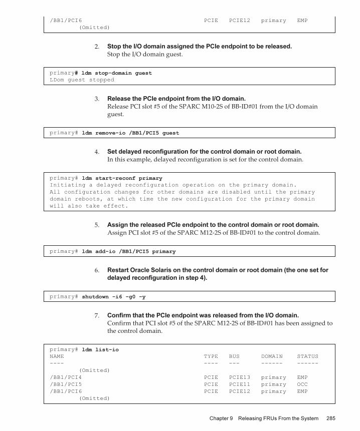
/BB1/PCI6
PCIE
PCIE12
primary
EMP
(Omitted)
primary#
ldm
stop-domain
guestLDom
guest
stopped
primary#
ldm
remove-io
/BB1/PCI5
guest
primary#
ldm
start-reconf
primaryInitiating
a
delayed
reconfiguration
operation
on
the
primary
domain.
All
configuration
changes
for
other
domains
are
disabled
until
the
primary
domain
reboots,
at
which
time
the
new
configuration
for
the
primary
domain
will
also
take
effect.
primary#
ldm
add-io
/BB1/PCI5
primary
primary#
shutdown
-i6
-g0
-y
primary#
ldm
list-ioNAME
TYPE
BUS
DOMAIN
STATUS
----
----
---
------
------
(Omitted)
/BB1/PCI4
PCIE
PCIE13
primary
EMP
/BB1/PCI5
PCIE
PCIE11
primary
OCC
/BB1/PCI6
PCIE
PCIE12
primary
EMP
(Omitted)
2. Stop the I/O domain assigned the PCIe endpoint to be released.
Stop the I/O domain guest.
3. Release the PCIe endpoint from the I/O domain.
Release PCI slot #5 of the SPARC M10-2S of BB-ID#01 from the I/O domain guest.
4. Set delayed reconfiguration for the control domain or root domain.
In this example, delayed reconfiguration is set for the control domain.
5. Assign the released PCIe endpoint to the control domain or root domain.
Assign PCI slot #5 of the SPARC M12-2S of BB-ID#01 to the control domain.
6. Restart Oracle Solaris on the control domain or root domain (the one set for
delayed reconfiguration in step 4).
7. Confirm that the PCIe endpoint was released from the I/O domain.
Confirm that PCI slot #5 of the SPARC M12-2S of BB-ID#01 has been assigned to the control domain.
Chapter
9
Releasing
FRUs
From
the
System 285

Table
9-8 Procedure for Statically Releasing a Root Complex
Step Operation Description Execution Location Command Used
1 Checking the assignment status of root complexes
Control domain primary# ldm list-io
2 Setting delayed reconfiguration for the control domain or root domain releasing the root complex
Control domain primary# ldm start-reconf <domain-name>
3 Releasing the root complex from the control domain or root domain
Control domain primary# ldm remove-io <bus> <domain-name>
4 Restarting Oracle Solaris on the control domain or root domain
Control domain When delayed reconfiguration has been set
for the control domain
primary# shutdown -i6 -g0 -yWhen delayed reconfiguration has been set
for the root domain
primary# ldm stop-domain -r <domain-name>
5 Confirming that the root complex was released from the logical domain
Control domain primary# ldm list-io
primary#
ldm
list-ioNAME
TYPE
BUS
DOMAIN
STATUS
----
----
---
------
------
(Omitted)
PCIE9
BUS
PCIE9
primary
IOV
PCIE10
BUS
PCIE10
guest
IOV
PCIE11
BUS
PCIE11
primary
IOV
(Omitted)
9.3.7 Statically
Releasing
the
Root
Complex
From
a
Logical
Domain
The operation of statically releasing the root complex from a logical domain must be performed from the control domain.
Before releasing the root complex, confirm that none of the devices in it is being used by the logical domain. For details, see the manual for the software being used.
For information on how resources are moved when the assignment of the root complex is statically released, see Figure 9-4.
Table 9-8 lists the procedure for statically releasing a root complex.
The following example executes the commands for releasing the root complex from the logical domain guest.
1. Check the assignment status of root complexes to logical domains.
In this example, the root complex PCIE10 is assigned to the logical domain guest.
2. Set delayed reconfiguration for the control domain or root domain releasing
Fujitsu
SPARC
M12-2/M12-2S
Service
Manual ・ June 2021286

primary#
ldm
start-reconf
guestInitiating
a
delayed
reconfiguration
operation
on
the
ldom
domain.
All
configuration
changes
for
other
domains
are
disabled
until
the
ldom
domain
reboots,
at
which
time
the
new
configuration
for
the
ldom
domain
will
also
take
effect.
primary#
ldm
remove-io
PCIE10
guest------------------------------------------------------------------------------
Notice:
The
ldom
domain
is
in
the
process
of
a
delayed
reconfiguration.
Any
changes
made
to
the
ldom
domain
will
only
take
effect
after
it
reboots.
------------------------------------------------------------------------------
primary#
ldm
stop-domain
-r
guest------------------------------------------------------------------------------
Notice:
The
ldom
domain
is
in
the
process
of
a
delayed
reconfiguration.
Any
changes
made
to
the
ldom
domain
will
only
take
effect
after
it
reboots.
------------------------------------------------------------------------------
Reboot
request
sent
to
ldom
primary#
ldm
list-ioNAME
TYPE
BUS
DOMAIN
STATUS
----
----
---
------
------
(Omitted)
PCIE8
BUS
PCIE8
primary
IOV
PCIE9
BUS
PCIE9
primary
IOV
PCIE10
BUS
PCIE10
PCIE11
BUS
PCIE11
primary
IOV
(Omitted)
the root complex.
In this example, delayed reconfiguration is set for the root domain guest.
3. Release the root complex from the control domain or root domain.
Release the assignment of the root complex PCIE10 from the root domain guest.
4. Restart Oracle Solaris on the control domain or root domain that is set for
delayed reconfiguration.
In this example, Oracle Solaris on the root domain guest is restarted.
5. Confirm that the root complex was released from the logical domain.
Confirm that the root complex PCIE10 was released from guest.
Chapter
9
Releasing
FRUs
From
the
System 287

Note - When using the PCI Hot Plug function, confirm that the target PCIe card supports thePCI Hot Plug function. For details, see "Appendix B Cards That Support PCI Hot Plug andDynamic Reconfiguration" in the Fujitsu SPARC M12 PCI Card Installation Guide.
9.4 Enabling
the
Removal
of
HardwareThis section describes the procedure for releasing an I/O device from the Oracle Solaris device configuration and enabling the removal of the I/O device from the SPARC M12 while Oracle Solaris is operating.
For details on the cfgadm command used here, see "Dynamically Configuring Devices" in the Managing Devices in Oracle Solaris for the Oracle Solaris version used.
When using the cfgadm command, log in to Oracle Solaris with administrative authority on the control domain or root domain. When using the PCI Hot Plug function, confirm that the hotplug service of Oracle Solaris is enabled.
9.4.1 Dynamically
Releasing
a
PCIe
Card
From
a
Logical
Domain
This section describes the procedure for enabling the removal of a PCIe card from the SPARC M12 by using the PCI Hot Plug function.
When using the PCI Hot Plug function for a PCIe card mounted in the PCI expansion unit, confirm that the direct I/O function is disabled for the PCI slot that houses the target PCIe card. For details on the direct I/O function for the PCI expansion unit, see "Chapter 15 Expanding the System Configuration" in the Fujitsu SPARC M12 and Fujitsu M10/SPARC M10 System Operation and Administration Guide.
Table 9-9 lists the procedure for dynamically releasing a PCIe card.
Fujitsu
SPARC
M12-2/M12-2S
Service
Manual ・ June 2021288

Table
9-9 Procedure for Dynamically Releasing a PCIe Card
Step Operation Description Execution Location Command Used
1 Checking the mounting location of the target PCIe card (Ap_Id)
Control domainRoot domain
# cfgadm -a
2 Releasing the target PCIe card from the Oracle Solaris device configuration
Control domainRoot domain
# cfgadm -c unconfigure <Ap_Id>
3 Powering off the PCIe card slot that houses the PCIe card released from the device configuration
Control domainRoot domain
# cfgadm -c disconnect <Ap_Id>
4 Confirming that you can remove the target PCIe card
Control domainRoot domain
# cfgadm -a
5 (*1) Having the ATTENTION LED (amber) of the PCIe card slot housing the target PCIe card blink
Control domainRoot domain
# cfgadm -x led=attn,mode=blink <Ap_Id>
6 (*2) Turning off the ATTENTION LED on the PCIe card slot by mounting the PCICS from which the PCIe card was removed
Control domainRoot domain
# cfadm -x led=attn,mode=off <Ap_Id>
*1 Before removing the PCICS from the PCI slot, check the PCIe card slot to see that the POWER LED is off and that the ATTENTION
LED (amber) is blinking.
*2 When replacing a PCIe card, incorporate the PCIe card into the Oracle Solaris device configuration and then turn off the ATTENTION
LED. For details, see "Dynamically Configuring Devices" in the Managing Devices in Oracle Solaris for the Oracle Solaris version used, and
the man page of the cfgadm_pci command.
Note - For the locations of the LEDs on PCIe card slots, see "PCIe card slot" in "2.4.3 LEDs ofEach Unit."
primary#
cfgadm
-aAp_Id
Type
Receptable
Occupant
Condition
BB#0-PCI#0
pci-pci/hp
connected
configured
ok
(Omitted)
primary#
cfgadm
-c
unconfigure
BB#0-PCI#0
The following example executes the commands for enabling the removal of the PCIe card mounted in PCI slot #0 of the SPARC M12 by using the PCI Hot Plug function.
1. Check the status of the PCIe card to be removed.
The following example confirms that the PCIe card to be removed using the control domain is incorporated in the Oracle Solaris device configuration.
2. Release the target PCIe card from the Oracle Solaris device configuration.
The following example releases the PCIe card mounted in PCI slot #0 from the Oracle Solaris device configuration by using the control domain.
3. Power off the PCIe card released from the Oracle Solaris device configuration.
The following example powers off the PCIe card mounted in PCI slot #0 by using
Chapter
9
Releasing
FRUs
From
the
System 289

primary#
cfgadm
-c
disconnect
BB#0-PCI#0
primary#
cfgadm
-aAp_Id
Type
Receptable
Occupant
Condition
BB#0-PCI#0
unknown
disconnected
unconfigured
unknown
(Omitted)
primary#
cfgadm
-x
led=attn,mode=blink
BB#0-PCI#0
Note - When the target HDD/SSD has a RAID volume configuration generated by software,you need to enable the release of the HDD/SSD from the Oracle Solaris device configuration.Before releasing the HDD/SSD from the Oracle Solaris device configuration, be sure to seethe manual for the software or application being used.
the control domain.
4. Confirm that you can remove the PCIe card.
The following example confirms that the PCIe card mounted in PCI slot #0 was released from the Oracle Solaris device configuration and powered off by using the control domain.
5. Have the ATTENTION LED (amber) of the PCIe card slot housing the PCIe card
to be removed blink.
The following example turns off the POWER LED on the PCIe card slot and blinks the ATTENTION LED (amber) before removing the PCIe card by using the control domain. Before removing the PCIe card, check the LEDs on that card.
9.4.2 Dynamically
Releasing
the
HDD/SSD
From
a
Logical
Domain
This section describes the procedure for enabling the removal of an HDD/SSD from the SPARC M12 by using the PCI Hot Plug function.
To remove an HDD/SSD composing the RAID volumes using the hardware RAID function of the SPARC M12, this procedure is not required.
Table 9-10 lists the procedure for dynamically releasing an HDD/SSD.
Fujitsu
SPARC
M12-2/M12-2S
Service
Manual ・ June 2021290

Table
9-10 Procedure for Dynamically Releasing an HDD/SSD From Oracle Solaris
Step Operation Description Execution Location Command Used
1 (*1) Checking the device path of the target HDD/SSD
primary domainRoot domain
Oracle Solaris 11
# diskinfoOracle Solaris 10 (*2)# diskinfo -ap
2 (*1) Checking the BB-ID of the SPARC M12-2S that houses the target HDD/SSD
XSCF shell Oracle Solaris 11
XSCF> showhardconfOracle Solaris 10
XSCF> showboards -a
3 Checking the mounting location of the target HDD/SSD (Ap_Id)
primary domainRoot domain
# cfgadm -al
4 Releasing the target HDD/SSD from the Oracle Solaris device configuration
primary domainRoot domain
# cfgadm -c unconfigure <Ap_Id>
5 Confirming that you can remove the target HDD/SSD
primary domainRoot domain
# cfgadm -al
6 Having the CHECK LED (amber) of the HDD/SSD released from the Oracle Solaris device configuration blink (*3) (*4)
primary domainRoot domain
# cfgadm -x led=fault,mode=blink <Ap_Id>
7 (*5) Turning off the CHECK LED primary domainRoot domain
# cfgadm -x led=fault,mode=off <Ap_Id>
*1 When using only one SPARC M12-2 or SPARC M12-2S, skip this operation.
*2 Check the device path of the target HDD/SSD and the LSB number of the SPARC M12-2S that houses the HDD/SSD, according to
"Appendix A Lists of SPARC M12/M10 System Device Paths" in the Fujitsu SPARC M12 and Fujitsu M10/SPARC M10 System Operation
and Administration Guide.
*3 Before removing the HDD/SSD, confirm that the CHECK LED (amber) is blinking.
*4 When removing a hard disk, pull it out slightly from its slot, wait for 10 seconds, and then remove it from the slot.
*5 When replacing the HDD/SSD, incorporate it into the Oracle Solaris device configuration and then turn off the CHECK LED. For
details, see Table 2-22.
#
diskinfo
D:devchassis-path
c:occupant-compdev
------------------------------
---------------------
/dev/chassis/SYS/BB0/HDD0
-
/dev/chassis/SYS/BB0/HDD1
-
/dev/chassis/SYS/BB0/HDD2
-
/dev/chassis/SYS/BB0/HDD3
-
/dev/chassis/SYS/BB0/HDD4/disk
c5t50000393D82954D6d0
/dev/chassis/SYS/BB0/HDD5
-
/dev/chassis/SYS/BB0/HDD6
-
/dev/chassis/SYS/BB0/HDD7/disk
c5t50000393B81B2446d0
The following example executes the commands for enabling the removal of an HDD/SSD by using the PCI Hot Plug function.
Confirming
the
HDD/SSD
to
be
released
[Oracle Solaris 11 with SRU 11.4.27.82.1 or later applied]
1. Use the diskinfo command to check the device pathname and BB-ID.
Chapter
9
Releasing
FRUs
From
the
System 291

primary#
diskinfoD:devchassis-path
c:occupant-compdev
-----------------------------------------------------------
------------------
/dev/chassis/SYS/BB0/CMUL/HDD0
-
/dev/chassis/SYS/BB0/CMUL/HDD1
-
(Omitted)
/dev/chassis/FUJITSU-BBEXP.500000e0e06d31bf/04GG_HDD00/disk
c4t50000394281B5312d0
/dev/chassis/FUJITSU-BBEXP.500000e0e06d31bf/04GG_HDD01/disk
c4t50000394281B59D6d0
(Omitted)
XSCF>
showhardconf
(Omitted)
BB#00
Status:Normal;
Role:Master;
Ver:3015h;
Serial:PZ51649002;
+
FRU-Part-Number:CA20369-B17X
005AC/7341758
;
+
Power_Supply_System:
;
+
Memory_Size:256
GB;
CMUL
Status:Normal;
Ver:2101h;
Serial:PP164804GG
;
(Omitted)
BB#01
Status:Normal;
Role:Standby;
Ver:2290h;
Serial:2081236002;
+
FRU-Part-Number:CA07361-D202
A0
/NOT-FIXD-P2
;
+
Power_Supply_System:
;
+
Memory_Size:128
GB;
CMUL
Status:Normal;
Ver:0101h;
Serial:PP1231043X
;
(Omitted)
[Oracle Solaris 11 without SRU 11.4.27.82.1 or later applied]
1. Check the device path of the target HDD/SSD. (Take this step only for a
building block configuration connecting two or more SPARC M12-2S units.)
The following example assumes that the user logs in to Oracle Solaris on the control domain and identifies the device path from the logical device name of the HDD/SSD. Write down the character string (three or four characters) in the "****" part of ".../****_HDDxx/..." contained in the identified device path.
2. Check the BB-ID of the SPARC M12-2S that houses the target HDD/SSD. (Take
this step only for a building block configuration connecting two or more
SPARC M12-2S units.)
The following example assumes that the user logs in to the XSCF shell and checks for a SPARC M12-2S BB-ID where the character string written down in step 1 matches the last four digits of the CMUL serial number. If the character string written down in step 1 consists of three characters, add "0" at the beginning of the character string to make it four characters long for matching purposes.
[Oracle Solaris 10]
1. Check the LSB number of the SPARC M12-2S that houses the target
HDD/SSD. (Take this step only for a building block configuration connecting
two or more SPARC M12-2S units.)
The following example assumes that the user logs in to Oracle Solaris on the control domain and checks the LSB number of the SPARC M12-2S that houses
Fujitsu
SPARC
M12-2/M12-2S
Service
Manual ・ June 2021292

primary#
diskinfo
-ap
(Omitted)
Label
Disk
name
Vendor
Product
Vers
--------
----------------------
--------
--------------
----
HDD_0
c0t50000393D8289180d0
TOSHIBA
MBF2600RC
3706
Physical
path
--------------------------------
0:
/pci@8000/pci@4/pci@0/pci@0/scsi@0/iport@f/disk@w50000393D8289180,0
(Omitted)
XSCF>
showboards
-aPSB
PPAR-ID(LSB)
Assignment
Pwr
Conn
Conf
Test
Fault
----
------------
-----------
----
----
----
-------
--------
00-0
00(00)
Assigned
y
y
y
Passed
Normal
01-0
00(01)
Assigned
y
y
y
Passed
Normal
primary#
cfgadm
-alAp_Id
Type
Receptacle
Occupant
Condition
(Omitted)
c2
scsi-sas
connected
configured
unknown
c2::dsk/c2t50000394281B59D6d0
disk
connected
configured
unknown
c2::es/ses0
ESI
connected
configured
unknown
c2::smp/expd0
smp
connected
configured
unknown
c3
scsi-sas
connected
unconfigured
unknown
c4
scsi-sas
connected
unconfigured
unknown
c5
fc
connected
unconfigured
unknown
c6
fc
connected
unconfigured
unknown
c7
scsi-sas
connected
unconfigured
unknown
(Omitted)
the HDD/SSD based on the device path identified from the logical device name of the HDD/SSD. For details on device paths, see "Appendix A Lists of SPARC M12/M10 System Device Paths" in the Fujitsu SPARC M12 and Fujitsu M10/SPARC M10 System Operation and Administration Guide.
2. Check the BB-ID of the SPARC M12-2S that houses the target HDD/SSD. (Take
this step only for a building block configuration connecting two or more
SPARC M12-2S units.)
The following example assumes that the user logs in to the XSCF shell and checks the BB-ID of the SPARC M12-2S from the LSB number identified in step 1.
Releasing
the
HDD/SSD
from
the
Oracle
Solaris
device
configuration
3. Check the mounting location of the target HDD/SSD (Ap_Id).
The following example checks the Ap_Id, including the logical device name of the target HDD/SSD, from Oracle Solaris on the control domain.
4. Release the HDD/SSD from the Oracle Solaris device configuration.
Chapter
9
Releasing
FRUs
From
the
System 293

primary#
cfgadm
-c
unconfigure
c2::dsk/c2t50000394281B59D6d0
primary#
cfgadm
-alAp_Id
Type
Receptacle
Occupant
Condition
(Omitted)
c2
scsi-sas
connected
configured
unknown
c2::dsk/c2t50000394281B59D6d0
disk
connected
unconfigured
unknown
c2::es/ses0
ESI
connected
configured
unknown
c2::smp/expd0
smp
connected
configured
unknown
c3
scsi-sas
connected
unconfigured
unknown
c4
scsi-sas
connected
unconfigured
unknown
c5
fc
connected
unconfigured
unknown
c6
fc
connected
unconfigured
unknown
c7
scsi-sas
connected
unconfigured
unknown
(Omitted)
primary#
cfgadm
-x
led=fault,mode=blink
c2::dsk/c2t50000394281B59D6d0
Note - The precautions for PPAR DR may vary depending on the versions of the XSCFfirmware, Oracle Solaris, and Oracle VM for SPARC used and the version of the SRU
The following example assumes that the user logs in to Oracle Solaris on the control domain and releases the HDD/SSD from the Oracle Solaris device configuration by using the Ap_Id checked in step 3.
5. Confirm that you can remove the HDD/SSD.
The following example assumes that the user logs in to Oracle Solaris on the control domain and confirms that the HDD/SSD has been released from the Oracle Solaris device configuration.
6. Have the CHECK LED (amber) of the HDD/SSD to be removed blink.
The following example assumes that the user logs in to Oracle Solaris on the control domain, causing the CHECK LED (amber) of the HDD/SSD to blink. Check the LEDs on the HDD/SSD, and then remove it. When removing a hard disk, pull it out slightly from its slot, wait for 10 seconds, and then remove it.
9.4.3 Dynamically
Releasing
the
SPARC
M12-2S
From
the
Physical
Partition
PPAR DR can be used in a building block configuration connecting two or more SPARC M12-2S units to a physical partition. By using PPAR DR, you can release the SPARC M12-2S from the physical partition without stopping Oracle Solaris on the logical domain.
This section describes the procedure for releasing the SPARC M12-2S by using PPAR DR in a building block configuration connecting two or more SPARC M12-2S units.
Fujitsu
SPARC
M12-2/M12-2S
Service
Manual ・ June 2021294

applied. Before using PPAR DR, be sure to see the latest version of Fujitsu SPARC M12Product Notes.
Note - To use PPAR DR, you need to configure the system with guaranteed availabilityaccording to "2.5 Dynamic Reconfiguration Conditions and Settings" in the Fujitsu SPARCM12 and Fujitsu M10/SPARC M10 Domain Configuration Guide.
Note - The procedure described in this section assumes that -m unbind=resource is not usedin the deleteboard command. In this case, before executing the deleteboard command, youneed to remove resources assigned to logical domains, in addition to removing physical I/Odevices, to ensure that enough BBs will be left for the number of CPUs and the memory size.For details, see "2.5.2 Considerations in System Operation for Dynamic Reconfiguration" inthe Fujitsu SPARC M12 and Fujitsu M10/SPARC M10 Domain Configuration Guide.
Table 9-11 lists the procedure for dynamically releasing the SPARC M12-2S from the physical partition.
Chapter
9
Releasing
FRUs
From
the
System 295

Table
9-11 Procedure for Dynamically Releasing the SPARC M12-2S From the Physical Partition
Step Operation Description Execution Location Command Used
1 Checking the physical partition configuration and the operation status of the target SPARC M12-2S
XSCF shell XSCF> showpcl -aXSCF> showboards -p <ppar_id>
2 Logging in to the XSCF shell and confirming that the XSCF of the target SPARC M12-2S is in the standby state or is the slave XSCF. (*1)
XSCF shell XSCF> showhardconf
3 Checking the operation status of logical domains
primary domain primary# ldm list-domain
4 Checking the connected virtual services in the control domain
primary domain primary# ldm list-services
5 Checking the mounting locations of the physical LAN ports
Service domain # dladm show-phys -L
6 Checking the virtual services and hardware resources assigned to logical domains
primary domain primary# ldm list-bindings <domain-name>primary# ldm list-socket
7 Checking the assignment status of I/O devices from the control domain in the physical partition to which the target SPARC M12-2S belongs
primary domain primary# ldm list-io
8 Releasing the assignment of I/O devices of the target SPARC M12-2S from the control domain in the physical partition to which the target SPARC M12-2S belongs
primary domain When releasing a virtual disk
primary# ldm remove-vdisk <disk-name> <domain-name>When releasing a virtual network
primary# ldm remove-vnet <if-name> <domain-name>primary# ldm remove-vsw <vswitch-name>When releasing an I/O device
primary# ldm remove-io <bus/device/vf-name> <domain-name>
9 Confirming that the I/O devices are not assigned to logical domains, from the control domain in the physical partition to which the target SPARC M12-2S belongs
primary domain primary# ldm list-io
10 Using the XSCF shell to release the target SPARC M12-2S from the physical partition
XSCF shell For maintenance on the target SPARC M12-2S
XSCF> deleteboard -c disconnect <psb>For changing the physical partition
configuration
XSCF> deleteboard -c unassign <psb>
11 Checking the release process end status from the XSCF shell
XSCF shell XSCF> showresult
12 Checking the status of the released SPARC M12-2S from the XSCF shell
XSCF shell XSCF> showboards -va
*1 If the XSCF of the SPARC M12-2S to be released is the master XSCF, switch it to the standby state with the switchscf command. For
details, see the Fujitsu SPARC M12 and Fujitsu M10/SPARC M10 XSCF Reference Manual of the XCP version used.
Fujitsu
SPARC
M12-2/M12-2S
Service
Manual ・ June 2021296

XSCF>
showpcl
-p
0PPAR-ID
LSB
PSB
Status
00
Running
(*1)
00
00-0
(*2)
01
01-0
(*3)
XSCF>
showboards
-p
0PSB
PPAR-ID(LSB)
Assignment
Pwr
Conn
Conf
Test
Fault
----
------------
-----------
----
----
----
-------
--------
00-0
00(00)
Assigned
y
y
y
Passed
Normal
(*3)
01-0
00(01)
Assigned
y
y
y
Passed
Normal
(*3)
*1 PPAR ID#00 is running.
*2 LSB#00 is defined for PSB#00-0 of PPAR ID#00, and LSB#01 is defined for PSB#01-0.
*3 PSB#00-0 and PSB#01-0 are assigned to PPAR ID#00, and both are running.
XSCF>
showhardconfSPARC
M12-2S;
+
Serial:PZ51552003;
Operator_Panel_Switch:Locked;
+
System_Power:On;
System_Phase:Cabinet
Power
On;
Partition#0
PPAR_Status:Running;
BB#00
Status:Normal;
Role:Master;
Ver:3009h;
Serial:PZ51552003;
+
FRU-Part-Number:CA20369-B17X
003AB/9999999
;
+
Power_Supply_System:
;
+
Memory_Size:64
GB;
(Omitted)
BB#01
Status:Normal;
Role:Standby;
Ver:3009h;
Serial:PZ51552006;
(*1)
+
FRU-Part-Number:CA20369-B17X
003AB/9999999
;
+
Power_Supply_System:
;
+
Memory_Size:128
GB;
(Omitted)
The following example executes the commands for releasing BB#01 in the 2BB configuration. To restore the system after maintenance on the SPARC M12-2S, write down the status checked in steps 1 to 7.
First, log in to the XSCF shell, and check the hardware configuration information for the SPARC M12-2S to be released.
1. Check the PSB configuration and operation status of the physical partition.
The following example assumes that the user logs in to the master XSCF, checks the PSB configuration, LSB number, and operation status of PPAR ID#00, and then checks the operation status of the PSB. Here, it is assumed that BB#01 (PSB#01-0) will be released.
2. Check the status of the XSCF of the SPARC M12-2S to be released.
The following example assumes that the user logs in to the master XSCF and confirms that the XSCF of the SPARC M12-2S to be released is in the standby state or is the slave XSCF.
Chapter
9
Releasing
FRUs
From
the
System 297

*1 The XSCF of BB#01 is in the standby state.
primary#
ldm
list-domainNAME
STATE
FLAGS
CONS
VCPU
MEMORY
UTIL
NORM
UPTIME
primary
active
-n-cv-
UART
32
16G
1.3%
1.3%
7d
17h
26m
(*1)
guest
active
-n----
5000
32
16G
0.0%
0.0%
7d
16h
(*2)
ldom
active
-n----
5001
32
32G
0.0%
0.0%
7d
14h
17m
(*3)
primary#
ldm
list-servicesVCC
NAME
LDOM
PORT-RANGE
primary-vcc0
primary
5000-5100
VSW
NAME
LDOM
MAC
NET-DEV
ID
DEVICE
LINKPROP
DEFAULT-VLAN-ID
PVID
VID
MTU
MODE
INTER-VNET-LINK
primary-vsw0
primary
00:14:4f:fb:e1:a8
net0
0
switch@0
1
1
1500
on
primary-vsw4
primary
00:14:4f:f8:42:2f
net4
1
switch@1
1
1
1500
on
VDS
NAME
LDOM
VOLUME
OPTIONS
MPGROUP
DEVICE
primary-vds0
primary
vdisk00
/dev/zvol/dsk/rpool/
export/ovm/vdisk00
vdisk01
/dev/zvol/dsk/rpool/
export/ovm/vdisk01
vol_iso
ro
/export/ovm/sol11u3_
iso/sol-11_3-text-sparc.iso
vdisk10
/dev/zvol/dsk/rpool/
Next, log in to Oracle Solaris on the control domain in the physical partition containing the SPARC M12-2S to be released. Then, check the operation status of logical domains and the assignment status of resources.
3. Check the operation status of the logical domains defined in PPAR ID#00.
The following example assumes that the user logs in to Oracle Solaris on the control domain and checks the defined logical domains and operation status.
4. Check the list of the set virtual services for the control domain.
- Virtual console service: The port numbers that the guest domain can use for primary-vcc0 for the virtual console service range from 5000 to 5100.
- Virtual switch: Physical LAN ports net0 and net4 are assigned to virtual switches primary-vsw0 and primary-vsw4, respectively.
- Virtual disk service: vdisk00, vdisk01, vdisk10, vdisk11, and vol_iso are assigned to primary-vds0 for the virtual disk service.
Fujitsu
SPARC
M12-2/M12-2S
Service
Manual ・ June 2021298

export/ovm/vdisk10
vdisk11
/dev/zvol/dsk/rpool/
export/ovm/vdisk11
Physical LAN Port Mounting Location
net0 to net3 BB#00 on-board LAN
net4 to net7 BB#01 on-board LAN
primary#
dladm
show-phys
-LLINK
DEVICE
LOC
net0
ixgbe0
/BB0/CMUL
net1
ixgbe1
/BB0/CMUL
net2
ixgbe2
/BB0/CMUU
net3
ixgbe3
/BB0/CMUU
net4
ixgbe4
/BB1/CMUL
net5
ixgbe5
/BB1/CMUL
net6
ixgbe6
/BB1/CMUL
net7
ixgbe7
/BB1/CMUL
(Omitted)
primary#
ldm
list-bindings
guest
(Omitted)
NETWORK
NAME
SERVICE
ID
DEVICE
MAC
MODE
PVID
VID
MTU
MAXBW
LINKPROP
vnet0
primary-vsw0@primary
0
network@0
00:14:4f:f9:58:4e
1
1500
PEER
MAC
MODE
PVID
VID
MTU
MAXBW
LINKPROP
5. Check the mounting locations of the physical LAN ports.
This example checks in advance that Oracle Solaris on the control domain does not use net4 to net7, to release BB#01 using PPAR DR.
6. Check the resources assigned to the logical domain guest and the logical
domain ldom.
The virtual network devices vnet0 and vnet1 are assigned to the logical domain guest. From the results of steps 4 to 6, you can also see that vnet0 uses the physical LAN port net0 of BB#00 and vnet1 uses the physical LAN port net4 of BB#01. In this example, the assignment of vnet1 is released from the logical domain guest beforehand in order to use the physical partition dynamic reconfiguration (PPAR DR) function to release BB#01.
From the assigned I/O resources, you can see that the logical domain ldom is the root domain configured by the root complexes of BB#00 and BB#01. In this example, the assignment of PCIE10 (pci@8a00) is released from the logical domain ldom beforehand in order to use the physical partition dynamic reconfiguration (PPAR DR) function to release BB#01.
Chapter
9
Releasing
FRUs
From
the
System 299

primary-vsw0@primary
00:14:4f:fb:e1:a8
1
1500
NAME
SERVICE
ID
DEVICE
MAC
MODE
PVID
VID
MTU
MAXBW
LINKPROP
vnet1
primary-vsw4@primary
1
network@1
00:14:4f:fb:4d:fe
1
1500
PEER
MAC
MODE
PVID
VID
MTU
MAXBW
LINKPROP
primary-vsw4@primary
00:14:4f:f8:42:2f
1
1500
DISK
NAME
VOLUME
TOUT
ID
DEVICE
SERVER
MPGROUP
vdisk00
vdisk00@primary-vds0
0
disk@0
primary
(Omitted)
primary#
ldm
list-bindings
ldom
(Omitted)
IO
DEVICE
PSEUDONYM
OPTIONS
pci@8600
PCIE6
pci@8a00
PCIE10
pci@8600/pci@4/pci@0/pci@9
/BB0/PCI5
pci@8600/pci@4/pci@0/pci@11
/BB0/PCI6
pci@8a00/pci@4/pci@0/pci@0
/BB1/PCI3
pci@8a00/pci@4/pci@0/pci@8
/BB1/PCI4
pci@8a00/pci@4/pci@0/pci@9
/BB1/PCI5
pci@8a00/pci@4/pci@0/pci@11
/BB1/PCI6
DISK
NAME
VOLUME
TOUT
ID
DEVICE
SERVER
MPGROUP
vdisk10
vdisk10@primary-vds0
0
disk@0
primary
vdisk11
vdisk11@primary-vds0
1
disk@1
primary
vol_iso
vol_iso@primary-vds0
2
disk@2
primary
(Omitted)
#
ldm
list-socket
CONSTRAINTS
DOMAIN
SOCKET_ID
STATE
primary
0,
2
active
...
Check whether CPU socket constraints are used.
The CPU socket constraint settings are not restored even if addboard -m bind=resource is executed. Therefore, you need to set the constraints again by using the ldm command after executing addboard.
CPU socket constraints are used if the domain information is output below CONSTRAINTS.
7. Check the assignment status of I/O devices.
Check I/O devices and assigned logical domain names. In this example, the I/O devices of BB#01 were not assigned to the logical domain beforehand to use the physical partition dynamic reconfiguration (PPAR DR) function to release BB#01.
Fujitsu
SPARC
M12-2/M12-2S
Service
Manual ・ June 2021300

#
ldm
list-ioNAME
TYPE
BUS
DOMAIN
STATUS
----
----
---
------
------
PCIE0
BUS
PCIE0
primary
IOV
PCIE1
BUS
PCIE1
primary
IOV
PCIE2
BUS
PCIE2
primary
IOV
PCIE3
BUS
PCIE3
primary
IOV
PCIE4
BUS
PCIE4
primary
IOV
PCIE5
BUS
PCIE5
primary
IOV
PCIE6
BUS
PCIE6
ldom
IOV
PCIE7
BUS
PCIE7
primary
IOV
PCIE8
BUS
PCIE8
primary
IOV
PCIE9
BUS
PCIE9
primary
IOV
PCIE10
BUS
PCIE10
ldom
IOV
PCIE11
BUS
PCIE11
primary
IOV
/BB0/CMUL/NET0
PCIE
PCIE0
primary
OCC
/BB0/CMUL/SASHBA
PCIE
PCIE0
primary
OCC
/BB0/PCI0
PCIE
PCIE1
primary
EMP
/BB0/PCI3
PCIE
PCIE2
primary
EMP
/BB0/PCI4
PCIE
PCIE2
primary
EMP
/BB0/PCI7
PCIE
PCIE3
primary
EMP
/BB0/PCI8
PCIE
PCIE3
primary
EMP
/BB0/CMUL/NET2
PCIE
PCIE4
primary
OCC
/BB0/PCI1
PCIE
PCIE5
primary
EMP
/BB0/PCI2
PCIE
PCIE5
primary
EMP
/BB0/PCI5
PCIE
PCIE6
ldom
OCC
/BB0/PCI6
PCIE
PCIE6
ldom
EMP
/BB0/PCI9
PCIE
PCIE7
primary
EMP
/BB0/PCI10
PCIE
PCIE7
primary
EMP
/BB1/CMUL/NET0
PCIE
PCIE8
primary
OCC
/BB1/CMUL/NET2
PCIE
PCIE8
primary
OCC
/BB1/CMUL/SASHBA
PCIE
PCIE8
primary
OCC
/BB1/PCI0
PCIE
PCIE9
primary
EMP
/BB1/PCI1
PCIE
PCIE9
primary
EMP
/BB1/PCI2
PCIE
PCIE9
primary
EMP
/BB1/PCI3
PCIE
PCIE10
ldom
EMP
/BB1/PCI4
PCIE
PCIE10
ldom
EMP
/BB1/PCI5
PCIE
PCIE10
ldom
OCC
/BB1/PCI6
PCIE
PCIE10
ldom
EMP
/BB1/PCI7
PCIE
PCIE11
primary
EMP
/BB1/PCI8
PCIE
PCIE11
primary
EMP
/BB1/PCI9
PCIE
PCIE11
primary
EMP
/BB1/PCI10
PCIE
PCIE11
primary
EMP
/BB0/CMUL/NET0/IOVNET.PF0
PF
PCIE0
primary
/BB0/CMUL/NET0/IOVNET.PF1
PF
PCIE0
primary
/BB0/CMUL/NET2/IOVNET.PF0
PF
PCIE4
primary
/BB0/CMUL/NET2/IOVNET.PF1
PF
PCIE4
primary
/BB1/CMUL/NET0/IOVNET.PF0
PF
PCIE8
primary
/BB1/CMUL/NET0/IOVNET.PF1
PF
PCIE8
primary
/BB1/CMUL/NET2/IOVNET.PF0
PF
PCIE8
primary
/BB1/CMUL/NET2/IOVNET.PF1
PF
PCIE8
primary
#
8. Release the I/O devices assigned to the logical domain, from Oracle Solaris
Chapter
9
Releasing
FRUs
From
the
System 301

#
ldm
remove-vnet
vnet1
guest#
ldm
list-bindings
guest
(Omitted)
NETWORK
NAME
SERVICE
ID
DEVICE
MAC
MODE
PVID
VID
MTU
MAXBW
LINKPROP
vnet0
primary-vsw0@primary
0
network@0
00:14:4f:f9:58:4e
1
1500
PEER
MAC
MODE
PVID
VID
MTU
MAXBW
LINKPROP
primary-vsw0@primary
00:14:4f:fb:e1:a8
1
1500
(Omitted)
#
ldm
remove-vsw
primary-vsw4#
ldm
list-bindings
primary
(Omitted)
VSW
NAME
MAC
NET-DEV
ID
DEVICE
LINKPROP
DEFAULT-VLAN-ID
PVID
VID
MTU
MODE
INTER-VNET-LINK
primary-vsw0
00:14:4f:fb:e1:a8
net0
0
switch@0
1
1
1500
on
PEER
MAC
PVID
VID
MTU
MAXBW
LINKPROP
INTERVNETLINK
vnet0@guest
00:14:4f:f9:58:4e
1
1500
(Omitted)
#
ldm
remove-io
PCIE10
ldom#
ldm
list-bindings
ldom
(Omitted)
IO
DEVICE
PSEUDONYM
OPTIONS
pci@8600
PCIE6
pci@8600/pci@4/pci@0/pci@9
/BB0/PCI5
pci@8600/pci@4/pci@0/pci@11
/BB0/PCI6
(Omitted)
on the control domain.
If a mirror volume is configured between multiple SPARC M12-2S units, release the HDD/SSD mounted in the target SPARC M12-2S from the mirror beforehand.
a. Release the virtual network device vnet1 assigned to the logical domain guest.
b. Delete primary-vsw4, which is set for the physical LAN port net4.
c. Release the assignment of PCIE10 (pci@8a00) from the logical domain ldom.
d. Release the I/O devices of BB#01.
Fujitsu
SPARC
M12-2/M12-2S
Service
Manual ・ June 2021302

#
ldm
remove-io
PCIE8
primary#
ldm
remove-io
PCIE9
primary#
ldm
remove-io
PCIE11
primary
#
ldm
list-ioNAME
TYPE
BUS
DOMAIN
STATUS
----
----
---
------
------
(Omitted)
PCIE8
BUS
PCIE8
PCIE9
BUS
PCIE9
PCIE10
BUS
PCIE10
PCIE11
BUS
PCIE11
(Omitted)
/BB1/CMUL/NET0
PCIE
PCIE8
UNK
/BB1/CMUL/NET2
PCIE
PCIE8
UNK
/BB1/CMUL/SASHBA
PCIE
PCIE8
UNK
/BB1/PCI0
PCIE
PCIE9
UNK
/BB1/PCI1
PCIE
PCIE9
UNK
/BB1/PCI2
PCIE
PCIE9
UNK
/BB1/PCI3
PCIE
PCIE10
UNK
/BB1/PCI4
PCIE
PCIE10
UNK
/BB1/PCI5
PCIE
PCIE10
UNK
/BB1/PCI6
PCIE
PCIE10
UNK
/BB1/PCI7
PCIE
PCIE11
UNK
/BB1/PCI8
PCIE
PCIE11
UNK
/BB1/PCI9
PCIE
PCIE11
UNK
/BB1/PCI10
PCIE
PCIE11
UNK
XSCF>
deleteboard
-y
-c
unassign
01-0PSB#01-0
will
be
unconfigured
from
PPAR
immediately.
Continue?[y|n]
:yStart
unconfigure
preparation
of
PSB.
[1200sec]
0end
Unconfigure
preparation
of
PSB
has
completed.
Start
unconfiguring
PSB
from
PPAR.
[7200sec]
0|
Processing
of
the
incoming
DR
request
by
the
LDoms
Manager
is
pendingIncoming
DR
request
is
being
processed
by
the
LDoms
ManagerDR
sequence
started
(sequence#=2,
message#=3)
Suspending
the
guest
domain
(ldom2)
Suspending
the
guest
domain
(ldom1)
Suspending
the
guest
domain
(ldom0)
\
Resumed
the
guest
domain
(ldom0)
Resumed
the
guest
domain
(ldom1)
|
Resumed
the
guest
domain
(ldom2)
../
9. Confirm that none of the I/O devices of BB#01 is assigned.
Log in to the XSCF shell, and release the SPARC M12-2S from the physical partition.
10. Release the SPARC M12-2S of BB-ID#01 from PPAR ID#01.
Chapter
9
Releasing
FRUs
From
the
System 303
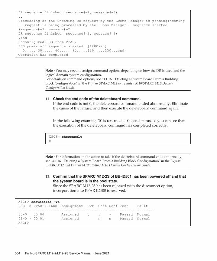
DR
sequence
finished
(sequence#=2,
message#=3)
..
Processing
of
the
incoming
DR
request
by
the
LDoms
Manager
is
pendingIncoming
DR
request
is
being
processed
by
the
LDoms
ManagerDR
sequence
started
(sequence#=3,
message#=2)
DR
sequence
finished
(sequence#=3,
message#=2)
.end
Unconfigured
PSB
from
PPAR.
PSB
power
off
sequence
started.
[1200sec]
0.....
30.....
60.....
90.....120.....150...end
Operation
has
completed.
Note - You may need to assign command options depending on how the DR is used and thelogical domain system configuration.For details on command options, see "3.1.16 Deleting a System Board From a BuildingBlock Configuration" in the Fujitsu SPARC M12 and Fujitsu M10/SPARC M10 DomainConfiguration Guide.
XSCF>
showresult0
Note - For information on the action to take if the deleteboard command ends abnormally,see "3.1.16 Deleting a System Board From a Building Block Configuration" in the FujitsuSPARC M12 and Fujitsu M10/SPARC M10 Domain Configuration Guide.
XSCF>
showboards
-vaPSB
R
PPAR-ID(LSB)
Assignment
Pwr
Conn
Conf
Test
Fault
----
-
------------
-----------
----
----
----
-------
--------
00-0
00(00)
Assigned
y
y
y
Passed
Normal
01-0
*
00(01)
Assigned
n
n
n
Passed
Normal
XSCF>
11. Check the end code of the deleteboard command.
If the end code is not 0, the deleteboard command ended abnormally. Eliminate the cause of the failure, and then execute the deleteboard command again.
In the following example, "0" is returned as the end status, so you can see that the execution of the deleteboard command has completed correctly.
12. Confirm that the SPARC M12-2S of BB-ID#01 has been powered off and that
the system board is in the pool state.
Since the SPARC M12-2S has been released with the disconnect option, incorporation into PPAR ID#00 is reserved.
Fujitsu
SPARC
M12-2/M12-2S
Service
Manual ・ June 2021304

Note - Before stopping the system, check with the system administrator or the logical domainadministrator about whether you can stop the logical domain.
Note - From the OPNL, you cannot instruct the system to stop a specific physical partition.
Table
9-12 Procedure for Stopping a Specific Physical Partition
Step Operation Description Command Used
1 Checking the operation status of physical partitions
XSCF> showpparstatus -a
2 Checking the operation status of the logical domains on the target physical partition
XSCF> showdomainstatus -p <ppar_id>
3 Checking the status of the SPARC M12-2S requiring maintenance
XSCF> showboards -p <ppar_id>
4 Stopping the physical partition XSCF> poweroff -p <ppar_id>
5 Checking the stop processing status of the physical partition
XSCF> showpparprogress -p <ppar_id>
6 Confirming that the target physical partition has stopped
XSCF> showpparstatus -a
9.5 Stopping
the
SystemFor hardware maintenance and for changing the hardware configuration, it is necessary to stop the system depending on the FRU requiring maintenance and the system configuration.
This section describes the following procedures for stopping the system:■ Stopping a Specific Physical Partition
■ Stopping All Physical Partitions
9.5.1 Stopping
a
Specific
Physical
Partition
This section describes the procedure for stopping a specific physical partition in a system with a building block configuration.
The operations described here are possible only from the XSCF shell. Table 9-12 lists the procedure after login to the master XSCF.
The following example executes the commands for stopping PPAR-ID#00.
1. Check the operation status of physical partitions.
The following example checks the operation status of the physical partition of
Chapter
9
Releasing
FRUs
From
the
System 305

XSCF>
showpparstatus
-aPPAR-ID
PPAR
Status
00
Running
01
Running
02
Running
03
Running
XSCF>
showdomainstatus
-p
0Logical
Domain
Name
Status
primary
Solaris
Running
guest00
Solaris
Running
guest01
Solaris
Running
iodomain
Solaris
Running
XSCF>
showboards
-p
0PSB
PPAR-ID(LSB)
Assignment
Pwr
Conn
Conf
Test
Fault
----
------------
-----------
----
----
----
-------
--------
00-0
00(00)
Assigned
y
y
y
Passed
Normal
01-0
01(01)
Assigned
y
y
y
Passed
Normal
02-0
02(02)
Assigned
y
y
y
Passed
Normal
03-0
03(03)
Assigned
y
y
y
Passed
Normal
XSCF>
poweroff
-p
0PPAR-IDs
to
power
off:00
Continue?
[y|n]
:y00
:
Powering
off
*Note*
This
command
only
issues
the
instruction
to
power-off.
The
result
of
the
instruction
can
be
checked
by
the
"showpparprogress".
PPAR-ID#00.
2. Check the operation status of the logical domains on the target physical
partition.
The following example checks the operation status of the logical domains defined in PPAR ID#00.
3. Check the status of the SPARC M12-2S requiring maintenance.
The following example checks the operation status of the PSB assigned to PPAR ID#00.
4. Stop the target physical partition.
The following example instructs PPAR-ID#00 to stop.
The showpparprogress command lets you check the progress of the process of stopping the physical partition. When a command prompt is returned, it means that he process of stopping the physical partition is complete.
Fujitsu
SPARC
M12-2/M12-2S
Service
Manual ・ June 2021306

XSCF>
showpparprogress
-p
0PPAR
Power
Off
PPAR#0
[
1/
3]
CPU
Stop
PPAR#0
[
2/
3]
PSU
Off
PPAR#0
[
3/
3]
The
sequence
of
power
control
is
completed
XSCF>
XSCF>
showpparstatus
-aPPAR-ID
PPAR
Status
00
Powered
Off
01
Running
02
Running
03
Running
XSCF>
Table
9-13 Procedure for Stopping All Physical Partitions by Using the XSCF Commands
Step Operation Description Command Used
1 Checking the operation status of physical partitions
XSCF> showpparstatus -a
As required, checking the operation status of the logical domains on the physical partitions
XSCF> showdomainstatus -p <ppar_id>
2 Checking the status of each SPARC M12-2S XSCF> showboards -a
3 Stopping all physical partitions XSCF> poweroff -a
As required, checking the stop processing status of the physical partitions
XSCF> showpparprogress -p <ppar_id>
4 Confirming that all physical partitions have stopped
XSCF> showpparstatus -a
5. Confirm that the target physical partition has stopped.
The following example checks that only PPAR-ID#00 is stopped while the other physical partitions are running.
9.5.2 Stopping
All
Physical
Partitions
This section describes the procedure for stopping all physical partitions.
You can stop all physical partitions by using either the XSCF commands or the OPNL.
Stopping
all
physical
partitions
from
the
XSCF
shell
Log in to the master XSCF, and stop all physical partitions by following the procedure in Table 9-13.
Chapter
9
Releasing
FRUs
From
the
System 307

XSCF>
showpparstatus
-aPPAR-ID
PPAR
Status
00
Running
01
Running
(Omitted)
XSCF>
showboards
-aPSB
PPAR-ID(LSB)
Assignment
Pwr
Conn
Conf
Test
Fault
----
------------
-----------
----
----
----
-------
--------
00-0
00(00)
Assigned
y
y
y
Passed
Normal
01-0
01(01)
Assigned
y
y
y
Passed
Normal
(Omitted)
XSCF>
poweroff
-aPPAR-IDs
to
power
off:00,01,02,03
Continue?
[y|n]
:y00
:
Powering
off
01
:
Powering
off
(Omitted)
*Note*
This
command
only
issues
the
instruction
to
power-off.
The
result
of
the
instruction
can
be
checked
by
the
"showpparprogress".
XSCF>
showpparstatus
-aPPAR-ID
PPAR
Status
00
Powered
Off
01
Powered
off
02
Powered
off
03
Powered
off
XSCF>
The following example executes the XSCF commands to stop all physical partitions.
1. Check the operation status of all physical partitions.
2. Check the status of each SPARC M12-2S.
3. Stop all physical partitions.
4. Confirm that all physical partitions have stopped.
Stopping
all
physical
partitions
by
operating
the
OPNL
In the building block configuration, operate the OPNL of the SPARC M12-2S that is running as the master XSCF. Table 9-14 lists the procedure for stopping all physical partitions by operating the OPNL.
Fujitsu
SPARC
M12-2/M12-2S
Service
Manual ・ June 2021308

Table
9-14 Procedure for Stopping All Physical Partitions With the OPNL
Step Operation Description Command Used
1 Checking the operation status of physical partitions
XSCF> showpparstatus -a
Checking the operation status of a specific physical partition or the operation status of the logical domains on a physical partition, as required
[Checking the operation status of a specific physical partition]XSCF> showpparstatus -p <ppar_id>[Checking the operation status of logical domains]XSCF> showdomainstatus -p <ppar_id>
2 Checking the status of each SPARC M12-2S XSCF> showboards -a
3 Switching the mode switch on the OPNL to Service mode
4 Pressing down the POWER switch on the OPNL for 4 seconds or longer
5 Confirming the power-off instruction XSCF> showlogs event
6 Confirming that all physical partitions have stopped
XSCF> showpparstatus -a
XSCF>
showpparstatus
-aPPAR-ID
PPAR
Status
00
Running
01
Running
(Omitted)
XSCF>
showboards
-aPSB
PPAR-ID(LSB)
Assignment
Pwr
Conn
Conf
Test
Fault
----
------------
-----------
----
----
----
-------
--------
00-0
00(00)
Assigned
y
y
y
Passed
Normal
01-0
01(01)
Assigned
y
y
y
Passed
Normal
(Omitted)
The following describes the procedure for stopping all physical partitions with the OPNL.
1. Check the operation status of all physical partitions.
2. Check the status of each SPARC M12-2S.
3. Switch the mode switch on the OPNL to Service mode.
For details on the mode switch, see "2.3.2 OPNL Control Function."
You can log in to the XSCF and check the status of the mode switch using the showhardconf command.
Chapter
9
Releasing
FRUs
From
the
System 309

XSCF>
showhardconfSPARC
M12-2S;
+
Serial:2081232002;
Operator_Panel_Switch:Service;
+
System_Power:On;
System_Phase:Cabinet
Power
On;
Partition#0
PPAR_Status:Running;
(Omitted)
XSCF>
showlogs
eventMay
30
14:00:13
JST
2016
power
switch
pushed
(short)
May
30
14:01:13
JST
2016
power
switch
pushed
(long)
May
30
14:01:16
JST
2016
PPAR-ID
0:shutdown
started
(Omitted)
XSCF>
showpparstatus
-aPPAR-ID
PPAR
Status
00
Powered
Off
01
Powered
Off
02
Powered
Off
03
Powered
Off
XSCF>
4. Press down the POWER switch on the OPNL for 4 seconds or longer.
For details on the POWER switch, see "2.3.2 OPNL Control Function."
5. Confirm the instruction to stop the physical partitions.
If you do not push down the POWER switch long enough, the message "power switch pushed (short)" appears. If so, try again to press down the POWER switch for 4 seconds or longer.
6. Confirm that all physical partitions have stopped.
9.6 Releasing
FRUs
From
the
SystemThis section describes the procedure for releasing a FRU from the system.■ Releasing the SPARC M12-2S From the Building Block Configuration
■ Releasing the FANU
■ Releasing the PSU
■ Releasing the XSCFU
Fujitsu
SPARC
M12-2/M12-2S
Service
Manual ・ June 2021310

XSCF>
replacefru
------------------------------------------------------------------------------
Maintenance/Replacement
Menu
Please
select
the
chassis
including
replaced
FRU.
No.
FRU
Status
---
-------------------
--------------
1
/BB#0
Degraded
2
/BB#1
Normal
3
/BB#2
Normal
4
/BB#3
Normal
------------------------------------------------------------------------------
Select
[1-4|c:cancel]
:1
9.6.1 Releasing
the
SPARC
M12-2S
From
the
Building
Block
Configuration
This section describes the procedure for releasing the SPARC M12-2S from the system in a building block configuration.
For the procedure for incorporating the SPARC M12-2S with a replacement unit into a building block configuration after releasing the SPARC M12-2S by using this procedure, see "10.4.1 Incorporating the SPARC M12-2S Into a Building Block Configuration."
Confirm that the XSCF of the target SPARC M12-2S is in the standby state or is the slave XSCF. If the XSCF of the SPARC M12-2S to be released is the master XSCF, switch it to the standby state with the switchscf command. For details on the command, see the Fujitsu SPARC M12 and Fujitsu M10/SPARC M10 XSCF Reference Manual of the XCP version used.
In this section, power off the SPARC M12-2S requiring maintenance by using the replacefru command.In the following example, maintenance is performed on an abnormal (Degraded) BB#0 chassis with four SPARC M12-2S units in a building block configuration.Even in cases where the status of the SPARC M12-2S requiring maintenance is not abnormal (Degraded), perform the same procedure.
1. Log in to the XSCF shell.
2. Execute the replacefru command to display the maintenance menu.
3. With a number key, select the FRU requiring maintenance.
Enter "1" since BB#0 is shown as "Degraded."
4. With a number key, select the FRU requiring maintenance.
Enter "1" to release BB#0 for maintenance.
Chapter
9
Releasing
FRUs
From
the
System 311

------------------------------------------------------------------------------
Maintenance/Replacement
Menu
Please
select
the
BB
or
a
type
of
FRU
to
be
replaced.
1.
BB
itself
(*1)
2.
FAN
(Fan
Unit)
3.
PSU
(Power
Supply
Unit)
4.
XSCFU
(Extended
System
Control
Facility
Unit)
5.
Crossbar
cable
------------------------------------------------------------------------------
Select
[1-5|c:cancel]
:1
*1 This cannot be done with the SPARC M12-2.
------------------------------------------------------------------------------
Maintenance/Replacement
Menu
Please
select
a
FRU
to
be
replaced.
No.
FRU
Status
---
-------------------
--------------
1
/BB#0
Degraded
------------------------------------------------------------------------------
Select
[1|b:back]
:1
You
are
about
to
replace
BB#0.
Do
you
want
to
continue?[r:replace|c:cancel]
:r
Please
execute
the
following
steps:
1)
Confirm
the
XSCF
STANDBY
LED
of
BB#0
is
not
lit.
2)
Turn
off
the
breaker
of
BB#0.
3)
Remove
BB#0.
4)
Execute
either
the
following:
4-1)
After
the
exchanged
device
is
connected
with
the
system,
turn
on
the
breaker
of
BB#0,
and
please
select
'finish'.
4-2)
If
you
want
to
suspend
the
maintenance
without
exchanging
device,
please
select
'cancel'.
[f:finish|c:cancel]
:
5. With a number key, select the faulty FRU.
6. Confirm that the FRU requiring maintenance is displayed, and then enter "r".
7. Confirm that the CHECK LED of the FRU is on or blinking.
To release the SPARC M12-2S, confirm that the system locator is blinking.
For the LED location, see "2.4.2 System Locator" and "2.4.3 LEDs of Each Unit."
As instructed in the above messages, confirm that the XSCF STANDBY LED of the BB#0 is off. After removing the power cord of BB#0, release the SPARC M12-2S from
Fujitsu
SPARC
M12-2/M12-2S
Service
Manual ・ June 2021312

XSCF>
replacefru
------------------------------------------------------------------------------
Maintenance/Replacement
Menu
Please
select
the
chassis
including
replaced
FRU.
No.
FRU
Status
---
-------------------
--------------
1
/BB#0
Normal
2
/BB#1
Unmount
3
/BB#2
Unmount
4
/BB#3
Unmount
------------------------------------------------------------------------------
Select
[1-4|c:cancel]
:1
------------------------------------------------------------------------------
Maintenance/Replacement
Menu
Please
select
the
BB
or
a
type
of
FRU
to
be
replaced.
1.
BB
itself
2.
FAN
(Fan
Unit)
3.
PSU
(Power
Supply
Unit)
4.
XSCFU
(Extended
System
Control
Facility
Unit)
5.
Crossbar
cable
------------------------------------------------------------------------------
Select
[1-5|c:cancel]
:2
the building block configuration for maintenance. After connecting the cables of the SPARC M12-2S that has undergone maintenance to the building block configuration, connect the power cord. Do not enter "f" before the READY LED on the XSCFU begins to blink.
After performing maintenance on the SPARC M12-2S, incorporate it into the building block configuration by using the procedure described in "10.4.1 Incorporating the SPARC M12-2S Into a Building Block Configuration."
9.6.2 Releasing
the
FANU
This section describes the procedure for releasing the FANU of the SPARC M12.
1. Log in to the XSCF shell.
2. Execute the replacefru command to display the maintenance menu.
3. With a number key, select the FRU requiring maintenance.
Enter "1" to perform maintenance on the FANU of the SPARC M12-2 (BB#0).
4. With a number key, select the FRU requiring maintenance.
Enter "2" to perform maintenance on the FANU of the SPARC M12-2.
5. With a number key, select the faulty FRU.
Chapter
9
Releasing
FRUs
From
the
System 313

------------------------------------------------------------------------------
Maintenance/Replacement
Menu
Please
select
a
FRU
to
be
replaced.
No.
FRU
Status
---
-------------------
--------------
1
/BB#0/FANU#0
Faulted
2
/BB#0/FANU#1
Normal
3
/BB#0/FANU#2
Normal
4
/BB#0/FANU#3
Normal
5
/BB#0/FANU#4
Normal
6
/BB#0/FANU#5
Normal
7
/BB#0/FANU#6
Normal
8
/BB#0/FANU#7
Normal
------------------------------------------------------------------------------
Select
[1-8|b:back]
:1
You
are
about
to
replace
BB#0/FANU#0.
Do
you
want
to
continue?[r:replace|c:cancel]
:r
Please
execute
the
following
steps:
1)
Confirm
the
Check
LED
is
blinking.
2)
Remove
BB#0/FANU#0.
3)
Execute
either
the
following:
3-1)
After
installing
the
exchanged
device,
please
select
'finish'.
3-2)
If
you
want
to
suspend
the
maintenance
without
exchanging
device,
please
select
'cancel'.
[f:finish|c:cancel]
:
XSCF>
replacefru
Enter "1" since a fault has been confirmed in FANU#0 of BB#0.
6. Confirm that the selected FRU is displayed, and then enter "r".
7. Remove the FANU to be replaced, as instructed in the output message.
Do not enter "f" until you mount the replacement FANU.
After mounting the replacement FANU, incorporate it into the SPARC M12-2/M12-2S by using the procedure described in "10.4.2 Incorporating the FANU."
9.6.3 Releasing
the
PSU
This section describes the procedure for releasing the PSU of the SPARC M12.
1. Log in to the XSCF shell.
2. Execute the replacefru command to display the maintenance menu.
Fujitsu
SPARC
M12-2/M12-2S
Service
Manual ・ June 2021314

------------------------------------------------------------------------------
Maintenance/Replacement
Menu
Please
select
the
chassis
including
replaced
FRU.
No.
FRU
Status
---
-------------------
--------------
1
/BB#0
Normal
2
/BB#1
Unmount
3
/BB#2
Unmount
4
/BB#3
Unmount
------------------------------------------------------------------------------
Select
[1-4|c:cancel]
:1
------------------------------------------------------------------------------
Maintenance/Replacement
Menu
Please
select
the
BB
or
a
type
of
FRU
to
be
replaced.
1.
BB
itself
2.
FAN
(Fan
Unit)
3.
PSU
(Power
Supply
Unit)
4.
XSCFU
(Extended
System
Control
Facility
Unit)
5.
Crossbar
cable
------------------------------------------------------------------------------
Select
[1-5|c:cancel]
:3
------------------------------------------------------------------------------
Maintenance/Replacement
Menu
Please
select
a
FRU
to
be
replaced.
No.
FRU
Status
---
-------------------
--------------
1
/BB#0/PSU#0
Faulted
2
/BB#0/PSU#1
Normal
3
/BB#0/PSU#2
Normal
4
/BB#0/PSU#3
Normal
------------------------------------------------------------------------------
Select
[1-4|b:back]
:1
You
are
about
to
replace
BB#0/PSU#0.
Do
you
want
to
continue?[r:replace|c:cancel]
:r
3. With a number key, select the FRU requiring maintenance.
Enter "1" to perform maintenance on the PSU of the SPARC M12-2 (BB#0).
4. With a number key, select the FRU requiring maintenance.
Enter "3" to perform maintenance on the PSU of the SPARC M12-2.
5. With a number key, select the faulty FRU.
Enter "1" since a fault has been confirmed in PSU#0 of BB#0.
6. Confirm that the selected FRU is displayed, and then enter "r".
Chapter
9
Releasing
FRUs
From
the
System 315

Please
execute
the
following
steps:
1)
Remove
BB#0/PSU#0.
2)
Execute
either
the
following:
2-1)
After
installing
the
exchanged
device,
please
select
'finish'.
2-2)
If
you
want
to
suspend
the
maintenance
without
exchanging
device,
please
select
'cancel'.
[f:finish|c:cancel]
:
XSCF>
replacefru
------------------------------------------------------------------------------
Maintenance/Replacement
Menu
Please
select
the
chassis
including
replaced
FRU.
No.
FRU
Status
---
-------------------
--------------
1
/BB#0
Normal
2
/BB#1
Normal
3
/BB#2
Unmount
4
/BB#3
Unmount
------------------------------------------------------------------------------
Select
[1-4|c:cancel]
:1
------------------------------------------------------------------------------
Maintenance/Replacement
Menu
Please
select
the
BB
or
a
type
of
FRU
to
be
replaced.
1.
BB
itself
2.
FAN
(Fan
Unit)
7. Remove the PSU, as instructed in the output message.
Do not enter "f" until you mount the replacement PSU.
After mounting the replacement PSU, incorporate it into the SPARC M12-2/M12-2S by using the procedure described in "10.4.3 Incorporating the PSU."
9.6.4 Releasing
the
XSCFU
This section describes the procedure for releasing the XSCFU of the SPARC M12-2S.Note that you can replace the XSCFU using the replacefru command only in a 2BB or larger configuration.
1. Log in to the XSCF shell.
2. Execute the replacefru command to display the maintenance menu.
3. With a number key, select the FRU requiring maintenance.
Enter "1" to perform maintenance on the XSCFU of the SPARC M12-2 (BB#0).
4. With a number key, select the FRU requiring maintenance.
Enter "4" to perform maintenance on the XSCFU of the SPARC M12-2.
Fujitsu
SPARC
M12-2/M12-2S
Service
Manual ・ June 2021316

3.
PSU
(Power
Supply
Unit)
4.
XSCFU
(Extended
System
Control
Facility
Unit)
------------------------------------------------------------------------------
Select
[1-4|c:cancel]
:4
------------------------------------------------------------------------------
Maintenance/Replacement
Menu
Please
select
a
FRU
to
be
replaced.
No.
FRU
Status
---
-------------------
--------------
1
/BB#0/XSCFU
Degrade
------------------------------------------------------------------------------
Select
[1|b:back]
:1
You
are
about
to
replace
BB#0/XSCFU.
Do
you
want
to
continue?[r:replace|c:cancel]
:r
Communicate
connection
between
the
OS
and
XSCF
might
be
disconnected.
When
disconnect
occurs,
OS/ldmd's
opereation
that
use
connection
will
fail.
Do
you
want
to
continue?[y:yes|n:no]
:y
Starting
the
preparation
for
shutting
down
XSCF
[1/3]
0
done
Stopping
the
system
control
[2/3]
0
done
Shutting
down
XSCF
[3/3]
0.
done
Please
execute
the
following
steps:
1)
Confirm
the
XSCF
STANDBY
LED
of
BB#0/XSCFU
is
not
lit.
2)
Remove
BB#0/XSCFU.
3)
After
installing
the
exchanged
device,
please
select
[f:finish]
:
5. With a number key, select the faulty FRU.
Enter "1" since a fault has been confirmed in XSCFU of BB#0.
6. Confirm that the selected FRU is displayed, and then enter "r".
7. A message is output about replacing the FRU to be replaced. Begin
replacement.
After that, start the maintenance work for the XSCFU. Do not enter "f" until you complete the maintenance work.
After replacing the XSCFU, perform the work in "10.4.4 Incorporating the XSCFU" to incorporate it into the system.
Chapter
9
Releasing
FRUs
From
the
System 317

Note - When removing the SPARC M12-2S due to a change in the building block configuration,be sure to perform the procedure described below.
XSCF>
showbbstatusBB#00
(Master) ←(*1)
XSCF>
*1 If the XSCF you have logged in to is in the standby state, Standby is displayed.
XSCF>
showboards
-a
-vPSB
R
PPAR-ID(LSB)
Assignment
Pwr
Conn
Conf
Test
Fault
----
-
------------
-----------
----
----
----
-------
--------
00-0
00(00)
Assigned
y
y
y
Passed
Normal
01-0
00(01)
Assigned
y
y
y
Passed
Normal
02-0
SP
Available
n
n
n
Passed
Normal ←(*1)
XSCF>
*1 If Available or Unavailable is not displayed under Assignment, release the PSB from the physical partition.
9.7 Removing
the
SPARC
M12-2S
This section describes the procedure for releasing the SPARC M12-2S from a building block configuration.Before removing the SPARC M12-2S, make sure that it is not assigned to any physical partition.For details on the commands used here, see the Fujitsu SPARC M12 and Fujitsu M10/SPARC M10 XSCF Reference Manual of the XCP version used.
1. Log in to the master XSCF.
After logging in to the XSCF shell, you can check whether it is in the master state, by using the showbbstatus command.
2. Check the status of the target SPARC M12-2S.
Log in to the master XSCF, and check that the target SPARC M12-2S is not used.
3. Delete the CPU Activation key.
Delete the CPU Activation key of the target SPARC M12-2S.
Regarding CPU resources assigned to logical domains, release from the logical domains the assignment of as many CPU resources as the number of CPU Activation keys to be deleted. After that, delete the CPU Activation keys.
For details, see "Chapter 5 CPU Activation" in the Fujitsu SPARC M12 and Fujitsu M10/SPARC M10 System Operation and Administration Guide.
Fujitsu
SPARC
M12-2/M12-2S
Service
Manual ・ June 2021318

XSCF>
initbb
-b
2You
are
about
to
initialize
BB/XB-Box.
NOTE
the
following.
1.
BB/XB-Box
is
exclueded
from
the
system
and
halted.
2.
PPAR-ID
of
the
same
value
as
BB-ID
becomes
invalid.
Continue?
[y|n]
:yXSCF>
XSCF>
showboards
-a
-vPSB
R
PPAR-ID(LSB)
Assignment
Pwr
Conn
Conf
Test
Fault
----
-
------------
-----------
----
----
----
-------
--------
00-0
00(00)
Assigned
y
y
y
Passed
Normal
01-0
00(01)
Assigned
y
y
y
Passed
Normal
XSCF>
Crossbar cable
Power cord
XSCF DUAL control cable
XSCF BB control cable
4. Release the SPARC M12-2S from the building block configuration.
5. Check that the LEDs of the released SPARC M12-2S are off.
Wait for the READY, CHECK, and MASTER LEDs on the XSCFU to turn off. (Approx. 10 minutes)
For the LEDs on the XSCFU, see "Figure 2-11."
6. Check the status of the building block configuration.
Check that the released SPARC M12-2S is not displayed.
7. Disconnect the power cord, crossbar cable, XSCF BB control cable, and XSCF
DUAL control cable.
Disconnect all the cables connected to the locations enclosed in dotted lines.
Note that, when the XSCFU is the slave XSCF, the XSCF DUAL control cable is not connected.
Figure
9-5 Disconnecting Cables
8. Set the BB-ID of the released SPARC M12-2S.
To release the SPARC M12-2S and use it as another system, set the BB-ID as appropriate for the system configuration.
Chapter
9
Releasing
FRUs
From
the
System 319

For the position of the BB-ID switch, see Figure 2-8.
9.8 Accessing
a
FRUThis section describes the procedure that must be done before accessing the FRU requiring maintenance in the SPARC M12 mounted in a rack.
9.8.1 Lowering
the
Cable
Support
Lower the cable support before starting maintenance work for the following FRUs, which are accessed from the rear of the SPARC M12-2/M12-2S:- XSCFU- PCIe card- CMU- Memory- BPU- PSUBP- XBU (SPARC M12-2S only)
1. Loosen the left- and right-side screws securing the cable support (A in Figure
9-6).
Fujitsu
SPARC
M12-2/M12-2S
Service
Manual ・ June 2021320

A A
B B
Figure
9-6 Cable Support Screw Locations
2. Lift the cable support to release the hook (B in Figure 9-7), and pull the cable
support toward you.
Figure
9-7 Releasing the Cable Support
3. Lower the cable support.
Chapter
9
Releasing
FRUs
From
the
System 321

Figure
9-8 Manipulating the Cable Support
9.8.2 Removing
the
Power
Cords
Remove the power cords from the SPARC M12 to perform work. After removing the cable clamps from the power cords, remove the power cords.
1. Release the tab of the cable clamp (A in Figure 9-9).
Figure
9-9 Releasing a Cable Clamp
Fujitsu
SPARC
M12-2/M12-2S
Service
Manual ・ June 2021322

2. Remove the power cords from the PSU.
Figure
9-10 Removing the Power Cords
9.8.3 Removing
the
Front
Cover
Remove the front cover before starting maintenance work for the following FRUs, which are accessed from the front of the chassis:■ FANU
■ FANBPU
■ HDD/SSD
■ HDDBPU
■ OPNL
■ CMUL/CMUU
■ BPU
■ PSUBP
1. Release the slide locks on the left and right sides of the front cover (1 in
Figure 9-11). Tilt back the top of the front cover (2 in Figure 9-11), and pull out
the front cover to remove it (3 in Figure 9-11).
Chapter
9
Releasing
FRUs
From
the
System 323

2
3
1
1
Note - If it is difficult to pull out the front cover at 3 in Figure 9-11, pull out the right side (1in Figure 9-12) first and then the left side (2 in Figure 9-12) to remove it.
12
Figure
9-11 Removing the Front Cover
Figure
9-12 Removing the Front Cover (Note)
Fujitsu
SPARC
M12-2/M12-2S
Service
Manual ・ June 2021324

Chapter
10
Setting
Up
the
System
This chapter describes the system setup work to be done after a FRU is replaced, added, or removed or after the building block configuration is changed. See this chapter, as required, after replacing, adding, or removing a FRU.
■ Preparing Hardware
■ Restoring Setting Information
■ Adding the SPARC M12-2S to a Building Block Configuration
■ Incorporating a FRU Into the System
■ Diagnosing a Replacement FRU
■ Incorporating the SPARC M12-2S or an I/O Device Into the PPAR
■ Incorporating I/O Resources Into a Logical Domain
■ Powering on a Physical Partition
■ Starting the System
10.1 Preparing
HardwareThis section describes the following procedures required for setting up the hardware.■ Installing a Power Cord
■ Securing the Cable Support
■ Installing the Front Cover
10.1.1 Installing
a
Power
Cord
If you have removed the power cord from the PSU to perform the maintenance work, connect the power cord to the PSU and then attach the power cord to the cable clamp.
1. Connect the power cord to the PSU.
325

Insert the power cord all the way straight into the PSU.
Figure
10-1 Installing the Power Cord
2. Bundle the power cords with the cable clamp, and then secure the cable
clamp.
Bundle the power cords with the cable clamp, and then slide the cable clamp toward the PSU to firmly secure the power cords.
Figure
10-2 Securing the Power Cords
10.1.2 Securing
the
Cable
Support
After completing the FRU maintenance at the rear of the SPARC M12, lift and secure the cable support.
Fujitsu
SPARC
M12-2/M12-2S
Service
Manual ・ June 2021326

A A
Note - Confirm that the cable support is firmly installed and secured.
1. Lift the cable support, and push (in the directions of the arrows) the brackets
above and below the screws to lock the cable support.
Figure
10-3 Locking the Cable Support
2. Tighten the left and right screws (A in Figure 10-4) to secure the cable support.
Figure
10-4 Securing the Cable Support
Chapter
10
Setting
Up
the
System 327

Note - Confirm that the front cover is firmly installed and secured.
10.1.3 Installing
the
Front
Cover
This section describes the procedure for installing the front cover on the SPARC M12.Install the front cover before putting the SPARC M12 into operation.
1. Insert the tabs on the front cover into the slots on the bottom front of the
chassis to install the front cover.
A label on which a serial number is printed is affixed both at the lower front right of the front cover and on the right side of the front of the chassis. Before installing the front cover, check that the serial numbers match.
Figure
10-5 Installing the Front Cover
Fujitsu
SPARC
M12-2/M12-2S
Service
Manual ・ June 2021328

Note - If it is difficult to install the front cover, insert the left tab of the front cover into theslot first (1 in Figure 10-6), and then insert the right tab (2 in Figure 10-6) to install the frontcover.
12
Figure
10-6 Installing the Front Cover (Note)
10.2 Restoring
Setting
Information
10.2.1 Restoring
the
Logical
Domain
System
Configuration
You can restore the logical domain system configuration from the configuration information saved in the XSCF firmware or an XML file.
This section describes how to restore the logical domain system configuration.
For details, see "10.11 Saving/Restoring Logical Domain Configuration Information in the XSCF" or "10.12 Saving/Restoring Logical Domain Configuration Information in an XML File" in the Fujitsu SPARC M12 and Fujitsu M10/SPARC M10 System Operation and Administration Guide.
Restoring
the
configuration
from
the
XSCF
firmware
This section describes an example of the operation of logging in to the XSCF shell, with the physical partition (PPAR-ID#00) stopped, and restoring the logical domain configuration from the factory-default state to the state of "ldom-config1".If the physical partition is in operation, the system configuration is applied after the physical partition is stopped.
Chapter
10
Setting
Up
the
System 329

XSCF>
setdomainconfig
-p
0PPAR-ID
:0
Booting
config ←
(*1)
(Current)
:factory-default
(Next)
:factory-default
-----------------------------------------------------------------------------
Index
:1
config_name
:factory-default
domains
:1
date_created:-
-----------------------------------------------------------------------------
Index
:2
config_name
:ldom-config1
domains
:12
date_created:'2016-09-29
18:30:00'
-----------------------------------------------------------------------------
Index
:3
config_name
:ldom-config2
domains
:12
date_created:'2016-10-03
20:53:03'
-----------------------------------------------------------------------------
Select
Index
of
Using
config_name
:2 ←
(*2)
PPAR-ID
of
PPAR
that
will
be
affected
:00
Logical
domain
config_name
will
be
set
to
"ldom-config1".
Continue?
[y|n]
:y ←
(*3)
Configuration
complete.
XSCF>
*1 The logical domain system configuration is in the factory-default state.
*2 The index number is entered for which the system configuration name of the logical domain is "ldom-config1".
*3 If you enter "y", the physical partition starts with the system configuration of the logical domain selected in (*2).
primary#
ldm
init-system
-i
/ldom_config.xml ←
(*1)
Aug
7
11:22:41
primary
syseventd[183]:
error
restarting
syseventconfd
-
No
child
processes
Initiating
a
delayed
reconfiguration
operation
on
the
primary
domain.
All
configuration
changes
for
other
domains
are
disabled
until
the
primary
domain
reboots,
at
which
time
the
new
configuration
for
the
primary
domain
will
also
take
effect.
primary#
shutdown
-i6
-g0
-y ←
(*2)
Shutdown
started.
Friday,
August
7,
2015
12:49:46
PM
JST
Changing
to
init
state
6
-
please
wait
Restoring
the
configuration
from
an
XML
file
This section describes an example of the operation of restoring the logical domain system configuration by using the ldm init-system command to read the /ldom_config.xml file from Oracle Solaris on the control domain.
Fujitsu
SPARC
M12-2/M12-2S
Service
Manual ・ June 2021330

Broadcast
Message
from
root
(console)
on
primary
Fri
Aug
7
12:49:46...
THE
SYSTEM
PRIMARY
IS
BEING
SHUT
DOWN
NOW
!
!
!
Log
off
now
or
risk
your
files
being
damaged
primary#
svc.startd:
The
system
is
coming
down.
Please
wait.
svc.startd:
143
system
services
are
now
being
stopped.
syncing
file
systems...
done
rebooting...
Resetting...
*1 Read the logical domain configuration information (/ldom_config.xml).
*2 Restart the control domain so that the logical domain configuration information read in (*1) is applied.
XSCF>
restoreconfig
-v
-V
file:///media/usb_msd/system.cfginitiating
file
transfer
from
'file:///media/usb_msd/system.cfg'
...
transfer
from
'file:///media/usb_msd/system.cfg'
to
'/ssd/transferred_file.bin'
*
Closing
connection
#0
done
file
decoding
done.
Configuration
backup
created
on
Thu
Nov
17
07:28:33
2016
from
system
'model_name'
with
serial
number
'serial_number',
version
'0001'
validating
backup
configuration
data
***
You
will
need
to
power-cycle
the
entire
system
after
this
operation
is
completed
***
The
system
data
are
overwrited
in
the
backup
data.
***
Do
you
want
to
restore
this
configuration
to
your
system?
[y/n]:y ←
(*1)
obtaining
lock
...
done
requesting
XSCF
reboot
to
perform
restore
...
requested
XSCF>
*1 Enter "y" to restore the XSCF settings information. The XSCF is automatically rebooted to apply the restored setting information to the
firmware.
10.2.2 Restoring
XSCF
Settings
Information
This section describes the procedure for restoring the XSCF settings information that was saved on a USB device in "9.1.2 Saving XSCF Settings Information."
To restore the XSCF settings information, use the restoreconfig command.This section describes the command examples that restore the XSCF settings information (file name: system.cfg) saved in a USB device or HTTPS server.
For details, see "10.10 Saving/Restoring XSCF Settings Information" in the Fujitsu SPARC M12 and Fujitsu M10/SPARC M10 System Operation and Administration Guide.
Restoring
the
information
from
a
USB
device
Chapter
10
Setting
Up
the
System 331

XSCF>
restoreconfig
-v
-V
-u
user_name
https://https_server/system.cfginitiating
file
transfer
from
'https://https_server/system.cfg'
...
transfer
from
'https://https_server/system.cfg'
to
'/ssd/transferred_file.bin'
Password: ←
(*1)
*
About
to
connect()
to
https_server
port
443
(#0)
*
Trying
https_server...
*
connected
*
Connected
to
https_server
(https_server_ip)
port
443
(#0)
*
Initializing
NSS
with
certpath:
/etc/pki/nssdb
*
CAfile:
/etc/pki/tls/certs/ca-bundle.crt
CApath:
none
*
Remote
Certificate
has
expired.
*
SSL
certificate
verify
ok.
*
SSL
connection
using
TLS_DHE_RSA_WITH_AES_256_CBC_SHA
*
Server
certificate:
*
subject:
[email protected],CN=localhost.localdomain,
OU=SomeOrganizationalUnit,O=SomeOrganization,L=SomeCity,ST=SomeState,C=--
*
start
date:
Jun
03
12:34:49
2011
GMT
*
expire
date:
Jun
02
12:34:49
2012
GMT
*
common
name:
localhost.localdomain
*
issuer:
[email protected],CN=localhost.localdomain,
OU=SomeOrganizationalUnit,O=SomeOrganization,L=SomeCity,ST=SomeState,C=--
*
Server
auth
using
Basic
with
user
'user_name'
<
HTTP/1.1
200
OK
<
Date:
Mon,
24
Oct
2016
02:28:46
GMT
<
Server:
Apache/2.2.3
(CentOS)
<
Last-Modified:
Mon,
24
Oct
2016
02:21:16
GMT
<
ETag:
"108887c-34a3a-be73f00"
<
Accept-Ranges:
bytes
<
Content-Length:
215610
<
Connection:
close
<
Content-Type:
text/plain;
charset=UTF-8
<
*
Closing
connection
#0
done
file
decoding
done.
Configuration
backup
created
on
Mon
Oct
24
11:21:03
2016
from
system
'model_name'
with
serial
number
'server_serial',
version
'0001'
validating
backup
configuration
data
***
You
will
need
to
power-cycle
the
entire
system
after
this
operation
is
completed
***
The
system
data
are
overwrited
in
the
backup
data.
***
Do
you
want
to
restore
this
configuration
to
your
system?
[y/n]:y
obtaining
lock
...
done
requesting
XSCF
reboot
to
perform
restore
...
requested
XSCF>
Restoring
the
information
from
an
HTTPS
server
Fujitsu
SPARC
M12-2/M12-2S
Service
Manual ・ June 2021332

*1 Enter the login password of the HTTPS server.
Note - When adding the SPARC M12-2S due to a change in the building block configuration,be sure to perform the procedure described below.
Note - To add a SPARC M12-2S with 64 GB DIMMs mounted, see "Notes on Memory" in thelatest version of the Fujitsu SPARC M12 Product Notes.
XSCF>
showboards
-a
-vPSB
R
PPAR-ID(LSB)
Assignment
Pwr
Conn
Conf
Test
Fault
----
-
------------
-----------
----
----
----
-------
--------
00-0
00(00)
Assigned
y
y
y
Passed
Normal
01-0
00(01)
Assigned
y
y
y
Passed
Normal
XSCF>
10.3 Adding
the
SPARC
M12-2S
to
a
Building
Block
Configuration
This section describes the procedure for adding the SPARC M12-2S to BB#2 of the building block configuration. The added SPARC M12-2S is incorporated into the building block configuration in the factory-default state. When you add a newly purchased SPARC M12-2S, do not connect power cords until instructed so. If the SPARC M12-2S to be added has been used in another system, be sure to reset it to its factory-default state by using the restoredefaults or initbb command and do not connect power cords until instructed so. To perform system-stopped/cold addition of the SPARC M12-2S to a building block configuration, see "5.6.6 System-Stopped/Cold Addition Workflow of the SPARC M12-2S."
For details on the commands used here, see the Fujitsu SPARC M12 and Fujitsu M10/SPARC M10 XSCF Reference Manual of the XCP version used.
1. Check the operation status of the building block configuration.
Log in to the master XSCF, and check the operation status of the building block configuration by using the showboards command.
The following example shows that BB#00 and BB#01 are connected to the building block configuration.
2. Set a BB-ID for the SPARC M12-2S.
Chapter
10
Setting
Up
the
System 333

XSCF>
addfru
------------------------------------------------------------------------------
Maintenance/Addition
Menu
Please
select
the
chassis
including
added
FRU.
No.
FRU
Status
---
-------------------
--------------
1
/BB#0
Normal
2
/BB#1
Normal
3
/BB#2
Unmount
4
/BB#3
Unmount
------------------------------------------------------------------------------
Select
[1-4|c:cancel]
:3 ←
(*1)
------------------------------------------------------------------------------
Maintenance/Addition
Menu
Please
select
the
BB
or
a
type
of
FRU
to
be
added.
1.
BB
itself
2.
PSU
(Power
Supply
Unit)
------------------------------------------------------------------------------
Select
[1,2|c:cancel]
:1 ←
(*2)
------------------------------------------------------------------------------
Maintenance/Addition
Menu
Please
select
a
FRU
to
be
added.
No.
FRU
Status
---
-------------------
--------------
1
/BB#2
Unmount
------------------------------------------------------------------------------
Select
[1|b:back]
:1 ←
(*3)
You
are
about
to
add
BB#2.
Do
you
want
to
continue?[a:add|c:cancel]
:a ←
(*4)
Please
execute
the
following
steps:
1)
After
the
added
device
is
connected
with
the
system,
please
turn
on
the
breaker
of
the
BB#2.
2)
Please
select[f:finish]
: ←
(*5)
Based on the check result in step 1, set the BB-ID of the SPARC M12-2S to be added to "02". For details on how to set a BB-ID, see "2.3 Understanding the OPNL Functions."
3. Prepare for the addition of the SPARC M12-2S.
Log in to the master XSCF, and add the SPARC M12-2S to the building block configuration by using the addfru command.
Fujitsu
SPARC
M12-2/M12-2S
Service
Manual ・ June 2021334

*1 Select the BB-ID to be added. Here, select BB#2.
*2 To add the SPARC M12-2S, select "BB itself".
*3 Check that the SPARC M12-2S is not connected to BB#2.
*4 Enter "a" to start the operation of adding the SPARC M12-2S to BB#2.
*5 Do not enter anything until step 4 is complete.
Note - For information on the connection of the various cables, see "Appendix A Lists ofCable Connections in a Building Block Configuration."
Please
execute
the
following
steps:
1)
After
the
added
device
is
connected
with
the
system,
please
turn
on
the
breaker
of
the
BB#2.
2)
Please
select[f:finish]
:f ←
(*6)
Waiting
for
BB#2
to
enter
install
state.
[This
operation
may
take
up
to
20
minute(s)]
(progress
scale
reported
in
seconds)
0.....
30.....
60.....
90.....
120.....
150.....
180.....
210.....
240.....
270.....
300.....
330.....
360.....
390.....
420.....
450.....
480.....
510.....
540.....
570.....
600.....
630.
done
Waiting
for
BB#2
to
enter
ready
state.
[This
operation
may
take
up
to
45
minute(s)]
(progress
scale
reported
in
seconds)
0.....
30.....
60.....
90.....
120.....
150.....
180.....
210.....
240....
done
Do
you
want
to
start
to
diagnose
BB#2?[s:start|c:cancel]
:s ←
(*7)
Diagnostic
tests
for
BB#2
have
started.
Initial
diagnosis
is
about
to
start,
Continue?[y|n]
:y ←
(*8)
PSB#02-0
power
on
sequence
started.
0.....
30....end
Initial
diagnosis
started.
[1
/
2]
[7200sec]
0.....
30.....
60.....
90.....120.....150.....180.....210.....240...../
4. Connect the cables to the SPARC M12-2S to be added.
Connect the XSCF BB control cable and crossbar cable to the SPARC M12-2S to be added. If the added SPARC M12-2S will operate as the standby XSCF, also connect the XSCF DUAL control cable.
After connecting the XSCF BB control cable, XSCF DUAL control cable, and crossbar cable, connect the power cord and start the XSCF. When you have done this, check that the READY LED on the XSCFU is blinking. For details, see the part about the XSCF unit in "2.4.3 LEDs of Each Unit."
5. Incorporate the SPARC M12-2S into the building block configuration.
When you have the cables and power cord connected to the SPARC M12-2S to be added and the READY LED blinking on the XSCFU, continue the operation of step 3.
Note that incorporating the SPARC M12-2S into the building block configuration makes the READY LED on the XSCFU stay lit.
Chapter
10
Setting
Up
the
System 335

270.....300.....330....end
Initial
diagnosis
has
completed.
PSB
power
off
sequence
started.
[1200sec]
0.....
30.....
60...end
PSB
powered
off.
PSB#02-0
power
on
sequence
started.
0.....
30...end
Initial
diagnosis
started.
[2
/
2]
[7200sec]
0.....
30.....
60.....
90.....120.....150.....180.....210.....240...../
270..end
Initial
diagnosis
has
completed.
PSB
power
off
sequence
started.
[1200sec]
0.....
30.....
60...end
PSB
powered
off.
PSB
Test
Fault
----
-------
--------
02-0
Passed
Normal
done
------------------------------------------------------------------------------
Maintenance/Addition
Menu
Please
select
the
chassis
including
added
FRU.
No.
FRU
Status
---
-------------------
--------------
1
/BB#0
Normal
2
/BB#1
Normal
3
/BB#2
Normal
4
/BB#3
Unmount
------------------------------------------------------------------------------
Select
[1-4|c:cancel]
:c ←
(*9)
*6 Enter "f" to start the operation of incorporating the SPARC M12-2S into the building block configuration.
*7 Check whether to perform the hardware diagnosis on the added SPARC M12-2S. If the added SPARC M12-2S has a PCIe card
mounted, cancel the hardware diagnosis, and temporarily complete the incorporation process. If you cancel the hardware diagnosis, see
"10.5.1 Diagnosing the SPARC M12 Hardware" and perform the diagnosis before incorporating the added SPARC M12-2S into the
physical partition.
*8 Enter "y" to start the hardware diagnosis.
*9 Enter "c" to end the addfru command.
XSCF>
showboards
-a
-vPSB
R
PPAR-ID(LSB)
Assignment
Pwr
Conn
Conf
Test
Fault
----
-
------------
-----------
----
----
----
-------
--------
00-0
00(00)
Assigned
y
y
y
Passed
Normal
01-0
00(01)
Assigned
y
y
y
Passed
Normal
02-0
SP
Available
n
n
n
Passed
Normal
6. Check the status of the building block configuration.
From the master XSCF, check the status of the building block configuration by using the showboards command. If you cancel the hardware diagnosis in step 5, "Unknown" is displayed in the Test column.
Fujitsu
SPARC
M12-2/M12-2S
Service
Manual ・ June 2021336

XSCF>
XSCF>
showhardconfSPARC
M12-2S;
+
Serial:PZ51618004;
Operator_Panel_Switch:Locked;
+
System_Power:On;
System_Phase:Cabinet
Power
On;
Partition#0
PPAR_Status:Running;
BB#00
Status:Normal;
Role:Master;
Ver:300ch;
Serial:PZ51618004;
+
FRU-Part-Number:CA20369-B17X
003AB/9999999
;
+
Power_Supply_System:
;
+
Memory_Size:256
GB;
CMUL
Status:Normal;
Ver:1101h;
Serial:PP16170119
;
+
FRU-Part-Number:CA07855-D201
A1
/9999999
;
+
Memory_Size:128
GB;
Type:
C
;
(Omitted)
BB#01
Status:Normal;
Role:Standby;
Ver:300ch;
Serial:PZ51617007;
+
FRU-Part-Number:CA20369-B17X
003AB/9999999
;
+
Power_Supply_System:
;
+
Memory_Size:256
GB;
CMUL
Status:Normal;
Ver:1101h;
Serial:PP1617010X
;
+
FRU-Part-Number:CA07855-D201
A1
/9999999
;
+
Memory_Size:128
GB;
Type:
C
;
(Omitted)
BB#02
Status:Normal;
Role:Slave;
Ver:300ch;
Serial:PZ51617011;
+
FRU-Part-Number:CA20369-B17X
003AB/9999999
;
+
Power_Supply_System:
;
+
Memory_Size:128
GB;
CMUL
Status:Normal;
Ver:1101h;
Serial:PP1617010U
;
+
FRU-Part-Number:CA07855-D201
A1
/9999999
;
+
Memory_Size:128
GB;
Type:
C
;
CPU#0
Status:Normal;
Ver:4241h;
Serial:00000056;
+
Freq:4.250
GHz;
Type:0x30;
+
Core:12;
Strand:8;
(Omitted)
7. Check the hardware configuration information.
From the master XSCF, check the hardware configuration of the SPARC M12-2S added to the building block configuration, by using the showhardconf command.
If there is a hardware error, an asterisk (*) appears in front of the corresponding FRU name. Remove the cause of the error by using the replacefru or other appropriate command, before proceeding with the system operation.
8. Assign the CPU core resources.
Assign the CPU core resources of the added SPARC M12-2S to physical partitions.
If you cannot assign the CPU core resources, check whether a CPU Activation key is registered. For details, see "Chapter 5 CPU Activation" in the Fujitsu SPARC M12 and Fujitsu M10/SPARC M10 System Operation and Administration Guide.
Chapter
10
Setting
Up
the
System 337

Note - This procedure assumes that the cables are connected to the SPARC M12-2S that hasundergone maintenance and that the READY LED on the XSCFU is blinking.
Please
execute
the
following
steps:
1)
Confirm
the
XSCF
STANDBY
LED
of
BB#0
is
not
lit.
2)
Turn
off
the
breaker
of
BB#0.
3)
Remove
BB#0.
4)
Execute
either
the
following:
4-1)
After
the
exchanged
device
is
connected
with
the
system,
turn
on
the
breaker
of
BB#0,
and
please
select
'finish'.
4-2)
If
you
want
to
suspend
the
maintenance
without
exchanging
device,
please
select
'cancel'.
[f:finish|c:cancel]
:f
Waiting
for
BB#0
to
enter
install
state.
[This
operation
may
take
up
to
20
minute(s)]
(progress
scale
reported
in
seconds)
0.....
30.....
60.....
90.....
120.....
150.....
180.....
210.....
240.....
270.....
300.....
330.....
360.....
done
Waiting
for
BB#0
to
enter
ready
state.
10.4 Incorporating
a
FRU
Into
the
SystemThis section describes the following procedures:■ Incorporating the SPARC M12-2S Into a Building Block Configuration
■ Incorporating the FANU
■ Incorporating the PSU
■ Incorporating the XSCFU
10.4.1 Incorporating
the
SPARC
M12-2S
Into
a
Building
Block
Configuration
This section describes the procedure for incorporating the SPARC M12-2S that has undergone maintenance into a building block configuration. This procedure is done after the one described in "9.6.1 Releasing the SPARC M12-2S From the Building Block Configuration."
1. Incorporate the SPARC M12-2S.
Return to the operation screen of the replacefru command of the XSCF shell, and enter "f".
The following screen appears when you enter "f". Wait for the processing to finish.
Fujitsu
SPARC
M12-2/M12-2S
Service
Manual ・ June 2021338

[This
operation
may
take
up
to
45
minute(s)]
(progress
scale
reported
in
seconds)
0.....
30.....
60.....
90.....
120.....
150.....
180.....
210.....
240.....
270.....
300.....
done
Do
you
want
to
start
to
diagnose
BB#0?[s:start|c:cancel]
:
Do
you
want
to
start
to
diagnose
BB#0?[s:start|c:cancel]
:s
Note - The hardware diagnosis in step 2 does not cover PCIe cards, HDDs/SSDs, and PCIexpansion units.In the following cases, select "c" (cancel) in step 2 to end the replacefru command. Then, runa diagnosis with the testsb command. For details on the testsb command, see "10.5.1
Diagnosing the SPARC M12 Hardware."- You have performed maintenance on a PCIe card, HDD/SSD, or PCI expansion unit with
the SPARC M12-2S released.- You have performed maintenance on a CMU, memory, BPU, or PSUBP for the SPARC
M12-2/M12-2S with a PCIe card mounted.
For the XSCF DUAL control cable and the XSCF BB control cable, select "c" (cancel) in step 2.
Diagnostic
tests
for
BB#0
have
started.
Initial
diagnosis
is
about
to
start,
Continue?[y|n]
:y
PSB#00-0
power
on
sequence
started.
0....end
Initial
diagnosis
started.
[7200sec]
0.....
30.....
60.....
90.....120.....150.....180.....210.....240...../
270.....300.....330.....360.....390.....420.....450.....480.....510.....-
540.end
Initial
diagnosis
has
completed.
PSB
power
off
sequence
started.
[1200sec]
0.....
30.....end
PSB
powered
off.
PSB
Test
Fault
----
-------
--------
00-0
Passed
Normal
done
2. Diagnose the hardware of the SPARC M12-2S that has undergone maintenance.
When the following message appears, enter "s." If you cancel the diagnosis, Unknown will be displayed under Status in step 4.
When the following message appears, check that the diagnosis target is BB#0 and then enter "y" to start the hardware diagnosis.
During the hardware diagnosis, the following is displayed to let you check the status of the diagnosis.
Chapter
10
Setting
Up
the
System 339

------------------------------------------------------------------------------
Maintenance/Replacement
Menu
Status
of
the
replaced
FRU.
FRU
Status
-------------------
--------------
/BB#0
Normal
------------------------------------------------------------------------------
The
replacement
of
BB#0
has
completed
normally.[f:finish]
:f
------------------------------------------------------------------------------
Maintenance/Replacement
Menu
Please
select
the
chassis
including
replaced
FRU.
No.
FRU
Status
---
-------------------
--------------
1
/BB#0
Normal
2
/BB#1
Normal
3
/BB#2
Normal
4
/BB#3
Normal
------------------------------------------------------------------------------
Select
[1-4|c:cancel]
:cXSCF>
lease
execute
the
following
steps:
1)
Confirm
the
Check
LED
is
blinking.
2)
Remove
BB#0/FANU#0.
3. Check the hardware diagnosis result.
Check that Normal is displayed under Status. Then, enter "f" to finish the maintenance of the SPARC M12-2S.
If the displayed status is abnormal (Degrade or Fault), finish the maintenance of the SPARC M12-2S and return to the maintenance start screen. Perform maintenance on the SPARC M12-2S again, and check whether the replaced FRU is correctly mounted.
4. End the replacefru command.
When the maintenance start screen appears, enter "c" to end the replacefru command.
10.4.2 Incorporating
the
FANU
This section describes the procedure for incorporating the FANU into the system. This procedure is done after the faulty FANU is removed, as described in "9.6.2
Releasing the FANU," and the replacement FANU is mounted.
1. Incorporate the FANU into the system.
After mounting the replacement FANU, return to the operation screen of the replacefru command and enter "f".
Fujitsu
SPARC
M12-2/M12-2S
Service
Manual ・ June 2021340

3)
Execute
either
the
following:
3-1)
After
installing
the
exchanged
device,
please
select
'finish'.
3-2)
If
you
want
to
suspend
the
maintenance
without
exchanging
device,
please
select
'cancel'.
[f:finish|c:cancel]
:f
Waiting
for
BB#0/FANU#0
to
enter
install
state.
[This
operation
may
take
up
to
1
minute(s)]
(progress
scale
reported
in
seconds)
0
done
Initializing
for
BB#0/FANU#0
have
started.
[This
operation
may
take
up
to
6
minute(s)
30
second(s)]
(progress
scale
reported
in
seconds)
0
done
------------------------------------------------------------------------------
Maintenance/Replacement
Menu
Status
of
the
replaced
FRU.
FRU
Status
-------------------
--------------
/BB#0/FANU#0
Normal
------------------------------------------------------------------------------
The
replacement
of
BB#0/FANU#0
has
completed
normally.[f:finish]
:f
------------------------------------------------------------------------------
Maintenance/Replacement
Menu
Please
select
the
chassis
including
replaced
FRU.
No.
FRU
Status
---
-------------------
--------------
1
/BB#0
Normal
During the incorporation process, the following screen is displayed to let you check the status.
2. Check the result of incorporating the FANU.
Check that Normal is displayed under Status. Then, enter "f" to finish the maintenance of the FANU.
If the displayed status is abnormal (Degrade or Fault), finish the maintenance of the FANU and return to the maintenance start screen. Perform maintenance on the FANU again, and check whether the FANU is correctly mounted.
3. End the replacefru command.
When the maintenance start screen appears, enter "c" to end the replacefru command.
Chapter
10
Setting
Up
the
System 341

2
/BB#1
Unmount
3
/BB#2
Unmount
4
/BB#3
Unmount
------------------------------------------------------------------------------
Select
[1-4|c:cancel]
:c
Please
execute
the
following
steps:
1)
Remove
BB#0/PSU#0.
2)
Execute
either
the
following:
2-1)
After
installing
the
exchanged
device,
please
select
'finish'.
2-2)
If
you
want
to
suspend
the
maintenance
without
exchanging
device,
please
select
'cancel'.
[f:finish|c:cancel]
:f
Waiting
for
BB#0/PSU#0
to
enter
install
state.
[This
operation
may
take
up
to
1
minute(s)]
(progress
scale
reported
in
seconds)
0
done
Diagnostic
tests
for
BB#0/PSU#0
have
started.
[This
operation
may
take
up
to
2
minute(s)]
(progress
scale
reported
in
seconds)
0.....
30....
done
------------------------------------------------------------------------------
Maintenance/Replacement
Menu
Status
of
the
replaced
FRU.
FRU
Status
-------------------
--------------
10.4.3 Incorporating
the
PSU
This section describes the procedure for incorporating the replacement PSU into the system. This procedure is done after the faulty PSU is removed, as described in "9.6.3 Releasing the PSU," and the replacement PSU is mounted.
1. Incorporate the PSU into the system.
Mount the replacement PSU, and connect the power cord to it. After connecting the power cord, wait for at least 10 seconds. Then, return to the operation screen of the replacefru command and enter "f".
During the incorporation process, the following screen is displayed to let you check the status.
2. Check the result of incorporating the PSU.
Check that Normal is displayed under Status. Then, enter "f" to finish the maintenance of the PSU.
Fujitsu
SPARC
M12-2/M12-2S
Service
Manual ・ June 2021342

/BB#0/PSU#0
Normal
------------------------------------------------------------------------------
The
replacement
of
BB#0/PSU#0
has
completed
normally.[f:finish]
:f
------------------------------------------------------------------------------
Maintenance/Replacement
Menu
Please
select
the
chassis
including
replaced
FRU.
No.
FRU
Status
---
-------------------
--------------
1
/BB#0
Normal
2
/BB#1
Unmount
3
/BB#2
Unmount
4
/BB#3
Unmount
------------------------------------------------------------------------------
Select
[1-4|c:cancel]
:c
Please
execute
the
following
steps:
1)
Confirm
the
XSCF
STANDBY
LED
of
BB#0/XSCFU
is
not
lit.
2)
Remove
BB#0/XSCFU.
3)
After
installing
the
exchanged
device,
please
select
[f:finish]
:f
Waiting
for
BB#0/XSCFU
to
enter
install
state.
[This
operation
may
take
up
to
20
minute(s)]
(progress
scale
reported
in
seconds)
0.....
30.....
60.....
90.....
120.....
150.....
180.....
210.....
240..
Done
Waiting
for
BB#0/XSCFU
to
enter
ready
state.
If the displayed status is abnormal (Degrade or Fault), finish the maintenance of the PSU and return to the maintenance start screen. Perform maintenance on the PSU again, and check whether the PSU is correctly mounted.
3. End the replacefru command.
When the maintenance start screen appears, enter "c" to end the replacefru command.
10.4.4 Incorporating
the
XSCFU
This section describes the procedure for incorporating the replacement XSCFU into the SPARC M12-2S. This procedure is done after the faulty XSCFU is removed, as described in "9.6.4 Releasing the XSCFU," and the replacement XSCFU is mounted.
1. Incorporate the XSCFU into the system.
After mounting the replacement XSCFU, wait at least 10 seconds. Then, return to the operation screen of the replacefru command and enter "f".
During the incorporation process, the following screen is displayed to let you check the status.
Chapter
10
Setting
Up
the
System 343
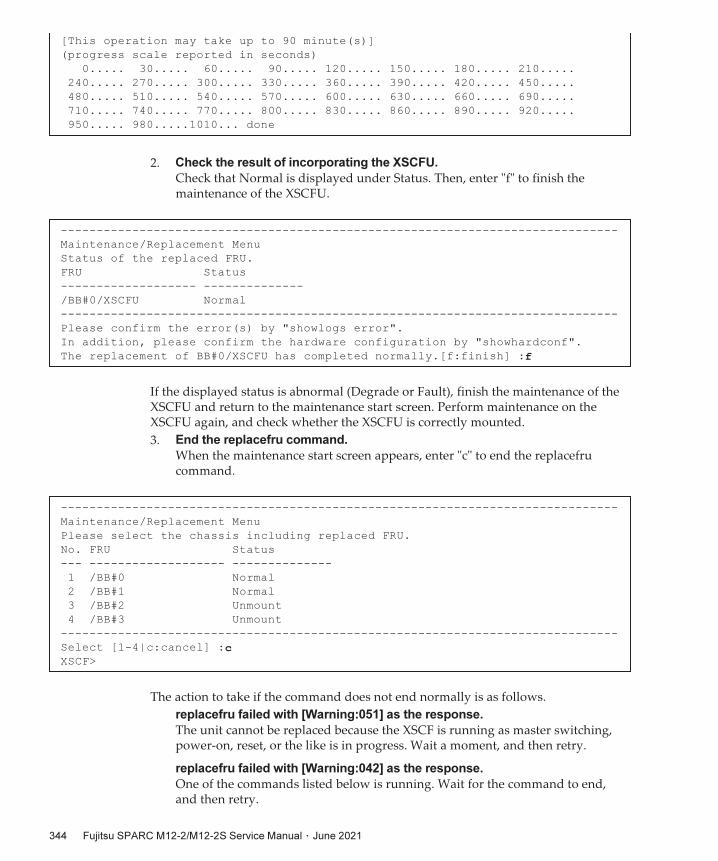
[This
operation
may
take
up
to
90
minute(s)]
(progress
scale
reported
in
seconds)
0.....
30.....
60.....
90.....
120.....
150.....
180.....
210.....
240.....
270.....
300.....
330.....
360.....
390.....
420.....
450.....
480.....
510.....
540.....
570.....
600.....
630.....
660.....
690.....
710.....
740.....
770.....
800.....
830.....
860.....
890.....
920.....
950.....
980.....1010...
done
------------------------------------------------------------------------------
Maintenance/Replacement
Menu
Status
of
the
replaced
FRU.
FRU
Status
-------------------
--------------
/BB#0/XSCFU
Normal
------------------------------------------------------------------------------
Please
confirm
the
error(s)
by
"showlogs
error".
In
addition,
please
confirm
the
hardware
configuration
by
"showhardconf".
The
replacement
of
BB#0/XSCFU
has
completed
normally.[f:finish]
:f
------------------------------------------------------------------------------
Maintenance/Replacement
Menu
Please
select
the
chassis
including
replaced
FRU.
No.
FRU
Status
---
-------------------
--------------
1
/BB#0
Normal
2
/BB#1
Normal
3
/BB#2
Unmount
4
/BB#3
Unmount
------------------------------------------------------------------------------
Select
[1-4|c:cancel]
:cXSCF>
2. Check the result of incorporating the XSCFU.
Check that Normal is displayed under Status. Then, enter "f" to finish the maintenance of the XSCFU.
If the displayed status is abnormal (Degrade or Fault), finish the maintenance of the XSCFU and return to the maintenance start screen. Perform maintenance on the XSCFU again, and check whether the XSCFU is correctly mounted.
3. End the replacefru command.
When the maintenance start screen appears, enter "c" to end the replacefru command.
The action to take if the command does not end normally is as follows.
replacefru failed with [Warning:051] as the response.
The unit cannot be replaced because the XSCF is running as master switching, power-on, reset, or the like is in progress. Wait a moment, and then retry.
replacefru failed with [Warning:042] as the response.
One of the commands listed below is running. Wait for the command to end, and then retry.
Fujitsu
SPARC
M12-2/M12-2S
Service
Manual ・ June 2021344

- addboard(8)
- addfru(8)
- addpowerschedule(8)
- clearremotepwrmgmt(8)
- deleteboard(8)
- deletepowerschedule(8)
- diagxbu(8)
- flashupdate(8)
- initbb(8)
- ioxadm(8)
- poweroff(8)
- poweron(8)
- rebootxscf(8)
- reset(8)
- restoreconfig(8)
- setcod(8)
- setdate(8)
- setpowerschedule(8)
- setpparmode(8)
- setremotepwrmgmt(8)
- setupfru(8)
- testsb(8)
- setinterimpermit(8)
- sethsmode(8)
While the XSCFU was being replaced, the replacefru command was aborted
because the XSCF was rebooted due to an XSCF panic or other cause.
Wait for the XSCF reboot to complete. Then, execute replacefru again to resume the replacement work.
Active replacement of the XSCFU failed because of a defective part (XSCFU).
Prepare a new replacement part (XSCFU) immediately to complete the replacement. If left unfinished, the failed replacement work may have a serious effect on the system.
If you cannot prepare a new replacement part (XSCFU) immediately, release the target SPARC M12-2S from the system by following the procedure below.
1. Shut down Oracle Solaris on all the PPARs and domains.
2. Execute the poweroff -f command to forcibly power off all the PPARs.
3. Remove the power cords of every SPARC M12-2S.
4. Release the target SPARC M12-2S from the system.
5. Install the power cords of every SPARC M12-2S.
Chapter
10
Setting
Up
the
System 345

XSCF>
showboards
-av
PSB
R
PPAR-ID(LSB)
Assignment
Pwr
Conn
Conf
Test
Fault
----
-
------------
-----------
----
----
----
-------
--------
00-0
00(00)
Assigned
y
y
y
Passed
Normal ←
PPAR
reset
completed
01-0
00(01)
Assigned
y
y
y
Passed
Normal ←
PPAR
reset
completed
02-0
00(02)
Assigned
y
y
y
Passed
Normal ←
PPAR
reset
completed
03-0
00(03)
Assigned
y
n
n
Passed
Normal ←
During
XSCFU
replacement,
PPAR
configuration
is
released.
During the active replacement of the XSCFU, the physical partition was
restarted because the hardware of another SPARC M12-2S failed.
After completing the XSCFU replacement work, execute the showboards command to check the status of the target PSB. If Pwr is y, Conn is n, and Conf is n for the target PSB, restore the system by performing the procedure below.
Restoration procedure:
1. Shut down Oracle Solaris on all the PPARs and domains.
2. Execute the poweroff -f command to forcibly power off all the PPARs.
3. Remove the power cords of every SPARC M12-2S.
4. Replace faulty parts if any.
5. Install the power cords of every SPARC M12-2S.
10.5 Diagnosing
a
Replacement
FRUThis section describes the diagnosis function for checking whether a replacement FRU is operating normally. For details on the commands, see the Fujitsu SPARC M12 and Fujitsu M10/SPARC M10 XSCF Reference Manual of the XCP firmware version used.■ Diagnosing the SPARC M12 Hardware
■ Diagnosing the XBU and Crossbar Cable
■ Checking the FRU Status After Maintenance
10.5.1 Diagnosing
the
SPARC
M12
Hardware
This section describes the procedure for performing a hardware diagnosis on the SPARC M12.
Select either step (1) or (2) below to perform a hardware diagnosis on the SPARC M12 with the testsb command.(1) Diagnosing the SPARC M12 by specifying its PSB
Fujitsu
SPARC
M12-2/M12-2S
Service
Manual ・ June 2021346

XSCF>
testsb
-v
-p
-s
-y
01-0Initial
diagnosis
is
about
to
start,
Continue?[y|n]
:yPSB#01-0
power
on
sequence
started.
:
(Omitted)
:
/pci@8500/pci@4/pci@0/pci@0/scsi@0
FCode
Version
1.00.56,
MPT
Version
2.00,
Firmware
Version
20.00.10.00
Target
a
Unit
0
Encl
Serv
device
FUJITSU
BBEXP
1303
SASAddress
500000e0e0b0117d
PhyNum
14
/pci@8100/pci@4/pci@0/pci@0/scsi@0
FCode
Version
1.00.56,
MPT
Version
2.00,
Firmware
Version
20.00.10.00
Target
a
Unit
0
Disk
TOSHIBA
AL13SEB600
3703
1172123568
Blocks,
600
GB
SASDeviceName
50000396f8120578
SASAddress
50000396f812057a
PhyNum
0
Target
b
Unit
0
Disk
TOSHIBA
AL13SEB600
3703
1172123568
Blocks,
600
GB
SASDeviceName
50000396f8120498
SASAddress
50000396f812049a
PhyNum
1
Target
c
Unit
0
Encl
Serv
device
FUJITSU
BBEXP
1303
SASAddress
500000e0e0b0117d
PhyNum
14
:
(Omitted)
:
/pci@8700/pci@4
/pci@8700/pci@4/pci@0
/pci@8700/pci@4/pci@0/pci@10
/pci@8600/pci@4
/pci@8600/pci@4/pci@0
/pci@8600/pci@4/pci@0/pci@10
/pci@8600/pci@4/pci@0/pci@1
/pci@8500/pci@4
/pci@8500/pci@4/pci@0
/pci@8500/pci@4/pci@0/pci@1
/pci@8500/pci@4/pci@0/pci@0
/pci@8500/pci@4/pci@0/pci@0/scsi@0
(2) Diagnosing all the SPARC M12 unitsFor a configuration with only one SPARC M12-2 or SPARC M12-2S, either of steps (1) and (2) can be selected for the diagnosis.
<Description of options>-v: Displays a detailed message on the hardware diagnosis.-p: Displays the storage connected to the SPARC M12.-s: Displays the device tree.-a: Diagnoses all the mounted SPARC M12 units.
If you do not specify -a, you need to specify the PSB of the SPARC M12-2S to be diagnosed.
(1) Diagnosing
the
SPARC
M12
by
specifying
its
PSB
The following example runs the hardware diagnosis on the SPARC M12-2S with PSB 01-0 and checks the I/O connections.
Chapter
10
Setting
Up
the
System 347

/pci@8500/pci@4/pci@0/pci@0/scsi@0/disk
/pci@8500/pci@4/pci@0/pci@0/scsi@0/tape
/pci@8400/pci@4
/pci@8400/pci@4/pci@0
/pci@8400/pci@4/pci@0/pci@1
/pci@8400/pci@4/pci@0/pci@0
/pci@8400/pci@4/pci@0/pci@0/network@0,1
/pci@8400/pci@4/pci@0/pci@0/network@0
:
(Omitted)
:
{0}
ok
PSB
power
off
sequence
started.
[1200sec]
0.....
30.....
60..end
PSB
powered
off.
PSB
Test
Fault
----
-------
--------
01-0
Passed
Normal
XSCF>
XSCF>
testsb
-v
-p
-s
-a
-yInitial
diagnosis
is
about
to
start,
Continue?[y|n]
:yPSB
power
on
sequence
started.
:
(Omitted)
:/pci@8500/pci@4/pci@0/pci@0/scsi@0
FCode
Version
1.00.56,
MPT
Version
2.00,
Firmware
Version
20.00.07.00
Target
a
Unit
0
Encl
Serv
device
FUJITSU
BBEXP
1303
SASAddress
500000e0e0b0103d
PhyNum
14
/pci@8100/pci@4/pci@0/pci@0/scsi@0
FCode
Version
1.00.56,
MPT
Version
2.00,
Firmware
Version
20.00.07.00
Target
a
Unit
0
Disk
TOSHIBA
AL13SEB600AL14SE
3702
1172123568
Blocks,
600
GB
SASDeviceName
50000397682141a1
SASAddress
50000397682141a2
PhyNum
0
Target
b
Unit
0
Disk
TOSHIBA
AL13SEB600AL14SE
3702
1172123568
Blocks,
600
GB
SASDeviceName
5000039768215115
SASAddress
5000039768215116
PhyNum
1
Target
c
Unit
0
Encl
Serv
device
FUJITSU
BBEXP
1303
SASAddress
500000e0e0b0103d
PhyNum
14
:
(Omitted)
:/pci@8700/pci@4
/pci@8700/pci@4/pci@0
/pci@8700/pci@4/pci@0/pci@10
/pci@8600/pci@4
(2) Diagnosing
all
the
SPARC
M12
units
The following example runs the hardware diagnosis on all the connected SPARC M12 units and checks the I/O connections.
Fujitsu
SPARC
M12-2/M12-2S
Service
Manual ・ June 2021348

/pci@8600/pci@4/pci@0
/pci@8600/pci@4/pci@0/pci@10
/pci@8600/pci@4/pci@0/pci@1
/pci@8600/pci@4/pci@0/pci@10/pci@0
/pci@8600/pci@4/pci@0/pci@10/pci@0/pci@0
/pci@8600/pci@4/pci@0/pci@10/pci@0/pci@0/pci@0
/pci@8600/pci@4/pci@0/pci@10/pci@0/pci@0/pci@0/pci@1
/pci@8600/pci@4/pci@0/pci@10/pci@0/pci@0/pci@0/pci@1/pci@0
/pci@8600/pci@4/pci@0/pci@10/pci@0/pci@0/pci@0/pci@1/pci@0/pci@11
/pci@8600/pci@4/pci@0/pci@10/pci@0/pci@0/pci@0/pci@1/pci@0/pci@10
/pci@8600/pci@4/pci@0/pci@10/pci@0/pci@0/pci@0/pci@1/pci@0/pci@8
/pci@8600/pci@4/pci@0/pci@10/pci@0/pci@0/pci@0/pci@1/pci@0/pci@1
/pci@8600/pci@4/pci@0/pci@10/pci@0/pci@0/pci@0/pci@1/pci@0/pci@0
/pci@8600/pci@4/pci@0/pci@10/pci@0/pci@0/pci@0/pci@1/pci@0/pci@11/pci@0
/pci@8600/pci@4/pci@0/pci@10/pci@0/pci@0/pci@0/pci@1/pci@0/pci@11/pci@0/pci@11
/pci@8600/pci@4/pci@0/pci@10/pci@0/pci@0/pci@0/pci@1/pci@0/pci@11/pci@0/pci@10
/pci@8600/pci@4/pci@0/pci@10/pci@0/pci@0/pci@0/pci@1/pci@0/pci@11/pci@0/pci@1
/pci@8600/pci@4/pci@0/pci@10/pci@0/pci@0/pci@0/pci@1/pci@0/pci@11/pci@0/pci@0
/pci@8600/pci@4/pci@0/pci@10/pci@0/pci@0/pci@0/pci@1/pci@0/pci@10/pci@0
/pci@8600/pci@4/pci@0/pci@10/pci@0/pci@0/pci@0/pci@1/pci@0/pci@10/pci@0/pci@11
/pci@8600/pci@4/pci@0/pci@10/pci@0/pci@0/pci@0/pci@1/pci@0/pci@10/pci@0/pci@10
/pci@8600/pci@4/pci@0/pci@10/pci@0/pci@0/pci@0/pci@1/pci@0/pci@10/pci@0/pci@1
/pci@8600/pci@4/pci@0/pci@10/pci@0/pci@0/pci@0/pci@1/pci@0/pci@10/pci@0/pci@0
:
(Omitted)
:{0}
ok
-----------------------------------------------------------------------------
---
[PCIBOX
Versions]
PCIBOX
Ver
Link
Ver
Info
PCIBOX#1001
1307
BB#00-PCI#03
1307
equal
-----------------------------------------------------------------------------
---
[PCIBOX
Informations]
Location
Type
FW
Ver
Serial
Num
Part
Num
State
PCIBOX#1001
PCIBOX
-
2121231001
On
PCIBOX#1001/PSU#0
PSU
-
FEJD1212000616
CA01022-0750-D/
On
PCIBOX#1001/PSU#1
PSU
-
FEJD1212000621
CA01022-0750-D/
On
PCIBOX#1001/IOB
IOBOARD
1310
PP123701KU
CA20365-B66X
009AH
On
PCIBOX#1001/LINKBD
BOARD
-
PP140801ZC
CA20365-B60X
009AD/7061035
On
PCIBOX#1001/FANBP
FANBP
-
PP1229015U
CA20365-B68X
004AC
On
BB#00-PCI#03
CARD
1310
PP13490468
CA20365-B59X
012AD/9999999
On
-----------------------------------------------------------------------------
Chapter
10
Setting
Up
the
System 349

---
PSB
power
off
sequence
started.
[1200sec]
0.....
30.....
60..end
PSB
powered
off.
PSB
Test
Fault
----
-------
--------
00-0
Passed
Normal
XSCF>
diagxbu
-y
-b
01
-p
0XBU
diagnosis
is
about
to
start,
Continue?[y|n]
:yPower
on
sequence
started.
[7200sec]
0.....
30.....
60.....
90..end
XBU
diagnosis
started.
[7200sec]
0.....
30.....
60.....
90.....120.....150.....180.....210.....240.....|
270.....300.....330.....360.....390.....420...end
completed.
Power
off
sequence
started.
[1200sec]
0.....
30.....
60.....
90.....120end
completed.
*Note*
Please
confirm
the
error
of
XBU
by
"showlogs
error".
In
addition,
please
confirm
the
degraded
of
XBU
by
"showstatus".
XSCF>
showpcl
-p
1PPAR-ID
LSB
PSB
Status
01
Powered
Off
00
01-0
01
02-0
XSCF>
diagxbu
-y
-b
03
-t
01
-t
02
10.5.2 Diagnosing
the
XBU
and
Crossbar
Cable
This section describes the procedure for diagnosing the XBU and crossbar cable in a building block configuration.
<Description of options>-b: Specify the BB-ID of the released SPARC M12-2S (communication source).-t: Specify the BB-ID of the released SPARC M12-2S (communication destination).-p: Specify the PPAR-ID (communication destination).
(1) Communication
destination
PPAR
is
running
(active
addition)
The following execution example diagnoses the XBU and crossbar cable between the SPARC M12-2S of BB#1 and the SPARC M12-2S operating in PPAR#0.
(2) Incorporation
destination
PPAR
is
stopped
(inactive
addition)
The following execution example diagnoses the XBU and crossbar cable between the SPARC M12-2S of BB#3 and the SPARC M12-2S of BB#1 and BB#2 contained in PPAR#1, which is the incorporation destination.
Fujitsu
SPARC
M12-2/M12-2S
Service
Manual ・ June 2021350

XBU
diagnosis
is
about
to
start,
Continue?[y|n]
:yPower
on
sequence
started.
[7200sec]
0.....
30.....
60.....
90.....120end
XBU
diagnosis
started.
[7200sec]
0.....
30.....
60.....
90.....120end
completed.
Power
off
sequence
started.
[1200sec]
0.....
30.....
60.....
90.....120end
completed.
*Note*
Please
confirm
the
error
of
XBU
by
"showlogs
error".
In
addition,
please
confirm
the
degraded
of
XBU
by
"showstatus".
XSCF>
showstatusXSCF>
XSCF>
showlogs
error
XSCF>
showhardconfSPARC
M12-2S;
+
Serial:PZ51649002;
Operator_Panel_Switch:Service;
+
System_Power:On;
System_Phase:Cabinet
Power
On;
The hardware diagnosis that is run during the execution of the replacefru command does not cover the crossbar cable. If you have released the SPARC M12-2S from the building block configuration by using the replacefru command, wait until the replacefru command ends, and then diagnose the crossbar cable by using the diagxbu command.
10.5.3 Checking
the
FRU
Status
After
Maintenance
This section describes the procedure for confirming that the FRU is operating normally after the completion of maintenance.
1. Log in to the XSCF shell.
2. Check the hardware status.
The following execution example checks the result output by the showstatus command. If the hardware is normal, the command displays nothing.
3. Confirm that no error is displayed.
In the following execution example, the showlogs command is entered with the error option to check that no error has occurred in the target SPARC M12-2/M12-2S since the start of maintenance.
4. Check the hardware configuration.
Enter the showhardconf command to check that the replacement FRU has been incorporated into the system. If there is an error, an asterisk (*) appears at the beginning of the line on which the corresponding FRU name is shown.
Chapter
10
Setting
Up
the
System 351

Partition#0
PPAR_Status:Running;
BB#00
Status:Normal;
Role:Master;
Ver:3015h;
Serial:PZ51649002;
+
FRU-Part-Number:CA20369-B17X
005AC/7341758
;
+
Power_Supply_System:
;
+
Memory_Size:256
GB;
CMUL
Status:Normal;
Ver:2101h;
Serial:PP164804GG
;
+
FRU-Part-Number:CA07855-D301
A5
/7341541
;
+
Memory_Size:128
GB;
Type:
C
;
CPU#0
Status:Normal;
Ver:4242h;
Serial:00070051;
+
Freq:4.250
GHz;
Type:0x30;
+
Core:12;
Strand:8;
MEM#00A
Status:Normal;
+
Code:ce8002M393A2K40BB1-CRC
00-31C04E6E;
+
Type:83;
Size:16
GB;
MEM#01A
Status:Normal;
+
Code:ce8002M393A2K40BB1-CRC
00-31C04ED1;
+
Type:83;
Size:16
GB;
MEM#02A
Status:Normal;
+
Code:ce8002M393A2K40BB1-CRC
00-31C0510D;
+
Type:83;
Size:16
GB;
MEM#03A
Status:Normal;
+
Code:ce8002M393A2K40BB1-CRC
00-31C04F51;
+
Type:83;
Size:16
GB;
MEM#04A
Status:Normal;
+
Code:ce8002M393A2K40BB1-CRC
00-31C04E6F;
+
Type:83;
Size:16
GB;
MEM#05A
Status:Normal;
+
Code:ce8002M393A2K40BB1-CRC
00-31C04F50;
+
Type:83;
Size:16
GB;
MEM#06A
Status:Normal;
+
Code:ce8002M393A2K40BB1-CRC
00-31C04EFB;
+
Type:83;
Size:16
GB;
MEM#07A
Status:Normal;
+
Code:ce8002M393A2K40BB1-CRC
00-31C051AE;
+
Type:83;
Size:16
GB;
CMUU
Status:Normal;
Ver:2101h;
Serial:PP164804GN
;
+
FRU-Part-Number:CA07855-D451
A4
/7341568
;
+
Memory_Size:128
GB;
Type:
C
;
CPU#0
Status:Normal;
Ver:4242h;
Serial:00070043;
+
Freq:4.250
GHz;
Type:0x30;
+
Core:12;
Strand:8;
MEM#00A
Status:Normal;
+
Code:ce8002M393A2K40BB1-CRC
00-31C04EF7;
+
Type:83;
Size:16
GB;
MEM#01A
Status:Normal;
+
Code:ce8002M393A2K40BB1-CRC
00-31C051AB;
+
Type:83;
Size:16
GB;
MEM#02A
Status:Normal;
+
Code:ce8002M393A2K40BB1-CRC
00-31C04EFD;
+
Type:83;
Size:16
GB;
MEM#03A
Status:Normal;
+
Code:ce8002M393A2K40BB1-CRC
00-31C04ED2;
+
Type:83;
Size:16
GB;
MEM#04A
Status:Normal;
+
Code:ce8002M393A2K40BB1-CRC
00-31C04EF6;
Fujitsu
SPARC
M12-2/M12-2S
Service
Manual ・ June 2021352

+
Type:83;
Size:16
GB;
MEM#05A
Status:Normal;
+
Code:ce8002M393A2K40BB1-CRC
00-31C04F57;
+
Type:83;
Size:16
GB;
MEM#06A
Status:Normal;
+
Code:ce8002M393A2K40BB1-CRC
00-31C04EAC;
+
Type:83;
Size:16
GB;
MEM#07A
Status:Normal;
+
Code:ce8002M393A2K40BB1-CRC
00-31C04EA8;
+
Type:83;
Size:16
GB;
PCI#0
Name_Property:network;
+
Vendor-ID:8086;
Device-ID:1521;
+
Subsystem_Vendor-ID:108e;
Subsystem-ID:7b18;
+
Model:SUNW,pcie-igb;
PCI#2
Name_Property:network;
+
Vendor-ID:8086;
Device-ID:1528;
+
Subsystem_Vendor-ID:108e;
Subsystem-ID:7b15;
+
Model:ATO:7070007,
PTO:7070005;
PCI#4
Name_Property:network;
+
Vendor-ID:8086;
Device-ID:10fb;
+
Subsystem_Vendor-ID:108e;
Subsystem-ID:7b11;
+
Model:X1109a-z/1109a-z;
PCI#6
Name_Property:QLGC,qlc;
+
Vendor-ID:1077;
Device-ID:2532;
+
Subsystem_Vendor-ID:1077;
Subsystem-ID:015d;
+
Model:QLE2562
;
XBU#0
Status:Normal;
Ver:1101h;
Serial:PP164601DU
;
+
FRU-Part-Number:CA20369-B18X
004AB/7341570
;
+
Type:
C
;
XBU#1
Status:Normal;
Ver:1101h;
Serial:PP164601DV
;
+
FRU-Part-Number:CA20369-B18X
004AB/7341570
;
+
Type:
C
;
XSCFU
Status:Normal;
Ver:0101h;
Serial:PP164603JA
;
+
FRU-Part-Number:CA20369-B08X
006AC/7341765
;
+
Type:
A
;
OPNL
Status:Normal;
Ver:0101h;
Serial:PP164702EE
;
+
FRU-Part-Number:CA20365-B35X
006AC/7060922
;
+
Type:
A
;
PSUBP
Status:Normal;
Ver:1101h;
Serial:PP164603HH
;
+
FRU-Part-Number:CA20369-B17X
005AC/7341758
;
+
Type:
C
;
PSU#0
Status:Normal;
Ver:303242h;
Serial:HWCD1622000551;
+
FRU-Part-Number:CA01022-0850/7334651
;
+
Power_Status:ON;
AC:200
V;
Type:
C
;
PSU#1
Status:Normal;
Ver:303242h;
Serial:HWCD1622000586;
+
FRU-Part-Number:CA01022-0850/7334651
;
+
Power_Status:ON;
AC:200
V;
Type:
C
;
PSU#2
Status:Normal;
Ver:303242h;
Serial:HWCD1622000524;
+
FRU-Part-Number:CA01022-0850/7334651
;
+
Power_Status:ON;
AC:200
V;
Type:
C
;
PSU#3
Status:Normal;
Ver:303242h;
Serial:HWCD1622000496;
+
FRU-Part-Number:CA01022-0850/7334651
;
+
Power_Status:ON;
AC:200
V;
Type:
C
;
FANU#0
Status:Normal;
Type:
C
;
FANU#1
Status:Normal;
Type:
C
;
Chapter
10
Setting
Up
the
System 353

FANU#2
Status:Normal;
Type:
C
;
FANU#3
Status:Normal;
Type:
C
;
FANU#4
Status:Normal;
Type:
C
;
FANU#5
Status:Normal;
Type:
C
;
FANU#6
Status:Normal;
Type:
C
;
FANU#7
Status:Normal;
Type:
C
;
HDDBP
Status:Normal;
Type:
A
;
XSCF>
XSCF>
addboard
-y
-c
configure
-p
0
00-0PSB#00-0
will
be
configured
into
PPAR-ID
0.
Continue?[y|n]
:yStart
connecting
PSB
to
PPAR.
[3600sec]
0.....
30..../
PSU
On
(BB#00)
.
60...../
CMU
Reset
Start
(BB#00)
90.-
XB
Reset
1
(BB#00)
...\
XB
Reset
2
(BB#00)
.120.|
XB
Reset
3
(BB#00)
....150.....180.....210.....240...../
270....-
CPU
Reset
1
(BB#00)
.300.....330|
10.6 Incorporating
the
SPARC
M12-2S
or
an
I/O
Device
Into
the
PPARThis section describes the following procedures:■ Incorporating the SPARC M12-2S Into the Physical Partition Using PPAR DR
■ Incorporating an I/O Device Into the Physical Partition by Using the Hot Plug Function
10.6.1 Incorporating
the
SPARC
M12-2S
Into
the
Physical
Partition
Using
PPAR
DR
The operation described in this section is available only with the SPARC M12-2S.
1. Log in to the XSCF shell.
2. Incorporate the SPARC M12-2S into the physical partition.
The following execution example incorporates the SPARC M12-2S of BB#00 into PPAR-ID#0 by using the addboard command.
Fujitsu
SPARC
M12-2/M12-2S
Service
Manual ・ June 2021354

CPU
Reset
2
(BB#00)
.....360.....390..\
Reset
released
(BB#00)
..
POST
Sequence
Start
(BB#00)
.420.....450.....480.....510.
POST
Sequence
Complete
(BB#00)
..end
Connected
PSB
to
PPAR.
Start
configuring
PSB
to
Logical
Domains
(LDoms)
Manager.
[1800sec]
0|
Processing
of
the
incoming
DR
request
by
the
LDoms
Manager
is
pendingIncoming
DR
request
is
being
processed
by
the
LDoms
ManagerDR
sequence
started
(sequence#=4,
message#=2)
DR
sequence
finished
(sequence#=4,
message#=2)
../
Processing
of
the
incoming
DR
request
by
the
LDoms
Manager
is
pendingIncoming
DR
request
is
being
processed
by
the
LDoms
ManagerDR
sequence
started
(sequence#=5,
message#=6)
../
Restoring
primary
succeeded,
PCIE16
was
assigned
.
30.
Restoring
primary
succeeded,
PCIE17
was
assigned
....-
Restoring
primary
succeeded,
PCIE18
was
assigned
60..../
Restoring
primary
succeeded,
PCIE19
was
assigned
.
90
Restoring
primary
succeeded,
PCIE20
was
assigned
../
Restoring
primary
succeeded,
PCIE21
was
assigned
...120.
Restoring
primary
succeeded,
PCIE22
was
assigned
.
Restoring
primary
succeeded,
PCIE23
was
assigned
...150.-
Restoring
primary
succeeded,
24
core(s)
were
assigned
....180.....210..-
Restoring
primary
succeeded,
163208757248
byte
memory
were
assigned
DR
sequence
finished
(sequence#=5,
message#=6)
end
Configured
PSB
to
Logical
Domains
(LDoms)
Manager.
Operation
has
completed.
Note - During the maintenance using PPAR DR, you cannot restore CPU socket constraintseven if you execute the addboard command with bind=resource specified in the operationmode option (-m option). Set the constraints again using the ldm command. For details onCPU socket constraints, see "8.14 Managing Logical Domain Resources Associated withCPU Sockets" in the Fujitsu SPARC M12 and Fujitsu M10/SPARC M10 System Operation andAdministration Guide and the Oracle VM Server for SPARC Reference Manual of the versionused. If resource assignments other than the CPU constraints cannot be restored, use the ldmcommand as well to set them again.
Chapter
10
Setting
Up
the
System 355

XSCF>
showresult0
Note - For information on the action to take if the addboard command ends abnormally, see"Appendix C Meanings of Messages and Corresponding Corrective Action" in the FujitsuSPARC M12 and Fujitsu M10/SPARC M10 Domain Configuration Guide.
XSCF>
showboards
-a
PSB
PPAR-ID(LSB)
Assignment
Pwr
Conn
Conf
Test
Fault
----
------------
-----------
----
----
----
-------
--------
00-0
00(00)
Assigned
y
y
y
Passed
Normal
01-0
00(01)
Assigned
y
y
y
Passed
Normal
02-0
00(02)
Assigned
y
y
y
Passed
Normal
03-0
00(03)
Assigned
y
y
y
Passed
Normal
XSCF>
showstatusXSCF>
XSCF>
showhardconf
3. Execute the showresult command to check the end status of the previously
executed addboard command.
If the end code is not 0, the addboard command ended abnormally. Eliminate the cause of the failure, and then execute the addboard command again.
In the following example, "0" is returned as the end status, so you can see that the execution of the addboard command has completed correctly.
4. Check the PSB configuration of the physical partition.
The following example executes the showboards command to check that PSB#00-0 (BB#00) has been added to PPAR-ID#00 and is running normally.
5. Check the hardware status.
The following execution example checks the result output by the showstatus command. If the hardware is normal, the command displays nothing.
6. Check the hardware configuration.
Enter the showhardconf command to check that the replacement FRU has been incorporated into the system. If there is an error, an asterisk (*) appears at the beginning of the line on which the corresponding FRU name is shown.
Hereinafter, perform the procedure described in "10.7 Incorporating I/O Resources Into a Logical Domain" to assign I/O resources to logical domains.
If you have replaced a FRU with the SPARC M12-2S released from the building block configuration, return the I/O configuration of the logical domains to the state it was
Fujitsu
SPARC
M12-2/M12-2S
Service
Manual ・ June 2021356

#
svcs
hotplug ←
If
the
STATE
is
disabled,
enable
the
service.
#
svcadm
enable
hotplug ←
Enables
the
hotplug
service.
Note - To perform maintenance on a PCIe card by using the hot plug function, see "AppendixB Cards That Support PCI Hot Plug and Dynamic Reconfiguration" in the Fujitsu SPARCM12 PCI Card Installation Guide to check whether the card can use PCI Hot Plug.
#
cfgadm
-x
led=attn,mode=blink
BB#0-PCI#0
(*1)
#
*1 The ATTENTION LED on BB#0-PCI#0 is blinking.
in before maintenance.If you have added the SPARC M12-2S to the building block configuration, assign the CPU resources, memory resources, and I/O resources as appropriate for the system configuration of the logical domains.
10.6.2 Incorporating
an
I/O
Device
Into
the
Physical
Partition
by
Using
the
Hot
Plug
Function
This section describes the flow of the procedure for incorporating an I/O device by using the hot plug function.To use the hot plug function, the hotplug service of Oracle Solaris must be enabled. Check the status of the hotplug service. If it is disabled, perform the following step to enable the service. You can use the hot plug function only on the control domain and root domain.
For details on cfgadm used here, see "Dynamically Configuring Devices" in the Managing Devices in Oracle Solaris for the Oracle Solaris version used.
When
incorporating
a
PCIe
card
Install a PCIe card in the target PCI slot, and perform the following procedure to incorporate it into a logical domain.
1. Log in to Oracle Solaris.
Log in to the logical domain (control domain or root domain) into which the target PCIe card will be incorporated.
The following steps are not necessary when you are replacing the PCIe card.
When adding a PCIe card, see the following example of the command executed to blink the ATTENTION LED of the PCI slot into which the PCIe card will be mounted.
2. Mount the PCIe card in the SPARC M12-2/M12-2S.
Chapter
10
Setting
Up
the
System 357

#
cfgadm
-aAp_Id
Type
Receptacle
Occupant
Condition
BB#0-PCI#0
unknown
disconnected
unconfigured
unknown
#
cfgadm
-c
connect
BB#0-PCI#0#
#
cfgadm
-c
configure
BB#0-PCI#0#
#
cfgadm
-aAp_Id
Type
Receptacle
Occupant
Condition
BB#0-PCI#0
pci-pci/hp
connected
configured
ok
#
cfgadm
-x
led=attn,mode=off
BB#0-PCI#0#
Mount the PCIe card in the SPARC M12-2/M12-2S by using the procedure described in "Chapter 12 Maintaining PCIe Cards."
3. From Oracle Solaris, check the mounting status of the PCIe card.
The following example checks that the PCIe card is mounted in BB#0-PCI#0.
4. Supply power to the mounted PCIe card.
The following example executes the cfgadm command with the connect option in Oracle Solaris on the control domain or root domain, to start power supply to the PCIe card mounted in BB#0-PCI#0.
5. Incorporate the PCIe card into the logical domain.
The following example executes the cfgadm command with the configure option in Oracle Solaris on the control domain or root domain, to incorporate the PCIe card mounted in BB#0-PCI#0 into the Oracle Solaris device configuration.
6. Confirm that the PCIe card has been incorporated into the device configuration.
The following example executes the cfgadm command with the -a option in Oracle Solaris on the control domain or root domain, to confirm that the PCIe card mounted in BB#0-PCI#0 has been incorporated into the Oracle Solaris device configuration.
7. Turn off the ATTENTION LED.
The following example turns off the ATTENTION LED of BB#-PCI#0.
Hereinafter, assign the I/O resources of the PCIe card to the guest domain or I/O domain. Assign the I/O resources as appropriate for the I/O configuration of the target logical domain, by referencing "10.7 Incorporating I/O Resources Into a Logical Domain."
Fujitsu
SPARC
M12-2/M12-2S
Service
Manual ・ June 2021358

Note - Dynamic reconfiguration of the PCIe endpoint device is supported by the combinationof XCP 2230 or later and Oracle VM Server for SPARC 3.1.1.1 or later.
#
cfgadm
-alAp_Id
Type
Receptacle
Occupant
Condition
(Omitted)
c2
scsi-sas
connected
configured
unknown
c2::dsk/c2t50000394281B50C6d0
disk
connected
configured
unknown
c2::es/ses0
ESI
connected
configured
unknown
c2::smp/expd0
smp
connected
configured
unknown
c3
scsi-sas
connected
unconfigured
unknown
c4
scsi-sas
connected
unconfigured
unknown
c5
fc
connected
unconfigured
unknown
c6
fc
connected
unconfigured
unknown
c7
scsi-sas
connected
unconfigured
unknown
(Omitted)
#
cfgadm
-c
configure
<Ap_Id>
When
incorporating
the
HDD/SSD
1. Log in to Oracle Solaris.
Log in to the logical domain (control domain or root domain) into which the HDD/SSD will be incorporated.
2. Mount the HDD/SSD in the SPARC M12-2/M12-2S.
Mount the HDD/SSD in the SPARC M12-2/M12-2S, by using the procedure described in "Chapter 15 Maintaining Internal Storage."
After mounting the HDD/SSD, wait until the READY LED on the HDD/SSD starts to blink and then comes on.
3. Check the status of the mounted HDD/SSD.
In Oracle Solaris on the control domain or root domain, execute the cfgadm command with the -al option to check the status of the mounted HDD/SSD. If the HDD/SSD has failed to be incorporated and configured is not shown, perform step 4.
The following example checks that the HDD/SSD whose Ap_Id is c2::dsk/c2t500003294281B50C6d0 is mounted.
4. Incorporate the mounted HDD/SSD into Oracle Solaris.
a. The following example executes the cfgadm command with the -c configure option in Oracle Solaris on the control domain or root domain, to incorporate the mounted HDD/SSD into the Oracle Solaris device configuration.
b. Execute the cfgadm command with the -al option to check that the mounted HDD/SSD is recognized in the Oracle Solaris device configuration.
5. Check that the mounted HDD/SSD's CHECK LED is turned off.
Chapter
10
Setting
Up
the
System 359

#
cfgadm
-x
led=fault,mode=off
<Ap_Id>
Note - If you have replaced the CMUL in a system with the HDD/SSD having the hardwareRAID configuration, you need to re-enable the hardware RAID volume. For details, see"14.2.11 Re-enabling a Hardware RAID Volume" in the Fujitsu SPARC M12 and FujitsuM10/SPARC M10 System Operation and Administration Guide.
Execute the cfgadm command to turn off the mounted HDD/SSD's CHECK LED if the CHECK LED is still blinking.
Hereinafter, assign the I/O resources of the HDD/SSD to the guest domain or I/O domain. Assign the I/O resources of the HDD/SSD as appropriate for the disk configuration of the target logical domain.
10.7 Incorporating
I/O
Resources
Into
a
Logical
DomainThis section describes the procedure for incorporating I/O resources into a logical domain. When restoring the I/O configuration of a logical domain after maintenance work or reconfiguring the I/O configuration of a logical domain after adding or removing a hardware resource, perform this procedure as appropriate for the system environment of the logical domain.For details on the procedure and the commands used, see "3.2 Operations and Commands Related to Logical Domain Configurations" in the Fujitsu SPARC M12 and Fujitsu M10/SPARC M10 Domain Configuration Guide, as well as the Oracle VM Server for SPARC Administration Guide and Oracle VM Server for SPARC Reference Manual of the version used.
10.7.1 Incorporating
the
Root
Complex
Into
the
Control
Domain
or
Root
Domain
The work procedure varies depending on whether dynamic PCIe bus assignment is used. For details, see Table 10-1.
Fujitsu
SPARC
M12-2/M12-2S
Service
Manual ・ June 2021360

Table
10-1 Procedure for Incorporating the Root Complex
-:
Unnecessary
Item Task Command Dynamic PCIe Bus
Assignment Used
(*1)
Dynamic PCIe Bus
Assignment Not
Used)
1 Setting the delayed reconfiguration mode for the logical domain into which the root complex is incorporated
ldm start-reconf
<domain-name>- Necessary
2 Incorporating the root complex into the logical domain
ldm add-io <bus> <domain-name>
Necessary Necessary
3 Restarting Oracle Solaris on the control domain or root domain that is set for delayed reconfiguration
shutdown -i6 -g0 -y - Necessary
*1 Dynamic reconfiguration of the root complex is supported by the combination of XCP 2240 or later and Oracle
VM Server for SPARC 3.2 or later. In addition, the control domain must be running Oracle Solaris 11.2 SRU 11.2.8
or later.
primary#
ldm
start-reconf
primaryInitiating
a
delayed
reconfiguration
operation
on
the
primary
domain.
All
configuration
changes
for
other
domains
are
disabled
until
the
primary
domain
reboots,
at
which
time
the
new
configuration
for
the
primary
domain
will
also
take
effect.
primary#
primary#
ldm
add-io
PCIE10
primaryprimary#
1. Set the delayed reconfiguration mode for the logical domain into which the
root complex is incorporated.
From Oracle Solaris on the control domain, set the delayed reconfiguration mode for the logical domain into which the root complex is incorporated. In this example, the delayed reconfiguration mode is set for the control domain.
Note that this step is not necessary when Dynamic PCIe bus assignment is used.
2. Incorporate the root complex into the logical domain.
In this example, the root complex of PCIE10 is incorporated into the control domain. If the root complex is incorporated in another logical domain, execute the remove-io subcommand so that the target root complex is not incorporated in any logical domain.
3. Restart Oracle Solaris on the control domain or root domain for which the
delayed reconfiguration mode has been set.
Chapter
10
Setting
Up
the
System 361

primary#
shutdown
-i6
-g0
-y
Note - If the delayed reconfiguration mode is set for the control domain, the ldm commandcannot be used for any logical domain other than the control domain. When you have set thedelayed reconfiguration mode for the control domain, restart the control domain immediatelyafter changing the control domain setting.
Table
10-2 Procedure for Incorporating the Root Complex Into the Stopped Root Domain
Item Task Command
1 Assigning the physical I/O device (root complex) to the root domain
ldm add-io
2 Starting the root domain ldm start-domain
#
ldm
add-io
<root
complex
name>
<root
domain
name>
#
ldm
start-domain
<root
domain
name>
Restart Oracle Solaris on the control domain or root domain for which the delayed reconfiguration mode has been set.
In this example, Oracle Solaris on the control domain is restarted.
Note that this step is not necessary when the root complex has been assigned to the logical domain using dynamic PCIe bus assignment.
10.7.2 Incorporating
the
Root
Complex
Into
the
Stopped
Root
Domain
Incorporate the physical I/O device (root complex) released from the root domain into the stopped root domain.
The procedure for statically reconfiguring a root complex is described below.
1. Reassign the I/O device (PCIe root complex) released from the root domain to
the root domain.
2. Start the root domain.
This step is unnecessary when the root complex is reconfigured dynamically.
Fujitsu
SPARC
M12-2/M12-2S
Service
Manual ・ June 2021362

Table
10-3 Procedure for Incorporating the PCIe Endpoint
-:
Unnecessary
Item Task Command Assigned
Dynamically
(*1)
Assigned
Statically
1 Setting the delayed reconfiguration mode for the control domain or root domain to which the PCIe endpoint is assigned
ldm start-reconf
<domain-name>- Necessary
2 Releasing a PCIe endpoint ldm remove-io <name> <domain-name>
Performed Performed
3 Restarting Oracle Solaris on the control domain or the root domain from which the PCIe endpoint has been released
For the control domain
shutdown -i6 -g0 -yFor the root domain
ldm stop-domain -r <domain-name>
- Necessary
4 Incorporating the released PCIe endpoint into the logical domain
ldm add-io <name> <domain-name>
Performed Performed
*1 Dynamic reconfiguration of the PCIe endpoint device is supported by the combination of XCP 2230 or later
and Oracle VM Server for SPARC 3.1.1.1 or later.
#
svcadm
enable
hotplug
primary#
ldm
start-reconf
primary
10.7.3 Incorporating
the
PCIe
Endpoint
Into
the
Logical
Domain
A PCIe card that is a PCIe endpoint is incorporated into the control domain or the root domain just after replacement by the PCI Hot Plug function or other means.After releasing the PCIe endpoint from the root domain, assign it to the logical domain.Note that the procedure for assigning the PCIe endpoint differs depending on whether it is performed dynamically or statically. For details, see Table 10-3.
The hotplug service needs to be enabled both in the I/O domain to which the PCIe endpoint will be assigned and in Oracle Solaris on the control domain or the root domain from which the PCIe endpoint will be released. Enable the hotplug service by using the following command.
1. Set the delayed reconfiguration mode for the control domain or root domain.
Set the delayed reconfiguration mode for the control domain or root domain to which the PCIe endpoint is assigned. In this example, the delayed reconfiguration mode is set for the control domain. This step is not necessary when you change the configuration dynamically.
Chapter
10
Setting
Up
the
System 363

primary#
ldm
remove-io
/BB1/PCI5
primary
#
shutdown
-i6
-g0
-y
#
ldm
add-io
/BB1/PCI5
guest
2. Release the PCIe endpoint from the control domain or the root domain.
This example releases the PCIe endpoint of /BB1/PCI5 from the control domain.
3. Restart Oracle Solaris on the control domain or the root domain from which
the PCIe endpoint has been released.
This step is not necessary when you release the PCIe endpoint dynamically.
4. Incorporate the PCIe endpoint into the logical domain.
This example incorporates the PCIe endpoint of /BB1/PCI5 into the logical domain guest.
When setting the delayed reconfiguration mode for the logical domain guest, do so before incorporating the PCIe endpoint.
10.7.4 Incorporating
the
SR-IOV
Virtual
Function
For the procedure for creating the SR-IOV virtual function, see Table 10-4.
Fujitsu
SPARC
M12-2/M12-2S
Service
Manual ・ June 2021364

Table
10-4 Procedure for Incorporating the SR-IOV Virtual Function (VF)
-:
Unnecessary
Item Task Command Dynamic
SR-IOV
Function Used
Static SR-IOV
Function Used
1 Checking whether the SR-IOV virtual function can be created
ldm list-io
2 Setting the delayed reconfiguration mode for the control domain or root domain to which the physical function (PF) of SR-IOV is assigned
ldm start-reconf <domain-name>
- Necessary
3 Creating the SR-IOV virtual function
ldm create-vf <pf_name> Necessary Necessary
4 Confirming that the SR-IOV virtual function was created
ldm list-io
5 Restarting Oracle Solaris on the control domain or service domain for which the delayed reconfiguration mode has been set
For the control domain
shutdown -i6 -g0 -yFor the root domain
ldm stop-domain -r <domain-name>
- Necessary
6 Stopping the logical domain to which the SR-IOV virtual function is assigned
ldm stop-domain <domain-name>
- Necessary
7 Assigning the SR-IOV virtual function to a logical domain
ldm add-io <vf_name> <domain_name>
Necessary Necessary
8 Starting the logical domain to which the SR-IOV virtual function was assigned
ldm start-domain <domain-name>
- Necessary
9 Confirming that the SR-IOV virtual function is assigned to the logical domain
ldm list-io
primary#
ldm
list-ioNAME
TYPE
BUS
DOMAIN
STATUS
----
----
---
------
------
<Omitted>
/BB0/PCI5/IOVNET.PF0
PF
PCIE3
primary
^^^^^^^^^^^^^^^^^^^^^^^^^^^^
/BB0/PCI5/IOVNET.PF1
PF
PCIE3
priamry
/BB0/PCI5/IOVNET.PF2
PF
PCIE3
primary
/BB0/PCI5/IOVNET.PF3
PF
PCIE3
primary
<Omitted>
primary#
1. Check whether the SR-IOV virtual function can be created.
This example checks that the SR-IOV virtual function can be created with the PCIe card mounted in PCI#5 of BB#00.
Chapter
10
Setting
Up
the
System 365

primary#
ldm
start-reconf
primary
primary#
ldm
create-vf
/BB0/PCI5/IOVNET.PF0
primary#
ldm
list-ioNAME
TYPE
BUS
DOMAIN
STATUS
----
----
---
------
------
<Omitted>
/BB0/PCI5/IOVNET.PF0.VF0
VF
PCIE3
primary#
primary#
shutdown
-i6
-g0
-y
primary#
ldm
stop-domain
guest
primary#
ldm
add-io
/BB0/PCI5/IOVNET.PF0.VF0
guest
2. Set the delayed reconfiguration mode for the control domain or root domain
to which the physical function (PF) of SR-IOV is assigned.
In this example, the delayed reconfiguration mode is set for the control domain.
3. Create the SR-IOV virtual function.
Create the SR-IOV virtual function in Oracle Solaris on the control domain.
This example creates the SR-IOV virtual function with the PCIe card mounted in PCI#5 of BB#00.
4. Confirm that the SR-IOV virtual function was created.
This example confirms the SR-IOV virtual function created in step 3 in Oracle Solaris on the control domain.
5. Restart Oracle Solaris on the control domain or service domain for which the
delayed reconfiguration mode has been set.
In this example, the control domain is restarted.
6. Stop the logical domain to which the SR-IOV virtual function is assigned.
This example stops logical domain guest to which the SR-IOV virtual function is assigned.
7. Assign the SR-IOV virtual function to a logical domain.
This example assigns the SR-IOV virtual function created in step 3 to the logical domain guest in Oracle Solaris on the control domain.
8. Start the logical domain to which the SR-IOV virtual function was assigned.
This example starts logical domain guest.
Fujitsu
SPARC
M12-2/M12-2S
Service
Manual ・ June 2021366

primary#
ldm
start-domain
guest
primary#
ldm
list-ioNAME
TYPE
BUS
DOMAIN
STATUS
----
----
---
------
------
<Omitted>
/BB0/PCI5/IOVNET.PF0.VF0
VF
PCIE3
guest
primary#
primary#
ldm
list-services<Omitted>
VSW
NAME
LDOM
MACADDRESS
NET-DEV
DVID|PVID|VIDs
----
----
----------
-------
--------------
primary-vsw
primary
00:14:4f:f9:00:e8
net0
1|1|--
VDS
NAME
LDOM
VOLUME
OPTIONS
MPGROUP
DEVICE
primary-vds
primary
vol
/dev/
zvol/dsk/rpool/guest
primary#
primary#
ldm
add-vnet
vnet0
primary-vsw
guestprimary#
ldm
add-vdisk
vdisk0
vol@primary-vds
guest
9. Confirm that the SR-IOV virtual function is assigned to the logical domain.
This example confirms that the SR-IOV virtual function created in step 3 is assigned to the logical domain guest.
10.7.5 Incorporating
Virtual
I/O
Devices
Into
a
Logical
Domain
This section describes the procedure for incorporating a virtual I/O device into a logical domain.For details on how to set the virtual service, see "3.2.12 Setting the Default Services" in the Fujitsu SPARC M12 and Fujitsu M10/SPARC M10 Domain Configuration Guide.
1. Check the virtual service.
This example checks that the virtual service is set in Oracle Solaris on the control domain.
2. Incorporate virtual devices into a logical domain.
This example incorporates virtual network device vnet0 and virtual disk vdisk0 into the logical domain guest in Oracle Solaris on the control domain.
3. Confirm that the virtual devices are incorporated in the logical domain.
This example confirms that virtual network device vnet0 and virtual disk vdisk0
Chapter
10
Setting
Up
the
System 367

primary#
ldm
list-bindings
guestNAME
STATE
FLAGS
CONS
VCPU
MEMORY
UTIL
NORM
UPTIME
guest
inactive
------4
8G
UUID
d1055960-a4d0-4650-89ae-ae741b9fa2b8
-(Omitted)-
VARIABLES
auto-boot?=false
boot-device=vdisk0
NETWORK
NAME
SERVICE
ID
DEVICE
MAC
MODE
PVID
VID
MTU
MAXBW
LINKPROP
vnet0
primary-vsw0
0
00:14:4f:f8:48:67
DISK
NAME
VOLUME
TOUT
ID
DEVICE
SERVER
MPGROUP
vdisk0
vol0@primary-vds0
0
XSCF>
showpparstatus
-aPPAR-ID
PPAR
Status
00
Powered
Off
XSCF>
XSCF>
poweron
-p
0
are incorporated in the logical domain guest.
10.8 Powering
on
a
Physical
PartitionThis section describes the procedure for powering on a physical partition.
1. Switch the mode switch on the OPNL to Locked mode.
In a building block configuration connecting multiple SPARC M12-2S units, switch the mode switch to Locked mode on the SPARC M12-2S units that house the master XSCF and the standby XSCF, respectively.
2. Check the operation status of the physical partition.
Log in to the XSCF shell, and check the operation status of the physical partition by using the showpparstatus command.
This example checks that PPAR-ID#00 is powered off.
3. Power on the physical partition.
From the XSCF shell, execute the poweron command to power on the physical partition.
This example powers on PPAR-ID#0.
4. Check the operation status of the physical partition.
Check the operation status of the physical partition. This example checks that
Fujitsu
SPARC
M12-2/M12-2S
Service
Manual ・ June 2021368

XSCF>
showpparstatus
-aPPAR-ID
PPAR
Status
00
Running
XSCF>
XSCF>
showpparstatus
-aPPAR-ID
PPAR
Status
00
Powered
Off
01
Powered
Off
XSCF>
PPAR-ID#00 is running.
For details on the operation status, see the Fujitsu SPARC M12 and Fujitsu M10/SPARC M10 XSCF Reference Manual of the XSCF firmware version used.
10.9 Starting
the
SystemThis section describes the procedure for starting all the physical partitions of the system.
You can start the system in the following two ways:■ Starting the System With an XSCF Command
■ Starting the System From the OPNL
10.9.1 Starting
the
System
With
an
XSCF
Command
This procedure assumes that you start the system from a remote location or in some other environment where you cannot check the status with the LEDs.For details on the commands used here, see the Fujitsu SPARC M12 and Fujitsu M10/SPARC M10 XSCF Reference Manual of the XSCF firmware version used.
1. Check the operation status of the physical partitions.
Log in to the XSCF shell, and check the operation status of the physical partition by using the showpparstatus command.
This example checks that PPAR-ID#00 and PPAR-ID#01 are powered off.
2. Power on all the physical partitions.
From the XSCF shell, enter the poweron command. In this example, the poweron command is entered for all the physical partitions and "y" is entered for the confirmation query.
Chapter
10
Setting
Up
the
System 369

XSCF>
poweron
-aPPAR-IDs
to
power
on:00,01
Continue?
[y|n]
:y00
:
Powering
on
01
:
Powering
on
*Note*
This
command
only
issues
the
instruction
to
power-on.
The
result
of
the
instruction
can
be
checked
by
the
"showpparprogress".
XSCF>
XSCF>
showpparstatus
-aPPAR-ID
PPAR
Status
00
Running
01
Running
XSCF>
The showpparprogress command lets you check the power-on status of the physical partitions. For details, see the Fujitsu SPARC M12 and Fujitsu M10/SPARC M10 XSCF Reference Manual of the XSCF firmware version used.
3. Check the operation status of all the physical partitions.
From the XSCF shell, execute the showpparstatus command to check the status of the physical partitions.
This example checks that PPAR-ID#00 and PPAR-ID#01 are running.
10.9.2 Starting
the
System
From
the
OPNL
This procedure assumes that you start the system in a server room or other environment where you can directly check the LEDs of the SPARC M12-2/M12-2S.For information on the LEDs you check here, see "2.4 Understanding the LED Indications."
1. Check the LEDs on the OPNL.
See the OPNL to check that its POWER LED is off and that its XSCF STANDBY LED is on.
2. Check the mode switch on the OPNL.
Check that the mode switch on the OPNL is set to Locked. In a building block configuration connecting multiple SPARC M12-2S units, set the mode switch to Locked on the SPARC M12-2S units that house the master XSCF and the standby XSCF, respectively.
3. Press the POWER switch on the OPNL to start the system.
Press the POWER switch on the SPARC M12-2/M12-2S that houses the master XSCF. The command to start the system is issued when you hold down the POWER switch for more than 1 second and less than 4 seconds.
For details, see "2.3.2 OPNL Control Function."
Fujitsu
SPARC
M12-2/M12-2S
Service
Manual ・ June 2021370

Note - For a building block configuration, press down the POWER switch on the masterchassis. The POWER switches on the other chassis are disabled.
4. Check the operation status of the system.
See the POWER LED on the OPNL to check the operation status. When the POWER LED turns on, it means that the system is running. Note that, in a building block configuration connecting multiple SPARC M12-2S units, the POWER LED for each physical partition turns on or blinks individually.
Chapter
10
Setting
Up
the
System 371

Fujitsu
SPARC
M12-2/M12-2S
Service
Manual ・ June 2021372

Note - The hot replacement of the XSCFU is possible only in a building block configurationconnecting multiple SPARC M12-2S units. When maintaining the XSCFU in a configurationusing only one SPARC M12-2 or SPARC M12-2S, remove the power cord and performsystem-stopped/cold replacement.
Chapter
11
Maintaining
the
XSCF
Unit
This section describes the maintenance procedures for the XSCFU mounted in the SPARC M12-2/M12-2S.
■ Maintenance Precautions
■ Location of the XSCFU
■ Before Maintenance on the XSCFU
■ Removing the XSCFU
■ Switching an SD Card
■ Installing the XSCFU
11.1 Maintenance
PrecautionsNote the following points when you maintain the XSCFU.■ Do not replace the XSCFU and the PSUBP at the same time. If the XSCFU and the
PSUBP are replaced at the same time, the system may fail to operate normally.
■ Do not mount and use any of the following SD cards in the XSCFU in another chassis:- the one currently mounted in the SPARC M12-2/M12-2S, or
- one that was once used as a maintenance part
This is because these SD cards store device identification information.
■ If you replace the SD card along with the XSCFU, dispose of the SD card mounted on the old XSCFU by appropriate means such as cutting it with cutting pliers.The old SD card stores the user information, IP address, and other information set
373

(1)
Location No. Unit
1 XSCF unit (XSCFU)
in the XSCF firmware.
11.2 Location
of
the
XSCFUThe XSCFU is mounted at the rear of the SPARC M12-2/M12-2S. Figure 11-1 shows the mounting location of the XSCFU.
Figure
11-1 Location of the XSCFU
11.3 Before
Maintenance
on
the
XSCFUWhen replacing the XSCFU with the server in the hot state, perform one of the maintenance procedures listed below.
[When replacing the XSCFU with the server in the hot state]- 4.1.1 Active/Hot Replacement Workflow of the XSCFU- 4.3.1 Inactive/Hot Replacement Workflow of the XSCFU- 4.5.1 System-Stopped/Hot Replacement Workflow of the XSCFU
[When replacing the XSCFU with the server in the cold state]- 4.2.1 Active/Cold Replacement Workflow of the XSCFU- 4.4.1 Inactive/Cold Replacement Workflow of the XSCFU- 4.6.1 System-Stopped/Cold Replacement Workflow of the XSCFU
Fujitsu
SPARC
M12-2/M12-2S
Service
Manual ・ June 2021374

Caution - Before you handle any unit, be sure to wear a wrist strap to ground any static electricity. If you perform this procedure without a wrist strap, individual components or the overall system may be seriously damaged. For details, see "1.5
Precautions on Static Electricity."
Note - When removing the XSCFU of the SPARC M12-2S in a building block configuration,do not remove the power cord, XSCF DUAL control cable, or XSCF BB control cable.
Note that, when replacing the XSCFU with the server in the cold state, you cannot replace the XSCFU and PSUBP at the same time. That would cause the system to malfunction.
11.4 Removing
the
XSCFUThis section describes the procedure for removing the XSCFU.
1. Remove the LAN cables, USB memory, and other components connected to
the XSCFU.
Remove the LAN cable, serial cable, and USB memory from the XSCFU.
Figure
11-2 Removing Cables and USB Memory
2. Lower the cable support.
Loosen the screws securing the cable support, and then pull out the cable
Chapter
11
Maintaining
the
XSCF
Unit 375
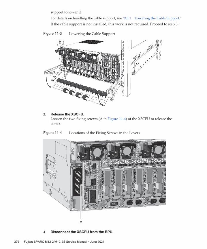
A
support to lower it.
For details on handling the cable support, see "9.8.1 Lowering the Cable Support."
If the cable support is not installed, this work is not required. Proceed to step 3.
Figure
11-3 Lowering the Cable Support
3. Release the XSCFU.
Loosen the two fixing screws (A in Figure 11-4) of the XSCFU to release the levers.
Figure
11-4 Locations of the Fixing Screws in the Levers
4. Disconnect the XSCFU from the BPU.
Fujitsu
SPARC
M12-2/M12-2S
Service
Manual ・ June 2021376

Open the two levers of the XSCFU to the right to disconnect it from the BPU.
Figure
11-5 Disconnecting the Connector of the XSCFU
5. Remove the XSCFU.
Remove the XSCFU with its levers open.
Figure
11-6 Removing the XSCFU
Chapter
11
Maintaining
the
XSCF
Unit 377

Note - After switching the SD card, return the SD card that is installed in the replacementXSCFU. Install the card in the faulty XSCFU, and return both the card and the unit together.
A
Note - Be careful not to drop the fixing screw of the protection cover onto the board. Also,store the protection cover and the fixing screw in a safe place.
11.5 Switching
an
SD
CardThis section describes the procedure for switching the SD card mounted in the XSCFU.When you do not switch the SD card, skip this work and perform the work described in "11.6 Installing the XSCFU."
11.5.1 Removing
an
SD
Card
1. Remove the SD card protection cover.
Remove the fixing screw (A in Figure 11-7) of the protection cover, and remove the cover from the XSCFU.
Figure
11-7 Removing the SD Card Protection Cover
2. Remove the SD card.
Release the lock by pressing the SD card (1 in Figure 11-8), and then remove the card from the XSCFU (2 in Figure 11-8).
Fujitsu
SPARC
M12-2/M12-2S
Service
Manual ・ June 2021378

2
1
Note - Be careful not to mix up the removed SD card with the SD card installed in thereplacement part.
Figure
11-8 Removing the SD Card
11.5.2 Installing
an
SD
Card
1. Install an SD card.
Insert the SD card in which the XSCF firmware to be used is installed into the socket of the XSCFU. Secure the SD card by pushing it until its latch locks into place.
Figure
11-9 Installing the SD Card
Chapter
11
Maintaining
the
XSCF
Unit 379

Caution - Be careful not to damage the SD card connector by pushing in the SD card too hard.
Note - Be sure to install the SD card protection cover. The SD card protection cover preventsthe lock of the SD card from being released due to a fault in the SD card socket, which makesyou unable to remove the XSCFU.
2. Install the SD card protection cover.
Install the protection cover on the XSCFU, and secure it with the screw.
Figure
11-10 Installing the SD Card Protection Cover
11.6 Installing
the
XSCFUThis section describes the procedure for installing the XSCFU in the SPARC M12-2/M12-2S.
1. Insert the XSCFU.
Insert the XSCFU into the server with the XSCFU levers open.
Fujitsu
SPARC
M12-2/M12-2S
Service
Manual ・ June 2021380

Caution - When inserting the XSCFU into the server, make sure that no cable or other foreign matter is caught between the two units. If so, the connector may be damaged.
Figure
11-11 Inserting the XSCFU Into the Server
2. Connect the XSCFU to the BPU.
Close the XSCFU levers to connect the XSCFU to the BPU.
Figure
11-12 Connector Connection of the XSCFU and BPU
3. Secure the XSCFU.
Tighten the fixing screws in the levers (A in Figure 11-13) to secure the XSCFU.
Chapter
11
Maintaining
the
XSCF
Unit 381

A
Note - Be sure to secure the levers of the XSCFU by tightening the screws. Securing the leversby tightening the screws prevents poor connection between the XSCFU and BPU.
Figure
11-13 Securing the XSCFU to the BPU
4. Connect the LAN cables and other components to the XSCFU.
Connect the LAN cables to the XSCFU to return it to the state it was in before the maintenance work. Then, return the cable support to its original position.
This completes the installation of the XSCFU.
Figure
11-14 Returning to the Pre-Maintenance State
Fujitsu
SPARC
M12-2/M12-2S
Service
Manual ・ June 2021382

Note - You can replace, add, and remove PCIe cards.
Chapter
12
Maintaining
PCIe
Cards
This chapter describes the maintenance procedures for the PCIe cards mounted in the SPARC M12 and the PCI expansion unit.
■ Locations of PCIe Cards
■ Before Maintenance on a PCIe Card
■ Removing a PCIe Card
■ Installing a PCIe Card
12.1 Locations
of
PCIe
CardsThe SPARC M12-2 can house up to 11 PCIe cards, and the SPARC M12-2S can house up to 8 cards. Figure 12-1 shows the mounting locations of PCIe cards.
383

(1) (2) (3) (4) (5) (6) (7) (8) (9) (10) (11)
(1) (2) (3) (4) (5) (6) (7) (8)
SPARC M12-2
SPARC M12-2S
Location No. Unit Slot
1 PCIe card PCI#0
2 PCIe card PCI#1
3 PCIe card PCI#2
4 PCIe card PCI#3
5 PCIe card PCI#4
6 PCIe card PCI#5
7 PCIe card PCI#6
8 PCIe card PCI#7
9 (*1) PCIe card PCI#8
10 (*1) PCIe card PCI#9
Figure
12-1 Mounting Locations of PCIe Cards in the SPARC M12
Fujitsu
SPARC
M12-2/M12-2S
Service
Manual ・ June 2021384

Location No. Unit Slot
11 (*1) PCIe card PCI#10
*1 This card can be mounted only in the SPARC M12-2.
(1) (2) (3) (4) (5) (6) (7) (8) (9) (10) (11)
Location No. Unit Slot
1 PCIe card PCIECS#1
2 PCIe card PCIECS#2
3 PCIe card PCIECS#3
4 PCIe card PCIECS#4
5 PCIe card PCIECS#5
6 PCIe card PCIECS#6
7 PCIe card PCIECS#7
8 PCIe card PCIECS#8
9 PCIe card PCIECS#9
10 PCIe card PCIECS#10
11 PCIe card PCIECS#11
Note - Only the link board connected to the SPARC M12-2/M12-2S can be mounted in theleftmost PCI slot as seen from the rear of the PCI expansion unit.
The PCI expansion unit can house up to 11 PCIe cards. Figure 12-2 shows the mounting locations of PCIe cards in the PCI expansion unit.
Figure
12-2 Mounting Locations of PCIe Cards in the PCI Expansion Unit
Chapter
12
Maintaining
PCIe
Cards 385

Caution - Before you handle any unit, be sure to wear a wrist strap to ground any static electricity. If you perform this procedure without a wrist strap, individual components or the overall system may be seriously damaged. For details, see "1.5
Precautions on Static Electricity."
12.2 Before
Maintenance
on
a
PCIe
CardWhen replacing a PCIe card, perform one of the maintenance procedures listed below.
[When replacing a PCIe card with the server in the hot state]- 4.1.2 Active/Hot Replacement Workflow of a PCIe Card- 4.3.2 Inactive/Hot Replacement Workflow of a PCIe Card- 4.5.2 System-Stopped/Hot Replacement Workflow of a PCIe Card
[When replacing a PCIe card with the server in the cold state]- 4.2.2 Active/Cold Replacement Workflow of a PCIe Card- 4.4.2 Inactive/Cold Replacement Workflow of a PCIe Card- 4.6.2 System-Stopped/Cold Replacement Workflow of a PCIe Card
When adding a PCIe card, perform one of the maintenance procedures listed below.
[When adding a PCIe card with the server in the hot state]- 5.1.1 Active/Hot Addition Workflow of a PCIe Card- 5.3.1 Inactive/Hot Addition Workflow of a PCIe Card- 5.5.1 System-Stopped/Hot Addition Workflow of a PCIe Card
[When adding a PCIe card with the server in the cold state]- 5.2.1 Active/Cold Addition Workflow of a PCIe Card- 5.4.1 Inactive/Cold Addition Workflow of a PCIe Card- 5.6.1 System-Stopped/Cold Addition Workflow of a PCIe Card
When removing a PCIe card, perform one of the maintenance procedures listed below.
[When removing a PCIe card with the server in the hot state]- 6.1.1 Active/Hot Removal Workflow of a PCIe Card- 6.3.1 Inactive/Hot Removal Workflow of a PCIe Card- 6.5.1 System-Stopped/Hot Removal Workflow of a PCIe Card
[When removing a PCIe card with the server in the cold state]- 6.2.1 Active/Cold Removal Workflow of a PCIe Card- 6.4.1 Inactive/Cold Removal Workflow of a PCIe Card- 6.6.1 System-Stopped/Cold Removal Workflow of a PCIe Card
Fujitsu
SPARC
M12-2/M12-2S
Service
Manual ・ June 2021386

Note - Unless otherwise noted, the model used in the figures shown in the followingprocedures is the SPARC M12-2S.
Note - When you add a PCIe card or perform maintenance in the inactive or system-stoppedstate, this step is not necessary.
Note - To release a PCIe card from an active system by using PCI Hot Plug or PPAR DR, youneed to make sure that the I/O resource of the PCIe card to be released or the I/O resource ofthe SPARC M12-2S to be released is not assigned to a logical domain. For details, see "9.3
Releasing I/O Resources From a Logical Domain" or "3.2 Operations and CommandsRelated to Logical Domain Configurations" in the Fujitsu SPARC M12 and Fujitsu M10/SPARC M10 Domain Configuration Guide.
12.3 Removing
a
PCIe
CardThis section describes the procedure for removing a PCIe card.
12.3.1 Enabling
the
Removal
of
a
PCIe
Card
1. Release the PCIe card from the system.
2. Lower the cable support.
For details on handling the cable support, see "9.8.1 Lowering the Cable Support."
Figure
12-3 Lowering the Cable Support
3. Remove the cable connected to the PCIe card.
Chapter
12
Maintaining
PCIe
Cards 387

Note - When you add a PCIe card, this step is not necessary. Proceed to step 4.
PUSH
1
2
Remove the cable connected to the PCIe card requiring maintenance. Record the cable connection locations before removing the cable to ensure that the system will be restored correctly.
4. Release the lock of the PCICS.
Release the lock of the PCICS by lifting the removal lever while pushing the latch at the base of the lever.
Figure
12-4 Releasing the Lock of the PCICS
5. Remove the PCIe card.
Hold the removal lever of the PCICS and remove the cassette.
Fujitsu
SPARC
M12-2/M12-2S
Service
Manual ・ June 2021388

Caution - When removing the PCICS, be careful not to bend its lever. If the lever is bent, you may not be able to secure the PCICS to the server or PCI expansion unit.
Note - Place the removed PCICS on the grounded ESD mat to ground any static electricity.
A
2
1 1
Figure
12-5 Removing the PCIe Card
12.3.2 Removing
a
PCIe
Card
or
PCIe
Card
Filler
This section describes the procedure for removing a PCIe card or PCIe card filler mounted in the PCICS.
1. Remove the PCIe card cover.
Remove the PCIe card cover by pinching its lock (A in Figure 12-6) with your fingers and lifting the cover while pushing the lock inside.
Figure
12-6 Removing the PCIe Card Cover
Chapter
12
Maintaining
PCIe
Cards 389

A
Note - Store the fixing bracket and screw of the PCIe card in a safe place.
A
B
Note - After removing the PCIe card filler, store it in a safe place.
2. Remove the fixing bracket of the PCIe card.
Remove the screw of the fixing bracket (A in Figure 12-7) of the PCIe card, and then remove the fixing bracket.
Figure
12-7 Removing the Fixing Bracket of the PCIe Card
3. Remove the PCIe card.
Remove the PCIe card (A in Figure 12-8) or the PCIe card filler (B in Figure 12-8) from the PCICS.
Figure
12-8 Removing the PCIe Card
Fujitsu
SPARC
M12-2/M12-2S
Service
Manual ・ June 2021390

Note - Unless otherwise noted, the model used in the figures shown in the followingprocedures is the SPARC M12-2S.
Note - Perform this work with the PCIe card cover and the fixing bracket of the PCIe cardremoved from the PCICS.
A
B
Note - Install a PCIe card filler in the PCICS when you have removed a PCIe card.
12.4 Installing
a
PCIe
CardThis section describes the procedure for installing a PCIe card.
12.4.1 Installing
a
PCIe
Card
or
PCIe
Card
Filler
This section describes the procedure for installing a PCIe card or PCIe card filler in the PCICS.
1. Install the PCIe card (A in Figure 12-9) or the PCIe card filler (B in Figure 12-9).
Figure
12-9 Installing a PCIe Card or PCIe Card Filler
2. Secure the PCIe card or PCIe card filler.
Install the fixing bracket (A in Figure 12-10) to the PCICS, and secure it with the screw.
Chapter
12
Maintaining
PCIe
Cards 391

A
A
2
1
Note - Confirm that the lock of the PCIe card cover (A in Figure 12-11) firmly fits into thePCICS.
Note - Be sure to install the PCIe card cover. This cover serves as a guide when you insert thePCICS into the server.
Figure
12-10 Securing the PCIe Card or PCIe Card Filler
3. Install the PCIe card cover.
Insert the PCIe card cover into the fixing guide of the PCICS (1 in Figure 12-11), and then push the rear part of the cover (2 in Figure 12-11) to secure it.
Figure
12-11 Installing the PCIe Card Cover
4. Install the PCIe card.
Insert the PCICS into the server or PCI expansion unit, with the removal lever of the PCICS pushed up.
Fujitsu
SPARC
M12-2/M12-2S
Service
Manual ・ June 2021392

Note - Securing the PCICS to the server or PCI expansion unit prevents the PCICS from beingshaken off by an unexpected vibration or shock.
Figure
12-12 Installing the PCIe Card
5. Secure the PCICS.
Lower the removal lever while pushing the latch of the PCICS to secure the PCICS to the server or PCI expansion unit.
Figure
12-13 Securing the PCICS
6. Connect the cables.
Connect the cable to the replacement or added PCIe card, and bundle the cables using the hook-and-loop fastener.
Chapter
12
Maintaining
PCIe
Cards 393

Note - When you have removed a PCIe card, this step is not necessary.
7. Return the cable support to the original position.
Return the cable support to the original position, and then secure it with two screws.
Figure
12-14 Securing the Cable Support
12.4.2 Incorporating
a
PCIe
Card
Into
the
System
This section provides an overview of the procedure for incorporating a PCIe card into the system after PCIe card replacement or addition. For details, see "10.6
Incorporating the SPARC M12-2S or an I/O Device Into the PPAR" or "3.2
Operations and Commands Related to Logical Domain Configurations" in the Fujitsu SPARC M12 and Fujitsu M10/SPARC M10 Domain Configuration Guide.
1. Incorporate the PCIe card into the physical partition.
When incorporating the PCIe card in the active state, use PCI Hot Plug. For details, see "10.6.2 Incorporating an I/O Device Into the Physical Partition by Using the Hot Plug Function."
2. Assign the I/O resource to a logical domain.
Assign the I/O resource as appropriate for the I/O configuration of the logical domain used. For details, see "10.7 Incorporating I/O Resources Into a Logical Domain."
3. Save the configuration information of the logical domain.
If there has been any change to the I/O resources of the logical domain in such a case as when you have added or removed a PCIe card or changed the mounting location of a PCIe card, be sure to save the logical domain configuration
Fujitsu
SPARC
M12-2/M12-2S
Service
Manual ・ June 2021394

information. For details, see "9.1.1 Saving Logical Domain Configuration Information."
Chapter
12
Maintaining
PCIe
Cards 395

Fujitsu
SPARC
M12-2/M12-2S
Service
Manual ・ June 2021396

(1) (2) (3) (4)
Chapter
13
Maintaining
the
Power
Supply
Units
This section describes the maintenance procedures for the PSUs mounted in the SPARC M12.
■ Locations of PSUs
■ Before Maintenance on a PSU
■ Removing a PSU
■ Installing a PSU
13.1 Locations
of
PSUsThe PSUs supply power to the individual units. The components have the 2+2 redundant configuration, enabling active/hot maintenance.
Figure 13-1 shows the mounting locations of the PSUs.
Figure
13-1 Locations of PSUs
397

Location No. Unit Slot
1 PSU PSU#0
2 PSU PSU#1
3 PSU PSU#2
4 PSU PSU#3
Caution - Before you handle any unit, be sure to wear a wrist strap to ground any static electricity. If you perform this procedure without a wrist strap, individual components or the overall system may be seriously damaged. For details, see "1.5
Precautions on Static Electricity."
13.2 Before
Maintenance
on
a
PSUWhen replacing a PSU, perform one of the maintenance procedures listed below.
[When replacing a PSU with the server in the hot state]- 4.1.3 Active/Hot Replacement Workflow of the Power Supply Unit (PSU)- 4.3.3 Inactive/Hot Replacement Workflow of the PSU- 4.5.3 System-Stopped/Hot Replacement Workflow of the PSU
[When replacing a PSU with the server in the cold state]- 4.2.3 Active/Cold Replacement Workflow of the PSU- 4.4.3 Inactive/Cold Replacement Workflow of the PSU- 4.6.3 System-Stopped/Cold Replacement Workflow of the PSU
13.3 Removing
a
PSUThis section describes the procedure for removing a PSU.
1. Remove the power cord.
Remove the power cord from the cable clamp of the PSU requiring maintenance, and then remove the power cord from the PSU. For details on removing the power cord from a PSU, see "9.8.2 Removing the Power Cords."
Fujitsu
SPARC
M12-2/M12-2S
Service
Manual ・ June 2021398

Figure
13-2 Removing a Power Cord
2. Pull down the handle of the PSU.
Figure
13-3 Handle of the PSU
3. Remove the PSU from the server.
Hook your finger around the handle of the PSU and pull out the PSU while pushing its latch (1 in Figure 13-4).
Chapter
13
Maintaining
the
Power
Supply
Units 399

1
2
Note - For your safety, remove the power cord from the PSU before removing the PSU fromthe server.
Note - When inserting the PSU into the server, make sure that the PSU power outlet is on theleft side.
Figure
13-4 Removing a PSU
13.4 Installing
a
PSUThis section describes the procedure for installing a PSU in the server.
1. Install a PSU in the server.
Insert the PSU into the server, push it until its latch locks, and then push up the handle of the PSU.
Figure
13-5 Installing a PSU
Fujitsu
SPARC
M12-2/M12-2S
Service
Manual ・ June 2021400

2. Install the power cord on the PSU.
Connect the power cord to the PSU and then secure the cord with the cable clamp. For details on installing the power cord on the PSU, see "10.1.1
Installing a Power Cord."
Figure
13-6 Installing the Power Cord
Chapter
13
Maintaining
the
Power
Supply
Units 401

Fujitsu
SPARC
M12-2/M12-2S
Service
Manual ・ June 2021402

Chapter
14
Maintaining
the
Fan
Units
and
Fan
Backplane
Unit
This chapter describes the maintenance procedures for the FANUs and FANBPU mounted in the SPARC M12.
■ Locations of the FANUs and FANBPU
■ Before Maintenance on a FANU or the FANBPU
■ Removing a FANU or the FANBPU
■ Installing a FANU or the FANBPU
14.1 Locations
of
the
FANUs
and
FANBPUA FANU consists of two cooling fans, and a FANBPU houses eight FANUs.
If one of the cooling fans fails during system operation, the redundant configuration enables the system to continue operation, and the XSCF firmware detects the failure.
Figure 14-1 shows the mounting locations of the FANUs and FANBPU.
403

(1) (3) (5) (7)
(8) (2) (4) (6)
(9)
Location No. Unit Slot
1 Fan unit FANU#0
2 Fan unit FANU#1
3 Fan unit FANU#2
4 Fan unit FANU#3
5 Fan unit FANU#4
6 Fan unit FANU#5
7 Fan unit FANU#6
8 Fan unit FANU#7
9 Fan backplane unit FANBPU
Figure
14-1 Locations of FANUs
14.2 Before
Maintenance
on
a
FANU
or
the
FANBPUWhen replacing the FANBPU, perform one of the maintenance procedures listed below. - 4.2.5 Active/Cold Replacement Workflow of the FANBPU- 4.4.5 Inactive/Cold Replacement Workflow of the FANBPU- 4.6.5 System-Stopped/Cold Replacement Workflow of the FANBPU
Fujitsu
SPARC
M12-2/M12-2S
Service
Manual ・ June 2021404

Note - You can remove a FANU in the active state.
Note - You can remove the FANBPU only when the server is in the cold state.
Note - The serial number of the server is printed on a label affixed on the front cover. Storethis cover such that it is not mixed up with the front covers of other SPARC M12 units.
When replacing a FANU, perform one of the maintenance procedures listed below. [When replacing a FANU with the server in the hot state]- 4.1.4 Active/Hot Replacement Workflow of the FANU- 4.3.4 Inactive/Hot Replacement Workflow of the FANU- 4.5.4 System-Stopped/Hot Replacement Workflow of the FANU
[When replacing a FANU with the server in the cold state]- 4.2.4 Active/Cold Replacement Workflow of the FANU- 4.4.4 Inactive/Cold Replacement Workflow of the FANU- 4.5.4 System-Stopped/Hot Replacement Workflow of the FANU
14.3 Removing
a
FANU
or
the
FANBPUThis section describes the procedure for removing a FANU or FANBPU.
14.3.1 Removing
a
FANU
This section describes the procedure for removing a FANU.
1. Remove the front cover.
For the procedure for removing the front cover, see "9.8.3 Removing the Front Cover."
2. Pull up the latch of the FANU.
Pinch the latch of the FANU (A in Figure 14-2) and pull it up.
Chapter
14
Maintaining
the
Fan
Units
and
Fan
Backplane
Unit 405

A
Note - If you are replacing only a FANU, this step is not necessary.
Note - Before removing the FANBPU, remove all the FANUs from it.
Figure
14-2 Latch of the FANU
3. Remove the FANU.
Hold the latch of the FANU, and pull out the FANU from the FANBPU.
Figure
14-3 Removing a FANU
14.3.2 Removing
the
FANBPU
This section describes the procedure for removing the FANBPU.
1. Loosen the three fixing screws of the FANBPU.
Fujitsu
SPARC
M12-2/M12-2S
Service
Manual ・ June 2021406

Caution - When loosening the fixing screws, work carefully with the screwdriver so as not to damage the PCIe cables, radiator cores (heat exchanging parts), and board substrates inside.
A
Figure
14-4 Fixing Screws of the FANBPU
2. Remove the FANBPU.
Hold the FANBPU by the parts indicated by A in Figure 14-5, and pull it out from the server. When you see the "HANDLING POSITION" labels on the sides of the FANBPU, hold the FANBPU by its sides and remove it from the server.
Figure
14-5 Removing the FANBPU
Chapter
14
Maintaining
the
Fan
Units
and
Fan
Backplane
Unit 407

Note - If you are replacing only a FANU, this step is not necessary.
Note - Make sure that the FANBPU has no FANUs in it when you insert it into the server.
14.4 Installing
a
FANU
or
the
FANBPUThis section describes the procedure for installing a FANU or FANBPU.
14.4.1 Installing
the
FANBPU
Install the FANBPU when the server is in the cold state.
1. Insert the FANBPU into the server.
Align the bottom left and right corners of the FANBPU with its slot inside the server, and insert the FANBPU along the slot.
Figure
14-6 Installing the FANBPU
2. Secure the FANBPU.
Tighten the three fixing screws to secure the FANBPU.
Fujitsu
SPARC
M12-2/M12-2S
Service
Manual ・ June 2021408

Caution - When tightening the fixing screws, work carefully with the screwdriver so as not to damage the PCIe cables, radiator cores (heat exchanging parts), and board substrates inside.
Figure
14-7 Securing the FANBPU
14.4.2 Installing
a
FANU
This section describes the procedure for installing a FANU.
1. Insert the FANU into the FANBPU.
Insert the FANU into the FANBPU, with the latch pulled up, and connect the FANU to the FANBPU connector.
Chapter
14
Maintaining
the
Fan
Units
and
Fan
Backplane
Unit 409

A
Caution - To connect a FANU to the FANBPU, push the FANU at two places at the bottom at the front (A in Figure 14-8). Pushing the latch of the FANU or the meshed section in front may cause a connector connection problem or the contact of the meshed section with the cooling fans inside, resulting in the FANU malfunctioning.
Lock
Figure
14-8 Inserting a FANU
2. Secure the FANU.
Insert the FANU into the FANBPU and fold back the latch of the FANU to secure the FANU. (Figure 14-9)
Figure
14-9 Securing a FANU
3. Incorporate the FANU into the system.
Fujitsu
SPARC
M12-2/M12-2S
Service
Manual ・ June 2021410

Note - The serial number of the server is printed on a label affixed on the front cover. Storethis cover such that it is not mixed up with the front covers of other SPARC M12 units.
If you have performed maintenance on the FANU when the server was in the hot state, incorporate the FANU into the system as instructed in "10.4.2
Incorporating the FANU."
4. Install the front cover.
For the procedure for installing the front cover to the front of the server, see "10.1.3 Installing the Front Cover."
If you have performed maintenance on the FANU when the server was in the hot state, the following step is not necessary.
5. Place the server in the hot state.
Power on the server to place it in the hot state. For details on installing the power cord on the PSU, see "10.1.1 Installing a Power Cord."
Figure
14-10 Installing the Power Cord
Chapter
14
Maintaining
the
Fan
Units
and
Fan
Backplane
Unit 411

Fujitsu
SPARC
M12-2/M12-2S
Service
Manual ・ June 2021412

Note - You can replace, add, and remove HDDs/SSDs.
Chapter
15
Maintaining
Internal
Storage
This section describes the maintenance procedures for the HDDs/SSDs mounted in the SPARC M12.
■ Locations of HDDs/SSDs
■ Before Maintenance on an HDD/SSD
■ Removing an HDD/SSD or Filler Unit
■ Installing an HDD/SSD or Filler Unit
15.1 Locations
of
HDDs/SSDsYou can install eight HDDs/SSDs in the server.
Figure 15-1 shows the mounting locations of the HDDs/SSDs.
413

(1) (2) (3)
(4)
(5)
(6) (7)
(8)
Location No. Unit Slot
1 HDD/SSD HDD#0
2 HDD/SSD HDD#1
3 HDD/SSD HDD#2
4 HDD/SSD HDD#3
5 HDD/SSD HDD#4
6 HDD/SSD HDD#5
7 HDD/SSD HDD#6
8 HDD/SSD HDD#7
Figure
15-1 Locations of HDDs/SSDs
15.2 Before
Maintenance
on
an
HDD/SSDWhen replacing an HDD/SSD, perform one of the maintenance procedures listed below.
[When replacing an HDD/SSD with the server in the hot state]- 4.1.5 Active/Hot Replacement Workflow of the HDD/SSD- 4.3.5 Inactive/Hot Replacement Workflow of the HDD/SSD- 4.5.5 System-Stopped/Hot Replacement Workflow of the HDD/SSD
[When replacing an HDD/SSD with the server in the cold state]- 4.2.6 Active/Cold Replacement Workflow of the HDD/SSD- 4.4.6 Inactive/Cold Replacement Workflow of the HDD/SSD
Fujitsu
SPARC
M12-2/M12-2S
Service
Manual ・ June 2021414

Caution - Before you handle any unit, be sure to wear a wrist strap to ground any static electricity. If you perform this procedure without a wrist strap, individual components or the overall system may be seriously damaged. For details, see "1.5
Precautions on Static Electricity."
- 4.6.6 System-Stopped/Cold Replacement Workflow of the HDD/SSD
[When adding an HDD/SSD with the server in the hot state]- 5.1.2 Active/Hot Addition Workflow of the HDD/SSD- 5.3.2 Inactive/Hot Addition Workflow of the HDD/SSD- 5.5.2 System-Stopped/Hot Addition Workflow of the HDD/SSD
[When adding an HDD/SSD with the server in the cold state]- 5.2.2 Active/Cold Addition Workflow of the HDD/SSD- 5.4.2 Inactive/Cold Addition Workflow of the HDD/SSD- 5.6.2 System-Stopped/Cold Addition Workflow of the HDD/SSD
[When removing an HDD/SSD with the server in the hot state]- 6.1.2 Active/Hot Removal Workflow of the HDD/SSD- 6.3.2 Inactive/Hot Removal Workflow of the HDD/SSD- 6.5.2 System-Stopped/Hot Removal Workflow of the HDD/SSD
[When removing an HDD/SSD with the server in the cold state]- 6.2.2 Active/Cold Removal Workflow of the HDD/SSD- 6.4.2 Inactive/Cold Removal Workflow of the HDD/SSD- 6.6.2 System-Stopped/Cold Removal Workflow of the HDD/SSD
15.3 Removing
an
HDD/SSD
or
Filler
UnitThis section describes the procedure for removing an HDD/SSD or an HDD/SSD filler unit. To remove an HDD/SSD, use the same procedure.
15.3.1 Removing
an
HDD/SSD
1. Open the removal lever of the HDD/SSD.
Pinch the latch (A in Figure 15-2), and open the removal lever of the HDD/SSD.
Chapter
15
Maintaining
Internal
Storage 415

A
Figure
15-2 Opening the Removal Lever of the HDD/SSD
2. Remove the HDD/SSD.
Hold the removal lever, and remove the HDD/SSD from the HDDBPU.
Figure
15-3 Removing an HDD/SSD
15.3.2 Removing
a
Filler
Unit
1. Remove a filler unit.
Pinch the latches on both sides to remove the filler unit from the HDDBPU.
Fujitsu
SPARC
M12-2/M12-2S
Service
Manual ・ June 2021416

Note - If you are replacing an HDD/SSD, this step is not necessary.
Figure
15-4 Removing the Filler Unit
15.4 Installing
an
HDD/SSD
or
Filler
UnitThis section describes the procedure for installing an HDD/SSD or an HDD/SSD filler unit. To add an HDD/SSD, use the same procedure.
15.4.1 Installing
an
HDD/SSD
1. Remove a filler unit.
To add an HDD/SSD, remove the filler unit mounted in the HDDBPU in which to install the HDD/SSD. For the removal procedure, see "15.3.2 Removing a Filler Unit."
2. Insert the HDD/SSD into the HDDBPU.
Install the HDD/SSD in the HDDBPU, with the removal lever open.
Chapter
15
Maintaining
Internal
Storage 417

Note - Before operating the system, be sure to install a filler unit in each disk slot that doeshouse an HDD/SSD.
Figure
15-5 Inserting an HDD/SSD
3. Secure the HDD/SSD.
Secure the HDD/SSD by closing the removal lever.
Figure
15-6 Securing an HDD/SSD
15.4.2 Installing
a
Filler
Unit
1. Install a filler unit.
Fujitsu
SPARC
M12-2/M12-2S
Service
Manual ・ June 2021418

Figure
15-7 Installing the Filler Unit
Chapter
15
Maintaining
Internal
Storage 419

Fujitsu
SPARC
M12-2/M12-2S
Service
Manual ・ June 2021420

(1)
(2)
(3)
(6)
(4)
(5)
Chapter
16
Maintaining
the
HDD
Backplane
Unit
and
Operation
Panel
This chapter describes the maintenance procedures for the HDDBPU and OPNL mounted in the SPARC M12.
■ Locations of the HDDBPU and OPNL
■ Before Maintenance on the HDDBPU and OPNL
■ Removing the HDDBPU or OPNL
■ Installing the HDDBPU or OPNL
16.1 Locations
of
the
HDDBPU
and
OPNLFigure 16-1 shows the mounting locations of the HDDBPU and OPNL.
Figure
16-1 Locations of the HDDBPU and OPNL
421

Location
No.
Unit
1 Front cover
2 FANU
3 FANBPU
4 HDDBPU
5 HDD/SSD
6 OPNL (*1)
*1 The OPNL is installed in the HDDBPU.
Caution - Before you handle any unit, be sure to wear a wrist strap to ground any static electricity. If you perform this procedure without a wrist strap, individual components or the overall system may be seriously damaged. For details, see "1.5
Precautions on Static Electricity."
16.2 Before
Maintenance
on
the
HDDBPU
and
OPNLWhen replacing the HDDBPU, perform one of the maintenance procedures listed below. - 4.2.7 Active/Cold Replacement Workflow of the HDDBPU- 4.4.7 Inactive/Cold Replacement Workflow of the HDDBPU- 4.6.7 System-Stopped/Cold Replacement Workflow of the HDDBPU
When replacing the OPNL, perform one of the maintenance procedures listed below. - 4.2.8 Active/Cold Replacement Workflow of the OPNL- 4.4.8 Inactive/Cold Replacement Workflow of the OPNL- 4.6.8 System-Stopped/Cold Replacement Workflow of the OPNL
16.3 Removing
the
HDDBPU
or
OPNLThis section describes the procedure for removing the HDDBPU or OPNL.
16.3.1 Enabling
the
Removal
of
the
HDDBPU
or
OPNL
Before removing the HDDBPU or OPNL, you need to remove the FANUs and
Fujitsu
SPARC
M12-2/M12-2S
Service
Manual ・ June 2021422

Note - The serial number of the server is printed on a label affixed on the front cover. Storethis cover such that it is not mixed up with the front covers of other SPARC M12 units.
FANBPU. This section describes the procedure for removing the FANUs and FANBPU.
1. Place the server in the cold state.
Stop the power supply to the server to place it in the cold state. For the procedure for removing the power cords, see "9.8.2 Removing the Power Cords."
2. Remove the front cover.
For the procedure for removing the front cover, see "9.8.3 Removing the Front Cover."
3. Remove all the FANUs.Remove all the FANUs mounted in the FANBPU. For details on the procedure, see "14.3.1 Removing a FANU."
Figure
16-2 Removing the FANUs
4. Remove the FANBPU.
Loosen the three fixing screws, and remove the FANBPU. For details, see "14.3.2 Removing the FANBPU."
Chapter
16
Maintaining
the
HDD
Backplane
Unit
and
Operation
Panel 423

Caution - When loosening the fixing screws, be careful not to damage the PCIe cables or radiator cores (heat exchanging parts) with the screwdriver, which may come into contact with these components.
Figure
16-3 Removing the FANBPU
16.3.2 Removing
the
HDDBPU
This section describes the procedure for removing the HDDBPU.
1. Loosen the three fixing screws of the HDDBPU.
Figure
16-4 Fixing Screws of the HDDBPU
Fujitsu
SPARC
M12-2/M12-2S
Service
Manual ・ June 2021424

Note - When pulling out the HDDBPU, put your hand under it to prevent it from falling.
A
Note - If you are replacing the OPNL of the SPARC M12-2S, make a note of the set BB-IDvalue.
2. Remove the HDDBPU.
Pull down the removal lever of the HDDBPU toward you, and pull out the HDDBPU while holding its handle (A in Figure 16-5).
Figure
16-5 Removing the HDDBPU
16.3.3 Removing
the
OPNL
This section describes the procedure for removing the OPNL mounted in the HDDBPU.
1. Remove the HDDs/SSDs.
Remove all the HDDs/SSDs mounted in the HDDBPU. If any filler units are mounted, remove them too. For details, see "15.3 Removing an HDD/SSD or Filler Unit."
Chapter
16
Maintaining
the
HDD
Backplane
Unit
and
Operation
Panel 425

Figure
16-6 Removing the HDD/SSD and Filler Units
2. Pull up the removal lever of the OPNL.
Pull up the removal lever of the OPNL (A in Figure 16-7), and pull the OPNL out from the HDDBPU.
Fujitsu
SPARC
M12-2/M12-2S
Service
Manual ・ June 2021426

A
Figure
16-7 Releasing the OPNL
3. Remove the OPNL.
Disconnect the connector (A in Figure 16-8) that connects the HDDBPU and OPNL. Disconnecting the connector completes the removal of the OPNL.
Chapter
16
Maintaining
the
HDD
Backplane
Unit
and
Operation
Panel 427

A
Caution - Do not pull the connector cable that connects the HDDBPU and OPNL. Pulling the connector cable forcibly may break it, in which case the cable cannot be used normally.
Figure
16-8 Pulling out the OPNL
Fujitsu
SPARC
M12-2/M12-2S
Service
Manual ・ June 2021428

Note - If you are replacing the OPNL of the SPARC M12-2S, first set the BB-ID value from thenote made in "16.3.3 Removing the OPNL," and then install the OPNL.
Note - In the case of the SPARC M12-2, you cannot set a BB-ID value for the OPNL.
Figure
16-9 Removing the OPNL
16.4 Installing
the
HDDBPU
or
OPNLThis section describes the procedure for installing the OPNL or HDDBPU.
16.4.1 Installing
the
OPNL
1. Connect the OPNL and HDDBPU.
After connecting the OPNL and HDDBPU via the connector, insert the OPNL into the HDDBPU.
Chapter
16
Maintaining
the
HDD
Backplane
Unit
and
Operation
Panel 429

Note - If the tip of the removal lever is not securely fitted or part of the gasket is seen, pullout the OPNL. Check whether the cables are stored properly, and then repeat step 1.
Figure
16-10 Installing the OPNL
2. Check that the OPNL is installed properly.
a. Make sure that the tip of the removal lever (A in Figure 16-11) is securely fitted.
b. Make sure that the gasket is pushed in all the way so that no part of it is seen (B in Figure 16-11).
Figure
16-11 Securing the OPNL
Fujitsu
SPARC
M12-2/M12-2S
Service
Manual ・ June 2021430

3. Install the HDD/SSD and filler units.
Install the removed HDD/SSD and filler units. For details, see "15.4 Installing an HDD/SSD or Filler Unit."
Figure
16-12 Installing the HDD/SSD and Filler Units
16.4.2 Installing
the
HDDBPU
in
the
Server
This section describes the procedure for installing the HDDBPU to the server, with the OPNL mounted in it.
1. Insert the HDDBPU into the server.
Fit the HDDBPU to the positioning guide (A in Figure 16-13), and insert it into the server.
Chapter
16
Maintaining
the
HDD
Backplane
Unit
and
Operation
Panel 431

A
Caution - Before connecting the HDDBPU to the connector of the CMU, confirm that the HDDBPU is fitted to the positioning guide and does not move left or right. Inserting the HDDBPU when it is not fitted to the positioning guide may damage the connector.
Figure
16-13 Inserting the HDDBPU
2. Secure the HDDBPU to the server.
Return the removal lever of the HDDBPU to the state it was in before the HDDBPU was removed. Then, tighten the three fixing screws shown in A in Figure 16-14 to secure the HDDBPU.
Fujitsu
SPARC
M12-2/M12-2S
Service
Manual ・ June 2021432

A
A
A
Figure
16-14 Securing the HDDBPU
16.4.3 Restoring
the
Server
This section describes the procedure for restoring the server after performing maintenance on the HDDBPU or OPNL.
1. Install the FANBPU.
Install the FANBPU to the server. For details, see "14.4.1 Installing the FANBPU."
Figure
16-15 Securing the FANBPU
Chapter
16
Maintaining
the
HDD
Backplane
Unit
and
Operation
Panel 433

Note - The serial number of the server is printed on a label affixed on the front cover. Storethis cover such that it is not mixed up with the front covers of other SPARC M12 units.
2. Install the FANUs.
Install the FANUs to the server. For details, see "14.4.2 Installing a FANU."
Figure
16-16 Installing the FANUs
3. Install the front cover.
For the procedure for installing the front cover, see "10.1.3 Installing the Front Cover."
4. Place the server in the hot state.
Power on the server to place it in the hot state. For details on installing the power cord on the PSU, see "10.1.1 Installing a Power Cord."
Figure
16-17 Installing the Power Cord
Fujitsu
SPARC
M12-2/M12-2S
Service
Manual ・ June 2021434

Note - You can replace the CMUL and replace, add, and remove CMUU units.
Caution - The CMUU weighs 10 kg (22 lb), and the CMUL weighs 13 kg (29 lb). Work must be done by two people if the server is mounted at the 24U or higher position of the rack. If the work is done by one person, it may result in an injury or damage to the server.
Chapter
17
Maintaining
the
CPU
Memory
Unit
and
Memory
This section describes the maintenance procedures for the CMU and memory mounted in the SPARC M12.
■ Maintenance Precautions
■ Locations of the CMU and Memory
■ Before Maintenance on the CMU and Memory
■ Removing the CMU or Memory
■ Installing the CMU and Memory
17.1 Maintenance
PrecautionsNote the following points when you maintain the CMU.
■ If you have replaced the CMUL that has the hardware RAID function enabled, re-enable the hardware RAID volume. For details, see "14.2.11 Re-enabling a Hardware RAID Volume" in the Fujitsu SPARC M12 and Fujitsu M10/SPARC M10 System Operation and Administration Guide.
■ When you add or remove a CMUU, a root complex is also added or removed. As a result, the PCIe card installation rules and the physical device paths may change, making it necessary to reconfigure the logical domains. For details, see "7.2
Precautions for FRU Expansion" or "7.3 Precautions for FRU Reduction."
435

(7)
(6)
(8)
(8)(5)
(3)
(4)
(1)
(2)
(1)
SPARC M12-2 (REAR) SPARC M12-2S (REAR)
17.2 Locations
of
the
CMU
and
MemoryFigure 17-1 and Figure 17-2 show the mounting locations of the CMU and memory. The numbers in the figure represent the order in which the units are to be removed.
Figure
17-1 Location of the CMU
Fujitsu
SPARC
M12-2/M12-2S
Service
Manual ・ June 2021436

Location
No.
Unit
1 PCIe card (*1)
2 XBU (*2)
3 Front cover
4 FANU
5 FANBPU
6 HDDBPU
7 CMU filler unit (*3)
8 CMU
*1 The SPARC M12-2 houses 11 cassettes, and the SPARC M12-2S houses 8 cassettes.
*2 This unit is mounted only in the SPARC M12-2S.
*3 This unit is mounted in a system that has only the CMUL when purchased.
(1)
(2)
Location
No.
Unit
1 CMUL top cover
2 Memory
Figure
17-2 Locations of Memory
Chapter
17
Maintaining
the
CPU
Memory
Unit
and
Memory 437

Caution - Before you handle any unit, be sure to wear a wrist strap to ground any static electricity. If you perform this procedure without a wrist strap, individual components or the overall system may be seriously damaged. For details, see "1.5
Precautions on Static Electricity."
17.3 Before
Maintenance
on
the
CMU
and
MemoryWhen replacing the CMU, perform one of the maintenance procedures listed below.
- 4.2.9 Active/Cold Replacement Workflow of the CMU- 4.4.9 Inactive/Cold Replacement Workflow of the CMU- 4.6.9 System-Stopped/Cold Replacement Workflow of the CMU
When adding a CMUU, perform one of the maintenance procedures listed below.
- 5.2.3 Active/Cold Addition Workflow of the CMUU- 5.4.3 Inactive/Cold Addition Workflow of the CMUU- 5.6.3 System-Stopped/Cold Addition Workflow of the CMUU
When removing a CMUU, perform one of the maintenance procedures listed below.
- 6.2.3 Active/Cold Removal Workflow of the CMUU- 6.4.3 Inactive/Cold Removal Workflow of the CMUU- 6.6.3 System-Stopped/Cold Removal Workflow of the CMUU
When replacing memory, perform one of the maintenance procedures listed below.
- 4.2.10 Active/Cold Replacement Workflow of Memory- 4.4.10 Inactive/Cold Replacement Workflow of Memory- 4.6.10 System-Stopped/Cold Replacement Workflow of Memory
When adding memory, perform one of the maintenance procedures listed below.
- 5.2.4 Active/Cold Addition Workflow of Memory- 5.4.4 Inactive/Cold Addition Workflow of Memory- 5.6.4 System-Stopped/Cold Addition Workflow of Memory
When removing memory, perform one of the maintenance procedures listed below.
- 6.2.4 Active/Cold Removal Workflow of Memory- 6.4.4 Inactive/Cold Removal Workflow of Memory- 6.6.4 System-Stopped/Cold Removal Workflow of Memory
Fujitsu
SPARC
M12-2/M12-2S
Service
Manual ・ June 2021438

Caution - Pulling out the CMUL with these cables (LAN, SAS, USB, or other cables) connected may damage the connectors.
17.4 Removing
the
CMU
or
MemoryThis section describes the procedure for removing the CMU or memory.
17.4.1 Enabling
the
Removal
of
the
CMU
To enable the removal of the CMU, you need to remove the FANBPU, HDDBPU, PCIe cards, and XBU from the server. This section describes the procedure for removing the other units from the server before removing the CMU.
1. Place the server in the cold state.
For details on handling power cords, see "9.8.2 Removing the Power Cords."
2. Lower the cable support.
For details on handling the cable support, see "9.8.1 Lowering the Cable Support."
3. The CMUL may have a LAN cable, SAS cable, USB cable, or other cable
connected to it. Remove them all.
4. Pull out the PCIe card from the server.
For details on handling the PCIe card, see "12.3.1 Enabling the Removal of a PCIe Card."
Chapter
17
Maintaining
the
CPU
Memory
Unit
and
Memory 439

PCIe card
XBU
Figure
17-3 Pulling Out the PCIe Card
5. Pull out the XBU from the server.
You can pull the XBU out of the CMU when you open its removal lever. For details on handling the XBU, see "20.3 Removing an XBU."
Note that, for the SPARC M12-2, this step is not necessary. Proceed to step 6.
Figure
17-4 Pulling Out the XBU
Fujitsu
SPARC
M12-2/M12-2S
Service
Manual ・ June 2021440

Note - The serial number of the server is printed on a label affixed on the front cover. Storethis cover such that it is not mixed up with the front covers of other SPARC M12 units.
6. Remove the front cover.
For the procedure for removing the front cover, see "9.8.3 Removing the Front Cover."
7. Remove the FANUs.
For the procedure for removing the FANUs, see "14.3.1 Removing a FANU."
Figure
17-5 Removing the FANUs
8. Remove the FANBPU.
For the procedure for removing the FANBPU, see "14.3.2 Removing the FANBPU."
Chapter
17
Maintaining
the
CPU
Memory
Unit
and
Memory 441

Figure
17-6 Removing the FANBPU
9. Remove the HDDBPU.
For the procedure for removing the HDDBPU, see "16.3.2 Removing the HDDBPU."
Figure
17-7 Removing the HDDBPU
17.4.2 Removing
the
CMU
This section describes the procedure for removing the CMU.
1. Remove the PCIe cables from the cable guide.
Remove the PCIe cables from the cable guide. When the CMUU is not mounted, this step is not necessary. Proceed to step 6.
Fujitsu
SPARC
M12-2/M12-2S
Service
Manual ・ June 2021442

PCIe cable
Cable guide
Caution - Hold the PCIe cables with both hands to carefully remove the cables from the cable guide. If excessive force is used to pull out the PCIe cables, the cables may break or the connectors may be damaged.
Caution - Remove the PCIe cable connectors carefully. If you roughly remove them, the PCIe cable may break or the connector may be damaged.
Figure
17-8 Removing the PCIe Cables From the Cable Guide
2. Remove the PCIe cables from the CMUL.
The latch of the PCIe cable connector is located on the underside of the connector. Pull out the connector by pinching the connector hood while pushing the latch.
Chapter
17
Maintaining
the
CPU
Memory
Unit
and
Memory 443

A
Caution - When removing either the CMUL or CMUU or both, be sure to bundle the PCIe cables using the cable clamps. Removing the CMU without bundling PCIe cables may damage the cables due to interference with the internal components.
Figure
17-9 Removing the PCIe Cable Connectors
3. Bundle the PCIe cables using the cable clamps of the CMUU.
Bundle the PCI0 and PCI1 cables and the PCI2 and PCI3 cables into pairs respectively using the cable clamps (A in Figure 17-10) in such a way that they cross each other.
Figure
17-10 Securing the PCIe Cables With the Cable Clamp
4. Loosen the fixing screws of the CMUU levers.
Loosen the fixing screws (A in Figure 17-11) of the CMUU levers.
Note that, if you do not remove the CMUU, this step is not necessary. Proceed to
Fujitsu
SPARC
M12-2/M12-2S
Service
Manual ・ June 2021444

A
Caution - Loosen the fixing screws carefully with the screwdriver so as not to damage the PCIe cables or the radiator located behind the PCIe cables.
Note - To remove the CMU filler unit, proceed to step 6.
step 6.
Figure
17-11 Fixing Screws of the CMUU Levers
5. Remove the CMUU.
a. Hold the CMUU levers (A in Figure 17-12), pull out the CMUU to the tip of "NEAR to END", and then hold it at "HANDLING POSITION" (B in Figure 17-12) on its side.
b. Hold the CMUU at HANDLING POSITION, and remove it from the server.
Chapter
17
Maintaining
the
CPU
Memory
Unit
and
Memory 445

A
B HANDLING POSIOTION
NEAR to END
HANDLING POSIOTION
Note - When removing the CMUU, be sure to bundle the PCIe cables using the cable clamps.
Note - If you do not remove the CMUL, the following steps are not necessary.
Figure
17-12 Removing the CMUU
6. Remove the filler unit.
When the filler unit is not mounted, this step is not necessary. Proceed to step 7.
a. Hook your fingers over the top part of the CMU filter unit (A in Figure 17-13) by inserting them into the gap there.
b. Pull out the CMU filler unit by pulling it toward you.
Fujitsu
SPARC
M12-2/M12-2S
Service
Manual ・ June 2021446

A
Note - When removing the CMU filler unit, hold it with both hands so that you do not dropit.
Figure
17-13 Gap in the Top Part of the CMU Filler Unit
Figure
17-14 Removing the CMU Filler Unit
Chapter
17
Maintaining
the
CPU
Memory
Unit
and
Memory 447

Note - If you do not remove the CMUL, the following steps are not necessary.
A
7. Loosen the fixing screws of the CMUL levers.
Loosen the fixing screws (A in Figure 17-15) of the CMUL levers.
Figure
17-15 Fixing Screws of the CMUL Levers
8. Remove the CMUL.
a. Hold the CMUL levers (A in Figure 17-16), pull out the CMUL to the tip of "NEAR to END", and then hold it at "HANDLING POSITION" (B in Figure 17-16) on its side.
b. Hold the CMUL at HANDLING POSITION, and remove it from the server.
Fujitsu
SPARC
M12-2/M12-2S
Service
Manual ・ June 2021448

A
B
NEAR to END
Caution - You need to pull out the CMUL completely from the server before lifting it up. Lifting up the CMUL before pulling it out completely may damage the CMUL due to interference with the internal components.
Note - After removing the CMUL from the server, place it horizontally on the workbenchgently to avoid mechanical shock.
Figure
17-16 Removing the CMUL
17.4.3 Removing
Memory
This section describes the procedure for removing the memory mounted in the CMU.Unless otherwise noted, the description provided herein applies to both the CMUL and CMUU.
Chapter
17
Maintaining
the
CPU
Memory
Unit
and
Memory 449

A
2
1
Note - To operate the system after removing memory, follow the instructions in "2.2.1
Memory Installation Rules."
1. Remove the top cover of the CMUL.
Remove the top cover by sliding it in the direction of the arrow while pushing the latches on both sides of the CMUL (A in Figure 17-17).
To remove memory from the CMUU, proceed to step 2.
Figure
17-17 Removing the CMUL Top Cover
2. Remove memory.
After opening the latches on both sides of the memory slot, remove the memory.
Figure
17-18 Removing Memory
17.5 Installing
the
CMU
and
MemoryThis section describes the procedures for installing memory and the CMU. To add a CMUU, perform the procedure described in this section as well.
17.5.1 Installing
Memory
This section describes the procedure for installing memory in the CMU.
Fujitsu
SPARC
M12-2/M12-2S
Service
Manual ・ June 2021450

Note - To add memory or change the type of memory installed, follow the instructions in"2.2.1 Memory Installation Rules."
Note - When replacing only the CMU, make sure that the memory mounting position is thesame before and after the replacement of the CMU.
Note - Confirm that the latches on both ends of the memory slot are closed. You need tomake sure that there is no unevenness (Figure 17-21) between the latches when seen fromdirectly above. If the latches are not closed, remove the memory and try installing it again.
1. Install the memory.
Check that the latches on both sides of the memory slot into which to install memory are open. Align the memory key grooves with the memory slot key, and place the memory in the memory slot.
Figure
17-19 Installing Memory
2. Secure the memory.
Push both ends of the memory until the latches of the memory slot close.
Figure
17-20 Securing the Memory
Chapter
17
Maintaining
the
CPU
Memory
Unit
and
Memory 451

Key groove
Figure
17-21 Installing Memory (No Unevenness)
3. Install the to cover to the CMUL.
Place the top cover on the CMUL with its key aligned with the key grooves on both sides of the CMUL. Then, slide the top cover in the direction of the arrow shown in Figure 17-22, and lock the latch to secure the cover. When locked, the latch "clicks".
Note that this step is not necessary for the CMUU.
Figure
17-22 Installing the Top Cover on the CMUL
17.5.2 Installing
the
CMU
1. Insert the CMUL into the server.
Hold the CMUL at "HANDLING POSITION" (B in Figure 17-23), insert it to the tip of "NEAR to END". Then, hold the CMUL levers (A in Figure 17-23) and insert the CMUL into the server.
Insert the CMUL into the server while taking care not to apply a load on the rear part of the CMUL.
Fujitsu
SPARC
M12-2/M12-2S
Service
Manual ・ June 2021452

A
B
C
NEAR to END
Caution - Check that the CMUL is fitted to the guide (C in Figure 17-23) in the server before holding it by other parts. If the CMUL is not fitted to the guide, it may fall and be damaged.
A
B B
If you have not removed the CMUL, proceed to step 3.
Figure
17-23 Inserting the CMUL
2. Secure the CMUL.
Insert the CMUL slowly, with its levers open, until it sops inside the server. When inserting the CMUL, push the flat part of each CMUL lever (B in Figure 17-24).
When the CMUL stops inside the server, close the CMUL levers and tighten the fixing screws (A in Figure 17-24) to secure the CMUL to the server.
Figure
17-24 Connector Connection of the CMUL and BPU
Chapter
17
Maintaining
the
CPU
Memory
Unit
and
Memory 453

Note - When inserting the CMUL into the server, do not push any part other than the flatparts of the CMUL levers. Pushing any other part may damage the CMUL.
3. Insert the CMUU into the server.
a. When you insert the CMUU, open the CMUU levers (A in Figure 17-25) while the PCIe cables are bundled with cable clamps.
b. Hold "HANDLING POSITION" (B in Figure 17-25) on the sides of the CMUU, and insert it to the server up to the tip of the "NEAR to END" display on the top panel.
c. Then, push the flat tips of the CMUU levers (C in Figure 17-25) to insert the CMUU into the server until it stops.
d. When the CMUU stops, close the CMUU levers to connect the CMUU to the server. When the CMUU levers are closed completely, tighten the fixing screws (D in Figure 17-25) to secure the CMUU to the server.
Fujitsu
SPARC
M12-2/M12-2S
Service
Manual ・ June 2021454

A
B
a.
b.
c.
d.
A
C
B
D
NEAR to END
Figure
17-25 Inserting the CMUU Into the Server
4. Connect the PCIe cables.
Remove the PCIe cables of the CMUU from the cable clamps and connect them
Chapter
17
Maintaining
the
CPU
Memory
Unit
and
Memory 455

Note - The connection destinations of the PCIe cables are shown on the label affixed to theCMUL. (A in Figure 17-26)
Note - When connecting a PCIe cable connector, push it in all the way and make sure that itdoes not come off.
A
to the CMUL.
Labels showing the connection destinations are affixed on the PCIe cables and CMUL (A in Figure 17-26). Connect the PCIe cable connectors according to these labels.
After connecting the PCIe cable connectors, route the PCIe cables through the cable guide inside the server.
Figure
17-26 Connecting the PCIe Cables and CMUL
5. Insert the CMU filler unit.
Insert the CMU filler unit into the server. Hook the claws at the bottom of the CMU filler unit (A in Figure 17-27) onto the top cover of the CMUL.
When the CMUU is mounted, this step is not necessary.
Fujitsu
SPARC
M12-2/M12-2S
Service
Manual ・ June 2021456

A
Figure
17-27 Inserting the CMU Filler Unit
17.5.3 Restoring
the
Server
This section describes the procedure for restoring the server after performing maintenance on the CMU.
1. Install the HDDBPU.
For details, see "16.4.2 Installing the HDDBPU in the Server."
Figure
17-28 Installing the HDDBPU
Chapter
17
Maintaining
the
CPU
Memory
Unit
and
Memory 457

Caution - When installing the HDDBPU, make sure that it is fitted to the positioning guide inside the chassis. If you install the HDDBPU in an improper position, the HDDBPU may be damaged.
Figure
17-29 Securing the HDDBPU
2. Install the FANBPU and FANUs.
Install the FANBPU and secure it to the server. Then, install all the FANUs. For details, see "14.4.1 Installing the FANBPU" and "14.4.2 Installing a FANU."
Figure
17-30 Installing the FANBPU
3. Install the front cover.
Fujitsu
SPARC
M12-2/M12-2S
Service
Manual ・ June 2021458

Note - For the SPARC M12-2, this step is not necessary.
Figure
17-31 Installing the Front Cover
4. Install the XBU.
Install the XBU in the server and secure it by tightening the fixing screws. For details, see "20.4 Installing an XBU." Note that, for the SPARC M12-2, this step is not necessary. Proceed to step 5.
Figure
17-32 Installing the XBU
5. Install the PCIe card.
Install the PCICS to the server, and secure it by pushing down its removal levers. Then, lower the cable support to secure the PCICS. For details, see "12.4.1
Installing a PCIe Card or PCIe Card Filler."
Chapter
17
Maintaining
the
CPU
Memory
Unit
and
Memory 459

SPARC M12-2
SPARC M12-2S
Figure
17-33 Installing the PCICS
6. Place the server in the hot state.
Connect the power cord to place the server in the hot state.
For details on installing the power cord on the server, see "10.1.1 Installing a Power Cord."
Fujitsu
SPARC
M12-2/M12-2S
Service
Manual ・ June 2021460

Figure
17-34 Installing a Power Cord
Chapter
17
Maintaining
the
CPU
Memory
Unit
and
Memory 461

Fujitsu
SPARC
M12-2/M12-2S
Service
Manual ・ June 2021462

Chapter
18
Maintaining
the
Backplane
Unit
and
PSU
Backplane
Unit
This section describes the maintenance procedures for the BPU and PSUBP mounted in the SPARC M12.
■ Maintenance Precautions
■ Locations of the BPU and PSUBP
■ Before Maintenance on the BPU and PSUBP
■ Removing the BPU and PSUBP
■ Installing the BPU and PSUBP
18.1 Maintenance
PrecautionsThis section describes precautions for maintenance on the BPU and the PSUBP.■ Do not replace the PSUBP and the XSCFU at the same time. If the PSUBP and the
XSCFU are replaced at the same time, the system may fail to operate normally. When you need to replace the PSUBP and XSCFU, replace one of the units first. Then, after the XSCF firmware starts up, power it off again and replace the other unit.
■ Do not mount and use any of the following PSUBP in another chassis:- the one currently mounted in the SPARC M12-2/M12-2S, or
- one that was once used as a maintenance part
This is because the above PSUBP stores device identification information.
■ Before removing the BPU, remove the XSCFU, PCICS, PSU, FAN, FANBPU, HDDBPU, CMU, XBU, XSCF DUAL control cable, and XSCF BB control cable from the BPU.
463

(1)
(2)
(6)
(7)
(5)
(3)
(4)
FRONT
(8)
(9)
(10)(11)
(1)
(8)
(9)
(10)(11)
REAR (SPARC M12-2S) REAR (SPARC M12-2)
Location
No.
Unit
1 PCICS (*1)
2 XBU (*2)
3 Front cover
4 FANU
5 FANBPU
6 HDDBPU
7 CMU
8 PSU
9 XSCFU
10 BPU
18.2 Locations
of
the
BPU
and
PSUBPFigure 18-1 shows the mounting locations of the BPU and PSUBP. The numbers in the figure represent the order in which the units are to be removed.
Figure
18-1 Locations of the BPU and PSUBP
Fujitsu
SPARC
M12-2/M12-2S
Service
Manual ・ June 2021464

Location
No.
Unit
11 PSUBP
*1 The SPARC M12-2 houses 8 PCICSs, and the SPARC M12-2S houses 11 PCICSs.
*2 This unit is mounted only in the SPARC M12-2S.
Caution - Before you handle any unit, be sure to wear a wrist strap to ground any static electricity. If you perform this procedure without a wrist strap, individual components or the overall system may be seriously damaged. For details, see "1.5
Precautions on Static Electricity."
18.3 Before
Maintenance
on
the
BPU
and
PSUBPWhen replacing the BPU, perform one of the maintenance procedures listed below.Note that active/cold replacement and inactive/cold replacement are possible only in a multiple-BB configuration. - 4.2.11 Active/Cold Replacement Workflow of the BPU- 4.4.11 Inactive/Cold Replacement Workflow of the BPU- 4.6.11 System-Stopped/Cold Replacement Workflow of the BPU
When replacing the PSUBP, perform one of the maintenance procedures listed below. Note that active/cold replacement and inactive/cold replacement are possible only in a multiple-BB configuration. - 4.2.12 Active/Cold Replacement Workflow of the PSUBP- 4.4.12 Inactive/Cold Replacement Workflow of the PSUBP- 4.6.12 System-Stopped/Cold Replacement Workflow of the PSUBP
18.4 Removing
the
BPU
and
PSUBP
18.4.1 Enabling
the
Removal
of
the
BPU
To enable the removal of the BPU, you need to remove the FRUs other than the BPU. This section describes the procedure for removing the FRUs other than the BPU.
1. Place the server in the cold state.
Remove the power cords from the PSUs to place the server in the cold state. For details on handling power cords, see "9.8.2 Removing the Power Cords."
Chapter
18
Maintaining
the
Backplane
Unit
and
PSU
Backplane
Unit 465

Figure
18-2 Removing a Power Cord
2. Remove the PCICSs from the server.
Remove all the PCICSs from the server. For details, see "12.3.1 Enabling the Removal of a PCIe Card." You do not need to remove the PCIe cards from the PCICSs.
Figure
18-3 Removing the PCICS
3. Remove the crossbar cables.
Remove all the crossbar cables connected to the XBU. For details, see "19.3
Removing the Crossbar Cable." Note that, when you use only one SPARC M12-2 or SPARC M12-2S unit, this step is not necessary.
When using only one SPARC M12-2S unit, proceed to step 4. When using only one SPARC M12-2 unit, proceed to step 5.
Fujitsu
SPARC
M12-2/M12-2S
Service
Manual ・ June 2021466

A B
A
Note - The serial number of the server is printed on a label affixed on the front cover. Storethis cover such that it is not mixed up with the front covers of other SPARC M12 units.
Figure
18-4 Removing the Crossbar Cable
4. Remove the XBU.
Loosen the two fixing screws (A in Figure 18-5) of the removal levers, and remove the XBU from the server with the removal levers (B in Figure 18-5) open. For details, see "20.3 Removing an XBU."
Figure
18-5 Removing the XBU
5. Remove the front cover.
For the procedure for removing the front cover, see "9.8.3 Removing the Front Cover."
6. Remove the FANUs and FANBPU.
Chapter
18
Maintaining
the
Backplane
Unit
and
PSU
Backplane
Unit 467

Caution - Pulling out the CMUL with these cables (LAN, SAS, USB, or other cables) connected may damage the connectors.
Remove all the FANUs from the FANBPU, and then remove the FANBPU from the server. For details, see "14.3 Removing a FANU or the FANBPU."
Figure
18-6 Removing the FANUs and FANBPU
7. Remove the HDDBPU.
Remove the HDDBPU from the server. For details, see "16.3 Removing the HDDBPU or OPNL."
Figure
18-7 Removing the HDDBPU
8. The CMUL may have a LAN cable, SAS cable, USB cable, or other cable
connected to it. Remove them all.
Fujitsu
SPARC
M12-2/M12-2S
Service
Manual ・ June 2021468

9. Disconnect the CMUL and CMUU from the BPU.
Loosen the fixing screws of the CMUL and CMUU, and pull them out to the opening of the server. For details, see "17.4.2 Removing the CMU." When the CMU filler unit is mounted, remove it from the server.
Figure
18-8 Pulling Out the CMU
10. Remove the PSUs.
Remove all the PSUs from the server. For details, see "13.3 Removing a PSU."
Figure
18-9 Removing a PSU
11. Remove the XSCF DUAL control cable and XSCF BB control cable.
Remove the XSCF DUAL control cable and XSCF BB control cable from the server. For details, see "21.3 Removing the XSCF DUAL Control Cable" and "22.3 Removing the XSCF BB Control Cable."
Note that, for a configuration that uses only one SPARC M12-2 or SPARC M12-2S unit, this step is not necessary. Proceed to step 12.
Chapter
18
Maintaining
the
Backplane
Unit
and
PSU
Backplane
Unit 469

Note - The XSCF DUAL control cable is connected only to the SPARC M12-2S that houses themaster XSCF or standby XSCF.
Caution - When removing the XSCF DUAL control cable or XSCF BB control cable, keep the latches on both sides of the connector hood pressed. Removing the cable forcibly may damage it.
Figure
18-10 Removing the XSCF DUAL Control Cable/XSCF BB Control Cable
12. Remove the XSCFU.
The XSCFU may have a LAN cable, a serial cable, and USB memory connected to it. Remove them all. Then, loosen the fixing screws of the XSCFU, and remove the XSCFU from the server. For details, see "11.4 Removing the XSCFU."
Figure
18-11 Removing the XSCFU
Fujitsu
SPARC
M12-2/M12-2S
Service
Manual ・ June 2021470

Note - The system shown in the illustrations provided herein is the SPARC M12-2S. Unlessotherwise noted, the locations of the fixing screws and other details are common to theSPARC M12-2.
A
HANDLING POSITION
Caution - Remove the BPU slowly. Applying great shock to the server may cause the CMU to fall and be damaged.
18.4.2 Removing
the
BPU
This section describes the procedure for removing the BPU from the server.
1. Enable the removal of the BPU from the server.
Loosen the four fixing screws of the BPU.
Figure
18-12 Fixing Screws of the BPU
2. Remove the BPU.
Hold the BPU by the parts indicated in A of Figure 18-13, and pull it out from the server. When you see the "HANDLING POSITON" labels on the sides of the BPU, hold the BPU by its sides and remove it from the server.
Figure
18-13 Removing the BPU
Chapter
18
Maintaining
the
Backplane
Unit
and
PSU
Backplane
Unit 471

Note - The system shown in the illustrations provided herein is the SPARC M12-2S. Unlessotherwise noted, the locations of the fixing screws and other details are common to theSPARC M12-2.
A
18.4.3 Removing
the
PSUBP
From
the
BPU
This section describes the procedure for removing the PSUBP from the BPU.
1. Remove the connector cover.
To remove the connector cover, loosen the fixing screw of the connector cover (A in Figure 18-14) on the left side of the BPU and slide the connector cover toward you.
Figure
18-14 Removing the Connector Cover
2. Remove the PSUBP and BPU connectors.
There are two connectors that connect the BPU and PSUBP. First, close the latches on both sides of the connector (brown) shown in A of Figure 18-15, and remove the connector. Next, pull out the connector (black) shown in B of Figure 18-15 while pressing its latches.
Fujitsu
SPARC
M12-2/M12-2S
Service
Manual ・ June 2021472

Caution - Do not pull the cable when removing a connector. The cable may break.
Figure
18-15 Removing the Connectors
3. Remove the PSUBP.
a. Remove the three fixing screws. Store the removed fixing screws in a safe place.
b. Keeping the PSUBP horizontal, lift it straight up until the positioning pin of the BPU is out of the positioning hole of the PSUBP.
c. Remove the PSUBP from the BPU while taking care not to get caught on the connectors removed in step 2.
Chapter
18
Maintaining
the
Backplane
Unit
and
PSU
Backplane
Unit 473

Fixing screws
Positioning pin
Positioning hole
a.
b.
c.
Note - When you place the removed PSUBP on the workbench, make sure that its top sidefaces down.
Figure
18-16 Removing the PSUBP
18.5 Installing
the
BPU
and
PSUBPThis section describes the procedures for installing the BPU and PSUBP and restoring the server.
Fujitsu
SPARC
M12-2/M12-2S
Service
Manual ・ June 2021474

Note - The system shown in the illustrations provided herein is the SPARC M12-2S. Unlessotherwise noted, the locations of the fixing screws and other details are common to theSPARC M12-2.
Positioning pin
Positioning hole a.b. Cable guide
18.5.1 Installing
the
PSUBP
in
the
BPU
This section describes the procedure for installing the PSUBP in the BPU.
1. Install the PSUBP in the BPU.
a. Hold the PSUBP horizontal and route the cable through the cable guide of the BPU.
b. While holding the PSUBP horizontal, lower it straight with the positioning hole of the PSUBP aligned with the positioning pin of the BPU. Install the PSUBP in the BPU. Make sure that the fixing screw holes of the PSUBP are aligned with those of the BPU.
Figure
18-17 Installing the PSUBP
Chapter
18
Maintaining
the
Backplane
Unit
and
PSU
Backplane
Unit 475

Caution - When installing the PSUBP, make sure that it is kept horizontal and perform the work carefully. Installing the PSUBP while it is tilted may damage the PSUBP due to interference from the BPU components.
2. Secure the PSUBP.
Tighten the three fixing screws to secure the PSUBP to the BPU.
Figure
18-18 Securing the PSUBP
3. Connect the PSUBP to the BPU.
There are two connectors that connect the PSUBP and BPU. Install the connector (black) shown in A of Figure 18-19 first and then the connector (brown) shown in B of Figure 18-19. To install the connector shown in B of Figure 18-19, insert it into the connector slot on the BPU side, with the latches closed, and then push it. Once the connector is secured, the latches open.
Fujitsu
SPARC
M12-2/M12-2S
Service
Manual ・ June 2021476

Caution - Do not pull the cable when connecting a connector. The cable may break.
Figure
18-19 Connector Connection of the PSUBP and BPU
4. Install the connector cover.
Hold the tab of the connector cover (A in Figure 18-20) to press the top surface (B in Figure 18-20) and the right ends (C in Figure 18-20) of the connector cover on to the BPU. Next, tighten the fixing screw (D in Figure 18-20) to secure the connector cover to the BPU.
Chapter
18
Maintaining
the
Backplane
Unit
and
PSU
Backplane
Unit 477

A
D
B
C
Note - The system shown in the illustrations provided herein is the SPARC M12-2S. Unlessotherwise noted, the locations of the fixing screws and other details are common to theSPARC M12-2.
Figure
18-20 Installing the Connector Cover
18.5.2 Installing
the
BPU
This section describes the procedure for installing the BPU.
1. Install the BPU.
Insert the BPU while aligning the guides on the both sides of its bottom to the both sides of the inside of the server.
Fujitsu
SPARC
M12-2/M12-2S
Service
Manual ・ June 2021478

Caution - Insert the BPU slowly into the server. If a large vibration is applied, the CMU may be damaged.
Figure
18-21 Installing the BPU
2. Secure the BPU.
Tighten the four fixing screws shown in Figure 18-22 to secure the BPU.
Figure
18-22 Securing the BPU
18.5.3 Restoring
the
Server
This section describes the procedure for restoring the server after performing maintenance on the BPU.
1. Install the CMUL.
Insert the CMUL into the server, with the CMUL levers open. Then, tighten the two fixing screws to secure the CMUL to the server. For details, see "17.5.2
Installing the CMU."
Chapter
18
Maintaining
the
Backplane
Unit
and
PSU
Backplane
Unit 479

Figure
18-23 Connecting the CMUL to the BPU
2. Secure the CMUU.
Insert the CMUU into the server, with the CMUU levers open. Then, tighten the two fixing screws to secure the CMUU to the server. For details, see "17.5.2
Installing the CMU."
When the CMUU is not mounted, this step is not necessary. Proceed to step 4.
Figure
18-24 Connecting the CMUU to the BPU
3. Connect the PCIe cables.
Remove the PCIe cables from the cable clamps and connect them to the CMUL. For details, see step 4 in "17.5.2 Installing the CMU."
Figure
18-25 Connecting the PCIe Cables
4. Install the CMU filler unit.
Fujitsu
SPARC
M12-2/M12-2S
Service
Manual ・ June 2021480

Note - If the CMUU is mounted or the CMU filler unit is not mounted, this step is notnecessary. Proceed to step 5.
Install the CMU filler unit. For details, see step 5 in "17.5.2 Installing the CMU."
Figure
18-26 Securing the Filler Unit
5. Install the HDDBPU.
Align the positioning guide of the HDDBPU with the guide on the front right side inside the server. Then, install the HDDBPU in the server and tighten the fixing screws to secure it. For details, see "16.4.2 Installing the HDDBPU in the Server."
Figure
18-27 Connecting the CMU While Keeping It Aligned with the Positioning
Guide of the HDDBPU
Chapter
18
Maintaining
the
Backplane
Unit
and
PSU
Backplane
Unit 481

Figure
18-28 Securing the HDDBPU
6. Install the FANBPU and FANUs.
Install the FANBPU in the server, and then install the FANUs. For details, see "14.4.1 Installing the FANBPU" and "14.4.2 Installing a FANU."
Figure
18-29 Securing the FANBPU
Fujitsu
SPARC
M12-2/M12-2S
Service
Manual ・ June 2021482

Figure
18-30 Installing the FANUs
7. Install the front cover.
Figure
18-31 Installing the Front Cover
8. Install the XBU.
Install the XBU in the server, and secure it to the server by tightening the fixing screws. For details, see "20.4 Installing an XBU."
Note that, when you use the SPARC M12-2, this step is not necessary. Proceed to step 10.
Chapter
18
Maintaining
the
Backplane
Unit
and
PSU
Backplane
Unit 483

Caution - When connecting the crossbar cable, do not hold the pull-tab but hold the connector part to insert it into the port for the connection, and push in the connector part. If you hold the pull-tab when connecting the crossbar cable, it may become impossible to remove the cable from the XBU.
Caution - A loose crossbar cable connection may, on rare occasions, cause an error due to poor connection. After connecting a crossbar cable, push it in again so that it is tightly in place to prevent any improper connection. Do not hold only the cable when performing the work at this time. Otherwise, the cable may bend out of shape. For details, see step 4 in "19.4 Installing the Crossbar Cable."
Note - The destination port for the XBU is described on a label affixed to the crossbar cable.Check the label first and connect the cable to the port of the XBU. For crossbar cableconnection destinations, see "4.3 Connecting Crossbar Cables" in the Fujitsu SPARC M12-2SInstallation Guide.
Figure
18-32 Installing the XBU
9. Connect the crossbar cables.
Connect the crossbar cables to the XBU. For details, see "19.4 Installing the Crossbar Cable."
10. Install the PCICS.
Install the PCICS in the server, and then secure the PCICS. For details, see "12.4
Installing a PCIe Card."
Fujitsu
SPARC
M12-2/M12-2S
Service
Manual ・ June 2021484

Figure
18-33 Installing the PCICS
11. Install the XSCFU.
Install the XSCFU in the server, and secure it by tightening the two fixing screws. For details, see "11.6 Installing the XSCFU."
Figure
18-34 Installing the XSCFU
12. Install the PSUs.
Install the PSUs to the server. Do not install the power cords yet. For details, see "13.4 Installing a PSU."
Chapter
18
Maintaining
the
Backplane
Unit
and
PSU
Backplane
Unit 485

Note - Install all of the four PSUs in the server.
Figure
18-35 Installing the PSUs
13. Connect the cables.
Connect the cables to the XSCFU, PCIe cards, and on-board I/Os. For the SPARC M12-2S in a multiple-BB configuration, connect the XSCF DUAL control cable and XSCF BB control cable.
14. Secure the cable support.
Return the cable support to the original position and tighten the two screws to secure it.
Figure
18-36 Securing the Cable Support
Fujitsu
SPARC
M12-2/M12-2S
Service
Manual ・ June 2021486

15. Start the XSCF.
Connect the power cords to the PSUs and start the XSCF. XSCF startup completes when the READY LED of the XSCFU is lit. For details, see "XSCFU" in "2.4.3 LEDs of Each Unit." After the XSCF starts up, perform the work required after maintenance such as restoring the logical domain.
Chapter
18
Maintaining
the
Backplane
Unit
and
PSU
Backplane
Unit 487

Fujitsu
SPARC
M12-2/M12-2S
Service
Manual ・ June 2021488

Chapter
19
Maintaining
the
Crossbar
Cable
This chapter describes the maintenance procedures for the crossbar cable.
■ Ports for Crossbar Cable Connection
■ Before Maintenance on the Crossbar Cable
■ Removing the Crossbar Cable
■ Installing the Crossbar Cable
19.1 Ports
for
Crossbar
Cable
ConnectionUse either crossbar cables (optical) or crossbar cables (electrical) exclusively for the connections of each SPARC M12-2S. Use only crossbar cables (optical) for the connections between a crossbar box and the SPARC M12-2S.When there is the need for crossbar cable replacement, replace crossbar cables in pairs, with each cable connected to a port assigned the same port number.■ SPARC M12-2S
A crossbar cable is connected to a crossbar cable connection port of the XBU in the SPARC M12-2S.
Every two adjacent crossbar cable connection ports of the XBU make up a pair, and the same port number is assigned to these two ports.
■ Crossbar boxA crossbar cable is connected to a crossbar cable connection port of the crossbar box.
Every two vertically adjacent crossbar cable connection ports make up a pair, and the same port number is assigned to these two ports.
Figure 19-1 and Figure 19-2 show the locations and configurations of the ports for crossbar cable connection.
489

0L
0R
1L
1R
2L
2R
1R
0R
0L
1L
2L
2R
0L
0R
1L
1R
2L
2R
1R
0R
0L
1L
2L
2R
XBU#0 XBU#1
Port number
L0 L2 L3L1
L0 L2 L3L1
L4 L6 L7L5
L4 L6 L7L5
R0 R2 R3R1
R0 R2 R3R1
R4 R6 R7R5
R4 R6 R7R5#2
#1
#0
L0 L2 L3L1
L0 L2 L3L1
L4 L6 L7L5
L4 L6 L7L5
R0 R2 R3R1
R0 R2 R3R1
R4 R6 R7R5
R4 R6 R7R5
L0 L2 L3L1
L0 L2 L3L1
L4 L6 L7L5
L4 L6 L7L5
R0 R2 R3R1
R0 R2 R3R1
R4 R6 R7R5
R4 R6 R7R5
Figure
19-1 Ports for Crossbar Cable Connection (SPARC M12-2S)
Figure
19-2 Ports for Crossbar Cable Connection (Crossbar Box)
Fujitsu
SPARC
M12-2/M12-2S
Service
Manual ・ June 2021490
Caution - Before you handle any unit, be sure to wear a wrist strap to ground any static electricity. If you perform this procedure without a wrist strap, individual components or the overall system may be seriously damaged. For details, see "1.5
Precautions on Static Electricity."
Note - The crossbar cables can be removed only in two cases. The first is when the physicalpartition dynamic reconfiguration (PPAR DR) function releases the SPARC M12-2S from abuilding block configuration, placing the server in the cold state. The second is when theSPARC M12-2S in a building block configuration is placed in the cold state.
19.2 Before
Maintenance
on
the
Crossbar
CableWhen replacing crossbar cables, perform one of the maintenance procedures listed below.
- 4.4.13 Inactive/Cold Replacement Workflow of the Crossbar Cable- 4.6.13 System-Stopped/Cold Replacement Workflow of the Crossbar Cable
When adding crossbar cables (SPARC M12-2S), perform one of the maintenance procedures listed below.
- 5.2.6 Active/Cold Addition Workflow of the SPARC M12-2S- 5.4.6 Inactive/Cold Addition Workflow of the SPARC M12-2S- 5.6.6 System-Stopped/Cold Addition Workflow of the SPARC M12-2S
When removing crossbar cables (SPARC M12-2S), perform one of the maintenance procedures listed below.
- 6.2.6 Active/Cold Removal Workflow of the SPARC M12-2S- 6.4.6 Inactive/Cold Removal Workflow of the SPARC M12-2S- 6.6.6 System-Stopped/Cold Removal Workflow of the SPARC M12-2S
19.3 Removing
the
Crossbar
CableThis section describes the procedure for removing the crossbar cable.
1. Confirm the crossbar cable to be replaced.
Log in to the XSCF and execute the showstatus command or showlogs error command. Then, confirm the ports connected to the crossbar cables to be replaced. For details on the commands, see "8.2.2 Identifying a Fault."
The underlined part in the error example below indicates that an error has been
Chapter
19
Maintaining
the
Crossbar
Cable 491

Date:
Sep
08
14:10:25
JST
2016
Code:
80002100-007d20007811007811-150650000130049a00313000
Status:
Alarm
Occurred:
Sep
08
14:10:12.925
JST
2016
FRU:
/BB#1/XBU#0/CBL#0R,/BB#1/XBU#0,/BB#0/XBU#0
Msg:
XB-XB
interface
link-up
error
found in the crossbar cable connected to port number 0R of XBU#0 mounted in BB#1.
From the above error message and "Appendix A Lists of Cable Connections in a Building Block Configuration," identify the port number at the other end of the connection of the target crossbar cable.In this example, "BB00-XBU0-0R" is the port number at the other end.
2. Affix labels to the crossbar cable.
The replacement crossbar cable comes with the labels shown in Figure 19-3. Write the connected port on these labels. For the crossbar cable, use LABEL-A to LABEL-D.
Fujitsu
SPARC
M12-2/M12-2S
Service
Manual ・ June 2021492

Figure
19-3 Labels on Which to Write the Connected Port
3. Place the server in the cold state.
To perform maintenance after every SPARC M12-2S was placed in the cold state without using the maintenance menu, remove the power cords of every SPARC M12-2S. For details on handling power cords, see "9.8.2 Removing the Power Cords."
Chapter
19
Maintaining
the
Crossbar
Cable 493

Figure
19-4 Removing a Power Cord
4. Unbundle the crossbar cable.
Release the crossbar cable to be replaced, by removing the hook-and-loop fastener that bundles the crossbar cable.
5. Lower the cable support.
Loosen the fixing screws, pull out the cable support, and lower the cable support.
Figure
19-5 Lowering the Cable Support
6. Remove the crossbar cable.
Pull the pull-tab (Figure 19-6 and A in Figure 19-7) of the crossbar cable to release the lock of the connector and the XBU, and remove the crossbar cable.
Fujitsu
SPARC
M12-2/M12-2S
Service
Manual ・ June 2021494

Note - Remove crossbar cables one by one.
Note - When you maintain the crossbar box, you may remove the crossbar cables with thepower on.
Note - The cables at the rear of the crossbar box are bundled together and fastened to theright-hand cable support with a hook-and-loop fastener. To remove the crossbar cables,remove the hook-and-loop fastener from the cable support.
The pull-tab differs in shape according to the type of crossbar cable. For details, see Figure 19-9 and Figure 19-10.
Figure
19-6 Removing the Crossbar Cable (SPARC M12-2S)
Chapter
19
Maintaining
the
Crossbar
Cable 495

Caution - When pulling out to remove the crossbar cable, do not hold the cable itself. Doing so may damage the crossbar cable.
Figure
19-7 Removing the Crossbar Cable (Crossbar Box)
19.4 Installing
the
Crossbar
CableThis section describes the procedure for connecting the crossbar cable to XBUs.
1. Affix labels to the crossbar cable.
Affix the labels filled out in step 2 in "19.3 Removing the Crossbar Cable" to the replacement crossbar cable.
For a crossbar cable (optical), affix them according to Figure 19-8. For a crossbar cable (electrical), affix them at the same locations as on the replaced cable.
Figure
19-8 Label Affixing Positions on the Crossbar Cable
Fujitsu
SPARC
M12-2/M12-2S
Service
Manual ・ June 2021496

Note - Affix a label 10 cm (4 in.) away from the crossbar cable connector.
(1)
(1)
(1)
Number in
Figure
Description
1 Pull-tab
2. Connect the crossbar cable to the XBUs.
Connect the crossbar cable to the XBU ports at the locations written on the labels.
There are four types of crossbar cables. Use only crossbar cables (optical) in maintenance/expansion of a SPARC M12-2S that uses crossbar cables (optical). Use only crossbar cables (electrical) in maintenance/expansion of a SPARC M12-2S that uses crossbar cables (electrical).
Connect crossbar cables of the same type to the same port numbers.
You can distinguish the type of crossbar cable by the pull-tab shape. (See Figure 19-9 and Figure 19-10.)
Figure
19-9 Crossbar Cable (Optical) Shapes and Pull-Tabs
Chapter
19
Maintaining
the
Crossbar
Cable 497

(1)
Number in
Figure
Description
1 Pull-tab
Caution - When connecting the crossbar cable, do not hold the pull-tab but hold the connector part to insert it into the port for the connection, and push in the connector part. If you hold the pull-tab when connecting the crossbar cable, it may become impossible to remove the cable from the XBU.
Note - On the crossbar box side, you may connect the crossbar cables with the power on.
Caution - A loose crossbar cable connection may, on rare occasions, cause an error due to poor connection. After connecting a crossbar cable, push it in again so that it is tightly in place to prevent any improper connection. Do not hold only the cable when performing the work at this time. Otherwise, the cable may bend out of shape.
Figure
19-10 Crossbar Cable (Electrical) Shape and Pull-Tab
3. Bundle the crossbar cables.
Bundle the crossbar cables with the hook-and-loop fastener.
4. Confirm that the crossbar cables are correctly and firmly connected.
With the crossbar cables connected to their ports, push in each cable while holding the joint (A in Figure 19-11 and Figure 19-12) at the base of the crossbar cable connector.
Fujitsu
SPARC
M12-2/M12-2S
Service
Manual ・ June 2021498

A
A
A
Figure
19-11 Part to Hold When Checking a Crossbar Cable (Optical) Connection
Figure
19-12 Part to Hold When Checking a Crossbar Cable (Electrical) Connection
5. Return the cable support to the original position.
Return the cable support to the pre-maintenance position.
Chapter
19
Maintaining
the
Crossbar
Cable 499

Figure
19-13 Returning to the Pre-Maintenance State
6. Place the server in the hot state.
To perform maintenance after every SPARC M12-2S was placed in the cold state without using the maintenance menu, install the power cords of every SPARC M12-2S. For details on installing the power cord on the server, see "10.1.1
Installing a Power Cord."
Figure
19-14 Installing the Power Cord
Fujitsu
SPARC
M12-2/M12-2S
Service
Manual ・ June 2021500

Note - XBUs are used in the SPARC M12-2S.
(1) (2)
Chapter
20
Maintaining
the
Crossbar
Unit
This chapter describes the maintenance procedures for XBUs.
■ Locations of the XBU
■ Before Maintenance on an XBU
■ Removing an XBU
■ Installing an XBU
20.1 Locations
of
the
XBUTwo XBUs are mounted in the SPARC M12-2/M12-2S.
Figure 20-1 shows the mounting locations of the XBUs.
Figure
20-1 Locations of the XBU
501

Location No. Unit Slot
1 XBU XBU#0
2 XBU XBU#1
Caution - Before you handle any unit, be sure to wear a wrist strap to ground any static electricity. If you perform this procedure without a wrist strap, individual components or the overall system may be seriously damaged. For details, see "1.5
Precautions on Static Electricity."
20.2 Before
Maintenance
on
an
XBUWhen replacing an XBU, perform one of the maintenance procedures listed below.
- 4.4.14 Inactive/Cold Replacement Workflow of the XBU- 4.6.14 System-Stopped/Cold Replacement Workflow of the XBU
20.3 Removing
an
XBUThis section describes the procedure for removing an XBU.
1. Place the server in the cold state.
For details on handling power cords, see "9.8.2 Removing the Power Cords."
Fujitsu
SPARC
M12-2/M12-2S
Service
Manual ・ June 2021502

Figure
20-2 Removing a Power Cord
2. Remove the crossbar cables.
Remove all the crossbar cables from the XBU to be replaced. For the procedure for removing the crossbar cables, see "19.3 Removing the Crossbar Cable."
Figure
20-3 Removing the Crossbar Cable
3. Loosen the fixing screws of the XBU.
Loosen the two fixing screws of the XBU to release the removal levers.
Chapter
20
Maintaining
the
Crossbar
Unit 503

Figure
20-4 Fixing Screws of the XBU
4. Open the removal levers of the XBU.
Open the removal levers of the XBU, and disconnect the connector from the CPU memory unit.
Figure
20-5 Opening the Removal Levers of the XBU
5. Remove the XBU.
Hold the top and bottom of the XBU with both hands, and remove the unit from the server carefully to avoid mechanical shock.
Fujitsu
SPARC
M12-2/M12-2S
Service
Manual ・ June 2021504

Note - If the cable support is used, remove the XBU with the cable support lowered.
Note - Place the removed XBU on the ESD mat to ground any static electricity.
Caution - When installing an XBU, check the connectors on the CPU memory unit and XBU beforehand to confirm that none of the pins are bent and that all the pins are neatly arranged in lines. If the XBU is installed with a bent pin in a connector, the CPU memory unit or XBU may be damaged. When installing a unit, insert it carefully so as not to bend any pins.
Figure
20-6 Removing the XBU
20.4 Installing
an
XBUThis section describes the procedure for installing an XBU.
1. Install the XBU.
Insert the XBU into the server gently to avoid mechanical shock, with the XBU removal levers open.
Chapter
20
Maintaining
the
Crossbar
Unit 505

Note - When installing the XBU, insert it all the way into the chassis, with its removal leversopen upward and downward. If you close the removal levers before inserting the XBU, youcannot install it. The removal levers will move in the closing direction as you insert the XBUall the way into the chassis. Push the removal levers manually to close them completely.
Figure
20-7 Inserting the XBU
2. Close the removal levers of the XBU.
Close the removal levers of the XBU, and connect the connector to the CPU memory unit.
Figure
20-8 Connecting the XBU
3. Secure the XBU.
Tighten the two fixing screws to secure the XBU.
Fujitsu
SPARC
M12-2/M12-2S
Service
Manual ・ June 2021506
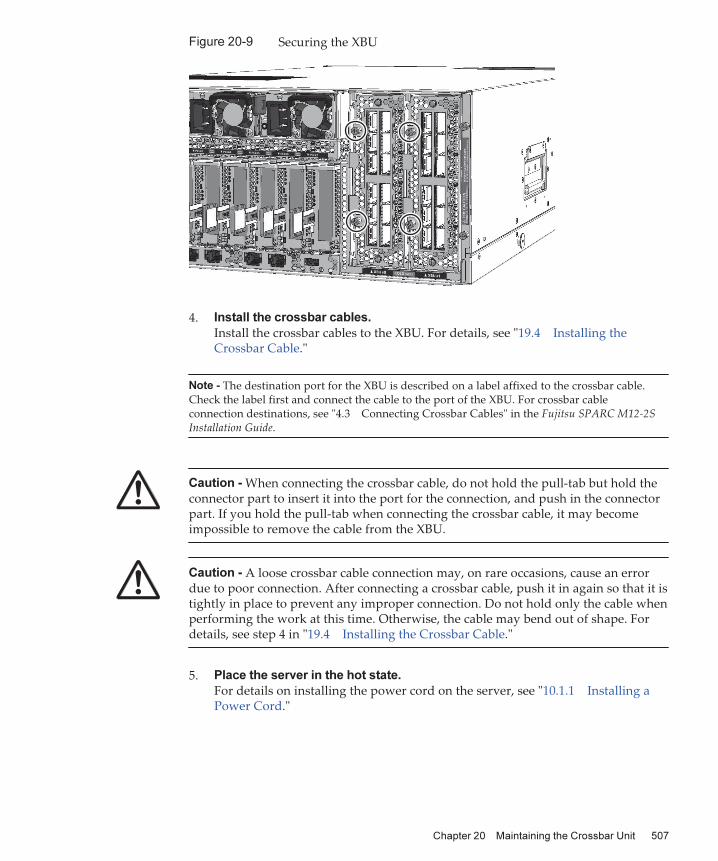
Note - The destination port for the XBU is described on a label affixed to the crossbar cable.Check the label first and connect the cable to the port of the XBU. For crossbar cableconnection destinations, see "4.3 Connecting Crossbar Cables" in the Fujitsu SPARC M12-2SInstallation Guide.
Caution - When connecting the crossbar cable, do not hold the pull-tab but hold the connector part to insert it into the port for the connection, and push in the connector part. If you hold the pull-tab when connecting the crossbar cable, it may become impossible to remove the cable from the XBU.
Caution - A loose crossbar cable connection may, on rare occasions, cause an error due to poor connection. After connecting a crossbar cable, push it in again so that it is tightly in place to prevent any improper connection. Do not hold only the cable when performing the work at this time. Otherwise, the cable may bend out of shape. For details, see step 4 in "19.4 Installing the Crossbar Cable."
Figure
20-9 Securing the XBU
4. Install the crossbar cables.
Install the crossbar cables to the XBU. For details, see "19.4 Installing the Crossbar Cable."
5. Place the server in the hot state.
For details on installing the power cord on the server, see "10.1.1 Installing a Power Cord."
Chapter
20
Maintaining
the
Crossbar
Unit 507

Figure
20-10 Installing the Power Cord
Fujitsu
SPARC
M12-2/M12-2S
Service
Manual ・ June 2021508

Note - The XSCF DUAL control cable is used in a building block configuration consisting ofmultiple SPARC M12-2S units.
Chapter
21
Maintaining
the
XSCF
DUAL
Control
Cable
This chapter describes the maintenance procedures for the XSCF DUAL control cable.
■ XSCF DUAL Control Port
■ Before Maintenance on the XSCF DUAL Control Cable
■ Removing the XSCF DUAL Control Cable
■ Installing the XSCF DUAL Control Cable
21.1 XSCF
DUAL
Control
PortThe XSCF DUAL control cable is used to connect a SPARC M12-2S that houses the master XSCF or a crossbar box to a SPARC M12-2S that houses the standby XSCF or a crossbar box.
Connect the XSCF DUAL control cable to the XSCF DUAL control port on the rear of the SPARC M12-2S or crossbar box. Figure 21-1 shows the location of the XSCF DUAL control port.
509

(1)
(1)
Location
No.
Unit
1 XSCF DUAL control port
Figure
21-1 Location of the XSCF DUAL Control Port (SPARC M12-2S)
Figure
21-2 Location of the XSCF DUAL Control Port (Crossbar Box)
Fujitsu
SPARC
M12-2/M12-2S
Service
Manual ・ June 2021510

XSCF>
showlogs
errorDate:
Jan
30
07:25:35
UTC
2016
Code:
40000000-00b8ff0000ff0000ff-01a100210000000000000000
Status:
Warning
Occurred:
Jan
30
07:25:31.377
UTC
2016
FRU:
/BB#00/SCF_DUAL
Msg:
Board
control
error
(MBC
link
error)
21.2 Before
Maintenance
on
the
XSCF
DUAL
Control
CableWhen replacing the XSCF DUAL control cable, perform the maintenance procedure listed below.
- 4.2.14 Active/Cold Replacement Workflow of the XSCF DUAL Control Cable- 4.4.16 Inactive/Cold Replacement Workflow of the XSCF DUAL Control Cable- 4.6.15 System-Stopped/Cold Replacement Workflow of the XSCF DUAL Control
Cable
Note that a system that uses one SPARC M12-2S may be in a building block configuration connected with another SPARC M12-2S. If so, be sure to connect the SPARC M12-2S that houses the master XSCF to the SPARC M12-2S that houses the standby XSCF by using the XSCF DUAL control cable.
21.3 Removing
the
XSCF
DUAL
Control
CableThis section describes the procedure for removing the XSCF DUAL control cable.
1. Make a note of the XSCF DUAL control cable to be replaced.
Log in to the XSCF and execute the showstatus command or showlogs error command. Then, make a note of the ports connected to the XSCF DUAL control cable to be replaced. For details on the commands, see "8.2.2 Identifying a Fault."
The underlined part in the error example below indicates that an error has been found in the XSCF DUAL control cable connected to BB#00 and BB#01.
From the above error message and "Appendix A Lists of Cable Connections in a Building Block Configuration," identify the port number at the other end of the connection of the target XSCF DUAL control cable.
In this example, "BB01-DUAL" is the port number at the other end.
Chapter
21
Maintaining
the
XSCF
DUAL
Control
Cable 511

Examples of label indications
BB00-DUALBB01-DUAL
BB00-DUALBB01-DUAL
BB00-DUALBB01-DUAL
BB00-DUALBB01-DUAL
2. Write the port number on labels.
The replacement XSCF DUAL control cable comes with the labels shown in Figure 21-3. Write the connected port on these labels. For the XSCF DUAL control cable, use LABEL-E. As in the example shown in Figure 21-3, write the port number identified in step 1 on two labels.
Figure
21-3 Accompanying Labels and Examples of Label Indications
3. Place the server in the cold state.
To perform maintenance after every SPARC M12-2S was placed in the cold state without using the maintenance menu, remove the power cords of every SPARC M12-2S. For details on handling power cords, see "9.8.2 Removing the Power Cords."
Fujitsu
SPARC
M12-2/M12-2S
Service
Manual ・ June 2021512

2 1
1
Figure
21-4 Removing the Power Cord
4. Remove the XSCF DUAL control cable.
Pull out the XSCF DUAL control cable (in the direction of arrow 2 in Figure 21-5) while pushing in the latches on both sides of the cable connector (in the directions of the arrows marked 1 in Figure 21-5).
Figure
21-5 Removing the XSCF DUAL Control Cable (SPARC M12-2S)
Chapter
21
Maintaining
the
XSCF
DUAL
Control
Cable 513

1
12
Caution - Do not pull the XSCF DUAL control cable itself. Otherwise, the cable may be damaged and the system may fail to operate normally.
Figure
21-6 Removing the XSCF DUAL Control Cable (Crossbar Box)
5. Remove the XSCF DUAL control cable from the other chassis.
Pull out the XSCF DUAL control cable (in the direction of arrow 2 in Figure 21-6) while pushing in the latches on both sides of the cable (in the directions of the arrows marked 1 in Figure 21-6).
21.4 Installing
the
XSCF
DUAL
Control
CableThis section describes the procedure for installing the XSCF DUAL control cable.
1. Affix labels to the XSCF DUAL control cable.
Affix the labels filled out in step 2 of "21.3 Removing the XSCF DUAL Control Cable" to the XSCF DUAL control cable (Figure 21-7).
Fujitsu
SPARC
M12-2/M12-2S
Service
Manual ・ June 2021514

Note - Affix a label 5 cm (2 in.) away from the XSCF DUAL control cable connector.
Figure
21-7 Label Affixing Positions on the XSCF DUAL Control Cable
2. Connect the XSCF DUAL control cable.
Figure
21-8 Connecting the XSCF DUAL Control Cable
3. Place the server in the hot state.
To perform maintenance after every SPARC M12-2S was placed in the cold state without using the maintenance menu, install the power cords of every SPARC M12-2S. For details on installing the power cord on the PSU, see "10.1.1
Installing a Power Cord."
Chapter
21
Maintaining
the
XSCF
DUAL
Control
Cable 515

Figure
21-9 Installing the Power Cord
Fujitsu
SPARC
M12-2/M12-2S
Service
Manual ・ June 2021516

Note - The XSCF BB control cable is used in a building block configuration consisting ofmultiple SPARC M12-2S units.
Chapter
22
Maintaining
the
XSCF
BB
Control
Cable
This chapter describes the maintenance procedures for the XSCF BB control cable.
■ XSCF BB Control Port
■ Before Maintenance on the XSCF BB Control Cable
■ Removing the XSCF BB Control Cable
■ Installing the XSCF BB Control Cable
22.1 XSCF
BB
Control
PortThe XSCF BB control cable is used in a building block configuration consisting of multiple SPARC M12-2S units to connect the XSCFs of those SPARC M12-2S units.
Connect the XSCF BB control cable to the XSCF BB control port on the rear of the server. Figure 22-1 shows the locations of the XSCF BB control ports.
517

(3) (2) (1)
Location
No.
Unit
1 XSCF BB control port (XSCF0)
2 XSCF BB control port (XSCF1)
3 XSCF BB control port (XSCF2)
Figure
22-1 Location of the XSCF BB Control Port (SPARC M12-2S)
22.2 Before
Maintenance
on
the
XSCF
BB
Control
CableWhen replacing the XSCF BB control cable, perform one of the maintenance procedures listed below.
- 4.2.15 Active/Cold Replacement Workflow of the XSCF BB Control Cable- 4.4.17 Inactive/Cold Replacement Workflow of the XSCF BB Control Cable- 4.6.16 System-Stopped/Cold Replacement Workflow of the XSCF BB Control Cable
When implementing a building block configuration by connecting multiple SPARC M12-2S units for a system that uses only one SPARC M12-2S unit, check the connection destinations of the XSCF BB control cable in "Appendix A Lists of Cable Connections in a Building Block Configuration."
Fujitsu
SPARC
M12-2/M12-2S
Service
Manual ・ June 2021518

XSCF>
showlogs
errorDate:
Feb
12
20:23:38
JST
2016
Code:
80000080-00b00000b7ff00b001-01a100270000000000000000
Status:
Alarm
Occurred:
Feb
12
20:23:38.337
JST
2016
FRU:
/BB#00/XSCFU,/BB#00/SCF_CBL#0,/BB#01/XSCFU,*
Msg:
XSCF
data
synchronization
failed
22.3 Removing
the
XSCF
BB
Control
CableThis section describes the procedure for removing the XSCF BB control cable.
1. Make a note of the XSCF BB control cable to be replaced.
Log in to the XSCF and execute the showstatus command or showlogs error command. Then, make a note of the ports connected to the XSCF BB control cable to be replaced. For details on the commands, see "8.2.2 Identifying a Fault."
The underlined part in the error example below indicates that an error has been found in the XSCF BB control cable connected to BB#00 and BB#01.
From the above error message and "Appendix A Lists of Cable Connections in a Building Block Configuration," identify the port number at the other end of the connection of the target XSCF BB control cable.In this example, "BB01-XSCF0" is the port number at the other end.
2. Write the port number on labels.
The replacement XSCF BB control cable comes with the labels shown in Figure 22-2. Write the connected port on these labels. For the XSCF BB control cable, use LABEL-E. As in the example shown in Figure 22-2, write the connected port number identified in step 1 on two labels.
Chapter
22
Maintaining
the
XSCF
BB
Control
Cable 519

Examples of label indications
BB00-SCF0BB01-SCF0
BB00-SCF0BB01-SCF0
BB00-SCF0BB01-SCF0
BB00-SCF0BB01-SCF0
Figure
22-2 Accompanying Labels and Examples of Label Indications
3. Place the server in the cold state.
To perform maintenance after every SPARC M12-2S was placed in the cold state without using the maintenance menu, remove the power cords of every SPARC M12-2S. For details on handling power cords, see "9.8.2 Removing the Power Cords."
Figure
22-3 Removing the Power Cord
4. Remove the XSCF BB control cable.
Pull out the XSCF BB control cable (in the direction of arrow 2 in Figure 22-4 and
Fujitsu
SPARC
M12-2/M12-2S
Service
Manual ・ June 2021520

2 1
1
Figure 22-5) while pushing in the latches on both sides of the cable connector (in the directions of the arrows marked 1 in Figure 22-4 and Figure 22-5).
Figure
22-4 Removing the XSCF BB Control Cable (SPARC M12-2S)
Chapter
22
Maintaining
the
XSCF
BB
Control
Cable 521

1
12
Caution - Do not pull the XSCF BB control cable itself. Otherwise, the cable may be damaged and the system may fail to operate normally.
Figure
22-5 Removing the XSCF BB Control Cable (Crossbar Box)
22.4 Installing
the
XSCF
BB
Control
CableThis section describes the procedure for installing the XSCF BB control cable.
1. Affix labels to the XSCF BB control cable.
Affix the labels filled out in step 2 of "22.3 Removing the XSCF BB Control Cable" to the XSCF BB control cable (Figure 22-6).
Fujitsu
SPARC
M12-2/M12-2S
Service
Manual ・ June 2021522

Note - Affix a label 5 cm (2 in.) away from the XSCF BB control cable connector.
Figure
22-6 Label Affixing Positions on the XSCF BB Control Cable
2. Connect the XSCF BB control cable.
Figure
22-7 Connecting the XSCF BB Control Cable
3. Place the server in the hot state.
To perform maintenance after every SPARC M12-2S was placed in the cold state without using the maintenance menu, install the power cords of every SPARC M12-2S. For details on installing the power cord on the PSU, see "10.1.1
Installing a Power Cord."
Chapter
22
Maintaining
the
XSCF
BB
Control
Cable 523

Figure
22-8 Installing the Power Cord
Fujitsu
SPARC
M12-2/M12-2S
Service
Manual ・ June 2021524

#0 #1 #2 #0 #1 #2 #0 #1 #2#0 #1 #2
BB#00 DUAL BB#01 DUAL BB#02 DUAL BB#03 DUAL
Table
A-1 Correspondence Table of XSCF DUAL Control Cable and XSCF BB Control
Cable Connections
Connection
Order
Combination of Connection Ports 2BB
Configuration
3BB
Configuration
4BB
Configuration
1 /BB#00/XSCFU-DUAL
--- /BB#01/XSCFU-DUAL
Available Available Available
/BB#00/XSCFU#0 --- /BB#01/XSCFU#0 Available Available Available
2 /BB#00/XSCFU#1 --- /BB#02/XSCFU#0 Available Available
/BB#01/XSCFU#1 --- /BB#02/XSCFU#1 Available Available
3 /BB#00/XSCFU#2 --- /BB#03/XSCFU#0 Available
/BB#01/XSCFU#2 --- /BB#03/XSCFU#1 Available
Appendix
A
Lists
of
Cable
Connections
in
a
Building
Block
Configuration
This appendix contains the connection diagrams and cable configuration lists of the XSCF cables and crossbar cables in a 4BB configuration.
Figure A-1 shows the connection diagram of the XSCF cables. For details on XSCF cables, see "Table A-1."
Figure
A-1 Connection Diagram of the XSCF Cables
Figure A-2 shows the connection diagram of the crossbar cables. The numbers in the parentheses indicate the order in which the cables are to be connected. For information on crossbar cables, see "Table A-2."
525

XBU#0
0L 0L
0R 0R
1L 1L
1R 1R
2L 2L
2R 2R
XBU#1
0L 0L
0R 0R
1L 1L
1R 1R
2L 2L
2R 2R
BB#00
XBU#0
0L 0L
0R 0R
1L 1L
1R 1R
2L 2L
2R 2R
XBU#1
0L 0L
0R 0R
1L 1L
1R 1R
2L 2L
2R 2R
BB#01
XBU#0
0L 0L
0R 0R
1L 1L
1R 1R
2L 2L
2R 2R
XBU#1
0L 0L
0R 0R
1L 1L
1R 1R
2L 2L
2R 2R
BB#02
XBU#0
0L 0L
0R 0R
1L 1L
1R 1R
2L 2L
2R 2R
XBU#1
0L 0L
0R 0R
1L 1L
1R 1R
2L 2L
2R 2R
BB#03
(1)
(3)
(7) (8)(9) (10)
(11) (12)
(4)
(2) (6)(5)
Figure
A-2 Connection Diagram of the Crossbar Cables
Fujitsu
SPARC
M12-2/M12-2S
Service
Manual ・ June 2021526

Table
A-2 Correspondence Table of the Crossbar Cable Connections
Connection
OrderCombination of Connection Ports
2BB
Configuration
3BB
Configuration
4BB
Configuration
1 /BB#00/XBU#0 - 0L (pink) --- /BB#01/XBU#0 - 0L (pink) Available Available Available
/BB#00/XBU#0 - 0L (black) --- /BB#01/XBU#0 - 0L (black) Available Available Available
/BB#00/XBU#0 - 0R (light blue)
--- /BB#01/XBU#0 - 0R (light blue)
Available Available Available
/BB#00/XBU#0 - 0R (black) --- /BB#01/XBU#0 - 0R (black) Available Available Available
2 /BB#00/XBU#1 - 0L (pink) --- /BB#01/XBU#1 - 0L (pink) Available Available Available
/BB#00/XBU#1 - 0L (black) --- /BB#01/XBU#1 - 0L (black) Available Available Available
/BB#00/XBU#1 - 0R (light blue)
--- /BB#01/XBU#1 - 0R (light blue)
Available Available Available
/BB#00/XBU#1 - 0R (black) --- /BB#01/XBU#1 - 0R (black) Available Available Available
3 /BB#01/XBU#0 - 2L (pink) --- /BB#02/XBU#0 - 2L (pink) Available Available
/BB#01/XBU#0 - 2L (black) --- /BB#02/XBU#0 - 2L (black) Available Available
/BB#01/XBU#0 - 2R (light blue)
--- /BB#02/XBU#0 - 2R (light blue)
Available Available
/BB#01/XBU#0 - 2R (black) --- /BB#02/XBU#0 - 2R (black) Available Available
4 /BB#01/XBU#1 - 2L (pink) --- /BB#02/XBU#1 - 2L (pink) Available Available
/BB#01/XBU#1 - 2L (black) --- /BB#02/XBU#1 - 2L (black) Available Available
/BB#01/XBU#1 - 2R (light blue)
--- /BB#02/XBU#1 - 2R (light blue)
Available Available
/BB#01/XBU#1 - 2R (black) --- /BB#02/XBU#1 - 2R (black) Available Available
5 /BB#00/XBU#0 - 1L (pink) --- /BB#02/XBU#0 - 1L (pink) Available Available
/BB#00/XBU#0 - 1L (black) --- /BB#02/XBU#0 - 1L (black) Available Available
/BB#00/XBU#0 - 1R (light blue)
--- /BB#02/XBU#0 - 1R (light blue)
Available Available
/BB#00/XBU#0 - 1R (black) --- /BB#02/XBU#0 - 1R (black) Available Available
6 /BB#00/XBU#1 - 1L (pink) --- /BB#02/XBU#1 - 1L (pink) Available Available
/BB#00/XBU#1 - 1L (black) --- /BB#02/XBU#1 - 1L (black) Available Available
/BB#00/XBU#1 - 1R (light blue)
--- /BB#02/XBU#1 - 1R (light blue)
Available Available
/BB#00/XBU#1 - 1R (black) --- /BB#02/XBU#1 - 1R (black) Available Available
7 /BB#02/XBU#0 - 0L (pink) --- /BB#03/XBU#0 - 0L (pink) Available
/BB#02/XBU#0 - 0L (black) --- /BB#03/XBU#0 - 0L (black) Available
/BB#02/XBU#0 - 0R (light blue)
--- /BB#03/XBU#0 - 0R (light blue)
Available
/BB#02/XBU#0 - 0R (black) --- /BB#03/XBU#0 - 0R (black) Available
8 /BB#02/XBU#1 - 0L (pink) --- /BB#03/XBU#1 - 0L (pink) Available
Appendix
A
Lists
of
Cable
Connections
in
a
Building
Block
Configuration 527

Table
A-2 Correspondence Table of the Crossbar Cable Connections (continued)
Connection
OrderCombination of Connection Ports
2BB
Configuration
3BB
Configuration
4BB
Configuration
/BB#02/XBU#1 - 0L (black) --- /BB#03/XBU#1 - 0L (black) Available
/BB#02/XBU#1 - 0R (light blue)
--- /BB#03/XBU#1 - 0R (light blue)
Available
/BB#02/XBU#1 - 0R (black) --- /BB#03/XBU#1 - 0R (black) Available
9 /BB#01/XBU#0 - 1L (pink) --- /BB#03/XBU#0 - 1L (pink) Available
/BB#01/XBU#0 - 1L (black) --- /BB#03/XBU#0 - 1L (black) Available
/BB#01/XBU#0 - 1R (light blue)
--- /BB#03/XBU#0 - 1R (light blue)
Available
/BB#01/XBU#0 - 1R (black) --- /BB#03/XBU#0 - 1R (black) Available
10 /BB#01/XBU#1 - 1L (pink) --- /BB#03/XBU#1 - 1L (pink) Available
/BB#01/XBU#1 - 1L (black) --- /BB#03/XBU#1 - 1L (black) Available
/BB#01/XBU#1 - 1R (light blue)
--- /BB#03/XBU#1 - 1R (light blue)
Available
/BB#01/XBU#1 - 1R (black) --- /BB#03/XBU#1 - 1R (black) Available
11 /BB#00/XBU#0 - 2L (pink) --- /BB#03/XBU#0 - 2L (pink) Available
/BB#00/XBU#0 - 2L (black) --- /BB#03/XBU#0 - 2L (black) Available
/BB#00/XBU#0 - 2R (light blue)
--- /BB#03/XBU#0 - 2R (light blue)
Available
/BB#00/XBU#0 - 2R (black) --- /BB#03/XBU#0 - 2R (black) Available
12 /BB#00/XBU#1 - 2L (pink) --- /BB#03/XBU#1 - 2L (pink) Available
/BB#00/XBU#1 - 2L (black) --- /BB#03/XBU#1 - 2L (black) Available
/BB#00/XBU#1 - 2R (light blue)
--- /BB#03/XBU#1 - 2R (light blue)
Available
/BB#00/XBU#1 - 2R (black) --- /BB#03/XBU#1 - 2R (black) Available
Fujitsu
SPARC
M12-2/M12-2S
Service
Manual ・ June 2021528

Table
B-1 Serial Port
Pin Arrangement Pin
Number
Signal
Name
Input/Output Description
1 RTS Output Transmission request
2 DTR Output Data terminal ready
3 TXD Output Transmitted data
4 GND --- Ground
5 GND --- Ground
6 RXD Input Received data
7 DSR Input Data set ready
8 CTS Input Transmission possible
Appendix
B
External
Interface
Specifications
This appendix provides the specifications of the external interface connectors and XSCF switch mounted on the SPARC M12-2/M12-2S.
The following external interface connectors are mounted on the SPARC M12-2/M12-2S:■ Serial Port
■ USB Port
■ SAS Port
The following XSCF switch is mounted on the SPARC M12-2/M12-2S: ■ RESET Switch
B.1 Serial
PortTable B-1 lists the specifications of the serial port on the SPARC M12-2/M12-2S.
529

Table
B-2 USB 2.0 Port (Front)
Pin Arrangement Pin
Number
Signal
Name
Input/Output Description
1234
1 VBUS Output Power supply
2 -DATA Input/Output
Data
3 +DATA Input/Output
Data
4 GND --- Ground
Table
B-3 USB 3.0 Port (Rear)
Pin Arrangement Pin
Number
Signal
Name
Input/Output Description
1234
5 6 7 8 9
1 VBUS Output Power supply
2 -DATA Input/Output
Data
3 +DATA Input/Output
Data
B.1.1 Wire
Connection
Chart
for
Serial
Cables
Figure
B-1 Wire Connection Chart for Serial Cables
B.2 USB
PortTable B-2, Table B-3, and Table B-4 list the specifications of the USB port on the SPARC M12-2/M12-2S.
Fujitsu
SPARC
M12-2/M12-2S
Service
Manual ・ June 2021530

Table
B-3 USB 3.0 Port (Rear) (continued)
Pin Arrangement Pin
Number
Signal
Name
Input/Output Description
4 GND --- Ground
5 -SSRX Input SuperSpeed data
6 +SSRX Input SuperSpeed data
7 GND --- Ground
8 -SSTX Output SuperSpeed data
9 +SSTX Output SuperSpeed data
Table
B-4 USB Port for Maintenance (Rear)
Pin Arrangement Pin
Number
Signal
Name
Input/Output Description
1234
1 VBUS Output Power supply
2 -DATA Input/Output
Data
3 +DATA Input/Output
Data
4 GND --- Ground
B.3 SAS
PortThe SAS port on the SPARC M12-2/M12-2S is used to connect external devices that have an SAS interface, such as a tape drive. The chassis has one SAS port on the rear.Consult our service engineer about compatible equipment.
B.4 RESET
SwitchThe RESET switch on the SPARC M12-2/M12-2S is an emergency switch for rebooting the XSCF. For details on how to use the RESET switch, see "18.2
Precautions Concerning Using the RESET Switch" in the Fujitsu SPARC M12 and Fujitsu M10/SPARC M10 System Operation and Administration Guide.The following diagrams show the location of the RESET switch: Figure B-2 for the SPARC M12-2, and Figure B-3 for the SPARC M12-2S. The RESET switch (A in Figure B-2 and Figure B-3) is mounted on the rear of the chassis.
Appendix
B
External
Interface
Specifications 531

A
A
Figure
B-2 Location of the RESET Switch (SPARC M12-2)
Figure
B-3 Location of the RESET Switch (SPARC M12-2S)
Fujitsu
SPARC
M12-2/M12-2S
Service
Manual ・ June 2021532

Note - Perform this work only when disassembling the product for disposal or recycling.
(1)
Location No. Component
1 Lithium battery
Appendix
C
Removing
the
Lithium
Battery
This appendix describes the procedure for removing the lithium battery mounted in the XSCF unit.
C.1 Location
of
the
Lithium
BatteryThis section describes the location of the lithium battery.One lithium battery is mounted in the SPARC M12-2/M12-2S XSCF unit.For details on removing the XSCF unit, see "11.4 Removing the XSCFU."
Figure
C-1 Location of the Lithium Battery
533

C.2 Removing
the
Lithium
BatteryThis section describes the procedure for removing the lithium battery.
1. Insert a flathead screwdriver or another fine-tipped tool between the lithium
battery and battery holder, and pry the battery from the holder.
Figure
C-2 Removing the Lithium Battery (1)
2. Gripping the lithium battery at the top with needle-nose pliers or another
fine-tipped tool, pull up the lithium battery to remove it.
Figure
C-3 Removing the Lithium Battery (2)
Fujitsu
SPARC
M12-2/M12-2S
Service
Manual ・ June 2021534

Index
A
active/cold addition, 51, 60, 154
active/cold removal, 64, 192
active/cold replacement, 57, 76
active/hot addition, 45, 50, 60, 151
active/hot removal, 47, 54, 64, 189
active/hot replacement, 44, 49, 57, 69
active maintenance, 40
B
backplane unit, 14, 463
BB-ID switch, 24
BPU, 14, 90, 116, 142, 464
building block configuration, 525
C
CHECK LED, 23
CMU, 31, 87, 114, 140, 228
CMUL, 14, 15
CMUU, 14, 15, 158, 170, 182, 196, 209,
222, 230, 232
cold maintenance, 40
CPU memory unit, 14, 15, 435
crossbar cable, 36, 119, 144, 350, 489
crossbar unit, 13, 501
E
emergency power-off, 9
external interface, 529
F
fan backplane unit, 12, 403
fan unit, 12, 403
FANBPU, 12, 82, 109, 136, 229, 403
FANU, 12, 32, 72, 81, 100, 108, 128, 135,
229, 313, 340, 403
FRU replacement, 69
FRU, releasing of, 261
H
HDD, 12, 35, 73, 83, 101, 110, 129, 137,
152, 156, 165, 169, 177, 181, 191, 195, 204
, 208, 216, 221, 229, 231, 233, 269, 290,
359, 413
HDD backplane, 12
HDD backplane unit, 421
HDDBPU, 12, 85, 112, 138, 230, 421
hot maintenance, 40
hot replacement, 125
I
I/O devices, 267
I/O resources, 271, 360
inactive/cold addition, 51, 62, 167
inactive/cold removal, 66, 206
inactive/cold replacement, 58, 103
inactive/hot addition, 61, 164
inactive/hot removal, 65, 202
inactive/hot replacement, 57, 97
535

inactive maintenance, 40
internal storage, 12, 413
L
LED indications, 26
lithium battery, location, 533
lithium battery, removing, 533, 534
Locked mode, 25
M
maintenance, types of, 39
MEM, 15
memory, 15, 89, 115, 141, 159, 172, 183,
198, 211, 223, 435
memory information, checking of, 21
memory installation rules, 16
mode switch, 24
O
operation panel, 12, 421
operation status, checking of, 265
OPNL, 12, 22, 86, 113, 139, 230, 308, 370,
421
P
PCI expansion unit, 74, 93, 102, 121, 130,
148, 153, 161, 166, 174, 178, 184, 191, 199
, 205, 212, 217, 224
PCICS, 13
PCIe card, 71, 78, 98, 106, 126, 152, 155,
164, 168, 177, 180, 190, 193, 203, 207, 219
, 229, 231, 233, 288, 357, 383, 386, 387, 391
PCIe card cassette, 13
PCIe card slot, 34
PCIe endpoint, 363
port for crossbar cable connection, 13
POWER LED, 23
power supply unit, 13, 397
power switch, 24
PSU, 13, 14, 33, 72, 79, 99, 107, 127, 134
, 229, 314, 342, 397
PSU backplane unit, 463
PSUBP, 91, 117, 143, 464
PSUBPU, 14
R
resource usage status, checking of, 265
RFID tag, 5
root complex, 362
S
SD card, 378
Service mode, 25
setting information, 329
SR-IOV virtual function, 364
SSD, 35, 73, 83, 101, 110, 129, 137, 152,
156, 165, 169, 177, 181, 191, 195, 204, 208
, 216, 221, 229, 231, 233, 269, 290, 359, 413
standard label, 3
system configuration, checking of, 235
system locator, 28
system nameplate label, 4
system-stopped, 125
system-stopped/cold addition, 52, 63, 180
system-stopped/cold removal, 47, 55, 219
system-stopped/cold replacement, 44, 49, 59,
131
system-stopped/hot addition, 45, 51, 62, 176
system-stopped/hot removal, 47, 54, 215
system-stopped/hot replacement, 44, 49, 58
system-stopped maintenance, 40
T
troubleshooting, 248
U
units, locations of, 11
units, names of, 11
V
virtual I/O devices, 367
W
warning labels, 2
wrist strap, 7
Fujitsu
SPARC
M12-2/M12-2S
Service
Manual ・ June 2021536

X
XBU, 13, 120, 145, 350
XML file, 330
XSCF BB control cable, 36, 96, 123, 147, 517
XSCF BB control port, 13
XSCF DUAL control cable, 36, 94, 122, 146,
509
XSCF DUAL control port, 13, 509
XSCF settings information, 263, 331
XSCF shell, 307
XSCF STANDBY LED, 23
XSCF unit, 13, 373
XSCFU, 13, 30, 70, 76, 97, 104, 125, 132,
316, 343, 374, 380
Index 537

Fujitsu
SPARC
M12-2/M12-2S
Service
Manual ・ June 2021538