SPARC T5-2 Server Service Manual - Oracle Help Center
186
SPARC T5-2 Server Service Manual Part No: E28856-14 February 2019
-
Upload
khangminh22 -
Category
Documents
-
view
0 -
download
0
Transcript of SPARC T5-2 Server Service Manual - Oracle Help Center

SPARC T5-2 Server Service Manual
Part No: E28856-14February 2019


SPARC T5-2 Server Service Manual
Part No: E28856-14
Copyright © 2013, 2019, Oracle and/or its affiliates. All rights reserved.
This software and related documentation are provided under a license agreement containing restrictions on use and disclosure and are protected by intellectual property laws. Exceptas expressly permitted in your license agreement or allowed by law, you may not use, copy, reproduce, translate, broadcast, modify, license, transmit, distribute, exhibit, perform,publish, or display any part, in any form, or by any means. Reverse engineering, disassembly, or decompilation of this software, unless required by law for interoperability, isprohibited.
The information contained herein is subject to change without notice and is not warranted to be error-free. If you find any errors, please report them to us in writing.
If this is software or related documentation that is delivered to the U.S. Government or anyone licensing it on behalf of the U.S. Government, then the following notice is applicable:
U.S. GOVERNMENT END USERS: Oracle programs, including any operating system, integrated software, any programs installed on the hardware, and/or documentation,delivered to U.S. Government end users are "commercial computer software" pursuant to the applicable Federal Acquisition Regulation and agency-specific supplementalregulations. As such, use, duplication, disclosure, modification, and adaptation of the programs, including any operating system, integrated software, any programs installed on thehardware, and/or documentation, shall be subject to license terms and license restrictions applicable to the programs. No other rights are granted to the U.S. Government.
This software or hardware is developed for general use in a variety of information management applications. It is not developed or intended for use in any inherently dangerousapplications, including applications that may create a risk of personal injury. If you use this software or hardware in dangerous applications, then you shall be responsible to take allappropriate fail-safe, backup, redundancy, and other measures to ensure its safe use. Oracle Corporation and its affiliates disclaim any liability for any damages caused by use of thissoftware or hardware in dangerous applications.
Oracle and Java are registered trademarks of Oracle and/or its affiliates. Other names may be trademarks of their respective owners.
Intel and Intel Xeon are trademarks or registered trademarks of Intel Corporation. All SPARC trademarks are used under license and are trademarks or registered trademarks ofSPARC International, Inc. AMD, Opteron, the AMD logo, and the AMD Opteron logo are trademarks or registered trademarks of Advanced Micro Devices. UNIX is a registeredtrademark of The Open Group.
This software or hardware and documentation may provide access to or information about content, products, and services from third parties. Oracle Corporation and its affiliates arenot responsible for and expressly disclaim all warranties of any kind with respect to third-party content, products, and services unless otherwise set forth in an applicable agreementbetween you and Oracle. Oracle Corporation and its affiliates will not be responsible for any loss, costs, or damages incurred due to your access to or use of third-party content,products, or services, except as set forth in an applicable agreement between you and Oracle.
Access to Oracle Support
Oracle customers that have purchased support have access to electronic support through My Oracle Support. For information, visit http://www.oracle.com/pls/topic/lookup?ctx=acc&id=info or visit http://www.oracle.com/pls/topic/lookup?ctx=acc&id=trs if you are hearing impaired.

Référence: E28856-14
Copyright © 2013, 2019, Oracle et/ou ses affiliés. Tous droits réservés.
Ce logiciel et la documentation qui l'accompagne sont protégés par les lois sur la propriété intellectuelle. Ils sont concédés sous licence et soumis à des restrictions d'utilisation etde divulgation. Sauf stipulation expresse de votre contrat de licence ou de la loi, vous ne pouvez pas copier, reproduire, traduire, diffuser, modifier, accorder de licence, transmettre,distribuer, exposer, exécuter, publier ou afficher le logiciel, même partiellement, sous quelque forme et par quelque procédé que ce soit. Par ailleurs, il est interdit de procéder à touteingénierie inverse du logiciel, de le désassembler ou de le décompiler, excepté à des fins d'interopérabilité avec des logiciels tiers ou tel que prescrit par la loi.
Les informations fournies dans ce document sont susceptibles de modification sans préavis. Par ailleurs, Oracle Corporation ne garantit pas qu'elles soient exemptes d'erreurs et vousinvite, le cas échéant, à lui en faire part par écrit.
Si ce logiciel, ou la documentation qui l'accompagne, est livré sous licence au Gouvernement des Etats-Unis, ou à quiconque qui aurait souscrit la licence de ce logiciel pour lecompte du Gouvernement des Etats-Unis, la notice suivante s'applique :
U.S. GOVERNMENT END USERS: Oracle programs, including any operating system, integrated software, any programs installed on the hardware, and/or documentation,delivered to U.S. Government end users are "commercial computer software" pursuant to the applicable Federal Acquisition Regulation and agency-specific supplementalregulations. As such, use, duplication, disclosure, modification, and adaptation of the programs, including any operating system, integrated software, any programs installed on thehardware, and/or documentation, shall be subject to license terms and license restrictions applicable to the programs. No other rights are granted to the U.S. Government.
Ce logiciel ou matériel a été développé pour un usage général dans le cadre d'applications de gestion des informations. Ce logiciel ou matériel n'est pas conçu ni n'est destiné à êtreutilisé dans des applications à risque, notamment dans des applications pouvant causer un risque de dommages corporels. Si vous utilisez ce logiciel ou ce matériel dans le cadred'applications dangereuses, il est de votre responsabilité de prendre toutes les mesures de secours, de sauvegarde, de redondance et autres mesures nécessaires à son utilisation dansdes conditions optimales de sécurité. Oracle Corporation et ses affiliés déclinent toute responsabilité quant aux dommages causés par l'utilisation de ce logiciel ou matériel pour desapplications dangereuses.
Oracle et Java sont des marques déposées d'Oracle Corporation et/ou de ses affiliés. Tout autre nom mentionné peut correspondre à des marques appartenant à d'autres propriétairesqu'Oracle.
Intel et Intel Xeon sont des marques ou des marques déposées d'Intel Corporation. Toutes les marques SPARC sont utilisées sous licence et sont des marques ou des marquesdéposées de SPARC International, Inc. AMD, Opteron, le logo AMD et le logo AMD Opteron sont des marques ou des marques déposées d'Advanced Micro Devices. UNIX est unemarque déposée de The Open Group.
Ce logiciel ou matériel et la documentation qui l'accompagne peuvent fournir des informations ou des liens donnant accès à des contenus, des produits et des services émanant detiers. Oracle Corporation et ses affiliés déclinent toute responsabilité ou garantie expresse quant aux contenus, produits ou services émanant de tiers, sauf mention contraire stipuléedans un contrat entre vous et Oracle. En aucun cas, Oracle Corporation et ses affiliés ne sauraient être tenus pour responsables des pertes subies, des coûts occasionnés ou desdommages causés par l'accès à des contenus, produits ou services tiers, ou à leur utilisation, sauf mention contraire stipulée dans un contrat entre vous et Oracle.
Accès aux services de support Oracle
Les clients Oracle qui ont souscrit un contrat de support ont accès au support électronique via My Oracle Support. Pour plus d'informations, visitez le site http://www.oracle.com/pls/topic/lookup?ctx=acc&id=info ou le site http://www.oracle.com/pls/topic/lookup?ctx=acc&id=trs si vous êtes malentendant.

Contents
Using This Documentation ................................................................................ 11Product Documentation Library ....................................................................... 11Feedback ...................................................................................................... 11
Identifying Components .................................................................................... 13Front Panel Components (Service) ................................................................... 13Rear Panel Components (Service) .................................................................... 15Internal System Cables ................................................................................... 16
Related Information ............................................................................... 16Internal Component Locations ......................................................................... 17Motherboard Component Locations .................................................................. 21I/O Component Locations ............................................................................... 22Power Distribution and Fan Module Component Locations ................................... 24System Schematic .......................................................................................... 25Component Task Reference ............................................................................. 28
Detecting and Managing Faults ........................................................................ 31Understanding Diagnostics .............................................................................. 31
Diagnostics Process ............................................................................... 32Tool Availability ................................................................................... 34▼ Log In to Oracle ILOM (Service) ........................................................ 35Oracle ILOM Service-Related Tools ......................................................... 35
Interpreting LEDs .......................................................................................... 36Front Panel Controls and LEDs ............................................................... 37Rear Panel Controls and LEDs ................................................................ 39
Configuring POST ......................................................................................... 40POST Overview .................................................................................... 41Oracle ILOM Properties That Affect POST Behavior ................................... 41
5

Contents
▼ Configure POST .............................................................................. 43▼ Run POST With Maximum Testing ..................................................... 45
Managing Faults ............................................................................................ 46PSH Overview ...................................................................................... 46▼ Check for Faults .............................................................................. 46▼ Clear a Fault ................................................................................... 49
Interpreting Log Files and System Messages ...................................................... 50▼ Check the Message Buffer ................................................................. 50▼ View Log Files (Oracle Solaris) .......................................................... 50▼ View Log Files (Oracle ILOM) .......................................................... 51
Preparing for Service ........................................................................................ 53Safety Information ......................................................................................... 53
Safety Symbols ..................................................................................... 54ESD Measures ...................................................................................... 54Antistatic Wrist Strap Use ....................................................................... 54Antistatic Mat ....................................................................................... 55
Tools Needed For Service ............................................................................... 55Filler Panels ................................................................................................. 55▼ Find the Server Serial Number ................................................................... 56▼ Locate the Server ..................................................................................... 57Component Service Categories ........................................................................ 57Removing Power From the Server .................................................................... 58
▼ Prepare to Power Off the Server ......................................................... 59▼ Power Off the Server (Oracle ILOM) ................................................... 60▼ Power Off the Server (Power Button - Graceful) .................................... 60▼ Power Off the Server (Emergency Shutdown) ........................................ 61▼ Disconnect Power Cords ................................................................... 61
Accessing Server Components ......................................................................... 62▼ Prevent ESD Damage ....................................................................... 62▼ Extend the Server to the Service Position ............................................. 63▼ Release the CMA ............................................................................. 64▼ Remove the Server From the Rack ...................................................... 66▼ Remove the Top Cover ..................................................................... 67
Attachment of Devices During Service .............................................................. 68
Servicing Drives ................................................................................................ 69
6 SPARC T5-2 Server Service Manual • February 2019

Contents
Drive LEDs .................................................................................................. 70▼ Locate a Faulty Drive ............................................................................... 71▼ Remove a Drive ....................................................................................... 71▼ Remove a Drive Filler Panel ...................................................................... 74▼ Install a Drive ......................................................................................... 76▼ Install a Drive Filler Panel ......................................................................... 77▼ Verify Drive Functionality ......................................................................... 78
Servicing Fan Modules ..................................................................................... 81Fan Module LEDs ......................................................................................... 82▼ Locate a Faulty Fan Module ...................................................................... 83▼ Remove a Fan Module .............................................................................. 83▼ Install a Fan Module ................................................................................. 86▼ Verify Fan Module Functionality ................................................................. 87
Servicing Power Supplies ................................................................................. 89Power Supply LEDs ...................................................................................... 89▼ Locate a Faulty Power Supply .................................................................... 91▼ Remove a Power Supply ........................................................................... 91▼ Install a Power Supply .............................................................................. 93▼ Verify Power Supply Functionality .............................................................. 95
Servicing Memory Risers and DIMMs ............................................................... 97Memory Riser and DIMM FRU Names ............................................................. 97Memory Riser and DIMM Configuration ........................................................... 99DIMM Rank Classification Labels .................................................................. 100▼ Locate a Failed DIMM (LEDs) ................................................................. 100▼ Locate a Failed DIMM (Oracle ILOM) ...................................................... 102▼ Remove a Memory Riser and DIMM ......................................................... 103▼ Install a DIMM and a Memory Riser ......................................................... 106▼ Enable and Verify Newly Installed DIMMs ................................................. 109
Servicing the DVD Drive .................................................................................. 113▼ Remove a DVD Drive ............................................................................. 113▼ Install a DVD Drive ............................................................................... 114
7

Contents
Servicing the Battery ....................................................................................... 117▼ Remove the Battery ................................................................................ 117▼ Install the Battery ................................................................................... 118
Servicing PCIe Cards ...................................................................................... 121PCIe Card Configuration ............................................................................... 121I/O Root Complex Connections ...................................................................... 122▼ Remove a PCIe Card or Filler Panel .......................................................... 123▼ Install a PCIe Card or Filler Panel ............................................................. 126
Servicing the SP .............................................................................................. 129SP Firmware and Configuration ..................................................................... 129▼ Remove the SP ...................................................................................... 130▼ Install the SP ......................................................................................... 131▼ Verify SP Functionality ........................................................................... 133
Servicing the Fan Board ................................................................................. 135▼ Remove the Fan Board ............................................................................ 135▼ Install the Fan Board ............................................................................... 137▼ Verify Fan Board Functionality ................................................................. 139
Servicing the Motherboard .............................................................................. 141▼ Remove the Motherboard ......................................................................... 141▼ Install the Motherboard ........................................................................... 147▼ Reactivate RAID Volumes ....................................................................... 153▼ Verify Motherboard Functionality .............................................................. 155
Servicing the Drive Backplane ........................................................................ 157▼ Remove the Drive Backplane ................................................................... 157▼ Install the Drive Backplane ...................................................................... 159▼ Verify Drive Backplane Functionality ......................................................... 161
Servicing the PS Backplane ............................................................................ 163▼ Remove the PS Backplane ....................................................................... 163▼ Install the PS Backplane .......................................................................... 165
8 SPARC T5-2 Server Service Manual • February 2019

Contents
▼ Verify PS Backplane Functionality ............................................................. 167
Returning the Server to Operation .................................................................. 169▼ Replace the Top Cover ............................................................................ 169▼ Return the Server to the Normal Operating Position ...................................... 170▼ Attach Power Cords ................................................................................ 172▼ Power On the Server (Oracle ILOM) ......................................................... 172▼ Power On the Server (Power Button) ......................................................... 173
Glossary .......................................................................................................... 175
Index ................................................................................................................ 181
9

10 SPARC T5-2 Server Service Manual • February 2019

Using This Documentation
■ Overview – Describes how to troubleshoot and maintain the SPARC T5-2 server fromOracle.
■ Audience – Technicians, system administrators, and authorized service providers.■ Required knowledge – Advanced experience troubleshooting and replacing hardware.
Product Documentation Library
Documentation and resources for this product and related products are available at http://www.oracle.com/goto/t5-2/docs.
Feedback
Provide feedback about this documentation at http://www.oracle.com/goto/docfeedback.
Using This Documentation 11

12 SPARC T5-2 Server Service Manual • February 2019

Identifying Components
These topics identify key components of the server, including major boards and internal systemcables, as well as front and rear panel features.
■ “Front Panel Components (Service)” on page 13■ “Rear Panel Components (Service)” on page 15■ “Internal System Cables” on page 16■ “Internal Component Locations” on page 17■ “Motherboard Component Locations” on page 21■ “I/O Component Locations” on page 22■ “Power Distribution and Fan Module Component Locations” on page 24■ “System Schematic” on page 25■ “Component Task Reference” on page 28
Related Information
■ “Detecting and Managing Faults” on page 31■ “Preparing for Service” on page 53
Front Panel Components (Service)
The following figure shows the layout of the server front panel, including the power and serverlocator buttons and the various status and fault LEDs.
Note - The front panel also provides access to internal drives, the removable media drive (ifequipped), and the two front USB ports.
Identifying Components 13

Front Panel Components (Service)
No. Description Links
1 Locator LED/Locator button (white) “Front Panel Controls andLEDs” on page 37
2 Service Action Required LED (amber) “Front Panel Controls andLEDs” on page 37
3 Power/OK LED (green) “Front Panel Controls andLEDs” on page 37
4 Power button “Front Panel Controls andLEDs” on page 37
5 SP OK/Fault LED (green or amber) “Front Panel Controls andLEDs” on page 37
“Servicing the SP” on page 129
6 Three Service Action Required LEDs (amber) for FanModule (FAN), Processor (CPU), and Memory (MEM)
“Servicing Fan Modules” on page 81
“Servicing the Motherboard” on page 141
“Servicing Memory Risers andDIMMs” on page 97
7 Power Supply (PS) Fault (Service Action Required)LED (amber)
“Servicing Power Supplies” on page 89
8 Overtemperature LED (amber) “Front Panel Controls andLEDs” on page 37
9 Serial number
10 Two USB 2.0 connectors Server Installation, USB port
11 HD-15 video connector Server Installation, video port
12 SATA DVD drive “Servicing the DVD Drive” on page 113
14 SPARC T5-2 Server Service Manual • February 2019

Rear Panel Components (Service)
No. Description Links
13 Drives 0 to 5 (numbered bottom to top) “Servicing Drives” on page 69
Related Information
■ “Rear Panel Components (Service)” on page 15■ “Rear Panel Components (Service)” on page 15■ “Motherboard Component Locations” on page 21■ “I/O Component Locations” on page 22■ “Power Distribution and Fan Module Component Locations” on page 24■ “System Schematic” on page 25
Rear Panel Components (Service)
No. Description Links
1 Power supply 0 status indicator LEDs “Servicing Power Supplies” on page 89
2 Power supply 0 AC inlet
3 Power supply 1 status indicator LEDs “Servicing Power Supplies” on page 89
4 Power supply 1 AC inlet
5 Server status LEDs “Rear Panel Controls and LEDs” on page 39
Identifying Components 15

Internal System Cables
No. Description Links
6 PCIe card slots 1 to 4 “Servicing PCIe Cards” on page 121
7 10GbE Network (NET) 100/1000/10000 Mbps ports(4): NET0 to NET3
8 USB 3.0 connectors (2)
9 PCIe card slots 5 to 8 “Servicing PCIe Cards” on page 121
10 HD-15 video connector
11 Serial management (SER MGT) RJ-45 serial port
12 SP network management (NET MGT) port
Related Information
■ “Front Panel Components (Service)” on page 13■ “Internal Component Locations” on page 17■ “System Schematic” on page 25
Internal System Cables
The following table identifies the internal system cables used in the server.
Cable Description
Top cover interlock cable This cable connects the safety interlock switch on the top cover tothe power distribution board. When the top cover is removed, thisconnection is broken, which causes the server to power down.
Power supply backplane signal cable (1 ribbon cable) This cable carries signals between the power supply backplane andthe power distribution board.
Motherboard signal cable (1 ribbon cable) This cable carries signals between the power distribution board andthe motherboard.
Drive data cables (2 bundled) These cables carry data and control signals between themotherboard and the drive backplane.
Mini SAS cables (2 bundled) These cables connect the drive backplane HDD/SSD to either an on-motherboard SAS controller or to a PCI-E low-profile form factorHBA option.
Related Information■ “Internal Component Locations” on page 17
16 SPARC T5-2 Server Service Manual • February 2019

Internal Component Locations
■ “Power Distribution and Fan Module Component Locations” on page 24
Internal Component Locations
The following figures identify the replaceable component locations with the top cover removed.
Note - The 2-processor server has eight memory risers. The 1-processor server has four memoryrisers.
Identifying Components 17

Internal Component Locations
This table applies to both the 2-processor server and the 1-processor server.
No. Component Oracle ILOM Target Links
1 SP /SYS/MB/SP “Servicing the SP” on page 129
2 PCIe card (in slot 1) /SYS/MB/PCIE1
/SYS/MB/PCIE2
/SYS/MB/PCIE3
/SYS/MB/PCIE4
/SYS/MB/PCIE5
/SYS/MB/PCIE6
/SYS/MB/PCIE7
/SYS/MB/PCIE8
“Servicing PCIe Cards” on page 121
3 Power supplies /SYS/PS0 (outer) “Servicing PowerSupplies” on page 89
18 SPARC T5-2 Server Service Manual • February 2019

Internal Component Locations
No. Component Oracle ILOM Target Links
/SYS/PS1 (inner)
4 PS backplane and cover /SYS/PDB “Servicing the PSBackplane” on page 163
5 Drive backplane /SYS/SASBP “Servicing the DriveBackplane” on page 157
6 Motherboard /SYS/MB “Servicing theMotherboard” on page 141
7 Battery /SYS/MB/BAT “Servicing the Battery” on page 117
8 Processor modules and heat sinks (theseare only replaceable by replacing themotherboard)
* This processor module is not present onthe 1-processor server
/SYS/MB/CM0
/SYS/MB/CM1*
“Servicing theMotherboard” on page 141
9 Memory risers
* These memory risers are not present inthe 1-processor server
/SYS/MB/CM0/CMP/MR0
/SYS/MB/CM0/CMP/MR1
/SYS/MB/CM0/CMP/MR2
/SYS/MB/CM0/CMP/MR3
/SYS/MB/CM1/CMP/MR0*
/SYS/MB/CM1/CMP/MR1*
/SYS/MB/CM1/CMP/MR2*
/SYS/MB/CM1/CMP/MR3*
“Servicing Memory Risers andDIMMs” on page 97
10 Fan board /SYS/FANBD “Servicing the Fan Board” on page 135
11 Fan modules As viewed from front of server:
/SYS/FANBD/F0 (left front)
/SYS/FANBD/F1 (center front)
/SYS/FANBD/F2 (right front)
/SYS/FANBD/F3 (left rear)
/SYS/FANBD/F4 (center rear)
/SYS/FANBD/F5 (right rear)
“Servicing Fan Modules” on page 81
12 DVD drive /SYS/SASBP/DVD “Servicing the DVDDrive” on page 113
13 Drives /SYS/SASBP/HDD0 (bottom)
/SYS/SASBP/HDD1
/SYS/SASBP/HDD2
“Servicing Drives” on page 69
Identifying Components 19

Internal Component Locations
No. Component Oracle ILOM Target Links
/SYS/SASBP/HDD3
/SYS/SASBP/HDD4
/SYS/SASBP/HDD5 (top)
Related Information
■ “Motherboard Component Locations” on page 21■ “I/O Component Locations” on page 22■ “Power Distribution and Fan Module Component Locations” on page 24■ “System Schematic” on page 25
20 SPARC T5-2 Server Service Manual • February 2019

Motherboard Component Locations
Motherboard Component Locations
No. Component Oracle ILOM Target LInks
1 SP /SYS/MB/SP “Servicing the SP” on page 129
2 Memory riser /SYS/MB/CMn/CMP/MRn “Servicing Memory Risers andDIMMs” on page 97
3 DIMMs /SYS/MB/CMn/CMP/MRn/BOBn/CHn/D0 “Servicing Memory Risers andDIMMs” on page 97
4 Motherboard /SYS/MB “Servicing theMotherboard” on page 141
5 Battery /SYS/MB/BAT “Servicing the Battery” on page 117
Identifying Components 21

I/O Component Locations
Related Information
■ “Component Service Categories” on page 57■ “Servicing Memory Risers and DIMMs” on page 97■ “Servicing the Motherboard” on page 141■ “Servicing the Battery” on page 117
I/O Component Locations
No. Component Oracle ILOM Target LInks
1 Drives /SYS/SASBP/HDD0 (bottom)
/SYS/SASBP/HDD1
/SYS/SASBP/HDD2
/SYS/SASBP/HDD3
“ServicingDrives” on page 69
22 SPARC T5-2 Server Service Manual • February 2019

I/O Component Locations
No. Component Oracle ILOM Target LInks
/SYS/SASBP/HDD4
/SYS/SASBP/HDD5 (top)
2 Front control panel lightpipe assembly
N/A “Servicing the DriveBackplane” on page 157
3 DVD drive /SYS/SASBP/DVD “Servicing the DVDDrive” on page 113
4 Drive backplane /SYS/SASBP “Servicing the DriveBackplane” on page 157
Related Information
■ “Component Service Categories” on page 57■ “Servicing Drives” on page 69■ “Servicing the DVD Drive” on page 113■ “Servicing the Drive Backplane” on page 157
Identifying Components 23

Power Distribution and Fan Module Component Locations
Power Distribution and Fan Module Component Locations
No. Component Oracle ILOM Target Links
1 PS backplane and cover /SYS/PDB “Servicing the PSBackplane” on page 163
2 Power supplies /SYS/PS0 (outer)
/SYS/PS1 (inner)
“Servicing PowerSupplies” on page 89
3 Fan modules /SYS/FANBD/F0
/SYS/FANBD/F1
/SYS/FANBD/F2
/SYS/FANBD/F3
/SYS/FANBD/F4
“Servicing FanModules” on page 81
24 SPARC T5-2 Server Service Manual • February 2019

System Schematic
No. Component Oracle ILOM Target Links
/SYS/FANBD/F5
4 Fan board /SYS/FANBD “Servicing the FanBoard” on page 135
Related Information
■ “Component Service Categories” on page 57■ “Servicing Power Supplies” on page 89■ “Servicing the PS Backplane” on page 163■ “Servicing Fan Modules” on page 81■ “Servicing the Fan Board” on page 135
System Schematic
These schematic diagrams show the connections between and among components and deviceslots on the 2-processor server and the 1-processor server. Use these schematic diagrams todetermine the optimum locations for optional cards or other peripherals, based on your system'sconfiguration and intended use.
Note - For more detail on root-complexes related to the PCIe slots, see “I/O Root ComplexConnections” on page 122.
Identifying Components 25

System Schematic
FIGURE 1 Schematic Diagram for a 2-Processor Server
26 SPARC T5-2 Server Service Manual • February 2019

System Schematic
FIGURE 2 Schematic Diagram for a 1-Processor Server
Identifying Components 27

Component Task Reference
Related Information
■ “Component Service Categories” on page 57■ “Internal Component Locations” on page 17■ “Motherboard Component Locations” on page 21■ “I/O Component Locations” on page 22■ “Power Distribution and Fan Module Component Locations” on page 24
Component Task Reference
This table lists the names of serviceable components. This table also lists the Oracle ILOMtarget and the task location for each component. Components not present on the 1-processorserver are marked with an asterisk (*).
Component Oracle ILOM Target Links
Battery /SYS/MB/BAT “Servicing the Battery” on page 117
DIMMs /SYS/MB/CMn/CMP/MRn/BOBn/CHn/D0 “Servicing Memory Risers andDIMMs” on page 97
Drive backplane /SYS/SASBP “Servicing the DriveBackplane” on page 157
Drives /SYS/SASBP/HDD0 (bottom)
/SYS/SASBP/HDD1
/SYS/SASBP/HDD2
/SYS/SASBP/HDD3
/SYS/SASBP/HDD4
/SYS/SASBP/HDD5 (top)
“Servicing Drives” on page 69
DVD drive /SYS/SASBP/DVD “Servicing the DVDDrive” on page 113
Fan board /SYS/FANBD “Servicing the FanBoard” on page 135
Fan modules As viewed from front of server:
/SYS/FANBD/F0 (left front)
/SYS/FANBD/F1 (center front)
/SYS/FANBD/F2 (right front)
/SYS/FANBD/F3 (left rear)
“Servicing FanModules” on page 81
28 SPARC T5-2 Server Service Manual • February 2019

Component Task Reference
Component Oracle ILOM Target Links
/SYS/FANBD/F4 (center rear)
/SYS/FANBD/F5 (right rear)
Front control panel light pipeassembly
N/A “Servicing the DriveBackplane” on page 157
Memory risers /SYS/MB/CM0/CMP/MR0
/SYS/MB/CM0/CMP/MR1
/SYS/MB/CM0/CMP/MR2
/SYS/MB/CM0/CMP/MR3
/SYS/MB/CM1/CMP/MR0*
/SYS/MB/CM1/CMP/MR1*
/SYS/MB/CM1/CMP/MR2*
/SYS/MB/CM1/CMP/MR3*
“Servicing Memory Risers andDIMMs” on page 97
Motherboard /SYS/MB “Servicing theMotherboard” on page 141
PCIe card (in slot 1) /SYS/MB/PCIE1
/SYS/MB/PCIE2
/SYS/MB/PCIE3
/SYS/MB/PCIE4
/SYS/MB/PCIE5
/SYS/MB/PCIE6
/SYS/MB/PCIE7
/SYS/MB/PCIE8
“Servicing PCIeCards” on page 121
Power supplies /SYS/PS0 (outer)
/SYS/PS1 (inner)
“Servicing PowerSupplies” on page 89
PS backplane and cover /SYS/PDB “Servicing the PSBackplane” on page 163
SP /SYS/MB/SP “Servicing the SP” on page 129
Related Information■ “Component Service Categories” on page 57■ “Internal Component Locations” on page 17■ “Motherboard Component Locations” on page 21
Identifying Components 29

Component Task Reference
■ “I/O Component Locations” on page 22■ “Power Distribution and Fan Module Component Locations” on page 24
30 SPARC T5-2 Server Service Manual • February 2019

Detecting and Managing Faults
These topics explain how to use various diagnostic tools to monitor server status andtroubleshoot faults in the server. The examples use the PSH fmadm faulty command.
■ “Understanding Diagnostics” on page 31■ “Interpreting LEDs” on page 36■ “Configuring POST” on page 40■ “Managing Faults” on page 46■ “Interpreting Log Files and System Messages” on page 50
Related Information
■ “Identifying Components” on page 13■ “Preparing for Service” on page 53■ “Component Service Categories” on page 57■ “Returning the Server to Operation” on page 169
Understanding Diagnostics
These topics explain the diagnostic process and tools.
■ “Diagnostics Process” on page 32■ “Tool Availability” on page 34■ “Log In to Oracle ILOM (Service)” on page 35■ “Oracle ILOM Service-Related Tools” on page 35
Detecting and Managing Faults 31
Understanding Diagnostics
Diagnostics Process
Depending on the fault, you might need to perform all of the steps or just some of them. Youalso might have to run diagnostic software that needs to be installed or enabled.
32 SPARC T5-2 Server Service Manual • February 2019

Understanding Diagnostics
Note - The diagnostic tools you use, and the order in which you use them, depend on the natureof the problem you are troubleshooting. However, for descriptive purposes, this table followsthe steps given in the illustration.
Detecting and Managing Faults 33

Understanding Diagnostics
Step Diagnostic Action Possible Outcome Links
1. Confirm that the Power OKand AC OK LEDs are lit.
If these LEDs are not lit, check the power source andpower connections to the server.
“Interpreting LEDs” on page 36
2. Check the server for detectedfaults.
Use these tools to check for faults:
■ System LEDs on the front and rear panels.■ fmadm faulty from the Oracle Solaris prompt or
through the Oracle ILOM fault management shell.■ show faulty from the Oracle ILOM. prompt or
through the Open Problems BUI■ Datacenter management tools, such as Oracle
Enterprise Manager Ops Center.
“Check for Faults” on page 46
3. Check the log files for faultinformation.
If system messages indicate a faulty component, replaceit.
“Interpreting Log Files and SystemMessages” on page 50
4. Run Oracle VTS software. To run Oracle VTS, the server must be running theOracle Solaris OS.
■ If Oracle VTS reports a faulty component, replace it.■ If Oracle VTS does not report a faulty component,
run POST.
■ Refer to the Oracle VTS softwaredocumentation.
■ “ConfiguringPOST” on page 40
■ Contact technical support if theproblem persists.
Related Information
■ “Tool Availability” on page 34■ “Log In to Oracle ILOM (Service)” on page 35■ “Oracle ILOM Service-Related Tools” on page 35
Tool Availability
This table describes what tools are available at the different states in which the server operates.
Tool Standby Power OpenBoot Prompt Oracle SolarisPrompt
Status LEDs Yes Yes Yes
PSH commands Yes No Yes
Oracle ILOM logs and commands Yes No No
OpenBoot commands No Yes No
Oracle Solaris logs and commands No No Yes
Oracle VTS No No Yes (if installed)
Third-party software No No Yes (if installed)
34 SPARC T5-2 Server Service Manual • February 2019

Log In to Oracle ILOM (Service)
Related Information
■ “Diagnostics Process” on page 32■ “Log In to Oracle ILOM (Service)” on page 35■ “Oracle ILOM Service-Related Tools” on page 35
Log In to Oracle ILOM (Service)At the terminal prompt, type:
ssh root@IP-addressPassword: passwordWaiting for daemons to initialize...
Daemons ready
Oracle (R) Integrated Lights Out Manager
Version 3.1.x
Copyright (c) 2013, Oracle and/or its affiliates, Inc. All rights reserved.
->
Related Information
■ “Diagnostics Process” on page 32■ “Tool Availability” on page 34■ “Oracle ILOM Service-Related Tools” on page 35
Oracle ILOM Service-Related Tools
You can use these Oracle ILOM CLI commands when performing service-related tasks.
Oracle ILOM Command Description
help [command] Displays a list of all available Oracle ILOM commandswith syntax and descriptions. Specifying a command nameas an option displays help for that command.
set /HOST send_break_action=break Takes the host server from the OS to either kmdb orOpenBoot prompt (equivalent to a Stop-A), depending onthe mode in which the Oracle Solaris OS was booted.
start /HOST/console Connects to the host.
show /HOST/console/history Displays the contents of the host's console buffer.
Detecting and Managing Faults 35

Interpreting LEDs
Oracle ILOM Command Description
set /HOST/bootmode property=value Controls the method of booting for the host server'sfirmware. The value of property can be state, config, orscript.
stop /System
or stop /SYS
Powers off the host server.
start /System
or start /SYS
Powers on the host server.
reset /System
or reset /SYS
Generates a hardware reset on the host server.
reset /SP Reboots the SP.
Related Information■ “Diagnostics Process” on page 32■ “Tool Availability” on page 34■ “Log In to Oracle ILOM (Service)” on page 35
Interpreting LEDsUse these steps to determine if an LED indicates that a component has failed in the server.
Steps Description Links
1. Check the LEDs on the front and rear of the server. ■ “Front Panel Controls andLEDs” on page 37
■ “Rear Panel Controls andLEDs” on page 39
2. Check the LEDs on the individual components.Note - Component LEDs might not be liteven though the component is faulty. Use theinstructions in these links to determine if thecomponent has been diagnosed as being faulty.
■ “Servicing Drives” on page 69■ “Servicing Fan Modules” on page 81■ “Servicing Power Supplies” on page 89■ “Servicing Memory Risers and
DIMMs” on page 97■ “Servicing PCIe Cards” on page 121■ “Servicing the Motherboard” on page 141
Related Information■ “Understanding Diagnostics” on page 31
36 SPARC T5-2 Server Service Manual • February 2019

Interpreting LEDs
■ “Managing Faults” on page 46
Front Panel Controls and LEDs
No. LED Icon or Label Description
1 Locator LED andbutton
(white)
You can turn on the Locator LED to identify a particular server. When lit, the LED blinksrapidly. Turn on the Locator LED by pressing the Locator button, or see “Locate theServer” on page 57.
2 Service RequiredLED
(amber)
The fmadm faulty command provides details about any faults that cause this indicator tolight. See “Check for Faults” on page 46.
Under some fault conditions, individual component fault LEDs are lit in addition to theService Required LED.
3 Power OK LED
(green)
Indicates these conditions:
■ Off – Server is not running in its normal state. Server power might be off. The SPmight be running.
■ Steady on – Server is powered on and is running in its normal operating state. Noservice actions are required.
■ Fast blink – Server is running in standby mode and can be quickly returned to fullfunction.
■ Slow blink – A normal but transitory activity is taking place. Slow blinking mightindicate that server diagnostics are running or that the server is booting.
Detecting and Managing Faults 37

Interpreting LEDs
No. LED Icon or Label Description
4 Power button The recessed Power button toggles the server on or off. See “Power Off the Server(Power Button - Graceful)” on page 60.
5 SP LED SP Indicates these conditions:
■ Off – AC power might have been connected to the power supplies.■ Steady on, green – SP is running in its normal operating state. No service actions are
required.■ Blink, green – SP is initializing the Oracle ILOM firmware.■ Steady on, amber – An SP error has occurred and service is required.
6 Fan Module FaultLED
(amber)
FAN Indicates these conditions:
■ Off – Steady state, no service action is required.■ Steady on – A fan module failure event has been acknowledged and a service action
is required on at least one of the fan modules.
6 CPU Fault LED
(amber)
CPU Indicates these conditions:
■ Off – Steady state, no service action is required.■ Steady on – A fault has been detected on one or more host processors.
6 Memory FaultLED
(amber)
MEM Indicates these conditions:
■ Off – Steady state, no service action is required.■ Steady on – A fault has been detected on one or more DIMMs.
7 Power SupplyFault LED
(amber)
PS Indicates these conditions:
■ Off – Steady state, no service action is required.■ Steady on – A fault has been detected on one of the two power supplies
8 System OvertempLED(amber)
Indicates these conditions:
■ Off – Steady state, no service action is required.■ Steady on – A temperature failure event has been acknowledged. A temperature limit
has been exceeded and a service action is required.
Related Information
■ “Rear Panel Controls and LEDs” on page 39■ “Understanding Diagnostics” on page 31
38 SPARC T5-2 Server Service Manual • February 2019

Interpreting LEDs
Rear Panel Controls and LEDs
No. LED Icon or Label Description
1 Power Supply AC OK LED AC Indicates these conditions:
■ Off – No AC power applied to this power supply.■ Green steady on – AC power is applied to this power supply and is
within specifications.■ Amber steady on – AC power is applied to this power supply and
is below 85V.
2 Power Supply DC OK LED
(green)
Indicates these conditions:
■ Off – 12V DC output from this power supply is disabled or notwithin spec.
■ Steady on – 12V DC output from this power supply is present andwithin specifications.
3 Power Supply Fault LED
(amber)
Indicates these conditions:
■ Off – Steady state, no service action is required.■ Steady on – A fault has been detected on this power supply
4 NET MGT Port Link/Activity LED
(green on left)
LINK/ACT Indicates these conditions:
■ Off – No link is established.■ Steady On – A link is established.■ Blinking – A link is established and there is activity on the port.
4 NET MGT Port Speed LED SPD Indicates these conditions:
Detecting and Managing Faults 39

Configuring POST
No. LED Icon or Label Description(green on right) ■ Off – The link is operating as a 10-Mbps connection.
■ Steady On – The link is operating as a 100-Mbps connection.
5 Locator LED and button
(white)
Turn on the Locator LED by pressing the Locator button, or see“Locate the Server” on page 57. When lit, the LED blinks rapidly.
6 Service Required LED
(amber)
The fmadm faulty command provides details about any faults thatcause this indicator to light. See “Check for Faults” on page 46.
Under some fault conditions, individual component fault LEDs are litin addition to the Service Required LED.
7 Power OK LED
(green)
Indicates these conditions:
■ Off – Server is not running in its normal state. System power mightbe off. The SP might be running.
■ Steady on – Server is powered on and is running in its normaloperating state. No service actions are required.
■ Fast blink – Server is running in standby mode and can be quicklyreturned to full function.
■ Slow blink – A normal but transitory activity is taking place. Slowblinking might indicate that system diagnostics are running or thatthe system is booting.
8 Host Ethernet Port Link/Activity LED
(green)
These LEDs, from left toright, represent NET 1, NET0, NET 3, and NET 2.
Indicates these conditions:
■ Off – No link is established.■ Steady On – A link is established.■ Blinking – A link is established and there is activity on the port.
Related Information
■ “Front Panel Controls and LEDs” on page 37■ “Understanding Diagnostics” on page 31
Configuring POST
These topics explain how to configure POST as a diagnostic tool.
■ “POST Overview” on page 41■ “Oracle ILOM Properties That Affect POST Behavior” on page 41■ “Configure POST” on page 43■ “Run POST With Maximum Testing” on page 45
40 SPARC T5-2 Server Service Manual • February 2019

Configuring POST
POST OverviewPOST is a group of PROM-based tests that run when the server is powered on or when it isreset. POST checks the basic integrity of the critical hardware components in the server.
You can also set other Oracle ILOM properties to control various other aspects of POSToperations. For example, you can specify the events that cause POST to run, the level of testingPOST performs, and the amount of diagnostic information POST displays. These properties aredescribed in “Oracle ILOM Properties That Affect POST Behavior” on page 41.
If POST detects a faulty component, the component is disabled automatically. If the server isable to run without the disabled component, the server boots when POST completes its tests.For example, if POST detects a faulty processor core, the core is disabled, POST completes itstest sequence, and the server boots using the remaining cores.
Related Information■ “Oracle ILOM Properties That Affect POST Behavior” on page 41■ “Configure POST” on page 43■ “Run POST With Maximum Testing” on page 45
Oracle ILOM Properties That Affect POSTBehavior
Note - The value of keyswitch_state must be normal when individual POST parameters arechanged.
Parameter Values Description
/HOST keyswitch_state normal The server can power on and run POST (based on the otherparameter settings). This parameter overrides all othercommands.
diag The server runs POST based on predetermined settings.
standby The server cannot power on.
locked The server can power on and run POST, but no flash updatescan be made.
/HOST/diag mode off POST does not run.
normal POST runs according to diag level value.
/HOST/diag level max If diag mode=normal, runs all the minimum tests plusextensive processor and memory tests.
Detecting and Managing Faults 41

Configuring POST
Parameter Values Description
min If diag mode=normal, runs minimum set of tests.
/HOST/diag trigger none Does not run POST on reset.
hw-change (Default) Runs POST following a FRU replacement or an ACpower cycle.
hw_change_level ■ max (default) – Runs the maximum set of tests.■ min – Runs the minimum set of tests.
hw_change_verbosity ■ min (default) – Displays the minimum level of output.■ max – Displays information for each step.■ normal – Displays a moderate amount of information,
including component names and test results.■ debug – Displays extensive debugging information.■ none – Disables the output.
power-on-reset Runs POST on every power on.
power_on_level ■ max (default) – Runs the maximum set of tests.■ min – Runs the minimum set of tests.
power_on_verbosity ■ min (default) – Displays the minimum level of output.■ max – Displays information for each step.■ normal – Displays a moderate amount of information,
including component names and test results.■ debug – Displays extensive debugging information.■ none – Disables the output.
error-reset (Default) Runs POST if fatal errors are detected.
error_reset_level ■ max (default) – Runs the maximum set of tests.■ min – Runs a minimum set of tests.
error_reset_verbosity ■ min (default) – Displays the minimum level of output.■ max – Displays information for each step.■ normal – Displays a moderate amount of information,
including component names and test results.■ debug – Displays extensive debugging information.■ none – Disables the output.
all-resets Runs POST after any reset.
/HOST/diag verbosity normal Displays all test and informational messages in POST output.
min Displays functional tests with a banner and pinwheel in POSToutput.
max Displays all test, informational, and some debuggingmessages in POST output.
debug Displays extensive debugging information.
none Does not display POST output.
This flowchart illustrates the same set of Oracle ILOM set command variables.
42 SPARC T5-2 Server Service Manual • February 2019

Configure POST
Related Information
■ “POST Overview” on page 41■ “Configure POST” on page 43■ “Run POST With Maximum Testing” on page 45
Configure POST
1. Log in to Oracle ILOM.See “Log In to Oracle ILOM (Service)” on page 35.
2. Set the virtual keyswitch to the value that corresponds to the POSTconfiguration you want to run.
Detecting and Managing Faults 43

Configure POST
This example sets the virtual keyswitch to normal, which configures POST to run according toother parameter values.
-> set /HOST keyswitch_state=normal
Set keyswitch_state to Normal
For possible values for the keyswitch_state parameter, see “Oracle ILOM Properties ThatAffect POST Behavior” on page 41.
3. If the virtual keyswitch is set to normal, and you want to define the mode, level,trigger, or verbosity, set the respective parameters.Syntax:
set /HOST/diag property=value
See “Oracle ILOM Properties That Affect POST Behavior” on page 41 for a list ofparameters and values.
Examples:
-> set /HOST/diag mode=normal
-> set /HOST/diag verbosity=max
4. View the current values for settings.Example:
-> show /HOST/diag
/HOST/diag
Targets:
Properties:
error_reset_level = max
error_reset_verbosity = normal
hw_change_level = max
hw_change_verbosity = normal
level = min
mode = normal
power_on_level = max
power_on_verbosity = normal
trigger = hw_change error-reset
verbosity = normal
Commands:
44 SPARC T5-2 Server Service Manual • February 2019

Run POST With Maximum Testing
cd
set
show
->
Related Information
■ “POST Overview” on page 41■ “Oracle ILOM Properties That Affect POST Behavior” on page 41■ “Run POST With Maximum Testing” on page 45
Run POST With Maximum Testing
This procedure describes how to configure the server to run the maximum level of POST.
1. Log in to Oracle ILOM.See “Log In to Oracle ILOM (Service)” on page 35.
2. Set the virtual keyswitch to diag so that POST runs in service mode.
-> set /HOST keyswitch_state=diag
Set keyswitch_state to Diag
3. Reset the server so that POST runs.There are several ways to initiate a reset. This example shows a reset using the resetcommand.
-> reset /SYS
Are you sure you want to reset /SYS (y/n)? y
Resetting /SYS
Related Information
■ “POST Overview” on page 41■ “Oracle ILOM Properties That Affect POST Behavior” on page 41■ “Configure POST” on page 43
Detecting and Managing Faults 45

Managing Faults
Managing FaultsThese topics describe the PSH feature.
■ “PSH Overview” on page 46■ “Check for Faults” on page 46■ “Clear a Fault” on page 49
PSH Overview
PSH provides problem diagnosis on the SP and the host. Regardless of where a fault occurs,you can view and manage the fault diagnosis from the SP or the host.
When possible, PSH initiates steps to take the component offline. PSH also logs the fault to thesyslogd daemon and provides a fault notification with a message ID. You can use the messageID to get additional information about the problem from the knowledge article database.
A PSH console message provides this information about each detected fault:
■ Type■ Severity■ Description■ Automated response■ Impact■ Suggested action for system administrator
If PSH detects a faulty component, use the fmadm faulty command to display informationabout the fault. See “Check for Faults” on page 46.
Related Information■ “Check for Faults” on page 46■ “Clear a Fault” on page 49
Check for Faults
The fmadm faulty command displays the list of faults detected by PSH. You can run thiscommand from either the host or through the Oracle ILOM fault management shell.
46 SPARC T5-2 Server Service Manual • February 2019

Check for Faults
1. Log in to Oracle ILOM.See “Log In to Oracle ILOM (Service)” on page 35.
2. Check for PSH-diagnosed faults.This example shows how to check for faults through the Oracle ILOM fault management shell.
-> start /SP/faultmgmt/shell
Are you sure you want to start /SP/faultmgmt/shell (y/n)? y
faultmgmtsp> fmadm faulty
------------------- ------------------------------------ -------------- -------
Time UUID msgid Severity
------------------- ------------------------------------ -------------- -------
2012-08-27/19:46:26 4ec16c8d-5cdb-c6ca-c949-e24d3637ef27 PCIEX-8000-8R Major
Problem Status : solved
Diag Engine : [unknown]
System
Manufacturer : Oracle Corporation
Name : SPARC T5-8
Part_Number : 12345678+11+1
Serial_Number : 1238BDC0DF
----------------------------------------
Suspect 1 of 1
Fault class : fault.io.pciex.device-interr-corr
Certainty : 100%
Affects : hc:///chassis=0/motherboard=0/cpuboard=0/chip=0/hostbridge=0/
pciexrc=0
Status : faulted but still in service
FRU
Status : faulty
Location : /SYS/PM0
Manufacturer : Oracle Corporation
Name : TLA,PN,NRM,T5 1.2
Part_Number : 7061001
Revision : 01
Serial_Number : 465769T+12445102WR
Chassis
Manufacturer : Oracle Corporation
Name : SPARC T5-8
Part_Number : 12345678+13+2
Serial_Number : 1248DC140
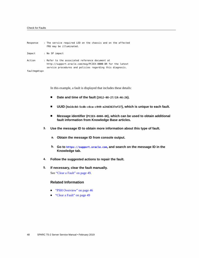
Description : A fault has been diagnosed by the Host Operation System.
Detecting and Managing Faults 47
Check for Faults
Response : The service required LED on the chassis and on the affected
FRU may be illuminated.
Impact : No SP impact
Action : Refer to the associated reference document at
http://support.oracle.com/msg/PCIEX-8000-8R for the latest
service procedures and policies regarding this diagnosis.
faultmgmtsp>
In this example, a fault is displayed that includes these details:
■ Date and time of the fault (2012-08-27/19:46:26).
■ UUID (4e16c8d-5cdb-c6ca-c949-e24d3637ef27), which is unique to each fault.
■ Message identifier (PCIEX-8000-8R), which can be used to obtain additionalfault information from Knowledge Base articles.
3. Use the message ID to obtain more information about this type of fault.
a. Obtain the message ID from console output.
b. Go to https://support.oracle.com, and search on the message ID in theKnowledge tab.
4. Follow the suggested actions to repair the fault.
5. If necessary, clear the fault manually.See “Clear a Fault” on page 49.
Related Information
■ “PSH Overview” on page 46■ “Clear a Fault” on page 49
48 SPARC T5-2 Server Service Manual • February 2019

Clear a Fault
Clear a Fault
When PSH detects faults, the faults are logged and displayed on the console. In most cases,after the fault is repaired, the corrected state is detected by the server, and the fault conditionis repaired automatically. However, this repair should be verified. In cases where the faultcondition is not automatically cleared, you must clear the fault manually.
1. After replacing a faulty FRU, power on the server.
2. At the host prompt, determine whether the replaced FRU still shows a faultystate.See “Check for Faults” on page 46.
■ If no fault is reported, you do not need to do anything else. Do not performthe subsequent steps.
■ If a fault is reported, continue to Step 3.
3. Clear the fault from all persistent fault records.In some cases, even though the fault is cleared, some persistent fault information remainsand results in erroneous fault messages at boot time. To ensure that these messages are notdisplayed, type this PSH command:
# fmadm acquit event-ID
4. If required, reset the server.In some cases, the output of the fmadm faulty command might include this message for thefaulty component:faulted and taken out of service
If this message appears in the output, you must reset the server after you manually repair thefault.
-> reset /SYS
Are you sure you want to reset /SYS? y
Resetting /SYS ...
Related Information■ “PSH Overview” on page 46■ “Check for Faults” on page 46
Detecting and Managing Faults 49

Interpreting Log Files and System Messages
Interpreting Log Files and System Messages
With the OS running on the server, you have the full complement of Oracle Solaris OS files andcommands available for collecting information and for troubleshooting.
If PSH does not indicate the source of a fault, check the message buffer and log files fornotifications for faults. Drive faults are usually captured by the Oracle Solaris message files.
These topics explain how to view the log files and system messages.
■ “Check the Message Buffer” on page 50■ “Understanding Diagnostics” on page 31■ “Managing Faults” on page 46
Check the Message Buffer
The dmesg command checks the system buffer for recent diagnostic messages and displaysthem.
1. Log in as superuser.
2. Type:
# dmesg
Related Information
■ “View Log Files (Oracle Solaris)” on page 50■ “View Log Files (Oracle ILOM)” on page 51
View Log Files (Oracle Solaris)
The error logging daemon, syslogd, automatically records various system warnings, errors, andfaults in message files. These messages can alert you to system problems such as a device thatis about to fail.
50 SPARC T5-2 Server Service Manual • February 2019

View Log Files (Oracle ILOM)
The /var/adm directory contains several message files. The most recent messages are inthe /var/adm/messages file. After a period of time (usually every week), a new messagesfile is automatically created. The original contents of the messages file are rotated to a filenamed messages.1. Over a period of time, the messages are further rotated to messages.2 andmessages.3, and then deleted.
1. Log in as superuser.
2. Type:
# more /var/adm/messages
3. To view all logged messages, type:
# more /var/adm/messages*
Related Information
■ “Check the Message Buffer” on page 50■ “View Log Files (Oracle Solaris)” on page 50
View Log Files (Oracle ILOM)1. View the event log.
-> show /SP/logs/event/list
2. View the audit log.
-> show /SP/logs/audit/list
Related Information
■ “Check the Message Buffer” on page 50■ “View Log Files (Oracle Solaris)” on page 50
Detecting and Managing Faults 51

52 SPARC T5-2 Server Service Manual • February 2019

Preparing for Service
These topics explain how to prepare the server for servicing.
Step Description Links
1. Review safety and handling information. “Safety Information” on page 53
2. Gather the tools needed for service. “Tools Needed For Service” on page 55
3. Consider filler panel options. “Filler Panels” on page 55
4. Review component service categories. “Component Service Categories” on page 57
5. Find the server serial number. “Find the Server Serial Number” on page 56
6. Identify the server to be serviced. “Locate the Server” on page 57
7. For cold-service operations, shut down the OS and removepower from the server.
“Removing Power From the Server” on page 58
8. Move the server out of the rack and gain access to internalcomponents.
“Accessing Server Components” on page 62
9. Attach devices to the server to perform service procedures. “Attachment of Devices During Service” on page 68
Related Information
■ “Identifying Components” on page 13■ “Returning the Server to Operation” on page 169
Safety Information
For your protection, observe the following safety precautions when setting up your equipment:
■ Follow all cautions and instructions marked on the equipment and described in thedocumentation shipped with your server.
■ Follow all cautions and instructions marked on the equipment and described in the SPARCT5-2 Safety and Compliance Guide.
Preparing for Service 53

Safety Information
■ Ensure that the voltage and frequency of your power source match the voltage andfrequency inscribed on the equipment's electrical rating label.
■ Follow the ESD safety practices as described in this section.
Safety Symbols
Note the meanings of the following symbols that might appear in this document:
Caution - There is a risk of personal injury or equipment damage. To avoid personal injury andequipment damage, follow the instructions.
Caution - Hot surface. Avoid contact. Surfaces are hot and might cause personal injury iftouched.
Caution - Hazardous voltages are present. To reduce the risk of electric shock and danger topersonal health, follow the instructions.
ESD Measures
ESD sensitive devices, such as the cards, drives, and DIMMS, require special handling.
Caution - Circuit boards and drives contain electronic components that are extremelysensitive to static electricity. Ordinary amounts of static electricity from clothing or the workenvironment can destroy the components located on these boards. Do not touch the componentsalong their connector edges.
Caution - You must disconnect all power supplies before servicing any of the components thatare inside the chassis.
Antistatic Wrist Strap UseWear an antistatic wrist strap and use an antistatic mat when handling components such as driveassemblies, circuit boards, or PCI cards. When servicing or removing server components, attachan antistatic strap to your wrist and then to a metal area on the chassis. Following this practiceequalizes the electrical potentials between you and the server.
54 SPARC T5-2 Server Service Manual • February 2019

Tools Needed For Service
Note - An antistatic wrist strap is no longer included in the accessory kit for this server.However, antistatic wrist straps are still included with options.
Antistatic MatPlace ESD-sensitive components such as motherboards, memory, and other PCBs on anantistatic mat.
Related Information■ “Prevent ESD Damage” on page 62■ “Tools Needed For Service” on page 55
Tools Needed For ServiceYou need the following tools for most service operations:
■ Antistatic wrist strap■ Antistatic mat■ No. 2 Phillips screwdriver■ No. 1 flat-blade screwdriver (battery removal)■ Pen or pencil (to power on server)
Related Information■ “Safety Information” on page 53
Filler PanelsA filler panel is an empty metal or plastic enclosure that is installed at the factory or in the fieldinto a server component slot that does not contain a functioning component. The filler panelsensure proper airflow through the system. Depending on the component configuration, theserver can include the following types of filler panels:
■ Drive filler■ PCIe card filler covering back panel, not filling the connector slot)
Preparing for Service 55

Find the Server Serial Number
Caution - When you remove a server component while the server is connected to power, inserta new component or filler panel within 60 seconds to ensure proper system chassis cooling.After you complete cold-servicing, ensure that all fillers are in place before connecting theserver to power.
Related Information■ “Servicing Drives” on page 69■ “Servicing the DVD Drive” on page 113■ “Servicing Memory Risers and DIMMs” on page 97■ “Servicing PCIe Cards” on page 121■ “Returning the Server to Operation” on page 169
Find the Server Serial Number
You need the serial number of the server's chassis to obtain technical support for the system.
Note - When a PDB, fan board, or drive backplane is replaced, the chassis serial number andpart number might need to be programmed into the new component. This must be done in aspecial service mode by trained service personnel.
Locate the serial number using one of the following methods:
■ Read the serial number from a sticker located on the front of the server oranother sticker on the side of the server.
■ At the Oracle ILOM prompt type:
-> show /System
/System
Targets:
. . .
In the output look for a line under Properties that identifies the product serial number. Forexample:
product_serial_number = BDL1026F8F
56 SPARC T5-2 Server Service Manual • February 2019
Locate the Server
Related Information
■ “Front Panel Components (Service)” on page 13
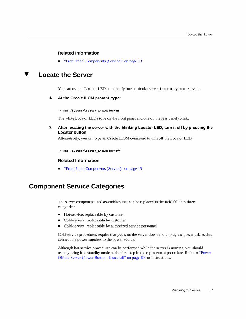
Locate the Server
You can use the Locator LEDs to identify one particular server from many other servers.
1. At the Oracle ILOM prompt, type:
-> set /System/locator_indicator=on
The white Locator LEDs (one on the front panel and one on the rear panel) blink.
2. After locating the server with the blinking Locator LED, turn it off by pressing theLocator button.Alternatively, you can type an Oracle ILOM command to turn off the Locator LED.
-> set /System/locator_indicator=off
Related Information
■ “Front Panel Components (Service)” on page 13
Component Service Categories
The server components and assemblies that can be replaced in the field fall into threecategories:
■ Hot-service, replaceable by customer■ Cold-service, replaceable by customer■ Cold-service, replaceable by authorized service personnel
Cold service procedures require that you shut the server down and unplug the power cables thatconnect the power supplies to the power source.
Although hot service procedures can be performed while the server is running, you shouldusually bring it to standby mode as the first step in the replacement procedure. Refer to “PowerOff the Server (Power Button - Graceful)” on page 60 for instructions.
Preparing for Service 57

Removing Power From the Server
The following table identifies the components in each category.
Component serviceCategory
Component Service information Notes
Hot-service, replaceable bycustomer
Drive “Servicing Drives” on page 69 Drive must be offline.
Drive filler “Servicing Drives” on page 69 Needed to preserve properinterior air flow.
Power supply “Servicing Power Supplies” on page 89 If two power supplies are inuse. Otherwise, cold service.
Fan module “Servicing Fan Modules” on page 81 Removal of a fan in the rearrow requires replacementwithin 30 seconds to avoidoverheating
Cold-service, replaceableby customer
Memory risers andDIMMs
“Servicing Memory Risers andDIMMs” on page 97
DVD drive “Servicing the DVD Drive” on page 113 Remove any media prior toreplacement.
A drive must be installed topreserve proper interior airflow.
System battery “Servicing the Battery” on page 117
I/O cards “Servicing PCIe Cards” on page 121
Cold-service, replaceableby authorized servicepersonnel
Fan board “Servicing the Fan Board” on page 135
Motherboard “Servicing the Motherboard” on page 141 Transfer system configurationPROM to new motherboard.
Drive backplane “Servicing the DriveBackplane” on page 157
PS backplane “Servicing the PS Backplane” on page 163
Related Information
■ “Component Task Reference” on page 28
Removing Power From the Server
Step Description Links
1. Prepare the server for powering off. “Prepare to Power Off the Server” on page 59
58 SPARC T5-2 Server Service Manual • February 2019

Prepare to Power Off the Server
Step Description Links
2. Power off the server by one of three methods. “Power Off the Server (Oracle ILOM)” on page 60
“Power Off the Server (Power Button -Graceful)” on page 60
“Power Off the Server (EmergencyShutdown)” on page 61
3. Disconnect the power cords from the server. “Disconnect Power Cords” on page 61
Related Information
■ “Front Panel Components (Service)” on page 13■ Servers Administration
Prepare to Power Off the Server
Perform this procedure before powering off the server.
1. Log in as superuser or equivalent.Depending on the type of problem, you might want to view server status or log files. You alsomight want to run diagnostics before you shut down the server.
2. Notify affected users that the server will be shut down.Refer to the Oracle Solaris system administration documentation for additional information.
3. Save any open files and quit all running programs.Refer to your application documentation for specific information on these processes.
4. Shut down all logical domains.Refer to Oracle Solaris system administration and Oracle VM Server for SPARC documentationfor additional information.
5. Shut down the Oracle Solaris OS.Refer to the Oracle Solaris system administration documentation for additional information.
Related Information
■ “Power Off the Server (Power Button - Graceful)” on page 60■ “Power Off the Server (Emergency Shutdown)” on page 61
Preparing for Service 59

Power Off the Server (Oracle ILOM)
■ “Front Panel Components (Service)” on page 13
Power Off the Server (Oracle ILOM)You can use the SP to perform a graceful shutdown of the server, and to ensure that all of yourdata is saved and the server is ready for restart.
Note - Additional information about powering off the server is provided in ServersAdministration.
1. Prepare to power off the server.See “Prepare to Power Off the Server” on page 59.
2. Switch from the system console to the Oracle ILOM prompt by typing the #.(Hash-Dot) key sequence.
3. Power off the server.
-> stop /System
Note - You can also use the Power button on the front of the server to initiate a graceful servershutdown. (See “Power Off the Server (Power Button - Graceful)” on page 60.) This buttonis recessed to prevent accidental server power-off.
Related Information■ “Prepare to Power Off the Server” on page 59■ “Power Off the Server (Power Button - Graceful)” on page 60■ “Power Off the Server (Emergency Shutdown)” on page 61■ “Front Panel Components (Service)” on page 13
Power Off the Server (Power Button - Graceful)
This procedure places the server in the power standby mode. In this mode, the Power OK LEDblinks rapidly.
1. Prepare to power off the server.
60 SPARC T5-2 Server Service Manual • February 2019

Power Off the Server (Emergency Shutdown)
See “Prepare to Power Off the Server” on page 59.
2. Press and release the recessed Power button.You might need to use a pointed object, such as a pen or pencil.
Related Information■ “Prepare to Power Off the Server” on page 59■ “Power Off the Server (Oracle ILOM)” on page 60■ “Power Off the Server (Emergency Shutdown)” on page 61■ “Front Panel Components (Service)” on page 13
Power Off the Server (Emergency Shutdown)
Caution - All applications and files will be closed abruptly without saving changes. File systemcorruption might occur.
1. Prepare to power off the server.See “Prepare to Power Off the Server” on page 59.
2. Press and hold the Power button for five seconds.
Related Information■ “Prepare to Power Off the Server” on page 59■ “Power Off the Server (Oracle ILOM)” on page 60■ “Power Off the Server (Power Button - Graceful)” on page 60■ “Front Panel Components (Service)” on page 13
Disconnect Power CordsBefore You Begin Remove the power cords from the server only after powering off the server.
Unplug all power cords from the server.
Caution - Because 3.3V standby power is always present in the server, you must unplug thepower cords before accessing any cold-serviceable components.
Preparing for Service 61

Accessing Server Components
Related Information
■ “Power Off the Server (Oracle ILOM)” on page 60■ “Power Off the Server (Power Button - Graceful)” on page 60■ “Power Off the Server (Emergency Shutdown)” on page 61■ “Rear Panel Components (Service)” on page 15
Related Information
■ “Safety Information” on page 53
Accessing Server Components
These topics explain how to access components on the outside and the inside of the server.Perform these tasks in this order, as needed.
■ “Prevent ESD Damage” on page 62■ “Extend the Server to the Service Position” on page 63■ “Release the CMA” on page 64■ “Remove the Server From the Rack” on page 66■ “Remove the Top Cover” on page 67
Related Information
■ “Safety Information” on page 53
Prevent ESD Damage
Many components housed within the chassis can be damaged by ESD. To protect thesecomponents from damage, perform the following steps before opening the chassis for service.
1. Prepare an antistatic surface to set parts on during the removal or installationprocess.Place ESD-sensitive components such as the printed circuit boards on an antistatic mat. Thefollowing items can be used as an antistatic mat:
■ Antistatic bag used to wrap a replacement part
62 SPARC T5-2 Server Service Manual • February 2019

Extend the Server to the Service Position
■ ESD mat
■ Disposable ESD mat (shipped with some replacement parts or optionalcomponents)
2. Attach an antistatic wrist strap.When servicing or removing server components, attach an antistatic strap to your wrist and thento a metal area on the chassis.
Related Information
■ “Safety Information” on page 53
Extend the Server to the Service Position
You can service the following components with the server in the service position:
■ Drives■ DVD drive■ Power supplies■ Fan modules■ Fan boards■ Memory risers■ DIMMs■ PCIe cards■ SP card■ Battery
Note - You can replace the drives, DVD drive, and power supplies without extending the serverinto the service position.
1. Verify that no cables will be damaged or will interfere when the server isextended.Although the CMA that is supplied with the server is hinged to accommodate extending theserver, you should ensure that all cables and cords are capable of extending.
2. From the front of the server, release the two slide release latches.
Preparing for Service 63

Release the CMA
Squeeze the green slide release latches to release the slide rails.
3. While squeezing the slide release latches, slowly pull the server forward until theslide rails latch.
Related Information■ “Release the CMA” on page 64■ “Remove the Server From the Rack” on page 66
Release the CMA
For some service procedures, such as replacing a power supply, if you are using a CMA, youmight need to release the CMA to gain access to the rear of the chassis.
Note - For instructions on how to install the CMA for the first time, refer to Server Installation.
64 SPARC T5-2 Server Service Manual • February 2019

Release the CMA
1. Press and hold the tab.The tab is on the inside rear of the left side of the CMA.
2. Swing the CMA out of the way.Do not allow the CMA to hang unsupported while it is unattached.
3. When you have finished the service steps that require the CMA to be out of theway, swing the CMA closed and latch it to the left rack rail.Check that the CMA and the cables are functioning properly after completing service.
Related Information
■ “Extend the Server to the Service Position” on page 63■ “Remove the Server From the Rack” on page 66
Preparing for Service 65

Remove the Server From the Rack
■ “Returning the Server to Operation” on page 169
Remove the Server From the Rack
You must remove the server from the rack to remove or install these components:
■ Motherboard■ PS backplane■ Drive backplane
Caution - The server chassis is heavy. To avoid personal injury, use two people to remove theserver from the rack.
1. Shut down the host.
2. Remove power from the server.See “Removing Power From the Server” on page 58.
3. Disconnect all the cables and power cords from the server.
4. Extend the server to the maintenance position.See “Extend the Server to the Service Position” on page 63.
5. Release the CMA from the rail assembly.The CMA is still attached to the cabinet, but the server chassis is now disconnected from theCMA. See “Release the CMA” on page 64.
6. From the front of the server, pull the release tabs forward and pull the serverforward until it is free of the rack rails.A release tab is located on each rail.
7. Set the server on a sturdy work surface.
Related Information
■ “Extend the Server to the Service Position” on page 63■ “Release the CMA” on page 64
66 SPARC T5-2 Server Service Manual • February 2019

Remove the Top Cover
Remove the Top Cover
Caution - Removing the top cover without properly powering down the server anddisconnecting the AC power cords from the power supplies will result in a chassis intrusionswitch failure. This failure causes the server to be immediately powered off. Any changes youmake to the memory riser or DIMM configurations will not be properly reflected in the serviceprocessor's inventory until you replace the top cover.
1. Ensure that the AC power cords are disconnected from the server powersupplies.
2. Unlatch the server top cover.Insert your fingers under the two cover latches and simultaneously lift both latches in anupward motion as shown in panel 1.
3. Lift the cover slightly and slide it toward the front of the server chassis about 0.5inch (12 mm).
4. Lift up and remove the top cover as shown in panel 2.A metal air baffle is attached to the rear inside surface of the top cover. When you remove thetop cover, lift it carefully so that the air baffle doe not catch on anything inside the server.
Preparing for Service 67

Attachment of Devices During Service
Related Information
■ “Replace the Top Cover” on page 169
Attachment of Devices During Service
During service procedures, you might have to connect devices to the server.
■ For OS support, connect an Ethernet cable to the one of the Ethernet connectors (NET 0,NET 1, NET 2, and NET 3).
■ If you plan to interact with the system console directly, you can connect additional externaldevices, such as a mouse and keyboard, to the server's USB connectors, and connect amonitor to a HD-15 video connector. The rear HD-15 video connector is active by default.For more details on selecting an active video port, refer to Server Installation.
■ If you plan to connect to the Oracle ILOM software over the network, connect an Ethernetcable to the Ethernet port labeled NET MGT.
Note - The service processor (SP) uses the NET MGT (out-of-band) port by default. Youcan configure the SP to share one of the sever's four Ethernet ports instead. The SP usesonly the configured Ethernet port.
■ If you plan to access the Oracle ILOM CLI through the management port, connect a serialnull modem cable to the RJ-45 serial port labeled SER MGT.
■ The USB connectors on the front panel support USB 2.0. The USB connectors on the rearpanel support USB 3.0.
Related Information
■ “Front Panel Components (Service)” on page 13■ “Rear Panel Components (Service)” on page 15■ “Detecting and Managing Faults” on page 31■ Server Installation
68 SPARC T5-2 Server Service Manual • February 2019

Servicing Drives
The server provides six 2.5-inch drive bays, accessible through the front panel. See “FrontPanel Components (Service)” on page 13. Drives can be removed and installed while the serveris running. This feature, referred to as being hot-serviceable, depends on how the drives areconfigured.
Note - The server supports traditional, disk-based storage devices and Flash SSDs, which arediskless storage devices based on solid-state memory. Either type of drive can be a boot device.The terms “drive” and “HDD” are used in a generic sense to refer to both types of internalstorage devices.
These topics explain how to service drives.
■ “Drive LEDs” on page 70■ “Remove a Drive Filler Panel” on page 74■ “Remove a Drive” on page 71■ “Install a Drive” on page 76■ “Install a Drive Filler Panel” on page 77■ “Verify Drive Functionality” on page 78
Related Information
■ “Component Service Categories” on page 57■ “Remove a Drive Filler Panel” on page 74■ “Remove a Drive” on page 71■ “Install a Drive” on page 76■ “Install a Drive Filler Panel” on page 77■ “Verify Drive Functionality” on page 78
Servicing Drives 69

Drive LEDs
Drive LEDs
The following table explains how to interpret the drive status LEDs.
LED Color Description
1 Ready toRemove
Blue Indicates that a drive can be removed during a hot-serviceoperation.
2 Service Required Amber Indicates that the drive has experienced a fault condition.
3 OK/Activity
(HDDs)
Green Indicates the drive's availability for use.
■ On – Read or write activity is in progress.■ Off – Drive is idle and available for use.
3 OK/Activity
(SSDs)
Green Indicates the drive's availability for use.
■ On – Read or write activity is in progress.■ Off – Drive is idle and available for use.■ Flashes on and off – This situation occurs during hot-
service operations. You can ignore this situation.
Note - The front and rear panel Service Action Required LEDs are also lit when the serverdetects a drive fault. See “Front Panel Components (Service)” on page 13 and “Rear PanelComponents (Service)” on page 15.
Related Information
■ “Front Panel Components (Service)” on page 13■ “Rear Panel Components (Service)” on page 15
70 SPARC T5-2 Server Service Manual • February 2019

Locate a Faulty Drive
■ “Remove a Drive” on page 71■ “Install a Drive” on page 76■ “Remove a Drive Filler Panel” on page 74■ “Install a Drive Filler Panel” on page 77■ “Verify Drive Functionality” on page 78
Locate a Faulty Drive
You must determine which drive is faulty before you replace it.
1. Check to see if any System Service Required LEDs are lit or flashing.See “Interpreting LEDs” on page 36.
2. Visually inspect the drive to see if any of its status LEDs are lit or flashing.See “Drive LEDs” on page 70.
If the drive is faulty, replace it. See “Remove a Drive” on page 71.
3. If you are unable to identify the faulty drive, seek further information.See “Detecting and Managing Faults” on page 31.
Related Information
■ “Drive LEDs” on page 70■ “Remove a Drive” on page 71■ “Install a Drive” on page 76■ “Verify Drive Functionality” on page 78■ “Detecting and Managing Faults” on page 31
Remove a Drive
A customer can perform this procedure while the server is running. See “Component ServiceCategories” on page 57 for more information about hot-service procedures.
To hot-service a drive, you must first take it offline. This action prevents applications fromaccessing the drive and removes software links to it.
Servicing Drives 71

Remove a Drive
1. Determine if you need to shut down the OS to replace the drive, and perform oneof the following actions:
■ If the drive contains the sole image of the OS or cannot be logically isolatedfrom the server's online operations, shut down the OS as described in“Power Off the Server (Oracle ILOM)” on page 60. Then go to Step 3.
■ If the drive can be taken offline without shutting down the OS, go to Step 2.
2. Take the drive offline.
a. At the Oracle Solaris prompt, list all drives in the device tree, includingdrives that are not configured.
# cfgadm -al
This command lists dynamically reconfigurable hardware resources and shows theiroperational status. In this case, look for the status of the drive you plan to remove. Thisinformation is listed in the Occupant column.
Ap_id Type Receptacle Occupant Condition
c0 scsi-bus connected configured unknown
c0::dsk/c1t0d0 disk connected configured unknown
c0::dsk/c1t0d0 disk connected configured unknown
usb0/1 unknown empty unconfigured ok
usb0/2 unknown empty unconfigured ok
...
You must unconfigure any drive whose status is listed as configured, as described in Step2b.
b. Unconfigure the drive.For example, where the drive to be unconfigured is the first drive listed in Step 2a:
# cfgadm -c unconfigure c0::dsk/c1t1d0
Replace c0:dsk/c1t1d0 with the drive name that applies to your situation.
c. Verify that the drive's blue Ready-to-Remove LED is lit.
3. Determine whether you can replace the drive using the hot-service procedure orwhether you need to power off the server using the cold-service procedure.
72 SPARC T5-2 Server Service Manual • February 2019

Remove a Drive
The cold-service procedure is required if the drive has one of these characteristics:
■ Contains the operating system, and the operating system is not mirrored onanother drive.
■ Cannot be logically isolated from the online operations of the server.
4. Take one of the following actions:
■ To cold-service the drive, power off the server. Complete one of theprocedures described in “Removing Power From the Server” on page 58.
■ To hot-service the drive, take the drive offline using one of the proceduresin “Power Off the Server (Power Button - Graceful)” on page 60. Thisaction removes the logical software links to the drive and prevents anyapplications from accessing it.
5. If you are hot-servicing the drive, locate the drive that displays the amber FaultLED and ensure that the blue Ready-to-Remove LED is lit.
6. Attach an antistatic wrist strap.
7. On the drive you want to remove, complete the following tasks.
Caution - The latch is not an ejector. Do not bend it too far to the right. Doing so can damagethe latch.
Servicing Drives 73
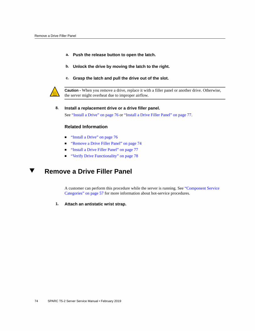
Remove a Drive Filler Panel
a. Push the release button to open the latch.
b. Unlock the drive by moving the latch to the right.
c. Grasp the latch and pull the drive out of the slot.
Caution - When you remove a drive, replace it with a filler panel or another drive. Otherwise,the server might overheat due to improper airflow.
8. Install a replacement drive or a drive filler panel.See “Install a Drive” on page 76 or “Install a Drive Filler Panel” on page 77.
Related Information
■ “Install a Drive” on page 76■ “Remove a Drive Filler Panel” on page 74■ “Install a Drive Filler Panel” on page 77■ “Verify Drive Functionality” on page 78
Remove a Drive Filler Panel
A customer can perform this procedure while the server is running. See “Component ServiceCategories” on page 57 for more information about hot-service procedures.
1. Attach an antistatic wrist strap.
74 SPARC T5-2 Server Service Manual • February 2019

Remove a Drive Filler Panel
2. On the drive filler panel you want to remove, complete the following tasks.
Caution - The latch is not an ejector. Do not bend it too far to the right. Doing so can damagethe latch.
a. Push the release button to open the latch and unlock the drive filler panel bymoving the latch to the right.
b. Grasp the latch and pull the filler panel out of the drive slot.
Caution - When you remove a drive filler panel, replace it with another filler panel or a drive.Otherwise, the server might overheat due to improper airflow.
3. Install a drive or a replacement drive filler panel.See “Install a Drive Filler Panel” on page 77 or “Install a Drive” on page 76.
Related Information
■ “Locate a Faulty Drive” on page 71■ “Remove a Drive” on page 71■ “Install a Drive” on page 76■ “Install a Drive Filler Panel” on page 77■ “Verify Drive Functionality” on page 78
Servicing Drives 75

Install a Drive
Install a Drive
Installing a drive into a server is a two-step process. You must first install the drive into thedrive slot and then configure that drive to the server.
Note - If you removed an existing drive from a slot in the server, you must install thereplacement drive in the same slot as the drive that was removed. Drives are physicallyaddressed according to the slot in which they are installed.
1. Remove a drive or a drive filler panel.See “Remove a Drive” on page 71 or “Remove a Drive Filler Panel” on page 74.
2. Unpack the drive and place it on an antistatic mat.
3. Fully open the release lever on the drive.
4. Install the drive by completing the following tasks.
a. Slide the drive into the drive slot until it is fully seated.
b. Close the latch to lock the drive in place.
5. Return the drive to operation by doing one of the following:
76 SPARC T5-2 Server Service Manual • February 2019

Install a Drive Filler Panel
■ If you cold-serviced the drive, restore power to the server. Complete theprocedure described in “Power On the Server (Oracle ILOM)” on page 172or “Power On the Server (Power Button)” on page 173.
■ If you hot-serviced the drive, configure it using the cfgadm -c configurecommand. The following example shows the drive at c0::dsk/c1t1d0 beingconfigured.
# cfgadm -c configure c0::dsk/c1t1d0
Replace c0:dsk/c1t1d0 with the drive name that applies to your situation.
6. Verify the drive functionality.See “Verify Drive Functionality” on page 78.
Related Information
■ “Locate a Faulty Drive” on page 71■ “Remove a Drive” on page 71■ “Remove a Drive Filler Panel” on page 74■ “Install a Drive Filler Panel” on page 77■ “Verify Drive Functionality” on page 78
Install a Drive Filler Panel
1. Remove a drive or a drive filler panel.See “Remove a Drive” on page 71 or “Remove a Drive Filler Panel” on page 74.
2. Fully open the release lever on the drive filler panel.
Servicing Drives 77

Verify Drive Functionality
3. Install the drive by completing the following tasks.
a. Slide the drive filler panel into the drive slot until it is fully seated.
b. Close the latch to lock the filler panel in place.
Related Information
■ “Locate a Faulty Drive” on page 71■ “Remove a Drive” on page 71■ “Install a Drive” on page 76■ “Remove a Drive Filler Panel” on page 74■ “Verify Drive Functionality” on page 78
Verify Drive Functionality
1. If the OS is shut down, and the drive you replaced was not the boot device, bootthe OS.Depending on the nature of the replaced drive, you might need to perform administrative tasksto reinstall software before the server can boot. Refer to the Oracle Solaris OS administrationdocumentation for more information.
78 SPARC T5-2 Server Service Manual • February 2019
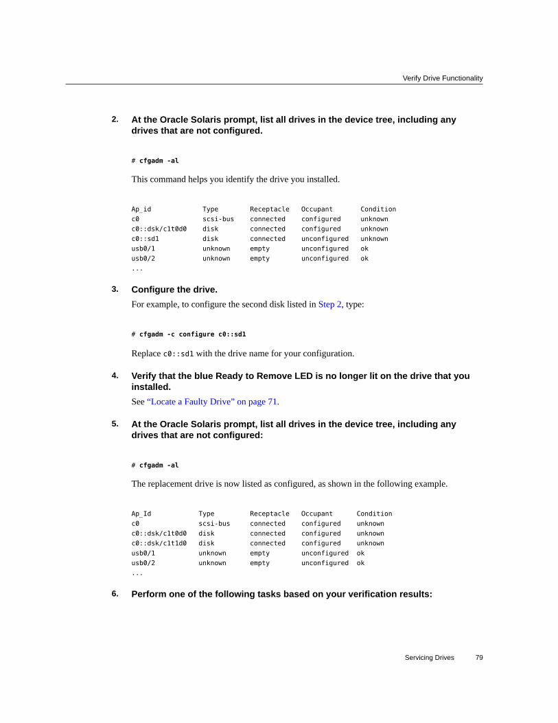
Verify Drive Functionality
2. At the Oracle Solaris prompt, list all drives in the device tree, including anydrives that are not configured.
# cfgadm -al
This command helps you identify the drive you installed.
Ap_id Type Receptacle Occupant Condition
c0 scsi-bus connected configured unknown
c0::dsk/c1t0d0 disk connected configured unknown
c0::sd1 disk connected unconfigured unknown
usb0/1 unknown empty unconfigured ok
usb0/2 unknown empty unconfigured ok
...
3. Configure the drive.For example, to configure the second disk listed in Step 2, type:
# cfgadm -c configure c0::sd1
Replace c0::sd1 with the drive name for your configuration.
4. Verify that the blue Ready to Remove LED is no longer lit on the drive that youinstalled.See “Locate a Faulty Drive” on page 71.
5. At the Oracle Solaris prompt, list all drives in the device tree, including anydrives that are not configured:
# cfgadm -al
The replacement drive is now listed as configured, as shown in the following example.
Ap_Id Type Receptacle Occupant Condition
c0 scsi-bus connected configured unknown
c0::dsk/c1t0d0 disk connected configured unknown
c0::dsk/c1t1d0 disk connected configured unknown
usb0/1 unknown empty unconfigured ok
usb0/2 unknown empty unconfigured ok
...
6. Perform one of the following tasks based on your verification results:
Servicing Drives 79

Verify Drive Functionality
■ If the previous steps did not verify the drive, see “DiagnosticsProcess” on page 32.
■ If the previous steps indicate that the drive is functioning properly, performthe tasks required to configure the drive. These tasks are covered in theOracle Solaris OS administration documentation.
For additional drive verification, you can run Oracle VTS. Refer to the Oracle VTSdocumentation for details.
Related Information
■ “Locate a Faulty Drive” on page 71■ “Remove a Drive” on page 71■ “Install a Drive” on page 76
80 SPARC T5-2 Server Service Manual • February 2019

Servicing Fan Modules
The six fan modules in the server are located at the front of the chassis. See “IdentifyingComponents” on page 13. You can access them without removing the server cover. You mightneed to extend the server from the rack to access the fan modules. Each fan module contains asingle fan that is mounted in an integrated, hot‐serviceable component.
These topics explain how to service faulty fan modules.
■ “Fan Module LEDs” on page 82■ “Locate a Faulty Fan Module” on page 83■ “Remove a Fan Module” on page 83■ “Install a Fan Module” on page 86■ “Verify Fan Module Functionality” on page 87
Related Information
■ “Preparing for Service” on page 53■ “Servicing the Fan Board” on page 135
Servicing Fan Modules 81

Fan Module LEDs
Fan Module LEDs
LED Color Status When Lit
Power OK Green The server is powered on and the fan module isfunctioning correctly.
Service Required Amber The fan module is faulty.
Related Information
■ “Locate a Faulty Fan Module” on page 83■ “Detecting and Managing Faults” on page 31
82 SPARC T5-2 Server Service Manual • February 2019

Locate a Faulty Fan Module
Locate a Faulty Fan Module
View the following LEDs, which are lit when a fan module fault is detected.
■ Fan Module (FAN) Fault LED on the front of the server. See “Front Panel Components(Service)” on page 13.
■ Fan Fault LED on or adjacent to the faulty fan module. See “Fan ModuleLEDs” on page 82. Each fan module contains an LED. When the amber ServiceRequired LED is lit, a fault has occurred on that fan module.
Note - The front and rear panel Service Action Required LEDs are also lit when the serverdetects a fan module fault. The server Overtemp LED might also light if a fan fault causes anincrease in server operating temperature.
Related Information■ “Front Panel Components (Service)” on page 13■ “Rear Panel Components (Service)” on page 15■ “Extend the Server to the Service Position” on page 63■ “Remove a Fan Module” on page 83■ “Detecting and Managing Faults” on page 31
Remove a Fan Module
Caution - While the fan modules provide some cooling redundancy, if a fan module fails,replace it as soon as possible to maintain server availability. When you remove one of the fansin the rear row (fans 3, 4, or 5), you must replace it within 30 seconds to prevent overheating ofthe server.
Caution - The fan module contains hazardous moving parts. Unless the power to the serveris completely shut down, replacing the fan modules is the only service permitted in the fancompartment.
A customer can perform this procedure while the server is running. See “Component ServiceCategories” on page 57 for more information about hot-service procedures.
1. Prepare for servicing.
a. Attach an antistatic wrist strap.
Servicing Fan Modules 83
Remove a Fan Module
See “Prevent ESD Damage” on page 62.
b. Extend the server to the maintenance position.See “Extend the Server to the Service Position” on page 63.
2. Identify the faulty fan module with a corresponding Service Required LED.The Service Action Required LEDs are located on the fan module as shown in “Locate a FaultyFan Module” on page 83.
3. Using your thumb and forefinger, grasp the handle on the fan module and lift itout of the server.
Caution - When removing a fan module, do not rock it back and forth. Rocking fan modulescan damage the fan board connectors.
84 SPARC T5-2 Server Service Manual • February 2019

Remove a Fan Module
Caution - When changing fan modules, note that only the fan modules can be removed orreplaced. Do not service any other components in the fan compartment unless the server is shutdown and the power cords are removed.
4. Install a new fan module.See “Install a Fan Module” on page 86.
Related Information
■ “Extend the Server to the Service Position” on page 63■ “Install a Fan Module” on page 86
Servicing Fan Modules 85

Install a Fan Module
Install a Fan Module
Before You Begin Caution - To ensure proper cooling, ensure that you install the replacement fan module in thesame slot from which the faulty fan was removed.
1. Remove a fan module.See “Remove a Fan Module” on page 83.
2. Unpack the replacement fan module and place it on an antistatic mat.
3. Install the replacement fan module into the server by completing the followingtasks.
a. Align the fan module and slide it into the fan slot.
86 SPARC T5-2 Server Service Manual • February 2019

Verify Fan Module Functionality
Note - Fan modules are keyed to ensure that they are installed in the correct orientation.
b. Apply firm pressure to fully seat the fan module.You will hear a click when the fan is properly seated.
4. Return the server to the normal operating position.See “Return the Server to the Normal Operating Position” on page 170.
Related Information
■ “Return the Server to the Normal Operating Position” on page 170.■ “Remove a Fan Module” on page 83■ “Verify Fan Module Functionality” on page 87
Verify Fan Module Functionality
1. Verify that the Service Required LED on the replaced fan module is not lit.See “Fan Module LEDs” on page 82.
2. Verify that the Top Fan LED and the Service Required LED on the front of theserver are not lit.See “Front Panel Controls and LEDs” on page 37.
Note - If you are replacing a fan module when the server is powered down, the LEDs mightstay lit until power is restored to the server and the server can determine that the fan module isfunctioning properly.
3. Use the Oracle ILOM show faulty command to verify that the fault has beencleared.See “Managing Faults” on page 46 for more information on using the show faulty command.
4. Perform one of the following tasks based on your verification results:
■ If the previous steps did not clear the fault, see “Detecting and Managing Faults” on page 31for information about the tools and methods you can use to diagnose component faults.
■ If the previous steps indicate that no faults have been detected, then the component has beenreplaced successfully. No further action is required.
Servicing Fan Modules 87

Verify Fan Module Functionality
Related Information
■ “Locate a Faulty Fan Module” on page 83■ “Front Panel Components (Service)” on page 13■ “Rear Panel Components (Service)” on page 15
88 SPARC T5-2 Server Service Manual • February 2019

Servicing Power Supplies
This server has redundant hot-serviceable power supplies. You can remove and replace a powersupply without shutting the server down, provided that the other power supply is online andworking.
These topics describe how to service power supply modules.
■ “Power Supply LEDs” on page 89■ “Locate a Faulty Power Supply” on page 91■ “Remove a Power Supply” on page 91■ “Install a Power Supply” on page 93■ “Verify Power Supply Functionality” on page 95
Related Information
■ “Servicing the PS Backplane” on page 163
Power Supply LEDs
Each power supply has LEDs that indicate its state.
Servicing Power Supplies 89
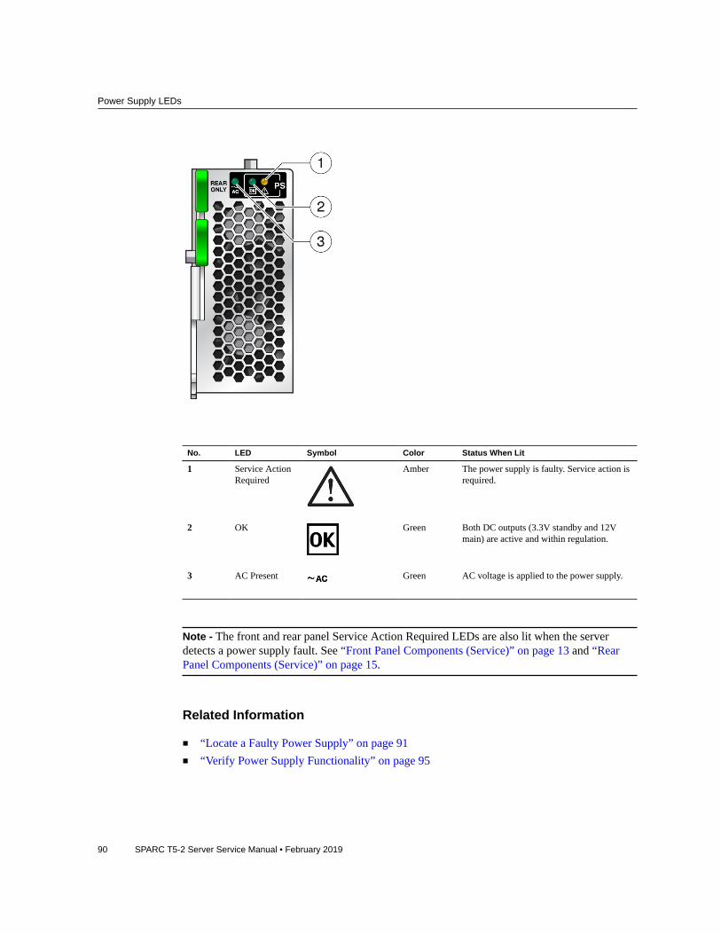
Power Supply LEDs
No. LED Symbol Color Status When Lit
1 Service ActionRequired
Amber The power supply is faulty. Service action isrequired.
2 OK Green Both DC outputs (3.3V standby and 12Vmain) are active and within regulation.
3 AC Present Green AC voltage is applied to the power supply.
Note - The front and rear panel Service Action Required LEDs are also lit when the serverdetects a power supply fault. See “Front Panel Components (Service)” on page 13 and “RearPanel Components (Service)” on page 15.
Related Information
■ “Locate a Faulty Power Supply” on page 91■ “Verify Power Supply Functionality” on page 95
90 SPARC T5-2 Server Service Manual • February 2019

Locate a Faulty Power Supply
Locate a Faulty Power Supply
View the following LEDs, which are lit when a power supply fault is detected.
■ Rear PS Fault LED on the front bezel of the server. See “Front Panel Components(Service)” on page 13.
■ Service Action Required LED on the faulted power supply. See “Power SupplyLEDs” on page 89.
Note - The front and rear panel Service Action Required LEDs are also lit when the serverdetects a power supply fault. See “Front Panel Components (Service)” on page 13 and “RearPanel Components (Service)” on page 15.
Related Information
■ “Power Supply LEDs” on page 89■ “Front Panel Components (Service)” on page 13■ “Rear Panel Components (Service)” on page 15■ “Remove a Power Supply” on page 91
Remove a Power Supply
Caution - Hazardous voltages are present. To reduce the risk of electric shock and danger topersonal health, follow the instructions.
Caution - If a power supply fails and you do not have a replacement available, to ensure properairflow, leave the failed power supply installed in the server until you replace it with a newpower supply.
A customer can perform this procedure while the server is running. See “Component ServiceCategories” on page 57 for more information about hot service procedures.
1. Prepare for servicing.
a. Attach an antistatic wrist strap.
b. If necessary, release the cable management arm to access the powersupplies.
Servicing Power Supplies 91

Remove a Power Supply
See “Release the CMA” on page 64.Do not allow the CMA to hang unsupported while it is unattached.
2. Disconnect the power cord from the power supply that displays an amber litService Action Required LED.
3. Press down on the release latch to open the ejector arm.
4. Slide the power supply out of the chassis.
Caution - There is no “catch” mechanism on the power supply to prevent it from slidingcompletely out of the chassis. Use care when removing the power supply to prevent it fromfalling.
Caution - Whenever you remove a power supply, you should replace it with another powersupply. Otherwise, the server might overheat due to improper airflow. If a new power supply isnot available, leave the failed power supply installed until it can be replaced.
92 SPARC T5-2 Server Service Manual • February 2019

Install a Power Supply
5. Install a new power supply.See “Install a Power Supply” on page 93.
Related Information
■ “Locate a Faulty Power Supply” on page 91■ “Install a Power Supply” on page 93
Install a Power Supply
Caution - Install an A239A power supply, labeled for upright installation, in the server. TheA239A power supply correctly exhausts air from the rear of the server. Do not install an A239power supply, which might cause the server to overheat and shut down.
1. Remove a power supply.See “Remove a Power Supply” on page 91.
2. If necessary, release the cable management arm to access the power supplies.See “Release the CMA” on page 64.
Do not allow the CMA to hang unsupported while it is unattached.
3. Align the power supply with the empty power supply chassis bay.
4. Slide the power supply into the bay until it is fully seated.
Servicing Power Supplies 93

Install a Power Supply
5. Move the release latch up to secure the power supply in place.
6. Reconnect the power cord to the power supply.
7. Verify that the AC OK LED is lit.See “Locate a Faulty Power Supply” on page 91.
8. Verify that the following LEDs are not lit:
■ Service Action Required LED on the power supply■ Front and rear Service Action Required LEDs■ Rear PS Failure LED on the bezel of the server
See “Interpreting LEDs” on page 36.
9. Verify power supply functionality.See “Verify Power Supply Functionality” on page 95.
Related Information
■ “Remove a Power Supply” on page 91■ “Verify Power Supply Functionality” on page 95
94 SPARC T5-2 Server Service Manual • February 2019

Verify Power Supply Functionality
Verify Power Supply Functionality
1. Verify that the amber Service Required LED on the replaced power supply is notlit.
2. Verify that the PS Fault LED on the front of the server is not lit.
3. Use the Oracle ILOM show faulty command to verify that the fault has beencleared.See “Check for Faults” on page 46 for more information on using the show faulty command.
4. Perform one of the following tasks based on your verification results:
■ If the previous steps did not clear the fault, see “Detecting and Managing Faults” on page 31for information about the tools and methods you can use to diagnose component faults.
■ If the previous steps indicate that no faults have been detected, then the component has beenreplaced successfully. No further action is required.
Related Information
■ “Locate a Faulty Power Supply” on page 91■ “Front Panel Components (Service)” on page 13■ “Rear Panel Components (Service)” on page 15
Servicing Power Supplies 95

96 SPARC T5-2 Server Service Manual • February 2019

Servicing Memory Risers and DIMMs
These topics explain how to remove and install memory risers and DIMMs in the server.
■ “Memory Riser and DIMM FRU Names” on page 97■ “Memory Riser and DIMM Configuration” on page 99■ “DIMM Rank Classification Labels” on page 100■ “Locate a Failed DIMM (LEDs)” on page 100■ “Locate a Failed DIMM (Oracle ILOM)” on page 102■ “Remove a Memory Riser and DIMM” on page 103■ “Install a DIMM and a Memory Riser” on page 106■ “Enable and Verify Newly Installed DIMMs” on page 109
Memory Riser and DIMM FRU Names
The 2-processor server includes eight memory risers. The 1-processor server includes fourmemory risers. Four memory risers are associated with each CMP in the server. A label is nextto each memory riser that shows the number of the CMP and of the riser. Four DIMM slots areon each memory riser.
Note - The server fails to boot unless all memory riser slots are populated. For moreinformation about memory riser configuration, see “Memory Riser and DIMMConfiguration” on page 99.
DIMM FRU names are based on the location of the memory riser in the server and the DIMMslot on the memory riser. For example, the full FRU name for the top-most DIMM slot (BOB1/CH1/D0) on the first memory riser (CMP0/MR0) is:
/SYS/MB/CMP0/MR0/BOB1/CH1/D0
Servicing Memory Risers and DIMMs 97

Memory Riser and DIMM FRU Names
Memory Riser Label Memory Riser or DIMM FRU Name EjectorColor
Slot BodyColor
CM0/MR0
(Farthest from powersupplies)
/SYS/MB/CM0/CMP/MR0 (riser)
/SYS/MB/CM0/CMP/MR0/BOB0/CH0/D0
/SYS/MB/CM0/CMP/MR0/BOB0/CH1/D0
/SYS/MB/CM0/CMP/MR0/BOB1/CH0/D0
/SYS/MB/CM0/CMP/MR0/BOB1/CH1/D0
Black
Black
White
White
Black
White
Black
White
CM0/MR1 /SYS/MB/CM0/CMP/MR1 (riser)
/SYS/MB/CM0/CMP/MR1/BOB0/CH0/D0
/SYS/MB/CM0/CMP/MR1/BOB0/CH1/D0
/SYS/MB/CM0/CMP/MR1/BOB1/CH0/D0
/SYS/MB/CM0/CMP/MR1/BOB1/CH1/D0
Black
Black
White
White
Black
White
Black
White
CM0/MR2 /SYS/MB/CM0/CMP/MR2 (riser)
/SYS/MB/CM0/CMP/MR2/BOB0/CH0/D0
/SYS/MB/CM0/CMP/MR2/BOB0/CH1/D0
/SYS/MB/CM0/CMP/MR2/BOB1/CH0/D0
/SYS/MB/CM0/CMP/MR2/BOB1/CH1/D0
Black
Black
White
White
Black
White
Black
White
CM0/MR3 /SYS/MB/CM0/CMP/MR3 (riser)
/SYS/MB/CM0/CMP/MR3/BOB0/CH0/D0
/SYS/MB/CM0/CMP/MR3/BOB0/CH1/D0
/SYS/MB/CM0/CMP/MR3/BOB1/CH0/D0
/SYS/MB/CM0/CMP/MR3/BOB1/CH1/D0
Black
Black
White
White
Black
White
Black
White
CM1/MR0
(Not on the 1-processorserver.)
/SYS/MB/CM1/CMP/MR0 (riser)
/SYS/MB/CM1/CMP/MR0/BOB0/CH0/D0
/SYS/MB/CM1/CMP/MR0/BOB0/CH1/D0
/SYS/MB/CM1/CMP/MR0/BOB1/CH0/D0
/SYS/MB/CM1/CMP/MR0/BOB1/CH1/D0
Black
Black
White
White
Black
White
Black
White
CM1/MR1
(Not on the 1-processorserver.)
/SYS/MB/CM1/CMP/MR1 (riser)
/SYS/MB/CM1/CMP/MR1/BOB0/CH0/D0
/SYS/MB/CM1/CMP/MR1/BOB0/CH1/D0
/SYS/MB/CM1/CMP/MR1/BOB1/CH0/D0
Black
Black
White
Black
White
Black
98 SPARC T5-2 Server Service Manual • February 2019

Memory Riser and DIMM Configuration
Memory Riser Label Memory Riser or DIMM FRU Name EjectorColor
Slot BodyColor
/SYS/MB/CM1/CMP/MR1/BOB1/CH1/D0 White White
CM1/MR2
(Not on the 1-processorserver.)
/SYS/MB/CM1/CMP/MR2 (riser)
/SYS/MB/CM1/CMP/MR2/BOB0/CH0/D0
/SYS/MB/CM1/CMP/MR2/BOB0/CH1/D0
/SYS/MB/CM1/CMP/MR2/BOB1/CH0/D0
/SYS/MB/CM1/CMP/MR2/BOB1/CH1/D0
Black
Black
White
White
Black
White
Black
White
CM1/MR3
(Not on the 1-processorserver.)
(Closest to powersupplies)
/SYS/MB/CM1/CMP/MR3 (riser)
/SYS/MB/CM1/CMP/MR3/BOB0/CH0/D0
/SYS/MB/CM1/CMP/MR3/BOB0/CH1/D0
/SYS/MB/CM1/CMP/MR3/BOB1/CH0/D0
/SYS/MB/CM1/CMP/MR3/BOB1/CH1/D0
Black
Black
White
White
Black
White
Black
White
Related Information
■ “Memory Riser and DIMM Configuration” on page 99■ “DIMM Rank Classification Labels” on page 100
Memory Riser and DIMM Configuration
The memory riser configuration rules for the server are as follows:
■ The 2-processor server contains eight memory risers. The 1-processor server contains fourmemory risers. Four memory risers are supported per CPU.
■ Each of the memory riser slots in the server must be filled with a memory riser.
There are only two possible memory configurations: Fully populated and half populated.DIMM configuration rules for each memory riser are as follows:
■ For a fully populated configuration, DIMMs must be installed in all four DIMM connectorson each memory riser.
■ For a half populated configuration (with 16GB or 32GB DIMMs), DIMMs must be installedin the two black DIMM connectors (labeled J701_ZA and J701_ZB) on each memory riser.
■ All memory risers must contain the same rank, size, and type of DIMM.
Servicing Memory Risers and DIMMs 99

DIMM Rank Classification Labels
Related Information
■ “Memory Riser and DIMM FRU Names” on page 97■ “DIMM Rank Classification Labels” on page 100■ “Locate a Failed DIMM (LEDs)” on page 100■ “Remove a Memory Riser and DIMM” on page 103■ “Install a DIMM and a Memory Riser” on page 106
DIMM Rank Classification Labels
Each DIMM is shipped with a label identifying its rank classification. The following tableidentifies the corresponding rank classification label shipped with each DIMM.
Note - Single-rank DIMMs are not currently offered.
DIMM Capacity DRAM Density Rank Classification Label
8 GB 4 GB Dual-rank x4 2Rx4
16 GB 4 GB Dual-rank x4 2Rx4
32 GB 4 GB Quad-rank x4 4Rx4
Related Information
■ “Memory Riser and DIMM FRU Names” on page 97■ “Memory Riser and DIMM Configuration” on page 99■ “Locate a Failed DIMM (LEDs)” on page 100■ “Remove a Memory Riser and DIMM” on page 103■ “Install a DIMM and a Memory Riser” on page 106
Locate a Failed DIMM (LEDs)
Each memory riser has a Remind button, a Power LED, and Fault LEDs adjacent to eachDIMM. This procedure describes how to identify a faulty DIMM using these buttons and LEDs.
100 SPARC T5-2 Server Service Manual • February 2019

Locate a Failed DIMM (LEDs)
1. Press the System Remind button to identify the memory riser that contains thefaulty DIMM.
2. Lift and remove the faulty memory riser.
3. Press the Remind button on the memory riser to identify the faulty DIMM. Anamber Fault LED will light next to the faulty DIMM.
No. LED Color Description
1 DIMM Fault LED Amber Identifies each faulty or misconfigured DIMM when you pressthe memory riser remind button.
2 DIMM slots A notch toward the middle of each slot ensures that the DIMMis correctly oriented. If only two DIMMs are installed in eachmemory riser, they must be in the black DIMM connectors(labeled J701_ZA and J701ZB).
3 Memory riser power LED Green
Amber
Indicates that the riser is operating normally.
Indicates that the riser has a fault.
4 Memory riser remindbutton
Blue Push this button to identify the faulty or misconfigured DIMMs.
Servicing Memory Risers and DIMMs 101

Locate a Failed DIMM (Oracle ILOM)
Note - The front and rear panel Service Required LEDs are also lit when the server detects aDIMM fault.
Related Information
■ “Locate a Failed DIMM (Oracle ILOM)” on page 102■ “Remove a Memory Riser and DIMM” on page 103
Locate a Failed DIMM (Oracle ILOM)
The Oracle ILOM show faulty command displays current faults, including DIMM failures.
1. Type show faulty at the Oracle ILOM prompt.
-> show faulty
Target | Property | Value
--------------------+-------------------+-------------------
/SP/faultmgmt/0 | fru | /SYS/MB/CM0/CMP/MR1/BOB1/CH0/D0
/SP/faultmgmt/0 | timestamp | Dec 21 16:40:56
/SP/faultmgmt/0/ | timestamp | Dec 21 16:40:56 faults/0
/SP/faultmgmt/0/ | sp_detected_fault | /SYS/MB/CM0/CMP/MR1/BOB1/CH0/D0
faults/0 | | Forced fail(POST)
2. Locate the DIMM that corresponds to the listed name.See “Memory Riser and DIMM FRU Names” on page 97.
In this example, /SYS/MB/CM0/CMP/MR1/BOB1/CH0/D0 indicates the memory riser that is secondfarthest from the power supplies and the DIMM in a slot with white handles and a black slot.
Related Information
■ “Locate a Failed DIMM (LEDs)” on page 100■ “Remove a Memory Riser and DIMM” on page 103
102 SPARC T5-2 Server Service Manual • February 2019

Remove a Memory Riser and DIMM
Remove a Memory Riser and DIMM
Caution - These procedures require that you handle components that are sensitive to ESD. Thissensitivity can cause the component to fail. To avoid damage, ensure that you follow antistaticpractices as described in “ESD Measures” on page 54.
A customer can perform this procedure. The system must be completely powered downbefore performing this procedure. See “Component Service Categories” on page 57 for moreinformation about cold-service procedures.
1. Prepare for servicing:
a. Attach an antistatic wrist strap.
b. Power off the server and unplug power cords from the power supplies.See “Removing Power From the Server” on page 58.
c. Extend the server to the maintenance position.See “Extend the Server to the Service Position” on page 63.
d. Remove the top cover.See “Remove the Top Cover” on page 67.
Servicing Memory Risers and DIMMs 103

Remove a Memory Riser and DIMM
2. Identify the memory riser with the faulty DIMM by pressing the Fault Remindbutton on the air divider as shown in the following figure.
■ If the memory riser Service Action Required LED is off, all DIMMs on thisriser are operating properly.
■ If the memory riser Service Action Required LED is on (amber), one or moreof the DIMMs installed on this riser is faulty or misconfigured.
104 SPARC T5-2 Server Service Manual • February 2019

Remove a Memory Riser and DIMM
3. Lift the memory riser that has a lit Service Action Required LED straight up toremove the memory riser from the memory module socket.
4. Identify the faulty or misconfigured DIMMs by pressing the Remind button on thememory riser. See “Locate a Failed DIMM (LEDs)” on page 100.
Servicing Memory Risers and DIMMs 105

Install a DIMM and a Memory Riser
5. On DIMMs that display an amber Fault LED, remove the DIMMs.
a. Press down both DIMM slot ejector tabs as far as they will go.
b. Carefully lift the DIMM straight up.
Caution - Whenever you remove a memory riser or DIMM, you should replace it with anothermemory riser or DIMM. Otherwise, the server might overheat due to improper airflow.
6. Install DIMMs in the memory riser and return the memory riser to the server.See “Install a DIMM and a Memory Riser” on page 106.
Related Information
■ “Install a DIMM and a Memory Riser” on page 106
Install a DIMM and a Memory Riser
1. Attach an antistatic wrist wrap and unpack the DIMMs and place them on anantistatic mat.
2. Install the DIMMs into the memory riser by performing the following tasks.
106 SPARC T5-2 Server Service Manual • February 2019

Install a DIMM and a Memory Riser
Note - If each memory riser will have only two DIMMs (half populated), place the DIMMs inthe two black DIMM connectors.
No. Description
1. DIMM connector slot
2. DIMM connector key
3. DIMM ejector lever
a. Ensure that the ejector levers at both ends of the memory module slot are ina fully open position.
b. Align each DIMM with the empty connector slot, aligning the notch in theDIMM with the key in the connector.The notch ensures that the DIMM is oriented correctly.
Servicing Memory Risers and DIMMs 107

Install a DIMM and a Memory Riser
c. Gently press the DIMM into the slot until the ejector tabs lock the DIMM inplace.
Repeat these steps until each DIMM has been installed.
3. Push the memory riser module into the associated CPU memory riser slot untilthe riser module locks in place.
4. Return the server to operation:
108 SPARC T5-2 Server Service Manual • February 2019

Enable and Verify Newly Installed DIMMs
a. Install the top cover.See “Replace the Top Cover” on page 169.
b. Return the server to the normal operating position.See “Return the Server to the Normal Operating Position” on page 170.
c. Reinstall the power cords to the power supplies and power on the server.See “Returning the Server to Operation” on page 169.
Related Information
■ “Memory Riser and DIMM Configuration” on page 99■ “Remove a Memory Riser and DIMM” on page 103■ “Enable and Verify Newly Installed DIMMs” on page 109
Enable and Verify Newly Installed DIMMs
1. Access the Oracle ILOM prompt.Refer to Servers Administration for instructions.
2. Use the show faulty command to determine how to clear the fault.
■ If show faulty indicates a POST-detected fault, go to Step 3.■ If show faulty output displays a UUID, which indicates a host-detected fault, skip Step 3
and go directly to Step 4.
3. Use the set command to enable the DIMM that was disabled by POST.In most cases, replacement of a faulty DIMM is detected when the service processor is powercycled. In those cases, the fault is automatically cleared from the server. If show faulty stilldisplays the fault, the set command will clear it.
-> set /SYS/MB/CM0/CMP/MR3/BOB1/CH0/D0 requested_config_state=Enabled
Note - Use requested_config_state rather than component_state, which existed in earlierversions of Oracle ILOM.
4. For a host-detected fault, perform the following steps to verify the new DIMM:
Servicing Memory Risers and DIMMs 109

Enable and Verify Newly Installed DIMMs
a. Set the virtual keyswitch to diag so that POST will run in Service mode.
-> set /HOST keyswitch_state=Diag
Set 'keyswitch_state' to 'Diag'
b. Power cycle the server.
-> stop /System
Are you sure you want to stop /System (y/n)? y
Stopping /System
-> start /System
Are you sure you want to start /System (y/n)? y
Starting /System
c. Check if the host has been powered off.Allow approximately one minute before performing this step. Type the show /HOSTcommand. When the host is powered off, the console displays status=Powered Off.
d. Switch to the system console to view POST output.Watch the POST output for possible fault messages. The following output indicates thatPOST did not detect any faults:
-> start /SYS/console
...
0:0:0>INFO:
0:0:0> POST Passed all devices.
0:0:0>POST: Return to VBSC.
0:0:0>Master set ACK for vbsc runpost command and spin...
Note - The server might boot automatically at this point. If so, go directly to Step 4f. If theserver remains at the OpenBoot prompt (ok) go to Step 4e.
e. If the server remains at the OpenBoot prompt, type boot.
f. Return the virtual keyswitch to Normal mode.
-> set /HOST keyswitch_state=Normal
Set 'keyswitch_state' to 'Normal'
110 SPARC T5-2 Server Service Manual • February 2019

Enable and Verify Newly Installed DIMMs
g. Switch to the system console and type the Oracle Solaris fmadm faultycommand.
# fmadm faulty
If any faults are reported, refer to the diagnostics instructions described in “Check forFaults” on page 46.
5. Switch to the Oracle ILOM command shell.
6. Run the show faulty command.
-> show faulty
Target | Property | Value
--------------------+------------------------+-------------------------------
/SP/faultmgmt/0 | fru | /SYS/MB/CMP0/MR1/BOB1/CH0/D0
/SP/faultmgmt/0 | timestamp | Dec 14 22:43:59
/SP/faultmgmt/0/ | sunw-msg-id | SUN4V-8000-DX
faults/0 | |
/SP/faultmgmt/0/ | uuid | 3aa7c854-9667-e176-efe5-e487e520
faults/0 | | 7a8a
/SP/faultmgmt/0/ | timestamp | Dec 14 22:43:59
faults/0 | |
If the show faulty command reports a fault with a UUID go to Step 7. If show faulty does notreport a fault with a UUID, you are done with the verification process.
7. Switch to the system console and type the fmadm repair command with the UUID.Use the same UUID that was displayed from the output of the Oracle ILOM show faultycommand.
# fmadm repair 3aa7c854-9667-e176-efe5-e487e520
Servicing Memory Risers and DIMMs 111

112 SPARC T5-2 Server Service Manual • February 2019

Servicing the DVD Drive
The DVD drive is mounted in a removable module that is accessed from the system's frontpanel. See “Front Panel Components (Service)” on page 13. The DVD drive must be removedfrom the drive cage in order to service the drive backplane.
Caution - If you remove the DVD drive you must replace it with a another DVD drive.Otherwise the server might overheat due to improper airflow.
These topics describe how to service a DVD drive.
■ “Remove a DVD Drive” on page 113■ “Install a DVD Drive” on page 114
Related Information
■ “Filler Panels” on page 55
Remove a DVD Drive
A customer can perform this procedure. The server must be completely powered downbefore performing this procedure. See “Component Service Categories” on page 57 for moreinformation about cold-service procedures.
1. Prepare for servicing.
a. Attach an antistatic wrist strap.
b. Remove any media from the drive.
c. Power off the server and unplug power cords from the power supplies.See “Removing Power From the Server” on page 58.
Servicing the DVD Drive 113

Install a DVD Drive
2. Push down on the latch on the top left corner of the DVD drive.
3. Slide the DVD drive out of the server.
Caution - Whenever you remove the DVD drive, you must replace it with another DVD drive.Otherwise the server might overheat due to improper airflow.
4. Install a new DVD drive.See “Install a DVD Drive” on page 114.
Related Information
■ “Install a DVD Drive” on page 114
Install a DVD Drive
A customer can perform this procedure. The server must be completely powered downbefore performing this procedure. See “Component Service Categories” on page 57 for moreinformation about cold-service procedures.
1. Unpack the DVD drive.Attach an antistatic wrist wrap and place the drive on an antistatic mat.
114 SPARC T5-2 Server Service Manual • February 2019

Install a DVD Drive
2. Slide the DVD drive into the front of the chassis until it seats.
3. Return the server to operation.
a. Return the server to the normal operating position.See “Return the Server to the Normal Operating Position” on page 170.
b. Reinstall the power cords to the power supplies and power on the server.See “Returning the Server to Operation” on page 169.
Servicing the DVD Drive 115

Install a DVD Drive
Related Information
■ “Remove a DVD Drive” on page 113
116 SPARC T5-2 Server Service Manual • February 2019

Servicing the Battery
The battery is located inside the chassis. See “Motherboard Component Locations” on page 21.The battery maintains system time when the server is powered off and disconnected from ACpower. If the IPMI logs indicate a battery failure, replace the battery.
These topics describe how to service the battery.
■ “Remove the Battery” on page 117■ “Install the Battery” on page 118
Related Information
■ “Detecting and Managing Faults” on page 31
Remove the Battery
Caution - This procedure requires that you handle components that are sensitive to ESD. Thissensitivity can cause the component to fail. To avoid damage, ensure that you follow antistaticpractices as described in “ESD Measures” on page 54.
A customer can perform this procedure. The server must be completely powered downbefore performing this procedure. See “Component Service Categories” on page 57 for moreinformation about cold-service procedures.
1. Prepare for servicing.
a. Attach an antistatic wrist strap.
b. Power off the server and unplug power cords from the power supplies.See “Removing Power From the Server” on page 58.
c. Extend the server to maintenance position.
Servicing the Battery 117

Install the Battery
See “Extend the Server to the Service Position” on page 63.
d. Remove the top cover.See “Remove the Top Cover” on page 67.
2. Gently push the battery toward the service processor to release it from theretention clip.
3. Install a new battery.See “Install the Battery” on page 118.
Related Information
■ “Install the Battery” on page 118
Install the Battery
1. Remove the battery.See “Remove the Battery” on page 117.
118 SPARC T5-2 Server Service Manual • February 2019

Install the Battery
2. Attach an antistatic wrist wrap and unpack the replacement battery.
3. Press the new battery into the battery holder with the positive side (+) facingaway from the metal tab that holds it in place.If the SP is configured to synchronize with a network time server using NTP, the Oracle ILOMclock will be reset as soon as the server is powered on and connected to the network. Otherwise,proceed to the next step.
4. If the SP is not configured to use NTP, you must reset the Oracle ILOM clockusing the Oracle ILOM CLI or the web interface.For instructions, see the Oracle ILOM documentation.
5. Return the server to operation.
a. Return the server to the normal operating position.See “Return the Server to the Normal Operating Position” on page 170.
b. Reinstall the power cords to the power supplies and power on the server.See “Returning the Server to Operation” on page 169.
Related Information
■ “Remove the Battery” on page 117
Servicing the Battery 119

120 SPARC T5-2 Server Service Manual • February 2019

Servicing PCIe Cards
These topics describe how to service PCIe cards and PCIe card slot filler panels.
■ “PCIe Card Configuration” on page 121■ “I/O Root Complex Connections” on page 122■ “Remove a PCIe Card or Filler Panel” on page 123■ “Install a PCIe Card or Filler Panel” on page 126
PCIe Card Configuration
Note - Before installing PCIe cards, refer to the SPARC T5-2 Server Product Notes andthe documentation for each PCIe card for detailed information about known issues andconfiguration limitations.
This server has eight PCI Express 3.0 slots that accommodate low-profile PCIe cards. All slotssupport x8 PCIe cards. Two slots are also capable of supporting x16 PCIe cards:
■ Slots 1, 2, 3, 6, 7, and 8 – x8 electrical interface■ Slots 4 and 5 – x8 electrical interface (x16 connector)
To determine the slot in which to install a PCIe card, follow these guidelines:
1. Install cards that require a specific slot. Refer to the SPARC T5-2 Server Product Notes andthe documentation for each card to determine if there are slot requirements.The following cards have certain requirements:■ Sun Flash Accelerator F80 PCIe card: You can install six of these cards. If the
maximum of six are installed, the remaining two slots cannot contain a Sun FlashAccelerator F40 PCIe card.
■ Oracle Dual Port QDR Infiniband Adapter M3: You can install four of these cards.On a 1-processor server, no more than two cards can be in slots 1 to 4, and no more thantwo cards can be in slots 5 to 8.
2. Install the remaining cards so that the load on the server is balanced.
Servicing PCIe Cards 121

I/O Root Complex Connections
■ Fill the PCIe slots in this sequence: 1, 8, 2, 7, 3, 6, 4, 5.■ Place the cards in this order: Expansion cards, storage cards, network cards, other cards.
Related Information
■ “I/O Root Complex Connections” on page 122■ “Rear Panel Components (Service)” on page 15■ “Remove a PCIe Card or Filler Panel” on page 123■ “Install a PCIe Card or Filler Panel” on page 126
I/O Root Complex Connections
On the 2-processor server, each CPU connects to four of the PCIe slots. Each PCIe slot alsouses a specific I/O subsystem (IOS0 or IOS1) and PCIe Switch (0 or 1)
■ CPU0, IOS1, and PCIe Switch 0 connect to slot 1.■ CPU0, IOS0, and PCIe Switch 1 connect to slots 5, 6, and 7.■ CPU1, IOS1, and PCIe Switch 0 connect to slots 2, 3, and 4.■ CPU1, IOS0, and PCIe Switch 1 connect to slot 8.
On the 1-processor server, the single CPU connects to all eight of the PCIe slots. Each PCIe slotuses a specific I/O subsystem (IOS0 or IOS1) and PCIe Switch (0 or 1)
■ CPU0, IOS1, and PCIe Switch 0 connect to slot 1, 2, 3, and 4.■ CPU0, IOS0, and PCIe Switch 1 connect to slots 5, 6, 7, and 8.
Note - For diagrams showing connections between PCIe slots and root complexes for the 2-processor and 1-processor servers, see “System Schematic” on page 25.
The pci@ values reported in the OpenBoot show-devs command output are paths in the I/O rootcomplex topology. The values are different for the 2-processor and 1-processor servers.
2-processor server root complex paths:
PCIeSlot
CPU IOS PCIeSwitch
Root Complex Path Oracle ILOM Target
1 0 1 0 /pci@300/pci@1/pci@0/pci@4 /SYS/MB/PCIE1
2 1 1 0 /pci@380/pci@1/pci@0/pci@5 /SYS/MB/PCIE2
122 SPARC T5-2 Server Service Manual • February 2019

Remove a PCIe Card or Filler Panel
PCIeSlot
CPU IOS PCIeSwitch
Root Complex Path Oracle ILOM Target
3 1 1 0 /pci@380/pci@1/pci@0/pci@6 /SYS/MB/PCIE3
4 1 1 0 /pci@380/pci@1/pci@0/pci@7 /SYS/MB/PCIE4
5 0 0 1 /pci@340/pci@1/pci@0/pci@4 /SYS/MB/PCIE5
6 0 0 1 /pci@340/pci@1/pci@0/pci@5 /SYS/MB/PCIE6
7 0 0 1 /pci@340/pci@1/pci@0/pci@6 /SYS/MB/PCIE7
8 1 0 1 /pci@3c0/pci@1/pci@0/pci@7 /SYS/MB/PCIE8
1-processor server root complex paths:
PCIeSlot
CPU IOS PCIeSwitch
Root Complex Path Oracle ILOM Target
1 0 1 0 /pci@300/pci@1/pci@0/pci@4 /SYS/MB/PCIE1
2 0 1 0 /pci@300/pci@1/pci@0/pci@5 /SYS/MB/PCIE2
3 0 1 0 /pci@300/pci@1/pci@0/pci@6 /SYS/MB/PCIE3
4 0 1 0 /pci@300/pci@1/pci@0/pci@7 /SYS/MB/PCIE4
5 0 0 1 /pci@340/pci@1/pci@0/pci@4 /SYS/MB/PCIE5
6 0 0 1 /pci@340/pci@1/pci@0/pci@5 /SYS/MB/PCIE6
7 0 0 1 /pci@340/pci@1/pci@0/pci@6 /SYS/MB/PCIE7
8 0 0 1 /pci@340/pci@1/pci@0/pci@7 /SYS/MB/PCIE8
Related Information
■ “System Schematic” on page 25■ “PCIe Card Configuration” on page 121■ “Rear Panel Components (Service)” on page 15■ “Remove a PCIe Card or Filler Panel” on page 123■ “Install a PCIe Card or Filler Panel” on page 126
Remove a PCIe Card or Filler Panel
Caution - This procedure requires that you handle components that are sensitive to ESD. Thissensitivity can cause the component to fail. To avoid damage, ensure that you follow antistaticpractices as described in “ESD Measures” on page 54.
Servicing PCIe Cards 123

Remove a PCIe Card or Filler Panel
A customer can perform this procedure. The server must be completely powered downbefore performing this procedure. See “Component Service Categories” on page 57 for moreinformation about cold-service procedures.
1. Prepare for servicing.
a. Attach an antistatic wrist strap.
b. Power off the server and disconnect all power cords from the server powersupplies.See “Removing Power From the Server” on page 58.
c. Extend the server to the maintenance position.See “Extend the Server to the Service Position” on page 63.
d. Remove the top cover.See “Remove the Top Cover” on page 67.
2. Locate the PCIe card or filler panel that you want to remove.See “Rear Panel Components (Service)” on page 15 for information about PCIe slots and theirlocations.
If you are removing a PCIe card slot filler panel, go to Step 6.
3. If necessary, make a note of the slot location for each PCIe card you plan toremove.
4. Unplug all data cables from the PCIe card.Note the location of all cables for reinstallation later.
5. Remove any transceivers from the PCIe card before removing the card.
6. Remove the PCIe card by completing the following tasks.
■ See these figures if you are removing a PCIe card.
124 SPARC T5-2 Server Service Manual • February 2019
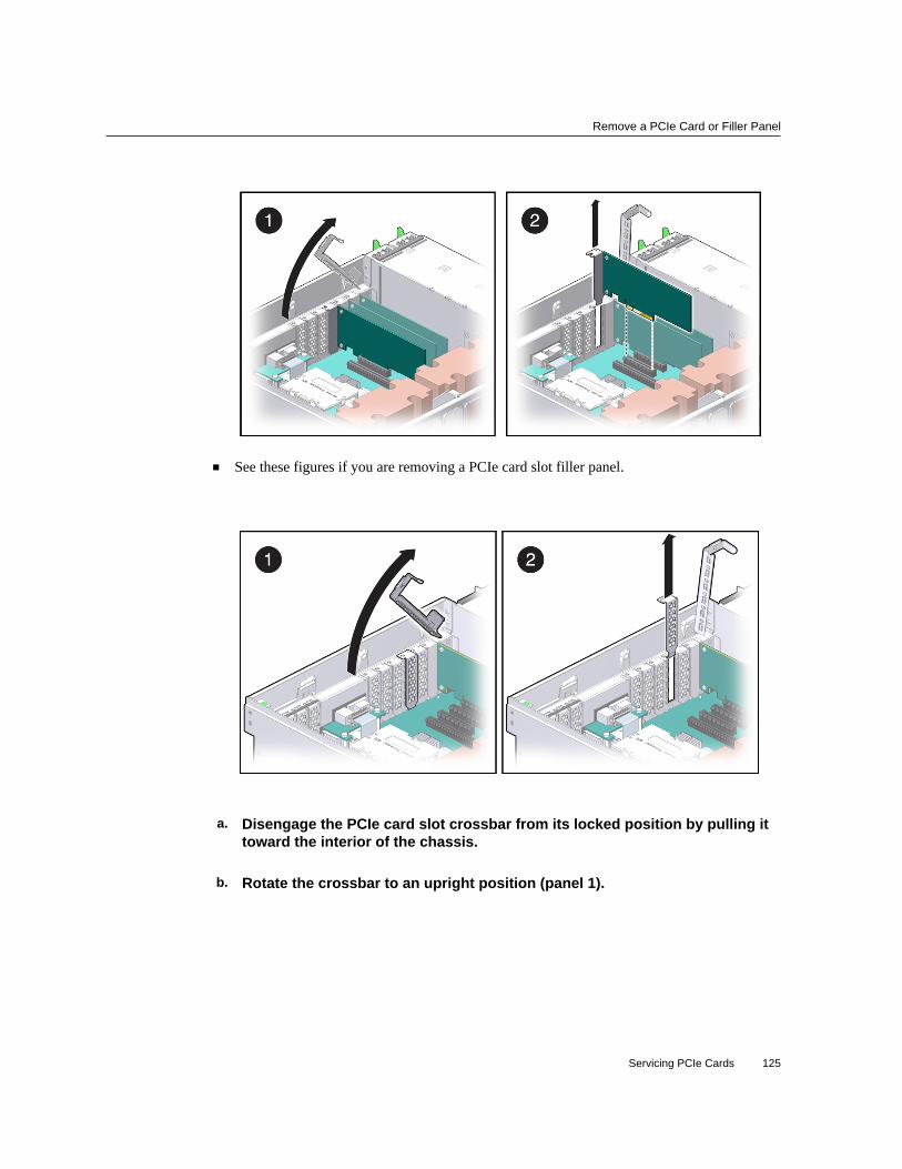
Remove a PCIe Card or Filler Panel
■ See these figures if you are removing a PCIe card slot filler panel.
a. Disengage the PCIe card slot crossbar from its locked position by pulling ittoward the interior of the chassis.
b. Rotate the crossbar to an upright position (panel 1).
Servicing PCIe Cards 125

Install a PCIe Card or Filler Panel
c. Carefully remove the PCIe card or filler panel from the card slot. (panel 2)
7. Replace with another PCIe card or filler panel before the server is connected topower again.See “Install a PCIe Card or Filler Panel” on page 126.
Related Information
■ “Install a PCIe Card or Filler Panel” on page 126
Install a PCIe Card or Filler Panel
Caution - This procedure requires that you handle components that are sensitive to ESD. Thissensitivity can cause the component to fail. To avoid damage, ensure that you follow antistaticpractices as described in “ESD Measures” on page 54.
1. Remove a PCIe card or filler panel.See “Remove a PCIe Card or Filler Panel” on page 123.
2. Attach an antistatic wrist strap, unpack the PCIe card or PCIe card slot fillerpanel, and place on an antistatic mat.
3. Remove any transceivers from the PCIe card before installing the card.
4. Ensure that the server is powered off and all power cords are disconnected fromthe server power supplies.See “Removing Power From the Server” on page 58.
5. Determine which slot to install the PCIe card in.If you are not replacing an existing PCIe card and need information about deciding which slotto install the card in, see “PCIe Card Configuration” on page 121.
6. Disengage the PCIe card slot crossbar from its locked position by pulling ittoward the interior of the chassis.The crossbar might already be disengaged if you removed a PCIe card or filler panel from thatslot.
7. Install the PCIe card or filler panel into the card slot and return the crossbar toits closed and locked position.
126 SPARC T5-2 Server Service Manual • February 2019

Install a PCIe Card or Filler Panel
■ See these figures if you are installing a PCIe card.
■ See these figures if you are installing a PCIe card slot filler panel.
8. Return the server to operation:
a. Install the top cover.See “Replace the Top Cover” on page 169.
Servicing PCIe Cards 127

Install a PCIe Card or Filler Panel
b. Return the server to the normal operating position.See “Return the Server to the Normal Operating Position” on page 170.
c. Reconnect all power cords to the server power supplies.See “Attach Power Cords” on page 172.
d. Power on the server.See “Power On the Server (Oracle ILOM)” on page 172 or “Power On the Server(Power Button)” on page 173.
9. Refer to the documentation shipped with the PCIe card for information aboutconfiguring the PCIe card, including installing required operating systems.To create or recover RAID configurations, refer to the LSI MegaRAID SAS Software User'sGuide.
Related Information
■ “Remove a PCIe Card or Filler Panel” on page 123
128 SPARC T5-2 Server Service Manual • February 2019

Servicing the SP
These topics describe how to service the SP.
■ “SP Firmware and Configuration” on page 129■ “Remove the SP” on page 130■ “Install the SP” on page 131■ “Verify SP Functionality” on page 133
SP Firmware and Configuration
System firmware consists of two components, an SP component and a host component.The SP firmware component is located on the SP, and the host component is located on themotherboard. For the server to operate correctly, the firmware in these two components must becompatible.
When replacing the SP, you must restore the configuration settings maintained in the SP. Beforereplacing the SP, save the configuration using the Oracle ILOM backup utility. Refer to theOracle ILOM documentation for instructions on backing up and restoring the Oracle ILOMconfiguration.
After replacig the SP, the new SP firmware component and the existing host firmwarecomponent must be consistent with each other. To ensure that the firmware iscompatible throughout the server, load new system firmware as described in “Install theSP” on page 131.
Related Information
■ Oracle ILOM documentation■ “Servicing the Motherboard” on page 141■ “Remove the SP” on page 130■ “Install the SP” on page 131
Servicing the SP 129

Remove the SP
Remove the SP
Caution - Ensure that all power is removed from the server before removing or installingthe motherboard assembly. You must disconnect the power cables from the server beforeperforming these procedures.
Caution - These procedures require that you handle components that are sensitive to ESD. Thissensitivity can cause the component to fail. To avoid damage, ensure that you follow antistaticpractices as described in “ESD Measures” on page 54.
Replacing the SP is a cold-service procedure that must be performed by qualified servicepersonnel. The server must be completely powered down before performing this procedure.See “Component Service Categories” on page 57 for more information about this category ofservice procedures.
Before You Begin The amber SP OK/Fault LED on the front panel will be lit when an SP fault is detected.
1. If possible, back up the Oracle ILOM configuration before removing the SP.After you replace the SP, restoring the SP configuration will be easier if you previouslysaved the configuration using the Oracle ILOM backup utility. Refer to the Oracle ILOMdocumentation for instructions on backing up and restoring the Oracle ILOM configuration.
To retain the same version of the system firmware with the new SP, note the current versionbefore removing the SP.
2. Prepare for servicing.
a. Attach an antistatic wrist strap.
b. Power off the server and unplug power cords from the power supplies.See “Removing Power From the Server” on page 58.
c. Remove the server from the rack.See “Remove the Server From the Rack” on page 66.
d. Remove the top cover.See “Remove the Top Cover” on page 67.
3. Locate the SP.
130 SPARC T5-2 Server Service Manual • February 2019

Install the SP
See “Internal Component Locations” on page 17.
4. Remove the SP.
Note - If you are removing the SP because you are replacing the motherboard, set the SP asidewhere it is protected from static. You must reinstall the SP on the new motherboard.
a. Grasp the SP by the two grasp points and lift up to disengage the SP fromthe connectors on the motherboard (panel 1).
b. Lift the SP up and away from the motherboard (panel 2).
5. Install a new SP.See “Install the SP” on page 131.
Related Information■ “SP Firmware and Configuration” on page 129■ “Install the SP” on page 131
Install the SP
1. Remove the SP.See “Remove the SP” on page 130.
Servicing the SP 131

Install the SP
2. Install the SP.
a. Lower the side of the SP with the Align Tab sticker at an angle down on theSP tab on the motherboard (panel 1).
b. Press the SP straight down until it is fully seated in its socket (panel 2).
3. Return the server to an operational condition.
a. Install the top cover.See “Replace the Top Cover” on page 169.
b. Return the server to the normal operating position.See “Return the Server to the Normal Operating Position” on page 170.
c. Reconnect the power cords to the power supplies.See “Attach Power Cords” on page 172.
4. Prior to powering on the server, connect a terminal or a terminal emulator (PC orworkstation) to the SP SER MGT port.Refer to Server Installation for instructions.
If the replacement SP detects that the SP firmware is not compatible with the existing hostfirmware, further action will be suspended and the following message will be displayed:
132 SPARC T5-2 Server Service Manual • February 2019

Verify SP Functionality
Unrecognized Chassis: This module is installed in an unknown or
unsupported chassis. You must upgrade the firmware to a newer
version that supports this chassis.
Note - Whenever you replace the SP or the motherboard, update the firmware on the server sothe portions of firmware in the two components remain consistent.
5. Configure the SP NET MGT port so that it can access the network, and log in tothe SP through the NET MGT port.Refer to Servers Administration or the Oracle ILOM documentation for network configurationinstructions.
6. Download the system firmware.Follow the firmware download instructions in Servers Administration or the Oracle ILOMdocumentation.
Note - You can load any supported system firmware version, including the firmware versionthat was installed prior to replacing the SP.
7. If you created a backup of your Oracle ILOM configuration, use the Oracle ILOMrestore utility to restore the configuration of the replacement SP.Refer to the Oracle ILOM documentation for instructions.
8. Power on the server.See “Power On the Server (Oracle ILOM)” on page 172 or “Power On the Server (PowerButton)” on page 173.
9. Verify the SP.See “Verify SP Functionality” on page 133.
Related Information
■ Oracle ILOM documentation■ “Remove the SP” on page 130■ “Verify SP Functionality” on page 133
Verify SP Functionality
1. Verify that the SP Status LED is illuminated green.
Servicing the SP 133
Verify SP Functionality
Note that the LED will flash green while the SP initializes the Oracle ILOM firmware. See“Interpreting LEDs” on page 36 for information about the status of the SP LED.
2. Use the Oracle ILOM show faulty command to verify that the fault has beencleared.See “Check for Faults” on page 46 for more information on using the show faulty command.
3. Perform one of the following tasks based on your verification results:
■ If the previous steps did not clear the fault, see “Detecting and Managing Faults” on page 31for information about the tools and methods you can use to diagnose component faults.
■ If the previous steps indicate that no faults have been detected, then the component has beenreplaced successfully. No further action is required.
Related Information
■ Oracle ILOM documentation■ “Install the SP” on page 131
134 SPARC T5-2 Server Service Manual • February 2019

Servicing the Fan Board
This board carries power to the fan modules and fan module status LEDs. This board alsotransmits status and control signals for the fan modules.
These topics describe how to service the fan board.
■ “Remove the Fan Board” on page 135■ “Install the Fan Board” on page 137■ “Verify Fan Board Functionality” on page 139
Remove the Fan Board
Caution - These procedures require that you handle components that are sensitive to ESD. Thissensitivity can cause the component to fail. To avoid damage, ensure that you follow antistaticpractices as described in “ESD Measures” on page 54.
This is a cold-service procedure that must be performed by qualified service personnel. Theserver must be completely powered down before performing this procedure. See “ComponentService Categories” on page 57 for more information about this category of service procedures.
1. Prepare for servicing.
a. Attach an antistatic wrist strap.
b. Power off the server and unplug power cords from the power supplies.See “Removing Power From the Server” on page 58.
c. Extend the server to the maintenance position.See “Extend the Server to the Service Position” on page 63.
d. Remove the top cover.
Servicing the Fan Board 135

Remove the Fan Board
See “Remove the Top Cover” on page 67.
2. Remove all fan modules.See “Remove a Fan Module” on page 83.
3. Remove all memory risers.See “Remove a Memory Riser and DIMM” on page 103.
4. Disconnect any cables plugged into the USB or video connectors on the front ofthe server.
5. Remove the fan board.
a. Loosen the three captive screws connecting the front memory riser guide tothe motherboard (panel 1).
136 SPARC T5-2 Server Service Manual • February 2019

Install the Fan Board
b. Remove the two screws on each side of the outside of the chassis that holdthe fan board in place and unplug the fan board and power cables frommotherboard (panel 2).
c. Remove the front memory riser guide by pulling it up and out of the chassis(panel 3).
d. Pull the fan board back and out of chassis (panel 4).The circuit board and the fan holder portions of the fan board should remain together.
6. Install a new fan board.See “Install the Fan Board” on page 137.
Related Information
■ “Install the Fan Board” on page 137
Install the Fan Board
1. Remove the fan board.See “Remove the Fan Board” on page 135.
2. Unpack the replacement fan board and place it on an antistatic mat.
3. Remove the fan board cable and power cables from the faulty fan board and plugthe cables into the fan board on the replacement fan board.
Servicing the Fan Board 137

Install the Fan Board
4. Reinstall the fan board.
a. Insert the fan board into the chassis, moving it down and toward the front(panel 1).
b. Reposition the front memory riser guide, routing the fan board and powercable through the riser guide (panels 2 and 3).
c. Plug the fan board cable and power cable into the connectors on themotherboard (panel 3).
d. Secure the fan board by reinserting and tightening the two screws on eachside of the outside of the chassis (panel 3).
e. Tighten the three captive screws to hold the front memory riser guide inplace (panel 4).
138 SPARC T5-2 Server Service Manual • February 2019

Verify Fan Board Functionality
5. Reinstall all fan modules.See “Remove a Fan Module” on page 83.
6. Reinstall all memory risers.See “Install a DIMM and a Memory Riser” on page 106.
7. Return the server to operation.
a. Install the top cover.See “Replace the Top Cover” on page 169.
b. Return the server to the normal operating position.See “Return the Server to the Normal Operating Position” on page 170.
c. Reinstall the power cords to the power supplies and power on the server.See “Returning the Server to Operation” on page 169.
Note - Authorized service personnel might need to reprogram the product serial number onthe fan board. This number is used for service entitlement and warranty coverage. The correctproduct serial number is located on a label on the front of the chassis.
Related Information
■ “Remove the Fan Board” on page 135■ “Verify Fan Board Functionality” on page 139
Verify Fan Board Functionality
1. Use the Oracle ILOM show faulty command to verify that the fault has beencleared.See “Check for Faults” on page 46 for more information on using the show faulty command.
2. Perform one of the following tasks based on your verification results:
■ If the previous steps did not clear the fault, see “Detecting and Managing Faults” on page 31for information about the tools and methods you can use to diagnose component faults.
■ If the previous steps indicate that no faults have been detected, then the component has beenreplaced successfully. No further action is required.
Servicing the Fan Board 139

140 SPARC T5-2 Server Service Manual • February 2019

Servicing the Motherboard
The motherboard includes one or two CMP modules, memory control subsystems, and all SP(Oracle ILOM) logic. The motherboard hosts a removable SCC module, which contains allMAC addresses, host ID, and Oracle ILOM configuration data. The motherboard connectsdirectly to the PS backplane, which distributes main 12V power from the power supplies to therest of the server. The PS backplane is directly connected to the motherboard through a bus barand ribbon cable and supports a top cover safety interlock switch.
These topics describe how to service the motherboard.
■ “Remove the Motherboard” on page 141■ “Install the Motherboard” on page 147■ “Reactivate RAID Volumes” on page 153■ “Verify Motherboard Functionality” on page 155
Related Information■ “Component Service Categories” on page 57■ “Remove the Motherboard” on page 141■ “Install the Motherboard” on page 147■ “Verify Motherboard Functionality” on page 155■ “Servicing the SP” on page 129
Remove the Motherboard
Caution - Ensure that all power is removed from the server before removing or installingthe motherboard assembly. You must disconnect the power cables from the server beforeperforming these procedures.
Caution - These procedures require that you handle components that are sensitive to ESD. Thissensitivity can cause the component to fail. To avoid damage, ensure that you follow antistaticpractices as described in “ESD Measures” on page 54.
Servicing the Motherboard 141

Remove the Motherboard
This is a cold-service procedure that must be performed by qualified service personnel. Theserver must be completely powered down before performing this procedure. See “ComponentService Categories” on page 57 for more information about this category of service procedures.
Note - When replacing the motherboard, remove the SP and System Configuration PROM fromthe old motherboard and install these components on the new motherboard. The SP containsthe Oracle ILOM system configuration data, and the System Configuration PROM containsthe system host ID and MAC address. Transferring these components preserves the system-specific information stored on these modules. Whenever you replace the motherboard or the SP,you must update the firmware so the portions of firmware in the SP and on the motherboard areconsistent.
1. Prepare for servicing.
a. Attach an antistatic wrist strap.
b. Power off the server and unplug power cords from the power supplies.See “Removing Power From the Server” on page 58.
c. Remove the server from the rack.See “Remove the Server From the Rack” on page 66.
d. Remove the top cover.See “Remove the Top Cover” on page 67.
2. Remove all PCIe cards.See “Remove a PCIe Card or Filler Panel” on page 123.
Always remove transceivers from a PCIe card before removing the card from the server.
3. Remove the System Configuration PROM from the motherboard.
142 SPARC T5-2 Server Service Manual • February 2019

Remove the Motherboard
You will reinstall it on the new motherboard.
4. Remove the SP.You will reinstall the SP on the new motherboard. See “Remove the SP” on page 130.
5. Remove all memory risers.See “Remove a Memory Riser and DIMM” on page 103.
6. On a 1-processor motherboard, remove the airflow baffle from the empty side ofthe center bracket.
Servicing the Motherboard 143

Remove the Motherboard
Note - Save the airflow baffle to install on the new 1-processor motherboard.
a. On the processor side of the center bracket, lift the airflow baffle's hooksaway from the edge of the center bracket (panel 1).
b. Lift the airflow baffle away from the motherboard (panel 2).
7. Remove the System Remind button assembly (air divider) by lifting it up andaway from the power supplies.
8. Disconnect all cables connected to the motherboard.
a. Disconnect two longer cables that connect the motherboard to the drivebackplane.Push down a metal tab on each connector and pull up.
b. Disconnect two shorter cables from the motherboard.One cable goes to the drive backplane. The other is a ribbon cable to the power supply.
c. Disconnect the fan board power cable and the ribbon cable from themotherboard.
144 SPARC T5-2 Server Service Manual • February 2019

Remove the Motherboard
9. Remove the power supply cover (panel 1).You must guide two slots on the PS backplane cover around two pins on the inside of the powersupply cage.
a. Lift the cover up a little to clear the first part of the slots.
b. Pull the cover a little towards the front of the chassis.
c. Push the tooth at the bottom of the cover to clear the edge of the powersupply cage.
d. Lift the cover out of the chassis.Notice the two cables that are now exposed. Be prepared to move those cables out of theway when you lift the motherboard.
10. Remove the four bus bar screws that secure the motherboard to the PSbackplane.See “Remove the PS Backplane” on page 163.
11. Position the drive end of the cables off to the side using the tab on the top of theplastic power supply cover.
Servicing the Motherboard 145

Remove the Motherboard
12. Remove the motherboard.
a. Loosen the captive screw (in the corner near the fans) that secures themotherboard to the chassis (panel 1).
b. Grasp the handle on the motherboard and slide it toward the front of thechassis.Tilt up the end of the motherboard that is near the front of the chassis.
c. Lift the motherboard out of the chassis.Ensure that remaining cables do not get caught on edges of the motherboard.
13. Remove the service processor from the motherboard so you can reinstall it onthe new motherboard.See “Remove the SP” on page 130.
14. Install a new motherboard.See “Install the Motherboard” on page 147.
146 SPARC T5-2 Server Service Manual • February 2019

Install the Motherboard
Related Information
■ “Install the Motherboard” on page 147■ “Verify Motherboard Functionality” on page 155
Install the Motherboard
Note - When replacing the motherboard, remove the SP and System Configuration PROM fromthe old motherboard and install these components on the new motherboard. The SP containsthe Oracle ILOM system configuration data, and the System Configuration PROM containsthe system host ID and MAC address. Transferring these components preserves the system-specific information stored on these modules. Whenever you replace the motherboard or the SP,you must update the firmware so the portions of firmware in the SP and on the motherboard areconsistent.
1. Unpack the replacement motherboard and place it on an antistatic mat.
Note - On the 1-processor motherboard, do not remove the protective covering on the unusedprocessor and memory riser areas.
2. Grasp the motherboard by the handle and place it into the chassis.Ensure that remaining cables do not get caught on edges of the motherboard.
Set the motherboard towards the front of the chassis, then slide it toward the rear of the chassis.
3. Tighten the captive screw (in the corner near the fans) that secures themotherboard to the chassis.
4. Reinsert and tighten the four bus bar screws that secure the motherboard to thePS backplane.Using a No. 2 screwdriver, tighten the bus bar screws until the PS backplane and themotherboard securely fasten to the bus bars.
See “Install the PS Backplane” on page 165.
5. Replace the PS backplane cover (panel 3).
a. Align the PS backplane cover.Ensure that the tooth at the bottom of the cover is clear of the power supply cage.
Servicing the Motherboard 147

Install the Motherboard
You must guide two slots on the PS backplane cover around two pins on the inside of thepower supply cage.
b. Fit the two slots on the cover around the two pins.
c. Lift up the cover a little to guide the two pins into the other part of the slots.
d. Attach the screw to fasten the PS backplane cover in place.
6. Push the power supplies back into place.
7. Reattach all cables to the motherboard.
a. In the center rear of the motherboard, connect the fan board power cableand the ribbon cable to the motherboard.
b. Near the drives, connect two shorter cables to the motherboard.One cable goes to the drive backplane. The other is a ribbon cable to the power supply.
c. Near the drives, connect two longer cables between the motherboard andthe drive backplane.
8. Reinstall the System Remind button assembly (air divider) by sliding it into thechassis.
Caution - After replacing the motherboard, inspect the gasket on the air divider before installingthe air divider securely. This dividing wall maintains a pressurized seal between the servercooling zones. Without this pressurized seal, the power supply fans will not be able to drawenough air to cool the drives properly.
9. Reconnect all cables from the PS backplane, drive backplane, and fan board totheir original locations on the motherboard.
10. On a 1-processor motherboard, attach the airflow baffle to the empty side of thecenter bracket.
Note - Use the airflow baffle that you saved from the old 1-processor motherboard.
a. On the memory riser side of the center bracket, align the airflow baffle overthe four unused slots.
148 SPARC T5-2 Server Service Manual • February 2019

Install the Motherboard
The four hoops on the airflow baffle face away from the center bracket.
b. Set the lower guide in the corner of the outer unused slots.
Servicing the Motherboard 149

Install the Motherboard
c. Press each of the four hoops until the airflow baffle's hooks snap firmly intoplace.
d. Verify that the airflow baffle is securely attached to the center bracket.
11. Reinstall all memory risers.See “Install a DIMM and a Memory Riser” on page 106.
12. Install the SP that you removed from the old motherboard.
150 SPARC T5-2 Server Service Manual • February 2019

Install the Motherboard
See “Install the SP” on page 131.
13. Install the System Configuration PROM that you removed from the oldmotherboard.
14. Reinstall all PCIe cards.See “Install a PCIe Card or Filler Panel” on page 126.
Remove all transcievers from a PCIe card before you install the card.
15. Install the top cover.See “Replace the Top Cover” on page 169.
16. Return the server to the normal operating position.See “Return the Server to the Normal Operating Position” on page 170.
17. Reconnect the power cords to the power supplies.
Servicing the Motherboard 151

Install the Motherboard
See “Attach Power Cords” on page 172.
18. Prior to powering on the server, connect a terminal or a terminal emulator (PC orworkstation) to the SP through the SER MGT port.Refer to Server Installation for instructions.
The SP detects the host firmware on the replacement motherboard is not compatible with theexisting service processor firmware, further action will be suspended and the following messagewill be displayed:
Unrecognized Chassis: This module is installed in an unknown or
unsupported chassis. You must upgrade the firmware to a newer
version that supports this chassis.
Note - Whenever you replace the motherboard or the SP, update the firmware on the server sothe portions of firmware in the two components remain consistent.
19. Prepare to download the system firmware.If necessary, configure the server's NET MGT port so that it can access the network. Log in tothe SP through the NET MGT port.
Refer to the Oracle ILOM documentation for network configuration instructions.
20. Download the system firmware.Follow the firmware download instructions in the Oracle ILOM documentation.
Note - You can load any supported system firmware version, including the firmware versionthat was installed prior to replacing the motherboard.
21. If necessary, reactivate any RAID volumes that existed prior to replacing themotherboard.If your server contained RAID volumes prior to replacing the motherboard, see “ReactivateRAID Volumes” on page 153 for instructions.
22. Power on the server.See “Power On the Server (Oracle ILOM)” on page 172 or “Power On the Server (PowerButton)” on page 173.
23. (Optional) Transfer the serial number and product number to the FRUID of thenew motherboard.If the replacement motherboard must have the same serial number as the server prior toservicing, trained service personnel must take this action in a special service mode.
152 SPARC T5-2 Server Service Manual • February 2019

Reactivate RAID Volumes
Related Information
■ Oracle ILOM documentation■ “Remove the Motherboard” on page 141■ “Reactivate RAID Volumes” on page 153■ “Verify Motherboard Functionality” on page 155
Reactivate RAID VolumesPerform this task only if your server had RAID volumes prior to replacing the motherboard.
1. Prior to powering on the server, log in to the SP.Refer to Servers Administration for instructions.
2. At the Oracle ILOM prompt, disable auto-boot so that the server will not boot theOS when the server powers on.
-> set /HOST/bootmode script="setenv auto-boot? false"
3. Power on the server.See “Power On the Server (Oracle ILOM)” on page 172 or “Power On the Server (PowerButton)” on page 173.
4. At the OpenBoot prompt, list the device paths on the server.
ok show-devs
...
/pci@400/pci@2/pci@0/pci@e/scsi@0
...
You can also use the devalias command to locate device paths specific to your server.
ok devalias
...
scsi0 /pci@400/pci@2/pci@0/pci@e/scsi@0
scsi /pci@400/pci@2/pci@0/pci@e/scsi@0
...
5. Choose the RAID module on the motherboard.
ok select scsi
Instead of using the alias name scsi, you could type the full device path name (such as/pci@400/pci@2/pci@0/pci@e/scsi@0).
Servicing the Motherboard 153

Reactivate RAID Volumes
6. List all connected logical RAID volumes to determine which volumes are in aninactive state.
ok show-volumes
For example, the following output shows an inactive volume:
ok show-volumes
Volume 0 Target 389 Type RAID1 (Mirroring)
WWID 03b2999bca4dc677
Optimal Enabled Inactive
2 Members 583983104 Blocks, 298 GB
Disk 1
Primary Optimal
Target 9 HITACHI H103030SCSUN300G A2A8
Disk 0
Secondary Optimal
Target c HITACHI H103030SCSUN300G A2A8
7. For each RAID volume listed as inactive, type the following command to activatethat volume.
ok inactive_volume activate-volume
where inactive_volume is the name of the RAID volume that you are activating. For example:
ok 0 activate-volume
Volume 0 is now activated
Note - For more information on configuring hardware RAID on the server, refer to ServersAdministration.
8. Unselect the SCSI device.
ok unselect-dev
9. Confirm that you reactivated the volume.
ok probe-scsi-all
/pci@400/pci@2/pci@0/pci@e/scsi@0
FCode Version 1.00.54, MPT Version 2.00, Firmware Version 5.00.17.00
Target a
Unit 0 Removable Read Only device TEAC DV-W28SS-R 1.0C
SATA device PhyNum 3
Target b
GB Unit 0 Disk SEAGATE ST914603SSUN146G 0868 286739329 Blocks, 146
154 SPARC T5-2 Server Service Manual • February 2019

Verify Motherboard Functionality
SASDeviceName 5000c50016f75e4f SASAddress 5000c50016f75e4d PhyNum 1
Target 389 Volume 0
Unit 0 Disk LSI Logical Volume 3000 583983104 Blocks, 298 GB
VolumeDeviceName 33b2999bca4dc677 VolumeWWID 03b2999bca4dc677
/pci@400/pci@1/pci@0/pci@b/pci@0/usb@0,2/hub@2/hub@3/storage@2
Unit 0 Removable Read Only device AMI Virtual CDROM 1.00
10. Set the auto-boot? OpenBoot PROM variable to true so the server boots the OSwhen powered on.
ok setenv auto-boot? true
11. Reboot the server.See Server Administration.
Related Information
■ “Install the Motherboard” on page 147■ “Verify Motherboard Functionality” on page 155
Verify Motherboard Functionality
1. Use the Oracle ILOM show faulty command to verify that the fault has beencleared.See “Check for Faults” on page 46 for more information on using the show faulty command.
2. Perform one of the following tasks based on your verification results:
■ If the previous steps did not clear the fault, see “Detecting and Managing Faults” on page 31for information about the tools and methods you can use to diagnose component faults.
■ If the previous steps indicate that no faults have been detected, then the component has beenreplaced successfully. No further action is required.
Related Information
■ “Install the Motherboard” on page 147■ “Reactivate RAID Volumes” on page 153
Servicing the Motherboard 155

156 SPARC T5-2 Server Service Manual • February 2019

Servicing the Drive Backplane
This board provides connectors for the drive signal cables. This board also serves as theinterconnect for the front I/O board, the Power and Locator buttons, and server or componentstatus LEDs.
These topics describe how to service the drive backplane.
■ “Remove the Drive Backplane” on page 157■ “Install the Drive Backplane” on page 159■ “Verify Drive Backplane Functionality” on page 161
Remove the Drive Backplane
This is a cold-service procedure that must be performed by qualified service personnel. Theserver must be completely powered down before performing this procedure. See “ComponentService Categories” on page 57 for more information about this category of service procedures.
1. Prepare for servicing.
a. Attach an antistatic wrist strap.
b. Power off the server and unplug power cords from the power supplies.See “Removing Power From the Server” on page 58.
c. Remove the server from the rack.See “Remove the Server From the Rack” on page 66.
d. Remove the top cover.See “Remove the Top Cover” on page 67.
2. Remove all drives and fillers.
Servicing the Drive Backplane 157

Remove the Drive Backplane
See “Remove a Drive” on page 71.
Note - Note the positions of the drives so you can return them to the correct slots.
3. Remove the DVD drive.See “Remove a DVD Drive” on page 113.
4. Remove one or more memory risers to have easier access to components in thedrive area.See “Remove a Memory Riser and DIMM” on page 103.
5. Remove the System Remind button assembly (air divider) by lifting it up andaway from the power supplies.
6. Remove the drive backplane.
a. Unplug the two SAS cables, power cables, and ribbon cable from the drivebackplane (panel 1).
158 SPARC T5-2 Server Service Manual • February 2019

Install the Drive Backplane
b. Push up on the wire tab in the upper corner of the drive backplane (panel 1).
c. Swing the drive backplane back and out of the chassis (panel 2).
7. Install a new drive backplane.See “Install the Drive Backplane” on page 159.
Related Information
■ “Install the Drive Backplane” on page 159
Install the Drive Backplane
1. Remove the drive backplane.See “Remove the Drive Backplane” on page 157.
2. Unpack the replacement drive backplane and place it on an antistatic mat.
3. Insert the drive backplane into the chassis.Verify that the drive backplane is seated properly at the bottom, in the small slot near the DVDdrive.
4. Lift up the metal hook and press the drive backplane to the front until it snapsinto place.
5. Replace the power cable, ribbon data cable, and SAS cables to their originallocations.
Servicing the Drive Backplane 159

Install the Drive Backplane
Note - You must insert the mini-SAS plug into the upper mini-SAS connector on the drivebackplane. This short cable connects the DVD drive to its USB bridge on the motherboard. Thelonger SAS cable connects drive bays 4 and 5 to a storage device in the rear of the server. Thelower mini-SAS connector on the disk backplane requires the standard, four-channel mini-SAScable for drive bays 0 to 3.
6. Replace the System Remind button assembly (air divider).
7. Replace all memory risers you removed.See “Install a DIMM and a Memory Riser” on page 106.
8. Replace the DVD drive.See “Install a DVD Drive” on page 114.
9. Replace all drives and filler panels.See “Install a Drive” on page 76.
10. Return the server to operation.
160 SPARC T5-2 Server Service Manual • February 2019

Verify Drive Backplane Functionality
a. Install the top cover.See “Replace the Top Cover” on page 169.
b. Return the server to the normal operating position.See “Return the Server to the Normal Operating Position” on page 170.
c. Power on the server.See “Returning the Server to Operation” on page 169.
Note - Authorized service personnel might need to reprogram the product serial number onthe drive backplane. This number is used for service entitlement and warranty coverage. Thecorrect product serial number is located on a label on the front of the chassis.
Related Information
■ “Remove the Drive Backplane” on page 157■ “Verify Drive Backplane Functionality” on page 161
Verify Drive Backplane Functionality
1. Use the Oracle ILOM show faulty command to verify that the fault has beencleared.See “Check for Faults” on page 46 for more information on using the show faulty command.
2. Perform one of the following tasks based on your verification results:
■ If the previous steps did not clear the fault, see “Detecting and Managing Faults” on page 31for information about the tools and methods you can use to diagnose component faults.
■ If the previous steps indicate that no faults have been detected, then the component has beenreplaced successfully. No further action is required.
Related Information
■ “Remove the Drive Backplane” on page 157■ “Install the Drive Backplane” on page 159
Servicing the Drive Backplane 161

162 SPARC T5-2 Server Service Manual • February 2019

Servicing the PS Backplane
This board carries 12V power from the power supplies to the motherboard over a pair of busbars. The power supplies connect directly to the PS backplane.
These topics describe how to service the PS backplane.
■ “Remove the PS Backplane” on page 163■ “Install the PS Backplane” on page 165■ “Verify PS Backplane Functionality” on page 167
Remove the PS Backplane
Caution - Power is supplied to the PS backplane even when the server is powered off. To avoidpersonal injury or damage to the server, you must disconnect power cords before servicing thePS backplane.
This is a cold-service procedure that must be performed by qualified service personnel. Theserver must be completely powered down before performing this procedure. See “ComponentService Categories” on page 57 for more information about this category of service procedures.
1. Prepare for servicing.
a. Attach an antistatic wrist strap.
b. Power off the server and unplug power cords from the power supplies.See “Removing Power From the Server” on page 58.
c. Extend the server to the maintenance position.See “Extend the Server to the Service Position” on page 63.
d. Remove the top cover.
Servicing the PS Backplane 163

Remove the PS Backplane
See “Remove the Top Cover” on page 67.
2. Pull both power supplies at least part-way out of the chassis, to disconnect themfrom the PS backplane.See “Remove a Power Supply” on page 91.
3. Remove all memory risers.See “Remove a Memory Riser and DIMM” on page 103.
4. Remove the air divider by pulling it up and out of the chassis.
5. Remove the ribbon cable connecting the PS backplane to the motherboard(panel 1).
6. Remove the screw that holds the PS backplane cover in place (panel 1).
7. Remove the PS backplane cover (panel 1).You must guide two slots on the PS backplane cover around two pins on the inside of the powersupply cage.
a. Lift the cover up a little to clear the first part of the slots.
164 SPARC T5-2 Server Service Manual • February 2019

Install the PS Backplane
b. Push the cover a little towards the front of the chassis.
c. Push the tooth at the bottom of the cover to clear the edge of the powersupply cage.
d. Lift the cover out of the chassis.
8. Remove the four bus bar screws that secure the motherboard to the PSbackplane.
9. Disconnect the AC cables from PS backplane.Tilt the PS backplane to access the cable connectors.
10. Lift the PS backplane out of the chassis.
11. Install a new PS backplane.See “Install the PS Backplane” on page 165.
Related Information
■ “Install the PS Backplane” on page 165.
Install the PS Backplane
1. Remove the PS backplane.See “Remove the PS Backplane” on page 163.
2. Unpack the replacement PS backplane and place it on an antistatic mat.
3. Hold the PS backplane at the end of the power supply cage at an angle, andconnect the AC cables to the AC connectors on the PS backplane.Ensure that each AC cable is connected to the appropriate connector. You must connect the ACcable on the right to the AC connector on the right, and connect the AC cable on the left to theAC connector on the left.
4. Insert the PS backplane into position (panel 1).
Servicing the PS Backplane 165

Install the PS Backplane
Ensure that the tabs on the power board slide onto the hooks on the power supply cage.
5. Install the four bus bar screws to secure the mother board to the PS backplane(panel 2).Use a No. 2 Phillips screwdriver to tighten the bus bar screws until the PS backplane and themotherboard are securely fastened to the bus bars.
6. Replace the PS backplane cover (panel 3).
a. Align the PS backplane cover.Ensure that the tooth at the bottom of the cover is clear of the power supply cage.
You must guide two slots on the PS backplane cover around two pins on the inside of thepower supply cage.
b. Fit the two slots on the cover around the two pins.
c. Lift up the cover a little to guide the two pins into the other part of the slots.
d. Attach the screw to fasten the PS backplane cover in place.
166 SPARC T5-2 Server Service Manual • February 2019

Verify PS Backplane Functionality
7. Reconnect the ribbon cable from the motherboard to the PS backplane (panel 3).
8. Reinstall the air divider by sliding it into the chassis.
9. Reinstall the memory risers.See “Install a DIMM and a Memory Riser” on page 106.
10. Push the power supplies all the way back into the chassis.See “Install a Power Supply” on page 93.
11. Return the server to operation.
a. Install the top cover.See “Replace the Top Cover” on page 169.
b. Return the server to the normal operating position.See “Return the Server to the Normal Operating Position” on page 170.
c. Reinstall the power cords to the power supplies and power on the server.See “Returning the Server to Operation” on page 169.
Related Information
■ “Remove the PS Backplane” on page 163■ “Verify PS Backplane Functionality” on page 167
Verify PS Backplane Functionality
1. Use the Oracle ILOM show faulty command to verify that the fault has beencleared.See “Check for Faults” on page 46 for more information on using the show faulty command.
2. Perform one of the following tasks based on your verification results:
■ If the previous steps did not clear the fault, see “Detecting and Managing Faults” on page 31for information about the tools and methods you can use to diagnose component faults.
■ If the previous steps indicate that no faults have been detected, then the component has beenreplaced successfully. No further action is required.
Servicing the PS Backplane 167

Verify PS Backplane Functionality
Related Information
■ “Remove the PS Backplane” on page 163■ “Install the PS Backplane” on page 165
168 SPARC T5-2 Server Service Manual • February 2019

Returning the Server to Operation
These topics describe how to return the server to operation.
Step Description Links
1. Replace the top cover and return the server to itsnormal operating position
“Replace the Top Cover” on page 169
“Return the Server to the Normal OperatingPosition” on page 170
2. Connect the power cords to the server. “Attach Power Cords” on page 172
3. Power on the server. “Power On the Server (OracleILOM)” on page 172
“Power On the Server (PowerButton)” on page 173
Replace the Top Cover
1. Place the top cover on the chassis (panel 1).A metal air baffle is attached to the rear inside surface of the top cover. When you place the topcover on the server, ensure that the air baffle does not catch on anything inside the server.
Set the cover down so that it is about 1 inch (2.5 cm) forward of the rear of the server.
2. Slide the top cover toward the rear of the chassis until the rear cover lip engageswith the rear of the chassis.
Returning the Server to Operation 169

Return the Server to the Normal Operating Position
3. Close the top cover by pressing down on the cover with both hands until bothlatches engage.
Related Information
■ “Remove the Top Cover” on page 67
Return the Server to the Normal Operating PositionBefore You Begin Caution - The chassis is heavy. To avoid personal injury, use two people to lift the server and
set it in the rack.
170 SPARC T5-2 Server Service Manual • February 2019
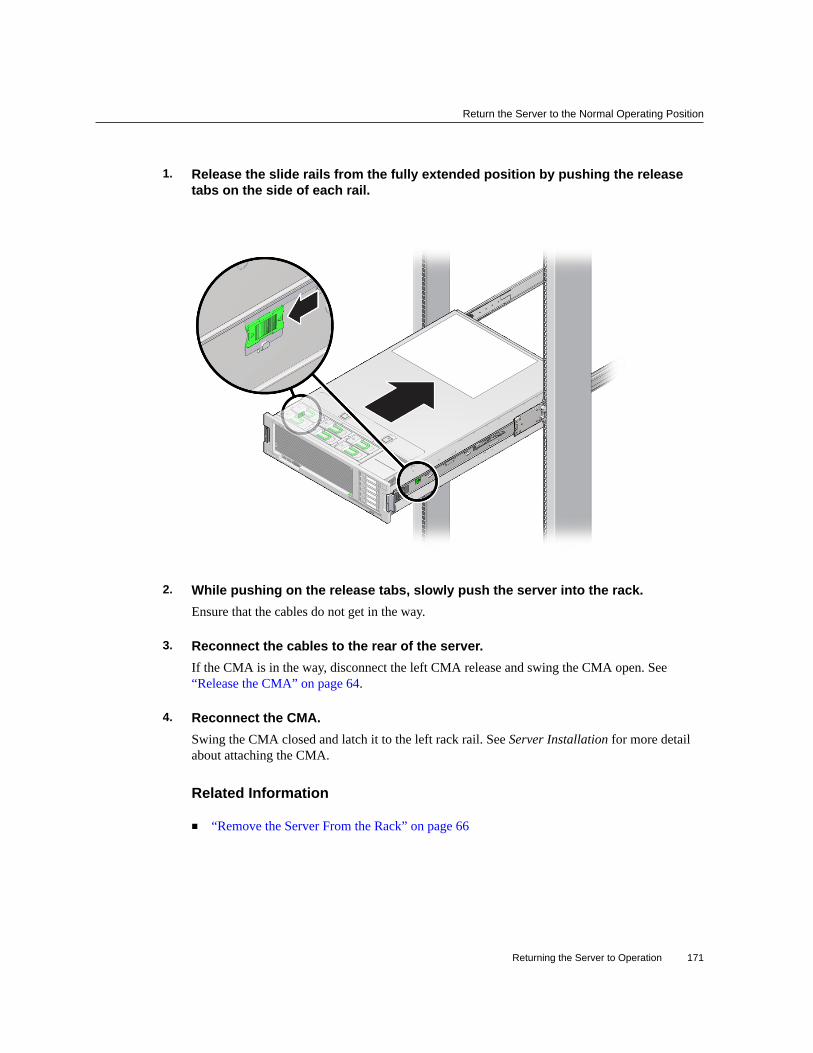
Return the Server to the Normal Operating Position
1. Release the slide rails from the fully extended position by pushing the releasetabs on the side of each rail.
2. While pushing on the release tabs, slowly push the server into the rack.Ensure that the cables do not get in the way.
3. Reconnect the cables to the rear of the server.If the CMA is in the way, disconnect the left CMA release and swing the CMA open. See“Release the CMA” on page 64.
4. Reconnect the CMA.Swing the CMA closed and latch it to the left rack rail. See Server Installation for more detailabout attaching the CMA.
Related Information
■ “Remove the Server From the Rack” on page 66
Returning the Server to Operation 171

Attach Power Cords
Attach Power Cords1. Attach both power cords to the power supplies.
Note - As soon as the power cords are connected to a power source, standby power is applied inthe server. Depending on how the firmware is configured, the server might boot at this time.
2. Power on the server.See “Power On the Server (Oracle ILOM)” on page 172 or “Power On the Server (PowerButton)” on page 173.
Related Information
■ “Power On the Server (Oracle ILOM)” on page 172■ “Power On the Server (Power Button)” on page 173
Power On the Server (Oracle ILOM)Before You Begin Note - If you are powering on the server following an emergency shutdown that was triggered
by the top cover interlock switch, you must use the poweron command.
Type poweron at the Oracle ILOM prompt.
-> poweron
You will see an alert message on the system console. This message indicates that the server isreset. You will also see a message indicating that the VCORE has been margined up to the valuespecified in the default .scr file that was previously configured. For example:
-> start /System
Related Information
■ “Power On the Server (Power Button)” on page 173
172 SPARC T5-2 Server Service Manual • February 2019

Power On the Server (Power Button)
Power On the Server (Power Button)
Caution - Do not operate the server without all fans, component heat sinks, air baffles, fillers,and the cover installed. Severe damage to server components can occur if the server is operatedwithout adequate cooling mechanisms.
1. Verify that the power cords are connected and that standby power is on.Shortly after power is applied to the server, the SP OK/Fault LED blinks as the SP boots. TheSP OK/Fault LED is illuminated solid green when the SP has successfully booted. After the SPhas booted, the Power OK/LED on the front panel begins flashing slowly, indicating that thehost is in standby power mode.
2. Press and release the recessed power button on the server front panel.
FIgure Legend
1 Power/OK LED
2 Power button
3 SP OK Fault LED
When main power is applied to the server, the main Power/OK LED begins to blink morequickly while the server boots and lights solidly once the operating system boots.
Each time the server powers on, POST can take several minutes to complete tests.
Related Information
■ “Power On the Server (Oracle ILOM)” on page 172
Returning the Server to Operation 173

174 SPARC T5-2 Server Service Manual • February 2019

Glossary
A
ANSI SIS American National Standards Institute Status Indicator Standard.
ASF Alert standard format (Netra products only).
AWG American wire gauge.
B
blade Generic term for server modules and storage modules. See server module and storage module.
blade server Server module. See server module.
BMC Baseboard management controller.
BOB Memory buffer on board.
C
chassis For servers, refers to the server enclosure. For server modules, refers to the modular systemenclosure.
CMA Cable management assembly.
CMM Chassis monitoring module (server modules only). The CMM is the service processor in themodular system that contains server modules. Oracle ILOM runs on the CMM, providing lightsout management of the components in the modular system chassis. See modular system andOracle ILOM.
CMP Chip multiprocessor.
Glossary 175

DHCP
D
DHCP Dynamic Host Configuration Protocol.
disk moduleor disk blade
Interchangeable terms for storage module. See storage module.
DTE Data terminal equipment.
E
EIA Electronics Industries Alliance.
ESD Electrostatic discharge.
F
FEM Fabric expansion module (server modules only). FEMs enable server modules to use the10GbE connections provided by certain NEMs. See NEM.
FRU Field-replaceable unit.
H
HBA Host bus adapter.
host The part of the server or server module with the CPU and other hardware that runs the OracleSolaris OS and other applications. The term host is used to distinguish the primary computerfrom the SP. See SP.
hot-pluggable Describes a component that can be replaced with power applied, but the component must beprepared for removal.
hot-swappable
Describes a component that can be replaced with power applied, and no preparation is required.
I
ID PROM Chip that contains system information for the server or server module.
176 SPARC T5-2 Server Service Manual • February 2019

NMI
IP Internet Protocol.
K
KVM Keyboard, video, mouse. Refers to using a switch to enable sharing of one keyboard, onedisplay, and one mouse with more than one computer.
L
LwA Sound power level.
M
MAC Machine access code.
MAC address Media access controller address.
modularsystem
The rackmountable chassis that holds server modules, storage modules, NEMs, and PCI EMs(server modules only). The modular system provides Oracle ILOM through its CMM.
MSGID Message identifier.
N
name space Top-level Oracle ILOM target.
NEBS Network Equipment-Building System (Netra products only).
NEM Network express module (server modules only). NEMs provide Ethernet and SAS connectivityto storage modules.
NET MGT Network management port. An Ethernet port on the server SP, the server module SP, and theCMM.
NIC Network interface card or controller.
NMI Nonmaskable interrupt.
Glossary 177

OBP
O
OBP OpenBoot PROM. Sometimes OBP is used in file names and messages to indicate arelationship to OpenBoot.
Oracle ILOM Oracle Integrated Lights Out Manager. Oracle ILOM firmware is preinstalled on a variety ofOracle systems. Oracle ILOM enables you to remotely manage your Oracle servers regardlessof the state of the host system.
Oracle ILOMCMM
Oracle ILOM that runs on the CMM (server modules only). See Oracle ILOM.
Oracle SolarisOS
Oracle Solaris operating system.
P
PCI Peripheral component interconnect.
PEM PCIe ExpressModule (server modules only). Modular components that are based on the PCIExpress industry-standard form factor and offer I/O features such as Gigabit Ethernet and FibreChannel.
POST Power-on self-test.
PROM Programmable read-only memory.
PSH Predictive self healing.
R
REM RAID expansion module (server modules only). Sometimes referred to as an HBA See HBA.Supports the creation of RAID volumes on drives.
S
SAS Serial attached SCSI.
SCC System configuration chip.
178 SPARC T5-2 Server Service Manual • February 2019

WWN
SER MGT Serial management port. A serial port on the server SP, the server module SP, and the CMM.
server module Modular component that provides the main compute resources (CPU and memory) in amodular system. Server modules also might have on-board storage and connectors that holdFEMs.
SP Service processor. In the server or server module, the SP is a card with its own OS. The SPprocesses Oracle ILOM commands providing lights out management control of the host. Seehost.
SSD Solid-state drive.
SSH Secure shell.
storagemodule
Modular component that provides computing storage to the server modules.
T
TIA Telecommunications Industry Association (Netra products only).
Tma Maximum ambient temperature.
U
U.S. NEC United States National Electrical Code.
UCP Universal connector port.
UI User interface.
UL Underwriters Laboratory Inc.
UTC Coordinated Universal Time.
UUID Universal unique identifier.
W
WWN World wide name. A unique number that identifies a SAS target.
Glossary 179

180 SPARC T5-2 Server Service Manual • February 2019

Index
AAC OK LED, location of, 15airflow baffle
removing, 141
Bbattery
installing, 118removing, 117
Ccfgadm command, 78chassis serial number, locating, 56clearing faults
PSH-detected faults, 49CMA
releasing left side, 64CMP, physical layout, 97cold service, 57component service categories, 57configuring
PCIe cards, 121configuring how POST runs, 43controls
front panel, 37
Ddiag_level parameter, 41diag_mode parameter, 41diag_trigger parameter, 42
diag_verbosity parameter, 42diagnostics
low-level, 41DIMMs
classification labels, 100enabling new, 109FRU names, 97installing, 106locating faulty
LEDs, 100Oracle ILOM, 102
physical layout, 97removing, 103
dmesg command, 50drive backplane
installing, 159removing, 157verifying function of replaced, 161
drivesabout, 69filler panels
installing, 77removing, 74
installing, 76removing, 71verifying function of replaced, 78
DVD driveinstalling, 114removing, 113
Eenabling new DIMMs, 109ESD, preventing, 54
181

Index
Ethernet cables, connecting, 68external cables, connecting, 68
Ffailed See faultedfan board
installing, 137removing, 135verifying function of replaced, 139
Fan Module Fault LED, 37fan modules
installing, 86LEDs, location of, 13locating faulty, 83removing, 83verifying function of replaced, 87
Fault Remind buttonon air divider, 104on memory riser, 105
faultedDIMMs, locating (Oracle ILOM), 102power supplies, locating, 91
faultsdetecting and managing, 31PSH-detected
checking for, 46faulty
DIMMs, locating (LEDs), 100filler panels
installingdrives, 77
removingdrives, 74
fmadm command, 49fmdump command, 46front panel controls and LEDs, 37front panel features, location of, 13
Ggraceful shutdown, defined, 60
HHD-15 video connector, location of, 15hot service, 57
Iinstalling
battery, 118DIMMs, 106drive backplane, 159drive filler panels, 77drives, 76DVD drive, 114fan board, 137fan modules, 86memory risers, 106motherboard, 147PCIe cards, 126power supplies, 93PS backplane, 165SP, 131top cover, 169
internal system cables, 16
LLEDs
Fan Module Fault, 37front panel, 37Locator, 37, 39, 57NET MGT port Link and Activity, 39NET MGT port Speed, 39NET ports Link and Activity, 39on front panel, 13on rear panel, 15Overtemperature, 13, 37Overtemperature LED, 39Power OK, 37, 39Power Supply Fault, 13Service Required, 37, 39SP fault, 13
locating
182 SPARC T5-2 Server Service Manual • February 2019

Index
chassis serial number, 56faulty
DIMMs (with LEDs), 100DIMMs (with Oracle ILOM), 102fan modules, 83power supplies, 91
server, 57location of replaceable components, 17Locator LED, 37, 39Locator LED and button, location of, 13log files
viewing, 50
MMAC address PROM
installing, 151removing, 143
maintenance position, 66maximum testing with POST, 45memory risers
FRU names, 97installing, 106physical layout, 97population rules, 99removing, 103
message buffer, checking the, 50message identifier, 46message log files, viewing, 50motherboard
installing, 147reactivate RAID volumes, 153removing, 141verifying function of replaced, 155
NNET MGT port Link and Activity LED, 39NET MGT port Speed LED, 39NET ports Link and Activity LED, 39network (NET) ports, location of, 15
OOracle ILOM
locating failed DIMMs, 102Oracle Solaris
files and commands, 50Oracle Solaris PSH
checking for faults, 46clearing faults, 49overview, 46
Oracle VTSusing for fault diagnosis, 32
Overtemperature LED, 37, 39Overtemperature LED, location of, 13
PPCIe cards
configuration rules, 121installing, 126removing, 123root complex paths, 122slot locations, 15, 15
physical layoutCMP, memory risers, DIMMs, 97
populating memory risers, 99POST
about, 41configuration examples, 43configuring, 43running in Diag Mode, 45
Power button, 37Power button, location of, 13Power OK LED, 37, 39power supplies
fault LED, location of, 13installing, 93locating faulted, 91removing, 91verifying function of replaced, 95
Power Supply Fail LED, location of, 15Power Supply OK LED, location of, 15power-on self-test, see POST, 41PS backplane
183

Index
installing, 165removing, 163verifying function of replaced, 167
PSH Knowledge article web site, 46
RRAID
reactivate RAID volumes, 153removing
airflow baffle, 141battery, 117DIMMs, 103drive backplane, 157drive filler panels, 74drives, 71DVD drive, 113fan board, 135fan modules, 83memory risers, 103motherboard, 141PCIe cards, 123power supplies, 91PS backplane, 163SP, 130top cover, 67
replaceable component locations, 17RJ-45 serial port, location of, 15root complex, 122running POST in Diag Mode, 45
Ssafety
information topics, 53precautions, 53symbols, 54
schematic diagrams, 25SER MGT port
location of, 15serial number (chassis), locating, 56server
locating, 57
Service Action Required LED, 13Service Required LED, 37, 39show faulty command, 49slide rail, 63SP
fault LED, location of, 13installing, 131NET MGT port, 15removing, 130verifying function, 133
standby power, defined, 60status LEDs, locations of, 15symbols, safety, 54system schematics, 25
Ttop cover
installing, 169removing, 67
troubleshootingusing Oracle VTS, 32
UUSB ports
location offront, 13rear, 15
UUID, 46
V/var/adm/messages file, 50verifying function of replaced
drive backplane, 161drives, 78fan board, 139fan modules, 87motherboard, 155power supplies, 95PS backplane, 167
184 SPARC T5-2 Server Service Manual • February 2019

Index
SP, 133video connector
location of, 13viewing message log files, 50
185

186 SPARC T5-2 Server Service Manual • February 2019