TWINNY T7 TWINNY T5 - F. Jannone AG
104
Leister Technologies AG Galileo-Strasse 10 CH-6056 Kaegiswil/Switzerland Tel. +41 41 662 74 74 Fax +41 41 662 74 16 www.leister.com [email protected] ® DE EN IT TWINNY T7 TWINNY T5
-
Upload
khangminh22 -
Category
Documents
-
view
0 -
download
0
Transcript of TWINNY T7 TWINNY T5 - F. Jannone AG

Leister Technologies AGGalileo-Strasse 10CH-6056 Kaegiswil/Switzerland
Tel. +41 41 662 74 74 Fax +41 41 662 74 16
® DE EN IT
TWINNY T7TWINNY T5

DE Deutsch Bedienungsanleitung 3
EN English Operating Instructions 36
IT Italiano Istruzioni per l’uso 69

DE Deutsch Bedienungsanleitung
Inhaltsverzeichnis
1. Wichtige Sicherheitshinweise .............................................................................................................. 51.1 Bestimmungsgemässe Verwendung ............................................................................................. 61.2 Nicht bestimmungsgemässe Verwendung ..................................................................................... 6
2. Technische Daten ................................................................................................................................. 6
3. Transport .............................................................................................................................................. 7
4. Ihr TWINNY T7/T5 ................................................................................................................................. 74.1 Typenschild und Identifizierung ..................................................................................................... 74.2 Lieferumfang (Standard-Ausrüstung im Koffer) .............................................................................. 74.3 Optionales Zubehör ..................................................................................................................... 74.4 Übersicht Geräteteile ................................................................................................................... 84.5 Netzunterbruch ........................................................................................................................... 9
5. Bedienfeld TWINNY T7 .......................................................................................................................... 95.1 Übersicht Bedienfeld TWINNY T7 .................................................................................................. 95.2 Funktionstasten ........................................................................................................................... 105.3 Status LED-Anzeige ..................................................................................................................... 105.4 Anzeigesymbole der Statusanzeige ............................................................................................... 115.5 Anzeigesymbole Funktionsanzeige ................................................................................................ 115.6 Anzeigesymbole der Arbeitsanzeige .............................................................................................. 12
6. Setup-Menü vom Bedienfeld des TWINNY T7 ....................................................................................... 136.1 Übersicht Menüführung ............................................................................................................... 136.2 Schweissrezepte einrichten, speichern und auswählen (Save Recipes) ............................................ 146.3 Eingeben von Rezeptnamen ......................................................................................................... 156.4 Bereitschaftsmodus (Standby) ...................................................................................................... 166.5 Grundeinstellung und Advanced Mode .......................................................................................... 166.6 Duty Info ..................................................................................................................................... 166.7 General Info ................................................................................................................................ 176.8 Warnings .................................................................................................................................... 176.9 Machine Setup ........................................................................................................................... 176.10 Einblenden aktueller Werte (Application Mode) .............................................................................. 176.11 Set Values .................................................................................................................................. 186.12 Reset to defaults ......................................................................................................................... 186.13 Anzeige Tagesdistanz .................................................................................................................. 186.14 Tastensperre ............................................................................................................................... 19
7. Inbetriebnahme TWINNY T7 .................................................................................................................. 197.1 Arbeitsumgebung und Sicherheit .................................................................................................. 197.2 Einstellen der Schweissparameter ................................................................................................ 197.3 Schweissvorbereitung .................................................................................................................. 217.4 Schweissablauf ........................................................................................................................... 217.5 Gerät ausschalten ....................................................................................................................... 23
8. Warnung und Fehlermeldung (TWINNY T7)........................................................................................... 24
9. Bedienfeld TWINNY T5 .......................................................................................................................... 269.1 Symbole ..................................................................................................................................... 269.2 Status LED-Anzeige ..................................................................................................................... 269.3 Einstellen der Parametereinheiten................................................................................................. 27

4
9.4 Tastensperre ............................................................................................................................... 27
10. Inbetriebnahme TWINNY T5 ................................................................................................................ 2810.1 Arbeitsumgebung und Sicherheit ................................................................................................... 2810.2 Einstellen der Schweissparameter ................................................................................................ 2810.3 Schweissvorbereitung .................................................................................................................. 3010.4 Schweissablauf ........................................................................................................................... 3010.5 Gerät ausschalten ....................................................................................................................... 31
11. Fehlermeldungen ................................................................................................................................ 31
12. Einstellungen am TWINNY T7/T5 ........................................................................................................ 3212.1 Austausch Andrückrollen ............................................................................................................. 3212.2 Austausch Schweissdüse ............................................................................................................. 3312.3 Montage Field-Kit ........................................................................................................................ 3412.4 Montage Führungsstab ................................................................................................................ 34
13. Zubehör .............................................................................................................................................. 35
14. Service und Reparatur ........................................................................................................................ 35
15. Schulung............................................................................................................................................. 35
16. Gewährleistung................................................................................................................................... 35
17. Konformität ......................................................................................................................................... 35
18. Entsorgung ......................................................................................................................................... 35

5
Bedienungsanleitung (Original Bedienungsanleitung)DE
LEISTER TWINNY T7/T5 Schweissautomat
Bitte lesen Sie die Bedienungsanleitung vor der ersten Inbetriebnahme unbedingt durch. Bewahren Sie diese Bedienungsanleitung immer beim Gerät auf.Geben Sie das Gerät nur mit Bedienungsanleitung an andere Personen weiter.
Bitte beachten Sie unbedingt die sicherheitstechnischen Hinweise in den einzelnen Kapiteln dieser Bedienungsan-leitung und die nachfolgenden Bestimmungen.
1. Wichtige Sicherheitshinweise
Wir gratulieren Ihnen zum Kauf Ihres TWINNY T7/T5.Sie haben sich für einen erstklassigen Heissluftschweissautomaten entschieden. Entwickelt und produziert wurde er nach dem aktuellsten Wissensstand der kunststoffverarbeitenden Industrie. Für seine Herstellung werden hochwertige Materialien verwendet.
Warnung
FI
Vorsicht
Lebensgefahr Vor dem Öffnen des Gerätes Netzstecker aus der Steckdose ziehen, weil span-nungsführende Komponenten und Anschlüsse freigelegt werden.
Feuer- und Explosionsgefahr Bei unsachgemässem Gebrauch des Schweissautomaten (z.B. durch Überhitzung von Material) sowie besonders in der Nähe von brennbaren Materialien und explosiven Gasen bestehen Feuer- und Explosionsgefahr.
Verbrennungsgefahr Heizelementrohr und Düse nicht im heissen Zustand berühren. Das Gerät stets zuerst abkühlen lassen. Heissluftstrahl nicht auf Personen oder Tiere richten.
Gerät an eine Steckdose mit Schutzleiter anschliessen.Jede Unterbrechung des Schutzleiters innerhalb oder ausserhalb des Gerätes ist nicht zulässig. Ausschliesslich Verlängerungskabel mit Schutzleiter verwenden.
Für den Einsatz des Gerätes auf Baustellen ist ein FI-Schutzschalter zum Schutz des dort arbeitenden Personals zwingend erforderlich.
Die auf dem Gerät angegebene Nennspannung muss mit der Netzspannung vor Ort übereinstimmen. Bei Ausfall der Netzspannung Hauptschalter ausschalten und Heissluftgebläse in Parkposition schwenken.
Gerät vor Feuchtigkeit und Nässe schützen.
Das Gerät darf ausschliesslich unter Aufsicht betrieben werden. Abwärme kann zu brennbaren Materialien gelangen, die sich ausser Sichtweite befinden.Das Gerät darf nur von ausgebildeten Fachleuten oder unter deren Aufsicht betrieben werden. Kindern ist die Nutzung gänzlich untersagt.
Mehr Informationen über den TWINNY und die myLeister-App finden Sie auf www.leister.com

6
TWINNY T7/T5 ist für das Überlappschweissen und Konfektionieren von Folien und Dichtungsbahnen vorgesehen. Die maximale Überlappbreite beträgt 125 mm. Die maximale Schweissnahtbreite beträgt 50 mm.
Verwenden Sie ausschliesslich original Leister-Ersatzteile und -Zubehör, weil Sie anderenfalls keine Gewährleis-tungs- oder Garantieansprüche geltend machen können.
Materialtypen und Materialstärken
Weitere Materialien auf Anfrage.
Jede andere oder darüber hinausgehende Benutzung gilt als nicht bestimmungsgemäss.
2. Technische Daten
* Anschlussspannung nicht umstellbar
Technische Änderungen bleiben vorbehalten.
1.1 Bestimmungsgemässe Verwendung
1.2 Nicht bestimmungsgemässe Verwendung
TWINNY T7230 V
TWINNY T5230 V
TWINNY T5120 V
Nennspannung* V~ 230 230 120Nennleistung W 3400 3400 1800Frequenz Hz 50 / 60Temperatur °C
°F100 - 560
212 - 1040Luftmenge % 45 - 100Antrieb m/min
ft/min0.8 – 8
2.6 – 26.2Fügekraft max. N/lbf 1000 / 225Emissionspegel LpA (dB) 73 (K = 3 dB)Masse (L × B × H) mm
inch350 × 360 × 260
13.8 × 14.2 × 10.2
Gewicht kg / lbs 10.5 / 23.1 9.5 / 21KonformitätszeichenSchutzklasse I
Material Materialstärke RichtwertPE-HD, PP 0.3 mm – 2.5 mmPVC-P, PE-LD, TPO, FPO 0.3 mm – 3.0 mm

7
Verwenden Sie für den Transport des Heissluftschweissautomaten ausschliesslich die im Lieferumfang enthaltene Transportbox (sowie den an der Transportbox angebrachten Griff).
Lassen Sie das Heissluftgebläse (19) vor dem Transport unbedingt ausreichend abkühlen (siehe Cool down mode).
Lagern Sie niemals brennbare Materialien (z.B. Plastik, Holz) in der Transportbox.
Verwenden Sie die Traggriffe (2) am Gerät oder an der Transportbox niemals für den Transport mit einem Kran.
3. Transport
4. Ihr TWINNY T7/T5
4.1 Typenschild und Identifizierung
4.2 Lieferumfang (Standard-Ausrüstung im Koffer)
4.3 Optionales Zubehör
Beispiel:
Die Typenbezeichnung und die Serienkennzeichnung sind auf dem Typenschild (21) Ihres Geräts angebracht.Bitte übertragen Sie diese Angaben in Ihre Bedienungsanleitung. Bei allen Anfragen an unsere Vertretung oder autorisierte Leister Service-Stelle beziehen Sie sich bitte immer auf diese Angaben.
Typ: ..................................................................................................................................................................
Serien-Nr.: ........................................................................................................................................................
Zum Anheben des Heissluftschweissautomaten von Hand benutzen Sie die Traggriffe (2).
1 x Gerät TWINNY T7/T5 (gem. Konfiguration)• 1 x Drahtbürste• 1 x Original-Bedienungsanleitung• 1 x Übersetzung Original-Bedienungsanleitung
• Field-Kit• Führungsstab• Div. Antriebs-/Andrückrollen• Div. Schweissdüsen
2
8
4.4 Übersicht Geräteteile
1. Netzanschlussleitung2. Handgriffe3. Bedienfeld4. Spannhebel5. Arretierung Spannhebel6. Fügekraftmodul7. Spannarm8. Pendelkopf9. Antriebs-/Andrückrollen oben10. Laufrolle hinten11. Antriebs-/Andrückrollen unten
12. Kontaktiersystem unten13. Schleppzunge14. Kontaktiersystem oben15. Schweissdüse16. Laufrolle vorne17. Einschwenkmechanik18. Arretierung Heissluftgebläse19. Heissluftgebläse20. Hauptschalter21. Typenschild
1
3
21 20 3
4
5
6
7
8
11
9
10
17 16
18
19
2
12131415

9
4.5 Netzunterbruch
5.1 Übersicht Bedienfeld TWINNY T7
Lassen Sie das Heissluftgebläse (19) vor dem Transport unbedingt ausreichend abkühlen (siehe Cool down mode).
Die auf dem Gerät angegebene Nennspannung muss mit der Netzspannung vor Ort übereinstimmen. Bei Ausfall der Netzspannung Hauptschalter ausschalten und Heissluftgebläse in Parkposition schwenken.
Zustand Gerät vordem Netzunterbruch
Dauer Netzunterbruch Zustand Gerät nach Netzunterbruch
TWINNY T7 TWINNY T5Antrieb und Heizung sind eingeschaltet (Schweiss-prozess).
≤ 5 Sek.Das Gerät läuft ohne Wiederanlaufschutz mit den gleichen Einstel-lungen wie vor dem Unterbruch weiter.
Antrieb und Heizung sind eingeschaltet (Schweiss-prozess).
> 5 Sek. Das Gerät startet und auf dem Display erscheint die Startanzeige.
Das Gerät befindet sich nicht im Schweisspro-zess.
- Das Gerät startet und auf dem Display erscheint die Startanzeige.
5. Bedienfeld TWINNY T7
22
23 29
31
30
24
25
26 27 28
22. Taste "Auf"23. Taste "Ab"24. Taste Heizung "Ein/Aus"25. Taste Antrieb "Ein/Aus"26. Status-LED27. «e-Drive»28. Funktionsanzeige29. Arbeitsanzeige30. Statusanzeige "Bereich 1"31. Statusanzeige "Bereich 2"

10
5.2 Funktionstasten
5.3 Status LED-AnzeigeHeizungDie LED bei der Taste Heizung "Ein/Aus" (24) zeigt den jeweiligen Zustand der Heizung an.
Tastaturmodus Aktuelle AuswahlArbeitsanzeige
Aktuelle Auswahl Funktionsanzeige
Aktuelle Auswahl Setup-Menü
Auf (22)Ab (23)
Verändern der Position innerhalb der Arbeits-anzeige.
Wechseln von Funktionsanzeige in Arbeitsanzeige.
Verändert die Position inner-halb des Setup-Menüs.
HeizungEin/Aus (24)
Schaltet Heizungein/aus
Schaltet Heizungein/aus
Keine Funktion
AntriebEin/Aus (25)
Schaltet Antrieb ein/aus
Schaltet Antrieb ein/aus
Keine Funktion
«e-Drive» (27) drücken
Eingestellter Wert wird direkt übernommen und die Auswahl springt direkt in die Funktionsanzeige zurück.
Ausgewählte Funktion wird ausgeführt.
Anwählen der markierten Position.
«e-Drive» (27) drehen
Einstellen der ge-wünschten Sollwerte in 10 °C bzw. 0.1 m/min-Schritten
Verändern der Position in der Funktionsanzeige.
• Verändert die Postion innerhalb des Setup-Me-nüs
• Einstellen des Wertes der angewählten Position
LED-Status (26)Heizung Ein/Aus (24)
Zustand Ursache
LED aus Heizung ist ausgeschaltet.
LED blinkt grünHeizung ist eingeschaltet. Tempe-ratur ist ausserhalb des Toleranz-bandes.
LED dauernd grünHeizung ist eingeschaltet. Tempe-ratur ist innerhalb des Toleranz-bandes.
Tritt während des Betriebes der Heizung eine Warnmeldung in der Statusanzeige Bereich 2 (31) auf oder eine Fehlermeldung in der Arbeitsanzeige (29), wird diese wie folgt dargestellt:
LED blinkt rot Warnmeldung der Heizung Siehe Warnung und Fehlermeldung.
LED dauernd rot Fehlermeldung der Heizung Siehe Warnung und Fehlermeldung.

11
Antrieb
LED-Status (26)Heizung Ein/Aus (24)
Zustand Ursache
LED aus Antrieb ist ausgeschaltet
LED dauernd grün Antrieb ist eingeschaltet
Tritt während des Betriebes des Antriebs eine Warnmeldung in der Statusanzeige Bereich 2 (31) auf oder eine Fehlermeldung in der Arbeitsanzeige (29), wird diese wie folgt dargestellt:
LED blinkt rot Antrieb Strombegrenzung ist aktiv. Siehe Warnung und Fehlermeldung.
LED dauernd rot Antrieb hat einen Fehler. Siehe Warnung und Fehlermeldung.
Die LED der Taste Antrieb "Ein/Aus" (25) zeigt den Zustand des Antriebs an.
5.4 Anzeigesymbole der Statusanzeige
5.5 Anzeigesymbole Funktionsanzeige
Name des abgespeicherten Wertes
Aktuell ausgewählte Schweissparameter. Bei Namen mit mehr als 6 Zeichen werden zuerst die ersten 6 Zeichen angezeigt, anschliessend die verbleibenden Zeichen.
230 V Aktuell am Netzstecker anliegende Netzspannung
001 Aktuelle Filenummer der Schweissdatenaufzeichnung
Statusanzeige "Bereich 1" (30)
Verfügbare Menüs wählen Sie mit dem «e-Drive» (27) des Bedienfelds (3) aus.
Unterspannung Überspannung
Heizung(nur bei aktivierter Heizung)
Tastensperre(nur bei aktiver Tastensperre)
Statusanzeige "Bereich 2" (31)
Warnung vorhanden(s. Kap. Warnung & Fehlermeldungen)
Symbol Bedeutung Symbol Bedeutung
Freie und vordefinierte Rezepte auswählen
Service Menü(nur über Passworteingabe verfügbar)
Einstellungen Speichern
Zurück zur Arbeitsanzeige(direktes Verlassen eines Menüs)
Ausgewählte Position löschen
Eine Ebene zurück Ausgewählte Position bearbeiten
Einstellungen oder Stundenzähler zurücksetzen

12
Symbol Bedeutung
Geschwindigkeit Antrieb [m/min / ft./min]
Geschwindigkeit Antrieb gesperrt [m/min / ft./min]
Lufttemperatur [°C/°F]
Fügekraft [N/lbf]
Luftmenge [%]
Informationsfenster
Geräte im Standby-Modus. Nach Ablauf des Zählers wird die Heizung ausgeschaltet.
Gerät hat einen Fehler. Zusätzlich erscheint ein Fehlercode (Gerät nicht mehr einsatzbereit). Autorisierte Service-Stelle kontaktieren.Siehe Kapitel "Warnungen und Fehlermeldungen"
Warnung: Siehe Kapitel "Warnungen und Fehlermeldungen"
380160 °C
Der Pfeil nach oben und der Fortschrittsbalken zeigen an, dass der Sollwert (Markierung im Fortschrittsbalken) noch nicht erreicht ist (zu kalt). Der blinkende Wert ist der Ist-Wert. Der Wert neben dem Fortschrittsbalken ist der eingestellte Soll-Wert.
390 °C380
Der Pfeil nach unten und der Fortschrittsbalken zeigen an, dass der Sollwert (Mar-kierung im Fortschrittsbalken) noch nicht erreicht ist (zu heiss). Der blinkende Wert ist der Ist-Wert. Der Wert neben dem Fortschrittsbalken ist der eingestellte Soll-Wert.
385 °C380
Ist Set Values aktiviert, wird die Ist-Temperatur (gross) und die Soll-Temperatur (klein) dargestellt. Standard-Einstellung ab Werk.
°C380 Ist Set Values deaktiviert, erscheinen im Betrieb nur die Ist-Werte (gross) ansonsten nur die Soll-Werte (gross).
Abkühlvorgang (Cool Down Mode)
Fehlermeldung Hardware (Heizelement defekt).Das Gerät ist nicht mehr einsatzbereit. Kontaktieren Sie ein autorisiertes Leister Service-Center.
5.6 Anzeigesymbole der Arbeitsanzeige

13
6. Setup-Menü vom Bedienfeld des TWINNY T76.1 Übersicht Menüführung
Nur im «Advanced Mode» verfügbar
14
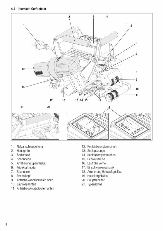
6.2 Schweissrezepte einrichten, speichern und auswählen (Save Recipes)
Ihr TWINNY T7 verfügt über neun frei definierbare Rezepte und über das Rezept „BASIC“Mit Save Recipes können Sie die Sollwerteinstellungen der Schweissparameter Antrieb, Lufttemperatur und Luft-menge unter einer frei wählbaren Bezeichnung abspeichern (siehe Eingeben von Rezeptnamen).
Erstellen eines neuen Rezepts
1. Gewünschte Sollwerte einrichten [Arbeitsanzeige, «e-Drive» (27)]2. Menü Einstellungen wählen und bestätigen [Menüwahl, ««e-Drive» (27)]3. Menü Save Recipes wählen [Menüwahl, ««e-Drive» (27)]4. Menü User-defined wählen und bestätigen [Menüwahl, «e-Drive» (27)]5. Menü Ausgewählte Position bearbeiten wählen und bestätigen [Menüwahl, «e-Drive» (27)]6. Gewünschten Rezeptnamen eingeben, Tastatur Enter wählen (siehe Eingeben von Rezeptnamen) und bestäti-
gen [Menüwahl, «e-Drive» (27)]7. Menü Speichern wählen und bestätigen [Menüwahl, «e-Drive» (27)]
Ihr neu erstelltes Rezept ist nun gespeichert und jederzeit unter dem eingegebenen Namen abrufbar.
Anpassen eines bestehenden Rezeptes
1. Gewünschte Sollwerte einrichten [Arbeitsanzeige, «e-Drive» (27)]2. Menü Einstellungen wählen und bestätigen [Menüwahl, «e-Drive» (27)]3. Menü Save Recipes wählen [Menüwahl, «e-Drive» (27)]4. Das anzupassende Rezept auswählen und bestätigen [Menüwahl, «e-Drive» (27)]5. Funktion Speichern, Ausgewählte Position bearbeiten oder Löschen wählen und bestätigen [Menüwahl,
«e-Drive» (27)]6. Wenn Ausgewählte Position bearbeiten gewählt wurde, einen frei wählbaren Rezeptnamen gemäss den oben
beschriebenen Schritten 6 und 7 eingeben

15
Rezeptwahl• Durch Anwählen des Icons „Freie und vordefinierte Rezepte anwählen“ in der Funktionsanzeige (28) gelangen
Sie ins Menü „Select Recipes“.• Setzen Sie den Cursor mit den Tasten „Auf“ und „Ab“ (22/23) auf das gewünschte Rezept und bestätigen Sie
mit dem «e-Drive» (27).• Ändern Sie Sollwerte in von Ihnen erstellten Rezepte während des Betriebs, werden diese nicht im Rezept
gespeichert. Bei einem Neustart des Geräts erscheinen wieder die im Rezept gespeicherten Werte.• Möchten Sie bei einem Neustart des Geräts die zuletzt verwendeten Sollwerte benutzen, müssen Sie das
vorprogrammierte Rezept „BASIC“ auswählen.• Das aktuell ausgewählte Rezept wird in der Statusanzeige „Bereich 1“ (30) angezeigt. Eine Ausnahme bildet
das Rezept „BASIC“, ist dies ausgewählt, so erscheint in der Statusanzeige (30) nur die Netzspannung.
6.3 Eingeben von RezeptnamenÜber den Tastaturmodus können Namen mit max. 12 Zeichen definiert werden.
Tastaturmodus Zeichenauswahl (32) Symbolauswahl (33)
Auf (22)Ab (23) Vertikale Zeichenauswahl
«e-Drive» (27) drehen Horizontale Zeichenauswahl Horizontale Symbolauswahl
«e-Drive» (27) drücken Ausgewählte Zeichen bestätigen Ausgewählte Symbole bestätigen
28
32
Wechsel zwischen Gross- und Kleinschreibung
Cursor-Position im Namen verschieben
Leerschlag einfügen
Löschen eines einzelnen Zeichens (Zeichen links von Cursor)
Durch Auswählen dieses Symbols Wechsel aufFunktionsanzeige (28)
33

16
Ist der Motor ausgeschaltet, die Heizung aktiviert und wird während der unter Standby Intervall definierten Zeit keine Taste betätigt, wechselt das Gerat automatisch in die Standby-Anzeige. Wird während den folgenden 180 Sek. der «e-Drive» (27) nicht gedrückt, schaltet die Heizung automatisch in den Cool Down Mode. Anschliessend erscheint auf dem Display Standby. Wird der «e-Drive» (27) gedrückt, wird in den Arbeitsmodus gewechselt.
Der Standby-Modus ist bei Auslieferung der Geräte nicht aktiviert.Das gewünschte zeitliche Intervall können Sie individuell festlegen, indem Sie das Stand-by-Menü mit dem «e-Drive» (27) anwählen und danach den gewünschten Wert mit dem «e-Drive» (27) einstellen.
6.4 Bereitschaftsmodus (Standby)
In der Grundeinstellung gelangen Sie über das Menü Setup zur Profilspeicherung, zur Standby-Funktion sowie zu Application Mode und Advanced Mode.
Im Advanced Mode stehen weitere Informationen und Einstellungsmöglichkeiten zur Verfügung.
Die Funktionen von „Kap. Duty Info“ bis „Kap. Reset to defaults“ sind nur im Advanced Mode verfügbar.
6.5 Grundeinstellung und Advanced Mode
Unter Duty Info erhalten Sie Angaben zur Laufzeit Ihres TWINNY T7.Gehen Sie mit dem «e-Drive» (27) ins Menü Einstellungen und bestätigen Sie Ihre Wahl. Stellen Sie nun mit dem «e-Drive» (27) den Advanced Mode auf On und wählen Sie dann Duty Info.
Hours Drive: aktuelle Laufzeit AntriebHours Blower: aktuelle Laufzeit GebläseHours Machine: aktuelle Laufzeit MaschineDay Distance: Zurückgelegte Strecke seit letzter Rückstellung (muss manuell zurückge-stellt werden)Total Distance: Zurückgelegte Strecke seit Inbetriebnahme des Gerätes
6.6 Duty Info

17
Unter General Info stehen Ihnen Versionsinformationen zur Software, sowie Angaben zum Produktionszeitpunkt zur Verfügung.
Gehen Sie mit dem «e-Drive» (27) ins Menü Einstellungen und bestätigen Sie Ihre Wahl. Stellen Sie mit dem «e-Drive» (27) den Advanced Mode auf On und wählen Sie nun General Info.
Gehen Sie mit dem «e-Drive» (27) ins Menü Einstellungen und bestätigen Sie Ihre Wahl. Stellen Sie nun mit dem «e-Drive» (27) den Advanced Mode auf On und wählen Sie anschliessend Machine Setup.
Wünschen Sie eine Übersicht relevanter Informationen wie Netzspannung, Auslastung der Heizung usw., wählen Sie das Menü Einstellungen und bestätigen Sie Ihre Wahl. Aktivieren Sie nun den Application Mode.
Warnmeldungen werden fallweise in der Statusanzeige (31) dargestellt. Liegt eine Warnung vor, können Sie weitgehend ohne Einschränkung weiterarbeiten. Im Menü Warnings wird angezeigt, welche Art von Störung vorliegt. Ist die Störung überwunden, erlischt der Eintrag.
Gehen Sie mit dem «e-Drive» (27) ins Menü Einstellungen und bestätigen Sie Ihre Wahl. Stel-len Sie mit dem «e-Drive» (27) den Advanced Mode auf On und wählen Sie nun Warnings.
Alle verfügbaren Informationen (Symbol i) werden nun in der Arbeitsanzeige (29) dargestellt (siehe Anzeigesymbole der Arbeitsanzeige). Das Informationsfeld wird immer unter dem Feld für die Luftmenge angezeigt.
Unit: Einstellen des Mass-Systems (metrisch oder imperial) für Unit Speed, Unit Heat und Unit ForceUnit Speed: individuelles Einstellen der verwendeten Einheit für Speed (metrisch/imperial)Unit Heat: individuelles Einstellen der verwendeten Einheit für Heat (metrisch/imperial)Unit Force: individuelles Einstellen der verwendeten Einheit für Force (metrisch/imperial)LCD Contrast: Kontrast LCD-Display anpassenLCD Backlight: Hintergrundbeleuchtung LCD-Display anpassenKey Backlight: Hintergrundbeleuchtung Tastatur Bedienfeld (3) anpassen
6.7 General Info
6.9 Machine Setup
6.10 Einblenden aktueller Werte (Application Mode)
6.8 Warnings
18
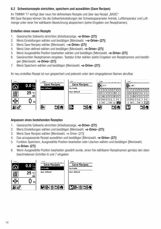
Wenn Sie die Funktion Set Values aktiviert haben, wird die Ist-Temperatur (gross) und die Soll-Temperatur (klein) in der Arbeitsanzeige (29) dargestellt. Dies gilt in analoger Form für die Antriebsgeschwindigkeit (m/min). Ist die Funktion deaktiviert, werden nur die Sollwerte dargestellt.Für den Parameter Fügekraft wird immer der Ist-Wert angezeigt.Die Funktion Set Values ist ab Werk aktiviert.
Gehen Sie mit dem «e-Drive» (27) ins Menü Einstellungen und bestätigen Sie Ihre Wahl. Stellen Sie nun den Advanced Mode auf On und wählen Sie anschliessend Reset to defaults.
Mit dieser Funktion setzen Sie alle individuell eingestellten Werte auf die Werkseinstellung zurück. Das Reset betrifft Einstellungen (Setup) ebenso wie Rezepte.Bestätigen Sie Ihre Wahl mit der Taste links unten (Auf Werkseinstellung zurücksetzen/Reset).
6.11 Set Values
6.12 Reset to defaults
6.13 Anzeige TagesdistanzSobald der Antrieb läuft und mehr als 200N Kraft in der Arbeitsanzeige (29) angezeigt werden, wird die geschweisste Distanz aufgezeichnet. Die Tagesdistanz kann wie folgt abgerufen werden:
• Setzen Sie mit den Pfeiltasten "Auf" (22) und "Ab" (23) den Cursor auf die Geschwindigkeit in der Arbeits-anzeige (29).
• Halten Sie «e-Drive» (27) 5 Sek. gedrückt.• In der Geschwindigkeitsanzeige werden nun die Werte
der Tagesdistanz und der Gesamt-Distanz angezeigt.• Durch kurzes Drücken des «e-Drive» (27) wird die
Geschwindigkeit in der Arbeitsanzeige (29) wieder angezeigt.
5 sec
1 ×
Im Schweissbetrieb• Während dem Schweissen ist die Arbeitsanzeige Geschwindigkeit gesperrt.• Durch kurzes Drücken des «e-Drive» (27) wird die Geschwindigkeitseinstellung freigegeben.• Halten Sie «e-Drive» (27) 5 Sek. gedrückt.• In der Geschwindigkeitsanzeige werden nun die Werte der Tagesdistanz und der Gesamt-Distanz angezeigt.• Durch kurzes Drücken des «e-Drive» (27) wird die Geschwindigkeit in der Arbeitsanzeige (29) wieder ange-
zeigt.• Nach Verlassen der Anzeige Tagesdistanz wird die Funktionsanzeige Geschwindigkeit wieder gesperrt.

19
Ihr TWINNY T7 verfügt mit „LQS“ (Leister Quality System) über eine Funktion zum Aufzeichnen der Schweissdaten. Mit dieser Funktion werden die Geschwindigkeit, die Temperatur und die Fügekraft während der Schweissung über die Schweissnahtlänge im vorgegebenen Distanz-Intervall aufgezeichnet. Weitere Informationen finden Sie in der dazugehörigen Bedienungsanleitung auf www.leister.com.
Gerät an eine Steckdose mit Schutzleiter anschliessen. Jede Unterbrechung des Schutzleiters inner-halb oder ausserhalb des Gerätes ist nicht zulässig. Ausschliesslich Verlängerungskabel mit Schutzleiter verwenden.
Die auf dem Gerät angegebene Nennspannung muss mit der Netzspannung vor Ort übereinstimmen. Bei Ausfall der Netzspannung Hauptschalter ausschalten und Heissluftgebläse in Parkposition schwenken.
Aggregate zur EnergieversorgungBeim Einsatz von Aggregaten zur Energieversorgung achten Sie bitte darauf, dass die Aggregate geerdet und mit FI-Schutzschalter ausgerüstet sind.Für die Nennleistung von Aggregaten gilt die Formel „2 × Nennleistung des Heissluftschweissautomaten“.
7.2 Einstellen der Schweissparameter
Netzanschlussleitung und Verlängerungskabel• Die Netzanschlussleitung (1) muss frei beweglich sein und
darf weder Anwender noch Dritte bei der Arbeit behindern (Stolpergefahr).
• Verlängerungskabel müssen für den Einsatzort (z.B. im Freien) zugelassen und entsprechend gekennzeichnet sein. Berück-sichtigen Sie gegebenenfalls den notwendigen Mindest-Quer-schnitt für Verlängerungskabel.
Der Heissluftschweissautomat darf nur im Freien oder in gut belüfteten Räumen eingesetzt werden.Setzen Sie den Heissluftschweissautomaten niemals in explosionsgefährdeter oder leicht entzündbarer Umgebung ein und halten Sie stets Abstand zu brennbaren Materialien oder explosiven Gasen.Lesen Sie das Material-Sicherheits-Datenblatt des Materialherstellers und befolgen Sie dessen Anwei-sungen. Achten Sie darauf, das Material während des Schweissprozesses nicht zu verbrennen.
Zurücksetzen der TagesdistanzDie Tagesdistanz kann nur zurückgesetzt werden, wenn der Antrieb ausgeschaltet ist.
7.1 Arbeitsumgebung und Sicherheit
6.14 TastensperreDer TWINNY T7 verfügt über eine Tastensperre. Diese sperrt die vier Tasten und den «e-Drive» (27) auf dem Bedienfeld (3). Durch gleichzeitiges Drücken der Tasten "Auf" und "Ab" (22/23) während mindestens 2 Sek. wird die Tastensperre aktiviert bzw. deaktiviert. Bei aktiver Tastensperre wird dies in der Statusleiste angezeigt.
7. Inbetriebnahme TWINNY T7
• Wählen Sie im Menüpunkt Duty Info (siehe Kapitel Duty Info) die Zeile Day Distance an.
• Der Cursor markiert dann automatisch das Icon „Stundenzähler zurücksetzen“. Bestätigen Sie dieses mit dem «e-Drive» (27)
• Der Stundenzähler ist nun zurückgestellt.

20
Für den Einsatz des Gerätes auf Baustellen ist ein FI-Schutzschalter zum Schutz des dort arbeitenden Personals zwingend erforderlich.
ACHTUNG!Bei Überschreiten der maximalen Fügekraft von 1000N können mechanische Beschädigungen auftreten
Quetschgefahr Durch mechanisch bewegte Teile besteht Quetschgefahr. Halten Sie den Heissluftschweissautomaten ausschliesslich an den dafür vorgesehenen Griffen.
Gerät starten• Schalten Sie den Heissluftschweissautomaten über den Hauptschalter (20) ein, wenn
Sie die Arbeitsumgebung und den Heissluftschweissautomaten gemäss Beschreibung vorbereitet haben.
• Nach dem Starten wird im Display für kurze Zeit das Startbild mit der Versionsnummer des aktuellen Software-Release sowie der Gerätebezeichnung angezeigt.
• Sofern das Gerät vorgängig abkühlen konnte, folgt eine statische Anzeige der Sollwerte des zuletzt verwendeten Rezeptes (bei der ersten Inbetriebnahme des Geräts wird das Rezept Basic angezeigt).
• In diesem Stadium ist die Heizung noch nicht eingeschaltet.
Einstellen der Fügekraft• Lösen Sie die Arretierung Einstellring (34) am Fügekraftmodul (6) und drehen Sie den Einstellring (35) am
Fügekraftmodul (6) bis zur maximalen Öffnung des Spannarms (7).• Legen Sie zwei Teststreifen (36) des zu verschweissenden Materials übereinander zwischen die obere und
untere Antriebs-/Andrückrollen (9/11) und schliessen Sie den Spannhebel (4).• Drehen Sie am Einstellring (35) des Fügekraftmoduls (6) bis die obere und untere Antriebs-/Andrückrollen
(9/11) die Teststreifen (36) leicht einklemmen.• Entriegeln Sie die Arretierung Spannhebel (5) und öffnen Sie den Spannhebel (4).• Drehen Sie am Einstellring (35) im geöffneten Zustand des Fügekraftmoduls (6) bis die auf dem Display an-
gezeigte Fügekraft bei geschlossenem Spannhebel (4) und eingelegten Teststreifen (36) mit der gewünsch-ten Fügekraft übereinstimmt. Dazu muss der Spannhebel wiederholt geöffnet und geschlossen werden.
• Verriegeln Sie die Arretierung Einstellring (34) am Fügekraftmodul (6), damit die Fügekraft nicht unbeab-sichtigt verstellt werden kann.
FI
Spannhebel (4) offenSpannhebel (4) geschlossen
4 5
34
6
7
36 11
35
9

21
1:1
Geschwindigkeit gesperrt
Einstellen von Geschwindigkeit, Temperatur und Luftmenge vor dem Schweissen• Ist der Antrieb ausgeschalten, werden die Schweissparameter Temperatur, Luftmenge und Geschwindigkeit in
der Arbeitsanzeige (29) wie folgt eingestellt:• Mit den Pfeiltasten "Auf" (22) und "Ab" (23) können Sie den Cursor auf die gewünschte Arbeitsanzeige
(29) stellen.• Durch Drehen des «e-Drive» (27) stellen Sie den Sollwert ein. Der eingestellte Wert wird sofort übernommen.• Nach 5 Sek. oder durch Drücken des «e-Drive» (27) wird in die Funktionsanzeige gewechselt.
Einstellen von Geschwindigkeit, Temperatur und Luftmenge während dem Schweissen• Ist der Antrieb eingeschaltet, werden die Schweissparameter Temperatur, Luftmenge und Geschwindigkeit in
der Arbeitsanzeige (29) wie folgt eingestellt:• Während des Schweissens ist die Arbeitsanzeige Geschwindigkeit gesperrt, und der Cursor befindet sich im
Feld der Antriebsgeschwindigkeit.• Durch kurzes Drücken des «e-Drive» (27) geben Sie die Geschwindigkeitseinstellung frei und durch Drehen
des «e-Drive» (27) kann die Sollgeschwindigkeit verändert werden.• Nach 5 Sek. oder durch Drücken des «e-Drive» (27) wird die Sperrung wieder aktiv.• Mit den Pfeiltasten „Auf" (22) und „Ab" (23) können sie den Cursor auf die Arbeitsanzeige Heizung oder
Luft stellen. Durch Drehen des «e-Drive» (27) verstellen Sie den Sollwert des angewählten Parameters. Der eingestellte Wert wird sofort übernommen.
Geschwindigkeit freigegeben
Heissluftgebläse (19) in Schweissposition Heissluftgebläse (19) in Parkposition
7.3 Schweissvorbereitung• Die maximale Überlappbreite beträgt 125 mm.• Die Dichtungsbahnen müssen zwischen der Überlappung sowie der Ober- und Unterseite sauber und trocken
sein.
• Bevor der Schweissautomat eingesetzt wird, sind Testschweissungen gemäss Schweiss-anleitung des Materialherstellers und nationaler Normen oder Richtlinien vorzunehmen. Die Testschweissungen müssen geprüft werden.
• Achtung: Ist die Heizung eingeschaltet, das Gerät jedoch nicht beim Schweissen, oder das Gerät befindet sich im Cool down mode, muss sich das Heissluftgebläse (19) in der Parkposition befin-den. Anderenfalls kann das Gerät Schaden nehmen.
7.4 Schweissablauf

22
Schweissung beginnen
Verbrennungsgefahr Heizelementrohr und Düse nicht im heissen Zustand berühren. Das Gerät stets zuerst abkühlen lassen. Heissluftstrahl nicht auf Personen oder Tiere richten.
• Nachdem Sie alle Schweissparameter nach Ihren Vorgaben eingestellt haben, starten Sie die Heizung und den Antrieb.
• Die Heizung starten Sie über die Taste Heizung Ein/Aus (24), den Antrieb über die Tasten Antrieb Ein/Aus (25). Die Taste Heizung Ein/Aus (24) muss 2 Sek. gedrückt gehalten werden.
• Sobald die Heizung eingeschalten ist, ertönt ein akustisches Signal, die Status-LED leuchtet auf und auf dem Display erscheint kurz "Heating on". Auf dem Display erhal-ten Sie eine dynamische Anzeige der aktuellen Lufttemperatur mit Fortschrittsbalken (Soll- und Ist-Wert).
• Achten Sie darauf, dass die Schweisstemperatur erreicht ist, bevor Sie mit der Arbeit beginnen (Aufheizzeit beträgt 3 − 5 Minuten).
• Führen Sie den Heissluftschweissautomat in die überlappten Kunststoffbahnen ein.• Ziehen Sie den Hebel Arretierung Heissluftgebläse (18), senken Sie das Heissluft-
gebläse (19) ab und führen Sie die Schweissdüse (15) zwischen die überlappend gelegten Bahnen bis zum Anschlag ein. Stellen Sie sicher, dass der Hebel Arretierung Heissluftgebläse (18) in der Schweissposition einrastet.
• Schliessen Sie den Spannhebel (4), so dass die Arretierung Spannhebel (5) einrastet.
• In der Statuszeile (30/31) wird zur Netzspannungsanzeige alternierend die File-Num-mer des Files eingeblendet.
Bewegliche Teile dürfen nicht berührt werden. Es besteht die Gefahr von ungewolltem Erfassen und Einziehen. Keine losen Kleidungsstücke wie Schals oder Tücher tragen. Langes Haar zusammenbinden und durch eine Kopfbedeckung schüt-zen.
Während der Schweissung• Der Heissluftschweissautomat kann während dem Schweissvorgang über die Handgriffe (2), den Spannhebel
(4) oder dem optionalen Führungsstab entlang der Überlappung geführt werden.• Schweissgeschwindigkeit, Luftmenge und Lufttemperatur können während dem Schweissen jederzeit verändert
werden (siehe Kapitel Einstellen von Geschwindigkeit, Temperatur und Luftmenge während dem Schweissen).
Schweissung beenden• Entriegeln Sie die Arretierung Spannhebel (5) und öffnen Sie den Spannhebel (4) kurz vor Ende der
Schweissnaht. Die Antriebs-/Andrückrolle oben (9) und die Antriebs-/Andrückrolle unten (11) dürfen nie direkt aufeinander laufen.
• Anschliessend ziehen Sie den Hebel Arretierung Heissluftgebläse (18), führen die Schweissdüse (15) aus der Überlappung und schwenken das Heissluftgebläse (19) in Parkposition.
• Stellen Sie sicher, dass der Hebel Arretierung Heissluftgebläse (18) in der Parkposition einrastet.
Achtung: Ist die Heizung eingeschaltet, das Gerät jedoch nicht beim Schweissen, oder das Gerät befindet sich im Cool down mode, muss sich das Heissluftgebläse (19) in der Parkposition befinden. Anderenfalls kann das Gerät Schaden nehmen.

23
7.5 Gerät ausschalten
• Schalten Sie Antrieb und Heizung mit den Tasten Antrieb Ein/Aus (25) und Heizung Ein/Aus (24) aus. Die Taste Heizung Ein/Aus (24) muss 2 Sek. gedrückt gehalten werden.
• Die Anzeige „Heating off“ erscheint auf dem Display und das Gerät wechselt in den Cool down mode (siehe Cool down mode).
• Das Gebläse schaltet nach ca. 6 Minuten automatisch ab. • Schalten Sie anschliessend das Gerät mit dem Hauptschalter (20) aus, und trennen
Sie die Netzanschlussleitung (1) vom elektrischen Netz.
• Warten Sie, bis das Gerät abgekühlt ist.• Prüfen Sie die Netzanschlussleitung (1) und den Stecker auf elektri-
sche und/oder mechanische Beschädigung.• Reinigen Sie die Schweissdüse (15) und Antriebs-/Andrückrollen
(9/11) mit einer Drahtbürste.

24
8. Warnung und Fehlermeldung (TWINNY T7)
Warn- und Fehlermeldungen werden fallweise in der Statusanzeige (31) oder in der Arbeitsanzeige (29) darge-stellt. Liegt eine Warnung vor, können Sie weitgehend ohne Einschränkung weiterarbeiten.
Beim Auftreten einer Fehlermeldung können Sie jedoch nicht mehr weiterarbeiten. Die Heizung wird automatisch aus-, das Gebläse eingeschaltet und der Antrieb wird blockiert. Die Anzeige der entsprechenden Error-Codes erfolgt umgehend in der Arbeitsanzeige (29).Konkrete Informationen zur Art des Fehlers oder der Warnung können jederzeit auch über das Menü Einstellungen unter Warnings abgerufen werden.
Art der Meldung Anzeige Fehler-Code /
Warnungsmeldung Fehlerbeschreibung
Warnung
Ambient Temperatur Umgebungstemperatur ist zu hoch
Undervoltage Unterspannung
Overvoltage Überspannung
Max. Force Exceeded Max. Spannkraft überschritten
Drive Overcurrent Strombegrenzung Antrieb
Fehler
0001.XXXXÜbertemperatur des GerätesLösung: Gerät abkühlen lassen
0002.XXXXÜber- oder Unterspannung der NetzspannungLösung: Spannungsquelle kontrollieren
0020.XXXXHeizelement defektLösung: Heizelement ersetzen
24

25
Fehler 1
0004.XXXX Fehler Hardware
0008.XXXX Thermoelement defekt
0200.XXXX Fehler Kommunikationsmodul
0400.XXXX Fehler Antrieb
1 Leister Service-Center kontaktieren

26
37
38 42
414039
37. Taste Antrieb „Ein/Aus“ mit Status-LED38. Taste Heizung „Ein/Aus“ mit Status-LED39. Taste „Minus“40. Taste „Bestätigen“41. Taste „Plus“42. Anzeigefelder
Die Ist-Werte werden gross, die Sollwerte klein dargestellt. Am linken Rand befindet sich der Coursor am rechten Rand die Parametereinheit.
9. Bedienfeld TWINNY T5
9.1 Symbole
9.2 Status LED-Anzeige
HeizungDie LED bei der Taste Heizung "Ein/Aus" (38) zeigt den jeweiligen Zustand der Heizung an.
Symbol Bedeutung
Tastensperre aktiv
Cool down modeSymbol für Abkühlvorgang
Fehler vorhandenSiehe Kapitel Fehlermeldungen (TWINNY T5)
Service
LED-StatusHeizung Ein/Aus (38) Zustand
LED aus Heizung ist ausgeschaltet.
LED blinkt grün Heizung ist eingeschaltet. Temperatur ist ausserhalb des Toleranzbandes.
LED dauernd grün Heizung ist eingeschaltet. Temperatur ist innerhalb des Toleranzbandes.

27
AntriebDie LED der Taste Antrieb "Ein/Aus" (37) zeigt den Zustand des Antriebs an.
Heizung und AntriebBlinken die beiden LED der Taste Heizung "Ein/Aus" (38) und der Taste Antrieb "Ein/Aus" (37) gleichzeitig, so liegt ein Fehler vor (siehe Kapitel Fehlermeldung).
• Halten Sie die Tasten Antrieb „Ein/Aus“ (37) und Heizung „Ein/Aus“ (38) gedrückt und schalten Sie das Gerät über den Hauptschalter (20) ein. Auf dem Display erscheint nun „UNIT“.
• Bestätigen Sie mit der Bestätigungstaste (40) und stellen Sie mit den Minus- / Plus-Tasten (39/41) die gewünschten Einheiten ein.
• Bestätigen Sie mit der Bestätigungstaste (40) und wählen Sie mit den Plus-Taste (41) „SAVE“ an. Bestätigen Sie mit der Bestätigungstaste (40), die Einheiten sind nun gespeichert.
Das Gerät wird anschliessend automatisch neu gestartet.
Die Einheiten für die Schweissgeschwindigkeit und für die Temperatur können umgestellt werden.Temperatur: °C oder °F
Geschwindigkeit: mmin oder
ftmin
Der TWINNY T5 verfügt über eine Tastensperre. Sie sperrt die fünf Tasten auf dem Bedienfeld. Durch Drücken der beiden Tasten Minus (39) und Plus (41) während mindestens 3 Sek. wird die Tastensperre aktiviert bzw. deaktiviert. Bei aktiver Tastensperre wird dies im linken oberen Displayrand angezeigt.
9.3 Einstellen der Parametereinheiten
9.4 Tastensperre
LED-StatusAntrieb Ein/Aus (37) Zustand
LED aus Antrieb ist ausgeschaltet
LED dauernd grün Antrieb ist eingeschaltet

28
10. Inbetriebnahme TWINNY T5
Gerät an eine Steckdose mit Schutzleiter anschliessen. Jede Unterbrechung des Schutzleiters inner-halb oder ausserhalb des Gerätes ist nicht zulässig. Ausschliesslich Verlängerungskabel mit Schutzleiter verwenden.
Die auf dem Gerät angegebene Nennspannung muss mit der Netzspannung vor Ort übereinstimmen. Bei Ausfall der Netzspannung Hauptschalter ausschalten und Heissluftgebläse in Parkposition schwenken.
Aggregate zur EnergieversorgungBeim Einsatz von Aggregaten zur Energieversorgung achten Sie bitte darauf, dass die Aggregate geerdet und mit FI-Schutzschalter ausgerüstet sind.Für die Nennleistung von Aggregaten gilt die Formel „2 × Nennleistung des Heissluftschweissautomaten“.
10.2 Einstellen der Schweissparameter
Netzanschlussleitung und Verlängerungskabel• Die Netzanschlussleitung (1) muss frei beweglich sein und
darf weder Anwender noch Dritte bei der Arbeit behindern (Stolpergefahr).
• Verlängerungskabel müssen für den Einsatzort (z.B. im Freien) zugelassen und entsprechend gekennzeichnet sein. Berück-sichtigen Sie gegebenenfalls den notwendigen Mindest-Quer-schnitt für Verlängerungskabel.
Der Heissluftschweissautomat darf nur im Freien oder in gut belüfteten Räumen eingesetzt werden.Setzen Sie den Heissluftschweissautomaten niemals in explosionsgefährdeter oder leicht entzündbarer Umgebung ein und halten Sie stets Abstand zu brennbaren Materialien oder explosiven Gasen.Lesen Sie das Material-Sicherheits-Datenblatt des Materialherstellers und befolgen Sie dessen Anwei-sungen. Achten Sie darauf, das Material während des Schweissprozesses nicht zu verbrennen.
10.1 Arbeitsumgebung und Sicherheit
Für den Einsatz des Gerätes auf Baustellen ist ein FI-Schutzschalter zum Schutz des dort arbeitenden Personals zwingend erforderlich.
Gerät starten• Schalten Sie den Heissluftschweissautomaten über den Haupt-
schalter (20) ein, wenn Sie die Arbeitsumgebung und den Heiss-luftschweissautomaten gemäss Beschreibung vorbereitet haben.
• Nach dem Starten wird im Display für kurze Zeit das Startbild mit der Versionsnummer des aktuellen Software-Release sowie der Gerätebezeichnung angezeigt.
• Sofern das Gerät vorgängig abkühlen konnte, folgt eine statische Anzeige der zuletzt eingestellten Sollwerte
• In diesem Stadium ist die Heizung noch nicht eingeschaltet.
FI

29
Ist der Antrieb ausgeschaltet, werden die Schweissparameter Temperatur, Luftmenge und Geschwindigkeit in den Anzeigefeldern (42) wie folgt eingestellt:• Mit der Bestätigungstaste (40) können Sie den Cursor auf den gewünschten Parame-
ter stellen.• Mit den Minus- / Plus-Tasten (39/41) können die Werte des angewählten Parameters
verstellt werden.
Bei eingeschaltetem Antrieb werden die Schweissparameter genau gleich eingestellt und sofort übernommen. Der Cursor wechselt 5 Sek. nach der Eingabe automatisch wieder in die Zeile der Antriebsgeschwindigkeit.
ACHTUNG!Bei Überschreiten der maximalen Fügekraft von 1000N können mechanische Beschädigungen auftreten
Quetschgefahr Durch mechanisch bewegte Teile besteht Quetschgefahr. Halten Sie den Heissluftschweissautomaten ausschliesslich an den dafür vorgesehenen Griffen.
Einstellen der FügekraftDas Fügekraftmodul (6) am TWINNY T5 verhindert beim Schweissen von Materialdicken bis 3 mm, dass eine zu grosse Fügekraft eingestellt werden kann. Für dünnere Materialstärken liegt eine kleinere, für dickere Material-stärken eine grössere Fügekraft an. Durch Drehen am Einstellring (43) kann die Fügekraft noch leicht erhöht oder verringert werden. Um die Fügekraft zu verstellen, gehen Sie wie folgt vor:
• Entriegeln Sie die Arretierung Spannhebel (5) und öffnen Sie den Spannhebel (4).• Entriegeln Sie die Arretierung Einstellring (44).• Drehen Sie am Einstellring (43) des Fügekraftmoduls (6). Durch Drehen in die mit "+" angezeigte Richtung
wird die Fügekraft erhöht, in die mit "–" angezeigte Richtung verringert. Der Einstellring (43) des Fügekraft-moduls (6) lässt sich maximal um 360° drehen.
• Ist die gewünschte Fügekraft eingestellt, verriegeln Sie die Arretierung Einstellring (44) wieder.
Spannhebel (4) offenSpannhebel (4) geschlossen
4
4 4 5 44
6
43
Einstellen von Geschwindigkeit, Temperatur und Luftmenge vor dem Schweissen

30
10.3 Schweissvorbereitung• Die maximale Überlappbreite beträgt 125 mm• Die Dichtungsbahnen müssen zwischen der Überlappung sowie der Ober- und Unterseite sauber und trocken
sein.
Heissluftgebläse (19) in Schweissposition Heissluftgebläse (19) in Parkposition
• Bevor der Schweissautomat eingesetzt wird, sind Testschweissungen gemäss Schweiss-anleitung des Materialherstellers und nationaler Normen oder Richtlinien vorzunehmen. Die Testschweissungen müssen geprüft werden.
• Achtung: Ist die Heizung eingeschaltet, das Gerät jedoch nicht beim Schweissen, oder das Gerät befindet sich im Cool down mode, muss sich das Heissluftgebläse (19) in der Parkposition befin-den. Anderenfalls kann das Gerät Schaden nehmen.
10.4 Schweissablauf
1:1
Schweissung beginnen
Bewegliche Teile dürfen nicht berührt werden. Es besteht die Gefahr von ungewolltem Erfassen und Einziehen. Keine losen Kleidungsstücke wie Schals oder Tücher tragen. Langes Haar zusammenbinden und durch eine Kopfbedeckung schüt-zen.Verbrennungsgefahr Heizelementrohr und Düse nicht im heissen Zustand berühren. Das Gerät stets zuerst abkühlen lassen. Heissluftstrahl nicht auf Personen oder Tiere richten.
• Nachdem Sie alle Schweissparameter nach Ihren Vorgaben eingestellt haben, starten Sie die Heizung und den Antrieb.
• Die Heizung starten Sie über die Taste Heizung Ein/Aus (38), den Antrieb über die Tasten Antrieb Ein/Aus (37). Die Taste Heizung Ein/Aus (38) muss 2 Sek. gedrückt gehalten werden.
• Sobald die Heizung eingeschalten ist, leuchtet die Status-LED auf. Auf dem Display erscheint neben der Solltemperatur ein Pfeil, der nach oben zeigt, die Ist-Temperatur steigt an.
• Achten Sie darauf, dass die Schweisstemperatur erreicht ist, bevor Sie mit der Arbeit beginnen (Aufheizzeit beträgt 3 − 5 Minuten).
• Führen Sie den Heissluftschweissautomat in die überlappten Kunststoffbahnen ein.• Ziehen Sie den Hebel Arretierung Heissluftgebläse (18), senken Sie das Heissluft-
gebläse (19) ab und führen Sie die Schweissdüse (15) zwischen den überlappend gelegten Bahnen bis zum Anschlag ein. Stellen Sie sicher, dass der Hebel Arretierung Heissluftgebläse (18) in der Schweissposition einrastet.
• Schliessen Sie den Spannhebel (4), so dass die Arretierung Spannhebel (5) einrastet.

31
11. Fehlermeldungen
Art der Meldung Anzeige Fehler-Code /
Warnungsmeldung Fehlerbeschreibung
Error
0001Übertemperatur des GerätesLösung: Gerät abkühlen lassen
0004 Fehler Hardware
0008 Thermoelement defekt
0400 Fehler Antrieb
Während der Schweissung• Der Heissluftschweissautomat kann während dem Schweissvorgang über die Handgriffe (2), den Spannhebel
(4) oder dem optionalen Führungsstab entlang der Überlappung geführt werden.• Schweissgeschwindigkeit, Luftmenge und Lufttemperatur können während dem Schweissen jederzeit verändert
werden (siehe Kapitel Einstellen von Geschwindigkeit, Temperatur und Luftmenge).
Schweissung beenden• Entriegeln Sie die Arretierung Spannhebel (5) und öffnen Sie den Spannhebel (4) kurz vor Ende der
Schweissnaht. Die Antriebs-/Andrückrolle oben (9) und die Antriebs-/Andrückrolle unten (11) dürfen nie direkt aufeinander laufen.
• Anschliessend ziehen Sie den Hebel Arretierung Heissluftgebläse (18), führen die Schweissdüse (15) aus der Überlappung und schwenken das Heissluftgebläse (19) in Parkposition.
• Stellen Sie sicher, dass der Hebel Arretierung Heissluftgebläse (18) in der Parkposition einrastet. • Achtung: Ist die Heizung eingeschaltet, das Gerät ist jedoch nicht beim Schweissen, oder das Gerät befindet
sich im Cool down mode, muss die Schweissdüse (15) in Parkposition sein. Anderenfalls kann das Gerät Schaden nehmen.
10.5 Gerät ausschalten
• Schalten Sie Antrieb und Heizung mit den Tasten Antrieb Ein/Aus (37) und Heizung Ein/Aus (38) aus. Die Taste Heizung Ein/Aus (38) muss 2 Sek. gedrückt gehalten werden.
• Die Anzeige „Heating off“ erscheint auf dem Display und das Gerät wechselt in den Cool down mode (siehe Cool down mode).
• Das Gebläse schaltet nach ca. 6 Minuten automatisch ab. • Schalten Sie anschliessend das Gerät mit dem Hauptschalter (20) aus, und trennen
Sie die Netzanschlussleitung (1) vom elektrischen Netz.
• Warten Sie, bis das Gerät abgekühlt ist.• Prüfen Sie die Netzanschlussleitung (1) und den Stecker auf elektri-
sche und/oder mechanische Beschädigung.• Reinigen Sie die Schweissdüse (15) und Antriebs-/Andrückrollen
(9/11) mit einer Drahtbürste.

32
12. Einstellungen am TWINNY T7/T5
Bevor Komponenten am Schweissautomaten demontiert oder montiert werden, muss das Gerät ab-gekühlt und der Hauptschalter ausgeschaltet sein. Die Netzanschlussleitung muss vom Netz getrennt sein.
12.1 Austausch AndrückrollenJe nach Anwendung können Sie unterschiedliche Antriebs-/Andrückrollen (9/11) am TWINNY verwenden (siehe Zubehör).
Demontage der oberen Antriebs-/Andrückrolle (9):Reihenfolge Nr. 1 – 7
Montage der oberen Antriebs-/Andrückrolle (9):Umgekehrte Reihenfolge Nr. 7 – 1
1. Zylinderschraube (4x) 2. Schutzblech Pendelkopf3. Gewindestifte4. Achse 5. Sicherungsring 6. Andrückrolle 7. Antriebsachse mit Passfeder
Demontage der unteren Antriebs-/Andrückrolle (11):Reihenfolge Nr. 1 – 5
Montage der unteren Antriebs-/Andrückrolle (11):Umgekehrte Nr.-Reihenfolge 5 – 1
1. Zylinderschrauben 2. Rollenabdeckung3. Zylinderschraube4. Scheibe 5. Andrückrolle
5
43
1
2
1
4
2
3
7
6
5

33
2
1
Demontage der Schweissdüse (15):Reihenfolge Nr. 1 – 2
Montage der Schweissdüse (15):Umgekehrte Reihenfolge Nr. 2 – 1
1. Montageschrauben2. Schweissdüse
Achtung: Ist die Schweissdüse montiert, muss zwischen Schweissdüse und Heizelement immer das Isolationsrohr eingelegt sein.
12.2 Austausch SchweissdüseJe nach Anwendung können Sie unterschiedliche Schweissdüsen (15) am TWINNY verwenden (siehe Zubehör).Schwenken Sie das Heissluftgebläse (19) für den Austausch der Schweissdüse (15) in die Parkposition.
Demontage Laufrolle hinten (10):Reihenfolge Nr. 1 – 4Montage Field-Kit hinten:Reihenfolge Nr. 5 – 10
Demontage Field-Kit hinten:Reihenfolge Nr. 10 – 5Montage Laufrolle hinten (10):Reihenfolge Nr. 4 – 1
1. Sechskantschraube2. Scheibe3. Büchse4. Rolle klein5. Zylinderschraube6. Scheibe7. Büchse8. Rolle gross9. Ausleger10. Sechskantschraube
1
5
76
89
10
23
4

34
12.3 Montage Field-KitWenn für den Schweissautomaten mehr Bodenfreiheit oder grössere Laufrollen benötigt werden, können die Stan-dard Laufrollen durch das Field-Kit ersetzt werden.
Demontage Laufrolle vorne (16):Reihenfolge Nr. 1 – 2Montage Field-Kit vorne:Reihenfolge Nr. 3 – 8
Demontage Field-Kit vorne:Reihenfolge Nr. 8 – 3Montage Laufrolle vorne (16):Reihenfolge Nr. 2 – 1
1. Zylinderschraube (2x)2. Rolle klein3. Zylinderschraube (2x)4. Scheibe (2x)5. Büchse (2x)6. Rolle gross (2x)7. Ausleger (2x)8. Zylinderschraube (2x)
12.4 Montage FührungsstabMit dem Führungsstab kann der Schweissautomat in aufrechter Körperhaltung geführt werden.
Montage des Führungsstabes:Umgekehrte Nr.-Reihenfolge 1–5
Demontage des Führungsstabes:Reihenfolge Nr. 5 – 1
1. Zylinderschraube (2x)2. Scheibe (2x)3. Halter4. Verbindungsrohr5. Griff
5
4
3
21
3
1
21
45
67
87
65
43

35
13. Zubehör
14. Service und Reparatur
• Verwenden Sie ausschliesslich original Leister-Ersatzteile und -Zubehör, weil Sie anderenfalls keine Gewährleis-tungs- oder Garantieansprüche geltend machen können.
• Weitere Informationen erhalten Sie unter www.leister.com.
• Reparaturen sind ausschliesslich durch autorisierte Leister Service-Stellen ausführen zu lassen.• Für die Reinigung des Gerätes keine aggressiven Reinigungs- oder Lösungsmittel verwenden.• Leister Service-Stellen gewährleisten innerhalb von 24 Stunden fachgerechten und zuverlässigen Repara-
tur-Service mit Original-Ersatzteilen gemäss Schaltplänen und Ersatzteillisten. • Die Adresse Ihrer autorisierten Service-Stelle finden Sie auf der letzten Seite.• Weitere Informationen erhalten Sie unter www.leister.com.• Erscheint beim Schweissautomat nach dem Einschalten des Gerätes die Anzeige für das Serviceintervall, muss
der Schweissautomat von einer autorisierten Leister-Service-Stelle kontrolliert werden.
17. Konformität
Leister Technologies AG, Galileo-Strasse 10, 6056 Kaegiswil/Schweiz, bestätigt, dass die Produkte in den von uns in Verkehr gebrachten Ausführungen die Anforderungen der folgenden EU-Richtlinien erfüllen.Richtlinien: 2006/42, 2014/30, 2014/35, 2011/65Harmonisierte Normen: EN ISO 12100, EN 55014-1, EN 55014-2, EN 61000-6-2, EN 61000-3-2,
EN 61000-3-3, EN 62233, EN 60335-1, EN 60335-2-45, EN 50581
Kaegiswil, 29.08.2018
Bruno von Wyl, CTO Christoph Baumgartner, GM
Elektrogeräte, Zubehör und Verpackungen sollen einer umweltgerechten Wiederverwertung zugeführt werden. Nur für EU-Länder: Bitte werfen Sie Elektrogeräte niemals in den Hausmüll.
18. Entsorgung
• Für dieses Gerät gelten die vom direkten Vertriebspartner/Verkäufer gewährten Garantie- oder Gewährleis-tungsrechte ab Kaufdatum.
• Bei einem Garantie- oder Gewährleistungsanspruch (Nachweis durch Rechnung oder Lieferschein) werden Herstellungs- oder Verarbeitungsfehler vom Vertriebspartner durch Ersatzlieferung oder Reparatur beseitigt.
• Weitere Garantie- oder Gewährleistungsansprüche werden im Rahmen des zwingenden Rechts ausgeschlos-sen.
• Schäden, die auf natürliche Abnutzung, Überlastung oder unsachgemässe Behandlung zurückzuführen sind, sind von der Gewährleistung ausgeschlossen.
• Heizelemente sind von der Gewährleistung oder Garantie ausgeschlossen.• Bei Geräten, die vom Käufer umgebaut oder verändert wurden, sowie bei Verwendung von nicht originalen
Leister-Zubehörteilen bestehen keine Garantie- oder Gewährleistungsansprüche.
• Die Leister Technologies AG sowie deren autorisierte Service-Stellen bieten Kurse für diverse Anwendungen an.
15. Schulung
16. Gewährleistung

36
EN English Operating instructions
Contents
1. Important safety instructions ............................................................................................................... 381.1 Intended use ............................................................................................................................... 391.2 Non-intended use ........................................................................................................................ 39
2. Technical data....................................................................................................................................... 39
3. Transport............................................................................................................................................... 40
4. Your TWINNY T7/T5 ............................................................................................................................... 404.1 Type plate and identification ......................................................................................................... 404.2 Scope of delivery (standard equipment in the case) ....................................................................... 404.3 Optional accessories ................................................................................................................... 404.4 Overview of device parts .............................................................................................................. 414.5 Power supply interruption ............................................................................................................ 42
5. TWINNY T7 control panel ...................................................................................................................... 425.1 Overview of the TWINNY T7 control panel ..................................................................................... 425.2 Function keys .............................................................................................................................. 435.3 Status LED display ....................................................................................................................... 435.4 Display symbols of the status display ............................................................................................ 445.5 Display symbols of the function display ......................................................................................... 445.6 Display symbols of the working display ......................................................................................... 45
6. Setup menu on the TWINNY T7 control panel ....................................................................................... 466.1 Menu navigation overview ............................................................................................................ 466.2 Setting up, saving, and selecting recipes (Save Recipes) ................................................................ 476.3 Entering recipe names ................................................................................................................. 486.4 Standby ...................................................................................................................................... 496.5 Basic setting and Advanced Mode ................................................................................................ 496.6 Duty Info ..................................................................................................................................... 496.7 Duty Info ..................................................................................................................................... 506.8 Warnings .................................................................................................................................... 506.9 Machine Setup ............................................................................................................................ 506.10 Showing current values (Application Mode) ................................................................................... 506.11 Set Values .................................................................................................................................. 516.12 Reset to defaults ......................................................................................................................... 516.13 Day distance display .................................................................................................................... 516.14 Key lock ...................................................................................................................................... 52
7. Commissioning the TWINNY T7 ............................................................................................................ 527.1 Work environment and safety ....................................................................................................... 527.2 Setting the welding parameters .................................................................................................... 527.3 Preparation for welding ................................................................................................................ 547.4 Welding sequence ....................................................................................................................... 547.5 Switching off the device ............................................................................................................... 56
8. Warnings and error messages (TWINNY T7) ......................................................................................... 57
9. TWINNY T5 control panel ...................................................................................................................... 599.1 Symbols ..................................................................................................................................... 599.2 Status LED display ....................................................................................................................... 599.3 Setting the parameter units .......................................................................................................... 60

37
9.4 Key lock ...................................................................................................................................... 60
10. Commissioning the TWINNY T5 .......................................................................................................... 6110.1 Work environment and safety ....................................................................................................... 6110.2 Setting the welding parameters .................................................................................................... 6110.3 Preparation for welding ................................................................................................................ 6310.4 Welding sequence ....................................................................................................................... 6310.5 Switching off the device ............................................................................................................... 64
11. Error messages................................................................................................................................... 64
12. Settings on the TWINNY T7/T5 ............................................................................................................ 6512.1 Replacement of pressure rollers ................................................................................................... 6512.2 Replacing the welding nozzle ....................................................................................................... 6612.3 Assembling the field kit ............................................................................................................... 6712.4 Assembling the guide bar ............................................................................................................ 67
13. Accessories ........................................................................................................................................ 68
14. Service and repair .............................................................................................................................. 68
15. Training ............................................................................................................................................... 68
16. Warranty ............................................................................................................................................. 68
17. Conformity .......................................................................................................................................... 68
18. Disposal .............................................................................................................................................. 68

38
Operating instructions (translation of operating instructions)EN
LEISTER TWINNY T7/T5 automatic welder
Read through the operating instructions before commissioning for the first time. Always store these operating instructions with the device.Do not pass the device on to anyone else without the operating instructions.
Please ensure that you observe the safety instructions provided in the individual chapters of these operating instructions as well as the following provisions.
1. Important safety instructions
Congratulations on your purchase of the TWINNY T7/T5.You have chosen a first-class hot-air welder. It was developed and produced in accordance with the very latest state of technology in the plastics-processing industry. It has also been manufactured using high-quality materials.
Warning
RCD
Caution
Danger to life Before opening the device, pull the power plug out of the socket, because volt-age-bearing components and connections will be exposed when it is opened.
Danger of fire and explosion If the automatic welder is used improperly, there will be a danger of fire and explosion (e.g., due to the material overheating), particularly in the vicinity of flammable materials and explosive gases.
Risk of burning Do not touch heating element tube and nozzle when they are hot. The device should always be allowed to cool down first. Do not point the hot air flow at people or animals.Connect the device to an outlet with a protective conductor.Any interruption of the protective conductor inside or outside of the device is not permitted. Only use extension cables with protective conductors.
If the device is being used on construction sites, a residual-current circuit breaker must be used to protect site personnel.
The nominal voltage specified on the device must match the local line voltage. If the line voltage fails, switch off the main switch and swivel the hot-air blower into the park position.
Protect the device from moisture and wet conditions.
The device may only be used under supervision. Waste heat can come into contact with flammable materials that are not in view.The device may only be operated by trained specialists or under their supervi-sion. Children are not permitted to operate the device under any circumstances.
You can find more information on the TWINNY and the myLeister app at www.leister.com.

39
TWINNY T7/T5 is intended for lap welding and the assembly of films and sealing sheets. The maximum overlap width is 125 mm. The maximum welding seam width is 50 mm.
Only use original Leister spare parts and accessories; otherwise, any warranty or guarantee claims will be invali-dated.
Material types and thicknesses
Additional materials upon request.
Any other use or any use beyond the type of use described is deemed non-intended use.
* Connection voltage cannot be switched
Subject to change without prior notice.
1.2 Non-intended use
TWINNY T7230 V
TWINNY T5230 V
TWINNY T5120 V
Nominal voltage* V~ 230 230 120Nominal output W 3400 3400 1800Frequency Hz 50 / 60Temperature °C
°F100 – 560
212 – 1040Air volume % 45 – 100Drive m/min
ft./min0.8 – 8
2.6 – 26.2Max. welding force N/lbf 1000 / 225Emission level LpA (dB) 73 (K = 3 dB)Dimensions (L × W × H) mm
inch350 × 360 × 260
13.8 × 14.2 × 10.2
Weight kg / lbs 10.5 / 23.1 9.5 / 21Conformity markingProtection class I
Material Material thickness reference valuePE-HD, PP 0.3 mm – 2.5 mmPVC-P, PE-LD, TPO, FPO 0.3 mm – 3.0 mm
1.1 Intended use
2. Technical data
40
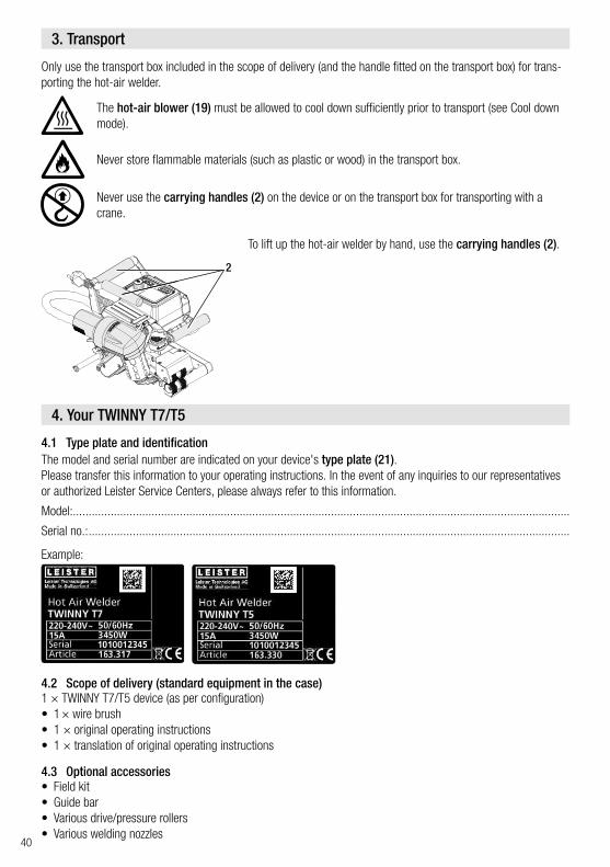
Only use the transport box included in the scope of delivery (and the handle fitted on the transport box) for trans-porting the hot-air welder.
The hot-air blower (19) must be allowed to cool down sufficiently prior to transport (see Cool down mode).
Never store flammable materials (such as plastic or wood) in the transport box.
Never use the carrying handles (2) on the device or on the transport box for transporting with a crane.
3. Transport
4. Your TWINNY T7/T5
4.1 Type plate and identification
4.2 Scope of delivery (standard equipment in the case)
4.3 Optional accessories
Example:
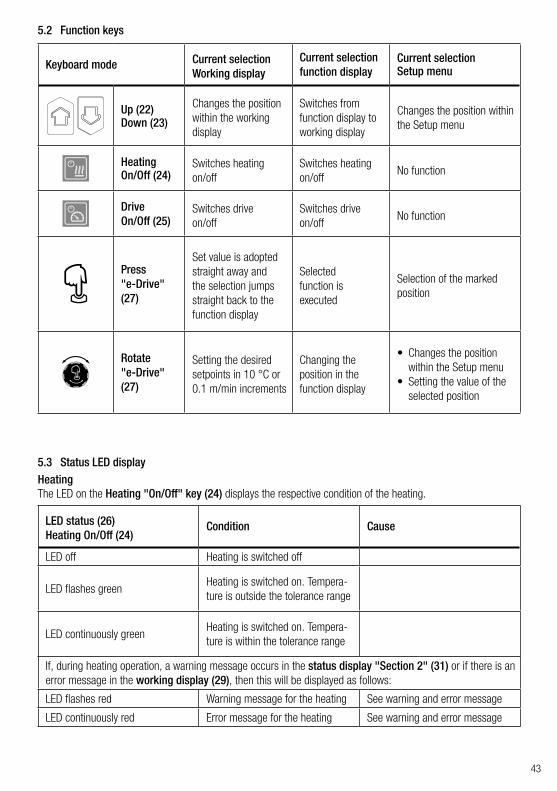
The model and serial number are indicated on your device's type plate (21).Please transfer this information to your operating instructions. In the event of any inquiries to our representatives or authorized Leister Service Centers, please always refer to this information.
Model:..............................................................................................................................................................
Serial no.: .........................................................................................................................................................
To lift up the hot-air welder by hand, use the carrying handles (2).
1 × TWINNY T7/T5 device (as per configuration)• 1 × wire brush• 1 × original operating instructions• 1 × translation of original operating instructions
• Field kit• Guide bar• Various drive/pressure rollers• Various welding nozzles
2

41
4.4 Overview of device parts
1. Power cord2. Handles3. Control panel4. Clamping lever5. Clamping lever lock6. Welding force module7. Clamping arm8. Swivel head9. Drive/pressure rollers, upper10. Track roller, rear11. Drive/pressure rollers, lower
12. Contacting system, lower13. Towing bar14. Contacting system, upper15. Welding nozzle16. Track roller, front17. Swivel-in mechanics18. Hot-air blower lock19. Hot-air blower20. Main switch21. Type plate
1
3
21 20 3
4
5
6
7
8
11
9
10
17 16
18
19
2
12131415

42
4.5 Power supply interruption
5.1 Overview of the TWINNY T7 control panel
The hot-air blower (19) must be allowed to cool down sufficiently prior to transport (see Cool down mode).
The nominal voltage specified on the device must match the local line voltage. If the line voltage fails, switch off the main switch and swivel the hot-air blower into the park position.
Condition of device prior to power supply interruption
Duration of power supply interruption
Condition of device after power supply interruption
TWINNY T7 TWINNY T5Drive and heating are switched on (welding process).
≤ 5 sec The device continues running without a restart safeguard with the same settings as before the interruption.
Drive and heating are switched on (welding process).
> 5 sec The device starts up and the start display appears on the display.
The device is not welding. - The device starts up and the start display appears on the display.
5. TWINNY T7 control panel
22
23 29
31
30
24
25
26 27 28
22. "Up" key23. "Down" key24. Key for heating "On/Off"25. Key for drive "On/Off"26. Status LED27. "e-Drive"28. Function display29. Working display30. Status display "Section 1"31. Status display "Section 2"
43
5.2 Function keys
5.3 Status LED displayHeatingThe LED on the Heating "On/Off" key (24) displays the respective condition of the heating.
Keyboard mode Current selectionWorking display
Current selection function display
Current selection Setup menu
Up (22)Down (23)
Changes the position within the working display
Switches from function display to working display
Changes the position within the Setup menu
HeatingOn/Off (24)
Switches heatingon/off
Switches heatingon/off
No function
DriveOn/Off (25)
Switches drive on/off
Switches drive on/off
No function
Press "e-Drive" (27)
Set value is adopted straight away and the selection jumps straight back to the function display
Selected function is executed
Selection of the marked position
Rotate "e-Drive" (27)
Setting the desired setpoints in 10 °C or 0.1 m/min increments
Changing the position in the function display
• Changes the position within the Setup menu
• Setting the value of the selected position
LED status (26)Heating On/Off (24)
Condition Cause
LED off Heating is switched off
LED flashes greenHeating is switched on. Tempera-ture is outside the tolerance range
LED continuously greenHeating is switched on. Tempera-ture is within the tolerance range
If, during heating operation, a warning message occurs in the status display "Section 2" (31) or if there is an error message in the working display (29), then this will be displayed as follows:
LED flashes red Warning message for the heating See warning and error message
LED continuously red Error message for the heating See warning and error message

44
Drive
LED status (26)Drive On/Off (25)
Condition Cause
LED off Drive is switched off
LED continuously green Drive is switched on
If, during operation of the drive, a warning message occurs in the status display "Section 2" (31) or if there is an error message in the working display (29), then this will be displayed as follows:
LED flashes red Drive current limiting is active See warning and error message
LED continuously red The drive has an error See warning and error message
The LED on the Drive "On/Off" key (25) displays the condition of the drive.
5.4 Display symbols of the status display
5.5 Display symbols of the function display
Name of the saved value
Welding parameters currently selected. If names consist of more than 6 characters, the first 6 characters are shown first followed by the remaining characters.
230 V Line voltage currently present on the power plug
001 Current file number of the welding data record
Status display "Section 1" (30)
Available menus are selected with the "e-Drive" (27) of the control panel (3).
Undervoltage Overvoltage
Heating(only with activated heating)
Key lock(only with active key lock)
Status display "Section 2" (31)
Warning present(see Chap. Warnings & error messages)
Symbol Meaning Symbol Meaning
Select freely definable and predefined recipes
Service menu(can only be accessed by entering the password)
Settings Save
Return to working display(exits a menu directly)
Delete the selected item
Go back one level Edit the selected item
Reset settings or hour counter

45
Symbol Meaning
Drive speed [m/min / ft./min]
Drive speed blocked [m/min / ft./min]
Air temperature [°C/°F]
Welding force [N/lbf]
Air volume [%]
Information box
Devices in standby mode. The heating is switched off after the counter runs through.
An error has occurred. An error code also appears (the device is no longer ready for use). Contact an authorized Service Center.See Chapter Warnings and error messages
Warning: See Chapter Warnings and error messages
380160 °C The arrow pointing upward and the progress bar indicate that the setpoint
(shown on the progress bar) has not yet been reached (too cold). The flashing value is the actual value. The value next to the progress bar is the setpoint.
390 °C380
The arrow pointing downward and the progress bar indicate that the setpoint (shown on the progress bar) has not yet been reached (too hot). The flashing value is the actual value. The value next to the progress bar is the setpoint.
385 °C380
If Set Values is activated, both the actual temperature (large font size) and the set temperature (small font size) are displayed. Default setting ex-works.
°C380 If Set Values is deactivated, then only the actual values (large) are displayed during operation, otherwise only the setpoint values (large).
Cool down mode
Hardware error message (heating element faulty).The device is no longer ready for operation. Contact an authorized Leister Service Center.
5.6 Display symbols of the working display

46
6. Setup menu on the TWINNY T7 control panel6.1 Menu navigation overview
Only available in "Advanced Mode"

47
6.2 Setting up, saving, and selecting recipes (Save Recipes)
Your TWINNY T7 has nine freely definable recipes and the "BASIC" recipe."Save Recipes" can be used to save the setpoint settings for the drive, air temperature, and air volumewelding parameters under a freely selectable designation (see Entering recipe names).
Creating a new recipe
1. Set up desired setpoints [Working display, "e-Drive" (27)]2. Select and confirm the Setup menu [Menu selection, "e-Drive" (27)]3. Select Save Recipes [Menu selection, "e-Drive" (27)]4. Select and confirm the User-defined menu [Menu selection, "e-Drive" (27)]5. Select and confirm the Edit selected item menu [Menu selection, "e-Drive" (27)]6. Enter desired recipe name, select Enter on the keyboard (see Entering recipe names), and confirm [Menu
selection, "e-Drive" (27)]7. Select and confirm the Save menu [Menu selection, "e-Drive" (27)]
Your newly created recipe is now saved and can be accessed at any time under the name that has been entered.
Adjusting an existing recipe
1. Set up desired setpoints [Working display, "e-Drive" (27)]2. Select and confirm the Setup menu [Menu selection, "e-Drive" (27)]3. Select Save Recipes [Menu selection, "e-Drive" (27)]4. Select and confirm the recipe to be adjusted [Menu selection, "e-Drive" (27)]5. Select and confirm either Save function, Edit selected item, or Delete [Menu selection, "e-Drive" (27)]6. If the Edit selected item has been selected, enter a freely selectable recipe name in accordance with Steps 6
and 7 described above

48
Selecting a recipe• Choosing the "Select freely definable and predefined recipes" icon in the function display (28) takes you to
the "Select Recipes" menu.• Use the "Up" and "Down" (22/23) keys to position the cursor on the desired recipe and press "e-Drive" (27)
to confirm.• If, during operation, you change setpoints in recipes you have created, the setpoints will not be saved in the
recipe. When the device is restarted, the values saved in the recipe will be displayed again.• If you wish to apply the most recently used setpoints when you restart the device, you have to select the
preprogrammed "BASIC" recipe.• The currently selected recipe is displayed in the status display "Section 1" (30). An exception to this is the
"BASIC" recipe; if this is selected, only the line voltage is displayed in the status display (30).
6.3 Entering recipe namesIn keyboard mode, you can define names with a maximum of 12 characters.
Keyboard mode Character selection (32) Symbol selection (33)
Up (22)Down (23) Vertical character selection
Rotate "e-Drive" (27) Horizontal character selection Horizontal symbol selection
Press "e-Drive" (27) Confirm the selected characters Confirm the selected symbols
28
32
Change between upper and lower case
Move the cursor position to enter the name
Insert a blank space
Delete one character (the character to the left of the cursor)
Select this symbol to switch to thefunction display (28)
33

49
If the engine is switched off, the heating is activated, and if no key is activated during the time defined under Standby interval, then the device will switch over automatically to the Standby display. If the "e-Drive" (27) is not pressed during the subsequent 180 seconds, then the heating will automatically switch to Cool down mode. Standby will then appear on the display. Pressing "e-Drive" (27) causes the device to switch to Working mode.
Standby mode is not activated when the devices are shipped.The desired time interval can be defined individually by selecting the Standby menu with the "e-Drive" (27) and then setting the desired value with the "e-Drive" (27).
6.4 Standby
In the Basic setting, move through the Setup menu to save the profile, to Standby func-tion, Application Mode, and Advanced Mode.
Additional information and setting options are available in Advanced Mode.
The functions listed in Chapters "Duty Info" to "Reset to defaults" are only available in Advanced Mode.
6.5 Basic setting and Advanced Mode
Under Duty Info you will find information regarding the runtime of your TWINNY T7.Use the "e-Drive" (27) to access the Setup menu and confirm your selection. Now use the "e-Drive" (27) to set the Advanced Mode to On and then select Duty Info.
Hours Drive: Current runtime of the driveHours Blower: Current runtime of the blowerHours Machine: Current runtime of the machineDay Distance: Distance covered since last reset (must be reset manually)Total Distance: Distance covered since commissioning of the device
6.6 Duty Info
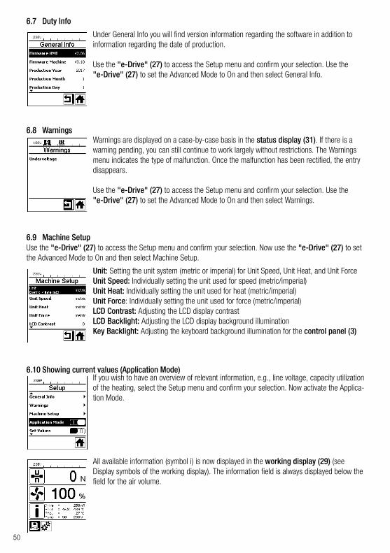
50
Under General Info you will find version information regarding the software in addition to information regarding the date of production.
Use the "e-Drive" (27) to access the Setup menu and confirm your selection. Use the "e-Drive" (27) to set the Advanced Mode to On and then select General Info.
Use the "e-Drive" (27) to access the Setup menu and confirm your selection. Now use the "e-Drive" (27) to set the Advanced Mode to On and then select Machine Setup.
If you wish to have an overview of relevant information, e.g., line voltage, capacity utilization of the heating, select the Setup menu and confirm your selection. Now activate the Applica-tion Mode.
Warnings are displayed on a case-by-case basis in the status display (31). If there is a warning pending, you can still continue to work largely without restrictions. The Warnings menu indicates the type of malfunction. Once the malfunction has been rectified, the entry disappears.
Use the "e-Drive" (27) to access the Setup menu and confirm your selection. Use the "e-Drive" (27) to set the Advanced Mode to On and then select Warnings.
All available information (symbol i) is now displayed in the working display (29) (see Display symbols of the working display). The information field is always displayed below the field for the air volume.
Unit: Setting the unit system (metric or imperial) for Unit Speed, Unit Heat, and Unit ForceUnit Speed: Individually setting the unit used for speed (metric/imperial)Unit Heat: Individually setting the unit used for heat (metric/imperial)Unit Force: Individually setting the unit used for force (metric/imperial)LCD Contrast: Adjusting the LCD display contrastLCD Backlight: Adjusting the LCD display background illuminationKey Backlight: Adjusting the keyboard background illumination for the control panel (3)
6.7 Duty Info
6.8 Warnings
6.9 Machine Setup
6.10 Showing current values (Application Mode)

51
If you have activated the Set Values function, then the actual temperature (large) and the setpoint temperature (small) will be presented in the working display (29). This will be in the analog form for the drive speed (m/min). If the function has been deactivated, only the setpoint values are displayed.The actual value is always displayed for the Welding force parameter.The Set Values function is activated ex-works.
Use the "e-Drive" (27) to access the Setup menu and confirm your selection. Now set the Advanced Mode to On and then select Reset to defaults.
This function can be used to reset all of the individually set values back to the factory settings. The reset affects not only settings (Setup) but also recipes.Confirm your selection with the key at the lower left (Reset to factory settings/Reset).
The welded distance is recorded as soon as the drive is running and more than 200 N force is displayed in the working display (29). The day distance can be called up as follows:
• Use the "Up" (22) and "Down" (23) arrow keys to position the cursor on the speed in the working display (29).
• Hold the "e-Drive" (27) down for 5 seconds.• The values of the day distance and the total distance are
now shown in the speed display.• Briefly pressing on the "e-Drive" (27) causes the speed
to be shown again in the working display (29).
5 sec
1 ×
In welding operation• The speed working display is blocked during welding.• The speed setting is enabled by briefly pressing the "e-Drive" (27).• Hold the "e-Drive" (27) down for 5 seconds.• The values of the day distance and the total distance are now shown in the speed display.• Briefly pressing on the "e-Drive" (27) causes the speed to be shown again in the working display (29).• The speed function display is blocked again once you have left the day distance display.
6.11 Set Values
6.12 Reset to defaults
6.13 Day distance display
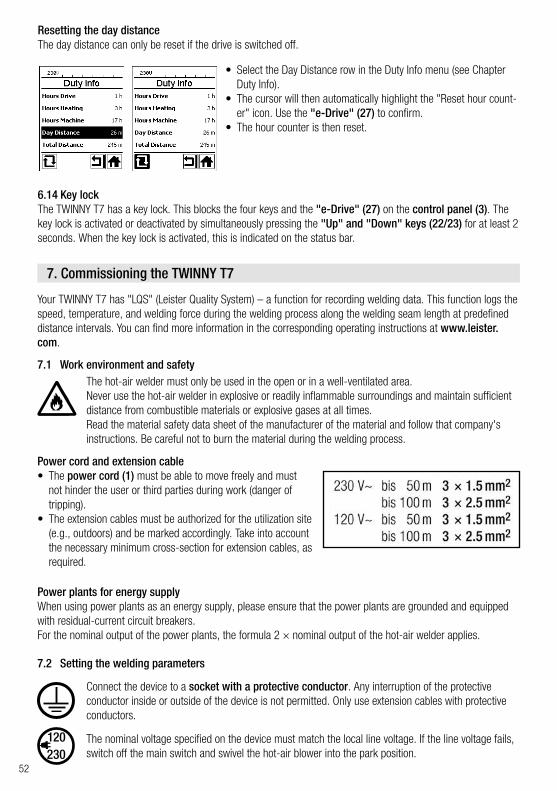
52
Your TWINNY T7 has "LQS" (Leister Quality System) – a function for recording welding data. This function logs the speed, temperature, and welding force during the welding process along the welding seam length at predefined distance intervals. You can find more information in the corresponding operating instructions at www.leister.com.
Connect the device to a socket with a protective conductor. Any interruption of the protective conductor inside or outside of the device is not permitted. Only use extension cables with protective conductors.
The nominal voltage specified on the device must match the local line voltage. If the line voltage fails, switch off the main switch and swivel the hot-air blower into the park position.
Power plants for energy supplyWhen using power plants as an energy supply, please ensure that the power plants are grounded and equipped with residual-current circuit breakers.For the nominal output of the power plants, the formula 2 × nominal output of the hot-air welder applies.
Power cord and extension cable• The power cord (1) must be able to move freely and must
not hinder the user or third parties during work (danger of tripping).
• The extension cables must be authorized for the utilization site (e.g., outdoors) and be marked accordingly. Take into account the necessary minimum cross-section for extension cables, as required.
The hot-air welder must only be used in the open or in a well-ventilated area.Never use the hot-air welder in explosive or readily inflammable surroundings and maintain sufficient distance from combustible materials or explosive gases at all times.Read the material safety data sheet of the manufacturer of the material and follow that company's instructions. Be careful not to burn the material during the welding process.
Resetting the day distanceThe day distance can only be reset if the drive is switched off.
6.14 Key lockThe TWINNY T7 has a key lock. This blocks the four keys and the "e-Drive" (27) on the control panel (3). The key lock is activated or deactivated by simultaneously pressing the "Up" and "Down" keys (22/23) for at least 2 seconds. When the key lock is activated, this is indicated on the status bar.
7. Commissioning the TWINNY T7
7.1 Work environment and safety
7.2 Setting the welding parameters
• Select the Day Distance row in the Duty Info menu (see Chapter Duty Info).
• The cursor will then automatically highlight the "Reset hour count-er" icon. Use the "e-Drive" (27) to confirm.
• The hour counter is then reset.

53
If the device is being used on construction sites, a residual-current circuit breaker must be used to protect site personnel.
CAUTION!Mechanical damage could occur if the maximum welding force of 1000 N is exceeded
Risk of crushing There is a risk of crushing due to the movement of mechanical parts. Only hold on to the hot-air welder at the handles provided.
Starting the device• Once you have prepared the work environment and the hot-air welder in accordance
with the description, switch on the hot-air welder using the main switch (20).• After startup, the Start screen will appear briefly in the display with the version number
of the current software release and the device designation.• If the device was allowed to cool down beforehand, this will be followed by a static
display of the setpoints of the most recently used recipe (the BASIC recipe is displayed when the device is commissioned for the first time).
• The heating is not yet switched on at this stage.
Adjusting the welding force• Unlock the adjustment ring lock (34) on the welding force module (6) and rotate the adjustment ring (35)
on the welding force module (6) until the clamping arm (7) opens fully.• Place two test strips (36) of the material to be welded on top of each other between the upper and lower
drive/pressure rollers (9/11) and close the clamping lever (4).• Rotate the adjustment ring (35) of the welding force module (6) until the upper and lower drive/pressure
rollers (9/11) lightly clamp the test strips (36).• Unlock the clamping lever lock (5) and open the clamping lever (4).• Rotate the adjustment ring (35) while the welding force module (6) is open until the welding force shown
on the display matches the desired welding force with the clamping arm (4) closed and the test strips (36) inserted. To do this, the clamping lever must be opened and closed repeatedly.
• Lock the adjustment ring lock (34) on the welding force module (6) so that the welding force cannot be adjusted unintentionally.
Clamping lever (4) open
RCD
Clamping lever (4) closed
4 5
34
6
7
36 11
35
9

54
1:1
Speed blocked
Setting the speed, temperature, and air volume before welding• If the drive is switched off, then the welding parameters for temperature, air volume, and speed are set as
follows in the working display (29):• Using the "Up" (22) and "Down" (23) arrow keys, you can set the cursor to the desired working display
(29).• Rotate the "e-Drive" (27) to set the setpoint. The set value is applied immediately.• A switch is made to the function display after 5 seconds or by pressing the "e-Drive" (27).
Setting the speed, temperature, and air volume during welding• If the drive is switched on, then the welding parameters for temperature, air volume, and speed are set as
follows in the working display (29):• During welding, the speed working display is blocked and the cursor is positioned in the drive speed field.• Briefly pressing the "e-Drive" (27) enables the speed setting and you can adjust the setpoint speed by rotating
the "e-Drive" (27).• The block becomes active again after 5 seconds or when you press the "e-Drive" (27).• Using the "Up" (22) and "Down" (23) arrow keys, you can set the cursor to the heating or air working
display. Rotate the "e-Drive" (27) to adjust the setpoint of the selected parameter. The set value is applied immediately.
Speed unblocked
Hot-air blower (19) in welding position Hot-air blower (19) in park position
7.3 Preparation for welding• The maximum overlap width is 125 mm.• The sealing sheets must be clean and dry between the overlaps and on the upper and lower side.
• Before the automatic welder is used, test welds are to be carried out in accordance with the welding instructions of the material manufacturer and with national standards or guide-lines. The test welds must be checked.
• Caution: If the heating is switched on but the device is not welding or if the device is in Cool down mode, the hot-air blower (19) must be in the park position. Otherwise, the device may become damaged.
7.4 Welding sequence
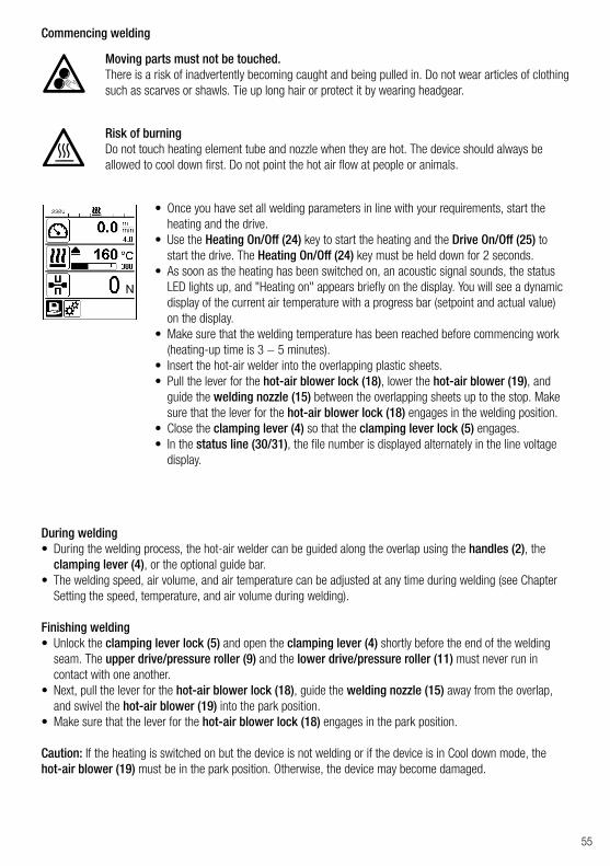
55
Commencing welding
Risk of burning Do not touch heating element tube and nozzle when they are hot. The device should always be allowed to cool down first. Do not point the hot air flow at people or animals.
• Once you have set all welding parameters in line with your requirements, start the heating and the drive.
• Use the Heating On/Off (24) key to start the heating and the Drive On/Off (25) to start the drive. The Heating On/Off (24) key must be held down for 2 seconds.
• As soon as the heating has been switched on, an acoustic signal sounds, the status LED lights up, and "Heating on" appears briefly on the display. You will see a dynamic display of the current air temperature with a progress bar (setpoint and actual value) on the display.
• Make sure that the welding temperature has been reached before commencing work (heating-up time is 3 − 5 minutes).
• Insert the hot-air welder into the overlapping plastic sheets.• Pull the lever for the hot-air blower lock (18), lower the hot-air blower (19), and
guide the welding nozzle (15) between the overlapping sheets up to the stop. Make sure that the lever for the hot-air blower lock (18) engages in the welding position.
• Close the clamping lever (4) so that the clamping lever lock (5) engages.• In the status line (30/31), the file number is displayed alternately in the line voltage
display.
Moving parts must not be touched. There is a risk of inadvertently becoming caught and being pulled in. Do not wear articles of clothing such as scarves or shawls. Tie up long hair or protect it by wearing headgear.
During welding• During the welding process, the hot-air welder can be guided along the overlap using the handles (2), the
clamping lever (4), or the optional guide bar.• The welding speed, air volume, and air temperature can be adjusted at any time during welding (see Chapter
Setting the speed, temperature, and air volume during welding).
Finishing welding• Unlock the clamping lever lock (5) and open the clamping lever (4) shortly before the end of the welding
seam. The upper drive/pressure roller (9) and the lower drive/pressure roller (11) must never run in contact with one another.
• Next, pull the lever for the hot-air blower lock (18), guide the welding nozzle (15) away from the overlap, and swivel the hot-air blower (19) into the park position.
• Make sure that the lever for the hot-air blower lock (18) engages in the park position.
Caution: If the heating is switched on but the device is not welding or if the device is in Cool down mode, the hot-air blower (19) must be in the park position. Otherwise, the device may become damaged.

56
7.5 Switching off the device
• Switch the drive and heating off using the Drive On/Off (25) and Heating On/Off (24) keys. The Heating On/Off (24) key must be held down for 2 seconds.
• The "Heating off" display appears and the device switches to Cool down mode (see Cool down mode).
• The blower switches off automatically after approx. 6 minutes. • Now switch off the device with the main switch (20) and disconnect the power cord
(1) from the electrical network.
• Wait until the device has cooled down.• Check the power cord (1) and plug for electrical and/or mechanical
damage.• Use a wire brush to clean the welding nozzle (15) and drive/pressure
rollers (9/11).

57
8. Warnings and error messages (TWINNY T7)
Warning and error messages are displayed on a case-by-case basis in the status display (31) or in the working display (29). If there is a warning pending, you can still continue to work largely without restrictions.
If an error message appears, however, you cannot continue working. The heating is switched off automati-cally, the blower is switched on, and the drive is blocked. The display of the corresponding error codes proceeds without delay in the working display (29).Concrete information regarding the type of error or the warning can be called up at any time, including via the Setup menu under Warnings.
Type of message Display Error code/
warning message Error description
Warning
Ambient Temperature Ambient temperature is too high
Undervoltage Undervoltage
Overvoltage Overvoltage
Max. Force Exceeded Max. clamping force exceeded
Drive Overcurrent Drive current limiting
Error
0001.XXXXDevice has overheatedSolution: Let the device cool
0002.XXXXOvervoltage or undervoltage of the line voltageSolution: Check voltage source
0020.XXXXHeating element is faultySolution: Replace heating element

58
Error 1
0004.XXXX Hardware error
0008.XXXX Thermocouple is defective
0200.XXXX Communication module error
0400.XXXX Drive error
1 Contact Leister Service Center

59
37
38 42
414039
37. Drive "On/Off" key with status LED38. Heating "On/Off" key with status LED39. "Minus" key40. "Confirm" key41. "Plus" key42. Display fields
The actual values are displayed in large font and the setpoint values in small font. The cursor is located on the left-hand side and the parameter unit on the right-hand side.
9. TWINNY T5 control panel
9.1 Symbols
9.2 Status LED display
HeatingThe LED on the Heating "On/Off" key (38) displays the respective condition of the heating.
Symbol Meaning
Key lock active
Cool down modeSymbol for cool-down process
Error pendingSee Chapter Error messages (TWINNY T5)
Service
LED statusHeating On/Off (38) Condition
LED off Heating is switched off
LED flashes green Heating is switched on. Temperature is outside the tolerance range
LED continuously green Heating is switched on. Temperature is within the tolerance range

60
DriveThe LED on the Drive "On/Off" key (37) displays the condition of the drive.
Heating and driveIf the two LEDs for the Heating "On/Off" (38) key and the Drive "On/Off" (37) key flash simultaneously, an error is pending (see Chapter Error messages).
• Hold down the Drive "On/Off" (37) and Heating "On/Off" (38) keys and switch on the device using the main switch (20). "UNIT" then appears on the display.
• Press the Confirm key (40) to confirm and set the desired units using the Plus/Minus keys (39/41).
• Press the Confirm key (40) to confirm and use the Plus key (41) to select "SAVE". Press the Confirm key (40) to confirm; the units are then saved.
The device then restarts automatically.
The units for the welding speed and for the temperature can be adjusted.Temperature: °C or °F
Speed: mmin or
ft.min
The TWINNY T5 has a key lock. It blocks the five keys on the control panel. The key lock is activated or deactivat-ed by pressing the Minus (39) and Plus (41) keys for at least 3 seconds. When the key lock is activated, this is indicated at the top left of the display.
9.3 Setting the parameter units
9.4 Key lock
LED statusDrive On/Off (37) Condition
LED off Drive is switched off
LED continuously green Drive is switched on

61
10. Commissioning the TWINNY T5
Connect the device to a socket with a protective conductor. Any interruption of the protective conductor inside or outside of the device is not permitted. Only use extension cables with protective conductors.
The nominal voltage specified on the device must match the local line voltage. If the line voltage fails, switch off the main switch and swivel the hot-air blower into the park position.
Power plants for energy supplyWhen using power plants as an energy supply, please ensure that the power plants are grounded and equipped with residual-current circuit breakers.For the nominal output of the power plants, the formula 2 × nominal output of the hot-air welder applies.
10.2 Setting the welding parameters
Power cord and extension cable• The power cord (1) must be able to move freely and must
not hinder the user or third parties during work (danger of tripping).
• The extension cables must be authorized for the utilization site (e.g., outdoors) and be marked accordingly. Take into account the necessary minimum cross-section for extension cables, as required.
The hot-air welder must only be used in the open or in a well-ventilated area.Never use the hot-air welder in explosive or readily inflammable surroundings and maintain sufficient distance from combustible materials or explosive gases at all times.Read the material safety data sheet of the manufacturer of the material and follow that company's instructions. Be careful not to burn the material during the welding process.
10.1 Work environment and safety
If the device is being used on construction sites, a residual-current circuit breaker must be used to protect site personnel.
Starting the device• Once you have prepared the work environment and the hot-air
welder in accordance with the description, switch on the hot-air welder using the main switch (20).
• After startup, the Start screen will appear briefly in the display with the version number of the current software release and the device designation.
• If the device was allowed to cool down beforehand, this will be followed by a static display of the setpoints.
• The heating is not yet switched on at this stage.
RCD

62
If the drive is switched off, then the welding parameters for temperature, air volume, and speed are set as follows in the display fields (42):• Using the Confirm key (40), you can set the cursor to the desired parameter.• The values of the selected parameter can be adjusted using the Minus/Plus keys
(39/41).
When the drive is switched on, the welding parameters are set in exactly the same way and transferred immediately. The cursor automatically switches back to the drive speed row 5 seconds after the entry has been made.
CAUTION!Mechanical damage could occur if the maximum welding force of 1000 N is exceeded
Risk of crushing There is a risk of crushing due to the movement of mechanical parts. Only hold on to the hot-air welder at the handles provided.
Adjusting the welding forceWhen welding materials up to a thickness of 3 mm, the welding force module (6) on the TWINNY T5 prevents an excessive welding force from being set. A smaller welding force is applied for thinner materials and a greater force for thicker materials. The welding force can be increased or decreased slightly by rotating the adjustment ring (43). Proceed as follows to adjust the welding force:
• Unlock the clamping lever lock (5) and open the clamping lever (4).• Unlock the adjustment ring lock (44).• Rotate the adjustment ring (43) on the welding force module (6). Rotating it in the "+" direction increases
the welding force and rotating it in the "–" direction decreases it. The adjustment ring (43) on the welding force module (6) can be rotated by a maximum of 360°.
• Once the desired welding force has been set, lock the adjustment ring lock (44) again.
Clamping lever (4) openClamping lever (4) closed
4
4 4 5 44
6
43
Setting the speed, temperature, and air volume before welding

63
10.3 Preparation for welding• The maximum overlap width is 125 mm.• The sealing sheets must be clean and dry between the overlaps and on the upper and lower side.
Hot-air blower (19) in welding position Hot-air blower (19) in park position
• Before the automatic welder is used, test welds are to be carried out in accordance with the welding instructions of the material manufacturer and with national standards or guide-lines. The test welds must be checked.
• Caution: If the heating is switched on but the device is not welding or if the device is in Cool down mode, the hot-air blower (19) must be in the park position. Otherwise, the device may become damaged.
10.4 Welding sequence
1:1
Commencing welding
Moving parts must not be touched. There is a risk of inadvertently becoming caught and being pulled in. Do not wear articles of clothing such as scarves or shawls. Tie up long hair or protect it by wearing headgear.
Risk of burning Do not touch heating element tube and nozzle when they are hot. The device should always be allowed to cool down first. Do not point the hot air flow at people or animals.
• Once you have set all welding parameters in line with your requirements, start the heating and the drive.
• Use the Heating On/Off (38) key to start the heating and the Drive On/Off (37) to start the drive. The Heating On/Off (38) key must be held down for 2 seconds.
• The status LED lights up as soon as the heating is switched on. If an arrow pointing upward appears on the display next to the set temperature, the actual temperature is increasing.
• Make sure that the welding temperature has been reached before commencing work (heating-up time is 3 − 5 minutes).
• Insert the hot-air welder into the overlapping plastic sheets.• Pull the lever for the hot-air blower lock (18), lower the hot-air blower (19), and
guide the welding nozzle (15) between the overlapping sheets up to the stop. Make sure that the lever for the hot-air blower lock (18) engages in the welding position.
• Close the clamping lever (4) so that the clamping lever lock (5) engages.

64
11. Error messages
Type of message Display Error code/
warning message Error description
Error
0001Device has overheatedSolution: Let the device cool
0004 Hardware error
0008 Thermocouple is defective
0400 Drive error
During welding• During the welding process, the hot-air welder can be guided along the overlap using the handles (2), the
clamping lever (4), or the optional guide bar.• The welding speed, air volume, and air temperature can be adjusted at any time during welding (see Chapter
Setting the speed, temperature, and air volume).
Finishing welding• Unlock the clamping lever lock (5) and open the clamping lever (4) shortly before the end of the welding
seam. The upper drive/pressure roller (9) and the lower drive/pressure roller (11) must never run in contact with one another.
• Next, pull the lever for the hot-air blower lock (18), guide the welding nozzle (15) away from the overlap, and swivel the hot-air blower (19) into the park position.
• Make sure that the lever for the hot-air blower lock (18) engages in the park position. • Caution: If the heating is switched on but the device is not welding or if the device is in Cool down mode, the
welding nozzle (15) must be in the park position. Otherwise, the device may become damaged.
10.5 Switching off the device
• Switch the drive and heating off using the Drive On/Off (37) and Heating On/Off (38) keys. The Heating On/Off (38) key must be held down for 2 seconds.
• The "Heating off" display appears and the device switches to Cool down mode (see Cool down mode).
• The blower switches off automatically after approx. 6 minutes. • Now switch off the device with the main switch (20) and disconnect the power cord
(1) from the electrical network.
• Wait until the device has cooled down.• Check the power cord (1) and plug for electrical and/or mechanical
damage.• Use a wire brush to clean the welding nozzle (15) and drive/pressure
rollers (9/11).

65
12. Settings on the TWINNY T7/T5
The device must have cooled down and the main switch must have been switched off before components on the automatic welder are dismantled or assembled. The power cord must have been disconnected from the power supply.
12.1 Replacement of pressure rollersDepending on the application, you can use different drive/pressure rollers (9/11) on the TWINNY (see Accesso-ries).
Dismantling the upper drive/pressure roller (9):Sequence no. 1 – 7
Assembling the upper drive/pressure roller (9):Reverse sequence no. 7 – 1
1. Cheese head screw (4x) 2. Protective plate, swivel head3. Grub screws4. Axle 5. Retaining ring 6. Pressure roller 7. Drive axle with parallel key
Dismantling the lower drive/pressure roller (11):Sequence no. 1 – 5
Assembling the lower drive/pressure roller (11):Reverse sequence no. 5 – 1
1. Cheese head screws 2. Roller cover3. Cheese head screw4. Washer 5. Pressure roller
5
43
1
2
1
4
2
3
7
6
5

66
2
1
Dismantling the welding nozzle (15):Sequence no. 1 – 2
Assembling the welding nozzle (15):Reverse sequence no. 2 – 1
1. Mounting screws2. Welding nozzle
Caution: Once the welding nozzle has been assembled, the insulation tube must always be inserted between the welding nozzle and heating element.
12.2 Replacing the welding nozzleDepending on the application, you can use different welding nozzles (15) on the TWINNY (see Accessories).Swivel the hot-air blower (19) into the park position to replace the welding nozzle (15).
Dismantling the rear track roller (10):Sequence no. 1 – 4Assembling the rear field kit:Sequence no. 5 – 10
Dismantling the rear field kit:Sequence no. 10 – 5Assembling the rear track roller (10):Sequence no. 4 – 1
1. Hexagon screw2. Washer3. Bushing4. Small roller5. Cheese head screw6. Washer7. Bushing8. Large roller9. Arm10. Hexagon screw
1
5
76
89
10
23
4

67
12.3 Assembling the field kitIf a greater floor clearance or larger track rollers are required for the automatic welder, the standard track rollers can be replaced by the field kit.
Dismantling the front track roller (16):Sequence no. 1 – 2Assembling the front field kit:Sequence no. 3 – 8
Dismantling the front field kit:Sequence no. 8 – 3Assembling the front track roller (16):Sequence no. 2 – 1
1. Cheese head screw (2x)2. Small roller3. Cheese head screw (2x)4. Washer (2x)5. Bushing (2x)6. Large roller (2x)7. Arm (2x)8. Cheese head screw (2x)
12.4 Assembling the guide barUsing the guide bar, the automatic welder can be routed with an upright posture.
Assembling the guide bar:Reverse sequence no. 1 – 5
Dismantling the guide bar:Sequence no. 5 – 1
1. Cheese head screw (2x)2. Washer (2x)3. Support4. Connecting tube5. Handle
5
4
3
21
3
1
21
45
67
87
65
43

68
13. Accessories
14. Service and repair
• Only use original Leister spare parts and accessories; otherwise, any warranty or guarantee claims will be invalidated.
• You can find more information at www.leister.com.
• Repairs shall be assigned exclusively to authorized Leister Service Centers.• Do not use any aggressive cleaning agents or solvents to clean the device.• Leister Service Centers guarantee a professional and reliable repair service within 24 hours with original spare
parts in accordance with circuit diagrams and spare parts lists. • You will find the address of your authorized Service Center on the last page.• You can find more information at www.leister.com.• If the service interval display appears after the automatic welder is switched on, the automatic welder must be
inspected by an authorized Leister Service Center.
Leister Technologies AG, Galileo-Strasse 10, 6056 Kaegiswil, Switzerland confirms that in the models made available for purchase, these products fulfill the requirements of the following EU directives:Directives: 2006/42, 2014/30, 2014/35, 2011/65Harmonized standards: EN ISO 12100, EN 55014-1, EN 55014-2, EN 61000-6-2, EN 61000-3-2,
EN 61000-3-3, EN 62233, EN 60335-1, EN 60335-2-45, EN 50581
Kaegiswil, 8/29/2018
Bruno von Wyl, CTO Christoph Baumgartner, GM
Electrical equipment, accessories, and packaging should be recycled in an environmentally friendly way. For EU countries only: Never dispose of electrical equipment with household refuse.
• The guarantee or warranty rights granted for this device by the direct distribution partner/salesperson apply from the date of purchase.
• In the event of a guarantee or warranty claim (verification by invoice or delivery note), manufacturing or pro-cessing errors will be rectified by the sales partner through replacement delivery or repair.
• Other guarantee or warranty claims are excluded within the framework of mandatory law.• Damage resulting from natural wear, overload, or improper handling are excluded from the warranty.• Heating elements are excluded from warranty obligations or guarantees.• Guarantee or warranty claims cannot be asserted for devices that have been converted or changed by the
purchaser or for which non-original Leister spare parts have been used.
• Leister Technologies AG and its authorized Service Centers offer courses for various applications.
15. Training
16. Warranty
17. Conformity
18. Disposal

69
IT Italiano Istruzioni per l’uso
Indice
1. Avvertenze importanti per la sicurezza ................................................................................................ 711.1 Utilizzo conforme ......................................................................................................................... 721.2 Utilizzo non conforme .................................................................................................................. 72
2. Specifiche tecniche .............................................................................................................................. 72
3. Trasporto ............................................................................................................................................... 73
4. Il Suo TWINNY T7/T5 ............................................................................................................................. 734.1 Targhetta e identificazione............................................................................................................ 734.2 Dotazione di fornitura (attrezzatura standard nella cassa) ............................................................... 734.3 Accessori opzionali ...................................................................................................................... 734.4 Panoramica delle parti dell'apparecchio ........................................................................................ 744.5 Interruzione dell'alimentazione ..................................................................................................... 75
5. Pannello di comando TWINNY T7 .......................................................................................................... 755.1 Panoramica pannello di comando TWINNY T7 ............................................................................... 755.2 Tasti funzione .............................................................................................................................. 765.3 Indicatore LED di stato ................................................................................................................. 765.4 Simboli visualizzati nella schermata di stato .................................................................................. 775.5 Simboli visualizzati nella schermata funzioni .................................................................................. 775.6 Simboli visualizzati della schermata del processo .......................................................................... 78
6. Menù Setup del pannello di comando del TWINNY T7 .......................................................................... 796.1 Panoramica della gestione menù .................................................................................................. 796.2 Configurare, salvare e selezionare ricette di saldatura (Save Recipes) ............................................. 806.3 Immissione dei nomi delle ricette ................................................................................................. 816.4 Modalità di attesa (Standby) ......................................................................................................... 826.5 Impostazione base e Advanced Mode [modalità avanzata] ............................................................. 826.6 Duty Info [Info servizio] ................................................................................................................ 826.7 General Info ................................................................................................................................ 836.8 Warnings [Avvertenze] ................................................................................................................. 836.9 Machine Setup [Configurazione macchina] ................................................................................... 836.10 Visualizzazione dei valori attuali (Application Mode) [Modalità applicazione] ..................................... 836.11 Set Values [Valori impostati] ......................................................................................................... 846.12 Reset to defaults [Reimposta predefiniti] ....................................................................................... 846.13 Visualizzazione distanza giornaliera ............................................................................................... 846.14 Blocco tasti ................................................................................................................................. 85
7. Messa in servizio TWINNY T7 ............................................................................................................... 857.1 Ambiente di lavoro e sicurezza ..................................................................................................... 857.2 Impostazione dei parametri di saldatura ........................................................................................ 857.3 Preparazione alla saldatura .......................................................................................................... 877.4 Esecuzione della saldatura ........................................................................................................... 877.5 Spegnimento dell’apparecchio ..................................................................................................... 89
8. Avvertenze e messaggi di errore (TWINNY T7) ..................................................................................... 90
9. Pannello di comando TWINNY T5 .......................................................................................................... 929.1 Legenda ..................................................................................................................................... 929.2 Indicatore LED di stato ................................................................................................................. 929.3 Impostazione delle unità dei parametri .......................................................................................... 93

70
9.4 Blocco tasti ................................................................................................................................. 93
10. Messa in servizio TWINNY T5 ............................................................................................................. 9410.1 Ambiente di lavoro e sicurezza ..................................................................................................... 9410.2 Impostazione dei parametri di saldatura ........................................................................................ 9410.3 Preparazione alla saldatura .......................................................................................................... 9610.4 Esecuzione della saldatura ........................................................................................................... 9610.5 Spegnimento dell’apparecchio ..................................................................................................... 97
11. Messaggi di errore .............................................................................................................................. 97
12. Impostazioni sul TWINNY T7/T5 .......................................................................................................... 9812.1 Sostituzione rulli di pressione ...................................................................................................... 9812.2 Sostituzione ugello di saldatura ................................................................................................... 9912.3 Montaggio Field-Kit .................................................................................................................... 10012.4 Montaggio barra di guida ............................................................................................................ 100
13. Accessori ........................................................................................................................................... 101
14. Assistenza e riparazioni ..................................................................................................................... 101
15. Formazione ........................................................................................................................................ 101
16. Garanzia legale .................................................................................................................................. 101
17. Conformità ......................................................................................................................................... 101
18. Smaltimento ...................................................................................................................................... 101

71
Istruzioni per l’uso (traduzione delle istruzioni per l’uso originali)IT
LEISTER TWINNY T7/T5 Saldatrice automatica
Leggere attentamente le istruzioni per l’uso prima della messa in servizio. Conservare sempre le presenti istruzioni per l’uso insieme al prodotto.Se affidato a terzi, il prodotto deve essere sempre provvisto delle istruzioni per l’uso.
Osservare sempre le indicazioni tecniche di sicurezza contenute nei vari capitoli di queste istruzioni per l’uso nonché le disposizioni seguenti.
1. Avvertenze importanti per la sicurezza
Congratulazioni per l’acquisto del prodotto TWINNY T7/T5.Avete optato per una saldatrice automatica ad aria calda di primissima scelta, sviluppata e e prodotta secondo lo stato attuale della tecnica dell'industria di lavorazione dei materiali plastici. Per la produzio-ne vengono utilizzati materiali di alta qualità.
Avvertenza
FI
Attenzione
Pericolo di morte Estrarre la spina elettrica dalla presa prima di procedere all'apertura dell'appa-recchio perché vengono esposti componenti e collegamenti sotto tensione.
Pericolo di incendio ed esplosione Pericolo di incendio ed esplosione in caso di uso non conforme della saldatrice automatica (per es. surriscaldamento dei materiali), specialmente nelle vicinanze di materiali infiammabili e gas esplosivi.
Pericolo di ustioni Non toccare il tubo dell’elemento riscaldante e l’ugello quando sono roventi. Lasciar raffreddare prima l’apparecchio. Non dirigere il getto di aria calda verso persone o animali.Allacciare l'apparecchio a una presa di corrente provvista di conduttore di terra.È vietata qualsiasi interruzione della linea di messa a terra all’interno o all’esterno dell’apparecchio. Usare solo cavi di prolunga con messa a terra.
Se l’apparecchio viene usato in cantiere, per garantire la protezione degli opera-tori è assolutamente necessario un interruttore differenziale (salvavita).
La tensione nominale indicata sull’apparecchio deve corrispondere alla tensione di rete locale. In caso di interruzione della tensione di rete, spegnere l’interruttore principale e ruotare il soffiante di aria calda in posizione di attesa.
Proteggere l’apparecchio dall’umidità e da ambienti bagnati.
L’apparecchio deve essere utilizzato esclusivamente sotto sorveglianza. Il calore perduto può raggiungere materiali infiammabili che si trovano al di fuori del campo visivo.L’utilizzo dell’apparecchio è consentito esclusivamente a personale qualificato o sotto il monitoraggio di quest’ultimo. È tassativamente vietato l’impiego da parte dei bambini.
Ulteriori informazioni sul TWINNY e sull’app myLeister sono disponibili nel sito www.leister.com

72
TWINNY T7/T5 è stato progettato per la saldatura a sovrapposizione e il confezionamento di pellicole e guaine di impermeabilizzazione. La larghezza massima di sovrapposizione è di 125 mm. La larghezza massima del cordone di saldatura ammonta a 50 mm.Utilizzare esclusivamente ricambi e accessori originali Leister. In caso contrario decade qualsiasi diritto alla garanzia.
Tipi di materiale e spessori dei materiali
Ulteriori materiali su richiesta.
Qualsiasi altro uso che esuli da ciò è da intendersi come non conforme.
2. Specifiche tecniche
* Tensione di attacco non commutabile
Modifiche tecniche riservate.
1.1 Utilizzo conforme
1.2 Utilizzo non conforme
TWINNY T7230 V
TWINNY T5230 V
TWINNY T5120 V
Tensione nominale* V~ 230 230 120Potenza nominale W 3400 3400 1800Frequenza Hz 50 / 60Temperatura °C
°F100 – 560212 - 1040
Portata d’aria % 45 - 100Azionamento m/min
ft/min0.8 – 8
2.6 – 26.2Forza di giunzione max. N/lbf 1000 / 225Livello di emissione LpA (dB) 73 (K = 3 dB)Dimensioni di ingombro (Lungh. × Largh. × Alt.)
mmpollici
350 × 360 × 26013,8 × 14,2 × 10,2
Peso kg / lbs 10,5 / 23,1 9,5 / 21Marchio di conformitàClasse di protezione I
Materiale Valore orientativo spessore materialePE-HD, PP 0.3 mm – 2.5 mmPVC-P, PE-LD, TPO, FPO 0.3 mm – 3.0 mm

73
Per il trasporto delle saldatrice automatica ad aria calda utilizzare esclusivamente la cassa di trasporto inclusa nella dotazione di fornitura (e la maniglia applicata alla cassa di trasporto).
Prima del trasporto, lasciar raffreddare sufficientemente il soffiante dell'aria calda (19) (vedi Cool down mode).
Non conservare mai materiali infiammabili (ad es. plastica, legno) nella cassa di trasporto.
Non utilizzare le maniglie da trasporto (2) sull'apparecchio o sulla cassa di trasporto per il trasporto con una gru.
3. Trasporto
4. Il Suo TWINNY T7/T5
4.1 Targhetta e identificazione
4.2 Dotazione di fornitura (attrezzatura standard nella cassa)
4.3 Accessori opzionali
Esempio:
La designazione del tipo e il numero di matricola sono indicati sulla targhetta (21) del Vostro apparecchio.Riportare questi dati sulle istruzioni per l’uso. Fare sempre riferimento a questi dati per qualsiasi richiesta ai nostri rappresentanti o ai centri assistenza Leister autorizzati.
Tipo: ................................................................................................................................................................
Numero di matricola: .........................................................................................................................................
Per il sollevamento manuale della saldatrice automatica ad aria calda utilizzare le maniglie da trasporto (2).
1 × apparecchio TWINNY T7/T5 (a seconda della configurazione)• 1 × spazzola metallica• 1 × istruzioni per l’uso originali• 1 × traduzione delle istruzioni per l’uso originali
• Field-Kit• Barra di guida• Vari rulli di azionamento/pressione• Vari ugelli di saldatura
2
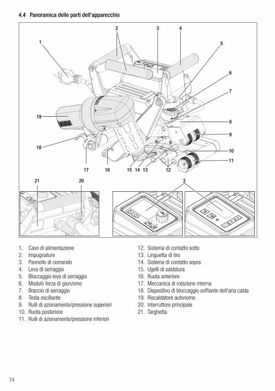
74
4.4 Panoramica delle parti dell'apparecchio
1. Cavo di alimentazione2. Impugnature3. Pannello di comando4. Leva di serraggio5. Bloccaggio leva di serraggio6. Modulo forza di giunzione7. Braccio di serraggio8. Testa oscillante9. Rulli di azionamento/pressione superiori10. Ruota posteriore11. Rulli di azionamento/pressione inferiori
12. Sistema di contatto sotto13. Linguetta di tiro14. Sistema di contatto sopra15. Ugelli di saldatura16. Ruota anteriore17. Meccanica di rotazione interna18. Dispositivo di bloccaggio soffiante dell'aria calda19. Riscaldatore autonomo20. Interruttore principale21. Targhetta
1
3
21 20 3
4
5
6
7
8
11
9
10
17 16
18
19
2
12131415

75
4.5 Interruzione dell'alimentazione
Prima del trasporto, lasciar raffreddare sufficientemente il soffiante dell'aria calda (19) (vedi Cool down mode).
La tensione nominale indicata sull’apparecchio deve corrispondere alla tensione di rete locale. In caso di interruzione della tensione di rete, spegnere l’interruttore principale e ruotare il soffiante di aria calda in posizione di attesa.
Stato dell’apparecchio prima dell’interruzione dell’alimentazione
Durata Interruzione dell'a-limentazione
Stato dell’apparecchio dopo l’interruzione dell’alimentazione
TWINNY T7 TWINNY T5Motore e riscaldamento accesi (processo di saldatura).
≤ 5 sec.L’apparecchio continua a funzionare senza protezione da riavvio con le stesse impostazioni che aveva prima dell’interruzione.
Motore e riscaldamento accesi (processo di saldatura).
> 5 sec.L’apparecchio si avvia e sul Display appare la schermata di inizio.
L’apparecchio non si trova nel processo di saldatura.
-L’apparecchio si avvia e sul Display appare la schermata di inizio.
5. Pannello di comando TWINNY T7
5.1 Panoramica pannello di comando TWINNY T7
22
23 29
31
30
24
25
26 27 28
22. Tasto “Su”23. Tasto “Giù”24. Tasto riscaldamento “Acc. / Spento”25. Tasto motore “Acc. / Spento”26. LED di stato27. «e-Drive»28. Schermata funzioni29. Schermata del processo30. Schermata di stato “Campo 1”31. Schermata di stato “Campo 2”

76
5.2 Tasti funzione
5.3 Indicatore LED di statoRiscaldamentoIl LED sul tasto Riscaldamento “acc./spento” (24) indica lo stato del riscaldamento.
Funzione tastieraSelezione correnteSchermata del processo
Selezione corrente schermata funzioni
Selezione corrente Menu Set-up
Su (22)Giù (23)
Cambio di posizione nella schermata del processo.
Cambio della scher-mata funzioni nella schermata di processo.
Modifica la posizione nel menu Setup.
RiscaldamentoAcc./ Spento (24)
Commuta il riscalda-mentoAcc./ Spento
Commuta il riscalda-mentoAcc./ Spento
Nessuna funzione
AzionamentoAcc./ Spento (25)
Commuta il motore Acc./ Spento
Commuta il motore Acc./ Spento
Nessuna funzione
Premere l’«e-Drive» (27)
Il valore impostato viene applicato direttamente e la selezione riporta diret-tamente alla schermata funzioni.
La funzione selezionata è eseguita.
Selezione della posizione contrassegnata.
Ruotare l’«e-Drive» (27)
Impostazione dei valori nominali desiderati con incrementi di 10 °C 0.1 m/min
Modifica della posizione nella schermata funzioni.
• Modifica la posizione nel menu Setup
• Impostazione del valore della posizione selezionata
Stato LED (26)Riscaldamento acc./spento (24) Stato Causa
LED spento Il riscaldamento è spento.
LED lampeggiante in verdeIl riscaldamento è acceso. Tempera-tura esterna alla banda di tolleranza.
LED verde fissoIl riscaldamento è acceso. Tempera-tura interna alla banda di tolleranza.
Se durante il funzionamento del riscaldamento viene emesso un messaggio di avviso nella schermata di stato Campo 2 (31) o un messaggio di errore nella schermata del processo (29), esso è rappresentato come segue:
LED lampeggiante in rossoMessaggio di avviso del riscalda-mento
Vedi avviso e messaggio di errore.
LED fisso rossoMessaggio di errore del riscalda-mento
Vedi avviso e messaggio di errore.

77
Azionamento
Stato LED (26)Motore acc./spento (25) Stato Causa
LED spento Motore spento
LED verde fisso Motore acceso
Se durante il funzionamento del motore viene emesso un messaggio di avviso nella schermata di stato Campo 2 (31) o un messaggio di errore nella schermata del processo (29), esso è rappresentato come segue:
LED lampeggiante in rosso Limitazione di corrente motore attiva. Vedi avviso e messaggio di errore.
LED fisso rosso Errore del motore. Vedi avviso e messaggio di errore.
Il LED del tasto Motore “acc./spento” (25) indica lo stato del motore.
5.4 Simboli visualizzati nella schermata di stato
5.5 Simboli visualizzati nella schermata funzioni
Nome del valore memorizzato
Parametri di saldatura selezionati. Nel caso di nomi composti da più di 6 caratteri, verranno mostrati inizialmente i primi 6 caratteri, quindi i restanti.
230 V Tensione di rete attualmente presente sulla spina
001 Numero di file attuale della registrazione dei dati di saldatura
Schermata di stato “Campo 1” (30)
È possibile selezionare i menù disponibili con l’«e-Drive» (27) del pannello di comando (3).
Sottotensione Sovratensione
Riscaldamento(solo in caso di riscaldamen-to acceso)
Blocco tasti(solo in caso di blocco tasti attivo)
Schermata di stato “Campo 2” (31)
Avvertenza presente(vedi cap. Avvertenze e messaggi di errore)
Simbolo Spiegazione Simbolo Spiegazione
Ricette libere e personalizzate selezione
Menu assistenza(solo con immissione della password)
Impostazioni Salvataggio
Torna alla schermata del processo(uscita diretta da uno dei menu)
Eliminare la posizione selezionata
Indietro di un livello Modificare la posizione selezionata
Resettare le impostazioni o il contaore

78
Simbolo Spiegazione
Velocità motore [m/min / ft./min]
Velocità motore con blocco [m/min / ft./min]
Temperatura aria [°C/°F]
Forza di giunzione [N/lbf]
Quantità d’aria [%]
Finestra informativa
Dispositivi in modalità standby. Al termine del conteggio da parte del contatore, il riscaldamento si spegne.
Errore dell’apparecchio. È presente, inoltre, un codice di errore (al momento, l’apparecchio non è più utilizzabile). Contattare il punto assistenza autorizzato.Vedi capitolo "Avvertenze e messaggi di errore"
Avvertenza: Vedi capitolo "Avvertenze e messaggi di errore"
380160 °C
La freccia verso l’alto e la barra di progressione indicano che il valore nominale (segno presente sulla barra di progressione) non è ancora stato raggiunto (troppo freddo). Il valore lampeggiante è il valore reale. Il valore che si trova accanto alla barra di progressione è il valore nominale impostato.
390 °C380
La freccia verso il basso e la barra di progressione indicano che il valore nominale (segno presente sulla barra di progressione) non è ancora stato raggiunto (troppo caldo). Il valore lampeggiante è il valore reale. Il valore che si trova accanto alla barra di progressione è il valore nominale impostato.
385 °C380
Attivando la funzione “Set Values” [Imposta valori] vengono visualizzate la tempe-ratura reale (in grande) e quella nominale (in piccolo). Impostazione standard in fabbrica.
°C380 Se si disattiva “Set Values” [Imposta valori], durante l’esercizio compaiono solo i valori reali (in grande), altrimenti solo i valori nominali (in grande).
Processo di raffreddamento (Cool Down Mode)
Messaggio di errore hardware (elemento riscaldante difettoso).L'apparecchio non è più utilizzabile! Contattare un centro assistenza autorizzato da Leister.
5.6 Simboli visualizzati della schermata del processo

79
6. Menù Setup del pannello di comando del TWINNY T76.1 Panoramica della gestione menù
Disponibile solo in “modalità avanzata”

80
6.2 Configurare, salvare e selezionare ricette di saldatura (Save Recipes)
Il TWINNY T7 dispone di nove ricette personalizzabili e della ricetta “BASIC”Con “Save Recipes” [Salva ricette] è possibile salvare le impostazioni dei valori nominali dei parametri di saldatu-ra, azionamento, temperatura dell'aria e portata d'ariacon una denominazione selezionabile liberamente (vedere Immissione del nome della ricetta).
Creazione di una nuova ricetta
1. Configurare i valori nominali desiderati [schermata del processo, «e-Drive» (27)]2. Selezionare il menù Setup [Impostazioni] e confermare [selezione del menù, «e-Drive» (27)]3. Selezionare il menù Save Recipes [selezione del menù, «e-Drive» (27)]4. Selezionare il menù User-defined [Definito dall'utente] e confermare [selezione del menù, «e-Drive» (27)]5. Selezionare Modificare la posizione selezionata e confermare [selezione del menù, «e-Drive» (27)]6. Immettere il nome desiderato della ricetta, premere Enter (vedere Immissione del nome della ricetta) e con-
fermare [selezione del menù, «e-Drive» (27)]7. Selezionare il menù Salvataggio e confermare [selezione del menù, «e-Drive» (27)]
A questo punto la ricetta appena creata è stata salvata e può essere richiamata in qualsiasi momento con il nome immesso.
Modifica di una ricetta esistente
1. Configurare i valori nominali desiderati [schermata del processo, «e-Drive» (27)]2. Selezionare il menù Setup [Impostazioni] e confermare [selezione del menù, «e-Drive» (27)]3. Selezionare il menù Save Recipes [selezione del menù, «e-Drive» (27)]4. Selezionare la ricetta da modificare e confermare [selezione del menù, «e-Drive» (27)]5. Selezionare la funzione Salvataggio, Modificare la posizione selezionata o Eliminazione e confermare [selezio-
ne del menù, «e-Drive» (27)]
6. Se è stata selezionata la funzione Modificare la posizione selezionata, immettere un nome di ricetta selezio-nabile liberamente secondo i passaggi 6 e 7 precedenti.

81
Selezione della ricetta• Selezionando il simbolo “Selezione di ricette predefinite e personalizzate” nella schermata funzioni (28) si
apre il menù “Select recipes” [Seleziona ricette].• Con i tasti “Su” e “Giù” (22/23) posizionare il cursore sulla ricetta desiderata e confermare con l’«e-Drive»
(27).• Se modificate i valori nominali nelle ricette da voi create durante il funzionamento, essi non verranno salvati
nella ricetta. Al riavvio dell'apparecchio i valori salvati nella ricetta vengono visualizzati nuovamente.• Se al riavvio si desidera utilizzare gli ultimi valori nominali utilizzati, selezionare la ricetta preprogrammata
“BASIC”.• La ricetta attualmente selezionata è visibile nella schermata di stato “Campo 1” (30). La ricetta “BASIC” costi-
tuisce un'eccezione: se è selezionata, nella schermata di stato (30) compare solo la tensione di rete.
6.3 Immissione dei nomi delle ricetteMediante la modalità tastiera è possibile definire nomi con al massimo 12 caratteri.
Funzione tastiera Scelta carattere (32) Scelta icona (33)
Su (22)Giù (23) Scelta carattere verticalmente
Ruotare l’«e-Drive» (27) Scelta carattere orizzontalmente Scelta icona orizzontalmente
Premere l’«e-Drive» (27) Conferma del carattere selezionato Conferma icone selezionate
28
32
Cambio Maiuscolo - minuscolo
Spostare la posizione del cursore all’interno del nome
Inserimento spazio
Cancellazione di un solo carattere (caratteri a sinistra del cursore)
Scegliere questa icona per passare allaSchermata funzioni (28)
33

82
Se il motore è spento, se si attiva il riscaldamento e per il tempo definito in “Standby Intervall” [Intervallo di attesa] non si preme alcun tasto, l’apparecchio passa automatica-mente alla schermata Standby. Se durante i successivi 180 sec. non si preme l’«e-Dri-ve» (27), il riscaldamento passa automaticamente al Cool down mode. Successivamente sul display compare Standby. Se si preme l’«e-Drive» (27), si passa alla modalità di lavoro.
La modalità Standby non è configurata al momento della consegna degli apparecchi.È possibile definire singolarmente l'intervallo temporale desiderato, selezionando il menù Standby con «e-Drive» (27) e impostando poi il valore desiderato con l’«e-Drive» (27).
6.4 Modalità di attesa (Standby)
Nell'impostazione base è possibile accedere attraverso il menù Setup [Configurazione] al salvataggio del profilo, alla funzione standby e alle modalità Application Mode [Modalità applicazione] e Advanced Mode [Modalità avanzata].
Nella Advanced Mode [Modalità avanzata] sono disponibili ulteriori informazioni e possi-bilità di impostazione.
Le funzioni da “Cap. Duty Info” fino a “Reset to defaults” sono disponibili solo nell'Advanced Mode.
6.5 Impostazione base e Advanced Mode [modalità avanzata]
Alla voce Duty Info [Info servizio] sono reperibili i dati relativi alla durata di esercizio del TWINNY T7.Con l’«e-Drive» (27) passare al menù Setup [Impostazioni] e confermare la propria selezione. Impostare quindi con l’«e-Drive» (27) l’Advanced Mode e su On selezionare Duty Info.
Hours Drive: durata di esercizio attuale del motoreHours Blower: durata di esercizio attuale del soffianteHours Machine: durata di esercizio attuale della macchinaDay Distance [Distanza giornaliera]: tragitto completato dall'ultimo azzeramento (deve essere azzerato manualmente)Total Distance [Distanza totale]: tragitto completato dalla messa in servizio dell'apparec-chio
6.6 Duty Info [Info servizio]
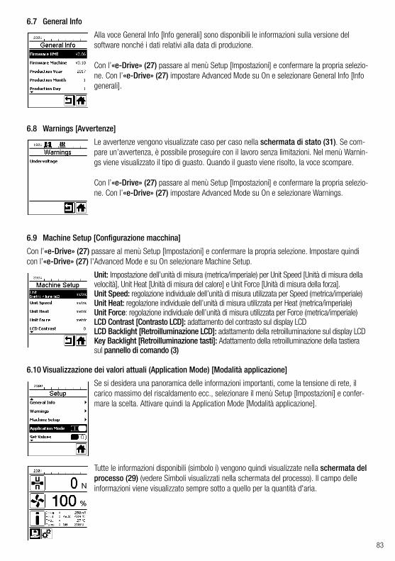
83
Alla voce General Info [Info generali] sono disponibili le informazioni sulla versione del software nonché i dati relativi alla data di produzione.
Con l’«e-Drive» (27) passare al menù Setup [Impostazioni] e confermare la propria selezio-ne. Con l’«e-Drive» (27) impostare Advanced Mode su On e selezionare General Info [Info generali].
Con l’«e-Drive» (27) passare al menù Setup [Impostazioni] e confermare la propria selezione. Impostare quindi con l’«e-Drive» (27) l'Advanced Mode e su On selezionare Machine Setup.
Se si desidera una panoramica delle informazioni importanti, come la tensione di rete, il carico massimo del riscaldamento ecc., selezionare il menù Setup [Impostazioni] e confer-mare la scelta. Attivare quindi la Application Mode [Modalità applicazione].
Le avvertenze vengono visualizzate caso per caso nella schermata di stato (31). Se com-pare un’avvertenza, è possibile proseguire con il lavoro senza limitazioni. Nel menù Warnin-gs viene visualizzato il tipo di guasto. Quando il guasto viene risolto, la voce scompare.
Con l’«e-Drive» (27) passare al menù Setup [Impostazioni] e confermare la propria selezio-ne. Con l’«e-Drive» (27) impostare Advanced Mode su On e selezionare Warnings.
Tutte le informazioni disponibili (simbolo i) vengono quindi visualizzate nella schermata del processo (29) (vedere Simboli visualizzati nella schermata del processo). Il campo delle informazioni viene visualizzato sempre sotto a quello per la quantità d'aria.
Unit: Impostazione dell’unità di misura (metrica/imperiale) per Unit Speed [Unità di misura della velocità], Unit Heat [Unità di misura del calore] e Unit Force [Unità di misura della forza].Unit Speed: regolazione individuale dell’unità di misura utilizzata per Speed (metrica/imperiale)Unit Heat: regolazione individuale dell’unità di misura utilizzata per Heat (metrica/imperiale)Unit Force: regolazione individuale dell’unità di misura utilizzata per Force (metrica/imperiale)LCD Contrast [Contrasto LCD]: adattamento del contrasto sul display LCDLCD Backlight [Retroilluminazione LCD]: adattamento della retroilluminazione sul display LCDKey Backlight [Retroilluminazione tasti]: Adattamento della retroilluminazione della tastiera sul pannello di comando (3)
6.7 General Info
6.9 Machine Setup [Configurazione macchina]
6.10 Visualizzazione dei valori attuali (Application Mode) [Modalità applicazione]
6.8 Warnings [Avvertenze]

84
Se la funzione Set Values è attivata, vengono visualizzate la temperatura reale (in grande) e quella nominale (in piccolo) nella schermata del processo (29). Questo vale allo stesso modo per la velocità di azionamento (m/min). Se la funzione è disattivata, vengono visualiz-zati solo i valori nominali.Per il parametro Forza di giunzione viene visualizzato sempre il valore reale.La funzione Set Values è attivata per default.
Con l’«e-Drive» (27) passare al menù Setup [Impostazioni] e confermare la propria selezio-ne. Impostare ora l'Advanced Mode su On e selezionare Reset to defaults.
Questa funzione consente di ripristinare le impostazioni predefinite per tutti i singoli valori impostati. Il reset riguarda le impostazioni (Setup) e le ricette.Confermare la propria scelta con il tasto sinistro inferiore (Ripristino impostazioni predefini-te/Reset).
6.11 Set Values [Valori impostati]
6.12 Reset to defaults [Reimposta predefiniti]
6.13 Visualizzazione distanza giornalieraNon appena il motore è in funzione e si visualizzano oltre 200 N di forza nella schermata di processo (29), la distanza saldata viene registrata. La distanza giornaliera può essere richiamata come segue:
• Con i tasti freccia “Su” (22) e “Giù” (23) posizionare il cursore sulla velocità nella schermata di processo (29).
• Tenere premuto l’«e-Drive» (27) per 5 sec.• Nell’indicazione della velocità si visualizzano i valori della
distanza giornaliera e della distanza totale.• Premendo brevemente l’«e-Drive» (27) si visualizza nuo-
vamente la velocità nella schermata di processo (29).
5 sec
1 ×
In modalità saldatura• Durante la saldatura, la schermata di processo velocità è bloccata.• Premendo brevemente l’«e-Drive» (27), si abilita l’impostazione della velocità.• Tenere premuto l’«e-Drive» (27) per 5 sec.• Nell’indicazione della velocità si visualizzano i valori della distanza giornaliera e della distanza totale.• Premendo brevemente l’«e-Drive» (27) si visualizza nuovamente la velocità nella schermata di processo
(29).• Quando si chiude la schermata Distanza giornaliera, la schermata funzioni Velocità viene nuovamente bloccata.

85
Il TWINNY T7 dispone del “LQS” (Leister Quality System), una funzione per la registrazione dei dati di saldatura. Con questa funzione la velocità, la temperatura e la forza di giunzione vengono registrate durante la saldatura lungo il cordone di saldatura nell’intervallo di distanza impostato. Ulteriori informazioni sono contenute nelle relative istruzioni per l’uso disponibili al link www.leister.com.
Collegare l'apparecchio a una presa di corrente provvista di conduttore di terra. È vietata qualsiasi interruzione della linea di messa a terra all’interno o all’esterno dell’apparecchio. Usare solo cavi di prolunga con messa a terra.
La tensione nominale indicata sull’apparecchio deve corrispondere alla tensione di rete locale. In caso di interruzione della tensione di rete, spegnere l’interruttore principale e ruotare il soffiante di aria calda in posizione di attesa.
Generatori di energiaSe si impiegano dei generatori di energia per l'alimentazione di corrente, accertarsi che i generatori siano dotati di messa a terra e di un interruttore FI (salvavita).Per calcolare la tensione nominale dei generatori si applica la formula "2 × tensione nominale della saldatrice automatica ad aria calda".7.2 Impostazione dei parametri di saldatura
Cavo di allacciamento alla rete e cavo di prolunga• Il cavo di collegamento alla rete (1) deve potere essere
liberamente spostato e non deve ostacolare l'utente o terze persone nello svolgimento delle operazioni di lavoro (pericolo di inciampo).
• I cavi di prolunga devono essere omologati per il luogo operati-vo prescelto (per es., all’aperto) e recare le relative marcature. Rispettare all'occorrenza la sezione minima necessaria per il cavo di prolunga.
La saldatrice automatica ad aria calda è progettata per essere utilizzata esclusivamente all’aperto oppure all’interno di locali ben aerati.Non impiegare mai la saldatrice automatica ad aria calda in ambienti o aree a rischio di esplosione o in cui sia presente un rischio di infiammabilità e osservare sempre una distanza sufficiente da materiali infiamma-bili o da gas esplosivi.Leggere la scheda di dati di sicurezza del materiale fornita dal produttore e attenersi alle indicazioni ivi contenute. Prestare attenzione a non bruciare il materiale durante il processo di saldatura.
Azzeramento della distanza giornalieraLa distanza giornaliera può essere azzerata solo a motore spento.
7.1 Ambiente di lavoro e sicurezza
6.14 Blocco tastiIl TWINNY T7 dispone di un blocco dei tasti. Il blocco blocca i quatto tasti e l'«e-Drive» (27) sul pannello di comando (3). Premendo contemporaneamente i tasti freccia “Su” e “Giù” (22/23) per almeno 2 secondi, viene attivato o disattivato il blocco tasti. L’attivazione del blocco tasti viene segnalato nella barra di stato.
7. Messa in servizio TWINNY T7
• Nel punto di menù Duty Info (vedi capitolo Duty Info) selezionare la riga Day Distance [Distanza giornaliera].
• Il cursore seleziona automaticamente il simbolo “Resettare contao-re”. Confermare con l’«e-Drive» (27)
• A questo punto il contaore è azzerato.

86
Se l’apparecchio viene usato in cantiere, per garantire la sicurezza del personale è assolutamente necessario un interruttore differenziale (salvavita).
ATTENZIONE:In caso di superamento della forza di giunzione massima di 1000 N possono verificarsi danni meccanici
Pericolo di schiacciamento Pericolo di schiacciamento causato dalle parti azionate meccanicamente. Utilizzare esclusivamente le apposite maniglie per tenere la saldatrice automatica ad aria calda.
Avviamento dell'apparecchio• Attivare la saldatrice automatica ad aria calda con l'interruttore principale (20), dopo
aver preparato l’ambiente di lavoro e la saldatrice automatica ad aria calda attenendosi alle indicazioni riportate.
• Dopo l'avviamento, viene visualizzata brevemente sul display la schermata iniziale con il numero di versione del software attualmente installato e la denominazione dell'appa-recchio.
• Se l'apparecchio si è raffreddato in precedenza, segue una visualizzazione statica dei valori nominali dell’ultima ricetta utilizzata (durante la prima messa in servizio dell'appa-recchio viene visualizzata la ricetta Basic).
• In questa fase il riscaldamento non è ancora acceso.
Regolazione della forza di giunzione• Staccare il bloccaggio anello di regolazione (34) sul modulo forza di giunzione (6) e girare l’anello di
regolazione (35) sul modulo forza di giunzione (6) fino alla massima apertura del braccio di serraggio (7).• Introdurre due strisce di test (36) di materiale da saldare una sopra l’altra tra i rulli di azionamento/pressio-
ne (9/11) superiori e inferiori e chiudere la leva di serraggio (4).• Ruotare l’anello di regolazione (35) del modulo forza di giunzione (6) fino a bloccare leggermente le stri-
sce di test (36) tra i rulli di azionamento/pressione (9/11) superiori e inferiori.• Sbloccare il bloccaggio leva di serraggio (5) e aprire la leva di serraggio (4).• Ruotare l’anello di regolazione (35) con il modulo forza di giunzione (6) aperto, fino a quando la forza di
giunzione visualizzata sul display con la leva di serraggio (4) chiusa e la striscia di test (36) inserita corri-sponde alla forza di giunzione desiderata. A tal fine la leva di serraggio deve essere aperta e chiusa ripetuta-mente.
• Bloccare il bloccaggio anello di regolazione (34) sul modulo forza di giunzione (6), per evitare una regola-zione accidentale della forza di giunzione.
FI
Leva di serraggio (4) apertaLeva di serraggio (4) chiusa
4 5
34
6
7
36 11
35
9

87
1:1
Velocità bloccata
Impostazione di velocità, temperatura e quantità d’aria prima della saldatura• Se il motore è spento, i parametri di saldatura Temperatura, Quantità d’aria e Velocità nella schermata di
processo (29) vanno impostati nel modo seguente:• Con i tasti freccia “Su” (22) e “Giù" (23) è possibile posizionare il cursore sulla schermata di processo (29)
desiderata.• Ruotando l’«e-Drive» (27) impostare il valore nominale. Il valore impostato è accettato immediatamente.• Dopo 5 sec. o dopo aver premuto l’«e-Drive» (27) si passa alla schermata funzioni.
Impostazione di velocità, temperatura e quantità d’aria durante la saldatura• Se il motore è acceso, i parametri di saldatura Temperatura, Quantità d'aria e Velocità nella schermata di
processo (29) vanno impostati nel modo seguente:• Durante la saldatura, la schermata di processo velocità è bloccata e il cursore si trova nel campo della velocità
di azionamento.• Premendo brevemente l’«e-Drive» (27), si attiva l’impostazione della velocità e la velocità nominale può essere
modificata ruotando l’«e-Drive» (27).• Dopo 5 sec. o dopo aver premuto l’«e-Drive» (27) il blocco viene riattivato.• Con i tasti freccia “Su” (22) e “Giù" (23) è possibile posizionare il cursore sulla schermata di processo
Riscaldamento o Aria. Ruotando l’«e-Drive» (27) è possibile impostare il valore nominale del parametro sele-zionato. Il valore impostato è accettato immediatamente.
Abilitare la velocità
Soffiante dell’aria calda (19) in posizione di saldatura
Soffiante dell’aria calda (19) in posizione di attesa
7.3 Preparazione alla saldatura• La larghezza massima di sovrapposizione è di 125 mm.• Le guaine di impermeabilizzazione devono essere pulite e asciutte tra la sovrapposizione e sul lato inferiore e
quello superiore.
• Prima di utilizzare la saldatrice automatica, è necessario svolgere saldature di prova in conformità alle istruzioni di saldatura del fabbricante del materiale e alle norme o direttive nazionali. Le saldature di prova devono essere controllate.
• Attenzione: Quando il riscaldamento è acceso, ma l’apparecchio non sta saldando o si trova nel Cool down mode, il soffiante dell’aria calda (19) deve essere in posizione di attesa. In caso contrario, l’apparecchio potrebbe riportare danni.
7.4 Esecuzione della saldatura

88
Inizio della saldatura
Pericolo di ustioni Non toccare il tubo dell’elemento riscaldante e l’ugello quando sono roventi. Lasciar raffreddare prima l’apparecchio. Non dirigere il getto di aria calda verso persone o animali.
• Dopo aver impostato tutti i parametri di saldatura secondo le proprie esigenze, accen-dere il riscaldamento e il motore.
• Accendere il riscaldamento con il tasto Riscaldamento acc./spento (24), il motore con i tasti Motore acc./spento (25). Il tasto Riscaldamento acc./spento (24) va tenuto premuto per 2 sec.
• Una volta acceso il riscaldamento viene emesso un segnale acustico, il LED di stato si illumina e nel Display compare brevemente “Heating on” [Riscaldamento acceso]. Nel display viene visualizzata un'indicazione dinamica della temperatura dell'aria attuale con una barra di progresso (valore nominale e reale).
• Accertarsi che venga raggiunta la temperatura di saldatura prima di iniziare il lavoro (tempo necessario al riscaldamento 3 - 5 minuti).
• Inserire la saldatrice ad aria calda nelle guaine sovrapposte di materiale plastico.• Tirare la leva del bloccaggio del soffiante dell'aria calda (18), abbassare il soffian-
te dell'aria calda (19) e inserire l'ugello di saldatura (15) tra le guaine sovrapposte fino a battuta. Accertarsi che la leva bloccaggio soffiante dell’aria calda (18) scatti nella posizione di saldatura.
• Chiudere la leva di serraggio (4) fino a far scattare il bloccaggio leva di serraggio (5).
• Nella riga di stato (30/31), per l’indicazione della tensione di rete appare alternata-mente il numero file del file.
Non toccare le parti mobili: vi è il pericolo di rimanere incastrati o impigliati. Non indossare capi d’abbigliamento larghi come sciarpe e foulard. Legare i capelli lunghi e proteggerli con un copricapo.
Durante la saldatura• Durante il processo di saldatura è possibile guidare la saldatrice ad aria calda lungo la sovrapposizione serven-
dosi delle maniglie (2), della leva di serraggio (4) o della barra di guida opzionale.• La velocità di saldatura, la quantità d’aria e la temperatura dell’aria possono essere modificate in ogni
momento durante la saldatura (vedi capitolo Impostazione di velocità, temperatura e quantità d’aria durante la saldatura).
Termine della saldatura• Sbloccare il bloccaggio leva di serraggio (5) e aprire la leva di serraggio (4) poco prima della fine del
cordone di saldatura. Il rullo di azionamento/pressione superiore (9) e il rullo di azionamento/pressione inferiore (11) non devono mai girare direttamente l’uno sopra l’altro.
• In seguito tirare la leva bloccaggio soffiante dell’aria calda (18), estrarre l’ugello di saldatura (15) dalla sovrapposizione e ruotare il soffiante dell’aria calda (19) in posizione di attesa.
• Accertarsi che la leva bloccaggio soffiante dell’aria calda (18) scatti nella posizione di attesa.
Attenzione: Quando il riscaldamento è acceso, ma l’apparecchio non sta saldando o si trova nel Cool down mode, il soffiante dell’aria calda (19) deve essere in posizione di attesa. In caso contrario, l’apparecchio potreb-be riportare danni.

89
7.5 Spegnimento dell’apparecchio
• Spegnere il motore e il riscaldamento con i tasti Motore acc./spento (25) e Riscal-damento acc./spento (24). Il tasto Riscaldamento acc./spento (24) va tenuto premuto per 2 sec.
• Il display visualizza “Heating off” [Riscaldamento spento] e l’apparecchio passa al Cool down mode (vedi Cool down mode).
• Il soffiante si spegne automaticamente dopo circa 6 minuti. • Spegnere quindi l'apparecchio con l'interruttore principale (20) e scollegare il cavo
di collegamento (1) dalla rete elettrica.
• Attendere che l'apparecchio si raffreddi.• Controllare che il cavo di collegamento alla rete (1) e la spina non
presentino danni elettrici e/o meccanici.• Pulire l'ugello di saldatura (15) e i rulli di azionamento/pressione
(9/11) con una spazzola metallica.

90
8. Avvertenze e messaggi di errore (TWINNY T7)
Le avvertenze e i messaggi di errore vengono visualizzati caso per caso nella schermata di stato (31) o nella schermata del processo (29). Se compare un’avvertenza, è possibile proseguire con il lavoro senza limitazioni.
Tuttavia, in caso di messaggio di errore non è più possibile continuare con il lavoro.Il riscaldamento viene automaticamente spento, il soffiante acceso e il motore bloccato. Viene immediatamente visualizzato il relativo codice di errore nella schermata del processo (29).È possibile richiamare informazioni concrete sul tipo di errore o di avvertenza in ogni momento attraverso il menù Setup [Impostazioni] alla voce Warnings [Avvertenze].
Tipo di messaggio Indicazione
Codice di errore /Messaggio di avver-timento
Descrizione dell'errore
Avvertenza
Ambient Temperature Temperatura ambiente troppo alta
Undervoltage Sottotensione
Overvoltage Sovratensione
Max. Force Exceeded Forza di serraggio max. superata
Drive Overcurrent Limitazione di corrente motore
Errore
0001.XXXXSovratemperatura dell’apparecchioSoluzione: Fare raffreddare l’apparecchio
0002.XXXXSovratensione o sottotensione della tensione di reteSoluzione: Controllare la fonte di tensione
0020.XXXXGuasto dell’elemento riscaldanteSoluzione: Sostituire l’elemento riscaldante
90

91
Errore 1
0004.XXXX Errore hardware
0008.XXXX Malfunzionamento della termocoppia
0200.XXXX Errore modulo di comunicazione
0400.XXXX Errore motore
1 Contattare il centro assistenza Leister

92
37
38 42
414039
37. Tasto Motore “acc./spento” con LED di stato38. Tasto Riscaldamento “acc./spento” con LED di
stato39. Tasto “Meno”40. Tasto “Conferma”41. Tasto “Più”42. Campi di visualizzazione
I valori reali vengono visualizzati in grande, quelli nominali in piccolo. Sul bordo sinistro si trova il cursore, su quello destro l’unità del parametro.
9. Pannello di comando TWINNY T5
9.1 Legenda
9.2 Indicatore LED di stato
RiscaldamentoIl LED sul tasto Riscaldamento “acc./spento” (38) indica lo stato del riscaldamento.
Simbolo Spiegazione
Blocco tasti attivo
Cool down modeSimbolo per il processo di raffreddamento
Presenza di erroreVedi capitolo Messaggi di errore (TWINNY T5)
Assistenza
Stato LEDRiscaldamento acc./spento (38)
Stato
LED spento Il riscaldamento è spento.LED lampeggiante in verde Il riscaldamento è acceso. Temperatura esterna alla banda di tolleranza.
LED verde fisso Il riscaldamento è acceso. Temperatura interna alla banda di tolleranza.

93
AzionamentoIl LED del tasto Motore “acc./spento” (37) indica lo stato del motore.
Riscaldamento e motoreSe i due LED del tasto Riscaldamento “acc./spento” (38) e del tasto Motore “acc./spento” (37) lampeggiano contemporaneamente, è presente un errore (vedi capitolo Messaggio di errore).
• Tenere premuti i tasti Motore “acc./spento” (37) e Riscaldamento “acc./spento” (38) e accendere l’apparecchio con l’interruttore principale (20). A questo punto sul display compare “UNIT”.
• Confermare con il tasto di conferma (40) e impostare le unità di misura desiderate con i tasti Meno/Più (39/41).
• Confermare con il tasto di conferma (40) e selezionare “SAVE” con il tasto Più (41). Confermare con il tasto di conferma (40) per memorizzare le unità di misura.
In seguito l’apparecchio viene riavviato automaticamente.
È possibile cambiare le unità di misura della velocità di saldatura e della temperatura.Temperatura: °C oppure °F
Velocità: mmin oppure
ftmin
Il TWINNY T5 dispone di un blocco dei tasti. Il blocco blocca i cinque tasti sul pannello di comando. Premendo contemporaneamente i tasti Meno (39) e Più (41) per almeno 3 secondi, il blocco tasti viene attivato o disattiva-to. L’attivazione del blocco tasti viene segnalato sul bordo del display in alto a sinistra.
9.3 Impostazione delle unità dei parametri
9.4 Blocco tasti
Stato LEDMotore acc./spento (37) Stato
LED spento Motore spento
LED verde fisso Motore acceso

94
10. Messa in servizio TWINNY T5
Collegare l'apparecchio a una presa di corrente provvista di conduttore di terra. È vietata qualsiasi interruzione della linea di messa a terra all’interno o all’esterno dell’apparecchio. Usare solo cavi di prolunga con messa a terra.
La tensione nominale indicata sull’apparecchio deve corrispondere alla tensione di rete locale. In caso di interruzione della tensione di rete, spegnere l’interruttore principale e ruotare il soffiante di aria calda in posizione di attesa.
Generatori di energiaSe si impiegano dei generatori di energia per l'alimentazione di corrente, accertarsi che i generatori siano dotati di messa a terra e di un interruttore FI (salvavita).Per calcolare la tensione nominale dei generatori si applica la formula "2 × tensione nominale della saldatrice automatica ad aria calda".
10.2 Impostazione dei parametri di saldatura
Cavo di allacciamento alla rete e cavo di prolunga• Il cavo di collegamento alla rete (1) deve potere essere
liberamente spostato e non deve ostacolare l'utente o terze persone nello svolgimento delle operazioni di lavoro (pericolo di inciampo).
• I cavi di prolunga devono essere omologati per il luogo operati-vo prescelto (per es., all’aperto) e recare le relative marcature. Rispettare all'occorrenza la sezione minima necessaria per il cavo di prolunga.
La saldatrice automatica ad aria calda è progettata per essere utilizzata esclusivamente all’aperto oppure all’interno di locali ben aerati.Non impiegare mai la saldatrice automatica ad aria calda in ambienti o aree a rischio di esplosione o in cui sia presente un rischio di infiammabilità e osservare sempre una distanza sufficiente da mate-riali infiammabili o da gas esplosivi.Leggere la scheda di dati di sicurezza del materiale fornita dal produttore e attenersi alle indicazioni ivi contenute. Prestare attenzione a non bruciare il materiale durante il processo di saldatura.
10.1 Ambiente di lavoro e sicurezza
Se l’apparecchio viene usato in cantiere, per garantire la sicurezza del personale è assolutamente necessario un interruttore differenziale (salvavita).
Avviamento dell'apparecchio• Attivare la saldatrice automatica ad aria calda con l'interruttore
principale (20), dopo aver preparato l’ambiente di lavoro e la saldatrice automatica ad aria calda attenendosi alle indicazioni riportate.
• Dopo l'avviamento, viene visualizzata brevemente sul display la schermata iniziale con il numero di versione del software attual-mente installato e la denominazione dell'apparecchio.
• Se l’apparecchio si è raffreddato prima, segue una visualizzazione statica dei valori nominali impostati precedentemente.
• In questa fase il riscaldamento non è ancora acceso.
FI

95
Se il motore è spento, i parametri di saldatura Temperatura, Quantità d’aria e Velocità nei campi di visualizzazione (42) vanno impostati nel modo seguente:• Con il tasto di conferma (40) è possibile posizionare il cursore sul parametro deside-
rato.• I valori del parametro selezionato possono essere impostati con i tasti Meno/Più
(39/41).
Con il motore acceso i parametri di saldatura vengono impostati allo stesso modo e im-mediatamente applicati. 5 sec. dopo l’immissione, il cursore si sposta automaticamente sulla riga della velocità di azionamento.
ATTENZIONE:In caso di superamento della forza di giunzione massima di 1000 N possono verificarsi danni meccanici
Pericolo di schiacciamento Pericolo di schiacciamento causato dalle parti azionate meccanicamente. Utilizzare esclusivamente le apposite maniglie per tenere la saldatrice automatica ad aria calda.
Regolazione della forza di giunzioneIl modulo forza di giunzione (6) del TWINNY T5 impedisce l’impostazione di una forza di giunzione eccessiva durante la saldatura di spessori di materiale fino a 3 mm. Per spessori ridotti di materiale viene applicata una forza di giunzione minore, per spessori maggiori la forza applicata è più grande. Girando l’anello di regolazione (43) è possibile aumentare o ridurre leggermente la forza di giunzione. Per regolare la forza di giunzione, procede-re come segue:
• Sbloccare il bloccaggio leva di serraggio (5) e aprire la leva di serraggio (4).• Sbloccare il bloccaggio anello di regolazione (44).• Ruotare l’anello di regolazione (43) del modulo forza di giunzione (6). Ruotando nella direzione indicata con
“+”, si aumenta la forza di giunzione, ruotando nella direzione indicata con “-”, la forza di giunzione viene ridot-ta. L’anello di regolazione (43) del modulo forza di giunzione (6) può essere ruotato al massimo di 360°.
• Quando è stata impostata la forza di giunzione desiderata, bloccare nuovamente il bloccaggio anello di regolazione (44).
Leva di serraggio (4) apertaLeva di serraggio (4) chiusa
4
4 4 5 44
6
43
Impostazione di velocità, temperatura e quantità d’aria prima della saldatura

96
10.3 Preparazione alla saldatura• La larghezza massima di sovrapposizione è di 125 mm• Le guaine di impermeabilizzazione devono essere pulite e asciutte tra la sovrapposizione e sul lato inferiore e
quello superiore.
Soffiante dell’aria calda (19) in posizione di saldatura
Soffiante dell’aria calda (19) in posizione di attesa
• Prima di utilizzare la saldatrice automatica, è necessario svolgere saldature di prova in conformità alle istruzioni di saldatura del fabbricante del materiale e alle norme o direttive nazionali. Le saldature di prova devono essere controllate.
• Attenzione: Quando il riscaldamento è acceso, ma l’apparecchio non sta saldando o si trova nel Cool down mode, il soffiante dell’aria calda (19) deve essere in posizione di attesa. In caso contrario, l’apparecchio potrebbe riportare danni.
10.4 Esecuzione della saldatura
Inizio della saldatura
Non toccare le parti mobili: vi è il pericolo di rimanere incastrati o impigliati. Non indossare capi d’abbigliamento larghi come sciarpe e foulard. Legare i capelli lunghi e proteggerli con un copricapo.
Pericolo di ustioni Non toccare il tubo dell’elemento riscaldante e l’ugello quando sono roventi. Lasciar raffreddare prima l’apparecchio. Non dirigere il getto di aria calda verso persone o animali.
• Dopo aver impostato tutti i parametri di saldatura secondo le proprie esigenze, accen-dere il riscaldamento e il motore.
• Accendere il riscaldamento con il tasto Riscaldamento acc./spento (38), il motore con i tasti Motore acc./spento (37). Il tasto Riscaldamento acc./spento (38) va tenuto premuto per 2 sec.
• Quando il riscaldamento è acceso, il LED di stato si illumina. Sul display, accanto alla temperatura nominale appare una freccia rivolta verso l’alto e la temperatura reale sale.
• Accertarsi che venga raggiunta la temperatura di saldatura prima di iniziare il lavoro (tempo necessario al riscaldamento 3 - 5 minuti).
• Inserire la saldatrice ad aria calda nelle guaine sovrapposte di materiale plastico.• Tirare la leva bloccaggio del soffiante dell'aria calda (18), abbassare il soffiante
dell'aria calda (19) e guidare l'ugello di saldatura (15) tra le guaine sovrapposte fino allo scatto in posizione. Accertarsi che la leva bloccaggio soffiante dell’aria calda (18) scatti nella posizione di saldatura.
• Chiudere la leva di serraggio (4) fino a far scattare il bloccaggio leva di serraggio (5).
1:1

97
11. Messaggi di errore
Tipo di messaggio Indicazione
Codice di errore /Messaggio di avver-timento
Descrizione dell'errore
Errore
0001Sovratemperatura dell’apparecchioSoluzione: Fare raffreddare l’apparecchio
0004 Errore hardware
0008 Malfunzionamento della termocoppia
0400 Errore motore
Durante la saldatura• Durante il processo di saldatura è possibile guidare la saldatrice ad aria calda lungo la sovrapposizione serven-
dosi delle maniglie (2), della leva di serraggio (4) o della barra di guida opzionale.• La velocità di saldatura, la quantità d’aria e la temperatura dell’aria possono essere modificate in ogni momen-
to durante la saldatura (vedi capitolo Impostazione di velocità, temperatura e quantità d’aria).
Termine della saldatura• Sbloccare il bloccaggio leva di serraggio (5) e aprire la leva di serraggio (4) poco prima della fine del
cordone di saldatura. Il rullo di azionamento/pressione superiore (9) e il rullo di azionamento/pressione inferiore (11) non devono mai girare direttamente l’uno sopra l’altro.
• In seguito tirare la leva bloccaggio soffiante dell’aria calda (18), estrarre l’ugello di saldatura (15) dalla sovrapposizione e ruotare il soffiante dell’aria calda (19) in posizione di attesa.
• Accertarsi che la leva bloccaggio soffiante dell’aria calda (18) scatti nella posizione di attesa. • Attenzione: Quando il riscaldamento è acceso, ma l’apparecchio non sta saldando o si trova nel Cool down
mode, l’ugello di saldatura (15) deve essere in posizione di attesa. In caso contrario, l’apparecchio potrebbe riportare danni.
• Spegnere il motore e il riscaldamento con i tasti Motore acc./spento (37) e Riscal-damento acc./spento (38). Il tasto Riscaldamento acc./spento (38) va tenuto premuto per 2 sec.
• Il display visualizza “Heating off” [Riscaldamento spento] e l’apparecchio passa al Cool down mode (vedi Cool down mode).
• Il soffiante si spegne automaticamente dopo circa 6 minuti. • Spegnere quindi l'apparecchio con l'interruttore principale (20) e scollegare il cavo
di collegamento (1) dalla rete elettrica.
• Attendere che l'apparecchio si raffreddi.• Controllare che il cavo di collegamento alla rete (1) e la spina non
presentino danni elettrici e/o meccanici.• Pulire l'ugello di saldatura (15) e i rulli di azionamento/pressione
(9/11) con una spazzola metallica.
10.5 Spegnimento dell’apparecchio

98
12. Impostazioni sul TWINNY T7/T5
Prima dello smontaggio o del montaggio di componenti della saldatrice automatica, l’apparecchio deve essere raffreddato e l’interruttore principale disinserito. Il cavo di collegamento deve essere scollegato dalla rete elettrica.
12.1 Sostituzione rulli di pressioneA seconda dell’applicazione, è possibile utilizzare diversi rulli di azionamento/pressione (9/11) sul TWINNY (vedi Accessori).
Smontaggio del rullo di azionamento/pressione superiore (9):Sequenza n. 1 – 7
Montaggio del rullo di azionamento/pressione superiore (9):Sequenza inversa n. 7 – 1
1. Viti a testa cilindrica (4x) 2. Lamiera di protezione testa oscillante3. Perno filettato4. Asse 5. Anello di fissaggio 6. Rullo pressore 7. Asse di azionamento con chiavetta
Smontaggio del rullo di azionamento/pressione inferiore (11):Sequenza n. 1 – 5
Montaggio del rullo di azionamento/pressione inferiore (11):Sequenza inversa n. 5 – 1
1. Viti a testa cilindrica 2. Coperchio del rullo3. Vite a testa cilindrica4. Disco 5. Rullo pressore
5
43
1
2
1
4
2
3
7
6
5
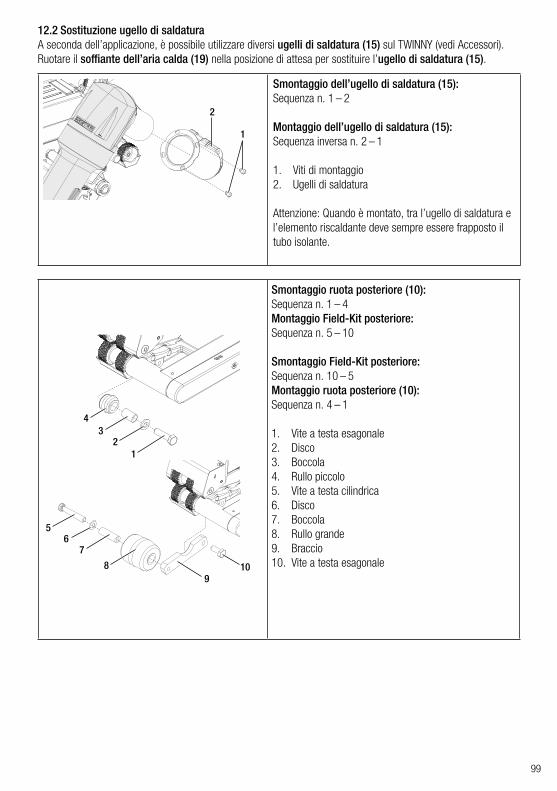
99
2
1
Smontaggio dell’ugello di saldatura (15):Sequenza n. 1 – 2
Montaggio dell’ugello di saldatura (15):Sequenza inversa n. 2 – 1
1. Viti di montaggio2. Ugelli di saldatura
Attenzione: Quando è montato, tra l’ugello di saldatura e l’elemento riscaldante deve sempre essere frapposto il tubo isolante.
12.2 Sostituzione ugello di saldaturaA seconda dell’applicazione, è possibile utilizzare diversi ugelli di saldatura (15) sul TWINNY (vedi Accessori).Ruotare il soffiante dell’aria calda (19) nella posizione di attesa per sostituire l’ugello di saldatura (15).
Smontaggio ruota posteriore (10):Sequenza n. 1 – 4Montaggio Field-Kit posteriore:Sequenza n. 5 – 10
Smontaggio Field-Kit posteriore:Sequenza n. 10 – 5Montaggio ruota posteriore (10):Sequenza n. 4 – 1
1. Vite a testa esagonale2. Disco3. Boccola4. Rullo piccolo5. Vite a testa cilindrica6. Disco7. Boccola8. Rullo grande9. Braccio10. Vite a testa esagonale
1
5
76
89
10
23
4

100
12.3 Montaggio Field-KitSe per la saldatrice automatica si necessita di una maggiore altezza da terra o di ruote più grandi, le ruote stan-dard possono essere sostituite con il Field-Kit.
Smontaggio ruota anteriore (16):Sequenza n. 1 – 2Montaggio Field-Kit anteriore:Sequenza n. 3 – 8
Smontaggio Field-Kit anteriore:Sequenza n. 8 – 3Montaggio ruota anteriore (16):Sequenza n. 2 – 1
1. Vite a testa cilindrica (2x)2. Rullo piccolo3. Vite a testa cilindrica (2x)4. Disco (2x)5. Boccola (2x)6. Rullo grande (2x)7. Braccio (2x)8. Vite a testa cilindrica (2x)
12.4 Montaggio barra di guidaUtilizzando la barra di guida, la saldatrice automatica può essere condotta mentre si assume una posizione eretta.
Montaggio della barra di guida:Sequenza inversa n. 1–5
Smontaggio della barra di guida:Sequenza n. 5 – 1
1. Vite a testa cilindrica (2x)2. Disco (2x)3. Supporto4. Tubo di collegamento5. Maniglia
5
4
3
21
3
1
21
45
67
87
65
43

101
13. Accessori
14. Assistenza e riparazioni
• Utilizzare esclusivamente ricambi e accessori originali Leister. In caso contrario decade qualsiasi diritto alla garanzia.
• Per ulteriori informazioni visitare www.leister.com.
• Le riparazioni devono essere eseguite esclusivamente dai centri di assistenza Leister autorizzati.• Non utilizzare detergenti o solventi aggressivi per la pulizia dell’apparecchio.• Questi ultimi assicurano riparazioni sicure e affidabili in 24 ore, con parti di ricambio originali come da schemi
elettrici ed elenchi parti di ricambio. • Gli indirizzi dei centri di assistenza locali autorizzati sono reperibili nell'ultima pagina.• Per ulteriori informazioni visitare www.leister.com.• Se, dopo l’accensione dell’apparecchio, sulla saldatrice automatica compare l’indicazione per l’intervallo di
assistenza, la saldatrice automatica deve essere controllata presso un centro di assistenza Leister autorizzato.
17. Conformità
Leister Technologies AG, Galileo-Strasse 10, CH6056 Kaegiswil/Svizzera conferma che i prodotti, nelle versioni da noi commercializzate, sono conformi alle seguenti direttive UE.Direttive: 2006/42, 2014/30, 2014/35, 2011/65Norme armonizzate: EN ISO 12100, EN 55014-1, EN 55014-2, EN 61000-6-2, EN 61000-3-2,
EN 61000-3-3, EN 62233, EN 60335-1, EN 60335-2-45, EN 50581
Kaegiswil, 29/08/2018
Bruno von Wyl, CTO Christoph Baumgartner, GM
Gli apparecchi elettrici, gli accessori e gli imballaggi devono essere riciclati nel rispetto dell’ambiente. Solo per i Paesi UE: Non smaltire mai gli apparecchi elettrici insieme ai rifiuti domestici.
18. Smaltimento
16. Garanzia legale• A questo prodotto si applicano i diritti previsti per la garanzia concessi dal partner di distribuzione/rivenditore
diretto, a partire dalla data di acquisto.• In caso di ricorso alla garanzia (fanno fede la fattura o la bolla di consegna), sono previste la fornitura sostitutiva
o la riparazione di difetti di fabbricazione o di lavorazione a cura del partner di distribuzione.• È esclusa qualsiasi ulteriore garanzia non espressamente prevista dalle vigenti norme di diritto cogente.• Sono esclusi dalla garanzia i danni riconducibili alla normale usura, ai sovraccarichi o alla gestione scorretta.• La garanzia non si applica agli elementi riscaldanti.• Il ricorso alla garanzia decade per gli apparecchi sottoposti a modifiche o alterazioni da parte dell’acquirente,
come anche in caso di impiego di accessori non originali Leister.
15. Formazione• La Leister Technologies AG e i rispettivi centri di assistenza autorizzati offrono corsi gratuiti per varie applicazioni.


Your authorised Service Centre is:
Leister Technologies AGGalileo-Strasse 10CH-6056 Kaegiswil/SwitzerlandTel. +41 41 662 74 74 Fax +41 41 662 74 16 [email protected]
© Copyright by Leister
TWIN
NY
T7/
T5 /
12.
2018
Art
. 163
.585
®