Ham Radio Magazine 1979
132
-
Upload
khangminh22 -
Category
Documents
-
view
0 -
download
0
Transcript of Ham Radio Magazine 1979


NOW YOU SAVE THREE WRYS RT HENRY RRDlO 7.. CALL FOR OUR LOW, LOW CASH
OR CREDIT CARDP R I c E s 0 N A L L MA J 0 R EQUIPMENT.
TAKE ADVANTAGE OF OUR
c " i d \ -
: q-aal Zb4 y* --Jp-qa,
9 b'. ENJOY THE WORLD FAMOUS HENRY RADIO SERVICE. NO ONE ELSE CAN OFFER YOU THE BACKGROUND OF EXPERIENCE AND THE VALUE OF RESPONSIBLE MARKETING LIKE HENRY RADIO. llt.1111 I<.I~I<I .IICI) 8111vt4 d 11111ad 11111. 111 8 1~111111.r-
4.1.11 ~ 1 1 d I C ( ICIK ~ i ~ ~ ~ ~ t ~ l ~ t v ~ l r ) t t n l > l l l ~ t ~ t \ G 01vr1119 t l i t . r.tn!lc of :I MH, t o 500 hlti,. Ha,nn. nnil,lil it.r\ . ~ r a . I,, uws AII r ~ ~ c > ~ 8 t l d IIIV ~ ( b r l d . C o t ~ ~ l i ~ v r ( ,dl a t i d ~ ~ ~ l ~ o r l i t l<luir ic.\ . t n i l,vil+.<l. I~IIII>~> VBII~I ~ICIIC ' ~ t ~ q ~ I t f ~ v r \ ~ r v a \ a ~ l , t l ~ l t , <*I T e n i p o
NEW TOLL FREE ORDER NUMBER (8001 421-6631 ~ l t + ~ l < , r \ I I I ~ c ~ ~ ~ ~ I I ~ ~ ~ ~ I I t l l v 1 5 Fol al l slates except Cal~lornia Call1 resldenls please call collecl on our regular numbers
11240 W Olyrnp~c Blvd , L o $ Angeles. Cal~f 90064 213/477 6701 931 N Euclld. Anahelm. Call1 92801 714/772 9200 Butler, Mlssour~ 64730 816/679 3127 ' J
DO ITH
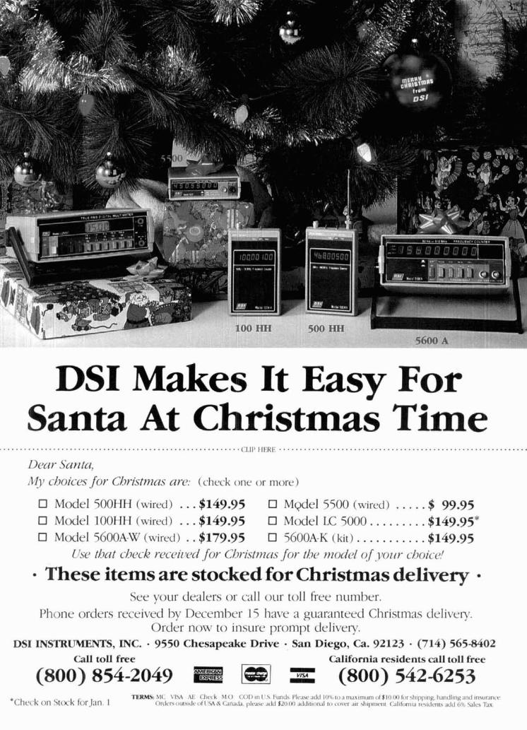
DSI Makes It Easy For Santa At Christmas Time
.......................................................... (;1.,1' ,1,<1<1.' ............................................................ Decir Santa, 1191 c-hoic--c.s for Christnzc~.s arcJ: (check one or more)
El Model 5OOHH (wired) ... $149.95 Mgel 5500 (urircd) . . . . . $ 99.95 El Model IOOHH (wired) ... $149.95 El Model LC 5000.. ....... $149.95* El Moclel 56OOA-W (wired) .. $179.95 El 5600A-K (k i t ) ........... $149.95
Cisc> d ~ i t d7cjc.k rc~cciz~c~cl for C/~ri.stmcrs for t / ~ mor/cl of . . yozir cl~oic-c>!
These items are stocked for Christmas delivery See your dealers or call our toll free numl2er.
Phone orders received bv Decen~ber 15 have a guar:inteed Christmas deliven. 0rd;r now to insure prompt delivery.
DSI INSTR-S, INC. . 9550 Chesapeake Drive San Diego, Ca. 92123 (714) 565-8402 Call toll free California residents call toll free
(800) 854-2049 1- (800) 542-6253

f NEW MFJ-4 10 "Professor Morse" lets you . . . \
COPY CW FASTER AND UPGRADE QUICKER NEW MFJ Random Code GeneratorIKeyer sends unlimited random code in random groups for practice. Never repeats same sequence. Tailor level to your ability. Vary speed 5 to 50 WPM. Vary spacing between characters. Speed Meter. Full Feature Keyer. - Sends unlimited random
Never repeats same sequence. Tailor level to your ability.
/7W , V a d d g k
" " I
Copy cmJe faster and upgrade qutcker. Now you tuatlon (pellid cmma, question, slash, double dash ) slon and spaclng Heavy base w ~ t h non slrp rub can tailor the level ol code practice to your exact Tone control. Room hlllng volume. Bullt In ber leet elrmlnates walklng $39 95 needs Practlce copying code anywhere and any speaker Ideal for classroom teachlng Earphone Order from MFJ and try i t - no obligation. If tlme you have a spare moment Pracllce at home, lack (2 5 nirn) lor private listening not delrghted return 11 wilhrn 3 0 days lor refund In bed drrvrnq to work, dur~ng lunch etc U s o 110 VAC. or 9 18 VDC. or 4.C cells (for (less shlpprng) I& year uncond~tlonal g u m
The new MFJ-410 "Professor Morse" IS a poilable use) Optlonal cable lor car cigarette l~ght Older today. Call toll lree 800 647 1800 Charge Computer lrke random code generator and keyer er ($3 00) 6 x 2 ~ 6 Inches VISA MC or mall check money order lor $149 95 that sends an unllm~ted supply ol preclslon Morse Bullt.in full feature keyer. Volume, speed. In plus $3 00 sh~pplng lor MFJ 410 andlor $39 95 Code ~n random groups ternal tone and we~ght controls Weight control plus $3 00 shrpprng for Bencher paddle
I t never npeats the same sequence so you adjusls dot dash space ratlo, makes your slgnal cant memor~ze 11 l~ke code tapes drst~nctlve to penetrate ORM Speed meter works
Vary sped 5-50 WPM and read on speed meter lor keyer too Tune sw~tch keys transm~tter lor Cai 601 323 5869 far lechnlcal nfoinlatlon Vary spaclng between characters and charac tunlng Rellable solid state orderlrepalr status Also call 601 323 5869 out
ter group5 (lor example, copy 5 WPM wlth 13 keylng gnd block. cathode. srde contrnental USA and ~n M~ssrss~pp~ WPM characters) to glve proper character sound sol~d state rlgs OPTlONAL at low speed BENCHER IAMBIC PADDLE. MFJ ENTERPRISES, INC. l select alphabetic only or alphanumeric plus punc Do1 and dash paddles have fully adlu5lnble ten BOX 494. MISSISSIPPI STATE. MS 39762 /
'NEW MFJ-624 Deluxe Hybrid Phone patch' Feature Packed: VU meter for line level and null. Has receiver gain, transmitter gain, null controls, bypass switch. Beautiful hum-free audio. RF filtered. VOX or push-to-talk. Works with any rig. Simple patch-in- patch-out installation. Crisp, clear hum-free audio
is what phone patching is all about and MFJ has it.
TRINSUITIEI
maxlmum null.
$5gg5 Thls new MFJ-624 Telepatch I hybrid phone Function switch: OFF lor normal operation. ON inches. $49.95 plus $3.00 sh~pping and hand-
patch glves you a comblnalron o l perlonnance, connects your rig to phone llne tor patching. ling. lealures. and qual~ty that you won't llnd In other NULL swltches VU meter 10 let you adlust lor One year uncond~tional Uy.@&i phone patches. Order from MFJ and try i t - no obligation. H
PERVRMhl Gives yw crisp dear. humlree Simple 2 cable installation (plus phnne line) not delighted, return 11 w~thrn 30 days lor relund audlu wh~ch IS what phone patching IS all about. when rig has patch-inpatch-out jacks. Connects (less shrpprng). Llse autonlatrc VOX or pushto talk. RF pi-filters eas~ly to any rig. Order today. Call toll free 800-647-1800. Charge and PC board construction ellminates RF feedback. Phono jacks lor patch-in.patch-oul, speaker. VISA. MC ur mall check, money order lor $59.95 Works wltli any rlg. microphone. Screw terminals for phone lines. plus $3 00 sh~pplng lor MFJ 624 and $49.95
FEATURES: VU meter monilors telephone line Eggshell white, walnut srdes. 8 x 2 ~ 6 rnches. plus $3 00 shlpplng lor MFJ 620. l e v n f i v e n t crosstalk between telephone O c w : Every single unit is tested lor per- channels Also lets you adjust null depth lor fornr,:nce and ~nspected lor quality Solid Amerl- maxlmum isolation between recelver and trans- can ~ol~slruct lon, qual~ty companenls. 1111 I~:c~I~III:~I~ I I I ~ O ~ ~ I ~ ~ I I I ~ I . i~r~Ii:r/rep,iir ~ , t , t l ~ ~ s . 111
mltter. MFJ.620 TELEPATCH MISS. oi~ls~de coi:t~nental USA, call 601 373 5869. Separate transminer and ncelver gain controls HYBRID PHONE PATCH.
eliminate readlustrng rig's controls alter patching. Sanie as MFJ 624 but &-&. \ Null control lor maximum ~solat~on. less VU meter. 6 x 2 ~ 6 -~ MFJ ENTERPRISES, INC.
BOX 494. MISSISSIPPI STRTE, MS 3g76Z 1 2 december 1979 M o r e Details? CHECK-OFF Page 126

magazine
contents 14 CMOS 144-MHz synthesizer
Thomas V. Cornell, K9LHA
24 environmental aspects of antenna radiation John R . Abbott, KGYB
28 Hellschreiber - a rediscovery Hans Evers, PA0CX
34 log periodic antenna design Paul A. Scholz, WGPYK George E. Smith, W4AEO
40 L-band local oscillators H. Paul Shuch, N6TX
50 low-noise preamplifiers Geoffrey H. Krauss, WAPGFP
62 variable high-voltage supply George A. Wilson, WlOLP
66 any-state ni-cad charger William E. Bretz, WAGTBC
4 a second look 72 new prod1 126 advertisers index 8 presstop 104 cumulative index 126 reader ser 91 flea market 62 repair ben
100 ham mart 73 short c i rc~ 6 letters
cts
rice :h its
december 1979 3

What appear to me to be arbitrary and capricious decisions by FCC staffers in Washington have shown once again that the FCC bureaucrats are apparently interested in responding neither to public interest or public need. What I'm referring to, of course, was a recent announcement that FCC type acceptance of solid-state wideband amplifiers for the Amateur Service has been terminated without explanation by the FCC's Office of Chief Scientist. Are Radio Amateurs to be denied the use of modern solid-state technology because of the autocratic decision of an obscure bureaucrat in a democratic government? Is this not a con- tradiction to paragraph 97.l(c) of the FCC's own Regulations which state that one of the fundamental pur- poses of the Amateur Radio Service is to encourage and improve ". . . the amateur radio service through rules which provide for advancing skills in the . . . technical phases of the art?"
This recent action is just another in a long series of official FCC decisions which are contrary to the needs and desires of the Amateur Radio community - the linear amplifier ban, an unpopular and ridicu- lous callsign system, equipment type acceptance, the ASCII ban, recommending to the World Administra- tive Radio Conference (WARC) that CW be an "option" for the Amateur Radio service. This last item is a real dilly and stresses the need for closer congressional scrutiny of the Commission.
Several years ago, as part of the WARC preparations, the FCC formed the Advisory Committee for Amateur Radio (ACAR) and gave them the task of recommending, on behalf of Amateur Radio, what pro- posals should be made by the United States at WARC '79. ACAR carefully reviewed Article 41, which contains miscellaneous rules pertaining to the Amateur service including a Morse code proficiency require- ment for operation below 144 MHz, and proposed no changes. As the WARC preparations proceeded, the FCC released Notices of Inquiry in Docket 20271 which requested public comment on various WARC draft proposals. The Commission requested comment on a proposal of "no change" to Article 41; those who responded supported that proposal. The FCC staff, however, chose to ignore both ACAR's advice and the public comments and recommended to the State Department that the United States' WARC position should include a proposal to delete the requirement for Morse code proficiency!
In Geneva the United States delegation proposed to make the code requirement below 144 MHz a "rec- ommendation" rather than a requirement, a position that was supported by both Canada and Japan. For- tunately, some 15 administrations opposed the move as did every Radio Amateur in attendance. Brazil argued that any change to Article 41 would jeopardize existing reciprocal licensing agreements; Sweden proposed a 28-MHz cutoff; Papua New Guinea suggested 30 MHz. In the end the Papua New Guinea pro- posal won out and will be recommended for adoption by the conference. In effect, this lowers the frequen- cy for a code-free Amateur Radio license to 30 MHz, a change which affects only six meters. Thus Amateur Radio lost a little - it could have been much worse - and the blame falls directly at the feet of unknown staffers within the FCC.
How could this happen? The publicly stated position of the FCC in April, 1977, regarding Article 41 reflected both the advice of ACAR and majority public opinion; its recommendations to the U.S. State Department less than two years later proposed a deletion of the Morse code requirement, in direct contra- diction to the public's wishes. Apparently the change was conceived by some staff member (or members) within the Commission in direct violation of the Administrative Procedures Act, and no one in authority felt strongly enough about their public responsibility to veto it. It's no secret that the CB industry has been applying tremendous pressure for a code-free high-frequency operator's license, and this recent effort to sneak an unpopular proposal to an international forum leads one to believe they may have found a respon- sive element; except for Amateur Radio's friends in the international community, they would have succeeded.
Jim Fisk, WlHR editor-in-chief
4 december 1979

, . - -. . . . . . - . - . - . . . - . . - - . . . - - . . I 2112l lbthAve,NE I
Bellewe, WA 98004 I 1 I I I Pkau send me: [L! K-551 spcdficatlom sheet; 1-1 full color I ! KOM Product Unc Cataloq; List of Authorized ICOM I -. i ~ k a ~ e r ~ . I
ICOM AMERICA, INCORPORATED ! -, I CW I
Sales S e ~ c e Centers located at ! ! I
2112 116thAvenue NE 3331 Towenmod Dr., Su~te 307 : I Bellewe, WA 98004 Dallas, 1X 75234 I I
I Cm STATE ZIP I Phone (206) 454-8155 Phone (214) 620-2780 I I
All stated spectflcatlonr are subject l o change wlthout nOtlCe All ICOM radlos s~qn~f~cantly exceed FCC regutattons Ilmltlng spurlous rmlsstons
save nearly a hundred dollars over the user's price if you buy a surplus tube. But what if your "bargain" tube is bad? If you have bought it from a sur- plus dealer by mail, do you think you will get a refund? Fat chance. I t all mmentS depends upon how much of a risk you want to take. You don't lose much with a surplus 873 or two.
Being in the power tube business, I am familiar with tear-stained letters from hams who have bought a JAN-
!,! " branded, expensive, power tube and have been dismayed to find the tube
e bad and no warranty on it. But if you linear power amplifiers understand the limitations on warran- Dear HR: ty with respect to surplus tubes, and
I would like to comment on Bill have the ability to test your tube im- Orr's article on linear amplifier con- mediately upon getting i t home (and struction in the June issue. I believe stand a reasonable chance of getting his warning against military surplus your money back if the tube is no tubes is much too conservative. I'm good), why not? After all, plenty of afraid most Radio Amateurs watch people lose a wad of money every costs. New high-power transmitting day at the horse races. But they have tubes will go a long way toward driv- the fun of watching the horses run. ing the cost of a homebrew linear Bill Orr, W6SA I past the cost of a commercial amplifi- Menlo Park, California er. I have built a linear using three 813s in parallel, and at 1500 watts PEP
memory keyer it performs beautifully, just as pre- Dear
dieted in author orris own Radio I have just finished building the
Handbook. Few tubes can beat the ke~er featured in the April
813 for clean response or ruggedness issue of ham radio; I wish to thank (carbon plate version). I have C. Cheek and your magazine acquired a collection of six JAN 813~, for a beautiful and accurate article on
mostly from other hams; all have the construction of this ke~er.
been tested in my amplifier and all I substituted 21L02 memory chips
work beautifully. For a small fraction for the 2102s and then added a 7400
of the cost of a 3-10002 or even two gate with all inputs tied to ground. A
3-500Zs, I have a good set of tubes in single switch in the 5-volt supply to
my amplifier and a spare set on hand. the 7400 will give a high or inactive
If you're considering building your Output On the four gates; three of
own linear amplifier, read everything these Outputs are tied to the chip-
you can, such as W6SAl's fine arti- enable pins of the 21L02 memory
cles, then build it yourself, and chips. With the addition of separate
scrounge. switches in 5-volt supply lines to the
william ~ ~ ~ i ~ , K ~ 5 E ~ memory board and the keyer, and a
H ~ ~ ~ ~ ~ ~ , T~~~~ separate supply line with a 70-ohm resistor bypassing the switch to
Right. There's nothing wrong with memory board, you can hold the buying a surplus 813 from a fellow memory in a power-down mode with ham for a few bucks and trying it out a drain of less than 40 mA (compared in your rig; maybe he'll even take it with over 300 mA to the memory back if.it doesn't work. board alone at 5 volts).
It's all a matter of judgment. How I found the power supply ran a little about buying a surplus 88777 You can warm when the drain was high and
the keyer was left on overnight to re- tain the memory. The 70-ohm resistor reduces the supply voltage to 1.5 volts to the memory board; the chip- enable pins on the 21L02s are float- ing at about 4.5 volts from gates of the 7400 chip. With the 5-volt supply to the 7400 switched off, the gate outputs are inactive and the 21L02 functions as before the modification. Switching to memory power-down mode must take place before the 5- volt supply to the memory board is opened or else memory is lost. There is a zero time factor from power on to power down.
William Hansen Glenwood, Illinois
split-band speech processor Dear HR:
Congratulations to Wes Stewart, N7WS, for his fine article, "Split- Band Speech Processor," in Septem- ber, 1979. Wes mentions that the cir- cuit is sensitive to rf and that the proper use of ferrite beads, bypass capacitors, and rf shielding is impor- tant; he is correct. To this end, I would like to suggest that rf bypass capacitors be added in parallel with the 1 N914 clipper diodes to prevent r f mixing. Values of several hundred picofarads should be sufficient.
Since symmetry is extremely im- portant in the prevention of second order harmonics, I would also recom- mend replacing the 1 N914 clipper di- odes with diode pairs such as Motor- ola's MSD6150. Using two diodes manufactured on the same substrate provide close matching of Vf and other electrical characteristics. It is also an ideal means of keeping both diodes at the same temperature, en- suring the best clipping symmetry possible. The additions have proven themselves in the processor I am using.
James D. Allen, WAPSSO Rochester, New York
(Continued on page 72)
6 december 1979

The TS-180s with DFC (Digital Frequency Control) is Kenwood's top-of-the-line all so l id-s ta te H F S S B l C W l F S K t r a n s c e i v e r covering 160 through 10 meters , with outstanding p e r f o r m a n c e and m a n y advanced func t i ons , including four tunable memories to provide more operating flexibility than a n y other rig!
TS-180s FEATURES: Digital Frequency Control (DFC), including four memories and digital upldown paddle-switch tuning. Memories are usable in transceiver or split modes, and can be tuned in 20-Hz steps up or down. slow or fast, with recall of the original stored freouencv. . . (Also available without DFC.) All solid-state: 200 W PEP1160 W DC input on 160-15 meters, and 160 W PEP1140 W OC on 10 meters. Improved dynamic range, with improved circuit design and flF AGC ("RGC"), which activates as an automatic RF attenuator to prevent receiver overload. Adaptable to three new bands, and VFO covers more than 50 kHz and DFC I00 kHz above and below each band. Built-in microprocessor-controlled digital display. Shows actual frequency and switches to show the difference between the VFO and "MI" memory frequencies. Blinking decimal points indicate "out of band." (An analog monoscale dial is also included.) IF shift (passband dialing to eliminate ORM). Dual SSB filter system (second filter is optional) to provide very sharp receiver selectivity, improved SIN, and 30 dB compression with RF speech processor on transmit.
Tunable noise blanker, to eliminate cross modulation from strong signals when noise blanker is on. Selectable wide and narrow CW bandwidth on receive (500-Hz CW filter 1s optional). SSB normallreverse switch (proper sideband is automatically selected with band switch). Dual RIT (VFO and memorylfix). Available without DFC. Digital frequency display still included, with differential function showing difference between VFO and "digital hold" frequencies.
OPTIONAL ACCESSORIES: OF-180 digital frequency control (for TS-180s without DFC). YK-88CW 500-Hz CW f~lter. YK-88SSB second filter for dual-lilter system.
T R I O - K E N W O O D C O M M U N I C A T I O N S I N C 1 1 1 1 WEST WALNUTfCOMPTON. CA 90220
WARC NEWS CONTINUED GENERALLY FAVORABLE for the Amateur service, ARRL's WARC team reported from Geneva in early November. Some consideration has now been given to the Amateur bands, and on a world-wide basis, the service is holding its own.
160 Meters: An exclusive 40-kHz slot in Region 1 seems to be within reach; Region 2 looks like it'll keep 1800-2000 kHz with 50 kHz exclusive (probably the bottom end) and 150 kHz shared. Region 3 is also likely to end up with 200 kHz, possibly all on a shared basis though an "Amateur Exclusive" slot is possible.
40 Meters: As of now, the present 7-MHz world-wide allocations appear to have been maintained. However, international broadcasting's desire for new frequencies should still be considered to be a potential threat to a portion of that band.
10 Meters: It was agreed in committee to maintain the 28.0-29.7 slot as Amateur ex- clusive, worldwide. That committee is discussing the possibility of a separate HF-bands broadcasting conference in the future, and has appointed a large working group to recom- mend the ground rules for such a conference.
6 And 2 Meters: Present 50-MHz allocations do not appear to have been altered at this time. 144-148 MHz is also retaining the status quo, though some reservations ("footnotes") are believed to have been Dro~osed for the band in some areas.
220 MHz: Amateur and ~bbiie services have been proposed as "Co-Primary" users for this band, in Renion 2 only.
1215 MHz; A reduction to 1240-1300 was voted after considerable discussion by the Working Group. 1215-1240 would go to the Radio Navigation Satellite Service, with 1240- 1300 a world-wide secondary allocation for Amateurs and the 1250-1260 MHz subband for Amateur satellite uplinks. The U.S.S.R. indicated it may later suggest a further reduc- tion to 1250-1300 for Amateurs.
Microwave: 10.45-10.50 GHz has been proposed as a world-wide "Amateur Satellite" subband. The present 24 GHz band has been sustained by the Working Group, and the out- look is good for Amateur interests in the millimeter wave area above 40 GHz.
ASCII WAS ACCEPTED, paving the way for its use by Amateurs in the near future, at the Commission's meeting in Washington in mid-October. After considerable discussion, the Commissioners agreed to let Amateurs use ASCII for RTTY and instructed the staff to pre- pare rules for its implementation. During the discussion identification of Amateur sta- tions operating on RTTY was a key issue, and the present requirement that RTTY users must identify using CW was the telling argument in getting the Commissioners to agree on the ASCII okay.
ANY AMATEUR LICENSE MODIFICATION will now require filing of a Form 610 or 610B, the FCC has decided. Previously, a change in mailing address (only) simply required a note to Gettysburg, though a station location change did require a Form 610 or 610B. For most Amateurs, mailing aadress and station location are the same. However, most Amateurs who have moved have not been submitting 610s, thus requiring a response from Gettysburg before their reauest for modification could be processed.
Modified ~icinses now will be extended for a' full 5-year term effective on the modi- fication date; changes were effective November 12. -
WIDEBAND FM ON ALL OF 6 METERS is to be proposed in a new Notice of Proposed Rule Making due shortly from the Commission; the Commissioners decided to throw the issue of 6-meter sub-bands squarely back to the Amateur fraternity by proposing that the band have no divisions by modulation. Strong opposition to the proposed deregulation can be ex- expected from SMIRK and other 6-meter DXers.
AMATEURS WHOSE LICENSES or upgrades were obtained by fraud will soon be the subject of enforcement action, as a result of a recent Commission meeting. In addition, a number of Commission employees who received callsigns in a manner "inconsistent" with Commission procedures soon will be receiving new callsigns. About 50 people in the first category were identified as a result of the FBI investigation that began in Indianapolis back in June, 1977. Many of them, along with other Amateurs who may have taken part in fraudu- lent licensing schemes, will be facing revocation or suspension proceedings.
No Action Is Planned against non-FCC Amateurs who received special callsign treat- mentin the past.
LAUNCHING OF THE UNIVERSITY OF SURREY/AMSAT UK UOAST has been approved by NASA. The l a u s h e inclusion of a synthesized telemetry system and a slow-scan TV camera on board the British OSCAR. The TV system will photog;aph cloud cover and the earth so that Amateurs can receive the pictures di- rectly on their equipment.
A 23-CM LINEAR TRANSLATOR was put into service near San Jose, California in September, after extensive low-level tests. The translator was developed to provide new techniques for orbiting and terrestrial translators using microwave frequencies and to encourage greater 23-cm activity by Amateurs.
8 5 december 1979

The follou,ing are excerpt* from unsollnted letters and registratton cards recc~ved from owners of the new TEN T t C OMNI transreiver
" I sold a Yaesu to buy this and am very impressed" -WBJULA
"MyJirst QSO wi th OMNI-A was L A l S V o n CWond second was EASSK on SSB." -N2CC
"Excellent rig. just os advertised." - WB5TMD
" V e y pleased wi th performance. QSK Jeaiure verv slick." -WBOELM
"This is my 5 th TEN-TEC transceiver in less than 2 years. I loved them all and still have 3." - WBOVCA
"Through the years I have had complete Drake and Collins stations. I tried a 544 Digital and liked it the best so decided to purchase the 546 OMNI-D Digital.'' - WA4NFM
"Your OMNI is the best rig I have had in 20 years of homing." -K41HI
"As a owner of Collins rig. your OMNI-D Is the best." -K9JJL
"I already have an OMNI-A. 544 and a TRITON 111. You may ask why I own so many TEN-TEC rigs. In case there is a great RFJamine. I wont to be ready!" - WD4HCS
"You guys really know how to iurn on an old timer!" -KSELS
"Best opemtfng & most conveniences oJ any tmnsceiver I've ever used." - W6LZI
"I like CW. Compared O M N I against IC701 (rcvr) and OMNI won hands down. XYL WD6GSB really enjoys rig on SSB. Finds rig is very stable and diaital readout accumte." -AC6B
"This must be the greatest. I've spent enough money on Jinal tubes to almost pay for this."
"This transceiver wos recommended to me by old t ime hams (Xtras) whom I have known Jor 40 yrs. Has excellent break-in."
"Best package job I've ever seen! First licensed 6AAV in 1926. Now in operatio+a sweetheati!"
"From a 32V21SX115 to an OMNI is a big step!"
"Receiver prominent-transmitter likewise- working comJoriable-pleasing design."
"First new rig Jor me in 10 years but seems to be v e y good."
"The best tmnsceiver I ever used or owned."
"I wouldn't swap my OMNI Jor anything on the market, regardless oJprice." - WDOHTE
OMNI/SERIES B FEATURES All solid-state: 160-10 meters; Broadband design; Standard 8-Pole 2.4 kHz Crystal Ladder I-F Filter + Optional 1.8 kHz SSB Filter & 0.5 kHz 8-Pole CW Filter: 3-Bandwidth Active Audio Filter: Choice of readout - OMNI-A (analog d~al l . OMNI D (dlgitnl): Built-in VOX and PTT. Selectable Break-in. Dual-Range Receiver Offset Tuning. Wide Overload Capabilities. Phone Patch Interface Jacks; Adjusta- ble ALC: Adjustable Sidetone: Exceptional Sensitivity: 200 Watts INPUT; 100% Duty Cycle. Front Panel Microphone and Key Jacks: Zero-Beat Switch: "S"/SWR Meter; Dual Speakers: Plug-In Circuit Boards: Complete Shielding: Easier-to-use size: 5'"h x 14'.4"w x I4"d. Full Options: Model 645 Kever $85, Model 243 Remote VFO $13'). Model 252MO mdtchlng AC power supply $139: Model 248 Noise Blanker 44'3. Model 217 500 Hz 8-Pole Cystal Ladder CW Filter $55. Model 218 I R kHz 8-Pole Crystal Ladder SSB Filter '$55.
4
"Have checked it out on both modesfrom "top band" Model 545 Series B OMNI -A . . . $949
(160) all the way to 29 MHz. Terrific!!!!" - W4DN Model 546 Series B OMNI-D . . . $1119
"Works well. parts layout and design much betterjor To add your name to the fast.growing Itst of OMNI owners. see you1
any possible servicing than other ham gear. The TEN-TEC dealer, or write for full details.
Japanese hybrid sets can't compare to TEN-TEC for audio. Audio reoorts excellent without soecial speech proces9ors, etc., to distod the signal." -AGSK
" I have been using the S-Line over 15 yrs and neuer thought anything could outperform it. 1 got the TEN-TEC .INC. biggest surprise and THRILLED wi th this OMNI-D 1r.7r S E V I E R V I L L ~ . , , , "... T E N N E S S E E % ,, J I E B Z ,.*. even though I have been a ham sinre 1936." -KV4GD

~ n v successo Roc
The The remarkat 380 continues heritage for quality amateur equipment.
Pro-mark KWM-380 is a complete base station in a smartly styled desktop configura- tion. The look is unmistakably professional.
All in one u speaker and a built in.
Microprocessor frequency control pro- vides rate selectable tuning in 1 MHz, I kHz, I Pro-mark I 100 Hz or 10 Hz increments. Frequency
I' memorv~rovides stlit VFO function (half- ! duplex jfbrtransrnii and receiver registers.
The high resolution frequency synthe- METER MIC / CARRIER MODE VFO
I sizer locked to a high stability frequency LSE USE B RA-TB
reference is accurate to iO Hz with no bandswitch. Eliminate undesired signals
I with independently selectable 1.E bandwidths and passband tuning. Optional
!; 1.E filters can be selected independent of GAIN SELECTIVITY PRT -)- BW
MIC PHONES
i - ...w hare science getsdown tobusiness
Specificationsf
Frequency Range: Tunahle in 10 H z steps. Receivemodc-2.0 to 30.0 MHz. 0.5 107.0 MHz at reduced sensitivity. 'kansmit mode - SSB or CW 160- thru 10- meter amateur bands. Mode: SSB (voice and KITY, either sideband selectable), CW, or AM (receive only). Powerrcqulrements: 105. 115. 125. ?10.2?0. 230, 240.220. f 5% V ac (Internal strapping option) 50-60 Hz. 12 V to I5 V dc (Connector strapping). I20 W input in receive max: 600 W input in transmit max.
*Subject to change without notice.
1 Frequency accuracy: Accurate to within 2 5 Hz when the 39.6 MHzoscillator and the 425.0 MHz os~illator arc set wirhin t 3Hz. Warm-up time is 10 min. Frequency stability: Stability is within +I50 Hz over the temperature range of 0-50°C. TRANSMIT PERFORMANCE Outpul impedance: 50 ohms nominal. Power output: I00 W PEP nominal from 1.6-30 MHz. In CW or RTTE there is au- tomatic turndown to 0 W aRer 10 seconds, 50% duty cycle, key down 15 minutes max.
With the optional blower kit, power is 100 W average. 5WZduty cycle, key down 1 hour max at ?c"C. M hour wax. at SVC for all modes.
I Unwanted signal suppression: (minimum values helorv)
Carrier suppression SO dB Undesiwd sideband,
I k H 7 ref 53 dB Harmonics tall) 40dR Mixer products 5 5 dB
Third order dislortion: 25 dR below eaih tone of a two-tone test. Audio inputs Microphone - low impedance type, internal strap Tor HI-Z. Line -M)O ohm input unbalanced impedance: level of 40 mV sufficient to produce full output.
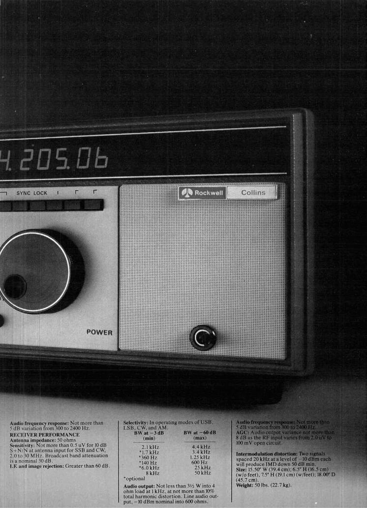
8 k H z u kHz (wlo feet). 7 . 5 " ' ~ (19.1 cm)(wlfeet): 18.00"D 'optional (45.7 cm). Audiooutpuk Not less than 3fi W into 4 Weight: 50Ibs. (22.7 kg). ohm load at I kHz . at not more than IWr, total harmonic distortion. Line audio out- pul. -10 dBm nominal into 600 ohms.

You'd expect the distributor - -~
who sells Rockwell-Collins'
new Pro-mark" KWM-380
to be an expert. H e is.
He:s your Rockwell-Collins Distributor, a real pro at answering questions and solving problems.
He's especially proud to have been selected to represent the new Pro-mark KWM-380. And he's made it his business to know i t inside out. See him soon. He'll be glad to give you a demonstra- tion. And remember, he'll be there to support your needs for years to come. Collins Telecommunications Products Division, Rockwell International. Cedar Rapids, IA 52406. Telex 464-435. eAUMRNlA MINNESOTA Anahelm - Ham Radlo Minneapolis- Elec-
Outlet t r o n ~ ~ Center. I ~ c . Anahelm - Henry Radlo MISSOURI
Co.. Inc. Butler - Henry Radio CO. Burlinoame - Ham St LOUIS - Ham Radio
Radio Outlet Center Los Angeles -Henry St. LOUIS - Mldcom
Radio Co., Inc. Electronics. Inc. Oakland - Ham Radlo NEVADA
Outlet San D~ego- Ham Radio
Outlet San Jose - Ouement
Electronlcs Van Nuvs - Ham Radlo
Outlkt COLORAW Denver - C. W. Elec-
tronic Sales Co. FLORIDA Mlam~ -Amateur Radlo
Center. Inc. M iam~ Springs- Argon
Electronics Co. Orlando - Amateur
Electronic Supply OEORGIA Atlanta -ACK Radio
supply HAWAII Honolulu - Honolulu
Ele~tronlcs ILUNOIS Chlcago - Erlckson
Communications. Inc. Peor~a - Klaus Radlo. Inc. INDIANA Terre Haute- Hoosier
Electronics. Inc. KANSAS Overland Park-
Associated Radlo Comm.. Inc.
U)UISIANA M e t a ~ r l ~ -Thomas J.
Morgavi Elec. MARYLAND Wheatoi - E l e c t r ~ n l ~ ~
Int ' l Service Corp.
as Vegas - Amateur Electronic Supply
NEW HAMPSHIRE Concord - Evans
Radlo. Inc. NEW YORK Amsterdam -Adiron-
dack Radlo Supply. Inc Farm~ngdale. L.I. -
Harrlson Radio New York - Barry
Electronics Corp. New York - Harrison
Radlo Valley Stream- Harrl-
son Radio NORTH U R O U l U Otto - Slep Electronlcs
Comoanv . , onlo Wlcklifle - Amateur
Electronic Supply OREGON Portland - Portland
Radlo Supply Co. PENNSYLVANIA Trevose - Hamtronlcs m s Dallas - Electronic
Center. Inc. Houston - Madison
Electronlcs Supply WASHINBmN Seattle - ABC
Commun~catlons Spokane - HCJ
Electronics mscoNslN Milwaukee -Amateur
Electronic Supply,
comments (Continued from page 61
lightning protection Dear HR:
While I was pleased to see two let- ters in the July issue complimenting my article on lightning protection, I must take exception t o W6RTKfs suggestion that the ground wire on a wooden pole be broken into short lengths, with small spark gaps be- ween segments.
The main ground conductor on a wooden pole is one of the most im- portant items in the protection sys- tem. The establishment of a low im- pedance path from the air terminal on top of the pole to ground is necessary to send the greatest possible percent- age of the total lightning stroke cur- rent directly to ground. Although lightning will certainly jump across the small gaps recommended, the presence of these gaps will have a negative effect on the performance of the overall protection system. I don't know how to quantify the amount of degradation, but I don't think it's wise to take a chance. Also, even if lightning doesn't strike the pole, the breaking up of this ground lead may allow the entire antenna system to acquire a large static charge, possibly sufficient to cause minor equipment damage.
Mr. Caldwell is concerned that this ground wire may have some undesir- able effects on the performance of the antenna system; when consid- ered from the standpoint that the ground wire only makes the wooden pole look electrically equivalent to a metal tower, I think it is safe to say that this effect must be minimal.
John E. Becker, K9MM Prospect Heights, Il l inois
quartz crystals Dear HR:
It has been brought to my attention that a statement in my article on quartz in the February issue was mis- leading if not incorrect. While it is
true that crystals have high induc- tance and low motional capacitance, this is not the reason for high Q, Q is a ratio of the charge stored to the charge dissipated. In crystals the charge is primarily stored by the in- ductance, so Q is determined by the value of the motional inductance divided by the motional resistance:
Most of us associate high inductance with a large piece of iron wrapped in copper wire - an arrangement which is completely ineffective at rf. With quartz, you must rethink the problem.
Don Nelson, WBZEGZ Voorhees, New Jersey
10 meters for satellite communications Dear HR:
I write in response t o WlGMP, who suggests (July ham radio) that we discontinue the use of 29.360 - 29.502 MHz for satellite communica- tions. To put this into proper perspec- tive, the frequency spectrum resewed for this purpose is no wider than two 25-kHz wide repeaters, adding both input and output bandwidths, yet serves fifty times as many stations on an intercontinental basis.
Apart from the aspect of communi- cations, the use of 10 meters has been the basis of valuable research into sub-horizon communications, Es and aurora detection and forecasting, and low-level signal techniques; it is also of great value in using Amateur Radio for teaching practical physics, geometry, trigonometry, astronomy, and mathematics through the use of a simple antenna and receiver.
The present maximum in the solar cycle will soon begin to decay, leav- ing only the satellite devotees t o effectively occupy the high end of 10 meters. This will help prevent intru- sion and takeover of the top part of the band, safeguarding it by regular, valuable usage.
Pat Gowen, G310R Norwich, England
12 december 1979 More Details? CHECK-OFF Page 126

WHEN OUR CUSK)MERSTALK.. . WE LISTEN.
I Tom Gentry, KSVOU Dallas, TX I I John Whitaker. W5HU
Baton Rouge. LA I And we respond with unexcelled RT'W equipment.
One reason Rmequipment designed by HAL customer ideas with their own to create the most is always state-of-the-art quality is our open channel advanced equipment features and capabilities in the of communications with customers. industry.
We want to hear the "What if's. . ." and "How It adds up to greater enjoyment of R lTY operation about's. . ."that come from active and dedicated and a dependability factor backed with a full one-year R l T Y operators. Our engineers have combined warranty.
Write or give us a'call. We'll be glad to send you our new RllY catalog.
HAL COMMUNICATIONS CORP. h x 365 For our European Customers Contact Urbana, Illinois 61801 R~chter & Co . D3000 Hannover 1 2 17-367-7373 I E.C Interelco. 6816 B~ssonelLugano

CMOS 2-meter synthesizer Construction details
synthesizer featuring choice of
output frequency and CMOS design
Soon after joining the 2-meter fm crowd about three years ago, I learned how limiting "rockbound" mobile operation can be. At the same time, I had been wanting to learn more about frequency synthe- sizers, and designing and building one looked like the perfect answer to both needs. The result of my labor tunes from 146.000 to 147.995 MHz in 5-kHz steps and provides a variety of output frequencies to per- mit use with quite a number of rigs. This article will give full details on how the design was thought out, as well as how to build a copy. If you are interested in the subject of synthesizers, want to design one of your own but wonder where to start, or have solder- ing iron in hand ready to begin building, this article is for you.
design requirements In addition to the above description, I expected the
completed design to meet the following require- ments:
1. Thumbwheel switch selection of receive and transmit frequencies
2. High output purity, at least 60-dB spur rejection
3. Self-contained; simple construction and cir- cuitry
4. Minimum of test equipment needed to align and test
5. Minimum modification of 2-meter rig
( 6. Capable of mobile operation
1 operating frequency The first choice was an operating frequency for the
synthesizer. By looking at schematics and informa- tion on a number of common rigs, I learned that most use a receive crystal near 45 MHz. Transmit frequen- cies are less consistent and include f/6, f/12, f/18, and f/24. The circuit simplicity and purity goals ruled out the use of multipliers; therefore, I picked 45 to 49 MHz, or one-third the channel frequency.
1 synthesizer concepts The next step was finding the most suitable
method of synthesis. A literature search showed that the most popular type of synthesizer today is an elab- oration of the phase-locked loop (PLL). Fig. 1 shows the block diagram of such a system. In this, the VCO (voltage-controlled oscillator) is made to run at N times the reference frequency, fR, which is normally fixed. Because of loop feedback, changing the divide ratio, N , also changes the VCO frequency to maintain the frequency relationship shown.
Because of its apparent simplicity, this kind of syn- thesizer seemed like an ideal approach for my design; but, after studying the logic required, some serious complications were obvious. The need for an i-f shift to go from transmit to receive made the design a real mess.
By Tom Cornell, KSLHA, RR2, Box 53A, Greentown, Indiana 46939
14 december 1979

Several synthesizer schematics showed a different approach that looked like it had real promise; fig. 2 v C ~ LOW PASS
F I L T E R
shows the basic block diagram. The design freedom introduced by choice of crystal frequency allows the PHASE
same variable divider ratio to be used in both transmit V A R I A B L E
and receive. This results in great simplification of the - D ~ ~ ~ D E R - N -
overall synthesizer system. f - f X
practical design This section will cover the more important design CRYSTAL
OSCILLATOR
considerations. fig. 2. Diagram of a mixing-type synthesizer where the same
VCO. The simplest form of VCO is a varactor-tuned divide ratio can be used for either transmit or receive, with oscillator, and a common circuit is shown in fig. 3. the change in frequency accomplished by shifting the crys- While a VCO can be developed by trial and error, it is tal oscillator frequency.
much easier to calculate tank circuit values using the equations shown in the Appendix of this article.
DC CONTROL W L T A G E
; $-I INPUT
REFERENCE 1 = 'R O S C I L L A T O R
I = N f R
fig. 1. Block diagram of a simple synthesizer using a phase- locked loop.
N at 146.000 MHz = 400
fxlal (TX) = 48 MHz
N at 147.995 MHz = 799
fxtal (R X) = 48 - i-f/3
These numbers are a good illustration of synthesizer operation, and i t might help your understanding if you plug them into the equation shown in fig. 2.
After selecting these points, design of the oscilla- tor and mixer was relatively uncomplicated. A dual- gate MOSFET with an untuned output circuit was selected as the mixer, and two separate oscillators were used for receive and transmit.
Variable divider. The variable divider design has a lot to do with the complexity of a synthesizer circuit, and an intelligent choice is very important. Some of the divider requirements have already been covered, and the remaining important characteristic is speed.
Assuming a receiver i-f of 10.7 MHz, the minimum For this kind of synthesizer, the highest divider speed and maximum VCO frequencies are: is:
f,,, = 147.995/3 = 49.33166 MHz
fmin = (1 46.000- 10.7)/3 = 45.1 MHz
After picking some varactors (Motorola MV-2209) and suitable end point voltages, I was able to begin using the equations.
Letting CI = 330 pF and C2 = 33 pF and assuming 3 pF of transistor and stray capacitance, the total fixed capacitance, T, was 33 pF. The equations then gave Cp = 88.2 pF and L = 0.19 pH. The circuit was built using these values and worked just about exactly as intended.
f,,(rnax) = N,,, x fR = 1331.66 kHz
After studying the above requirements and the data sheets of a number of prospective devices, I chose the RCA CD4059 as the most suitable. This IC is a CMOS, 5-stage, BCD-programmable counter which has exactly the capability needed in this design. Additional factors favoring this choice were the inherent properties of CMOS. This logic family offers greater circuit density than TTL. I t also con- sumes far less power, which incidentally means that there will be much less high-frequency energy pro- duced to cause interference in other parts of the syn- thesizer.
Oscillator/mixer. Design of the oscillator/mixer Phase detector. A second CMOS IC, the CD4046, has quite an impact on the variable divider, and, after was selected as the phase detector. This is a special much study I decided on: purpose device designed specifically for such an
decernber 1979 15

fig. 3. Schematic diagram of the basic VCO oscillator. The computations for the component values are shown in the appendix.
application. In addition to the phase detector, the CD4046 has a lock detection circuit that will be described later.
Lowpass filter. To keep the phase detector switch- ing products from frequency modulating the VCO, a lowpass filter is inserted in the tuning line to the VCO. Because of its inherent phase shift, this filter is also to a large degree responsible for determining the PLL stability. And, while there are formulas for calculat- ing filter values, I felt that the complex relationships involved would dictate some "cut and try" anyway, so that was the design approach I used. A circuit from another synthesizer was used as the starting point, and experimentation helped to determine the final values.
Fig. 4 shows the basic circuit. R1 and R2 together with C1 establish the main cutoff frequency, which must be somewhat less than the system reference frequency. C2 and C3 must be several times smaller than C1 to avoid instability and are included to add to the filtering action. R3 dampens the filter to control overall synthesizer system stability. My design method was to listen to VCO harmonics on an fm receiver and to make a sudden change in synthesizer frequency. R3 was then adjusted until the system demonstrated stable transient behavior.
Reference-frequency circuit. The reference fre- quency of a synthesizer is normally equal to the channel spacing. For this design, the spacing is 5 kHz and the reference frequency is 5/3 kHz, since the VCO operates at one-third the output frequency. For reasons of stability and accuracy, crystal control is usually considered a must.
After looking at several alternatives, I chose a crys- tal frequency of 2.56 MHz and a CD4060 CMOS oscil- latorldivider IC to generate the &kHz signal. A CD4027 dual J-K flip-flop was then used to divide by three to get 513 kHz.
System tests. When all of the preceding synthesizer circuits were hooked together, Murphy put in his first appearance. Switching from receive to transmit invariably causes the loop to drop out of lock, and output signal purity was awful. The first problem resulted from something I overlooked; transmit1 receive switching caused the input frequency to the variable divider to jump by i-f/3, which could exceed the reliable counting speed of that IC. Adding a fre- quency-shifting circuit to the VCO to retune the tank for the receive and transmit ranges solved the problem.
A buffer amplifier was placed between the VCO and mixer because it was found that the crystal oscil- lator was the cause of spurs in the VCO output, and the oscillator signal was getting to the VCO through the mixer. Purity now measured better than 60 dB, so I figured the design was adequate. After finishing the rest of the circuits, doing printed circuit artwork, building the synthesizer and hooking it up to my rig, I learned that Murphy doesn't give up very easily! The oscillatorltripler of my rig's receiver degraded purity to only 55 dB. Since the crystal oscillator was still the source of unwanted signals, lowering the output of the crystal oscillator was the logical way to reduce
FROM R I R 2 PHASE
70
DETECTOR 0 V C O
fig. 4. Schematic diagram of the lowpass filter that is insert- ed between the phase detector and the vCO.
the spurs. Unfortunately, this change resulted in insufficient drive to the variable divider, and new cir- cuit boards were required to add the extra amplifier between the mixer and divider needed to bring the level back up. But the effort was worth it. Purity at the synthesizer output improved to about 75 dB, and at the receiver mixer 65 dB.
Output divider. To obtain the various output fre- quencies needed from this synthesizer, I made the logical choice of a divider stage driven by the VCO. Of the frequencies listed earlier, only f / 18 presented any problems. The others could easily be derived by dividing the VCO frequency by 2, 4, or 8. Not provid- ing an fl18 output did seem to be a compromise of the original requirements, but the improvement in circuit simplicity looked like a desirable trade-off, especially since only one rig that I knew of (Regency HR-2B) used f/18. Builders are still encouraged to consider this synthesizer design even though they may have to substitute for a small portion of the cir-
16 december 1979

cuitry in order to get the precise frequencies.
operation This section will briefly describe the function of the
major circuit elements shown in fig. 5. The VCO is composed of 03 and surrounding components. CR1 is the tuning varactor. Three buffer amplifiers and U6, the output divider, follow up the VCO. Buffer 0 4 acts as a squaring amplifier to convert the sinewave VCO output to a squarewave suitable to drive NAND gate buffers U5D and U5B. U5D amplifies the f l 3 VGO signal, and U5B isolates this output from U6 and its back-fed divider products. Any of the four divider outputs from U6, as well as f /3 from U5D, can be jumper-selected as the synthesizer receive and trans- mit output frequencies. NAND gates U5A and U5C actually supply these outputs to the transceiver.
To the left of the VCO are 02 (the MOSFET isola- tion buffer) and 01 (the VCO frequency-shifting tran- sistor). During receive, 01 is turned on and places C14 across the VCO tank. A TTL logic-level signal at the 01 collector also serves to turn off the transmit output during receive.
Below 01 are the two crystal oscillators, which together with mixer 0 7 were added to simplify the variable divider design. Either 0 5 or 06 is turned on by application of supply voltage. LC tanks are in series with both crystals to allow slight adjustment of actual oscillator frequency.
The mixer output signal is amplified by 08 and 09 to an adequate level to drive U1, the variable divider. As shown, U1 looks deceptively simple; actually, it is very busy inside. The divide ratio is loaded from the switch inputs, U1 counts down N pulses to zero, pro- duces a single output pulse, and then reloads the divide ratio to begin the cycle again.
All the frequency selector switches are shown in two groups below U1. Diode OR-gates between the transmit and receive switches isolate the two groups of switches and allow selection of transmit or receive operation by mere application of supply voltage. Toggle switches are used for both MHz and 5-kHz ranges, since they are all that is necessary and are much cheaper than thumbwheels.
To the right of U1 is the phase detector, U2. This IC provides a tuning voltage for the VCO at pin 13 that is filtered by the lowpass filter composed of R23, R24, R25, C27, C28, and C29. At pin 1 of U2 is the lock-detector output, which is normally high when the PLL is locked and goes low in a series of pulses when out of lock.
010 and 01 1 amplify and stretch the lock detector pulses of U1 to produce a continuous logic-level sig- nal that both lights the UNLOCKED indicator and shuts off the synthesizer transmit output. C26 serves to slightly delay the turn-on of 010 so that slight dis-
turbances of the loop don't shut down the trans- mitter.
ICs U3 and U4 generate the synthesizer reference frequency. U4 contains a crystal oscillator running at 2.56 MHz and a divide-by-512 circuit (in this applica- tion) to produce 5 kHz. U3 then divides this frequen- cy by three to produce 513 kHz. C23 allows for exact adjustment of oscillator frequency.
In the power supply, three-terminal regulators U7 and U8 provide 5 and 8 volts respectively. Control gates 012 and 013 are driven by the transceiver push-to-talk line and select either receive or transmit operation of the synthesizer by providing logic supply voltages. The input LC filter, L8 and C49, serves to protect the synthesizer from transients and noises from the car's electrical system.
construction The two synthesizer circuit boards may be
assembled in any order, with the exception of the CMOS IC's which should be saved to the last to avoid damage from static electricity. (See figs. 6 and 7, respectively, for the circuit board pattern and parts placement diagram.)* Clip a ground wire from the soldering iron to the ground copper of the board when soldering these ICs.
Fig. 8 shows construction of the VCO coil.+ Since this coil form was chosen for reasons of mechanical rigidity, you will need to cover the completed wind- ing with Q-dope or airplane cement to ensure coil stability. Tighten the shield can to the base by mak- ing small impressions on at least two sides of the can into the plastic base with a center punch.
The plastic-molded coils used in the crystal oscilla- tors may prove hard to find, and you'can probably substitute most any good-quality coil forms of suit- able size. Information on the number of turns is shown in the parts list.
L8, the supply filter choke can be made, or a suit- able commercial part used. To make the choke, cut the heads off some small-diameter nails and tape them together to form a core roughly 30-mm (1 114- inch) long by 5-mm (3116-inch) in diameter. Wind a coil of about one-hundred turns of no. 22-26 AWG (0.6-0.4 mm) wire over the core. Finish by covering with electrical tape. Form the leads to fit the circuit board and mount to the board with ordinary string or wire wrapped over the body of the coil.
Install jumpers to select the correct output fre- quencies for your rig. For receive, connect a small piece of insulated wire from pin 2 of U5 to one of the divider outputs. For transmit, the jumper goes from
"The circuit boards and many components to build the synthesizer are available from Radiokit. Box 429, Hollis, New Hampshire 03049.
tThe vCO coil form is a standard 10-mm i-f transformer form. If you are unable to find such a part, it may be purchased from the author for $1.00.
decernber 1979 17

S 3 I - - 1 5.5 BCD
m u BCO THUMBWHEEL
' THUMBWHEEL
SWITCH 4 m 4 SWITCH
8 -
I 5 + 8 V r 0
0
16 - I 5 k H Z i 13
TEST POINT 0 (16OkHzl

ON/OFF + 10.5 -
INPUT
2NZ907 PUSH- TO-TALK
ZN2907 R5 7 INPUT R54 P.Pk 6.8k
fig. 5. Schematic diagram of the CMOS synthesizer (oppo- siteLTheindividual portions of this schematic are discussed in the text. All small-valued capacitors are NPO ceramics. Power supply is seen above; parts list is below.
L4 11 1 12 turns 6.5 rnm (114 inch) diameter, slug-tuned, close- spaced molded plastic form
L5 10 1 12 turns, same as L4
L8 see text
T I 5 112 turns, tap at 2 turns, no. 32 AWG (see fig. 8).
T2 6 112 turns, tap at 1 314 turns, spaced 1 wire diameter, no. 26 AWG (0.4-mml wire, plastic-molded 6.5 mm (114-inch) diameter form, J-iron core
T3 same as T2 except aluminum core
Y1 f = (48-i-fl3) MHz, see text (44.4333 MHz, i-f = 10.7), same as Y2 except frequency
Y2 48.000 MHz, series mode, third overtone, 0.0025 per cent tolerance, HC-18IU case
Y3 2.5600 MHz, parallel mode, fundamental, 32-pF load, HC-61U case with wire leads, 0.005 per cent tolerance
pin 9 of U5 to a divider output. Note that the receive frequencies actually contain an i-f offset and are real- ly (f - i-f)/3, (f - i-f)/6, etc. If the f l 3 receive option is used, install jumper J1 as shown in fig. 7. This will turn off U6 during receive and eliminate some low- level subharmonic spurs U6 produces. If f l 3 is not used for receive, install jumper J2 instead to allow U6 to operate in both transmit and receive.
Temporarily install interconnecting wires between the two boards to allow circuit alignment. Connect the following: 5 volts, 8 volts, 8 volts RX, VCO tuning voltage (coax), and the VCO buffer output (coax). The synthesizer will operate on 146.000 MHz in this condition.
alignment Alignment of the synthesizer requires the following
equipment: a dc voltmeter (VTVM or high-input impedance), and a-mlfm radio (a portable set is fine), the diode detector probe shown in fig. 9 , and a regulated power supply (preferably current limited). Other useful equipment includes a frequency counter (50 MHz, high-input impedance), a grid-dip meter, and a general-coverage receiver.
Connect the synthesizer to a 12-volt supply; it should draw approximately 125 mA. Next, check the 5- and &volt supplies, which should be within 5 per cent of the correct value. Test the 8V-RX and 8V-TX lines. With the push-to-talk line open, 8V-RX should read 8 volts and 8V-TX about a volt. Grounding the push-to-talk input should bring the 8V-TX up to 8 volts and drop 8V-RX to zero.
Next, some kind of check on the 2.56-MHz oscilla- tor should be made. There are several possibilities, including connecting the diode probe to pin 7 of U4 (dc output voltage should be around 6.5 volts); measuring the same point with the counter (it should be 160.000 kHz, adjust with C23); and listening with the a-mlfm receiver (antenna near U4) at 640 or 1280 kHz, or listening with the communications receiver at 2.560 MHz. Alignment can be by the counter or by comparing one of the U4 divider products (1.28 MHz, 640 kHz, etc.) with a known frequency such as an a-m radio station.
The easiest method for testing the receive crystal oscillator is to hold a grid-dip meter near T2 as the slug is adjusted. An fm receiver tuned to the second harmonic of the oscillator can also be used, as well as the diode detector probe connected across R37. Adjust the slug of T2 for maximum output and then turn it toward the top of the coil until the dc volt- meter connected to the diode probe reads 0.25 volts. Ground the push-to-talk line, and then make the same adjustment and check on the transmit crystal oscillator and T3. If you are able to use an aluminum slug in T3, remember that, compared with an iron slug, it works backwards.
If the oscillators refuse to run, temporarily bypass the base to ground with a 0.001-to-0.002 pF capaci- tor. You can then find out what the free-running fre- quency of the oscillator is and make corrections in T2 or T3 or the value of C39 or C42. If you can adjust the oscillator in this condition to the crystal frequency, then crystal control should work, too.
If you have a high-impedance counter available, connect it across R37. Adjust the slugs of L4 and L5 to fine-tune the frequency of each oscillator. Without a counter, you may be able later to arrange some type of on-the-air check to adjust frequency.
Measure the VCO tuning voltage with your dc volt-
december 1979 19
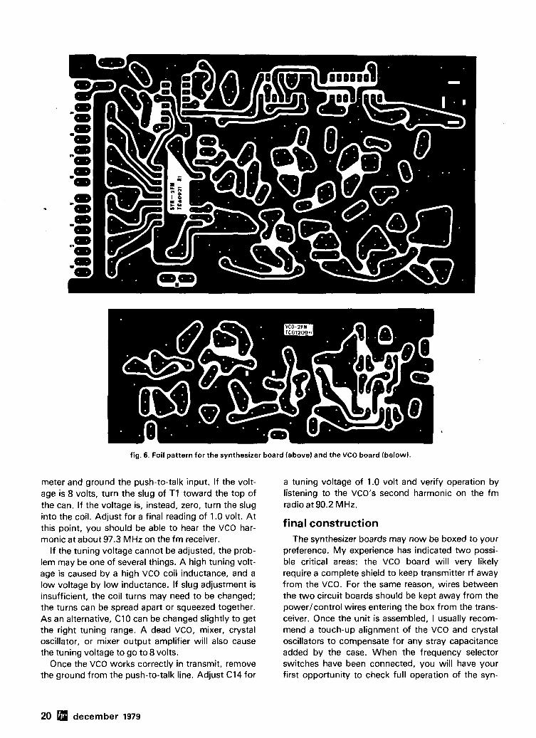
fig. 6. Foil pattern for the synthesizer board (above) and the VCO board (below).
meter and ground the push-to-talk input. If the volt- a tuning voltage of 1.0 volt and verify operation by age is 8 volts, turn the slug of T I toward the top of listening to the VCO's second harmonic on the fm the can. If the voltage is, instead, zero, turn the slug radio at 90.2 MHz. into the coil. Adjust for a final reading of 1.0 volt. At this point, you should be able to hear the VCO har- final construction monic at about 97.3 MHz on the fm receiver.
If the tuning voltage cannot be adjusted, the prob- lem may be one of several things. A high tuning volt- age is caused by a high VCO coil inductance, and a low voltage by low inductance. If slug adjustment is insufficient, the coil turns may need to be changed; the turns can be spread apart or squeezed together. As an alternative, C10 can be changed slightly to get the right tuning range. A dead VCO, mixer, crystal oscillator, or mixer output amplifier will also cause the tuning voltage to go to 8 volts.
Once the VCO works correctly in transmit, remove the ground from the push-to-talk line. Adjust C14 for
The synthesizer boards may now be boxed to your preference. My experience has indicated two possi- ble critical areas: the VCO board will very likely require a complete shield to keep transmitter rf away from the VCO. For the same reason, wires between the two circuit boards should be kept away from the power/control wires entering the box from the trans- ceiver. Once the unit is assembled, I usually recom- mend a touch-up alignment of the VCO and crystal oscillators to compensate for any stray capacitance added by the case. When the frequency selector switches have been connected, you will have your first opportunity to check full operation of the syn-
20 december 1979

-7 ill I 40% 1
- CI I
,;r u -
- VOLTAGE
fig. 7. Component placement diagrams for the synthesizer board labovel and the VCO board (below),
thesizer by listening to it on the fm radio or your 2- meter rig.
connecting your rig Fig. 10 shows the circuits I used to couple the syn-
thesizer to my rig's receive and transmit oscillators. Install these right at the crystal sockets of your rig, drill holes, and mount two coax connectors on the rear of your rig. Connect up the entire system using coax cable. Make sure the inductor tunes to the transmit crystal frequency with the capacitors of your oscillator circuit, and adjust the resistor (470 ohms in fig. 10) to keep the transmit oscillator from running on its own (you will be mighty unpopular on 2 meters if it does).
Next, connect the power and push-to-talk lines from your rig to the synthesizer. Shielded cable is strongly recommended for this purpose.
The synthesizer and transmitter should now be thoroughly tested in the transmit mode, first on a dummy load and then on an antenna. Any rf that gets into the VCO can cause instability and flickering or illumination of the LED indicator. The dummy load check will determine if your rig is feeding rf back from its oscillators into the synthesizer. This condi- tion may be corrected by insertion of a lowpass filter, having a cutoff frequency just above the synthesiz- er's output frequency, in one or both of the synthe- sizer output lines. The antenna test is somewhat more complicated in that certain antenna types,
december 1979 21

especially the gutter-mount and magnet-base variety SYNTHESIZER
can cause appreciable ground currents to flow on the coax. The solution in these cases is wire rerouting away synthesizer, from the and synthesizer use of additional and possibly shielded within wires plus the o u ~ ~ u T o ~ r ~ T ? u RECEIVE
the VCO shield.
additional possibilities I
The simple BCD programming of this synthesizer makes it easily adaptable to some interesting fre-
fig. 8. Detailed diagram of the VCO coil. The form is a stan- dard 10-mm shielded slug-tuned form.
quency control methods. Replacing the switches with an up-down counter will allow scanning as well as LED frequency readout. A memory can be used to store favorite channel frequencies, or a microproces- sor can be added for all kinds of control functions including scanning all channels, a group of channels, or those you preset. Your imagination is the limit.
When this synthesizer was developed, I intended to build at least one unit to cover 150 to 159.995 MHz to tune some of the vhf mobile channels, That is the
SYNTHESIZER
TRANSMIT
fig. 10. Diagrams of the interface circuits between the syn- thesizer and the rig's receive and transmit crystal oscil- lators.
lems in construction, please feel free to write me, but do enclose an SASE.
I'd like to offer my thanks to those who helped me in this project: Dib, KSHLG, and Tom, W91J, for their encouragement, counsel, and interest in the project; to Russ, KSAYD, for his valuable ideas on logic and synthesizer design; and to Bill, WASGUY, for his mechanical help and engraving of the front panel.
appendix
b = (1 - a ) [ T(Cmax + CmiJ + Cmax Cmin] (1 - a ) T + Cmax - aCmin
fig. 9. Schematic diagram of an rf diode probe suitable for tuning the synthesizer. C T = T + CP Cmax
cp + Cmax
reason for the two jumpers beneath U1. Although I've not had time yet to try this, expanded coverage CT = total tank C a t fmin might appeal to you. This design will, therefore, per- mit operation over the expanded 2-meter band as L = 1 proposed by the FCC. ( 2 ~ f m i n ) ~ CT
final comments - - 25330.34 p H f i n MHz
I hope that this article has proven valuable to you. Cfmid2C~ CT in pF should you have questions about the design or prob- ham radio
22 december 1979

fact: the sound of the professionals belongs in amateur radio SHURE
-
Experienced operators recognize that the audio quality of Fixed Station Mics.
the transmitter is limited by the quality of the input from the microphone. On the air, there's no mistaking the crisp, intelligible messages from Shure microphones.
Shure microphones have been the overwhelming choice of professional communications users all over the world for over 30 years. And, many of the milestone improvements developed for the demanding professionals are found on Shure microphones for amateur radio. Described below are just some of the Shure-developed advances that have eliminated many field Controlled Magnetic" maintenance costs common to amateur radio microphones. ARMO-DURmCase: Lightweight, immune to oil, grease, fumes, (Models 444.450)
salt spray, sun, rust, and corrosion. Prevents RF burn! Our 1110::t popular fixed
"Million Cycle" leaf switch: Just one of the crucial wear points station n~tcrophones. Unmatched perform-
Shure-tested to insure reliability and extraordinary durability. ance characler~st~cs. TRIPLE-FLEXm Cable: Provides three or four times longer flex life Adlustable stand ralses
than previously ava~lable cords on hand-held microphones. mlcrophor~e lor mosl cornlortable lalklng
CONTROLLED MAGNETICm'or Dynamic Transducer: The exclus~ve Shure-des~gned super-rugged transducers that glve excellent volce ~ntelligiblity and super reliability. To improve your on-air intelligibility we suggest
the following Shure Microphones for amateur radio applications:
Mobile Fixed Station Application Application
SSB 414A' 407A' 444" 577A^* 526T Series II
ans storlzed Flxed . . .-- tMion Micro~hone
FM 414U- 5078' 450 5778" 526T Series II
'General recommendallon Consult equlpmenl lnslfuctlon manual for correct microphone lmpeoance
SHURE Hand-Held Mobile Mics MICS (Models 407A, 4078.5078) Small, easy-lo-handle de. s~gn, w ~ l h rugged Dynamlc or CONTROLLED MAG- NETIC' lransducers for ex- cellent volce ~nlell~g~billty Hum-sh~elded and Insu. laled agalnsl shock Model 5078 Dynamlc verslon lea- lures extended low and h~gh lrequency response. espec~ally su~lable lor moblle FM lransmlllers Modular construction
Compact Mln~ Mlcs (Models 414A. 4146) Ideal lor m~nlalur~zed or portable communlcallons systems, or where dashboard space 1s hm- led The 414 Serles CON- TROLLED MAGNETIC' ni~crophonesare aboul hall the slze and welghl 01 con- venl~onal m~crophones- yet they are rugged unlls. recommended lor crttlcal ouldoor or ~ndoor appllcaltons
-
(Model 5267 &les llj Anew de~.wrr lor I \ ~x l r l r r t r ! , "el- sal~llly In lhxel l stallon operation
Moduhl~on level (volume) conlrol lor h~gh und~storted outpul wlth h~gh- or low-~mpedance lnpuls
Intelligibility & Reliability
No~se-Canceling M~cs (Models 577A. 5778) These Shure Dynamlc ml- crophones shut out back- ground nolse. permlt clear transmlsslon even where the nolse level IS so greal Ihat the operator cannot hear htmsell lalklngl The ARMO.DUW case is Ihghl- we~ght, Ipels nalural lothe louch The 577A IS hlgh Im- pedance Ihe 5778 1s low ~mpedance
Shure Brothers Inc., 222 Hartrey Ave., Evarlston, lL 60204. In Canada: A . C. Slmmonds & Sons Limited Ou t s~de the U.S. or Canada, write to Shure Brothers Inc., Attn: Dept J6 for informat~on on your local distributor.
Manufacturers of high fidelity components, microphones, sound systems and related circuitry.

environmental aspects of
antenna radiation How to calculate
a approximate near-field
radiation levels to meet existing
environmental standards A t present there's a great deal of interest and con- troversy regarding non-ionizing electromagnetic radi- ation and its effect on the environment. This issue, of course, affects Amateur Radio. Suggestions have been made that all nonionizing electromagnetic radi- ation be eliminated from residential areas, or that such radiation be limited to levels that would make Amateur Radio operation impossible.
Some groups, in a wave of hysteria, are attempt- ing to make allradiation illegal. As in most situations of this type, when one looks at the facts, the picture becomes clearer.
In a report by the U.S. General Accounting Office dated March 29, 1978,' it states that 10 mWlcm2 is the maximum level to which a human should be exposed for 6 minutes per hour, and that 1 mWIcm2 is the maximum continuous exposure. In other words, to be completely safe, one should stay at levels of 1 rnW/cmz or less. These levels are recom- mended by the American National Standards Insti- tute (ANSI) for frequencies between 10 MHz through the microwave region.
analysis I have calculated the approximate separation dis-
tances between the radiation source (Amateur antennas) and humans to meet the recommended levels in reference 1. These data are shown in figs. 1A through I D for four Amateur antennas: half wave, quarter wave, eighth wave, and sixteenth wave. Parametric curves show the input power to the antenna at two field-strength levels, 1 mWlcm2 and 10 mWIcm2.
Looking at fig. I A , one can see that if an Amateur
operates on 7 MHz using a half-wave antenna with 100 watts input, the antenna must be at least 4.6 meters (15 feet) from any human to keep the field strength at 1 mWIcm2 or less. At a power of 1 kW input to the antenna, the field at 4.6 meters (15 feet) increases to 10 mWIcm2. Thus it's necessary to move the antenna a distance of 7.3 meters (24 feet) from any human to reduce the field to 1 mWIcm2.
If the antenna has 10 dB gain in one direction, the equivalent antenna input would be 10,000 watts instead of 1000 watts. The field at 7.3 meters (24 feet) would increase to 10 mWlcm2 in the direction of the antenna gain.
The apparent free-space field strength near any antenna can be approximated by:
1 where L = length of antenna (meters)
I Pan, = power input to antenna (watts at Zan,)
I Zant = input impedance of-antenna (ohms)
I A = wavelength in meters (300/fMHz)
K = 3((Yr)2+ (values in table 1) (arj6
(Y = 2 n A
r = distance from the antenna (meters)
f = frequency
After the apparent free-space field strength has been calculated in wattslmeter2 it can be converted to mWIcm2 by multiplying the calculated value by 0.1. In other words, 100 WIm2 is the same as 10 mWlcm2. If the field strength in voltslmeter is desired, the following expression can be used:
Efield = d \ j l 2 0 ~ ( ~ ~ ~ ~ W/m2) volts/meter (2)
By John Abbott, KGYB, P.O. Box 66, Newhall, California 91322
24 december 1979

FREOUENCY ( M H z ) FREQUENCY ( M H z )
100.0 1 30.5 1 100 .01 30 5 1
F R E Q U E N C Y ( M H z 1 FREOUENCY ( M H z )
fig. 1. Separation distance as a function of frequency for recommended input power to four Amateur antennas: (A) one-half wave- length; (B) one-quarter wavelength; (C) one-eighth wavelength; and (Dl one-sixteenth wavelength.
where 120a is the impedance of free space. Using this expression, 10 mWIcm* is the same as 194 voltslmeter field intensity.
K values (eq. 1) are shown in table 1 as a function of TA, the ratio of the distance from the antenna in meters to the wavelength in meters. Using this table and eq. 1 for Pfield, it's possible to calculate the fields at various distances from an antenna to obtain the apparent free-space field intensity. Otherwise, use fig. 1 to make sure that your antenna is always at a separation distance with less than 1 mWlcm2 field intensity. (A mathematical derivation of eq. 1 is avail- able from ham radio upon receipt of a self-addressed stamped envelope).
practical considerations
There should be no problem for most Amateurs in installing an antenna away from houses and areas occupied by humans, except for the 160- and 80- meter bands. In these cases it may be necessary to limit power input to the antenna if necessary dis- tances can't be maintained. The real difficulty lies in the operation of handheld portables above 25 MHz. If adequate separation from the body is maintained, it will be difficult to talk into a handheld unit. You'll have to decide if the risk is worth the exposure.
Mobile operation above 25 MHz should be no problem if simple precautions are followed. Tables 2
december 1979 25

table 1. Proximity coefficient K as a function of the ratio of distance from antenna, 7, to wavelength, A.
ratio of distance from antenna, r, t o wavelength. X
r l h
0.01 0.015 0.02 0.04 0.06 0.08 0.10 0.15 0.20 0.25
% 0.30 0.35 0.40 0.45 0.50 0.60 0.70 0.80 0.90 1.00 1.20 1.40 1.60 1.80 2.00 2.50 5.00
proximity coefficient, K
81,000,000.000 7,170,000.000 1,282,000.000
20,620.000 1,890.000
364.700 103.000 12.300 3.110 1.186 0.640 0.388 0.252 0.187 0.135 0.089 0.0596 0.0452 0.0346 0.0272 0.01872 0.01368 0.0104 0.0080 0.00654 0.00416 0.001028
and 3 show a summary of approximate operating dis- tances that should prevent overexposure for most Amateur installations.
I'd like to emphasize that, in this article, I make no attempt to account for the shielding effects of build- ings or the susceptibility of humans to radiation at any given frequency. The field levels are simply cal- culated at each frequency shown. It may well be that 1 mWIcm2 is more of a hazard at 420 MHz than at 1.8 MHz. Such matters will have to be explored by medical research.
The data presented here will allow Amateurs to estimate field-strength levels from the antennas described in a manner that will meet present recom- mended criteria. Furthermore, the data will provide ammunition with which to fight pressure groups who are trying to abolish Amateur Radio!
addendum The effects of radiation from electronic equipment
on the environment has become a hot issue of late. The FCC has issued a Notice of Inquiry (NOI), General Docket 79-144 (June 15, 1979) which states in para- graph 33: "It may be desirable for the Commission to consider the need for applying to the subjects of its jurisdic-
tion one of the existing safety criteria, such as the 10 milliwatt per square centimeter (10 mW/cmZ) short- term exposure limit used by ANSl and OSHA . . ."
Furthermore, ANSl is considering reducing this level to 1 mWlcm2. What does all this mean to Ama- teur Radio? The answer is presented in the article above.
If you are concerned you'll want to file comments to the FCCINOI mentioned above before the December 15, 1979 deadline.
hr report has been publishing material on this sub- ject since early March, 1979. The following excerpts from hr report* are for those wishing more back- ground information:
PROHIBITION OF RADIO TRANSMISSIONS in residential areas is being considered by the Oregon State Senate. Sen- ate Bill 423, sponsored by Senator Ted Hallock of Portland, proposes sharply restricting all electromagnetic emissions in residential areas. In Testimony Favoring the bill Merrie Buel, government affairs coordinator for the Oregon Environmental Council, said that medical studies "have found that persons living next to electromagnetic sources often experience serious health effects, including rashes, headaches, dizziness and tingling sensations." Power Transformers and transmission lines as well as radio and TV transmitters would be curtailed under the bill's pro- visions, though Senator Hallock and members of the Sen- ate Committee on Environment and Energy have been dis- cussing removing transmission lines from its coverage. As Written the bill would become effective January 1, 1983, after which violations of the standards established for it would be a misdeameanor punishable by a $250 fine. However, Ms. Buel termed the $250 fine "merely a slap on the hand," stating that her group felt that "endangering
table 2. Approximate operating distances between an antenna and humans for 1 mWIcm2 or less exposure.
antenna length and minimum separation meters (ft.)
w i th 100 W antenna input for 0.1 mWIcm2 field
or 1000 W antenna input for 1 mW/cm*field frequency half quarter eighth sixteenth
(MHz) wave wave wave wave
1.8 16.8 13.7 11.0 8.5 (55) (45) (36) (28)
3.5 11.0 9.1 7.0 5.5 (36) (30) (23) (18)
7.0 7.3 5.8 4.6 3.7 (24) (19) (15) (12)
14.0 4.9 4.0 3.0 2.4 (16) (13) (10) (8)
21 .O 4.0 3.0 2.4 1.8 (131 (10) (8) (6)
28.0 3.7 2.7 2.1 1.5 (12) (9) (7) (5)
'hr report is published by Communications Technology, Inc., Greenville, New Hampshire 03048.
26 december 1979

people's health should be considered a much more serious offense." Furthermore, she said, the OEC wants the bill to become law much sooner since, "we suggest that the
table 3. Approximate operating distances between portable/mobile antenna and humans.
Antenna length and minimum separation, c m (in.)
w i th 10 W or 1 W antenna input for 10 mW/cm2* (divide power by 10 for 1 rnW/cmzfield)
sooner electromagnetic radiation is under control, the safer the public health." (HRR245, March 16, 1979).
frequency (MHz)
50
1 44
220
420
EFFECTS OF CB ANTENNA RADIA TlON on the bodies of nearby people is being investigated by the Department of Heath, Education and Welfare. The first study, published in
half wave quarter wave eighth wave sixteenth wave low 1W low 1W low 1W low 1W
55.9 40.6 48.3 33.0 35.6 25.4 27.9 20.3 (22) (16) (191 (13) (14) (10) (11) (8)
27.9 17.8 25.4 15.2 17.8 12.7 15.2 10.2 (11) (7) (10) (6) (7) (5) (6) (4)
22.9 15.2 17.8 12.7 15.2 10.2 10.2 7.6 (9) (6) (7) (5) (6) (4) (4) (3)
15.2 10.2 12.7 7.6 10.2 7.6 7.6 5.1 (6) (4) (5) (3) (4) (3) (3) (2)
a 24-page booklet titled "Measurement of Electromagnetic Fields in Close Proximity of CB Antennas," discusses bumper, trunk lid and rooftop-mounted mobile antennas as well as those on hand-held units. Near field radiation distri-
"Maximum exposure at 10 mW/cm2 should be limited t o 6 minuteslhr.
bution of each type is presented graphically, in an attempt to determine what hazard, if any, radiation presents.
The Study Concludes: "The health implications (of CB antenna radiation) are not clear at this time. The Bureau of Radiological Health is continuing to investigate this mat- ter." HEW is obviously quite concerned with the effects of RF on the population, and with Amateurs running 200 times the power of CBers on frequencies from 1.8 MHz through millimeter wavelengths, our operations are sure to come under careful scrutiny as well - if they haven't already. (HRR 247, March 30, 1979).
AMATEUR RADIO WAS ATTACKED as "one of the main non-ionizing radiation hazards in the United States" at an April 9-10 meeting of the Subcommittee on Public Health Aspects of Energy, in New York. The group is an arm of the New York Academy of Medicine's Committee on Public Health, reports KGYB, who has an article on the effects of Amateur RF radiation on family and neighbors coming out in ham radio magazine later this year. (HRR 253, May 18, 1979).
RF RADIATION HAZARDS are the subject of a new FCC Notice of Inquiry, General Docket 79-144, agreed to by the commissioners earlier this month. Although the Commis- sion noted that promulgation of RF radiation health and safety standards is the responsibility of health and safety agencies, it also recognized that it would have to consider radiation exposure standards adopted by other Federal agencies in its licensing activities. Full Text Of This Potentially very important NOI, which is reported to contain a number of questions on specific areas of concern, hasn't yet been released. With the environment currently a hot public issue, this NO1 could easily become a
crucial one for Amateur Radio as well as most other radio services. Comment Date for Docket 79-144 is December 15, with Reply Comments due March 15 of next year. (HRR 258, June 22, 1979).
ANOTHER FCC PROPOSAL that could affect Amateur Radio is in General Docket 79-163, which proposes changes in the Commission's environmental impact rules. At pres- ent those rules offer some leeway with respect to prospec- tive stations that could have a "Major Impact" on the envi- ronment when the actual impact would seem less signifi- cant. Under the proposed tighter restrictions, it appears formal impact statements would be required of many more applicants, probably including a number of Amateurs, and the Commission would then have to prepare and distribute a written environmental assessment for each such case. In A Dissenting Statement to the proposed change, Com- missioner Washburn makes the point that environmental impact is not the Commission's business and to make it so would add to their already heavy workload and thus increase licensing delays. Comments On Docket 79-163 are due by August 1. (HRR 260, July 6, 1979).
HIGH LEVELS OF RF RADIATION have been detected by the FCC in its test of some popular personal computers. Tests of computers manufactured by Atari, Apple, Com- modore, Heath, Southwest Technical, and Radio Shack have reportedly shown that, in most cases rf radiation levels far exceed allowable Class 1 TV limits. With The Popularify of home computers sharply on the rise, the FCC plans to use the data it's collected to set up new rules governing all computers that could be used in the home. It will probably be several months before the FCC decides what action to take and files a notice of proposed rule-making. (HRR261, page 2, July 13, 1979).
references 1 . Efforts by the Environmental Protection Agency to Protect the Public from Environmental Non-Ionizing Radiation Exposure, U . S . General Accounting Office, Report CED 78-79, March 29, 1978. 2. Richard A. Tell, "Broadcast Radiation: How Safe is Safe?", Spectrum, IEEE, August, 1972, pages 43-51. 3. Reference Data for Radio Engineers, Chapter 25, "Antennas," Howard W . Sams & Co., Inc., Fifth Edition, pages25-1 through 25-3.
ham radio
december 1979 27

the Hellschreiber a rediscovery
European Amateurs are using
a teleprinting system made from
World-War I I surplus - will it replace ~ m ?
The Hellschreiber is a teleprinting machine based on a principle entirely different from that of the RTTY teleprinter. The Hell sytem (named after its inventor, Dr. Rudolf Hell) could have been invented with the requirements of the Radio Amateur in mind, but strangely enough the Hell system has never been ful- ly accepted by the Amateur fraternity. The reason may be that an enormous number of used RTl ' machines flooded the market at low prices after World War II.
Hell and RTTY existed simultaneously for a long time for both military and commercial use. However, Hellschreibers have now disappeared, mainly as a result of the introduction of protected RTTY systems with automatic-request and error-correcting circuits. Most hams have probably never heard of the Hell system as a means of communications.
the Hellschreiber What is the Hellschreiber? In contrast to the RTTY
machine, in which received pulses determine the character to be printed, the Hellschreiber uses the transmitted pulses to directly write images of charac- ters on paper tape. Thus, Hell writing could be con- sidered a simple form of facsimile, covering seven image lines per character, with seven elements per line.
Not only has this system of printing character images some very important advantages to offer, but the simple way in which the Hell teleprinter works is extraordinarily elegant. The thread of a fast-turning worm shaft wipes, with high speed, transversely across a slowly moving paper tape. This worm thread is wet with printing ink. Every time the paper is
iy Hans Evers, PABCX (DJBSA), Am Stockberg 15, 0-5165 Huertgenwald, West Germany
28 december 1979

How The Hellschreiber Works
A. Imagine a fast turning worm shaft above a relatively B. The thread on this worm shaft is kept wet with printing slow-moving paper tape: ink:
/ I INK PAD
C. Under the paper is a mechanism that taps the paper D. What is printed on the paper depends against the worm shaft by means of an electromagnet: upon the rhythm and the length of time
ple, if the paper is just tapped, one gets: I'TJ the electromagnet is actuated. For exam- ;___
'9 What you see are the little dots where the
FROM RADIO paper touched the fast-turning worm R X " A F OUT" shaft. I f the thread sweeps fast over the
paper, and if the electromagnet pushes a bit longer, a little line is printed:
i'ii If the tape is tapped in rhythm with the revolutions of the worm shaft, a sequence
ELECTROMAGNET of little dots is printed:
E. Thus. all sorts of simple images can be written; for instance, all the characters of the alphabet: '
F. Or, i f necessary, the characters of anybody else's alphabet, such as Greek, Arabic, or Chinese:
G. What happens if the worm-shaft speed is not quite correct7 Nothing serious; the lines of the Hell text threaten to run off the paper tape:
This provides a simple method for determining the correct speed. If, for example, the lines show a tendency to drop, the motor speed must be increased until the lines run straight again. But whatever happens, the text remains legible.
december 1979 29

Hell writing. This enlargement shows how each character takes the space of seven image lines. As a result of the rela- tively slow-moving tape, the characters hang slightly over.
tapped against the turning worm shaft, little lines are formed across the paper tape. Several of these lines together form a character.
The Hellschreiber of the World War II Wehrmacht type we're using runs somewhat slower than the RTTY machine: 2 % characters per second. Neverthe- less, a respectable 25 words per minute is achieved. This CW terminology is not misplaced, as Hell and CW have much in common. In fact, given a certain bandwidth, the reliability of Hell communications approaches that of CW.
QRM proof? During World War II the Hellschreiber proved its
reliability. Users recognized that a Hellschreiber could be the only link between an isolated military unit and its headquarters. When all other means of communications failed, often the Hellschreiber man- aged to get the message through, even when only barbed wire and an earth connection were available as a signal path.
Amateur applications Our Hell QSOs occur on 80 meters (over here, the
official RTTY segment is between 3575-3625 kHz). It's difficult to think of a better part of the radio spec- trum for putting the Hell system to the test because of the high QRM level in this portion of the band.
In this context I'd like to mention an interesting side effect. Our modest prrt, prrt, prrt Hell signals apparently tend to provoke fury among some hams, who seem to be convinced that the unusual sounds are caused by commercial stations. This turns our lit- tle Hell channel into the center of zero-beating and ORZ-blaring stations. This intentional interference does, however, provide us with an invaluable oppor- tunity to test the communications system under highly adverse conditions and is, therefore, to some
course, that the signal is stronger than ours. By maneuvering with tuning, bandwidth, and threshold level it's possible to get through. We might lose con- tact for a moment; however, contact is restored through the foggy QRM clouds on our printouts, and we pick up the text as soon as the characters become distinguishable again. This sort of working on the threshold is possible with Hell: The text, even under the worst conditions, is never subject to errors of a substitution-of-characters type. The character may, however, be difficult to read because of mutilation.
Hell versus R l T Y Under certain circumstances the communications
reliability of Hell can be even better than that of CW. The received Hell signal is printed in its original form. At the moment of reception no decision has to be made such as, "Did I hear correctly?" Thus wrong decisions are avoided. The Hell printer enables the reader to decide later on, at his ease, what was actu- ally sent by the distant station.
Some examples are shown of radio Hell-communi- cations in which the printer obviously has great trouble in keeping the text intelligible because of a high noise level or heavy QRM. The examples con- tain considerably more information than can be deciphered on first sight. If you really take the trouble to read the text, you immediately realize to what the Hellschreiber owes its superior qualities: it calls in the services of a computer, i.e., our human ability to rec- ognize pictures in a chaos of little specks and lines.
rmshmft
extent, not unwelcome. Of course, the interfering determind Printing mechanism of the Hellechmiber. The ink pad (felt
roll1 has been lifted to show the worm shaft. The paper tape to cause serious trouble by tuning carefully zero-beat is slowlv moved bv the transport capstan. The electromag- with our Hell signals may eventually manage to tern- net (not visible) taps the paper tape from below against the porarily destroy our communications, provided, of fast turning worm shaft.
30 december 1979
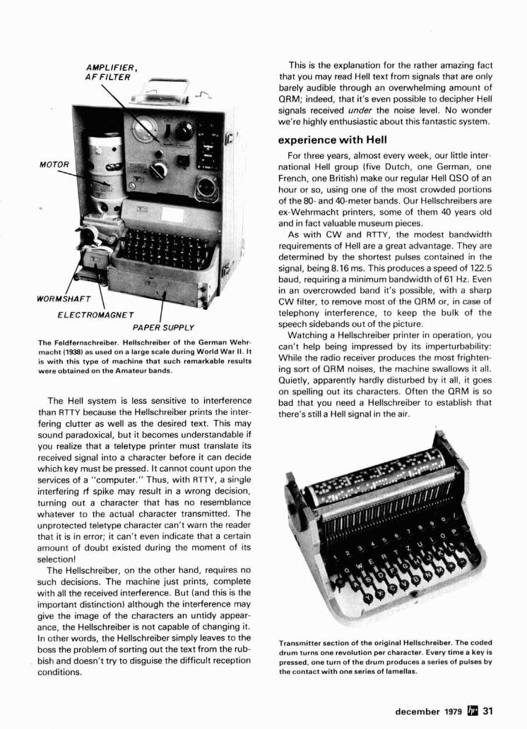
AMPLIFIER, AF FILTER A -
ELECTROMAGNET I PAPER SUPPLY
The Feldfernschreiber. Hellschreiber of the German Wehr- macht 11938) as used on a large scale during World War II. I t is with this type of machine that such remarkable results were obtained on the Amateur bands.
The Hell system is less sensitive to interference than RTTY because the Hellschreiber prints the inter- fering clutter as well as the desired text. This may sound paradoxical, but it becomes understandable if you realize that a teletype printer must translate its received signal into a character before it can decide which key must be pressed. It cannot count upon the services of a "computer." Thus, with RTTY, a single interfering rf spike may result in a wrong decision, turning out a character that has no resemblance whatever to the actual character transmitted. The unprotected teletype character can't warn the reader that it is in error; it can't even indicate that a certain amount of doubt existed during the moment of its selection!
The Hellschreiber, on the other hand, requires no such decisions. The machine just prints, complete with all the received interference. But (and this is the important distinction) although the interference may give the image of the characters an untidy appear- ance, the Hellschreiber is not capable of changing it. In other words, the Hellschreiber simply leaves to the boss the problem of sorting out the text from the rub- bish and doesn't try to disguise the difficult reception conditions.
This is the explanation for the rather amazing fact that you may read Hell text from signals that are only barely audible through an overwhelming amount of QRM; indeed, that it's even possible to decipher Hell signals received under the noise level. No wonder we're highly enthusiastic about this fantastic system.
experience with Hell For three years, almost every week, our little inter-
national Hell group (five Dutch, one German, one French, one British) make our regular Hell QSO of an hour or so, using one of the most crowded portions of the 80- and 40-meter bands. Our Hellschreibers are ex-Wehrmacht printers, some of them 40 years old and in fact valuable museum pieces.
As with CW and RTTY, the modest bandwidth requirements of Hell are a great advantage. They are determined by the shortest pulses contained in the signal, being 8.16 ms. This produces a speed of 122.5 baud, requiring a minimum bandwidth of 61 Hz. Even in an overcrowded band it's possible, with a sharp CW filter, to remove most of the QRM or, in case of telephony interference, to keep the bulk of the speech sidebands out of the picture.
Watching a Hellschreiber printer in operation, you can't help being impressed by its imperturbability: While the radio receiver produces the most frighten- ing sort of QRM noises, the machine swallows it all. Quietly, apparently hardly disturbed by it all, it goes on spelling out its characters. Often the QRM is so bad that you need a Hellschreiber to establish that there's still a Hell signal in the air.
Transmitter section of the original Hellschreiber. The coded drum turns one revolution per character. Every time a key is pressed, one turn of the drum produces a series of pulses by the contact with one series of lamellas.
december 1979 31

Between transmitter and receiver a certain amount of synchronization is needed, which requires a means of regulating receiver-motor speed. Not that this synchronization is very critical; contrary to what you'might expect from a synchronous image-line system, the good old Hell machine is not so easily disturbed by the wrong motor speed. The only thing that might happen is that the written text might drop over the edge of the paper. The text remains legible, however, and, while continuing to read the text, you correct the motor speed by hand until the text prints correctly along the plane of the paper strip. I t is this reliable, almost undisturbable, character of the Hell- schreiber that makes it such a fine instrument for Amateur Radio communications.
The CW-like disposition of Hell signals permits break-in. Spaces don't produce signals (the tape just runs without printing), so it's possible to cut in between words of the distant station's text. You can even keep watch on the QRM situation between transmitted words.
Hell is economical with transmitted energy. With considerable fewer marks than spaces in its signals, and without start and stop pulses, the average out- put is about 25 per cent of the maximum output. This low duty cycle permits increased transmitting power.
quo vadis? It's possible to make a Hellschreiber yourself -
something that can't be said for any ordinary tele-
Home made Hellschreiber.
The transmitter part, "pulse machine," is some- what more complex to build. In the original Hell- schreiber the transmit pulses were produced by a coded drum requiring some mechanical refinements. But a solid-state solution exists here. It was PA0WV again who built the first clock-plus-matrix system that can be hidden under a small keyboard, produc- ing all characters in complete silence.
A converter isn't required for receiving Hell sig- nals. The Hellschreiber can be plugged directly into the headphone jack of any radio receiver (or any tele- phone line, for that matter). The transmitter output plugs into the KEY jack of any CW transmitter, that's all.
ham radio
Reception of Hell signals under extreme conditions.
1. Very weak signal, drowning in the noise. On first sight it's unusable; however, our ability to recognize pictures in a chaos of little specks permits us to read the text into the noise.
2. Interference by a strong SSB telephony signal on the same channel. [Text: "Do you also believe that the other boys are there".) 3. Hell signal exactly zero-beat with equally strong 14-wpm CW signal. (Text: "but as you know the situation is".)
printer. The actual printer consists of only a simple mechanism. This is another advantage of the Hell- schreiber. The receiving part is easy to build and may be a good starting point. After gaining some experi- ence with receiving Hell QSOs, you can decide whether it is worthwhile building a Hell transmitter.
We have already built some mechanical Hell print- ers. Of course, electronics have advanced consider- ably since 1938, and the dimensions of our modern Hellschreiber can no longer be compared with those of that bulky German design. We now have small electric motors with solid-state speed regulation and we can use refinements such as coils with ferrite cores to pick Hell signals out of overwhelming QRM. Accurately defined Schmitt-triggers are available for separating signals of different levels.
You could even go as far as PAQWV, who has developed a microprocessor displaying received sig- nals as a slowly moving line of characters, complete with interfering pulses (thus fully maintaining all qual- ities of the Hell system) on an oscilloscope screen.
32 december 1979

FOR THE EXPERIMENTER -- ----- -
INTERNATIONAL CRYSTALS & KITSIOSCILLATORS RF MIXERS RF AMPLIFIER POWER AMPLIFIER
Crystal controlled transis- tor type. 3 to 20 MHz. OX-Lo. Cat. No. 035100. 20 to 60 MHz, OX-Hi, Ca No. 035101. Speclb when ordering. $5.22 ea.
MXX-1 TRANSISTOR RF MIXER [ e l A single tuned circuit intended for signal conversion in the 3 to 170 MHz range. Harmonics of the OX or OF-1 oscillator ar used for injection in the 60 to 17 MHz range. 3 to 20 MHz, Lo Kit, Cat. No. 035105. 20 to 170 MHz. Hi Kit. Cat. No. 035106. S ~ ~ c r f v when ordermo.
OF-1 OSCILLATOR PAX-1 TRANSISTOR RF
with the desired crystal. 2
o. 035108. 18 to 60 MHz OF-1 H Cat. No. 035109. Specily when ordenng $4.48 e
uned or untuned unit
Specrty when ordering. $5.8
EXPERIMENTER CRYSTALS (HC 6/U Holder) Specifications
031080 3 to 20 MHz - for use in OX OSC Lo Specify when ordenng $6.25 ea.
031081 20 to 60 MHz - For use in OX OSC Hi Specify when ordering $6.25 ea.
031300 3 to 20 MHz - For use in OF-1L OSC Specify when ordering $5.22 ea.
031310 20 to 60 MHz - For use in OF-1H OSC I I
Specrfy when ordering $5.22 ea.
Shipping and postage (inside US.. Canada and Mexico only) will be prepaid by International. Prices quoted for U.S.. Canada and Mexico orders only. Orders for shipment to other countries will be quoted on request. Address orders to: MIS Dept.. PO. Box 34297. Oklahoma City. Oklahoma 73132
INTERNATIONAL CRYSTAL MFG. CO.. INC. 10 N~) i l l ' LUP @b'dhiirla l 8 l v Okia 73112

I' log-periodic antenna design
I above isotropic (dBi) and sometimes include ground reflection gain over a perfect reflecting surface. Such approaches are misleading and can yield numbers
- The LP is a useful antenna anywhere from 2.2 to 8 dB higher over a dipole.
for Amateur applications - it provides constant gain
and a low VSWR
over a wide frequency range
The log-periodic (LP) array is a moderate-gain antenna useful for many Amateur applications. It has the desirable characteristics of constant gain and low VSWR over a wide frequency range. It's very forgiv- ing of construction and design tolerances. Accord- ingly it doesn't require fancy test equipment or inter- minable pruning to achieve satisfactory operation. Minor errors may result in somewhat reduced gain but won't markedly affect the basic radiation pattern or front-to-back ratio. Once a design has been com- pleted, it's seldom necessary to make adjustments after the antenna has been erected.
This article deals with the design of LP antennas using simple formulas that can be worked on any 4- function calculator. Also given is a simplified approach using only tables and elementary arithme- tic, which allows you to design single or multiband LPs to fit into an available space. Examples shown are for wire antennas. For vhf arrays using tubing, appropriate changes should be made to obtain the effective element length. Robert Carrell presented an excellent paper, "The Design of Log-Periodic Dipole Antennas," which is in the IEEE International Con-
Amateur applications The LP is particularly useful in split-band operation
such as working DX on 40 or 75 meters, where the frequency separation of U.S. and foreign bands is frequently greater than the bandwidth of many other types of antennas, such as Yagis.
In many areas of the world, material such as tele- scoping aluminum tubing is difficult and expensive to obtain. The LP, either in a fixed configuration or rota- table in a design using forward V-shaped horizontal- wire elements supported by a shaped stress-line dia- mond, may be built from simple available materials: wire, bamboo, and nylon line. YV5DLT, Ansel Eckels, has built several of the latter configuration that have worked very well.
In all probability the number of Amateur bands will increase in the not too distant future; new bands have been proposed at 10.1, 18.1, and 25.25 MHz. An LP can be designed to cover 1030 MHz, with per- formance and size making it comparable to many current triband beams. At least two Amateur manu- facturers (KLM and Telrex) have a practical-size LP rotatable array that comes close to meeting this requirement. Alternatively, a multiband Yagi cover- ing six bands would be quite a mechanical challenge. Unless extreme care is taken in trap design, it would be quite lossy.
For those who operate in the vhf bands, a single LP can yield good performance from 50 MHz through 432 MHz. After many years and many other design approaches, the LP has become the standard config- uration for most TV antennas.
Don Bostrom, N61C, in the DXpedition to Wallis
I Island in 1974, used a homemade LP with good suc-
vention decord for 1961. Data for the article here I
was, in a large part, derived from that paper. By P. A. Scholz, WGPYK, and George E. The design gains shown here are approximate and Smith. W4AEO. Mr. SchOIzrs address is 12731
may seem low to many readers. They are given as Jimeno Avenue. Granada Hills. California 91344. the free-space pattern gain with reference to a dipole Mr. Smith can be reached at 1816 Brevard Place, (dBd). Many antenna designs are quoted as dB Camden, South Carolina 29020
34 december 1979

FEED
C
ELEMENT NUMBER
Q
7 6 5 4 3 2 I
ELEMENT NUMBER
L P .POWER CELL"
7 6 5 4 3 2 I
ELEMENT NUMBER
Q
250
ZOO
I50
Lu
100 2
50
fig. 1. A 7-element LP antenna (A) with equations defining taper factor, 7, in terms of element length, L, and element- spacing relationships, S,, S , . . . S,. Characteristics are shown in (8). Upper curve: voltage, current, and phase at an arbitrary frequency higher than lowest desired operating frequency, f,. Lower curve: approximate power distribu- tion, illustrating the "LP cell," which occurs in the region where the elements are less than XI2 long.
cess. It was a vertically polarized 5-element wire array for 10, 15, and 20 meters.
Compared with the Yagi, the LP will usually have somewhat lower gain. However, it does have a signif- icant advantage in bandwidth and maintains its front- to-back characteristics over the entire design fre- quency. A properly designed LP working through a balun will allow a solid-state transmitter to operate efficiently over a wide frequency range without an antenna tuner. For example, a 7-element wire beam covering the low end of 80 meters to the high end of 40 meters, and with a good match, can be erected in a space roughly 43 meters square (140 feet square) and will have a gain of about 6 dB.
description The basic LP consists of a number of dipoles
arranged in a plane (fig. 1A). The element lengths, L, and the relative spacing, a, are arranged in a geo- metric progression with a taper factor, T . Each ele- ment is connected to the feeder in an alternating manner. The feedline is transposed between each set of elements as the easiest method with wire elements and as an intra-element feedline.
The array operates as a backward-wave antenna; radiation is in the direction of the feed. Propagation velocity is about 0.35. The free-space pattern in the plane at right angles to the elements is similar to a cardioid: egg-shaped in the radiation direction in the plane of the elements. The LP operqtes over a fre- quency band defined by the longest element, about XI2 long at the lowest frequency, and the shortest element, about XI4 at the highest frequency. The gain is constant over this frequency interval; there- fore the beam width in E and H planes is constant in free space. Over real ground, the elevation beam maxima will change in angular position with frequen- cy because the effective height in wavelengths will change.
Many configurations have been discussed in ham radio and other literature. These include the inverted T monopole, which is a vertically polarized ground- plane array; a configuration using inverted V ele- ments; and truncated LPs, which use fewer than the optimum number of elements.
characteristics Power to the elements is maximum in the region
where the elements are somewhat less than XI2 long. This is called the "LP cell" (fig. 1B). The cell at a particular frequency encompasses the longest ele- ment, Xl2, and a few shorter elements. The shortest
decernber 1979 35

r 25 50 75 100 250 5W 75OlOW PSW 5600 IOOW
THICKNESS RATIO. J?/d
5 I0
2 6
2s 5
kc? 4 P C k u 3
$ @ 2 % 3 C
15 .2 .3 . 4 .5 .6 .7 8.910 2 3 4 5 6 7 8 9 1 0 12
t RELATIVE CHARACTERISTIC IMPEDANCE OF A DIPOLE ELEMENT, Zo/Ro
fig. 2. Data for the LP intra-array feedline design. The "natural" dipole impedance is selected from curve (A), which shows the average characteristic impedance of a dipole, 2, = 120 (Rn Q/d-2.25). 15) shows relative feeder impedance as a function of dipole impedance with spacing factor. a, as a parameter.
element is approximately XI4 long. The array will operate as an antenna at frequencies
lower than that defined by the longest element of Xl2; however, the front-to-back ratio will degrade rapidly, and the gain will be impaired.
For large taper factors (7 near unity) many ele- ments are within the cell and the array has high gain. For small taper factors only a very few elements will be within a cell, and the gain will be much lower. Table 1 shows how the gain for an optimum-gain design varies as a function of the frequency range and number of elements.
feed system
venient feedline impedance can be used with a balun at the antenna to obtain a low VSWR (fig. 2). Air die- lectric should be used to prevent excessive phase shift within the array feed. Any other dielectric increases the spacing factor, a, in a complex manner. From tests run by W4AE0, the driving point impe- dance for low-frequency arrays at XI4 high is on the order of 225 ohms, with an intra-array feedline char- acteristic impedance of 450 ohms. Typically the intra- array feedline is formed from 14 AWG (1.6-mm) wire spaced for a feedline impedance of about 450 ohms. This, with a 4:1 balun, results in a close match to 52- ohm coax.
array gain considerations For each value of taper factor, 7, there is a corres-
ponding value of spacing factor, a, which yields max- imum gain (fig. 3). Smaller-than-optimum spacing factors may be used with consequent loss of gain but without pattern degradation. Larger-than-optimum values of spacing factor cause undesirable lobes. The optimum spacing factor, a, is approximately 0.19 times the taper factor, 7.
Some commercial rotatable or space-saving arrays have spacing factors as low as 0.03. For example, one may build an array covering 7-30 MHz on a 10- meter (33-foot) boom (sixteen elements, 7 = 0.895; a = 0.03). It would have about 5.5 dBd gain over this band. With the optimum spacing factor of 0.17, the gain would increase to 7.3 dBd, but the boom length would become 59.5 meters (195 feet). Thus by compromising gain for bandwidth you can build an effective, very broadband array with a practical boom length. This may be more desirab!e than stack- ing several potentially interacting Yagi arrays.
mathematical design Here's a design approach for LP antennas using
simple mathematics that can be worked on a 4-func- tion calculator. It is presented to show how the basic design is evolved.
Definition of terms. All of the LP design terms needed for calculator implementation are as follows:
fH = highest desired operating frequency
fL = lowest desired operating frequency
B = fn = desired frequency ratio ' fL
B, = structure bandwidth; ratio of length of longest-to-shortest element
The LP at low frequencies is usually fed by coax B,, = array bandwidth of active region (amount by
through a balun. The LP feedpoint impedance, unlike which B, is reduced to obtain usable band-
that of other antennas, is a function of the natural width; B = (2) dipole impedance and the spacing factor, a. A con-
36 december 1979

022 - Bs = B X Bar
020 - GAIN, dBd
\ /OpTIMuMc 5. Calculate array length:
- TAPER FACTOR, T
fig. 3. Relative spacing, a, as a function of taper factor. 7.
with contours of constant gain, dBd, as a parameter. Circled values are used in a simplified LP design approach as described in the text.
T = taper factor
a = spacing factor
ho = free-space wavelength
- - - joO in meters; 984 in feet ~ M H Z ~ M H *
X L = free-space wavelength a t lowest fre- quency
X I = antenna wavelength using wire
- - - 286 in meters; 936 in feet ~ M H Z ~ M H Z
( X I is 5 per cent less than the free-space number because of end effects.)
L = element length
= array length
SI = spacing of first two elements
dBd = gain above dipole, approximately 2.2 dB below isotropic gain (dBi)
design steps for log-periodic antenna fH 1 . Select desired band ratio, B = - fL
2. Select an initial set of values for T , the taper; and a, the element spacing factor from fig. 3. Spacing of first element = a x X L Other elements spaced at T x previous S
3. Calculate array bandwidth, Bar: Bar = 1.1 + r30.8 (1 - T) 01
4. Calculate structure bandwidth, B,:
6. Calculate number of elements, N:
log Bs N = I + and round to next largest I
log - T
number.
7. Calculate new length y: = rounded N Q
N
simplified design approach Design of an LP array using the basic equations
above is arduous, since the designer has little feel for the size of the array until he's made one or more iter- ations. Furthermore, most first tries won't equate to an integral number of elements. Accordingly, a com- puter program was written to yield initial data on key array characteristics and in terms of antennas with an integral number of elements, table 1 . This table allows an antenna design based on desired param- eter such as number of elements, length, and gain. The following example of antenna design uses the curves of fig. 3 and table 1 .
A three-band LP antenna is desired covering 14-29 MHz. Length is about 15 meters (50 fekt). Proceed as follows:
29 1 . B = fH = - = 2.1 (desired frequency ratio)
fL 14
2. Desired length is 15 meters (50 feet) 300 X L = - = 21.4 meters (70 feet) 14
15 Length = - = 0.71X 21.4
3. From table 1 choose ( B = 2 ) , and R I A = 0.87, or R 7 0.87X. The desired length is slightly shorter to stay on the correct, or lower, side of the optimum spacing factor, a.
N = 10, R / X = 0.87, T = 0.875, a/X = 0.155, gain = 7 dB
4. From fig. 3 proceed as follows:
a. Modify u of 0.155 by the ratio 0.71(desired) = 0.82x0.155 = 0.13 = 0.87 (table 1)
december 1979 37

b. Draw a vertical line through T = 0.875 (see ex- ample in fig. 3).
c. Draw a horizontal line through a = 0.155.
d.' Optimum gain occurs at the intersection (7.0 dB).
e. Modify by drawing a horizontal line through a' = 0.13 to intersect vertical through T = 0.875.
f. A new gain occurs, ~ 6 . 7 d B (down only 0.3 dB from optimum).
element parameters f L = MHz, f H = 29 MHz,
T = 0.875, a' = 0.13
for a wire antenna, X/2
L = - - - 14' - 10.2 meters (33.4 feet)at f~ ~ M H ~
SI = a'*XL = 0 .13x21 .4
= 2.8 meters (9.2 feet)
table 1. Number of elements and array length w i th optimum taper and spacing.
1 one-band operation ( B = 1)"
gain over N !?,/A T o/A Bs dipole dBd
4 0.34 0.79 0.142 2.02 5.9 5 0.52 0.88 0.155 1.67 7.0 6 0.73 0.92 0.170 1.52 8.0 7 0.91 0.927 0.175 1.39 8.9 8 1.12 0.963 0.178 1.30 9.7 9 1.33 0.972 0.180 1.26 10.2 10 1.48 0.978 0.181 1.22 10.6
2 B = 1 . 5 6 0.49 0.810 0.142 2.9 6.1 8 0.77 0.875 0.158 2.56 7.0 12 1.35 0.93 0.172 2.21 8.2 15 1.79 0.95 0.175 2.05 9.0
3 B = 2 7 0.52 0.795 0.142 4.0 5.9 10 0.87 0.875 0.155 3.39 7.0 14 1.37 0.917 0.170 3.07 8.0 19 1.97 0.943 0.175 2.8 8.9
4 B = 3 9 0.59 0.8 0.142 5.93 5.9 15 1.18 0.895 0.155 4..80 7.0 22 1.90 0.932 0.170 4.38 8.0
S2 = 2.8X T, etc .
LI = 10.2 meters (33.4 feet)
L2 = 10.2 X 7, etc .
L, in meters (f t)
10.2 (33.4) 8.9 (29.3) 7.8 (25.6) 6.8 (22.4) 6.0 (19.6) 5.2 (17.2) 4.6 (15.0) 4.0(13.1)
S, in meters ( f t )
2.8 (9.21 2.4 (8.0) 2.1 (7.0) 1.9 (6.1) 1.6 (5.3) 1.4 (4.7) 1.3 (4.1) 1 .I (3.6)
9 3.5 (11.5) 0.9 (3.2) 10 3.0 (10.0)
. - - --
array length 15.5 meters (51 f t )
conclusion We have presented design details for a log-period-
ic antenna using simple mathematical formulas. We have also given a simplified approach to LP antenna design using tables and elementary arithmetic. The LP antenna certainly has a place in Amateur Radio. It has advantages of bandwidth which Yagi and quad antennas don't have. A well-designed LP will provide acceptable forward gain and front-to-back ratio over a wide band of frequencies. The LP can be designed with wire elements for lower frequencies - another advantage when aluminum tubing is hard to obtain. An LP antenna can be designed to cover 10-30 MHz with performance and size comparable to that of many current triband beams.
bibliography ,
Smith, George E., W4AEO. "Log-Periodic Antenna, 14. 21, and 28 MHz." ham radio, August, 1973, page 18. Smith, George E., W4AEO. "Log-Periodic Antenna, 7 MHz," ham radio. May, 1973, page 16. Smith, George E., W4AEO. "Feed System for Log-Periodic Antennas," ham radio, October, 1974, page 30. Smith, George E., W4AEO. "Graphical Design Method for Log-Periodic Antennas," hamradio, May, 1975, page 14. Smith, George E., W4AEO. "Log-Periodic Antennas, Vertical Monopole, 3.5 and 7.0 MHz," ham radio, September, 1973, page 44. Smith, George E., W4AEO. "Improved Log-Periodic Beams," (letter), ham radio, May. 1975. page 74. Smith, George E., W4AEO. "Log-Periodic Beam, 15 and 20 Meters," ham radio. May, 1974, page6. Smith, George E., W4AE0, "Log-Periodic Feeds," (letter), ham radio, May, 1974, page 66. Smith, George E. W4AEO. "Three-Band Log-Periodic," ham radio, May, 1977, page 10.
appendix
intra-array feedline design The characteristic impedance of the feedline is a function of the
natural dipole impedance, Z,, and the spacing factor, o. The '6 desired bandsatio (harmonic number) = jH For an array covering natural dipole impedance is related to the length-to-diameter ratio
28 . / I . 1 4 , 2 1 , 2 8 M H z , 8 = ' = - 2 of the elements. The optimum intra-array feedline impedance is
/L 14 determined as follows:
38 .m december 1979

a. Select the desired driving impedance. Rn
b. Determine the mean spacing factor o" = \m
c. Determine the natural dipole impedance: I'
L, = 120 1 F n - 2.25). or from fig. A l , where A is length
to- diameter ratio
d . Calculate '" Ro
e. Determine '"he intra-array feedline modifier, M. Ro '
Zo = - I Ro = Zo
Ro
0 orfromfig. A l . 2- W ~ R E LINE
Zo = Ro x M zo = 276 I O R , ~ 2f for2-wire line or d -
138 loglo q o r q w i r e line, o I .-WIRE LINE T
where D = center-to-center spacing, and d = wire diameter.
If a non-optimum intra-array feedline impedance is used, the antenna VSWR will vary considerably with frequency, in a some- what periodic manner.
design example Array parameters:
r = 0.875 0 = 0.13
Ro = 200 o h m (wi th 4:l balun from 52 ohms)
Mean spacing factor
Natural dipole impedance using no. 14 AWG (1.6-mml wire:
= 62 i: = 3938; since Z. varies as log,,
C . the mean IS usually sufficiently accurate
From fig. A l , Z,, = 72 ohms, and
Feedline impedance from fig. A l :
I - .- I - R x 0 . 1 3 9 x 3 . 6 + J(dx O ~ I 3 P x j.6)j • I = I 2R
= 0.245+ 1 '13 = 1.28
Zn = M R o = 1 . 2 8 ~ 2 0 0 = 2 5 5 o h m
ham radio
V"Orx A @ K.V.G. by
CRYSTAL FILTERS and DISCRIMINATORS 9 0 MHz FILTERS XF9.A 2.5 kHz XF9.B 2.4 kHz XF9-C 3.75 kHz XF9.D 5.0 kHz XF9.E 12.0 kHz XF9-M 0.5 kHz XF9.NB 0.5 kHz 9.0 MHzCRYSTALS
SSB TX SSB RX/TX AM AM NBFM cw 4 pole cw le polel
F 4 o r l
Inquiries
1nvite-d
XF900 9000.0 kHz Carrier $5.15 Shipping XF901 8998.5 kHz USB $5.15 XF902 9001.5kHz LSB $5.15 $1.75 XF903 8999.0 kHz BFO $5.15 F-05 Hc251u Socket Chassis .50 per filler F.06 Hc251u Socket P.C. Board .50 I VHF and UHF FILTERS ELIMINATE IMD "BIRDIES" 432 MHz PSI432 255.95 FROM YOUR RECEIVER. 1296 MHz PSf1296 $55.95 I
OSCARS 7.8 81 PHASE 3 I Transverlers by M~crowave Modules and olher nianularlurers can Convert your ex1sIlng LOW Band 119 lo operate on Iht. VHF 8 UHF bands. Models alsa avaklable lor 2M l o 70cm and lor ATV operalors Iron1 Ch2lCh3 l o 7OCmS. Each lransverler conla~ns bolh a Tx up-converler and a Rx down.canverter. I Wrlle lor delalls of Ihe larpesl select~on ava~lable. I Prices start st $189.95 plus 53.50 shipping.
SPECIFICATIONS Oulpul Power 10 W Receiver N.F. 3 dB lyp. Receiver Gain 30 dB lyp. Prlme Power 12V DC
Altenl~on owners ol the ori inal MM143 to operate OSCAR 8 g PHA% 3 by addl ~nclud~ng full ~nslructlons $23.00 plus 161 50 shlpplng, etr
ANTENNAS (FOB CONCORD. VIA UPS) 144-148 MHz J-SLOTS 8 OVER 8 HORIZONTAL POL. + 12.3 dBd D812M $54.60 8 BY 8 VERTICAL POL. ., D8l2M-VERT. 564.00 8+ 8 TWIST 8XYI2M $56.35
- 420.450 MHz MULTIBEAMS
For local, DX. OSCAR. and ATV use.
48 EL. GAlN + 15.7dBd 701MBM48 88 EL. GAlN + 18.5dBd 70lMBM88 UHF LOOP YAGlS 711 l ~ O P S GAIN +20dBi - - - - - . - -. . . . . . -. - - . 1250-1340 MHz 1296-LY S59.80 16501750 MHz 1891-LY $8335 Sen0 3W i? slamps) lor lull delalls 01 KVG cryslal prcdu~ls and all your VHF 6 UHf equlo- men! requlremenls Pre Seleclor Ftlters Am~llllers SSB Transvenars Varactor lrlplers Crystal rlllsrs FM Transverlers Decade Pre Scalers Freouencv Filters VHF Conveners 1-1 Anlennas ~ s ~ h l a t o f Cryslals UHF Converlers 1-1
International, Inc.
More Details? CHECK - OFF Page 126 december 1979 39

compact and clean L-band local oscillators
trolled LO for 1.1 through 1.6 GHz that is only A clean, L-band 1 6 . 4 ~ 1 0 cm ( 2 . 5 ~ 4 inches) and employs microstrip-
local-oscillator system featuring spurious rejection
greater than 30 dB with simple test equipment
The recent popularization of microstripline con- struction for Amateur uhf equipment1 has made it relatively simple for countless experimenters to build state-of-the-art multipliers, amplifiers, mixers, filters, and the like directly from magazine construction arti- cles. A major exception, unfortunately, has been in the area of microwave local oscillator chains. Most will agree that the LO is the weak link in just about every microwave transmitter, receiver, or converter. Local oscillators generally require extensive tweaking on costly spectrum analyzers, even then often falling short of the required calibration tolerance, stability, and spectral purity. And, since a spurious or drifting LO can negate all the benefits of the very finest low- noise front end or ultra-linear power amplifier, it is evident that the LO requires a great deal of attention. I've been making an effort in recent months to take some of the mystique out of local oscillator design and construction. In this article I shall present the results of that effort - a high-stability, crystal-con-
CRYSTAL- BUFFER CONTROLLED AMPLIFIER
UHF LO CHAIN
DIODE OUTPUT 1200 MHz TRIPLER BANOPASS - OUT
X 3 FILTER 5mW
4 0 0 MHz ) I 2 0 0 M H Z I 1 2 0 0 ~ H z / 5mW - 1/2mW 6mW
fig. 1. Block diagram of a module LO system for L band. Each block represents a physically separate stage, individu- ally boxed and interconnected by short lengths of coaxial cable.
line construction (with absolutely no coils to wind). It can be built for about $70 in parts, and can be com- pletely aligned with only a VOM and a diode detector.
The basic approach that numerous experimenters (myself included) have used for L-band local-oscilla- tor chains over the past several years is blocked out in fig. 1. I implemented this system modularly, with each of the blocks representing a separate, shielded box, the various modules being interconnected via coaxial cable. The basic 400-MHz oscillator is a ver- sion of my recently published uhf LO chain,2 driving a diode tripler built on a microstrip bandpass filter board.3 In order to make up the power lost in the pas-
Y I 01 0 2 CRYSTAL DOUBLER DOUBLER
OSCILLATOR
L 2 - 3 / C 5 - 6 2-POLE
BANDPASS FILTER
IOOMHz _/ 200MHr 4OOMHz 1/2mW
IPOOMHz IOmW
TRIPL ER L5 -7 /CB- I0
3-POLE JI BANOPASS OUT
FILTER
fig. 2. Block diagram of the microstrip local oscillator.
sive multiplier, a buffer amplifier is employed.4 The final microstrip filter keeps all spurious frequency components down better than 40 dB with respect to the desired output.
The modular LO chain has some major drawbacks. It is physically large, since each stage must occupy its own separate enclosure to achieve acceptable spurious rejection. The cost of jumper cables, coax connectors, and die-cast aluminum boxes can be
By H. Paul Shuch, NGTX, Microcomm, 14908 Sandy Lane, San Jose, California 95124
40 december 1979

designation description
C01-03 miniature ceramic disc capacitor, 0.01 pF
C04-10 ceramic piston trimmer capacitor, Triko 202-08M. 1-
5 PF Cll-12 chip capacitor, ATC type 1008, 100 pF
C13-15 ceramic feedthrough capacitor, Erie 2404-000- X5UO-102P. loo0 PF
C16 ceramic trimmer capacitor, 9-35 pF
DO1 zener, 9.1 V f 5%, 400 mW. IN52393
J01 SMA receptacle, E. F. Johnson 142-0298-001
microstrip inductor (PC artwork LO-1200-601 )
uhf silicon bipolar transistor, Motorola MRF-901
carbon composition resistor, 180 ohm 10% 1 14 watt
carbon composition resistor, 470 ohm 10% 114 watt
carbon composition resistor, 330 ohm 10% 1 14 watt
carbon composition resistor. 10 ohm 10% 1 14 watt
0.33 pH molded choke, Nytronics mini-ductor
crystal oscillator assembly, International Crystal OE- 5,90 to 130 MHz (output frequency + 12)
fig. 3. Schematic diagram of the L-band local oscillator. C1, C2, and C3 are miniature ceramic disc capacitors. C4 through C10 are Triko 202-08M, 1-5 pF ceramic piston trimmers. ATC type 1006 chip capacitors are used for C11 and C12. All resistors are 'La watt. 10 per cent tolerance. The rf choke is a Nytronics Mini-ductor. The crystal oscillator assembly should be in the frequency range of 90 t o 130 MHz, depending upon the desired output frequency (LO output frequency divided by 12).
prohibitive. Plus, the use of a passive multiplier fol- lowed by a buffer amplifier is a crude and inefficient way to generate the required 5 to 10 mW of LO output.
I toyed with the idea of integrating the LO chain onto a single board, but became convinced that first it would be necessary to develop a reliable active multiplier circuit to take the place of the diode tripler and buffer amplifier modules. For a time I considered the push-pull tripler approach which Wade had used in his 1296-MHz LO,5 but in studying the spectrum analyzer photos from his article, I noticed a few potential difficulties. Wade's output filter had the advantage of requiring no tuning whatever, but it afforded only about 20 dB of spurious rejection. His active multiplier, though far easier to tune than my diode triplers, appeared to offer about the same degree of conversion loss. Since I was seeking multi- plier gain of not less than unity, I decided to try a sin-
employed in an earlier 1296-MHz converter.6 The secret is to place a series tank circuit, which reso- nates at the desired output frequency, in the base lead of a standard class-C common-emitter multi- plier. This throws the base into a negative-resistance region at the stage's output frequency, enhancing the gain of the desired frequency multiple relative to that of the other multiples. The result is an improve- ment in the multiplier's spurious rejection without resorting to harmonic-cancelling circuits like push- pull and push-push.
With the active multiplier and an output filter tacked onto the end of one of my 400-MHz LO chains, I found I was getting as much output, with as clean a signal as my modular LO had yielded. Plus, it took up only half the space, and without the various coaxial jumpers between stages. Fig. 2 shows the block dia- gram of the new LO, and the complete schematic is shown in fig. 3.
gle-ended active tripler followed by a tunable, 3-pole microstrip filter to keep the spurs down. circuit description
What finally produced acceptable results was an Refer to fig. 3 and the accompanying parts list. active parametric multiplier, a circuit technique I had The stages to the left of Q3 are essentially the same
december 1979 41

fig. 4. Full-size artwork for the printed circuit board. The reverse side remains unetched, acting as a groundplane.
+ r 2 7 9 K C S
$ L ! I JPLCS . * % ZJPLCS
@ EVELETS l K C S + r .v 3 PLCS
as those used in my uhf LO, except for a few compo- nent substitutions. Oscillator module Y1 is a high- stability, crystal overtone oscillator producing - 3 dBm (112 mW) of output near 100 MHz. This assem- bly requires a regulated +9 volt supply, which is fur- nished by zener diode CR1. The output port of Y1 exhibits dc continuity to ground, this continuity being essential in providing a bias return for the fol- lowing stage.
At the input to 01, common-emitter class-C double stage, C16 is used to resonate Yl's output inductive link, creating a double-tuned, interstage transformer between the oscillator stage and the first multiplier. The output circuit for 0 1 consists of microstripline inductor L1 resonated by C4 at 200 MHz.
Collector current for 0 1 is limited to 10 mA at R2. This resistor, along with C2 and C13, provide power supply decoupling for the first multiplier stage.
Q2 serves as a second class-C common-emitter doubler. Its input is fed via C3, which is tapped down on L1 for impedance matching. R3 provides base bias return. The collector is shunt-fed by R6, with a
fig. 5. Drilling diagram for the etched side of the circuit board. In addition to the etched side, the three locations marked with arrows are also countersunk on the ground- plane side.
collector current of approximately 15 mA. The out- put circuit for 02 consists of two microstripline inductors (L2, L31 resonated at 400 MHz by two pis- ton trimmers (C5 and C6). Inductivecoupling between filtering poles, provided by RFCI, suppresses higher- order harmonics at the output of the second doubler. The conversion gain of each doubler - exclusive of any filter losses - is on the order of + 6 dB.
As mentioned previously, tripler 0 3 operates as a parametric multiplier. The input is applied via a low- pass filter consisting of microstripline inductor L4 and piston trimmer C7. The series inductance of C7 is such that it self-resonates at the desired output fre- quency, maximizing gain at that particular frequency by driving the base impedance of 0 3 negative. For this reason, use only the specified capacitor at C7. Shunt collector feed for the active tripler is via R7, with dc decoupling provided by R5 and C15. Collec- tor current for 0 3 is on the order of 15 mA, and the stage operates at approximately 3-dB gain.
The output of Q3 is capacitively coupled via C12 into a 3-pole output filter consisting of microstripline
42 december 1979

fig. 6. Component placement diagrams for the microstripline and groundplane sides
inductors L5, L6, and L7, resonated at 1.2 GHz by piston trimmers. Coupling between filter poles is a result of the proximity of the piston trimmer stators; hence, spacing between filter poles is critical.
The final + 10 dBm (10-mW) LO output is available on connector J1. This level is suitable for driving most transmit and receive diode balanced mixers.
construction Assembling the LO is relatively simple, since all cir-
cuitry is mounted on a single printed circuit board and the bulk of the critical components are imple- mented as etched microstriplines. The circuit should be etched on fiberglass-epoxy circuit laminate 1.5 mm (0.063 inch) thick, clad on both sides with 1 ounce per square foot copper. One side of the board is etched in accordance with the artwork supplied in fig. 4, the other side remaining fully clad and serving as a groundplane. It is essential that the pattern of the printed circuit artwork be followed exactly (photo etching is recommended), since the dimensions of the microstriplines are critical and the placement of
the circuits on the board determines the degree of spectral purity achieved. In fact, the layout of the board was changed several times during the develop- ment phases in order to optimize performance and ease of tuning.
After the board is etched, it should be drilled as in fig. 5. Be sure to remove a small portion of ground- plane metallization from around the holes that will accommodate the center pin J1 and the output and power pins of oscillator Y1. Neglecting this crucial step will result in these pins being shorted to ground, which will obviously have a detrimental effect upon circuit performance! Note that five of the microstrip- line inductors (L2, 3, 5, 6, and 7) must be grounded through the board. This is best accomplished, as out- lined in reference 3, with eyelets 0.5-mm in diameter set with a punch and soldered on both sides of the board.
When mounting components on the printed circuit board, you will find it helpful to refer to the photo- graphs, the schematic diagram in fig. 3, the layout drawings shown in fig. 6, and perhaps to reference
decernber 1979 43

2. 1 personally find it easiest to install J1 first, solder- ing the five pins to their respective pads on the microstripline side of the printed circuit board and then running a smooth bead of solder around the bodyof the connector, securing it electrically and mechanically to the groundplane side. Next, I install feedthrough capacitors C13, 14, and 15. Here I pre- pare a small solder preform (1 turn of multi-core sol- der wrapped around the body of the capacitor just under the flange), position the capacitor in its mount- - . . ing hole, and apply heat to theflange from above. The solder preform will flow, filling the space between the flange and the groundplane. This tech- nique prevents excess solder from accumulating on the groundplane side of the printed circuit board.
Installing the resistors and capacitors according to the layout diagram is relatively easy. Do not install power decoupling resistors R4 and R5 at this time; they will be added during the tune-up sequence. When installing the three transistors, note that the raised dot on the plastic package indicates the collec- tor lead. The base lead emerges from the opposite side of the transistor package, with the two emitter leads appearing at right angles to the collector and base. Bend the two emitter leads of each transistor down sharply before installing the transistors in their holes. That way the emitter leads can protrude through to the groundplane side, where they will be bent over and soldered directly to ground.
When installing oscillator stage Y1, care should be taken to prevent traces on the oscillator's printed cir- cuit board from shorting to the groundplane of the LO main circuit board. I recommend installing a thin insulating washer between the oscillator can and the groundplane.
The only additional advice I might offer in micro- stripline projects is that it is not unusual for compo- nent leads to be laid on and soldered directly to print- ed circuit board traces or pads, rather than running the component leads through holes in the board. For this reason, it is generally helpful to preform and pre- trim the component leads prior to installation.
tune up and test I cannot overemphasize the importance of employ-
ing a systematic, orderly approach in tuning up local- oscillator chains. Tuning for maximum smoke (a favorite Amateur pastime) is a surefire way to make one or more of the multiplier stages oscillate (see fig. 7). Further, since the LO chain was designed to pro- vide maximum user flexibility, it may be built for a fairly wide range of frequencies and applications. As a consequence, each of the resonant circuits has a relatively wide tuning range, and it is entirely possible to tune up any one of the multiplier stages on the
wrong multiple, if maximum apparent output power is the only criterion.
In fact, whether a microwave spectrum analyzer is available or not, it's a good idea to pre-align the vari- ous piston trimmers to the appropriate part of the spectrum. This is easier than it may sound. If the intended output frequency is below about 1.3 GHz, adjust all seven of the piston trimmer capacitors to maximum capacitance (screws all the way in). If the
fig. 7. Aligning microwave LO chains for maximum output power often results in a spurious output spectrum. In this case, the LO was tuned for maximum output. The numerous spurs near the desired output are not harmonically related to the crystal frequency. This suggests that they ere the result of one of the active stages going into self-oscillation. The horizontal scale is 0 to 2 GHz, with a vertical calibration of 10 dBlcm.
intended output frequency is above about 1.4 GHz, adjust all piston trimmers for minimum capacitance (screws almost all the way out). And, if the oscillator is intended to operate between about 1.3 and 1.4 GHz, pre-adjust all piston trimmers at about mid- range. Now, as you proceed with the alignment pro- cedure, it should not be necessary to adjust any of these capacitors by more than a couple of turns. Keep this in mind, because if you find yourself adjusting the trimmers more than just a little, you're probably enhancing the wrong frequency com- ponent.
The approach I recommend for tuning this L-band LO requires no test equipment other than a VOM and a diode detector (or some other means of monitoring relative rf power). It is based upon the principle that, as a class-C multiplier stage is tuned, the signal level applied to the next stage (hence the next stage's col- lector current) will vary. By knowing what kind of variations to expect and by monitoring stage current closely, it is possible to tune the LO chain to produce an output spectrum such as that shown in fig. 8. But it is necessary to monitor the various stage currents
44 december 1979

separately, to be sure you're observing proper multi- potential to feedthrough capacitors C13 and C14, plier action and not oscillation. and this time monitor the current drawn at C14. This
With the piston trimmers pre-adjusted as outlined, current should peak smoothly at 10 to 12 mA while the next task in aligning the L-band LO is to get the adjusting C4 no more than two or three turns from its oscillator stage oscillating. On the side of the crystal preset position. oscillator can is a small access hole, behind which is Adjusting the interstage circuitry between the sec- found the ceramic trimmer capacitor which reso- ond doubler and the parametric tripler is perhaps the nates the oscillator's collector tank circuit. This trim- trickiest part of aligning this LO because there are mer is pre-adjusted at the factory to ensure that the three separate trimmer capacitors and the adjust- oscillator will start each time power is applied; it should not be adjusted at this time. Rather, it should be possible to optimize drive to the first multiplier stage merely by adjusting C16, which, you'll recall, .--!:. J,q
.resonates the oscillator stage's output coupling link. Apply a well-regulated voltage between + 12 and 1
+ 13 volts to feedthrough capacitor C13. This pow- ers both the oscillator stage and the first doubler.
'1 ii 4 :
Monitor the current drawn by these two stages as C16 is adjusted through its range. Since the sum of I
the current drawn by the oscillator stage and its zen- er regulator will remaln constant at between 16 and 22 mA (depending upon the power supply potential), * .-, any variation in current as C16 is adjusted represents
A -t
tuning range where the Current at C13 will rise band LO svstem after beinq aligned as described in the arti- - - smoothly to about 10 mA above its minimum value cle. Spurious rejection of close to 30 dB was achieved with (that is, 26 to 32 mA, total), and this is the point to the simple test equipment called for in the article.
adjust C16. Now, momentarily remove Vc,from C13. If the current returns to the previous value, all is well. ments are all interactive. Note that at this point the If on the other hand 0 1 appears not to be drawing any current (that is, total current at C13 decreases to between 16 and 22 mA), then the oscillator stage is not starting smoothly and it will be necessary to re- adjust Yl's trimmer. Do so carefully; it should be necessary to rotate the trimmer only about ten degrees one way or the other, and the current should rise again, indicating oscillation. Now, repeak C16 for the proper rise in current, and again remove and re- apply power. The adjustments of C16 and the oscilla- tor's trimmer capacitor are somewhat interactive, so repeat the above procedure until the oscillator starts reliably each time power is applied.
Once the adjustment of C16 and the oscillator trim- mer is completed, do not under any circumstances change their settings while aligning the balance of the local-oscillator chain. I usually paint a dot of nail polish on C16 to lock it down and tape over the access hole in the side of Y1, lest I be tempted to backtrack and screw things up completely! Remem- ber, the objective is to perform a reasonably clean LO alignment without the use of any costly test equip- ment, so don't jump sequence.
The easiest way to resonate the collector tank of the first multiplier stage is to monitor the current drawn by second doubler, Q2. Apply operating
only clue you have to proper alignment is the collec- tor current drawn by Q3, so watch it closely. Apply operating potential to all three feedthrough capaci- tors (C13, 14, and 151, this time monitoring current at C15. First, adjust C7, slightly, just to the point that a few milliamperes of current flow through C15. Now, carefully adjust both C5 and C6 to maximize this cur- rent. As before, a peak should occur before the trim- mers have been adjusted very far from their preset positions. Once a peak has been found with C5 and C6 both set at approximately the same point, re- adjust C7 slightly. A t this point, C4 (the collector tank of the first multiplier) may be adjusted ever so slightly to maximize current at C15. Now, back to C5 and C6 again, then C7 if necessary, and so on until the current at C15 settles in at about 15 mA. Note that when you're done, both C5 and C6 should have their tuning screws protruding by about the same amount.
All that remains is to align the output bandpass fil- ter. An rf-diode detector can be connected to the output connector, the dc from the diode assembly being fed to a sensitive microammeter as an indica- tion of relative rf output. Any other method of meas- uring relative rf power (bolometer bridge, calorim- eter, or similar) may also be employed. The object is
december 1979 45

fig. 9. Example of the output spectrum after aligning the local-oscillator chain with a microwave spectrum analyzer. In this case, all spurs are down greaterthan 40 dB.
to adjust C8, C9, and C10 simultaneously for maxi- mum indicated output (the three trimmer capacitors should all track relatively closely). Keep monitoring the current at C15. If it jumps abruptly, the tripler stage is self-oscillating. It can be tamed down by slightly adjusting C7 until current at C15 returns to its proper value.
With C8, C9, and C10 all peaked at approximately the same setting (not too far, you hope, from the preset position) and output power maximized, one last adjustment to C7 is in order. Adjust this capaci- tor for the maximum output level obtainable without causing an increase in the current at C15. A t this point, you may be tempted to go back and repeak all the other trimmer capacitors in the circuit; resist that temptation. You can only disrupt what would in all likelihood be a very clean output spectrum, such as that shown in fig. 8.
Of course, if you are fortunate enough to have access to a microwave spectrum analyzer, adjusting the trimmer capacitors ever so slightly can indeed clean up the output spectrum still further (see fig. 9). But this should be attempted only after the current- sensitive tuning method has been completed and decoupling resistors R4 and R5 installed.
One final thought. Those super-purists fortunate enough to possess a complete laboratory of micro- wave test equipment will doubtless notice that any tuning adjustment can potentially affect output pow- er, spectrum, andfrequency. Thus, you m y wish to simultaneously monitor all three parameters during alignment. Fig. 10 is the lab setup I use in aligning these LO chains. The key to the success of this method is the resistive three-way power divider, which applies equal samples of the LO'S output sig- nal to the counter, spectrum analyzers, and power meter. The divider is built simply from four 27-ohm,
118-watt, carbon-composition resistors, arranged symmetrically in a small shielded box which supports four coaxial connectors.
parts procurement Readers of my construction articles frequently
write asking if I can supply a complete kit of parts for a given project. Unfortunately, I have neither the time nor the inclination to get into that business. But I am not heedless of the plight of the home construc- tor, and as much as possible like to help identify (or sometimes create) sources for some of the less-com- mon components.
For example, I have in the past endeavored to make etched, drilled, and plated circuit boards avail- able at cost, for the benefit of those experimenters who prefer not to fabricate their own. This project is no exception. I will supply the boards for $10 each, postpaid anywhere in the U.S. or Canada ($1 1 else- where).
In a previous article, I mentioned a source of sup- ply for the Triko trimmer capacitors I employ in this and other modules. Unfortunately, I later discovered that the importer had a $50 minimum order require- ment. Thus, I have recently obtained a quantity ship- ment of the piston trimmer capacitors used in the LO chain, and will gladly supply them to Amateurs in sets of seven pieces (the quantity needed for each LO chain) at $10.50 per set postpaid in the U.S. or Canada, $1 1.50 elsewhere.
MICROWAVE POWER M E I E R
A RESISTIVE ,-WAY POWER
0,YIDEO
fig. 10. Test configuration for monitoring power, frequency. and output spectrum simultaneously during alignment of the LO chain.
The crystal oscillator assembly designated Y1 is available only from International Crystal Manufactur- ing Company. I recently spoke t o Mr. Royden Free-
46 december 1979


48 a decernber 1979 More Details? CHECK - OFF Page 126

r t
OUR BEST-SELLING MULTI-BAND!
One hall the length of convenl~onal halt wave dlpoles (TMI)~ Mull~.band MMII treguenry Maxtmum efl~clency -- no traps load~ng tolls or stubs Fully assembled and pre tuned - no measuring no cutttng All wealher raled - 1 KW AM 2 5 KW CW or PEP SSB
AS LOW AS Proven perlormance - more than 10 000 have been del~vered
' $ 5 8 7 5 Perm11 use 01 the lul l capabtllttes of today s 5 band xcvrs One feedllne for operation on all bands
40.10HDIA 40120115110 Mtrs (36) . . . . 563.25 75/40 M e t e r 80-40HDIA 80140 Mtr bands (69) . . . . .61.25
75140HDIA 75140 Mtr bands (66) . . . . .58.75 75.1OHDIA 7514012011 5110 Mtr (66). . . . 78.25 80-10HDIA 8014012011 511 0 M t r (69). . . .80.25
r
s€LE c'fEP O~lcS E5! €crR ,, ,ALU SP \
2 METER ANTENNAS at BARGAIN PRICES!!
1
SPECTRONICS, mc. 1009 G a r f i e l d St., O a k Park. l l l i n o i s . 60304
(312) 848-6777 /
@@J' 3 db GAlN MAGNETIC MOUNT
NEW! ONLY - - M o d e l 287 $1 9mm A Wt. 2.5 Ibr.
I f i t 's the u l t imate i n paddles your looking for may we recommend the Bencher. It 's simply the n icest one we've seen yet.
BY1 paddle wlblack base.. . . . . . . . . $39.95 c BY1 Deluxe model wlchrome base. . .49.95 c
w- CRAMPED FOP SPACE ? '
Cash pa id for c lean used gear. That 's r ight ... I f you n o longer need i t w e c a n con. vert tha t extra r ig in to cash.
-,.r-,--.-rv rrru-.-rrvvrrrY9990 -3 ESTIMATED WEIQHT CODING *> -3 After the price 01 each Item you w ~ l l l l nd a $ 2 letter. I e . 19 95 a. To make 11 eesler to 110 .:. .:. ure shlpplng costs, these letters ~nd lca le .:. ;. the eoDroxlmate we~aht of the Item as . . 0:- follows: .:. *:* a. Less than 1 Ib f. 20-30 Ibs O 3 b. 1-3Ibs. d. 7.lOlbs. 0.30-40 lbs *:' .:. c. 4 6 Ibs. e. 10-20 Ibs. h. 40-50 lbs $ .:. Sr will be sent truck collect. .:. 2. **.:..:.**.:..:..:. ........................ +.:..:..:, .:.
An economical alternative to drilling a hole. A magnetic antenna by a name you can trust at a low, low prlce.
Modd 286 Same but trunk lid.. . . . . S15.95 b
NEW from F I m 2.8 dbd GAlN
PANASONIC "COMMAND" SERIES BASE ANTENNA
RF.2100 8 BAND AMIFM. SW freqs from 3 9 lo 28 MHz Double super he!. erodyne Pfec~se call- brated tunlng to I 0 kHz Double-check xtal marker M o d e l A2-QP at 500 kHz and 125 knz Wt. 2 Ibr. RF galn control tor AMISW BFO sw~tch for SSB 8 SW PIUS many more features such as ext jacks lor AC At last! An inexpensive, omni directional, ant 8 spkr Big radlo features at IOW pr~ce 144-148 MHz, 112 wave antenna. Fits 1 'h"
Plu. S Z . 5 0 Sh8pptng
RF 2800 DIGITAL AMIFM SW tram 3 2 to 30 MHz 5 d ~ g ~ t LED display
reads all bands Double SuDerheterodyne I'Lclr cultry FM AFC 8 w~dei narrow bandw~dth control
SSBICW And much much more lor the price
MHz. ALL DIGITAL PIUS
tng . AFC on FM Narrow w~de select~vlty swttch tor AMISW BPO Pjtch control . Cal!bration control ANL swttch tor AM FET RF clrcult RF Ga~n control Inc
Low P r ~ c e
YODEL PLF-2 Improves weak stgnals as well as lmage and spurlous relectlon ol most receivers Dlrect SWltChlnQ to rec or preamp Includes pwr supp I t 7 VAC wlred 8 lested Cpd 149 95
More Details? CHECK-OFF Page 126 decernber 1979 49

vhf preamplifiers
today's devices and techniques for building
a truly low-noise preamp for vhf reception
The vhf converters and preamplifiers of ten and fifteen years ago are inadequate by today's stan- dards. This article presents the results of my experi- ence with many low-noise preamps using modern devices and techniques, all of which have been built and tested as a part of a program to update my vhf station. The problems of wide dynamic range and in- termodulation distortion are not addressed in this article.
analysis Consider a typical vhf receiver (fig. 1). The receiv-
er consists of X stages, where X is some number. Each stage has a noise figure, NFx, and therefore a stage noise factor, Fx. Each stage has a gain, Gx, which may be an actual gain or it may be a loss as in the feedline, attenuator/filters, or even in the mixer. Noise figure, NF, is expressed in dB; noise factor, F, is nondimensional. NFand Fare related by
F = log- 1 (NF/ lO) (1)
The most common error in analyzing system noise performance is to lump noise figures and noise fac- tors - a simple but bold dB symbol after each noise figure helps to differentiate the noise figure numbers from noise factors.
It's well knownl-4 that the system noise factor,
The "gain" of passive elements, such as the feedline and interstage networks (and often the mixer), is ac- tually a loss. That is, a negative gain occurs, which is expressed in dB. When converted into a numerical ratio for use in eq. 2 this "gain" will be less than unity.
Thus a feedline with a 2.2 dB loss has a ratio of 1.66, which means that about 39.7 per cent of the input power is lost in the feedline. The gain, in this case, is - 2.2 dB, or 1/1.66 = 0.6. Noise figure in this portion of the system is essentially equal to the loss, NFo = Go, and noise factor Fo = log- I
(- Go/lO). Therefore Fo = 1.66 and Go = 0.6. Similarly, a double-balanced mixer has a negative
gain. A double-balanced mixer is a passive circuit to which rf signals and LO inputs are supplied. It uses nonlinear elements (diodes) to derive the i-f signal. However, the double-balanced mixer has a noise figure about 1-3 dB greater than the conversion loss. Thus a typical balanced mixer with a, conversion loss of, say, 6dB (numel.ica1 loss = log-1 (6/10) = 3.98) has a numerical conversion gain Gc = 1/3.98 = 0.25 but may have a noise figure of 8 dB, or a noise factor of 6.3. The noise figure is greater than mixer conversion loss.
system noise factor: some simplifications
Several simplifications to eq. 2 can be made. Each interstage network can be considered as a portion of the rf amplifier output circuit preceding the inter- stage circuit. The noise factor, F4, of the subsystem following the first stage can be neglected if the first i- f has a gain, Gj, of at least 100 (20 dB).
The effects of the feedline (Go and Fo) can be removed if the first rf amplifier is placed directly at the antenna, and if the first rf amplifier has a gain, GI, at least 10 dB greater than the losses in the fol-
fiJo, as presented by the receiver at the antenna, is I influenced to some extent by the noise factors and By Geoffrey H. Krauss, WA2GFP, 16 Riviera gains of the following stages: Drive, Latham, New York 121 10
50 december 1979

lowing interstage network and feedline ( G A and Gh, should have at least 10 dB more gain than the noise fig. 2A). figure (in dB) of the subsequent portion of the sys-
Thus the receiving system (fig. 2B), for noise con- tem. However, the noise figure of the subsequent siderations, can be reduced to: portion is predominantly established by the noise
a) A low-noise preamp at the antenna, may figure in its first stage. Therefore, this stage should
contain input and output filters as well as the feedline have a reasonable noise figure even if adjusted for
to the second rf amplifier, and which may have an maximum gain. Thus, if the noise factor presented
overall stage noise factor, F; and stage gain, G;. by the conversion stage is Fi2 = 10 (or NF& = 10 dB), the second amplifier stage should have a target
bl The second rf amplifier with noise factor and gain gain, G2, of d B + NFSZ) = Z O d B and a relatively of F2 and G2. low noise factor, F2. C) The frequency conversion stage. For image and If, after the second rf amplifier stage is built and aoise rejection it includes a bandpass filter as part of tested, the noise factor, G I , of the second rf arnpli-
G~
I S T INTERSTAGE ANTENNA FEEOLINE
NETWORK
Fs.0 Fs I
LOCAL OSCILLATOR
fig. 1. Typical vhf receiver used in the analysis.
an interstage network. It has a noise factor, Fc, and a fierlfrequency-conversionli-f system is measured, stage gain (or loss) of Gh. for example, as FiI = 2 (NFil = 3 dB) the require-
d) I-f amplifier, which has an input noise factor, F;. ments for the first preamplifier stage are that the gain, G;, be equal to 10 dB+ NFil ( = 13 dB), with
The system noise factor, Fie, is now the smallest noise factor, Fj , (and noise figure) achievable at that gain for minimizing the total sys-
(Fz-I )+ (%-I) + ( G - 1 ) Fi0 = F; + ------- (3) tem noise factor, Fie. The actual value of the system G; GiG.2 G;GZGh noise factorlnoise figure will depend on the device
noise factor and selected for the preamplifier stage.
noise figure The system noise factor establishes the overall
receiving-system signal sensitivity; a low noise factor (and, therefore, a low noise figure) is desirable above 100 MHz. Occasions arise when low noise figures are also desirable below 100 MHz, as in an extremely quiet location for 50-MHz operation. Accordingly, an evaluation of low-noise amplifier stages for 30, 50, 144,220, and 432 MHz is useful.
Many receiving systems may use more than one preamplifier. In the systems of figs. 1 and 2, first and second preamplifiers are used between antenna and
. mixer. Regardless of the number of preamplifier stages between antenna and mixer, the general rule is to first adjust the first stage (at the antenna) for minimum noise figure, and then adjust the remaining stages, between the first preamplifier stage and the mixer stage, for maximum power gain. However, as shown by the system noise-factor equations, even the remaining rf amplifier stages should have reason- ably low noise figures.
As mentioned, the rule of thumb is that each stage
background information on devices What devices are available for low-noise vhf pre-
amplifier use, and what performancecan be achieved? To give a proper perspective, consider first a short history of low-noise vhf preamplification.
About twenty years ago, in 1958, the predomi- nantly used vhf bands were 50 and 144 MHz. Little was done, except by a few adventurous Amateurs, with the higher frequency bands. The "low" noise figures then achievable were about 4 dB on 50 MHz, typically with cascade-connected triode vacuum tubes such as the twin triodes of the 6827 variety. About 5 dB was obtained with single triode vacuum tubes such as the 6AM4 on 144 MHz.
Serious experimenters tried to obtain type 58421 417A triodes, which could be used to achieve 3-dB noise figures up to about 250 MHz and about 5-dB noise figures at 432 MHz. A better low-noise tube for 432 MHz was the gold-plated 4168, which was occa- sionally available as pullouts from microwave relay transmitters. The problems of using pullouts, partic- ularly at the relatively high current levels required for
december 1979 m. 51

low noise figure operation and the high cost and low availability of special-purpose tubes, deterred wide- spread Amateur use. Many 432-MHz and most 1296- MHz mixers were of the diode-mixer type, with no prearnplification used in many 432-MHz and almost all 1296-MHz Amateur receivers.
Between about 1958 and 1963, vacuum-tube tech- nology progressed to introduce the Nuvistor,@ a min- iature ceramic-metal tube best typified by the 6CW4, which had the high transconductance and low inter- electrode capacitance necessary for high-gain, low- noise preamplification. Noise figures of 3 dB at 50, 144, and 220 MHz were possible, by 1963, in a host of commercially available vhf converters, transvert- ers, and at least one complete receiver (the Clegg Interceptor, for 6 and 2 meters). Versions of the Nuvistor,@ would even yield 3-5 dB noise figures at 432 MHz, and a few commercial converters and pre- amplifiers were offered.
With the advent of relatively inexpensive, relatively low-noise preamps, interest in 220 MHz increased, although not as rapidly as in 432-MHz operation. Interest in 432 MHz was greater because the output of a 2-meter transmitter could be tripled for operation on 432 MHz, whereas a completely new transmitter had to be built for 220 MHz.
Parametric amplifiers were noted for very low noise operation but weren't very popular because of the need for a pump oscillator above 1 GHz and for special components.
Solid-state devices. Early silicon transistors did not, in 1963, appear to have any advantage over the new vacuum tubes. Consequently they saw limited use. However, in another five years, by 1968, the pressure of the commercial home-entertainment market forced development of relatively inexpensive and relatively low-noise silicon transistors. Several transistor types became available at sufficiently low cost for Amateur use. The 2N3819 family was often used for i-f amplifiers. The 2N3823 was specified for
ter noise figures than their germanium counterparts. Best remembered of that group were the devices
available from KMC Transistors and from Fairchild Microwave Transistors. The KMC devices (now available under different device numbers from Micro- wave Associates) were capable of less than 2 dB noise figure at 144 and 220 MHz. With selected devices a 2-dB noise figure could be achieved at 432 MHz. If the preamplifier configuration and matching network were chosen and built with care, some of the FMT devices, such as the FMT 4575, reference 5, were capable of even better performance, but cost was generally prohibitive. The availability of the best FMT devices apparently ceased, as later batches of these devices were rumored to have poor noise figures, compared with the earlier batches, and a "lost recipe" was widely rumored as the cause. Solid-state low-noise vhf preamplifiers, were, how- ever, firmly entrenched by this time.
Devices available today. As this is written, some twenty years after the 6827 and 417A era, noise fig- ures of 1 dB are easily obtained on the vhf Amateur bands. I built and tested forty-four preamplifiers to ascertain the performance that might be expected with a wide range of devices. Not all devices avail- able to Amateurs were tested. Financial considera- tions limited this program to building units only with devices donated by various sources (including many engineers who wished to have a device evaluated and who arranged for these transistors to be made available to me). Results are shown in table 1 by band and in order of increasing noise figure. Table 1 also lists
a) The minimum noise figure, M:
which is indicative of the minimum noise figure obtained with a cascade connection of several such stages. -
If to more than 150 MHz' Devices such b) The return loss, R, through the preamplifier from as the Motorola MPF-102 family, the 2N2857. and output to input, which is a measure of preamplifier the 2N4416 Germanium nota- and should be at least 8 dB greater than the bly the 2N1742 and the Philco T2028, were available gain, G, 51. with even better noise figures than most silicon devices. Transistorized preamplifiers and converters C) A performance ratio factor, P, indicative of the
were built with noise figures of 2 d~ on 10 and 6 noise figure vs preamplifier cost, which is changing
meters, 3 dB on 2 meters and 220 MHz, and 4-5 dB between units of the same noise figure because of
on 432. MHz. The use of vacuum tubes in Amateur device price.
vhf receiving gear diminished and all but ceased. All preamplifiers in this article require a low-noise By 1973 a host of solid-state devices were available active device and a pair of matching networks. The
for vhf receiver use. Silicon devices, with better per- input matching network matches the device input formance vs temperature characteristics than germa- impedance to the antenna impedance (50 ohms). nium devices, had, in this period, also achieved bet- Device input impedance may be different, for mini-
52 m decernber 1979

F I G I
I Fa Ga F b G b
INTERSTAGE NETWORK
F 'so 0 SCILLATOR
T T E N AT S T A T 0 4
F'C G'C
fig. 2. System block diagrams to illustrate how simplifications can be made to the system noise factor, Fs,o (eq. 2). The system is divided into two parts: antenna and station. Sketches A and B are used in the text to explain the derivation of the simplified sys- tem noise factor, F's,o (eq. 3).
mum noise-figure operation, from the data sheet and second, even potentially unstable devices can be values typically given for maximum gain operation. used if care is taken in matching-network design. In The output matching network matches the device this respect, the use of a collector resistance of rela- output impedance to 50 ohms. tively low value is often helpful and may be found in
device choice Choice of a suitable device should, in general, be
governed by the manufacturer's data sheet. It not only lists expected noise figure and associated gain (at that noise figure) at some optimum bias level (generally stated in terms of V,, and I , for a bipolar transistor, or the equivalent Vds and Id for an FET device), but also gives
a) Rf parameters for determining stability and match- ing-network design.
b) A frequency range in which best operation of a device may be expected.
These data are advisory - they are typical values, which may be determined by testing a group of devices. They may not always be obtained for all devices of that type but are good starting points.
stability If the selected device will operate in the desired
frequency range, its stability is always the most im- portant consideration. Nothing is achieved if a low- noise preamplifier is unstable with the input or output impedances found in the system. Instability may result in oscillation and may produce birdies, block- ing, or other undesirable results.
Tests for stability are well covered elsewhere. However, two concepts should be kept in mind: First, the device should be stable over a wide fre- quency range, including the frequency of interest,
many of the low-noise preamplifiers discussed in later portions of this article.
bias voltage The bias voltage and current figures on a device
data sheet should always be considered as nominal values and should always be varied to achieve best noise figure, assuming that a noise figure test setup is available.
I've tuned several identical preamplifiers contain- ing devices taken from the same shipment. I found
LC - 2 a- C u 2 - 2 M P - 1 0 0 6
Lu 2 MRF 101 1904
NED2135
FREQUENCY (rnHz) 10 METERS 6 METERS 2 METERS 2 2 0 METERS 4 3 2 METERS
AMATEUR BAND
fig. 3. Noise figure as a function of frequency with several devices as a parameter. Note the apparent "useful frequen- cy band" effect, particularly with the dgfet and the U310. Note also the lower frequency limitations shown by devices such as NE22235 and MP-1006.
december 1979 53

that, while almost identical noise figures and gains were achieved, each device had to be biased differ- ently. For example I built and tested four units using NE64535s at 432 MHz; each unit was initially adjust- ed for data-sheet bias values of 8 volts Vc, and 7 mA I,. All units were then adjusted for minimum noise figure in a test setup using a precision automatic
: . # I .'#W
1,aw
m
, R5 :. 6 0 0 . ' , , 8 1 01*2a . ' I # ,
, -PO B l F l L l R
, la W 7 2 5 - 10
coec
Q #W
0
noise figure indicator and noise source:
R,
ultimate NF IdB) (Y method.
unit +0.3dB; - O.ldB) "c. IC 1 0.86 8.6 7.5 2 0.84 7.9 6.4 3 0.91 8.1 10.0 4 0.90 4.9 5.0
Most device data sheets give rf characteristics in terms of S-parameters for gain amplification. While S-parameter design may be new to many Amateurs, several very good articles have appeared.9-13 The design procedures are relatively easy for devices that are unconditionally stable; i.e., having a stability fac- tor. K, greater than unity at the frequency of interest. However, if the device is only conditionally stable (K less than 1) and the input and output S-parameters
0 0 5 0 0 5
R3
tion coefficient, r,,, is often missing. This is the parameter that should govern the entire design of a low-noise preamplifier.15-16 Given r,,, the input matching network is designed to transform the noise matched input impedance, derived from r,,, to the antenna impedance (generally 50 ohms). The output matching circuit may be designed once the device output impedance, for the device input connected to the optimum noise-match impedance, is known. Thus, both S and optimum-noise parameters should be known.
device frequency range The range of device operation should be carefully
determined from the data sheet. Many devices appear to be designed for a specific application and, in meeting those application requirements, have parameters that limit the useful frequency range. As an example, the dual-gate FET (DGFET) of table 1 is an experimental device designed for a noise figure of less than 2 dB over the frequency range of the com- mercial fm broadcast band. A low noise figure is obtained near this band at 50 and 144 MHz, while the noise figure at 30 and 220 MHz is very high. These latter frequencies were of no interest to the device designer, so the device characteristics are relatively
CRZ
' IZV 3 9 0 0 OC@
IN ' I (4 ,Om*
54 december 1979
m
0 DO, CR,
A ..- 0-H-0 f l Z V l5n"
n, R. ,300 IN,,,.
fig. 4. Preamplifiers for 30 and 50 MHz. (A) shows a circuit using the MRF-904, which has very wide bandwidth. 16) is a pictorial layout of the MRF-904 unit. In (C1 a 2N5109 is used. which has a 1.7-dB noise factor. Many other devices are usable at this frequency (see text).
(SI1 and SZ2) are less than 1, a low-inductance resistor (between 50-200 ohms) may often be used as a col- lector load to provide a stable preamplifier config- uration.14
Many data sheets don't give noise-related informa- tion. Most particularly, the optimum source reflec-

uncontrolled at these frequencies. Note also the believe the antenna pattern and pointing accuracy noise figure (fig. 3) for the NE22235 and NE64535 are of greater concern than noise figure in this appli- devices, which are intended for use at 1-4 GHz and cation. 0.5-4 GHz respectively. The noise figure curves show that these two devices were designed for optimum noise figure at frequencies above about 500 MHz. On the other hand, from the noise figure curves of fig. 3, devices such as the MRF9011904 were apparently designed for broadband application use from dc through the vhf range.
Device data sheets frequently give a circuit in which the device is tested, and which often makes a good starting point for design of an Amateur circuit. As the frequency increases, care must be taken in
'circuit layout. Short lead lengths and high-quality components (of types intended for vhf, uhf, or microwave use) are required.
band-by-band discussion
30-MHz. This band is primarily of interest for either OSCAR downlink or as an intermediate frequency for microwave equipment, such as the Microwave Asso- ciates Gunnplexers.@ In i-f preamplifier application, the preamplifier design following the microwave mix- er (generally a diode having 6-10 dB of conversion loss and noise figure) will be an important factor in establishing the overall receiver noise figure.
The MA42001-509, as used in W1HR's two-stage i-f amplifier,17 certainly has the lowest noise figure of units thus far built and tested. However the cost (about $16.50 at the time of writing) of the two devices required for each such preamplifier must be balanced against the small loss in system sensitivity if you use a single-stage i-f preamplifier with a less- expensive 2N5109 or MRF901 device. Use of older devices, such as the 2N4416 and MPF102, is not advised; preamplifiers using these devices have been found to be only conditionally stable, even with heavily loaded output circuits.
The MRF-904 is of particular interest. Apparently it was designed from minimum noise figure when inserted into a %-ohm system. As shown in fig. 4A, matching networks aren't required on either input or output of this transistor in a %-ohm system. Coup- ling capacitors C1 and C6 provide dc isolation be- tween input and output feedlines and the device bias circuit. This preamplifier has a very wide bandwidth, as no input or output filtering is used. Output filtering is usually provided by the receiver or converter. The need for, and degree of, input filtering is established by a particular use and location.
For the OSCAR down-link application almost any of the devices yielding less than a 2-dB noise figure should be acceptable, especially in front of a 10- meter receiver having a noise figure of 6-10 dB. I
50 MHz. The background noise at 50 MHz is high enough so that a system noise figure of less than ,
about 2 dB is unnecessary. Most of the devices tested achieved this noise figure for a single-stage preamplifier. The noise contribution of succeeding stages (existing converter and the like) will dictate the preamplifier gain and also indicated that a first- stage noise figure somewhat lower than 2 dB is required if the 2-dB system noise figure is to be achieved.
For example, I presently use a %-MHz converter with a single 6CW4 rf amplifier preceding a mixer (a remnant of earlier 1960s equipment not yet replaced).
FOR N E 6 4 5 3 5 470 1
fig. 5. Preamp for 144 and 220 MHz using the MRF-901, NE02135 or NE22235. Design is similar to that by WB5LUA (reference 18).
The converters have input noise figures between 3.5 and 4.5 dB. If the highest expected converter noise figure (4.5 dB) is taken for worst-case analysis, and if a single-stage rf preamplifier with at least 14.5 dB (equal to 10 dB plus the maximum noise figure of the following stage, 4.5 dB) is to be used, then, by the noise-figure equation, Fs = F1 + (F2 - l ) / G I , where the value of F2 = log-' (4.5/10), with GI = log-' ( 1 4 . 5 / 1 0 ) and Fs = l o g - ' ( 2 . 0 / 1 0 ) . Thus Fs = 1.585; F2 = 2.818, and GI = 28.184. These values are substituted into the equation and give
1.585 = F1 + (2.818- 1)/28.184 = Fl + 0.065 Therefore, F1 = 1.585- 0.065 = 1.52, and the pre- amplifier noise figure, NFl, should be no greater than lOlog(1.520) = 1.82dB.
Devices tested at 50 MHz that are usable for this particular applicatiion include MA42001 (0.95 dB NF,
december 1979 55

K = 18.92); NE02135 (1.55 dB NF, K = 19.08); advisable. Additional information for %-MHz pream- MRF-901 (1.67 dB NF, K = 16.87); KD6003 (1.7 dB plifiers is shown in figs. 4 through 7. NF, K = 22.88); and 2N5109 (1.7 dB NF, K = 16.62). An example of a preamp using the 2N5109 is shown in fig. 48.
Other factors, dependent on your needs, may now be coilsidered, such as circuit simplicity, resistance to overload, and preamplifier bandpass character- istics.
Note that many of the low-noise preamplifier cir- cuits are broadband; a high-Q input circuit will add undesired noise before the desired signals can be amplified by the device. Of course, if use is intended in an environment near other rf sources, then input filtering may be mandatory to prevent receiver over- load. The amount of input bandpass filtering is deter- mined on a case-by-case basis, although use of low- intermodulation-producing, and therefore overload- tolerant devices, such as the 2N5109 provides some leeway in achieving the desired result. I prefer to place a separate low-insertion-loss filter such as a helical resonator or interdigital filter, having steep
fig. 6. Details of preamp shield construction.
skirts and high out-of-band loss, before the first pre- amplifier. Such filters have a varying impedance out- side the passband of interest, so this reactance may cause a potentially unstable preamplifier to oscillate.
If a 50-MHz i-f system is used with higher frequen- cy (microwave) equipment, the i-f amplifier noise fig- ure may, depending on its total noise figure contribu- tion, require a very low noise configuration using a device such as the MA42001. However, use of such a low-noise-figure preamplifier would usually be expected only when no additional rf amplification is inserted between the antenna and the higher-fre- quency mixer.
Devices are available for low-noise preamplifiers for the bands up to at least 3300 MHz. Image-rejec- tion considerations at even higher bands, above 5650 MHz, dictate the use of i-fs higher than 50 MHz, so little is gained by using low-noise 50-MHz i-f ampli- fiers following a microwave mixer. Exceptions always occur - one is a %-MHz i-f with the mixer portion of a 10-GHz GunnplexeP transceiver in which a low- noise-figure device, such as the MA42001, would be
144 and 220 MHz. The 2-meter band has a suffi- ciently low background noise to allow very low- noise-figure preamplifiers to be used to advantage. The frequencies of the 2- and 1 % meter bands are relatively close (less than one octave apart). Similar device and circuit design and selection criteria are valid. Furthermore, the 2-meter band is a common i-f for 1296 and 2304 MHz converters, wherein low- noise-figure i-f amplifiers may be used to advantage. The same 2-meter preamplifier may be used between a 2-meter receiver and either a 2-meter antenna or the i-f output of a 1296- or2304-MHz mixer.
For truly low noise figures, the NE64535, priced at about $17, provides a 1-dB noise figure in a relatively simple circuit. This device is potentially unstable at all Amateur bands of interest; therefore, the collector circuit (fig. 5) is heavily loaded with a 100-ohm, 118- watt resistor.
The design is similar to that of WB5LUA (reference 18), but with added shielding between the device base and collector terminals. This shielding must be properly designed, because with improper shielding, the preamplifier exhibits a strong tendency towards oscillation, as noted by WB5LUA in his article. While the 432-MHz preamplifier of that article did not require shielding, at the lower frequencies of 144 and 220 MHz, the greater forward gain of these devices makes full shielding mandatory.
The preamplifiers are built in a box (fig. 7 ) formed of double-sided PC board with a double-sided PC- board shield (fig. 61, into which a small hole is drilled. The hole diameter is slightly larger than the device package dimension between the opposed emitter leads. The edges of both copper-clad sides of the shield are soldered to the bottom and two side walls of the basic enclosure. Most important, at least two small strips of copper foil, as found in most hobby shops, are passed through the hole and soldered on each side of the shield.
The opposed pair of emitter leads are soldered to the copper foil straps on the input side of the shield after the collector lead is passed through the hole in the field (see figs. 6 and 7). Thus, the base and emit- ter leads are on the input-circuit side of the shield, and the collector lead extends through the shield to the output-circuit side of the box. Failure to use the copper foil straps under the emitter leads, or solder- ing the emitter leads to the output-circuit side of the shield, will invariably cause oscillation, even with a resistive collector load.
Note particularly the use of ferrite beads, low- inductance coaxial feed-through capacitors, and the 0.05 pF low-frequency bypass capacitors in parallel with the feed-throughs, to prevent oscillations at fre-
56 december 1979
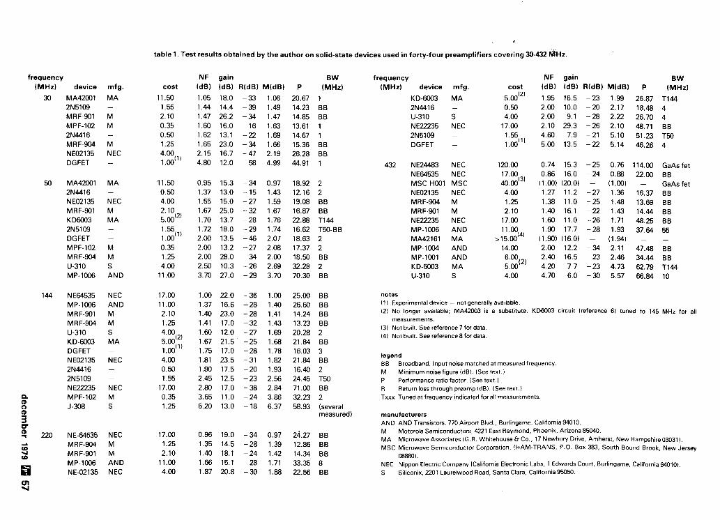
d
table 1. Test results obtained by the author on solid-state devices used in forty-four preamplifiers covering 30-432 d ~ z .
frequency (MHz) device
NF gain (dB) (dB) R(dB) MldB)
1.05 18.0 -33 1.06 1.44 14.4 -39 1.49 1.47 26.2 -34 1.47 1.60 16.0 - 16 1.63 1.62 13.1 -22 1.69 1.65 23.0 -34 1.66 2.15 16.7 -47 2.19 4.80 12.0 -58 4.99
BW P (MHz)
20.67 1 14.23 BB 14.85 BB 13.61 1 14.67 1 15.36 BB 26.28 BB 44.91 1
frequency (MHz) device mfg. cost
KD-6003 MA 5.00'2' 2N4416 - 0.50 U-310 S 4.00 NE22235 NEC 17.00 2N5109 - 1.55 DGFET - l.OO(ll
gain (dB) RldB) M(dB)
16.5 -23 1.99 10.0 -20 2.17 9.1 -28 2.22
29.3 -26 2.10 7.9 -21 5.10
13.5 -22 5.14
B W P (MHz)
26.87 TI44 18.48 4 26.70 4 48.71 BB 51.23 T50 46.26 4
mfg.
MA -
M M -
M NEC
COSt
11.50 1.55 2.10 0.35 0.50 1.25 4.00
1 .00( l )
30 MA42001 2N5109 MRF-901 MPF-102 2N4416 MRF-904 NE02135 DGFET 432 NE24483 NEC
NE64535 NEC MSC-H001 MSC NE02135 NEC MRF-904 M MRF-901 M NE22235 NEC MP-1006 AND MA42161 MA MP-1004 AND MP-1001 AND KD-6003 MA U-310 S
GaAs fet B B GaAs fet B B B B B B B B 55 -
BE B B T I 44 10
50 MA42001 2N4416 NE02135 MRF-901 K D6003 2N5109 DGFET MPF-102 MRF-904 U-310 MP-1006
-
M M S AND
144 NEW535 MP-1006 MRF-901 MRF-904 U-310 KD-6003 DGFET NE02135 2N4416 2N5109 N E22235
NEC AND M M S MA -
NEC
notes ( 1 ) Experimental device - not generally available. 12) No longer available; MA42003 is a substitute.
measurements. 13) Not built. See reference 7 for data. 14) Not built. See reference 8for data.
K D W 3 circuit (reference 6) tuned to 145 MHz for all
3 B B 2 T50 B B 2 (several measured)
legend BB Broadband. Input noise matched at measured frequency M Minimum noise figure (dB). (See text.) P Performance ratio factor. (See text.) R Return loss through preamp (dB). (See text.) Txxx Tuned at frequency indicated for all measurements.
manufacturers AND AND Transistors. 770 Airport Blvd., Burlingame. California 94010. M Motorola Semiconductors, 4221 East Raymond, Phoenix. Arizona 85040. MA Microwave Associates (G.R. Whitehouse & Co., 17 Newbuv Drive, Amherst, New Hampshire 03031). MSC Microwave Semiconductor Corporation. (HAM-TRANS. P.O. Box 383. South Bound Brook, New Jersey
08880). NEC Nippon Electric Company (California Electronic Labs, 1 Edwards Court, Burlingame. California 94010). S Siliconix, 2201 Laurelwood Road, Santa Clara, California 95050.
N EC M M AND N EC

quencies removed from the frequency to which the preamplifier is tuned. Also note the biasing arrange- ment. A zener between transistor collector and base is not recommended because zeners are themselves often used as noise sources. Thus, even if bypassed, they will inject noise.
As previously stated, arrangement is made for adjusting both the voltage and current at the device collector; noise figure is affected by these param- eters. The zener limits the maximum V,, to avoid device burnout; the actual V,, value, adjusted for minimum noise figure, is less than the zener voltage.
The preamplifier may be initially tuned for maxi- mum gain but should be finally tuned using a noise generator. A vacuum-tube noise generator, such as one using a 5722 tube, is discouraged: voltage spikes
fig. 7. Isometric drawing showing internal construction.
of sufficient amplitude to destroy the transistor may be present.
A semiconductor noise generator is preferred, if available. If a precision noise-figure test set isn't available, you'll find that the units of this preamplifier are close to minimum noise figure when adjusted for maximum gain, at the manufacturer's suggested optimum bias level of 8 volts and 7 mA.
Slightly higher noise figures can be achieved with a variety of lower-cost devices, as listed in table 1. Of particular interest is the 2-meter preamplifier using the U310, which is unconditionally stable in a grounded-gate configuration.19 It has tuned input and output circuits, achieving a relatively narrow bandpass characteristic. The narrow bandpass char- acteristic prevents preamplifier intermodulation and blockage problems caused by strong signals in the aircraft, business, and other adjacent bands.
432 MHz. This band may, to the purist, be consid- ered above the vhf frequencies. However, it is the
highest-frequency Amateur band at which point-to- point wiring techniques have been found to be gen- erally usable. So it's included as the highest frequen- cy band at which vhf-type preamplifiers may be easily built.
The listings of table 1 illustrate that high-frequen- cy versions of the 144- and 220-MHz preamplifiers previously discussed do, indeed, give performance unheard of twenty years ago. The best performance is, however, obtained by using microwave gallium arsenide field effect transistors (GaAs fet) devices such as the NE244tW or MSC-H001.7 Because of the inordinately high cost and great susceptibility to damage of these devices, they are used mainly by moonbounce operators. The NEM535 or one of the MRFSO1 or NE02135 devices in a 432-MHz preampli- fier if followed by a converter with a 3-dB input noise figure, will fulfill the needs of most operators of this band. The preamplifier must be installed at the antenna to realize this increase in sensitivity.
Values are shown for 432-MHz operation in the figures for 144-220 MHz preamplifiers having circuits directly extendable to 432-MHz. Fig. 7 is a typical vhf preamplifier layout that can be adapted to most, if not all, of the preamplifiers discussed in this article.
further construction hints I've tried both point-to-point and PC-board con-
struction (fig. 8). Because full shielding of the pre- amplifier is desirable in addition to bias-lead filtering, PC technique is more costly and time consuming. Furthermore, if a double-sided PC board is used, with the unetched ground side as part of the shield- ing enclosure, the microstripline impedances of the circuit traces will have unexpected effects, particu- larly at 432 MHz. Unless the preamplifier is specific- ally designed to use microstripline (which will be considerably larger than a point-to-point wired pre- amplifier at 432 MHz), the low noise figure of modern-day transistors won't be realized.
Microstripline design generally assumes matching at least the resistive component of the input impe- dance to the data-sheet-specified device impedance. Because the device you use may have a slightly dif- ferent impedance, optimum match can only be approached but never fully achieved. The illustrated, discrete-component, input-matching circuits allow adjustment for a range of resistive and reactive com- ponents of antenna and device impedances.
in summary This article illustrates that truly low-noise vhf
receiving preamplifiers can be built at the present time. Many of the preamplifiers built as part of this program have been tested not only on the lab bench
58 decarnber 1979

( lndlno 01 ~ n d u i wol) szu!od p ~ e o q 8141 uo Moire eq1 1eq1 e1oN) le,l!rue uoruwo:, '~otstsuerl lelodiq e pue :e:,lnos uoruwo:, '~e48p 'ele0 uoruwo:, '$841 'eolnos uoru~o:, '1e)l e lo) S~III~II:, ' A I ~ A ! ~ : , ~ ~ s B J ' ~ o q s (3) q6norq1 (a) +weld pun016 e se ep!s asrenel) pesn SI pleoq pepis-ow e )I sdrueeld 2 ~ w - m )o uo l l e l~d0 l:,ej)e Atsno -!res Aeru ZHW lnoqe enoqe swe))e eutld!llg ' z ~ w ~n 01 elqesn (v) 'sdrueeld p )qn 10) pleoq 3d ,,leslentun,, tl 8 814
r l
+a*-
- --W---=CL
CLI
a
LU
(1
$3
I
m
53

but also under contest conditions by W2SZI1 in various vhf and uhf contests over the past two years. Additional preamplifiers are constantly being built as new devices are received. And, depending on the results eventually derived from such new preampli- fiers, an update may be forthcoming. Preamplifiers for 1296 and 2304 MHz are also being built and evalu- ated. An article covering these preamplifiers will be written when a sufficiently large number have been evaluated.
It should be kept in mind that all noise-figure meas- urements, especially those below about 2 dB, are not absolute but are relative indications of noise perform- ance of the devices tested. The same test setup with circuits designed and built by one person may or may not result in the same answers obtained by others using identical circuits and procedures.
acknowlegments I'd like to thank everyone who made devices avail-
able to me for construction and test of the preamps in this program. Special thanks are due the RPI Radio Club, W2SZ, for contest evaluation and, to Dick Frey, WBPBXP, for his help and encouragement.
references 1. S. Maas, K3WJQ. "The Meaning of Sensitivity." OST. June. 1975. pages 20-22 and 33. 2. R. Lente. DL3WR. VHF Communicarions. 4th Edition. 1975, pages 217-235. 3. D. Vollhardt, DL3NO. VHF Communtcations. 4th Edition. 1976. pages 234.242. 4. F.E. Gardiel. "Simplified NF Calculations of Cascaded Two-Ports." Microwaves. April. 1978, pages80~81. 5. J. Reisert. WIJR. "Ultra Low-Noise Uhf Preamplifier,'' ham radio, March. 1975. pages8~19. 6. H. Cross. W100P. "Solving Overload Problems with Vhf Converters." ham radio. January. 1973. pages 53.55. 7. P. Wade. WA2ZZF. and A. Katz. K2UYH. "Low-Noise GaAs FET Uhf Preamplifiers." QST. June. 1978. pages 14. 15. 8. TransistorDesigners Guide. Microwave Associates. 1978, pages 28-32. 9. H.P. Shuch. WA6UAM. "Solid-State Microwave Amplifier Design." ham radio. October. 1976. pages40-47. 10. G.J. Clements. VK3TK. (Commentsl "Microwave Amplifier Design." ham radto, September. 1977, pages 98-100. 11. High-Frequency Transistor Primer, Part 11. Avanrek. 1975. 12. S Paramerers, Circuit Analysrs and Design. Hewlett.Packard, Applica- tion Note95. 1968. 13. S ParameferDesign. Hewlett-Packard. Application Note 154. 1973. 14. L. 8esser and S. Swenson. "Update Amplifier Design with Nework Synthesis, Microwaves, October. 1977. (Note especially f~g . 4.1 15. J.A. Eisenberg. "Designing Amplifiers for Opt~mum Noise Figure." Microwaves. April. 1974. pages36-44. 16. Application Bulletin 17 and Application Notes 967 and 970. Hewlett- Packard. 17. J.R. Fisk. WlHR. "Low-Noise 30-MHz Preamplifier." ham radio. Oc- tober. 1978, pages 38-41 18. A. Ward. WBSLUA. "Super Low-Nose 432 MHz Preamplifier." ham radio. October. 1978. pages26-29. 19. Moon Bounce Notes, AS.49-9, design by W2AZL. Eimac Division of Varian Associates. 20. S. Sando. JHIBRY. "Very Low Noise GaAs FET Preamp for 432 MHz." hamradio. April. 1978. pages22 27.
ham radio
2 Meter Portable
G.E. MASTR PR 36 132-1 50 MHz - 5 Watts ALL SOLID STATE with Ni-Cad Battery
New Low Price
Vehicular Charger 4 E P 6 3 A c s o r d only wtth ~ n t t ) $25.
WHY GET ON FAST SCAN ATV? You can send broadcast quality video of home movies, video tapes. cornouter games, etc, at a cost that 1s less than sloxan. Really improves public service communications for parades, RACES. CAP searcher, weather watch, efc. D X is about the same as 2 meter simplex - 15 to 100 miles.
ALL I N ONE BOX TC-1 Transmltter/Conv Plug i n camera, ant, mic end you are on the air . . . . . . . . . . $399 ppd
HlTACHl HV-62 TV CAMERA High performance closed circuit camera just right for atv. with lens . . . . . . . . . . . . . . . . $239 ppd
( PUT YOUR OWN SYSTEM TOGETHER I TVC-1B CONVERTER tuner 420 mhz down to ch 2 or 3 . ,949.50 ppd TXA5 EXCITER . . . . . . f 6 9 p p d PA5 10 WATT LINEAR. . $79 ppd FMA5 Audoo Subcarrier. $24.50 ppd
SEND FOR OUR CATALOG, WE HAVE IT ALL Modules for the bullder, complete units for the operator,antennas, color cameras, repeaters, preamps, linears, video ider and clock. and more. 19 years in ATV.
Call 213-447-4565 5.6 pm ur time
60 december 1979 M o r e Details? CHECK- OFF Page 126

Six profess: nal sc mes offer huif - it-yo self savingsl
six 1 feat lar c
Heath Model -
Hea
A
10 dual
m, eac. lpare He e how n:
yes
yes
full
fun
full .. .
embly n lpacking . . .
:tronic ( )ne call I
-
reathkif Heathkit Producb ~rviced at Heathkit Electronic Centers r u n n t m ua e~,..u...-.ger Products Corp.) in major cities throughout the U.S. See vour whlte oaaes.
old and a# I-.,..-La-.
HMh Company, h p t . 112-800. Eonton Harbor. MI 4#)?1

con rectifiers are used. Vacuum-tube rectifiers would
repair bench-
George Wilson, W1OLP
variable high-voltage supply
This workbench supply fulfills a need for test volt- ages in the 50-500 volt range. It can be built using mostly junkbox parts. It's particularly useful in reforming high-voltage electrolytic capacitors.
The title of this article originally was "The Care and Feeding of Electrolytic Capacitors." When it came time to take pencil in hand it appeared that the power supply needed to condition electrolytic capacitors has wider application and, hence, the more general (if less exciting) title. The supply described is meant to be used for light-duty experimental work. Its occa- sional utility on the workbench makes it a good investment of the construction time and cost for parts.
circuit description This is a high-voltage supply. Variable-voltage sup-
plies for the range between zero and 50 volts are easi- ly built wi th solid-state devices and have been described in the literature. The supply described here covers 50-500 Vdc. Output voltage adjustment to amounts less than 50 volts is touchy. So if you're interested in a power supply for lower voltages it's best to use one specifically designed for the purpose.
The circuit (f ig. 1) is an ac voltage regulator (simi- lar to those used in light dimmers and universal motor controllers) followed by a high-voltage trans- former, rectifier and filter system. High-voltage sili-
require a separate filament transformer and switch to provide constant voltage to the filaments. An LC fil- ter is used to provide relatively ripple free dc. The choke also helps protect the 450-volt filter capacitor from current spikes. Note that this capacitor will be working close to its voltage rating at times. A %-ohm Swatt resistor can be substituted for the choke if you can't locate a suitable choke.
A separate ac switch is used rather than one con- nected to the voltage-control pot, which allows set- ting a voltage and turning the supply off and on with- out changing the set voltage. The bleeder resistor is primarily a safety device to help limit the voltage out- put (under light or no-load conditions) and to dis- charge the filter capacitor when the supply is turned off.
The component values in the ac voltage regulator circuit have been selected to provide relatively good voltage control over the 50-500 volt range. The triac circuit does not excel at the lower end of its control range, but its simplicity and low cost make it other- wise attractive.
(A) Author's experimental version of the variable high-volt- age supply. The size and layout of yours will depend on the parts you can obtain. Note the separate on-,off switch to allow voltage to be turned off and on without disturbing the variable setting. Terminal strips to mount small parts is rec- ommended. A bottom plate will add safety. Don't omit the fuse. A low-value fuse is a good way to protect the circuit you're working on - a panel fuse mount will allow easy replacement.
62 december 1979

TRANSFORMER 115 V PRIMARY 7 5 0 V CENTER TAPPED SECONDARY (SEE TEX T I
SLIDE O R / T O FJ[~ DISC a PdPER Tgi:
8-15 HENRIES ( S E X T I
F ILAMENT WINDINGS P NOT USE0
* C R I . B I L A T E R A L TRIGGER HEP R - 2 0 0 2
* * C R 2 . C R 3 IN4OO7, I N S 0 6 2 . E T C 1 0 0 0 P I V / A ( R A D I O SHACK 2 7 6 - 1 1 1 4 )
fig. 1. Variable high-voltagesupply.
symbol
C l
C2
C3
CR1
CR2, CR3
F
L
Q
R 1
R2
R3, R4
part
capacitor
capacitor
capacitor
bilateral trigger
diode
fuse
choke
triac
potentiometer
resistor
resistor
description
0.01 pF, 400 V disc or paper
0.01 pF, 400 V disc or paper
20 FF, 450 V electrolytic
HEP R-2002
1N4007, 1N5062, etc. 1000 PIV 1 Ampere (Radio Shack 276-1 114)
1 Ampere
8-15 Henries (see text)
200-volt triac (Radio Shack 276-1001 )
150k audio taper
10k 0.5 watt
100k 2 watt
T transformer 115-volt primary, 750-volt center tapped secondary (see text)
Except for the transformer and choke, the compo- nents should be relatively easy to obtain. The best source for the transformer and choke is an old TV set or a flea market. The semiconductors may be Radio Shack or Motorola HEP devices. An audio taper pot is suggested for smooth low-voltage control; a linear control is acceptable. The maximum voltage may be limited by adding a resistor in series with the wiper end of the pot. Take care not to exceed the filter capacitor rating by more than a few volts.
uses The supply can be used for experimental tube and
transistor circuits calling for voltages within its range.
Current output is limited by the transformer or the choke you can obtain. The supply is particularly use- ful in reconditioning (or reforming) electrolytic capacitors. If you're reactivating an old piece of equipment or using capacitors from the junkbox, it's always best (and frequently necessary) to reform the electrolytic capacitors before applying full voltage. If reforming is neglected, the capacitor may short (completely or partially) internally. This causes heat- ing and promotes further shorting and eventual capacitor destruction. Reforming is accomplished by allowing the voltage across the capacitor to increase slowly to its rated value. This can be done by increas- ing the voltage slowly by means of the voltage con- trol. Capacitor polarity must be observed: The posi- tive side of the capacitor must go to the positive side of the supply.
A better method of reforming electrolytics is to allow them to reform through a high resistance. This may be done by connecting the capacitor to the sup- ply through a 100k resistor (fig. 2). The resistor limits the current to less than 5 mA even if a shorted 450- volt capacitor is connected. A 2-watt resistor is recommended when reforming capacitors with work- ing voltages above 300 volts. The current through the series resistor (and the power dissipated by it) will decrease rapidly if the capacitor can be reformed.
To use the setup in fig. 2, set the supply voltage (A to C) to the capacitor's rated voltage using a volt- meter. Then, with a high-impedance voltmeter con- nected to points B and C, measure the voltage across the capacitor. This voltage should increase slowly until the capacitor reforms completely. At this time the voltage across the supply ( A to C) will be essentially equal to the voltage across the capacitor (B to C).
As in all high-voltage devices, be careful when
b c A P A c , T o R
T BEING REFORMED
fig. 2. Circuit for reforming electrolytic capacitors. Proce- dure is described in the text.
assembling and using this device. Dangerous volt- ages are present. Make sure you use well-insulated clip leads in experimental setups and follow the old adage: "Keep one hand in your pocket when work- ing with high voltages."
ham radio
december 1979 63

The TS-7OOSP is an all-mode (SSB. FM, CW, and AM) solid-state transceiver covering the entire 21neter band, including repeater operation on all sub- bands. It's the perfect rig for the serious 2-meter Amateur.
TS-7008P FEATURES: All modes ... SSB (USE and LSB). FM. CW, and AM. VFO tuning from 144 to 148 MHz in four bands. Seven-digit readout of receive frequency, with 100-Hz resolution. (Last digit can be eliminated automatically in the FM mode.) Simplex and repeater operation, including all repeater subbands. Switchable to REVERSE mode. Built-in receiver preamplifier. AClOC capab~tity, lor fixed or mobile operation. 44 fixed channels with 11 crystals. Multifunction meter ... S-meter on all receive modes, zero-center meter on FM receive, and RF transmit. High-low power switch (10 W l l W). RIT for both VFO and fixed channels. Effective noise blanker.
=..--..>- TS-600 FEATURES:
-. .. *-- All modes ... SSB (USE and LSB). FM. CW, and AM. VFO tuning from 50 to 54 MHz in four bands. Main dial graduated
I at 1-kHz intervals. AClOC capability, for fixed or mobile operatlon. 20 fixed channels with five crystals. Effective noise blanker. 100-kHz marker. Multifunction meter ... S-meter on all receive modes, zero- center meter on FM receive. and RF on transmit. RIT for both VFO and fixed channels. 20 W PEP i n ~ u t on SSB. 10 W output on CW and FM, 5 W output on AM.
The TS-600 is an all-mode (SSB, FM, CW, and AM) solid-state trans- ceiver covering the entire 6-meter band. It's the ideal transceiver to OPTIONAL ACCESSORY: enjoy the many exciting propagation conditions On 6 meters. VOX-3, to provide VOX and semi-break-in CW operation.
TR-8300 FEATURES: Covers 445.0-450.0 MHz (transmit) and 442.0-447.0 MHz (receive). 23 channels, three supplied (446.0 MHz simplex. 446.5 MHz simplex, and 449.10 MHz transmit1444.10 MHz receive). Five-section helical resonator and two-oole crvstal filter in
1 receiver IF, for imoroved intermodulation characteristics.
I Call channel switch, for user-desired function (such as subtone) The TR-8300 mobile FM transceiver operates in the 70-cm band, on . High-low power switch W), 23 crystal-controlled channels (three supplied). Transmitter Output Monitor circuit, to allow listening to modulation while making is 10 watts, and a very sensitive and selective receiver is provided. frequency adjustments.

TR-760MR-7625 FEATURES: One memory channel. Mode switch for simplex or repeater operation. Repeater mode shifts the transmit frequency
The KPS-7 is a matching AC power supply for the TR-7600 and TR-7625. Output is 13.8 VDC at 7 A ICS (50% duty cycle).
repeater channel between 143.7 and 148.3 (with modification kit).
ADDED FEATURES WITH RM-76: fast continuous 5-kHz steps. + 1 MHz transmitter offset as well as + 600 kHz and memory offset for repeater operation.
with selectable upper and lower frequency MARS operation on 143.95 MHz simplex. limits. Versatile digital display ot transmit and Manual scan up or down the band in single or receive frequencies, and operating functions.
The TR-2400 synthesized 2-meter hand-held Upldown manual scan and repeater or simplex operation transceiver features a large LCD frequency from 143.900 to 148.495 MHz in single or fast continuous
5-kHz steps. readout, lo scanning, and much Two lock switches to prevent accidental frequency change and accidental transmission. Subtone switch (subtone module not Kenwood supplied). More than 1.5 W RF output.
FEATURES: High-impact plastic case and zinc die-cast frame. Large, illuminated LC0 BNC antenna connector. digital frequency readout. Standard accessories included with the TR-2400 are a flexible Readable in direct sun- rubberized antenna with BNC connector, ni-cad battery pack. light, and a lamp switch makes i t readable in the dark. Shows receive and ST-1 OPTIONAL ACCESSORIES: transmit frequencies and Attractive leather case. memory channels, and indicates "ON AIR", memory Model ST-1 base stand, which provides 1.5-hour quick charge. recall, battery status, and lamp switch on. trickle charge, and base-station operation with microphone 10 memories. with battery backup. connector and impedance-conversion circuit for using
Automatic memory scan, for "busy" or "open" MC-30s microphone. Model BC-5 OC quick charger.
Mode switch for simplex. + 600 kHz transmit repeater offset, and memory frequency ("M 0 ) transmit repeater oftset. REVERSE momentary switch. Built-in 16-button Touch-Tone generator. Keyboard selection of 5-kHz channels from . . .parrs~rtrr in nrnatrcrr rndio
144.00 to 147.995 MHz. T R I O - K E N W O O D C O M M U N I C A T I O N S I N C .
TOP CONTROLS 1 1 1 1 WEST WALNUT COMPTON. CA 90220

any-state ni-cad charger The advantage of constant-potential
and constant-current charging techniques
are incorporated into this circuit
Have you ever wanted to connect your hand-held to a charger and walk away, knowing the charger will charge the battery as quickly as possible, then automatically become a trickle charger to keep the battery charged until you need it again? Here's a cir- cuit that does exactly that.
ni-cad battery charging Before describing the charger, a brief review of ni-
cad battery-charging technique is in order. There are two basic charging methods: constant potential and constant current.
Constant-potential charging. This is the most rapid method and requires no adjustment to the charger during the charge period. This method re- quires a charger capable of delivering high currents, because at the start of the charge, the battery has a very low internal impedance. This high-current charge tapers off exponentially as a function of charge time (fig. 1). The constant-charge voltage should be set at 1.55 times the number of cells in the battery.
A fully discharged ni-cad can be completely re- charged by this method in one hour, although the charge should be continued for three hours or until the current stabilizes for one-and-a-half hours.'
The major disadvantage of the constant-potential charger is the high initial charge current. Not only
does this require a voltage supply with high-current capability, but it's also possible to damage the bat- tery being charged because of the high initial power being dissipated by the individual cells.
The usual method used to prevent cell damage with constant-potential charging is to monitor the temperature of a cell of the battery being charged and reduce the current to keep the temperature at
T I M E
fig. 1. Constant-potential charging of ni-cads at 1.55 volts per cell. This method requires a charger Capable of deliver- ing high current.
some predetermined value. This is the system used with Motorola's "rapid charge" batteries and charger. The Motorola NLN-6900A rapid-charge bat- tery has a thermistor that gives the charger battery temperature information.
Constant-current charging. The constantcurrent method requires a charging source of dc with a volt- age of at least 1.8 times the number of cells in the battery. A simple constant-current charger is shown in fig. 2. To maintain constant current, the rheostat will require adjusting during the charge as the battery counter emf increases.
Practical values of charging current are usually
Ey Bill Bretz, WAGTBC, Hewlett Packard, 11300 Lomas Boulevard, N. E., Albuquerque, New Mexico 87123
66 decernber 1979

4 R H E O S T A T
fig. 2. Simple constant-current charger. Constant current is maintained by adjusting the rheostat during the charge period.
- selected to accomplish a full charge in three to seven hours. A 1-Ah battery might thus be charged at any current rate between 500 and 200 mA, since it is necessary to put more energy back into the battery than was taken out. A good working figure is to ad- just the charging time so that the battery receives at least 30 per cent more energy than the discharge, measured in ampere hours. Cell voltage versus time is shown in fig. 3.
The major disadvantage of constant-current charging is that if the charge current is not ter- minated when the battery reaches full charge, the cell must dissipate power no longer needed for charging. This causes cell temperature to rise and also causes loss of electrolyte. The most common method of circumventing this problem is to charge the battery at a constant current of 10-20 per cent of its ampere-hour capacity for a minimum of twelve hours. Overcharging the battery at 10-20 per cent is not usually harmful (although not good) to the bat- tery as long as there is ample electrolyte in the cell.
. +
design
B A T T E R Y
The charger shown in fig. 4 is a constant-current, constant-potential battery charger that has the ad-
T I M E
fig. 3. Cell voltage as a function of time using the constant- current charging method.
vantages of both the systems described above and the disadvantages of neither. With this charger, the current is initially constant at a reasonably high level until the battery nears full charge, at which time the current decreases and the charger becomes a con- stant-potential charger.
R3, R1, Q1, and CR1 form a constant-current source with R1 controlling the amount of current flowing in Q1 emitter. This is the major source of charging current for the battery. When the potential across the battery reaches the point where CR2 and 02 turn on, Q2 starts pulling away Ql's supply of base current, which reduces the current from the current source, so that the potential across the bat- tery is constant.
A practical charger for a 200-mAh, 12-volt nickel- cadmium battery is shown in fig. 5. This circuit charges the battery at 75 mA until the battery is charged, then reduces the current to a trickle rate. It
S U P P L Y + B A T T E R Y U N D E R + '~r!f- CHARGC
fig. 4. Basic design of the constant-current, constant-poten- tial ni-cad battery charger, which has all the advantages of both techniques and the disadvantages of neither.
will completely recharge a dead battery in four hours and the battery can be left in the charger indefinitely. To set the shut-off point, connect a 270-ohm, 2-watt resistor across the charge terminals and adjust the pot for 15.5 volts across the resistor.
The circuit shown in fig. 6 is built into the base of my HT-220 Omni charger. This circuit is built around the original Motorola power transformer and fur- nishes a constant-current charge of 200 mA (45 per cent of capacity). The charging lamp becomes a sim- ple pilot lamp for the charger. The original "charge- trickle" switch now functions as an on-off switch for the charger. The pot is set for a voltage of 18.6 volts with a 240-ohm, 2-watt resistor across the charge terminals.
To modify this circuit to furnish different charge currents, the value of R1 may be determined by:
RL = 5 volts current desired
The constant-potential voltage can be determined by
decernber 1979 67

11 980 is the year for
1 and Lunar can put you there. LUNAR TRANSVERTER M O W U S Lunar s lone o l modules allow complete system flex~btl~ty In achlevfng mullt-bandVHF/UHF stat4 of-the-art capablllty By comblnlng approprlate modules. EME capab~llty IS read~ly achteved The baslc system IS the Downconverter module and the Upconverter module selected to sult your IF requirement Addlng the approprlate Local Osc~llator/F~lter module puts you on the deslred band Changlng LO modules changes bands- thus retalnlng the converter modules The baslc system y1eldsapprox1mately6dB DSB NFand 200 mW RF output (1-5 mW dr~ve at IF)
POWER AMPLIFIERS 6 PREAMPS Addlng preamps to recelve slde will y~e ld deslred NF whlle addlng power ampllflers on output wlll yleld deslred power level F~ltersutlllze mtcrowave techn~ques lncludlng prlnted capacttors Power ampl~ l~er modules due In early 80's boost the 200 mW to readtly deslred levels
1 1
AVAILABILITV LISTING FOR MOWLLS ' 1 qtr. '80 " late 1 qtr. '80 "* 2 qtr. '80
D a m a r W e r Moduln: (spsclly IF) model DC-26, DC-50'. DC-144' Upconvutu Modules: lspeclty IF) model UC-28. UC-50'. UC-144' L-1 0.~1II~tor Moduk.: ISDBE,~V 0~11)ul band11Fl - - ~ - ~~~ . . . . Model.: LO-50128. LO-144128, LO-144150' (sin le lreq models) LO-14412812, LO-22012812. LO-432/2&2. LO-144/5012'; LO-22015012'. LO-220114412"; LO-43215012". LO-432122W2."
, P-r Ampll(*rModuk.: 10 W PEP outpul lmm MO mW UC module loreach band.These modules due 2nd qtr '80.
, Anenwtor: Model AT-33 3368 10W attenuator reducing 1DW rigs to 5 mW IF level
WBENMT 2785 Kurtz Street, Suite 10
ctronics San D~ego. CA 92110 (714) 299-9740 Telex 181747
For AddlHavl Infcwnrtion Wria: DADE RADIO CLUB. INC.
P.O. Box 350045 - Rlvsrslda Stallon Maam,. Flor~da 33135
f ig . 5. Pract ica l charger for a 200-milliampere-hour, 12-volt n i -cad battery.
multiplying the number of cells by 1.55. The con- stant-potential voltage can be set by putting a load on the charger that pulls about one-half the desired maximum current and adjusting the pot for the desired voltage across this load. The supply voltage to the charger should be approximately two times the desired constant potential. This circuit will work for
RED/ YELLOW
fig. 6. Circuit of author 's charger, which i s built into the base of an HT-220 O m n i charger. Transformer T1 i s the origi- na l Motorola power transformer.
batteries in the 6-18 volt range with no changes. The maximum current available is 250 mA; however, this could be increased by adding a Darlington connec- tion to Q1.
references 1. NlCAD Sinnrsd Plsn Nickel Cadmium Srwsgs Bensrias lnsfdbtion end Cam. Booklet 527. Nicad Division, Gwld-National Batteries. Inc., 1959, Pgs 3. ham radio
More Details? CHECK-OFF Page 126

Wilson ... has your needs well in hand. Today's Amateur demands rugged, rap~d and accurate communi- cations between Hams in the know. That's why they choose the Wilson Mark Series of hand-held radios. W~th exceptional qualities like these . . . why not choose the most popular radio available for yourself?
F E A T U R E S Advantages such as solid state circuitry, rugged Lexanao case, removable rear panel (enabling easy access to battery com- partment) and compact mini-size enhance the Mark Series portable radio's versatility. In addition, Wilson carries a full line of accessories to satisfy almost any of your requirements.
SPECIFICATIONS 1 The Mark radios offer: 144-148 MHz range 6 Channel operation
Individual trimmers on TX and RX xtals Rugged Lexanm
outer case Current drain: RX; 15 mA, TX; Mark I l : 500 rnA. Mark IV: 900 mA A power saving Hi/Lo Switch 12 KHz
ceramic filter and 10.7 monolithic filter included 10 7 MH7
and 455 KHz IF Spurious 2nd harmonics, morr than 50 dB
below quieting UWS special rechargeable Ni-Carl battery
pack LED battery condition indicator Ruhber duck and
one pair Xtals 52/52 included Weiqht: 19 07. including
batteries S i x : 6" x 1.770" x 2.440".
OPTIONS Options available, include Touch Tone Pad, CTCSS, Leather Case, Chargers for Desk Top, Travel or Auto- mobile, Speaker Mike and large capacity, small size batteries.
For more details and/or the name of your nearest dealer, contact: Consumer Products Division, Wilson Electronics Incorporated, 4288 So. Polaris Ave., P. 0. Box 19000, Las Vegas, Nevada 89 1 19. Phone 7021 739-1 931.
Wilson Electronics 'b ,.co,,orat.d
More Details? CHECK-OFF Page 126 decernber 1979 69


operator to transmit immediately Copies of the Larsen Amateur An- upon dialing in a frequency. Even the tenna Catalog are available at no transmit lowpass filters are automati- charge from any Larsen dealer. They cally selected by relays. This feature may also be obtained by writing to provides split frequency operation on Larsen Electronics, attention John any two frequencies within the Ama- Beaman, P.O. Box 1686, Vancouver,
' teur bands. Washington 98663.
The front panel meter in the KWM- products 380 measures signal strength i n Avanti no-holes 2-meter
Collins KWM-380 transceiver
Collins Telecommunications Prod- ucts Division of Rockwell Internation- al Corporation introduced a new all- solid state Amateur transceiver in October. The new Collins KWM-380 transceiver is a self-contained Ama- teur station including an internal split frequency VFO function, a built-in ac dc power supply, and speaker. The fully synthesized KWM-380, wi th
receive; in transmit, it measures auto- matic level control (ALC), supply volt- age (VC), forward power (FP), and reflected power (RF). Options for the new KWM-380 include a noise blank- er for use in transceivers located in high-impulse rf noise environments, a choice of i-f filters for CW and RTTY, and related accessories. A speech processor will be available next year which will increase the average "talk- power" in SSB transmission.
Card Cage construction intercon- nected with ribbon cables allows the KWM-380 to be easily maintained. The cards can be removed for servic- ing while the radio is still operational, eliminating the need for extender boards.
The new Collins KWM-380 is avail- able through any authorized Rock- well-Collins dealer/se~ice agency.
microprocessor controlled tuning, gives frequency stability and accura-
new Larsen amateur cy in four tuning rates, even down to antenna catalog 10 Hz. All frequencies are derived Larsen Electronics, Inc., one of the from a single master oscillator, allow- nation's leading mobile-antenna man- ing all bands and frequencies of 500 ufacturers, has just published a new kHz to 30 MHz. Transmit power is catalog for its complete line of Kulrod 100 watts in upper sideband (USB), (R) Amateurantennas. lower sideband (LSB), and CW In addition to mobile antennas, this modes within the 160- to 10-meter 12-page brochure also includes base Amateur bands. In addition to provid- ing four-speed tuning, the KWM- 380's microprocessor controls the LED frequency display, band selec- tion, and two-register memory for split-frequency operation without the need for an external VFO unit or separate receiver. The frequency dis- play always shows the exact carrier
station antennas, Yagis, and anten- nas for hand-held and portable two- way radios. Available models cover the complete range of Amateur fre- quencies in the low, vhf, and uhf bands.
The catalog is conveniently ar- ranged wi th antennas and corre- sponding mounts on the same page,
mobile antenna
From the research laboratory of Avanti Research and Development, Inc., of Addison, Illinois, comes a re- markable new concept in vhf mobile antennas.
It is an antenna that mounts on glass in minutes wi thout tools, according to the manufacturer. No ground plane is required. There are no holes to drill.
A low-profile, one-inch, stainless steel mount holds the whip to the window by a new aerospace adhesive discovery that is stronger than a 1/4-20 metal bolt. Yet it can be easily removed, according to instructions, and is guaranteed by Avanti to hold securely under even abnormal weath- er conditions and excessive vehicular vibrations.
There are no external electrical connections to corrode, as the coax
frequency. so it's easy to order the right combi- cable and capacitor box are mounted The KWM-380 has no bandswitch nation. There is also a complete price inside the vehicle. The new AH
or tune-up controls; this enables the list for all equipment. 151.3G antenna has been tested as 1
72 december 1979

dB better than a conventional 518- wave, trunk-mount antenna, accord- ing to the manufacturer. It is also claimed to have a more uniform pat- tern than ground-plane type an- tennas.
Because this unique 112-wave de- sign is mounted higher than a trunk- mount antenna, it offers a higher effective radiation point for maximum performance in all applications. The capacitive coupler forms a highly tuned- circuit between the antenna and the radio to ensure maximum performance throughout the 2-meter band.
The stainless-steel whip and hard- ware connects to a chrome-plated casting. The tough ABS capacitive coupling box houses a tuning coil connected to the radio by a pre- assembled coaxial-cable assembly. All components have built-in Avanti quality.
For more information, contact Avanti Research and Development, Inc., 340 Stewart Avenue, Addison, Illinois 60101.
insulated diode- shorting plugs
New, insulated diode-shorting plugs that make custom program- ming panels and links simple, safe, and easy have been developed by the Cambridge Thermionic Corporation of Cambridge, Massachusetts. Cam- bion insulated diode-shorting plugs have the anode and cathode clearly marked on the bodies to reduce the possibility of polarity reversal. The diodes are molded into the insulation of the popular 0.040-inch diameter
jumper plugs. Cambion insulated diode-shorting plugs with specific diode types are available manufac- tured-to-order.
The Cambridge firm offers a large selection of 0.040-inch diameter mating jacks suitable for mounting on many board and panel configurations to be used in conjunction with its new insulated diode-shorting plugs. Each diode plug, which is molded into a miniature handle-shaped holder, is designed for unidirectionally joining two points in any patch board with 0.040-inch jacks, printed circuit board, or connector having corre- sponding alignment and mating por- tions.
For spec sheets and complete in- formation on these new Cambion in- sulated diode-shorting plugs, write Cambridge Thermionic Corporation, 445 Concord Avenue, Cambridge, Massachusetts 02138.
Nye Viking receives FCC phone-patch registration
Approval by the FCC for official registration under Part 68 of the FCC regulations has been granted to Wm. M. Nye Company, Bellevue, Wash- ington, which allows the Nye Viking phone patch to be plugged directly into the telephone line without the need (or cost) of a telephone- company-supplied coupling device. However, users must still notify the telephone company that they are connecting the phone patch to the telephone line and must furnish to the company the official registration number and the ringer equivalence number, which are printed on an attached label.
Telephone patches may not be connected legally to party lines or pay telephone lines. Users are cautioned that they must comply with all other requirements of the FCC pertaining to Amateur Radio communications.
The Nye Viking phone patch comes in t w o models: No. 250-
0046-001, without speaker, which provides connection to your own ex- te rna l speaker; and No. 250- 0046-003, with built-in loud speaker, for use with most transceiver installa- tions. Model -001 is priced at $45.50, and Model -003 at $55.00 throughout the U.S.A. These new units provide the finest interface connection to telephone lines.
Nye Viking phone patches manu- factured before the official FCC approval and registration can be up- graded to approved status with the necessary changes, which include the 2-meter (7-f00t) cord and plug to connect into the telephone company line socket. The charge for the com- plete modifications is $5 plus $1.50 for shipping and handling.
Units returned for modification should be carefully packed and con- tain your name and address, with check or money order covering modi- fication charge and handling. Send by mail or UPS to Wm. M. Nye Com- pany, Inc., 1614 130th Ave. N.E., Bellevue, Washington 98005. Expect a 2-3 week turnaround.
short circuit updating vacuum-tube receivers
In W6HPH's article on "Updating Vacuum-Tube Receivers" in the De- cember, 1978, issue of ham radio, the 2-volt zener diode (CR11 in fig. 2) should be replaced with a short cir- cuit. In W6HPHfs case, 2 volts was correct because 012 happened to be a very low transconductance fet, but an average 2N3819 or MPF102 will be biased nearly to cutoff by 2 volts.
Also, in fig. 2 the transistor in the upper right-hand corner should be marked Q2 - 2N2222, not Q12 - 2N3819; in fig. 3 the trimmer capaci- tor to the left of L3 (L3 to ground) should be labeled C2. And in fig. 4 the 5k trim-pot in the upper right- hand corner should be labeled R6; the bypass on pin 2 of Q17 is 0.001 pF.
dacember 1979 73

RANGES AC TRUE RMS TO 1000V - 200mv, 2v, 20v, 200v, 1000v DC VOLTAGE TO 1000V - 200mv, 2v, 20v, 200v, 1000v DC CURRENT TO 2 Amps - 200pa, 2ma, 20ma 200ma, 2A RESISTANCE TO 20 Megohms - 200, 2k, 20k, 200k, 2mg, 20mg
AN UNPRECEDENTED DSI VALUE . . . in a high quality, LSI Design, .l0/o basic accuracy, 3% digit DMM and because it's a DSI innovation, you know it obsoletes all competitive makes, both in price and performance.
No longer do you have to settle for small readouts, short battery life, a kit with a bag of parts, a black box with 20 Resistors that need adjustment every time you need to recalibrate, because you only budgeted $100.00 or $150.00 for a DMM.
Resistor Networks to provide maximum accuracy, resulting in long time periods between recalibration and a simple two adjustment calibration procedure. The LC 5000 incorporates a fused input circuit to help prevent damage to the DMM. The large .5 inch LCD Readouts are easy to read even in the brightest sun- light and allows for very low battery drain, normally only two battery changes a year is required. The LC 5000 is the perfect lab quality instrument on the bench or in the field -you can depend on DSI LC 5000
The Model LC 5000 is factory assembled and tested in to meet all your needs. Buy Quality - Buy Performance the USA. DSI has designed in Precision Laser Trimmed - Buy Reliability - Buy DSI.
- LC 5WO w r e a laclon, burned.~n I year llm~led warranty PrlceS and1 or S W ~ I ~ C O I ~ O ~ S ILII~IBCI 10 C ~ R ~ Q C W , I ~ O U I noltcn at obllgatlon Model LC 5000 . . . . . $149.95 TERMS: MC - VISA - AE - Check - M 0 - C 0 D In U S Funds Please add 10% lo .I maxdmum 01 $10 00 lor shlpplng handllng and lnsutvnce Orders aulsde of USA L Canads please add DSI INSTRUMENTS, INC. LCBA - Rechargeable S m 00 ada~ttanal to cover a ~ r sh!pmanl Cal~forn~n restdents 9550 Chesapeake Dr~ve sad 6% Sales Tax San D~ego. Cal~forn~a 92123
Battery Pack Includes (714) 565-8402 AC Battery Charger . $24.95

50 Hz to 512 MHz
Compare These Features and You Will Buy DSI 8 Digits Not 6 or 7 Digits Resolution 1 Hz @ 50 MHz Not 10 Hz 1 PPM TCXO Not 1.5 PPM - 10 PPM Resolution 10 Hz @ 450 MHz Not 100 Hz
FREQUENCY COUNTER STRAIGHT TALK
T h e r e nrt. onl! t h r r r f u n r t i n n n l r ~ ~ q u i r e m v n t s f o r n f r rquc~~r , ! . r n t rn t c r : I. G o o d errrrrnt,y owzr tt.mpr.rnturc 2. Rr . *o l~ t t ion 3. S r n s i t i v i t ?
C o o r l n r c u r n q o r r r t w n p r r o t u r r . Crys tn l osc.il lntnrr r l r i f l w i t h tr.mpr.rntrrrr c h n ~ ~ g r s . T h i ~ chnngt* i s s p r r i f i r d in p u r l s p r r m i l l i o n (1'1'11). Thr 55011 T ( : Y O ( t r n ~ p r r n t u r r r o m p r n s a t r < l crystal o s r i l l n t o r ) h r ~ l c l r a n nrc.llrur! o f 1 P P M f r o m 17" t o 10"(:. T h i s cor r rsponc ls t o + .tS0 117 n t ,431 M l l z . ( : o o n t ~ r s w i t h 2 PPM ac~ct lrocy wot l lc l rmil t o + u 0 0 l I z n l 4.511 MII7. ( : t ,~rn t r r r w i t h Ill l ' I '3 ln r rurncy w o u l d r t d t o + 4500lIzn11d so 011.
Rr. iolur ion. W h n t i a t h r v n l u r o f t h r I r ss t s ign i f icant d i g i t c l iap lnv t~r l?A r n u n t r r w i t h 10 H z r r s o l ~ l t i o n w o ~ l l e l di5pla! 146.52000 ?~111zn.i 1.16.52000 i.r. w i t h t h r letat d i p i t l e f t o f f . !\ c.ountrr w i t h 100 I l z r r v t t l l l t i o n w o ~ ~ l d rl ispla! 1.16.5200. T h e 5500 w i t h R 1 ) i ~ i t a is r n p n h l v o f r r so l v i r l g 1 I I z I r on1 511 117 t o 50 J l l l r n t l c l I 0 l l z f r o n ~ 50 M11z t o 3 0 0 C l l I z . C o ~ ~ n t r r r w i t h o n l y 7 cl igi ta ~ l . r la l ly can o n l y r r s o l v r I 0 H z t o 50 \ 1 1 1 ~ uncl I 0 0 I Iz t o 5 0 0 \1112. T h e n h o v r e l f re ts , accr lrsr? n n d r r . i o l l ~ t i o n n r v e t ~ m ~ l l n t i v r . Erarnplc.: n sc \ rn .d ig i t r o l l n t r r w i t h 1.5 PI'U nr.cttrory rcsoding 450 I l I l z w o l ~ l r l o n l y 111. nc . c~~ rn te t o ? 675 H z * I 0 0 l l z (Inst d i g i t r r r o r ) o r i i j 112. l'hr 5501) w i t h r i g h t 11111 c l i p i t snnd I P P Z l acctlrnr! w o ~ l l r l h r u r r ~ t r n t r t o 150 HZ
In I l z ( last d i p i t r r r o r ) o r ' 460 l l z m n ~ i m u m . S a t h n d f o r $99.95. Yo11 r r n l l v n v r d t hn t e i g h t h d i g i t t o n c h i r v r rt.nl u r r u r a r y .
S m s i t i r ~ i r ? . T h e 5500 r r q u i r r s o n l y 10.15 mx o f h igno l t n . tnI t i l izr n n d n r h i r v c n n o r w r n t r read ing. :\ o n e wn t t hnnc l -hr I< I c . i ~ n h e r r u d w i t h urrurar.? n l n ~ l i u l n n r r o f 15-20 f t . f r o n l lhr c.alrntrr l t a i ~ l g tht. T600 nn t r r l na . 1:ountrrs w i t h 150 m\ s r n ~ i l i t it! u ill onl! . i t n b i l i z ~ ~ ~ t cl i* lanrcc o f 11.w t h a n n font .
T h e o l l tx tnnt l iny . s rns i l i \ i t ! o f t h e 5500, t h r rrwll c ~ f i t s ~ rn iq l r c * c n g i l l r e r i n g clr.;ign. a n d I t u i l t - i n p r r n n t p nhsurt*.; ?i ln l t l r . n r cu rn te rrncl inga r v r r v t i m e yo11 key I I ~ !.our t r n n s n l i t t r r .
I f go11 n r r t i r r r l o f rrc.c.iving n p lnv t i r hng o f s o m r t i m r s . iurpl l l r . s o m r t i m r s r l c ~ f r r t i ~ c m n t r r i o l o n l y t o +pen11 n l l n i r h t t r y i n g t o sr,lclt.r 110th .iiclr.i o f t h e I'l: Honrcl ht.r.nllse. the. mnnt1fnrtctr1.r v l lnsr t o 11.i~ lor- 1-041 P C Ronrr ls w i t h n o t p l n t r r l - t h r r r ho l rs : i f ?nun r h o s r n k i t h r r e r l s r ) n u o n l y I ~ o ~ l g c t e ~ d n I t ~ ~ n r l r r . ~ l c l ~ ~ l l n r s f o r n f r r c l ~ i r n c ! ri>untr.r, t h r n t l i r n S I - - a;,00 ( :cr l lntrr i.i the. HIISH.~.~. I t i * IOO? fnvtor!. n ~ s r m l t l ~ d nnr l t r r t r ~ l . 1)51 utrivc..; t o pc~rc.hn.ir t h ~ h igheh l q ~ ~ a l i l ? . . print,. m n t r r i n l q i m p o r i n g t h r mos t r i po ro r l s q ~ ~ u l i t ? r r c l r ~ i r r m ~ r ~ t s ~ ~ c ~ s s i l ~ l c . l?vrr!. I)(; H n a r d t ha t D S l m n n ~ ~ f a e t o r r s i~ p l n t ~ c l - ~ l ~ r ~ ~ so lc l r r rr . f Ior-rr l , n n d 10Or; fn r tor ! o ~ s r n ~ l t l e c l . t r ~ t r t l nnr l I t u r n r r l - i n in 1 h e ( 'S t , n.;rrrring !rnr. o f l r o ~ l h l r - f r r r rr.r\irr.. I)S1 ha* w o r k r d hn r r l t o s c h i r v r o u r wo r l c lw i i l r r r . p ~ ~ t a t i n n f o r t h r I)I-SI p r i ~ ~ r t o q ~ l a l i t ~ f r ~ n t ~ ~ r r r r i i t i o in thr.in.lurtr). I )Sl ' r3301lnnw m n k r x i t posa ih l r t o I>II! n IIIOr> f n r t o r r nsh rmh l r t l ncvllrntr. U - r l i ~ i t f r equency r o l l n t r r f o r u n d e r Xl00.00. I3uy q l l o l i t ! - R I I ~ p r r f o r m u n r e - I111y rox t r f fcc, t iveness - B u y I)SI.
5500 Wired.. . . . . . . . . . . . . . . . . . . $99.95 5500 wtred factory burned-bn 1 year lmlted wnrrsnly Prlces and/or speclf~cal$ons sublrct to change wlthoul nollce 5500lW 55BA. . . . . . . . . . . . . . . . . .119.95 TEAMS. MC - VISA - AE Check - M o c o D an U S Funds Includes Rechargeable NiCad Battery Pack P I ~ S C add 10% lo n mnxlmurn of S T O W for shtpptnq hnnd~lnq DSI INSTRUMENTS, INC. and AC Adapter, one trlsuranm Orders outsldp 01 USA 8 C~nada ~ I P ~ S P add SlnOo ndd~llonal lo cover air sh~pmenl Calflorn~a rrs8donls 9550 C h e s a p e a k e D r i v e aco 606 Snlri Tax sari D ~ ~ ~ ~ , ~ a l l f o r n l a 92123 T600 BNC Antenna . . . . . . . . . . . . . . 7.95
(714) 565-8402 AC-9 AC Adapter.. . . . . . . . . . . . . . . 7.95
Slzc H -W D
l ' . j " x 5 " x 5 ' a ' '
'With AC-9 Adaptor.
Power Req~ l fmn l s
'115VACor
Nurnbr 01 f l a ~ ~ " l *
8 1 P P M 4 4 O 0 C 8 . 2 2 5 VDC
Accuny OrN Ternparalure
TCXO
Prlc.
$99.95
SENSITIVITY Frequency Range
50 Hz - 512 MHz
6' 2% - I50 MHz
15 -50MV
@' ?W Hz. 25 MHz
10-15MV
@ SP_1_250_MHI
10-15MV

Field Dayk is ready to go1 The best code / radioteletype reader and speed-display package available!
77" Plus shipping We've designed a special Field Day, model "B," that is in stock and ready to ship. Right now. Some of the parts designed into the original Field Day just couldn't meet your ordering demand. The Field Day-B has a special, high-reliability, 8 character display that costs us about 540 more than the original displays! But we've still held the original price. We've added a "tuning eye" to make tuning easler and fasrer. slow-arrival parts have been deslgned out, and an improved demodulator circuit has been des~gnea In. ~ u t the best part 1s they're ready to go now. Get 'um while they're hot.
Alabama - Long's; California - Electronics Emporium, Fontana; Colorado - H.E-P Enterprises; Delaware - Amateur & Advanced Communications; Florida - Amateur Electronic Suuply, Amateur Ranlo Center. N & G Distributors. Ray's Amateur Radio: Georgia - ZZZ: Idaho - Ross Distributing; Illinois - Spectron~cs, Indiana - Ham Shack; Kansas - Associated Radlo; Kentucky - Cohoon; Massachusetts - Tufts; Michigan - Omar; Minneapolis - PAL; Missouri - Bi~rste~n-Applebee. MldCOm. North Carolina - Bob's Amateur Center; Nebraska - Heinrlchs Communication New Hampshire - Met2 Communication; New York - Amerisil Overseas, Barry. Comrnun~cations Technology, Ham Shack, Hirsch. Kelper, Radio World; Ohio - Queen City; Oklahoma - Brodie; South Dakota - Burghardt; Texas - Kennedy AsSoclaCeS, Madlson, Tracy Virginia -Tuned Circuit; Washington - Northwest Radlo; Wisconsin - Amateur Electronlc Supply; Ontario - Metro Ham Shack; west Germany - Rlchter & Company
A commitment to excellence.
1202 E. 23rd Street (91 3) 842-7745 Lawrence, Kansas 66044 Visa, Master Charge aCCeDted
"CALL FOR QUOTE"
KENWOOD TS-520SE
MADISON ELECTRONICS SUPPLY, INC.
1508 McKinney Houston. TX 77002
(71 3) 658-0268 MASTERCHARGE VISA
-
WANTED FOR CASH
m 490.T Ant. Tuning Unit (Also known as CU1658 and CU1669) -
4CX150 4CX250 4CX300A 4CX350A
4CX1000 4CX1500 4CX3000 4CX10,OOO 4-65 4-250 4-1000 4CX5000 5CX1500 4-125A 4-400 304TL
Other tubes and Klystrons also wanted.
Highest price paid fortheseunits. Parts purchased. Phone Ted, W2KUW collect. We will trade for new amateur gear.GRClO6,ARCl05, ARC112, ARC114, ARC115, ARC116, and some aircraft units also requ~red.
DCO, INC. 10 Schuyler Avenue No. Arlington, N. J. 07032 Call Toll Free (201) 998-4246 800526- 1 270 Evenings (201) 998-6475
76 december 1979 More Details? CHECK -OFF Page 126
More Details? CHECK-OFF Page 126 december 1979 77

WILSON SYSTEMS, INC. presents the SYSTEM 36
..5. .,- .. ,r - -rr r * I T ' IICr'
A trap loaded antenna that performs l ike a monobander! as the bandswitching is automatical ly made vla the H ~ g h - Q That's the characteristic o f this six element three band beam. Wilson traps. Designed t o handle the m a x i m u m legal power. Through the use o f w ide spacing and interlacing o f elements, t he traps are capped at each end t o p rov idea weather-proof the fo l lowing is possible: three active elements o n 20, three seal against rain and dust. The special H igh.0 traps are the active elements o n 15, and four active elements o n 10 me- strongest available i n the industry today. ters. N o need t o r u n separate coax feed lines fo r each band,
SPECIF ICATIONS
Band MHz . . . . . . . . . 14-21-28 Boom (O.D. x Length). . 2 " x 24'2::" Wind loading O 80 mph . ,215 Ibs. Maximum power input. Lwal lamit No. of elemsntl. . . . . . . 6 Maximum wind survival . ,100 rnph
. . . . . . . . . . . . . . . . . Gain (dBd). Up to 9 dB Longest element . . . . . .28 '2%" Feed method C<nilx~aI Balun VSWR @resonance . . . 1.3:l Turning radius . . . . . . . 18'6" Assembled weight lapprox. 53 It><. Impedance. . . . . . . . .50 11 Maximum mast diameter. 2" Shipping weight (approx.1. 62 111s
. . . . . . . . . FIB ratio . . . . . . . . . .20 dB or better Surface area 8.6 sq. I t .
Compare the SY-36 with others ... B R A N D -
LC - + BRAND +
HG + +WILSON+ --
SYSTEMS
Compare the size ant1 strength o f the b o o m t o element clamps. See w h o offers the largest and heaviest du ty . W h ~ c h wou ld y o u prefer?
Wilson Systems traps o f fer a larger diameter t rap co i l and a larger outside housing,
giving excellent O and power capabilities.
FACTORY DIRECT WILSON SYSTEMS, INC.
1-800-634-6898 4 2 8 6 S. Polarlr Ave.. Las Veqas. Nevada 89103 P,,C.\ ..n n.c.* .r .~lon.ub~a to r h n p . w-lhout notlc.

WILSON SYSTEMS INC. MULTI-BAND ANTENNAS
(FORMERLY SYSTEM THREE)
Capable of handling the Legal Limit, the "SYSTEM 33" is the finest com- pact tri-bander available to the amateur.
Designed and produced by one of the world's largest antenna manufacturers, the traditional quality of workmanship and materials excells with the "SYSTEM 33".
New boom-toelement mount consists of two 118" thick formed aluminum plates that will provide more clamping and holding strength to prevent ele- ment misalignment.
Superior clamping power is obtained with the use of a rugged 114" thick aluminum plate for boom to mast mounting.
The use of large diameter High-Q traps in the "SYSTEM 33" makes it a high performing tri-bander and at a very economical price.
A complete step-by-step illustrated instruction manual guides you to easy assembly and the lighweight antenna makes installation of the "SYSTEM 33" quick and simple.
The same quality traps are used in the SY33 that are used in the SY36.
SPECIFICATIONS
Band MHz . . . . . . . . Maximum power input Gain (dbd). . . . . . . . VSWR at resonance . . Impedance . . . . . . . . FIB ratio. . . . . . . . . Boom (O.D. x length). . No. elements . . . . . . .
. . . . . Longest element
14-21-28 Legal limit Up to 8 dB 1.3: 1 50 ohms 20 dB or better 2" x 14'4" 3 27'4"
FACTORY DIRECT
Turning radius . . . . . . . . . . 15'9" Maximum mast diameter. . . . 2" O.D. Surface area . . . . . . . . . . . . 5.7 sq. ft.
. . . . Wind loading at 80 mph 114 Ibs. Assembled weight (approx.) . 37 Ibs.
. . . Shipping weight (approx.) 42 Ibs. Direct 52 ohm feed-no balun required maximum wind survival . . . . 100 moh
4286 S . Polaror Ave.. Las Veqar. Nevada 89103
1: WV-1A I 4 BAND
/ TRAP VERTICAL
1 (10 -40 METERS)
No bandswitching necessary with this vertical. An excellent low cost DX antenna with an electrical quarter wavelength on each band and low angle radiation.
[I Advanced design provides low SWR and exceptionally flat response across the full width of each band.
I Featured is the Wilson large diameter High-Q traps which will maintain resonant points with
I varying temperatures and humidity.
Easily assembled, the WV-1A is supplied with a hot dipped galvanized base mount bracket to attach to vent pipe or to a mast driven in the ground.
Note: Radials are required f o ~ peak operation. (See GR.1 below).
SPECIFICATIONS: Self support~ng-no guys required. Input Impedance: 50 fi Powerhandling capability: Legal L im i t T w o High-Q Traps wi th large diamater coils LOW Angle Radiation Omnidirectional performance Taper Swaged A l u m ~ n u m Tubing Automattc Bandswitching Mart Bracket furnished
S W R : 1 .1 : l or less on all
The GR-1 is the comr~lete ground radial k i t for the WV- 1A. It consists of: 150' of 7/14 stranded copper wire and heavy duty egg insulators, in- structions. The GR-1 will in- crease the efficiency of the GR-1 by providing the correct counterpoise.

WILSON MONO-BAND REAMS
- 7 - I
/I THE ALL NEW
I 5 ELEMENT 20 METER BEAM
'f * - M520A
At last, the antennas that you have been waiting for are here! The top quality, optimum spaced, and newest designed mono- banders. The Wilson Systems' new Monoband beams are the latest in modern design and incorporate the latest in design principles utilizing some of the strongest materials available. Through the select use of the current production of aluminum and the new boom to element plates, the Wilson Systems' antennas will stay up when others are falling down due to heavy ice loading or strong winds. Note the following features: 1. Taper Swaged Elements - The taper swaged elements provide strength where i t counts and lowers the wind loading more
efficiently than the conventional method of telescoping elements of different sizes. 2. Mounting Plates - Element to Boom - The new formed aluminum plates provide the strongest method of mounting the
elements to the boom that i s available in the entire market today. No longer will the elements ti l t out of line if a bird should land on one end of the element.
3. Mounting Plates - Boom to Mast- Rugged 114" thick aluminum plates are used in combination with sturdy U-bolts and saddles for superior clamping power.
4. - There are no holes drilled in the el- ements of the Wilson HF Monobanders. The careful attention given to the design has made i t possible to eliminate this require- ment as the use of holes adds an unneccess- ary weak point to the antenna boom.
With the Wilson Beta-match method, it is a "set it and forget it" process. You can now assemble the antenna on the ground, and using the guide- lines from the detailed instruction manual, ad- just the tuning of the Beta-match so that it will remain set when raised to the top of the tower.
The Wilson Beta-match offers the ability to ad- just the terminating impedance that is far su- perior to the other matching methods including the Gamma match and other Beta-matches. As this method of matching requires a balanced
: line it will be necessary to use a 1:l balun, or RF choke, for the most efficient use of the HF
. .
. . W, Monobanders.
I The W~lson Monobanders are the perfect answer to the Ham who wants to stack antennas for
a max~mum uttllzatlon of space and galn. They v r offer the most economtcal method to have
more antenna for less money w ~ t h better galn and maxlmum strength. Order yours today and
W~lson's Beta match offers rnaxarnum power transfer.
see why the serious DXers are running up that impressive score in contests and num- ber of countries worked.
SPECIFICATIONS
FACTORY DIRECT WILSON SYSTEMS. INC.

NEW IMPROVED
Heavier wall tubing greatly increases the
stress capabilities over the older
TT-45 and MT-61.
FEATURES: Is freestanding with use o f proper base Maximum He~ght is 61' (wtll handle 12sq. I t . at 53') 8 50mph 1200 Ib. brake winch
FEATURES: 4200 Ib. raising cable
Max~mum Height 45' (will handle Total Weight, 400 Ibs.
12 so. f t . at 38') @ 50 mph Recommended base accessory: R B S I A ,
1200 Ib. winch FB -6 lA .
.Totally freestanding with proper base The MT.6 lA is our largest and tallest freestanding Total Weight, 243 Ibs. tower. By using the R B S l A rotating base f ixture
The TT45A is a tower, ideal for in. the M T - 6 l A is ideally suited for the SY33 or SY-
stallations where guys cannot be used. I f the tower 3 6 I f plan To tower lo house,
is not being supported against the house, pro. caution should be taken t o make certain the eave
per base f ixture accessory must be selected. is properlv retnforced t o handle the tower. I f not. one of the base accessory f~x tu res should be used.
(Requires 12 "~12 "x36 " o f concrete.) (Requ~res 18"xl8"x48" concrete.)
GENERAL FEATURES All towers use high strength heavy galvanized steel tubing that conforms to ASTM speci- fications for vears of maintenance-free service. The larae diameters orovide unexcelled
I I s 1 1 I strength. All welding is performed with state-of-the-art equipment. T& sections are 2" towcr to I?' t i l t rd over for O.D. for proper antennatrotor mounting. A 10' push-up mast i s included in the top sec-
acccss to ~n t~111 ld dlld rotor tion of each tower. Hinge-over base plates are standard with each tower. The high loads of from the ground. today's antennas make Wilson crank-ups a logical choice.
TILT-OVER BASES FOR TOWERS I I FIXED BASE T t u ~ F B Serfcs was designed t o r,rov~rlv on econoln~cal method o f Inovfng the towrr away f rom the Ihouse. I t wtII supllort the tower !n a coml,l~tely free-stand~ng vertical ~ ~ o r ~ t ~ o n , w h ~ l e also liavtng the cal,al,~l~tles o f 111ttrig the tower ovrBr to ~ ~ r o v ~ ( l e an easy access to the antvnna. The rotor mounts at 111~. to11 of the tower ~n the corr. vrnrton.tl manner, and w ~ l l not ro. I ! tlie comI>Ietc? tower. IRs. (lunrrs 3'x3'~5::, ' o l concrete.)
FB45A. . . S 99.95 FB-6lA . . . 129.95
ROTATING BASE TIi,, RB Scr i r? was dcs~<t,it*d for lhf? Amateur who wants the add- ed conventence o f betng able t o work on the rotor f rom the ground posttlon. This sertes of bases w ~ l l give that ease plus ro- tate the complete tower and an- tenna system by the use of a heavy duty thrust bearing at the base of the tower mounting posi- tton, w h ~ l e still be~ng able t o t i l t the tower over when desiring t o make changes on the antenna system. (Rt!qu~res 3'x3'x6' of concrete.)
RB45A. . . $139.95 RE61A. . . 199.95
4286 S. Polar~s Avenue WILSON Las V-, Nevada 89,W (702) 739-7401
S YSTEMS, INC. TolLFree Order Number 800-634
T ~ l t ~ n r ] the tower over is a oneman task with
the Wilson bases. (Shown above IS
the RB-61A (Rotor not ~ncludcd)

SPECIFICATIONS M27 M29 M211 Band MHz 144.148 MHz 144.148 MHz 144-148 MHz Gat" ldBl 11 dB 13.7 dB 14.5dB VSWR .. Ln. than 1.21 na. than 1.21 Lessthen 1.2:l
r r o u band r s o s b.nd r r o n band ImWdance 50 ohms ba1enc.d W ohms b a l a n d W ohms b a l m 4 Nvmbsr of El.m.nts 7 9 1 t Boom 10.0. x Lsnqthl 1"O.D. x 5'4"L. l"O.D. i I V O L . 1%" 0.0, x 12'6" Lonqnt Ebmant 40" 40" 40" Svrfwa Area ISq. Ft.1 .8 1.5 2.8 Auambled w#nt APPIOX. 3.5 Ibs. 5 Ibr. 6 Ibs. shtppcna wphl. Approl. 6.5 Ibr. 8 Ibs. 9 Ibl. Tufnong Radws 38" 64" 78" DIIII I $ 1 1 95 524 95 SP, $6
Band MHI Maxbmum P o v a Input Gab" ldBl \ SWR ta t r.rarunca1 1.1.1 lmpedan~ W ohms Fie Rat40 IdBl
No. Elemmn Lonaat Element 1Ft.l 9'8" Turntng Radius 1Ft.I
Baom Dnam.1.r 1X" O.D. su;txa A,*. IS.. Ft.1
and VK landl Choose 4, 6 or 8 e l e m e n t s to put you in the action on six
charac te r i s t i cs p r o v i d i n g full 144-148 M H z coverage with less than 1.2 t o 1 V S W R across t h e b a n d . Un ive rsa l m o u n t i n g is provided for ver t i ca l or h o r i z o n t a l p o l a r i z a t i o n .
I
I W I L S O N SYSTEMS. INC. - 4286 S. Polar is T < ~ l l . l ~ 6 , 1 J t ~ l ~ v t Nt! ,~~l>+,r
as Vegas. N V 89103 - (7021 739-7401
N ~ n e l v Day Llrntred Warranty. Al l Products FOB Lar Vegas. Nevada I 'RICFSFFFECTIVE N O V . 1. 1979 ..---------.----.-.----..---.--..--------'
Nevada Residents Add Sales Tax
Ship C.O.D. Check e n c l o s e d Charge to V i s a MIC
S t a t e - Z

MoreDetails? CHECK -OFF Page 126 december 1979 83
all the features at the least cost . Auto speed acquisition
16 character readout- crawling display
Speed range 5-75 WPM Auto word space Plugs into RCVR
earphone jack Industry's most
sophisticated Morse demodulator with AGC
Attractive, professional enclosure
LED lock light * Add $5.00 for shipping. NM residents add 4% sales tax. We accept Visa, Master Cards
Call or Write for Delivery or Quote
PALOMAR ENGINEERS Shkp(n0l
P h . Hmndllng
. . . . . . . . . . . . . . . . . . . . . . R-X Noise Bridge ,549.95 $2.00 VLF Converter.. . . . . . . . . . . . . . . . . . . . . . . . . 55.00 2.00 All Bands Preamplifier . . . . . . . . . . . . . . . . . . 89.50 2.00 IC Keyer . . . . . . . . . . . . . . . . . . . . . . . . . . . . . . . 97.50 3.00 500 Watt RF Transformer . . . . . . . . . . . . . . . 35.00 2.00 2 KW RF T.ransformer . . . . . . . . . . . . . . . . . . . 42.50 2.00 1 K Toroid Balun . . . . . . . . . . . . . . . . . . . . . . . 22.50 2.00 2 K Toroid Balun . . . . . . . . . . . . . . . . . . . . . . . 42.50 2.00 Beam Balun (6 KW PEP) . . . . . . . . . . . . . . . . 47.50 2.00
Loop Amplifier . . . . . . . . . . . . . . . . . . . . . . . . . 67.50 2.00 Plug-in Loop (160/80 meters) . . . . . . . . . . . 47.50 2.00 Plug-~n Loop (broadcast) . . . . . . . . . . . . . . . 47.50 2.00 Plug-in Loop VLF (150-550 KHz) . . . . . . . . 47.50 2.00
CW Filter.. . . . . . . . . . . . . . . . . . . . . . . . . . . . . . 39.95 2.00
LARSEN MOBILE ANTENNA SPECIALS . . . . . . LM-150 5/8 Wave Whip and Coi l . . .$21.65 $2.00
Complete with LM Magnetic Mount . . 34.94 2.00 2.00 . . . . . Complete with LM Trunk Mount 3442
NMO-150 5/8 Wave Whip and Coil ,523.22 $2.00 . . . . . . Complete with NMO Magnetic Mount 38.13 2.00 Complete with NMO Trunk Mount . . . 39.20 2.00
WRITE FOR A FREE COPY OF OUR CATALOG MASTER CHARGE VISA
All (!ems F 0 8 Loncoln. St W mon8mum shlppong Prices suhlecl to change w ~ l h o ~ l nollce Nehrarha rrs!denlS pleast. add 3% lax
g & C C o n m u n i c a t i ~ n s 730 Cottonwood Lincoln. Nebraska 68510
Phone (402) 489-4891
. . t
ICOM IC701 with AClMlC
LEAVE A MESSAGE h WE'LL CALL YOU BACK!
All prlces lob Houslon excepl where sndcated Plrces sublecl lo change W O I ~ O U I noltce. all ,terns gualanleed Some *terns ~ U ~ I P C I D ~ I O I sale Send lenerhead lor Dealer Drlce llsl Texas resodent5 add 6 Ian oleare add poslage esllrnale. St 00 mhn8rnurn WSGJ WSMBB K5AAD N5JJ AGSK W5VVM WDSEDE KSZD WASTGU WBSAVF K5RC K5RGB w 8 5 u S v
MASTERCHARGE VISA
MADISON ELECTRONICS 1508 McK~NNEY HOUSTON, SUPPLY, TEXAS 77002 INC.
71 31658.0268

Practical Antennas for the Radio Amateur
You've never seen an antenna book quite like thisl It tells you how to choose, use and build your antenna system. Here's what you get: 0 How to build practical beams, quads and
wire antennas 0 Computer-generated beam headings to every known country in the world 0 Charts and tables to
eliminate tricky calculations 0 Practical ideas for the newcomer 0 OSCAR antennas 0 Complete bibliography
of magazine articles on antennas 0 Antenna safety 0 Trick antennas for portable work 0 Tips on how to
keep your antenna up. Durable vinyl cover. Only $9.95
P I M S ~enonal Information Management p-....... System Keep an automatic log. Compare anten- na performance. Catalog your pans and equipment. Keep a mailing list for your club. Plain-talk booklet tells how. In-
!!@!! &A i I-..". .-. ,,,..,*
cludes ready-to-use program for home -_---_- computer systems. A bargain at just ~.C~.-.lll...-.I UII 1...., 1-.-LO.*
$9.95. --- --.- m
Brand New Antenna Book! Id,h ,.I.- C**nim
New format.. . Big diagrams.. . Easy-to-read Introduction to Low Resolution 8RA?U\CS By well-known author, Robert Myers, W1XT GRAPHICS
Produce amazing computer graphics - even if you can't draw a straight line. Literally! Learn how to draw lines and
In a Hurry? Order Toll Free 1-800-258-5353 shapes, make graphs, draw plctures and even do animation. A l l the simple r,--,--------,--------------- 1 secrets are contained in this brand new
~ ~ ~ ~ ~ h l l ~ I book. Only $9.95. I Ham Radio's Bookstore ,, I I EASl< 1 n ~ r a c t i c a l Antennas OPersonal Information Management System I I q Introduction to Low Resolution Graphics q Calculating with Basic I Calculating with I I BASIC I Name 1 Use a home computer t o calculate vol-
I Street I tage across a capacitor, f ind the value of I inductance, determine the capacitance of I City State- Zip I parallel plates, compute the time to
I Pleas enclose proper amount for books plus $1.00 shipping or credit I charge a capacitor and convert power.
1 card information. 1 voltagg and current to decibels. A l l the n ;.:.-::;.~.: ,:', ' - C - . .
L - , - - - - , - - - - - - - - , - - - - - - - , - - - - A routines needed and morel ~ u s t $7.95. .
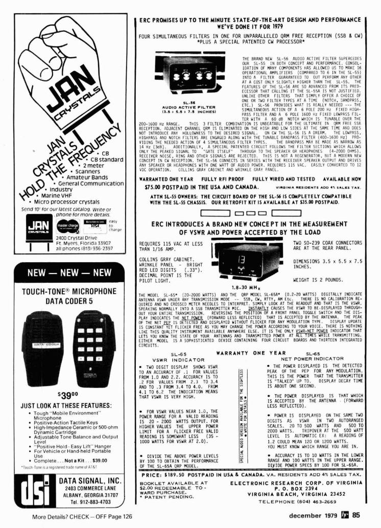
MarlneVHF
Send 10' for our latest catalog wrrte or
- 2400 crystal Drive Ft M y e r s Florld.1 33907 I ( a11 onones 18131 936 2397
TOUCH-TONE" MICROPHONE I DATA CODER 5
$ 3 9 0 °
JUST LOOK AT THESE FEATURES: Tough "Mobile Environment" Microphone Positive.Action Tactile Keys High-Impedance Ceramic or 500-ohm Dynamic Cartridge Adjustable Tone Balance and Output Level "Positive Hold. Easy Lift" Hanger For Vehicle or Hand-held Portable Use Complete. . . Not a Kit . . . S39.W
.louch l one ~ s d reg~s le red l radennmeo l A l R l
DATA SIGNAL, INC. 2403 C O M M E R C E LANE
ALBANY, G E O R G I A 31707
I ERC PROMISES UP TO THE MINUTE STATE-OF-THE-ART DESIGN AND PERFORMANCE WE'VE DONE I T FOR 1979 I
I F O U R SIMULTANEOUS FILTERS I N O N E F O R U N P A R A L L E L E D QRM FREE R E C E P T I O N ( S S B I CW) *PLUS A S P E C I A L P A T E N T E D CW P R O C E S S O R * I
THE BRAND NEW S L - 5 6 AUDIO ACTIVE F I L T E R SUPERCEDES OUR S L - 5 5 I N BOTH CONCEPT AND PERFORMANCE. CONSOL- I D A T I O N OF W N Y COMPONENTS HAS A L L W E D US TO MAKE 1 6 OPERATIONAL AMPL IF IERS (COMPARED TO 6 I N THE S L - 5 5 ) INTO A F I L T E R GUARANTEED TO OUT PERFORM ANY OTHER AT A COST ONLY SLIGHTLY HIGHER THAN THE SL-55. THE FEATURES OF THE S L - 5 6 ARE SO ADVANCED FROM 1 1 5 PRCD- ECESSOR THAT CALL ING I T THE SL -55A I S NOT J U S T I F I E D . UNLIKE OTHER F I L T E R S THAT SIMPLY OFFER A CHOICE OF
SL-s. ONE OR THO F I L T E R TYPES AT A T lME (NOTCH. SANDPASS.
AUDIO ACTIVE FILTER ETC.) S L - 5 6 PROVIDES WHAT I S PLALLY NEEDED --- THE
11.1 + 5.1 + 7.3 INCHESI SIEIIILTANEOUS ACTION OF A 6 POL f 2 0 0 Hz F I X E D H IGH- PASS F I L T E R AND A 6 W L E 1 6 0 0 H z F I X E D L W P A S S F I L - TER WITH A 6 0 d B NOTCH WHICH I S TUNABLE OVER THE
2 0 0 - 1 6 0 0 H z RANGE. T H I S 3 F I L T E R C C W I N A T I O N I S UNBEATABLE FOR THE ULTIMATE I N QRM FREE 5 5 8 RECEPTION. ADJACENT CHANNEL QRM I S EL IM INATED ON THE H I G H AND LOW S IDES AT THE SAME T l M E AN0 DOES NOT INTROOUCE ANY HOLLOWNESS TO THE DESIRED SIGNAL. ON cw THE SL -56 IS A o n E n n . THE LOWPASS. HIGHPASS AND NOTCH F I L T L R S ARE ENGAGED ALONG Y l T H THE TUNABLE BANOPASS F I L T E R ( 4 0 0 - 1 6 0 0 HZ) PRO- V I D I N G THE NEEDED ACTION OF 4 SIMULTANEOUS F I L T E R TYPES. THE BANDPASS MAY BE MADE AS NARRW AS 1 4 H z ( 3 6 0 ) . ADDITIONALLY. A SPECIAL PATENTED C I R C U I T FOLLOWS THE F I L T E R SECTIONS WHICH ALLOUS ONLY THE PEAKEO SIGNAL TO " U T E I T S E L F " THROUGH TO THE SPEAKER OR HEADPHONES ( 4 - 2 0 0 0 OHMS). RECEIVER NOISE. R ING AN0 OTHER SIGNALS ARE RE.IfCTED. T H l S I S NOT A REGENERATOR. BUT A MODERN NEW CONCEPT I N CY RECEPTION. THE SL -56 CONNECTS I N SERIES WITH THE RECEIVER S P t l K L R OUTPUT AN0 DRIVES ANY SPEAKER OR HLADPHONES Y l T H ONE WATT OF AUDIO POWER. REQUIRES 1 1 5 VAC. EASILY CONVERTIO TO li VDC OPERATIMI. COLLINS GRAY CABINET AND WRINKLE GRAY PANEL.
WARRANTEDONEYEAR FULLYRFIPROOF FULLYWIREDANOTESTED AvAILAnLEnow
175.00 POSTPAID IN THE USA AND CANADA. VII)OIWIA RCSIDCYTS ADD a* SALES TAX.
ATTH SL-55 OWHERS: THE CIRCUIT BOARD OF THE SL-56 IS COUPLETELY COUPATIBLE WITH THE SL-5s CHASSIS. OUR RETROFIT KIT IS AVAILABLE AT U5 .m POSTPAID.
n = o = n ERC INTRODUCES A BRAND NEW CONCEPT IN THE MEASUREMENT
OF VSWR AND POWER ACCEPTED BY THE LOAD I
R E Q U I R E S 115 V A C A T L E S S T H A N 1/16 AMP. I I
I C O L L I N S G R A Y C A B I N E T . I I
1 . 8 - 3 0 M H z
THE MODEL SL-65' ( 2 0 - 2 0 0 0 U A l l S ) AND THE QRP MODEL SL-65A' ( 0 . 2 - 2 0 Y A l l S ) D I G I T A L L Y INDICATE ANTENNA VSYR UNDER ANY TRANSMISSICN MODE -- SSB. CY. RTTY. b# E t c . THERE I S NO CAL IBRATION RE- QUIRED AND NO CROSSED METER NEEDLES TO INTERPRET. SIMPLY LOOK AT THE READOUT AND THAT I S THE VSWR. SPEAKING NOFWLLY INTO A SSB TRANSMITTER M lC . lKI,LWJ CAUSES THE VSYR TO B f .D ISPLAYED THROUW- OUT YOUR ENTIRE TRANSMISSION. REVERSING THE POSIT ION OF A FRONT PANEL TOGGLE SUITCH AND THE D I S - PLAY INDICATES THE NET P W E R (FORWARD LESS REFLECTED) THAT I S ACCEPTED BY THE ANTENNA. THE PEAK OF THE NET I S D f rECTED AND DISPLAYED Y I T H M l T FL ICKER FOR ANY MODULATION TYPE. D ISPLAY UPDATE I S CONSTANT YET FL ICKER FREE AS Y W M Y CHANGE THE POWER ACCORDING TO YOUR VOICE. THERE I S NOTHING L I K E T H l S W A L I T Y INSTRUMENT AVAILABLE ANYYHERE ELSE. I T I S THE ONLY YSUR-NET W Y E q INDICATOR THAT LETS YOU KNOW THE STATE OF Y W R ANTENNAS AN0 TRANSMITTED P W E R AT ALL T IMES Y H l L E TRANSMITTING. E ITHER MODEL I S A SOPHISTICATED DEVICE CONTAINING FOUR C I R C U I T BOARDS AND THIRTEEN INTEGRATED C IRCUITS .
I SL-65 WARRANTY O N E Y E A R S L d S VSWR I N D I C A T O R NET POWER INDICATOR 1
TUO D I G I T D I S P L A Y S H W S VSYR ",
T H E POUER D I S P L A Y E D I S T H E DETECTED T O A N ACCURACY OF .1 FOR VALUES ", ..a
PEAK OF THE PEP FOR ANY MODULATION. FROM 1.0 AND 2 .2 . ACCURACY I S T O ,+ T H I S I S THE W U E R T H A T T H E TRANSMITTER . 2 FOR VALUES FROPI 2 . 3 10 3 . 4 - 3 I S "TALKED" U P TO. D I S P L A Y DECAY T l M E A N D T O . 3 F R O M 3 . 4 T O 4 . 0 . FROH - I S ABOUT ONE SECOND. 4 . 1 T O 6 . 2 THE I N D I C A T I O N MEANS
u E
THAT VSYR I S VERY H I G H . T H E W Y E R D I S P L A Y E D I S T H A T WHICH gz I9 ACCEPTFO B Y THE ANTENNA . (FORYARD
FOR VSYR VALUES NEAR 1 .0 . THE P W E R F!ANGE FOR A V A L I D R E A D I N G 1s - 2 0 - iooo WATTS OUTPUT. FOR H I G H E R VALUES T H E UPPER POUER L I M I T FOR A F L I C K E R FREE V A L I D READING I S S W E Y H A T L E S S ( 3 5 - 1 0 0 0 Y A T T S FOR VSYR A T 2 . 0 ) .
P W E R I S D I S P L A Y E D ON THE SAME TUO D I G I T S AS VSYR I N TWO AUTORANGED SCALES. 2 0 TO 5 0 0 WATTS A N 0 5 0 0 TO 2 0 0 0 WATTS. T R I P O V E R A T THE 5 0 0 WATT L E V E L I S AUTOMATIC E X : A R E A D I N G OF 1.2 COULD MEAN 1 2 0 OR 1200 WATTS. YOU MUST KNOW WHICH RANGE YOU ARE I N .
D I V I D E T H E ABOVE P W E R L E V E L S ACCURACY I S T O 10 Y T T S I N T H E LWER B Y 100 T O O B T A I N THE PERFORWNCE RANGE AND 100 MATTS I N T H E UPPER RANGE. OF T H E S L - 6 5 A ORP MODEL. D I . V I O E W U E R SPECS B Y 100 FOR SL-65A . - P R I C E : 1 1 8 9 . 5 0 POSTPAID I N USA 6 CANADA. VA. RESIDENTS ADD 4% SALES T A X .
BOOKLET AVAl LABLE A T E L E C T R O N I C R E S E A R C H CORP. O F V I R G I N I A ~ 2 . 0 0 REDEEMABLE TO - P. 0. BOX 2394 WARD PURCHASE.
PATENT PENDING. V I R G I N I A B E A C H , V I R G I N I A 23452 T E L E P H O N E ( 8 0 4 1 463-2669
december 1979 [rm 85 M o r e Details? CHECK-OFF Page 126
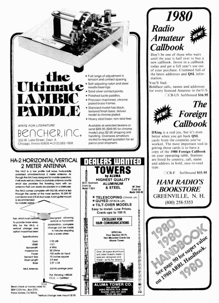
the Full range of adjustment in tension and contact spacing.
-Ultimate Self-adjusting nylon and steel needle bearings. Sol~d silver contact mints.
Prec~s~on-mach~ned, chrome I AMBIC ' ""'lz"::I."."Ies I I PRDDLE Standard model has black.
textured finish base; deluxe model is chrome plated. I I Heavy steel base; non-skid feet. I I
WRITE FOR LITERATURE Ava~lable at selected dealers or send %39 95 ($49 95 tor chrome Be n c H e R , i n c P.S $2 00 sh~pp~ng and
0 handl~ng Overseas amateurs 333 W Lake Slreet. Depl A ~nv~ted to request quotallon for alr
1 Chlcago, lll~nols 60606 (312) 263-1808 parcel post sh~pment I mall slle p- the hawllng ham Wh on antenna Mal can eoslly be pocked In a Wcon~. me ma comes corn@& wah RG/M, wnkh I tad mrough me center ol me most recWon, R.259 RF conneClaand 318 2Artud bore.Amlngur)errnwnl
HA-2 HORIZONTAL/VERTICAL I 11
\ t+on.whm krnWb- designed aIlot*lng r0ptaMemonHmo ,
verllcal a harizonlol
IIIW lor me m.2, a ,I W a n o n . corn-
2 METER ANTENNA Rr, W 2 k a lor prdle h o w wvw. hmon)olh, @xlzed omnldkecllonol 2 meter antenm. A). lhough meH&2*0sderlgnedknmobReopero(lon. ii MR vmk we11 as a hed a~a~ tabk antenna and Na
v a ~ ~ ~ chonpe - change con be mode @Ion mwnl has been I In mlnulea requldng
enb n sneu drher
1 TOWERS by ALurnA
HIGHEST QUALITY Ml ii. Llumlnum. ALUMINUM Cr8nk.U~ Modal T.(IOH 8 STEEL UIS(MI
Crsnk.Up Modal S H O 4
*TELESCOPING (CRANK UP)
+GUYED (STACK-up) * TILT-OVER MODELS Easy lo install. Low Prices.
Crank-ups to 100 ft. I ,,,,, 1, HAM COMMUNKATIM
L
SPECIAL Four 9.sHon 50 FI.
Van YOunlod Crank-Up
' S k
hnpedance X ) ohms Power 1 150r*amdc hPUl and steel towers made-
Elementslm 1 10 lwheauawls 2 0 Be(
318" K 24
$39.95 pOIkse pold
m. ~ e ~ h g r m w F.C.C. - Cd lMd
Radio Amateur
I Callbook Don't he one o f those who wails until the year is half over l o buy a new callbook. Invest in a callbook today and get a ful l year's use out o f your purchase. Crammed ful l o f the latest addresses and QSL infor- mation.
You'll find: Boldface calls, names and addresses for every licensed Amateur i n the U.S.
LICB-US Softbound $16.95
me Foreign * Callbook
DXing i s a real joy. hut it's even better when you get back QSI. cards from the countries you've worked. The most important tool i n getting those cards is to have a copy o f the 1980 Foreign Callhook on your operating table. Stations are listed by country, call, name and address in bold, easy-to-read type.
I dCB-F Softbound $15.95
I M R A D I O ' S BOOKSTORE
GREENVILLE, N. H. (800) 258-5353
-- Send c M k a m o m orde, lo StM CON Iw . Box 2751. Pol- V e W . CA 90274
'Mmcal chonge um mounlS5 O
10 GHz GUNNPLEXER" MICROWAVE TRANSCEIVER FRONT END BY MICROWAVE ASSOCIATES I FEATURES
LOW COS1 TRANSMIT-RECEIVE HIGH SENSlTlVlTV TELEMETRY/VIOEO DATA AFC AC-DC OPERATION FUNCTION METER MULTIPLE IF FREO'S TONE OSCILLATOR MODULAR CONSTRUCTION ELECTRONICALLY TUNEABLE WEATHER RESISTANT CASE SOUELCH 8 VOLUME CONTROLS COMPLETELY WIRED/TESTEO
THREE MODELS AVAILABLE TELEMETRY MODEL TMXIO MODEL rvxlo
10 GHI 10 MW Gunn Transcelver 10 GHz 10 MW Gunn Transcelvet 17 dB Horn Antenna 1 7 dB Horn Antenna
30 MHz Low Nolse Pre Amp 45 MHz Low Notse Pre.Amp 10 7 MHz Posl IF AmplDemod 45 MHz Posl IF AmplOemod Ctyslal IF F~lters Addlo Subcarrler ModlDemod Inlegrated Clrcull Modulator Room lor Ill V~deo Channels Inletrial Vollaqe Regulalors lnlernal Vollage Regulators A F C Volume Conltol Tone Oscrllalor
TMIVIDEO MODEL TMIVXIO 10 GHI 10 MW Gunn Transcelver 17 dB Horn Antenna
45 MHz Low Nolse Pre-Amp 45 MHz Posl IF AmplOemod WldebandlNarrowband Operalton Aud~o Subcatrler ModlDemod A F C AC-OC Power Supply
PHYSICAL SPECIFICATIONS Sue: 6" h. x 9" 1. x 5" d. Color. Blue Enclosure. Gray Fronl Panel We~ghl: 3 Pounds Speaker Included Tr~pod or Mast Mounting M~crophone Opt~onal
OPTIONS PRICE LIST
45 60 100 Ill MHI IF Freq Avatlable TMX'O ' ' ' ' 5379'95 TCI CORP. Narrow Band Crystal F~lters MODELTVX10 . . . . ,5379.95 411 N HuCHANAN CIRCLE lJ3 . 50 nz 220 VAC power supply MODELTMIVXIO.. . $529.95 PACHECO C A 94553 . Hlqher Gunn OSC Power Oulpul 'C""lhtneS TM'V'deo
Hlgher Galn Anletinas TO ORDER CALL ( 4 1 5) 6 7 6 - 6 1 0 2 or W r ~ l c lor FREE OETAILED DATA SHEET on l h ~ r and our
VHFIUHF TRANSMITTER & RECEIVER PRODUCT LINE k'111 t \ \.,lil,',I I,, Llld111t1 W I I I ~ ~ . I I hllllll I
We have the worlds largest selec- t ion of synthesizers for receivers, transmitters and transceivers. For complete details see our 113 page ad in the April 1976 issue o f th is magazine o r call o r wr i te for addi- t ional information. Phone orders accepted between 9 AM and 4 PM EDT. (212) 468-2720
VANGUARD LABS 196-23 JAMAICA AVENUE
HOLLIS, N. Y. 11423
ISTEP UP TO TELREX Professionally Engineered Antenna Systems Single transmission line "TRI-BAND" ARRAY"
c~ ILLUSTRATION BALUN MONARCH rn T85EM/4KWP
.. vql ILLUSTRATION TRAP
\ By the only test that means anything.. . on the air comparison . . . this array con- tinues to outperform all competition.. . and has for two decades. Here's why ~0~ technical data and prices on corn- . . . Telrex uses a unique trap ,design plete Telrex line, write for Catalog PI. 7 emplov~no 20 H i 0 7500V ceramlc con- denseis per antenna. Telrex uses 3 opti- mum-spaced, optimum-tuned reflectors to provide maximum gain and true F/B Tri-band performance. - % .. , . D l , . ri... ,IUII.I.lll, I , s .

the
Rated 5 KW peak-accepts substantial mis- match at legal l ~ m ~ t DC grounded-helps protect against lightning Silver plated hook-up braid: Custom molded case Amphenol' connector: Rubber rlng to stop water leakage
Model ZA-1 3.5-30 mHz $1 5.95 Model ZA-2 optimized 14-30 mHz
includes hardware for 2" boom
A complete line of QUALITY 50 thru 450 MHz TRANSMITTER AND RECEIVER KITS. Only two boards for a complete receiver. 4 pole crystal f i l ter i s stan- dard. Use w i t h our CHAN- NELIZER or your crysta ls. Priced from $69.95. Matching transmitter strips. Easy con- struction, clean spectrum, TWO WATTS output, unsurpassed audio quality and built in TONE PAD INTERFACE. Priced from $29.95.
I SYNTHESIZER KITS from 50 to 450 MHz. Prices start at $119.95.
Now available in KIT FORM - GLB Model 200 MINI-SIZER.
Available at selected dealers. add $2.00 postage and handling m U.S.A. 333 West Lake Street. Dept A WRITE FOR LITERATURE Chicago, Illinois 60606(312) 263-1808
Fits any HT. Only 3.5 mA current drain. Kit price $159.95 Wired and tested. $239.95 Send for FREE 16 page catalog.
We welcome Mastercharge or VISA I GLB ELECTRONICS 1952 Cl~nlon St.. Buffalo. N Y 14206
before you move arid we W I I make :,ure vour HAM RADIO Maaaz~ne arrlves on
Then compleie your new address (Or any other correcl~ons) In the space provided
--I I kchedul~ Juql rernou; the malllng label from th~s rnaaazlne and a f f~x below
I Featur~ng Yaesu lcorll D r d k i Atlas. Ten Tec. Swan,DenTron Pace Pal?.ma!. Sda. M!dland. I 1 and we'll take care of the rest I
I I Thanks for helping us to serve you better. r-- \ r--
88 decernber 1979 More Details? CHECK-OFF Page 126

r~eawfl n q n o 9u211: c r y , . ~ . m ~llo,ni,nij sxtnlant m,wr lacto,, ano U I I ~ ~ A I ~ I I J P C ~ ~ O ~ ex~eeolt>q 80 08 lnry are curlom m.wr tor flrop ~n ~ n ( ! d l ~ ! < n n rnatrnlnq Sr,lor!lr liotn pnrr l ia l i r .#nd ner:con,rallr Out nlme \* , ,C","Q Ro.,rOr mrte ,X,\~,"lF inn* or 8" 1°F l l l l l l re, ,he ado, (,on o l a $arle!y 01 xultm wrnldnir I~llrr% ~11oromq superror var ia~ le n.mowlfl!n w,tnour me I:*" to IIIW an P I P ~ ~ I I V F new m o m I YOU
CORPORATION l d n l I h r Lvrl la< 1.55 you I n u ? I O X lAY(in Jurl 1e11 u l !be MnO w ~ , , ~ ~ , . . I nrwm IO, YOU, m.,kr nnn maor, Communi~ations
RF Speech Processor Model RF-440 1ncre;ises l;ilk power with splaller tree operallon. RF cl~pp~ng assures tow d~stortion. RF Speech Processor S~rnply ~nstall belween rn~crophone and lrallsmilter.
Increases ldlk power w~lh splatter free Talk Power: Better than 6 dB
Output Level More than 50 rnV at 1 kHz Power Requ~rernent 115V AC. 60 Hz. I W. for sell contalned AC power supply. or 13.5 V DC.
*I"," ,,,,.".Hi Il,l.*acn 55 rnA lor allernale external power
Power Requiremenl Exlernal source. DC Volts P GUD c~nwns r.,n,og n ~ n ~ n , lo *UM.UI* wp ororld, mwr
l;oilnnnl*mnInDulmOovlDvl W l r i l rnOIr5lW PC W r G IeM?Oru5r 13 5 at 50 rnA no s~gnal D~mens~ons: 90 x 25 x 92 mrn. 3 56 x I x 3.62 in.
Exclusive USA agent for these units; inquiries invited.
~!:?:,iY!:!:!!!:$:~!:~!~~Lra, ,*,,e,$ ,ban ,nose ,or W",C" ,be md""l.t,".r. ylu",Ul, .mn r ,Will" l.,maOl. Ullng allallnq Ilonl W0.l wlii nr\ an. nrrl~abic lo. I-W ms cm- ~ ~ u , p n m l tatm
Write lor literature.
BELL INDUSTRIES
a N E W a n t e n n a p r i n c i p l e PROVEN IN EXACTING TESTS AND MANY YEARS ON THE AIR AT W@MBH - KBAST - K8VRM
B E A M A N T E N N A
only 27 inches high by 22 inches wide
A COMPLETELY NEW ANTENNA Here is an ultra com act beam antenna which can be tuned t o any frequency between 7.0 and 14.5 MHz. Weighing only f8 Ibs. this antenna may not outperform a ful l sized beam but it sure will give you your share of OX and stateside contacts. Will handle 1 KW over a 100 kHz bandwidth. • Fully weather proof HI-Q, attenuates hurmonncs
Mounts eas~ly on TV masting Comes assembled & tested s122.50 FlPure 8 pattern
LITTLE GIANT MODEL 100X100040 $149.50 Other models avanlable for 10. 15 & 20 meters Add $3 trans.
Little Giant Antenna Labs, Box 245, Vaughnsville, Ohio 45893 Subsidiary "Apollo Products" Village.Twig Co.
419-646-3495
More Details? CHECK-OFF Page 126 december 1979 89

Increased talk power: Up to 15 ~~~~i~~~ 72 vdc dB, adjustable (10 dB recommended at 200 under most operating conditions) Frequency response: 350 Hz - Add $10 for built-in AC vower SUVP~Y
2.4 kHz at 3 dB down (200 Hz - 3 kHz at 12 dB down) Harmonic Distortion: Less than 12% at 1 kHz wllh 10 dB clipplng
THIS IS IT DAMES COMMUNICATION SYSTEMS -'.-:: 5.5-z.2 : ,,n;7 :& , ~ Q Q ~ / f f ! ~ , ~ ilim . ..
Merry Christmas and
Happy New Year to All!
"plea* call w o n uud equipment qperialr'
: +.Fz -,, w-w:. .d. ::FA:: !,&,? #e.y*,T 201-998-4256
10 SCHUVLER AYE.. N. ARLINGTON. NJ 07032
M O D t l . 4451 T H R U L I N E '
RF DIRECTIONAL WATTMETER $ 6 tf 0 CrM wi th VARIABLE RF
SIGNAL SAMPLER - B U I L T I N IN STOCK FOR PROMPT DELIVERY
AUTHORIZED DlSTRlBUTOR
a s s o c i a t e s 115 BELLARMINE
ROCHESTER. MI 48063
C A L L T O L L FREE 800 - 521-2333
DUNES HOTEL IN MICHIGAN 313 - 375-0420
LAS VEGAS, NEVADA JANUARY 10-1 3,1980
I BRAND NEW! STEP INTO THE SO'S WITH THE LA TEST HANDBOOK FROM THE EDITORS A T ARRI.
Full o f exciting new features for the 80's, NOW is the time to order your copy o f the 1980 ARRL "RADIO AMATEUR'S HAND- BOOK." Internationally recognized and universally consulted, every Amateur should have the latest edi- tion. The new HANDBOOK covers virtually al l o f the state-of-the-art developments i n electronics theory and design. Novices wi l l f ind il to be an indispensable study guide, while the more advanced Amateur wil l enjoy building !he many new projects.
O Order AR-HBSO Available Softbound $10.00 November 1979
U Order AR-BBSO Available Hardbound $15.75 January 1980
HAlMRADIO'S BOOKSTORE
GREENVILLE, N. H. (800) 258-5353

flea ~t market RATES Non-commercial ads 10c per
word; commercial ads 604 per word both payable in advance. No cash discounts or agency commissions allowed.
HAMFESTS Sponsored by non-profit organizations receive one free Flea Market ad ( s u b j e c t to our e d i t i n g ) . Repeat inser- t ions of hamfest ads pay the non- commgrcial rate.
COPY No spec ia l l ayou t or ar- rangements available. Material should be typewritten or clearly printed ( n o t all c a p i t a l s ) and must include full name and address. We reserve the right to reject un- suitable copy. Ham Radio cannot check each advertiser and thus cannot be held responsible for claims made. Liability for correctness o f material limited to cor- rected ad in next available issue.
DEADLINE 15th of second preceding month.
SEND MATERIAL TO: Flea Market, Ham Radio, Greenville, N.H. 03048.
MOBILE HF ANTENNA, 3.5-30 MHz inclusive, 750 watts PEP, center loaded coil, tuned from the base, eliminat- ing coil changing or removing from mount. Less than 1.5 to 1 VSWR on ail ham bands. $119.95 each - contact your local dealer or order from Anteck, Inc., Box 415, Route 1. Hansen. ID 83334. (208) 423-4100. Master Charge and VISA cards accepted. Dealer inquiries inv~ted.
KDK 2015R OWNERS. Use memory for any oddball splits. Shows TransmitlReceive frequencies. Simple, 15 minutes. No holes drilled, no boards l ifted. SASE. Details free. WA2HQD. 105-18 131. Richmond Hill, NY 11419. (212) 641-2559.
VERY in.ter-est.ing! Next 3 issues $1. "The Ham Trader", Wheaton. lL80187.
HOT CARRIER DIODES by HP 41$5, large LEDs red 151$2, green or yellow 12/$2. LED mounting hardware 201$2. Koemp - El Co., Box 3358, Keansburg, NJ 07734.
MOBILE IGNITION SHIELDING provides more range with no noise. Available most engines. Many other sup- pression accessories. Literature, Estes Engineering, 930 Marine Dr., Port Angeles, WA 98362.
Foreign Subscription Agents for Ham .Radio Magazine
Ham Radio Auslrla Harn Radm Hol lar~d F Bast1 MRL Ectron8cs Heuptplalz 5 Postbus88 A 2700 W ~ e n e r Neustadl NL 2204 D e l l Austra Holland
Ham R s d o B e l g u m Stereohouse Ham Radio Italy Brusselsesteerlreg 416 STE ",a anl la go 15 8 9 2 1 8 G r n t Belgtum
1201 34 M a n o Italy
Ham Rad8oCBndda 8 0 1 400 Goderch Ontar80 < anad, N7A 4C7 ~ , " ~ n " , " , " ~ ~ ~ w " " a n ' '
Ham R a d o Europe 2454 80,444 D 7850 Loerrach S 194 04 l )ppldndh Y d B b Germany
Sweden
Ham RaOlo France Ham Radio UK Chr511dne Mchel P 0 Box 63 Harrow F 89117 Pdrly Middlesex HA36HS
Franc? England
Ham Rdclo Germany Kartn Ueber Holland R a d o Postlach 2454 143Greenway D 7850 Loerrach Greenarde Johannesburg West Gerrnany Republic 01 South A f r c a
AFC - STOP VFO DRIFT. See June '79 HR. Complete unit $49.95 + shipping. Read Easton, KGEHV, 3691 Gay Way, Riverside. CA 92504.
REPLACE RUSTED ANTENNA BOLTS with Stainless Steel. Small quantities, free catalog. Elwick. Dept. 360, 230 Woods Lane, Somerdale. NJ 08083.
OSL CARDS 5001$10. 400 illustrations, sample. Bowman Printing, Dept. HR, 743 Haward, St. Louis, MO63130.
-
SPLIT-BAND SPEECH PROCESSOR circuit boards are now available from the author. See September issue HR. Set of three; includes power supply board and layout, et- ched, drilled, plated, $12.50 postpaid. N7WS.
HAM RADIO REPAIR, alignment. Prompt, expert, reasonable. "Grid" Gridley, W4GJ0, Route 2, Box 1388, Rising Fawn, GA 30738.
-
XTAL FILTERS: C-F Networks 9 MHz SSB filter - 2.1 kHz BW, similar to KVG XF9-8, $25 postpaid. KBDRN, J. Wiggenhorn, 1678 NW 84th Or., Coral Springs, FL 33065. (305) 752.7444.
FERRITE BEADS: wlspecification and application sheet - 121$1.00. Assorted PC pots - 101$1.00. Miniature mica trimmers, 3-40 pF. - 5/$1.00. Postpaid. Includes latest catalog. Stamp for catalog alone. CPO Surplus. Box 189. Braintree, MA 02184.
WANTED: ROBOT 400 - Prefer Operative. Accept Not Working if price is right. Need 2nd for SSTV Color. W3FAKlAB3T Duffy, Hystone Ave., Johnstown, PA 15905. (814) 288-2130.
RTTY AFSK Modulator PC board. See Feb. 79 Ham Radio. Drilled $5.00 F. E. Hinkie, 12412 Mossy Bark, Aust~n. TX 78750.
THE MEASUREMENT SHOP has usedlreconditioned test equipment at sensible prices; catalog. 2 West 22nd St., Baltimore, MD 21218.
MANUALS for most ham gear 193711970. Send 250 for "Manual Catalog." HI, Inc., Box H864, Councll Bluffs, Iowa 51502.
WANTED - Hilttop Property near Pol,ock Pines. Cal~lor- nla. WAGCOA. 4 Alax Place. Berkeley. CA 94708.
PORTA PAK - Make your FM mobile a self-contained portable. Models in stock for most popular makes. 4.5 amp hr model $80.00. 9 amp hr $103.00. Charger includ- ed, shipping extra. P.O. 60x67, Somers, WI 53171.
WANTED - Motorola KXN1024 and KXN1052 channel elements. WAGCOA, 4 Ajax Place. Berkeley. CA 94708.
OX, YOU BET! THE DX BULLETIN - Best weekly DX info in the world. For FREE sample copy, send business-size SASE to: The DX Bulletin, 306 Vernon Avenue, Vernon, Connecticut 06066.
ROHN TOWER - Buy wholesale f rom Worldwide distributor. 20G $27.06 section; 25G $37.62 section; 45G $67.78 section; 48 ft. foidover tower, $605.00; 4811. BX free-standing $213.40. Hill Radio, 2503 GE Road, Box 1405, Bloomington, IL61701.(309)663-2141.
NORTH AMERICAN DX REPORT - free sample - SASE t o Suites R2-R3, 615 S. Frederick Ave., Gaithersburg. MD 20i60 - Phone (301) 840-1987.
COSMAC ASSEMBLER runs in lKB, text editor in one page. Cassette and manual $19.95, specs for SASE. The Elfry. Box 802H, Clarksville, MD 21029.
WANTED: AFSAV-39C keyers. ANIFRA-86 B AFSAV.133 demods., and type "N" coaxial bulkhead lightning arresters. C.T. Huth, 146 Schonhardt St., T~ffin, OH 44883.
FREQUENCY ALLOCATION CHART. See how the entire radio spectrum is used. 2 kHz to 200 GHz. Send $3.00. Collins Chart Co.. Box 935, Coronado, CA 921 18.
STOP LOOKING for a good deal on amateur radio equip- ment - you've found it here - at your amateur radio headquarters in the heart of the Midwest. Now more than ever where you buy is as important as what you buy. We are factory-authorized dealers for Kenwood, Drake, Yaesu, Collins, Wilson, Ten.Tec, Atlas, ICOM, DenTron, MFJ, Tempo, Regency, Hy.Gain, Mosley, Alpha, CushCraft, Swan and many more. Write or call us today for our low quote and try our personal and friendly Hoosier Service. HOOSIER ELECTRONICS, P.O. Box 2001, Terre Haute, Indiana 47802. (812) 238-1456.
COMPLETE HAM STATION $225. Heathkit DX-100, Drake 2-C, used, excellent KAIBEB, Kangas Rd.. New Ipswich, NH 03071. Tel. (603) 878-1554.
-
ICOM 701 USER'S CLUB is now operational. Send SASE to NBRT, Rob Pohorence, Dept. HR, 9600 Kickapoo Pass, Streetsboro, OH 44240.
THE Z E N E R .
AN5 P T 9 0 RNC 90" ELROW
A L L I N I C N N A c , A R E CI3N l Y l l M E T E R .
UHF F/UHF-F PL-258 $1.50
' N ' F/UHF-M UG-83BU $4.75
RG8 Adapter lJG-175 $ .25 BNC M - C A B L E '
UG-88 1 1 . 3 5
8NC F P A N E L
V G - 5 8 $ 2 . 2 5
More Details? CHECK-OFF Page 126 december 1979 91

Station ID Timer and Code Practice Oscillator
0.w $1 9 95 IN KIT ORM EAGLE TM - IOW'
S2695 ASSEMBLED PLUS $2.00 SHIPPING s l lrne nrr- o a t . - , -
NOW! EAGLE ELECTRONICS INTRO- THE TM-100oTM AUTOMATICALLY DUCES a practical accessorl to every RESETS after alerting you and can be reset amateur station: The TM-1000T 10 minute any time by pressing the reset button. ID timer and code practice oscillator will re- mind you with a loud clear tone when it is AMATEURS time to identify, N~ longer is it necessary to endeavored to obey all regulations as closely keep an eye on the clock to be sure you iden- as possible. The TM-loooTM is an impor- tify in time. the ~ ~ - 1 0 0 0 T M keeps tant aid to help amateurs maintain that Of the for you. And, when not tradition by assuring that ~dentification is ac- on the air, you can use it to improve your cOmplished at the proper code speed because it doubles as a code THE ~ ~ - 1 0 0 0 T M COMES WITH A 1 practice oscillator. guarantee and a 10 day, money back (less THE TM-100OTM HAS FULLY ADJUST- shipping) guarantee. ABLE volume and tone and its timer is ad- ORDER YOUR TM-lOOO~~ ID justable from 45 seconds to 10 minutes. It PRACTICE OSCILLITOR comes in an attractive walnut-grain cabinet TODAY FROM: and is powered by one 9v battery (not in- cluded). THERE'S NO NEE0 TO WORRY ABOUT EAGLE ELECTRONICS@ missed ID'S during roundtables and OSO's BOX 4268, P O ~ T A G E , MI 49081 anymore. With the TM-1000TW in your C ~ I I 1-616-375-7469 to order COD or by bank card. station, you are assured of identitying Mich. res. add 4% sales tax in time. Optional AC adapter 57.95 emra.
SELLING AMPHENOL PL-259 60e 101500. RG8U S15.001100 It.. Rdghl angle 10117.00. T-Connector 10120.00. SASE lor Itsl. John Rogers, 1927 Barry. Chlcago. lL60657.
---
HEATH HWISB.104 OWNERS: Improve sensitivity, selec. livlly, ~nlermoduialion perlarmance. For lnfo sheet send $2 and SASE lo WB4RRC. Box 461. Warner Roblns. GA 310%.
SELLING OUT - Colllns KWM-2. 516F-2. sealed relays. excellent 5650 Drake DSR.2. New 11895. lcom 701s. PIS. Mlke. Mtnl, as New. SlHX). IC.RM.2. New 1150 Aslro m A . Console. PIS. Touch-Tone mnke. as New I925 All FOB. prlces flrm WABNWP, 52632 Rd 426. Oakhursl. CA 93644.
BUY.SELL.TRADE. Send $1.00 lor catalog. Give name address andcall letters. Complete stock o l malor brands new and rrrcondlt~oned amaleur radlo equipment. Call lor best deals. We buy Calllns. Drake. Swan, elc. Assoctaled Radio. 8012 Conser. Overland Park. KS 66204.(913) 381.5900
- QSL's - $2.70 par hundred (minimum order. 1W4 and up. 32 two-color designs. Send 306Istamps lor caialog. Satislaction guaranteed or money back. Since 1934. VP5OED Press. Box 1523. Boca Ralon. FL33432.
--
STAR.TRONICS monthly picture flyer is lull 01 pans and pleces lor the builder. U.S. only. Slar.Tronics. Box 683. McM~nnv~lle. OR97128.
SELL complete collection (all 142 issues) Ham Radio magazlne Excellenl condition. Make offer. W9SSI WSDDL. Dennqs Ekslen. M06 N. Second. Loves Park. tL 6 l l l l .
WANTED: VFO, either Heath or Elco. Stale condltlon and prlce. WAZVJL. 442 Englewood. Bullalo. NY 14223.
- - RECONDITIONED TEST EQUIPMENT lor sale. Catalog 1.50. Wallet. 2697 Nickel. San Pablo. CA 94806
--
HAM RADIO MAGAZINES complete set Vol. 1 No. 1 March 1968 lhrouah lodav In HR binders. Mlnt condition. $2'30 W ot trade lor ham gear model rantroad llems or ran load ana Steve Hyell r(9ZUF. I440 Royal St George Dr VP Na~ewallr IL60540
-- WANTED: ST.8: several used 220 MHz rigs. Michaelson. N7SM. t8Oli 467.6785.
RF Speech Processors for Drake TR-7, TR-4s. T-4Xs S p c a Opals IF ayml Rltring. fol lorrd by hiphlv effktius ktivr hrd lirnitinp: tlm key m intelligibility and
NEW! RF CLIPPERS talk-. TR-7 pmcasor p w i d s mom for m dditiorul m-ry film. All lolid-nm p i n d i i witching. TR-7. TR-4 units larmm wlmable 16.pola W i w . Modd 7.SP for TR-7: S26265.W. Model 4-SP for T4X: SZ85.W. T R 4 unit mailable st a later date. -
Mike Equalizer Pre-Proce~sor Fkrwood EngiMEring ~nc 1268 South Ogden St .
Compnion m .ban unh, but goad b.trraa any mike Denver. Colo. 80210 and rig. C.n d u r n distortion, imp- c r n p ~ a ~ , intsl. (303) 722-2257 ligibility. Eslily.sd;mtabh ringls m t r o l tailors both hi* M~~~~ back satasfled m d low frsquanclm l o optimils r s l pom of m y micro. Add 53 per order shb~1,8n% phone. Contains inlout. gsln, aquaiizstion controls. 16 oversea an, Madai SE.1: $65.00. Dealer hquiries Welcome
.~~ - . S m l l , IIqh, m l h o r - c d I)alm
. , * -121 I - p d m w c o d l 8 :-- - . I~ IH" e m o r lnu- 0- -.. . WoIm .Ilnl@ T V I
.Cwllv 8wmrmnt.d
Van '9.95 ,
P C 0
Gorden Engineering BOX 11305, 1. CUCLID , OHIO 44121 - - ~ -
8IOC""stl ..OC*WfS - Hildreth Engineering
. ..........-.. ........ ,., .t",
-. - + ,--- -. .......... , .,,., . , ............................. . . - . " ......--.... - , . ., .. ,... ,,,.,w. ....- ".&.,- ..........--.. *.. " ."-. d .-* T 8, i.".",. I . . ............. . . . . . . . . . . . . . . . .
..... .. ........... I - - ... - ... ,- . . -. - .... - ... - ................... - - - . -. ... ....... .......... ---- . ." . .. - .- .... ...---- -.- ...........
" ........................... & . .......... " ................ ....................... y-. nm .... ....................

More Details? CHECK - OFF Page 126 decernber 1979 93
<-@AC/DC V o l m Taster H W r h l b i l i n rolt.p.indiutor 1m. 1
m e to 240.277. 440 m ~ O O V A C : 120.2r10.4~. BW VDC. Polnir. or -1". DC 01. l d m t i led bv neon tamp.
*P.,",. l o r 4u.k prod - * C.-.
* C a r - ~ p ' O d h & h r l w o n hand op.mtion. S.U~it inguMlng. hqh-irnp.st 5.- l o r 1.4 Irl..
. C o n t ~ ~ o u s dut* r.1.d thm W V .
.D~mmYin l : 4-9/18" i 2-1118"~ 718". Color: Orang..
VT200.. .92.95 ..................... .
MICROPROCESSOR COMPONENTS --.rruwr,
lo01 cw ~ . m u ~ u ~ ~ ~ ~ N , , ' P I - I I T * O c s U O " LUYI-
2 8 sll lMMiDUlOYl 1114 hlom loluluol M M ;: "CDPI101 U U %*in I YI
&?I8 L omon. ~ l . an ,9 Y an uw Y~,,,.I
0 2 4 C W Lnernoc.Dr*ci 8 % a n 6 BW ~mml
*II
11228 Sv*m MlrgY.nLlakI!W% M 1171 Ssllrn Dn!l&r
'*
; : ; 1211 P.w Canm I O I W " 82s Piw tnlrrA8 r l n n ,: 2 ~~& & 2 ~ ~ ~ ~ ~ Y m q I :
1151 P ~ W R < # D ~ t m m l 9 I 1117 Rw OUlCmllOl 19 1
U*l
I?1I Rw I I I I c I I Y D t a M , ; '"1 St.,,C '( *
!m'x! 4 w m Y r n W 1--- ',(* 210111101) m4 SI.1 MEW
Y P , ~ , ; ; '"4x1 s"w ::
YEW^ ~ w m n ~ o : ~ o : ~ w n m ~ 0 2 1 ~ 1 slam UCMlOIR 1,818 1110~ Rm 5DI 111111411) 1.614 Sun.
Fz;: ~ ~ ~ v ~ ~ m u ~ ~ ~ z t t ? z w a S I A ~ ~ C ~ :E
The Incredible "Pennywhlstle 103"
. % ... .......l.. .. ..I. .... $ 1 3 9 . 9 5 m m ,",""."nr. 1. Upam d IClllO,. I,,. ill> " lo.... nmor r,"iOl *" ,.-n(, lo, mm om*, 2nd IUlr rw......n.W.r "1 n i n 2n04m .,*#. m. I,,, "4, !.l , * s h a m nrn>m,n, .,r 8 ron.n..nlu,*l" n
+M,,mn n,i"n",m,,u,."j,~mnnnnr*,~ln~l~ o n . innon *"l*nllm* ern5 D l . 7 - l M lW I W U m Yll" "mnl cut, lruw. lh*! *"*" WxmmmD. b. . . m bd
-*I .
0.u TNI . . . . . . . . . . . b m m n ~ ~ m ~ ~ ~ m o u n w ~ m w m , , "a am,,
~ Z m Z ~ ~ : ~ < Z ~ ? 2 s ~ 2 ~ ~ 2 1 - o m - ' I : o r w , h "lo" On- m5mm
. . . . . -- r ~ n a - ~ a n u m - ~ v m u w . . . . . . . . . . n.1m11.11 1, l b l " nomln.l Ld,"TI.b* l.rn 6 a m
I0 ,Onan a c n m r - . r re.~.nr, 8.1 .en. . u r o m l l u l r *,m*, to
M l l O l O p ' " D n l l l * l ,mWMl ,m*1 pw.ID.1.- . . . . r l " P C ? l " c . r n ~ . m n n l m , , - t *
OPI(IIYUI.I am ar m*, - wd-....::: 1. k ~ ~ ~ ~ ~ ~ ~ , D , ~ % n ~ ~ ~ ~ 8 f i ~ h 9 w 9.
ocmnn n,rv, mno U, -nn, - R ~ U ~ ~ V P Y . wmcamr. fiqiam~ounnt r m l m O M ~ ~ C ~ O * * F
TRS-80 16K Conversion Kit
E w m d your 4K TRS 80 SVRRR to 16K. KI, wn*l.rmp*ta ~ , t h 8 . r k UPD416-1 116K Dv"am(c R a m 1 250NS .Doc"mnt.tan 10, conr..,i.n
. . . . . . . . . . . TRS-16K $75.00
Cables "mpers M C W ~ ~ ' D ~ ~ I W O " ' U - . ~ 4 $::: :::::::EbBI E:Ez ~ ~ ~ ~ ~ ' ~ ~ ~ M ~ ~ ~ :: 2 l l t . l 10NX4 PUIIC YXDI
';; ;;
r w CONNECTORS ::: our, %?$:a,lK .lYI A,i - 2 1 2% s?m ..Rymlwti >we rrum -N, .5" .,N
9.J 77th l l I%.' 6DliOU
lM*'s R5232' ouai z ia stmr 4 m m! . t (nn) la>, ~ ~ ~ n ~ n u p a r mmw. DLYIIJPTlO* TSXJ out 240BII SL r m orotnsmlzu OW~C-,
OB2W PLUG Ins y8rtundl S2.95 :yo* '" 'Irn 2 n ~ S Z lira orno maor ............. 691 1?1.111 1 ~ s 8100~1 OB215 SOCKtT . . . . . . . . . . . . . . . . . . . 1.50 i r rsm .x4~awwlm-, 2.9 I:bllJ 31Y1 lln1ata
,'Id6 11? 111 om..*. 9 % -24 AWG w ~ r e . OZI" qumr. -
OB512ZII CABLE COVER IorDB25PorOB2S.. 1.75 W P S i l l 8 8 251 ri l O I l l M D I
.D.,," <ha," 0. .Bull, In rut ow OB25P-811 PLUG - Rlqht Angle - PC. Mount .... 1.96
&q& 1 B 111161 1074 S<Allc 4' want-toPOlnl ~ I n c l u d ~ ~ Y 3 l l . w l ~
08215811 SOCKET - Rlqht AM. - P.C. Mounl . . 5.25 h-"-5-'0'1 la .NO nrwp8np or llmstmnp rqu8r.d-
JEGDD HEXADECIMAL DIGITAL Printed -------- Circvit ENCODER KIT THERMOMETER KIT
n1,Wlts . '"8 I 'C Ufm M D Y ( I I rnlVO. M.1-w Whlll 11.85
Connectors m . ~ " . ~ ~ ~ ~ ~ . .Il Sprly.Tin.Oouble RmdOu!
,Itbl* O D ' * ' l " . Dmaunre i v c u l )tondl0 lor L I9 e,furut.d cont.n, LC",
in .OM to ,010 PC. eolldr . it^ marno to nllw mllm
.&"IS mMgorlo* .= . f a r , nl .a~ng .,In $lnal,o 161n I! <O""enOl
v r m ..... . . . . . . 151lOSE 15'30 C o n l x l s - n l d u sydu . . . $1.95 .an,+ . m i ,mwa r ocerna. ' - R JW B Blue.. 60 I? rol l . . $2.98
11116s~ IBiJ6 cunrurtr -laldar eyslat . . . . 2.49 FULL BIT L A T C ~ E O OL~PUI-19 KEYWARO .ou.l mm....wiTcn,n. ..nc.oi tor In. R-JWW Wht'e . ...... ....... 2.98 . . . . . . . . . . . . . . 22/44 Sf 2211 Contacts l o l d 8 r evela( 2.85 m e i r m cnro,lf, roma,nn,n.,dn n.la,isen.lorona~ doorlouvdoor or dual moni!orlng R.JW Y Yel low.. 50 1 , rol l . . 2.98 22/44 W 22 44 Contacts - wire m a p ,g5 .a,,s D,nav..l Wvlii.il.. s o ,ao. d , , . ~ olw -Conlinuoul L E O .a ' ' n l dlyll.*
,*"m,,, rir,,o,o.l ml,,r.,r *,,, ,",.. .R."o. 40'I 1 0 199- i 4 0 1 ~ 0 1 0 0 % JW lied .... . . . . '.". . . . . . . 2.98 .A.t"l.CY t 7. "0mln.l 5°!100w 50 100 Cfl1llatlS - w ' l s m a p i ~ Q ~ l l . .,,,,,.,.,.,......*,3.,0. ",a",." ,ae<m,,, , m,,,. "no",,%,", (0, F.",a""O,, Or C.,., ". ,..din.
I.I~~sP.=~~oI ................. 5.95 ..,,,, ,,4..., .... .,,. r,8.wu.v ,.,,. ,,,.,,8cmn8,0..6 .s,, E.,. A C *.,, JWJ UnwrapTool $3.49 11, 1 < 1 IU~IO~I> l i l i n~8~tIO1 ..... .I..> $ : l o r .Sr. 3 114 ' " " 6 518 W l l I i B ' D
............ JE600.. $59.95 Jumbo &Digit Clock Kit H.U~TIMI K.IW o n l v . . .... .Sl4.95 JE300 ...... .$39.95 Four .W'h<. and I r o . W h l . LOmmOn .noao dilD,.". . V Y I IIMUY ClDCL cnlD . 5WilCh.1101 no",,. minY,DI.nd no,., l""<tl"", . HOYrl. . I I IY "!.I.** ( 0 rnI..I
62-Key ASCII Encoder Keyboard Kit . *,mu,.,.a *.,nut o m
FEATURES: . llSVnC oDor.llon .M K#vs wnr.1. t h l u l l 118 ck.r. . U 0, a n o u r oPsr.llon
act"', v p p r and Ian ur ASCII
I"<t"O...I, .omoon.n,,, o".nd wall tr.n.lorrn.r "I Fully bull.nd
WRAP' Kit .sot, .a :b*u.,wht.....ct. . .Silo: 6- i 111 x 1%
*.,to* wir. - 2 umddl~ k . ~ p~ldd (01 .JUS1 W R A P Toor .Unwr.oDioO Tool
cumom ..pllcrt*", ........................ J E 747 .............. 529.95 *c*p. 1- U m r - onh JWK-6 $24.95 .IOh. Ch.r.CI.n
.Brlshi 300 th1 runl.ll r a m .U1#11zn a 2378 140 p ln l rrodn
0.9. dOU),." ,awl only rn.rnow oh*
Th. JE61062 Key ASCII Enrodar Keyboard .OU~PY~S dir*ctl
: ~ ~ ~ 2 ~ 5 ~ ~ ~ ~ ~ ~ ~ ~ ~ u , . , Knt on bs ~nlscfacsd into most any corn- TTL/DTL or M d ; ' P , ~ ~ %
an* hold mod.. pl ter sqslsm. Tha JE610 KI! r o m n corn. *E.lr ~nl.rfarlw w ~ t h 18-pm dip a..,sY ri.w.b!e m 20 11. plate wnth an ~ndu#rc=l 0r.d. Levboard 18P'n .dW connec(w
.simuloxrt walnut s.w lrrmtch aaurnbly 162 kevll. IC's. -ksls. -115 VI \C ooarmelon m n ~ ~ t o ~ . s ~ a n r o n ~ c comwnant. and . V.= ,,,, ?. I,,,,..,, ,,Oh, .,"," . I 2 or 24 hr. ooer.llOn .,"c,, a,, * dwb*-nd.d prlntcd ~ ~ . i n O board. ~ h . JE610.. ... $79.95 I", ,,".i. iomnon.nt, .. JE701 w.,, ,,.n.form.r
k a y b ~ r d .srrnbly requwer +5V @ 150rnA .nn ror.u... ABS con
62-Key Keyboard only. .534.95 .,,uc,lo.l I . I.". I. 1%'' .Ssre 6X.. . IX.. and -12V @ IOmA lor opsr.toon. I... ol C.noe~mrm.n.nltv
6-Digit Clock Kit $19.95 REGULATED POWER SUPPLY C$~!I w-1 ....... $3.49 5"-1 AMP JE205 ADAPTER BOARD
JE200 POWER SUPPLY - Adapu 10 JE200 - +5V. 29V mnd'l2V Erasing
0 2 each IOOK pols I L i n u r Lamp
bO.,d
* w ' t c h ' n ~ XMFR .ERI.2708.2716. 1702A. 82030.62WO.~1c.
*Printed Circuit Board .She" C"C.Prot'elion .~r..nup to 4 r h w . r w ~ ~ h ~ n 20 rn1nut.r
; .M.lntm~nsconnant e r w w r a doll.- o l o n l m h .Spr#.l condustsun loam lbnar e1lrnlnm.s * m u bul ldup
*Sire: l " r l . 3 / 1 6 " r l ~ 3 1 1 6 . I n c l u d s . w m p o n ~ ~ . -,. .S l i e , 3X.,x2..X 8nB.. .B"#I!-ln Y ~ S I Y lock 10 melent UV e x P Y I e
hardware L innrunbra .compact - onlv 7-5m" i 2 - 7 N ' 12" JE200 $14.95 .so... 3.1...5..~2..~ '- JE205 $12.95 .cornplmo ~ 8 t h holdong tray for 4~h8.1
. . . . . . . . . . . . . . . . . . Micro-Miniature Joystick ... .$4.95 . SlO.00 Mln. hd.. - U.S. Funds Onlv Spr Shesrr - 2% - UVS.11E.. .$69.95
C.l#l. R.s#&ntr Add 6% 5.1.1 Tar 1980 c.!alop Arsihb1.- S m d l l d ~ r n p Digital Stopwatch Kit IDEAL FOR TRS 80 CASSEllE CONTROLLER
" 5 . ~nlr . , i# m c n l s - PHONE c ~ ~ ~ ~ ~ ~ ? 3 $ k ' % & ~ ~ ~ . m . 1 ~ l n r v doutllo.naed P.C. 8oara ORDERS rsmoll conltal ol carrase .LED ~ I I D I ~ Y Ireel T i m ~ , 1.1 19 m,n.YJ.YIHc. rat" ."to re,., .auartr cryst., controt~ca - (4151 592.8097 k~tick%%?m-: . ~ n m e s t o ~ ~ a t m . s m on*: s m ~ m w n n t , s ~ 8 ~ 1 tap. w t o n wnn n ontern#
ICUmmYI .,I"., 'I.YIOI IWU..tI.I llrnl"9l MAIL 0RDI.H I.LEC7RO.VICY - Ir'ORLDWIDE spnaker an# rapurrtr no . "Y, , pon,,ts n.11.rlar m e , flLmm".l~ol"Q mw . S12a: 4.5'' x 2.L.. r .I.' JE900 $39.95 1021 HOWARD AVENUE. SAN CARLOS. C A Y 0 7 0 and unpiwgmp or m a n !ur- xcc. lo0
ADVERTISED PRICES GOOD THRU DECEMBER mg iornllulal b M m 9 own. ,>on trom id$Y"*
09 25 S e r i e s Cables P a n NO. cable ~ength Conneclorr P d n 0825P-4-P : 1 1 ' I I 515 95 Fa D B ? ~ P . ~ . s 4 FI I ill^?^^ 1 25s 516 95 ea 0B?5S-4-S 4 11 2 I ' I17 95 ea
Dip Jumpen OJl4-1 111 I l l $15988
1 11 1 16 Pill DJI~J 1 79 ea 2 19 11 0~24.1 I n 1-21 PI" 2 ,g OJl4-1-14 111 2-1.) PlO
0116-1-16 1 ll 2-16 Pm 3 19 ca DJ24-1-24 1 11 2-24 Ptn 4 95 aa F, C ~ M mln L *-, ~n UMEW im ~ ~ i m I*
rl(kld0ci C P , ~ 114 1 95121 7 ~ x 7 5u!r '1
IR(U,?U.O C Y I ~ ! ~ D I UPII‘II (I I P Y , , . ~ !bm :; CIIP>UV CPU 19% IU<M)I ?'" MVU ,.% O,,B (hnrr ,(* 2M, BPI
0 95 8YI4I98t E,;, ',11& W,noa, aru, ,mn. ,uunu. ,. un. wmr wu
11 11
l M 6 W I61UPU.-n, m4* 1091 4,ML
WIIDII 1 ~ 4 x 4 s a r L& 4895 2111 ,I).mI, -- 14= s s - - - In- MW,
ywy l . au 2% wt mm IY I U Y M ~ mt mmc Y Y Y M OullYIW7~mmlc
411 m YI
YYYV" bYI I T R I W C I0 mn YI qmrr 2Pra tauas * ::E fiLrn$E- n 2 w t m o ~
uuvm~ M I , ? lul r,rium: 89 ~ s ~ b t l i 16*. ~ P R C ~ U
:;;I ~ 3 ~ ~ ~ ~ ~ ~ n c 1% 121161 ' W m m L .ND.( -
2: 4 l TMS2U2 4 R l b tmOU
., . , nli--- .s I n # - 0 I U I I * U W R E 2u? Ovai !3!8ll St* I I 1108 II [PROM

37 FANTASTIC FEATURES! Theamazing AEA MorseMatic. Whether you areacontesler, serlousVHF DXer. learning codelc~r lhefirsl llrne s t~~dy~n i l lor a marlne rad~ooperalor'sl~ckel, or s~mply a CW enlhusiasl. you can now own the t~nest eleclronlc Morse keyer ever bull1 and program 11 lo your speclflc needs. Count these features1
1. Two custom des~aned microcomouter ch~os. 2. Two wom to 99 wpm in one wpm increments. 3. Seleclgble dot and/or dash memory.
4. MorseMatic is a memory keyer. 5.500 Morsecharacter memory (oplional to 2.000 cha~~rclers C ,Jllaq..e S o l l ~ a r t l i~r i8ng"lo e m nate wasted memory soace 7 c l s ~ cnl re memory lor one messaqe or d~vlde memory In up lo ten messages 8 Message loadlng beglns wlth tlrst character sen1 9 Easy to load memory Cholce of auto- matlc mode lor perfect format or real-t~me mode for ~nd~v~dua l~z~ng messages 10 Speclal pri~tlno mndp tor mpmorv load correcllon 11 Load memorv In aulomatlc kever mode or sem1-zut66at1c bug mode (garbs e ~n/pertectlon out) 12 Low power memory hold 13 Mpmorv l lm~ l lndlcator llahls when 90 characters are left In memory Mon~tor tone chanqes whenmemory oGrflow<
14. MorseMatic is a Morse trainer. 15. Cornouter qenerated Morse trainer. lncorporales IPII repcul.ln~r! (answ~rsavallab e and one random siarllng pos.t~on 16 Pro- arammable socjeo UI) 111 code rale lrorrl bea nn nq to end ol oract ce sesslon 17 Selecl = ~
slow cooe or tasl : Fnrnsworlh code millnod - 18 Select llve cnaracler code groups or random arouo lenalhs 19 Selectable. un<electable. uncommon characters lor advanced rad~o operat& tral&n 20. Use lralner mode to key transmitler for on-air practice.
21. ~orsebatic is a beacon. 22. Unlque beacon mode for beacons: moon. bounce. scatter or Iro[~ospher~c DX schedul~ng -T-- ---- 23 Comoulers set messaae code speed to 111 pro- 7 I grammed lransrnlltlng w16dow
24. MorseMatic has serial number. 25 Aulomatlc scr~al number sequenclnq for sweep- slakesand other conlesls 01 9999 (even beacon mode) 26 Serlal number placemenl at any po~nt w~thln message 27 Ser~al number repetlllon w~lh- In same message 28 Easy ser~al number repeal ~n next messa e
29 8oerates w~th all oooular oaddles- 30. Easy to learnand use keypad conlrol lor all lea- tures. 31. Plug ~n IC s. 32. Independently selecl- able dot and/or dash weightin 33. Can be used to kev transmitter for tuninq. 84. Transmitter key- ing output lor grid block, cathode or transistor cir- cults 35. Ooerates off 8 to 16 volts DC. 36. Fully tesled and 96 hour burn-in. 37. Introductory prlce only $1 99.95.
The MorseMatic is also available striclly as a non-memory ke er lor only $79.95 (introduc- torv orlce). For "our Yree MorseMatic booklet ex- , 7 --, Ga~n ng theseaid moreleaturcs, or lor lnformat on aoout orderlno a MorseMa1,c wr,te or call Advanc- ed Electronic App~lcations. Inc.. P.0. Box 21 60. Lvnnwood. WA 98036. Phone 206/775-7373.
Brings you the breakthroughs!
I nsnr
Bind 'em and
Find 'em Keep those valuable issues a l both Ham Radio and HORIZONS like new. Revenlsmears, tears and dog ears. Bind 'em together and enioy lor years to come. You'll be happy you did!
* * * HAM RADIO BINDERS Beaulltul buckram b~nders complele wlth date labels. Available ~n our new large size lo ac- commodate HAM RADIO'S hefly Issues 1-iHR-BDL Each Just $6.95
3 for 317.95 HAM RADIO MAGAZINE FILES Your collecl~on of HAM RADIO Magazines is a valuable resource. Here's a brand new. Inex- pensive way to store Ihem. These slurdy card. board magazlne llles keep them clean, neat and up lronl where you can use them lor qulck and easy reference. OHR-HRMF $1.95 each
3 for $4.95 HAM RADIO HORIZONS BINDERS Handsome washable blnders complete with date labels. [ IHR-HRDL Each Just $6.95
3 for 117.95 HORIZONS MAGAZINE FILES Your collection ol Ham Rad~o HORIZONS IS a valuable resource. Here's a brand new, inex- penslve way lo slore them. These sturdy card. board magazlne llles keep them clean, neat and up lronl where you can use lhem tor qulck and easy reference. L-. HR-HRHF $1.95 each
3 for $4.95
ORDER TODAY Ham Radio's Bookstore GREENVILLE. NEW HAMPSHIRE 03048
OR CALL TOLL FREE 1 (800) 258-5353
----------- -- BINDERS FILES
IIIHR-BOL S6.95ea. OHR-HRMF S1.95 01.
LHR-HROL 3lS17.95 OHM-HRHF 3/S4.95
[ ~ ICASH ' CHARGE CMC 1 'VISA Exp. --
Card Number
Name Address .-
cnv State Zipp--
94 december 1979 More Details? CHECK-OFF Page 126

Operate Legally Without An FCC License in
the 160-190 kHz Band
tad!! 3 . s. . . . .. ..-
LOW & MEDIUM FREQUENCY RADIO SCRAPBOOK (3rd Edition)
by Ken Cornell, W2lMB Here's your chance lo get 011 Ihe d~r and have some legal Ihcense.lree excilemenl In Ihe 160.190 kHz range. Explore Ihe enllclng world ol Ihe low trequen- cles and uncover some new tun' Complete delails on assembling homebrew lo work lhese lrequenc~es plus lull lnlo on FCC rules and regulations. A book you just can't allord to mtss 110 pages. Z11977. IUHR-LF Softbound $6.95
ADDENDUM '77/'78 for the Low & Medium Frequency Radio Scrapbook
by Ken Cornell, W2lMB Even more good~es lrom the 160.190 kHz region. Addendum '771'78 IS destgned to complement The Low 6 Msdlum Frequency Radio Scrapbook. The lecnnlcal dala ~sexcellenl and will provlde you "low. lers" even more ~nlormal~on. appllcallons, and lech- nlques lor these enllclng lrequencles Latest reused FCC rules governing the non-licensed communlca- loon bands. 68 pages. , 1977. !JHR-LFA Softbound $3.95
Be a LOWFER Join the fun and get on 160-1 90 kHz this winter
Send your order today or call TOLL FREE
1 (800) 258-5353 Clip & Mail Today!
OHR-LF 56.95 OHR-LFA $3.95 Rus shipping - $1.00 -
Total enclosed- OCharge MC OVlSA Expiration Card Number
W l m a
Mdmt
CHI
Slue DP
Ham Radio's Bookstore GREENVILLE. NEW HAMPSHIRE 03048
Here is an excltlng new devlce to Improve your reception on 160, 80, the broadcast band, and on VLF. It is well known that loops pick up far less nolse than most other antennas. And they can null out interference. Now Palomar Engineers brlngs you these features and more In a compact, carefully engineered, attractive desktop package. Unllke ordlnary direction-flnder loops, It tilts to match the Incoming wave front. The result: Deep nulls up to 70 db. You have to listen to believe it! Does the Loran on 160 give you a headache? The loop ~practlcally eliminates It. Broadcast station 2nd harmonlc rulnlng your DX? Turn and tilt the loop and It's gone. Does your friend In the next block wlth his kllowatt block those weak ones? Use the loop and hear hlm fadeout. Loop nulls are very sharp on local and ground wave slgnals but usually are broad or nonexistent on distant skywave slgnals. Thls allows local interference to be eliminated while DX stations can stlll be heard from all directions. The loops are Lltz-wlre wound on RF ferrlte rods. They plug Into the Loop Ampllfler whlch boosts the loop signal 20 db and Isolates and preserves the high Qof the loop. The tuning control peaks the loop and gives extra preselection to your recelver.
I Plug-in loops are available for these bands:
150-550 KHz (VLF) 540-1 600 KHz (Broadcast) 1600-5000 KHz (1 60 8 80 meters) m
Send for f r w dercrlptlve brochure.
I Order dlrect. Loop Ampllfler 587.50; Plug-in Loop Antennas 547.50 each [specify frequency band]. Add $3 packlnglshlpping. Calif. residents add sales tax. I
More Details7 CHECK-OFF Page 126 december 1979 95

ASTRON POWER SUPPLIES HEAVY DUN HIGH QUALITY RUGGED RELIABLE
SPECIAL FEATURES SOL10 STATE ELECTRONICALLY REGULATED FOLD-BACK CURRENT LIMITING Prolecls Power Supply lrom excessive current 6 conllnuous shorted oulpul . CROWBAR OVER VOLTAGE PROTECTION on Models RS-7A RS-l2A. US-MA. RS.35A RS-?fJM & RS-35M MAINTAIN REGULATION 8 LOW RIPPLE a l low line Inpul Vollage HEAVY DUTY HEAT SINK. CHASSIS MOUNT FUSE THREE CONDUCTOR POWER CORD ONE YEAR WARRANTY MADE IN U S A VOLT 8 AMP METER ON MOOELS RS-20M 6 RS-35U ASTRON 20 AMP REGULATED
PERFORMANCE SPEClFlCATlOUS POWER SUPPLY Model RS-ZOM INPUT VOLTAGE 105. 125 VAC 16 Amps conl~n~oos OUTPUT VOLTAGE 138 VOC .O 05 volls 20 Amps ICS' (Internally Adlustable 11-15 VOCI 5" (HI . Y(WI . 10 5- ID1 RIPPLE Less lhan 5mv peak lo peak Ilull load B low Ihne) Shlpp~nq Weuqhl M Ibs . REGULATION. 05 volts no load lo lull load 8 low lhne lo htqh line Prlcll . . . . . . . . . . . . . $11295
'ICS - lnlermitlent Cornmun~cation Service (50% Duly Cycle) I1 not available a1 your local dealer. please contact us directly.
l n s i d r V ~ e w RS-12A
1971 South Ritchey Street A ST O Santa A n , CA ,2705 CORPORATION 17141835-0682
~ - ~- - -- -
/uN,&B~$J;L& - --
FULL- POWER, Q U ~ L I T ~ . - ~- - ~ ~ -
-~ - _ ~~ - - ... HAM ANTENNA PARTS ~ ~ :- ' The WA2ZOT "INTERFILTER"
. :- BALUNS.TRAPS-INSULATORS MOO W A l l LO-PASS QUAD PARTS.ANTENNA KITS
U LIFETIMEGUARANTEE BOOM/MdST MOUNTS. WIRE CABLE.CONNECTORS
The only LePass you'l l ever need Writeor call for fu l l Catalmg
~SSISIIICI? l caowrv r UNAOILLA/REYCO OlVlSlO Call: MUCH CUNIISOI. 1112101
l o l l .F ru 800.448.1666 OMPANV INC
1 l 1 S Colltrl315.437-39531 S l 4 l l l l l N E SIITET EAST S V R ~ C U S E NEW ,0111 11057
----~ . -. - . - - - - - DEALERS WANTED - OVER 300 WORLD-WIDE-
- J
ONLY ONE NEAT S M A L L ANTENNA FOR TRANSCEIVERS - T R A N S M f T T E R S - U 7 T O 6 BANDS1 EXCELLENT FOR C O N - GUARANTEED FOR 2 0 0 0 W A T T S S S B G E S T E D HOUSING AREAS - APARTMENTS 1 0 0 0 W A T T S CW, INPUT FOR NOVICE AND L!GHT - S T R O N G - ALMOST INVISIBLE I ALL C L A S S AMATEURS!
3 0 0 lb. l e s l dscron end %uoporlr. center connector wnh bvln In Ilghnlna arrester and rt.tlc dl=sh.rge - molded. Sealed, wcslherDroo1, resonant t r a ~ s l"X6"-you lust rwnoh to band ecrlred for excellent worldwtde opcrauon - tranrmntlng and rcclerlng! WT. L E S S T H A N 5 L B S 160-80-40-20-15-10 b-nds 2 trap--209 1t.wIlh 90 ( 1 . R G 5 8 U - connector - Model 777BU . . , 5 6 4 9 5 0 0 - 4 0 - 2 0 - 1 5 - 1 0 bands 2 trap --- 102 I t , w l lh 90 11. R G 5 0 U - sonnostor - Model 9 9 6 0 U . . , 8 5 9 9 5 4 0 - 2 0 - 1 5 - 1 0 bends 2 trap ---5411. wlth 90 11. RG5BU coal - conneclor - Model 1001BU. . . 558.95 20-15-10 bands 2 tr.0 --- 26 I t . 4 t h 90 11. R G 5 8 U coas - connector - Model 1 0 0 7 B U . . . . 5 5 7 . 9 5
S E N D FULL PRICE FOR P O S T PAID INSURED DEL. I N USA. (Canad. Is 5 5 . 0 0 s l t re for Dorlage - clcrtcal - customs - etc.1 or order vrlng VISA Bank Amcrlcard - M A S T E R CHARGE - AMER. E X - PRESS.Give number and ex. data. Ph 1 - 3 0 0 - 2 3 6 - 5 3 3 3 9 A M - 6 P M wbck days. We r h l ~ In 2 - 3 days. ALL PRICES WILL INCREASE MAR ! -SAVE -ORDER NOW! All antennas guaranteed tor I rear. I0 day Money back trial! Mndc In U S A . FREE INFO. AVAlLABlE ONLY FROM.
6 db INCREASE I N AVERAGE ==- WWER . . MAINTAINS VOICE QUALITY IMPROVES INTELLIGIBILITV fl= NO CABLES OR BENCH SPACE REQUIRED EXCELLENT FOR PHONE PATCH NO ADDITIONAL ADJUST- MENTS - MIKE GAIN ADJUSTS CLIPPING LEVEL UNIQUE PLUG-IN UNIT- NO MODIFICATIONS REQUIRED
is R F Enve lope Cl ipping- feature being used in new
t r a n s m i t t e r d e s i g n s f o r a m a t e u r a n d m i l i t a r y use.
Models Now Avai lable / Collins 32s. I W M - 2 . f 98.50 ea. I Drake TR-3; TR-4. TR-6, T R - 4 ~ . T-4. T-4X. T4XB. T-4XC $12850 er.
Postpa id - Cali f . R e s ~ d e n t s a d d 6% T a x
decernber 1979 More Details? CHECK - OFF Page 126

Gift HanzRadio
Additional Gift
is both fun and thoughtful. And at the receiving end of a Ham Radio gift sub- scription it's remembered all year long as a token of your friendship. We have a super busy year planned for 1980. Just take a look at a sampling of what your special amateur friend(s) will see in their 12 big gift issues next year:
W2PV's series on Yagi Antennas Wire Beams for 75 meters
magazine Touch Tone Decoder
Greenville, NH 03048 Solid State VHF Linear Amplifier Plus HR's giant annual Antenna & Receiver
Prices U.S. only issues Much Much More!
There's never been a better time to give a gift of Ham Radio than now. Gift now and SAVE!

Ham Radio
Drake Users' Report It 's new! It's exciting! It 's like nothing you ever read before. It's a fascinating report you can't afford to miss.
Nearly 200 actual owners and former owners, hams just llke yourself, give you their own factual down to earth report on what they like and what they don't like about the famous and ever popular Drake Twins.
This is just the first install- ment of what is going to be a super exciting new mon- thly feature in Ham Radio HORIZONS. Virtually every issue will be examining another popular AtTIateUr rig to find out what you our readers, not some industry or advertiser supported lab, thinks of the gear in ques- tion. Chances are we'll be looking a t your own rig in the months ahead.
There'il be other surprises too in Ham Radio HORIZONS for 1980 and you'll be in line for them also. New monthly columns.even a new look are amoilg the plans we have in store for you. They all add up to a magazine you can't afford to miss. Certainly these are features that you'll want to see - every month - fortunately we're prepared to see that you get every issue delivered right to your door. You'll get our big December 1979 issue abso- lutely free if you take a year (12 issue) subscription. This way you'll be first in line to receive all these exciting owners' reports as they are issued each month, plus all our other fabulous new features. NO need to send any money now, we'll be glad to bill you after the first of the year.
The January 1980 issue of Ham Radio HORIZONS Wil l feature the Kenwood 820. on sale 12-26-79 at vour favorlte radio Store or newsstand or subscribe today.
Tells it like it
is. ORDER TOLL FREE
800-258-5353 1 - ,F-
I A pt%-'
?; = $?2 '@::<p'*
*" =='C-? $ 9 . . * . , iSI-.il n.
- -3 !
4 'ear
Yes - sign me up! - -- e- Please send me my free copy of ,a,e Call
$1 2 December HORIZONS and enter a ,,,,,, one-year subscription. c i t y State- Zip
The Ham Radio Publishing Grout3 Greenvilte, NH 03048

R E M O T E CONTROLLED A N T E N N A SWITCHING LETS YOUR FEEDLINE W O R K H A R D E R . . .
five times as hard, in fact.
switch allows instant switch selection of up to five antennas with a single feedline and a control cable between the operating position and MODEL 50
the remote switch location. . amote Antenna Swltch Sl60=0 +$3 shipping
Ellmlnates the tangle of feedlines and manual witches usually associated with multipleantennas.
With 3kW power rating, high-speed low-loss operation, rugged weather-proof construction
and LED indication of antenna in use, it adds up toTHE solution
to your antenna switching problems.
Order factorydlrect or write for complete information on our line of available models.
IRON POWDER and FERRITE PRODUCTS I Fast, Reliable Service Since 1963
Small Orders Welcome Free 'Tech-Data' Flyer I Toroidal Cores, Shielding Beads, Shielded Coil Forms
Ferrite Rods, Pot Cores, Baluns, Etc. I 12033 OTSEGO STREET, NORTH HOLLYWOOD, CALIFORNIA 91607 I
These ~I,I, ,I 1 1 1 1 ,;\, 1 , 1, I ,I1 , ,, os are for you!
800 Hz &Pole F in t - IF Filter for Drake R-4C
125 Hz 8-Pole Second - I F Filter for R-4C S111t .Nrp. t .waISt4.' 175 H I nl W d81 Urn ORM la.1 I* DX.nd-o.l1 -,, Ur.dl.d undn nod.., Md oonditlrn, w. u(.".r Ih.7 ."dl0 t ~ l l . ~ PM ulmlnls an AGC I- Unltle n l h Nlso l l l t n r-on gun rW
4 O R U O ~ ~ . , ~ p- CF t x m slam
Sumrior 8-Pole CW Selectivitv for TR-4s
16-Pole R-4C SSBI R d U . OAH I..,*). a.*ci(ul, ,,l."lar I . i , O t , W""9 Oarall %hap !.no, 1 4 >LHr 01 M A 2 BkHt .I 60111 CF ? K I A lr,l sjmm R.I." . w r n *,,I m r t at s u m
3kHz 8-Pole F~l ter for R-4C, R-7, TR-7
9 u p l t AM lll,., .IP.n*Nrm TSR tn 7 ISM 0011m.I m ~ f l ~ t n ~ . l . n t h ~ I I ~ o q R 4c U I ~ CF I ~ R . C C D I K ~ I ~ R ~ T R ) smm
R I C FRONTPANEL DC CONTROUAQC WAL- FUNCTION ROTARV WITCH sism ~n '4 nrm * cr m m CF z ~ m CF .nd nimq
In, nm IF rr*.,
--k 1268 Soulh Ogden St. Denver. Colo 80210
l707\ 722-2257 , - - - , - - - - - M HI a! 6 dB B U I HI a8 B M A CUU ORY W* "Ml" * 8 d CW Money back not sallsfled I8lm ln TR IC* P a aII TR 4s YN 2 6 W and .boI CF Will SImW c,,* -d - u n s m m ~ i ~ slam Add $3 p r ordcr ~hlplrlnp . . -
16 o w n air
SignaIlOne CX-7, CX-11 8-Pole CW Filter - A,, lugu cw ~ h n d r h . 1 ~ 4 ~ m ~ . I~.I* R n Y csmm siwm Dealer hqumnes V\ildcome a
. . . Your One Source For Amateur Radio Gear
FEATURING THE ALL NEW COLLINS Pro-markTM
KWM-380 TRANSCEIVER
All Solid-State 100 Watts Output Built-in AC/DC Fully Synthesized No Bandswitching Frequency Mem-
ory Microprocessor Frequency Control Rate Selectable Tuning . Famous
Collins Quality - Write or call NOW! 1 YAESU - The New FT-207R Programmable Hand-Held
f and The Sensational FT-901 Series HF Transceivers
I ASTRON - 35-Wan Amplifiers In Stock!
[ ROBOT - Amateur N Gear 1 DENTRON - FanrasticClippertonL.
Buy NOW - Also . . . SPECIAL PRICE!
AEA ALD A ANTENNA
SPECIALISTS ATLAS 88, W BIRD COMMUNICATIONS
SPECIALISTS
KDK KLM MFJ MIRAGE MOSLEY MURCH NEWTRONICS ROBOT
COLLINS CUSHCRAFT DSI DENTRON DRAKE ElMAC E-Z WAY HY-GAIN ICOM
'ROHN SHURE STANDARD SWAN TEMPO TI.N.TEC TRI.FX VHF
I.NGINEERING
We also have: ANTENNAS FOR HF & UHF ROTORS TOWERS REPEATERS MICROPHONES KEYS & KEYERS TUBES and much. more
NEW Ask about our Amateur Radio License Classes: Novice thru Extra!
The Export Exports Invite Oversea6 orders - We Ship Worldwide
BARRY 1 ELECTRONICS 51 2 BROADWAY NEW YORK. N. Y. 10012
(2 12) 925-7000
More Details? CHECK-OFF Page 126 december 1979 99

Ham Radio's guide to help you find your Iocz z , Arizona
HAM SHACK 4506-A NORTH 16TH STREET PHOENIX, AZ 85016 602-279-HAMS Serving all amateurs from beginner to expert. Classes, sales & servlce.
KRY DER ELECTRONICS 5520 NORTH 7TH AVENUE NORTH 7TH AVE. SHOPPING CTR. PHOENIX, AZ 85013 602-249-3739 Your Complete Amateur Rad~o Store. POWER COMMUNICATIONS 6012 N. 27 AVE. PHOENIX, ARIZONA 85017 602-242-6030 Arizona's # 1 "Ham" Store. Yaesu, Kenwood, Drake, lcom and more.
California C & A ELECTRONIC ENTERPRISES 22010 S. WlLMlNGTON AVE. SUITE 105, P. 0. BOX 5232 CARSON, CA 90745 800-421-2258 213-834-5868 - Calif. Res. Not The Biggest, But The Best - Since 1962.
HOBBI-TRONICS 1378 S. BASCOM AVENUE SAN JOSE, CA 95128 408-998-1 103 Atlas, Kenwood, Yaesu, KDK, Icom, Tempo, Wilson, Ten-Tec, VHF Ennineerinn. - - JUN'S ELECTRONICS 11656 W. PIC0 BLVD. LOS ANGELES, CA 90064 213-477-1824 Trades 714-463-1886 San Diego The Home of the One Year Warranty - Parts at Cost - Full Service.
QUEMENT ELECTRONICS 1000 SO. BASCOM AVENUE SAN JOSE, CA 95128 408-998-5900 Serving the world's Radio Amateurs since 1933.
TELE-COM 15460 UNION AVE. SAN JOSE, CA 95124 408-377-4479
Connecticut THOMAS COMMUNICATIONS 9 5 KITTS LANE NEWINGTON, CT 0611 1 800-243-7765 203-667-081 1 Call us toll free.
Delaware
DELAWARE AMATEUR SUPPLY 7 1 MEADOW ROAD NEW CASTLE, DE 19720 302-328.7728 ICOM, Ten-Tec, Swan, DenTron, Wilson, Tempo, KDK, and more. One mile off 1-95. no sales tax.
Florida
AGL ELECTRONICS, INC. 1898 DREW ST. CLEARWATER, FL 33515 813-461.HAMS West Coast's only full service Amateur Radio Store.
AMATEUR RADIO CENTER, INC. 2805 N.E. 2ND AVENUE MIAMI, FL 33137 305-573-8383 The place for great dependable names in Ham Radio.
RAY'S AMATEUR RADIO 1590 US HIGHWAY 19 SO. CLEARWATER, FL 33516 813-535-1416 Atlas, B&W, Bird, Cushcraft, DenTron, Drake, Hustler, Hy-Gain, Icom, K.D.K., Kenwood, MFJ, Rohn, Swan, Ten-Tec, Wilson.
SUNRISE AMATEUR RADIO 1351 STATE RD. 8 4 FT. LAUDERDALE, FL 33315 (305) 761-7676 "Best Prices in Country. Try us, we'll prove it."
AUREUS ELECTRONICS, INC. 1415 N. EAGLE STREET NAPERVILLE, IL 60540 3 12-420-8629 "Amateur Excellence"
ERICKSON COMMUNICATIONS, INC. 5456 N. MILWAUKEE AVE. CHICAGO, IL 60630 Chicago - 312-631-5181 Outside Illinois - 800-621-5802 Hours: 9:30-5:30 Mon, Tu, Wed & Fri.; 9:30-9:00 Thurs; 9:OO-3:00 Sat.
SPECTRONICS, INC. 1009 GARFIELD STREET OAK PARK, IL 60304 3 12-848-6777 One of America's Largest Amateur & SWL Stores.
Indiana
KRYDER ELECTRONICS GEORGETOWN NORTH SHOPPING CENTER 2810 MAPLECREST RD. FORT WAYNE, IN 46815 2 19-484-4946 Your Complete Amateur Radio Store. 10-9 T, TH, F; 10-5 W, SAT.
BOB SMITH ELECTRONICS RFD #3, HIGHWAY 169 & 7 FORT DODGE, IA 50501 51 5-576-3886 800.247-2476/ 1793 Iowa: 800-362-2371 For an EZ deal.
Kansas - ASSOCIATED RADIO 8012 CONSER, P. 0. BOX 4327 OVERLAND PARK, KS 66204 913.381-5901 America's No. 1 Real Amateur Radio Store. Trade - Sell - Buy.
Maryland
THE COMM CENTER, INC. 9624 FT. MEADE ROAD LAUREL PLAZA, RT. 198 LAUREL, MD 20810 800.638-4486 R. L. Drake, Ten-Tec, ICOM, Wilson, 'Tempo, DenTron, Mosley, Cushcraft.
Massachusetts
TEL-COM, INC. 675 GREAT RD. RT. 119 LITTLETON, MA 01460 61 7-486-3040 The Ham Store of New England you can rely on.
I I
YOU SHOULD BE HERE TOO! Dealers: c ontact Ham Radio now for comdete details.
100 december 1979

dma teur Radio Dealer TUFTS RADlO ELECTRONICS 206 MYSTIC AVENUE MEDFORD, MA 02155 617-395-8280 New England's friendliest ham store.
Michigan RSE HAM SHACK 1207 W. 14 MILE CLAWSON, MI 48017 3 l$-435-5660 Complete Amateur Supplies.
Minnesota PAL ELECTRONICS INC. 3452 FREMONT AVE. NO. MINNEAPOLIS, MN 55412 612-521-4662 Midwest's Fastest Growing Ham Store, Where Service Counts.
Missouri HAM RADlO CENTER, INC. 8340-42 OLIVE BLVD. ST. LOUIS, MO 63132 800-325-3636 For Best Price and Fast Delivery Call toll free 1-800-325-3636
Nebraska COMMUNICATIONS CENTER, INC. 443 NORTH 48TH ST. LINCOLN, NE 68504 800-228-4097 Lowest Prices in the USA on Ham Equipment.
New Hampshire EVANS RADIO, INC. BOX 893, RT. 3A BOW JUNCTION CONCORD, NH 03301 603-224-9961 Icom, DenTron & Yaesu dealer. We service what we sell.
New Jersey ATKINSON & SMITH, INC. 17 LEWIS ST. EATONTOWN, NJ 07724 201 -542-2447 Ham supplies since "55".
BARGAIN BROTHERS ELECTRONICS 216 SCOTCH ROAD GLEN ROC SHOPPING CTR. WEST TRENTON, NJ 06828 609-883-2050 A million parts - lowest prices anywhere. Call us!
METUCHEN RADIO 216 MAlN STREET METUCHEN, NJ 08840 201-494-8350 New and Used Ham Equipment WA2AET "T" Bruno
RADIOS UNLIMITED P. 0. BOX 347 1760 EASTON AVENUE SOMERSET, NJ 08873 201 -469-4599 New Jersey's Fastest Growing Amateur Radio Center.
WlTTlE ELECTRONICS 384 LAKEVIEW AVENUE CLIFTON, NJ 07011 (201) 772-2222 Same location for 62 years. Full line authorized Drake dealer.
New York -
HAM-BONE RADlO 3206 ERIE BLVD. EAST SYRACUSE, NY 13214 3 15-446-2266 We deal, we trade, all major brands! 2-way service shop on premises!
HARRISON RADlO CORP. 20 SMITH STREET FARMINGDALE, NY 11735 51 6-293-7990 "Ham Headquarters U S A since 1925. Call toll free 800-645-9187.
RADlO WORLD ONEIDA COUNTY AIRPORT TERMINAL BLDG. ORISKANY, NY 13424 Toll Free 800-448-7914
NY 315-337-2622 Res. 315-337-0203
New & Used Ham Equipment. See Warren K21XN or Bob WA2MSH.
Ohio
AMATEUR RADlO SALES & SERVICE INC.
2187 E. LIVINGSTON AVE. COLUMBUS, OH 43209 614-236-1625 Antennas and Towers for All Services.
UNIVERSAL AMATEUR RADIO, INC. 1280 AlDA DRIVE COLUMBUS (REYNOLDSBURG)
OH 43068 614-866-4267 Complete Amateur Radio Sales and Service. All major brands - spacious store near 1-270.
Oklahoma
KRYDER ELECTRONICS 5826 N.W. 50TH MacARTHUR SQ. SHOPPING CTR. OKLAHOMA CITY, OK 73122 405-789-1951 Your Complete Amateur Radio Store
Pennsylvania
ELECTRONIC EXCHANGE 136 N. MAlN STREET SOUDERTON, PA 18964 215-723-1200 Demonstrations, Sales, Service New/Used Amateur Radio Equip.
HAMTRONICS, DIV. OF TREVOSE ELECTRONICS 4033 BROWNSVILLE ROAD TREVOSE, PA 19047 215-357-1400 Same Location for 30 Years. Call Toll Free 800-523-8998.
- -
LaRUE ELECTRONICS 1112 GRANDVIEW STREET SCRANTON, PENNSYLVANIA 18509 717-343-21 24 ICOM, Bird, Cushcraft, CDE, Ham-Keys, VHF Engineering, Antenna Specialists.
SPECIALTY COMMUNICATIONS 2523 PEACH STREET ERIE, PA 16502 814-455-7674 Authorized Atlas Radio East Coast Service Center.
South Dakota
BURGHARDT AMATEUR RADlO CENTER, INC.
P. 0. BOX 73 WATERTOWN, SD 57201 605-886.73 14 "America's Most Reliable Amateur Radio Dealer".
Texas
HARDIN ELECTRONICS 5635 E. ROSEDALE FT. WORTH, TX 76112 817-461-9761 Your Full Line Authorized Yaesu Dealer.
decernber 1979 101

Mirage 2-Meter Amplifier 10 W in180 W out, with Rx preamp., 5-year warranty
Christmas Special . S139.95!
Xmas Specials from Kenwood: , TS-7OOSP . . . . . . . . . . . . . $599!
TR-7600.. . . . . . . . . . . . . . $299! TR-7625 ............... $339!
Above prices subject to change.
I I
CALL TOLL FREE (ou ts ide llllnolr on ly )
I [EOO] 621-5802 for the Erickson price! I' HOUfI 1-1 9:30-5:50 Man. Tuns.. W a d I Fri.
9:M-9:W Thurtdll 9:W-3:W SIIufdlV
DIPOLE ./ANTENNA CONNECTOR *"rOUc ,YO 1, d,WI' r'.nn.rlo, n., CO.. w119 ,arrr, rn.8O.d l"," 91.5s llllsd .I..!IC mo, I" .crag, r l v . R n 9 ",lQ on leal,". iX,I,~.FI*.D,to..lll,,n~IOl, ,n.ll"cl~onrIn rlvilnO Guaranlnl$ A8 , I lu l !la.iat% ur IIH p , p w rl,m"..,"",",.,~.!,>r,,, Z Y p
BUDWIG MFG. CO. FU Box828. Ramona. CB.92065 ca RBS aad6% sales T ~ I
for your military surplus electronics I f you have or know of availability:
TT-98 TT-76 Teletypewriler phone me collect
POSITIVE TOUCH (KEYS DEPRESS) . MOBILE HANDHELD. POSITIVE MOUNT NO RFI NO POTTED PARTS (SERVICEABLE) MIL-SPEC COMPONENTS SELF CONTAINED XTAL CONTROLLED LEVEL ADJUSTMENT FROM FRONT - 4.5 . 60 V.D.C. WILL OPERATE ANY SYSTEM . LETTERING OPTIONAL
Supp, ed wltn Instructions. srhernal c. lemDlale. hardware PP 1A flesjg!iea for Slanoard Comrnunlcal8ons Hannne fls ( C a ~ ~ l o r n ~ a orders add 6 % sales lax I
# SPP.l = S49.W PP.2 = S53.00 PP1.A = 158.00 PP.1K = 555.00 PP.2K = $59.00
OB\" K.series = Self Conlained Delay Relay 'M.Series . Detached Frame.for irregular inslallalions
Ava~lableat Ham RadloCenter (800) 325 3636 Henry Radio Los Angeles (2131272 0861 Eleclran~c Equlprnenl Vlrglnla (703I93H 3350 CW Electron#cs Denver (3031 893 5525 C K A EIPC~IO~ICS Lona Beach (2131834 5868
Send For Complete Dealers List & Catalog
102 decernber 1979 More Details? CHECK-OFF Page 126

When it comes to AMATEUR RA Dl0 QSL's ...
ONLY BOOK! US or DX Listings
ca NOW READY!
Here they are! The latest edltlons. World- famous Rad~o Amateur Callbooks, the most respected and complete l is t~ng of rad~o amateurs. Lists calls, license classes, ad- dress information. Loaded with speclal features such as call changes. prelixes 01 the world, standard time charts, world-wlde OSL bureaus and more. The new 1980 Radio Amateur Callbooks are available now. The U.S. Edition features ovel 400.000 listings. over 120.000 changes lrom last year. The Foreign Edition. over 315.000 listings. over 90,000 call changes. Place your order now.
Each Shlpplnp Tall
:! USCallbmk 116 95 11 75 118 70
:1 Fonlgn Callbmt 115 95 11 75 117 70
Order botn Woks al Iheume lime lor 134 65, lncludcs sh!pplng
Order lrom your lavorlle electronics dealer or dlrecl lrom Iha publ~sher All dlrecl orders add 51 75 lor sh~pplng llllnor resldenls add 5% Sales Tar
RspECIAL LIMITEDOFFER! Amateur Radio
Emblem Patch I,.AIEm 9U*0 only $2.50 postpaid
Pegasus on blue field, red lenering. 3 " w~de x 3 " high. Great on jackets and caps. Sorry, no call letters.
ORDER TODAY!
R A M AMATEUR a 1 DepL \bZk FB 2
Leks Bluff. I1 00044
IF THIS " C A N " WORK - - - THINK WHAT A Hamtronics OR VHF Engineering KIT L L
CAN" DO FOR YOU ! ! RECEIVERS V H F ENGINEERING FM KITS FOR: 10 M E T E R S - A X 28 C
G M E T E R S - R X 5 0 C
(goo) 241 -4547 & a f t a d e(lazqf w i t X ysuz v d d a az
W a d t a , &(laz9r & a d
Spinner Handle Add S1.50
More Details? CHECK-OFF Page 126 decernber 1979 103
/m3 p - d
10 wattr in - 75 Wanr OUI
2 M n s FM or SSB Ampllfkr
~eatund In MOTOROLA ~ p p . Note AN-791
Cornplne Kn Modd 875-K S99.95 Seo anlck in S q t . 79 QST pgs. 11-16
COMMUNICATION CONCEPTS,INC. 2a8 N& Aragm Aw.
hymn. ohlo 45420 Phone (513) 294-8425
UHF Klu Ako Avdlabk Smd For FREE Dms SheR
............... + EK480: C.MOS Oeluxs Ksysr 1134.95 ...........
....................... + EK4BOM: Above plus 8peedrnatsr 149.95
............................. + 1480: lnstructoMate 124.95 + M.480: MemoryMats 124.95
............... + IM.480: Inslruclo-MsrnoryMats 179.95 .............. 8044: Keyer-On-A-Chlp1Replrrm8DUI 14.95
I p r 7 5 MR. Fsb 76 051. Radlo Hdbk 75. ARIL Wlbh 77-79 .................. 8044.3: IC. PCB. Sockel. Manual 24.95
80444: Semi-Kll ........................ 54.95 ............. 8045: Morse ~eyboard.0.n-~.Chlp IC 59.95
8045-1: IC. PCB. FIFO. Sockets. Manual ......... 89.95 . . . . . . . . . . . . . . . . . . . . . . 8045-2: Semi-Kit 159.95
................ 8046: Inslructakey~r-On-A-Chlp IC 49.95 .................................... 8046.1: Semi-Kit 79.95
............ 8047: Message MemolyOn-AGhlp lC 39.05 ......... 8041.1: IC. PCB. RAM. Sockel:. Manual 69.95
ladd SI 75 IO LII wlcsr lor pmlags md Immlnql ........ IK440A: Instruclokeyer [Mar '76 OSTl 22445
Curtls Elsclro Oavlwr. Inc. LY'Y i.~ 14151 W.m5 Box WO. I m # n Vln. E l DYWl m

Log-periodic antennas. 7-MHz W4AEO D. 16. Mav 73 . . .
Log-periodic antennas, feed system for W4AEO p. 30, Oct 74
Logperiodic antennas, graphical design method for W4AEO p. 14, May 75
Log-periodic antennas, verticai monopole, 3.5 and 7.0 MHz W4AEO p. 44, Sep 73
Log-periodic beams, improved (letter) W4AEO p. 74, May 75
Log-periodic beam, 15 and 20 meters W4AEO p. 6, May 74
Log periodic design W6PY K, W4AEO p. 34. Dec 79
Log.periodic feeds (letter) W4AEO p. 66. May 74
Log-periodic, three-band W4AEO p. 28, Sep 72
Longwire antenna, new design K4EF p. 10. May 77
Longwire multiband antenna W3FQJ p. 28, Nov 69
Loop antennas W40Q p. 18, Dec 76
Loop receiving antenna W2iMB , p. 66, May 75 Correction p. 58, Dec 75
Loopyagi antennas VKZZTB p. 30, May 76
Lowband antenna problem, solution to W8YFB p. 46, Jan 78
Lowmounted antennas W3FQJ p. 66, May 73
Mobile antenna, helically wound ZE6JP p. 40, Dec 72
Moblle color code (letter) WB6JFD p. 90. Jan 78
Mono-loop antenna (HN) W8BW p. 70, Sep 69
Multiband antenna system VKZAOU p. 62, May 79
Multiband dipoles for portable use W6SAI p. 12, May 70
Multiband vertical antenna system WBNCU p. 28. May 78
Phased antenna (letter) Thacker, Jerry p. 6, Oct 78
Phased array, design your own KlAON p. 78, May 77
Phased array, electrically-controlled W5TRS p. 52. May 75
Phased vert~cal array, fine tuning W4FXE p. 46, May 77
Phased vertical array, four-element W8HXR p. 24. May 75
Quad antenna, modified ZFlMA p. 68, Sep 78
Quad antenna, multiband DJ4VM p. 41. Aug 69
Quad antenna, repairs (HN) K9MM p. 87, May 78
Quads vs Yagis revisited N6NB p. 12, May 79 Comments, WBGMMV, N6NB p. 80, Oct 79
Receiving antennas K6ZGQ p. 56. May 70
Satellite antenna, simple (HN) WA6PXY p. 59, Feb 75
Selective antenna system minimizes unwanted signals WSTRS p. 28, May 76
Selective receiving antennas W5TRS p. 20. May 78
Shunt-fed tower (HN) N6HZ p. 74, Nov 79
Shunt-feed systems for grounded vertical radiators, how to design W40Q p. 34, May 75
Simple antennas for 40 and 80 W5RUB p. 16, Dec 72
Sloping dipoles W5RUB p. 19. Dec 72 Performance (letter) p. 76, May 73
Small beams, high performance G6XN p. 12, Mar 79
Small-loop antennas W4YOT p. 36. May 72
Stressed quad (HN) W5TIU p. 40. Sep 78
Stub bandswitched antennas WZEEY p. 50, Jul69
Suitcase antenna, high-frequency VK5BI p. 61, May 73
Tailoring your antenna, how to KH6HDM p. 34, May 73
Telephone-wire antenna (HN) K9TBD p. 70, May 76
Traps and trap antennas W8FX p. 34, Aug 79
Triangle antennas W3FQJ p. 56. Aug 71
Triangle antennas W6KlW p. 58, May 72
Triangle antennas (letter) K4ZZV p. 72, Nov 71
Triangle beams W3FQJ p. 70, Dec 71
Tuning aid for the sightless (HN) W6VX p. 83, Sep 76
Unidirectional antenna for the lowfrequency bands GW3NJY p. 61, Jan 70
Vertical antenna for 40 and 75 meters W6PYK p. 44, Sep 79
Vertical antenna radiation patterns W7LR p. 50, Apr 74
Vertical antenna, lowband W41YB p. 70, Jul 72
Vertical antenna, portable WABNWL p. 48. Jun 78
Vertical antenna, three-band W9BQE p. 44, May 74
Vertical antennas, improving performance of K6FD p. 54, Dec 74
Vertical antennas, performance characteristics W7LR p. 34, Mar 74
Vertical beam antenna, 80 meter VElTG p. 26, May 70
Vertical dipole, gamma-loopfed W6SAI p. 19. May 72
Vertical for 80 meters, toploaded WPM6 p. 20, Sep 71
Vertical radiators W40Q p. 16, Apr 73
Vertical, top-loaded 80 meter VElTG p. 48, Jun 69
Vertical-tower antenna system W40Q p. 56, May 73
Windom antenna, four-band W4VUO p. 62. Jan 74 Correction (letter) p. 74, Sep 74
Windom antennas K4KJ p. 10, May 78
Windom antenna (letter) K6KA p. 6, Nov 78
Zepp antenna, extended W6QVI p. 48. Dec 73
ZL special antenna, understanding the WA6TKT p. 38, May 76
3.5MHz broadband antennas N6RY p. 44, May 79
3.5MHz phased horizontal array K4JC p. 56, May 77
3.5MHz sloping antenna array WZLU p. 70. May 79
3.5MHz tree-mounted ground-plane K2INA p. 48, May 78
7-MHz antenna array K7CW p. 30. Aug 78
7-MHz rotary beam W7DI p. 34, Nov 78
7-MHz short vertical antenna WBTYX p. 60, Jun 77
14-MHz delta-loop array N2GW p. 16. Sep 78
160-meter loop, receiving K6HTM p. 46, May 74
160meter vertical, shortened (HN) W6VX p. 72. May 76
160 meters with 40-meter vertical W2IMB p. 34, Oct 72
vhf antennas Antennas for satellite communications, simple
K4GSX p. 24, May 74 Antenna-performance measurements
using celestial sources W5CQIW4RXY p. 75, May 79
Circularly-polarized ground.plane antenna for satellite communications K4GSX p. 28, Dec 74
Collinear antenna for two meters, nine-element W6RJO p. 12, May 72
Collinear antenna (letter) W6SAI p. 70, Oct 71
Collinear array for two meters. 4-element WB6KGF p. 6, May 71
Collinear antenna, four element 440-MHz WA6HTP p. 38, May 73
Collinear, six meter K4ERO p. 59, Nov 69
Converting iowband mobile antenna to 144-MHz (HN) K7ARR p. 90, May 77
Corner reflector antenna, 432 MHz WA2FSQ p. 24. Nov 71
Cubical quad, economy six-meter W6DOR p. 50. Apr 69
Feed horn, cylindrical, for parabolic reflectors WA9HUV p. 16, May 76
Folded whip antenna for vhf mobile - Weekender WB2lFV p. 50. Apr 79
Ground plane, 2-meter. 0.7 wavelength W3WZA p. 40, Mar 69
Ground plane, portable vhf (HN) K9DHD p. 71, May 73
Log-periodic, yagi beam KGRIL, W6SAI p. 8, Jul 69 Correct ion P. 68. Feb 70
Magnet-mount antenna, portable (HN) WB2YYU p. 67. May 76
Magnetic mount for mobile antennas WWK p. 52. Nov 78
Matching techniques for vhfluhf antennas WlJAA p. 50, Jul 76
Microwave antenna, Low-cost K6HIJ p. 52, Nov 69
Mobile antenna, magnet-mount WlHCi p. 54, Sep 75
Mobile antenna, six-meter (HN) W4PSJ p. 77, Oct 70
Mobile antennas, vhf, comparlson of W4MNW D. 52, Mav 77
Moonbounce antenna, practical 144-MHz K6HCP p. 52, May 70
Multiband J antenna WB6JPI p. 74, Jul 78
Oscar antenna, mobile (HN) W6OAL p. 67, May 76
Oscar az-el antenna system WAlNXP p. 70. May 78
Parabolic reflector antennas VK3ATN p. 12, May 74
Parabolic reflector element spacing WA9HUV p. 28. May 75
Parabolic reflector gain W2TQK p. 50. JuI 75
Parabolic reflectors, finding the focal length (HN) WA4WDL p. 57, Mar 74
Parabolic reflector, 16-foot homebrew WB6IOM p. 8, Aug 69
Quad.yagi arrays, 432- and 1296-MHz W3AED p. 20, May 73 Short circuit p. 58, Dec 73
Simple antennas, 144-MHz WA3NFW p. 30, May 73
Switch, antenna for 2 meters, solid-state K2ZSQ p. 48, May 69
Two-meter fm antenna (HN) WBBKYE p. 64, May 71
Vertical antennas, truth about 38-wavelength KBDOK p. 48, May 74 Added note (letter) ' p. 54. Jan 75
Whip. 518-wave. 144-MHz (HN) VE3DDD p. 70, Apr 73
Yagi antennas, how to design WIJR p. 22, Aug 77
Yagi uhf antenna simplified (HN) WA3CPH p. 74, Nov 79
Yagi, 1296-MHz W2CQH p. 24, May 72
7-MHz attic antenna (HN) W2lSL p. 68, May 76
10-GHz dielectric antenna (HN) WA4WDL p. 80, May 75
144-MHz vertical, 51bwavelength K6KLO p. 40, Jul 74
144-MHz antenna. 518-wavelength built from CB mobile whip (HN) WB4WSU p. 67, Jun 74
144-MHz collinear uses PVC pipe mast (HN) K8LU p. 66, May 76
144.MHz mobile antenna (HN) W2EUQ p. 80, Mar 77
144.MHz mobile antenna WD8QIB p. 68, May 79
144-MHz vertical mobile antennas, 114 and 518 wavelength, test data on WZLTJ, WPCQH p. 46, May 76
144-MHz, 51Ewavelength vertical WlRHN p. 50. Mar 76
144-MHz. 518-wavelength, vertical antenna for mobile K4LPQ p. 42, May 76
432-MHz highqain Yagi KBHCP p. 46, Jan 76 Comments, W0PW p. 63, May 76
432-MHz OSCAR antenna (HN) WlJAA p. 58, Jul 75
1296-MHz antenna, high-gain W3AED p. 74, May 78
105 december 1979

1296-MHz Yagi array W3AED p. 40, May 75
matching and tuning
Active antenna coupler for VLF Burhans, Ralph W. p. 46. Oct 79
Antenna bridge calculations Anderson, Leonard H. p. 34, May 78
Antenna,bridge calculations (letter) W5QJR p. 6. Aug 78
Antenna coupler for three-band beams ZS6BT p. 42, May 72
Antenna coupler, six-meter K l RAK p. 44, Jul 74
Antenna impedance transformer for receivers (HN) WGNIF p. 70, Jan 70
Antenna instrumentation, simple, (repair bench) K41PV p. 71, Jul 77
Antenna matcher, oneman W4SD p. 24, Jun 71
Antenna tuner adjustment (HN) WA4MTH p. 53, Dec 75
Antenna tuner, automatic WAQAOC p. 36, Nov 72
Antenna tuner, mediumpower toroidal WB2ZSH p. 58, Jan 74
Antenna tuner for optimum power transfer WZWLR p. 28, May 70
Antenna tuners W3FOJ P. 58. Dec 72
Antenna tuning units W3FOJ p. 58, Jan 73
Balun, adjustable for yagi antennas W6SAI p. 14, May 71
Balun, Simplified (HN) WAQKKC p. 73, Oct 69
Broadband balun, simple and efficient WlJR p. 12. Sep 78
Broadband reflectometer and power meter VK2ZTB. VK2ZZQ p. 28, May 79
Couplers, random4ength antenna W2EEY p. 32, Jan 70
Dummy loads W4MB p. 40, Mar 76
Feedlng and matching techniques for vhfluhf antennas WlJAA p. 54, May 76
Gamma-match capacitor, remotely controlled KZBT p. 74, May 75
Gamma-matching networks, how to design W71TB p. 46. May 73
Impedance bridge, low-cost RX WBYFB p. 6, May 73
Impedance-matching baluns, open-wire W6MUR p. 46. Nov 73
Impedance-matching systems, designing W7CSD D. 58. Jul 73
Johnson Matchbox, improved K4lHV p. 45, Jul 79 Short circuit p. 92, Sep 79
Loads, affect of mismatched transmitter W5JJ p. 60, Sep 69
Matching, antenna, two-band with stubs W6MUR p. 18, Oct 73
Matching complex antenna loads to coaxial transmission lines WB7AUL p. 52. May 79
Matching system, two-capacitor W6MUR p. 58. Sep 73
Matchlng transformers, multiple quarter-wave K3BY p. 44. Nov 78
Measuring complex Impedance wlth swr brldge WB4KSS p. 46. May 75
Mobile transmitter, loadlng W4YB p. 46. May 72
RX noise bridge, improvements to W6BXI. W6NKU p. 10, Feb 77 Comments p. 100. Sep 77
Ouadrifilar toroid (HN) W9LL p. 52, Dec 75
Stub-switched, stub-matched antennas WPEEY p. 34, Jan 69
Swr alarm circuits W2EEY p. 73. Apr 70
Swr bridge WBZZSH p. 55, Oct 71
Swr bridge and power meter, integrated W6DOB p. 40, May 70
Swr bridge readings (HN) W6FPO p. 63. Aug 73
Swr indicator, aural, for the visually handicapped K6HTM p. 52, May 76
Swr meter WB6AFT p. 68, Nov 78
Swr meter W6VSV p. 6, Oct 70
Swr meter, improving (HN) W5NPD p. 68, May 76
Swr, what is your? N40E p. 68, Nov 79
T-Network impedance matching to coaxial feedlines W6EBY p. 22, Sep 78
Transmatch, five-to-one W71V p. 54, May 74
Transmission lines, grid dipping (HN) WZOLU p. 72, Feb 71
Transmission Ilnes, uhf WAZVTR p. 36, May 71
Uhf coax connectors (HN) WQLCP D. 70, Sep 72
towers and rotators Antenna and rotator preventive maintenance
WAlABP p. 66, Jan 69 Antenna and tower restrictions
W71V p. 24, Jan 76 Antenna guys and structural solutions
W6RTK p. 33. Jun 76 Antenna mast, build your own tilt-over
W6KRT p. 42. Feb 70 Correction p. 76, Sep 70
Antenna position display AE4A p. 18, Feb 79
Az-el antenna mount for satellite communications W2LX p. 34, Mar 75
Cornell-Dubilier rotators (HN) K6KA p. 82, May 75
Ham-M modifications (HN) WPTQK p. 72, May 76
Ham-M rotator automatic position control WB6GNM p. 42, May 77
Pipe antenna masts, design data for W3MR p. 52, Sep 74 Added desian notes (letter) D. 75. Mav 75
Rotator. AR-25, fixing a sticky WAlABP
Rotator for mediumsized beams KZBT
Rotator, T-45, Improvement (HN) WAQVAM
Stress analysis of antenna systems WZFZJ
Telescoping tv masts (HN) WAQKKC
Tilt.over tower uses extension ladder W5TRS
Tower guying (HN) K9MM
Tower, homemade tilt-over WA3EWH
Tower, wind-protected crank-up (HN)
Towers and rotators K6KA
Wind loading on towers and antenna
p. 34, Jun 71
p. 48, May 76
p. 64, Sep 71
p. 23, Oct 71
p. 57. Feb 73
p. 71, May 75
p. 98, Nov 77
p. 28. May 71
p. 74. Oct 69
p. 34, May 76
Coax connectors, repairing broken (HN) WQHKF p. 66. Jun 70
Coaxial cable (CLT) WlDTY p. 50, Jun 76
Coaxlal cable, checking (letter) W2OLU p. 68. May 71
Coaxial cable connectors (HN) WAlABP p. 71. Mar 69
Coaxial-cable fittings, type-F KZMDO p. 44, May 71
Coaxial connectors can generate rfi W l DTY p. 48. Jun 76
Coaxial feedthrough panel (HN) W3URE p. 70, Apr 69
Coaxial-line loss, measuring with reflectometer W2VCl p. 50, May 72
Coax. Low-cost (HN) K6BIJ p. 74, Oct 69
Coaxial transmission lines, underground WQFCH p. 38, May 70
Connectors for CATV coax cable Wl l lM p. 52, Oct 79
Impedance transformer, non-synchronous (HN) W5TRS p. 66, Sep 75 Comments, W3DVO p. 63. May 76
Matching transformers, multiple quarter-wave K3BY p. 44, Nov 78
Matching 75-ohm CATV hardline to 50-ohm system K1XX p. 31, Sep 78
Open-wire feedthrough insulator (HN) W4RNL 0. 79. Mav 75
Remote switching multiband antennas G3LTZ p. 68, May 77
Single feedline for multiple antennas K2ISP p. 58, May 71
Transmission line calculations using your pockel calculator for W5TRS p. 40. Nov 76
Transmitlreceive switch, solid-state vhf-uhf W4NHH p. 54, Feb 78
Tuner, receiver (HN) WA7KRE p. 72. Mar 69
Tuner, wall-to-wall antenna (HN) W2OUX p. 56, Dec 70
Uhf microstrip swr bridge W4CGC p. 22. Dec 72
VSWR indicator, computing WB9CYY p. 58, Jan 77 Short circuit p. 94, May 77
Zip-cord feedlines (HN) W7RXV p. 32, Apr 78
Zip-cord feedlines (letter) WB6BHI p. 6, Oct 78
75-ohm CATV cable in amateur installations W7VK p. 28, Sep 78
75-ohm CATV hardline matching to 50-ohm systems KlXX p. 31. Sep 78
audio Active filters
K6J M Audio agc principles and practice
WA5SNZ Audio CW filter
W7DI Audio filter, tunable, for weak-signal
communications K6HCP
Audio filters, aligning (HN) W4ATE
Audio filters, inexpensive W8YFB
Audio filter mod (HN) K6HIL
Audio mixer (HN) W6KNE
p. 70, Feb 78
p. 28, Jun 71
p. 54, Nov 71
p. 28, Nov 75
p. 72, Aug 72
p. 24. Aug 72
p. 60, Jan 72
p. 66, Nov 76 Noise bridge construction (letter) structures~ how to calculate Audio module, a complete
OHZZAZ D. 8. S ~ D 78 K4KJ D. 16. AUQ 74 K4DHC P. 18. Jun 73 Nolse brldge, antenna
WBZEGZ Added note
D. 18. Dec 70 - - - - - , Noise bridge, antenna (HN)
K8EEG p. 71. May 74 Noise bridge calculat~ons wlth
TI 58159 calculators WD4GRl p. 45, May 78
Nolse br~dge for ~rnpedance measurements YAlGJM p. 62. Jan 73 Added notes p. 66. May 74: p. 60, Mar 75 Comments, W6BXI p. 6. May 79
Omega-matching networks, design of W71TB p. 54, May 78
Phase meter, rf VEZAYU, Korth p. 28, Apr 73
' p. 56, ~ u i 75 Audio-osc~llalor module, Cordover WBZGQY D. 44. Mar 71
transmission lines Antenna-transmission line analog, part 1
W6UYH p. 52. Apr 77 Antenna-transmission line analog, part 2
W6UYH p. 29, May 77 Balun, coaxial
WAQRDX p. 26. May 77 Coax cable dehumidifier
K4RJ p. 26. Sep 73 Coax cable, repairing water damage (HN)
W5XW p. 73. Dec 79
- - - -
Correction 6. 80: Dec 71 Audio.power integrated circuits
W3FQJ p. 64, Jan 76 Audio transducer (HN)
WAlOPN p. 59, Jul 75 Binaural CW reception, synthesizer for
W6NRW p. 46. Nov 75 Comment p. 77, Feb 77
Distortion and splatter K5LLl p. 44, Dec 70
Duplex audio-frequency generator with AFSK features WB6AFT p. 66, Sep 79
106 december 1979


Heath HR-2B external speaker and tone pad (HN) N l F B p. 89. Nov 78
Heath HW-7 mods, keying and receiver blanking (HN) WA5KPG p. 60, Dec 74
Heath HW.12 on MARS (HN) KBAUH p. 63, Sep 71
Heath HW-16 keying (HN) W7DI p. 57, Dec 73
Heath HW-16. iow.imoedance head~hones for (HN) WNBWJR p. 88, Jul 77
Heath HW-16. vfo oDeratlons for WB6MZN p. 54, Mar 73 Short circuit p. 58. Dec 73
Heath HW-17A, perking up (HN) p. 70, Aug 70 Heath HW.17 modifications (HN)
WA5PWX p. 66, Mar 71 Heath HW-100. HW.lO1, grid-current monitor for
K4MFR p. 46. Feb 73 Heath HW-100 incremental tuning (HN)
KIGUU p. 67, Jun 69 Heath HW-100 tuning knob, loose (HN)
VE3EPY p. 68, Jun 71 Heath HW.101 sidetone control (HN)
p. 79, Jul 79 He%:W-101, uslng with a separate receiver (HN)
WAlMKP p. 63, Oct 73 Heath HW-202, adding private-line
WABAWJ p. 53, Jun 74 Heath HW-202, another look at the fm channel
scanner for K7PYS p. 68, Mar 76
Heath HW-202 lamp replacement (HN) W5UNF D. 83. Sep 76
Heath HW.2036 antenna socket (HN) W3HCE p. 80, Jan 79
Heath HW2036; Lever action switch illumination (HN) W2lFR p. 99, Jul 78
Heath HW2036, outboard LED frequency display WBETJL p. 50, Jui 78
Heath HW-2036, updating to the HW-2036A WBGTMH, WA6ODR p. 62, Mar 79
Heath HWA-2036-3 crowbar circuit (HN) W3HCE p. 88, Nov 78
Heath IM-11 vtvm, convert to IC voltmeter K6VCl p. 42, Dec 74
Heath intrusion alarm (HN) Rossman p. 81, Jun 77
Heath Micoder improvements WlOLP p. 42. Nov 78
Heath Micoder matching (letter) WBBVUN p. 8, Sep 78
Heath SB-100, using an outboard receiver with (HN) K4GMR p. 68. Feb 70
Heath SB-102 headphone operation (HN) K l KXA p. 87, Oct 77
Heath SB-102 rnodifications (HN) W2CNO p. 58, Jun 75
Heath SB-102 rnodifications (HN) W2CNQ p. 79, Mar 77
Heath SB-I02 modifications (HN) W2CNO p. 78, Mar 77
Heath 88-102 modifications (letter) W1JE p. 110, Mar 78
Heath 88.102, rf speech processor for W61VI p. 38. Jun 75
Heath SB-102, receiver incremental tuning for (HN) KlKXA p. 81, Aug 76
Heath SB-102. WWV on (HN) K1 KXA p. 78, Jan 77
Heath SB-200 amplifier modifying for the 8873 zero-bias triode W6UOV p. 32, Jan 71
Heath SB-200 amplifier, six-meter conversion KIRAK p. 38. Nov 71
Heath SB.200 CW modification K6Y B p. 99, Nov 77
Heath 58-303. 10-MHz coverage for (HN) WIJE p. 61, Feb 74
Heath SB-400 and SB-401, improving alc response in (HN) WA9FDO p. 71, Jan 70
Heath SB-610 as RTTY monitor scope (HN) K9HVW p. 70, Sep 74
Heath 88.650 using with other receivers K2BY M p. 40, Jun 73
Heath SB receivers, RTTY reception with (HN) K9HVW p. 64, Oct 71
Heath SB-series crystal control and narrow shift RTTY with (HN) WA4VYL p. 54, Jun 73
Heathkit Micoder adapted to low-impedance input (HN) WBZGXF p. 78, Aug 79
Heathklt HW-8, increased break-in delay (HN) K6Y B p. 84, Jun 79
Heathkit SB-series equipment, heterodyne crystal switching (HN) KIKXA p. 78, Mar 77
Heath ten-minute timer K6KA p. 75, Dec 71
Heathkit Sixer, spot switch (HN) WA6FNR p 84. Dec 69
Heathkit, noise limiter for (HN) W7CKH p. 67, Mar 71
Heathkit HW202, fm channel scanner for W7BZ p. 41, Feb 75
Henry 2K4 and 3KA linears, electronic bias switching WlCBy p 75, Aug 78
Hy-Gain 400 rotator, improved indicator system for W4PSJ p. 60, May 78
HP-35 calculator, keyboard cleanlng (HN) Anderson, Leonard H. p. 40. Jul 78
ICOM-22A wiring change (HN) K l KXA p. 73, Feb 77
ICOM IC-22s. usina below 146 MHz (HNI Wl lBl p. 92, Apr 79
ICOM IC-230, adding splinter channels (HN) WAlOJX D. 82. Sep 76
ICs, drilling template for (HN) WAIWDL, WB4LJM p. 78, Mar 77
Johnson Matchbox, improved K41HV p 45, Jul 79 Short circuit p. 92. Sep 79
Kenwood TR7500, preprogrammed (HN) W9KNI p. 95, Oct 78
Kenwood TS-520 CW filter modification (HN) W7ZZ p. 21, Nov 75
Kenwood TS-520. TVI cure for IHN) . . W3FUN p. 78, Jan 77
Knight-kit inverterlcharger review WIDTY p. 64. Apr 69
Knight-kit two-meter transceiver W 1 DTY p. 62, Jun 70
Measurements Corporation 59 grid-dip oscillator improvements W6GXN p. 82, Nov 78
Micro Mart RM terminal modification (HN) WA5VOK p. 99, Jun 78
Mini-mitter II W6SLQ p. 72. Dec 71
Mini-mitter II modifications (HN) K I ETU p. 64, Apr 78
Motorola channel elements WB4NEX p. 32. Dec 72
Motorola Dispatcher, converting to 12 volts WB6HXU p. 26, Jul 72 Short circuit p. 64, Mar 74
Motorola fm receiver mods (HN) VE4RE p. 60, Aug 71
Motorola P-33 series, improving WB2AEB p. 34, Feb 71
Motorola receivers, op-amp relay for W6GDO p. 16, Jut 73
Motorola voice commander, improving W0DKU p. 70, Oct 70
Motrac Receivers (letter) K5ZBA p. 69, Jul 71
National NCL.2000, using the Drake T-4XC (HN) K5ER p. 94, Jan 78
Regency HR transceivers, signal-peaking indicator and generator for (HN) W8HVG p. 68. Jun 76
Regency HR-2, narrowbanding WABTMP p.44, Dec 73
Regency HR-212, channel scanner for WABSJK p. 28, Mar 75
R-392 receiver mods (HN) KHGFOX p. 65. Apr 76
SEE linear amplifier tips (HN) WA6DCW p. 71, Mar 69
SB3011401, Improved sidetone operation WlWLZ p. 73. Oct 69
Signal One review WlNLB p. 56. May 69
Spurious causes (HN) K6KA p. 66, Jan 74
Standard 826M, more power from (HN) WBGKVF p. 68, Apr 75
Swan television interference: an effective remedy wzoux p. 46, Apr 71
Swan 160X birdie suppression (HN) W6SAI p. 36, Oct 78
Swan 250 Carrier suppression (HN) WBBLGA p. 79, Oct 76
Swan 350, curing frequency drift WA6IPH p. 42, Aug 79
Swan 350 CW monitor (HN) K l KXA p. 63, Jun 72 Correction (letter) p. 77, May 73
Swan 350, receiver ~ncremental tuning (HN) K l KXA p. 64, Jul 71
Swan 350 and 400, RTTY operation (HN) WB2MlC p. 67, Aug 69
Swan 250, update your (HN) KBZHZ p. 84, Dec 69
Telefax transcelver conversion KWMR p. 16. Apr 74
Ten-Tec Argonaut, accessory package for W7BBX p. 26, Apr 74
Ten.Tec Horizon12 audlo modification (HN) WB9RKN p. 79, Oct 79
Ten-Tec KR-20 keyer, stab~lizatlon of (HN) W3CRG p 69. Jul 76
Ten-Tec RX10 communicators receiver WlNLB p 63, Jun 71
Tl50A frequency s tab~ l~ ty (HN) WBZMCP p. 70. Apr 69
Yaesu sideband swilchlng (HN) W2MUU p. 56, Dec 73
Yaesu spurious signals (HN) K6KA p. 69, Dec 71 Units affected (letter) p. 67, Oct 73
Yaesu FTlOl clarifier (letter) KlNUN p 55, Nov 75
Yaesu FT-227R memorizer, Improved memory (HN) WAPDHF p. 79, Aug 79
construction techniques AC line cords (letter) . .
W6EG p. 80, Dec 71 Aluminum tubing, clamping (HN)
WA9HUV p. 78, May 75 Anodize dyes (letter)
W4MB p. 6, Sep 79 Anodizing aluminum
VE7DKR p. 62, Jan 79 Comments, WASUXK p. 6, Nov 79
Antenna insulators, homemade (HN) W7ZC p. 70, May 73
APC trimmer, adding shaft to (HN) W l ETT p. 68. Jul 69
Blower-to-chassis adapter (HN) K6JYO p. 73, Feb 71
BNC connectors, mounting (HN) W9KXJ p. 70, Jan 70
Cabinet construction techniques W7KDM p. 76, Mar 79
Capacitors, custom, now to make WBQESV p. 36. Feb 77
Capacitors, oil-filled (HN) WPOLU p. 66, Dec 72
Center insulator, dipole WAlABP p. 69, May 69
Circuit boards with terminal inserts (HN) W3KBM p. 61, Nov 75
Cliplead carousel (HN) WBlAOM p. 79, Oct 79
Coaxial cable connectors (HN) WAlABP p. 71, Mar 69
Coax connectors, repairing broken (HN) W0HKF p. 66, Jun 70
Coax relay coils, another use (HN) K0VOY p. 72, Aug 69
Coils, self-supporting Anderson p. 42. Jui 77
Cold galvanizing compound (HN) W5UNF p. 70, Sep 72
Color coding parts (HN) WA7BPO p. 58, Feb 72
Component marking (HN) WlJE p. 66, Nov 71
Crystal switching, remote (HN) WABY BT p. 91, Feb 79
Drill guide (HN) W5BVF p. 68, Oct 71
Drilling aluminum (HN) W61 L p. 67, Sep 75
Enclosures, homebrew custom W4YUU p. 50, July 74
Etch tank (HN) W3HUC p. 79, Jan 77
Exploding diodes (HN) VE3FEZ p. 57, Dec 73
Ferrite beads W5JJ p. 48. Oct 70
Files, cleaning (HN) Walton p. 66, Jun 74
Ferrite beads, how to use KlORV p. 34. Mar 73
Grounding (HN) W9KXJ p. 67, Jun 69
108 december 1979

Heat s~nks, homemade (HN) WAWOZ p. 69. Sep 70
Homebrew art WWEM p. 56, Jun 69
Hot etchlng (HN) KBEKG p. 66. Jan 73
Hot wire strlpper (HN) WBDWT p. 67, Nov 71
IC holders (HN) W3HUC p. 80. Aug 76
IC lead former (HN) WSICV p. 67. Jan 74
lndlcator clrcu;t. LED WB6AFT p. 60, Apr 77
Inductance, toro~dal coll (HN) W3WLX p. 26. Sep 75
Inductors, graphical aid for wlndlng W7POG p. 41, Apr 77
Lightning protection (letter) K9MM p. 12, Dec 79
Magnetlc fields and the 7360 (HN) W7DI p. 66. Sep 73
Metallzed capacitors (HN) WBYFB p. 82, May 79
Metrlc conversions for screw and wire sues W 1 DTY p. 67, Sep 75
M~croclrcu;ts, v~sual aids for working on K9SRL p. 90, Jul 78
Miniature sockets (HN) Lawyer p. 84, Dec 69
Minibox, cutting down to size (HN) W2OUX p. 57, Mar 74
Mob~le lnstallatlon, putting together W0FCH p. 36, Aug 69
Moblle mount bracket (HN) WdNJF p 70. Feb 70
Modular converter, 144-MHz W6UOV p. 64. Oct 70
Neutrallzlng tip (HN) ZE6JP p. 69, Dec 72
Noisy fans (HN) WBIUF p. 70. Nov 72 Correction (letter) p. 67, Oct 73
Nuvlstor heat slnks (HN) WA0KKC p. 57, Dec 73
Parasitic suppressor (HN) WA9JMY p. 80, Apr 70
Phone plug wlring (HN) N lFB p. 85. Jun 79
Prlnted.circuit boards, cleaning (HN) W5BVF p. 66, Mar 71
Printed-circuit boards, how to clean K2PMA p. 56, Sep 76
Printed-circuit boards, how to make K4EEU p. 58, Apr 73
Pr~nted-circuit boards, low-cost W6CMQ p. 44, Aug 71
Printed-circuit boards, low.cost W8YFB p. 16. Jan 75
Printed-clrcuit boards, pracllcal photofabrication of Hutchinson p. 6, Sep 71
Printed.circuit labels (HN) WA4WDK p. 76, Oct 70
PC layout using longhand WB9QZE p. 26, Nov 78 Comments, W5TKP p. 6, Jun 79
Printed-circult standards (HN) W6JVE p. 58. Apr 74
Printed-circu11 tool (HN) W2GZ p. 74. May 73
Printed-c~rcuits, slmple method for (HN) W4MTD p. 51, Apr 78
Printed clrcuits without printing W4ZG p. 62, Nov 70
Rack construction, a new approach K l EUJ p. 36, Mar 70
Rect~fier terminal strip (HN) W5PKK p. 80. Apr 70
Rejuvenating transmitting tubss with Thoriated4ungsten filaments (HN) W6NIF p. 80, Aug 78
Restoring panel lettering (HN) WBCL p. 69, Jan 73
Screwdriver, adjustment (HN) WAQKGS p. 66, Jan 71
Silver plating (letters) WA0AGD p. 94, Nov 77
Silver plating made easy WA9HUV p 42, Feb 77
Soldering aluminum (HN) ZE6JP p 67, May 72
Solderlng tip (HN) Lawyer p. 68. Feb 70
Solderlng tip cleaner (HN) W3HUC p. 79. Oct 76
Solderlng tips WA4MTH p. 15. May 76
Thumbwheel switch modll~cation (HN) VE3GDX p 56, Mar 74
Toro~ds, plug-in (HN) KBEEG p. 60. Jan 72
Transfer letters (HN) WA2TGL p. 78. Oct 76
Transformers, repairing W6NIF p. 66, Mar 69
Trlmmers (HN) WSLHG p 76. Nov 69
Uhf coax connectors (HN) WQLCP p. 70. Sep 72
Uhl hardware (HN) W6CMO p. 76, Oct 70
Underwriter's knot (HN) W l DTY p. 69. May 69
Vectorboard tool (HN) WAlKWJ p. 70, Apr 72
Volume controls, noisy, temporary fix (HN) W9JUV p. 62, Aug 74
Watercooling the 2C39 K6MYC p. 30. Jun 69
Wire-wound potentiometer repair (HN) W4ATE p. 77. Feb 78
Wirlng and grounding W l EZT p 44, Jun 69
Workbench, electron~c W 1 EZT p. 50. Oct 70
digital techniques Basic rules and gates
Anderson, Leonard H p. 76, Jan 79 Counters and we~ghts
Anderson. Leonard H p. 66. Aug 79 Dlglscope
WBQCLH p. 50, Jun 79 Down counters
Anderson, Leonard H. p. 72. Sep 79 Flip-flop internal structure
Anderson, Leonard H. p. 86. Apr 79 Gate arrays for pattern generation
Anderson, Leonard H. p. 72. Ocl 79 Gate slruclure and loglc famil~es
Anderson, Leonard H. p. 66. Feb 79 Multlvibrators and analog Input inlerfaclng
Anderson, Leonard H. p. 78. Jun 79 Packet radio, introduction to
VE2BEN p. 64, Jun 79 Propagation delay and flip-flops
Anderson, Leonard H. p. 82. Mar 79 Self-gating the 82S90174S196 decade counter (HN)
W9LL p. 82, May 79 Talking dig~tal clock
K9KV p 30. Oct 79
features and fiction Alarm, burglar-proof (HN)
Eisenbrandt p. 56, Dec 75 Bind~ng 1970 Issues of ham radio (HN)
WlDHZ p. 72. Feb 71 Brass pounding on wheels
K6QD p. 58, Mar 75 Catalina wireless. 1902
W 6 B U p. 32, Apr 70 Fire protection in the ham shack
Darr p. 54, Jan 71 First wireless in Alaska
W6BLZ p. 48, Apr 73 Halllcrafters history
W6SAI p. 20. Nov 79 Ham Rad~o sweepstakes winners, 1972
WlNLB p. 58, Jul 72 Ham Radio sweepstakes winners, 1973
WlNLB p. 68, Jul 73 Ham Radio sweepstakes winners, 1975
WlNLB p. 54, Jul 75 Hellschreiber, a rediscovery
PAQCX p. 28, Dec 79 Jammer problem, solut~ons lor
UX3PU p 56, Apr 79 Comments p. 6. Sep 79
Nostalg~a w ~ t h a vengance W6HDM p. 28, Apr 72
Photographic illustrat~ons WA4GNW p. 72. Dec 69
Reminisces of o ld- t~me rad~o K4NW p. 40. Apr 71
Ten commandments lor technicians p. 58. Oct 76
Use your old magazines Foster p. 52. Jan 70
Wlreless Point Loma W 6 B U p 54. Apr 69
1929-1941, the Golden years of amateur radio W6SAI p. 34, Apr 76
1979 world admln~stratlve radio conference W6APW p. 48, Feb 76
fm and repeaters Amateur fm, close look at
W2YE p. 46. Aug 79 Antenna and control-l~nk calculat~ons
for repeater licensing W7PUG p. 58. Nov 73 Short circuit p. 59. Dec 73
Antenna design for omn~d~rectional repeater coverage N9SN p. 20, Sep 79
Antennas, slmple, lor two-meter fm WA3NFW p 30. May 73
Antenna. two-meter fm (HN) WB6KYE p. 64, May 71
Antenna, 518-wavelength, two-meter K6KLO p. 40, Jul 74
Antenna, 518 wavelength two-meter. build from CB mobile whlps (HN) WB4WSU p 67, Jun 74
Automatically controlled access to open repeaters WBGRG p. 22, Mar 74
Aulopatch system for vhl fm repeaters WBGRG p 32. Jul 74
Base station. two-meter I r n W9JTQ p 22. Aug 73
Carrier-operated relay KOPHF. WAQUZO p. 58. Nov 72
Carrier-operated relay and call monitor VE4RE D. 22. Jun 71
Cavity filter, 144.MHz WlSNN p 22, Dec 73
Channel scanner W2FPP P 29. Aug 71
Channels, three lrom two (HN) VE7ABK p. 68. Jun 71
Charger, fet-controlled for nlcad batteries WAUYK p. 46, Aug 75
Collinear antenna for two meters, nine- element W6RJO p 12, May 72
Collinear array for two meters. 4-element WB6KGF p. 6. May 71
Command functlon debugging clrcult WA7HFY D 84. Jun 78
Continuous tunlng for fm converters (HN) WlDHZ p 54. Dec 70
Control head, customlzlng VE7ABK p. 28, Apr 71
Converting low.band moblle antenna to 144 MHz (HN) K7ARR p. 90. May 77
Decoder, control funct~on WA9FTH p 66. Mar 77
Detectors, fm, survey of W6GXN p 22, Jun 76
Dev~ation measurement (letler) K5ZBA p 68. May 71
Deviation measurements W3FQJ p. 52. Feb 72
Deviation, measuring N6UE p. 20, Jan 79
Deviation meter (HN) VE7ABK p. 58, Dec 70
Digital scanner for 2-meter synthesizers K4GOK p. 56. Feb 78
Digltal touch.tone encoder for vhf frn W7FBB p 28. Apr 75
Discrim~nalor, quartz crystal WAWYK p. 67. Oct 75
Distortion in fm systems W5JJ p. 26. Aug 69
Encoder, combined digital and burst KBAUH p. 48. Aug 69
European vhf-fm repeaters SM4GL p. 80. Sep 76
External frequency programmer (HN) WB9VWM p 92, Apr 79
F~l ler , 455-kHz for f m WAWYK p 22. Mar 72
Fm demodulator using the phase-locked loop KL7IPS p. 74. Sep 78 Comments Anderson, Leonard H. p. 6, Apr 79
decernber
Fm demodulator, TTL W3FQJ p. 66, NOV 72
Fm receiver frequency control (letter) W3AFN p. 65, Apr 71
Fm technlques and practices for vhf amateurs W6SAI p. 8, Sep 69 Short clrcuit p. 79, Jun 70
Fm transmitter, solid-state twometer WGAJF p. 14. Jul 71
Fm transmitter. Sonobaby, 2 meter WAWZO p. 8, Oct 71 Short, clrcult p. 96, Dec 71 Clystal deck for Sonobaby p. 26, Oct 72
Folded whip antenna for vhf mobile - Weekender WB2lFV p. 50, Apr 79
Frequency meter, two-meter fm W4JAZ p. 40, Jan 71
Short circuit p. 72. Apr 71 Frequency synthesizer, inexpensive
ail-channel, for two-meter frn WOO A p. 50, Aug 73 Correction (letter) p. 65. Jun 74
Frequency-synthesizer, one-crystal for two-meter fm WBMV p. 30, Sep 73
Frequency synthesizer, for two-meter fm WB4FPK p. 34, Jui 73
~ r e a u e n c ~ synthesizer sidebands, filter reduces (HN) K l PCT p. 80, Jun 77
Frequency synthesizers. 600 kHz offset for (HN) K6KLO p. 96, Jui 78
High performance vhf fm transmitter WA2GCF p. 10, Aug 76
IC.230 modification (HN) W8PEY p. 80, Mar 77
Identifier, programmable repeater W6AYZ p. 18, Apr 69 Short circuit p. 76, Jul 69
I-f system, multimode WA2lKL p. 39. Sep 71
Indicator, sensitive rf WB9DNI p. 38, Apr 73
interface problems, fm equipment (HN) W9DPY p. 58, Jun 75
Interference, scanning receiver (HN) K2Y A H p. 70. Sep 72
Logic oscillator tor multi-channel crystal control WlSNN p. 46, Jun 73
Magnet mount antenna, portable (HN) WBZYYU p. 67, May 76
Mobile antenna, magnet-mount WlHCI p. 54, Sep 75
Mobile antennas, vhf, comparison of W4MNW p. 52, May 77
Mobile operation with the Touch-Tone pad WQLPQ p. 58, Aug 72 Correction p. 90, Dec 72 Modification (letter) p. 72, Apr 73
Mobile rig, protecting from theft (C&T) WlDTY p. 42, Apr 76
Modulation standards for vhf fm W6TEE p. 16, Jun 70
Monitor receivers, two-meter fm WB5EMi p. 34, Apr 74
Motorola channel elements WB4NEX p. 32, Dec 72
Motorola fm receiver mods (HN) VE4RE p. 60, Aug 71
Motorola P-33 series, improving the WB2AEB p. 34, Feb 71
Motorola voice commander, improving WQDKU p. 70, Oct 70
Motrac receivers (letter) K5ZBA p. 69. Jul 71
Mullimode transceivers, fm-ing on uhf (HN) W6SAI p. 98, Nov 77
Ni-cad charger, any-state WA6TBC p. 66. Dec 79
Phaselocked loop, tunable, 28 and 50 MHz WlKNl p. 40, Jan 73
Phase modulation principles and techniques VE2BEN p. 28, Jul 75 Correction p. 59, Dec 75
Power amplifier, rf 220-MHz fm K7JUE p. 6, Sep 73
Power amplifier, rf, 144 MHz Hatchett p. 6, Dec 73
Power amplifier, rf, 144-MHz fm W4CGC p. 6, Apr 73
Power amplifier, two-meter fm. 10.watt W 1 DTY p. 67, Jan 74
Power supply, regulated ac for mobile fm equipment WA6TMP p. 26, Jun 73
Preamplifier for handi-talkies WB2IFV p. 89, Oct 78
Preampllfler, two meter WAZGCF p. 25, Mar 72
Preampllfler, two meter W8BBB p. 36, Jun 74
Private call system for vhf fm WA6TTY p. 62, Sep 77
Private call system for vhf Im (HN) W9ZTK p. 77, Feb 78
Private-line, adding to Heath HW-202 WA8AWJ p. 53, Jun 74
Push-to-talk for Styleline telephones WlDRP p. 18, Dec 71
Receiver alignment techniques, vhf fm K41PV p. 14, Aug 75
Recelver for six and two meters, multichannel fm WlSNN p. 54. Feb 74
Receiver for two meter, fm WSEK p. 22, ~ e p 70 Short clrcuit p. 72, Apr 71
Receiver isolation, fm repeater (HN) WIDTY p. 54, Dec 70
Receiver, modular fm communlcations KBAUH p. 32, Jun 69 Correction p. 71. Jan 70
Receiver, modular, for two-meter fm WA2GBF p. 42, Feb 72 Added notes p. 73, Jul 72
Recelver performance, comparison of VE7ABK p. 68, Aug 72
Receiver performance of vacuum.tube vhf-fm equipment, how to improve W6GGV p. 52, Oct 76
Receiver, tunable vhf fm K8AUH p. 34, NOV 71
Receiver, vhf fm WAZGCF p. 6. Nov 72
Receiver, vhf fm WAZGCF p. 8, NOV 75
Receiver, vhf fm (letter) K8lHQ p. 76, May 73
Receivers, setup using hf harmonics (HN) K9MM p. 69. Nov 78
Relay, operational.amplifier, for Motorola receivers W6GDO p. 16, Jul 73
Remote base, an alternative to repeaters WA6LBV, WA6FVC p. 32. Apr 77
Repeater channel spacing (letter) WB6JPI p. 90, Jan 78
Repeater control with simple timers W2FPP p. 46, Sep 72 Correction p. 91, Dec 72
Repeater decoder, multi-function WA6TBC p. 24, Jan 73
Repeater installation W2FPP p. 24, Jun 73
Repealer jammers, tracking down W4MB p. 56. Sep 78
Repeater kerchunk eliminator WB6GTM p. 70, Oct 77
Repeater linking, carrier-operated relay for KQPHF p. 57, Jul 76
Repeater problems VE7ABK p. 38, Mar 71
Repeater, receiving system degradation K5ZBA p. 36, May 69
Repeater transmitter, improving W6GDO p. 24, Oct 69
Repeater shack temperature, remote checking ZLPAMJ p. 84, Sep 77
Repeaters, slngle4requency fm W2FPP p. 40, Nov 73
Reset timer, automatic W5ZHV p. 54. Oct 74
Satellite receivers for repeaters WA4YAK p. 64, Oct 75
Scanner, two-channel, for repeater monitoring WBGRG p. 48, Oct 76
Scanner, vhf receiver KZUG p. 22, Feb 73
Scanning receiver, improved for vhf fm WA2GCF p. 26, Nov 74
Scanning receiver modifications, vhf fm WA5WOU p. 60, Feb 74
Scanning receivers for twometer fm K4iPV p. 28, Aug 74
Sequential encoder, mobile fm W3JJU p. 34, Sep 71
Sequential switching for Touch-Tone repeater control WBGRG p. 22. Jun 71
Repeater interference: some corrective actions W4MB p. 54. Apr 78
Simple scope monitor for vhf frn WlRHN p. 66, Aug 78
Single-frequency conversion, vhfluhf W3FQJ p. 62, Apr 75
Single-sideband fm, introduction to W3EJD p. 10. Jan 77
Singletone decoder WA2UMY p. 70, Aug 78
Smeter, audible, for repeaters ZL2AMJ p. 49, Mar 77
S.meter for Ciegg 270 (HN) WA2YUD p. 61. Nov 74
Solar powered repeater design WB5REAIWB5RS.N p. 26. Dec 78
Squelch-audio amplifier for fm receivers WB4WSU p. 68. Sep 74
Squelch circuit, another (HN) WB4WSU p. 78, Oct 76
Squelch circuits for transistor radios WB4WSU p. 36, Dec 75
Subaudible tone encoders and decoders W8GRG p. 26. Jul 78
Synthesized channel scanning WAWZO p. 68, Mar 77
Synthesized two-meter fm transceiver WlCMR, KlIJZ p. 10. Jan 76 Letter, W5GQV p. 78. Sep 76
Synthesizer, 144 MHz, 800channel K4VB, WA4GJT p. 10. Jan 79
Synthesizer, 144-MHz CMOS K9LHA p. 14, Dec 79
Telephone controller, automatic for your repeater KQPHF. WAWZO p. 44, Nov 74
Telephone controller for remote repeater operation K0PH F, WAWZO p. 50, Jan 76 Precautions (letter) p. 79, Apr 77
Test set for Motorola radios K0BKD p. 12, Nov 73 Short circuit p. 58, Dec 73 Added note (letter) p. 64, Jun 74
Time-out warning lndlcator for fm repeater users K3NEZ p. 62, Jun 76
Timer, simple (HN) W3ClX p. 58. Mar 73
Tone-alert decoder W8ZXH p. 64, Nov 78
Toneburst generator (HN) K4COF p. 58. Mar 73
Toneburst generator for repeater accessing WA5KPG p. 68, Sep 77 Short circuit p. 94. Feb 79
Toneburst keyer for fm repeaters W8GRG p. 36. Jan 72
Tone encoder and secondary frequency oscillator (HN) K8AUH p. 66, Jun 69
Tone encoder, universal for vhf frn W6FUB p. 17, Jul 75 Correction p. 58. Dec 75
Tone generator, iC . Ahrens p. 70, Feb 77
Tone generator, iC (HN) W61PB p. 88, Mar 79
Touch.tone circuit, mobile K7QWR p. 50. Mar 73
Touch-tone decoder, IC W3QG p. 26. Jul 78
Touch-tone decoder, multi-function KQPHF. WAWZO p. 14. Oct 73
Touch-tone decoder, three-digit W6AYZ p. 37. Dec 74 Circuit board for p. 62, Sep 75
Touch-tone encoder W3HB p. 41, Aug 77
Touch-lone hand-held K7YAM p. 44, Sep 75
Touch-tone handset, converting slim-line K2YAH p. 23, Jun 75
Transceiver for two-meter f m m p a c t W8AOI p. 36, Jan 74
Transmitter for two meters, phase-modulated W6AJF p. 18, Feb 70
Transmitter, two-meter fm W9SEK p. 6, Apr 72
Tunable receiver modification for vhf fm WB6VKY p. 40, Oct 74
Two-meter synthesizer, direct output WBSCPA p. 10, Aug 77 Short circuit p. 68, Dec 77
144-MHz synthesizer, direct output WBPCPA p. 10, Aug 77
144-MHz synthesizer, direct output (letter) WBBJPl p. 90, Jan 78
Upidown repeater-mode circuit for two-meter synthesizers, 600 kHz WB4PHO p. 40, Jan 77 Short circuit p. 94, May 77
110 5 december 1979

Vertical antennas, truth about 518-wavelength K0DOK p. 48. May 74 Added note (letter) p. 54. Jan 75
Weather monltor receiver, retune to two-meter fm (HN) W3WTO p. 56, Jan 75
Whip. 518.wave, 144 MHz (HN) VE3DDD p. 70, Apr 73
144-MHz digital synthesizers, readout display 'WB4TZE p. 47, Jul 76
144-MHz fm exclter, high performance WAPGCF p. 10, Aug 76
144-MHz mobile antenna (HN) W2EUQ p. 80, Mar 77
144-MHz vertical mobile antennas, 114 and 518 wavelength, test data on WPLTJ, W2CQH p. 46, May 76
144-MHz, 5l&wavelength vertical antenna W l RHN p. 50, Mar 76
144-MHz 518-wavelength, vertical antenna for mobile K4LPQ p. 42, May 76
144-MHz synthesizer, direct output WBZCPA p. 10, Aug 77
144-MHz synthesizer, direct output (letter) WB6JPI p. 90, Jan 78
220 MHz fyquency synthesizer W6GXN p. 8, Dec 74
450-MHz preamplifier and converter WAZGCF . p. 40, Jul 75
integrated circuits Active filters
K6J M p. 70, Feb 78 Amplifiers, broadband IC
W6GXN p. 36, Jun 73 Applications, potpourri of IC
W1 DTY, Thorpe p. 8, May 69 Audio-power ICs
W3FQJ p. 64, Jan'76 Balanced modulator, an integrated-circuit
K7QWR p. 6, Sep 70 Cmos logic circuits
W3FQJ p. 50, Jun 75 CMOS programmable divide-by-N
W7BZ Counter gating sources
K6KA Counter reset generator (HN)
W3KBM C L logic circuit
W l DTY Digital counters (letter)
WlGGN Digital ICs, part I
W3FQJ Digital ICs, part II
W3FQJ Correction
Digital mixers WB8lFM
counter (HN) p. 94, Jan 78
p. 48. Nov 70
p. 68, Jan 73
p. 4, Mar 75
p. 76, May 73
p. 41. Mar 72
p. 58, Apr 72 p. 86, Nov 72
p. 42, Dec 73 Digital multivibrators
W3FQJ p. 42, Jun 72 Digital oscillators and dividers
W3FQJ p. 62, Aug 72 Digital readout station accessory, part I
K6KA p. 6, Feb 72 Digital station accessory, part II
K6KA p. 50, Mar 72 Digital station accessory, part It1
K6KA p. 36. Apr 72 Divide-by-n counters, high-speed
WlOOP p. .36, Mar 76 Electronic counter dials, IC
K6KA p. 44. 6ep 70 Electronic keyer, cosmos IC
WB2DFA p. 6, Jun 74 Short circuit p. 62, Dec 74
Emitter-coupled .logic W3FQJ p. 62, Sep 72
Exar XR-205 waveform generator as capacitance meter (HN) W8WR p. 79. Jul 79
Flip-flops W3FQJ p. 60, Jul 72
Flop-flip, using (HN) W3KBM p. 60, Feb 72
Function generator. IC W l DTY p. 40, Aug 71
Functlon generator. IC K4DHC p. 22. Jun 74
Gain control LC for audio signal processing Jung p. 47, Jul 77
IC arrays K6JM p. 42, Sep 78
IC op amp update Jung, Walter
IC power (HN) W3KBM
IC tester, TTL WA4LCO
p. 62, Mar 78
p. 68, Apr 72
p. 66. Aug 76 lntegrated circuits, part I
W3FQJ p. 40, Jun 71 lntegrated circuits, part II
W3FQJ p. 58, Jul 71 Integrated circuits, part I l l
W3FQJ p. 50, Aug 71 I L logic circuits
W l DTY p. 4, Nov 75 Logic families, IC
W6GXN p. 26, Jan 74 Logic monitor (HN)
WA5SAF p. 70. Apr 72 Correction p. 91, Dec 72
Logic test probe VE6RF p. 53, Dec 73
Logic test probe (HN) Rossman p. 56, Feb 73 Short circuit p. 58, Dec 73
Low-cost linear lCs WA7KRE p. 20, Oct 69
Missent ID K6KA p. 25, Apr 76
Modular moduios W9SEK p. 63, Aug 70
Multi-function integrated circuits W3FQJ p. 46, Oct 72
National LM373, using in ssb transceiver W5BAA p. 32, Nov 73
Op amp challenges the 741 WA5SNZ p. 76, Jan 78
Op amp (741) circuit design WA5SNZ p. 26, Apr 76
Operational amplifiers WB2EGZ p. 6, Nov 69
Phase-locked loops, IC W3FQJ p. 54. Sep 71
Phase-locked hops, IC, experiments with W3FQJ p. 58. Oct 71
Plessey SL6OO-senes Cs, how to use G8FNT
Removing ICs (HN) WGNIF
Seven-segment readouts, multiplexed W5NPD
Socket label for lCs (HN) WA4WDL. WB4LJM
Ssb detector, IC.(HN) K4ODS Correction (letter)
Ssb equipment, using TTL ICs in G4ADJ
Surplus ICs (HN) W4AYV
Svnc aenerator. IC, for ATV ' W ~ ~ G I
Transceiver, 9-MHz ssb, IC G3ZVC Circuit change (letter)
TTL oscillator (HN) WB6VZM
p. 26, Feb 73
p. 71, Aug 70
p. 37, Jul 75
p. 94, Jan 78
p. 67, Dec 72 p. 72, Apr 73
p. 18, Nov 75
p. 68, Jul 70
p. 34, Jul 75
p. 34, Aug 74 p. 62, Sep 75
p. 77, Feb 78 TTL sub-series ICs, how to Select
WAlSNG p. 26, Dec 77 UIART, how it works
Titus p. 58, Feb 76 Using ICs with single-polarity
power supplies WZEEY p. 35, Sep 69
Using integrated circuits (HN) W9KXJ p. 69, May 69
Voltage regulators W6GXN p. 31, Mar 77
Voltage regulators, IC W7FLC p. 22, Oct 70
Voltage-regulator ICs, adjustable WB9KEY p. 36, Aug 75
Voltage-regulator ICs, three-terminal WB5EMl p. 26. Dec 73 Added note (letter) p. 73, Sep 74
Vtvm, convert to an IC voltmeter K6VCI p. 42, Dec 74
555 timer operational characteristics WB6FOC p. 32. Mar 79
keying and control Accu-keyer speed readout
K5MAT P. 60. Sep 79 Accu-Mill, keyboard interface for the Accu-Keyer
WN9OVY p. 26, Sep 76
ASCII.to-Morse code translator Morley, Scharon p. 41, Dec 76
Automatic beeper for station control WAGURN p. 38. Sep 76
Biquad bandpass filter for CW NODE p. 70, Jun 79 Short circuit p. 92. Sep 79 Comments p 6. Nov 79
Break-in circuit. CW W8SYK p. 40. Jan 72
Break-in control system, IC (HN) W9ZTK p. 68, Sep 70
Bug, solid-state KZFV p. 50, Jun 73
Carrier-operated relay KQPHF, WAWZO p. 58, Nov 72
CMOS keyer, simple HB9ABO p. 70, Jan 79
Cmos keying circuits (HN) WB2DFA p. 57, Jan 75
Code speed counter K8TT p. 86, Feb 79
Constant pitch monitor for cathode or grid-block keyed transmitters (HN) K4GMR p. 100. Sep 78
Contest keyer (HN) K2UBC p. 79, Apr 70
Contest keyer, programmable W7BBX p. 10, Apr 76
CW break-in, quieting amplifiers for WlDB p. 46. Jan 79
CW operator's PAL W2Y E p. 23, Apr 79
CW reception, enhancing through a simulated-stereo technique WAIMKP p. 61, Oct 74
CW regenerator for interference-free c ~ m m u n i c a t i o n ~ Leward, WBPEAX p. 54, Apr 74
CW signal processor W7KGZ p. 34. Oct 78 Comments, VE3CBJ p. 6, Jun 79
CW sidetone (C&T) WlDTY p. 51, Jun 76
Dasher KH6JF p. 68, Mar 79
Deluxe memory keyer with 3072-bit capacity W3VT p. 32, Apr 79 Short circuit p. 92. Sep 79
Differential keying circuit W4lYB p. 60. Aug 76
Electronic hand keyer K5TCK p. 36, Jun 71
Electronic keyer OK31A p. 10, Apr 78
Electronic keyer, cosmos IC WB2DFA p. 6, Jun 74 Short circuit p. 62, Dec 74
Electornic keyer, IC VE7BFK p. 32, Nov 69
Electronic keyer notes (HN) ZLlBN p. 74, Dec 71
Electronic keyer package, compact W4ATE p. 50, Nov 73
Electronic keyer with random-access memory WB9FHC p. 6, Oct 73 Corrections (letter) p. 58, Dec 74
p. 57, Jun 75 Improvements (letter) p. 76. Feb 77 Increased felxibility (HN) p. 62. Mar 75
Electronic keyer. 8043 IC W6GXN p. 8, Apr 75
Electronic keyers, simple IC WA5TRS p. 38, Mar 73
End-of-transmission K generator GBKGV p. 58. Oct 79
Grid-block keying, simple (HN) WA4DHU p. 78. Apr 70
Improving transmitter keying K6KA p. 44, Jun 76
Key and vox clicks (HN) K6KA p. 74. Aug 72
Keyboard electronic keyer, the code mill W6CAB p. 38, Nov 74
Keying, paddh?. Siamese WASKPG p. 45, Jan 75
Keyer modification (HN) W9KNI p. 80, Aug 76 comments p. 94, Nov 77
Keyer mods, micro-TO DJ9RP p. 68. Jui 76
Keyer paddle, portable WASKPG p. 52. Feb 77
Keyer with memory (letter) Hansen. William p. 6. Dec 79
Keying the Heath HG-1OB vfo (HN) K4BRR p. 67, Sep 70
december -1979 111

Key toggle W6NRW
Latch circuit, dc WQLPQ Correction
Memo-key WA7SCB
Memory accessory, programmable for electronic keyers WA9LUD
MinLpaddle K6RlL
Morse generator, keyboard W7CUU
Morse sounder, radio controlled (HN) KBQEQ
Oscillators, electronic keyer WA6JNJ
o. 50. Mar 79 . . p. 42. Aug 75 p. 58, Dec 75
p. 58, Jun 72
p. 24, Aug 75
p. 46. Feb 69
p. 36, Apr 75
p. 66, Oct 71
p. 44, Jun 70 Paddle, electronic keyer (HN)
KL7EVD D. 68. S ~ D 72 Paddle for electronic keyers
ZS6AL p. 28, Apr 78 Paddle, homebrew keyer
W3NK p. 43. May 69 Proorammable accessow for electronic kevers
( 6 ~ ) K9WGNIWQUSL p. 81, Aug 78
PuSh-to-talk for Stvleline teleDh0nes WlDRP p. 18. Dec 71
RAM keyer update K3NEZ p. 60, Jan 76
Relay activator (HN) K6KA p. 62, Sep 71
Relays, surplus (HN) W2OLU p. 70, Jul 70
Relay, transistor replaces (HN) W3NK p. 72, Jan 70
Relays, undervoltage (HN) WPOLU p. 64, Mar 71
Remote keying your transmitter (HN) WA3HOU p. 74, Oct 69
Reset timer. automatic W5ZHV p. 54, Oct 74
Sequential swttchtng (HN) W5OSF D. 63. Oct 72
Step-start circuit, high-voltage (HN) W6VFR p. 64, Sep 71
Suppression networks, arc (HN) WA5EKA p. 70, Jul 73
Time base, calibrated electronic keyer WlPLJ p. 39. Aug 75
Timer, ten-minute (HN) DJ9RP p. 66, Nov 76
Transistor switching for electronic keyers (HN) W3QBO p. 66, Jun 74
Transmitlreceive switch PIN diode W9KHC p. 10, May 76
Typewriter-type electronic keys. further automation for W6PRO D. 26. Mar 70
vox, IC W2EEY
Vox keying (HN) VE7IG
Vox, versatile W9KIT Short circuit
p. 50, Mar 69
p. 83. Dec 69
p. 50, Jul 71 p. 96. Dec 71
measurements and test equipment Absorption measurements, using your
signal generator for WZOUX p. 79. Oct 76
Ac current monitor (letter) WB5MAP p. 61. Mar 75
AC power-line monitor WZOLU p. 46, Aug 71
AFSK generator, crystal-controlled K7BVT p. 13, Jul 72
AFSK generator, phase-locked loop K7ZOF D. 27. Mar 73
A-rn modulation monitor, vhf (HN) K7UNL p. 67. Jul 71
Antenna bridge calculations Anderson, Leonard H. p. 34. May 78
Antenna bridge calculations (letter) W5OJR p. 6, May 78
Antenna gain, measuring KGJYO p. 26, Jul 69
Antenna matcher W4SD p. 24, Jun 71
Antenna and transmission line measurement techniques W40Q p. 36. May 74
Automatic noise-figure measurements Repair Bench W6NBI p. 40, Aug 78
Base step generator WB4YDZ p. 44, Jul 76
Bridge for antenna measurements, simple W2CTK p. 34, Sep 70
Bridge, noise, for impedance measurements YAlGJM p. 62, Jan 73 Added notes p. 66, May 74; p. 60, Mar 75
Bridge, rf noise WB2EGZ p. 18, Dec 70
Broadband reflectometer and power meter VKZZTB. WB2UQ p. 28, May 79
Calibrating ac scales on the vtvm, icvm and fet voltmeter W7KQ p. 48, Sep 76
Calibrator, plug-in IC K6KA p. 22. Mar 69
Capacitance measurements with a frequency counter - Weekender Moran. John p. 62, Oct 79
Capacitance meter Mathieson, P. H. p. 51, Feb 78
Capacitance meter, digital K4DHC p. 20, Feb 74
Capacitance meter, direct-reading ZL2AUE p. 46, Apr 70
Capacitance meter, direct-reading W6MUR p. 48, Aug 72 Short circuit p. 64, Mar 74
Capacitance meter, direct-reading WA5SNZ p. 32, Apr 75 Added note p. 31, Oct 75
Capacitance meter, direct reading, for electrolytics W9DJZ p. 14, Oct 71
Capacitance meter, simplified WA5SNZ p. 78, Nov 78
Coaxial cable, checking (letter) W2OLU p. 68, May 71
Coaxial-line loss, measuring with a reflectometer W2VCl p. 50. May 72
Continuity bleeper for circuit tracing G3SBA p. 67, Jul 77
Converter, mosfet, for receiver instrumentation WA9ZMT p. 62. Jan 71
Counter, compact frequency K4EEU p. 16, Jul 70 Short circuit p. 72. Dec 70
Counter gating sources K6KA p. 48, Nov 70
Counter readouts, switching (HN) K6KA p. 66, Jun 71
Counter reset generator (HN) W3KBM p. 68, Jan 73
Counters: a solution to the readout problem WAUGOZ p. 66, Jan 70
CAT intensifier for RTTY K4VFA p. 18. Jul 71
Crystal checker W6GXN p. 46. Feb 72
Crystal test oscillator and signal generator K4EEU p. 46. Mar 73
Crystal-controlled frequency markers (HN) WA4WDK p. 64, Sep 71
Cubical quad measurements W4YM p. 42, Jan 69
Decade standards, economical (HN) W4ATE p. 66, Jun 71
Deviation, measuring N6UE p. 20, Jan 79
Digital counters (letter) WlGGN p. 76, May 73
Digital readout station accessory, part I K6KA p. 6, Feb 72
Digitai statlon accessory, part II K6KA p. 50. Mar 72
Digitai station accessory, part Ill K6KA p. 36, Apr 72
Diode noise source for receiver noise measurements W6NBI p. 32, Jun 79
Diode tester W6DOB p. 46, Jan 77
Dip-meter converter for VLF W4YOT p. 26, Aup 79
Dummy load and rf wattmeter, low-power W2OLU p. 56. Apr 70
Dummy load low.power vhf WB9DNI p. 40, Sep 73
Dummy loads W4MB p. 40, Mar 76
Dynamic transistor tester (HN) VE7ABK p. 65. Oct 71
Electrolytic capacitors, measurement of (HN) W2NA p. 70, Feb 71
Fm deviation measurement (letter) K5ZBA p. 68, May 71
Fm deviation measurements W3FQJ p. 52, Feb 72
Fm frequency meter, two-meter W4JAZ p. 40, Jan 71 Short circuit p. 72, Apr 71
Frequencies, counted (HN) K6KA p. 62, Aug 74
Frequency calibrator, general coverage W5UQS p. 28, Dec 71
Frequency calibrator, how to design W3AEX p. 54. Jul 71
Frequency counter, miniature K5WKQ p. 34, Oct 79
Frequency counter, modify for direct counting to 100 MHz WAlSNG p.26, Feb78
Frequency counter, CMOS W20KO p. 22, Feb 77 Short circuit p. 94, May 77
Frequency counter, front-ends for a 500-MHz K4JIU p. 30. Feb 78
Frequency counter, how to improve the accuracy of WlRF p. 26. Oct 77
Frequency counter, high-impedance preamp and pulse shaper for l4YAF p. 47, Feb 78
Frequency counter, simple (HN) WZQBR p. 81, Aug 78
Frequency counter, simplifying WlWP p. 22, Feb 78 Short circuit p. 94, Feb 79
Frequency counters, uhf and microwave W6NBI p. 34, Sep 79
Frequency counters, understanding and using W6NBI p. 10. Feb 78
Frequency counters, high-sensitivity preamplifier for WlCFl p. 80. Oct 78
Frequency counter. 50 MHz, 6 digit WBZDFA p. 18, Jan 76 Comment p. 79. Apr 77
Frequency-marker standard using cmos W41YB p. 44, Aug 77
Frequency measurement of received signals W4AAD p. 38, Oct 73
Frequency measurement, vhf, with hf receiver and scaler (HN) W3LB p. 90, May 77
Frequency meter, crystal controlled (HN) W5JSN p. 71, Sep 89
Frequency scaler, divide-by-ten K4EEU p. 26, Aug 70 Short circuit p. 72, Apr 71
Frequency scaler, divide-by-ten W6PBC p. 41, Sep 72 Correction p. 90, Dec 72 Added comments (letter) p. 64, Nov 73 Prescaler, improvements for W6PBC p. 30, Oct 73
Frequency scaler, uhf (llC90) WB9KEY p. 50, Dec 75
Frequency scaler, 500-MHz W6URH p. 32, Jun 75
Frequency scalers, 1200-MHz WB9KEY p. 38, Feb 75
Frequency-shift meter, RTTY VK3ZNV p. 33, Jun 70
Frequency standard (HN) WA7JIK p. 69, Sep 72
Frequency standard, universal K4EEU p. 40, Feb 74 Short circuit p. 72, May 74
Frequency synthesizer, high-frequency KZBLA p. 16, Oct 72
Function generator, IC W 1 DTY p. 40. Aug 71
Function generator, IC KUDHC p. 22. Jun 74
Functionlunits indicator using LED displays KQFOP p. 58. Mar 77
Gallon-size dummy load W4MB p. 74, Jun 79
Gate-dip meter W3WLX p. 42, Jun 77
Grid-dip meter, no-cost WBYFB p. 87, Feb 78
Grid-dip oscillator, solid-state conversion of W6AJZ p. 20, Jun 70
Harmonic generator (HN) W5GDQ p. 76, Oct 70
I-f alignment generator 455-kHz WA5SNZ p. 50, Feb 74
112 december 1979

I-f sweep generator K4DHC p. 10, Sep 73
lmpedance bridge (HN) WGKZK p. 67, Feb 70
lmpedance bridge, low-cost RX WBYFB p. 6, May 73
lmpedance bridge measurement errors and corrections K4KJ p. 22, May 79
Impedance, measuring with swr bridge WB4KSS p. 46. May 75
Impulse generator, pulse-snap diode Siegal, Turner p. 29, Oct 72
Intermodulation-distortion measurements on ssb transmitters W6VFR p. 34, Sep 74
L, C. R bridge, universal W6AOI p. 54, Apr 76
Linearity meter for ssb amplifiers W4MB p. 40, Jun 76
Line-voltage monitor (HN) WABVFK p. 66, Jan 74 Current monitor mod (letter) p. 61, Mar 75
Logic monitor (HN) WA5SAF p. 70, Apr 72 Correction p. 91. Dec 72
Logic probe K9CW * p. 83, Feb 79
Logic test probe VE6RF p. 53, Dec 73
Logic test probe (HN) Rossman p. 56, Feb 73 Short circuit p. 58, Dec 73
Meter amplifiers, calibrating W40HT p. 80, Sep 78
Meter amplifier, electronic WA9HUV p. 33. Dec 76
Meter interface, high-impedance Laughlin p. 20. Jan 74
Meters, testing unknown (HN) WlONC p. 66, Jan 71
Microwave marker generator. 3cm band (HN) WA4WDL p. 69, Jun 76
Milliammeters, how to use W4PSJ p. 48, Sep 75
Monitorscope, miniature WA3FlY p. 34, Mar 69
Monitorscope, RTTY W3CIX p. 36. Aug 72
Multi-box (HN) W3KBM p. 68. Jul 69
Multiplexed counter displays (HN) KlXX p. 87, May 78
Multitester (HN) WlDTY p. 63, May 71
Noise bridge, antenna (HN) KBEEG D. 71. Mav 74
Noise bridge calculations with TI 58159 calculators WD4GRI p. 45, May 76
Noise figure measurements W6NBI p. 40, Aug 78 Comments WB5LHV, W6NBI p. 6, Aug 79
Noise-figure measurements for vhf WB6NMT p. 36. Jun 72
Noise figure, vhf, estimating WA9HUV p. 42, Jun 75
Noise generator, 1296-MHz W3BSV p. 46, Aug 73
Oscillator, audio W6GXN p. 50. Feb 73
Oscillator, frequency measuring W6IEL p. 16, Apr 72 Added notes p. 90. Dec 72
Oscillator, two-tone, for ssb testing W6GXN p. 11, Apr 72
Oscilloscope calibrator (HN) K4EEU p. 69, Jul 69
Oscilloscope, putting it to work Allen p. 64, Sep 69
Oscilloscope, troubleshooting amateur gear with Allen p. 52, Aug 69
Oscilioscope voltage calibrator W6PBC p. 54, Aug 72
Peak envelope power, how to measure W5JJ p. 32, Nov 74
Phase meter, rf
Prescaler. 1-GHz, for frequency counters W6NBI p. 84, Sep 78
Probe, sensitive rf (HN) W5JJ p. 61, Dec 74
Q measurement G3SBA p. 49. Jan 77
Radio Shack meters, internal resistance Katzenberger p. 94, Nov 77
Reflectometers KlYZW p. 65, Dec 69
Regenerative detectors and a wideband amplifier W8YFB p. 61, Mar 70
Repairs, thinking your way through Allen p. 58, Feb 71
Resistance standard, simple (HN) W2OLU p. 85, Mar 71
Resistance values below 1 ohm, measuring W40HT p. 66, Sep 77
Resistance values below 1 ohm. measuring (letter) W1 PT p. 91, Jan 78
Resistance values, measuring below 1 ohm W4OHT p. 66, Sep 77
Resistor decades, versatile W4ATE p. 66. Jul 71
Rf current readout, remote (HN) W4ATE p. 87. May 78
Rf detector, sensitive WB9DNI p. 38, Apr 73
Rf power meter, low-level W5WGF p. 58, Oct 72
Rf signal generator, solid-state VESFP p. 42, Jul 70
Rf wattmeter, accurate low power WA4ZRP p. 33. Dec 77
RTTY monitor scope, solid-state WB2MPZ p. 33, Oct 71
RTTY signal generator W7ZTC p. 23, Mar 71 Short circuit p. 96, Dec 71
RTTY test generator (HN) W3EAG p. 67, Jan 73
RTTY test generator (HN) W3EAG p. 59, Mar 73
RTTY test generator WB9ATW p. 64, Jan 78
RX impedance bridge WPCTK p. 34, Sep 70
RX impedance bridge, low-cost WBYFB p. 6. May 73
RX noise bridge, improvements to WGBXI, W6NKU p. 10. Feb 77 Comments p. 100. Sep 77
Noise bridge construction (letter) OH2ZAZ P. 8. Sep 78
Swr indicator, aural, for the visually handicapped K6HTM p. 52, May 76
Swr indicator, how to use (repair bench) W6NBI p. 66. Jan 77
Swr measuring at high frequencies DJ2LR p. 34, May 79
Swr meter W6VSV p. 6, Oct 70
Swr meter WB6AFT p. 68, Nov 78
Swr meter, improving (HN) W5NPD p. 68. May 76
Swr meters, direct reading and expanded scale WA4WDK p. 28, May 72 Correction p. 90, Dec 72
Tester for 6146 tubes (HN) WGKNE p. 81, Aug 78
Test-equipment mainframe W4MB p. 52. Jul 79
Test probe accessory (HN) W2lMB p. 89. Jul 77
Testing power tubes K4IPV p. 60, Apr 78
Time-base oscillators, improved calibration WA7LUJ. WA7KMR p. 70. Mar 77
Timedomain reflectometry, experimenter's approach to WA0PlA p. 22, May 71
Toroid permeability meter W6RJO p. 46. Jun 77
Transconductance tester for fets W6NBI p. 44, Sep 71
Transistor and diode tester ZL2AMJ p. 65, Nov 70
Transistor curve tracer WA9LCX p. 52, Jul 73 Short circuit p. 63, Apr 74
Transistor tester, shirt pocket W0MAY p. 40, Jul 76
Transmitter tuning unit for the blind W9NTP p. 60, Jun 71
Trapezoidal monitor scope VE3CUS p. 22. Dec 69
Turn-off timer for portable equipment W5OXD p. 42, Sep 76
TVI locator W6BD p. 24, Aug 78
Uhf tuner tester for tv sets (HN) Schuler p. 73, Sep 69
Vacuum tubes, testing high-power (HN) WPOLU p. 64, Mar 72
Vhf prescaler WBCHK p. 92, Jun 78
Vhf pre-scaler, improvements for W6PBC D. 30. Oct 73
Safer suicide cord (HN) K6JYO
Voltage calibrator for digital voltmeters D. 64. Mar 71 W6NBI D. 66. Jul 78
Sampling network, rf - the milli-tap W6QJW p. 34, Jan 73
Signal generator, tone modulated for two and six meters WABOIK p. 54, Nov 69
Signal generator, wide range W6GXN p. 18, Dec 73
Slotted line, how to use (repair bench) W6NBI p. 58, May 77
Slow-scan tv test generator K4EEU p. 6, Jui 73
Spectrum analyzer, dc.100 MHz W6URH p. 16, Jun 77 Short circuit p. 69. Dec 77 Short circuit p. 94, Feb 79
Spectrum analyzer for ssb W3JW p. 24, Jul 77
Spectrum analyzer, four channel W91A p. 6, Oct 72
Spectrum analyzer, microwave N6TX p. 34. Jul 78
Spectrum analyzer tracking generator W6URH p. 30. Apr 78
Spectrum analyzers, understanding WA5SNZ p. 50. Jun 74
Ssb, signals, monitoring W6VFR p. 35, Mar 72
Sweep generator, how to use Allen p. 60. Apr 70
Sweep response curves for low-frequency i-1's Allen p. 56, Mar 71
Switch-off flasher (HN)
Short circuit p. 94, Feb 79 Voltmeter calibrator, precision
Woods, Hubert p 94. Jun 78 Vomlvtvm, added uses for (HN)
W7DI p. 67. Jan 73 VSWR bridge, broadband power-tracking
KlZDl p. 72, Aug 79 VSWR indicator, computing
WB9CYY p. 58, Jan 77 Short circuit p. 94, May 77
Vtvm modification W6HPH p. 51. Feb 69
Vtvm, convert to an IC voltmeter K6VCI p. 42, Dec 74
Wavemeter, indicating W6NIF p. 26, Dec 70 Short circuit p. 72, Apr 71
Weak-signal source, stable, variable-output K6JYO p. 36, Sep 71
Weak-signal source, 144 and 432 MHz K6JC p. 58, Mar 70
WWV receiver, simple regenerative WA5SNZ p. 42, Apr 73
WWV-WWVH, amateur applications for W3FQJ p. 53, Jan 72
WWVB signal processor W9BTI p. 28. Mar 76
Zener tester, low-voltage (HN) K3DPJ p. 72, Nov 69
1.5 GHz prescaler, divide by 4 N6JH p. 88. Dec 78
VEZAYU, Korth Power meter. rf
p. 28, Apr 73 Thomas Swr bridae
p. 64, Jul 71 micro~rocessors. KBEEG p. 26. Oct 73 WBZSH p. 55, Oct 71
Power meter, rf, how to use (repair bench) Swr bridge and power meter, integrated W6NBI p. 44, Apr 77 W6DOB p. 40, May 70
computers and a
Pre-scaler, vhf (HN) Swr bridge (HN) W6MGI p. 57. Feb 73 WA5TFK p. 66, May 72
calculators Prescaler, vhf, for digital frequency counters Swr bridge readings (HN) Accumulator 110 versus memory I10
K4GOK p. 32. Feb 76 W6FPO p. 63, Aug 73 WB4HYJ, Rony, Titus p. 64. Jun 76
december 1979 113

CW keyboard, Microprocessor controlled WBPDFA D. 81. Jan 78
CW trainerlkeyer using a single-chip mic;ocomputer N6TY p. 16. Aug 79
Data converters WAl MOP p. 79. Oct 77
Decision, how does a microcomputer make a WB4HYJ, Titus, Rony p. 74. Aug 76
Device-select pulses, generating inputloutput WB4HYJ, Titus, Rony p. 44. Apr 76
Digital keyboard entry system NPYKINZGW p. 92, Sep 78
How microprocessors fit into scheme of computers and controllers WB4HYJ. Rony, Titus p. 36, Jan 76
IC tester using the KIM-1 W3GUL p. 74. Nov 78
Inputloutput device, what is a? WB4HYJ, Rony, Titus p. 50, Feb 76
lnterfacing a digital multimeter with an 8080-based microcomputer WB4HYJ, Rony, Titus p. 66, Sep 76
lnterfacing a 10-bit DAC (Microprocessors) Rony, Titus, WB4HYJ p. 66, Apr 78
Internal registers, 8080 Rony, Titus, WB4HYJ p. 63, Feb 77
interrrupts, microcomputer \NB4HYJ, Rony, Titus p. 66. Dec 76
lntroduction to microprocessors WB4HYJ, Rony, Titus p. 32, Dec 75 Comments, WB4FAR p. 63, May 76
Logical instructions Titus. WBIHYJ, Rony p. 83, Jul 77
MOV and MVI 8080 instructions Titus. WBIHYJ, Rony p. 74, Mar 77
Register pair instruction Rony, Titus, WB4HYJ p. 76, Jun 77
Software UARIT, interfacing a WB4HYJ, Rony, Titus p. 60, Nov 76
Substitution of software for hardware WB4HYJ, Rony, Titus p. 62. Jul 76
UARIT, how it works Titus p. 58, Feb 76
Vectored interrupts WB4HYJ, Rony, Titus p. 74, Jan 77
Video display, simple VK3AOH p. 46, Dec 78
8080 logical instructions WBPHYJ, Rony. Titus p. 89. Sep 77
8080 microcomputer output instructions WBIHYJ, Rony, Titus p. 54. Mar 76
miscellaneous technical Active bandpass filters
WB6GRZ p. 49, Dec 77 Short clrcuit p. 94. Feb 79
Admittance, impedance and circuit analysis Anderson p. 76, Aug 77 Short circuit p. 94, Feb 79
Alarm, wet basement (HN) W2EMF p. 68. Apr 72
Antenna masts, design for pipe W3MR p. 52, Sep 74 Added design notes (letter) p. 75. May 75
Antennas and capture area K6MIO p. 42, Nov 69
Bandpass filter design K4KJ p. 36, Dec 73
Bandpass filters for 50 and 144 MHz, etched W5KHT p. 6, Feb 71
Bandpass filters, slngle-pole W6HPH p. 51, Sep 69
Bandpass filters, top-coupled Anderson p. 34. Jun 77
Bandspreading techniques for resonant circuits Anderson p. 46, Feb 77 Short circuits p. 69, Dec 77
Batteries, selecting for portable equipment WB0AlK p. 40. Aug 73
Bipolar-fet amplifiers W6HDM p. 16, Feb 76 Comments, Worcester p. 76, Sep 76
Broadband amplifier, bipolar WB4KSS p. 58, Apr 75
Broadband amplifier uses mospower let Oxner p. 32. Dec 76
Broadband amplifier, wlde-range W6GXN p. 40, Apr 74
Bypassing, rf, at uhf WB6BHI p. 50, Jan 72
Calculator-aided circuit analysis Anderson p. 38, Oct 77
Calculator, hand-held electronic, its function and use W4MB p. 18, Aug 76
Calculator, hand-held electronic, solving problems with it W4MB p. 34, Sep 76
Capacitors, oil-filled (HN) W20LU p. 66, Dec 72
Clock, 24-hour digital K4ALS p. 51, Apr 70 Short circuit p. 76, Sep 70
Coil-winding data, vhf and uhf K3SVC p. 6, Apr 71
Communications receivers, designing for strong-signal performance Moore p. 6, Feb 73
Commutating filters W6GXN p. 54, Sep 79
Computer.aided circuit analysis KlORV p. 30. Aug 70
Contact bounce eliminators (letters) W71V p. 94. Nov 77
Crystal filters, monolithic DKlAG p. 28. Nov 78
Digital clock, low-cost WA6DYW p. 26, Feb 76
Digital mixer, introduction WBBIFM p. 42, Dec 73
Digital readout system, simplified W601S p. 42, Mar 74
Double-balanced modulator, broadband WA6NCT p. 8, Mar 70
Earth currents (HN) W7OUI p. 80. Apr 70
Effective radiated power (HN) VE7CB p. 72, May 73
Electrical units: their derivation and history WB6EYV p. 30. Aug 76
Electrolytic capacitors, re.forming the oxide layer (HN) K9MM p. 99, Jut 78
Ferrite beads W5JJ p. 48, Oct 70
Ferrite beads, how to use KlORV p. 34. Mar 73
Fet biasing W3FQJ p. 61, Nov 72
Field-strength meter and volt-ohmmeter WB6AFT p. 70, Feb 79
Filter preamplifiers for 50 and 144 MHz, etched W5KHT p. 6, Feb 71
Filters, active for direct-conversion receivers W7ZOI p. 12, Apr 74
Fire extinguishers (letter) WSPGG p. 68. Jul 71
Fire protection Darr p. 54, Jan 71
Fire protection (letter) K7QCM p. 62, Aug 71
Fm techniques W6SAI p. 8. Sep 69 Short circuit p. 79, Jun 70
Four.quadrant curve tracerlanalyzer WlQXS p. 46, Feb 79
Frequency counter as a synthesizer DJ2LR p. 44, Sep 77
Freon danger (letter) WA5RTB p. 63, May 72
Frequency-lock loop WA3ZKZ p. 17. Aug 78
Frequency multipliers W6GXN p. 6, Aug 71
Frequency multipliers, transistor W6AJF p.49. Jun 70
Frequency synchronization for scatter-mode propagation KZOVS p. 26, Sep 71
Frequency synthesis WA5SKM p. 42, Dec 69
Frequency synthesizer, high-frequency K2BLA p. 16, Oct 72
Frequency synthesizer sidebands, filter reduces (HN) K l PCT p. 80, Jun 77
Frequency synthesizers, how to design DJLLR p. 10, Jul 76 Short circuit p. 85, Oct 76
Gamma-matching networks, how to design W7ITB p. 46, May 73
Glass semiconductors W 1 EZT p. 54, Jul 69
Graphical network solutions WINCK. WZCTK p. 26, Dec 69
Gridded tubes, vhPuhf effects WGUOV p. 8. Jan 69
Grounding and wiring W 1 EZT p. 44. Jun 69
Ground plow W 1 EZT p. 64, May 70
Gyrator: a synthetic inductor WB9ATW p. 96, Jun 78
Harmonic generator, crystal-controlled WlKNI p. 66, Nov 77
Harmonic output. how to predict Utne p. 34, Nov 74
Heatsink problems, how to solve WA5SNZ p. 46, Jan 74
Hf synthesizer, higher resolution for N4ES p. 34, Aug 78
Hybrids and couplers, h i WZCTK p. 57. Jul 70 Short circuit p. 72. Dec 70
Hydroelectric station, amateur K6WX p. 50. Sep 77
Impedance bridge measurement errors and corrections K4KJ p. 22, May 79
Impedance-matching systems.deaigning W7CSD p. 58, Jul 73
Impedance measurements using an SWR meter K4QF p. 80, Apr 79
Inductors, how to use ferrite and powdered4ron for WGGXN p. 15, Apr 71 Correction p. 63, May 72
Infrared communications (letter) K20AW p. 65, Jan 72
lnjection lasers (letter) Mims p. 64, Apr 71
Injection lasers, high power Mims p. 28, Sep 71
lntegrated circuits, part I W3FQJ p. 40, Jun 71
lntegrated circuits, part II W3FQJ p. 58, Jul 71
lntegrated circuits, part I l l W3FQJ p. 50, Aug 71
Interference, hi-fi (HN) K6KA p. 63, Mar 75
Interference problems, how to solve ON4UN p. 93, Jul 78
Interference, rf W 1 DTY p. 12, Dec 70
Interference, r l (letter) G3LLL p. 65, Nov 75
Interference, rf WA3NFW p. 30, Mar 73
Interference, rf, coaxial connectors can generate WlDTY p. 48, Jun 76
Interference, rf, its cause and cure G3LLL p. 26. Jun 75
Intermittent voice operation of power tubes W6SAI p. 24. Jan 71
Isotropic source and practical antennas K6FD p. 32, May 70
Laser communications W4KAE p. 28, Nov 70
LC circuit calculations WZOUX p. 68. Feb 77
LED experiments W4KAE p. 6, Jun 70
Lightning protection for the amateur station K9MM p. 18, Dec 78 Comments WGRTK, WB2FBL p. 6, Jul 79
Lighthouse tubes for uhf W6UOV p. 27, Jun 69
Local-oscillator waveform effects on spurious mixer responses Robinson, Smith p. 44, Jun 74
Lowpass filters for solid-state linear amplifiers WAUYK p. 38, Mar 74 Short circuit p. 62. Dec 74
L-networks, how to design W7LR p. 26, Feb 74 Short circui p. 62, Dec 74
Lunar.path nomograph WA6NCT p. 28, Oct 70
Marine Installations, amateur, on small boats W3MR p. 44, Aug 74
Matching networks, how to design Anderson. Leonard H. p 44, Apr 78
Matching techniques, broadband, for transistor rf amplifiers WA7WHZ p. 30, Jan 77
Microprocessors, introduction to WB4HYJ, Rony, Titus p. 32. Dec 75
Microwave rf generators, solid-state W l HR p. 10. Apr 77
Microwaves, getting started in Roubal p 53, Jun 72
Microwaves, lntroduction WlCBY p. 20, Jan 72
114 december 1979

Mini-moblle K9UQN p. 58. Aug 71
Mismatched transmitter loads, affect of W5JJ p. 60. Sep 69
Mnemonics W6NIF p. 69. Dec 69
Multi-function integrated circuits W3FQJ p. 46, Oct 72
Network, the ladder W2CHO D. 48. Dec 76
Networks, transmitter matching W6FFC p. 6, Jan 73
Neutralizing small-signal amplifiers WA4WDK p. 40, Sep 70
Noise bridge for impedance measurements YAlGJM p. 62, Jan 73 Comments, W6BXI p. 6. May 79
Noise figure, meaning of K6MIO p. 26. Mar 69
Operational amplifiers WBPEGZ p. 6, Nov 69
Passive lumped constant Wdegree phase-difference networks K6ZV p. 70, Mar 79
Phase detector, harmonic W5TRS p. 40, Aug 74
Phase-locked loops WB6FOe p. 54. Jul 78
Phase-locked loops. IC W3FQJ p. 54, Sep 71
Phase-locked loops. IC, experiments with W3FQJ p. 58, Oct 71
Phase-shift networks, design criteria for G3NRW p. 34, Jun 70
Pi network design W6FFC p. 6. Sep 72
Pi network design Anderson, Leonard H. p. 36. Mar 78 Comments Anderson. Leonard H. p. 6, Apr 79
Pi network design and analysis WZHB p. 30. Sep 77 Short circuit p. 68. Dec 77
Pi network inductors (letter) W71V p. 78, Dec 72
Pi networks, series-tuned WPEGH p. 42, Oct 71
Power amplifiers, high-efficiency rf WB8LQK p. 8, Oct 74
Power dividers and hybrids W1 DAX p. 30. Aug 72
Power supplies, survey of solid-state W6GXN p. 25. Feb 70
Power, voltage and impedance nomograph WZTQK p. 32, Apr 71
Printed-circuit boards, photofabrication of Hutchinson p. 6, Sep 71
Programmable calculator simplifies antenna design (HN) W3DVO p. 70, May 74
Programmable calculators, using W3DVO p. 40, Mar 75
Proportional temperature control for crystal ovens VE5FP p. 44. Jan 70
Pulse-duration modulation W3FQJ p. 65, Nov 72
Q factor, understanding W5JJ D. 16. Dec 74
Quartz crystals WBPEGZ p. 37, Feb 79
Radiation hazard, rf WlDTY p. 4. Sep 75 Correction p. 59, Dec 75
Radio communications links W 1 EZT p. 44, Oct 69
Radio observatory, vhf Ham p. 44, Jul 74
Radio-frequency interference WA3NFW p. 30. Mar 73
Radio sounding system KL7GLK p. 42. Jul 78
Radiotelegraph translator and transcriber W7CUU, K7KFA p. 8, Nov 71 Eliminating the matrix KH6AP p. 60, May 72
Rating tubes for linear amplifier service WGUOV, W6SAI p. 50, Mar 71
RC active filters using op amps W4YIB p. 54, Oct 76 Comments, W6NRM p. 102, Jun 78 Short circuit p. 94, Feb 79
Reactance problems, nomograph for W6NIF p. 51. Sep 70
Resistor performance at high frequencies KlORV p. 36. Oct 71
Resistors, frequency sensitive (HN) W8Y FB D. 54, Dec 70
Wind loading on towers and antenna structures, how to calculate
Resistors, frequency sensitive (letter) K4KJ p. 16. Aug 74 WSUHV p. 68, Jul 71 Added note p. 56, Jul 75
Rf amplifier, wideband Y parameters, using in rf amplifier design WB4KSS p. 58, Apr 75 WA0TCU p. 46, Jut 72
Rf autotransformers, wideband 24-hour clock, digital K4KJ p. 10, Nov 76 WB6AFT p. 44. Mar 77
Rf chokes, performance above and below resonance WA5SNZ p. 40. Jun 78
Rf exposure WA2UMY p. 26, Sep 79
Rf power-detecting devices K6JYO p. 28, Jun 70
Rf power transistors, how to use WA7KRE p. 8, Jan 70
Rf interference, suppression in telephones K6LDZ p. 79, Mar 77
Rf radiation, environmental aspects of KGY B p. 24, Dec 79
Safety circuit, pushbutton switch (HN) KBRFF, WAlFHB p. 73, Feb 77
Safety in the ham shack Darr, James p. 44, Mar 69
Satellite communications, first step to K1 MTA p. 52, Nov 72 Added notes (letter) p. 73. Apr 73
Satellite signal polarization KH6IJ p. 6, Dec 72
Signal detection and communication in the presence of white noise WBGIOM p. 16, Feb 69
Silverlsilicone grease (HN) W6DDB p. 63, May 71
Simple formula lor microstrip impedance (HN) WlHR p. 72. Dec 77
Smith chart, how to use WlDTY p. 16, Nov 70 Correct ion p. 76. Dec 71
Solar energy W3FQJ p. 54, Jul 74
Speech clippers, rf, performance of GGXN p. 26. Nov 72
Square roots, finding (HN) K9DHD p. 67, Sep 73 Increased accuracy (letter) p. 55, Mar 74
Staircase generator (C&T) WlDTY p. 52, Jun 76
Standing-wave ratios, importance of W2HB p. 26, Jul 73 Correction (letter) p. 67. May 74
Stress analysis of antenna systems WZFZJ p. 23. Oct 71
Synthesizer design (letters) WB2CPA p. 94, Nov 77
Synthesizer system, simple (HN) AA7M p. 78, Jul 79
Talking digital readout for amateur transceivers N9KV p. 58. Jun 79
Temperature sensor, remote (HN) WAlNJG p. 72. Feb 77
Tetrodes, external-anode W6SAI p. 23, Jun 69
Thermometer, electronic VK3ZNV p. 30, Apr 70
Thyristors, introduction to WA7KRE p. 54, Oct 70
Toroidal coil inductance (HN) WJWLX p. 26. Sep 75
Toroid coils, 88-mH (HN) WAlNJG p. 70, Jun 76
Toroids, calculating inductance of WB9FHC p. 50, Feb 72
Toroids, plug-in (HN) KBEEG p. 60, Jan 72
Transistor amplifiers, tabulated characteristics of WSJJ p. 30. Mar 71
Trig functions on a pocket calculator (HN) W9ZTK p. 60. Nov 75
Tube shields (HN) W9KNI p. 69. Jul 76
Tuning, Current-controlled K2ZSCl p. 38, Jan 69
TVl locator W6BD p. 23, Aug 78
Vacuum-tube amplifiers, tabulated characteristics of W5JJ p. 30, Mar 71
Warning lights, increasing reliability of W3NK p. 40, Feb 70
White noise diodes, selecting (HN) W6DOB p. 65, Apr 76
Wideband amplifier summary DJZLR p. 34, Nov 79
Wind generators W3FQJ p. 24, Jui 76
novice reading Ac power line monitor
WZOLU p. 46, Aug 71 Amplifiers, tube and transistor,
tabulated characteristics of W5JJ p. 30, Mar 71
Antenna, bobtail curtain for 40 meters VElTG p. 58, Jul 69
Antenna, bow tie for 80 meters W9VMQ p. 56, May 75
Antenna, converted vee for 80 and 40 W6JKR p. 18. Dec 69
Antenna couplers, simple W2EEY p. 32, Jan 70
Antenna ground system installation WlEZT p. 64, May 70
Antenna, long wire, multiband W3FQJ p. 28, Nov 69
Antenna, multiband phased vertical WA7GXO p. 33. May 72
Antenna systems for 40 and 80 meters K6KA p. 55. Feb 70
Antenna, top-loaded 80-meter vertical VElTG p. 48, Jun 69
Antenna tuning units W3FQJ p. 58, Dec 72, p. 58. Jan 73
Antenna, unidirectional for 40 meters GW3NJY p. 61, Jan 70
Antenna, 80-meter vertical VEtTG p. 26, May 70
Antenna, 80 meters, for small lot W6AGX p. 28. May 73
Antennas, dipole KH6HDM p. 60, Nov 75
Antennas, low elevation W3FQJ p. 66. May 73
Antennas, QRM reducing receiving types W3FQJ p. 54, May 71
Antennas, simple dual-band W6SAI p. 18, Mar 70
Antennas, simple for 80 and 40 meters W5RUB p. 16, Dec 72
Audio agc principles and practice WASSNZ p. 28, Jun 71
Audio filter, tunable WAlJSM p. 34, Aug 70
Audio filters, inexpenswe W8YFB p. 24, Aug 72
Audio module, solid-state receiver K4DHC p. 18, Jun 73
Batteries, selecting for portable equipment WBQAIK p. 40, Aug 73
Battery power W3FQJ p. 56, Aug 74. p. 57, Oct 74
COSMOS integrated circuits W3FQJ p. 50, Jun 75
CW audio filter, simple W7DI p. 54, Nov 71
CW audio filter, simplest W4VN K p. 44, Oct 70
CW monitor, simple WA9OHR p. 65, Jan 71
CW reception, improved through simulated stereo WAlMKP p. 53. Oct 74
CW transceiver, low-power for 40 meters W7BBX p. 16, Jul 74
Detectors, regenerative WBYFB p. 61. Mar 70
Diode detectors W6GXN p. 28, Jan 76
Dipoles, multiband for portable use W6SAI p. 12, May 70
Dummy load and rf wattmeter WPOLU p. 56, Apr 70
Feedpoint impedance characteristics of practical antennas W5JJ p. 50. Dec 73
Filter, tunable for audio selectivity W2EEY p. 22, Mar 70
Fire protection in the ham shack Darr p. 54, Jan 71
Frequency spotter, crystal controlled W5JJ p. 36, Nov 70
ICs, basics of W3FQJ p. 40. Jun 71, p. 58, Jul 71
decernber 1979 115

ICs, digital, basics W3FOJ p. 41, Mar 72, p. 58, Apr 72
ICs, digital flip-flops W3FOJ p. 60. Jul 72
ICs, digital multivibrators W3FOJ p. 42, Jun 72
ICs, digital, oscillators and dividers W3FQJ p. 62, Aug 72
Interference, hi-fi G3LLL p. 26, Jun 75
Interference, radio frequency WA3NFW p. 30, Mar 73
Man-made interference, how to find WIDTY p. 12, Dec 70
Meters, how to use W4PSJ p. 48, Sep 75
Morse code, speed standards for VEZZK p. 58, Apr 73
Mosfet circuits W3FQJ p. 50, Feb 75
Preamplifier, 21 MHz WA5SNZ p. 20, Apr 72
Printed-circuit boards, how to make your own K4EEU p. 58, Apr 73
Printed-circuit boards, low cost WBYFB p. 16, Jan 75
Q factor, understanding W5J J p. 16. Dec 74
Radio communicatins links, basics of WIEZT p. 44, Oct 69
Receiver frequency calibrator W5UOS p. 28, Dec 71
Receiver, regenerative for WWV WA5SNZ p. 42, Apr 73
Receivers, direct-conversion W3FOJ p. 59, Nov 71
Rectifiers, improved half-wave Bailey p. 34, Oct 73
Safety in the ham shack Darr p. 44, Mar 69
Semiconductors, charge flow in WB6BlH p. 50, Apr 71
Semiconductor diodes, evaluating W5JJ p. 52, Dec 71
S-meters, circuits for K6SDX p. 20, Mar 75
Speaker intelligibility, improving WA5RAQ p. 53, Aug 70
Swr bridge WB2ZSH p. 55, Oct 71
Towers and rotators K6KA p. 34, May 76
Transistor power dissipation, how to determine WN9CGW p. 56, Jun 71
Transmitter keying, improving K6KA p. 44, Jun 76
Transmitter, low-power, 80-meter W3FQJ p. 50, Aug 75
Transmitter, multiband low power with vfo KBEEG p. 39, Jul 72
Transmitter power levels WA5SNZ p. 62, Apr 71
Troubleshooting, basic James p. 54, Jan 76
Troubleshooting by voltage measurements James p. 64, Feb 76
Troubleshooting, resistance measurements James p. 58, Apr 76
Troubleshooting, thinking your way through Allen p. 58. Feb 77
Tuneup, off-the-air W4MB p. 40, Mar 76
Underground coaxial transmission line, how to install WQFCH p. 38, May 70
Vertical antennas. im~rovina efficiencv . . - K6FD
Vfo for 40 and 80 meters W3QBO
Vfo, stable solid-state K4BGF
Wiring and grounding W I EZT
Workbench, electronics WIEZT
operating Beam antenna headings
W6FFC Code practice stations (letter)
WB4LXJ Code practice (HN)
W2OUX Computers and ham radio
W5TOM
CW monitor WZEEY
CW monitor, simple WAQOHR
CW transceiver operation with transmit-receive offset WIDAX
DXCC check list, simple W2CNO
Fluorescent light, portable (HN) KBBYO
Great-circle charts (HN) K6KA
Great-circle maps N5KR
Identification timer (HN) K9UQN
Magazines, use your old Foster
Morse code, speed standards for VEZK Added note (letter)
Protective material, plastic (HN) W6BKX
Replays, instant (HN) W6DNS
Sideband location (HN) K6KA
Spurious signals (HN) K6KA
Tuning with ssb gear WQKD
Zulu time (HN) K6KA
p. 46. Aug 69
p. 65. Jan 71
p. 56, Sep 70
p. 55, Jun 73
p.62, Oct 73
p. 62. Oct 73
p. 24, Feb 79
p. 60, Nov 74
p. 52, Jan 70
p. 68, Apr 73 p. 68, Jan 74
p. 58, Dec 70
p. 67, Feb 70
p. 62, Aug 73
p. 61, Nov 74
p. 40, Oct 70
p. 58, Mar 73
oscillators AFC circuit for VFOs
K6EHV p. 19, Jun 79 Audio oscillator. NE566 IC
WIEZT p. 36, Jan 75 Blocking oscillators
W6GXN p. 45. Apr 69 Clock oscillator, TTL (HN)
W9ZTK p. 56. Dec 73 Colpitts oscillator design technique
WB6BPI p. 78. Jul 78 Short circuit p. 94, Feb 79
Crystal oscillator, frequency adjustment of W9ZTK p. 42. Aug 72
Crystal oscillator, high stability W6TNS p. 36, Oct 74
Crystal oscillators W6GXN p. 33, Jul 69
Crystal oscillator, simple (HN) WPOUX p. 98. Nov 77
Crystal oscillators, stable DJZLR p. 34. Jun 75 Correction P. 67, Sep 75
Crystal oscillators, survey of VK2ZTB
IC crystal controied oscillators (letter) W7EKC
Crystal oven, simple (HN) Mathieson
Crystal ovens, precision temperature ( K4VA
IC crystal controlled oscillators VKZTB
Crystal switching (HN) K6LZM
Crystal test oscillator and signal generator K4EEU
p. 10, Mar 76
p. 91. Jan 78
p. 66, Apr 76 :ontrol
p. 34. Feb 78
p. 10, Mar 76
p. 70, Mar 69
p. 46, Mar 73 p. 54. Dec 74 Crystals. overtone (HN)
GBABR D. 72. Aua 72 p. 36, Aug 70 Drift-correction circuit for free
running oscillators p. 8. Dec 71 PAQKSB p. 45, Dec 77
Goral oscillator notes (HN) p. 44, Jun 69 K5QlN p. 66, Apr 76
Hex inverter vxo circuit p. 50, Oct 70 W2LTJ p. 50, Apr 75
Local oscillator, phase locked VE5FP p. 6, Mar 71
Monitoring oscillator W2JIO p. 36, Dec 72
Multiple band master-frequency oscillator K6SDX p. 50, Nov 75
p. 64. Apr 71 Multivibrator, crystal-controlled WN2MOY p. 65. Jul 71
p. 75, Dec 72 Noise sideband performance in oscillators, evaluating
p. 74, May 73 DJ2LR p. 51. Oct 78 Oscillator, audio, IC
p. 60. Mar 69 W6GXN p. 50, Feb 73
Oscillator, electronic keyer WAGJNJ p. 44, Jun 70
Oscillator, Franklin (HN) W5JJ p. 61, Jan 72
Oscillator, frequency measuring W6IEL p. 16, Apr 72 Added notes p. 90, Dec 72
Oscilator, gated (HN) WB9KEY p. 59, Jui 75
Oscillator-monitor, audio WAIJSM p. 48. Sep 70
Oscillator, phaselocked VE5FP p. 6, Mar 71
Oscillator, two-tone, for ssb testing W6GXN p. 11, Apr 72
Oscillators (HN) WIDTY p. 68, Nov 69
Oscillators, cure for cranky (HN) WBYFB p. 55, Dec 70
Oscillators, repairing Allen p. 69, Mar 70
Oscillators, resistance-capacitance W6GXN p. 18, Jul 72
Overtone crystal oscillators without inductors WA5SNZ p. 50, Apr 78
Quadrature-phased local oscillator (letter) K6ZX p. 62, Sep 75
Quartz crystals (letter) WB2EGZ p. 74, Dec 72
Regulated power supplies, designing K5VKO p. 58, Sep 77
Stable vfo (C&T) WlDTY p. 51, Jun 76
l T L crystal oscillators (HN) WUVA p. 60, Aug 75
TTL oscillator (HN) WB6VZW p. 77, Feb 78
UHF local-oscillator chain N6TX p. 27. Jul 79
Vco, crystal-controlled WB6IOM p. 58, Oct 69
Versatile audio oscillator (HN) W7BBX p. 72, Jan 76
Vfo buffer amplifier (HN) W30BO p. 66, Jul 71
Vfo design, stable WICER p. 10, Jun 76
Vfo design using characteristic curves 12BVZ p. 36. Jun 78
Regulated power supplies, designing K5VKO p. 58, Sep 77
Vfo, digital readout WBBIFM p. 14, Jan 73
Vfo for solid-state transmitters W3QBO p. 36, Aug 70
Vfo, high stability WBYFB p. 14, Mar 69
Vfo, high-stability, vhf OH2CD p. 27, Jan 72
Vfo, multiband fet KBEEG p. 39, Jul 72
Vfo, stable K4BGF p. 8, Dec 71
Vfo transistors (HN) WlOOP p. 74. Nov 69
Vxo design, practical K6BIJ p. 22, Aug 70
Voltage-tuned mosfet oscillator WASHUV p. 26. Mar 79
1-MHz oscillator, new approach WA2SPl p. 46, Mar 79
5-ampere power supply, adjustable NIJR p. 50, Dec 78
power supplies AC current monltor (letter)
WB5MAP p. 61. Mar 75 AC power supply, regulated, for mobile
fm equipment WABTMP p. 28, Jun 73
Adjustable 5-ampere supply NIJR p. 50, Jan 79
All-mode-~rotected power SUDD~V . . . KZPMA p. 74, O C ~ 77
Arc suppression networks (HN) WA5EKA p. 70, Jul 73
Batteries, selecting for portable equipment WAQAIK p. 40, Aug 73
Battery drain, auxiliary, guard for (HN) W I DTY p. 74, Oct 74
Battery power W3FOJ p. 56. Aug 74
Charger, fet-controlled, for nicad batteries WAUYK p. 46, Aug 75
116 december 1979

Constant-current battery charger for Regulated power supplies, designing (letter) portable operation W9HFR p. 110, Mar 76 K5PA p. 34, Apr 76 Regulated power supply, 500-watt
receivers and Converter, 12 to 6 volt (C&T) WA6PEC
WlDTY D. 42. AD^ 76 Short circuit p. 30, Dec 77 converters 0. 94. Feb 79
Current limiting (HN) WQLPQ p. 70, Dec 72
Current limiting (letter) K5MKO p. 66, Oct 73
Dc-dc converter, iowpower W5MLY p. 54, Mar 75
Dc power suppl), regulated (CbT) WIDTY p. 51. Jun 76
Diode surge protection (HN) WA7LUJ p. 65, Mar 72 Added note p. 77. Aug 72
Dry-cell life WlDTY p. 41, Apr 76
Dual-voltage power supply (HN) WlOOP p. 71, Apr 69 Short circuit p. 60, Aug 69
Dual-voltage power supply (HN) W5JJ p. 66, Nov 71
Filament transformers, miniature Bailey p. 66. Sep 74
High-current regulated dc supply N6AKS p. 50, Aug 79
IC power (HN) W3KBM p. 66, Apr 72
IC power supply, adjustable (HN) W3HB p. 95, Jan 78
IC regulated power supply WPFBW p. 50. Nov 70
IC regulated power suppiy W9SEK p. 51, Dec 70
Instantaneous-shutdown high-current regulated supply W6GB p. 81, Jun 78
Klystrons, reflex power for (HN) W6BPK p. 71. Jul 73
Line-voltage monitor (HN) WABVFK p. 66, Jan 74 Current monitor mod (letter) p. 61, Mar 75
Load protection, scr (HN) W50ZF p. 62, Oct 72
Low-value voltage source (HN) WA5EKA p. 66. NOV 71
Low.voltage dc power supplies - Repair Bench K41PV p. 38, Oct 79
Low voltage, variable bench power supply (weekender) W6NBi p. 56. Mar 76
Mobile power supplies, troubleshooting Allen p. 56, Jun 70
Mobile power suppiy (HN) WNBDJV p. 79, Apr 70
Mobile supply, lowcost (HN) W4GEG p. 69, Jul 70
Motorola Dispatcher, converting to 12 volts WB6HXU p. 26, Jui 72
Nicad battery care (HN) WlDHZ p. 71, Feb 76
Ni-cad charger, any-state WA6TBC p. 66. Dec 79
Nickel-cadmium batteries, time.current charging WlOLP p. 32, Feb 79
Operational power supply WA2lKL p. 8. Apr 70
Overvoltage protection (HN) W1 AAZ p. 64, Apr 76
Piiot4amp life (HN) WZOLU p. 71, Jul 73
Polarity inverter, medium current Laughlin p. 26. Nov 73
Power supplies for single sideband Belt p. 38. Feb 69
Power-supply hum (HN) W6YFB p. 64, May 71
Power supply, ~mproved (HN) W4ATE p. 72, Feb 72
Power supply, precision W7SK p. 26, Jul 71
Power supply protection for your solid-state circuits W5JJ p. 36, Jan 70
Power supply troubleshooting (repair bench) K41PV p. 78, Sep 77
Precision voltage supply for phase-locked terminal unit (HN) WA6TLA p. 60. Jul 74
Protection for solid-state power supplies (HN) W3NK p. 66, Sep 70
Rectifier, half-wave, improved Bailey p. 34, Oct 73
Regulated power supplies, how to design K5VKQ p. 58, Sep 77
Regulated solid-state high-voltage power suppiy W6GXN Short circuit
Regulated 5-volt supply (HN) W6UNF
SCR-regulated power supplies W4GOC
Selenium rectifiers, replacing WlDTY
Servicing power supplies W6GXN
Solar energy W3FQJ
Soiar Dower W ~ F Q J
Soiar power source, 36-volt W3FQJ
Step-start circuit, high-voltage (HN) W6VFR
Storage-battery QRP power W3FQJ
Super regulator, the MPC1000 W3HUC
Survey of solid-state power supplies W6GXN Short circuit
Transformers, high-voltage, repairing W6NIF
7 .
p. 40, Jan 75 p. 69, Apr 75
p. 67. Jan 73
p. 52, Jul 70
p. 41. Apr 76
p. 44, Nov 76
p. 54, Jul 74
p. 52, Nov 74
p. 54. Jan 77
p. 63, Sep 71
p. 64. Oct 74
p. 52, Sep 76
p. 25. Feb 70 p. 76, Sep 70
0. 66 Mar 69 Transformers, miniature (HN)
W4ATE p. 67, Jui 72 Transient eliminator (C&T)
WIDTY p. 52, Jun 76 Transients, reducing
W5JJ p. 50. Jan 73 Variable high-voltage supply
WlOLP p. 62, Dec 79 Variable power supply for transistor work
WA4MTH p. 68. Mar 76 Variable-voltage power supply, 1.2 amps
WB6AFT p. 36, Jul 78 Vibrator replacement, solid-state (HN)
KBRAY p. 70, Aug 72 Voltage regulators, IC
W7FLC p. 22, Oct 70 Voltage-regulator ICs, adjustable
WB9KEY p. 36, Aug 75 Voltage-regulator ICs, three-terminal
WB5EMI p. 26, Dec 73 Added note (letter) p. 73, Sep 74
Voltage regulators, boosting bargain (HN) WA7VVC p. 90, May 77
Voltage regulators, IC W6GXN p. 31, Mar 77
Voltage safety valve W2UVF p. 76. Oct 76
Wind generators W3FQJ p. 50. Jan 75
propagat ion Artificial radio aurora, scattering
characteristics of WB6KAP p. 18, Nov 74
Calculator-aided propagation predictions N4UH p. 26. Apr 79 Comments p. 6, Sep 79
Echoes, long delay WB6KAP p. 61, May 69
Ionospheric E-layer WB6KAP p. 56, Aug 69
Ionospheric science, short history of WBGKAP p. 58, Aug 69
Scatter-mode propagation, frequency synchronization for K2OVS p. 26. Sep 71
Solar cycle 20, vhfer's view of WA51YX p. 46, Dec 74
Sunspot numbers WB6KAP p. 63, Jul 69
Sunspots and solar activity WB6KAP p. 60, Jan 69
Tropospheric-duct vhf communications WB6KAP p. 68, Oct 69
6.meter sp0radic.E openings, predicting WA9RAQ p. 38, Oct 72 Added note (letter) p. 69, Jan 74
general Antenna impedance transformer for
receivers (HN) W6NIF p. 70, Jan 70
Antenna tuner, miniature receiver (HN) WA7KRE p. 72. Mar 69
Anti-QRM methods W3FQJ p. 50, May 71
Attenuation pads, receiving (letter) KQH N Q p. 69, Jan 74
Audio agc amplifier WA5SNZ p. 32. Dec 73
Audio agc principles and practice WA5SNZ p. 28, Jun 71
Audio filter for CW, tunable WAlJSM p. 34, Aug 70
Audio filter-frequency translator for CW reception WPEEY p. 24, Jun 70
Audio filter mod (HN) K6HIU p. 60, Jan 72
Audio filter, simple W4NVK p. 44, Oct 70
Audio filters, CW (letter) 6Y5SR p. 56. Jun 75
Audio filters for ssb and CW reception K6SDX p. 18, Nov 76
Audio-filters, inexpensive W8YFB p. 24, Aug 72
Audio filter, tunable peak-notch WZEEY p. 22, Mar 70
Audio filter, variable bandpass W3AEX p. 36, Apr 70
Audio, improved for receivers K7GCO p. 74, Apr 77
Audio module, complete K4DHC p. 18. Jun 73
Bandspreading techniques for resonant circuits Anderson p. 46, Feb 77 Short circuits p. 69, Dec 77
Bandspreading techniques for resonant circuits Anderson, Leonard H. p. 46. Feb 77
Bandspreading techniques for resonant circuits (letter) WQEJO p. 6, Aug 78
Bandspreading techniques (letter) Anderson, Leonard H. p. 6, Jan 79
Batteries, how to select for portable equipment WAQAIK 0. 40, Aug 73
Bfo multiplexer for a multimode detector WA3YGJ , p. 52, Oct 75
Broadband jfet amplifiers N6DX p. 12, Nov 79
Calibrator crystals (HN) K6KA p. 66, Nov 71
Calibrator, plug-in frequency K6KA p. 22. Mar 69
Calibrator, simple frequency-divider using mos ICs W6GXN p. 30, Aug 69
Communications receivers, design ideas for Moore p. 12, Jun 74
Communications receivers, designing for strong-signal performance Moore p. 6, Feb 73
Converting a vacuum-tube receiver to solid.state WlOOP p. 26, Feb 69
Counter dials, electronic K6KA p. 44. Sep 70
Crystal-filter design, practical PYZPEC p. 34, Nov 76
CW filter, adding (HN) WZOUX p. 66, Sep 73
CW monitor, simple WA9OHR p. 65. Jan 71
CW processor for communications receivers W6NRW ' p. 17, Oct 71
CW reception, enhancing through a simulated-stereo technique WAlMKP p. 61, Oct 74
CW reception, noise reduction for W2ELV p. 52, Sep 73
CW regenerator for interference-free communications Leward, Libenschek p. 54. Apr 74
CW selectivity with crystal bandpassing W2EEY p. 52, Jun 69
decernber 1979 PI(/) 117

CW transceiver ooeration with transmit-receive offset WIDAX p. 56, Sep 70
Detector, reciprocating WlSNN p. 32, Mar 72 Added notes p. 54, Mar 74; p. 76, May 75
Detector, single-signal phasing type WB9CYY p. 71. Oct 76 Short circuit p. 68, Dec 77
Detector, superregenerative, optimizing Ring p. 32, Jul 72
Detectors, fm, survey of W ~ G ~ N p. 22, Jun 76
Digital display N3FG p. 40, Mar 79 Comments p. 6, Jul 79
Digital frequency display WB2NYK p. 26, Sep 76
Digital readout, universal WB8IFM p. 34. Dec 78
Digital vfo basics Earnshaw p. 18, Nov 78
Diode detectors W6GXN p. 28, Jan 76 Comments p. 77, Feb 77
Direct-converslon receivers (HN) YU2HL p. 100, Sep 78
Di%rsity receiving system W2EEY p. 12, Dec 71
Diversity reception K4KJ p. 48, Nov 79
Double-balanced mixer, active, high- dynamic range DJ2LR p. 90, Nov 77
Dynamic range, measuring WB6CTW p. 56. Nov 79
Filter alignment W7UC p. 61, Aug 75
Filter, vari.0 WlSNN p. 62, Sep 73
Frequency calibrator, how to design W3AEX p. 54, Jul 71
Frequency calibrator, receiver W5UQS p. 28, Dec 71
Frequency-marker standard using cmos W41YB p. 44, Aug 77
Frequency measurement of received signals W4AAD p. 38. Oct 73
Frequency spotter, general coverage W5JJ p. 38, Nov 70
Frequency standard (HN) WA7JlK p. 69. Sep 72
Frequency standard, universal K4EEU p. 40, Feb 74 Short circuit p. 72, May 74
Hang agc circuit for ssb and CW WIERJ p. 50, Sep 72
Headphone cords (HN) W2OLU p. 82, Nov 75
I-f amplifier design DJZLR p. 10, Mar 77 Short circuit p. 94, May 77
I-f detector receiver module K6SDX p. 34. Aug 76
I-f system, multimode WA2IKL p. 39, Sep 71
I-f transformers, problems and cures - Weekender K4lPV p. 56, Mar 79
Image suppression (HN) W6NIF p. 68, Dec 72
Intelligibility of communications receivers, improving WA5RAQ p. 53, Aug 70
Interference, electric fence K6KA p. 88. Jul 72
Interference, hi-fi (HN) K6KA p. 63, Mar 75
Interference, rf W 1 DTY p. 12, Dec 70
Interference, rf WA3NFW p. 30, Mar 73
Interference, rf, its cause and cure G3LLL p. 26. Jun 75
Intermodulation distortion, reducing in high-frequency receivers WB4ZNV p. 26, Mar 77 Short circuit p. 69, Dec 77
Local oscillator, phase-locked VE5FP p. 6, Mar 71
Local-oscillator waveform effects on spurious mixer responses Robinson, Smith p. 44, Jun 74
Mixer, crystal WZLTJ p. 38, Nov 75
Monitor receiver modification (HN) W2CNO p. 72, Feb 76
Noise blanker K4DHC p. 38, Feb 73
Noise Blanker W5QJR p. 54. Feb 79
Noise blanker design K7CVT p. 26. Nov 77
Noise blanker, hot-carrier diode W4KAE p. 16. Oct 69 Short circuit p. 76, Sep 70
Noise blanker, IC W2EEY p. 52, May 69 Short circuit p. 79, Jun 70
Noise effects in receiving systems DJ2LR p. 34, Nov 77
Noise figure, the real meaning of K6MIO p. 26. Mar 69
Phase4ocked 9-MHz bfo W7GHM p. 49, Nov 78
Phaselocked up-converter W7GHM p. 26, Nov 79
Phase.shift networks, design criteria G3NRW p. 34. Jun 70
Power-line noise K4TWJ p. 60, Feb 79
Preamplifier, wideband W I AAZ p. 60, Oct 76
Product detector, hot-carrier diode VE3GFN p. 12, Oct 69
Radio-direction finder W6JTT p. 38. Mar 70
Radio4requency interference WAJNFW p. 30, Mar 73
Radiotelegraph translator and transcriber W7CUU. K7KFA p. 8, Nov 71 Eliminating the matrix KH6AP p. 60, May 72
Receiver spurious response Anderson p. 82, Nov 77
Receivers - some problems and cures WBWGP. K8RRH p. 10, Dec 77 Ham notebook p. 94, Oct 78 Short circuit p. 94, Feb 79
Receiving RTTY, automatic frequency control for W5NPO p. 50, Sep 71
Reciprocating detector as fm discriminator WlSNN p. 18, Mar 73
Reciprocating-detector converter WlSNN p. 58, Sep 74
Resurrecting old receivers K4lPV p. 52, Dec 76
Rf-agc amplifier, high-performance WAlFRJ p. 64, Sep 78
Rf amplifiers for communications receivers Moore p. 42, Sep 74
Rf amplifiers, isolating parallel currents in G3lPV p. 40. Feb 77
Rf amplifier, wideband WB4KSS p. 58, Apr 75
Selectivity and gain control, improved VE3GFN p. 71, Nov 77
Selectivity, receiver (letter) K4UV p. 68, Jan 74
Sensitivity, noise figure and dynamic range WIDTY p. 8, Oct 75
Signals, how many does a receiver see? DJ2LR p. 58, Jun 77 Comments p. 101, Sep 77
S-meters, solid-state K6SDX p. 20, Mar 75
Spectrum analyzer, four channel W91A p. 6, Oct 72
Squelch, audio-actuated K4MOG p. 52. Apr 72
Ssb signals, monitoring W6VFR p. 36. Mar 72
Superhet tracking calculations WA5SNZ p. 30, Oct 78
Superregenerative detector, optimizing Ring p. 32. Jul 72
Superregenerative receiver, improved JAlBHG p. 48, Dec 70
Threshold-gatellimiter for CW reception W2ELV p. 46. Jan 72 Added notes (letter) W2ELV p. 59, May 72
Troubleshooting the dead receiver K41PV p. 56, Jun 76
Vacuum.tube receivers, updating W6HPH p. 62, Dec 78 Short circuit p. 73, Dec 79
Vlf converter (HN) W3CPU p. 69. Jul 78
Weak signal reception in CW receivers ZS6BT p. 44. Nov 71
Wideband amplifier summary DJ2LR p. 34. Nov 79
WWV receiver, five-frequency W6GXN p. 36. Jul 76
high-frequency receivers
Bandpass filters for receiver preselectors W7ZOI p. 18, Feb 75
Bandpass tuning, electronic, in the Drake R-4C Horner p. 58. Oct 73
BC-1206 for 7 MHz, converted W4FIN p. 30, Oct 70 Short circuit p. 72. Apr 71
Collins receivers, 300-Hz crystal filter for WlDTY p. 58, Sep 75
Collins receivers (letter) G3UFZ p. 90, Jan 78
Collins 75A-4 hints (HN) W6VFR p. 68, Apr 72
Collins 75A-4 modifications (HN) W4SD p. 67. Jan 71
Communications receiver, five band K6SDX p. 6, Jun 72
Communications receiver for 80 meters. IC VE3ELP p. 6, Jui 71
Communications receiver, micropower WB9FHC p. 30, Jun 73 Short circuit p. 58, Dec 73
Communications receivers, miniature design ideas for K4DHC p. 18, Apr 76
Communications receiver, miniaturized K4DHC p. 24, Sep 74
Communications receiver, optimum design for DJZLR p. 10, Oct 76
Communications receiver, solid-state I5TDJ p. 32, Oct 75 Correction p. 59, Dec 75
Companion receiver, all-mode WlSNN D. 18. Mar 73
Converter, hf, solid-state VE3GFN p. 32. Feb 72
Converter, tuned very low-frequency OHZKT p. 49, Nov 74
Converter, very low frequency receiving W2IMB p. 24, Nov 76
Crystal-controlled phase-locked converter W3VF p. 58, Dec 77
Digitally programmable high-frequency communications receiver WA9HUV p. 10, Oct 78 Comments Foot, WA9HUV p. 6. Apr 79
Direct-conversion receivers W3FQJ p. 59, Nov 71
Direct-conversion receivers PAQSE p. 44, Nov 77
Direct-conversion receivers, improved selectivity K6BIJ p. 32, Apr 72
Direct-conversion receivers. simple active filters fpr W7ZOI p. 12, Apr 74
Double-conversion hf receiver with mechanical frequency readout Peroio p. 26, Oct 76
Fet converter for 10 to 40 meters, second- generation VE3GFN p. 28, Jan 70 Short circuit p. 79, Jun 70
Frequency synthesized local-oscillator system W7GHM p. 60, Oct 78
Frequency synthesizer for the Drake R-4 W6NBI p. 6. Aug 72 Modification (letter) p. 74, Sep 74
General coverage communications receiver W6URH p. 10, Nov 77
Gonset converter, solid-state modification of Schuler p. 58, Sep 69
Hammarlund HQ215, adding 160-meter coverage W2GHK p. 32, Jan 72
Heath SB-650 frequency display, using with other receivers K2BYM p. 40, Jun 73
High dynamic range receiver input stages DJ2LR p. 26, Oct 75
High-frequency DX receiver WB2ZVU p. 10, Dec 76
Incremental tuning to your transceiver, adding VEJGFN p. 66, Feb 71
Low-nolse 30.MHz preamplifier WIHR p. 38. Oct 78 Short circuit p. 94, Feb 79
Monitoring oscillator W2JIO p. 38. Dec 72
Multiband high.frequency converter K6SDX p. 32, Oct 78
118 december 1979

Outboard receiver with the SB-100, using an (HN) K4GMR p. 68, Feb 70
Overload response in the Collins 75A-4 receiver, improving W6ZO p. 42. Apr 70 Short circuit p. 76, Sep 70
Phasing-type ssb receiver WAWYK p. 6, Aug 73 Short circuit p. 58, Dec 73 Added note (letter) p. 63, Jun 74
Preamplifier. emitter-tuned. 21 MHz WA5SNZ p. 20, Apr 72
Preamplifier, low-noise high-gain transistor W2EEY p. 66, Feb 69
Preseiector, general-coverage (HN) W5OZF p. 75, Oct 70
QSer, solid-state W5TKP p. 20, Aug 69
Receiver incremental tuning for the Swan 350 (HN) K l KXA p. 64, Jul 71
Receiver, reciprocating detector WlSNN p. 44. Nov 72 Correction (letter) p. 77, Dec 72
Receiver, versatile solid-state WlPLJ , p. 10, Jul 70
Receiving RTTY with Heath SB receivers (HN) K9HVW p. 64, Oct 71
Reciprocating detector WlSNN p. 68, Oct 78
Rf amplifiers, selective K6BlJ p. 58, Feb 72
Regenerative detectors and a wideband amplifier for experimenters WBYFB p. 61, Mar 70
RTTY monitor receiver K4EEU p. 27, Dec 72
RTTY receiver-demodulator for net operation VE7BRK p. 42, Feb 73
Swan 350 CW monitor (HN) K l KXA p. 63, Jun 72
Synthesizer, high resolution hf (letter) DJZLR p. 6, Jan 79
Transceiver selectivity improved (HN) VE3BWD p. 74, Oct 70
Tuner overload, eliminating (HN) VE3GFN p. 66. Jan 73 Attenuators for (letter) p. 69, Jan 74
WWV receiver Hudor. Jr. p. 28, Feb 77
WWV receiver, fixed-tuned W6GXN p. 24. Nov 69
WWV receiver, regenerative WA5SNZ p. 42, Apr 73
WWV receiver, simple (HN) WA3JBN p. 68, Jul 70 Short circuit p. 72, Dec 70
WWV receiver, simple (HN) WA3JBN p. 55, Dec 70
WWV-WWVH, amateur applications for W3FQJ p. 53, Jan 72
20meter receiver with digital readout, part 1 K6SDX p. 48. Oct 77
20-meter receiver with digital readout, part 2 K6SDX p. 56, Nov 77
160-meter receiver, simple W6FPO p. 44, Nov 70
1.9 MHz receiver W3TNO p. 6, Dec 69
7-MHz direct-conversion receiver W0YBF p. 16, Jan 77
7-MHz receiver K6SDX p. 12. Apr 79
7-MHz ssb receiver and transmitter, simple VE3GSD p. 6, Mar 74 Short circuit p. 62. Dec 74
432-MHz converter N9KD p. 74, Apr 79
vhf receivers and converters Converters for six and two meters, mosfet
WB2EGZ p. 41, Feb 71 Short circuit p. 96. Dec 71
Cooled preamplifier for vhf-uhf WA0RDX p. 36, Jul 72
Fllter-preamplifiers for 50 and 144 MHz etched W5KNT p. 6, Feb 71
Fm channel scanner W2FPP p. 29, Aug 71
Fm communications receiver, modular KBAUH p. 32. Jun 69 Correction p. 71, Jan 70
Fm receiver frequency control (letter) W3AFN p. 65, Apr 71
Fm receiver performance, comparison of VE7ABK p. 68, Aug 72
Fm receiver, multichannel for six and two WlSNN p. 54, Feb 74
Fm receiver, tunable vhf KBAUH p. 34, Nov 71
Fm receiver, uhf WA2GCF p. 6, Nov 72
Fm repeaters, receiving system degradation in K5ZBA p. 38, May 69
HW-17A, perking up (HN) WBZEGZ p. 70. Aug 70
Improving vhfluhf receivers WtJAA p. 44, Mar 76
Interdigital preamplifier and comb-line bandpass filter for vhf and uhf W5KHT p. 6, Aug 70
Interference, scanning receiver (HN) KZYAH p. 70, Sep 72
Monitor receivers. two-meter fm WB5EMI p. 34, Apr 74
Overload problems with vhf converters, solving WlOOP p. 53, Jan 73
Receiver alignment techniques, vhf fm K4lPV p. 14, Aug 75
Receiver, modular two-meter fm WA2GFB p. 42, Feb 72
Receiver, vhf fm WAPGCF p. 6, Nov 75
Receiving converter, vhf four-band W3TQM p. 64, Oct 76
Scanning receiver for vhf fm, improved WA2GCF p. 26. Nov 74
Scanning receiver modifications. vhf fm (HN) WA5WOU p. 60, Feb 74
Scanning receivers for two-meter fm K41PV p. 28. Aug 74
Six-meter converter, improved K l BQT p. 50, Aug 70
Squelch-audio amplifier for fm receivers WB4WSU p. 68, Sep 74
Ssb mini-tuner K l BQT p. 16. Oct 70
Terminator. 50-ohm for vhf converters WAGUAM p. 26, Feb 77
Vhf fm receiver (letter) WBIHQ p. 76, May 73
Vhf receiver scanner KZLZG p. 22, Feb 73
Vhf superregenerative receiver, low-voltage WA5SNZ p. 22, Jul 73 Short circuit p. 64. Mar 74
28-30 MHz preamplifier for satellite reception WlJAA p. 48, Oct 75
50-MHz preamplifier, improved WAPGCF p. 46. Jan 73
144-MHz converter (HN) KQVQY p. 71. Aug 70
144-MHz converter (letler) WQLER p. 71, Oct 71
144.MHz converter, hot-carrier diode K8CJU p. 6. Oct 69
144-MHz converter, modular W6UOV p. 64, Oct 70
144-MHz converters, choosing fets for (HN) K6JYO p. 70, Aug 69
144-432 MHz GaAs fet preamp JHlBRY p. 38. Nov 79
144-MHz preamp, low-noise WlDTY p. 40. Apr 76
144-MHz preamp, super (HN) K6HCP p. 72, Oct 69
144.MHz preamplifier, improved WA2GCF p. 25, Mar 72 Added notes p. 73, Jul 72
220.MHz mosfet converter WE2EGZ p. 28. Jan 69 Short circuit p. 76, Jul 69
432.MHz converter., low-noise K6JC p. 34, Oct 70
432 MHz preamp (HN) WlDTY p. 66, Aug 69
432 MHz preamplifier and converter WAPGCF p. 40, Jul 75
1296-MHz converter, solid-state VK4ZT p. 6, Nov 70
1296-MHz, double-balanced mixers for WA6UAM p. 8, Jul 75
1296-MHz preamplifier WAGUAM p. 42, Oct 75
1296-MHz preamplifier, low-noise WAPVTR p. 50, Jun 71 Added note (letter) p. 65. Jan 72
2304-MHz converter, solid-state KZJNG, WAZLTM, WA2VTR p. 16. Mar 72
2304.MHz preamplifier, solid-state WA2VTR p. 20, Aug 72
receivers and converters, test and troubleshooting Rf and i-f amplifiers, troubleshooting
Allen p. 60, Sep 70 Weak-signal source, variable.output
K6JYO p. 36, Sep 71 Weak-signal source, 144 and 432 MHz
K6JC p. 58, Mar 70
RTTY Active bandpass filter for RTTY
W4AYV p. 46, Apr 79 AFSK, digital
WA4VOS p. 22, Mar 77 Short circuit p. 94, May 77
AFSK generator (HN) F8KI p. 69. Jui 76
AFSK generator and demodulator WB9ATW p. 26, Sep 77
AFSK generator, crystal-controlled K7BVT D. 13. Jul 72
AFSK generator, crystal-controlled W6LLO p. 14, Dec 73 Sluggish osc~llator (letter) p. 59, Dec 74
Audio-frequency keyer, simple W2LTJ p. 56, Aug 75
Audio-frequency shift keyer KH6FMT p. 45. Sep 76
Audio-frequency shift keyer, simple (CBT) WlDTY p. 43, Apr 76
Audio-shift keyer, continuous-phase VE3CTP D. 10. Oct 73 Short circuit 6. 64, Mar 74
Automatic frequency control for receiving RTTY W5NPO p. 50, Sep 71 Added note (letter) p. 66, Jan 72
Autostart, digital RTTY K4EEU p. 6, Jun 73
Autostart monitor receiver K4EEU p. 37. Dec 72
CRT intensifier for RTTY K4VFA p. 18, Jul 71
Carriage return, adding to the automatic line.feed generator (HN) K4EEU p. 71, Sep 74
Cleaning teleprinters (HN) W8CD p. 86, May 78
Coherent frequency-shift keying, need for K3WJQ p. 30, Jun 74 Added notes (letter) p. 58, Nov 74
Crystal test oscillator and signal generator K4EEU p. 46, Mar 73
CW memory for RTTY identification W6LLO p. 6, Jan 74
Digital reperf1TD WB9ATW D. 58. Nov 76
DT-500 demodulator KgHVW, K40AH, WB4KUR p. 24. Mar 76 Short circuit p. 65, Oct 76
DT-600 demodulator KgHVW, K40AH, WB4KUR p. 8, Feb 76 Letter, K5GZR p. 78, Sep 76 Short circuit p. 85, Oct 76
Dual demodulator terminal unit K89AT Comments WB6PMV, KB9AT
Duplex audio-frequency generator with AFSK features WB6AFT
Electronic speed conversion for RTTY WA6JYJ Printed circuit for
Electronic teleDrinter keyboard WWHY
Frequency-shift meter. RTTY VK3ZNV
Line-end indicator, IC W20KO
Line feed, automatic for RTTY K4EEU
p. 74, Oct 78
p. 6, Oct 79
p. 66, Sep 79 teleprinters
p. 36, Dec 71 p. 54. Oct 72
p. 56. Aug 78
p. 53, Jun 70
p. 22, Nov 75
p. 20, Jan 73
december 1979 119

Mainline ST-5 autostart and antispace K2YAH p. 46, Dec 72
Mainline ST-5 RTTY demodulator W6FFC p. 14, Sep 70 Short circuit p. 72, Dec 70
Mainline ST-6 RTTY demodulator W6FFC p. 6, Jan 71 Short circuit p. 72. Apr 71
Mainline ST-6 RTTY demodulator, more uses for (letter) W6FFC p. 69, Jul 71
Mainline ST4 RTTY demodulator, troubleshooting W6FFC p. 50, Feb 71
Message generator, random access memory RTTY K4EEU p. 8, Jan 75
Message generator, RTTY WGOXP, W8KCQ p. 30. Feb 74
Modulator-demodulator for vhf operation W6LLO p. 34, Sep 78
Monitor scope, phase-shift W3ClX p. 36, Aug 72
Monitor scope, RTTY, Heath HO-10 and SB-610 as (HN) K9HVW p. 70, Sep 74
Monitor scope, RTTY, solid-state WB2MPZ p. 33. Oct 71
Performance and signal40-noise ratio of low.frequency shift RTTY K6SR p. 62, Dec 76
Phase-coherent RTTY modulator K5PA p. 26, Feb 79
Phase-locked loop AFSK generator K7ZOF p. 27, Mar 73
Phase-locked loop RlTY terminal unit W4FQM p. 8. Jan 72 Correction p. 60, May 72 Power supply for p. 60, Jul 74 Optimization of the phase locked terminal unit p. 22, Sep 75 Update, W4AYV p. 16, Aug 76
Precise tuning with ssb gear W0KD p. 40, Oct 70
Printed circuit for RTTY speed converter W7POG p. 54, Oct 72
RAM RTTY message generator, increasing capacity of (HN) FZES p. 86, Oct 77
Receiver-demodulator for RTTY net operation VE7BRK p. 42, Feb 73
Ribbon re-inkers W6FFC p. 30, Jun 72
RTTY converter, mlnlature IC K9MRL p. 40, May 69 Short circuit p. 80, Aug 69
RTTY distortion: causes and cures WB6IMP p. 36. Sep 72
RTTY for the blind (letter) VE7BRK p. 76, Aug 72
RTTY, introduction to K6JFP p. 38. Jun 69
RTTY line-length indicator (HN) W2UVF p. 62, Nov 73
RTTY reception with Heath SB receivers (HN) K9HVW D. 64. Oct 71 . .
Selcom KQHVW, WBIKUR, K4EID p. 10, Jun 78
Serial converter for 8-level tele~rinters VE3CTP p. 67, Aug 77 Short circuit p. 68, Dec 77
Signal Generator, RTTY W7ZTC p. 23, Mar 71 Short circuit p. 96, Dec 71
Simple circuit replaces jack patch panel K4STE p. 25, Apr 76
Speed control, electronic, for RTTY W3VF p. 50, Aug 74
ST-5 keys polar relay (HN) W0LPD p. 72, May 74
Swan 350 and 400 equipment on RTTY (HN) WB2MlC p. 67, Aug 69
Synchrophase afsk oscillator W6FOO p. 30. Dec 70
Synchrophase RTTY reception W6FOO p. 38. Nov 70
Tape editor W3EAG p. 32. Jun 77
Teleprinters, new look in WGJTT p. 38, Jul 70
Terminal unit, phase-locked loop W4FQM p. 8, Jan 72 Correction p. 60, May 72
Terminal unit, phase-locked loop W4AYV p. 36, Feb 75
Terminal unit, variable-shlft RTTY W3VF p. 16. Nov 73
Test generator, RTTY WB9ATW p. 64, Jan 78
Test generator, RTTY (HN) W3EAG p. 67. Jan 73
Test generator, RTTY (HN) W3EAG P. 59, Mar 73
Test.message generator, RTTY KSGSC, K9PKQ p. 30. Nov 76
Timeldate printout W0LZT p. 18, Jun 76 Short circuit p. 68, Dec 77
Voltage supply, precision for phase4ocked terminal unit (HN) WA6TLA p. 60, Jul 74
satellites Amsat-Oscar D
W3PK, G3ZCZ p. 16, Apr 78 Antenna accuracy in satellite tracking systems
N5KR p. 24, Jun 79 Antenna control, automatic azimuthlelevation
for Satellite communications WA3HLT p. 2ti, Jan 75 Correction p. 58, Dec 75
Antenna, simple satellite (HN) WA6PXY p. 59. Feb 75
Antennas, simple, for satellite communications K4GSX p. 24. May 74
Az-el antenna mount for satellite communications W2LX p. 34, Mar 75
Calcu-puter, OSCAR WSCGI p. 34. Dec 78
Clrcularly-polarized ground-plane antenna for satellite communications K4GSX p. 28, Dec 74
Communications, flrst step to satellite K l MTA p. 52, Nov 72 Added notes (letter) p. 73, Apr 73
Future of the amateur satellite service KZUBC p. 32, Aug 77
Medical data relay via Oscar K7RGE p. 67, Apr 77
Oscar antenna (C&T) WlDTY p. 50, Jun 76
Oscar antenna, mobile (HN) W6OAL p. 67, May 76
Oscar az-el antenna system WAlNXP p. 70, May 78
Oscar tracking program, HP-65 calculator (letters) WA3THD p. 71, Jan 76
Oscar 7, communications techniques for G3ZCZ p. 6, Apr 74
Programming for automated satellite communication KP4MD p. 66. Jun 78
Receiving preamplifier for OSCAR 8 Mode J KlRX and Puglia p. 20, Jun 78
Satellite communications on 10 meters (letter) G310R p. 12, Dec 79
Satellite tracking - pointing and range with a pocket calculator Ball, John A. p. 40, Feb 78
Signal polarization, satellite KH61J p. 6, Dec 72
Tracking the OSCAR satellites Harmon, WA6UAP p. 18. Sep 77
28-30 MHz preamplifier for satellite reception WlJAA p. 48, Oct 75
432-MHz OSCAR antenna (HN) WIJAA p. 58, Jul 75
semiconductors Antenna bearings for geostationary
satellites, calculating N6TX p. 67, May 78
Antenna switch for meters, solld-state K2ZSQ p. 48. May 69
Avalanche translstor circuits W4NVK p. 22, Dec 70
Charge flow in semiconductors WB6BlH p. 50, Apr 71
Converting a vacuum4ube receiver to solid-state WlOOP p. 26, Feb 69 Short circuit p. 76, Jul 69
Dlodes, evaluating W5JJ p. 52, Dec 71
Dynamic transistor tester (HN) VE7ABK p. 65. Oct 71
European semiconductor numbering system (C&T) W 1 DTY p. 42, Apr 76
Fet bias problems simplified WA5SNZ p. 50, Mar 74
Fet biasing W3FQJ p. 61, Nov 72
Fetrons, solid.state replacements for tubes W1 DTY p. 4, Aug 72 Added notes p. 66, Oct 73; p. 62. Jun 74
Frequency multipliers WGGXN p. 6, Aug 71
Frequency multipliers, transistor W6AJF p. 49, Jun 70
GaAs field-effect transistors, introduction WA2ZZF p. 74, Jan 78
Glass semiconductors W 1 EZT p. 54, Jul 69
Grid-dip oscillator, solid.state conversion of W6AJZ p. 20, Jun 70
Heatsink problems, how to solve transistor WA5SNZ p. 46. Jan 74
Impulse generator, snap diode Siegal. Turner p. 29, Oct 72
Injection lasers, high power Mims p. 28, Sep 71
Injection lasers (letter) Mims p. 64. Apr 71
Linear power amplifier, high power solid-state Chambers p. 6, Aug 74
Linear transistor amplifier W3FQJ p. 59. Sep 71
Matching techniques, broadband, for translstor rf amplifiers WA7WHZ p. 30. Jan 77
Microwave amplifier design, solid state WA6UAM p. 40. Oct 76
Moblle converter, solid-state modlflcation of Schuler p. 58, Sep 69
Mosfet circuits W3FQJ p. 50, Feb 75
Mosfet power amplifier, 160. 6 meters WAlWLW p. 12, Nov 78
Mosfet transistors (HN) WB2EGZ p. 72, Aug 69
Mospower fet (letter) W3QQM p. 110, Mar 78
Motorola fets (letter) WlCER p. 84. Apr 71
Neutralizing small-signal amplifiers WA4WDK p. 40, Sep 70
Noise, zener-diode (HN) VE7ABK p. 59, Jun 75
Parasitic oscillations in high-power transistor rf amplifiers W0KGI p. 54, Sep 70
Pentode replacement (HN) W l DTY p. 70, Feb 70
Power dissipation ratings of transistors WN9CGW p. 56, Jun 71
Power fets W3FQJ p. 34. Apr 71
Power transistors, parallelling (HN) WA5EKA p. 62. Jan 72
Predicting close encounters: OSCAR 7 and OSCAR 8 KZUBC p. 62, Jul 79
Protecting solid-state devices from voltage transients WB5DEP p. 74, Jun 78
Relay, transistor replaces (HN) W3NK p. 72, Jan 70
Rf power detecting devices K6JYO p. 28, Jun 70
Rf power transistors, how to use WA7KRE p. 8. Jan 70
Snap diode impulse generator Siegal, Turner p. 29. Oct 72
Surplus transistors, identifying WZFPP p. 38, Dec 70
Switching inductive loads with solid-state devices (HN) WAGROC p. 99, Jun 78
Thyristors, introduction to WA7KRE p. 54, Oct 70
Transconductance taster for field-effect transistors W6NBI p. 44. Sep 71
Transistor ampliflers, tabulated characteristics of W5JJ p. 30, Mar 71
Transistor and dlode taster ZLZAMJ p. 85. Nov 70
Transistor breakdown voltages WA5EKA p. 44, Feb 75
Translstors for vhf transmitters (HN) WlOOP p. 74. Sep 69
120 december 1979

Transistor testing Allen p. 62, Jul 70
Trapatt diodes (letter) WA7NLA p. 72, Apr 72
Vfo transistors (HN) WlOOP p. 74, Nov 69
Y parameters in rf design, using WAQTCU p. 46, Jul 72
Zener tester, low voltage (HN) K3DPJ p. 72, Nov 69
single sideband Balanced modulator, Integrated-circuit
K7QWR p. 6. Sep 70 Balanced modulators, dual fet
W3FQJ p. 63, Oct 71 Communications receiver, phasing-type
WA'aJYK p. 6, Aug 73 Detector, ssb. IC (HN)
K40DS p. 67, Dec 72 Correction p. 72, Apr 73
Double-balanced modulator, broadband WA6NCT p. 8, Mar 70
Electronic bias switching for linear amplifiers W6VFR p. 50, Mar 75
Filters, ssb (HN) K6KA p. 63, Nov 73
Frequency dividers for ssb W7BZ p. 24, Dec 71
Hang agc circuit for ssb and CW WlERJ p. 50, Sep 72
lntermittent voice operation of power tubes W6SAI p. 24, Jan 71
Intermodulation-distortion measurements on ssb transmitters W6VFR p. 34, Sep 74
Linear amplifier design W6SAI Part 1 p. 12, Jun 79 Part 2 p. 34, Jul 79 Part 3 p. 58. Aug 79
Linear amplifier, five-band conduction- cooled W9KIT p. 6, Jul 72
Linear amplifier, five-band kilowatt W40Q p. 14, Jan 74 Improved operation (letter) p. 59, Dec 74
Linear amplifier, homebrew five-band W71V p. 30, Mar 70
Linear amplifier performance, improving W4PSJ p. 68, Oct 71
Linear amplifier, 100-watt W6WR p. 28, Dec 75
Linear, five-band hf W7DI p. 6, Mar 72
Linear for 8010 meters, high-power W6HHN p. 56. Apr 71 Short circuit p. 96, Dec 71
Linearity meter for ssb amplifiers W4MB p. 40, Jun 76
Linears, three bands with two (HN) W4NJF p. 70, Nov 69
Minituner, ssb K1 BQT p. 16, Oct 70
Modifying the Heath SB-200 amplifier for the new 8873 zero-bias triode W6UOV p. 32, Jan 71
Peak envelope power, how to measure W5JJ p. 32, Nov 74
Phase-shift networks, design criteria for G3NRW p. 34, Jun 70
Power supplies for ssb Belt p. 38. Feb 69
Precise tuning with ssb gear WQKD p. 40, Oct 70
Pre-emphasis for ssb transmitters OH2CD p. 38, Feb 72
Rating tubes for linear amplifier service WGUOV, W6SAI p. 50, Mar 71
Rf clipper for the Collins S-line K6JYO p. 18, Aug 71 Letter p. 68, Dec 71
Rf speech processor, ssb WZMB p. 18. Sep 73
Sideband location (HN) K6KA p. 62, Aug 73
Solid-state circuits for ssb Belt p. 18, Jan 69
Solid-state transmitting converter for 144-MHz ssb W6NBI p. 6, Feb 74 Short circuit p. 62, Dec 74
Speech process, logarithmic WA3FIY p. 38, Jan 70
Speech clipper. IC K6HTM p. 18, Feb 73 Added notes (letter) p. 64, Oct 73
Speech clipper, rf, construction G6XN p. 12, Dec 72
Speech clippers, rf, performance of G6XN p. 26, Nov 72 Added notes p. 58. Aug 73; p. 72. Sep 74
Speech clipping K6KA p. 24. Apr 69
Speech clipping in single-sideband equipment KlYZW p. 22, Feb 71
Speech processing, principles of ZLl BN p. 28, Feb 75 Added notes p. 75, May 75; p. 64, Nov 75
Speech processor for ssb K6PHT p. 22, Apr 70
Speech processor, ssb VK9GN p. 31, Dec 71
Speech splatter on single sideband W4MB p. 28, Sep 75
Ssb generator, phasing4ype W7CMJ p. 22, Apr 73 Added comments (letter) p. 65, Nov 73
Ssb generator. 9-MHz W9KlT p. 6, Dec 70
Ssb phasing techniques, review VKZZTB p. 52, Jan 78 Short circuit p. 94. Feb 79
Ssb phasing techniques, review (letter) WB9YEM p. 82, Aug 78
Phasing networks (letter) WPESH p. 6, Nov 78
Speech processor, split-band NNVS p. 12, Sep 79
Ssb transceiver. IC, for 80 meters VE3GSD p. 48, Apr 76
Switching and linear amplification W3FQJ p. 61, Oct 71
Syllabic vox system for Drake equipment W6RM p. 24, Aug 76
Transceiver, high-frequency with digital readout DJ2LR p. 12. Mar 78
Transceiver, miniature 7-MHz W7BBX p. 16, Jul 74
Transceiver, single-band ssb WlDTY p. 8. Jun 69
Transceiver, ssb, IC G3ZVC p. 34, Aug 74 Circuit change (letter) p. 62, Sep 75
Transceiver, ssb, using LM373 IC W5BAA p. 32, Nov 73
Transceiver, 3.5-MHz ssb VE6ABX p. 6. Mar 73
Transmitter alignment Allen p. 62, Oct 69
Transmitter and receiver for 40 meters, ssb VE3GSD p. 6, Mar 74 Short circuit p. 62. Dec 74
Transmitter, phasing-type ssb WA'aJYK p. 8, Jun 75
Transmitting mixers, 6 and 2 meters K2lSP p. 8, Apr 69
Transverter, lowpower, high-frequency WQRBR p. 12, Dec 78
Trapezoidal monitor scope VE3CUS p. 22. Dec 69
TTL ICs, using in ssb equipment G4ADJ p. 18, Nov 75
Tuning up ssb transmitters Allen p. 62, Nov 69
Two-tone oscillator for ssb testing W6GXN p. 11, Apr 72
Vacuum tubes. using odd-ball types in linear amplifier service W5JJ p. 58, Sep 72
Vhf, uhf transverter, input source for (HN) F8MK p. 69, Sep 70
Vox, versatile W9KIT p. 50, Jul 71 Short circuit p. 96, Dec 71
144-MHz linear, 2 kW W6UOV. W6Z0, K6DC p. 26, Apr 70
144-MHz low-drive kilowatt linear W6HHN p. 26, Jul 70
144-MHz transverter, the TR-144 K1 RAK p. 24, Feb 72
432 MHz rf power amplifier K6JC p. 40, Apr 70
4 3 2 . ~ ~ 2 ssb converter K6JC p. 48, Jan 70 Short circuit p. 79, Jun 70
432-MHz ssb, practical approach to WA2FSQ p. 6, Jun 71
1296-MHz ssb transceiver WA6UAM p. 8, Sep 74
television Broadcast quality television camera
WABRMC p. 10. Jan 78 Callsign generator
WBZCPA p. 34, Feb 77 Camera and monitor, sstv
VEJEGO, Watson p. 38, Apr 69 Caption device for SSTV
G3LTZ p. 61, Jul 77 Color tv, slow.scan
W4UMF. WB8DQT p. 59, Dec 69 Computer, processing, sstv pictures
W4UMF p. 30, Jul 70 Display SSTV pictures on a fast-scan TV
K6AEP p. 12, Jul 79 Fast-scan camera converter for sstv
WA9UHV p. 22, Jul 74 Fast- to slowscan conversion, tv
W3EFG. W3YZC p. 32, Jul 71 Frequency-selective and sensitivity
controlled sstv preamp DKlBF p. 36, Nov 75
Interlaced sync generator for ATV camera control WABRMC p. 10, Sep 77
Slowscan television WAZEMC p. 52. Dec 69
Slow-to-fast-scan television converters, an introduction K4TWJ p. 44. Aug 76
Sync generator for black-and.white 525.1ine TV K4EEU p. 79. Jul 77
Sync generator, IC, for ATV WOKGI p. 34. Jul 75
Sync generator, sstv (letter) WlIA p. 73, Apr 73
Television DX WA9R AQ p. 30, Aug 73
Test generator, sstv K4EEU p. 6, Jul 73
Vestigial sideband microtransmitter for amateur television WA6UAM p. 20, Feb 76 Short circuit p. 94, May 77
50 years of television WlDTY, K4TWJ p. 36, Feb 76 Letter. WA6JFP p. 77, Sep 76
transmitters and power amplifiers general
Amplitude modulation, a different approach WA5SNZ p. 50, Feb 70
Batteries, how to select for portable equipment WA0AlK p. 40, Aug 73
Blower maintenance (HN) W6NIF p. 71, Feb 71
Blower-to-chassis adapter (HN) K6JYO p. 73, Feb 71
Digital readout, universal WB8IFM p. 34. Dec 78
Digital vfo basics Earnshaw p. 18, Nov 78
Efficiency of linear power amplifiers. how to compare W5JJ p. 64, Jul 73
Electronic bias switching for linear amplifiers W6VFR p. 50. Mar 75
Fail-safe timer, transmitter (HN) K9HVW p. 72, Oct 74
Filter converter, an upldown W5DA p. 20, Dec 77
Filters, ssb (HN) K6KA p. 63, Nov 73
Frequency multipliers W6GXN p. 6, Aug 71
High.voltage fuses in linear amplifiers (HN) K9M M p. 76. Feb 78
Intermittent voice operation of power tubes W6SAI p. 24, Jan 71
Key and vox clicks (HN) K6KA p. 74, Aug 72
Linear power amplifiers (letter) KBSEY, W6SAI p. 6, Dec 79
december

Lowpass filters for solid-state linear amplifiers WAQJYK p. 38, Mar 74 Short circuit p. 62, Dec 74
Matching techniques, broadband, tor transistor rf amplifiers WA7WHZ p. 30, Jan 77
Multiple tubes in parallel grounding grid (HN) W7CSD p. 60, Aug 71
National NCX-500 modification for 15 meters (HN) WAlKYO p. 87, Oct 77
Networks, transmitter matching W6FFC p. 6. Jan 73
Neutralizing tip (HN) ZE6JP p. 89. Dec 72
Parasitic oscillations in high-power transistor rf amplifiers WQKGI p. 54, Sep 70
Parasitic suppressor (HN) WA9JMY p. 80, Apr 70
Pi network design Anderson, Leonard H. p. 36, Mar 78 Comments p. 6, Apr 79
Pi network design aid W6NIF p. 62, May 74 Correction (letter) p. 58, Dec 74
Pi-network design, high-frequency power amplifier W F F C p. 6, Sep 72
Pi networks (letter) W6NIF p. 6. Oct 78
Pi-network inductors (letter) W71V D. 78. Dec 72 . .
Pi-network rf choke (HN) W6KNE p. 98, Jun 78
Pi networks, series tuned WZEGH p. 42, Oct 71
Power attenuator, all-band 10-dB KICCL D. 68. AD^ 70 . . .
Power fets W3FQJ p. 34, Apr 71
Power tube open filament pins (HN) W9KNI p. 69, Apr 75
Pre-emphasis for ssb transmitters OHZCD D. 38. Feb 72
Quartz crystals (letter) WB2EGV D. 12. Dec 79 . .
Relay activator (HN) K6KA p. 62. Sep 71
Rf leakage from your transmitter, preventing K9MM p. 44, Jun 78
Rf power amplifiers, high-efficiency WBBLQK p. 8, Oct 74
Rf power transistors, how to use WA7KRE D. 8. Jan 70
Sstv reporting system WB6ZYE p. 78, Sep 76
Step-start circuit, h~gh-voltage (HN) W6VFR p. 64, Sep 71
Swr alarm circuits WPEEY D. 73. Apr 70
Temperature alarms for high-power amplifiers WPEEY 0. 48. Jul 70
Transmitter power levels, some observations regarding WA5RNZ p. 62, Apr 71
Transmitter, remote keying (HN) WA3HDU p. 74, Oct 69
Transmitter-tuning unit for the blind W9NTP p. 60. Jun 71
Vacuum tubes, using odd-ball types in linear amplifiers W5JJ p. 58, Sep 72
Vfo, digital readout WBBIFM p. 14, Jan 73
high-f requency transmitters ART-13, Modifying for noiseless CW (HN)
K5G KN p. 68. Aug 69 CW transceiver for 40 and 80 meters
W3NNL, K3010 p. 14. Jul 69 CW transceiver for 40 and 80 meters, improved
W3NNL p. 18. Jul 77 CW transceiver, low-power 20-meter
W7ZOI p. 8, Nov 74 CW transmitter, half-watt
KQVQY p. 69, Nov 69 Driver and final for 40 and 80 meters.
solid-state W3QBO p. 20. Feb 72
Electronic bias switch for negativeiv-biased . . power amplifiers WA5KPG p. 27, Nov 76
Field-effect transistor transmitters KPBLA p. 30. Feb 71
Filters, lowpass for 10 and 15 meters W2EEY p. 42, Jan 72
Five-band transmitter, hi, solid-state l5TDJ p. 24. Apr 77
Frequency synthesizer, high frequency KZBLA p. 16. Oct 72
Grounded-grid 2 kW PEP amplifier, high frequency W6SAl p. 6, Feb 69
Heath HW-101 transceiver, using with a separate receiver (HN) WAIMKP p. 63, Oct 73
Linear amplifier design WGSAI Part 1 p. 12. Jun 79 Part 2 p. 34, Jul 79 Part 3 p. 58, Aug 79
Linear amplifier, five-band W71V p. 30. Mar 70
Linear amplifier, five.band conduction-cooled W9KIT p. 6. Jul 72
Linear amplifier performance, improving W4PSJ p. 68, Oct 71
Linear amplifier, 100-watt W6WR p. 28. Dec 75
Linear amplifiers, modifying for full break-in operation K4XU p. 38. Apr 78
Linear, five-band hf W7DI p. 6. Mar 72
Linear, five-band kilowatt W40Q p. 14. Jan 74 Improved operation (letter) p. 59. Dec 74
Linear for 80-10 meters, high-power W6HHN p. 56, Apr 71 Short circuit p. 96. Dec 71
Linear power amplifier, high-power solid-state Chambers p. 6, Aug 74
Linears, three bands with two (HN) W4NJF p. 70, Nov 69
Lowpass filter, high-frequency WZOLU p. 24, Mar 75 Short circuit p. 59, Jun 75
Modifying the Heath SB-200 amplifier for the new 8873 zero-bias triode W6UOV p. 32, Jan 71
Mosfet power amplifier, for 160 - 6 meters WAIWLW p. 12, Nov 78
Phase-locked loop, 28 MHz WlKNl p. 40. Jan 73
QRP fet transmitter, 80-meter W3FQJ p. 50, Aug 75
Ssb transceiver, miniature 7-MHz W7BBX p. 16, Jul 74
Ssb transceiver using LM373 IC W5BAA p. 32, Nov 73
Ssb transceiver, 9-MHz, IC G3ZVC p. 34, Aug 74 Circuit change (letter) p. 62. Sep 75
Ssb transmitter and receiver. 40 meters VE3GSD p. 6, Mar 74 Short circuit p. 62, Dec 74
Ssb transmitter, phasing type WAWYK p. 8, Jun 75
Tank circuit, inductively-tuned high-frequency W6SAI p. 6, Jui 70
Transceiver, high-frequency with digital readout DJ2LR p. 12, Mar 78
Transceiver, single-band ssb W 1 DTY p. 8, Jun 69
Transceiver, 3.5-MHz ssb VE6ABX p. 6. Mar 73
Transmitter, five-band, CW and ssb WN3WTG p. 34, Jan 77
Transmitter, low-power W6NIF p. 26, Dec 70
Transmitter, universal flea-power K2ZSQ p. 58, Apr 69
Transverter, low.power, high.frequency WA0RBR p. 12. Dec 78
Wideband linear ampiifier. 4 watt VE5FP p. 42, Jan 76
3.4002, 3.5002 filament circuits, notes on K9WEH p. 66, Apr 76
7-MHz QRP CW transmitter WA4MTH p. 26, Dec 76
14-MHz vfo transmitter, solid-state W3QBO p. 6, Nov 73
160-meters, 500-watt power amplifier W2BP p. 8. Aug 75
vhf and uhf transmitters Fm repeater transmitter, improving
W6GDO p. 24, Oct 69
Linear for 2 meters W4KAE p. 47. Jan 69
Phase-locked loop, 50 MHz WlKNl p. 40. Jan 73
Transistors for vhf transmitters (HN) WlOOP p. 74, Sep 69
Transmitter, flea power K2ZSQ p. 58, Apr 69
Transmitting mixers for 6 and 2 meters K2lSP p. 8. Apr 69
Transverter for 6 meters WA9IGU p. 44, Jul 69
Vhf linear, 2kW, design data for W6UOV p. 6, Mar 69
10-GHz transceiver for amateur microwave communications DJ700 p. 10, Aug 78
30-MHz preamplifier, low-noise WlHR p. 38, Oct 78
50-MHz kilowatt, inductively tuned KlDPP p. 8, Sep 75
50-MHz linear amplifier K1 RAK p. 38, Nov 71
50-MHz linear amplifier, 2-kW W6UOV p. 16, Feb 71
50-MHz linear, inductively tuned W6SAI p. 6, Jui 70
50-MHz transverter K l RAK p. 12. Mar 71
50H44-MHz multimode transmitter KZISP p. 28, Sep 70
144-MHz fm transmitter W9SEK p. 6, Apr 72
144-MHz fm transmitter, solid-state W6AJF p. 14, Jul 71
144-MHz fm transmitter. Sonobaby WAWZO p. 8, Oct 71 Short circuit p. 96. Dec 71 Crystal deck for p. 26, Oct 72
144-MHz lowdrive kilowatt linear W6HHN p. 26, Jul 70
144-MHz lowpower solid-state transmitter KQVQY p. 52, Mar 70
144-MHz phase-modulated transmitter W6AJF p. 18, Feb 70
144-MHz power amplifier, high-performance W6UOV p. 22, Aug 71
144-MHz power amplifier, 10-watt solid-state WIDTY p. 67, Jan 74
144-MHz power amplifiers, solid state W4CGC p. 6, Apr 73
144-MHz transmitting converter, solid-state ssb W6NBI p. 6, Feb 74 Short circuit p. 62, Dec 74
144-MHz transceiver, a-m KlAOB p. 55, Dec 71
144-MHz two-kilowatt linear WGOUV, W6Z0, K6DC p. 26. Apr 70
144- and 432- stripline amplifierltripler K2RlW p. 6. Feb 70
220-MHz exciter WB6DJV p. 50, Nov 71
220-MHz power amplifier W6UOV p. 44, Dec 71
220-MHz, rf power ampiifier for WB6DJV p. 44. Jan 71
220-MHz rf power amplifier, vhf fm K7JUE p. 6, Sep 73
432-MHz exciter, solid-state WlOOP p. 38, Oct 69
432-MHz rf power amplifier K6JC p. 40, Apr 70
432-MHz solid-state linear amplifier WBGQXF p. 30, Aug 75
432-MHz ssb converter K6JC p. 48, Jan 70 Short circuit p. 79, Jun 70
432-MHz 100-watt solid-state power amplifier WA7CNP p. 36, Sep 75
1296-MHz frequency tripler K4SUM. W4API p. 40. Sep 69
1296-MHz power amplifier WZCOH, WPCCY, W20J, WlMU p. 43, Mar 70
1296-MHz transverter K6ZMW p. 10, Jul 77
2304-MHz power amplifier WA9HUV p. 8. Feb 75
transmitters and power amplifiers, test and troubleshooting Ssb transmitter alignment
Alien p. 62, Oct 69
122 december 1979

Tuning up ssb transmitters Allen p. 62, Nov 69
troubleshooting Analyzing wrong dc voltages
Allen p. 54, Fob 69 Audio distortion, curing in speech
amplifiers Allen p. 42. Aug 70
Basic troubleshooting James p. 54, Jan 76
Dc-dc converters, curing trouble in Allen p. 56, Jun 70
I-f transformers, problems and cures - Weekender K41PV p. 56, Mar 79
Logic circuits, troubleshooting WBGRG p. 56. Feb 77
Mobile power supplies, troubleshooting Allen p. 56, Jun 70
Ohmmeter troubieshooting Allen p. 52, Jan 69
Oscillators, repairing Allen p. 69. Mar 70
Oscillator troubleshooting (repair bench) K4IPV p. 54, Mar 77
Oscilloscope, putting to work Allen p. 64, Sep 69
Oscilloscope, troubleshooting amateur gear with Allen p. 52, Aug 69
Power supply, troubleshooting K4lPV p. 76. Sep 77
Receiver alignment techniques, vhf fm K4lPV p. 14, Aug 75
Receivers, troubleshooting the dead K41PV p. 56, Jun 76
Resistance measurement, troubleshooting by James p. 58. Apr 76
Rf and i-f amplifiers, troubieshooting Allen p. 60, Sep 70
Speech amplifiers, curing distortion Allen p. 42. Aug 70
Ssb transmitter alignment Allen p. 62, Oct 69
Sweep generator, how to use Alien p. 60, Apr 70
Transistor circuits, troubleshooting K4iPV p. 60, Sep 76
Transistor testing Allen p. 62, Jul 70
Tuning up ssb transmitters Allen p. 62, Nov 69
Voltage troubleshooting James p. 64, Feb 76
vhf and microwave general Artificial radio aurora, vhf
scattering characteristics WB6KAP p. 18, Nov 74
A-m modulation monitor (HN) K7UNL p. 67, Jul 71
Band change from six to two meters, quick K0YQY p. 64, Feb 70
Bandpass filters, single-pole W6HPH p. 51. Sep 69
Bandpass filters, 25 to 2500 MHz K6RIL p. 46. Sep 69
Bypassing, rf, at vhf WB6BHI p. 50, Jan 72
Cavity filter, 144-MHz WISNN p. 22, Dec 73 Short circuit p. 64, Mar 74
Coaxial filter, vhf W6SAI p. 36. Aug 71
Coaxial-line resonators (HN) WA7KRE p. 82, Apr 70
Coil-winding data, practical vhf and uhf K3SVC p. 6, Apr 71
Effective radiated power (HN) VE7CB p. 72, May 73
Frequency multipliers W6GXN p. 6, Aug 71
Frequency multipliers, transistor W6AJF p. 49, Jun 70
Frequency scaler, 500-MHz W6URH p. 32, Jun 75
Frequency scalers, 1200-MHz WB9KEY p. 36, Feb 75
Frequency synchronization for scatter-mode propagation K2OVS p. 26, Sep 71
Frequency synthesizer. 220 MHz W6GXN p. 8, Dec 74
GaAs field-effect transistors, introduction WAZZZF p. 74, Jan 78
Gridded tubes, vhfluhf effects in W6UOV p. 8, Jan 69
Harmonic generator (HN) W5GDQ p. 76. Oct 70
Impedance bridge (HN) W6KZK p. 67, Feb 70
Improving vhfluhf receivers WlJAA p. 44. Mar 76
indicator, sensitive rf WB9DNI p. 36, Apr 73
Klystron cooler, waveguide (HN) WA4WDL p. 74, Oct 74
L-band local oscillators N6TX p. 40, Dec 79
Lunar-path nomograph WA6NCT p. 28. Oct 70
Microstrip impedance, simple formula for WlHR p. 72, Dec 77
Microstrip transmission line WlHR p. 28, Jan 78
Microwave bibliography W6HDO p. 68, Jan 78
Microwave communications, amateur standards for K6HIJ p. 54, Sep 69
Microwave frequency doubler WA4WDL p. 69, Mar 76
Microwave hybrids and couplers for amateur use W2CTK p. 57. Jul 70 Short circuit p. 72, Dec 70
Microwave marker generator, 3cm band (HN) WA4WDL p. 69. Jun 76
Microwave path evaluation N7DH p. 40. Jan 78
Microwave rf generators, solid-state WlHR p. 10. Apr 77
Microwaves, getting started in Roubal p. 53. Jun 72
Microwaves, introduction to WlCBY p. 20, Jan 72
Microwave solid-state amplifier design WA6UAM p. 40, Oct 76 Comment. VKBTK, WA6UAM p. 98, Sep 77
Noise figure, meaning of K6MIO p. 26, Mar 69
Noise figure measurements, vhf WB6NMT p. 36. Jun 72
Phase-locked loop, tunable 50 MHz WlKNi p. 40. Jan 73
Polaplexer design K6MBL p. 40, Mar 77
Power dividers and hybrids WIDAX p. 30, Aug 72
Proportional temperature control for crystal ovens VESFP p. 44, Jan 70
Radio observatory, vhf Ham p. 44. Jui 74
Reflex klystrons, pogo stick for (HN) W6BPK p. 71, Jul 73
Rf power-detecting devices K6JYO p. 28, Jun 70
Satellite communications KlTMA p. 52, Nov 72 Added notes (letter) p. 73, Apr 73
Satellite signal poiarizntion KH6IJ p. 6. Dec 72
Solar cycle 20, vhfer's view of WA5lYX p. 46, Dec 74
Spectrum analyzer, microwave WA6UAM p. 54, Aug 77
Spectrum analyzer microwave N6TX p. 34, Jui 78
Tank circuits, design of vhf K7UNL p. 56. Nov 70
Uhf dummy load, 150-watt WB6QXF p. 30, Sep 76
Uhf hardware (HN) W6CMQ p. 76, Oct 70
Vfo, high-stability vhf OH2CD p. 27. Jan 72
Vhf beacons K6EDX p. 52. Oct 69
Vhf beacons W3FQJ p. 66, Dec 71
Vhf circuits, eliminating parallel currents (HN) G3lPV p. 91, May 77
Weak-signal communications W4LTU p. 26, Mar 78
10-GHz cross-guide coupler , WB2ZKW p. 66. Oct 79
10-GHz Gunnplexer transceivers, construction and practice p. 26. Jan 79 Comments, W6OAL p. 6, Sep 79
50-MHz bandpass filter W4EKO p. 70, Aug 76
50-MHz frequency synthesizer WlKNI p. 26. Mar 74
144-MHz fm frequency meter W4JAZ p. 40, Jan 71 Short circuit p. 72, Apr 71
144-MHz frequency synthesizer WB4FPK p. 34. Jul 73
144-MHz frequency-synthesizer. one- crystal W0KMV p. 30, Sep 73
220-MHz frequency synthesizer W6GXN p. 8, Dec 74
432-MHz ssb, practical approach to WAZFSQ p. 6, Jun 71
440-MHz bandpass filter WA8Y BT p. 62, Nov 79
1296-MHz double-stub tuner K6LK p. 70, Dec 78
1296-MHz microstripline bandpass filters WA6UAM p. 46, Dec 75
1296-MHz microstrip filter, improved grounding for N6TX p. 60, Aug 78
2304-MHz stripline bandpass fiiter WA4WDL. WB4LJM p. 50. Apr 77
vhf and microwave antennas Antenna-performance measurements
using celestial sources W5CQIW4RXY p. 75. May 79
Circularly-polarized ground-plane antenna for satellite communications K4GSX p. 28, Dec 74
Feed horn, cylindrical, for parabolic reflectors WA9HUV p. 16, May 76
Feeding and matching techniques for vhfluhf antennas WlJAA p. 54, May 76
Ground plane, portable vhf (HN) K9DHD p. 71, May 73
Log-periodic yagi beam antenna KGRIL, W6SAI p. 8, Jul 69 Correction p. 68, Feb 70
Matching techniques for vhfluhf antennas WlJAA p. 50. Jul 76
Microstrip swr bridge, vhf and uhf W4CGC p. 22, Dec 72
Microwave antenna, low-cost K6HIJ p. 52, Nov 69
Oscar ace1 antenna system WAlNXP p. 70, May 76
Parabolic reflector antennas VK3ATN p. 12, May 74
Parabolic reflector element spacing WA9HUV p. 28, May 75
Parabolic reflector gain W2TQK p. 50, Jul 75
Parabolic reflector, 16-foot homebrew WB6IOM p. 8. Aug 69
Parabolic reflectors, finding focal length of (HN) WA4WDL p. 57. Mar 74
Swr meter W6VSV p. 6, Oct 70
Transmission lines, uhf WA2VTR p. 36, May 71
10 GHz, broadband antenna WAIWDL, WB4LJM p. 40, May 77 Short circuit p. 94, Feb 79
10 GHz dielectric antenna (HN) WA4WDL p. 80, May 75
50-MHz antenna coupler KlRAK p. 44, Jul 71
50-MHz collinear beam K4ERO p. 59, Nov 69
50-MHz cubical quad, economy W6DOR p. 50, Apr 69
50-MHz mobile antenna (HN) W4PSJ p. 77. Oct 70
144-MHz antenna, 516 wave vertical K6KLO p. 40, Jul 74
144-MHz antenna, 516-wave vertical, build from CB mobile whips WB4WSU p. 67. Jun 74
144-MHz antennas, simple WA3NFW p. 30, May 73
144-MHzantenna switch, solid-state KZZSQ,. p. 48, May 69
144-MHz collinear antenna W6RJO p. 12, May 72
144-MHz collinear uses PVC pipe mast (HN) K8LLZ p. 66, May 76
144-MHz four-element coilinear array WB6KGF p. 6, May 71
december 1979 123

144-MHz ground plane antenna, 0.7 wavelength W3WZA p. 40, Mar 69
144-MHz moonbounce antenna K6HCP p. 52. May 70
144-MHz whip, 518-wave (HN) VE3DDD p. 70, Apr 73
432-MHz corner reflector antenna WAZFSQ p. 24, Nov 71
432-MHz high-gain Yagi K6HCP p. 46. Jan 76 Comments, W0PW p. 63, May 76
432.MHz OSCAR antenna (HN) WlJAA p. 58. Jul 75
432- and 1296-MHz quad-yagi arrays W3AED p. 20. May 73 Short circuit p. 58. Dec 73
440-MHz coliinear antenna, four-element WA6HTP p. 38. May 73
1296-MHz antenna, high-gain W3AED p. 74. May 78
1298MHz Yagi W2CQH p. 24, May 72
1296-MHz Yagi array W3AED p. 40, May 75
vhf and microwave receivers and converters Audio fiiter, tunable, for weak-signal
communications K6HCP p. 28, Nov 75
Calculating preamplifier gain from noise-figure measurements N6TX p. 30, Nov 77
Cooled preamplifier for vhf.uhf reception WABRDX p. 36, Jul 72
Double-balanced mixers, circuit packaging for WA6UAM p. 41. Sep 77
Interdigital preamplifier and comb.line bandpass filter for vhf and uhf W6KHT p. 6, Aug 70
Microwave amplifier design, solid State WA6UAM p. 40. Oct 76
Microwave mixer, new WABRDX p. 84, Oct 76
Noise figure, sensitivity and dynamic range WlDTY p. 8. Oct 75
Noise figure, vhf, estimating WA9HUV p. 42, Jun 75
Overload problems with vhf converters, solving WlOOP p. 53. Jan 73
Preamplifiers, vhf low-noise WA2GFP p. 50. Dec 79
Receiver scanner, vhf K2LZG p. 22, Feb 73
Receiver, superregenerative, for vhf WASSNZ p. 22, Jul 73
Signal detection and communication in the presence of white noise WB6IOM p. 16, Feb 69
Signal generator for two and six meters WA8OIK p. 54, Nov 69
Single-frequency conversion, vhfluhf W3FQJ p. 62, Apr 75
UHF local-oscillator chain N6TX p.27. Jul 79
Vhf receiver, general-purpose KlZJH p. 16. Jul 78
Vhfluhf preamplifier burnout (HN) WlJR p. 43, Nov 78
Weak-signal source, stable, variable output K6JYO p. 36. Sep 71
Weak-signal source, 144 and 432 MHz K6JC p. 58, Mar 70
10 GHz hybrid-tee mixer G3NRT p. 34, Oct 77
28-30 MHz low-noise preamp WlJAA p. 48, Oct 75
30-MHz preamplifier, low-noise WlHR p. 38. Oct 78 Short circuit p. 94, Feb 79
50-MHz deiuxe mosfet converter WBZEGZ p. 41, Feb 71
50-MHz etched-inductance bandpass filters and filter-preamplifiers W5KHT p. 6, Feb 71
50-MHz preamplifier, improved WA2GCF p. 46. Jan 73
144-MHz converter (HN) KQVQY p. 71, Aug 70
144-MHz converter, high dynamic range DJPLR p. 55, Jul 77
144-MHz converters, choosing fets (HN) K6JYO p. 70, Aug 69
144-MHz deiuxe mosfet converter WB2EGZ p. 41, Feb 71
Short circuit Letter, W0LER
144-MHz etched-inductance bandpass filters and filter.preamplifiers W5KHT
144-MHz fm receiver W9SEK
144.MHz fm receiver WAZGBF Added notes
144-MHz fm receiver WA2GCF
144-MHz preamplifier, improved WAZGCF
144.MHz preamplifier, low noise WBBBB
144-MHz preamp. low-noise WIDTY
144-MHz preamp, super (HN) K6HCP
144-MHz transverter sing power fets WB6BPI
144-432 MHz GaAs fet preamp JHlBRY
220MHz mosfet converter WB2EGZ Short circuit
432-MHz converter N9KD
432.MHz convener, low-noise K6JC
432-MHz fet preamp (HN) W1 DTY
432.MHz GaAs preamp JHlBRY
432-MHz preamplifier. low-noise WB5LUA
432 MHz preamplifier and converter WAZGCF
432.MHz preampilfier, ultra low-noise WlJAA
1296MHz converter, solld state VK41r
1296 MHz, double-balanced mixers for WAGUAM
1296-MHz local-oscillator chain W A W F
1296-MHz noise generator W3BSV
1298MHz preampllf~er WAGUAM
1296-MHz preampllfier, iow.noise transistor WAZVTR Added note (letter)
1296-MHz preamplifiers, microstripiine WA6UAM Comments, W2DU
1296-MHz ssb transceiver WA6UAM
1296-MHz rat-race balanced mixer WA6UAM
2304-MHz balanced mixer W A W F
2304-MHz converter, solid-state KZJNG, WAZLTM, WA2VTR
2304-MHz preamplifier, solid-state WAZVTR
2304-MHz preamplifiers, narrow-band solid-state WA9HUV
vhf and microwave transmitters External anode tetrodes
W6SAI Induct~veiy-tuned tank circuit
W6SAi L~ghthouse tubes for uhf
W6UOV Pi networks, ser1e9tuned
WZEGH Ssb input source for vhf, uhf transverter
FBMK Transistors for vhf transmitters (HN)
WlOOP Vhf linear. 2 kW, design data for
W6UOV Water.cooled 2C39 (HN)
WA9RPB 2C39, water cooling
K6MYC 50-MHz customized transverter
KlRAK 50-MHz heterodyne transmitting mixer
K2lSP Correction
50-MHz kilowatt, inductively-tuned KlDPP
p. 96, Dec 71 p. 71, Oct 71
p. 6, Feb 71
p. 22. Sep 70
p. 42. Feb 72 p. 73. Jul 72
p. 6, Nov 72
p. 25, Mar 72
p. 36, Jun 74
p. 40, Apr 76
p. 72, Oct 69
p. 10, Sep 76
p. 38, Nov 79
p. 28, Jan 69 p. 76, Jul 69
p. 74, Apr 79
p. 34. Oct 70
p. 86, Aug 69
p. 22. Apr 76
p. 26, Oct 78
p. 40, Jui 75
p. 8. Mar 75
p. 6, Nov 70
p. 8. Jui 75
p. 42, Oct 78
p. 46, Aug 73
p. 42, Oct 75
p. 50, Jun 71 p. 65. Jan 72
p. 12. Apr 75 p. 68, Jan 76
p. 8, Sep 74
p. 33. Jul 77
p. 58, Oct 75
p. 16, Mar 72
p. 20, Aug 72
p. 6, Jui 74
p. 23, Jun 69
p. 6, Jul 70
p. 27, Jun 69
p. 42, Oct 71 .s (HN) p. 69, Sep 70
p. 74. Sep 69
p. 7, Mar 69
p. 94, Sep 77
p. 30, Jun 69
p. 12, Mar 71
p. 8, Apr 69 p. 76, Sep 70
p. 8, Sep 75
50-MHz 2 kW linear amplifier W6UOV p. 16. Feb 71
50-MHz linear amplifier K l RAK p. 38, Nov 71
50.MHz multimode transmitter K2lSP p. 28, Sep 70
50-MHz SSB exciter K1 LOG p. 12, Oct 79
50-MHz lransverter WA9iGU p. 44, Jul 69
144-MHz 10180-watt amplifier WB9RMA p. 12. Feb 79
144-MHz fm transceiver, compact W6AOi p. 36, Jan 74
144-MHz fm transmitter W6AJF p. 14, Jui 71
144-MHz fm transmitter W9SEK p. 6, Apr 72
144-MHz fm transmitter. Sonobaby WAQUZO p. 8, Ocl 71 Crystal deck for Sonobaby p. 26, Oct 72
144.MHz heterodyne transmitting mixers K2lSP p. 8, Apr 69 Correction p. 76, Sep 70
14CMHz iinear W4KAE p. 47, Jan 69
144-MHz iinear, 2kW, design data for W6UOV p. 7, Mar 69
144.MHz low-drive kilowatt linear W6HHN p. 26, Jul 70
144-MHz multlmode transmitter K21SP p. 26, Sep 70
144-MHz phasemodulated transmitter W6AJF p. 18, Feb 70
144-MHz power amplifier, high performance WGUOV p. 22, Aug 71
144-MHz power amplifiers, fm W4CGC p. 6, Apr 73
144-MHz power amplifier, l0watt solid.state (HN) WlDTY p. 67. Jan 74
144-MHz power amplifier. 80-watt, solid-state Hatchett p. 6, Dec 73
144-MHz stripline kllowatt W2GN p. 10, Oct 77
144.MHz transceiver, a.m KIAOB p. 55, Dec 71
144,MHz transmitting converter, solid-state ssb W6NBi p. 6. Feb 74 Short circuit p. 62, Dec 74
144-MHz transverter KlRAK p. 24, Feb 72
144-MHz two-kllowatt linear WGUOV, W6ZO. K6DC p. 26, Apr 70
144. and 432-MHz stripline ampiifierltripler K2RlW p. 6, Feb 70
220-MHz exciter WBGDJV p. 50, Nov 71
220.MHz power ampiifier W6UOV p. 44, Dec 71
220.MHz rf power amplifier WB6DJV p. 44, Jan 71 220.MHz rf power ampiifier, fm
K7JUE p. 6, Sep 73 432.MHz exciter, solid-state
WlOOP p. 38, Oct 69 432-MHz power ampiifier using stripline
techniques W3HMU p. 10, Jun 77
432-MHz rf power ampiifier K6JC p. 40, Apr 70
432-MHz solid-state linear ampiifier WB6QXF p. 30, Aug 75
432.MHz ssb converter K6JC p. 48, Jan 70 Short circuit p. 79. Jun 70
432-MHz ssb, practical approach WA2FSQ p. 6, Jun 71
432-MHz stripllne tripier KZRlW p. 6, Feb 70
432-MHz 100-watt solid-state power amplifier WA7CNP p. 36, Sep 75
1152- to 2304-MHz power doubler WA9HUV p. 40, Dec 75
1270-MHz video-modulated power amplifier W9ZiH p. 67, Jun 77
1296-MHz frequency tripier K4SUM, W4API p. 40, Sep 69
1296-MHz power ampiifier WZCOH, W2CCY. W20J, WliMU p. 43, Mar 70
1296-MHz ssb transceiver WA6UAM p. 6, Sep 74
1296-MHz transverter K6ZMW p. 10, Jul 77
2304-MHz power ampiifier WA9HUV p. 8, Feb 75
124 december 1979

ct frequer icy every
4Y our n a600A: Because 95% of the assembly is completed by DSI d you are only one hour away from solving all those difficult bench Iblems, from settlng the frequency of a audio signal to within 1/10 of a :, to checking the frequency of a 486 MHZ mobile radio. Whether you e servicing a VTR? trouble shooting a PLL circuit, the 5600A 1s the right Jnter with accuracy that will 'meet any FCC land mobile, broad- st, or telecommunications requtrements. On the bench or in the field e 5600A will do the job you need. The 5600A includes a self contained tery holder prov~d~ng Instant portabil~ty or weoffer a 10 hour recharge- e battery pack option. Other options include a audio multipl~er whlch bws you to resolve a 1/1000 of a HZ s~gnal and f~nally a 25db pream- fier with an adjustable attenuator making the 5600A perfect for mmunications, TV serviclnq, industrial testlng or meetinq your OSO 1 the corre time.
FACTS ARE FACTS: With the introduction of the 5600A. The sun has set on the competition. Thls may sound like a bold statement on the part of DSI BUT FACTS ARE FACTS. No counter manufacturer except DSI offers a Full Range 50 HZ to 512 MHz counter w ~ t h -- 9 Dig~ls - 0.1 HZ resolution - .2 PPM 10" to 40 C proportional oven - RF pre-amp - 600 MHz prescaler - three selectable gate times - oven ready, standby and gate time indicator lights as standard features - For only $149.95 kit and $179.95 factory wired. In fact Ihe competition doesn't even come close unless you consider $200.00 to $800.00 close. With DSI having the
jt price to quality features ratio in the ~ndustry, no wonder we've :ome one of the world's largest manufacturers of high qualitv fre- ency counter instrumentation.
be: be1 qul
3550 OWNERS You can add the 35P.2 . 2 PPM 10' 10 40" c
proportional oven
i to your existing 3550
p.2 ......................... ctory Installed ..............
DSI INSTRUMENTS, INC. 9550 Chesapeake Drive
San Diego. California 92123 (714) 565-8402
TEAMS: MC - VISA - A E - Check - M 0 - COD In U S Funds Plnase add 10% to a moxlmum 01 $10 W for shcpplng. hsndllng and &rrsurrlnce Orders oul-lldn 01 USA 8 Canada, please odd
. 29.95 SZ0.W edd~ltonal lo cavnr sir shlpmenl Calllornta restdents 49.95 add 6% Sales Tax
' W l l h A C - 9 Adi(D1Or
5600A Kit ................... $149.95 5600A Wired ................ 179.95
........... AC-9 AC Adaptor. 7.95 .............. T600 BNC Ant. 7.95
BUILT-IN OPTIONS BA56 Rechargeable 10 Hr. Bat. Pack ............. 29.95 AM56 Audio Multiplier
. . . . . . . . . . . .001Hz Resolution 34.95 PA56 25dB Preamplifier with Attenuator.. ............ 59.95
Accuracy Over
Tarnpr.lurc
Proporl~onal Oven 2 PPM 10" -40°C .- -. - - -
TCXO 1 PPM 17'-40°C
TCXO 1 PPM 17"-40°C
FRqUMEI Range Typ
50Hz-550MHz
50Hz-550MHz
50Hz-55OMHz
Price
56WA-K
5600A-W
5500 Wired
5WHH , - . '
5149 95 51 79 95
99 95
$149 95
%n*llhlh TyP
-
C I00H1~25UHz
5-10MV
10-15MV
75MV
N
Re b
50-2SOMHr
5-10MV
10-15MV
20MV
3 ' ~ " x 9'+" x 9"
1%'' x 5" x 5's'
1" x 3'.j" x 5l."
. 115 VAL or
C 25MWMHz
5-50MV
15-50MV
75MV
8
8
02-14 5 VDC
'115 VAC or 8.2-14.5 VDC
'1 15 VAC or
8.2-14 5 VOC or NlCAD PAK.

AdVerTisers v' check-off
. . . for literature. in a hurry -- we'll rush your name to the companies whose names you "check-off" Place your check m a r k in t h e s p a c e e tween n a m e a n d n u m b e r . Ex: Ham R a d i o . /234
INDEX
Adv . Elec . Appl . - 677 AED 710 A l m - 589 Amidon a)5
Anlenna Marl 539 &Iron - 734 Atlantic Surplus ' Avant4 775 Barry ' Bauman 017 Bencher - 629 Budwlg - 233 Cambridge
Thermlonic 810
Jameca 333 Jan 067 Jones - 626 Kanlronics Kenwoal . Larwtn 078 Lllrle Giinl _ 011 Long'a - 468 Lunar 57 MFJ 082 Madison ' Microwave Filler 637 J.W. Miller - 745 MomPah 809 .-
Cammun~calionr William M . Nye - 214 Center 5M P.C. Elec . - 7m
Comm Concepts 797 Eng. . Comm . S w . 330 Pmpo - 481 Craetke Elec . - 751 Callbmh 1W Curtis Eleclro - 034 Radiokll 831 DCO 9 4 Radto S w . Tech . 422 DSI 656 Radto World ' DX Eng . - in Ramrey 442 Dame. Comm . - 551 Rockwell Collins X8 Data Signal - 270 Saroc ' Dave ' Sem Con 8U3 Daylapro . - 455 Sherwwd 435 Eagle . E T O . ' El- . Research Virginia Erlckson ' Fox Tango . 657 G B C Comm . - M GLB . . 552
. ~ -
Shure Brolhers - 771 Swtronocs 191 s I lc8 Swan 1 1 1 TCI . 785 Telrex 377 Ten Tee .- . . .
Hal ' Van Gordsn - . 737 Hal-Tronlx - 254 Vanguard Labs - 716 H . R . 8 . - 150 Varian - _ 043 HORIZONS - 150 Webrter H . R . Magazine ' Asroe . . 423 Healh OBO Western ' Henry 062 Wtlson Elect - 123 Hnldrelh 283 Wilson Syrlemr 787 lcom . Yaesu - 127 Int Cryslal 066 Yolk Elec 792
'Please contact lhis advertiser directly .
Limit 15 inquiries per request .
December. 1979 Please use before Januaty 31.1980
Tear off and mail lo H A M RADIO MAGAZINE . "check oft" Greanvllls . N . H.030(8
NAME
CALL . . . . . . . . . . . . . . . . . .
STREET . . . . . . . . . . . . . . . . . . . . . . . . . . . . . .
CITY . . . . . . . . . . . . . . . . . . . . .
. . . . . . . . . . . . . . . . . STATE . .ZIP
126 decernber 1979
01 ;gUlF "800 GANG."
NOW. LIST THE EQUIPMENT YOU WANT IN THE SPACES PROVIDED BELOW. CUT OUT THIS AD. AND SEND IT TO US WITH YOUR NAME. AD- DRESS AND TELEPHONE NUMBER . WE WILL WRITE OR CALL (CHECK ONE) YOU BACK AS SOON AS POS- SIBLE WITH THE MADISON QUOTE . (HINT: DON'T GO BELOW OUR COST) . WE HAVE AN IN-DEPTH STOCK AND LARGE INVEN- TORY OF MAJOR LINES AND ACCESSORIES .
ELECTRONICS SUPPLY. INC . 1508-0 McKlNNEY HOUSTON . TEXAS 77002 7131658-0268 NlTES 7131497 5683
. . . . . . . . . Advanced Electronic Appl~cal!ons 44 . . . . . . . . . . . . . . . . . . . . . . . AEDEleclronlcr 102
Alume Tower Co . . . . . . . . . .. . . . . . . . . . . . . . . . . . . 86
Amidon Associales . . . . . . . . . . . . . . . . . . . . . . . . 99 . . . . . . . . . . . . . . . . . . . . . . . . . . . . Anlenna Marl 99
. . . . . . . . . . . . . . . . . . Aslron Corporalion 96 . . . . . . . Allanlie Surplus Sales . 92
. . . . . . . . . . . . . . . Barry Eleclronics 99
. . . . . . . . . . . . . . . . R H Bauman Sales Co 103 Bencher . lnc . . . . . . . . . . . . . . . . . . . . 68 . @
. . . . . . . . . . . . . . . . . . . . Budwlg M lg Ca 102 . . . . . . . . . . . . . . . . . . Communications Center 77
. . . . . . . . . . . . . Communicafion Cancep~s 103 . . . . . . . . . . . . . . . . . . Communicatmns Specialis~s X) 71
. . . . . . . . . . . . . . . . . . Creative Eleclranicr im . . . . . . . . . . . . . . . . . . . . Curl~r ElectroDev~ces 103
. . . . . . . . . . . . . . . . . . . . . . . DCO.Inc . . . 76 . . . . . . . . . . . . . . . . . DSI Irr*twmnls 1.74. 75.125 . . . . . . . . . . . . . . . . . . . . . . DX Engineering 96
. . . . . . . . . . . . . . . Dams Communocations Swlsms 90 . . . . . . . . . Data Slew1 Inc . . 8 5
. . . . . . . . . . . . . . . . . . . . . . . . . . . . Dave 102 . . . . Daylapra Elscrtanicr . 08
. . . . . . . . . . . . . Eagle Electronics . . 92 Ehrharn Technological Op9talions . . . 96
. . . . . . . . . . . Elcclrontc Rasearch Corp of Virginia 85
. . . . . . . . . . . . . . . . . Erickson Communicalions 102 . . . . . . . . . . . . . . . . . . . . . Fox TangoCorp 89
. . . . . . . . . . . . . . . . . . . . G 6 C Cnmmun~caloono 53 . . . . . . . . . . . . GLB Electron~cs MI
. . . . . . . . . . . . . . . . . . . . Gregory Eleclronics 60 . . . . . Hal Cammun~calaons Corp . 13
Hal Tron, " . . . . . . . . . . . . . . . . . . . . . . . . . . . . 47 Ham Radlo'r Bookslare . . . . . . . . . . . . . 84.86.90.9. 95
. . . . . . . . . . . . . . . . . . . . . Ham Rad~o HORIZONS 98 . . . . . . . . . . . . . . . . . . Ham Radm Magazcne 88.92.97
. . . . . . . . . . . . . . . . . . neath C o m p l n y 61 Henry Radbo Slores . . . . . . . . . Cover I1 Hildrelh Eng~neernng . . . . . . . . . . . . . 92
Icam . . . . . . . . . . . . . . . . . . . . . . . 5 Inlernational Crystal Mfg . Co 33
. . . . . . . . . . . . . Jameen Eleclronlcs . . 93 Jan Cryslals . . 05 Jones . Marlm P B Anoc . . . . . . 91
. . . . . . . . . Kanlronocs . . 76 Tna Kenwoal Communralioos . Inc . . . 7 . M . 65
. . . . Little Gmnt Anlenna Lahr Inc . 89 Long's Elecrranicr . . . . . . . . . . 128
. . . . . . . . . . . . . . . ~unar ~leclronocr 68 MFJ Enlerprtses . . . . . . . . . . . . . 2 . . . . . . . . . . . . . Madison Eleclrnnic Supply 76 ffl. 126
. . . . . . . . . . . . . . . . . . Mtoowsve Fller Inc 96 . . . . . . . . . . . J.W. Miller Diwaon Bell lnduslrler 89
Morse Pek . lnc . . . . . . . . . ffl . . . . . . . . . . . P C Electron~cs . . 60
Palomar Engonews . . . . . . . 95 . . . . . . . . . . Ptpo Commun~calionr 102
. . . Radio Amaleur Callbwh . . 103 . . . . . . . . . . . . . . . Radtohll II)
. . . . . . . . Radw Syrlems Technalrwv Inc 08 . . . . . . . . . . . . . . . . . . Radm Wotld 08
Ramsev Eloclranes . . . . . . . 48
Rochwell Internat~onal . Colltnr Division. 10.11.12
ssroc . . . . . . . . . . . . . . . . . . . . . . . . 90 Sem Con . Inc . . . . . . . . . . . . . . . . . . 86
. . . . . . . . . . . . . . . sherwood ~ngineertng 92.99 Shure Brafherr . Inc . . . . . . . . . . . . . . . 23 Smclronicr . . . . . . . . . . . . . . 49 Spec~rum ln!ermtional . . . . . . 39 Swan Elecrronics . . . . . . . . . . . . . . . . . 127 Telemelry Communicalionr 6 Inslrumentalion . Inc . . 87
. . . . . . . . . . . . . . . . . . . Telrex Laboralorl es 81 . . . . . . . . . . . . . . . . Ten Tec . 9
. . . . . . . . . . . . Tloplcal Hamhorse 68 . . . . . Van Gorden Engineering . . . 92
vanguard ~ a h s . . . . . . . . . . . . .-- . . . 8) Vanan . Eimar: Dav#rton . . . . . Cover IV
. . . . . . . . . . . . . . . . . Webrler Assoclales 90 Wenern Elsclroncs ~ . . . . . . . . . . . %
. . . . . . . Wtlaon Eleclroncs . . . 69
Wilson Systems . lnc . . 78.19.83.81.82 . . . . . . . . . Yaestl Eleclron8cr Corp Cover Ill
vorh Elec!ronics . . . . . . . . . . . . . 87

Variable AGC Decay Continuously variable to suit your preference.
Passband Tunlng with 16 Tunable Notch Filter Pole Filters Provides the ability to Two 8-pole crystal filters in "notch out" QRM. When cascade provides a 1.4:l used in conjunction with the shape factor at -100dB! passband tuning, provides The ultimate in selectivity. the ultimate in removing
interference.
Dual PTO's Two independent high stability PTO's provide true split band operation. The digital counter reads the PTO selected, or in split band reads the PTO used for receive. then switches
All Band Coverage using PLL and Synthesizer for Band Selection Full coverage of 160 meters through all of 10 meters in 9 ranges . . . diode matrix programmed for now - or for the future!
to the transmat frequency selected when the mlc IS keyed.
The ASTRO 102BX wlth 11's companion PSU 6 Power Supply. 15002 Llnear Ampl~fler and ST-2A Antenna Tuner prov~oes a malched and highly eff~clent 1500 watt PEP or 1000 watt CW complete slatlon lo be complemented by a greal Swan antenna - --
-3 4 L
I ' '-'- - &+-I- 'W ELECTRONICS
A - w d m & k ~ # h W I & d c m n ~
1 305 Airport Road I Oceanside, CA 92054 1714-757-7525

MAIL ORDERS P 0 BOX 11347 B I R M I N C ~ G AL 35202 . STRFFT ADDRESS 2808 7TH AVENUE SOUTH RlRMlNGHAM ALABAMA 35233
Remember, you can Call Toll Free: 1-800-633-3410 in the U.S.A. or call 1-800-292-8668 in Alabama for our low price quote. Store hours: 9:00 AM ti1 5:30 PM, Monday thru Fr~day.
128 decernber 1979 More Details? CHECK-OFF Page 126
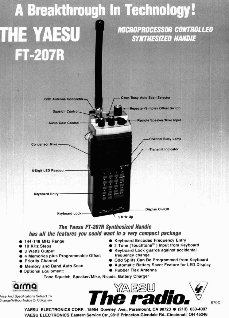
Audio C
. . Condensor
501git L
Keyboard
can Selector
iplex Offs et Switch Squelch Control
Channel Busy Lamp
Transmit Indicator
The Yaesu iT-207R Synthesized Handie has all the features you could want in a very compact package
144-148 MHz Range Keyboard Encoded Frequency Entry 10 KHz Steps 2 Tone ouchto tone^ ) Input from Keyboard 3 Watts Output Keyboard Lock guards against accidental 4 Memories plus Programmable Offset frequency change Priority Channel Odd Splits Can Be Programmed from Keyboard Memory and Band Auto Scan Automatic Battery Saver Feature for LED Display
Optional Equipment: Rubber Flex Antenna
Tone Squelch, SpeakerlMike, Nicads, Battery Charger
'rice And Speclflcat~ons Subject To :hange W~thout Notlce Or Obl~gat~on
VAEBU @7 yAIW
The radio, 679X
YAESU ELECTRONICS COUP., 15954 Downey Ave., Paramount, CA 90723 (213) 633-4007 YAESU ELECTRONICS Eastern Service Ctr.,9812 Princeton-Glendale Rd.,Cincinnati. OH 45246

out of 25 kW FM transmitter design.
I
New cavity amplifier and tetrode combo.
The new EIMAC CV-2200 power am lifier B cavity assembly an com-
anion 8990 tetrode is ready For use in next generation FM transmitters in the 88-108 MHz band.
EIMAC engineered interface provides capabili
commanding position in continuing high power
between tube and cavity vacuum tube technology.
design and the result is an amplifier of classic simplicity that combines a useful power output of 25 kW with a stage gain of approximately 20 dB. These numbers make a one tube, high power FM transmitter a reality today.
Cost effective modern design. For full information on the CV-2200, EIMAC's cost-effectiveness the 8990 (25 kW) and the 8989 (15
and modern design are yours in the kW) write EIMAC, Division of Varian. new cavity and tube combo. 301 Industrial Way, San Carlos, California reduced transmitter down-time an 94070. Telephone (415) 592-1221. Or con- higher revenues with this new amplifier tact any of the more than 30 Varian Elec, concept. Make sure your new transmit- tron Device Group sales offices throughoul ter is EIMAC equipped. varian the world.