Ham Radio Magazine 1981
100
-
Upload
khangminh22 -
Category
Documents
-
view
1 -
download
0
Transcript of Ham Radio Magazine 1981

! ./jk::? q pv . - -' P a -
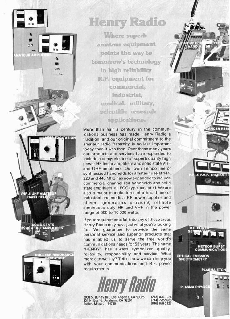
More than half a century in the commun- ications business has made Henry Radio a tradition, and our original commitment to the amate I fraternity is no less important today vas then. Over these many years our pl and services have expanded to inrtnnle a complete line of superb quality high
HF linear amplifiers and solid state VHF IHF amplifiers. Our own Tempo line of
sy,~t~lesized handhelds for amateur use at 144, 220 and 440 M ow expa commercial cl ed hand1 state amplifiers, all rbC type ac;r;ep~eu. vvt: are
also a major manufacturer of a broad line of industrial and medical RF power supplies and plasma generators providing reliable contir ~ t y HF and VHF in the power range o 10,000 watts.
If your requ~rements fall into any of theseareas Henry Radio may have just what you're l o ~ k i n g for. We guarantee to provide the same personal service and superior products that
us to serve the free world's Ins needs for 53 years. The name s always symbolized quality,
reliability, responsibility and service. What more can we say? Tell us how we can help you with your communications aqd R.F. power requirements.
!ur radio than it v roducts
IIIbIUU
power and L r . .-bL..
Hz has n iannelizl - -,, , - - A
nded to i helds an ----.-A
nclude d solid la#- -"-
mabled lunicatio RY" ha!
has E comrr "HEN'
2050 S. Bundy Dr.. LOS ~n eles. CA 90025 931 N. Euclid. Anaheim. CW 92801 Butler. miss our^ 64730

A fresh idea! Our new crop of tone equipment is the freshest thing growing in the encoder/decoder field today. All tones are instantly programmable by setting a dip switch; no counter is required. Frequency accuracy is astonishing + . I Hz over all temperature extremes. Multiple tone frequency operation is a snap since the dip switch may be remoted. Our TS-32 encoderldecoder may be programmed for any of the 32 CTCSS tones. The SS-32 encode only model may be programmed for all 32 CTCSS tones plus 19 burst tones, 8 touch-tones, and 5 test tones. And, of course, there's no need to mention our one day delivery and one year warranty.
coMMu~tcAnoIs sPEctALtm 426 West Tafc Avcnuc, Orange, California 92667 (800) 84-0547 'California: (714) 998-3021
=I"] I SS-32 $29.95, TS-32 $59.95

MFJ Su~er is-
" -.-.
5 MODES: CW, Baudot, ASCII, memory keyer, . Morse code practice. TWO MODELS: MFJ-496, $339.95. 2 5 6 character buffer, 2 5 6 character mes- sage memory, automatic messages, serial numbering, repeat/delay. MFJ-494, $279.95. 50 character buffer, 3 0 character memory, automatic messages.
MFJ brings you a pair of 5 Mode Super Key weight because they are more human oriented boards that gives you more features per dollar than keystroke sequences and they remember than any other keyboard available. You can send vour settings when power is off. CW. Baudot. ASCII. Use it as a memory keyer Weight control makes your signal distinctive and for MORSE code practice. to penetrate ORM.
You get text buffer, programmable and auto- matic message memories, error deletion, buffer preload, buffer hold, plus much more.
MOM 1: CW The 256 character (50 for 494) fext buffer
makes sending perfect CW effortless even i f you "hunt and peck."
You can preload a message into the buffer and transmit when ready. For break-in, you can stop the buffer. send comments on key paddles and then resume sending the buffer content.
Delete errors by backspacing. A meter gives buffer remaining or speed. Two
characters before buffer full the meter lights up red and the sidetone changes pitch.
Four programmable message memorles (2 for 494) give a total of 256 characters (30 for 4941. Each message starts after one ends for no wasted memory. Delete errors bv backsoacina.
To use the automatic messages, type your call into message A. Then by presslng the CO button you send CO CO OE (message A).
The other automatic messages work the same wav: CO TEST OE. DE. ORZ.
MODE 2 a 3 (Rnr): BAUDOT a ASW 5 level Baudot IS transmitted at 60 WPM.
Both RTTY and CW I0 are prov~ded. Carnage return, line feed, and "LTRS" are sent
automatically on the first space after 63 charac- ters on a line. This gives unbroken words at the receiving end and frees you from sending the carriage return. After 70 characters the function is initiated without a space.
All up and down shift is done automatically. A downshift occurs on every space to quickly clear garbled reception.
The buffer, programmable and automatic mes- sages, backspace delete and PTT control (keys your rig) are included.
The ASCll mode includes all the features of Baudot. Transmission speed is 110 baud. Both upper and lower case are generated.
MOOE 4: MEMORY KEYER Plug in a paddle to use it as a deluxe full
feature memory keyer w ~ t h automatic and pro. grammable memories, iambic operation, dot-dash memories, and all the features of the CW mode.
Select alphabetic or alphanumeric plus punc- tuation. You can even pause and then resume.
MORE FEATURES Automrllc Incnmenling serial number from 0
to 999 can be Inserted into buffer or message memory for contests.
Repeat tunctlon allows repetition of any mes- sage memory w ~ t h 1 to 99 seconds delay. Lets you call CO and repeat until answered.
Two key bckout operation prevents lost c h a m ters dunng typlng speed bursts.
Clock option (496 only) send time in CW. Bau- dot, ASCII. 24 hour format.
Set CW sending speed before or while sending. Tune switch with LEO keys transmitter for tun-
ing. Tune key provides continuous dots to save finals. Built-in sidetone and speaker.
P l l (push-to-talk) output keys transmitter f a Baudot and ASCll modes.
Relbble solid state keying for CW: grid block, cathode, sol~d state transmitters (-300V, 10 ma Max. + 300V. 100 ma Max). TTL and open col- lector outputs for R l l Y and ASCII.
Fully shielded. RF proof. All aluminum cabinet. Black bottom, eggshell white top. 12"Ox7"Wxl %"H (front) x3l/z"H (back). Red LEO indicates on.
9-12 VDC or 110 VAC with optional adapter. MFJ-494 is llke MFJ-496 less sequencial num-
berlng, repeatldelay functions. Has 50 character buffer, 30 character message memory. Clock op- tion not available for MFJ.494.
Every single unit Is tested for performance and inspected for qualify. Solid American construction.
0PM)NS MFJ-53 AFSK PLUG-IN MOWLE. 170 and 850
Hz shift. Output plugs Into mlc or phone patch jack for FSK with SSB rigs and AFSK with FM or AM rigs. $39.95 ( + $3).
MFJ.54 LOOP KEYING PLUGII MODULE. 300V. 60 ma loop keying c~rcuit drives your RTTY print- er. Opto-isolated. ?lL input for your computer to drive your printer. $29.95 (+ $3).
MFJ-61 CLOCK MOWLE (MFJ.496 only). Press key to send time in CW. Baudot or ASCII. 24 hour format. $29.95 ( + $3).
110 VAC ADAPTER. $7.95 (+ 53). BENCHER IAMBIC PAWLE. $42.95 (+ $4).
A PERSONAL TEST Give the MFJ.496 or MFJ.494 Super Keyboard
a personal test right in your own ham shack. Order one from MFJ and try it - no obligation.
See how easy it is to operate and how much more enjoyable CW and RTTY can be. If not de- lighted, return it within 30 days for refund (less shipping). Oneyear unconditional
To order, call toll free 800-647.1800. Charge VISA. MC, or mail check or money order for $339.95 for MFJ-496. $279.95 for MFJ-494. $39.95 for MFJ.53 AFSK module. $29.95 for MFJ-54 Loop Keying module, $29.95 for MFJ-61 Clock module, $7.95 for the 11 0 VAC adapter and $42.95 for Bencher Paddle. Include $5.00 shipping and handllng per order or as indicated in parentheses if items are ordered separately.
Why not really enjoy CW and RTTY? Order your MFJ Suoer Kevboard at no oblioation todav.
orderlrepa~r status. Also call 601 323-5869 out- special keys f i r KN. SK. BT. AS, AA and AR. MODE 5: MORSE COOE PRACTICE side continental USA and in Mississippi. A lot of thought has gone into human engineer. There are two Morse code practice modes.
ing these MFJ Super Keyboards. Mode 1: random length groups of random charac Write FREE Over 80 products For example, you press only a one or two key ters. Mode 2: pseudo random 5 character groups
sequence to execute any command. in 8 separate repeatable lists (with answers). MFJ ENTERPRISES, All controls and keys are positioned logically Insert space between characters and groups to INCORPORATED
and labeled clearly tor instant recognition. t o n high speed characters at Slower Speed tor B,, 494, ~ i ~ ~ l ~ ~ i ~ ~ ~ State, MS 39762 Pots are used tor speed, volume, tone, and easy character recognition.
2 August 1981 Tell 'em you saw it in HAM RADIO!

magazine incorporating
~ l u m e 14, number 8
T. H. Tenney. Jr., WlNLB publisher and
editor-in-chief I
Alfred Wilson, WGNIF editor I
editorial staff Martln Hanft, WBlCHO
productton edltar
Joseph J Schroeder W9JUV Leonard H Anderson
assocaate editors
W E Scarborough Jr KAlDXO graphic product~on manager
Irene Holl~ngswarth edltorlal asststant I
W E Scarborough Jr KAlDXO cover
publishing staff J Crag Clark Jr NlACH
asstslant publisher and advertlslng manager I
Susan Shorrock circulallon manager
ham radio magame IS published monthly by I
Comr Greet
subscription rates u n
IWO year:
da and other counfr~ea lv fa Surface Mall1 one year. $21 50. two years. $40 00
three years, $57 W 1 All 5ubscrlpt10n orders payable I"
Untted States funds please
foreign subscription agents Foreign subscrtpt\on agents are
I d on p a 7 1 Mlcrof~lm caples
are ava~lable from Unlverslty M~craf~lms lnternatlonal
Ann Arbor Mlchlgan 48106 Order publ~cat~on number 3076
Cassette tapes of selected artlcles from hamradm are available to the
blmd and phys8calIv handicapped from Recorded Perlodlcals
919 Walnut Street 8th Floor Phlladelohfa Pennsvlvanta 19107
Comr Title re'
10 John L. Reinartz father of shortwave radio Leonard Spencer, WAGCBQ
19 an analysis of ALC circuits John P. Weber, Jr., K4JW
25 a new look at dip meters Hank Olson, WGGXN
30 ham radio techniques Bill Orr. WGSAI
33 how important is low SWR? Stan Gibilisco, WlGV14
38 ham radio questionnaire: synthesized 2-meter hand-helds
42 dual-voltage surge-protection circuit for high-voltage power supplies Edwin Hartz, K8VIR
50 t w o delta loops fed in phase Jerrold A. Swank, W8HXR
54 from Amateur to professional John Edwards. K12U
60 DXer's Diary Bob Locher. W9KNI
94 advertisers index 4 observation 46 DX forecaster opinion 77 flea market 9 presstop 88 ham calendar 43 questions a1 90 ham mart answers 74 ham notes 94 reader servil 6 letters 42 weekender
76 new products
and
August 1981 3

enration Opinion
Automat~c ~ o a d Control (ALC) was discussed briefly in last month's "Questions and Answers" column. Judging from some of the illegal SSB signals on the alr, it seems that ALC is still a mystery to some and should be explored a little more thoroughly. Our guest editorial is by the author of just such an article, wh~ch appears In this Issue. I'd like to introduce John Weber. K4JW.
Alf Wilson. WGNIF. Editor
To me, it's becoming more and more apparent that some of our phone bands are becoming impossi- ble to enjoy, especially on weekends, because of heavy QRM. Being a "professional loafer," I can enjoy most of my phone operation during the week, usually keeping schedules with old friends around the country.
We have to keep some of these schedules in the General portion of 20 meters because some of our group are restricted to this portion of the band (not to say that the rest of the band is much differ- ent!), and many times we are forced to use our linears to plow through the adjacent QRM; thus we too add to the overall QRM level. Although ours is a technical hobby, it gives old friends a chance to meet and talk - no earth-shattering technical or philosophical discussions, just friendly get-togeth- ers. But, when somebody "buckshots" from 4 to 7 kHz away, the enjoyment rapidly disappears.
Just think what a mess we would have if this were still a-m instead of SSB! While NBVM (which hasn't caught on) might help, and future spread-spectrum techniques will allow us to hop, skip, and jump all over the band with minimum QRM, I am afraid we must still deal with the situation as it is today.
One of our problems has been receiver design: old receivers cannot survive alongside present-day linears and high-gain directive antennas, with IMD being the problem usually impeding copy. Fortun- ately, manufacturers have made considerable improvements to contemporary receivers; with pass- band shifters, variable passband, and high-performance filters, it is possible to copy signals that would have been impossible to read on older receivers. I hope we all enhance the ability of our receiv- ers to reject or minimize adjacent QRM by using the rf attenuator and backing off on the rf gain when conditions warrant.
Even so, when an Amateur runs his rig "wide-open," fails to monitor his signal output, and shouts into the mike, it gets pretty rough to tweak him out. For some reason, otherwise clean signals get very broad when the operator is running phone patches, suggesting somebody is not paying atten- tion to modulation levels. Of course, these are operator-control problems. One problem it's possible to have and not be aware of is an incompatibility of ALC characteristics between the exciter and linear amplifier. This can occur because the exciter and linear were made by different manufacturers, or because they are of different generations: the 15-year-old linear and the 1981 transceiver. And, of course, maybe the ALC line isn't even connected - that's really an operator-control problem.
I have been using a term not well understood by some Amateurs - ALC. Somebody said it is not even mentioned any more in the ARRL Handbook. I think if you look under "Speech Processing" in the chapter on SSB you will find it; it did disappear from the index for some reason. ALC is a form of speech processing.
Now, if you would like to know more about ALC, I suggest you read the article entitled, "An Analy- sis of ALC Circuits" in this issue. With luck, it will help reduce splatter on the bands, and perhaps it will prod manufacturers into paying more attention to the design problem and into providing us with meaningful numbers so at least we know whether or not a "compatibility" problem exists.
John P. Weber, Jr., K4JW
4 August 1981

i M I m r d spwnVohm ore opCur)xlrnol~ ond w h w :o c?onqp Wrhrx,: norur or obL)ovon All ICOM mdb, 5qnlAmnh exceed LC< vqubmn llmlnnq 5m!h~5 r m n m
' --: FM Ease. 0 Automatic stop and automatic I c~sume scan after II Five memorie + 2 IrFO'S - store your favorite 1 c.ui r ~ r hop or predetermined adjusfahlr drlav.
o Pr~grammable offsets - for odd repeater splits. q 5 KHz or 1 KHz tuning.
SSB/CW Convenience. o Squelch on SSB - silently scan for signals. o 2 VFO'g with equalizing capability - mark your signal
frequency with the touch of a button. o RIT - receiver incremental tuning. o 1 KHz or 100 Hz tuning. 0 mi sidetone. 0 AGC - selectable slow or fast in SSB and CU'. 0 NR - Noise blanker - suppreses pulse type noises on
SSB/CW.
repeaters. 0 Priority channel - check you! most i rnpnrtant
f m u e n n automaticallv.
ICOM Performance. o 143.8 to 148.199.9 MHz coverage. o Remote tuning from optional HM 10 microphone. o Digital frequency displav - significant digits onlk. o Hi /low power swl tch . o LED inchcaton - RECV/SEND/PRIO/DUP o LED bar meter. o Provision for mention of memory with optional
NiCd hattery system. ~ 'Touch Tonemwith tIhIH OCarnpactsize-6 ll'16Wx
0 kljustablv a n rate. 1 :) KHz or 3 K H z FM $canning steps.
o Stop on husv or empty channels.

intruder watch Dear HR:
In regard to W5SAD's letter on Amateur band intruders (October, 19801, W5SAD and others may find, as I have, that the following message sent in CW on the frequency that Russian intruders are using will often get them to shift out of the band:
UJTA OEASTOTA OEASTX MEVDUNARODNOJ UMBITELXSKOJ POLOSY OEASTOT POVALUJSTA QSY TOTOEASVE
The italicized OE's, UI, and IM are run together to form the additional Cyril- lic alphabet characters.
This message when taken down in Cyrillic script reads, "This frequency is part of the International Amateur band - please QSY immediately."
Whether or not you sign the mes- sage with your callsign will depend on your local rules. Here in ZL, Amateurs are not permitted to communicate with non-Amateur stations. This legal problem has been overcome by the issue of a special call of ZL6IW. I use this callsign to ask intruders to shift and this works in many cases, al- though it is sometimes necessary to keep on asking for long periods be- fore they "get the message."
A fact that most Amateurs choose to ignore, whilst still bemoaning the presence of intruders, is that most of the intruders into our exclusive bands are there only because we allow them to be. Given the numbers and geo- graphic spread of Amateur stations around the world, it is within our power to deny an intruder the use of any of our frequencies. Do not move aside for intruders when they come onto your frequency; you are the le- gitimate user of the Amateur band, not them. Protest the intrusion and continue to protest it in any way you can. Number 115 of the I.T.U. Regu- lations reads: "Administrations . . .
shall not assign to a station any fre- quency in derogation of . . . the Table of Frequency Allocations given in this chapter . . . except on the express condition that harmful interference shall not be caused to services carried on by stations operating in accord- ance with the provisions . . . of these regulations." It follows that, unless an intrusion is protested, the intrud- ers' administration has the right to as- sume that its stations are not causing harmful interference.
In addition to any protest you may make, your intruder watch should be advised of the date, time, frequency, and nature of the intrusion, along with any relevant information you may have, such as I.D., bearing, and so forth. It is my opinion that Ama- teurs generally have allowed the pres- ent chaotic situation regarding intrud- ers to develop by "leaving it to the other guy" to do something about it while they chased off "up the band" looking for a clear frequency. Unless and until Amateurs as a whole are prepared to act, either through their intruder watch or personally, the situ- ation will not improve.
R.E. Knowles, ZLGIW/ZLlBAD N.Z.A.R.T.
Intruder Watch Coordinator Papakura, New Zealand
instant balun Dear HR:
Here is some pleasant news, an ad- dition to the fourth in the series of fine articles by W6GGV on transmis- sion-line circuit design (March, 1981, ham radio). Last year I went through Wheeler's 1978 MTT paper (reference 1 in W6GGV's article) of constructing a 4:1 balun for the K2RIW 432 anten- na. The results were pleasant indeed.
We haveallseen Paul Shuch, NGTX, exploit the fact that a 0.1-inch strip- line on the standard G-10 glass epoxy board with groundplane has a charac- teristic impedance of 50 ohms. What Wheeler's equations show is that a 0.1-inch stripline centered between two parallel plates, constructed of our G-10 boards, is also 50 ohms! (See sketch.) You'll need four one- sided boards. Etch a 0.1-inch-stripline on one using the standard tape. Etch a second board free of copper, then
-
A sandwich of four G-10 glass epoxy boards make an instant 50-ohm balun.
epoxy all four boards together. In- stant balun.
C.R. MacCluer, W8MQW East Lansing, Michigan
ten-second call swaps Dear HR:
As a newcomer to DX, I find myself dismayed when, after exchanging callsigns with a DX station, the other operator rushes off to make another contact. While I realize that he is try- ing to give other operators in the win- dow a chance to make contact, I feel that these ten-second QSOs should be limited to Field Day and similar contests. It is my opinion that, in order to qualify for a DX award, the operator should acquire some mini- mum information regarding power, antenna, or even atmospheric condi- tions. This would add possibly another ten seconds to each QSO, which I don't think would be exces- sive or prohibitive.
Part 95 states that one of the fun- damental purposes for the Amateur Radio Service is to advance radio technology. A call-swap QSO does not help to accurately evaluate a new antenna or an experimental matching network. Armed with the information I suggest to be exchanged, some rea- sonable judgments can be made and conclusions drawn concerning a sta- tions performance.
I am aware that the system I pro- pose is not perfect, and some modifi- cations would have to be made but I can see nothing constructive or crea- tive coming from the current DX practices, and I think that it is time for a change.
Bill Marinara, WBlFJE Hamden, Connecticut
6 August 1981

FOR LESS IOST
MorseMaticTM Keyer Trainer Morse Trainer Contest Keyw Morse Keyer - AEA ClCl
500 Soft Yes Yes
Yes Yes m No -
Yes
Yes, Yes Yes w%e
Characten lRlcs
Yes C129.95 . -
,ur keyers (except the MT-1) will operate with any popular t lever or Iambic squeeze paddle and will key any type of m amateur transmitter with no external circuitry required. AEA s are as easy to operate as a four function calculator. The ~al AEA computers are all pregrogrammed for the featl
- -
9 above. Each AEA I fullv RF protected and rece ~plete elevated temc I test before it is ship the factow.
OPnON! MT-lP (P m-1) with
batten1 ~ne ME1 20Uo cnaracrer plug-ln memory
expansion for M AG1600 Ma. 12 C
MM-1 with ME-1
All c single
5 tmde keyer
M-1 Iolt wall ac I 1-1. ..-I1 -.
japtor for
.I--*-- .-.. product i! ~rature bl umih and
AC-2 350 Ma. 12 Lon wall aoevrur rur all AEA keyer and trainer products ASK a friend how he likes his AEA keyer comparec except MM-1 w/ ME-1 else he has wer tried, then JUDGE FOR YOURS1
AEA keyer and trainer family at your favorite dealer. DC-1 Cigarette lighter cord for all AEI
and trainers except MT-1 P 5 Advanced Electronic Applications, Inc., PO. Box z IW,
nctory cor Lynmmod, WA 98036. Call 206/775-73 1 to KT-1
PRICES AND SPEClFlcAtr~mi YUWKI 10 CHAhut m l n w T NOTICE OR OBLIGATION.
1 to anytl ELF. See
. - A n n
ling the
More Details? CHECK-OFF Page 94 August 1901 7

INTRODUCING W T E C ' S , _ , SANTEC*NOLOGY breaks into pad is a SANTEC Standard at no I the 440 band with style! The new I extra cost and the ST-7/TS OD-
= I
ST-7/T synthesizes the entire band tional synthesized subtone en- in 5 kHz steps, works both up and coder is controlled by the radio's down repeater splits and does it front panel switch. all right from your hand, with ver- satile power options of 3 watts, 1 All the regular SANTEC acces- watt or even 50 milliwatts (all
the ST-7/T as well, meaning that vou can eniov both bands fullv
1 sories used with your HFl2OO fit
nominal), to reach out to where vou want The hiah Dower mode J - - - - of 3 watts radiatGs on 440 like 5 h i t h a sm$l& cash investment. watts on 2 meters . . . and that's a I Grab the new W T E C ST-7/T and ~ - ~ - ~
handfull! I join the fun on 440 MHz. See your SANTEC Dealer for delivery
Tones? This one has them . . . tones I details. and subtonesf The 16 button tone
--
8IsR wsGE- STILL THE LEADER
- -
SANTEC'S popular HT-1200 is the incom- I parable 2 meter leader. This little rig is hand-
ing over quality, power and features that you'd expect from something nearer the 5 i 7 ~ of a bread box. SANTEC packs a 2 m~ ham shack into the palm of your hand!
You can carry scan, search, 10 memories dl IU
fully synthesized key pad control around with you and still get out with a big 3.5 watts (nominal). Compare them apples to anything you want and settle for nothing less.
eter
ZANTEC radios exceed K C rwulations limiting spuriot
I I 1-
U U I
Both the SANTEC ST-7il and the SANTEC HT-1200 I - I
are certtfied under FCC Pan I 5 I
- - I
I =s - -
ci 1981, Encamm, Inc. I
2000 Avenue G. Su~te 800, Plano, Texas 75074 I
- - - I
Phone (214) 423-0024 INTL T U 203920 ENCOM U I * - sur ZIP - I LII-~ y o u ~ u ~ ~ o l m ~ m o f n m ~ # ~ ~ . r---d --- t f- - I I-* -
ALL 1 . 8 - 1 . 9 MHz POWER LIMITS WERE LIFTED on June 10 , when t h e Commission a l s o reduced r e s t r i c t i o n s on t h e top h a l f of t h e 160-meter band. The remaining r e s t r i c t i o n s , l i s t e d h e r e by s t a t e , a r e :
S t a t e s ME. MA. N m
1900-1925 & 1975-2000 MHz 1925-1975 MHz l00W davl25W n i e h t no o ~ e r a t i o n . ---,
C T , DE, MD: NJ, NY, PA, VT 200W d a i f 5 6 ~ n i g h t no ope ra t ion KY, N C , OH, SC, TN, VA, WV 500W day/100W n i g h t no ope ra t ion FL, GA, IL , IN, M I , W I 500W day/100W n i g h t l00W day/25W n i g h t AL, AR, IA, MN, MS, MO l000W day1200W n i g h t 200W dayI50W n i g h t A l l remaining s t a t e s l000W day/200W n i g h t , e n t i r e 1900-2000 kHz
The FCC Also Warned, i n i t s announcement o f t h e r e l a x a t i o n , t h a t new l i m i t s could be imposed a t t h e end o f 1982 a t which t ime t h e WARC agreements go i n t o e f f e c t . However, 1 .8 -1 .9 should n o t be a f f e c t e d . - - - - - - .
ARRL Deserves A Big Vote of thanks from a l l Amateurs f o r i t s l e a d e r s h i p of t h e e f f o r t t o r e s t o r e 160 meter p r i v i l e g e s .
PROHIBITIONS AGAINST 420-430 MHZ USE by U.S. Amateurs nea r t h e Canadian bo rde r , a channe i n 220-225 MHz s t a t u s . and a new 902-928 MHz band a r e a l l inc luded i n t h e FCC's j u s tyou t General Docket 80-739. In t h i s "Second Notice o f Inqu i ry i n the Matter of Implementation of t h e F i n a l Acts of t h e World Adminis t ra t ive Radio Conference ," t h e Com- miss ion reviews t h e spectrum from 28 through 1215 MHz wi th no changes proposed f o r 1 0 , 6 , o r 2 me te r s .
However, 220-225 I s To Go from i t s p re sen t Radiolocation-Primary, Amateur Radio-Secon- dary s t a t u s t o one w i t h Amateur, F ixed, and Mobile a l l sha r ing primary s t a t u s . I n ac- cordance wi th t h e WARC Region 2 a l l o c a t i o n , t h i s would l eave t h e door open f o r l a t e r FCC a l l o c a t i o n of p a r t of t h e band t o one of t h e o t h e r s e r v i c e s .
0 e r a t i o n Between 420 And 430 MHz would be forbidden t o Amateurs l o c a t e d i n a s t r i p of t g e no r the rn U.S. s t r e t c h i n g from t h e A t l a n t i c t o t h e P a c i f i c , t o prevent i n t e r f e r e n c e wi th Canadian commercial u se r s of t h a t segment formal ly ass igned worldwide f o r t h e Fixed and Mobile s e r v i c e s a t WARC. Among t h e Amateurs a f f e c t e d a r e those i n o r nea r such major c i t i e s a s S e a t t l e , D e t r o i t , Toledo, Cleveland, Buf fa lo , and Bangor. A p r e c i s e d e s c r i p - t i o n of t h e a r e a a f f e c t e d appears i n P a r t 1 .955 of t h e Commission's r u l e s .
A New Band A t 902-928 MHz i s t h e good news, wi th Amateur Radio a secondary a l l o c a t i o n t o Radiolocat ion . The only p a r t of t h e country t h a t won' t have use of t h i s new band i s i n Colorado, i n an a r e a t h a t un fo r tuna te ly inc ludes Denver.
Reply Comments on t h i s Notice of Inqui ry a r e due a t t h e FCC by J u l y 30.
ROBERT W. STANKUS (KESWICK SALES) WAS INDICTED on 22 counts of u s ing t h e U.S. ma i l s t o defraud by a Federa l grand jury i n R o a n o k e . r r g i n i a , June 10. He'd a d v e r t i s e d new Renwood T S - 5 2 0 ~ ~ s i n the- am ~ ; a d e r f o r $369.95 l a s t f a l l , and though h e ' d even de l ive red a couple (purchased from l e g i t i m a t e d e a l e r s a t nea r l i s t p r i c e s ) , more than 50 Amateurs had even tua l ly f i l e d complaints w i th t h e P o s t a l Se rv ice over h i s f a i l u r e t o d e l i v e r r i g s a s promised.
Eleven Of The Complaining Amateurs were s e l e c t e d f o r t h e ind ic tmen t s , wi th two i n d i c t - ments r e tu rned f o r each complainant. S tankus , NlAAR, was t o have been a r r a igned J u l y 1 and w i l l probably go t o t r i a l t h i s f a l l . I f conv ic t ed , he f a c e s a maximum f i n e of $1000 and k ive years i n p r i son on each of t h e 22 coun t s .
PROPOSED PLAIN-LANGUAGE AMATEUR RULES, PR Docket 80-729, has r ece ived a l a s t -minu te two-month extens ion on t h e due d a t e f o r Comments. Acting on a r eques t from t h e ARRL, t h e Commissioners agreed June 15 on an August 2 2 due d a t e f o r Comments, wi th Reply Com- ments due on o r be fo re October 21.
OSCAR 7 IS PROBABLY DEAD FOR GOOD, fo l lowing a sudden f a i l u r e June 12 . Thermal s t r e s s induced by t h e s o l a r e c l i p s e i t began exper iencinn on each o r b i t a f t e r Nay 22 may have t r i g g e r e d t h e f a i l u r e . he currenf theory i s t h a t t h e b a t t e r y pack (which had been open s i n c e a c e l l f a i l e d i n 1978) has sho r t ed and pu l l ed t h e power bus down. KA9Q, whose c a l - c u l a t i o n s p r e d i c t e d t h e s o l a r e c l i p s e , e s t ima tes t h e s p a c e c r a f t w i l l r e t u r n t o f u l l sun- l i g h t about J u l y 12 . There i s a p o s s i b i l i t y , considered remote, t h a t i t could recover then . Users a r e asked t o monitor OSCAR 7 ' s beacon f r e q u e n c i e s , 29.502 and 145.972, and t o r e p o r t any s i g n s of l i f e t o AMSAT.
OSCAR 7 H ~ S ~ e e n An Exemplary S a t e l l i t e . Launched November 15 , 1974, wi th a design l i f e of t h r e e y e a r s , i t has provided Amateurs throughout t h e world wi th l i t e r a l l y m i l - l i o n s of c o n t a c t s dur ing more than s i x and a h a l f yea r s of ope ra t ion . OSCAR 6 , wi th a one-year des ign l i f e , l a s t e d over fou r and a h a l f y e a r s .
The Ariane Launch June 19 from French Guiana was a complete s u c c e s s , r e i n f o r c i n g ex- p e c t a t i o n s t h a t t h e Phase 3 B s p a c e c r a f t w i l l go up next year a s scheduled . Two s a t e l - l i t e s , each weighing about 1500 pounds, were launched i n t o o r b i t by t h e French r o c k e t . One, t h e experimental Indian "Apple" s a t e l l i t e , i s r epor t ed t o be having problems ex- tending i t s s o l a r pane l s . W6VIO a t t h e J e t Propuls ion Laboratory jo ined WA3NAN and WA2LQQ i n r e p o r t i n g t h e 12032 launch t o l i s t e n i n g Amateurs worldwide.
August 1981 9

John 1. Re~naatz
By Leonard Spencer, WA6CBQ
As a Novice-class Amateur attending one of my first radio-club meetings, I was recruited to help the guest speaker with his demonstration of a "tuna-fish- can rf bridge." It was the Monterey Bay Radio Club in Salinas, California, during September of 1959, and that speaker was John L. Reinartz. Little did I realize at the time the scope of his electronic accomplish- ments.
We met again when I served as president of the same club and invited him to furnish a program. He was accompanied by Mrs. Reinartz, who was a true helpmate and at that time also an Amateur with the call KGMJH. She was an observer and participant in much of the pioneer experimentation which brought about shortwave communications. It is with her co- operation that facts pertaining to these events have been obtained for this article.
Between the years 1921 and 1925, John L. Rein- artz led the Amateur Radio experimenters of that time in development of shortwave communications below 200 meters wavelength. Recognized engineers and scientists of that time considered these wave- lengths useless.
Reinartz engineered the receiving and transmitting circuits, developed tune-up procedures, and did the research necessary to explain how the shortwaves performed as they did. For this Amateur Radio accomplishment, he truly earned recognition as the father of shortwave radio. He upset many of the accepted theories of fundamental radio communica- tions and probably for this reason did not get the rec- ognition he deserved at that time.
greatest contribution In 1964, Herbert Hoover, Jr., WGZH, then presi-
dent of the American Radio Relay League, awarded Mr. Reinartz the first Hiram Percy Maxim Gold Medal for the greatest contribution to Amateur Radio in the past 50 years. The ceremony took place on the 50th anniversary of QST, at the Pacific Division Conven- tion in Sacramento, California. Actual presentation was made later at the Fort Ord Hospital, as Reinartz was unable to attend the convention.
Mr. Hoover summed up his address with this trib- ute to Reinartz, then retired and living in Aptos, Cali- fornia, and using the call KGBJ:
"In the immediate scramble for shortwaves that followed his basic concepts, Reinartz' pioneering work became strangely overlooked. Perhaps the fact that he was an obscure electrician in a New England textile mill, who had overturned the accepted theories of the scientific authorities of the day, had something to do with it.
"But John Reinartz should not be forgotten. Quiet, modest, and unassuming as he may be, he - perhaps more than any other individual - is the father of shortwave radio. When we realize that to- day, 40 (now 57) years later, the great bulk of the world's long distance radio communications - broadcast, point-to-point, marine, aviation and all others - still takes place on these same shortwaves that were first demonstrated by Reinartz, we can justly be proud of his Amateur accomplishment."
When Mr. Hoover's activities at that time are con- sidered, these statements give more perspective to
10 August 1981

Reinam was radio operator on board Bowdoin for MacMillan's 1925 Arctic Expedition using WNP (Wireless North Pole). Many firsts occurred that summer when shortwave radio provided daily communications from the far north in the daytime. Commander MacMillan wrote in a National Geographic story, "Much of the success of the Ex- pedition's radio work depended upon the eager cooperation of Reinam' associates of the American Radio Relay League in transmitting messages. More than 30,CMO words of news dispatches alone were sent out from Bowdoin ad- dressed to the National Geographic Society and released by it, day and night, to the press associations." All without financial remuneration - remember the regulations!
August 1981 11

events in early-day radio. With the call 3ZH he had a kilowatt tube-type transmitter in Washington, D.C., and during the 1922 transatlantic tests his station was heard in Switzerland and elsewhere in Europe. He was trying to communicate across the Atlantic at much the same time as Reinartz. It was the shorter wavelength 100-meter equipment used by Reinartz that made the accomplishment possible, using a 100- watt transmitter with 400 watts input. As Reinartz said in a magazine article at the time, "I didn't give a darn whether I burnt up the tubes or not."
honored as a professional engineer
More professional recognition was given Mr. Rein- artz in January, 1958, when he was named a Fellow of the Institute of Radio Engineers for his early work on radio-wave propagation. He had 28 patents in the electronics field, but his early circuits were not con- trolled, as he wished everyone to make use of them, even to the extent of letting commercial enterprises manufacture them.
Reinartz received a bronze-plaque life membership in the Institute of Electrical and Electronics Engi- neers, Inc. A medal was awarded him by the Man- chester, Connecticut, Chamber of Commerce on May 14, 1925. Manchester was his home town. The 1960 session of the California Legislature passed a resolution, dated March 8, commending Mr. Reinartz for his contributions to microwave radar. A beautiful plaque from the Central California Radio Council was presented to Reinartz, KGBJ, on April 6, 1960, in rec- ognition of his many years of service to Amateur Radio. Among his other honors he was a member of the Explorers Club of New York, the American Polar Society, an original member of the American Radio Relay League, and an associate member of the Naval Institute.
spark station in 1908 John's youthful interest in radio started in 1908
when he bought an issue of The Electrical Experi- menter at a magazine counter near school. He bought the secondary of a one-inch spark coil he saw advertised there by saving the 10 cents a day he earned working for a blacksmith. The transformer was completed by using iron wire for the core and bell wire for the primary winding. He made the elec- trolytic interrupter for the spark coil, and fashioned a coherer from a quarter-inch glass tube filled with fil- ings from nickel coins. Using his initials, JL, as his call (as was done in the days before controls), he connected his spark transmitter to a 600-foot anten-
na installed between some trees and went on the air. By 1921, Reinartz, using the call 1QP and working
as superintendent of the local power company, pub- lished a magazine, How to Build Receivers and Transmitters at Low Cost. It was distributed free, and it was at this time that his famous tuner was de- veloped. These circuits were reproduced and infor- mation on construction reprinted in the radio maga- zines of nearly every country in the world. Because of this wide publicity, thousands of his tuners were built.
QSTin October, 1922, carried a symposium of fur- ther improvements on the Reinartz tuner. An editor's note states: "It is impossible for us to keep up with this man Reinartz. Since preparing the foregoing for publication he has dropped around with another 'trigger circuit' that knocks its predecessors cold."
first across Atlantic on 100 meters
Reinartz participated in the planning of, and de- signed the circuits used for transmitting, the first transatlantic two-way radio communications. Mon- sieur Leon Deloy, f8AB, of Nice, France, had been in the United States to attend the 1923 ARRL National Convention in Chicago. At that time, Deloy visited the Reinartz home in South Manchester, Connecti- cut, where he was given the circuits and construc- tion details of the famous transmitters at a session that lasted until 3 AM. Together, they arranged for the transatlantic tests op 100 meters. Reinartz had developed a single tuner for receiving which was var- iable from 200 meters down to 28 meters, along with the technique of setting the transmitting and receiv- ing equipment to precisely the desired frequencies so each station was compatible with the others.
This great event in shortwave radio took place the night before Thanksgiving Eve at exactly 10:30 EST, the time at which the restrictions on Amateurs, to prevent interference with broadcast listening, were lifted.
F.H. Schnell, alMO, traffic manager for the ARRL in Hartford, Connecticut, had secured special per- mission from the Supervisor of Radio in Boston to use the 100-meter wavelength for these experiments.
Deloy, f8AB, on the night of November 27, 1923, called America and sent two messages prior to the 10:30 schedule. Both of these messages were copied by Reinartz at his home station in South Manchester.
At 10:30 long calls to France by alXAM, the spe- cial experimental call assigned to John Reinartz, and alMO, the call of the station owned jointly by Schnell and Kenneth B. Warner, secretary of the
12 August 1981

ARRL, were heard "QSA vy one foot from phones," across the Atlantic. Steady and reliable communica- tions were carried on for two hours and five minutes that night, which was until 6:35 A M in France.
Message number one from America was addressed to General Ferrie, Director of Telegraphs for the French government, which was acknowledged at 11 :06, and read as follows:
"America greets you for the first time by Amateur Radio across the ocean on 100 meters." Signed ARRL.
long-wave communications
Another sidelight to the problems of this era was that very little commercial equipment was available for use below 200 meters. Reinartz' circuits accom- plished this, making the short waves practical for experimentation.
Early transmitting circuits were not shielded. They were of open breadboard construction, so rf poten- tials were prevalent pretty much everywhere. Rein- artz seems to have been the first to establish a nodal
This operating position shows John L. Remam rn 1921 with h a famous tuner of that era in use, with three stages of audro amplification in the top cabinet. The spark transmitter, located m the cellar, was remote/y controlled from this upstajrs room. The Kewple doll on top of the re- ceiver was sent to hrm by a Canadian Amateur as a mascot - he had the famous 1QP call ar that time and signed some of his message traffic "Kewpie. "
Two nights later, Reinartz' station, IXAM, suc- ceeded in connecting with Deloy's f8AB in France twice, and at 10:40 asked Deloy to change his wave- length as he was being interfered with by station KDKA at about 103 meters. Deloy was not heard after that.
A complication arose when international DX be- came possible, that of identifying call letters for the various countries. Assignment of calls specified a district by number and a suffix of alphabetical char- acters, but no prefix to the call. The early DX workers added prefix "u" for United States, "a" for America, or "y" for Yankee, to establish country of origin as the United States of America. Great Britain used "g" and France "f" to do the same.
point, or point of zero rf potential, at the filament tap on the oscillating circuit. He did this by connecting an rf choke from filament to ground and tuning the circuit until no current flowed through the choke. This later became part of the standard technique.
A really practical shortwave transmitting circuit de- signed by Reinartz was published in an Amateur Radio magazine, The Modulator, in May of 1923. This was the official organ of the Executive Radio Council, Second District, published in New York City.
The story was tied in with another article concern- ing the failure of two-way transatlantic work be- tween the American and English Amateurs. Because of the great amount of interference, anything in the
- -
August 1981 13

Here is a panel view of 1922 version of the Reinam shortwave tuner, built by W. W. "Woody" Wilson, WAGKVW, from an early . magazine article. He used authentic parts of that period from his extensive antique wireless collection. Switch points picked up pro- gressive taps on the coils - an early version of band switching, you might say.
way of continuous reception had been prevented when stations were operating between 180 and 350 meters. Most of the transmitting and receiving equip- ment was designed to function somewhere in that part of the spectrum.
shortwave experimentation Following are quoted paragraphs from The Modu-
lator: ". . . real shortwave transmission did not exist until
the recent ARRL tests between stations BALN, 1 HX and IAW, in cooperation with 1QP were consum- mated.
"The results of these tests were of great interest to the Amateur world. They proved that transmission on 103 meters was a practical proposition. It was car- ried on for several weeks before the officials would commit themselves.
"And now, with the announcement of the Hoover Conference recommendations, we find that we may have to transmit on those shorter waves! The study, therefore, of a successful transmitter will be of imme- diate interest.
"One of the best shortwave transmitters used in the preliminary tests was that of station IQP, John L. Reinartz, of Tuner fame, located in South Manches- ter, Connecticut. Reinartz developed for these tests a type of transmitting circuit which is not less remark- able than his receiving circuit. With it, he reached the low limit of 100 meters, with mighty good radiation.
"Reinartz tells us that the success of his transmit- ter depends on the adjusting of the counterpoise and
plate current is lowest. To further regulate the cir- cuit, the grid condenser is adjusted so that the plate current falls no further.
"Now that the Amateur has proved his efficiency on what were considered 'useless' waves, he will have the opportunity to show what he can do on the lower ranges and limits. Here is the field - some of the pioneer work has been done - so let's get at it. The field is large in its opportunities, and if the Ama- teur's skill is equal to it, he will contribute many things to the science and art of communication on the shorter waves."
Reinartz' station on 100 meters, IXAM, determined a new principle in antenna operation. For the first time, he used a counterpoise as the other half of a balanced antenna system instead of a capacity ground connection as had been common practice.
explains shortwave propagation During 1923 and 1924, Reinartz compiled statistics
on the stations he worked and those which reported hearing his experimental shortwave transmissions, some 5,000 in number. He hoped to determine why the shortwaves performed as they did. Experiments were carried on during an eclipse of sun to prove that sunshine made shortwave communications possible.
From his experiments, he came up with a "skip distance" theory, based on reflection or refraction from the ionized Kennelly-Heaviside layer, to explain the shortwave phenomena, and he predicted that communications would be possible across the nation in the daytime hours, which was an entirely new con- cept at that time.
Reinartz had schedules with stations NKF (call of Naval Research Laboratory at Bellevue, D.C.), 8XC, and 2EB on wavelengths below 40 meters in 1924. Tests were made at night, with three miles or so being the only completed QSOs.
antenna current so that there is equal amount of cur- rent flowing through both, -ro obtain this, both the Inside view of the Rdnam tuner with s p i d m b inductance,
which was an improvement over the original version in June, 1921 antenna and counterpoise are tuned separately with QST. The tube is a UV- 199. Gridleak resistor was in clip holder for a radiation meter, and the adjustment of the helix easy changing. Note hole in panel to check on tube filament olow. " . (coil) turns in both circuits. At this adjustment, the controlledbyvarying rheostat on front panel.
14 August 1981

Then daylight tests were made on December 21. At 3:25 PM CST, 9EK, Hoffman, called IXAM, Rein- artz. They had been hearing each other for some time and suspected they could work together easily. This they did on 21 meters until 4:30 PM when sig- nals suddenly dropped out. As usual with this band, darkness had changed the transmission pattern. The most important part of this QSO was that GAJF, Frank C. Jones, at Berkeley, California, copied both stations - 9EK in Madison, Wisconsin, and 1XAM in South Manchester, Connecticut!
daytime transcontinental signals
Two-way communications on 21 meters were con- ducted between Reinartz, IXAM, from South Man- chester, Connecticut, and Ed N. Willis, 6TS, Santa Monica, California, at noon on January 22, 1925. They maintained continuous communications for 25 minutes and had to stop so Reinartz could get back to work as electrician at the silk mills.
The April, 1925, issue of QST contained "The Re- flection of Short Waves," by John L. Reinartz, IXAM, in which the editor said: "We consider this article one of the most important contributions made to radio literature." This evaluation proved to be true.
The article explains with drawings and text how the shortwaves propagated, providing the theories for the Maximum Usable Frequency and Lowest Usable Frequency as we know them today. These theories contradicted the then-accepted action of re- flection by the Kennelly-Heaviside layer surrounding the earth. Reinartz' theory of "skip" is now scientific fact.
There was a controversy as to who was first to work across the Atlantic Ocean on 20 meters during daylight, but credit is given to Reinartz, uIXAM, and Secretan, g5LF, in England, for being the first to accomplish the feat.
On May 3, 1925, communication was made on 20 meters between British Amateur station g20D and Australian a2CM, following planned experiments, so the use of shortwaves for DX rapidly became popular once the Amateurs could make the equipment work on these wavelengths. (Notice that frequency is not mentioned in the early days of radio. It was always wavelength in meters - metric units from the start!)
In 1923, Amateur Don Mix, ITS, was assigned as radio operator with the MacMillan Expedition to the Arctic. His equipment was built to work in the 180 to 220 meter range, and this proved to be unreliable for consistent communications from the north because of the long period of daylight during the summer-
time. This was the eighth polar exploration of which MacMillan had been a part - and the first to use Amateur Radio to maintain contact with civilization.
Arctic expedition of 1925
John Reinartz' participation in the Navy-MacMillan Arctic Expedition of 1925 began when he received a letter from Hiram Percy Maxim, president of the ARRL, inviting him to cooperate with Commander Donald B. MacMillan, USNR, and E.F. McDonald, Jr., president of Zenith Radio, which was to supply the radio equipment. Reinartz helped to design and construct the shortwave station installed on Bow- doin, a schooner with an auxiliary oil-burning engine, commanded by MacMillan.
Captain McDonald, USNR, was in command of Peaty, a coal-burning steamship, on the expedition. Lieutenant Commander Richard E. Byrd, Jr., on ac- tive duty in U.S. Navy, was in command of the Naval Aviation Detachment with the expedition in his first attempt to fly over the North Pole.
This expedition was organized under auspices of the National Geographic Society and the U.S. Navy. Here is a quotation from the National Geographic magazine of that time:
"Airplanes will explore in days icy areas of the Arc- tic which would take months to traverse by dog sleds. Radio is telling the daily program of work which in years past would be shrouded in silence for months. For the first time in Arctic history, color photographers are recording, for members in early issues of their Geographic, the surprising tints of the far north, the native life, birds and many beautiful Arctic flowers.
"These new aids to travel and communication enable the expedition to engage upon a program per- haps of broader exploration and scientific study than any expedition heretofore has attempted.
"The flying of the U.S. Navy airplanes under the direction of Lieutenant Commander Richard E. Byrd, Jr., and his splendid personnel, not only is epoch- making, but marks an important experiment in avia- tion that will focus the world's attention."
First date of the personal radio log kept by Reinartz on the Arctic expedition is June 16, 1925, while the crew was preparing to depart from Wiscasset, Maine. Amateur calls worked on 40 meters are entered in the record for several days and the Nation- al Geographic message of the day was transmitted using Amateur Radio for relay. Some of the interest- ing entries follow:
"June 26 - Left Sydney (Nova Scotia) at 9:15 AM. During radio watches, worked NKF and IQP
August 1981 15

(his home station in Connecticut), 1MY (a personal friend), and several other Amateurs in 40-meter band.
"June 28 - At sea bound for Battle Harbor. Gave 1MY a message by voice at 7:20 PM in the 40-meter band.
"July 1 - At Battle Harbor. Met Stanley W. Brazil who operates the northernmost Marconi radio sta- tion on Labrador coast. Made him a transmitter and receiver operated entirely from dry batteries and ex- pected that he would be able to keep in touch with me on the trip north, which he did!
"July 2 - Don't forget to learn the code better please - I want to hear you on the air when we are up north." (This was in a letter from John to Mrs. Reinartz mailed from the last post office on the way north, Battle Harbor, Labrador.)
"July 5 - Left Battle Harbor at 12:30 AM aboard Peary for Hopedale (Labrador). Sailed on Peary in order to put their defunct radio equipment in com- mission. Was necessary to tear out all the radio equipment and rebuild more compactly.
"July 6 - Left Peary after fixing radio equipment and reboarded Bowdoin when she stopped on account of fog.
"July 23 - From WNP to 1MY 6 PM via f8QQ. Have Gertie (Mrs. Reinartz - Gertrude) keep 1XAM going on 20-meter band with bug 8 AM to 8 PM Sat- urday and Sunday. Sig. Kewpie." (This was for ex- periments in determining time when 20 meters would be open to the United States from the northern end of Greenland. Reinartz had an automatic code send- ing device at his home station, which he had used earlier in his experiments on shortwaves. The keyer was made by John from a clock mechanism and the spring had to be wound up every half hour. Code sig- nals were made by timing from a revolving disk at- tached to the clock.)
"August 2 - Etah at last. Had a great time today. Heard many 20-meter Amateur stations and worked SCXX, Cedar Rapids, lowa, on 16 meters. Gave him message number 218 to Mrs. QP."
Quote Am well and happy. Love via 20 meters from
Etah the first time in history of radio at 3:40 PM. Kewpie Unquote
This message was telegraphed to Mrs. John L. Reinartz that same day by Arthur Collins, and several other Amateur stations who received it, and was the first message ever to be sent on short wavelengths from the frozen north in the daytime.
Etah, Greenland, was the ship base from which the
planes explored the uncharted regions of the North Pole. WNP (Wireless North Pole) operated by Rein- artz, was aboard Bowdoin at Etah. (9CXX was the station of Arthur A. Collins, then a student in high school. He cut classes to get back to his rig to handle these communications. He was to become famous for the manufacture of quality electronic equipment, and Collins Radio is now part of Rock- well International conglomerate.)
"August 11 - The three planes off to Ellesmere Island at 10:47 AM. The NA-3 back at 2:15 PM, the NA-2 back at 2:30 PM, and the NA-1 back at 2:44 PM. They could not land due to fog. Was in radio communication with Washington, D.C., through Cedar Rapids, lowa, and gave notification the instant the planes returned. Newspapers had news within 15 minutes of their return.
"August 12 - It is evident that planes are not go- ing to be useful up here. The Los Angeles (dirigible) would be much better. A drop means certain death. Looks as if the flyers knew it too well.
"August 15 - Made world's record by using radio telephone to Cedar Rapids at 12:30 PM.
"August 17 - Not much doing. Planes having hard time finding landing place on Ellesmere Island. Again talked with Cedar Rapids at 2 PM. It was noon at Cedar Rapids.
"August 18 - Same old story. Planes not suited for job." (These single engine Loening biplanes were specifically equipped with dry-battery-operated receivers and transmitters capable of operating be- tween 37 and 42 meters wavelength, plus standard Navy aircraft equipment operating on 500 meters. 1
"August 20 - Bad weather. Packing up to go home.
"August 21 - Left Etah at 6:29 AM for home. "September 14-20 - At Godthaab (Greenland).
While there visited the Norse ruins, going to the ruins on September 15 at 7 AM and returning on the 16th. The ruins are about 15 miles from Godthaab, at the end of the fjord.
"October 10 - stayed at Monhegan due to storm until Monday morning when Bowdoin left for Wiscasset. The end of the journey."
The next year, after the expedition of which Rein- artz was a part, Lieutenant Commander Richard E. Byrd and his pilot, Floyd Bennett, flew over the North Pole in a commercial type Fokker three-motor plane, Josephine Ford. Bennett had been a Navy Pilot with the 1925 MacMillan Expedition. The flight left from Kings Bay, Spitsbergen, May 9, 1926, mak- ing a 15-hour, 1500-mile trip over the pole, returning to Spitsbergen.
Three days later, May 11, 1926, the Amundsen-
16 August 1981

Ellsworth-Nobile flight, leaving from the same place, using a dirigible 347 feet long, dropped Norwegian, American, and Italian flags over the North Pole and continued on to Teller, Alaska. Each expedition add- ed more knowledge about the Arctic region, making it easier for other explorers to follow them.
After the Arctic expedition, Reinartz did further experimentation for the Navy, and worked on meas- urement of voltages produced by growing plants at what is now the University of Connecticut. He was commissioned a lieutenant in the Naval Reserve in 1929 and conducted weekly classes via radio for Third Naval District personnel.
fying fm radio. Professional engineering status was earned in the
State of Connecticut, July, 1936, when he was issued Certificate of Registration number 947. active Navy duty
In 1938, Reinartz was called to active duty in the Navy as a personnel officer, assigned to assemble eli- gible, experienced radio personnel for training and research. By the time of Pearl Harbor, he had assem- bled a list of 720 reserve officers and 3500 enlisted re- serves who were quickly assigned to communica- tions duties.
His initial job done, Reinartz was assigned to other
At the 1955 ARRL Pacific Division Convention in Fresno, California, the tecnnical discussion topic was "Your Future One-kW SSB Final. " Here John L. Reinartz shows the finished transmitter to very interested Amateurs at the conclusion of the lecture. About his work he said, "I'm not selling anything, but basically these hams are the men who eventually move into places of prominence as operators of the big com- mercial stations, engineers in the telephone industry. ship operators, executives in the communications field, and military signal transmis- sion experts. They have the know-how for the important jobs. "
Reinartz' formal education ended at the eighth grade level. He took correspondence courses and at- tended evening school classes to keep learning. In 1930, he decided on a college education. He attend- ed Connecticut University for two years, majoring in radio and mathematics, but received a job offer from Radio Corporation of America that was too good to turn down, so went to work for RCA in 1933. Twenty- three Reinartz patents were assigned to RCA in this five-year period, some of them on methods of simpli-
Washington duties, including a tour as head of the Radio and Radar Division of the Naval Research Lab- oratories, at which time he supervised the work of 1200 physicists.
As a member of the Joint Chiefs of Staff commu- nications setup, he had a lot to do with the vital nerve system which meant so much to Allied victory. He was assigned to the office of the Chief of Naval Operations.
Reinartz was a member of the Defense Communi-
August 1981 17

This portrait was taken while Reinartz worked for EIMAC. Shortly after World War 11, many photos showed him in his Captain's uniform in advance publicity of his many tours thoughout the United States, giving lectures and demonstrations before profes- 1 0 h n 1. R 1 n R t z sional engineering, ~mareur Radio, and public services groups.
Here Mrs. Reinartz points to an entry in the personal log kept by John L. Reinartz wh~le he was radio operator of station WNP on board Bowdoin during 1925 Arctic Expedition to North Pole regions. Captain Reinartz is in photograph beside replica of 1922 version of his famous tuner. Scrapbook behind photo is of Arctic trip and larger book contains clippings and programs of events in which John participated while with the ElMAC firm.
cations Board at its formative meeting January 6, Check your OSL cards to see if you have worked 1941. For a time, he was on the West Coast in charge John L. Reinartz on the air. Calls he held and used of modification of all airborne radar for the Pacific were JL, lQP, 1XT (a special land station call issued areas. by Bureau of Navigation, U.S. Department of Com-
In 1946, Reinartz rejoined RCA, and in 1949 moved merce), 1XAM (special shortwave experimentation west to become part of the Eitel-McCullough, Inc., call), NDF, WNP, NlQP, W3RB, WBIBS, and K6BJ. organization at San Bruno, California, in a similar The Santa Cruz County Amateur Radio Club now capacity, as field engineer and manager of the Ama- uses the K6BJ call for its John L. Reinartz Memorial teur Radio Service Department, until retirement Jan- Station in the Santa Cruz, California, area, so listen uary 30, 1960. (The Eimac transmitting-tube manu- for it Field Day, and work it. facturing firm was founded in 1934 by two Amateurs, This quotation comes from an interview with John W.W. "Bill" Eitel, WGUF, and Jack A. McCullough, Reinartz published in the Augusta, Georgia, Chroni- W6CHE.I cle of Thursday, May 3, 1956: honored in retirement " 'It's a wonderful hobby - radio,' he says. 'I
His retirement prompted a John Reinartz Testi- can't recommend it too highly. A normal lad can monial Amateur Radio Banquet February 1, 1960, in build himself a receiver for as little as $10 - and a San Mateo, California. Seventeen speakers praised transmitter for only $25. If he uses the right frequen- John for his pioneer accomplishments in the field of cies he can cover a good part of the world with such electronics. Two hundred invited guests paid him a rig. And experience in radio can stand him in tribute by their attendance at the banquet, almost all mighty good stead in this Atomic Age.' " of them with Amateur Radio calls. ham radio
18 August 1981

an analysis
ALC circuits Automatic load control circuits
are investigated as a means for avoiding distortion
in sss transmitters
This article dispels the mystery of the ALC circuit used in Amateur SSB transmitters and addresses problems encountered when using linear amplifiers made by one manufacturer with exciters made by an- other manufacturer. Such problems include splatter, which may occur even though the ALC line is con- nected between the two pieces of equipment.
ALC defined ALC is an acronym for automatic load control
when used with SSB transmitters. The term goes back to the days when Bell Labs made a high-fre- quency SSB transmitter whose output was in four channels. The term loading in telephone work indi- cated the number of channels in a multichannel sys- tem that were in use at any given time. Their auto-
My thanks to Professor Charles Gould, W4LZ0, for rev~ewing this manuscript - John P Weber.
matic load control kept the peak envelope power from the SSB transmitter about the same, regardless of whether only one or all four channels were in use. Probably there would be less confusion as to the function of automatic load control if it had meant au- tomatic level control." Even automatic gain control might be appropriate, except for the fact that it would be confused with thesystem used in receivers.
So in terms of today's technology, what is ALC? What does it do? Why use it? These questions are ex- plored in this article, which includes a discussion of the principles of ALC and why, if used properly, it helps to eliminate interference on the Amateur bands by reducing spurious products in SSB transmitters.
some background information In a-m communications systems it was common to
use speech compressors and clippers, so that the power amplifier could operate near its maximum power-output capability without excessive distortion products. As used in single-sideband, ALC is part of a system that is intended to maintain the distortion products of a linear amplifier within acceptable limits.
ALC may be thought of as an rf compressor. You might ask, Why not use audio compression to hold
'To add to the confusion, automatic level control has been used in Broad- cast engineering to define a method for taming speech amplifiers. Editor
John P. Weber, Jr., K4JW. 102 Southgate Boulevard, Melbourne, Florida 32901
August 1981 a 19

I S Y S T E M
FORCING INPUT
!;IGNAL INPUT EXCITER LINEAR AMPLIFIER OUTPUT
FEEDBACK SYSTEM g-_. fig. 1. Block diagram of linear-amplifier control system. The device being acted upon is the linear amplifier; the stimulus, or system-forcing function is from the ex- citer. Thus a control-system feedback loop is formed. which prevents the amplifier from being overdriven and producing distortion products on audio peaks.
the transmitter output to an acceptable maximum? Well, the peak levels of the SSB signal don't always correspond to those of the audio signal. So the method referred to as ALC in SSB controls the drive power from the exciter (input to the linear amplifier) by sampling the rf output of the linear amplifier, recti- fying this output signal to obtain an audio signal, and feeding the filtered dc back to a stage in the exciter that controls the exciter's gain. It is similar in opera- tion to the AGC circuit in a receiver.
The point is that we are trying to maintain a linear input-output relationship for the amplifier over the range we're using. Of course, if the linear amplifier could maintain its linearity over the desired operating range by its design, ALC would not be needed. But in today's world, it's possible to overdrive the linear amplifier, which creates splatter.
Now if you don't care about your signal quality or what you're doing to the hams 7 kHz away, stop here! When contacting manufacturers for technical
information, an engineer at one company replied, "It is our considered opinion that most DXers do not use the ALC feature inasmuch as they wish to obtain maximum power output, splatter or no splatter." While I don't think it applies only to DXers, this gen- tleman's observation is borne out by listening on the Amateur phone bands. I'm interested in the ham who has his ALC line hooked upand isstillsplattering.
4 / IDEAL AMPLIFIER
analysis
-. V)
L
For a thorough discussion of linear distortion mechanisms and measurements, I refer you to the ar- ticle by Warren B. Bruene;l this is must reading. Ref- erences 2, 3, and 4are excellent material, not only on ALC circuits, but on all facets of SSB. They may not, however, be easy to obtain.
Fig. 1 is a block diagram of a basic ALC system, from the standpoint of control-system design. The device being acted upon is the linear amplifier; the stimulus, or system-forcing input, is the exciter. The linear amplifier has a transfer characteristic; that is, its output related to its input stimulus. If we sample the amplifier output, process it, feed it back to con- trol the stimulus (or exciter), we have a closed-loop control system. Why this roundabout approach? I've found that some hams get confused if I use the term feedback, relating it only to an audio amplifier; but they seem to understand the control system concept.
What we are trying to accomplish is shown in the curves of fig. 2. We see the ideal linear transfer char- acteristic that is linear over the entire range, regard- less of the input. Then we see a nonlinear condition occur as we go over a certain value of input. In a practical grounded-grid SSB vacuum-tube linear am- plifier, this is usually the result of two effects:
/ /
/ /
/
1. Plate voltage saturation - the output of the tubes tries to exceed twice the value of the supply voltage.
I L 3 - TYPICAL ALC
CHARAC TERISTIC C
0 CHARACTERISTIC
t 4 !? 2 z
* EXCITER OUTPUT - A M P L I F I E R INPUT ( W A T T S 1
fig. 2. Amplifier transfer function. showing the rela- tionship between linear and nonlinear characteristics; the latter caused by plate saturation and grid loading.
-
2. Gridloading - as the grids begin to draw current, they present a varying load to the exciter, and be- cause of the exciter's regulation, the exciter will drop its output, generate harmonics, and the power out- put from the linear will decrease.
Ideally, we want to cut the output power at a point where further exciter drive will not result in additional amplifier output that is distorted. Our compressor would have a curve that suddenly flattens off at the threshold point; but practically, we will get some fur- ther increase in output, as shown.
basic circuit A basic ALC circuit is shown in fig. 3. The output
rf voltage of the amplifier is sampled, divided by a ca- pacitive divider consisting of C1 and C2, rectified by diode CRI, and fed into a filter consisting of R1, C3,
20 August 1981

and R2. This ALC voltage is fed into the exciter. Most modern exciters have an internal ALC system
that works from the exciter's output stage back into earlier stages to control its linearity. We can take the ALC from the power linear amplifier and feed it into the internal loop of the exciter to reduce its output to prevent overdrive of the linear amplifier.
In the case of this simple form of ALC system, the threshold point at which ALC action starts is deter- mined by the exciter's ALC circuitry. Many times, this takes the form of a zener or biased diode arrange- ment. Since the exciter controls the point where the threshold is, how do we know we have the right volt- age from the linear amplifier to initiate this action? If both designs were by the same person, he could en- sure that these points coincide. But, if the linear am- plifier comes from one company and the exciter from
1 1 R F EXCITER u
ALC INPUT
1,:: 1 F I X E D CAPACITOR VOLTAGE D I V I D E R
C3
fig. 3. Basic automatic load control IALC) system. Am- plifier output rf voltage is sampled, divided by a capaci- tive divider, rectified, and filtered. This voltage is then fed to the exciter. Compatibility between exciter and amplifier is necessary for effective control of the amplifier.
another, how can we assume that the ALC action is optimum, or even exists?
examples of ALC circuits Now let's look at some circuits. The sampling was
from 24 models made by nine manufacturers. Exam- ining fig. 4 we see the first step above the basic cir- cuit. In fig. 4-A, again we have the capacitive voltage divider, this time across the cathode or input circuit of the grounded-grid linear amplifier. Why sample the cathode rf voltage? Well, the power gain of the tube or tubes is very nearly equal to the ratio of rf plate voltage to the rf cathode voltage, since the tubes' plate current is common to both the input and output circuit. Actually, it's a little different because of the power absorbed by the grid(s) and input- and output-circuit losses; but it is a convenient low-volt- age point in which to work. This divided voltage is rectified by CR 1, filtered by R 1, C1, and R2, then fed to the high side of a pot, R3. This pot enables adjust- ment of the output voltage (ALC) to match the re- quirements of the particular exciter with which it's
being used. However, the threshold is still controlled by the exciter's internal circuitry.
the most common ALC circuit
Fig. 4B shows the most common ALC circuit in use, according to my study of manufacturers' dia- grams and also from knowing which are the most popular units by on-the-air listening.
The components are all established by the designer and probably are intended for use with exciters man- ufactured by his company - remember, he has ex- tensive knowledge of the exciter.
Again, a capacitive divider is in the cathode circuit; a diode is used to rectify this rf voltage. However the diode is biased so that it will not conduct - this bias is usually derived from a resistor tap in the high-volt- age supply bleeder circuit; or, in some cases, from a separate low-voltage power supply that is used to en- ergize relays and pilot lights.
Since the diode is biased, no ALC voltage appears from the linear amplifier until the amplifier reaches a power level where this bias is overcome and the di- ode conducts.
In effect, the designer has set the threshold point in the linear amplifier. But if that point is below the required threshold voltage needed by your exciter's ALC bus, no ALC action will occur until you overdrive the linear sufficiently to start ALC action. The older exciters needed -2.0 to -4.0 volts for threshold; some of the newer ones need - 6.0 to - 10.0 volts. For ultra-conservatives, who are safety conscious, examine this circuit in terms of the bleeder resistor tap-to-ground opening up!
biased diode, variable threshold circuit
Fig. 4C is a circuit that allows you to overcome the restrictions mentioned above. Simply stated, the threshold point is made variable by using a pot to set the diode bias. If you note the curves shown beside each circuit, it becomes apparent that the most flexi- bility to work with different exciters is afforded by this circuit.
This convenience is negated, however, if the ALC control is put inside the linear or on its back panel. The control should be placed on the front panel of the linear - it is an operating control. Why? Well, first (and please don't laugh), so you can set the lin- ear to 1 kW legal limit while in the CW-TUNE position. Second, as we've been discussing, different exciters require different values of ALC voltage. Third, the ALC setting can vary from band to band, the extent depending on its gain variation. Fourth, the input impedance of the linear can vary from band to band, changing the loading on the exciter.
August 1981 21

The input impedance of a grounded-grid amplifier is a function of the tube design and the plate load im- pedance presented to the tube. This plate load impe- dance is determined by the characteristic of the load (antenna plus line) and how the output network is tuned. (Is loading accomplished by plate current tuned for dip or for maximum output?) Unfortunately, only one currently available unit (two-piece) has this facili- ty; an older unit is no longer in production, and a yet- to-be-proved unit has just appeared on the market.
ALC using grid and plate detection
A unique circuit bears discussion and is shown in fig. 5. Unfortunately, to the best of my knowledge, it was never exported to this country. This circuit is unique in that it samples both the grid and plate sig- nals of the amplifier. The detector connected to the grid circuit senses the pulses of grid current when the grid is driven into the positive voltage region. This voltage is doubled and fed along with the sensed plate signal to the ALC bus. A balance between these signals can be achieved by individual pot settings. The thing about this circuit that struck me was the similarity to the method of measuring linearity des-
cribed by Bruene in 1954. His linearity tracer sampled the input and output of the amplifier and portrayed them on a scope; why not use them to generate an error signal for the ALC function?
time constants The discussion above has dealt with static operat-
ing conditions: measurements made on a point-by- point basis. The amplifier, however, is operated in a dynamic condition with the stimulus being voice ex- citation. Now we must deal with additional consider- ations - the transient behavior of the system. First, there's attack time; the time for the ALC system to respond to the stimulus, or voice peaks. If this attack time is too long, the system will overshoot and "buckshot" will result. Second, the release time must be considered; this is how long it takes the ALC system to recover or return to normal gain. If release time is too long, the amplifier gain is unnecessarily reduced, especially after a loud blast into the micro- phone - it can result in an unpleasant pumping ef- fect if too short.
what can be done I've painted a gloomy picture for those who don't
R F INPUT 0-t
R F DRIVE
@
I R F INPUT 1
OUTPUT
BIAS VOLTAGE
R F DRIVE
1 BIAS POTENTIOMETER RF DRIVE
fig. 4. Examples of practical ALC circuits. Circuit at (A) is a simple system with no threshold and is adjustable by potenti- ometer R3. The most common ALC circuit is shown in (8). a system using a biased diode to determine the threshold point at which ALC action begins. In (C), the threshold point is made variable by using the potentiometer (R3) to set the bias to the diode.
22 August 1981

PI NETWDRI RF OUTPUT
DIVIDER
RF INPUT fig. 5. A unique ALC circuit using both grid and plate de-
tection. When the grid is driven into the positive-volt- age region, this voltage is doubled and fed together with the sensed plate signal to the ALC bus. The two voltages are balanced by individual potentiometer set-
WLTAGE .LC tings. DOUOLER
WTPUT
BIAS
know the characteristics of their exciter or linear ALC systems - don't feel bad, neither do I! For those who say, "I watch my grid-current meter and keep the gain down until the meter just kicks," I ask, Do you know the ballistic characteristics of your meter? For those who say, "I watch my monitor scope pat- tern for signs of flat-topping," I ask, Do you know how much distortion is represented by how much flattening on the small pattern as it moves across the screen?
I think the same applies to those who use a trape- zoidal scope pattern, although I feel it gives a fair in- dication of linearity. The correct method is to use a spectrum analyzer for a monitor; but I can neither af- ford one nor do I want to stare at scope patterns while I am talking!
If you're beginning to have reservations about using your 10-year old linear with your new exciter, or vice-versa, with ALC incompatibility problems, why not compare the manufacturer's specs on the ALC system constants? Can't find them? Neither can I!
What's needed is standardization in the industry - ALC voltage polarity, magnitude, intended load im- pedance, attack and release times. Having sat in on many industry standardization committee meetings, 1 can't give you much hope that this will happen. If military procurement or industrial safety require- ments prevailed, it might happen. I don't find any- thing in FCC type-acceptance procedures that will help. As a matter of fact, examining one such sub- mittal I find no mention of ALC connection, and the harmonic analysis was run with single, rather than two-tone, input and at a 50-watt input level!
Perhaps manufacturers will publish the ALC char- acteristics of their current and older models; it sure would be helpful. In the meantime, you can measure
the voltage required to decrease your exciter's out- put by using a variable low-voltage dc supply, or bat- teries and a pot. You can a) measure your amplifier's ALC capability by terminating its ALC output with a resistor equal to your estimate of your exciter's ALC input impedance, b) excite the linear with a two-tone generator into the exciter with the linear amplifier ter- minated by a dummy load, and, c) measure the ALC voltage available (beware of meter loading) at the point where nonlinearity of the trapezoid scope pat- tern begins. At least you'll know if you need more or less ALC voltage from the linear amplifier. If you're lucky enough to have too much ALC voltage, you can add a pot on the front panel (or in a separate but accessible box) and attenuate the ALC voltage until you obtain the desired results.
final remarks The problems of connecting ALC circuits in equip-
ment of different manufacture have been discussed. Perhaps we can get more comprehensive data from the equipment manufacturers to assist us in properly interfacing our equipment. Consider measuring your equipment's ALC characteristics, putting a threshold control where you can get at it, and using a monitor scope. And remember, when you have that speech processor working full bore and your ALC line discon- nected, you are not making many friends a few kHz up or down the band.
references 1. Warren B. Bruene, "Distortion in Single-Sideband Linear Amplifier." QST, November. 1954, page 122. 2. Amateur Single Sideband, Collins Radio Co., 1962. Available from The Ham Radio Publishing Group, Greenville, NH 03048. 3. Fundamentals of Single Sideband. Collins Radio Co., 2nd edition, 1959. 4. Single Sideband Principles and Circuits. Pappenfus, er al., McGraw Hill Book Co., New York, New York.
ham radio
August 1981 23

'HONES
A U W C l l l E R
I XZ.2 AUDIO CW FILTER I . . . THE COPY MACHINE
I 4 active stages. true bandpass filter Low Q design I I Tunable center frequency 4 bandwidths-90Hz. 115Hz, 150Hz & SSB
One-watt+ available audio output
Simple to operate Matches any impedance Especially designed for the CW operator, useful as well on SSB
XZ-2 Audio Filter $69.95 At selected dealers or add 12V Power Supply $ 9.95 $2.00 handling. Quotation for WRITE FOR LITERATURE
overseas postage on request.
333 West Lake St.. Chicago. IL 60606 (312) 263-1808
AUGUST SALE TOLL 1 800 -336 4799 FREE ORDERS ONLY
BONUS 2 % discount for prepaod orders HOURS M-F 1 1.8 SAT 9 - 3 EDT ( c a s h t ~ r s c l l r > ~ k or mon(.v order) CLOSEDTUESDAYS
When it comes to
RADIO QSLYs . . .
ONLY BOOK! US or DX Listings
lg8' llbooks ca
Here they are! The latest editions. World- famous Radio Amateur Callbooks, the most respected and complete listing of radio amateurs. Lists calls, license classes. address information. Loaded wlth special features such as call changes. preflxes of the world, standard tlme charts, world- wide QSL bureaus, and more. The U.S. EditlOn features over 400,000 Ilstlng. with over 100.000 changes from last year. The Foreign Edition has over 300.000 Ilstlngs. over 90.000 changes. Place your order for the new 1981 Radlo Amateur Callbooks, avallable now.
Each Shlpplng Total
UsCallbook $17.95 $2.55 $20 .50
' Forelgn Callbwk $16.95 $2.55 $19.50
Order both books at- the same tlme for $37 .45 including shlpplng.
Order from your dealer or dlrectly from the publisher. All direct orders add $2.55 for shipping. Illinois residents add 5% sales tax.
SPECIAL LIMITED OFFER! Amateur Radio Emblem Patch
A?mTl UP qnMO only $2.50 postpaid
Pegasus on blue field, red lettering. 3 " wide x 3 " h~gh. Great on jackets and caps. Sorry , no call letters
ORDER TODAY!
RADIO AMATEUR
. . . . . . . . . . Lake Bluff. lL 60044. USA
2
M F J PRODUCTS COMPLETE LINE I N STOCK 1 989 New 3KW Tuner 244 ' I r , 962 1 5KW Tunrr mlr sw~tc l l 174 q r 9498 300 watt deluxe luner 122 0 0 94 1 0 300 wal l ltjner sw~lchlmtr 78 47 940 300 wal l tunrr swtlchlmlr 69 70 484 Grdndmasler me,. d r v keyer 12 msg 121 72 482 4 msy Memory keyrr 87 96 422 Pacesetter Keyer w l8ench~r BY1 87 15 4 10 Professor Morsr keyer 11 3 95 408 Deluxr Keyer wtlh speed mlr 69 69 406 Deluxe Kryer 58 95 7528 Dual turnable llller 78 42 102 24 hour clork 30 95 2601262 Dry Dummy Loads 23 50143 55 250 2KW PEP Dummy Load 2 8 2 5 820 SWRlWatt Meter + one sensor 58 95 825 Dual SWRlWatt Meter + onr sensor 101 95
BENCHER PADDLES BlacklChrome 35 90143 75 ASTRON POWER SUPPLIES 11 3 8 VOCI
RS7A 5 aml,z contrnuous 7 amp ICS 48 6 0 RSl2A 9 amps < onttnuous 12 amps ICS 66 35 RS2OA 16 amps continuous 20 amp ICS 87 20 RS2OM same as RS20A + meters 105 5 0 RS35A 25 amps contnn~~ous 35 amp ICS 131 95 RS35M samr as RS30A + meters 149 95
TELEX HEADSETS-HEADPHONES C1210/C1320 Headphones 22 95/32 95 PROCOM 200 Headselfdual Imp MIC 77 50 PROCOM 300 I t lwt Hesdsetldual Imp mlc 69 95
B b W 370-15 Allband dlpolr 123 4 5 VoCom Antennasl2m Amps
5 8 wave 2m hand held Ant 18 95 2 watts on 25 watts out 2m Amp 69 95 200 m w ~n 25 walls out 2m Amp 82 95 2 watts ~n 5 0 watts out 2 m Amp 108 95
MIRAGE AMPS b WATT METERS MP 1 HF SWRlWatt M e t ~ r 101 95 NP-2 VHF SWRIWatt Meter 101 95 823 2 on 30 out All Mode 76 95 8108 10 an 8 0 out All Modp Prr Amp 151 95 81060 10 tn 160 our All Mode Pre Amp 235 95
KENWOOD. ICOM. YAESU. TEN.TEC, AZDEN SANTEC Call for quotes
2410 Drexel Street Woodbndga. VA 22192
Inl I ,n (703)643 1063 Orrlrr.; 1-800-336 4799 - -- -
24 August 1981
HY GAIN ANTENNAS THOOXX T mlllr~d 8e.lm 238 95 TH3MK3 3 E l r m ~ r > t B ~ a m 179 95 TH3JH 3 Elpment rnband 138 95 18AVT W 8 10-80 V~r t tca l 82 95 14AVO'WB 10-40 Ver t~ra l 5 0 77
CUSHCRAFT ANTENNAS A4 Ncw Trbband Bram 10 15 20m 206 95 A3 NPW Trtband Beam 10-1 5 20m 169 95 AV3 New 10 15 20m Verrrral 41 50 AV5 New 10 80m Verf~cal 89 75 ARX 2 8 New Rtngo Ranger 2m 34 0 0 A32-19 2m Boomer DX Bedm 75 95 2208 220 MHz Boomer 68 95 2148 J r Boomer 144-146 MHz 62 10 214FB Jr Boomer 144 5 148 MHz 62 10 A147-1 1 11 Elrmrnt 2m 34 5 0
MINI(1UAD Ha-1 12995 ALLIANCE H073 Rotor 91 95 CDE H A M 1V ROTOR 178 20 CABLE RCB/U Foam 959; Shncld 25Cll l 8 whrr Rotor 2 # 18 6 t 2 2 17Clfl BUTTERNUT HF-5V-I l l 10-80m Verllcal 84 95 KLM ANTENNAS
160V 160 Mpter Verrlcal 84 95 KT34A 4 Elcment Traband Bedm 320 75 KT34XA 6-Element Trjhand Beam 469 5 0 144 148 13 LB 2m 13 E lem~n t wtth balun 77 95 144 148 16C 2m 16.Element for oscar 93 55 420.450 14 420-450 MHz 14-Elrment Beam 37 54 420-450 18C420-450 MHz 18 Elrmrntnscar 58 70 432 16LB 16 elem 430.434 MHz tlramlbalun 60 70
HUSTLER 58TV 10-80m V~rr tca l 87 50 48TV 10-40m Verttcal 69 50 3TBA New 10-15.20m Beam 161 95
HF Mobde Reaonetors Standard Super 10 and 15 meter 7 2 5 1 2 5 0 20 meters 9 9 5 1495 40 meters 1 1 9 5 1 6 5 0 75 mclrrs 12 95 26 95 Avant1 AP 151 3G 2m on qlasc an! 26 95
- CALL FOR CIUOTES - Send stamp lor a flyer Terms Prices do no1 lnclude shlppbng VISA and Master Charqe accepted 2% dls- count for p r e p a ~ d orders ( c a s h ~ e r s check or money order) COD lee $7 0 0 per order Prlces sublecl t o change w ~ t h o u l nollce or o b l ~ q a l ~ o n
Tell 'em you saw it in HAM RADIO!

a new look at dip meters
Some updated versions of that most useful tool - the grid-dip meter
One of the most useful accessories in the Amateur station is the grid-dip oscillator, grid-dip meter, or just plain dip meter. It can help solve many problems associated with resonant circuits. With proper cali- bration the dip meter can be used to determine the frequency of resonant circuits and, with capacitors and inductors of known values, it can be used to measure unknown inductances and capacitances. VHF parasitic oscillations can be detected in rf ampli- fiers, and antennas and transmission lines can be checked for resonance if proper precautions are used to determine harmonic responses with respect to fundamental resonant frequency.
The original grid-dip meter used a tube-type, class-C oscillator with a meter in its grid circuit. An external resonant circuit coupled to the oscillator's tank caused a decrease, or dip, in grid current; hence the name of the instrument. If this external circuit was a high-Q tuned circuit, the dip in grid current was noticed at a rather sharply defined frequency as the oscillator was tuned. It is precisely because the grid-cathode diode of the tube rectifies rf voltage that the oscillator operates in a stable class-C mode; and this rectified rf provides the dc grid current to op- erate a conventional dc current meter. A typical grid- dip meter is shown in fig. 1.
Historically, the oldest Amateur reference to grid- dip oscillators was that made by Bud Bane, WGWB, in the March, 1947, issue of CQ magazine. W6WBfs meter used a 3A5 for battery operation, and covered 80 through 10 meters with three coils. Still earlier use of the grid-dip oscillator is discussed in the "Zero
By Hank Olson, WGGXN, P. 0. Box 339, Menlo Park, California 94025
August 1981 25

PLUG-IN COIL
0 0 1
,I t ,
Except as gndrcatsd, declmel 18Iues of ~ a p a ~ ~ t a n ~ e are in micro- farads (,,F); others are m picofar- ads (pFJ; rsrlstancar are tn ohms. k = 1,WO M = 1.OW.W
fig. 1. Basic grid-dip meter using a triode vacuum-tube (9002 and 6C4 also commonly used).
5
250k
1 Except as indicated, decimal values of ~ P I C l l a n c I are In mlcre
2 i3'5v
hndr (*Fk athers are In plcofar- ads (pFk r.ris1anc.s a n in ohms. k = 1 . m *I = I,WO,WO
fig. 2. Typical dip meter using germanium PNP bipolar transistor with separate diode detector.
Bias" column of CQ, April, 1979, and in "Our Readers Say," CQ, October, 1979.
When bipolar transistors became available, they were almost immediately applied as the active ele- ments in rf oscillators - and also applied in dip meters. The term grid-dip had to be shortened to dip since, of course, there are no grids in bipolar transis- tors. The bipolar transistor (whether NPN or PNP) is unlike the tube in a number of ways. The bipolar transistor is a current-operated device; that is, it re- quires base current to control collector current. This generally means that it is a lower impedance active device, and that the base has dc current flowing in it
whether oscillation is present or not. Even though the base-emitter junction of a bipolar transistor is a diode, the base current is not a very sensitive indica- tor of oscillation level because a good portion of the base current is dc bias current.
So we find, that, although a number of dip meters have been built using bipolar transistors, all of them make use of a separate diode detector to provide dc current for the meter.l.2 Most of these circuits use a 1N34A or some other germanium point-contact diode as the diode detector, and might be updated by use of one of the newer (silicon) Schottky diodes. A typical bipolar dip meter is shown in fig. 2.
26 [IICI August 1981

It is even possible (and one was commercially built by Heathkit for a time) to use a two-terminal form of oscillator: a tunnel-diode. In the Heath HM-1OATun- nel Dipper, a tunnel-diode was used as the oscillator and a standard diode detector was used as the rf de- tector to provide dc meter current. The Tunnel-Dip- per is shown in fig. 3 (reprinting is by permission of the Heath Company).
junction field effect transistors The junction field effect transistor (JFET) is the first
solid-state device to come along that really behaves in a "dip-meter" circuit the way tubes used to be- have. Like a tube, the JFET requires voltage on the gate (grid) to control current in the drain (plate), and the gate-source junction operates like a "grid-leak" diode. So, with a lower supply voltage, an N-channel JFET can be put in an old tube-type dip-meter circuit and it will usually work immediately.3 Early silicon JFETs had rather limited performance at VHF, and it was not until the arrival of the TIS3412N3823 (Texas Instruments) that a good, cheap, silicon JFET was available for Amateur dip-meter construction. Sub- sequently, the Motorola MPF102, Union-Carbide 2N4416, Siliconix 2N5197, and other excellent N- channel, silicon JFETs became available inexpensive- ly; these too fit dip-meter service quite well. An ex- ample of a dip-meter using an N-channel JFET is shown in fig. 4.4
the MOSFET The MOSFET, unlike the JFET, does not have an in-
herent gate-source diode, and there are many MOSFETs that operate very well up through the VHF range. RCA and Motorola have a number of N-chan- nel (depletion mode) MOSFETs that were designed for TV tuner service and are therefore inexpensive enough for Amateur dip-meter service. The 3N128 is a favorite in Amateur designs, and has been incorpo- rated into at least one dip-meter design (see fig. 51.5 Since there is no gate-source diode in a MOSFET,
MPFlO2
68
5 0
5 0 0 k
ImH SENSlTlVlTr sopa
Except as tndicaled, decimal va1u.s 01 eap.cllanca are In micro- Brads luFL olherr .re In plsoler- ads (pF); r~ris1anc.s are In ohms. k = 1,OW M = t.OW.WO
fig. 4. Dip meter using silicon junction FET.
rectification of the rf is accomplished by adding a diode. It is even feasible to use one of the dual-gate MOSFETs, using the No. 2 gate as an oscillation level control (see fig. 61.6
Note that in figs. 1 through 6 some of the oscillators use the Colpitts configuration and some use the Hartley circuit. Either form of oscillator will work, or any other form will do, as demonstrated in fig. 3. The Colpitts circuit has the advantage over the Hartley tnat only two leads must be provided for the plug-in coils.
It is possible to build a dip meter without plug-in coils. This has the advantage that the accessory coils don't get misplaced. One author has written at least two articles on bandswitching dip n1eters.7~8 In refer- ence 8, Fred Brown adds two worthwhile innova- tions to dip-meter technology: 1) a broadband 50- ohm output for driving a frequency counter, and 2) a square-wave modulation system which amplitude modulates at 1 kHz without fm.
With frequency counters now available for less than $200.00 that cover the range 0 to 1000 MHz, the
3N12B 5 0
PLUG-IN
3 3 SENSITIVITY
I N 3 4 4 I O p A M
- €.Cap1 8s lndlc.ted, dsclmal values of capa~ilance .re in micro. farads (PF), 01h.r~ #re b plcofar. ads (pF); rerlslances an In ohms. k = 1,000 M = I,OW,WO
fig. 5. Dip meter using N-channel IG FET (MOSFET) and separate diode detector.
Excepl as bdlcaled, declmal va~ues of capac~tance are ~n micro. B n d r LF); olhsrr are In p l c o f a ~
SENSITiVITY ads 1pF); rerlr1anc.s a n In ohms. 2 7 1 5 0 1 4 7 1 k = 1,WO M = l.OW,WO
I 0 0 0
PLUG-IN
m
fig. 6. Dip meter using dual-gate IG FET (MOSFET) where No. 2 gate is used to adjust oscillation level.
August 1981 27

I CRi. CR2 . MOTOROLA MVAM-2 CR3 - MOTOROLA MSolOl 01 * MOTOROLA MPFIOP, HEPBOP.
OR HEP-F0015 0 2 = 2 N 3 6 4 3 UI = NATIONAL LM30 lA U2 = RCA C 0 4 0 0 1
Deep1 as indicated, decimal valves of capacitance an, in micro- israds ("F); others are m plcolar-
L VALUES ads (pFJ; resistances are in ohms. k = 1,000 M = l.OOO,00O
C15V
BOTTOM ViEW MPFIOZ
fig. 7. Varicap-Tuned FET-dip meter with 1-kHz modulation.
time is perhaps right to dispense with the calibration dial on the modern dip meter. Once this step has been taken, it is only a logical, short jump to replace the tuning capacitor with varicaps and use a remote dc pot to tune the dip oscillator, since no calibration scales are now needed. If the counter is not desired, the dc pot can be calibrated just as well as could the traditional tuning capacitor dial.
One tempting way to combine voltage-tuning the dip meter and using a frequency counter as a readout would be a microcomputer-controlled dipper. The oscillator varicap input would be a ramp (sawtooth) generated by the microprocessor; the detected dc output of the oscillator would be A to D converted and fed to the microprocessor. The program would sense a point of minimum detection voltage (where the dc slope changes from negative-going to posi- tive-going) and remember the frequency counter dig- ital reading at that point. This system could then simply be placed near the resonant circuit to be measured and the frequency would be read out digi- tally. The details of oscillator design, programming, integration with a frequency-counter, and provision for multiple dips could be a big development job; but it's certainly a system that seems feasible.
a simple dip meter As a simple example of how one might build up a
voltage-tuned, counter read-out dip meter, the cir- cuit of fig. 7 is shown. It was built to accept plug-in
coils with banana-pins with 314 inch spacing; the coils were borrowed for this breadboard circuit from an old tube-type grid-dip meter
As shown, the circuit operates over the 2-32 MHz range with each coil covering about an octave of fre- quency. I t would probably be worthwhile to have coil units made up with three terminals, so that varicaps are changed with the plug-in coil, to allow for lower minimum capacitance at the higher frequencies, a 2N5197 or other similar VHF FET might also improve things above 32 MHz.
Look at the circuit of fig. 7. The I-kHz square- wave osciilator has been redesigned around a CMOS IC, and the meter's dc amplifier redesigned around an LM301A op amp IC.
references 1. "Gr~d Dip Meter," RCA Transistor, Thyristor, and Diode Manual, SC-15, 1971. section 15-22, page 736. 2. P.A. Lovelock. "Solid State Conversion of the G.D.O.," ham radio, June. 1970, page 20. 3. P.A. Lovelock. "Solid State Conversion of the G.D.O.," ham radio. June 1970. page 22. 4. C G. Miller. "Gate Dip Meter That Really Dips." ham radio. June. 1977, page 42. 5. L.G. McCoy, "A Field Effect Transistor Dipper," QST, February, 1968, page 24. 6. Frans Bruin, "A Dual Gain MOSFET Dip Meter," OST, January. 1977, page 16. 7. Fred Brown, "A Band-Switching Grid-Dip Meter," CO, February, 1966, page 60. 8. Fred Brown, "A 1980 Dipper." QST, March, 1980, page 11.
ham radio
28 August 1981

MSEN A A I T E N N T c ~ ~ " ' -
F-
;WE THE AND€:- I
Communications in the Andes loss heat-shnnkoble tublng f hot pro Mountains takes an antenna that'll Sleek PvC cwt ing tho? tect the element without detw
dmsn't touch element to go fhe distance in performance C , ~ U S ~ drelectr~c 105s iorating performance. And a top and durability It's a long walk bock coat of W C that gives the Kulduckie down fhe hill for a replacement. ortable antenna a sleek finish.
Larsen Kulduckie '" portable a n Even if your communicafions don't tennas used for seismological sur- veying in the Andes are meeting that challenge. Proving they can scale comrnun~cote mountains without scaling down their performance.
Larsen makes over 20 VHF and UHF models to mate with most popular won't leave you high and dry handhelds. All designed with double protected electrical connections at the maximum stress points so the an- tenna can bend 180 degrees in any direction With a copper plated radiating element that uses power
communicate' not for ~ " l f l ~ ~ k y e " 15 13 frcx%zvnork ollonerl Electron~cs Inc Kulduckie portable antenna
heating. TWO l0yerS of /OW dielectric vra "nil Conodion lone" ~frl. C ]nodo demonstration.
For the lorsen dealer neclrest you co11 or wnte
k s e n Rntennos IN USA. Larsen Electronlcs. Inc.
PO Bax 1799 Vancouver. WA 98668 Phone 206-573-2722 Toll Free Order Une 1-800 426.1656 and
Washlngton State 1-800-562-1747
IN CANADA. Canadlan Larsen Electronlcs. Ud. 283 E. 11th Avenue. Unrt 10l
Vancouver B.C., V5T2C4 Phone 604 872-8517 J , -
More Details? CHECK-OFF Page 94
U
August 1981 29

ham radio The first contact on the air. The first DX contact. The first QSL card. Every Radio Amateur remembers these outstanding events long after other early memories of ham radio are blurred. Sometimes one particular event stands out in the memory, sig- naling a turn of fortune, a change in the pattern of life - or even a turn in history.
For thousands of Amateurs, the following story is typical of what might have happened some years ago on a date "that will live in infamy."
the greatest DXer in the world
The streetcar gave a long wheeze, as if it were dying, and slowly ground to a halt at the corner. The accordian door creaked open and I jumped out, to be greeted by a swirl of dust and dead leaves stirred up by the ancient vehicle. With a clang of the bell it slowly resumed its journey down the cobblestone street.
Dodging a new Pierce-Arrow, I reached the curb and headed down a sidestreet. I could see Pendergast's house ahead and noted that he'd put up a brand-new Zepp antenna. It ran from the high chimney over to a tree in the back yard. The new copper wires gleamed in the winter sun.
I hadn't seen my friend for over a year. We had both been away at col- lege, and this was the first time we both found ourselves home together. I knew from the few quick notes I'd received from him that he was work- ing on a new DX-type transmitter. Now, he'd gotten home a few days
ahead of me and possibly was already on the air.
I hastened my steps and trotted up the gravel walk. It was only a few steps to the wooden porch, which looked cold and empty. The summer lawn swing and folding chairs had long ago been put away for the win- ter and the storm windows were al- ready up, even though the weather had been unusually warm for early winter.
Through the glass door I saw Pen- dergast's sister. She was sitting on the davenport, listening to a sym- phony on the radio. She was wearing an angora sweater, plaid skirt, bobby sox, and white loafers. I thought to myself, "Little sister is growing up."
"Hi, Miriam, long time no see," I said as she answered the door.
Miriam was going to be a knockout in a few years, I mentally noted. It would be fun to date the sister of a fellow Radio Amateur.
After a few pleasantries, Miriam motioned for me to go upstairs to the radio room, and she returned to the symphony, curling up once again on the davenport.
"Come on up," yelled Pendergast from the rear bedroom. I bounded up the stairs, two at a time, and saw my friend. He looked quite a bit older and had grown a mustache. He had on a white sweater with a big letter Con it. He looked very collegiate.
"Good to see you," said Pender- gast, shaking my hand warmly. "Come into the shack and bring me up to date . . . and, incidentally, look at my new DX rock crusher."
I followed Pendergast into what had once been his bedroom. How things had changed! Gone was the push-pull 210 TNT oscillator on 40 meters. Gone was the National SW-3. Down from the wall were all of Pendergast's cherished QSL cards from the stations he had worked while he was in high school. The wall was blank now.
Replacing all of the old gear was a brand-new National HRO receiver on the operating table and a new, gleam- ing transmitter sitting to one side on a small table. And there was a chromi- um-plated bug key on the table next to the receiver.
"You look older," said Pendergast. giving me a penetrating glance.
"I feel older," I replied. "That damned course in Descriptive Geom- etry last semester nearly finished me off. I pulled a D in it."
"I don't know why we have to study that stuff for an Electrical Engi- neering degree," Pendergast said. "Anyway, I'm running a good 8-plus average so I can't complain."
Pendergast sat down in his oper- ating chair and sighed.
"Is the transmitter ready to play?" I asked.
Pendergast smiled. "Yep," he said. "And 20 meters seems to be pretty good. I heard Guam this morning. Boy, could I use a KB6!"
"You have plenty of room on the wall for DX QSLs," I noted. "Now, suppose you tell me about this trans- mitter. It looks beautiful."
"Doesn't it?" said Pendergast. "I've worked on it night and day for
30 August 1981

two weeks to get it going in time for this vacation. Here's the circuit." (See fig. 1.) He handed me a large, white sheet with a carefully drawn schematic on it.
"Watch my lips as I explain every- thing and you'll understand all," he joked.
My friend flipped a switch and the filaments of the transmitting tubes lit UP.
"O.K. Now, over here is a 6F6 metal-tube crystal oscillator on 7199.75 kilocycles. I am using a vari- able crystal so I can QSY from 14,390 to about 14,405 kilocycles."
"Plenty of DX to work outside the band edge," I remarked.
"No, no!" said Pendergast. "I have the band edge marked on the knob of the crystal with ink. No problem, there. Anyway, after the oscillator
stage I have an 807 doubler to 20 meters."
"Were you able to tame the 807? It's a tricky tube," I remarked doubt- fully.
"No problem. My double-E lab in- structor is a ham and he told me to place a parasitic choke in the plate lead. It's a new idea and it really works."
I examined the tiny choke hanging
7 M C S
XTA L
I4 MCS hE
T O Z E P P F E E D E R S
RFC
n
L I N K T O F I N A L
fig. 1. The 1941-model 20-meter DX transmitter. This transmitter delivers over 100 watts CW crystal controlled, on 20 meters. Representative component values are marked on the schematic. Pendergast built his transmitter in t w o sec- tions. The 6F6 oscillator and 807 doubler were built on a small aluminum chassis. A variable crystal was used for quick frequency change. This was accomplished by a special crystal holder that had a variable air gap between the crystal blank and one holder plate. Adjusting the top plate changed crystal frequency. The 807 was keyed in the bias circuit. Cutoff bias was applied t o the 807 and was removed when the key was closed. Pendergast soon found that a more com- plex keying system that reduced screen voltage under key-up conditions was required - otherwise a small back wave was heard in the keying intervals between characters.
The exciter was link coupled t o the final amplifier stage, which was built on a separate aluminum chassis. Coaxial cable was generally unavailable in the 1940s. so Pendergast used twisted lamp cord for his link line. The 838 zero-bias tri- ode was a forerunner of today's modern "grounded grid" tubes, such as the 3-5002 and the 8877. In this circuit, it was grid driven and plate neutralized. The split-stator tank circuit was coupled to a simple series-tuned circuit in the open- wire feeders to the end-fed Zepp antenna mounted high atop Pendergast's roof.
Want to build an old-time DX transmitter? This circuit wi l l work today for you!
August 1981 31

from the plate cap of the 807. "Maybe the reason the 807 has
such a bad reputation is that it goes into a parasitic oscillation," I guessed.
Pendergast ignored my remark and hurried on. "I have link coupled the 807 to the final amplifier, which is an 838 tube, one of those new zero-bias triodes. A really great tube. No bias required at all. So I key the 807 and the 838 goes along for the ride."
"Look at it!" said Pendergast with pride. "The 838 has 100 watts of plate dissipation. I run it at 1000 volts and nearly 200 mils plate current. Just about 200 watts input. And with the link coupling to the 807 1 get plenty of grid drive."
"How is it to neutralize?" I asked. "No problem. I just apply excita-
tion with plate voltage off and watch the grid meter as I increase neutraliz- ing capacity. When I can turn the plate tank condenser all the way around without a kick in the grid cur- rent, it is completely neutralized."
"Very good," I admitted. "I see you are using a split-stator tank cir- cuit."
"Yep," said Pendergast. "And now I think it's about time to fire up and work some DX before the band goes dead for the evening."
Pendergast turned on the receiver and soon I could hear the crystal note of the oscillator's harmonic on 20 meters. He closed the side contact on the bug and quickly tuned the 807 to resonance. The note in the receiver grew intolerably loud. Pendergast flicked the rf gain control and my ears returned to normal.
I noticed my friend tuned his trans- mitter like a pro. Now, he quickly neutralized the final and adjusted the variable link coupling. Then he reached down and threw another switch. With a growl the power sup- ply came to life, the 866s casting a blue tint across the lower portion of the panel. Pendergast retuned a bit, fussed with the antenna coupling and then said, proudly, "We're on the air. How about a little DX now?"
"Suits me fine," I replied. "What
do you hear?" Pendergast gestured to a second
pair of headphones. "Let's tune the band," he said.
I donned the extra phones and lis- tened. It had been almost a year since I had been on the air, and I was sure my CW was rusty. Pendergast tuned through a bunch of W9s and W6s as he approached the edge of the band.
"Listen!" Pendergast whispered to me. I closed my eyes to concentrate better.
"CO . . . CQ . . . CQ . . ." Who was it? I opened my eyes and looked at my friend. "Certainly sounds DX-y," I said. "Listen to that fade on him."
The station faded into the noise and then started to come up again. It was a chirpy note, with a bit of an echo on it. Finally after an intermina- ble wait, it signed:
"CQ de KF6ROV . . . KFGROV . . . KF6ROV"
Pendergast grabbed a late copy of QS Tand rapidly flipped the pages un- til he came to the DX column.
"KF6 . . . KF6," he muttered to himself. "Who is that? Almost in- stantly he answered his own ques- tion.
"KF6 . . . that's Baker lsland! Baker Island in the Pacific!"
"What a long CQ," I muttered. "By the time he signs, every ham in the world will be here."
"CQ de KFGROV . . . KF6ROV . . . KF6ROV . . . K"
"Go get him, buddy-boy," I yelled. Pendergast fired up the rig and
reached for his key. Out of the corner of my ear I heard
a commotion downstairs. Miriam was calling something to us. There were excited voices talking back and forth. Hurried voices on the radio.
I looked at Pendergast. He was calling the KF6 now with his left hand and writing in the log with his right. Now, he was standing by. The ear- phones came to life.
We listened to the background noise for a second. Pendergast frowned as he heard his sister calling loudly to him as she ran up the stairs. Suddenly, there was the KF6. Calling
Pendergast. My friend let out a whoop and
started to write in the log as Miriam burst into the room. Her face was white and she shook Pendergast by the shoulder as he wrote. I glanced in the log. Pendergast had just written: December 7, 7947.
The Japanese attack came just about sunrise, Hawaiian time, or about 1 o'clock EST. One of the first radio announcements was made by breaking into the New York Philhar- monic Orchestra broadcast to an- nounce the news flash.
Amateur Radio operation contin- ued for a day or so. Many ham con- tacts were made with Hawaii, and confused reports of the raid filtered back via Amateur Radio and were picked up in the newspapers. On Monday, the FCC met in a special ses- sion and issued the following:
Order No. 87 At a session of the Federal
Communications Commission held at its offices in Washington, D.C., on the 8th day of December, 1941;
Whereas a state of war exists between the United States and the Imperial Japanese Govern- ment, and the withdrawal from private use of all Amateur fre- quencies is required for the pur- pose of the National Defense;
IT IS ORDERED, that except as may hereafter be specifically authorized by the Commission, no person shall engage in any Amateur Radio operation in the Continental United States, its ter- ritories and possessions, and that all frequencies heretofore allo- cated to Amateur Radio stations under Part 12 of the Rules and regulations, BE, AND THEY ARE HEREBY, WITHDRAWN from use by any person except as may hereafter be authorized by the Commission.
By order of the Commission: T. J. Slowie, Secretary
ham radio
32 August 1981

how important is
This controversy is put to rest
once and for all
What, exactly.isthemeaning of SWR? What signifi- cance does SWR have in Amateur Radio applica- tions? Is a low SWR important?
This subject has always been a popular topic for discussion, and one ham may tell you something completely different from another. This article is writ- ten to tell you the facts about SWR. Then, you should be able to determine whether or not you should try to improve the SWR of your antenna system, or perhaps change to a better feed line. (Chances are quite good that you won't have to do anything at all to your present system!)
definition of SWR When asked exactly what SWR is, many people
will answer with something like, "Well, SWR is what you get a reading of when you hook up an SWR meter to your feed line." Then, although they have just admitted they don't know what SWR is, they'll probably add, "If it's more than 1.5:1, it's bad."
SWR is the relationship, or ratio, between the max- imum and minimum currents and voltages along a transmission line; hence its name: standing-wave ratio. Ideally, the current and voltage are constant all along a transmission line. This ideal condition occurs when, and only when, the load (antenna) and the line have equalirnpedances. However, this ideal situation is seldom the case in this imperfect world of ours.
More often than not, the load and line have impe- dances that are different - sometimes by quite a lot.
When the load and the line have different impe- dances, the current and voltage distribution along the line is not uniform. In some places the voltage will be high, and in other places it will be low; the same is true of the current. The VSWR (voltage standing-wave ratio) is the ratio of the highest volt- age on the line to the lowest voltage on the line. When talking about SWR, it is generally understood that we are talking about VSWR, although the cur- rent standing-wave ratio is theoretically the same. ' The SWR is also the relationship between the antenna, or load, impedance, Z L , and the character- istic impedance of the line, Z o . Mathematically it gets rather complicated, but if the load is resistive, SWR is the ratio Z L / Z o or Z o / Z L (whichever is greater than 1).
Often, you'll see SWR given as a ratio, such as 3: 1. However, since 3: 1 simply means 31 1, mathematical- ly we might just as well do away with the "1" and say that the SWR is 3. (Any number divided by 1 is just the number, right?)
reflected power Nowhere is the SWR misconception more wide-
spread than with respect to "reflected power."l To understand what this really is, we must first know what power is. Power is defined as the rate at which energy is expended. Direction has nothing to do with power. Power is just dissipated someplace or places. In an antenna system, most of the power is dissipat-
By Stan Gibilisco, W1GVl4, 6630 SW 72 Court, Miami, Florida 33143
August 1981 33

ed, one hopes, as radiation. Some power is dissipat- ed as heat in the transmitter final-amplifier tank coil, some is dissipated in the feed line, and some is dissi- pated in objects surrounding the antenna.
Reflected power is, literally, what a directional wattmeter reads when put in the reflected power mode! Reflected power is not a force (expended energy) moving toward your rig from your antenna.
Even though reflected power is somewhat ficti- tious, being caused as a wattmeter reading only because of certain phase relationships and ratios between feed-line currents and voltages,l it is very useful in certain antenna calculations. That is, if it is properly interpreted.
forward power If reflected power is a fictitious invention because
power has no direction, the same is true of "forward power." The reading on a directional wattmeter in the forward-power mode is the sum of the actual transmitter output power and the "reflected power."
If you have ever used a directional wattmeter and observed that your transmitter was putting out 770 watts for a dc plate input of 200 watts, did you con- clude that your rig was 85 percent efficient? If you did, you were probably wrong. (You know, of course, that 85-percent efficiency is virtually unheard of, even with class-C amplifiers.) Most likely, your SWR was high, causing an inflated "forward-power" reading. The actual output of the transmitter is the difference between the "forward power" and the "reflected power." (Think about it!)"
The relationship between the forward and reflect- ed readings on a directional wattmeter is a function of the SWR. Fig. 1 illustrates this function.
problems a high SWR may cause A high SWR can, and sometimes does, cause cer-
tain problems. These problems include damage to the feed line, damage to transmitter components, reduced transmitter power output, and increased harmonic output. Let's discuss these one at a time.
The transmission line. Coaxial feed line in particu- lar, and also certain other types such as TV ribbon line, can withstand only so much current and volt- age. If the current becomes too high, the conductors will get so hot that they melt the dielectric material. If the voltage gets too high, arcing may occur between the conductors, again damaging the dielectric. This kind of problem rarely happens with power input levels of under 200 watts; but if you plan on using a kilowatt, you had better consider this possibility. For
"The power from the transmitter into the line is the sum of al the power lost in and from the line and in any additional rnatch~ng or other dev~ces Inserted into the line and b) the power delivered to the antenna (from refer- ence 1 ).
34 August 1981
il r o o - z z 9 0 - - a
5 8 0 - -
C W 7 0 -- P s o - -
a
1 2 3 4 5 6 7 8 9 1 0
STINDING-WAVE RATIO (SWRI
fig. 1. Relationship between SWR and the percentage of "forward power" that is "reflected."
a given power level, the higher the SWR, the higher the observed current and voltage will be. If you're using RG-58lU or TV-type twin lead, don't use a power input over 200 watts. If you're using RGSU with a kilowatt, beware if the SWR is more than 5.
Depending on the exact length of the transmission line, you might have a current or voltage maximum at your transmitter. Excessive current can cause the transmitter tank coil to overheat and become dam- aged. Excessive voltage can cause arcing in the out- put loading capacitor. Usually this problem occurs only with transmitters that have wide-range pi net- works with components that aren't sufficiently rug- ged. It's also quite rare for SWR values of less than about 4; but it can still happen. Components. Solid-state transmitters are often designed to work into a 50-ohm nonreactive load and have no matching circuits to compensate for other loads. With some of these rigs, there is an "SWR pro-
10
9
8
7
6
5 - ; 4 - -
" 3 0 -' 2
I
- --
-- -- -- --
-- -- --
0 7 ; : ~ ; : ~ : ; ~ I 3 5 7 9 1 1 13 15 17 19
S W R
fig. 2. Determining the matched-line loss for old trans- mission line. Short circuit the far end of the line and measure the SWR at the input. The graph shows the relationship between SWR and matched-line loss.

table 1. Loss per foot, under perfectly matched conditions (SWR = 1). of various types of transmission lines commonly used by Amateurs. Accuracy is to two significant digits. ( I foot = 3.05rneters.)
loss per foot, (dB) characteristic
cable impedance frequency (MHz) type (ohms) 3.5 7 14 21 28
RG-581U" 52 0.0070 0.0100 0.0150 0.0190 0.0230 RG-59/U* 75 0.0065 0.0090 0.0130 0.0160 0.0180 RG-62/U* 93 0.0050 0.0072 0.0100 0.0130 0.0150 RG-11/UU 75 0.0038 0.0055 0.0080 0.0100 0.0120 RG-8/U* 52 0.0031 0.0045 0.0065 0.0081 0.0095 TV ribbon lead 300 0.0020 0.0030 0.0042 0.0054 0.0061
'Values are nominal since there are no set standards for commercial coax.
tection" circuit built in, but with many solid-state final amplifiers, damage can occur with an antenna system that presents a high SWR. If you have a solid- state rig, check your instruction manual to see if the final is "SWR protected." If it is not, check to see how high the SWR can be without risking damage to the output transistor(s1, and be sure the SWR is not above this limit! Output. Most commercially manufactured rigs will function all right if the SWR is less than 2 or 3. Some, with no output loading network, may tolerate an SWR of only 1.5 before power output is degraded. Certain of the older-vintage radios will compensate for SWR levels up to 5 or even 10. The radio's instruc- tion manual should tell you how high the SWR can get before power output is degraded. If the SWR is beyond this limit, the final amplifier will not operate at full efficiency because the impedance mismatch will be too severe. If your loading control must be set to one extreme or the other to get a semblance of proper final-amplifier tuning, the SWR is too high for the circuit. Harmonics. If the loading capacitor must be set all the way to maximum and you still can't get the trans- mitter to tune to the required power input level, you're being forced to under-load the transmitter. This can cause increased harmonic output, because under-loading causes nonlinearity in the final amplifier.
Of these problems, three can be eliminated by us- ing a transmatch at the transmitter output. A "per- fect" impedance match will then be presented to the transmitter. The transmatch will normalize the cur- rents and voltages in the transmitter tank circuit, thus maximizing energy transfer and preventing under loading. The possibility of feed-line damage still remains, however, (as explained previously) unless the transmatch is placed at the point where the line feeds the antenna. This is generally not very convenient.
problems a high SWR doesn't cause
A high SWR, by itself, will not make a feed line radiate, and will not make an antenna less efficient. A perfectly matched feed line may radiate, and may be terminated by a grossly inefficient antenna (for example, a dummy load!). These problems are not related to SWR. If the transmitter can be properly loaded, a high SWR will not cause radio-frequency interference (RFI) that would not otherwise occur.
Surprisingly enough, at high frequency, a high SWR will generally not cause very much loss of sig- nal. With several hundred feet of RG-58/U at 28 MHz and an SWR of, say 20, there will admittedly be a lot of loss because of the SWR. But this is an extreme case. In ordinary applications, the SWR can be sur- prisingly high before serious signal loss occurs.*
We will now investigate this phenomenon quanti- tatively. With the following information, you will be able to:
1. Determine how much signal loss your SWR is causing.
2. Find out whether or not it is significant.
3. Tell whether changing the feed line type, such as from RG-58/U to RG-8/U, is worth it, and perhaps
4. Save a lot of time, energy, money, and grief.
matched-line loss Table 1 shows the loss in dB per foot for the most
common types of transmission lines used by Ama- teurs. The numbers in table 1 are based on perfectly matched systems; thus the antenna must have a pure resistance of 52 ohms for RGS/U and RG- 58/U, 75 ohms for RG-59/U, and 300 ohms for TV ribbon, for these data to be correct. However, the
'Consider the end-fed Zepp antenna of 50 years ago. These antennas were efficient even with an SWR of lOor more. Editor
August 1981 35

table 2. Actual SWR as a function of matched-line loss (vertical) and the apparent SWR (horizontal). SWR values greater than 10 are indicated by x. SWR values above 6 are accurate to about * 0.5.
apparent SWR (at transmitter) 1.0 1.2 1.4 1.6 1.8 2.0 2.5 3.0 4.0 5.0 6.0 7.0
0 1.0 1.2 1.4 1.6 1.8 2.0 2.5 3.0 4.0 5.0 6.0 7.0 0.2 1.0 1.2 1.4 1.6 1.9 2.1 2.6 3.1 4.2 5.5 6.8 8.0 0.4 1.0 1.2 1.4 1.7 1.9 2.1 2.7 3.4 4.7 6.3 8.0 9.5 0.6 1.0 1.2 1.5 1.7 2.0 2.2 2.9 3.7 5.2 7.6 10.0 x 0.8 1.0 1.2 1.5 1.7 2.0 2.3 3.1 4.0 6.0 9.0 x x 1.0 1.0 1.2 1.5 1.8 2.1 2.4 3.3 4.3 7.0 x x x 1.2 1.0 1.3 1.5 1.9 2.2 2.6 3.6 4.8 8.3 x x x 1.4 1.0 1.3 1.6 1.9 2.3 2.8 4.0 5.5 9.9 x x x
w m 1.7 1.0 1.3 1.6 2.0 2.5 3.0 4.3 6.5 x x x x
2.0 1.0 1.3 1.7 2.1 2.8 3.3 5.3 8.4 x x x x g 2.5 1.0 1.4 1.8 2.4 3.2 4.0 8.0 x x x x x - E 3.0 1.0 1.4 1.9 2.7 3.7 4.9 9.8 x x x x x -- 3.5 1.0 1.4 2.1 3.1 4.6 6.9 x x x x x x
4.0 1.0 1.5 2.3 3.7 6.0 10.0 x x x x x x 4.5 1.0 1.6 2.6 4.7 7.9 x x x x x x x 5.0 1.0 1.8 3.0 6.0 x x x x x x x x 5.5 1.0 2.0 3.4 8.5 x x x x x x x x
information in table 1 is essential for determining the SWR loss in your system - so get it down.
For example, suppose you are using 60 feet of RG- 58/U at 7 MHz. The loss is 0.01 dB per foot, so the total loss under perfectly matched conditions is 0.01 x 60 or 0.60 dB.
If your SWR happens to be 1, then you already know what the feed line loss is. You thus have no use for tables 2 and 3. But if the SWR is not 1, there will
be additional loss in the line. This additional loss is sometimes called "SWR loss."
Incidentally, the data in table 1 are for brand-new cable. Coaxial cable gets lossier with age. Some types are better in this regard than others. Generally the foam dielectric type deteriorates faster than the solid dielectric type. There is a way to check old transmission line to find out what the loss really is. Short-circuit the far end of the line and place an SWR
36 August 1981
table 3. Additional loss caused by standing waves. Find the line loss when perfect- ly matched in the vertical column; read across for the actual SWR. Find the figures that are closest to yours if yours are not exactly represented. Conditions above and to the left of the heavy line indicate an SwR loss of less than 1 dB.
actual SWR (at antenna) 1.0 1.5 2.0 2.5 3.0 4.0 5.0 6.0 7.0 8.0 9.0 10.0
0 0 0 0 0 0 0 0 0 0 0 0 . 0 0.2 0 0 0.1 0.1 0.1 0.2 0.3 0.4 0.5 0.6 0.6 0.7 0.4 0 0 0.1 0.2 0.2 0.4 0.5 0.7 0.8 11.0 1.1 1.3 0.6 0 0 0.1 0.2 0.3 0.5 0.7 0.9 11 .1 1.3 1.5 1.7 0.8 0 0 0.2 0.3 0.4 0.7 0 . 9 1 1.2 1.5 1.7 1.9 2.1
E 1.0 0 0 0.2 0.3 0.5 0 . 8 1 1.2 1.4 1.7 1.9 2.2 2.5 $ 1.2 0 0 0.2 0.4 0.6 5 1.4 0 0 0.3 0.4 0.6 4.
0 0 0.3 0.5 0.7 !::: 0 0.1 0.3 0.5 0.8 g 2 . 5 0 0.1 0.3 0.6 0 . 9 1 . 5 -
1.0 1.3 1.7 1.9 2.2 2.5 2.8 1.1 1.5 1.8 2.1 2.4 2.7 3.0 1.3 1.7 2.0 2.3 2.6 3.0 3.3 1.3 1.8 2.1 2.5 2.8 3.2 3.6
1.9 2.3 2.8 3.1 3.5 3.7 ~ 3 . 0 0 0.1 0.4 0.6 " 3 . 5 0 0.1 0.4 0.7
4.0 0 0.1 0.4 0.7 4.5 0 0.1 0.4 0.7 5.0 0 0.1 0.4 0.8 5.5 0 0.1 0.5 0.8
1.0 1.5 2.0 2.5 2.9 3.2 3.7 4.0 1.1 1.6 2.1 2.6 3.1 3.4 3.8 4.1 1.1 1.7 2.2 2.7 3.2 3.5 3.9 4.2 1.1 1.7 2.3 2.8 3.2 3.6 4.0 4.3 1.2 1.8 2.3 2.9 3.3 3.7 4.1 4.4 1.2 1.8 2.4 2.9 3.3 3.8 4.2 4.5

meter at the transmitter output. Measure the SWR with a small amount of power. Fig. 2 shows the rela- tionship between SWR and perfectly matched line loss for this method.
The concept of reflected power is useful for obtaining the data for fig. 2. With a short circuit at the antenna end of the line, we may assume that 100 percent of the power is reflected, since a short circuit cannot dissipate power. Then, based on the SWR versus reflected power function, we can figure out what proportion of the power "came back" to the SWR meter to be registered as reflected power. The remainder was dissipated as heat in the line.
actual and apparent SWR Most hams measure their SWR in the station at the
transmitter output. However, measuring it at this point does not give an accurate reading. The actual SWR, the quality of the match between the antenna and the feed line, must be measured at the antenna if an SWR indicator is to give accurate results. The reading you get in the station is the apparent SWR, and is always less than the actual SWR. Sometimes the difference is considerable.
To accurately determine the SWR loss in your feed line, you need to know the actual SWR. This can be found out, of course, by climbing your tower or rent- ing a "cherry picker" and physically placing an SWR indicator at the proper point. But there is an easier way.
If you know the line loss under perfectly matched conditions (from table 1 or fig. 21, table 2 will give you the actual SWR as a function of the apparent SWR.
Once you know the actual SWR as well as the line loss under perfectly matched conditions, you are ready to find the SWR loss - the extra feed line loss caused by standing waves on the line.
is it significant? Use table 3 to determine the SWR loss in your feed
line. Does the result surprise you? How do you know whether or not it is significant?
In general, if the SWR loss is less than 1 dB, you are wasting your time by striving for a perfect match. A change in signal strength of 1 dB is recognized as the smallest detectable change; therefore, in prac- tice, anything less is nothing. A gain of less than 1 dB will not be detected by the other station under any conditions. In table 3, the heavy black line differenti- ates between significant SWR losses (lower right) and those that are not significant (upper left).
Just because you have an SWR loss of less than 1 dB does not mean that you have a good antenna. It simply means there is no point in trying to get a bet-
ter match with the existing feed line. A 2000-foot (1 foot = 0.305 meter) run of RG-58/U at 21 MHz will be very lossy even if the SWR is 1. A 3-foot loaded vertical without radials at 3.5 MHz will have a lot of inductor and ground losses, even if it displays an SWR of 1. A small SWR loss does not make up for a poor antenna or feed line system.
The data here can be used to determine whether or not it is a good idea to change your feed line. Sup- pose, for example, that you are using 300 feet of RG- 59/U with an antenna having a pure resistive impe- dance of 75 ohms, so the SWR is 1. At 21 MHz there will be 4.8-dB loss in the line (table I), although none of it is attributable to the SWR. Would it be worthwhile to change to RG-8/U, which has a 52- ohm characteristic impedance?
Using table 1, note that 300 feet of RG-81U has 2.4 dB loss at 21 MHz. The SWR using this cable will be 1.5 (751521, so there will be some SWR loss. How much? Table 3 tells us it will be only 0.1 dB, giving an overall feed-line loss of 2.5 dB. This is an improve- ment of 2.3 dB over the perfectly matched run of RG- 59/U! A change of 2.3 dB is fairly significant. If money is no object, this change would be worth- while.
The above is a rather unusual example, but in addi- tion to showing you how to use these data, it illus- trates another point as well: feed line loss is not a simple direct function of SWR.
conclusion For all practical purposes, an actual SWR of 2.5 or
better is just as good as a perfect match, as far as loss is concerned. This is apparent from examining table 3. So next time you try out a new antenna, don't throw your hands up in dismay and declare that it is no good just because your SWR meter reads 1.7!
The data presented here are primarily intended for the DXer or contester, since optimum antenna per- formance is especially important for them. Actually, a good antenna is important in any ham station. Of course we should try to optimize antenna systems. But there is a point of diminishing returns. The fear of an SWR that's not perfect or near perfect can take the fun out of hamming - not because there is any- thing actually wrong, but because you think there is. Now you know the real story. If your SWR loss is less than 1 dB and you're using the best grade of feed line you can, you have no more excuse not to get on the air and start operating!
reference 1. For a detailed discussion of reflected power, see: Hubert Woods, "Power in Reflected Waves," ham radio, October, 1971, page 49. Also see "Corn- ments," ham radio, December. 1972, page 76.
ham radio
August 1981 37

Amateur Radio equipment survey:
synthesized 2-meter hand-helds
High-frequency rigs have received all of the atten- tion in the ham radio equipment surveys thus far, and so the editors have decided that it's about time to let VHFers have a voice. This month, ham radio is surveying its readers' opinions of five of the most popular 2-meter hand-helds. The five are the Santec HT-1200, Tempo S-1 and S-5, ICOM IC-2A and 2AT, Yaesu FT-407, and Kenwood TR-2400.
All of these radios are frequency-synthesized, and all of them have now been around long enough for Amateurs to have had a chance to put them through their paces and come up with a fair appraisal. Two- meter portables have become enormously popular in recent years, thanks mostly to the technological innovations that have made possible PLL synthesiz- ers, multi-channel memories, and - just as impor- tant - reasonable prices. Attend any ham conven- tion and you'll see just how well-liked these hand- helds really are: they're everywhere.
The information that we're requesting is designed to help us get the clearest picture possible of what the owners of these radios think about them - what kind of problems they've had, what they think the best features are and what the worst. If you own or have owned one of these radios, please take the time to fill out the questionnaire. Only that way will other
Amateurs be able to take advantage of your experi- ences.
The results of this survey will be published as soon as all of the results have been received and tabulated. It is not mandatory that you give your name and call, although we like to know who has replied. By check- ing the box marked Yes underneath your signature, you will be giving ham radio permission to quote from your comments and use your callsign. If you choose to check No, your wishes will be respected and your callsign will not be used. Those who do not wish to remove pages from their magazine are urged to photocopy the questionnaire, or send a stamped, self-addressed envelope to ham radio, Greenville, New Hampshire 03048; we will send you a copy.
Please mail in your completed form, one for each radio you want to report on, no later than September 30. Questionnaires received after that date may not be used. The readers of ham radio have always, in past surveys, been eager to let other hams in on their experiences with Amateur equipment - to let a fellow ham in on a good deal or warn him away from a bad one. Here is another chance to lend a hand to a fellow Amateur.
ham radio
38 August 1981

I
Owner's Report on 2-Meter Synthesized Hand-helds (Please report only from your own experience. Type or print clearly. If you own more than one of these hand-helds,
please use a separate report form for each.)
1. Make and Model (please circle the exact unit you are reporting on).
SANTEC HT-1200 TEMPO S-1 ICOM IC-2AT YAESU FT-207 KENWOOD TR-2400 S-5 IC-2A
2. What year did you buy it? New? Used?
3. Where did you buy it? Dealer Mail Order Individual Flea Market
800 Number Other
4. Would you buy from the same source again?
5. Amount of use: Daily Often Occasional Seldom
6. Is this your primary or backup 2-meter fm rig?
7. What is the rig's best feature?
8. Worst feature?
9. Have you had any problems? Explain
10. Have you had the rig serviced? Where? Manufacturer Dealer Other
11. Was the service satisfactory? Yes No
12. What accessories have you purchased for this rig?
13. Have you been able to obtain all the accessories and parts you need?
14. Have you been satisfied with these accessories? Yes No
15. If not, why?
August 1961 .m 39

16. Additional features you would like to see built into a rig of this type
17. Give the equipment a score from 1 to 10 (with 1 being poorest, 4 to 6 average, and 10 perfect).
Ease of operation
Reliability
Durability (in continuous use)
Instruction Book
Factory1 Dealer Service
Quality of Workmanship
Performance
Maintenance
Parts Availability
Accessories (ease of connection)
Price
Flexibility
18. Would you buy this same rig again?
19. What rig would you like to see reported on in the future?
20. How long have you been licensed? Your Age License Class
21. (Optional: fill in the following only if you wish.)
Submitted by: Name Call
Address
City State Zip
(Signature)
(Your signature authorizes ham radio to quote portions of your comments in our report.) May we use your name andlor call?
Yes No
Completed survey forms must be returned no later than September 30,1981, to be included in our report.
Mail To: Ham Radio Owner's Report on 2-Meter Hand-helds, Greenville, NH 03048
40 August 1981
/ HAM RADIO'S SUMMER FUN I
BRAND NEW 2ND OP
by Jim Rafferty, N6RJ Completely rev~sed and updated wlth all of the latest Informat~on. the brand new 2nd Op IS an lnd~spensable operatlng a ~ d for all Rad~o Amateurs The 2nd Op glves you at the twlst of a d~a l pref~xes In use, continent zone, country, beam headlng tlme d~fferent~al postal rates IISO and I ISL record and the offlclal ITU preflx llst Every ham needs a 2nd Op Order yours today @I981 1st Ed~ t~on O HR-OP $6.95
AVAILABLE FROM BEVERAGES THRU OSCAR - A BIBLIOGRAPHY
by Rich Rosen, K2RR From Beverages Thru Oscar - A Blbllography IS a complete list of every artlcle that would be of Interest to a Rad~o Amateur or proless~onal that has been pub llshed over the last 65 years References are from CQ Ham Rad~o 73 QST Proceedings of both the IRE and IEEE and Wlreless Englneer to name just a few In fact over 292 Magazines have been llsted In thls book wlth 92 difterent Subject areas reterenced If you can t find ~t In thls wonderfully complete b~bl~ography chances are 11 was never publtshed Never before has a book l ~ k e this been put together Don t wall another mlnute to get thls invaluable reference tool It costs lust $29 95 but IS worth much much more 0 1 9 7 9 OPR-BO Soft bound $29.95
U .S . & FOREIGN 1981 RADIO AMATEUR CALLBOOKS This is the operating tool for today's Radio Amateur. The 1981 Callbook is crammed full of the latest addresses, (ISL information and other vital data. The Callbook is an invaluable aid in your quest for WAZ. WAS or DXCC. Order yours today. 0 1 9 8 0 OCB-US Softbound $17.95
CB-F Softbound $16.95 Please add $2.55 to cover Callbook shipping.
BRAND NEW WORLD PRESS SERVICES, FREQUENCIES
by Thomas Harrington In today s fast movlng world staylng up-to date can be a very dlfflcult undertaking Tun~ng In to the d~ffer ent world w ~ d e press servlces IS one way to keep abreast of all the latest developments There are hun dreds of news servlce teletype statlons operatlng around the clock from all parts of the world The easlest way to f ~ n d these statlons IS to have a copy of t h ~ s brand new book on your operatlng table Statrons are l~sted by tlmes and frequencies for easy locatlng and llstenlng Author Harrlngton also glves you plenty of helpful hlnts on the Ins and outs of RTTY equlpment and other t r~cks of the trade A must 11 you want to stay tuned to the latest world developments &) I981 OUE-PS Softbound $5.95
MODERN ELECTRONIC CIRCUIT MANUAL
by John Markus 3600 c~rcults from ampllf~ers to zero voltage reference sw~tchesl Exhaust~vely researched and arranged for ease of use thls comprehensrve volume 1s an lnvalua ble a ~ d to anyone Interested In electronlcs For the ham there are f~lters ampllf~ers counters cl~ppers and more Electronics hobby~sts w ~ l l also f ~ n d t h ~ s book full of valuable and lnterestlng clrcults that can be used In a varlety of d~fferent ways It would seem that the list IS almost endless C~rcu~ ts are fully refer enced as to where they came from SO that further research can be done 11 necessary It s b ~ g ~t s heavy and ~t s expenslve But ~t s a must f you want your l~brary to be complete 0 1 9 8 0 1238 pages 8 5 pounds
MH-40446 Hardbound $44.50 plus $2 50 sh~pplng
OWNER REPAIR OF RADIO EQUIPMENT
by Frank Glass, K6RQ The successful repalr of any dev~ce results In restor
Ing ~ t s operation at least to the level ~t had just before 11 q u ~ t Wlth thls baslc concept In mlnd author Frank Glass glves you step by step lnstructlons on how to repalr all klnds of electronic equlpment Fourteen chapters cover every aspect of repalr procedure from component use and fa~lure and how to read schematic dlagrams to a most Important subject safety Thls book is requ~red for the amateur new to servlclng hls own equipment 85 pages 0 1 9 7 9 ORQ-OR Softbound $7.95
SHORTWAVE PROPAGATION HANDBOOK
Edited by George Jacobs, WJASK, and Theodore J. Cohen, N4XX
For many hams both new and old rad~o wave propa gatlon is st111 a mystery Reallz~ng thls the authors went about the task of preparing a slmpllfled text that could be understood by hams swl s and engineers a l~ke Stress has been glven to simplrf~ed explanattons and charts The authors also detail a s lmpl~f~ed method of do 11-yourself propagation forecasting To asslst your forecasttn efforts the book contalns a complete llstlng of the 18 month smoothed sunspot numbers slnce 1749 Join those who know how to predlct when the bands will open to speclflc areas of the world 0 1 9 7 9
CQ-PH $7.50
THE 10 METER FM HANDBOOK by Bob Heil, K9EID
Here s an excltlng and Inexpensive new way to have fun Convert that old CB rad~o to 10 meter FM 10 meter FM IS very slm~lar to 2-meter FM except you can talk around the world wlth broadcast quallty s ~ g nals Thls new book glves you slmple preclse step by step lnstructlons on how to convert most C8 rad~os to 10-meter FM The author also goes through a corn plele descrlpllon of everything else you need lo know to get on 10 meter FM band plan operatlng proce dure ampl~flers antenna systems and how to put a 10 meter repeater on the air If you want a way to chat wlth the world from your car but don t Want to put a bulky HF franscelver In the front seat 10 meter FM 1s a natural lor you @I980
MP-FM Softbound $4.95
ARRL LICENSE MANUAL 78th Edition
Do you have your copy? Brand new fully rev~sed covers the latest FCC exams The new 78th Ed~ t~on should be requ~red readlng tor everyone study~ng tor the Technlclan General Advanced or Extra class llcense Th~s grandfather of all study guldes has been carefully researched and prepared to ensure that you are capable of passlng the Amateur exams 11 you successfully complete the book Every Amateur should have a copy as ~t aiso contalns a complete set of the latest FCC Amateur Rules and Regulat~ons ~ 1 9 8 1 B~gger than ever U AR-LG Softbound $4.00
ELECTRONIC COMMUNICATION 1981's Best Seller
by Robert Shrader 1980 e d ~ t ~ o n based on the latest exams Thls popular volume presents In a s~mple step by step method the basic practical theory of rad~o and electronlcs This rev~sed e d ~ t ~ o n covers every FCC exam from Amateur Radlo Novlce to Commercial In w ~ d e use as a text book Electron~c Commun~catlan IS based upon the most up-to.date FCC sample exam qbestlons ava~ aole TO re nforce learn no, ekerv few oaaes Inere s a o,lr that tests your comijrehens~on A cirefully planned home study program thls book wlll allow you to pass any of the FCC exams 0 1 9 8 0 , 783 pages OMH-57138 Hardbound $26.95
THE RADIO AMATEUR ANTENNA HANDBOOK
by William I . Orr, W6SAI and Stuart Cowan, W2LX
Thls book contalns lots of well tllustrated construct~on projects for vert~cal long wlre and HFIVHF beam antennas You II also get lnformat~on not usually found In antenna books There 1s an honest judgment of an tenna galn l~gures lnformat~on on the best and worst antenna locations and he~ghts a long look at the quad vs the yagl antenna ~nformatlon on baluns and how to use them and new lnformatlon on the popular Sloper and Delta Loop antennas The text IS based on proven data plus pract~cal on-the alr experience The Radlo Amateur Antenna Handbook will make a valuable and often consulted reference 190 pages 0 1 9 7 8
RP-AH Softbound $6.95
FROM: C a t a l o g # I T i t l e 1 QTY. 1 P r i c e I T o t a l
N a m e c a l l 1 I I I I I A d d r e s s C i t y S t a t e Z i p
C h e c k o r M o n e y O r d e r E n c l o s e d Allow 2-4 w e e k s f o r d e l i v e r y pr~ces subject to change without not~ce LESS 10%
V I S A For Callbook please add $2.55 each order ship- ' ping charge. Acct. # TOTAL
MC B a n k # SEND TO: HAM RADIO'S BOOKSTORE
E x p i r e s GREENVILLE, NH 03048 - - - -
More Details? CHECK-OFF Page 94 August 1981 (mJ 41

the weekender
dual voltage surge-protection circuit for high-voltage power supplies The circuit described here features dual output voltages with current surge protection. I developed the circuit so I could obtain, from one dc source, 2000 volts dc for my 3-5002 and 4000 volts dc for a 4-
charges, the voltage drop across resistors R1 and R2 decreases. When the voltage across the relay coils reaches the pickup voltage of the relays, the contacts of these relays close, shorting out resistors R1 and R2, which applies full voltage to the primary winding of the power-supply transformer.
When the output voltage switch, S2, is set for low voltage (position 1 ), the same process applies, but only relay RY2 operates. When switching the supply from low to high voltage, the voltage applied to the filter capacitor must again be increased slowly. This action is accomplished by components CR1, C1, R5, and relay RY3. When the power supply is switched from low to high voltage, capacitor C1 retains a voltage across the coil of relay RY3 for a time deter-
Except as md,cated, dsclmsl values 01 capac,lance are ~n mtcro- farads OiFJ: others are on plcolar. ads ipF1: rer!rtancer are m ohms. X = 1,000 M = 1.OOO.OW
T T I
110 V A C
t i 220 V A C 0- 60Hz
t
S I B '
4%
(NO1 (NCI FILTER CAPACITORS
fig. 1. Schematic of the high-voltage primary circuit. Surge protection for power-supply components is provided during the instant of turn-on.
1000A linear amplifier conveniently and at minimum cost.
circuit description Because of the very large secondary filter capaci-
tor (or capacitors) in a linear amplifier power supply, it's necessary to apply voltage slowly to this capaci- tor to prevent tremendous current surges, which could destroy the power supply components. See fig. 1.
When the high-voltage power supply is first turned on, the filter capacitor presents a short circuit. This low impedance is reflected back through the high- voltage power transformer, T, and short circuits the coils of relays RY1 and RY2. The contacts of these relays are normally open, and resistors R1 and R2 decrease the 110 volts. As the filter capacitor
CRl 11. 12 R1 R2 R3 R4 RVl, RY3 S1
S2
T
of 'cl to set ;day dropout time at approxlmalsly 2.5 seconds (see text1 2.5 amp. 1wO V ~HEP 170 or sqdral~nl l fuse according to your supply requirements 25 ohms 40 watts 25 ohms 40 walls 25 ohms 40 waltr 25 ohm6 40 walls
RY2 120 v ac relay, SSPST, wllh 25.amp contscls dc relay. DPST, with 25.amp contacts DPST, 15 A contacts; 30 A 101 2 kW linear ampllf#sr supply DPDT. 15 A c~ntacIs; 30 A 101 2 kW IBear amplifier supply high-voltage Iranslormel with 220 VaC C.I. primary, or two 110 Vac primary-wlndmg high-voltage lnnrtormsrs in sarias. Secondary rollape lor your high.raltaga
parallel combinations can be used. Example: two 50-ohm 20 walls
mined by C1 and the internal dc resistance of the relay coil. (Time constant = R C . )
Since the contacts of RY3 are normally closed, resistors R3 and R4 are short circuited when the volt- age across C1 decreases below the dropout voltage of the relay. This action brings the voltage of the filter capacitor to the high output-voltage value. An additional feature of the circuit is that, if a voltage breakdown short circuit should occur in the linear amplifier during operation, relay RY2 and/or RY1 will drop out and provide limited current surge protec- tion.
This circuit has given excellent service. Compo- nents for the circuit are not critical as long as each has an adequate current and voltage rating.
bibliography Marcellino, F.T., W3BYM. "Inrush Current Protection for the SB-220
By Edwin Hartz, K8VIR, 108 Hartz Drive, Linear," (Weekender), ham radio, December, 1980, page 66.
Holly, Michigan 48442 ham radio
42 August 1981

Questions and Answers Entries must be by letter or post card only. No telephone requests will be accepted. All entries will be acknowledged when received. Those judged to be most informative to the most Amateurs will be published. Questions must relate to Amateur Radio.
Readers are invited to send a card naming the question they feel is most useful that appears in each issue. Each month's winner will receive a prize. In addition we will have a drawing of all the voters each month, and that winner will receive a prize. We will also give a prize for the most popular question of the year. In the case of two or more questions on the same subject, the one arriving the earliest will be used.
radio propagation In the "DX Forecaster" column,
mention is made of the terms solar- flux values and geomagnetic-field dis- turbances. 1 recognize these as the same as those I hear on WWV at 18 minutes after the hour. Could you ex- plain these and other terms (A index, K index) and how they affect radio- frequency propagation? - Kathleen N. Freeman, KL 7IFF
These terms were discussed by Jim Gray, W2EUQ (now WIXU), in the September, 1977, issue of Ham Radio HORIZONS. We have had other in- quiries on this subject, so it seems worthwhile to explain these terms again.
solar flux and geo- magnetic A indexes
For best propagation of radio signals on the high-frequency bands, a relatively high solar flux and low geomagnetic A index are desirable. The solar flux is measured at 2800 MHz and consists of radio noise whose magnitude has proven to be
analogous to the magnitude of the energies that excite the E and F layers of the ionosphere. Solar-flux magni- tudes range from about 65 to 150 and can be roughly equated to smoothed sunspot numbers and Maximum Usable Frequencies (MUF).
geomagnetic activity A index This number tells how well the
ionosphere has performed with respect to the reflection and absorp- tion of radio signals, or both, particu- larly in the polar regions. An A index of 0-7 means excellent reflection of signals from the ionosphere, whereas an A index of 50 or more would indi- cate that a major magnetic storm is occurring, with severely disturbed, if not disrupted, radio-propagation con- ditions. Intermediate values indicate the relative condition of the earth's electromagnetic field.
solar K index Also broadcast from WWV at 18
minutes past the hour, this data is up- dated every six hours. The K index ranges from 0 to 9 and corresponds to the A index of from 0 to 50 respec-
tively. Fig. 1 shows how the various indexes relate to expected radio- propagation conditions.
tube or solid-state finals? Would you please outline the
primary advantages and disadvan- tages of tubes versus solid-state final amplifiers? - Lewis I. Hegyi, N2BPO
First, let's talk about power. Tubes are being used in most of today's high-powered linears. Solid-state technology, however, is beginning to produce devices that are capable of furnishing large amounts (several hundred watts) of rf energy. At least three manufacturers of Amateur equipment are now producing solid- state linear amplifiers that are capable of running at or near the Amateur legal limit. But it's probable that tubes will still be around for a while.
One of the advantages of tubes is that they are much more forgiving of mismatched loads. It's pretty hard to damage a tube amplifier when trying to make it work into a load presenting
50 70 75 80 90 100 120 Is0
SOLAR FLUX
fig. 1. Relationship between geomagnetic and solar flux indexes and their combined effect on ionospheric propagation of radio signals.
August l O B l frm 43

a high standing-wave ratio. A transis- tor amplifier, on the other hand, will almost certainly be damaged under these conditions unless it has built-in overload protection. Also, tubes are easier to replace than transistors, especially in modern high-density solid-state circuits.
An advantage of solid-state finals is that transistors are smaller than tubes, which allows a lot of radio to be packaged into a small volume.
There's a difference in power- supply requirements for the two types of amplifiers. Solid-state ampli- fiers require supplies that produce large amounts of current at low volt- age, while the opposite is true of tube rigs. An advantage of the solid- state amplifier in this case, of course, is that the danger of high voltages is eliminated.
selecting equipment Having had no previous experience
in Amateur Radio, I find myself draw- ing blanks when reading ads for ham gear. What are all those switches, dials, knobs, bells and whistles for anyway? How do 1 go about selecting ham gear when 1 have no idea what everything is or does? What are my options? - Dr. Crosb y Pulliam.
Selecting ham gear pretty much depends on your sphere of interest, such as high-frequency communica- tions, VHFIUHF, microwaves, or whatever. If you decide to work the high-frequency bands and want to select a commercially manufactured receiver, transmitter, or transceiver, you can write to the manufacturer of the radio of your choice and order an instruction manual. The manual will provide details of the radio's features, both from a theoretical and operating standpoint.
Or you can enlist the aid of a reput- able ham-equipment dealer. Many have radios set up and operating, complete with antennas. Visit a deal- er and ask for help in selecting a radio, then try it out (assuming you're licensed, of course). You'll find sales-
people helpful and ready to answer your questions.
An alternative is to ask a ham friend to demonstrate his equipment. Some of the features you'll like, others perhaps not, depending on how you plan to operate. The con- trols and switches on today's equip- ment look mighty impressive to a beginner, but each one considered separately is not all that mysterious.
A good idea is to ask still another ham friend to demonstrate his equip- ment and explain its features. Keep in mind that your friends are partial to their equipment. Features that may appeal to one person may not appeal to others. Take a notebook and jot down your likes and dislikes.
For example, suppose you're inter- ested in CW DX operating and want a receiver that will fit these require- ments. You'll want a receiver with excellent mechanical and electrical stability as well as good sensitivity and selectivity.
Choose a receiver that has pass- band tuning, a notch control, and a sharp CW filter. With these three features you can virtually eliminate strong interfering signals and hear the desired DX signal, which would otherwise be inaudible. Passband tuning allows you to move the inter- fering signal around within the receiver's i-f passband. Then, by varying the notch control, you can null out the interfering signal or at least reduce its amplitude until you can hear the desired signal. Now, with the CW filter switched into the circuit, you'll have just about the best selectivity anyone could want.
A recommended book to help the beginner become acquainted with Amateur equipment is the ARRL's Understanding Amateur Radio, avail- able from Ham Radio's Bookstore for $5.00 plus $1.00 postage and han- dling.
off-the-air tune up I dislike the possible annoyance I
might cause to other stations by put-
ting a signal on the air when match- ing my antenna to my radio. Is there a way to match my set to my antenna without causing interference? - Donald G. Ramras, M. D., KDGGR.
It would be great if others had your unselfish attitude toward this prob- lem. Some hams are conscientious and take steps to tune their antennas without radiating an interfering sig- nal. They use accepted methods for tune up and keep charts to indicate control settings for their equipment for different frequencies and bands. Others use the brute-force method and tune their rigs while on the air - never mind the interference!
dummy load First of all, you'll want to tune your
transmitter to resonance without an antenna. A dummy load, represent- ing the impedance into which your transmitter works, is the best device. A dummy load can be one of the many commercially available ver- sions, consisting of a 50-ohm nonre- active resistor immersed in a cooling liquid, such as transformer oil. Most Amateur transmitters want to see a 50-ohm nonreactive load. After you've tuned up your transmitter into a dummy load of this impedance, you're ready to match the transmitter to your antenna.
Amateur antennas have an input impedance varying from 50 ohms (dipole or Yagi beam) to several- hundred ohms (extended double Zepp, multiple-band dipole, long- wire). For antennas such as these, you'll need an impedance-matching device (sometimes referred to as a transmatch). This apparatus is designed to help you match your antenna impedance to that of your transmitter.
For complete off-the-air tune up you'll need, in addition to the dummy load and transmatch, a receiver with good frequency calibration, and an antenna noise bridge. The noise bridge will help you determine the resonant frequency of whatever antenna you are using.
44 August 1981

the noise bridge This instrument consists of two
basic elements: a bridge circuit and a noise source, usually a diode. Con- nect the bridge to your receiver, and connect the receiver to your antenna. When the bridge is balanced, a null will occur in your receiver, indicating the resonant frequency of your antenna.
One arm of a typical bridge con- sists of a potentiometer and dial that indicates resistance. When you ob- tain a null, the potentiometer dial will indicate the resistance of the tuned circuit (antenna). The resonant fre- quency of the antenna will be indicat- ed by your calibrated receiver.
Ideally, the null will occur only when the antenna input impedance is a pure resistance. Some noise bridges include a "reactance" con- trol; others do not. If your noise bridge does contain a reactance con- trol, this control should be adjusted, along with the other controls, to ob- tain a null. Noise bridges that do not contain a "reactance" control may or may not include a reactive compo- nent in their indication of antenna impedance.
When using the antenna noise bridge with your receiver, you'll prob- ably have to adjust your antenna- matching network (transmatch) to obtain a sharp null in the receiver and a resistance of 50 ohms, as indicated by the antenna noise bridge. Once these adjustments have been made, you can be sure that your antenna system is resonant and ready to take power from your transmitter.
Before connecting your transmitter to the antenna, however, the trans- mitter should have been tuned to res- onance with its output connected to a dummy load. When this condition has been met, you know the trans- mitter is working into a nonreactive %ohm load. You can then discon- nect the dummy load from the trans- mitter and connect the transmitter to your antenna, which has been tuned to resonance, asdescribed previously.
ham radio
6 p e H a hkit
Discover the newest in amateur radio -all in easy- to-build, money-saving kits.
Complete line of transceivers, including the popular Heathkit HW-lbl. New deluxe antenna tuner puts you in control of all your power. Unbeatable values in receiver1 transmitter combos. VHF & HF Wattmeters
Rugged Linear Amps 1 Exciting 2-Meter Digital Scanning Transceiver
,upon is miss~ng. I write Heath Co., I
Deot.122-802 t
Plus a complete line of antennas and aoces- sories.. . all money-saving values, now in the new, 104-page Heathkit Catalog. Send for
yours today.
11-111111111
Please send my free Heathkit Catalog. 1 I am not currently receiving one. Send to bath Co., Dspl.122-802
I Benton Harbor, MI 49022
I I
ent ton ~a;bor. MI I 49022 1 Name I
I
In Canada, write 1 Heath Co.. 1480 Address
Dundas Hi hway East. I State
i hessissauga. I city
Ontarlo L4X 2 137 I
I AM-4, ZIP I I 1--111111-1-----11--1--
August 1981 45

FOR ECASTER
(0-50 units). As the number of QSOs plotted grows, a family of similar sig- nal strengths builds so as to be usable for forecasting signal strengths from solar flux and A values. For more de- tail and examples of this method see articles in CQ magazine for Septem- ber, 1974, by Cohen; March, 1975, by Jacobs and Cohen; August, 1979, by Cohen and Jacobs; and in QST
Garth Stonehocker, K0RYW magazine for September, 1977, by Sartoni. It works! The North Atlantic
last-minute forecast forecast on radio station WWV over prediction is needed - that is, until the years was done by this
The higher frequency bands are ex- the day or hour before. We can of method on a six-hour forecast period pected to provide good DX openings course try to keep track of the geo- using the past two measured gee- during the first week of the month. physical factors that could alter the magnetic Kvalues4 Then DX conditions will probably wilt prediction. This is like using low or like a DXer in the August heat, while high pressure areas, fronts, and band-by-band forecast the nighttime DX will have the better openings. Of course, the QRN may take some of the joy out of that un- less you're game for the early-morn- ing, pre-dawn hours. The higher bands should again come into their own with good DX toward the end of the month. Disturbed propagation conditions may appear around the 8th and 25th for short, solar-flare-re- lated periods of a one or two days' duration, then around the 17th for a coronal hole period of three to five days' duration.
The lunar perigee is on the 22nd and full moon on the 15th this month. The Perseids meteor shower occurs from the 10th to 14th, with its maxi- mum the 1 l t h and 12th at better than fifty meteors per hour.
August is a good month for short- skip openings by Sporadic-E (Es), but one of the last this Es season. The long hours of daylight will begin to fade noticeably by the end of the month.
forecasting In the June DX Forecaster I gave
some basic ideas on how propagation predictions are usually made. Here is some more shop talk about forecast- ing. Rather than trying to increase the accuracy of predictions by more closely defining variations of the ion- osphere, better we shorten the length of the time in advance of when the
winds in weather forecasting to say what the weather is going to be like. The geophysical factors found to be best for forecasting the ionosphere are the solar flux (in place of sunspot numbers) for predictions days in ad- vance and the magnetic field variabil- ity within three hours (K figure) or daily (A figure) for predictions hours in advance.
As the solar radio flux goes up, ex- pect the mid-latitude maximum usa- ble frequency (MUFI to go up, after a two- to three-day delay. Or, as the geomagnetic field increases its vari- ability (A or K becomes larger), the MUF will drop overnight. The amount of drop is a function of geomagnetic latitude, varying inversely from 30 de- grees to the auroral zone (about 60 degrees). The MUF increases directly with geomagnetic latitude every- where else. So you can forecast how the ionosphere propagation is going to behave from day to day or hour to hour by checking the daily solar flux value and geomagnetic A and K val- ues from radio station WWV at 18 minutes after each hour.
Alternative to keeping track of the ionospheric propagation, you can plot signal strength for your favorite DX QSOs to a particular location. Plot each QSO signal strength at a point on a linear graph with abscissas of solar flux (70-200 units) and ordi- nates of the geomagnetic A value
Ten and fifteen meters should pro- vide excellent daytime openings. The hours of daylight should begin to be noticeably shorter particularly toward the end of the month. Watch for the best openings during periods of high solar flux. They should be north- south paths to Africa, South Ameri- ca, and the South Pacific. A sun-fol- lowing sequence of Africa in the AM local time, South America in the early PM, and South Pacific in the late af- ternoon is usually seen from most QTHs in the U.S.A. Fifteen will be open a little before ten and will last a little longer in the evening.
Twenty meters will be open around the clock on most days and will be the long-skiplshort-skip workhorse of the high-frequency DX bands. Sig- nals will peak in the morning and af- ternoon hours, but will be readable to one area or another all the day and night.
Forty meters is going to start coning back strong, except for the high QRN levels during local thunderstorms.
Eighty and one-sixty meters will be- come active once again for DX during the nighttime hours, with strong openings into the south. High QRN levels will still be a problem generally, but they will be almost usable be- tween local thunderstorms.
ham radio
46 August 1981

*Look at next higher band for possible openings.
August 1981 a 47

ing, 1
- - -- IF tflters tor optimum AM. SSB. CW 12-kHz and 6-kHz (adaptable to 6-kHz and 2.7-kI-lzl fllters for AM wide and narrow. and 2.7-k11z filtrr for high-quality SSH IUSR anti LSI5) and CW rrcc-ptlon. Communications-type noi r Eliminates ignition and o t t ~ JPe noisr. Superior to noise lin Recording terminal
((.f-r~al t:i[)r :ontrol sired nudlt n 4-inch s ality souncl rrproduc :r switch Is S-meter zital-tlispla antenna termrnars
W~re ter~nin;tls for 200 klIz to 2 MHz 2nd 2 MHz to :%0 MHz. Coax (SO-239) ten for 2 MHz to 3 0 MHz. Selectable operating voltage AC voltace svlrctor lor 100. 120. 220
Thl opt *a,,
s an amazingly eas! I-performance, com ,., .,,,.. a , covering 200 kH;
IZ in 30 bands. This PLL synt eiver features a digital frequl play and analog dial. plus a q ital clock and timer. Its easy ,b tuning and high sensitivity, SCICG-
~ty, and stability make the R- ~vorite amongst Radio Amate brtwave listeners, engineers, nmunicators, and others who aemana h quality'in a general-coveral nmunications recei
.a",
MH rec dis dig .__ .
" .., U"
hesized ency uartz .single- - n n r
tivi a fr shc cor - .
For r x l Tone c I:or de: Built-h I:nr n r t
. rrcorder. 1000 !%US, maritime 1 response
.peaker HC-10 Digital World Clo, Two 24-hour displays with quartz time base iiiqht di+pl,~v: lo(.al (or UTCl hour. rnlnute, sr.cond.dav.Left dlsplav month. date. world tlme I r i various cltlrs.
, rnc-mory time (QSO starting time). and
€!e
'e from
. >, . -I- Dimmt ('orltro and tfif Three ...
and o t h e ~ iy intensit! . .
ver. - panel ligl 1.
-~ntinuous xrequency coverag 200 kHz to 30 MHz Iit~.e~vc.s shortw;~vc. n long-wave hands.
- 30 bands. each 1 MHi "~~sy-to.use band swit~hl w t t t t t a l ~ r ~ n r u u .
ive-digit frequency lalog dial :.t.ur:ltc. tl~gltal display wlth I-k ~ r l and ill~lmlnated analog dial
r,.erise gear dial mc.chanism. Built-in quartz digital clock with timer I'rt,t,~sc. 12-l~our c.lork with AM and I'M intlicators. Timer turns on racllo for scheduled listening, and even controls ;t rvcorder through remote terminal. Up-conversion PLL, wideband RF circuits I'rovidr exceptlonal performance and easy operation without the need for band- spread. preselector. or antenna tuning. Excellent sensitivity. selectlvitv. and stability. Step attenuator 0-60 dl% in 20-dB steps. Prevents overload.
tve. and nedium-w:
c wide I. ... i*l. I-,
time di*r Time in l( I'lus two ;I
zones. - - -
rnce (In hl ) cities art dditional
ours from ound the I wograrnmi
UTC). world iblr time
r. ' * Fj ax A I tic -.
YTOMORROW" and TESTER Indicators Memorize Arb11 r(ac.;~ll
avallaulr I ~ U I I I d r l ~ U L I I U I ILCLI U C ~ I C I - High accuracy of Trio-Kenwood Communirations. Inc.. + I0 seconds/rnonth 1111 West Walnut Street. <:om~ton.
\( : Also at )(: I with (
3 operate I CK-I kit I .
-1000 Is .A .,-..I--
DAY"
Irposes.
display ax s present s later, for
time logging PI Hz resolu-
with More 11 -..-..-,. nformatior
-1 - c--- ^ I
1 on the R 1 .....L....,--
California 90220.
- - r e - -
Matching accessories: SP-100 external speaker HS-5 deluxe headphones
Other accessories not shown:
I IS-4 hradphones DCK-I rasv-to-install modilicatlon kit for 12-VIIC operation
I Spcci~calions a n d pricrs arc. s~rh/rrl lo rhnnq~ ~lrilhouf nolic-e or ohllgalion

The exciting TR-9000 2-meter all-mode transceiver combines the convenience of FM with long-distance SSB and CW in a very compact, affordable package, ideal for mobile installation. With its fixed-station accessories it becomes the obvious choice for your ham shack.
FM. USB. LSB, and CW All the popul;tr 2-meter modes. Extended frequency range Covers all 2-mcbter Amateur frequencies a s well a s MARS and CAI' frequencies (siniplrx aritl ally r rpeat r r split) I>rtween 143.9000 and 148.9999 MHz. Digital dual VFOs Wirh srlt.clablr tuning steps of 100 Hz. 5 kHz. and 10 kHz. convenient for each mode of operation. - Digital frequency display F~vc.. lour, o r thrct- d~glts. depending on srlrctrd tuning s t rp Scan of entire band A ~ ~ t o m ; ~ t l c busy slop and frc.ca scan
Five memories M1-M4.. .for simplex o r f 600 kHz repeater offset. Ms.. . for nonstandard offset (memorizes transmit and receive frrquency indrprndrntly). SSB/CW search S\r,reps bctwrcm 0 a n d 9.9 kHz around the selected lrc.quency In 100-Hz steps, while the main knob selects in 10-kHz steps. Easy way to find SSH o r CiV ,activity. UPIDOWN microphone "15ee~" sounds with c.nch freauencv steo. . - . ( ~ u ~ p l i e d with TH-9000.) Effective noise blanker Suppresses puisc*-typt. noise o n SSB and CW. Improved receiver front-end characteristics Lo\\--noisr. dui~l-gate MOSFET and two- stage monolill~ic crystal filter. RIT control lirceivrr incrt=rnent;ll tuning, to tune onlv the rrrriver slightly off frequency in the SSI3lCW mode. Functions on memory. also. RF gain control 'fhrc.shold-tvpc. control. permitting accurate S-mrter reatllngs on SSIVCW and FM modes.
CW sidetone I.:nablrs monitoring of keying during CW oprratlon.
* Automatic AGC crelection AGC 11me constant s r l rc t rd automatically w ~ t h MODE swttch [slow lor SSH and fast for CW). HIILOW power switch 10 watts11 watt R F oulpuCon FMICW. Alw;~vs 10 watts on SS13. Improved power module for rc~liable anti stable linear HF outout. LED in'dicatom Vt:O A/I3. RIT. ON AIR. and BUSY. Rear-panel accessory terminals Krv. mrmorv bark-up volt;lgr, tone Input. standbv. external spc,akrr. 1)C supply voltage. and antennil. Compact size Only (5-11/16 inches wide bv 2-21/32 inchrs high by 9-7/32 inches deep. Adjustable-angle mobile mount WIIII quick-rrlt.;ise Irvrrs (or casv rernoval.
More information on the TR-9000 is available from all authorized dealers of Trio-Kenwood Cornmunications. Inr.. 1111 West Walnut Strert. Compton. California 90220.
P - - - Matching accessories for flxed-station operation: - - i ~ 2 0 lMwer s~rppiv SIJ-120 t-xternal sptxtkrr 130.9 System Bas(*. ..with power switch. SI-:ND/HI.:CEIVE switch for CW operation. backup power supplv for memorv reten- tion [ I E - l backup powt%r adaptor may ;ilso t)e usrd for this ;~pplic;~lion), and hc*:idphone jack MC-46 16-button autooatch (DTMFI

two delta loops fed in phase
Another version of this popular antenna eliminates
the suspension boom Many months ago Ken Bale, WVCB, sent me a copy of an antenna article describing a "ZF Special" antenna by ZF1 MA in Grand Cayman, B.W.I. It used a pair of connected delta loops suspended from a 20- foot boom, as in fig. 1. Once in a while I would look at this idea and discard it, because 20-foot booms are pretty difficult to come by, not to mention to erect.
fig. 1. The "ZF Special uses pair of delta loops suspend- ed from a 20-foot boom. Antenna is vertically polar- ized. since it is fed at one corner.
L
L Ll
fig. 2. The improved phased delta-loop array is sus- pended by nylon line, thus eliminating the boom. Antenna is fed at the top, which keeps the high-current point as high as possible.
Then one day I said to myself, "Why a boom?" I turned the page upside down and mentally suspend- ed the antenna from a nylon rope running from my 50-foot TV tower to a mast 48 feet away. It looked in- teresting. I'd often used both 20-meter and 15-meter 1oops suspended this way, but never two of them at a time.
I decided that what ZFIMA had was two full waves in phase, and that the array was vertically polarized, since they were fed at a corner.
improved phased delta-loop array
Fig. 2 shows the result of my efforts. I changed the feed point to the flat top to keep the high-current point at the top. Feed-point detail is shown in fig. 3.
So what do we have? A single delta loop has a gain of close to 2 dB referenced to a dipole. A pair of them at the close spacing shown will add another 2 dB. The pattern will be as in fig. 4.
If the antenna is oriented so that one lobe is toward Europe, the other lobe will be toward the South Pacific. Or you can orient the antenna so that Japan and the South Atlantic are covered.
My antenna is aimed at Antarctica in one direction and European USSR and the Persian Gulf in the other. It has provided excellent results with phone- patch traffic between my location and McMurdo Sta- tion, Antarctica. It has also performed well with many other DX stations on the 20-meter band.
If I had more space, I'd use the feed system in fig. 5, which provides horizontal polarization. Ilncidental- ly, Bill Orr's Antenna Handbook shows that a delta loop fed in this manner yields a substantial, low- angle, vertically polarized signal. )
element-spacing considerations Although the elements of my antenna are spaced
as closely as possible without overlap (0.33 wavelength, or 23 feet, center-to-center, for the 20- meter band), wider spacing would increase gain, as shown below.
For two elements (20-meter band):
spacing gain wavelength feet (meters) (dB1
0.33 23 (7) 2.0 0.40 27 (8) 2.8 0.50 34 (10) 4.0 0.65 44 (13) 4.8
The gain numbers shown are in addition to the 2-dB gain for a delta loop over a dipole.
Jerrold A. Swank, W8HXR, 657 Willabar ive, Washington Court House, Ohio 43160
50 August 1981

For more than two elements, with half- and three- quarter wavelength spacing, here are the gain figures (from the ARRL Antenna Book):
number of half wave- 3/4 wave- parallel length spacing length spacing
elements gain (dB1 gain (dB1 3 5 7.0 4 6 8.5 5 7 10.0 6 8 11 .O
other arrangements I can picture some lucky ham who lives on a farm
and who could stretch out a series of six elements with half-wavelength spacing for 10-dB total gain; or with 3/4-wavelength spacing for 13-dB gain, sus- pended from trees or a row of telephone poles. Or how about two arrays at right angles to each other, with the intersection at a cross point of two fence rows, using no farmland space?
With an antenna gain of 13 dB, you'd have a power gain of 20, which would make a 2 kW PEP signal sound like 40 kW!
For two band operation, spacing for the 15-meter band at 314 wavelength would be the same as half- wavelength spacing for the 20-meter band. And you could suspend the 15-meter-band loops inside each 20-meter-band loop.
Each delta loop has a feed-point impedance of about 120 ohms, so a pair is about 60 ohms, which is what mine measure. For more loops, the impedance should be as follows, with each feed line being the same length:
Four loops, 30 ohms with an SWR of 1.7:1 and six loops with a 2.5:1 SWR. None of these will be diffi- cult to match.
It would probably be well to use a 1:1 balun at each feedpoint.
concluding remarks Stations from the South Atlantic, the Caribbean,
and South America really pound in here during the day, with many pinning my meter at 60 dB over S9. At night, the Antarctic stations are often over S9 and are easy phone-patch quality both ways.
Oh, yes - if you want to make a unidirectional beam, you can stretch a director or reflector element, or both, about 8 feet from the center of the array. Use a single wire 31 feet, 2 inches for the director and 34 feet, 6 inches for the reflector. This arrangement will, of course, reduce the feed point impedance, making some sort of tuner or matching section nec- essary to reduce the SWR. This is especially impor- tant if you have one of the new solid-state rigs, which are intolerant of high SWR.
fig. 3. Feed-point detail of the phased delta-loop array.
0
90
fig. 4. Radiation pattern of two collinear elements.
li. *W" I 4 t h nylon cord I
fig. 5. Another version of the phased delta array using one-half wavelength spacing.
Antennas are great fun. They are much more inex- pensive than amplifiers. Let me know how you make out - I'm always interested in what my antenna ideas do for others.
One caution: if you use a really high-gain array, a polar map is essential for pointing directions. I read about a ham who put up a ten-element Bruce array, and used a regular orthogonal map and completely missed his objective.
ham radio
August 1981 51

Synthesized General Coverage Receiver
Full general coverage reception, 0-30 MHz, with . .The famous Drake full electronic passband tuning system no gaps or range crystals required. is employed, permitting the passband position to be
Continuous tuning all the way from vlf thru hf. adjusted for any selectivity filter. This is a great aid in interference rejection.
Superb state-of-the-art performance on a-m, ssb, RnY, and cw-and it with Drake TR7. *Three agc time constants plus "Off" are switch-selected
from the front panel.
100°/~ solid state broadband design, fully synthesized with Complete transceivelseparate functions when used with the . a permeability tuned oscillator (PTO) for smooth, continous Drake TR7 transceiver are included, along with separate R7 tuning. R.I.T. control.
.Covers the complete range 0 to 30 MHz with no gaps in .Special multi-function antenna selector150 ohm splitter is frequency coverage. Both digital and analog frequency switch-selected from the front panel, and provides readout. simultaneous dual receive with the TR7. This makes
especial front.end circuitry employing the high level double possible the reception of two different frt?~uencies at the balarlced mixer and 48 MHz "upconverted" 1st i-f for same time. Main and alternate antennas and vhfluhf
superior general coverage, image rejection and strong converters may also be selected with this switching
signal handling performance. network.
.Complete frontsnd bandpass filters are included that *The digital madout the R7 may be used as a '50 operate from hf thru vlf. External vlf preselectors are not counter9 and is switched from the front panel. Access thru
required. rear panel connector. .10 dB pushbuttmcmtrolled broadband preamp can be *The built-in Power supply operates from 100, 120, 200, 240
activated on all ranges above 1.5 MHz. Low noise design. V-ac* 50160 Hz, Or 13.8 Vdc.
*Various optional selectivity filters for cw, R n Y and a-m are . The R7 includes a built-in speaker, or an external e rake switch-selected from the front panel. Ssb filter standard. MS7 speaker may be used.
0 ~ ~ 1 ~ 1 new low distortion "synchrnphase" a.m detector Built-in 25 kHz calibrator for calibration of analog dial.
provides superior international shortwave broadcast l Low level audio output for tape recorder. reception. This new technique permits 3 kHz a-rn sideband . up to eight crystal controlled fixed channels can be response with the use of a 4 kHz filter for better selected. (With Drake Aux7 installed.) interference rejection.
Optional Drake NB7A Noise Blanker available. Provides .Tunable i-f notch filter effectively reduces heterodyne true impulse type noise blanking performance.
interference from nearby stations.
Specitications, availability and prlces subiect to change without notice or obligation.
R. L. DRAKE COMPANY 54ORichardSt. M~am~sburg. Oh1045342. USA Phone: (513) 866-2421 Telex- 288-017
August 1981 Tell 'em you saw it in HAM RADIO!

BARKER h WILLIAMSON ".I Barry is Now a Full Line Distributor of Satel l i te TV Receivers, LNA's,
r., . Antennas a n d 1 VERTICAL ANTENNAS Accessories. Call o r
write Kitty today for Your Quote. I
MODEL 15, 20 i
heiaht 2
370-31 Sli and 40 mc
m Line Ve !ters. All tr , hr .,-..A .
rtical desig aps pretun ..,+I. r. ... ; t C
ned for 10 led. Overal BARRYS HAS HAND-HELDS
TEMPO S-4 70 cm Yaesu FT-207R lcom IC-SAT Santec HT-1200
VOCOM ANTENNAS AND AMPLIFIERS FOR YOUR HANDHELD.
1 feet. Carl ut: usw Wllll WllllVUL UIUUII~
radials. I 80 mete on kit. PI
dodel370-: r operation Iwer rating
33-75m optional \ru
1 KW-2 K\
eter add or rith model : iV P.E.P.
r kit. 75 anc 370-33 adc
MODEL 20 and traps. 0 t.,ithfin d ,
370-30 Economy model vertical for 10, 15, 40 meter operation. High Q factory tuned iverall height 21 feet. Can be used with or ground rad~als. Model 370-32 - 75 meter
1
i
DENTRON Clipperton L. GLA-1000B. AT2K KLM TVRO Receivers & Accessories
August - Yaesu FT 902DM - Best Prices and accessories for all major lines.
ASTRO 1 0 3 BlRD WATTMETERS MIRAGE 2M amplifiers MURCH UT 20008
ROBOT 400 SSTV It's Barry's for the Drake TRIDR-7, R-7, and L75
CW O p s - we've got NYE keys, Vibroplex, Bencher paddles and electronic keyers. AEA Morse-A-Matic
MT-1. KT-1, MN-1; ICOM IC-720A. IC-730. and IC-22U. Slinky Dipoles. HyGain Antennas, 2 m beams & mobile,
18AVT/WB, KLM. Cushcraft and H a m IV Rotators
."IIII"U, '
add on I Lit. 75 and 70-32 add
80 meter I on kit. Povl
operation a veer rating 1 rnodel 3
P.E.P. MODEL 370-34 Radial Kit. Radial Kit for Models 370- 30 and 370-31 Vertical antennas. All necessary wire and hardware for two ground plane radials. Write for
tails and other antenna products.
Imson, Inc. Iristol, Pa. I!
Barker & Willia locanalst., E 21 5788-558 1 I The outstanding Yaesu FT-
707. FT-902DM, FT-107M or the FT-IOIZD I
FT 720RVH. 25 watts. 2 meter transceiver. FT-720RU, UHF transceiver. FT 480, 2 meter. all mode, 3 0 watts. FT- 780R, all mode 430-440 MHz.
BARRY now carries the ALPHA 76CA with three 8874 tubes, 2,000W PEP and hypersilmtransformer
Kantronics Field Day and Mini-Reader Cubic Astro 150
Complete selection of radio books inchding 1981 Handbook and Repeater Directory
Our lines include: AEA CUSHCRAFT KLM TEMPO ALLIANCE DENTRON KANIRONICS TRI-EX ASTRON DRAKE MFJ VIBROPLEX AVANT1 ETO MIRAGE VCKOM B & W ElMAC MURCH WACOM BIRD ENCOMM ROROT YAESU COLLINS HUSTLER SHURE AND MORE. COMMUNlCATlONS HY-GAIN STANDARD
SPECIALISTS SWAN/CUBIC
BOATERS: Satellite Navigation Equipment. Call for info on "SATNAV." I
I BUSINESSMEN: Ask about BARRYS line of business-band equipment. We've got it! I
I Amateur Radio License Classes: Wednesday &Thursday: 7-9 pm. Saturday 10 am-noon I
GROVE FTR-2 SCANNER FILTER . . . WORTH A CLOSER LOOK!
FOR PRODUCT INFORMATION 81 CATALOG: WRITE TO DEPT. K
' AQU' SE me Export Invite ~vcrrear ordm I H A B U 1 ESPANOL . - We Ship Worldwide LSSJLI
BARRY ELECTRONICS 512 BROADWAY, NEW YORK, N.Y. 10012
TELEPHONE (2 12) 925-7000 ". . . searching for the sounds o f tornorrow"
GROVE ENTERPRISES, INC. Brasstown, North Carolina 28902
TELEX 12-7670
August 1981 (aP 53 More Details? CHECK - OFF Page 94
How to use your Amateur Radio experience to gain a career in the professional world
from Amateur to professional
The Federal Communications Commission is quite explicit on the following point: United States Amateur Regulations: 97.112 a ) An amateur station shall not be used to transmit or receive messages for hire, nor for communication for material compensation, direct or indirect, paid or promised.
In other words, you can't make money from Amateur Radio. Or can you? Well, you can't charge fees for passing traffic, and running commercials is strictly verboten. However, there are legal ways of
earning money indirectly from your hobby. As a mat- ter of fact, the FCC says, in another part of its rules (Section 97.11, that the aims of the Amateur service are to provide an expansion of the existing reser- voir.. .of trained operators, technicians and elec- tronics experts. In the past, this section of the Amateur regulations has been interpreted by many as meaning a pool of experts available to the military in time of war, but it's obvious that such people can serve private industry as well. And Amateurs serving private industry meansjobs for hams.
cashing in on Amateur Radio
Perhaps like no other hobby or pastime, Amateur Radio provides its participants with a real opportunity
John Edwards, KIZU, 78-56 86th Street, Glendale, New York 11385
54 August 1981

to acquire skills immensely useful in the world of time clocks and paychecks. The fact that this training can also be lots of fun is an extra benefit. Just think of some recent ham-radio contacts you've had. Odds are that half (probably more) of the people you spoke to were employed in some type of radio or electron- ics-related field. Now, whether ham radio got these people interested in their jobs or vice versa is subject to debate. But the fact of the matter is that ham radio and professional electronics go hand in hand.
What this means to you is that all those hours spent poring over electronics theory books and attending licensing classes didn't go to waste the moment you received your ticket. Depending on how high up the Amateur licensing ladder you've pro- gressed, you may be qualified for scores of jobs with only a little extra training. Other, more advanced positions, may require additional formal study; but with an Amateur Radio head start, you'll probably jump to the top of your class in no time. Whether you're a high-school student looking for a career, a person in mid life frustrated with your present job, or retired and in need of some extra income, Amateur Radio may be the pathway to your financial goal.
types of jobs There are many types of occupations open to job-
seeking Amateurs. The FCC, in a published list," has counted more than 65 different career categories covering radio alone. So, contrary to public opinion, not all hams professionally employed in electronics are electrical engineers (although many are), but run the full gamut of occupations within the industry. For the purpose of this article, I've narrowed the list down to five specific fields: broadcasting, television repair, electrical engineering, computing, and two- way radio servicing. While this compilation doesn't cover the dntire spectrum of jobs having an Amateur- Radio connection, it should give you a rough idea of the choices available and show how you can match your skills and interests to a specific radio-electronics career.
broadcasting Although nearly everyone seems to have forgotten
by now, at one time Amateur and broadcast radio were one and the same. Stations such as Pitts- burgh's KDKA and New York's WOXR (originally, experimental station W2XR1, among others, were pioneered by Amateurs fascinated with the concept of radiotelephone communications. Only when advertisers realized the potential of mass electronic communications, and began pouring money into the
'A publication called "Careers in Broadcasting," routinely sent to those writing the FCC for job information.
,--
as a full or part-time job, has
broadcast radio service, did Amateur and profes- sional radio enthusiasts part ways.
Practical experience. Even though the gap between Amateur and professional radio is now large, the distance separating the two isn't all that far. For instance, if you know how to build and operate an Amateur am transmitter, chances are you can do the same with a commercial rig. And, of course, when it comes to troubleshooting a circuit, it makes no difference whether the rig you're working
dustry will open to women. (Photo courtesy Hewlett-
August 1981 55

on is Amateur or commercial. Actually, the greatest barrier separating technical people in the two ser- vices is the FCC. Just as the Commission has an incentive licensing ladder for hams, a similar struc- ture also exists for broadcast engineers. To operate or service any type of commercial equipment within the United States, you must hold one of three levels of commercial radiotelephone licenses, which are designated as First, Second, and Third Class tickets. A First, in most cases, is required for broadcast sta- tion technical employment.
Technical requirements. The examinations for these licenses are rigorous (although there is some
The cbmputer, two-way radio, broadcast and many
disagreement on whether the Amateur Extra or First- Class Radiotelephone is tougher), but not beyond the comprehension of most Amateurs. While the material in these tests is much too detailed to cover here, your local FCC field office can provide you with the latest syllabus together with an examination time schedule for your area.
While a radiotelephone ticket is necessary to get your foot into broadcasting's door, you'll probably
switch from the past, many prospective broadcast engineers are also going the four-year college route. An extra benefit here is that most schools offering a broadcasting or communications major will have a radio station and television studio available for students for hands-on experience. Such practice, besides training the student, also gives him or her a chance to decide which specific area of broadcast engineering to enter.
Compensation. Pay for broadcast engineers is good, from about $9,000 a year for a beginner at a small-town station to over $35,000 for a chief engineer at a "Top 10" market outlet. In a middle- level position, pay ranges between $15,000 and $20,000 - somewhat higher at larger, unionized sta- tions, and, of course, the networks., In addition, scanning the want ads in Broadcasting magazine (available at most larger libraries) will give you a good idea of job opportunities around the country.
television repair The receiving end of the broadcasting industry
also has ample job opportunities for Amateurs. Although being a television service technician may not sound as glamorous as working at a radio or TV station, it's still an excellent field in which to make an adequate, steady income. Independent shop or salaried employee? There are two traditional ways to earn money from televi- sion repairs. You can either open your own shop and be your own boss, or you can become someone else's salaried employee. If you operate your own shop, there's really no simple way of telling how much income you'll make in a year. You might hit the big time and decide to start a chaintof television serv- ice centers in shopping malls across the nation, or you could fail and lose everything.
Factors affecting your chances for success will hinge on the size of your shop's community, poten- tial competition and, certainly, your own business sense and technical acumen. On the other hand, working as a technician in someone else's business offers the comforting prospects of a weekly pay- check and job security. As a tradeoff, many TV tech- nicians with an eye toward opening their own busi- ness will opt to put in at least five years work as a service shop employee before setting off on their own. This trial period gives the budding entrepreneur time to acquire the skills of the trade while simultane- ously learning from his boss's mistakes. The average $1 1,000-$15,000 a year such an employee can expect to earn should also help to provide at least some of the nest egg for his eventual business.
need some outside education, too. This can include 'For more information about careers in broadcan engineering, write to the
technical school, junior college and even, in Some National Association of Broadcast Employees and Technicians lucky cases, on-the-job training. These days, in a (NABET), 135 west 5mh Street, New York, New York 10019
56 5 August 1981

Free lancing. Besides the two ways mentioned above, there's also a third path to making a TV serv- icing income that's especially appealing to part- timers - free lancing. With this method you can use your own ham-radio workbench to service TVs on a small scale in your own home. Of course, you'll have to scrounge your own customers; but by advertising in local newspapers and undercutting the high-over- head competition, you should be able to make more than a few bucks. Just be sure to fine out in advance if your community has any laws regulating TV repair shops.
Shoddy practices by a minority of TV technicians have forced severe crackdowns by some localities, and you'll want to be sure that you're operating within the law. But whichever route you take, if you're good at troubleshooting and perhaps have a year or two of technical-school training, TV servicing may be your answer.
electrical engineering
"If you've got the degree, we've got the job." That seems to be the rallying cry for EEs springing from virtually every major newspaper's employment pages these days. Whether you want to be a design engi- neer, technical writer, or consultant, it's certainly a job hunter's market with companies literally all over each other to get qualified applicants. So tight is the current EE job squeeze that many firms in California's "Silicon Valley" have even taken to building on-site tennis courts and swimming pools to attract workers.
What's available. Needless to say, with some employers even going so far as to fly applicants across the country at no charge just to look over the facilities, many EEs can almost write their own ticket. It's not unusual for someone in such especially desir- able fields as microprocessor and energy work hav- ing say, five years' experience, to be earning up- wards of $30,000. Not bad. But there is a price to pay for such a rosy picture; and the cost here is educa- tion - the more the better.
While a bachelor's degree is a must, the ever- increasing flood of technical information swamping the industry is making engineers holding masters degrees and even doctorates especially sought-after. Of course, you'll have to pay to get that education; but with the salaries currently being offered, you should be able to make the money back quickly. Many firms will even refund your education costs as a bonus for signing up.
Using your ham experience. Obviously, a ham ticket isn't as important here as it might be in broad- cast engineering or TV servicing. Just because you passed a few FCC exams doesn't mean you can
design an aircraft radar system. Yet, Amateur exper- ience can be a big boost to your education. The mere fact that you hold an Amateur license is evidence of your interest in the field. While it may not be your only key to success, it will give you a leg up on the competition. And when it comes to the tough schooling an EE needs, every bit of an advantage helps. Anyway, who knows? With your Amateur Radio background, someday you may even get a job designing ham rigs!'
computing As in electrical engineering, the job situation here
is pretty wild. Although employers won't go to quite the same lengths to get qualified computer people as they do for EEs, the money is tops, the job market very open and, perhaps best of all, you won't have to spend six or more years at college to get started.
Depending on the exact area of computing you're contemplating, you may be able to get away with as little as a year or two at a technical school or junior college. Data processing and computer maintenance are just a couple of areas open to applicants with as little as a few months of classroom training. Of course, for higher-level positions in such areas as programming or analysis, you'll need a four-year col- lege degree; but, as in electrical engineering, the financial rewards are substantial, so an educational investment can be most worthwhile.
Although the computer field isn't directly related to Amateur Radio, many hams do manage to com- bine the two. Just ask your friend who spends his weekends swapping programs, through ASCII RTTY, on 2 meters.
So, if you're the type of person who can't enjoy getting on the air without a keyboard at hand, you may be able to enter the computer field without any additional schooling at all - or you can finance your advanced education by working at a part-time com- puter job.
Depending on your exact skills, many openings exist for computer operators and program trouble- shooters with virtually no knowledge of computer electronics but requiring a deep understanding of computer languages, something many advanced computer hobbyists seem to possess almost by sec- ond nature. Also, most companies specializing in games and other personal-computer software are constantly searching for people who can supply them with new and interesting software. So take a look around! If you regularly operate a home com- puter. chances are there's a job waiting for you somewhere.
- -
'For more information on electrical-engineering careers, drop a line to the Institute of Electrical and Electronics Engineers (IEEE), 345 East 47th Street, New York, New York 10017.
August 1981 57

two-way radio servicing A long-time career choice for many Amateurs, the
two-way radio servicing business is experiencing something of a renaissance. An explosion in two- way radio use, combined with a serious drought of expert technicians, has created an ever-widening de- mand for skilled people to repair everything from police radios to CB sets.
Since two-way radio technicians (like their broad- casting counterparts) must make transmitter repairs, workers here are required to hold an FCC radio- telephone license. On the brighter side, however, only a Second-Class ticket is usually needed for most two-way equipment servicing.
Pay for these radio technicians is superb, especial- ly when you consider that a reasonably intelligent Amateur holding a Second-Class commercial license doesn't need anything more than a basic high-school diploma to begin his career. Such a person can expect to make around $10,000 a year to start, with salary prospects going as high as $25,000 for a super- visory position, and even more for repair-department heads for such major employers as the airlines and government.
H a t r y E l e c t r o n i c s
Uncle Sam
5 0 0 Ledyard SI (South)
203-527-1881
ICOM 720A
Dual VFOs recewes 1 lo 30 MHz 200 Wan PEP tnpul SSB CW AM and RTTY modes s~eech processor PBT VOX ~IMIS protect ed dlal lock broad banded lull meterlng quadruple conversion recever The New Slan- dard ~n Ham Radm
$1 349.00 can tor quote
L
lCOM 730
Compact atfordabk conventen1 200 Wan PEP lnpul bull1 In rece~ver prsamp VOX nose blanker RIT 10 80 M lncludlng WARC bands speech praessor IF Shltt tlnals pro lected lull solid stale
$829.00 C ~ I I lor quote
r
ICOM 22U
VHF Mob~k Performance at a budget prlce Easy to operate versathle compact 10 wans 100% duly Flnals protected H11Low power remote frequency selecl~on optlon
$299.00 Call for quote
FM. SSB CW Two VFOs Squelch on SSB Three nmnmrm Memory Scan Program. mable Band Scan Repealer 01isets Nolse Blanker VOX RIT Variable Repaater Spllls Yob~leor Slatmn Reg Loaded'
$749.00 call lor quote
89.. SHIPPING F 0
Speaking of the government, many good opportu- nities exist within Civil Service for radio technicians. Federal, state and local governments are in almost constant need of qualified people to repair and main- tain radios for police, fire, safety, and other public services. For the latest line on government jobs in your area, write to your state or local Civil Service department .*
By the way, if you feel you can't drag your inter- ests too far away from Amateur Radio, the U.S. Office of Personnel Management will also send you information on how to apply for a job with the FCC. Now, there's a job with a real Amateur-Radio con- nection!
Hartford. Cl. 06114
(Ask for Ham Dept I
TEN-TEC OMNl C
Nine Bands All Sol~d State Broadbandud D~g~tal Readwl 100% Duty Cycle 200 Warts Input F~nals Prolected Bulll In VOX PTT Notch Fllter Nolse Blanker 2 speed Break In Automatr Sldeband Selection Full lhne of Accessorfes
$1 289 .OO C~II tor quota
TEN-TEC DELTA 580
160 10 Meter ~ncludlng lhrw nsw hl bands (10 18 8 24 5 MHz) LW nolse double con verslon des~gn 200 wans lnpul on all Mnds 100% duty cycle Otlrel tuning Full break ~n Buflt ~n VOX and PTT
$869 .OO call tor quote
ASK ABOUT OUR CURRENT
STOCK OF USED GEAR!
Other line lines we carry: Ameco MF J Am~don J W M~ller Antenna S ~ l a l l s t s Mlrage ARRL Mulch Aslat~c Radm Amateur Callbaok Barker 8 Wllllamson Regency Bash Rahn Eelden Sams Bencher Saxton Cushcrall Signals Da~wa Telex DenTron Trac ~~~k~ Turner
~ ' , " ~ l ~ ~ l a l t l e s Unadllla'Reyco Valor
Ham Key Van Gorden Eng~neer~ng Hayden Vlbroplex Husller ~oCom Hy Ga~n WZAU tarsen
B HARTFORD [COD-
final comments So put your Amateur-Radio skills to work. There's
a big, wide world out there crying for people with your technical knowledge, and they're willing to pay good money for what you learned from those study manuals. One last word: when applying for a job, be sure to mention Amateur Radio on your resume or application. More than one ham has been pleasantly surprised when that imposing person interviewing him or her for a job suddenly looked up from the form, smiled, and said, "Say, I'm a ham, too."
'If you're interested in working for the federal government, contact the U.S. Office of Personnel Management. 1900 E. Street Northwest, Wash- ington, D.C. 20415, for details on Civil Service applications and examina- tions.
ham radio
58 August 1981

More Details? CHECK-OFF Page 94 August 1981 59
Nabnd f a-~lock M~,d,"l= AUTOMOTIVE' INSTRUMENT
CLOCK . Ind.sn .~~ocaoske . Att.,.m,tk., .".I,/
RV CIOE~I ~ l rc r . l t merln. ~ I k h . I ~ V D C OD.,. Inmru. . pO,..b~.,b.twr~ pOw.rod ~ n n r u m n m
Frtum:Brl+t 0.3" g n m dio1.r. Internal crystal t i m e b.r. t 0.5 uc.l&y pcur.Au~o.dovlmv brlghlnaslcontrol log=. D i v l n . c o l w f i l n n b l e to blue. b l u a g r ~ n , prssn h va l l o r . C a k l a t a - l u s t add switches and lens.
MA1003 Module . . . . . . . . . . . . . $16.95 CLOCK M O W L E S
MA1013 .7" LOW Colt Dl01t.l LED CI-k ModuI. 8.95 M A l O l 6 .7" Dl* LEO Alarm ClockiTh.rmm.Wr 18.95 MA5036 .3.' LOW Cost Dls3t.l LED C1oskiTlm.r M A t o o z -6'. LED 01wI.y Dng c loct . xtorrn-r t!
TRANSFORMERS 1 0 1 . ~ 1 0 xqormer for MA1023 Clock M0dul.l 3.49 1 0 1 . ~ 1 2 xform., 10. MA7026 clock ~ o d u l n 3.49 103.PlO Xf0rrn.r for MA5036 Clock M ~ d u l n 3.49
@ 8 OHM SPEAKER 2 ~ " - 8 oh,,, - .25 wan
$ l 2 6 r 2 n l . @ 6 r 1 0 m . W ~
POWER CORD SALE MICROPROCESSOR COMPONENTS - #
-WEMiMEOA SUPPORT DEVICES tea- ceu DP.lll CBI1 I"DU,(OY,D",
cr
-1. "i.,"," I"t..."L ce"n* LS ,I rr -I' ''Dartmn*.u'wh..
19 :;;::y"w'm'"' 1- wn Ir*.m Cenl.or*.mvl m* ..I om* srm*n ~ o n w 8 m . LI .. 8nwU ~ r o r s - n a *ov-*lr ,*- . a ~ r ~ r n . o ~ o u ~ conm EM IW zz *"" CDIn lUS*"rl 'I
Rc. ,",.".I I,"". - h w ccmr.t n,o gm, Y. *
0-l our c*n*ro4 111
Ez rz ~~~~~~~~~~u 0.1 O R ~ PW K.I~D.~~,OI.OUI IIH- n r * * zX ~2Z' ,2~: '~L. ,n, 6.1 0- ,.I, ~l-0lr .Cl l~n. l IU*.. ,I D M , ,*It .l.Ol..Cl*".l n-.w 1- 0- 8 - e ' ~ a# o ~ r a r t ' o n u a r o l r r 1s --- sUrrORT -
14.. MCn w- M P Y - ~ ~ C I . X . C ~ 11u n w
MCYIU., I.., ,I.llt l a M .. r c w t R.mn.ru l*,.* urt I=..( uc- **o.jtr ~nt * - r@t c o n r m r mw ::= ~ ~ ~ ~ o ~ ~ ~ z ~ , ! ! ~ u c m ,""mron.". ).,* 0.1. I.- L. MC- -. OI1I.I WODLM m n
U. L Z "Z2:,,.-l--l W C R W R O C E S S O R CHIPS I I (-1 C'" ,UI..I*, IIM*., 1 x 9
n.m FAm" ~ ~ ' M r m N r l ' u n "
' DATA ACOUISITIW (CWTINUEDI- r-cn ..u r ,ocm.nr ,cc* MUIU I sr Y T % 1 2 rocmnccrr *st* rtocannr ~ * - c n . u , t o I ur j .9 0- o r c m c ~ ,e-ano,rcon. ware comv ,-&u- .39 .35 .30 OICI-LCII ~114r011con. wtcro. C-P I O ~ I 11 47-
- DICI-CI I IOmllO/A C-rtC I- LLL.1 0 I C M I . C N Z . I tD /LCDI I r l . I (tin LI I I :: p g * L-
O l C l m L C N U BIIOIA C O I I r I U blDI L4I.I I n ><- .... - *, -., C-~N CE-.~"., M ~ W ~ . . C r lr 438828 1 ' 1 I O I I L m I " D " I I 1 .
llol RAM'S
Y., I l . l l C ,101 m., or".-* t l O l (UI I I . 4 SI.IIc
' 9 % I= 2- ,me., S,.t#C
&- .-z5 , ,- ,,., - .., -, 11- m.1 S1.11'
I n
1111 l.111 m.. 11.11. I.
,,,, ,184
X.. LI.l,C 110.
ttuL ,.*., I,.,Ie - "nsformers
,,,,., I-.. St.,% -. LOl b-.. .m I a . 4 I l . 1 1 IDDnl
,,,a L., 101.8 11.11. -- I., I . Y . l i > v ~ m ~ r . I I ~ L w ~ ~ l I %
W I * . " l l L I
I IW4IVDIMI 16" DI".rn8r ~ l l w ~ 4 1 1 0 -."-rC*
4," "I Dvn lm lm. "I . n * W . I A C .
UUNII .I., r.n m. "I Dt-.
S,O, m.4 maau 7 m WMlll l I-., ""n.ml.v"."O.OW I w- rr.t D Y ~ . ~ ~ c
Wo. llpvt oumul Mr M- -.I ~ . . - I c
260 l t7V160Hr 1 1 VAC l5OmA 13 05,
I 2 : ::::$:::: :: :2E :=,* :i u ~ , ~ * ~ ~ O,,.n,.\lD-, AC17OO 117V/60nz 0 V A C 1.7 mmo S6 06 "-I./..- ,I D"".rn,C ,g,n ,, D V PlOO 117V/60H1 BVDCZOOmA $ 3 1 5 7 M M . r . L 4" .I.ll. ,M-
w r DC9OO l l O V / 6 0 n ~ O VOCS00mA $ 3 0 6 I. r
,Dl. PROMSIECROII-
r a % I," I ..-I. .llOY I l CPROM
I I ,I
CONNECTORS *I T M Y ~ L(- LI~OM $4". WY. ~ W I nn
A0201 I I II"ln,.ImMIII Yl rDnO.4 , , I U .,"I
II>U1.IIDC CPv+.4Slb.(Ca.Trru 0.-I 11- Illllnl.IIY1I.I m YOU ,an -
UC- YPU W C I o c . IUI .I*$ *.-WI 11 . 111 I. n
"I MI I* c * a o u (I- .SVI ~n m. "SOU "I BAHERY HOLDER ::=,", ~ p Y E : A r ~ 2 t t m e v w m L y I 8.n -,,,a u., OeoM 1- ,-,I ,I
H o l d s 2 ea. C cel ls ln- C N III .It.$ mIY$ ZI ~ l l l ~ .D. e4mol.r P l O U n m OBm 0-Submin#.tur. Plug . . . . . . . $Z@O ,nww ce- B",.. w I m b r 3 t * u 1 7.l s8.w atoar PROW r m DB2!U
,r " s o w 0.Submlnlmlur. Sockn . . . . . $3.60 - CP"
nn D L I B ~ ~ ~ O b v a r t o r DBzSPIS. . . . . . . . L1.75
SPECIAL FUNCTION -
The JEelO A M l l K.vm.?d Kl l o n b. I n l r h d Into mom en* wmputer nn- Th. t l t c o m n mmkn with ~1 Indu~14.I wad. kwboara w t c n r r m b l v (62.k.v.I. IC". .oSkets. 0Onn.FtOl. .bC.~tronk COI IPO. n.nm and doub~.-sabd pr~nt.d wlrlng b w r d Th. hevbo.rd -mbly r .qu l rn r 5 V BD 1 W m A .nd - l Z V IP 10 m A tor or,.r.tlon F.nur.l W k.y. lh. 116 ch.7Kt.r.. upper mnd lowar ur ASCII rv. Ful ly b ~ f f . , ~ TWO urrd.fln. k.vs nrovlOM tor cu.tom .PPIIO~IO~L CDS I O C ~ l o r VPO.I-C.IQ~IY alpha ch.8.~-

By Bob Locher W9KNI
I arrive home from work at the usual time. It was a full day for sure, and I'm a bit tired. But a good dinner - and a chance to relax a bit while reading the paper - refresh me and I'm ready to go. By 0030 Zulu, 7:30 ten years, the last operation having But the DXCC program recognizes Central Daylight Saving Time, I'm been put on by a British VP8 station. operation from either country, and I easing into the operating chair. The islands harbor an environment will be perfectly content to receive a
I flip the switches to turn on the hostile to man. The small group is QSL from either LU3ZY or a VP8, as gear and move the bandswitches to actively volcanic, and a volcanic long as it says, "South Sandwich 15 meters. With the elevated sunspot eruption in fact caused the emergen- Islands" on it. count these days, 15 is queen of the cy evacuation of a scientific team a I bring the antenna around to 151 DX bands during latesummer. Usable few years ago. The island group is degrees, the bearing my Second Op during the day for DX, it really comes claimed by both Argentina and the says is correct for the American Mid- alive in the late afternoon and early United Kingdom, but neither party west bearing to the South Sand- evening, and probably will stay open seemed too concerned about the wiches, and I begin tuning the band. all night if conditions are any good at matter unt i l internat ional l aw LU3ZY is proving to be an elusive all. developed the concept of 200-mile catch. I have heard him twice this
I'm hoping that LU3ZY will show zones of economic control around summer, once on that memorable up again tonight. This station is run islands such as the South Sand- night when I snagged the A51 in Bhu- by the Argentine Navy from the wiches. Suddenly, these deserted, tan (the thought still brings a grin to exceedingly rare South Sandwich remote, Antarctic islands became the my face - sure hope the QSL shows Islands. Until this station became sacred soil of the motherland, with up soon), and I heard him again three operational recently there had been both Argentina and Great Britain weeks later, again on 15 CW. A YV no activity from these islands for over heatedly arguing their claims. station told me that he was often on
60 August 1981
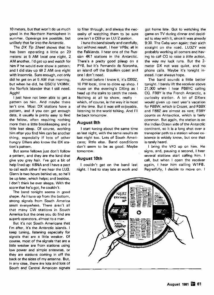
10 meters, but that won't do us much good in the Northern Hemisphere in summer. Openings are possible, but unlikely that far into the Antarctic.
The DX Tip Sheet shows that he has been operating a little on 20 meters: at 5 AM local one night, 2 AM another. I'd get up and watch for him if he would ever show a pattern; and I did stay up till 2 AM one night with insomnia. Sure enough, not only did he get on at 5 AM that morning, but when he did, he QSO'd VKSNV, the Norfolk islander that I still need. Aggh!
I just have not been able to get a pattern on him. And maybe there isn't one. Most DX stations have a pattern, and if you can get enough data, it usually is pretty easy to find the fellow, often requiring nothing more than a little bookkeeping and a little lost sleep. Of course, working him after you find him can be another thing, especially i f lots of other hungry DXers also know the DX sta- tion's pattern.
But some fellows just don't follow a pattern, and they are the kind that give you grey hair. I've got a bit of help lined up: K6NA and I have a pact to call each other if we hear the LU3. Glenn is two hours behind us, so he'll be up later, which helps; and besides, I don't think he ever sleeps. With the score that he's got, he couldn't.
The band tonight seems in good shape. As I tune up from the bottom, strong signals from South America seem everywhere. There aren't all that many CW stations in South America but the ones you do find are superb operators, almost to a man.
But it's not South Americans that I'm after, it's the Antarctic islands. I keep tuning, listening especially for signals that are a little weaker. Of course, most of the signals that are a little weaker are from stations using low power and simple antennas, or they are stations coming in off the back or the sides of my antenna. But, in any case, there are lots and lots of South and Central American signals
to filter through, and always the nec- essity of watching them to be sure one isn't a CE9 or an LUIZ station.
I tune the bandslowly and carefully, but without result. I hear VP8s; all in the Falklands. I hear one of the Rus- sian 4K1 stations in the Antarctic. There's a pretty good pileup on a PY0, but it's Fernando de Noronha, an island off the Brazilian coast and one I don't need.
Almost before I know it, it's 03002, 10 PM local, time to close up shop. I muse on the evening's DXing as I head up the stairs to catch the news. Nothing at all to show, really - which, of course, is the way it is most of the time. But it was still enjoyable, listening to the world talking. And I'll be back tomorrow.
August 8th I start tuning about the same time
as last night, with the same results as last night too. Lots of South Ameri- cans; little else. Band conditions don't seem to be as good. Maybe tomorrow.
August 10th I couldn't get on the band last
night. I had to stay late at work and
got home late. Got to watching the game on TV during dinner and decid- ed to stay with it, since it was already 9:30. The Cubs won again; their sixth straight on the road. LU3ZY was probably working all comers and hav- ing to call CQ to raise a little action, the way my luck runs. But the 2- meter DX net was quiet, and no phone calls. Maybe it's tonight in- stead. I can always hope.
The band sounds a little better tonight. I barely lift the receiver above 21,000 when I hear FB8YC calling CQ. FB8Y is the French Antarctic, a curiosity station. A lot of DXers would given up next year's vacation for FB8W, which is Crozet, and FB8X and FB8Z are almost as rare; FB8Y counts as Antarctica, which is fairly common. But again, the station is on the Indian Ocean side of the Antarctic continent, so it is a long shot over a transpolar path to a station whose ex- istence is widely know, but one that is rarely heard.
I bring the VFO up on him. He signs, and, pausing a second, I hear several stations start calling him. I call, but when I open the receiver again, I hear him calling WIFB. Regretfully, I decide to move on. I
August 1981 61

don't need him for a country counter, and I do need the LU3ZY QSO. If I could have nailed him quick and easy, I would have, but I can't. Maybe later, after I've had a look across the band, I'll find him without a pileup. If I do, I'll try again.
With that behind me, I continue tuning up the band. It quickly becomes apparent that conditions are pretty good, with lots and lots of sig- nals. Hey, there's a bit of a pileup. OK, it's 8R1 G. And the pileup on him is mostly JA stations; some of them are pretty loud, and off the back of my antenna at that.
At 21,033 kHz, I run across ZD8TC negotiating his way through a crowd of admirers in contest style. And three kHz above him is VP5FM. And everywhere are South Americans; PYs, LUs, plus the occasional CE, ZP, and CX.
There's a weak signal calling a CQ. OK, another J A . And there's KC4AAF, one of the American scien- tific stations in the Antarctic. Well, the band's open, for sure. I decide to speed up my tuning for a few minutes, and use that old Novice technique, "tune for the pileup."
Normally, I never use this tech- nique on purpose. I much prefer to crawl up a band, listening to every signal at least for a moment. It's a heck of a lot more productive, and frankly, a lot less boring. In fact, it's fun, even if I don't catch a new one. A good open band is a dynamic, liv- ing thing, with a possible surprise at every kHz: to hear a band, to explore it, to hear signals from everywhere on different paths, to eavesdrop on old friends chatting or people making new friends.
Careful tuning brings other thrills, too. Digging a really rare one out, getting him in a one-on-one situation, having a nice ragchew with liberal use of his callsign - and then the enor- mous pileup on him when you sign clear with your 100 watts - it's heady stuff.
Tuning for pileups is a great way to
run up an SWL DXCC, but getting the QSO can be tough, really tough. Especially when you're after a rare one. Still, suppose that the LU3ZY station is already on the band? A half hour's careful tuning from the bottom up that leads to finding him at 21,080 with a horrendous pileup isn't neces- sarily the right way to do it either.
I start tuning higher, but much more rapidly. Instead of individual signals, I look for concentrations of signals; in a word, for pileups.
At 21,057, 1 find one. I should say centered on 057. This one's huge; hundreds of stations frantically call- ing; but calling whom? The calling stations seem to be spread out a bit, over at least five kHz. That's a pretty good sign that whomever they are chasing is working split frequency. And yes, they all start calling at once, and they all stop calling at almost the same time.
Whoever's running this pileup is a real pro; he's got everyone marching to his drumbeat. And the way they are calling so neatly in unison sug- gests that he has a pretty loud signal. He's probably lower in frequency; I drop back to 21,050 and have a look.
Almost immediately I find him; a good 579 signal, really pounding it out:
"W1DA 5NN K" . . . "R TU" "4SMX 7 5NN K" . . . "R K4SMX
EE"
"N4AR HI BILL 5NN K" . . . "CU E E"
"PY7PO 5NN K" . . . "R QSL VIA KBHGB QTH SO GEORGIA 73 DE VP8MU QRZ UP8"
South Georgia. A real goody in- deed, and one I don't need, but that's another story. I call it on 2 meters; "VP8MU, that's Victor Pappa Eight Mexico Uniform, South Georgia, twenty one oh five oh, South Geor- gia, twenty one oh five oh, listening up eight, he's got a good signal, here's W9KN I ."
I get a terse response: "All right!" Hmm. Whoever that was really should sign a call. Oh well.
Anyhow, it's time to keep moving. I'm soon up to 21,150 and, as I sus- pected after hearing the South Geor- gian pileup, no LU3ZY. In a non-con- test situation, it's rare to have two or more huge pileups on a band. If nothing else, two rare stations split the band population between them, limiting the size of either pileup.
Anyhow, it's back to slow, careful tuning for me, now that I'm pretty confident that the LU3ZY station isn't a featured guest in a pileup. I move the receiver back down to the bottom of the band and start tuning up higher again. My interest is heightened now, helping me to keep the concentration needed for the job at hand. Hearing that VP8 on South Georgia has got- ten my fires lit, even though I don't
62 August 1981

I'm right.
need him. After all, South Georgia and the South Sandwich isles are neighbors in that frozen part of the globe. Maybe there is hope. The band is open, at least, and that pileup is so huge that there can't be too many people after LU3ZY if he does show.
Another factor is in my favor. It's summer here and winter there: the long night of the polar regions, and so cold that the personnel at the sta- tion have to pretty well stay inside. Maybe there's a shortage of enter- tainment; operating 15-meter CW could be an ideal pastime.
I tune much more carefully this time, more the way I prefer to tune. If I didn't have a specific target (that is, the LU3) I would tune through 100 kHz, then rotate the antenna 90 degrees and do it again. If the band is open at all, it can be a fascinating exercise, listening to the world. I lis- ten to this signal, "QTH HR BUENOS AIRES," and that signal, "QSL SURE VIA BUREAU," obviously a statesid- er with backscatter, and if he is going
to QSL via the bureau he obviously isn't too excited.
Then, another backscatter state- sider, "OK ISIDRO QSL VIA LU2CN TNX NEW ONE ES 73 . . ." That almost has to be him! The right name, the right manager, and a new country for whoever's in QSO. I punch the switch to turn on the line- ar. Bzzzt - zap - the surge relay drops out, and it's operational. It's already tuned on 15; 1 only need to trim the drive level from the exciter. I back off the drive control on the ex- citer; I will advance it to the proper level as I start my call.
There - the other station is sign- ing - sure enough, "LU3ZY DE W3KT SK." I listen intently. There he is, almost dead on 3KT's frequency.
"R W3KT DE LU3ZY OK OM TNX ES 73 MUST QRT FOR DUTY W3KT DE LU3ZY SK CL EE."
Arrrhhhghl Ohhhhgh! I call, desperately, a one by two. I
listen. Nothing. Absolutely nothing; no competition and no QSO. I call again, but I know I'm dead. I listen.
After a pause, I hear, "SRI HOPE U GET HIM'NEXT TIME W9KNI 73 DE W3KT" That KT'S a gentleman, a class act.
I respond, "R TNX JESSE ES CONGRATS UR FINE CATCH 73 ES GL W3KT DE W9KNI EE."
Gad. Maybe I should go back to stamp collecting.
But even as I consider such op- tions, I make notes on my little chalk board, "LU3ZY 21032 0154Z." 1 make a mental note as well that the slight chirp he appeared to have last time I heard him seems to be gone; his sig- nal was nice and clean this time. Hmmm. The time is interesting. Obvi- ously his watch must change at 0200 Zulu, so that he has to go on duty, and QRT. I'm pretty sure that he could not have been on the band long, or there would have been a ter- rific pileup on him. 1 wonder how W3KT caught him? On a CQ maybe? Or hunting? 3KT's a sharp old fox, and his QSO with the LU3 was proba- bly no accident. He knew what he was doing.
Well, I don't really have enough data to mark any kind of a trend, although I have a good deal more than I did yesterday at this time. But you better believe one thing - I'm going to be watching tomorrow around 21,032 at 01302 like a hawk.
I turn off the gear and head up the stairs. Might as well go for a walk.
August 11 I had to work late again tonight,
but still, I managed to get home in good time. My wife, sympathetic to the cause, has dinner ready when I get home, and I'm in front of the rig with a few minutes to spare against my self-appointed schedule.
OK. Antenna south-southeast. Check. Linear tuned for 15. Check. Attenuator out. Check. I settle the headphones into place, bring up the receiver gain - and there he is, square in the middle of the passband.
"CQ CQ DE LU3ZY LU3ZY AR K.
August 1981 63

A beautiful piece of furniture -your XYL will love it!
$1 6450 S-F RADIO DESK Deluxe - Ready to Assemble Designed with angled rear shelf for your viewing comfort and ease of operation.
FINISHES: Walnut or Teak Stain. Floor Space: 39" Wlde by 30" Deep
QRZ Wl's, W2's and W3's...
LOOKING FOR AEA PRODUCTS I IN THE NORTHEAST?
LOOK TO RADIOS UNLIMITED... NEW JERSEY'S FASTEST GROWING HAM STORE!
Get your hands on A E A s great keyers huge stock of ham gear). and try belore and lsopole antennas at Rad~os Unl~m~ted you buy' We don t mean a llltle off the alr You can reach us eas~ly vla the Jersey d~ddltng wlth the keyer we let you PUT Turnp~ke and when you get here you can IT ON THE AIR AND HAVE A QSO really TRY BEFORE YOU BUY at our ~n-store check 11 out underYOUR k ~ n d of operating operat~ng pos~t~on Yes1 P~ck out any AEA cond~ttons then dectde We know AEA keyer (or any other equ~pment lrom our and we know you II select one of these
CK-1 Contest Keyer w ~ t h 500 character memory, soft message partltlonlnq. aulo- matlc ser~al number. andmuch, muchmore.
call for super.lowpr~ce~ MK.1 Morse Keyer with selectable dot 8 dash memory, full we~ght~ng, callbraled speed. bug mode and more. . . . . . . . . . . .
call lor super. low prfcel KT.l Kever Trainer w ~ t h all the features of
MAXIMUM GAIN
ANGLE AND 1.4:l
1760 EASTON AVENUE, SOMERSET, NJ 08873 (201)469-4599
Bzzzt. Snap, the linear's on. I pause a moment as I back down the exciter drive level control. Ahh, no one else seems to be calling, as I yank the VFO dead on him. I start calling him and quickly bring the drive up as I go. I can't believe it; this is all hap- pening so fast 1 haven't even had time to get excited or get butterflies yet. "LU3ZY DE WSKNI W9KNI AR K." I open the receiver without yet having to touch the receiver dial from where I left it last night.
Huh! There are two signals calling me! Hah! Yes, one is the LU3ZY sta- tion. OK, the other's an LU2. Guess he thought I was signing from a CQ. I ignore him.
"KNI DE LU3ZY R GE OC ES TNX QSO UR RST 589 589 NAME HR ISIDRO ISIDRO QSL VIA LU2CN LU2CN HW CPY W9KNI DE LU3ZY KN."
How sweet it is! "R LU3ZY DE W K N I FB DR ISIDRO ES TNX NEW COUNTRY RST. 579 579 HR NR CHICAGO NR CHICAGO ES NAME BOB BOB QSL SURE LU2CN OK? LU3ZY DE W9KNI AR."
"R FB BOB QSL SURE ES GLD BE NEW FOR U 73 ES GOOD DX W9KNI DE LU3ZY SK QRZ? K."
As he starts the QRZ, I shove the headset back, grab the telephone, and start punching digits. Let's see. It's almost 7 PM out there on the Coast; Glenn should be home by now. The phone rings, but no answer. I pull the headphone jack out to activate the speaker, and desper- ately start dialing again.
But wait! "HOW CPY? K6NA DE LU3ZY AR KN." Hah! No wonder the phone went unanswered.
"OK GLENN TNX QSO MUST QRT FOR DUTY 73 ES GL K6NA DE LU3ZY SK CL EE."
I keep listening. Sure enough, a couple of stations are calling, but I know how well that is going to work out. I swing the antenna around to the west. "K6NA UP 2 DE W9KNI." Glenn responds with a brief "R" and we go up for a very happy ragchew.
ham radio
64 August 1981

W H Y GET O N F A S T S C A N A T V ? Y o u can send broadcast qua l i t y v ~ d e o o f home movies, video tapes, compute r games, etc, at a cost that is less than sloscan. Really improves pub l i c service communicat ions f o r parades. RACES. CAP searches, weather watch, etc. DX is about the same as 2 meter simplex - 1 5 t o 1 0 0 miles.
A L L IN O N E B O X - - -
T C - 1 T r a n s m i t t e r I C o n v e r t e r . . . . P l u g in camera , ant., rnic, a n d TV a n d y o u a r e o n t h e air. C o n t a i n s A C s u p p l y , TIR sw, 4 M o d u l e s b e l o w . . . . . . . . . . . . . $ 3 9 9 ppd
PUT Y O U R O W N S Y S T E M T O G E T H E R
T X A 5 A T V E x c i t e r c o n t a i n s v i d e o m o d u l a t o r a n d x t a l o n 4 3 4 o r 4 3 9 . 2 5 m H z . A l l m o d u l e s w l r e d a n d tes ted . . . . . $89 ppd
P A 5 10 W a n L i n e a r m a t c h e s IS P X C I T P ~ f o r o o o d c o l o r a n d s o u n d .
~ 6 s - a n d ;all m o d u l e s r u n o n 1 3 . 8 vdc. . . . . . . . . . . $89 ppd T V C - 2 D o w n c o n v e r t e r t u n e s 4 2 0 t o 4 5 0 m H z . O u t p u t s T V c h 2 o r 3 . c o n t a t n s l o w n o s e M R F 9 O l p r e a m p . . . . . . $55 ppd
PACKAGE S P E C I A L a l l F M A 5 A u d i o S u b c a r r i e r adds four modules $249 P~ s t a n d a r d T V s o u n d t o t h e
p l c t u r e . . . . . . . . . . . . $29 ppd
S E N D S E L F - A D D R E S S E D S T A M P E D E N V E L O P E F O R O U R L A T E S T C A T A L O G I N C L U D I N G :
Info on h o w t o b e s t ge t on A T V , m o d u l e s f o r t h e b u i l d e r , c o m p l e t e un i t s , b & w a n d c o l o r cameras, antennas, m o n i t o r s , e tc . a n d m o r e . 20 years e x p e r i e n c e in A T V . C r e d i t c a r d o r d e r s c a l l (2131 4 4 7 - 4 5 6 5 . C h e c k . M o n e y O r d e r o r C r e d ~ t C a r d b v m a l l .
ANTENNA BOOKS by Bill Orr, W6SAI ALL ABOUT CUBICAL QUAD ANTENNAS The cublcal quad antenna 1s cons~dered by many to be the best DX antenna because of 11s slmple, l~ghtwe~ght des~gn and h ~ g h per- formance In Bill Orr s latest e d ~ t ~ o n of thls well known book you'll flnd quad des~gns tor everythlng from the slngle element to the multl- element monster quad, plus a new, hlgher galn expanded quad (X-0) des~gn There s a wealth of supplementary data on constructlon. feed~ng, tunlng, and mountlng quad antennas It s the most com- prehenslve slngle ed~tlon on the cublcal quad available 11 2 pages \ 1977
RP-CO Softbound $4.75
THE RADIO' AMATEUR ANTENNA HANDBOOK by William I . Orr, W6SAI and Stuart Cowan, W2LX
If you are pondering what new antennas to put up, we recommend you read thls very popular book It conta~ns lots of well illustrated construc- tlon projects for vert~cai long wtre, and HF/VHF beam antennas But. you'll also get lnformat~on not usually found In antenna books There IS an honest judgment of anlenna galn f~gures, lnformatlon on the best and worst antenna iocatlons and he~ghts a long look at the quad vs the yagl antenna, lntormatlon on baluns and how to use them, and some new lnformatlon on the ~ncreas~ngly popular Sloper and Delta Loop antennas The text 1s based on proven data plus practical, on-the- alr experlence We don t expect you'll agree w ~ t h everythlng Orr and Cowan have to say, but we are convinced that Ths Rad~o Amateur Antenna Handbook will make a valuable and often consulted addltlon to any Ham s l~brary 190 pages (i 1978
RP-AH Softbound $6.95
BEAM ANTENNA HANDBOOK Here s recommended readtng for anyone thlnklng about puttlng up a yagl beam thls year It answers a lo1 ol commonly asked questions l ~ k e What IS the best element spacing? Can d~llerent yagi antennas be stacked w~thout tos~ng perlormance? Do monoband beams outperform tr~banders? Lots of constructlon prolects, d~agrams, and photos make read~ng a pleasurable and ~nforrnatlve experlence 198 pages 8 1 9 7 7
RP-BA Softbound $5.95
Please add $1.00 to cover shipping ond handling.
HAM RADIO'S BOOKSTORE GREENVILLE, Irr. H. 03048
XF-9B Reduce ORM with improved IF selectivity T h e XF.96 c r y s t a l f i l t e r i s t h e hear t o f good , m o d e r n rece ive r ( a n d transceiver) d e s ~ g n s . I t 1s u s e d b e t w e e n t h e m l x e r s t a g e a n d t h e I C I F a m ~ l ~ f i e r s t a o e t o s u D o r e s s a d i a c e n t c h a n n e l I n - . . te r fe rence b y over 100 d g s .
1 XF9B I.C. IF XF910 DET. AMPL.
T h e X F - 9 6 c a n a l s o b e u s e d t o u p g r a d e o l d e r rece ive r d e s i n s w h i c h u s e v a c u u m t u b e o r d i s c r e t e t r a n s i s t o r I F a m p l i s i e r s tages. PRICE $68.60 p l u s s h i p p i n g .
I S p e c i f l ~ t l o n XF.9B Center Frequency 9.0 MHz Shape Factor 6:60 d B 1.8 Bandwidlh 2.4 KHz 6:80 dB 2.2 Passband Rlpple 42.0 dB Ultimate Attenuation 100 dB lnser l~on Loss 43.5 dB Terminat~ons: 500 ohms
I Export Inquiries Invited 30 PF
1296 MHz EQUIPMENT Announcing the new 1296 MHz units by Microwave Modules.
LOW YOIS? H I L I V t ConrPrlr, MMk12% 144 Low hiolrr R f i t I V t Preamolfl~er MMa1296 LOW Power l N f I \ H I R A Y S Y L R T E R MM1179h I 4 4
mu% NIOYI I ~ P Y I Y 0 9 6 MH, f i n s mennu I n n I ~ C S
TRANSVERTERS FOR ATV OSCARS 7,8 & PHASE 3
Transverters by M~crowave Modules and other manulaclurers can convert your exlstlng Low Band rlg lo operate on the VHF 8 UHF bands Models also ava~lable for 2M to 70cm and tor ATV operators lrom Ch2lCh3 to 70CmS Each transverter conta~ns both a Tx up-converter and a Rx down-converter Wr~te lor detalls of the iarqest select~on ava~lable Pr l ces s ta r t a t 5199.95 p l u s $6.50 sh ipp ing .
SPECIFICATIONS Output Power 10 W Receiver N.F. 3 dB typ. Receiver Galn 30 dB typ. Prime Power 12V DC
Attent~on owners of the or1 ~ n a l MMt432 28 niodels Upddte your IrCinsvprter to operate OSCAR 8 8 PHAtE 3 by addlng Ihe 434 to 436 MHz ,ange Mod k ~ t lncludlng full ~nstructlons $26 50 plus $1 50 sh~pp~ng etc
ANTENNAS ( F o e CONCORD, VIA u p s ) 144-148 MHz J-SLOTS 8 O V E R 8 H O R I Z O N T A L POL. + 1 2 . 3 d B d D812M $63.40 8 BY 8 VERTICAL P O L D812M-VERT $76.95 - - - -
8 + 8 T W l S T 8XY12M $62.40
420-450 MHz M U L T I B E A M S
For local , DX, OSCAR. and A T V use.
4 8 E L . G A l N + 1 5 . 7 d B d 7 D / M B M 4 8 $75.75 88 EL. G A I N + 1 8 . 5 d B d 701MBM88 $105.50 UHF LOOP YAGlS 2 8 L O O P S G A l N + 2 0 d B i 50-ohm, T y p e N C o n n e c t o r 1250-1340 M H z 1296-LY 8 ft. b o o m $64.70
I 1650-1750 M H z 1691.LY 6 ft. boom1S70~900 Send 36c ( 2 slarnps) lor lull dela~ls 01 KVG cryslal products and all your VHF L UHF equlp-
I rnent requlrernents Pre Seleclor F~llers Ampl~flers SSB Transvertsrs Varaclor Trlplers Crystal hltws FM Transverters Decade Pre-Scalers Frequency Flltars VHF Converters Anlennas Osc~llator Crystals UHF Converters
rational, Ice Box
, Inc. 1084 USA
August 1981 6 More Details? CHECK-OFF Page 94

1900 MHz to 2500 MHz DOWN CONVERTER This receiver is tunable over a range of 1900 to 2500 mc and is intended for amateur radio use. The local oscillator is voltage controlled (i.e.) making the i-f range approximately 54 to 88 mc (Channels 2 to 7).
. . . . . . . . . . . . . . . . . . . . . . . . . . . . . . . . . . . . . . . . . . . . . . . . . . . . . . . . . . . . . . . . . . . . . . . . . . . . . . . . . . . . . . . . . . . . . . . . . . . . . . PC BOARD WITH DATA $19.99 PCBOARDWlTHCHlPCAPAClTORS13 . . . . . . . . . . . . . . . . . . . . . . . . . . . . . . . . . . . . . . . . . . . . . . . . . . . . . . . . . . . . . . . . . . . . . . . . . . . . . . . . . . . . . . . . $44.99
. . . . . . . . . . . . . . . . . . . . . . . . . . . . . . . . . . . . . . . . . . . . . . . . . . . . . . . . . . . . . . . . . . . . . . . . . . . . . . . . . . PC BOARD WITH ALL PARTS FOR ASSEMBLY $69.95 PC BOARD WITH ALL PARTS FOR ASSEMBLY PLUS2N6603 . . . . . . . . . . . . . . . . . . . . . . . . . . . . . . . . . . . . . . . . . . . . . . . . . . . . . . . . . . . . . . . . . . . . . . $89.99 PCBOARDASSEMBLEDANDTESTED . . . . . . . . . . . . . . . . . . . . . . . . . . . . . . . . . . . . . . . . . . . . . . . . . . . . . . . . . . . . . . . . . . . . . . . . . . . . . . . . . . . . . . . . . $79.99 PC BOARD WITH ALL PARTS FOR ASSEMBLY, POWER SUPPLY AND ANTENNA. . . . . . . . . . . . . . . . . . . . . . . . . . . . . . . . . . . . . . . . . . . . . . . . . . . . $159.99 POWERSUPPLYASSEMBLEDANDTESTED . . . . . . . . . . . . . . . . . . . . . . . . . . . . . . . . . . . . . . . . . . . . . . . . . . . . . . . . . . . . . . . . . . . . . . . . . . . . . . . . . . . . $49.99 YAGl ANTENNA4' LONG APPROX. 20TO23dB GAIN.. . . . . . . . . . . . . . . . . . . . . . . . . . . . . . . . . . . . . . . . . . . . . . . . . . . . . . . . . . . . . . . . . . . . . . . . . . . $39.99 YAGl ANTENNA 4' WITH TYPE (N, BNC, SMA Connector) . . . . . . . . . . . . . . . . . . . . . . . . . . . . . . . . . . . . . . . . . . . . . . . . . . . . . . . . . . . . . . . . . . . . . . . . . $64.99 2300 MHz DOWN CONVERTER HMRII, with dish antenna - 6 months warrantee. . . . . . . . . . . . . . . . . . . . . . . . . . . . . . . . . . . . . . . . . . . . . . . . . . . . . $200.00 2300 MHz DOWN CONVERTER
Includes converter mounted in antenna, power supply, plus90 DAY WARRANTY.. . . . . . . . . . . . . . . . . . . . . . . . . . . . . . . . . . . . . . . . . . . . . . . . . . $200.00 . . . . . . . . . . . . . . . . . . . . . . . . . . . . . . . . . . . . . . . . . . . . . . . . . . . . . . . . . . . . . . . . . . . . . . . . . . . . . OPTION $1 MRF902 in front end. (7dB noise figure). $299.99
OPTION #2 2N6603 in front end. (5dB noise figure) . . . . . . . . . . . . . . . . . . . . . . . . . . . . . . . . . . . . . . . . . . . . . . . . . . . . . . . . . . . . . . . . . . . . . . . . . . . . . . $359.99 2300 MHz DOWN CONVERTER ONLY
10dB Noise Figure 23dB gain in box with N conn. Input F conn. Output. . . . . . . . . . . . . . . . . . . . . . . . . . . . . . . . . . . . . . . . . . . . . . . . . . . . . . . . . . . $149.99 7dB Noise Figure23dB gain in box with N conn. Input F conn. Out ut . . . . . . . . . . . . . . . . . . . . . . . . . . . . . . . . . . . . . . . . . . . . . . . . . . . . $169.99
. . . . . . . . . . . . . . . . . . . . . . . . . . . . . . . . . . . . . . . . . . . . . . . . . . . . . 5dB NoiseFigure23dBgain in box with SMAconn. Input Fconn. 8u tb l i : : : $189.99 . . . . . . . . . . . . . . . . . . . . . . . . . . . . . . . . . . . . . . . . . . . . . . . . . . . . . . . . . . . . DATA IS INCLUDED WITH KITS OR MAY BE PURCHASED SEPARATELY $15.00
Shipping and Handling Cost: Receiver Kits add $1.50, Power Supply add $2.00, Antenna add $5.00, Option 112 add $3.00, For complete system add $7.50.
* INTRODUCING THE HOWARDICOLEMAN TVRO CIRCUIT BOARDS * ( Satellite Receiver Boards )
................................................................................................. DUAL CONVERSION BOARD $25.00 This board prov~des conversion from the 3.7-4.2 band first to 900 MHz where gain and bandpass filtering are provided and, second, to 70 MHz. The board contains both local oscillators, one fixed and theother variable, and the second mixer. Construction is greatly simplified by the use of Hybrid IC amplifiers for the gain stages..
47pFCHlPCAPAClTORS ..................................................................................................... $6.00 For use w ~ t h dual conversion board. Consists of 6 - 47 pF.
........................................................................................................... 70MHzIFBOARD $25.00 This circuit rovides about 43 dB gain with 50 ohm input and output impedance. It is desi ned to drive the HOWARDICOLEMAN TVRO De- modulator. ?he on-board band pass filter can be tuned for bandwidths between 20 and 35 haHz with a passband ripple of less than l/z dB. Hy. brid ICs are used for the gain stages.
................................................................................................... .O1 pF CHIP CAPACITORS.. $7.00 For use with 70 MHz IF Board. Consists of 7 - .O1 pF.
.................................................................................................... DEMODULATOR BOARD.. 40.00 This circuit takes the 70 MHz center frequency satellite TV signals in the 10 to 200 millivolt range, detects them usin a phase locked loop, de- emphasizes an* filters the result and amplifies the result to produce standard NTSC video. Other outputs include t%e audio subcarrier, a DC voltage proportional to the strength of the 70 MHz signal, and AFC voltage centered at about 2 volts DC.
SINGLEAUDIO ............................................................................................................. $15.00 This circu~t recovers the audio signals from the 6.8 MHz frequency. The Miller 9051 coils are tuned to pass the 6.8 MHz subcarrier and the Miller 9052 coil tunes for recovery of the audio.
............................................................................................................... DUAL AUDIO $25.00 Duplicate of the single audio but also covers the 6.2 range.
.............................................................................................................. DC CONTROL $15.00 This circu~t controls the VTO's, AFC and the S Meter.
TERMS: WE REGRET WE NO LONGER ACCEPT BANK CARDS. PLEASESEND POSTAL MONEY ORDER, CERTIFIED CHECK, CASHIER'S CHECK OR MONEY ORDER. PRICES SUBJECT TO CHANGE WITHOUT NOTICE. ALL RETURN ORDERS SUBJECT TO PRIOR APPROVAL BY MANAGEMENT. ALL CHECKS AND MONEY ORDERS IN US FUNDS ONLY. ALL ORDERS SENT FIRST CLASS OR UPS. ALL PARTS PRIME AND GUARANTEED. WE WILL ACCEPT COD ORDERS FOR $25.00 OR OVER, ADD $2.50 FOR COD CHARGE.
(602) 242-891 6 PLEASE INCLUDE $2.50 MINIMUM FOR SHIPPING OR CALL FOR CHARGES. WE ALSO ARE LOOKING FOR NEW AND USED TUBES,
21 1 1 W. Camelback TEST EQUIPMENT, COMPONENTS. ETC. WE ALSO SWAP OR TRADE. Phoenix, Arizona 850 1 5
NEW - TOLL-FREE NO. 800-528-01 80 - please, orders only!
66 August 1981 Tell 'em you saw it in HAM RADIO!

1 RF TRANSISTORS
FAIRCHILD VHF AND UHF PRESCALER CHIPS 95H90DC 350 MHz Prescaler Divide by 10111 95H91DC 350 MHz Prescaler Divide by 5/6 11C90DC 650 MHz Prescaler Divide by 10111 11C91DC 650 MHz Prescaier Divide by 5/6 11C83DC 1 GHz Divide by 2481256 Prescaler 11 C70DC 600 MHz FlIplFlop with reset llC58DC ECL VCM 11C44DCIMC4044 Phase Frequency Detector llC24DClMC4024 Dual TTL VCM 11COGDC UHF Prescaler 750 MHz D Type FliplFlop 11CO5DC 1 GHz Counter Divide by 4 llCOlFC High Speed Dual 5 4 input NOINOR Gate
TRW BROADBAND AMPLIFIER MODEL CA615B Frequency response 40 MHz to 300 MHz Gain: 3W MHz 16 dB Mln., 17.5dB Max.
50MHzOto -1dBfrom3WMHz Voltage: 24 volts dc at 220 ma max.
CARBIDE - CIRCUIT BOARD DRILL BITS FOR PC BOARDS Size: 35,42,47,49,51, 52 Size: 53,54,55.56.57.58,59.61.63.64.65 Size: 68 Size: 1.25 mm, 1.45 mm Size: 3.20 mm
CRYSTAL FILTERS: TYCO 001.19880 same as 2194F 10.7 MHz Narrow Band Crystal Filter 3 dB bandwldth 15 kHz mln. 20 dB bandwldth 60 kHz mln. 40 dB bandwidth 150
kHz min. Ultimate 50 dB: Insertion loss 1.0 dB max. Ripple 1.0 dB max. Ct. 0 +I- 5 pf 3600
ohms. $5.95
MURATA CERAMIC FILTERS Models: SFD-455D 455 kHz $3.00
SFB-455D 455 kHz 2.00 CFM.455E 455 kHz 7.95 SFE.10.7 10.7 MHz 5.95
TEST EQUIPMENT - HEWLETT PACKARD - TEKTRONIX - ETC. Howlott Packard: 491C TWT Amplifier2 to 4 Gc 1 watt 30 dB galn 51150.00 808C 1010480 mc .1 uv to .5 V Into 50ohms Slgnal Generator 500.00 8080 10 to420 mc .1 uV to .5 V into 50 ohms Signal Generator 500.00 812A 450 to 1230 mc .1 uV to .5V into50 ohms Slgnal Generator 750.00 614A 900 to 2100 mc Signal Generator 500.00 618A 1.8 to 4.2 Gc Signal Generator 400.00 6188 1.8 104.2 Gc Signal Generator 500.00 618A 3.8 to 7.2 Gc Signal Generator 400.00 6188 3.810 7.2 Gc Signal Generator 500.00
7 to 11 Gc signal Generator Microwave Test Set 10 to 15 Gc Slgnal Generator 12.4 to 18 Gc Sweep Generator
225 to 400 mc AMlFM Signal Generator 750.00
Universal Spectrum Analyzer with 1 kHz to 27.5 mc Plug In 1200.00
T\NT Ampllfler 8 to 12.4 Gc 100 watts 40 dB gain 9200.00
102A Calibrated Display wlth an SSB Analysis Module and a 10 to 40 mc SlngleTone Synthesizer 1500.00
HAMLIN SOLID STATE RELAYS 120Vac at 40 Amps. lnput Voltage 3 to 32 Vdc.
240 Vac at 40 Amps. lnput Voltage 3 to 32 Vdc.
Your Choice $4.98
TYPE 2N1561 2N1582 2N1692 2N1693 2N2832 2N2857JAN 2N2876 2N2880 2N2927 2N2947 2N2948 2N2949 2N2950 2N3287 2N3294 2N3301 2N3302 2N3304 2N3307 2N3309 2N3375 2N3553 2N3755 2N3818 2 N W 2N3866JAN 2N3866JANl
PRICE $15.00 15.00 15.00 15.00 45.00 2.52
12.35 25.00 7.00
18.35 15.50 3.90 5.00 4.30 1.15 1.04 1.05 1.48
12.60 3.90 9.32 1.57 7.20 6.00 1.09 2.80 4.49
We can supply any value chip capac- Itors you may need.
PRICES 1 to 10 $1.49 11-50 1 . a 51.100 .89 101 . 1,000 .89 1,001 up .49
TYPE 2N5590 2N5591 2N5837 2N5641 2N5642 2N5643 2N6545 2N5764 2N5842 2N5849 2N5862 2N5913 2N5922 2N5942 2N5944 2N5945 2N5948 2N6080 2N6081 2NB082 2N8083 2 N W 2N8094 2N6095 2N8096 2N6097 2N8136
PRICE $8.15 11.65 22.15 6.00
10.05 15.62 12.38 27.00 8.78
21.29 51.91 3.25
10.00 46.00 8.92
12.38 14.69 7.74
10.05 11.30 13.23 14.66 7.15
11.77 20.77 29.54 20.15
CHIP CAPACITORS
TYPE MM1550 MM1552 MM1553 MM1601 MM1602/2N5842 MM1607 MM1661 MM1669 MM1943 MM2605 MM2608 M M 8 W MMCM918 MMT72 MMT74 MMT2857 MRF245 MRF247 MRF304 MRF420 MRF450 MRF450A MRF454 MRF458 MRF502 MRF504 MRF509
PRICE $10.00 50.00 56.50 5.50 7.50 8.65
15.00 17.50 3.00 3.00 5.00 2.23
20.00 1.17 1.17 2.63
33.30 33.30 43.45 20.00 11.85 11.85 21.83 20.68
1.08 6.95 4.90
ATLAS CRYSTAL FILTERS FOR ATLAS HAM GEAR 5.52-2.718 5.595-2.718/u 5.595.500/4/CW 5.5952.7LSB YOUR CHOICE 524.95 5.595-2.7USB 5.6452.718 9.0uSB1CW
NEW - TOLL-FREE NO. 800-528-0180 - please, orders only!
More Details? CHECK- OFF Page 94 August 1981 67

@) MOTOROLA Semiconductor The RF Line
NPN SILICON RF POWER TRANSISTORS
deslgned for power ampllfler appllcat~ons In lndustrlal, com merclal and amateur rad~o eaulpment t o 30 MHz -
MRF458 $20.68
NPN SILICON RF POWER TRANSISTOR
des~gned for power ampl~f~er appl~cat~ons In ~ndustr~al.
commer~cal and amateur radlo equlpment to 30 MHz
Spec~f~ed 12 5 Volt 30 MHz Character~st~cs Spec~f~ed 12 5 Volt, 30 MHz Character~st~cs - Output Power 80 Warts
Output Power = 80 Watts Mjn~mum Ga~n 12 dB Mlnlmum Galn = 12 dB Ef f~c~ency - 50% Efflclencv = 50%
Capable of W~thstand~ng 30 1 Load VSWR @ Rated Pout and VCC
NPN SILICON RF POWER TRANSISTOR des~gned prlmar~ly for use In large s~gnal output ampl~f~er stages
Intended for use In Clt~zen Band communlcatlons equlpment
MRf 472 operatlng at 27 MHz ~ ~ g h breakdown voltages allow a h~gh percentage of up modulat~on In AM clrcults
$2.50 Spec~fled 12 5 V 27 MHz Character~sttcs Power Output = 4 0 Watts Power Galn = 10 dB M ~ n ~ m u m . Efflc~ency = 65% Typ~cal
MRF475 NPN SILICON RF POWER TRANSISTOR
. . des~gned p r~mar~ l y for use In s~ngle s~deband l~near amplifier output appllca~ions In citizens band and other commun~cations
equ~pment operatany to 30 MHz.
Characterized for S~nyle Sldeband and Large S~ynal Ampl~fler
Appllcatlons U t ~ l ~ z ~ n g Low Level Modulat~on
Spec~fled 13 6 V 30 MHz Characterlstlcs - Output Power = 12 W (PEP) M~nimum Ef f~c~ency = 40% (SSB)
Output Power = 4 0 W (CW)
$5.00 Mln~murn Ef f~c~ency = 50% (CW) M ~ n ~ m u m Power Ga~n = 10 dB (PEP & CW)
Common Collector Character~zat~on
Tektronix Test Equipment
I! W ldchdO l l l y h G d l l l IPIu(! 181 [ A Dua l Trace D luy I!! K i d t : Hi\! UC Yluy 1 x 8
Sampl l r lg P l u q I" Trdr l i l$:or R l se t l # l l ' . P l u g 1 8 1 H l g h L o l l ? i l l f f e r r n t l o l Lon lpd ra t l l r Y l l i l l I n Tes t i nn i l I ' l uy 1 8 1 18>r i 3 0 1 L 4 ~ . 1 r , o Molrm l r a m r \ U>d rhand l i ua l I r a & ' P l u g 118 ~ d r n y l l ~ ~ c i Lllilt Wl th J',IIPS R l ~ , c ~ l l l s r 0C Ira 1Iz!1/ A C olrf.rc.ntlal p l u g I,, Dual TIOLI. i amp l l r ! i J Dl t o 1TH2 P l u g 1.8 Dual l r d i r i d m p l i n , l DC t o C 7 I M I I I P l u g I N ;dmpl l r ly ',weep PI"., 11, 5pcc t rum A n a l y i r r I L,I I~MH! ~ l u y IN A m ~ l l f l p r P l u q In Sweep P l u g In I ::1',4E Wlderd,!,, H l q h G a l " P l u q I"
53r54C Oual T l a l t . Plug Ir, 531540 ~ i g h OC u ~ f r c , r p n t i a l P l u q Irl 53154G Wld?!>.rnd UC i l > f f e r r n f l a l P l t i y 181
1117 squa re uavi, Gpneratnr 4 t o lMH7 H M l i i P r r d l l l p l l f l r r LHI (0 QIlKH? 113 AC Coup l rd I ' r ~ a m ~ ~ l l f l r , r I 3 1 C u r r r n ~ Probe A m p l l f l r , r 1134 ~ l m e Mark Lerieratnr RZ10 Program C o r ~ t r o l U n l t 280 T r ~ g q e r Countdawn U n i t 5350 OC t o 1 5 M l l l Scope R a c k Mount 5 DC t o 33MHI Scope 561 DL t o IDMI17 Scope Rack Mount 56111 DC t n lUMH7 SCOPP Hack M o ~ r :
51 llll 1 / 1 1 1111
(I / J J l l
:,,!I [;I1 I l h O'l 2 R l 1111
'.11 01: 21" I00 1 1 0 Ill l i l !,'I 210 on / < , l 011 1 ' 1 r I ol1
100'1 O i l 53 UII ',', 00 4 ' no
11: ' 1 ) 1,' 011 6 ii !1!1 1 , I10 3H 011 b I 00 25 011 50.00
3 6 3 00 150 00
184 011 263.00 1011 00 110.00 200. 00
UHF POWER AMPLIFIER MODULE
des~gned for 12 5 volt UHF power ampl~f~er appl~cat~ons In
lndustr~al and commerc~al FM equlpment operatlng from 400 to 512 MHz
Spec~f~ed 12 5 Volt UHF Character~stlcs -
Output Power 13 Watts Min~mum Galn 19 4 dB
Harmon~cs 40 dB
50 12 InputIOutput Impedance
Guardnteed S tab~ l~ t y and Ruggedness
Ga~n Control Pin for Manual or Automat~c Output Level Control
T h ~ n F ~ l m Hyb r~d Construct~on G~ves Cons~stent Performance
and Relldblllty
Scopes with Plug-ins
,,bL, OI t , ~ IOMII l r , l r l ii~..,,, .cop,. w t r h a L A ~ I l m f f and r >A61 O ~ f l P l u g In", '101' 110
58'1 Or t o ill1MliI S ~ a i l P v l t l ! n H1 Liual TraL8. H l q h Cinlrl P l u q I n h i l l 110
Tubes
NEW - TOLL-FREE NO. 800-528-01 80 - please, orders only! 1
68 August 1981 Tell 'em you saw it in H A M RADIO!

MICROWAVE COMPONENTS PRD UlOl 12.4to 18 GHzVariable AttenuatorOto80 dB XI01 6.2 to 12.4GHz Variable AttenuatorO to 60 dB
ARRA DESCRIPTION :d5";/367 Variable Attenuator 0 to80 dB Slotted Ltne with Type N Adapter
2416 Variable Attenuator $ 50.00 8 210 12.4 GHz Variable Attenuator 0 to 50 dB
361 4-60 Variable Attenuator 0 to 60dB 75.00 ;:EEsl 7.0510 10 GHz Variable AttenuatorO to 40 dB
KU520A Variable Attenuator 18 to 26.5 GHz 8.2 to 12.4 GHz Var~able AttenuatorO to 45dB
4684-2OC Variable Attenuator 0 to 180 dB loo.oO 1708 100.00 588A
3.95 to 5.85 GHz Variable Attenuator 0 to 45 dB
6684-2OF Variable Attenuator 0 to 180 dB Frequency Meter 5.3 to 6.7 GHz
140A. C. D. E Fixed Attenuators 109J. I Fixed Attenuators WEINSCHEL ENG. 2692 Variable Attenuator + 30 to60 dB
General Microwave Directional Coupler 2 to 4 GHZ 20dB Type N 75.00 COMPUTER I.C. SPECIALS
Hewlett H487B H487B 4778 X467A X487B J468A 478A J382 X382A NK292A 8436A 8471A H532A G532A J532A 809A
Packard l00ohms Neg. Thermistor Mount (NEW) 100 ohms Neg. Thermistor Mount (USED) 200 ohms Neg. Thermistor Mount (USED) IOOohms Neg. Thermistor Mount (USED) 1OOohms Neg. Thermistor Mount (USED) 100 ohms Neg. Thermlstor Mount (USED) 200 ohms Neg. Thermlstor Mount (USED) 5.85 to 8.2 GHz Variable Attenuator 0 to 50 dB 8.2 to 12.4 GHzVariable Attenuator 0 to 50 dB Waveguide Adapter Bandpass Filter 8 t o 12.4 GHz RF Detector 7.05 to 10 GHz Frequency Meter 3.95 to 5.85 GHz Frequency Meter 5.85 to 8.2 GHz Frequency Meter Carriage with a 444A Slotted Line Untuned Detector Probeand 809B Coaxial Slotted Section 2.6 to 18 GHz 8.2 to 12.4 GHz Noise Source 2.8 to 3.95 GHz Noise Source 3.95 to 5.85 GHz Noise Source 5.85 to 8.2 GHz Noise Source 7.05 to 10GHz Noise Source 400 to 4000 MHz Noise Source 12.4 to 18 GHz Frequency Meter Frequency Meter 0-50 dB Attenuator .5 Watts, 50 Ohm DC to 1.000 MC Attenuator Adapter Microwave Switch Pin Absor tion Modulator Tracking tenerator shunt Feed-throuah Termination Terminatlo; 7.05 to 10 GHz Crystal Detector 7.05 to 10GHzCrystal Detector - Matched Pair
Merrimac AU-26AI 801 162 Variable Attenuato~
MicrolablFXR X638S Horn 8.2 to 12.4 GHz 601-El8 X to N Adapter 8.2 to 12.4 GHz Y6100 Coupler
Narda
D~rect~onal Coupler 4to8GHz 20dB Type N Direct~onal Coupler 240 to 500 MC 20 dB Ty e N 22006 Dlrect~onal Couoler 1 7 to 4 20 c J T v ~ e N 2201 1 Dlrectlonal Coupler 2 t o 4 GHz lOdB ~~k N 22012 Dlrectlonal Coupler 2104 GHz 30dB Type N 22007 D~rect~onal Coupler 1 7 to 3 5 GHz 30 dB Type N D~rect~onal Cou ler 2 to4 GHz lOdB Type N Coav~al Hybrld $10 4 GHz 3dB Type N Coax~al Hybrld 95010 2 GHz 3dBType N 22380 Var~able Attenualor 1 to 90 dB 2102 5GHZ Type SMA Wavegutde to Type N Adapter F~xed Attenuator 8 210 14.4GHz6dB Waveguide
MEMORY DESCRIPTION PRICE 2708 IKXBEPROM 271612516 2K x 8 EPROM 5Volt Single Supply 211419114 1K x 4 Static RAM 45011s 2114L2 1K x 4 Static RAM 250ns 21 14L3 1K x 4 Static RAM 350ns 4027 4Kx 1 Dynamic RAM 406012107 4K x 1 Dynamic RAM 405019050 4K x I Dynamic RAM 2111A-218111 256x 4Static RAM 2112A.2 256x 4 Static RAM 21 15AL-2 1K x I Static RAM 55ns 6104-314104 4K x 1 Static RAM 320ns 7141.2 4K x 1 ~ t a t r c RAM 200ns MCM6641 L20 4K x 2 Statlc RAM 200ns 9131 1K x I Stat~c RAM 300ns
ETC. Micro rocessor 128 x !Static RAM 450ns 128 x 8 Static RAM 360ns 128 x 8 Static RAM 250ns PIA PIA PIA PIA Mikbug PTM CRTController CRT Controller AClA SSDA SSDA ADLC 0-800 BPS Modem 2400 BPS Modem F8 Microprocessor F8 Memory lnterface F8 Memory lnterface F8 Direct Memory Access Microprocessor Microprocessor Microprocessor PIA Support For 6500 Series Microprocessor Four Bit Microprocessor 9 x64 Digital Storage Buffer (FIFO) IlART B i iR i te Generator Four Digit CounterlDisplay Drivers Repertory Dialer Push Button Tele~hone Dialers Keyboard ~ n c o d e r TV Game Chip llART -. .. .. UART DMA Controller Communication Interface System Controller & Bus Driver 8 Bit InputlOutput Port 2 of 8Tone Encoder Low Speed Modem Binary To Phone Pulse Converter Binar To Phone Pulse Converter ~ ~ 2 3 z Driver RS232 Receiver AID Converter Subsystem 6 Bit DIA Converter 8 Bit DIA Converter Low Level Video Detector Video IF Amplifier LM733 OP Amplifier PhaseLockLoop
NEW - TOLL-FREE NO. 800-528-0180 - please, orders only! r 1
More Details? CHECK-OFF Page 94 August 1981 69

\ . - . . . . . .
MAONAVOX MX-40CC Converts Mid and Superband S~gnals to UHF Channels 43 to 8 3 Allows all sets to tune w~thout costly separate selector boxes. 'Rated d l by Consumer Reports.
Call o r write for F r e e Cata log
Other 75 ohm Cable Supplies: 2-way C a b l e S w i t c h . . . . . . . . . . . .S4.95 F59A C o n n e c t o r s . . . . . . . . . . .101$2.15 MTGUVFM Back of Set XFMR.. . .S2.39 2-way Spl i t t e r . . . . . . . . . . . . . . . . .S2.79 4-way Spl i t t e r . . . . . . . . . . . . . . . . .S4.39 FBI "F" Bar re l . . . . . . . . . . . . . . . .S .48 RG-59/U C o a x 100% Foil . . . . . . t .101ft lnline Grounding Block. . . . . . . . .Sl.89
. . . . Outdoor Matching XFMR.. .S2.25 . . . . . . . Indoor Matching XFMR. .t1.25
F61 C h a s s i s Mt. F e m a l e . . . . . . . .$ .48
Parts shlpplng add lo%, 51.50 mlnlmum. COD add $1.50. FIa. Rss. add 4%.
NEMAL ELECTRONICS 5685 SW 80th Street, Miami, FL 33143
Telephone: (305) 661-5534
a For transceivers and repeaters! mail - only 2.3" x 1.7" x 0.6"! Low cost - only $39.95 (wired & tested)! Easy installation - 2 wires plus ground! Pots for speed & amplitude! 8 switchable messages! Each message up to 2000 bits long! Automatic operation! Reprogrammable memory! Allow $1.50 for shipping & handling
We have a complete line of trans- mitter and receiver strips and synthesizers for Amateur and commercial use. Write for our catalog.
W e welcome Mastercard o r VISA
I GLB ELECTRONICS ( 1952Clinton St., Buffalo, N. Y. 14206
AUGUST $ALE AT Ham Radio's Ultimate Flea
"Bumper" Sticker Put 'em everywhere - they're removable' These dura- -- rn ble v~nyl 33/4" X 15" stickers are color-fast and will not fade from weathering. Have fun w~th these snappy slogans UBSl High On Ham Radio Bumper
St~cker 51.75 hlIKlmhJ52 UBSZ Ohm's Law Bumper Stlcker $ 5 51.75 x 51.75 k h h ? -- UBS3 Mon~toring 52 Bumper Sticker
T-shirt "FLEX" Designs Do-11-yourself and g v e that new or old T-shirt some real nng' "FLEX" Deslgns are colorful heat-sens~hve transfers wh~ch are far superlor to screen-palnted T- shlrts - FLEX Designs won't crack or fade. they're colorfast, too' Just ~ron-on transfer to any cotton-base garment Important: Machine washable For best results turn shirt ins~de out when machine drying UTl Ham Radio Freq UT2 Ham It Up UT3 One World UT4 Something New iig UT5 Ult~mate Flea
I.D. Badges No ham should be wlthout an I D badge It's just the thlng for club meetings, conventions, and get- togethers, and The Ultlmate Flea glves you a w ~ d e cho~ce of color Have your name and call engraved In e~ther standard or script type on one of these plast~c lammated I D badges Wear ~t with pride' Ava~lable in the follow~ng color combinat~ons (badge/lettenng) wh~te/red, woodgra~n/white, blue/wh~te, wh~te/black, yellow/blue, red/wh~te. green/wh~te, metall~c gold/black, metall~c HAROLD sllver/black UID Engraved 1.D Badge 52.50
REDUCED FURTHER Equipment Dust
Cover 0i9 ‘3 Keep dust out and keep your equipment performing at ~ t s very best By uslng these high-qual~ty, v~nyl dust covers you'll not only susta~n the hlgh performance of your gear, but you will prolong cts l~fe and keep that resale value at ~ t s h~ghest dollar price This IS not a pur- chase, ~t s an ~nvestment' Order yours now Be sure to use equlpment model number when order- ing your equipment cover The Ult~mate Flea IS cur- rently stock~ng those l~sted below. although many are interchangeable unth equlpment of slrnllar d~mens~ons UDC Dust Cover $2.95 Now available: Drake R4. T4X. TR4 L4B. Yaesu--101. FT301. FP301, Ten Tec Triton IV Century 21 Kenwood-TS- 820 TS 520 and more
Please add $1 for shipping & handling
Ham Radio's Ultimate Flea GREENVILLE, NH 03048
70 August 1981 Tell ' em you saw it in HAM RADIO1

FULL POWER - QUALITY
HAM ANTENNA ACCESSORIES at your dealer LONDON: AMCOMM 01 804 1166
VICTORIA: Scalar 725 %77 CONCEPCION: Telecom Trans Chile 25471 BUENOS AIRES: Multi-Radio 773-1266
the Big Signal COL. ANAHUAC: Rad~ac 2-50-32-40 HELSINKI: Er~ko~smediat (90) 611258
Balun AUSTRIA Renox Telex: 7602 1 t RANC'E. SFI. IW!I 5339 4U
H M - call for our G E R M A N Y Williges I W Z I I 5114021 free catalog PC-80
DEALERS - join over 400 dealers world-wide. Call For over 20 years, the choice - us today for no-risk deal. of Hams, Armed Forces and
HAMFLST MANAGERS - Commercial Communications - world-wide. UNADILLA cooperates! Call us. US - TOLL-FREE 1-800-448-1 666 WEUCNU-10" NY/HawaiilAlaskalCanada - 10-Meter COLLECT 1-31 5-437-3953 Indoor TWX - 710-541-0493 Helix
Antenna Ask for Bonnie, or Emily.
UNADKLA / REYCO Division Microwave Filter Co., Inc., E. Syracuse, NY 13057
the Old reliable WZVS Traps
- Lo-Pass Filter 2000W . Quad Parts Baluns I Traps
-Insulators -Wire & Cable .Connectors -Antenna Kits
More Details? CHECK-OFF Page 94 August 1981 71

r
Bencher Lets your antenna radiate-not your coax
/'1 a Helps fight TVI-no ferrite core to
saturate or reradiate d Rated 5 KW peak-accepts substantial mismatch at legal limit DC grounded-helps protect against lightning Amphenol" connector; Rubber ring
A to stop water leakage
Avallable at selected dealers, add $2.00
Model ZA-1A 3.5-30 mHz 517.95 postage and handling Model ZA-PA optimized 14-30 mHz in U.S.A.
includes hardware for WRITE FOR LITERATURE 2 boom 521.95
- - -
333 W W E ST. CHICAGO. L Mlsas. (312)2(L3-1IYI)
.-- I N V O C I F ? eNTENNAS
R r o o n s t r c h s - 5 ' x I " m o n o b a n d e r s 20 t o I m e t e r s ; CR t o o . S41 .95
HF B a n t a m D ~ p a l r - 7 ' o r 1 3 ' l o n g 3 .4 t o 3 0 MHz. p l u s 6 i 2 n r t r r s D V N I H I T E p e r f o r m a n c r - l n d o o r o r p o r t a b l e . S 7 6 . 9 5
W I N D O W ANTENN- 1 3 9 ' o v e r a l l . B a l u n ~ n c l u d r d . 8 0 t o 2 m e t o r s p l u s Z?O MHz. C o a x f e d . S4E.95
ALUM I N U W 6 0 6 1 - 1 6 t v b l n ~ f r o m 1 / 4 ' t o 2' 6. l r n q t h s s.nt UPS
8 3 0 D I V MONEY-RICK G U I R I N T E E ' I D R T I SHEET. S I S E C I T I L O G . 4 0 CENTS
P.O. BOX 2 7 3 B D N I F I V , FL. 3 2 4 2 5 ( 9 0 4 ) 5 4 7 - 4 4 1 1 ( 3 0 1 ) 2 7 0 - B E 6 6
, , . . , . . , WITH THESE LOW-COST- 2-METER AMPLIFIERS.
h o n e who can o~era lc a2.meler na wnasembklheselOl
8 Mdpc. ~- &nmler. or 0th- equlprnnl nqulred ~ o d e l 2 2 5 2s wan. ar~ wtth SomW anvc Yode l 3 3 5 35w.llsonFM wilh 3 w a l I 1 n p u L 2 w ~ y ~ S O wan. 1 wan yldds IS w.(b -01 8 7 s Full TS watts on FM or SSB rrlm 10 wan kpu(. Y O ~ + I K E B ~ ~ O Y M X loo w r n ~ ~ r r r I r m ~ l H k r m hmh Dower kll IS dnlpned lor ATV. SSB or FM o p t n t h h lh; 420 lo 450 MHz band
Communication Concepts Inc.
+8 4
The Gunnplexer 9+
Cookbook ,, @k&@
Robert M. ~ichardson, W4UCH/2 I Ever wanted to take a good look at 10 GHz operation? Well, here's your chance. Start-
ing with the basic theory of the Microwave Associate's Gunnplexer transceiver, author Richardson describes in 16 building-block chapters, how to put a functioning Gunn- plexer system into operati ion.
ncy anc
-
I Power Chapters include: Freque Measurements, Power Supplies, Proportional Temperature Control, I-f Amplifiers, Antennas, Television and Computer Data Links and more. The Gunnplexer Cookbook has been written for the Radio Amateur or electronic stu- dent who has at least modest experience assembling vhf converter or receiver kits. Only very basic test equipment is required. You've waited a long time for this book. Don't wait any longer. Order your copy today! a1981 Softbound HR-GP$9.95 plus $1.00 for shipping.
Ham Radio Publishing Group Greenville, New Hampshire 03048
72 August 1991 Tell 'em you saw it in HAM RADIO!

/We lead! For information call (81 7) 265-0391
TOLL FREE - ORDERS ONLY (800) 433-51 72
SUPERVERTER I . . .q. .............. .$109.95 The ultimate in converter technology! Dual stage selec- tive preamp, mixer, i.f. amplifier and no-drift crystal controlled oscillator. This unit is better than any com- mercial unit in use today.
SUPERVERTER II .................... $79.95 Time tested and field proven STOP-SIGN converter with added on, high performance preamp.
. . . . . . . . . . . . . . . . . . . . . . . . . M R F ~ O I Transistor. $2.75 ea.
. . . . . . . . . . . . . . . . . . . . . . 2300 MHz CONVERTER KIT. $38.50 complete with PC board, parts and 10 page instruction book.
. . . . . . . . . 2300 MHz COMPLETE CONVERTER BOARD $65.00 assembled and tested.
. . . . . . . . . . . . . . POWER SUPPLY, 3 "F" Connectors. $24.95 deluxe metal case
. . . . . . . . . . . . . . . . SELECTIVE PREAMP ................. $49.50 2300 MHz YAGl CIGAR ANTENNA. $28.50 This new unit is not like the competitor's wide band 33 elements. Stronger than the loop Yagi, equal in gain. preamps. This unit really works! Can be used with any BOGNER, COMMERCIAL OUALITY, ASSEMBLED UNIT $188.00 converter to significantly improve reception. Easily complete with hardware. adapted to our competitor's boards or added on to our board. COMING SOON
TERMS: COD, ~ ~ n e y Order, ~ a n k Cards SUPERVERTER ATV TRANSMITTER FOR 2300 MHz AND SATELLITE TV RECEIVERS, OUR OWN DESIGN, WITH A COM-
HOURS: 8:30-4:30 CDST PLETE LINE OF HIGH PERFORMANCE ACCESSORIES.
Our product may be copied, but the performance is never equalled.
UNNERSAL COMMUNICATIONS P.O. BOX 339 Arl ington, TX 76010 J
You will build and test prototype medium-power RF systems in VHF range, and high voltage power supplies.
An ASEE or equivalent, and 2-4 years direct experience with RF systems is required. Experience with analog and digital circuits is desirable.
Interested candidates please call Wendy Palmer at 617-658-5125 or toll free at 800-225-4040, or send resume in confidence to:
Instrumentation Laboratory lnc.
ANALYTICAL INSTRUMENT DIVISION Jonspln Rd.. Wllmington. M A . 01887 An Eoual Opportunity Employer MIF
I The Faxs Are Clear - on our full slze (18-112 wade) recorders Free Fax Gulde 6 AMP, preclslon regulated
1 power supply $41.00 1 Order 24 hours a day (215) 884-6010 FREE UPS - N.P.S. lnc. WA31FQ 1138 BOXWOOD RD., JENKINTOWN. PA. 19046
SEE US FOR THE BEST DEAL^
G.I.S.M.O. 2305 CHERRY ROAD Service Department ROCK HILL, S.C. 29730 Call 803-366-71 58 I
August 1981 73 M o r e Details? CHECK-OFF Page 94


unning as well. The key to coaxing a iquirrel-cage motor (virtually all large- ~ppliance, fractional-hp motors are his type) to perform as an alternator s in the use of capacitance to supply I field voltage.
split-phase-start motor
Without going too deeply into notor theory, a capacitor placed across the power leads of a motor :reates a split-phase condition in the notor windings, which produces a .esonance between the inductance of :he winding and the induced current n the rotating squirrel-cage arma- :ure. Within certain power limits, the notor will perform as an alternator. Because such motors are "induction" notors with a 5 per cent slippage fac- :or, the squirrel-cage must rotate 3bout 5 per cent faster than syn- :hronous speed to produce 60 Hz: a notor rated at 1750 RPM would have :o be turned at 1890 RPM to obtain 60 i z (synchronous speed: 1800 plus 5 Ier cent).
Sometimes such a motor used as a lower source will start to deliver cur- ,ent by itself as it comes up to speed. =requently, however, it is necessary :o supply a momentary dc pulse to :he motor windings to induce mag- ietic-field poles into the soft-iron ar- nature. This pulse may be applied ither before starting the engine, or ~ f te r the motor has come up to ;peed. If the latter, it is obvious that :he pulse should be just that - a ~ulse, because the dc source be- :omes a short circuit to the alternator ~utput the moment power generation legins.
Such an alternator will not produce IS much power as the labeled motor ,sting, for two or more reasons: effi- :iency losses, power-factor losses, ~ n d perversity. The latter, which ;eems somewhat facetious, will be 'ound to hold quite true in practice.
zapacitor-run motor A split-phase, capacitor-run motor
ill not need an additional capacitor fig. 2). It is ready to operate as an al- :ernator with only the occasional
glossary of terms induction motor - An ac motor featuring a primary power winding (usually the stator) and a unique "squirrel-cage" secondary lusually the armature). Currents, and therefore magnetic poles, are induced into the secondary by the rotating primary magnetic field; thus the armature rotates at slightly slower than synchronous speed, called "slip." The amount of slip increases with an increase in mechanical loading.
split-phase motor - Single-phase induction motors are not self-starting. They are momentarily con- verted to two-phase (polyphase, self-starting) motors by inclusion of additional primary power windings displaced 90" from the main windings. Occasionally the auxiliary windings are designed to operate full time rather than momentarily.
resistance-start motor - A split-phase induction motor employing a resistive auxiliary starting winding (copper alloy or iron wire) to shift the phase angle approximately 90'. Used almost exclusively for low- starting-power requirements, this winding is switched out of the circuit when the armature approaches near-synchronous speed.
capacitor-start motor - When greater starting torque is required for a split-phase induction motor, a capacitor is used in series with the auxiliary starting winding to provide a leading current vector of 90°. which momentarily converts the motor to a polyphase induction motor.
capacitor-run motor - A single-phase induction motor using a capacitor in series with a second pri- mary winding displaced 90° from the first. This winding remains in the circuit full time, converting the machine to polyphase operation.
three-phase motor - A true polyphase induction motor with three or more power windings designed specifically to operate from a three-phase power source. It is self-starting.
synchronous motor - A motor that runs at a speed in step with the power-station frequency lfunda- mental or harmonic of the alternator speed). Often started as an induction motor and converted to syn- chronous operation as it approaches synchronous speed.
universal motor - A motor with wound field and armature, with commutator to make dc operation possible. When all windings are connected in series-aiding, it will operate on ac as well as dc, although the higher the ac frequency the more carefully the iron must be laminated to prevent excess eddy-current
heating loss.
need for a momentary dc starting pulse. A resistance-start, split-phase motor will require from 8 to 100 pF across the power terminals; final size to be determined by cut-and-try. Ac-rated electrolytic capacitors should be used, obtainable from motor-rewinding shops, although standard dc electrolytics may be used by connecting them in series, back- to-back. Choose at least 300-volt ratings, as electrolytics must be de- rated for use in power ac circuits. The capacitance of a back-to-back combi- nation is the capacitance of one - they are not additive or subtractive in this circuit. The momentary starting pulse may be applied through a sim- ple touch-switch circuit from a 12- volt automobile battery.
three-phase machines Larger squirrel-cage motors are
sometimes available from discarded power-shop equipment. Table saws, planes, and sanders use motors rated from 314 to 2 hp, usually capacitor- run variety. Even larger motors are used for water pumping and many in- dustrial demands, but usually are
three-phase types (figs. 3 and 4). These are equally useful as alterna- tors, but the output is three phase, al- though single phase across any two legs (except when four wires - see fig. 4). The voltage, however, is usually either 208 or 220 volts across each leg. When used as an alternator, it is necessary to parallel only one leg of the three with a capacitor.
It is almost impossible to burn out a squirrel-cage motor operating as an alternator. An overload will null the rotating field, and the alternator will simply cease to generate. Generation can be started again by a pulse of dc across the output leads. It may there- fore be advisable to breadboard a power supply before building it into a fancy metal frame, to make sure that the motor (alternator) is large enough to supply the rig plus a small-wattage bulb for nighttime log-keeping or whatever. For test, parallel a number of bulb sockets and screw in one bulb at a time. Add to the load until the al- ternator suddenly ceases to function. The sum of the bulb wattages is your absolute top output power.
Walt Boyd, K6DZY
August 1981 75

1 CALL I I TOLL I I FREE 1
FOr the best deal on *AEA*Al l iance*Ameco*Apple*ASP *Avanti*Belden*Bencher.Bird.COE *CES*Com mun ica l i ons Spec ia l i s t s *Collins*Cushcralt*Daiwa*DenTron *Drake*Husller*Hy-Gain*lcom*IRL*KLM Kenwood*Larsen* Macrolronics* MFJ
*Midland*Mini-Products*Mirage.Mosley *NPC*Newtronics*Nye.Panasonic *Palomar Engineers.Regency*Robol *Shure*Standard*Swan*Ternpo *Ten-Tec*Transcom*Yaesu
I Hot Buys for August! I C O M IC-720A alcband Xcvr ...
Now in stock! $1 2 9 9 TENTEC ARGOSY all-band H F
Xcvr, only $495.95 I C O M IC-2A Hand Held ...
Limited special - $21 9 .50 IC-ZAT with pad, $249.50
MIRAGE 8 - 2 3 2-meter 2 / 3 0 W FM/SSB l i n e a r $79.95
APPLE Disk Based System: Apple I1 or I1 Plus with 48k R A M installed, Disk II with controller, DOS 3.3 ,$I869
APPLE Game Paddles available Quantities limited ... all prices subject to
chanoe without notice We alwak have an excellent assorimeit of fine used equip- ment in stock. .. Come in or call Erickson is accepting late model amateur radio equipment for service:
full time technician on duty 1 CALL TOLL FREE I (outslde llllnolr only)
products The Gunnplexer Cookbook
"1 have tried to present the sub- jects in such a way that an isolated VHFIUHF enthusiast, working with- out help, can build these modules. "
With this basic premise in mind, Bob Richardson, W4UCH, set about the task of writing the Gunnplexer Cookbook. Starting with basic micro- wave theory and Microwave Asso- ciate's Gunnplexer transceiver, author Richardson describes, in 16 chapters, how to put a functioning Gunnplexer system into operation.
Chapters include: Frequency and Power Measurements; Power Sup- plies; Proportional Temperature Con- trol; I-f Amplifiers; Antennas; Televi- sion and Computer Data Links; and much more.
The Gunnplexer Cookbook has been written for the Radio Amateur or electronics student who has at least modest experience assembling VHF converter or receiver kits. The only test equipment required is a grid- dip meter, VTVM or multimeter, a standard broadcast fm receiver, an ordinary TV set, and a good-quality high-frequency communications re- ceiver that covers 500 kHz to 30 MHz.
This book is a basic primer for those interested in exploring the fas- cinating world of 10 GHz. Author Richardson writes in an easy-going style that gives you the impression that he's looking over your shoulder as you build the Gunnplexer system, from the first building blocks to the finished station. The book is profuse- ly illustrated with clear, sharp photos and construction drawings - every- thing is here to get you on the Ama- teur 10-GHz band. It's a must for those who want to explore something more than the "dc bands."
The Gunnplexer Cookbook, 16 chapters, 335 pages, softbound. Pub- lished by The Ham Radio Publishing Group, Greenville, New Hampshire 03048. Price: $9.95 plus $1 .OO ship- ping and handling.
double zepp antenna In an unprecedented move, Telex
Communications, Inc., has an- nounced that its Hy-Gain division will guarantee the new 2-meter V-2 Ama- teur antenna to "equal or surpass the electrical performance of any compet- itive two stacked 518-wave antenna, regardless of gain claims, or your money back." If not satisfied, the purchaser is required to return the an- tenna to the place of purchase within 30 days.
The antenna is a 2-meter extended double zepp vertical consisting of two stacked 518 waves decoupled inside the antenna for complete weather- proofing. The decoupling system allows no rf on the coax feedline. The V-2 is a complete antenna that is easy to assemble and will mount on any mast up to 2 inches (50.8 mm) in diameter.
Two sets of 114-wave radials and a centered feedpoint produce an excel- lent radiation pattern that is very close to the horizon with a minimum of power loss into the sky. Radiation pattern testing was achieved on a ground-reflection range designed ac- cording to IEEE standard 149-1979, and the test results of the V-2 and various competitive products are available from Telex/ Hy-Gain.
The V-2 is designed to operate from 138 MHz through 174 MHz and obtains a VSWR of less than 1.5:1 at resonance; it has a 2: l VSWR band- width of at least 7 MHz. The anten- na's isolation from the supporting mast is 20 dB minimum.
For further information write Telex Communications, Inc., 9600 Aldrich Ave. South, Minneapolis, Minnesota 55420.
76 August 1981

flea m t market RATES Noncommercial ads 10e per
word; commercial ads 60& per word both payable in advance. No cash discounts or agency commissions allowed.
HAMFESTS Sponsored by non-profit organizations receive one f r e e Flea Market ad ( s u b j e c t to our e d i t i n g ) on a space avail- able basis only. Repeat insertions o f ham- f e s t ads pay the non-commercial rate.
COPY No special layout or arrange- ments available. Material should be type- written or clearly printed ( n o t all capitals) and must include f u l l name and address. We reserve the right to r e j e c t unsuitable copy. Ham Radlo cannot check each advertiser and thus cannot be held respon- sible for claims made. Liability f o r correct- ness o f material limited to corrected ad in n e x t available issue.
DEADLINE 15th of second preceding month.
SEND MATERIAL TO: Flea Market, Ham Radio, Greenv i l l e , N. H. 03048.
QSL CARDS PSL'S - BE PLEASANTLY SURPRISED! Order our three :olored QSL's in all varieties for $8.00 per 100 or $13.00 tor 200. Satisfaction guaranteed. Samples $1.00 (refund- sble). Constantine Press. 1219 Ell~ngton. Myrtle Beach. SC 29577.
DSLs 6 RUBBER STAMPS - Top Ouallty! Card Samples and Stamp Info - SOc - Ebbert Graphics 5R. Box 70. Nestervllle. Ohio 43081.
100 OSL's, $10. Catalogue. 743 Harvard. St. Louis. MO 53130.
3SL'S: No stock designs! Your art or ours; photos. 3rlginals. 5Oa for samples 6 details (refundable). Certl. lied Commun~cations. 4138 So. Ferris. Fremont. Wlchigan 49412. - DISTINCTIVE QSL's - Largest selection, lowest prices. :op quality photo and completely customized cards. Wake your OSL's truly unique at the same cost as a stan. lard card, and get a better return rate! Free samples, cat. ~logue. Stamps apprec~ated. Stu K2RPZ Print. P.O. Box 112. Rocky Po~nt. NY 11778(516) 744-6260.
Foreign Subscription Agents for Ham Radio Magazine
n m R.dlo Aue~rlo nun R ~ ~ I O n0118nd F &all MRL Eclronles Haup1 lot15 POSIQUI 88 A 21d~lenex~~Uelodl NL 2m4 Ml1l AY~IIIB Holland
Ham W l o 8.lglum Slereohouss Ham Rodlollaly Brussel~eaIwnwe~416 G VUlWlll 80218(ssnl P O Bc.37 8sl0wn 122083 t.nlu Ham Rodlo-
11.1"
00, lOO Godalch Onlarm Cenade N7A 4C7 Wm Wlo Swlllarlnd Hun Rodlo Europe Ueae' 001 444 Posltocn 24% s IW (U upplnas V ~ W k.l:$kr.'$h swsdnn
Hun Rodlo Frnce SM Eleclronlc Wm W l o UK 2O bla Are aaa Clubne ~ & ~ & ~ H ~ : ~ s F 0%203 Aurarra France England Ham RodloOlmany Karin U e m Hollmd M I 0 PostlacI~ 24% 143Grmw.y 0 7850 Loarrrh Crssns~la JoMnnmburg Weal Germany R e p u b l ~ 01 South A l r l u
CADILLAC OF OSL CARDS. 3 to 4 colors. send $1 for samples (Refundable). Mac's Shack. P.O. Box 43175, Seven Points, TX 75143.
QSL ECONOMY: 1000 for $12. S.A.S.E. for samples. W4TG Box F. Gray. GA 31032.
PICTURE QSL's - Quality photo and standard cards. Free samples and lnformatlon. Planet Publishing. P.O. Box 0. Mart~nsville. lL62442.
-- SEND S.A.S.E. for list of "hard to f i n d Rl l 'Y parts end supplies. H. Krakover. 459lh So. Palm Dr.. Beverly Hills. CA 90212 or call Eddle (213) 274.4048.
RTlY JOURNAL.EXCLUSIVELY AMATEUR RADIOTELE. TYPE. one year subscr~ption $7.00. Beginners RTTY Handbook $5.00. RTTY Index $1.50. P.O. Box RY. Cardiff. CA 92007. - SALE: Standard #146a 2M. HT. 10 xtals, external micro- phone, touch tone, charger, rubber ducky. Nlcads. extras, mint. $175.00. 6 and 2 meter gear, best offer. W2SCW. Jerry Zeller. 1064 East 86th Street. Brooklyn. NY 11236.
ROHN TOWER - available direct to you from worldwide distributor, all products available. Sample prices - 25 G sections $40.54 each, 45 G sections $91.85 each. BX 48 Tower $231.00 each. Hill Rad~o. Box 1405,2503 G.E. Rd.. Bloomington. IL81701. (309) 6632141.
--
RADIO REPAIR: Fast. professional service by 1st phone. Jay Brown, WAQOJZ. Climax. Kansas 67027. (316) 583.6981.
HAMS - Don't let your license expire! Let me renew for you. SASE for details. KCSIG. 2525 Avenido Dei Pinar, Gautier, MS 39553.
CUSTOM EMBROIDERED EMBLEMS - Your design. low mlnlmum. Informational booklet. Emblems. Dept 65. Littleton. New Hampshire03561.
WANTED: 450 singlechannel receiver. GSARA: Chuck Goldman. Pres. (KAlBJ). Box 68, Deerlleld. NH 03037.
PRINTED CIRCUIT BOARDS with running water! Tech- nological breakthrough. Precise reproduction. Ideal lor beginners. COVAL. Dept. HR8. 2706 Kirby, Champaign. lli1no1s61820.
WANTED: Technical Manual for military transceiver. Motorola Model BC.611 "Handie Talkie." R.D. Carbone. 805 Colusa Ave.. Oroville. CA 95965.
RTTY CLOSEOUT: 50% off of all RrrY equipment llsted on my January. 1981 list. Send S.A.S.E. for six.paQe list of Model 14. 15.28. 33 and 35 Teletype equipment. parts and supplies. Lawrence R. Pfleger. K9WJB. 2600 S. 14th Street. St. Cloud. MN 56301. Phone (612) 2559794.
WANTED: Realistic DX-160 receiver. State condition and prlce. Ship your way. John Hayes. 1305 E. Chapman. Orange. CA 92666. - MANUALS tor most ham gear made 193711970. Send $1 00 for 18page "Manual List", postpaid. H.I.. Inc.. Box H864. Council Bluffs. lowa51502.
TOWER: 54 ft. Self.supporling, crank-up, tllt over, hot dip galvanized, one-man installat~on. Trlstao Tower TWS-TO 3546. Base-BCS-7054, mast 10ft. steel. $1800.00 or best offer. Norm Atlas. 11416 Harrisburg Rd.. Los Alamitos. CA 90720. (213) 430-8379.
ATLAS DDGC and 350XL Digital DiallFrequency Count- ers. $175.00 plus $3.00 UPS. AFC! Stop VFO drift. See June 79 HR. $65.00 plus 53.00 UPS. Mica1 Devices. P. 0. Box 343, Vista. CA 92083.
FOR SALE: CDE Ham IV Rotor, new; Hy-Gain 402BA. 40 meter, 2 element beam. new. partly assembled. $300.00 - you pick up. Chester G. Rich. WBIGLR. 27 Arnolds Lane Apt.. Wlllimantic. CT 06226 (203) 456-2676.
BUY.SELL-TRADE your computer. HAM, electronic equipment In COMPUTER TRADER. Send S.A.S.E. for detalls. Chet Lambert. W4WDR. 1704 Sam Drive. Birm- ingham. AL 35235. - TRISTAO C2454 with raising fixture and motorlzed w~nch. Telrex TB5EM. Ham Ill. Yaesu FT 901DM. SP901. All excellent condltlon. Best offers. Must sell - moving. Barry. WBZESL. (516)922.6163.
490T ANTENNA TUNING UNIT WANTED for cash or trade. DCO. 10 Schuyler Avenue, No. Arlington, N.J. 07032 (800) 526-1270
VIDICONS: used 7735'9, some burned-in images or spots, some not strong enough for use in low-light sltua- tlons. all a bargain. $10 ea. ppd. Send details about way you will use tube and I will select most usable for your application and equlpment. Satisfaction guaranteed. just return with~n 30 days. Brian Sherrett. 7016 Cameron. Tampa. FL33614.
12 VOC C O A X R E L A Y SP
L G q . 1 11.35
THE BEST THINGS come i n l it t le packages ...
ISOTRON 40 ISOTRON 20 Sl IN. HIGH 17 IN. HIGH
BIG ON PERFORMANCE
More Details? CHECK-OFF Page 94 August 1981 n

WHY PAY FULL PRICE FOR AN 80-10 METER VERTICAL
. . . if ou can use only 113 oAt on I07
. . . or only 112 of it on 207
. . . or only 314 of it on 407
Only Butternut's new HF5V-Ill lets you use the entire 26-foot radiator on 80, 40, 20 and 10 meters (plus a full unloaded quar- ter-wavelength on IS) for higher radiation resistance, better efficiency and greater VSWR bandwidth than conventional multl-trap de- signs of comparable size. The HFSV-Ill uses only two high-0 L-C circuits (not traps11 and one practically lossless linear decoupler for completely automatrc and low VSWR resonance (lypi- cally below 1.5: 1 ) on 80 through 10 meters. inclu- sive. For further informa- tion, including complete specifications on the HF5V- Ill and other Butternut an- tenna products. ask for our latest free catalog. If you've already "gone vertical," ask for one anyway. There's a lot of informat~on about vert~cal antennas In gener- al, ground and radlal sys- tems, plus helpful t~ps on in- stalling verticals on roof- tops, on mobile homes, etc. I
@ 6UTTc~NUT C ELECTRONIC8
P.O. Box t1411 San Marcos, Texas 78666
Phone: (512) 396-41 11
WANTED: Help In completing the largest collection of Hallicrafter equipment in the world. Urgently needed are receivers with alumlnum colored panels, back lighted plastic dlals with "airplane" hands, early transmitters. unusual accessories, etc. Chuck Dachis. WD5EOG. "The Halllcrafter Collector." 4500 Russell Drlve, Austln. Texas 76745.
AFFORDABLE REQULATED WWER SUPPLIES - Up to 60% off, plus Scanners. Amateur accessories at Super Dtscounts. Flyer. 25' (refundable) and S.A.S.E - Roger. N5CAO. 214 Hill Lane. Red Oak. Texas. 75154.
TUBES, TUBES wanted for cash or trade: 340TL. 4CXtOM). 5CX1500. Any high power or special purpose tubes of E~maclVarian. DCO. 10 Schuyler Avenue, No. Arlington. N.J. 07032(800) 526-1270. - FREE AD with subscription to Rlgs 8 Stuff (25 words free, extras 1Oc each!) Ham Buy. Sell. Trade Want Ads. 12 Issues, $3.00. WA40SR.s Rigs 8 stuffTh Dept. Ha. Box 973. Mobile. AL 36601.
RECIPROCATING DETECTOR Construction Handbook. $10 ppd. Peters Publications, P.O. Box 62, Lincoln. MA 01773.
FOR SALE: 2 model 19 Teletype sets complete. Good condillon. Box spare parts with each set. $50 each. Buyer to plck up. W3GVJ 3417 Forestvllle Rd.. S.E. Forestv~lle. MD. 20028 (Wash DC suburb.) (301) 7355904.
QUALITY PRINTED CIRCUIT BOARDS mean trouble-free projects. Catalog of over 600 popular boards. $1.50 postpaid. Dynaclad Industr ies. P.O. Box 296, Meadowlands. PA 15347.
HAMMERLUND SP-OO excellent ham and SWL recelver. Recond~tloned. with manual. $295. FOB. W V Z R . 4627 North Bartlett Avenue. Milwaukee. WI 53211
ELECTRONIC BAROAINS. CLOSEOUTS. SURPLUSI Parts, equlpment, stereo. Industrial, educational. Am- ing values! Fascinating items unavailable In stores or catalogs anywhere. Unusual FREE catalog. ETCO.012. Box 762. Plattsburgh. NY 12901. SURPLUS WANTED.
NEED MINT CONDITION ARRL handbooks for 1947, 1952,1955,1981.1962,1966.1967,1975.1977 8 1979. Top dollar pa~d. Norlon K. Earle. 6421 Burgundy Way. Las Vegas. Nevada 89107. - KEYER PADDLES, iambic, more features, better action. Klts avaliable. $15.00 up. Wrlte Earl Snyder. 213 W. Davis. Sapulpa. OK 74066. - AMATEUR RADIO SERVICING. Professional laboratory. Professional technlclan holding 1st phone, 1st tele graph, amateur extra. electronics teachlng credential. S.F. Bay. Will Klepatsky, N6ABE. 4797 Mlraloma St.. Castrovalley. CA 94546. (415) 881.5429 Great Circle Elec- tronics.
MOBILE IGNITION SHIELDING provldes more range wlth no nolse Ava~lable most englnes Many other sup. presslon accessories Literature. Estes Engineering. 930 Marme Dr . Port Angeles. WA 98362
WANTED: Government Surplus radar equlpment, mlcre wave equlpment and "old" General Radlo test equlp. ment P J Pllshner. 2 Lake Avenue Extens~on. Danbuty. CT08810WAILDU
WANTED: Cabinet back for Hallicrafters Model 538-0 short wave receiver. C.D. Prewitt. 129 No. Maysvllle St.. Mt. Sterling. KY 40353.
SALE: HW.16. $120.00 - wanted keyer. power meter. 1-50 MHz recelver. KA4EBW.
APARTMENT DX - Get out like a bandit from apartment or condo - HANDBOOK OF APARTMENT OPERATION by Dan Fox. W210D. Only 58.95 plus $1.00 postage and handilng. Moneyback Guarantee. Send Check. VISA or MC to Wessex Publishing Co.. Dept A9 POB 175 N. Chelmsford. MA 01863.
ETCH IT YOURSELF PRINTED CIRCUIT KIT. PhotmPosi. tlve Method - No darkroom required, All the supplies for making your own boards, dlrect from magazlne artl- cle in less than 2 hours. Only 524.95. S.A.S.E. for deta~ls: Excel Clrcuits Co.. 4412 Fernlee. Royal Oak, MI 48073.
ONE METER DISH; 1.4GHz receiving equipment and feed; I. f. strlps needed by 8th grade student for Science Falr Pro)ect. Deta~ls and lowest price f~rs t letter. c/o WSUOJ, 410 Lawndale Drive. Richardson. Texas 75080.
RUBBER STAMPS: 3 lines. $3.25 ppd. Send check or M.0 to G.L. Pterce, 5521 Birkdale Way, San Dlego. CA 92117. S.A.S.E brlngs information.
EARLY TEST EQUIPMENT - Collectors: C l o u ~ h . Brengle. Supreme. Weindenhoff. Measurements. Cheap! Also books. Must dispose. J. Cohen. 200 Woodside. Win- throp. MA02152
MODEL 6154 TERMALINEF?
I'D BUY FROM US YOUR INQUIRY OR ORDER WILL GET OUR PROMPT ATTENTION
UrmORIZEIJ .- MSTIIWOI
m&il a s s o c i a t e s
115 B E L L A R M I N E
ROCHESTER. M I 48063
CALL TOLL FREE
800-521-2333 IN M I C H I G A N 313 - 375-0420
MORSE CODE. BAUDOT and ASCII RTTY FOR THE TRS-80 MODELS I and Ill DISASSEMBLED HANDBOOK I( VOLUME 4
n lo 800 WPM Morse lransmnl pqm Aadtnq !yPe ahead CaPaD.lllle5 MorSe rPcewe oecodknq program M~rqmnq I2 prepared messages Aaudol lransmal 60 66 75 100 WPM R~uoot receave lor a t o w S D W ~ S Merqmnq + 22 prpparpa rnezsaqes AWll trdnsnrtl vlu9lnm I t0 Baud ASCII , P C P , V ~ aeron8no proqrarn Mprqtnq + 22 oreualeo me55aqrs
Sl8 ! US1 p r cop* d d $2 rhlpplnq IS4 50oreruar aormwili
bFRMAN O FRENCH LANGUAGE EOITIONS-
Morse. Baudot b ASCII on dlnks $49 IVoI 4 required lor inslr~CllonsI
RICHCRAFT ENGINEERING LTD r l C Wahmeda Industrial Park Chatauqua. New York 14722
PC BOARD BARGAINS GI0 FR 1116" 1 0 2 COPPER
1 SlOF 17" x 1 7 " PKC O f !J $31 25 1 SIDE 5J/4"x l l f i " PKGOF 5 5 1 8 75 ?SIDE I ? " x 17" PKG Of 5 $35 25 2 SlOF 5*/4 " x 11 '1. PKG OF 5 $71 75
MARC0 P 0 HOX 2310 WEIRTON. WV 26061
cmr I*.0,,,,* , iAl.l,". om W.l,\l lnl.rr.c11,1, ).a I . . as. "4 1- .m-r I". "-8, $ ! h *'I CALL TODAl F.~O .PIallw m y n t mu* r,m ... r a w CI... u.04 80 ?a MW c o o
78 August 1981 Tell 'em you saw it in HAM RADIO!

HAM RADIO REPAIR - Professional lab, personal ser. vice. "Grid" Gridley, W4GJO. April thru October: Rt. 2, Box 1388, Rising Fawn, Georgia 30738. (404) 657.7841. November thru March: 212 Martin Drive. Brooksv~lle, Florida 33512. (904) 799-2769.
APPLIED 1 INVENTION 1 THE SOURCE FOR SOLID STATE I STATE.OF.THE-ART LAB EQUIP CLEARANCE: General Radio IOOlA Stan-
dard Signal Generator, 5Khz - SOMhz, $175. Ballantine 300H VTVM, exc., $45. Tektronix Plug-ins: CA, $95. 2, calibrated differential comparator, gives 2000 cm screen height. $85. 531A. 532 scopes flparts - write. Fairchild 5AFP2 Dual Beam Tube, magnif., $35. Gertsch Complex Ratio Bridge, exc.. cost $1700, sell wlmanual $90. Military tube tester. 1-778, mutual cond. wlBk, $30. Em- pire Microwave Sig. Gen. 3.8-7.6 Ghz, digital, cost $2175, needs tube. otherwise exc.. $135. Sylvania spectrum analyzer, 30Mhz, use f1Gunnplexer experfments, see Apr. 81 HR. $55. Weighs 85 Ibs. can pack. Measurements 65-B. Laboratory signal generator, repairable, clean, $125. 1978 IC-Master, 2175P.. $18. Costs $80 retail. Col- lins 75A3 manual, $8.50. Perkin-Elmer var. H.V.P.S. 300-1500 VDC, $15. FOB Joseph Cohen, 200 Woodside, Winthrop, MA02152(617)846-6312.
- - 1 GaAs FETS ~ ~ M I T S U B I ~ H I The BEST prlcelperformance available
vHF j h r r i ~ ~ o h 18 HI 8 SMASHING ALL SALES RECORDS -OUR NEW
30 CHANNEL CABLE TV CONVERTER' C,,ll"~lll m i i & ru,>a , 1,ind rahlc challllnlc 10, ulew,rrg y o l ~ r
MGF 1200 $13 00 MGF 140: $i3;0 MGF 1402 $40 50 MGF 1412 10 Rdb NF a1 4GHX $61 00 MGF 140311 8dh NF a1 12 GHrl $130 A l l devices 8 , ) stuck Can~ptele dala
I Ouanllty discounts available
Microwave Modules NEW from MlTSUBlSHl
.* l i I, , , , . ,un,, i l j lo , I , , al l $74 95 No 3a7V1275
ETCOMKll WIRELESS - THE ULTIMATE CABLE TV CONVERTER'
X BAND very high s l a b l ~ t y GdAs FEr I Dlelectllc Resonalr,r 1,5cllIalois
FO l O l O X 15mw transnlltter 10 tlGHr 0 12MHz!Co $37 50
FO UP1 I K F hCIeri,dyt~e receiver 10 I IGHZ $34 50
NEW from PLESSEY -- P MIRROR4N-THE.LID, and other pre-1946 television set wanted. Paying 500+ for any complete RCA "TRK serles, or General Electric "HM" series set. Also looking for 12AP4. MW-31-3 picture tubes, parts, literature on pre-war television. Arnold Chase, WAIRYZ. 9 Rushle~gh Road. West Hartford. Conn. 061 17 (203) 521.5280.
y K BAND Gulvn Dtt,de ilscll lalors and deleclors Y GOO ):I 24 125GHz 10mw lran5rnltler
f SOM 31 24GH2 deteclorlGaAs S t ~ ~ ~ l t k e y d~ode) Hsirn antennas also avn~lable 1
X -~ -~
Send tor prlce and dala X Components
MICROWAVE CHIP CAPACITORS VITRAMON Veo Jeln 7800 series for bypass!cr!upllny
7800P7G08 I 1 1 7GHr 7800P7G04 1 3 26GHr 7800P7G01 2 6 42GHZ
5 I,,, $500 n,, 877 ~ l n q Dala prov8ded
SOLDER IN DISK CAPACITORS for VHF UHF bypass lng RMC JF s m e s 100 220 470 680pf 10 for $2 50
OPTOELECTRONICS from Slemens LD271 H8yh eff8ctency ~n l ra red LED $ 1 00
BPW34 Fast large area PIN phr,! zdlode $3 00 THERMOELECTRIC COOLERS
MELCOR FRlGlCHlP -- MINIMUM ORDER
$5 00 ADD $2 00 POSTAGE & HANDLING N Y STATE RESIDENTS ADD 6" SALES TAX
SEND S A S E FOR CATALOG
VIDCOR 2000 CONVERTER ELIMINATES PROBLEMS
, , .,, , # I , , , I , $V,,>,
PRINTED CIRCUIT BOARDS: From $0.25 to $0.40 per square inch with your negative. Free estimates. Com- munications Design, Inc. 1105 Lehr, West Memphis, AR 72301.
WANTED: R-2780, T-217A, 8 MD-129A:lGR (GRC-27 units) unit enclosures. C.T. Huth, 146 Schenhardt St.. Tiffin, OH 44883.
FOR SALE: Kenwood TS-520. CW filter. SP-520 speaker, Shure 444 mic, extra finals and drlver. Ail for $400. ICOM 211. RM-2 remote control. Both for $550. All items guaranteed mint condition in factory cartons. Certified check or money order. I ship. Rob Yaw WA71AL Box 1904, Havre. MT 59501. - - - - AMATEUR REPAIR: Professional service, reasonable rates, ALL BRANDS. USA KDK repair center. Amateur Radio Repair Center of I.E.C., Inc., 1020 Brookstown Ave., U5, Winston.Saiem, NC 27101 (919) 725-7500.
FACTORY SURPLUS UHF TUNERS
B I ~ ~ ? ~ ~ OPW p1l,1l~irfloll IUILIIUI
A , , ,D, , , % , d l " l l l D ~ i 101 L""el
5, 95 , , n e , m d ~ WOI* h ~ I d nq cable T V # l o , ~ ~ > ~ ~ r ! e r t D ~ C NO 341SU099
R.D.2 ROUTE 21 HILLSDALE. NY 12529 518.325.3911
MINIATURE FM WIRELESS MICROPHONE
H,i , . \ rnr,,,, , , I R e c r l ' l o n the i l r lnl u,, of "81" ya,ir $,dl>
,,a,,, Fht ra,,,,, 0, # ? G e # " e t
No I d l V A I B 2 ea 3 10
THE VHF SHOP - August Special - Lunar 2M10-80P 2 Meter80 Watt Linear Amplifier with Preamp, call or write for a super deal! Linear Amplifiers, Preamps. GaAsFet Preamps, Converters. Transverters, Filters, Antennas, etc., by: Lunar, Spectrum International. KLM, Tama, Microwave Modules. K3MKZ Box 349 RD #4 Mountain- top, Pennsylvania. 18707 (717) 868-8565. MCIVISA accepted.
0UARTER.MILE WIRELESS MICROPHONE
! , , ,> ,C," c , , , , , .>,,,< Ll<,c,r, > -8,l# 549% * ,,,,,.,,l,,,, l i , V,,,r,',*,
2
MUSEUM for radio historians and collectors now open. Free admission. Old amateur (W2AN) and commercial station exhibits. 1925 store and telegraph displays. 15,000 items. Write for details. Antique Wireless Assn., Holcomb. NY 14469.
WmAmc 808 N. Meln
Evansville. IN 4771 1
TEN-TEC 546 Omni C $1060.00 580 Delta 760.00 525 Argosy 485.00 280 Power Supply 150.00 255 Power SupplylSpkr. 170.00 243 Vfo-Omni 169.00 283 Vfo-Delta 169.00 444 Hercules Amp. 134O.M)
Azden PCS 3000lTTP kit $315.00 CUBIC Astro 103 117500 SANTEC HT 1200 300 00 540 TenTec 500.00 MFJ 496 Keyboard 295 00 ALLIANCE HD73rotator 99.00
HY-GAIN TH6DXX 240 00 TH5DX 210.00 TH3MK3 180.00 TH3JR 140.00
KANTRONICS M~ni-reader 279.00 Wrfte for our new and used equrpmenl I fs l 5 81 2-422-0231
MON-FRI SAM-6PM SAT 9AM-4PM - wrue lor our new and used equ~pmenl lnsr -
- FACTORY SURPLUS VHF / UHF
TWIN" VARACTOR TUNERS! Adm<!.#l No NC 3143 1 BRAND NEW' r l t . . l , I 1 1 1 , ,,,,, ll/lll. 1 .~,,,,.," l i I I
7 , L , , < ~ P , , 6 ,,,>, b I, ,,,, t,, , ,,,, 8 , , , . , I , .,, ,, ~ . # # , , , < , , , , , , l ,,,,,,' M 347VC308
ar 15 WANTED: AN.MS connectors, synchros, etc. Send list, Bill Williams, P.O. 7057, Norfolk. Virginia23509.
WANTED: Micor and Master II base stations, 406-420 MHz. Any solid state 2 and 6 GHz microwave equipment, AK7B,4 Ajax Place, Berkeley. CA 94708. - CRYSTALS FM 2 METERS STILL AVAILABLE! Crystals for equipment on our parts list. $4.50 each. For equip- ment list, send self addressed stamped envelope. SAVOY ELECTRONICS. P.O. Box 5727, Ft. Lauderdale, FL 33310 - Tel. (305) 563-1333.
WANTED: Motorola micor base stations. 406-420 MHz. AK7B. 4 Ajax PI., Berkeley. CA 94708.
I N STOCK - THE MURA CORDLESS TELEPHONE SYSTEM1
, : 14qn; 8,. i,i,,tl.,,i ,,,,,, U", ( 1 , ,,,, , b<, ,,,,, , ,,.., , ,#, ,.,l, ,,,,,,,, , , , , , 8 P,,, , , ,# ,, , , , ,~, w , , ,,.," #w,,.LJ,," ,,,,,,,
No 141VAZ14 H Y-GAIN Antennaflower special
SALE OF GARTZ BATTERY. OPERATED CLOCK MOVEMENTS!
95 ", , ' ' "" ,'' 8 ,, ,# ,,' ,, 4 , , , ,,,>,, ,#,,,,,,,, , .,<L , , < , , I I 1 , , . . I I I , , 1,,,,,1
$8 95 "h,l G , , l ~ i , # l i NO 341VA561
SATELLITE TELEVISION ... HOWARDICOLEMAN boards to build your own receiver. For more information write: Robert Coleman. Rt. 3. Box 58-AHR, Travelers Rest. SC 29690.
MAKE HAM RADIO FUN! Supplement your learning pro- orams with a motivational hvonosis cassette. Tape U3, I 20 AMP REGULATED 1ZVDC POWER SUPPLY1 I Learning the Code; Tape 114. ~reaking the Speed Barrier; Tape U7, Electronic Theory. Free catalog. For tapes, $10.95 each to Gem Publishing. 3306 North 6th St.. Coeur d-Alene. ID 83814.
VERY In-1eresl.lngl Next 5 issues $2. Ham Trader "Yellow Sheets". POB356. Wheaton. lL60187. - CB TO 10 METER PROFESSIONALS: Your rlg or buy ours - AMISSBICW. Certified Communications, 4138 So. Ferris, Fremont, Michigan 49412; (616) 924-4561.
NEED HELP for your Novice or General ticket? Recorded audio-visual theory instruction. No electronic back- ground required. Free information. Amateur License, P.O. Box 6015, Norfolk, VA 23508.
Check wl%h alOsr plsa%e Yirr 8 M l l l ~ r < ~ ~ d OX <Sorry noC 0 D 'I Add 15'. lor UPS Wandllnll IE.rrss ratundedl N Y Stat. r.lldenlr add 7 ,11ar In. mdr,a ,,,.,I nr,,Ld our lelcphan. order dell nt*.. dm.,
C.II 1 - 518 561 - 8700.
August 1981 79 More Details? CHECK-OFF Page 94

CASH for December 1915 to June 1920 OSTs for per. sonal collection. Kenn Miller, K61R, 16904 George Washington. Rockville, Maryland 20853 (301) 774.7709.
F 1 5 OGHZ S:1 00 FTSOGHZ 5 3 5 0 FT45GHZ 5 3 2 5
T Y P E NF 2 7DR MAG 12DB @ 2 OGHZ $5 00
HAMS FOR CHRIST - Reach other Hems wlth a Gospel Tract sure to please. Clyde Stenfield. WA6HEG. 1570 N. Albright, Upland. CA91786.
FREE SAMPLE Ham Radio lnslder Newsletter! Send large S.A.S.E.. WSYI. Box UlOlOl-H. Dallas, Texas 75207. - MOBILE ANTENNAS 30.50 MHz. Baseloaded hole mount. Four ranges. Flrst quallty by Avanti. $15.00 prepald. H. C. Van Valzah. 1140 Hickory Trail. Downers Grove. lL 60515 (312) 852-0472.
BUY.SELL-TRADE Send $1.00 for catalog. Glve name ad. dress and call letters. Complete stock of major brands new and reconditioned amateur radio equipment. Call for best deals. We buy Collins. Drake. Swan, etC. Associated Radlo. 8012 Conser. Overland Park. KS 66204. (913) 381.5900.
Coming Events ACTIVITIES "Places to go ..."
ALABAMA: The Central Alabama Amateur Radio Assoc~ation's 4th Annual Hamfest, Sunday. September 13. CIVIC Center, downtown Montgomery. Free admls. slon; free parklng. Air-conditioned Flea Market. Set.up 0600. Doors open from 08W-1500. Prlze drawlng 1400 COST. Restaurants and motels wlthin walklng distance ol Civic Center. Refreshments available. Talk-in on 146.041.M or 146.521s. For Information or reservations: Hamfest Comm~ttee. PO Box 3141. Montgomery. AL 36109
ALABAMA: The Huntsville Hamfest (formerly the North Alabama Hamfest). Saturday and Sunday. August 15 and 16. Von Braun Civlc Center. Huntsville. Free admission. Prizes, exhiblls, forums, air-conditioned indoor flea market and ladies' activities. Flea market tables S3.00lday. Famlly tours of the Alabama Space 8 Rocket Cenler avallable. Llmited camp sites wlth hookups. Talk In on 3.965 and 34194. For information: Huntsville Ham. lest. PO Box 4563. Huntsville. AL35802.
ARIZONA: The Scotlsdsle Amateur Radio Club. Inc. will host the 1981 Southwestern Dlvlsion ARRL Regional Conventlon, October 9-11. Ramada Safarl Resort In Scottsdale. 1alk.m on 146.52 and 147.84124 MHz. Further lnformatlon: S.A.R.C. Conventlon Comm~ttee. PO Box 3073. Scottsdale. AZ 85257.
CALIFORNIA: The Tri-County Amateur Radlo Associa- t~on's annual Harnfest. Saturday. August 8. 9 AM to 3 PM. Los Angeles County Fairgrounds (Thummer's Patio). No charge. Bring a picnlc lunch. Refreshments avallable. A noon raffle is featured. Grand Prizes: Quasar 10" TV; Tempo S.1 Hand.Held. Winner must be licensed Ham but need not be present. Donation: $1.00. Talk In on 146.34194. For Informatlon: TCARA. PO Box 142. Pomona. CA 91 767. - DELAWARE: The Sixth annual New Delmarva Hamfest. Sunday. August 16. Gloryland Park. Bear. 8 AM to 4 PM. Admtssion: $2.25 advance; $2.75 gate. YL and jr ops free. Tallgatlng or covered table space $3.50. Refreshments avallabie. First prlze: ICOM IC.2A and many other prizes. Ta1k.m on 52 and 13173. For tickets. map. info: SASE to Stephen J. Momot. K3HBP. 14 Balsam Rd., Wllmington. DE 19804.
GEORGIA: Augusta Amateur Radlo Club's annual Hamfest will be held September 20. 1981, at the Julian Smlth Casino. Prizes will be a DenTron Clipperton L, a Cushcraft A4 Trlbander, and an lcom IC2A. Bingo for the family. Talk-in 34.94. Tailgating $3.00 Includes one ticket. Tickets $1.00 each. Further information Call Diane. WB4YHT. (404) 88Q3700. - ILLINOIS: llllana Repeater Systems 12th annual Danvllle area Hamfest, September 5 and 6, Georgetown. Illinois. Fairgrounds. Flea market. free parking. forums, family entertainment. many prizes and more. Gates open at 6:30 AM. Talk In 22182 and 146.52. Tickets: $1.50 advance, $2.00 gate. For more info: Lowell Wells. WD9AFG. Hamfest Chairman. RR 3. Box 215. Danville. IL 61832. (21 7) 7597560.
ILLINOIS: Radlo Expo.81 sponsored by the Chlcago FM Club will be held, rain or shlne, on September 19th and 20th at the Lake County Fair Grounds, routes 45 and 120 in Grayslake. Grayslake is 30 minutes north of Chlcago and 45 minutes south of Milwaukee. This year we will have a super large flea market with plenty of indoor and outdoor space, free wlth a gate ticket. Just bring your own table and chair or tallgate it. Parking is free. We will also have new camplng sltes complete wlth power hook. UDS. There wlil be Ham semlnars both Saturday and Sun. day. YL's have a ladies program and door piizes both
Two E l e m e n t s $182.00 Extra Elements $130.00 Price is F.O.B. Transcona INCLUDES U.S. Customs Duty
KIT COMPLETE WITH
'BALUN KIT 'BOOM WHERE
WINNER OF MANITOBA DESIGN INSTITUTE
AWARD OF EXCELLENCE Rrry two elements now - a third and forrrth ma!/ he added later rcith littlc ~ f l0 I?.
Enjoy trp to 8 dl) forward gain on DX, tcith a 25 dl) hack to front ratio and c~xccllo~t ~ i d c discrimit~atiot~. Get maximum stntctrrral strength with loru we igh t , rising our "Trirletic" arms. Pleuse ii~qrrire directly to:
GEM QUAD PRODUCTS LTD. Box 53
Transcona Manitoba Canada R2C 225
Tel. (204) 866-3338
- -+- ,
MODEL SG lOOC
MAOF IN $319 95 USA plus shlpplnp
Covers 100 to 179 999 MHz ~n 1 kHz steps wlth thumb-wheel d~al Arcuracy 00001% at all tre- quencles Internal frequency modulat~on from 0 to over 100 kHz at a 1 kHz rate Spurs and nolse at least 60dB below carrler RF output adlustable from 5-500mV across 50 ohms Operates on 12vdc @ '/7 amp Pr~ce $329 95 plus shlpplng
In stock lor lmrned~ate s h ~ p p ~ n g Overnight dellvery ava~lable at extra cost Phone (212) 468-2720
VANGUARD LABS 196.23 Jamacia Ave. Hollis, NY 11423
I RFI MRF 901 : LINE FILTER MICROWAVE for lano lo Iln. TRANSISTOR ' L Iln. l o ground : w n01.0 suppt.8~1~1 53.00 EACH
CORCOM U 10 KO
Ra1.d I0 amp
115250~ 50-4Wh1
! C?,Z.. 2'b INCH X '4 INCH
80 August 1981 Tell 'em you saw it in HAM RADIO!

nly the best manufacturers of Ham and computer ent and thelr dlstrlbutors wlll be at our huge bullding for you to meet and buy from. As in the po will be glvlng out thousands of dollars worth
rizes and admission tlckets are good lor both days. advanced registration, send $3.00 per person and a S.A.S.E. to Radlo Expo Tickets. P.O. Box 1532.
nston. Illlnols. Tickets at the gate are $4.00 each. under seven are frw. For more Informat~on call
) BST.EXP0. Talk.ln on 146.161.76. 146.52, and
- LINOIS: State ARRL Convention end annual Hsmfest
by the Fox Rlver Radlo League. Sunday, , Kane County Falrgrounds, St. Charles. antennas. OX and ARRLoperallons. contests
nstratlons. Advance tickets $1.50, $2.00 at e. For t~ckets and Information: SASE to Jerry
eden, WSZGP. 1501 Molitor Rd., Aurora. IL 80505. mmerclel exhlbltors contact Mike Pitlard. KA9EVT. 2) 89&7383. Talk.in on 146.940 MHz. -
LLINOIS: Peorle Area Amateur Radlo Club's Peorla 6 uperfest '81. September 19 and 20. Exposltion Gardens. Northmoor Rd.. Peoria Gate opens 8 AM, commercial llding 9 AM. Admlsslon. 52.00 advance, $3.00 gate. rums. Amateur1 computer product dlsplays, flea mar. , Ladles and children's programs, camping faclllties. urday night smorgasbord. Heritage House. 6209 N. Hawley Rd. Movies at hamfest site Ta1k.m on
.1W76, call WBUVI. For information and reservations: uperfest '81.5808 N. Andover Ct., Peorla. IL61615. -
HERN ILLINOIS: Shewnw Amateur Radio Assocl. s 25th annlverslty Silver Jubliee Hamlest wlll be
ugust 30 at JOHN A. LOGAN ColleQe In Cartersville. nols. Offerings include Air Condit~oned Flea Market Prizes - Forums - Computers - Food - Relresh- nts - Contests. For details OSL Blll May. KB90Y. Hilldate. Herrin. IL828*8or(818)942.2511 days - IAN& The Blwmlngton Area Amateur Radlo Hams hold thelr 4th annual "Hoosier Backyard Hamfest." day. September 8. 7 AM to 5 PM. 2335 Vernal Plke. omlngton. Admiss ion: 52.00. Door pr lzes. 'n'shop, vendors, free set.ups, balloon rldes. W50 ing, refreshments. ATV demonslratlons. Grand : Aptron Lab A N Converter. Ram or shlne. Talk.ln
6/18, 04164, 233.261224.86. For Informallon: Bob ers. K9KTH at above address or call (812) 332.2433 -
AN& The Tlppeunoe Amateur k d l o Asaoclation's annual Hamfest, Sunday, August 18. Tlppecanoe
nty Falrgrounds. Teal Ad. and 18th Strwt. Lafayette. unds open 7 AM. Talk-In on 148.13/73 or 146.52. Flea ket, dealers, fun and prlzes. For tickets and ~nforma- : J B. Van Slckle, K9KRE. RR 1. Box 83. Westpolnt. IN
- TA: The St. Cloud Amateur Radlo Club'r August 9. 8 AM to 4 PM. Whltney Senior
1. Cloud. Swaptest. prizes, refreshments. Talk- 34/94. For Information: Mlke Lynch, KAOHOS. t Street South. St. Cloud. MN 58301. (612)
- OURI: The St. Charles Amaleur Radlo Club'a est '81, August 23, Wentzvllle Community Club. Ad- on S1.a) per car. Advance tlckets: $1.00 each1 4 for At door: $1.50 wch l 4 for $5.00. Prlzes, contests,
flea market, lun for all.'Air condltloned exhlbltlon bullding. For tickets end Infomnatlon: SCARC Hamfest '61. clo Bill Graham. 512 Bermuda Or.. O'Fellon. MO 63353
NEW JERSEY: The Sussex County Amateur Radlo Club's third annual hamfest. SCARC 81, Saturday. Sep tember 12. Sussex County Farm and Horse Show brounds. PIalns Rd. off US Hlghway 208. Augusta. Out. Uoor Ilea market sellers: $4.00 pre-registered. $5 00 gate. Indoor sellers: $5.00 preregistered, $6.00 gate. Reglstra- lion: $2.00. Door prizes. For informatlon: Sussex County Amateur Radlo Club. P.O. Box 11. Newton. NJ 07860 or Lloyd Buchholtz, WA2LHX. 10 Black Oak Drlve. Vernon. NJ 07462. Talk.~non 147,90/30and 146.52.
-.
NEW IORK: The Suffolk County Radlo Club's ARRL sup ported 4th annual electronic flea market. Sunday. Sep tember 13, (rain date - September 20) Odd Fellows Hall. Jayne Blvd.. Port Jefferson. L.I. Gates open 7 AM Sellers - f3.00 - one car, one driver. Walk-ins $1.50. No charge for XYL's and Harmonics of attending Hams. Bargains. prizes. food and Hamship. Talkdn on 2 meters .52 and .94. 223.5 MHz. For detalls: Floyd Davis. 516-234.9376.
NEW YORK: HAMQRAMA 81. Frlday. September 18.6 PM to 9 PM. Saturday. September 19.7 AM to 5 PM, Erie County Falrgrounds. south of Buffalo. Oulsidellnside Flea Markets. Equipment dlsplays, technlcel programs. women's programs end more! General admlssion for both days: S3.M) Advance. $4.00 gate. Refreshments evallable. Talk in on W2EUPlR 146.31191. For Inforrna- tlon: Nelson Oldlleld. 126 Greenway Blvd., Cheek- towaga. NY 14225. 6346394 or Mike Merrlck. 419 Som- merville Avenue, Tonawanda. NY 14150.8350888.
' i i
2300 MHz MICROWAVE DOWNCONVERTERS
. . . . . . . . . ASSEMBLED 65*
2300 M H Z PREAMPS PREAMP # 1
. . . . . . . . . . . . . KIT" 28- . . . . . . . . . ASSEMBLED 48=
SUPER AMP (Commercial Oualityl KIT" . . . . . . . . . . . . . 48' ASSEMBLED . . . . . . . . . 68%
. . . . . . POWER SUPPLY KIT* 19'' "All k i t s I nc lude P.C. board, parts. and detalled ~ n s t r u c t l o n s .
SLOTTED ARRAY ANTENNA
- - - - - - . . -
[ w ~ t h box for d o w n
DOWNCONVERTERS KIT' . . . . . . . . . . . 3Sm
c o n v e r t e r )
350°
rn
I P.B. Radio Service /I II I 1950 E, Park Row 0 Arlington. TX 760 1 0
Can Order Dept. Toll Free - For Information Call
I I
&Pole Tunabk hwan Flltm FW-300-3000 H z . Tunabk Bandpan Flltrr FBP-300-3iK)0 Hz.
6andwldth.l.e~~ than 75 Hz. to grralrr than 1500 HZ.
Tunabk Notch Fllirr F Notch r 300-3000 Hz.. Notch depth-50 dB
CPolr F ind Hlghpnm FHP-300 Hz. 1 wan
Pmrm Rrqulrrmrna 12-14 VDC @300 MA 110 Vmc wtih optlonal a d q n ($8.95)
Short-Wave Listening And Contemporary
lectronic Gear.
ALSO AVAILABLE: COMMERCIAL SYSTEMS, BOGNER ANTENNAS, PARABOLIC ANTENNAS, MICROWAVE PARTS AND SATELLITE T.V. KITS
More Details? CHECK-OFF Page 94 August 1981 81

THE \ R I
BOC
I CLASSIC 1 Over 200,000 copies of the
thirteenth edition of the ARRL Antenna Book have been sold since it was first published in 1974. There are 329 pages of text covering propagation, fun- damentals, transmission lines, wires, beams, quads, verticals and specialized antennas. If you don't have an Antenna Book or your classic is dogeared and battered from constant use, why not order a copy today!
1 1 1 1 - I I I I I I I
I ARRL ANTENNA BOOK I
13th Ed. Copyright 1974 I ( $5 ($5.50 OUTSIDE OF THE U.S.)
SHIPPED POSTPAID. ALLOW 4 5 WKS. I
I FOR DELIVERY. I I
I I ( 1 My check for $ i s enclosed. I ( ) Please charge my Master Charge I
] or Visa
I I I I I Name
I I I Address
I I city State - I
I zip I
I Visa or MC account I I number
I I
I Expiration date I I
I MC Bank no. I I I
NEW YORK: The Seaway Valley Hamfest. Saturday. September 12. Municipal Arena. Louisville, near Massena and the St. Lawrence Seaway. Activ~tles in- clude flea market, commercial exhibitors, movies, magic show, snack bar and more. For information: Louis G. lerlan, WA2RXO. Secretary. Seaway Valley Hamfest Commlttee. 725 Proclor Avenue. Ogdensburg. NY 13669.
NEW YORK: The Hall of Science ARC'S Slxth annual Hamfest. September 13. from 9 to 4. Munlclpal Parking Garage. one block north of Queens Boulevard. 80-25 - 126th Street. Kew Gardens. Sellers. $3.00: Buyers $1.00. Refreshments, free parking. Talk-in on .52. For informa. Iron: Tom Doyle. KA2DTB (212) 738.8887 or (212) 641-1700.
OHIO: The Origlnal Fortyfourth Annual Hamfest. Sun. day. September 20, 1981. at Strlcker's Grove on State Route 128. one mile west of Venlce (Ross) Ohio. Ex. h~bits, prlzes, food and refreshments available. Flea Market (radio related products only), music, talks. hid. den transmitter hunt and sensational air show. Admls- sion and registratlon $4.00. For information: Lillian Ab- bolt, KBCK1,317 Greenwell Road,Cincinnati, Ohio45238.
OHIO: The 24th Annual Warren Hamfest. August 16, Kent State Branch. Trumbull County. Warren. Major prizes include: Ten.Tec Omni C with power supply; Ten. Tec Delta: lcom 2ATs. Tickets $2.50 advance; $3.00 gate. Banquet Saturday evening. August 15, tickets $10.00. For lntormatlon and tickets: Warren Hamfest. PO Box 809, Warren. Ohio 44482.
OREGON: The Wlllametta Valley DX Club's 1981 North- west OX Convention, August 8 and 9. Greenwood Inn. Beaverton, just west of Portland. Speakers, WA4ZNHI WB4FVU. Grand prize: ICOM-730. For information: Willa. mette Valley DX Club. PO Box 555. Portland. OR 97207. - RHODE ISLAND: The Brlstol County Amateur Radlo Association's annual Indoorloutdoor flea market, Sun. day. September 13. V.F.W. Hall. Tiverlon. 12 noon ti1 4 PM. Flea market spaces. $6.50. Admission: $1.00. Talk-in on 147 6303 and .52 direct. Door prizes. For Info and maps: SASE to Ann M. Carro. KAIDNB. 652 Old Colony Terrace. Tlverton. RI 02878.
SOUTH DAKOTA: The 15th annul CSVHF Society Con- ference. July 30. 31 and August 1. Holiday 1nn.Airport. SIOUX Falls. Fun and activ~ties for the entlre family. For deta~ls. WQSD.
VIRGINIA: ARRL Roanoke Division Convention Septem. ber 26 and 27 in the Virginia Beach. Virglnia Pavlllion. Free lransportatlon to the oceanfront where the Nep tune Festival is also taking place. FCC Amateur Exams given to those sending form 610 request In advance. Ad- mission $3.50. Advance ticket drawing for FM transceiv. er. Flea market tables. $5 day. $7 both days. TRC PO Box 7101. Portsmouth. Virglnia 23707.804.587-1695.
WEST VIRQINIA: The East River Amateur Radio Club's Hamfest '81 on Sunday. August 23, Bluefield. Armory Civic Center, one mile north of Bluefield on US 52. Ad- mission: $2.00 advance. 53.00 gate, includes prize ticket. Tables $5.00 ($4.00 each for 3 or more). Tailgaters 52.00. Food, dealers, flea market, forums, entertainment - something for the whole family. Talk-in 89149, 52/52. For info: Bluefield Hamfest '81,2113 Hemlock HIII. Bluefield, WV 24701. - QUEBEC: RAQI. Radio Amateur du Quebec's annual con. vention. August 1 and 2, CEGEP Levis.Lauzon. 205 mgr Bourget. Lauzon. near Quebec City. Inquiries to Jean. Marc Labarre. VEZBZL.
OPERATING EVENTS "Things to do ..."
JULY 27. AUQUST 4: Amateur Radio Station KZBSA will operate from the 1981 Boy Scout Jamboree at Fort A.P. Hill. Operation will be on 80-10 meters. See August QST for frequencies. No formal schedule. Best bet evenings. QSL card and SASE to K2BSA14, c/o ARRL HQ. 225 Maln St.. Newlngton. CT 0611 1. - AUQUST 1 L 2: Mlcro-expedltlon to Forest County. Penn. sylvanla. Call WB3iQE13. Mode: CW only. Frequencies: 80, 40 and 15 meters. Wlll operate in bottom 50 kHz of each of two bands, exact frequencies depending on con- ditions. Time will be spent outside the extra.only sub bands. QSL to WB3IQE. Rt. 1. 3 ox 297. Brockway. PA 15824. USlCanadlan stations, send SASE. DX stations. 1 IRC for QSLvia shlp. 2 lRCs for QSL via air.
AUQUST 15: The Englewood Amateur Radlo Associa. tlon's 22nd annual New Jersey QSO party. Tlme: 2000 UTC Saturday, August 15 to 0700 UTC Sunday. August 18; 1300 UTC Sunday. August 16 to 02M1 UTC Monday. August 17. Phone and CW are considered same contest. General call "CQ NEW JERSEY or "CQ NJ." Suggested frequencies: 1810. 3535, 3900. 7035. 7135. 7235. 14035, 14280, 21100. 21355. 28100. 28610. 5050.5 and 144.146. Phone activity on even hours; 15 meters on odd hours
Improve RX and TX Perfurrnance! See April 1981 Ham Radio Magazine!
FREE! Complete Instructions (SASE or $1)
SAVE! Time. . . Trouble. . . Money
We stock the needed parts in Kits Get Them All - with OneOrder
FTH-1: RX Sensit iv i ty Imp rovemen t . $13 FTH-2: RX M i x e r Improvemen t . . 125 FTH-3: Select iv i ty imp rovemen t * . . . 160 FTH-4: St rong Signal Handl ing . . . . $10 FTH-5: TX Swi tch ing 8 Audio . . . . . S 5 FTH-A : A l l above, w i t h Coax. . . On ly $100 .Includes recommended 8.pole Fox-Tango Fitter
F o r A i r m a i l US/Canada a d d $2; Elsewhere $5; F lo r i da residents add 4% (Sales T a x )
Fox-Tango s tocks a wide variety of t ime-tested d rop - i n c r ys ta l f i l t e r s f o r Yaesu, Kenwood, Heath, Drake, and Col l ins r igs . A L L sets c a n be improved b y bet ter I F f i l t e r i ng b u t you m u s t use t he BEST f i l te rs ! Cheap im i t a t i ons a r e n o ba rga in ! FOX. TANGO F i l t e r s a r e wr Main L i n e - not a side line. We guarantee sat is fac t ion or you r money back p lus fast, f r iendly, knowledge- able, personal ized service. Ca l l o r w r i t e f o r f r ee brochure o r m o r e in format ion.
We welcome Mail or Phone Orde rs Paymen t b y V isa/MasterCard/
Cash/Check/COD
I Spinner Handle Available Caw: 2x4": shaft X"x3"
~ o d e l TC2: Skirt 2-118";
M o d e l TC3: Skirt 3";
Sccond Class Rndlolrtrphonr IhCensPI NF I @ V I % P ~ mulllple chooce ssr rnr core, a11 arc les lsd on the actual FCC axam Plus -
I
SAY YOU SAW IT IN
HAM RADIO
82 August 1981 Tell 'em you saw it in HAM RADIO!
Box 528, Englewood. NJ 07631.
LUOUST n: The Pend Oreille Amateur Radio Club's "Spec~al Event Station" wlll be operating August 27.28. 29 and 30 from I6002 to 05002 each dav durlna the Pond Dreille County Fair at Cusick, washington,-uslng the Newport High School's ARC call WBTTBN. Frequencies: 14.340. 21.400. 28.700. 39.45. 37.15 CW. RTTY 28.090, 21.090. 14.080, 36.50. For a special commemorative OSL card SASE to: Mike Blce. WB7SGU. Star Rt.. Box 251. Spirlt Lake. ldsho 83869. - SEPTEMBER 8: "CO YL" Howdy Days. Wednesday, September 9 at 1800 UTC through Friday. September 11 61 1BM) UTC. Ail bands and modes of emlssion may be used YLRL member or non.YLRL member. All licensed women operators world-wide are invited to participate. For inlormetion: Kay Eyrnan. WAWOF. RR2, Garnett. Kansas 66032.
ne. Burnsville. MN 55337 or via the ARRL DX Bureau.
BEPTEMBER 12 1 13: The Albuquerque. New Mexico. DX Yssociation will sponsor a QSO party. Suggested Ire-
CW - 83 kHz from the low end of each band. SB - 3900,7205,14285,21365, and 28650 kHz. Novice - 705, 7105. 21105. 28105 kHz. Entries must be post-
marked no later than October 15. 1981. SASE t0,Albu. querque DX Associalion. PO Box 997, Corrales. NM 87048 lor complete results.
1 INVENTORY OVERSTOCK. I OUR LOSS WILL BE YOUR
GAIN ... ORDER TODAY. QUANTITIES LIMITED.
High Quality Cassette Tapes Novice 15wpm 5 wpm 17 wpm
MICROWAVE TELEVISION The standard UP d?wnconverler pdrhaqp shown dnovp qlves you a proven converter dsslgn mnonter In a weathsrIigM tntanna that taalures low wlnd loadlng an3 easy lnstallatbn W~th tn~s package you are ready lor hours 01 Ammwr lalwisbn m t r r t d n M Just alm Ihe antenna connect one 75 cable trom the antenna to the power supply and a second line lrom the power supply to your I V and you areon theahr All downconverler models use mhcrostrlp construction lor long and rellable operation A low nolse microwave preampl~tter IS used lor pulllng In weak slgnals The downconverter also ~ncludes a broad band output arnpllller matched lo 75 ohms The RP model IS recom mended lor up to 15 rn~les Over a range ot 15 lo 25 mlles Ihe RP+ wh~ch has a lower noise and hlgher galn RF ampllller slage provldes belle1 televlslon recepllon These ranges are necessarhly approximate as slgnal strength IS very senstlrve to lhne ol sight obstrucllons For Inslallathons over 25 mlles an RPC unll whlch uses a separate antenna IS available All models are warranted la one ysar ~rn --a , t f '*
Prices including UPS shipment are as lollows:
Modd RP rsealwr package . . . . . . . . . . . . . . $150 Modal RP+ recstver package . . . . . . . . . . . . $170
K. & S. Enterprises Model RPC recelver package . . . . . . . . . . . $170 P.O. Box 741, Mansfield, MA 02048
7 wpm 20 wpm 10 wpm 22 wpm 13 wpm 25 wpm
35 wpm Reg. $3.95 ea.
NOW JUST $1 .SO ea., 3 for $3.50
Get 'em all for $14.95 A 543.45 value
Please add $ 1 per order for shipping
HAM RADIO'S BOOKSTORE Greenville, NH 03048
More Details? CHECK-OFF Page 94 August 1981 83
ATLAS CRYSTAL FILTERS FOR ATLAS HAM GEAR
Your Choice
5.645 . 2 . 7/8 5.595 . 2 . 7 USB 5.595 . 2.7/8/L 5.595 . 2.7 LSB 5.595 . . 500/4 9.0 . USB/CW
New Weller Soldering Iron Kit #SP.23F ............. 9.99 each Kit includes:
1 . 25 Watt soldering iron, develops 750" of tip temperature
3 . t ips (screwdriver. chisel. cone)
1 . soldering aid tool 1 . coil 60/40 rosin core solder
CERAMIC PLATE CAPS
$1.09 each #1 type for 3/8 plate cap #2 type for 5/8 plate cap
Used C Nickel Cadmium Batteries 1.8 amp hour Pack of ten $8.99 per pack
CERAMIC COIL FORMS $1.99 each
#1 3/16" x 4/8" #2 3/16" x 1/4" #3 1/4 " x 3/4" #4 3/8 " x 7/8" #5 3/8 " x 5/8"
All of the above have powdered iron cores .
#6 1/2"x 2 3/4"
NEW BOGNER DOWNCONVERTER Industrial version . 1 year guarantee .......... $225.00
UHF/VHF RF POWER TRANSISTORS CD2867/2N6439 60 Watts outp~lt
................ Reg . Price $45.77 SALE PRICE ............... $19.99
....
. 1-3 uH ................... 2.99 VIV -15 . 15 uH--.--.--.-.-2.99 VIV 150 150uH-.-.-------.2.99 5-20 ................... 1.69
...... Variable coil 10-80 uH 2.99 ... 1 Transformer dual 8.8 uH .1.00
. ..... . 47 uH 1.00 ea o r 10/7.50 ..... . . 68 uH 1.00 ea o r 10/7.50
. ..... 1 uH 1.00 ea or 10/7.50 ..... . 1.2 uH 1.00 ea o r 10/7.50 ..... . 1.5 uH 1.00 e a o r 10/7.50
. ...... 2.2 uH 1. 00 ea o r 10/7.50 2.7 uH ...... 1. 00 ea . o r 10/7.50 3.3 uH ...... 1. 00 ea . o r 10/7.50 6.5 uH ...... 1. 00 ea . o r 10/7.50 7.5 uH ...... 1. 00 ea . o r 10/7.50 10 uH ...... 1. 00 ea . o r 10/7.50 15 uH ...... 1.00 ea . o r 10/7.50
. ...... 20 uH 1. 00 e a o r 10/7.50
. ...... 22 uH 1.00 ea o r 10/7.50 33 uH ...... 1. 00 ea . or 10/7.50 39 uH ...... 1. 00 ea . or 10/7.50 47 uH ...... 1. 00 ea . o r 10/7.50 50 uH .................... 2.99 56 fl .................... 1.69 . ...... 62 uH 1. 00 ea o r 10/7.50 . ...... 68 uH 1. 00 e a o r 10/7.50 100 .................... 2.99 120 uH .................... 1.69
. ...... 185 uH 1. 00 ea or 10/7.50 538 uH ...... 1. 00 e a . o r 10/7.50
...... . 680 uH 1. 00 ea o r 10/7.50 1000 uH ...... 1. 00 ea . o r 10/7.50 1630 uH .................... 1. 50 1 mH .................. 2.99 . 2 mH .................. 2.99 . 22 mH .................. 2.99 -27 mH .................. 2.99 . 33 mH .................. 2.99 . 39 mH .................. 2.99 . 240 mH .................. 2.99 1.2 mH .................. 2.99 1.5 mH .................. 2.99 1.65 mH .................. 2.99
1 1.75 mH .................. 2.99 1.9 mH .................. 2.99
.................. I 1 mH 1.69 1.88 rnH .................. 3.99 2 a .................. 2.99
1 2.4 mH .................. 2.99 . .... 2.5 mH 1. 00 ea o r 10/7.50 2.7 mH .................. 2.99 3.0 mH .................. 2.99
i 3.6 mH .................. 2.99 4.3 mri .................. 2.99
HIGH VOLTAGE CAPS
420 MFD @ 400 VDC 3.99 each 600 MFD @ 400 VDC 3.99 each
New Fairchild Prescaler Chip
........... 95H90DCQM 6 .50 each 350 MHz preaealer divide by 10/11 1
84 August 1981 Tell 'em you saw it in HAM RADlOl

More Details? CHECK-OFF Page 94 August 1981 85
1/4 x 2 1/2" shaft $2.50 each
193-10-6 2.2 t o 34 pF 193- 1.5 to 27.5pF 193- . 6 to 6.4pF
$1.00 each 160-107-16 - 5 to 12 pF
193-10-9 2.2 to 34 pF 193-10- 104 2.2 to 34 p F
193-4-5 3 to 30 pF
B # MRF454 Same a s MRF458 12.5 VDC, 3-30 MHz 80Watts output, 12dB gain
$17.95 ea.
#124-0311-100.. . . . . . . 6.99 each For 8072 etc.
#124-oio7-00i . . . . . . . 13.99 each For 4CX250B/R, 4X150A etc.
#124-0111-001. - . . . . . . 4.99 each Chimney for 4CX250B/R and 4x150
#124-0113-001 and 124-0113-021 $12.99 each
Capacitor for #124-0107-001
#123-209-33 Sockets.. . .6.99 each For 811A, 5728,866, etc.
9 A 1
6.8pF 47pF 8.2pF 62pF
lOpF lOOpF 12pF 160pF 13pF l8OpF 14pF 200pF 20pF 240pF 24pF 3 80pF 33pF 470pF 36pF lOOOpF 43pF 350V $l. O0 each
86 Pin Motorola Blrs Edge Connectors
Gold plated contacts Dm1 43/86 pin . l 5 6 spacing Soldertail for P C B . . . . . . . . . . . . . . .$3.00 each
llOVAC MUFFIN FANS
New . . . . . . . . . . . . . . . . . . . . $11.95 Used .................... $5.95
1.60 2N5842 8.00 1.10 2N5849 20.00 7.00 2N5942 40.00
2N2857JAN 2-50 2N2949 3-60 2N2947 15-00 2N2950 4- 60 2N3375 8-00 2N3553 1 - 5 7 2N3 81 8 5-00 2N3866 1.00 2N3866JAN 2.50 2N3866JANTX 4.00 2N3925 10.00 2N3948 2.00 2N3950 25.00 2N3959 3.00
1.00 2N4959 2.00 2N4976 15.00 2N5070 8.00 2N5071 15.00 2N5108 4.00 2N5109 1.50 2N5 179 1.00 2N5583 4.00 2N5589 6.00 2N5590 8.00 2N5591 11.00 2N5635 5.44 2N5636 11.60 2N5637 20.00 2N5641 5.00 2N5643 14.00
2N5946 14.00 2N5862 50.00 2N6080 7.00 2N6081 10.00 2N6082 11.00 2N6083 13.00 2N6084 14.00 2N6095 11.00 2N6096 20.00 2N6097 28.00 2N6166 38.00 2N6368 22.99 A210/MRF517 2.00 BLY38 5.00 40280/2N4427 1.10 40281/2N3920 7.00 40282/2N3927 10.48
B A
$4.95 each 5.120 7.3435 7.4585 7.4615 7.4625 ~ - 4 ~ 6 ~ 7.4685 7.4715 7.4725 7.4765 7.4785 7.4815
7.4825 7.4865 7.4925 7.4985 7.5015 7. 5025 7.5065 7.7985 7. 8025 9.545 9.555
30 MFD @ 500 VDC 1.69 22 MFD @ 500 VDC 1.69
100 MFD @ 450 VDC 2. 29 150 MFD @ 450 VDC 3.29 225 MFD @ 450 VDC 4.29 .001/1000pF @ 10 KV - 8 9 -001 @ ~ K V 4j1.00
.0015@ 3 KV 3/1.00 . O l @ 4 KV ' 79 . O l @1.6KV .02 @ 8 KV
4'1'00 2.00
6/1.00 . O l @ 1 K V
NEW 2" ROUND SPEAKERS 100 Ohm coil $. 99 each
PLASTIC TO-3 SOCKETS 4/$1.00
CRYSTAL FILTERS Tyco 001-19880 Same a s 2194F
10.7 MHz narrow band 3 d~ bandwidth 15 KHz min.
20 dB bandwidth 60 KHz min. 40 dB bandwidth 150 KHz min.
Ultimate 50 dB insertion loss 1 dB max. Ripple 1 dB max. Ct. 0+/-5 pF 3600 Ohms
$3.99 each
78M05 Same a s 7805 b* only l/2 Amp 5 VDC . 49 each or 10/$3.00
38.000
9.565 9.575 9.585
10.000 10.010 10.020 10.030 10.040 10.0525 10.130 10.140
Sprague. Stable Polypropylene. .50 each or 10/4.00
not sold mixed 1 .2 to 13pF 2 to 30pF
3. 9 to 18pF 3.9 to 40pF 3.9 to 55pF
Carbide Circuit Board Dril l Bits for PCB Boards
5 mix for $5.00
5310 N-CHANNEL J-FET 450 MHz Good for VHF/UHF Amplifier, Oscillator and Mixers 3/$1.00
MURATA CERAMIC FILTERS SFD 455D 455 KHz 2.00 SFB 455D 455 KHz 1.60 CFM455E 455 KHz 5.50 CFU45SH 455 KHz 3.00 SFE 10.7MA 10.7 MHz 2.99
TEXAS I N S T R U M E N T T I L 3 0 5 P 5 x 7 array alphanumeric display
$3. 85 each
10.150 10.160 10.170 10.180 10.240
245 10.595 10.605 10.615 10.625 10.635
17.315 17.355 17.365 37.600 37.650 37.700 37.750 37.800 37.850 37.900 37.950
11.155 11.275 11.700 11.705 11. 730 11.750 11. 755 11.800 11.850 11.855 11.900
11.905 11.955 12.000 12.050 12.100 16.965 17.015 17.065 17.165 17.215 17.265

86 August I S 1 Tell 'em you saw it in HAM RADIO1
~a.*v&l.lllll,4g D D
EFCL455K13E 3.99 EFC L455K40B2 2.99 FX-07800L, 7.8 MHz 12.99 FHA103-4, 10.7 MHz 12.99
$4.95 each 51-T
T 1 T 15 T 28 T2 T 16 T 29 T 3 T17 T 30 T4 T18 T31 T5 T 19 T32 ~6 T 20 T 33 T7 T21 T 34 T 8 T22 T35 Tg T 23 T 36 T10 T 24 T37 T11 T25 T38 T12 T 26 T 39 T13 T27 T40 T14
R1 5 1-R
R 2 R15 R28 R 16 R29
R 3 R17 R 30 R 4 R18 R31 R5 R19 R32 R 6 R 20 R33 ~7 R21 R 34 ~8 R22 R35 ~g R23 R 36 R10 R 24 237 ~ 1 1 R 25 3 3 8 ~ 1 2 R 26 R39 R~~ R27 R 40 ~ 1 4
NEW CHERRY BCD SWITCH New end plates Type T - 2 a . . . . . . . . . . . 1.29 each
$1.00 each T-3-5 1 to 5 pF T-6-5 1.7 to 11 pF T-9-5 2 to 15 pF
189-6- 1 . 1 to 10 pF 189-502-y 1.3 t o 6.7pF
189-503-105 1.4 to 9.2pF 189-504-5 1.5 to 11.6pF 189-505-5 1.7 to 14.1pF
189-505-107 1. 7 to 14.1pF 189-506-103 1.8 to 16.7pF 189-507-105
189-508-5 2 to 19.3pF
2.1 to 22.9pF 189-509-5 2.4 to 24.5pF
545-043 1.8 to 11.4pF
A ' 304 100-550pF 1.50 400 .9-7pF 1.00 40 2 1.5-20pF 1.00 420 1-12pF 1.00 423 7- 100pF 1.00 426 37-250pF 1.01 464 25-280pF 1.00 46 5 50-380pF 1.39 46 7 110-580pF 1.03
469 170-780pF 1.40 4615 390- 1400pF 2.02 404 8-60pF 1.00 405 10-80pF 1.00 422 4-40pF 1.00 424 16- 150pF 1.00 427 55-300pF 1.00 462 5-80pF 1.50
6KD6 7.99 6LQ6/6JE6 5.00 6MJ6/6LQ6/6JE6C 5.69 6LF6/6MH6 7.95 12BY 7A 12-00 2E 26 8.00 4X 150A 9.00 4CX250B 9.00 4CX250R 145.00 4CX30OA 145.00 4CX350A/8321 44.00 4CX350F/J/8904 9.95
229.00 4CX 1500B/8660 141.00 811A
6360
12.65 BFR91 1.25 12.65 BFR96 1.50 11.00 BFW92A 1.00 11.77 BFW92 .79 15.00 MMCM918 14.30
MRF203 P. 0. R. MRF216 19.47 MRF221 8.73 MRF226 10.20 MRF227 2.13 MRF238 10.00 MRF240 14.62 MRF245 28.87 MRF247 28.87 MRF262 6.25 MRF314 12-20 MR F406 11.33 MRF412 20.65 MRF421 27.45 MRF422A 38.25 MRF422 38-25 MRF428 38.25 MRF428A 38.25 MRF426 8.87 MRF426A 8.87
MRF453 13.72 MRF454A 21.83 MRF455 14.08 MRF455A 14.08 MRF474 3.00 MRF475 2.90 MRF476 2.25 MRF477 10.00 MRF485 3.00 MRF492 20.40 MRF502 -93 MRF604 2.00 MRF629 3.00 MRF648 26.87 MRF901 3.99 MRF902 9.41 MRF904 3.00 MRF911 4.29 MRF5176 11.73 MRF8004 1.39 BFRW 1.00
MMCM2222 15.65 MMCM2369 15.00 MMCM2484 15.25 MMCM3960A 24.30 MWAl2O 7.80 MWA130 8.08 MWA2lO 7.46 MWA220 8.08 MWA230 8.62
8.08 MWA310
NEW MRF472 12.5 VDC, 27 MHz 4 Watts output 10 dB gain
1.69 ea. 5O
1oo/69. O0 1ooo/480- O0
TO-3 TRANSISTaZ SOCKETS Phenolic type.. . . . . . . . . . .6 /$ l . 00
NEW SMPSON 260-7 $99.99
RG174/U - $15.00 per 100 ft. Factory new
PL259 TERMINATION 52 Ohm 5 Watts $1.50 each
TORIN TA700 FANS NEW $29.99 each Model A30340 230 VAC @ . 7 8 Amps W i l l also work on 115 VAC


HAM CALENDAR August -- -
Sunday Saturday Tuesday Monday CENTRAL STATES VHF SOCIETY s Inn ANNUAL CON
FERENCE - Holtday Inn Airwn Stour Fall3 SO - WOSO 1
ILLINOIS OSO PARTY 12 MICRO-EXPEDITION l a Forrri Counlr PA Call W831(1E/3.
MDde CW ad" Frsquenctn a. 40 and 15 melerr - W831QE 1 2
S R D ANNUAL UPPER PENlSULA HAMFEST IMlCHlGANl - Dell. COunR Repeater AsmC Fi8l Rock To*"*#. Hall. k a n a b a MI - WABOMB 1-2
JACKSONVILLE HAMfEST b NORTHERN FLORIDA ARRL CONVENTION - Oranp Park Kennel Club. 1-295 6 U S 11 much Dl Ja~Xsnul(le 1.1
11A010 AMATEUR DE OUEBEC - Annuat conuenlron at CEGEP Lev85 Laulon 105 Mpl Bourge,. Lavlon near oue- CC" C*l VE28ZL 418871 28Yi 1.2 1
Wednesday
A M S A T Eastcoaa Net 3850 kHz 9 W PM EDST lOl00Z Wednesday Morncngi
A M S A T Mld Contlnenl Net 3850 kHz 9 00 PM CDST I02002 Weanesday Morntngi
A M S A T WertcoasI Net
WEST CO&ST OUAllFYINF RUM I
Thursday
EUROPEAN C W CONTEST b9. UHF CONTEST - Bajmnr 1933 UTC Sal and ends a, IPm uTC
gn sun CY
Friday
2IRO ANNUAL CROOKED LAKE FM PlCNlC b HAMFEST by Sreuhn Count* R d l o Arnaleui~ Anwho IN WBBIlT 2
NORTltWrST K l N S A S 1ST AMATEUR RAOtO SWAP MEET - Communlry Bldg Ca3r KS - WABGBN or KLBFBO 2
WEST COAST BULLETIN 8 PM PST IMM UTC 3YU i H i A 122 *PM 3
NORTHWEST OX CONVENTION - by W8ll8melte Y l l ev OX club. he ~ ~ e c n w m d ~nn. Beavenan OR w r ~ e POB 556
OR s7m7 ~3 BUlLlNGTON ARC ANNUAL INTERNATIONAL HAMLEST -
Old Lanlern Carn~raund DU roule 7. Chanone. VT - W l V S l b 9
TRI-COUNN AMATEUR RADIO ASSN ANNUAL HAMFEST - Lor A n g d n Counll Famrgroundr Tnummer's Palo Wnre TCARA PO8 142. Pomona CA 91767 8 8
l lL lNOlS BELVIOERE BIG THUNDER ARC ANNUAL HAMFCST - Bmne County Fa#lgroundr H w 76 K9OGG I
3RO ANNUAL NORTH CENTRAL MISSOURI HAMFEST Munmcloal Audnanum Moberlv MO - W80ENV 2
3850 kHz 8 W PM PDST (03002 Wednesday Mornmgl 41
n CLOUD AMATEUR RAOIO CLUB HAMFEST - whmtner Sr tenre, 51 Cioud MN Coniact Mmke Lynch XABHOS 9
CENTRAL KENTUCKY ARRL HAMFEST - bv the Biuegrari Amale" Rrn.380 Sale," a1 Taler C r e e Jr H s Cenlle
Pa,L*av Le.#nplon It" K4OHU 3
HAMIESTERS RADIO CLUB s 4 n ~ ANNUAL HAMFEST Sanld Fe Park Olrl b Woll Rd Willow Splmnpr I I
NBBlP 9
A M S A T Eastcoast Net 38Y) kHz 9 W PM EDST IOIWZ Wednesday
WIAW OUIILIFYING RUN I 3 TEXAS V H f FM SOClETV
STATE CONVENTION b 2ND ANNUAL SUPER CLN- TRAL TEXAS SWAPFEST -
ALL ASIAN CW CONTEST PIT . RHODE ISLAM0 OSO P A R N 1 5 l l
RADIO CLUB O f TACOMA ANNUAL HAMFAIR - Pacmf~c Lvlheran Unlrervcy Tacoma WA - WBIONS 1576
NEW JERSEY OSO PARTY 1511
Hsllon Inn Aunmn TX Con tact VHF '81. PO6 ,2473 ' CapctaI Sla Aunmn TX 7078> 14-16
A M S A T Msd Conrlnent Net 3850 kHz 9 W PM CDST 102002 Wednesday
SIXTH I N N U A L NEW OLLMARVA HAMFEST Glaryiond Park Bed, DL Conlac3 K3HBP 14 Balsam Rd Wmlmnglon OE lPBLl 16
IOlH ANNUAL LAFAILlTE HAMFEST - Tlo~ecanoe Counlr Farg!~unds ~n Lafavslta h 16
9 WEST COAST BULLETIN -
8 PM PST CMW VTCI 3 M ,HI A i 22WPM 17
A M S A T Eastcoanr Net 3850 kHz 9 W PM EDST IOlWZ Wednesday Mornlngl
A M S A T Mid-Contlnenl Net 3850 kHz 9 W PM CDST 102002 Wednesday
A M S A T Werlcaast Net 3850 kHz 8 W PM
PDST 1 1 102032 Wednesday
OHIO OSO P A R N - P - 2 3 TMI FUN DXEOITION - Central PA OX Club's flrsr OXcdedlra
lo T h r a Mtr Idand QSL lo CPOXC cio WB3ONA a-Z1
Marnlngl A M S A T Weetcoast Net
103002 Wednesday Mornlngl
I 2
WtAW OUALIFVING r(UN = ST CHARLES ARC MAMFEST - Wenuulie M l rav i l Colnnl~nc)
Club Canlacl SCARC Hamtest 81 cra 8111 Graham 512 Ber mudl or . O'Falion M 0 6P66 23
BLUEFlElD HAMFEST B1 - bv Edsl Rver ARC a! Biuetleld Army Cwlc W t w . I mi north of Blueflel WV on US V i l r l le
BiusMd H m f s t . 2113 Hemlock Hmil. Blvetleld W 24101 23
ISl IUlNOlS STATE ARRL CONVENTION - by FOX Rlver R d o Lesgve l(me Count" Falrgrounds 8" St Charles IL 23
IOWA 75 METER NET PlCNlC b SWIPFEST - Ewlng wrk n
-!has! Des Moo- iA Conlac8 WBWFF 23 23.
A M S A T Easicoarl Net 38Yl kHz 9 W PM EDST lOl00Z Wednesday Mornmgl
A M S A T Mtd-Conllnent Net 3850 kHz 9 00 PM CDST 102002 Wednesday
13
PEN0 OREILLE I R C SPECIAL EVENT S I A
TION' - from P n d Orecile Count" Falrgroundr a1 c u 9 c i WA on 1m lo CCaY vr,ng cell WB7TBN n-I)
Morntngi A M S A T Westcoast Net
3850 kHz 8 W PM
103032 Wednesday
14
WlAW Schedule A p r i l 260ctobar 26. 1981
15
W A W N f AMATEUR RADIO ASSOC Z n H ANNUAL YAMFES? - &I John Li Logan CdWe -t ol Canenille II
m SUI. l(t 13
GLOUCESTER COUWTOV bRC HAMFEST a? Gloucn* CounCRCdlsB. Tanlard Rd Scrrll k, Contact "amlac h n n ~ PO8 IlO Prtmn NJ W7l I)
UTC Slow Code Practlce MWF. 0.203. I-. ZSO: T T h S S n 2000; S, 0200
Fast Code Pracrlce MWF XW TTh: 0200. 13M: TlhSSn: 2333; S . nxn UPORTE COUNTY HIYFEST - County Flrgrsund% on nu).
2 at ol b P m e 3N I).
I I Code p n u I* cw b u l t o n frequencce 1 16. 1.53. 7 08.14 08.21 08.28 08. 50 C8. 147 565 M H z

h e right design - for all the right easons. In setting forth design pa- )meters for ARGOSY, Ten-Tec engi- eers pursued the goal of giving mateurs a rig with the right features t a price that stops the amateur tdio price 'spiral. The result is a unique new trans-
2iver with selectable power
Other cw and ssb filters are available as options, see below. I-f frequency is 9 MHz, i-f rejection 60 dB. Offset tuning is 2 3 kHz with a detent zero position in the center. Built-in notch filter has a better than 50 dB rejec- tion notch, tunable from 200 Hz to 3.5 kHz. An optional noise blanker of
utes on all bands. 3-funcHon meter shows forward peak power o n t ransmi t , SWR, a n d received signal strength. PTT on ssb, full break-in on cw. PIN diode an- tenna switch. Built-in cw sidetone with variable pitch and uolume. ALC control on "high" power only where
needed, with LED indicator. wels (convertible frdm 10 Automatic normal sideband Here's a Concept selection PIUS reverse. Nor- f a switch), a rig with the ma1 12-14V dc operation ght bands (80 through 10 plus ac operation with op- reters including the new 30 YOU Haven't Seen tional power supply. heter band), a-rig with the The right styling. the right ght operational features In Amateur Radio sire. ~asy-to-use controls. \us the riaht ontions. and fast-action ~ u s h buttons. all
4 r
e right price for today's located ;n raised front onomy-just $549. For A Long Time- panel sections. New meter w power or high power. with lighted, easy-to-read
RGOSY has it. Now you LOW Ricern scales. Rigid steel chassis, n eniov the s ~ o r t and 1 molded front ane el with
hd ' e f f k i e n t . he bodern new . b
!adout on the ,RGOSY is a techanical de- New, lgn tha t in- andy gives you all significant figures f any frequency. Right down to five $Ires (2 2 kHz). The band switch ldicates the first two figures (MHz), be linear scale with lighted red bar- binter indicates the third figure iundreds) and the tuning knob skirt lves you the fourth and fifth figures :ens and units). Easy. And effi- ent-so battery operation is easily chieved. he right receiver features. Sen- itivity of 0.3 pV for 10 dB S+N/N. electivity: the standard 4-pole rystal filter has 2.5 kHz bandwidth nd a 2.7: 1 shape factor at 6/50 dB.
TEN-TEC AD $549
the i - f type has 50 dB blanking range. Built-in speaker is powered by low-distortion audio (less than 2% THD) The right transmitter features. Fre- quency covemge from 8 0 through 10 meters, including the new 30 me- ter band, in nine 500 kHz segments (four segments for 10 meters), with approximately 40 kHz VFO ovenun on each band edge. Convertible powec 100 or 10 watts input with 100% duty cycle for up to 20 min-
8-pole ssb filter $55; Model 218 1.8 kHz 8
pole ssb filter -$55; Model 217 500 Hz cw
Model 219 250 Hz cw filter $55; Model 224 Audio cw filter $34; Model 223 Noise blanker $34; Model 226 internal Ca- librator $39; Model 1125 Dc circuit breaker $15; Model 225 117/230V ac power supply $129; Model 222 mobile mount, $25; Model 1126 lin- ear switching kit, $15.
Model 525 ARGOSY - $549. Make the right choice, ARGOSY- for the right reasons and low price. See your TEN-TEC dealer or write.
TEN-TEC ,m. SEVIERVILLE, TENNESSEE 37882 imr

Ham Radio's guide to help you find your Ic
YOU SHOULD BE HERE TOO! Dealers: c ontact Ham Radio now for complete details.
Arizona POWER COMMUNICATIONS CORPORATION 1640 W. CAMELBACK ROAD PHOENIX, AZ 85015 602-242-6030 or 242-8990 Arizona's #1 "Ham" Store. Kenwood, Yaesu, lcom and more.
California C & A ELECTRONIC ENTERPRISES 2210 S. WILMINGTON AVE. SUITE 105 CARSON, CA 90745 21 3-834-5868 Not The Biggest, But The Best - Since 1962.
JUN'S ELECTRONICS 3919 SEPULVEDA BLVD. CULVER CITY, CA 90230 213-390-8003 Trades 714-463-1886 San Diego The Home of the One Year Warranty - Parts at cost - FUII Service.
QUEMENT ELECTRONICS 1000 SO. BASCOM AVENUE SAN JOSE, CA 95128 408-998-5900 Serving the world's Radio Amateurs since 1933.
SHAVER RADIO, INC. 1378 S. BASCOM AVENUE SAN JOSE, CA 95128 408-998-1 103 Azden, Icom, Kenwood, Tempo, Ten-Tec, Yaesu and many more.
Connecticut HATRY ELECTRONICS 500 LEDYARD ST. (SOUTH) HARTFORD, CT 061 14 203-527-1881 Connecticut's Oldest Ham Radio Deafer
Delaware DELAWARE AMATEUR SUPPLY 71 MEADOW ROAD NEW CASTLE, DE 19720 302-328-7728 Icom, Ten-Tec, Swan, DenTron, Tempo, Yaesu, Azden, and more. One mile off 1-95, no sales tax.
90 August 1981
Florida
AGL ELECTRONICS, INC. 1898 DREW STREET CLEARWATER, FL 33515 813-461-HAMS West Coast's only full service Amateur Radio Store.
AMATEUR RADIO CENTER, INC. 2805 N.E. 2ND AVENUE MIAMI, FL33137 305-573-8383 The place for great dependable names in Ham Radio.
RAY'S AMATEUR RADIO 1590 US HIGHWAY 19 SO. CLEARWATER, FL 33516 81 3-535-1 416 Atlas, BBW, Bird, Cushcraft, DenTron, Drake, Hustler, Hy-Gain, Icom, K.D.K., Kenwood, MFJ, Rohn, Swan, Ten-Tec, Wilson.
lllin ois
AUREUS ELECTRONICS, INC. 1415 N. EAGLE STREET NAPERVILLE, IL 60540 31 2-420-8629 "Amateur Excellence"
ERICKSON COMMUNICATIONS, INC. 5456 N. MILWAUKEE AVE. CHICAGO, IL 60630 Chicago - 312-631-5181 Outside Illinois - 800-621-5802 Hours: 9:30-5:30 Mon, Tu, Wed & Fri.; 9:30-9:00 Thurs; 9:OO-3:00 Sat.
Indiana
THE HAM SHACK 808 NORTH MAIN STREET EVANSVILLE, IN 47710 81 2-422-0231 Discount prices on Ten-Tec, Cubic, Hy-Gain, MFJ, Azden, Kantronics, Santec and others.
Kansas
ASSOCIATED RADIO 8012 CONSER, P. 0. BOX 4327 OVERLAND PARK, KS 66204 91 3-381-5900 America's No. 1 Real Amateur Radio Store. Trade - Sell - Buy.
Maryland
THE COMM CENTER, INC. LAUREL PLAZA, RT. 198 LAUREL, MD 20810 800-638-4486 Kenwood, Drake, Icom, Ten-Tec, Tempo, DenTron, Swan & Apple Computers.
Massachusetts
TUFTS RADIO ELECTRONICS 206 MYSTIC AVENUE MEDFORD, MA 02155 61 7-391-3200 New England's friendliest ham store.
Minnesota
PAL ELECTRONICS INC. 3452 FREMONT AVE. NO. MINNEAPOLIS, MN 55412 61 2-521 -4662 Midwest's Fastest Growing Ham Store, Where Service Counts.
New Jersey
RADIOS UNLIMITED P. 0. BOX 347 1760 EASTON AVENUE SOMERSET, NJ 08873 201 -469-4599 New Jersey's only factory authorized Yaesu and lcom distributor. New and used equipment. Full service shop.

la teur Radio Dealer
ROUTE ELECTRONICS 46 225 ROUTE 46 WEST TOTOWA, NJ 07512 201 -256-8555 Drake, Cubic, DenTron, Hy-Gain, Cushcraft, Hustler, Larsen, MFJ, Butternut, Fluke & Beckman Instruments, etc.
WlTTlE ELECTRONICS 384 LAKEVIEW AVENUE CLIFTON, NJ 0701 1 201 -546-3000 Same location for63 years. Full-line authorized Drake dealer. We stock most popular brands of Antennas and Towers.
New Mexico PECOS VALLEY AMATEUR RADlO SUPPLY 112 W. FIRST STREET ROSWELL, NM 88201 505-623-7388 Now stocking Ten-Tec, Lunar, Icom, Morsematic, Bencher, Tempo, Hy-Gain, Avanti and more at low, low prices. Call for quote.
New York BARRY ELECTRONICS 512 BROADWAY NEW YORK, NY 10012 21 2-925-7000 New York City's Largest Full Service Ham and Commercial Radio Store.
GRAND CENTRAL RADlO 124 EAST 44 STREET NEW YORK, NY 10017 21 2-599-2630 Drake, Kenwood, Yaesu, Atlas, Ten-Tec, Midland, DenTron, Hy-Gain, Mosley in stock.
HARRISON RADlO CORP. 20 SMITH STREET FARMINGDALE, NY 11735 51 6-293-7990 "Ham Headquarters USA" since 1925. Call toll free 800-645-9187.
RADlO WORLD ONEIDA COUNTY AIRPORT TERMINAL BLDG. ORISKANY, NY 13424 TOLLFREE 1(800)446-9338 NY Res. 1 (31 5) 337-0203 Authorized Dealer - ALL major Amateur Brands. We service everything we sell! Warren K2lXN or Bob WA2MSH.
Ohio UNIVERSAL AMATEUR RADIO, INC. 1280 AlDA DRIVE COLUMBUS (REYNOLDSBURG), OH
43068 61 4-866-4267 Complete Amateur Radio Sales and Service. All major brands - spacious store near 1-270.
Oklahoma DERRICK ELECTRONICS, INC. 714 W. KENOSHA - P.O. BOX A BROKEN ARROW, OK 74012 Your Discount Ham equipment dealer in Broken Arrow, Oklahoma 1-800-331-3688 or 1-91 8-251-9923
Pennsylvania HAMTRONICS, DIV. OF TREVOSE ELECTRONICS 4033 BROWNSVILLE ROAD TREVOSE, PA 19047 21 5-357-1 400 Same Location for 30 Years.
LaRUE ELECTRONICS 11 12 GRANDVIEW STREET SCRANTON, PENNSYLVANIA 18509 71 7-343-21 24 Icom. Bird, Cushcraft, Beckman, Fluke, Larsen, Hustler, Astron, Antenna Specialists, W2AUIW2VS, AEA, BBW, CDE, Sony, Vibroplex.
SPECIALTY COMMUNICATIONS 2523 PEACH STREET ERIE, PA 16502 81 4-455-7674 Service. Parts, 8 Experience For Your Atlas Radio.
Virginia ELECTRONIC EQUIPMENT BANK 516 MILLSTREET, N.E. VIENNA, VA 22180 703-938-3350 Metropolitan D.C.'s One Stop Amateur Store. Largest Warehousing of Surplus Electronics.
Washington THE RADlO STORE 1505 FRUITDALE BLVD. YAKIMA, WA 98902 509-248-4777 Your complete Ham store for sales1 service. All major brands. TRADE- SELL-BUY!
Hl=Q BALUN *For dlpoles. yagls. ~nverted ,.+-
vees 8 dollblels P,, . Replaces cenler ~nsulator Pu~s power ~n antenna !?
Broadbanded 3-40 MHz *Small. lbghlwe~ghl and M1-Q
wealherprwf Balun 1 1 Impedance ratto For lull legal power and more . , . Helps etlmlnate TVI . With SO 239 connector
$10.95 Ig
HI-Q ANTENNA CENTER INSULATOR
"& Small rugged Ihghtwe~ght. wealherprool Replaces cenler Insulator
f zd&syl legal power
"1 a <r $5.95 Wllh SO 239 conneclor
HI-Q ANTENNA END INSULATORS
.<,,;;, , :.,*, :., , 1,). ,.,,,,*,, , / / , , . " . I . . , I . . . , *l.lll.L,.l,,,, .it.
!I :,.1,,,.., ,.,,: ..., , I I , , % , ~L.,", . .
.,,11,1, I l ~"\,,~,,!"l5 .,r.. I .rn\!l", I.,,:
'. .I sp11 I >n..n3mg ,.,mion !,. (sir.,,
* , n n , m o .' !nr,,lnq 8 .!ll5,ll "ar!a:*ln, " 2 !,If ,,'",.,,,,a,,.
May be used lor .Guy W I ~ P slraln ~nsulalors
End or center tnsulalors lor anlennas
.95 .Conslruct~on of antenna load- 40.1 JIO Ing co~ls or mulllband lraps
DlPOLES wIm HI-0
PRICE WlTn CENTER YODEL OANDS LENGTH HI.0 OALUN INSUUTOR 71" s . . , 111, $.*< r.. 5 r a,.
! / i .Is2 1.. IX ." V-, I d .
,I 1111 .J'+ , , ,*, I, I , 1 1 .I..
/ I I :. ,(.. I S I ,
-r"-,. ,# > I f 91 , . 3.
5.1 3 1 1.. . , " , a , I I
4,J, , , l , , , ,, , , o I? o., 4.. 2 , , , , ,a I , li, ,I I,, .., 4 ,
d,,sr, ",>4t, ,', ! 4 0 ,.I Cl', 0 I(
a , I
,,) < 2 ,,,, 8 4 I ;Q I , h, ,, a , y .y,;,&". """ "1- hl I0 m0d.l. $ 1 , , c . ,,.
.. , j, , ,., A , ,",.., ,,,,, .,,, . ,,,..,-, ,, WIl, 4 8 4 , <,,,,,.,,T>,,,,<, o A r t v , V , , ,
1 ...,,., , ,,,,,,,, h I 3 ,., l,...,,' "1, . a , . , 11.., <1. 1..
, ,,,, ,.. , , , I , , ,,,, .,,,,,,..". .,. ';,I . .I..... , I , .. I . 4,. , . , 1 , I.. ,-(I, , * ' ,,..I,',. ,I .,,, 1" ,., ..I.. I. ., .... 1, 1 _ 1. ! .a I,. ..... ' I , hl.tl4'. ,. \ih
mcnn. rc.ua*.. .,. . I : . A " I..'. . * , 5. . . .*, : , , . : , ; , < , , . I , . .* I ' , ' ,.,.. , ;I .,.,, :.;. ,,,1..,. , .,,, l,l,l-.
. . , . a , ,. . !,.
: ,., . . , . : . $ , . i..h 8" A , . ,, . , I . . . , . . . . I. ,... , . . , , : , ... .. Van Corden Englneerlng .en 21sm1, s. I~CLI * m m a b n n '"qu"'' '""'"
--
NEW ENGLAND'S H A M STORE Stocking Distributor for Major
Equipment a n d Accessories
& THEORY CLASSES ARE IN PROGRESS- lNSTR,UCTlON FROM ,\'() VICE TO /:.YTf?.,l. CALL TODAY FOR THE NEXT STARTING DATE!
(617) 391-3200 206 MYSTIC AVENUE
MEDFORD, MASS. 02155
August 1981 91

- - 8-
The
o lac _ HD-73 CUIIIUII IUS Dual-Speed rotation
d a single 5-position switch with the clear visibility of a backlit D'Arsonval meter. So J get precise control for fast and fine tuning.
And the advanced technology of HD-73 is backed by quality construction. Heavy
duty aluminum casings and hardened steel drive gears. Lifetime factory lubrication that
withstands -20°F. to 1 20°F. temperatures. The superior design
of the HD-73 mast support bracket, with
optional no-slip positive drive, assures perfect
in-tower centering with special tools.
aking nertia tress.
sy to ins - '
?asure tc e HD-73
b: your wavelc
Ea PIC Thl
matic br limizes i~
S
e for per ance d
1
""I
itall, a 3 use. I is on :ngth. form- etails today.
flmll-lllllllllll
I want to tune in on HD-73. \
I I I Send complete details I 1 [7 Give me the name of my nearest dealer. I
NAME I I I
an STATE ZIP I The Alliance Manufacturing Company. Inc.,
I Alliance, Ohio 44601 I
I
H A L 2 3 0 4 MHz DOWNCONVERTERS (FREO RANLL 2000/2500 MHz1 2 3 0 4 M O D E L W K I T ( w l t h r e a m p ) . ,559.95 2 3 0 4 M O D E L *3 KIT ( w i t h R l g h G a t n p r e a m p ) . $69 9 5 ALL ABOVE MODELS WlTH COAX FITTINGS IN 8 OUT AND WlTH WEATHER PROOFFD OlE CAST HOUSINGS FACTORY WIRED 8 TESTED $50 . b d l l l ~ l l e l WWER SUPPLY KIT FOR ABOVE 524.95 FACTORY WIRED &TESTED $34 9 5
WlTH OPTIONAL 10 SEC GATE AVAILABLE ACCURACY 2 001%. UTILIZES 10 MHz CRYSTAL 5 PPM C O M P L E T E K I T $129
MAL.300A 7-DIGIT COUNTER (SIMILAR TO 600A) WlTH FREOUENCV RANGE OF 0. 300 MHz C O M P L E T E K I T $109
CRYSTAL 5 PPM C O M P L E T E K I T $109
FREE: HAL-79 CLOCK KIT PLUS AN INLINE RF PROBE WlTH PURCHASE OF ANY FRE- QUENCY COUNTER.
PRE-SCALER KlTS .... ..... H A L 3 0 0 P R E (P re -d r l l l cd G- i0 bosrd a n d a l l c o m p o n e n t s ) . $14.85 ........ . . . . . . . . H A L 3 0 0 A I P R E . ( S a m e a s a b o v e b u t w i t h p reamp) . 524.95 . . . . ..... H A L 6 0 0 P R E ( P r e d r l l l e d G.10 b o a r d a n d a l l c o m p o n e n t s ) . $29.95
. . . . . . . ....... H A L 600 AIPRE. . ( S a m e a s a b o v e b u t w l t h p r e a m p ) . .539.95
HAL-1 GHz PRESCALER VHF c UHF INWT 8 OUT- PUT DIVIDES BY 1000 OFF RAILS ON A SINELE SVOLT SUPPLY
P R E B U I L T 6 T E S T E D $79.85
TOUCH TONE DECODER KIT HIGHLY STABLE DECODER KIT COMESWlIH2SlOEO PLATFit THRlJ AND SOLDER FLOWED G 10 PC BOARD. 7-567 s. 2-7402 AND ALL ELECTRONIC COMPONENTS BOARD MEAS- URES 3 -112x 5-112 INCHES HAS 12 LINES OUT ONLY $39.95
D E L U X E 1 2 - B U T T O N T O U C M T O N E E N C O D E R K I T UTILIZING THE NEW ICM 7206 CHIP PROVIDES BOTH VISUAL AND AUDIO INDICATIONS' COMES w l T n ITS OWN TWO-TONE ANODIZED ALUMINUM CABINET MFASURES ONLY 2.314" X 3-314" COM- PLETE WlTH TOUCH.TONE PAD. BOAR11 CRYSTAL. CHlP AND ALL NECESSARY COMPO- NENTS lOF lN lSH THE KIT P R I C E D A T 529.95 FOR THOSE WHO WlSH TO MOUNT THE ENCODER IN A HAND-HELD UNIT, THE PC BOARO MEASURES ONLY 9/16" x 1-314" THlS PARTIAL KIT WlTH PC BOARD, CRYSTAL. CHlP AN0 COMPONENTS P R I C E D A T 514.95
A C C U K E Y E R ( K m THlS ACCUKEYER IS A REVISED VERSION OF THE VERY WPULAR W84VVF ACCUKEYER ORIGINALLY DESCRIBED BY JAMES GARRETT. IN OST MAGAZINE AND THE 1375 RADIO AMATEUR'S HANDBOOK $16.95
A C C U K E Y E R - M E M O R Y O P T I O N K I T PROVIDES A SIMPLE, LMN COST METHOD OF ADDING MEMORY CAPABILITY TO THE WB4VVF.ACCUKEYER. WHILE DESIGNED FOR DIRECT ATTACHMENT TO THE ABOVE ACCUKEYER. IT CAN ALSO BE ATTACHED TO ANY STANOARDACCUKEYER BOAR0 WITH LITTLE DIFFICULTY $16.95
PRE-AMPLIFIER MAL.PA.19 W I D E B A N D P R E . A M P L I F I E R , 2 -200 MHz BANDWIDTH (-348 POINTS). 1 9 d B GAIN F U L L Y A S S E M B L E D A N D T E S T E D $8.95
CLOCK KIT - HAL F O U R - D I G I T S P E C I A L - ST.=. OPERATES ON 12.VOLT AC (NOT SUPPLIED) PROVISIONS FOR OC AN0 ALARM OPERATION
6-DIGIT CLOCK 12/24 HOUR . - - - - - -
COMPLETE KIT CONSISTING OF 2 PC G-10 PAE-DRILLED PC BOARDS, 1 CLOCK CHIP. 6 FND COMM. CATH READOUTS. I 3 TRANS . 3 CAPS. 9 RESISTORS. 5 DIODES. 3 P U S H BUTTON SWITCHES. POWER TRANSFORMER AN0 INSTRUCTIONS W N ' T BE FDOLED BY PARTIAL KlTS WHERE YOU HAVE TO BUY EVERYTHING EXTRA P R I C E D A T $12.95
C L O C K C A S E AVAILABLE AND WlLL FIT ANY ONE OF THE ABOVE CLOCKS REGULAR PRICE $6 50 BUT ONLY $4.50 WHEN BOUGHT WlTH CLOCK.
S I X - D I G I T A U R M C L O C K K I T FOR HOME. CAMPER. RV. OR FIELD.DAV USE. OPER. ATES ON 12.VOLT AC OR DC. AND HAS ITS OWN 60-HZ TIME BASE ON THE BOARD. COM- PLETE WlTH ALL ELECTRONIC COMPONENTS AN0 TWO-PIECE. PRE-DRILLED PC BOARDS. BOARO SIZE 4" x 3" COMPLETE WlTH SPEAKER AN0 SWITCHES. IF OPERATE0 ON DC. THERE IS NOTHING MORE 1 0 BUY ' P R I C E D A T $18.95 'TWELVE.VOLT AC LINE CORD FOR THOSE WHO WlSH TO OPERATE THE CLOCK FROM 110-VOLT AC $2.50
S H I P P I N G I N F O R M A T I O N - ORDERS OVER $20.00 WlLL BE SHIPPED POSTPAID EXCEPT ON ITEMS WHERE ADDITIONAL CHARGES ARE REOUESTED. ON ORMRS LESS THAN $20 W PLEASE INCLUDE ADOlTlONAL $1 50 FOR HANDLING AN0 MAILING CHARGES SEND SASE FOR FRCE FLYlR
DISTRIBUTOR FOR Aluma Tower AP Produels
y e have the new HobbyBlox System) - 11sa '
"HAL" ji;- P. 0. BOX 11 01 HAR~CD C. NOWLAND m H G A T E , MICH. 48195
WBZXH PHONE (313) 2851782 - - - - - - -
92 August 1981 Tell 'em you saw it in HAM RADIO!

I TUBESTERS '" ( Plug-I". sold stat? tube replacements
S-line performance-solid state! Heat dissipation reduced 60%
Goodbye hard-to-find tubes Unlimited equipment life
TUBESTERS cost less than two tubes, and are guaranteed for so long as you own your S-l~ne.
9 W f E C Write or phone for Box 535 specs and prices. Talmage, CA 95481 (707) 462-6882
\ Valor's comm2:I Il
RED HOT SPECIALS AZDEN PCS-3000.2 meters . 313.00 ICOM 720A wIPSl5PS . . . . . . . . . . . . 1279 00 KANTRONICS CODE READER F.D 11.. . . ,360 00
' SANTEC HT1200 HANDHELD . . . . . . . . . . ,315.00 ICOM 2KL. Llnear Amp . . . . . . . . . . . . . 1599 00 ICOM 730 XMTR . . . . . . . . . . . . . . . . . . . . . ,699.00 BEARCAT 220 or 250 SCANNER. . . . . . . . . . 269 00 ICOM IC251A. 2m All Mode . . . . . . . . . . 588.00 JANEL OSA 5.2177 Pre Amp . . . . . . . . . . . . 36 50 ICOM IC2A HANDHELD w Nicad . . . . . . 20800
wtth Touch Tone Pad . . . . . . . . . . . . . ,235.00 ICOM 551.6 meters. . . . . . . . . . . . . . . ,399 00 ALL MFJ PRODUCTS.. . . . . . . . . . . 12% of1 Llst
Pr~ccs sublect lochange w~lhout nollce Wf~te tor our Large Spectals and Used Equ~pmenl Lrsts
BEN FRANKLIN ELECTRONICS
l l S 1 h N. Main Hillsboro, KS67063 31 6-947-2269
and omni-gainrM 1
.
quality amateur mobile antennas Valor's "comm-X" and "omni-gain" antennas are 518 wave length design, rated at 200 watts. Both have a typical gain of 3dB over 114 wave standard. Adjustable whips allow field tuning for optimum VSWR, typically 1.5:1 or less at resonance. Chrome-plated brass ferrule fits standard 3/8-24 mount. Omni-gain antennas have a unique matching section that eliminates copper coil for max- imum efficiency. MODEL FREQ. LENGTH CX-144 144-1 4 8 MHz 52" CX-220 220-225 MHz 35" OG- 146 144- 148 MHz 48" OG-220 220-225 MHz 32"
More Details? CHECK- OFF Page 94
Omni-gain also available in base station models Write for Valor's full-line amateur catalog.
VALOR ENTERPRISES, INC. West Milton, Ohio 45385 (51 3) 698-41 94 Outside Ohio: 1-800-573-2 1 97 OG 146

~dver7i~ers v' check-off
. ... for literature. in a hurry we'll rush your name to the companies whose names you "check-off" Place your check m a r k i n t h e space etween n a m e a n d n u m b e r Ex: H a m Rad io L2P2.4
Ace - 850 AEA - 677 Alaska Microwave - 816 All Elec - 926 Aillance _- 700 Aluma - 589
ARRL - 780 Applied Inv . - 862 Atlantic Surplus ' Barker Et
Williamson - 015 Barry ' Baurnan -_ 017 Bencher - 629 Ben Franklin 864 Bilal - 817 Butternut Command
Productions - 029 Comm Concepts - 797 Comm Spec . - 330 Cube -- 11 1 Drake ' EGE 901 Encomm - 888
Erickson Comm . ' ETCO 856 Fox-Tango - 657 Gem Quad G.I.S.M.O. - 691 GLB - 552 Grove 848 Hal Tronix _ 254 H R B . 150 Ham Shack - 879 Hairy - 889
Heath - 060 Henry - 062 lcom ' lnstru Lab . ' fnt Comm . - 9 4 4 Jarneco 333
Jones - 626 K&S-903 KLM - 073 Kenwood ' Larsen - 078 I
MEtM - 937 MFJ - 082 MHz Eiec . - 415 Madison - 431 Marco - 929 Microcraft - 774 Microwave Filter 637 Mid-Com - 479 N.P.S. - 866 Nemal ' P.B. Radio - 921 P.C. - 766 Callbook - 100 Radlos Unlmited 941 Radio World - 592 Richcraft - 945 S-F A.R S . - 640 Sem~conductors
Surplus .- 512 Skytec - 704 Smithe - 930 Spectronics Spectrum Int . - 108
Stewart Quads -- 890 Telex - 693 Ten-Tec ' Tufts - 321 Universal Comm . - 885 UNR-Rohn - 410 Valor - 946 Van Gorden - 737 Vanguard Labs _- 716 Varlan - 043 Webster Assoc .- 423 Western Elec - 909 Vaesu - 127
'Please contact this advert~ser directly .
Limit 15 inquiries per request .
August. 1981 Please use b e f o r e S e p t e m b e r 30. 1981
Tear of f and mail to HAM RADIO MAGAZINE . "check off" Greenville. N . H . 03048
NAME . . . . . . . . . . . . . . . . . . . . . . . . . . . . . . . . . . . . . . . . .
CALL
STREET
STATE . . . . . . . . . . . . . . . . . . . ZIP . . . . . . . . . . . . . . . . . . .
94 August 1981
call toll free: nights
6-10 PM CDST. I4.W.F. days: 713 658-0268
. . . . . . . ICOM IC 7201AC $1298 IC730 . . . . . . . . . . . . . 729 IC 2AT . . . . . . . . . . . . 249 IC 22U . . . . . . . . . . . . 269
Santec HT 1200 . . . . . . . . . . . 299 ETO Alpha78 . . . . . . . . . 2707
374 . . . . . . . . 2036 76A . . . . . . . . 1585 76PA . . . . . . . 1866
. . . . . . . . . . . Telrex TB 5EM 425 . . . . . . . . . Drake TR7 OR7 1349
R71DR7 . . . . . . . . . . 1299 AEA Morse matic . . . . . . . 169
Order KWM 380 Now OLD PRICE
Rockwell Accessories in Stock
Bash Books . . . . . . . . . . . . . . . . 9.95 Amphenol Silver Plate PL.259 . 1.00
. . . . . . . . . AntiquelRare Tubes Call . . . . . . . . . . . . . . . . . . . GE572 38
Timex 24 hour Wallclock . . . . 24.95 Robot 800A . . . . . . . . . . . . . . . . 749
. . . . . . . . . . . . . . . . . Cubic 103 1195 Bird 43 SLUGS Portable VJ Amplifier
. . . . . 2 watts in 33 watts out $89.95 Belden 9405 Heavy Duty
. . . . . Rotor Cable 2#16, 6#18 45clft . . . . Belden 8214 RG-8 Foam 36clft
Belden 9258 RG-8X . . . . . . . . . . . . . . Mini-coax 19Clft
Alliance HD73 Rotor . . . . . . 109.95
Call for TS830S, TS130S, TS-530 plus accessories
MASTERCARD VISA A l l p r i c e s f o b H o u s t o n e x c e p t w h e r e in . d i c a t e d . Pr ices s u b j e c t t o c h a n g e w i t h o u t not ice. a l l i t e m s guaran teed . S o m e i t e m s s u b j e c t p r io r sa le . S e n d le t te rhead f o r Dealer p r i c e l i s t . T e x a s r e s i d e n t s a d d 6% t a x . P l e a s e a d d s u f f i c i e n t p o s t a g e . b a l a n c e c o l l e c t .
Electronics Supply, lnc 1508 McKinney
Houston, Texas 77010
Ace Communications. Inc . . . . . . . . . . . . . . . . . . . . . . 95 AEA. Advanced Electronic Applications . . . . . . . . . 7
. . . . . . . . . . . . . . . . . . . . . . . . Alaska Microwave Labs 80 . . . . . . . . . . . . . . . . . . . . . . . . . . AiIElectronicsCorp 80
The Alliance Manufacturing Company. Inc . . . . . . . 92 Aluma Tower Company . . . . . . . . . . . . . . . . . . . . . . . 95
. . . . . . . . . . . . . . . American Radio Relay League 82 . . . . . . . . . . . . . . . . . . . . . . Applied Invention ..- 79
Atlantic Surplus Sales 73 . . . . . . . . . . . Barker B Will~amson. Inc . . . . . . . . . . . . . . . . . . . . . . 53
. . . . . . . . . . . . . . . . . . . . . . . . . Barry Electron~cs .-- 53 . . . . . . . . . . . . . . . . . Bauman . R.H.. Sales Company 82
. . . . . . . . . . . . . . . . . . . . . . . . . . . . . . . Bencher. lnc 24. 72
Ben Franklin Electronics . . . . . . . . . . . . . . . . . . . . . . 93 BilaiCompany . . . . . . . . . . . . . . . . . . . . . . . . . . . . . . . 77
. . . . . . . . . . . . . . . . . . . . . . . . Butternut Electronics 78 . . . . . . . . . . . . . . . . . . Command Product#ons 82
. . . . . . . . . . . . . . . . . . Communication Concepts 72 Communications Specialists . . . . . . . . . . . . . . . 1
. . . . . . . . . . . . . . . . . . Cubic Communications . Inc 93 . . . . . . . . . . . . . . . . . . . . . Drake . R . L .. Co 52
. . . . . . . . . . . . . . . . . . . . . . . . . . . . . . . . . . EGE. lnc 24 . . . . . . . . . . . . . . . . . . . . . . . . . . . . . . . Encomm. lnc 8
. . . . . . . . . . . . . . . . . . . Erickson Communications 76 . . . . . . . . . . . . . . . . . . . . . . . . . . . . ETCO 79
. . . . . . . . . . . . . . Fox-Tango Corp ...- . . . . . . . . . . . 82 . . . . . . . . . . . . . . . . . . . . . . . . . . . . . GemQuad 80
. . . . . . . . . . . . . . . . . . . . . . . . . G.I.S.M.O. 73 GLB Electronics . . . . . . . . . . . . ...- . . . . . . . . . . . . 70
. . . . . . . . . . . . . . . . Grove Enterpr~ses. . . . ... 53 . . . . . . . . . . . . . . . . . . . . . . . . . . . . . . . . . Hal-Tronix 92
. . . . . . . . . . . . Ham Rad~o's Bookstore 41.65.70.72.82
TheHamShack . . . . . . . . . . . . . . . . . . . . . . . . . . . 79 . . . . . . . . . . . . . . . . . . . . . . . . . . Hatry Electronics 58
. . . . . . . . . . . . . . . . . . . . . . . . . . . Heathcompany 45 . . . . . . . . . . . . . . . . . . . . . . Henry Radio Stores Cover II . . . . . . . . . . . . . . . . . . . . . . . . Icom America . Inc 5
Instrumentation Laboratory . Inc . . . . . . . . . . . . . . . 73
International Communications . . . . . . . . . . . . . . . . . 78 . . . . . . . . . . . . . . . . . . . . . . . . . . . Jameco Electronics 59
. . . . . . . . . . . . . . . . . Jones, Marlin P . B Associates 77
. . . . . . . . . . . . . . . . . . . . . . . . . . K & S Enterprises .. 83 . . . . . . . . . . . . . . . . . . . . . . . . . . KLM Electronics. Inc 96
Trio-Kenwood Communications. Inc . . . . . . . . . . 48. 49 . . . . . . . . . . . . . . . . . . . . . . . . . . . . Larsen Electron~cs 29
. . . . . . . . . . . . . . . . . . . . . . . . . MBM Electronics. Inc 81 . . . . . . . . . . . . . . . . . . . . . . . . . . . . MFJ Enterprises 2 . . . . . . . . . . . . . . . . . . . . . MHz Electronics 66.67.68.69
. . . . . . . . . . . . . . . . . Madison Electron~cs Supply 94 . . . . . . . . . . . . . . . . . . . . . . . . . . . . . . . . . . . . . . Marco 78
Microcraft Corporation . . . . . . . . . . . . . . . . . . . . . . 95 . . . . . . . . . . . . . . . . . . . . . . . . . Microwave Filter. Inc 71 . . . . . . . . . . . . . . . . . . . . . . . . Mid-Com Electronics 71
. . . . . . . . . . . . . . . . . . . . . . . . . . . . . . . . N.P.S.. lnc 73 . . . . . . . . . . . . . . . . . . . . . . . . . . . . . . . . . . . . Nemal 70
. . . . . . . . . . . . . . . . . . . . . . . . . . . P.B.Radio 81 . . . . . . . . . . . . . . . . . . . . . . . . . . . . P.C. Electronics 65
. . . . . . . . . . . . . . . . . . . . . . . Radio Amateur Callbook 24 . . . . . . . . . . . . . . . . . . . . . . . . . . . . . Radios Unlimited 64
. . . . . . . . . . . . . . . . . . . . . . . . . . . . . . . . . . Radioworld 82 . . . . . . . . . . . . . . . . . . . . . Richcraft Engineering Ltd 78
. . . . . . . . . . . . . . . . . . . S-F Amateur Radio Services 64 . . . . . . . . . . . . . . Semiconductors Surplus 84.85.86.87
. . . . . . . . . . . . . . . . . . . . . . . . . . . . . . . . . . . . . Skytec 9? . . . . . . . . . . . . . . . . . . . Srn~the Aluminum. . . . . 72
. . . . . . . . . . . . . . . . . . . . . . . . . . . . . . . . . Spectronics 81 . . . . . . . . . . . . . . . . . . Spectrum International . lnc 65
. . . . . . . . . . . . . . . . . . . . . . . . . . . . . Stewart Quads 95 . . . . . . . . . . . . . . . . . . . . . . . . . . . . . . . . . . Ten.Tec. lnc 89
Tufts Electronics . . . . . . . . . . . . . . . . . . . . . . . . . . . . 91
Universal Commun~cal~ons . . . . . . . . . . . . . . . . . . . 73
UNR-Rohn 83
Valor Enterprises. inc . . . . . . . . . . . . . . . . . . . . . . . . . 93 . . . . . . . . . . . . . . . . . . . . . Van Gorden Engineering 91
. . . . . . . . . . . . . . . . . . . . . . . . . . . . . . VanguardLabs 80 . . . . . . . . . . . . . . . . . . . Varian . Eimac Division.. Cover IV
. . . . . . . . . . . . . . . . . . . . . . . . . . Webster Associates 78
. . . . . . . . . . . . . . . . . . . . . . . . . . . Western Electronics 95 . . . . . . . . . . . . . . . . . . . Yaesu Electronics Corm Cover iii

/I I TOWERS 11 Ib by ALUMA I
IH ALUMINUM & STEEL MI F l Alum. Crank.Up 4(1 Sln l Model T.8OH Crank.Up
I Mods1 S H 0 4
*TELESCOPING (CRANK UP)
1 *GUYED (STACK-UP) I *TILT-OVER M O ~ E L S Easy to install. Low Prices.
Crank-UDS to 100 it.
p i i G G q 11 AMATEUR COMMUNICATIONS
SPEC . Four Sectton so r ~ . IAL -- -.
Van Mounted Crank-Up Aluma Tower
i!
.-U NEED A d BATTERY - BEATER!!!
1 iRaJio not included1
I BEAT YOUR BATTERIES! 0P.-:ATE your SYNT'!r:I: O Hi 1 I'ITINUOUSLY from any n-'Tv-D.C. sourtr, Auto. Trurl, R V , Ltqht Aircrafl (1) or 7Rv system). Honle D.C. Power Supply!!!
HIGH QUALIN ULTRA MINIATURE
I
'
8
t
LOW FREQUENCY QUARTZ CRYSTALS
STEWART'S N & " B R T T E R Y - B E A T E R * ~ ~ O ~ ~ ~ ~ ~ the proper REGULATED vol taqTfoT y F t i q and plenty of cu r ren i fo r CONTINUOUS FULL POWER TRANSMIT! A l l day travel. a ~ v ~ i n b ~ p ~ x ~ e f -2 TO RE-CHARGE! TRAN5MIT FVEN YlTH DEkn NiCads!'!! -. . -- - - - - . . - - - - -
.NOT a battery charger but a FULL POWER SOURCE w i t h TWO PROTlCTlON CIRCIIITS!
.RlbGED ALIMINIIM C A I F ! NEW, IMPROVE0 MODEL FOR ICOM sn rnutit THF AVERAGE MAN CAN STAND ON IT!
.YOUR NiCad5 RfMAIN IN PLACF! Simply unplug for INSTAYT PORTABILITY!! - - - . . - . . . - --
*DESIGNED by an engineer from NASA's Jet Propulsion Laboratory with cmponents rated 50% beyond requiremnts!
.PP:-UIRr[) JACK for your radio'uith detailed. step-
a SPACE SAVER a COST SAVER a TIME SAVER
vour winnin~ hand 1.000MHZ HC-45lU COLD WELDING
a High Stability a Low Drive Level a Low E.S.R.
u Actual size
100 KHz TUNING FORK TYPE
a Available Different Frequencies
a Ultra Miniature a Perfect Shock &
I Eight charac te r r n o v l n g d isp lay . Built-in c o d e p r a c t i c e osc i l l a to r .
I E x c e l l e n t f o r l e a r n i n g M o r s e Code.
I C o m p l e t e - n o C R T o r expens ive w o n 5 1 1 Y O Y D
e x t r a s needed. I
I D e c o d e s a u d i o C W signals f r o m y o u r
rece~ver ' s speaker a n d d i s p l a y s letters. n u m b e r s . p u n c t u a t i o n a n d specia l M o r s e
I charac te rs as t h e c o d e Is received. -1 I M O R S E - A - W O R D Kit w i t h 4 charac te r r e a d o u t . . . . . . . . . . . . M A W K - 4 $149 .95 . M O R S E - A - W O R D K i t w i t h 8 charac te r r e a d o u t . . . . . . . . . . . . M A W K - 8 5169 .95 I M O R S E - A - W O R D w i r e d & tes ted with 8 charac te r r e a d o u t . . . M A W F $249 .95 1 S e n d c h e c k o r m o n e y o rder . U s e y o u r V I S A o r M a s t e r c a r d . A d d $5.00 s h i p p i n g
I a n d h a n d l i n g f o r c o n t i n e n t a l U.S. W i s c o n s i n res iden ts a d d 4 % S t a t e Sales Tax . I C o r p o r a t i o n T e l e p h o n e : (414) 241-8144
P. 0. Box 513HR, Thiensville, Wisconsin 53092 1
PRETUNED - COMPLETELY ASSEMBLED - FOR ALL MAKES 6. MODELS OF AMATEUR ONLY ONE NEAT S M A L L ANTENNA FOR TRANSCEIVERS - TRANSMITTERS - U P T O 7 BANDS! EXCELLENT FOR CON- GUARANTEED FOR 2 0 0 0 W A T T S S S B GESTED HOUSING AREAS - APARTMENTS 1 0 0 0 W A T T S CW. INPUT FOR NOVICE AND L IGHT - STRONG - A L M O S T INVISIBLE! ALL CLASS AMATEURS!
C O M P L E T E A S S H O W N wtth 9 0 I t . R G 5 8 U - 5 2 L h m feedllne, and P L 2 5 9 connector, Insulators. 3 0 f t . 3 0 0 lb. test dacron end supports center connector wtth buin In Iightnlng arrester and static discharge - molded. sealed, weatherproof, resinant traps l"X6"-you lust rwnch to band deslred lor elcelient worldwide operation - trsnsmntlng and reclerlngl LowSWR over all bands -Tmers usually NOT NEEDED! Can be used as Inverted V'r - sbpcrs - ~n attics on bulidlng tops or narrow lats.The ONLY ANTENNA YOU WlLL EVER NEED FOR ALL DESIRED BANDS :WITH ANY TRANSCEIVER - NEW - EXCLUSIVE! NO BALUNS NEEDED! . - . . - - - - 80-40-20-15-10-6 meter - 2 trap --- 104 11. wl th 9 0 11. R G 5 8 U -connector -Model 9 9 0 B U A . . . $79.95 40-20-15-10 meter --- 2 trap - - - 5 4 f t . wlth 9 0 l t . R G 5 8 U -connector - Model 1001BUA . . . . 178 .95 20-15-10 meter --- 2 trap --- 2 6 f t . wi th 90 ft. R G 5 8 U - connector - Model 1007BUA. . . . . . $77.95 SEND FULL PRICE FOR POSTPAID INSURED. DEL. IN USA. (Canada Is S5.00 extra lor postage - clerncal- customs etc.)or order usmg VISA - MASTER CHARGE - CARD - AMER. EXPRESS. Give number and ex.
date. Ph 1-308-236-5333 S A M - 6 P M week days. We shim on 2-3days. ALL PRICES WlLL INCREASE.. SAVE - ORDER NOW! All antennas guaranteed for I yea. 10 day money back trlal 01 returned In new condnionl Made In USA FREE INFO. AVAILABLE ONLY FROM
WESTERN ELECTRONICS Ocpt. A R - 8 Kearney. Nebmka. 6 8 8 4 7
More Details? CHECK-OFF Page 94 August 1981 95

96 August 1981 Tell 'em you saw it in HAM RADIO!

"WAYFARER" The introduction of the "WAYFARER" by Yaesu is the beginning of a new era in compact solid state transceivers. The FT-707 "WAYFARER" offers you a full 100 watts output on 80-10 meters and operates SSB, CW, and AM modes. Don't let the small size fool you! Though it is not much larger than a book, this is a full-featured transceiver which is ideally suited for your home station or as a traveling companion for mobile or portable operation. The receiver offers sensitivity of .25 uVl1O dB SN as well as a degree of selectivity previously unavailable in a package this small. The "WAYFARER" comes equipped with 16 poles of IF filtering, variable bandwidth and optional crystal filters for 600 Hz or 350 Hz. Just look at these additional features:
IT-707 with Standard Features
Fast/slow AGC selection a Advanced noise blanker • a Built-in calibrator •
WWV/JJY Band • Bright Digital Readout • Fixed crystal position • 2 auxiliary bands for future expansion Unique multi-color bar metering-monitors • signal strength, power output, and ALC voltage.
FT-707 with Opti~ftd FV-707DM 81 Scanning Microphone
Choice of 2 rates of scan Remote scanning from microphone Scans in 10 cycle steps Synthesized VFO Selection of receiverltransmitter functions
from either front panel or external VFO "OMS" (Digital Memory Shift)
Impressive as the "WAYFARER" is its versatility can be greatly increased by the addition of the N-707DM (optional). The FV-707DM, though only one inch high, allows the storage of 13 discrete frequencies and with the use of "DMS" (Digital Memory Shift) each memory can be band-spread 500 KHz. These 500 KHz bands may be remotely scanned from the microphone at the very smooth rate of 10 Hz steps.
The FT-707 "WAYFARER" is a truly unique rig. See it today at your authorized Yaesu Dealer. VABOU
The radio. V
YAESU ELECTRONlCS CORP., 6851 Watthall Way, l'hmount, CA 90723 (21 3) 633407 YAESU ELECTRONICS Eastem Sewics Ctr.,9812 Primeton-Glendale Rd.,Cincinnati ,OH 45246 80

4CX40,OOOG; tet rode and cavi t ie Eimac.
Ein of are . . .
es We es anc ed infc . -
lac's new CV-2200 seri practical, low-cost caviti available now. Combin
with Eimac's 4CX40,OOOG V h t tetrode, this efficient, compac package is recommended fo FM broadcast service, VHF television, particle acceleration and VHF radar. Generating a measured power output of 60 kW, the 4CX40,- OOOG tetrode offers power gains of 20 dB up to 218 MHz. High stability is achieved with the pyrolytic graphite grid structure. And a highly eff icient, economical and quiet anode cooling system is inherent in its design.
Eimac supplies cavity and tube to match your requirements.
! back it up with know-t d application engineer ~rmation
bow thc ing vic
wr
50 kW FM broadcast cavity CV-22 with 4CX40.000G tetrode.
More information is availa from Varian Eimac Division. Or
roo
ble
3 nearest Varian Electron :e Group sales office. Cal ite today.
Electron Device Gr Eimac Division 301 Industrial Way San C.arlos, Califorr 41 5.592-1 221, pyt. 218
iia 9407(
De- ll or