Ham Radio Magazine 1980
100
$2.00 ham radio b magazine JUNE 1980 Woodpecker noise blanker 18 kilowatt linear Yagi antenna design Antenna restrictions Tone encoder
-
Upload
khangminh22 -
Category
Documents
-
view
0 -
download
0
Transcript of Ham Radio Magazine 1980
$2.00
ham radio
b magazine
JUNE 1980
Woodpecker noise blanker 18
kilowatt linear Yagi antenna design
Antenna restrictions
Tone encoder
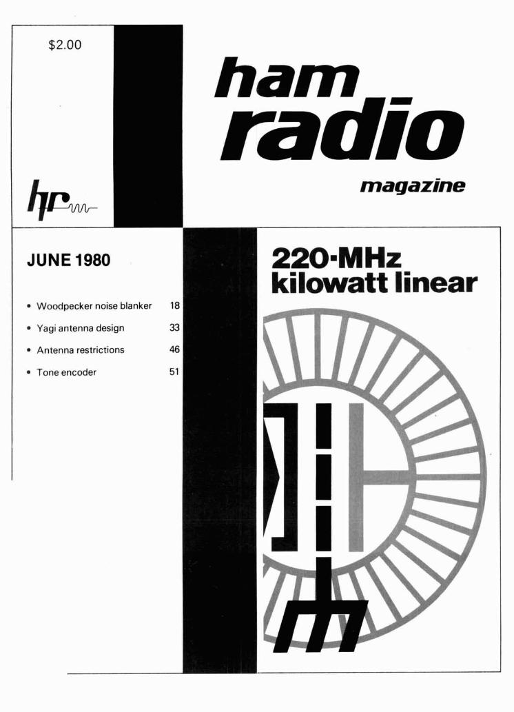
IT'S A FACT ... HENRY RADIO STILL PRODUCES THE BROADEST LINE OFSUPERIOR QUALITY AMPLIFIERS IN THE WORLD.
WHETHER FOR AMATEUR RADIO, COMMERCIAL OR MILITARY USE, WE OFFER A CHOICE OF FIELD PROVEN STATE-
OF-THE-ART UNITS TO FIT THE REQUIREMENTS AND BUDGETS OF THE MOST DISCRIMINATING USER.
ifl; 1KD-5 ... the newest member of the famous Henry Radlo famlly of flne ampllflem. And we're still convlnced that it'd the world's flnest Ilnear In
Its class. The 1KD-5 was deslgned for the amateur who wants the quallty and dependablllty of the 2KD-5 and 2K-4, whomay prefer thesmallerslze, llghter welght and lower price and who wlll settle for a llttle less power. But make no mlstake, the 1KD-5 Is no slouch. Its 1200 watt PEP lnput (700 watt PEP nomlnal output) along with Its superb operating characterlstlcs will still punch out clean powerful slgnals ... signals you'll be proud of. Compare Its speclflcatlons, Its features and Its flne components and we're sure you wlll agree that the 1KD-5 Is a superb value at only $695.
2KD-5 We have been suggesting that you look Inslde any ampllfler before you buy It. We hope that you wlll. If you "lift the Ild" on a 2KD-5 you wlll see
only the hlghest quallty, heavy duty components and careful workmanshlp ... allrlbutes that promlse a long llfe of contlnous operation In any mode at full legal power. The 2KD-5 Is a 2000 wall PEP lnput (1200 watt PEP nomlnal output) RF Ilnear ampllfler, coverlng the 80,40,20, and 15 meter amateur bands. It operates wlth two Elmac 3-5002 glass envelope trlodes and a PI-L plate clrcult wlth a rotary sllver plated tank coll. Price $945.
And don't forget the rest of the Henry famlly of amateur ampllflen ... the Tempo 2002 hlgh power VHF ampllfler and the broad llne of top quallty solld state ampllflem. Henry Radlo also offers the 3K-A and 4K-Ultra superb hlgh power H.F. ampllflers and a broad llne of commercial FCC type accepted ampllflem for two way FM communlcations covering the range to 500 MHz.
NEW TOLL FREE ORDER NUMBER: (8MI) 421-8631 ' d-- ,
For all states except Callfornla !. A
Callf res~dents please cal l collect on our regular numbers '
11240 W. Olympic Blrd.. Lm Anfjels. Calif. 90064 213,477-6701 931 N. Eucl~d. Anahelm. Cal~f. 92801 7141772.9200 Butler, Missour1 64730 8161679.3127
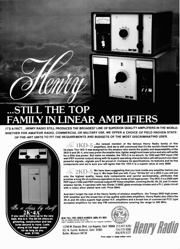
'! WILSON SYSTEMS, INC. PRESENTS 1; THE NEW SYSTEM 40 TRlRAhlRER
3 MDNOBAND ANTENNAS IN ONE - EACH WITH FULL MONOBAND PERFORMANCE i j
FACTORY DIRECT ONLY
AVAILABLE ONLY
I
I
I
1 1
FACTORY DIRECT CALL
TOLL 1-800-634-6898 FREE
- L
WILSON ! 5 Y S T E M S . IN ( : . mnm
i 1
1 A NEW CONCEPT IN ANTENNA DESIGN I ' USING A 26 FT. BOOM
.l,'?l, ' , t ' o l , , , , , , I ,,,, Vtq,t<, ~ I~V; I I I , I 89103 PRlCES AND SPECIACATDNS SUBJECT TO CM4NGE WlHOUl NOTICE.
I
FOR THE SERIOUS DXer WHO WANTS MONOBANDERS ON 10-1520 I
FOUR FULL SlZE 20 MTR ELEMENTS WITH 10 dbd GAlN THREE WIDE SPACED 15 MTR ELEMENTS WITH 8.2 dbd GAIN I
FOUR WlDE SPACED 10 MTR ELEMENTS WlTH 10.2 dbd GAIN I
ONLY ONE FEED LINE REQUIRED 11
DESIGNED WITH NO INTERACTIONS BETWEEN ELEMENTS i I
ALL DRIVEN ELEMENTS AND DIRECTOR ELEMENTS ARE INSULATED FROM BOOM I ALL PARASITIC ELEMENTS ARE FULL SIZE I( BROADBANDED-NO SEPARATE SETTINGS REQUIRED FOR PHONE OR CW I I
SAME QUALITY HARDWARE AS USED IN ALL WILSON ANTENNAS I
1R i
SPECIFICA TIONS Max. RM. Input . . . . . . . . Legal Limit Longest Element . . . . . . . . . . . . . 36 ' VSWR fi3 Res . . . . . . . . . . . . . . 1.2:l Turning Radius.. . . . . . . . . . . . 22 6" ,, Impedance . . . . . . . . . . . . . . . 50 ohm Surface Area . . . . . . . . . . . 12.1 sq. ft. rtrrm Feed Method . . Coax Balun Supplied Wind Loading (a 80 mph . . . 309 Ibs
. . . . . . Match~ng Method . . . Modified Beta Assem. Welght 75 Ibs. F'B Ratio . . . . . . . . . . . . . . . . . . 25 db Shipping Welght . . . . . . . . . 84 Ibs. tR
WlHR
Becembrr 12, ~ q 3 + 4 l p r i l 18, 1980
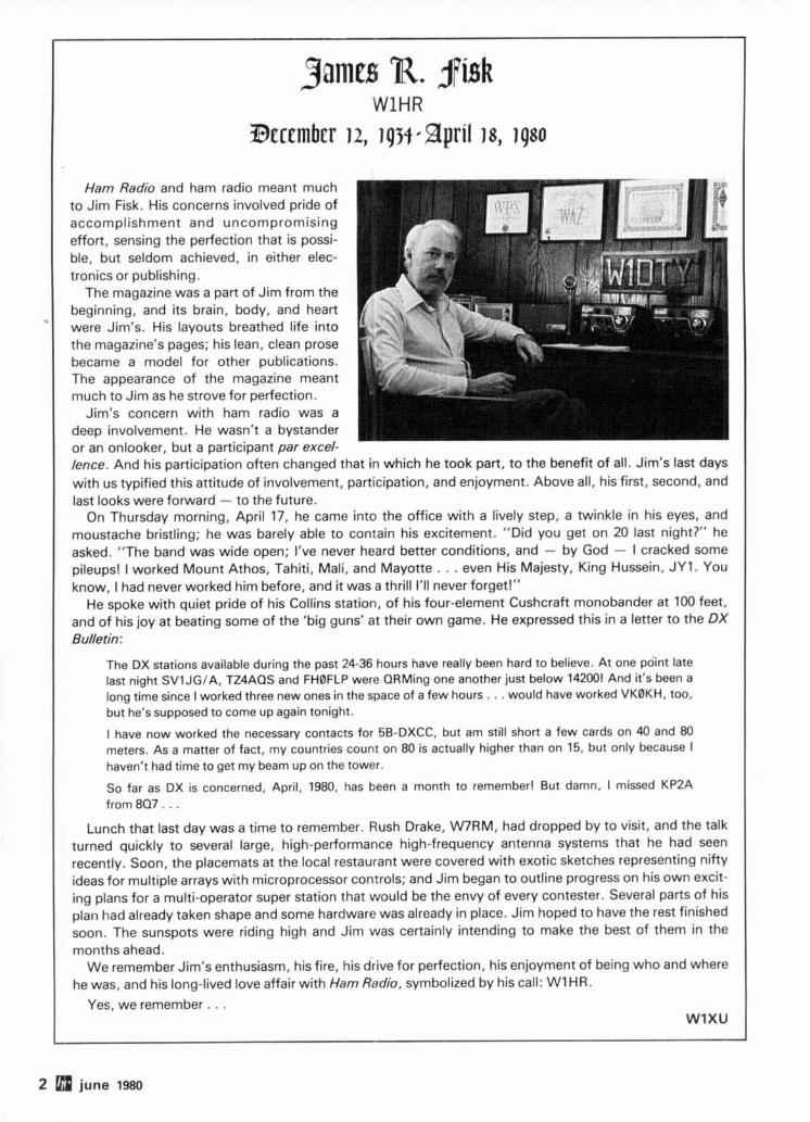
Ham Radio and ham radio meant much to Jim Fisk. His concerns involved pride of accomplishment and uncompromising effort, sensing the perfection that is possi- ble, but seldom achieved, in either elec- tronics or publishing.
The magazine was a part of Jim from the beginning, and its brain, body, and heart were Jim's. His layouts breathed life into the magazine's pages; his lean, clean prose became a model for other publications. The appearance of the magazine meant much to Jim as he strove for perfection.
Jim's concern with ham radio was a deep involvement. He wasn't a bystander or an onlooker, but a participant par excel- lence. And his participation often changed that in which he took part, to the benefit of all. Jim's last days with us typified this attitude of involvement, participation, and enjoyment. Above all, his first, second, and last looks were forward - to the future.
On Thursday morning, April 17, he came into the office with a lively step, a twinkle in his eyes, and moustache bristling; he was barely able to contain his excitement. "Did you get on 20 last night?" he asked. "The band was wide open; I've never heard better conditions, and - by God - I cracked some pileups! I worked Mount Athos, Tahiti, Mali, and Mayotte . . . even His Majesty, King Hussein, JY1. You know, I had never worked him before, and it was a thrill I'll never forget!"
He spoke with quiet pride of his Collins station, of his four-element Cushcraft monobander at 100 feet, and of his joy at beating some of the 'big guns' at their own game. He expressed this in a letter to the OX Bulletin:
The DX stations available during the past 24-36 hours have really been hard to believe. At one po;nt late last night SVlJGIA, TZ4AQS and FHBFLP were QRMing one another just below 142001 And it's been a long time since I worked three new ones in the space of a few hours. . . would have worked VKBKH, too, but he's supposed to come up again tonight.
I have now worked the necessary contacts for 5B-DXCC, but am still short a few cards on 40 and 80 meters. As a matter of fact, my countries count on 80 is actually higher than on 15, but only because I haven't had time to get my beam up on the tower.
So far as DX is concerned, April, 1980, has been a month to remember1 But damn, I missed KP2A from 8Q7 . . .
Lunch that last day was a time to remember. Rush Drake, W R M , had dropped by to visit, and the talk turned quickly to several large, high-performance high-frequency antenna systems that he had seen recently. Soon, the placemats at the local restaurant were covered with exotic sketches representing nifty ideas for multiple arrays with microprocessor controls; and Jim began to outline progress on his own excit- ing plans for a multi-operator super station that would be the envy of every contester. Several parts of his plan had already taken shape and some hardware was already in place. Jim hoped to have the rest finished soon. The sunspots were riding high and Jim was certainly intending to make the best of them in the months ahead.
We remember Jim's enthusiasm, his fire, his drive for perfection, his enjoyment of being who and where he was, and his long-lived love affair with Ham Radio, symbolized by his call: W1HR.
Yes, we remember . . . WlXU
2 W june 1980
ham
magazine
contents 12 220-MHz kilowatt linear
Robert I. Sutherland, W6PO
18 Woodpecker noise blanker Ulrich L. Rohde, DJ2LR
20 automation for synthesized two-meter fm mobile David J. Brown, W9CGI
33 Yagi antenna design: multi-element simplistic beams James L. Lawson. W2PV
42 21-MHz phased verticals Edmund H. Marriner. WGXM '
46 antenna restrictions J.W. Bryant, N4AQD
51 tone encoder for auto patches Christopher P. Winter, WB0VSZ
58 solid-state T-R switch Malcolm Crawford, KlMC
62 understacking high- frequency Yagi antennas Robert M. Myers, WlXT
68 macromatcher improvements Arnold C. Bachmann, K9DCJ
94 advertisers index 76 new produ 85 flea market 8 publishers 70 ham mart 94 reader sen 72 ham notebook
june 1980 3
New MFJ 3 & 1.5 KW Versa Tuners Run up to 3 KW or 1.5 KW PEP and match evevthing from 1.8 thru
30 MHz: coax, balanced line, random wire. Built-in balun. 3 KW VERSA T U N E R IV's 1.5 KW VERSA TUNER Ill's
. NEW MFJ KW VERSA TUNERS HAVE THESE FEATURES IN COMMON
Thctc 6 new MFJ KW Vena Tumn let you run up to 3 KW or 1 5 KW Fl~p down stand t~ l ts tuner for easy vlewlng PEP (depending on the model) and match any feedllne cont~nuously from Effe~ent, encapsulated 4:l ten ih balun. 250 pf. 6000 volt capacitors 1 8 to 30 MHz coax. balanced llne or random wlre Glves maximum 18 pos~t~on dual ~nductor, 17 amp. 3000 V ceramlc rotary swttch (3 KW power transfer Harmon~c attenuation reduces TVI, out of band emlsslons vers~on) 12 pos~t~on ~nductor, ceramlc rotary sw~tch (1 5 KW vers~on)
All metal, low pmfile cabinet glves RFI protect~on, r ~ g ~ d construction. 2% meters SO 239 coax connectors, ceramlc feedthru for random wlre sleek styling Black Rlch anodlzed alumlnum front panel 5x14~14 Inches and balanced llne One year llm~ted warranty Made ~n U S A
<
, MFJ-980 3 KW VERSA TUNER IV
MFJ-984 3 KW VERSA TUNER IV $16gg5 Heavy d u t y encapsulated 4:l ferr i te b a l u n fo r ba lanced lines.
$29gg5 EXCLUSIVE R F AMMETER Insures maxrmum power t o antenna a t The MFJ-980 is MFJ's lowest priced 3 KW Versa Tuner IV but has the
mrnrmum SWR. Burlt-rn d u m m y load. same matchlng capabll~t~es as the other 3 KW Versa Tuner IV's Features an effic~ent, encapsulated 4:l k m e balun for balanced llnes
Thls IS MFJ's best 3 KW Versa Tuner IV. The MFJ 984 Deluxe 3 KW Versa Tuner IV gtves you a comblnat~on of qual~ty, performance, and features that others can't touch at thls prlce
An exclusive 10 amp RF ammeter Insures maxmum power to antenna at mlnlmum SWR A separate meter glves SWR, forward, reflected power ~n 2 ranges (2000 and 200 watts)
Venat~le antenna switch lets you select 2 coax lrnes thru tuner and 1 El MFJ-962 1.5 KW VERSA TUNER 111 thru or dlrect or random wire, balanced line or dummy load
$1 7gg5 SWR, d u a l range forward and re f lec ted
A 200 wan 50 ohm dummy load lets you tune your exc~ter off a ~ r for p o w e r meter, 6 posrtron antenna peak performance Ell~c~ent encapsulated 4 1 ferr~te balun swrtch, encapsulated 4:1 ferrrte balun.
@ MFJ-981 3 KW VERSA TUNER IV The MFJ-962 1.5 KW Vena Tuner Ill 1s an exceptional value An accurate meter glves SWR, forward reflected power ~n 2 ranges
$1 9gg5 Accura te mete r grves SWR, forward (2000 and 200 watts) a n d re f lec ted p o w e r i n 2 ranges: 2000 A versatile six position antenna switch lets you select 2 coax llnes thru a n d 200 watts. 4:1 ferr i te balun. tuner or d~rect or random wlre and balanced l~ne Encapsulated 4 1 balun
The MFJ 981 3 KW Vena Tuner IV 1s one of MFJ s most popular Versa 'lack Iron' panel has reverse lettering
Tuners An accurate meter glves you SWR, forward and reflected power ~n 2 ranges 2000 and 200 watts Encapsulated 4 1 ferr~te balun
MFJ-982 3 XW VERSA TUNER IV MFJ-961 1.5 KW Versa Tuner Ill
$1 5gg5 6 posi t ron antenna sw i t ch le ts y o u
$19995 Antenna swrtch le ts y o u se lect 1 coax se lect 2 coax lrnes thru tuner o r direct, t h r u tuner a n d 2 coax t h r u tuner o r o r random wrre a n d ba lanced line. drrect, o r random wrre a n d balanced line. The MFJ-961 1.5 KW Versa Tuner Ill glves you a versatile SIX posltlon
The MFJ-982 3 KW Vena Tuner IV glves you a versatlle 7 pos~t~on an antenna sw~tch It lets you select 2 coax l~nes thru tuner or dlrect, or tenna sw~tch that lets you select 1 coax thru tuner and 2 coax thru tuner random wlre and balanced llne Encapsulated 4 1 ferrlte balun or d~rect or random wlre and balanced l~ne Encapsulated 4 1 balun H you already have a SWRlwattmeter, the MFJ 961 IS for you
H you already have a SWRlwanmeter, the MFJ 982 IS for you Black front panel has reverse lettering
W h y n o t visi t your dealer today? Compare these 3 K W a n d 1.5 KW Versa Tuners t o other tuners. You' l l b e convinced that i ts value, qua l i t y a n d features make i t a t ru ly outs tanding value. If n o dealer i s available, order d i rect f rom M F J a n d t ry it. If no t del ighted, re turn I t wi th in 30 days for a prompt re fund (less shipping). Charge VISA, MC. Or mai l cneck, money order p lus $10 shipplnglhandl ing.
For technical l n f o r m a t l o n , orderlrepalr status, In Mlsslsslppl, outside continental USA, call 601-323-5869.
Order By Mail or Call TOLL FREE 800-647-1800 and Charge It On - P. 0. BOX 494 L d m1 M F J ENTERPRISES, I NC. M l s s l s s l P ~ I STATE, MISSISSIPP~ 39x2
4 june ISM More Details? CHECK-OFF Page 94
---- - F
GO WITH THE BEST.
U
nil Ce
r The IC-251A is the newest IC-551 specifications. IC-251A 's Squelch Sensitivity: SSB/CW/AM addition to ICOM's all mode trans- specs are identical except where 1 PV ceiver line. Like the marching noted (in bold). FM* 0.4 pV (0.4pV) 'C-551, the IC-251A has dual digi- Frequency Coverage: 50-54MHz Seledivity: SSB/CW/AM -1 VFO's, three memories, scan- (1 43.8-1 48.1 9MHz) More than 21 .I KHz ar -6au(i.z)
79 (even SSB), and many other atures you only get from ICOM. RF Ovtput Power: Less than _+ 2.2KHz at -6dB (2.4)
550 10W PEP (When Pass Band Tuning Unit is Both units include the no
(1 -10W adjustable) (10W) installed: less than ldilcklash, no delay light chopper, similor to the IC-701, as a standard low 1KHz at -6dB)
(1 - 10W adjustable) (10W) FM* More than _+ 7.5KHz at -6dB feature at no cosr. Coupled to the
AM 4W Less than _+ 15KHz at - 60~0 microporcessor, this provides split frequency operation as well as (0-4W adjustable) ( - Dimensions: I I lmm (H) completely variable offsets. FM* 10 x 241mm (W) x 311mm (Dl
Check the specs, and you'll (1 ad.iustable) (i--iOW) Weiaht: 6,lka (5ka) .. d - .. agree, either way YOU 90, ICOM is Sensithrity: SSB/CW/AM simpty the best. Spurious Response Rejection Ratio:
L a than 0.5~Vfor 1 0 d S+N/N More than 60& SPECIFICATIONS FM* More than 30dB ~ i s t e d below are some of the S+N+D/N+D at lPV
r--"""""----"---------------
I 2:12116thAve,NE I Bellewe, WA 98004 I I Pi- send me: IC-551 spedflcatlons sheet 0 IC-251A I speclfkafions sheet: O l l s c of Authorized ICOM Dealers. I I :onn AMERICA, INCORPORATED I MU
Sales Service Centen located at. I
2 1 16th Avenue NE 3331 Towewood Dr., Suite 307 1 N'DREss- --
m e , WA 98004 Dallas, Tx 75234 I Cry. STATE I 2IP
ne (236) 454-8155 Phone (214) 62@2780 I
All stated spectf~cations are subject t o change wlthout notrce All lCOh4 radlos s~gn~flcantly exceed FCC regulations ltmtttng spurlous emlsslons
garnee R. $I&, WIHR - s o m e Reflectione
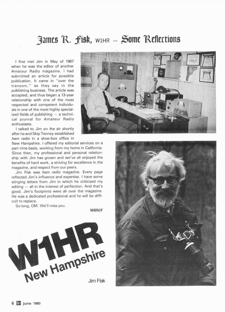
I first met Jim in May of 1967 when he was the editor of another Amateur Radio magazine. I had submitted an article for possible publication. It came in "over the transom," as they say in the publishing business. The article was accepted, and thus began a 13-year relationship with one of the most respected and competent individu- als in one of the most highly special- ized fields of publishing - a techni- cal journal for Amateur Radio enthusiasts.
1 talked to Jim on the air shortly after he and Skip Tenney established ham radio in a shoe-box office in New Hampshire. I offered my editorial services on a part-time basis, working from my home in California. Since then, my professional and personal relation- ship with Jim has grown and we've all enjoyed the benefits of hard work, a striving for excellence in the magazine, and respect from our peers.
Jim Fisk was ham radio magazine. Every page reflected Jim's influence and expertise. I have some stinging letters from Jim in which he criticized my editing - all in the interest of perfection. And that's good. Jim's footprints were all over the magazine. He was a dedicated professional and he will be diffi- cult to replace.
So long, OM. We'll miss you. W6NIF
6 a june 1980
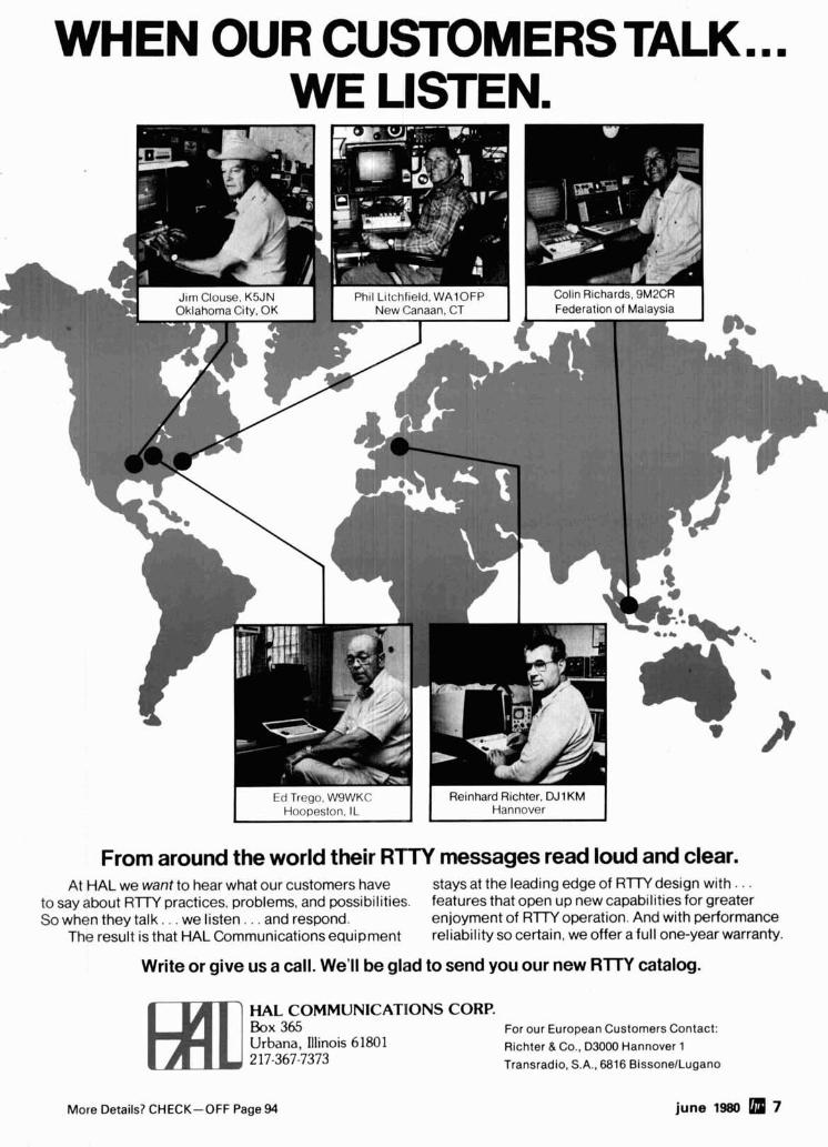
WHEN OUR CUSTOMERS TALK ... WE LISTEN.
t d T~c'qo W9WK(' Re~nhard R~chter. DJ1 KM Hoopeston. IL Hannover
From around the world their R l T Y messages read loud and clear. At HAL we want to hear what our customers have stays at the leading edge of R lTY design with . . .
to say about R T W practices, problems, and possibilities. features that open up new capabilities for greater So when they talk. . . we listen. . . and respond. enjoyment of R lTY operation. And with performance
The result is that HAL Communications equipment reliability so certain, we offer a full one-year warranty.
Write or give us a call. We'll be glad to send you our new RlTY catalog.
HAL COMMUNICATIONS CORP. h x 365 For our European Customers Contact: Urbana, Illinois 61801 Richter 8. Co., D3000 Hannover 1 2 17-367-7373 Transradio, S.A., 6816 BissonelLugano
More Details? CHECK-OFF Page 94 june 1980 7
' There are certainly few business situations that can bring two people much closer than working as pub- lisher and editor of a small magazine during its start-up years. It was my privilege to share with Jim Fisk, then W1 DTY, just such an exciting, yet often highly frustrating, experience.
We had embarked on a project which many told us was pure folly: a fourth entry in the already well-filled Amateur Radio magazine field. Success was impossible, they said. But with Jim's expertise and ambition, plus my stubbornness and determination, we felt that we had something to offer that was really different - a completely new publication, dedicated to excellence and professionalism, which would make a very real contribution to the hobby we both loved so well.
Our success is history now, but it didn't come easily. Editorial problems, printing difficulties, mailing mixups, promotional disappointments; I guess we saw them all. But working 26 hours a day, seven days a week, we overcame them one by one and gradually ham radio magazine established itself as the technical leader we'd envisioned, and new standards were set for both technical and graphic excellence in our field. These standards were the work of Jim Fisk, certainly the most capable and professional editor in many years to touch the pages of a ham magazine. He has set a standard that Amateur Radio editors will strive to reach for a long time to come.
But Jim was much more to our hobby than merely an excellent editor. He was at the center of new ideas and technical advances. His office was virtually a central switchboard or meeting place for the top thinkers and leaders in our hobby to exchange their ideas and discoveries, and he introduced, through the maga- zine, many of the contributions to Amateur state-of-the-art which have been developed in recent years.
This was probably never better demonstrated than during the 1980 Dayton Hamvention, which took place just a week after Jim's death. As our staff met literally hundreds of people who had known and worked with Jim, we were constantly reminded just how important he had become not just to our own publishing efforts but also to the continuing progress of Amateur Radio itself.
Jim will be sorely missed both in the pages of ham radio magazine and in the Amateur Radio hobby at large. Fortunately, however, he has left behind much which will continue to make significant contributions for a long time to come. Thanks to his efforts, we now have a well-trained editorial staff who have learned how to do things to Jim's standards. The magazine itself will act as a living memorial to Jim, as it con- tinues to be the rallying point for excellence in both Amateur theory and practice. Although we will now be operating without him, we will continue to work to his standards. The question, "How would Jim have done this?" will be asked many times, and the answer will provide our guidelines and keep us on our toes.
The question of just who is going to take his place on the masthead has already been asked many times. It is a difficult decision and one which we want to approach with a great deal of care and deliberation. For the time being, I personally will serve as acting editor, a position which I can fulfill only with the help and backing of Jim's top notch staff. They will be doing the work and I'll try primarily to provide the focal point between them and all of you.
In closing, I know I speak for all of us, both the ham radio family and Jim's personal family, when I express our thanks for all the many letters and calls we have received in recent days. They have been a great inspiration to all of us during this difficult period.
W1NLB
8 june I=
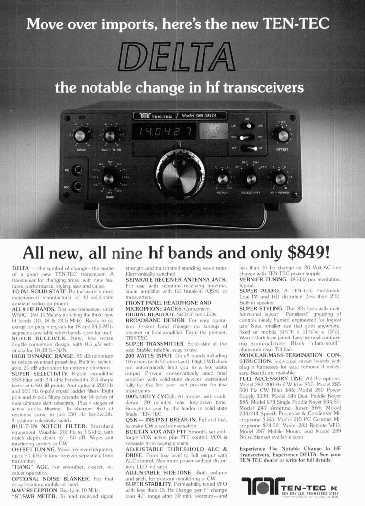
All new, all nine hf bands and only $849! DELTA - the svmhol of change-the name of a great new TEN TEC transcelver A transcelver for changing times w ~ l h new lea tures performance. stvl~ng. s17e and value TOTAL SOLID-STATE Bv the world s most experienced manufacturer of hf sold state amateur r a d ~ o equlpmrnt ALL 9 HF BANDS. FIR! new transceiver slnce WARC I60 10 Meters lncludlng the three new hf hands (10 18 & 24 5 MH/) Readv to go except for plug In cwstals for 18 and 24 5 MH7 seqments (avallahle when hands open for use) SUPER RLCEIVER. New I O U . noise
double conversion deslgn w ~ t h 0 3 pV sen s ~ h v l ~ for 10 d B S + N/N HIGH DYNAMIC RANGE. 8 5 dB mlnlmum to reduce overload porslhll~ty Built ~n switch able. 2 0 d B attenuator for extreme sltuahons SUPER SELECTIVITY. 8 pole monol~ th~c SSH f~lter w ~ t h 2 4 kH7 handwldth, 2 5 shapr factor at 6 / 6 0 dB po~nts And opt~onal 200 Hc and 5 0 0 Hz 6 pole crvstal ladder filters E~ght pole and G pole f~lters cascade for 14 poles o f nrar ult~mate sklrl selectlvlh, Plus 4 stages of actlve a u d ~ o hlterlng To sharpen that I f response curve to lust 150 ti7 hnntiwldth 4 posltlon selectlv~tv switch BUILT-IN NOTCH FILTER. S t a n d a r d equipment Vanahle 200 H/ to % 5 kH/ wlth notrh depth down to 50 dB Wipes out lnterferlny lamer5 or CW OFFSET TUNING. Moves recelver frequencv up to - 1 kH7 to tune rvcelvcr separatelv from transmlner "HANG" AGC. For smoother, clearer. re celver overahon
strength and trarlsm~ttc*tl s tand~ng wnwe ratto Electron~callv sw~tched SEPARATE RECEIVER ANTENNA JACK. l o r use w ~ t h 5eparate recelvlng antenna llnear ampllfler w ~ t h full hreak In (QSK) or lransverlers FRONT PANEL HEADPHONE AND MICROPHONE JACKS. Convenient DIGITAL READOUT. 51x 0 3 red LEDs BROADBAND DESIGN. For easv opera t l o r i Instant hand cl~ange-no tuneup of recetver or final ampllfler From the ploneer TEN TEC SUPER TRANSMITTER. Solid state all the wav Stahle. reliable e<lsv to use 200 WATTS INPUT. On all bands ~nc lud~ng 10 meters ( w ~ t h 50 ohm load) Hlqh SWR does not au tomat~ca l l~ l~rnlt you to a few walls output Proven con\ervatlvelv rated final ampllfler w ~ t h solld s t ,~te devlces warranted fullv for the hrst year and pro rata for /111e more years 100% DUTY CYCLE. All modes. wlth con11 derice 2 0 m~nutes rnax kev down time Brought to voc~ by thv leader ~n sol~d state f~nals TEN TEC QSK - INSTANT BREAK-IN. Full and fast to make* CW a rval rnriversatlon BUILT-IN VOX AND P I T Smooth set and forget VOX actlon plu, PTT control VOX IS
separate from kevlnq orcults ADJUSTABLE T H ~ E S H O L D ALC & DRIVE. From low level to full output w ~ t h ALC control Mailmum power w~thout dlstor tlon LED ~ndlcator ADJUSTABLE SIDETONE. Both volume
less than 10 HI change for 2 0 Volt AC llne change ~11th TEN TFC power supplv VERNIER TUNING 18 kH7 per revolution. tvplcal SUPER AUDIO A TEN TEC trademark L.ow IM and HD d~s to r t~on (less than 2':) Built ~n speaker SUPER STYLING. The 80s look w~th neat functional lavout Panel17ed grouplng of controls nlcelv human enqlneered for logical u5e New smaller size that goes anvwhore f ~ x r d or moblle (4'4 h x 11 ' n w x 15 dl Warm dark front panel Easv to read coritrdst Ing nomenc la tu re Black c lam shell a lum~num case T~lt hall MODULARIMASS-TERMINATION CON- STRUCTION. Indlv~dual clrcult hoards w~th plug In harnesses for easL removal 11 neces saw Boards are mallable FULL ACCESSORY LINE. All the op t~ons Model 252 200 HI CW fllter $50 Model 285 5 0 0 H7 CW Fllter $45 Model 280 Power Supplv $130 Model h45 Dual Paddle Kever $85 Model 670 Slngle Paddle Keyer $34 50 Model 2 4 7 Antenna Tuner $ 6 9 Model 2.34/2 14 Speech Processor & Condenser MI crophone '$163 Model 215 PC Ceramlc MI rrophone $.34 5 0 Model 283 Remote VFO Model 287 Mob11e Mount and Model 289 No~se Blanker avallahle soon
Experience The Notable Change In HF Transceivers. Experience DELTA. See your TEN-TEC dealer or write for full details.
OPTIONAL NOISE BLANKER. For that and p~tch for pleasant rnonltonng of CW nolsy locahon, mob~lc. or f~xed SUPER STABILITY. Permeah~l~tv tuned VFO WWV RECEPTION. Readv at 10 MH7 w ~ t h less than 15 H7 change per F change 1blF,~-Ec. S E V ~ ~ R V I I L E T C N N ~ S S E E 37862 1°C. "S"/SWR METER. To read recelved slgnal over 4 0 range after 30 mln warmup-and ., . , * a
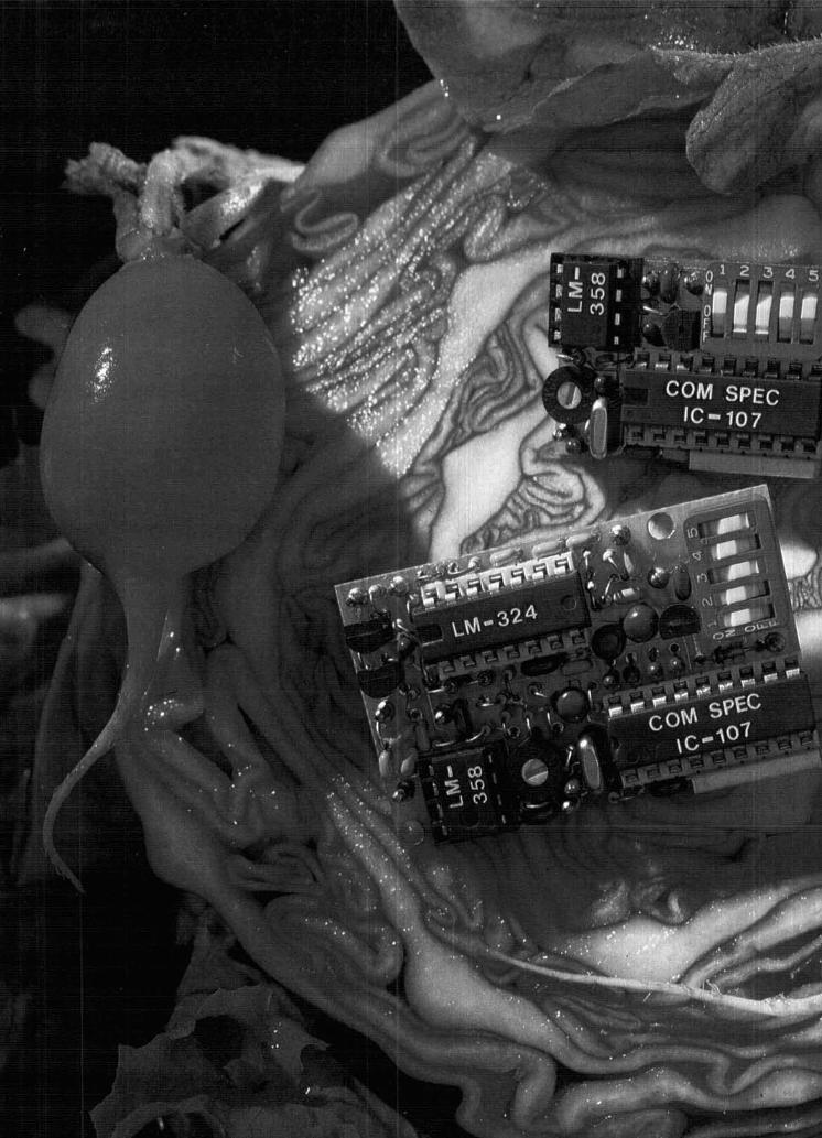
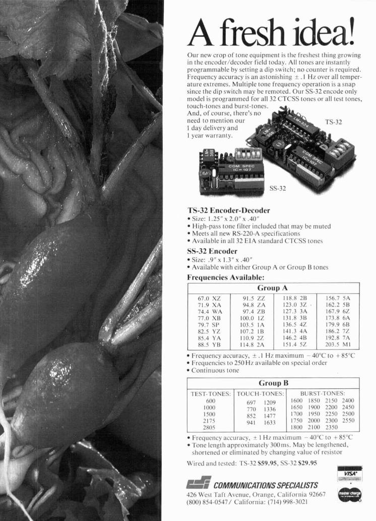
A fresh idea! Our new crop of tone equipment is the freshest thing growing in the encoder/decoder field today. All tones are instantly programmable by setting a dip switch; no counter is required. Frequency accuracy is an astonishing + . 1 Hz over all temper- ature extremes. Multiple tone frequency operation is a snap since the dip switch may be remoted. Our SS-32 encode only model is programmed for all 32 CTCSS tones or all test tones, touch-tones and burst-tones. u And, of course, there's no need to mention our 1 day delivery and 1 year warranty.
TS-32 Encoder-Decoder Size: 1.25" x 2.0" x .40" High-pass tone filter included that may be muted Meets all new RS-220-A specifications Available in all 32 EIA standard CTCSS tones
SS-32 Encoder Size: .9" x 1.3" x .40" Available with either Group A or Group R tones
Frequencies Available:
I Group A 67.0 XZ 91.5 ZZ 118.8 2B 156.7 A 71.9 XA 94.8 LA 123.0 3% 162.2 5B 74.4 WA 97.4 ZB 127.3 3A 167.9 6% 77.0 XU 100.0 1 % 131.8 3B 173.8 6A 79.7 S P 103.5 1A 136.5 4% 179.9 6R 82.5 YZ 107.2 IB 141.3 4A 186.2 7% 85.4 YA 110.9 2Z 146.2 4B 192.8 7A 88.5 YB 114.8 2A 151.4 5% 203.5 MI
Frequency accuracy, t . l Hz maximum - 40°C to + 85°C Frequencies to 250 H7 available on special order Continuous tone
TEST-TONES: 600
1000 1 500 2175 2x05
BU KST-TONES: 1600 1850 2150 2400 1650 1900 2200 2450 1700 1950 2250 2500 1750 2000 2300 2 5 0 1800 2100 2350
- - -
Frequency accuracy, 1 Hz maximum - 40°C to + 85°C Tone length approximately 300ms. May be lengthened, shortened or eliminated by changing value of resistor
Wired and tested: TS-32 $59.95, SS-32 529.95 Y
426 \\c\t Talt iZ\enuc. Oranyc, C'alilornia 93667 I (800) 854-0547/ California: (714) 998-3021
grounded-grid 220=MHz kilowatt linear
The Eimac 8877 is a high-mu ceramic-metal triode rated for use up to 250-MHz and several successful amplifier designs using this tube have been con- structed for hf through ~ h f . l . 2 ~ 3 The 220-MHz amplifier described here has proven to operate very well during the last year, including several successful Earth-Moon-Earth (EME) contacts.
This 220-MHz 8877 linear amplifier is designed for the serious vhf DXer who demands reliable service combined with good linearity and efficiency. The am- plifier requires no neutralization, is completely stable and free of parasitics, and is very easy to operate.
The amplifier is designed for continuous duty oper- ation at the 1000-watt dc input level, and can develop 2000-watts PEP input for SSB operation with ample reserve. For operation at 2000-watts PEP the plate supply should be between 2500 and 3000 volts; under these conditions the amplifier will deliver 1230 watts output. With the higher plate-voltage supply, up to 14-dB gain can be obtained with an amplifier efficien- cy of 61 per cent; see table 1.
The 8877 triode has very good current division; that is, the grid current is quite low in comparison to the plate current. The grid current is typically about 15 per cent of the value of the plate current. the 8877 also has good gain and intermodulation distortion characteristics. The plate dissipation rating is 1500- watts. The cathode is indirectly heated; filament re- quirements are 5.0-volts at 10.5 amperes. The tube base mates with a standard septar socket.
the circuit In the amplifier circuit shown in fig. 1 the 8877 grid
is operated at dc ground. The grid ring at the base of the tube provides a low-inductance path between the grid element and the chassis. The plate and grid cur- rents are measured in the cathode return lead. A 12- volt, 50-watt zener diode in series with the negative return sets the desired value of idling current. Two additional diodes are shunted across the meter circuit to protect the instruments in case plate voltage arcs over to ground, or if there is an internal tube arc.
Standby plate current of the 8877 is reduced to a very low value by a 10,000-ohm cathode resistor. This resistor is shorted out in the transmit mode by the station control circuit. The resistor must be in the cathode circuit when receiving to eliminate the noise generated in the station receiver if electron flow is permitted within the 8877 tube.
A 200-ohm safety resistor insures that the negative side of the power supply does not go below ground potential by an amount equal to the plate voltage if the positive side is accidentally grounded. A second safety resistor across the IN3311 zener diode pre- vents the cathode potential from rising if the zener should accidentally burn open.
input circuit The cathode matching circuit is a T-network which
transforms the input impedance of the tube (about 54 ohms in parallel with 40 pF) to 50 ohms at the coaxial input connector; the network consists of two series inductors and a shunt variable capacitor. The inductors are fixed and have a very low value of in- ductance; in fact, the rf return path through the chassis has about the same inductance value. To de- sign the input circuit, many values of circuit Q were tried in the calculations. When the design equations yielded physically realizeable inductance values, then several combinations were tried in the actual ampli- fier. Since the stray inductances in the chassis and connecting leads in the socket were not included in the calculations, the final inductors were smaller in value than the calculated size. The actual inductors which resonated and provided a reasonable input match are specified in fig. 1 and are shown in some of the photographs. For those who build this ampli- fier I would expect that some minor variations in these coils might be required to attain an adequate input match.
By Robert I. Sutherland, W6P0, ElMAC Divi- sion of Varian, 301 Industrial Way, San Carlos, California 94070
12 june 1980
and input line blocking capacitor C1.
7
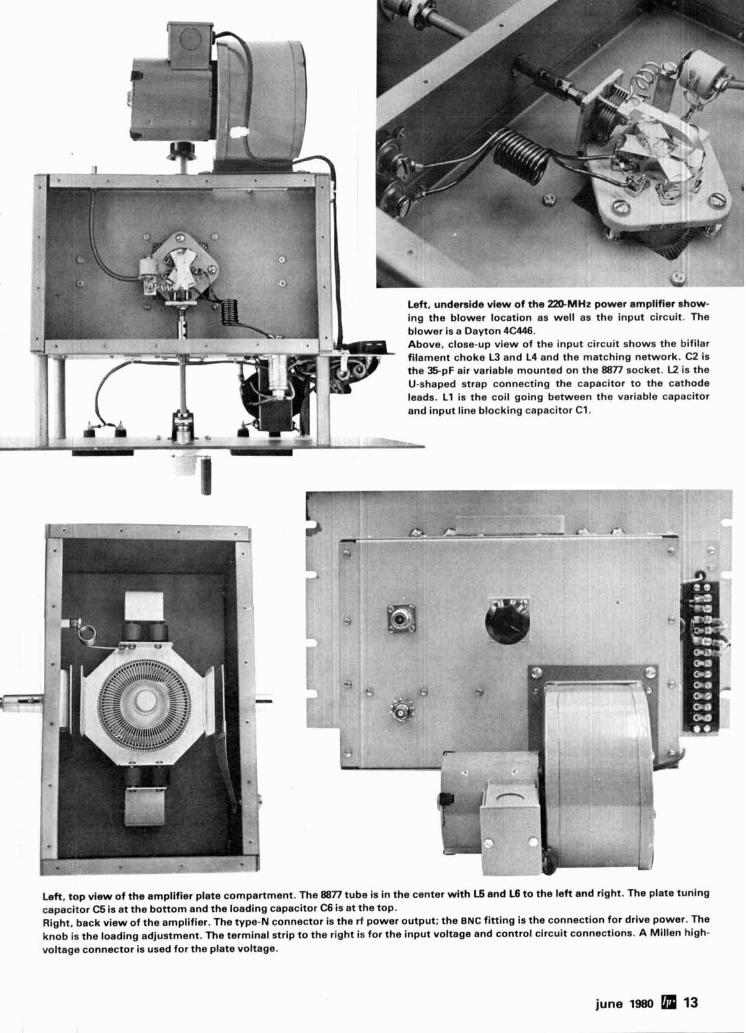
Left. underside view of the 2MMHz power amplifier show- ing the blower location as well as the input circuit. The blower is a Dayton 4C446. Above, close-up view of the input circuit shows the bifilar - filament choke L3 and L4 and the matching network. C2 is ' the 35-pF air variable mounted on the 8877 socket. K is the
r '- U-shaped strap connecting the capacitor to the cathode leads. L1 is the coil going between the variable capacitor
Left, top view of the amplifier plate compartment. The 8877 tube is in the center wi th 15 and L6 t o the left and right. The plate tuning capacitor C5 is at the bottom and the loading capacitor C6 is at the top. Right, back view of the amplifier. The type-N connector is the rf power output; the BNC fitting is the connection for drive power. The knob is the loading adjustment. The terminal strip to the right is for the input voltage and control circuit connections. A Millen high- voltage connector is used for the plate voltage.
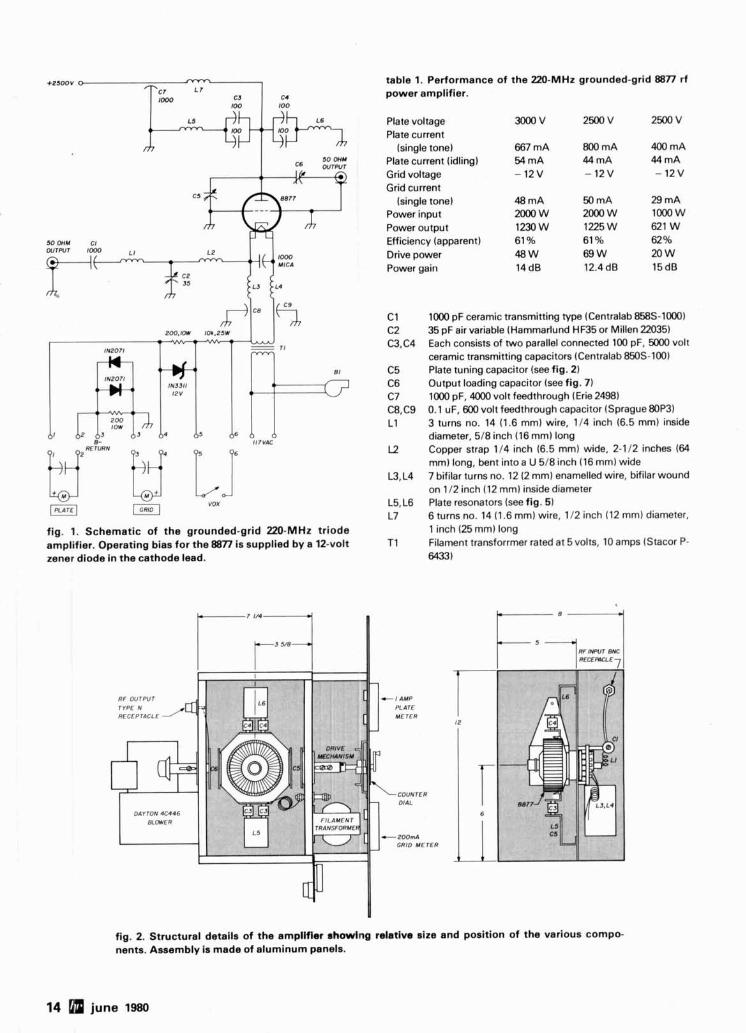
fig. 1. Schematic of the grounded-grid 220-MHz triode amplifier. Operating bias for the 8877 is supplied bye 12-volt zener diode in the cathode lead.
RF OUTPUT
DAYTON4C446
table 1. Performance of the 220-MHz grounded-grid 8877 rf power amplifier.
Plate voltage Plate current
(single tone) Plate current (idling) Grid voltage Grid current
(single tone) Power input Power output Efficiency (apparent) Drive power Power gain
FILAMENT 'RANSFORME
GRID M E T E R
1000 pF ceramic transmitting type (Centralab 8588-1000) 35 pF air variable (Hammarlund HM5 or Millen 22035) Each consists of two parallel connected 100 pF, 5000 volt ceramic transmitting capacitors (Centralab 850s-100) Plate tuning capacitor (see fig. 2) Output loading capacitor (see fig. 7 ) 1000 pF, 4000 volt feedthrough (Erie 2498) 0.1 uF, 600volt feedthrough capacitor (Sprague80P3) 3 turns no. 14 (1.6 mm) wire, 114 inch (6.5 mm) inside diameter, 518 inch (16 mm) long Copper strap 114 inch (6.5 mm) wide, 2-112 inches (64 mm) long, bent into a U 518 inch (16 mm) wide 7 bifilar turns no. 12 (2 mm) enamelled wire, bifilar wound on 112 inch (12 mm) inside diameter Plate resonators (see fig. 5 ) 6 turns no. 14 (1.6 mm) wire, 112 inch (12 mml diameter, 1 inch (25 mm) long Filament transforrmer rated at 5 volts, 10 amps (Stacor P- 6433)
fig. 2. Structural details of the amplifier showing ralatlva size and position of the various compo- nents. Assembly is made of aluminum panels.
14 june 1980
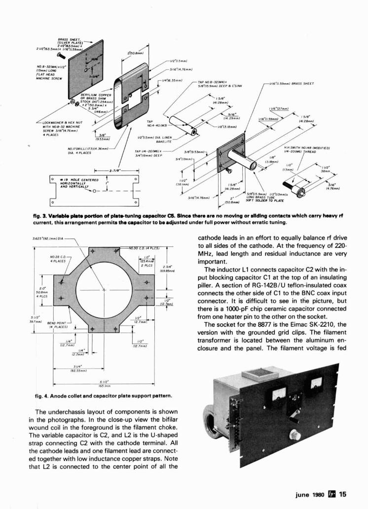
flg. 3. VarkM. pkto portion of phtttunlng cmpmchr C6. Mnca there am no moving or dldlng contacts whlch carry heavy rf current, this arrangement permib tha capacitor to be adjusted under full power without erratic tuning.
3 625'192 ~ m m ~ DH cathode leads in an effort to equally balance rf drive to all sides of the cathode. At the frequency of 220- MHz, lead length and residual inductance are very important.
The inductor L1 connects capacitor C2 with the in- put blocking capacitor C1 at the top of an insulating piller. A section of RG-142BlU teflon-insulated coax connects the other side of C1 to the BNC coax input connector. It is difficult to see in the picture, but there is a 1000-pF chip ceramic capacitor connected
1/2* -, from one heater pin to the other on the socket. The socket for the 8877 is the Eimac SK-2210, the
version with the grounded grid clips. The filament transformer is located between the aluminum en- closure and the panel. The filament voltage is fed
3 I/# I82 55mml
6 l/Za 2 165 lmm
fig. 4. Anode collet and capacitor plate support pattern.
The underchassis layout of components is shown in the photographs. In the close-up view the bifilar wound coil in the foreground is the filament choke. The variable capacitor is C2, and L2 is the U-shaped strap connecting C2 with the cathode terminal. All the cathode leads and one filament lead are connect- ed together with low inductance copper straps. Note that L2 is connected to the center point of all the
through the enclosure wall using 0.1 pF Sprague Hy- Pass feedthrough capacitors.
plate circuit The plate circuit of the amplifier is a transmission-
line type resonator. The line (L5 plus L6) is one half- wavelength long with the tube placed at the center. This type of circuit is actually two quarter-wave- length lines in parallel. One of the advantages is that each of the quarter-wavelength lines is physically longer than if only one is used. This is because only half of the tube output capacitance loads each quarter-wavelength section. Another advantage to this layout is a better distribution of rf currents atound the tube seals.
The dc blocking capacitors are surplus Centralab 100-pF, 5000-volt ceramic capacitors. Two are used on each line to handle the rf current. The homemade variable capacitor C5 tunes the plate circuit. Note that this type of capacitor structure has no wiping contacts. All the rf currents flow through a fixed path which provides very smooth tuning with no jumping meter readings. The load capacitor C6 is constructed in a similar manner.
The plate choke L7 is visible in the photograph of the plate compartment. It is connected to the plate collet assembly with the Erie high voltage feed- through capacitor C7.
INTERNAL TOOTH
N 0 6 - 3 Z z L * ( U 3 5 * 5 35mml MACHINE SCREW
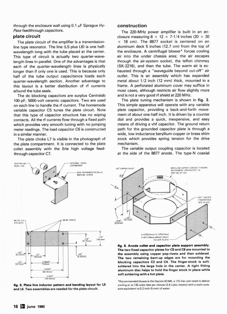
fig. 5. Plate line inductor pattern and bending layout for L5 and L6. Two assemblies are needed for the plate circuit.
construction The 220-MHz power amplifier is built in an en-
closure measuring 8 x 12 x 7-114 inches (20 x 30 x 18 cm). The 8877 socket is centered on an aluminum deck 5 inches (12.7 cm) from the top of the enclosure. A centrifugal blowerx forces cooling air into the under chassis area; the air escapes through the air-system socket, the teflon chimney (SK-2216), and then the tube. The warm air is ex- hausted through a "waveguide beyond cut-off" air outlet. This is an assembly which has expanded metal about 112 inch (12 mm) thick, mounted in a frame. A perforated aluminum cover may suffice in most cases, although restricts air flow slightly more and is not a very good rf shield at 220 MHz.
The plate tuning mechanism is shown in fig. 3. This simple apparatus will operate with any variable plate capacitor, providing a back-and-forth move- ment of about one-half inch. It is driven by a counter dial and provides a quick, inexpensive, and easy means of driving a vhf capacitor. The ground return path for the grounded capacitor plate is through a wide, low inductance beryllium-copper or brass shim stock which provides spring tension for the drive mechanism.
The variable output coupling capacitor is located at the side of the 8877 anode. The type-N coaxial
vB'CDPPER RIVET B E R ~ L I U M COPPER CONTACT FINGERS INSTRUMENT SPECIALTIES CO W R T NO 91-09
2 1/Z.m35mml. Z I n Y b i . 5 m d
#1/16.11.59mml BRASS SHEET ISILVER PLATE)
fig. 6. Anode collet and capacitor plate support assembly. The two fixed capacitor plates for C5 and C6 are mounted to the assembly using copper pop-rivets and than soldered. The two remaining bent-up edges are for mounting the blocking capacitors C3 and C4. The finger-stock is soft- soldered into the large hole in the center. A tight fitting aluminum disc helps to hold the finger stock in place while soft soldering with a hot plate.
'Recommended blower is the Dayton 4C446, a 115-Vac unit rated to deliver cooling air at 135 cubic feet per minute (3.8 cubic meters) with a static pres- sure equivalent to 0.2 inch (5 mm) of water.
16 june 1980
Me-% W I # V P ( l 3 m m l Ld(YO
FLAT M A 0 MACHINE SCREW7 TAP 8-321M4l . S/B'115 9mml
[ D E E P e c3s,N&
\ 1CENTCRED I N PLATE)
C 0. NO. 0-38 1/2'10 7mm) LINEN BAKELITE
P M Y S J . l m m l . 2 V2%3.Smm . V16~11.59mml BRASS SHEET {SILVER PLATE1
TAP M - 2 0 IU6) X M l 9 m m l DEEP
NillTl.IT3114.3mmlOIC.
S B ~ l l l 9mml rn 1/2.113mml * 13M.143 2 m m l LONG BRASS TUBE,SOFT SOLOER TO PLATE
H.H.SYITH NO.148 1MOOIFIEOl 1 /4-20lM61 THREAD
I / 2 ~ l l 3 m m l
SOFT S O L M R m 2 m.163.Smml a 2 VZ'l63.5mml . 1/16?1.59mml BRASS CAFUCITOR PLATE
BERILIUY COPPER OR BRASS SHIM STOCK .OID%PSlmmI THICK 81 3 S-%fmS.hnml RINGS
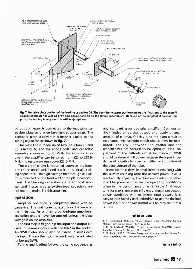
fig. 7. Variable plate portion of the loading capacitor CB. The beryllium-copper portion carries the rf current to the m N coaxial connector as well as providing spring tension on the tuning mechanism. Because of the constant rf conducting path, the loading is very smooth with no jumpiness.
output connector is connected to the moveable ca- pacitor plate by a wide beryllium-copper strap. The capacitor plate is driven in a manner similar to the tuning capacitor as shown in fig. 7.
The plate line is made up of two inductors L5 and L6 (see fig. 5) and the anode collet and capacitor assembly shown in fig. 6. With the inductor sizes given, the amplifier can be tuned from 220 to 222.5- MHz; no tests were run above 222.5-MHz.
The plate rf choke is mounted between the junc- tion of the anode collet and a pair of the dual block- ing capacitors. The high-voltage feedthrough capaci- tor is mounted on the front wall of the plate compart- ment. The blocking capacitors are rated for rf sew- ice, and inexpensive television-type capacitors are not recommended for this amplifier.
operation Amplifier operation is completely stable with no
parasitics. The unit tunes up exactly as if it were on the hf bands. As with all grounded-grip amplifiers, excitation should never be applied unless the plate voltage is on the amplifier.
The first step is to grid-dip the input and output cir- cuits to near-resonance with the 8877 in the socket. An SWR meter should also be placed in series with the input line so the input network may be adjusted
any standard grounded-grip amplifier. Connect an SWR indicator at the output and apply a small amount of rf drive. Quickly tune the plate circuit to resonance; the cathode circuit should now be reso- nated. The SWR between the exciter and the amplifier will not necessarily be optimum. Final ad- justment of the cathode circuit for minimum SWR should be done at full power because the input impe- dance of a cathode-driven amplifier is a function of the plate current of the tube.
Increase the rf drive in small increments along with the output coupling until the desired power level is reached. By adjusting the drive and loading together it will be possible to attain the operating conditions given in the performance chart in table 1. Always tune for maximum plate efficiency: maximum output power combined with minimum input power. It is easy to load heavily and underdrive to get the desired power input but power output will be reduced if this is done.
references 1. R. Sutherland, WGUOV. "Two Kilowatt Linear Amplifier for Six Meten." hamradio. February, 1971, page 16. 2. R . Sutherland, WGUOV, "High Performance 144-MHz Power Amplifier," ham radio, August. 1971. page 22. 3. M. Partin, K6DC. "Custom Design and Construction Techniques for Linear Amplif'ers," QST, September. 1971, page 24.
for lowest SWR. Tuning and loading follows the same sequence as ham radio
Woodpecker noise blanker
The Russian over-the-horizon radar
has been causing interference on the
high-f requency bands - here's a noise blanker
that helps
Anyone who operates regularly on the high- frequency Amateur bands has probably run into in- terference from the Russian over-the-horizon radar which operates between 10 and 30 MHz; because of its peculiar sound, it is popularly known as the "Rus- sian Woodpecker." The noise-blanker circuit shown in fig. 1 was designed especially by M. Martin of the Hahn-Meitner Institute in West Berlin to blank the
Woodpecker noise pulses;l this unit is also suitable for blanking out the Loran pulses that plague long- distance communications on the Amateur 160-meter band.
Although the circuit of fig. 1 was built for a 9-MHz i-f, it should be relatively easy to adapt the circuit to other i-f systems. The circuit requires only two inte- grated circuits and six transistors; it has a blanking range of about 80 dB and does not degrade the re- ceiver's dynamic range.
circuit description The rf signal is picked up at the receiver's first mix-
er (9 MHz in this case), amplified by the CP643 fet amplifiers, and fed through the four diode gate, which is frequency compensated: the output is de- signed to drive a 9-MHz crystal filter. It should be possible to use this same basic circuit over the range from about 3 MHz to 70 MHz by changing the fre- quency tuned circuits.
A small fraction of the rf signal is coupled through the BF246C source follower and a tuned circuit to the Siemens TCA440 IC, which is actually a complete a-m receiver on a single chip;* this IC operates up to
"Circuit designers who are interested in developing the Woodpecker blank- er for use in the Drake R4C. Collins 75s-3C, and other Amateur communi- cations receivers please contact the editor.
-
By Ulrich L. Rohde, DJ2LR, 52 Hillcrest Drive, Upper Saddle River, New Jersey 07458
18 june 1980
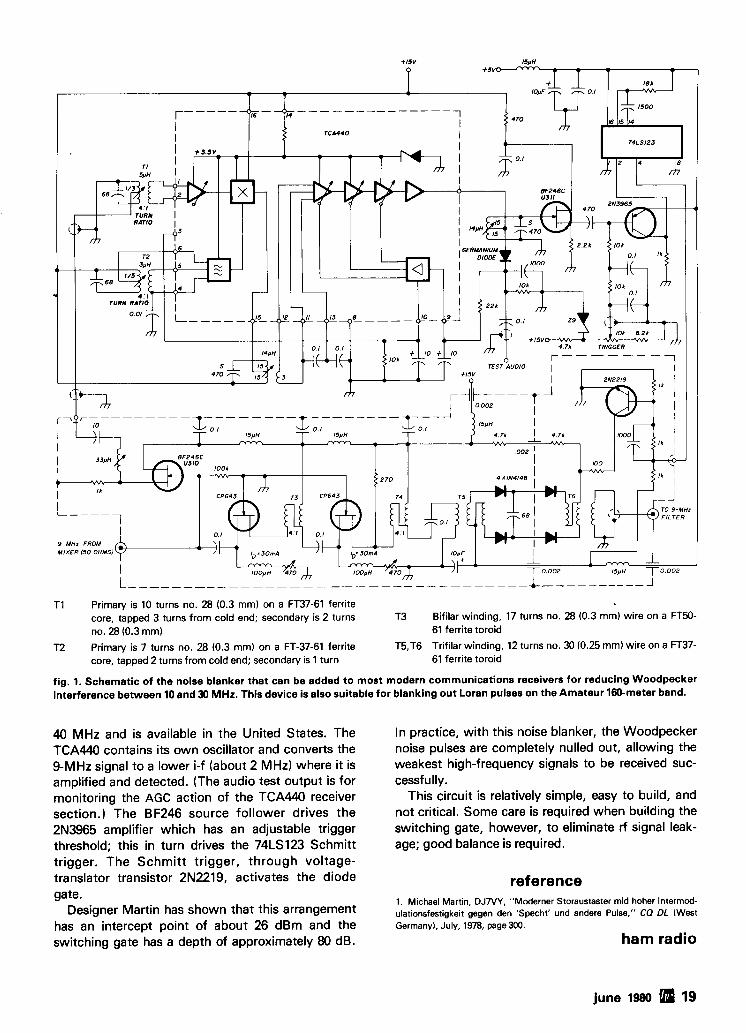
TI Primary is 10 turns no. 28 (0.3 mm) on a FT37-61 ferrite core, tapped 3 turns from cold end; secondary is 2 turns T3 Bifilar winding, 17 turns no. 28 (0.3 mm) wire on a FT50- no. 28 (0.3 mm) 61 ferrite toroid
T2 Primary is 7 turns no. 28 (0.3 mm) on a FT-37-61 ferrite T5,T6 Trifilar winding, 12 turns no. 30 (0.25 mm) wire on a FT37- core, tapped 2 turns from cold end; secondary is 1 turn 61 ferrite toroid
fig. 1. Schematic of the noise blanker that can be added to most modern communications receivers for reducing Woodpecker interference between 10 and 30 MHz. This device is also suitable for blanking out Loran pulses on the Amateur 160-meter band.
40 MHz and is available in the United States. The TCA440 contains its own oscillator and converts the 9-MHz signal to a lower i-f (about 2 MHz) where it is amplified and detected. (The audio test output is for monitoring the AGC action of the TCA440 receiver section.) The BF246 source follower drives the 2N3965 amplifier which has an adjustable trigger threshold; this in turn drives the 74LS123 Schmitt trigger. The Schmitt trigger, through voltage- translator transistor 2N2219, activates the diode
In practice, with this noise blanker, the Woodpecker noise pulses are completely nulled out, allowing the weakest high-frequency signals to be received suc- cessfully.
This circuit is relatively simple, easy to build, and not critical. Some care is required when building the switching gate, however, to eliminate rf signal leak- age; good balance is required.
reference gate.
1. Michael Martin, DJ7VY, "Moderner Storaustaster mid hoher Intermod- Designer Martin has shown that this arrangement ulationsfestigkeit gegen den 'Specht' und andere Pulse," CQ DL (West
has an intercept point of about 26 dBm and the Germany), J U I ~ , 1978, p a g e 3 ~ .
switching gate has a depth of approximately 80 dB. ham radio
june 1980 19
automation for synthesized
2-meter mobile stations
Meet the Auto-mate - a design for
improving operation of 2-meter radios
using synthesizers
You say you've joined the crowd and have stopped buying crystals for your 2-meter rig? Now that you're into synthesizers and can dial up every- thing from the area's most valuable and used ma-
' chine to the three-man operation 50 miles (80 km) away, no doubt you wish you could keep track of all the action. It gets rather scary when you try to manipulate all those dials in the darkness of your automobile.
This article may not solve all your problems, but it goes a long way toward making your mobile opera- tion safer and more fun. It allows you to eaves- drop on the metropolitan chaos while keeping both hands on the wheel. I'II show you how to automate your synthesizer so that it "knows" exactly what you
want when you dial in only the desired receiver fre- quency. I'II show you how to add scanning push-to- talklpush-to-receive controls to relieve you from "mobile thumb" derived from holding down the PTT button, and more. In the end you'll have 1) a radio setup that has a synthesizer up front with you and a trunk-mounted radio if you desire (sorry thieves!), 2) short microphone wires to avoid trash pickup in mo- bile operation, and 3) a unit you can run in complete darkness. I call it the Auto-mate.
background My project began with an article by Bob Fanning,
K4VB, and Gary Grantland, WA4GJT.l This article showed how to build an 800-channel synthesizer from boards and parts supplied by the authors.
I had already fallen in love with the KLM 2700 syn- thesized radio I use for a base station on 2 meters, so synthesis had to be the way to go for mobile opera- tion. I mounted a Heath HW-202 in the trunk of my Toyota. It became a case of running a huge wiring harness or settling for one channel (trunk chosen) and stopping every time I wanted to change chan- nels. This doesn't make for the greatest operation when you travel around the country! In addition, I had alternator whine because I tried to run un- shielded microphone lines to the trunk to simplify the wiring. Bob and Gary1 gave me the solution to that one with their synthesizer, because you can modu-
By D. J. Brown, WSCGI, R.R. 5, Box 39, Noblesville, Indiana 46060
20 june 1980
- ,. - - - - - - C F O E A B
NOTE 4 +5V +5v '? Q
I 6 I 1 16 I I 16 I I - j3 4 - l3 4 2 +I3
5 UI3 I2 5 U12 I2 5 UI I UZI
+SV O-- 74192 PIN I3
I 5 74192
14 15 14 15 74193
14
b 1 1 0 9 8 1 1 1 0 9 8 1 1 0 9 8
- - BCD IN BCD I BCD DATA INPUT 1
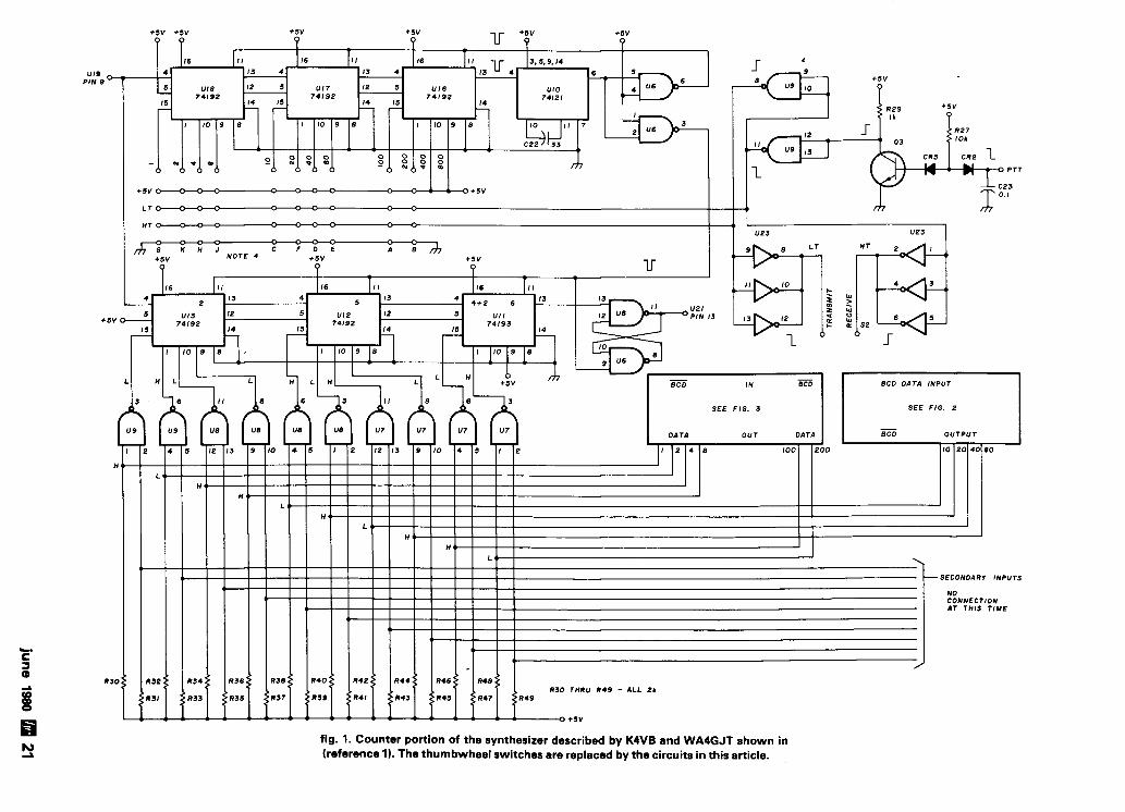
fig. 1. Counter portion of the synthesizer described by K4VB and WA4GJT shown in (reference 1). The thumbwheel switches are replaced by the circuits in this article.
late the sythesizer up front and run only two small rf coaxial cables to the trunk for full-channel control.
The synthesizer1 used two BCD-encoded output switch sets to control channel selection and a sepa- rate .switch to control transmit and receive modes. This can be quite confusing in a mobile, even in the daylight; at night it becomes a disaster! I can't give enough praise for the synthesizer, boards, parts, and most of all, the personal help by K4VB and WA4GJT. If you are about to go the synthesizer route on any rig, do read their article,l and look into this one further.
How would you like to dial up only the receive fre- quency on one BCD switch, set (three) switches and have a readout automatically tell you your switches are set correctly for both transmit and receive?
switching logic If you're acquainted with BCD codes for the
numbers 0-9 (you can learn them very quickly, I as- sure you), you can use inexpensive SPST switches for one BCD set and the second set can be eliminated altogether. If you arrange the BCD sets as two rows of four switches for the 100s and 10s of kHz, and a ninth switch to control the 146- or 147-MHz choice, you can do your setup in the dark.
The action is totally by feel. For example, you feel the front panel and locate the top row or switches. Flip up the right-hand three switches (A - B - C, from right to left - a decimal 7). Drop down to the second row. Flip the middle pair up (B - C, from right to left - a decimal 6). Make sure the MHz switch, placed by itself, is to the left (146 MHz, or lower segment), and you'll be on our local machine: 16/76. It's just that simple and you can do it blindfolded. If you're in Indiana, please, don't do this to prove a point while driving! It's really easier than the decimal-faced1BCD output switches and cheaper.
control circuit operation Now you must be wondering what takes the place
of the BCD set switches (at $10 per set), besides one set of SPST switches. Simple TTL gates! (And very few of them, thanks to our band plan setup.) Consult the tables included here and you'll see the very nice arrangement of our channels. Pay close attention to the numbers in bold type, as these are the only num- bers on which my circuit operates. The 10s of kHz are fed in straight from the switches of that row (I suggest the bottom row). This is a 1 - 2 - 4 - 8 line combination in Bob and Gary's article.1 The 1461147- MHz solution is by another single switch, rather than by a BCD deck. I simplified matters by wanting only the 2 MHz. The 100s of kHz (in bold face) are the on- ly numbers processed on the gate board.
some examples You feed the switch information into the gate
board on A - B - C - D, and their respective outputs are marked 10 - 20 - 40 - 80, as in reference 1. The scheme will work on any synthesizer using the same encoding shown in fig. 1, which is from reference 1. The authors use TTL 7400 NAND gates at the switch inputs to allow for the dual switches. Some synthe- sizers require true BCD inputs directly to an upldown counter to set "jam" inputs. Just add inverters to the 10 - 20 - 40 - 80 lines for these models and wire the other switches for true data as well.
For my example frequency of 146.76 MHz, the 7 would be A - B - C low and D high, at the 10 - 20 - 40 - 80 lines that are my board outputs. If you must have true data, invert the 10 - 20 - 40 - 80 outputs - not the data from the switch feeding my gate board. My board has true data as inputs and it outputs inverted data as shown.
gating circuit For the same example, the 7 is operated on my
board (remember the A - B - C inputs are high and the D low). In receive, and in all simplex channels, the information is handled by gate U1 (fig. 2). The A - B - C high and D-low condition results in a low on U1 pins 3, 6, 8, and a high on pin 11. These are the outputs of my board and the inputs to the synthesiz- er 7400 gates. The gate on the synthesizer board' in- verts the data and sets it for the jam inputs of the counters. Be sure to wire the 100s of kHz for true in- puts to the gate board, and the 10s of kHz and MHz switches for the inverted data, as showp for the syn- thesizer board1 since that's where they're connected. (See fig. 3 for details.
144-147 MHz coverage There's a good design scheme in the synthesizer1
that only allows the 4-MHz frequency spread from 144-148 MHz to be dialed in. A 4 is hardwired on the C jam line input (400). Only two wires come from the BCD deck switch that are used in the synthesizer for MHz. These two lines allow you to add a 0 - 1 - 2 - 3 to achieve 144 + 0 - 144 + 3 as a usable MHz figure. Thus, you get 144 + - 147 + MHz coverage, so I only have to enter a 2 or 3 on the two lines. The 2 (for 146 MHz) requires the A line to be low and the B line to be high. The 3 (for 147 MHz) requires the A and B lines to be 800-line high.
I ran the 200 line as a hardwire to ground as in the circuit of reference 1, causing the B input after the gate to always be high. Then I tied the 100 line to + 5 volts through a 2200-ohm resistor. When the MHz switch is to the right in the 147-MHz position, it grounds the 100 line through the 2200-ohm resistor
22 june 1980
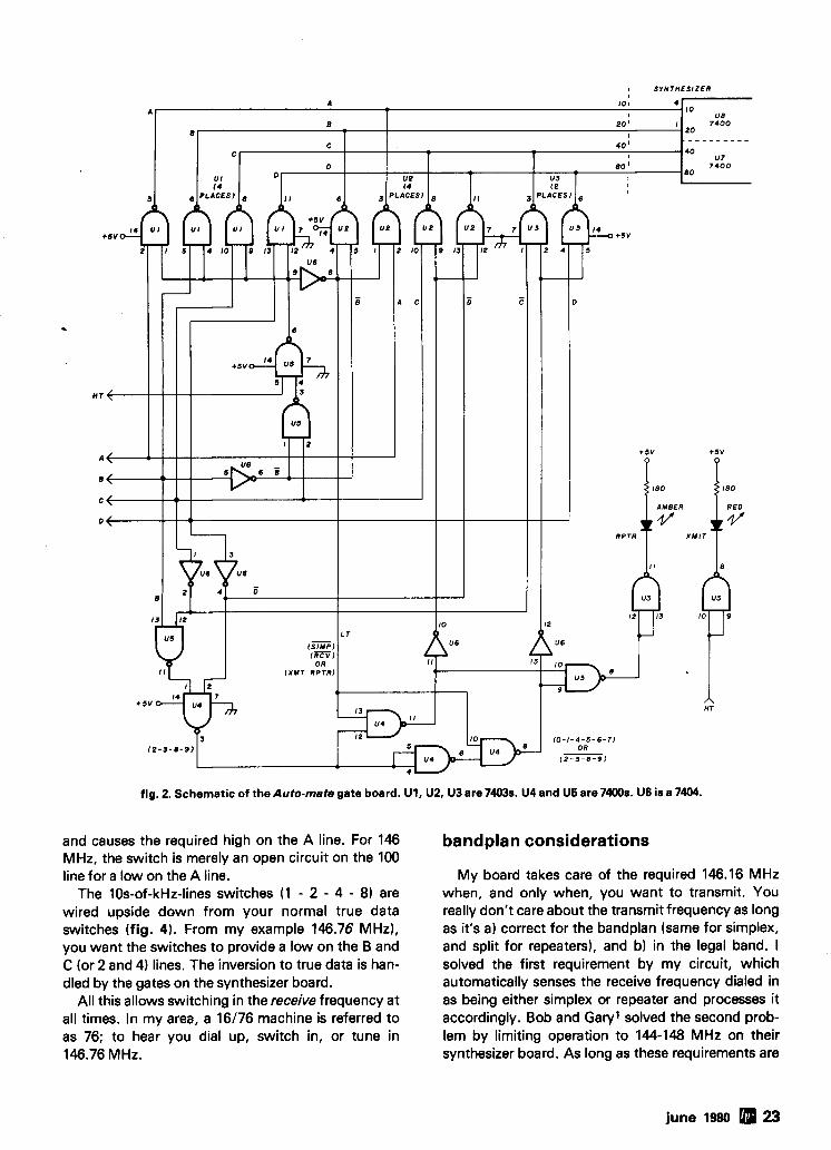
fig. 2. Schematic of the Auto-mate gate board. U1, U2, U3 are 7403s. U4 and U5 are 7400s. U6 is a 7404.
and causes the required high on the A line. For 146 MHz, the switch is merely an open circuit on the 100 line for a low on the A line.
The 10s-of-kHz-lines switches (1 - 2 - 4 - 8) are wired upside down from your normal true data switches (fig. 4). From my example 146.76 MHz), you want the switches to provide a low on the B and C (or 2 and 4) lines. The inversion to true data is han- dled by the gates on the synthesizer board.
All this allows switching in the receive frequency at all times. In my area, a 16/76 machine is referred to as 76; to hear you dial up, switch in, or tune in 146.76 MHz.
bandplan considerations
My board takes care of the required 146.16 MHz when, and only when, you want to transmit. You really don't care about the transmit frequency as long as it's a) correct for the bandplan (same for simplex, and split for repeaters), and b) in the legal band. I solved the first requirement by my circuit, which automatically senses the receive frequency dialed in as being either simplex or repeater and processes it accordingly. Bob and Gary1 solved the second prob- lem by limiting operation to 144-148 MHz on their synthesizer board. As long as these requirements are
june 1980 23
met why bother with dialing in the transmit frequen- cy? For thosewho want to go upside down he., 76116 if the repeater is down), it's as simple as dialing in the transmit frequency. My board will still shift things correctly for the actual transmit cycle. If you dial in 146.16 MHz to receive, you'll automatically transmit 146.76 MHz. This proper shift holds true for all repeater pairs anywhere in the 146-147 MHz region.
gating-circuit operation The simple gates are easy to follow, line-by-line, in
fig. 2. I'm sure you want to know how the circuit does its tricks. For this, see the tables. I'II cover only t k 146-148 MHz region I use.
All my board does in the repeater function is add or subtract the proper 600 kHz from the receiver fre- quency that you've input to the switches. The tables show you how the bandplan allows this function. In the 146-MHz region, the receive-frequency numbers dialed in, such as 6 - 7 - 8 - 9 for the 100s of kHz col- umn, result in 0 - 1 - 2 - 3 respectively (i.e., 76 receive116 transmit) (table 3). For all these repeater pairs, my board gives a 600-kHz offset number no matter which one you dial in.
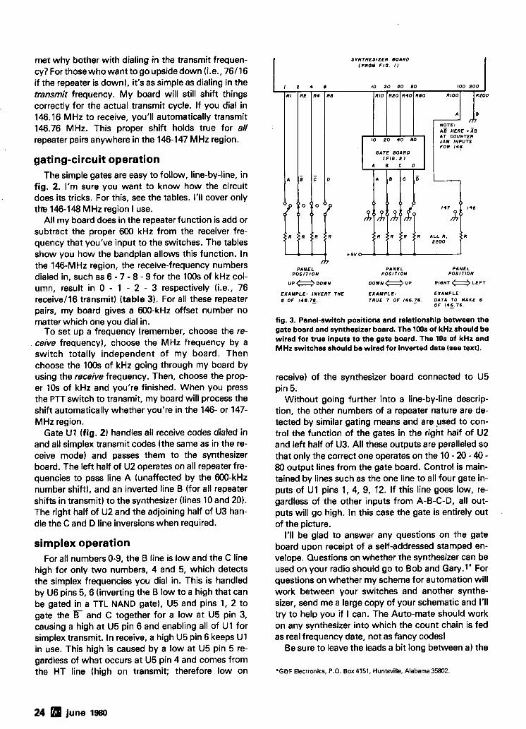
To set up a frequency (remember, choose the re- ceive frequency), choose the MHz frequency by a switch totally independent of my board. Then choose the 100s of kHz going through my board by using the receive frequency. Then, choose the prop- er 10s of kHz and you're finished. When you press the PTT switch to transmit, my board will process the shift automatically whether you're in the 146- or 147- MHz region.
Gate U1 (fig. 2) handles all receive codes dialed in and all simplex transmit codes (the same as in the re- ceive mode) and passes them to the synthesizer board. The left half of U2 operates on all repeater fre- quencies to pass line A (unaffected by the 600-kHz number shift), and an inverted line B (for all repeater shifts in transmit) to the synthesizer (lines 10 and 20). The right half of U2 and the adjoining half of U3 han- dle the C and D line inversions when required.
simplex operation For all numbers 0-9, the B line is low and the C line
high for only two numbers, 4 and 5, which detects the simplex frequencies you dial in. This is handled by U6 pins 5.6 (inverting the B low to a high that can be gated in a TTL NAND gate), U5 and pins 1, 2 to gate the and C together for a low at U5 pin 3, causing a high at U5 pin 6 and enabling all of U1 for simplex transmit. In receive, a high U5 pin 6 keeps U1 in use. This high is caused by a low at U5 pin 5 re- gardless of what occurs at U5 pin 4 and comes from the HT line (high on transmit; therefore low on
S Y N T H E S I Z E R BOAR0 (FROM FIG. 1)
EXAMPLE: INVERT THE E X A M P L E : EXAMPLE' 6 OF 146.75. TRUE I OF 146.16. DATA TO MAKE 6
OF 145.76.
fig. 3. Panel-switch positions and relationship between the gate board and synthesizer board. The lWs of kHz should be wired for true inputs to the gate board. The 10s of kHz and MHz switches should be wired for inverted data (see text).
receive) of the synthesizer board connected to U5 pin 5.
Without going further into a line-by-line descrip- tion, the other numbers of a repeater nature are de- tected by similar gating means and are ysed to con- trol the function of the gates in the right half of U2 and left half of U3. All these outputs are paralleled so that only the correct one operates on the 10 - 20 - 40 - 80 output lines from the gate board. Control is main- tained by lines such as the one line to all four gate in- puts of U1 pins 1, 4, 9, 12. If this line goes low, re- gardless of the other inputs from A-B-C-D, all out- puts will go high. In this case the gate is entirely out .
of the picture. I'II be glad to answer any questions on the gate
board upon receipt of a self-addressed stamped en- velope. Questions on whether the synthesizer can be used on your radio should go to Bob and Gary.'' For questions on whether my scheme for automation will work between your switches and another synthe- sizer, send me a large copy of your schematic and I'II try to help you if I can. The Auto-mate should work on any synthesizer into which the count chain is fed as real frequency date, not as fancy codes!
Be sure to leave the leads a bit long between a) the
*G&F E l e c t r o n i c s , P.O. B o x 4 1 5 1 , H u n t s v i l l e , Alabama 35802.
24 june 1980
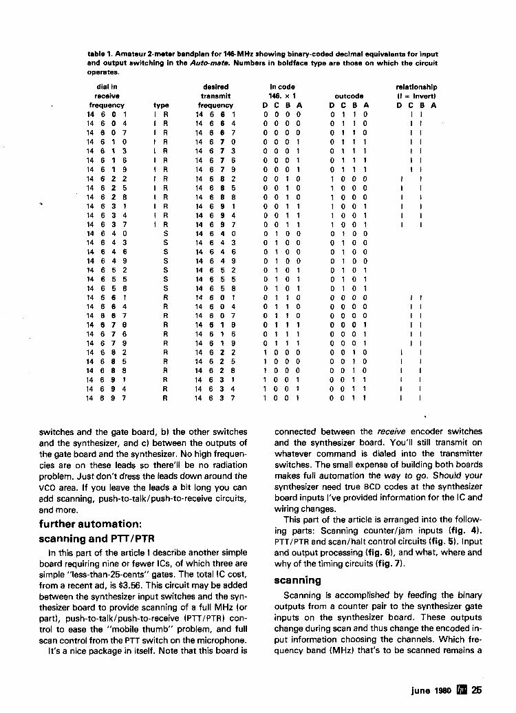
table 1. Amateur 2-meter bandplan for 146-MHz showing binary-coded decimal equivalents for input and output switching in the Auto-mate. Numbers in boldface type are those on which the circuit operates.
dial in desired in code relationship receive transmit 146. x 1 outcode ( I = Invert)
frequency tY Pe frequency D C B A D C B A D C B A 1 4 6 0 1 I R 1 4 6 6 1 0 0 0 0 0 1 1 0 I I 1 4 6 0 4 I R 1 4 6 6 4 0 0 0 0 0 1 1 0 I I 1 4 6 0 7 I R 1 4 6 6 7 0 0 0 0 0 1 1 0 I I 1 4 6 1 0 I R 1 4 6 7 0 0 0 0 1 0 1 1 1 I I 1 4 6 1 3 I R 1 4 6 7 3 0 0 0 1 0 1 1 1 I I 1 4 6 1 6 I R 1 4 6 7 6 0 0 0 1 0 1 1 1 I I 1 4 6 1 9 I R 1 4 6 7 9 0 0 0 1 0 1 1 1 I I 14 6 2 2 I R 1 4 6 8 2 0 0 1 0 1 0 0 0 I I 1 4 6 2 5 I R 1 4 6 8 5 0 0 1 0 1 0 0 0 I I 1 4 6 2 8 I R 1 4 6 8 8 0 0 1 0 1 0 0 0 I I 1 4 6 3 1 I R 1 4 6 9 1 0 0 1 1 1 0 0 1 I I 1 4 6 3 4 I R 1 4 6 9 4 0 0 1 1 1 0 0 1 I I 1 4 6 3 7 I R 1 4 6 9 7 0 0 1 1 1 0 0 1 I I 14 6 4 0 S 1 4 6 4 0 0 1 0 0 0 1 0 0 14 6 4 3 S 1 4 6 4 3 0 1 0 0 0 1 0 0 1 4 6 4 6 S 14 6 4 6 0 1 0 0 0 1 0 0 1 4 6 4 9 S 1 4 6 4 9 0 1 0 0 0 1 0 0 1 4 6 5 2 S 1 4 6 5 2 0 1 0 1 0 1 0 1 14 6 5 5 S 1 4 6 5 5 0 1 0 1 0 1 0 1 1 4 6 5 8 S 1 4 6 5 8 0 1 0 1 0 1 0 1 1 4 6 6 1 R 1 4 6 0 1 0 1 1 0 0 0 0 0 I I 1 4 6 6 4 R 1 4 6 0 4 0 1 1 0 0 0 0 0 I I 1 4 6 6 7 R 1 4 6 0 7 0 1 1 0 0 0 0 0 I I 14 6 7 0 R 1 4 6 1 0 0 1 1 1 0 0 0 1 I I 1 4 6 7 6 R 1 4 6 1 6 0 1 1 1 0 0 0 1 I I 1 4 6 7 9 R 1 4 6 1 9 0 1 1 1 0 0 0 1 I I 1 4 6 8 2 R 1 4 6 2 2 1 0 0 0 0 0 1 0 I I 1 4 6 8 5 R 1 4 6 2 5 1 0 0 0 0 0 1 0 I I 1 4 6 8 8 R 1 4 6 2 8 1 0 0 0 0 0 1 0 I I 1 4 6 9 1 R 1 4 6 3 1 1 0 0 1 0 0 1 1 I I 14 6 9 4 R 1 4 6 3 4 1 0 0 1 0 0 1 1 I I 1 4 6 9 7 R 1 4 6 3 7 1 0 0 1 0 0 1 1 I I
switches and the gate board, b) the other switches and the synthesizer, and c) between the outputs of the gate board and the synthesizer. No high frequen- cies are on these leads so there'll be no radiation problem. Just don't dress the leads down around the VCO area. If you leave the leads a bit long you can add scanning, push-to-talklpush-to-receive circuits, and more.
further automation: scanning and PlTIPTR
In this part of the article I describe another simple board requiring nine or fewer ICs, of which three are simple "less-than-25-cents" gates. The total IC cost, from a recent ad, is $3.56. This circuit may be added between the synthesizer input switches and the syn- thesizer board to provide scanning of a full MHz (or part), push-to-talklpush-to-receive (PTTIPTR) con- trol to ease the "mobile thumb" problem, and full scan control from the PTT switch on the microphone.
It's a nice package in itself. Note that this board is
connected between the receive encoder switches and the synthesizer board. You'll still transmit on whatever command is dialed into the transmitter switches. The small expense of building both boards makes full automation the way to go. Should your synthesizer need true BCD codes at the synthesizer board inputs I've provided information for the IC and wiring changes.
This part of the article is arranged into the follow- ing parts: Scanning counterljam inputs (fig. 4). PTTIPTR and scanlhalt control circuits (fig. 5). Input and output processing (fig. 61, and what, where and why of the timing circuits (fig. 7 ) .
scanning Scanning is accomplished by feeding the binary
outputs from a counter pair to the synthesizer gate inputs on the synthesizer board. These outputs change during scan and thus change the encoded in- put information choosing the channels. Which fre- quency band (MHz) that's to be scanned remains a
june 1980 25
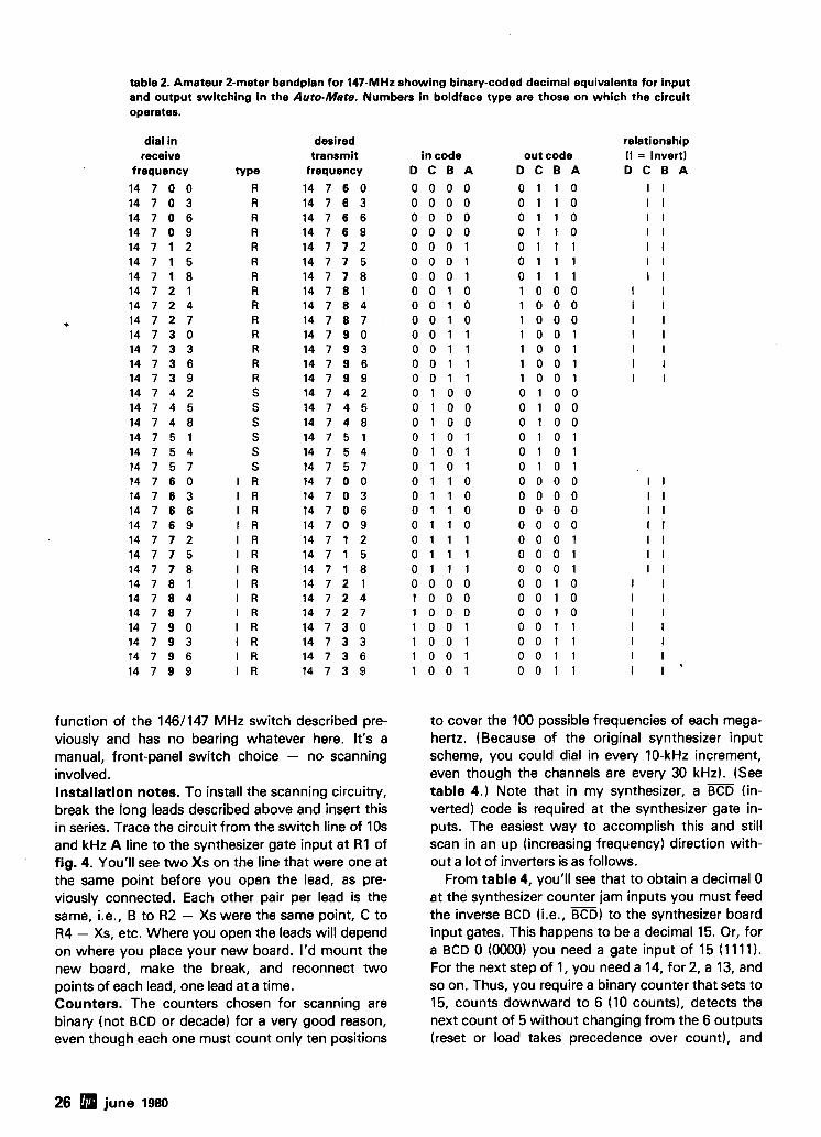
table 2. Amateur 2-meter bandplan for 147-MHz showing binary-coded decimal equivalents for input and output switching in the Auto-Mate. Numbers in boldface type are those on which the circuit operates.
dial in receive
frequency
1 4 7 0 0 14 7 0 3 1 4 7 0 6 1 4 7 0 9 1 4 7 1 2 1 4 7 1 5 1 4 7 1 8 1 4 7 2 1 14 7 2 4 1 4 7 2 7 1 4 7 3 0 1 4 7 3 3 1 4 7 3 6 1 4 7 3 9 1 4 7 4 2 1 4 7 4 5 1 4 7 4 8 1 4 7 5 1 1 4 7 5 4 1 4 7 5 7 14 7 6 0 14 7 6 3 14 7 6 6 1 4 7 6 9 14 7 7 2 1 4 7 7 5 1 4 7 7 8 1 4 7 8 1 14 7 8 4 14 7 8 7 1 4 7 9 0 1 4 7 9 3 1 4 7 9 6 14 7 9 9
desired transmit
frequency
14 7 6 0 1 4 7 6 3 14 7 6 6 14 7 6 9 14 7 7 2 1 4 7 7 5 1 4 7 7 8 1 4 7 8 1 1 4 7 8 4 1 4 7 8 7 1 4 7 9 0 1 4 7 9 3 1 4 7 9 6 1 4 7 9 9 1 4 7 4 2 14 7 4 5 14 7 4 8 1 4 7 5 1 1 4 7 5 4 1 4 7 5 7 14 7 0 0 1 4 7 0 3 1 4 7 0 6 1 4 7 0 9 1 4 7 1 2 1 4 7 1 5 1 4 7 1 8 1 4 7 2 1 14 7 2 4 1 4 7 2 7 1 4 7 3 0 14 7 3 3 1 4 7 3 6 1 4 7 3 9
function of the 1461147 MHz switch described pre- viously and has no bearing whatever here. It's a manual, front-panel switch choice - no scanning involved. Installation notes. To install the scanning circuitry, break the long leads described above and insert this in series. Trace the circuit from the switch line of 10s and kHz A line to the synthesizer gate input at R1 of fig. 4. You'll see two Xs on the line that were one at the same point before you open the lead, as pre- viously connected. Each other pair per lead is the same, i.e., B to R2 - Xs were the same point, C to R4 - Xs, etc. Where you open the leads will depend on where you place your new board. I'd mount the new board, make the break, and reconnect two points of each lead, one lead at a time. Counters. The counters chosen for scanning are binary (not BCD or decade) for a very good reason, even though each one must count only ten positions
in code D C B A
0 0 0 0 0 0 0 0 0 0 0 0 0 0 0 0 0 0 0 1 0 0 0 1 0 0 0 1 0 0 1 0 0 0 1 0 0 0 1 0 0 0 1 1 0 0 1 1 0 0 1 1 0 0 1 1 0 1 0 0 0 1 0 0 0 1 0 0 0 1 0 1 0 1 0 1 0 1 0 1 0 1 1 0 0 1 1 0 0 1 1 0 0 1 1 0 0 1 1 1 0 1 1 1 0 1 1 1 0 0 0 0 1 0 0 0 1 0 0 0 1 0 0 1 1 0 0 1 1 0 0 1 1 0 0 1
out code D C B A
0 1 1 0 0 1 1 0 0 1 1 0 0 1 1 0 0 1 1 1 0 1 1 1 0 1 1 1 1 0 0 0 1 0 0 0 1 0 0 0 1 0 0 1 1 0 0 1 1 0 0 1 1 0 0 1 0 1 0 0 0 1 0 0 0 1 0 0 0 1 0 1 0 1 0 1 0 1 0 1 0 0 0 0 0 0 0 0 0 0 0 0 0 0 0 0 0 0 0 1 0 0 0 1 0 0 0 1 0 0 1 0 0 0 1 0 0 0 1 0 0 0 1 1 0 0 1 1 0 0 1 1 0 0 1 1
relationship (I = Invert) D C B A
I I I I I I I I I I I I I I
I I I I I I I I I I I I I I
I I I I I I I I I I I I I I
I I I I I I I I I I I I I I '
to cover the 100 possible frequencies of each mega- hertz. (Because of the original synthesizer input scheme, you could dial in every 10-kHz increment, even though the channels are every 30 kHz). (See table 4.) Note that in my synthesizer, a BCD (in- verted) code is required at the synthesizer gate in- puts. The easiest way to accomplish this and still scan in an up (increasing frequency) direction with- out a lot of inverters is as follows.
From table 4, you'll see that to obtain a decimal 0 at the synthesizer counter jam inputs you must feed the inverse BCD (i.e., ED) to the synthesizer board input gates. This happens to be a decimal 15. Or, for a BCD 0 (0000) you need a gate input of 15 (1111). For the next step of 1, you need a 14, for 2, a 13, and so on. Thus, you require a binary counter that sets to 15, counts downward to 6 (10 counts), detects the next count of 5 without changing from the 6 outputs (reset or load takes precedence over count), and
26 june 1980
I SYNTHESIZER COUNTERS I
C L l P OUT RES ISTOR ON SYNTHESIZER BOARD FOR FOR R I T O RBO P O I N T S . f R 4 9 - R 4 7 .... R 3 5 ) ( 8 8 E S I S T O R S )
I SYNTHESIZER GATES
1 2 4 8 10 2 0 4 0 8 0 1 0 0 2 0 0
L H H L H H H H C L l P OUT R 3 3 GROUND R 2 0 0 LEAVE R 3 I .
L H
I 2 4 8 10 2 0 4 0 8 0 1 0 0 2 0 0
AND P O I N T .
BREAK ADDED
RPOO
N O T E S : I . H l L = CODE STATUS FOR NUMBER SHOWN IN QUOTES.
2 . H : I : HIGH 3 . L = O : L O W
RBO RIOO
U Z 7 4 0 0 U 3 , U 4 7 4 1 9 3 - - + V P I N S 5 . 16
GND P I N S 8 , 14 NC P I N S 12. I 3
RI
FORCE T O M A N U I L - SCAN WHEN ENABLED USE S W I T C H E N T R I E S
RIO
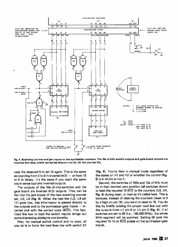
fig. 4. Scanning counter and jam inputs to the synthesizer counters. The 10s-of-kHz switch outputs and gate-board outputs are inverted BCD data, which can be fed directly into U3, U4, the counter ICs.
RZ
uses the detected 5 to set 15 again. This is the same as counting from 0 to 9 in inverted BCD - or from 15 to 6 in binary. It's the same if you want the same count sense (up) and inverted outputs.
The outputs of the 10s-of-kHz-switches and the gate board are inverted BCD outputs. They can be fed into the jam inputs of the new scanning counter set, U3, U4 (fig. 4). When the load line (U3, U4 pin 11) goes low, this information is passed directly to the outputs and to the synthesizer gate inputs - in- verted and with the correct code (ED). This fact, (load line low to load the switch inputs) brings out some interesting sidelights and benefits.
First, for manual switch control and no scan, all you do is to force the load lines low with switch S1
R 2 0
(fig. 4). You're then in manual mode regardless of the states on H I and H2 or whether the control (fig. 5) is in SCAN or HALT.
Second, the switches of 100s and 10s of kHz must be in their decimal zero position (all switches down) to feed the required 15 to the counters (U3, U4, fig. 4) during reset, or load as it's called here. This is because, instead of clearing the counters (reset to 0 by a high on pin 141, you want to reset to 15. You do this by briefly pulsing the proper load line low with the outputs from U1 pin 6 or U1 pin 3 (fig. 4). If all switches are set to 00 (i.e., 146.000 MHz), the whole MHz segment will be scanned. Setting 00 puts the required 15-15 on BCD pulses on the synthesizer gate inputs.
R 4 0 R 4
june 1980 27
R8
',": 1 TRANSMIT
"E J TRANSMIT
CD 8 AD SEE T I M I N G f F I G . 7 )
AUDIO /SO. CLOCK N E - 5 5 5
+5V f F l G . 7 ) SCAN RATE SEE F IG . 7
/,. 0 . 0 1
+SV
5 . 14 12
U 3 0 I u2.4 a- S I C * 74121 % :if3
0s-1 5 ' CLR
I , I I I I , I 9 I 1 8 I I I 1' K E Y I N G I I I I I I ( F I G 61
+ 5 v
+ 5 v 3 I , I I I I , , I I , I I , I I I
6 I 1 1 I 8 I
US 0 I , I I I
S 2 c 7 4 1 2 1 I ) I I I I 0 s - 2 I I , * I )
I I , I I I
7 * A I I I
: n r I ; 6
I 'P2 8 2 2 0 0 O S E E F10. 7 FOR 1 : : j, + S V - 7 4 1 2 1 T l Y l N C COMPONENTS 1 1 I
1 1 I 1 p3
+'b I I I I SAME C IRCUIT ON U 2 A . P IN 2 ,
P U S H ~ U T T O N FOR CLEAR TO SCAN I F NOT. CLEAR T O T I E U 2 A . P I N 2 . T O + 5 V
THROUGH 2 2 0 0 OHMS U I 7 4 0 3
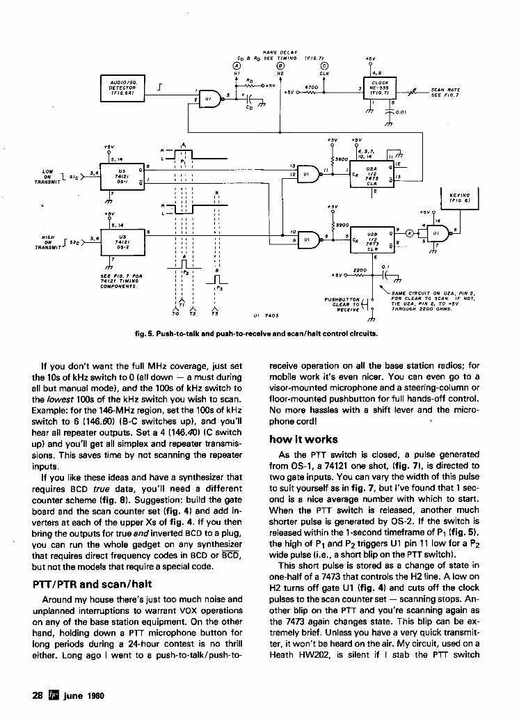
fig. 5. Push-to-talk and push-to-receive and scanlhalt control circuits.
If you don't want the full MHz coverage, just set the 10s of kHz switch to 0 (all down - a must during all but manual mode), and the 100s of kHz switch to the lowest 100s of the kHz switch you wish to scan. Example: for the 146-MHz region, set the 100s of kHz switch to 6 (146.80) (0-C switches up), and you'll hear all repeater outputs. Set a 4 (146.40) (C switch up) and you'll get all simplex and repeater transmis- sions. This saves time by not scanning the repeater inputs.
If you like these ideas and have a synthesizer that requires BCD true data, you'll need a different counter scheme (fig. 8). Suggestion: build the gate board and the scan counter set (fig. 4) and add in- verters at each of the upper Xs of fig. 4. If you then bring the outputs for true and inverted BCD to a plug,
' you can run the whole gadget on any synthesizer that requires direct frequency codes in BCD or m, but not the models that require a special code.
PTTIPTR and scanlhalt Around my house there's just too much noise and
unplanned interruptions to warrant VOX operations on any of the base station equipment. On the other hand, holding down a PTT microphone button for long periods during a 24-hour contest is no thrill either. Long ago I went to a push-to-talklpush-to-
receive operation on all the base station radios; for mobile work it's even nicer. You can even go to a visor-mounted microphone and a steering-column or floor-mounted pushbutton for full hands-off control. No more hassles with a shift lever and the micro- phone cordl
how it works As the PTT switch is closed, a pulse generated
from 0s-1, a 74121 one shot, (fig. 71, is directed to two gate inputs. You can vary the width of this pulse to suit yourself as in fig. 7, but I've found that 1 sec- ond is a nice average number with which to start. When the PTT switch is released, another much shorter pulse is generated by 0s-2. If the switch is released within the 1-second timeframe of PI (fig. 51, the high of P1 and Pq triggers U1 pin 11 low for a P2 wide pulse he., a short blip on the PTT switch).
This short pulse is stored as a change of state in one-half of a 7473 that controls the H2 line. A low on H2 turns off gate U1 (fig. 4) and cuts off the clock pulses to the scan counter set - scanning stops. An- other blip on the PTT and you're scanning again as the 7473 again changes state. This blip can be ex- tremely brief. Unless you have a very quick transmit- ter, it won't be heard on the air. My circuit, used on a Heath HW202, is silent if I stab the PTT switch
28 june 1980
KEY TRANSMITTER
? ? LOCATE . . + ?
FULL RECEIVER
l U 0 l O
H I
(FIG. 5 ) 1 0 . 4 7
T 'OoV KEYING
1 F IG . S I l S m A MAX. COIL )
NOTE: GATE AT X CAN KEY TRANSMITTER I F I 6 m A NOT EXCEEDED. I T ' S SAFER TO A 0 0 THE C IRCUIT SHOWN USING RELAY CONTROL.
e 0
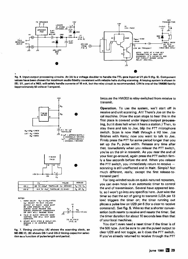
fig. 6. Input-output processing circuits. At (A) is a voltage doubler to handle the TTL gate input at U1 pin 5 (fig. 5). Component values have been chosen for maximum audio fidelity consistent with reliable halts during scanning. A keying system is shown in (B). U1, part of a 7403, will safely handle currents of 16 mA, but the relay circuit is recommended. CR4 is one of the IN4000 family (approximately 50 volts at 1 ampere).
L R A + ~ R ~ ' I M E O 0 .1 TO 1°F T T A N T A L U M L E T RA = S S O I
R g a 6 8 0 1 /j7 O . l p F - APPROXIMATELY 4 C H A N N E L S / SECOND
I p F - - APPROXIMATELY I CHANNEL /SECOND
because the HW202 is relay-switched from receive to transmit.
Operation. To use the system, we'll start off in receive and unit scanning. Ahl There's Joe on the lo- cal machine. (How the scan stops to hear this in the first place is covered under inputloutput process- ing, but it does halt when it hears a station.) Then, to stay there and talk to Joe, blip the PTT microphone switch. Scan is now Halt through a H2 low. Joe finishes with Harry; now you want to talk to Joe. Firmly press the PTT for some period longer than you set up the P1 pulse width. Release any time after that. Immediately when you release the PTT switch, you're on the air in transmit. As you llear the end of your first go-around, again press the PTT switch firm- ly a few seconds before the end. When you release the PTT switch, you immediately return to receive - scanning is still unaffected and in Halt. Simple? Not much different, really, except the first release-to- transmit part1
For long-winded souls on quick-natured repeaters, you can even hook in an automatic timer to control the end of transmission. Several have appeared late- ly, so I won't go into any specifics here. Just wire the
NOTES:
I . HANO DELAY: RD l k < R D < 4 7 0 0 . CD: ADJUST TO SUIT VOLUME OUTPUT O F RADIO. HANO MUST BE LONG ENOUOH TO HOLD DURINO VOICE PAUSES AND DURINO OPERATOR CHANOEOVER OR UNIT W I L L RESUME SCAN.
2 . T H I S IS AUDIO- DERIVED HANO CONTROL AND W I L L SK IP DEAD CARRIERS. T O UI . P I N 3
3. START W I T H 4700 a ~ ~ O ~ F / I S V . REDUCE C TO SHORTEN HANG
l F IG . 5 )
T I M E .
PERIOD
TO-TO-T2
P2 OR PS
0 s - I
0 s - 2
fig. 7. Timing circuitry; (A) shows the scanning clock, an NE-555 IC; (B) shows 0s-1 and 0s-2 timing-capacitor selec- tion as a function of pulse length and period.
CT P U L S E
6 8 TO 1 0 0 p F TANTALUM 12, I SECOND)
6 . 8 TO 10°F TANTALUM I t I O m S )
timer so that the act of going to transmit (U2A pin 13 low) triggers the timer on; the timer running out places a pulse low on U2B pin 6 (for a clear to receive command). See fig. 5. Wire so that a shorter conver- sation both resets to receive and resets the timer. Set the timer duration for about 10 seconds less than that of your local machines.
You don't even need a reset timer if the timer is of the 555 type. Just be sure to use the pulsed output to clear U2B and not toggle, as it does the PTT switch. If you've already returned to receive through the PTT
june 1980 29
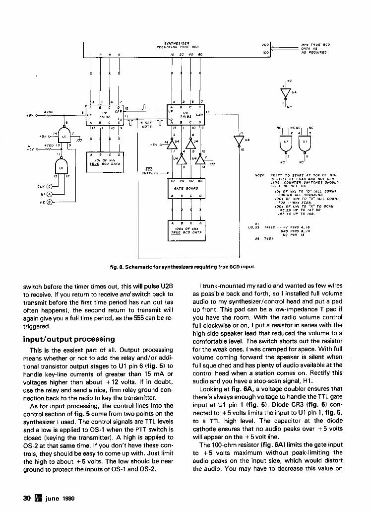
fig. 8. Schematic for synthesizers requiring true BCD input.
switch before the timer times out, this will pulse U2B to receive. If you return to receive and switch back to transmit before the first time period has run out (as often happens), the second return to transmit will again give you a full time period, as the 555 can be re- triggered.
inputloutput processing This is the easiest part of all. Output processing
means whether or not to add the relay and/or addi- tional transistor output stages to U1 pin 6 (fig. 5) to handle key-line currents of greater than 15 mA or voltages higher than about + 12 volts. If in doubt, use the relay and send a nice, firm relay ground con- nection back to the radio to key the transmitter.
As for input processing, the control lines into the control section of fig. 5 come from two points on the synthesizer I used. The control signals are TTL levels and a low is applied to 0 s - I when the PTT switch is closed (keying the transmitter). A high is applied to 0s-2 at that same time. If you don't have these con- trols, they should be easy to come up with. Just limit the high to about + 5 volts. The low should be near ground to protect the inputs of 0 s - I and 0s-2.
I trunk-mounted my radio and wanted as few wires as possible back and forth, so I installed full volume audio to my synthesizer/control head ahd put a pad up front. This pad can be a low-impedance T pad if you have the room. With the radio volume control full clockwise or on, I put a resistor in series with the high-side speaker lead that reduced the volume to a comfortable level. The switch shorts out the resistor for the weak ones. I was cramped for space. With full volume coming forward the speaker is silent when full squelched and has plenty of audio available at the control head when a station comes on. Rectify this audio and you have a stop-scan signal, HI .
Looking at fig. 6A, a voltage doubler ensures that there's always enough voltage to handle the TTL gate input at U1 pin 1 (fig. 5). Diode CR3 (fig. 6) con- nected to + 5 volts limits the input to U1 pin 1, fig. 5, to a TTL high level. The capacitor at the diode cathode ensures that no audio peaks over + 5 volts will appear on the + 5 volt line.
The 100-ohm resistor (fig. 6A) limits the gate input to + 5 volts maximum without peak-limiting the audio peaks on the input side, which would distort the audio. You may have to decrease this value on
30 june 1980
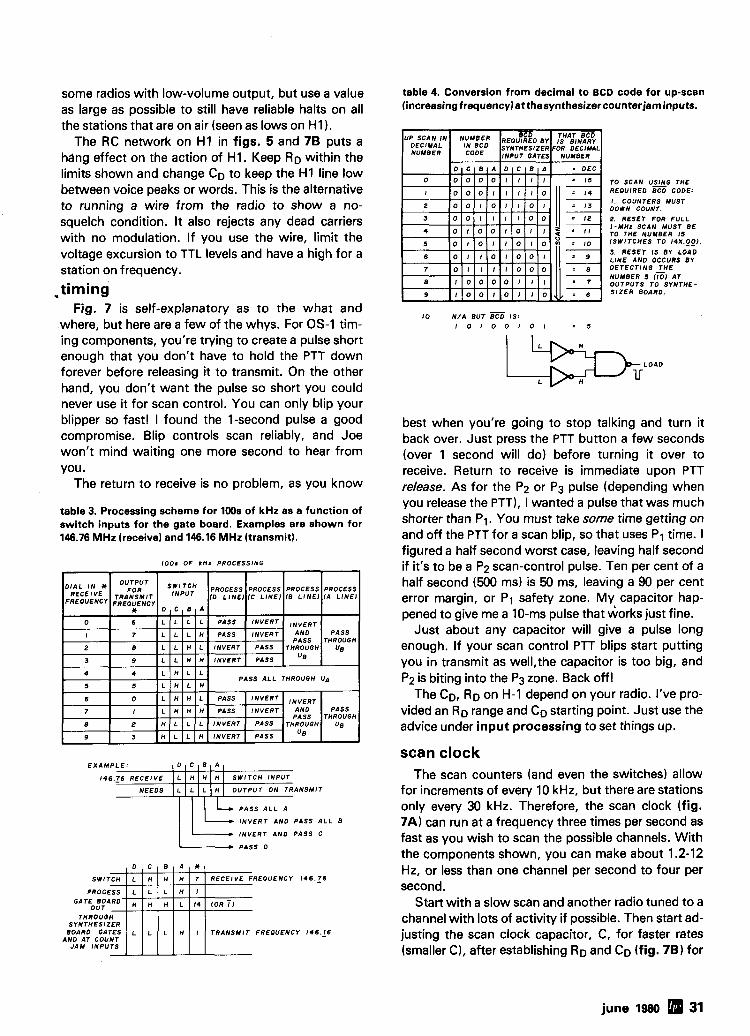
some radios with low-volume output, but use a value as large as possible to still have reliable halts on all the stations that are on air (seen as lows on H I 1.
The RC network on H I in figs. 5 and 78 puts a hang effect on the action of HI. Keep RD within the limits shown and change CD to keep the H I line low between voice peaks or words. This is the alternative to running a wire from the radio to show a no- squelch condition. It also rejects any dead carriers with no modulation. If you use the wire, limit the voltage excursion to TTL levels and have a high for a station on frequency.
.timing Fig. 7 is self-explanatory as to the what and
where, but here are a few of the whys. For 0s-1 tim- ing components, you're trying to create a pulse short enough that you don't have to hold the PTT down forever before releasing it to transmit. On the other hand, you don't want the pulse so short you could never use it for scan control. You can only blip your blipper so fast! I found the I-second pulse a good compromise. Blip controls scan reliably, and Joe won't mind waiting one more second to hear from you.
The return to receive is no problem, as you know
table 3. Processing scheme for 100s of kHz as a function of switch inputs for the gate board. Examples are shown for 146.76 MHz (receive) and 146.16 MHz (transmit).
100 . OF kHz PROCESSING
PASS A L L A
I N V E R T A N 0 PASS ALL B
INVERT AND PASS C
PASS D
PROCESS
T R A N S M I T FREOUENCY 1 4 6 . 1 6 AND AT COUNT
JAM INPUTS
table 4. Conversion from decimal to BCD code for up-scan lincreasingfrequency)atthesynthesizercounterjam inputs.
I 0 N / A BUT I S ;
I O I O O I O I . 5
TO SCAN U Z G THE REOUIREO BCD CODE:
I . COUNTERS MUST DOWN COUNT.
2. RESET FOR F U L L I - M H z SCAN MUST BE TO THE NUMBER 15 f S W l T C H E S T O 14X._0_0).
3. RESET IS 81 LOAD LINE AND OCCURS BY DETECTING T H E NUMBER 5 (XI AT OUTPUTS T O SYNTHE- S I Z E R BOARD.
best when you're going to stop talking and turn it back over. Just press the PTT button a few seconds (over 1 second will do) before turning it over to receive. Return to receive is immediate upon PTT release. As for the Pq or P3 pulse (depending when you release the PTT), I wanted a pulse that was much shorter than P1. You must take some time getting on and off the PTT for a scan blip, so that uses P1 time. I figured a half second worst case, leaving half second if it's to be a Pq scan-control pulse. Ten per cent of a half second (500 ms) is 50 ms, leaving a 90 per cent error margin, or PI safety zone. My capacitor hap- pened to give me a 10-ms pulse that works just fine.
Just about any capacitor will give a pulse long enough. If your scan control PTT blips start putting you in transmit as well,the capacitor is too big, and P2 is biting into the Pg zone. Back off!
The CD, RD on H-1 depend on your radio. I've pro- vided an RD range and CD starting point. Just use the advice under input processing to set things up.
scan clock The scan counters (and even the switches) allow
for increments of every 10 kHz, but there are stations only every 30 kHz. Therefore, the scan clock (fig. 7A) can run at a frequency three times per second as fast as you wish to scan the possible channels. With the components shown, you can make about 1.2-12 Hz, or less than one channel per second to four per second.
Start with a slow scan and another radio tuned to a channel with lots of activity if possible. Then start ad- justing the scan clock capacitor, C, for faster rates (smaller C), after establishing RD and CD (fig. 78) for
june 1980 31
7
invites you to call and ask
1 about BARRY'S Field Day Specials for June:
I With the purchase of a major piece of equipment, you'll get a valuable FREE gift to go along with it . . . just to show you BARRY cares!
Maybe you'd like . . . From YAESU: FT-107, FT-707, or the FTlOlZD From TEN-TEC: Omni-C or the new DELTA F ~ o m MURCH: UT-2000B antenna tuner From AEA: Two-meter ISOPOLE antenna; or a Kantronics Field Day code reader;
, or a "Slinky" dipole; '
or maybe a "Vacationer" portable antenna; I or how about a Hy-Gain portable 18TD tape dipole
antenna?
Our lines include: AEA ALLIANCE ANTENNA SPECIALISTS ASTRON B & W BIRD COLLINS COMMUNICATIONS
SPECIALISTS CUSHCRAFT DSI DENTRON DRAKE ETO ElMAC E-Z WAY HUSTLER HY-GAIN
ICOM K3K KLM KANTRONICS MFJ MIRAGE MOSLEY MURCH ROBOT ROHN SHURE STANDARD SWAN TEN-TEC TEMPO TRI-EX YAESU VHF ENGINEERING AND M O R E . . .
I BUSINESSMEN: Ask about BARRY'S line of business-band equipment. We've got it!
I Amateur Radio License Classes: Wednesday & Thursday: 7-9 pm Saturday 10 am-Noon
1 The Export Experts Invite Overseas orders
I ' A Q U ~ SE 1 HABLA 1 - We Ship Worldwide ESPANOL
1 BARRY ELECTRONICS 1512 BROADWAY. NEW YORK. N.Y. 1001
TELEPHONE (212) 925-7000
32 june 1930
the desired hang delay on channel. You could go up to the TTL counter limit of 32 MHz were it not for other limiting factors and the fact it's ridiculous anyway.
Some of the limits are found in a) the ability of the radio or, in my input circuit, to recognize a station and respond with a control stop only on H-1, b) the limit of the synthesizers to want data only so often (and settled data at that), and the fact that, as scan rates get high, trash is generated by switching that could cause havoc in the synthesizer itself.
Use the second radio to determine when your ra- dio and scanner fail to stop on a station and remem- ber, you're scanning only to remove the drudgew of always flipping switches.
stunt box fun My scanner and synthesizer are such that I can still
do a few cute tricks late at night when activity is low. Every time my synthesizer board wants new switch data input, the load line of the switch data input counters (pin 11 that controls the counters on the synthesizer board) goes low. The counter set (U3, U4, fig. 4) used for scanning happens to clock or ad- vance on a low-to-high transition. With these two facts, I can cause some amusing things to happen! By making RD and CD provide a short pulse, like 10 ms, and using the synthesizer board load line as the clock input to the scan counter set, scan action really moves along! It only stops for 10 ms on each active channel and then moves on. By moving so fast, I can get 10-ms bursts of audio from each active channel - for a multiplex action. You wind up listening to more than one conversation at once. Scan control and PTTIPTR remain unaffected, but it would be a miracle if you could blip fast enough to stop on the channel you really wanted.
It's a novelty and demonstrates one of the upper limits of how fast is fast enough for scanning. All the commercial scanners are capable of scanning at many times the rates used, but you wouldn't be able to watch all the pretty LEDs go scanning along! The voices get pretty choppy in my speedy example above if you don't get the hang time just right. If several stations are on at once, it sounds like your local lodge meeting - everyone talking at once. It's just one of the cute things you can do with this miracle age of electronics. After all, now that you have a fully automatic station doing all the work, you must have something to do - it's called having fun!
reference 1. Bob Fanning. K4VB. and Gary Grantland, WA4GJT. "800-Channel 2- Meter Synthesizer," h8mradi0, January, 1979, pages 10-18.
ham radio
More Details? CHECK-OFF Page 94
Yagi antenna design: more data on the
performance of
simplistic beams Manipulating
the boom length and element spacing
of Yagi beams to maximize
forward gain and f ront-to-back ratio
This is a continuation of last month's discussion5 of simplistic Yagi antennas. To provide continuity to the complete subject I shall continue the sequential numbering of tables and illustrations. Last month I presented the performance characteristics of 2, 3, and Celernent simplistic Yagi antennas over a range
of useful boom lengths. Systematic detailed compu- tations have also been made for simplistic Yagi an- tennas for 3, 6, and 7 elements. To illustrate the be- havior of these larger and more complex antennas the characteristics of 6-element Yagi simplistic beams are shown in fig. 13 where free-space an- tenna gain in dBi is plotted against frequency, F, for a range of boom lengths up to 1.5A0. Numbered curves correspond to element lengths given in table 3 of reference 5.
The total range of results shows a number of char- acteristics of interest. First, the bandwidth over which gain is high is determined primarily by the fre- quency spread between the reflector and the direc- t o r ( ~ ) . Second, the shape of the gain curve is generally not flat in the region of interest; indeed it may be sloped and/or humped or dished. Usually the slope favors the higher frequencies. Third, the shape of the gain curve is more complex where the number of elements is large, and the shape of the F/B ratio varies enormously - much more than the shape of the associated gain curve. It may show more than one peak; moreover, the peak structure shifts very rapidly with boom length. The height of the peak does not necessarily seem to vary monotonically with the frequency separation of reflector and director(s1. Very high F / B values (greater than 30 dB) are quite rare and when present are invariably very narrow banded. In addition, the frequency bandwidth of the
By James L. Lawson, W2PV, 2532 Troy Road, Schenectady, New York 12309
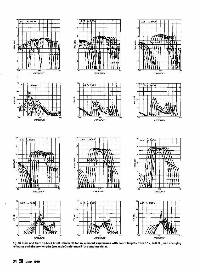
FREOUENCY ..
-90 KK) I10
FREOUENCY
FREWENCY
FREWENCY FREOUENCY
40
30
- m B 2 20 = 20
'$ : 10 10
0 90 100 110 90 100 110
0
FREQUENCY FREQUENCY
"90 100 110
FREOUENCY 90 I00 110
FREOUENCY
40
30
... m P
20 s 10
0 90 100 110
FREOUENCY FREMIENCY FREQUENCY
fig. 13. Gain and front-to-back (FIB1 ratio in dB for six-element Yagi beams with boom lengths from 0.1X, to 0.5X0, and changing reflector and director lengths (sea tabla3 reference 5for complete data).
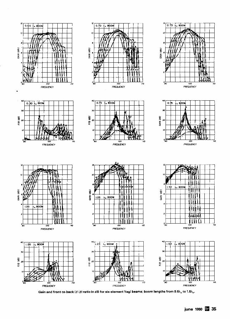
12
10
8
= ' S 6 z 9
4
2
0 90 100 110
FREQUENCY
I2
10
8
.2 m E 6 Z 9
4
2
0 W 100 110
FREWENCY FREWENCY
FREWENCY FREWENCY FREQUENCY
12
10
8
- i% = 6
4
2
0 90 1 0 0
FREQUENCY
FREOUENCY FREQUENCY FREQUENCY
Gain and front-to-back (FIB) ratio in dB for six-element Yagi beams; boom lengths from 0 .6X0 to 1.5X0.
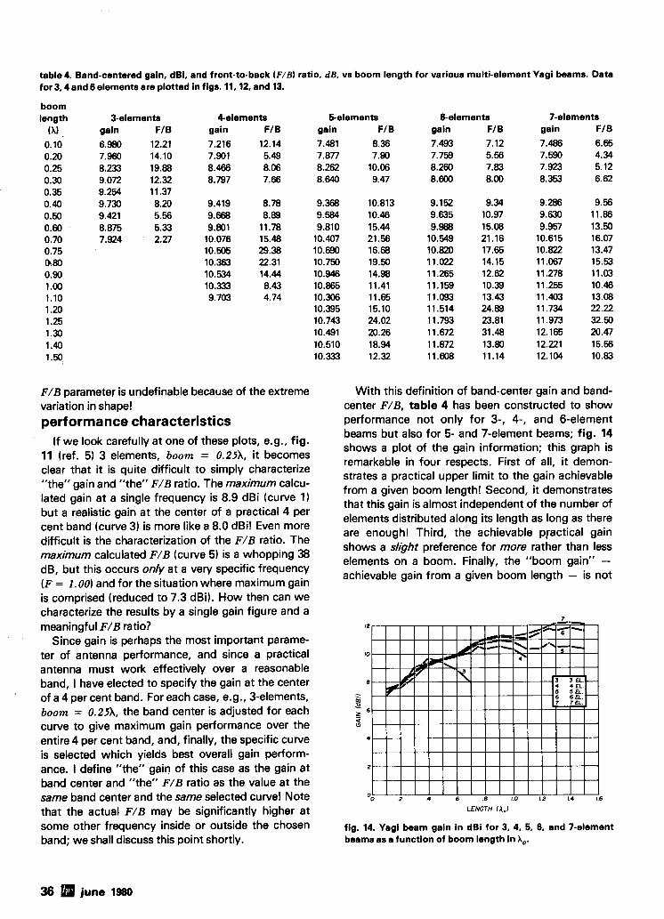
taMe 4. Band-centered gain, dBi, and front-to-back (F/BI ratio. dB, vs boom length for various multi-element Yagi beams. Data for 3.4 and 6 elements are plotted in figs. 11.12. and 13.
boom length
(hl , 0.10 0.20 0.25 0.30 0.35 0.40 0.50 0.60 0.70 0.75 0.80 0.90 1.00 1.10 1.20 1.25 1.30 1.40 1.50,
3-elements gain F l B
6.980 12.21 7.960 14.10 8.233 19.88 9.072 12.32 9.254 1 1.37 9.730 8.20 9.421 5.66 8.875 5.33 7.924 2.27
4elements gain FIB
7.216 12.14 7.901 5.49 8.466 8.06 8.797 7.66
5-elements gain FI B 7.481 8.36 7.877 7.90 8.262 10.06 8.640 9.47
6-elements gain FI B
7.493 7.12 7.759 5.56 8.260 7.83 8.600 8.00
7-elements gain FIB
7.486 6.65 7.590 4.34 7.923 5.12 8.353 6.62
F/B parameter is undefinable because of the extreme With this definition of band-center gain and band- variation in shape! center F/B, table 4 has been constructed to show ~erformance characteristics performance not only for 3-, 4-, and 6-element m- -
If we look carefully at one of these plots, e.g., fig. 11 (ref. 5) 3 elements, boom = 0.251, it becomes clear that it is quite difficult to simply characterize "the" gain and "the" F/B ratio. The maximum calcu- lated gain at a single frequency is 8.9 dBi (curve 1) but a realistic gain at the center of a practical 4 per cent band (curve 3) is more like a 8.0 dBi! Even more difficult is the characterization of the F/B ratio. The maximum calculated F/B (curve 5) is a whopping 38 dB, but this occurs only at a very specific frequency (F = 1.00) and for the situation where maximum gain is comprised (reduced to 7.3 dBi). How then can we characterize the results by a single gain figure and a meaningful F/B ratio?
Since gain is perhaps the most important parame- ter of antenna performance, and since a practical antenna must work effectively over a reasonable band, I have elected to specify the gain at the center of a 4 per cent band. For each case, e.g., 3-elements, boom = 0.251, the band center is adjusted for each curve to give maximum gain performance over the entire 4 per cent band, and, finally, the specific curve is selected which yields best overall gain perform- ance. I define "the" gain of this case as the gain at band center and "the" F/B ratio as the value at the same band center and the same selected curve! Note
beams but also for 5- and 7-element beams; fig. 14 shows a plot of the gain information; this graph is remarkable in four respects. First of all, it demon- strates a practical upper limit to the gain achievable from a given boom length! Second, it demonstrates that this gain is almost independent of the number of elements distributed along its length as long as there are enough! Third, the achievable practical gain shows a slight preference for more rather than less elements on a boom. Finally, the "boom gain" - achievable gain from a given boom length - is not
that the actual F/B may be significantly higher at LENGTH iA.1
some other frequency inside or outside the chosen fig. 14. Yagi beam gain in dBi for 3, 4, 5, 6, and 7-element band; we shall discuss this point shortly. beams as a function of boom length in A,.
36 june 1980
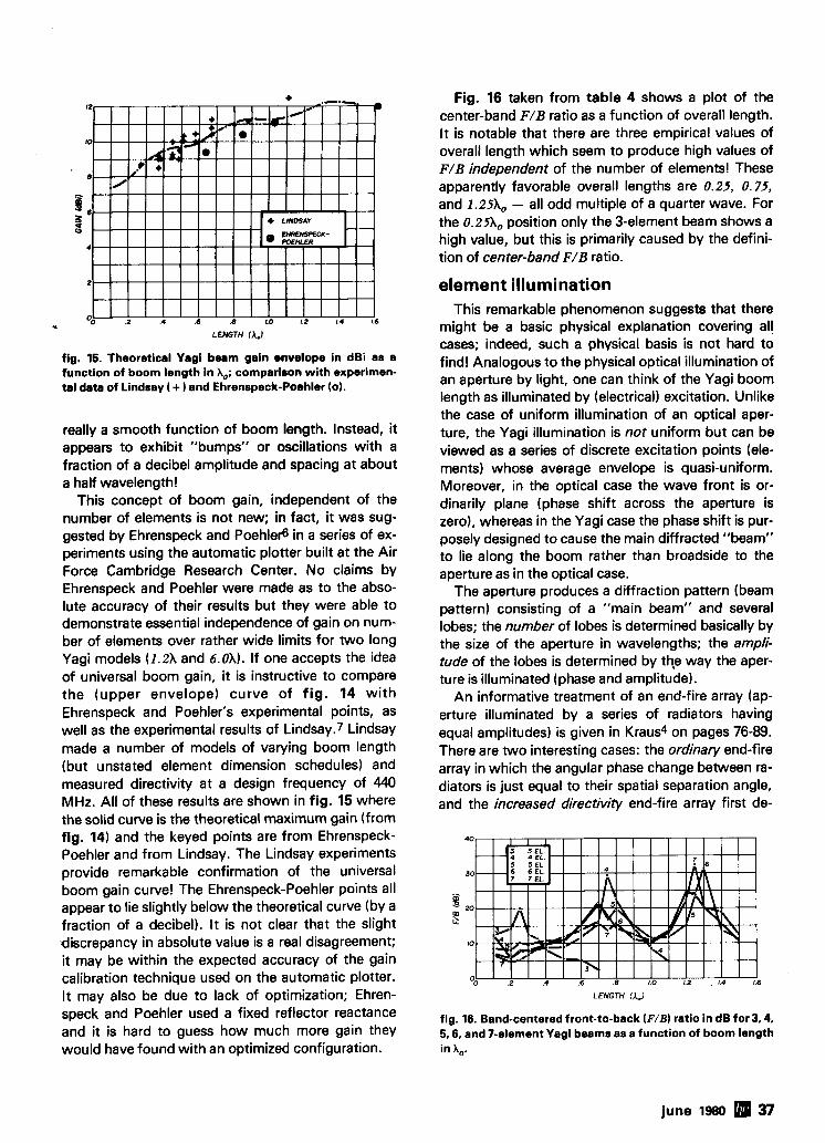
'0 .2 .4 .6 .a 1.0 LZ L 4 1.6
LENGTH (,I.)
fig. 16. Theoretical Yagi beam gain envelope in dBi as a function of boom length in A,; comparison with experimen- tal data of Lindsay I + 1 and Ehrenspeck-Poehler (01.
really a smooth function of boom length. Instead, it appears to exhibit "bumps" or oscillations with a fraction of a decibel amplitude and spacing at about a half wavelength!
This concept of boom gain, independent of the number of elements is not new; in fact, it was sug- gested by Ehrenspeck and Poehlefi in a series of ex- periments using the automatic plotter built at the Air Force Cambridge Research Center. No claims by Ehrenspeck and Poehler were made as to the abso- lute accuracy of their results but they were able to demonstrate essential independence of gain on num- ber of elements over rather wide limits for two long Yagi models (1.2X and 6.OX). If one accepts the idea of universal boom gain, it is instructive to compare the (upper envelope) curve of f ig . 14 with Ehrenspeck and Poehler's experimental points, as well as the experimental results of Lindsay.7 Lindsay made a number of models of varying boom length (but unstated element dimension schedules) and measured directivity at a design frequency of 440 MHz. All of these results are shown in fig. 15 where the solid curve is the theoretical maximum gain (from fig. 14) and the keyed points are from Ehrenspeck- Poehler and from Lindsay. The Lindsay experiments provide remarkable confirmation of the universal boom gain curve! The Ehrenspeck-Poehler points all appear to lie slightly below the theoretical curve (by a fraction of a decibel). It is not clear that the slight discrepancy in absolute value is a real disagreement; it may be within the expected accuracy of the gain calibration technique used on the automatic plotter. It may also be due to lack of optimization; Ehren- speck and Poehler used a fixed reflector reactance and it is hard to guess how much more gain they would have found with an optimized configuration.
Fig. 16 taken from table 4 shows a plot of the center-band F / B ratio as a function of overall length. It is notable that there are three empirical values of overall length which seem to produce high values of F / B independent of the number of elements! These apparently favorable overall lengths are 0.25, 0.75, and 1.25X0 - all odd multiple of a quarter wave. For the 0.25X0 position only the 3-element beam shows a high value, but this is primarily caused by the defini- tion of center-band F/B ratio.
element illumination This remarkable phenomenon suggests that there
might be a basic physical explanation covering all cases; indeed, such a physical basis is not hard to find! Analogous to the physical optical illumination of an aperture by light, one can think of the Yagi boom length as illuminated by (electrical) excitation. Unlike the case of uniform illumination of an optical aper- ture, the Yagi illumination is not uniform but can be viewed as a series of discrete excitation points (ele- ments) whose average envelope is quasi-uniform. Moreover, in the optical case the wave front is or- dinarily plane (phase shift across the aperture is zero), whereas in the Yagi case the phase shift is pur- posely designed to cause the main diffracted "beam" to lie along the boom rather than broadside to the aperture as in the optical case.
The aperture produces a diffraction pattern (beam pattern) consisting of a "main beam" and several lobes; the number of lobes is determined basically by the size of the aperture in wavelengths; the ampli- tude of the lobes is determined by th,e way the aper- ture is illuminated (phase and amplitude).
An informative treatment of an end-fire array (ap- erture illuminated by a series of radiators having equal amplitudes) is given in Kraus4 on pages 76-89. There are two interesting cases: the ordinary end-fire array in which the angular phase change between ra- diators is just equal to their spatial separation angle, and the increased directivity end-fire array first de-
LENGTH (A.1
fig. 16. Band-centered front-to-back (NB) ratio in dB for 3,4, 5.6. and Felement Yagi beams as a function of boom length in A,.
june 1980 37
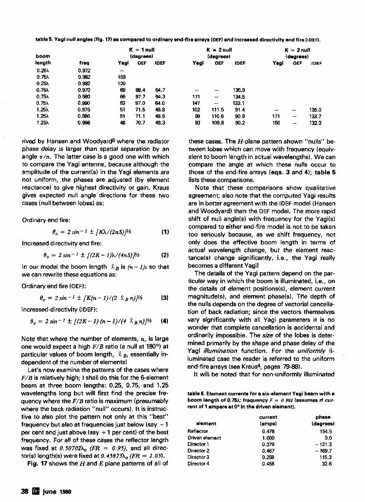
table 5. Yagi null angles (fig. 17) as compared to ordinary end-fire arrays (OEF) and increased directivity end fire (IDEF).
boom length
0:25X 0.75X 0.25X 0.75X 0.75X 0.75X 1.25X 1.25X 1.25X
f req
0.972 0.982 0.992 0.970 0.980 0.990 0.976 0.986 0.996
K = 1 null (degrees)
Yagi OEF IDEF -
159 120 69 98.4 64.7 66 97.7 64.3 63 97.0 64.0 51 71.5 48.8 51 71.1 48.6 48 70.7 48.3
rived by Hansen and Woodyard8 where the radiator phase delay is larger than spatial separation by an angle a / n . The latter case is a good one with which to compare the Yagi antenna, because although the amplitude of the current(s1 in the Yagi elements are not uniform, the phases are adjusted (by element reactance) to give highest directivity or gain. Kraus gives expected null angle directions for these two cases (null between lobes) as:
Ordinary end fire:
8, = 2 sin - 1 f [KX/(znS)lJ/i (1)
Increased directivity end fire:
0, = 2 sin- 1 f [(ZK - I)X/(4nS)]% (2)
In our model the boom length R B is (n- 1)s so that we can rewrite these equations as:
Ordinary end fire (OEF):
6, = 2sin-1 f [K(n-1)/(2 RBn)]G (3)
Increased-directivity (IDEF):
0 , = 2 s i n - 1 f [ (ZK- l ) (n-1) / (4 RBn)]% (4)
Note that where the number of elements, n, is large one would expect a high F/B ratio (a null at 180°) at particular values of boom length, R B, essentially in- dependent of the number of elements!
Let's now examine the patterns of the cases where F/B is relatively high; I shall do this for the Selement beam at three boom lengths: 0.25, 0.75, and 1.25 wavelengths long but will first find the precise fre- quency where the F/B ratio is maximum (presumably where the back radiation "null" occurs). It is instruc- tive to also plot the pattern not only at this "best" frequency but also at frequencies just below (say - 1 per cent and just above (say + 1 per cent) of the best frequency. For all of these cases the reflector length was fixed at 0.50702X0 (FR = 0.95), and all direc- t o r (~ ) lengthls) were fixed at 0. 45873X0 (FR = 1.05).
Fig. 17 shows the Hand E plane patterns of all of
K = Znull K = 3 null (degrees) (degrees)
Yagi OEF IDEF Yagi OEF IDEF
these cases. The H-plane pattern shown "nulls" be- tween lobes which can move with frequency (equiv- alent to boom length in actual wavelengths). We can compare the angle at which these nulls occur to those of the end-fire arrays (eqs. 3 and 4); table 5 lists these comparisons.
Note that these comparisons show qualitative agreement; also note that the computed Yagi results are in better agreement with the IDEF model (Hansen and Woodyard) than the OEF model. The more rapid shift of null angle(s1 with frequency for the Yagi(s) compared to either end-fire model is not to be taken too seriously because, as we shift frequency, not only does the effective boom length in terms of actual wavelength change, but the element reac- tance(~) change significantly, i.e., the Yagi really becomes a different Yagi!
The details of the Yagi pattern depend on the par- ticular way in which the boom is illuminated, i.e., on the details of element positions(s), element current magnitude(s1, and element phase(s1. THe depth of the nulls depends on the degree of vectorial cancella- tion of back radiation; since the vectors themselves vary significantly with all Yagi parameters it is no wonder that complete cancellation is accidental and ordinarily impossible. The size of the lobes is deter- mined primarily by the shape and phase delay of the Yagi il/umination function. For the uniformly il- luminated case the reader is referred to the uniform end-fire arrays (see Kraus4, pages 79-88).
It will be noted that for non-uniformly illuminated
table 6. Element currents for a six-element Yagi beam with a boom length of 0.m; frequency F = 0.980 (assumes rf cur- rent of l ampere at O0 in the driven element).
element current phase (amps) (degrees)
Ref lector 0.476 154.5 Driven element 1.000 0.0 Director 1 0.379 - 121.3 Director 2 0.467 - 169.7 Director 3 0.258 115.3 Director 4 0.458 32.6
38 june 1980
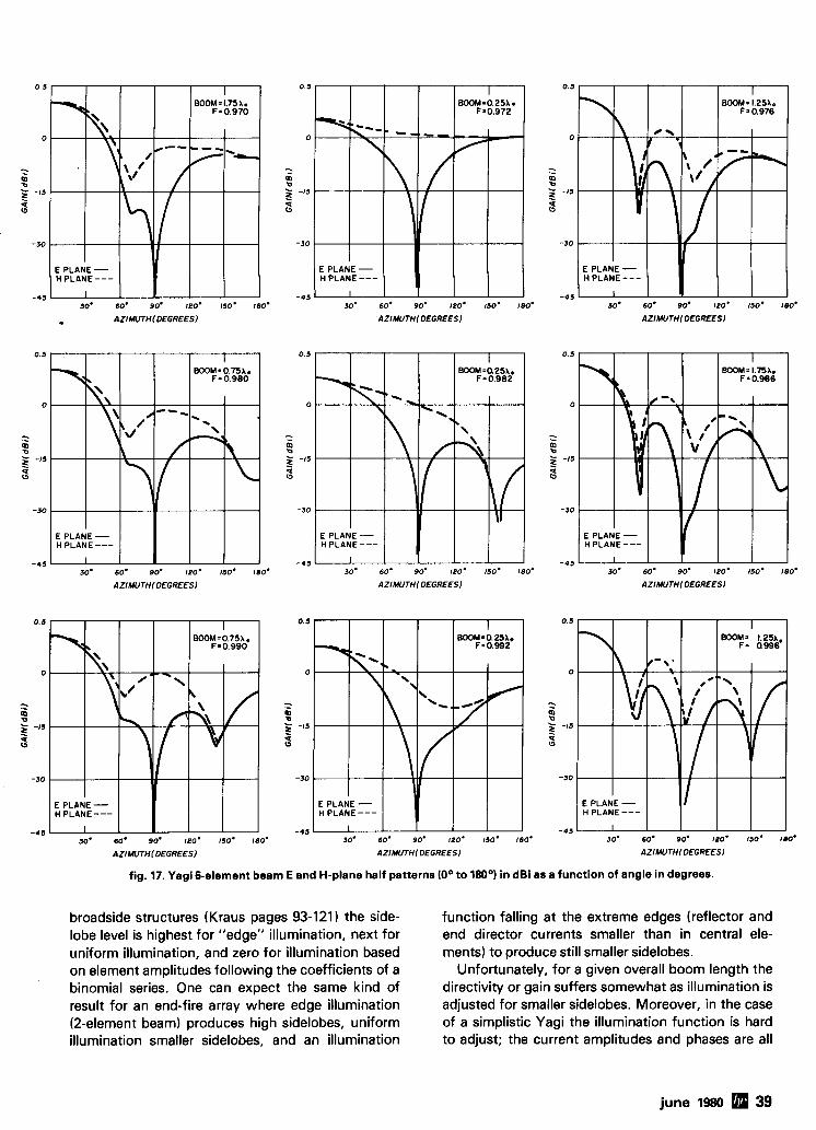
0 5
0
-IS
-30
E PLANE - H PLANE---
-45 1 30' 60' 90' !PO' 150. 180'
0.5
0
-. - 0 - -15 z 0
-30
E PLANE - H PLANE ---
-45 I
30- 60' 90' 120. 150' 180'
o AZIMUTH1 DEGREES) AZIMUTHlDEGREES) AZIMUTHIDEGREES)
0.5
0
- - 2
-15
q (1
-30
E PLANE - H PLANE---
-45 I 30' 60. 90. IPO. 150. 180'
AZIMUTH(DEGREES) AZIMUTH1 DEGREES) AZIMUTHIDEGREES)
fig. 17. Yagi 6-element beam E and H-plane half patterns (0° to 180°) in dBi as a function of angle in degrees.
broadside structures (Kraus pages 93-121 the side- lobe level is highest for "edge" illumination, next for uniform illumination, and zero for illumination based on element amplitudes following the coefficients of a binomial series. One can expect the same kind of result for an end-fire array where edge illumination (2-element beam) produces high sidelobes, uniform illumination smaller sidelobes, and an illumination
function falling at the extreme edges (reflector and end director currents smaller than in central ele- ments) to produce still smaller sidelobes.
Unfortunately, for a given overall boom length the directivity or gain suffers somewhat as illumination is adjusted for smaller sidelobes. Moreover, in the case of a simplistic Yagi the illumination function is hard to adjust; the current amplitudes and phases are all
june 1980 39
table 7. Computed F / B ratios for six-element Yagis with various boom lengths (see fig. 17).
E-plane H-plane F / B F/B minimum F/B minimum
length, freq. (180°) (90°-180°) (90°-180°1
0.25X 0.982 25.7dB 18.75dB 7.5 dB 0.75X 0.980 32.5dB 19.65 dB 12.6 dB 1.25X 9.986 35.0dB 18.8 dB 14.9 dB
frequency as does the change in reactance with fre- quency. Thus to insure a reasonably reliable electrical feed system it is wise to keep element separation well above 0 . 05X0; all such cases investigated have reasonably well behaved driving point impedances.
summary Let me summarize the results for simplistic Yagi
antennas:
determined by element reactancek) and position(s1 to 7-element beams with lengths to
and it is necessary to simply accept the result! To get have been
an idea of the current(s1 and phase(s) to be expected taQle 6 shows the current(s) and phase(s) of the elements for the case of the 6-element beam, boom = 0 . 7 5 X o , where the driver current is set at 1.0 ampere at O0 phase. Note that while the current amplitudes are not "uniform illumination," they seem to average out surprisingly alike! Incidentally, the current in the last director is always character- istically higher than that in the preceding director; this is due to the "end effect" (no mutual to an ele- ment ahead of it).
Thus we now have a consistent picture of the high F / B ratio Yagi design; the essence of correct design is to place the null between lobes exactly in the back direction! This will occur for simplistic Yagi antennas when the overall length is approximately an odd mul- tiple of a quarter wavelength. The specific best design will involve optimizing the boom length and the boom illumination function (the particular ele- ment excitation currents and phases) to yield the best F / B ratio. Such optimization can be carried out around the best boom lengths; this will be the sub- ject of a future article. For the present it is sufficient to note that really excellent F / B ratios are possible with these simplistic designs as long as one is willing to accept boom length(s) which are approximately odd multiples of a quarter wavelength.
As a final note on these simplistic best designs, not only is the back radiation low but the minimum (worst case) F / B ratio in the entire reverse direction (90° to 180°) is also surprisingly high! Table 7 shows the result. These Yagi designs seem to be generally excellent!
With the exception of the 2-element beam case I have not yet commented on the driving point im- pedance of any of the Yagis shown. Remember that one can, by adjusting the length of the driver, always null out the driving point reactance at a designated frequency. The remaining resistance, however, just like that for the 2-element beam, varies enormously from case to case. It is very low for very short beams where there is very strong coupling between ele- ments; moreover, in such cases it varies wildly with
2. Simplistic Yagis display a gain function where bandwidth is primarily a function of the resonant fre- quency separation between reflector and director(s1. The bandwidth can easily be made several per cent of the central frequency.
3. The shape of the gain function is generally not flat in the region of interest. It is also more complex for beams which use a large number of elements.
4. Simplistic Yagis display a F / B ratio function with a shape that varies enormously from case to case. The shape may contain more than one peak and changes rapidly with boom length and/or frequency. I t is so complicated that i t is not possible to characterize its bandwidth.
5. High values of the F / B ratio (more than 30 dB) are quite rare; when they occur F / B is high only over a very narrow band of frequencies.
6. The spacing between elements should be general- ly greater than 0 . 0 5 X o to realize a well-behaved feed.
7. The maximum practical gain of the simplistic Yagi is almost entirely determined by boom length. Max- imum gain increases, but not steadily with boom length.
8. Best design for a high F / B ratio requires the ap- proximate boom length to be an odd multiple of a quarter wavelength at the design frequency.
references 1 . J.L. Lawson, "Design of Yagi Antennas," ham radio, January, 1980, page 22. 2. The ARRL Antenna Book, 13th edition, American Radio Relay League, Newington, Connecticut, 1974. 3. G.H. Brown, "Directional Antennas," Proceedings of the IRE, January, 1937, pages 78-145. 4. J.D. Kraus, Antennas, McGraw-Hill, New York, 1950. 5. J.L. Lawson, "Design of Yagi Antennas," ham radio, May, 1980 page 18. 6. H.W. Ehrenspeck and H. Poehler, " A New Method for Obtaining Max- imum Gain from Yagi Antennas," IRE Transactions on Antennas and Prop- agation, October, 1959, pages 379-386. 7. J.E. Lindsay, "Quads and Yagis." QST, May, 1968, page 11. 8. W . W . Hansen and J.R. Woodyard, " A New Principle in Directional Antenna Design," Proceedings of the IRE, March, 1938, pages 333-345.
ham radio
40 june 1980
More Details? CHECK-OFF Page 94 june 1980 41
MINIATURE SCREWDRIVER
RLlOliEO CONSTROCTION ~ m . o + U S ~ S 1 - 8 T I P 2/$1.00 . . . . . . . . . . . . . . . . .
MAGNETIC RETRIEVER TOOL
@-. Pick. UP 01u.h. m u 1 PYU or tools
in h.rd.to-r.rh PI-%
EXTENDS TO 26%" - ROTATES 360- STRONG, LIFETIME MAGNET
MRT-2281 .................. $3.95
1- 7 CONTINENTAL SPECIALTIES
LOGIC PROBE KIT
MlCROPROCESSOR COMPONENTS -mmIYtVIAlmm- ow CPll s ' 9 5
*ICnOmOCtSson MI*UILl- ,, , 8217 11 R~I lnpul ovtpu~ ; ;; :gplm ,,,I::; ::::::: I , 8714 Pllonfl I r > l r r r i r ~ l C4mlol 8716 ~i nlrminna8 rjil, nrmr (9 H 7f'M "Wt M2#7,,*4 '" 8174 C L x * G l l r r r l o t 111~11 3 95 8776 RuilI~~vrr mw B>?R slam conl?olkrm Drmr 873 Svstern C~nllMw ' ~ 2
95
:;;; ;;: y;, ;,w;mn ,: :: ;;a:;::;; Hrmrm I g5 9 91 8755 Plw Ptllnh 1'0 1PPII
8157 PIW OMA Mild 19 % MCS
194 I;; 7Sxl Sqa!,~ ,9 8 , ~ P ~ W I ~ I C ~ S W D I comm lmlxl Qinrmr ummm runom m c - 7101111011 156x4 SIXI~C
99
U r n UP,,
,; ;;:;, 10?4Xl stat,, ; g UCW~CP ~ P i i n t h UOtk am urn IO7IX1 Silli' ura twu I : R ~ st*lr nun ' * MC18?I Pellph inler Adapl lAW&7Dl i 19 7111'81111 75"4
95 1117 ?'*il4 Sl.rilc MCfS : 2 MCI,R?R Pllollh Inlerw~I Cmlrolbr 1U.I.lX4 Slrllt 4Wm M ~ ~ ~ ~ a a to.3rra ROM ~ ~ m u o - s ~ : ,,,,,,, ,,,,,,,,, ,,, 1:2 M( fJ(W LWn<nrOnou$ Comm ldapllr !0>4X4 S!AI#< 3 M S MT6852 Sywntanarr na!. rm!
The Incredible
"Pennywhistle 103"
$ 1 3 9 . 9 5 K i l O n r* -gin. la ,. , . , I , A ~ ~ * nmrdll.o ,,,,, , , am1it8o m a n Ollal I g r , 8.l) ill, rn.li!' I,., lna I.mlbl .#I,, I , I ,,.I? 11 1,11,1 . .11.1.1 111 iJI.nh.m ... .,lo,Cl lnr*rl am lrlmln.i ,o, lmhm h...l........l m....... ".<"..01 I" 1,,",,,0" 8 I,., 1r~",c,,,,r~l.",YIfmt,,.ionbulll.ill llrln 01*1\1"11 l"1d1li > " m u pa,, 011~1msm1su111 Umnd f m w w Shm ~mmo lull du&% inam-
* , ID* , *..I- rnb Rae . . m Raid oa~a F-0, *~rnrntonam~~m lntum lo rmlr M -
LlW" (I lh OYrH1111 MI 0-1 f- 1075 ,+, lor .MI 7775 nl lo, ma 1r.n.nn cnm* - s-ilrn *tab* ia lrnrmau tom -.
11'0 rmll *oh , 075 lorn 7775 ma* M"maemwh mmna r.n
4f1 nn-r, lrrolntulh r o u ~ . . . I 5 onm nolnmal Mlulflh* ID"! l mT
ID 70 8-m
194 1MuM71 D380 Id rlrruil b a r 0 UI m p m n t l Mlusd
;j:$z ;;$$;3;;y 1;; z :&,07 ?Kj ""'3 lo'ux4 Udtr n m ' h ~ - m- l- . .fwpueniv re fenon amornalwllv a a t m lo
4 95 H w !a, owwlon w n lm HI nd 7 m M MI s."COI O"3" 3 \late ""5 I l rn . lmml OINI mu hmme. . CIA R!, II?C of m rm cutren~ mp 1"- b - mewnoassan MI-Y~~~LW~~DVI- ::& it::, :::::: r.,,,,, aplolwutd and mn mull
. . :: : . ~ 2 ~ ~ " , : ~ ? ~ n I I " . . " 2 m p C 1' h P 78n,TBOC) Ci'll ZAOAOBO I) C",,
Sl3.55 91411 75I1Xl 51rlc 15.55 UDIMII 4r [l,nm*t l8.n
~ -
SPECIFICATIONS
I n p u t Impedance. 300.000 Ohnis Thresholds: "Lo" 30"6Vcc - "HI" 70%Vcc M a x i m u m Speed: 3 0 0 nsec.. 1.5MHz l n p u t Protection: t 5 O V D C continuous 117VAC for 15 sec. Power: 3 0 m A @ 5 ~ - 4 0 m A Q 1 5 V - 2 5 V max. reverw, voltage protected; 36" cable w l t h color coded clips included. Operat ing Temp.: 0.50.C. Dimensions: 5.8L x l . 0 W x 0.70 in. . (147 x 2 5 x 18rnnl) Weight: 3 0 oz. (85 g m l
LPK-1 ................. $21.95/Kit
1111111 Proto Clips fi;J . . . . WPIN CLIP PC.(. s 4.60
( W I N CLIP PC.16 S 4.75 . . . . 2CPIN CLIP PC.24 $10.00 . . . . .
.))))))I 40-PINCLIP PC40 . . . . 116.00
Proto Boards PB6 . . . . . . . . $17.95 p B - l w . . . . . . . . 19.85 PB.101. . . . . . . . 22.95 PB-102. 26.95 . . . . . . . p ~ . 1 0 3 . . . . . . . . M.95 . . . . . . . PB-104. 65.95 PB.~OJ . . . . . . . . 99.95 Pa-203A. . . . . . ,55.00 PB-203A-Kh ,31.00 . . .
( ? 95 UPMI ,a hnumr l6 ." lYh Wmnrr MU MD OvUmr ffagunrr Caunnl aM'or oulm- lo w 1 1 W IMllll6l
8015 8 IIII W .m. M. lmnm 19 95 TWIIM~. saw PBW5 CPu 1995 ('IUL
14 %
l w \ m 16 1 1 p u w m m m . WOQ TMIIOIL 1m4x4 s a r TRS-80
Ldmda 498s ?!I: 16wX1 l h r u r n l ~ m $4. 16K Conversion Kit 9 95
M nfUWrnS-------- I ~ Y MMI Expand y w r 4K TRS.80 Synam to 16K. UUIDM Oull75BnPmmr $50 YY1m 82x1 Wnir 411 00 uuurxu ou, s sn ovname
Kit conus complete ~ 0 t h : s
MMYYH O w l 16 &I Slnr Y1 mows 8 a u h UP0416 1 IlGK Oynnnic R m r I ?SONS
M im7r ma IAMOS . 0 0 ~ m n l . l ~ o n lor conrers~on
.UyU<% ::: LmC1~2,"- y l 71161Nltl 361' II,I~<)IA Z T R S - 1 6 K . . . . . . . . . . . yFz'* " ~ ~ m ~ N m
69 TMS75l6 161' Ii'llllM 195 (77111 'Fw4r.I Ma* , 5V prm ((Dh
$75.00 Z ~ I R n.. 37 81 S ~ ~ M 4 95 IUS?Y? 4 ~ ~ 8 FPUOM 89 % 1571 Oval 137 RII SI* 7 4 7708 8r IPROU 5 512 ~ t a i r w 7it6 T I la.. EPROM 7575 lo74 W n m 7 95 "Rq.lrn 3 *n -5V. +N. .IN 2521 nun 2% I SUBC 7 95 urn ?M8 $AMOS 7518 nun 150 stlor 4 im 6Y)1-l(76lll ,074 ~rs-nw(LpOlar 75s OWI 240 RII SU* 4 m c a . 1 r m z 1 7 ~ own c souas 70s 2517 a d so rl stale 7 4 87511 ?:XI omn tolmor 393 314, fllo BPI 05115 4 8,noul I9 95 ~rrssm rr4 ~ p m n H* (TnSml 2 (9 675ln 3'18 Ih,.t~t* 3 95
74186 50 TTL OD~CDII~D~ 995 -30 AWG wsr. a.025" quare porn
7 4 1 ~ 756 r l i om W m w -0.m chon or .Bunll-in sul off
, ,,,, ,,, ,, w: 1 7IC?87 1O14 Slrln
polnl.to~paln1 Includes54 (ltl.wk .NO nrapp~n. ov sl~ttnnp rwuird-
JE6W HEXADECIMAL DIGITAL i u n wrap
W h ENCODER KIT THERMOMETER KIT muo !a!!! m r
RAlUOtl 1W.l.B Bl", s1Ki-T . hi 8 on uw anpd 10, maoo IW.1.W Wh81w 14.95 JW.1.Y Yellow 14.95 . 3 U I I ~ Dtb* lnsmn m mno b- JW.1.R Rad 14.95
017ounce <~!C" l f ...%w C an 99
ta..l n..rflcO *fin tlm,a 16 pn cr 5 - - - -. Replacement Wire IC t o n ~ m o ~
C.1DI hse. . . . . . . . . . . . . nnw . 5vDc rmnd nr mwn( 4 - R-JW B Blue.. 50 tt. rol l . . $2 98
FULL 8 BIT UfCHED OUTPUT-19 KEYBOARD .DU*I n n o r . - ~ ~ t r h , n p sont,ob lo, I". R.JW Wh'le.. 'Of'. 2.98 . . . . . . . . . . . . . . . . . . . . l n ~ t m a inoat rqmea paonntr 1.0 sqrnew.riearm~ d00r10utd00r or av.1 r n ~ n ~ t o r ~ n ~ 50 11. rol l . 2.98 R-JW-Y Y ~ l l 0 w . . amar prod- from 3qu.n!,.~ h mln to dllrc. prw -Confanuo"* LED 8" hT a'*p'*v
,"moii,o<r.w, 8)dwrmr l i , , . . . . . . . . ". . . . . . . 2.9B In,.e -R."o= a0-p 10 199 .~ / 4 0 ~ to700-c wJW-'
~ 3 ~ ~ ~ ~ ~ ~ 0 ~ 1 ~ w ~ r ~ r ~ t o ~ ~ ~ a e ~ ~ c ~ o m ~ n ~ 0 ~ 1 - a ~ o n ~ ~ ~ o :~~~L;b:C\,k!.%.?'~~'c.~~ ...ding &bsldOitoUIDlillva~bh* 1 * ~ 0 ~ 1 ~ ~ 1 s a r o a ~ m e m t r m n n a ~ m .S,m w.lnur c.u AC w.II ,., JLfSr WRAP' Unwrap TOO! $3.49 n n I ~ O ,rrnnlnl A,,, nrltim sr a hey r vr wow .slz. 3 114"H 16 W~..W. 1 3 i8 .0
.............. Jumbo 6-Digit Clock Kit ...... JE6OO $59.95 Hax.d.comI K w d only 514.95
F O Y ~ .writ. ana two .m"nt.
...... JE300 .$39.95
Vacuum Vise Vecuurn L>aled imnht duty YIU lor sms l l com~on.n!s .M essernblle. ARS con- .truc,,on 1 :;" 1.w.. I U'. travel Cen ha o.rman.ntlv
....... w-1 $3.49 ADJUSTABLE WRENCH
.Two S i m . 6" and 1 0
.P~D~.uIo~I O".llt~
.Chrome Vanedlum S d
. . 6"- AW". $4.95 10"- AW.10. $6.95
JOYSTICK VIDEO CONTROLLER
common mods alsolayr . Usel MMUl4 clock chlo Sw~t~n.l lo, n ~ ~ ~ . . mln~t.. and hold tuncllons Hours e.sIIY VIeWaDI~ to I l e t Slmulatea walnul uu
• 1 1 5 ~ ~ ~ owratlon v or 21 hour oper.tlon Includes a11 components. case ma wall tr.nsfermer . 511e. 6% x 3% X 1%
JE747.. .529.95 ........... .8rnpht 300 ht comn% calh
M a dlwlav
:~~:~'5$~~",~ zlzutm .nd now mode1 .,,I.. ..,, lv vl.w.b~. 20 11.
.somulatea walnut w -115 V A C oosratlon -12 or 24 hr. o~.r.flon ~ ~ 7 0 1 .I.CI. cOmp.,.nt.. wall transtotrnsr
6X. . , 3%'.
. 3 * . . . . . . . I . . . . . . , , . , ., . . , . *. *.,,, ,, , . I., . , -. ....I.. . . . . . . . . . . . . . . . . . . . . . . . . . . . .............................. Regulated Power Supply .,"..".. .,I.w,
.I.......... I, .,.. Y..,.l(.,,Ol, D:......-C, ~ , . " " , . , r m . *.I..-. .L1,\.~,D..I I I....- 1 ~ 1 1
Uses LM309K. Heat slnk
1 amp (a 5 volts. Can supply u p ....... to 15V. t 9 V and t l 2 V w i t h JE205 Adapter. Includes compo- ......... nents. hardware and instructions. Stze: 3:'~" x 5" x 2"H
1.9s JE200.. ...... $14.95 15 cO 1 0 An,c# OC Cilrrenl ylunl 1.95
ADAPTER BOARD SlO.00 Min. Ordr - U.S. Fund~Onlv Spr - 2W C.l,f. Resod.ntr Add 6% S.1.s Tar 1880 C.t.1~ Avmilnbb- Smd414nemp
~ d a p t ~ to JE2M- P o ~ . c * - A d d 5 % p l u ~ S l Inwrmnn t l fda lnd l vno-.r v , , ~ m-xma~ m#-mv , , -
t5V. +9V and +12V IDEAL FOR A L L VIDEO GAMES OR REMOTE CON- PHONE TROL PROJECTS
ORDERS .SMALL CASE SIZE: 1-1lY'H x 2-31B'W x C 6 / l r ' L
DC;DC corivcrrer w i t h +5V input. Toriodal hi- speed swjtching XMF R. Short c ircui t protect ion.
WELCOME ' 2 MINIATUREPOTENTIOMETERS-MKOHM EACH
(415) 592-8097 '"ST PUSH BUTTON CONTROL PC board construction. Piggvback l o JE 2 0 0 WIRE CONNECTION CABLE - 5 FEET LONG board. Stze: 3%" x 2" x 9116"H .RUGGED PLASTIC CASE
LJE205 .$12.95 JVC-40. $4.95eachJ 1355 SHOREWAY ROAD. BELMONT. C A 94002 ..... .............. PRICES SUBJECT TO CHANGE
62-Key ASCII Encoded Keyboard Kit FEATURES:
80 K.v. pm.1. th full 128 shr. nctar. u p p r mnd 1- a ASCII - I Fully buff.nd
- 2 ur rdd in . h s p a w e d for cunom .pplic.tion.
*COPS lock for upp. c... only alphe ch.r.st.n
*Uttlmm a 2376 I 4 0 plnl rpDdr r e d only numow h l p
Th. JE61062 Key AS d Kwvhoard Outpun dnrsctl mmptlblo rkh Klt a n b. ~ n t e r l d into m a t snv corn- TTLIOTL or ~8Slwtlc.rr.vs puw rynem. The JE610 K D ~ comn corn -Easy ~nmrtacong wllh 8 16.pin dip plete ~ 0 t h an ondunr8.1 prd. kaybo.fd 0' 1 8 w n .dw conneflw m s t h suanblv 162 ksysl. IC'r, u rkou. .... mn-or. eI.nronnc componmn and JEbl0. $79.95
print* wlranQ board. keybwrd arrmbly r q u l r a s *5V @ 1WmA and - lZV 0 1 h A f w opratlon. 62.Key Keyboard only. . 534.95
6-Digit Clock Kit $19.95 HICKOK 1x303 Portable LCD Digital Multimeter
phased vertical antenna for 21 MHz
An economical approach to beam antennas
for the band
Most of the Amateur antenna handbooks don't describe the phased vertical beam. For economy and performance they should be used more! I built a phased vertical beam using the references indicat- ed.1-4 I hope the explanation given here will motivate others to try this antenna. There's probably an easier way to construct the beam. W E L de- scribes another method of matching in reference 4. However, I chose to use the more classical Wilken- son match. Perhaps there should be more experi- menting and discussion on feeding this beam. WEL's method would do away with the problem of locating 100-ohm noninductive resistors for termina- tion and balance.
phased vertical array The phased vertical beam has some good features.
Fig. 1 shows horizontal radiation patterns for a two- element phased vertical array using three different
phase angles for feeding the two elements. If both elements are fed in phase (zero-degree phase angle), the radiation pattern will be bidirectional at right angles to the plane of the two elements. This is known as broadside radiation. If the antenna ele- ments are fed 180 degrees out of phase, an end-fire pattern results, producing bidirectional coverage in the plane of the elements (end fire). If one element is fed 90 degrees out of phase with respect to the other, a unidirectional pattern is obtained. Thus, with two vertical elements, properly phased with relay switching, you can cover all four quadrants of the compass.
I was interested in only one direction, and it just happened that my brick fence was in a line where I wanted the antenna pattern to go. The rest was easy, because only holes had to be drilled with a con- crete drill and lead slugs driven in place to mount the element insulators.
1 construction Fig. 2 shows construction details for my two-
element phased vertical beam. I obtained two pieces of 112-inch (12.5-mm) diameter aluminum tubing 12 feet (3.7 meters) long. I cut each tube at 11 feet (3.4 meters) for the 114-wavelength antenna elements. The formula is:
By Ed Marriner, WGXM, 528 Colima Street, La Jolla, California 92037
42 fl june 1980
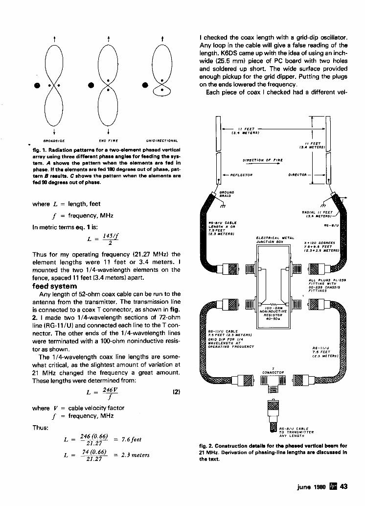
B R O A O S l a E END F I R E U N I D I R E C T I O N A L -*
fig. 1. Radiation patterns for a two-element phased vertical array using three different phase angles for feeding the sys- tem. A shows the pattern when the elements are fed in phase. If the elements are fed 180 degrees out of phase, pat- tern B results. C shows the pattern when the elements are fed 90 degrees out of phase.
where L = length, feet
f = frequency, MHz
In metric terms eq. 1 is:
Thus for my operating frequency (21.27 MHz) the element lengths were 11 feet or 3.4 meters. I mounted the two 114-wavelength elements on the fence, spaced 11 feet (3.4 meters) apart. feed system
Any length of 52-ohm coax cable can be run to the antenna from the transmitter. The transmission line is connected to a coax T connector, as shown in fig. 2. 1 made two 114-wavelength sections of 72-ohm line (RG-11 IU ) and connected each line to the T con- nector. The other ends of the 114-wavelength lines were terminated with a 100-ohm noninductive resis- tor as shown.
The 114-wavelength coax line lengths are some- what critical, as the slightest amount of variation at 21 MHz changed the frequency a great amount. These lengths were determined from:
where V = cable velocity factor f = frequency, MHz
Thus:
L = 74 (0'66) = 2.3 meters 21.27
I checked the coax length with a grid-dip oscillator. Any loop in the cable will give a false reading of the length. K6DS came up with the idea of using an inch- wide (25.5 mm) piece of PC board with two holes and soldered up short. The wide surface provided enough pickup for the grid dipper. Putting the plugs on the ends lowered the frequency.
Each piece of coax I checked had a different vel-
- 11 F E E T 1 3 . 4 Y E T E R S )
I 1 F E E T 1 1 . 4 METERS1
O l R E C T l O N O F F I R E
c R E F L E C T O R
1 3 . 4 METERS
RG-8 /U CABLE LENGTH X OR
1 2 . 3 M E T E R S ) E L E C T R I C A L METAL
X + I 2 0 DEGREES 7 . 6 + 9 . 5 F E E T ( 2 . 3 + 2 . 9 METERS)
ALL PLUGS P L - 2 5 9 F I T T I N G W I T H
RES ISTOR 4 0 - S O W
R G - I I / U CABLE 7 .5 F E E T 12 .3 M E T E R S ) GRID D I P FOR 1 / 4 WAVELENGTH A T
R G - B / U C A B L E T O T R A N S M I T T E R ANY L E N G T H
fig. 2. Conrtruction details for the phased vertical beam for 21 MHz. Derivation of phasing-line lengths are discussed in the text.
june 1980 43
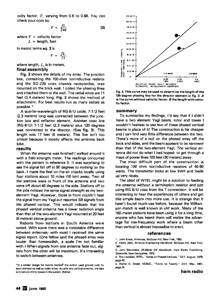
ocity factor, V, varying from 0.6 to 0.68. You can check your coax by
where V = velocity factor L = length, feet
In metric terms eq. 3 is
where length, L, is in meters. final assembly
Fig. 2 shows the details of my array. The junction box, containing the 100-ohm noninductive resistor and the SO-239 coax chassis receptacles, was mounted on the brick wall. I coiled the phasing lines and attached them to the wall. The radial wires are 11 feet (3.4 meters) long. Fig. 2 shows the method of attachment. For best results run as many radials as possible.
A quarter-wavelength of RGSIU cable, 7-1 I 2 feet (2.3 meters) long was connected between the junc- tion box and reflector element. Another coax line (RG8/U) 7-1/2 feet (2.3 meters) plus 120 degrees was connected to the director. (See fig. 3). This length was 17 feet (5 meters). This line isn't too critical because it mostly affects the antenna back lobe. results
When the antenna was finished I walked around it with a field-strength meter. The readings concurred with the pattern in reference 3. It was surprising to see the signal fall off at 90 degrees to nothing on the back. I made the first on-the-air checks locally using four stations about 10 miles (16 km) away. Two of the stations were in front of the antenna and two were off about 45 degrees to the side. Stations off to the side noticed the same signal strength as my two- element Yagi. However, those in front couldn't hear the signal from my Yagi but reported S9 signals from the phased vertical. This would indicate that the phased vertical antenna has a lower radiation angle than that of the two-element Yagi mounted at 20 feet 16 meters) above ground.
Reports from stations in South America were varied. With some there was a noticeable difference between antennas; with most I received the same signal report. (One fellow said the phased array was louder than horseradish, a scale I'm not familiar with.) When signals from one antenna fade out, sig- nals from the other will be maximum. It's interesting to switch between antennas.
'In a similar design fw twenty m e t e d the author used ground rods for each element as well as radial wires. As with any vertical antenna, the idea is to reduce ohmic losses in the system. Editor.
1211.71--
1013.01 -- 012.41 -- 6 11.81--
411.21--
t/4 WAVE l/C UM
o 0.2s 0.8 190) 11201 oaoJ
RELATIVE PHASE SHIFT BETWEEN ELEMENTS, WAVELENOTH (OEOREESI
fig. 3. This curve may be used to determine the length of the 120-degree phasing line for the director element in fig. 2. A is the curve without velocity factor. B the length with veloc- itv factor.
summary To summarize my findings, I'd say that if I didn't
have a two element Yagi beam, rotor and tower I wouldn't hesitate to use two of these phased vertical beams in place of it! The construction is far cheaper and I can find very little difference between the two. There's more of a null on the phased array off the back and sides, and the beam appears to be narrower than that of the two-element Yagi. The vertical an- tenna did not do what I had hoped: to get through a maze of power lines 100 feet (30 meters) away.
The most difficult part of the construction is locating 100 ohm noninductive resistors of 40-50 watts. The transmitter looks at low SWR and loads up very nicely.
The ideal of W E L might be a solution to feeding the antenna without a termination resistor and just using RG8lU coax from the T connection. It will be interesting to hear the experiences of others and get this simple beam into more use. It is strange that it hasn't found much use before, because the Wilken- son match is well known in uhf work. Many of the 160-meter stations have been using it for a long time, anyone who has heard them will realize the advan- tage for low-frequency work where a beam other than vertical is almost impossible to erect.
references 1. John Kraus, Antennas. McGraw-Hill, New York, 1950. 2. Henw Jasik, Antenna Engineering Handbook. McGraw-Hill. New York, 1961. 3. John Devoldere, 69-Meter DX Handbook, Ham Radio Publishing, Greenville, New Hampshire, 1978. 4. Roy Lewallen. WIEL, "Notes on Phased Verticals," OST, August, 1979, page 42. 5. Walter D. Stead, VE3DZL. "Twins on Twenty.'' OST, May. 1961, page 24.
ham radio
44 june 1980
TheCT-70 breaks theprtce barr~er on lab quality frequency counters No longer do you have tosettle for a klt, half-k~t or poor performance. the CT-70 IS completely wlred and tested, features profess~onal qual~ty construction and speclf~cat~ons, plus IS covered by a one year warranty Power for the CT-70 IS provlded by four 'AA slze batter~es or 12 volts. AC or DC, available as optlons are a nlcad battery pack. and AC adapter Three selectable frequency ranges, each w ~ t h 11s own pre-amp, enable you to make accurate measurements from less than 10 Hz to greater than 600 mHz All sw~tches are conven~ently located on the front panel for ease of operation. and a slngle Input jack ellmlnates the need to change cables as d~nerent ranges are selected Accurate readlngs are Insured by the use of a large0 4 Inch seven d~gl t LED dlsplay, a 1 0 ppm TCXO tlme base and a handy LED gate l~ght lndlcator
The CT-70 a the answer to all your measurement ileeds. In the held. In the lab, or In the ham shack Order yours today, examlne 11 for 10 days. 11 you're not completely satlsf~ed, return the unlt for a prompt and courteous refund
I Frequency range 10 Hz to over 600 mHz Senslllvlty less than 25 mv to 150 mHz
less than 150 mv to 600 mHz Stab~llty 1 0 ppm. 2040°C. 0 05 ppmf "C TCXO crystal
tlme base D~splay 7 dlglts, LED. 0 4 Inch he~ght lnput protection 50 VAC to 60 mHz. 10 VAC lo 600 mHz lnput Impedance 1 megohm. 6 and 60 mHz ranges 50 ohms,
600 mHz range Power 4 'AA cells. 12 V AC/DC Gate 0 1 sec and 1 0 sec LED gate llght Dec~mal polnt Automatic, all ranges S~ze S"W x 1 %"H x 5%"D We~ght 1 Ib with banerles
I Prices
I CT-70 wired + tested. . . . . . . . . . . . . . . . . . . . . . . . . . . . . . . . CT.70kitform . . . . . . . . . . . . . . . . . . . . . . . . . . . . . . . . . . . . . . ACadapter . . . . . . . . . . . . . . . . . . . . . . . . . . . . . . . . . . . . . . . .
I Nicad pack with AC adapterlcharger. Telescopic whip antenna. BNC plug. Tilt ball assembly . . . . . . . . . . . . . . . .
More Details? CHECK-OFF Page 94 june 1980 45
antenna restrictions - another solution
How to install a full-size
40-meter dipole inside a mobile home
Antenna restrictions often make life difficult for hams who live in one of the new mobile-home parks. In fact, restrictions can make it almost impossible to get on the air without using a high degree of ingenu- ity. Articles have been written describing the use of fake (and not so fake) flagpoles as vertical antennas,
but the problems of ground radials and low radiation angles limit the effectiveness of this kind of solution.
Lately many of the new double-wide modular homes are being built using conventional framing and roof construction with wood joists and rafters, wood sheathing and composition shingles. This leaves only the matter of space in the attic - how do you hide an 80-meter or even a 40-meter antenna in- side if the long dimension is only 12-15 meters (40- 50 feet)?
15-meter antenna In my situation, our home is a 7.3-meter (24-foot)
wide double unit in a park where restrictions prohibit outside antennas. As a retiree ham, off the air for about 40 years until 1978,l was able to solve my own antenna problem this way: For 15 meters I made up a simple dipole using four pieces of I .&meter (6-foot) long telescoping aluminum tubing, fed directly with 50-ohm coax and secured inside the attic close to the apex of the roof rafters. It works quite well, with low SWR and easy loading to one of the new "touchy"
By J. W. Bryant, N4AQD, 4736 Dauphine Boulevard, Tallahassee, Florida 32303
46 june 1980
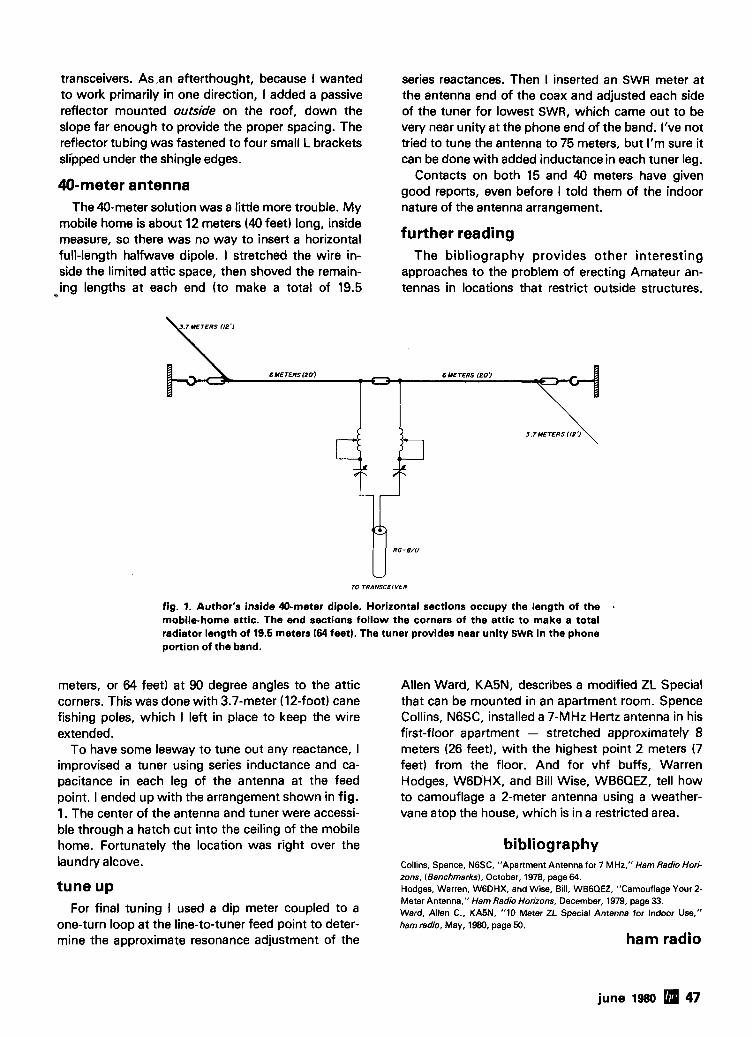
transceivers. As ,an afterthought, because I wanted to work primarily in one direction, I added a passive reflector mounted outside on the roof, down the slope far enough to provide the proper spacing. The reflector tubing was fastened to four small L brackets slipped under the shingle edges.
40-meter antenna The 40-meter solution was a little more trouble. My
mobile home is about 12 meters (40 feet) long, inside measure, so there was no way to insert a horizontal full-length halfwave dipole. I stretched the wire in- side the limited attic space, then shoved the remain- ing lengths at each end (to make a total of 19.5
series reactances. Then I inserted an SWR meter at the antenna end of the coax and adjusted each side of the tuner for lowest SWR, which came out to be very near unity at the phone end of the band. I've not tried to tune the antenna to 75 meters, but I'm sure it can be done with added inductancein each tuner leg.
Contacts on both 15 and 40 meters have given good reports, even before I told them of the indoor nature of the antenna arrangement.
further reading The bibliography provides other interesting
approaches to the problem of erecting Amateur an- tennas in locations that restrict outside structures.
TO TRANSCEIVER
fig. 1. Author's inside 40-meter dipole. Horizontal sections occupy the length of the a
mobile-home attic. The end sections follow the corners of the attic to make a total radiator length of 19.5 meters (64 feet). The tuner provides near unity SWR in the phone portion of the band.
meters, or 64 feet) at 90 degree angles to the attic corners. This was done with 3.7-meter (12-foot) cane fishing poles, which I left in place to keep the wire extended.
To have some leeway to tune out any reactance, I improvised a tuner using series inductance and ca- pacitance in each leg of the antenna at the feed point. I ended up with the arrangement shown in fig. 1. The center of the antenna and tuner were accessi- ble through a hatch cut into the ceiling of the mobile home. Fortunately the location was right over the laundry alcove.
tune up For final tuning I used a dip meter coupled to a
one-turn loop at the line-to-tuner feed point to deter- mine the approximate resonance adjustment of the
Allen Ward, KASN, describes a modified ZL Special that can be mounted in an apartment room. Spence Collins, NGSC, installed a 7-MHz Hertz antenna in his first-floor apartment - stretched approximately 8 meters (26 feet), with the highest point 2 meters (7 feet) from the floor. And for vhf buffs, Warren Hodges, WGDHX, and Bill Wise, WBGQEZ, tell how to camouflage a 2-meter antenna using a weather- vane atop the house, which is in a restricted area.
bibliography Collins, Spence, NGSC, "Apartment Antenna for 7 MHz," Ham Radio Hori- zons, (Benchmarks), October, 1978, page64 Hodges, Warren, WGDHX, and Wise, Bill, WBGQEZ, "Camouflage Your 2- Meter Antenna," Ham Radio Horizons, December, 1979, page 33. Ward, Allen C., KA5N. "10 Meter ZL Special Antenna for Indoor Use," ham radio, May, 1980, page 50.
ham radio
june 1980 47
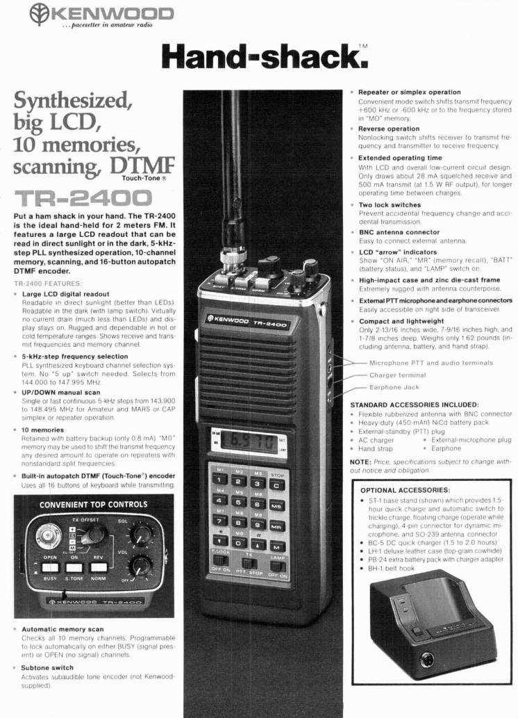
Synthesized,
IC- memories, scanning 3TlW Touch-Tone
Put a ham shack in your hand. The TR-2400 is the ideal hand-held for 2 meters FM. It features a large LCD readout that can be read in direct sunlight or in the dark, 5-kHz- step PLL synthesized operation, 10-channel memory, scanning, and 16-button autopatch DTMF encoder.
Large LCD digital readout Readable In d~rect sunl~ght (better than LEDs) Readable In the dark (wtth lamp sw~lch). V~rtually no current dram (much less than LEDs) and d ~ s - play stays on Rugged and dependable In hot or cold temperature ranges. Shows recelve and trans- m ~ l lrequenc~es and memory channel.
5-kHz-step frequency selectlon PLL synthesized keyboard channel selectlon sys- tem No "5 up" sw~ tch needed Selects from 144 000 lo 147 995 MHz
UP/DOWN manual scan Slngle or fast continuous 5-kHz steps lrom 143 900 lo 148 495 MHz for Amateur and MARS or CAP s~mplex or repeater operallon
10 memories Retained w ~ l h battery backup (only 0 8 mA) 'MO' niemory may be used lo sh~ft the lransmtt frequency any desired amount to operate on repeaters wlth nonstandard spill frequencies
Built-in autopatch DTMF (Touch-Tone') encoder Uqes all If bultons of keyboard wh~le transrnltt~ng
Automat~c memory scan ( A t l ~ ~ ( ks , 411 10 rrlprnory ( hdnnels Programmabl~ lo lock automattcally on ellher BUSY (stgnal pres rn l ) or OPEN (no s~gnal) channels
Subtone switch 1 Acl~vntes subnud~ble tone encoder (not Kenwood- supplted)
Repeater or simplex operation Convrn~enl mode sw~tch zh~fls transrnlt frequency t 600 kHz or 600 kHz or to the frequency stored In "MO' memory
Reverse operation Nonlocklnq sw~tch shtfts recelver to transmit Ire- quency and transm~ller lo recelvr frequency
Extended operating time Wlth LCD and overall low-current c~rcutt des~gn Only draws about 28 mA squelched receive and 500 mA lransmtt (at 1 5 W RF oulput). for longer operahng f~me between charges
W o lock switches Prevent acctdental frequency change and accl- dental transm~sston
BNC antenna connector Easy lo connect external antenna
LCD "arrow" indicators Show 'ON AIR," "MU" (memory recall). 'BATT' (battery status), and 'LAMP' sw~tch on.
High-impact case and zinc die-cast frame Extremely rugg6.d w~th antenna counlerpo~se
External PTT microphoneandealphoneconnecton, Easlly accesstble on r~ght s~de ol transceiver
Compact and lightweight Only 2-13/16 Inches w~de. 7-9/16 Inches h~gh. and 1-718 Inches deep We~ghs only 162 pounds (In- cludtng antenna, battery, and hand strap).
& Microphonr- PTT and audto ferm!nals
7 Charger term~nal - Earphone Jack
STANDARD ACCESSORIES INCLUDED: Flex~ble rubber~zed antenna wtth BNC ~0flrteClOl Heavy-duty (450-mAh) NlCd battery pack
External-standby (PTT) plug AC charger External-mtcrophone plug Hand strap Earphone
NOTE: Pnce specrfrcafrons sub l~c f lo change wffh OIJ~ notrce and ohlrgafron
OPTIONAL ACCESSORIES: ST-1 base stand (shown) wh~ch prov~des 1.5- hour qulck charge and automal~c swltch to lrtckle charge. floatlng charge (operate wh~le charg~ng). 4-pln conneclor for dynamlc ml- crophone, and SO-239 antenna connector BC-5 DC qu~ck charger (1 5 lo 2 0 hours) LH-1 deluxe leather case (top-grain cowhide)
PB-24 extra battery pack wllh charger adapter
7 A
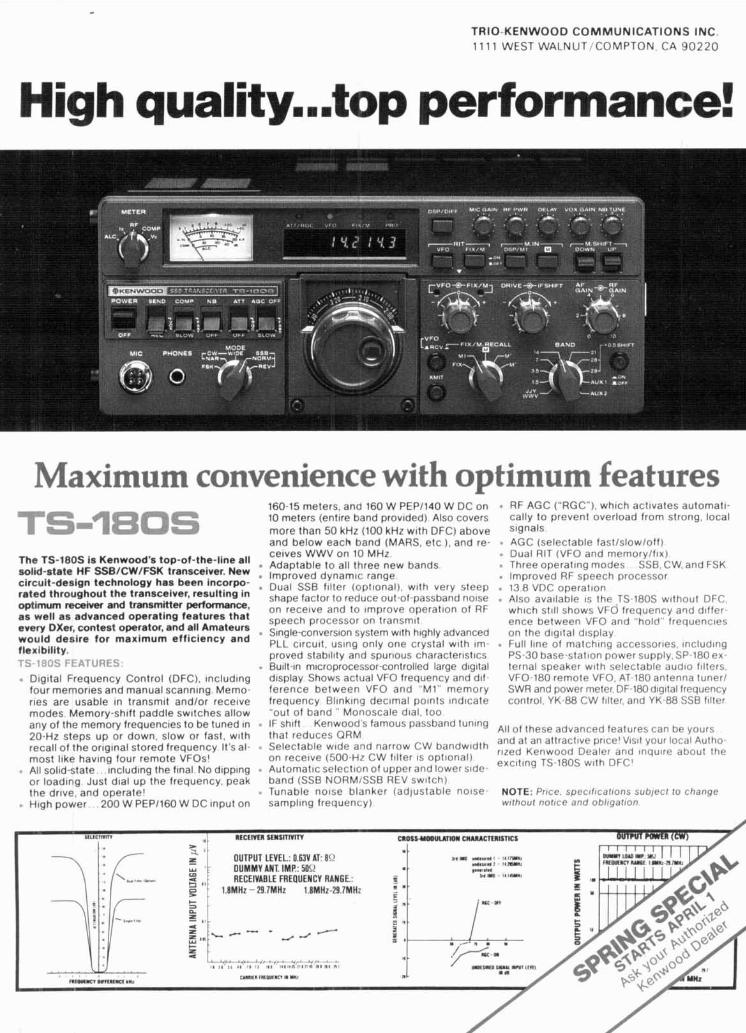
TRIO-KENWOOD COMMUNICATIONS INC.
1 1 1 1 WEST WALNUT/COMPTON. CA 9 0 2 2 0
Maximum convenience with optimum features
The TS-180s i s Kenwood's top-of-the-line all solid-state HF SSB/CW/FSK transceiver. New circult-deslgn technology has been incorpo- rated throughout the transceiver, resulting In optimum mceiver and transmitter pertonnance. as well as advanced operattng features that every DXer, contest operator, and all Amateurs would desire for maximum etticlency and t lex~bi i i ty.
rFATURES . Dlgttal Frequency Control (DFC), lncludlng four memorles and manual scannlng Memo- rles are usable In transmlt andlor recelve modes Memory-sh~ft paddle swltches allow any of the memory frequencles to be tuned In 20-Hz steps up or down, slow or fast, w ~ t h recall of the or~glnal stored frequency It's al- most llke havlng four remote VFOst . All solld-state lncludlng the flnal No dlpplng or loadlng Just dlal up the frequency, peak the drlve, and operate1 . H ~ g h power 200 W PEP1160 W DC tnput on
160-15 meters. and 160 W PEP1140 W DC on RF AGC ("RGC"). whlch activates automatl- 10 meters (entlre band provided) Also covers cally to prevent overload from strong, local more than 50 kHz (100 kHz wtth DFC) above Signals and below each band (MARS. etc ). and re- AGC (selectable fastlslowloff) . ,. celves WWV on 10 MH; Adaptable to all three new bands Improved dynamlc range . Dual SSB f~lter (opt~onal), w ~ t h very steep shape factor to reduce out-of-passband nolse on recelve and to Improve operat~on of RF speech processor on transm~t . S~ngle-convers~on system w~th h~ghly advanced PLL clrcutt, uslng only one crystal w ~ t h Im- proved stabll~ty and spurlous charactercstlcs . Bu~lt-ln m~croprocessor-controlled large d~gltal dlsplay Shows actual VFO frequency and d ~ f ference between VFO and "MI" memory frequency Bllnklng declmal polnts lndlcate "out of band " Monoscale dtal, too . IF sh~ft Kenwood's famous passband tunlng that reduces ORM . Selectable wtde and narrow CW bandw~dth on recelve (500-Hz CW fllter 1s optional) . Automatic select~on of upper and lower s ~ d e - band (SSB NORMISSB REV sw~tch) . Tunable n o s e blanker (adjustable nolse- sampling frequency)
. Dual RIT (VFO and memorylfrx) . Three operating modes SSB. CW. and FSK . lmproved RF speech processor 13 8 VDC operat~on . Also available IS the JS-180s w~thout DFC. whlch st111 shows VFO frequency and d~f fer - ence between VFO and "hold" frequenc~es on the d ~ g ~ t a l dlsplay . Full llne of matchlng accessories. lncludlng PS-30 base-stat~on power supply. SP.180 ex. ternal speaker w ~ t h selectable aud~o fllters. VFO-180 remote VFO. AT-180 antenna tuner1 SWR and power meter, DF-180 d~g~ta l frequency control. YK-88 CW filter, and YK-88 SSB f~lter
All of these advanced features can be yours and at an attractive pr~cel VISI~ your local Autho- rued Kenwood Dealer and lnqulre about the excttlng TS-180s w ~ t h DFC'
NOTE: Prrce, spec~l~catrons sublecl lo change ~ ~ f h o u r nollce and oblrgafron
SI~ICIWTW , ntctnrn r t~snnm mos1-1~0- ~ ( ~ ~ ~ c m t s n c s
RECEIVABLE FREOUENCV RANGE.: 1.8MHz - 29 7MH2 1 BMHz-29 7MHz
,, 4
z *
I - ~ m m r
W I I R l K V m W
r)
the
Lets your antenna radiate-not your w a x
Ra ted 5 KW peak-accepts substantial mis- match at legal limit
DC grounded-helps protect against lightning Silver plated hook-up braid; Custom molded case Amphenolm connector; Rubber r ing t o s top water
I
leakage
Mock1 ZA-1 3.5-30 HZ $1 5.95 Model ZA-2 optimized 14-30 mHz
includes hardware for
I 2 boom $17.95 I
Ultimate A I:IBACUN
I Available at selected dealers, add $2.00 p ~ ~ t p n n and handlinn
m 1 1 :
I
.Y., "..- ..-..-.... 333 West Lake Street, Dept A
I ' h ; & k R MTERATURE Chicago, Illinois 80606 (31 2) 263-1808 I 1
MILITARY SURPLUS 1 COPY SATELLITE PHOTOS. 1 WANTED WEATHER MAPS. PRESS1
Highest prices ever on recent U.S. Military sur- plus, especially on Colllns equ~pment or parts. We pay freight. Call collect for high offer. (201) 440- 8787.35 Ruta Court. S. Hackensack. N.J. 07606
SPACE ELECTRONICS CO.
WE HAVE A NEW NUMBER ALL 3 CIRCUITS ARE .180' IN THICKNESS
The P-3 SERIES is a Quality P IP0 COMMUNICATIONS Touch- Tone' Encoder consisting of a separate keyboard and 3 differ-
t board arrangements to choose P-3A, and P-38 . . . . . . . . . . . . . . *
The P-3 SERIES offers a variety of installa- l i o n oossihilities for the custom builder and the0.E.M.. . . . . . . . . . . . . . . . . . . . . . .*
FEATURES: Wide Voltage Range Immune t o RFI C o l d Contacts • Not a K i t . . . . . . . . . . . . . * Temperature Range - lS°F lo + 160°F.
12Key . . . . . . . . . . . . . . . . . . . . . . . $ 3 9 . 0 16Key . . . . . . . . . . . . . . . . . . . . . . . . 543.00 I PJ4 I 16 Key Slim. . . . . . . . . . . . . . . . . . . ,548.00
17 (Tempo-S1, Wilson M K IV)
FOR YOU )
-L,.-&..". LOS ANGfLfS HENRV RADIO lRMl421-bhll DENVER CWELtCTRONICS ( 1 0 I l R l l l l l l S T LOUIS, MO HAM RADIOCENTER IRiY)) IZSlhIh VltNNA VA EltC EQUIPMENT BANK ('R1l91K~lF~
'For Complete Information P JR A n d Dealers List Wr i te to: PATENTED m a r x r
Operate Legally Without An FCC License in
the 160-190 kHz Band
LOW & MEDIUM FREQUENCY RADIO SCRAPBOOK (3rd Edition)
by Ken Cornell, WPlMB Here's your chance to get on the alr and have some legal I~cense-free excitement ~n the 160-190 kHz range Explore the entlclng world of the low trequen- cles and uncover some new fun1 Complete detalls on assembtlng homebrew to work these frequenctes plus full lnfo on FCC rules and regulat~ons A book you lust can't afford to mtss 110 pages 01977 OHR-LF Softbound 56.95
ADDENDUM '77/'78 for the Low 8 Medium Frequency Radio Scrapbook
by Ken Cornell, WPIMB Even more gwd~es from the 160-190 kHz reglon. Addendum '77/'78 1s des~gned to complement The Low 6 Medium Frequency Radio Scrapbook The techn~cal data IS excellent and wlll prov~de you "low- fers even more ~nformatton, appl~cat~ons, and tech- nlques for these entlcfng trequenctes Latest revlsed FCC rules governing the non-llcensed communlca- t~on bands 68 pages 01977 OHR-LFA Softbound $3.95
Be a LOWFER Join the fun and get on
160-190 kHz Send your order today or call
TOLL FREE 1 (800) 258-5353
C l ~ p & Mall Today !
OHR-LF $6.95 OHR-LFA $3.95 Plus shipping $1 .OO --
Total enclosed- q Charge MC OVlSA Expiration Card Number
N81m
Mdrnaa
m a.0 DP
Ham Radio's Bookstore GREENVILLE, NEW HAMPSHIRE 03048
50 june 1980 More Details? CHECK - OFF Page 94
tone-encoder for 2-meter
autopatches
A design that produces clean sine waves
tamed by AGC amplifiers for constant level -
also featured is automatic P l l
with delayed release
As the use of the Touch-Tone* system - both in telephones and in Amateur Radio - became wide- spread, a number of ICs were developed to generate the tones. Among the most popular are the Motorola MC14410 and the Mostek MK5087; there are several others on the market. These chips are generally
"Touch Tone is the registered trademark of the American Telephone and Telegraph Company.
1 superior to those in the original Western Electric Touch Tone (or DTMF) encoder, with its cup-core in- ductors. But they do have one disadvantage in com- mon: they produce the tones by digital methods, so the outputs are not pure sine waves but are similar to the waveform shown in fig. 1. In telephone applica- tions this doesn't matter, since the line itself acts as a lowpass filter, effectively restoring sine-wave purity. Also, being designed to work into such lines, the chips have greater output at higher frequencies to counteract the natural attenuation of the line.
When such a Touch Tone chip is used to activate a repeater autopatch through a 2-meter fm transmitter, these natural filter effects don't exist. Thus, in addi- tion to harmonic distortion, the repeater autopatch must cope with deviation levels that vary according to the tones selected. This can cause problems in completing a call.
I designed a DTMF board that produces good, clean sine waves. In addition, it has agc amplifiers to keep the tones at constant levels. There's also provi- sion for keying the transmitter automatically when- ever any button of the Touch Tone pad is pressed and keeping it keyed until the dialing of the number is complete. The circuit will fit on a 3 x 5 inch (7.6 x 12.8 cm) board. After describing the circuit, I'll go in-
By Chris Winter, WBBVSZ, 610 South Clinton, lowa City, lowa 52240
june 1980 51
fig. 1. A sketch of the typical output of the MC14410 shows that it is not a true sine wave. This output is produced by a 16-stage walking-ring counter.
to the fine points of assembling and using the board - or of rolling your own, if that's your style.
circuit description The tones are generated by a Motorola
MC14410P. The advantage of this chip is that it has separate outputs for the low and high tone groups; this makes it easier to filter the tones. Since the MC14410 is widely used, there's no need to go too deeply into the circuit. The tone outputs are pro- duced by walking-ring counters driving weighted-re- sistor networks. In addition to a dc level, each output waveform contains harmonics whose order is deter-
cI-Ce*O.oI RI- R#*IOh
mined by the number of stages in the counter. A good source on this subject is reference 1.
The main schematic of the DTMF board is shown in fig. 2. The wiring of U1 is standard except for two things: capacitors C1-C8 are for RFI protection, and the output of pin 7 - a square-wave test signal, not normally used - drives the automatic keyer circuit.
filter considerations The filters don't have to be extremely sharp or
well-centered on the nominal center frequency, since they don't have to separate the tones. Bandpass fil- ters are required to block both the dc levels and the high-order harmonics in the outputs from U1. I used a multiple-feedback configuration because it permits a bandpass filter with a single op amp. One stage per filter gives sufficient selectivity; this allows both filters and the two agc amplifiers to be built using a single quad op amp IC.
In reference 2, Moberg described design equations for the multiple-feedback filter where the two capac- itors are of unequal values (see appendix). These equations give great flexibility in choosing the filter parameters and are easily turned into a program for a handheld calculator.
The design procedure starts with the values of the two capacitors and the three filter parameters: Q, gain Ao, and center frequency, fo. The values of the three resistors are calculated (for filter-component designations see fig. 3). U1 will produce roughly 2 or 3 volts p-p. To avoid overdriving the agc amplifiers, a
0 -5v TO U I - 1 1 AND
fig. 2. The main schematic of the DTMF board. Note the liberal use of bypassing and decoupling networks. To avoid duplica- tion, filters and amplifiers are not shown in this illustration.
52 june 1980
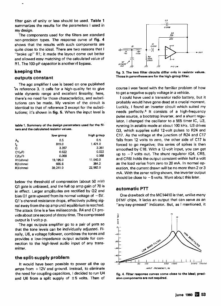
filter gain of unity or less should be used. Table 1 summarizes the results for the parameters I used in my design.
The components used for the filters are standard non-precision types. The response curve of fig. 4 shows that the results with such components are quite close to the ideal. There are two reasons that I "broke up" R1; it made the layout come out better and allowed easy matching of the calculated value of R1. The 100-pF capacitor is another rf bypass.
keeping the outputs constant
The agc amplifier I use is based on one published i n reference 3. It calls for a high-quality fet to give wide dynamic range and excellent linearity; here, there's no need for those characteristics, and substi- tutions can be made. My version of the circuit is identical to that of reference 3 except for the substi- tutions; it's shown in fig. 5. When the input level is
table 1. Summary of the design parameters used for the fil- ters and the calculated resistor values.
low group high group
'41 0.5 0.5
fo 819.0 1,421 .O 0 3.357 3.351 Cl(pF) 0.022 0.022 C2(pF) 0.068 0.068 R l (ohms) 19,195.0 11,040.0 R2(ohms) 665.6 384.2 R3(ohms) 39,241 .O 22,582.0
below the threshold of compression (about 50 mV) Q1 gate is unbiased, and the full op amp gain of 70 is in effect. Larger amplitudes are rectified by Q2 and bias Q1 gate upward from its normal voltage of - 5V. Q l 's channel resistance drops, effectively pulling sig- nal away from the op amp until equilibrium is reached. The attack time is a few milliseconds. R4 and C1 pro- vide about one second of decay time. The compressed output is 1 volt p-p.
The agc outputs amplifier go to a pair of pots so that the tone levels can be individually adjusted. Fi- nally, U6, a voltage follower, combines the tones and provides a low-impedance output suitable for con- nection to the high-level audio input of any trans- mitter.
the split-supply problem It would have been possible to power all the op
amps from + 12V and ground. Instead, to eliminate the need for coupling capacitors, I decided to run U4 and U6 from a split supply of f 5 volts. Then of
680 - v
BYPASS I 0 0 P/O U4
fig. 3. The two filter circuits differ only in resistor values. Those in parentheses are for the high-group filter.
course I was faced with the familiar problem of how to get a negative supply voltage in a vehicle.
I could have used a transistor radio battery, but it probably would have gone dead at a crucial moment. Luckily, I found an inverter circuit which suited my needs perfectly.4 It consists of a high-frequency pulse source, a bootstrap inverter, and a shunt regu- lator. I changed the oscillator to a 555 timer IC, U3, running in astable mode at about 100 kHz. U3 drives 0.3, which supplies solid 12-volt pulses to R24 and C17. As the voltage at the junction of R24 and C17 falls from 12 volts to zero, the other side of C17 is forced to go negative; this series of spikes is then smoothed by C18. With a 12-volt input, you can get up to -7 volts out. The shunt regulator (04, CR5, and CR6) holds the output constant within half a volt as the load varies from zero to 20 mA. In normal op- eration, the current drawn will be no more than 2 or 3 mA. With the zener rating shown, the inverter output should be close to - 5 volts. More about this later.
automatic PTT One drawback of the MC14410 is that, unlike many
DTMF chips, it lacks an output that can serve as an "any-key-pressed" indicator. But, as I mentioned, it
INPUT FREWENCY, Hz
fig. 4. Filter response curves come close to the ideal; preci- sion components are not required.
june 1980 53
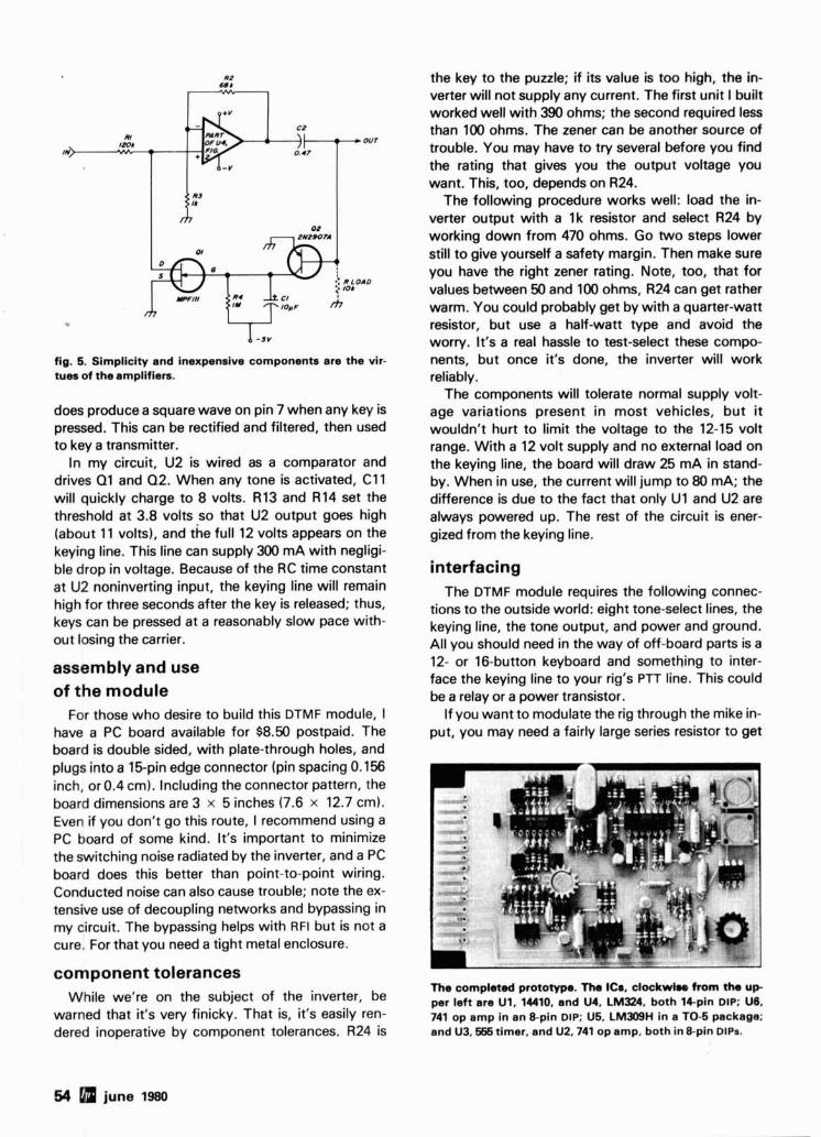
fig. 5. Simplicity and inexpensive components are the vir- tues of the amplifiers.
does produce a square wave on pin 7 when any key is pressed. This can be rectified and filtered, then used to key a transmitter.
In my circuit, U2 is wired as a comparator and drives 01 and Q2. When any tone is activated, C11 will quickly charge to 8 volts. R13 and R14 set the threshold at 3.8 volts so that U2 output goes high (about 11 volts), and the full 12 volts appears on the keying line. This line can supply 300 mA with negligi- ble drop in voltage. Because of the RC time constant at U2 noninverting input, the keying line will remain high for three seconds after the key is released; thus, keys can be pressed at a reasonably slow pace with- out losing the carrier.
assembly and use of the module
For those who desire to build this DTMF module, 1 have a PC board available for $8.50 postpaid. The board is double sided, with plate-through holes, and plugs into a 15pin edge connector (pin spacing 0.156 inch, or 0.4 cm). Including the connector pattern, the board dimensions are 3 x 5 inches (7.6 x 12.7 cm). Even if you don't go this route, I recommend using a PC board of some kind. It's important to minimize the switching noise radiated by the inverter, and a PC board does this better than point-to-point wiring. Conducted noise can also cause trouble; note the ex- tensive use of decoupling networks and bypassing in my circuit. The bypassing helps with RFI but is not a cure. For that you need a tight metal enclosure.
component tolerances While we're on the subject of the inverter, be
warned that it's very finicky. That is, it's easily ren- dered inoperative by component tolerances. R24 is
the key to the puzzle; if its value is too high, the in- verter will not supply any current. The first unit I built worked well with 390 ohms; the second required less than 100 ohms. The zener can be another source of trouble. You may have to try several before you find the rating that gives you the output voltage you want. This, too, depends on R24.
The following procedure works well: load the in- verter output with a 1k resistor and select R24 by working down from 470 ohms. Go two steps lower still to give yourself a safety margin. Then make sure you have the right zener rating. Note, too, that for values between 50 and 100 ohms, R24 can get rather warm. You could probably get by with a quarter-watt resistor, but use a half-watt type and avoid the worry. It's a real hassle to test-select these compo- nents, but once it's done, the inverter will work reliably.
The components will tolerate normal supply volt- age variations present in most vehicles, but it wouldn't hurt to limit the voltage to the 12-15 volt range. With a 12 volt supply and no external load on the keying line, the board will draw 25 mA in stand- by. When in use, the current will jump to 80 mA; the difference is due to the fact that only U1 and U2 are always powered up. The rest of the circuit is ener- gized from the keying line.
interfacing The DTMF module requires the following connec-
tions to the outside world: eight tone-select lines, the keying line, the tone output, and power and ground. All you should need in the way of off-board parts is a 12- or 16-button keyboard and something to inter- face the keying line to your rig's PTT line. This could be a relay or a power transistor.
If you want to modulate the rig through the mike in- put, you may need a fairly large series resistor to get
The completed p r o t o w . The ICs, clockwh. from tho u p per left are U1, 14410, and U4, LM324. both 14-pin DIP; U6, 741 op amp in an 8-pin DIP; U5, LM309H in a TO-5 package; and U3,555 timer, and U2.741 op amp, both in 8-pin DIPS.
54 june I=
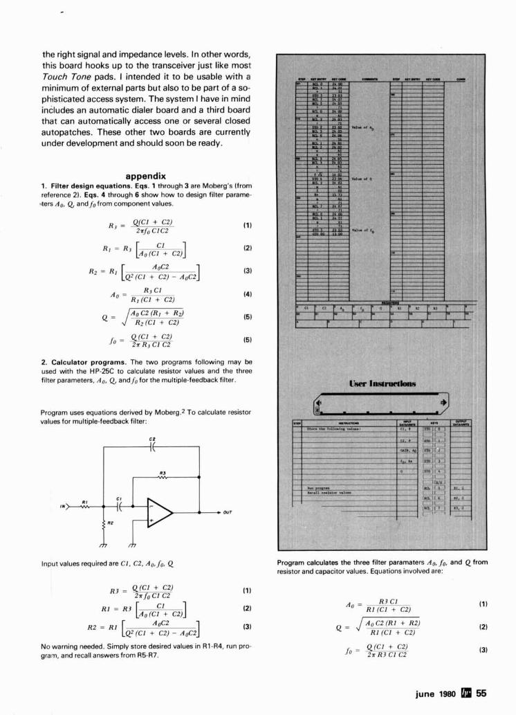
the right signal and impedance levels. In other words, this board hooks up to the transceiver just like most Touch Tone pads. I intended it to be usable with a minimum of external parts but also to be part of a so- phisticated access system. The system I have in mind includes an automatic dialer board and a third board that can automatically access one or several closed autopatches. These other two boards are currently under development and should soon be ready.
appendix 1. Filter design equations. Eqs. 1 through 3 are Moberg's (from reference 2). Eqs. 4 through 6 show how to design filter parame-
aers Ao, Q, and fofrom component values.
Rz = R I [QZ(C1 + C2) - AoC2
A . =
A0c2 I R3 C l
R1 (Cl + C2)
2. Calculator programs. The two programs following may be used with the HP-25C to calculate resistor values and the three filter parameters, Ao, Q, and fo for the multiple-feedback filter.
Program uses equations derived by Moberg.2 To calculate resistor values for multiple-feedback filter:
Input values required are C1, C2, Ao, fo. Q
No warning needed. Simply store desired values in R1-R4, run pro- gram, and recall answers from R5-R7.
!a- *I A,,
Program calculates the three filter paramaters Ao, fo, and Q from resistor and capacitor values. Equations involved are:
AoC2 (Rl + R2)
fo = _UCI+CZ) . 2 x R3 C l C2
june 1980 56
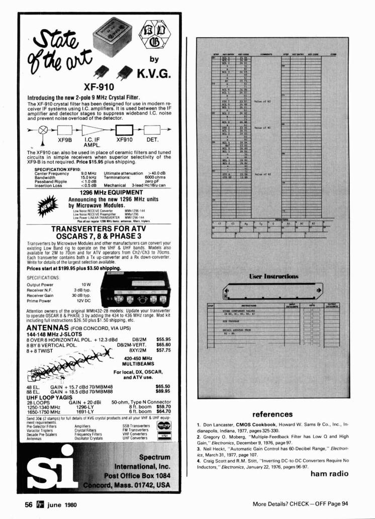
Introducing the new 2-pole 9 MHz Crystal Filter. The XF-910 crystal filter has been deslgned for use In modern r e ceiver IF systems using I.C. amplifiers. It is used between the IF amplifier and detector stages to suppress wideband I.C. noise and prevent noise overload of thedetector.
XF9B I.C. IF XF910 DET. AMPL. .
The XF910 car! also be used in place of ceramlc filters and tuned circuits in simple receivers when superior selectivity of the XF9-B is not required. Prlce $15.95 plus shipping.
I SPECIFICATION XFO10: Center Frequency 9.0 MHz Ultlmate attmuatlon >40.0 dB Bandwidth 15.0 kHz Termlnatlons: 8000ohms
I Passband Rl~ole c 1.0 dB zero DF I lnsart~on LOSS <0.5 dB Mechanical %lead HclBiu can
1296 MHz EQUIPMENT -
Announcing the new 1296 MHz units by Microwave Modules.
L o w Nolre HtLLIVE Converler MMkl296.144 LOW 401x R I L t ~ V E Prearnpl~l~er MMa1296 LOW PUWP! l N f l R TRANSVERIER MMt12% 144
OSCARS 7,8 & PHASE 3 Transverters by M~crowave Modules and olher rnanulacturers Can Convert your exlstlng Low Band rlg l o operate on the VHF & UHF bands. Models also available for 2M lo 70cm and lor ATV operators lrom Ch2/Ch3 lo 70cms Each lransverter conlalns both a Tx up-converter and a Rx down-converter Wrlte tor detalls 01 the laroesl selection ava~lable
I Prices start at ~199.95 plus $3.50 ahlpplnp.
SPECIFICATIONS: Output Power Recelver N.F. 3 dB typ. Recelver Gain 30 dB typ. Prime Power 12V low DC i Attention owners of the or1 lnal MMt432 28 models Upddle your lransverler to operate OSCAR 8 & PHA!E 3 by addlng Ihe 434 l o 436 MHz range Mod klt lnciudlng full lnstructlons $26 50 plus $1 50 sh~pp~ng etc
ANTENNAS (Foe CONCORD, VIA UPS) 144.148 MHz J-SLOTS 8 OVER 8 HORIZONTAL POL. + 12.3 dBd DW2M $55.95 8 BY 8 VERTICAL POL. DLV2M-VERT. $65.60 8 + 8 TWIST 8XY12M 557.75
420-450 MHz MULTIBEAMS
For local, DX, OSCAR, and ATV use.
48 EL. GAlN + 15.7 dBd 701MBM48 I I. EL. GAIN + I8.SdBd 7OlMBMBB
I UHFLOOP YAGlS 28 LOOPS GAIN + 20 dB1 50-ohm, T pe N Connector 1250-1340 MHz 1296LY 8 rt. boom $59.70 1650-1750 MHz -~ 1691-LY 6 ft. boom S64LO
I send 3 0 ~ ( 2 stamps) for full details 01 KVG crystal products and all your VHF (L UHF equlp
I ment requirements Pre Selector F~lters Amplillsrs SSB Transvertsrs Varactor Trlplers Crystal Flltus FM Transwrfers Decade Pre Scalers Frequency F~lters VHF converters Anlpnnas Oscillator Crvstals UHF Conveners
;rrurn
International, Inc. Poat Office Box 1084
sLWwmLxdllW 1. I , . (I>. Ih. El - - ---
m u * --
As- nn*
references 1. Don Lancaster, CMOS Cookbook, Howard W. Sams b Co., Inc., In- dianapolis, Indiana, 1977, pages325-330. 2. Gregory 0. Moberg, "Multiple-Feedback Filter has Low Q and High Gain," Electronics, December 9. 1976, page 97. 3. Neil Heckt, "Automatic Gain Control has 60-Decibel Range," Electron- ics, March31, 1977, page 107. 4. Craig Scott and R.M. Stitt, "Inverting DC-to-DC Converters Require No Inductors," Electronics, January 22, 1976, pages 96-97.
ham radio
56 june 1980 More Details? CHECK-OFF Page 94
Bind 'em and
Find 'em Keep those valuable Issues of both Ham Radio and HORIZONS Ilke new. Prevent smears, tears and dog ears Blnd 'em together and enjoy for years to come. You'll be happy you dldl
* * * HAM RADIO BINDERS Beautiful buckram b~nders complete wlth date labels Available In our new large slze to ac- commodate HAM RADIO'S hefty Issues UHR-BDL Each Just 56.95
3 for $17.95 HAM RADIO MAGAZINE FILES Your collectlon of HAM RADIO Magazines IS a valuable resource Here s a brand new. Inex- penslve way to store them These sturdy card- board magazlne flles keep them clean, neat and up front where you can use them for qulck and easy reference UHR-HRMF $1.95 each
3 for $4.95 HAM RADIO HORIZONS BINDERS Handsome washable blnders complete with date labels U HR-HRDL Each Just 56.95
3 for $17.95 HORIZONS MAGAZINE FILES Your collectlon of Ham Radlo HORIZONS IS a valuable resource Here's a brand new, Inex- pensive way to store them These sturdy card- board magazlne flles keep them clean, neat and up front where you can use them for qulck and easy reference U HR-HRHF $1.95 each
3 for $4.95
ORDER TODAY Ham Radio's Bookstore GREENVILLE, NEW HAMPSHIRE 03048
OR CALL TOLL FREE 1 (800) 258-5353
-_----- ------ BINDERS FILES
OHR-BOL $6 95 @a OHR-HRMF $1.95 @a. OHR-HRDL 3/$17.95 OHR-HRHF 3/$4.95
OCASH OCHARGE OMC OVlSA h P Card Number
Name Address
crtv state ZIP
Only Palomar Baluns Have Al l These Features
RF toroidal core for highest efficiency. Teflon insulated wire. Stainless steel hardware. Won't rust. Epoxy filled case. Waterproof. Wideband 1.7 to 30 MHz. White case to reflect the sun. Lightning protection built in.
Free brochure sent on request How many lightweight baluns have you burned out already? Install the balun that will stay up there working year after year.
To order, add $3 shippinglhandling. California residents add sales tax. @@-
I I
M o r e Deta i ls? CHECK-OFF P a g e 94 june 1980 57
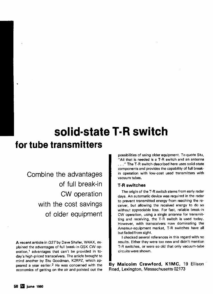
solid=state T=R switch for tube transmitters
Combine the advantages of full break-in CW operat ion
with the cost savings of older equipment
A recent article in QST by Dave Shafer, W4AX, ex- plained the advantages of full break-in QSK CW op- eration,' advantages that can't be provided in to- day's high-priced transceivers. The article brought to mind another by Stu Goodman, KZRPZ, which ap- peared a year earlier.2 He was concerned with the economics of getting on the air and pointed out the
I possibilities of using older equipment. To quote Stu, "All that is needed is a T-R switch and an antenna . . ." The T-R switch described here uses solid-state components and provides the capability of full break- in operation with low-cost used transmitters with vacuum tubes.
T-R switches The origin of the T-R switch stems from early radar
days. An automatic device was required in the radar to prevent transmitted energy from reaching the re- ceiver, but allowing the received energy to do so without appreciable loss. For fast, reliable break-in
, CW operation, using a single antenna for transmit- ting and receiving, the T-R switch is used today. However, with transceivers now dominating the Amateur-equipment market, T-R switches have all but faded from sight.
I checked several references in this regard with no results. Either they were too new and didn't mention T-R switches, or were so old that only vacuum-tube
I circuits were shown.
By Malcolm Crawford, K I M C , 19 Ellison Road, Lexington, Massachusetts 02173
58 june 1980
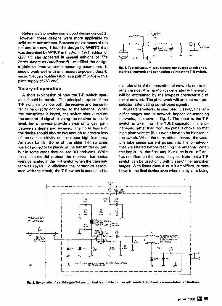
Reference 3 provided some good design concepts. However, these designs were more applicable to solid-state transmitters. Between the extremes of too old' and too new, I found a design by W4ETO that was described by W1ICP in the April, 1971, edition of QST (it later appeared in several editions of The Radio Amateurs Handbook. 4) I modified the design slightly to improve some operating parameters. It should work well with any moderate-power, class-C vacuum-tube amplifier (such as a pair of 6146s with a plate supply of 750 Vdc).
theory of operation A short explanation of how the T-R switch oper-
ates should be helpful. The principal purpose of the T-R switch is to allow both the receiver and transmit- ter to be directly connected to the antenna. When the transmitter is keyed, the switch should reduce the amount of signal reaching the receiver to a safe level, but otherwise provide a near unity gain path between antenna and receiver. The noise figure of the device should also be low enough to prevent loss of receiver sensitivity on the upper high-frequency Amateur bands. Some of the older T-R switches were designed to be placed at the transmitter output, but in some cases they caused RFI problems. While these circuits did protect the receiver, harmonics were generated in the T-R switch when the transmit- ter was keyed. To eliminate the harmonics associ- ated with the circuit, the T-R switch is connected to
T - R SWITCH
r--l *iyr
fig. 1. Typical vacuum-tube transmitter output circuit show- ing the pi network and connection point for the T-R switch.
the tube side of the transmitter pi-network; not to the antenna side. Any harmonics generated in the switch will be attenuated by the lowpass characteristic of the pi-network. The pi-network will also act as a pre- selector, attenuating out-of-band signals.
Most transmitters use shunt-fed, class-C, final am- plifier stages and pi-network impedance-matching networks, as shown in fig. 1. The input to the T-R switch is taken from the TUNE capacitor in the pi- network, rather than from the plate rf choke, so that high plate voltage (B + ) won't have to be blocked in the switch. When the transmitter is keyed, the vacu- um tube sends current pulses into the pi-network that are filtered before reaching the antenna. When the key is up, the final amplifier tube is cut off and has no effect on the received signal. Note that a T-R switch can be used only with class-C final amplifier stages. With linear class A or AB amplifiers, current flows in the final device even when no signal is being
+ VCC t - - - - -- - - - - - - - - - - - - - - - - - - - - - (::J z 1 I aOO1 - - - - - - - - - - r---------#.-/r- I
I ' I I I I I
TRANSMITTER I I l PI - NET WORK I I
I I I I
I 2 TURNS BINLAR I I W N O ON FT50 -61 CORE TAPPED AT ( I SIX TURNS
C4 0.10
I 1
CRI. 2, 3. 4 = IN914 OR IN4148 SILICON HIGH-SPEED SWITCHING OIOOE
fig. 2. Schematic of a solid-state T-R switch that is suitable for use with moderate-power, vacuum-tube transmitters.
june 1980 59
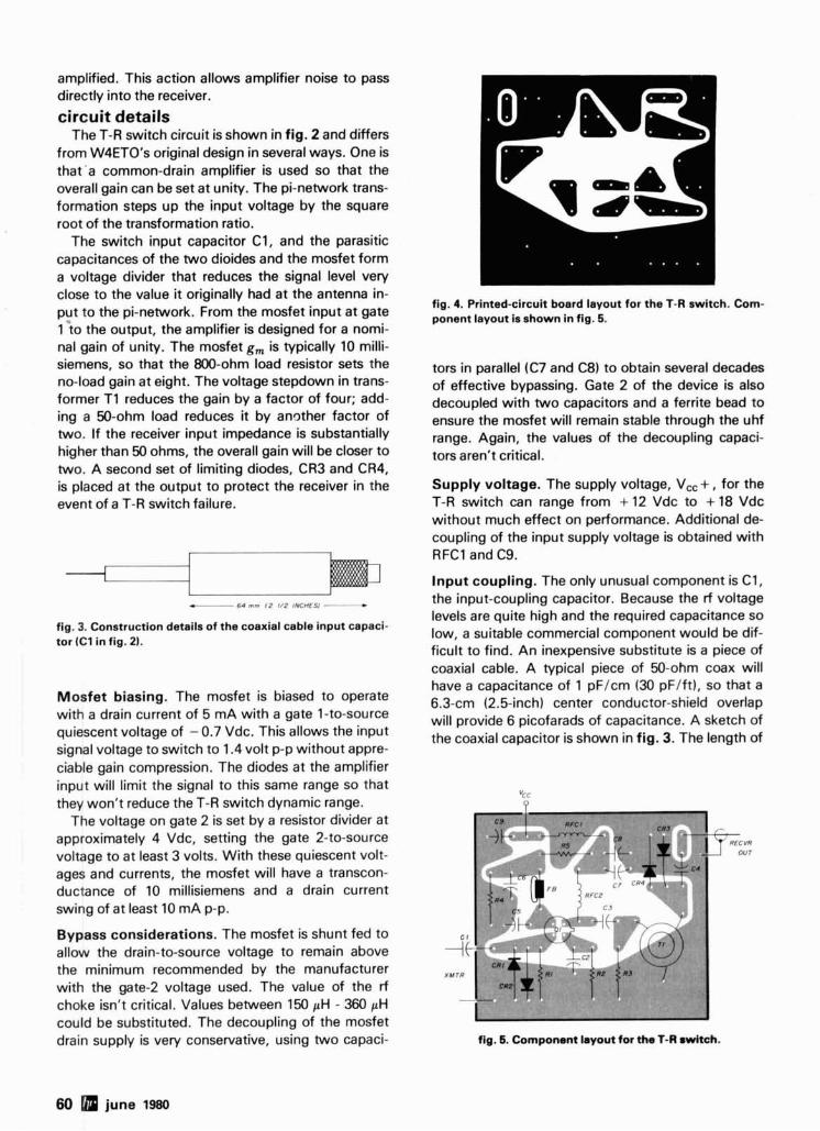
amplified. This action allows amplifier noise to pass directly into the receiver.
circuit details The T-R switch circuit is shown in fig. 2 and differs
from W4ET01s original design in several ways. One is that'a common-drain amplifier is used so that the overall gain can be set at unity. The pi-network trans- formation steps up the input voltage by the square root of the transformation ratio.
The switch input capacitor C1, and the parasitic capacitances of the two dioides and the mosfet form a voltage divider that reduces the signal level very close to the value it originally had at the antenna in- put to the pi-network. From the mosfet input at gate 1 'to the output, the amplifier is designed for a nomi- nal gain of unity. The mosfet g, is typically 10 milli- siemens, so that the 800-ohm load resistor sets the no-load gain at eight. The voltage stepdown in trans- former T I reduces the gain by a factor of four; add- ing a 50-ohm load reduces it by another factor of two. If the receiver input impedance is substantially higher than 50 ohms, the overall gain will be closer to two. A second set of limiting diodes, CR3 and CR4, is placed at the output to protect the receiver in the event of a T-R switch failure.
fig. 3. Construction details of the coaxial cable input capaci- tor (C1 in fig. 2).
fig. 4. Printed-circuit board layout for the T-R switch. Com- ponent layout is shown in fig. 5.
tors in parallel (C7 and C8) to obtain several decades of effective bypassing. Gate 2 of the device is also decoupled with two capacitors and a ferrite bead to ensure the mosfet will remain stable through the uhf range. Again, the values of the decoupling capaci- tors aren't critical.
Supply voltage. The supply voltage, Vcc + , for the T-R switch can range from + 12 Vdc to + 18 Vdc without much effect on performance. Additional de- coupling of the input supply voltage is obtained with RFC1 and C9.
Input coupling. The only unusual component is C1, the input-coupling capacitor. Because the rf voltage levels are quite high and the required capacitance so low, a suitable commercial component would be dif- ficult to find. An inexpensive substitute is a piece of coaxial cable. A typical piece of 50-ohm coax will have a capacitance of 1 pF/cm (30 pF/ft), so that a
Mosfet biasing' The mosfet is biased to Operate 6.3-cm (2.5-inch) center conductor-shield overlap with a drain current of 5 mA with a gate 1-to-source will provide picofarads of capacitance. A sketch of quiescent voltage of - 0.7 Vdc. This allows the input the coaxial capacitor is shown in fig. 3. The length of signal voltage to switch to 1.4 volt p-p without appre- ciable gain compression. The diodes at the amplifier input will limit the signal to this same range so that
"cc they won't reduce the T-R switch dynamic range.
The voltage on gate 2 is set by a resistor divider at approximately 4 Vdc, setting the gate 2-to-source voltage to at least 3 volts. With these quiescent volt- ages and currents, the mosfet will have a transcon- ductance of 10 millisiemens and a drain current swing of at least 10 mA p-p.
Bypass considerations. The mosfet is shunt fed to allow the drain-to-source voltage to remain above the minimum recommended by the manufacturer with the gate-2 voltage used. The value of the rf choke isn't critical. Values between 150 pH - 360 pH could be substituted. The decoupling of the mosfet drain supply is very conservative, using two capaci- fig. 5. Component layout for ths 1-R mitch.
60 june l!BO
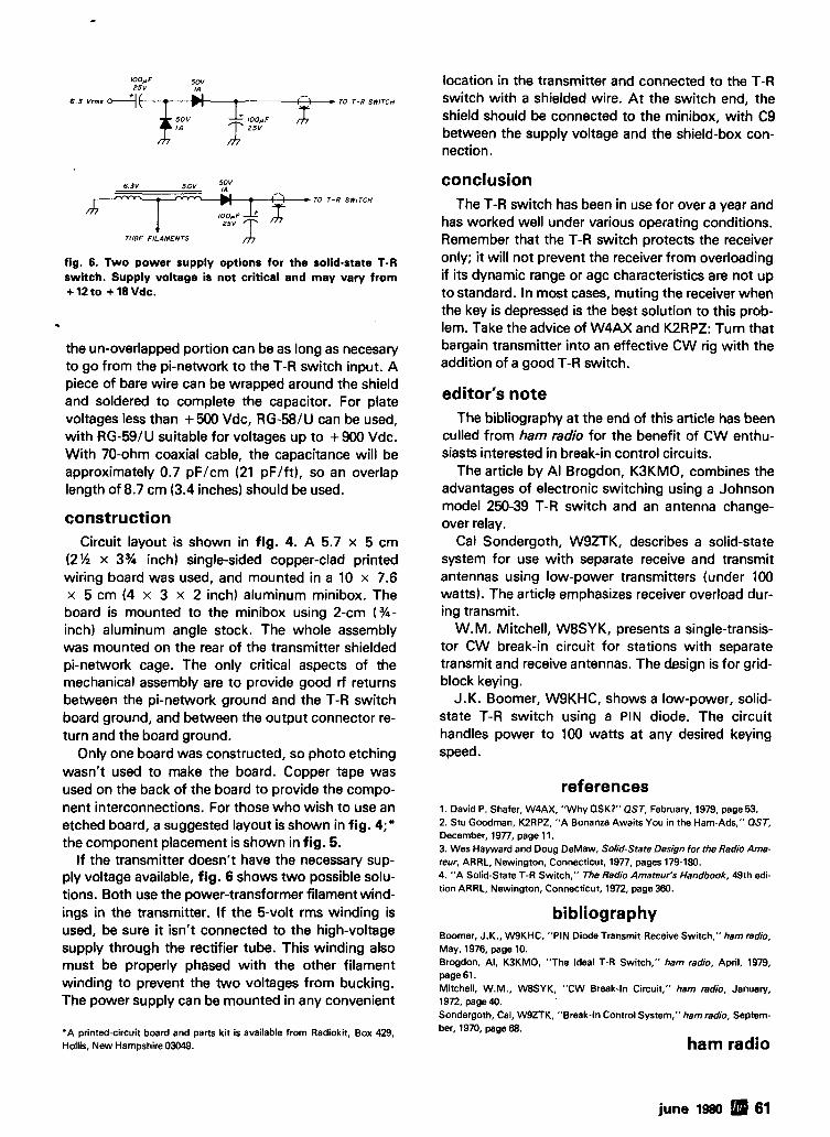
lOO,.F 2 5 v
5 0 v
TO T - R SWITCH
fig. 6. Two power supply options for the solid-state T-R switch. Supply voltage is not critical and may vary from + 12 to + 18 Vdc.
the un-overlapped portion can be as long as necesary to go from the pi-network to the T-R switch input. A piece of bare wire can be wrapped around the shield and soldered to complete the capacitor. For plate voltages less than + 500 Vdc, RG-58lU can be used, with RG-59lU suitable for voltages up to + 900 Vdc. With 70-ohm coaxial cable, the capacitance will be approximately 0.7 pF/cm (21 pF/ft), so an overlap length of 8.7 cm (3.4 inches) should be used.
construction Circuit layout is shown in fig. 4. A 5.7 x 5 cm
(2% x 3% inch) single-sided copper-clad printed wiring board was used, and mounted in a 10 x 7.6 x 5 cm (4 x 3 x 2 inch) aluminum minibox. The board is mounted to the minibox using 2-cm (%- inch) aluminum angle stock. The whole assembly was mounted on the rear of the transmitter shielded pi-network cage. The only critical aspects of the mechanical assembly are to provide good rf returns between the pi-network ground and the T-R switch board ground, and between the output connector re- turn and the board ground.
Only one board was constructed, so photo etching wasn't used to make the board. Copper tape was used on the back of the board to provide the compo- nent interconnections. For those who wish to use an etched board, a suggested layout is shown in fig. 4;" the component placement is shown in fig. 5.
If the transmitter doesn't have the necessary sup- ply voltage available, fig. 6 shows two possible solu- tions. Both use the power-transformer filament wind- ings in the transmitter. If the 5-volt rms winding is used, be sure it isn't connected to the high-voltage supply through the rectifier tube. This winding also must be properly phased with the other filament winding to prevent the two voltages from bucking. The power supply can be mounted in any convenient
'A printed-circuit board and parts kit is available from Radiokit, Box 429, Hollis, New Hampshire 03049.
location in the transmitter and connected to the T-R switch with a shielded wire. At the switch end, the shield should be connected to the minibox, with C9 between the supply voltage and the shield-box con- nection.
conclusion The T-R switch has been in use for over a year and
has worked well under various operating conditions. Remember that the T-R switch protects the receiver only; it will not prevent the receiver from overloading if its dynamic range or agc characteristics are not up to standard. In most cases, muting the receiver when the key is depressed is the best solution to this prob- lem. Take the advice of W4AX and K2RPZ: Turn that bargain transmitter into an effective CW rig with the addition of a good T-R switch.
editor's note The bibliography at the end of this article has been
culled from ham radio for the benefit of CW enthu- siasts interested in break-in control circuits.
The article by Al Brogdon, K3KM0, combines the advantages of electronic switching using a Johnson model 250-39 T-R switch and an antenna change- over relay.
Cal Sondergoth, WSZTK, describes a solid-state system for use with separate receive and transmit antennas using low-power transmitters (under 100 watts). The article emphasizes receiver overload dur- ing transmit.
W.M. Mitchell, W8SYK, presents a single-transis- tor CW break-in circuit for stations with separate transmit and receive antennas. The design is for grid- block keying.
J.K. Boomer, WSKHC, shows a low-power, solid- state T-R switch using a PIN diode. The circuit handles power to 100 watts at any desired keying speed.
references 1. David P. Shafer, W4AX, "Why QSK?" OST, February, 1979, page 53. 2. Stu Goodman, K2RPZ. "A Bonanza Awaits You in the Ham-Ads," OST, December, 1977, page 11. 3. Wes Hayward and Doug DeMaw, Solid-State Design for the Radio Ama- teur, ARRL. Newington, Connecticut, 1977, pages 179-180. 4. "A Solid-State T-R Switch," The Radio Amateur's Handbook, 49th edi- tion ARRL, Newington, Connecticut, 1972, page 360.
bibliography Boomer, J.K., WSKHC, "PIN Diode Transmit-Receive Switch," hem radio, May, 1976, page 10. Brogdon, Al, K3KMO. "The Ideal T-R Switch," ham radio, April. 1979, page 61. Mitchell, W.M., WBSYK, "CW Break-In Circuit." ham radio, January, 1972, page 40. Sondergoth, Cal, WSZTK, "Break-In Control System," ham radio, Septem- ber, 1970, page 68.
ham radio
june 1980 61
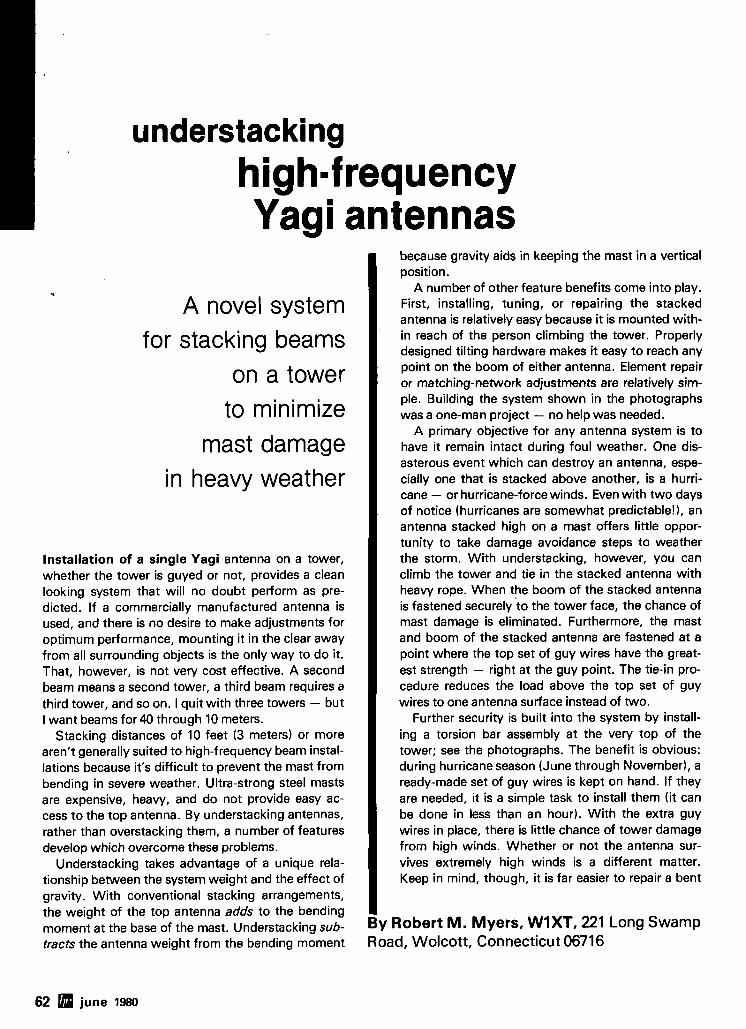
understacking highmf requency Yagi antennas
A novel system for stacking beams
on a tower to minimize
mast damage in heavy weather
Installation of a single Yagi antenna on a tower, whether the tower is guyed or not, provides a clean looking system that will no doubt perform as pre- dicted. If a commercially manufactured antenna is used, and there is no desire to make adjustments for optimum performance, mounting it in the clear away from all surrounding objects is the only way to do it. That, however, is not very cost effective. A second beam means a second tower, a third beam requires a third tower, and so on. I quit with three towers - but I want beams for 40 through 10 meters.
Stacking distances of 10 feet (3 meters) or more aren't generally suited to high-frequency beam instal- lations because it's difficult to prevent the mast from bending in severe weather. Ultra-strong steel masts are expensive, heavy, and do not provide easy ac- cess to the top antenna. By understacking antennas, rather than overstacking them, a number of features develop which overcome these problems.
Understacking takes advantage of a unique rela- tionship between the system weight and the effect of gravity. With conventional stacking arrangements, the weight of the top antenna adds to the bending moment at the base of the mast. Understacking sub- tracts the antenna weight from the bending moment
because gravity aids in keeping the mast in a vertical position.
A number of other feature benefits come into play. First, installing, tuning, or repairing the stacked antenna is relatively easy because it is mounted with- in reach of the person climbing the tower. Properly designed tilting hardware makes it easy to reach any point on the boom of either antenna. Element repair or matching-network adjustments are relatively sim- ple. Building the system shown in the photographs was a one-man project - no help was needed.
A primary objective for any antenna system is to have it remain intact during foul weather. One dis- asterous event which can destroy an antenna, espe- cially one that is stacked above another, is a hurri- cane - or hurricane-force winds. Even with two days of notice (hurricanes are somewhat predictable!), an antenna stacked high on a mast offers little oppor- tunity to take damage avoidance steps to weather the storm. With understacking, however, you can climb the tower and tie in the stacked antenna with heavy rope. When the boom of the stacked antenna is fastened securely to the tower face, the chance of mast damage is eliminated. Furthermore, the mast and boom of the stacked antenna are fastened at a point where the top set of guy wires have the great- est strength - right at the guy point. The tie-in pro- cedure reduces the load above the top set of guy wires to one antenna surface instead of two.
Further security is built into the system by install- ing a torsion bar assembly at the very top of the tower; see the photographs. The benefit is obvious: during hurricane season (June through November), a ready-made set of guy wires is kept on hand. If they are needed, it is a simple task to install them (it can be done in less than an hour). With the extra guy wires in place, there is little chance of tower damage from high winds. Whether or not the antenna sur- vives extremely high winds is a different matter. Keep in mind, though, it is far easier to repair a bent
By Robert M . Myers, WlXT, 221 Long Swamp Road, Wolcott, Connecticut 06716
62 june 1980
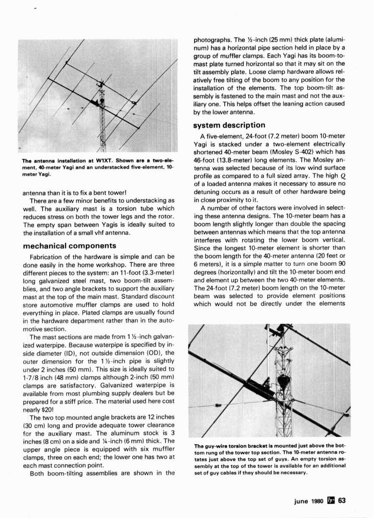
The antenna installation at WlXT. Shown are a two-el* ment, &meter Yagi and an understacked five-element, 10- meter Yagi.
antenna than it is to fix a bent tower! There are a few minor benefits to understacking as
well. The auxiliary mast is a torsion tube which reduces stress on both the tower legs and the rotor. The empty span between Yagis is ideally suited to the installation of a small vhf antenna.
mechanical components Fabrication of the hardware is simple and can be
done easily in the home workshop. There are three different pieces to the system: an 11-foot (3.3-meter) long galvanized steel mast, two boom-tilt assem- blies, and two angle brackets to support the auxiliary mast at the top of the main mast. Standard discount store automotive muffler clamps are used to hold everything in place. Plated clamps are usually found in the hardware department rather than in the auto- motive section.
The mast sections are made from 1 %-inch galvan- ized waterpipe. Because waterpipe is specified by in- side diameter (I Dl, not outside dimension (OD), the outer dimension for the 1 %-inch pipe is slightly under 2 inches (50 mm). This size is ideally suited to 1-718 inch (48 mm) clamps although 2-inch (50 mm) clamps are satisfactory. Galvanized waterpipe is available from most plumbing supply dealers but be prepared for a stiff price. The material used here cost nearly $20!
The two top mounted angle brackets are 12 inches (30 cm) long and provide adequate tower clearance for the auxiliary mast. The aluminum stock is 3 inches (8 cm) on a side and W-inch (6 mm) thick. The upper angle piece is equipped with six muffler clamps, three on each end; the lower one has two at each mast connection point.
Both boom-tilting assemblies are shown in the
photographs. The %-inch (25 mm) thick plate (alumi- num) has a horizontal pipe section held in place by a group of muffler clamps. Each Yagi has its boom-to- mast plate turned horizontal so that it may sit on the tilt assembly plate. Loose clamp hardware allows rel- atively free tilting of the boom to any position for the installation of the elements. The top boom-tilt as- sembly is fastened to the main mast and not the aux- iliary one. This helps offset the leaning action caused by the lower antenna.
system description A five-element, 24-foot (7.2 meter) boom 10-meter
Yagi is stacked under a two-element electrically shortened 40-meter beam (Mosley S-402) which has 46-foot (13.8-meter) long elements. The Mosley an- tenna was selected because of its low wind surface profile as compared to a full sized array. The high Q of a loaded antenna makes it necessary to assure no detuning occurs as a result of other hardware being in close proximity to it.
A number of other factors were involved in select- ing these antenna designs. The 10-meter beam has a boom length slightly longer than double the spacing between antennas which means that the top antenna interferes with rotating the lower boom vertical. Since the longest 10-meter element is shorter than the boom length for the 40-meter antenna (20 feet or 6 meters), it is a simple matter to turn one boom 90 degrees (horizontally) and tilt the 10-meter boom end and element up between the two 40-meter elements. The 24-foot (7.2 meter) boom length on the 10-meter beam was selected to provide element positions which would not be directly under the elements
The guy-wire tomlon bracket ir mounted just above the bot- tom rung of the tower top section. The 10-meter antenna ro- tates just above the top set of guys. An empty torsion as- sembly at the top of the tower is available for an additional set of guy cables if they should be necessary.
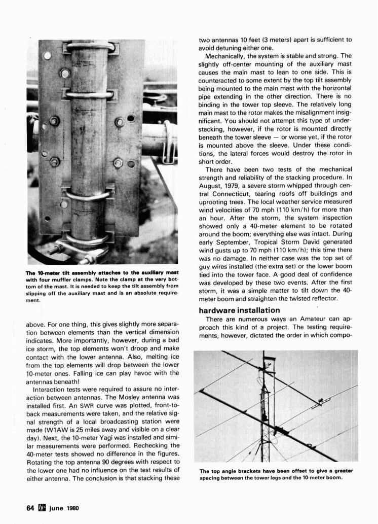
two antennas 10 feet (3 meters) apart is sufficient to avoid detuning either one.
Mechanically, the system is stable and strong. The slightly off-center mounting of the auxiliary mast causes the main mast to lean to one side. This is counteracted to some extent by the top tilt assembly being mounted to the main mast with the horizontal pipe extending in the other direction. There is no binding in the tower top sleeve. The relatively long main mast to the rotor makes the misalignment insig- m nificant. You should not attempt this type of under- stacking, however, if the rotor is mounted directly beneath the tower sleeve - or worse yet, if the rotor is mounted above the sleeve. Under these condi- tions, the lateral forces would destroy the rotor in short order.
There have been two tests of the mechanical strength and reliability of the stacking procedure. In August, 1979, a severe storm whipped through cen- tral Connecticut, tearing roofs off buildings and uprooting trees. The local weather service measured \ wind velocities of 70 mph (110 km/h) for more than an hour. After the storm, the system inspection showed only a 40-meter element to be rotated around the boom; everything else was intact. During early September, Tropical Storm David generated wind gusts up to 70 mph (1 10 kmlh); this time there was no damage. In neither case was the top set of auv wires installed (the extra set) or the lower boom
Th. 9@wwtmr tllt assembly attachr to the auxiliary m a d with four muffler clamps. Note the clamp at the very bot- tom of the mast. It is needed to keep the tilt assembly from slipping off the auxiliary mast and is an absolute require- ment.
above. For one thing, this gives slightly more separa- tion between elements than the vertical dimension indicates. More importantly, however, during a bad ice storm, the top elements won't droop and make contact with the lower antenna. Also, melting ice from the top elements will drop between the lower 10-meter ones. Falling ice can play havoc with the antennas beneath!
Interaction tests were required to assure no inter- action between antennas. The Mosley antenna was installed first. An SWR curve was plotted, front-to- back measurements were taken, and the relative sig- nal strength of a local broadcasting station were made (W1AW is 25 miles away and visible on a clear day). Next, the 10-meter Yagi was installed and simi- lar measurements were performed. Rechecking the 40-meter tests showed no difference in the figures. Rotating the top antenna 90 degrees with respect to the lower one had no influence on the test results of either antenna. The conclusion is that stacking these
i e d into the tower face. A good deal of confidence was developed by these two events. After the first storm, it was a simple matter to tilt down the 40- meter boom and straighten the twisted reflector.
hardware installation There are numerous ways an Amateur can ap-
proach this kind of a project. The testing require- ments, however, dictated the order in which compo-
The top angle brackets have been offset to give a greater spacing between the tower legs and the 10-meter boom.
64 june 1980
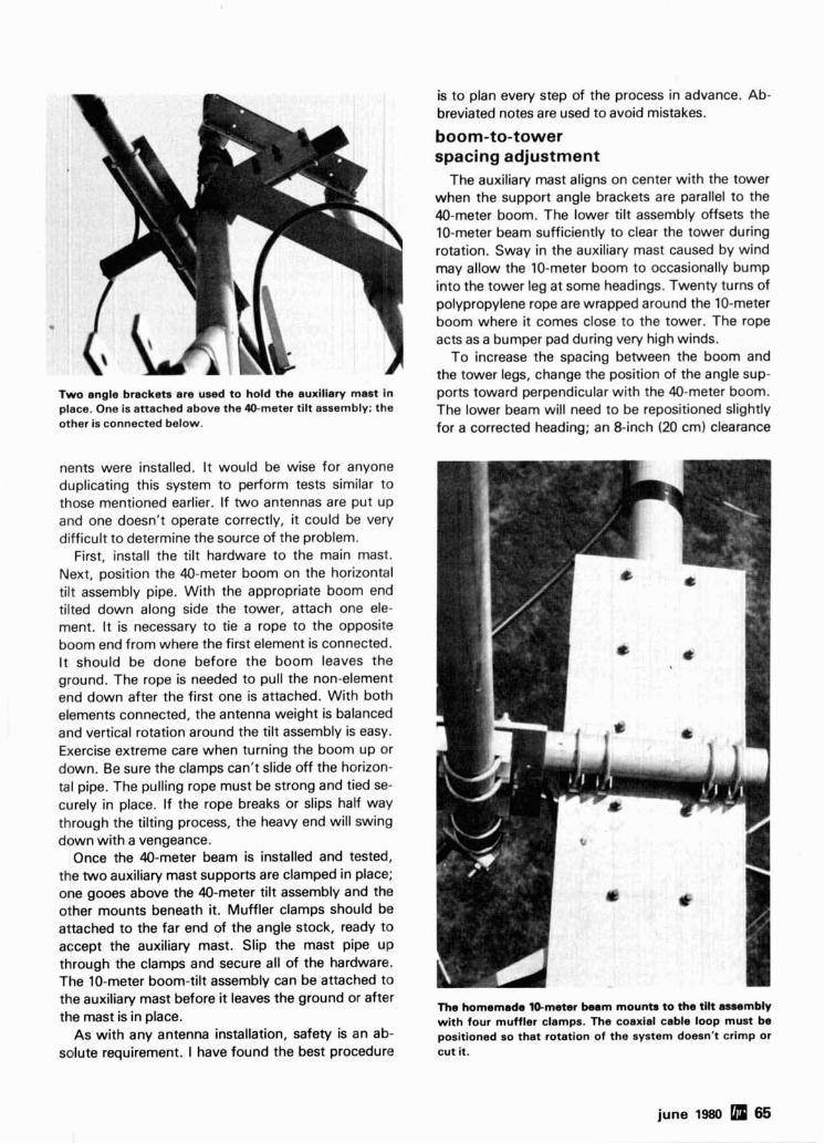
Two angle brackets are used to hold the auxiliary mast in place. One is attached above the 40-meter tilt assembly; the other is connected below.
nents were installed. It would be wise for anyone duplicating this system to perform tests similar to those mentioned earlier. If two antennas are put up and one doesn't operate correctly, it could be very difficult to determine the source of the problem.
First, install the tilt hardware to the main mast. Next, position the 40-meter boom on the horizontal tilt assembly pipe. With the appropriate boom end tilted down along side the tower, attach one ele- ment. It is necessary to tie a rope to the opposite boom end from where the first element is connected. It should be done before the boom leaves the ground. The rope is needed to pull the non-element end down after the first one is attached. With both elements connected, the antenna weight is balanced and vertical rotation around the tilt assembly is easy. Exercise extreme care when turning the boom up or down. Be sure the clamps can't slide off the horizon- tal pipe. The pulling rope must be strong and tied se- curely in place. If the rope breaks or slips half way through the tilting process, the heavy end will swing down with a vengeance.
Once the 40-meter beam is installed and tested, the two auxiliary mast supports are clamped in place; one gooes above the 40-meter tilt assembly and the other mounts beneath it. Muffler clamps should be attached to the far end of the angle stock, ready to accept the auxiliary mast. Slip the mast pipe up through the clamps and secure all of the hardware. The 10-meter boom-tilt assembly can be attached to the auxiliary mast before it leaves the ground or after the mast is in place.
As with any antenna installation, safety is an ab- solute requirement. I have found the best procedure
is to plan every step of the process in advance. Ab- breviated notes are used to avoid mistakes.
boom-to-tower spacing adjustment
The auxiliary mast aligns on center with the tower when the support angle brackets are parallel to the 40-meter boom. The lower tilt assembly offsets the 10-meter beam sufficiently to clear the tower during rotation. Sway in the auxiliary mast caused by wind may allow the 10-meter boom to occasionally bump into the tower leg at some headings. Twenty turns of polypropylene rope are wrapped around the 10-meter boom where it comes close to the tower. The rope acts as a bumper pad during very high winds.
To increase the spacing between the boom and the tower legs, change the position of the angle sup- ports toward perpendicular with the 40-meter boom. The lower beam will need to be repositioned slightly for a corrected heading; an &inch (20 cm) clearance
The homemade 10-meter beem mounts to the tilt assembly with four muffler clamps. The coaxial cable loop must be positioned so that rotation of the system doesn't crimp or cut it.
june 1980 65
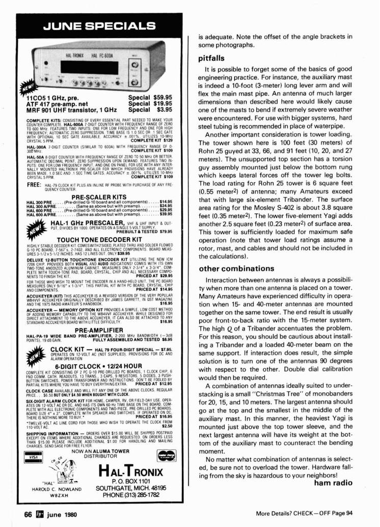
C O M P L E T E KITS: CONSISTING OF EVERY ESSENTIAL PART NEEDED TO MAKE YOUR COUNTER COMPLETE. HAL.(IOOA 7-DIGIT COUNTER WlTH FREOUENCY RANGE OF ZERO TO 600 MHz FEATURES TWO INPUTS ONE FOR LOW FREOUENCY AND ONE FOR HIGH FREOUENCY. AUTOMATIC ZLRO SUPPRESSION TIME BASE IS 1 O SEC OR 1 SEC GATE WlTH OPTIONAL 10 SEC GATE AVAILABLE ACCURACY + W 1 % UTILIZES 10-MHz CRYSTAL 5 PPM. COMPLETE KIT $129
H A L - 3 0 0 A 7-DIGIT COUNTER (SIMILAR TO 600A) WlTH FREOUENCY RANGE OF 0. C O M P L E T E K I T S t 0 8
HAL.50A 8-DIGIT COUNTER WlTH FREQUENCY RANGE OF ZERO TO 50 MHz OR BETTER. AUTOMATIC DECIMAL POINT ZERO SUPPRESSION UPON DEMAND FEATURES TWO IN. PUTS ONE FOR LOW FREQUENCY INPUT, AND ONE ON PANEL FOR USE WITH ANY INTER- NALLY MOUNTED HALTRONIX PRE-SCALER FOR WHICH PROVISIONS HAVE ALREADY BEEN MADE. 1 0 SEC AND 1 SEC TIME GATES ACCURACY s 001% UTILIZES 10-MHz CRYSTAL 5 PPM C O M P L E T E K I T $108
FREE: HAL-79 CLOCK KIT PLUS AN INLINE RF PROBE WITH PURCHASE OF ANY FRE- OUENCY COUNTER.
PRE-SCALER KITS H A L 300 P R E . . . . . ( R e d r i l l e d G - 1 0 b o a r d a n d a l l c o m p o n e n t s ) . . . . . 514.85 H A L 300 AIPRE. . . . . . . . . ( S a m e a s a b o v e b u t w i t h p reamp) . . . . . . . . . $24.85 H A L 8 0 0 P R E . . . . . ( P r e d r i l l e d G.10 b o a r d a n d a l l c o m p o n e n t s ) . . . . . 529.95 H A L 6 0 0 A IPRE. . . . . . . . . ( S a m e a s a b o v e b u t w l l h p r e a m p ) . . . . . . . . . $39.95
HAL1 GHz PRESCALER VHF (I. UHF INPUT a OUT- PUT. DIVIDES BY 1000 OPFRATES ON A SINELE 5VOLTSUPPLY.
P R E B U I L T 6 T E S T E D $79.95
TOUCH TONE DECODER KIT HIGHLY STABLE DECODER KIT COMESWITH2SIDED.PLATED THRU AND SOLDER FLOWED G-10 PC BOARD 7.567's. 2.7402. AN0 ALL ELECTRONIC COMPONENTS BOARD MEAS- URES 3-112 x 5 - i / 2 INCHES HAS 12 LINES OUT ONLY 539.95
D E L U X E 12 .BUTTON T O U C H T O N E E N C O D E R K I T UTILIZING THE NEW ICM 7706 CHIP. PROVIDES BOTH VISUAL AND AUDIO INDICATIONS' COMES WlTH ITS OWN TWO.TONE ANODIZED ALUMINUM CABINET MEASURES ONLY 2-314" X 3.314". COM- PLETE WlTH TOUCH-TONE PAD. BOARD. CRYSTAL. CHlP AND ALL NECESSARY COMPO. NENTS TO FINISH THE KIT. P R I C E D A T $29.95 FOR THOSE WHO WlSH TO MOUNT THE ENCODER IN A HAND-HELD UNIT. THE PC BOARD MEASURES ONLY 9 / 1 6 x 1.314" THIS PARTIAL KIT WlTH PC BOARD. CRYSTAL, CHlP AND COMPONENTS. P R I C E D A T $14.95 A C C U K E Y E R (KIT) THIS ACCUKEYER IS A REVISED VERSION OF THE VERY POPULAR WB4VV$ ACCUKEYER ORIGINALLY DESCRIBED BY JAMES GARRETT. IN OST MAGAZINE AND THE 1975 RADIO AMATEUR'S HANDBOOK $16.95
A C C U K E Y E R - M E M O R Y O P T I O N K I T PROVIDES A SIMPLE. LOW COST METHOD OF ADDING MEMORY CAPABILITY TO THE WB4VVF ACCUKEYER. WHILE DESIGNED FOR DIRECT ATTACHMENT TO THE ABOVE ACCUKEYER, IT CAN ALSO BE ATTACHED TO ANY STANDARD ACCUKEYER BOARD WITH LITTLE DIFFICULTY $16.95
PRE-AMPLIFIER HAL.PA.18 W I D E B A N D PRE.AMPLIF IER, 2-200 MHz BANDWIDTH ( - 3 6 8 POINTS). 19dBGAIN. F U L L Y A S S E M B L E D A N D T E S T E D $8.95
CLOCK KIT - H A L 78 F O U R - D I Q I T S P E C I A L - $7.85. OPERATES ON I2.VOLT AC (NOT SUPPLIED) PROVISIONS FOR DC AND ALARM OPERATION
6-DIGIT CLOCK 12/24 HOUR COMPLETE KIT CONSISTING OF 2 PC G-10 PRE-DRILLED PC BOARDS. 1 CLOCK CHIP. 6 FNO COMM. CATH READOUTS 13 TRANS. 3 CAPS 9 RESISTORS. 5 DIODES 3 PUSH. BUTTON SWITCHES POWER TRANS FOR ME^^ AND INSTRUCTIONS DON'T BE FOOLED BY PARTIAL KITS W H E ~ E Y O U HAVE TO BUY EVERYTHING EXTRA P R I C E D A T 512.95
C L O C K C A S E AVAILABLE AND WlLL FIT ANY ONE OF THE ABOVE CLOCKS. REGULAR PRICE . $6 50 BUT ONLY $4.50 WHEN BOUGHTWIfH CLOCK. SIX.DIGIT A L A R M C L O C K K I T FOR HOME CAMPER RV OR FIELD-DAY USE. OPER- ATES ON 12.VOLT AC OR OC, AND HAS ITS OWN 60-Hz T ~ M E BASE ON THE BOARD. COM- PLETE WlTH ALL ELECTRONIC COMPONENTS AN0 TWD.PIECE. PRE-DRILLED PC BOARDS. BOARD SIZE 4" x 3" COMPLETE WITH SPEAKER AND SWITCHES IF OPERATED ON OC. THERE IS NOTHING MORE TO BUY P R I C E D A T 518.95
'TWELVE-VOLT AC LINE CORD FOR THOSE WHO WlSH TO OPERATE THE CLOCK FROM 110-VOLT AC $2.50
S H I P P I N G I N F O R M A T I O N - ORDERS OVER $15.00 WlLL BE SHIPPED POSTPAID EXCEPT ON ITEMS WHERE ADDITIONAL CHARGES ARE REOUESTED. ON ORDERS LESS THAN $15.00 PLEASE INCLUDE ADDITIONAL $1.00 FOR HANDLING AND MAILING CHARGES SEND SASE FOR FREE FLYER
NOW AN ALUMA TOWER DISTRIBUTOR
P.O. BOX1101 HAROLD C. NOWLAND SOUTHGATE, MICH. 48195
WBZXH PHONE (313) 2351782
is adequate. Note the offset of the angle brackets in some photographs.
pitfalls It is possible to forget some of the basics of good
engineering practice. For instance, the auxiliary mast is indeed a 10-foot (3-meter) long lever arm and will flex the main mast pipe. An antenna of much larger dimensions than described here would likely cause one of the masts to bend if extremely severe weather were encountered. For use with bigger systems, hard steel tubing is recommended in place of waterpipe.
Another important consideration is tower loading. The tower shown here is 100 feet (30 meters) of Rohn 25 guyed at 33, 66, and 91 feet (10,20, and 27 meters). The unsupported top section has a torsion guy assembly mounted just below the bottom rung which keeps lateral forces off the tower leg bolts. The load rating for Rohn 25 tower is 6 square feet (0.55 meter21 of antenna; many Amateurs exceed that with large six-element Tribander. The surface area rating for the Mosley S-402 is about 3.8 square feet (0.35 meter2). The lower five-element Yagi adds another 2.5 square feet (0.23 meter2) of surface area. This tower is sufficiently loaded for maximum safe operation (note that tower load ratings assume a rotor, mast, and cables and should not be included in the calculations).
other combinations Interaction between antennas is always a possibili-
ty when more than one antenna is placed on a tower. Many Amateurs have experienced difficulty in opera- tion when 15- and 40-meter antennas are mounted together on the same tower. The end result is usually poor front-to-back ratio with the 15-meter system. The high Q of a Tribander accentuates the problem. For this reason, you should be cautious about install- ing a Tribander and a loaded 40-meter beam on the same support. If interaction does result, the simple solution is to turn one of the antennas 90 degrees with respect to the other. Double dial calibration would then be required.
A combination of antennas ideally suited to under- stacking is a small "Christmas Tree" of monobanders for 20, 15, and 10 meters. The largest antenna should go at the top and the smallest in the middle of the auxiliary mast. In this manner, the heaviest Yagi is mounted just above the top tower sleeve, and the next largest antenna will have its weight at the bot- tom of the auxiliary mast to counteract the bending moment.
No matter what combination of antennas is select- ed, be sure not to overload the tower. Hardware fall- ing from the sky is hazardous to your neighbors!
ham radio
66 5 june 1980 More Details? CHECK-OFF Page 94
'h;oughr ir 3 Larsen 1
WANTED FOR CASH
490-T Ant. Tunln Unit 618-T Transceiuer (Also known as ?~1658 (Also known as MRC95. and CU1669) ARC94. ARC102. or VC102)
4CX150 4CX250 4CX300A 4CX350A
405(1ooo 4CX1500 4CX3000 4CX10,OOO 4 -65 4-250 4-1000 4CX5000 5CX1500 4-125A 4400 304TL
Other tubes and Klystrons also wanted.
Highest price paid fortheseunits. Parts purchased. Phone Ted, W2KUW collect. We will trade for new amateur gear.GRClO6,ARC105, ARC1 12, ARC1 14, ARC1 15, ARC1 16, and some aircraft units also required.
DCO, INC. 10 Schuyler Avenue No. Arlington, N. J. 07032 Call Toll Free (201) 998-4246 800526-1 270 Evenings (201) 996-8475
These a .-..-b. b.:-
+
r is as bes , L - . . - . A - ,
tapes, computer games, etc, at a cost that is less than sloscan. Really improver public service communications for parades, RACES. CAP searches, weather watch, etc. D X is about the same as 2 meter simplex -- 15 to 100 miles.
A L L I N ONE BOX TC-1 Transmitterlconverter . . . . Plug in camera, ant., mic, and T V and you are on the air. Contains
PUT YOUR OWN SYSTEM TOGETHER
TXA5 ATV Exciter contains video modulator and xtal on 434 or 439.25 mHz. Al l modules
. . . . . wired and tested $ 84 ppd PA5 10 Watt Linear matches exciter for good color and sound. This and all modules run on
. . . . . . . . . . 13.8 vdc. $ 7 9 ppd TVC-1 B Downconverter tunes 420 to 450 mHz. Outputs T V ch 2 or 3. Contains low noise 9 0 preamp. . . $49.50 p@
PACKAGE SPECIAL all FMA5 Audio Subcarrier adds four modules $ 225 ppd standard TV sound to the . . . . . . . . . . . . picture $ 2 5 ppd
SEND FOR OUR CATALOG. WE H A V E IT A L L Modules for the builder, complete units for the operator, antennas, color cameras, repeaters, preamps, linearstvideo ider and clock, video monitors, computer interface, and more. 19 years in ATV.
ruty does' arsen KG , . .
". And the lrod Ante
! nna
I solid ficient
ten you u:
.... .L.
They say "beaut) streamlined, low silriuue~te L
performs as beautifully as it loo&! You get real performance, thanks to
contacts with no power wasted in inef base or ha sing coils. And there's no pvwcl IU=S t efficient high loss whips wt : CSlrod Antenna.
~ntennas were engineered to serve rne ~UIJ~ I I, I ~ ~ g h l y competitive two-way communications field. They are in demand and sold throughout t United States and around the world - though often priced a bit above other antennas. The reason? Top performance and looks.
Larsen KSlrod Antennas are available at leadi Amateur stores. Choose from a variety of easy-t install permanent and temporary mounts and in the 50,144,220 and 440 MHz amateur frequenci
Write for a free catalog and name of the near( Larsen dealer. And before long you'll be getting "fine signal" reports on your new Larsen KSlroc
DIJ can HEAR the difference!
I U.S.A., write to: In Canada, H .O. Box 1686 Unit 101
.ancouver. WA98663 283 E. 1 l th A.,..,, Phone (206) 573-2722 Vancouver, B.C. V5T 2C4
Phone (604) 872.851 7
,rite to:
LVD", la
KOlrod Is a Registered Trademark of Larsen Electronics.
es.
?St
1.
I
Inc.
More Details? CHECK-OFF Page 94 june 1980 67
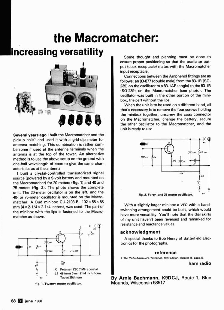
68 june 1980
the Macromatcher: Some thought and planning must be done to
ensure proper positioning so that the oscillator out- put (coax receptacle) mates with the Macromatcher input receptacle.
Connections between the Amphenol fittings are as follows: an 83-877 (double male) from the 83-1 R (SO- 239) on the oscillator to a 83-1AP (angle) to the 83-1 R (SO-239) on the Macromatcher (see photo). The oscillator was built in the other portion of the mini- box, the part without the lips.
When the unit is to be used on a different band, all that's necessary is to remove the four screws holding the minibox together, unscrew the coax connector on the Macromatcher, change the battery, secure the other oscillator to the Macromatcher, and the unit is ready to use.
I = 11
- ( 1
4 I 27R
ID I . + - fig. 2. Forty- and 75-meter oscillator. '"
With a slightly larger minibox a VFO with a band- switching arrangement could be built, which would have more versatility. You'll note that the dial skirts of my unit haven't been reversed and remarked for resistance and reactance values.
acknowledgment A special thanks to Bob Henry of Satterfield Elec-
tronics for the photographs.
reference 1. The Radio Amsteur's Handbook, 1979 edit~on, chapter 16, page 25
ham radio
By Arnie Bachmann, KSDCJ, Route 1, Blue Mounds, Wisconsin 53517
increasing versatility
.
Several years ago I built the Macromatcher and the pickup coils1 and used it with a grid-dip meter for antenna matching. This combination is rather cum- bersome if used at the antenna terminals when the antenna is at the top of the tower. An alternative method is to use the above setup on the ground with one-half wavelength of coax to give the same char- acteristics as at the antenna.
I built a crystal-controlled transistorized signal source (powered by a 9-volt battery and mounted on the Macromatcher) for 20 meters (fig. 1) and 40 and 75 meters (fig. 2). The photo shows the complete unit. The 20-meter oscillator is on the left, and the 40- or 75-meter oscillator is mounted on the Macro- matcher. A Bud minibox CU-2103-B, 102 x 58 x 58 mm (4 x 2-1 I 4 x 2-1 14 inches), was used. The part of the minibox with the lips is fastened to the Macro- matcher as shown.
- 01
LI
I \ n
CI
I I oo
X Petersen Z9C 7 MHz crystal L1 49 turns6 mrn (1 14 inch) form.
OY Tap at 25th turn
fig. I. Twenty-meter oscillator.
"WORLD FRIENDSHIP THROUGH AMATEUR RADIO"
SEANARC '80 SEATTLE - NATIONAL - AMATEUR - RADIO CONVENTION -
26 th NATIONAL ARRL CONVENTION
July 25 - 27. 1980 Seattle. Washington
ENJOY THE 26th NATIONAL ARRL CONVENTION IN THE BEAUTIFUL PACIFIC NORTHWEST
SEMINARS. DISPLAYS, LADIES PROGRAMS, FORUMS AND MAJOR EQUIPMENT EXHIBITORS WILL HIGHLIGHT THIS GATHERING AT THE SEA-TAC AIRPORT RED LION MOTOR INN.
Roy Neal, K6DUE, of NBC News will be the featured Saturday night banquet speaker.
Vic Clark, W4KFC will explain the results of WARC-79 and what it means to the future of amateur radio.
Meet ARRL President Harrv Dannals. WZHD, and other ARRL officials.
For Program and Registration Materials Write:
1980 A R R L NATIONAL CONVENTION COMMITTEE P. 0. BOX 68534 , SEATTLE, WASHINGTON 98168
More Details? CHECK-OFF Page 94 june 1980 69
Ham Radio's guide to help you find your Ioca 0 Arizona Connecticut
HATRY ELECTRONICS 500 LEDYARD ST. (SOUTH) HARTFORD, CT 06114 203-527.1881 Connecticut's Oldest Ham Radio Dealer.
-
AUREUS ELECTRONICS, INC. 1415 N. EAGLE STREET NAPERVILLE. IL 60540 3 12-420-8629 "Amateur Excellence"
KRYDER ELECTRONICS 5520 NORTH 7TH AVENUE NORTH 7TH AVE. SHOPPING CTR. PHOENIX, AZ 85013 6020249.3739 Your Complete Amateur Radio Store.
ERICKSON COMMUNICATIONS, INC. 5456 N. MILWAUKEE AVE. CHICAGO, IL 60630 Chicago - 312-631-5181 Outside Illinois - 800-621-5802 Hours: 9:30-5:30 Mon, Tu, Wed & Fri.; 9:30-9:00 Thurs; 9:OO-3:00 Sat.
-- --
THOMAS COMMUNICATIONS 95 KlTTS LANE NEWINGTON, CT 06111 203-667-081 1 Authorized dealer for Kenwood, Yaesu, Drake, Icom, etc. - CALL US!
POWER COMMUNICATIONS CORPORATION 6012 N. 27TH AVE. PHOENIX, AZ 85017 602-242-6030 or 242-8990 Arizona's #1 "Ham" Store. Yaesu, Kenwood, lcom and more. I Delaware I Indiana
DELAWARE AMATEUR SUPPLY 7 1 MEADOW ROAD NEW CASTLE, DE 19720 302-328-7728 ICOM, Ten-Tec, Swan, DenTron, Wilson, Tempo, KDK, Yaesu, and more. One mile off 1-95, no sales tax.
California KRYDER ELECTRONICS GEORGETOWN NORTH SHOPPlNG CENTER 2810 MAPLECREST RD. FORT WAYNE, IN 46815 2 19-484-4946 Your Complete Amateur Radio Store. 10-9 T, TH, F; 10-5 W, SAT.
C & A ELECTRONIC ENTERPRISES 2210 S. WlLMlNGTON AVE. SUITE 105 CARSON, CA 90745 213-834-5868 Not The Biggest, But The Best - Since 1962. Florida
-
Kansas AGL ELECTRONICS, INC. 1898 DREW STREET CLEARWATER, FL 33515 813-461-HAMS West Coast's only full service Amateur Radio Store.
JUN'S ELECTRONICS 11656 W. PIC0 BLVD. LOS ANGELES, CA 90064 213-477-1824 Trades 714-463-1886 San Diego The Home of the One Year Warranty - Parts at Cost - Full Service.
--
ASSOCIATED RADIO 8012 CONSER, P. 0. BOX 4327 OVERLAND PARK, KS 66204 913-381-5900 America's No. 1 Real '~mateur Radio Store. Trade - Sell - Buy.
AMATEUR RADIO CENTER, INC. 2805 N.E. 2ND AVENUE MIAMI, FL 33137 305-573-8383 The place for great dependable names in Ham Radio.
Maryland QUEMENT ELECTRONICS 1000 SO. BASCOM AVENUE SAN JOSE, CA 95128 408-998-5900 Serving the world's Radio Amateurs since 1933.
THE COMM CENTER, INC. LAUREL PLAZA, RT. 198 LAUREL, MD 20810 800-638-4486 Kenwood, Drake, Icom, Ten-Tec, Tempo, DenTron, Swan & Apple Computers.
RAY'S AMATEUR RADIO 1590 US HIGHWAY 19 SO. CLEARWATER, FL 33516 813-535-1416 Atlas, B&W, Bird, Cushcraft, DenTron, Drake, Hustler, Hy-Gain, Icom, K.D.K., Kenwood, MFJ, Rohn, Swan, Ten-Tec, Wilson.
SHAVER RADIO, INC. 1378 S. BASCOM AVENUE SAN JOSE, CA 95128 408-998-1 103 Atlas, Kenwood, Yaesu, KDK, Icom, Tempo, Wilson, Ten-Tec, VHF Engineering.
Massachusetts
SUNRISE AMATEUR RADIO 1361 STATE RD. 8 4 FT. LAUDERDALE, FL 33315 (305) 761-7676 "Best Prices in Country. Try us, we'll prove it."
TEL-COM, INC. 675 GREAT ROAD, RT. 119 LITTLETON, MA 01460 617-486-3040 The Ham Store of New England You Can Rely On.
TELE-COM 15460 UNION AVE. SAN JOSE, CA 95124 408-377-4479 --
YOU SHOULD BE HERE TOO! Dealers: c ontact Ham Radio now for complete details.
70 june 1980
june 1980 71
When it comes to Amateur Radio Dealer
TUFTS RADIO ELECTRONICS 206. MYSTIC AVENUE MEDFORD, MA 02155 61 7-395-8280 New England's friendliest ham store.
Minneso ta PAL ELECTRONICS INC. 3452 FREMONT AVE. NO. MINNEAPOLIS, MN 55412 612-521-4662 Midwest's Fastest Growing Ham Store, Where Service Counts.
New Hampshire EVANS RADIO, INC. BOX 893. RT. 3 A BOW JUNCTION CONCORD, NH 03301 603-224-9961 Icom, DenTron & Yaesu dealer. We service what we sell.
New Jersey RADIOS UNLIMITED P. 0. BOX 347 1760 EASTON AVENUE SOMERSET. NJ 08873 201 -469.4599 New Jersey's Fastest Growing Amateur Radio Center.
ROUTE ELECTRONICS 46 225 ROUTE 46 WEST TOTOWA, NJ 07512 201-256-8555 Drake, Swan, DenTron, Hy-Gain, Cushcraft, Hustler, Larsen, Etc.
Wl lT lE ELECTRONICS 384 LAKEVIEW AVENUE CLIFTON, NJ 07011 (201) 772-2222 Same location for 62 years. Full line authorized Drake dealer.
New Mexico PECOS VALLEY AMATEUR RADIO SUPPLY 115 W. WALNUT ST. ROSWELL, NM 88201 505 - 623-7388 Your DX, Contest, and Antenna Headquarters featuring A.E.A., Hy-Gain, Azden, Butternut, and Most Major Brands.
New York GRAND CENTRAL RADlO 124 EAST 44 STREET NEW YORK, NY 10017 21 2-599-2630 Drake, Kenwood, Yaesu, Atlas, Ten-Tec, Midland, DenTron, Hy-Gain, Mosley in stock.
HAM-BONE RADIO RADIO QSLYs . . .
3206 ERIE BLVD. EAST SYRACUSE, NY 13214 3 15-446.2266 We deal, we trade, all major brands! 2-way service shop on premises!
HARRISON RADlO CORP. 20 SMITH STREET FARMINGDALE, NY 11735 51 6.293-7990 "Ham Headquarters USA" since 1925. Call toll free 800-645-9187.
RADIO WORLD ONEIDA COUNTY AIRWRT TERMINAL BLDG. ORISKANY, NY 13424 Toll Free 800-448-7914
NY 3 15.337-2622 Res. { 315-337-0203
New & Used Ham Equipment. See Warren K2lXN or Bob WA2MSH.
Ohio UNIVERSAL AMATEUR RADIO, INC. 1280 AlDA DRIVE COLUMBUS (REYNOLDSBURG)
OH 43068 614-866-4267 Complete Amateur Radio Sales and Service. All major brands - spacious store near 1-270.
Oklahoma KRYDER ELECTRONICS 5826 N.W. 50TH MacARTHUR SQ. SHOPPING CTR. OKLAHOMA CITY, OK 73122 405-789-1951 Your Complete Amateur Radio Store
Pennsylvania HAMTRONICS, DIV. OF TREVOSE ELECTRONICS 4033 BROWNSVILLE ROAD TREVOSE. PA 19047 215-357-1400 Same Location for 3 0 Years.
LaRUE ELECTRONICS 11 12 GRANDVIEW STREET SCRANTONe PENNSYLVANIA 18509 717-343-2124 ICOM, Bird, Cushcraft, CDE, Ham-Keys, VHF Engineering, Antenna Specialists.
SPECIALTY COMMUNICATIONS 2523 PEACH STREET ERIE, PA 16502 814455-7674 Service, Parts, & Experience For Your Atlas Radio.
ONLY BOOK! US or DX Listings
CSI "" "Ilbooks NOW READY!
Here they are! The latest editions. World- famous Radio Amateur Callbooks, the most respected and complete listing of radio amateurs. Lists calls, license classes, ad- dress information. Loaded with speclal features such as call changes, prefixes of the world, standard time charts, world-wide QSL bureaus and more. The new 1980 Radio Amateur Callbooks are available now. The U.S. Edition features over 400.000 listings. over 120.000 changes from last year. The Foreign Edition, over 315.000 listings. over 90.000 call changes. Place your order now.
Each Shlpplng Tdal
, US callnook $16 95 51 75 SIB 70
I- Foreign Callbook $15 95 $1 75 $17 70
Order bolh books a1 Ihe same time for $34 65,includes shtpplng
Order lrom your lavorile eleclronlcs dealer or dlrecl lrorn !he publtsher A l l dlrecl orders add $1 75 for s h ~ ~ p ~ n g llllnols resldents add 5 % Sales Tax
SPECIAL LIMITED OFFER! Amateur Radio Emblem Patch
A W L T ~ U R qao*) only $2.50 postpaid
Pegasus on blue field. red lettering. 3 " wide x 3 " high. Great on jackets and caps. Sorry. no call letters.
ORDER TODAY!
RADIO AMATEUR
Dept. FB 2 925 Shemood Drlvs Lake Bluff, I1 60044 aca" INc.
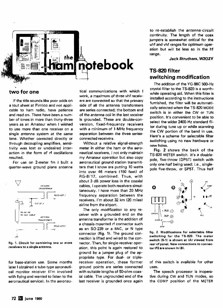
tebook P
two for one
If the title sounds like poor odds on a tout sheet at Pimlico and not appli- cable to ham radio, have patience and read on. There have been a num- ber of times in more than thirty-three years as an Amateur when I wished to use more than one receiver on a single antenna system at the same time. Whether corrected directly or through decoupling amplifiers, sensi- tivity was lost or undesired inter- action in the form of rf oscillations resulted.
For use on 2-meter fm I built a quarter-wave ground plane antenna
ANTENNA TRANSFORMER
RECEIVER I il,?c f f i -5BU CABLE
ANTENNA
TRANSFORMER
fig. 1. Circuit for combining one or more receivers to a single antenna.
for base-station use. Some months later I obtained a tube-type aeronauti- cal monitor receiver (I'm involved with flying and wanted to listen to the aeronautical service). In the aeronau-
tical communications with which I work, a maximum of three vhf receiv- ers are connected so that the primary side of all the antenna transformers are series connected; the bottom end of the antenna coil in the last receiver is grounded. These are double-con- version, fixed-frequency receivers with a minimum of 1-MHz frequency separation between the three series- connected receivers.
Without a relative signal-strength meter in either the ham or the aero- nautical receivers, I not only maintain my Amateur operation but also copy aeronautical ground station transmit- ters that I know are putting 10 watts into over 46 meters (150 feet) of RG-8/17, combined. Thus, with about 3 dB power loss in the coaxial cables, I operate both receivers simul- taneously. I have more than 20 MHz frequency separation between the receivers. I'm about 32 km (20 miles) airline from the airport.
The only modification to any re- ceiver with a grounded end on the antenna transformer is the addition of a chassis-mounted rf connector such as an SO-239 or a BNC, or N type connector (fig. 1). The ground con- nection is lifted and wired to the con- nector. Then, for single-receiver oper- ation, this point is again restored to ground by a jumper plug of the ap- propriate type. For dual- or triple- receiver operation, these former ground points are series connected with suitable lengths of 50-ohm coax- ial cable. The ungrounded end of the last receiver is grounded once again
to re-establish the antenna-circuit continuity. The length of the coax jumpers is somewhat critical for the uhf and vhf ranges for optimum oper- ation but will be less so in the hf range.
Jack Struthers, WZOZY
TS-820 filter switching modification
The addition of the YG-88C 500-Hz crystal filter to the TS-820 is a worth- while operating aid. When this filter is installed according to the instructions furnished, the filter will be automati- cally selected when the TS-820 MODE switch is in either the CW or TUN position. It's convenient to be able to select the wider 2400-Hz standard fil- ter during tune up or while scanning the CW portion of the band in use. Here's a scheme for selectable filter switching using no new hardware or new holes.
Fig. 2 shows the back of the TS-820 METER switch. It's a double- pole, five-throw (DP5T) switch with only one-half being used; i.e., single- pole five-throw, or SP5T. Thus half
puRpLEr@ GRAY
fig. 2. Modifications for selectable filter switching for the TS-820. The meter switch (S-11 is shown at (A) viewed from rear of panel. New connections to connec- tor IF2 are shown in (B).
of this switch is available for other uses.
The speech processor is inopera- tive during CW and TUN modes, so the COMP position of the METER
72 june 1980
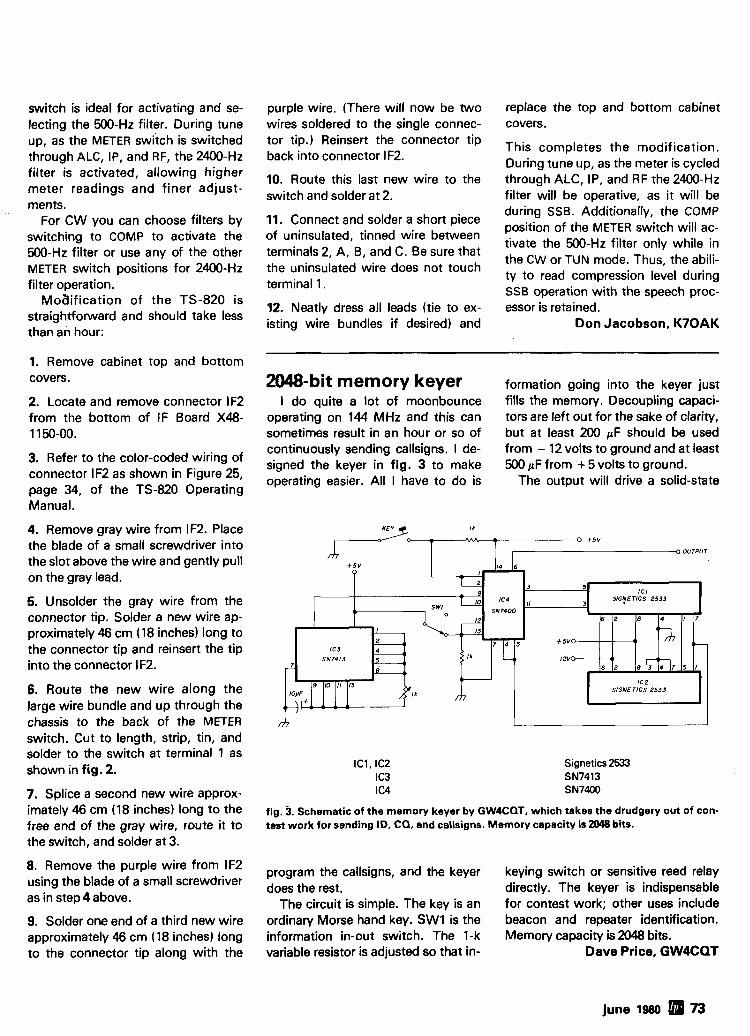
switch is ideal for activating and se- purple wire. (There will now be two replace the top and bottom cabinet lecting the 500-Hz filter. During tune wires soldered to the single connec- covers. up, as the METER switch is switched tor tip.) Reinsert the connector tip This completes the modification. through ALC, IP, and RF, the 2400-Hz back into connector IF2.
During tune up, as the meter is cycled filter is activated, allowing higher Route this last new wire to the through ALC, IP, and RF the 2400-Hz meter readings and finer adjust- switch and solder at 2. filter will be operative, as it will be ments. during SSB. Additionally, the COMP
For CW you can choose filters by 11. Connect and solder a short piece position of the METER switch will ac-
switching to COMP to activate the of uninsulated, tinned wire between tivate the 500-Hz filter only while in
500-Hz filter or use any of the other terminals 2, A, B, and C. Be sure that the CW or TUN mode. Thus, the abili-
METER switch positions for 2400-Hz the uninsulated wire does not touch ty to read compression level during
filter operation. terminal 1. SSB operation with the speech proc- MOaification of the TS-820 is 12. Neatly dress all leads (tie to ex- essor is retained.
straightforward and should take less isting wire bundles if and Don Jacobson, K7OAK than an hour:
1. Remove cabinet top and bottom covers.
2. Locate and remove connector IF2 from the bottom of IF Board X48- 1150-00.
3. Refer to the color-coded wiring of connector IF2 as shown in Figure 25, page 34, of the TS-820 Operating Manual.
4. Remove gray wire from IF2. Place the blade of a small screwdriver into the slot above the wire and gently pull on the gray lead.
5. Unsolder the gray wire from the connector tip. Solder a new wire ap- proximately 46 cm (18 inches) long to the connector tip and reinsert the tip into the connector IF2.
6. Route the new wire along the large wire bundle and up through the chassis to the back of the METER switch. Cut to length, strip, tin, and solder to the switch at terminal 1 as shown in fig. 2.
7. Splice a second new wire approx- imately 46 cm (18 inches) long to the free end of the gray wire, route it to the switch, and solder at 3.
8. Remove the purple wire from IF2 using the blade of a small screwdriver as in step 4 above.
9. Solder one end of a third new wire approximately 46 cm (18 inches) long to the connector tip along with the
=-bit memory keyer formation going into the keyer just I do quite a lot of moonbounce fills the memory. Decoupling capaci-
operating on 144 MHz and this can tors are left out for the sake of clarity, sometimes result in an hour or so of but at least 200 pF should be used continuously sending callsigns. I de- from - 12 volts to ground and at least signed the keyer in fig. 3 to make 500 pF from + 5 volts to ground. operating easier. All I have to do is The output will drive a solid-state
KEY 4 I I
f~ +5v ? OUTPUT
SlGNE TICS 2533
Signetics 2533 SN7413 SN7400
fig. 3. Schematic of the memory keyer by GW4CQT, which takes the drudgery out of con- test work for sending ID, CQ, and callsigns. Memory capacity is 2048 bits.
program the callsigns, and the keyer keying switch or sensitive reed relay does the rest. directly. The keyer is indispensable
The circuit is simple. The key is an for contest work; other uses include ordinary Morse hand key. SW1 is the beacon and repeater identification. information in-out switch. The 1-k Memory capacity is 2048 bits. variable resistor is adjusted so that in- Dave Price, GW4CQT
june 1980 73
1900 MHz to 2500 MHz DOWN CONVERTER This receiver is tunable over a range of 1900 to 2500 mc and is intended for amateur radio use. The local oscillator is voltage controlled (i.e.) making the i-f range approximately 54 to 88 mc (Channels 2 to 7).
. . . . . . . . . . . . . . . . . . . . . . . . . . . . . . . . . . . . . . . . . . . . . . . . . . . . . . . . . . PC BOARD WITH CHIP CAPACITORS 13. $44.99 . . . . . . . . . . . . . . . . . . . . . . . . . . . . . . . . . . . . . . . . . . . . . . . . . . . . . PC BOARD WITH ALL PARTS FOR ASSEMBLY $79.99
. . . . . . . . . . . . . . . . . . . . . . . . . . . . . . . . . . . . . . . . . . . . . . . . . . . . . . . . . . . PC BOARD ASSEMBLED AND TESTED $120.00 POWERSUPPLYKIT . . . . . . . . . . . . . . . . . . . . . . . . . . . . . . . . . . . . . . . . . . . . . . . . . . . . . . . . . . . . . . . . . . . . . . . . . . . . $44.99
. . . . . . . . . . . . . . . . . . . . . . . . . . . . . . . . . . . . . . . . . . . . . . . . . . . . . . . POWER SUPPLY ASSEMBLED AND TESTED $69.99 . . . . . . . . . . . . . . . . . . . . . . . . . . . . . . . . . . . . . . . . . . . . . . . YAGl ANTENNA 4' LONG APPROX. 20 TO 23 dB GAIN $59.99
. . . . . . . . . . . . . . . . . . . . . . . . . . YAGl ANTENNA 4' WITH TYPE (N, BNC, SMA Connector) .'. . . . . . . . . . . . . . . . . $64.99 2300 MHz DOWN CONVERTER
Includes converter mounted in antenna, power supply, antenna, 75 ' and 3' RG59 cable with connectors, . . . . . . . . . . . . . . . . . . . . . . . . . . . . . . . . . . . . . . . . . . . . . . . . . 75 to 300 ohm adapter, Plus 90 DAY WARRANTY $299.99 . . . . . . . . . . . . . . . . . . . . . . . . . . . . . . . . . . . . . . . . . . . . . . . . OPTION #1 MRF902 in front end. (7 dB noise figure). $349.99
. . . . . . . . . . . . . . . . . . . . . . . . . . . . . . . . . . . . . . . . . . . . . . . . . OPTION #2 2N6603 in front end. (5 dB noise figure). $400.00 2300 MHz DOWN CONVERTER ONLY
10dB Noise Figure 23 dB gain in box with N conn. Input Fconn. Output.. . . . . . . . . . . . . . . . . . . . . . . . . . . . . $149.99 . . . . . . . . . . . . . . . . . . . . . . . . . . . . . 7 dB Noise Figure 23 dB gain in box with N conn. Input F conn. Output. $169.99
. . . . . . . . . . . . . . . . . . . . . . . . . . 5 dB Noise Figure 23 dB gain in box with SMA conn. Input F conn. Output. $189.99 . . . . . . . . . . . . . . . . . . . . . . . . . . . . . . DATA IS INCLUDED WITH KITS OR MAY BE PURCHASED SEPARATELY $15.00
Shipping and Handling Cost: Receiver Kits add $1.50, Power Supply add $2.00, Antenna add $5.00, Option 112 add $3.00, For complete system add $7.50. Replacement Parts: MRF901 $5.00 MBD101 $2.00 MRF902 $10.00 .001 chip caps $2.00 2N6603 $12.00 PC Board only $25.00 with data
3.7 to 4.2 Gc SATELLITE DOWN CONVERTER 70 MHz i-f (30 MHz @ 3 dB) 10 dB min. IMAGE REJECTION 15 dB max. Noise Figure 15 dB Gain ASSEMBLED AND TESTED WlTH N OR SMA CONNECTOR FOR INPUT AND F CONNECTOR FOR OUTPUT
$499.99
I-F AMPLIFIER FOR ABOVE 70 MHz 45 dB Gain - 30 MHz @ 3 dB - ASSEMBLED AND TESTED F CONNECTQR
DEMOD FOR ABOVE 70 MHz COMPOSITE VIDEO OUTPUT (NO RF) - ASSEMBLED AND TESTED
TERMS: MASTER CHARGE, MASTERCARD, VISA, BANK AMERICARD. WE CHARGE 5% FOR HANDLING
CARD NUMBER EXP. DATE
YOUR SIGNATURE PHONE NUMBER
PLEASE SEND POSTAL MONEY ORDER, CERTIFIED CHECK, CASHIER'S CHECK OR MONEY ORDER. PRICES SUBJECT TO CHANGE WITHOUT NOTICE. WE CHARGE 15% FOR RESTOCKING ON ANY ORDER. ALL CHECKS AND MONEY ORDERS IN US FUNDS ONLY. --. -
ALL ORDERS SENT FIRST CLASS OR UPS. ALL PARTS PRIME AND GUARANTEED. WE WILL ACCEPT COD ORDERS FOR $25.00 OR OVER, ADD $1.50 FOR COD CHARGE. (602) 242-3037 PLEASE INCLUDE $1.50 MINIMUM FOR SHIPPING OR CALL FOR CHARGES. WE ALSO ARE LOOKING FOR NEW AND USED TUBES,
(602) 242-89 1 6 TEST EQUIPMENT, COMPONENTS ETC. WE ALSO SWAP OR TRADE. 2 1 1 1 W. Camelback FOR CATALOG SEE JANUARY, 1980, 73 Magazine, 10 Pages. Phoenix, Arizona 8501 5
74 june 1980 More Details? CHECK-OFF Page 94
FAIRCHILD VHF AND UHF PRESCALER CHIPS 95H90DC 350 MHz Prescaler Divide by 10111 $9.50 95H9lDC 350 MHz Prescaier Divide by Y6 9.50 11C90DC 650 MHz Prescaler Divide by 10111 16.50 11C91 DC 650 MHz Prescaier Divide by Y6 16.50 11C83DC 1 GHz Dlvide by 2481256 Prescaier 29.90 11C7ODC 800 MHz FiiplFlop wlth reset 12.30 11 CMIDC ECL VCM 4.53 llC44DClMC4044 Phase Frequency Detector 3.82 llC24DCIMC4024 Dual TTL VCM 3.62 11 CWDC UHF Prescaler 750 MHz D Type FliplFlop 12.30 11 C05DC 1 GHz Counter Divide by 4 74.35 llCOlFC High Speed Dual 5 4 input NOINOR Gate 15.40
WISPER FANS This fan is super quiet, efficient cooilng where low acoustical disturbance Is a must. Slze 4.68" x 4.68' x 1.5OW, Impedance protected, 50160 Hz. 120 Vac.
$9.99 (I
TRW BROADBAND AMPLIFIER MODEL CA615B Frequency response 40 MHz to 300 MHz Gain: 300 MHz l 6dB Min., 17.5dB Max.
50 MHz0 to - 1 dB from 300MHz Voltage: 24 volts dc at 220 ma max. $19.99
CARBIDE - CIRCUIT BOARD DRILL BITS FOR PC BOARDS Slze: 35,42,47,49,51,52 $2.15 Slze: 53,54,55,56,57,58,59,61,63,64,65 1.85 Size: 66 1 .90 Size: 1.25 mm, 1.45 mm 2.00 Size: 3.20 mm 3.58
CRYSTAL FILTERS: TYCO 001-19880 same as 2194F 10.7 MHz Narrow Band Clystal Filter 3 dB bandwidth 15 kHz min. 20 dB bandwidth 60 kHz mln. 40 dB bandwidth 150
kHz min. Ultimate 50dB: insertion loss 1.0dB max. Ripple 1.0 dB max. Ct. 0+/ - 5 pf 3600
ohms. $5.95
MURATA CERAMIC FILTERS Models: SFD-455D 455 kHz $3.00
SFB.455D 455 kHz 2.00 CFM-455E 455 kHz 7.95 SFE-10.7 10.7 MHz 5.95
TEST EQUIPMENT - HEWLETT PACKARD - TEKTRONIX - ETC. Hewletl Packard: 491C T W l Amplifier2 to 4 Gc 1 watt 30dB galn 608D 10 to420 mc .1 uV to .5 V into 50ohms Signal Generator 612A 450 to 1230 mc .l uV to .5V into 50 ohms Slgnal Generator 614A 900 to 2100 mc Signal Generator 6168 1.810 4.2 Gc Sional Generator 6186 3.6 to 7.2 GC signal ene era tor 820A 7 to 11 Gc Signal Generator 6238 Microwave Test Set 624C Microwave Test Set 32008 10 to 500 mc vhf Oscillator 8691A 1 to 2 Gc Plus In For8690A Sweeper 8692A 2 to 4 Gc plug In For 8690A Sweeper 8693A 4 to 8 Gc Plua In For 8690A Sweeoer 8742A Reflection ~ i s t UnH 2 to 12.4 Gc
Tektmnix: 1908 350 kHz to 50 mc Osclilator 150.00
Alltech: 473 22510 400 mc AMlFM Signal Generator 750.00 Slnger: MF51VR-4 Universal Spectrum Analyzer with 1 kHzto 27.5 mc Plug In 1200.00
Keltek: XR630-100 TWlAmplifier6 to 12.4 Gc 100 watts 40 dB gain 9200.00
Polmd: 203812436I1102A
Calibrated Display wlth an SSB Analysis Moduleand a 10 to 40 mc Single Tone Synthesizer 1500.00
RF TRANSISTORS TYPE PRICE 2N1561 $15.00 2N1562 15.00 2N1692 15.00 2N1893 15.00 2N2632 45.00 2N2857JAN 2.45 2N2676 12.35 2N2880 25.00 2N2927 7.00 2N2947 17.25 2N2948 15.50 2N2949 3.90 2N2950 5.00 2N3287 4.30 2N3294 1.15 2N3301 .75 2N3302 1.05 2N3304 1.48 2N3307 10.50 2N3309 3.90 2N3375 6.75 2N3553 1.45 2N3755 7.20 2N3818 6.00 2N3866 1.09 2N38WAN 2.70 2N3866JANTX 4.43 2N3924 3.20 2N3925 6.00 2N3927 11.50 2N3950 26.25 2N4072 1.70 2N4135 2.00 2N4261 14.60 2N4427 1.09
TYPE 2N5590 2N5591 2N5637 2N5641 2N5642 2N5643 2N6545 2N5764 2N5842 2N5649 2N5662 2N5913 2N5922 2N5942 2N5944 2N5945 2N5946 2 N W 2N6081 2N8082 2N-3 2N-4 2N6094 2N6095 2N6096 2N6097 2N6136 2N6166 2N6265 2N6266 2N6439 2N6459lF 2N6603 2N8804 A5012
PRICE $6.00 10.35 20.00 4.90 8.63
14.38 11.00 27.00 8.65
19.50 50.00 3.25
10.00 46.00 7.50
10.90 13.20 5.45 8.60 9.90
11.80 13.20 5.75
10.35 19.35 26.00 18.70 36.80 75.00
100.00 43.45
T9795 18.00 12.00 12.00 25.00
CHIP CAPACITORS l p f 27pf
We can supply any 1.5pf 33pf
value chip capac. 2.2pf 39pt
itors you may need. 2.7pf 47pf 3.3pf 56pf
PRICES 3.8pf 68pf 1 to 10 $1.99 4.7pf 82pf 11 - 50 1.49 5.6pf 1 Wpf 51-100 1.00 6.8pf 1lOpf 101 up POR 6.2pf 120pf
10pf 130Pf 12pf 150pf
POR = CALL FOR PRICE 150f l60of
TYPE PRICE MM1550 $10.00 MM1552 50.00 MM1553 56.50 MM1601 5.50 MM160212N5842 7.50 MM1607 6.65 MM1661 15.00 MM1669 17.50 MM1943 3.00 MM2605 3.00 MM2608 5.00 M M8006 2.15 MMCM918 1.00 MMT72 .61 MMT74 .94 MMT2657 2.68 MRF304 43.45 MRF420 20.00 MRF450 11.65 MRF450A 11.85 MRF454 20.10 MRF458 16.95 MRF475 5.00 MRF476 5.00 MRF502 .49 MRF504 6.95 MRF509 4.90 MRF511 8.60 MRF901 5.00 MRF5177 20.70 MRF8004 1.44 PT4186B 3.00 PT4571A 1.50 PT4612 5.00 PT4628 5.00
ATLAS CRYSTAL FILTERS FOR ATLAS HAM GEAR 5.52-2.718
YOUR CHOICE $24.95
More Details? CHECK-OFF Page 94 june 1980 a 75
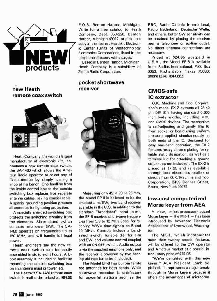
products
n'ew Heath remote coax switch
Heath Company, the world's largest manufacturer of electronic kits, an- nounces a new remote coax switch, the SA-1480 which allows the Ama- teur Radio operator to select any of five antennas by simply turning a knob at his bench. One feedline from the inside control box to the outside switching box replaces five separate antenna cables, saving coaxial cable. A special grounding position grounds all antennas for lightning protection.
A specially shielded switching box protects the switching circuitry from the elements. Silver-plated switch contacts help lower SWR. The SA- 1480 operates on frequencies up to 150 MHz, and will handle full legal power.
Heath engineers say the new re- mote coax switch can be easily assembled in six to eight hours. A U- bolt assembly is included to facilitate mounting the outside switching box on an antenna mast or tower leg.
The Heathkit SA-1480 remote coax switch is mail order priced at $84.95
F.O. B. Benton Harbor, Michigan. Write for a free catalog to Heath Company, Dept. 350-220, Benton Harbor, Michigan 49022, or pick up a copy at the nearest Heathkit Electron- ic Center (Units of Veritechnology Electronics Corporation), listed in the telephone directory white pages.
Based in Benton Harbor, Michigan, Heath Company is a subsidiary of Zenith Radio Corporation.
pocket shortwave receiver
Measuring only 45 x 73 x 25 mm, the Model EP-8 is believed to be the smallest a-m/SW, two-band receiver available in the U.S. In addition to the standard "broadcast" band (a-m), the EP-8 receives shortwave frequen- cies from 3.9 to 12 MHz (ideal for re- ceiving WWV time signals on 5 and 10 MHz). Controls include a band- select switch, tunable dial for a-m and SW, and volume control coupled with an ON-OFF switch. Audio output is via the supplied earphone only, and the receiver is powered by two hear- ing-aid type batteries (included).
The Model EP-8 has built-in ferrite rod antennas for both bands. While shortwave reception is satisfactory for powerful stations such as the
BBC, Radio Canada International, Radio Nederland, Deutsche Welle, and others, better SW sensitivity can be obtained by placing the receiver near a telephone or ac-line outlet. No direct antenna connections are necessary.
Priced at $24.95 postpaid in U.S.A., the Model EP-8 is available from: Radios International, P.O. Box 6053, Richardson, Texas 75080; phone (214) 784-0862.
CM 0s-saf e IC extractor
O.K. Machine and Tool Corpora- tion's model EX-2 extracts all 28-40 pin DIP IC's having standard 0.600 inch body widths, including MOS and CMOS devices. The mechanism is self-adjusting and gently lifts IC from socket or board using uniform pressure applied simultaneously at both ends of the IC. Designed for easy one-hand operation, the EX-2 features heavy chrome plating for re- liable static dissipation, as well as a terminal lug for attaching a ground strip (strap not included). The EX-2 is priced at $7.95 and is available through local electronics retailers or directly from O.K.'Machine and Tool Corporation, 3455 Conner Street, Bronx, New York 10475.
low-cost computerized Morse keyer from AEA
A new, microprocessor-based Morse keyer - the MK-1 - has been introduced by Advanced Electronic Applications of Lynnwood, Washing- ton.
The MK-1, which incorporates more than twenty special features, will be offered to the CW operator and Amateur market at a special in- troductory price of $79.95.
"We're delighted with this new keyer," AEA President Lamb ex- plained. "It represents a major break- through in Morse keyers because it offers the advantages of microproc-
76 june 1980
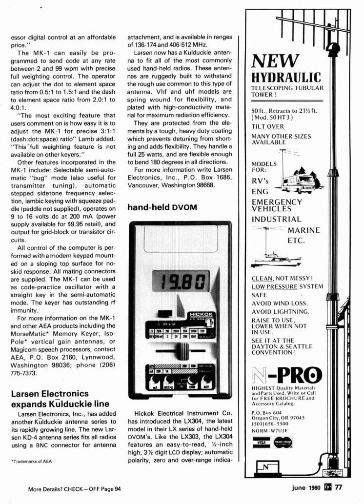
essor digital control at an affordable price."
The MK-1 can easily be pro- grammed to send code at any rate between 2 and 99 wpm with precise full weighting control. The operator can adjust the dot to element space ratio from 0.5:1 to 1.5:1 and the dash to element space ratio from 2.0:1 to 4.0: 1.
"The most exciting feature that users comment on is how easy it is to adjust the MK-1 for precise 3:1:1 (dash:dot:space) ratio" Lamb added. "This"full weighting feature is not available on other keyers."
Other features incorporated in the MK-1 include: Selectable semi-auto- matic "bug" mode (also useful for transmitter tuning), automatic stepped sidetone frequency selec- tion, iambic keying with squeeze pad- dle (paddle not supplied), operates on 9 to 16 volts dc at 200 mA (power supply available for $9.95 retail), and output for grid-block or transistor cir- cuits.
All control of the computer is per- formed with a modern keypad mount- ed on a sloping top surface for no- skid response. All mating connectors are supplied. The MK-1 can be used as code-practice oscillator with a straight key in the semi-automatic mode. The keyer has outstanding rf immunity.
For more information on the MK-1 and other AEA products including the MorseMatic* Memory Keyer, Iso- Pole* vertical gain antennas, or Magicom speech processors, contact AEA, P.O. Box 2160, Lynnwood, Washington 98036; phone (206) 775-7373.
Larsen Electronics expands ~ i l d u c k i e line
Larsen Electronics, Inc., has added another ~dduck ie antenna series to its rapidly growing line. The new Lar- sen KD-4 antenna series fits all radios using a BNC connector for antenna
'Trademarks of AEA
More Details? CHECK-OFF Page 94
attachment, and is available in ranges of 136-174 and 406-512 MHz.
Larsen now has a ~ i lduck ie anten- na to fit all of the most commonly used hand-held radios. These anten- nas are ruggedly built to withstand the rough use common to this type of antenna. Vhf and uhf models are spring wound for flexibility, and plated with high-conductivity mate- rial for maximum radiation efficiency.
They are protected from the ele- ments by a tough, heavy duty coating which prevents detuning from short- ing and adds flexibility. They handle a full 25 watts, and are flexible enough to bend 180 degrees in all directions.
For more information write Larsen Electronics, Inc., P.O. Box 1686, Vancouver, Washington 98668.
hand-held DVOM
Hickok Electrical Instrument Co. has introduced the LX304, the latest model in their LX series of hand-held DVOM's. Like the LX303, the LX304 features an easy-to-read, K-inch high, 3 '/2 digit LCD display; automatic polarity, zero and over-range indica-
TELESCOPING TUBULAR TOWER !
50 ft., Retracts to 21 % ft. ( Mod. 50 HT3 ) TILT OVER
MANY OTHER SIZES AVAl LABLE
EMERGENCY VEHICLES INDUSTRIAL
CLEAN, NOT MESSY! LOW PRESSURE SYSTEM
AVOID WIND LOSS. AVOID LIGHTNING. RAISE TO USE, LOWER WHEN NOT IN USE. SEE IT AT THE DAYTON & SEATTLE CONVENTION !
HIGHEST Qual~ ty M.lter~.il\ and Parts Used. Wr~te or Cdll for F R E E BROCHUREand Accessory Catalog.
P.O. Box 604 Oregon City,OR 97045 (503) 656- 5500 N O R M - W 7 U J F
june 1980 77
A Note fkom the
Department
Dear Readers: Did you know that ADVERTIS- ING pays a big share of the cost of producing each issue of HR? It's important that YOU tell our advertisers where you saw their ads. Therefore, when you seen an ad in HAM RADIO - TELL THEM WE SENT YOU! The result of all this is more of the kind of magazine you've over- whelmingly told us you want!
Jim, WlXU Craig, NlACH
tion; %-year battery life in typical use; simplified one-hand operation and ultra-rugged construction with excellent overload characteristics for long-term reliability.
Other features of the M304 include an automatic decimal point, a built-in low battery indicator, diode and tran- sistor testing capability and 0.5 per cent accuracy on dc volt ranges.
Designed for convenient and eco- nomical bench and field use, Hickok M Series multimeters are self-con- tained, with test leads that store in the removable, protective thermo- plastic cover. They will withstand a four-foot drop without loss of accu- racy. A complete line of inexpensive accessories extends their use into high voltage applications and temper- ature measurements.
Price of the LX304 is $89.95. For more information, contact Hickok Electrical Instrument Co., 10514 Du- Pont Avenue, Cleveland, Ohio 44108.
programmable encoder
Communications Specialists has introduced a programmable 12-tone encoder, model TE-12P, available in either sub-audible or burst-tone con- figuration.
In the sub-audible range, this en- coder allows the programming of 12 standard frequencies from 67.0 Hz to 203.5 Hz. In the audible range, burst tones may be selected in the range of 1600 Hz to 2550 Hz in 50-Hz incre- ments. Additionally, there are thir- teen other frequencies available which may be used for either burst or test purposes.
This encoder is housed in a durable
plastic case measuring 5.25 x 3.3 x 1.7 inches and is complete with mounting bracket and hardware. It may be powered by 6 to 30 Vdc, un- regulated at 8 mA and provides a low- impedance, low-distortion, adjust- able sine-wave output of 5 V p-p. Re- verse polarity protection is built-in.
Programming each channel can be done in seconds. A five position DIP switch is furnished for each of the twelve channels and it is merely a matter of setting each switch to the proper ON and OFF positions to achieve a binary-coded frequency.
The output level is flat to within 1.5 dB over the entire range of frequen- cies selected. In the low-frequency range, the frequency accuracy is f 0.1 Hz and in the high-frequency range, the accuracy is within f 1.0 Hz. Sub-audible tones are designated as Group A tones and audible fre- quencies are Group B tones. No counter or other frequency meas- uring device is needed to set fre- quencies.
The TE-12P is priced at $89.95, wired and tested, complete with in- structions. For more information write Communications Specialists, 426 West Taft Avenue, Orange, Cali- fornia 92667.
transistor replacement guide
A 1980 edition of the RCA Solid- State Replacement Guide offering 1080 solid-state replacement devices which replace more than 161,000 do- mestic and foreign types is now avail- able from RCA SK Device Distrib- utors.
Published in January, the 1980 RCA SK Replacement Guide contains easy to read information on RCA's full line of replacement transistors, rectifiers, thyristors, integrated cir- cuits, and high-voltage triples includ- ing many MRO (maintenance and re- pair operations) replacements. The guide also includes an index and a comprehensive data section with list- ings grouped according to type of de-
More Details? CHECK-OFF Page 94
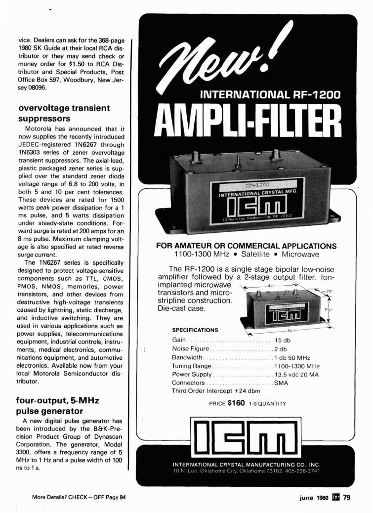
vice. Dealers can ask for the 368-page 1980 SK Guide at their local RCA dis- tributor or they may send check or money order for $1.50 to RCA Dis- tributor and Special Products, Post Office BOX 597, Woodbury, New Jer- sey 08096.
overvoltage transient suppressors
Motorola has announced that it now supplies the recently introduced JEDEC-registered 1 N6267 through 1 N6303 series of zener overvoltage transient suppressors. The axial-lead, plastic packaged zener series is sup- plied over the standard zener diode voltage range of 6.8 to 200 volts, in both 5 and 10 per cent tolerances. These devices are rated for 1500 watts peak power dissipation for a 1 ms pulse, and 5 watts dissipation under steady-state conditions. For- ward surge is rated at 200 amps for an 8 ms pulse. Maximum clamping volt- age is also specified at rated reverse surge current.
The IN6267 series is specifically designed to protect voltage-sensitive components such as TTL, CMOS, PMOS, NMOS, memories, power transistors, and other devices from destructive high-voltage transients caused by lightning, static discharge, and inductive switching. They are used in various applications such as power supplies, telecommunications equipment, industrial controls, instru- ments, medical electronics, commu- nications equipment, and automotive electronics. Available now from your local Motorola Semiconductor dis- tributor.
four-output, 5-MHz pulse generator
A new digital pulse generator has been introduced by the B&K-Pre- cision Product Group of Dynascan Corporation. The generator, Model 3300, offers a frequency range of 5 MHz to 1 Hz and a pulse width of 100 ns to 1 s.
FOR AMATEUR OR COMMERCIAL APPLICATIONS 1 100-1 300 MHz Satellite Microwave
The RF-1200 is a single stage bipolar low-noise amplifier followed by a 2-stage output filter. lon- implanted microwave transistors and micro- stripline construction. Die-cast case.
SPECIFICATIONS 'rt--
Gain. . . . . . . . . . . . . . . . . . . . . . . . . . .15 db I . . . . . . . . . . . . . . . . . . I Noise Figure. . 2 db
Bandwidth. . . . . . . . . . . . . . . . . . . . . .1 db 50 MHz Tuning Range . . . . . . . . . . . . . . . . . . .1100-1300 MHz Power Supply. . . . . . . . . . . . . . . . . . .13.5 vdc 20 MA Connectors . . . . . . . . . . . . . . . . . . . . . SMA Third Order Intercept +24 dbm
More Details? CHECK-OFF Page 94 june 1980 79
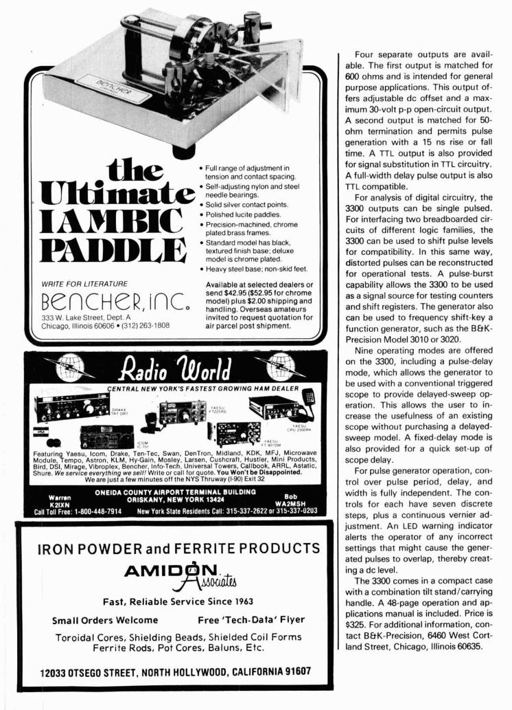
Full range of adjustment in tension and contact spacing. Self-adjusting nylon and steel needle bearings. Solid silver contact points. Polished lucite paddles. Prec~sion-machined. chrome plated brass frames.
PADDLE Standard model has black. textured finish base; deluxe model is chrome plated. Heavy steel base; non-skid feet.
WRITE FOR LITERATURE Available at selected dealers or send $42.95($52.95 for chrome Be c H e R , i n c model) PIUS $2.00 shipping and
O handling. Overseas amateurs 333 W. Lake Street, Dept. A invited to request quotation for Chicago, Illinois 60606 (312) 263-1808 air parcel post shipment.
Four separate outputs are avail- able. The first output is matched for 600 ohms and is intended for general purpose applications. This output of- fers adjustable dc offset and a max- imum 30-volt p-p open-circuit output. A second output is matched for 50- ohm termination and permits pulse generation with a 15 ns rise or fall time. A TTL output is also provided for signal substitution in TTL circuitry. A full-width delay pulse output is also TTL compatible.
For analysis of digital circuitry, the 3300 outputs can be single pulsed. For interfacing two breadboarded cir- cuits of different logic families, the 3300 can be used to shift pulse levels for compatibility. In this same way, distorted pulses can be reconstructed for operational tests. A pulse-burst capability allows the 3300 to be used as a signal source for testing counters and shift registers. The generator also can be used to frequency shift-key a function generator, such as the B&K- Precision Model 3010 or 3020.
Nine operating modes are offered on the 3300, including a pulse-delay mode, which allows the generator to be used with a conventional triggered scope to provide delayed-sweep op- eration. This allows the user to in- crease the usefulness of an existing scope without purchasing a delayed- sweep model. A fixed-delay mode is also provided for a quick set-up of scope delay.
For pulse generator operation, con- trol over pulse period, delay, and width is fully independent. The con- trols for each have seven discrete steps, plus a continuous vernier ad- justment. An LED warning indicator alerts the operator of any incorrect settings that might cause the gener- ated pulses to overlap, thereby creat- ing a dc level.
The 3300 comes in a compact case with a combination tilt standlcarrying handle. A 48-page operation and ap- plications manual is included. Price is $325. For additional information, con- tact B&K-Precision, 6460 West Cort- land Street, Chicago, Illinois 60635.
ENTRAL N E W YORK'S FASTEST G R O W I N
1
IRON POWDER and FERRITE PRODUCTS
Fast, Reliable Service Since 1963
Smal l Orders Welcome Free 'Tech-Data' F l ye r
Toroidal Cores, Shielding Beads, Shielded Coil Forms Fe r r i t e Rods, Pot Cores, Baluns, Etc.
12033 Of SEGO STREET, NORTH HOLLYWOOD, CALIFORNIA 91607
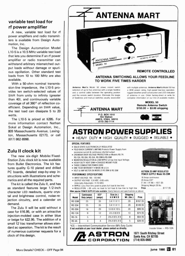
variable test load for rf power amplifier
A new, variable test load for rf power amplifiers and radio transmit- ters is available from Design Auto- mation, Inc.
The Design Automation Model L10-5 is a 10.5 MHz variable test load that lets you determine if an rf power amplifier or radio transmitter can withstand arbitrary mismatched out- put loads without damage or spuri- ous oscillation. Other standard test loads from 10 to 100 MHz are also available.
With a 50-ohm nominal transmis- sion-line impedance, the L10-5 pro- vides ten switch-selected values of SWR from unity to infinity (greater than 401, and continuously variable coverage of all 360° of reflection co- efficient. Depending on SWR value, the test load can dissipate 5 to 20 watts.
The L10-5 is priced at $285. For more information contact Nathan Sokal at Design Automation, Inc., 809 Massachusetts Avenue, Lexing- ton, Massachusetts 02173, or call (617) 862-8998.
Zulu II clock kit The new six-digit MobilefFixed-
Station Zulu clock kit is now available from Bullet Electronics. The kit fea- tures quality G-10 plated and drilled PC boards, detailed step-by-step in- structions with illustrations and sche- matics and all the required parts.
The kit is called the Zulu 11, and has as standard features large 112-inch character LED readouts, quartz crys- tal and brightness control, noise-re- jection circuitry, and a calendar on demand.
The Zulu II will be sold without a case for $16.95, or with an attractive injection-molded case in either blue or beige for $22.95. The addition of a small 12 Vac transformer allows stan- dard ac operation. The kit is the result of numerous customer requests for a clock of this design.
I REMOTE CONTROLLED I ANTENNA SWITCHING ALLOWS YOUR FEEDLINE TO WORK FIVE TIMES HARDER
Antenna Mart's Model 50 allows Instant Switch with mult~ple antennas A n t a n s Mart's Model 50 has selection of up to fwe antennas wlth a slngle feedllne a 3KW power ratlng hlgh-speed low-loss operatJon. and a control cable between the OpWabng posltm rugged weather-proof conslructlon and LED lndlC~hUI and the remote switch locat~on Ellmlnate the tangle of anlenna In use Order laclotyd~recl or wrtte for of leedllnes and manual switches usually assoc~ated complete lnlormallon on our ltne of avallable models
MODEL 50 Remote Antenna Switch $150.00 + $3.00 shipping
I P.O. BOX 101 0 I S U Stat ion
AWES, IOWA 50010 (515) 292-71 14
I ASTRON POWER SUPPLIES I HEAW DUTY HIGH QUALITY RUGGED RELIABLE
SPECIAL FEATURES SOLID STATE ELECTRONICALLY REGULATED FOLD-BACK CURRENT LIMITING Protects Power Supply from excessive current 8 contlnuous shorled output. CROWBAR OVER VOLTAGE PROTECTION on Models RS-7A. RS-12A. RS-2DA. RS-35A. AS-20M 8 RS-35M MAINTAIN REGULATION 8 LOW RIPPLE at low line input Voltage. HEAVY DUTY HEAT SINK CHASSIS MOUNT FUSE THREE CONDUCTOR POWER CORD ONE YEAR WARRANTY MADE IN U.S.A. VOLT 8 AMP METER ON MODELS RS-20M 8 RS-35M
PERFORMANCE SPECIFICATIONS ASTRON 20 AMP REGULATED POWER SUPPLY Model RS-?OM
INPUT VOLTAGE: 105 - 125 VAC 16 Amps continuous
OUTPUT VOLTAGE: 13 8 VDC t0.05 volts M Amps ICS' (Internally Adlustable. 11.15 VDC) 5" (ti) Y(W) < 10 5' (D) RIPPLE Less than Smv peak lo peak (full load 8 low line) Shlpp~ng Welghl 20 Ibs REGULATION t.05 volts no load to full load 8 low llne lo high line Price . . . . . . . . . . . . . $1 17.95
Olhn popular POWER SUPPLIES also avallablt ISame leatures and spec~flcatlons as above)
Continuous ICS* Slze (in.) Shipping Modd Duty (amps) (amps) H X W X D . b . R b
1 I
35 1 5 x 1 1 X l l I 29 [ $167.95
RS-35A 1 25 1 35 1 5 X l l X l l I 29 1 $149 95
RS-7A 5 7 3'/1X6'/zX9 8 1 $54.95
RS-4A 3 4 3%X6'/zX9 5 $39.95
'ICS - Intermittent Communication Service (50% Duty Cycle) If not 81flIllbl8 81 your local dealer, please contact us directly.
1971 South Rltchey Street ASTRoN SantaAn,CA!l2705 CORPORATION (714)835-0682
More Details? CHECK-OFF Page 94 june 1980 81
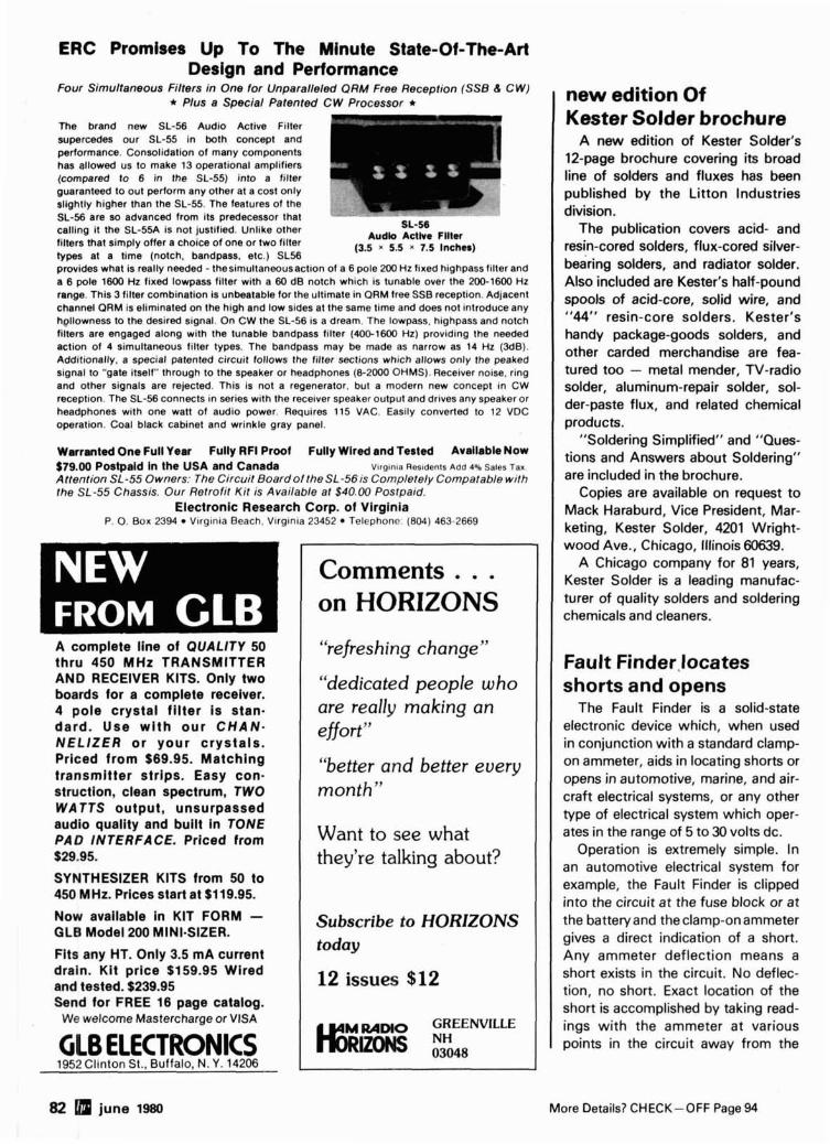
ERC Promises Up To The Minute State-Of-The-Art Design and Performance
Four Simultaneous Filters in One for Unparalleled ORM Free Reception (SSB 6 C W ) * Plus a Special Patented CW Processor
m e brand new SL-56 Audio Active Filter supercedes our SL-55 in both concept and performance. Consolidation of many components has allowed us to make 13 operational amplifiers (compared to 6 in the SL-55) into a frlter guaranteed to out perform any other at a cost only slightly higher than the SL-55. The features of the SL-56 are so advanced from its predecessor that calling it the SL-55A is not justified. Unlike other filters that simply offer a choice of one or two filter types at a time (notch. bandpass, etc.) SLS6
SL-56 Audk Actlve Flller
(3.5 5.5 7.5 Inches) . .
provides what is really needed - thesimultaneousaction of a 6 pole 200 Hz fixed highpass filter and a 6 pole 1600 Hz fixed lowpass filter with a 60 dB notch which is tunable over the 200-1600 Hz range. This 3 filter combination is unbeatable for the ultimate in ORM free SSB reception. Adjacent channel ORM is eliminated on the high and low sides at the same time and does not introduce any hollowness to the desired signal. On CW the SL-56 is a dream. The iowpass, highpass and notch filters are engaged along w ~ t h the tunable bandpass filter (400-1600 Hz) providing the needed action of 4 simultaneous filter types. The bandpass may be made as narrow as 14 Hz (348). Additionally. a special patented circuit follows the filter sections which allows only the peaked signal to "gate itself" through to the speaker or headphones (6-2000 OHMS). Receiver noise, ring and other signals are rejected. This is not a regenerator, but a modern new concept in CW reception. The SL-56 connects in series with the receiver speaker output and drives any speaker or headphones with one watt of audio power. Requires 115 VAC. Easily converted to 12 VDC operation. Coal black cabinet and wrinkle gray panel.
Warranted One Full Year Fully RFI Proof Fully Wlred and Tested Available Now $79.00 Postpaid in the USA and Canada Vlrg~nla Res~dents Add 4% Sales Tax. Attention SL-55 Owners: The Ctrcuit BoardoltheSL-56is Completely Compatable with the SL-55 Chassis. Our Retrofit Kit is Available at $40.00 Postpaid.
Electronic Research Corp. of Virginia P. 0. Box 2394 Vlrginla Beach. V ~ r g ~ n ~ a 23452 Telephone. (804) 463-2669
A complete line of QUALITY 50 thru 450 MHz TRANSMITTER AND RECEIVER KITS. Only two boards for a complete receiver. 4 pole crystal fi lter is stan- dard. Use wi th our C H A N - N E L l Z E R or your crystals. Priced from $69.95. Matching transmitter strips. Easy con- struction, clean spectrum, TWO WATTS output, unsurpassed audio quality and built in TONE PAD INTERFACE. Priced from $29.95.
SYNTHESIZER KITS from 50 to 450 MHz. Prlces start at $119.95.
Now avaliabie In KIT FORM - GLB Model 200 MINI-SIZER.
Fits any HT. Only 3.5 mA current drain. Kit price $159.95 Wired and tested. $239.95 Send for FREE 16 page catalog.
We welcome Mastercharge or VISA
GLB ELECTRONICS 1952 Cl~nton St.. Buffalo. N. Y. 14206
"refreshing change"
"dedicated people who are really making an effort"
"better and better every month"
Want to see what they're talking about?
Subscribe to HORIZONS today
12 issues $12
new edition Of Kester Solder brochure
A new edition of Kester Solder's 12-page brochure covering its broad line of solders and fluxes has been published by the Litton Industries division.
The publication covers acid- and resin-cored solders, flux-cored silver- bearing solders, and radiator solder. Also included are Kester's half-pound spools of acid-core, solid wire, and "44" resin-core solders. Kester's handy package-goods solders, and other carded merchandise are fea- tured too - metal mender, TV-radio solder, aluminum-repair solder, sol- der-paste flux, and related chemical products.
"Soldering Simplified" and "Ques- tions and Answers about Soldering" are included in the brochure.
Copies are available on request to Mack Haraburd, Vice President, Mar- keting, Kester Solder, 4201 Wright- wood Ave., Chicago, Illinois 60639.
A Chicago company for 81 years, Kester Solder is a leading manufac- turer of quality solders and soldering chemicals and cleaners.
Fault Finder,locates shorts and opens
The Fault Finder is a solid-state electronic device which, when used in conjunction with a standard clamp- on ammeter, aids in locating shorts or opens in automotive, marine, and air- craft electrical systems, or any other type of electrical system which oper- ates in the range of 5 to 30 volts dc.
Operation is extremely simple. In an automotive electrical system for example, the Fault Finder is clipped into the circuit at the fuse block or at the battery and the clamp-on ammeter gives a direct indication of a short. Any ammeter deflection means a short exists in the circuit. No deflec- tion, no short. Exact location of the short is accomplished by taking read- ings with the ammeter at various points in the circuit away from the
82 june 1980 More Details? CHECK-OFF Page 94
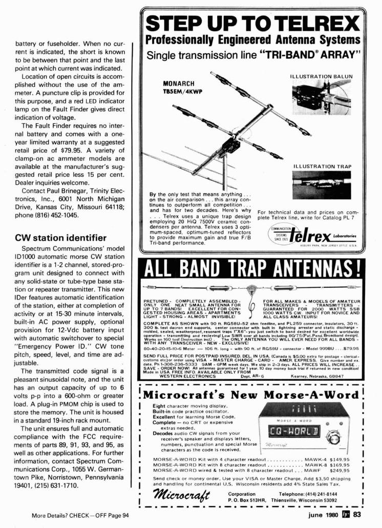
battery or fuseholder. When no cur- rent is indicated, the short is known to be between that point and the last point at which current was indicated.
Location of open circuits is accom- plished without the use of the am- meter. A puncture clip is provided for this purpose, and a red LED indicator lamp on the Fault Finder gives direct indication of voltage.
The Fault Finder requires no inter- nal battery and comes with a one- year limited warranty at a suggested retail price of $79.95. A variety of clamp-on ac ammeter models are available at the manufacturer's sug- gested retail price less 15 per cent. Dealer inquiries welcome.
Contact Paul Brinegar, Trinity Elec- tronics, Inc., 6001 North Michigan Drive, Kansas City, Missouri 641 18; phone (816) 452-1045.
CW station identifier Spectrum Communications' model
ID1000 automatic morse CW station identifier is a 1-2 channel, stored-pro- gram unit designed to connect with any solid-state or tube-type base sta- tion or repeater transmitter. This new lDer features automatic identification of the station, either at completion of activity or at 15-30 minute intervals, built-in AC power supply, optional provision for 12-Vdc battery input with automatic switchover to special "Emergency Power ID." CW tone pitch, speed, level, and time are ad- justa ble.
The transmitted code signal is a pleasant sinusoidal note, and the unit has an output capacity of up to 6 volts p-p into a 600-ohm or greater load. A plug-in PMOM chip is used to store the memory. The unit is housed in a standard 19-inch rack mount.
The unit ensures full and automatic compliance with the FCC require- ments of parts 89, 91, 93, and 95, as well as other applications. For further information, contact Spectrum Com- munications Corp., 1055 W. German- town Pike, Norristown, Pennsylvania 19401, (215) 631-1710.
More Details? CHECK-OFF Page 94
IISTEP UP TO TELREX II 111 Professionally Engineered Antenna Systems 111 11 Single transmission line "TRI-BANDm ARRAY9' Ill
ILLUSTRATION TRAP
By the only test that means anything.. . on the air comparison.. . this array con-
111 tinues to outperform all competition. . . 111 and has fo r - two decades. why For technical data and prices on corn- . . . Telrex uses a unique trap design plete Telrex line, write for Catalog PL 7 employing 20 HiQ 7500V ceramic con- - h n s e r s per antenna. Telrex uses 3 opti- mum-spaced, optimum-tuned reflectors to provide maximum gain and true FIB SING[ I Y ~ I Tri-band performance. -- % . I I . I r P L I . N l i I I U l l l s r l l : U S .
PRETUNED - COMPLETELY ASSEMBLED - FOR ALL MAKES & MODELS OF AMATEUR ONLY ONE NEAT SMALL ANTENNA FOR TRANSCEIVERS - TRANSMITTERS UP TO 7 BANDS! EXCELLENT FOR CON- GUARANTEED FOR 2000 WATTS S S ~ GESTED HOUSING AREAS - APARTMENTS 1000 WATTS CW. INPUT FOR NOVICE AND LIGHT -STRONG - ALMOST INVISIBLE! ALL CLASS AMATEURS!
COMPLETE AS SHOWN wnh 90 ft. RG58U-52 ohm feedllne, and PL259 connector. Inrulatorr. 30 ft. 300 h. test dacron end support., center connector wnh buln In llghtnlng arrester and statlc discharge - molded. sealed, weatherproof, resonant traps l"X6"- you Just swkch to band deaked for excellent worldwide operation - tranamntlng and reclevlngl Low SWR over all bands incbding 8W75(Pat.Pend Broadband design). Works on 160 too! (Instruction Inc l j . The ONLY ANTENNA YOU WlLL EVER NEED FOR ALL BANDS - WITH ANY TRANSCEIVER - NEW - EXCLUSIVE! 00-40-20-15-10-6 Meter -- 106 ft. long - with 90 11. of RG58U - connector - Model 999BU . . . ,679.95
SEND FULL PRICE FOR POSTPAID INSURED. DEL IN USA. (Canada Is 55.00 extra for postage - clerkat- customs etcJor order using VlSA - MASTER CHARGE - CARD - AMER. EXPRESS. Give number and ex. date. Ph 1-308-236-5333 9AM - 6PM week days. We shb In 2-3 days. ALL PRICES WlLL INCREASE . . SAVE - ORDER NOW! All antennas guaranteed for 1 yea. 10 day money back trlal If returned In new condnlonl Made In USA. FREE INFO. AVAILABLE ONLY FROM
WESTERN ELECTRONICS Dcpt. AR- 6 Kearney, Nebraska. 68847
! ~ i c r o c r a f t ' e New Morse-A-Word ! ( Eight character moving display.
Built-in code practice oscillator. I
1 Excellent for learnlnq Morse Code. .
( Complete - no C R T ~ ~ expensive 1 ., I , I
extras needed.
I Decodes audio CW signals from your
recelver1s speaker and displays letters. i a numbers, punctuation and special Morse
I characters as the code is received.
MORSE-A-WORD K i t with 4 character readout.. . . . . . . . . . . MAWK-4 $149.95 MORSE-A-WORD Ki t with 8 character readout . . . . . . . . . . . . MAWK-8 $169.95
( MORSE-A-WORD wired EL tested with 8 character readout.. . MAWF $249.95 1 l Send check or money order. Use your VlSA or Master Charge. Add $3.50 shipping a
I and handling for contlnental U.S. Wisconsin residents add 4% State Sales Tax. 1 I I w Corporation Telephone: (414) 241-El44 w
I P. 0. Box 513HR. Thiensville. Wisconsin 53092 I
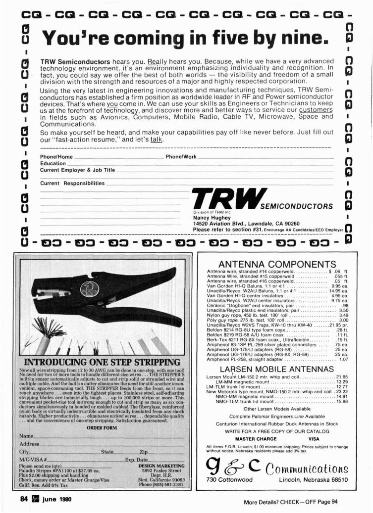
0 8 Yougre corning in five by nine. D I I
TRW Semiconductors hears you. B l y hears you. Because, while we have a very advanced 0 technology environment, it's an environment emphasizing individuality and recognition. In
0 . fact, you could say we offer the best of both worlds - the visibility and freedom of a small . division with the strength and resources of a major and highly respected corporation. 0 I
Using the very latest in engineering innovations and manufacturing techniques, TRW Semi- conductors has established a firm position as worldwide leader in RF and Power semiconductor devices. That's where y c come in. We can use your skills as Engineers or Technicians to keep us at the forefront of technology, and discover more and better ways to service our customers in fields such as Avionics, Computers, Mobile Radio, Cable TV, Microwave, Space and Communications. So make yourself be heard, and make your capabilities pay off like never before. Just fill out our "fast-action resume," and let's m. PhonelHome PhonelWork Education Current Employer & Job Title
Current Res~onsibilities
-- Lhv<s~on of TRW Irl:
I -- - Nancy Hughey I -- 14520 Aviation Blvd., Lawndale, CA 90260
Please re fe r to section #31. Encourage AA CandidaIeslEEO Employer 0 A
State-
I
- 4 1
'. ,' , I I' \ *.\, ,.+'\ ,,,
Y M I
\
INTRODUCING ONE STEP STRIPPING Now al l wire stripping from 12 to 30 AWG can be ?one i n one st? . with one tool! No nerd for two or more tools to handlo different s~ze wires. T~IE SI'RIPPER'S . . built-in sensor automnlicallv adjusts lo cut nnd strip solid or stmnrted wire and mllltiple cahle. Anrl tho built-in cutter eliminntes tho neod for slil l another inctm- venient. space-consuminp tool. TFlE STRIPPER fends from the front. so i t can ronrh anywhere.. . even into the tightest places. St;~inloss stnel. self-adjusting stripping blatles are intlustrially tough . . . up to 100.000 strips or morc. This convonit!nt pocket-size tool is strong enough to c r ~ t ant1 strip as manv as six con- ductors simult:~nnously i n bondcd or molded cables! The fiborg ced nvlon body is vir tr~al lv indestruc:tible and clectricnlly insulated ock hazards. I{ighc!r prtrrfuclivitv. . .eliminates nickotl wires. . . dep l i ly ... end the ~:onvc?nic!nce ol one-step strippiny. Satisfaction guar
ORDER FORM
Na Ac
Cii MIC-VISA # - Please send me (qty) [NG Paladin Stripex #PA1 100 nt $37.95 ea. et Plus 82.00 shipping and handling Check, money order or Mastcr Chargerv1an CaliC RRS. Add fi06 Tax Phone (805) 581-2181 -
Z i p -
............. ANTENNA COMPONENTS
Antenna wire, stranded #14 copperweld.. $ .06 ft. Antenna Wire, stranded # I5 coppenveld .............. ,055 ft.
............. ..................
Antenna wire, stranded #16 coppenveld.. .05 ft.
............. Van Gorden HI-Q Baluns. 1:l or 4 : l 9.95 ea. UnadillaIReyco. W2AU Baluns. 1 : l or 4:l 14.95 ea. Van Gorden HI-Q center insulators ................... 4.95 ea. UnadillalReyco. W2AU center insulators . r . . .......... 9.75 ea. Ceramic "Dogbone" end insulators, pair .................. .98 UnadillalReyco plastic end ~nsulators, pair.. .............. 3.50
.....................
..................... Nylon guy rope. 450 Ib. test, 100' roll 3.49 Poly guy rope. 275 Ib. test. 100' roll.. 3.00 UnadillalReyco W2VS Traps. KW-10 thru KW-40 ...... .21.95 pr. Belden 8214 RG-BU type foam coax.. .................. .28 ft. Belden 8219 RG-58 AIU foam coax. ................... .I 1 ft.
....... Berk-Tex 6211 R G d X foam coax.. Ultraflexible.. .15 ft. .... Amphenol 83-1SP PL-259 silver plated connectors .75 ea.
............... Amphenol UG-175lU adapters (RG-58) .25 ea. Amphenol UG-176lU adapters (RG-BX. RG-59). ....... .25 ea.
....................... Amphenol PL-258, stra~ght adapter 1.07
LARSEN MOBILE ANTENNAS I ............... Lanen Mount LM-150 2 mtr. whip and coil .21.65
............................ LM-MM magnetic mount .13.29 .............................. LM-TLM trunk l id mount.. .12.77
New Motorola type mount, NMO-150 2 mtr. whip and coil .23.22 ......................... NMO-MM magnetic mount . . 14.91
NMO-TLM trunk lid mount . . ......................... 15.98
Other Larsen Models Available
Complete Palomar Engineers Line Available
Centurion International Rubber Duck Antennas i n Stock
WRITE FOR A FREE COPY OF OUR CATALOG
MASTER CHARGE VISA
All items F.O.B. Llncoln. $1.00 minimum shipping. Prices subject to change without notice. Nebraska residents please add 3% tax.
g & c C 0 m m u n i ~ ~ t i o ) l ~ 730 Cottonwood Lincoln. Nebraska 68510
lass; reinfor from nny sh entlable qua ,nntoed.
84 june More Details? CHECK-OFF Page 94
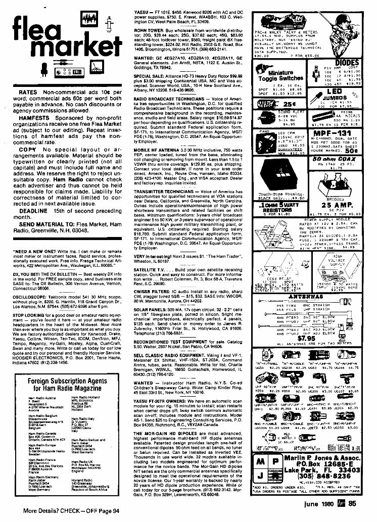
flea m t market RATES Non-commercial ads 10C per
word; commercial ads 60c per word both payable in advance. No cash discounts or agency commissions allowed.
HAMFESTS Sponsored by non-profit organizations receive one free Flea Market ad ( s u b j e c t to our editing). Repeat inser- tions of hamfest ads pay the non- commercial rate.
COPY No spec ia l layout or ar- rangements available. Material should be typewritten or clearly printed (not all c a p i t a l s ) and must include f u l l name and address. We r e s e r v e the right to r e j e c t un- suitable copy. Ham Radio cannot check each advertiser and thus cannot be held responsible for claims made. Liability for correctness of material limited to cor- rected ad in next available issue.
DEADLINE 15th of second preceding month.
SEND MATERIAL TO: Flea Market, Ham Radio, Greenville, N.H. 03048.
"NEED A NEW ONE? Write me. I can make or remake most meter or instrument faces. Rapid service, profes- sionally executed work. Free info. Frasga Technical Art- works, 422 Metropolitan Ave., Waukegan, ILL. 60085."
DX,YOU BET! THE DX BULLETIN - Best weekly DX info in the world. For FREE sample copy, send business-size SASE to: The DX Bulletin, 306 Vernon Avenue, Vernon, Connecticut 06066. - OSCILLOSCOPE: Tektronix model 541 30 MHz scope. without plug-in, $200. G. Hamlin. 118 Grand Canyon Dr.. Los Aiamos, N.M. 87544. (505) 672-9396 after 6 pm.
STOP LOOKING for a good deal on amateur radio equip- ment - you've found it here - at your amateur radio headquarters in the heart of the Midwest. Now more than ever where you buy is as important as what you buy. We are factory-authorized dealers for Kenwood, Drake, Yaesu, Collins, Wilson, Ten-Tec, ICOM, DenTron, MFJ, Tempo, Regency. Hy-Gain, Mosiey, Alpha, CushCraft, Swan and many more. Write or call us today for our low quote and try our personal and friendly Hoosier Service. HOOSIER ELECTRONICS. P.O. Box 2001, Terre Haute, indiana47802. (812) 23E1456.
Foreign Subscription Agents for Ham Radio Magazine
Ham RadIo Austria Ham Radio Holland F. Basll MRL Ectronlcs Hauptplalz 5 PostbusBB A-2700Wlener Nsustadt NL-22M Delft Auatrla Holland
Ham Radlo Belglum Stermohouse Ham Radla Italy Brusadwsteenwsg 4t6 G. Vulpsttl Be218 Ganl P.0 80x37 blglurn 1.22083 Canlu
Ham Radlo Canada Italy
Box 400 Goderlch 0ntulo:~anada N7A 4C7 Ham Redlo Switzerland
Ham Radlo Europe I(ar1n Box u 4 Po8Itach 2454 S1MM Uppl.ndB V.Sby ~ ~ ~ G ~ ~ ~ ~ h Sweden Ham Redlo Francs
Hm Redlo UK SM Eleclronlc 20 b~s. A V ~ den Clarions ~ P , . $ , " ~ e ~ A ~ ~ ~ ~ ~ F.BOOOO Auxsrra Frmce England Ham RadloGsrmany mrln Usbr Holland Radlo Postfwh 2454 143 Grwnvay D78M Lwrrach Grwnalda, Johannesburg West Germany Papubllc of South Afrlc.
YAESU - FT 101E. $450. Kenwood 8205 with AC and DC power supplies. $750. E. Kravat, WA4BBH, 103 C. Well- ington CV, West Palm Beach, FL33409.
ROHN TOWER: Buy wholesale from worldwide distribu- tor; 20G, $28.44 each; 25G, $37.62 each; 456, $83.60 each; 48-foot foldover tower. $860, freight paid; BX free- standing tower, $224.02. Hill Radio, 2503 G.E. Road, Box 1405, Bloomington, Illinois 61701. (309) 663.2141.
WANTED: GE 4EG27A10, 4EG28A10, 4EG28A11, GE General elements. Jim Arndt, NBTA, 1122 E. Austin St., Giddings, TX 78942. - SPECIAL SALE: Alliance HD-73 Heavy Duty Rotor $99.99 plus $3.00 shipping Continental USA. MC and Visa ac- cepted. Scanner World, USA., 10H New Scotland Ave.. Albany, NY 12208.518.436-9606.
RADIO BROADCAST TECHNICIANS - Voice of Ameri. ca has opportunities in Washington, D.C. for qualified Radio Broadcast Technicians. These positions require a comprehensive background in the recording, mainten- ance, studio and field areas. Salary range: $10.59$14.87 per hour depending on qualifications. U.S. citizenship re- quired. Submit standard Federal application form. SF.171, to international Communication Agency, MGTl PDE (1-78), Washington, D.C. 20547. An Equal Opportuni- ty Employer.
MOBILE HF ANTENNA 3.2-30 MHz inclusive. 750 watts PEP, center loaded, tuned from the base, eliminating coil changing or removing from mount. Less than 1.5 to 1 VSWR thru entire coverage. $129.95 ea. plus shipping. Contact your local dealer, i f none in your area order direct. Anteck, tnc., Route One, Hansen, Idaho 83334. (208) 422-4100. Master Chg., and VISA accepted. Dealer and factory rep. inquiries invited.
TRANSMlllER TECHNICIANS - Voice of America has opportunities for qualified technicians at VOA stations near Delano, California, and Greenville, North Carolina. Duties include operationslmaintenance of high power shortwave transmitters and related facilities on shift basis. Minimum qualifications: byears chief broadcast engineer 5 to 50 KW, or %years supervisor of operations1 maintenance high power military transmitting plant, or equivalent. U.S. citizenship required. Starting salary $18,760. Submit standard Federal application form. SF-171, to international Communication Agency, MGTI PDE (1-78) Washington, D.C. 20547. An Equal Opportuni- ty Employer.
VERY In.ter.est.lng! Next 3 issues $1. "The Ham Trader". Wheaton, IL60187.
SATELLITE T.V. . . . Build your own satellite receiving station. Quick and easy to construct. For more informa. tion write. . . Robert Coiemen, Rt. 3, Box W A , Travelers Rest, S.C. 29690.
CWlSSB FILTERS: IC audio install in any radio, sharp CW, stagger tuned SSB - $15, $32. SASE info: W8CBR, 80 W. Mennonite. Aurora, OH 44202. - SOLAR PANELS: 500 MA. 1 7 ~ open circuit. 32.2.2" cells on 118" fiberglass plate, potted in silicon. Slight me- chanical imperfections, electrically perfect. 4 panels. $125 each. Send check or money order to James R. Zubrecky, 116091/2 Friar St., N. Hollywood, CA 91606. Telephone: (213) 766.6831.
RECONDITIONED TEST EQUIPMENT for sale. Catalog $.50. Waiter, 2697 Nickel, Sen Pabio, CA 94806.
SELL CLASSIC RADIO EQUIPMENT. Viking I and VF-1, Meissner EX Shifter, VHF-152A, ST-203A, Command Xmtrs, tubes, parts. Reasonable. Write for list. Charlie Bremigan, WSWJL, 18650 Gottschaik, Homewood, IL 60430. (31 2) 798-61 20. - WANTED - instructor Ham Radio, N.Y.S. Co.ed Children's Sleepaway Camp. Write: Camp Kinder Ring, 45 East 33rd St.. New York, NY 10016.
YAESU FT.207R OWNERS: We have an automatic scan module for your rig. 15 minutes to install; scan restarts when carrier drops off; busy switch controls automatic scan on-off; includes module and instructions. Model AS-1. Send $25 to Engineering Consulting Services. P.O. Box 94355, Richmond, B.C., V6Y2A8 Canada. - THE MOR-GAIN HD DIPOLES are most advanced, highest performance multi-band HF dipole antennas available. Patented design provides length one-half of conventional dipoles. 50 ohm feed on ail bands, no tuner or balun required. Can be installed as inverted VEE. Thousands in use world wide. 22 models available in- cluding two models engineered for optimum perfor- mance for the novice bands. The Mor-Gain HD dipoles NIT series are the only commercial antennas specifically designed to meet the operational requirements of the novice license. Our 1-year warranty is backed by nearly 20 years of HD dipole production experience. Write or call today for our 5page brochure. (913) 682-3142. Mor- Gain, P.O. Box 329H. Leavenworth, KS66048.
june 1980 85 More Details? CHECK-OFF Page 94
COLLINS: 75S3B - $550: 30LI - $595; 31205 - $425: KWM2 - $495. All mint. Schaaf, Box 301, DePere, W1 541 15. (414) 532.6643. - HAM RADIO REPAIR, allgnment. Prompt, expert. reasonable. "Grid" Grldley. WIGJO, Route 2, Box 1388. Rising Fawn, GA 30738. - WE-WK) - sell lor 3325. Just reconditloned by Wilson. Purchased late 1979. Dan Shamanski. 1202 Inchon. Nor- folk. VA 2351 1. (804) 4844460.
ATLAS OWNERS DDgC and 350XL Dlgital DlallFrquen- cy Counters. $175.00 + Shipping (Calif. add tax). Mlcal Devlces. Box 343. Vista. CA 92083.
WANTED: Older tube radio for grandson. Ham band or general coverage. Worklng or not. J.D. Grigas, 1449 W. Ash Ave., Fullerton, CA 92633.
--
REPLACE RUSTED ANTENNA BOLTS with stainleas steel. Small quantilles, free catalog. Elwick. Dept. 378. 230 Woods Lane. Somerdale. N.J. 08083.
I
3 TERMINAL IN. OUT. GROUND ?-p) a 6 db INCREASE IN AVERAGE
POWER I
MAINTAINS VOICE QUALITY IMPROVES INTELLIGIBILITY NO CABLES OR BENCH SPACE REQUIRED
EXCELLENT FOR PHONE PATCH
NO ADDITIONAL ADJUST- MENTS - MIKE GAIN ADJUSTS MULTIBAND ANTENNAS1 Completely assembled,
tuned; half the length of a conventional dipole! Includes 90' RG58U, postpaid, guaranteed one lull year. 8010M. $59.95; 80-4OM, $55.95: 4010M. $49.95! Compare our prlces! MPV Eleclron~cs. Box 1133. Cumberland. MD 21502.
I CLIPPING LEVEL I S REQUIRED
t ransmi t ter d e s ~ g n s f o r amateur ,>-and mi l i ta ry use.
SMA CHASSIS MOUNT SQUARE FLANGE 15.60
TYPE N PLUG FOR RG-9lRG-B
RTTY - Solld state automatic OCer. Board with PROM programmed your call $21.50 Ppd. SASE for info. Nat Stinnette Electronlcs, Tavares. FL 32778.
SATELLITE N RECEPTION: =page "How-To" book. Complete reprlnt of Bob Cooper's 7.article series from Radio Electronics magazine. $8 postpaid. U.S. and Canada. All others add $3 postage. N.Y.S. residents add 488 sales tax. Satellite TV Reception. Box C. Radio Elec- tronics.45 E. 17th Street. New York. N.Y. 10003.
-
CALLETTERINAME.BADGE - 1' x 3' Engraved i n wood-grain appearing surface. 51.25 per Ilne. Send check to Engraving Speclallsts, Box 77. Ypsllanti. Michl- gan 48197. - NEW 6 USED HAM AND COMPUTER EQUIPMENT. Monthly publication. Subscription $5.00. Wrlte Nuts 6 Volts. P.O. Box 1111, Placentia. CA92670.
I Models Now Availabln I Collins 32S, KWM-2 ..... $ 985;0 ea. Drake TR-3, TR-4, TR-6, TR-4C, T-4, T-4X, T4XB. T-4XC $128.50 ea.
Postpaid - Cal~ f . Res~dents add 6% Tax
I Watch tor other models Imtmrl 1
FOR SALE: Kenwood TS-820s transceiver. Used 10 hrs and in mlnt condition. S700.00and will ship UPS.
WANTED: ElCO #720 or #723 xmtr, Halllcrafters HT40 xmtr and HA5 vfo. J. Titus. Box 242. Blacksburg, VA 24060. (703) 951-2684. sotron Antennas
T H E ULTIMATE space savers.. . I +-- + YAESU FT-207R OWNERS + AUTOMATIC SCAN MODULE
15 minutes to ~nstall: scan restarts when carrler drops off; busy sw~tch controls automatic scan on-off: ~ n - cludes module and Instructions. Model AS-1. Send $25.00 to ENGINEERING CONSULTING. P.O. Box 94355. Richmond. 8 C . V6Y2A8. Canada
MANUALS for most ham gear 193711970. Send 2% for "Manual Catalog." H.I.. Inc., Box H W . Council Bluffs, Iowa 51502.
for 80 and 40 meters
* 9.
or F Hsar on 7245 kHz Deslgned
and proved by WDBEJA
ICOM INTERNATIONAL USER'S CLUB. Details SASE NBRT, Pohorence. 9600 Kickapoo Pass. Streetsboro, Ohto 44240.
at 3 6 5 P M
MOT
40 M@t@n
3 11. 4 Ibs. 250 kHz' 3 3 1 coax $44.95
MOBILE IDNITION SHIELDING provides more range with no noise. Available most engines. Many other sup presslon accessories. Literature. Estes Engineerlng. 930 Marine Dr.. Port Angeles, WA 98362. I PAY CASH
for your military surplus electronics I f you have or know of availability:
TT-98 TT-76 Teletypewriter phone me collect
Dave - (21 3) 760-1 000
,
4 H It. 8 ibs. 110 kHz' m coax 554.95
Length Weight
Bandwidth Feed Prtce WANTED - Hallicrafters SR.150 or SR-160. Also Heath-
kit HA.10 Linear. Stale price and condition. N4CSV. 538 Raccaan Trail, Chattanooga, TN 37419.
'Llmlls for 2 1 SWR. center lrequency adjustable lmmn antmnn n d no radlals or malchlng devtces Feed wtlh 5Ml coax For lndwr or outdwr mountlna Excellenl lor
MINI HAM NEWSPAPER: Ham News. Building 6 conver- sion schematics, Advanced modulation highlights, Edi- torials. Letters. Much more, Five Issues 53.00. Press Ex- change. 60 Brookfield La.. Ramsey. NJ 07446.
COLLINS PAINT: All 3 S.Llne colors, factory fresh. Sacan plus U.P.S. WSQYH. 1805 Rldge Rd.. Green Bay.
all amateur uses.
BlLAL COMPANY (303) 687-3219
STAR ROUTE FLORISSANT, C0.80816
WI 54304. - BUY.SELL.TRADE. Send $1.00 for catalog. Glve name address and call letters. Complete stock of major brands new and recondilloned amateur radio equipment. Call lor best deals. We buy Collins. Drake, Swan, etc. Asso ctated Radio. 8012 Conser, Overland Park. KS 86204. (913) 381-5900.
BOOK FREE FLYER
Panel Mount Handy Logging Area
Whether you're interested in Ama- teur Radio, Electronics, Radio Astronomy, Old-Time Radio. VHF, SSB or just novels that involve Ama- teur Radio - you'll f i n d a large selection of these books and more! Vast inventory o f over 200 titles. Send your name and address to:
H A M RADIO'S BOOKSTORE Greenville, NH 03048
FOR SALE: Colllns Mechanical Fllters - F 500Y: F 500 F 94; F455 D 60; F455 Z 5 - all $20 each. F 250 A 20; F 200 L10;F112Z4;FBBM03;F76Z2;F76Z7-allS10each. Hank Olson. P.O. Box 339, Menlo Park. CA 94025.
I Spinner Handle Available Case: 2x4" : shaft X"x3" Coming Events ~ b d e l TC2: Sk i r t 2-1 18";
ode1 TC3: Sk i r t 3"; ONTARIO: Lake Simcoe Hamfest. June 13th, 14th and 15th, at Molson's Park. Barrie. Ontario. Canada. Reglstra- tion: $4 by mail. 55 at gate. Children under 18 admitted free. Doors open at 12:00 noon on Friday the 13th. with talk-in on VE3LSR 146.251.85 and 148.52 simplex. or 3780 kHz SSB. For information, reservations, or tickets, wrtle to Lake Simcoe Hamfest. P.O. Box 2283. Orillia. Ontario U V 6S1. Canada.
We'll send you our most current book flyer and add your name to our bookstore list
86 june 1980 More Details? CHECK-OFF Page 94
l O w r a 1 n - 7 5 w n a ~ ~
2 M w F M a S S B k n p M h
Canplete Kk Modd 875K Ssc ar&* in Scpt. 79 QST pgr 11-16
COMMUNICATION CONCEPTS.MC. 7.648 Norch Angm AK
~~~ DqRon.ONo45120 VISA CHARGE Phone (5W) 296-1411
UHF Klb ALa Avd*b* Ssd For FREE Data Shes
Brand name. first line components Stocked In depth 24 hour dellvery Low prices and money back guarantee on all products we carry
STAMP BRINGS CATALOG
I S P E C I A L S w D H PRICE* I
s2 UT4 SPEED CVTR BOARD SHlPmNG KIT $109.95
6 HANDLING BOARD ALONE 517.95 AUTO CW ID KIT $27.90
MAINE: Yankee Hamfest '80 sponsored by the Yankee Radio Club wlll be held on Saturday, June 28th at the Ox- ford County Fairgrounds. Oxford. Ladles and youth prc- grams, swap tables, buffet dinner. Tickets: $8 wlth din- ner, $7 in advance; for admission only 52.50. Camper hook-ups avallable at S21night. Talk.in on 146.28188, 146.52 simplex. For tickets and information send SASE to: Lynda Mount. 198 Cony Extension. August. ME 04330. - RADIO EXPO "W' Lake County falr grounds, Rt. 45 I3 120. Sept. 6 LL 7 - advanced tlckets $2.00, $3.00 at gate. Write: Radlo Expo Tickets, P.O. Box 1532, Evanston. IL 60204. Exhibitor Information call (312) BST.EXP0.
CALIFORNIA: 1880 Santa Maria Swapfest and BBO. Sun- day, June 15th. Best steak and biggest hamfest in the west. Prizes include the Yaesu FT-707. Swap tables avail. able. QLF and QBK contests. Tlckets $7 adults. $3.50 children 6-12, Write Santa Maria Swapfest. P.O. Box 1615, Vandeberg AFB. CA 93437 or call KA6AKC (805) 734-1380.
ILLINOIS The Jacksonville Area Amateur Radlo Club will hold Its annual Hamfest and Flea Market on June 15th, at the Morgan County Fairgrounds. Jacksonville. Indoor facilltles. lood available. Talk in on 52152. Tlckets $1.50 each or 4 for 55.00. Contact: Ken Gotsch, 213 Brookside, Jacksonvllle. lL82650.
MICHIGAN: Central Michlgan Amateur Repeater Assocl. ation's Swap I3 Shop. Midland. June 21st, at the Mldland County Fairgrounds. Computer demonstrations, door prizes. Talk.ln on: 148.73 WRBARB and 146.52 simplex. Tlckets and Info SASE to: R.L. Wert, W8001, 309 E. Gor. donville Rd.. R112. Midland, MI 48640.
MICHIQAN: The annual Monroe County Radio Communl- catlons Hamfest Is June 8th, from 8 a.m. to 4 p.m.. Monroe Community College. Monroe. Tlckets $1.50 - Xyl's and children free. Free parklng. Plenty of table space - contest, auction, displays. Talk In on: 148.1373 and 52. Contact: Fred Lux, WDBITZ, P.O. Box 982, Mon- roe. MI 48161 or ca11(313)243-1088.
OHIO: The annual Wood County Ham-A-Rarna wlll be held Sunday, June 29th at the Wood County Fair- grounds, Bowllng Green. Gates open at 10 a.m. with free admission and parklng. There wlll be drawlngs for prizes; tickets $1.50 In advance. $2.00 at door. Tables and trunk sales space available - advance table rentals to dealers only. K8TIH talk-in on .52. For more Info write: Wood County A.R.C.. c/o C. Falls. 201 Martendale. Walbridge. OH 43485. - NEW JERSET: The Rarltan Valley Rsdlo Club's annual Hamfest and Electmnic Flea Market, June 21st from 8 am. to 4 p.m. at Columbia Park. Dunellen. Club calls W2QW and WRZACS. For detalls write: RVRC. RD 3, Box 317. Somerset. NJ 08873, or call (201) 3588435. Talk-In: 146.0251.825, 146.52. Tickets $2; sellersS3. - OHIO: The Champalgwlogan Amateur M l o Club's an- nual Hamtest. Sunday. June 29, at the Memorial Hall. Belle Center. Tickets $1.50 advance. 52 at door; trunk and table space is $3.00 Talk-in on 146.52 slmplex. For more information wrlte: C.LA.R.C.. P.O. Box 837. Belle fontaine, OH 43311.
VlRQlNlk The Ole Vlrginla Hema A.R.C. of M a n ~ e ~ announce8 Its "Ouallty Hamfest" for June 181. Prince Wllllam County Fairgrounds - 112 rnlle south of Man- assas. Admission $3 - chlldren under 12 free; tallgater $2 addltional per vehicle. Indoor and outdoor exhibits. clinics, programs. breakf88t and lunch available. Talk in on: 37197 and 52 simplex. For more information wrlte: Dlck Fredrickson - W7MPU4.9511 Sudley Manor Drive. Manassas. VA 221 10.
ILLINOIS: The annual ABC Hmfaat aponaorad by the Six Meter Club of Chicago, wlll be h d d on Sunday, June 8th at Santa Fe Park, Wlllow Sprlngs. Plcnlc grounds, dlsplays, swapper's row, refreshments avallable - tlckets in advance $1.50. at gate 52. Talk In on 148.94 FM or WRSABC 37-97 (PKA). For tickets wrlte: Val Hellwig. K9ZWV. 3420 South 60th Court, Cicero. lL80850.
VlROlNlk Woilcahop: TRSBO Intertaclng and R o g m ming lor lnstrumentatlon and Contml. June a 2 7 . A hands-on workshop wlth partlclpants working wlth and designing Interfaces for TRSBO Microcomputer. For more infonnalion write: Dr. Llnda Leffel. CEC, Virglnla Tech. Blacksburg. VA 24061 - (703)981.5241.
WEST VIRQINIk The Trl-State Amateur Radlo AssocC tlon's Hamfest wlll ba held on June 7th and 8th at the Huntington Civlc Center. Huntlngton. Commercial and flea market space still available. Many OCtIvltleS planned for both amateurs and non-amateurs lncludlng banquet on Saturday nlght. Admission $3 for both days. Talk-in on 146.04/146.64. For further detalls wrlte: The Trl-State Amateur Radio Association, d o Phll Jones. WDBOTJ. 309 22nd Street West. Huntington. WV 25704.
Day tapro Electronics. Inc. 3029 N. WtLSHlRE LN . ARLINGTON HTS.. ILL. 80004
PHONE 312-870-0555
More D e t a i l s ? CHECK-OFF Page 94
NEW YORK: WA2JHD will be taking calls on June 14th from 10 a.m. to 12 midnight EDT for speclal OSL cards commemorating the sesqulcentennlal of the town of Amity. Call CQcentennlal on 3915 .t QRM.
* TELESCOPING (CRANK UP) *GUYED (STACK-UP) * TILT-OVER MODELS Easy to Insta l l . L o w P r l a s .
C r a n k - u p s to 100 It.
bur(irc(lon!iaFt. Van Yountod CnnlrYp
Alum. T o m
Seven* ne\n f inaer talke.,
from CUR1 19 ............... c E K 4 & C-MOI L l u x 8 K q e r $ 1 3 1 1
........... c EK-111: Abnn plus rpwdm* I4095 .............................. c Im l m h u c t a l a t ~ 124.95 ............................. c M480: MamoqMab 12495
............... c IM480: Inrtructo-MmuyM8b l7Q% .............. c KB480: M o m K8ybmrdM:b - 199%
..................... KB480a. M o m K q b m r d 34095 .............. BDC(: K 8 y 8 r - O n - A E h l p ( ~ ~ ~ 14%
75 5. Fa '78 051. Rdb Wt 75. lllR IY1'77-TO ................... WU3: IC. PCB. Sock#!. Manual 24%
......................................... 80444: Stml-Klt M95 ............. 8045: Mona K8ybmrbOnA-Chlp lC 5895
......... 8045-1; IC. PCB. FIFO. Sockets. M a d 89.95 ...................................... 8045.2: SmI-Klt 159B
................ 8048, Inltrudoklyrr-On-A-ChIp IC 4995 ......................................... BWgl; S8ml-Klt 7995
8047; Illelraga M8m-On-AGhlp lC ............ 3995 ......... 6047-1; IC. PCB. RAM. Sockets. M ln ln l 89.95
l l ( d S 1 . 7 5 m a l m I w ~ ~ a n d ~ IK44IM: Inrtruetok8yer (Mar '76 QSTl ........ P24.05
July 26 thru August 8,1980 Our 2lsr year of succes.~ful teaching
Boost your Ham Skills on the Blue Ridge
"A Vacation with a Purpose"
T w o weeks sa tu ra t i on l e a r n i n g p r o g r a m
in A m a t e u r Radio: . N o v i c e t o Gene ra l
Gene ra l or T e c h n i c i a n to A d v a n c e d
.Atlvanced t o A m a t e t l r E x t r a
E x p e r t I n s t r l ~ c t i o n s t a r t i n g a t your leve l .
C o d e ant1 T h e o r y in t l e p t h a l o n g with Friendly Amateurs , Who Care A l w r l t
Yotr.
----------------------------------. C. L. PETERS. K4DNJ. Director. Oak Hi l l Academy Amateur R a d ~ o Session Mouth of Wilson. Virginia 24363
Name- Call-
Address -- -
The Best Got Bett>
M O D E L 4381 RF POWER ANALYST
Thi ipgmat ion RF Wathneter wrth n~ne-mode
system vetsatility reads, IN STOCK QUICK DELIVERY
URHOllZED .- MnllWTw
a s s o c i a t e s 115 B E L L A R M I N E
ROCHESTER, M I 48063
CALL TOLL FREE
800-521 -2333 I N M I C H I G A N 313 - 375-0420
NEW HAMPSHIRE: The Mount Morlah Repeater Society will hold a DXpedltion at Mystery Hill, North Salem on June 7 8 8 from 18002 Saturday untll 18002 Sunday. Mystery Hlll is a 4000 year old astronomical observatory and pre-hlstorlc temple. Frequencies: Phone - 3980. 7280. 14280, 21380, 28580, 146.52; CW - 3550, 3710, 7050, 7110. 14050. 21050. 21110. 28150 - call sign: K1 MDX. For certificates send legal size SASE to Kt RCT. P.O. Box 123, North Salem, NH 03073.
TEXAS: Iiam.Com is hostlng the West Gulf Dlvision ARRL Convention at the North Park Inn, Dallas, on June 6, 7 6 8. For reservations write Ham.Com, InC.. Box 29340. Dallas. TX 75229 or call Tom Gentry at (214) 620-2784 and he will sign you up. - PENNSYLVANIA: The Mliton Amateur Radlo Club's Hamfest wlll be held June 8 at the Allenwood Firemen's Fairgrounds on U.S. Rte. 15. Allenwood. from 8 a.m. l o 5 o.m. Sellers' tickets In advance: $2.50. $3 at gate. XYL's and children free. Prizes, contests, indoor area available. food and beverages. Talk-In on 37/97 and 52 slmplex: club calls: K3FLT. WR3ADL. For further details call or write: Kenneth E. Hering, WA3IJU. R.D. 01. Box 381, Allenwood. PA 17810. (717)528-9168.
MARYLAND: Frederick A.R.C. Hamfest, June 15th, at the Frederick Falrgrounds, East Patrlck Street. Grounds open 6 a.m. for commercial and tallgatlng; breakfast available. Hamfest opens 8 a.m. for general admlsslon; donation $3 and $2 extra for tailgating: YLs and children free. Plenty f w d . drlnk, parking. Talk.in K3ERM 146.52 simplex. For more information, write Mike Staley, WB3LJK, New Market. MD 21774; or Hamfest Commit- tee. P.O. Box 1260. Frederick, MD21701. - WEST VIROINIA: OSO party, from 16002 21 June to 16002 22 June, wlth no operatlng tlme limlts. One con- tact for each statlon per band. Exchange OSO number. report, county (W.Va only), state or country. Only one un. assisted operator per statlon for award. Multiplier for QRP. Send logs to West Virginia OSO Party, Route 1-A. Box &A. Moorefield. West Virginia 26836.
PENNSYLVANIA: The Broadcasters' Amateur Radio Club wlll conduct Its Hamfest on July 13th from 9 a.m. to 4 p.m. at the Pocono Downs Race Track, Rt. 315, Wllkes- Barre. Unlimited outdoor and indoor space, refresh- ments, prizes; admission $2.50 - XYL's and children free. No additional charge for sellers. Gates open at 8 a.m. for set.up. Talk in 147.661.06 and 146.52. Contact: Charles Baltimore, WA3NUT (717) 8233101; B.A.R.C. 62 S. Franklln St.. Wilkes.Barre. PA. 18773.
"I find Amateur Radio is less complicated. much cheaper, and far less taxing than my former hobby."
I Digitrex Electronics
P A - 1 9 W i d e b a n d P rea rnp l l t l e r 2 l o 200 MHz Bnndrr#dlh(.3dB Pmnrsl
d 19 dB Caltr' 50 Ohms Input 6 Oulput Impdance
\ Tiny PC Board Siz.(710 ' r 1 5111 1 Absolutely NO Tvnnnp Rwulnd Extremely Stable Draws only 20MAelZVOC
only Great Way to Increase sonsnhny 01 Rece8v.11 Coun1.r~ etc '8.95 Fully Assembbd and Tested
r SOSnlppm I Ha, rim, Inslr~~1~)ns Prorlded. Full Wamntv
PflrtatJle 600 MHz . I ,d,, M,,, F,,,,,, Frequency Counter . I KII, ,,, I~KI H, Rmnlu18nn
.Aru.vnl>lc*l drld l e w d *FIIII .S4z? ( 5 tlrltme L x 2 Warrnnlv A x I . M
.BNC Whip Anten"., Opt 38 95
s59.95 z,,, I - C 0 D 0rd.r. W d c m
Digitrex Electronicm 1 1 I f +~n Iw t i ay.4 Oak
.75 mV Senr#rlv#Ir Mtrl, <IUI 4807 4 313651 9247
Plug-un. so ld state tube rpplacements
S-l ine per formance-so l id state! H e a t d iss ipat ion reduced 60%
G o o d b y e ha rd - to - f i nd t ubes U n l i m i t e d e q u i p m e n t l i f e
T U B E S T E R S cost less t h a n two tubes, a n d are guaranteed f o r so l o n g as y o u own y o u r S - l ~ n e .
s m W r i t e or p h o n e for B o x 535 specs a n d prices. Talmage, CA 95481 (707) 462-6882
Covers 100 to 179 999 M H r ~n 1 kHz steps with thumb-wheel dial Accuracy 00001 % at all fre- quencies Internal frequency modulation from 0 to over 100 kHz at a 1 kHz rate Spurs and noise at least 6068 below carrler RF output adjustable from 50 to 500mv across 50 ohms Operates on 12vdc @ M amp Price $299.95 plus sh~pplng.
In stock for ~mmediate shlpp~ng. Overnight delivery available a1 extra cost. Phone: (212) 468-2720.
VANGUARD LABS 196-23 Jamacia Ave. Hollis, NY 11423
DIPOLE.- ANTENNA CONNECTOR H O S I d ~ m ~ ha* c-x
5 0 2 % 3ocksl m o l M lnlo 01." I11IM 0t.lllr m y lo X C ~ P ~ CD.. R 259 plus 00 I..dlln. a 8 D C ~ D *eeos cor. ~ < m n o ~ a . r ~ n s t . ~ c t , o n = $0 rludsn Gurlrn lnd A t you! Osaia3 at I S M m 8 p l d C.~imsanmon~nruia!orr(l YYv
BUDWIG MFG. CO. PO BOX 829. Ramona. CA 92085 Ca. Res. add 6% Sales Tax
NOT A SUBSCRIBER?
DO IT TODAY! use the handy card between
pages 92 &93.
88 june 19130 More Details? CHECK-OFF Page 94
THE Vd PRODUCTSooo
wired for sound
. . . - - -. . . - Ust: $le9.00
.-. .-"" Ust: slls.00
In fact, each VJ Products 2 meter amplifier is HAND WIRED. The model 110 with 140 watts out, or the V-80 with 80 watts both feature parasitic coils delicately hand balanced to resonance. And each unit is individually tested and burned in. The heat sink, which totally surrounds each unit, insures cool operation with the cleanest FM or SSB signal on the air. Warranty? You Bet! 90 days on the power transistors and 1 full year on all other components. You can buy a 2 meter amplifier anywhere, but the VJ Products model ll0 and V-80 are only available at:
Call for quote! BDOSOM Askabout the V-J30 amp Power Supply coming soon
Electronics Supply, inc. 1548 McKlnney, Houston, Texas TI002, (n3) 6!JM2IM
NEXT MONTH IN
JULY &;,Er;s" Field Day Surplus Gold Mine DX Lessons Ham Radio Techniques And More . . .
You're missing an exciting magazine if you don't subscribe to Ham Radio Horizons. Try a subscription today. It's backed by our money back guarantee.
12 issues just "Z2" wri! GREENVIUE. NH 03048
&fit I VlealMC welcomed. Money back ll not oatlafled. -
8-POLE FILTER BANDWIDTHS IN STOCK I
[ 75s-38fC I 1 / 1 EQUALS OR E X C E L S S4W COLLINS UNIT ] *DIODE SWITCHING BOARDS available to permit 1 . 2 or more filters than those for wh~ch manufacturer provides room. SPECIFY make and model. Single-filter type: $1 2 Ainnail postpaid
Dual-filter type: $21 Airmail postpaid r=r res~dents add 4% (sales lax) (FOI1ElGN ADO $3 o a filter)
BROCHURE ON REQUEST Oerkr Inquiries Welwmed
More Details7 CHECK-OFF Page 94 j- 1- 11s 89
there's nothing like it at any price
MORSE PAK-B $350'' with all the receive features of MORSE PAK-A, it also is a complete MORSE KBD
i Features include:
1. S ~ e e d set from n KBD 5 to 80 wpm I I
2. Defeatable side tone 1 plmOm~~A"n 3 . 4 0 key full travel KBD
I -
4. 16 character transmit buffer
' \ 5. Displays received and transmitted text
6. Same excellent MORSE PAK-A receiver and demodulator
7. Relay keyed output for complete compatibility
8. Unbelievable price $350 plus $5 shipping 1
Trap D i p o l ~ luMeErs,
,,,u.". ... -....".<. ...,.=..- less than 6 ounces. r r vc ts l rnntrnl 17-15 1
and affix below. new address (or any
ctlons) ~n the space provided and we'll take care of the rest.
ham-- - 0 , - . . #
T I J ' i -.. ,--. --.. .-. ..., VDC. S25.95
. - .- , I rdd,n Allow 4-6 weeks for I
------a :.
8040 B Covers the Novice por- t i n n c 2nd rnnrn nn An
I L,". 0 2 " # #" 8 r , " , u " m . 7"
Pre-assembled: I and 80 meters for cw I Mode1 370- 1 1 I receiving. Only 3" by 5"
by 7" and 24 ounces! I
Power rated 2kW PEP, appmx. 11 0-ft span 1 589.95 I I
Complete with w l r e t raps Freedom@ i end insulators 50 ft RG-8/U, Fret? yourself from cws- I PL-259 connector heavy duty cast a l u m i n u m and stea- I 80 and 15 meters. Great I
for many old transmit- 1 t i te c e n t e r c o n n e c t o r . ! ters! S64.95
At your 4-Band (40 thru 70M).
B&W dealer, 55 ft model 370-73 also available. Dre- assembled only.
Madp 111 Rrrsrol Penrisylvanra by
Barker & Williamson Inc. 10 Carial Street Br~stol, PA 19007
- cur ~acuon. Magaz~ne
Greenv~lle. NH 03048
Thanks for helping us to serve you better. r-- \ / - - - 1
u 5 0,
a 0 1 AFFIX 3 ". GI
I I LARFL
Please add $2 per orcler, or $5 for ~0mblnb I
tions, for skipping1 handling. I I
--- I I HERE I
1202 E. 23rd Street i Lawrence, Kansas 66044
1111-11111-1-14
90 June 1- More De 'tails? CHECK-OFF Page 94
SPRING SALE
SDlina into summer with ' t h k sizzling titles
i * E yi! r 180 - --,ra~c
Apnl14 rnru May dl CLOSED SATURDAYS
ELECTRONIC COMMUNICATION (4th Edition) by Robert L. Shrader
Thls popular volume presents as slmply as poss~ble, the practical basic theory ot rad~o and electronics I n w ~ d e use as a college and technical school text, Electronic Communiutbn IS based on the latest sample ques- tlons from FCC Commerc~al Operator Llcense Exams and Amateur Exams. rearranged lnto a more effect~ve teachlng and learnlng order The author also prov~des checkup qulzzes every few pages to greatly relnlorce learn- Ing Its bold lace type and mult~ple d~agrams make 11 a pleasure to read W ~ t h careful, Independent home study t h ~ s book wlll enable you to pass any FCC Amateur Commerc~al Radiotelephone or Telegraph llcense exam including the radar and broadcast endorsements 783 pages 0 1 9 8 0
MH-57138 Hardbound $19.50
80 METER DXlNG by John Devoldere, ON4UN
Going tor 5 Band DXCC or just looking for a new DX challenge? This is pos~tlvely the last word on working 80 meter DX. The author combines his many years of 80 meter operating experience with that o l others to produce chapters on propagallon, antenna systems, slatlon equipment and interna- tlonal operating practices pecultar to 80 - all In a handy scrapbook tormal. What are the best tlmes to be on? What's the best antenna? You'll find answers to these and many more 80 meter questions. 80 pages. 01978 .
HR-80M Softbound $4.50
AEACOMI'UTEfUZED KEYER MODEL MK-1
The only law cost Microcomputer keyer available. Offers many unique featu are operator programma t
AMATEUR SINGLE SIDEBAND Originally by The Collins Radio Company
Ham Rad~o ~n cwperatlon with The Collins Radlo Group has reprinted what many cons~der "the blbie on Amateur slngle s~deband" T h ~ s softbound e d ~ t ~ o n leatures an lntroduct~on to SSB, nature of SSB s~gnals, excllers. RF h e a r ampl~f~ers, SSB receivers, tests and measurements, and what com- prises an Amateur SSB stallon Absolutely THE flnest publ~catlon available on SSB 143 pages 0 1 9 7 7 OHR-SSB Softbound 54.95
Ires whi ich
PRACTICAL ANTENNAS From the folks at SCELBI. PRACTICAL ANTENNAS IS not qulte l ~ k e any of the other ham antenna books Wrltten by a knowledgeable DX'er, thls new book 1s chock-full of helpful hlnts and suggest~ons on the how-to's o l
I puttlng up a super antenna system Chapters Include lnformat~on on des~gn and construction of pract~cal Yag~s, quads and wlre type antennas lns~de you'll also llnd a complete b~bl~ography ot antenna articles from the popular amateur publtcat~ons Charts and tables are des~gned to ellmlnate all those tricky calculat~ons And SCELBI has Included a list of computer generated beam headlngs from major population centers to all the countries of the world A new format, large easy-to read text and durable vlnyl cover make PRACTICAL ANTENNAS a "must' lor every amateur l~brary 0 1 9 7 9 U SC-PA $9.95
'recise speed conrrol2 to 99 WPM
'recise i eightin1
..I I.,.
'dash and ind 9.
)le dot ;
iatic "I:
idepen~ iemory. - Aelectable seml-autorr - .
;ingle output for keying any
dently : and das
,ua" ml - - -
itter. transmi anced Electronic Applications, Inc
, , "0, Lynnwood, WA 98036. Call 206/f /s-/3! :., P.O. Bc .--- --- ~
adio 's HAM RADIO'S BOOKSTORE GREENVILLE, NH 03048
AEA Brings you the Bmakthrough
june 1980 91 More Details? CHECK-OFF Page 94
adio's #ikStO. SAVE TIME & MONEY!
Shop By 1980 U.S. RADIO AMATEUR CALLBOOK Crammed full of the latest addresses and OSL lntormat~on You'll lind Boldface calls, names and addresses tor every l~censed Amateur In the U S - It's a llst that's more accurate than the FCC's Slow Scan TV directory The latest ARRL countries list Internat~onal Postal Inlo OSL Managers trom around the world Standard tlme charts A complete census of international Amateur populat~on PLUS MUCH MUCH MORE1 A super value at an amazingly low prlce The 1980 Callbook IS a perfect g~ t t tor trlends or tor yoursell 01979. OCB-US Softbound $16.95
THE 1980 FOREIGN CALLBOOK DXlng is a real joy. but 11's even better when you get back OSL cards lrom the countr~es vou ve worked The most imDortanf tool in oettlno those cards 1s to have a copy ot the 1980 Fore~gn Callbook on your oj;eratl;g table Sta- tlons are llsted by country, call, name and address In bold. easy-to-read type. You also get Great Clrcle Beam headlngs trom mator U S cltles. lnternat~onal Postal ~ntormat~on. DXCC Countrtes List. Worldw~de OSL bureaus. Standard trme charts and more Get the DX intormation you want. when you want 11 Order today (cll979 @ CB-F Soft bound $15.95
1980 ARRL HANDBOOK Internationally recognized and universally consulted, eve amateur should have the latest ed~t~on of the ARRL Radlo Amllsur's Han%ook. The new Handbook covers vlrt~ally all of the state-01-the-art developments In electronics theory and deslgn Novlces will tlnd 11 to be an lndlspensable study gu~de, wh~le the more advanced Amateur will enjoy bu~ldlng the many new projects IS Order AR-HBIO Soft bound $10.00 C Order AR-BBBO Hardbound $15.75
RADIO ANGELS by Paul Jerome Stack, WA6IPF
Thls excltlng book deplcts the herolc, glor~ous efforts of Amateurs around the world servtng thelr lellow man durlng the tomes of need Darlng res. cues, emergency assistance and human compassion all In one super volume Thls book was over Iwo years In the maklng Get your thrtlllng copy now1 160 pages @)I978 q HR-RA Softbound $4.50
GOING SAILING WITH AMATEUR RADIO Are you Inlo sa~llng? Then you need Golng Salllng - an extremely helpful book, especially lor the boating and yachtlng enthuslast who wants lo Incorporate Amateur Rad~o In hls ship s gear Whether 11 1s lust tor tun or salety measures, brlnglng Amateur Rad~o aboard makes a lot ot sense Next tlme you re headed lor sea, take Amateur Radlo and a copy of thls great new book lor long-range rad~o communlcatlons 64 pages 01978 C HR-GS Softbound $3.95
THE GOLDEN YEARS OF RADIO Thls excltlng book trom The Ham Radio Publlshlng Group captures the new excitement (and the trustrations) ot the glor~ous bygone days of Rad~o's early years ... the dlscover~es, people and events. You can dig lnto radlo's oast w~ th thls tlne book and aaln lnslaht Into Amateur Radto s herltaae 64 pages. 01978. UHR-GYR Softbound 53.95
1 ANTENNA BOOKS by Bill Orr, W6SAI ALL ABOUT CUBICALQUAD ANTENNAS The cublcal quad antenna IS cons~dered by many to be the best DX antenna because ot 11s slmple, l~ghtwetght des~gn and h~gh pertormance In B~ l l Orr's latest edlt~on of th~s well known book, you II tlnd quad deslgns tor everyThtng trom the slngle element to the multi-element monster quad, plus a new, h~gher galn expanded quad (X.0) des~gn There's a wealth ot sup- plementary data on constructton. teedlng, tuning, and mountln quad antennas It s the most comprehensive slngle edlt~on on the cu%tcal quad ava~lable 112 pages Qt977
RP-CO Softbound $4.75
SIMPLE LOW-COST WIRE ANTENNAS Learn how to build slmple, econom~cal wlre antennas Even 11 you don't know a leedllne from a teed4hrough. W6SAl will gel you on the alr w~th an effective low-cost wlre antenna And, apartment dwellers take notel Fool your landlord and your ne~ghbors w~th some of the 'lnvls~ble" antennas found here For the old41mer as well as the beginner. 11's a clearly wrltten. well diagramed, and even humorous antenna book 192 pages a1972 ORP-WA Softbound $5.95
BEAM ANTENNA HANDBOOK Here's recommended readrng tor anyone thlnkrn about puttlng up a yagi beam thls year It answers a lot of commonly asied questions l~ke What Is the best element spacing? Can d~tlerent yagl antennas be stacked w~thout loslng performance7 Do monoband beams outperlorm tr~banders? Lots of constructlon projects, d~agrams and photos make reading a pleasurable and lnformatlve experience 198 pages P I 9 7 7 URP-BA Softbound $4.95
THE RADIO AMATEUR ANTENNA HANDBOOK by William I. Orr, W6SAI and Stuart Cowan, W2LX
It you are pondering what new antennas to put up, we recommend you read thls very popular book It contams lots of well ~llustrated constructlon prop ects lor vertical long wire, and HF/VHF beam antennas But, you ll also get lnformat~on not usually found In antenna books There 1s an honest judgment ot antenna gatn 11 ures. ~ntormat~on on the best and worst anten. na iocat~ons and he~ghts, a Yona look at the Quad vs the yaql antenna. lntormat~on on baluis and how-to use them, an0 some new intormat~on on the ~ncceastnatv oooular Slooer and Delta Looo antennas The text 1s based on proven daiaplus pract~cal, on-the.a~r exper~ence We don't expect you'll agree w~th everything Orr and Cowan have to say, but we are convinced that The Radlo Amateur Antenna Handbook w~l l make a valuable and otten consulted addltlon to any Ham's llbrary 190 pages a1978 URP-AH Softbound $6.95
THE WORKS. ALL FOUR BOOKS $22.60 VALUE - JUST $18.95
ORP-OL FOUR BOOKS $18.95
adio 's
IEW NEW NEW NEW NEW YNER REPAIR OF RADIO EQUIPMENT , by Frank Glass, K6RO le successful repabr ot any devlce resu!!s In restoring 11s operation at
to the level 11 had lust before 11 q u ~ t W ~ t h thls baslc concept In , author Frank Glass glves you step by step lnstructlons on how to
Ir all klnds of electronlc equlpment Fourteen chapters cover every I bct 01 repalr procedure from component use and tallure and how to read /rnat~c d~agrams to a most Important subject. safety This book IS a I lor the amateur.new to servlclng h ~ s own equlpment 85 b s 0 1 9 7 9 bO-OR Softbound $7.95
ests, satellites. RTTY and Slow Scan Telev~slon You also get 5 blg 1 nd~xes lam ~ a c k e d wlth more ~ntormat~on, callslgns In use, maps. C country Ilst. tlme zones and lnternat~onal calls~gn ass~gnments 190
k-tt79 Softbound $9.95
/Bo 34th EDITION IRLD RADIO & TV HANDBOOK world s on y complete reference gtllde lo lnlernat~onal rad~o and televl.
Tnls 1980 eoltlon has comDlete ~ntormat~on on each slatcon lncludlna
Softbound $14.95
ORTWAVE PROPAGATION HANDBOOK Edited by George Jacobs, W3ASK, and Theodore J. Cohen, N4XX any hams both new and old rad~o wave propagallon 1s st111 a mys Reallzlng th~s , the authors went about the task 01 preparing a Slmpll. ext that could be understood by hams, swl's and engineers allke I
6s has been glven to s ~ m p l ~ l ~ e d explanat~ons and charts The authors detall a slmplll~ed method ol do-11-yoursell propagallon forecastlng To I t your forecasting eltorts. the book contalns a complete llstlng 01 the honth smoothed sunspot numbers slnce 1749 J o ~ n those who know to pred~ct when the bands w~l t open to specttlc areas 01 the h ic)lq79
TUNE IN THE WORLD WITH HAM RADIO by ARRL staff
Learn what Amateur Radlo is, how to pass your Nov~ce exam and how to talk to other hams In the U S and around the world Tune In the World With Ham Radio glves an excitlng overvlew of ham radio h~ghllghtlng varlous lacets ot this great hobby In addltlon. 11 has everylhlng you need to pass the Nov~ce exam - lrom a plaln talk, bas~c rad~o electronics manual and study gu~de to a Morse Code cassette lnstructlon course - here In one package Tens of thousands 01 hams have started w ~ t h this package UAR-HR Complete package $7.00 Includes booklet, study guide. and cassette tape.
GENERAL CLASS AMATEUR LICENSE STUDY GUIDE
by Phil Anderson, WlXl This book was wrltten in simple laymen's language with uncomplicated explanat~ons and examples used to present electronic radio concepts and Ideas. Throughout each chapter, questlons and answers are used to strengthen your understanding 01 the terms and concepts presented. This book also covers several methods that can be used to Improve code recep- tlon Skills. The llnal chapter IS a sample FCC exam whlch the author feels he would ask 11 he were to glve the FCC exam. 160 pages. (91979. U 21 61 7 Softbound $6.50
* , , ,~ ,~ . .* l $ L ) , *
234; ADVANCED CLASS TEST GUIDE
bv Dick Bash. KL71HP Based upon the FCC exam syllabus and feedback lrom actual test expert- ences, this new book IS probably one 01 the best study gu~des ava~lable today Over 190 sample questlons cover each major subject area cornplete- ly You also get helpful hlnts on how to study successlully and on how to prepare yourself mentally belore you take the exam You aren t lully pre- pared 11 you don7 have t h ~ s book 0 1 9 7 9 ODB-FE Softbound $9.95
KANTRONICS THEORY CASSETTE Here's a new. easy way to study theory tor your Novice. General. Advanced or Extra class exam. Deslgned tor folks on the run. All you have to do IS drop In the cassette at home, work, or in the c2r and listen lo an interview- style tape coverlng Novlce. General. Advanced or Extra class theory. A great way to reenforce other study methods UKT-NT Novice Class Theory Cassette One tape $4.95
KT-GT General Class Theory Cassette TWO tapes $8.95 OKT-AT Advanced Class Theory Cassette One tape $4.95 OKT-ET Extra Class Theory Cassette One tape $4.95
~I-PH- - $7.50
mmmmmuwmwmmmmmwmmmmmmmmmmmmmmmmmmmmmmmmmm~ : Send me the books I 've checked below. ORDER FORM rn rn . . . . . i ,CB-US. . . . . . . . . $16.95 . ,CB-F. . . . . . . . . $1 5 95 :HR-RA $4.50
. . . . . . . . . . . . . . . . . . . . . . . I N A HURRY? L:AR-HBBO.. $10.00 UHR-GS $3 95 ; IHR-GYR $3.95 . . . . . . . . . . . . . . . . . . . . . . . . . ORDER
C!AR-BBBO $15.75 URP-CQ. $4.75 !IlRP-WA $5.95 . . . . . . . . . . . . . . . . . . . . . . . . . . . . . I . . . . . . . . . . . . . . .
CRP-BA $4.95 U R P - A H . $6.95 CAP-OL $18.95
TOLL FREE : E R R - O R $7.95 G A S - O M $9.95 G W R - T V $14.95 . . . . . . . . . . . . . . . . . . . . . . . . . . . GCR-PH. $7.50 L A R - H A $7.00 Li21617. $6.50
. . . . . . . . . . . . . . . . . . . . . . . . . . . . . -800-258-5353 COB-FE. $9.95 UKT-NT. $4.95 LKT-GT. $8.95 rn : L ' K T - A T . . . . . . . $4.95 C KT- IT . . . . . $ 4.95 Tk] : .Check o r m o n e y order enclosed V I S A rn q Master Charge . m rn rn Acct. # Expires M C Bank #
Mail payment and order form to: rn : N a m e Cal l rn am Radio's Bookstore : Add,ss rn
Greenville, NH 03048 rn c i t y rn Sta te z i p ¤
rn Please include $7 .00 additional for shipping
rn m mmmmmmmmmmmmmmmmmmmmmmmmmmmmmmmummmmmmmmmm
Awertsers v' check-off
. ... for literature. in a hurry we'll rush your name to the companies whose names you "check-off" Place y o u r check m a r k in t h e space e tween n a m e a n d n u m b e r . Ex: Ham Radio J234
INDEX 1 AED - 710 AEA - 677 w s k a Microwave - 826 Aluma - 589 Amidon - 005
Antenna Mart - 009 Astron - 734 Atlantic Surplus " B & K Precision - 799 Barker
Williamson - 015 Barry ' Bauman - 017 Bencher - 629 Bilal - 817 Budwig 233 Comm . Concepts - 797 Comm . Spec . - 330 Curtis Electro - 034 DCO - 324 DX Eng . - 222 Dave ' Daytapro - 455 Design Marketing ' Digitrex - 823 E . T . 0 . " Elec . Research Virginia ' Eng . Consulting ' Fox-Tango 657 G & C Comm . - 754 GLB - 552 Gregory Hal Hal-Tronix - 254 H . R . Bookstore - 150 Horizons H . R . Magazine ' Heath -
Henry - 062 Hickok - 402
lcom . I Int . Crystal - 066 Jameco - 333 Jones - 626 Kantronics Kenwood Larsen - 078 Long's - 468 MFJ 082 MHz Elec . - 415 Madison - 431 Microcraft - 774 Morse Pak - 809 N-Pro - 836 Oak Hill Academy A . R . S . ' OK Machine - 622 P.C. Elec . - 766 Palomar Eng . Pip0 481 RCA Distr . - 782 Callbook - 100 Radio World Radios Intnl . - 838 Ramsey - 442 SEANARC ' Skytec - 704 Space 107 Spectronics - 191 Spec . Int . - 108 TRW Telrex Ten-Tec Vanguard Labs - 716 Varian - 043 Webster
Assoc . - 423 Western Elec . Wilson Sys . - 787
Yaesu - 127
'Please contact this advertiser directly . Limit 15 inquiries per request .
June. 1980 Please use before July 31. 1980
Tear off and mail to HAM RADIO MAGAZINE . "check off" Greenville. N . H . 03048
NAME . . . . . . . . . . . . . . . . . . . . . . . . . . . . . . . . . . . . . . . . .
CALL . . . . . . . . . . . . . . . . .
STREET . . . . . . . . . . . . . . . . . . . . . . . . . . . . . . . . . . . . . . .
CITY . . . . . . . . . . . . . . . . . . . . . . . . . . . . . . . . . . . . . . . . .
STATE . . . . . . . . . . . . . . . . . . . ZIP . . . . . . . . . . . . . . . . . . .
94 june 1980
+
JUNE JOULES ALPHA 76.374. 78 in Stock ......... Call
. . . . . . . . . . . . . . Cushcraft "boomer" 69.95 . . . . . . . . . OMNI-J 2 Meter Antenna 39.95
Bird 43 and slugs. UPS paid in USA .stock Microwave Modules. Less 10% off list
stock .......... Telrex TB5EM. in stock 41 5.00
. . . . . . . . . . . . . . . . . Telrex TB6EM 520.00 . . . . . . Complete Line Monobanders .stock
New Telrex TB5ES. 2KW ... . . . . . . . . . . . . . . . Pep version 31 5.00
New Palomar Transceiver preamp . 89.50 . . . . . . . Bencher Paddles. Standard 39.95
. . . . . . . . Bencher Paddles. Chrome 49.95 . . . . . . Vibroplex Paddles and bugs .stock
Lunar 6M-2M-220 In-line Preamps . .stock Janel QSAd .................... 41.95
. . . . . . . . . HAM-X Tailtwister Rotor 239.00 . . . . . . . . . . . . . . . . . . . HAM-4 Rotor 169.00
. . . . . . . . . . . Cetron or GE 5728 .3 2.00Iea . . . GE. AMPEREX. Raytheon 61468 9.95
. . . . . . . . . . . . . . . . . Motorola HEP170 0.29 Mallory 2.5A/1000 PIV Epoxy diode . . 0.19
. . . . . Sprague 100MFD/450VDC Cap 2.00 Aerovox 1000PF/500V Feedthru Cap 1.95
. . . . . . . . . . . . . . . . . Adel Nibbling Tool 8.45 Technical books: Ameco. ARRL. Sams.
TAB. Rider. Radio Pub., Callbook. Cowan. WRTVH. etc . . . . . . . . . . . . . Call
New Belden 9405 (2#16) (6#18) 8 wire Rotor cable. heavy duty for
. . . . . . . . . . . . . . . . . . . . long runs 0.38Ift 8448 8 wire Rotor Cable . . . . . . . . . 0.24/H 9888 Double Shield PG8 Foam . . . 0.56/ft 8214 RG8 Foam . . . . . . . . . . . . . . . 0.32/ft 8237 RG8 Regular . . . . . . . . . . . . . . 0.28/ft
. . . . . . . . . . . . . . . . . . . 8267 RG213 0.361H 9251 RG8 A/U . . . . . . . . . . . . . . . . . 0.421ft Belden #8000 14GA
. . . . . . . . . Stranded Antenna wire 0.1 Olft Amphenol Silverplate PL259 (831SP) 1.00
. . . . . . . . BerMex RG8X 52 OHM KW .O.lg/ft . . . . . . . . . Robot "Slow Scan" 400 549.00
Need a schematic? We've got'em - $2.00
ICOM IC 2A HANDHELD WITTP. battery pack. Rubber Duck and charger $229.00
Looking for antique parts? Write specific need to W5GJ .
THIS MONTH'S SPECIALS: New IC701. AC. MIC $1 195.00.
New ICOM. IC251A -2M $599.00. IC551D - 6M-100W $599.00.
IC551 $399.00 . . . . . . . . . . . . . Dentron GLAl OOOB 295.00 . . . . . . . . . . . . Dentron Clipperton L 599.00
. . . . . . . . . . . . . . . Bearcat 250. 220 299.00 . . . . . . . . . . . . . . . . . . . Bearcat 300 399.00
MASTERCHARGE VISA All prlceh fob Houston except where indicated . Prices subject to change without notice, all items guaranteed . Some Items subject prior sale . Texas residents add 6% tax . Please add postage estimate . $1 . 00 minimum .
LI!DOSQM Electronics Supply, Inc .
1508 McKinney Houston. Texas 77002 7131658-0268
. . . . . . . . . . . . . . . . . . . . . . . . . . . . . . . . AED Electronics 95 Advanced Electronics Applications . . . . . . . . . . . . . . . . . . 91
Alaska Microwave Labs . . . . . . . . . . . . . . . . . . . . . . . . . . 86
Aluma Tower Co . . . . . . . . . . . . . . . . . . . . . . . . . . . . . . . . 87 Amidon Associates . . . . . . . . . . . . . . . . . . . . . . . . . . . . . . 80
. . . . . . . . . . . . . . . . . . . . . . . . . . . . . . . . . . AntennaMa rt 81
. . . . . . . . . . . . . . . . . . . . . . . . . . . . . . Astron Corporation 81 . . . . . . . . . . . . . . . . . . . . . . . . . . . Atlantic Surplus Sales 50
. . . . . . . . . . . . . . . . . . . . . . . . . . . . . Barker &Williamson 90
. . . . . . . . . . . . . . . . . . . . . . . . . . . . . . . Barry Electronics 32
. . . . . . . . . . . . . . . . . . . . . . . . . . . . . R H Bauman Sales Co 86 . . . . . . . . . . . . . . . . . . . . . . . . . . . . . . . . Bencher. lnc 50.80
. . . . . . . . . . . . . . . . . . . . . . . . . . . . . . . . . Bilal Company 86 . . . . . . . . . . . . . . . . . . . . . . . . . . . . . . . . . Budwig Mfg Co 88
. . . . . . . . . . . . . . . . . . . . . . Communication Concepts Inc 87
. . . . . . . . . . . . . . . . . . . . . Communications Specialists 10. 11
Curtis Electro Devices . . . . . . . . . . . . . . . . . . . . . . . . . . . . 87 . . . . . . . . . . . . . . . . . . . . . . . . . . . . . . . . . . . . . . DCO. lnc 67
. . . . . . . . . . . . . . . . . . . . . . . . . . . . . . . . DX Engineering 86 Dave . . . . . . . . . . . . . . . . . . . . . . . . . . . . . . . . . . . . . . . . . 86
Daytapro Electronics . . . . . . . . . . . . . . . . . . . . . . . . . . . . 87 . . . . . . . . . . . . . . . . . . . . . . . . . . . . . . . Design Marketing 84 . . . . . . . . . . . . . . . . . . . . . . . . . . . . . . Digitrex Electronics 88
Ehrhorn Technological Operations . . . . . . . . . . . . . . . . . . 87 Electronic Research Corp . of Virginia . . . . . . . . . . . . . . . . 82
. . . . . . . . . . . . . . . . . . . . Engineering Consulting Services 86 . . . . . . . . . . . . . . . . . . . . . . . . . . . . . . . . Fox-TangoCorp 89
G & C Communications . . . . . . . . . . . . . . . . . . . . . . . . . . 84
. . . . . . . . . . . . . . . . . . . . . . . . . . . . . . . . GLB Electronics 82 . . . . . . . . . . . . . . . . . . . . . . . . . . . . . Gregory Electronics 91
Hal Communications Corp . . . . . . . . . . . . . . . . . . . . . . . . . 7
. . . . . . . . . . . . . . . . . . . . . . . . . . . . . . . . . . . . Hal-Tronix 66 . . . . . . . . . . . . . Ham Radio's Bookstore 50.57.86.91.92.93
. . . . . . . . . . . . . . . . . . . . . . . . . . Ham Radio Horizons 82.89 . . . . . . . . . . . . . . . . . . . . . . Ham Radio Magazine 78.86.90
. . . . . . . . . . . . . . . . . . . . . . . . . . Henry Radio Stores Cover ll
. . . . . . . . . . . . . . . . . . . . . . . . . . . . . . . . . . . . . . . . . lcorn 5 . . . . . . . . . . . . . . . . . . . . . . . International Crystal Mfg . Co 79
. . . . . . . . . . . . . . . . . . . . . . . . . . . . . Jameco Electronics 41 . . . . . . . . . . . . . . . . . . . . . Jones . Marlin P . &Associates 85
. . . . . . . . . . . . . . . . . . . . . . . . . . . . . . . . . . . . Kantronics 90 . . . . . . . . . . . . . . Trio-Kenwood Communications. Inc 48.49
. . . . . . . . . . . . . . . . . . . . . . . . . . . . . . . Larsen Antennas 67 . . . . . . . . . . . . . . . . . . . . . . . . . . . . . . Long's Electronics 96
MFJ Enterprises . . . . . . . . . . . . . . . . . . . . . . . . . . . . . . . . 4
. . . . . . . . . . . . . . . . . . . . . . . . . . . . . MHz Electronics 74-75
. . . . . . . . . . . . . . . . . . . . Madison Electronics Supply 89.94
. . . . . . . . . . . . . . . . . . . . . . . . . . . Microcraft Corporation 83
MorsePak.Inc . . . . . . . . . . . . . . . . . . . . . . . . . . . . . . . . . 90
. . . . . . . . . . . . . . . . . . . . . . . . . . . . . . . . . . . . . . . . N-pro n . . . . . . . . . . . . Oak Hill Academy Amateur Radio Session 88
. . . . . . . . . . . . . . . . . . . . . . . . . . . . . . . . P.C. Electronics 67
Palomar Engineers . . . . . . . . . . . . . . . . . . . . . . . . . . . . . . 57
Pipo Communications . . . . . . . . . . . . . . . . . . . . . . . . . . . 50
. . . . . . . . . . . . . . . . . . . . . . . . . . Radio Amateur Callbook 71
Radioworld . . . . . . . . . . . . . . . . . . . . . . . . . . . . . . . . . . . 80
Ramsey Electronics . . . . . . . . . . . . . . . . . . . . . . . . . . . . . 45
. . . . . . . . . . . . . . . . . . . . . . . . . . . . . . . . . . . . SEANARC 69
Skyrec . . . . . . . . . . . . . . . . . . . . . . . . . . . . . . . . . . . . . . 88
. . . . . . . . . . . . . . . . . . . . . . . . . . . . . . . Space Electronics 50
Spectronics . . . . . . . . . . . . . . . . . . . . . . . . . . . . . . . . . . . 95 . . . . . . . . . . . . . . . . . . . . . . . . . . . Spectrum International 56
TRWSemiconductors . . . . . . . . . . . . . . . . . . . . . . . . . . . 84
Telrex Laboratories . . . . . . . . . . . . . . . . . . . . . . . . . . . . . . 83
. . . . . . . . . . . . . . . . . . . . . . . . . . . . . . . . . . . . . . Ten-Tec 9
VanguardLabs . . . . . . . . . . . . . . . . . . . . . . . . . . . . . . . . . 88 . . . . . . . . . . . . . . . . . . . . . . . Varian, Eimac Division Cover IV
Webster Associates . . . . . . . . . . . . . . . . . . . . . . . . . . . . . 88
Western Electronics . . . . . . . . . . . . . . . . . . . . . . . . . . . . . 83 . . . . . . . . . . . . . . . . . . . . . . . . . . . . . Wilson Systems, Inc 1
. . . . . . . . . . . . . . . . . . . . . . . Yaesu Electronics Corp Cover Ill
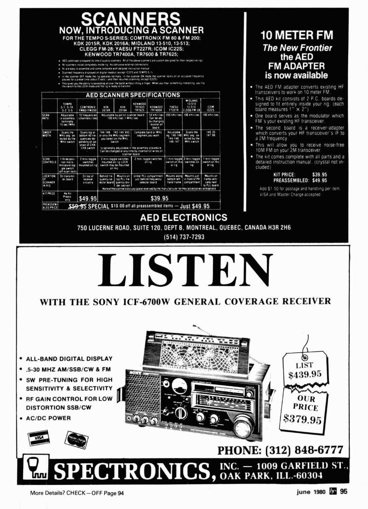
LISTEN WITH THE SONY ICF-6700W GENERAL COVERAGE RECEIVER
ALL-BAND DIGITAL DISPLAY
.5-30 MHz AM/SSB/CW & FM
SW PRE-TUNING FOR HIGH SENSITIVITY & SELECTIVITY
RF GAIN CONTROL FOR LOW
DISTORTION SSB/CW
AC/DC POWER
PHONE: 1312) 848-6777 1
More Details? CHECK-OFF Page 94 june 1980 95
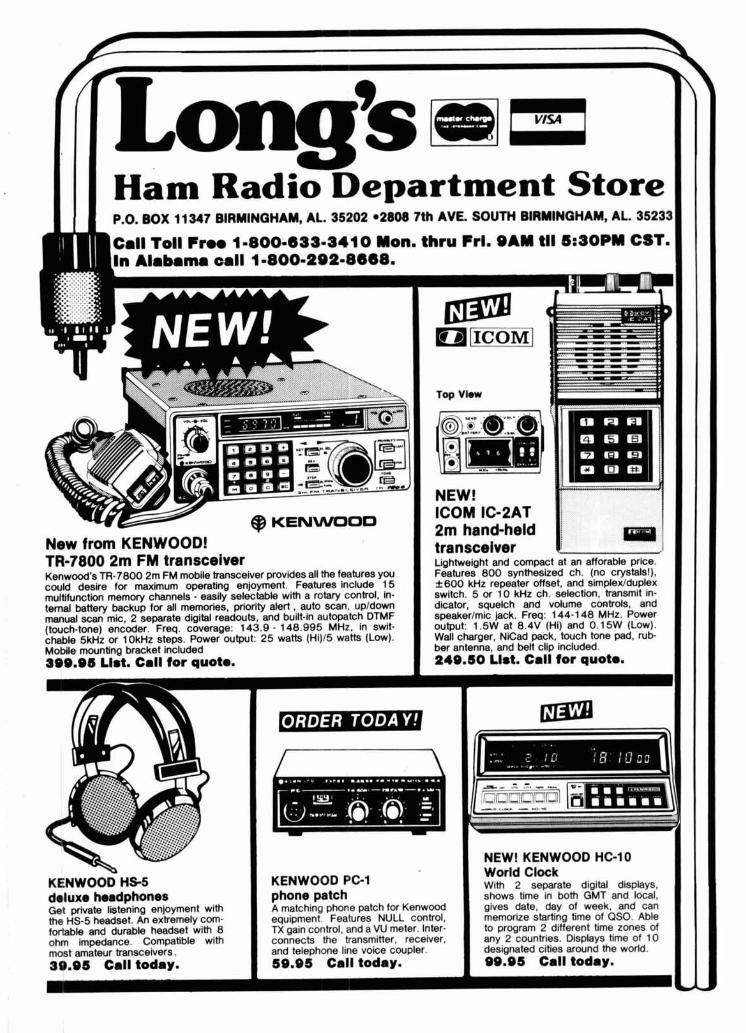
P.O. BOX 11 347 BIRMINGHAM, AL. 35202 02808 7th AVE. SOUTH BIRMINGHAM, AL. 35233
Call Toll F m 1-800-699-8410 Mon. thru Frl. SAM tll 5:SOPM CST. In Alabama call 1-800-292-8668.
New from KENWOOD! TR-7800 2m FM transceiver Lightweight and compact at an afforable price. Kenwood's TR-7800 2m FM mobile transceiver provides all the features you Features 800 synthesized ch. (no crystals!). could desire for maximum operating enjoyment. Features include 15 2600 kHz repeater offset, and simplex/duplex multifunction memory channels - easily selectable with a rotary control, In- switch. 5 or 10 kHz ch. selection, transmit in- ternal battery backup for all memories, priority alert, auto scan, upldown dicator, squelch and volume controls, and manual scan mic, 2 separate digital readouts, and built-in autopatch DTMF speakerlmic jack. Freq: 144-1 48 MHz. Power (touch-tone) encoder. Freq. coverage: 143.9 - 148.995 MHz, in swit- output: 1.5W at 8.4V (Hi) and 0.1 5W (Low). chable 5kHz or 10kHz steps. Power output: 25 watts (Hi)15 watts (Low). Wall charger. NiCad pack, touch tone pad, rub- Mobile mounting bracket included ber antenna, and belt clip Included. 399.95 List. Call tor quota. 249.50 List. Call tor quota.
I 1 NEW! KENWOOD HG10 World Clock I
KENWOOD HS-5 KENWOOD PG1 drlm.rr h r m r ( n h n n r e 1 nhone rmkh Ger prtvare Ilsrerilr the HS-5 headset. nn exlrwrllaly GUIII-
fortable and durable headset with 8 ohm impedance. Compatible with most amateur transceivers. 39.96 Call today.
-- -. .- -.--.- With 2 separate digital displays, I showq me in mth aur and local. I -,YAW ..--..,m .".."" r---"- r-----
I - . . - . . - . . . . . - . . . - - . . . - . . . . - - . . - A - ,.-*--: -~p enjoyment with I A matching phone patch for Kenwwd gives date, day of week, and-can ._ _ _ _ L _ _ _ I . . --... equipment Features NULL control, memorize starting time of QSO. Able - --: n control, and a VU meter. Inter- to program 2 different time zones of
ctP the trancmitter receiver. anv 2 countries. Dis~lavs time of 10 I I A yall conne,., .. ." .. -. .-. . , . . -. . and telephone line voice coupler. 59.95 Call today. I
2 - - - designated cities around the world. 99.95 Call today. I
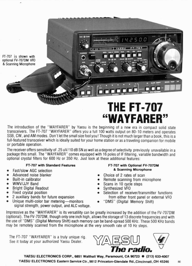
"WAYFARER" The introduction of the "WAYFARER" by Yaesu is the beginning of a new era in compact solid state transceivers. The FT-707 "WAYFARER" offers you a full 100 watts output on 80-10 meters and operates SSB, CW, and AM modes. Don't let the small size fool you! Though it is not much larger than a book, this is a full-featured transceiver which is ideally suited for your home station or as a traveling companion for mobile or portable operation. The receiver offers sensitivity of .25 uV11O dB SN as well as a degree of selectivity previously unavailable in a package this small. The "WAYFARER" comes equipped with 16 poles of IF filtering, variable bandwidth and optional crystal filters for 600 Hz or 350 Hz. Just look at these additional features:
FT-707 with Standard Features
Fastlslow AGC selection Advanced noise blanker Built-in calibrator WWVIJJY Band Bright Digital Readout Fixed crystal position 2 auxiliary bands for future expansion Unique multi-color bar metering-monitors signal strength, power output, and ALC voltage.
FT-707 with Optional W-707DM & Scanning Microphone
Choice of 2 rates of scan Remote scanning from microphone Scans in 10 cycle steps Synthesized VFO Selection of receiverltransmitter functions
from either front panel or external VFO "DMS" (Digital Memory Shift)
Impressive as the "WAYFARER" is its versatility can be greatly increased by the addition of the FV-707DM (optional). The FV-707DM, though only one inch high, allows the storage of 13 discrete frequencies and with the use of "DMS" (Digital Memory Shift) each memory can be band-spread 500 KHz. These 500 KHz bands may be remotely scanned from the microphone at the very smooth rate of 10 Hz steps.
The FT-707 "WAYFARER" is a truly unique rig. See it today at your authorized Yaesu Dealer.
The radio. V
YAESU ELECTRONICS CORP., 6851 Walthall Way, Paramount, CA 90723 (213) 633-4007 YAESU ELECTRONICS Eastern Service Ctr.,9812 Princeton-Glendale Rd.,Cincinnati ,OH 45246 w,
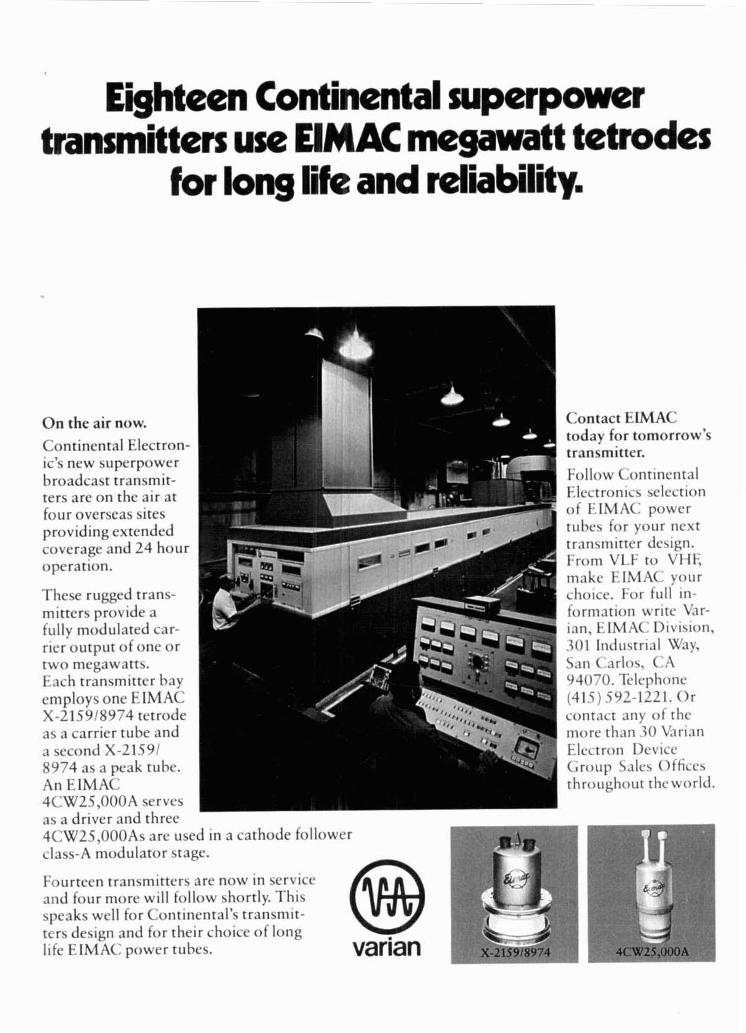
Eighteen Continental superpower transmitters use EIMAC megawatt tetrodes
for long life and reliability.
O n the air now.
Continental Electron- ic's new superpower broadcast transmit- ters are on the air at four overseas sites providing extended coverage and 24 hour operation.
These rugged trans- mitters provide a fully modulated car- rier output of one or two megawatts. Each transmitter bay employs one EIMAC X-215918974 tetrode as a carrier tube and a second X-21591 8974 as a peak tube. An EIMAC 4CW25,OOOA - serves
Contact EIMAC today for tomorrow's transmitter. Follow Continental Electronics selection of EIMAC power tubes for your next transmitter design. From VLF to VHE make EIMAC your choice. For full in- formation write Var- ian, EIMAC Division, 301 Industrial Way, San Carlos, CA 94070. Telephone (415) 592-1221. Or contact any of the more than 30 Varian Electron Device Group Sales Offices throughout theworld.
as a driver and three 4CW25,OOOAs are used in a cathode follower I
class-A modulator stage. ---q
Fourteen transmitters are now in service and four more will follow shortly. This speaks well for Continental's transmit- @ $!I! I I
ters design and for their choice of long life EIMAC power tubes. varian a
m 7 4