DB-1978-04.pdf - thehistoryofrecording.com
56
-
Upload
khangminh22 -
Category
Documents
-
view
6 -
download
0
Transcript of DB-1978-04.pdf - thehistoryofrecording.com

fact:
you can choose your
microphone to enhance
your sound system.
Shure makes microphones for every imaginable use. Like musical instruments, each different type of Shure microphone has a distinctive "sound,'1 or physical characteristic that optimizes it for particular applications, voices, or effects. Take, for example, the Shure SIVI58 and SM59 microphones:
SM59 SM58
Mellow, smooth, Crisp, bright silent... "abuse proof
Shure Brothers Inc., 222 Hartrey Ave., Evanston, IL 60204, In Canada: A. C. Simmonds & Son Limited Manufacturers of high fidelity components, microphones, sound systems and related circuitry.
professional microphones...by
The SM59 is a relatively new, dynamic cardioid microphone. Yet it is already widely accepted as a standard for distinguished studio
productions. In fact, you'll often see it on TV. . . especially on mus-
ical shows where perfection of sound quality is a major considera-
tion. This revolutionary cardioid microphone has an exceptionally flat frequency response and neu-
tral sound that reproduces exactly what it hears. It's designed to give good bass
response when miking at a distance. Re- markably rugged — it's built to shrug off rough handling. And, it is superb in reject- ing mechanical stand noise such as floor and desk vibrations because of a unique, patented built-in shock mount. It also fea-
tures a special hum-bucking coil for superior noise reduction!
Some like it essentially flat...
Probably the most widely used on-stage, hand-held cardioid dynamic microphone. The SM58 dynamic microphone is preferred for its punch in live vocal applications . . . espe- cially where close-up miking is important. It is THE world- standard professional stage mi- crophone with the distinctive Shure upper mid-range presence peak for an intelligible, lively sound. World- renowned for its ability to withstand the kind of abuse that would destroy many other microphones. Designed to minimize the boominess you'd ex- pect from close miking. Rugged, effi- cient spherical windscreen eliminates pops. Lightweight (15 ounces!) hand-sized. The first choice among rock, pop, R & B, country, gospel, and jazz vocalists.
...some like a "presence" peak.
Circle 10 on Reader Service Card
Coming
Next
Month
• May's issue will contain a detailed wrapup of the convention and exhibi- tion recently concluded in Hamburg, Germany. A lot of digital equipment was seen, and associate editor John Woram describes it all.
• Ronald Ajemian, who starts off in this issue with some basics of digital electronics goes on from the AND. ORs as he continues with his Anatomy of Digital Logic, part two.
• In The Lost Art of Recording, Ar- len H. Smith details where we are at in the recording studio and where we once were. Why aren't we there now?
• It's all in the May issue of db. The Sound Engineering Magazine.
THE SOUND ENGINEERING MAGAZINE APRIL 1978 VOLUME 12, NUMBER 4
36 ANATOMY OF DIGITAL LOGIC Ronald Ajemian
38 SPEECH PRIVACY IN THE OPEN OFFICE R. Max Mayer
41 NOISE LEVEL LIMITS IN RECORDING STUDIOS Michael Rettinger
44 SOUND MEASUREMENT AND INSTRUMENTATION MICROPHONES Sidney L. Silver
2 LETTERS
8 THEORY AND PRACTICE Norman H. Crowhurst
14 BROADCAST SOUND Patrick S. Finnegan
21 CALENDAR
22 SOUND WITH IMAGES Martin Dickstein
25 THE SYNC TRACK John M. Woram
30 NEW PRODUCTS AND SERVICES
35 EDITORIAL
49 CLASSIFIED
52 PEOPLE. PLACES. HAPPENINGS
db is listed in Current Contents: Engineering and Technology
About
Hie
Cower
• "Girl With Violin" is the title of this photo supplied by R. Armstrong Roberts and the cover created by art director Bob Laurie.
Larry Zide EDITOR-PUBLISHER
Bob Laurie ART DIRECTOR
Eloise Beach CIRCULATION MANAGER
Ann Russell ADVERTISING PRODUCTION
John M. Woram ASSOCIATE EDITOR
Hazel Krantz COPY EDITOR
Lydia Anderson BOOK SALES
Crescent Art Service GRAPHICS AND LAYOUT
db, the Sound Engineerinj; Magazine is published monthly by Sagamore Publishing Company, Inc. Entire contents copyright © 1978 by Sagamore Publishing Co., Inc., 1120 Old Country Road, Plainview, L I., N.Y. I 1803. relephone (5I6> *133 6530. db is published for those individuals and firms in professional audio- recording, broadcast, audio-visual, sound reinforcement, consultants, video recording, film sound, etc. Appli- cation should be made on the subscription form in the rear of each issue. Subscriptions are $7.00 per year ($14.00 per year outside U.S. Possessions. Canada and Mexico) m U.S. funds. Single copies arc $1.00 each. Controlled circulation paid at Hrattleboro. VT 05301. Editorial, Publishing, and Sales Offices: 1120 Old Country Road, Plainview, New York 11803. Postmaster: Form 3579 should be sent to above address.

fiidlkjtd
PURE
audio design
The new standard in Professional Sound offers you everything;
Spectrum-Master Equalization Most complete line available: Vb- Octave Equalizer/Test Set; two addi- tional Vb and 1-Octave Equalizers; a unique Tunable Notch Filter; a ver- satile Equalization Test Set.
Spectrum-Master In-Wall Amplifiers There is nothing to equal these pro- fessional units, each with built-in 1-Octave Equalizer and exclusive Dynamic Range Extender. Available in 35-watt, 60-watt, 100-watt outputs.
Spectrum Master Amplifiers Imcomparable DX and TAX Solid- state amplifiers, designed for opti- mum continuous-duty performance. Available in a broad selection from 70 to 250 watts RMS to meet any professional audio requirement.
4400 | Series
Spectrum-Master Mixer-Amplifiers Superior 4400 Series with less than 1.5% THD and program equalization provisions. Flexible, advanced de- sign; professional in every sense—for the most demanding applications.
Spectrum-Master Input Equipment Have optimum mixing performance with maximum flexibility In the 4900 Series. Ideal for broadcast and re- cording use, theatres, auditoriums, and churches. Distinguished for ultra- low distortion and wide-range.
quality's other name in Sound and Communications
WRITE FOR TECHNICAL BULLETINS
RAULAND-B0RG CORPORATION 353B W. Addison St., Dept. N., Chicago, III. 60618
Circle 36 on Reader Service Card
Letters
The Editor; In response to the continuing con-
troversy in the pages of db over signal processing and the listeners" interests, I would like to add a few words from a different perspective. As a disc jockey, I know that different types of music are recorded in specific ways in order to reach certain audiences. The type and degree of limiting/compression that a station employs should reflect not only the needs of their listeners, but also the psychoacoustic and musi- cal content of their programming.
As Fletcher & Munson pointed out some years ago, the human ear has a changing sensitivity to frequency as the sound level changes. A recording heard at 100 phons may sound flat in comparison when heard at 50 phons. The bass appears to roll off quite steeply and there will be a lack of presence at around 3,500 Hz. Any good recording engineer knows this and therefore sets his monitors at a fairly low level when recording since this is the way most records are lis- tened to. In fact, when recorded to sound good at this low level, the rec- ord will have stronger bass when lis- tened to at a higher level.
With this in mind, what happens to a record when broadcast on a radio station which employs limiting/com- pression on their signal? I think it de- pends on the record being played.
The newer rock. R&B, jazz-rock fusion, and disco records are often mixed in a certain way to enhance the musical content. The so called "Disco Mix" has a good deal of boost around 50 Hz to get that feeling of thump in the solar plexus which is so necessary to start feet tapping. There will also be some boost at the high end to add bite to cymbals and make those swirl- ing arrangements of strings and syn- thesizers more dazzling. In part, this is what causes the dancing fever to in- crease; Saturday Night, as it were. For the pop and rock recordings, these techniques are used to help get that elusive "hook" which producers use to get their product recognized by the
(continued)
AES 12 Altec Cover 4 Audio-Technica, U.S 17 B&K Instruments 47 Bogen 28-29 BTX Corporation 10 Clear-Corn 20 College for Recording Arts .... 24 Crown International 19 Deltalab Research 14 Garner Industries 46 Inovonics 16,31 I&R Music World 22 Microtran 43 Orban/Parasound 27 Otari 1, 13 Penny & Giles 6 Philips Audio 18,23 Rauland-Borg 2 Recording Supply Co 22 Robins Industries 24 Showco 25 Shure Brothers Cover 2 SME Ltd 8 Sony Corporation of America . . 9 Sounderaft Electronics 3 Sound Technology 11 Standard Tape Lab 16 Studer-Revox 7 Technics by Panasonic 5 Telex Communications 26 Uni-Sync 15 UREl 4 White Instruments 21 Yamaha International 27
(® sales offices
THE SOUND ENGINEERING MAGAZINE
New York 1120 Old Country Rd.
Plalnvlew, N.Y. 11803 516-433-6530
Roy McDonald Associate*, Inc. Dallas
Stemmons Tower West, Suite 714 Dallas, Texas 75207 214-637-2444
Denver 3540 South Poplar St.
Denver, Colo. 80237 303-758-3325
Houston 3130 Southwest Freeway
Houston, Tex. 77006 713-529-6711
Los Angeles 500 S. Virgil, Suite 360
Los Angeles, Cal. 90020 213-381-6106
Portland 2035 S. W. 58th Ave.
Portland, Ore. 97221 503-292-8521
San Francisco Suite 265, 5801 Christie Ave.
Emeryville, Cal. 94608 415-653-2122

The Series IS, based on the world famous industry standard Series I. Unequalled features,technical soohistication and a modest price.
Input channels (12,16or20) Transformer balanced mic input with a 20dB pad. Variable gain mic
amp. Insert send/return (line input). 120Hz high pass filter. Four band EQ, with the two mid band frequencies sweepable. Two monitor sends (post-EQ) and one echo send (post-fade). Automatic pre-fade Solo. LED peak indicator whose delay time indicates the relative size of the transient. Five outputs
Left and right main, monitors A and B and master echo, each with hvo band EQ, solo and insert. Each output may be balanced by a plug-in transformer.
Encore.
Meters Two studio quality VU's and peak reading LED's display the main
stereo output or any function soloed. Communication
There's both talkback and intercom. The talkback mic can speak into the main output, monitors A or 8, or into a ClearCom (or compatible) intercom system. Specifications
Excellent, ie incredibly quiet and distortion-free. Finally
Two echo returns, conductive plastic potentiometers throughout, socket for Shure lamp and, of course, the Soundcraft comprehensive 2-vear warranty.
The new EX4S studioquality 2,3 or 4-way stereo electronic crossover. Internal switching
The facilities for changing the crossover points, and for converting the unit to a 2,3 or 4-way are inside, to provide maximum protection for P.A. systems, by avoiding accidental switching. Front panel controls
Eight band-attenuators, eight LED peak indicators, and LED's to indicate 2,3 or 4-way mode. Circuitry
Bessel function filters (superior to Butterworth filters in other crossovers) give an ultimate slope of 24dB/octave, the most linear phase response and the best transient response. The result is, quite simply, a better sound. And the rest
EX4S is built into an all extruded black anodised 19" case, tough enough to stand up to all the wear and tear of the road. XLR and multipin connectors on the back. Inputs are electronically balanced while outputs may be balanced by plug-in transformers. Of course, it's also covered by Soundcraft's comprehensive 2-year warranty. Soundcraft Electronics Ltd., 5-8 Great Sutton Street, London EC1V OBX. Telephone 01-251 3631. Telex 21198. Soundcraft North America, PO Box 883, JFK Station, Jamaica, New York 11430, USA.Telephone (212) 528 8158.Telex 01 -2203. Debut.
Circled on Reader Service Card SDLinOCRfiFT i
ELECTRONICS LIMITED \

NcwIWD
Smart Plotter
Plug-ins
for Our
lop Drcw-er
MODEL 2010 LEVEL AND FREQUENCY DETECTOR The new UREI Model 2010 is the second of a series of plug-in modules for our Model 200 X-Y Plotter. The 2010 module enables the 200 to plot both amplitude and frequency information received from coherent signals such as pre recorded test tapes, records or other remote signal sources. It features SFD (Smart Frequency Detection) which distinguishes between coherent signals and random voice-type interruptions. The circuit stores the last measured frequency in memory, lifts the pen, and waits for new updated frequency and level informa tion before continuing. It can be synchronized from either the input signal or a different external source for plotting channel separation, head crosstalk, etc. MODEL 2000 AUTOMATIC SWEEP FREQUENCY GENERATOR AND RECEIVER The Model 2000 plug-in module, our first of the series, has an internal sine wave generator and receive circuitry for automatically creating amplitude versus frequency response plots on the UREI Model 200 X-Y Plotter. The Model 2000 features a unique Slope Sense* circuit which automatically slows the sweep rate when rapid amplitude changes occur, and then resumes its normal rate afterwards. Both Models 2010 and 2000 plot signals from 20 Hz to 20 kHz on K&E or DIN Audio Response Graph paper with 0.05 db resolu- tion and a dynamic range of over 60 db. Vertical scaling is switch able from centimeters to inches. (UREI quality, of course) Avail able from your UREI dealer. "patent applied for.
MODEL 2010
MODEL 2000
letters (cont.)
public. As special close miking tech- niques, reliance on peak over vu meter readings, and special equalization in recording become more prevalent in these types of music, stations which program them must become more aware of how they affect their signals. They must also pay more attention to the type and degree of signal process- ing they use in order to keep the im- pact of the music their listeners are interested in.
Older records, mainstream jazz, and classical or easy listening music repre- sent another situation. Often in an ensemble of orchestral musicians, or in a straight ahead jazz group, the re- cording engineer on a session will ask that the musicians restrain themselves somewhat so that he will be able to record them without undue limiting or compression. Close miking is rarely used and then only for isolation, and the recording is made as flat as pos- sible. This is again in deference to the listeners' desires and use of the music. Many of these recordings arc done live and overdubbing is rarely used. The effect that the producer is looking for is "depth"' and realism, not a psy- choacoustic "hook."
I believe one reason why Fleetwood Mac's album. Rumors was the biggest album of the year and is the demon- stration record of choice for many hi-fi salespeople, is because of the pro- ducers' use of the mix as an integral part of the production. Even the cheap- est in-house speakers sound good when played with this record. And on the radio it sounds better than most other records even when heavy signal proc- essing is employed by the station.
In my profession as a disc jockey, I often talk to record promoters. As a condition of receiving promotional products from them I must give them written, in depth, anaylsis of each new record. This involves not only my personal opinion, but also comments on crowd response. Because of com- plicated surveys, the promoters know what type of clientele each club has, and based on these feedback reports they do much of their marketing strat- egy. I have often reported poorly on a record, not because the musicianship was lacking, but the sound just did not move my crowd. This can make or break a record and more than once I have dived for the equalizer or the gain in an attempt to strengthen a record I believe in. I have even gone so far as to re-record some records and play my tape rather than the record.
Record companies have been known to complain that promoting a record
(continued)
8460 San Fernando Road, Sun Valley, California 91352 (213) 767-1„„ Exclusive export agent: Gotham Export Corporation, New York
Circle 26 on Reader Service Card

A radical departure in circuit principles,Technics SH-9010 stereo universal frequency equalizer offers the experienced technician and demanding audiophile the flexibility of both a graphic and a parametric equalizer.
The five bands of each stereo channel have a center frequency that's independently variable. By turning the control knob below each slide pot, the center frequency can be varied up or down by as much as 1.6 octaves. So, unlike conventional equalizers with a fixed-center freq'uency, the SH-9010 has no frequency 'blind spotsl' What's more, each band of the SH-9010 can adjust to overlap the adjacent band to further boost or attenuate a selected frequency width.
Incredible for the price? You're right. But what's even more incredible is that variable center frequency is just one of the SH-9010's advantages. Variable "Q' or bandwidth is another. With it you can broaden or
narrow any frequency band. Independently or both at the same time. Which means you can balance an entire string section or eliminate an annoying little hum.
Technics SH-9010. Compare specifications. Compare prices. And you'll agree there's no comparison.
THD: 0.02%. FREQUENCY RESPONSE: 10 Hz-20 kHz ( + 0, -0.2 dB). 10 Hz—70 kHz ( + 0, -3 dB). GAIN: 0 ± 1 dB. S/N: 90 dB (IHF: A), BAND LEVEL CONTROL: + 12 dB to — 12 dB (5 elements x 2). CENTER FREQUENCY CONTROL: +1.6 oct. to -1.6 oct. BANDWIDTH (Q) CONTROL: 0,7 to 7.0. CENTER FREQUENCIES: 60 Hz (Variable 20 Hz^lSO Hz), 240 Hz (Variable 80 Hz'v,720 Hz), 1 kHz (Variable 333 Hz^3 kHz), 4 kHz (Variable 1.3 kHz^^ kHz) and 16 kHz (Variable 5.3 kHz^48 kHz). SUGGESTED RETAIL PRICE: $499,95*
Technics SH-9010, A rare combination of audio technology, A new standard of audio excellence,
•Technics recommended price, but actual retail price will be set by dealers.
Technics Professional Series by Panasonic
Circle 24 on Reader Service Card

SLIMLINE
Penny&Giles
small
development
in the fader
business
Penny & Giles new Slimline fader is only 12-7mm wide with a 68mm electrical stroke. Yet, within that 12-7mm body width you can have mono or
stereo outputs, linear or audio taper with an infinitely smooth and stepless fade - Bius the
other performance advantages of Penny & Giles
conductive plastic faders.
Our small development sounds good - and has a small price to match.
Write for full details or phone our sales office.
Penny & Giles Conductive Plastics Limited 1640 5th Street Santa Monica California 90401 Telephone 213 393-0014
letters (cont.)
through the discos is a waste of money. If a record is a hit in the discos, it does not follow that it will he a hit on the radio. I think the attitude of the record companies and radio managers concerning the quality of the signal is the culprit here. For many new rec- ords there is the disco version and the radio version. The disco version is typically longer, better recorded, and hotter mixed. It may have special ef- fects missing from the radio version, such as phasing and reverb. So if a person is really turned on by some- thing heard in a disco and later hears the same song on the radio, he or she may not even recognize it. All the dynamics will be missing due to a combination of the changed version, station's signal processing, and the re- duced volume at home or in a car. In comparison, the Fleetwood Mac album is identical in every respect to the sin- gles taken from it. and all are mixed quite hot. So it sounded great at the disco, and better than most records on the radio, either in the car or at home.
In light of this, the type and degree of signal processing employed by a radio station is obviously of interest to record companies and their promot- ers as well as any deejay who attempts to put together a creative show, and all listeners who have a purpose for their listening. Station managers should try to tailor their signal to the type of music they play as well as the type of listener they have targeted.
Craig Barney Craig Barney/Discoservice Berkeley, Ca.
MOVING?
Keep db coming without interruption!
Send in your new address promptly.
Enclose your old db mailing label, too.
Write to:
Eloise Beach, Circ. Mgr.
db Magazine 1120 Old Country Rd. Plalnvlew, N.Y. 11803
Circle 12 on Reader Service Card

Studcr introduces the A80/RC
the quality defies comparison
the price invites it
From now on you don't have to pay more money to get Studer quality. The new Studer A80/RC two-channel recorder costs the same as or less than two of the other three popular names.
It sounds unbelievable. And it is the most perfect machine you can buy for any two-channel application you can think of.
Because nothing but a machine created by Willi Studer records, plays, handles, and lasts like a machine created by Willi Studer.
Now you have a choice: you can pay less for an A80/RC and get more tape recorder, or pay more for another brand and get less tape recorder.
Visit Studer for a hands-on experience with the A80/RC or for full information, call:
MmflnMa R^/bx
Studer Revox America, Inc., 1819 Broadway, Nashville, Tennessee 37203 / (615) 329-9576 ■ in Canada: studer Revox Canada, Ltd. / (416) 423-2831
Circle 21 on Reader Service Card

C 3 O c/j C^J Qj 0) ^ !
■S ^ S ?; n
T> "O ; m ^ . El' £ § Q) o "; ^ -o .! ^ s j ^ ro i 0) O) , E S ' E -g i 8 §.- ID ^ J
~o ' 1 -0 C CD ^ 1
^ I -C > I- ^3 •!
^ 5 o ? 03 03
O -Q O ^ o
I ■
^ <b cj ^ Q) O ^
03 ^ . - O N -Q ^ CT3 LO
O Csl o CD C/3 "o C CN - CQ CO C o g c Ij CD > LU o
CD 03" 13 C c O 03 > O) < c > 'k- 03
~a o c CO Q_ CD X cn cm T3 CD o c CN LU CN CC
>- "O E CD o 03 CO CD
o -C O)
z Q. c CD O = X <D
O Q — LO cn (/5 C/3 r- 03 CD
CO -C -6 u> o IJ c CO "c > 03 c O 03 CO
CO -C LO ■O c ~6 03 CO CD C/3 b "D
E 03 C o —I E LU E (S) in CO O d CO .-Q < *— CD q..£ 03 CD c: Q 03 CD o <o 03
"Cs C CD
NORMAN S. CROWHURST
4^j» Theory & Practice
How Quadriphonic Fits In
• Perhaps there is no better example of how theory and practice coincide than in the derivation of the quadri- phonic system used for the SQ disc. A couple of columns back, I discussed how stereophonic really means "solid sound," so that really, however many channels may be used, if the objective is better depth perception, it is still stereo. Stereo does not mean "two- channel."
But using the variety of stereo that does utilize two channels, as a starting point, we can better understand how a 4-channel system can be derived from it, to produce the desired effect. And from that, with any luck, we may get into considering how to install ef- fective quadriphonics in various kinds of environments.
Back in the days when the kind of stereo intended for the home used only two channels, a lot of work was done listening to program from two loudspeakers to see what was respons- ible for creating the illusion that the sound sources occupy space, instead of just coming out of a "hole in the wall," which is what any loudspeaker vir- tually is, from the acoustic viewpoint.
Many experiments were conducted, to determine the effect of varying fre- quency range, changing relative intens- ity. and timing, from a system con- sisting of two loudspeakers spaced apart, usually in front of the listener. If timing is identical—such as that used in single-channel sound, but varying the intensity fed to each unit—such changes in intensity affect the apparent
FRONT LEFT FRONT CENTER FRONT RIGHT
MID LEFT MID RIGHT
REAR LEFT REAR CENTER REAR RIGHT
The S.Q. System
Circle 37 on Reader Service Card

ACOUSTIC" PHASE CIRCUIT
Take a look at what's taking the industry by storm. The Back Electret, another giant step forward from Sony.
Never before has it been possible for thin polyester film to be used in electret con- denser microphones. That's because polyes- ter film, acknowledged as the best material for microphone dia- phragms, just can't hold a static charge for a long duration.
But Sony's engineers have made the impossible, possible. They've found a way to adhere the electret material directly to the back plate of the microphone. By thus putting the charge on the back plate, we are able to use polyester film in the diaphragm.
The result will be obvious to your ears. Clearly superior sound quality, without particular color-
in wwwm
i s a; i
■
■ A
-DIAPHRAGM RING
OUTPUT TERMINAL
ation in the upper frequency range. The low mass diaphragm means better transient charac- teristics over the entire frequency range.
You can find the Back Elec- tret in four Sony microphones: ECM-56E $220; ECM-65E $210; ECM-33E $165; and ECM-23E $100.
But you don't have to look at Back Electrets to see why Sony is ahead. NO MATTER WHAT KIND OF MIKE YOU NEED TO GET WE'VE GOT IT
Sony's micro- phone line is thoroughly complete. It ranges from professional con- denser to semi-profes- sional to microphones for public address, vocalists, and outdoor use. There's omni and um-directional. And we think it's big of us to make sophisticated
miniatures. And all microphones are
available with Phantom Power, battery operated, or both.
So if you need something to talk into, it makes a lot of sense to talk to Sony. Write to Sony, 714 Fifth Avenue, Dept. TK, New York, NY 10019.
SONY
> "a
o. o-
' 1978 Sony Corp. of America. Sony, 9 W. 57 St., N.Y., N.Y. 10019. SONY is a trademark of Sony Corp.
"Sbu can hear
the difference because the
difference is right here.
Circle 40 on Reader Service Card

What's
cooking? IC Op-Amp Cookbook by Walter G. Jung. Explains basic theory of the IC op amp in a down-to-earth manner. Includes over 250 practical circuit applica
Fully illustrated and designed for all interested in modern linear IC
design techniques. Covers general operating procedures, such as offset nulling, frequency compensation, and protection against abuses and failures; signal-processing circuits: audio circuits including low-level preamps, active fil- ters and equalization circuits, power-booster stages up to 100 watts, and a variety of other specialized circuits. Includes unique devices that cannot be categorized with standard types — programmable op amps, operational trans- ductance amplifiers, quad current-differencing amplifiers, etc. $12.95
SAGAMORE PUBLISHING CO, INC. 1120 Old Country Road, Plainview, N.Y. 11803 Please send copies of IC Op-Amp Cookbook at $12.95. N.Y.S. residents add 8% sales tax.
Name
Address
City
State/Zip
theory and practice (cent.)
position, to the listener, of the source, The apparent location of the sound
seems to depend on how much louder one unit is than the other. But timing also affects the apparent position of the source. In this context, the word timing refers to milliseconds. If the sound from one loudspeaker precedes that from the other by a few millisec- onds, the one that gets to the hearer first will establish itself as the appar- ent source, even when the sound com- ing from the slower loudspeaker is quite a bit louder.
That is true mainly over the mid- range frequencies. For the low fre- quencies, whose wavelengths are com- parable with room dimensions, there is no real sense of direction indoors. Apparent position is determined by other component frequencies that hap- pen to belong to the same composite sound. And for the high frequencies, usually handled by the tweeter or supertweeter. the time element again breaks down, because the wave lengths are so short.
PHASING
But the effect we want to talk about here, that forms a starting point for
getting into the SQ quad system, is not based on that kind of time or in- tensity difference. It is better related to something that caused a lot of dis- cussion even before stereo generally made the scene on the home front. I refer to phasing.
The best way to illustrate phasing is to use single channel sound with two loudspeakers. Space them a distance apart and connect the two units in phase so that both diaphragms move forward together and the sound ap- pears to come from midway between them. If you get closer to one unit than the other, the sound may appear to come from the closer unit.
But now reverse connections to one unit so the speakers are out of phase. The sound becomes discombobulated or, as we used to call it, disassociated. It no longer seems to come from those loudspeakers at all, but appears to fill the room, to completely surround you.
Before stereo program became avail- able, one method some hi-fi nuts adopted to get a sense of space was to use two playback heads, with a few milliseconds between them, and sepa- rate amplification. They fed the output from the first pickup to both loud- speakers in phase, and that from the second pickup out-of-phase.
The effect was extraordinarily real- istic, for single channel source. The first pickup came from front and cen- ter, and the second pickup simulated reverberation by seeming to fill the room, although the loudspeakers were both located in front of the listener. Then two-channel stereo came, and who needed tricks like that?
But in the course of time, some realized that two-channel stereo is lim- ited. All of the sound comes from in front, none from behind, unless the mixing has adopted something very sophisticated, like putting in an out-of- phase delayed mix. Do you begin to see how this very naturally leads into the SQ system?
First let us take two-channel sound, coming from in front as it would be recorded on a 45/45 disc. As has been described many times before, the left channel is engraved on the left wall of the record groove and the right chan- nel on the right wall. When an equal signal is present in both channels, in phase, both walls come into play and the groove is just like the old mono- phonic lateral recording; the groove wiggles horizontally, from side to side.
Signals recorded out of phase, to produce a synthetic reverberation ef- fect, would create a vertical movement of the groove, up and down. So far, it seems we don't even need the rear speakers. But while that method works, its effectiveness depends on the acous-
SMPTE synchronizer
■ interfaces all recorders
■ Reads code to -12 dBm
■ Tracks within SO^us
■ inaudible lip-sync adjust
■ Programmable offset
■ Studio quality performance
■ Broadcast reliability
The BTX Corporation, 438 Boston Post Road Weston, Massachusetts 02193 • 617-891-1239
Circle 33 on Reader Service Card
Its

Today's performance requires the best
in an audio test source.
That's the new Sound Tech 1410A.
No question about it, the new Sound Tech 141 OA is the finest audio test source available. It provides both sine wave (10 Hz - 110 kHz) and SMPTE intermodulation test outputs.
We classify it as an ultra-high- performance audio signal generator. Here's why:
Besides providing an ultra-pure test signal (typical distortion is less than .001% over most of audio range), the test signal is adjustable by precision output attenuators. And you have an exceptionally large output level range; from +26 dBm to —89.9 dBm in 0.1 dB steps. That +26 dBm can be a powerful help in line testing (no pun intended).
The output system on the 1410A is Sound Tech's special circuit. For minimum distortion, it has no output transformer, yet it's both fully Iso- lated and balanced. That means you can connect to any load: balanced or unbalanced, floating or grounded.
INTERMODULATION TESTING For intermodulation measurements,
the 141 OA provides the standard 60 Hz signal combined with a 7 kHz signal. You can vary the LF/HF ratio over a 100:1 range. The IM signal is provided from the same flexible out- put system discussed earlier.
With the high performance possible in today's audio systems, the 141 OA
SEE AT NAB You can see the new 1410A at our Sound Technology
exhibit at NAB, I'll be at booth number 1308 to demonstrate the 1410A, See you there.
Rosemary.
(or its relative, the 1710 system) is what's needed for adequate testing.
CALL FOR DATA Call Mike Hogue/Larry Maguire
and get our literature on the industry's most advanced audio test source.
They can also arrange a demo for you almost instantly.
" 6666
REMOTE TESTING In broadcast work involving re-
mote transmitters, you can test by using the 1410A with the Sound Tech 171 OA Distortion Measurement Sys- tem. With its Vi watt of audio power, the 1410A can be used, say, at the studio to test studio-transmitter links, amplifiers, etc., while the 171 OA is measuring at the transmitter.
SOUIMD TECHIMOLOGY -MOO DELL AVENUE CAMPBELL, CALIFORNIA SSOOS C40B1 37a-6S4a In Don Mills, Ont., Canada: The Pringle Group
Circle 31 on Reader Service Card

theory and practice (cont.)
00 N- O)
Q. < n ■o
Be sure to
attend the.
AUDIO
ENGINEERING
SOCIETY'S
60«.
Technical
Meeting and
Exhibition of
Professional
Equipment
at the
Los Angeles
Hilton
May 2-5
For details, write or phone:
rw15] AUDIO
\ U / ENGINEERING
W SOCIETY
60 East 42ral Street
New York City 10017 212/661-8528 and 661-2355
tic environment where the program is reproduced. Let us say, for the mo- ment, that some surroundings lead to more effective reproduction than oth- ers. So what can we do to help the tough cases?
It would help if we could have loudspeakers actually located behind the listeners. This is essentially what quadriphonic does. If, for the mo- ment, we forget about left and right and think only about front and back, then lateral or sideways stylus move- ment goes to the front, and vertical stylus movement goes to the back.
LEFT/RIGHT SEPARATION
It would be relatively easy to make that separation, merely by taking the 45/45 and transcribing it as vertical/ lateral, if it were not for the fact that we also want to keep our left and right separation. Let us take a hypo- thetical problem with such a system. Suppose we want a trumpet solo to come from right front. The compo- nent of the groove modulation repre- senting the trumpet will be a pure 45 degree movement, modulating the right wall of the groove.
Based on a 45/45 analysis, that puts the sound on the right where it should be. But based on a vertical/lateral analysis, it contains both in equal parts, so the music would come from both front and back loudspeakers on the right, producing an illus:on that the trumpeter is at the side of the lis- tener, instead of front right.
We cannot put four independent outputs on a phonograph pickup. We can use 45/45, or vertical/lateral, not both. And we can matrix from one to the other. But essentially, the most we can have, physically, are two inde- pendent outputs, either left and right. or front and back. Any effort to com- bine them on a continuous basis re- sults in ambiguity; more than one location of input can produce the same two-channel combination, which- ever way you happen to view it.
QUADRATURE
Just a moment there. That discus- sion of movement refers to movements that coincide in time. Going back to the two loudspeakers, either both dia- phragms move together, the same way at the same time, or they move oppo- site ways at the same time. Are those the only possibilities? No, they can move in quadrature too. These are two different ways in which components can be isolated—by being at right an-
gles in the physical world, such as 45/45, or vertical—lateral; or by being in time quadrature, 90 degrees apart in their phasing.
If two loudspeaker diaphragms arc moving in a 90 degree relationship, one is ?rioving when the other is not, and vice versa. They are neither mov- ing together, nor opposed but, in that sense, independently. This is the extra fact that the SQ quadriphonic uses.
We want to preserve the stereo illu- sion, across the front, so we make lat- eral movement, produced by in-phase left and right, representing front cen- ter, with each 45 degree movement representing its own side, left or right. Intermediate positions are represented by intermediate angles, but always in phase, just varying the relative amounts of movement.
Now, making the rotation one way, with this quadrature relationship will correspond with left rear, while the other way corresponds with right rear. Add them together and, as before if they are equal, the result is simple vertical movement, corresponding with center rear. It all adds up. What we need is a set of coding and decoding circuits, to produce these 90 degree phase shifts that will enable us to separate front and back, independently from the left-right separation.
That is precisely what the SQ system does. As the diagram shows, this en- ables us to put the sound anywhere we want it, around the listener. We have effectively, 4-channel resolution, but with only two information chan- nels; we get the extra two by compar- ing phasing critically.
For this to be exact, we need four separate channels at the input, which must be critically processed so the composite is precisely applied with the correct phase, as well as directional relationship, at all audio frequencies. Then, on playback, or reproduction, the same code is used in reverse, to reconstruct the original four separate channels.
The system is compatible, largely because it follows a natural develop- ment, as I have shown here. If you played an old stereo, in which the syn- thetic reverb was achieved by delay and phase reversal, the decoder would put the reverb in center back, and program items originating at front left or front right, would come out right, too. It would not provide all the capa- bility of a signal that had been coded from four separate channels, but at least would be compatible.
That's the theory. Does it work? CBS Labs, who developed the system, has made quite a lot of program ma- terial available, coded this way. Try it, if you have not already. ■
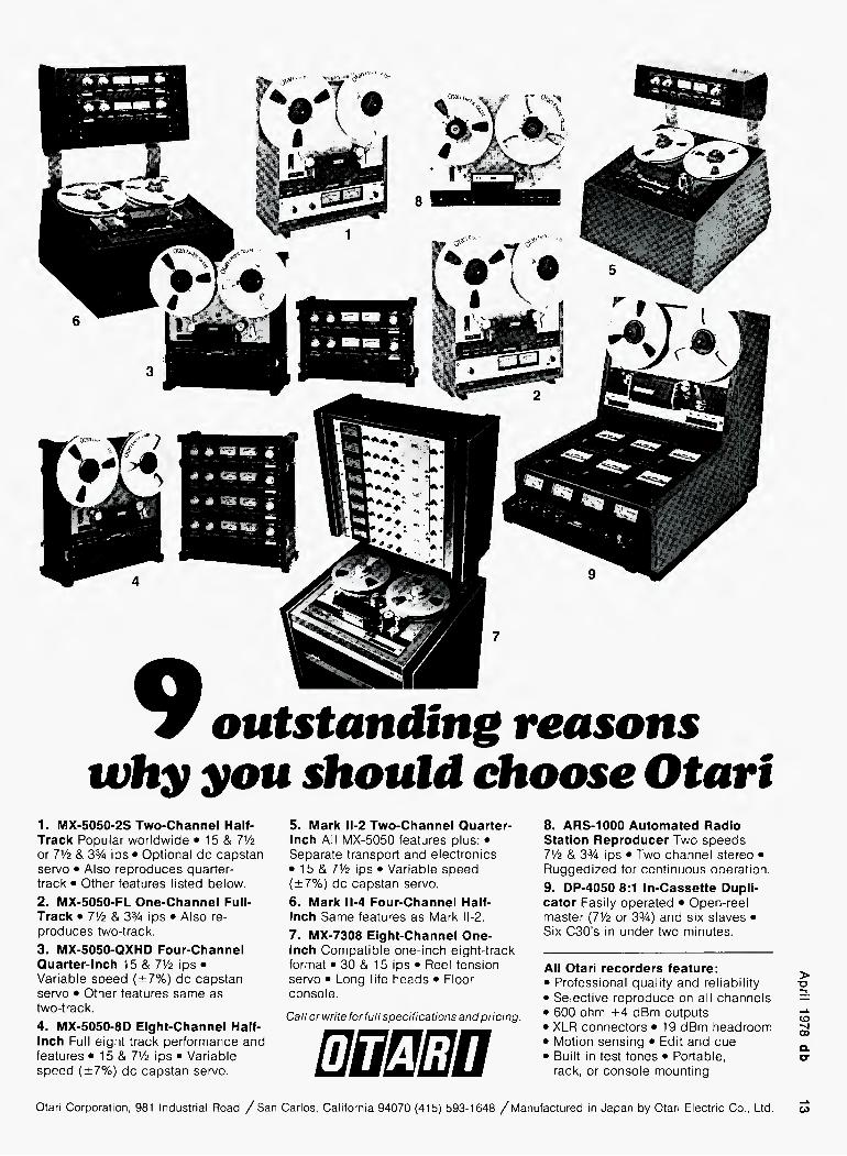
Otari^
outstanding reasons
why you should choose Otart
1. MX-5050-2S Two-Channel Half- Track Popular worldwide • 15 & 71/2 or 7V2 & 3% ips • Optional do capstan servo • Also reproduces quarter- track • Other features listed below. 2. MX-5050-FL One-Channel Full- Track • 7V2 & 3% ips • Also re- produces two-track. 3. MX-5050-QXHD Four-Channel Quarter-Inch 15 & IV2 ips • Variable speed (±7%) dc capstan servo • Other features same as two-track. 4. MX-5050-8D Eight-Channel Half- Inch Full eight track performance and features • 15 & IVz ips • Variable speed (±7%) dc capstan servo.
5. Mark 11-2 Two-Channel Quarter- Inch All MX-5050 features plus: • Separate transport and electronics • 15 & 7V2 ips • Variable speed (±7%) dc capstan servo. 6. Mark II-4 Four-Channel Half- Inch Same features as Mark II-2. 7. MX-7308 Eight-Channel One- Inch Compatible one-inch eight-track format • 30 & 15 ips • Reel tension servo • Long life heads • Floor console.
Call or write for full specifications and pricing.
mnsmn
8. ARS-1000 Automated Radio Station Reproducer Two speeds 71/2 & 3% ips • Two channel stereo • Ruggedized for continuous operation. 9. DP-4050 8:1 In-Cassette Dupli- cator Easily operated • Open-reel master (71/2 or 3%) and six slaves • Six C30's in under two minutes.
All Otari recorders feature: > • Professional quality and reliability -a • Selective reproduce on all channels —' • 600 ohm +4 dBm outputs ^ • XLR connectors • 19 dBm headroom jjj • Motion sensing • Edit and cue a • Built in test tones • Portable, sr
rack, or console mounting
Otari Corporation, 981 Industrial Road / San Carlos, California 94070 (415) 593-1648 /Manufactured in Japan by Otari Electric Co., Ltd

PATRICK S. FINNEGAN
Broadcast Sound
Crosstalk
• Many are the problems which can afflict the station's audio system, and one of these is crosstalk, the undesir- able coupling of the audio signal in one channel into another channel. With the well controlled situation in solid state units and the excellent grades of shielded cable available today, cross- talk is not as great a problem as it once was. But that does not mean that it cannot occur. When it does happen, the cause can often be traced to care- lessness in the installation of the inter- connecting wiring, and when modifi- cations arc made within units. Cross- talk problems which show up in the system can sometimes be difficult to trace down, and a cure can be difficult. As with any problem, understanding and identification are the first steps in affecting a cure, so let's take a brief review of the basics.
SOME BASICS The movement of current flowing
MAGNETIC
current Flovj
Figure 1. Fields around the current in a conductor. Larger currents produce stronger fields that also extend farther out.
through a wire or conductor creates a magnetic and an electric field around that conductor. The magnetic field is a complete loop around the conductor and concentric with it, while the elec- tric field moves out from the con- ductor and terminates on surrounding
metallic objects. These fields take on the nature of the current which is cre- ating them. If that current is steady and in one direction (d.c.), the fields are established and steady. But if the current is fluctuating and changing polarity (a.c.), then the fields build up to their maximum magnitude, collapse and reverse, all in step with the con- ductor current. The magnitude of these fields is determined by the mag- nitude of the conductor current. Larger currents create stronger fields, and extend a greater distance from the conductor.
When another wire or metallic ob- ject is within these fields, a current will be set up in that conductor or object, with the same nature as the original current creating the fields. The magni- tude of this new current depends upon a number of factors and relationship to the field creating the current. The flux lines of the magnetic field, their density and number which "cut" the
4- The flew Leader In DICITPL DELAY For natural, unobtrusive sound reinforcement in any church, theater, or hall.
For chorus, doubling, and echo effects in recording or broadcast. THE PROBLEM: Digital delay lines (DDLs) are the established standard for time delay, due to their high S/N, low distortion, long delays and wide bandwidth at all delay lengths. But DDLs have been too expensive for many applications.
Analog delay lines have been accepted as a substitute because they provide some useful effects at a modest price. But their performance and flexi- bility are severely limited: frequency response and dynamic range deteriorate as delay length is increased.
/
- digital Kim moouie-
THE SOLUTION DELTALAB DIGITAL DELAY DeltaLab introduces the Problem-Solver; a new high- performance DDL at a price comparable to ordinary analog units. It features;
• Three outputs with independently selectable delays.
• Delay lengths from 5 mS to 160 mS. • Frequency response 30-15K Hz at all delay
lengths, all outputs. • No audible noise. (Dynamic range > 90 dB.) • No audible distortion. (THD < 0.2%, mostly
pure second harmonic.) • No audible side effects—hum, whistles, birdies,
quantizing noise, or compander noise-pumping. • Input and output levels adjustable from 0 to
+24 dBm. • Price: approx. $1200.
WHO IS DELTALAB? In digital audio, experience counts. DeltaLab is a new consortium of engineers and scientists with a combined experience of over 50 years in aerospace, digital electronics, and high- quality audio. Our previous designs (under other brand names) include some of the most respected products in audio today. For more information, including the name of your nearest distributor, write or call. DeltaLab Research Inc.. Att. Peter Tribeman (617) 458-2545.
0 I 71 DeltaLab^esearch, Inc. DeltaLab 25 DRUM h|H road' CHELMSFORD>^ASS. 01824
Available at Quality Dealers
. \ J / , -•
■X /
Circle 13 on Reader Service Card

TWO FOR
THE ROAD
THE UNI-SYNC
DUAL PROFESSIONAL
POWER AMPLIFIER
MODEL 100
The Trouper Series met the challenge of combining readability with top performance, on the road or off, UNI-SYNC delivers sound. Designed in the same tradition, comes the MODEL lOO Professional Power Amplifier with these exclusive features:
Two Amplifiers: Not just a stereo amplifier, but actually two amplifiers in one chassis, which means accurate bass response, greater dynamics and elimination of the crosstalk distortion phenomenon.
Design: Greater efficiency due to technically superior transformer and heat sink designs.
Size: Smallest dual lOO watt professional power amplifier on the market - a inch package.
True modular construction: road tested inter- locking PC board assemblies eliminate incon- sistencies in performance, and serviceability problems found in hand-wired products.
Connections: Balanced bridging XLR and 'A inch phone inputs; both may be used bal-
anced or unbalanced. Outputs are 5-way Banana Binding Posts. Mono operation switch.
Specifications: 8 ohm power outputs; lOO watts average continuous power per channel; power band 20Hz to 20kHz, Total Harmonic Distortion: .02%. Intermodulation Distortion: Less than .004% @ rated output. Frequency Response: -3Db 1Hz and ICOkHz. Fully complimentary output.
Protection Features: On/off transient speaker protection circuitry for DC offset; SOA limiting circuitry; Independent Thermal Shutdown; and Available Power Monitor, provides accurate LED indication of amplifier status,
UNI-SYNC has made significant strides in the design and packaging of the MODEL lOO and companion power amplifiers. We invite you to take an inside look at the . MODEL lOO, see your local dealer or write for a free brochure, a bsr company
DESIGNERS8c MANUFACTURERS OF PROFESSIONAL AUDIOSYSTEMS&EQUIPMENT 742 HAMPSHIRE ROAD/WESTLAKE VILLAGE, CALIFORNIA 91361/(805) 497-0766
> "O
CO "Vl 00 Q. O"
Circle 20 on Reader Service Card
yj a new and valuable
DATA BOOK
The Standard Tape Manual is not a text book, but rather a practical and much-needed source for sophisticated users of magnetic recording equipment. Robert K. Morrison, international authority in the field and founder of Standard Tape Laboratory, recognized the need for compilation of material used in standard- ization efforts and compiled this practical tool. It is available as a limited edition.
STL can serve all your needs with tapes in 2", 1", V?", VJ" and 150 mil cassette sizes giving you the most accurate reference possible in the widest range of formats.
Most catalog items can be shipped from our Inventory the same day we receive your order. Write or phone for fast delivery. Write for free catalog.
STANDARD TAPE LABORATORY, Inc. 26120 Eden Landing Road / #5 / Hayward, CA 94545 (415) 786-3546
Circle 41 on Reader Service Card
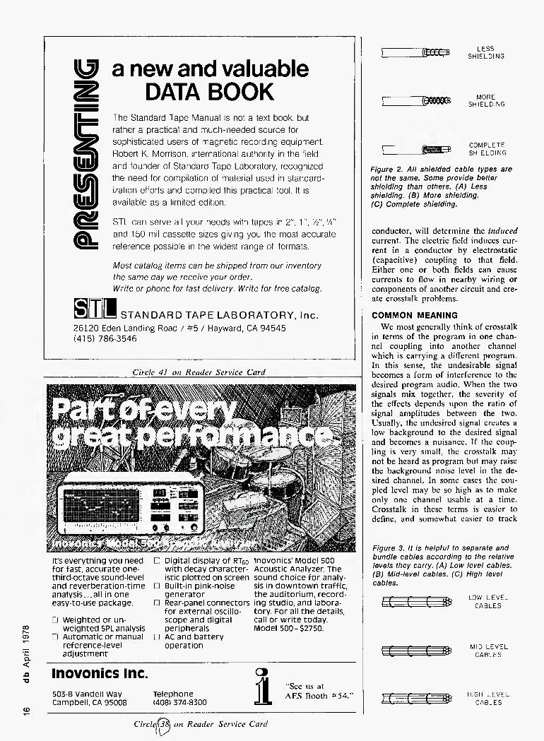
It's everything you need for fast, accurate one- third-octave sound-level and reverberatlon-tlme analysis...all In one easy-to-use package.
□ weighted or un- weighted SPL analysis
□ Automatic or manual reference-level adjustment
Digital display of RTeo with decay character- istic plotted on screen
□ Built-in pink-noise generator
□ Rear-panel connectors for external oscillo- scope and digital peripherals
□ AC and battery operation
inovonics Model 500 Acoustic Analyzer. The sound choice for analy- sis in downtown traffic, the auditorium, record- ing studio, and labora- tory. For all the details, call or write today. Model 500-$2750.
Inovonics Inc.
503-B Vandell Way Campbell. CA 95008
Telephone (408) 374-8300 1
"See us at AES Booth #54.-
LESS SHIELDING
MORE SHIELDING
COMPLETE SHIELDING
Figure 2. All shielded cable types are not the same. Some provide better shielding than others. (A) Less shielding. (B) More shielding. (C) Complete shielding.
conductor, will determine the induced current. The electric field induces cur- rent in a conductor by electrostatic (capacitive) coupling to that field. Either one or both fields can cause currents to flow in nearby wiring or components of another circuit and cre- ate crosstalk problems.
COMMON MEANING We most generally think of crosstalk
in terms of the program in one chan- nel coupling into another channel which is carrying a different program. In this sense, the undesirable signal becomes a form of interference to the desired program audio. When the two signals mix together, the severity of the effects depends upon the ratio of signal amplitudes between the two. Usually, the undesired signal creates a low background to the desired signal and becomes a nuisance. If the coup- ling is very small, the crosstalk may not be heard as program but may raise the background noise level in the de- sired channel. In some cases the cou- pled level may be so high as to make only one channel usable at a time. Crosstalk in these terms is easier to define, and somewhat easier to track
Figure 3. It is helpful to separate and bundle cables according to the relative levels they carry. (A) Low level cables. (B) Mid-level cables. (C) High level cables.
LOW LEVEL CABLES
MID LEVEL CABLES
HIGH LEVEL CABLES
CirclenJtt] on Reader Service Card

Audio-Technica
rewrites the book
on professional
phono
cartridges.
> "O
CD -si CO
audio-technica INNOVATION □ PRECISION □ INTEGRITY
AUDIO-TECHNICA U.S., INC., Dept. 48BD, 33 Shiawassee Avenue, Fairlawn, Ohio 44313 • In Canada: Superior Electronics, Inc.
The all-new ATP cartridges were specially developed for the work-
ing environment. Three models provide a choice of either spher- ical or elliptical styli. Each car-
tridge is hand-tuned for optimum performance, with stereo chan-
nels matched within 1.5 dB to eliminate balance problems.
All ATP cartridges feature tapered cantilever tubes that
combine high strength with min- imum moving mass. There's no problem with back cueing, and the brightly colored cantilever
tip is readily visible so that you can spot an LP cut quickly and
accurately.
ATP cartridges are priced from $25.00 suggested profes- sional net. Write for complete specifications. Try the ATP Professionals on your own turntables. We know you'll be pleased with what you hear. From the thoughtful pros at Audio-Technica.
Upgrade your entire record-playing system with new ATP tone arms. Rugged and precise, like ATP cartridges. Professional in every respect. Model ATP-12T or ATP-16T just $120.00 sug- gested professional net.
Introducing
The Professionals
The new
Audio-Technica
ATP Series
Dual Magnet Stereo '
Phono Cartridges
What do you really need from a ' professional phono cartridge? Impeccable quality. Reliability. Uniformity. And reasonable cost. The goals we've met with the new ATP Series cartridges.
The new ATP Series are flat, smooth, low distortion per- formers that will do your station, studio, disco, library, or commercial installation proud. They are also very tough... the next best thing to "bullet proof". Because we know that "needle drop" isn't just a way to pay for music or SFX. It's a fact of life!
Both ATP cartridges and styli are uniformly excellent. When you at last need to replace a stylus, you always get "like new" performance again, and again, and again.
Don't confuse the ATP Series with other "professional" cartridges that are merely modified home units. ATP units don't have to be treated with kid gloves. And yet we haven't sacrificed tracking ability to make them rugged.

down because of the two different pro- gram audio signals involved.
OTHER WAYS The fields around a sicnal-carrying
conductor are no respecter of pro- grams in any channel. These fields can induce currents in other parts of the same channel if the wiring or compo- nents are within their range. When this type of crosstalk occurs, a variety of different effects may ensue, de- pending upon in what areas of the channel the coupling is taking place, the phase and amplitude of the signals at that place, and so forth. A couple of examples come easily to mind: the demodulated audio from the modula- tion monitor coupling back into earlier stages, or the output of the console speaker monitor coupling back into earlier stages.
SOME EFFECTS Coupling the same program audio
back into earlier stages of the same channel can produce more serious ef- fects than the mixing of two different audio programs. If the coupled signal is exactly out of phase with the on- going signal, negative feedback oc- curs. This is much the same process as is created in many audio stages in a
(POOR DRESS)
(GOOD DRESS)
Figure 4. Poor wire dress can create crosstalk problems. (A) Poor dress. (B) Good dress.
controlled manner. But in the crosstalk situation, the feedback is taking place in an uncontrolled manner.
Phase delay also enters the picture. If there is a small amount of delay, the feedback distorts the outgoing wave-
form. On a speaker this will often have a raspy sound in the audio as though some stage were being overloaded, or peak clipping is taking place. Greater amounts of phase delay can produce an echo effect in the program. This is about the same as when the output of a tape recorder feeds back into the console which is feeding the record section of the tape machine. If the phase of the coupled signal is such that it is in-phase with the outgoing signal, then feedback oscillation can easily occur.
STEREO In a stereo system we have twin
audio channels, the Left and the Right. A signal from the Left or the Right can couple back into its own channel and deteriorate the audio just as it will do in a single channel system. But crosstalk between the Left and the Right channels can create far more serious problems to the stereo signal. This type of crosstalk can reduce chan- nel separation, create peculiar stereo effects such as moving singers and in- struments from positions different than on the original recording, and in some serious cases can reduce the stereo signal to a monaural signal.
When a situation exists where the Left channel can couple over into the Right channel, the same conditions al- low the Right to couple into the Left at the same time. Crosstalk between the audio channels can seriously de- grade the stereo signal before it ever arrives at the stereo generator; that is what will be transmitted!
HOW IT HAPPENS Unless we design and build our own
audio units, we normally purchase standard commercial units and then interconnect all these together into what is our system. The units them- selves are so well designed today that internal crosstalk is almost non-ex- istent. This condition can change, how- ever, especially when we begin to make modifications. We may desire to add an earphone jack or a switch, for example, to the front panel of a unit. Besides mounting that component, we run some "outboard" wiring to con- nect it to the source with which we want to use it. Unless the placement of these components and the routing of the extra wiring inside the unit is done carefully, we can easily create crosstalk problems within that unit.
When we interconnect all the audio units with external cables to form the audio system, there are many hazards which can create crosstalk situations. The average studio contains thousands of feet of interconnecting audio cables that route to many places. All this
Jleet^iKGVJIeui professionals"
mAKSB ■£aa3 ClOOUQClCSJ
AKG is a research, development and manu- facturing organization specializing in electro- acoustic technology. Our designs have been awarded over 600 transducer related pa- tents, and our products have earned the highest degree of user respect tor quality and dependability.
The AKG line of various microphone models is considered to be the most sophis- ticated available for applications ranging through the spectrum of professional uses. From studio, to in-concert recording and re- inforcement, to location film sound, .our products can be called on to solve the most difficult situations you may en- counter. AKG has developed a ', broad range of products to <|il meet your varying creative re- WKs quirements and, as new audio frontiers evolve, our engineers will lead the technological pioneering.
We set our goals rather high
and turn every stone to live up to, and im- prove upon, self-imposed challenges. We constantly strive to advance beyond state- of-the-art developments. Some of these ad- vancements you see illustrated below. Loaded with practical, innovative features, AKG's "New Professional" microphones are intended to further build upon the remark- able results achievable with the other AKG "Professionals." Ask your dealer or write:
PHILIPS AUDIO VIDEO SYSTEMS CORP A NORTH AMERICAN PHILIPS COMPANY 91 McKee Drive, Mahwah, N,J, 07430 . (201) 529-3800
I The Mark of i Professional Quality... I in microphones, headphones, phonocarthdges, reverb units.

The "better than" equalizer
crouun eo-s
octave equalizer;
2 channels, tl bands/channel
Adjustable center frequencies - The Crown EQ-2 is better than a parametric because you can control boost and cut for eleven-bands per channel with adjustable center frequency for all 22 bands. It cures many more room problems.
Simple set-up — The Crown EQ-2 is better than a 1/3-octave graphic because it's simpler to set up, yet provides full-range control. The EQ-2 can also be cascaded to create a 22-band, 1/2 octave mono equalizer.
Unique tone control - The Crown EQ-2 is bet- ter than other equalizers because of its unique tone control section. Shelving-type bass and treble con- trols with selectable hinge points reduce phase shift problems, since low and high frequency problems can be resolved before equalizing begins. This fea- ture also permits quick reshaping of the response
curve for different room populations without altering basic equalization.
Superb specifications-The Crown EQ-2 is "better than" because of a signal-to-noise ratio 90dB below rated output, and THD less than .01% at rated output.
Reliability — It's "better than" because it's Crown. That means reliability, ruggedness, and better value.
New RTA— It's also "better than" because Crown now manufactures a real time analyzer which, used in conjunction with EQ-2, makes the job of equaliz- ing even easier. Write or call today. We'll be glad to arrange a dem- onstration of both the EQ-2 and the new RTA at your convenience. Your systems deserve to be "better than."
croujn
1718 W. Mishawaka Road, Elkhart, Indiana 46514
American innovation and technology...since 1951.
> TJ
CD -si 00 a a-
Circle 29 on Reader Service Card

RACK RACK
Figure 5. Use a patchcord or a temporary circuit to isolate suspected cable sections.
The first trouble spot could be the wiring itself. If we skimp and use wir- ing that does not have good shield coverage, we can create crosstalk prob- lems that can't be cured without tak- ing some very radical measures. All could easily become a "rat's-nest" un- less we dress the wiring neatly into larger cables, conduits, ducts, and so forth. But when we consolidate all this wiring into a neat installation, we also bring these various signal carrying ca- bles into close proximity to each other, opening the door for crosstalk and other problems.
shielded cables are not the same; some provide better shielding than others. The shield not only reduces or pre- vents external fields from entering the cable, it also contains the internal fields within the cable. Besides con- sidering the quality of the shielding, care must be taken to see that all the shields are connected into a well con- trolled grounding system.
Shielding alone may not always be able to do the entire job. We can assist the effectiveness of the shielding by grouping similar signal level cables into groups of larger cables, for exam-
ple, all speaker level circuits grouped together (and away from low level microphone cables).
Still other trouble spots can occur at terminal strips, terminal blocks, and jack fields in patch bays. At these lo- cations, the protected wiring must be exposed so it can be attached to the terminals. The exposed wiring loses the protection of its shielding, while at the same time, the wire lea^s are brought closer together. Ordinarily, we can wire in and out of these locations without difficulty, just so long as we are careful with the wiring dress. In our desire to make a very neat instal- lation, for example, wc may place the unshielded ends of the input/output cables close together, and then tightly lace the two together!
TROUBLESHOOTING Perhaps the best method of trouble-
shooting crosstalk problems is through signal-tracing methods. Make use of patchcords to isolate circuits, ampli- fiers, cable segments, and so forth, until the particular crossover point is located. Correction then depends upon what you discover. If the coupling is taking place in a larger cable consist- ing of many small cables bound to- gether, try running some temporary interconnecting cables between the two "clean" units. If this isolates or re- moves the crosstalk, then run those two units over a new ciruit path which should be installed in a perma- nent manner. Whether or not you can still use the older cable for another purpose depends upon what will be sent over it. In severe cases, that old cable may have to be abandoned altogether.
Should the problem be occurring at a terminal block in the base of a rack, you can often cure it by moving the circuit to another pair of terminals or to another block in the same rack. We can sometimes slip up in the installa- tion of circuits and mount a high level and a low level circuit on adjacent pairs of terminals. Crosstalk will soon remind us of the error and cause us to correct it.
RECAP The fields around signal-carrying
conductors can couple into other cir- cuits and components that are within their range. The best cure is preven- tion, by the use of well-shielded inter- connecting cables, a good ground system, careful wire dress at terminals and terminal blocks, and the separa- tion of cables according to the general signal levels they carry. When making modifications within equipment units, be careful of placement of the compo- nents and new wiring. ■
"See us at the AES Show Booth #68A."
The Clear-Com
Switchboard Monitor
^ties it all together^ With our new SB-8 Switchboard Monitor, you can assign Clear-Corn remote stations from any location such as: Lighting Director Mixing Console, spot- lights. dressing room, etc. to eight separate channels on the switchboard for total control of your production When using the SB-8 at the Stage Manager's position or other control points, channels can be monitored individually or in groups Our unique signalling system allows off-line remote stations to contact the switchboard wiih a continuous
flashing signal until acknowledged Features •Compatible with all Existing Clear-Com Systems • Portable and Rack Mount • Optional Channel Muting • Compact 5" x 17" x 9 ' • 3 Position Illuminated Switches (Function) Call or write us for details today
(^Mear-Com, ^ ^ intercom systems 759 Harrison St. S.F. Ca. 94107 415-989-1130

^Calendar
MAY 2-6 A.E.S. Convention, Los Ange-
les Hilton. Contact: Audio En- gineering Society, 60 E. 42nd St., N.Y.C. 10017. (212) 661- 2355 or 8528.
10-12 Synergctic Audio Concepts Seminar, Los Angeles. Contact: Bidwell Sales Associates (213) 770-0300.
19-21 International High Fidelity Show. Georgia World Congress Center, Atlanta, Ga. Contact: Inter. High Fidelity Show, 331 Madison Ave., New York, N.Y. 10017. (212) 682-4802.
20-22 International Light & Sound Show. Sheraton Atlanta Hotel, Atlanta, Ga. Entertainment equipment. Contact: Multi- media International Inc., 155 Michael Dr., Syosset, N.Y. 11791. (516) 364-1912.
29- Fundamentals of Recording. 6/2 Seminar at Banff Center for
Continuing Education. Contact: Banff Centre, Box 1020, Banff, Alberta TOL OCO, Canada or Stephen E. Temmer, Gotham Audio Corp., 741 Washington St., New York City 10014. (212) 741-7411.
JUNE 9 NRBA Sales Management
Seminar. Welsh Company, Tulsa, Okla. Contact: NRBA. Suite 500, 1705 De Sales St., N.W.. Washington. D.C. 20036. (202) 466-2030,
11-14 Consumer Electronics Show. Chicago, Conrad Hilton Hotel, McCormick Place, McCormick Inn. Contact: CES, 2001 Eye St. N.W., Washington, D.C. 20006. (202) 457-4919. New York Management Semi- nars. Contact: Heidi E. Kaplan. 14NR, N.Y. Management Cen- ter, 360 Lexington Ave., New York, N.Y. 10017. (212) 953- 7262.
1,2 Unlocking Creativity. NYU. Chicago.
5, 7 Project Management for Engi- neers. NYU. Houston, Texas.
8, 9 The Federal Procurement Proc- ess. U. of Chicago. Los Angeles.
12-14 Management of New Tech- nology Projects. NYU. Chicago.
21-23 Effective Communications for Engineers. NYU. New York.
22-23 Industrial Noise Control. NYU. New York.
CUT ONLV
counuzcfts
The Model 4004 is a one- third octave audio equalizer for professional sound rein- forcing applications. High reliability components are used throughout. As a pas- sive device, no noise is in- troduced. All filter sections are designed for low distor- tion and there is NO HARD CLIPPING at high level.
FEATURES: An all passive one-third oc- tave equalizer. High reliability. No noise Low distortion. No hard clipping. • Full 15dBcuton ISO one-third octave centers. • Full double-tuned constant-K filters, 63 Hz through 12.5 kHz. • High-cut and low-cut adjustable finishing filters. • Mil-spec sealed potentiometers. • Stan- dard 600 ohm line terminations. • Bi-amp output option with plug-In crossover net. • Standard 19" relay rack, 31/2" height.
The Series 4200 Gut Only Active Equalizers have been carefully designed and pat- terned after the well known Series 4000 Active Equal- izers. All negative feedback circuitry around the latest Integrated operational am- plifiers assures high linear- ity and stability.
instruments, incorporated PHONE AREA 512/892-0752 • P.O. Box G98 AUSTItU TEXAS 78767
Circle 23 on Reader Service Card
FEATURES: 27y3 octave bands on ISO centers from 40 Hz through 16 kHz. • 0 to -15 dB of cut on continuous calibrated control. • Variable high-pass filter from 20 Hz to 160 Hz with 12 dB/octave roll- off. • Unity to + 10 dB of makeup gain. 1
Filter Q optimized for best summation with adjacent bands. • Noise guaranteed to be -92 dBm or better. • EO IN/EO OUT switch on front panel • PLUS OPTIONAL GROSSOVERS FOR BI-AMPING! • Dual buffered outputs for bi-amp operation. Accessory socket to permit insertion of 12 dB/oct. or 18 dB/oct. low level cross- over for bi-amp outputs.
> "O
CD co Q. cr

?iudioTape\
for professionals
REEL TOUEEL TAPE Ampex, 3M. All grades. On reels or hubs.
CASSETTES, C-10-C-90. With Agfa, Ampex, 3M tape.
LEADER & SPLICING TAPE
EMPTY REELS & BOXES All widths, sizes.
— COMPETITIVE • FROM STOCK —
For your catalog, cill orwritc Vito Cappi 312/297-0955
WJ Recording Supply Co. D'v of 1233 Rand Road
.Polyline Corp. pes Plaines, IL60016,
Circle 18 on Reader Service Card
MARTIN DICKSTEIN
Sound With Images
Programmers-
Digital and Otherwise
• Have you noticed how complex some of the latest multi-media audio- visual shows have become? It seems as if the show producers are trying to outdo motion pictures with the rapid- ity of motion of slides on the many screens. Filmstrip at 24 frames a sec- ond creates the illusion of continuous movement although we know the film is being pulled through the gate one frame at a time. Slides, too, must be shown one at a time. How, then, do you speed things up? Programmers ... of all kinds.
Until fairly recently, it was neces- sary to operate a projector manually. That is, someone had to push a button to get the slides to move. This is still being done, of course, in single-slide single-screen presentations, where the audio portion is a person speaking. Not that this is bad. It isn't. Depend- ing on the circumstances, this type of show must still go on. But when it came to many images being activated, that many hands had to push that many buttons to show that many slides. And, just like in the simplest form of slide presentations, it took practice to make the show perfect. Both of these types of presentations, whether simple or complex, had to take place in "real" time (as opposed to "fake" time?). That meant that as the audio was being heard (live or from tape) the slides were to be acti- vated at the required places in the script. The limitations are obvious. Slow, plodding, limitations of the me- chanics of the projector to a maximum speed of a slide per I V2 seconds, brief but obvious black spaces between slides . . . etc. Not the best way to keep all eyes open and on the screen.
The black spaces were soon elimina- ted by use of a dissolve system, again, manually operated in the old days.
but soon after made electrically con- trolled. Now that the black intervals were eliminated by using more than one projector, the speed of slide move- ment could also be increased with multi-projectors. The trick was to be able to control them as desired, and then to be able to record the move- ment so that it could be repeated as many times as required with perfect synchronization each time, after that to permit changes to be made in the programming to change effects or to vary the way the slides moved with the audio track.
This brings up the possibility of classifying the slide movement with respect to the audio. If the slides have to be shown in direct sequence with the track (and consist usually of writ- ten copy or charts) then the presenta- tion might be labeled linear, as op- posed to slides with abstract images, polarized slides, or random photos, which can be shown in random ac- tion, The non-linear show tries to create an effect, perhaps with emo- tional impact. The linear format how- ever, has a message and requires chronological arrangement. The dif- ference between the two has a very important effect on the programming of presentations.
PROGRAMMING Programming in "real" time keeps
the sequencing fairly simple. As the show progresses, slides are moved. Even using many projectors, the speed of the human operator with only ten fingers on two hands is restricted. The type of programmer usually used in this method of operation is of the pulse tone category. The simplest con- trol used to be a device plugged into a slide projector and a remote control plugged into the "sound synchronizer"
Circle 14 on Reader Service Card

device. As a slide was advanced, a "noise" was developed which could be recorded on an audio tape. On play- back, the broad band sound fed through the device and activated the slides. Most times it worked fairly well.
Another simple unit is the tape re- corder (usually a cassette machine) which has a button on it which ad- vances slides when the output cable is plugged into the carousel projector, and simultaneously puts a single fre- quency tone on the "second" track of the cassette. On playback, the tape tone activates an internal relay which acts as a closure and advances the slides.
The next step was a multi-button programmer which still put out audio tones for recording on tape, but now allowed different frequencies to acti- vate more than one channel. This per- mitted more than one projector to be controlled, either on one screen or on several. Programming was still in real time, but now the show could be spiced up with a bit of action. Since the human doing the programming still had only two hands and ten fingers he remained limited.
As for correcting the programmed pulses on the tape, this was also get- ting more complicated. With one pulse at a time and one projector, the spaces between pulses allowed modification to take place fairly easily. With the multi-channel tones, a complete sequence might have to be redone because the action within the sequence did not permit editing a pulse at a time.
There were different types of de- vices used for programming. One was the well known paper tape unit. Holes were punched in the paper tape when an action was desired, and the desired action would take place on cue as the tape moved between tiny contacts and a roller. As the contact was made (in the hole) by the sensor with the roller, a circuit was closed and a relay initiated the required action. These programmers came with as many as 82 channels. Editing was simple enough; the wrong or unde- sired hole was covered over and a newer, more correct hole was punched. These could be continuously running or activated by a tape re- corder pulse to run a number of holes and then stopped to await another run-cue.
Another form of programmer was a type made like a pianola. A circular drum with holes in it allowed pins to be inserted in the proper positions to activate microswitches as the drum rotated. Easy editing could be done by shifting the pins.
An amazing programming system was specially developed for use at Expo '67 in Montreal. (Remember that one?) It used a 35mm film in which the frames became a punch- hole matrix. As the film moved, light showing through the holes fell on a corresponding matrix of light sensors, each one connected to a relay which in turn controlled a device. Over 75,000 commands could be controlled with the 900 function matrix.
A similar but less complex device makes use of a slide projector using only blank slides. The blanks are punched out with a much smaller
matrix, and the machine has been modified (by removal of the lens) to allow a circular "probe" to he in- serted instead. The probe contains a matching matrix of light sensitive de- vices and these are in turn connected to an external control box or to other projectors which operate normally. Editing of the program consists sim- ply of changing the blank slides as needed, altering the punch holes. How- ever, there is no tone to record on tape on this one.
There are other ways to control other devices—for example, notches on film, metal foil or tape on audio
VS.
>\ r/0 j %, -
-; % . ? A Ml, V
tSeS:* °
Circle 17 on Reader Service Card

THE COFFEE PROOF POT
U.S. PAT. NO. 3,916,368
ROTARY SLIDER ATTENUATORS Robins patented Slide/Rotary Fad- ers combine the best features of the slide fader and the rotary attenuator. They meet the need for low cost, high reliability products required in today's professional audio mixing.
FEATURES Two tandem spillproof sealed ele- ments, for mono, stereo or quad. Smooth, quiet operation. Simple sturdy construction. Dust, dirt, cof- fee and coke proof.
For complete details call or write Sam Jones
!(esj[
BROADCAST & SOUND EQUIP. CORP. 75 Austin Blvd., Commack, N.Y. 11725
(516) 543-5200
Circle 42 on Reader Service Card
"I Want To Work In the Record/Music Industry ... Where Can I Get the Best Training?"
The ONLY School of its kind approved by the Cali- fornia Superintendent of Public instruction, and ac- creditated by the Accrediting Commission of the National Association of Trade and Technical Schools, and the NARAS Institute. Here is a sample of what you learn: AUDIO ENGINEERING—the theory of sound and the
techniques of recording RECORDING WORKSHOP-microphone techniques/con-
sole mixing/in-depth recording production MUSIC PROOUCTION-prepare and produce a session/
sharpen your professional ear MUSIC LAW—copyrights/contracts/relationship be-
tween artist, manager, producer, record company BUSINESS AND FINANCE OF MUSIC-from artistic in-
ception to retail distribution STUDIO ELECTRONICS-become familiar with all elec-
tronic aspects of the recording studio SYNTHESIZER PRINCIPLES-a working knowledge of
electronic music DISC MASTERING-practical application of the mas-
tering process and Many Others . . .
More than 500 Hours of Instruction in Our Own Studios wtih Everything from a 24-Track Quad-Eight Board to the finest Neumann Disc Mastering Room. You Learn from our Many Experienced Instructors who are Successfully Active in the Industry, as well as from Highly Qualified and Respected Guest Lecturers. Call now for a free catalogue detailing the college, the courses, the instructors and tuition fees. You are welcome to visit us and sit in on any class. New Semester Begins June 12th!
College for Recording Arts 665 Harrison Street San Francisco, California 94107 (415) 781-6306
tape, reflective foil to operate light sensitive devices, translucent tape to permit light to shine through when desired to control light sensitive de- vices, or even simple cams driven by clock motors to activate small switches. But all of these can't be recorded, aren't complex enough, or require deli- cate or time consuming editing to change the effects. Then came a break- through. Why not use the latest tech- nology^digital information systems? Why not, indeed?
DIGITAL INFORMATION In the audio and video fields, sound
and picture information is being con- verted to digital information, stored or tampered with, then spewed out again either in its original or better- than-original form. Quality improve- ment and storage quantity are easily achieved. Similarly, in the program- mer field, the switchover has been made to digital output devices. They have several distinct advantages and a few disadvantages, too, as compared to the earlier audio tone systems.
When depending on audio tone for programming, in order to have enough tone pulses to activate numerous de- vices with a limited number of but- tons to handle, the tones must be available individually, as well as also in combination. There is a limit to the number of tones that can be mixed together before enough distortion to prevent proper action of the con- trolled devices is introduced. With digital output, there is virtually no such limit. Computers use digtial in- formation in this quantitive way to store a great deal of material in a rela- tively small space. For tone pulses, a similar number of controls would re- quire many channels.
Another advantage to digital infor- mation is that it is free of frequency distortion. Digital pulses can be read from the tape even if the speed of the tape varies quite a bit, contrasted with the use of sound pulses, when wow and flutter and speed variations cause havoc in the playback, with quite a few pulses going by without activating the desired effect.
The great advantage to digital pulses is that there need not be a real time program running at presentation speed with which the pulses have to be syn- chronized. All programming can be done in "unreal" time, that is, at lei- sure, with cues set up individually at any desired speed and stored in a memory within the programmer be- fore actually recording. These can then be played back, watched and checked visually both on the screen and on a numerical readout on the device, and
corrected in any desired way, cue-by- cue, until the effect is satisfactory. Then the entire series of pulses can be dumped from the memory onto the audio tape and kept there for future reference, or for re-entry into the memory again for further adjustment. This type of operation permits a mas- sive amount of control information to be assembled in a short space on the tape, and allows for eye-blinding, mind boggling activity on as many screens with as many projectors or de- vices as anyone could wish. All it takes is practice to learn how to oper- ate the programmers and to find out how much they can really do.
DISADVANTAGES There are a few disadvantages, too.
It does take quite some effort to learn how to manipulate the programmer until its entire capability is made avail- able to the producer. A digital pro- grammer is quite a bit more expensive than the tone pulse devices. When us- ing tones they can be heard when played back through a speaker, mak- ing it possible to check them aurally as well as visually by the effect they create.
The greatest advantage to digital systems is that they can be used in producing large, complex presentations which will remain perfect for any length of time no matter how many times they are repeated. Otherwise, they are probably too expensive to even fool with when planning the gen- eral run of presentations, which tend to be simple. This also illustrates the biggest problem expensive digital sys- tems introduce—the fever to buy equipment, produce one or two big shows, and then finding them of such limited use for all the other presenta- tions that the devices collect dust.
There are presently over 35 manu- facturers of programmer devices, each with its own features, each with its own advantages, and each probably best for certain effects and operations. Among these are such names as Arion. AVL, DuKane, MacKenzie, Tiffen, UAV, Wollensak, A-V Services, Au- dio-Sine, Avtek, Columbia Scientific. Clear Light, Bergen, EEG, Electro- sonic, Motiva, Montage, Pavco, Spind- ler & Sauppe, and others. Digitals are here to stay, and will make a great ad- vance possible in the visual effect that audio-visual multi-media presentations will have on the viewer, but they are not necessarily the overall answer to all presentations and their needs. How- ever, digital devices have already and will continue to make their marks and to play a most important role in the look of future audio-visual presenta- tions. ■
Circle 39 on Reader Service Card

JOHN M WORAM
4|^ Hie Sync Itack
The Truth About Digital Audio
• Every year around this time, db Magazine likes to offer its readers a little something extra, beyond the re- strictions of its usual format.
This year, our subject is digital tech- nology. Our research staff has re- cently discovered that there is actually no such thing as digital audio. Rather, it is all part of a well-planned plot to raise the price tags of conventional analog audio hardware. We have found that once the term "digital" is stencilled on the face plate of any signal processing device, it is possible to raise the list price by at least one order of magnitude (±3dB).
In the past, our cver-watchful staff has uncovered other misleading prac- tices, such as the well-known cardioid microphone fallacy. Our research has demonstrated that the so-called cardi- oid polar pattern is actually kidney shaped. However, the term "cardioid" sounds more respectable, and there- fore more expensive.
And so it goes. In order to eliminate any confusion over the current rash of digital expressions, we offer here a collection of the most-often-seen terms, together with their proper analog defi- nitions. Once these terms are properly understood, it will be seen that there is
really nothing at all to digital electron- ics. And remember, you read it here first. A/D Converter A device used to convert an audio sig- nal into a series of useless pulses. D/A Converter A device used to convert a series of useless pulses into an audio signal. Flip-flop A mild heart condition, brought on by failure of a digital delay line during a live concert. Disc Memory Trying to remember who took the test pressings home.
(continued)
Your music will come alk^wlW^ *" '' Showco's new sound control Stereo Mixer Preamplifier. The S-1600 is a compact, high quality control center designed and engineered by the world famous producers o( the Showco con- cert sound. Its features include four inputs with individual level controls, a master level con- . trol and four bands of equalization. The / versatile and efficient S-1600 also offers a special balance control which minim- izes the possibility of overdriving speakers and power amplifiers. Designed for rack or flush con- sole mounting, Showco's S-1600 is amazingly easy to operate. f/<T>. Also suited for sophisticated I lb; 1 home stereo systems, Showco's [ S-1600 Mixer Preamplifier allows ; VVtVVTC you the ultimate control of sound!
SHOWCO Manufacturing Corp. 1225 Round Table Dr./Dallas.Tx. 75247 Phone: (214)630-7121 TWX 910-861-4278
Circle 43 on Reader Service Card
ONE REASON
HE'S AN ACE
MECHANIC FOR
HIS UNCLE HARRY
IS BECAUSE HE
LEARNED IT FROM
HIS UNCLE SAM.
Training Programs in the Guard and Reserve are helping many men and women do better in their civilian jobs. Thousands of people are learning new skills. Or sharpening ones they al- ready have.
A lot of what Guard and Reservists learn has business applications. And that is one reason employers and supervisors should support the Guard and Reserve and urge their employees to join.
Those local Guard and Reserve units make up nearly 30% of our de- fense force at a cost of only a small fraction of the defense budget. An- other good reason for lending your support to the Employer Support of the Guard and Reserve program. Most employers are behind us. Won't you join them? Contact Employer Support, Arlington, VA 22209 for details.
EMPLOYER SUPPORT OF THE GUARD & RESERVE
A PuWc Service oi This M»g«ine 4 The Adveiivng Council
the sync track (cont.)
Fan-Out A frequent problem with studio air conditioning systems. Integrated Circuit A circuit in which at least twenty per cent of the electrons are minority car- riers. Logic A quality rarely found in digital elec- tronics circuits. Buffer Someone who can explain digital elec- tronics to an analog engineer. Multiplexing A digital logic circuit that confuses more than three people. Parity Bit Trying to con the producer into giv- ing you equal billing with him on the album jacket. Positive Logic Your method of arguing with the pro- ducer. Negative Logic His method of ignoring you. Ripple Counter Keeping track of the empty wine bot- tles. Random Access A faulty record button.
Packing Density Ability to crowd a string section into the isolation booth. Packing density decreases with fan-out. Truth Table Sitting around the chief engineer's of- fice, trying to find out who erased the brass tracks. Low Logic Level A measure of the producer's ability to explain what he wants.. Sampling Rate Measure of ability to check out the back up vocalists, after the session. Bistable Multivibrator Device used to sample kinky back up vocalists. Floppy Disc Leaving the test pressings next to the coffee machine. Algorithm A new disco step, introduced by an Algonquin Indian. Data Block Nervous condition, which prevents an engineer from understanding binary arithmetic. Binary Arithmetic Math for people who have trouble with the two-times table. PCM Pretty Confusing Machine. ■
the rugged stability of the dife cast main frdme, DTL logic and exceptionally clean electronics. Compare our speed, specs, and price. We invite you to make a split second decision.
*At l/t ips, adjustable ± 1% to compensate for tape thicknesses and mechanical wear.
9600 ALDRICH AVE. SC.* MINNEAPOLIS, MINN, 55420 US A. Europe: 22 rue da la Legion-d'honneur, 93200 St. Denis, France
Canada: Telak Electronics, Ltd., Scarborough. Ontario
Circle 32 on Reader Service Card

Another Limiter?
So ask the cynics. That's why we made the O ban/Para- sound 418A special. It's a stereo compressor/limiter/high- frequency limiter system that compresses the dynamic range of complex program material with astonishing subtlety and freedom from side-effects. It simultaneously and independently controls the high frequency energy to protect preemphasized media (like disc, cassette, and op- tical film) from high frequency overload distortion. It's cleaner than most linear amplifiers (THD at 1 kHz is typically 0.02% for any degree of gain reduction), and stereo tracking is locked-in for life without adjustments.
The 418A is highly "smart" and automatic. There are only three controls that affect the sound quality. This means that the 418A can speed the process for budget- conscious customers (like commercial producers) and bring them back again and again. The 418A is also ideal in the broadcast production studio ahead of the cart recorder, where it guarantees clean carts, free from over-
load and high frequency saturation due to excessive EQ. The recording studio can use the 418A to generate
master tapes which will transfer to disc and cassette gracefully and cleanly. The subtle, dynamic high frequency control means that high frequency equalization can be used more freely than ever before without danger of overload. The cassette duplicator and optical film recorder can condition problem masters to maximize signal-to- noise and eliminate high frequency splatter in these touchy and demanding media.
The Orban/Parasound 418A isn't "just another limiter"—it's a time-saving system that handles chores ordinary limiters can't touch. It's available at your Orban/Parasound dealer.
orbon/poro/ound
680 Beach Street, San Francisco, CA 94109 (415) 673-4544
' ' ,^::r 7^.; "■.[r'
IV- ^ I *
Orban/Parasound Products are manufactured by Orban Associates, San Francisco, Ca.
Circle 30 on Reader Service Card
^bltuaexutdsCOsuzueb.
L ^
mm ^ '-v ^ * if >.31
■ ■ " V- -'X " ' " "" / \ W \ .. ' m I '*m' ^ s' 4«"
i at.
Conquer distortion, defeat clipping, clean up your mix.
Bi-amplification or tri-amplification with Yamaha's F-1030 frequency- dividing network can fake you a long way down the road to audio perfection.
By separating high, mid and low frequencies before amplification, the F-1030 increases efficiency and head- room to the point where you need fewer amplifiers and speakers to pro- duce the same sound level. What's more, by dividing the sound for several amplifiers and many sets of speakers, the F-1030 eliminates the cost of individual passive crossovers.
Control your own! Unlike other dividing networks, Yamaha's F-1030 offers dB-callbrated detented controls on both inputs and outputs, as well as frans- former-coupled XLR and standard phone jack connectors. Twelve select- able crossover frequencies range from 250Hz to 8kHz, with your choice of 12dB/ocfave or 18dB/octave slopes, plus a swifchable 40Hz 12dB/octave'high- pass filter.
Use with confidence! Noise and distortion are virtually extinct.The Yamaha F-1030 will drive a full +24dBm (12.3 volt) output into a 600 ohm load. It will also accept input levels to +30dB.
There's just not enough room here to give you the whole story. So send this ad along with three dollars. (Please, certified check or money order only. No cash or personal checks.) We'll rush you the F-1030 operation manual. Or better yet, see your Yamaha dealer.
•YMUHA
Musical Instrument Combo Division 6600 Orongethorpe Avenue, Bueno Park. CA 90620 Write: P.O. Box 6600, Buena Park, CA 90622
> ~o
CO ^4 CO a or
ro ^4
Circle^ Reader Service Card

m
Crazy Like a Fox
..naiHl**' .dU tv.
h:,; •>
TCM-100 Mixer
TCB-60 Power Amplifier
31
TCX-E100 Electronic Crossover
TCM-E100 Mixer-Extender
TCB-125 Power Amplifier
'^mma
TCE-100 Equalizer
f TCM-200 Mixer
TCB-250 Power Amplifier
TCE-200 Equalizer
TCM-E200 Mixer- Extender [
I ' • .■
TCB-S160 Dual-Channel Power Ampl
TCA-75 Mixer-Power Amplifier #

■200 Compressor/Line Amplifier
-S320 Dual-Channel Power Amplifier
150 Mixer-Power Amplifier
VVV»
Drive a drill with a 125-waft audio amplifier? Of course you wouldn'f. But we did.Jo prove a point. OurTech-crofTTCB-125 professional amplifier drove the drill for a solid week, continuously, even though we repeatedly clamped the chuck to overload it. Feeding an induction motor like that is one of the toughest torture tests you can give an amplifier, yet if drove the drill through a 2x4 again and again ...thanks to our current limiting circuit which protected it from harm even under adverse overload. Crazy? Not if this unusual test convinces you that at Bogen, RELIABILITY is NUMBER ONE.
If it can handle a drill, you can be positive that a Tech-cratT amplifier can handle any speaker load under virtually any conditions, beautifully. The performance specs include frequency response within ± 1 db from 20 to 20,000 Hz at rated output power.,.and total harmonic distortion less than 1 % from 25 to 22,000 Hz, also at rated power.
What does it take to produce a line like Tech-crafT? A company like Bogen.
TheTech-crafT Professional Series incorporates all the knowledge and skill we've acquired during 45 years in sound. Yet it isn't encumbered by any earlier design concepts. We developed the entire series at the same time, using the latest state-of-the-art technology It includes active mixers and mixer- extenders, single and dual channel power amplifiers, mixer- power amplifiers, graphic equalizers, a compressor/line amplifier, and a wide range of accessories.
They are designed with unsurpassed features and specifications for today's sophisticated requirements highest reliability and total system compafibilifY. We believe they offer the finest values in professional sound equipment.
Availability7 Who but Bogen delivers a line like this from stock?
One last point. The drill we drove was made by another LSI division. National Twist Drill and Tool. They're tops in their field, too, and we mention it to emphasize the vast technological resourcesthatstandbehindusaspartofaSl billion corporation.
For more information, please write or phone us.
Tech-crarl PROFESSIONAL SOUND by
;im A DIVISION OF-LEAR SIEGLER, INC P O Box 500. Paramus, NJ 07652 >201)343-5700
Circle 22 on Reader Service Card

4^; New Products & Services
MODULAR CONSOLE
• Expanding configurations from 12 x 8 up to 36 x 32 are possible with Series 1600 automated mixing con- sole, featuring a fully modular main- frame. The console is available with the automation package installed or an automation retro-fit in two steps can be added later, providing first vca automation control cards to each input module for sub-grouping and then adding the automation processor, al- lowing full level and mute automation compatible with MCFs automation system. Rather than designed around a standard I/O module, the console has a separate input module and out- put module which interface electrically and mechanically to form one unit. Assign matrix and equalizers (3-band parametric with 20:1 frequency sweep and 4 "Q" positions per band or 3- band, peak/dip type with 4 frequen- cies per band) operate from separate internal subassemblies. All jacks are mounted on separate removable p.c. boards. Mfr: Sound Workshop Price: $10,000460,000. Circle 50 on Reader Service Card
POWER AMPLIFIER
• Complementary-symmetry circuitry are featured in Grandson amplifier, with claimed harmonic distortion at less than 0.3 per cent. Open-loop and closed-loop gain-bandwidth maintains intermodulation distortion to below a claimed 0.01 per cent. Grandson is rated at 80 watts per channel into 4 ohms, yet capable of operating at loads as low as 2 ohms, where it delivers 120 watts per channel output. Following the input capacitors, the circuitry is fully d.c.-coupled and includes a servo- control loop to maintain the d.c. offset to less than ± 25 mV. The amplifier is equipped with an integrated-circuit,
co bias-current regulator and thermal 05 breakers. Grandson is available in two
models, one equipped with a pair of fast-acting power meters calibrated in
< watts and decibels, and one without n meters.
Mfr: Great American Sound Co. Inc. Price: Metered: $349.00-Unmetered:
$309.00. « Circle 51 on Reader Service Card
COMPONENT RACKS
• Rack-it shelves are planned to fit the special configurations of audio components. The equipment racks are 51 in. overall height and 17 in. deep. The shelving rack has four adjustable shelves and will accept equipment up to 23,/i in. wide. The 19 in. deep rack contains 25 rack spaces, totalling 43% in. The tape console will hold any tape machine up to 19 in. wide and 21 in. long, with an additional shelf for tape and accessory storage. All units are finished in a dark walnut formica and come with 21/i in. ball-type casters. Mfr: Midwest Sound Co. Price: $180.00. Circle 52 on Reader Service Card
HEAD CLEANER
• Especially attacking "wet shed," a condition where tape binder oxide ad- hesive skiffs off the tape through fric- tion and is deposited on recorder heads, Model 85-02 Pentagon Tape Duplicator, Heads & Guide Cleaner is also safe for rubber parts. In fact, the manufacturer claims that it actu- ally conditions rubber. The cleaner is also effective on tough residue and impacted dirt clinging to capstans, pinch rollers, and heads. It leaves no film. Mfr: Pentagon Industries Circle 53 on Reader Service Card
PLINTH & COVER RADIO COMPUTERIZER
• For kit addicts, the BD1 plinth and cover may be combined with an arm of your choice. The plinth is made of walnut veneer, fitted with spherical, antivibration feet. The cover is acrylic, in bronze, hinged with a two-position stay. The unit stands on a totally en- closed metal base. Dimensions are 15 x 13'/4 x 3 ins. Claimed rumble is —65 dB and hum level, -—80 dB. BD2/A, an integrated assembly, in- cluding tone arm with automatic lift off, is also available, as well as larger units. Mfr: Hervic Electronics Circle 54 on Reader Service Card
TIME DELAY SYSTEMS
• Three time delay systems. Models 1640, 1660, and 1661, have been de- veloped to serve situations in a sound reinforcement system when seating under a rear balcony can't be covered by the central loudspeaker cluster or when the room is very long. Model 1640 features shift-register digital cir- cuitry, with a maximum delay time of 120 ms; six outputs are at fixed 20 ms. delay intervals. Models 1660/1661 have Random Access Memory cir- cuitry and accept up to six memory modules for a maximum delay time of 510 ms., with five output modules. Mfr: Altec Lansing Circle 55 on Reader Service Card
• Expandable Series 7000 computer center offers information processing and display useful to radio automation. The control center is a Z-80 micro- processor with a computer-grade CRT. The basic sequential system also in- cludes 16 audio source capacity (the first nine are random-selectable to 999 trays), and thousand-event memory. The system is expandable to four sepa- rate CRT channels, up to 10,000 events, and as many as 64 audio sources. Features include plain Eng- lish programming, programming error detection, programming lookahead (19 program and 9 time events, with op- tional clock), multi-CRT capability, dual (music and voice) program busses, programmable source cards which are switch-selected to match various makes or models of audio sources, a six-source multi-cue system, and multi-level subroutine capability. The system has computer ports for billing/traffic automated systems, tele- phone line remote connection, VEL, a "debug" module, modem, and a load' dump cassette system. Mfr: Cetec Broadcast Group Circle 57 on Reader Service Card
POWER AMPLIFIER
• Two-channel power amplifier Model S500-D generates 500 watts per chan- nel in a S'/i inch rack space. Forced cool dissipators keep the unit cool even with IVz ohm loads. The output section, easily replaceable, is com- pletely modular. Especially slated for p.a. use, the device is lightweight and compact. Mfr: Audio Marketing. Ltd. (HH
Electronics) Price: Under $1,000.00. Circle 56 on Reader Service Card
TUrn on a better idea
circuitry.
Inovomcs1
Audio
Limiter Model 201-$480
Inovonics inc. c> 503-B vandell way Campbell, CA 95008 (408) 374-8300 1
"See us at AES Booth *54."
Circle 15 on Reader Service Card
+ 10VU + 8 +12
Fully in- dependent ovu off average and PEAK CEILING peak limiting for studio record- ing, mastering, and broadcast production. Open-loop gain con- trol with ripple-cancelling
-ON
24-IN/8-OUT MIXER
INVEST IN
THEFUNDTHAT
PAYS THE BEST
DIVIDENDS.
GUARANTEED DIVIDENDS.
The United Negro Col- lege Fund hasn't missed a payment since 1944. Each year it pays off in more than 7,000 black professionals from Fund-sponsored col- leges, with training in busi- ness, social and technical sciences America's industry needs today. (JMCF gradu- ates have proved to be prof- itable for business. And your investment will guaran- tee even higher payments in the future.
PREFERRED STOCK.
By making it possible for these young people to attend college, you help in- crease the number and quality of tomorrow's class of professionals.
MUTUAL BENEFITS.
In your business, you can recruit these eager pro- fessionals who return to the community with fresh ideas that can help your company move ahead.
Today, (JMCF grad- uates are making valuable contributions as computer experts, engineers, market- ing professionals, doctors, physical therapists and teachers. Chances are, you've already benefited from the Fund. Isn't that reason enough to make an investment this year? Send your check today to United Negro College Fund, Box B, 500 East 62nd Street, New York, N.Y 10021.
fNo one can do it alone. GIVE TO THE
UNITED NEGRO COLLEGE FUND. A m ind is a terrible thing to waste.
A Public Service of This Magazine & The Advertising Council cT^I UHJXll
• A sophisticated echo circuit that can send the reverb signal to print, the studio, or the control room is featured on Model 15 24-in/8-out mixer. The unit contains the following features: switchable six-bank equalizer; new- knob controls that allow pre- and post- fading for both cue and echo mix; two 8x2 sub-mixes that can be used separately or cascaded and from which either bus or tape can be monitored; 100 mm. sliding pot controls; plug-in modules. The power supply is a sepa- rate unit. Mfr: TEAC Price: 24/8: Under $9,000.
16/8: Under $7,000. Circle 59 on Reader Service Card
i
AUDIO MIXING CONSOLE
• Totally modular construction is em- ployed for the XPC Series mixing con- soles, eliminating motherboards. The unit is designed for studio or touring use, built of Vs in. aluminum extru- sion. Included features are full stereo assignable submastering, eight selecta- ble band point equalization, switchable channel breaks, two effects send (se- lectable post-preamp, post-equalization, post-fader), solo, pan. phase reverse, pad, variable gain, three-light l.e.d. meter and integral rear patchbay. Any number up to fifty input modules may be used with a single power supply. Additional modules include submast- ers, A/B/Solo masters, an eight-mix master module and a communications module. Mfr: Custom Audio Electronics Circle 60 on Reader Service Card
12-INPUT MIXER
• Twelve inputs, with four main out- puts, four cue sends, and four echo sends are included in Model 12x4 mixer. Four four-inch lighted v.u. meters can be switched to the outputs. There are two possibilities for mod- ules, type N for control-room mix- down and type TS for studio talkback and slating. The input modules pro- vide gain set in 10 dB steps with two input-pad positions, pushbutton track or submix assign, monitor-only solo, line/mic input select, odd-even pan. and four cue sends which can be pre- or post-slider and one of which dou- bles as echo send. Echo returns to each track and to the mixdown are in- cluded. There are a number of inter- face options available. Mfr: Interface Electronics Price: Standard: $3,720
8-Input: $3,000. Circle 61 on Reader Service Card

mnsmn
From Otari for uncompromising recordists.
MX5050-2SHD designed for
peerless two-track quarter-inch masters.
Japan: Otari Electric Co., Ltd , 4-29-18 Minami Ogikubo, Suginami-ku, Tokyo 167, Japan U.S.A.: Otari Corporation, 981 Industrial Road, San Carlos, California 94070 Canada: Noresco Manufacturing Co., Ltd., 100 Floral Parkway, Toronto, Ontario M6L 2C5
Please send me details on MX5050-2SHD
Name
Company
Address
It's an exception of compact record- ers. Specially designed for critical professional applications from the
ground up. It leaves nothing to be de- sired. 68dB signal-to-noise and great- er-than-60dB crosstalk. Variable speed DC-servo capstan motor for less than 0.05% wow/flutter and +7% pitch control. +19dBm headroom before clipping. Motion sensing control logic. Front panel edit and cue; stepless bias adjustability; built-in test and cue oscial- lator; all front accessible. 600 ohm, + 4dBm or -lOdBm fixed-level output and XLR connectors. Remote control- lability for all transport functions. In short, it's a sheer professional master- piece to produce desired 15 or 7-1/2 ips masters.
The performance and reliability have been fully proven since its original version was introduced in 1973, in more than one thousand practical appli- cations by broadcasters, studio record- ists, audio-visual professionals and musicians all over the world. For the full story of this unigue and compact pro- fessional machine, ask anyone wnp uses if or get in contact with your nearest Otari distributor.
Circle 35 on Reader Service Card

STAGE MONITOR/SPEAKER
• Meeting the dilemma faced by en- tertainers who want to monitor their own work while performing is the purpose of Model 702 monitor speaker. The device is designed to provide a tweeter configuration that disperses the sound in a broad pattern, allowing performers to move about freely. Fre- quency response has boosted midrange and controlled bass rolloff, cutting through ambient sounds on stage. The small (ISA x 21 x 10% in.) unit may be used in either of two positions, at 60 degrees for distant throw, and at 30 degrees for close throw. The unit can be used with any amplifier capable of delivering up to 50 watts to a 16- ohm load. Included are parallel phone jacks for interconnecting 702s using only one cable from the amplifier. Mfr: Shure Brothers Inc. Price: $238.00. Circle 62 on Reader Service Card
FREQUENCY RESPONSE RECORDER
• Measurement and graphic charts are achieved by Model LFR-5600 recorder for frequency response, wow & flutter, drift, voltage, and temperature param- eters. The unit consists of two sections, an audio sweep oscillator and a pen recorder. The sweep oscillator may be used separately for direct frequency response readout on an oscilloscope, and the chart section can also serve as a direct current reader to lOmV/cm. Included among the features of the portable unit are automatic start cir- cuitry, standard signal frequencies of 1 kHz and 333 Hz for reel-to-reel or cassette recorder check-outs; selectable 25 dB, 50 dB, or linear scales, 20 dB and 40 dB attenuation readings of the sweep oscillator, use of external sig- nals for response checks, and a slow speed range of 1/10/cm which per- mits long-term drift measurements. Mfr: Leader Instruments Corp. Price: Under $3,000. Circle 63 on Reader Service Card
REPLACEMENT HEADS
• Hot pressed glass bonded ferrite heads for Ampex AG 440 and 350 re- corders are available in all track for- mats, compatible with existing elec- tronics. It is claimed that heads of this construction, including glass bonded gaps, will outlast standard metal by 10 to 15 times. Mfr: Saki Magnetics Circle 64 on Reader Service Card
New
Literature
PANEL METERS A four-color 60 page catalog lists
stock analog and digital panel meters, meter relays, controllers, and test instruments. Mfr: Simpson Electric Co., 853 Dundee Ave.. Elgin, 111. 60120.
MEASUREMENT & COMPUTATION This leaflet includes information re-
garding a microprocessor, semicon- ductor memory, software libraries, and a programmable i.e. tester. Mfr: Hew- lett-Packard, 1507 Page Mill Rd., Palo Alto, Ca. 94304.
PHONOGRAPH PREAMPLIFIERS Reports by Tomlinson Holman, in
extensive detail, of various factors in- volved in phonograph preamplifier de- sign, reprinted on heavy paper in a durable booklet. Mfr; Apt Corp., Cam- bridge, Ma. 02139.
HARD-TO-FIND TOOLS Another edition of this company's
fat collection of tools. Mfr: Jensen Tools and Alloys, 1230 S. Priest Dr., Tempe, Az. 85281.
URETHANE FOAMS This brochure describes industrial
urethane foams. Mfr: Tenneco Chemi- cals, Park 80 Plaza West -1, Saddle Brook, N.J. 07662. (201) 646-3800.
NOISE ISOLATORS Information sheets detail Kenetics
Models SL and SM housed spring vi- bration isolators. Mfr: Peabody Noise Control Inc.. P.O. Box 655, Dublin, Ohio 43017.
TEST EQUIPMENT A 76-page catalog describes elec-
tronic test equipment from a number of well-known manufacturers. Mfr: Dept. AA 78, North American Elec- tronics, 1468 W. 25th St., Cleveland, Ohio 44113.
VIDEO SUPPLIES Over 500 video accessories are listed
in "The Catalog of Video Supplies and Accessories"—tape, cassettes, labels, mics, cables, connectors, adaotors, printed video forms. Mfr; WIDL Video, 5325 N. Lincoln, Chicago, 111. 60625.

Editorial
You probably don't need us to inform you that digital audio is "the new kid on the block." And from every indication, sooner or later this fast-growing kid will be taking over the whole block. Over the next few years, microphones and loudspeakers may not change much, but it's a sure bet that everything else will, thanks to digital technology. And that means we shall all have to do some serious studying, if we want to keep up with what's happening in audio.
Ronald Ajemian helps us on our way with A Digital Logic Review for the Audio Engineer. ANDs, ORs, NANDs and NORs are in our future, and Ajemian helps us figure out what these mysterious gadgets really do. In future issues of db, we shall try fitting them together, to get a better idea of their influence on the previously- analog world of audio.
What has digital audio got to do with recording studio construction? Plenty! In Noise Level Limits in Recording Studios, Michael Rettinger points out that quieter studios may be in order, if we wish to get the most out of digital technology. Rettinger examines the acoustician's NCs, PNCs and NRs, and finds them inadequate to the task of measuring studio noise levels. He proposes a simple alterna- tive that may be more appropriate for studio specifications.
In reading R. Max Mayer's Speech Privacy in the Open Office, we discover that office privacy problems are closely related to studio separation problems. As in the studio, a variety of inter-related factors are juggled to achieve the desired result. As a further refinement, mask- ing noise sound systems are introduced. While these may be just right for the office, could they be used with any success in the recording studio? Probably not, but as Edsel Murphy might have said, "When all else fails, . .
Although your favorite new microphone may be just right for acoustic guitar and bass trombone, don't try to use it to make sound level measurements, either in the studio or the open office. Sidney L. Silver guides us through the complexities of Sound Measurement and Instrumentation Microphones, and leads us to an ail-too familiar conclusion; when making sound measurements, there is no such thing as the ideal microphone for all occasions.
And as for broadcast audio, the mail continues to arrive. > For a somewhat different perspective, see Craig Barney's ^ thoughts in this month's letters column.
CD 00 o. a-
CO cn

RONALD AJEMIAN
Anatomy of Digital Logic
Open and closed switches initiate the logic
behind the logic.
Most contemporary audio equipment employs digital logic, with many of the new audio equipment manufacturers standardizing on the use of positive logic. Positive logic uses
the convention of a 1 to represent the "true," or more positive, level and a 0 to represent the "false," or less positive, level (0 volt). Therefore, we may say a 1 equals a HI state and a 0 equals a LO state.
Examples of states: 1 = HI (light bulb is on) = o-^o closed switch 0 = LO (light bulb is off) = o-^o open switch
by a small circle at the input/output of the logic symbol. Without the small circle, the inverter would merely repre- sent a non-inverting amplifier.
NAND and NOR GATES The NAND gate (Figure 4) is simply an AND gate
followed by an inverter indicator. The NOR gate (Figure 5) is simply an OR gate fol-
lowed by an inverter indicator. The symbol indicates this by being formed from the OR symbol plus the small cir- cle at the output.
LOGIC DIAGRAMS AND TRUTH TABLES Even the most complex digital audio system may be
broken down into a series of relatively simple logic cir- cuits, or gates, several of which are illustrated and ex- plained below. A truth table is used with each logic dia- gram to show input and output conditions.
THE AND GATE The first basic logic circuit is the AND gate. The AND
gate can have two or more inputs and a single output. The output of the AND gate is HI only when all the inputs are HI. A LO state on any of the input leads will produce a LO state at the output. Thus the AND gate can be represented with the following circuit and truth table. (Figure 1).
The circuit diagram for this AND gate shows that a voltage (E) is delivered to light the bulb only when both switches are closed.
THE OR GATE The second basic logic circuit is the OR gate. The OR
gate contains two or more inputs and a single output. The output of the OR gate is HI when one or more inputs are HI. The circuit diagram for this OR gate (Figure 2) shows that a voltage (E) is delivered to light the bulb when either or both switches are closed.
THE INVERTER AMPLIFIER The inverter amplifier is a device with only one input and
one output and hence inverts the input signal at its output. The logic diagram for the inverter amplifier can be drawn in Figure 3.
Logic diagrams make extensive use of the inverter indi- cator. The inverter indicator inverts the state and is drawn
Ronald Ajemian is an engineer with the N.Y. Telephone Company.
r E — I
-cr^o- SWI
-cr—'o- SW2
LIGHT BULB
(A)
A B F 0 0 0 0 1 0
1 0 1 1
0 1
(C)
Figure 1. The AND Gate. (A) Circuit diagram. (B) AND Gate logic symbol. (C) Truth table tor AND Gate.
Figure 2. The OR Gate. (A) Circuit diagram. (B) OR Gate logic symbol. (C) Truth table for OR Gate.
(A)
(8)
A B F 0 0 0 0 1 1
1 0 1 1
1 1
(C)

A F 0
1 1 0
(A) (B)
Figure 3. The inverter amplifier. (A) inverter amplifier logic symbol. (B) Truth table for the inverter.
A B F 0 0 1 0 1 1
1 0 1 1 1 0
(A) (B)
Figure 4. The NAND Gate. (A) NAND gate logic symbol. (B) Truth table for NAND gate.
The basic Flip-Flop can be drawn (Figure 7) using two NAND gates. To understand how the Flip-Flop works, assume the two inputs R and S do not exist. When power is applied, opposite states will appear on the outputs.
For example, assume that the output of Gate X is LO. This LO will be applied to input A of Gate Y, whose output will then become HI. When this HI is applied to input B of Gate X, a LO will remain on the output of Gate X. Thus, the gates are "latched" into a stable state.
Next, connect R and assume it is HI. Thus, the output of Gate X remains LO. The state of the gates can be changed by applying a LO to input R. This LO causes the output of Gate X to go to HI, and therefore the Y
(A)
A B F 0 0 1 0 1 0
1 0 0 1 1 0
(B)
Figure 5. The NOR gate. (A) NOR gate iogic symbol. (B) Truth tabie lor NOR gate.
5
(A)
A B F 0 0 0 0 1 1
1 0 1 1 i 0
Figure 6. The Exclusive-OR Gate. (A) Exclusive-OR gate logic symbol. (B) Truth table tor Exclusive-OR Gate.
THE EXCLUSIVE—OR GATE The Exclusive-OR gate (Figure 6) produces a HI
output when the input states are not identical. The output is LO when the inputs are identical, regardless of whether these inputs are all HI or all LO.
FLIP-FLOPS The Flip-Flop performs the logical operation of storage
and is a bistable device with one or more inputs. A Flip- Flop circuit will remain in its last state until an input causes it to change its output state. Because of this ability to "store" a bit of information, the Flip-Flop is the basic building block in digital logic. The state of the Flip-Flop is available on the output line. Almost all Flip-Flops employ a second output line on which the complement (i.e., the opposite state) of the stored function is avail- able. The other terminals of a Flip-Flop are input termi- nals and may receive either level or pulse signals, depend- ing on the particular circuit.
Figure 7. Basic Flip—Flop, using two NAND gates.
gate output goes LO. (NAND gate—if both or either in- put is LO, the output is HI.) Since input B of Gate X is now LO (from the Gate Y output), there is no way to return to the original state through the use of R. This LO input will keep the output of Gate X HI, regardless of the R input state. But now, by connecting S, the state of the Flip-Flop can be changed by applying a LO to the input (R or S) of the gate whose output is LO and the Flip- Flop is fully controlled. It is assumed that the input (S or R) to the opposite gate is HI. (If both the R and S inputs are LO, the Flip-Flop's output states will be inde- terminate.) Thus, a basic Flip-Flop consists of two NAND gates with outputs cross-coupled to the inputs.
LOGIC DlflGRflinS GATES TRUTH TABLES
AND OR A B F
:=D-'
0 0 0 0 10 1 0 0 1 1 1
'.=0' :=C>"'
0 0 1 Oil 1 0 1 110
:-0' ; O > 0 0 0 0 1 1 1 0 1 1 1 1
^D- :=!>'
0 0 1 0 10 1 0 0 1 1 0 0 0 0 0 1 1 10 0 110
: £> ' .■ i>- 0 0 0 0 10 1 0 1 1 1 0
rD - 0 0 1 0 1 0 10 1 1 1 1
: O - : E> ' 0 0 1 Oil 10 0 111
Figure 8. Logic diagrams chart.
I have provided a useful chart (Figure 8) on logic gates, with respective truth tables. This chart can be used for substitutions of equivalent logic gates. ■

R. MAX MAYER
Speech Privacy in the
Open Office
A careful intermix of architectural and electronic masking
devices keep interfering sounds out of work zones.
IN the interests of economy, as well as flexibility, the open-office plan has become popular. Not only are portable walls or screens cheaper to construct than floor-to-ceiling walls, but it becomes possible
to deploy workers in small or large groups, as needed. For example, portable walls are used in the Federal Gov- ernment's New York H.U.D. offices, where there are times when the core office staff is greatly augmented by the presence of field appraisers on special assignment and larger work areas are needed temporarily.
However, along with the open-office plan, there comes the problem of conversation and other noises penetrating from one work zone to another. This is not only dis- tracting, but interferes with privacy.
An approach to this problem has been dubbed Speech Privacy Potential (SPP). This involves the consultation of an acoustical expert, who combines his knowledge of the nature of sound and its movement with the architec- tural particulars of the work space and the needs of the workers. All interzone voice paths are studied until a work zone's maximum voice isolation is achieved.
A criterion for voice signals is known as Noise Isolation Criteria Prime (NIC). Definition of a standard NIC curve states that a minimum NIC of voice isolation must be attained between work zones through an acoustical ceiling/screen combination. Achieving acoustical privacy requires incremental adjustments of the sound-masking spectrum within individual one-third octave bandwidths.
Ideally, the final spectrum adjustment of the system should bracket the full range of each individual's voice level. However, inasmuch as some people are very loud, this cannot be realistically expected. The practical aim is to mask only conversation at the level of average male speech patterns, based on the required NIC and NC
R. Max Mayer is the manager of field services for the Dukane Corporation, of St. Charles, III.
SPEAKER LISTENER
Figure 1. Sound travelling on a direct path can be easily understood by a listener 8 to 12 feet away.
(Noise Criteria) curves. These two curves are derived from years of physical and psychological testing by inde- pendent acoustic labs across the nation.
The acoustics expert juggles a number of factors in cre- ating a viable atmosphere. He takes into consideration the nature of sound and its pathways. Then he works with architectural devices, such as acoustical tiles and separat- ing screens, understanding their limitations as well as their value. Finally, he must consider not only the physi- cal properties of the human ear but the psychology of hearing, which causes us to pay attention to certain sounds over others.
All of these elements must mate, complementing one another, to create a totally efficient system. None of the approaches can do the job alone.
Figure 2. A vertical barrier (screen) reduces by at least one-halt loudness the transmission of sound.
SPEAKER 10 dB LOSS LISTENER

LOCALIZATION OF SOUND (NIC CONCEPT) Office noises, including the sounds of typewriters and
telephones, as well as conversation, permeate the atmo- sphere, traveling over, around, through, and across ob- stacles, bouncing to the ceiling and the space above the ceiling, the plenum, reflecting from walls and furniture. Even an almost acoustically dead room will reveal certain noises, such as the hum of air-conditioning. However, in the typical room, air handling sounds are usually drowned out by louder noises.
Figure 4. Voice signals pass through the plenum and at angles of 30-60 degrees: the skipping effect comes off the ceiling board surface.
SPEAKER LISTENER
Figure 3. Sounds sneak above and below screens.
The way we hear is tied into a process known as the localization of sound, which isolates a particular noise. To completely understand this, imagine yourself standing on a train station platform, engaged in conversation with another person. The voice of your companion is perfectly clear—until the train roars into the station. Then all you hear is the sound of the train.
The train noise has been localized, replacing the sound of your companion's voice; your ears are paying attention to the loudest and most immediate sound present. What we are interested in doing in a work area is localizing de- sirable sounds, keeping communication between workers clear, and at the same time soft-pedalling distracting sounds.
According to acoustic principles, the loudest noise heard is that which travels in a straight line. The sound loses approximately 6 dB of power every time the distance is doubled. Sound travelling on a direct path from a speaker will be loud enough, on the average, to be easily under- stood by a listener eight to twelve feet away—typical of office spacing. Therefore, what we are interested in doing is containing the direct-path communication between work- ers in an enclosed area while blanking out, as much as possible, sounds coming from outside the work area.
The book
that turns businessmen
into best sellers.
Many who've read it are now reaping the rewards. Because they've found that U.S exports are a more than $100 billion a year business, that exporting creates both company profits and company growth, that U.S. goods have never been more competitive in international markets. Above all, they've found that, with the help available from the U.S. Commerce Department, selling over- seas is no more difficult than selling at home. And this fact-filled book can prove the same to you. Write The Secretary of Commerce, U.S. Dept. of Commerce, BIC 8B, Washington, D.C. 20230.
U.S. Department of Commerce
A Public Service of This Magazine & The Advertising Council

CEILING
SPEAKER LISTENER
Figure 5. After the ear localizes upon the loudest signal, the other waveforms fill in the missing frequencies and makes the conversation in the adjacent work zone understandable.
SCREENS The first obvious devices used in an open-office situ-
ation are screens, providing the portable walls needed to set off various work areas. At the same time, screens im- pede the direct-line passage of sound, reducing by at least a one-half loudness factor the transmission of sound between the source and the listener. Normally, a screen is padded, septumed, and braced to reduce the amount of signal bouncing olf its surfaces. Often of attractive design or providing space for decorations, screens also add to the total human environment.
The screen's design should minimize any refraction (bending) of sound over its surface or reflection under- neath its lowest edge, where the floor's direct reflective field is a serious consideration. Therefore, a sound seal at the floor junction is a necessity to stop noise which could filter underneath the screen. The refractive properties of wood or metal should mitigate against the use of screens with this type of edge material.
Carpeting is of some help in eliminating the reflective/ refractive properties of screens and partitions. However, although carpeting deadens the room acoustics for impact sound sources, it does not affect voice levels. Speech fre- quency levels are not attenuated to any degree by the carpeting on an eight-foot wide interzone path.
CEILING REFLECTION We have said that sound travels in a straight line and
that screens frustrate this path. But where do the sound waves go when they are deflected by a vertical surface? Up to the ceiling, of course, at a 90 degree angle. If the ceiling is made of a hard, untreated surface, they bounce right off and drop into the next work area. The plenum (the area above the ceiling) also can reflect voice signals down into other work zones, providing another localiza- tion path. If the offices are quiet, people in adjacent cubicles will distinctly localize and recognize voice signals.
When acoustical tiles are used, they "grab" the sounds, permitting them to seep through into the plenum area. The sound waves skip along the plenum chamber and drop down through the tiles at a diffused 30 to 60 de- grees, which creates a vague mumble instead of distinct conversation. The inquisitive ears of the listeners, unable to make sense out of the mumble, lose interest and psy- chologically turn off the sound; it is no longer localized.
Figure 6. Backed tile diffuses reflection.
NON-BACKED TILE
FACE / \ SINGLE
REFLECTION
The efficiency of ceiling tiles varies. At times, com- promises must be made because of cost. For example, one- inch backed ceiling board will transmit less signal into the plenum space and therefore more reflected signal into an adjacent work zone than thicker tile. But one-inch backed ceiling board may be considered desirable because it is economical. This is the type of tradeoff which often takes place in the extensive consideration of an open- office planning technique.
MASKING SOUND Although screens and ceiling tiles, as well as the care-
ful arrangement of furniture, installation of carpeting and draperies, etc. do a good deal to mitigate distracting noise, there is still some sound remaining. A new ploy to over- come this is the masking sound, electronically produced, which localizes in the listeners' ears and dims in the lis- teners' consciousness the noise of the office.
The masking sound, it must be understood, is used in conjunction with architectural devices. The variants of acoustical modification must work together to produce the desired effect.
ABOVE FLOOR
A A A CEILING
Figure 7. An induced masking signal showers down from the plenum and permeates the atmosphere.
The electronic sound loudspeakers direct the sound through the plenum area, where it skips along just as the conversational signals do, and comes down in a diffused manner into the atmosphere. Care is taken to obtain a volume which will be sufficiently loud to overcome other sounds and yet not intrusive. The type of sound introduced is pleasant and soothing, like the soughing of the sea upon the shore. The wideband sound easily masks out the leftover interzone voice levels. Combined with low screens, equal coverage results can be achieved throughout the entire floor plan.
Typical electronic devices used to produce voice mask- ing include one-third octave filter sets, and sound-masking speaker baffles. The filter set should provide accurate, individual one-third octave adjustments of all frequency bands. Therefore, the sound spectrum in a room may be adjusted to fit the optimum SPL curve within the specific open-office environment.
The masking baffle causes the electronic sound to "shower" through the ceiling board from the plenum area, providing a uniform unobtrusive sound.
SUMMARY Privacy and sound isolation in an open-office arrange-
ment are achieved through a combination of architectural modifications and masking sound. Efficiently planned screens, carpeting, furniture arrangement, and ceiling tiles mute the sound sufficiently so that masking may be intro- duced without being intrusive. To complete the circle, electronic masking sound permits the creation of a pleasant human environment in an office plan free of inflexible, ex- pensive floor-to-ceiling walls between work zones. ■
BACKED TILE
REFLECTION

MICHAEL RETTINGER
Noise Level Limits in
Recording Studios
Digital recording requires a reconsideration of
studio noise levels.
SPL
Hz
Figure 1. Preferred Noise Criteria (PNC) curves. Each curve is a code for specifying the noise level characteristic, or spectrum, of the noise in rooms. TH is the threshold of hearing for continuous noise fields. SPL is sound pressure level in decibels relative to 0.0002 microbars.
With the advent of digital recording on mag- netic tape, new vistas in dynamic range and signal-to-noise ratios are opening up for both verbal and musical entertainment programs. In
the recording studio, these improvements lead us toward a reconsideration of those maximum acceptable noise levels created by disturbances such as air-conditioning sys- tem rumble, transmission of automobile or aircraft din through the walls and roof of a building, or the electronic hiss generated in microphones and in the first stage of their associated preamplifiers.
Two questions immediately present themselves: how should such limits be expressed and what are the minimum signal levels that are to be recorded?
NOISE CRITERIA In the past, acceptable noise level limits in enclosures
were specified either as a broadband single-figure value, like 30, 25, 20, or 15 dBA, or as a Noise Criterion rating, like the NC (Noise Criterion) first proposed by Leo L. Beranek in 1967; PNC (Preferred Noise Criteria), de- veloped by Beranek in 1971; or NR (Noise Rating, em- ployed in Europe). None of these noise criteria pertain specifically to recording studios, but apply either to offices or to homes.
Figure 1 shows the series of PNC curves, together with the threshold of hearing for normal (young) people Each curve is a code for specifying the noise level characteristic, or spectrum of the maximum acceptable noise in the room under consideration.
There is a point to be made about such ratings which is sometimes ignored. Sketched in on Figure I in dashed lines is the graphic representation of a noise which would not be found acceptable if a PNC-15 rating had been

specified for a room because it penetrates the PNC-15 curve. On the other hand, a noise characteristic which al- most duplicates the PNC-15 graph—only 0.5 dB below it—would be found acceptable by this system of assessing room noise. Yet it should be obvious that the former noise is more tolerable than the latter, if only because its broad- band A-weighted sound level is 10 dB lower.
The table below gives the A-weighted sound levels for various PNC, NC and NR ratings. Note the discrepan- cies between the various rating systems. For example, a sound level of 70 dB SPL corresponds to a PNC or NR rating of 65 and an NC rating of 60. Also note that a rating of 45 corresponds to three different SPLs, depend- ing on the rating system used.
A-WEIGHTED SOUND LEVELS
PNC A-Level NC A-Level NR A-Level 65 70 65 75 65 70 60 65.5 60 70 60 66 55 61 55 65 55 62 50 57 50 60 50 58 45 52.5 45 55 45 54 40 48 40 50 40 50 35 43.5 35 46 35 46 30 39 30 42 30 42 25 35 25 38 25 38 20 30.5 20 33 20 34 15 26 15 28 15 30
Figure 3. Decile speech peak pressure characteristics exceeded 90% of the time (composite of the voices of five women) in one-eighth-second intervals, at 1', 3', and 10' from the mouth of the speaker (calculated from information given in "Speech and Hearing in Communication" by Harvey Fletcher).
SPEECH LEVELS Before one can answer the question of how to specify
noise levels in a recording studio, he must consider the minimum signal levels to be recorded, and the character- istics of English speech. Figure 2 shows that the dynamic range for speech is on the order of 30 dB and that the mean level is 12 dB below the peak level, with minimum speech levels at 18 dB below the mean level.
Further information about speech can be found in Harvey Fletcher's book Speech and Hearing in Communi- cation. In it he published the decile (one of the values of a variable which divides the distribution of the variable into ten groups having equal frequencies) speech levels
Figure 2. Characteristics of English speech.
dB
SPEECH PEAKS
MEAN LEVEL B i f 30dB
18dB MINIMUM LEVEL j
for men and women in one-eighth-second intervals for both peak and mean levels. In acoustics, a decile sound level refers to all the values about the stated figure, so that, for instance, a decile sound level of Lnn is that wide- band or octave-band level which is exceeded 90 per cent of the test period. While Fletcher listed the results of his tests in sound levels which employed 1 dyne/cm2 as the zero dB reference level, here we will employ the more common reference level of 0.0002 microbars or micro- pascals (f = 0.0002 dynes/cm2). Thus a constant sound level of 0 dB referred to 1 dyne/square centimeter, would be defined as a sound level of 74 dB when referred to 0.0002 microbars.
Figure 3 shows the decile speech peak pressure level characteristics exceeded 90 per cent of the time (composite of the voices of five women) at 1 foot, 3 feet, and 10 feet from the mouth of the speaker. Also shown is the PNC-20 rating sometimes called for in building specifications for recording studios. Note that the curves pertain to speech maxima, which are 30 dB above speech minima.
In Figure 4 we again see the L,l0 levels for speech peaks at 1 foot and at 3 feet, labelled P-l' and P-3' respectively (top of figure); below it the NC-15 and PNC-15 graphs and below them, the L90 levels for speech minima at 1 foot and at 3 feet from the mouth of the speaker. Also shown on the figure is the threshold of hearing curve.
It is seen that neither the PNC-15 nor NC-15 rating is adequate to specify the noise in a room intended for

50
40
30
dB
20
0
Till
p - r
I
L90 \ A
P-3,\ \ L90 \ A \\ \ /\
- vN w V
\\ PNC-I5 \ \ \\NC-I5
V \ \ M-A \
-
TH\^ L9O\ / / /
y -""X
O <T) _l
125 250 500 IK Hz
2K 4K 8K
Figure 4. Speech peak level characteristics exceeded 90% of the test period at 1 foot and at 3 feet from the speaker, identified as P-V and P-3' respectively; speech minimum level characteristics exceeded 90% of the time, at 1 foot and at 3 feet, labelled M-V and M-3' respectively: NC-15 and PNC-15 graphs, and threshold of hearing curve, marked TH
sound recording, because the speech minima at both 1 foot and at 3 feet from the speaker fall below these two specified criterion curves.
Nor should A-weighted sound levels be employed to specify maximum noise levels for recording studios, since low frequencies are attenuated too much by the A network in the common sound level meter (16 dB down at 125 hertz).
No ratings below PNC-15 and NC-15 are available in the literature, and even if they were available, would be subject to the drawback outlined previously. Therefore, it is suggested that a B-weighted sound level, like 23 dB-B, be adopted for specifying the noise level in a new studio. In the B network, 125 hertz is attenuated only 4 dB, and noise measuring equipment of this sensitivity is readily available. (General Radio's Sound Level Meter 1551-C, Bruhl & Kjaer's 2203, etc.)
In respect to microphone noise. Dr. Harry F. Olson states that the principal sources are thermal agitation dis- turbances generated in the conductors and the polarizing and biasing resistors, if any, contained in the transducer. He reports that, for a high-quality microphone, the thermal agitation noise in the audio frequency range is of the order of an equivalent sound pressure level of 10 dB, which is 10 dB below the ambient noise of a "very quiet" studio.
In respect to preamplifier noise level limits, a figure of —120 dBm is often quoted for a high-quality unit, which is equivalent to 0.77 microvolts across 600 ohms.
DIRECT-TO-DISC Digital recording on magnetic tape is not the only system
which can benefit by a very low noise level in the studio. Direct-to-disc systems also derive advantages in an im- proved signal-to-noise ratio. There is experimentation going on to achieve an optical digital track on 35mm film by means of a light valve which opens and closes rapid]y and which can also accommodate four tracks on a one-cighth- inch wide track, because crosstalk between adjoining digi- tal tracks is very low for the hi-fi enthusiast.
CONCLUSION Digital recording technology will offer the possibility of
recording very wide dynamic range programs. To take full advantage of the potential of digital recording, acceptable noise level criteria for studio construction may have to be revised. A suitable measurement system will take into account broadband and low-frequency noise levels, both of which may become more apparent due to the improved performance characteristics of digital tape recording. B- weighted sound level measurements may be more appro- priate than the various noise criterion rating systems now in use. *
References Fletcher, Harvey. Speech and Hearing. D. Van Nostrand Com- pany, Inc. New York. 1953. Rettinger, M. Acoustic Design and Noise Control. Chemical Publishing Co. 1977.
MICROPHONE INPUT
TRANSFORMERS
MICROTRAN S101-SP
FOR PROFESSIONAL SOUND STUDIO APPLICATIONS
EQUIVALENT TO IMPORTED EUROPEAN STUDIO GRADE TRANSFORMERS Response 30-20 KHz ± IdB Turns Ratio 1:1 Through 1:20
Single Threaded Stud Mounting
Complete Specifications and Price Sheet Available
Complete line of AUDIO - POWER
COMMERCIAL - MIL
Transformers IMMEDIATE DELIVERY FROM DISTRIBUTORS
MICROTRAIM COMPANY, INC.
145 E. Mineola Ave., Box 236, Valley Stream, N.Y. 11582
Circle 27 on Reader Service Card

SIDNEY L. SILVER
Sound Measurement
and Instrumentation
Microphones
Microphones used for measurement purposes
must be selected according to field conditions
and sensitivity requirements.
Basically, there are two acoustical environments that may be applied in sound measurements—the acoustical free field and the acoustical diffuse field. In the free-field environment, all the sound
waves arriving at the point of measurement are radiated directly from the source, and the effects of reflecting ob- stacles on the sound propagation are insignificant. A sim- ple acoustical environment that closely approximates ac- tual operating conditions for many types of sound sources is attainable by placing the source on a hard, smooth sur- face with no disturbing sound-reflecting objects in the vicinity. This is not always possible to achieve in practice, but nearly ideal free-field conditions can be created in an anechoic chamber, where the boundaries absorb prac- tically all of the incident sound energy. Such an environ- ment can also be provided by flat, open, outdoor areas de- void of large reflecting surfaces, such as buildings or trees.
In the diffuse-field environment the sound source is mounted in a large reverberation chamber, producing a sound field in which the time-averaged flow of sound en- ergy is essentially uniform throughout the field. Here reflected sound waves from all possible directions are just as likely to arrive at the microphone with the same in- tensity, and the phase of the sound waves random at the microphone position. Such a field may also be approxi- mated by a room with highly irregular walls and reflecting
objects of various sizes and shapes within it to break up the standing wave patterns. It should be pointed out that dif- fusion does not diminish the total sound energy in the enclosure, but rather tends to increase the number of reflections occurring per unit time, hence lessening the intensity level of individual reflections.
As previously stated, both free-field and diffuse-field conditions relate to the properties of the surrounding en- vironment. But it is also important to consider the be- havior of the sound source radiation as a function of dis- tance. Figure 1 illustrates the variation of sound pressure
Figure 1. Variations in sound pressure level (SPL) as a function of distance (r) between a microphone and a sound source.
THE RANGE OF SPLS MEASURED AT VARIOUS POINTS ON A CIRCUMFERENCE WITH RADIUS, r, AROUND THE SOUND SOURCE.
/ _J CL U~)
Sidney L. Silver is on the supervisory staff of the Telecommunications Section of the United Nations, where he is in charge of sound and recording.

INSULATOR
AIR GAP
AIR VENT
PROTECTIVE GRID / DIAPHRAGM
DAMPING HOLES BACK PLATE
POLARIZING VOLTAGE
Figure 2. Schematic view of an air-condenser microphone.
between a typical source and a microphone. The region designated as the near field (within the limits shown by the shaded area) is characterized by an appreciable change in sound pressure when the microphone is moved to another nearby point at the same distance from the source. These variations are caused by the fact that the microphone responds not only to the predominant generat- ing source, but also to phase cancellations and additions from other radiating sources in the vicinity. Probe micro- phones are sometimes used at close proximity in the near field to isolate sources of noise, but most sound measure- ments are made in the far field.
FAR-FIELD In the far-field region (between the near field and the
reverberant field), the same measurement is obtained any- where around the path of sound propagation; the sound energy is distributed over a larger space and the air-particle velocity is in phase with the sound pressure. Under these conditions, the sound pressure level decreases at the rate of 6 dB for each doubling of the distance from the source. This relationship holds true if the source is in free space and the absorption of the room is sufficiently great, so that the reverberant field has not yet been reached. Stated another way, it is possible to satisfy free-field conditions if the absorption is not so small that, the near field and reverberant field merge. In general, the near-field/far-field border is reached when the microphone distance is at least three to four diameters greater than the largest dimensions of the radiating source.
Referring to Figure 1, the shaded area in the rever- berent field covers the limits of sound pressure fluctuations measured with small shifts in microphone position. At the far-field/reverberent-field border, the reduction of sound pressure with distance becomes nonlinear because the reflected sound energy predominates over the direct sound energy originating from the source. The micro- phone picks up these sounds as separate sources, thereby affecting the measurement data received. Because of these errors, the most suitable transducer must be selected and oriented in the sound field to minimize these effects, espe- cially when making highly precise measurements.
SELECTING THE PROPER MICROPHONE The technical literature on high-quality microphones for
recording speech and music is fairly extensive, but very
little information is available on microphones specifically designed for acoustic measuring purposes. However, ac- curate and precise sound measurements require a working knowledge of measuring microphones, if sound-level meters and other associated equipment are to be applied effec- tively. In order to interpret measurement results correctly, it is essential to understand the capabilities and limitations of the particular microphone utilized.
Ideally, the basic requirements of an instrumentation microphone are that it have an absolutely stable sensitivity with well-defined operating characteristics. Its structural dimensions should be small compared with the shortest wavelength of interest, so that interference and diffraction effects are negligible. Its frequency response should be fiat within the desired audio frequency range without intro- ducing phase shifts between the applied sound pressure and the electrical output. Moreover, its performance should be independent of environmental conditions, so that nei- ther extremes, nor changes in temperature, humidity, and vibration will have a detrimental effect on the microphone or its calibration.
In practice, no single microphone can satisfy all these requirements, and certain compromises have to be made in the selection of a suitable transducer for a precision measurement problem. With regard to frequency response, directional characteristics, and dynamic range, there are conflicting aspects to be considered which relate to the geometrical dimensions of the microphone. For example, directional effects increase with frequency, (that is, with diminishing wavelength) so that a very small transducer is necessary for high-frequency measurements. But, the smaller the physical size of the microphone, the lower is its sensitivity, so only high-intensity sound can be mea- sured accurately. Where sensitivity is of primary impor- tance, it may be optimized at the expense of long-term stability in order to measure very low sound levels.
CONDENSER VS CERAMIC MICROPHONES Of the various types of measuring microphones in com-
mon use today, those supplied with current models of sound-level meters are the air-condenser, electret-con- denser, and ceramic types. Others, such as the dynamic types, are of limited use in precision measurement work because they are relatively less stable and lack the fre- quency-response control necessary to obtain accurate re- sults. Generally, the air-condenser microphone is capable of the highest performance with regard to long-term
Figure 3. Schematic representation of an eiectret- condenser microphone.
AIR
AIR
INSULATOR
LEAK
PROTECTIVE GRID
METALLIZED FILM ELECTRET DIAPHRAGM
BACK PLATE DAMPING HOLES
LAYER

PROTECTIVE GRID
Figure 4. Schematic construction of a ceramic microphone.
stability, flat response over a broad frequency range, and wide availability in various sizes.
Basically, an air-condenser microphone consists of a tightly-stretched metal diaphragm, and a rigid back plate electrically insulated from the diaphragm, to form the electrodes of a capacitance displacement transducer. As shown in Figure 2, the back plate is perforated with prop- erly designed damping holes to control the resonant peak of the diaphragm response. The peak frequency is deter- mined by the diaphragm mass, while the damping effect is a function of the air flow between the electrodes. Mo- tion of the diaphragm by the applied sound pressure pro-
duces an air stream through the damping holes with re- sulting friction and energy dissipation, the system behav- ing essentially like a simple mass-spring dashpot for fre- quencies below its natural resonance.
Because changes in ambient pressure as a function of time are considerably greater than the small pressure vari- ations due to sound waves, a tiny capillary hole provides an air leakage path through the housing to the atmosphere. The air leak is small enough to allow only long-term pres- sure equalization, so that the static pressure within the microphone capsule always equals the ambient pressure. By maintaining the same acoustical loading inside and out- side the microphone, a well-defined limit will be imposed on the low-frequency response. If, for example, the air vent has an acoustical time constant of, say, 0.03 sees, this will correspond to a 3 dB cut-off at approximately 5 Hz. However, for the measurement of extremely low frequencies in the infrasonic range, the air vent may be completely sealed to bring the low limiting frequency down to a fraction of one hertz.
In operation, displacement of the diaphragm caused by impinging sound waves changes the spacing of the air dielectric, and hence the effective capacitance. By charging the capacitance with a d.c. polarizing voltage (on the order of 200V), the sound pressure variations are transformed into corresponding voltage signals. Here the polarizing voltage not only acts as circuit excitation, but also deter- mines the zero-pressure diaphragm position due to the electrostatic force between the capacitance plates. The variable capacitance of the microphone is connected in a simple series circuit with a high resistance and the polar- izing source, the charging time constant being long enough to maintain a constant charge on the microphone capaci- tance. For stationary pressure differences across the dia- phragm, there is no current flow and the output will be zero, but for dynamic pressure differences, a current will flow through the resistor and an output signal will be developed.
ELECTRET Another transducer of the condenser type is the electret
microphone, which utilizes a flexible plastic diaphragm conductively-coated on the outside surface. The electret material is actually a self-polarizing polymer film which has a permanent charge embedded within it, so that an external biasing source is not required. As shown in Fig- ure 3, the nonmetallized surface is placed next to a sta- tionary back plate, to form an electret capacitance. Across the surface of the back plate are a large number of pro- trusions which make contact with the electret material, leaving a narrow air gap between the raised surfaces. These protrusions correspond to sensory cells which effectively operate in parallel to generate the composite output volt- age of the microphone. The perforated back plate enables the air layer to communicate with the larger cavity within the microphone, increasing the sound pressure amplitude, and hence, the acoustic sensitivity of the system.
An important advantage of the electret microphone is that a strong bond exists between the charged particles and the molecules of the elecret material. Since there is no free electrostatic charge at the surface of the dia- phragm. the microphone is relatively insensitive to noise in humid environments. Also, because the plated surface of the diaphragm is electrically insulated from the back plate by the electret material, the diaphragm can be rig- idly supported by the backplate with proper tensioning, thus giving the microphone a low vibration sensitivity rating.
Ceramic microphones depend for operation on the fact that an electric voltage is generated when certain ceramic substances having piezo-electric properties are subjected to
The fast, sure way to
professional quality dubs Garner Model 1056 is the professional's answer to low-cost, high-quality, fast dubbing. Here's why: Five 1200' copies in four minutes. Single capstan drive provides constant speed. Solid-state electronics and custom-made head guarantee uniform frequency response (±1 db max. of master from 50 Hz to 15 KHz). 30 or 60 ips. Rewinds in 60 seconds. Built to last for years. Garner Model 1056 is the best duplicator buy today. Costs less than half of some competitors. We'd like
to prove to you just how good it is. Write or call today for a brochure and specifications.
GARNER INDUSTRIES 4200 N. 48th St.-Lincoln. NE 68504-402-464-5911
Circle 16 on Reader Service Card

mechanical forces or stresses. The ceramic material serves as a sensing element (Figure 4), which is mechanically coupled to a conically-shaped diaphragm fabricated of a thin metallic foil. Here the diaphragm responds to sound pressure variations by transmitting corresponding com- pressive forces to the ceramic element, thereby generating an electrical potential proportional to the applied sound pressure. The perforated backplate mounted in close prox- imity to the diaphragm acts as an absorbing device (to- gether with the shallow air layer in between) to dampen the natural resonances of the system.
Although ceramic microphones are mechanically rugged and relatively insensitive to temperature and humidity en- vironments, they are characterized by low acoustic sensi- tivity. Therefore, special precautions must be taken to avoid the generation of spurious electrical signals caused by vibrations. Also the resonant frequency of the dia- phragm system is lower than that of the air-condenser microphone, giving this unit a comparatively limited high- frequency response.
m S + IO 2 o P +5 o UJ en g o o
RANDOM ^^INCIDENCE
PRESSURE .RESPONSE
3+10 IL) cn
Figure 5. Typical family of free-field correction curves to be applied to a pressure curve.
.001 ,01 0.1 1.0 NORMALIZED FREQUENCY (d/X)
FREQUENCY-RESPONSE CHARACTERISTICS For acoustic measurements, microphones are designed
to have either a flat pressure characteristic, a flat free- field characteristic, or a flat random-incidence (as in a rev. field) characteristic.
Pressure response is the term used to express the ratio of the open-circuit voltage of a microphone to the ap- plied sound pressure, when sound is incident only on the surface of the microphone diaphragm. It can easly be measured by a number of accepted methods, including the use of an electrostatic actuator to simulate a sound pressure equally distributed across the diaphragm, or an acoustic coupler of such shape and dimensions as to make it possible to establish a uniform sound field at the dia- phragm.
What is usually desired, however, is the free-field re- sponse, i.e., the relationship between the microphone's out- put voltage and the sound pressure that existed at the microphone's measuring position in the sound field before the microphone was placed there. The output voltage is produced when the microphone is introduced in the sound field at a specific orientation with respect to the angle of incidence. Sound waves impinging on the diaphragm will give rise to complex reflection and diffraction effects, causing an increase in the effective sound pressure. This rise in amplitude depends upon the wavelength of the sound, the microphone size and shape, and the direction of sound propagation. The reason that the presence of the microphone disturbs the sound field is that its acoustic impedance is substantially different from that of the air medium surrounding it. At low frequencies, the sound wavelength is very large compared with the mechanical dimensions of the microphone. The effects of reflection and diffraction are negligible, free-field response is the same as pressure response. But at high frequencies, where the acoustic wavelength is comparable to the microphone dimensions, the sound pressure at the diaphragm for frontal waves is considerably higher than it would be if the micro- phone were absent.
For a given microphone, there is a useful relationship between the pressure response and free-field response known as the free-field corrections. These corrections rep- resent the increase of sound pressure caused by high-fre- quency interference, and have been determined for a particular type of microphone by previous measurements. Figure 5 shows a family of free-field correction curves for a typical one-inch microphone measured at various angles of incidence. For the sake of comparison, the pres- sure response is also shown. The frequency axis is normal- ized to show the ratio of the frontal diameter of the
microphone to the sound wavelength (f = d/X). Note that maximum correction occurs when the value of this ratio is unity. Since the wavelength in inches of sound waves in air at normal temperatures is roughly 13,000/f inches, where f is the frequency in hertz, this maximum correc- tion is reached at about 13000 Hz for a one-inch micro- phone. The random-incidence curve, shown by the dashed line, represents the small correction integrated across all angles of incidence and averaged. In order to derive the free-field response of the microphone, it is only necessary to add the measured pressure response to the appropriate
presents a nationwide
INSTRUMENTATION & SEMINAR
FORUM
The B & K Instrumentation FORUM will tour the nation - coast-to-coast, border-to-border. For 2 days in each of 27 scheduled cities, FORUM will establish a private instrumentation showing in conjunction with EIGHT separate seminar sessions. These sessions will include such pertinent subjects as:
■ Acoustic Measurements ■ Vibration Measurements ■ Analysis of Acoustic Signals ■ Analysis of Vibration Signals ■ Sound Power ■ Electroacoustics (Hi-Fi) ■ Instrumentation Tape Recording Techniques
Contact Ms. Julie Pelz, B & K Instruments, Inc., 51II West 164th St., Cleveland, OH 44142, (216) 26'7-4800, and ask for a copy of the FORUM program. FORUM is presented free-of-charge.
Circle 19 on Reader Service Card

NORMALIZED FREQUENCY (d/X) NORMALIZED FREQUENCY (d/X)
Figure 6. Parallel (ninety degree) incidence and off-axis frequency response characteristics of a typical pressure microphone.
Figure 7, Perpendicular (zero degree) incidence and off-axis frequency response characteristics of a typical free-field microphone.
free-field correction curve. The resultant curve selected is based on the angle of incidence which yields the flattest frequency response.
It should be noted that it is also possible to determine the free-field response of a microphone directly by means of absolute free-field calibration techniques. But this pro- cedure is rather cumbersome and time consuming, involv- ing an anechoic chamber, mechanical devices, and a sta- bilized sound source. It is therefore common practice to add the diffraction corrections to the pressure calibration to achieve more accurate results.
PRESSURE VS FREE-FIELD MICROPHONES In describing instrumentation microphones, a trans-
ducer whose high-frequency response is flat under con- stant pressure, or close-coupled conditions, such as the near field of a sound source, is referred to as a pressure- response microphone, or simply as a pressure microphone. When a pressure microphone is employed in a free field, it must be oriented so that its diaphragm is parallel to the sound source (or 90 degrees incident to the center-line axis), in order to obtain a relatively flat response over the entire audio frequency range. However, if reflective sources are present in the environment, the microphone's frequency response will be different for each source, de- pending upon the angle of incidence. Substantial high- frequency errors will result, for example, if the incidence is predominantly perpendicular, because the microphone will amplify sound waves at the higher frequencies and its basic response will be unpredictable. The smaller (less than one-inch diameter) pressure microphones can be used for random-incidence measurements, since the free- field corrections are very small at the high frequencies and less dependent upon the angles of incidence. Typical microphone response characteristics are shown in Figure 6 for a condenser microphone of the pressure type under three conditions of incident sound waves.
Pressure microphones find wide application as a ref- erence transducer as artificial ears to calibrate earphones and audiometers under well-defined conditions. They are often used as a reference to regulate the sound source when calibrating close-talking microphones for communi- cations headsets, and as probing sensors to measure noise in the near field. Application also includes measurements of sound sources that move in one plane, since the 90 de- gree grazing incidence is independent of source position.
Free-field response microphones, on the other hand, are designed with an overdamped diaphragm. Thus when the free-field correction for perpendicular orientation (or 0 degrees incident to the center-line axis), is added to the
pressure response rolloff, the resulting free-field response is independent of frequency. This means that sound measurements must be made in a free field with the microphone pointed directly at the predominant sound source, in order to achieve a flat, wideband response. Since the measuring axis of a free-field microphone is also its most sensitive axis, sound waves incident from any other angle of incidence will have their high-frequency com- ponents attenuated. The curves shown in Figure 7 indi- cate that when the axis of flat response is aimed at the source, the microphone can be oriented for a maximum reading and thus ensure the recording of accurate data.
In situations involving the measurement of noise from machinery, air conditioners, electric motors, etc., the microphone must measure only the directly radiated sound from the source. Accordingly, the free-field microphone will best serve to avoid directional errors where the inci- dence of sound is not well-defined. Thus where there are many undesirable sound sources caused by reflections, these errors will be less significant using the smallest diameter microphone available.
In order to accurately measure acoustical environments where there is more than one source, such as in an audi- torium, the microphone should have the same frequency response for each source. This requires that the micro- phone be omnidirectional over the dominant frequency spectrum. Ideally, true omnidirectivity implies that the microphone responds to sounds equally from all directions at all frequencies, irrespective of angle of incidence. But in practice, this condition is seldom met, and some direc- tivity is apparent at the very high frequencies in the audio spectrum. Random-incidence microphones have a reason- ably flat response in a diffuse field, where the sound waves at various angles of incidence impinge on the diaphragm simultaneously, the directional errors averaging out to near-zero. To obtain such a nondirectional response, a very small diameter microphone, say, 1/4-inch, may be used because it is far less dependent upon the angle of incidence and will not interfere with the acoustical field. But, as stated earlier, unfortunately the smaller the micro- phone, the less is its acoustic sensitivity. As an alternate procedure, a one-inch free-field microphone can be used for random-incidence measurements, when fitted with an adaptive device to eliminate directional errors. These so- called random-incidence correctors increase the linear range and omnidirectional properties of the microphone when applied to diffuse-field measurements. They accom- plish this effect by increasing the apparent sensitive area of the diaphragm and make the transducer appear smaller than it actually is in the acoustical field. ■

Classified
Closing date is (he fifteenth of the second month preceding the date of issue. Send copies to: Classified Ad Dept. db THE SOUND ENGINEERING MAGAZINE 1120 Old Country Road, Plainview, New York 11803
Rates are 50c1 a word for commercial advertisements. Employment offered or employment wanted ads are accepted at ISr per word. Frequency discounts; 3 times, 10%; 6 times, 20%; 12 times, 33%. db Box number: $1.00 per issue.
All classified ads must be prepaid. Frequency discount advertisements are to be prepaid in advance.
FOR SALE
AMPEX SPARE PARTS; technical sup- port; updating kits, for discontinued pro- fessional audio models; available from VIF International, Box 1555, Mountain View, Ca. 94042. (408) 739-9740.
STAGE / STUDIO / BROADCAST audio systems: AKG, Allison Research, Amber, Amco., A.P.I., Audiotronics, Beyer, Can- non, dbx, E-V, Eventide Clockworks, Ivie, JBL, Lexicon, MicMix, MRL, MXR, Nagra, Neotek, Neumann, Nortronics, Orban/ Parasound, Orange County, Otari, Pul- tec, Robins, Russco, Scully, Sennheiser, Sescom, Shure, Sony, Soundcraft, Speck, Switchcraft, Spectra Sonics, 3M, Tas- cam. Technics, White, UREI plus many more. For rurther information on these and other specialty items from our fac- tory operations contact: Midwest Sound Co., 4346 W. 63rd St., Chicago, III. 60629. (312) 767-7272.
FREE CATALOG A AUDIO APPLICATION? CONSOLES KITS A WIRED AMPLIFIERS MIC., EO, ACN^INE,
TAPE,DISC,POWER OSCILLATORS
AUDIO, TAPE BIAS POWER SUPPLIES lOPAMP
LABS INC. 1033 N. SYCAMORE AVE. LOS ANGELES, CA. 90038 (213) 934-3566
PRO AUDIO EQUIPMENT & SERVICES
P.A. and custom touring sound sys- tems, studio equipment, and turn- key installations, theatre and disco sound. Representing over 100 lines, including: AKG, Allen & Heath, Alembic, Community Light & Sound, dbx, Denon, Dokorder, Dynaco, Emilar, ESS-Pro, E-V, For- sythe Audio, Fons. Furman, Gal- lien-Kruger, Gale, Gauss, Goldring, Grace, J&H Formula 4, Kelsey, Koss, Lamb, Langevin, 3M, 3A, Marantz, Meteor, Mitsubishi, Max- ell, Malatchi, MXR-Pro. Otari, Rus- sound, Revox, SAEC, Sennheiser. Scotch, Shure, Sonab, Sound Craftsman, Soundcraft, Sound Workshop, Sony, Switchcraft. Ses- com, Stax. Supex, TAPCO, TDX Tascam, Technics, TEAC, Thor- ens, Uher, West Penn, All equip- ment on display in a working en- vironment. Competitive pricing and comprehensive service. K&L Pro Audio, 75 N. Beacon St.,
Watertown, Matt. 03172 (617) 926-6100 (Alt. Ken Berger)
THE LIBRARY . . . Sound effects re- corded in STEREO using Dolby through- out. Over 350 effects on ten discs. $100.00. Write The Library, P.O. Box 18145, Denver, Colo. 80218.
TASCAM, TEAC, Sound Workshop, Nak- amichi, Otari, dbx, MXR, Dynaco, ADS, Eventide, E-V, Shure, Maxell, Ampex. AKG Pro, Beyer, UREI, Stax, Sennheiser. TAPCO, BGW, and more! Send for price quotes. Zimet Pro Audio, Dept. DB, 1038 Northern Blvd., Roslyn, NY. 11576
SERVICEMEN — Cleaners, Lubricants, Adhesives for all electronic repairs. Write for free catalog. Projector-Recorder Belt Corp., Box 176, Whitewater, Wl 53190. (414) 473-2151
NAGY SHEAR-TYPE TAPE SPLICERS FOR CASSETTE V4 * Vi IN, TAPES • HAND-CRAFTED • FIELD PROVEN • FAST, ACCURATE • SELF-SHARPENING
NRPD Box 289 McLean, Va. 22101
> T3
CO 00 a. a-
CO

FOR SALE
WISCONSIN'S PRO AUDIO CENTER. Featuring equipment from TASCAM, Klark-Teknik, dbx, TAPCO, Crown, AKG, Revox, Beyer, E-V, Shure, and many more; Complete professional consulting available. Large displays, in-store. In stock, TASCAM 704A 1/2"-4-track decks Planner & Hafsoos, 2500 N. Mayfair Rd., Milwaukee, Wis. 53226 (414) 476-9560. Ask for John Loeper, Terry, or Tom.
AST: THE PROFESSIONAL SOUND STORE. Full line of ALTEC, CROWN, CERWIN-VEGA. E-V, GAUSS, SHURE, SUNN, and ATLAS pro sound equip- ment; factory authorized service on most speakers. Large stock of ALTEC, CER- WIN-VEGA and E-V replacement dia- phragm assemblies available. AST, 281 Church St., New York, N.Y. 10013. (212) 226-7781.
CUTTERHEAD REPAIR SERVICE for all models Westrex, HAECO, Grampian. Modifications done on Westrex. Avoid costly down time; 3-day turnaround upon receipt. Send for free brochure: Inferna- tlonal Cutterhead Repair, 194 Kings Ct., Teaneck, N.J. 07666. (201) 837- 1289.
SOUND WORKSHOP mixing consoles, reverbs and support equipment setting new standards In the semi-pro industry available in New England at: K&L Pro Audio, 75 N. Beacon St., Watertown, Mats. 02172. (617) 926-6100.
NAB ALUMINUM FLANGES. We manu- facture 8", IGVi", & 14". Also, larger flanges and special reels to order. Stock delivery of assembly screws & nuts & most aluminum audio, video, & com- puter reels. For pricing, call or write Records Reserve Corp., 56 Harvester Ave., Batavia, N.Y. (716) 343-2600.
TEXAS STUDIO SUPPLY. Lowest prices! dbx, Sennheiser, TAPCO, AKG, MRL alignment tapes, etc. 2036 Paskef, Hous- ton, Texas 77092.
AUDIO and VIDEO On a Professional Level
Lebow Labs specializes in equip- ment sales, systems engineering, and installation—full service and demonstration facilities in-house. We represent over 200 manufac- turers of professional and semi- professional equipment for record- ing, broadcast, sound reinforce- ment, and for commercial sound. Call or write for information and pricing.
LEBOW LABS, INC. 424 Cambridge St.
Allston (Boston) Mass. 02134 (617) 782-0600
INACTIVE FLORIDA CORPORATION FOR SALE
Reg. T.M.—Formed 1950-TL.9M 5880 S.W. 51st St., Miami, Fla, 33155
(305) 661-4458
SOUNDCRAFT MIXING CONSOLES for recording and sound reinforcement available exclusively in New England at: K&L Pro Audio, 75 N. Beacon St., Wat- ertown, Mass. 02172. (617) 926^6100.
TEST RECORD for equalizing stereo systems. Helps you sell equalizers and installation services Pink noise in 'A octave bands, type QR-2011-1 @ $20. Used with precision sound level meter or B & K 2219S B4K Instruments, Inc., 5111 W 164th St., Cleveland, Ohio 44142.
SOUND SYSTEM design and installa- tion, loudspeaker enclosures for profes- sional applications, custom passive crosssover assemblies, room equaliza- tion, road equipment cases, touring sound rental. K4L Pro Audio, 75 N. Beacon St., Watertown, Mass. (617) 926-6100.
MODERN RECORDING TECHNIQUE, by Robert E. Runstein. The only book cov- ering all aspects of multi-track pop music recording from microphones thru disc cutting. For engineers, producers, and musicians. $9.95 prepaid. Robert E Runstein, 1105 Massachusetts Ave., #4E, Cambridge, Mass. 02138.
SCULLY 8-TRACK/syncmaster; Accurate console, 8x4, patch to 8 x 8; other equipment. (201) 359-5520.
THE RESONATOR is more than a re- verb. Designed for use with any console. Including Tascam. $359.00. Dyma, Box 1697, Taos, N.M. 87571.
BUY YOUR TAPE from Sun Sound Co. Ampex audio tape—everything from cas- settes to 2" mastering tape, plus empty reels, boxes, etc. Grand Master 2" x 101/2—$82.20. Also BGW, Audioarts, and many other pro lines. Sun Sound Co., 34 Belden St., Stamford, Ct. 06902. (203) 348-4433.
AMPEX, NAGRA professional sales and service. ATR 100's in stock for immedi- ate delivery. Techniarts, 8555 Fenton St., Silver Spring, Md. 20910. (301) 585-1118,
ONE-THIRD OCTAVE filter set. General Radio #1925; 30 filters, 20 Hz-20 kHz, each with 50 dB attenuator (1 dB/step), graphic display. 30 parallel outputs; and summed, weighted, or serial remote- controlled scan outputs, $5,500 new. Like new, $4,000 or best offer. Contact: R. Koziol, GAP Broadcasting, 1180 Ave- nue of the Americas, N.Y.C. 10036. (212) 626-1043.
FOR SALE: MCI JH-528 recording con- sole wtih producer's area, $46,000; re- placing with new automated JH-528-B Plasma Display. Sound 80, Inc. (612) 721-6341.
CROWN INTERNATIONAL. Complete re- pair, overhaul, and rebuilding service for current and early model tape record- ers. Reconditioned recorders in stock. Used recorders purchased. Techniarts, 8555 Penton St., Silver Spring, Md. 20910. (301) 585-1118.
RAZOR BLADES, single edge; tape ed- iting. RALTEC, 25884 Highland, Cleve- land, Ohio 44143.
TAPCO and Electro-Voice, mixers, equal- izers, amps, mics, and loudspeakers. Write for low mail order prices. Sonix Co., P.O. Box 58, Indian Head, Md. 20640.
REELS AND BOXES 5" and 7" large and small hubs; heavy duty white boxes. W-M Sales, 1118 Dula Circle, Duncan- vllle, Texas 75116. (214) 296-2773.
SCULLY 280-4 console, mount included; excellent condition, just aligned and tested; less than 300 hours of recording time. Sennheiser Model CV571 spring reverb; excellent condition. Spectra- Sonics ± 25V power supply; .regulated. Call (614) 876-1919.
JULIANA'S SOUND SERVICES, New York, requires an experienced techni- cian for the installation and servicing of their audio/visual disco equipment. Per- son prepared to be based in New York, but lots of travel in USA and Canada involved. Ring Stephen, (212) 879-8550.
AUDIO CONNECTORS
MULTI-SWITCH SWITCHES
Send for FREE catalog A Complete Line of Audio Accessories
Immediate Delivery
CALIFORNIA SWITCH & SIGNAL 13717 S. Normandie Ave., Gardens, California 90249 (213)770-2330
IVIE DEMO models, 1E10A and 1E20A; full factory reconditioning and warranty; limited number; good price. Theatre Technology, 37 W. 20fh St., New York City 10011.
SPECK SP800C mixing console, 16-in/ 8-out; must sell. Perfect condition. Call Tim Hunnicutt, (602) 258-9282.
IVIE SOUND ANALYZERS, all models in stock. Theatre Technology, 37 W. 20th St., New York City 10011. (212) 929-5380.
COLLECTORS: 90 Edison cylinders for sale. Good to excellent condition. Make offer. Steve (415) 848-4931 days. (415) 533-4927 (eves.).
STUDIO SOUND—back issues available in U.S. $1 each postpaid, January 74 to June '75 available. 3P Recording, P.O. Box 99569, San Francisco, Ca. 94109.
3M 8-TRACK Model 510, with Dolby M8, $8,000; UREI 530, $250; UREI 565T, $400; UREI 560, $250; dbx 187, $1,600; dbx 160, $200; AKG BX 20, $2,500; E-V Sen- try V, $350/pair; all are recent trade-ins in excellent condition and have been shop tested by us for specifications. Techniarts, 8555 Fenton St., Silver Spring, Md. 20910. (301) 585-1118.
$3 MILLION in used recording equip- ment. Send $1.00 for list, refundable, to The Equipment Locator, 55 New Mont- gomery #704, San Francisco, Ca. 94105.
AMPEX TAPE. Va in. and wide widths in stock. Techniarts, 8555 Fenton St., Silver Spring, Md. 20910. (301) 585-1118.
AMPEX, SCULLY, TASCAM, all major professional audio lines. Top dollar trade-ins, 15 minutes George Washing- ton Bridge. Professional Audio Video Corporation, 432 Main St., Paterson, N.J. 07505. (201) 523-3333.
360 SYSTEMS 20/20 frequency shifter, $600 or best offer. Oberheim ring modu- lator, $100. Call early a.m. or late p.m. (213) 472-8229, Los Angeles.
PERCUSSION RECORDING of superior quality. Write Percussion, P.O. Box 88, Palisades Park, N.J. 07650.
IN STOCK: TEAC, Tascam, dbx, Sound Workshop, UREI, Eventide, Ampex, Sennheiser, E-V, JBL, TAPCO, BGW, many more. Home & Commercial Audio, 4773 Convention St., Baton Rouge, La. 70806. Call (504) 924-1006.
MUST SELL! Stevenson Interface Series 300 mixer, 18-in/8-out; mixdown to stereo; excellent condition; used 40 hours; best offer. (713) 668-9501.
FOR SALE: IGM Series 500 Broadcast Automation System. 2 (24 cart each) carousels. Model 20 ARS; 2 Scully trans- ports, Type 270-1; Model 90A record center; Model 10A playback module; Model 382 A time announcer; peg clocks —voice & music modules, etc.; monitor panel; silence sensor; power supply; music timer; instruction books. For fur- ther information write P.O. Box 430, Flin Flon, Manitoba R8A 1N3, Canada or phone (204) 687-3469.
RECORDING STUDIO mailing list for sale: over 4,000 Pitney-Bowes mailing plates. We've gone computer, so make us an offer. The Equipment Locator. P.O. Box 99569, San Francisco, Ca. 94109.
BUSINESS OPPORTUNITIES
WANTED: Partner, young ambitious man or woman interested in a partnership in a recording studio in Nashville, L.A., or elsewhere. Randy Carter, 317 Liberty St., Steele, Missouri 63877.
INSTRUCTION
INTENSIVE SUMMER WORKSHOPS in recording techniques, electronics, elec- tronic music, jazz improvisation, instru- mental master classes. Write Frank Stachow, Lebanon Valley College, Ann- ville, Pa. 17003.
WANTED
WANTED: Used 16-track tape machine; 20+-in/16-out console; both in excellent condition. Costa Colligas, 69-01 Northern Blvd. Woodside, N.Y. 11377. (212) 899- 2633.
WANTED: Recording equipment of all ages and variety; Neumann mics, EMT. etc. Dan Alexander, 6026 Bernhard, Rich- mond, Ca. 94805. (415) 232-7933.
EMPLOYMENT
COMPUTER PROFESSIONAL desires to begin a career in audio engineering; FCC first class phone; associate mem- ber AES; Eastman School of Music, Ad- vanced Recording Techniques; B.A. in English (Theater): recording experience (location, editing, demos); broadcasting experience (engineering, announcing); strong musical background (classical, jazz); strong mathematics background; knowledgeable in digital concepts, ap- plications, and hardware; well read in audio and able to use resources. Will consider all possibilities—this is your opportunity to engage a hard-working, well-rounded, motivated, professionally minded person. Resume, references pro- vided. Dept. 42, db Magazine, 1120 Old Country Rd., Plainview, N.Y. 11803.
SMALL AGGRESSIVE production com- pany looking for concert sound/lighting technician; must have shop experience in repair, drafting. Resume and salary requirements, db, Dept. 41, 1120 Old Country Rd., Plainview, N.Y. 11803.
CHIEF ENGINEER, established motion picture/t.v. sound recording studio has opening for E.E. with heavy experience in audio equipment maintenance, modi- fication, design, and fabrication. Confi- dential interview; send resume and sal- ary history. Photo Magnetic Sound Stu- dios, Inc., 222 E. 44th St., New York, N.Y. 10017.
AESTHETICALLY GIFTED and techni- cally knowledgeable sound mixer seeks position with sound company or record- ing studio. Will relocate. Call (203) 274- 9123.
MUSICIAN-ENGINEER seeks position in- volving work in both fields. B.S.E., M. Mus. degrees. Music, teaching, loca- tion recording experience P.O. Box 220, St. Clair, Mich. 48079.
ESTABLISHED PROFESSIONAL sound equipment company in Dallas, Texas seeks sales applicant capable of system design and sales. Minimum three years' experience required. Excellent oppor- tunity. All replies held strictly confiden- tial. Send resume and reerences to: Manager, P.O. Box 8205, Dallas, Texas 75205.
EXPERIENCED MUSIC MIXER Major N.Y.C. studio. New auto- mated 24-track. Send resume to Dept. 83, db Magazine, 11 20 Old Country Rd., Plainview, N.Y. 1 1803.

ify People/Places/Happenings
• The new post of senior electro- acoustic systems engineer at the Koss Corporation of Milwaukee, Wis. has been filled by John R. Bruss. Mr, Bruss had been with the Heath Company,
• Capitol Stage Lighting Co., Inc, of New York City has announced the appointment of Tom Fay as their na- tional sales manager, Mr, Fay, an ex- pert in show lighting, comes to Capitol from Berkey Colortran.
• Culminating involvement in the manufacturing process at Teledyne Acoustic Research (AR) of Norwood, Mass, since 1965, Ercilio Costa has been promoted to the position of vice president of manufacturing. Mr, Costa's particular responsibility will be the maintenance of production schedules,
• As a promotion from the post of marketing manager, microwave and scientific products, Roy K. Durnwirth has been named general marketing manager at Amperex Electronic Cor- poration of Hicksville, N,Y, Before joining Amperex in 1975, Mr, Durn- wirth had been with the Raytheon Corp. and RCA.
• Coming from Electro-Voice, William S. Sutherland has joined GC Elec- tronics, of Rockford, 111. as advertising and sales promotion manager, GC manufactures electronic chemicals, tools, and replacement components, as well as the Matrecs line.
• John Spiker has joined the broad- cast sales group of Omega Video, Inc. of Lawndale, Ca, He will be respon- sible for video system and equipment sales on the west coast, Mr, Spiker comes to Omega from the Grass Valley Group.
• EICO Electronic Instruments Co. Inc, has moved its headquarters. Their new address is 108 New South Rd,, Hicksville, N.Y, 11801, The telephone number is (516) 681-9300.
oo en • Coming from Brookshire Elec-
tronics, Jim Brawley has been appointed ^ applications engineer for the profes- < sional division of James B. Lansing •Q Sound, Inc. of Northridge, Ca, Mr. 13 Brawley will assist JBL sound con-
tractors in backup system design and will provide technical information to
Jo the public.
• A call for papers to be presented at the SMPTE Technical Conference, scheduled for October 29-November 2 at the Americana Hotel in New York City, has been made. Persons interested in presenting papers should contact Lynne Robinson, SMPTE Conference Programs Secretary, 862 Scarsdale Ave,, Scarsdale, N,Y, 10583, (914) 472-6606,
• The reassignment of two executives at the Cetec Corporation has moved Robert M. Ward from the position of president and general manager to cor- porate staff vice president, Edward W. Watts, who had served as a corporate vice president, has assumed manage- ment of the broadcast group.
• Acoustical engineering inventor and writer Abraham B. Cohen died on March 21 in New York City, at the age of 67, Mr, Cohen was associated wtih Instrument Systems Corp. of Huntington, N,Y. Holder of patents in the field of loudspeakers, he had been chief engineer for University Loud- speakers in White Plains, N,Y, and Oklahoma City, A book he wrote on loudspeakers was trans- lated into Spanish and Japanese for widespread use.
• One of the deans of the audio industry, G. A. Briggs, died on January 11 at the age of 87 at his home in Yorkshire, England. Founder of the Wharfedale Wire- less Works, now Rank Wharfe- dale, Ltd., Mr, Briggs was a prime mover in the promotion of high fi- delity, organizing sell-out concerts in Carnegie Hall in 1955 and 1956 to demonstrate live versus recorded music. He was also well known as a writer of wit and entertaining style. Best known of his ten books about high fidelity, audio, and music was Loudspeakers, the How and Why of High Fidelity, pub- lished in 1948.
• Curtis Pickelle has been appointed to the position of marketing com- munications manager at Altec Lansing International, of Anaheim, Ca. Mr, Pickelle will be responsible for ad- vertising, public relations, trade show, and other communications operations,
• The appointment of Wayne Free- man as sales manager at Uni-Sync, Inc. of Westlake Village, Ca, has been announced, Mr. Freeman comes from BGW .
• Entitled "Standard Tape Manual," a data reference source of magnetic re- cording equipment for sophisticated users, is available from R. K. Morrison Illustrative Materials, 819 Coventry Rd., Kensington, Ca, 94707,
• Ownership of the Mellotron trade- mark has been obtained by Sound Sales, Inc. of Sherman, Conn,, who have commenced U,S. manufacturing of the instrument. There will be ver- sions with single and double keyboards. A 20-in/quad/stereo mixing console will also be produced under the name Mellotron.
• RCA Broadcast Systems of Cam- den, N,J, has agreed to serve as a mar- keting channel for the Sony Corpora- tion's one-inch non-segmented helical scan video tape recorders. The re- corders are intended for television and professional teleproduction applica- tions. The new one-inch products will conform to the recording format which is being established by SMPTE.
• A coalition of manufacturers has formed CAMEO, Creative Audio and Music Electronics Organization to pro- mote and standardize electronic music equipment. Companies participating include, AKG, BGW, dbx, MXR, Phase Linear, Tapco, and TEAC. Head- quarters of CAMEO are at Suite 3501 LaSalle Plaza, 180 N, LaSalle St,, Chicago, III, 60601, David Schulman is the director,
• Audio tape manufacturer Memorex Corporation has expanded its audio tape plant in Santa Clara, California. The new operation, including a 52 ft, long cassette assembly line, will ex- pand production considerably.
• Operating from a Miami, Florida base, Art Nobo is the newly appointed RCA manager of sales for the Carib- bean and Central America, Mr, Nobo has been with RCA since 1968,

From the publishers of
"John Woram
has filled a gap- ing hole in the audio
literature. . . This is a very fine book... I recommend it
very highly..- High Fidelity.
And the Journal of the Audio Engine ring Society said:"... a very useful guide for
anyone seriously concerned with the magnetic recording of sound."
The technique of creative sound recording has never been more complex than it is today. The proliferation of new devices and techniques require the recording engineer to operate on a level of creativity somewhere between that of a technical superman and a virtuoso knob-twirler. This is a difficult and challenging road. But John Woram's book charts the way.
The Recording Studio Handbook is an indispens- able guide. It is the audio industry's first complete handbook that deals with every important aspect of recording technology.
Here are the eighteen chapters:
• The Decibel •Sound • Microphone Design • Microphone Technique
• Loudspeakers • Echo and
Reverberation • Equalizers • Compressors, Limit- ers and Expanders
• Flanging and Phasing • Tape and Tape
Recorder Fundamentals
• Magnetic Recording Tape
• The Tape Recorder • Tape Recorder
Alignment • Noise and Noise
Reduction Principles • Studio Noise
Reduction Systems • The Modern Record-
ing Studio Console • The Recording
Session • The Mixdown
Session
Hie
Recording
Studio
Handbook
by John woram
This hard cover text has been selected by several universities for their audio training programs. With 496 pages and hundreds of illustrations, photo- graphs and drawings, it is an absolutely indispens- able tool for anyone interested in the current state of the recording art.
Use the coupon at the right to order your copy of The Recording Studio Handbook. The price is only $35.00, and there's a 15-day money-back guarantee.
SAGAMORE PUBLISHING COMPANY, INC. 1120 Old Country Road, Plainview, N.Y. 11803 Yes! Please send- .copies of THE RECORDING STUDIC HANDBOOK at $35,00 each. On 15-day approval. Name
Add ress City/State/Zip. Total payment enclosed $ [In N.Y.S. add appropriate sales tax)
Please charge my DMaster Charge □ BankAmericard/Visa
Account It- Signature _
Exp. date-
[charges not valid unless signed) Outside U.S.A. add $2.00 for postage

'A Sound System
Without Feedback?
Photography courtesy City of Huntington Beach
Your ears won't
believe what they're hearing
Feedback has plagued sound systems since the day they were invented. It's something city councils, church choirs and boardrooms have had to cope with... something most sound system manufacturers have learned to live with—or ignore. Not Altec. Altec never gave up their search to find a better way of controlling nagging feedback.
It wasn't an easy task, but it was the kind of challenge that Altec has been meeting for over 40 years... applying advanced research techniques to perfecting sound system technology. That's why they're the leader.
To Altec, being a leader also means being an innovator: introducing the 1628A Automatic Microphone Mixer. Several microphones can be used simultaneously with this newly-patented device that automatically divides the system's volume among the in-use microphones, compensating for the number of persons speaking into them—without affecting intelligibility or the overall volume of the system. Each person will still be heard loud and clear all the way to the back of the room. If only one microphone is in use, it receives the maximum system attention while the others are automatically silenced.
1515 So. Manchester Ave., Anaheim, Calif. 92803 • 714/774-2900 ALTEC CORPORATION ^ /; ^ ^
The 1628A also automatically turns the various microphones up or down as persons speak or stop speaking into them. And, up to five 1628A's can be linked together to accommodate up to 40 microphones. That's an innovation!
The difference with automatic microphone mixing... In conventional systems, multiple microphones used simultaneously have had to rely on manual techniques, or, in some cases, a less-than-adequate "voice gating system. Neither has been successful.
The sophisticated 1628A operates on the principle of adaptive threshold audio gating (unique to Altec), which means that its activation point is automatically adjusted, allowing the system to discriminate between various noise levels and the voice signal that activates the microphone.
Let a professional Altec sound contractor demonstrate the 1628A to you. Your ears won't believe what they're not hearing. Write today for further information.
Sste'&tMMnd of