Rev 2 to "Effects of Bolt Hole Oversize in Cable Tray Hanger ...
Upload
khangminh22Category
view
2download
0
. . ._ . . - _ . - _ - . . - - - __
l
Unresolved Safety Issue (USI) A-46
!
Seismic Evaluation Report(Attachment 1)
!
,
Davis-Besse Nuclear Power Station
Toledo Edison
August,1995
!!R'"8a!!88888146e eosg,
. - - _ - _ _ _ _ _ _ _ _ _ _

'
I
TABLE OF CONTENTS
SECTION PAGE
1. INTRODUCTION
1.1 Purpose 1
1.2 Plant Description 1
1.3 Background 1
1.4 Report Organization 2
2. SAFE SHUTDOWN EARTHQUAKE
2.1 Ground Response Spectra 4
2.2 In-Structure Response Spectra 42.2.1 Conservative, Design In-structure Response spectra 4
2.2.2 Realistic, Median-Centered In-structure Response Spectra 42.2.3 Conservative Design USI A-46 Spectra 5
3. PROJECT TEAM
3.1 Utility Representatives 7
3.2 Seismic Capability Engineers 7
3.3 Third-Party Auditors S
4. SAFE SHUTDOWN EQUIPMENT LIST (SSEL)
4.1 Safe Shutdown Equipment List Path Selection 94.1.1 Discussion of Safe Shutdown Function and System 11
4.1.2 Supporting Equipment 18
4.2 Development of Safe Shutdown Equipment List 20
4.3 Operations Department Review of the SSEL 21
Page i
\ J
1,
i
TABLE OF CONTENTS i
(Continued) !
SECTION PAGE
5. MECHANICAL AND ELECTRICAL EQUIPMENT REVIEW i
l5.1 Summary of Review 24 |
5.1.1 Seismic Capacity vs. Demand 24 ;
5.1.2 Equipment Class Descriptions 255.1.3 Equipment Anchorage 285.1.4 Seismic Interaction 28 ;
5.2 Instances ofIntent but Not the Letter of the Caveat Met 29
!5.3 Summary of Outliers 29 |
6. TANKS AND HEAT EXCHANGER REVIEW
6.1 Summary of Review 57
6.2 Summary of Outliers 58 t
i
''
7. CABLE AND CONDUIT RACEWAY REVIEWi,
7.1 Summary of Raceway Review 62
7.2 Evaluation of Bounding Samples 63
7.3 Summary of Outliers 64
8. PLAN FOR ADDRESSING UNRESOLVED OUTLIERS 76
!9. SIGNIFICANT OR PROGRAMMATIC DEVIATIONS FROM THE GIP 77
10. THIRD-PARTY AUDIT SUMMARIES 78 i
10.1 Summary of Audits 78,
10.2 Informal Audits 78
i10.3 Formal Audits 78 ;
10.3.1 Dr. John D. Stevenson 78 !
10.3.2 Dr. James J. Johnson 79i
Page il
(. _ _ . _ _ _ . ._ _ _ _ _ ------a

. . _ _ . . _ . _ . . . _ _ _ . _ _ . ~
|
!
TABLE OF CONTENTS ,
(Continued) :
SECTION PAGE
11. REFERENCES 80
,
APPENDICES.
'
APPENDIX A R6sumds for the Seismic Capability EngineersAPPENDIX B Composite Safe Shutdown Equipment List (SSEL)APPENDIX C Seismic Review Safe Shutdown Equipment List (SSEL)APPENDIX D Screening Verification Data Sheets (SVDS)APPENDIX E Thirty-Party Audit Reports
&
b
C
!
t
Page iii j
i
-- -. . .- - - . - J

,
LIST OF TABLES
SECTION 2
2-1 SQUG Bounding Spectra vs Davis-Besse Ground Response Spectra
SECTION 5
5-1 Equipment Met the Intent, but Not the Letter of Caveat Summary
5-2 Anchorage Outlier Description and Resolution Summary
5-3 Capacity Vs Demand Outlier Description and Resolution Summary
5-4 Caveat Outlier Description and Resolution Summary
5-5 Interaction Outlier Description and Resolution Summary
5-6 "Other" Outlier Description and Resolution Summary
SECTION 6
6-1 Anchorage Tank and Heat Exchanger Outlier Description and Resolution Summary
6-2 Interaction Tank and Heat Exchanger Outlier Description and Resolution Summary
SECTION 7
7-1 Cable and Conduit Raceway Limited Analytical Review
7-2 Cable and Conduit Raceway Outlier Description and Resolution Summary
;
i
i
;
Page iv
._ . _ _ _ _ _ _ _ _ _ _ _ _ _ _ _ _ _ _ _ _ _ _ _ _ _ . _

LIST OF DRAWINGS
Safe Shutdown Equipment List for Decay Heat Removal
SQUG l-001 through SQUG l-012
Safe Shutdown Equipment List for Reactor Coolant Inventory Control
SQUG 2-001 through SQUG 2-012 ,
Safe Shutdown Equipment List for Reactor Coolant Pressure Control
SQUG 3-001 through SQUG 3-006
Safe Shutdown Equipment List for Reactor Reactivity Control
SQUG 4-001 through SQUG 4-012
Safe Shutdown Equipment List for Support Systems
SQUG 5-001 through SQUG 5-018
Page v
. J

_ - _ _ . _ _ _ -. .. _ _ - - . -
:!
Section 1
INTRODUCTION,
4
1.1 PURPOSE
The purpose of this report is to document the seismic evaluations performed to addressUnresolved Safety Issue (USI) A-46 at the Davis-Besse Nuclear Power Station, using theGeneric Implementation Procedure (GIP) developed by the Seismic Qualification Utility Group(SQUG). This report, Seismic Evaluation Report (Attachment 1), documents the developmentof the SQUG equipment list, and the results of the seismic evaluations. The relay evaluations '
associated with the resolution to USI A-46 are documented in report, Relay Evaluation Report,(Attachment 2).
1.2 PLANT DESCRIPTION
Davis-Besse Nuclear Power Station (DBNPS) consists of a single unit, 925MW pressurizedwater reactor located in Oak Harbor, Ohio. The Nuclear Steam Supply System was designed byBabcock and Wilcox, and Bechtel Power Corporation designed the balance of plant and was theconstruction manager. DBNPS began commercial operation in July,1978. Toledo Edison, asubsidiary of Centerior Energy, is partial owner of and is responsible for the operation of theDBNPS.
j
1.3 BACKGROUND
Because of the extent of changes in the requirements for seismic qualification of equipment overthe years, the U.S. Nuclear Regulatory Commission (NRC) initiated USI A-46, " Seismic 4
Qualification of Equipment in Operating Nuclear Plants," in December 1980. The purpose ofUSI A-46 is to verify the seismic adequacy of essential equipment in operating plants which had
1
not been qualified in accordance with more recent criteria.
In 1982, SQUG was formed to develop a practical approach for seismic qualification of |equipment in operating plants. The approach developed by SQUG was to use experience withthe performance of power plant and industrial equipment in actual earthquakes as the primarybasis for evaluating the seismic ruggedness and functionality of essential equipment in nuclearpower plants. In 1983, the NRC issued NUREG 1018 which includes a general endorsement ofthe use of experience data for verification of the seismic adequacy of equipment in nuclearplants. ;
In early 1987, the NRC issued Generic Letter (GL) 87-02 to owners of operating nuclear plants |which were licensed prior to development of modern seismic qualification standards. Therecipients of GL 87-02 are referred to as A-46 plants and include the Davis-Besse NuclearPower Station. Essentially, all owners of A-46 plants, including Toledo Edison, are SQUGmembers. GL 87-02 requires owners to take action to verify the seismic adequacy ofimportantequipment in their plants. The SQUG approach embodied in the Generic Implementation
,
l' age 1 ;
|
. -_ -

- -- --. - - . -._ - . - - .
Procedure (GIP) is explicitly recognized by the NRC as the preferred method for accomplishingthis objective.
In 1992, the NRC issued Supplement No. I to GL 87-02 (Reference 2) which transmitted theSupplemental Safety Evaluation Report No. 2 on SQUG GIP, Revision 2, as corrected onFebruary 14,1992 (Reference 1). References 1 and 2 are the basis for the seismic evaluationdescribed in this report.
In Reference 3, Toledo Edison described their approach for resolving USI A-46. This approachwas accepted by the NRC in Reference 4.
1.4 REPORT ORGANIZATION
The remaining sections of this repon are organized in accordance with Section II.9.4 of the GIP.These sections include the following:
Section 2," Safe Shutdown Earthquake" The Davis-Besse Ground Response Spectra (GRS).
and In-Structure Response Spectra (IRS) are described. The bases for determining howseismic demand is determined for each equipment are provided in Section 5, anddocumented on the Screening Verification Data Sheets (SVDS) forms in Appendix D of thisreport.
Section 3, " Project Team" : The Davis-Besse project team is discussed. Resumes for the.
Seismic Capability Engineers (SCE) are included in Appendix A of this repon.
Section 4, " Safe Shutdown Equipment List (SSEL)" This section contains information from.
the SSEL repon recommended for submittal to the NRC, per Section II.9.2 of the GIP.Descriptions of the safe shutdown path selection, plant operation procedures used, andToledo Edison Operations Depanment review of the SSEL are discussed. Lists ofequipment on the Composite SSEL and Seismic Review SSEL are included in Appendices Band C of this report. The list of equipment included on the Relay Review SSEL is includedin the Relay Report (Reference 5).
Section 5, " Mechanical and Electrical Equipment Review" Screening Verification and |.
Walkdown results for mechanical and electrical equipment are discussed, in addition to the |SVDS forms provided in Appendix D. Instances in which the intent of a caveat is met l
without meeting the specific wording of the caveat rule are identified. A summary ofoutliers and their resolution is provided.
Section 6, " Tanks and Heat Exchanger Review": Results of the tanks and heat exchangers*
review are discussed, including instances in which the intent, but not the letter, of a caveat ismet. A summary of outliers and their resolution is provided.
Section 7, " Cable and Conduit Raceway Review": Results of the raceway review, including.
bounding samples and outliers, are summarized.
i
Page 2
J

_ . . _ . . ._. . _ _ _ . _ _ _ _ _ - . _ _ _ _ . . _ . _ . . . _ . _ . _ . _ _ _ . _ _ _ _ _ _ _-
+
i-
:
Section 8," Plan for Addressing Unresolved Outliers" The plan and schedule for addressing* i
remaining unresolved outliers are discussed.
Section 9, "Significant or Programmatic Deviations from the GIP": A statement is made that*
no significant or programmatic deviations from the GIP are made at Davis-Besse.
Section 10," Third-Party Audit Summary" The Third-Party Audits are summarized,*
including resolution of recommendations made by the Auditors during the initial Audit. TheAudit reports are included in Appendix E.
,
1
I
I
f
I
.
|
|
|
|
|
|
Page 3
. - _ , _ ._ _ _ _ _ _ _ _ _ _ _ _ _ _ . . _ _ _ _ . _ . . _ _ . - __ . _ _ . _ _
_ . _ _ _ - . . . ___ _ _- . _ _ ___ _
Section 2
SAFE SHUTDOWN EARTHQUAKE
2.1 GROUND RESPONSE SPECTRA |:
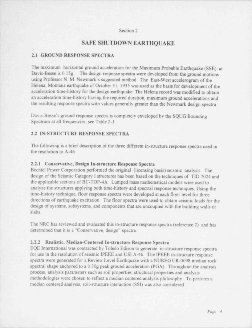
The maximum horizontal ground acceleration for the Maximum Probable Earthquake (SSE) at '
Davis-Besse is 0.15g. The design response spectra were developed from the ground motionsusing Professor N. M. Newmark's suggested method. The East-West accelerogram of theHelena, Montana eanhquake of October 31,1935 was used as the basis for development of theacceleration time-history for the design earthquake. The Helena record was modified to obtainan acceleration time-history having the required duration, maximum ground accelerations andthe resulting response spectra with values generally greater than the Newmark design spectra.
Davis Besse's ground response spectra is completely enveloped by the SQUG BoundingSpectrum at all frequencies, see Table 2-1.
4
2.2 IN-STRUCTURE RESPONSE SPECTRA
The following is a brief description of the three different in-stmeture response spectra used inthe resolution to A-46.
1
2.2.1 Conservative, Design In-structure Response SpectraBechtel Power Corporation perfonned the original (licensing basis) seismic analysis. Thedesign of the Seismic Category I structures has been based on the techniques of TID 7024 andthe applicable sections of BC-TOP-4A. Lumped mass mathematical models were used toanalyze the structures applying both time-history and spectral response techniques. Using thetime-history technique, floor response spectra were developed at each floor level for threedirections of earthquake excitation. The floor spectra were used to obtain seismic loads for thedesign of systems, subsystems, and components that are uncoupled with the building walls orslabs.
The NRC has reviewed and evaluated this in-structure response spectra (reference 2) and hasdetermined that it is a " Conservative, design" spectra.
2.2.2 Realistic, Median-Centered In-structure Response SpectraEQE International was contracted by Toledo Edison to generate in-structure response spectrafor use in the resolution of seismic IPEEE and USI A-46. The IPEEE in-structure responsespectra were generated for a Review Level Earthquake with a NUREG CR-0098 median rockspectral shape anchored to a 0.30g peak ground acceleration (PGA). Throughout the analysisprocess, analysis parameters such as soil properties, structural properties and analysis |
methodologies were chosen to reflect a median centered analysis philosophy. To perform a,
i median centered analysis, soil-structure interaction (SSI) was also considered. ;
Page 4
I ,
1 t
. . -_. . . - . - - - .
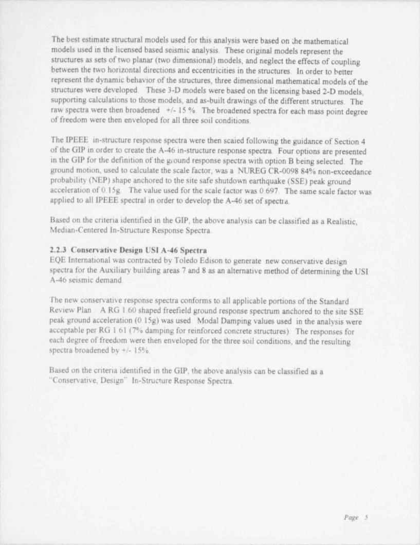
The best estimate stmetural models used for this analysis were based on 2e mathematical
models used in the licensed based seismic analysis. These original models represent thestructures as sets of two planar (two dimensional) models, and neglect the effects of couplingbetween the two horizontal directions and eccentricities in the structures. In order to betterrepresent the dynamic behavior of the structures, three dimensional mathematical models of the
stmetures were developed. These 3-D models were based on the licensing based 2-D models,supporting calculations to those models, and as-built drawings of the different structures. Theraw spectra were then broadened +/- 15 %. The broadened spectra for each mass point degreeof freedom were then enveloped for all three soil conditions.
The IPEEE in-structure response spectra were then scaled following the guidance of Section 4of the GIP in order to create the A-46 in-structure response spectra. Four options are presentedin the GIP for the definition of the giound response spectra with option B being selected. Theground motion, used to calculate the scale factor, was a NUREG CR-0098 84% non-exceedanceprobability (NEP) shape anchored to the site safe shutdown earthquake (SSE) peak groundacceleration of 0.15g. The value used for the scale factor was 0.697. The same scale factor wasapplied to all IPEEE spectral in order to develop the A-46 set of spectra.
Based on the criteria identified in the GIP, the above analysis can be classified as a Realistic,Median-Centered In-Structure Response Spectra.
2.2.3 Conservative Design USI A-46 SpectraEQE International was contracted by Toledo Edison to generate new conservative designspectra for the Auxiliary building areas 7 and 8 as an alternative method of determining the USIA-46 seismic demand.
The new conservative response spectra conforms to all applicable portions of the StandardReview Plan . A RG 1.60 shaped freefield ground response spectmm anchored to the site SSEpeak ground acceleration (0.15g) was used. Modal Damping values used in the analysis wereacceptable per RG 1.61 (7% damping for reinforced concrete structures). The responses foreach degree of freedom were then enveloped for the three soil conditions, and the resultingspectra broadened by +/- 15%.
Based on the criteria identified in the GIP, the above analysis can be classified as a" Conservative Design" In-Stmeture Response Spectra.,
:|
Page 5
- - _ _ _ - - _ _ _ - _ _ - _ _ - _ _ - _ - .

_ _- - .
. k
.
.
TABLE 2-1 r
1
. ;-.
- GROUND SPECTRA - BOUNDING SPECTRAt
0.8 - !
'
:-
,
!ZO 0.s -
ii' p
&. it
'
: m .c
a 3
:m ;
U 0.4 -
<-
;'
;
i 02 -
A
<
I 1 i f00 10 20 30 40
Hz
FREQUENCY
; SQUG BOUNDING SPECTRA vs. DAVIS-BESSE GROUND RESPONSE SPECTRA >
|\
-
| Page 6 )
|
I
. . _ _ _ . _ . _ _ - , . - . . - , . - _ , _ . _ - . . - _ _ . . . . . _ . . . - , - - .. - - . _ . . . . . - -. , , , . ..

.
Section 3
PROJECT TEAM
It was identified in the very early stages of planning for the SQUG project, that in would be inthe best interest of Toledo Edison that as much of the work associated with the resolution ofUSI A-46 be performed in house. The knowledge and experience gained through such aprogram would have long term benefits to Davis-Besse.
The Toledo Edison Seismic Capability Engineers were supplemented during the 8th and 9thRefueling Outages by qualified EQE International consultants.
3.1 UTILITY REPRESENTATIVES
3.1.1 The Safe Shutdown Equipment List (SSEL) was developed in house by Davis-Besse'sNuclear Engineering staff using the Operation Schematics and knowledge of the plant. The leaddeveloper of the SSEL has had extensive operations experience (including Shift Supervisor) atDavis-Besse. In addition, the individuals responsible for the development of the SSEL attendedthe SQUG sponsored Safe Shutdown Equipment Selection training.
3.1.2 The relay review and evaluation was performed by two experienced Toledo Edisonengineers. These individuals exceed the minimum requirements of Section 11.2.1.3 of the GIPfor the Lead Relay Reviewer. The r6 sum 6s for the Lead Relay Reviewers can be found inAttachment 2, Relay Evaluation Report.
3.1.3 The SSEL was reviewed and accepted by operations representatives using the requirementsidentined in Section II.2.3 of the GIP. In addition, the equipment identified on the SSEL wasused as a basis for training the site operators on the simulator for a seismic scenario and served
as a confirmation to the ability of the SSEL to provide an adequate shutdown path.
3.1.4 EQE International developed the SQUG response spectra by scaling the IPEEE ReviewLevel Earthquake for USI A-46 applications. In addition, they developed a conservative designspectra for a few areas of the plant.
3.2 SEISMIC CAPABILITY ENGINEERS
The Seismic Capability Engineers (SCEs) are the individuals responsible for implementing theseismic evaluations for the equipment on the Seismic Review Safe Shutdown Equipment List(Appendix C). These SCEs have acquired many years of formal and practical experience in thefield of structural and seismic design and analysis. These individuals exceed the minimumqualification requirements identified in Section 11.2.1.2 of the GIP. The r6 sum 6s for all of theSeismic Capability Engineers (SCEs) along with their SQUG training certificates are included inAppendix A.
I
Page 7
il
_. . _ . _ _ _

_ _. . _ . . . . . - - . _ _ - _ - . _ . _ _ _ . . . _ _ _ _ _ _ - _ _ _ _ _ _ _ _ _
,
I|
|
The following is a list of the on-site Toledo Edison individuals that comprised the seismicwalkdown teams:Jagdish C. Arora PE, Richard N. Bair PE, Thomas E. Dabrowiak PE, Jon G. Hook PE, |Steven J. Osting PE, and Scott R. Saunders. !
The following is a list ofindividuals supplied by EQE International that were used tosupplement our in-house teams at various times during the 8th and 9th Refueling Outages:
.
James R. Disser, John O. Dizon PE, Steven J. Eder PE, Gayle S. Johnson PE,'
Omar Khemici PE, and Basilio Sumodobila PEi
The SCEs were rotated amongst the different Seismic Review Teams to take advantage of their,
individual expertise. Many items were walked down with as many as 4 or 5 SCE. This was'
done early on in the walkdown phase to acclimate the team members as well as providing for '
good team interaction.
3.3 THIRD-PARTY AUDITORS
During the early stages of the walkdown program, two informal reviews were conducted byoutside contractors. The purpose of these informal reviews was to assess the effectiveness of thewalkdown teams in meeting the GIP requirements. In addition, two formal Third-Party Auditswere conducted, the first was mid-way through the program and a final audit at the end of theprogram.
Dr. John D. Stevenson of Stevenson & Associates performed a formal audit midway through theprogram at the request of Davis-Besse's Q.A. Department. Dr. Stevenson has approximately 30 |
years of experience in the seismic area, has been a contributor and reviewer of the of the SQUGprogram and has performed SQUG walkdowns and Third-Party Audits at other nuclear facilities.Dr. Stevenson is an industry recognized expert in the seismic field.
Dr. James J. Johnson of EQE International performed his Third-Party Audit at the conclusion ofthe walkdown phase of the program. Dr. Johnson has over 20 years experience in thedevelopment, implementation and teaching of seismic issues. Dr. Johnson has played asignificant role in the development of general and plant specific seismic evaluation procedures,including the SQUG program. Dr. Johnson has performed Third-Party Audits at other nuclearfacilities. Dr. Johnson is an industry recognized expert in the seismic field.
The results of Drs. Stevenson's and Johnson's review can be found in Section 10, Third-PartyAudit Summary.
;
{
!,'
,
Page 8 *
. _ _ - . _ - _ .
.-. - .= - - -. - ...._ - _-- - .- - - .-
Section 4
SAFE SHUTDOWN EQUIPMENT LIST
4.1 SAFE SHUTDOWN EQUIPMENT LIST PATH SELECTION
The Davis-Besse Safe Shutdown Equipment List (SSEL) was prepared in accordance withSection II.3 and Appendix A of the Generic Implementation Procedure (GIP) Revision 2,February 1992. The SSEL consists of components and equipinent lineups which can be usedfollowing a Safe Shutdown Earthquake (SSE) to bring the plant from a normal operatingcondition to achieve and maintain a safe shutdown condition. The criteria used in the selectionof the equipment is that the plant should be capable of being brought from normal operatingconditions to hot shutdown condition during the first 72 hours following a SSE. Hot Shutdownis defined within the Technical Specifications as being kgless than 0.99 and average coolanttemperature within the temperature range 200-280 F. The four safe shutdown functions of !
concern are reactor reactivity control, reactor coolant inventory control, reactor coolant pressure '
control, and decay heat removal.
The assumptions used in the identification of safe shutdown paths and required equipment are asfollows:
|
1. Offsite power may not be available for up to 72 hours following the earthquake. Thepossibility of not losing offsite power is also considered where adverse effects mayoccur.
2. No other extraordinary events or accidents (e.g., LOCAs, HELBs, fire, floods, extremewinds, sabotage) are postulated to occur other than the SSE and loss of offsite power.
3. If achieving and maintaining safe shutdown is dependent on a single item of equipmentwhose failure to perform its active function, either due to seismic loads or randomfailure, would prevent accomplishment of any of the four essential safe shutdownfunctions, an alternative method to provide safe shutdown by use of a different path or adifferent item of equipment will be identified for seismic evaluation. An equipmentfailure is defined as the failure of the active functional capability of the equipment, notnecessarily a failure ofits structural integrity.
4. Where operator actions are relied upon to achieve and maintain safe shutdown, theselection of safe shutdown paths and equipment are based on normal and emergency !operating procedures. Where necessary, additional guidance is provided in these
|procedures.
5. The equipment identified for seismic evaluation includes the following:
Active mechanical and electrical equipment which operates or changes state toa.
accomplish a safe shutdown function.,
Page 9r
-. - ._ . . . - . . - - --
b. Active equipment in systems which support the operation ofidentified safe shutdownequipment; e.g., p,wer supplies, control systems, cooling systems, lubricationsystems.
c. Instrumentation needed to confirm that the four safe shutdown functions have beenachieved and are being maintained. Instrumentation needed to operate the safeshutdown equipment.
d. Tanks and heat exchangers utilized within the identified safe shutdown paths.
e. Cable and conduit raceways which suppon electrical cable for the selected safeshutdown equipment.
6. The following equipment types were not identified for seismic evaluation.
Equipment which could possibly be operational, but is not necessary to operate due toa.
failing in a desired position or state. This type of equipment is defined as passive forthe purposes of this evaluation.
b. Passive equipment such as piping, filters, and electrical penetration assemblies.
c. Self-actuated check valves and manual valves.
d. Major items of equipment in the nuclear steam supply system, their supports, andcomponents mounted on or within this equipment such as the reactor pressure vessel,reactor fuel assemblies, reactor internals, control rods and their drive mechanisms,reactor coolant pumps, steam generators, pressurizer, and reactor coolant piping.
7. The following types of equipment are identified for use in the relay evaluation proceduredescribed in GIP Section 6:
a. Active, electrically-powered or controlled equipment.
b. Electrically-powered or controlled equipment considered passive but in whichspurious operation due to relay chatter could adversely affect safe shutdown of theplant.
B
Page 10

- . . - . - - . - - - . . - - -- - .-. - - - . . -.. - .~. - .
I
l
4.1.1 DISCUSSION OF SAFE SHUTDOWN FUNCTIONS AND SYSTEMS j
Consistent with the preferred normal plant line up for the makeup system, plant train 2 ;
equipment has been chosen as the primary safe shutdown path for the SQUG project. Thischoice was made because it was deemed less burdensome to Plant Operations rather than the useof alternative / standby systems. Also, the GIP requires the use of equipment in the normal mode,for the same reasons, where possible.
;
I. Reactivhv Control
A. Safe Shutdown Function: Reactor Reactivity Control
B. Paths Available
1. Control Rod insertion for short tenn reactivity control. t
2. Boron addition to the RCS for long term reactivity control using both borated waterstorage tank (BWST) and boric acid addition tanks (BAATs).
C. Primary / Backup Path Selection i
1. Short Term Reactivity Control
The following major components comprise the equipment necessary for the primaryand backup paths for short term reactivity control. Further details are listed on theSQUG drawings and SSEL.
Primary path: Manual reactor trip using one of the two manual reactor tripa.
push-buttons
b. Backup path: Manual reactor trip using the other of the two manual reactor trip '
push-buttons
2. Long Term Reactivity Control
The following major components comprise the equipment necessary for the primaryand backup paths for long term reactivity control. Further details are shown on theSQUG drawings and SSEL.
.
a. Primary path
i. BWST, Makeup Tank, and both BAATs
ii. Makeup Pump 2, Boric Acid Pump 2, Normal Makeup Injection Line
Page 11 i
|- _ . _ _ _ ._. _ -. . - - - _ - - _ _ --- . - _--
. -_. ._. _ _ ..
b. Backup path
i. BWST, Makeup Tank, and both BAATs
ii. Makeup Pump 1, Boric Acid Pump 1, Alternate Makeup Injection Line
D. Description of Primary and Backup Paths
As outlined above, short term reactivity control requirements are met by control rodinsertion. This is accomplished via manual reactor trip utilizing HS-NI46 as the primaryswitch, and HS-NI45 as the backup switch.
Long term reactivity control requirements during plant cooldown are met via boric acidaddition to the reactor coolant system (RCS). The Davis-Besse SSEL includesequipment required to place decay heat system in operation. As such, cold shutdownRCS boron concentrations are required. Accordingly, the makeup tank, boric acidpumps, and BAATs are required for long term reactivity control since the RCScontraction volume alone is insufficient in attaining adequate cold shutdown boronconcentrations when borating solely from the BWST. It would be possible to boratesolely from the BWST if a feed and bleed operation was established, but this wouldrequire undesirable bleed paths such as the PORV, or adding a significant number ofnon-seismic components to support the RCS letdown flow path. In addition, to supportoperation of the letdown line would also require component cooling water (CCW) to theletdown coolers and a flow path to the clean waste receiver tanks (CWRTs). BothBAATs are included in both the primary and backup paths because they are considered acommon source during normal plant operations. Boron samples from the RCS will notbe required to verify boric acid additions since the batch addition method can beconfirmed using makeup tank and pressurizer level indications. Dilution sources for theaddition of boric acid are not considered to be credible since these flow paths arenormally isolated by manual valves and the makeup pumps will be taking their suctiondirectly from either the BWST or the makeup tank.
E. Required Instrumentation
1. Shon Term Reactivity Control
Primary instruments for verification of short term reactivity control includemonitoring core neutron flux using channel 2 source range nuclear instmmentation.
Backup instruments for verification of short term reactivity control includej momtormg core neutron flux using channel I source range nuclear instrumentation.l|
Page 12
i
. _-__-_ __ . _ _- . .. .-- - -
2. Long Term Reactivity Control
Primary instruments for verification oflong term reactivity control will includechannel 2 source range nuclear instrumentation, zero percent zone reference lights forall control rods, and temperature monitoring of RCS loop 2 cold leg temperature, i
i
Backup instruments for verification oflong term reactivity control will include !channel 1 source range nuclear instrumentation, in limit zone reference lights for allcontrol rods, and temperature monitoring of RCS loop I cold leg temperature.Instrumentation for verification of boric acid additions will include the makeup tanklevel and pressurizer level indications. BAAT level indication is not requiredbecause boric acid additions may be confirmed by an increasing level in the makeuptank during the batch addition and BAAT level may be estimated using the methoddescribed in Abnormal Procedure DB-OP-02528, Loss ofInstrument Air, Rev. 2.
II. Inventory Control
A. Safe Shutdown Function: Reactor Coolant Systern Inventory Control
B. Paths Available
Inventory control is maintained by isolation of all non-essential discharge paths from theRCS to conserve RCS inventory. Additionally, water is added from the BWST with themakeup pumps to account for normal RCS leakage and the RCS contraction volumeduring RCS cooldown.
C. Primary / Backup Path Selection
The following major components comprise the equipment necessary for the primary andbackup paths for the inventory control function. Further details are shown on the SQUGdrawings and SSEL.
1. Primary path
a. BWST and hiakeup Tank
b. hiakeup Pump 2, Normal hiakeup Injection Line, and Seal Injection (Valves MU-66A through D held open via air volume tanks)
c. Isolation ofletdown will be accomplished by shutting valve MU-2B. Seal returnwill be maintained for the case in which offsite power is not lost, however, for aloss of offsite power, seal return may be isolated using the manual hand wheel toclose MU-38.
Page 13

2. Backup path
a. BWST and Makeup Tank
b. Makeup Pump 1, Alternate Makeup Injection Line, Seal injection (Valves MU-66A through D manually opened)
c. Isolation ofletdown will be accomplished by shutting valves MU-1 A and MU-IB. Seal return will be maintained for the case in which offsite power is not lost,however, for a loss of offsite power, seal return may be isolated using the controlroom switch to close MU-38.
D. Description of Primary and Backup Paths
The RCS pressure boundaiy is made up primarily of passive components with theexception of the letdown and seal return paths. Seal injection and seat return areincluded in the SSEL for reactor coolant pump (RCP) seal integrity, which is consideredpart of the RCS pressure boundary. Assuming a loss of offsite power, seal return is
.
desired, but not required if seal injection is maintained. However, in considering the !
effects of not losing offsite power, seal return is included in the SSEL to protect therunning RCP. Since the makeup pump will primarily be running with suction from theBWST, it is judged that CCW will not be required for the seal return coolers. In definingthe normal plant SQUG lineup, makeup pump 2 was assumed to be the initially runningpump. Makeup pump recirculation flow, when mixed with the seal return flow, willprovide sufficient cooling such that high makeup tank temperature will not be a problem.Makeup pump room cooling is not necessary for only one running makeup pump.
E. Required Instmmentation
Primary instrumentation for verification of inventory control will include bothpressurizer level and makeup tank level indications powered by train 2 power supplies.
Backup instrumentation for verification ofinventory control will include both pressurizerlevel and makeup tank level indications powered by train 1 power supplies.
III. Pressure Control
A. Safe Shutdown Function: Reactor Coolant System Pressure Control
B. Paths Available
1. The pressurizer heaters are used, as necessary, to raise saturation pressure within thepressurizer, and hence the RCS, by heat addition. Pressure reduction may beaccomplished by use of the PORV in venting steam to the pressurizer quench tank.
Page 14
.__ _ _- - _ _ _ _ _ _ _ _ _ - _ - _ _ _ _ _ _ _ _ _ _ _ _ _ _ _ _ _ _ _

- . - . - - ... .
RCS overpressure protection is also afforded by means of the pressurizer code safetyvalves which vent to the containment atmosphere.
2. Low temperature overpressure (LTOP) protection is satisfied by means of relief valveDH-4849. Valves DH-11 and DH-12 with the associated RCS pressure andpressurizer heater interlocks are required in establishing the necessary flow path withthe RCS.
3. Containment air coolers and their associated service water heat exchangers arerequired for containment heat removal.
C. Primary / Backup Path Selection
The following major components comprise the equipment necessary for the primary andbackup paths for the pressure control function. Further details are shown on the SQUGdrawings and SSEL.
1. Primary path
a. Pressurizer Quench Tank
b. Pressurizer Heater Essential Bank 2, Quench Tank Relief Valve RC-207,Pressurizer Code Safety Valve RC-13A, Relief Valve DH-4849 for LTOPprotection, and CAC 1-2
2. Backup path
a. Pressurizer Quench Tank
b. Pressurizer Heater Essential Bank 1, Pilot Operated Relief Valve (PORV),Pressurizer Quench Tank Rupture Disk PSE-226, Pressurizer Code Safety ValveRC-13B, Manual Use of PORV for LTOP Protection, and CAC 1-1
D. Description of Primary and Backup Paths
Maintaining temperature within the allowable pressure and temperature operating bandwill be accomplished using a combination of pressurizer heaters, the pressurizer vent lineto the quench tank, the PORV (RC-2A), and the pressurizer code safety valves (RC-13 Aand RC-13B). The water level in the pressurizer will be maintained above thepressurizer heaters by means of equipment chosen for the RCS Inventory Controlfunction. Additionally, LTOP protection for the RCS when below 280 F will beprovided by an open flow path to the decay heat removal (DHR) system suction reliefvalve (DH-4849). The backup method for providing LTOP protection will be bymanually controlling use of the PORV. The primary path for LTOP protection mayrequire electrically cross-connecting MCC F1I A and MCC ElIB in order to remotelyopen valve DH-12. Energy released from the quench tank to containment through the
Page 15!
i|

. -. . . . - .- --_ . ,
quench tank relief valve (RC-207) or rupture disk (PSE-226) will be removed by meansof the containment air coolers (CACs) which are cooled by the service water system.Energy removal from containment may be required if entry into containment isperformed to manually open DH-21 and DH-23 for the backup method of providing aDecay Heat Removal flow path. The containment energy removal equipment isarbitrarily included in the RCS Pressure Control function because this function implies apossible energy release from the RCS into containment.
E. Required Instrumentation
Primary instmments for verification of pressure control include indications for thefollowing parameters: channel 2 pressurizer level, channel 2 RCS pressure, channel 2RCS saturation temperature, RCS loop 2 cold leg temperature, CAC 1-2 suctiontemperature, and SFAS channel 2 containment pressure.
Backup instruments for verification of pressure control include indications for thefollowing parameters: channel I pressurizer level, channel 1 RCS pressure, channel 1RCS saturation temperature, RCS loop I cold leg temperature, CAC 1-1 suctiontemperature, and SFAS Channel I containment pressure.
IV. Decav Heat Removal
A. Safe Shutdown Function: Reactor Core Decay Heat Removal
B. Paths Available
With RCS pumps unavailable due to loss of offsite power, heat removal will be affordedby means of natural circulation with auxiliary feedwater (AFW) flow to the steamgenerators (SGs). AFW flow will be actuated by the Steam and Feedwater RuptureControl System (SFRCS) due to loss of all Reactor Coolant Pumps. Steam will bevented to atmosphere via either the main steam safety valves (MSSVs) or atmosphericvent valves (AVVs). Upon reaching a RCS temperature of 280 F, the DHR system willbe placed in operation, in which decay heat will be removed from the DHR coolers via.
the CCW and service water (SW) systems.
C. Primary / Backup Path Selection
The following major components comprise the equipment necessary for the primary andbackup paths for the decay heat removal function. Further details are shown on theSQUG drawings and SSEL
1. Primary path: SG 2, Main Steam Line 2 MSSVs, Actuation of SFRCS for AFWTrain 2, Manual Control of AVV ICS-11 A, DHR train 2 via DH-11 andDH-12.
Page 16

-.- . _ _ _ .
2. Backup path: SG 1, Main Steam Line 1 MSSVs, Actuation of SFRCS for AFWTrain 1, Manual Control of AVV ICS-1IB, DHR train 1 via DH-21 andDH-23.
D. Description of Primary and Backup Paths
Decay heat removal will be accomplished via natural circulation of the RCS with theAFW system adding feedwater to the steam generators. The SW system will besupplying feedwater to the AFW system since the condensate storage tanks areconsidered unavailable as a result of the seismic event. Steam from the steam generatorswill be discharged to the atmosphere through the MSSVs or the AVVs. This mode ofheat removal will perform the decay heat removal function until RCS pressure andtemperature conditions are established which will allow use of the DHR system. Becauseof this, the DHR system is included within the SSEL.
E. Required Instrumentation
Primary instmments for verification of decay heat removal include indications for thefollowing parameters: RCS loop 2 hot leg and cold leg temperatures, incorethermocouple temperatures, channel 2 RCS pressure, channel 2 pressurizer level, SG 2pressure, SG 2 startup level, and DHR loop 2 flow rate.
Backup instruments for verification of decay heat removal include indications for thefollowing parameters: RCS loop I hot leg and cold leg temperatures, incorethermocouple temperatures, channel 1 RCS pressure, channel 1 pressurizer level, SG 1pressure, SG 1 startup level, and DHR loop 1 flow rate.
1
I
;
,
I'
Page 17
___ - _ _ _ _ _ _ _ _ _ _ _ _ _ _

._ _ _ _ _._ _ _ __ _ _. ._ _ _ _ . _ _ _ . _ -
4.1.2 SUPPORTING EQUIPMENT
Support equipment required for the primary and backup equipment identified for each of the
four safe shutdown functions is included as a part of the SSEL. If the support equipment is onlyrequired for one of the safe shutdown functions, it has been included on the SSEL for that
particular function. If the support equipment is needed for success of multiple shutdownfunctions, it is included on the SSEL as a support system. Additional discussion on individualsupport systems is discussed below.
A. Service Water System
The assumed initial lineup is as shown on SQUG drawing 5-001 with SW train 1 andpump supplying primary plant cooling loads, and train 2 and its associated pumpsupplying secondary plant loads. The return header How cath to the intake forebay isused to provide ultimate heat sink cooling.
Manual valves may be closed to demonstrate a flow diversion boundary isolationbetween the primary and backup SSEL trains (most of the system check valves haveinternals removed). However, since structural failure of passive components is notassumed, flow diversion pathways are not expectei
B. Emergency AC Power
In the event offsite power is lost as a result of the earthquake, backup AC power will beprovided by at least one train of essential 4.16 KvAC via one of the emergency dieselgenerators (EDGs). The primary train is represented by EDG l-2 and the backup trainby EDG l-1. In addition to the EDG fuel oil day tanks, long-term operation of the EDGsis supported by including each train's respective fuel oil storage tank and supportingequipment on the SSEL to allow the plant to achieve hot shutdown within the 72 hour
mission time. It is assumed that following the seismic event, there is a sufficient quantityof air in the EDG air receivers to allow starting of the EDGs so that the starting aircompressors are not required for support. In the event offsite power is lost as a result ofthe earthquake, backup AC power will be provided by one of the Emergency DieselGenerators (EDGs). The primary train is represented by EDG l-2 and EDG l-1 providesbackup.
C. DC Power
DC power is supplied by either of the two trains (primary and backup) of batteries whicheach provide +125 vDC and -125 vDC supply of potential voltage. In the absence ofload shedding, the batteries are estimated to remain operational for at least 2 to 4 hours.
Page 18
__
. .. _ _ _ . - _ . _ _ -
i
D. Component Cooling Water System
The assumed initial lineup is as shown on SQUG drawing 5-002 with train 1 and its i
associated pump supplying primary plant cooling loads and train two and associated
pump in a standby condition. CCW surge tank level indication is required to support l
system inventory requirements with makeup supplied by the SW system.
E. Control Room Emergency Ventilation System jl
The control room emergency ventilation system (CREVS) is required following theseismic event to support control room equipment cooling needs and personnelhabitability. The normal control room ventilation system is non-seismic and requires thestation air system as a support system. Since the station and instrument air system is notconsidered available following the seismic event due to seismic ruggedness and offsitepower concerns, the normal control room ventilation system cannot be relied upon.
F. Miscellaneous Ventilation Systems
Other ventilation components have been added to the SSEL to support coolingrequirements for the low voltage switch gear rooms, the emergency diesel generators,and both the CCW and SW pump rooms.
G. Instrument AC Power Sources
Electrical buses YAU (backup train) or YBU (primary train) are required to support plant
instrumentation needs. All four 120 VAC essential instmmentation channels (via DCbackup) are assumed necessary for support of both the primary and backup flow paths.Protection of all four channels is necessary to prevent spurious isolation of flow paths iftwo channels of SFAS or SFRCS were to trip due to the consequences of a seismic event
II. Safety Features Actuation System (SFAS)
In order to prevent SFAS trips due to a loss of power to a particular SFAS Channel,power is maintained via the DC system cross tie to an alternate source. All four SFASChannels are required to prevent trips which may adversely affect desired system lineupsfor the various safe shutdown functions. The SFAS cabinets and system block switchesare also included on the SSEL to support the RCS pressure control function.
.
Page 19

4.2 DEVELOPMENT OF THE SAFE SHUTDOWN EQUIPMENT LIST (SSEL)
- Based on the above discussion, the SSEL was compiled using the step-by-step procedureoutlined in Appendix A of the GIP. The Operational Schematics (OSs) were chosen as thedrawings in which to highlight both primary and backup flow paths since they directly show theelectrical power supplies for most equipment. Manual vent valves, drain valves, and all samplepoints were not included in drawing highlights. All sample points were reviewed to ensure thata flow path diversion does not exist which could adversely impact a safe shutdown function.Electrical power supplies are included on the list at the level of detail shown on the appropriateOS drawing, e.g. power to a MOV or pump is shown traced back to the respective EDG,including breakers, MCCs, unit substations, etc. Not listed but required are the power suppliesto the below listed components. The appropriate power supply dependencies are reviewed as apart of the relay evaluation:
Instmmentation (sensors, string components, indicators, etc.).a.
b. Solenoid valves.
c. Hand indicating switches and local switches which require a power supply tosuccessfully operate.
Printouts of the SSEL database are included in Appendices B and C. Appendix B is a printoutof the Composite SSEL with associated notes, which includes equipment requiring SeismicReviews and Relay Reviews. Appendix C contains the Seismic Review SSEL.
1
t
Page 20
- - - - . . . - - -.-- _ . . ~ . . . - - . - - - . _ . . . _ - . _ _ _---
.- . - . . . . -
4.3 OPERATIONS DEPARTMENT REVIEW OF THE SSEL
A review of the Safe Shutdown Equipment List (SSEL) utilizing the Operations Schematicbased Seismic Qualification Utility Group (SQUG) figures and the appropriate Davis-Besseprocedures was conducted by a representative of the Operations Section. The Operations'reviewer has held a Senior Reactor Operator license for approximately 10 years and hasexperience in both Operations and Training Sections at Davis-Besse. In addition, the revieweris the procedure writer for Davis-Besse's Emergency Operating Procedure, DB-OP-02000, andhas played an active role in the maintenance of Operation's procedures used for normal andabnormal events. The reviewer is familiar with the General Criteria and GoverningAssumptions contained in Section 3.2 and the Scope of Equipment for the USI A-46 Programcontained in Section 3.3 of the of the Generic Implementation Procedure (GIP) Rev 02.
A desk top review was conducted using the following sequence of events as the basis for thereview:
1. A Main Turbine trip occurs due to vibration.
2. A Reactor trip occurs due to the Main Turbine trip.
3. Offsite power is lost.
4. The Steam and Feedwater Rupture Control System (SFRCS) actuates theAuxiliary Feedwater System due to the loss of all Reactor Coolant Pumps.
5. The SFRCS isolates Main Steam and Main Feedwater Systems due to Steam toFeedwater Differential Pressure Trip when Main Feed Pumps are lost due to lossof AC power.
6. No major primary or secondary (upstream of the Main Steam Isolation Valves)boundary failures occur.
Based on these events, the following is a summary of the procedures and the main ste: e thatwould be used to bring Davis-Besse to a safe shutdown condition.
1. Enter DB-OP-02000, RPS, SFAS, SFRCS, Trip or SG Tube Rupture, ImmediateActions. (Rev 04 used for review)
2. Complete Immediate Actions, steps 3.1 through 3.4.
3. Complete Supplemental Actions, steps 4.1 through 4.15. Step 4.15 will establishmanual control of the Atmospheric Vent Valves (AVV) using Attachment 3.
4. Enter DB-OP-06910, Trip Recovery (Rev 00 used for review)
!
l
,
me n|
_ __. __ - - _ _

_.
;
i
5. Complete step 3.1, routing to Section 4.0, Recovery from Reactor Trip and'
SFRCS Actuation.
6. Step 4.2 restores normal Makeup and Reactor Coolant Pump (RCP) Operation.Without offsite electrical power, RCP operation is not possible. This step allows Ishifting Makeup Pump suction to the Makeup tank, however, once the ReactorCoolant System (RCS) cooldown is started, the suction will be returned to theBorated Water Storage Tank (BWST) to accommodate RCS contraction.
7. Step 4.3 establishes Secondary Pressure control. Manual operation of the AVVswill be required. Condenser Vacuum can not be established without the
Circulating Water System Pumps that are not available without offsite power.
8. Step 4.4 restores normal secondary inventory control if possible. Based on theseismic event, secondary inventory control will remain on Auxiliary Feedwater.
9. Step 4.5 establishes a normal electrical alignment. A majority of these steps cannot be completed until offsite power is restored
10. Step 4.6 provides miscellaneous actions to be completed as time permits. Arouting step to Section 5 is provided.
I1. Section 5.0 provides direction to cooldown to the no load average temperature of532 F and stabilize at Hct Standby.
12. Once the decision to continue the cooldown is reached or the plant begins tocooldown based on the decay heat rate, routing is provided to DB-OP-06903,Plant Shutdown and Cooldown.
13. Enter DB-OP-06903, Plant Shutdown and Cooldown, Section 7, Cooldown on
Natural Circulation. (Rev 02 used for this review)
14. Section 7 is used in conjunction with Section 4, Cooldown of NSSS from HotStandby Condition, and Section 5, NSS Cooldown by Decay Heat to ColdShutdown, to cool the plant from 532 F to Cold Shutdown. These sectionsinclude steps that provide direction to establish operation of the Decay HeatRemoval System.
Thir review concluded that a trained licensed operator, without a need for an operatingprocedure following a seismic event, can follow the existing Davis-Besse procedures and willbe directed to use the Safe Shutdown Equipment and Instruments to cool the plant to HotShutdown conditions. Although direction to use Safe Shutdown Equipment and Instrumentswas not always provided as the primary procedure flowpath, no procedural flowpaths wereidentified that would prevent a trained licensed operator from completing the cooldown to theHot Shutdown condition.
Page 22

- . . . .- - .. ., - - . .. . - - _--
I
|The Davis-Besse Simulator was utilized to confirm the results of this desk top review. Nuclear
|Operation Training developed a scenario (ORQ-SIM-S134) that limited operator response to |only that equipment on the Safe Shutdown Equipment List. In addition, this scenario included
ia single failure (loss of one train of essential onsite AC power) that prevented the use of onetrain of essentially powered equipment. This scenario was presented to all six on-shift crews aswell as all oft-shift crews during normal Requalification Training (Cycle 95-04). No specifictraining was provided on seismic events or anticipated equipment response prior to presentingthis scenario. This training session served as an introduction to the Safe Shutdown EquipmentList for the Davis-Besse licensed operators.
Based on observations by the Simulator Instructors, this simulator scenario confirmed theresults of the desk top review. In addition, this scenario demonstrated that normal crew sizewas sufficient. It should be noted that based on time constraints, the scenario did not include acooldown to Hot Shutdown conditions, however control of equipment necessaiy to completethis cooldown was established.
Page 23

. - . . _ . - . .- _ _ _ - - - - . _ - _ - - -- .
Section 5
MECHANICAL AND ELECTRICAL EQUIPMENT REVIEW
5.1 SUMMARY OF REVIEW
The reviews of the seismic adequacy of mechanical and electrical equipment on the Davis-BesseSafe Shutdown Equipment List (SSEL) were performed in accordance with Section II.4 of theGeneric Implementation Procedure (GIP).
The Seismic Review Safe Shutdown Equipment List (Appendix C) is a sort on the seismic field -of the Composite Safe Shutdown Equipment List (SSEL) (Appendix B). The Seismic Review
SSEL was reviewed for the " rule-of-the-box" items which were then deleted from the list. Thislist became the basis for the seismic walkdown list, i.e. the Screening Verification Data Sheets(SVDS)(Appendix D).
Each piece of mechanical and electrical equipment on the seism. : walkdown list was walkeddown and evaluated by a minimum of two Seismic Capability En;tineers (SCEs), one of whichwas a Professional Engineer. In many cases, the teams consisted or m:: tm the minimumnumber of two SCE. In addition, each team consisted of at least one Toledo Edison engineer.
The walkdown portion of the SQUG program started just prior to our 8th Refueling Outage(Feb.1992). The majority of the walkdowns were performed during the 8th and 9th Refueling ,
Outages when access to the equipment was more available. During this time, craft assistance'
was used to provide access to various equipment to allow for an internal inspection and to i
perform anchor tightness checks.
i
Cabinets that contained essential relays were walked down with the Lead Relay Reviewer whoidentified the essential relays. The appropriate cabinet amplification factor was determinedbased on the relay (s) location, mounting configuration and the cabinet itself. This information
,
was used by the Lead Relay Reviewer to establish the relay seismic demand. !
The results of the seismic walkdown are documented on the Screening Verification Data Sheets |(SVDSs) along with the SVDS Certificate which are contained in Appendix D.
.
5.1.1 Seismic Canacity vs. Demand
The Davis-Besse ground response spectra is enveloped by the SQUG Bounding Spectrum andthe 1.5 times the Bounding Spectrum at all frequencies (see Table 2-1). The in-structureresponse spectra (Conservative, design and the Realistic, Median-centered spectra) is envelopedby the SQUG Bounding Spectrum at the lower elevations in the plant but not always at the
|higher elevations. The SCEs were cognizant of which areas in the plant were enveloped by the '
Bounding Spectrum, the 1.5 times the Bounding Spectrum and which areas were not.
Page 24
!- - . _ _ _ - _ - - - ____- _ _ _ ___-____-_ _

._ _
The " effective grade" elevations, as deDned in Section 11.4.2.3 of the GIP varied for eachstructure et the site. The effective grade was established in accordance with the GIP byaveraging the elevation of the ground surrounding the building along its perimeter.
The " effective grade" elevation for the buildings on-site that houses equipment on the SSEL areas follows:
Auxiliary Building Area 6 El.573' Containment Internal Structure El 565'
Auxiliary Building Area 7 El 562' Intake Structure El 569'
Auxiliary Buildmg Area 8 El 567' Yard structures El 585'
In cases where the equipment had a natural frequency of < 8 Hz and/or was located more thanabout 40 feet above the " effective grade", the seismic capacity was established by comparison toeither the 1.5 times the Bounding Spectrum, the Generic Equipment Ruggedness Spectrum(GERS) or existing documentation.
Equipment that could not be screened using the GIP criteria are classiDed as outliers, and arediscussed further at the end of this section.
5.1.2 Equipment Class Descriptions
The following is a brief description of the plant's SSEL equipment by equipment class.
Eauipment Class 1 Motor Control Centers
MCCs are located in the Auxiliary Building Area 6,7, and 8 as well as the Intake Structure. Themaximum Door elevation at which MCCs are located is El. 603' The manufacturer of theMCCs is Westinghouse Electric Corp. with the majority of the MCCs being Type W. TheMCCs are all Door mounted with the majority of the MCCs either top braced with a structuralchannel or have several rigid conduits supported close to the top.
Eauipment Class 2 I.ow Voltace SwitchuearThe two Low Voltage Switchgears are Door mounted in the Auxiliary Building Area 6 atEl.603' These Switchgears are supplied by General Electric.
Equipment Class 3 Medium Voltace SwitcheearThe four Medium Voltage Switchgears are Door mounted in the Auxiliary Building Area 6 atEl 585' and are supplied by Westinghouse Electric Corp.
Eauipment Class 4 TransformersThe four transformers fall wit':in two different sizes. The larger 4.16Kv units are located in theAuxiliary Building Area 6, El 603' and are supplied by General Electric.The smaller 480-240V units are located in the Auxiliary Building Areas 7 and 8 at El 603'These units are supplied by Square D.
|Page 25
. - - _ - _ _ - - -

.= -- - _ -- . _ . - -_. .- -
Eauipment Class 5 Horizontal Pumns
The horizontal pumps include the auxiliary feed pumps, boric acid pumps, borated waterrecirculating pumps, component cooling water pumps, containment spray pumps, decay heatpumps, high pressure injection pumps, and makeup pumps. These pumps are located in theAuxiliary Building Areas 7 and 8 at El 585' or below. The pumps are supplied by variousmanufacturers.
Eauipment Class 6 Vertical Pumns
The service water pumps are located in the Intake Structure at El. 576' and are manufactured byGould. The fuel oil transfer pumps are located in the yard area at El. 585' and are manufacturedby Crane Chem Pump.
Eauipment Class 7 Fluid-Operated Valves
Fluid-Operated Valves are located throughout the Auxiliary Building Areas 6,7, and 8 as well asthe Containment and are associated with a variety of systems. The maximum elevation thesevalves are located is El. 643' which are the main steam code safety valve and the atmosphericvent valves. A variety of manufacturers are used in supplying these fluid-operating valves.
Eauipment Class 8A Motor-Operated Valves
Motor-operated valves are located throughout the Auxiliary Building Areas 6,7, and 8 as well asthe Containment Building and the Intake Structure. These valves are associated with a varietyof manufacturers and systems.
Eauipment Class 8B Solenoid-Operated Valves
The solenoid-operated valves included in this class are associated with the auxiliary feed pumpsystem, control room air supply and the EDG air receiver system. These valves are located inthe Auxiliary Building Areas 6 and 7 at a maximum elevation of 603' A variety ofmanufacturers are used in supplying these solenoid-operated valves.
Eauipment Class 9 Fans
Fans, when not included as a sub-set to Equipment Class 10 Air Handlers, are associated withthe air intake or exhaust from the following rooms: auxiliary feed pump room; control room;battery room; component cooling water pump room; emergency diesel generator room; IntakeStructure; and the switchgear room. These fans are located in the Auxiliary Building Areas 6and 7 as well as the Intake Stmeture. The maximum elevation for these fans is 638' A varietyof manufacturers are used in supplying these fans.
Eauipment Class 10 Air Handlers
Air Handlers class of equipment includes the containment air coolers, the ECCS room coolersand the control room emergency ventilation system. This equipment is located in the AuxiliaryBuilding Areas 7 and 8 as well as the Containment. The maxim m elevation of this equipmentis the Auxiliary Building roof at El. 660' A variety of manufacturers are used in supplyingthese air handlers.
Eauipment Class 11 Chillers
There is no equipment class 11 on the SSEL.
Page 26
- ._ -___ - _ - _ _ _ _ . - - _ _ -
Eauipment Class 12 Air Compressors
The Air compressors on the SSEL are associated with the Emergency Diesel Generator airreceiver skid. These compressors are located in the Auxiliary Building Area 6 at elevation585'
Eauipment Class 13 Motor-Generators
There is no equipment class 13 on the SSEL.
Equinment Class 14 Distribution Panels
Distribution panels consist of essential distribution panels, essential instrumentation distributionpanels, and the uninterrupted power instrumentation distribution panel. These panels are locatedthrough-out the Auxiliary Building Area 6,7, and 8 as well as the Containment .
Eauipment Class 15 Batteries on Racks
The Station batteries are the only batteries on racks that are identified on the SSEL. The stationbatteries are located in the Auxiliary Building area 6 at El. 603' The manufacturer of thebatteries is GNB Batteries Inc.
Eauipment Class 16 Battery Charcers and Inverters
The battery chargers and inverters associated with the station batteries are located in the,
Auxiliary Building Area 6 at El. 603'.|
Eauinment Class 17 Enuine-GeneratorsThe Emergency Diesel Generators (EDG) are the only equipment class 17 components. TheEDGs are located in the Auxiliary Building Area 6 at El. 585' The manufacturer of the EDGsis General Motors Electro-Motive Division.
Eauinment Class 18 Instruments on RacksInstmments on Racks are located through-out the Auxiliary Building Areas 6,7, and 8 as well asthe Containment Building, and the Intake Structure. These instmments are manufactured by avariety of companies.
Eauipment Class 19 Temocrature Sensors
The temperature sensors on the SSEL are associated with the Reactor Coolant system. Thisequipment is located in the Containment Building at various elevations.
i
Eauinment Class 20 Instrumentation and Control Panels and CabinetsThe equipment included in this class of equipment include the Control Room consoles andupright panels, control room emergency ventilation system cabinets, disconnect switch cabinets,
i
EDG control panels, post accident equipment, relay cabinets, SFAS, SFRCS and smallmiscellaneous control panels. This equipment is located through-out the Auxiliary BuildingAreas 6,7, and 8 as well as the Containment Building, Intake Structure and the Yard area.
Page 27
- - _ _ _ - _ - - _ _ _ _ _ _ _ _ _ _ _ - - .

_ _ _ _ _-- _
Eauipment Class 0 Other
When equipment identined on the SSEL do not fall within the criteria of one of the above
equipment classes, it is classi6ed as Other and 'oecomes an Outlier. The following pieces ofequipment have been reviewed and determined to fall within this category: motor operated andpneumatic operated HVAC dampers; Emergency Diesel generator air intake filter; power reliefvalve; safety rupture disks; service water strainers; and portable temperature indicators.
Table 5-6 is a listing of the individual equipment that falls within this category along with thecorresponding outlier resolution.
5.1.3 Equipment Anchornee
Several different types of anchorage methods were used to anchor the equipment on the SSEL tothe structure. The most popular type of anchorage used is the expansion anchor. However, cast-in-place J-Bolts, thm-bolts, as well as embedded channels were used.
Both stud and shell type expansion anchors were used for anchoring. The stud type anchors usedare: Hilti Kwik Bolts, Phillips Wedge and the Wej-It wedge anchors. The shell type anchorsused are: Hilti HDI, and the Phillips Self-Drilling anchors.
The appropriate capacity reduction factors were used including the SQUG recommendedknockdown factor of 0.5 for Wej-it wedge anchors.
Per Section 11.4.4.1 of the GIP, anchorage tightness checks were verified by one of the followingmethods:
Anchors in tension, due to self weight, are not required to be checked.
A tug test was performed on small light weight equipment.
Forgo the tightness check if the anchorage was judged to be " robust" (i.e. installation.
exhibited large margin between the applied load and the anchorage capacity)Inaccessible anchors were verified adequate by either visual inspection of the installation.
(i.e. lock washer fully compressed under the nut) orjudged to be adequate based on similarinstallations.The SCEs performed the tightness check with a wrench on the remainder of the anchors.
A sample of shell type expansion anchors were inspected and found to be properly set.
Equipment whose anchors do not meet the GIP screening criteria are classified as outliers, andare discussed at the end of this section.
5.1.4 Seismic InteractionThe screening evaluations included evaluation for potential seismic interaction concerns, perGIP Section II.4.5 and Appendix D. Any seismic interaction concerns identified are classified as
,
outliers, and are discussed at the end of the this section. I
i
Page 28
_ . _ . _- - _ . _ . _ _ _ . . _ _ _ - _ _ . _ . . _ _ _ _ _ _ _ _ _
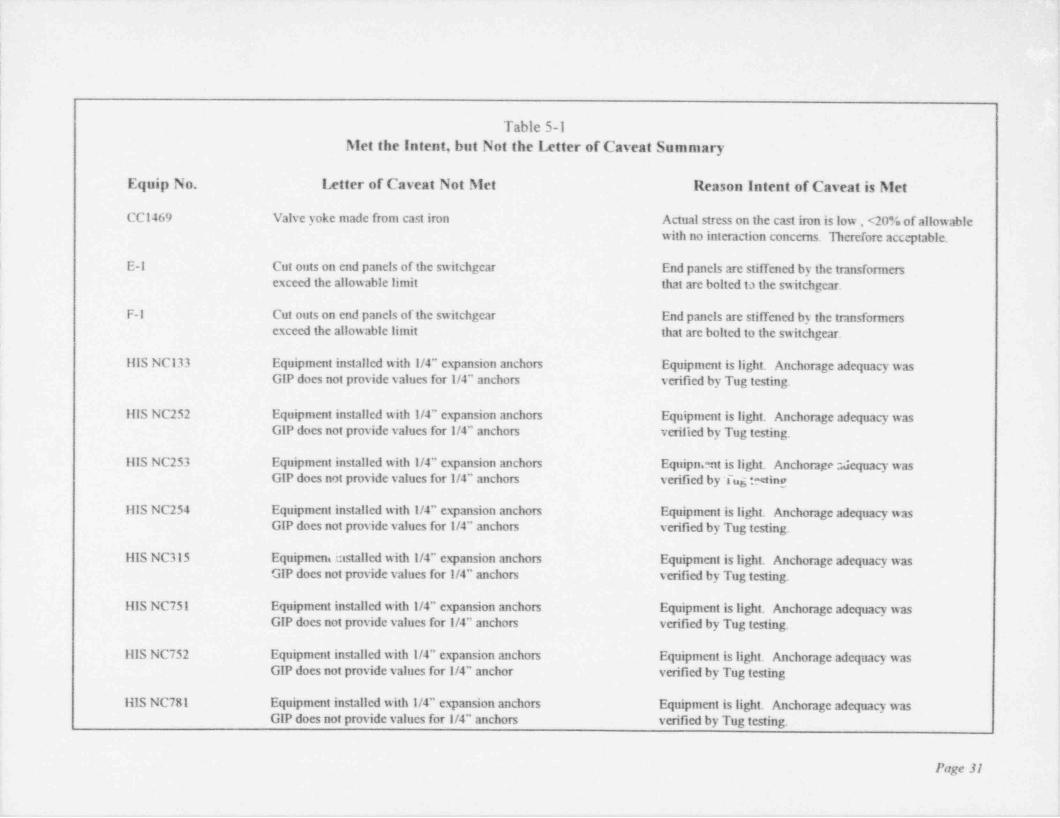
5.2 INSTANCES OF INTENT BUT NOT THE LETTER OF THE CAVEAT MET:
Instances in which the intent of a caveat is met without meeting the speci6c wording of the :
caveat rule are identiDed in Table 5-1.,
5.3 SUMMARY OF OUTLIERS -
}A total of 155 outliers were identined affecting 122 pieces of equipment out of 531 pieces ofequipment identi6ed on the Davis-Besse's SVDS. This includes 53 outliers affecting 53 piecesof equipment that did not fall within the SQUG's "20 Classes of Equipment" criteria. Several i
pieces of equipment may have had multiple outliers written against them. A short description of ,
each equipment outlier and its resolution are provided in the following Tables:
Table 5-2 Anchorage Outlier Description and Resolution SummaryTable 5-3 Capacity Vs Demand Outlier Description and Resolution SummaryTable 5-4 Caveat Outlier Description and Resolution SummaryTable 5-5 Interaction Outlier Description and Resolution SummaryTable 5-6 "Other" Outlier Description and Resolution Summary
1
!
!
Page 29

,
'?
.
Table 5-1Met the Intent, but Not the Ixtter of Caveat Summary i
,
Equip No. Letter of Cavent Not Met Reason Intent of Cavent is Met !
C3645 Cabinet installed with 1 1/4" expansion anchors 1" anchor allowables were used in analysis fGlP provides anchor allowables up to 1" diameter and found acceptable
C3645 Cabinet Omtains pmgrammable controllers Pmgrammable controllers were qualified in ;
accordance with IEEE 344-75 and foundacceptable
C4625 Cabinet installed with 1 1/4" expansion anchors 1" anchor allowables were used in analysis |GlP provides anchor allowables up to 1" diameter and found acceptable .|
|C4625 Cabinet contains programmable controllers Programmable contmllers were qualified in !
i accordance with IEEE 344-75 and found I
acceptable !$
C73-1 Fan base isolators not evaluated in accordance with He fan is suspended fmm the ceiling and[Section 4.4 of the GIP does not resist lateral forces. Herefore, the !
concern identified in Section 4.4 of the GIP is !not applicable. I
!
C73-2 Fan base isolators not evaluated in acconiance with he fan is suspended from the ceiling and [,'
Section 4.4 of the GIP does not resist lateral forces. Herefore, the "
'
concern identified in Section 4.4 of the GIP isnot applicable. j
r
CCl467 Valve yoke made from cast iron Actual stress on the cast iron is low , <20% of allowable Iwith no interaction concerns. Herefore acceptable. I
r
!
I
f!(
Page 30 ;
;
;
. _ . _ . _ . . - - . . _ . - . . _ _ _ _ _ _ _ . , . ~ . _ _ _ _ . . , . . . _ . _ _ . . . . _ _ _ . _ - . . _ . . _ _ . . _ _ . . . . . _ _ . _ . _ . . _ . . ._.
!
|:
Table 5-1Met the Intent, but Not the Letter of Caveat Summary
Equip No. Letter of Caveat Not Met Reason Intent of Caveat is Met
CCl469 Valve yoke made from cast iron Actual stress on the cast iron is low , <20% of allowablewith no interaction concerns. Therefore acc ptable.
I E-1 Cut outs on end panels of the switchgear End panels are stiffened by the transformersexceed the allowable limit that are bolted ta the switchgear.
F-1 Cut outs on end panels of the switchgear End panels are stiffened by the transformersexceed the allowable limit that are bolted to the switchgear.
IIIS NCl33 Equipment installed with 1/4" expansion anchors Equipment is light. Anchorage adequacy wasGIP does not provide values for I/4" anchors verified by Tug testing.
Ills NC252 Equipment installed with 1/4" expansion anchors Equipment is light. Anchorage adequacy wasGIP does not provide values for 1/4" anchors verified by Tug testing.
HIS NC253 Equipment installed with 1/4" expansion anchors Equipn. nt is light. Anchorage ::Jequacy wasGIP does not provide values for 1/4" anchors verified by Tug :-< ting
ills NC254 Equipment installed with 1/4" expansion anchors Equipment is light. Anchorage adequacy wasGIP does not provide values for 1/4" anchors verified by Tug testing.
111S NC315 Equipmeni installed with 1/4" expansion anchors Equipment is light. Anchorage adequacy wasGlP does not provide values for 1/4" anchors verified by Tug testing.
I{lS NC751 Equipment installed with 1/4" expansion anchors Equipment is light. Anchorage adequacy wasGIP does not provide values for 1/4" anchors verified by Tug testing.
lilS NC752 Equipment installed with 1/4" expansion anchors Equipment is light. Anchorage adequacy wasGIP does not provide values for 1/4" anchor verified by Tug testing
i
lilS NC781 Equipment installed with 1/4" expansion anchors Equipment is light. Anchorage adequacy wasGIP does not provide values for 1/4" anchors verified by Tug testing.
Page 31

Table 5-1Met the Intent, but Not the Letter of Caveat Summary
Equip No. Letter of Caveat Not Met -
i
filS NC782 Equipment installed with 1/4" expansion anchors Equipment is light. Anchorage adequacy wasGlP does not provide values for 1/4" anchors verified by Tug testing.
K3-1 Pump / motor installed with 1 1/2 expansion anchors 1" anchor allowables were used in analysis.GlP provides anchor allowables up to 1" diameter
K3-2 Pump / Motor installed with 11/2 expansion anchors I" ancho '!awables were used in analysis.'
GlP provides anchor allowables up to 1" diameter
h1U-19 Valve actuator and yoke are supported independently Actuator is supported on the wallof pipe. three feet from n here pipe is supported. i
Therefore relative motion is judged tobe negligible.
h1U-38 Valve actuator and yoke are supported independently Pipe is well supported close to the valveof pipe. Relative motion is judged to be negligible.
h1U46A Valve actuator and yoke are supported independently Original analysis showed that differential displacementofpipe. is not a concern.
h1U66B Valve actuator and yoke are supported independently Original analysis showed that differential displacementofpipe. is not a concern.
h1U66C Valve actuator and yoke are supported independently Original analysis showed that differential displacementofpipe. is not a concern.
MU66D Valve actuator and yoke are supported independently Original analysis showed that differential displacementofpipe. is not a concern.
i;
Page 32
I

,
Table 5-1Met the Intent, but Not the Letter of Caveat Summary
4
Equip No. Letter of Caveat Not Met Reason Intent of Caveat is Meti
NV-55980 Instrument is anchored to the wall with thru-bolts Anchorage is acceptable due to low loads ;His type of anchorage is not identified in the GIP.
P14-1 Pump /hiotor installed with 1 1/2" expansion anchors 1" anchor allowables were used b analysis.GIP provides anchor allowables up to 1" diameter
P14-2 Pump /hfotor installed with 1 1/2" expansion anchors 1" anchor allowables were used in analysis. [GIP provides anchor allowables up to I" diameter
!
PI-h1U52A Instrument is anchored to a blockwall. GIP does not Equipment is light. Anchorage adequacy was I
provide anchor capacity when installed in blockwalls. verified by Tug testing, :|
PI-AlU52B Instrument is anchored to a blockwall. GIP does not Equipment is light. Anchorage adequacy was ;
provide anchor capacity when installed in blockwalls. verified by Tug testing.I
RC 200 Valve actuator and yoke are supported independently Actuator and pipe are both anchored toof the pipe. the same wall, and relative motion is i
judged to be negligible.
RC 239A Valve actuator and yoke are supported independently Actuator and pipe are both anchored toof the pipe. the same wall, and relative motion is
,
!judged to be negligible.
!SS-598 Valve actuator and yoke are supported independently he piping analysis considered the independently I
ofpipe. supported actuator and the stresses are acceptable.,
Analyzed and stresses are within the allowables. !
-
,
!
;
{Page 33 ;
i
_ . . _ . . - , _ - - - - - - - - - _ . - - _. -- --,. --_.. - - . . ~ - - - . - - - . . - - - - - - - - - - -- - ---- - - - - - - - - - - - - - - - - - - - - -

Table 5-1Met the Intent, but Not the Letter of Caveat Summary
Equip No. Letter of Caveat Not Met Reason Intent of Caveat is Met i
SS-598 Valve is on a pipe smaller than I" in diameter He piping system with the valve has beenanalyzed and stresses are within the allowables.
SS-607 Valve actuator and yoke are supported independently The piping analysis considered the independently;of pipe. supported actuator and the stress are acceptable.|t
SS-607 Valve is on a pipe smaller than 1" in diameter ne piping system with the valve has beenanalyzed and stresses are within the allowables *
SW-5896 He GERS for equip, class 7 requires only carbon steel Re GlP's concern is with cast iron and not stainlessvalves. De valve is made out of stainless steel. steel. Therefore; this is acceptable
r
SW-5997 The GERS for equip, class 7 requires only carbon steel The GIP's concern is with cast iron and not stainlessvalves. He valve is made out of stainless steel. steel. Therefore; this is acceptable
!TE-5443 Instrument is anchored to the wall with thru-bolts Anchorage is acceptable due to low loads. |
This type of anchorage is not identified in the GIP.
TIC 5443 Instrument is anchored to a blockwall. GIP does not Anchorage is acceptable due to low loads i;provide anchor capacity when installed in blockwalls.r
iTIC 5444 Instrument is anchored to a blockwall. GIP does not Anchorage is acceptable due to low loads iprovide anchor capacity when installed in blockwalls.
\TS-4688 Instrument is anchored to the wall with thru-bolts Anchorage is acceptable due to low loads
4
;His type of anchorage is not identified in the GIP.
.
!TT-5443 Instrument is anchored to the wall with thru-bolts Anchorage is acceptable due to low loads
This type of anchorage is not identified in the GIP. I
t
! !
Page 34 s
i
_ .-__ ,_ -.-- _-- . - . - .. ~ - - . . - . - _ . . - -.- - - _. - -. .- - . - - . . - . . . . - . -. . - . - . . . . .

,
Table 5-2Anchorage Outlier Description and Resolution Summary
Equipment ID Location Outlier Description Outlier Resolution!
C-2 Aux El. 585 Flexible base connections results in Relocate the relay and remove C-2an inadequate load path from the SSEL
Ref. h10D 95-0023!
C25-2 Aux El. 585 Expansion anchor did not meet the A reduction factor was used andminimum embedment of the GIP. based on light loads the
anchorage is acceptable.
C25-3 Aux El. 585 Expansion anchor did not meet the A reduction factor was used and i'
minimum embedment of the GIP. based on light loads theanchorage is acceptable.
lC25-4 Aux El. 585 Expansion anchor did not meet the A reduction factor was used andminimum embedment of the GIP. based on light loads the
anchorage is acceptable.F
C5755C Aux El. 623 Anchorage for adjacent cabinet (C5755 E & F) hiodify existing anchorage Iis not adequate when C5755C is bolted to it Ref. MOD 9' '032 !
to prevent cabinets from banging. t?rC5755D Aux El. 623 Anchorage for adjacent cabinet (C5755E & F) Modify existing anchorage [
is not adequate when C5755D is bolted to it Ref. MOD 95-0032 :to prevent cabinets from banging. '
C5755G Aux El. 623 Anchcrage for adjacent cabinet (C5755E & F) Modify existing anchorage #
is not adequate when C5755G is bolted to it Ref. MOD 95-0032to prevent cabinets from banging.
I
!
t
I
:>
Page 35
i
___ __ __ __ . _ _ . , . ._. _ __ . . - - . - - , .- - . -_ . _ - . _ _ _ - _ _ _ _ . - - _ - _ _
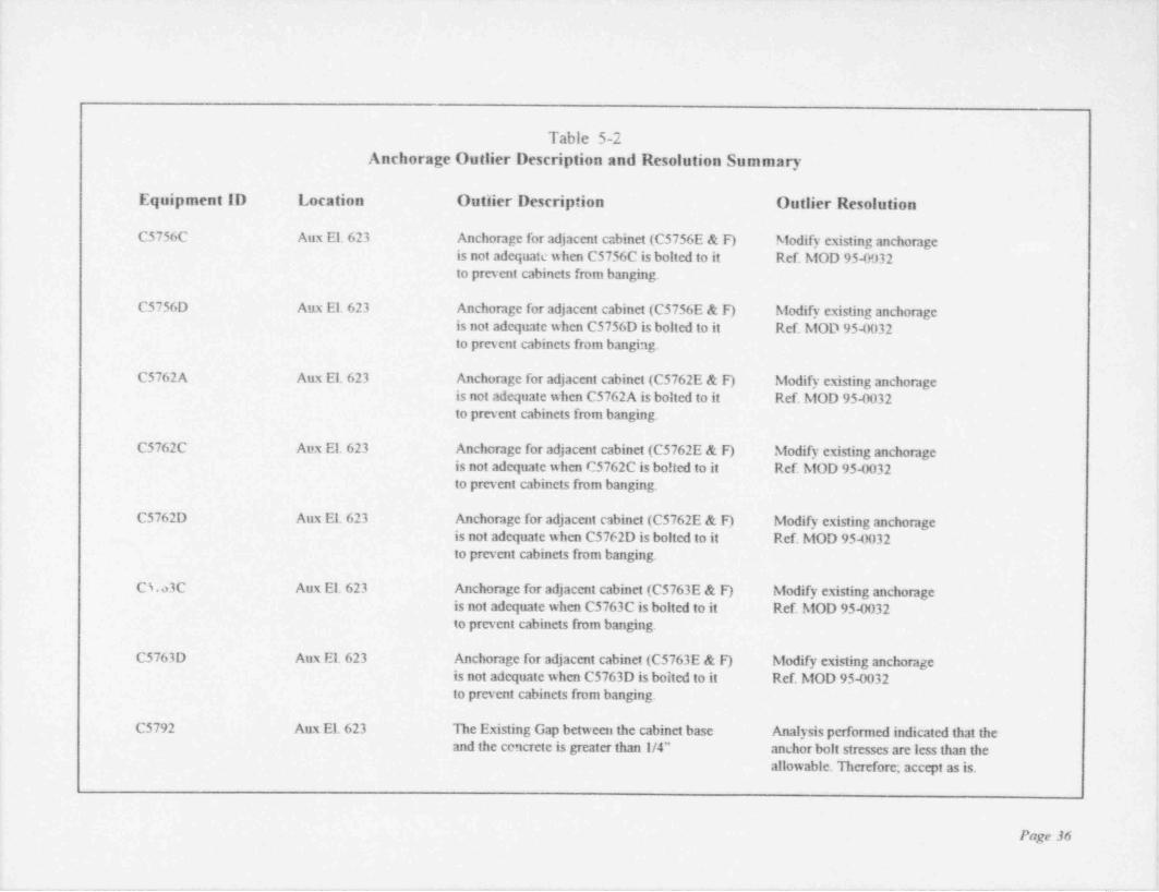
Table 5-2Anchorage Outlier Description and Resolution Summary
Equipment ID Location Outlier Description Outlier Resolution
C5756C Aux El. 623 Anchorage for adjacent cabinet (C5756E & F) Nfodify existing anchorageis not adequate w hen C5756C is bolted to it Ref. h10D 95-0932to prevent cabinets from banging.
C5756D Aux El. 623 Anchorage for adjacent cabinet (C5756E & F) hiodify existing anchorageis not adequate when C5756D is bolted to it Ref. h10D 95-0032to prevent cabinets from banging.
C5762A Aux El. 623 Anchorage for adjacent cabinet (C5762E & F) hiodify existing anchorageis not adequate when C5762A is bolted to it Ref. Af0D 95-0032to prevent cabinets from banging.
C5762C Aux El. 623 Anchorage for adjacent cabinet (C5762E & F) hiodify existing anchorageis not adequate when C5762C is bolted to it Ref. AlOD 95-0032to prevent cabinets from banging.
C5762D Aux El. 623 Anchorage for adjacent cabinet (C5762E & F) hiodify existing anchomgeis not adequate when C5762D is bolted to it Ref. h10D 95-0032to prevent cabinets from banging.
C L3C Aux El. 623 Anchorage for adjacent cabinet (C5763E & F) Afodify existing anchorageis not adequate when C5763C is bolted to it Ref. h10D 95-0032to prevent cabinets from banging.
C5763D Aux El. 623 Anchorage for adjacent cabinet (C5763E & F) hiodify existing anchorageis not adequate when C5763D is boited to it Ref. h10D 95-0032to prevent cabincts from banging.
C5792 Aux El. 623 The Existing Gap between the cabinet base Analysis performed indicated that theand the cencrete is greater than 1/4" anchor bolt stresses are less than the
allowable. Therefore; accept as is.
Page 36
_ . _ _ _ _ _ _ . _ _ __ _ _ - _ _ _ _ _ _ _ _ _ _ _ _ _ _
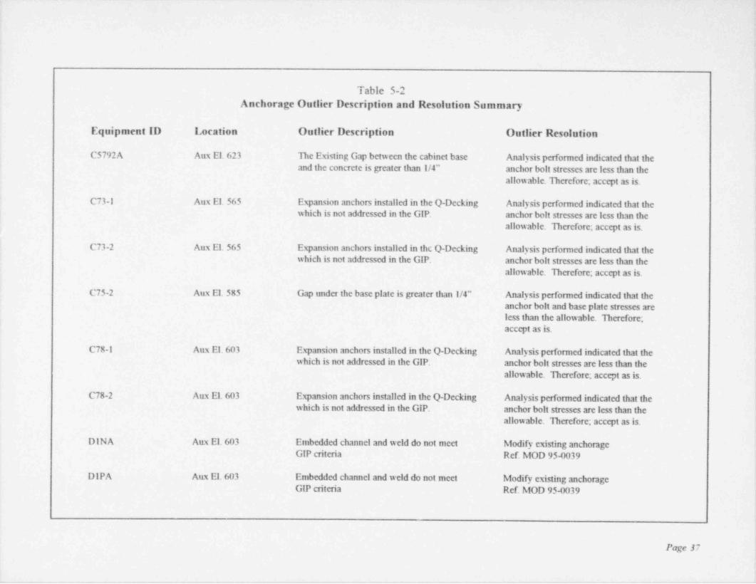
Table 5-2Anchorage Outlier Description and Resolution Summary
Equipment ID Location Outlier Description Outlier Resolution
C5792A Aux El. 623 He Existing Gap between the cabinet base Analysis performed indicated that theand the concrete is greater than 1/4" anchor bolt stresses are less than the
allowable. Herefore; accept as is.
C73-1 Aux El. 565 Expansion anchors installed in the Q-Decking Analysis performed indicated that thewhich is not addressed in the GIP. anchor bolt stresses are less than the
allowable. Therefore; accept as is.
C73-2 Aux El. 565 Expansion anchors installed in the Q-Decking Analysis performed indicated that thewhich is not addressed in the GIP. anchor bolt stresses are less than the
allowable. Therefore; accept as is.
C75-2 Aux El. 585 Gap under the base plate is greater than 1/4" Analysis performed indicated that theanchor bolt and base plate stresses areless than the allowable. Therefore;accept as is.
C78-1 Aux El. 603 Expansion anchors installed in the Q-Decking Analysis performed indicated that thewhich is not addressed in the GIP, anchor bolt stresses are less than the
allowable. Herefore; accept as is.
C78-2 Aux El. 603 Expansion anchors installed in the Q-Decking Analysis performed indicated that thewhich is not addressed in the GIP. anchor bolt stresses are less than the
allowable. Therefore; accept as is.
DINA Aux El. 603 Embedded channel and weld do not meet Modify existing anchorageGIP criteria Ref. MOD 95-0039
DIPA Aux El. 603 Embedded channel and weld do not meet Modify existing anchorageGIP criteria Ref. MOD 95-0039
!
Page 37
-

-;
Table 5-2,
Anchorage Outlier Description and Resolution Summary [,
Equipment ID Location Outlier Description Outlier Resolution - |h,
! El Aux El. 603 Anchor bolts do not meet GIP allowables Modify existing anchorage '
f when all of the GIP reduction factors are Ref. MOD 95-0030 '
j applied
|i'
E12C ITK. El. 576 MCC is anchored with Nelson studs with less Analysis performed indicated that the |than the minimumlength specified existing anchorage detail is adequate.
Herefore; accept as is. i
'.E16B Aux El. 623 MCC is anchored with Nelson studs with less Analysis performed indicated that the
"
,
than the minimum length specified existing anchorage detail is adequate. !
Therefore; accept as is.[
E37-1 CTM El. 585 Embedment length of the J-Bolt is less Analysis performed indicated that thethan the GIP minimum value existing anchorage detail is adequate. r
nerefore; accept as is. :i
E37-2 CTM El. 585 Embedment length of the J-Bolt is less Analysis performed indicated that thethan the GlP minimum value existing anchorage detail is adequate.
Derefore; accept as is. '
!E37-3 C111 El. 585 Embedment length of the J-Bolt is less Analysis performed indicated that the jthan the GIP minimum value existing anchorage detail is adequate.
1
Herefore; accept as is.
F1 Aux El. 603 Anchor bolts do not meet GIP allowables Modify existing anchorage,
when all of the GIP reduction factors are Ref. MOD 95-0030 '
appliedi
F12D ITK El. 575 MCC is anchored with Nelson studs with less Analysis performed indicated that the [than the minimum length specified existing anchorage detail is adequate. !
Therefore; accept as is. t
ii
Page 38
i. _ __ _.___ _ _, _ _ - - . . . - - . - . _ . _ . _ . . . . _ , .- - - - , _ . . _ _ _ . . _ , .- - . . . . _ - . . _ _ _ . - - - !
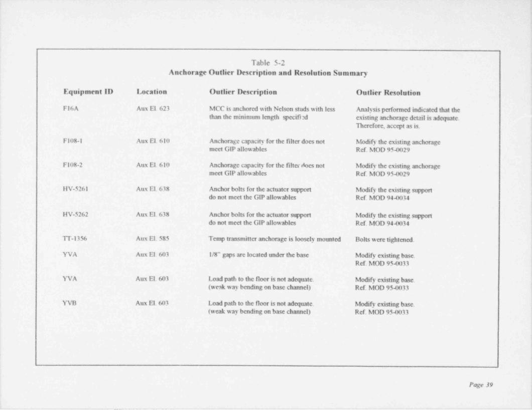
,
Table 5-2Anchorage Outlier Description and Resolution Summary
Equipment ID Location Outlier Description Outlier Resolution
F16A Aux El. 623 htCC is anchored with Nelson studs with less Analysis performed indicated that the ;
than the minimum length specifi:d existing anchorage detail is adequate. *
Therefore, accept as is.
F108-1 Aux El 610 Anchorage capacity for the filter does not hiodify the existing anchorage i
meet GIP allowables Ref h10D 95-0029,
F108-2 Aux El. 610 Anchorage capacity for the filter does not hiodify the existing anchorage ;
meet GIP allowables Ref. h10D 95-0029 j
IIV-5261 Aux El. 638 Anchor bolts for the actuater support h1odify the existing support;,
i do not meet the GIP allowables Ref. h10D 94-0034
r
HV-5262 Aux El. 638 Anchor bolts for the actuator support hiodify the existing support; do not meet the GIP allowables Ref. h10D 94-0034 !
TT-1356 Aux El. 585 Temp transmitter anchorage is loosely mounted Bolts were tightened.
YVA Aux El. 603 1/8" gaps are located under the base biodify existing base.Ref. h10D 95-0033
YVA Aux El. 603 Load path to the floor is not adequate. hiodify existing base.,
(weak way bending on base channel) Ref. htOD 95-0033
YVB Aux El. 603 Load path to the floor is not adequate. hiodify existing base.(weak way bending on base channel) Ref. h10D 95-0033
:
i
Page 39
|i
___ ____- __ _. - .-- - - - . . . .-. - . - . _ ..

._
Table 5-3Capacity Vs Demand Outlier Description and Resolution Summary
Equipment ID Location Outlier Description Outlier Resolution.
C5759D Aux El. 623 Here is no existing documentation Remove the relay that is located insideto establish seismic capacity the cabinet to a location with known
seismic capacity.Ref. h10D 95-0019
11V-5261 Aux El. 638 Documentation to establish capacity hiodify support to conform tobased on actualinstallation is not documentation requirementsavailable Ref. h10D 94-0034
IIV-5262 Aux El. 638 Documentation to establish capacity hiodify support to conform tobased on actualinstallation is not documentation requirementsavailable Ref. h10D 94-0034
,
,
Page 40
- - . - - -- .. .-. .- - .-- . - - - - . .- - .-. - - _ . .. -- _ - - - -

___
Table 5-4Caveat Outlier Description and Resolution Summary
Equipment ID Location Outlier Description Outlier Resolution
C21-1 Aux El. 585 Base vibration isolators do not provide hiodify existing anchorageadequate restraint of overtuming moment. Ref. h10D 95-0031
C21-2 Aux El. 585 Base vibration isolators do not provide hiodify existing anchorageadequate restraint of overturning moment. Ref. h10D 95-0031
C5703 Aux. El. 623 1 of 4 mounting bolts missing on two Re missing bolts were replaced.local instruments. Refer Work Request 94-1248
D2 Aux El. 585 He intemal portion of the switchgear Relocate the relay and remove D2was not available for inspection from the SSEL,
'
Ref. h10D 95-0023
El Aux El. 603 Lifling hoist is free to slide which is not Restrain the lifting hoist.included in the GERS Ref. h10D 95-0030
Fl Aux El. 603 Lifting hoist is free to slide which is not Restrain the lifting hoist.included in the GERS Ref. h10D 95-0030
P3-1 ITK El. 576 He vertical pump shaft is 29 feet long which Analysis performed indicated that thej is greater than the GIP value of 20 ft. deflections and stresses were low.
Ecrefore, accept as is.
I P3-2 ITK El. 576 He vertical pump shaft is 29 feet long w hich Analysis performed indicated that theis greater than the GIP value of 20 ft. deflections and stresses were low.
Herefore, accept as is.
I S31-1 Aux El. 638 Spring isolators are not adequate for hiodify the existing supportside leading Ref. hiOD 95-0046
Page 41
- _ _ - - _ - _ _ _ _ _ _ _ _ - - - - - _ _

.
Table 5-4Caveat Outlier Description and Resolution Summary
!
Equipment ID Location Outlier Description Outlier Resolution: t
S31-2 Aux El. 638 Spnng isolators are not adequate for Modify the existing support.
side loading Ref. MOD 95-0046.
li
.
i
.
!
|| t
!,
>
i'
rNOTE: Per the GIP criteria, any anchorage outlier is by definition an outlier against '
,
the Caveats as well. Since these anchorage outliers have already been identified inTable 5-2, they will not be duplicated in this table. ;
f
h
;>
?
>
,
s
k
s
Page 42 +
f
. - . . - - . _. -... .- ,. . - _ _ _ _ _ _ _ - _ . _ _ - _ _ _ - - - _ _ _ _ _ - _ _
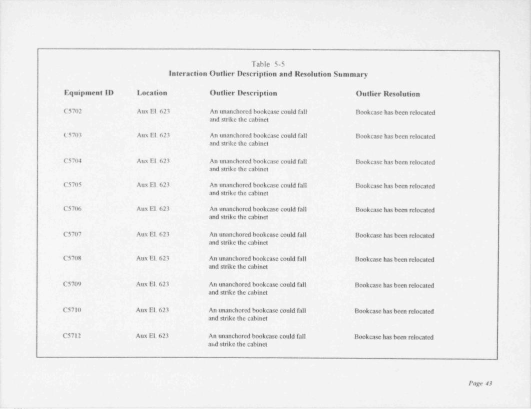
Table 5-5Interaction Outlier Description and Resolution Summary
i
Equipment ID Location Outlier Description Outlier Resolution'
'C5702 Aux El. 623 An unanchored bookcase could fall Bookcase has been relocated,
'
and strike the cabineti
C5703 Aux El. 623 An unanchored bookcase could fall Bookcase has been relocatedand strike the cabinet :
C5704 Aux El. 623 An unanchored bookcase could fall Bookcase has been relocated; and strike the cabinet
'C5705 Aux El. 623 An unanchored bookcase could fall Bookcase has been relocated ,
and strike the cabinet t
: lC5706 Aux El. 623 An unanchored bookcase could fall Bookcase has been relocated
and strike the cabinet I
!
C5707 Aux El. 623 An unanchored bookcase could fall Bookcase has been relocated fand strike the cabinet I
i
C5708 Aux El. 623 An unanchored bookcase could fall Bookcase has been relocated !and strike the cabinet f
1
1
C5709 Aux El. 623 An unanchored bookcase could fall Bookcase has been relocated [and strike the cabinet *
C5710 Aux El. 623 An unanchored bookcase could fall Bookcase has been relocated !and strike the cabinet (
C5712 Aux El. 623 An unanchored bookcase could fall Bookcase has been relocated i
and strike the cabinet.
!
!
Page 13
;
_ _ _ _ _ _ - _ . -- .._ . - .-. .. . . . .

Table 5-5Interaction Outlier Description and Resolution Summary
Equipment ID Location Outlier Description Outlier Resolution
C5755C Aux El. 623 Due to either a small or no gap, and the Provide a restraint to prevent thepresence of essential relays in the cabinet adjacent cabinets from strikingstriking with an adjacent cabinet could exist Ref. MOD 95-0032
C5755C Aux El. 623 Suspended ceiling deficiencies noted To be corrected
C5755D Aux El. 623 Due to either a small or no gap, and the Provide a restraint to prevent thepresence of essential relays in the cabinet adjacent cabinets from strikingstriking with an adjacent cabinet could exist Ref. MOD 95-0032
C5755D Aux El. 623 Suspended ceiling deficiencies noted To be corrected
C5756C Aux El. 623 Due to either a small or no gap, and the Provide a restraint to prevent thepresence of essential relays in the cabinet adjacent cabinets from strikingstriking with an adjacent cabinet could exist Ref. MOD 95-0032
C5756C Aux El. 623 Suspended ceiling deficiencies noted To be corrected
C5756D Aux El. 623 Due to either a small or no gap, and the Provide a restraint to prevent thepresence of essential relays in the cabinet adjacent cabinets from striking (striking with an adjacent cabinet could exist Ref. MOD 95-0032
C5756D Aux El. 623 Suspended ceiling deficiencies noted To be corrected
C5761A Aux El. 623 Suspended ceiling deficiencies noted To be corrected
C5762A Aux El. 623 Due to either a small or no gap, and the Pruvide a restraint to prevent the '
presence of essential relays in the cabinet adjacent cabinets from strikingstriking with an adjacent cabinet could exist Ref. MOD 95-0032
C5762A - Aux El. 623 Suspended ceiling deficiencies noted To be corrected
Page 44
-- __________-____ - - -

Table 5-5Interaction Outlier Description and Resolution Summary
Equipment ID Location Outlier Description Outlier Resolution
C5762C Aux El. 623 Due to either a small or no gap, and the Provide a restraint to prevent the <
presence of essential relays in the cabinet adjacent cabinets from strikingstriking with an adjacent cabinet could exist Ref. MOD 95-0032
C5762C Aux El. 623 Suspended ceiling deficiencies noted To be corrected
C5762D Aux El. 623 Due to either a small or no gap, and the Provide a restraint to prevent thepresence of essential relays in the cabinet adjacent cabinets from strikingstrik.ing with an adjacent cabinet could exist Ref. MOD 95-0032
C5762D Aux El. 623 Suspended ceiling deficiencies noted To be corrected
C5763C Aux El. 623 Due to either a small or no gap, and the Provide a restraint to prevent thepresence of essential relays in the cabinet adjacent cabinets from strikingstriking an adjacent cabinet could exist Ref. MOD 95-0032
C5763C Aux El. 623 Suspended ceiling deficiencies noted To be corrected
C5763C Aux El. 623 Small cart adjacent to the cabinet The cart has been relocatedcould strike the cabinet
| C5763D Aux El. 623 Due to either a small or no gap, and the Provide a restraint to prevent thepresence of essential relays in the cabinet adjacent cabinets from strikingstriking with an adjacent cabinet could exist Ref. MOD 95-0032
C5763D Aux El. 623 Small cart adjacent to the cabinet The cart has been relocatedcould strike the cabinet
C5763D Aux El. 623 Suspended ceiling deficiencies noted To be corrected
C5792 Aux El. 623 Suspended ceiling deficiencies noted To be corrected
Page 45
- _________ ______ - _ .

_ _ _ _ _ - - _ _ _ _ _ _ _ _ .
Ta' ole 5-5
Interaction Outlier Description and Resolution Summary
Equipment ID Location Outlier Description Outlier Resolution
C5792A Aux El. 623 Suspended ceiling deficiencies noted To be corrected
CDEIID Aux Ei. 565 Due to either a small or no gap, and the Provide a restraint to prevent thepresence of essential relays in the cabinet adjacent cabinets from striking
,
striking with an adjacent cabinet could exist Ref. h10D 95-4041
CDFlI A-2 Aux El. 603 Due to either a small or no gap, and the Provide a restraint to prevent thepresence of essential relays in the cabinet adjacent cabinets from strikingstriking with an adjacent cabinet could exist Ref. h10D 954)040
DIN Aux El. 603 Due to either a small or no gap, and the Provide a restramt to prevent thepresence of essential relays in the cabinet adjacent cabinets fmm strikingstriking with an adjacent cabinet could exist Ref. h10D 95-0039
D2P Aux El. 603 Due to either a small or no gap, and the Provide a restramt to prevent the |
.
(See YV2) presence of essential relays in the cabinet adjacent cabinets from striking *
striking with an adjacent cabinet could exist Ref. h10D 95-0038t
ElIB Aux El. 585 Several breakers in the h1CC have padlocks Padlocks to be replaced with snnller ;
that are free to strike the h1CC ones and attached to the MCC '
iElIC Aux. El. 585 A large portable frame is located behind The frame has been relocated .
the h1CC that could strike the MCC i
!El1D Aux El. 565 An abandon cable tray support is in close Cable tray support removed '
proximity to the MCC, which could strike i
the MCC '
E12B Aux El. 585 MCC is in contact with the support for Modify the existing pipe restraint ,
(See YEI) a pipe restraint Ref. MOD 95-0044 ,
!:i
Page 46 ?
!
_ _ _ _ _ _ _ _ . _ _ _ _ _ _ _ _ _ _ _ _ _

m
Table 5-5Interaction Outlier Description and Resolution Summary L
Equipment ID Location Outlier Description Outlier Resolution
F1IA Aux El. 603 Several breakers in the h1CC have padlocks Padlocks to be replaced with smallerthat are free to strike the hiCC one and attached to the h1CC
FII.A Aux Et,603 Due to either a small or no gap, and the Pmvide a restraint to prevent thepresence of essential relays in the cabinet adjacent cabinets from strikingstriking with an adjacent cabinet could exist Ref. h10D 95-0040
F11A Aux El. 603 An adjacent electrical junction box is in P.ciocate/modifyjunction boxclose proximity to the htCC which could Ref. h10D 95-0040impact the h1CC
F1IC Aux El. 565 h1CC is located next to a fire extinguisher that Pmvide a barrier to prevent impact3
1
could strike the h1CC Ref. FPR 95-0671-901. '
IIV 5261 Aux El. 638 Inadequate clearance between the operator and Provide lateral supportthe llVAC support Ref. h10D 94-0034
II HV 5262 Aux El. 638 Inadequate clearance between the operator and Provide lateral supportthe HVAC support Ref. hiOD 94-0034
LT-1402 Aux. El. 623 Instrument line from T12-1 to LT-1402 Provide lateral support for the platformis in contact with platform Ref. h10D 95-0037 '
LT-1403 Aux El. 623 Instrument line from T12-Il to LT-1403 Provide lateral support for the platformis in contact with platform Ref. h10D 95-0037
PSL 4928A Aux El. 565 Chain from overhead hoist could strike Chain was secured iPSL 4928A i
<
PSL 4928B Aux El. 565 Chain from overhead hoist could strike Chain was secured |
PSL 4928B |
f
h
Page 47 |i
--- _ -- _ _. _ _ _ _ _ . . . _ _ _ _ - - . . - - _ - _ _ _ _ _ _ _______ _
.

_
1
Table 5-5Interaction Outlier Description and Resolution Summary
.
! Equipment ID Location Outlier Description Outlier Resolution
| RC 2826 Aux El. 565 Unsecured hydrazine barrel is adjacent flydrazine barrel was removed andto the cabinet secured.
RC 3004 ITK El. 565 Rod-hung conduit support could swing Rework conduit supportand strike cabinet Ref. MOD 95-0042
RC 3701 Aux El. 585 Back of cabinet is in contact with pipe support Rework cabinet / supportRef. MOD 95-0036
TS 5262 Aux El. 638 Instrument is in the arc of an unanchored MCC Provide anchorage for the MCCRef. MOD 95-0035
' YEl Aux El. 585 MCC is in contact with the support for Modify the existing pipe restraint(See E12B) a pipe restraint Ref. MOD 95-0044
YV2 Aux El. 603 Due to either a small or no gap, and the Provide a restraint to prevent the(See D2P) presence of essential relays in the cabinet adjacent cabinets from striking
striking with an adjacent cabinet could exist Ref. MOD 95-0038
YV3 Aux El. 603 Due to either a small or no gap, and the Provide a restraint to prevent thepresence of essential relays in the cabinet adjacent cabinets from strikingstriking with an adjacent cabinet could exist Ref. MOD 95-0043
YV4 Aux El. 603 Existing gap between cabinet and the increase the gap to prevent the cabinetContainment is not sufficient to preclude from strikingstriking Ref. MOD 95-0034
Pe;y 48
_ _ . . - - - _ _ __-_ _ .~. ._ . . , _ .-_ _ _ _ - _ _ , - - _ . . - , . - _ . _ - . . _ . . - . . _ _ - . _ _ . _
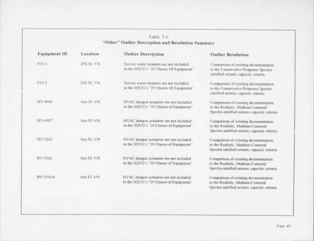
Table 5-6"Other" Outlier Description and Resolution Summary
Equipment ID Location Outlier Description Outlier Resolution
F15-1 ITK El. 576 Service water strainers are not included Comparison of existing documentationin the SQUG's "20 Classes Of Equipment" to the Conservative Response Spectra
satisfied seismic capacity criteria
F15-2 ITK El. 576 Service water strainers are not included Comparison of existing documentationin the SQUG's "20 Classes Of Equipment" to the Conservative Response Spectra
satisfied seismic capacity criteria
llV-4906 Aux El. 656 IIVAC damper actuators are not included Comparison of existing documentationin the SQUG's "20 Classes of Equipment" to the Realistic, Medium-Centered
Spectra satisfied seismic capacity criteria
IIV-4907 Aux El. 656 IIVAC damper actuators are not included Comparison of existing documentationin the SQUG's "20 Classes of Equipment" to the Realistic, Medium-Centered
Spectra satisfied seismic capacity criteria
IIV-5261 Aux El. 638 liVAC damper actuators are not included Comparison of existing documentationj m the SQUG's "20 Classes of Equipment" to the Realistic, Medium-Centered
.
Spectra satisfied seismic capacity criteriai
| liv-5262 Aux El. 638 liVAC damper actuators are not included Comparison of existing documentationin the SQUG's "20 Classes of Equipment" to the Realistic, Medium-Centered
Spectra satisfied seismic capacity criteria
llV-5301 A Aux El. 656 liVAC damper actuators are not included Comparison of existing documentationin the SQUG's "20 Classes of Equipment' to the Realistic, Medium-Centered
Spectra satisfied seismic capacity criteria
t
|
|
|;
Page 49!
_ _ _ _ _ _ - _ - _ _ _ _ _ _ _ _ _ _ _ _ _ _ _ _ - _ _ _ _ _ _ _ - _ _ _ _ _ _ _ _ - _ _ _ _ _ _ _ _ _ _ _ _ _

Table 5-6"Other" Outlier Description and Resolution Summary
Equipment ID Location Outlier Description Outlier Resolution
IIV-5301B Aux El. 656 IIVAC damper actuators are not included Comparison of existing documentationin the SQUG's "20 Classes of Equipment" to the Realistic, hiedium-Centered
Spectra satisfied seismic capacity criteria
IIV-530lC Aux El. 656 IIVAC damper actuators are not included Comparison of existing documentationin the SQUG's "20 Classes of Equipment" to the Realistic, Medium-Centered .
Smctra satisfied seismic capacity criteria
IIV-530lD Aux El. 638 IIVAC damper actuators are not included Comparison of existing documentation;
in the SQUG's "20 Classes of Equipment" to the Realistic, Medium-Centered ~
Spectra satisfied seismic capacity criteria
IIV-5301E Aux El. 638 IIVAC damper actuators are not included Comparison of existing documentationin the SQUG's "20 Classes of Equipment" to the Realistic, Medium-Centered
Spectra satisfied seismic capacity criteria
llV-5301F Aux El. 638 11VAC damper actuators are not included Comparison of existing documentationin the SQUG's "20 Classes of Equipment" to the Realistic, Medium-Centered
Spectra satisfied seismic capacity criteria
llV-530lG Aux El. 638 liVAC damper actuators are not included Comparison of existing documentationin the SQUG's "20 Classes of Equipment" to the Realistic, Medium-Centered
Spectra satisfied seismic capacity criteria
llV-5430lli Aux El. 638 liVAC damper actuators are not included Comparison of existing documentationin the SQUG's "20 Classes of Equipment" to the Realistic, Medium-Centered
Spectra satisfied seismic capacity criteria
Page 50
- - _ _ _ _ _ _ _ _ _ _ _ - - -
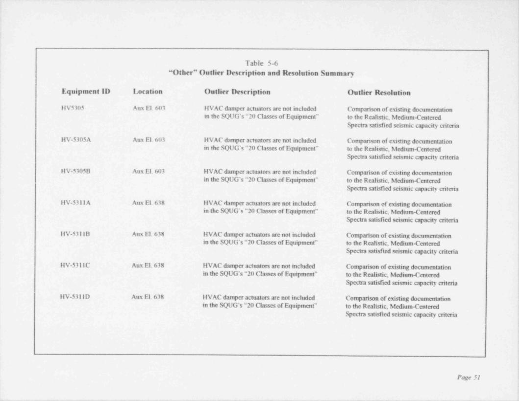
.
t
r
t
Table 5-6"Other" Outlier Description and Resolution Summary
Equipment ID Location Outlier Description Outlier Resolution
llV5305 Aux El. 603 IIVAC damper actuators are not included Comparison of existing documentationin the SQUG's "20 Classes of Equipment" to the Realistic, Medium-Centered
Spectra satisfied seismic capacity criteria!
IIV-5305A Aux El. 603 IIVAC damper actuators are not included Comparison of existing documentation;
in the SQUG's "20 Classes of Equipment" to the Realistic, Medium-Centered '
Spectra satisfied scismic capacity criteria '
IIIV-5305B Aux El. 603 IIVAC damper actuators are not included Comparison of existing documentation
pin the SQUG's "20 Classes of Equipment' to the Realistic, Medium-Centered
Spectra satisfied scismic capacity criteria i
;
IIV-5311 A Aux El. 638 IIVAC damper actuators are not included Comparison of existing documentation <
in the SQUG's "20 Classes of Equipment" to the Realistic, Medium-Centered E
Spectra satisfied seismic capacity criteria,
tIIV-5311B Aux El. 638 IIVAC damper actuators are not ir.cluded Comparison of existing documentation
in the SQUG's "20 Classes of Equipment" to the Realistic, Medium-Centered i
Spectra satisfied seismic capacity criteria,
!HV-5311C Aux El. 638 IIVAC damper actuators are not included Comparison of existing documentation :in the SQUG's "20 Classes of Equipment" to the Realistic, Medium-Centered i
Spectra satisfied seismic capacity criteriaj
IIV-5311D Aux El. 638 IIVAC damper actuators are not included Comparison of existing documentationin the SQUG's "20 Classes of Equipment" to the Realistic, Medium-Centered
Spectra satisfied seismic capacity criteria,
;
.
i
Page 51 k
_ . ~ . . _ . . _ _ . .. _-. . . _ _ _ _ . - - _ _ - _ _ _ , _ _ _ _ _ __
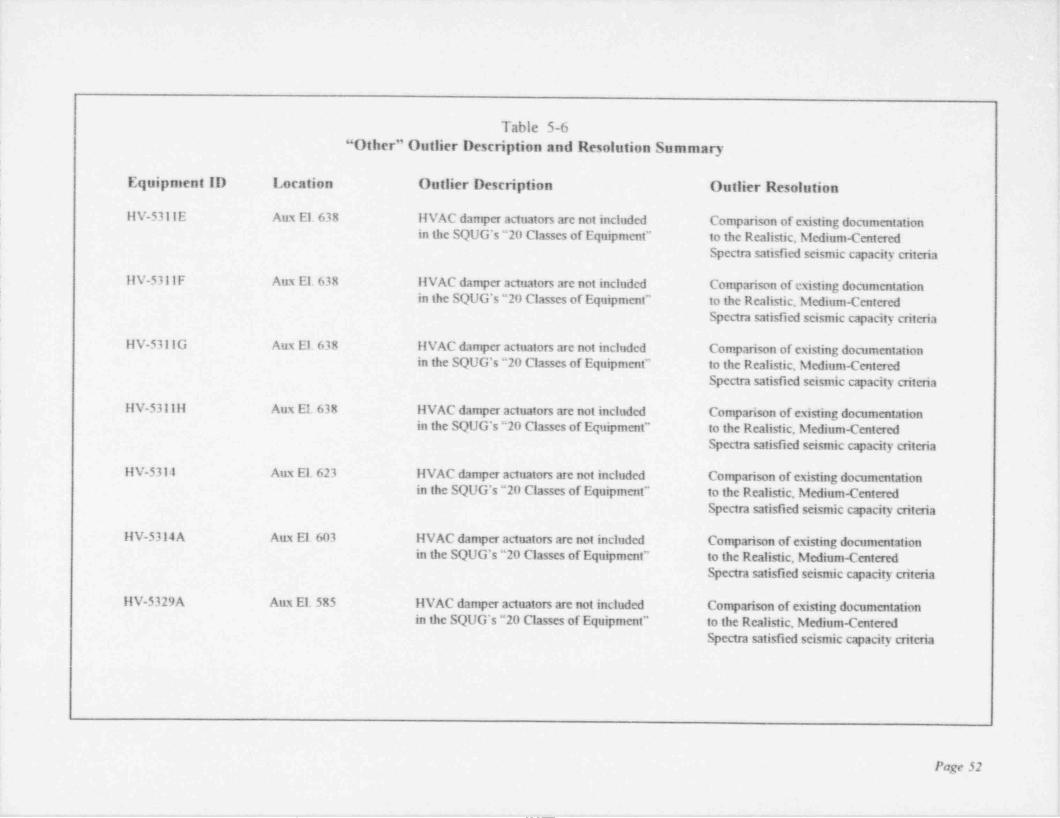
.-
,
1
!,
Table 5-6 !t
"Other" Outlier Description and Resolution Summary i
Equipment ID Location Outlier Description Outlier Resolution fI
'
:IIV-53IIE Aux El. 638 IIVAC damper actuators are not included Comparison of existing documentation !
in the SQUG's "20 Classes of Equipment" to the Realistic, hiedium-CenteredSpectra satisfied seismic capacity criteria
,
ilV-5311F Aux El. 638 IIVAC damper actuators are not included Comparison of existing documentationin the SQUG's "20 Classes of Equipment" to the Realistic, Medium-Centered
Spectra satisfied seismic capacity criteda
IIV-53IIG Aux El. 638 liVAC damper actuators are not included Comparison of existing documentationin the SQUG's "20 Classes of Equipment" to the Realistic, Medium-Centered
Spectra satisfied seismic capacity criteria
iilV-53I111 Aux El. 638 IIVAC damper actuators are not included Comparison of existing documentation i.; in the SQUG's "20 Classes of Equipment" to the Realistic, Medium-Centered !
Spectra satisfied seismic capacity criteriai.
LIIV-5314 Aux El. 623 IIVAC damper actuators are not included Comparison of existing documentation f
in the SQUG's "20 Classes of Equipment" to the Realistic, Medium-CenteredSpectra satisfied seismic capacity criteria t
(
I,IIV-5314A Aux El. 603 IIVAC damper actuators are not included Comparison of existing documentation !
in the SQUG's "20 Classes of Equipment" to the Realistic, Medium-Centered !l
Spectra satisfied seismic capacity criteria
t; ilV-5329A Aux El. 585 IIVAC damper actuators are not included Comparison of existing documentation ,
j in the SQUG's "20 Classes of Equipment" to the Realistic, Medium-Centered '
Spectra satisfied seismic capacity criteriai
e
!
Ii
t'
Page 52 i
!
_ _ _ _ . _ . , _ _ _ _ _ _ . . . . . _ __. _ _ ~_ ______. _ _ _ _ . _ _ . _ _ _ _ . . _ . _ ~ _ . ___ __ j

,
Table 5-6"Other" Outlier Description and Resolution Summary
Equipment ID Location Outlier Description Outlier Resolution
IIV-5329B Aux El. 585 HVAC damper actuators are not included Comparison of existing documentationin the SQUG's "20 Classes of Equipment" to the Realistic, hiedium-Centered
Spectra satisfied seismic capacity criteria
11V-5329C Aux El. 585 IIVAC damper actuators are not included Comparison of existing documentationin the SQUG's "20 Classes of Equipment" to the Realistic, hiedium-Centered
Spectra satisfied seismic capacity criteria
llV-5336A Aux El. 585 liVAC damper actuators are not included Comparison of existing documentationin the SQUG's "20 Classes of Equipment" to the Realistic, hiedium-Centered
Spectm satisfied seismic capacity criteria
llV-5336B Aux El. 585 11VAC damper actuators are not included Comparison of existing documentationin the SQUG's "20 Classes of Equipment" to the Realistic, hiedium-Centered
Spectra satisfied seismic capacity criteria
llV-5336C Aux El. 585 }{VAC damper actuators are not included Comparison of existing documentationin the SQUG's "20 Classes of Equipment" to the Realistic, hiedium-Centered
Spectra satisfied seismic capacity criteria
IIV-5361 A Aux El. 623 IIVAC damper actuators are not included Comparison of existing documentationin the SQUG's "20 Classes of Equipment" to the Realistic, Afedium-Centered
Spectra satisfied seismic capacity criteria
llV-5361B Aux El. 623 IIVAC damper actuators are not included Comparison of existing documentationin the SQUG's "20 Classes of Equipment" to the Realistic, hiedium-Centered
Spectra satisfied scismic capacity criteria
Page 53
_ _ - _ _ _ _ _ _ _ _ _ _ _ _ _ _ _ - _ _ _ _ _ _ _ _ _ _ _ _ _ _ _ _ _ _ _ _ _ _ _ _ _ _ _ - - _ - _ _ _ _ _ - _
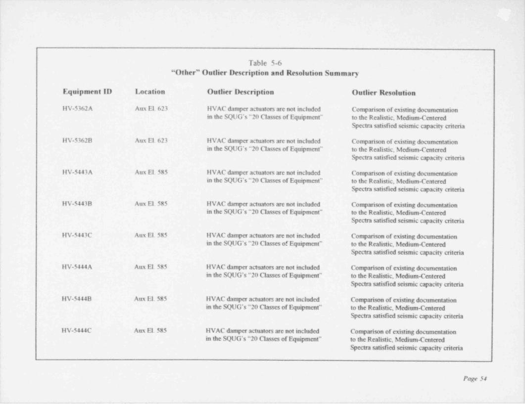
Table 5-6"Other" Outlier Description and Resolution Summary
Equipment ID Location Outlier Description Outlier Resolution
ilV-5362A Aux El. 623 IIVAC damper actuators are not included Comparison of existing documentationin the SQUG's "20 Classes of Equipment" to the Realistic, hiedium-Centered
Spectra satisfied seismic capacity criteria!
! IIV-5362B Aux El. 623 IIVAC damper actuators are not included Comparison of existing documentationin the SQUG's "20 Classes of Equipment" to the Realistic, hiedium-Centered
Spectra satisfied seismic capacity criteria
llV-5443A Aux El. 585 IIVAC damper actuators are not included Comparison of existing documentationin the SQUG's "20 Classes of Equipment" to the Realistic, hiedium-Centered
Spectra satisfied seismic capacity criteria
11V-5443B Aux El. 585 IIVAC damper actuators are not included Comparison of existing documentationin the SQUG's "20 Classes of Equipment" to the Realistic, hiedium-Centered
Spectra satisfied seismic capacity criteria
IIV-5443C Aux El. 585 IIVAC damper actuators are not included Comparison of existing documentationin the SQUG's "20 Classes of Equipment" to the Realistic, hiedium-Centered
Spectra satisfied seismic capacity criteria
IIV-5444A Aux El. 585 IIVAC damper actuators are not included Comparison of existing documentationin the SQUG's "20 Classes of Equipment" to the Realistic, hiedium-Centered
Spectra satisfied seismic capacity criteria,
|
IIV-5444B Aux El. 585 IIVAC damper actuators are not included Comparison of existing documentationin the SQUG's "20 Classes of Equipment" to the Realistic, hiedium-Centered
i
Spectra satisfied seismic capacity criteria
IIV-5444C Aux El. 585 liVAC damper actuators are not included Comparison of existing documentationin the SQUG's "20 Classes of Equipment" to the Realistic, hiedium-Centered
Spectra satisfied seismic capacity criteria
Page 54
_ _ _ _ _ _ - _ - _ _ _ _ _ - - _ - - _ _ _ _ _ _ - _ _ . -_ _
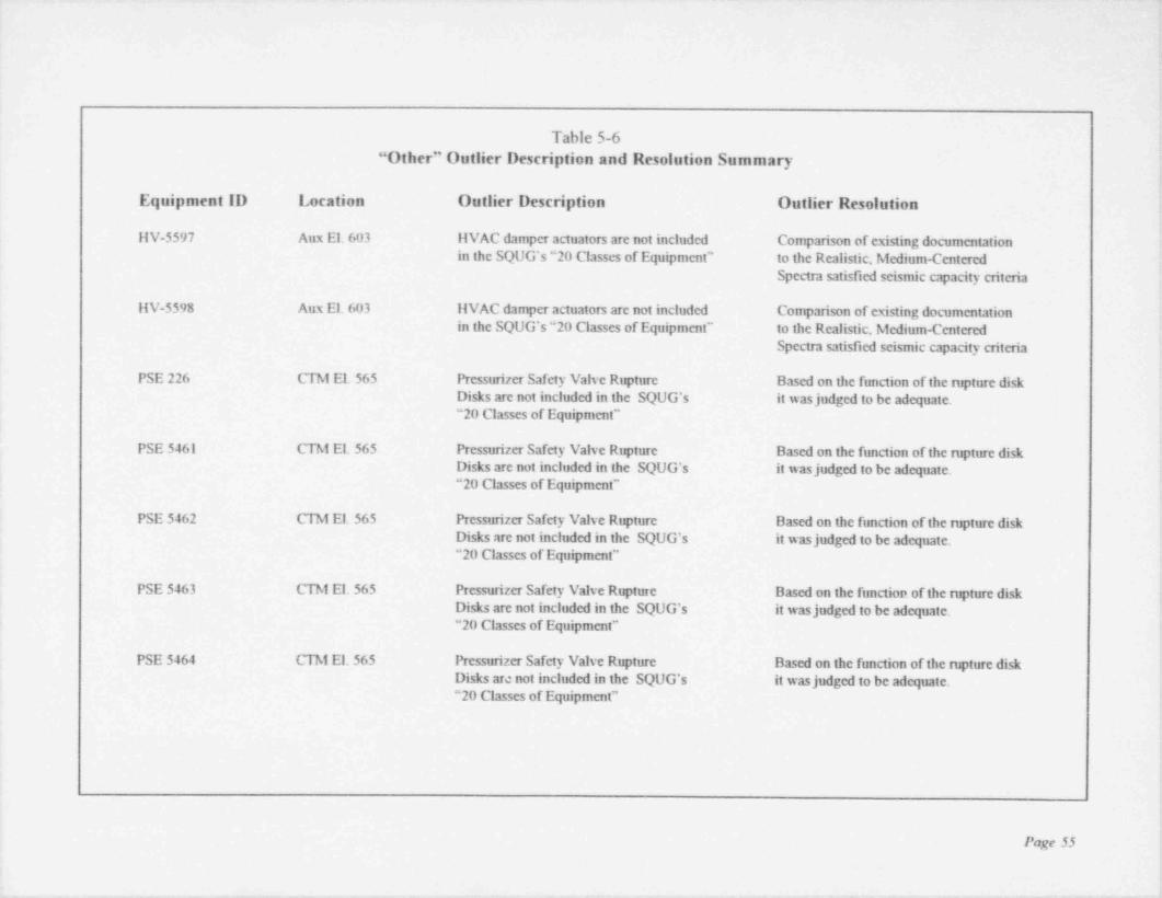
Table 5-6"Other" Outlier Description and Resolution Summary
Equipment ID Location Outlier Description Outlier Resolution
ilV-5597 Aux El. 603 HVAC damper actuators are not included Comparison of existing documentationin the SQUG's "20 Classes of Equipment' to the Realistic, Medium-Centered
Spectra satisfied seismic capacity criteria
HV-5598 Aux El. 603 IIVAC damper actuators are not included Comparison of existing documentationin the SQUG's "20 Classes of Equipment" to the Realistic, Medium-Centered
Spectra satisfied seismic capacity criteria
PSE 226 CTM El. 565 Pressurizer Safety Valve Rupture Based on the function of the rupture diskDisks are not included in the SQUG's it wasjudged to be adequate."20 Classes of Equipment"
PSE 5461 CTM El. 565 Pressurizer Safety Valve Rupture Based on the function of the rupture diskDisks are not included in the SQUG's it wasjudged to be adequate."20 Classes of Equipment"
PSE 5462 CTM El. 565 Pressurizer Safety Valve Rupture Based on the function of the rupture diskDisks are not included in the SQUG's it wasjudged to be adequate."20 Classes of Equipment"
PSE 5463 CTM El. 565 Pressurizer Safety Valve Rupture Based on the function of the rupture diskDisks are not included in the SQUG's it wasjudged to be adequate. L
"20 Classes of Equipment"
PSE 5464 CTM El. 565 Pressurizer Safety Valve Rupture Based on the function of the rupture diskDisks are not included in the SQUG's it wasjudged to be adequate."20 Classes of Equipment"
Page 55
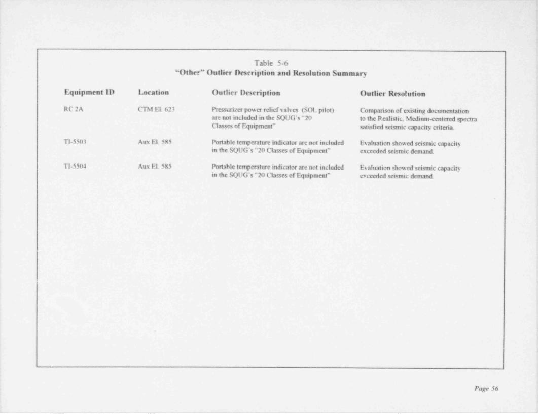
.
.
Table 5-6'
"Other" Outlier Description and Resolution Summary
Equipment ID Location Outlier Description Outlier Resolution
RC 2A CTM El. 623 Pressurizer power relief valves (SOL pilot) Comparison of existing documentation;
are not included in the SQUG's "20 to the Realistic, Medium-centered spectra [Classes of Equipment" satisfied seismic capacity critena.
,
lTI-5503 Aux El. 585 Portable temperature indicator are not included Evaluation showed seismic capacity !
'
in the SQUG's "20 Classes of Equipment" exceeded seismic demand i
TI-5504 Aux El. 585 Portable temperature indicator are not included Evaluation showed seismic capacityin the SQUG's "20 Classes of Equipment" e7ceeded seismic denund. ;
,
I
!
,
I
b
l
!
!!
i
II
iPage 56
. - . _ _ _ _ _ _ _ _ _ _ _ _ _ _ _ - _ . - .- . . - - . - - - . - . - - - - - . . - - _ _ _ - . _ - , . -.

-- - . . - - _ - --.. - - _ - _ - --
,
Section 6
TANKS AND HEAT EXCHANGERS REVIEWt
6.1 SUMMARY OF REVIEW
The tanks and heat exchangers on the Davis-Besse SSEL were evaluated in accordance withSection II.7 of the GIP.
A total of 19 tanks and heat exchangers were evaluated. The following is a brief description ofeach type.
Tanks--Horizontal
A total of eight horizontal tanks were evaluated, consisting of two of each of the following:Component cooling surge tanks, EDG fuel oil storage tanks, EDG day tanks, and the boric acidadditions tanks. The EDG fuel oil tanks are buried in the yard and were not available for acomplete inspection. Drawings and the qualification report were used to verify the backfill coveris sufficient to hold the tanks in place.
The Component Cooling Surge Tanks (T12-1 and T12-II) were identified as outliers resultingfrom an interaction concern between two small pipes coming out of the tanks and a near-byaccess platform. Although the GIP does not specifically require the SCEs to investigateinteraction concerns the SCEs were cogr.izant of the potential problem and identified it as an -
Outlier.
Tanks--Vertical
A total of 3 vertical tanks were evaluated consisting of the following: borated water storage tank,make-up tank and the spent fuel pool demineralizer tank. The make-up tank does not have a flatbottom, but a hemispherical bottom supported by a steel skirt. The spent fuel pool demineralizertank has a hemispherical bottom supported by four legs and was not accessible for walkdownbecause it is located in a high radiation area.
The spent fuel pool demineralizer tank will require further analysis and a determination can notbe made at this time if any modification is warranted.
Heat Exchancers
A total of 8 heat exchangers were evaluated consisting of the following: (3) component coolingwater; (2) decay heat removal; (2) seal return cooler; and (1) borated water storage tank heater.
The component cooling water and the decay heat removal heat exchangers are currentlyundergoing further analysis and a determination can not be made at this time if any modificationare warranted.
Page 37

_ _ . ._ . . . _ _ _ . . _ _ _ . . _ . . . . . _ _ . - .
|
)|l
6.2 Summary of Outliers |
A total of 12 outliers were identified afTecting 10 tanks or heat exchangers. A short descriptionof each tank or heat exchanger outlier and its resolution are provided in the following tables:
Table 6-1 Tank and Heat Exchanger Anchorage Outlier Description and ResolutionSummary
Table 6-2 Tank and Heat Exchanger Interaction Outliers Description and ResolutionSummary
,
!
!
!
;
;
,
!
!
,
I
Page S8
.- . _ _ _ _ _ _ _ . _._
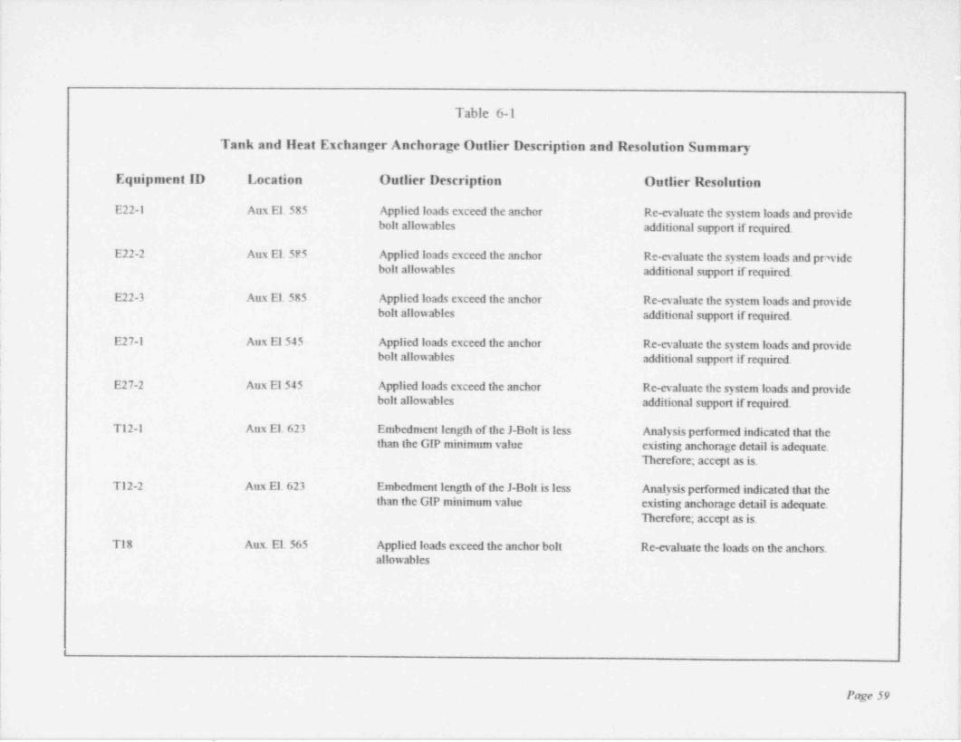
.
I
k
!. :'
iTable 6-1 *
- Tank and Heat Exchanger Anchorage Outlier Description and Resolution Summary!
| Equipment ID Location Outlier Description Outlier Resolution |
| -
E22-1 Aux El. 585 Applied loads exceed the anchor Re-evaluate the system loads and providej bolt allowables additional support if required. i
| E22-2 Aux El. SFS Applied loads exceed the anchor Re-evaluate the system loads and pr, vide<
! bolt allowables additional support if required. |,
E22-3 Aux El. 585 Applied loads exceed the anchor Re-evaluate the system loads and pmvidebolt allowables additional support if required.
,
E27-1 Aux El 545 Applied loads exceed the anchor Re-evaluate the system loads and provide |bolt allowables additional support if required. ,
E27-2 Aux El 545 Applied loads exceed the anchor Re-evaluate the system loads and providebolt allowables additional support if required.
T12-1 Aux El. 623 Embedment length of the J-Bolt is less Analysis performed indicated that thethan the GIP minimum value existing anchorage detail is adequate.,
| Therefore; accept as is.,
T12-2 Aux El. 623 Embedment length of the J-Bolt is less Analysis performed indicated that thethan the GIP minimum value existing anchorage detail is adequate.
Herefore; accept as is. !
!
| TI8 Aux. El 565 Applied loads exceed the anchor bolt Re-evaluate the loads on the anchors.allowables
,
!t
i
Page 59
l
__ _ __ . . , . - - - - _ _ _ _ _ . _ _ .

t
e
Table 6-1
Tank and llent Exchanger Anchorage Outlier Description and Resolution Summary |t
Equipment ID Location Outlier Description Outlier Resolution !
:T7-1 Aux El 565 Embedment length of the J-Bolt is less Analysis performed indicated that the i
than the GIP minimum value existing anchorage detail is adequate. !
Therefore, accept as is.f
T7-2 Aux El 565 Embedment length of the J-Bolt is less Analysis performed indicated that the |
than the GIP minimum value existing anchorage detail is adequate. i
Therefore, accept as is.
:
l
t'
I
l f
,
t
|r
'
lt
>
Page 60
i. _ . . _ _ _ _ _ _ . . _ . _ _ _ . _ _ _. . _ _ . . , . - __ _ _. _ __ ._ _ _ _ . .

.
4-
,
i
Table 6-2
Tank and Heat Exchanger Interaction Outlier Description and Resolution Summaryi
l Equipment ID Location Outlier Description Outlier Resolution 1
>
T12-1 Aux El 623 Instmment line from the tank is in contact Provide lateral support for the platform(See LT-1402) with a platform Ref. MOD 95-0037 .
T12-Il Aux E1623 Instrument line from the tank is in contact Provide lateral support for the platform(See LT-1403) with a platfonn Ref. MOD 95-0037 !
i
t
I
! ;
,
t
i :
,!'
| !
1
!
!
I [l !I |
Page 61 |i
_. . - . .
Section 7
CABLE AND CONDUIT RACEWAY REVIEW
7.1 SUMMARY OF RACEWAY REVIEW
The review for cable tray and conduit systems at Davis-Besse was performed per the guidelinesof Section II.8 of the Generic Implementation Procedure (GIP). Only the buildings that housethe SSEL equipment were included in the walkdown. In general, all rooms in these buildingswere walked down unless it was fairly cenain that no cable trays or conduits associated with theSSEL were located or passed through the room. In a limited number of cases, access to roomswas limited due to radiation concerns. In all cases, the walkdown was performed by a minimumof 2 qualified Seismic Capability Engineers (SCE), with at least one of them being aProfessional Engineer.
Conduits are the main routing method for cables at Davis-Besse, with the size varying up to andincluding 4" nominal diameter rigid steel. Cable trays, when used, are predominately 24" ladderand trough type construction.
Based on the SSEL equipment location, the majority of the cable trays and conduits are locatedin the cable spreading room, electrical penetration rooms, switchgear rooms, EDG room, and thehallways in the vicinity of the above rooms.
The cable and conduit raceway systems consist primarily oflight steel strut frame constructionmanufactured by Unistmt Corporation. Supports for Q installations are generally quite robust
with vertical members made from unistrut or structural steel members. Non-Q installations areusually supponed by threaded rod. The strut hangers vary from the very simple singlecantilever strut supporting one conduit to a multi-tier, three-dimensional strut frames supportingseveral cable trays and conduits. The cable trays and conduits are attached to the suppon usingstandard tray and conduit type clamps. The supports are attached to the structure using expansionanchors, or welded to structure steel or embeds. Supports can be found attached to the ceiling,walls, and the floor.
The SCEs were cognizant of the seismicjoints throughout the Auxiliary Building and consideredthe building displacement along with the suppon flexibility in determining the adequacy of thesupports. Ilowever, it should be noted that since the Auxiliary building is founded on rock thatthe building displacements are relatively small.
During the course of the walkdown, several housekeeping items were identified that should becorrected. Although the supports / raceway met the SQUG criteria, when corrected they wouldenhance the overall seismic capability of the support / raceway system. Since this action is inaddition to the requirements of the GIP, it is not presented in this report.
In general the cable tray and conduit raceways are well supported.
Page 62
- _ _ _ _ _ _ - . - _ _ _ _ - _ - _ _ _ _ _ _ _ _ _ - _ _ _ _ _ _ _ _ _ _ - _
__. _ . _ _ _ _ _ . _ _ _ - . _ - _ _ _ .._. _ ~__ _ __
s
7.2 EVALUATION OF BOUNDING SAMPLES ,
As part of the in-plant review, worst-case bounding samples of raceway supports were selectedfor further analytical reviews. The SCEs selected representative, wors> case bounding samplesof the raceway supports based upon a thorough walkdown of the applicable areas. Boundingsamples were selected to encompass the diversity of the plant's raceway support systems usingthe SCEs experience and technicaljudgment.
. Some of the characteristics used by the SCEs in establishing the worst case bounding sampleswere:
Most heavily loaded supports*;
Unique support configuration or orientatione;
High load to member size ratio"
e
High load to anchor bolt size ratio Le
High load to span ratioe
A total of 26 supports were selected for the Limited Analytical Review. Table 7-1 provides abrief description of each of the samples chosen.
Four supports did not pass the analytical review and are identified as outliers. The four supportsare LAR 318-1, LAR 422A-1, LAR 501-1, and LAR 601-1.
Limited Analytical Review sample LAR 318-1 represents a cantilever conduit support mountedon a blockwall with a 2-bolt baseplate oriented horizontally. This support did not pass the
*
analytical review due to reduced anchor bolt allowables. However, since this support is notrequired to meet the conduit spacing criteria, no fix is required. Further review showed that this :
is a unique suppon and other blockwall supports have extremely small loads or utilize thru-bolts.
Limited Analytical Review sample LAR 422A-1 represents a floor to ceiling cable tray suppon,
in which the base plate for a cantilever bracket exceeded the allowable value. Two additional '
samples were then selected (LAR 422A-2 and LAR 422A-3) that represented the next worst case |(bounding) conditions. Both of these supports were analyzed and found to be acceptable. :
,
Limited Analytical Review sample LAR 501-1 represents a heavily loaded wall mounted conduitsupport that did not pass the analytical review. Further evaluation showed that the existing iconduit span is acceptable without the support attached to the wall. Therefore; no fix is ;
required. The next worst case bounding sample was identified (LAR 110-1) and was found i
acceptable. !
Limited Analytical Review sample LAR 601-1 support passed the analytical review however, ;
the web of the structural beam in which it was attached did not meet the local bending stress i
criteria. Since this conduit support is unique in the plant, the next worst case (bounding) sampleanalysis is not applicable.
Page 63
_ _ _ . . . _ _ _ -_ -_
_ . . _ _ _ . . - - -
7.3 SUMMARY OF OUTLIERS
The SCEs, using the requirements of the Section 8 of the GIP checked the raceway systems forcompliance with the " Inclusion Rules" , "Other Seismic Performance Concerns" and " SeismicInteraction" Conditions that did not meet the requirements were identified as Outliers.
In addition the SCEs searched out other installation configurations that could affect the seismicperformance of the support / system that were not specifically identified in the GIP. In particular,the distance between the unistrut clamp and the free edge of the unistrut. The concern is that ifthe distance is to small, the clamp could slide off of the end of the unistrut.
A total of 31 Outliers were identified during the cable and conduit raceway walkdown.Table 7-2 provides a listing of each Outlier and the resolution.
Page 64
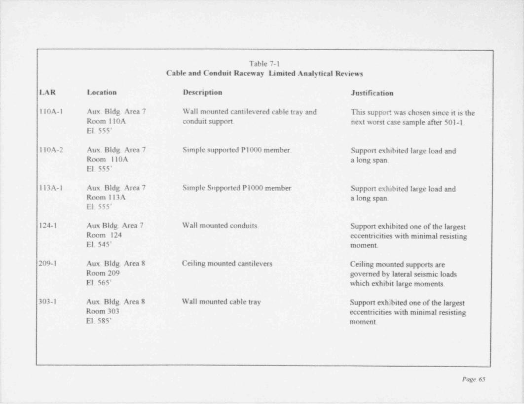
|
|Table 7-1
Cable and Conduit Raceway Limited Analytical Reviews
LAR Location Description Justification
110A-1 Aux. Bldg. Area 7 Wall mounted cantilevered cable tray and This support was chosen since it is theRoom 110A conduit support. next worst case sample after 501-1.El.555'
110A-2 Aux. Bldg. Area 7 Simple supported P1000 member. Support exhibited large load andRoom 110A a long span.El.555' !
113 A-1 Aux. Bldg. Area 7 Simple Supported P1000 member Support exhibited large load andRoom 113A a long span.El.555'
124-1 Aux Bldg. Area 7 Wall mounted conduits. Support exhibited one of the largestRoom 124 eccentricities with minimal resistingEl.545' moment.
209-1 Aux. Bldg. Area 8 Ceiling mounted cantilevers Ceiling mounted supports areRoom 209 governed by lateral seismic loadsEl.565' which exhibit large moments.
303-1 Aux. Bldg. Area 8 Wall mounted cable tray Support exhibited one of the largestRoom 303 eccentricities with minimal resistingEl.585' moment.
Page 65
i
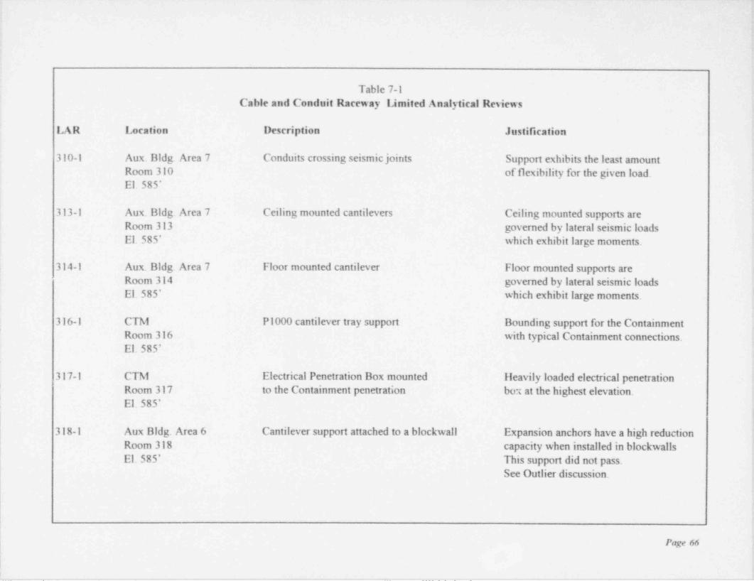
Table 7-1Cable and Conduit Raceway Limited Analytical Reviews
i'
LAR Location Description Justification +
1
310-1 Aux. Bldg. Area 7 Conduits crossing seismicjoints Support exhibits the least amount fRoom 310 of flexibility for the given load !
El. 585'
313-1 Aux. Bldg. Area 7 Ceiling mounted cantilevers Ceiling mounted supports areRoom 313 governed by lateral seismic loads
,
El.585' which exhibit large moments.!
314-1 Aux. Bldg. Area 7 Floor mounted cantilever Floor mounted supports are t
'
! Room 314 governed by lateral seismic loads [El. 585' which exhibit large moments. ~
i ,
i 316-1 CTM P1000 cantilever tray support Bounding support for the Containment ;
Room 316 with typical Containment connections. ;
El. 585';
i317-1 CTM Electrical Penetration Box mounted Heavily loaded electrical penetration |
! Room 317 to the Containment penetration box at the highest elevation. |El. 585'
|
318-1 Aux Bldg. Area 6 Cantilever support attached to a blockwall Expansion anchors have a high reduction,
Room 318 capacity when installed in blockwalls !
El.585* This support did not pass. !See Outlier discussion. ;
i
i
Page 66
| !'
:_ _ _ _ _m _ - , _ _ . . . . - _ ._ _ _ . _ _ _ _ . . _ . _ . _ _ _ _ _ _ __. _,__ - .__ ._ ._ . . _ _ _ _ _ _ _ . _ . _ . . _ . . . - _ _ . _ , . - _ , _ , _ _ . _ . ~ . _ . - _ . . _ . .
*

,
Table 7-1Cable and Conduit Raceway Limited Analytical Reviews i|
IAR Location Description Justification'
325-1 Aux. Bldg. Area 6 Lateral braced support Support does not have clip anglesRoom 325 and has a small lateral capacity. !

=
!:
:
: Table 7-1 [Cable and Conduit Raceway Limited Analytical Reviews
LAR Location Description Justification1
422A-3 Aux. Bldg. Area 7 Floor to ceiling tray supports Chosen as the next worst bounding typeRoom 422A support for 422A-1. ;
El.614'|
422A-4 Aux. Bldg. Area 7 Floor to ceiling tray supports Second of three worst caseRoom 422A variations of the floor to ceiling ;
El.614' support. !
422A-5 Aux. Bldg. Area 7 Floor to ceiling tray supports Third of three worst caseRoom 422A variations of the floor to ceilmg iEl.614' support. !
427-1 Aux. Bldg. Area 7 Rod hung multi cable tray and conduit This support was chosen since rod hung ;
Room 427 support supports exhibit the largest expansion :El.603' anchor loads due to dead ioad. ;
501-1 Aux Bldg. Area 7 Wall mounted cantilevered This support was chosen since it is 1
Room 501 conduit support. controlled by the dead load case. This |El.623' support did not pass.
"~,
See Outlier discussion.:
501-2 Aux. Bldg. Area 7 Conduits crossing seismicjoints Support exhibits the least amount'
Room 501 of flexibility for the given load. !El.623'
|,
t
i
Page 68
I_- __ _ - _ - .__.__.____-_----__w_ m -t- _ ___m_*e- T- w+g- -- *'-vb - _ _ -w- - * a - -er . ____ _ * ---W_ _ -e - - - _ _ _ F- - _ _m__--_______a-_ a -- - -.= - -

,_ - _
i
i
7
.
I
Table 7-1Cable and Conduit Raceway Limited Analytical Reviews .i,
.
LAR Location Description Justification ;
1
i
601-1 Aux. Bldg. Area F Unique cantilever support Unique support. ;
Room 601 The support passed the analytical |El.643' check, but the beam had local
'
yielding of the web.
{See Outlier discussion
|.'
| ,
i
! i,
i
r,
!>
f
!.
!
It
!
it
i
I>
!
|-
I
E
Page 69 '
y
I
_ _ _ _ _ _ - _ . _ . . _ _ . - - . . _ _ _ _ . . _ . _. _ -_ . _ . - _ _ _ _ _ _ -. _ -.-_.._ _ _.. - _ . . _ ----

_ _ _ _ _ - - . -,
_-_
Table 7-2Cable and Conduit Raceway Outlier Description and Resolution Summary
Outlier No. Outlier Description Outlier Resolution
101-1 Edge distance on conduit clamp to the edge Provide end restraintsof the unistrut channel is very small at six Refer to PCAQ 94-0011consecutive supports
105-1 Threaded rod to the overhead shell anchor is Install the missing threaded rodmissing. Refer to PCAQ 95-0567
209-1 2" conduit support beam clamp is not Re-install supportproperly installed Refer to PCAQ 95-0567
218-i Conduit 39242C is missing several conduit Install the conduit missing clampsclamps. Work to be done during an outage.
Refer to PCAQ 95-0567
218-2 Cable tray BCBD and BLBE are missing Install missing tray clampsclamps to the tray Work to be done during an outage.
Refer to PCAQ 95-0567
227-1 12" cable tray (ACEMIS) has a 17' The lightly loaded tray (15 lb/ft) is containedL-shape span without an acceptable in place by existing trays, piping, conduits, orintermediate support. supports, without damage to the tray or cables.
Therefore; existing condition is acceptable as is.
236-1 3/4" conduit has a span greater than Clamp the conduit to an adjacent existingGIP allowable support.
Refer to PCAQ 95-0567
Page 70
- - - - _ - _ . - - - _ - _ _ - _ _ _ _ _ _ _ _ _ _ _ _ _ - __.

Table 7-2 -
Cable and Conduit Raceway Outlier Description and Resolution Summary,
Outlier No. Outlier Description Outlier Resolution
|240-1 1 1/2" conduit does not have an Install a new support
industry acceptable support creating a Refer to PCAQ 95-0567cantilever overspan condition
303-1 Inadequate flexibility for the differential Remove clamp for this conduit at ;
building movement. Conduit has 6" span the support to provide suflicientbetween the floor penetration and support. conduit flexibility. ;
Refer to PCAQ 95-0567.
304-1 Conduit support has horizontal member Install unistrut brackets for connection i
disconnected from the vertical member. to the vertical member
Refer to PCAQ 95-0567 .
,
304-2 Tray span of Il'-6" exceeds GIP Tray has less weight than permitted in -
allowable of 10' GIP. In addition the trays are 6" deepin lieu of the 4" in the GIP.
; Therefore, acceptable as is.
!
304-3 Tray span of Il'-6" exceeds GIP Tray is lightly loaded (34 lb/ft in lieu of [allowable of 10' 50 lb/ft). In addition the trays are 6"
'
deep in lieu of 4" in the GIP.,
Therefore, acceptable as is.
304-4 Tray span of Il'-6" exceeds GIP Tray has less weight than permitted in iallowable of 10' the GIP. In addition the trays are 6" ,
deep in lieu of 4" in the GIP.Therefore, acceptable as is.
!
Page 71
|._. . - . - , - . . .. - . . . - . - . . -

,
,
Table 7-2
| Cabic and Conduit Raceway Outlier Description and Resolution Summary
Outlier No. Outlier Description Outlier Resolution
314-1 Tray span of I l'- 8" exceeds GIP Tray is lightly loaded (18 lb/ft in lieu of ;
allowable of 10' 50 lb/ft). In addition the trays are 6" :
deep in lieu of 4" in the GIP. |Therefore, acceptable as is.;
:i
314-2 Tray span of I l'- 8" exceeds GIP Tray is lightly loaded (11 lb/ft in lieu ofallowable of 10' 50 lb/ft). In addition the trays are 6" :
deep in lieu of 4" in the GIP.Therefore, acceptable as is. '
314-3 Tray span of 12' exceeds GIP Tray is lightly loaded (21 lb/ft in lieu ofallowable of 10' 50 lb/ft). In addition the trays are 6" i
deep in lieu of 4" in the GIP.Therefore, acceptable as is.
314-4 Tray span of 12' exceeds GlP Tray is lightly loaded (22 lb/ft in lieu ofallowable of 10' 50 lb/ft). In addition the trays are 6"
deep in lieu of 4" in the GIP. ;
'
Therefore, acceptable as is.
318-1 Wall mounted support does not This support is redundant (i.e. not(LAR 318-1) meet GIP dead load check needed to meet spacing criteria)
Therefore, acceptable as is.
i
f
Page 72
_ _ _ . . _ _ - , . = _
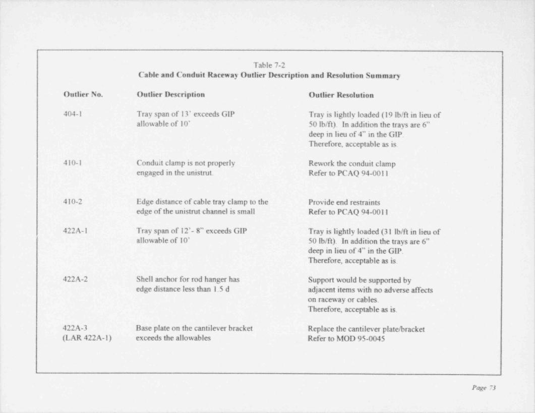
, -
.
Table 7-2Cable and Conduit Raceway Outlier Description and Resolution Summary
Outlier No. Outlier Description Outlier Resolution >
404-1 Tray span of 13' exceeds GIP Tray is lightly loaded (19 lb/ft in lieu of;
allowable of 10' 50 lb/ft). In addition the trays are 6" t
deep in lieu of 4" in the GIP.Therefore, acceptable as is.
410-1 Conduit clamp is not properly Rework the conduit clampengaged in the unistrut. Refer to PCAQ 94-0011
;
410-2 Edge distance of cable tray clamp to the Provide end restraintsedge of the unistnit channel is small Refer to PCAQ 94-0011
!
422A-1 Tray span of 12'- 8" exceeds GIP Tray is lightly loaded (31 lb/ft in lieu of7
allowable of 10' 50 lb/ft). In addition the trays are 6"deep in lieu of 4" in the GIP. I
Therefore, acceptable as is. i
!422A-2 Shell anchor for rod hanger has Support would be supported by
edge distance less than 1.5 d adjacent items with no adverse affects,
on raceway or cables. !
Therefore, acceptable as is. !!
422A-3 Base plate on the cantilever bracket Replace the cantilever plate / bracket i
(LAR 422A-1) exceeds the allowables Refer to MOD 95-0045 i
;
Page 73
i
__ _ _
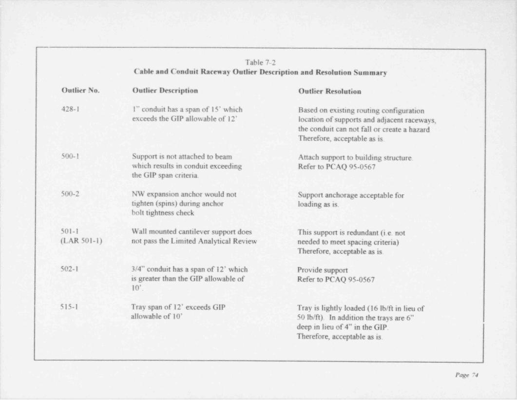
.
Table 7-2Cable and Conduit Raceway Outlier Description and Resolution Summary
Outlier No. Outlier Description Outlier Resolution
428-1 1" conduit has a span of 15' which Based on existing routing configurationexceeds the GIP allowable of 12' location of supports and adjacent raceways,
the conduit can not fall or create a hazardTherefore, acceptable as is.
500-1 Support is not attached to beam Attach support to building structure.which results in conduit exceeding Refer to PCAQ 95-0567the GIP span criteria. -
t
| 500-2 NW expansion anchor would not Support anchorage acceptable for.
|tighten (spins) during anchor loading as is.bolt tightness check r
'
!501-1 Wall mounted cantilever support does This support is redundant (i.e. not j
(LAR 501-1) not pass the Limited Analytical Review needed to meet spacing criteria) '
Therefore, acceptable as is. !
i502-1 3/4" conduit has a span of 12' which Provide support ;
is greater than the GIP allowable of Refer to PCAQ 95-0567 |10'.
515-1 Tray span of 12' exceeds GIP Tray is lightly loaded (16 lb/fl in lieu ofallowable of 10' 50 lb/ft). In addition the trays are 6" ;
deep in lieu of 4" in the GIP.Therefore, acceptable as is. !,
Page 74
t
a r ~
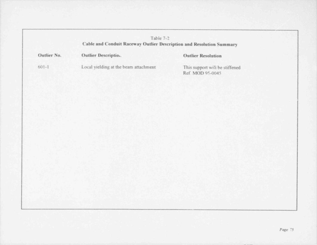
,
,
Table 7-2Cable and Conduit Raceway Outlier Description and Resolution Summary
Outlier No. Outlier Descriptiou Outlier Resolution
601-1 Local yielding at the beam attachment This support will be stilTened'Ref. MOD 95-0045i
!.
<
!
!
L
['
'
i
!'
| t
1
.
:
f!
I
|
;
i
1
5
!i
:Page 75 i
!t
. _- . - .. - - . ___ -__ _____ _______--______-_!
.. . .. . .. - - _ _ - -
I
Section 8 ;:
PLAN FOR ADDRESSING UNRESOLVED OUTLIERS
,
3
Actions have been initiated to resolve all the outliers identified as a result of the SQUG program.Many outliers have already been satisfactorily resolved using analytical means, and several otheroutliers have been corrected. The remaining outliers will be addressed through DBNPS existing '
Modification (MOD) or Potential Condition Adverse to Quality (PCAQ) processes.
Toledo Edison has currently scheduled the remaining outliers to begin work in Cycle 10.However, not all of the equipment will be available during the operating cycle for outlier '
resolution In addition, some designated trains are available only during a refueling outage with ,
alternating trains available during alternating refueling outages. The time required to complete |all of the identified SQUG outliers in a timely manner that corresponds to the equipmentavailability will be by the end of the 12 th Refueling Outage (12 RFO). !
P
,
!
i
!
|
L
e
t
Page 76
,

Section 9
SIGNIFICANT OR PROGRAMMATIC DEVIATION FROM THE GIP !
,
Toledo Edison has not taken any significant or programmatic deviations from the GIP in the,
resolution to the USI A-46 program at Davis-Besse. As allowed in the GIP, Toledo Edison hasmade interpretation; of the wording of the GIP caveats when appropriate while meeting the
,
intent of the caveats. These have been identified in Table 5-1. All other equipment not listed in !
the table met the specific wording of the caveats identified in the GIP. (
,
!
!
!i
,
i
Ii
i
!
i
!
:
i
,
>
i
Page 77 |
|!
i
. . _. . . . . - . - - _m..
. - - - - - -- .- _- --. -
E
,
ir
Section 10 |
THIRD-PARTY AUDIT SUMMARY;
!
10.1 SUMMARY OF AUDITS
As required by Section I.2.2.7 of the GIP, a Third-Party Audit was performed by a qualifiedindividual who was not part of the Seismic Review Teams (SRTs). The final Third-PartyAudit report is included in Appendix E of this report.
Several audits were conducted at Davis-Besse by qualified individuals who were not part of the !SRTs during the time the walkdowns were performed. These audits are briefly summarizedbelow.
,
10.2 INFORMAL AUDITS
Two informal audits were conducted in the early stages of the implementation of the SQUG '
program by two separate consultants (Stevenson and Associates and EQE Consultants) notdirectly involved with the walkdowns or formal reviews. These activities included the review of +
the completed Screening Verification Work Sheets (SEWS); information gathering in the plant;review of engineering documentation and judgment. These informal audits confirmed that
'
Toledo Edison was properly implementing the SQUG program in accordance with the GIP.
10.3 FORMAL AUDITS t
i
Two formal audits were conducted at Davis-Besse by qualified individuals independent of the :walkdown. These audits are described in further detail below. !
i
10.3.1 Dr. John D. StevensonDr. John D. Stevenson (Stevenson and Associates) performed a peer review of the A-46activities at the request of Davis-Besse's Q.A. Department. Dr. Stevenson has approximately 30years of experience in the seismic area, been a contributor and reviewer of the SQUG program '
and has performed SQUG walkdowns and Third-Party Audits at other nuclear facilities. Dr.Stevenson is an industry recognized expen in the seismic field. Dr. Stevenson's activities
,
included a review of completed SEWS packages, and the inspection of the corresponding i'
equipment in the plant. A total of 15 items were reviewed. The following statements weredocumented by Dr. Stevenson in his report
"It is my opinion that none of my observations or recommendations made concemmgSEWS Items 1-15 reviewed would result in the invalidation of the conclusions reached !
by the SRT's in their preparation of the SEWS."
"My basic conclusion is that the USI A-46 resolution effon at Davis-Besse NPS is
Page 78
. _ . - - __ _ _ _
. -
being performed using the SQUG developed Generic Implementation Erocedurein a thoroughly competent and adequate manner. It should be understood that thisprogram relies to a considerable extent on thejudgment of the qualified SRT teamconsistent with the requirements of the GIP and therefore thejudgment of a thirdpart is not binding. I have some recommendations which I believe would enhancedocumentation and future performance of the program.
-
1) Pictures if feasible should be taken of all components and their anchoragesand in instances where interaction has been identified.-
2) A calibrated tug test (i.e. record approximate amount of tug in Ibs andestimated weight of component) in cases where component in questionhas a frequency above 8.0 Hz and the component has a weight of 100 lbs.or less should be used to verify seismic adequacy rather than rely on moresubjective orjudgments or anchorage calculations as to anchorage capacity.
3) I also strongly recommended that the block wall seismic verification analysisbe checked to insure walls with attached equipment and distribution systemswere evaluated with these added masses."
10.3.2 Dr. James J. JohnsonDr. James J. Johnson (EQE International) performed the final Third-Party Audit at theconclusion of the SQUG program. Dr. Johnson has over 20 years experience in thedevelopment, implementation and teaching of seismic issues. Dr. Johnson has played asignificant role in the development of general and plant specific seismic evaluation proceduresincluding the SQUG program.
Dr. Johnson's review of the SQUG program as implemented at Davis-Besse concluded thatToledo Edison implemented the GIP requirements " . in an appropriate and adequate fashion."In addition, Dr. Johnson agreed with the SRT's conclusion on the seismic adequacy of theequipment in which he reviewed.
Appendix E contains Dr. Johnson's letter to Toledo Edison that documents his review andconclusions en the SQUG program at Davis-Besse.
||
!;
!
Page 79;
I1
_ _ _ _ _ _

.. - . . - - - - . . .. - ._ - . . . - - - -. - __. -
Section 11
REFERENCESi
1. Generic Implementation Procedure (GIP) for Seismic Verification of Nuclear PlantEquipment, dated February 1992, copyright Seismic Qualification Utility Group .
(SQUG), Revision 2 corrected February 14,1992. |
2. USNRC, " Supplement No. I to Generic Letter (GL) 87-02 that transmitsSupplemental Safety Evaluation Report No. 2 (SSER No.2) on SQUG Generic
IImplementation Procedure, Revision 2, as Corrected on February 14,1992 (GIP-2),"dated May 22,1992.
3. Letter to the NRC from Donald C. Shelton, dated Sept. 17,1992 (Serial Number 2090)
4. Letter to Donald C. Shelton from the NRC dated December 8,1992
5. USI A-46 Relay Evaluation Report (Attachment 2)
:
:
i
h
I
:
|
l
I
i
|
Page 80
. - . .

__ - .. - __
-
.
DAVIS-BESSE NUCLEAR POWER STATION
Unresolved Safety Issue (USI) A-46
Seismic Evaluation Report
APPENDIX A
Rssum6s for Seismic Capability Engineers (SCEs)
1
- _ _ _ _ _ _ _ - - _ - - _ _ _ _ _ _ _ _ _ _ _ _ _ _ _ _ - _ _ _
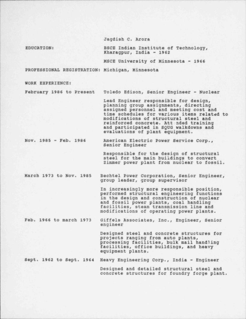
I
I
t
Jagdish C. Arora
EDUCATION: BBCE Indian Institute of Technology, I|Kharagpur, India - 1962
MSCE University of Minnesota - 1966
PROFESSIONAL REGISTRATION: Michigan, Minnesota
WORK EXPERIENCE:
February 1986 to Present Toledo Edison, Senior Engineer - Nuclear
Lead Engineer responsible for design,planning group assignments, directingassigned personnel and meeting cost andtime schedules for various items related tomodifications of structural steel andreinforced concrete. Attanded trainingand participated in SQUG walkdowns andevaluations of plant equipment.
Nov. 1985 - Feb. 1986 American Electric Power Service Corp.,Senior Engineer
Responsible for the design of structuralsteel for the main buildings to convertZimmer power plant from nuclear to fossil.
March 1973 to Nov. 1985 Bechtel Power Corporation, Senior Engineer,group leader, group supervisor
In increasingly more responsible position,performed structural engineering functionsin the design and construction of nuclearand fossil power plants, coal handlingfacilities, steam transmission line andmodifications of operating power plants.
Feb. 1966 to march 1973 Giffels Associates, Inc., Engineer, Seniorengineer
Designed steel and concrete structures forprojects ranging from auto plants,processing facilities, bulk mail handlingfacilities, office buildings, and heavyequipment plants.
Sept. 1962 to Sept. 1964 Heavy Engineering Corp., India - Engineer
Designed and detailed structural steel andconcrete structures for foundry forge plant.
1

__ _.
Richard N. Bair1800 McCord Road, Apt. 67
Toledo, Ohio 43615
EDUCATION: BSCE Michigan Technological University - 1974Graduate Course - University of Michigan
PROFESSIONAL REGISTRATION: Michigan
VORK EXPERIENCE:
May 1988 to Present Toledo Edison, Senior Engineer - NuclearResponsible for: Preparation of PlantModification Packages (including SafetyEvaluations), perform analysis and design ofmiscellaneous structural items (including:raceway supports, pipe supports, platforms,and equipment anchorages). Attended trainingand participated in SOUG and IPEEE valkdownsand evaluations of plant equipment andsupports. Responsible engineer for the DryFuel Storage Facility Modification to augmentthe storage capacity of the spent fuel pool.
March 1980 - May 1988 Bechtel Power Corporation, Senior EngineerResponsible for: Design and construction ofsupports; raceway and piping, constructionand outage support for Civil designs at PowerPlant sites, analysis and design ofmiscellaneous structures; platforms andbuildings, and equipment supports.Performed a variety of office and siteassignments.
July 1979 - March 1980 Giffels Associates, Inc., Field RepresentativeResponsible for: Reviewing all aspects of theindustrial construction as the client's siterepresentative. Assisted in resolving siteconstruction problems, and the issuance ofchange orders.
June 1974 - July 1979 Bechtel Power Corporation, EngineerResponsible for: Field inspections of Civil /Structural construction at industrial site.Perform design of structural steel forbuildings and miscellaneous supports.

._
Thomas Dabrowiak808 Lambkins St.
)Saline Mi. 48176 i
i
EDUCATION: BSCE Purdue University - 1970 l1!
!
PROFESSIONAL REGISTRATION: California
WORK EXPERIENCE:
June 1991 to Present Toledo Edison, Senior Engineer-NuclearResponsible for: Preparation of plant modifications,design of miscellaneous stmetural items, performseismic analysis of piping systems. Attended trainingand participated in SQUG walkdowns and evaluations.Provided Civil / Structural response to the ElectricalDistribution System Functional Inspection (EDSFI)program.
June 1973 to June 1991 Bechtel Power Corporation, Group LeaderResponsible for: Design of numerous structures atnuclear and fossil power plants. Performed dynamicanalysis of fan foundations and flue gas ductwork.Analyzed and designed chimney and power blockfoundations and structural steel superstmetures.Experience at construction sites as well as the designoffice.
June 1970 to June 1973 Sargent & Lundy, EngineerResponsible for: Analysis and design of electricalsubstation superstructures and foundations.

. _ . - - . = . . . . - . _ - _ . - - - . . - . . . . . - _ ~ -
Jon G. Hook2640 Sequoia Rd.
Toledo, Ohio 43617 '
EDUCATION: BSCE, Michigan Technological University - 1974Graduate Courses - University of Michigan
PROFESSIONAL REGISTRATION: Michigan
WORK EXPERIENCE:
June 1987 to Present Toledo Edison, Senior Engineer - NuclearLead Engineer in the Civil /Stmetural Unit.Responsible for the seismic qualification ofequipment, design criteria, procedures,modifications, architectural and civil siteactivities. Responsible engineer for theSQUG and IPEEE programs.
February 1978 - June 1987 Bechtel Power Corporation, Senior EngineerResponsible for: Design and construction ofraceway and HVAC supports. Performanalysis and design of miscellaneousstructures and platforms. Activities includedwriting specifications, evaluating bids,resolving various problems associated withconstruction of various nuclear powerplants.
June 1976 - February 1978 Bechtel Power Corporation, Q.A. EngineerResponsible for performing inspections andaudits of civil /stmetural activities duringconstmetion of a nuclear facility.
June 1974 - June 1976 Stone and Webster Engineering Corp.Q.C. Engineer
Responsible for performing inspections andtests on the installation of soils, concrete,coatings and structural steel duringconstruction of nuclear facilities.
i

Steven J. Ostmg5247 Seaman Rd.
Oregon, Ohio 43616
EDUCATION: General coursework- University of Cincinnati- 1975Associate: Engineering Applied Science- Lima
Technical College- 1978Bachelor: Mechanical Engineering Technology- University of
Dayton- 1980
PROFESSIONAL REGISTRATION: Ohio- 1990
WORK EXPERIENCE:1976-1978 U.S. Fiber Ccrporation- QC lab technician.
Performed various Quality Control / Testing functions for amajor U.S. cellulose insulation manufacturer. Duties: in-labchemical analysis and physical property testing to insurecompliance with company standards, NFPA guidelines, andUnderwriters Laboratories (UL) regulations; assisted in thedevelopment , operation and surveillance of manufacturingand installation equipment. Responsible for equipmentperformance reports and monitoring / reporting product testresults.
1979 Mitchell & Jensen, Architect / Engineers- Engineering AssistantWorked in the Mechanical Engineering Dept. assisting in thedesign of HVAC and piping for newly designed commercialbuildings in the Dayton, Ohio area. Duties: heating / coolingload analysis, HVAC duct layout and design, miscellaneousdrafting- HVAC/ plumbing, water well location survey forfuture sitings.
1980-present Toledo Edison Co.- Senior Design EngineerProvided technical support for the Davis Besse Nuclear PowerStation. This involves daily problem resolution, long termplanning / engineering design of process system enhancementsor upgrades, performing modification design resiews andcoordinating field implementation interface.Specific duties: technical studies and cost benefit analysis;develop safety reviews aad evaluations for equipment andsystem modifications; root cause analysis; and defectivecomponent analysis orjustification of non-conformingconditions ofinstalled components and systems; developingcomplete detailed engineering design packages and thesupporting calculations / drawings; interface with regulatingbodies such as the Nuclear Regulatory Commission;participate in technical committees such as Owner's Groups.Involved heavily in the area of process piping stress analysis ,
and pipe support design. )Completed the Seismic Qualification Utility Group (SQUG)
'
walkdown screening and seismic evaluation course inNovember,1993. ]
I
||

. _ - . _ . . - . . - - - _ _ - - _ . _ - .. --
Scott R. Saunders3518 Lynnbrooke Lane
Oregon, Ohio 43616.
EDUCATION: BSCE, The Ohio State University - 1983 |
WORK EXPERIENCE:
May 1985 - Present Toledo Edison Company, Senior Engineer - Nuclear
Responsible for: Preparation of Plant Modification,
packages, safety reviews and evaluations; performinganalysis of process piping systems, design and analysisof miscellaneous structural items and supports ( piping,electrical raceway, HVAC, tubing ); evaluation of non-conforming plant conditions including root causeanalyses; participate as Core Committee member of theSnubber Utility Group ( SNUG ); attended training andparticipated in SQUG walkdowns and evaluations.
June 1984 - May 1985 Jones & Henry Engineers, Limited, Design Engineer
Responsible for: Process design, layout of piping,equipment, and stmetures, cost estimating,specification and drawing development for wastewatertreatment plant projects.
!
June 1980 - June 1984 Toledo Edison Company, Student Engineer
Performed various duties in support ofMaintenanceEngineering staff at Acme and Bay Shore Stationsincluding, procurement of new and replacement parts,implementing spare parts program, compilingequipment lubrication manual, computerizedscheduling for major maintenance outages, financial -
reports and budgets.
.- . . - __

JAMES R. DISSER
:
,
PROFESSIONAL HISTORY
EQE Internaftonal Stratham, New Hampshire, Project Engineer,1993-presentMffchell, Jobe & Companp, Dallas, Texas. Senior Engineer, 1992-19937U Electric, Glen Rose. Texas, 1980-1992
PROFESSIONAL EXPERIENCE
Mr. Disser has approximately 13 years of experience in the nuclear engineeringand construction industry which includes design, analysis, and projectmanagement experience.
As Project Engineer for EQE's Engineering Consultants, Mr. Disser is currentlyinvolved in the USI A-46 program at Carolina Power and Light (CP&L) BrunswickSteam Electric Plant (BSEP) and GPU Nuclear Oyster Creek Nuclear GeneratingStation. Prior to this, he has provided services at BSEP in support of the MaterialCondition Upgrade Project. He was responsible for providing innovativeengineering resolutions to ensure short-term structural integrity (STSI) for a widevariety of plant equipment, inchiding all structural elements of the plant buildings,all suspended systems, and mechanical and electrical equipment. STSIresolutions are provided using established plant short-term acceptance criteria;accepted USI A-46 methodology; and/or other creative, sound, short-termengineering qualification methods. The project scope includes in-plant walkdownsto identify potential material condition deficiencies; researching designdocumentation related to the identified concerns; evaluation of the structural
condition, production, review, and design verificadon of supporting calculations;initiation of any modifications to support the STSI resolutions; and engineeringsupport of construction or maintenance crews in the installation of themodifications. The project group is also responsible for follow-up engineering toprovide long-tenn quallflcation of the STSI resolutions within the Plant DesignBasis which may require additional engineering work or plant modifications forlong-term qualification of the equipment and commodities involved. The project'sSTSI and long-term resolutions quality the equipment and commodities foroperational, seismic, and postulated accident conditions as required by the Plant'scurrent Design Basis.
Prior to EQE, Mr. Disser was Technical Manager of the Unit 2 Civil / Structural.Engineering Mechanics, and Suspended Support System Engineering Contract atthe Comanche Peak Steam Electric Station (CPSES) in Glen Rose, Texas. Thecontract provided engineering services for CPSES Unit 2 for the civil, structural,engineering mechanics, seismic equipment qualification, protective coatings,HVAC supports, conduit and conduit supports, cable tray and cable tray supports,instrumentation tubing and supports, non-ASME piping and support, pipenJpture and commodity clearance disciplines. The contract also included asubcontract for the CPSES Unit 2 Seismic Category 11/1 Adequacy Evaluation. Mr.Disser was responsible for reviewing and approving budget; technical overview ofthe architect / engineer; conducting technical assessment; reviewing and approvingtechnical criteria and process procedures; and interfacing with project
res8/Disser/Aug-94 1
- - _ _ _ - _ _ _ _ - _ _ _ _ _ _ - - _ _ _ - _ - - _ _

- - - - - _. - .-. . . . . . . - _ . - - -- .-- - - - -. - - .-
JAMES R. DI@SER
!
PROFESSIONAL EXPERIENCE (Continued)
management, construction, startup, Quality Assurance (QA)/ Quality Control (QC),Unit 1, and the NRC. He was responsible for providing the A/E with design critela !and assuring that design basis commitment were met.. He was also active in TUElectric engineering management of the Unit 2 ASME Pipe Stress and SupportEngineer; the Unit 2 Mechanical and Electrical Systems Engineer and the NSSSsupplier, Engineer and Analyst in the TU Electric Engineering Unit 2 scope of '
work; and Unit 1 Design Engineering group perfonning structural, engineering ;
mechanics, pipe stress and supports, and I&C tubing and HVAC stress andsupports engineering. :
!
Mr. Disser provided engineering services for va;ious 'IU Electric Comanche Peak, i
projects, specifically described below: !
Unit 2 Reactor Containment Structural integrity Test*
(SrJ7 Milestone Manager. Responsible for all aspects of the ;
Unit 2 SIT, including direction of all activities related to the ;
SIT performed by the civil / structural engineer, startup, and t
construction. Responsible for schedule; budget; engineering i
specification; test procedures; pre-test preparations: !
engineering and startup activities; restoration of the !Containment building after completion of the test, review
,
and approval of the Sfr test report: and interface with the i!Integrated Leakage Rate Test personnel.
Original Project Engineer for the Unit 2 Construction |*
Restart Estimating Project. Developed the engineering jbaseline scope, manhour estimate, and budget for the Unit 2
|
Completion Project that preceded restart of Unit 2 ;
engineering activities in 1990. Responsibilities included I
development of the baseline scope for the ASME and non-ASME piping and supports analysis scope, the Unit 2 3
Seismic Category II/I Adequacy Evaluation, participation in i
the preparation of the baseline scope for the civil / structural, ,
engineering mechanics, mechanical systems, and NSSSEngineering scopes of work. j
Engineer for the ERC Comanche Peak Review Team ;*
9A/9C Review in the Mechanical Sqfety Sign (ficance i
Evaluation Group. Responsibilities included evaluauon ofdeviation reports generated by CPRT inspectors as a result of
i
inspections for construction deviations from design !irequirements. The evaluations determined the safety
significance of the deviations through research into design ,
requirements in effect during the construction phase of '
Comanche Peak Unit 1, analysis of the design andconstruction evolution of the deviating item and performance ,
of calculations, as required, to determine the effects of the '
deviation on the integrity of the item.
m8/Disser'Aug 94 2 I
.
iI-

JAMES R. DI~SER
PROFESSIONAL EXPERIENCE (Continued)
Mr. Disser also provided services at the Beaver Valley 2 Nuclear Power Station,Duquesne Light Company. Spec!Ilc projects are briefly described below:
Responsible for final qualification of pipe stress calculations*
in support of the BVPS-2 ASME III N-5 Certification ProgramResponsibilities included preparation and independentreview of final stress calculations incorporating final designand as-built input for ASME III Class 2 and 3 piping. Thisincluded review of existing reconciled calculations foradequacy and conformance with the BVPS-2 criteriadocument, assessment of impact of revised final designinput, assessment of accuracy of the NUPIPE model andanalysis versus the as-built configuration, and incorporationof this review into the pipe stress calculations by statementsof engineering judgment, hand calculations, orpartial / complete restress, as required. Also performedanalysis and calculation reviews for ASME buried piping.
Responsible for special tasks related to pipe and duct*
supports. Responsibilities included maintenance of the pipeand duct support installation specifications, resohringconstruction problems, disposition of nonconformance,development and implementation of backfit construction andinspection programs, resolution of NRC Infractions and OpenItems related to pipe supports, resolution of vendorproblems, and supervision of all pipe support engineeringactivities of the Site Engineering Group.
Responsible for site IE Bulletin 79-14 Stress Reconcillation*
Program activities. Responsibilities included assuring thequality and accuracy of as-installed piping and supportinformation transmitted to the Boston ofIlce for stressreconcillation, development and implementation ofprocedures to achieve flnal issue of as-constructeddocuments to support the N-5 program.
Responsible for pipe support engineering and design*
activities in the Boston office for BV-2. Responsibilitiesincluded redesign of supports in support of construction,support of licensing activities related to pipe supports,engineering support of the site instrumentation tubing :stress analysis and support group, design support of thestress reconciliation program, and general pipe supportengineering support of the Site Engineering Group, Torontoand New York offices. Also, BV-2 EMD System TurnoverCoordinator, which entailed assuring the completion andquality of all pipe support engineering software prior to thescheduled turnover of systems to DLC. Responsible for thedirection and supervision of all engineering and designpersonnel assigned to carry out these activities.
res8/Disser/Aug-94 3
i|
|
JAMES R. DISSER,
PROFESSIONAL EXPERIENCE (Continued)
Responsible for pipe, duct, and instrumentation tubing=
support engineering activities at the BV-2 site. Alsoresponsible for the instrumentation tubing stress analysisand support design program which was assigned to the BV-2Site Engineering Group. Responsibilities includedmaintenance of the pipe, duct, and instrumentation tubinginstallation specifications, various field constructionprocedures, disposition and issue of design documentchanges and nonconformance reports, interface with otherdesign oinces, direct interface with client's engineering ofIlceand with the NRC on EMD related issues. Also responsiblefor technical direction and supervision of al IBV-2 site
assigned EMD support engineers and all design personnelengaged in the instrumentation tubing stress analysis andsupport design effort.
Responsible for technical direction of site pipe, duct, and*
instrumentation tubing support design personnel,maintenance, and development of field constructionprocedures and installation specifications for supports,generic resolution of construction problems with supportinstallations, and interface with NRC personnel during siteinspections.
As SWEC Assistant to the Manager of Engineering, Mr. Disser provided services tothe Nuclear Construction Division at Duquesne Light Company, as follows:
Assisted the Manager of Engineering in establishing the*
Engineering Department in the newly created NuclearConstruction Division. Responsibilities included developingand implementing Engineering Department procedures forreview of the BV-2 FSAR and technical review of BV-2licensing issues (NRC infractions, open items, etc.) andcontractor correspondence.
Responsible for assuring the technical quality of pipe*
support designs produced by the Site Engineering Group forBV-2. Developed and implemented project design criteriaand supervised and provided design changes at the site forcritical path piping. Assisted in the supervision of all projectpipe support activities.
Shoreham Nuclear Power Station, long Island Lighting*
Company. ASME III Class 1 pipe stress analyst.
EDUCATION
|UNIVERsTTY OF MICHIGAN: B.S. Civil Engineering,1980 '
res8/Disser/Aug-94 4
_ _ _ _ _ _ _ _ _ _ _ _ - _ _ _ _ _ _ _ _ _ _ _ _ _ _ _ _ _ _ _ - _ - _ _ _ _ _ _ _ _ _ _ _ _ _ - _ _ _ _ _ _ _ _
J

-. _. . . - . .. .. -. . . . - . . . . _ . - _ - - - . . . . - . . - . - - . . . - _ _ . - - - - . .
JAME3 R. DISSER
1
1
'PUBIJCATION
li
With T. Roche, C. Abou-Jaoude, and J. P. Conoscente. 1993. " Comparison i
'Between Analytical and Test Results for Transfonner Base Details." ASMEPressure Vessel and Piping Conference, Seismic Engineering, July 1993. ,
|
.
|
i
!
i
!;.
I,
f
'
,'
t
[
!
t1
!L
!
>
:
|
i
!
|
t1
i;
|
*
res8/Disser/Aug-94 5;
>
- -- --. _. - ---_ _. -__ ___ . _ ______ _ ___ _ _ _ _ _ _ _ _ _ _ _ _ _ _ _ _ . _ _ _ . _ _ _ _ _-
_
|JOIIN O. DIZON
!!I
PROFESSIONAL IIISTORY
EQE International, San Francisco, California, Associate,1986 presentEngineering Decision Analysis Company, Cupertino, California, Project Engineer,
1984-1986Genera / Electric Company, San Jose, California, Senior Engineer,1984URS//ohn A. Blume Associates, San Francisco, California, Senior Engineer,
1982-1984; Associate Engineer, 1977-1980Structural Systems Engineering. Inc., Lafayette, California, Senior Engineer,
1980 1982
Stanford University, John A. Blume Earthquake Engineering Center, Palo Alto,California. Teaching and Research Assistant, 1975-1977
PROFESSIONAL EXPERIENCE
Mr. Dizon has over 15 years of experience in seismic analyses and designassessments of primary structures and piping systems, and seismic qualification ofmechanical and electrical systems for the nuclear power industry. As a PrincipalEngineer for EQE's Engineering Consultants Division, he has taken primaryresponsibility for the technical development of several seismic evaluation programs.These include acting as Group Manager for evaluating essential systems and,:omponents at the Savannah River Site; developing alternate analysis criteria forCategory I small bore piping at the Donald C. Cook plant and alternate designcriteria to the Tennessee Valley Authority for the Sequoyah Nuclear Plant; andproviding guidance to the seismic equipment qualification program for thePlutonium Handling Facility at Lawrence Livermore National Laboratory.
As Group Manager for EQE at the Savannah River Site, Mr. Dizon is responsiblefor the seismic verification program of safety-related mechanical and electricalsystems and components. His tasks include developing seismic evaluation criteriaand procedures for restart and long-term seismic programs, consistent with theSQUG Generic Implementation Procedure for use in USl A-46 plants; managing theseismic walkdown and evaluation efforts; providing technical support in resolvingseismic issues; and serving as an interface with the client.
Mr. Dizon has participated in the seismic evaluation of the High Flux IsotopeReactor at Oak Ridge National Laboratory. This project involved performingseismic analyses and upgrades for the primary coolant piping system and relatedequipment and the reactor and control buildings. He was responsible for theraceway evaluation program for Cooper Nuclear Station and Browns Ferry NuclearPlant, and participated in the seismic piping reevaluation programs for SequoyahNuclear Plant and Comanche Peak Nuclear Plant where he performed plantwalkdowns and pipe stress analyses for piping systems.
res2/dison2/May10-91
,
--_- _ ----- - _ ___ - -_--- __--__ _ __-___- - _ _ - _ _

JOHN O. DIZON
PROFESSIONAL EXPERIENCE (Continued)
With General Electric Company, Mr. Dizon was responsible for stress analysis andcode conformation of main steam and recirculation piping systems for BWR powerplants. He was involved in the evaluation and development work on a pipe supportoptimization program.
At EDAC, Mr. Dizon was responsible for the evaluation and development of a pipesupport optimization program (OPTPIPE). He was responsible for the snubberreduction pilot program for Commonwealth Edison's La Salle County Station Unit1. Other areas of his involvement consisted of finite element analyses of MX-missile launch tube components and systems for thermal and pressure loads,equipment qualification of major mechanical and electrical components, andseismic evaluation of cooling towers for the Vermont Yankee Power Plant.
At URS/Blume & Associates, Mr. Dizon was responsible for the development andmaintenance of in house computer programs for both linear and nonlinear analysesof structural and piping systems. He was also involved in the seismic analysis andevaluation of the reactor, turbine and admini* nation buildings for Nine Mile PointUnit 1 in New York. He helped develop a soil-structure interaction computerprogram using a three-dimensional finite element technique to evaluate thedynamic response of structures due to arbitrary plane body and surface waveexcitations. He performed a research study involving soil-structure interactionanalysis using the finite element FLUSH program to investigate the dynamicresponse of typical containment structures due to underground blast excitations.He was also involved in the linear and nonlinear dynamic analyses, finite element
! modeling, and generation of floor response spectra for the containment and turbinebuildings at the Diablo Canyon Nuclear Power plant near San Luis Obispo,California.
Mr. Dizon worked as a consultant to Bechtel Power Corporation with StructuralSystems Engineering, Inc. He performed structural analyses and design assessmentsof the primary containment structure and the reactor / control buildings ofLimerick Generating Station in Pennsylvania for various types of hydrodynamicloads. He was involved in the Limerick in-plant test procedures, data reductionand correlation study to determine the dynamic response, including soil-structureinteraction of the reactor / control buildings during Mark H hydrodynamic loadactuation in the primary containment.
At Stanford University, Mr. Dizon performed statistical analyses of earthquakeacclerograms and various response parameters. He conducted seismic risk analysesand formulated seismic design criteria for Nicaragua. In addition, he was involvedin the dynamic testing of structural models and equipment.
EDUCATION
STANFORD UNIVERSITY, Palo Alto, California: Engineer Degree,1977STANFORD UNIVERSITY, Palo Alto, California: M.S. Structural Engineering,1975MAPUA INSTITUTE or TECHNOLOGY, Manila, Philippines: B.S. Civil Engineering,1973
res2/daon2/May10-91
3^@

- . - .
JOHN O. DIZON
REGISTRATION
California: Civil EngineerPhilippines: Civil Engineer
PUBLICATIONS
With S. J. Eder. 1991. " Advancement in Design Standards for Raceway Supportsand its Applicability to Piping Systems." To be presented at the 1991 AmericanSociety of Mechanical Engineer (ASME) Pressure Vessel and Piping DivisionConference, San Diego, California, June 1991.
With S. P. Harris, R. S. Hashimoto, and R. L. Stover. 1989. " Seismic, High Wind,and Probabilistic Risk Assessments of the High Flux Isotope Reactor." SecondDOE Natural Phenomena Hazards Mitigation Conference.
With D. Ray and A. Kabir. 1979. "A 3-D Seismic Analysis for Arbitrary PlaneBody and Surface Wave Excitations." American Society of Civil Engineers NuclearSpecialty Conference, Boston, Massachusetts.
With D. Ray and A. Zebarjadian. 1978. " Dynamic Response of Surface andEmbedded Disk Foundations for SH, SV, P and Rayleigh Wave Excitations." SixthIndian Symposium on Earthquake Engineering, Roorkee, India.
"A Statistical Analysis of Earthquake Acclerograms and Response Parameters."1977. Thesis, Stanford University, Palo Alto, California,
With H. Shah T. Zsutty, H. Krawinkler, and L. Padilla. 1977. "A Seismic DesignProcedure for Nicaragua." Paper presented at the Sixth World Conference onEarthquake Engineering, New Delhi, India. |
With H. Shah, T. Zsutty, H. Krawinkler, C. P. Mortgat, and A. Kiremidjian. 1976."A Study of Seismic Risk for Nicaragua, Part II, Summary and Commentary." JohnA. Blume Earthquake Engineering Center, Report No.12A and 12B. StanfordUniversity, Palo Alto, California.
!
|
|
res2 /dison2/May 10-91 -
1
i

w - . -- .- --. - . - . - - - . - . _ - - _ . . - - . . _ .- - .-
i
|,
!!
STEPHEN J. EDERi
!
!
I
PROESSIONAL HISTORY |
EQE International, San Francisco, California,1985-presentURS/ John A. Blume & Associates. Engineers, San Francisco, California, 1982-1985J. G. Bouwktsmp. inc. Structural Engineers, Berkeley, California, 1981-19g2
t--. . .
PROESSIONAL EXPERIENCE
Mr. Eder provides engineering and management consulting for safety evaluation ofpower plants, national laboratories, and industrial facilities. He is Vice Presidentand Regional Manager for EQE Engineering Consultants' San Francisco regionaloffice. His experience includes structural dynamic analyses, seismic evaluation-
;
and margin assessments, post-earthquake reconnaissance studies, and shake table .
and other dynamic tests and qualification. Mr. Eder provides technical direction '
|to many projects, targeted at efficient balance of computational analysis and|experience based screening evaluations.)\'
,
In support of the Seismic Qualification Utility Group (SQUG), Mr. Eder preparedand reviewed several sections of the SQUG Generic Implementation Procedure, andprovides the Steering Group with ongoing technical and licensing support. As aSQUG subject matter expert, Mr. Eder prepared and overviews the development of -
several sections of the Unresolved Sa'fety Issue A-46 (USI A-46) walkdown training !course.
]
For the U.S. Department of Energy (DOE) Environmental, Safety, and Health,
programs, in conjunction with Lawrence Livermore National Laboratory (LLNL), iMr. Eder developed the field guide for walkthrough screening evaluation of DOE '
facilities. This included trial walkthroughs at LLNL and Stanford Linear ;Accelerator Center. He assisted in developing the Program Plan for evaluating !
existing DOE facilities. Mr. Eder was lead reviewer in support of the Tiger Team '
Technical Safety Appraisal of Los Alamos National Laboratory for the NaturalPhenomena Hazard team. -
i
Mr. Eder has provided a leading role in program plan development, criternadefinition, program implementation, and configuration control design for DOEfacilities. These projects include the Savannah River Site (SRS); K, L, and Preactors; Oak Ridge National Laboratory High Flux Isotope Reactor; and the LLNL
.IPlutonium Facility. While at SRS, Mr. Eder was a member of the Senior ReviewTeam'for seismic issues in support of reactor restart. :
Mr. Eder pioneered the development of the innovative raceway system seismicevaluation guidelines for SQUG, using earthquake experience data, test results, andfatigue analysis as a basis. To ensure applicability of the SQUG procedure forconduit and cable trays, he performed trial reviews for several nuclear powerplants including Zion, Three Mile Island, Oyster Creek, Vermont Yankee, Prairie
!
t
,
ress/eder2/DecsO-91/1 |i$
r
h
" . - - - . - - - - . - - - - . . . _ - - _ _ - - - - _ _ - . . _ - - - - - - _ _ --_n - . . . . -- . . . . - - - -- - , ,--
. - . .. - - - -
STEPHEN J. EDER
PROFESSIONAL EXPERIENCE (Continued)
Island, Kewnaunce, Point Beach, Palisades, Yankee Rowe, Millstone, Calvert Cliffs,Beaver Valley, and Nine Mile Point.
In the capacity of a project manager and project engineer, Mr. Eder has beeninvolved with cable tray and conduit system seismic evaluation programs at manynuclear power plants. His involvement includes plant-specific criteria developmentand review. He has supported raceway qualification at near-term operating licenseplants, including Seabrook Station, Watts Bar, Bellefonte, and Darlington. Heperformed raceway evaluations at several older operating plants including Tihange,Browns Ferry, Cooper Station, Sequoyah, Davis Besse, Robinson,-Peach Bottom,-andHatch. He conducted raceway qualification training courses for engineers fromGeneral Public Utilities, Toledo Edison, Carolina Power and Light, and SouthernCompany Services, as well as generic courses for SQUG.
Mr. Eder participates in expansion of experienced-based evaluation techniques totechnical areas outside of the scope of the USI A-46 program. Mr. Eder supporteddevelopment of the evaluation program for piping systems at SRS and Oak RidgeNational Laboratory. He assisted in developing design criteria for fire protectionpiping at SRS, Watts Bar, and Darlington. He has performed non-safety pipingreviews in support of systems interaction reviews at Browns Ferry, Sequoyah, WattsBar, Darlington, and Savannah River. He has supported development of ductsystem seismic evaluation guidelines for Brunswick, Browns Ferry, Bellefonte, andComanche Peak. He also has contributed to anchorage design and evaluationcriteria and procedure development programs for Savannah River and Bernau, andsystems interaction programs at Watts Bar and Comanche Peak. At SRS, heprovided consulting for the in-situ test program for lead cinch anchors.
Mr. Eder has supported miscellaneous component and equipment qualificationefforts for several nuclear power and DOE facilitics, including Rancho Seco,Browns Ferry, Duane Arnold, Robinson, Davis Besse, Fort Calhoun, Cooper Station,Beznau, Rocky Flats, Savannah River, and Oak Ridge National Laboratory.
At URS/Blume, Mr. Eder served as Project Engineer to assess the fragility ofstructures in St. Louis for a reoccurring New Madrid Earthquake. He alsoconducted seismic vulnerability assessment of processing facilities for SouthernCalifornia Gas Company which included structures, pipelines, tanks, andequipment. Mr. Eder performed seismic analysis and design review of the DiabloCanyon Unit I and 2 turbine buildings. He also conducted seismic analyses of the
,
Diablo Canyon Unit I containment building annulus structure and piping, and |buildings at Millstone 3 Nuclear Plant. '
I
Mr. Eder's research projects include development of decoupling criteria for pipingand equipment systems dynamic models, and statistical evaluations to compare the
]validity of modal combination techniques used in dynamic analysis. He developedguidelines on nonlinear tubular strut behavior for seismic evaluation of offshore )platforms, by correlative anclysis of shake-table tests. He also performedcorrelative dynamic analyses of high-rise towers to evaluate the effects ofmodeling assumptions on predicting response for seismic design, and to assesscarthquake building code practices.
1
I
res2/eder2/Dec20-91/2
is l

_. .- - . .. . - . . - .- - . .
STEPHEN J. EDER
EDUCATION
UNIVERSITY OF CALIFORNIA, Berkeley: M.Eng., Structural Engineering and StructuralMechanics,1982
CLARKSON COLLEGE OF TECHNOLOGY, Potsdam, New York: B.S. Civil andEnvironmental Engineering,1980
CANISIUS COLLEGE, Buffalo, New York: Engineering Science and Computer Science,1978
REGISTRATION
California: Civil Engineer ~ ~
AFFILIATIONS
American Society of Civil EngineersASCE Seismic Raceway Working GroupEarthquake Engineering Research InstituteApplied Technology CouncilStructural Engineers Association of Northern CaliforniaSEAONC Seismology Subcommittee on Non-Building Structures and Building
ComponentsElectric Power Research Institute's Post Earthquake Investigation TeamTau Beta Pi National Engineering Honor SocietyPhi Kappa Phi National Honor Society
PUBLICATIONS AND REPORTSi
With M. W. Eli. 1991. "Use of Earthquake Experience Data." Prepared for theThird DOE Natural Phenomena Hazards Mitigation Conference, St. Louis, Missouri.
.
With M. W. Eli and L. J. Bragagnolo. 1991. "Walkthrough Screening EvaluatsonField Guide, Natural Phenomena Hazards at Department of Energy Facilities." !Special Release for 3rd DOE Natural Phenomena Hazard Mitigation Conference,October 1991, St. Louis, Missouri.
With J. O. Dizon. 1991. " Advancement in Design Standards for Raceway Supportsand Its Applicability to Piping systems." PVP-Volume 210-1, Codes and Standards ;
and Applications for Design and Analysis of Pressure Vessel and Piping 1
Components. ASME 1991.
" Cable Tray and Conduit System Seismic Evaluation Guidelines.* March 1991.EPRI Report NP-7151. Prepared for the Electric Power Research Institute. San |Francisco, CA: EQE International.
With G. S. Johnson. March 1991. "The Performance of Raceway Systems in Strong.motion Earthquakes." EPRI Report NP-7150. Prepared for the Electric PowerResearch Institute. San Francisco, CA: EQE International.
res2/eder2/Dec20-91/3 EI
l
_ ___ _ _ __ __- _ ___ __ _ ___ . _ _ _ _

. _. - -_- - . .- , - - _ . _ . - - - _ . _ - .
FI'EPHEN J. EDER
PUBLICATIONS AND REPORTS (Continued)
With G. S. Johnson. March 1991. " Longitudinal Load Resistance in SeismicExperience Data Base Raceway Systems." EPRI Report NP-7153. Prepared for the <
Electric Power Research Institute. San Francisco, CA: EQE International.
With J. P. Conoscente and B. N. Sumodobila. March 1991. " Seismic Evaluation ofRod Hanger Supports for Electrical Raceway Systems." EPRI Report NP-7152.Prepared for the Electric Power Research Institute. San Francisco, CA: EQEInternational.
With Winston & Strawn, MPR Associates, Inc., etal. June 1991. " GenericImplementation Procedure (GIP) for Seismic Verification of Nuclear PlantEquipment." Revision 2. Prepared for the Seismic Qualification Utility Group.
With G. S. Johnson and T. R. Kipp. 1991. " Integrated Interaction ProgramScreening and Acceptance Criteria." Design Criteria WB-DC-20-32. Prepared forTennessee Valley Authority.
With R. J. Hookway and T. R. Kipp. 1991. " Commodity Clearance Requirements."Engineering Specification N3C-941. Prepared for Tennessee Valley Authority.
With R. D. Hookway and T. R. Kipp. 1991. " Seismic Qualification of CategoryI(L) Fluid System Components and Electrical or Mechanical Equipment." DesignCriteria WB-DC-40-31.13. Prepared for Tennessee Valley Authority.
With R. D. Hookway and T. R. Kipp. 1991. " Seismic Design Specification forCategory I(L) Piping, Pipe Supports, and In-line Components." EngineeringSpecification N3C-943. Prepared for Tennessee Valley Authority.
With L. J. Bragagnolo and J. P. Conoscente. 1990. "A Proposed Methodology forthe Seismic Design of Rectangular Duct Systems." Applied Technology Center(ATC) Seminar on Seismic Design and Performance of Equipment andNonstructural Elements in Building and Industrial Structures, Irvine, California.ATC-29.
With J. J. Johnson and N. P. Smith. 1990. " Developments of the SeismicQualification Utility Group. Applied Technology Center (ATC) Seminar onSeismic Design and Performance of Equipment and Nonstructural Elements inBuilding and Industrial Structures, Irvine, California. ATC-29.
With R. P. Kennedy, J. D. Stevenson, J. J. Johnson, W. R. Schmidt, and K. Collins.June 1990. " Watts Bar Civil Program Review." Prepared for Tennessee ValleyAuthority.
With W. Djordjevic, J. Eidinger, and F. Hettinger. 1990. "American Society ofCivil Engineers Activities on Seismic Design of Electrical Raceways." CurrentIssues Related of Nuclear Power Plant Structures, Equipment, and Piping.Proceedings of the Third Symposium, Orlando, Florida, December 1990.
|
| res2/eders/Dec20-91/4
|
?. _ . _ _ _ _ _ _ _ _ _ _ _ _ _ _ _ _ _ _ - _ _ _ - - _ _ _ _ _ _ _
.. - - ~ _ . - - - . . - - - ----. - - . . - . - - - - - - -.
--.|||
STEPHEN J. EDER |
PUBLICATIONS AND REPORTS (Continued)
With H. L. Williams. 1990. '* Qualification of Cable Tray Supports by EarthquakeExperience Data: Application at H. B. Robinson Plant" Current Issues Related of
,
Nuclear Power Plant Structures, Equipment, and Piping. Proceedings of the ThirdSymposium, Orlando, Florida, December 1990.
1'
With J. P. Conoscente, B. N. Sumodobila, and S. P. Harris. 1989. "Scismic FatigueEvaluation of Rod Hung Systems." Prepared for the Tenth Conference on Structural |
'
Mechanics in Reactor Technology, (SMlRT).
With J. O. Dizon and G. M Zaharoff. 1989. " Evaluation of Seismic induced SprayHazards at Browns Ferry Nuclear Plant." Report No. 51001.02-R-001. Prepared forthe Tennessee Valley Authority. San Francisco, CA: EQE Engineering.
" Seismic Evaluation of Cable Tray Systems at H. B. Robinson Plant, Unit 2." 1989.Report No. 50018.01-R-01. Prepared for Carolina Power & Light Company. SanFrancisco, CA: EQE Engineering.
With L. J. Bragagnolo, K. M David, J. E. Hockendijk, and G. M Zaharoff. 1989." Program Plan for the Seismic Evaluation of HVAC Duct at Brunswick SteamElectric Plant." Prepared for Carolina Power & Light Company. Project No.i
52029.03. San Francisco, CA: EQE Engineering.
With P. D. Smith. 1989. " Trial Implementation of the SQUG Raceway SeismicEvaluation Guidelines at A-46 Pla nts." Report prepared for the SeismicQualification Utilities Group. San Francisco: EQE Engineering.
With P. D. Smith and J. P. Conoscente. December 1988. "SQUG Cable Tray andConduit Evaluation Procedure." Paper presented at the Second Symposium onCurrent Issues Related to Nuclear Power Plant Structures, Equipment and Piping,Orlando, FL.
With S. P. Harris, P. D. Smith, and J. E. Hockendijk. October 1988. " Performanceof Condensers and Main Steam Piping in Past Earthquakes." Report prepared forGeneral Electric Nuclear Energy Boiling Water Reactor Owners Group. San IFrancisco: EQE Engineering. ,
With J. J. Johnson, G. S. Hardy, N. G. Horstman, G. Rigamonti, M. R. Reyne, and D.R. Ketcham. August 1988. " Technical Basis, Procedures and Guidelines forSeismic Characterization of Savannah River Plant Reactors." E. I. Dupont DeNemours & Co, Aiken, South Carolina.
With S. P. Harris, P. S. Hashimoto, J. O. Dizon, B. Sumodobila, G. M Zaharoff, and i
L. J. Bragagnolo. March 1988. " Seismic Evaluation of the High Flux Isotope iReactor Primary Containment System." Report prepared for Martin MariettaEnergy Systems, Inc. San Francisco: EQE Engineering.
With P. L Yanev. 1988. " Evaluation of Cable Tray and Conduit Systems Using the ,
Seismic Experience Data Base." Nuclear Engineering and Design (North Holland,Amsterdam) 107: 149 153.
res2/eder2/Decso.91/6|
|
. _ . _ . __ ._ -_. . ._ _ _ _ _ _
- . - - - - . .- ~. . - - . - - - - .- . - -.. . - -..-. -.
STEPHEN J. EDER
PUBLICATIONS AND REPORTS (Continued)
With S. W. Swan, " Summary of the Effects of the 1985 Mexico Earthquake to Powerand Industrial Facilities." Proceedings of the American Society of Civil Engineers
. International Conference on the 1985 Mexico Earthquake, Factors Involved andLessons Learned, Mexico City, Mexico, September 1986.
With A. F. Kabir and S. Bolourchi, "Scismic Response of Pipes Supported onComplex Framing Systems." Proceedings of the American Society of CivilEngineers Structures Congress, New Orleans, Louisiana, September 1986.
With S. W. Swan, "The Mexico Earthquake of September 19, 1985; Performance ofPower and Industrial Facilities," Proceedings of the Third U. S. NationalConference on Earthquake Engineering, Charleston, South Carolina, August 1986.
" Performance of Industrial Facilities in the Mexican Earthquake of September 19,1985," Electric Power Research Institute Report No. NP-4605, Project 1707-30 FinalReport, Palo Alto, California, June 1986, also presented at the IEEE PowerEngineering Society Summer Meeting, Mexico City, Mexico, July 1986.
" Earthquake Response Analysis of a Braced Offshore Platform," Master ofEngineering Thesis, University of California, Berkeley (June 1982), also presratedat American Petroleum Institute Committee Hearing, October 1982, San Freacisco,California.
:
!
|
||
!|
|
res2/eder2/Dec20-91/6
_ _
GAYLE S. JOHNSON
PROFESSIONAL IIISTORY
EGE Incorporated, San Francisco, California, Principal Engineer, 1986-1988; 1990-present
PMB Engineering Inc., San Francisco, California, and Oslo, Norway, ProjectEngineer, 1981-1986 and 1988-1990
SUMMARY-
Mr. Johnson has over ten years of experience in seismic evaluations, seismiccriteria development, structural design, linear and nonlinear analysis, and softwaredevelopment. He has participated in and managed several seismic evaluations ofindustrial facilities, seismic safety evaluations of nuclear facilities, and analysisand design projects in the offshore industry. Specific projects are brieflydescribed as follows.
PROFESSIONAL EXPERIENCE
Industrial Facilities:
While with EQE and PMB, Mr. Johnson has managed and participated in severalRisk Management and Prevention Program (RMPP) seismic evaluations, includingthe Unocal Refinery in Rodeo, California; the Shell Refinery in Martinez andWilmington, California; the Tosco Refinery in Martinez, California; and PG&EPower Plants in San Francisco and Pittsburg, California. He was responsible forthe evaluation of equipment and piping at the Oro Loma Sanitary District wastetreatment facility in San Lorenzo, California. He is also managing seismicequipment qualification projects for the Rocky Flats Plant in Colorado. For BasicAmerican Foods, he developed and evaluated seismic criteria on equipment andstructures for the American I cogeneration plant, using seismic experience data.
Offshore Facilities:
While with PMB, Mr. Johnson managed and participated in numerous structuraldesign and analysis projects. He was responsible for independent certification andverification (CVA) of the fatigue design for the Texaco Harvest platform. He wasresponsible for fatigue analysis and design of the Chevron Hidalgo platform andwas lead engineer responsible for design wave analyses, fatigue analysis anddesign, transportation analysis, and seismic ductility analysis of the Cities ServiceJulius platform. He participated in the fatigue reevaluation of the OccidentalClaymore platform, including analysis of the as-built and as-repaired conditions,calibration of actual damage to analytical results, and evaluations of existing andproposed repairs. He was also responsible for conceptual design and analysis ofseveral structures in frontier technologies, such as proposed guyed and complianttowers for deep water (up to 3,000 feet water depth) sites. Tasks includedconceptual design, foundation analysis, spectral fatigue analysis, time domain
rus/gjohn4 /industnal/ August 16,1991
1_
. _ _
GAYLE S. JOIINSON
PROFESSIONAL EXPERIENCE
fatigue analysis, seismic ductility analysis, reserve strength pushover analyses, riskanalyses, cost estimating and scheduling, and fabrication / installation st.: dies. Healso developed methodologies and software to evaluate low frequency fatigue ofcompliant towers using time domain nonlinear analysis and rainflow cycle countingtechniques.
While with PMB in Oslo, Norway, Mr. Johnson was Technical Manager responsiblefor marketing, managing, and engineering North Sea oil related projects. Specificprojects included third party fatigue review of Saga's Snorre TLP riserconnections, pushover analysis of Statoil's Veslefrikk platform, and conceptualdesign, design analyses, and pile / sleeve wear evaluation of the Aker ConcreteCompliant Tower. Mr. Johnson also converted a nonlinear soil / pile analysisprogram to a VAX computer for Norsk Hydro.
Earthquake lnvestigations:
Mr. Johnson has participated in numerous post-earthquake reconnaissanceinvestigations to evaluate the performance of structures, piping, and equipment.Earthquakes include the 1989 Loma Prieta,1987 Whittier,1986 Chalfant Valley,1985 Mexico, and 1984 Morgan Hill carthquakes.
Nuclear Facilities:
While with EQE Mr. Johnson has been involved with several seismic safetyprograms, including the evaluation of Category 1(L) piping at Sequoyah, cable traysand conduit at Sequoyah and Browns Ferry, HVAC at Brunswick, seismicinteraction at Salem and Comanche Peak, and tank qualification at Cooper Station.He has managed the data base development and criteria development for cable
and conduit for the Seismic Qualification Utility Group (SQUG) andtrays
participated in the trial plant cable tray walkdown at Zion. He has participated inthe development of the SQUG seismic evaluation training courses and haspresented training segments at Three Mile Island.
EDUCATION
UNIVERSITY OF MINNESOTA, Minneapolis: B.S. Civil Engineering,1980UNIVERSITY OF CALIFORNIA, Berkeley: M.S. Civil Engineering,198i
PROFESSIONAL AITILIATIONS
Structural Engineers Association of Northern CaliforniaEarthquake Engineering Research InstituteNorwegian Earthquake Engineering Society
REGISTRATION
California: Civil Engineer
res3/gjohn4/industnal/ August 16,1991
GAYLE S. JOIINSON
PUBLICATIONS
With M. K. Ravindra, W. H. Tong, and M. J. Griffin. 1991. *Scismic AssessmentUnder RMPP: Recent Applications." In Proceedings for the HAZMACON 1991Conference. Santa Clara, CA.
With A. E. Hasle, and R. F. Figgers. 1989. " Evaluation of Wear in CompliantTower Pile S ystems." OTC 5912. Presented at the 21st Annual OffshoreTechnology Conference, Houston, Texas, May 1-4, 1989.
With P.1. Yanev and S. J. Eder. 1987. " Qualification of Nuclear Plant RacewaySystems Based on Earthquake Experience Data." Presented at the 9th SMiRTConference,1987.
.
tess/gjohn4/ industrial / August 16,1991

OMAR KHEMICI
PROFESSIONAL HISTORY
EQE intemational, San Francisco, Cahfornia, Principal Engineer,1990-presentAmmann & Whitney Consulting Engineers, New York, New York. Senior Engineer,1989-
1990EPI-Center, Palo Alto, California, Consultant, 1988-1989Jack R. Beq/ amin & Associates, Mountain View, Cahfornia, Senior Engineer,1986-
1989; Engineer, 1981-1982Universtig des Sciences et de la Technologie, Bab Ezzouar, Algeria, Assistant Professor,
1985-1986Ecole Nationale d'Ingenieurs et Techniciens d' Algeria, B.E. Bahri, Algeria, Consulting
Professor, 1982-1986
PROFESSIONAL EXPERIENCE
Dr. Khemici has over eight years of extensive professional experience in earthquakeengineering. As a Principal Engineer for EQE Engineering Consultants Division, heprovides technical direction and support to a variety of key projects. He is currentlyperforming a one-year assignment for Consolidated Edison Company, in their New YorkCity ofBces, to coordinate and support the implementation of the USI A-46 and IPEEEprograms at Indian Point Nuclear Plant Unit 2. In this capacity, he supports resolutionof several seismic issues for Consolidated Edison, including qualification of new andreplacement equipment and parts. He has become a key individual in the ConsolidatedEdison engineering group, and the utility has estimated that his involvement has savedthem several hundred thousand dollars in earthquake engineering costs at the IndianPoint Plant. Dr. Khemici has completed both the SQUG-certified training for seismicwalkdown screening evaluations (as a Seismic Capability Engineer) and the EPRItraining for seismic margins assessment.
Dr. Khemici has assisted the criteria development activities for seismic assessment ofraceway and HVAC duct systems for Texas Utilities, as well as the Tennessee ValleyAuthority. He is also conducting correlauve studies of electrical switchyardcarthquake performance with parameters of recorded time history records of the event.At Ammann & Whitney, Dr. Khemici was responsible for various projects including thefollowing: defining the seismic provisions for the design of several structures accordingto the 1988 Untform Buffding Code (UBC) and the 7M-Services Manual, generatedresponse spectra to use in the design of the future extension of the DullesInternational Airport Terminal, based on all existing Eastern United States strong-motion data and the A'IC-14 recommendations; evaluated the seismic resistance of anexisting unreinforced masonry (URM) laboratory and detailed upgrading schemes;specified characteristics of vibration isolators for large emergency generators in orderto meet tolerances for human comfort; investigated crack damage due to dynamicoverstress in a multi-story pedestrian bridge and prescribed repair work; andperformed blast-resistant design.
rn3/khemiet/Aprol-93

.__
CMAR KHEMICIl4
PROFESSIONAL EXPERIENCE (Continued)
As Consultant for the EPI-Center, Dr. Khemici performed seismic risk analyses at largeindustrial facilities including the City of los Angeles Wastewater Treatment System.The results of such studies provided the clients with the exposure of their facilities toearthquake hazards, an estimate of their potential losses from earthquakes, the cost-feasibility of earthquake insurance, and an earthquake risk mitigation andpreparedness plan. He also performed plant walkthroughs to survey various buildingsand equipment, and reviewed structural drawings.
At Jack R. Benjamin, Dr. Khemici performed the analytical work for an EPRI-sponsoredstudy that involved the design of a methodology stipulating criteria for nuclear powerplant shutdown following a potentially damaging earthquake. This study compliedstrong-motion data of over 300 earthquake time histories and their conesponding siteintensities as a way to investigate existing damage parameters and identify new ones.The Cumulauve Absolute Velocity (CAV), a new and powerful damage indicator, wasdefined during the course of this work. In addition, he also studied the
characterization of small magnitude earthquakes and their damage potential:developed and checked software for seismic hazard analyses for the central andEastern United States; parucipated in probabilistic risk assessment studies of variousnuclear power plants: and conducted linear and nonlinear dynamic analyses.
Dr. Khemici's academic experience included developing a graduate program; teachingvarious courses in structural dynamics, random vibrations, and earthquakeengineering: supervising research programs.
EDUCATION
STANFORD UNIVERsrn', Palo Alto, CA: Ph.D. Civil Engineering,1982STANIVRD UNIVERsnY, Palo Alto, CA: Degree of Engineering.1980STANFORD UNIVERSHY, Palo Alto, CA: M.S. CMI Engineering,1978PO!XDBCilNIC INSTm.TTE OF AirlERS, Algeria: B.S. CMI Engineering.1975
AFFILIATIONS AND AWARDS
National Recipient of Graduate Scholarship
res3/klemici/AprCl-93

BASILIO N. SUMODOBILA, JR.
PROFESSIONAL IHSTORY
EQE Incorporated San Francisco, California, Principal Engineer,1986-presentEast Bay Municipal Utility District, Oakland, California, Associate Engineer,
1984-1986URS/ John A. Blume and Associates, San Francisco, California, Senior Engineer,
1982-1984Bechtel Power Corporation, San Francisco, California, Senior Engineer 1979-1982URS/ John A. Blume and Associates, San Francisco, California, Senior Engineer,
1973 1979
PROFESSIONAL EXPERIENCE
Mr. Sumodobila has over 19 years of experience in seismic evaluations, structuraldynamic analysis, seismic analysis, structural design, linear and nonlinear analysis,and finite element software development. As Principal Engineer for EQE'sEngineering Consultants Division, he is currently providing support for theequipment qualification at the Savannah River Site in Georgia.
At EQE Mr. Sumodobila has performed various aspects of seismic evaluation andanalysis of a variety of electrical, mechanical and structural components. He hasextensive experience in seismic evaluation of electrical raceways and components,
. mechanical equipment, piping, and structures. He has also performed seismicinteraction evaluations, including II/I interaction, and seismic-induced sprayhazards evaluation. In addition, he has performed building structure analysis andevaluation, including soil-structure interaction effects. He is well versed with theactual performance of industrial components and structures in actual earthquake,and has applied the seismic experience approach in qualification of equipment.
For the Browns Ferry Nuclear Plant, Cooper Station, and Savannah River Plant,Mr. Sumodobila was involved with the seismic evaluation of electrical raceways.For the Browns Ferry Nuclear Plant, and Savannah River Plant he has performed11/1 interaction hazards evaluation. For the Sequoyah Nuclear Power Plant,Beznau Nuclear Power Plant (Switzerland), High Flux Isotope Reactor (HFIR-Oakridge), and Savannah River Plant he has performed piping analysis andevaluation. For the Winfrith Generating Station (UK), and Savannah River Planthe was involved with the seismic evaluation of confinement system. For theBrowns Ferry Nuclear Power Plant, he was involved with seismic induced sprayhazards evaluation.
Mr. Sumodobila has also performed a number of seismic analysis on' structures,including soil-structrure interaction effects. For the SRS 105-K, L, and P Reactors,he performed the structural analysis of the VTS monorail frames. He performedthe seismic analysis including soil structure interaction for the Tower ShieldingReactor (TSR-Oak Ridge), Surry Nuclear Power Plant, N-Reactor intake Pump
res2/sumodob/Jul06-92
BASILIO N. SUMODOBILA, JR.
PROFESSIONAL EXPERIENCE (Continued)
Structure, and the Bellene Nuclear Plant (Bulgaria). He also performed the seism'canalysis and evaluation of the HFIR Reactor Building.
At East Bay Municipal Utility District, Mr. Sumodobila was responsible for seismicanalysis of Water Storage Tanks. He developed a computer code for seismicanalysis and design of water storage tanks per AWWA D-100 Code. He was alsoinvolved with layout of filter plants for the San Ramon Valley Filter Plant.
As a senior engineer at URS/Blume, he was responsible for the dynamic analysis ofstructures using finite element methods, which included mathematical modeling,calculation of structural response, and determination of critical sections. Inaddition, he provided modifications to structures to reduce stresses.
He completed the analysis of several nuclear power plant structures. For theDiablo Canyon Nuclear Plant, he completed the analysis of the Turbine Buildingsfor the Hosgri Earthquake load. As a lead engineer, his responsibilities includedmathematical modeling for finite element analysis, time history analysis,calculation of dynamic time history response, generation of response spectra,preparation of calculations and reports, and supervision of other engineers workingon the specified task. He was also responsible for the dynamic seismic analysis ofthe Turbine and Administration buildings of the Nine Mile Point Unit i PowerPla n t.
While employed at Bechtel Power Corporation, he completed several aspects ofdesign, structural analysis, and stress evaluation for the Limerick Nuclear PowerPlant. He was involved in the stress analysis of various structural components suchas the containment primary structures, suppression chamber columns, downcomersand downcomer bracing system for dead, seismic and various hydrodynamic loadssuch as safety relief valve actuation, chugging, condensation oscillation andthermal loa ds. Tasks included the development of mathematical models forANSYS, BSAP (a Bechtel program), STRUDL and NASTRAN computer programs.He also performed design assessment of these structural components and wasresponsible for the complete analysis and design of the downcomer bracing systemconstructed of stainless steel, which was designed by analysis iterative process dueto the numerous loadings. Various methods were developed in the analysis for thehydrodynamic loads. Some unusual design approaches were used. He developed acomputer program to check member stresses for numerous loading combinations foracceptability.
He was also involved in the stress evaluation of the concrete slab and walls for thespent fuel pool for the Limerick Plant for dead, seismic and thermal loads.Performed a finite element nonlinear analysis of the spent fuel pool to determinethe stress distribution and the capacities of the critical sections in the concrete slaband walls of the spent fuel pool.
While employed at URS/Blume, he was responsible for the seismic and stressanalysis of structures, equipment, and piping systems of nuclear facilities.
For the Diablo Canyon Nuclear Power Plant, he performed the dynamic analysis ofthe containment structure, (using axisymmetric finite element method) the
i re 2/oumodob/Jul06-92
_. . ..

___ > . - ___. - _ . _ _ _ - _ . . . _ _ . ~ . _ _ _ _ _ _ __ _ _ . _. _ . _ . ._. - -_
'
t
BASILIO N. SUMODOBILA, JR.
-.
PROFESSIONAL EXPERIENCE (Contin ued)
auxiliary building. (including torsional modes of vibration) .and the turbinebuilding, as well as performing the seismic analysis of piping systems for the DEand DDE.
.
He was involved in the stress analysis of several underground waste storage tanksfor the Hanford Reservation in Washington, for dead, live, and thermal loads and
iearthquake ground motions, and evaluated stresses at the steel tank she!! in ;accordance with the ASME Section VIII Division 2 code.
Also, he assisted in the development and debugging of various computer programsfor structural analysis. He developed a module for direct integration and modalsuperposition time history analysis for a piping analysis program and otheralgorithms for time series analysis.
In addition, he is proficient in the use of the following computer programs:SAPIV, ANSYS, BSAP, STRUDL, AXIDYN, NASTRAN, DRAIN-2D, STARDYNE.
EDUCATION
MAPUA INSTITUTE OF TECHNOLOGY, Manila, Philippines: B.S. EnvironmentalEngineering,1973 ,
MAPUA INSTITUTE OF TECHNOLOGY, Manila, Philippines: B.S. Civil Engineering,1970U.C. BERKELEY EXTENSION: Courses in structural dynamics, design and computer '
programming '
REGISTRATION
California: Civil EngancerPhilippines: Civil Engineer
HONORS|
Philippine Board Examination for Civil Engineers, First Place,1970iPhilippine Association of Civil Engineers, Certificate of Merit,1971
PUBLICATIONS'
With J. J. Johnson and R. L Stover. 1989 " Seismic and Cask Drop ExcitationEvaluations of the Tower Shielding Reactor." Second DOE Natural PhenomenaHazards Mitigation Conference.
;
1
With S. J. Eder and J. P. Conoscente. 1989. " Seismic Fatigue Evaluation of RodHung Systems." Tenth Conference on Structural Mechanics in Reactor Technology.
.
|;
!
!i
!,
res2/sumodob/JulD6-92 I
:
1
f,- .. . - , - - _ _ -

BASILIO N. SUMODOBILA, JR.
PUBLICATIONS (Continued)
With S. P. Harris, P. S. Hashimoto, J. O. Dizon, G. M. Zaharoff, and L. J.Dragagnolo. March 1988. " Seismic Evaluation of the High Flux isotope ReactorPrimary Containment Syste m." Report prepared for Martin Marietta EnergySystems, Inc. San Francisco: EQE Engineering.
|
res2 /sumodob/J ul06-92
. - - _ _ _ _ _ __

-
g gf ^ - y- - zg,,
^ ^-:=
. _ ,g ,
,, .
;_- . {{{H. s'
---
- ,4I \;a.| . . ~ |),' St c |- '4(I! ' 5~
\ C* 3 ?a
y),,:=
> ;; 4 .5 ; " '4h_
,
a = w y'
t)g , ~ a *~ *~ = w r-7 ,'" = .F | 6[
- 1T4. , .
!) T % *. C ? *e[!!![ eht U k. i 0E ?
'
~: e '
\ fE et "4>!'l|
-,~ m
h Q = C' C , b _
S3 ). v %. i -r:
2, . = * a= -
: 4(m g N -
+ ., g .
4p . a
ffij h w h 'E#M ra -
~|fP 5CJ,e ; 6: =
P"p).
G <g a < e~= cei- s=,
'
;ER%4e- --
6,'. ~ } t-=
A* ))),~
k.9 .0 '
[i s % ~):%> mz:~
1-. ,
-
6: .e. Co O_ ' = 0 g! 4CA
'
,<< - -.~ = . :- :
& |' * " '
|
%". k _ 4(I g yy
4.e cp e =e =:.=- ~>
( +> s g y< v "a- --
p3 1% c . h ~- _'i~
4
~
i
W,,.=
)_-=
. =\,e,: g
\ Q c
>y-- <
y m ,_ -__
ggg : 4-e ">.#m s
1a = g,-
)y- 4 :r{ .so y=
f,~
=.e ,a -
g& m,4 s=I)z qO 4g= e
L m B [ t- d. 8 (4"" n. y Q.
Q\p J . I= c, sW %)
''~
f :]= v 3;. _,;-
'1~
p1 . . :_ ;?.
5 h-
.- . = m,=> = _ = _ --- - .. -
--- _.
--
,-. .
-- ..
A
[9 SQUG - ))), , _
)'
(fertificale of Argieuentent'
Blyis is to G rrlify ilynt s
I!
iRirlarb X Bair7 .
1 as Gontplcleb 11 e @(Q~dG R1alkbotun @rreening7 7
anh &cistnir iEualuation Braining Gourse!!icib &cplenther 14-18, 1992 "
-
f
'*$- fg]//Q>( *\ . Neil P. Smith. Commonwealth Edison
J8M1 77' 5;
) f- David A. Freed, MPR Associates Robert P. Kassawara. EPRI -.
SQUG Training Coordinator SQUG Program Manager
>< .
, . , , .. ,
-
:3,
_O.C 5 .vOC,,
=L, 5; ."v
- - - . .-- .- -_

a . . _ . # 4
-% ' #C2: '%*h C 2- n T. ~' ~~ $" SL'~/A M' 4 ~-T'}% S ~C-}Q C ^''Q',, X"."% F w d , ,* % 4* . " e % ar a.
_
" * '
A'''.m
-- A fd _. ... ..
RQ, Uj).
+4 _4-=
b'( W $ -
/1.J {$ .5' j_
33.),),_
'
sr e,,, a/i-= m e
m c y c wt -
>|~ ? % = E fE 4
% Co o "I.
tRt 9 d k. ". " % eS- M \ s~ i % .
E :2 * s ''
,_, m .r -
Q hs - " w - -~ y
z % ," * aQ ;: ---
.wp 4 | *W "~~ _c g 3-w ,
If y 'E e -I)'-
_
y e o ecm:,,-
F Lis /w; f s_ a e p) ~i -))\
)e ,m,g3
*5*-
e =m -
Ce 9
P4[t-
h$ 5 N 5, .
' '/pay ,: V e' 929k m"! iI))
-
] .$ N tj't C C 5
Q m : %: - :en s 3 26 4>s >:S
g- I b 1 h IMC Ty& })|
' '
i 8 3 :sh 4%$ s -
O| 5 t$ c 5 ,- d,
a))'>
ng - ~ z- u\
,S -
kna k *m G e$p \, in:\
-% (~, % sw 4,, _. gNI = Et
(
pp % <w i
05 4_my C rw
g)0 .
'-; s$$
I 1 % m,
a, .
n
W [U* s
u) ~n - .,>y, V -
4
~ -
).. -
t 5 .

_ _ - _ _ _ _ _ _ _ _ _ .
7
| i,f?' .. " ' *. (3 . .- i + ,
-G .] , : .' -- i.,i s. : r.~..
'r ,. A.
,
. - . ;. .
. . . ;,
5, - ~.p .4; .fy. '' . -,._
. - > , _. ,,.
.- .a.- i,
.;., .
''
.' c + + +"
. j: ?
'
/
{ < *TQji\ ? j) fQ%.J').y.n .
h . . v.b.
;t|UGy^;e .. . 9;'!b :
'f}
i ,, ..' W9' El is is to GIertifg il ai ;f - ' ' 'tl t' e'"jtf/
y.s ,s}sy}j;g. .y 3.If:rh
N, -c ,hh ames R 'Disser M;s 81.
e -; , .
%.,.,n 1.. ,.v: : ;<
d has (Corttpletch ihe #0)M@ 3Halkhofun $creentng [jg;':.
94: . . m AsJ
g)3 9.;j,i}'anh $ctsntic [ Evaluation TE.raturng O' ourse Q ' .,
,
:4. ..
t
. '' h''
; M j jY f.: /.
5 P".+ p;j %''.E \
-.
( ' . Yii?,5l|)|h!N
' Q'
h.?}-':
~.% ::| .'} 4%'f;j.,
- - ' ~ *y January 10 -15,1994 .j' ' .. |
. ' ?|N.,fh|kf{_'yi[@|-A Date of Course . ' , ' .g', ,
( ..t ; .
* w. -
g: 4.%. . /. 3 ja;.! +. t .
;d r/ :q - / / ': ~
i
tQ.e t ',:;. , 3- ,
m of.,/ . 1.<. e (t/, (, I s - '~
,
./,.,,
Y > ' i.!en ,
Ronald L Knott, Carolina Power & Light Ron W. Cushing, EQE Intet'fiational .E!.j ! SQUG Representative Training Course Administator
*
' . .*
. . . . .- .
g '. . . * ..: .a .s .. . , .'> e.:p . ,. . q. . . . ,
L
.
f h * ' !. i ?,5! ' 'Y-
m EQQtj%;u'f- :m'ShD:F.}a\-
' J 9: %s u YI
: X r'.,.n%. u :~: jY'?, .:c.'$ |1\y e' u. If- Y .iI?'t; ' ? \! N
'
. *w..%d?A.? %: +2%WRSSM.c.vw ytm . a.a . s% '..> w;c m '2 &M. $'W;.,.-
.
. .. .w .:,
. 5: m :g Q. m 2VE../._ .
.
_ _ _ _ _ _ _ _ . -__ - - - - -

!',
9dN)/f4e Ph' n w~\ O -
4 i , 4 4 j/
=g " h,
.
--
' =
R; ' .~
Oi n
ot s
r gi
dE
M e n hi e lt
Iat ns e R
w Pn t r n E r
Mm[]p'=
eoe u m a.gar r ne r o m a a
o wM
n @G . a
C an s
ms'a3 hm a
K rtr
e ug9 imi . og
a PS h r
un9 P.C t
st P rt i 1l
G 'e Gb Uon iU oQeQl n b i NS RS
g! a-
k a ,
- y
rf O r0l-
l
y H ae1Al mf W -i
in3r
S Go1 fr
G st
d.f eI l t
- ~G a y i rL aa
ol n Qt r otc o
l* ( t s asl a A ins ] &ai di R rt P o0 us n M o
el cEa .Cs .B"iy
5 y d g
a ml e nt G J eiJI
Ar ncf fFi
f a ai .r
h ATt bc nlr ivUd G
i s ci aQe i i DSst l
#reE
nt p9t
st ni
M'
i odr Gn .
a\e s g
a ~
Le Y71
( ~
a%.
FiL i'hbd/ I " rb L
',
~

. _ __ _
W"??#W L ~ ._..
f; ptrgme gyq j(, ,
. , a .. ., . , .
( .
Pr trR: P 0:: C.fitP U pen [P]n[1 s" .
t't
Glyis is in G rrlify ilyni _%" '@tepl en 3. ifber7
>
'
3,
s'
1 as Montpleich 11 e @(QEI6 Wallthotttu @rrerning7' =
7'/ f anh &cistair iEualuulian Graining Montse 1
,
Ecid April ti- 10, 1992> .g.
sOVO'
! re( 7 _ JV'//sM ;-
Neil P. Smith. Commonwealth Edison.
' SQUG Chairman
64A&+ '. , 6
( . .[ David A. Freed. MPR A'ssociates Robert P. Kassawara. EPRI '43SQUG Training Coordinator SQUG Program Manager
3\
b-
|

|
%' i% % m*
| /' ,
4 4 j 4,
'.'), / X
s
)
~-
t non is
~dg E
e n ht
_i e l
mIans Rn e
hE. gPw re r , n eor e t
t m a ar 4 r ne r o m a ao wMC a@G2 . a s
n smu 9 m K r
h a ati r gmi . oe n g. 9 P rS h Pu n1 . C tq i t i G eGP r
bU
hl k an iUl
T|oQeQ RS,
NSu hi a8cl oJ t
l l
5r1l
L o aG -\ yf 1 _
- l B R .
i lc
r n
O- ! 6i1r oI s( e
f ~dt
i r
. r - t
5 a0 3 a e c o
o1 0 Q( uh ot _s as
a n in@l t As
k s di R re P on u M oFb s l .CeEpNel i
z d g
Ftf o e nl c ei@ i r nA? J c@ . r
J Fiaab i
h ATt
c nh i Gd
b c i vUsl aQb c c DS
i
$ fi i ci
n@Ep
h t
ih? t ohGnh r Oa u$ ,o *
$ e s s
a
N?- y
l0-
I_
h : ,fg H . b-$ ,- :
g3) \ M.Wp
!> ( y, /
,
sI, ,
;
u-
-
I'/, 4
s) ', 4 ' / 4,$
. D'' )) ' 8t + -
o Mh -; ='
.
- , ' ,
n i EW,1- o g n
o
U sd
ie E
i Pa l M
t s hit .c r l
Ars
Q ae eu w
Wr n t rT er o
Bo g
m l a,
F @G f , nm O ao V .MC A
- a D ugn D .s, m
WH un2 f h. am x rat
= ir g
= P Omii9 oa ct S h r
= .C n Pa n9 f P ,,3 S hkp !m M
G . Gth U
ab n1 liUJ cQti
H r NSeQl aSk a l
r
gb f l} ae 8a i ,
t
0Wi;i
#c 'k y O=sb
1
, nr
E3 6 o -ii
ph .r ( t Rc Gl ls i
=N f a Es-g Qni
N
. l,1-o (
O 5 @i r og! rt <
3.
z;Nn p t
p s ass nuA ixi
5d
ef n r 1s P y i e ob l mo
P [ I h .Ci
t
pNr
t
e.rl g
M . r
$ ,1 s [ n
r,. inh ic i
ui3 
,gio" c5,7 c 5=' "@~ 'ess ==- - 7 " .R
$ ,~g p,== a
--'
C~ " . EE':o"-riEE>"EC LZ? -73 == . , - = = -~ -- - -- =;: =-
p ;. .
t bt._
?.
4. Jin
e j hit +4
_. _
> % .5 ~ t _ ;p<<e = m i .
; E.. .
p ;ff ! E'
3cw % o e e of~ 4 @$ j i%"
|;il
> -
3 ga
@; w-
,j,, . g = e, m .
mcmagg B .E a ii.- -. . _ ,
kf. |} M ~ .h hh~ IN ##-
= = '
in ;p'<L> g,.!
i).:g ne, j
$_ 4 3 I n'l. 1 r "s e- e.
f ) e' 'g ,qm .c& =, ;_%q
as$ .j $
a ty,,
$nE Q L E' .5
~W? dit n %%- on Q xi
hy) yO\' c4 i; 8m
t-* c ~ u
|t is vpt is t[ -
- t- a
& c* 2 bi
q; ~ = ~ - -
2'd 5M dl $ /-
>; =, ,- 4,y -
( % [email protected] -.
O C> g0 g),
b,, . % 'm S 1;
if j +w ;~
\\ ~ ,
-~s. .
. -
i&
{' AEN$hS_i '~
_ _ _ _

, ,\)j { '3I' 4/ -
)ol
' ) ) / ))
d.
.
s L ; -
at non i
s
g dE
e n hte l
I
-i
at u s P
Rewn c r n e -
E ro , ge u m a ar r ne c o m a
-a
o wM
n u C a@G . a sn s
mh a am3 imi
K rt
m_ e g u g0r g
oa PS h rP
i u n0 .C t
P ri t i , eGll
C.U o n1 iU , b U
m qi oQi
-eQ RSi N Sa t b] ar tvr s r5
,il
Mt
- l
D aE -m
yO u
i t 1i n
m.In Uos Gi. r s
3 & ab i r
e eI t t
aoI
= U c: at Qu ot otu s( a
us
1 ai
kn=ns 1 @l Ac di
~i P uR ru P o
is M oo .C hU cE W.
ei1r
Sa _
N d gytl e n
3I g at s P l * d ei
kr nc F i f- a h'd id r
hA T
c 5 t
!m_ie u
ivU!d Gcl s n _aQ
I c _DSi ., ii _
: fl c _
p
u@ 4 _kt-
== it ad
= r Gn =
w. f g. EJ
, i~aG 3a-. e ! s S
OO
- p,a
7. 0 | 1
_
w _~ -
s _ -.
_-
=_ ,
. g ._ ;. ,
,,
( ,y.(r, , ,c'\ I
gh_
_
-
_| | j|I | ! ||||

"%,)))g'l4', v i ',)) i )'
:|
) ' d'j
)'
'
|
wj.
*
7 n i km-
t nos
Jdg E _
5 e n ht
ie l
iaE mae RIn s P
-
w Je r n E reo
d e u m a.g
-ar r n
r o m a aea @G gimi . o
o wMC a
h u 2n s
mh, a sa as mt K r
D r
e r ng9 g.
a PtS rhn9 g P. Ci t
i e t
MAiaP r
G e Gt i 1i b U
b on liU
$ hl oQeQ R SN Sa bin ,
t a!
cl r3E l l
lu aG1-R y
W -f
G l
n9@ri e oG GirM s
f E a i r
eI t te aa . i cf o
ol R Qnt ots a( t f sn @i u A ins i a c R r
di
t P o
i is t t M oc .Ce i iE oi
? d gtl e nl dN" Gi
ei//lo r Fi
r naa c h AT
i . r
udf c @ f id Gc t l vUi s e aQe ;D SI iMi
5l cpf u@
i t
f ad '
tl Gnri
$}e"a "
'e s '
a 77
1C/
M f s|
-
d'~
p' xp<(' <i f,
( t [>',>s , r > )
;'
i ! , >\i i '
, e 'g )4 ',
I
. s Uw)3 y-
-/
*~
( -
. t non is
g dE
e n h
_h
Dtei l
Iau sm
RePwc r E rn ee ou m a.
gar
# . a ~s m
r ne m ar o ao wM
@G C an su a 3
s_h a am K rt
.e ug9 l irl gmi . o
4 a PS hi r
un9 P.C t
i b P r- p, t i G 'e G1 sU 5on Ul
i
- [<=i n o eQ oQ- t
bi NS RS=
ri b k a ,y '
l
r9-
dl
. a aG1
_Aimty'r j
-l
i
r n3u_c Ps u Go1 /(
.- ii s
f e
@ Mtic
. u ot Qurt
ao a y root ,-
( s as
@l a A ins
s o u R ra di.
k_P os u- n M o
el cE .Ci i
em ty
7T a d g.
l e ns i i 3 ei
-
mg a s . r
r n 'r Fi ai
h ATuda c 4c ivUt l d G
i s cS e DSaQ-
i
i I i
cEl
pf u@4-i t
- t ab
W\_
r Gu _
_
- a
\, (> ' __
- e s _
a
f(7
1
'
" f-
';
t
b_r ' < I,y,,;t t4 I ' f I'( (' /, 1
I
t ,' ;

. . __ __ _ . -
DAVIS-BESSE NUC. LEAR POWER STATION
Unresolved Safety Issue (USI) A-46
Seismic Evaluation Report
APPENDIX B
COMPOSITE
SAFE SHUTDOWN EQUIPMENT LIST (SSEL),
!
|_ -. _

.. . _ _ . _ . _ . _ _
.
i
Certification of the Safe Shutdown Eauloment List
The information identifying the equipment required to bring the plant to a safe shutdown condition on thisSafe Shutdown Equipment List (SSEL) is, to the best of our knowledge and belief, correct and accurate.
2,htI WL Auuihyr. $dd|A/L- 7/n/95Print or TypehaI6e/ Title tignaturF [ # Dath
Aaki A' 5+sl\vJJw %In,., Ala8u Afd&3 J|2% W h
Print or Type Name/ Title $lgnature" bate'
!
>
,
.
I
_ _ _ _ _ _ _ _ _ _ _ _ _ . _ _ _ _ _ _ _ _ _ _ _ _ . _ _ _ _ _ _ _ _ _ _ _ _ _ _ _ _ _ _ _ _ _ _ _ . _

_.
TAGE NC. Ie07/19/95
CCMPOSITE SW3 SAFE SHUT'XWN EQUIMENT LIS' ($$EL)
G.4Line ET2ip ETaipment Drawing Poom Eval Nor-al Desired Pwr Form SupportNo. Train Class ID Number System /ETaipment Description Number Bldg Elev No. Cat. Note State State Reqd Number System RC IC PC DH SU
.
1 P 20 08ZRL 0% ZONE PEF LIGHTS - PANEL ZI3000 N/A AUX 623 505 SR ON ON Y 313 ELECTRICAL 1 0 0 0 0554 9 15 1N STATION BATTERY -125V de 05-060 SH 1 AUX 603 429B S CN ON N 0 0 0 0 1 >
555 B 15 1P STATION BATTERY +125V dc OS-060 SH 1 AUX 603 429B S ON ON N O O O O 1 '
556 P 15 2N STATION BATTERY -125V de OS-060 SH 1 AUX 603 428A S ON ON N O O O O 1557 P 15 2P STATION BATTERY *125V dc OS-060 SH 1 AUX 603 428A S CN ON N 0 O O O 1558 P 3 AACD1 BUS D1, CUB 2 BRKR FRM BUS. OS-058 SH 2 AUX 585 323 SR OPN OPN N 292 0 0 0 0 1559 8 3 ABDC1 BUS C1, CUB 2 BRKR FRM BUS. OS-058 SH 1 AUX $85 325 SR OPN OPN N 284 0 0 0 0 1 |
i
298 P 3 AC 111 HPI 1-1 BKR C5-058 SH 1 AUX 585 325 S 68 OPN R/O Y 290 ELECTRICAL 0 0 1 0 0 i560 B 3 AC-101 BREAKER FROM EDG 1 OS-041A SH 1 AUX 585 325 SR OPN CLS Y 283 ELECTRICAL 0 0 0 0 1
2 B 3 AC-105 BRER, wJP MTR 1-1 MP37-1 CS-002 SH 3 AUX 585 325 SR OPN CLS Y 106 ELECTRICAL 1 0 0 0 0184 B 3 AC-105 BRER, MUP MTR 1-1 MP37-1 05-002 SH 3 AUX 585 325 SR OPN CLS Y 106 ELECTRICAL 0 1 0 0 0561 B 3 AC-107 BUS C1 CUB 7 FDR BRKR FR SWF1-1 CS-020 SH 1 AUX 585 325 SR CLS CLS N 287 0 0 0 0 1562 9 3 AC-110 BUS C1, CUB 10 BRKR TO 4.16. 0S-058 SH 1 AUX 585 325 SR CLS OT16 Y 285 ELECTRICAL 0 0 0 ,0 1563 P 3 AC-111 BRKR, HP INJ mP MOTOR 1-1 OS-058 SH 1 AUX 585 325 SR 68 OPN R/O Y 290 ELECTRICE O O O O 1308 B 3 AC-112 BUS C1 CBOL 12 FOR BRKR FOR DH PMP 1-1 OS-004 SH 1 AUX 585 325 SR OFF ON Y 288 ELECTRICAL 0 0 0 1 0
,564 B 3 AC-113 BREAKER, CC IHP MTR 1-1 MP431 OS-021 SH 1 AUX 585 325 SR CLS CLS N 289 0 0 0 0 1-
565 B 3 AC-1CE11 BUS C1. CCB 4-FEED BRKR FRM. OS-058 SH 1 AUX 585 325 SR CLS CLS N 286 0 0 0 0 1299 P 3 AD 111 HPI 1-2 BKR 05-058 SH 2 AUX 585 323 S 68 OPN R/O Y 297 ELECTRICE O O 1 0 0 t566 P 3 AD-101 BUS D1, CUB 1-FD BRKR FRM EDG2 OS-041A SH 2 AUX 585 323 SR OPN CLS Y 291 ELECTRICE O O O O 1
3 P 3 AD-105 BRKR,MUP1-2 MP 37-2 OS-002 SH 3 AUX 585 323 SR CLS CLS N 110 1 0 0 0 0185 P 3 AC-105 BRKR.MUP1-2 MP 37-2 OS-002 SH 3 AUX 585 323 SR CLS CLS N 110 0 1 0 0 0567 P 3 AD-107 BUS D1 CBCLE 7-BRKR FR SWP1-2 OS-020 SH 1 AUX 585 323 SR CLS CLS N 295 0 0 0 0 1568 P 3 AD-110 BUS D1, CUB 10 BRKR FOR SwGR. OS-058 SH 2 AUX 585 323 SR CLS OPN Y 293 ELECTRICAL 0 0 0 0 1569 P 3 AD-111 BUS D1 CUB 11-FD BRKR HPIP 1-2 05-058 SH 2 AUX 585 323 SR 6d OPN R/O Y 297 ELECTRICAL 0 0 0 0 1
'
309 P 3 AD-112 BUS D1 CUB 12-FDR BPKR FR DH PMP 1-2 OS-004 SH 1 AUX $85 323 SR OFF ON Y 296 ELECTRICAL 0 0 0 1 0570 P 3 AD-113 BUS D1 CUB 13 BRKR FR CCPMP1-2 0S-021 SH 1 AUX 585 323 SR OPN CLS Y 298 ELECTRICAL 0 0 0 0 1
j 571 P 3 AD-1DF12 BUS D1, CUB 4 BRKR FOR SUB. OS-058 SH 2 AUX 585 323 SR CLS CLS N 294 0 0 0 0 1 ;310 B 8A AF-3869 AFP 1-1 TO STEAM GEN 1-2 STOP VALVE OS-017A SH 1 AUX 565 237 R CLS CLS N 169 0 0 0 1 0 ii
[311 B 8A AF-3870 AFP 1-1 TO STEAM GEN 1-1 STOP VALVE OS-017A SH 1 AUX 565 237 R OPN OPN N 170 0 0 0 1 0312 P 8A AF-3871 AFP 1-2 TO STEAM GEN 1-1 STOP VALVE OS-017A SH 1 AUX 565 238 R CLS CLS N 171 0 0 0 1 0313 P OA AF-3872 AFP 1-2 W STEAM GEN 1-2 STOP VALVE OS-017A SH 1 AUX 565 238 R OPN OPN N 172 0 0 0 1 0
"
314 P 8A AF-599 AUX FEED TO STEAM GEaf1-2 LINE STOP VLV OS-017A SH 1 AUX 535 314 R OPN CPN N 173 0 0 0 1 0315 B 8A AF-608 AUX FEED TO STEAM GEN 1-1 LINE STOP VLV OS-017A SH 1 AUX 585 303 R OPN OPN N 174 0'0 0 1 0316 P BB AF-6451 AFP 1-2 SOL CONTROL VALVE OS-017A SH 1 AUX 565 238 SR OPN THR Y 308 ELECTRICAL 0 0 0 1 0317 B 8B AF-6452 AFP 1-1 SOL CONTROL VALVE OS-017A SH 1 AUX 565 237 SR OPN THR Y 309 ELECTRICAL 0 0 0 1 0572 B 2 BCE 11 BUS El NORM FEED BRKR FROM. OS-059 SH 1 AUX 603 429 SR CLS CLS N $9 0 0 0 0 1573 P 2 BDF 12 BUS F1 NORM FEED BRKR FROM. OS-059 SH 1 AUX 603 428 SR CLS CLS N 60 0 0 0 0 1574 B 2 BE-106 FEEDER BREAKER FOR MCC E12A OS-059 SH 1 AUX 603 429 SR CLS CLS N 61 0 0 0 0 1 [$75 B 2 BE-107 FEEDER BREAKER FOR MCC EllA OS-059 SH 1 AUX 603 429 SR CLS CLS N 62 0 0 0 0 1 i
576 B 2 BE-110 FEEDER BREAKER FOR MCC E14 0S-059 SH 1 AUX 603 429 SR CLS CLS N 63 0 0 0 0 1318 B 2 BE-1106 BREAKER FVR LP INJ 1 VALVE, MVDH1B 05-004 SH 1 AUX 565 209 SR ON ON Y 78 ELECTRICAL 0 0 0 1 0
4 B 2 BE-1109 BREAKER FOR MVMU400 OS-002 SH 1 AUX 565 209 SR CLS CLS N 80 1 0 0 0 0577 9 2 BE-1120 FEEDER BREAKER FOR MCC E11B OS-059 SH 1 AUX 565 209 SR CLS CLS N 1 0 0 0 0 1319 B 2 BE-1121 BREAKER FOR DH PUMP 1 SUC VALVE FRM BWST CS-004 SH 1 AUX 565 209 SR ON ON Y 81 ELECTRICAL 0 0 0 1 0 *
320 9 2 BE-1126 BREAKER FOR DH NORM SUC LINE 1 ISO VLV OS-004 SH 1 AUX 565 227 SR ON ON Y 83 ELECTRICAL 0 0 0 1 0 !
5 B 2 BE-1127 BRKR, RC NJP SUCTION VLV MOTOR OS-002 SH 3 AUX 565 227 SR CLS CLS N 85 1 0 0 0 0.
179 B 2 BE-1127 BRKR, RC MUP SUCTION VLV MOTOR C5-002 SH 3 AUX 565 227 SR CLS CLS N 85 0 1 0 0 0 t578 B 2 BE-1144 BRKR, CTRM EMERG VNT FANI..VLV OS-032B AUX 585 304 SR CLS CLS N 88 0 0 0 0 1
'h
, _ -. , - - , - .-.- -. .. -. .. . - - - . - - . - - .

7 AGE FC. 2
07/19/95COMPCSITE SQUG SAFE SHUIVOW't EQUINENT LIST ISSEL)
G.4 |Line E72tp ETJipent Drawing Room Eval Normal Desired Pwr Form SupportNo. Train Class ID N eber System / Equipment Description Number Bldg Elev No. Cat. Note State State Read Number System RC IC PC DH SU
579 9 2 BE-1148 BRKR, CTRM EMEPG STND BYFAS. OS-032B AUX 603 402 SR CLS CLS N 90 0 0 0 0 1580 B 2 BR-1150 FEEDER BREAFER TO MCC EllE OS-059 SH 1 AUX 585 304 SR CLS CLS N 4 0 0 0 0 1581 B 2 BE-1151 BREAKER FOR FEED FROM MCC E11C 05-059 SH 1 AUX 603 402 SR CLS CLS N 6 0 0 0 0 1582 9 2 BE-1154 BRER, CC FMP RM VNT FAN 1. 05-036 SH 1 AUX 585 304 SR CLS CLS N 96 0 0 0 0 11149 9 2 BE-1162 BRD FOR CFT 1 ISO 1ATION VALVE OS-006 AUX 585 304 S 18 OPN CLS Y MANUAL 0 1 0 0 0 t
$83 9 2 BE-1166 BRKR FOR FEED TO MCC EllB OS-059 SH 1 AUX 585 304 SR CLS CLS N 3 0 0 0 0 1111 B 2 BE-1172 RC LETDOWt ISO VALVE OS-002 SH 1 AUX 585 304 SR CLS CLS N 98 0 1 0 0 0 i584 8 2 BE-1180 BREAKER FOR XYE2 ftR TO MCCTE2 OS-052 SH 1 AUX 585 304 SR CLS CLS N 2 0 0 0 0 1218 P 2 BL-1183 BREAKER FOR DH REMOVAL SUCT IR VLV MOTOR OS-004 SH 1 AUX $85 304 SR CLS CLS N 99 0 0 1 0 0 |321 P 2 BE-1183 BREAKER FOR DH REMOVAL SUCT LN VLV MOTOR CS-004 SH 1 AUX 585 304 SR OFF ON Y 99 ELECTRICAL 0 0 0 1 0
6 B 2 BE-1185 BREAKER FOR BA PUMP 1 MP381 OS-046 AUX 565 227 SR CLS CLS N 101 1 0 0 0 07 B 2 BE-1191 BRKR RC MUP1 MN OIL FMP MP371B OS-002 SH 4 AUX 565 227 SR CLS CLS N 103 1 0 0 0 0
'
194 B 2 BE-1191 BRKR RC MCP1 MN OIL TMP MP371B 03-002 SH 4 AUX 565 227 SR CLS CLS N 103 0 1 0 0 0101 B 2 BE-1192 BKR FOR MUP1 AUX CEAR FMP MP371D OS-002 SH 4 AUX 565 227 SR CLS CLS N 105 1 0 0 0 0196 B 2 BE-1192 BKR FOR MUP1 AUX GEAR FMP MP371D OS-002 SH 4 AUX 565 227 SR CLS CLS N 105 0 1 0 0 0
8 9 2 BE-1194 BRKR FOR CTMT IV MOTOR MUf 421 OS-002 SH 3 AUX 565 227 SR CLS CLS N 111 1 0 0 0 0 <
}208 B 2 BE-1194 BRKR FOR CIMT IV MOTOR MU6421 05-002 SH 3 AUX $65 227 SR CLS CLS N 111 0 1 0 0 0585 B 2 BE-1196 BREAKER FR FEEDER FRM MCC EllA OS-059 SH 1 AUX 565 227 SR CLS CLS N 5 0 0 0 0 1586 B 2 BE-1201 BRKR, CR EMERG SYS STANDBY. OS-032B AUX 603 429 SR CLS CLS N 92 0 0 0 0 1587 9 2 BE-1202 FEEDER BREAKER TO MCC E12C 05-059 SH 1 AUF 603 429 SR CLS CLS N 7 0 0 0 0 1588 8 2 BE-1205 BRKR, SW PMP VENT FAN 2 MC99-2 OS-038B ITK 575 051 SR CLS CLS N 118 0 0 0 0 1;
589 9 2 BE-1208 BR D , BAT RM 4299- ATM DAMP MO OS-035 AUX 603 429 SR CLS CLS N 112 0 0 0 0 1590 B 2 BE-1209 BRER, CTRL RM EMERG VENTILATN OS-032B AUX 603 429 SR CLS CLS N 94 0 0 0 0 1
! 591 B 2 BE-1212 BRKR, SW PFP VENT FAN 1 MC99-1 OS-038B ITK 575 051 SR CLS CLS N 114 0 0 0 0 1592 B 2 BE-1216 BRKR, CTRM EMERG COND UNT1 FIR OS-032B AUX 603 429 SR CLS CLS N 74 0 0 0 0 1 ,
593 B 2 BE-1217 BRRR, VNT FN 1 MTR L.V.S.G. RM OS-035 AUX 603 429 SR CLS CLS N 116 0 0 0 0 1322 B 2 BE-1218 BREAKER FOR AFP 1 SUCTION VALVE MV1382 OS-017A SH 1 AUX 603 429 SR CLS CLS N 120 0 0 0 1 0323 9 2 BE-1222 BREAKR FOR AFP ROOM VENT FAN 3 MOTOR OS-036 SH 1 AUX 603 429 SR CLS CLS N 122 0 0 0 1 0 '
219 9 2 BE-1223 FEEDER B9KR FOR FRZR HTRS CH 1 OS-001A SH 2 AUX 603 429 SR CLS CLS N 124 0 0 1 0 0 |! 594 B 2 BE-1226 BREAKER, CCW DISCH 1R ISO VLV OS-021 SH 1 AUX 603 429 SR CLS CLS N 126 0 0 0 0 1 II 595 B 2 BE-1232 BRKR, CTRM EMERG CNDS 1 VLV MO OS-020 SH 1 AUX 603 429 SR CLS CLS N 128 0 0 0 0 1
596 B 2 BE-1233 BREAKER FOR BATT CHARGER DBCIP OS-060 SH 1 AUX 603 429 SR CLS CLS N 10 0 0 0 0 1,
597 B 2 BE-1234 FEEDER BREAKER FOR MCC E12E OS-059 SH 1 AUX 603 429 SR CLS CLS N 8 0 0 0 0 1 e
598 B 2 BE-1235 BREAKER FOR BATT CHARGER DBCIN OS-040 SH 1 AUX 603 429 SR CLS CLS N 9 0 0 0 0 1599 R 2 BE-1240 BRRR, L.V.S.C. RM 429 VNT VLV OS-035 AUX 603 429 SR CLS CLS N 140 0 0 0 0 1600 B 2 BE-1241 BRKR, L.V.S.G. RM VNT VLV MTR OS-035 AUX 603 429 SR CLS CLS N 141 0 0 0 0 1 !
601 B 2 BE-1255 BRKR, EDG RM 1 VENT FAN 1 OS-035 AUX 585 318 SR CLS CLd N 130 0 0 0 0 1602 B 2 BE-1256 BRKR, EDG RM 1 VENT FAN 2 OS-035 AUX 585 318 SR CLS CLS N 131 0 0 0 0 1
1095 9 2 BE-1258 EDG 1 IMMERSION HEATER BREAKER OS-041A AUX 585 318 SR CLS CLS N 276 0 0 0 0 1 I
{ 603 B 2 BE-1259 BRER, FDR TO 120VAC MCC YE1 OS-059 SH 1 AUX 585 318 SR CLS CLS N 12 0 0 0 0 1 f604 B 2 BE-1261 BRKR, EDG SOAK W P MP1471 OS-041A SH 1 AUX 585 318 SR CLS CLS N 132 0 0 0 0 1
'
1061 B 2 BE-1273 FEEDER BREAKER FOR MCC E12F OS-059 SH 1 AUX 585 318 SR CLS CLS N 11 0 0 0 0 1605 8 2 BE-1274 BREAKER, SW PUMPSTRNR MF12-1 OS-020 SH 1 ITK 585 051 SR CLS CLS N 134 0 0 0 0 1 4
606 B 2 BE-1275 BRKR, SW FMP STRNR DRAIN VALVE OS-020 SH 1 ITK 585 051 SR CLS CLS N 136 0 0 0 0 1607 B 2 BE-1281 BREAKER, SW - INTAKE STRCT VLV OS-020 SH 1 ITK 585 051 SR CLS CLS N 138 0 0 0 0 1 [
'608 B 2 BE-1282 BREAKER, SW TO CLNG TWR MU VLV 0S-020 SH 1 ITK 585 051 SR CLS CLS N 139 0 0 0 0 1,
609 B 2 BE-1284 BREAKER FR FEEDER FRM MCC E12A 0S-059 SH 1 ITK 585 051 SR CLS CLS N 13 0 0 0 0 1610 B 2 BE-1285 BRKR, BAT RM VENT FAN 1-1 0S-035 AUX 585 318 SR CLS CLS N 142 0 0 0 0 1
.
,
. , - _ _ ._ _ _ - . _ . - __ _ _ _ _, _ .. _ _ . _ _

FAGE NO. 3
07/19/95COMPOSITE SOUG SAFE SH7TDOWN EQUIPMENT LIST (SSEL)
G,4
Line ETaip Equipment Drawing Room Eval Normal Desired Pwr Forte SupportNo. Train Class ID Number System / Equipment Descriptien Ntab*r Bldg Elev No. Cat. Note State State Reqd Number System RC IC PC DH SU $
611 B 2 BE-1289 BP R. EDG1 AC WRBO CIL FMP FJ OS-041A SH 1 AUX 585 318 SR CLS CLS N 144 0 0 0 0 1612 B 2 BE-1291 BRFAKER FOR FEEDER TO MCC E12A OS-059 SH 1 AUX 545 101 SR CLS CLS N 14 0 0 0 0 1 $
1070 B 2 BE-1292 BRKR FOR C31-4 05-034 SH 2 AUX 545 101 SR CLS CLS N 146 0 0 0 1 01071 B 2 BE-1293 BRKR FOR C31-5 0S-034 SH 2 AUX 545 101 SR CLS CLS N 147 0 0 0 1 0
9 B 2 BE-1295 BRKR FOR MU-6419 CS-002 SH 3 AUX 545 101 SR CLS CLS N 150 1 0 0 0 0205 B 2 BE-1295 BRKR FOR MU-6419 OS-002 SH 3 AUX 545 101 SR CLS CLS N 150 0 1 0 0 0
1062 B 2 BE 1297 FEEDER BREAKER TO MCC E12F OS-059 SH 1 AUX 585 318 SR CLS CLS N 15 0 0 0 0 1613 B 2 BE-1298 BRKR. EDG FUEL OIL STRG & XTER OS-041C AUX 585 318 SR CLS CLS N 151 0 0 0 0 1220 9 2 BE-1401 HI & LO SFD STARTER FR C7MT AIR CLR FAN 1 OS-033A AUX 603 429 SR CLS CLS N 167 0 0 1 0 0221 9 14 BE12 EStrFL PZR HTR BNK 1 SPLY PNL OS-001A SH 2 AUX 603 429 SR 63 ON ON Y 124 ELECTRICAL 0 0 1 0 0614 P 2 BF-110 BRKR, MCC F14 (CTMT AIR CLR 2) OS-059 SH 1 AUX 603 428 SR CLS CLS N 65 0 0 0 0 1
1063 P 2 BF-1101 BRKR FOR FEEDER TO MCC YF2 OS-059 SH 1 AUX 603 427 SR CLS CLS N 18 0 0 0 0 1615 P 2 BF-1103 BRKR, CTRM EMERG SYS STNDBY. OS-032B AUX 603 427 SR CLS CLS N 91 0 0 0 0 1
'
616 P 2 BF-1106 BRKR, CC erTR DISCH LN 2 ISOVLV OS-021 SH 1 AUX 603 427 SR CLS CLS N 127 0 0 0 0 1617 F 2 BF-1112 BRKR, CC FMP RM VENT FAN 2 OS-036 SH 1 AUX 603 427 SR CLS CLS N 97 0 0 0 0 1
1150 P 2 BF-1120 BRKR IVR CFT 2 ISO 1ATION VALVE OS-006 AUX 603 427 5 18 OFN CLS Y MANUAL 0 1 0 0 0324 P 2 BF-1124 BREAKER FOR AFP WRB 1-2 MS INLET ISOVLV OS-017B SH 1 AUX 603 427 SR CLS CLS N 153 0 0 0 1 0222 P 2 BF-1126 BREAKER FOR FRZR VAPOR SAMPLE LINE VALVE OS-001A SH 2 AUX 603 427 SR CLS CLS N 154 0 0 1.0 0 '
325 P 2 BF-1129 BREAKER FOR DH NORM SUCT LINE 2 ISO VLV OS-004 SH 1 AUX 565 236 SR ON ON Y 84 ELECTRICAL 0 0 0 1 0223 P 2 BF-1130 BREAKER FOR DH REMOVAL SUCTION IJt VALVE OS-004 SH 1 AUX 603 427 SR CLS CLS N 100 0 0 1 0 0326 P 2 BF-1130 BREAFER FOR DH REMOVAL SUCTION LN VALVE OS-004 SH 1 AUX 603 427 SR OFF ON Y 100 ELECTRICAL 0 0 0 1 0618 P 2 BF-1131 BRKR, CTPM EMERG COND UNT 2 03-032B AUX 603 427 SR CLS CLS N 75 0 0 0 0 1 *
619 P 2 BF-1132 BREAKER, CTRM EMERG COND 2 VLV OS-020 SH 1 AUX 603 427 SR CLS CLS N 129 0 0 0 0 1327 P 2 BF-1134 BREAKER FOR DH PMP 2 SUC VLV FRM BWST OS-004 SH 1 AUX 565 236 SR ON ON Y 82 ELECTRICAL 0 0 0 1 0
| 328 P 2 BF-1136 BREAKER FOR LP INJ 2 VALVE MVDHIA 05-004 SH 1 AUX $65 236 SR ON ON Y 79 ELECTRICAL 0 0 0 1 0' 620 P 2 B F-1137 BREAKER FOR FEEDER TO MCC F11B 05-059 SH 1 AUX 603 427 SR CLS CLS N 19 0 0 0 0 1
621 P 2 BF-114 BREAKER FOR MCC F12A OS-059 SH 1 AUX 603 428 SR CLS CLS N 67 0 0 0 0 1622 P 2 BF-1146 BREAKER FOR FEEDER TO MCC F11D OS-059 SH 1 AUX 603 427 SR CLS CLS N 17 0 0 0 0 1623 P 2 BF-1149 BRKR, CTRM EMERG VENT SYS FAN 2 OS-0328 AUX 603 427 SR CLS CLS N 95 0 0 0 0 1 i624 P 2 BF-115 BREAKER FOR MCC Fila OS-059 SH 1 AUX 603 428 SR CLS CLS N 68 0 0 0 0 1 j625 P 2 BT-1162 BREAKER FOR FEEDER FRM MCCF11A 05-059 SH 1 AUX 603 405 SR CIS CLS N 20 0 0 0 0 1 4
10 P 2 BF-1167 BRKR FR RC MUP2 MN OIL PMP MOT OS-002 SH 4 AUX 565 236 SR CLS CLS N 107 1 0 0 0 0 ,
I197 P 2 BF-1167 BRKR FR RC MUP2 MN OIL PMP MOT OS-002 SH 4 AUX 565 236 SR CLS CLS N 107 0 1 0 0 0102 P 2 BF-1168 BKR FOR MUP2 AUX GEAR PMP MP372D OS-002 SH 4 AUX 565 236 SR CLS CLS N 109 1 0 0 0 0,
199 P 2 BF-1168 BKR FOR MUP2 AUX GEAR FMP MP372D OS-002 SH 4 AUX 565 236 SR CLS CLS N 109 0 1 0 0 0 '
11 P 2 BF-1169 BRKR FOR BA FMP 1-2 MP382 OS-046 AUX 565 227 SR CLS CLS N 102 1 0 0 0 0 *
626 P 2 BF-1175 BREAFER FR FEEDER FRM MCC Fila 05-059 SH 1 AUX 565 227 SR CLS CLS N 21 0 0 0 0 1 L329 P 2 BF-1177 BREAKER FOR AFP 2 SUC VLV M7IOR MV1383 OS-017A SH 1 AUX 565 236 SR CLS CLS N 121 0 0 0 1 0627 P 2 BF-118 BREAKER FOR MCC F16A 05-059 SH 1 AUX 603 428 SR CLS CLS N 69 0 0 0 0 1 ;628 P 2 BF-1186 BRKR, CTRM EMERG VENT FAN..VLV 05-032B AUX 603 405 SR CLS CLS N 89 0 0 0 0 1
1085 P 2 BF-1189 BRKR FOR FEEDER TO MCC F11E OS-059 SH 1 AUX 603 427 SR CLS CLS N 16 0 0 0 0 1!1086 P 2 BF-1191 FEEDER BRKR FOR MCC F11E OS-059 SH 1 AUX 545 101 SR CLS CLS N 22 0 0 0 0 1
1068 P 2 BF-1192 BRKR FOR C31-1 0S-034 SH 2 AUX $45 101 SR CLS CLS N 148 0 0 0 1 01069 P 2 BF-1193 BRKR FOR C31-2 0S-034 SH 2 AUX 545 101 SR CLS CLS N 149 0 0 0 1 0
629 P 2 BF-1204 BRKR, VENT FAN 2 L.V.S.G. RM OS-035 AUX 603 428 SR CLS CLS N 117 0 0 0 0 1330 P 2 BF-1205 BREAKER FOR AFP ROOM VENT FAN 2 OS-036 SH 1 AUX 603 428 SR CLS CLS N 123 0 0 0 1 0, i630 P 2 BF-1209 BREAKER FOR BATT CHRGER DBC2P OS-060 SH 1 AUX 603 428 SR CLS CLS N 23 0 0 0 0 1 L
I631 P 2 BF-1210 BRKR, BATT RM 428A TO ATM DPR OS-035 AUX 603 428 SR CLS CLS N 113 0 0 0 0 1e
,
'
l
. _ . -- ~ =_ _ ~ m v -- - -. . .w , . . .-

PAGE NO. 4 '
07/19/95COMPOSITE SQUG SAFE SHUTDOWN EQUI M ENT LIST (SSEL)
G.4Line ET. sip Equipment Drawing Room Eval Normal Desired Pwr Form SupportNo. Train Class ID Number System /Equipmant Description Number Bldg Elev No. Cat. Note State State Reqd Number System C IC PC DH SU
632 P 2 BF-1211 BRKR, SW F*4P VENT FAN 3 NC99-3 OS-0389 ITK $75 051 SR CLS CLS N 115 0 0 0 0 1633 P 2 B F-1212 BREAKER FOR BATT CHARGER DBC2N OS-060 SH 1 AUX 603 428 SR CLS CLS N 24 0 0 0 0 1224 P 2 BF-1217 BREAKER FOR PRZR HTRS CH 2 OS-001A SH 2 AUX 428 603 SR CLS CLS N 125 0 0 1 0 0
; 634 P 2 BF-1229 BRKR, CTRM EMERG SYS STNBY. OS-032B AUX 603 428 SR CLS CLS N 93 0 0 0 0 1635 P 2 BF-1230 BRRR, EDG FUEL OIL STOR & IFER OS-041C AUX 603 428 SR CLS CLS N 152 0 0 0 0 1636 P 2 BF-1236 BRER, SW PMP YENT FAN 4 MC99-4 OS-038B ITK 575 051 SR CLS CLS N 119 0 0 0 0 1112 P 2 BF-1237 RC LETDOWN COOLER 1-1 INLET ISO VALVE OS-002 SH 1 AUX 603 428 SR CLS CLS N 155 0 1 0 0 0113 P 2 BF-1238 BREAKER FR LETDOWN COOLER 2 INLT VLV MTR OS-002 SH 1 AUX 603 428 SR CLS CLS N 156 0 1 0 0 0637 P 2 BF-1239 BRKR, LOW VOLT SWGR RM VENT. OS-035 AUX 603 428 SR CLS CLS N 157 0 0 0 0 1638 P 2 BF-1255 BRER, EDG RM 2 VNTL FAN 3 CS-035 AUX 585 319 SR CLS CLS N 158 0 0 0 0 1639 P 2 BF-1256 BRKR, EDG RM 2 VNTL FAN 4 OS-035 AUX 585 319 SR CLS CLS N 159 0 0 0 0 1
1096 P 2 BF-1258 WDG 2 IMMERSION HEATER BREAKER OS-041A AUX 585 319 SR CLS CLS N 277 0 0 0 0 1640 P 2 BF-1259 BRKR, BATT RM VENT FAN 1-2 0S-035 AUX 585 319 SR CLS CLS N 143 0 0 0 0 1641 P 2 BF-1261 BRKR, EDG 2 SOAK PUMP MP1472 OS-041A SH 2 AUX 585 319 SR CLS CLS N 133 0 0 0 0 1642 P 2 BF-1270 BREAKER FOR FEEDER TO MCC YF1 OS-059 SH I AUX 585 319 SR CLS CLS N 25 0 0 0 0 1643 P 2 BF-1274 BRG, SW PUMP STRAINER MF15-2 OS-020 SH 1 ITK 585 052 SR CLS CLS N 135 0 0 0 0 1644 P 2 BF-1275 BRKR, SW FMP STRNR DRAIN VALVE OS-020 SH 1 ITK 585 052 SR CLS CLS N 137 0 0 0 0 1645 P 2 BF-1277 BRKR, SW ISO VLV - COOLING WTR OS-020 SH 1 ITK 585 052 SR CLS CLS N 160 0 0 0 0 1 *
646 P 2 BF-1278 SREAKER FR FEEDER TO MCC F12D OS-059 SH 1 ITK 585 052 SR CLS CLS N 27 0 0 0 0 1647 P 2 BF-1281 BREAKER, SW - INTK FOREBAY VLV OS-020 SH 1 ITK 585 C52 SR CLS CLS N 161 0 0 0 0 1648 P 2 BF-1282 BRKER, SW - COLLECT BASIN VLV OS-020 SH 1 ITK $85 052 SR CLS CLS N 162 0 0 0 0 1649 P 2 BF-1284 BREAKER FR FEEDER FRM MCC F12A OS-059 SH 1 ITK $85 052 SR CLS CLS N 26 0 0 0 0 1 |225 P 2 BF-1285 BREAKER FOR PRZR SMPL LINE TO. .HDR VLV OS-001A SH 2 AUX 603 428 SR CLS CLS N 163 0 0 1 0 0 t650 P 2 BF-1289 BRKR, EDG 2 AC TURBO OIL PUMP' OS-041A SH 2 AUX $85 319 SR CLS CLS N 145 0 0 0 0 1226 P 2 BF-1401 HI/LO SPD STARTER FOR CAC FAN 2 OS-033A AUX 603 428 SR CLS CLS N 168 0 0 1 0 0
12 P 2 BF-1617 BRKR FOR MUP SUCT VLV M73971 CS-002 SH 3 AUX 603 428 SR CLS CLS N 164 1 0 0 0 0180 P 2 BF-1617 BRKR FOR MUP SUCT VLV MV3971 OS-002 SH 3 AUX 603 428 SR CLS CLS N 164 0 1 0 0 0227 P 14 BF12 ESNTL PZR HTR BNK 2 SPLY PNL OS-001A SH 2 AUX 603 428 SR 63 ON ON Y 125 ELECTRICAL 0 0 1 0 0
13 P 2 BRKR-A CRDM TRIP BRKR-A C4606 E-659 SH 14 AUX 603 428 SR CLS OFN Y 183 ELECTRICAL 1 0 0 0 0 |14 P 2 BRFR-B CRDM TRIP BRKR-B C4603 E-658 SH 13 AUX 603 429 SR CLS OPN Y 183 ELECTRICAL 1 0 0 0 0 f15 B 2 BRER-C CRIN TRIP BRKR-C C4612 E-65B SH 16 AUX 603 428 SR CLS OPN Y 183 ELECTRICAL 1 0 0 0 016 B 2 BRKR-D CRDM TRIP BRKR-D C4806 E-65B SH 15 AUX 603 402 SR CLS OPN Y 183 ELECTRICAL 1 0 0 0 0 |
462 P 20 C 5755C SFAS CHANNEL 2 OS-001A SH 1 AUX 623 502 SR ON ON Y 311 ELECTRICAL 0 0 0 1 0 |
463 9 20 C 5761A SFRCS ACTUATION CHANNEL 1 N/A AUX 623 502 SR ON ON Y 312 ELECTRICAL 0 0 0 1 0 ;
552 B 20 C 5762A SFRCS ACTUATION CHANNEL 1 N/A AUX 623 502 SR ON ON Y 312 ELECTRICAL 0 0 0 1 0461 B 20 C 5762C SFAS CHANNEL 1 OS-001A SH 1 AUX 623 502 SR ON ON Y 311 ELECTRICAL 0 0 0 1 0464 P 20 C 5792 SFRCS ACTUATION CHAPNEL 2 N/A AUX 623 502 SR ON ON Y 312 ELECTRICAL 0 0 0 1 0553 P 20 C $792A SFRCS ACTUATION CHANNEL 2 N/A AUX 623 502 SR ON ON Y 312 ELECTRICAL 0 0 0 1 O i
1043 B 3 C1 4.16 KV SWITCH GEAR 05-058 SH 1 AUX 585 325 SR ON ON Y 299 ELECTRICAL 0 0 0 0 1228 B 10 C1-1 CAC 1-1 (AIR SIDE FUNCTION) OS-033A CIM 585 217 SR 66 FAST FAST Y 167 ELECTRICAL 0 0 1 0 0229 P 10 C1-2 CAC 1-2 (AIR SIDE FTJNCTION) OS-033A Cm 585 217 SR 66 FAST FAST Y 168 ELECTRICAL 0 0 1 0 0651 P 9 C133 VEfff FAN FOR L.V.S.G. ROOM OS-035 AUX 603 428 SR 36 STB O/O Y 117 ELECTRICAL 0 0 0 0 1 !
1202 B 3 C2 4.16 KV SWITCH GEAR AUX 585 325 S 4 ON ON Y ELECTRICAL 0 0 0 0 1 ;
652 B 10 C21-1 C"TRL RM EMERG VENT SYS FAN 1-1 OS-032B AUX 638 603 SR 36 OFF ON Y 94 ELECTRICAL 0 0 0 0 1 ;653 P 10 C21-2 CNTRL RM EMERG VENT SYS FAN 1-2 OS-032B AUX 638 603 SR 36 OFF ON Y 95 ELECTRICAL 0 0 0 0 1 '
654 B ,.9 C25-1 SUPPLY FAN 1-1 OS-035 AUX 585 318 SR 36 OFF ON Y 130 ELECTRICAL 0 0 0 0 1 f655 B 9 C25-2 SUPPLY FAN 1-2 OS-035 AUX 585 318 SR 36 OFF ON Y 131 ELECTRICAL 0 0 0 0 1656 P 9 C25-3 EDG RM SUPPLY FAN OS-035 AUX 585 319 SR 36 OFF ON Y 158 ELECTRICAL 0 0 0 0 1 |
|e
' i
- -

_ _ _ _ _ _ _ _ _ _ _ _ _ _ _ _ _ _ _ _ _ _ _ _ - _ _ _ _ _ _ _ _ _ - _ _ _ _ _ _ _ _ _ . _ . _
bFAGE NO. 5
07/19/95CCMPCSITE SCUG SAFE SHiTTDCWN ECCIPMENT LIST (SSEL)
sG.4
Line Equip Equipmen- Drawing Room Eval Normal Desired Pvr Form SupportNo. Train Class ID Number System / Equipment Description Number Bldg Elev No. Cat. Note State State Red Number System RC IC PC DH SU !
i
657 P 9 C25-4 EDG SUPPLY FAN 1-4 OS-035 ACX 585 319 SR 36 OF7 ON Y 159 ELECTRICE O O O O 1,
658 9 20 C3017 SW STRNR 1-1 DRAIN /BCKWASH VLV CABINET OS-020 SH 1 ITK 576 052 SR ALT AUT Y 134 ELECTRICAL 0 0 0 0 1659 P 20 C3010 SW STRNR 1-2 DRAIN /BCKWASH VLV CABINET OS-020 SH 1 ITK 576 052 SR AUT AUT Y IM ELECTRICE O O O O 11064 P 10 C31-1 ECCS RM CLR 1-1 FAN 05-034 SH 2 AUX 545 115 SR 36 STB O/O Y 148 ELECTRICAL 0 0 0 1 01065 P 10 C31-2 ECCS RM CLR 1-2 FAN OS-034 SH 2 AUX 545 115 SR 36 STB O/O Y 149 ELECTRICAL 0 0 0 1 01C66 B 10 C31-4 ECCS RM CIJt 1-4 FAN 05-034 SH 2 AUX 545 105 SR 36 STB O/O Y 146 ELECTRICAL 0 0 0 1 01067 B 10 C31-5 ECCS RM CLR 1-5 FAN OS-034 SH 2 AUX 545 105 SR 36 STB O/O Y 147 ELECTRICE O O O 1 0 p1041 B 20 C3615 EDG 1 CONTROL PANEL OS-041A SH 1 AUX 585 318 SR 102 ON CN Y 356 ELECTRICAL 0 0 0 0 11042 P 20 C3616 EDG 2 CONTROL PANEL OS-041A SH 2 AUX 585 319 SR 102 ON ON Y 355 ELECTRICE O O O O 11097 B 20 C3617 EDG 1-1 STATIC EXCITER VOLTAGE REG PNL OS-041A AUX 585 310 SR ON ON Y 352 ELECTRICE O O O O 11098 P 20 C3618 EDG 1-1 STATIC EXCITER VCLTAGE REG PNL OS-041A AUX 585 319 SR ON ON Y 354 ELECTRICE O O O O 1
660 B 20 C3621 EDG 1-1 ENGINE MNTD CTRL FNL OS-041C AUX 585 318 SR 46 ON ON Y 351 ELECTRICAL 0 0 0 0 11999 B 20 C3621A EDG 1-1 IDLE START /STOP CONTROL PNL OS-041B AUX 585 318 SR ON ON Y 351 ELECTRICAL 0 0 0 0 1
661 P 20 C3622 EDG 1-2 ENGINE MNTD CTRL PNL OS-041C AUX 585 319 SR 46 ON ON Y 353 ELECTRICAL 0 0 0 0 11100 P 20 C3622A EDG 1-2 IDLE START /STOP CONTROL FNL OS-041B AUX 585 319 SR ON ON Y 353 ELECTRICAL 0 0 0 0 11156 P 20 C3712 CABINET FOR PORTABLE RC TEMP IND T15503 AUX 585 314 S CLS OPN Y MANUAL 1 0 1 1 0 !1153 B 20 C3812 CABINET FOR PORTABLE RC TEMP IND T15504 AUX 585 303 S CLS OPN Y MANUAL 1 0 1 1 O 1281 C 20 C5755C SFAS CHANNEL 2 OS-001A SH 1 AUX 623 502 SR CN ON Y 311 ELECTRICAL 0 0 1 0 01187 P 20 C5755D SFAS CHANNEL 2 AUX 623 502 S 4 ON ON Y ELECTRICAL 0 0 0 0 11188 P 20 C5756C SFAS CHANNEL 4 AUX 623 502 S 4 ON ON Y ELECTRICAL 0 0 0 0 1
283 C 20 C5756D SFAS CHANNEL 4 OS-001A SH 1 AUX 623 502 SR ON ON Y 311 ELECTRICE 0 0 1 0 01209 C 20 C5759D CONTROL ROOM NON-NUCLEAR INST-X AUX 623 502 S 4 CN ON Y ELECTRICAL 0 0 0 0 11189 9 20 C5762A SFRCS ACIUATION CHANNEL 1 AUX 623 502 S 4 ON ON Y ELECTRICE O O O O 1280 C 20 C5762C SFAS CHANNEL 1 OS-001A SH 1 AUX 623 502 SR ON ON Y 311 ELECTRICE O O 1 0 0 [
1192 B 20 C5762D SFAS CHANNEL 1 AUX 623 502 S 4 ON ON Y ELECTRICAL 0 0 0 0 1 '
1193 B 20 C5763C SFAS CHANNEL 3 AUX 623 502 S 4 ON ON Y ELECTRICE O 0 0 0 1 *282 C 20 C5763D SFAS CHANNEL 3 OS-001A SH1 AUX 623 502 SR ON ON Y 311 ELECTRICAL 0 0 1 0 0 ,
1185 P 20 C5792 SFRCS ACIUATION CHANNEL 2 AUX 623 502 S 4 ON ON Y ELECTRICAL 0 0 0 0 1662 B 9 C71-1 L.V.S.G. RM VENT FAN 1-1 OS-035 AUX 603 429 SR 36 STB O/O Y 116 ELECTRICAL 0 0 0 0 1 r
331 8 9 C73-1 AFP ROOM EXHAUST FAN OS-036 SH 1 AUX 565 237 SR 92 STB ON Y 122 ELECTRICE O O O 1 0 ,
332 P 9 C73-2 AFP ROOM EXHAUST FAN OS-0 3 6 S'i 1 AUX 565 238 SR 92 STB ON Y 123 ELECTRICE O O O 1 0 I
663 B 9 C75-1 CC IMP RM VENT FAN 1-1 OS-036 SH 1 AUX 555 328 SR 36 C/O C/O Y 96 ELECTRICAL 0 0 0 0 1664 P 9 C75-2 CC PMP PM VENT FAN 1-2 OS-036 SH 1 AUX 585 328 SR 36 O/O O/0 Y - 97 ELECTRICE O O O O 1665 B 9 C78-1 BATTERY ROOM VENT FAN 1-1 OS-035 AUX 603 429B SR 36 STB O/0 Y 142 ELECTRICAL 0 0 0 0 1666 P 9 C78-2 BATTERY ROCM VENT FAN 1-2 OS-035 AUX 603 428A SR 36 STB O/0 Y 143 ELECTRICAL 0 0 0 0 1667 8 9 C99-1 EXHAUST FAN 1-1 OS-038B ITK 585 52A SR 36 O/O O/0 Y 114 ELECTRICAL 0 0 0 0 1668 8 9 C99 2 EXHAUST FAN 1-2 OS-038B ITK 585 52A SR 36 O/O O/0 Y 118 ELECTRICE O O O O 1669 P 9 C99-3 EXHAUST FAN 1-3 03-038B ITE 585 52A SR 36 O/O O/0 Y 115 ELECTRICE O O O O 1670 P 9 C99-4 EXHAUST FAN 1-4 05-0389 ITK 585 52A SR 36 O/O O/0 Y 119 ELECTRICAL 0 0 0 0 1671 B 7 CC-1467 CCW FRM DH RMVL CLR 1-1. .VLV OS-021 SH 1 AUX $45 113 SR 33 CLS OP/CL Y 175 ELECTRICE O O O 0 1672 P 7 CC-1469 CCW FRM DH RMVL CLR 1-2. .vLV OS-021 SH 1 AUX 545 113 SR 33 CLS OP/CL Y 176 ELECTRICAL 0 0 0 0 1673 B 7 CC-1471 CC FRM EDG 1-1 SOL OUTLET VLV CS-021 SH 1 AUX 585 318 SR 33 CLS OP/CL Y 177 ELECTRICAL 0 0 0 0 1674 P 7 CC-1474 CC FRM EDG 1-2 SOL OUTLET VLV OS-021 SH 1 AUX 585 319 SR 33 CLS OP/CL Y 178 ELECTRICAL 0 0 0 0 1675 B BA CC-5095 CC LN 1 DISCH ISO VALVE OS-021 SH 1 AUX 585 328 SR OPN OP/CL Y 126 ELECTRICE O O 0 0 1676 P SA CC-5096 CC LN 2 DISCH ISO VEVE 05-021 SH 1 AUX 585 328 SR CLS OP/CL Y 127 ELECTRICAL 0 0 0 0 1
1197 B 20 CDE11C DISCONNECT SWITCH CABINET AUX 585 304 S 4 ON ON Y ELECTRICAL 0 0 0 0 1,5
1166 B 20 CDE11D DISCONNECT SWI M CABINET AUX 565 227 S 4 ON ON Y ELECTRICAL 0 0 0 0 11159 9 20 CDE12A1 DISCONNECT SWITCH CASINET AUX 603 429 S 4 ON ON Y ELECTRICE O O O O 1 '
',
!* t
.,_m . _ _ .

PAGE NO. 407/19/95
CCMPOSITE SQUG SAFE SHUTDOWN EOUIPMENT LIST (SSEL)
i
G.4Line Equip Equipment Drawing Room Eval Norm 1 Desired Pwr Form SupportNo. Train Class ID Number System /Equiprent Description Number Bldg Elev No. Cat. Note State State Reqd Number System RC IC PC DH SU
L
1183 B 20 CDE12C DISCONNECT SWITCH CABINET ITK 576 051 S 4 TN ON Y ELECTRICAL 0 0 0 0 11204 P 20 CDF11A2 DISCONNECT SWITCH CABINET AUX 603 427 S 4 ON ON Y ELECTRICAL 0 0 0 0 11169 P 20 CSF11C DISCONNECT SWITCH CABINET AUX 565 236 S 4 Ot; ON Y ELECTRICAL 0 0 0 0 11184 P 20 CDF11D DISCONNECT SWITCH CABINET AUX 565 227 S 4 ON ON Y ELECTRICAL 0 0 0 0 11162 P 20 CDF12A1 DISCONNECT SWITCH CABINET AUX 603 428 S 4 ON ON Y ELECTRICAL 0 0 0 0 1 ;1170 P 20 CDF12A2 DISCONNECT SWITCH CABINET AUX 603 428 S 4 ON ON Y ELECTRICAL 0 0 0 0 1 .
677 B 4 CEl-1 4.16 KV-480V TRANSFORMER OS-059 SH 1 AUX 603 429 SR ON ON Y 278 ELECTRICAL 0 0 0 0 11147 C 8A CF-1A CORE FLOOD TANK 2 ISO VLV OS-006 CIM 565 217 S 18 OPN CLS Y ELECTRICAL 0 1 0 0 01148 C BA CF-1B CORE FLOOD TANK 1 ISO VLV OS-006 CIM 565 214 S 18 OPN CLS Y ELECTRICAL 0 1 0 0 0230 B 8A CV-2000B RPS SFAS CH1 CTMT PRESS SWT C'IMI ISO VLV OS-033F AUX 585 303 R OPN OPN N 179 0 0 1 0 0 !
231 P SA CV-2001B 2PS SFAS CH2 CTMT FRESS SWT CTMT ISO VLV OS-033F AUX 603 427 R OFN OPN N 180 0 0 1 0 0300 C 8A CV-2002B RPS SFAS CH3 C'IMT PRESS SWT CINT ISO VLV OS-033F AUX 603 402 R OFN OPN N 181 0 0 1 0 0301 C BA CV-2003B RPS SFAS CH4 CTMT PRESS SWT C1MT ISO VLv OS-033F AUX 585 314 R OPN OPN N 182 0 0 1 0 0
1060 P 3 D1 4.16 KV SWITCH GEAR 05-058 SH 2 AUX 585 323 SR ON ON Y 350 ELECTRICAL 0 0 0 0 1678 8 2 0101 BRKR FOR +125VDC DIST FNL D1P 05-060 SH 1 AUX 603 429 SR CLS CLS N 30 0 0 0 0 1679 B 2 D102 BRKR FOR +125VDC DIST PNL D2P OS-060 SH 1 AUX 603 429 SR 42 OPN CLS Y 31 ELECTRICAL 0 0 0 0 1680 B 2 D103 BREAKER FOR + SUPPLY FRM DSCIP OS-060 SH 1 AUX 603 429 SR CLS CLS N 29 0 0 0 0 1681 B 2 D104 BREAKER FOR STATION BATT IP OS-060 SH 1 AUX 603 429 SR CLS CLS N 28 0 0 0 0 1682 B 2 Dill BRKR FR EMERG LIGHT XPER SWT 1 OS-060 SH 1 AUX 603 429 SR CLS CLS N 32 0 0 0 0 1684 B 2 D112 BRKR FR EMERG LIGHT XFER SWT 3 OS-060 SH 1 AUX 603 429 SR CLS CLS N 33 0 0 0 0 1683 B 2 D116 BREAKER FOR INVERTER YVA OS-060 SH 1 AUX 603 429 SR CLS CLS N 34 0 0 0 0 1103 B 2 D117 BKR FOR MUP1 DC OIL FMP 0S-002 SH 4 AUX 603 429 SR CLS CLS N 104 1 0 0 0 0195 B 2 D117 BKR FOR MUP1 DC OIL PMP OS-002 SH 4 AUX 603 429 SR CLS CLS N 104 0 1 0 0 0685 B 2 D131 BREAKER FOR STATION BATT IN OS-060 SH 1 AUX 603 429 SR CLS CLS N 35 0 0 0 0 1686 B 2 D132 BRKR FOR -125VDC DIST FNL OS-060 SH 1 AUX 603 429 SR CLS CLS N 36 0 0 0 0 1687 B 2 D133 BRKR FOR -125VDC DIST FNL D2N OS-060 SH 1 AUX 603 429 SR 42 CPN CLS Y 37 ELECTRICE O O O O 1688 8 2 D134 BRKR FOR - SUPPLY FROM DBCIN OS-060 SH 1 AUX 603 429 SR CLS CLS N 43 0 0 0 0 1333 B 2 D135 BREAKER FOR AFP TURB 1 MS INLT ISO VALVE OS-017B SH 1 AUX 603 429 SR CLS CLS N 250 0 0 0 1 0703 B 2 D145 ERKR FOR DINA OS-060 SH 1 AUX 603 429 SR CLS CLS N 38 0 0 0 0 1689 C 14 DIN ESSEN DIST PNL * DIN" OS-060 SH 2 AUX 603 429A SR ON ON Y 53 ELECTRICE O O O O 1690 B 2 D1N 01 BREAKER FOR INCOMING DC MCC 1 OS-060 SH 2 AUX 603 429A SR CLS CLS N 53 0 0 0 0 1691 P 2 DIN 02 BRKR FOR INCOMNG FRM DC MCC 2 OS-060 SH 2 AUX 603 429A SR 41 OPN CLS Y 53 ELECTRICE O O O O 1692 C 2 D1N 03 BREAKER FOR INVERTER YV3 OS-060 SH 2 AUX 603 429A SR CLS CLS N 53 0 0 0 0 1
1103 P 20 DIN 09 DISC SW FOR EDG 1-1 FUNCTION C3615 (E T) AUX 603 429A SR CLS CLS N 53 0 0 0 0 1,
706 B 2 DINA ESSENTIAL -125VDC DIST PNL CHI OS-060 SH 1 AUX 603 429 SR ON ON Y 38 ELECTRICE O O O O 1694 C 14 D1P ESSEN DIST FNL "D1P" OS-060 SH 2 AUX 603 429 SR ON ON Y 55 ELECTRICE 0 0 0 0 1 f695 B 2 DIP 01 BREAKER FOR DC MCC 1 OS-060 SH 2 AUX 603 429 SR CLS CLS N 55 0 0 0 0 1696 P 2 D1P 02 BREAKER FOR DC MCC 2 OS-060 SH 2 AUX 603 429 SR 41 OPN CLS Y 55 ELECTRICAL 0 0 0 0 1
'697 C 2 DIP 03 BREAKER FOR INVERTER YV1 OS-060 SH 2 AUX 603 429 SR CLS CLS N 55 0 0 0 0 11102 B 20 D1P09 DISC SW FOR EDG 1-1 FUNCTION C3615 AUX 603 429 SR CLS CLS N 55 0 0 0 0 1 i
334 B 2 D1P20 CIRCUIT DIP 20 OS-017B SH 1 AUX 603 429 SR CLS CLS N 72 0 0 0 1 01190 B 14 DIPA 125/250 VDC MCC AUX 603 429 S 4 ON ON Y ELECTRICAL 0 0 0 0 11203 P 3 D2 4.16 KV SWITCH GEAR AUX 585 323 S 4 ON ON Y ELECTRICAL 0 0 0 0 1
699 P 2' D201 BRKR FOR +125VDC DISTR PNL D1P OS-060 SH 1 AUX 603 428 SR 41 OPN CLS Y 41 ELECTRICAL 0 0 0 0 1700 P 2 D202 BRKR FR +125VDC DIST PNL D2P OS-060 SH 1 AUX 603 428 SR CLS CLS N 42 0 0 0 0 1 |
701 P 2 D203 BREAKER FOR + SUPPLY FRM DBC2P OS-060 SH 1 AUX 603 428 SR CLS CLS N 40 0 0 0 0 1, ,
702 P 2 D204 BRKR FOR INCOM FW FRM BATT 2P OS-060 SH 1 AUX 603 428 SR CLS CLS N 39 0 0 0 0 1704 P 2 D212 BRKR FR EMERG LIGHT XFER SWT 4 OS-060 SH 1 AUX 603 428 SR CLS CLS N 44 0 0 0 0 1
e
,. . -

--
FATIE NO. 707/19/95
CCMPOSITE SOUG SAFE SHUTDOWN EQUIPMENT LIST (SSEL) #
G.4Line ETaip ET21pment Drawing Room Eval Normal Desired Pwr Form SupportNo. Train Class ID Number System / Equipment Description Number Bldg Elev No. Cat. Note State State Reqd Nu-ber System RC IC PC DH SU
705 P 2 D216 BREAKER FOR INVERTER YvB OS-060 SH 1 AUX 603 428 SR CLS CLS N 45 0 0 0 0 1.104 P 2 D217 BKR FOR MUP2 DC OIL PMP OS-002 SH 4 AUX 603 428 SR CLS CLS N 108 1 0 0 -0 0198 P 2 D217 BKR FOR MUP2 DC OIL PMP OS-002 SH 4 AUX 603 428 SR CLS CLS N 108 0 1 0 0 0707 P 2 D231 BREAKER FOR BATT STATIO't 2N OS-060 SH 1 AUX 603 428 SR CLS CLS N 49 0 0 0 0 1708 P 2 D232 BRKR FR -125V DC DIST PNL DIN 0S-060 SH 1 AUX 603 428 SR 41 OPN CLS Y 46 ELECTRICAL 0 0 0 0 1709 P 2 D233 BRKR FR -125V DC DIST PNL D2N OS-060 SH 1 AUX 603 428 SR CLS CLS N 47 0 0 0 0 1710 P 2 D234 BRKR FOR - SUPPLY FRM DBC2N OS-060 SH 1 AUX 603 428 SR CLS CLS N 48 0 0 0 0 1711 C 14 D2N ESSEN DIST PNL *D2N" OS-060 SH 2 AUX 603 428B SR ON ON Y 56 FLECTRICAL 0 0 0 0 1712 P 2 D2N 01 BREATER FOR DC MCC D1 OS-060 SH 2 AUX 603 428 SR CLS CLS N 56 0 0 0 0 1713 9 2 D2N 02 BREAKER FOR DC MCC D2 OS-060 SH 2 AUX 603 428 SR 42 CPN CLS Y $6 ELECTRICAL 0 0 0 0 1714 C 2 D2N 03 BREAKER FOR INVERTER YV4 0S-060 SH 2 AUX 603 428 SR CLS CLS N 56 0 0 0 0 1
1104 P 20 D2N09 DISC SW FOR EDG 1-2 FLHCTION C3616 (ALT) AUX 603 428 SR ON ON Y 56 ELECTRICAL 0 0 0 0 1 *
715 C 14 D2P ESSNTL +125VDC DISTBTN PNL CH2 OS-060 SH 2 AUX 603 428 SR ON ON Y 54 ELECTRICAL 0 0 0 0 1716 P 2 D2P 01 BREAKER FCR DC MCC 2 OS-060 SH 2 AUX 603 428 SR CLS CLS N 54 0 0 0 0 1717 B 2 D2 P 02 BREAKER FOR DC MCC 1 05-060 SH 2 AUX 603 428 SR 42 C4N CLS Y 54 ELECTRICAL 0 0 0 0 1718 C 2 D2P 03 BREAKER FOR INVERTER YV2 OS-060 SH 2 AUX 603 428 SR CLS CLS N 54 0 0 0 0 1
1101 P 20 D2P09 DISC SW FOR EDG 1-2 FUNCTION C3616 AUX 603 428 SR ON ON Y 54 ELECTRICAL 0 0 0 0 1335 P 2 D2 P20 CIRCUIT D2P20 OS-017B SH 1 AUX 603 428 SR CLS CLS N 73 0 0 0 1 0719 B 8B DA-3783 EDG AIR RCVR 1-1-1 TO AIR..VLv OS-041B AUX $85 318 SR OPN CLS Y 186 ELECTRICE O O O O 1720 B 8B DA-3784 EDG AIR RCVR 1-1-2 TO AIR..VLV OS-041B AUX 585 318 SR OPN CLS Y 187 ELECTRICAL 0 0 0 0 1721 P 8B DA-3785 EDG AIR RCVR 1-2-1 TO AIR..VLV OS-041B AUX 585 319 SR OPN CLS Y 188 ELECTRICAL 0 0 0 0 1722 P BB DA-3786 EDG AIR RCVR 1-2-2 TO AIR..VLV OS-041B AUX 585 319 SR OPN CLS Y 189 EIECTRICAL 0 0 0 0 1
f723 B 16 DBCIN BATTERY CHARGER -125V de 0S-060 SH 1 AUX 603 429 SR ON ON Y 57 ELECTRICE O O O O 1724 B 16 DBC1P BATT CHARGER FOR BATT 1P +125V OS-060 SH 1 AUX 603 429 SR ON ON Y 57 ELECTRICAL 0 0 0 0 1725 P 16 DBC2N BATTERY CHARGER 125V de OS-060 SH 1 AUX 603 428 SR ON ON Y 57 ELECTRICAL 0 0 0 0 1 1
f726 P 16 DBC2P BATTERY CHARGER +125V OS-060 SH 1 AUX 603 428 SR ON ON Y $7 ELECTRICAL 0 0 0 0 1693 B 14 DC MCC-1 DC BUS TRAIN 1 0S-060 SH 1 AUX 603 429 SR ON ON Y 28 ELECTRICAL 0 0 0 0 1698 P 14 DC MCC-2 DC BUS TRAIN 2 OS-060 SH 1 AUX 603 428 SR ON ON Y 39 ELECTRICAL 0 0 0 0 1 I727 P 4 DF1-2 4.16kV-480V TRANSFORMER OS-059 SH 1 AUX 603 428 SR ON ON Y 279 ELECTRICE O O O O 1
: 336 C R DH-10 DH PMP 1-1 MIN COOLDOWN ISO VALVE OS-004 SH 1 AUX $65 236 81 OPN OP/CL Y MANUAL 0 0 0 1 017 C 8A DH-11 RCS TO DH SYSTEM ISO VALVE OS-004 SH 1 CTM 565 290 R CLS CLS N 100 1 0 0 0 0
232 P 8A DH-11 RCS TO DH SYSTEM ISO VEVE OS-004 SH 1 C1N 565 290 SR 64 CLS OPN Y 100 ELECTRICAL 0 0 1 0 0 !337 C 8A DH-11 RCS TO DH SYSTEM ISO VALVE OS-004 SH 1 CTM 565 290 SR CLS OPN Y 100 ELECTRICAL 0 0 0 1 0114 C 8A DH-12 RCS TO DH SYSTEM ISO VALVE OS-004 SH 1 CIN 565 290 R CLS CLS N 99 0 1 0 0 0233 P 8A DH-12 RCS TO DL SYSTEM ISO VALVE OS-004 SH 1 CIN 565 290 SR CLS OPN Y 99 ELECTRICAL 0 0 1 0 0338 C 8A DH-12 RCS TO DH SYSTEM ISO VALVE OS-004 SH 1 CIN 565 290 SR CLS OPN Y 99 ELECTRICAL 0 0 0 1 0339 P 7 DH-13A DH COOLER 1-2 BYPASS FLOW CTRL VEVE OS-004 SH 1 AUX 545 113 R CLS CLS N 190 0 0 0 1 0340 B 7 DH-13B DH COOLER 1-1 BYPASS FICW CTRL VEVE OS-004 SH 1 AUX $45 113 R CLS CLS N 191 0 0 0 1 0 i341 P 7 DH-14A DH COOLER 1-2 OUTLET FLOW CTRL VEVE OS-004 SH 1 AUX 545 113 R OPN OPN N 192 0 0 0 1 0342 B 7 DH-14B DH COOLER 1-1 OUTLET FIfW CTRL VAVLE OS-004 SH 1 AUX 545 113 R OPN OPN N 193 0 0 0 1 0343 C 8A DH-1517 DH PLMP 1-1 SUCTION FROM RCS VALVE OS-004 SH 1 AUX 565 236 SR 68 CLS OP/CL Y 83 ELECPRICA L 0 0 0 1 0 "
344 C 8A DH-1518 DH PUMP 1-2 SUCTION FROM RCS OS-004 SH 1 AUX 565 236 SR 84 CLS OP/CL Y 84 ELECTRICAi 0 0 0 1 0345 P 8A DH-1A DH COOLER 1-2 DISCH TO RCS ISO VALVE OS-004 SH 1 AUX 565 236 SR 82 OPN THR Y 79 ELECTRICAL 0 0 0 1 0346 B 8A DH-1B DH COOLER 1-1 DISCH TV RCS ISO VALVE OS-004 SH 1 AUX 565 208 CR 47 OPN THR Y 78 ELECTRICAL 0 0 0 1 0
'
347 C R DH-21 RCS TO DH SYS ISO BYPASS VALVE OS-004 SH 1 CIM 565 220 80 CLS OP/CL Y MANUAL 0 0 0 1 0348 C R DM-23 RCS TO DH SYS ISO VALVE OS-004 SH 1 CTM 565 220 80 CLS OP/CL Y MANUE O O O 1 0>
! 349 C R DR-26 DH PMP 1-2 MIN COOLDOWN ISO VALVE OS-004 SH 1 AUX 565 236 83 OPN OP/CL Y MANUAL 0 0 0 1 0,
I 350 B 8A DH-2733 DH PMP 1-1 SUC (E4ST OR EMERG SLHP) VLV OS-004 SH 1 AUX 545 105 SR OPN CLS Y 81 ELECTRICAL 0 0 0 1 0e
w
5
6
yv. .
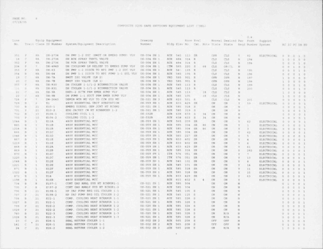
-- -
PAGE NO. 8
07/19/95COMPOSITE SOUG SAFE SHUTDOWN EQUIPMENT LIST (TSEL)
i
G.4Lane Equip Equipment Drawing Room Eval Normal Desired Pwr Form Support
No. Train Class ID Number System / Equipment Description Numbar Bldg Elev No. Cat. Note State State Reg 3 Nuder System RC IC PC DH SU
351 P 8A DM-2734 DH PMP 1-2 SUC (BWST OR EMERG SLYP) VLV OS-004 SH 1 AUX 545 113 SR CPN CLS Y 82 ELECTRICE O O O 1 018 C 8A DH-2736 CH AUX SPRAY THRTL VEVE OS-004 SH 1 AUX 484 314 R CLS CLS N 194 1 0 0 0 0
352 P 8A DH-2736 DH PUX SPRAY THRTL VALVE OS-004 SH 1 AUX 484 314 R CLS CLS N 194 0 0 0 1 0'
234 P 7 DH-4849 DH CODIDOWN LN PELIEF TO EMERG SLHP VLV OS-004 SH 1 CIH 565 220 5 68 CLS OP/CL N 0 0 1 0 0353 P 8A DH-63 DH W P 1-2 DISCH 70 HPI PMP 1-2 SUC VLV OS-004 SH 1 AUX 545 115 R CLS CLS N 195 0 0 0 1 0354 8 8A DH-64 DH IMP 1-1 DISCH TO HPI PLHP 1-1 SUL VLV OS-004 SH 1 AUX 545 105 R CLS CLS N 196 0 0 0 1 0
19 C 8A DR-7A DNST ISO VALVE (LN 2) OS-004 SH 1 YRD 585 901 R OPN OPN N 197 1 0 0 0 020 C 8A DH-7B BNST ISO VE VE (IR 1) OS-004 SH 1 YRD 585 901 R OPN OPN N 198 1 0 0 0 0
355 P BA DH-R30 DR COOLER 1-1/1-2 XCONNECTION VALVE OS-004 SH 1 AUX 545 113 R CLS CLS N 199 0 0 0 1 O156 B 8A DH 831 DH COOLER 1-1/1-2 XCONNECTION VALVE OS-004 SH 1 AUX 545 113 R CLS CLS N 200 0 0 0 1 021 C BA DH-9A DHP1-2 SC"N FRM EMER SLHP VLV OS-004 SH 1 E'X 545 113 18 CIS CLS N 1 0 0 0 022 C 8A DH-99 DH PUMP 1-1 SUCT PRM EMER SLMP VLV OS-004 SH 1 AUX 545 105 18 CLS CLS N 1 0 0 0 0 .
728 P 7 DM-2643 DEMIN WTR MU VLV TO CCW SYS MU OS-021 SH 3 AUX 623 501 R CLS CLS N 201 0 0 0 0 1729 9 2 El 480V ESSENTIAL UNIT SUBSTATION 05-059 SH 1 AUX 603 429 SR ON ON Y $9 ELECTRICAL 0 0 0 0 1730 B 21 E10-1 EMERG DIESEL GEN JCKT HT XCHNG OS-021 SH 1 AUX 585 318 S ON ON N O O O O 1
! 731 P 21 E10-2 EDG JACKET CW HT XCHANGER 1-2 OS-021 SH 1 AUX 585 319 S ON ON N 0 0 0 0 1732 B 10 E106-1 COOLING COIL 1-1 OS-032B AUX 638 603 S 34 ON ON N 0 0 0 0 1
'
731 P 10 E106-2 COOLING COIL 1-2 OS-0329 AUX 638 603 S 34 ON ON N O O O O 11044 8 1 EllA 480V ESSFNTIE MCC 0S-059 SH 1 AUX 565 209 SR ON ON Y 62 ELECTRICAL 0 0 0 0 1
865 B 1 E11B 480V ESSENTIAL MCC OS-059 SH 1 AUX 585 304 SR 86 ON ON Y 1 ELECTRICE O O O O 11218 8 1 E11B 480V ESSENTIAL MCC OS-059 SH 1 AUX 585 304 SR 86 ON ON Y 3 ELECTRICE O O O O 1
666 B 1 E11C 480V ESSENTIAL MCC OS-059 SH 1 AUX 585 304 SR ON ON Y 62 ELECTRICAL 0 0 0 0 11046 B 1 E11D 480V ESSENTIE MCC OS-059 SH 1 AUX 565 227 SR ON ON Y 5 ELECTRICAL 0 0 0 0 1
867 B 1 EllE 480V ESSEPrTIE MCC 05-059 SH 1 AUX 603 402 SR ON ON Y 4 ELECTRICE O O O O 11219 9 1 EllE 480V ESSENTIAL MCC 03-059 SH 1 AUX 603 402 SR ON ON Y 6 ELECTRICE O O O O 1
068 B 1 E12A 480V ESSENTIAL MCC OS-059 SH 1 AUX 603 429 SR ON ON Y 61 ELECTRICAL 0 0 0 0 1869 9 1 E12B 480V ESSENTIAL MCC OS-059 SH 1 AUX 585 318 SR ON ON Y 282 ELECTRICAL 0 0 0 0 1870 B 1 E12C 480V ESSENTIAL MCC OS-059 SH 1 ITX 576 051 SR ON ON Y 7 ELECTRICAL 0 0 0 0 1
1220 B 1 E12C 480V ESSENTIAL MCC OS-059 SH 1 ITK 576 051 SR ON ON Y 13 ELECTRICAL 0 0 0 0 11048 B 1 E12E 480V ESSEJTIAL MCC OS-059 SH 1 AUX 545 101 SR ON ON Y 8 ELECTRICAL 0 0 0 0 11221 B 1 E12E 480V ESSENTIE MCC OS-059 SH 1 AUX 545 101 SR ON ON Y 14 ELECTRICAL 0 0 0 0 1
871 B 1 E12F 480V ESSENTIAL MCC OS-059 SH 1 AUX 585 318 SR ON ON Y 11 ELECTRICAL 0 0 0 0 11222 B 1 E12F 480V ESSENTIAL MCC 05-059 SH 1 AUX 585 318 SR ON OM Y 15 ELECTRICE O O O O 1
872 B 1 Ett 480V ESSENTIAL MCC OS-059 SH 1 AUX 603 429 SR ON ON Y 63 ELECTRICE O 0 0 0 1,
1190 B 1 E16B 480V ESSENTIAL MCC AUX 603 402 S 4 CN ON Y ELECTRICE O O O O 1734 B R E197-1 CO?rf GAS ANE SYS HT XCHNGR1-1 03-021 SH 1 AUX 585 304 CN ON N O C 0 0 1735 P R E197-2 CONT GAS ANEY SYS HT XCHGR1-2 03-021 SH 1 AUX 585 304 ON ON N O O O O 1736 B 21 E198-1 RP INJ PLHP BRG OIL COOLER 1-1 05-021 SH 1 AUX 545 105 S ON ON N 0 0 0 0 1737 P 21 E198-2 HP INJ PLHP BRG OIL COOLER 1-2 OS-021 SH 1 AUX 545 115 S ON ON N O O O O 1738 B 21 E22-1 COMP. COOLING HEAT XCHANGR 1-1 OS-020 SH 1 AUX 585 328 S ON ON N 0 0 0 0 1
1027 B 21 E22-1 COMP. COCLING HEAT XCHANGR 1-1 05-021 SH 1 AUX 585 328 S ON ON N O O 0 0 1739 P 21 E22-2 COMP. COOLING HEAT XCHANGR 1-2 OS-020 SH 1 AUX 585 328 $ ON ON N O O O O 1
1029 P 21 E22-2 COMP. COOLING HEAT XCHANGR 1-2 OS-021 SH 1 AUX 585 328 S ON ON N 0 0 0 0 1740 B 21 E22-3 COMP. COOLING HEAT XCHANGR 1-3 0S-020 SH 1 AUX 585 328 S ON N/A N 0 0 0 0 1
1028 B 21 E22-3 COMP. COOLING HEAT XCHANGR 1-3 OS-021 SH 1 AUX 585 328 S ON N/A N O O O O 123 C 21 E26-1 SEAL RETJRN COOLER 1-1 OS-002 SH 2 AUX $65 200 S OFF OFF N 1 0 0 0 0,
141 C 21 E26-1 SEAL RETURN COOLER 1-1 OS-002 SH 2 AUX 565 208 S OFF OFF N O 1 0 0 024 C 21 E26-2 SEAL RETURN COOLER 1-2 05-002 SH 2 AUX 565 208 S ON N/A N 1 0 0 0 0
e
_ _ _ _ _ _ _ _ _ _ _ _ . . . _ _ _ _ _ __ _ _ _ _ . . - _ - _ _ . _ _ , . . ._ . , , . _ , . , _ _ . , . . . .m, . .,, _ _ _ , . _ , _

FAGE NO. 9
07/19/95;
COMPOSITE SOUG SAFE SHUTDCWM ECUIPMENT LIST (SSEL)
G.4Line ETaip ETaipment Drawing Room Eval Normal resired Pwr Form Support.No. Train Class ID Nurber System /ETaipment Description Neber B1d] Elev No. Cat. Note State State Re d Neb *r System RC IC PC DH SU
142 C 21 E26-2 SEE RETURN COOLER 1-2 OS-002 SH 2 AUX 565 208 S ON ON N O 1 0 0 025 C 21 E27-1 DECAY MEAT REPOVE COOLER 1-1 OS-004 SH 1 AUX 545 113 S ON N/A N 1 0 0 0 0
357 B 21 E27-1 DECAY HEAT REMCV E COOLER 1-1 CS-004 SH 1 AUX 545 113 S 79 CN CN N O O O 1 026 C 21 E27-2 DECAY HEAT REMOVAL COOLER 1-2 05-004 SH 1 AUX 545 113 S ON N/A N 1 0 0 0 0
358 P 21 E27-2 DECAY MEAT REPOVAL COOLER 1-2 OS-004 SH 1 AUX 545 113 S 79 ON ON N O O O 1 0 '
27 C 21 E34 BNST HEATER 05-007 AUX 565 209 S 99 ON N/A N 1 0 0 0 0148 C 21 E34 BWST HEATER OS-007 AUX 565 209 5 99 ON N/A N 0 1 0 0 0 |235 B 10 E37-1 CAC COIL 1-1 (SW SIDE) OS-033A C7M 585 317 S 79 ON ON N O O 1 0 0741 B 10 E37-1 CAC COIL 1-1 (SW SIDE) CS-020 SH 1 CIN $85 317 S ON ON N 0 0 0 0 12?6 P 10 E37-2 CAC COIL 1-2 (SW SIDE) CS-033A CIN 585 317 5 79 ON ON N 0 0 1 0 0742 B 10 E37-2 CAC COIL 1-2 (SW SIDE) 05-020 SH 1 CIM 585 317 S ON ON N 0 0 0 0 1743 B 10 E37-3 CTMT AIR COOLER 1-3 OS-020 SH 1 CIM 585 317 S OFF OFF N O O 0 0 1744 P 10 E42-1 ECCS ROOM COOLER COIL 1-1 OS-020 SH 1 AUX 545 115 S ON N/A N O 0 0 0 1745 P 10 E42-2 ECCS ROOM COOLER COIL 1-2 OS-020 SH 1 AUX 545 115 S ON N/A N 0 0 0 0 1746 P 10 E42-3 ECCS ROOM COOLER COIL 1-3 05-020 SH 1 AUX 545 113 S ON N/A N 0 0 0 0 1747 B to E42-4 ECCS ROOM COOLER COIL 1-4 05-020 SH 1 AUX 545 105 S ON N/A N 0 O O O 1748 9 10 E42-5 ECCS ROOM COOLER COIL 1-5 OS-020 SH 1 AUX 545 105 S ON N/A N 0 0 0 0 1749 B 20 EI-4553 BUS Y1A VOLTMETER OS-060 SH 2 AUX 623 505 SR ON ON Y 52 ELECTRICAL 0 0 0. 0 1 '
750 P 20 EI-4554 BUS Y2A VOLTYETER OS-060 SH 2 AUX 623 505 SR CN ON Y $2 ELECTRICAL 0 0 0 0 1 I1057 B 20 El-6271 BUS D1P VCLTMETER 05-060 SH 2 AUX 623 505 SR ON ON Y 52 ELECTRICAL 0 0 0 0 11058 P 20 EI-6272 BUS D2N VOLTYETER OS-060 SH 2 AUX 623 505 SR ON ON Y 52 ELECTRICAL 0 0 0 0 1
751 B 20 EI-6273 BUS 1P-BUS INCOMING VOLTMETEF OS-060 SH 1 AUX 623 502 SR ON ON Y 52 ELECTRICAL 0 0 0 0 1752 P 20 EI-6274 BUS 2P-BUS 2N VOLTMETER OS-060 SH 1 AUX 623 502 SR ON ON Y 52 ELECTRICAL 0 0 0 0 1
1059 B 20 EI-6275 BUS DIN VOLTMETER OS-060 SH 2 AUX 623 505 SR ON ON Y 52 ELECTRICAL 0 0 0 0 1753 P 20 EI-6276 BUS D2P VOLTMETER 0S-060 SH 2 AUX 623 502 SR ON ON Y 52 ELECTRICAL 0 0 0 0 1754 B 20 EI-6277 BUS Y1 VOLTMETER OS-060 SH 2 AUX 623 505 SR CN CN Y 52 ELECTRICAL 0 0 0 0 1755 F 20 EI-6278 BUS Y4 VOLTMETER OS-060 SH 2 AUX 623 505 SR ON ON Y 52 ELECTRICE O O O O 1756 B 20 EI-6281 BUS Y3 VOLINETER OS-060 SH 2 AUX 623 505 SR ON ON Y 52 ELECTRICAL 0 0 0 0 1757 P 20 EI-6282 BUS Y2 VOLINETER 05-060 SH 2 AUX 8;23 505 SR ON ON Y 52 ELE" TRICE O O O O 1758 B 20 EI-6297 BUS YAU VOLTMETER OS-060 SH 1 AUX 623 505 SR ON CN Y 52 ELECTRICAL 0 0 0 0 1759 P 20 EI-6298 BUS YBU VOLINETER OS-060 SH 1 AUX 623 SCS SR ON ON Y 52 ELECTRICE O O O O 1760 P 2 F1 480V ESSENTIE UNIT SUBSTATION OS-059 SH 1 AUX 603 428 SR ON ON Y 60 ELECTRICE O 0 0 0 1 ,
873 P 1 F11A 480V ESSENTIAL MCC OS-059 SH 1 AUX 603 427 SR ON ON Y 68 ELECTRICAL 0 0 0 0 1 i874 P 1 F11B 480V ESSENTIE MCC 0S-059 SH 1 AUX 603 405 SR ON , ON Y 19 ELECTRICAL 0 0 0 0 1 I
1223 P 1 F11B 480V ESSENTIAL MCC 0S-059 SH 1 AUX 603 405 SR ON ON Y 20 ELECTRICE O O O O 11049 P 1 F11C 480V ESSENTIAL MCC 05-059 SH 1 AUX 565 ~36 SR ON ON Y 281 ELECTRICE O 0 0 0 1 !
1045 P 1 F11D 480V ESSENTIAL MCC OS-059 SH 1 AUX 565 227 SR ON ON Y 17 ELECTRICAL 0 0 0 0 1 j1224 P 1 F11D 480V ESSENTIE MCC OS-059 SH 1 AUX 565 227 SR ON ON Y 21 ELECTRICAL 0 0 0 0 1
!1084 P 1 F11E 480V ESSENTIAL MCC OS-059 SH 1 AUX 545 101 SR ON ON Y 16 ELECTRICE O 0 0 0 11225 P 1 F11E 480V ESSENTIAL MCC OS-059 SH 1 AUX 545 101 SR CN ON Y 22 ELECTRICE O O O 0 1 L
875 P 1 F12A 480V ESSENTIAL MCC OS-059 SH 1 AUX 603 428 SR ON ON Y 67 ELECTRICE O O O O 1876 P 1 F12B 480V ESSENTIAL MCC 05-059 SH 1 AUX 585 319 SR ON ON Y 280 ELECTRICAL 0 0 0 0 1877 P 1 F12C 480V ESSENTIAL MCC OS-059 SH 1 ITK 576 052 SR ON ON Y 26 ELECTRICAL 0 0 0 0 1
,
878 P 1 F12D 480V ESSENTIAL MCC 05-059 SH 1 ITK 576 052 SR ON ON Y 27 ELECTRICAL 0 0 0 0 1879 P 1 F14 480V ESSENTIAL MCC OS-059 SH 1 AUX 603 428 SR ON ON Y 65 ELECTRICAL 0 0 0 0 1761 B 0 F15-1 SERVICE WATER STRAINER 1-1 05-020 SH 1 ITK 576 052 SR STB O/O Y 134 ELECTRICAL 0 0 0 0 1*762 P O F15-2 SERVICE WATER STRAINER 1-2 OS-020 SH 1 ITK 576 052 SR STB O/O Y 135 ELECTRICAL 0 0 0 0 1 |
1047 P 1 F16A 480V ESSENTIAL MCC OS-059 SH 1 AUX 603 428 SR ON ON Y 69 ELECTRICAL 0 0 0 0 1,
Ie
!
. _ _ _ _ _ _ _ _ _ _ _ _ _ _ _ _ _ _ _ _ _ _ _ _ _ _ _ _ _ _ _ _ _ _ _ _ _ _ _ _ _ ___ _ _. ._ _ _ _ _ __ ___ _ _ _ . _
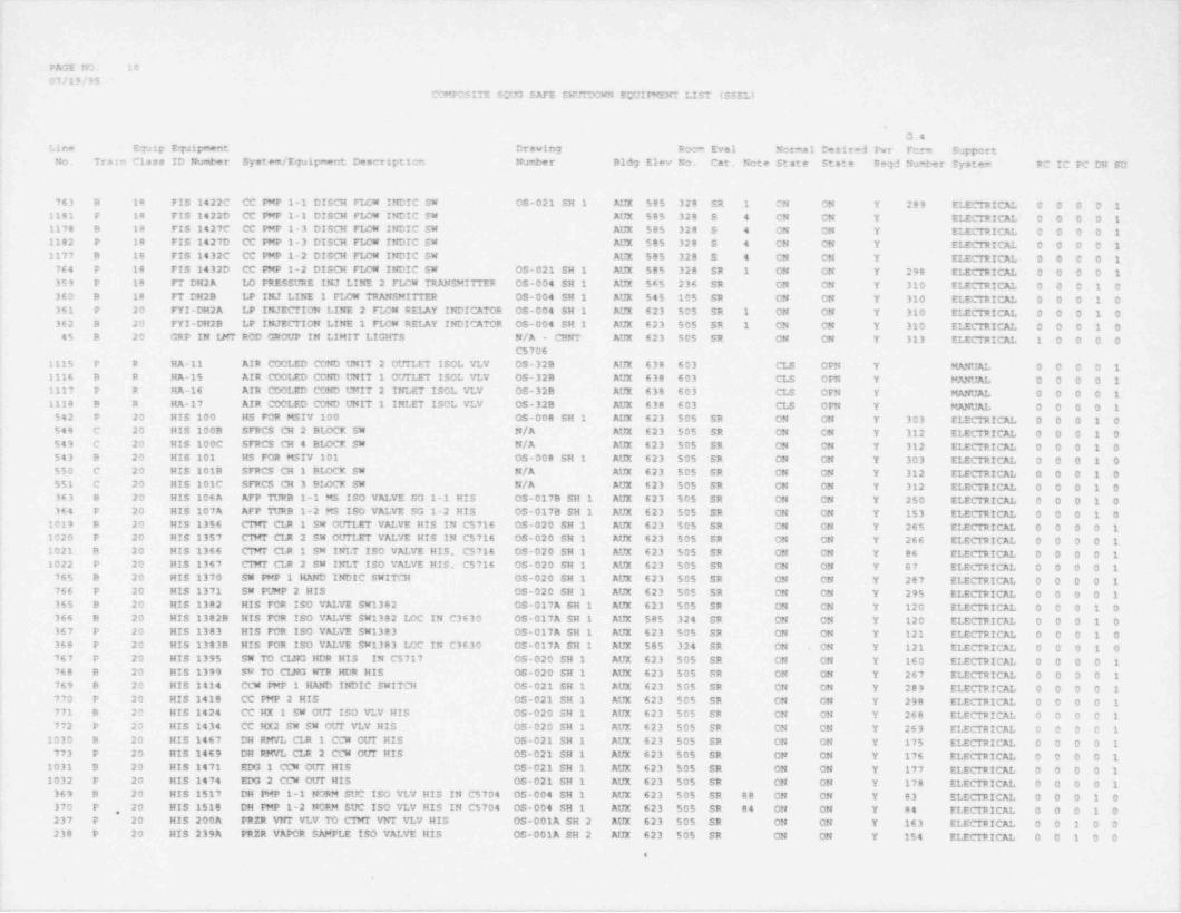
M
PAGE NO. 10
07/19/95COMPOSITE S7JG SAFE SHTDCWN E7JIMENT LIST ($$EL)
G.4Line Equip ETJipment Drawing Roca Eval Normal Desired Fwr Fcrm Support
~
No. Train Class ID Number System / Equipment Descriptien Number Bldg Elev No. Cat. Note State State Reqd Number System RC IC PC DH SU t
763 B 18 FIS 1422C CC mP 1-1 DISCH FLOW INDIC SW OS-021 SH 1 AUX 585 328 SR 1 CN ON Y 289 ELECTRICE O O O O 11181 P 18 FIS 1422D CC PMP 1-1 DISCH FLOW INDIC SW AUX 585 328 S 4 CN CN Y ELECTRICE O O O O 11178 9 18 FIS 1427C CC PMP 1-3 DISCH F1418 INDIC SW AUX 585 320 S 4 ON ON Y ELECTRICE O O O O 11182 P 18 FIS 1427D CC PMP 1-3 DISCH FLOW INDIC SW AUX 585 328 S 4 CN ON Y ELECTRICAL 0 0 0 0 11177 9 18 FIS 1432C CC PMP 1-2 DISCH FIDW INDIC SW AUX 585 328 5 4 ON CN Y ELECTRICE O O O O 1764 P 18 FIS 1432D CC mP 1-2 DISCH FLOW INDIC SW OS-021 SH 1 AUX 585 328 SR 1 ON ON Y 298 ELECTRICAL 0 0 0 0 1359 P 18 FT DH2A ID PRESSURE INJ LINE 2 FLCW TRANSMITTER OS-004 SH 1 AUX 545 236 SR ON ON Y 310 ELECTRICE O O O 1 0360 B 18 FT DH2B LP INJ LINE 1 FIDW TRANSMITTER OS-004 SH 1 AUX 545 105 SR CN ON Y 310 ELECTRICE O O O 1 0361 P 20 FYI-DH2A LP INJECTION LINE 2 FLOW RELAY INDICATOR OS-004 SH 1 AUX 623 505 SR 1 ON ON Y 310 ELECTRICAL 0 0 0 1 0 '
362 B 20 FYI-DH2B LP INJECTION LINE 1 FLOW REIAY INDICATOR OS-004 SH 1 AUX 623 505 SR 1 CN ON Y 310 ELECTRICE C 0 0 1 0 i45 B 20 GRP IN iMT RCD GROUP IN LIMIT LIGHTS N/A - CBNT AUX 623 505 SR ON ON Y 313 ELECTRICE 1 0 0 0 0
C57061115 P R HA-11 AIR COCLED COND UNIT 2 OUTLET ISOL VLV OS-32B AUX 638 603 CLS CPN Y MANUE O O O O 11116 B R HA-15 AIR COOLED COND UNIT 1 OUTLET ISOL VLV C5-32B AUX 638 603 CLS OFN Y MANUE O O O O 1 '
1117 P R HA-16 AIR COOLED COND UNIT 2 INLET ISOL VLV OS-32B AUX 638 603 CLS OFN Y MANUAL 0 0 0 0 11118 9 R HA-17 AIR COOLED COND UNIT 1 INLET ISOL VLV OS-32B AUX 638 603 CLS OFN Y MANUAL 0 0 0 0 1 =
542 P 20 HIS 100 HS FOR MSIV 100 OS-008 SH 1 AUX 623 505 SR ON ON Y 303 ELECTRICE O O O 1 0 '
548 C 20 HIS 1008 SFRCS CH 2 BIDCK SW N/A AUX 623 505 SR CN ON Y 312 ELECTRICAL 0 0 0 1 0'
549 C 20 HIS 100C SFRCS CH 4 BLOCK SW N/A AUX 623 505 SR ON ON Y 312 ELECTRICE O O 0 1 0543 B 20 HIS 101 HS FOR MSIV 101 OS-008 SH 1 AUX 623 505 SR ON ON Y 303 ELECTRICE 0 0 0 1 0550 C 20 HIS 101B SFRCS CH 1 BIDCK SW N/A AUX 623 505 SR CN ON Y 312 ELECTRICAL 0 0 0 1 0551 C 20 HIS 101C SFRCS CH 3 BLOCK SW N/A AUX 623 505 SR ON ON Y 312 ELECTRICE O O O 1 0363 B 20 HIS 106A AFP TURB 1-1 MS ISO VALVE SG 1-1 HIS OS-017B SH 1 AUX 623 505 SR ON CN Y 250 ELECTRICE O O O 1 0364 P 20 HIS 107A AFP TURB 1-2 MS ISO V EVE SG 1-2 HIS OS-017B SH 1 AUX 623 505 SR ON ON Y 153 ELECTRICAL 0 0 0 1 0
1019 B 20 HIS 1356 CIMT CLR 1 SW OUTLET VEVE HIS IN C5716 OS-020 SH 1 AUX 623 505 SR ON ON Y 265 ELECRICE O O O O 11020 P 20 HIS 1357 CTMT CIJt 2 SW OUTLET VEVE HIS IN C5716 OS-020 SH 1 AUX 623 505 SR ON ON Y 266 ELECTRICAL 0 0 0 0 11021 B 20 HIS 1366 CIMF CLR 1 SW INLT ISO VALVE HIS. C5716 05-020 SH 1 AUX 623 505 SR ON CN Y 86 ELECTRICAL 0 0 0 0 1 "
1022 P 20 HIS 1367 CIMT CLR 2 SW INLT ISO VALVE HIS. C5716 0S-020 SH 1 AUX 623 505 SR ON ON Y 07 ELECTRICAL 0 0 0 0 1 a
765 B 20 HIS 1370 SW PMP 1 HAND INDIC SWITCH OS-020 SH 1 AUX 623 505 SR ON ON Y 287 ELECTRICAL 0 0 0 0 1766 P 20 HIS 1371 SW PUMP 2 HIS OS-020 SH 1 AUX 623 505 SR ON CN Y 295 ELECTRICAL 0 0 0 0 1365 8 20 ftIS 1382 HIS FOR ISO VALVE SW1382 OS-017A SH 1 AUX 623 505 SR ON CN Y 120 ELECTRICAL 0 0 0 1 0 f366 B 20 HIS 1382B HIS FOR ISO VEVE SW1382 LOC IN C3630 OS-017A SH 1 AUX 585 324 SR ON ON Y 120 ELECTRICAL 0 0 0 1 0367 P 20 HIS 1383 HIS FOR ISO VALVE SW1383 OS-017A SH 1 AUX 623 505 SR ON ON Y 121 ELECTRICAL 0 0 0 1 0368 P 20 HIS 1383B HIS FOR ISO VALVE SW1383 LOC IN C3630 OS-017A SH 1 AUX 585 324 SR ON ON Y 121 ELECTRICAL 0 0 0 1 0 $.
767 P 20 HIS 1395 SW TO CIRG HDR HIS IN C5717 05-020 SH 1 AUX 623 505 SR ON ON Y 160 ELECTRICAL 0 0 0 0 1768 B 20 HIS 1399 SW TO CLNG WTR HDR HIS OS-020 SH 1 AUX 623 505 SR ON ON Y 267 ELECTRICAL 0 0 0 0 1769 B 20 HIS 1414 CCW NP 1 HAND INDIC SWITCH OS-021 SH 1 AUX 623 505 SR CN ON Y 289 ELECTRICAL 0 0 0 0 1770 P 20 HIS 1418 CC FMP 2 HIS OS-021 SH 1 AUX 623 505 SR ON ON Y 298 ELECTRICAL 0 0 0 0 1771 B 20 HIS 1424 CC HX 1 SW OUT ISO VLV HIS OS-020 SH 1 AUX 623 505 SR ON ON Y 268 ELECTRICAL 0 0 0 0 1772 P 20 HIS 1434 CC HX2 SW SW OUT VLV HIS OS-020 SH 1 AUX 623 505 SR ON CN Y 269 ELECTRICAL 0 0 0 0 1 ;
1030 B 20 HIS 1467 DH RM7L CLR 1 CCW OUT HIS 05-021 SH 1 AUX 623 505 SR ON ON Y 175 ELECTRICAL 0 0 0 0 1773 P 20 HIS 1469 DH RMVL CLR 2 CCW OUT HIS 05-021 SH 1 AUX 623 505 SR ON CN Y 176 ELECTRICAL 0 0 0 0 1 j
1031 B 20 HIS 1471 EDG 1 CCW OUT HIS OS-021 SH 1 AUX 623 505 SR ON ON Y 177 ELECTRICAL 0 0 0 0 11032 P 20 HIS 1474 EDO 2 CCW OUT HIS OS-021 SH 1 AUX 623 505 SR ON ON Y 178 ELECTRICAL 0 0 0 0 1369 B 20 HIS 1517 DH PMP 1-1 NORM SUC ISO VLV HIS IN C5704 05-004 SH 1 AUX 623 505 SR 88 CN ON Y 83 ELECTRICAL 0 0 0 1 0370 P 20 HIS 1518 DH PMP 1-2 NORM SUC ISO VLV HIS IN C5704 OS-004 SH 1 AUX 623 505 SR 84 ON CN Y 84 ELECTRICE O O O 1 0,
237 P 20 HIS 200A FRZR VNT VLV M CIMT VNT VLV HIS OS-001A SH 2 AUX 623 505 SR ON CN Y 163 ELECTRICE 0 0 1 0 0 t238 P 20 HIS 239A PRZR VAPCR SAMPLE ISO VALVE HIS OS-001A SH 2 AUX 623 505 SR ON ON Y 154 ELECTRICAL 0 0 1 0 0 i
e
.
m- .-1-.,v- .,- --- -*ev. , rs , .m -.m,---r .- - -r- - - - - - - -%~e-,- , -w -.nv-.- . . . , . - - . ._

FACE NO. 1107/19/95
COMPOSITE SCOG SAFE SHUTDOWN ECUIPMENT LIST (SSEL)
sG.4
Line ETaip ET21pment Drawing Room Eval Normal Desired Fwr Form SupportNo. Train Class ID Number System /ETaipment Description Nuber Bldg Elev No. Cat, Nete State State Req 3 !M ber System RC IC PC DH SU
171 B 20 HIS 2733 DH FMP 1-1 SUCT FPM LP INJ LINE HIS 05-004 SH 1 AUX 623 505 SR ON ON Y 81 ELECTRICE o 0 0 1 0,
372 P 20 HIS 2734 DH FMP 1-2 SUCT FRM LP INJ LINE HIS OS-004 SH 1 AUX 623 505 SR ON ON Y 82 E11CTRICAL 0 0 0 1 0774 B 20 HIS 2927 CTRM EMERG COND 1 SW OUTLT VLV OS-020 SH 1 AUX 623 505 SR ON ON Y 128 ELECTRiCE O O O O 1775 P 20 HIS 2928 CTRM ENER CND 2 SW OtJT VNT VLV OS-020 SH 1 AUX 623 505 SR ON ON Y 129 ELECTRICAL 0 0 0 0 1776 B 20 HIS 2929 SW TO INTAKE STRUCIUPE VLV HIS OS-020 SH 1 AUX 623 505 SR ON ON Y 138 ELECTRICE O O O O 1777 P 20 HIS 2930 SW TO INTK FCREBAY VALVE HIS OS-020 SH 1 AUX 623 505 SR ON ON Y 161 ELECTRICE O O O O 1778 8 20 HIS 2931 SW TO CLNG WR MU VLV HIS OS-020 SH 1 AUX 623 505 SR ON ON Y 139 ELECTRICAL 0 0 0 0 1779 P 20 HIS 2932 SW - COLLECTION BASIN VLV HIS OS-020 SH 1 AUX 623 505 SR ON ON Y 162 ELECTRICAL 0 0 0 0 1
28 P 20 HIS 3971 RC MUP SCTN HIS IN C5703 OS-002 SH 3 AUX 623 505 SR ON ON Y 164 ELECTRICAL 1 0 0 0 0182 P 20 HIS 3971 RC MUP SCTN HIS IN C5703 OS-002 SH 3 AUX 623 505 SR CN ON Y 164 ELECTRICAL 0 1 0 0 0
1119 B 20 HIS 4823 CTRL RM EMER SYS COND 1 IN HIS (C6708) OS-032B AUX 643 603 SR ON ON Y 90 ELECTRICAL 0 0 0 0 11120 B 20 HIS 4823A CTRL RM EMER SYS COND 1 IN HIS OS-032B AUX 643 603 ER ON ON Y 90 ELECTRICAL 0 0 0 0 11121 B 20 HIS 4824 CTRL RM EMER SYS COND 1 CUT HIS (C6708) LS-032B AUX 643 603 SR ON ON Y 90 ELECTRICE O 0 0 0 11122 P 20 HIS 4827 CTRL RM EMER SYS COND 2 IN HIS (C6709) CS-032B AUX 643 603 SR ON ON Y 91 ELECTRICAL 0 0 0 0 11123 P 20 HIS 4827A CTRL RM EMER SYS COND 2 IN HIS OS-032B AUX 643 603 SR ON ON Y 91 ELECTRICE O O O O 11124 P 20 HIS 4828 CTRL RM EMER SYS COND 2 OUT HIS (C6709) OS-032B AUX 643 603 SR ON CN Y 91 ELECTRICAL 0 0 0 0 1239 9 20 HIS 5031 CTMT COOLER FAN 1 HIS OS-033A AUX 623 505 SR ON ON Y 167 ELECTRICE O O 1 0 0 [240 P 20 HIS $032 CTMT COOLER FAN 2 HIS OS-033A AUX 623 505 SR ON ON Y 168 ELECTRICAL 0 0 1 0 0780 B 20 HIS 5095 CCW IR 1 M NON-ESSEN HDR HIS OS-021 SH 1 AUX 623 505 SR ON ON Y 126 ELECTRICE O O O O 1781 P 20 HIS 5096 CCW LN 2 HAND INDIC SWITCH OS-021 SH 1 AUX 623 505 SR ON ON Y 127 ELECTRICAL 0 0 0 0 1373 B 20 HIS 520A AFP 1-1 GOV CTRL HIS, LOC IN C5709 CS-017B SH 1 AUX 623 505 SR ON ON Y 72 ELECTRICAL 0 0 0 1 0 i374 P 20 HIS 521A AFP OOV CTRL HIS. LOCATED IN C5709 OS-017B SH 1 AUX 623 505 SR ON ON Y 73 ELECTRICE O O 0 1 0 ,
782 B 20 HIS 5261 EMERG VENT FAN 1-1 HIS OS-032B AUX 623 505 SR ON ON Y 94 ELECTRICAL 0 0 0 0 1783 B 20 HIS 5261A HIS FR EMERG VENT FAN INLT VLV OS-032B AUX 623 505 SR ON ON Y 88 ELECTRICE O O C 0 1 |784 C 20 HIS 5262 HIS FOR EMERG VENT FAN 2 1-2 OS-032B AUX 623 505 SR ON ON Y 95 ELECTRICAL 0 0 0 0 1785 P 20 HIS 5262A HIS FR EMER VENT FAN 2 IN C5720 OS-032B AUX 623 505 SR ON ON Y 89 ELECTRICE O O O O 1786 B 20 HIS 5301 HIS FOR AUX BLDG CTRM INFR AIR OS-032A AUX 623 505 SR ON ON Y 270 ELECTRICAL 0 0 0 0 1787 P 20 HIS 5311 HIS FOR AUX BLDG CTRM DAMP AIR OS-032A AUX 623 505 SR ON ON Y 271 ELECTRICAL 0 0 0 0 1375 B 20 HIS 5889A AFP WRB 1-1 STEAM INLET VALVE CS-0173 SH 1 AUX 623 505 SR ON ON Y 225 ELECTRICAL 0 0 0 1 0376 P 20 HIS 5809B AFP 1-2 RAND INDICATING SWITCH, IN C5709 05-017B SH 1 AUX 623 505 SR ON ON Y 226 ELECTRICE O O O 1 0 |377 P 20 RIS 598 STEAM CEN ISO VALVE HIS, IN C5717 OS-051 SH 2 AUX 623 505 SR ON ON Y 272 ELECTRICE O O 0 1 0 '
378 B 20 HIS 607 SG 1-1 SAMPLE ISO VALVE HIS, IN C5717 OS-051 SH 2 AUX 623 505 SR ON ON Y 273 ELECTRICAL 0 0 0 1 0379 B 20 HIS 640? SFRCS/AFW MANUAL INITIATION SWITCH TRN 1 N/A AUX 623 505 SR ON ON Y 208 ELECTRICAL 0 0 0 1 0380 P 20 HIS 6404 SFRCS/AFM MANUE INITIATION SWITCH TRN 2 N/A AUX 623 505 SR ON ON Y 209 ELECTRICAL 0 0 0 1 029 8 20 HIS 6405 RC MUP SUCTION VALVE 1 OS-002 SH 3 AUX 623 505 SR ON ON Y 85 ELECTRICAL 1 0 0 0 0 I
181 B 20 HIS 6405 RC MUP SUCTION VALVE 1 OS-002 SH 3 AUX 623 505 SR ON ON Y 85 ELECTRICAL 0 1 0 0 0'
30 B 20 HIS 6419 RC MU DISCH VALVE 1 OS-002 SH 3 AUX 623 505 SR ON ON Y 150 ELECTRICAL 1 0 0 0 0 |206 B 20 HIS 6419 RC MU DISCH VALVE 1 CS-002 SH 3 AUX 623 505 SR ON ON Y 150 ELECTRICAL 0 1 0 0 0
31 B 20 HIS 6421 RC MU DISCH VALVE OS-002 SH 3 AUX 623 505 SR ON ON Y 111 ELECTRICAL 1 0 0 0 0209 B 20 MIS 6421 RC MU DISCH VALVE OS-002 SH 3 AUX 623 505 SR ON CN Y 111 ELECTRICAL 0 1 0 0 0304 C 20 MIS 7528 SFAS CHANNEL 1 BLOCK SW OS-001A SH 1 AUX 623 505 SR ON ON Y 311 ELECTRICAL 0 0 1 0 0 l
305 C 20 HIS 7529 SFAS CHANNEL 2 BLOCK SW OS-001A SH 1 AUX 623 505 SR ' ON ON Y 311 ELECTRICAL 0 0 1 0 0 !306 C 20 MIS 7530 SFAS CHANNEL 3 BIOCK SW OS-001A SH 1 AUX 623 505 SR ON ON Y 311 ELECTRICAL 0 0 1 0 0307 C 20 HIS 7531 SFAS CHANNEL 4 BLOCK SW OS-001A SH 1 AUX 623 505 SR ON ON Y 311 ELECTRICAL 0 0 1 0 0 i
1152 P 20 HIS CFIA HS FOR CFIA OS-006 AUX 623 505 S 18 ON ON Y ELECTRICAL 0 1 0 0 0 t1151 B 20 HIS CF1B HS FOR CF1B OS-006 AUX 623 505 S 18 ON ON Y ELECTRICAL 0 1 0 0 0 j
,
241 P 20 HIS DH11 NORM DH SUCTN ISO VLV DH 11 HIS IN C5704 OS-004 SH 1 AUX 623 505 SR ON ON Y 100 ELECTRICE O O 1 0 0 >
381 P 20 HIS DH11 NORM DH SUCIN ISO VLV DH 11 HIS IN C5704 0S-004 SH 1 AUX 623 505 SR ON ON Y 100 ELECTRICE O O O 1 0 (.
'
f
I4
. . . - - .-,,m - - - .._. ... __ . _ _ _ . _ . _m - m __ _ _ . - _ ,. . - -_
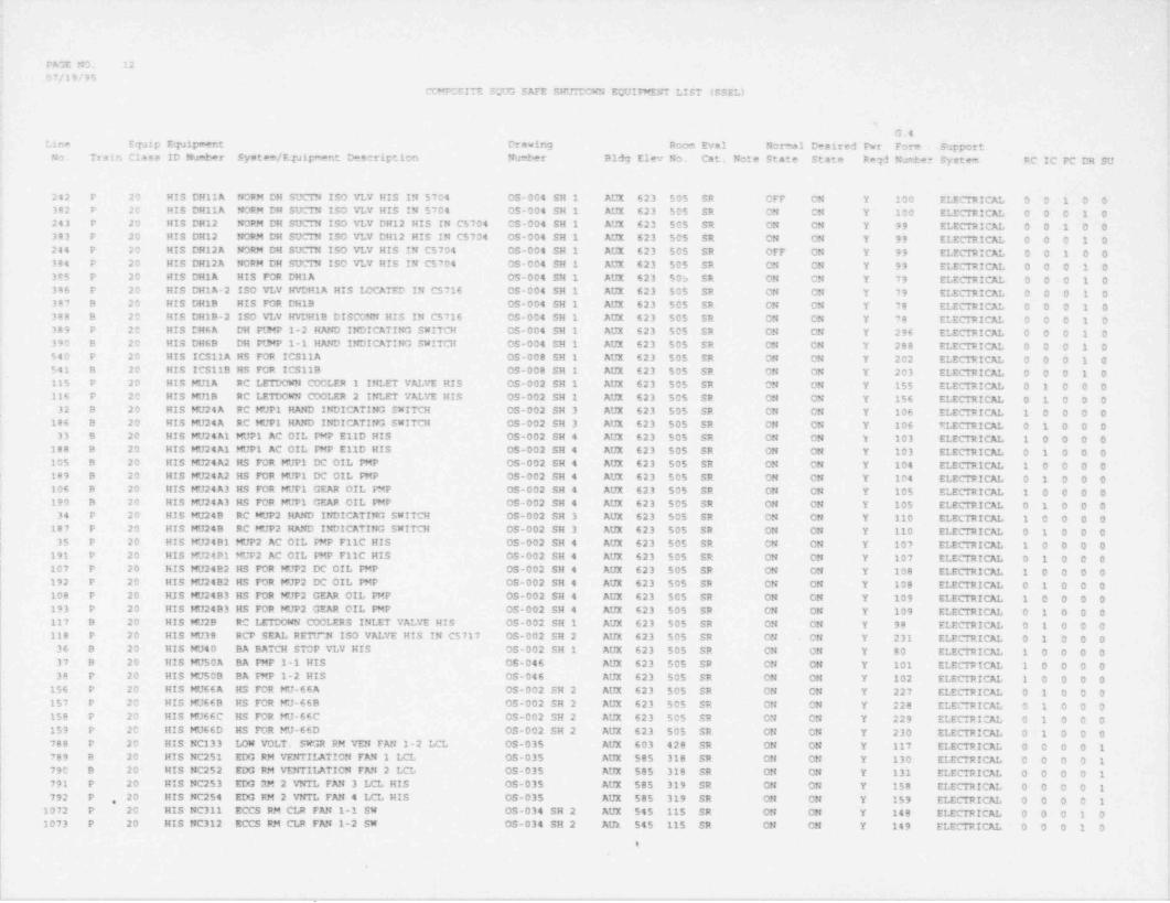
FAGE NO. 1207/19/95
CC"PCSITE S7.;G SAFE SHUDOW'i EQUIPMENT LIST (SSEL)
sG.4
Lina Equip Equipment Drawing Room Eval Normal Desired Pwr Form SupportNo. Train Class ID Numbar System /Equipm=nt D=scription Number Bldg Elev No. Cat. Note State State Reqd Nurter System RC IC PC DR SU
242 P 20 MIS DH11A NORM DH SUCIN ISO VLV HIS IN 5704 OS-004 SH 1 AUX 623 505 SR OFF ON Y 100 ELECTRICE O O 1 0 0382 P 20 HIS DR11A NORM DH SUCIN ISO VLV HIS IN 5704 0S-004 SH 1 AUX 623 505 SR ON CN Y 100 ELECTRICE O O O 1 0243 P 20 HIS DH12 NORM DH SUCTN ISO VLV DH12 HIS IN C5704 CS-004 SH 1 AUX 623 505 SR ON ON Y 99 ELECTRICAL 0 0 1 0 0383 P 20 HIS DH12 NORM DH SUCTN ISO VLV DH12 HIS IN C5704 05-004 SH 1 AUX 623 505 SR ON ON Y 99 ELECTRICE 0 0 0 1 0244 P 20 HIS DH12A NORM DH SUCIN ISO VLV HIS IN C5704 OS-004 SH 1 AUX 623 505 SR OFF ON Y 99 ELECIRICAL 0 0 1 0 0384 P 20 HIS DH12A NORM DH SUCTN ISO VLV HIS IN C5704 0S-004 SH 1 AUX 623 505 SR ON ON Y 99 ELECTRICAL 0 0 0 1 0385 P 20 HIS DH1A HIS FOR DH1A OS-004 SH 1 AUX 623 50s SR ON ON Y 79 ELECTRICAL 0 0 0 1 0386 P 20 HIS DH1A-2 ISO VLV HVDHIA HIS 14CATED IN C5716 OS-004 SH 1 AUX 623 505 SR ON ON Y 79 ELECTRICAL 0 0 0 1 0387 B 20 HIS DHIB HIS FOR DH1B 0S-004 SH 1 AUX 623 505 SR ON ON Y 78 ELECTRICAL 0 0 0 1 0
t
388 B 20 HIS DHIB-2 ISO VLV HVIH1B DISCONN HIS IN C5716 OS-004 SH 1 AUX 623 505 SR ON ON Y 78 ELECTRICE O O O 1 0 1
389 P 20 MIS DH6A DH PUMP 1-2 HAND INDICATING SWITCH 05-004 SH 1 AUX 623 505 SR ON ON Y 296 ELECTRICAL 0 0 0 1 0390 B 20 HIS DH6B DH PUMP 1-1 MAND INDICATING SWITCH OS-004 SH 1 AUX 623 505 SR ON ON Y 288 ELECTRICAL 0 0 0 1 0540 P 20 HIS ICS11A HS FOR ICS11A OS-008 SH 1 AUX 623 505 SR ON ON Y 202 ELECTRICE O O O 1 0
*541 B 20 HIS ICS119 HS FOR ICS11B 0S-008 SH 1 AUX 623 505 SR ON ON Y 203 ELECTRICAL 0 0 0 1 0115 P 20 HIS MU1A RC LEECWN COOLER 1 INLET VALVE HIS 05-002 SH 1 AUX 623 505 SR ON ON Y 155 ELECTRICE 0 1 0 0 0116 P 20 HIS MU1B RC LETDOW4 COOLER 2 INLET VALVE HIS OS-002 SH 1 AUX 623 505 SR ON ON Y 156 ELECTRICAL 0 1 0 0 0
32 B 20 HIS MU24A RC WJP1 MAND INDICATING SNITCH OS-002 SH 3 AUX 623 505 SR ON ON Y 106 ELECTRICAL 1 0 0 0 0 i186 B 20 HIS MU24A RC MUP1 HAND INDICATING SWITCH CS-002 SH 3 AUX 623 505 SR ON ON Y 106 KLECTRICAL 0 1 0 0 0
33 9 20 HIS MU24A1 MUP1 AC OIL PMP E11D HIS OS-002 SH 4 AUX 623 505 SR ON ON Y 103 ELECTRICAL 1 0 0 0 0188 B 20 HIS MU24A1 MUP1 AC OIL PMP E11D HIS OS-002 SH 4 AUX 623 505 SR ON ON Y 103 ELECTRICAL 0 1 0 0 0105 B 20 HIS MU24A2 HS FOR MUP1 DC OIL PMP OS-002 SH 4 AUX 623 505 SR ON ON Y 104 ELECTRICAL 1 0 0 0 0189 8 20 HIS WJ24A2 HS FOR MUP1 DC OIL PMP OS-002 SH 4 AUX 623 505 SR ON ON Y 104 ELECTRICE O 1 0 0 0106 B 20 HIS WJ24A3 HS FOR MUP1 GEAR OIL PMP OS-002 SH 4 AUX 623 505 SR ON ON Y 105 ELECTRICAL 1 0 0 0 0190 B 20 HIS WJ24A3 MS FOR MUP1 GEAR OIL PMP OS-002 SH 4 AUX 623 505 SR ON ON Y 105 ELECTRICE O 1 0 0 0
34 P 20 HIS MU249 RC MUP2 HAND INDICATING SWITCH OS-002 SH 3 AUX 623 505 SR ON ON Y 110 ELECTRICAL 1 0 0 0 0187 P 20 HIS MU24B RC MUP2 HAND INDICATING SWITCH 05-002 SH 3 AUX 623 505 SR ON ON Y 110 ELECTRICE O 1 0 0 0
35 P 20 MIS WJ24B1 MUP2 AC OIL WP F11C HIS OS-002 SH 4 AUX 623 505 SR ON ON Y 107 ELECTRICE 1 0 0 0 0,
! 191 P 20 HIS MU2491 MUP2 AC OIL WP F11C HIS OS-002 SH 4 AUX 623 505 SR ON ON Y 107 ELECTRICE O 1 0 0 0[ 107 P 20 HIS MU24B2 HS FOR MUP2 DC OIL PMP OS-002 SH 4 AUX 623 505 SR ON ON Y 108 ELECTRICE 1 0 0 0 0 i~| 192 P 20 HIS WJ2482 MS FOR MUP2 DC OIL PMP OS-002 SH 4 AUX 623 505 SR ON ON Y 108 ELECTRICAL 0 1 0 0 0l 108 P 20 MIS MU24B3 HS FOR MUP2 GEAR OIL PMP 0S-002 SH 4 AUX 623 505 SR ON ON Y 109 ELECTRICAL 1 0 0 0 0
193 P 20 HIS MU24B3 HS FOR MUP2 GEAR OIL PMP 05-002 SH 4 AUX 623 505 SR ON ON Y 109 ELECTRICAL 0 1 0 0 0117 B 20 HIS MU2B RC LETDOWN COOLERS INLET VALVE HIS OS-002 SH 1 AUX 623 505 SR ON ON Y 98 ELECTRICE O 1 0 0 0118 P 20 HIS MU38 RCP SEAL RETU 38 ISO VALVE HIS IN C5717 OS-002 SH 2 AUX 623 505 SR ON ON Y 231 ELECTRICAL 0 1 0 0 0
36 B 20 MIS MU40 BA BATCH STOP VLV HIS OS-002 SH 1 AUX 623 505 SR ON ON Y 80 ELECTRICE 1 0 0 0 037 B 20 HIS MU50A BA PMP 1-1 HIS OS-046 AUX 623 505 SR ON ON Y 101 ELECTRICAL 1 0 0 0 038 P 20 HIS MU50B BA PMP 1-2 HIS OS-046 AUX 623 505 SR ON ON Y 102 ELECTRICE 1 0 0 0 0
156 P 20 HIS MU66A HS FOR MU-66A OS-002 SH 2 AUX 623 505 SR ON ON Y 227 ELECTRICAL 0 1 0 0 0
[157 P 20 HIS WJ669 HS FOR WJ-66B OS-002 SH 2 AUX 623 505 SR ON ON Y 228 ELECTRICAL 0 1 0 0 0158 P 20 HIS MU66C HS FOR HU-66C OS-002 SH 2 AUX 623 505 SR ON ON Y 229 ELECTRICAL 0 1 0 0 0 |159 P 20 HIS MU66D HS FOR MU-66D OS-002 SH 2 AUX 623 505 SR ON ON Y 230 ELECTRICAL 0 1 0 0 0788 P 20 HIS NC133 LOW VOLT. SWOR RM VEN FAN 1-2 LCL OS-035 AUX 603 428 SR ON ON Y 117 ELECTRICAL 0 0 0 0 1789 B 20 HIS NC251 EDG RM VENTILATION FAN 1 LCL OS-035 AUX 585 318 SR ON ON Y 130 ELECTRICAL 0 0 0 0 1 .
790 B 20 HIS NC252 EDG RM VENTILATION FAN 2 LCL OS-035 AUX 585 318 SR ON ON Y 131 ELECTRICE O O O O 1 I791 P 20 HIS NC253 EDG RM 2 VNTL FAN 3 LCL HIS OS-035 AUX 585 319 SR ON ON Y 158 ELECTRICE O O O O 1 ,
792 P 20 HIS NC254 EDG RM 2 VNTL FAN 4 LCL HIS OS-035 AUX 585 319 SR ON CN Y 159 ELECTRICAL 0 0 0 0 1,
1072 P 20 HIS NC311 ECCS RM CLR FAN 1-1 SW OS-034 SH 2 AUX 545 115 SR ON ON Y 148 ELECTRICE O O O 1 01073 P 20 HIS NC312 ECCS RM CLR FAN 1-2 SW OS-034 SH 2 AUX 545 115 SR CN ON Y 149 ELECTRICAL 0 0 0 1 0 '
t
.
- - . - - - -- ._ - - _. - - . . - - - - .

PAGE NO. 1307/19/95
'COMPOSITE S7JG SAFE SHUTDOWN E7JIPMENT LIST (SSEL)
G,4
Line Equip EqJigeent Drawing Room Eval Normal Desired Pwr Form SupportNo Train class ID Number System / Equipment Description Number B14 Elev No. Cat. Note State State Reqd Number System RC IC PC DH SU
1074 B 20 HIS NC314 E O RM CLR FAN 1-4 SW 05-034 TH 2 AUX 545 105 SR ON ON Y 146 ELECTRICAL 0 0 0 1 01075 B 20 HIS NC315 ECCS RM CLR FAN 1-5 SW OS-034 EM 2 AUX $45 105 SR ON ON Y 147 ELECTRICE O O O 1 0793 B 20 HIS NC711 LOW VOLT. SWGR RM VENT FAN 101 LCL OS-035 AUX 603 429 SR ON ON Y 116 ELECTRICE O O O O 1794 B 20 HIS NC751 CCW PMP RM VNT FAN 3-1 LOC. 05-036 SH 1 AUX 585 328 SR AUT AUT Y 96 ELECTRICE O O O O 1 ,
795 P 20 HIS NC752 CCW PMP RM FAN 1-2 IOCAL. OS-036 SH 1 AUX 585 328 SR A7T AITT Y 97 ELECTRICAL 0 0 0 0 1796 B 20 MIS NC781 BATTERY RM VEFTT FAN 1-1 LCL OS-035 AUX 603 429 SR ON ON Y 142 ELECTRICAL 0 0 0 0 1797 P 20 HIS NC782 BATTERY RM VENT FAN 1-2 LCL 05-035 AUX 603 428 SR ON ON Y 143 ELECTRICAL 0 0 0 0 1 {
1105 B 20 HIS NP1951 EDG FT.?EL OIL ST TK 1-1 HAND IND SW OS-041C AUX 585 321A SR ON ON Y 151 ELECTRICE O O O O 1'
1106 B 20 HIS EDO FUEL OIL ST TK 1-1 MAND IND SW OS-041C AUX 585 321A SR ON ON Y 151 ELECTRICE O O O O 1NP1951A
1107 P 20 HIS NP1952 ED3 FUEL OIL STOR TK 1-2 PLHP IND SW OS-041C AUX 585 320A SR ON ON Y 152 ELECTRICAL 0 0 0 0 11108 P 20 HIS EDG FUEL OIL STOR TK 1-2 PUMP IND SW OS-041C AUX 585 320A SR ON ON Y 152 ELECTRICAL 0 0 0 0 1 |
ItP1952A [245 B 20 MIS RC2-6 RC PRZR AtJTO VENT TO QUENCH TANK HIS OS-001A SH 2 AUX 623 505 SR ON ON Y 255 ELECTRICAL 0 0 1 0 0246 B 20 HIS PC2-7 PRESSURIZER HEATER CTRL SEIACT HIS OS-001A SH 2 AUX 585 324 SR ON ON Y 124 ELECTRICAL 0 0 1 0 0247 P 20 HIS RC2-8 PRESSURIZER HEATER CONTROL SELECT HIS OS-001A SH 2 AUX 585 324 SR ON ON Y 125 ELECTRICE O O 1 0 0248 B 20 HIS RC2- A RC PRESSURIZER ESSEN BNK 1 HTR CTRL HIS OS-001A SH 2 AUX 623 505 SR ON ON Y 124 ELECTRICAL 0 0 1 0 0
[249 P 20 HIS RC2-8 RC PRESSURIZER ESSEN BNK 2 HTR CTRL HIS OS-001A SH 2 AUX 623 505 SR ON ON Y 125 ELECTRICAL 0 0 1 0 039 C 8A HP-2A HPI IJf2-1 ISO VALVE OS-003 AUX 565 236 R CLS CLS N 204 1 0 0 0 040 C 8A HP-2B HP1 LN2-2 ISO VALVE OS-003 AUX 565 236 R CLS CLS N 205 1 0 0 0 0
119 C OA HP-28 HP1 LN2-2 ISO VALVE OS-003 AUX 565 236 R CLS CLS N 205 0 1 0 0 0 *
41 C BA HP-2C HPI LINE 1-1 VALVE OS-003 AUX 565 208 R CLS CLS N 206 1 0 0 0 0120 C 8A HP-2C HPI LINE 1-1 VALVE OS-003 AUX 565 208 R CLS CLS N 206 0 1 0 0 0
42 C 8A HP-2D HPI LINE 1-1 VALVE OS-003 AUX 565 208 R CLS CLS N 207 1 0 0 0 0 t391 B 20 HS-4627 INCORE TEMP HAND SWITCH OS-001A SH 1 AUX 623 505 SR ON ON Y 305 ELECTRICAL 0 0 0 1 0 t392 P 20 HS-4628 INCORE TEMP HAND SWITCH OS-001A SH 1 AUX 623 505 SR ON ON Y 305 ELECTRICAL 0 0 0 1 0798 9 20 HS-4688 H. S. FR XHAUST FAN 1-1 NC 9901 OS-038B ITK 576 052 SR AUT AUT Y 114 ELECTRICE O O O O 1 !799 P 20 HS-4689 H. S. FR XHAUST FAN 99-3 NC 9903 OS-038B ITK 576 052 SR AITT AUT Y 115 ELECTRICE O O 0 0 1 L
800 B 20 MS-4698 H. S. FR XHAUST FM C99-2 NC 9901 OS-038B ITK 576 052 SR AUT AUT Y 118 ELECTRICAL 0 0 0 0 1801 P 20 HS-4699 H. S. FR VENT FAN C99-4 NC 9903 OS-0388 ITK 576 052 SR AUT AUT Y 119 ELECTRICE O O O O 1 !393 B 20 RS-5902 H. S. FOR AFP ROCM 1 VENT FAN NC 0731 OS-036 SH 1 AUX 565 237 SR ON ON Y 122 ELECTRICAL 0 0 0 1 0394 P 20 HS-5903 H. S. FOR AFP RM 2 VENT FAN NC 0732 05-036 SH 1 AUX 565 238 SR ON ON Y 123 ELECTRICAL 0 0 0 1 0 !395 B 20 HS-6453A SG LVL/ TEST SLCT HS FOR AFP 1-1 DISCH OS-017A SH 1 AUX 505 324 SR ON ON Y 309 ELECTRICAL 0 0 0 1 0396 P 20 HS-6454A SG LVL/ TEST SLCT HS FOR AFP 1-2 DISCH OS-017A SH 1 AUX 585 324 SR ON CN Y 308 ELECTRICAL 0 0 0 1 0,
397 P 20 HS-ICS38A AFP WRB 1-2 GOV CTRL SELECT HIS, C3630 OS-017B SH 1 AUX 585 324 SR ON ON Y 73 ELECTRICE O O O 1 0398 B 20 HS-ICS38B AFP TURB 1-1 CI1tL SELECT HIS, IN C3630 OS-017B SH 1 AUX 585 324 SR ON ON Y 72 ELECTRICE O O 0 1 0
43 B 20 HS-NI45 MANUAL TRIP SWITCH E-65B SH AUX 623 505 SR ON ON Y 183 ELECTRICE 1 0 0 0 0 |15A/16A '
44 P 20 HS-NI46 MANUAL TRIP SWITCH E-65B SH AUX 623 505 SR ON ON Y 183 ELECTRICAL 1 0 0 0 013A/14A
,
1125 B 0 HV-4906 CTRM EVS STBY COND 1 MOTOR OPER OS-032B AUX 656 N/A SR CLS CP/CL Y 90 ELECTRICE O O O O 1 !
1126 P 0 HV-4907 CTRM EVS STBY COND 2 MOTOR OPER OS-032B AUX 656 N/A SR CLS OP/CL Y 91 ELECTRICAL 0 0 0 0 1802 B 8A HV-5261 CTRM EMERG VENT FAN 1 INLT MDO OS-032B AUX 638 603 SR CLS OPN Y 88 ELECTRICE O O O 0 1
,
803 P 8A HV-5262 CTRM EMERG VENT FAN 2 INLT MDO 0S-032B AUX 638 603 SR CLS OPN Y 89 ELECTRICAL 0 1 0 0 1804 B 7 HV-5301A CTRM COMPUT CONFER & COMPT SUP. OS-032A AUX 638 603 SR 33 OPN CLS Y 270 ELECTRICAL 0 0 0 0 1805 B 7 HV-5301B CTRM CTRL CABNET PM Q PNEU OP OS-032A AUX 638 603 SR 33 OPN CLS Y 270 ELECTRICE O O O O 1,
806 B 7 HV-5301C CTRM CABLE SPRDNG RM Q PNEU OP OS-032A AUX 638 603 SR 33 OFN CLS Y 270 ELECTRICAL 0 0 0 0 1807 B 7 HV-5301D CTRM I&C SHOP &KTCHN Q PNEU OP OS-032A AUX 638 603 SR 33 OPN CLS Y 270 ELECTRICAL 0 0 0 0 1
e
. . _ _ _ - - . ,_ - . - ~_ -

PAGE NO. 14
07/19/95COMPOSITE SQUG SAFE SHL*TDCWN EOUIPMENT LIST (SSEL)
4
G.4Line Equip Equipment Drawing Room Eval Normal Desired Pwr Form Support i
No. Train Class ID Number System / Equipment Description Number Bldg Elev No. Cat. Note State State Regi Number System RC IC PC DH SU
808 B 7 F#-5301E CTRM RTP5 AIR FANS IN FNEU..OP OS-032A AUX 638 603 SR 33 OPN CLS Y 270 ELECTRICE O O O O 1809 B 1 HV-5301F CTRM TOILET 2 EXH FAN PNEU OP OS-032A AUX 638 603 SR 33 OPN CLS Y 270 ELECTRICE O O 0 0 1 j810 B 7 HV-5301G CTRM TOILET EXH FAN FNEU OP OS-032A AUX 638 603 SR 33 OPN CLS Y 270 ELECTRICE O O O O 1 1811 B 7 F#-5301H CTRM KITCHEN EXH FAN PNEU OP OS-032A AUX 638 603 SR 33 OFN CLS Y 270 ELECTRICE O O O O 1812 B o F#-5305 L.V.S.G. RM 429 YENT DAMP OPER OS-035 AUX 603 429 SR OP/CL OP/CL Y 210 ELECTRICE O O O O 1 |
'813 B 0 HV-5305A L.V.S.G. PN 429 INTK A DAMP OP 05-035 AUX 603 429 SR 36 CP/CL OP/CL Y 140 ELECTRICAL 0 0 0 0 1814 B 0 FI-5305B L.V.S.G. RM INTK B DAMP OPER 05-035 AUX 603 429 SR 36 CP/CL CP/CL Y 141 ELECTRICAL 0 0 0 0 1 I
f815 P 7 HV-5311A CTPM AREA HVAC DMPR PNEU VLV. OS-032A AUX 638 603 SR 33 OFN CLS Y 271 ELECTRICAL 0 0 0 0 1816 P 7 HV-5311B CTRM CTRL CABNET RM Q FNEU VO OS-032A AUX 638 603 SR 33 OFN CLS Y 271 ELECTRICAL 0 0 0 0 1 i
'817 P 7 FI-5311C CTRM SFRDNG CABLE RM Q FNEU VO OS-032A AUX 638 603 SR 33 OPN CLS Y 271 ELECTRICE O O C 0 1ele P 7 HV-5311D CTRM IEC LB&KTCHN Q PNE VLV OP OS-032A AUX 638 603 SR 33 OFN CLS Y 271 ELECTRICE D 0 0 0 1 ;
819 P 7 HV-5311E CTRM RTRN AIR FANS IN FNUE OP OS-032A AUX 638 603 SR 33 OPN CLS Y 271 ELECTRICAL 0 0 0 0 1'
820 P 7 HV-5311F CTRM TOILET 2 EXH FAN PNEU VO OS-032A AUX 638 603 SR 33 OFN CLS Y 271 ELECTRICE O O C 0 1 ;821 P 7 HV-5311G CTRM TOILET EXH FAN PVO OS-032A AUX 638 603A SR 33 OFN CLS Y 271 ELECTRICAL 0 0 0 0 1822 P 7 HV-5311H CTRM KITCHEN EXH FAN PVO OS-032A AUX 638 603 SR 33 OPN CLS Y 271 ELECTRICE O O O O 1823 P 0 HV-5314 L.V.S.G. RM 428 VENT DAMFER OP OS-035 AUX 623 515 SR OP/CL OP/CL Y 211 ELECTRICE 0 0 0 0 1824 P O HV-5314A L.V.S.G RM 428 INTKE DMPR OFER OS-035 AUX 603 428 SR 36 OP/CL OP/CL Y 157 ELECTRICE O O O O 1825 B 0 W/-5329A EDG RM 318 AIR DAMP OPERATOR OS-035 AUX 585 318 SR OP/CL OP/CL Y 212 ELECTRICE O O O O 1826 B 0 HV-53299 EDG RM 318 AIR DAMP OPERA 1VR OS-035 AUX 585 318 SR OP/CL CP/CL Y 213 ELECTRICE O O 0 0 1 )827 B o HV-5329C EDG RM 318 AIR DAMP OPERATOR OS-035 AUX 585 318 SR 36 OP/CL OP/CL Y 214 ELECTRICAL 0 0 0 0 1 I
828 P 0 HV-5336A EDG PN 2 OTSD AIR CTRL DAMP OP OS-035 AUX 585 319 SR OP/CL OP/CL Y 215 ELECTRICE O O O O 1829 P O HV-5336B EDG RM 2 RECIRC CTRL DAMP OPER OS-035 AUX 585 319 SR OP/CL OP/CL Y 216 ELECTRICE O O O O 1 !
830 P 0 FI-5336C EDG RM 2 XHST AIR CTRL DAMP OP OS-035 AUX 585 319 SR 36 OP/CL OP/CL Y 217 ELECTRICAL 0 0 0 0 1 L
831 9 7 HV-5361A CABLE SPRDNG RM DMPR INLT OPER OS-032A AUX 623 506 SR 33 OPN CLS Y 270 ELECTRICE O O O O 1832 B 7 HV-5361B CABLE SPRDNG RM INLT DMPR OPER OS-032A AUX 623 501 SR 33 OPN CLS Y 270 ELECTRICE 0 0 0 0 1833 P 7 HV-5362A CABLE SPRDNG RM CMPR OUTLT OPR OS-032A AUX 623 506 SR 33 CFN CLS Y 271 ELECTRICE 0 0 0 0 1 !
834 P 7 HV-5362B CABLE SPRDNG RM OUTLT DMPR OPR OS-032A AUX 623 501 SR 33 OPN CLS Y 271 ELECTRICE O O O O 1835 B 0 F#-5443A CCP RM VNT FN 1 RM OUT DAMP OP OS-036 SH 1 AUX 585 328 SR OP/CL OP/CL Y 218 ELECTRICAL 0 0 0 0 1836 0 0 HV-5443B CCP RM VNT FN 1 RM IN DAMP OP OS-036 SH 1 AUX 585 328 SR OP/CL OP/CL Y 219 ELECTRICE O O O O 1
f837 B 0 HV-5443C CCP RM VNT FN1-1 RM IN DAMP OP OS-036 SH 1 AUX 585 328 SR 36 OP/CL OP/CL Y 222 ELECTRICAL 0 0 0 0 1838 P 0 HV-5444A CCP RM VWT FN 2 RM OtTT DAMP OP OS-036 SH 1 AUX 585 328 SR OP/CL OP/CL Y 220 ELECTRICE O O O O 1839 P O HV-5444B CCP RM VNT FN RM INLT DAMP OFR OS-036 SH 1 AUX 585 328 SR OP/CL OP/CL Y 221 ELECTRICAL 0 0 0 0 1 ;840 P O HV-5444C CCP RM VNT FN2 RM INLT DAMP OP OS-036 SH 1 AUX 585 328 SR 36 CP/CL OP/CL Y 223 ELECTRICAL 0 0 0 0 1 i841 B 0 HV-5597 BAT RM A VENT *IC ATM DAMP OPER OS-035 AUX 603 429B SR OP/CL. OP/CL Y 112 ELECTRICE O O O O 1 ;
842 P 0 HV-5598 OPER,DMFR FRM BAT RM VENT -ATM OS-035 AUX 603 428A SR OP/CL OP/CL Y 113 ELECTRICAL 0 0 0 0 1 [160 P 7 IA-630 IA PCV FOR MU66D OS-002 SH 2 AUX 565 208 S THR THR N 0 1 0 0 0 [161 P 7 IA-636 IA PCV FOR MU66A 03-002 SH 2 AUX 565 208 S THR THR 'N O 1 0 0 0 i
'151 P 7 IA-648 IA PCV FOR MU38 OS-002 SH 2 AUX 565 208 S THR THR N 0 1 0 0 0162 P 7 IA-654 IA PCV FOR MU66B OS-002 SH 2 AUX 565 208 S THR THR N 0 1 0 0 0 I'
I 163 P 7 IA-660 IA PCV FOR MU66C OS-002 SH 2 AUX 565 208 S THR THR N O 1 0 0 0i 399 P 7 ICS-11A MS LINE 2 ATMOSPHERIC VENT VEVE OS-008 SH 1 AUX 643 602 SR 93 CLS OP/CL Y 202 ELECTRICAL /M 0 0 0 1 0 I
ANUAL i,
1158 P R ICS-11AB CLOSING AIR BLEEDOFF (MANUAL VALVE) OS-008 SH 1 AUX 623 501 CLS OPN Y MANUAL 0 0 0 1 0 ;
544 P 7 ICS-11AD AIR CONT VLV FOR ICS 11A OS-008 SH 1 AUX 643 602 S CLS OPN N 0 0 0 1 0 }400 8 7 ICS-11B MS LINE 1 ATTOSFHERIC VENT VALVE OS-008 SH I AUX 643 601 SR 93 CLS OP/CL Y 203 ELECTRICAL /M 0 0 0 1 0 ,J
ANUAL ',
1157 B R ICS-11BB CLOSING AIR BLEEDOFF (MANUAL VALVE) OS-008 SH 1 AUX 623 500 CLS OPN Y MANUE 0 0 0 1 0'
i
|545 B 7 ICS-11BD AIR CONT VLV FOR ICS 11B OS-000 SH 1 AUX 643 601 S CLS OFN N O O O 1 0
a
I_ _ -. - - . . . . , _ _. _ _ . . _ . - _ - - __ _ _. .__ . _
4
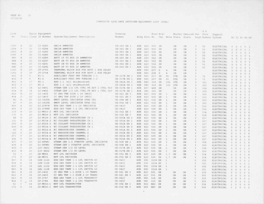
. _ _ _
PAGE N1 1507/19/95
CCEPOSITE SCUG SAFE SHL*TDCVN ECUIFwENT LIST (SSEL)
s
G.4Line E7Jip Equipment Drawing Room Eval Normal Desired Pwr Fcrm Support
No. Train Class ID Number System / Equipment D=scription Nu4er Bldg Elev No. Cat. Note State State Reld Number System RC IC PC DH SU
i1053 B 20 11-6283 DBCIP AMMETER OS-060 SH 1 AUX 623 505 SR ON ON Y 52 ELECTRICAL 0 0 0 0 11054 P 20 II-6284 DBC2N AMMETER 05-060 SH 1 AUX 623 505 SR ON ON Y 52 EIICTRICAL 0 0 0 0 11055 B 20 11-6285 DBC1N APNETER OS-060 SH 1 AUX 623 505 SR , CN ON Y 52 ELECTRICAL 0 0 0 0 11056 P 20 II-6286 DBC2P AtHETER 03-060 SH 1 AUX 623 505 SR CN ON Y 52 ELECTRICAL 0 0 0 0 1
843 8 20 11-6289 BATT iP TO BUS 1P AMMMETER OS-060 SH 1 AUX 623 502 SR CN ON Y 52 ELECTRICAL 0 0 0 0 1844 P 20 II-6290 BATT 2N TO BUS 2N AMMETER OS-060 SH 1 AUX 623 502 SR ON ON Y 52 ELECTRICAL 0 0 0 0 1845 B 20 II-6291 BATT IN TO BUS IN AlHETER 05-060 SH 1 AUX 623 502 SR ON ON Y 52 ELECTRICAL 0 0 0 0 1846 P 20 II-6292 BATT 2P TO BUS 2P AMMETER 05-060 SH 1 AUX 623 502 SR CN ON Y 52 ELECTRICAL 0 0 0 0 1 'I
1160 B 20 JT-2703 TERMINAL BLOCK BOX FOR AFPT 1 AUX RELAY AUX 565 237 S 4 ON ON Y ELECTRICAL 0 0 0 0 11161 P 20 JT-2704 TERMINAL BLOCK BOX FOR AFPT 2 AUX RELAY AUX 565 238 S 4 CN ON Y ELECTRICAL 0 0 0 0 1401 B 5 K3-1 AUXILIARY FEED PMP WRBINE 1-1 OS-0179 SH 1 AUX 565 237 SR 91 STB ON Y 72 ELECTRICAL 0 0 0 1 0402 P 5 K3-2 AUXILIARY FEED PMP WRBINE 1-2 OS-017B SH 1 AUX 565 237 SR 91 STB ON Y 73 ELECTRICAL 0 0 0 1 0851 B 17 F5-1 EDG 1-1 fall skidmounted) OS-041A SH 1 AUX 585 318 SR 102 STB ON Y 351 ELECTRICAL 0 0 0 0 1852 P 17 K5-2 EDG 1-2 (all skidmounted) OS-041A SH 2 AUX 585 319 SR 102 STB ON Y 353 ELECTRICAL 0 0 0 0 1403 P 18 IJC-64 51 STEAM GEN 1/2 LYL CIRL FR AFP 2 CTRL VLV OS-017A SH 1 AUX 603 428 SR ON ON Y 308 ELECTRICAL 0 0 0 1 0404 B 18 LC-6452 STEAM GEN 1/2 LVL CTRL FR AFP 1 CTRL VLV OS-017A SH 1 AUX 585 325 SR ON O*I Y 309 ELECTRICAL 0 0 0 1 0853 B 20 LI-1402 CC SRG TNK SIDE 1 LV INDIC OS-021 SH 3 AUX 623 505 SR 1 ON ON Y 315 ELECTRICAL 0 0 0 0 1854 P 20 LI-1403 CC SRG TNK SIDE 2 Lv INDIC OS-021 SH 3 AUX 623 505 SR 1 ON ON Y 315 ELECTRICAL 0 0 0.0 1
46 B 20 LI-1525A BWST LEVEL INDICATOR SFAS CHI OS-004 SH 1 AUX 623 502 SR 1 ON ON Y 300 ELECTRICAL 1 0 0 0 047 P 20 LI-1525B BWST LEVEL INDICAWR SFAS Cr12 OS-004 SH 1 AUX 623 502 SR 1 ON ON Y 300 ELECTRICAL 1 0 0 0 0
855 B 20 LI-2787B EDG DAY TANK 1-1 LV INDICATCR OS-041C AUX 623 505 SR 1 ON ON Y 316 ELECTRICAL 0 0 0 0 1856 P 20 LI-2788B EDG DAY TANK 1-2 LVL INDICATOR OS-041C AUX 623 505 SR 1 ON ON Y 316 ELECTRICAL 0 0 0 0 1109 B 20 LI-MU16-2 MUT LVL INDICATOR OS-002 SH 3 AUX 623 505 SR 1 ON ON Y 314 ELECTRICAL 1 0 0 0 0175 B 20 LI-MU16-2 MUT LVL INDICATOR OS-002 SH 3 AUX 623 505 SR 1 ON ON Y 314 ELECTRICAL 0 1 0 0 0
48 B 20 LI-RC14-3 RC COOLANT PRESSURIZER CH 1 OS-001A SH 2 AUX 623 505 SR 1 ON ON Y 317 ELECTRICAL 1 0 0 0 0121 B 20 LI-RC14-3 RC COO!Rrr PRESSURIZER CH 1 OS-001A SH 2 AUX 623 505 SR 1 ON ON Y 317 ELECTRICAL 0 1 0 0 0250 B 20 LI-RC14-3 RC COOLANT PRESSURIZER CH 1 OS-001A SH 2 AUX 623 505 SR 1 ON ON Y 317 ELECTRICAL 0 0 1 0 0405 B 20 LI-RC14-3 RC COOIRIT PRESSURIZER CH 1 OS-001A SH 2 AUX 623 505 SR 1 ON ON Y 317 ELECTRICAL 0 0 0 1 0
49 P 20 LI-RC14 -4 RC PRESSURIZER CHANNEL 2 OS-001A SH 2 AUX 623 505 SR 1 ON ON Y 317 ELECTRICAL 1 0 0 0 0122 P 20 LI-RC14-4 RC PRESSURIZER CHANNEL 2 OS-001A SH 2 AUX 623 505 SR 1 ON ON Y 317 ELECTRICAL 0 1 0 0 0 !251 P 20 LI-RC14-4 RC PRESSURIZER CHANNEL 2 OS-001A SH 2 AUX 623 505 SR 1 ON ON Y 317 ELECTRICAL 0 0 1 0 0406 P 20 LI-RC14-4 RC PRESSURIZER CHANNEL 2 OS-001A SH 2 AUX 623 505 SR 1 ON ON Y 317 ELECTRICAL 0 0 0 1 0 *
407 P 20 LI-SP9Al STEAM GEN 1-2 STARTUP LEVEL INDICATOR OS-008 SH 1 AUX 623 505 SR 1 ON ON Y 308 ELECTRICAL 0 0 0 1 0408 B 20 LI-SP991 STEAM GEN 1 STARWP IREL INDICATOR OS-000 SH 1 AUX 623 505 SR 1 ON ON Y 309 ELECTRICAL 0 0 0 1 0409 P 20 LIC 6451 STEAM GEN 1/2 SU LEVEL OS-017A SH 1 AUX 623 505 SR 1 ON ON Y 308 ELECTRICAL 0 0 0 1 0410 B 20 LIC 6452 STEAM GEN 1/2 SU LEVEL OS-017A SH 1 AUX 623 505 SR 1 ON ON Y 309 ELECTRICAL 0 0 0 1 0
30 C 20 LR-MU16 MUT LVL RECORDER OS-002 SH 3 AUX 623 505 SR 1,7 ON ON Y 314 ELECTRICAL 1 0 0 0 0173 P 20 LR-MU16 MUT LVL RECORDER OS-002 SH 3 AUX 623 505 SR 1,7 ON ON Y 314 ELECTRICAL 0 1 0 0 0857 P 18 LSH 1122 EDG DAY TANK 1-1 LVL SWITCH HI OS-041C AUX 595 320A SR 1 Y 152 ELECTRICAL 0 0 0 0 1 .
858 B 18 LSH 1128 EDG DAY TANK 1-1 LVL SWITCH HI OS-041C AUX 595 321A SR 1 Y 151 ELECTRICAL 0 0 0 0 1 !859 P 18 LSL 1122 EDG DAY TANK 1-2 LVL SWITCH LO OS-041C AUX 595 320A SR 1 Y 152 ELECTRICAL 0 0 0 0 1860 B 18 LSL 1128 EDG DAY TANK 1-1 LVL SWITCH Is0 OS-041C AUX 595 321A SR 1 Y 151 ELECTRICAL 0 0 0 0 1861 B 18 LT-1402 CC SRG W K 1-1 SIDE 1 IV TRANS OS-021 SH 3 AUX 623 501 SR ON ON Y 315 ELECTRICAL 0 0 0 0 1862 P 18 LT-1403 CC SRG TNK 1-1 SIDE 2 LV TRANS OS-021 SH 3 AUX 623 501 SR ON ON Y 315 ELECTRICAL 0 0 0 0 1863 B 18 LT-2787 EDG DAY TANK 1-1 LVL TRANSMITT OS-041C AUX 585 318 SR ON ON Y 316 ELECTRICAL 0 0 0 0 1 i864 P 18 LT-2788 EDG DAY TANK 1-2 LVL TRANSMITT OS-041C AUX 585 319 SR ON ON Y 316 ELECTRICAL 0 0 0 0 1 ;,
51 C 18 LT-MU16-1 MUT LVL TRANSMITTER 05-002 SH 3 AUX 565 AB3 SR ON ON Y 314 ELECTRICAL 1 0 0 0 0 |172 P 18 LT-MU16-1 MUT LVL TRANSMITTER OS-002 SH 3 AUX 565 AB3 SR 04 ON Y 314 ELECTRICAL 0 1 0 0 0
e
_ _ _ _ _ _ _ _ _ _ _ __ , -- ,_ , _. . _ _ _ , _ , , , . _ , . _ _

PME NO. 1607/19/95
CCMPOSITE SOUG SAFE SHLJTDOWN EQUIPWENT LIST (SSEL)
G.4Line Equip Equipment Drawing Room Eval Normal Desired Pwr Form SupportNo. Train Class ID Number System /Equipmant Dascription Nu-ber Bldg Elev No. Cat. Note State State Reqd Number System RC IC PC DH SU
110 B 18 LT-MU16-2 MCTT LVL TRANSMITTER OS-002 SH 3 AUX 565 AB3 SR ON ON Y 314 ELECTRICAL 1 0 0 0 0174 B 18 LT-MU16-2 MtTT LVL TRANSMITTER OS-002 SH 3 AUX 565 AB3 SR ON ON Y 314 ELECTRICAL 0 1 0 0 0
52 P 18 LT-PC14-1 RC PRESSURIZER CH 2 LEVEL TRANSMITTER OS-001A SH 2 C174 '585 317 SR ON ON Y 317 ELECTRICAL 1 0 0 0 0123 P 18 LT-RC14-1 RC PRESSURIZER CH 2 LEVEL TRANSMITTER OS-001A SH 2 CIM 585 317 SR ON ON Y 317 ELECTRICAL 0 1 0 0 0252 P 18 LT-R C14 -1 RC PRESSURIZER CH 2 LEVEL TRANSMITTER OS-001A SH 2 CIM 585 317 SR CN ON Y 317 ELECTRICAL 0 0 1 0 0 Itil P 18 LT-RC14-1 RC PRESSURIZER CH 2 LEVEL TPANSMITTER OS-001A SH 2 CIN 585 317 SR ON ON Y 317 ELECTRICAL 0 0 0 1 0 |
53 9 le LT-RC14-3 RC PRESSURIZER CH 1 LEVEL TRANSMITTER OS-001A SH 2 CIN 585 317 SR ON ON Y 317 ELECTRICAL 1 0 0 0 0 i
124 9 18 LT-RC14-3 RC PRESSURIZER CH 1 LEVEL TRANSMITTER OS-001A SH 2 CIN 585 317 SR ON ON Y 317 ELECTRICAL 0 1 0 0 0253 8 18 LT-RC14-3 RC PRESSURIZER CH 1 LEVEL TRANSMITTER OS-001A SH 2 CIM 585 317 SR ON ON Y 317 ELECTRICAL 0 0 1 0 0412 B 18 LT-RC14 -3 RC PRESSURIZER CH 1 LEVEL TPARSMITTER OS-001A SH 2 CTM 585 317 SR ON ON Y 317 ELECTRICAL 0 0 0 1 0413 P 18 LT-SP9A3 STEAM GEN 1-2 STARTUP LEVEL TPANSMIT 3 OS-008 SH 1 CIM 565 286 SR 89 ON ON Y 308 ELECTRICAL 0 0 0 1 0414 B 18 LT-SP9B3 STEAM GEN 1 STARWP LEVEL TRANSMITTER OS-008 SH 1 CIM 565 285 SR 90 ON ON Y 309 ELECTRICE O O O 1 0415 P 7 MS-100 MAIN STEAM LINE 2 ISO VEVE OS-008 SH 1 AUX 643 602 SR OPN CLS Y 303 ELECTRICAL 0 0 0 1 0416 P 7 MS-100-1 MAIN STEAM LINE 2 MSIV BYPASS VALVE OS-008 SH 1 AUX 643 602 R CLS CLS N 232 0 0 0 1 0417 B 7 MS-101 MS LINE 1 ISO VALVE OS-008 SH 1 AUX 643 601 SR OPN CLS Y 303 ELECTRICAL 0 0 0 1 0418 B 7 MS-101-1 MS LINE 1 MSIV BYPASS V EVE OS-008 SH 1 AUX 643 601 R CLS CLS N 233 0 0 0 1 0419 B eB MS-106 MS LINE 1 TO AFP TURB 1-1 ISO V EVE OS-017B SH 1 AUX 623 500 SR CLS OPN Y 250 ELECTRICAL 0 0 0 1 0
1087 P 8A MS-106A MS LINE 2 TO AFP TURB 1-1 ISO VEVE OS-017B SH 1 E*X 623 501 R OPN OPN N 358 0 0 0 1 0420 P 8A MS-107 MS IR 2 W AFP TUPE 1-2 MTR CTRL ISO VLV OS-017B SH 1 AUX 623 501 SR CLS OPN Y 153 ELECTRICAL 0 0 0 1 0
1088 8 8A MS-107A MS LINE 1 TO AFP W RB 1-2 ISO VALVE OS-017B SH 1 AUX 623 500 R OPN OPN N 359 0 0 0 1 0421 P 7 MS-375 MAIN STEAM LINE 2 WARMUP DRAIN VALVE OS-008 SH 1 AUX 643 602 R CLS CLS N 224 0 0 0 1 0422 B 7 MS-394 MS LINE 1 WARMUP DRAIN VALVE 0S-008 SH 1 AUX 643 601 R CLS CLS N 234 0 0 0 1 0423 C 7 MS-5889A AFP TURB 1-1 STEAM AMISSION VALVE OS-017B SH 1 AUX 565 237 SR CLS OPN Y 225 ELECTRICAL 0 0 0 1 0424 C 7 MS-5889B AFP WRB 1-2 STEAM ADMISSION VALVE OS-017B SH 1 AUX 565 238 SR CLS OPN Y 226 ELECTRICAL 0 0 0 1 0425 P 8A MS-603 SG 1-2 DPAIN LINE ISO VALVE OS-008 SH 3 AUX 565 236 R CLS CLS N 235 0 0 0 1 0426 B BA MS-611 SG 1-1 DRAIN LINE ISO VALVE OS-008 SH 3 AUX 565 236 R CLS CLS N 236 0 0 0 1 0
54 C 8A MU-11 MX BED 1 OUT TO ION BED LN VLV OS-002 SH 1 AUX 565 211 R MtJT MtTT N 237 1 0 0 0 055 C 8A MU-12A MU FILTER 1 INLET ISO VALVE OS-002 SH 1 AUX 565 211 R OPN OPN N 238 1 0 0 0 056 C 8A MU-12B MIXED BED 1-2 INLET ISO VALVE OS-002 SH 1 AUX 565 211 R CLS CLS N 239 1 0 0 0 057 C 7 MU-19 RCP SEAL INJ FICW CTRL VLV OS-002 SH 3 AUX 585 303 S 3 WR N/A N 319 1 0 0 0 0
215 C 7 MU-19 RCP SEAL INJ FIcW CTRL VLV OS-002 SH 3 AUX 585 303 SR 10 THR OPN N 319 0 1 0 0 0125 P 8A WJ-1A RC LETDOWN COOLER 1-1 INLET ISO VALVE OS-002 SH 1 CIN 565 215 SR OPN CLS Y 155 ELECTRICAL 0 1 0 0 0126 P 8A MU-1B RC LETDOWN COOLER 1-2 INLET ISO VALVE OS-002 SH 1 CTM 565 215 SR OPN CLS Y 156 ELECTRICAL 0 1 0 0 0
58 C R MU-209 NORM MJ FLOW CTRL IN ISO VLV OS-002 SH 3 AUX 565 225 11 OPN OP/CL Y MANUAL 1 0 0 0 0.
211 C R MU-209 NORM WJ FLOW CTRL IN ISO VLV OS-002 SH 3 AUX 565 225 11 OPN OP/CL Y MANUAL 0 1 0 0 0216 C R MU-216 BYPASS VLV FOR MU-19 06-002 SH 3 AUX 585 303 20 CLS THR Y MANUAL 0 1 0 0 0
59 C 7 MU-23 BA PMP PNEUMATC DISCH CTRL VLV OS-046 AUX 565 240 SR CLS OPN Y 318 ELECTRICAL 1 0 0 0 0127 C 8A MU-2B RC LETDONN ISO VALVE OS-002 SH 1 CIM 565 216 SR OPN CLS Y 98 ELECTRICAL 0 1 0 0 0
60 P 7 MU-32 MU FION CTRL VALVE OS-002 SH 3 AUX 565 225 SR THR OPN Y 319 ELECTRICE 1 0 0 0 0213 P 7 WJ-32 MU FI4W CTRL VALVE OS-002 SH 3 AUX 565 225 SR THR OPN Y 319 ELECTRICAL 0 1 0 0 0 !
61 C R MU-338 BAAT 1 & 2 DISCH XCONN VALVE OS-046 AUX 565 240 37 CLS OPN Y MANUAL 1 0 0 0 0 |62 C R MU-348 BORIC ACIC PMP 1-1 DISCH VALVE OS-046 AUX 565 240 38 OPN THR Y MANUAL 1 0 0 0 063 C R MU-349 BA FMP 1-2 DISCH VALVE OS-046 AUX 565 240 38 OPN THR Y MANUAL 1 0 0 0 0 ,
64 C R MU-366 BA PMP 1-2 TO MU FLTRS ISO VLV OS-046 AUX 565 240 2 CLS OPN Y MAPPJAL 1 0 0 0 0128 C 7 WJ-38 RCP SEAL RETURN ISO VALVE OS-002 SH 2 AUX 565 208 SR 51 OPN OPN Y 231 ELECTRICAL /M 0 1 0 0 0
ANUAL65 C 8A MU-3971 MU PIT 4P2 SUCTION 3 WAY MOV OS-002 SH 3 AUX 565 225 SR 9 OPN OPN Y 164 ELECTRICAL 1 0 0 0 0 i
177 C 8A MU-3971 MU PUMP 2 SUCTION 3 WAY MOV OS-002 SH 3 AUX 565 225 SR 9 CPN OPN Y 164 ELECTRICAL 0 1 0 0 0 j
ie
!
_ . , , _ - - - _ . _ _ _ _ _ _ _ _ _ _ _ _ . _ _ _
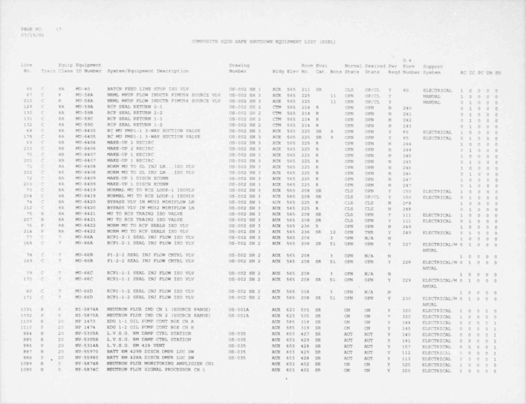
- _ . _ _ _ _ _ _ _ _ _ _ _
FAGE NO. 1707/19/95
COMPOSITE SOUG SAFE SHUIDCWN EOUIPMENT LIST iSSEL)
G.4Line E7aip Equipment Drawing Room Eval Normal Desired Pwr Fom SupportNo. Train Class ID Number System / Equipment Description Number Bldg Elev No. Cat. Note State State Reqd Nuwi>er System RC IC PC CH SU
66 C 8A FJ-40 BATCH FEED LINE STOP ISO VLV OS-002 SH 1 AUX 565 211 SR CLS OP/CL Y 80 ELE::" TRICE 1 0 0 0 067 C R KJ-58A NPJG MKUP F14W INDCTR FINJ58 SOURCE VLV OS-002 SH 3 AUX 565 225 11 OPN OP/CL Y MANUAL 1 0 0 0 0 *
210 C R MU-50A NRML MKUP F14W INDCTR FIFJ58 SOURCE VLV OS-002 SH 3 AUX 565 225 11 OFN OP/CL Y MANUE O 1 0 0 0129 C 8A MJ-59A RCP SEAL RETURN 2-1 OS-002 SH 2 CTM 565 214 R OPN OPN N 240 0 1 0 0 0
i 130 C 8A FJ-59B RCP SEE RETURN 2-2 OS-002 SH 2 Cm 565 214 R OFN OFN N 241 0 1 0 0 0 !131 C 8A MU-59C RCP SEAL RE1VRN 1-1 OS-002 SH 2 Cm 565 214 R OFN CPN N 242 0 1 0 0 0
I 132 C 8A MU-590 RCP SEE RETURN 1-2 OS-002 SH 2 CTM 565 214 R OFN OFN N 243 0 1 0 0 0,
68 C 8A MU-6405 RC MU PMP1-1 3-WAY SUCTION VALVE OS-002 SH 3 AUX 565 225 SR 9 CPN OFM Y 85 ELECTRICAL 1 0 0 0 0178 C 8A FJ-6405 RC MU PMP1-1 3-WAY SUCTION VALVE OS-002 SH 3 AUX 565 225 SR 9 OFN OPN Y 85 ELECTRICAL 0 1 0 0 0 )69 C 8B MJ-6406 MAKE-UP 2 RECIRC 05-002 SH 3 AUX 565 225 R OPN OFN N 244 1 0 0 0 0
2C0 C 88 KJ-6406 MAKE-UP 2 RECIRC OS-002 SH 3 AUX 565 225 R OPN OrN N 244 0 1 0 0 070 C 89 FJ-6407 MAKE-UP 1 RECIRC 0S-002 SH 3 AUX 565 225 R OPN OPN N 245 1 0 00 0 t
201 C 8B MU-6407 MAKE-UP 1 RECIRC 0S-002 SH 3 AUX 565 225 R OFN OFN N 245 0 1 0 0 071 C 8A MU-6408 NORM WJ TO SL INJ LN. . ISO VLV 05-002 SH 3 AUX 565 225 R OPN OPN N 246 1 0 0 0 0 |202 C 8A MU-6408 NORM MU TO SL INJ LN. . ISO VLV OS-002 SH 3 AUX 565 225 R OPN OFN N 246 0 1 0 0 0 [72 C 8A MU-6409 MAKE-UP 1 DISCH XCONN OS-002 SH 3 AUX 565 225 R OFN OPN N 247 1 0 0 0 0 !
203 C 8A WJ-6409 MARE-UP 1 DISCH XCONN OS-002 SH 3 AUX 565 225 R OFN OPN N 247 0 1 0 0 0'
73 C 8A MU-6419 NORMAL KJ TO RCS LOOP-1 ISOVLV OS-002 SH 3 AUX 565 208 SR CLS OPN Y 150 ELECIRICAL 1 0 0 0 0204 C 8A MU-6419 NORMAL MU TO RCS LOOP-1 ISOVLV OS-002 SH 3 AUX 565 200 SR CLS OP/CL Y 150 ELECTRICAL 0 1 0 0 0
74 C 8A WJ-6420 BYPASS VLV IN WJ32 MINIFLOW LN OS-002 SH 3 AUX 565 225 R CLS CLS N 2*8 1 0 0 0 0 t212 C 8A MU-6420 BYPASS VLV IN MU32 MINIFLOW LN OS-002 SH 3 AUX 565 225 R CLS CLS N 248 0 1 0 0 075 B 8A MU+6421 MU TO RCS TRAIN 2 ISO VEVE OS-002 SH 3 AUX $65 208 SR CLS OFN Y 111 ELECTRICAL 1 0 0 0 0
207 B 8A MU-6421 WJ TO RCS TRAIN 2 ISO VALVE OS-002 SH 3 AUX 565 208 SR CLS OPN Y 111 ELECTRICE O 1 0 0 076 P 8A MU-6422 NORM MU TV RCP SEALS ISO VLV OS-002 SH 3 AUX 565 236 2 CFN OPN N 249 1 0 0 0 0
214 P 8A MU-6422 NORM MU TO RCP SEALS ISO VLV OS-002 SH 3 AUX 565 236 SR 12 OPN THR Y 249 ELECTRICAL 0 1 0 0 077 C 7 wJ-66A RCP1-2-1 SEE INJ FLOW ISO VLv 05-002 SH 2 AUX 565 208 3 OPN N/A N 1 0 0 0 0
168 C 7 MU-66A RCP1-2-1 SEAL INJ FIDW ISO VLV OS-002 SH 2 AUX $65 208 SR 51 OPN OPN Y 227 ELECTRICE/M 0 1 0 0 0ANUE
78 C 7 MU-669 P1-2-2 SEAL INJ FLOW CNT1tL VLV OS-002 SH 2 AUX 565 208 3 OPN N/A N 1 0 0 0 0169 C 7 MU-66B P1-2-2 SEAL INJ FLOW CNTRL VLV 05-002 SH 2 AUX 565 208 SR 51 OPN OPN Y 228 ELECTRICAL /M 0 1 0 0 0
ANUAL79 C 7 MU-66C RCP1-1-1 SEE INJ FLOW ISO VLV OS-002 SH 2 AUX 565 208 3 OPN N/A N 1 0 0 0 0
170 C 7 MU-66C RCP1-1-1 SEAL INJ FLOW ISO VLV OS-002 SH 2 AUX 565 208 SR 51 OFN CFN Y 229 ELECTRICAL /M 0 1 0 0 0ANUAL.
80 C 7 MJ-66D RCP1-1-2 SEAL INJ FLOW ISO VLv OS-002 SH 2 AUX $65 208 3 OPN N/A N 1 0 0 0 0171 C 7 KJ-66D RCP1-1-2 SEAL INJ FLOW ISO VLV 05-002 SH 2 AUX 565 208 SR 51 OPN OFN Y 230 ELECTRICE/M 0 1 0 0 0 ,
ANUE |1091 B 0 NI-5874A NEUTRON FLUX IND CH 1 (SOURCE RANGE) OS-001A AUX 623 505 SR ON ON Y 320 ELECTRICE 1 0 0 0 0
71092 P O NI-5875A NEUTRON FLUX IND CH 2 (SOURCE RANGE) OS-001A AUX 623 505 SR ON ON Y 320 ELECTRICAL 1 0 0 0 01109 B 20 NP 1473 EDO 1-1 OIL PUMP CONT BOX CH A AUX 585 318 SR ON ON Y 144 ELECTRICAL 0 0 0 0 11110 P 20 NP 1474 EDG 1-2 CIL PLHP CONT BOX CH B AUX 585 319 SR ON ON Y 145 ELECTRICAL 0 0 0 0 1 |
884 B 20 NV-5305A L V.S.G. RM DAMP CTRL STATION ' OS-035 AUX 603 423 SR AITT AITT Y 140 ELECTRICE O O O C 1 I885 B 20 NV-5305B L.V.S.G. RM DAMP CTRL STATION OS-035 AUX 603 429 SR AUT AUT Y 141 ELECTRICAL 0 0 0 0 1886 P 20 NV-5314A L.V.S.G. RM 428 VENT OS-035 AUX 603 428 SR AUT AUT Y 157 ELECTRICAL 0 0 0 0 1
.
887 8 20 NV-55970 BATT RM 429B DISCH DMPR LOC SW OS-035 AUX 603 429 SR AUT AUT Y 112 ELECTRICE O O O O 1 f888 P 20 NV-55980 BATT RM 428A DISCH DMPR IOC SW 0S-035 AUX 603 428 SR AUT AUT Y 113 ELECTRICE O O O O 1 !,
1089 B 0 NY-5874B NEUTRON FLUX MONITORING AMPLIGIER CH1 AUX 603 402 SR ON ON Y 320 ELECTRICAL 1 0 0 0 0 [1090 B 0 NY-5874C NEUTRON FLUX SIGNE PROCESSOR CH 1 AUX 603 402 SR ON ON Y 320 ELECTRICAL 1 0 0 0 0
!a
.
t
.n , -. - -a.- -- - .- , , - __ --

FA';E NO. 181 07/19/95
COMPOSITE SQUG SAFE SHUITCWN EQUIPMENT LIST (SSELI f
.
G.4Line Equip Equipment Drawing Room Eval Normal Desired Pwr Form Support
N1 Train Class ID Number System / Equipment Description Number Bldg Elev No. Cat. Note State State Reqd Nueter System RC IC PC CH SU
1093 P 0 NY-5875B NEUTPON FLUX SIGNAL AMPLIFIER AUX 603 427 SR ON CN Y 320 ELECTRICAL 1 0 0 0 01094 P O NY-5875C NEUTRON FI/UX SIGNAL PROCESSOR CH 2 AUX 603 427 SR ON ON Y 320 ELECTRICAL 1 0 0 0 0427 B 5 P14-1 AUXILIARY FEEDWATER PLHP 1-1 CS-017A SH 1 AUX 565 237 S STB CN Y STEAM 0 0 0 1 0 ,
428 P 5 P14-2 AUXILIARY FEEDWATER PLHP 1-2 OS-017A SH 1 AUX 565 238 S STB ON Y STEAM 0 0 0 1 0889 B 6 P195-1 EDG FUEL CIL TRANSFER PUMP 1-1 OS-041C YRD 585 N/A SR O/O C/O Y 151 ELECTRICAL 0 0 0 0 1890 P 6 P195-2 EDG FUEL OIL TPANSFER PUMP 1-2 OS-041C YRD 585 N/A SR O/O O/O Y 152 ELECTRICAL 0 0 0 0 1891 B 6 P3-1 SERVICE WATER PUMP 1-1 OS-020 SH 1 ITK 576 052 SR ON ON Y 287 ELECIRICAL 0 0 0 0 1892 P 6 P3-2 SERVICE WATER PUMP 1-2 OS-020 SH 1 ITK 576 052 SR ON ON Y 295 ELECTRICAL 0 0 0 0 1
81 C 5 P37-1 MAKEUP PUMP 1-1 OS-002 SH 3 AUX 565 225 SR 8 OFF ON Y 106 ELECTRICAL 1 0 0 0 0176 C 5 P37-1 MAKEUP PUMP 1-1 OS-002 SH 3 AUX 565 225 SR 8 OFF ON Y 106 ELECTRICAL 0 1 0 0 0
82 C 5 P37-2 MAKEUP PLMP 1-2 0S-002 SH 3 AUX 565 225 SR 8 ON ON Y 110 ELECTRICAL 1 0 0 0 0183 C 5 P37-2 MAKEUP PUMP 1-2 05-002 SH 3 AUX 565 225 SR 8 ON ON Y 110 ELECTRICAL 0 1 0 0 0
83 C 5 P38-1 BORIC ACID PUMP 1-1 0S-046 AUX $65 240 SR OFF ON Y 101 ELECTRICAL 1 0 0 0 084 C 5 P38-2 BORIC ACID PUMP 1-2 0S-046 AUX 565 240 SR OFF ON Y 102 ELECTRICAL 1 0 0 0 085 C 5 P42-1 DECAY HEAT PUMP 1-1 OS-004 SH 1 AUX 545 105 SR 15 OFF OFF N 288 1 0 0 0 0
143 C 5 P42-1 DECAY HEAT PUMP 1-1 05-004 SH 1 AUX 545 105 SR 15 OFF OFF N 288 0 1 0 0 0 '
429 B 5 P42-1 DECAY MEAT PUMP 1-1 05-004 SH 1 AUX 545 105 SR 79 OFF ON Y 288 ELECTRICAL 0 0 0 1 086 C 5 P42-2 DECAY MEAT PLHP 1-2 OS-004 SH 1 AUX 545 115 SR 15 OFF OFF N 296 1 0 0 0 0
144 C 5 P42-2 DECAY HEAT PUMP 1-2 OS-004 SH 1 AUX 545 115 SR 15 OFF OFF N 296 0 1 0 0 0430 P 5 P42-2 DECAY HEAT PUMP 1-2 0S-004 SH 1 AUX 545 115 SR 79 OFF ON Y 296 ELECTRICAL 0 0 0 1 0893 B 5 P43-1 CCNP COOLING PUMP 1 1 CS-021 SH 1 AUX 585 328 SR ON ON Y 289 ELECTRICAL 0 0 0 0 1894 P 5 P43-2 COMPONENT COOLING PLHP 1-2 OS-021 SH 1 AUX 585 328 SR OFF ON Y 298 ELECTRICAL 0 0 0 0 1895 B 5 P43-3 CC PUMP 1-3 05-021 SH 1 AUX 585 328 S OFF N/A N 0 0 0 0 1 ,
87 C 5 P56-1 CONTAINMENT SPRAY PUMP 1-1 OS-005 AUX 545 100 SR 17 OFF OFF N 374 1 0 0 0 0,
145 C 5 P56-1 CofrTAINMENT SPRAY PUMP 1-1 OS-005 AUX 545 105 SR 17 OFF OFF N 4 /4 0 1 0 0 088 C 5 PS6-2 CONTAINMENT SPRAY PtHP 1-2 OS-005 AUX 545 115 SR 17 OFF OFF N 275 1 0 0 0 0
146 C 5 P56-2 CONTAINMENT SPRAY PLHP 1-2 OS-005 AUX 545 115 SR 17 OFF OFF N 275 0 1 0 0 089 C 5 P57 BORATED WATER RECIRC PLHP 1-1 OS-007 AUX 565 209 5 99 ON N/A N 1 0 0 0 0 i
147 C 5 P57 BORATED WATER RECIRC PUMP 1-1 OS-007 AUX 565 209 S 99 ON N/A N 0 1 0 0 090 C 5 F58-1 HI PRESSURE INJECTION PUMP 1-1 OS-003 AUX 545 105 SR 13 OFF OFF N 290 1 0 0 0 0 !i
| 91 C 5 P58-2 HI PRESSURE INJECTION PUMP 1-2 OS-003 AUX 545 115 SR 13 OFF OFF N 297 1 0 0 0 01127 B 20 PC-5898 CREVS STBY COND 1 DAMPER CONTROL (C6714) OS-032B AUX 643 603 SR CLS CPN Y 90 ELECTRICAL 0 0 0 0 11128 P 20 PC-5899 CREVS STBY COND 2 DAMPER CONTROL (C6715) OS-032B AUX 643 603 SR CLS OPN Y 91 ELECTRICAL 0 0 0 0 1 i
896 B 18 PDIS 1379A SW STRNR 1-1 PRESS DIFF IND SW OS-020 SH 1 ITK 576 052 SR 1 ON ON Y 134 ELECTRICAL 0 0 0 0 1897 P 18 PDIS 1380A SW STRNR 1-2 PRESS DIFF IND SW OS-020 SH 1 ITK 576 052 SR 1 ON ON Y 135 ELECTRICAL 0 0 0 0 1 ,
1033 B 18 POSH 3981 DG1 JKT CC CUT ISO VLV PDSH OS-021 SH 1 AUX 595 318 SR 32 ON ON Y 177 ELECTRICAL 0 0 0 0 1 *
I1034 P 18 PDSM 3982 DG2 JKT CC OUT ISO VLV PDSH OS-021 SH 1 AUX 585 319 SR 32 ON ON Y 178 ELECTRICAL 0 0 0 0 1254 B 20 PI-2000 CIHT SFAS CH 1 PRESSURE INDICATOR OS-033F AUX 623 505 SR 1 ON ON Y 300 ELECTRICAL 0 0 1 0 0255 P 20 PI-2001 CTMT SFAS CH 2 PRESSURE INDICATOR OS-033F AUX 623 505 SR 1 ON ON Y 300 ELECTRICAL 0 0 1 0 0
92 B 20 PI-MU52A BA PMP 1-1 DISCH PRESS INDIC OS-046 AUX 565 241 SR 1 ON ON Y 301 ELECTRICAL 1 0 0 0 093 P 20 PI-MU52B BA PMP 1-2 DISCH PRESS INDIC 05-046 AUX 565 241 SR 1 ON ON Y 301 ELECTRICAL 1 0 0 0 0
256 P 20 PI-RC2A4 RC LOOP 2 HIA) WR SFAS CH 2 OS-001A SH 1 AUX 623 505 SR 1 ON ON Y 300 ELECTRICAL 0 0 1 0 0431 P 20 PI RC2A4 RC IDOP 2 HIA3 WR SFAS CH 2 OS-001A SH 1 AUX 623 505 SR 1 ON ON Y 300 ELECTRICAL 0 0 0 1 0257 B 20 PI-RC2B4 RC LOOP 1 HI4 WR SFAS CH 1 OS-001A SH 1 AUX 623 505 SR 1 ON ON Y 300 ELECTRICAL 0 0 1 0 0432 B 20 PI-RC294 RC I40P 1 HLG WR SFAS CH 1 OS-001A SH 1 AUX 623 505 SR 1 ON ON Y 300 ELECTRICAL 0 0 0 1 0433 P 20 PI-SP12A STEAM GEN 2 DISCHARGE PRESSURE INDICATOR OS-008 SH 1 AUX 623 505 SR 1 ON ON Y 302 ELECTRICAL 0 0 0 1 0*434 B 20 PI-SP12B STEAM GEN 1 DISCH PRESSURE INDICATOR OS-008 SH 1 AUX 623 505 SR 1 ON ON Y 302 ELECTRICAL 0 0 0 1 0
1131 B 18 PS 20020 CREVS COND 1 MTR UNLOADER PRESS SWITCH OS-032B AUX 643 603 SR ON ON Y 74 ELECTRICAL 0 0 0 0 1
e
. - ,. - - - - - , . ____ _ _ _ _ _ _ _ _ _ _ _ - _ . - _
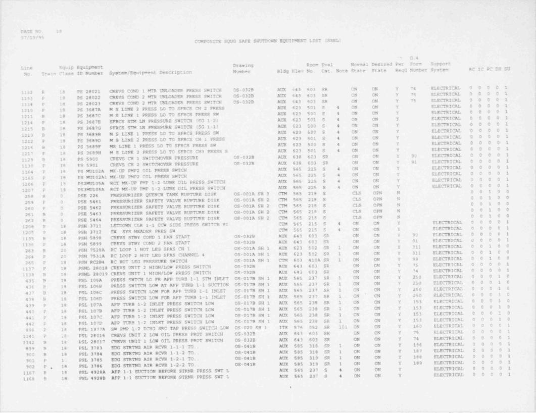
.
>
PAGE NO. 19
07/19/95COMPOSITE SQ33 SAFE SH"DCWN EOUIIMENT LIST (SSEL)
' G.4 i
Line Equip Equipment Drawing Room Eval Normal Desired Fwr Form Support I
No. Train Class ID Number System / Equipment Description Number Bldg Elev No. Cat. Note State State Pegd Nu eer System RC IC PC DH SU
f
1132 B 18 PS 28021 CREYS COND 1 WR UNICADER PRESS SWITCH OS-032B AUX 643 603 SR CN ON Y 74 ELECTRICAL 0 0 0 0 1
1133 P 18 PS 28022 CREVS COND 2 MTR UNI 4ADER FRESS SWITCH 05-032B AUX 643 603 SR ON ON Y 75 ELECTRICAL 0 0 0 0 1 c
1134 P 18 PS 20023 CREVS COND 2 Milt UNLCADER PRESS SWITCH OS-032B AUX 643 603 SR ON ON Y 75 ELECTRICAL 0 0 0 0 1'
,
1210 P 18 PS 3687A M S LINE 2 PRESS LO TO SFRCS CH 2 FRESS AUX 623 501 S 4 ON ON Y ELECTRICAL 0 0 0 0 1
1211 B 18 PS 3687C M S LINE 1 PRESS LO TO SFRCS FPESS SW AUX 623 500 S 4 ON CN Y ELECTRICAL 0 0 0 0 1 .
1214 P 18 PS 3687E SFRCS SIM LN PRESSURE SWITCH (SG 1-2) AUX 623 501 S 4 ON ON Y ELECTRICE O O O O 1
1215 B 18 PS 3687G FFRCS STM LN PRESSURE SWITCH (SG 1-1) AUX 623 500 S 4 ON ON Y ELECTRICAL 0 0 0 0 1
1213 9 18 PS 3689B M S LINE 1 PRESS LO TO SFRCS PRESS SW AUX 623 500 S 4 CN ON Y ELECTRICE O O O O 1
1212 P 18 PS 3689D M S LINE 2 PRESS ID TO SFRCS CH 1 PRESS AUX 623 501 S 4 ON ON Y ELECTRICAL 0 0 0 0 1 |'
1216 B 18 PS 3689F MS LINE 1 PRESS LO TO SFRCS FRESS SW AUX 623 500 S 4 CN ON Y ELECTRICAL 0 0 0 0 1 t
1217 P 18 PS 3689H M S LINE 2 PRESS LO TO SFRCS CH3 PRESS S AUX 623 501 S 4 ON ON Y ELECTRICAL 0 0 0 0 1
1129 B 18 PS 5900 CREVS CH 1 SWITCHOVER PRESSURE OS-0329 AUX 638 603 SR ON ON Y 90 ELECTRICAL 0 0 0 0 1
1130 P 18 FS 5901 CREVS CH 2 SWITCHOVER FRESSURE OS-032B AUX 638 603 SR ON ON Y 91 ELECTRICAL 0 0 0 0 1
1164 P 18 PS MU102A MK-UP PMP2 OIL FRESS SWTCH AUX 565 225 S 4 ON ON Y ELECTRICAL 0 0 0 0 1
1165 P 18 PS MU102A1 MK-UP PMP2 OIL PRESS SWTCH AUX 565 225 S 4 ON CN Y ELECTRICE D 0 0 0 1
1206 P 18 PS2MU105A RCT MK-UP PMP 1-2 LUBE CIL PRESS SWITCH AUX 565 225 S 4 ON ON Y ELECTRICAL 0 0 0 0 1 r
1207 P 18 PS3MU105A RCT MK-UP PMP 1-2 LUBE OIL PRESS SWITCH AUX 565 225 S 4 ON ON Y ELECTRICAL 0 0 0 0 1 !
i 258 B 0 PSE 226 PRESSURIZER QUENCH TANX RUPTURE DISK OS-001A SH 3 CTM 565 218 S CLS OFN N O O 1 0 0
259 P O PSE 5461 PRESSURIZER SAFETY VALVE RUPTURE DISK OS-001A SH 2 CIN 565 218 S CLS CPN N O O 1 0 0
260 P O PSE 5462 PRESSURIZER SAFETY VALVE RUPTURE DISK OS-001A SH 2 CIN 565 218 S CLS OPN N O O 1 0 0 |
, 261 B 0 PSE 5463 PRESSURIZER SAFETY VALVE RUPTURE DISK OS-001A SH 2 CIM 565 218 S CLS OFN N O O 1 0 0'
262 B 0 PSE 5464 PRESSURIZER SAFETY VALVE RUPTURE DISK OS-001A SH 2 CIN 565 218 S CLS OPN N 0 O 1 0 0|
1208 P 18 PSH 3711 LETDOWN CLR 1-1 CCW SIDE PRESS SWITCH HI CTM 565 215 S 4 CN ON Y ELECTRICE 0 0 0 0 1
1205 P 18 PSH 3712 SW SYS HEADER PRES SW CTM 565 215 S 4 ON ON Y ELECTRICAL 0 0 0 0 1 r
'
1135 B 18 PSH 5898 CREVS STBY COND 1 FAN START OS-032B AUX 643 603 SR ON ON Y 90 ELECTRICAL 0 0 0 0 1
1136 P 18 PSH 5899 CREVS STBY COND 2 FAN START OS-032B AUX 643 603 SR ON ON Y 91 ELECTRICAL 0 0 0 0 1
263 B 20 PSH 7528A RC IDOP 1 HOT LEG SFAS CH 1 OS-001A SH 1 AUX 623 502 SR 1 CN ON Y 311 ELECTRICAL 0 0 1 0 0
264 P 20 PSH 7531A RC LOOP 2 HOT LEG SFAS CHANNEL 4 OS-001A SH 1 AUX 623 502 SR 1 ON ON Y 311 ELECTRICAL 0 0 1 0 0
265 P 18 PSH RC2B4 RC HOT LEG PRESSURE SWITCH OS-001A SH 1 CTM 603 410A SR 1 ON ON Y 99 ELECTRICAL 0 0 1 0 0
1137 P 18 PSHL 28018 CREVS UNIT 2 HIGH/ LOW FRESS SWITCH C5-0329 AUX 643 603 SR ON ON Y 75 ELECTRICAL 0 0 0 0 1 (1138 B 18 PSHL 28019 CREVS UNIT 1 HIGH/ LOW PRESS SWITCH OS-032B AUX 643 603 SR ON ON Y 74 ELECTRICAL 0 0 0 0 1 |
435 B 18 PSL 106A PRESS SMTCH I4 FR AFP TURB 1-1 STM INLET OS-017B SH 1 AUX 565 237 SR 1 ON ON Y 250 ELECTRICAL 0 0 0 1 0
436 B 18 PSL 106B PRESS SWITCH IOW AT AFP TURB 1-1 SUCTION OS-017B SH 1 AUX 565 237 SR 1 ON ON Y 250 ELECTRICAL 0 0 0 1 0 i
437 B 18 PSL 106C PRESS SWITCH I4W FOR AFP TURB 1-1 INLET OS-017B SH 1 AUX 565 237 SR 1 ON ON Y 250 ELECTRICAL 0 0 0 1 OI
438 9 18 PSL 106D PRESS SWITCH ICW FOR AFP TURB 1-1 INLET OS-017B SH 1 AUX 565 237 SR 1 ON CN Y 250 ELECTRICAL 0 0 0 1 0*
439 P 18 PSL 107A AFP TURB 1-2 INLET FRESS SWITCH LCW OS-017B SH 1 AUX 565 238 SR 1 ON ON Y 153 ELECTRICAL 0 0 0 1 0
440 P 18 PSL 107B AFP TURB 1-2 INLET PRESS SWITCH LOW OS-017B SH 1 AUX 565 238 SR 1 ON ON Y 153 ELECTRICAL 0 0 0 1 0
441 P 18 PSL 107C AFP TURB 1-2 INLET PRESS SWITCH LOW OS-017B SH 1 AUX 565 238 SR 1 ON ON Y 153 ELECTRICAL 0 0 0 1 0
442 P 18 PSL 107D AFP TURB 1-2 INLET PRESS SWITCH LOW OS-017B SH 1 AUX 565 238 SR 1 ON CN Y 153 ELECTRICAL 0.0 0 1 0
| 898 P 18 PSL 1377A SW PMP 1-2 DCHG SRC TAP PRESS SWITCH LOW OS-020 SH 1 ITK 576 052 SR 101 ON ON Y 160 ELECTRICAL 0 0 0 0 1
I 1141 P 18 PSL 28016 CREVS UNIT 2 LOW OIL PRESS PROT SWITCH OS-032B AUX 643 603 SR CN ON Y 75 ELECTRICAL 0 0 0 0 1
1142 B 18 PSL 28017 CREYS UNIT 1 LOW OIL PRESS PROT SWITCH - 05-032B AUX 643 603 SR ON ON Y 74 ELECTRICAL 0 0 0 0 1
899 B 18 PSL 3783 EDG STRTNG AIR RCVR 1-1-1 TO. OS-041B AUX 585 318 SR 1 ON ON Y 186 ' ELECTRICAL 0 0 0 0 1L
900 B 18 PSL 3784 EDG STRTNG AIR RCVR 1-1-2 TO. OS-041B AUX 585 318 SR 1 ON ON Y 187 ELECTRICAL 0 0 0 0 1'
901 P 1; PSL 3785 EDG STRTNG AIR RCVR 1-2-1 TO. OS-041B AUX 585 319 SR 1 ON ON Y 188 ELECTRICAL 0 0 0 0 1
902 P 18 PSL 3786 EDG STRTNG AIR RCVR 1-2-2 TO. OS-041B AUX 585 319 SR 1 CN ON Y 189 ELECTRICAL 0 0 0 0 1 ;
1167 B 18 PSL 4928A AFP 1-1 SUCTION BEFORE STRNR PRESS SWT L AUX 565 237 S 4 ON ON Y ELECTRICAL 0 0 0 0 1 |,
1168 B 18 PSL 4928B AFP 1-1 SUCTION BEFORE STRNR FRESS SWT L AUX 565 237 S 4 ON ON Y ELECTRICAL 0 0 0 0 1.
4
1 I'
. _ _ _ _ . .-- . . _ _ _ ___
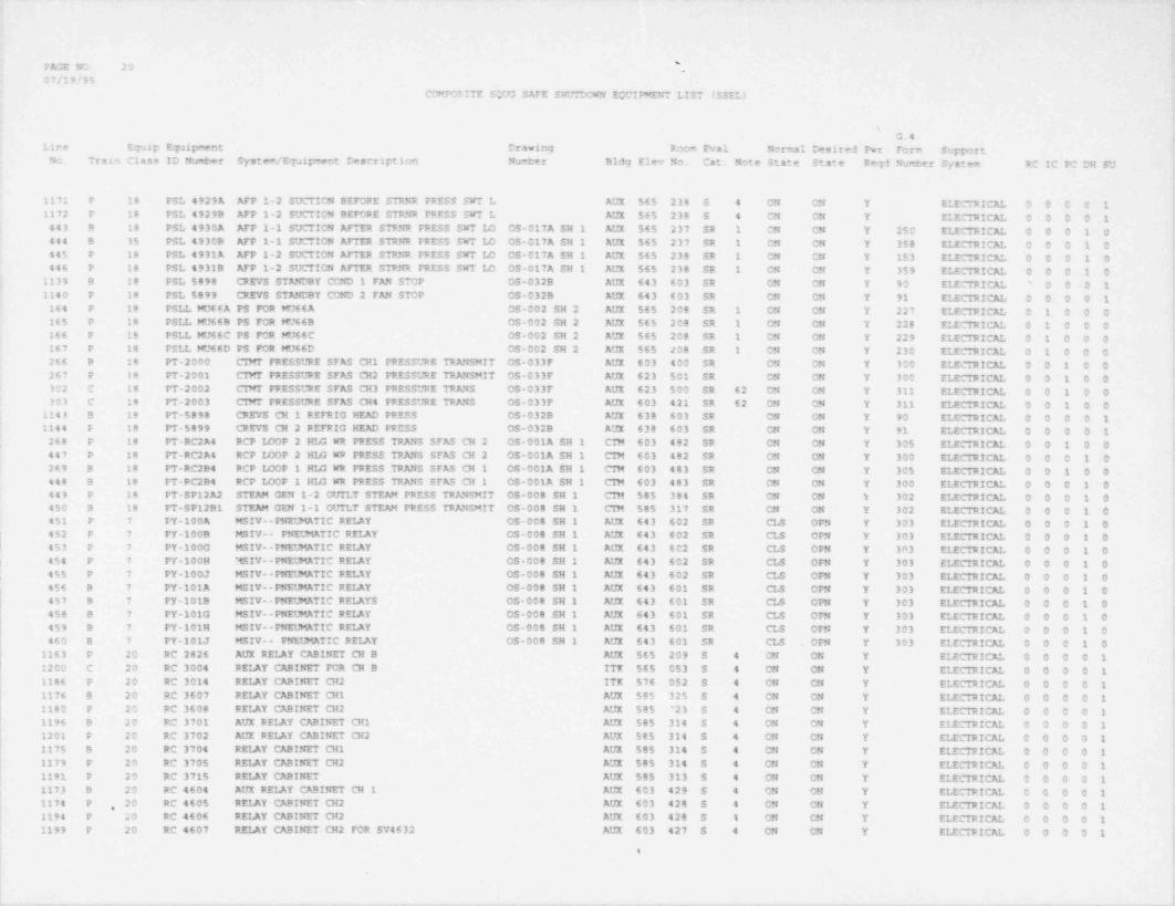
sFAGE NO. 20 "
07/19/95COMPCSITE SO93 SAFE SHUTDOWN EWIPMENT LIST ISSEL)
G.4Line Eqalp E7aipment Drawing Room Eval Normal Dasired Pwr Form SupportNo. Train Class ID Number System /E7aipment Description Number Bldg Elev No. Cat. Note State State Reqd Nu%er System RC IC PC CH SU
1171 P 18 PSL 4929A AFP 1-2 SUCTICN BEFORE STRNR PRESS SWT L AUX 565 238 S 4 ON CN Y ELECTRICAL 0 0 0 0 11172 P 18 PSL 4929B AFP 1-2 SUCTION BEFORE STPNR FPESS SWT L AUX 565 238 S 4 ON ON Y ELECTRICAL 0 0 0 0 1443 9 18 PSL 4930A AFP 1-1 SUCTION AFTER STPNR FRESS SWT 14 OS-017A SH 1 AUX 565 237 SR 1 CN CN Y 250 ELECTRICAL 0 0 0 1 0444 8 35 PSL 4930B AFP 1-1 SUCTION AFTER STP5R FRESS SWT LO OS-017A SH 1 AUX 565 237 SR 1 CM CN Y 358 ELECTRICAL 0 0 0 1 0 }445 P 18 PSL 4931A AFP 1-2 SUCTION AFTER STRNR PFESS SWT ID OS-017A SH 1 AUX 565 238 SR 1 CN ON Y 153 ELECTRICAL 0 0 0 1 0
'
446 P 18 PSL 4931B AFP 1-2 SUCTION AFTER STPER PRESS SWT ID OS-017A SH 1 AUX 565 238 SR 1 ON CN Y 359 ELEC11t! CAL 0 0 0 1 01139 8 18 PSL $698 CREVS STANOBY CCND 1 FAN STOP OS-032B AUX 643 603 SR ON ON Y 90 ELECTRICAL O O O 1'
1140 P 18 PSL 5899 CREVS STANCBY COND 2 FAN STOP CS-032B AUX 643 603 SR CN ON Y 91 ELECTRICAL 0 0 0 0 1164 P 18 PSLL MU66A PS FOR MU66A 0S-002 SH 2 AUX 565 208 SR 1 CN CN Y 227 ELECTRICAL 0 1 0 0 0165 P 18 PSLL MU66B PS FOR WJ66B OS-002 SH 2 AUX 565 208 SR 1 ON CN Y 228 ELECIRICAL 0 1 0 0 0166 P 18 PSLL KJ66C PS FCR MU66C OS-002 SH 2 AUX 565 208 SR 1 CN ON Y 229 ELECTRICAL 0 1 0 0 0167 P 18 PSLL MU66D PS FOR MU66D OS-002 SH 2 AUX 565 JOB SR 1 ON CN Y 230 ELECTRICAL 0 1 0 0 0266 B 18 PT-2000 CTMT FRESSURE SFAS CH1 PRESSURE TRMSMIT OS-033F AUX 603 400 SR ON ON Y 300 ELECTRICAL 0 0 1 0 0267 P 18 PT-2001 CIMr PRESSURE SFAS CH2 PRESSURE TRANSMIT OS-033F AUX 623 501 SR ON ON Y 300 ELECTRICAL 0 0 1 0 0302 C 18 PT-2002 CIMT PPESSURE SFAS CH3 PRESSURE TRANS OS-033F AUX 623 500 SR 62 CN CN Y 311 ELECTRICAL 0 0 1 0 0303 C 18 PT-2003 CINT PRESSURE SFAS CH4 PRESSURE TPANS OS-033F AUX 603 421 SR 62 ON CN Y 311 ELECTRICAL 0 0 1 0 0
1143 B le PT-5898 CREVS CH 1 REFRIG HEAD FRESS OS-032B AUX 638 603 SR ON ON Y 90 ELECTRICAL 0 0 0 0 11144 E 18 PT-5899 CREVS CH 2 REFRIG HEAD PRESS OS-032B AUX 638 603 SR ON ON Y 91 ELECTRICAL 0 0 0 0 1268 P 18 PT-RC2A4 RCP ISOP 2 HI4 WR PRESS TPANS SFAS CH 2 OS-001A SH 1 CTM 603 482 SR CN CN Y 305 ELECTRICAL 0 0 1 0 0447 P 18 PT-RC2A4 RCP LOOP 2 HI4 WR FRESS TRANS SFAS CH 2 OS-001A SH 1 CIM 603 482 SR ON ON Y 300 ELECTRICAL 0 0 0 1 0269 e 18 PT-RC2B4 RCP IDOP 1 HI4 WR PRESS TRANS SFAS CH 1 CS-001A SH 1 CIM 603 483 SR CN ON Y 305 ELECTRICAL 0 0 1 0 0448 9 18 PT-RC2B4 RCP LOOP 1 HI4 WR PRESS TRANS SFAS CH 1 OS-001A SH 1 CIN 603 483 SR ON ON Y 300 ELECTRICAL 0 0 0 1 0449 P 18 PT-SP12A2 STEAM GEN 1-2 CUTLT STEAM PRESS TRANSMIT OS-008 SH 1 CIN $85 384 SR ON ON i 302 ELECTRICAL 0 0 0 1 0450 B 18 PT-SP1291 STEAM GEN 1-1 OUTLT STEAM PRESS TRANSMIT OS-008 SH 1 CIM $85 317 SR CN ON Y 302 ELECTRICAL 0 0 0 1 0451 P 7 PY-100A MSIV--PNEUMATIC RELAY 0S-008 SH 1 AUX 643 602 SR CLS OPN Y 303 ELECTRICAL 0 0 0 1 0
j 452 P 7 PY-1009 MSIV-- PNEUMATIC RELAY OS-008 SH 1 AUX 643 602 SR CLS OFN Y 303 ELECTRICAL 0 0 0 1 0l 453 P 7 PY-100G MSIV--FNEUMATIC REIAY 05-008 SH 1 AUX 643 602 SR CLS OPN Y 303 ELECTRICAL 0 0 0 1 0| 454 P 7 PY-100H MSIV--PNEUMATIC REIAY OS-008 SH 1 AUX 643 602 SR CLS OFN Y 303 ELECTRICAL 0 0 0 1 0
455 P 7 PY-100J MSIV--PNEUMATIC REIAY 0S-000 SH 1 AUX 643 602 SR CLS OPN Y 303 ELECTRICAL 0 0 0 1 0456 B 7 PY-101A MSIV--PNEUMATIC REIAY OS-008 SH 1 AUX 643 601 SR CLS OPN Y 303 ELECTRICAL 0 0 0 1 0457 B 7 PY-1019 MSIV--PNEUMATIC RELAYS OS-008 SH 1 AUX 643 601 SR CLS OPN Y 303 ELECTRICAL 0 0 0 1 0450 B 7 FY-101G MSIV--PNECMATIC RELAY OS-008 SH 1 AUX 643 601 SR CLS OFN Y 303 ELECTRICAL 0 0 0 1 0459 B 7 PY-101H MSIV--PNEUMATIC RELAY OS-008 SH 1 AUX 643 601 SR CLS OFN Y 303 ELECTRICAL 0 0 0 1 0460 B 7 PY-101J MSIV-- PNEUMATIC RELAY OS-008 SH 1 AUX 643 601 SR CLS OFN Y 303 ELECTRICAL 0 0 0 1 0
1163 P 20 RC 2826 AUX RELAY CABINET CH B AUX 565 209 S 4 ON ON Y ELECTRICAL 0 0 0 0 11200 C 20 RC 3004 PEIAY CABINET FOR CH B ITX $65 053 S 4 ON ON Y ELECTRICAL 0 0 0 0 11186 P 20 RC 3014 REIAY CABINET CH2 ITK 576 052 S 4 ON ON Y ELECTRICAL 0 0 0 0 11176 B 20 RC 3607 REIAY CABINET CH1 AUX 585 325 S 4 CN CN Y ELECTRICAL 0 0 0 0 11180 P 20 RC 3608 REIAY CABINET CH2 AUX 585 '23 S 4 ON CN Y EI.ECTRICAL 0 0 0 0 11196 B 20 RC 3701 AUX RELAY CABINET CHI AUX 585 314 5 4 ON ON Y ELECTRICAL 0 0 0 0 11201 P 20 RC 3702 AUX REIAY CABINET CH2 AUX 585 314 S 4 ON CN Y ELECTRICAL 0 0 0 0 11175 B 20 RC 3704 RELAY CABINET CH1 AUX 585 314 S 4 CN CN Y ELECTRICAL 0 0 0 0 11179 P 20 RC 3705 REIAY CABINET CH2 AUX 585 314 S 4 ON ON Y ELECTRICAL 0 0 0 0 11191 P 20 RC 3715 REIAY CABINET AUX 585 313 S 4 CN ON Y EI.ECTRICAL 0 0 0 0 11173 9 20 RC 4604 AUX REIAY CABINET CH 1 AUX 603 429 S 4 ON ON Y ELECTRICAL 0 0 0 0 11174 P 20 RC 4605 REIAY CABINET CH2 AUX 603 428 5 4 CN CN Y ELECTRICAL 0 0 0 0 1,
1194 P 20 RC 4606 RELAY CABINET CH2 AUX 603 428 S 1 CN CN Y ELECTRICAL 0 0 0 0 1
{1199 P 20 RC 4607 RELAY CABINET CH2 FOR SV4632 AUX 603 427 S 4 CN CN Y ELECTRICAL 0 0 0 0 1
.
|
'
-_ _ ._
- _ . . _ _
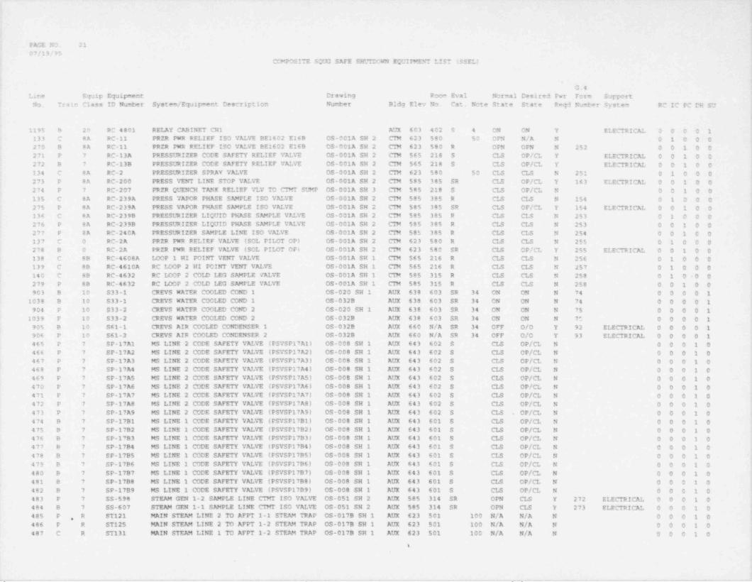
PAGE NO. 2107/19/95
' COMPOSITE SQUG SAFE SHL'rDOWN EQUI MENT LIST (SSEL)
|
G.4 *
Line Equip Equipment Drawing Room Eval Normal Desired Pwr Forin Support .
No. Train Class ID Number System / Equip **nt Description Nurter Bldg Elev No. Cat. Note State State Reqd Nu+1*r Syste9 RC IC PC DH SU |
.i
1195 B 20 RC 4801 RELAY CABINET CH1 AUX 603 402 5 4 ON ON Y ELECTRICAL 0 0 0 0 1133 C 8A PC-11 PRZR PWR RELIEF ISO VE VE BE1602 E169 CS-001A SH 2 CTM 623 580 50 OPN N/A N 0 1 0 0 0270 B 8A RC-11 PRZR DtR RELIEF ISO VALVE BE1602 E16B OS-001A SH 2 CTM 623 580 R OPN OPN N 252 0 0 1 0 0271 P 7 RC-13A PRESSURIZER CODE SAFETY RELIEF VALVE OS-001A SH 2 CIN 565 218 S CLS OP/CL Y ELECTRICAL 0 0 1 0 0272 B 7 PC-138 PRESSURIZER CODE SAFETY PELIEF VALVE OS-001A SH 2 CTM 565 218 S CLS OP/CL Y ELECTRICE O O 1 0 0134 C 8A RC-2 PRESSURIZER SPRAY VEVE OS-001A SH 2 CTM 623 580 50 CLS CLS N 251 0 1 0 0 0 [273 P 8A RC-200 PRESS VEIC LINE STOP VALVE OS-001A SH 2 CTM 585 385 SR CLS OP/CL Y 163 ELECTRICAL 0 0 1 0 0274 P 7 RC-207 PRZR QUENCH TANK RELIEF VLV TO CTMT SUMP OS-001A SH 3 C1M 585 218 S CLS OP/CL N 0 O 1 0 0135 C 8A RC-239A PRESS VAPOR PHASE SAMPLE ISO VALVE OS-001A SH 2 CTM 585 385 R CLS CLS N 154 0 1 0 0 0275 P 8A RC-239A PRESS VAPOR PHASE SAMPLE ISO VALVE OS-001A SH 2 CTM 585 385 SR CLS OP/CL Y 154 ELECTRICAL 0 0 1 0 0136 C 8A RC-2398 PRESSURIZER LIQUID PHASE SAMPLE VALVE OS-001A SH 2 CIM 585 385 R CLS CLS N 253 0 1 0 0 0276 P BA RC-239B PRESSURIZER LIQUID PHASE SAMPLE VALVE CS-001A SH 2 CIM 585 385 R CLS CLS N 253 0 0 1 0 0277 P 8A RC-240A PRESSURIZER SAMPLE LINE ISO VEVE OS-001A SH 2 CTM 58$ 385 R CLS CLS N 254 0 0 1 0 0137 C 0 RC-2A PRZR PWR RELIEF VALVE (SOL PILOT OP) OS-001A SH 2 CTM 623 580 R CLS CLS N 255 0 1 0 0 0278 B 0 RC-2A PRZR PWR RELIEF VEVE (SOL PII4T OP) OS-001A SH 2 C7N 623 580 SR CLS OP/CL Y 255 ELECTRICAL 0 0 1 0 0138 C 8B RC-4608A LOOP 1 HI POINT VENT VALVE OS-001A SH 1 CIM 565 216 R CLS CLS N 256 0 1 0 0 0139 C 88 RC-4610A RC LOOP 2 HI POINT VENT VALVE OS-001A SH 1 CTM 565 216 R CLS CLS N 257 0 1 0 0 0140 C 8B RC-4632 RC LOOP 2 COLD LEG SAMPLE VALVE OS-001A SH 1 CIM 585 315 R CLS CLS N 258 0 1 0-0 01
'
279 P 8B RC-4632 RC LOOP 2 C01D LEG SAMPLE VALVE OS-001A SH 1 CIM 585 315 R CLS CLS N 258 0 0 1 0 0903 B 10 S33-1 CREYS NATER COOLED COND 1 OS-020 SH 1 AUX 638 603 SR 34 ON ON N 74 0 0 0 0 1
1038 B 10 S33-1 CREVS NATER COOLED COND 1 OS-032B AUX 638 603 SR 34 ON ON N 74 0 0 0 0 1'
904 P 10 S33-2 CREVS NATER COOLED COND 2 OS-020 SH 1 AUX 638 603 SR 34 ON ON N 75 0 0 0 0 11039 P 10 S33-2 CREVS NATER COOLED COND 2 OS-032B AUX 638 603 SR 34 ON ON N 75 0 0 0 0 1
905 B 10 S61-1 CRIVS AIR COOLED CONDENSER 1 OS-032B AUX 660 N/A SR 34 OFF O/0 Y 92 ELECTRICAL 0 0 0 0 1906 P 10 S61-2 CREVS AIR COOLED CONDENSER 2 OS-032B AUX 660 N/A SR 34 OFF O/O Y 93 ELECTRICAL 0 0 0 0 1465 P 7 SP-17Al MS LINE 2 CODE SAFETY VALVE (PSVSP17A1) OS-008 SH 1 AUX 643 602 S CLS OP/CL N 0 0 0 1 0466 P 7 SP-17A2 MS LINE 2 CODE SAFETY VALVE (PSVSP17A2) OS-008 SH 1 AUX 643 602 S CLS OP/CL N 0 0 0 1 0467 P 7 SP-17A3 MS LINE 2 CODE SAFETY VALVE (PSVSP17A3) OS-008 SH 1 AUX 643 602 S CLS OP/CL N 0 0 0 1 0468 P 7 SP-17A4 MS LINE 2 CODE SAFETY VEVE (PSYSP17A4) OS-008 SH 1 AUX 643 602 S CLS OP/CL N O O O 1 0469 P 7 SP-17AS MS LINE 2 CODE SAFETY VALVE (PSVSP17A5) 0S-008 SH 1 AUX 643 602 S CLS OP/CL N O O O 1 0470 P 7 SP-17A6 MS LINE 2 CODE SAFETY VALVE (PSVSP17A6) OS-008 SH 1 AUX 643 602 S CLS OP/CL N 0 0 0 1 0471 P 7 SP-17A7 MS LINE 2 CODE SAFETY VALVE (PSYSP17A7) OS-000 SH 1 AUX 643 602 S CLS OP/CL N 0 0 0 1 0472 P 7 SP-17A8 MS LINE 2 CODE SAFETY VALVE (PSVSP17A81 OS-008 SH 1 AUX 643 602 S CLS OP/CL N 0 0 0 1 0473 P 7 SP-17A9 MS LINE 2 CODE SAFETY VALVE (PSYSP17A9) 09-008 SH 1 AUX 643 602 S CLS OP/CL N 0 0 0 1 0474 B 7 SP-1791 MS LINE 1 CODE SAFETY VEVE (PSVSP17B1) OS-008 SH 1 AUX 643 601 S CLS OP/CL N 0 0 0 1 0475 B 7 SP-17B2 MS LINE 1 CODE SAFETY VEVE (PSVSP17B2) OS-008 SH 1 AUX 643 601 S CLS OP/CL N O O O 1 0476 B 7 $P-1?B3 MS LINE 1 CODE SAFETY VALVE (PSVSP17B3) 0S-008 SH 1 AUX 643 601 S CLS OP/CL N 0 0 0 1 0 ,
f477 B 7 SP-17B4 MS LINE 1 CODE SAFETY VALVE (PSYSP17B4) 0S.008 SH 1 AUX 643 601 S CLS OP/CL N O O O 1 0478 B 7 SP-1795 MS LINE 1 CODE SAFETY VALVE (PSVSP17BS) OS-008 SH 1 AUX 643 601 S CLS OP/CL N 0 0 0 1 0 '[479 B 7 SP-17B6 MS LINE 1 CODE SAFETY VEVE (PSYSP17B6) 0S-006 SH 1 AUX 643 601 S CLS OP/CL N 0 0 0 1 0 [480 B 7 SP-17B7 MS LINE 1 CODE SAFETY VALVE (PSVSP17B7) OS-008 SH 1 AUX 643 601 S CLS OP/CL N O O O 1 0 !
481 B 7 SP-17B8 MS LINE 1 CODE SAFETY VALVE (PSYSP17B8) OS-008 SH 1 AUX 643 601 S CLS OP/CL N O O O 1 0 [482 B 7 SP-17B9 MS LINE 1 CODE SAFETY VEVE (PSYSP17B9) 0S-008 SH 1 AUX 643 601 S CLS OP/CL N 0 0 0 1 0483 P 7 SS-598 STEAM GEN 1-2 SAMPLE LINE CTMT ISO VALVE OS-051 SH 2 AUX 585 314 SR OPN CLS Y 272 ELECTRICAL 0 0 0 1 0 t
484 B 7 SS-607 STEAM GEN 1-1 SAMPLE LINE CTMT ISO VALVE OS-051 SH 2 AUX 585 314 SR OPN CLS Y 273 ELECTRICAL 0 0 0 1 0 $'485 P R ST121 MAIN STEAM LINE 2 TO AFPT 1-1 STEAM TRAP OS-017B SH 1 AUX 623 501 100 N/A N/A N 0 0 0 1 0,
466 P R ST125 MAIN STEAM LINE 2 TO AFFT 1-2 STEAM TRAP OS-017B SH 1 AUX 623 501 100 N/A N/A N 0 0 0 1 0487 C R ST131 MAIN STEAM LINE 1 TO AFPT 1-2 STEAM TRAP OS-017B SH 1 AUX 623 501 100 N/A N/A N O O O 1 0
'e
s
S
I
_.. . . _ _ _ , - - - . - _ . - . . ~ . ,m - _ . . _- _ _ _- _ - _ _ . .

FA'IE NO. 2207/19/95
COMPOSITE SCUG SAFE SHUTDCWN EOUIP"ENT LIST (SSEL) |
.I
G.4Line Equip Equipment Drawing Room Eval Normal Desired Fwr Form Support *
No. Train Class ID Number System / Equipment Description Number B1dg Elev No. Cat. Note State State Fegd Number System RC IC PC DH SU$
i488 B R ST132 MAIN STEAP" LINE 1 TO AFPT 1-2 STEAM TRAP OS-017B SH 1 AUX 623 500 100 N/A N/A N O 0 0 1 0
'
489 C R ST133 MAIN STEAM LINE 2 'IO AFPT 1-1 STEAM TRAP OS-017B SH 1 AUX 565 237 100 N/A N/A N 0 0 0 1 0490 C R ST134 AFPT INLET HDR INLET XCONNECT S m TRAP OS-017B SH 1 AUX 565 238 100 N/A N/A N 0 0 0 1 0491 C R ST137 MAIN STEAM INLT HDR TO AFFT 1-2 S m TRAP OS-017B SH 1 AUX 585 314 100 N/A N/A N 0 0 0 1 0492 C R ST138 MAIN STEAM INLT HDR TO AFPT 1-1 STM TRAP OS-017B SH 1 AUX 585 314 100 N/A N/A N O O C 1 0
'
493 C R ST139 MAIN STEAM LINE TO AFPT 1-1 STEAM TRAP OS-017B SH 1 AUX 623 501 100 N/A N/A N O O O 1 0494 B R ST148 STEAM TRAP OS-0179 SH 1 AUX 565 237 100 N/A N/A N O O O 1 0
,
495 B R ST149 STEAM TRAP OS-017B SH 1 AUX 545 125 100 N/A N/A N O O O 1 0496 P R ST150 AFPT 1-2 CASING DRAIN STEAM TRAP OS-017B SH 1 AUX 565 238 100 N/A N/A N O O O 1 0
'497 P R ST151 STEAM TRAP OS-017B SH 1 AUX 545 125 100 N/A N/A N 0 0 0 1 0498 B R ST39 MAIN STEAM LINE TO AFPT 1-1 STEAM TRAP OS-017B SH 1 AUX 630 500 100 N/A N/A N 0 0 0 1 0
"499 C R ST90 MAIN STEAM LINE 2 TO AFFT 1-1 STEAM TRAP OS-017B SH 1 AUX 623 500 100 N/A N/A N O O O 1 0500 P BB SV-100A MS LINE 2 ISO VALVE OS-008 SH 1 AUX 643 602 SR ON OFF Y 303 ELECTRICE O O O 1 0501 P 8B SV-1008 MS LINE 2 ISO VALVE OS-008 SH 1 AUX 643 602 SR ON OFF Y 303 ELECTRICE O O 0 1 0
, 502 P BB SV-100F MS LINE 2 ISO VALVE 05-008 SH 1 AUX 643 602 SR ON CFF Y 303 ELECTRICE O O O 1 0 |
l 503 B 8B SV-101A MS LINE 1 ISO VALVE SOL VEVE OS-000 SH 1 AUX 643 601 SR ON OFF Y 303 ELEC71t!CE O O O 1 0504 B BB SV-101B MS LINE 1 ISO VALVE SOL VALVE OS-008 SH 1 AUX 643 601 SR ON OFF Y 303 ELECTRICAL 0 0 0 1 0505 B 8B SV-101F MS LINE 1 ISO VALVE SOL VALVE OS-008 SH 1 AUX 643 601 SR ON OFF Y 303 ELECTRICE O 0 0 1 0
1023 B 8B SV-1356A CAC 1-1 SW OUTLET ISO VALVE OS-020 SH 1 AUX 585 314 SR 65 ON OFF Y 265 ELECTRICE O O O O 13024 B 8B SV-1356B CAC 1-1 SW OUTLET ISO VEVE 05-020 SH 1 AUX 585 314 SR 65 ON OFF Y 265 ELECTRICE O 0 0 0 11025 P BB SV-1357A CAC 2 SW OUTLET ISO SOLENOID VALVE OS-020 SH 1 AUX 585 314 SR 65 ON OFF T 266 ELECTRICAL 0 C 0 0 1
|1026 P 8B SV-1357B CAC 2 SW OUTLET ISO VALVE OS-020 SH 1 AUX 585 314 SR 65 ON OFF Y 266 ELECTRICE O O O O 1 |907 8 88 SV-1424 SOL VLV FR CC HX 1 SW OUT ISO VLV 05-020 SH 1 AUX 585 328 SR 30 ON OFF Y 268 ELECTRICE O O O O 1
908 P 8B SV-1434 SOL VLv FR CC HK 2 SW CITT ISO VLV OS-020 SH 1 AUX 585 328 SR 30 ON OFF Y 269 ELECTRICE D 0 0 0 1 i| 1035 B 8B SV-1467 SOL VLV FOR HV-1467 0S-021 SH 1 AUX 545 113 SR 33 ON O/O Y 175 ELECTRICAL 0 0 0 0 1i 909 P 8B SV-1469 SOL VALVE FOR HV1469 OS-021 SH 1 AUX 545 113 SR 33 ON O/0 Y 176 ELECTRICAL 0 0 0 0 1| 1036 B 8B SV-1471 SOL VLV FOR HV-1471 OS-021 SH 1 AUX 585 318 SR 33 ON C/O Y 177 ELECTRICAL 0 0 0 0 1 ['
1037 P 8B SV-1474 SOL VLV FOR HV-1474 CS-021 SH 1 AUX 585 319 SR 33 ON O/O Y 178 ELECTRICE O O O O 1| 910 B 8B SV-5301 AUX BLDG CTRM DMPR AIR SOL VLV OS-032A AUX 638 603 SR ON OFF Y 270 ELECTRICAL 0 0 0 0 1
911 B 8B SV-5301A CTRM COMP CONF RMECOMP..SOLVLV OS-032A AUX 638 603 SR ON OFF Y 270 ELECTRICE O O O O 1912 P 8B SV-5311 CTRM ISO DAMPERS SOL VALVE OS-032A AUX 638 603 SR ON OFF Y 271 ELECTRICE O O O O 1913 P BB SV-5311A AUX BLDG CTRM DMPR AIR SCL VLV OS-032A AUX 638 603 SR ON OFF Y 271 ELECTRICAL 0 0 0 0 1 h506 B BB SV-5809A AFP TURS 1-1 Sm ADM BLD OFF SOL VEVE OS-017B SH 1 AUX 565 237 SR ON OFF Y 225 ELECTRICAL 0 0 0 1 0 !507 P 8B SV-5889B AFP WRB 1-2 STM ADM BLD OFF SOL VALVE OS-017B SH 1 AUX 565 238 SR ON . OFF Y 226 ELECTRICE O O O 1 0 .
508 P 8B SV-598 SCLENOID VEVE FOR VALVE SS598 OS-051 SH 2 AUX 585 314 SR ON OFF Y 272 ELECTRICAL 0 0 0 1 0509 B 8B SV-607 STEAM GEN 1-1 SAMPLE LINE CTMT ISO VALVE OS-051 SH 2 AUX 585 314 SR ON OFF Y 273 ELECTRICE O O O 1 0546 P 8B SV-ICS11A2 SV FOR ICS-11A OS-008 SH 1 AUX 643 602 SR ON OFF Y 202 ELECTRICE 0 0 0 1 0 h547 B 88 SV-ICS1192 SV FOR ICS-11B OS-008 SH 1 AUX 643 601 SR CN OFF Y 203 ELECTRICAL 0 0 0 1 0
'
150 P BB SV-MU38 SOL VLV FOR MU-38 OS-002 SH 2 AUX 565 208 SR ON ON Y 231 ELECTRICE O 1 0 0 0 ,
I152 P 88 SV-MU66A SOL VLV FOR MU-66A OS-002 SH 2 AUX 565 208 SR ON ON Y 227 ELECTRICAL 0 1 0 0 0153 P 8B SV-MU66B SOL VLV FOR MU-66B 0S-002 SH 2 AUX 565 206 SR ON ON Y 228 ELECTRICAL 0 1 0 0 0154 P 8B SV-MU66C SOL VLV FOR MU-66C 0S-002 SH 2 AUX 565 208 SR ON ON Y 229 ELECTRICE O 1 0 0 0155 P 8B SV-MU66D SOL VLV FOR HU-66D 05-002 SH 2 AUX 565 208 SR ON ON Y 230 ELECTRICAL 0 1 0 0 0 i
914 C R SW-105 ECCS RM COOLER 1-2 BYFASS VLV OS-020 SH 1 AUX 545 115 28 OPN OP/CL Y MANUAL 0 0 0 0 1 I915 C R SW-113 ECCS ROOM CLR 1-4 BYPASS VALVE OS-020 SH 1 AUX 545 105 27 OPN OP/CL Y MANUAL 0 0 'O O 1 i
[916 C ,'R SW-121 ECCS RM CLR 1-5 BYPASS VEVE OS-020 SH 1 AUX 545 105 27 OPN OP/CL Y MANUE 0 0 0 0 1917 9 7 SW-1356 CAC 1-1 OtTTLET TEMP CTRL VALVE OS-020 SH 1 AUX 585 314 R THR OPN Y 265 ELECTRICAL 0 0 0 0 1 ;
918 P 7 SW-1357 CAC 1-2 O!TILET TEMP CTRL VALVE OS-020 SH 1 AUX 585 314 R THR OPN Y 266 ELECTRICE O O O O 1 y
e i
i!
| I'
l, _ , _ __ _ _ . . _ ._ . -. , , .. ._ __._ ._ . _ , .
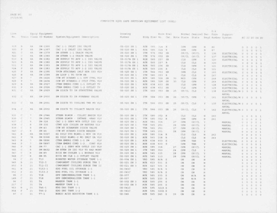
_ _ _ _ _ _ _ _ _ _ _ - _ _ - _ - - _ _ - _ _ -
FAGE NO. 2307/19/95
COMPOSITE SCtR3 SAFE SHITTDCWN EQUIPMENT LIST (SSEL)>
G.4Line EqJip Equipment Drawing Room Eval Normal Desired Pwr Form Support
Nm Train Class ID Numt:er System / Equipment Description Number B1dg Elev No. Cat. Note State State Reqd Number System RC IC FC DH SU
919 B BA SW-1366 CAC 1-1 INLET ISO VALVE OS-020 SH 1 AUX 585 314 R OFM OFN N 86 0 0 0 0 1920 P 8A SW-1367 CAC 1-2 INLET ISO VALVE OS-020 SH 1 AUX 585 314 R OFN CPN N 87 0 0 0 0 1921 C BA SW-1379 SW STRNR 1-1 DRAIN VALVE OS-020 SH 1 ITK 576 052 SR OP/CL OP/CL Y 136 ELECTRICAI. 0 0 0 0 1922 C 8A SW-1380 SW STRNR 1-2 DRAIN VALVE OS-020 SH 1 ITK 576 052 SR OP/CL OP/CL Y 137 ELECTRICAL 0 0 0 0 1510 B 8A SW-1382 SW SUPFLY TO AFP 1-1 ISO VALVE OS-017A SH 1 AUX 565 237 SR CLS OPN Y 120 ELECTRICE O O O 1 0923 B 8A SW-1382 SW SUPPLY TO AFP 1-1 ISO VALVE OS-017A SH 1 AUX 565 237 R CLS CLS N 120 0 0 0 0 1511 P 8A SW-1383 SW SUPPLY TO AFP 1-2 ISO VALVE OS-017A SH 1 AUX 565 236 SR CLS OPN Y 121 ELECTRICAL 0 0 0 1 0924 P 8A SW-1383 SW SUPPLY TO AFP 1-2 ISO VALVE OS-017A SH 1 AUX 565 236 R CLS CLS N 121 0 0 0 0 1925 P 8A SW-1395 TPCW HTXCHANG INLT HDR ISO VLV OS-020 SH 1 ITK $66 053 SR OFN CLS Y 160 ELECTRICAL 0 0 0-0 1926 B BA SW-1399 SW I40P 1 TO TPCW HX OS-020 SH 1 ITK 585 053 R CLS CLS N 267 0 0 0 0 1927 B 7 SW-1424 CCW HT XCHMG 1-1 OUT CTRL VLV OS-020 SH 1 AUX $85 328 SR 30 MOD OFN Y 268 ELECTRICE O O O 0 1928 P 7 SW-1434 CCW Irf XCHANGI-2 OTLT CTRL VLV OS-020 SH 1 AUX 585 328 SR 30 CLS OFN Y 269 ELECTRICAL 0 0 0 0 1929 B 8A SW-2927 CTRM EMERG COND 1-1 OCTILET TV OS-020 SH 1 AUX 638 603 SR CLS OPN Y 128 ELECTRICE O O O O 1930 P 8A SW-2928 CTRM EMERG COND 1-2 OUTLET TV OS-020 SH 1 AUX 638 603 SR CLS OFN Y 129 ELECTRICAL 0 0 0 0 1931 C BA SW-2929 SW DISCH TO IN STRUC"IllRE VALVE OS-020 SH 1 ITK 566 053 SR 25 OP/CL CLS Y 138 ELECTRICAL /M 0 0 0 0 1
ANUAL932 C BA SW-2930 SW DISCH TO IN FOREBAY VALVE OS-020 SH 1 ITK 566 053 SR 26 OP/CL OPN Y 161 ELECTRICAL /M O O O O 1 f
ANUAL933 C 8A SW-2931 SW DISCH TO COOLING 7HR MU VLV OS-020 SH 1 ITK 566 053 SR 25 OP/CL CLS Y 139 ELECTRICAL /M 0 0 0 0 1 |
ANUE |934 C BA SW-2932 SW DISCH TO COLLECT BASIN VLV OS-020 SH 1 ITK 566 053 SR 26 OP/CL CLS Y 162 ELECTRICAL /M 0 0 0 0 1 |
ANuE935 C 7 SW-2944 STRNR BLWDN - COLLEC BASIN VLV OS-020 SH 1 ITK 585 052 R CLS CLS N 260 0 0 0 0 1 i936 C 7 SW-2945 STRNR BLWDN - INTAKE. 4 BAY VLV OS-020 SH 1 ITK 585 052 R OPN OPN N 261 0 0 0 0 1937 C R SW-326 CAC 1-3 SERV WTR OtTTLT ISO VLV OS-020 SH 1 AUX 585 314 27 OFN OP/CL Y MANUE O O O 0 1938 C R SW-335 CTMI AIR COOLER SW RET *JRN VLV OS-020 SH 1 TUR 565 251 28 CPN OP/CL Y MANUAL 0 0 0 0 1 I939 C R SW-43 CCW HT XCHANGER DISCH VALVE OS-020 SH 1 TUR 565 251 27 OFN OP/CL Y MANUAL 0 0 0 0 1940 C R SM-44 CCW HT XCHANG DISCH HEADER OS-020 SH 1 TUR 565 251 28 OPN OP/CL Y MANUAL 0 0 0 0 1 L
i 941 B BA SM-5067 H2 DILU SYS BLWR1-1 MOV IN VLV OS-020 SH 1 AUX 585 314 R CLS CLS N 262 0 0 0 0 1 t
942 P ?A SM-5068 H2 DILU BLWR1-2 MO INLT GA VLv OS-020 SH 1 AUX 565 208 R CLS CLS N 263 0 0 0 0 1943 9 7 SW-5896 CTRM EMERG COND 1-1 SW .VLV OS-020 SH 1 AUX 638 603 S CFN THR Y ELECTRICAL 0 0 0 0 1944 P 7 SW-5897 CTRM EMERG COND 1-2. . CONT VLV OS-020 SH 1 AUX 638 603 S OFN THR Y ELECTRICAL 0 0 0 0 1946 P R SW-77 CAC 1-1 SERV WTR OCTTLT ISO VLV OS-020 SH 1 AUX 585 314 27 OPN OP/CL Y MANUAL 0 0 0 0 1 ;945 C R SW-8432 SW RTRN IN ISO VLV TO RAD MONT OS-020 SH 1 ITK 585 053 24 OFN . CLS Y MANUAL 0 0 0 0 1
'
947 C R SW-89 ECCS RM COOLER 1-1 BYPASS VLV OS-020 SH 1 AUX 545 115 28 OPN OP/CL Y MANUAL 0 0 0 0 1) 948 C R SW-95 ECCS RM CLR 1-3 OUTLET VALVE 05-020 SH 1 AUX 545 113 28 OPN OP/CL Y MANUE 0 0 0 0 1 (, 94 C 21 T10 BORATED WATER STORAGE TANK 1-1 05-004 SH 1 YRD 585 N/A S ON ON N 1 0 0 0 0
949 B 21 T12-I COMPONENT COOLING SURGE TNK I 05-021 SH 3 AUX 623 501 S ON ON N 0 0 0 0 1*950 P 21 T12-II COMPONENT COOLING SURGE TNK II OS-021 SH 3 AUX 623 501 S ON ON N 0 O O O 1
951 B 21 T153-1 EDG FUEL OIL STORAGE 1-1 OS-041C YRD 585 N/A S ON ON N O O O O 1952 P 21 T153-2 EDG FUEL OIL STORAGE 1-2 OS-041C YRD 585 N/A S ON ON N 0 0 0 0 1 I
| 95 C 21 T18 SFP DEMINERALIZER TANK 1-1 OS-OO7 AUX 565 233 S ON N/A N 1 0 0 0 0
f149 C 21 T18 SFP DEMINEREIZER TANK 1-1 OS-007 AUX 565 233 S ON N/A N O 1 0 0 0
96 C 21 T4 MAKEUP TANK 1-1 OS-002 SH 3 AUX 565 205 S CN ON N 1 0 0 0 0'
217 C 21 T4 MAKEUP TANK 1-1 0S-002 SH 3 AUX 565 205 S ON ON N O 1 0 0 0 '
953 B 21 T46-1 EDO DAY TANK 1-1 OS-041C AUX 595 321A S ON ON N O O O O 1*954 P 21 T46-2 EDG DAY TANK 1-2 OS-041C AUX 595 320A S ON ON N 0 0 0 0 1 ,
97 C 21 T7-1 BORIC ACID ADDITION TANK 1-1 CS-046 AUX 565 240 S 39 ON ON N 1 0 0 0 0 i
I
e
!
- - - - - - . -. _ . . - . _ _ . .- _ _
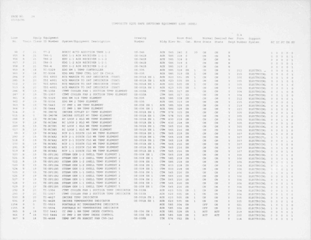
- _ _ _ _ _ - _ _ - _ _ _ - _ - _ _ - . _ _ -- -- -.
PAGE NO. 2407/19/95
COMPCSITE SOUG SAFE SHWCCNN EQUIPMEh7 LIST (SSEL)
'
G.4Line Equip Equipment Drawing Room Eval Normal Desired Pwr Form Support
No. Train Class ID Number System / Equipment Descriptien Number Bldg Elev No. Cat. Note State State Reqd Nu +er System RC IC FC DH SU
98 C 21 T7-2 BORIC ACTD ADDITION TANK 1-2 OS-046 AUX 565 240 S 33 ON ON N 1 0 0 0 0955 B 21 786-1 EDG 1-1 AIR RECEIVER 1-1-1 OS-041B AUX 585 318 S ON ON N O O 0 0 1956 B 21 T86-2 EDG 1-1 AIR RECEIVER 1-1-2 OS-041B AUX 585 318 S ON C'N N 0 O O O 1957 P 21 786-3 EDG 1-2 AIR RECEIVER 1-2-1 OS-041B AUX 585 319' S CN ON N 0 0 0 0 1958 P 21 T86-4 EDG 1-2 AIR RECEIVER 1-2-2 OS-041B AUX 585 319 S ON ON N O O O O 1959 8 18 TC-5329 EDG RM 1 TEMP CONTROLLER 05-035 AUX 585 318 SR 1 CN ON Y 212 ELECTRIL b 0 0 0 0 1960 P 18 TC-5336 EDG PN2 TEMP CTRL LOC IN C3616 OS-035 AUX 585 319 SR 1 ON ON Y 215 ELECTRICAL 0 0 0 0 1284 P 20 TDI 4950 RCS MARGIN TO SAT INDICATCR (TSAT) CS-001A SH 1 AUX 623 505 SR 1 CN ON Y 305 ELECTRICAL 0 0 1 0 0285 B 20 TDI 4951 RCS MARGIN TO SAT INDICATOR (TSAT) OS-001A SH 1 AUX 623 505 SR 1 ON ON Y 305 ELECTRICAL 0 0 1 0 0512 P 20 TDI-4950 RCS MARGIN TO SAT INDICATOR (TSAT) OS-001A SH I AUX 623 505 SR 1 ON ON Y 305 ELECTRICAL 0 0 0 1 0513 B 20 TDI-4951 RCS MARGIN TO SAT INDICATOR (TSAT) OS-001A SH 1 AUX 623 505 SR 1 ON ON Y 305 ELECTRICAL 0 0 0 1 0286 B 19 TE-1356 CIMT COOLER FAN 1 SUCTION TFMP ELEMENT OS-033A CTM 585 317 SR ON ON Y 304 ELECTRICAL 0 0 1 0 0287 P 19 TE-1357 CIMT COOLER FAN 2 SUCTION TEMP ELEMENT OS-033A CIM 585 317 SR ON ON Y 304 ELECTRICAL 0 0 1 0 0
|961 B 19 TE-5329 EDG RM 318 TEMP ELEMENT OS-035 AUX 585 318 SR ON ON Y 212 ELECTRICAL 0 0 0 0 1 [962 P 19 TE-5336 EDG RM 2 TEMP ELEMENT OS-035 AUX 585 319 SR ON CN Y 215 ELECTRICAL 0 0 0 0 1,
963 8 19 TE-5443 CC PMP 1 RM TEMP ELEMENT OS-036 SH 1 AUX 585 328 SR ON OM Y 219 ELECTRICAL 0 0 0 0 1 {964 P 19 TE-5444 CC PMP 1 RM TEMP ELEMENT OS-036 SH 1 AUX 585 328 SR ON ON Y 220 ELECTRICAL 0 0 0 0 1514 P O TE-IM07E INCORE OCTTLET E7 TEMP ELEMENT OS-001A SH 1 CIM 578 315 SR ON ON Y 305 ELECTRICAL 0 0 0 1 0 !515 B 0 TE-IM07M INCORE OtJTLET M7 TEMP ELEMENT OS-001A SH 1 CIM 578 315 SR ON ON Y 305 ELECTRICAL 0 0 0 1 0288 P 19 TE-RC3A6 RC LOOP 2 HLG WR TEMP ELEMENT OS-001A SH 1 CTM 630 218 SR ON ON Y 305 ELECTRICAL 0 0 1 0 0 t
516 P 19 TE-RC3A6 RC LOOP 2 HLG WR TEMP ELEMENT OS-001A SH 1 CTM 630 218 SR ON ON Y 305 ELECTRICAL 0 0 0 1 0 1
289 B 19 TE-RC395 RC LOOP 1 HIG WR TEMP ELEMENT OS-001A SH 1 CTM 565 216 SR ON ON Y 305 ELECTRICAL 0 0 1 0 0517 B 19 TE-RC3B5 RC LOOP 1 HI/3 WR TEMP ELEMENT 0S-001A SH 1 CIN 565 216 SR ON ON Y 305 ELECTRICAL 0 0 0 1 0
99 P 19 TE-RC4A2 RCP 2-1 DISCH CLG WR TEMP ELEMENT OS-001A SH 1 CIN 565 218 SR ON ON Y 307 ELECTRICAL 1 0 0 0 0290 P 19 TE-RC4A2 RCP 2-1 DISCH CI/3 WR TEMP ELEMENT OS-001A SH 1 CIM 565 218 SR ON ON Y 307 ELECTRIC *.L 0 9 1 0 0518 P 19 TE-RC4 A2 RCP 2-1 DISCH CIA WR TEMP ELEMENT OS-001A SH 1 CTM 565 218 SR ON ON Y 307 ELECTRICAL 0 0 0 1 0100 B 19 TE-RC4B2 RCP 1-1 DISCH CLG WR TEMP ELEMENT OS-001A SH 1 CIN 565 216 SR ON ON Y 307 ELECTRICAL 1 0 0 0 0291 B 19 TE-RC4B2 RCP 1-1 DISCH CLG WR TEMP ELEMENT OS-001A SH 1 CIM 565 216 SR ON ON Y 307 ELECTRICAL 0 0 1 0 0519 B 19 TE-RC4B2 RCP 1-1 DISCH CIA WR TEMP ELEMENT OS-001A SH 1 CTM 565 216 SR ON ON Y 307 ELECTRICAL 0 0 0 1 0 ,
520 B 19 TE-SP11A1 STEAM GEN 1-2 SHELL TEMP ELEMENT 1 OS-008 SH 1 CIM 565 218 SR ON ON Y 306 ELECTRICAL 0 0 0 1 0 '
521 B 19 TE-SP11A2 STEAM GEN 1-2 SHELL TEMP ELEMENT 2 OS-008 SH 1 CIN 585 218 SR ON ON Y 306 ELECTRICAL 0 0 0 1 0522 B 19 TE-SP11A3 STEAM GEN 1-2 SHELL TEMP ELEMENT 3 CS-008 SH 1 CIM 585 218 SR ON ON Y 306 ELECTRICAL 0 0 0 1 0523 B 19 TE-SP11A4 STEAM GEN 1 2 SHELL TEMP ELEMENT 4 OS-008 SH 1 CIM 603 218 SR ON ON Y 306 ELECTRICAL 0 0 0 1 0524 B 19 TE-SP11A5 STEAM GEN 1-2 SHELL TEMP ELEMENT 5 OS-006 SH 1 CIM 603 218 SR ON . ON Y 306 ELECTRICAL 0 0 0 1 0525 P 19 TE-SP11B1 STEAM GEN 1-1 SHELL TEMP ELEMENT 1 05-008 SH 1 CIM 565 216 SR ON ON Y 306 ELECTRICAL 0 0 0 1 0526 P 19 TE-SP11B2 STEAM GEN 1-1 SHELL TEMP ELEMENT 2 OS-008 SH 1 CIM 565 216 SR ON ON Y 306 ELECTRICAL 0 0 0 1 0527 P 19 TE-SP11B3 STEAM GEN 1-1 SHELL TEMP ELEMErrr 3 CS-008 SH 1 CTM 565 216 SR O'N ON Y 306 ELECTRICAL 0 0 0 1 0528 P 19 TE-SP1194 STEAM GEN 1-1 SHELL TEMP ELEMENT 4 OS-008 SH 1 CIN 565 216 SR CN ON Y 306 ELECTRICAL 0 0 0 1 0529 P 19 TE-SP1185 STEAM GEN 1-1 SHELL TEMP FLEMENT 5 OS-000 SH 1 CIN 565 216 SR ON ON Y 306 ELECTRICAL 0 0 0 1 0292 B 20 TI-1356 CTNT COOLER FAN 1 SUCTION TEMP INDICATOR OS-033A AUX 623 505 SR 1 ON ON Y 304 ELECTRICAL 0 0 1 0 0293 P 20 TI-1357 CTNT COOLER FAN 2 SUCTION TEMP INDICATOR OS-033A AUX 623 505 SR 1 ON ON Y 304 ELECTRICAL 0 0 1 0 0 !530 B 20 TI-4627 INCORE TEMP INDICATOR OS-001A EH 1 AUX 623 505 SR 1 ON ON Y 305 ELECTRICAL 0 0 0 1 0
'
531 P 20 TI-4628 INCORE TEMPERATURE INDICATOR OS-001A SH 1 AUX 623 505 SR 1 ON ON Y 305 ELECTRICAL 0 0 0 1 01154 P O TI-5503 PORTABLE RC TEMPERATURE INDICATOR AUX 585 304 SR OFF ON Y 321 ELECTRICAL 1 0 1 1 01155 B 0 TI-5504 PORTABLE RC TEMFERATURE INDICATOR AUX 585 304 SR OFF ON Y 321 ELECTRICAL 1 0 1 1 0
965 B 18 TIC 5443 CC PMP 1 RM TEMP INDEX CONTROL 0S-036 SH 1 AUX 585 328 SR 1 ALT AtTT Y 219 ELECTRICAL 0 0 0 0 1* ,
966 P 18 TIC 5444 CC PMP 2 RM TEMP INDEX CONTROL OS-036 SH 1 AUX 585 328 SR 1 AIJT AUT Y 220 ELECTRICAL 0 0 0 0 1967 B 18 TS-4688 TEMP SWT FR XHAUST FAN C99-1&2 OS-038B ITK 576 052 SR 1 Y 114 ELECTRICAL 0 0 0 0 1 '
i-
:
i'
, - , -.,

PAGE NO. 2507/19/95
COMPOSITE SOO3 SAFE SHUTDOWN EQUIFEENT LIST (SSEL)
G.4Line Equip Equipment Drawing Room Eval Nomal Desired Pwr Form Supporti
No. Train Class ID Number System / Equipment Description NuwJber Bld2 Elev No. Cat. Note State State Req-1 Number System RC IC PC DH SU
968 P 18 TS-4689 TEMP SWT FR XHAUST FAN C99-3E4 OS-038B ITX 576 052 SR 1 Y 115 ELECTRICAL 0 0 0 0 1532 B ;8 TS-5135 TEMP SWITCH FCR AFP ROOM VENT FAN 1-1 OS-036 SH 1 AUX 565 237 SR 1 CN CN Y 122 ELECTRICAL 0 0 0 1 0533 P 18 TS-5136 AFP ROOM VENT FAN 2 TEMPERATURE SWITCH 0S-036 SH 1 AUX 565 238 SR 1 ON ON Y 123 ELECTRICAL 0 0 0 1 0969 8 18 TS-5261 CTRM EMERG VENT FAN 1 TEMP SWT OS-032B AUX 638 603 SR 1 Y 74 ELECTRICAL 0 0 0 0 1 i970 P 18 TS-5262 CTRM EMERG VENT FAN 2 TEMP SWT OS-0329 AUX 638 603 SR 1 Y 75 ELECTRICAL 0 0 0 0 1971 P 18 TS-5315 TEMP SWT FR L.V.S.G.RM 428 VNT OS-035 AUX 603 428 SR 1 Y 117 ELECTRICAL 0 0 0 0 1972 B 18 TS-5318 L.V.S.G. RM DAMP TEMP SWITCH OS-035 AUX 603 429 SR 1 Y 116 ELECTRICAL 0 0 0 0 1973 B 18 TS-5443 CC PMP RM VNT FN 1 TEMP SWITCH OS-036 SH 1 AUX 585 328 SR 1 Y 96 ELECTRICAL 0 0 0 0 1974 P 18 TS-5444 CC PMP VTT FN RM 2 TEMP SWITCH 05-036 SH 1 AUX 585 328 SR 1 Y 97 ELECTRICAL 0 0 0 0 1
1040 B 18 TS-5597 TEMP SW FR BATT RM A THERMO OS-035 AUX 603 429 SR 1 Y 112 ELECTRICAL 0 0 0 0 1975 P 18 TS-5598 TEMP SW FR BATT RM B THERMO OS-035 AUX 603 428 SR 1 Y 113 ELECTRICAL 0 0 0 0 1976 P 18 TSH 1435 CC HX 2 CCW OLTT TEMP SWTCH HI 0S-021 SH 1 AUX 585 328 SR 1 Y 298 ELECTRICAL 0 0 0 0 1 ;
977 B 18 TSH 1483 CC HX CCW OtfT TEMP SWICH HICH OS-021 SH 1 AUX 585 328 SR 1 Y 289 ELECTRICAL 0 0 0 0 1' 1078 B 18 TSH 5421 ECCS RM CLR FAN 1-5 TEMP SW OS-034 SH 2 AUX 545 105 SR 1 ON CN Y 147 ELECTRICAL 0 0 0 1 0 !
1079 B 18 TSH 5422 ECCS RN CLR FAN 1-4 TEMP SW OS-034 SH 2 AUX 545 105 SR 1 CN ON Y 146 ELECTRICAL 0 0 0 1 0 !
1077 P 18 TSH 5424 ECCS RM CLR FAN 1-2 TEMP SW OS-034 SH 2 AUX 545 115 SR 1 ON ON Y 149 ELECTRICAL 0 0 0 1 01076 P 18 TSH 5425 ECCS RM CLR FAN 1-1 TEMP SW 05-034 SH 2 AUX 545 115 SR 1 ON ON Y 148 ELECTRICAL 0 0 0 1 01083 B 18 TSL 5421 ECCS RM CLR FAN 1-5 TEMP SW OS-034 SH 2 AUX 545 105 SR 1 CN ON Y 147 ELECTRICAL 0 0 0 1 01082 B 18 TSL 5422 ECCS RM CLR FAN 1-4 TEMP SW OS-034 SH 2 AUX 545 105 SR 1 ON ON Y 146 ELECTRICAL 0 0 0 1 01081 P 18 TSL 5424 ECOS RM CLR FAN 1-2 TEMP SW OS-034 SH 2 AUX 545 115 SR 1 ON ON Y 149 ELECTRICAL 0 0 0 1 01080 P 18 TSL 5425 ECCS RM CLR acN 1-1 TEMP SW OS-034 SH 2 AUX 545 115 SR 1 ON ON Y 148 ELECTRICAL 0 0 0 1 0
294 B 18 TT-1356 CTMT COOLER FAN 1 SUCTION TEMP TRANSMIT OS-033A AUX 585 303 SR ON CN Y 304 ELECTRICAL 0 0 1 0 0 l295 P 18 TT-1357 CTMT COOLER FAN 2 SUCTION TEMP TRANSMIT OS-033A AUX $85 314 SR ON ON Y 304 ELECTRICAL 0 0 1 0 0 f978 9 18 TT-5329 EDG RM 1 TEMP TRANSMITTER OS-035 AUX $85 318 SR ON ON Y 212 ELECTRICAL 0 0 0 0 1 L
979 P 18 TT-5336 EMG RM 2 TEMP TRANSMITTER 05-035 AUX 585 319 SR ON ON Y 215 ELECTRICAL 0 0 0 0 1 |980 B 18 TT-5443 CC PMP 1 RM TEMP TRANSMITTER OS-036 SH 1 AUX 585 328 SR ON ON Y 219 ELECTRICAL 0 0 0 0 1981 P 18 TT-5444 CC PMP 2 RM TEMP TRANSMITTER OS-036 SH 1 AUX 585 328 SR ON ON Y 220 ELECTRICAL 0 0 0 0 1 >
534 P 18 TT-IM07E INCORE OtTTLET E7 TEMP TRANSMIT OS-001A SH 1 AUX 623 502 SR ON ON Y 305 ELECTRICAL 0 0 0 1 0 I
535 B 18 TT-IM07M INCORE OUTLET M7 TEMP TRANSMIT OS-001A SH 1 AUX 623 502 SR ON ON Y 305 ELECTRICAL 0 0 0 1 0296 P 18 TT-RC3A6 RC TEMP HI4 WR CH 2 TSAT TEMP OS-001A SH 1 AUX 623 502 SR ON ON Y 305 ELECTRICAL 0 0 1 0 0 ;536 P 18 TT-RC3A6 RC TEMP HI4 WR CH 2 TSAT TEMP OS-001A SH 1 AUX 623 502 SR ON ON Y 305 ELECTRICAL 0 0 0 1 0297 B 18 TT-RC3B5 RC TEMP HLG WR CH 1 TSAT TEMP TRANS OS-001A SH 1 AUX 623 502 SR ON ON Y 305 ELECTRICAL 0 0 1 0 0537 B 18 TT-RC3B5 RC TEMP HLG WR CH 1 TSAT TEMP TRANS OS-001A SH 1 AUX 623 502 SR ON 04 Y 305 ELECTRICAL 0 0 0 1 0
1145 8 20 Y-104 CREVS DISC SWITCH FOR C6708 & C6714 AUX 603 429 SR CLS . CLS N 50 0 0 0 0 11111 B 20 Y-105 EDG 1-1 DISCONNECT SWITCH FOR C3615 AUX 603 429 SR CLS CLS N 50 0 0 0 0 11146 P 20 Y-204 CREVS DISC SWITCH FOR C6709 & C6715 AUX 603 428 SR CLS CLS N 50 0 0 0 0 1 |1113 P 20 Y-205 EDG 1-2 DISCONNECT SWITCH FOR C3616 AUX 603 428 SR CLS CLS N 50 0 0 0 0 1 i
1112 B 20 Y-305 EDG 1-1 DISCONNECT SWITCH FOR C3615 AUX 603 429A SR CLS CLS N 50 r 0 0 0 1 I1114 P 20 Y-405 EDG 1-2 DISCONNECT SWITCH FOR C3616 AUX 603 428 SR CLS CLS N 50 C D 0 0 1 !
982 C 14 Y1 ESSEN INSTR DIST PNL "Y1" OS-060 SH 2 AUX 603 429 SR 41 ON ON Y 50 ELECTRICAL 0 0 0 0 1 [983 C 2 Y101 XFER SWITCH FOR INV YV1 E. OS-060 SH 2 AUX 603 429 SR CLS CLS N 50 0 0 0 0 1 [984 C 2 Y101A XFER SWITCH FOR Y1A OS-060 SH 2 AUX 603 429 SR CLS CLS N 51 0 0 0 0 1985 C 14 Y1A 120VAC ESSEN INST DIST PANEL OS-060 SH 2 AUX 603 429 SR 41 ON ON Y 51 ELECTRICAL 0 0 0.0 1986 C 14 Y2 ESSEN INSTR DIST PNL "Y2" 120V OS-060 SH 2 AUX 603 428 SR 42 ON ON Y 50 ELECTRICAL 0 0 0 0 1 |997 C 2 Y201 XFER SWT FOR YV2 ABD YBR BUS OS-060 SH 2 AUX 603 428 SR CLS CLS N 50 0 0 0 0 1 (
!988 C 2 Y201A XFER SWT FOR INV YV2 AND YBR CS-060 SH 2 AUX 603 428 SR CLS CLS N 51 0 0 0 0 1,
989 C 14 Y2A 120VAC ESSEN INST DIST PANEL OS-060 SH 2 AUX 603 428 SR 42 ON ON Y 51 ELECTRICAL 0 0 0 0 1990 C 14 Y3 ESSEN INSTR DIST PNL *Y3* 120V OS-060 SH 2 AUX 603 429A SR 41 ON ON Y 50 ELECTRICAL 0 0 0 0 1
e
. . - ~-. - - - , ~ _ _ . , .
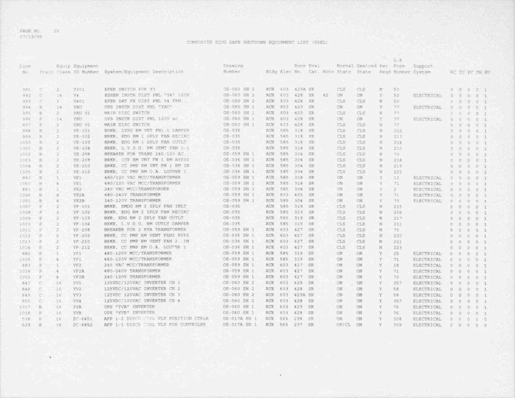
PAGE NO. 2607/19/95
CG4POSITE SOUG SAFE SHUIDOWN EQUIPMENT LIST ISSEL)
'
G.4Line Equip Equipment Drawing Room Eval Normal Desired Fwr Form Support
No. Train Class ID Number System / Equipment Description Numt'er Bldg Elev No. Cat. Note State State Reqd Number System RC IC PC DH SU
i
991 C 2 Y301 XFER SWITCH FOR Y3 05-060 SH 2 AUX 603 429A SR CLS CLS N 50 0 0 0 0 1 I
992 C 14 Y4 ESSEN INSTR DIST PNL "Y4* 120V OS-060 SH 2 AUX 603 428 SR 42 CN ON Y 50 ELECTRICAL 0 0 0 0 1993 C 2 Y401 XFER SWT FR DIST FNL Y4 FFM. OS-060 SH 2 AUX 603 428 SR CLS CLS N 50 0 0 0 0 1994 B 14 YAU UPS INSTR DIST PNL "YAU' OS-060 SH 1 AUX 603 429 SR CN ON Y 77 ELECTRICAL 0 0 0 0 1 {
995 B 2 YAU 01 MAIN DISC SWITCH OS-060 SH 1 AUX 603 429 SR CLS CLS N 77 0 0 0 0 1996 P 14 YBU UPS INSTR DIST FNL 120V ac 05-060 SH 1 AUX 603 428 SR ON ON Y 77 ELECTRICAL 0 0 0 0 1997 P 2 YBU 01 MAIN DISC SWITCH CS-060 SH 1 AUX 603 428 SR CLS CLS N 77 0 0 0 0 1 !
998 B 2 YE-101 B*4KR, LYSG RM VNT FN1-1 CAMFER OS-035 AUX 585 318 SR CLS CLS N 212 0 0 0 0 1999 B 2 YE-102 BRKR, EDG RM 1 SFLY FAN RECIRC 05-035 AUX 585 318 SR CLS CLS N 213 0 0 0 0 1
1000 9 2 YE-103 BRKR, EDG RM 1 SPLY FAN OtfrLT OS-035 AUX 585 318 SR CLS CLS N 214 0 0 0 0 1,
2001 9 2 YE-104 BRKR, L.V.S.G. RM VENT FAN 1-1 OS-035 AUX 585 318 SR CLS CLS N 210 0 0 0 0 11002 B 2 YE-208 BREAKER FOR TRANS 240-120 AC. 05-059 SH 1 AUX 585 304 SR CLS CLS N 70 0 0 0 0 11003 9 2 YE-209 BRKP., CCP RM VNT FN 1 RM BYFSS OS-036 SH 1 AUX 585 304 SR CLS CLS N 218 0 0 0 0 11004 B 2 YE-210 BRKR, CC PMP RM V?rr FN 1 RM IN OS-036 SH 1 AUX 585 304 SR CLS CLS N 219 0 0 0 0 12005 B 2 YE-212 BRKR, CC M P RM O.A. LOUVER 1 OS-036 SH 1 AUX 585 304 SR CLS CLS N 222 0 0 0 0 1
880 B 1 YE1 480/120 VAC MCC/ TRANSFORMER OS-059 SH 1 AUX 585 318 SR ON ON Y 12 ELECTRICAL 0 0 0 0 11050 B 4 YE1 480/120 VAC MCC/ TRANSFORMER 05-059 SH 1 AUX 585 318 SR CN ON Y 71 ELECTRICAL 0 0 0 0 1881 B 1 YE2 240 VAC MCC/ TRANSFORMER OS-059 SH 1 AUX 585 304 SR ON ON Y 2 ELECTRICAL 0 0 0 0 1
1006 B 4 YE2A 480-240V TRANSFORMER OS-059 SH 1 AUX 603 405 SR ON ON Y 71 ELECTRICAL 0 0 0 0 1 f
1051 B 4 YE2B 240-120V TRANSFORMER OS-059 SH 1 AUX 585 304 SR ON ON Y 70 ELECTRICAL 0 0 0 0 11007 P 2 YF-101 BRKR, EMDG RM 2 SFLY FAN INLT OS-035 AUX 585 319 SR CLS CLS N 215 0 0 0 0 11008 P 2 YF-102 BRKR, EDG RM 2 SPLY FAN RECIRC OS-035 AUX 585 319 SR CLS CLS N 216 0 0 0 0 11009 P 2 YF-103 BKR, EDG RM 2 SPLY FAN OUILT OS-035 AUX 585 319 SR CLS CLS N 217 0 0 0 0 1
l 1010 P 2 YF-104 BRKR, L.V.S.G. RM OUTLT DAMPER OS-035 AUX 585 319 SR CLS CLS N 211 0 0 0 0 1'
1011 P 2 YF-208 BREAKER FOR 2 KVA TRANSFORMER OS-059 SH 1 AUX 603 427 SR CLS CLS N 70 0 0 0 0 1 1
1012 P 2 YF-209 BRKR, CC F9tP RM VENT FAN 2 BYPS OS-036 SH 1 AUX 603 427 SR CLS CLS N 220 0 0 0 0 11013 P 2 YF-210 BRKR, CC PMP FM VENT FAN 2. .IN OS-036 SH 1 AUX 603 427 SR CLS CLS N 221 0 0 0 0 11014 P 2 YF-212 ERKR. CC mP RM O. A. LOtP"tR 1 OS-036 SH 1 AUX 603 427 SR CLS CLS N 223 0 0 0 0 1
882 P 1 YF1 400-120V MCC/ TRANSFORMER OS-059 SH 1 AUX 585 319 SR ON ON Y 25 ELECTRICAL 0 0 0 0 1| 1015 P 4 YF1 '480-120V MCC/ TRANSFORMER OS-059 SH 1 AUX 585 319 SR ON ON Y 71 ELECTRICAL 0 0 0 0 1
883 P 1 YF2 240 VAC MCC/ TRANSFORMER OS-059 SH 1 AUX 603 427 SR ON ON Y 18 ELECTRICAL 0 0 0 0 1 ;1016 P 4 YF2A 480-240V TRANSFORMER 0S-059 SH 1 AUX 603 427 SR ON ON Y 71 ELECTRICAL 0 0 0 0 1 *
1052 P 4 YF2B 240-120V TRANSFORMER OS-059 SH 1 AUX 603 427 SR ON ON Y 70 ELECTRICAL 0 0 0 0 1847 C 16 YV1 125VDC/120VAC INVERTER CH 1 OS-060 SH 2 AUX 603 429 SR ON ON Y 357 ELECTRICAL 0 0 0 0 1848 C 16 YV2 125VDC/120VAC INVERTER CH 2 0S-060 SH 2 AUX 603 428 SR ON ON Y 58 ELECTRICAL 0 0 0 0 1 f
849 C 16 YV3 125VDC 120VAC INVERTER CH 3 OS-060 SH 2 AUX 603 429A SR CN ON Y 58 ELECTRICAL 0 0 0 0 1 i850 C 16 YV4 125VDC/120VAC INVERTER CH 4 05-060 SH 2 AUX 603 428 SR ON ON Y 357 ELECTRICAL 0 0 0 0 1
'
1017 B 16 YVA UPS 'YVA* INVERTER OS-060 SH 1 AUX 603 429 SR ON ON Y 76 ELECTRICAL 0 0 0 0 11018 P 16 YVB UPS 'YVE" INVFPTER OS-060 SH 1 AUX 603 428 SR ON ON Y 76 ELECTRICAL 0 0 0 0 1
538 P 18 ZC-6451 AFP 1-2 DISCR FL VLV POSITION CTRLR OS-017A SH 1 AUX 565 238 SR ON ON Y 308 ELECTRICAL 0 0 0 1 0 ;
539 B 18 ZC-6452 AFP 1-1 DISCH CTRL VLV POS CONTROLER OS-017A SH 1 AUX 565 237 SR OP/CL ON Y 309 ELECTRICAL 0 0 0 1 0 !
i
.
- . - . . - -- - - .-. . - . - . - - _. - .- .. .
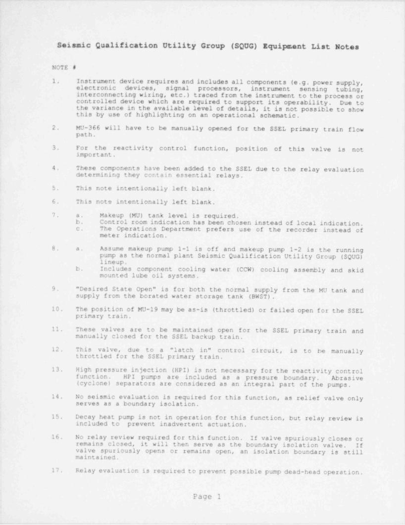
._. __ _ _ _ _ _ _ _ _ . _ _ _ . _ . _ __ _ . _ _ _ . . _ . . __ ._ _ _ _ ._. ____ _ .
!
i
Seismic Qualification Utility Group (SQUG) Equipment List Notes t
,
NOTE #
1. Instrument device requires and includes all components (e.g. power supply,electronic devices, signal processors, instrument sensing tubing,interconnecting wiring, etc.) traced from the instrument to the process orcontrolled device which are required to support its operability. Due to ;the variance in the available level of details, it is not possible to show '
this by use of highlighting on an operational schematic.
2. MU-366 will have to be manually opened for the SSEL primary train flowpath.
3. For the reactivity control function, position of this valve is notimportant.
4. These components have been added to the SSEL due to the relay evaluationdetermining they contain essential relays.
5. This note intentionally left blank.
6. This note intentionally left blank.
7. a. Makeup (MU) tank level is required. '
b. Control room indication has been chosen instead of local indication. '
c. The Operations Department prefers use of the recorder instead of I
meter indication.!
8. a. Assume makeup pump 1-1 is off and makeup pump 1-2 is the running '
pump as the normal plant Seismic Qualification Utility Group (SQUG)lineup.
b. Includes component cooling water (CCW) cooling assembly and skidmounted lube oil systene. :
9. " Desired State Open" is for both the normal supply from the MU tank and 4
supply from the borated water storage tank (BWST).
10. The position of MU-19 may be as-is (throttled) or failed open for the SSEL i
primary train,
11. These valves are to be maintained open for the SSEL primary train andmanually closed for the SSEL backup train.
12. This valve, due to a " latch in" control circuit, is to be manuallythrottled for the SSEL primary train.
13. High pressure injection (HPI) is not necessary for the reactivity controlfunction. HPI pumps are included as a pressure boundary. Abrasive {(cyclone) separators are considered as an integral part of the pumps, j
14. No seismic evaluation is required for this function, as relief valve only |serves as a boundary isolation.
15. Decay heat pump is not in operation for this function, but relay review isincluded to prevent inadvertent actuation.
16. No relay review required for this function. If valve spuriously closes orremains closed, it will then serve as the boundary isolation valve. Ifvalve spuriously opens or remains open, an isolation boundary is stillmaintained.
17 Relay evaluation is required to prevent possible pump dead-head operation.|
|
Page 1|
<
., |

_- . .
18. Since the breaker for the power supply is normally open, no relay reviewis required.
19. Valvr, is to be manually closed to preserve a flow boundary.
20. Manually open for the SSEL backup train flow path.
21. Manually open for the SSEL primary train flow path.
22. Manually open for the common flow path.
23. This note intentionally left blank.
24. Manually close for the common flow path.
25. For the primary train, SW-2929 & SW-2931 may have to be manually closed toensure the service water (SW) return flow path is directed to the otherend of the intake forebay for cooling.
26. For the backup train, SW-2932 may have to be manually closed and SW-2930manually opened to ensure a SW return flow path to the forebay.
27. Manually close for the SSEL primary train.
28. Manually close for the SSEL backup train.
29. Valve position is of no consequence for SQUG purposes.
30. Air line between solenoid valve and service water (SW) valve is notincluded .s a part of SQUG.
31. This note intentionally left blank.
32. Includes interlock to emergency diesel generator (EDG) CCW outlet valve asdescribed in note "CL-6" on OS-21 SHl.
33. Air line is not included as a part of SQUG.
34. The necessary control room emergency ventilation system (CREVS) equipmentis skid mounted, which includes the condensing unit (S33-1,2), the aircooled condenser (S61-1,2), and the cooling coil (E106-1,2).
35. This note intentionally left blank.
36. Associated piping /ductwork for air path is also included.
37 Manually open to cross-connect both boric acid addition tanks (BAATs).
38. Manually throttle MU-349 for the SSEL primary train, and MU-348 for theSSEL backup train.
39. Both boric acid addition tanks (BAATs) are required because there is noassurance that one alone will contain the necessary amount of boric acid.
40. This note intentionally left blank.
41. This panel needs to feed at least channel 1 steam and feedwater rupturecontrol system (SFRCS) and safety features actuation system (SFAS)cabinets to prevent trips to support channel 2 (SSEL primary train).
42. This panel needs to feed at least channel 2 SFRCS & SFAS cabinets toprevent trips to support channel 1 (SSEL backup train) .
43. This note intentionally left blank.
Page 2
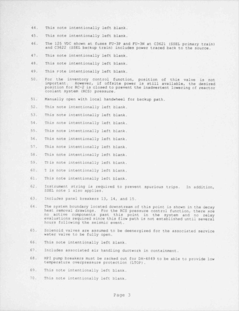
, . . . .__ _ _ _ _ . - _ _ _ __-.m. . _ _ . _ . . _ . _ _ . _ _ . . _ _ _ _ _ . _
i
|
t
P
'44. This note intentionally left blank.
45. This note intentionally left blank. |
46. The 125 VDC shown at fuses FU-3P and FU-3N at C3621 (SSEL primary train)and C3622 (SSEL backup train) includes power traced back to the source.
47. This note intentionally left blank.i
48. This note intentionally left blank. ||
49. This pote intentionally left blank.,
50. For the inventory control function, position of this valve is not jimportant. However, if offsite power is still available, the desired L
,
position for RC-2 is closed to prevent the inadvertent lowering of reactor ;coolant system (RCS) pressure.
,
51. Manually open with local handwheel for backup path.
52. This note intentionally left blank. ;
'53. This note intentionally left blank.
54. This note intentionally left blank. r
i: 55. This note intentionally left blank.
56. This note intentionally left blank.,
|57. This note intentionally left blank. !
!58. This note intentionally left blank.
;
59. This note intentionally left blank. |
60. T is note intentionally left blank.
61. This note intentionally left blank.f
62. Instrument string is required to prevent spurious trips. In addition,SSEL note 1 also applies.
|
[63. Includes panel breakers 13, 14, and 15.
64. The system boundary located downstream of this point is shown in the decay iheat removal drawings. For the RCS pressure control function, there areno active- components past this point in the system and no relay
,
evaluations required since this flow path is not established until severalhours following the seismic event.
>
65. Solenoid valves are assumed to be deenergized for the associated servicewater valve to be fully open.
66. This note intentionally left blank.
67. Includes associated air handling ductwork in containment.,
l68. HPI pump breakers must be racked out for DH-4849 to be able to provide low !
temperature overpressure protection (LTOP).
69. This note intentionally left blank. >
t70. This note intentionally left blank.
;
Page 3 Itt
'-- - ... - - - .- ._ _ _ _ _ _ _

71. This note intentionally left blank.
72. This note intentionally left blank.
73. This note intentionally left blank.
74 This note intentionally left blank.
75. This note intentionally left blank.
76. This note intentionally left blank.
77. This note intentionally left blank.
78. This note intentionally left blank.
79. Additional equipment is shown on support systene drawings.
80 DH-21 and DH-23 are manually opened for the backup train.
81. Manually close for the SSEL primary train.
82. Operators to control decay heat removal (DHR) flow by throttling valve DH-1A via HIS DH1A.
83. Manually close for the SSEL backup train.
84. Operators to open DH-1518 for the SSEL primary train via HIS 1518. DH-1518 is to remain closed for the SSEL backup train.
85. This note intentionally left blank.
86. For SSEL primary train operation, MCC E11B may have to be powered via thecross tie from MCC Fila using breakers described in note 15 of OS-059.This is for the decay heat removal and pressure control functions only.
87 Operators to control DHR flow by throttling valve DH-1B via HIS DH1B.
88. Operators to open DH-1517 for the SSEL backup train via HIS 1517 DH-1517is to remain closed for the SSEL primary train.
89. Includes control signal to LIC 6451 (OS-17A SH1).
90. Includes control signal to LIC 6452 (OS-17A SH1).
91, a. Includes trip throttle valve & governor valve.b. Includes equipment for steam exhaust path to atmosphere.
92. Includes associated fan intake & discharge path.
93. Includes associated reach rod and air tubing to bleed off the closing airsupply. For decay heat removal, both ICS11A and ICS11B will be controlledby use of a manual handwheel.
94. The SOUG boundary for the piping extends to the S/I boundary outside theauxiliary building. Pipe integrity is not required past this point forthe purposes of SQUG.
95. This note intentionally left blank.
96. This note intentionally left blank.
97. This note intentionally left blank,
l 98. This note intentionally left blank.
Page 4
1.
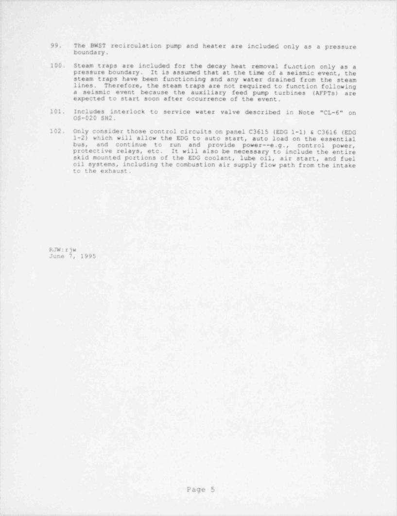
- . .- ._. .-. . . _ _ _ _ = . _ _ .-
99. The BWST recirculation pump and heater are included only as a pressureboundary.
100. Steam traps are included for the decay heat removal function only as apressure boundary. It is assumed that at the time of a seismic event, thesteam traps have been functioning and any water drained from the steamlines. Therefore, the steam traps are not required to function followinga seismic event because the auxiliary feed pump turbines (AFPTS) areexpected to start soon after occurrence of the event.
101. Includes interlock to service water valve described in Note "CL-6" onOS-020 SH2.
102. Only consider those control circuits on panel C3615 (EDG l-1) & C3616 (EDG1-2) which will allow the EDG to auto start, auto load on the essentialbus, and continue to run and provide power--e.g., control power,protective relays, etc. It will also be necessary to include the entireskid mounted portions of the EDG coolant, lube oil, air start, and fueloil systems, including the combustion air supply flow path from the intaketo the exhaust.
RJW:rjwJune 7, 1995
Page 5
_ . .- _._. ..- _ . - _ _ _ - - - - . .-
DAVIS-BESSE NUCLEAR POWER STATION
Unresolved Safety Issue (USI) A-46
Seismic Evaluation Report
APPENDIX C
SEISMIC REVIEWSAFE SHUTDOWN EQUIPMENT LIST (SSEL)
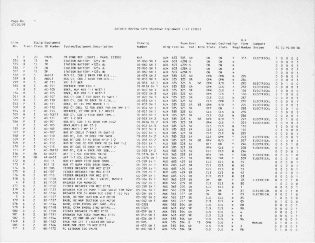
Page No. 1
07/20/95Seismic Review Safe Shutdown Equipment List (SSEL)
G.4Line Equip Equipment Drawing Room Evat Normal Desired Pwr Form SimportOo. Train Class ID Ntaber System / Equipment Description Number Bldg Elev No. Cat. Note State State Reqd NuP6er System RC IC PC DN SU
!1 P 20 0%ZRL 0% ZONE REF LIGHTS - PANEL 213000 N/A AUX 623 505 SR ON ON Y 313 ELECTRICAL 1 0 0 0 0554 8 15 1N STATION BATTERY -125V de OS-060 SH 1 AUX 603 429B S ON ON N O O 0 0 1535 8 15 1P STATION BATTERY +125V de 05-060 SH 1 AUX 603 4298 $ ON ON N O O O O 1556 P 15 2N STATION BATTERY -125V de OS-060 SH 1 AUX 603 428A S ON ON N O O O 0 1 '
55F P 15 2P STATION BATTERY +125V de 0s-060 SH 1 AUX 603 428A S ON ON N 0 0 0 0 155G P 3 AACD1 BUS D1, CUB 2 BRKR FRM BUS.... 0S-058 SH 2 AUX 585 323 SR OPN OPN N 292 0 0 0 0 1.
559 8 3 ABDC1 BUS C1, CUB 2 BRKR FRM BUS... 0S-058 SH 1 AUX 585 325 SR OPN OPN N 284 0 0 0 0 1298 P 3 AC 111 HPI 1-1 BKR OS-058 SH 1 AUX 585 325 S 68 OPN R/0 Y 290 ELECTRICAL 0 0 1 0 0560 B 3 AC-101 BREAKER FROM EDG 1 CS-041A SH 1 AUX 585 325 SR OPN CLS Y 283 ELECTRICAL 0 0 0 0 12 8 3 AC-105 BRKR, MVP MTR 1-1 MP37-1 OS-002 SH 3 AUX 585 325 SR OPN CLS Y 106 ELECTRICAL 1 0 0 0 0
1G4 B 3 AC-105 BRKR, MVP MTR 1-1 MP37-1 OS-002 SH 3 AUX 585 325 SR OPN CLS Y 106 ELECTRICAL 0 1 0 0 0561 B 3 AC-107 BUS C1 CUB 7 FDR BRKR FR SWP1-1 OS-020 SH 1 AUX 585 325 SR CLS CLS N 287 0 0 0 0 1562 B 3 AC-110 BUS C1, CUB 10 BRKR TO 4.16... 05-058 SH 1 AUX 585 325 SR CLS OPN Y 285 ELECTRICAL 0 0 0 0 1563 P 3 AC-111 BRKR, HP INJ PMP MOTOR 1-1 OS-058 SH 1 AUX 585 325 SR 68 OPN R/0 Y 290 ELECTRICAL 0 0 0 0 1300 8 3 AC-112 BUS C1 CBCL 12 FOR BRKR FOR DH PMP 1-1 05-004 SH 1 AUX 585 325 SR OFF ON Y 288 ELECTRICAL 0 0 0 1 0564 8 3 AC-113 BREAKER, CC PMP MTR 1-1 MP431 0S-021 SH 1 AUX 585 325 SR CLS CLS N 289 0 0 0 0 1565 8 3 AC-1CE11 BUS C1, CUB 4-FEED BRKR FRM... OS-058 SH 1 AUX 585 325 SR CLS CLS N 286 0 0 0.0 1
'
! 299 P 3 AD 111 HPI 1-2 BKR 05-058 SH 2 AUX 585 323 S 68 OPN R/0 Y 297 ELECTRICAL 0 0 1 0 0| 566 P 3 AD-101 BUS 01, CUB 1-FD BRKR FRM EDG2 05-041A SH 2 AUX 585 323 SR OPN CLS Y 291 ELECTRICAL 0 0 0 0 1l 3 P 3 AD-105 BRKR MUP1-2 MP 37-2 OS-002 SH 3 AUX 585 323 SR CLS CLS N 110 1 0 0 0 0| 105 P 3 AD-105 BRKR,MUP1-2 MP 37-2 OS-002 SH 3 AUX 585 323 SR CLS CLS N 110 0 1 0 0 0| 56F P 3 AD-107 BUS 01 CBCLE 7-BRKR FR SWP1-2 05-020 SH 1 AUX 585 323 SR CLS CLS N 295 0 0 0 0 1568 P 3 AD-110 BUS D1, CUB 10 BRKR FOR SWGR.. 05-058 SH 2 AUX 585 323 SR CLS OPN Y 293 ELECTRICAL 0 0 0 0 1
569 P 3 AD-111 BUS DI CUB 11-FD BRKR HPIP 1-2 05-058 SH 2 AUX 585 323 SR 68 OPN R/0 Y 297 ELECTRICAL 0 0 0 0 1309 P 3 AD-112 BUS D1 CUB 12-FDR BRKR FR DH PMP 1-2 OS-004 SH 1 AUX 585 323 SR OFF ON Y 296 ELECTRICAL 0 0 0 1 0
,
5F0 P 3 AD-113 BUS 01 CUB 13 BRKR FR CCPMP1-2 05-021 SH 1 AUX 585 323 SR OPN CLS Y 298 ELECTRICAL 0 0 0 0 1 i
SF1 P 3 AD-1DF12 BUS D1, CUB 4 BRKR FOR SUB.... 05-058 SH 2 AUX 585 323 SR CLS CLS W 294 0 0 0 0 1316 P 8B AF-6451 AFP 1-2 SOL CONTROL VALVE OS-017A SH 1 AUX 565 238 SR OPN THR Y 308 ELECTRICAL 0 0 0 1 0
,
31F B 88 AF-6452 AFP 1-1 SOL CONTROL VALVE OS-017A SH 1 AUX 565 237 SR OPN THR Y 309 ELECTRICAL 0 0 0 1 0 '
572 8 2 BCE 11 BUS El NORM FEED BRKR FROM.... OS-059 SH 1 AUX 603 429 SR CLS CLS N 59 0 0 0 0 1573 P 2 BDF 12 BUS F1 NORM FEED BRKR FROM... OS-059 SH 1 AUX 603 428 SR CLS CLS N 60 0 0 0 0 1 i574 8 2 BE-106 FEEDER BREAKER FOR MCC E12A OS-059 SH 1 AUX 603 429 SR CLS CLS N 61 0 0 0 0 1575 8 2 BE-107 FEEDER BREAKER FOR MCC EllA 05-059 SH 1 AUX 603 429 SR CLS CLS N 62 0 0 0 0 1 *
576 B 2 BE-110 FEEDER BREAKER FOR MCC E14 OS-059 SH 1 AUX 603 429 SR CLS CLS N 63 0 0 0 0 131G B 2 BE-1106 BREAKER FOR LP INJ 1 VALVE, MVDH1B OS-004 SH 1 AUX 565 209 SR ON ON Y 78 ELECTRICAL 0 0 0 1 034 8 2 BE-1109 BREAKER FOR MVMU400 OS-002 SH 1 AUX 565 209 SR CLS. CLS N 80 1 0 0 0 057F B 2 BE-1120 FEEDER BREAKER FOR MCC E11B 05-059 SH 1 AUX 565 209 SR CLS CLS N 1 0 0 0 0 1319 8 2 BE-1121 BREAKER FOR DH PUMP 1 SUC VALVE FRM BWST 05-004 SH 1 AUX 565 209 SR ON ON Y 81 ELECTRICAL 0 0 0 1 0 '
320 8 2 BE-1126 BREAKER FOR DH NORM SUC LINE 1 ISO VLV OS-004 SH 1 AUX 565 227 SR ON ON Y 83 ELECTRICAL 0 0 0 1 0 L5 B 2 BE-1127 BRER, RC MVP SUCTION VLV MOTOR OS-002 SH 3 AUX 565 227 SR CLS CLS N 85 1 0 0 0 0 [179 8 2 BE-1127 BRKR, RC MUP SUCTION VLV MOTOR OS-002 SH 3 AUX 565 227 SR CLS CLS N 85 0 1 0 0 0578 8 2 BE-1144 BRER, CTRM EMERG VNT FAN 1..VLV 0S-0328 AUX 585 304 SR CLS CLS N 88 0 0 0 0 1579 B 2 BE-1148 BRER, CTRM EMERG STND BYPAS... OS-0328 AUX 603 402 SR CLS CLS N 90 0 0 0 0 1580 B 2 BE-1150 FEEDER BREAKER TO MCC E11E 05-059 SH 1 AUX 585 304 SR CLS CLS N 4 0 0 0 0 1
581 B 2 BE-1151 BREAKER FOR FEED FROM MCC E11C 05-059 SH 1 AUX 603 402 SR CLS CLS N 6 0 0 0 0 1582 B 2 BE-1154 BRKR, CC PMP RM VNT FAN 1... OS-036 SH 1 AUX 585 304 SR CLS CLS N % 0 0 0 0 11149 8 2 BE-1162 BRKR FOR CFT 1 ISOLATION VALVE 03-006 AUX 585 304 S 18 OPN CLS Y MANUAL 0 1 0 0 0583 8 2 BE-1166 BRKR FOR FEED TO MCC E118 OS-059 SH 1 AUX 585 304 SR CLS CLS N 3 0 0 0 0 1111 B 2 BE-1172 RC LETDOWN ISO VALVE OS-002 SH 1 AUX 585 304 SR CLS CLS N 98 0 1 0 0 0
,
a- -- ---m -- - - - - - _ _ - - - - - - - - - _ _ _ _ - _ _ - . _ _ _ _
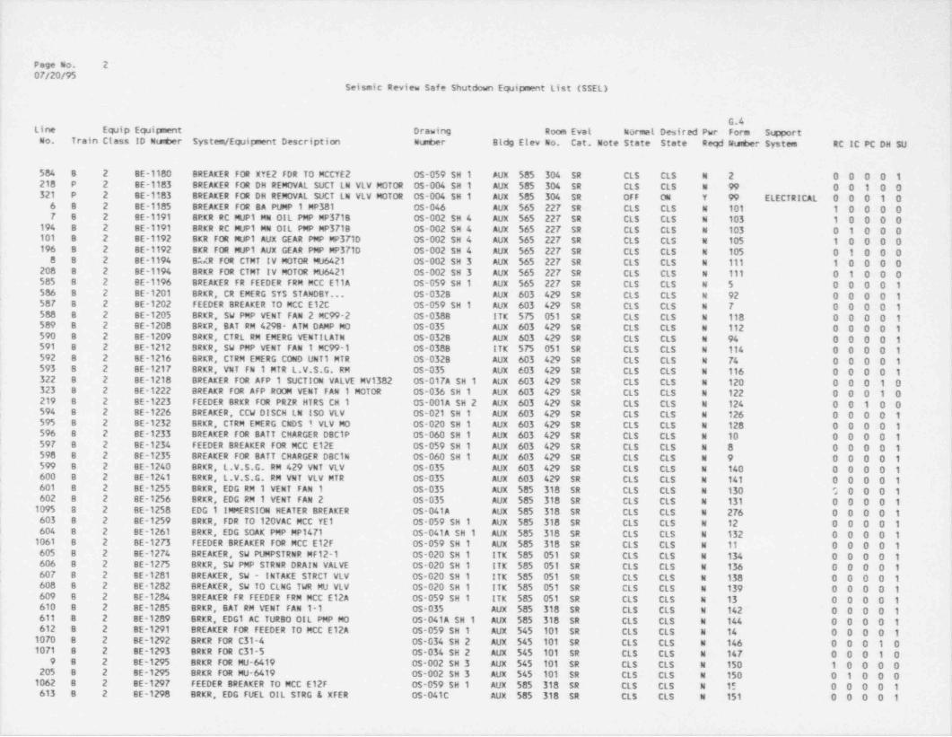
Page No. 20F/20/95
Seismic Review Safe Shutdown Equipnent List (SSEL)
G.4Line Equip Eq2ipment Drawing Room Evel Normel Desired Pwr Form S@ portCo. Train Class ID Nuter System / Equipment Description Nuter Bldg Elev No. Cat. Note State State Regf Wunber System RC IC PC DH SU
584 8 2 BE-1180 BREAKER FOR XYE2 FDR TO MCCYE2 OS-059 SH 1 AUX 585 304 SR CLS CLS N 2 0 0 0 0 1210 P 2 BE-1183 BREAKER FOR DH REMOVAL SUCT LN VLV MOTOR OS-004 SH 1 AUX 585 304 SR CLS CLS N 99 0 0 1 0 0321 P 2 BE-1183 BREAKER FOR DH REMOVAL SUCT LN VLV MOTOR OS-004 SH 1 AUX 585 304 SR OFF ON Y 99 ELECTRICAL 0 0 0 1 06 B 2 BE-1185 BREAKER FOR BA PUMP 1 MP381 05-046 AUX 565 227 SR CLS CLS N 101 1 0 0 0 0F B 2 BE-1191 BRKR RC MUP1 MN O!L PMP MP3718 OS-002 SH 4 AUX 565 227 SR CLS CLS N 103 1 0 0 0 0
194 B 2 BE-1191 BRKR RC MUP1 MN OIL PMP MP3718 OS-002 SH 4 AUX 565 227 SR CLS CLS N 103 0 1 0 0 0101 8 2 BE-1192 BKR FOR MUP1 AUX GEAR PMP MP371D OS-002 SH 4 AUX 565 227 SR CLS CLS N 105 1 0 0 0 0196 B 2 BE-1192 BKR FOR MUP1 AUX GEAR PMP MP371D OS-002 SH 4 AUX 565 227 SR CLS CLS N 105 0 1 0 0 0Q B 2 BE-1194 BMR FOR CTMT IV MOTOR M06421 OS-002 SH 3 AUX 565 227 SR CLS CLS N til 1 0 0 0 0
208 8 2 BE-1194 BRKR FOR CTMT IV MOTOR MU6421 0s-002 SH 3 AUX 565 227 SR CLS CLS N 111 0 1 0 0 0SGS B 2 BE-1196 BREAKER FR FEEDER FRM MCC EllA OS-059 SH 1 AUX 565 227 SR CLS CLS N 5 0 0 0 0 1586 8 2 BE-1201 BRKR, CR EMERG STS STANOBY... OS-0328 AUX 603 429 SR CLS CLS N 92 0 0 0 0 15GT B 2 BE-1202 FEEDER BREAKER TO MCC E12C OS-059 SH 1 AUX 603 429 SR CLS CLS W 7 0 0 0 0 1588 8 2 BE-1205 BRKR, SW PMP VENT FAN 2 MC99-2 OS-0388 ITK 575 051 SR CLS CLS N 118 0 0 0 0 1589 B 2 BE-1208 BRKR, BAT RM 4298- ATM DAMP MO 05-035 AUX 603 429 SR CLS CLS N 112 0 0 0 0 1590 B 2 BE-1209 BRKR, CTRL RM EMERG VENTILATN 0$-0328 AUX 603 429 SR CLS CLS N 94 0 0 0 0 1591 B 2 BE-1212 BRKR, SU PMP VENT FAN 1 MC99-1 OS-038B ITK 575 051 SR CLS CLS N 114 0 0 0 0 1592 B 2 BE-1216 BRKR, CTRM EMERG COND UNT1 MTR OS-0328 AUX 603 429 SR CLS CLS N 74 0 0 0 0 1593 B 2 BE-1217 BRKR, VNT FN 1 MTR L.V.S.G. RM OS-035 AUX 603 429 SR CLS CLS N 116 0 0 0 0 1322 8 2 BE-1218 BREAKER FOR AFP 1 SUCTION VALVE MV1382 OS-017A SH 1 AUX 603 429 SR CLS CLS N 120 0 0 0 1 0323 8 2 BE-1222 BREAKR FOR AFP ROOM VENT FAN 1 MOTOR OS-036 SH 1 AUX 603 429 SR CLS CLS N 122 0 0 0 1 0219 8 2 BE-1223 FEEDER BRKR FOR PRZR HTRS CH 1 OS-001A SH 2 AUX 603 429 SR Cts CLS N 124 0 0 1 0 0594 8 2 BE-1226 BREAKER, CCW DISCH LN ISO VLV 0S-021 SH 1 AUX 603 429 SR CLS CLS N 126 0 0 0 0 1595 B 2 BE-1232 BRKR, CTRM EMERG CNDS 1 VLV MO 0S-020 SH 1 AUX 603 429 SR CLS CLS N 128 0 0 0 0 1596 8 2 BE-1233 BREAKER FOR BATT CHARGER DBC1P OS-060 SH 1 AUX 603 429 SR CLS CLS N 10 0 0 0 0 1597 B 2 BE-1234 FEEDER BREAKER FOR MCC E12E OS-059 SH 1 AUX 603 429 SR CLS CLS N 8 0 0 0 0 1598 8 2 BE-1235 BREAKER FOR BATT CHARGER DBC1N OS-060 SH 1 AUX 603 429 SR CLS CLS N 9 0 0 0 0 1$99 8 2 BE-1240 BRKR, L.V.S.C. RM 429 VNT VLV OS-035 AUX 603 429 SR CLS CLS N 140 0 0 0 0 1600 B 2 BE-1241 BRKR, L.V.S.G. RM VNT VLV MTR 0S-035 AUX 603 429 SR CLS CLS N 141 0 0 0 0 1601 B 2 BE-1255 BRKR, EDG RM 1 VENT FAN 1 0S-035 AUX 585 318 SR CLS CLS N 130 0 0 0 0 1602 B 2 BE-1256 BRKR, EDG RM 1 VENT FAN 2 OS-035 AUX 585 318 SR CLS CLS N 131 0 0 0 0 11095 8 2 BE-1258 EDG 1 IMMERSION HEATER BREAKER OS-041A AUX 585 318 SR CLS CLS N 276 0 0 0 0 1603 8 2 BE-1259 BRKR, FDR TO 120VAC MCC YE1 CS-059 SH 1 AUX 585 318 SR CLS CLS N 12 0 0 0 0 1604 8 2 BE-1261 BRKR, EDG SOAK PMP MP1471 OS-041A SH 1 AUX 585 318 SR CLS CLS N 132 0 0 0 0 11061 8 2 BE-1273 FEEDER BREAKER FOR MCC E12F OS-059 SH 1 AUX 585 318 SR CLS CLS X 11 0 0 0 0 1605 B 2 BE-1274 BREAKER, SW PUMPSTRNR MF12-1 OS-020 SH 1 ITK 585 051 SR CLS CLS N 134 0 0 0 0 1606 8 2 BE-1275 BRKR, SW PMP STRNR DRAIN VALVE OS-020 SH 1 ITK 585 051 SR CLS CLS N 136 0 0 0 0 1607 B 2 BE-1281 BREAKER, SW - INTAKE STRCT VLV OS-020 SH 1 ITK 585 051 SR CLS CLS N 138 0 0 0 0 1608 8 2 BE-1282 BREAKER, SW TO CLNG TWR MU VLV OS-020 SH 1 ITK 585 051 SR CLS CLS N 139 0 0 0 0 1609 8 2 BE-1284 BREAKER FR FEEDER FRM MCC E12A OS-059 SH 1 ITK 585 051 SR CLS CLS N 13 0 0 0 0 1610 8 2 BE-1285 BRKR, BAT RM VENT FAN 1-1 05-035 AUX 585 318 SR CLS CLS N 142 0 0 0 0 1Gil B 2 BE-1289 BRKR, EDG1 AC TURBO OIL PMP MO OS-041A SH 1 AUX 585 318 SR CLS CLS N 144 0 0 0 0 1612 8 2 BE-1291 BREAKER FOR FEEDER TO MCC E12A OS-059 SH 1 AUX 545 101 SR CLS CLS N 14 0 0 0 0 110TD B 2 BE-1292 BRKR FOR C31-4 0s-034 SH 2 AUX 545 101 SR CLS CLS N 146 0 0 0 1 01071 B 2 BE-1293 BRKR FOR C31-5 OS-034 SH 2 AUX 545 101 SR CLS CLS N 147 0 0 0 1 0
9 B 2 BE-1295 BRKR FOR MU-6419 CS-002 SH 3 AUX 545 101 SR CLS CLS N 150 1 0 0 0 0205 B 2 BE-1295 BRKR FOR MU-6419 0s-002 SH 3 AUX 545 101 SR CLS CLS N 150 0 1 0 0 01062 8 2 BE-1297 FEEDER BREAKER TO MCC E12F OS-059 SH 1 AUX 585 318 SR CLS CLS N 15 0 0 0 0 1G13 8 2 BE-1298 BRKR, EDG FUEL OIL STRG & XFER OS-041C AUX 585 318 SR CLS CLS N 151 0 0 0 0 1
___ - _ . _ _ _ _ _ _ _ _ _ _ _ _ _ _ _ _ _ _ _ _ - _ _ _ _ -
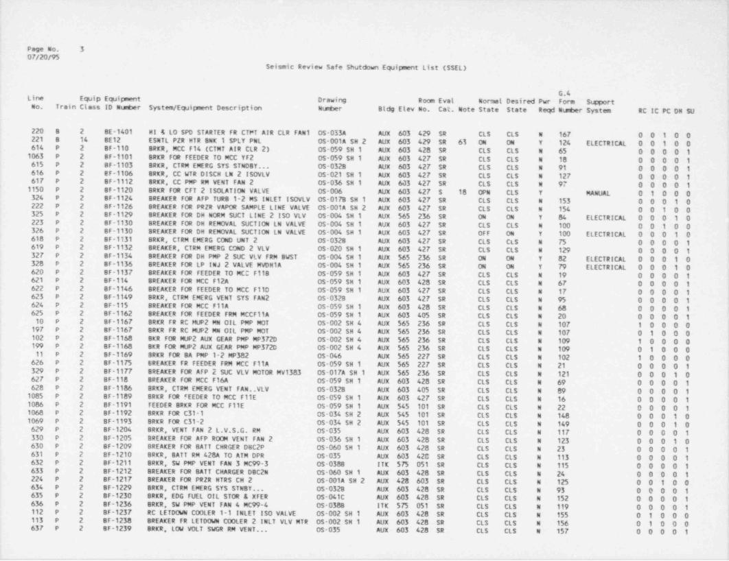
i
o
Page No. 307/20/95
Seismic Review Safe Shutdow1 Equipment List (SSEL)
G.4Line Equip Equipment Drawing Room Eval Normal Desired Pwr Form SupportCo. Train Class ID Ntaber System / Equipment Description Nueer Bldg Elev No. Cat. Note State State Reqd Ntsuber System RC IC PC DH SU
220 8 2 BE-1401 HI 4 L0 SPD STARTER FR CTFT AIR CLR FAN 1 0S-0334 AUX 603 429 SR CLS CLS N 167 0 0 1 0 0<
221 8 14 BE12 ESNTL PZR HTR BNK 1 SPLY PNL OS-001A SH 2 Aux 603 429 SR 63 04 ON Y 124 ELECTRICAL 0 0 1 0 0614 P 2 8F-110 BRKR, MCC F14 (CTMT AIR CLR 2) OS-059 SH 1 AUX 603 428 SR CLS CLS N 65 0 0 0 0 19063 P 2 BF-1101 BRKR FOR FEEDER TO MCC YF2 05-059 SH 1 AUX 603 427 SR CLS CLS N 18 0 0 0 0 1615 P 2 BF-1103 BRER, CTRM EMERG SYS STN08Y... 05-0328 AUX 603 427 SR CLS CLS N 91 0 0 0 0 1G16 P 2 EF-1106 BRER, CC WTR DISCH LN 2 ISOVLV OS-021 SH 1 AUX 603 427 SR CLS CLS N 127 0 0 0 0 1617 P 2 BF-1112 BRKR, CC PMP RM VENT FAN 2 0s-036 SH 1 Aux 603 427 SR CLS CLS N 97 0 0 0 0 11130 P 2 BF-1120 8RKR FOR CFT 2 ISOLATION VALVE 0s-006 Aux 603 427 $ 18 OPN CLS T MANUAL 0 1 0 0 0324 P 2 BF-1124 BREAKER FOR AFP TUR8 1-2 MS INLET ISOVLV OS-017B SH 1 AUX 603 427 SR CLS CLS N 153 0 0 0 1 0222 P 2 BF-1126 BREAKER FOR PR2R VAPOR SAMPLE LINE VALVE OS-0014 SH 2 Aux 603 427 SR CLS CLS N 154 0 0 1 0 0325 P 2 BF-1129 BREAKER FOR DH NORM SUCT LINE 2 ISO VLV OS-004 SH 1 AUX 565 236 SR ON ON Y B4 ELECTRICAL 0 0 0 1 0223 P 2 BF-1130 BREAKER FOR DH REMOVAL SUCTION LN VALVE 05-004 SH 1 AUX 603 427 SR CLS CLS N 100 0 0 1 0 0326 P 2 BF-1130 8REAKER FOR DH REMOVAL SUCTION LN VALVE 05-004 SH 1 AUX 603 427 SR OFF ON Y 100 ELECTRICAL 0 0 0 1 0610 P 2 8F-1131 BRKR, CTRM EMERG COND UNT 2 OS-0328 AUX 603 427 SR CLS CLS N 75 0 0 0 0 1619 P 2 BF-1132 8REAKER, CTRM EMERG COND 2 VLV 05-020 SH 1 AUX 603 427 SR CLS CLS N 129 0 0 0 0 132P P 2 8F-1134 BREAKER FOR DH PMP 2 SUC VLV FRM BWST OS-004 SH 1 AUX 565 236 SR ON ON Y 82 ELECTRICAL 0 0 0 1 0320 P 2 BF-1136 BREAKER FOR LP INJ 2 VALVE MVDH1A OS-004 SH 1 AUX 565 236 SR ON ON Y 79 ELECTRICAL 0 0 0 1 0 ;620 P 2 BF-1137 BREAKER FOR FEEDER TO MCO F118 05-059 SH 1 AUX 603 427 SR CLS CLS N 19 0 0 0 0 1 '
621 P 2 BF-114 BREAKER FOR MCC F12A OS-059 SH 1 AUX 603 428 SR CLS CLS N 67 0 0 0 0 1G22 P 2 BF-1146 BREAKER FOR FEEDER TO MCC F110 05-059 SH 1 AUX 603 427 SR CLS CLS N 17 0 0 0 0 1623 P '2 BF-1149 BRKR, CTRM EMERG VENT SYS FAN 2 OS-032B AUX 603 427 SR CLS CLS N 95 0 0 0 0 1G24 P 2 BF-115 BREAKER FOR MCC F11A OS-059 SH 1 AUX 603 428 SR CLS CLS N 68 0 0 0 0 1 P
,
625 P 2 BF-1162 8REAKER FOR FEEDER FRM MCCF11A OS-059 SH 1 AUX 603 405 SR CLS CLS N 20 0 0 0 0 1'
1 10 P 2 SF-1167 BRKR FR RC MUP2 MN OIL PMP MOT 05-002 SH 4 Aux 565 236 SR CLS CLS N 107 1 0 0 0 0197 P 2 8F-1167 BRKR FR RC MUP2 MN OIL PMP MOT 0S-002 SH 4 AUX 565 236 SR CLS CLS N 107 0 1 0 0 0102 P 2 BF-1168 8KR FOR MUP2 AUX GEAR PMP MP372D 05-002 SH 4 AUX 565 236 SR CLS CLS N 109 1 0 0 0 0,
199 P 2 8F-1168 BKR FOR MUP2 AUX GEAR PMP MP3720 0s-002 SH 4 AUX 565 236 SR CLS CLS N 109 0 1 0 0 011 P 2 BF-1169 BRKR FOR BA PMP 1-2 MP382 0s-046 AUX 565 227 SR CLS CLS N 102 1 0 0 0 0626 P 2 8F-1175 BREAKER FR FEEDER FRM MCC F11A 05-059 SH 1 AUX 565 227 SR CLS CLS N 21 0 0 0 0 1 ,
329 P 2 BF-1177 BREAKER FOR AFP 2 SUC VLV MOTOR MV1383 05-017A SH 1 AUX 565 236 SR CLS CLS N 121 0 0 0 1 0 :62P P 2 BF-118 BREAKER FOR MCC F16A 0S-059 SH 1 AUX 603 428 SR CLS CLS N 69 0 0 0 0 1620 P 2 BF-1186 BRKR, CTRM EMERG VENT FAN..VLV OS-0328 AUX 603 405 SR CLS CLS N 89 0 0 0 0 1 t10G5 P 2 BF-1189 BRKR FOR FEEDER TO MCC F11E OS-059 SH 1 Aux 603 427 SR CLS CLS N 16 0 0 0 0 1 r1086 P 2 BF-1191 FEEDER BRKR FOR MCC F11E OS-059 SH 1 AUX 545 101 SR CLS CLS N 22 0 0 0 0 1 '
1068 P 2 BF-1192 BRKR FOR C31-1 05-034 SH 2 AUX 545 101 SR CLS CLS N 148 0 0 0 1 01069 P 2 BF-1193 BRKR FOR C31-2 OS-034 SH 2 AUX 545 101 SR CLS CLS N 149 0 0 0 1 0629 P 2 8F-1204 BRKR, VENT FAN 2 L.V.S.G. RM 05-035 AUX 603 428 SR CLS CLS N 117 0 0 0 0 1330 P 2 BF-1205 BREAKER FOR AFP ROOM VENT FAN 2 OS-036 SH 1 AUX 603 428 SR CLS CLS N 123 0 0 0 1 0I 630 P 2 BF-1209 BREAKER FOR BATT CHRGER DBC2P OS-060 SH 1 AUX 603 428 SR CLS CLS N 23 0 0 0 0 1 '
G31 P 2 BF-1210 BRKR, BATT RM 428A TO ATM DPR OS-035 AUX 603 420 SR CLS CLS N 113 0 0 0 0 1 '
G32 P 2 BF-1211 BRKR, SW PMP VENT FAN 3 MC99-3 0s-0388 ITK 575 051 SR CLS CLS N 115 0 0 0 0 1633 P 2 BF-1212 BREAKER FOR BATT CHARGER D8C2N OS-060 SH 1 AUX 603 428 SR CLS CLS N 24 0 0 0 0 1224 P 2 BF-1217 BREAKER FOR PRZR HTRS CH 2 OS-001A SH 2 Aux 428 603 SR CLS CLS N 125 0 0 1 0 0634 P 2 8F-1229 BRKR, CTRM EMERG SYS STN8Y... 05-0328 AUX 603 428 SR CLS CLS N 93 0 0 0 0 1635 P 2 BF-1230 BRKR, EDG FUEL O!L STOR & XFER OS-041C AUX 603 428 SR CLS CLS N 152 0 0 0 0 1636 P 2 BF-1236 BRKR, SW PMP VENT FAN 4 MC99-4 OS-0388 ITK 575 051 SR CLS CLS N 119 0 0 0 0 1112 P 2 BF-1237 RC LETDOWN COOLER 1-1 INLET ISO VALVE 05-002 SH 1 AUX 603 428 SR CLS CLS N 155 0 1 0 0 0113 P 2 BF-1238 8REAKER FR LETDOWN COOLER 2 INLT VLV MTR OS-002 SH 1 AUX 603 428 SR CLS CLS N 156 0 1 0 0 0,
637 P 2 BF-1239 BRKR, LOW VOLT SWGR RM VENT... OS-035 AUX 603 428 SR CLS CLS N 157 0 0 0 0 1ii
,

._ _ _ _ _ _ _
Page No. 407/20/95
Seismic Review Safe Stutdown EqJipnent List (SSEL)
G.4Line EqJip Equirnent Drawing Doces Eve! Normel Desired Pwr Form S @ ortKo. Train Ctess ID Nuter System / Equipment Description Number Bldg Elev A Cat. m W State State Reqd Nuter System RC IC PC DH SU
638 P 2 BF-1255 BRKR, EDG RM 2 VWTL FAN 3 05-035 AUX SG M SR CLS CLS N 158 0 0 0 0 1639 P 2 BF-1256 BRKR, EDG RM 2 VNTL FAN 4 05-035 AUX $ 8', 319 SR CLS CLS N 159 0 0 0 0 11096 P 2 BF 1258 EDG 2 IMMERSION HEATER BREAKER OS-041A AUX 585 319 SR CLS CLS N 277 0 0 0 0 1640 P 2 BF-1259 BRKR, BATT RM VENT FAN 1-2 OS-035 AUX 585 319 SR CLS CLS 4 143 0 0 0 0 1641 P 2 BF-1261 BRKR, EDG 2 SOAK PUMP MP1472 05-041A SH 2 AUX 585 319 SR CLS CLS N 133 0 0 0 0 1642 P 2 BF-1270 BREAKER FOR FEEDER TO MCC YF1 0s-059 SH 1 AUX 585 319 SR CLS CLS N 25 0 0 0 0 1643 P 2 BF-1274 BRKR, SW PUMP STRAINER MF15-2 OS-020 SH 1 ITE 585 052 SR CLS CLS N 135 0 0 0 0 1644 P 2 BF-1275 BRKR, SW PMP STRNR DRAIN VALVE 0s-020 SH 1 ITK 585 052 SR CLS CLS N 137 0 0 0 0 1645 P 2 BF-1277 BRKR, SW ISO VLV - COOLING WTR 05-020 SH 1 ITK 585 052 SR CLS CLS N 160 0 0 0 0 1646 P 2 BF-1278 BREAKER FR FEEDER TO MCC F12D OS-059 SH 1 ITK 585 052 SR CLS CLS N 27 0 0 0 0 1647 P 2 BF-1281 BREAKER, SW - INTK FOREBAY VLV OS-020 SH 1 ITK 585 052 SR CLS CLS N 161 0 0 0 0 1
'
643 P 2 BF-1282 BRKER, SW - COLLECT BASIN VLV 05-020 SH 1 ITK 585 052 SR CLS CLS N 162 0 0 0 0 1 '
649 P 2 BF-1284 BREAKER FR FEEDER FRM MCC F12A 0S-059 SH 1 ITK 585 052 SR CLS CLS N 26 0 0 0 0 1225 P 2 BF-1285 BREAKER FOR PRZR SMPL LINE TO... HOR VLV OS-001A SH 2 AUX 603 428 SR CLS CLS N 163 0 0 1 0 0650 P 2 BF-1289 BRKR, EDG 2 AC TURBO OIL PUMP * 05-0414 SH 2 AUX 585 319 SR CLS CLS N 145 0 0 0 0 1226 P 2 BF-1401 Hl/Lo SPD STARTER FOR CAC FAN 2 OS-033A Aux 603 428 SR CLS CLS N 168 0 0 1 0 012 P 2 BF-1617 BRKR FOR MVP SUCT VLV MV3971 05-002 SH 3 AUX 603 428 SR CLS CLS N 164 1 0 0 0 0180 P 2 BF-1617 BRKR FOR MVP SUCT VLV MV3971 05-002 SH 3 AUX 603 428 SR CLS CLS N 164 0 1 0 0 0227 P 14 BF12 ESNTL PZR HTR BNK 2 SPLY PNL OS-001A SH 2 AUX 603 428 SR 63 ON ON Y 125 ELECTRICAL 0 0 1 0 0
13 P 2 BRKR A CRDM TRIP BRKR-A C4606 E-658 SM 14 AUX 603 428 SR CLS OPW Y 183 ELECTRICAL 1 0 0 0 0 ,
14 P 2 BRKR-B CRDM TRIP BRKR-B C4603 E-65B SH 13 AUX 603 429 SR CLS OPN Y 183 ELECTRICAL 1 0 0 0 0 t
15 5 2 BRKR-C CRDM TRIP BRKR-C C4612 E-65B SH 16 AUX 603 428 SR CLS OPN Y 183 ELECTRICAL 1 0 0 0 016 8 2 BRKR-0 CRDM TRIP BRKR-D C4806 E-658 SH 15 AUX 603 402 SR CLS OPN Y 183 ELECTRICAL 1 0 0 0 0462 P 20 C 5755C SFAS CHANNEL 2 OS-001A SH 1 AUX 623 502 SR ON ON Y 311 ELECTRICAL 0 0 0 1 0463 8 20 C 5761A SFRCS ACTUATION CHANNEL 1 N/A AUX 623 502 SR ON ON Y 312 ELECTRICAL 0 0 0 1 0
|552 8 20 C 5762A SFRCS ACTUAfl0N CHANNEL 1 N/A AUX 623 502 SR ON 04 Y 312 ELECTRICAL 0 0 0 1 0461 8 20 C 5762C SFAS CHANNEL 1 05-001A SH 1 AUX 623 502 SR ON 04 Y 311 ELECTRICAL 0 0 0 1 0
| 464 P 20 C 5792 SFRCS ACTUAftON CHANNEL 2 N/A AUX 623 502 SR ON 04 Y 312 ELECTRICAL 0 0 0 1 0' 553 P 20 C 5792A SFRCS ACTUATION CHANNEL 2 N/A AUX 623 502 SR ON ON Y 312 ELECTRICAL 0 0 0 1 0
1043 9 3 C1 4.16 KV SWITCH GEAR OS-058 SH 1 AUX $85 325 SR ON ON Y 299 ELECTRICAL 0 0 0 0 1223 8 to C1-1 CAC 1-1 (AIR SIDE FUNCTION) OS-033A CTM 585 217 SR 66 FAST FAST Y 167 ELECTRICAL 0 0 1 0 0229 P 10 C1-2 CAC 1-2 (AIR SIDE FUNCTIONI OS 033A CTM 585 217 SR 66 FAST FAST Y 168 ELECTRICAL 0 0 1 0 0651 P 9 C133 VENT FAN FOR L.V.S.G. ROOM OS-035 AUX 603 428 SR 36 STB O/0 Y 117 ELECTRICAL 0 0 0 0 11202 8 3 C2 4.16 KV SWITCH GEAR AUX 585 325 $ 4 ON ON Y ELECTRICAL 0 0 0 0 1652 8 10 C21-1 CNTRL RM EMERG VENT SYS FAN 1-1 05-0328 AUX 638 603 SR 36 OFF ON Y 94 ELECTRICAL 0 0 0 0 1653 P 10 C21-2 CNTRL RM EMERG VENT SYS FAN 1-2 05-032B AUX 638 603 SR 36 OFF ON Y 95 ELECTRICAL 0 0 0 0 1654 8 9 C25-1 SUPPLY FAN 1-1 05-035 Aux $85 318 SR 36 OFF ON Y 130 ELECTRICAL 0 0 0 0 1655 B 9 C25-2 SUPPLY FAN 1-2 0s-035 AUX 585 318 SR 36 0FF ON Y 131 ELECTRICAL 0 0 0 0 1656 P 9 C25-3 EDG RM SUPPLY FAN 05-035 AUX 585 319 SR 36 OFF ON Y 158 ELECTRICAL 0 0 1) 0 1 i
657 P 9 C25-4 EDG SUPPLY FAN 1-4 05-035 AUX 585 319 SR 36 OFF ON Y 159 ELECTRICAL 0 0 0 0 1658 8 20 C3017 SW STRNR 1-1 DRAIN /BCKWASH VLV CABINET 05-020 SH 1 ITK 576 052 SR AUT AUT Y 134 ELECTRICAL 0 0 0 0 1659 P 20 C3018 SW STRNR 1-2 DRAIN /BCKVASH VLV CABINET 05-020 SH 1 ITK 576 052 SR AUT AUT Y 135 ELECTRICAL 0 0 0 0 11064 P 10 C31-1 ECCS RM CLR 1-1 FAN 05-034 SH 2 AUX 545 115 SR 36 STB 0/0 Y 148 ELECTRICAL 0 C 0 1 01065 P 10 C31-2 ECCS RM CLR 1-2 FAN 0S 034 SH 2 AUX 545 115 SR 36 STB 0/0 Y 149 ELECTRICAL 0 0 0 1 01066 8 to C31-4 ECCS RM CLR 1-4 FAN OS-034 SH 2 AUX 545 105 SR 36 STB 0/0 Y 146 ELECTRICAL 0 0 0 1 01067 8 10 C31-5 ECCS RM CLR 1-5 FAN 0s-034 SH 2 AUX 545 105 SR 36 STB 0/0 Y 147 ELECTRICAL 0 0 0 1 01041 8 20 C3615 EDG 1 CONTROL PANEL OS-041A SH 1 AUX 585 318 SR 102 ON ON Y 3?S ELECTRICAL 0 0 0 0 11042 P 20 C3616 EDG 2 CONTROL PANEL OS-041A SH 2 AUX 585 319 SR 102 ON 04 Y 355 ELECTRICAL 0 0 0 0 11097 8 20 C3617 EDG 1-1 STATIC EXCITER VOLTAGE REG PNL 05-041A AUX 585 318 SR ON 04 Y 352 ELECTRICAL 0 0 0 0 1
|
_____ _ _- _ _ _ _- -_. _ _ _ _ _ _ .
- - _
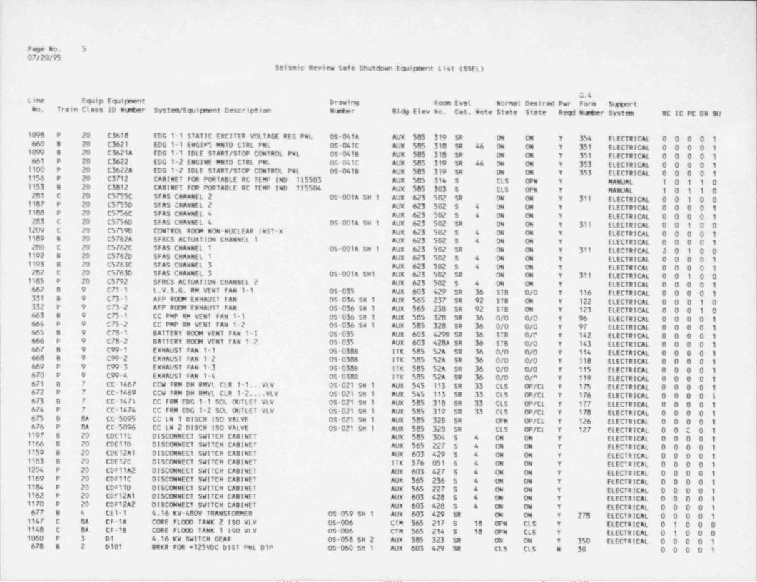
Page No. 50F/20/95
Seismic Review Safe Shutdoun Equipment List (SSEL)
G.4Line Equip Equipment Drawing Room Eval Nomal Desired Pwr Form SupportCo. Train Class ID Nunber System / Equipment Description Ntaber Blde Elev No. Cat. Note State State Reqd utsuber System RC IC PC DH SU
1098 P 20 C3618 EDG 1-1 STATIC EXCITER VOLTAGE REG PNL OS-041A AUX 585 319 SR 04 ON Y 354 ELECTRICAL 0 0 0 0 1660 8 20 C3621 EDG 1-1 ENGI M MNTD CTRL PNL OS-041C AUX 585 318 SR 46 04 04 Y 351 ELECTRICAL 0 0 0 0 11099 8 20 C3621A EDG 1-1 IDLE START /STOP CONTROL PNL 05-041B AUX 585 318 SR ON 04 Y 351 ELECTRICAL 0 0 0 0 1661 P 20 C3622 EDG 1-2 ENGlWE MNTD CTRL PNL OS-041C AUX 585 319 SR 46 ON 04 Y 353 ELECTRICAL 0 0 0 0 11163 P 20 C3622A EDG 1-2 IDLE START /STOP CONTROL PNL 05-0418 AUX 585 319 SR ON 04 Y 353 ELECTRICAL 0 0 0 0 11156 P 20 C3712 CA8tNET FOR PORTABLE RC TEMP IND TI5503 AUX 585 314 S CLS OPN Y MANUAL 1 0 1 1 01153 e 20 C3812 CASINET FOR PORTABLE RC TEMP IND TI5504 AUX 585 303 S CLS OPN Y MANUAL 1 0 1 1 0289 C 20 C5755C SFAS CHANNEL 2 OS-001A SH 1 AUX 623 502 SR ON ON Y 311 ELECTRICAL 0 0 1 0 01107 P 20 C57550 SFAS CHANNEL 2 AUX 623 502 S 4 ON ON Y ELECTRICAL 0 0 0 0 11188 P 20 C5756C SFAS CHANNEL 4 AUX 623 502 S 4 04 ON Y ELECTRICAL 0 0 0 0 1293 C 20 C5756D SFAS CHANNEL 4 05-001A SH 1 AUX 623 502 SR ON ON Y 311 ELECTRICAL 0 0 1 0 01209 C 20 C5759D CONTROL ROOM NON-NUCLEAR INST-X AUX 623 502 S 4 ON ON Y ELECTRICAL 0 0 0 0 1
i 19G9 8 20 C5762A SFRCS ACTUATION CHANNEL 1 AUX 623 502 S 4 04 04 Y ELECTRICAL 0 0 0 0 1280 C 20 C5762C SFAS CHANNEL 1 OS-001A SH 1 AUX 623 502 SR 04 04 Y 311 ELECTRICAL 3 0 1 0 01192 8 20 C5762D STAS CHANNEL 1 AUX 623 502 5 4 04 ON Y ELECTRICAL 0 0 0 0 11
1193 8 20 C5763C SFAS CHANNEL 3 AUX 623 502 S 4 ON ON Y ELECTRICAL 0 0 0 0 1282 C 20 C57630 SFAS CMANNEL 3 05-001A SH1 AUX 623 502 SR ON ON Y 311 ELECTRICAL 0 0 1 0 01105 P 20 C5792 SFRCS ACTUATION CHANNEL 2 AUX 623 502 S 4 ON 04 Y ELECTRICAL 0 0 0 0 1662 B 9 C71-1 L.V.S.G. RM VENT FAN 1-1 05-035 AUX 603 429 SR 36 STS 0/0 Y 116 ELECTRICAL 0 0 0 0 1331 8 9 CT3-1 AFP ROOM EXHAUST FAN 05-036 SH 1 AUX 565 237 SR 92 STB ON Y 122 ELECTRICAL 0 0 0 1 0332 P 9 C73-2 AFP ROOM EXHAUST FAN 05-036 SH 1 AUX 565 238 SR 92 STB 04 Y 123 ELECTRICAL 0 0 0 1 0663 8 9 C75-1 CC PMP RM VENT FAN 1-1 OS-036 SH 1 AUX 585 328 SR 36 0/0 0/0 Y % ELECTRICAL 0 0 0 0 1664 P 9 C75-2 CC PMP RM VENT FAN 1-2 0s 036 SH 1 AUX 585 328 SR 36 0/0 0/0 Y 97 ELECTRICAL 0 0 0 0 1665 8 9 C78-1 BATTERY ROOM VENT FAN 1-1 0S-035 AUX 603 4298 SR 36 STB 0/c Y 142 ELECTRICAL 0 0 0 0 1666 P 9 C78-2 BATTERY ROOM VENT FAN 1-2 OS-035 AUX 603 428A SR 36 STB 0/0 Y 143 ELECTRICAL 0 0 0 0 11 667 8 9 C99-1 EXHAUST FAN 1-1 05-0388 ITK $85 52A SR 36 0/0 0/0 Y 114 ELECTRICAL 0 0 0 0 1| 668 8 9 C99-2 EXHAUST FAN 1-2 0s-0388 ITK 585 52A SR 36 0/0 0/0 Y 118 ELECTRICAL 0 0 0 0 1|
669 P 9 C99-3 EXHAUST FAN 1-3 05-0388 ITK $85 52A SR 36 0/0 0/0 Y 115 CLECTRICAL 0 0 0 0 1GTO P 9 C99 4 EXHAUST FAN 1-4 0S-0388 ITK 585 52A SR 36 0/0 0/a Y 119 ELECTRICAL 0 0 0 0 1,
1 671 B 7 CC-1467 CCW FRM DH RMVL CLR 1-1...VLV 05-021 SH 1 AUX 545 113 SR 33 CLS OP/CL Y 175 ELECTRICAL 0 0 0 0 1GP2 P 7 CC-1469 CCW FRM DH RMVL CLR 1-2....VLV 05-021 SH 1 AUX 545 113 SR 33 CLS OP/CL Y 176 ELECTRICAL 0 0 0 0 1GF3 0 7 CC-147) CC FRM EDG 1-1 SQL OUTLET VLV 0s-021 SH 1 AUX 585 318 SR 33 CLS OP/CL Y 177 ELECTRICAL 0 0 0 0 1674 P 7 CC-1474 CC FRM EDG 1-2 SOL CUTLET VLV 05-021 54 1 AUX 585 319 SR 33 CLS OP/CL Y 178 ELECTRICAL 0 0 0 0 1675 B BA CC 5095 CC LN 1 DISCH ISO VALVE 0s-021 SH 1 AUX 585 328 SR OPN OP/CL Y 126 ELECTRICAL 0 0 0 0 1GFG P 8A CC-5096 CC LN 2 DISCH ISO VALVE 0s-021 SH 1 AUX 585 328 SR CLS OP/CL Y 127 ELECTRICAL 0 0 0 0 11197 B 20 CDE11C DISCONNECT SWITCH CABINET AUX 585 304 S 4 ON ON Y ELECTRICAL 0 0 0 0 111G6 B 20 CDE11D DISCONNECT SWITCH CABINET AUX 565 227 S 4 04 ON Y ELECTRICAL 0 0 0 0 11159 8 20 CDE12A1 DISCONNECT SWITCH CA8INET AUX 603 429 $ 4 ON 04 Y ELECTRICAL 0 0 0 0 11103 B 20 CDE12C DISCONNECT SWITCH CABINET ITK 576 051 S 4 ON ON Y ELECTRICAL 0 0 0 0 11204 P 20 CDF11A2 DISCONNECT SWITCH CABINET AUX 603 427 5 4 CM ON Y ELECTRICAL 0 0 0 0 19169 P 20 CDF11C DISCONNECT SWITCH CA81 NET AUX 565 236 S 4 ON ON Y ELECTRICAL 0 0 0 0 11184 P 20 CDF11D DISCONNECT SWITCH CA8INET AUX 565 227 S 4 ON ON Y ELECTRICAL 0 0 0 0 11162 P 20 CDF12A1 DISCONNECT SWITCH CABINET AUX 603 428 s 4 04 04 Y ELECTRICAL 0 0 0 0 11170 P 20 CDF12A2 DISCONNECT SWITCH CABINET AUX 603 428 S 4 04 ON Y ELECTRICAL 0 0 0 0 1677 8 4 CEl-1 4.16 KV-480V TRANSFORMER OS-059 SH 1 AUX 603 429 SR ON ON Y 278 ELECTRICAL 0 0 0 0 1114? C 8A CF-1A CORE FLOOD TANK 2 ISO VLV 05-006 CTM 565 217 S 18 OPN CLS Y ELECTRICAL 0 1 0 0 01140 C 8A CF 1B CORE FLOOD TANK 1 150 VLV OS-006 CTM 565 214 S 18 OPN CLS Y ELECTRICAL 0 1 0 0 01060 P 3 D1 4.16 KV SWITCH GEAR 05-058 SH 2 AUX 585 323 SR 04 ON Y 350 ELECTRICAL 0 0 0 0 16TB B 2 D101 BRKR FOR +125VDC DIST PNL D1P OS-060 SH 1 AUX 603 429 SR CLS CLS N 30 0 0 0 0 1
,_ , , -_ _ _ _ - . - _ _ . _ _ _ . _ . . - - _ _ _ _ _ _ _ _ _ _ __ _ _ . _ _ _ _ _ _ _ _ . _ _ _ _ _ _ _ _ _ _ _ _ _ _ _ _ _ _ _
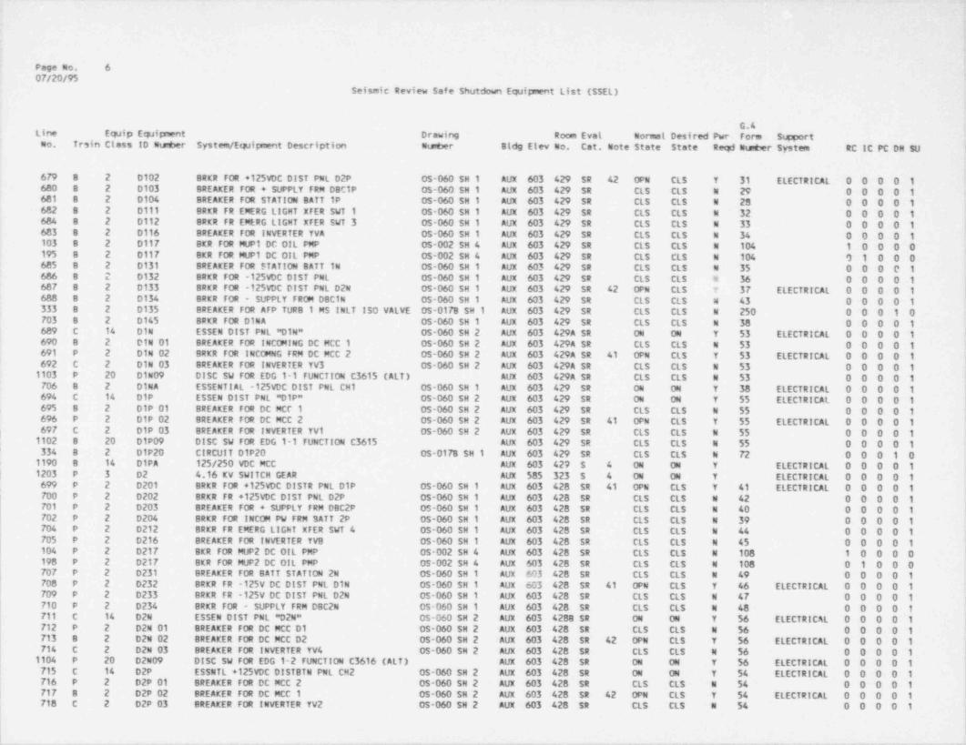
Page No. 607/20/95
Seismic Review Safe Shutdown Equip'ent List (SSEL)
G.4Line Equip Equipnent Drawing Room Eval Normal Desired Pwr Form SupportCo. Trsin Class ID Nmber System / Equipment Description Nueer Bldg Elev No. Cat. Note State State Reqd Wupter System RC IC PC DH SU
679 8 2 0102 BRKR FOR +125VDC DIST PNL D2P 0S-060 SH 1 AUX 603 429 SR 42 OPN CLS Y 31 ELECTRICAL 0 0 0 0 1680 8 2 D103 BREAKER FOR + SUPPLY FRM DBC1P 0$-060 SH 1 AUX 603 429 SR CLS CLS N 29 0 0 0 0 1681 B 2 D104 BREAKER FOR STATION BATT 1P 05-060 SH 1 AUX 603 429 SR CLS CLS N 28 0 0 0 0 1682 8 2 D111 BRKR FR EMERG LIGHT XFER SVT 1 OS-060 SH 1 AUX 603 429 SR CLS CLS N 32 0 0 0 0 1684 8 2 0112 BRKR FR EMERG LIGHT XFER SVT 3 05-060 SH 1 AUX 603 429 SR CLS CLS N 33 0 0 0 0 1683 8 2 D116 BREAKER FOR INVERTER YVA 0s-060 SH 1 AUX 603 429 SR CLS CLS N 34 0 0 0 0 1103 8 2 D117 BKR FOR MUP1 DC OIL PMP 05-002 SH 4 AUX 603 429 SR CLS CLS N 104 1 0 0 0 0195 8 2 D117 BKR FOR MUP1 DC OIL PMP 05-002 SH 4 AUX 603 429 SR CLS CLS N 104 0 1 0 0 0685 B 2 0131 BREAKER FOR STATION BATT IN OS-060 SH 1 AUX 603 429 SR CLS CLS N 35 0 0 0 0 1686 8 2 0132 BRKR FOR -125VDC DIST PNL OS-060 SH 1 AUX 603 429 SR CLS CLS w 36 0 0 0 0 1687 8 2 0133 BRKR FOR -125VDC DIST PNL D2N 05-060 SH 1 AUX 603 429 SR 42 OPN CLS T 37 ELECTRICAL 0 0 0 0 1688 8 2 0134 BRKR FOR - SUPPLY FROM DBC1N 05-060 SH 1 AUX 603 429 SR CLS CLS W 43 0 0 0 0 1333 8 2 D135 BREAKER FOR AFP TURB 1 MS INLT ISO VALVE 05-017B SH 1 AUX 603 429 SR CLS CLS N 250 0 0 0 1 0703 8 2 D145 BRKR FOR DINA OS-060 SH 1 AUX 603 429 SR CLS CLS N 38 0 0 0 0 1689 C 14 DIN ESSEN DIST PNL " DIN" 0s-060 SH 2 AUX 603 429A SR 04 ON Y 53 ELECTRICAL 0 0 0 0 1690 8 2 DIN 01 BREAKER FOR INCW ING DC MCC 1 0s-060 SH 2 AUX 603 429A SR CLS CLS N 53 0 0 0 0 1691 P 2 DIN 02 BRKR FOR INCmNG FRM DC MCC 2 OS-060 SH 2 AUX 603 429A SR 41 OPN CLS Y 53 ELECTRICAL 0 0 0 0 1692 C 2 DIN 03 BREAKER FOR INVERTER YV3 05 060 SH 2 AUX 603 429A SR CLS CLS N $3 0 0 0 0 11103 P 20 01N09 DISC SW FOR EDG 1-1 FUNCTION C3615 (ALT) AUX 603 429A SR CLS CLS N 53 0 0 0 0 1706 B 2 DINA ESSENTIAL -125VDC DIST PNL CH1 0s-060 SH 1 AUX 603 429 SR ON ON Y 38 ELECTRICAL 0 0 0 0 1694 C 14 DIP ESSEN DIST PNL "D1P" 05-060 SH 2 AUX 603 429 SR ON ON Y 55 ELECTRICAL 0 0 0 0 1695 B 2 01P 01 BREAKER FOR DC MCC 1 05-060 SH 2 AUX 603 429 SR CLS CLS N SS 0 0 0 0 1696 P 2 DIP 02 BREAKER FOR DC MCC 2 05-060 SH 2 AUX 603 429 SR 41 OPN CLS Y 55 ELECTRICAL 0 0 0 0 1697 C 2 01P 03 BREAKER FOR INVERTER YV1 05-060 SH 2 AUX 603 429 SR CLS CLS N SS 0 0 0 0 1;
, 1102 8 20 D1P09 DISC SW FOR EDG 1-1 FUNCTION C3615 AUX 603 429 SR CLS CLS N 55 0 0 0 0 1334 8 2 01P20 CIRCUIT D1P20 05-017B SH 1 AUX 603 429 SR CLS CLS N 72 0 0 0 1 0
'
1190 8 14 D1PA 125/250 VDC MCC AUX 603 427 5 4 ON ON Y ELECTRICAL 0 0 0 0 1| 1203 P 3 D2 4.16 KV SWITCH GEAR AUX 585 323 $ 4 04 ON Y ELECTRICAL 0 0 0 0 1
699 P 2 D201 BRKR FOR +125VDC DISTR PNL DIP 05-060 SH 1 AUX 603 428 SR 41 OPN CLS Y 41 ELECTRICAL 0 0 0 0 1700 P 2 D202 BRKR FR +125VDC DIST PNL D2P OS-060 SH 1 AUX 603 428 SR CLS CLS N 42 0 0 0 0 1701 P 2 D203 BREAKER FOR + SUPPLY FRM DBC2P 05-060 SH 1 AUX 603 428 SR CLS CLS N 40 0 0 0 0 1702 P 2 D204 BRKR FOR INCOM PW FRM SATT 2P OS-060 SH 1 AUX 603 428 SR CLS CLS N 39 0 0 0 0 1704 P 2 D212 BRKR FR EMERG LIGHT XTER SWT 4 0S-060 SH 1 AUX 603 428 SR CLS CLS N 44 0 0 0 0 1705 P 2 D216 BREAKER FOR INVERTER YVB 05-060 SH 1 AUX 603 428 SR CLS CLS N 45 0 0 0 0 1104 P 2 D217 BKR FOR MUP2 DC OIL PMP OS-002 SH 4 AUX 603 428 SR CLS CLS N 108 1 0 0 0 0193 P 2 D217 BKR FOR MUP2 DC OIL PMP 05-002 SH 4 AUX 603 428 SR CLS CLS N 108 0 1 0 0 0707 P 2 D231 BREAKER FOR BATT STATION 2N OS-060 SH 1 AUK 603 428 SR CLS CLS N 49 0 0 0 0 1703 P 2 D232 BRKR FR -125V DC DIST PNL D1N OS-060 SH 1 AUX 603 428 SR 41 OPN CLS Y 46 ELECTRICAL 0 0 0 0 17D9 P 2 D233 BRKR FR -125V DC DIST PNL D2N 05-060 SH 1 AUX 603 428 SR CLS CLS N 47 0 0 0 0 1710 P 2 D234 BRKR FOR - SUPPLY FRM DBC2N 05-060 SH 1 AUX 603 428 SR CLS CLS N 48 0 0 0 0 1711 C 14 D2N ESSEN DIST PNL "D2N" OS-060 SH 2 AUX 603 4288 SR ON ON Y 56 ELECTRICAL 0 0 0 0 1712 P 2 D24 01 BREAKER FOR DC MCC D1 0S-060 SH 2 AUX 603 428 SR CLS CLS N 56 0 0 0 0 1713 8 2 02N 02 BREAKER FOR DC MCC D2 05-060 SH 2 AUX 603 428 SR 42 OPN CLS Y 56 ELECTRICAL 0 0 0 0 1714 C 2 D2N 03 BREAKER FOR INVERTER YV4 05-060 SH 2 AUX 603 428 SR CLS CLS N 56 0 0 0 0 11104 P 20 D2N09 DISC SW FOR EDG 1-2 FUNCTION C3616 (ALT) AUX 603 428 SR ON ON Y 56 ELECTRICAL 0 0 0 0 1
| 715 C 14 D2P ESSNTL +125VDC DISTBTN PNL CH2 05-060 SH 2 AUX 603 428 SR 04 ON Y 54 ELECTRICAL 0 0 0 0 1716 P 2 D2P 01 BREAKER FOR DC MCC 2 05-060 SH 2 AUX 603 428 SR CLS CLS N 54 0 0 0 0 1717 8 2 D2P 02 BREAKER FOR DC MCC 1 05-060 SH 2 AUX 603 428 SR 42 OPN CLS Y 54 ELECTRICAL 0 0 0 0 1718 C 2 D2P 03 BREAKER FOR INVERTER YV2 OS-060 SH 2 AUX 603 428 SR CLS CLS N 54 0 0 0 0 1
. . _
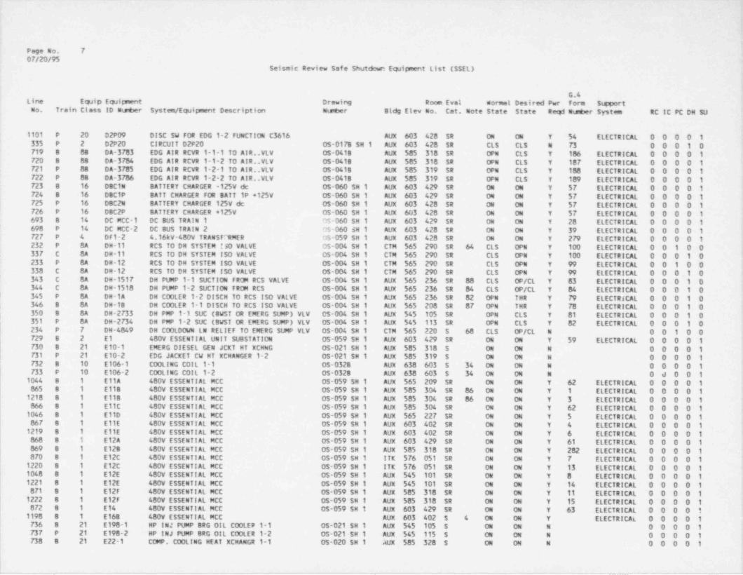
Page No. 707/20/95
Seismic Review safe Shutdown Equipment List (SSEL)
.
G.4Line Equip Equipment Drawing Room Eval Normal Desired Pwr Foria S g ortCo. Train Class ID 4ts6er SysteWEquipment Description Ntster Bldg Elev No. Cat. Note State State Reqd Nts6er Systeen RC IC PC DH SU
1101 P 20 D2P09 DISC SW FOR EDG 1-2 FUNCTION C3616 AUX 603 428 SR ON ON Y 54 ELECTRICAL 0 0 0 0 1335 P 2 D2P20 CIRCUIT D2P20 05-0178 SH 1 AUX 603 428 SR CLS CLS N 73 0 0 0 1 0719 8 88 DA-3783 EDG AIR RCVR 1-1-1 TO AIR..YLV 05-0418 AUX 585 318 SR OPN CLS Y 186 ELECTRICAL 0 0 0 0 1720 8 88 DA-3784 EDG AIR RCVR 1-1-2 TO AIR..VLV 05-0418 AUX 585 318 SR OPN CLS Y 187 ELECTRICAL 0 0 0 0 1721 P 88 04-3785 EDG AIR RCVR 1-2-1 TO AIR..VLV 05-0418 AUX 585 319 SR OPN CLS Y 188 ELECTRICAL 0 0 0 0 1722 P 88 04-3786 EDG AIR RCVR 1-2-2 TO AIR..VLV 05-041B AUX 585 319 St OPN CLS Y 189 ELECTRICAL 0 0 0 0 1723 8 16 Dec1u BATTERY CHARGER -125V de 05-060 SH 1 AUX 603 429 SR 04 04 Y 57 ELECTRICAL 0 0 0 0 1724 8 16 D8C1P BATT CHARGER FOR BATT 1P +125V 05-060 SH 1 AUX 603 429 SR ON ON Y 57 ELECTRICAL 0 0 0 0 1725 P 16 DBC2N BATTERY CHARGER 125V de 05-060 SH 1 AUX 603 428 SR ON ON Y 57 ELECTRICAL 0 0 0 0 1726 P 16 08C2P BATTERY CHARGER +125V OS-060 SH 1 AUX 603 428 SR ON ON Y 57 ELECTRICAL 0 0 0 0 1693 B 14 DC MCC-1 DC BUS TRAIN 1 0s-060 SH 1 AUX 603 429 SR 04 ON Y 28 ELECTRICAL 0 0 0 0 1698 P 14 DC MCC-2 DC BUS TRAIN 2 OS-060 $N 1 AUX 603 428 SR ON ON Y 39 ELECTRICAL 0 0 0 0 172 7 P 4 DF1-2 4.16kV-480V TRANSF'1tMER 05-059 SH 1 AUX 603 428 SR ON ON Y 279 ELECTRICAL 0 0 0 0 1232 P 8A DM-11 RCS TO DH SYSTEM !so VALVE 0s-004 SH 1 CTM 565 290 SR 64 CLS OPN Y 100 ELECTRICAL 0 0 1 0 0337 C BA DM-11 RCS TO DH SYSTEM ISO VALVE 05-004 SH 1 CTM 565 290 SR CLS OPN Y 100 ELECTRICAL 0 0 0 1 0 '
233 P 8A DM-12 RCS TO DH SYSTEM ISO VALVE 05-004 SH 1 CTM 565 290 SR CLS OPN Y 99 ELECTRICAL 0 0 1 0 0338 C 8A DM-12 RCS TO DH SYSTEM ISO VALVE 05-004 SH 1 CTM 565 290 SR CLS OPN Y 99 ELECTRICAL 0 0 0_1 0343 C BA DH-1517 DH PUMP 1-1 SUCTION FROM RCS VALVE 05-004 SH 1 AUX 565 236 SR 88 CLS OP/CL Y 83 ELECTRICAL 0 0 0 1 0344 C BA DM-1518 DH PUMP 1-2 SUCTION FROM RCS 05-004 SH 1 AUX 565 236 SR 84 CLS OP/CL Y 84 ELECTRICAL 0 0 0 1 0
l 345 P 8A DH-1A DH COOLER 1-2 DISCH TO RCS ISO VALVE 05-004 SH 1 AUX 565 236 SR 82 OPN THR Y 79 ELECTRICAL 0 0 0 1 0346 8 8A DM-1B DH COOLER 1-1 DISCH TO RCS ISO VALVE 05-004 SH 1 AUX 565 208 SR 87 OPN THR Y 78 ELECTRICAL 0 0 0 1 0350 8 8A DH-2733 DH PMP 1-1 SUC (BWST OR EMERG SUMP) VLV 05-004 SH 1 AUX 545 105 SR OPN CLS Y 81 ELECTRICAL 0 0 0 1 0;351 P BA DM-2734 DH PMP 1-2 SUC (BWST OR EMERG SUMP) VLV 05-004 SH 1 AUX 545 113 SR OPN CLS Y 82 ELECTRICAL 0 0 0 1 0234 P 7 DM-4849 DH COOLDOWN LN RELIEF TO EMERG SUMP VLV OS-004 SH 1 CTM 565 220 5 68 CLS OP/CL M 0 0 1 0 0 '
729 8 2 El 480V ESSENTIAL UNIT SUBSTATION 0s-059 SH 1 AUX 603 429 SR 04 ON Y 59 ELECTRICAL 0 0 0 0 1730 B 21 E10-1 EMERG DIESEL GEN JCXT HT XCHNG OS-021 SH 1 AUX 585 318 5 04 ON N 0 0 0 0 1731 P 21 E10-2 EDG JACKET CW HT XCHANGER 1-2 05-021 SH 1 AUX 585 319 $ 04 ON N 0 0 0 0 1732 B 10 E106-1 COOLING COIL 1-1 05-0328 AUX 638 603 S 34 04 ON N O 0 0 0 1
'
733 P 10 E106-2 COOLING COIL 1-2 05-0328 AUX 638 603 S 34 ON ON N O d 0 0 11044 8 1 EllA 480V ESSENTIAL MCC 0S-059 SH 1 AUX 565 209 SR ON ON Y 62 ELECTRICAL 0 0 0 0 1865 B 1 E118 480V ESSENTIAL MCC 05-059 SH 1 AUX 585 304 SR 86 ON ON Y 1 ELECTRICAL 0 0 0 0 1 '
1213 8 1 E118 480V ESSENTIAL MCC 05-059 SH 1 AUX 585 304 SR 86 ON 04 Y 3 ELECTRICAL 0 0 0 0 1866 8 1 E11C 480V ESSENTIAL MCC OS-059 SH 1 AUX 585 304 SR ON ON Y 62 ELECTRICAL 0 0 0 0 1
,
1046 B 1 E110 480V ESSENTIAL MCC OS-059 SH 1 AUX 565 227 SR 04 ON Y 5 ELECTRICAL 0 0 0 0 1867 8 1 E11E 480V ESSENTIAL MCC 05-059 SH 1 AUX 603 402 SR ON ON Y 4 ELECTRICAL 0 0 0 0 11219 8 1 E11E 480V ESSENTIAL MCC 05-059 SH 1 AUX 603 402 SR ON ON Y 6 ELECTRICAL 0 0 0 0 1 t
868 B 1 E12A 480V ESSENTI AL MCC 05-059 SH 1 AUX 603 429 SR 04 ON Y 61 ELECTRICAL 0 0 0 0 1'
869 8 1 E128 480V ESSENTIAL MCC 05-059 SH 1 AUX 585 318 SR ON ON Y 282 ELECTRICAL 0 0 0 0 1 *
870 8 1 E12C 480V ESSENTIAL MCC 05-059 SH 1 ITK 576 051 SR ON ON Y 7 ELECTRICAL 0 0 0 0 11220 8 1 E12C 480V ESSENTIAL MCC OS-059 SH 1 ITK 576 051 SR ON ON Y 13 ELECTRICAL 0 0 0 0 11048 8 1 E12E 480V ESSENTIAL MCC OS-059 SH 1 AUX 545 101 SR ON ON Y 8 ELECTRICAL 0 0 0 0 11221 B 1 E12E 480V ESSENTIAL MCC OS-059 SH 1 AUX 545 101 SR 04 ON Y 14 ELECTRICAL 0 0 0 0 1871 B 1 E12F 480V ESSENTIAL MCC OS-059 SH 1 AUX 585 318 SR ON ON Y 11 ELECTRICAL 0 0 0 0 11222 8 1 E12F 480V ESSENTIAL MCC 05-059 SH 1 AUX 585 318 SR ON ON Y 15 ELECTRICAL 0 0 0 0 1G72 B 1 E14 480V ESSENTIAL MCC OS-059 SH 1 AUX 603 429 SR 04 ON Y 63 ELECTRICAL 0 0 0 0 11198 B 1 E168 480V ESSENTIAL MCC AUX 603 402 S 4 04 04 Y ELECTRICAL 0 0 0 0 1T36 8 21 E198-1 HP INJ PUMP BRG OIL COOLEP 1-1 OS-021 SH 1 AUX 545 105 S ON ON N 0 O O O 173 7 P 21 E198-2 HP INJ PUMP BRG OIL COOLER 1-2 OS-021 SH 1 AUX 545 115 S ON ON N O O O O 173 8 8 21 E22-1 COMP. COOLING HEAT XCHANGR 1-1 05-020 SH 1 AUX 585 328 S ON ON N 0 O O O 1
I
_ . . _ . , _ . , . - .,,- _ -, . _ -. --- _ _ _ _ _ _ _ _ - - _ _ _ _ . _ _ _

.. _ _ _ _ _ . . - ..
I
Page No. 8OF/20/95
j
!Seismic Review Safe Shutdown Equipment List (SSEL)
I
G.4Line Equip Equipnent Drawing Room Evat Normal Desired Pwr Form SupportCo. Train Class ID Nu@er System / Equipment Description Nte er Bldg Elev No. Cat. L'Jte State State Reqd Nts6er System RC IC PC DH SU
'
1
102F B 21 E22-1 COMP. COOLING HEAT XCHANGP. 1-1 0S-021 SH 1 AUX 585 328 5 ON ON N 0 0 0 0 1739 P 21 E22-2 COMP. COOLING HEAT XCHANGR 1-2 05-020 SH 1 AUX $85 328 S ON ON N 0 0 0 0 11029 P 21 E22 2 COMP. COOLING HEAT XCHANGR 1-2 05-021 SH 1 Aux 585 328 S ON ON N 0 0 0 0 1740 8 21 E22-3 COMP. COOLING HEAT XCHANGR 1-3 0s-020 SH 1 Aux 585 328 5 ON N/A N O 0 0 0 1 i5020 8 21 E22-3 COMP. C0 CLING HEAT XCHANGR 1-3 05-021 SH 1 Aux 585 328 S ON N/A N O O O 0 123 C 21 E26-1 SEAL RETURN COOLER 1-1 OS-002 SH 2 Aux 565 208 S OFF OFF M 1 0 0 0 0141 C 21 E26-1 SEAL RETURN COOLER 1-1 05-002 SH 2 AUX 565 208 5 0FF OFF M 0 1 0 0 024 C 21 E26-2 SEAL RETURN COOLER 1-2 0s-002 SH 2 Aux 565 208 S ON N/A N 1 0 0 0 0142 C 21 E26-2 SEAL RETURN COOLER 1-2 05 002 SH 2 AUX 565 208 S ON ON N 0 1 0 0 025 C 21 E27-1 DECAY MEAT REMOYAL COOLER 1-1 05-004 SH 1 AUX 545 113 S ON N/A N 1 0 0 0 035F B 21 E27-1 DECAY HEAT REMOVAL COOLER 1-1 OS-004 SH 1 AUX 545 113 5 79 ON ON N O 0 0 1 02G C 21 E27-2 DECAY HEAT REMOVAL COOLER 1-2 0S-004 SH 1 AUX 545 113 S ON N/A N 1 0 0 0 0350 P 21 E27-2 DECAY HEAT REMOYAL COOLER 1-2 05-004 SH 1 AUX 545 113 5 79 ON ON N 0 0 0 1 027 C 21 E34 BWST HEATER 0s-007 AUX 565 209 S 99 04 N/A N 1 0 0 0 0160 C 21 E34 BWST HEATER 05-007 AUX 565 209 5 99 ON N/A N 0 1 0 0 0235 8 10 E37-1 CAC COIL 1-1 (SW SIDE) 0s-033A CTM 585 317 5 79 ON ON N O O 1 0 0741 B 10 E37-1 CAC COIL 1-1 (SW SIDE) 05-020 SH 1 CTM 585 317 $ 04 ON N O O O O 1236 P 10 E37-2 CAC C0!L 1-2 (SW SIDE) OS-033A CTM 585 317 5 79 ON ON N 0 0 1 0 0742 B 10 E37-2 CAC COIL 1-2 (SW SIDE) 05-020 SH 1 CTM 585 317 5 ON ON N 0 0 0 0 1 '
743 8 10 E37-3 CTMT AIR COOLER 1-3 05-020 SH 1 CTM 585 317 S OFF OFF N 0 0 0 0 1744 P 10 E42-1 ECCS ROOM COOLER C0!L 1-1 0s-020 SH 1 AUX 545 115 S ON N/A N O O O O 1 ;T45 P 10 E42-2 ECCS ROOM COOLER COIL 1-2 OS-020 SH 1 AUX 545 115 S ON N/A N O O O O 1 '
, 746 P 10 E42-3 ECCS ROOM COOLER COIL 1-3 05-020 SH 1 AUX 545 113 5 ON N/A N 0 O O O 1 .'
747 B 10 E42-4 ECCS ROOM COOLER COIL 1-4 OS-020 SH 1 AUX 545 105 S ON N/A N O O O O 1 !74Q B 10 E42 5 ECCS ROOM COOLER COIL 1-5 05-020 SH 1 AUX $45 105 S ON N/A N 0 0 0 0 1 !
F49 9 20 El 4553 BUS Y1A VOLTMETER 05-060 SH 2 Aux 623 505 SR ON ON Y 52 ELECTRICAL 0 0 0 0 1 e
750 P 20 El-4554 BUS Y2A VOLTMETER 05-%0 SH 2 AUX 623 505 SR ON ON Y 52 ELECTRICAL 0 0 0 0 1105F B 20 EI-6271 BUS D1P VOLTMETER 05-060 SH 2 AUX 623 505 SR ON ON Y 52 ELECTRICAL 0 0 0 0 1 i105G P 20 EI-6272 BUS D2N VOLTMETER OS-060 SH 2 Aux 623 505 SR ON ON Y 52 ELECTRICAL 0 0 0 0 1 '
751 B 20 El-6273 BUS 1P-BUS INCOMING VOLTMETER OS-060 SH 1 Aux 623 502 SR ON ON Y 52 ELECTRICAL 0 0 0 0 1752 P 20 E l-6274 BUS 2P-BUS 2N VOLTMETER OS-060 SH 1 AUX 623 502 SR ON 04 Y 52 ELECTRICAL 0 0 0 0 1 |1059 B 20 El-6275 BUS DIN VOLTMETER 05-060 SH 2 AUX 623 505 SR ON ON Y 52 ELECTRICAL 0 0 0 0 1753 P 20 El-6276 BUS D2P VOLTMETER 05-060 SH 2 AUX 623 502 SR ON ON Y 52 ELECTRICAL 0 0 0 0 1756 8 20 El-6277 BUS Y1 VOLTMETER OS-060 SH 2 Aux 623 505 SR ON ON Y 52 ELECTRICAL 0 0 0 0 1755 P 20 El-6278 BUS Y4 VOLTMETER 05-060 SH 2 AUX 623 505 SR ON ON Y 52 ELECTRICAL 0 0 0 0 1
'
756 8 20 El-6281 BUS Y3 VOLTMETER OS-060 SH 2 Aux 623 505 SR ON ON Y 52 ELECTRICAL 0 0 0 0 1757 P 20 El-6282 BUS Y2 VOLTMETER OS-060 SH 2 AUX 623 505 SR 04 ON Y 52 ELECTRICAL 0 0 0 0 1 t
i
750 B 20 El-6297 BUS YAU VOLTMETER OS-060 SH 1 AUX 623 505 SR ON ON Y 52 ELECTRICAL 0 0 0 0 1 <
759 P 20 El-6298 BUS YBU VOLTMETER 05-060 SH 1 AUX 623 505 SR ON 04 Y 52 ELECTRICAL 0 0 0 0 1 '
760 P 2 F1 480V ESSENTIAL UNIT SUBSTATION 0S-059 SH 1 AUX 603 428 SR 04 ON Y 60 ELECTRICAL 0 0 0 0 1GF3 P 1 F11A 480V ESSENTIAL MCC OS 059 SH 1 Aux 603 427 SR ON 04 Y 68 ELECTRICAL 0 0 0 0 18F4 P 1 F11B 480V ESSENTIAL MCC OS-059 SH 1 AUX 603 405 SR ON ON Y 19 ELECTRICAL 0 0 0 0 11223 P 1 F11B 480V ESSENTI AL MCC OS-059 SH 1 AUX 603 405 SR ON ON Y 20 ELECTRICAL 0 0 0 0 11049 P 1 F11C 480V ESSENTIAL MCC 05-059 SH 1 AUX 565 236 SR ON ON Y 281 ELECTRICAL 0 0 0 0 11045 P 1 F110 480V ESSENTIAL MCC OS-059 SH 1 AUX $65 227 SR ON 04 Y 17 ELECTRICAL 0 0 0 0 1 !1224 P 1 F11D 480V ESSENTIAL MCC OS-059 SH 1 Aux 565 227 SR ON ON Y 21 ELECTRICAL 0 0 0 0 1
31084 P 1 F11E 480V ESSENTIAL MCC OS-059 SH 1 AUX 545 101 SR ON ON Y 16 ELECTRICAL 0 0 0 0 11225 P 1 F11E 480V ESSENTIAL MCC OS-059 SH 1 AUX 545 101 SR ON ON Y 22 ELECTRICAL 0 0 0 0 18 75 P 1 F12A 480V ESSENTIAL MCC 05-059 SH 1 AUX 603 428 SR 04 ON Y 67 ELECTRICAL 0 0 0 0 1
.
.- -- - , , - - - ,-- , ,, ~ . . - . , . -, --w , . , - --n.--> n-,+-- --,.n.m ,-.-m n-- -s - -.*-

Page No. 907/20/95
Seismic Review Safe Shutdown Equipment List (SSEL)
G.4Line Equip Equipment Drawing Roor' Eval Norset Desired Pwr Form Support,
Co. Train Class ID Nts@er System / Equipment Descriptf on Ntster Bldg Elev No. Cat. Note State State Reqd Ntster System RC IC PC DN SU
876 P 1 F128 480V ESSENTIAL MCC 05-059 SH 1 AUX 585 319 SR ON ON Y 280 ELECTRICAL 0 0 0 0 1877 P 1 F12C 480V ESSENTIAL MCC 05-059 SH 1 ITK 576 052 SR 04 ON Y 26 ELECTRICAL 0 0 0 0 1878 P 1 F12D 480V ESSENTIAL MCC 05-059 SH 1 ITK 576 052 SR ON ON Y 27 ELECTRICAL 0 0 0 0 1879 P 1 F14 480V ESSENTIAL MCC 05-059 SH 1 AUX 603 428 SR ON ON Y 65 ELECTRICAL 0 0 0 0 1761 8 0 F15-1 SERVICE WATER STRAINER 1-1 05-020 SH 1 ITK 576 052 SR STB 0/0 Y 134 ELECTRICAL 0 0 0 0 1762 P 0 F15-2 SERVICE WATER STRAINER 1-2 05-020 SH 1 ITK 576 052 SR ST8 0/0 Y 135 ELECTRICAL 0 0 0 0 11047 P 1 F164 480V ESSENTIAL MCC 05-059 SH 1 AUX 603 428 SR ON ON Y 69 ELECTRICAL 0 0 0 0 1763 8 18 FIS 1422C CC PMP 1-1 DISCH FLOW INDIC SW OS-021 SH 1 AUX 585 328 SR 1 04 04 Y 289 ELECTRICAL 0 0 0 0 11181 P 18 Fis 1422D CC PMP 1-1 DISCH FLOW INDIC SW AUX 585 328 S 4 ON ON Y ELECTRICAL 0 0 0 0 11170 8 18 FIS 1427C CC PMP 1-3 DISCH FLOW INDIC SW AUX 585 328 5 4 ON ON Y ELECTRICAL 0 0 0 0 11182 P 18 FIS 1427D CC PMP 1-3 DISCH FLOW INDIC SW AUX 585 328 5 4 04 04 T ELECTRICAL 0 0 0 0 11177 8 18 FIS 1432C CC PMP 1-2 DISCH FLOW INDIC SW AUX $85 328 S 4 04 04 Y ELECTRICAL 0 00 0 1764 P 18 FIS 1432D CC PMP 1-2 DISCH FLOW INDIC SW 05-021 SH 1 AUX 585 328 SR 1 ON ON Y 298 ELECTRICAL 0 0 0 0 1359 P 18 FT DH2A LO PRESSURE INJ LINE 2 FLOW TRANSMITTER 0s-004 SH 1 AUX 565 236 SR 04 04 Y 310 ELECTRICAL 0 0 0 1 0360 8 18 FT DH2B LP INJ LINE 1 FLOW TRANSMITTER 05-004 SH 1 AUX 545 105 SR ON ON Y 310 ELECTRICAL 0 0 0 1 0361 P 20 FYI-DH2A LP INJECTION LINE 2 FLOW RELAY INDICATOR 0s-004 SH 1 AUX 623 505 SR 1 04 ON Y 310 ELECTRICAL 0 0 0 1 0362 8 20 FYI-DH28 LP INJECTION LINE 1 FLOW RELAY INDICATOR 05-004 SH 1 AUX 623 505 SR 1 04 ON Y 310 ELECTRICAL 0 0 0 1 045 B 20 GRP IN LMT ROD GROUP IN LIMIT LIGHTS N/A - C84T AUX 623 505 SR ON ON Y 313 ELECTRICAL 1 0 0 0 0
C5706542 P 20 HIS 100 MS FOR MSIV 100 05-008 SH 1 AUX 623 505 SR ON 04 Y 303 ELECTRICAL 0 0 0 1 0543 C ' 20 HIS 1008 SFRCS CH 2 BLOCK SW N/A AUX 623 505 SR ON 04 Y 312 ELECTRICAL 0 0 0 1 0549 C 20 MIS 100C SFRCS CH 4 BLOCK SW N/A AUX 623 505 SR ON ON Y 312 ELECTRICAL 0 0 0 1 0543 8 20 HIS 101 HS FOR MSIV 101 05-008 SH 1 AUX 623 505 SR ON ON Y 303 ELECTRICAL 0 0 0 1 0550 C 20 HIS 1018 FFRCS CH 1 BLOCK SW N/A AUX 623 505 SR ON 04 Y 312 ELECTRICAL 0 0 0 1 0551 C 20 HIS 101C SFRCS CH 3 BLOCK SW N/A AUX 623 505 SR ON ON Y 312 ELECTRICAL 0 0 0 1 0363 8 20 His 106A AFP TUR8 1-1 MS ISO VALVE SG 1-1 HIS OS-017B SH 1 AUX 623 505 SR ON ON Y 250 ELECTRICAL 0 0 0 1 0364 P 20 MIS 107A AFP TURB 1-2 MS ISO VALVE SG 1-2 HIS OS-017B SH 1 AUX 623 505 SR ON ON Y 153 ELECTRICAL 0 0 0 1 01019 B 20 HIS 1356 CTMT CLR 1 SW OUTLET VALVE HIS IN C5716 05-020 SH 1 AUX 623 505 SR Oh 04 Y 265 ELECTRICAL 0 0 0 0 11020 P 20 HIS 1357 CTMT CLR 2 SW OUTLET VALVE HIS IN C5716 0S-020 SH 1 AUX 623 505 SR ON ON Y 266 ELECTRICAL 0 0 0 0 11021 8 20 MIS 1366 CTMT CLR 1 SW INLT ISO VALVE HIS, C5716 0S-020 SH 1 AUX 623 505 SR ON 04 Y 86 ELECTRICAL 0 0 0 0 11022 P 20 HIS 1367 CTMT CLR 2 SW INLT ISO VALVE HIS, C5716 0S-020 SH 1 AUX 623 505 SR ON 04 Y 87 ELECTRICAL 0 0 0 0 1765 B 20 MIS 1370 SW PMP 1 MAND INDIC SWITCH 05-020 SH 1 AUX 623 505 SR ON ON Y 287 ELECTRICAL 0 0 0 0 1766 P 20 HIS 1371 SW PUMP 2 HIS OS-020 SH 1 AUX 623 505 SR ON ON Y 295 ELECTRICAL 0 0 0 0 1365 e 20 MIS 1382 HIS FOR ISO VALVE SW1382 OS-017A SH 1 AUX 623 505 SR ON ON Y 120 ELECTRICAL 0 0 0 1 0366 8 20 HIS 13828 HIS FOR ISO VALVE SW1382 LOC IN C3630 OS-017A SH 1 AUX 585 324 SR ON ON Y 120 ELECTRICAL 0 0 0 1 0367 P 20 HIS 1383 HIS FOR ISO VALVE SW1383 OS-017A SH 1 AUX 623 505 SR ON ON Y 121 ELECTRICAL 0 0 0 1 0368 P 20 HIS 13838 HIS FOR ISO VALVE SW1383 LOC IN C3630 0$-017A SH 1 AUX 585 324 SR 04 ON Y 121 ELECTRICAL 0 0 0 1 0767 P 20 MIS 1395 SW TO CLNG HDR HIS IN C5717 0S-020 SH 1 AUX 623 505 SR 04 ON Y 160 ELECTRICAL 0 0 0 0 1768 8 20 MIS 1399 SW To CLNG WTR HDR HIS OS-020 SH 1 AUX 623 505 SR ON 04 Y 267 ELECTRICAL 0 0 0 0 1769 8 20 MIS 1414 CCW PMP 1 HAND INDIC SWITCH 05-021 SH 1 AUX 623 505 SR 04 ON Y 289 ELECTRICAL 0 0 0 0 1770 P 20 HIS 1418 CC PMP 2 HIS OS-021 SH 1 AUX 623 505 SR ON ON Y 298 ELECTRICAL 0 0 0 0 1771 B 20 HIS 1424 CC HX 1 SW OUT ISO VLV HIS OS-020 SH 1 AUX 623 505 SR ON ON Y 268 ELECTRICAL 0 0 0 0 1772 P 20 HIS 1434 CC HX2 SW SW OUT VLV HIS 05-020 SH 1 AUX 623 505 SR ON ON Y 269 ELECTRICAL 0 0 0 0 11030 8 20 MIS 1467 DH RMVL CLR 1 CCW OUT HIS 05-021 SH 1 AUX 623 505 SR ON ON Y 175 ELECTRICAL 0 0 0 0 1773 P 20 MIS 1469 DH RMVL CLR 2 CCW OUT HIS 05-021 SH 1 AUX 623 505 SR ON ON Y 1 76 ELECTRICAL 0 0 0 0 1
1031 B 20 MIS 1471 EDG 1 CCW OUT HIS 05-021 SH 1 AUX 623 505 SR ON 04 Y 177 ELECTRICAL 0 0 0 0 11032 P 20 HIS 1474 EDG 2 CCW OUT HIS 05-021 $4 1 AUX 623 505 SR ON ON Y 178 ELECTRICAL 0 0 0 0 1369 B 20 HIS 1517 DH PMP 1-1 NORM Sur: ISO VLV HIS IN C5704 0S-004 SH 1 AUX 623 505 SR 88 04 DN Y 83 ELECTRICAL 0 0 0 1 0370 P 20 HIS 1518 DH PMP 1-2 NORM SUC 150 VLV HIS IN C5704 05-004 SH 1 AUX 623 505 SR 84 04 ON Y 84 ELECTRICAL 0 0 0 1 0
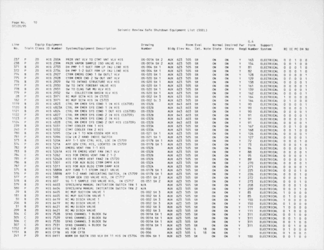
.
Page No. 1007/20/95
Seismic Review Safe Shutdown Equipment List (SSEL)
G.4Line Equip Equipment Drawing Room Evat Normal Desired Pwr Form SwportCo. Train Class 10 Ntster System / Equipment Description Nteber Bldg Elev No. Cat. Note State State Reqd Ntster System RC IC PC DN SU
23F P 20 HIS 2004 PRZR VNT VLV TO CTMT VNT VLV HIS OS-001A SH 2 AUX 623 505 SR ON ON Y 163 ELECTRICAL 0 0 1 0 0238 P 20 MIS 239A PRZR VAPOR SAMPLE ISO VALVE His OS-001A SH 2 AUX 623 505 SR ON 04 Y 154 ELECTRICAL 0 0 1 0 03F1 8 20 Hl$ 2733 DH PMP 1-1 SUCT FRM LP INJ LINE MIS OS-004 SH 1 AUX 623 505 SR 04 ON Y 81 ELECTRICAL 0 0 0 1 03F2 P 20 HIS 2734 DH PMP 1-2 SUCT FRM LP INJ LINE MIS OS-004 SH 1 AUX 623 505 SR ON ON Y 82 ELECTRICAL 0 0 0 1 0774 B 20 MIS 2927 CTRM EMERG COND 1 SW OUTLT VLV 05-020 SH 1 AUX 623 505 SR ON ON Y 128 ELECTRICAL 0 0 0 0 1775 P 20 MIS 2928 CTRM EMER CND 2 SW OUT VNT VLV 0s-020 SH 1 AUX 623 505 SR ON ON Y 129 ELECTRICAL 0 C 0 0 17FG B 20 HIS 2929 SW TO INTAKE STRUCTURE VLV HIS 05-020 SH 1 Aux 623 505 SR ON ON Y 138 ELECTRICAL 0 0 0 0 1F7F P 20 MIS 2930 SW TO INTK FOREBAY VALVE HIS 05-020 SH 1 AUX 623 505 SR ON ON Y 161 ELECTRICAL 0 0 0 0 1779 8 20 MIS 2931 SW TO CLNG TWR MU VLV HIS 05-020 SH 1 AUX 623 505 SR ON ON Y 139 ELECTRICAL 0 0 0 0 1779 P 20 MIS 2932 SW - COLLECTION BASIN VLV HIS OS-020 SH 1 AUX 623 505 SR ON ON Y 162 ELECTRICAL 0 0 0 0 120 P 20 HIS 3971 RC MVP SCTN HIS IN C5703 OS-002 SH 3 AUX 623 505 SR ON ON Y 164 ELECTRICAL 1 0 0 0 0182 P 20 MIS 3971 RC MUP SCTN HIS IN C5703 OS-002 Se 3 AUX 623 505 SR ON ON Y 164 ELECTRICAL 0 1 0 0 01119 8 20 HIS 4823 CTRL RM EMER SYS COND 1 IN HIS (C6708) 0s-0328 AUX 643 603 SR ON ON Y 90 ELECTRICAL 0 0 0 0 11120 8 20 His 4823A CTRL RM EMER SYS COND 1 IN HIS OS-032B AUX 643 603 SR ON ON Y 90 ELECTRICAL 0 0 0 0 11121 B 20 HIS 4824 CTRL RM EMER SYS COND 1 OUT HIS (C6708) OS-0328 AUX 643 603 SR ON ON Y 90 ELECTRICAL 0 0 0 0 11122 P 20 HIS 4827 CTRL RM EMER SYS COND 2 IN HIS (C6709) 05-0328 AUX 643 603 SR ON ON Y 91 ELECTRICAL 0 0 0 0 11123 P 20 MIS 4827A CTRL RM EMER SYS COND 2 IN HIS OS-0328 AUX 643 603 SR ON ON Y 91 ELECTRICAL 0 0 0 0 11124 P 20 His 4828 CTRL RM EMER SYS COND 2 OUT HIS (C6709) OS-0328 AUX 643 603 SR ON ON Y 91 ELECTRICAL 0 0 0 0 1230 8 20 HIS 5031 CTMT C00LER FAN 1 HIS OS-033A AUX 623 505 SR ON ON Y 167 ELECTRICAL 0 0 1 0 0240 P 20 HIS 5032 CTMT COOLER FAN 2 HIS OS-033A AUX 623 505 SR ON ON Y 168 ELECTRICAL 0 0 1 0 0700 8 20 HIS 5095 CCW LN 1 TO NON-ESSEN HDR HIS OS-021 SH 1 AUX 623 505 SR ON ON Y 126 ELECTRICAL 0 0 0 0 1El P 20 MIS 5096 CCW LN 2 MAND INDIC SWITCH 05-021 SH 1 AUX 623 505 SR ON ON Y 127 ELECTRICAL 0 0 0 0 13 73 e 20 HIS 520A AFP 1-1 GOV CTRL HIS, LOC IN C5709 OS-017B SH 1 AUX 623 505 SR ON ON Y 72 ELECTRICAL 0 0 0 1 03 76 P 20 HIS 521A AFP GOV CTRL HIS, LOCATED IN C5709 0s-017B SH 1 AUX 623 505 SR ON ON Y 73 ELECTRICAL 0 0 0 1 0782 P 20 HIS 5261 EMERG YENT FAN 1-1 HIS OS-0328 AUX 623 505 SR ON 04 Y 94 ELECTRICAL 0 0 0 0 1783 8 20 HIS 5261A HIS FR EMERG VENT FAN INLT VLV OS-032B Aux 623 505 SR ON ON Y 88 ELECTRICAL 0 0 0 0 1784 C 20 HIS 5262 HIS FOR EMERG VENT FAN 2 1-2 05-032B AUX 623 505 SR ON ON Y 95 ELECTRICAL 0 0 0 0 1
t 785 P 20 HIS 5262A HIS FR EMER VENT FAN 2 IN C5720 OS-032B AUX 623 505 SR ON ON Y 89 ELECTRICAL 0 0 0 0 1786 8 20 HIS 5301 HIS FOR AUX BLDG CTRM DMPR AIR OS-032A AUX 623 505 SR ON ON Y 270 ELECTRICAL 0 0 0 0 1( 78 7 P 20 HIS 5311 HIS FOR AUX BLDG CTRM DAMP AIR OS-032A AUX 623 505 SR ON ON Y 271 ELECTRICAL 0 0 0 0 1375 B 20 HIS 5889A AFP TURB 1-1 STEAM INLET VALVE OS-017B SH 1 AUX 623 505 SR ON ON Y 225 ELECTRICAL 0 0 0 1 037G P 20 HIS 58898 AFP 1-2 MAND INDICATING SWITCH, IN C5709 OS-017B SH 1 AUX 623 505 SR ON ON Y 226 ELECTRICAL 0 0 0 1 0377 P 20 HIS 598 STEAM GEN ISO VALVE HIS, IN C"717 0s-051 SH 2 AUX 623 505 SR ON ON Y 272 ELECTRICAL 0 0 0 1 0370 8 20 HIS 607 SG 1-1 SAMPLE ISO VALVE HIS, IN C5717 05-051 SH 2 AUX 623 505 SR ON ON Y 2 73 ELECTRICAL 0 0 0 1 0379 8 20 HIS 6403 SFRCS/AFW MANUAL INITIATION SWITCH TRN 1 N/A AUX 623 505 SR ON ON Y 208 ELECTRICAL 0 0 0 1 0,
| 300 P 20 HIS 6404 STRCS/AFW MANUAL INITIATION SWITCH TRN 2 N/A AUX 623 505 SR ON ON Y 209 ELECTRICAL 0 0 0 1 0l 29 8 20 HIS 6405 RC MUP SUCTION VALVE 1 05-002 SH 3 Aux 623 505 SR ON ON Y 85 ELECTRICAL 1 0 0 0 0
101 B 20 HIS 6405 RC MUP SUCTION VALVE 1 0s-002 SH 3 Aux 623 505 SR ON ON Y 85 ELECTRICAL 0 1 0 0 030 B 20 HIS 6419 RC MU DISCH VALVE 1 OS-002 SH 3 AUX 623 505 SR ON ON Y 150 ELECTRICAL 1 0 0 0 0206 B 20 HIS 6419 RC MU DISCH VALVE 1 0S-002 SH 3 AUX 623 505 SR ON ON Y 150 ELECTRICAL 0 1 0 0 039 B 20 HIS 6421 RC MU DISCH VALVE 0S-002 SH 3 AUX 623 505 SR ON ON Y 111 ELECTRICAL 1 0 0 0 0,
| 209 8 20 MIS 6421 RC MU DISCH VALVE 05-002 SH 3 AUX 623 505 SR ON ON Y 111 ELECTRICAL 0 1 0 0 0l 304 C 20 HIS 7528 SFAS CHANNEL 1 BLOCK SW OS-001A SH 1 AUX 623 505 SR ON ON Y 311 ELECTRICAL 0 0 1 0 0
305 C 20 HIS 7529 SFAS CHANNEL 2 BLOCK SW 05-001A SH 1 AUX 623 505 SR ON ON Y 311 ELECTRICAL 0 0 1 0 0306 C 20 MIS 7530 SFAS CHANNEL 3 BLOCK SW OS-001A SH 1 AUX 623 505 SR ON ON Y 311 ELECTRICAL 0 0 1 0 030F C 20 HIS 7531 SFAS CHANNEL 4 BLOCK SW OS-001A SH 1 AUX 623 505 SR ON ON Y 311 ELECTRICAL 0 0 1 0 01152 P 20 HIS CF1A HS FOR CF1A OS-006 AUX 623 505 S 18 ON ON Y ELECTRICAL 0 1 0 0 01151 B 20 HIS CF1B HS FOR CF1B 0S-006 AUX 623 505 S 18 ON 04 7 ELECTRICAL 0 1 0 0 C
! 241 P 20 HIS DH11 NORM DH SUCTN ISO YLV DH 11 HIS IN C5704 OS-004 SH 1 AUX 623 505 SR ON ON Y 100 ELECTRICAL 0 0 1 0 0l
|
. _ _ _ . - _ .

Page No. 11
0F/20/95Seismic Review Safe Shutdown Equipment List (SSEL)
G.4Line EqJip Equipment Drawing Room Eval Normal Desired Pwr Form SumortCo. Train Class ID Nuter System / Equipment Description Arter Bldg Elev No. Cat. Note State State Reqd Nts@er System RC IC PC DH SU
381 P 20 HIS DH11 NORM DH SUCTN ISO VLV DH 11 HIS IN C5704 OS-004 SH 1 AUX 623 505 SR ON ON Y 100 ELECTRICAL 0 0 0 1 0242 P 20 HIS DH11A NORM DH SUCTN ISO VLV HIS IN 5704 05-004 SH 1 AUX 623 505 SR OFF 04 Y 100 ELECTRICAL 0 0 1 0 0382 P 20 MIS DH11A NORM DH SUCTN ISO VLV HIS IN 5704 05-004 SH 1 AUX 623 505 SR ON ON Y 100 ELECTRICAL 0 0 0 1 0243 P 20 HIS DH12 NORM DH SUCT4 ISO VLV DH12 HIS IN C5704 05-004 SH 1 AUX 623 505 SR ON ON Y 99 ELECTRICAL 0 0 1 0 0383 P 20 HIS DM12 NORM DH SUCTN ISO VLV DH12 HIS IN C5704 OS-004 SH 1 AUX 623 505 SR ON ON Y 99 ELECTRICAL 0 0 0 1 0244 P 20 MIS DH12A NORM DH SUCTN ISO VLV HIS IN C5704 05-004 SH 1 AUX 623 505 SR OFF ON Y 99 ELECTRICAL 0 0 1 0 0384 P 20 MIS DH12A NORM DH SUCTN ISO VLV His IN C5704 OS-004 SH 1 AUX 623 505 SR ON ON Y 99 ELECTRICAL 0 0 0 1 0385 P 20 MIS DH1A HIS FOR DH1A 05-004 SH 1 AUX 623 505 SR ON ON Y 79 ELECTRICAL 0 0 0 1 0386 P 20 HIS DH1A-2 ISO VLV HVDH1A HIS LOCATED IN C5716 05-004 SH 1 AUX 623 505 SR ON ON Y 79 ELECTRICAL 0 0 0 1 038F B 20 MIS DH1B HIS FOR DH1B 05-004 SH 1 AUX 623 505 SR ON ON Y 78 ELECTRICAL 0 0 0 1 0388 8 20 HIS DH18-2 ISO VLV HVDH1B DISCONN HIS IN C5716 OS-004 SH 1 AUX 623 505 SR ON ON Y 78 ELECTRICAL 0 0 0 1 0389 P 20 MIS DH6A DH PUMP 1-2 HAND INDICATING SWITCH OS-004 SH 1 AUX 623 505 SR ON 04 Y 26 ELECTRICAL 0 0 0 1 0390 8 20 MIS DH68 DH PUMP 1-1 HAND INDICATING SWITCH OS-004 SH 1 AUX 623 505 SR ON ON Y 288 ELECTRICAL 0 0 0 1 0540 P 20 MIS ICS11A HS FOR ICS11A 05-008 SH 1 AUX 623 505 SR ON ON Y 202 ELECTRICAL 0 0 0 1 0541 8 20 His ICS118 HS FOR ICS11B 05-008 SH 1 AUX 623 505 SR ON ON Y 203 ELECTRICAL 0 0 0 1 0915 P 20 His MU1A RC LETDOWN COOLER 1 INLET VALVE MIS OS-002 SH 1 AUX 623 505 SR ON ON Y 155 ELECTRICAL 0 1 0 0 0116 P 20 His MU1B PC LETDOWN COOLER 2 INLET VALVE HIS 05-002 SH 1 AUX 623 505 SR ON ON Y 156 ELECTRICAL 0 1 0 0 032 8 20 HIS MU24A RC MUP1 MAND INDICATING SWITCH 0S-002 SH 3 AUX 623 505 SR ON ON Y 106 ELECTRICAL 1 0 0 0 0186 8 20 HIS MU244 RC MUP1 MAND INDICATING SWITCH 05-002 SH 3 AUX 623 505 SR ON ON Y 106 ELECTRICAL 0 1 0 0 033 8 20 MIS MU24A1 MUP1 AC OIL PMP E11D HIS OS-002 SH 4 AUX 623 505 SR ON ON Y 103 ELECTRICAL 1 0 0 0 0188 8 20 MIS MU24A1 MUP1 AC OIL PMP E11D HIS OS-002 SH 4 AUX 623 505 SR ON ON Y 103 ELECTRICAL 0 1 0 0 0105 B 20 HIS MU24A2 MS FOR MUP1 DC OIL PMP OS-002 SH 4 AUX 623 505 SR ON ON Y 104 ELECTRICAL 1 0 0 0 0109 8 20 HIS MU24A2 HS FOR MUP1 DC OIL PMP OS-002 SH 4 AUX 623 505 SR ON ON Y 104 ELECTRICAL 0 1 0 0 0106 8 20 HIS MU24A3 HS FOR MUP1 GEAR OIL PMP 05-002 SH 4 AUX 623 505 SR ON ON Y 105 ELECTRICAL 1 0 0 0 0190 B 20 MIS MU24A3 HS FOR MVP1 GEAR O!L PMP OS-002 SH 4 AUX 623 505 SR 04 04 Y 105 ELECTRICAL 0 1 0 0 034 P 20 HIS MU24B RC MUP2 MAND INDICATING SWITCH 05-002 SH 3 AUX 623 505 SR ON ON Y 110 ELECTRICAL 1 0 0 0 0107 P 20 His MU248 RC MUP2 HAND INDICATING SWITCH 05-002 SH 3 AUX 623 505 SR ON ON Y 110 ELECTRICAL 0 1 0 0 035 P 20 HIS MU2481 MUP2 AC OIL PMP F11C HIS 05-002 SH 4 AUX 623 505 SR ON ON Y 107 ELECTRICAL 1 0 0 0 0
191 P 20 MIS MU24B1 MVP2 AC OIL PMP F11C HIS OS-002 SH 4 AUX 623 505 SR ON ON Y 107 ELECTRICAL 0 1 0 0 0107 P 20 HIS MU24B2 HS FOR MUP2 DC OIL PMP OS-002 SH 4 AUX 623 505 SR ON ON Y 108 ELECTRICAL 1 0 0 0 0102 P 20 HIS MU2482 HS FOR MUP2 DC Olt PMP OS-002 SH 4 AUX 623 505 SR ON ON Y 108 ELECTRICAL 0 1 0 0 0109 P 20 MIS MU2483 HS FOR MUP2 GEAR Olt PMP 05-002 SH 4 AUX 623 505 SR ON 04 Y 109 ELECTRICAL 1 0 0 0 0193 P 20 His MU2483 HS FOR MUP2 GEAR OIL PMP OS-002 SH & AUX 623 505 SR ON 04 Y 109 ELECTRICAL 0 1 0 0 011F B 20 HIS MU2B RC LETDOWN COOLERS INLET VALVE MIS OS-002 SH 1 AUX 623 505 SR ON ON Y 98 ELECTRICAL 0 1 0 0 0110 P 20 MIS MU38 RCP SEAL RETURN ISO VALVE HIS IN C5717 OS-002 SH 2 AUX 623 505 SR ON ON Y 231 ELECTRICAL 0 1 0 0 03G B 20 HIS MU40 BA BATCH STOP VLV HIS OS-002 SH 1 AUX 623 505 SR ON ON Y 80 ELECTRICAL 1 0 0 0 037 8 20 MIS MU50A BA PMP 1-1 HIS 05-046 AUX 623 505 SR ON ON Y 101 ELECTRICAL 1 0 0 0 03G P 20 MIS MU508 BA PMP 1-2 HIS OS-046 AUX 623 505 SR ON ON Y 102 ELECTRICAL 1 0 0 0 0156 P 20 MIS MU66A HS FOR MU-66A 05-002 SH 2 AUX 623 505 SR ON ON Y 227 ELECTRICAL 0 1 0 0 0157 P 20 HIS MU66B HS FOR MU-668 05-002 SH 2 AUX 623 505 SR ON ON Y 228 ELECTRICAL 0 1 0 0 0150 P 20 HIS MU66C HS FOR MU-66C 05-002 SH 2 AUX 623 505 SR ON ON Y 229 ELECTRICAL 0 1 0 0 0159 P 20 MIS MU660 MS FOR MU-660 OS-002 SH 2 AUX 623 505 SR ON ON Y 230 ELECTRICAL 0 1 0 0 0F88 P 20 MIS NC133 LOW VOLT. SWGR RM VEN FAN 1-2 LCL 0S-035 AUX 603 428 SR ON ON Y 117 ELECTRICAL 0 0 0 0 1780 B 20 MIS NC251 EDG RM VENTILATION FAN 1 LCL OS-035 AUX 585 318 SR ON ON Y 130 ELECTRICAL 0 0 0 0 1790 B 20 MIS NC252 EDG RM VENTILATION FAN 2 LCL 0s-035 AUX 585 318 SR ON ON Y 131 ELECTRICAL 0 0 0 0 1791 P 20 HIS NC253 EDG RM 2 VNTL FAN 3 LCL HIS 0S 035 AUX 585 319 SR ON ON Y 158 ELECTRICAL 0 0 0 0 1792 P 20 HIS NC254 EDG RM 2 VNTL FAN 4 LCL HIS OS-035 AUX 585 319 SR ON ON Y 159 ELECTRICAL 0 0 0 0 1
1072 P 20 MIS NC311 ECCS RM CLR FAN 1-1 SW 05-034 SH 2 AUX 545 115 SR ON ON Y 148 ELECTRICAL 0 0 0 1 01073 P 20 HIS Nc312 ECCS RM CLR FAN 1-2 SW 05-034 SH 2 AUX 545 115 SR ON ON Y 149 ELECTRICAL 0 0 0 1 0
__ _ _ _____

Page No. 1207/20/95
Seismic Review Safe shutdown Equipnent List (SSEL)
G.4Line Equip Equipment Drawing Room Eval Normal Desired Pwr Form SupportOo. Train Class ID Nuter System /Equipwnt Description Nuter Bldg Elev No. Cat. Note State State Reqd Nu6er System RC IC PC DH SU
,
1076 8 20 HIS NC314 ECCS RM CLR FAN 1-4 SW OS-034 SH 2 AUX 545 105 SR ON ON Y 146 ELECTRICAL 0 0 0 1 01075 B 20 HJS ftC315 ECCS RM CLR FAN 1-5 SW 05-034 SH 2 AUX 545 105 SR ON ON Y 147 ELECTRICAL 0 0 0 1 0793 8 20 H1$ NC711 LOW VOLT. SWGR RM VENT FAN 101 LCL 05-035 AUX 603 429 SR ON 04 Y 116 ELECTRICAL 0 0 0 0 1794 B 20 His NC751 CCW PMP RM VNi FAN 1-1 LOC.... OS-036 SH 1 AUX 585 328 SR AUT AUT Y % ELECTRICAL 0 0 0 0 1795 P 20 HIS NC752 CCW PMP RM FAN 1-2 LOCAL.... 0S-036 SH 1 AUX 585 328 SR AUT AUT Y 97 ELECTRICAL 0 0 0 0 1796 8 20 HIS NC781 BATTERY RM VENT FAN 1-1 LCL OS-035 AUX 603 429 SR ON ON Y 142 ELECTRICAL 0 0 0 0 1797 P 20 HIS NC782 BATTERY RM VENT FAN 1-2 LCL 05-035 AUX 603 428 SR ON ON Y 143 ELECTRICAL 0 0 0 0 11105 8 20 HIS NP1951 EDG FUEL OIL ST TK 1-1 HAND IND SW OS-041C AUX 585 3214 SR ON 04 Y 151 ELECTRICAL 0 0 0 0 11106 B 20 HIS EDG FUEL OIL ST TK 1-1 HAND IND SW OS-041C AUX 585 321A SR ON ON Y 151 ELECTRICAL 0 0 0 0 1
NP1951A1107 P 20 HIS NP1952 EDG FUEL OIL STOR TK 1-2 PUMP IND SW OS-041C Aux 585 320A SR ON ON Y 152 ELECTRICAL 0 0 0 0 11100 P 20 HIS EDG FUEL OIL STOR TK 1-2 PUMP IND SW OS-041C AUX 585 3204 SR ON ON Y 152 ELECTRICAL 0 0 0 0 1
NP1952A245 8 20 HIS RC2-6 RC PRZR AUTO VENT TO QUENCH TANK HIS OS 001A SH 2 AUX 623 505 SR ON ON Y 255 ELECTRICAL 0 0 1 0 0246 8 20 MIS RC2-7 PRESSURIZER HEATER CTRL SELECT HIS OS-001A SH 2 AUX 585 324 SR ON ON Y 124 ELECTRICAL 0 0 1 0 024F P 20 His RC2-8 PRES $URIZER HEATER CONTROL SELECT HIS OS-001A SH 2 AUX 585 324 SR ON ON Y 125 ELECTRICAL 0 0 1 0 0240 8 20 MIS RC2-A RC PRESSURIZER ESSEN BNK 1 HTR CTRL HIS OS-001A SH 2 AUX 623 505 SR ON ON Y 124 ELECTRICAL 0 0 1 0 0249 P 20 MIS RC2-8 RC PRESSURIZER ESSEN BNK 2 HTR CTRL HIS OS-001A SH 2 AUX 623 505 SR ON ON Y 125 ELECTRICAL 0 0 1 0 0391 8 20 HS-4627 INCORE TEMP HAND SWITCH OS-001A SH 1 AUX 623 505 SR ON ON Y 305 ELECTRICAL 0 0 0 1 0392 P 20 HS-4628 INCORE TEMP HAND SWITCH OS-001A SH 1 AUX 623 505 SR ON ON Y 305 ELECTRICAL 0 0 0 1 0790 B 20 HS-4688 H. S. FR XHAUST FAN 1-1 NC 9901 05-0388 ITK 576 052 SR AUT AUT Y 114 ELECTRICAL 0 0 0 0 1799 P 20 HS-4689 H. S. FR XHAUST FAN 99-3 NC 9903 OS-0388 ITK 576 052 SR AUT AUT Y 115 ELECTRICAL 0 0 0 0 1800 8 20 HS-4698 H. S. FR XHAUST FN C99-2 NC 9901 05-0388 ITK 576 052 SR AUT AUT Y 118 ELECTRICAL 0 0 0 0 1001 P 20 HS-4699 H. S. FR VENT FAN C99-4 NC 9903 05-0388 ITK 576 052 SR AUT AUT Y 119 ELECTRICAL 0 0 0 0 1393 B 20 HS-5902 H. 5. FOR AFP ROOM 1 VENT FAN NC 0731 05-036 SH 1 AUX 565 237 SR ON ON Y 122 ELECTRICAL 0 0 0 1 0394 P 20 HS-5903 H. S. FOR AFP RM 2 VENT FAN NC 0732 OS-036 SH 1 AUX 565 238 SR ON ON Y 123 ELECTRICAL 0 0 0 1 0305 B 20 MS-6453A SG LVL/ TEST SLCT HS FOR AFP 1-1 DISCH OS-017A SH 1 AUX 585 324 SR ON ON Y 309 ELECTRICAL 0 0 0 1 0396 P 20 HS-6454A SG LVL/ TEST SLCT HS FOR AFP 1-2 DISCH OS-017A SH 1 AUX 585 324 SR ON ON Y 308 ELECTRICAL 0 0 0 1 0397 P 20 MS-ICS38A AFP TURB 1-2 GOV CTRL SELECT HIS, C3630 0s-017B SH 1 AUX 585 324 SR ON ON Y 73 ELECTRICAL 0 0 0 1 0398 8 20 MS-ICS388 AFP TURS 1-1 CTRL SELECT HIS, IN C3630 05-017B SH 1 AUX 585 324 SR ON Oil Y 72 ELECTRICAL 0 0 0 1 043 B 20 HS-NI45 MANUAL TRIP SWITCH E-658 SH AUX 623 505 SR ON ON Y 183 ELECTRICAL 1 0 0 0 0
15A/16A44 P 20 HS-N146 MANUAL TRIP SWITCH E-65B SH AUX 623 505 SR ON ON Y 183 ELECTRICAL 1 0 0 0 0
13A/14A1125 B 0 HV-4906 CTRM EVS STBY COND 1 MOTOR OPER 05-0328 AUX 656 N/A SR CLS OP/CL Y 90 ELECTRICAL 0 0 0 0 11126 P O HV-4907 CTRM EVS STBY COND 2 MOTOR OPER OS-032B AUX 656 N/A SR CLS OP/CL Y 91 ELECTRICAL 0 0 0 0 1002 8 8A Hv-5261 CTRM EMERG VENT FAN 1 INLT MDO OS-0328 AUX 638 603 SR CLS OPN Y 88 ELECTRICAL 0 0 0 0 1803 P 84 HV-5262 CTRM EMERG VENT FAN 2 INLT MDO OS-0328 AUX 638 603 SR CLS OPN Y 89 ELECTRICAL 0 0 0 0 1004 B 7 HV-5301A CTRM CCMPUT CONFER & COMPT SUP.. OS-032A AUX 638 603 SR 33 OPN CLS Y 270 ELECTRICAL 0 0 0 0 1G05 6 7 Hv-5301B CTRM CTRL CABNET RM Q PNEU OP OS-032A AUX 638 603 SR 33 OPN CLS Y 270 ELECTRICAL 0 0 0 0 1806 B 7 Hv-5301C CTRM CABLE SPRDNG RM Q PNEU OP OS-032A AUX 638 603 SR 33 OPN CLS Y 270 ELECTRICAL 0 0 0 0 1807 8 7 HV-5301D CTRM IEC SHOP &KTCHN O PNEU OP OS-032A AUX 638 603 SR 33 OPN CLS Y 270 ELECTRICAL 0 0 0 0 1008 B 7 Hv-5301E CTRM RTRN AIR FANS IN PNEU. 0P OS-032A AUX 638 603 SR 33 OPN CLS Y 270 ELECTRICAL 0 0 0 0 1809 8 7 Hv-5301F CTRM TolLET 2 EXH FAN PNEU OP OS-032A AUX 638 603 SR 33 OPN CLS Y 270 ELECTRICAL 0 0 0 0 1G10 B 7 Hv-5301G CTRM TOILET EXH FAN PNEU OP OS-032A AUX 638 603 SR 33 OPN CLS Y 270 ELECTRICAL 0 0 0 0 1011 B 7 Hv-5301H CTRM KITCHEN EXH FAN PNEU OP OS-032A AUX 638 603 SR 33 OPN CLS Y 270 ELECTRICAL 0 0 0 0 1012 B 0 HV-5305 L.V.S.G. RM 429 VENT DAMP OPER OS-035 AUX 603 429 SR OP/CL OP/CL Y 210 ELECTRICAL 0 0 0 0 1Q13 B 0 Hv-5305A L.V.S.G. RM 429 INTK A DAMP OP 05-035 AUX 603 429 SR 36 OP/CL OP/CL Y 140 ELECTRICAL 0 0 0 0 1814 9 0 Hv-5305B L.V.S.G. RM INTK B DAMP OPER 05-035 AUX 603 429 SR 36 OP/CL OP/CL Y 141 ELECTRICAL 0 0 0 0 1
_ _ _ . . _ _ _ _ _ _ _ _ - - - . _ _ _ _ _ _ - _ _ _ _ _ _ _ _ _ _ _ _ _ _ _ _ _ _ _ _ _ _ _ _ _ _ _ _ _ _ _ _ _ _ _ _ _ _ _ _ _ _ _ _ _ - _ _ _ _ - - - _ _ - - _ . _ _ _ _

_
W.=
Page No. 13 !0F/20/95
Seismic Review Safe Shutdoun Equipment List (SSEL)
G.4Liae Equip Etpipment Drawing Room Eval Normal Desired Pwr Form Steport
i Co. Train Class ID Nueer System / Equipment Description Nw*er Bldg Elev No. Cat. Note State State Reqd Nu 6er System RC IC PC DN SU !
i'
Q15 P 7 HV-5311A CTRM AREA HVAC DMPR PNEU VLV.. OS-032A Aux 638 603 SR 33 OPM CLS Y 271 ELECTRICAL 0 0 0 0 1816 P 7 HV-53115 CTRM CTRL CA8 MET RM G PNEU VO 05 032A AUX 638 603 SR 33 OPN CLS Y 271 ELECTRICAL 0 0 0 0 1.
817 P 7 HV-5311C CTRM SPRDNG CA8tE RM Q PNEU VO OS-032A AUX 638 603 SR 33 OPN CLS Y 2 71 ELECTRICAL 0 0 0 0 1818 P 7 HV-53110 CTRM IRC LB&KTCHN O PNE VLV OP OS-032A AUX 638 603 SR 33 OPN CLS Y 2 71 ELECTRICAL 0 0 0 0 1819 P 7 HV-5311E CTRM RTRN AIR FANS IN PNUE OP 05-032A AUX 638 603 SR 33 OPN CLS Y 271 ELECTRICAL 0 0 0 0 1820 P 7 HV-5311F CTRM TOILET 2 ExN FAN PNEU VO OS-032A AUX 638 603 SR 33 OPN CLS Y 271 ELECTRICAL 0 0 0 0 1821 P 7 Hv-5311G CTRM TOILET ExH FAN PVO 05-032A Aux 638 603A SR 33 OPN CLS Y 271 ELECTRICAL 0.0 0 0 1822 P 7 HV-5311H CTRM KITCHEN EXH FAN PVO OS-032A AUX 638 603 SR 33 OPN CLS Y 271 ELECTRICAL 0 0 0 0 1
. 823 P O HV-5314 L.V.S.G. RM 428 VENT DAMPER OP 0S-035 Aux 623 515 SR OP/CL OP/CL Y 211 ELECTRICAL 0 0 0 0 1'824 P O HV-5314A L.V.S.G RM 428 INTKE DMPR OPER 0s-035 AUX 603 428 SR 36 OP/CL OP/CL Y 157 ELECT *:ICAL 0 0 0 0 1G25 8 0 Hv-5329A EDG RN 318 AIR DAMP OPERATOR 0S-035 AUX 585 318 SR OP/CL OP/CL Y 212 ELECTRICAL =0 0 0 0 1826 8 0 Hv-53298 EDG RM 318 AIR DAMP OPERATOR 05-035 AUX 585 318 SR OP/CL OP/CL Y 213 ELECTRICAL 0 0 0 0 1G2P 8 0 Hv-5329C EDG RM 318 AIR DAMP OPERATOR 05-035 AUX 585 318 SR 36 OP/CL OP/CL Y 214 ELECTRICAL 0.0 0 0 1
j 829 P O Hv-5336A EDG RM 2 OTSD AIR CTRL DAMP OP OS+035 Aux 585 319 SR OP/CL OP/CL Y 215 ELECTRICAL 0 0 0 0 1 '
G29 P O Hv-53368 EDG RM 2 RECIRC CTRL DAMP OPER 05-035 AUX 585 319 SR OP/CL OP/CL Y 216 ELECTRICAL 0 0 0 0 1G30 P O Hv-5336C EDG RM 2 KMST AIR CTRL DAMP OP OS-035 Aux 585 319 SR 36 OP/CL OP/CL Y 217 ELECTRICAL 0 0 0 0 1G31 8 7 Hv-5361A CABLE SPRDNG RM DMPR INLT OPER OS-032A AUX 623 506 SR 33 OPN CLS Y 270 ELECTRICAL 0 0 0 0 1 7iG32 8 7 Hv-53618 CABLE SPRDNG RM INLT DMPR OPER OS-032A AUX 623 501 SR 33 OPN CLS Y 270 ELECTRICAL 0 0 0 0 1 iQ33 P 7 Hv-5362A CABLE SPRDNG RM DMPR OUTLT OPR OS-032A AUX 623 506 SR 33 OPN CLS Y 271 ELECTRICAL 0 0 0 0 1 }G34 P 7 HV-53628 CABLE SPRDNG RM OUTLT DMPR OPR OS-032A AUX 623 501 SR 33 OPN CLS Y 271 ELECTRICAL 0 0 0 0 1 7
G35 8 0 Hv-5443A CCP RM VNT FN 1 RM OUT DAMP OP 0S-036 SH 1 AUX 585 328 SR OP/CL OP/CL Y 218 ELECTRICAL 0 0 0 0 1836 8 0 HV 54438 CCP RM VNT FN 1 RM IN DAMP OP 05-036 SH 1 AUX 585 328 SR OP/CL OP/CL Y 219 ELECTRICAL 0 0 0 0 1G3F 8 0 HV-5443C CCP RM VNT FN1-1 RM IN DAMP OP 0S-036 SH 1 AUX 585 328 SR 36 OP/CL OP/CL Y 222 ELECTRICAL 0 00 0 1830 P 0 Hv-5444A CCP RM VNT FN 2 RM OUT DAMP OP 05-036 SH 1 AUX 585 328 SR OP/CL OP/CL Y 220 ELECTRICAL 0 0 0 0 1839 P O Hv-54448 CCP RM VNT FN RM INLT DAMP OPR OS-036 SH 1 AUX 585 328 SR OP/CL OP/CL Y 221 ELECTRICAL 0 0 0 0 1
*
840 P O Hv-5444C CCP RM VNT FN2 RM INLT DAMP OP OS-036 SH 1 AUX 585 328 SR 36 OP/CL OP/CL Y 223 ELECTRICAL 0 0 0 0 1841 8 0 HV-5597 BAT RM A VENT TO ATM DAMP OPER 05-035 AUX 603 4298 SR OP/CL OP/CL Y 112 ELECTRICAL 0 0 0 0 1 t842 P O Hv-5598 OPER,DMPR FRM 8AT RM VENT -ATM OS-035 AUX 603 428A SR OP/CL OP/CL Y 113 ELECTRICAL 0 0 0 0 1 '
160 P 7 IA-630 IA PCV FOR MU660 05-002 SH 2 AUX 565 208 5 THR THR N O 1 0 0 0 :
161 P 7 IA-636 IA PCV FOR MU66A OS-002 SH 2 AUX 565 208 $ THR THR N O 1 0 0 0 I151 P 7 IA-648 IA PCV FOR MU38 05-002 SH 2 AUX 565 208 s THR THR N O 1 0 0 0 ;162 P 7 IA-654 IA PCV FOR MU668 05-002 SH 2 AUX 565 208 S THR THR N O 1 0 0 0- '
163 P 7 IA-660 IA PCV FOR MU66C OS-002 SH 2 AUX 565 208 S THR THR N O 1 0 0 0 i390 P 7 ICS-11A MS LINE 2 ATMOSPHERIC VENT VALVE 05-008 SH 1 AUX 643 602 SR 93 CLS OP/CL Y 202 ELECTRICAL /M 0 0 0 1 0 iANUAL ,
564 P 7 ICS-11A0 AIR CONT VLV FOR ICS 11A OS-008 SH 1 AUX 643 602 S CLS OPN N O O O 1 0400 8 7 ICS-118 MS LINE 1 ATMOSPHERIC VENT VALVE OS-008 SH 1 AUX 643 601 SR 93 CLS OP/CL Y 203 ELECTRICAL /M 0 0 0 1 0 ,
'ANUAL545 8 7 ICS-1180 AIR CONT VLV FOR ICS 118 OS-008 SH 1 AUX 643 601 S CLS OPN N O O O 1 010M 8 20 II-6283 D8C1P AMMETER OS-060 SH 1 AUX 623 505 SR ON ON Y 52 ELECTRICAL 0 0 0 0 1105. P 20 11-6284 D8C2N AMMETER OS-060 SH 1 AUX 623 505 SR ON ON Y 52 ELECTRICAL 0 0 0 0 11055 8 20 11-6285 D8C1N AMMETER 05-060 SH 1 AUX 623 505 SR ON ON Y 52 ELECTRICAL 0 0 0 0 11036 P 20 II 6286 D8C2P AMMETER OS-060 SH 1 AUX 623 505 SR ON ON Y 52 ELECTRICAL 0 0 0 0 1843 8 20 II-6289 BATT 1P TO SUS 1P AMMMETER OS-060 SH 1 AUX 623 502 SR ON ON Y 52 ELECTRICAL 0 0 0 0 1844 P 20 Il-6290 BATT 2N TO BUS 2N APW9ETER OS-060 SH 1 AUX 623 502 SR ON ON Y 52 ELECTRICAL 0 0 0 0 1845 8 20 11-6291 8ATT IN TO BUS 1N AMMETER 05-060 SH 1 AUX 623 502 SR ON ON Y 52 ELECTRICAL 0 0 0 0 1846 P 20 11-6292 8ATT 2P TO SUS 2P AMMETER OS-060 SH 1 AUX 623 502 SR 04 on Y 52 ELECTRICAL 0 0 0 0 1
-1160 8 20 JT-2703 TERMINAL BLOCK 80x FOR AFPT 1 AUX RELAY AUX 565 237 $ 4 ON ON Y ELECTRICAL 0 0 0 0 11161 P 20 JT 2704 1ERMINAL BLOCK Box FOR AFPT 2 AUX RELAY AUX 565 238 5 4 04 ON Y ELECTRICAL 0 0 0 0 1
- - - - - - ~_- -- . ,,. - -- ,

Page No. 1407/20/95
Seismic Review Safe Shutdown Equipment List (SSEL)
G.4Line Equip Equipment Drawing Room Evat Normal Desired Pwr Form Stpport
.Ko. Train Ctess 10 Ntaber System / Equipment Description Ntaber 8tdg Elev No. Cat. Note State State Reqd skaber System RC IC PC DH SU'
s
401 8 5 K3-1 AUXILIARY FEED PMP TURBINE 1-1 OS-0178 SH 1 AUX 565 237 SR 91 ST8 ON Y 72 ELECTRICAL 0 0 0 1 0402 P 5 K3-2 AUXILIARY FEED PMP TUR8INE 1-2 05-0178 SH 1 AUX 565 237 SR 91 STB ON Y 73 ELECTRICAL 0 0 0 1 0,
CSI B 17 KS-1 EDG 1-1 (att skidnounted) OS-041A SH 1 AUX 585 318 SR 102 STB ON Y 351 ELECTRICAL 0 0 0 0 1C52 P 17 K5-2 EDG 1-2 (att skidnounted) OS-041A SH 2 AUX 585 319 SR 102 ST8 ON Y 353 ELECTRICAL 0 0 0 0 1403 P 18 LC-6451 STEAM GEN 1/2 LVL CTRL FR AFP 2 CTRL VLV 0$-017A SH 1 AUX 603 428 SR ON 04 Y 308 ELECTRICAL 0 0 0 1 0404 8 18 LC-6452 STEAM GEN 1/2 LVL CTRL FR AFP 1 CTRL VLV OS-017A SH 1 Aux 585 325 SR ON 04 Y 309 ELECTRICAL 0 0 0 1 0.
653 8 20 LI-1402 CC SRG TNK SIDE 1 LV INDIC 05-021 SH 3 AUX 623 505 SR 1 ON 04 Y 315 ELECTRICAL 0 0 0 0 11 854 P 20 LI-1403 CC SRG TNK SIDE 2 LV INDIC OS-021 SH 3 AUX 623 505 SR 1 ON ON Y 315 ELECTRICAL 0 0 0 0 146 8 20 LI-1525A BWST LEVEL INDICATOR SFAS CH1 05-004 SH 1 AUX 623 502 SR 1 ON ON Y 300 ELECTRICAL 1 0 0 0 047 P 20 LI-15258 BWST LEVEL INDICATOR SFAS CH2 05-004 SH 1 AUX 623 502 SR 1 ON 04 Y 300 ELECTRICAL 1 0 0 0 0655 8 20 LI-2787B EDG DAY TANK 1-1 LV INDICATOR OS-041C AUX 623 505 SR 1 ON ON Y 316 ELECTRICAL 0 0 0 0 1856 P 20 LI-27888 EDG DAY TANK 1-2 LVL INDICATOR OS-041C Aux 623 505 SR 1 ON 04 Y 316 ELECTRICAL 0 0 0 0 1109 8 20 LI-MU16-2 MUT LYL INDICATOR 05-002 SH 3 AUX 623 505 SR 1 ON ON Y 314 ELECTRICAL 1 0 0 0 0175 8 20 LI-MU16-2 MUT LVL INDICATOR 05-002 SH 3 AUX 623 505 SR 1 ON ON Y 314 ELECTRICAL 0 1 0 0 040 8 20 LI-RC14-3 RC COOLANT PRESSURIZER CH 1 OS-001A SH 2 Aux 623 505 SR 1 ON 04 Y 317 ELECTRICAL 1 0 0 0 0
121 8 20 L1-RC14-3 RC COOLANT PRESSURIZER CH 1 OS-001A SH 2 Aux 623 505 SR 1 ON ON Y 317 ELECTRICAL 0 1 0 0 0250 8 20 LI-RC14-3 RC COOLANT PRESSURIZER CH 1 OS-001A SH 2 AUX 623 505 SR 1 ON ON Y 317 ELECTRICAL 0 0 1 0 0405 8 20 LI-RC14-3 RC COOLANT PRESSURIZER CH 1 0$-001A SH 2 Aux 623 505 SR 1 ON ON Y 317 ELECTRICAL 0 0 0 1 049 P 20 LI-RC14-4 RC PRESSURIZER CHANNEL 2 OS-001A SH 2 AUX 623 505 SR 1 ON ON Y 317 ELECTRICAL 1 0 0 0 0122 P 20 LI RC14-4 RC PRESSURIZER CHANNEL 2 OS-001A SH 2 Aux 623 505 SR 1 ON ON Y 317 ELECTRICAL 0 1 0 0 0 s
251 P 20 LI-RC14-4 RC PRESSURIZER CHANNEL 2 OS-001A SH 2 Aux 623 505 SR 1 04 ON Y 317 ELECTRICAL 0 0 1 0 04% P 20 LI-RC14-4 RC PRESSURIZER CHANNEL 2 OS-001A SH 2 AUX 623 505 SR 1 ON ON Y 317 ELECTRICAL 0 0 0 1 0407 P 20 LI-SP9A1 STEAM GEN 1-2 STARTUP LEVEL INDICATOR 05-008 SH 1 AUX 623 505 SR 1 04 ON Y 308 ELECTRICAL 0 0 0 1 0408 8 20 Lt-SP991 STEAM GEN 1 STARTUP LEVEL INDICATOR 05-008 SH 1 AUX 623 505 SR 1 ON ON Y 309 ELECTRICAL 0 0 0 1 0409 P 20 LIC 6451 STEAM GEN 1/2 SU LEVEL OS-017A SH 1 AUX 623 505 SR 1 ON 04 Y 308 ELECTRICAL 0 0 0 1 0410 8 20 LIC 6452 STEAM GEN 1/2 SU LEVEL OS-017A SH 1 AUX 623 505 SR 1 ON ON Y 309 ELECTRICAL 0 0 0 1 050 C 20 LR-MU16 MUT LVL RECORDER 05-002 SH 3 Aux 623 505 SR 1,7 ON 04 Y 314 ELECTRICAL 1 0 0 0 0173 P 20 LR-MU16 MUT LVL RECORDER 0s-002 SH 3 AUX 623 505 SR 1,7 ON ON Y 314 ELECTRICAL 0 1 0 0 0557 P 18 LSH 1122 EDG DAY TANK 1 1 LVL SWITCH HI OS-041C AUX $95 320A SR 1 Y 152 ELECTRICAL 0 0 0 0 1858 8 18 LSH 1128 EDG DAY TANK 1-1 LVL SWITCH HI OS-041C AUX 595 321A SR 1 Y 151 ELECTRICAL 0 0 0 0 1859 P 18 LSL 1122 EDG DAY TANK 1-2 LVL SWITCH LO OS-041C AUX 595 320A SR 1 Y 152 ELECTRICAL 0 0 0 0 1
:*
860 8 18 LSL 1128 EDG DAY TANK 1-1 LYL SWITCH LO OS-041C Aux 595 321A SR 1 Y 151 ELECTRICAL 0 0 0 0 1 i
861 8 18 LT-1402 CC SRG TNK 1-1 SIDE 1 LV TRANS OS-021 SH 3 Aux 623 501 SR ON ON Y 315 ELECTRICAL 0 0 0 0 1862 P 18 LT-1403 CC SRG TNK 1-1 SIDE 2 LV TRANS OS-021 SH 3 AUX 623 501 SR ON ON Y 315 ELECTRICAL 0 0 0 0 1863 8 18 LT-2787 EDG DAY TANK 1-1 LVL TRANSMITT OS-041C Aux 585 318 SR 04 ON Y 316 ELECTRICAL 0 0 0 0 1 *
864 P 18 LT-2788 EDG DAY TANK 1-2 LYL TRANSMITT OS-041C AUX 585 319 SR ON ON Y 316 ELECTRICAL 0 0 0 0 151 C 18 LT-MU16-1 MUT LVL TRANSMITTER 05-002 SH 3 AUX 565 A83 SR ON ON Y 314 ELECTRICAL 1 0 0 0 0172 P 18 LT-MU16-1 MUT LVL TRANSMITTER 05-002 SH 3 Aux 565 AB3 SR ON ON Y 314 ELECTRICAL 0 1 0 0 0 'a110 8 18 LT-MU16-2 MUT LVL TRANSMITTER OS-002 SH 3 AUX 565 AB3 SR ON ON Y 314 ELECTRICAL 1 0 0 0 0 I174 8 18 LT-MU16-2 MUT LVL TRANSMITTER 0s-002 SH 3 AUX 565 A83 SR ON ON Y 314 ELECTRICAL 0 1 0 0 0 |52 P 18 LT-RC14-1 RC PRESSURIZER CH 2 LEVEL TRANSMITTER OS-001A SH 2 CTM 585 317 SR ON ON Y 317 ELECTRICAL 1 0 0 0 0 :123 P 18 LT-RC14-1 RC PRESSURIZER CH 2 LEVEL TRANSMITTER OS-001A SH 2 CTM 585 317 SR ON ON Y 317 ELECTRICAL 0 1 0 0 0 '252 P 18 LT-RC14-1 RC PRESSURIZER CH 2 LEVEL TRANSMITTER OS-001A SH 2 CTM 585 317 SR ON ON Y 317 ELECTRICAL 0 0 1 0 0411 P 18 LT-RC14-1 RC PRESSURIZER CH 2 LEVEL TRANSMITTER OS-001A SH 2 CTM 585 317 SR ON ON Y 317 ELECTRICAL 0 0 0 1 0 i53 8 18 LT-RC14-3 RC PRESSURIZER CH 1 LEVEL TRANSMITTER OS-001A SH 2 C)M 585 317 SR ON ON Y 317 ELECTRICAL 1 0 0 0 0 !124 8 18 LT-RC14-3 RC PRESSURIZER CH 1 LEVEL TRANSMITTER OS-001A SH 2 CTM 585 317 SR ON ON Y 317 ELECTRICAL 0 1 0 0 0 t253 8 18 LT-RC14-3 RC PRESSURIZER CH 1 LEVEL TRANSMITTER OS-001A SH 2 CTM 585 317 SR ON 04 Y 317 ELECTRICAL 0 0 1 0 0412 8 18 LT-RC14-3 RC PRESSURIZER CH 1 LEVEL TRANSMITTER OS-001A SH 2 CTM 585 317 SR ON ON Y 317 ELECTRICAL 0 0 0 1 0 r413 P 18 LT-SP9A3 STEAM GEN 1-2 STARTUP LEVEL TRANSMIT 3 05-008 SH 1 CTM 565 286 SR 89 ON ON Y 308 ELECTRICAL 0 0 0 1 0
Eh
, - .-. , - - ,- . .

Page No. 1507/20/95
Seismic Review Safe Shutdown Ewipment List (SSEL)
G.4Line Equip Equipment Drawing Room Eval Normat Desired Pwr Form SupportCo. Train Class ID Nuser System / Equipment Description Ntster Bldg Elev No. Cat. Note State State Reqd Nu6er System RC IC PC Dn SU
414 B 18 LT-SP983 STEAM GEN 1 STARTUP LEVEL TRANSMITTER 05-008 SH 1 CTM 565 285 SR 90 ON ON Y 309 ELECTRICAL 0 0 0 1 0415 P 7 MS-100 MAIN STEAM LINE 2 ISO VALVE OS-008 SH 1 AUX 643 602 SR OPN CLS Y 303 ELECTRICAL 0 0 0 1 041F 8 7 MS-101 MS LINE 1 ISO VALVE 05-008 SH 1 AUX 643 601 SR OPN CLS Y 303 ELECTRICAL 0 0 0 1 0619 8 88 MS-106 MS LINE 1 TO AFP TUR81-1 ISO VALVE OS-0178 SH 1 Aux 623 500 SR CLS OPN Y 250 ELECTRICAL 0 0 0 1 0420 P 8A MS-107 MS LN 2 TO AFP TURS 1-2 MTR CTRL ISO VLV OS-01TB SH 1 AUX 623 501 SR CLS OPN Y 153 ELECTRICAL 0 0 0 1 0423 C 7 MS-5889A AFP TURB 1-1 STEAM ADMISSION VALVE OS-017B SM 1 Aux 565 237 SR CLS OPN Y 225 ELECTRICAL 0 0 0 1 0 ,
424 C 7 MS-58898 AFP TUR8 1-2 STEAM ADMISSION VALVE 05-017B SH 1 AUX 565 238 SR CLS OPN Y 226 ELECTRICAL 0 0 0 1 05F C 7 MU-19 RCP SEAL INJ FLOW CTRL VLV 05-002 SH 3 Aux 585 303 S 3 THR N/A N 319 1 0 0 0 0215 C 7 MU-19 RCP SEAL INJ FLOW CTRL VLV OS-002 SH 3 AUX 585 303 SR 10 THR OPN N 319 0 1 0 0 0
'
125 P BA MU-1A RC LETDOWN COOLER 1-1 INLET ISO VALVE 0S-002 SH 1 CTM 565 215 SR OPN CLS Y 155 ELECTRICAL 0 1 0 0 0126 P 8A MU-1B RC LETDOWN COOLER 1-2 INLET ISO VALVE 05-002 SH 1 CTM 565 215 SR OPN CLS Y 156 ELECTRICAL 0 1 0 0 059 C 7 MU-23 BA PMP PNEUMATC DISCH CTRL VLV OS-046 AUX 565 240 SR CLS OPW Y 318 ELECTRICAL 1 0 0 0 0127 C 8A MU-28 RC LETDOWN ISO VALVE OS-002 SH 1 CTM 565 216 SR OPN CLS Y 98 ELECTRICAL 0 1 0 0 060 P 7 MU-32 MU FLOW CTRL VALVE 05-002 SH 3 Aux 565 22' SR THR OPN Y 319 ELECTRICAL 1 0 0 0 0213 P 7 MU-32 MU FLOW CTRL VALVE OS-002 SH 3 Aux 565 225 SR THR OPN Y 319 ELECTRICAL 0 1 0 0 0920 C 7 MU-38 RCP SEAL RETURN ISO VALVE os-002 SH 2 AUX 565 208 SR 51 OPN OPN Y 231 ELECTRICAL /M 0 1 0 0 0 i
ANUAL .
65 C BA MU-3971 MU PUMP 2 SUCTION 3 WAY MOV 0s-002 SH 3 AUX 565 225 SR 9 OPN OPN Y 164 ELECTRICAL 1 0 0 0 017F C 8A MU-3971 MU PUMP 2 SUCTION 3 WAY MOV 0s-002 SH 3 AUX 565 225 SR 9 OPN OPN Y 164 ELECTRICAL 0 1 0 0 0 |
,
66 C BA MU-40 8ATCH FEED LINE STOP ISO VLV 05-002 SH 1 AUX 565 211 SR CLS OP/CL Y 80 ELECTRICAL 1 0 0 0 0 t
68 C 8A MU-6405 RC MU PMP1-1 3 WAY SUCTION VALVE 0s-002 SH 3 AUX 565 225 SR 9 OPN OPN Y 85 ELECTRICAL 1 0 0 0 0179 C BA MU-6405 RC MU PMP1-1 3-WAY SUCTION VALVE 05-002 SH 3 AUX 565 225 SR 9 OPN OPN Y 85 ELECTRICAL 0 1 0 0 073 C 8A MU-6419 NORMAL MU TO RCS LOOP-1 ISOVLV 0s-002 SH 3 AUX 565 208 SR CLS OPN Y 150 ELECTRICAL 1 0 0 0 0204 C 8A MU-6419 NORMAL MU TO RCS LOOP-1 ISOVLV 0s-002 SH 3 AUX 565 208 SR CLS OP/CL Y 150 ELECTRICAL 0 1 0 0 075 8 8A MU-6421 MU TO RCS TRAIN 2 ISO VALVE 05-002 SH 3 AUX $65 208 SR CLS OPN Y 111 ELECTRICAL 1 0 0 0 020F 8 BA MU-6421 MU To RCS TRAIN 2 ISO VALVE 05-002 SH 3 AUX 565 208 SR CLS OPN Y 111 ELECTRICAL 0 1 0 0 0216 P SA MU-6422 NORM MU TO RCP SEALS ISO VLV OS-002 SH 3 Aux 565 236 SR 12 OPN THR Y 249 ELECTRICAL 0 1 0 0 0169 C 7 MU-66A RCP1-2-1 SEAL INJ FLOW ISO VLv OS-002 SH 2 Aux 565 208 SR 51 OPN OPN Y 227 ELECTRICAL /M 0 1 0 0 0
ANUAL169 C 7 MU-668 P1-2-2 SEAL FNJ FLOW CNTRL VLV OS-002 SH 2 AUX 565 208 SR 51 OPN OPN Y 228 ELECTRICAL /M 0 1 0 0 0
ANUAL1F0 C 7 MU-66C RCP1-1-1 SEAL INJ FLOW ISO VLV OS-002 SH 2 AUX 565 208 SR 51 OPN OPN Y 229 ELECTRICAL /M 0 1 0 0 0
ANUAL171 C 7 MU-660 RCP1-1-2 SEAL INJ FLOW ISO VLV 05-002 SH 2 AUX 565 208 SR 51 OPN OPN Y 230 ELECTRICAL /M 0 1 0 0 0
ANUAL1091 8 0 N I-5874 A NEUTRON FLUX IND CH 1 (SOURCE RANGE) OS-001A AUX 623 505 SR ON ON Y 320 ELECTRICAL 1 0 0 0 01092 P O NI-5875A NEUTRON FLUM IC CH 2 (SOURCE RANGE) 05-001A AUX 623 505 SR ON ON Y 320 ELECTRICAL 1 0 0 0 0 !1109 8 20 NP 1473 EDG 1-1 OIL PUMP CONT Box CH A AUX 585 318 SR ON 04 Y 144 ELECTRICAL 0 0 0 0 1 .1110 P 20 NP 1474 EDG 1-2 OIL PUMP CONT B0x CH 8 AUX 585 319 SR ON ON Y 145 ELECTRICAL 0 0 0 0 1884 8 20 NV-5305A L.V.S.G. RM DAMP CTRL STATION 05-035 AUX 603 429 SR AUT AUT Y 140 ELECTRICAL 0 0 0 0 1885 8 20 NV-53058 L.V.S.G. RM DAMP CTRL STATION 0S-035 AUX 603 429 SR AUT AUT T 141 ELECTRICAL 0 0 0 0 1886 P 20 NV-5314A L.V.S.G. RM 428 VENT OS-035 AUX 603 428 SR AUT AUT Y 157 ELECTRICAL 0 0 0 0 1887 8 20 NV-55970 BATT RM 4298 DISCH DMPR LOC SW OS-035 Aux 603 429 SR AUT AUT Y 112 ELECTRICAL 0 0 0 0 11
888 P 20 NV-55960 BATT RM 428A DISCH DMPR LOC SW 0S-035 AUX 603 428 SR AUT AUT Y 113 ELECTRICAL 0 0 0 0 11089 B 0 NY-58748 NEUTRON FLUX MONITORING AMPLIGIER CH1 AUX 603 402 SR 04 ON Y 320 ELECTRICAL 1 0 0 0 09090 B 0 NY-5874C NEUTRON FLUM SIGNAL PROCESSOR CH 1 AUX 603 402 SR ON ON Y 320 ELECTRICAL 1 0 0 0 0
,
"
1093 P O NY-58758 NEUTRON FLUX SIGNAL AMPLIFIER AUX 603 427 SR ON ON Y 320 ELECTRICAL 1 0 0 0 01094 P O NY-5875C NEUTRON FLUM SIGNAL PROCESSOR CH 2 AUX 603 427 SR ON ON Y 320 ELECTRICAL 1 0 0 0 042F e 5 P14-1 AUXILIARY FEEDWATER PUMP 1-1 OS-017A SM 1 AUX 565 237 5 STB ON Y STEAM 0 0 0 1 0
1
!
-_.

Page No. 160F/20/95
Seismic Review Safe Shutdown Equipment List (SSEL)
G.4Line Equip EmJipnent Drawing Room Eval Normal Desired Pwr Form S@ portOo. Train Class 10 Ntater System / Equipment Description NLanber Bldg Elev No. Cat. Note State State Reqd Nwber System RC IC PC DH SU
428 P 5 P14-2 AUXILIARY FEEDWATER PUMP 1-2 OS-017A SH 1 AUX 565 238 S ST8 04 Y STEAM 0 0 0 1 0889 8 6 P195-1 EDG FUEL OIL TRANSFER PUMP 1-1 CS-041C YRD 585 N/A SR O/0 O/0 Y 151 ELECTRICAL 0 0 0 0 1890 P 6 P195 2 EDG FUEL OIL TRANSFER PUMP 1-2 OS-041C YRD 585 N/A SR O/0 O/0 Y 152 ELECTRICAL 0 0 0 0 1891 8 6 P3-1 SERVICE WATER PUMP 1-1 OS-020 SH 1 ITK 576 052 SR ON ON Y 287 ELECTRICAL 0 0 0 0 1892 P 6 P3-2 SERVICE WATER PUMP 1-2 05-020 SH 1 ITK 576 052 SR ON ON Y 295 ELECTRICAL 0 0 0 0 1
81 C 5 P37-1 MAKEUP PUMP 1-1 05-002 SH 3 AUX 565 225 SR 8 OFF 04 Y 106 ELECTRICAL 1 0 0 0 0176 C 5 P37-1 MAKEUP PUMP 1-1 05-002 SH 3 AUX 565 225 SR 8 OFF ON Y 106 ELECTRICAL 0 1 0 0 082 C 5 P37-2 MAKEUP PUMP 1-2 05-002 SH 3 AUX 565 225 SR 8 04 ON Y 110 ELECTRICAL 1 0 0 0 01G3 C 5 P37-2 MAKEUP PUMP 1-2 OS-002 SH 3 AUX 565 225 SR 8 ON ON Y 110 ELECTRICAL 0 1 0 0 0G3 C 5 P38-1 80RIC ACID PUMP 1-1 05-046 AUX 565 240 SR OFF 04 Y 101 ELECTRICAL 1 0 0 0 084 C 5 P38-2 BORIC ACID PUMP 1-2 OS-046 AUX 565 240 SR OFF ON Y 102 ELECTRICAL 1 0 0 0 005 C 5 P42-1 DECAY HEAT PUMP 1-1 OS-004 SH 1 AUX 545 105 SR 15 OFF OFF N 288 1 0 0 0 0143 C 5 P42-1 DECAY MEAT PUMP 1-1 05-004 SH 1 AUX 545 105 SR 15 OFF OFF N 288 0 1 0 0 0429 8 5 P42-1 DECAY HEAT PUMP 1-1 OS-004 SH 1 AUX 545 105 SR 79 OFF 04 Y 288 ELECTRICAL 0 0 0 1 086 C 5 P42-2 DECAY HEAT PUMP 1-2 05-004 SH 1 AUX 545 115 SR 15 OFF OFF N 296 1 0 0 0 0144 C 5 P42-2 DECAY MEAT PUMP 1-2 05-004 SH 1 AUX 545 115 52 15 OFF OFF N 296 0 1 0 0 0430 P 5 P42-2 der.AY HEAT PUMP 1-2 05-004 SH 1 AUX 545 115 SR 79 OFF ON Y 296 ELECTRICAL 0 0 0 1 0093 8 5 P43-1 COMP COOLING PUMP 1-1 05-021 SH 1 AUX $85 328 SR ON ON Y 289 ELECTRICAL 0 0 0 0 1G94 P 5 P43-2 COMPONENT COOLING PUMP 1-2 05-021 SH 1 AUX 585 328 SR OFF ON Y 298 ELECTRICAL 0 0 0 0 1095 8 5 P43-3 CC PUMP 1-3 OS-021 SH 1 AUX 585 328 5 OFF N/A N 0 0 0 0 1G7 C 5 P56-1 CONTAINMENT SPRAY PUMP 1-1 05-005 AUX 545 105 SR 17 OFF OFF N 274 1 0 0 0 0145 C 5 P56-1 CONTAINMENT SPRAY PUMP 1-1 05-005 AUX 545 105 SR 17 OFF OFF N 2 74 0 1 0 0 088 C 5 P56-2 CONTAINMENT SPRAY PUMP 1-2 OS-005 AUX 545 115 SR 17 OFF OFF N 275 1 0 0 0 0146 C 5 P56-2 CONTAINMENT SPRAY PUMP 1-2 05-005 AUX 545 115 SR 17 OFF OFF N 2 75 0 1 0 0 009 C 5 P57 80 RATED WATER RECIRC PUMP 1-1 OS-007 AUX 565 209 S 99 ON N/A N 1 0 0 0 014F C 5 P57 BORATED WATER RECIRC PUMP 1-1 05-007 AUX 565 209 S 99 ON N/A N O 1 0 0 090 C 5 P58-1 HI PRESSURE INJECTION PUMP 1-1 05-003 AUX 545 105 SR 13 OFF OFF N 290 1 0 0 0 091 C 5 P58-2 HI PRESSURE INJECTION PUMP 1-2 OS-003 AUX 545 115 SR 13 OFF OFF N 297 1 0 0 0 0
1127 8 20 PC-5898 CREVS STBY COND 1 DAMPER CONTROL (C6714) 05-0328 AUX 643 603 SR CLS OPM Y 90 ELECTRICAL 0 0 0 0 11120 P 20 PC-5899 CREVS STBY COND 2 DAMPER CONTROL (C6715) 0S-0328 AUX 643 603 SR CLS OPN Y 91 ELECTRICAL 0 0 0 0 1C96 8 18 PDIS 1379A SW STRNR 1-1 PRESS DIFF IND SW OS-020 SH 1 ITK 576 052 SR 1 ON ON Y 134 ELECTRICAL 0 0 0 0 100F P 18 PDIS 1380A SV STRNR 1-2 PRESS DIFF IND SW 05-020 SH 1 ITK 576 052 SR 1 ON ON Y 135 ELECTRICAL 0 0 0 0 11033 8 18 PDSM 3981 DG1 JKT CC OUT ISO VLV PDSH 05-021 SH 1 AUX 585 318 SR 32 ON ON Y 177 ELECTRICAL 0 0 0 0 11034 P 18 PDSM 3982 DG2 JKT CC OUT ISO VLV PDSH 05-021 SH 1 AUX 585 319 SR 32 ON ON Y 178 ELECTRICAL 0 0 0 0 1254 8 20 PI-2000 CTMT $FAS CH 1 PRESSURE INDICATOR OS-033F AUX 623 505 SR 1 ON ON Y 300 ELECTRICAL 0 0 1 0 0255 P 20 PI-2001 CTMT SFAS CH 2 PRESSURE INDICATOR OS-033F AUX 623 505 SR 1 ON ON Y 300 ELECTRICAL 0 0 1 0 092 8 20 PI-MU52A BA PMP 1-1 DISCH PRESS INDIC 05-046 AUX 565 241 SR 1 ON ON Y 301 ELECTRICAL 1 0 0 0 093 P 20 PI-MU528 BA PMP 1-2 DISCH PRESS INDIC OS-046 AUX 565 241 SR 1 ON ON Y 301 ELECTRICAL 1 0 0 0 0
256 P 20 PI-RC2A4 RC LOOP 2 HLG WR SFAS CH 2 OS-001A SH 1 AUX 623 505 SR 1 ON ON Y 300 ELECTRICAL 0 0 1 0 0431 P 20 PI-RC2A4 RC LOOP 2 HLG WR SFAS CH 2 OS-001A SH 1 AUX 623 505 SR 1 ON ON Y 300 ELECTRICAL 0 0 0 1 025F 8 20 Pi-RC284 RC LOOD 1 HLG WR SFAS CH 1 OS-001A SH 1 AUX 623 505 SR 1 ON ON Y 300 ELECTRICAL 0 0 1 0 0632 8 20 PI-RC284 RC LOOP 1 HLG WR SFAS CH 1 OS-001A SH 1 AUX 623 505 SR 1 ON ON Y 300 ELECTRICAL 0 0 0 1 0433 P 20 PI-SP12A STEAM CEN 2 DISCHARGE PRESSURE INDICATOR 05-008 SH 1 AUX 623 505 SR 1 ON ON Y 302 ELECTRICAL 0 0 0 1 0434 8 20 PI-SP128 STEAM GEN 1 DISCH PRESSURE INDICATOR OS-008 SH 1 AUX 623 505 SR 1 ON ON Y 302 ELECTRICAL 0 0 0 1 01131 8 18 PS 28020 CREVS COND 1 MTR UNLOADER PRESS SWITCH OS-0328 aux 643 603 SR ON ON Y 74 ELECTRICAL 0 0 0 0 11932 8 18 PS 28021 CREYS COND 1 MIR UNLOADER PRESS SWITCH 05-0328 AUX 643 603 SR ON ON Y 74 ELECTRICAL 0 0 0 0 11133 P 18 PS 28022 CREVS COND 2 MTR UNLOADER PRESS SWITCH OS-0328 AUX 643 603 SR ON ON Y 75 ELECTRICAL 0 0 0 0 1193$ P 18 PS 28023 CREYS COND 2 MTR UNLOADER PRESS SWITCH 05-0328 AUX 643 603 SR ON ON Y 75 ELECTRICAL 0 0 0 0 11210 P 18 PS 3687A M S LINE 2 PRESS LO TO SFRCS CH 2 PRESS AUX 623 501 S 4 ON ON Y ELECTRICAL 0 0 0 0 1
_ _ _ _

_ _ _ _ -___ - _ _ _ _ . _ - _ __
Page No. 1707/20/95
Seismic Review Safe Shutdown Equipment List (SSEL)
G.4Line Equip Equipment Drawing Room Eval Normal Desired Pwr Form SupportCo. Train Class ID Nurter System / Equipment Description Nmber Bldg Elev No. Cat. Note State State Reqd Nuter System RC IC PC DH SU
1299 8 18 PS 3687C M S LINE 1 PRESS LO TO SFRCS PRESS SW AUX 623 500 5 4 DN ON Y ELECTRICAL 0 0 0 0 11216 P 18 PS 3687E SFRCS STM LN PRESSURE SWITCH (SG 1-2) AUX 623 501 5 4 ON ON Y ELECTRICAL 0 0 0 0 11215 B 18 PS 3687G SFRCS STM LN PRESSURE SWITCH (SG 1-1) AUX 623 500 S 4 ON ON Y ELECTRICAL 0 0 0 0 19213 8 18 PS 36898 M S LINE 1 PRESS LO TO SFRCS PRESS SW AUX 623 500 S 4 04 04 Y ELECTRICAL 0 0 0 0 11212 P 18 PS 3689D M S LINE 2 PRESS LO TO SFRCS CH 1 PRESS AUX 623 501 S 4 ON ON Y ELECTRICAL 0 0 0 0 11216 B 18 PS 3689F MS LINE 1 PRESS LO TO SFRCS PRESS SW AUX 623 500 5 4 ON ON Y ELECTRICAL 0 0 0 0 1121F P 18 PS 3689H M $ LINE 2 PRESS LO TO SFRCS CH3 PRESS S AUX 623 501 5 4 04 ON Y ELECTRICAL 0 0 0 0 11129 8 18 PS 5900 CREYS CH 1 SWITCHOVER PRESSURE OS-032B AUX 638 603 SR ON ON Y 90 ELECTRICAL 0 0 0 0 11130 P 18 PS 5901 CREVS CH 2 SWITCHOVER PRESSURE OS-0328 AUX 638 603 SR ON ON Y 91 ELECTRICAL 0 0 0 0 11104 P 18 PS MU102A MK-UP PMP2 OIL PRESS SWTCH AUX 565 225 5 4 ON ON Y ELECTRICAL 0 0 0 0 11165 P 18 PS MU102A1 MK-UP PMP2 OIL PRESS SWTCH AUX 565 225 S 4 ON ON Y ELECTRICAL 0 0 0 0 11206 P 18 PS2MU105A RCT MK-Up PMP 1-2 LUBE OIL PRESS SWITCH AUX 565 225 S 4 ON 04 Y ELECTRICAL 0 0 0 0 1120F P 18 PS3MU105A RCT MK-UP PMP 1-2 LUBE OIL PRESS SWITCH AUX $65 225 5 4 ON ON Y ELECTRICAL 0 0 0 0 1
| 250 B 0 PSE 226 PRESSURIZER QUENCH TANK RUPTURE DISK OS-001A SH 3 CTM 565 218 S CLS OPN N 0 0 1 0 0259 P O PSE 5461 PRESSURIZER SAFETY VALVE RUPTURE DISK OS-001A SH 2 CTM 565 218 S CLS OPN N 0 0 1 0 0260 P O PSE 5462 PRESSURIZER SAFETY VALVE RUPTURE DISK OS-001A SH 2 CTM 565 218 S CLS OPN N 0 0 1 0 0261 B 0 PSE 5463 PRESSURIZER SAFETY VALVE RUPTURE DISK OS-001A SH 2 CTM 565 218 5 CLS OPN N 0 0 1 0 0262 8 0 PSE 5464 PRESSURIZER SAFETY VALVE RUPTURE DISK OS-001A SH 2 CTM 565 218 S CLS OPN N O O 1 0 01208 P 18 PSH 3711 LETDOWN CLR 1-1 CCW SIDE PRESS SWITCH HI CTM 565 215 5 4 ON 04 Y ELECTRICAL 0 0 0 0 1
! 1205 P 18 PSH 3712 SW SYS HEADER PRES SW CTM 565 215 S 4 ON ON Y ELECTRICAL 0 0 0 0 11135 8 18 PSH 5898 CREVS STBf COND 1 FAN START 05-032B AUX 643 603 SR ON 04 Y 90 ELECTRICAL 0 0 0 0 1113G P 18 PSH 5899 CREVS STBY COND 2 FAN START 05-0328 AUX 643 603 SR ON ON Y 91 ELECTRICAL 0 0 0 0 1263 8 20 PSH 7528A RC LOOP 1 HOT LEG SFAS CH 1 OS-001A SH 1 Aux 623 502 SR 1 ON ON Y 311 ELECTRICAL 0 0 1 0 0264 P 20 PSM 7531A RC LOOP 2 HOT LEG SF AS CHANNEL 4 OS-001A SH 1 AUX 623 502 SR 1 ON ON Y 311 ELECTRICAL 0 0 1 0 02G5 P 18 PSM RC284 RC HOT LEG PRESSURE SWITCH OS-001A SH 1 CTM 603 410A SR 1 ON ON Y 99 ELECTRICAL 0 0 1 0 0113F P 18 PSHL 28018 CREVS UNIT 2 HIGH/ LOW PRESS SWITCH OS-0328 AUX 643 603 SR ON ON Y 75 ELECTRICAL 0 0 0 0 11138 B 18 PSHL 28019 CREVS UNIT 1 HIGH/ LOW PRESS SWITCH OS-0328 AUX 643 603 SR ON ON Y 74 ELECTRICAL 0 0 0 0 1435 B 18 PSL 106A PRESS SWTCH LO FR AFP TURB 1-1 STM INLET 05-017B SH 1 AUX 565 237 SR 1 ON ON Y 250 ELECTRICAL 0 0 0 1 0436 B 18 PSL 1068 PRESS SWITCH LOW AT AFP TURB 1-1 SUCTION OS-017B SH 1 AUX 565 237 SR 1 ON ON Y 250 ELECTRICAL 0 0 0 1 063F B 18 PSL 106C PRESS SWITCH LOW FOR AFP TURB 1-1 INLET OS-017B SH 1 AUX 565 237 SR 1 ON ON Y 250 ELECTRICAL 0 0 0 1 0438 8 18 PSL 1060 PRESS SWITCH LOW FOR AFP TURB 1-1 INLET OS-017B SH 1 Aux 565 237 SR 1 04 ON Y 250 ELECTRICAL 0 0 0 1 0639 P 18 PSL 107A AFP TURB 1-2 INLET PRESS SWITCH LOW OS-017B SH 1 AUX 565 238 SR 1 ON ON Y -153 ELECTRICAL 0 0 0 1 0640 P 18 PSL 107B AFP TURB 1-2 INLET PRESS SWITCH LOW OS-017B SH 1 AUX 565 238 SR 1 ON ON Y 153 ELECTRICAL 0 0 0 1 0641 P 18 PSt 107C AFP TURB 1-2 INLET PRESS SWITCH LOW 05-017B SH 1 AUX 565 238 SR 1 04 ON Y 153 ELECTRICAL 0 0 0 1 0442 P 18 PSL 107D AFP TURB 1-2 INLET PRESS SWITCH LOW OS-017B SH 1 AUX 565 238 SR 1 ON ON Y 153 ELECTRICAL 0 0 0 1 0G9Q P 18 PSL 1377A SW PMP 1-2 DCHG SRC TAP PRESS SWITCH LOW 05-020 SH 1 ITK 576 052 SR 101 DN ON Y 160 ELECTRICAL 0 0 0 0 1i
| 1141 P 18 PSL 28016 CREYS UNIT 2 LOW OIL PRESS PROT SWITCH 05-0328 AUX 643 603 SR ON ON Y 75 ELECTRICAL 0 0 0 0 11142 8 18 PSL 28017 CREVS UNIT 1 LOW OIL PRESS PROT SWi!CH 0S-0328 AUX 643 603 SR ON ON Y 74 ELECTRICAL 0 0 0 0 1899 8 18 PSL 3783 EDG STRTNG AIR RCVR 1-1-1 TO.. 0s-0418 AUX 585 318 SR 1 ON ON Y 186 ELECTRICAL 0 0 0 0 1900 B 18 PSL 3784 EDG STRTNG AIR RCVR 1-1-2 TO.. 05-041B Aux 585 318 SR 1 ON ON Y 187 ELECTRICAL 0 0 0 0 1901 P 18 PSL 3785 EDG STRTNG AIR RCVR 1-2-1 TO.. 05-0418 AUX 585 319 SR 1 ON ON Y 188 ELECTRICAL 0 0 0 0 1902 P 18 PSL 37S6 EDG STRTNG AIR RCVR 1-2-2 10.. OS-0418 Aux 585 319 SR 1 ON ON Y 189 ELECTRICAL 0 0 0 0 1116F B 18 PSL 4928A AFP 1-1 SUCTION BEFORE STRNR PRESS SVT L AUX 565 237 S 4 ON ON Y ELECTRICAL 0 0 0 0 11168 B 18 PSt 49288 AFP 1-1 SUCTION BEFORE STRNR PRESS SWT L AUX 565 237 5 4 ON ON Y ELECTRICAL 0 0 0 0 1
| 1171 P 18 PSL 4929A AFP 1-2 SUCTION BEFORE STRNR PRESS SWT L AUX 565 238 5 4 ON ON Y ELECTRICAL 0 0 0 0 111F2 P 18 PSL 49298 AFP 1-2 SUCTION BEFORE STRNR PRESS SVT L AUX 565 238 $ 4 04 ON Y ELECTRICAL 0 0 0 0 1443 8 18 PSL 4930A AFP 1-1 SUCTION AFTER STRNR PPESS SVT LO OS-017A SH 1 AUX 565 237 SR 1 ON ON Y 250 ELECTRICAL 0 0 0 1 0444 8 35 PSL 4930B AFP 1-1 SUCTION AFTER STRNR PRESS SVT LO OS-017A SH 1 AUX 565 237 SR 1 ON ON Y 358 ELECTRICAL 0 0 0 1 0645 P 18 PSL 4931A AFP 1-2 SUCTION AFTER STRNR PRESS SVT LO OS-017A SH 1 AUX 565 238 SR 1 CN ON Y 153 ELECTRICAL 0 0 0 1 0
. _ _ _ _ _ _ _ _ _ _ _ _ _ _ _ _ _ _ _ _ _ - _ _ _ _ - _ - - - _ _ - _ _ - - - _

._ - _ - _ _ _ _ __ _
4
Page No. 1807/20/95
Seismic Review Safe Shutdown Equipment List (SSEL)
G.4Line EqJip E @ipment Drawing Room Eval Normal Desired Pwr Form Supportto. Train Class 10 Nw ber System / Equipment Description Ntaber Bldg Elev No. Cat. Note State State Reqd Ntaber System RC IC PC DH SU
446 P 18 PSL 49318 AFP 1-2 SUCTION AFTER STRNR PRESS SWT LO OS-0ITA SH 1 AUX 565 238 SR 1 ON ON Y 359 ELECTRICAL 0 0 0 1 01139 8 18 PSL 5898 CREVS STAND 8Y COND 1 FAN STOP 05-0328 AUX 643 603 SR ON ON Y 90 ELECTRICAL 0 0 0 0 11140 P 18 PSL 5899 CREVS STAND 8Y COND 2 FAN STOP OS-0328 AUX 643 603 SR ON ON Y 91 ELECTRICAL 0 0 0 0 1,
164 P 18 PSLL MU66A PS FOR MU66A 05-002 SH 2 AUX $65 208 SR 1 04 04 Y 227 ELECTRICAL 0 1 0 0 0165 P 18 PSLL MU668 PS FOR MU668 05-002 SH 2 AUX 565 208 SR 1 04 04 Y 228 ELECTRICAL 0 1 0 0 0166 P 18 PSLL MU66C PS FOR MU66C OS-002 SH 2 AUX 565 208 SR 1 ON 04 Y 229 ELECTRICAL 0 1 0 0 0167 P 18 PSLL MU66D PS FOR MU66D 05-002 SH 2 AUX 565 208 SR 1 04 ON Y 230 ELECTRICAL 0 1 0 0 0266 8 18 PT-2000 CTMT PRESSURE SFAS CH1 PRESSURE TRANSMIT 05-033F AUX 603 400 SR ON ON Y 300 ELECTRICAL 0 0 1 0 0267 P 18 PT-2001 CTMT PRESSURE SFAS CH2 PRESSURE TRANSMIT OS-033F AUX 623 501 SR ON ON Y 300 ELECTRICAL 0 0 1 0 0302 C 18 PT-2002 CTMT PRESSURE SFAS CH3 PRESSURE TRANS 05 033F AUX 623 500 SR 62 ON ON Y 311 ELECTRICAL 0 0 1 0 0303 C 18 PT-2003 CTMT PRESSURE SFAS CH4 PRESSURE TRANS OS-033F AUX 603 421 SR 62 04 ON Y 311 ELECTRICAL 0 0 1 0 01143 8 18 PT-5898 CREVS CH 1 REFRIG HEAD PRESS 05-0328 AUX 638 603 SR ON ON Y 90 ELECTRICAL 0 0 0 0 11144 P 18 PT-5899 CREVS CH 2 REFRIG HEAD PRESS 05-0328 AUX 638 603 SR 04 ON Y 91 ELECTRICAL 0 0 0 0 1268 P 18 PT-RC2A4 RCP Loop 2 HLG WR PRESS TRANS SFAS CH 2 OS-001A SH 1 CTM 603 482 SR ON 04 Y 305 ELECTRICAL 0 0 1 0 0447 P 18 PT-RC2A4 RCP LOOP 2 HLG WR PRESS TRANS SFAS CH 2 OS-001A SH 1 CIM 603 482 SR 01 04 Y 300 ELECTRICAL 0 0 0 1 0269 8 18 PT-RC284 RCP LOCP 1 HLC WR PRESS TRANS SFAS CM 1 05-001A SH 1 CTM 603 483 SR ON 04 Y 305 ELECTRICAL 0 0 1 0 0448 8 18 PT-RC284 RCP LOOP 1 HLG WR PRESS TRANS SFAS CH 1 OS-001A SH 1 etM 603 483 SR 04 ON Y 300 ELECTRICAL 0 0 0 1 0449 P 18 PT-SP12A2 STEAM GEN 1-2 OUTLT STEAM PRESS TRANSMIT 05-008 SH 1 CTM 585 384 SR ON ON Y 302 ELECTRICAL 0 0 0 1 0450 8 18 PT-SP1281 STEAM GEN 1-1 OUTLT STEAM PRESS TRANSMIT OS-008 SH 1 CTM 585 317 SR ON 04 Y 302 ELECTRICAL 0 0 0 1 0 [451 P 7 PY-100A MSIV--PNEUMATIC RELAY 0S-008 SH 1 AUX 643 602 SR CLS OPN Y 303 ELECTRICAL 0 0 0 1 0452 P 7 PY-1008 MS!V-- PNEUMATIC RELAY 05-008 SH 1 AUX 643 602 SR CLS OPN Y 303 ELECTRICAL 0 0 0 1 0453 P 7 PY-100G MSIV--PNEUMATIC RELAY 05-008 SH 1 AUX 643 602 SR CLS OPN Y 303 ELECTRICAL 0 0 0 1 0454 P 7 PY-100H MSIV--PNEUMATIC RELAY 0S-008 SH 1 AUX 643 602 SR CLS OPN Y 303 ELECTRICAL 0 0 0 1 0455 P 7 PY-100J MSIV--PNEUMATIC RELAY 05-008 SH 1 AUX 643 602 SR CLS OPN Y 303 ELECTRICAL 0 0 0 1 01
t456 8 7 PY-101A MSIV--PNEUMATIC RELAY OS-008 SH 1 AUX 643 601 SR CLS OPN Y 303 ELECTRICAL 0 0 0 1 0457 8 7 PY-1018 MSIV--PNEUMATIC RELAYS OS-008 SH 1 AUX 643 601 SR CLS OPN Y 303 ELECTRICAL 0 0 0 1 0458 8 7 PY-101G MSIV--PNEUMATIC RELAY 05-008 SH 1 AUX 643 601 SR CLS OPN Y 303 ELECTRICAL 0 0 0 1 0459 8 7 PY-101H MSIV--PNEUMATIC RELAY 05-008 SH 1 AUX 643 601 SR CLS OPN Y 303 ELECTRICAL 0 0 0 1 0460 8 7 PY-101J MSIV-- PNEUMATIC RELAY 05-008 SH 1 AUX 643 601 SR CLS OPN Y 303 ELECTRICAL 0 0 0 1 0,
'
1163 P 20 RC 2826 AUX RELAY CABINET CH 8 AUX 565 209 $ 4 ON 04 Y ELECTRICAL 0 0 0 0 11200 C 20 RC 3004 RELAY CABINET FOR CH 8 ITK 565 053 S 4 ON ON Y ELECTRICAL 0 0 0 0 11186 P 20 RC 3014 RELAY CABINET CH2 ITK 576 052 S 4 ON 04 Y ELECTRICAL 0 0 0 0 1 ;1176 8 20 RC 3607 RELAY CABINET CH1 AUX 585 325 S 4 ON ON Y ELECTRICAL 0 0 0 0 1 '
1180 P 20 RC 3608 RELAY CABINET CH2 AUX 585 323 5 4 ON ON Y ELECTRICAL 0 0 0 0 11196 8 20 RC 3701 AUX RELAY CABINET CHI AUX 585 314 5 4 ON 04 Y ELECTRICAL 0 0 0 0 1 >
1201 P 20 RC 3702 AUX RELAY CABINET CH2 AUX 585 314 S 4 ON 04 Y ELECTRICAL 0 0 0 0 11175 8 20 RC 3704 RELAY CABINET CH1 AUX 585 314 S 4 ON ON Y ELECTRICAL 0 0 0 0 1 !1179 P 20 RC 3705 RELAY CABINET CH2 AUX 585 314 S 4 ON ON Y ELECTRICAL 0 0 0 0 11191 P 20 RC 3715 RELAY CABINET AUX 585 313 S 4 ON ON Y ELECTRICAL 0 0 0 0 11173 8 20 RC 4604 AUX RELAY CABINET CH 1 AUX 603 429 5 4 04 ON Y ELECTRICAL 0 0 0 0 11174 P 20 RC 4605 RELAY CABINET CH2 AUX 603 428 5 4 ON ON Y ELECTRICAL 0 0 0 0 11
1194 P 20 RC 4606 RELAY CABINET CH2 AUX 603 428 $ 4 04 04 Y ELECTRICAL 0 0 0 0 11199 P 20 RC 4607 RELAY CASINET CH2 FOR SV4632 AUX 603 427 5 4 04 ON Y ELECTRICAL 0 0 0 0 11195 8 20 RC 4801 RELAY CABINET CHI AUX 603 402 5 4 ON ON Y ELECTRICAL 0 0 0 0 1271 P 7 RC-13A PRESSURIZER CODE SAFETY RELIEF VALVE OS-001A SH 2 CTM 565 218 $ CLS OP/CL Y ELECTU CAL 0 0 1 0 0272 8 7 RC-138 PRESSURIZER CODE SAFETY RELIEF VALVE OS-001A SH 2 CTM 565 218 S CLS OP/CL Y EttCTRICAL 0 0 1 0 0273 P 8A RC-200 PRESS VENT LINE STOP VALVE OS-001A SH 2 CTM 585 385 SR CLS OP/CL Y 163 ELECTRICAL 0 0 1 0 0274 P 7 RC-207 PRZR QUENCH TANK RELIEF VLV TO CTMT SUMP OS 001A SH 3 CTM 585 218 S CLS OP/CL N O O 1 0 0275 P 8A RC-239A PRESS VAPOR PHASE SAMPLE ISO VALVE OS-001A SH 2 CTM 585 385 SR CLS OP/CL Y 154 ELECTRICAL 0 0 1 0 0
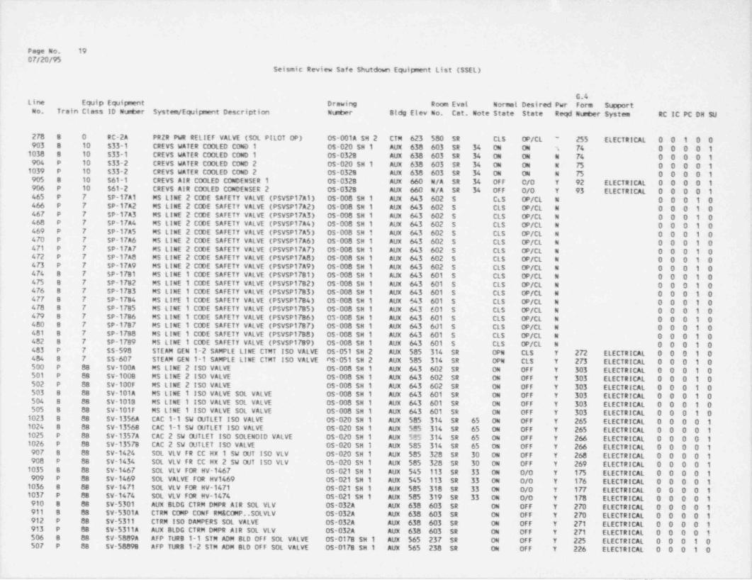
.
Page No. 1907/20/95
Seismic Review Safe Shutdown Equipment List (SSEL)
G.4Line Ewip Equipment Drawing Room Eval Normal Desired Pwr Form S@ portOo. Train Class ID Nunber System / Equipment Description Number Bldg Elev No. Cat. Note State State Reqd Nisqber System RC IC PC DH SU
278 8 0 RC-2A PRZR PWR RELIEF VALVE (SOL PILOT OP) OS-001A SH 2 CTM 623 580 SR CLS OP/CL 255 ELECTRICAL 0 0 1 0 0'
903 8 10 $33-1 CREVS WATER COOLED COND 1 05-020 SH 1 AUX 638 603 SR 34 ON ON T 74 0 0 0 0 11038 8 10 533-1 CREVS WATER COOLED COND 1 05-0328 AUX 638 603 SR 34 ON ON N 74 0 0 0 0 1904 P 10 $33-2 CREVS WATER COOLED COND 2 OS-020 SH 1 AUX 638 603 SR 34 ON ON N 75 0 0 0 0 11039 P 10 $33-2 CREVS WATER COOLED COND 2 0s-032s AUX 638 603 SR 34 ON 04 N 75 0 0 0 0 1905 8 10 S61-1 CREVS AIR COOLED CONDENSER 1 0S-0328 AUX 660 N/A SR 34 0FF C/0 Y 92 ELECTRICAL 0 0 0 0 1906 P 10 561-2 CREVS AIR COOLED CONDENSER 2 05-0328 AUX 660 N/A SR 34 0FF 0/0 Y 93 ELECTRICAL 0 0 0 0 1465 P 7 SP-17A1 MS LINE 2 CODE SAFETY VALVE (PSYSP17A1) 0S-006 SH 1 AUX 643 602 S CLS OP/CL N O O O 1 0466 P 7 SP-17A2 MS LINE 2 CODE SAFETY VALVE (PSYSP17A2) OS-008 SH 1 AUX 643 602 S CLS OP/CL N 0 0 0 1 04GF P 7 SP-17A3 MS LINE 2 CODE SAFETY VALVE (PSVSP17A3) 0s-008 SH 1 AUX 643 602 S CLS OP/CL N 0 0 0 1 04G8 P 7 SP-17A4 MS LINE 2 CODE SAFETY VALVE (PSYSP1744) 05-008 SH 1 AUX 643 602 S CLS OP/CL N 0 O O 1 0460 P 7 SP-17AS MS LINE 2 CODE SAFETY VALVE (PSYSP17AS) 05-008 SH 1 AUX 643 602 S CLS OP/CL N O O O 1 0470 P 7 SP-17A6 MS LINE 2 CODE SAFETY VALVE (PSYSP17A6) 05-008 SH 1 AUX 643 602 S CLS OP/CL N 0 0 0 1 0471 P 7 SP-17A7 MS LINE 2 CODE SAFETY VALVE (PSYSP17A7) 0S-008 SH 1 AUX 643 602 S cts OP/CL N O O O 1 0472 P 7 SP-17A8 MS LINE 2 CODE SAFETY VALVE (PSVSPITAS) 05-008 SH 1 AUX 643 602 S CLS OP/CL N O O O 1 04 73 P 7 SP-17A9 MS LINE 2 CODE SAFETY VALVE (PSYSP17A9) 05-008 SH 1 AUX 643 602 S CLS OP/CL N O O O 1 04F4 B 7 $P-1781 MS LINE 1 CODE SAFETY VALVE (PSYSP17B1) 05-008 SH 1 AUX 643 601 S CLS OP/CL N 0 0 0 1 0475 B 7 $P-17B2 MS LINE 1 CODE SAFETY VALVE (PSYSP1782) 0S-008 SH 1 AUX 643 601 S CLS OP/CL N 0 0 0 1 04 76 B 7 SP-1783 MS LINE 1 CODE SAFETY VALVE (PSYSP1783) OS-008 SH 1 AUX 643 601 S CLS OP/CL N O O O 1 04FF B 7 SP-17B4 MS LIFE 1 CODE SAFETY VALVE (PSYSP1784) 0S-008 SH 1 AUX 643 601 S CLS OP/CL N 0 0 0 1 0470 B 7 SP-1785 MS LINE 1 CODE SAFETY VALVE (PSYSP17BS) 0S-008 SH 1 AUX 643 601 S CLS OP/CL N O O O 1 0479 8 7 SP-17B6 MS LINE 1 CODE SAFETY VALVE (PSVSP17B6) 0s-008 SH 1 AUX 643 601 S CLS OP/CL N 0 0 0 1 0400 8 7 SP-1787 MS LINE 1 CODE SAFETY VALVE (PSYSP17B7) 0S-008 SH 1 AUX 643 601 S CLS OP/CL N O O O 1 04G1 8 7 SP-17B8 MS LINE 1 CODE SAFETY VALVE (PSYSP17B8) 05-008 SH 1 AUX 643 601 S CLS OP/CL N 0 0 0 1 04G2 8 7 SP-17B9 MS LINE 1 CODE SAFETY VALVE (PSVSP17B9) 0S-008 SH 1 AUX 643 601 5 CLS OP/CL N O O O 1 0483 P 7 SS-598 STEAM GEN 1-2 SAMPLE LINE CTMT ISO VALVE OS-051 SH 2 AUX 585 314 SR OPN CLS Y 2 72 ELECTRICAL 0 0 0 1 0484 8 7 SS-607 STEAM GEN 1-1 SAMPLE LINE CTMT ISO VALVE AS-051 SH 2 AUX 585 314 SR OPN CLS Y 2 73 ELECTRICAL 0 0 0 1 0500 P 88 SV-100A MS LINE 2 ISO VALVE OS-008 SH 1 AUX 643 602 SR ON OFF Y 303 ELECTRICAL 0 0 0 1 0501 P 88 SV-1008 MS LINE 2 ISO VALVE 05-008 SH 1 AUX 643 602 SR ON OFF Y 303 ELECTRICPL 0 0 0 1 0502 P 88 SV-100F MS LINE 2 ISO VALVE OS-008 SH 1 AUX 643 602 SR ON OFF Y 303 ELECTRICAL 0 0 0 1 0 ;503 8 88 SV-101A MS LINE 1 ISO VALVE SOL VALVE 05-008 SH 1 AUX 643 601 SR ON OFF Y 303 ELECTRICAL 0 0 0 1 0504 B 88 SV-1013 MS LINE 1 ISO VALVE SOL VALVE 0S-008 SH 1 AUX 643 601 SR ON OFF Y 303 ELECTRICAL 0 0 0 1 0505 8 88 SV-101F MS LINE 1 ISO VALVE SOL VALVE OS-008 SH 1 AUX 643 601 SR ON OFF Y 303 ELECTRICAL 0 0 0 1 01023 8 88 SV-1356A CAC 1-1 SW GJTLET ISO VALVE 05-020 SH 1 AUX 585 314 SR 65 ON OFF Y 265 ELECTRICAL 0 0 0 0 11024 8 88 SV-13568 CAC 1-1 SW OUTLET ISO VALVE 05-020 SH 1 AUX $85 314 SR 65 ON OFF Y 265 ELECTRICAL 0 0 0 0 1
'
1025 P 88 SV-1357A CAC 2 SW OUTLET ISO SOLENOID VALVE OS-020 SH 1 AUX 535 314 SR 65 ON OFF Y 266 ELECTRICAL 0 0 0 0 11026 P 88 SV-13578 CAC 2 SW OUTLET ISO VALVE OS-020 SH 1 AUX 585 314 SR 65 ON OFF Y 266 ELECTRICAL 0 0 0 0 190F 8 88 SV-1424 SOL VLV FR CC HX 1 SW OUT ISO VLV OS-020 SH 1 AUX 585 328 SR 30 ON OFF Y 268 ELECTRICAL 0 0 0 0 1,
900 P 88 SV-1434 SOL VLV FR CC HX 2 SW OUT ISO VLV 05-020 SH 1 AUX 585 328 SR 30 ON OFF Y 269 ELECTRICAL 0 0 0 0 11035 B 88 SV-1467 SOL VLV FOR HV-1467 OS-021 SH 1 AUX 545 113 SR 33 ON 0/0 Y 175 ELECTRICAL 0 0 0 0 1909 P 88 SV-1469 SOL VALVE FOR HV1469 0S-021 SH 1 AUX 545 113 SR 33 ON 0/0 Y 176 ELECTRICAL 0 0 0 0 11036 8 88 SV-1471 SOL VLV FOR HV-1471 0S-021 SH 1 AUX 585 318 SR 33 ON 0/0 Y ITT ELECTRICAL 0 0 0 0 1103F P 88 SV-1474 SOL VLV FOR HV-1474 05-021 SH 1 AUX 585 319 SR 33 04 O/0 Y 178 ELECTRICAL 0 0 0 0 1910 8 88 SV-5301 AUX BLDG CTRM DMPR AIR SOL VLV OS-032A AUX 638 603 SR 04 0FF Y 270 ELECTRICAL 0 0 0 0 1011 8 88 SV-5301A CTRM COMP CONF RM& COMP..SOLYLV OS-032A AUX 638 603 SR ON OFF Y 270 ELECTRICAL 0 0 0 0 1912 P 88 SV-5311 CTRM 150 DAMPERS SOL VALVE OS-032A AUX 638 603 SR ON OFF Y 2 71 ELECTRICAL 0 0 0 0 1913 P 88 SV-5311A AUX BLDG CTRM DMPR AIR SOL VLV OS-032A AUX 638 603 SR 04 0FF Y 271 ELECTRICAL 0 0 0 0 1SM B 88 SV-5889A AFP TURB 1-1 STM ADM BLD OFF SOL VALVE OS-0178 SH 1 AUX 565 237 SR ON OFF Y 225 ELECTRICAL 0 0 0 1 050F P 88 SV-58898 AFP TUR8 1-2 STM ADM BLD OFF SOL VALVE OS-017B SH 1 AUX 565 238 SR ON OFF Y 226 ELECTRICAL 0 0 0 1 0
. _ _ _ _ _ _ .- - - ___-_ _ -

Page No. 200F/20/95
,
Seismic Review Safe Shutdown Equipment List (SSEL)
i
G.4 iLine Equip Equipment Drawing Room Eval Normal Desired Pwr Form Support I
No. Train Class ID Nu@er System / Equipment Description Ntaber Bldg Elev No. Cat. Note State State Reqd Ntaber System RC IC PC DN SU
508 P 88 SV-598 SOLENotD VALVE FOR VALVE $5598 05-051 SH 2 AUX 585 314 SR ON OFF Y 272 ELECTRICAL 0 0 0 1 0309 8 88 SV-607 STEAM GEN 1-1 SAMPLE LINE CTMT ISO VALVE 05-051 SH 2 AUX 585 314 SR ON OFF Y 2 73 ELECTRICAL 0 0 0 1 0546 P 88 SV-ICS11A2 SV FOR ICS-11A 05-006 SH 1 AUX 643 602 SR ON OFF Y 202 ELECTRICAL 0 0 0 1 054F 8 88 SV-ICS1182 SV FOR ICS-118 OS-008 SH 1 AUX 643 601 SR ON OFF Y 203 ELECTRICAL 0 0 0 1 0150 P 88 SV-MU38 SOL VLV FOR MU-38 05-002 SH 2 Aux 565 206 SR ON ON Y 231 ELECTRICAL 0 1 0 0 0
f 132 P 88 SV-MU66A SOL VLV FOR MU-66A 05-002 SH 2 Aux 565 208 SR ON ON Y 227 ELECTkICAL 0 1 0 0 0153 P 88 SV MU668 SQL VLV FOR MU-668 05-002 SH 2 AUX 565 208 SR ON ON Y 228 ELECTRICAL 0 1 0 0 0154 P 88 SV-MU66C SOL VLV FOR M.l-66C 05-002 SH 2 AUX 565 208 SR ON ON Y 229 ELECTRICAL 0 1 0 0 0155 P 88 SV-MU660 SQL VLV FOR MU-660 05-002 SH 2 AUX 565 208 SR ON ON Y 230 ELECTRICAL 0 1 0 0 0921 C 8A SW-1379 SW STRNR 1-1 DRAIN VALVE 0S-020 SH 1 ITK 5 76 052 SR OP/CL OP/CL Y 136 ELECTRICAL 0 0 0 0 1922 C 8A SW-1380 SW STRNR 1-2 DRAIN VALVE OS-020 SH 1 ITK 576 052 SR OP/CL OP/CL Y 137 ELECTRICAL 0 0 0 0 1 ;510 8 8A SW-1382 SW SUPPLY TO AFP 1-1 ISO VALVE OS-017A SH 1 AUX 565 237 SR CLS OPN Y 120 ELECTRICAL 0 0 0 1 0511 P BA SW-1383 SW SUPPLY TO AFP 1-2 ISO VALVE OS-017A SH 1 AUX 565 236 SR CLS OPN Y 121 ELECTRICAL 0 0 0 1 0925 P 8A SW-1395 TPCW HTxCHANG INLT HDR ISO VLV OS-020 SH 1 ITK 566 053 SR OPN CLS Y 160 ELECTRICAL 0 0 0 0 1927 8 7 SW-1424 CCW HT XCHANG 1-1 OUT CTRL VLV OS-020 SH 1 AUX 585 328 SR 30 MOD OPN Y 268 ELECTRICAL 0 0 0 0 192Q P 7 SW-1434 CCW HT XCHANG1-2 OTLT CTRL VLV OS-020 SH 1 AUX 585 328 SR 30 CLS OPN Y 269 ELECTRICAL 0 0 0 0 1929 8 8A SW-2927 CTRM EMERG COND 1-1 OUTLET TV 05-020 SH 1 AUX 638 603 SR CLS OPN Y 128 ELECTRICAL 0 0 0 0 1
,
930 P 8A SW-2928 CTRM EMERG COND 1-2 OUTLET TV OS-020 SH 1 AUX 638 603 SR CLS OPN Y 129 ELECTRICAL 0 0 0 0 1931 C 8A SW 2929 SW DISCH TO IN STRUCTURE VALVE OS-020 SH 1 ITK 566 053 SR 25 OP/CL CLS Y 138 ELECTRICAL /M 0 0 0 0 1
ANUAL *
932 C 8A SW-2930 SW DISCH TO IN FOREBAY VALVE 0S-020 SH 1 ITK 566 053 SR 26 OP/CL OPN Y 161 ELECTRICAL /M 0 0 0 0 1ANUAL
933 C BA SW-2931 SW DISCH TO COOLING TWR MU VLV OS-020 SH 1 ITK 566 053 SR 25 OP/CL CLS Y 139 ELECTRICAL /M 0 0 0 0 1,
ANUAL !
934 C BA SW-2932 SW DISCH TO COLLECT BASIN VLV OS-020 SH 1 ITK 566 053 SR 26 OP/CL CLS Y 162 ELECTRICAL /M 0 0 0 0 1ANUAL
943 8 7 SW-5896 CTRM EMERG COND 1-1 SW ....YLV OS-020 SH 1 AUX 638 603 S OPN THR Y ' ELECTRICAL 0 0 0 0 1 !944 P 7 SW 5897 CTRM EMERG COND 1-2... CONT VLV OS-020 SH 1 AUX 638 603 8 OPN THR Y ELECTRICAL 0 0 0 0 1 i94 C 21 T10 BORATED WATER STORAGE TANK 1-1 0S-004 SH 1 YRD 585 N/A S ON ON N 1 0 0 0 0 |949 8 21 T12-1 COMPONENT COOLING SU'GE TNK I 0s-021 SH 3 AUX 623 501 S ON ON N 0 0 0 0 1 +
950 P 21 T12-!! COMPONENT COOLING SURGE TNK 11 OS-021 SH 3 AUX 623 501 S ON ON N 0 0 0 0 1951 8 21 T153-1 EDG FUEL OIL STORAGE 1-1 OS-041C YRD 585 N/A S ON ON N O 0 0 0 1952 P 21 T153-2 EDG FUEL OIL STORAGE 1-2 0$-041C YRD 585 N/A S ON ON N 0 0 0 0 195 C 21 T18 SFP DEMINERALIZER TANK 1-1 OS-007 AUX 565 233 $ ON N/A N 1 0 0 0 0 <
149 C 21 T18 SFP DEMINERALIZER TANK 1-1 OS-007 Aux 565 233 S ON N/A N O 1 0 0 0 !
% C 21 T4 MAKEUP TANK 1-1 05-002 SH 3 AUX 565 205 S ON ON N 1 0 0 0 021F C 21 T4 MAKEUP TANK 1-1 OS-002 SH 3 AUX 565 205 S ON ON N O 1 0 0 0953 8 21 T46-1 EDG DAY TANK 1-1 OS-041C AUX 595 321A S ON ON N 0 0 0 0 1954 P 21 T46-2 EDG DAY TANK 1-2 OS-041C AUX 595 320A S ON ON N O 0 0 0 19F C 21 T7-1 80RIC ACID ADDITION TANK 1-1 05-046 AUX 565 240 S 39 04 ON N 1 0 0 0 098 C 21 T7-2 80RIC ACID ADDITION TANK 1-2 OS-046 AUX $65 240 S 39 ON ON N 1 0 0 0 0955 8 21 T86-1 EDG 1-1 AIR RECEIVER 1-1-1 OS-0418 AUX 585 318 S ON ON N O O O O 1 t
956 8 21 T86-2 EDG 1-1 AIR RECEIVER 1-1-2 OS-0418 AUX 585 318 5 ON ON N 0 0 0 0 195F P 21 186-3 EDG 1-2 AIR RECEIVER 1-2-1 OS-0418 AUX 585 319 S ON ON N O O O O 1950 P 21 186-4 EDG 1-2 AIR RECEIVER 1-2-2 OS-0418 AUX 585 319 S ON ON N O O 0 0 1959 8 18 TC-5329 EDG RM 1 TEMP CONTROLLER OS-035 AUX 585 318 SR 1 ON ON Y 212 ELECTRICAL 0 0 0 0 1960 P 18 TC-5336 EDG RM2 TEMP CTRL LOC IN C3616 OS-035 AUX 585 319 SR 1 ON ON Y 215 ELECTRICAL 0 0 0 -0 1 5
284 P 20 TDI 4950 RCS MARGIN TO SAT IN0!CATOR (TSAT) OS-001A SH 1 AUX 623 505 SR 1 ON ON Y 305 ELECTRICAL 0 0 1 0 0283 8 20 TDI 4951 RCS MARGIN TO SAT INDICATOR (TSAT) 05-001A SH 1 AUX 623 505 SR 1 ON ON Y 305 ELECTRICAL 0 0 1 0 0
, _ _
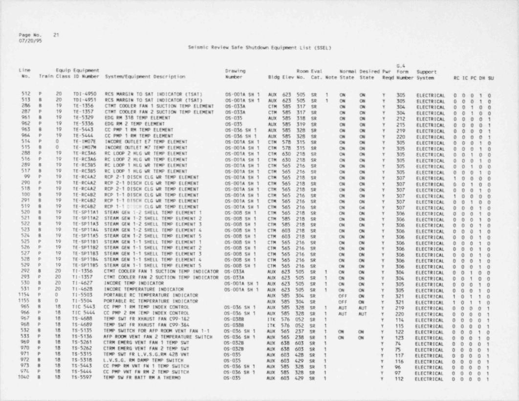
Page No. 2107/20/95
Seismic Review Safe Shutdown Equipnent List (SSEL)
G.4Line Equip Equipment Drawing Room Evat Normal Desired Pwr Form S p ortOo. Train Class ID N mber System / Equipment Description Ntster Bldg Elev No. Cat. Note State State Reqd Nu 2er System RC IC PC DH SU
512 P 20 TDI-4950 RCS MARGIN TO SAT INDICATOR (TSAT) 05-001A SH 1 AUX 623 505 SR 1 ON ON Y 305 ELECTRICAL 0 0 0 1 0513 8 20 TDI-4951 RCS MARGIN TO SAT INDICATOR (TSAT) OS-001A SH 1 AUX 623 505 SR 1 ON ON Y 305 ELECTRICAL 0 0 0 1 0286 8 19 TE-1356 CTMT COOLER FAN 1 SUCTION TEMP ELEMENT OS-033A CTM 585 317 SR ON 04 Y 304 ELECTRICAL 0 0 1 0 02G7 P 19 TE-1357 CTMT COOLER FAN 2 SUCTION TEMP ELEMENT OS-033A CTM 585 317 SR ON ON Y 304 ELECTRICAL 0 0 1 0 0961 B 19 TE-5329 EDG RM 318 TEMP ELEMENT OS-035 AUX 585 318 SR ON ON Y 212 ELECTRICAL 0 0 0 0 1962 P 19 TE-5336 EDG RM 2 TEMP ELEMENT 05-035 AUX $85 319 SR ON ON Y 215 ELECTRICAL 0 0 0 0 1963 B 19 TE-5443 CC PMP 1 RM TEMP ELEMENT 05-036 SH 1 AUX 585 328 SR ON ON Y 219 ELECTRICAL 0 0 0 0 1964 P 19 TE-5444 CC PMP 1 RM TEMP ELEMENT 05-036 SH 1 AUX 585 328 SR ON ON Y 220 ELECTRICAL 0 0 0 0 1514 P O TE-! MOTE INCORE OUTLET ET TEMP ELEMENT OS-001A SH 1 CTM 578 315 SR 04 ON Y 305 ELECTRICAL 0 0 0 1 0515 8 0 TE-IM07M INCORE OUTLET M7 TEMP ELEMENT 0s-001A SH 1 CTM 578 315 SR ON ON Y 305 ELECTRICAL 0 0 0 1 0288 P 19 TE-RC3A6 RC LOOP 2 HLG WR TEMP ELEMENT OS-001A SH 1 CTM 630 218 SR ON ON Y 305 ELECTRICAL 0 0 1 0 0516 P 19 TE-RC3A6 RC LOOP 2 HLG WR TEMP ELEMENT OS-001A SH 1 CTM 630 218 SR ON ON Y 305 ELECTRICAL 0 0 0 1 0200 B 19 TE-RC385 RC LOOP 1 HLG WR TEMP ELEMENT OS-001A SH 1 CTM 565 216 SR ON ON Y 305 ELECTRICAL 0 0 1 0 051F B 19 TE-RC385 RC LOOP 1 HLG WR TEMP ELEMENT OS-001A SH 1 CTM 565 216 SR ON ON Y 305 ELECTRICAL 0 0 0 1 099 P 19 TE-RC4A2 RCP 2-1 DISCH CLG WR TEMP ELEMENT OS-001A SH 1 CTM 565 218 SR ON ON Y 307 ELECTRICAL 1 0 0 0 0290 P 19 TE-RC4A2 RCP 2-1 DISCH CLG WR TEMP ELEMENT OS-001A SH 1 CTM 565 218 SR ON ON Y 307 ELECTRICAL 0 0 1 0 0
| 510 P 19 TE-RC4A2 RCP 2-1 DISCH CLG WR TEMP ELEMENT OS-001A SH 1 CTM 565 218 SR ON ON Y 307 ELECTRICAL 0 0 0 1 0| 100 B 19 TE-RC4B2 RCP 1-1 DISCH CLG WR TEMP ELEMENT OS-001A SH 1 CTM 565 216 SR ON ON Y 307 ELECTRICAL 1 0 0~0 0| 291 B 19 TE-RC4B2 RCP 1-1 DISCH CLG WR TEMP ELEMENT OS-001A SH 1 CTM 565 216 SR ON ON Y 307 ELECTRICAL 0 0 1 0 0; 519 8 19 TE-RC482 RCP 1-1 C :::'M CLG WR TEMP ELEMENT OS-001A SH 1 CTM 565 216 SR ON ON Y 307 ELECTRICAL 0 0 0 1 0
520 8 19 TE-SP11A1 STEAM GEN 1-2 SHELL TEMP ELEMENT 1 OS-008 SH 1 CTM 565 218 SR ON ON Y 306 ELECTRICAL 0 0 0 1 0521 B 19 TE-SP11A2 STEAM GEN 1-2 SHELL TEMP ELEMENT 2 OS-008 SH 1 CTM 585 218 SR ON ON Y 306 ELECTRICAL 0 0 0 1 0522 8 19 TE-SP11A3 STEAM GEN 1-2 SHELL TEMP ELEMENT 3 OS-008 SH 1 CTM 585 218 SR ON ON Y 306 ELECTRICAL 0 0 0 1 0
| 523 B 19 TE-SP11A4 STEAM GEN 1-2 SHELL TEMP ELEMENT 4 OS-008 SH 1 CTM 603 218 SR ON ON Y 306 ELECTRICAL 0 0 0 1 0524 8 19 TE-SP11A5 STEAM GEN 1-2 SHELL TEMP ELEMENT 5 OS-008 SH 1 CTM 603 218 SR ON ON Y 306 ELECTRICAL 0 0 0 1 0525 P 19 TE-SP1181 STEAM GEN 1-1 SHELL TEMP ELEMENT 1 05-008 SH 1 CTM 565 216 SR ON ON Y 306 ELECTRICAL 0 0 0 1 0526 P 19 TE-SP1182 STEAM GEN 1-1 SHELL TEMP ELEMENT 2 OS-008 SH 1 CTM 565 216 SR ON ON Y 306 ELECTRICAL 0 0 0 1 0527 P 19 TE-SP1183 STEAM GEN 1-1 SHELL TEMP ELEMENT 3 0S-008 SH 1 CTM 565 216 SR ON ON Y 306 ELECTRICAL 0 0 0 1 0520 P 19 TE-SP1184 STEAM GEN 1-1 SHELL TEMP ELEMENT 4 OS-008 SH 1 CTM 565 216 SR ON ON Y 306 ELECTRICAL 0 0 0 1 0529 P 19 TE-SP11B5 STEAM GEN 1-1 SHELL TEMP ELEMENT 5 OS-008 SH 1 CTM 565 216 SR ON ON Y 306 ELECTRICAL 0 0 0 1 0292 B 20 TI-1356 CTMT COOLER FAN 1 SUCTION TEMP INDICATOR OS-033A AUX 623 505 SR 1 ON ON Y 304 ELECTRICAL 0 0 1 0 0293 P 20 TI-1357 CTMT COOLER FAN 2 SUCTION TEMP INDICATOR OS-033A AUX 623 505 SR 1 ON ON Y 304 ELECTRICAL 0 0 1 0 0530 B 20 TI-4627 INCORE TFMP INDICATOR OS-001A SH 1 AUX 623 505 SR 1 ON ON Y 305 ELECTRICAL 0 0 0 1 0531 P 20 TI-4628 INCORE TEMPERATURE INDICATOR OS 001A SH 1 AUX 623 505 SR 1 ON ON Y 305 ELECTRICAL 0 0 0 1 0
| 1154 P O TI-5503 PORTABLE RC TEMPERATURE INDICATOR AUX 585 304 SR OFF ON Y 321 ELECTRICAL 1 0 1 1 0i 1155 8 0 TI-5504 PORTABLE RC TEMPERATURE INDICATOR AUX 585 304 SR OFF ON Y 321 ELECTRICAL 1 0 1 1 0| 965 8 18 TIC 5443 CC PMP 1 RM TEMP INDEX CONTROL OS-036 SH 1 AUX 585 328 SR 1 AUT AUT Y 219 ELECTRICAL 0 0 0 0 1
966 P 18 TIC 5444 CC PMP 2 RM TEMP INDEX CONTROL OS-036 SH 1 AUX 585 328 SR 1 AUT AUT Y 220 ELECTRICAL 0 0 0 0 19GF B 18 TS-4688 TEMP SWT FR XHAUST FAN C99-1&2 OS-0388 ITK 576 052 SR 1 Y 114 ELECTRICAL 0 0 0 0 1968 P 18 TS-4689 TEMP SWT FR XHAUST FAN C99-3&4 05-0388 ITK 576 052 SR 1 Y 115 ELECTRICAL 0 0 0 0 1532 B 18 T5-5135 TEMP SWITCH FOR AFP ROOM VENT FAN 1-1 OS-036 SH 1 AUX 565 237 SR 1 ON ON Y 122 ELECTRICAL 0 0 0 1 0533 P 18 TS-5136 AFP ROOM VENT FAN 2 TEMPERATURE SWITCH OS-036 SH 1 AUX 565 238 SR 1 ON ON Y 123 ELECTRICAL 0 0 0 1 0969 8 18 TS-5261 CTRM EMERG VENT FAN 1 TEMP SWT 05-0328 AUX 638 603 SR 1 Y 74 ELECTRICAL 0 0 0 0 19FD P 18 TS-5262 CTRM EMERG YENT FAN 2 TEMP SWT 05 0328 AUX 638 603 SR 1 Y 75 ELECTRICAL 0 0 0 0 1971 P 18 TS-5315 TEMP SVT FR L.V.S.G.RM 428 VNT 05-035 AUX 603 428 SR 1 Y 117 ELECTRICAL 0 0 0 0 19 72 8 18 TS-5318 L.V.S.G. RM DAMP TEMP SWITCH 05-035 AUX 603 429 SR 1 Y 116 ELECTRICAL 0 0 0 0 19F3 8 18 TS-5443 CC PMP RM VNT FN 1 TEMP SWITCH OS-036 SH 1 AUX 585 328 SR 1 Y 96 ELECTRICAL 0 0 0 0 19F4 P 18 TS-5444 CC PMP VNT FN RM 2 TEMP SWITCH 0S-036 SH 1 AUX 585 328 SR 1 Y 97 ELECTRICAL 0 0 0 0 1
i 1040 8 18 TS-5597 TEMP SW FR BATT RM A THERMO 05-035 AUX 603 429 SR 1 Y 112 ELECTRICAL 0 0 0 0 1|
|_. ._ __

- - - _ ._ - - _ _
Page No. 2207/20/95
Seismic Review Safe Shutdown Equipment List (SSEL)
G.4Line Equip Equipment Drawing Room Evat Normel Desired Pwr Form Support tCo. Train Ctess ID Nuser System / Equipment Description Neber Bldg Elev No. Cat. Note State State Reqd Nu6er System RC It PC DH SU
975 P 18 TS-5598 TEMP SW FR SATT RM B THERMO 05-035 Aux 603 428 SR 1 Y 113 ELECTRICAL 0 0 0 0 1976 P 18 TSH 1435 CC Nx 2 CCW OUT TEMP SWTCH HI 05-021 SH 1 AUX 585 328 SR 1 Y 298 ELECTRICAL 0 0 0 0 1977 8 18 TSH 1483 CC HX CCW OUT TEMF SWICH HIGH OS-021 SH 1 AUX 585 328 SR 1 Y 289 ELECTRICAL 0 0 0 0 1 '
1078 8 18 TSH 5421 ECCS RM CLR FAN 1-5 TEMP SW 05-034 SH 2 AUX 545 105 SR 1 ON ON Y 147 ELECTRICAL 0 0 0 1 0 i
1079 8 18 TSH 5422 ECCS RM CLR FAM 1-4 TEMP SW 05-034 SH 2 AUX 545 105 SR 1 ON ON Y 1 ELECTRICAL 0 0 0 1 01077 P 18 TSH 5424 ECCS RM CLR FAN 1-2 TEMP SW 0s-034 SH 2 AUX 545 115 SR 1 ON ON Y'
ELECTRICAL 0 0 0 1 0,
1076 P 18 TSH $425 ECCS RM CLR FAN 1-1 TEMP SW 05-034 SH 2 Aux 545 115 SR 1 ON 04 Y 14. 'LECTRICAL 0 0 0 1 0<
1083 8 18 TSL 5421 ECCS RM CLR FAN 1-5 TEMP SV 05-034 SH 2 Aux 545 105 SR 1 ON ON Y 14T ECTRICAL 0 0 0 1 01082 8 18 TSL 5422 ECCS RM CLR FAN 1-4 TEMP SV 0s-034 SH 2 AUX 545 105 SR 1 ON ON Y 146 ,'CTRICAL 0 0 0 1 01001 P 18 TSL 5424 ECCS RM CLR FAN 1-2 TEMP SW 05-034 SH 2 AUX 545 115 SR 1 04 ON Y 149 LLECTRICAL 0 0 0 1 0 l
<
1080 P 18 TSL 5425 ECCS RM CLR FAN 1-1 TEMP SW 05-034 SH 2 Aux 545 115 SR 1 ON 04 Y 148 ELECTRICAL 0 0 0 1 0294 8 18 TT-1356 CTMT COOLER FAN 1 SUCTION TEMP TRANSMIT OS-033A AUX 585 303 SR ON ON Y 304 ELECTRICAL 0 0 1 0 0295 P 18 TT-1357 CTMT COOLER FAN 2 SUCTION TEMP TRANSMIT OS-033A AUX 585 314 SR ON ON Y 304 ELECTRICAL 0 0 1 0 0978 8 18 TT-5329 EDG RM 1 TEMP TRANSMITTER 05-035 Aux 585 318 SR ON ON Y 212 ELECTRICAL 0 0 0 0 1979 P 18 TT-5336 EMG RM 2 TEMP TRANSMITTER OS-035 AUX 585 319 SR ON ON Y 215 ELECTRICAL 0 0 0 0 1960 8 18 TT-5443 CC PMP 1 RM TEMP TRANSMITTER 05-036 SH 1 AUX $85 328 SR ON ON Y 219 ELECTRICAL 0 0 0 0 1931 P 18 TT-5444 CC PMP 2 RM TEMP TRANSMITTER 05-036 SH 1 AUX 585 328 SR ON 04 Y 220 ELECTRICAL 0 0 0 0 1534 P 18 TT-IM07E INCORE OUTLET E7 TEMP TRANSMIT OS-001A SH 1 AUX 623 502 SR ON ON Y 305 ELECTRICAL 0 0 0 1 0535 8 18 TT-IM07M INCORE OUTLET MT TEMP TRANSMIT OS-001A SH 1 AUX 623 502 SR ON ON Y 305 ELECTRICAL 0 0 0 1 0296 P 18 TT-RC3A6 RC TEMP HLG WR CH 2 TSAT TEMP OS-001A SH 1 AUX 623 502 SR ON ON Y 305 ELECTRICAL 0 0 1 0 0536 P 18 TT-RC3A6 RC TEMP HLG WR CH 2 TSAT TEMP OS-001A SH 1 AUX 623 502 SR ON ON Y 305 ELECTRICAL 0 0 0 1 0297 8 18 TT-RC385 RC TEMP HLG WR CH 1 TSAT TEMP TRANS 05-001A SH 1 AUX 623 502 SR ON ON Y 305 ELECTRICAL 0 0 1 0 0537 8 18 TT-RC385 RC TEMP HLG WR CH 1 TSAT TEMP TRANS OS-001A SH 1 AUX 623 502 SR ON ON Y 305 ELECTRICAL 0 0 0 1 01145 B 20 Y-104 CREVS DISC SWITCH FOR C6708 & C6714 AUX 603 429 SR CLS CLS N 50 0 0 0 0 11111 8 20 Y-105 EDG 1-1 DISCONNECT SWITCH FOR C3615 Aux 603 429 SR CLS CLS N 50 0 0 0 0 11146 P 20 Y-204 CREVS DISC SWITCH FOR C6709 & C6715 Aux 603 428 SR CLS CLS N 50 0 0 0 0 11113 P 20 Y-205 EDG 1-2 DISCONNECT SWITCH FOR C3616 AUX 603 428 SR CLS CLS N 50 0 0 0 0 11112 B 20 Y-305 EDG 1-1 DISCONNECT SWITCH FOR C3615 Aux 603 429A SR CLS CLS N 50 0 0 0 0 11114 P 20 Y-405 EDG 1-2 DISCONNECT SWITCH FOR C3616 AUX 603 428 SR CLS Ces N 50 0 0 0 0 1 i9G2 C 14 Y1 ESSEN INSTR DIST PNL "Y1" 0s-060 SH 2 AUX 603 429 SR 41 ON 04 Y 50 ELECTRICAL 0 0 0 0 1983 C 2 Y101 XFER SWITCH FOR INV YV1 &.... 05-060 SH 2 AUX 603 429 SR CLS CLS N 50 0 0 0 0 1984 C 2 Y101A XFER SWITCH FOR Y1A OS-060 SH 2 AUX 603 429 SR CLS CLS N 51 0 0 0 0 1985 C 14 Y1A 120VAC ESSEN INST DIST PANEL 0s-060 SH 2 AUX 603 429 SR 41 ON 04 Y 51 ELECTRICAL 0 0 0 0 1986 C 14 Y2 ESSEN INSTR DIST PNL "Y2" 120V 05 060 SH 2 Aux 603 428 SR 42 ON ON Y 50 ELECTRICAL 0 0 0 0 1937 C 2 Y201 XFER SWT FOR YV2 A80 YBR BUS 05-060 SH 2 AUX 603 428 SR CLS CLS N 50 0 0 0 0 1
'
988 C 2 Y201A XTER SWT FOR INV YV2 AND TBR OS-060 SH 2 AUX 603 428 SR CLC CLS N 51 0 0 0 0 1989 C 14 Y2A 120VAC ESSEN INST DIST PANEL 05-060 SH 2 AUX 603 428 SR 42 ON ON Y 51 ELECTRICAL 0 0 0 0 1
.I990 C 14 Y3 ESSEN INSTR DIST PNL "Y3" 120V 05-060 SH 2 AUX 603 429A SR 41 ON ON Y 50 ELECTRICAL 0 0 0 0 1991 C 2 Y301 XFER SWITCH FOR Y3 05-060 SH 2 AUX 603 429A SR CLS CLS N 50 0 0 0 0 1992 C 14 Y4 ESSEN INSTR DIST PNL "Y4" 120V OS-060 SH 2 AUX 603 428 SR 42 ON ON Y 50 ELECTRICAL 0 0 0 0 1993 C 2 Y401 XFER SWT FR DIST PNL V4 FRM... OS-060 SH 2 AUX 603 428 SR CLS CLS N 50 0 0 0 0 1 ,
994 B 14 YAU UPS INSTR DIST PNL "YAU" 0s-060 SH 1 AUX 603 429 SR ON ON Y 77 ELECTRICAL 0 0 0 0 1995 B 2 YAU 01 MAIN DISC SWITCH OS-060 SH 1 AUX 603 429 SR CLS CLS N 77 0 0 0 0 1996 P 14 YBU UPS INSTR DIST PNL 120V ac OS-060 SH 1 AUX 603 428 SR ON ON Y 77 ELECTRICAL 0 0 0 0 1997 P 2 YBU 01 MAIN DISC SWITCH 05-060 SH 1 AUX 603 428 SR CLS CLS N 77 0 0 0 0 1 *
998 8 2 YE-101 BRKR, LVSG RM VNT FN1-1 DAMPER OS-035 AUX 585 318 SR CLS CLS N 212 0 0 0 0 1999 8 2 YE-102 BRKR, EDG RM 1 SPLY FAN RECIRC 05-035 AUX 585 318 SR CLS CLS N 213 0 0 0 0 1 ,1000 s 2 YE-103 BRKR, EDG RM 1 SPLY FAN OUTLT 05-035 AUX 585 318 SR CLS CLS N 214 0 0 0 0 1 f1001 B 2 YE-104 BRKR, L.V.S.G. RM VENT FAN 1-1 05-035 Aux 585 318 SR CLS CLS W 210 0 0 0 0 1
_ - _ - _ _ - . _ , . . - ._. - .

_ _ _ _ . .
Page No. 2307/20/95
Seismic Review Safe Shutdown Equipment List (SSEL)
G.4Line Equip Equipment Drawing Room Eval Normal Desired Pwr Form SupportNo. Train Class ID Nunber System / Equipment Description Ntaber Bldg Elev No. Cat. Note State State Reqd Ntaber System RC IC PC 04 SU
L
1002 8 2 YE-208 BREAKER FOR TRANS 240-120 AC.. OS-059 SH 1 Aux 585 304 SR CLS CLS N 70 0 0 0 0 11003 B 2 YE-209 BRKR, CCP RM V4T FN 1 RM 8YPSS 05-036 SN 1 AUX 585 304 SR CLS CLS N 218 0 0 0 0 11004 8 2 YE-210 BRKR, CC PMP RM VNT FN 1 RM IN 05-036 SM 1 Aux 585 304 SR Cts CLS 4 219 0 0 0 0 11005 8 2 YE-212 BRKR, CC PMP RM O.A. LOUVER 1 05-036 SN 1 AUX 585 304 SR CLS CLS 4 222 0 0 0 0 1880 8 1 YE1 480/120 VAC McC/ TRANSFORMER OS-059 SN 1 AUX 585 318 St ON ON Y 12 ELECTRICAL 0 0 0 0 11050 8 4 YE1 480/120 VAC MCC/ TRANSFORMER 0S-059 SN 1 AUX 585 318 SR 04 ON Y 71 ELECTRICAL 0 0 0 0 1881 8 1 YE2 240 VAC MCC/ TRANSFORMER 05-059 SM 1 AUX 585 304 SR ON ON Y 2 ELECTRICAL 0 0 0 0 11006 B 4 YE2A 480-240V TRANSFORMER 05-059 SN 1 AUX 603 405 SR ON ON Y 71 ELECTRICAL 0 0 0 0 11051 B 4 YE2B 240-120V TRANSFORMER 05-059 SH 1 AUX 585 304 SR ON ON Y 70 ELECTRICAL 0 0 0 0 1100F P 2 YF-101 BRKR, EpcG RM 2 SPLY FAN INLT 05-035 Aux 585 319 SR CLS CLS N 215 0 0 0 0 11CDS P 2 YF-102 BRKR, EDG RM 2 SPLY FAN RECIRC 05-035 AUX 585 319 SR CLS CLS N 216 0 0 0 0 11009 P 2 TF-103 BKR, EDG RM 2 SPLY FAN OUTLT 05-035 Aux 585 319 SR CLS CLS N 217 0 0 0 0 11010 P 2 YF-104 BRER, L.V.S.G. RM OUTLT DAMPER 05-035 Aux 585 319 SR CLS CLS N 211 0 0 0 0 11011 P 2 YF-208 BREAKER FOR 2 KVA TRANSFORMER 05-059 SH 1 AUX 603 427 SR CLS CLS N 70 0 0 0 0 11092 P 2 YF-209 BRKR, CC PMP RM VENT FAN 2 BYPS OS-036 SH 1 AUX 603 427 SR CLS CLS N 220 0 0 0 0 11013 P 2 YF-210 BRKR, CC PMP RM VENT FAN 2..lN 05-036 SM 1 AUX 603 427 SR CLS CLS N 221 0 0 0 0 1$014 P 2 YF-212 BRKR, CC PMP RM 0.A. LOUVER 1 OS-036 SH 1 AUX 603 427 SR CLS CLS N 223 0 0 0 0 1 '
882 P 1 YF1 480-120V MCC/ TRANSFORMER 05-059 SH 1 AUX 585 319 SR ON ON Y 25 ELECTRICAL 0 0 0 0 11015 P 4 YF1 480-120V MCC/ TRANSFORMER 05-059 SH 1 AUX 585 319 SR ON 04 Y 71 ELECTRICAL 0 0 0 0 1883 P 1 YF2 240 VAC MCC/ TRANSFORMER OS-059 SM 1 Aux 603 427 SR OM ON Y 18 ELECTRICAL 0 0 0 0 1101G P 4 YF2A 480-240V TRANSFORMER OS-059 SH 1 AUX 603 427 SR ON ON Y 71 ELECTRICAL 0 0 0 0 11052 P 4 YF28 240-120V TRANSFORMER OS-050 SH 1 AUX 603 427 SR ON ON Y 70 ELECTRICAL 0 0 0 0 1847 C 16 YV1 125vDC/120VAC INVERTER CH 1 05 060 SH 2 AUX 603 429 SR ON ON Y 357 ELECTRICAL 0 0 0 0 1848 C 16 YV2 125vDC/120VAC INVERTER CH 2 OS-060 SM 2 Aux 603 428 SR ON ON Y 58 ELECTRICAL 0 0 0 0 1840 C 16 Yv3 125VDC 120V4C INVERTER CH 3 OS-060 SH 2 AUX 603 429A SR ON ON Y 58 ELECTRICAL 0 0 0 0 1850 C 16 YV4 125VDC/120VAC INVERTER CH 4 05-060 SH 2 AUX 603 428 SR 04 ON Y 357 ELECTRICAL 0 0 0 0 1 .
101F B 16 YVA UPS "YVA" INVERTER OS-060 SM 1 AUX 603 429 SR ON ON Y 76 ELECTRICAL 0 0 0 0 1 '
$010 P 16 YVB UPS "YVB" INVERTER OS-060 SH 1 AUX 603 428 SR 04 ON Y 76 ELECTRICAL 0 0 0 0 1538 P 18 2C-6451 AFP 1-2 DISCH CTRL WLV POSITION CTRLR OS-017A SN 1 AUX 565 238 SR ON ON Y 308 ELECTRICAL 0 0 0 1 0539 B 18 2C-6452 AFP 1-1 DISCH CTRL VLV POS CONTROLER OS-017A SH 1 AUX 565 237 SR OP/CL ON Y 309 ELECTRICAL 0 0 0 1 0 '
!
!
.
h
i>
i
- , e ~ - ____m.<__ _ _ _ _ _ _ _ _

. - . _ __ - . .
DAVIS-BESSE NUCLEAR POWER STATION
Unresolved Safety Issue (USI) A-46
Seismic Evaluation Report
APPENDIX D
SCREENING VERIFICATION DATA SHEETS(SVDS)
____ _ _ _ _ - __ _____ ___ _ _ .

-A - k: -.s,, _ . - +-. . h. -
APPENDIX D
DAVIS-BESSE NUCLEAR POWER STATION
SCREENING VERIFICATION DATA SHEETS(SVDS)
,
1__ . _ _ . _ _ _ - _ _ _ _ _

_ _. _ _ . _ _ . _ . _ _ _ _
.
SCREENING VERIFICATION DATA SHEET (SVDS)NV-55980 CERTIFICATION
All the information contained on the following Screening Verification Data Sheets (SVDS) is,to the best of our knowledge and belief, correct and accurate. "All information" includes eachentry and conclusion (whether verified to be seismically adequate or not).
The "SQUGGER" number adjacent to each seismic Capability Engineer (SCE) corresponds tothe SQUGGER column on the SVDS. It represents the cognizant SCEs who were responsiblefor performing the walkdown and evaluation for the specified equipment.
APPROVED: Signatures of all Seismic Capability Engineers on the Seismic Reviews Team(SRT) are required. There should be at least two SCE on each SRT with at least one signatory alicensed professional engineer. All signatories should agree with all of the entries andconclusions.
SQUGGERNO. NAME SIGNATURE DATE
Jnvan c.8 hoek Arora P.E. M),m /1stra< d'|mt ni'* eper UU '
1 Richard N. Bair P.E. MO2 ZMF
2 Thomas E, Dabrowiak P.E. kb r//4/9r
11 James R. Disser /1/tr/ - 84/~
'
3 John O. Dizon P.E. '3'I-
WNdoC elu/w12 Steven J. Eder P.E. / s -- i
4 Jon G. Hook P. E. M Y~/S
5 Gayle S. Johnson P.E. ?/4/E-
10 Omar Khemici P.E. wik 4 9t I
9 Steven J. Osting P.E. OM Bh5/ff6 Scott R. Saunders bb k. 8//d9f -
7 Basilio Sumodobila P.E. mvt7do/>et 8/4/9F ,
'
/ 1
_ _ _ _ _ _ _ . _ _ _ _ _ _

!
QI21/95 *
,
SCREENING VERIFICATION DATA SHEET (SVDS) !;
UNE EQ EQ BASE SPECTRUM CAP > CAVEATS ANCH WTE4 OUTIKR EQUP |E C3. ASS NO EOtM9AENT DESCRPT10N M R Of_ ftA SOUGGER (t(V <40 CAP EGAAND DBAAND WOFD NTENT OK 1 E OK_ |_ ACT OK V
1 15 1N STATION BATTERY -125V de AUX 603 4298 34 603 Y BS GRS Y Y Y Y .Y ;i
2 15 1P STATON BATTERY + 125V de AUX 603 42d8 34 603 Y BS GRS Y Y Y Y Y
l3 15 2N STATION BATTERY.125V de AUX 603 428A 34 603 Y BS GRS Y Y Y Y Y [
4 15 2P STATIOM BATTERY + 125V dc AUX 603 428A 34 603 Y BS GRS Y Y Y Y Y
] 5 88 AF-6451 AFP 12 SOL CONTROL VALVE AUX 565 238 17 565 Y BS GRS Y Y N/A Y Y
!
e 88 AF-6452 AFP 1-1 SOL CONTROL VALVE AUX 565 237 17 565 Y BS GRS Y Y N/A Y Y
7 3 C1 4.16 KV SWITCH GEAR AUX 585 325 2 11 585 Y ABS NtS Y Y Y Y- Y i
!
} 8 10 C1-1 CAC 1-1 WIR SOE FUNCTION) CTM 585 217 14 585 Y ABS CRS Y Y Y Y Y !$
9 to C1-2 CAC 1-2 MIR SOE FUNCTION) CTM 585 217 14 585 Y ABS CRS Y Y Y Y Y
i, [
10 9 C133 VENT FAN FOR L.V S.G. ROOM AUX 603 428 14 618 NO DOC CRS Y Y Y Y Y
11 3 C2 4.16 KV SWITCH GEAR AUX 585 325 14 585 Y ABS RRS Y NO NO NO Y Y NO NOi
12 9 C21 1 CNTIL PM EMERG VENT SYS FAN 1 1 AUX 638 603 79 638 NO DOC RRS Y NO NO Y Y Y NO NO }
13 9 C212 CNTit FN EMERG VENT SYS FAN 1-2 AUX 638 603 79 638 NO DOC fWtS Y NO NO Y Y Y NO NO I
14 9 C251 SUfMY FAN 1-1 AUX 585 318 14 610 Y BS CRS Y Y Y Y Yf
f15 9 C25-2 SUFPLY FAN 12 AUX 585 318 14 610 Y BS CRS Y NO NO NO Y Y Y Y
?16 9 L25-3 EDG FRA SUPPLY FAN AUX $85 319 146 610 Y. BS CRS Y NO NO NO Y Y Y Y [
17 9 C25-4 EDG SUfRY FAN 1-4 AUX 585 319 146 610 Y BS CRS Y NO NO NO Y Y Y Y
18 20 C3017 SW STINR 1 1 DRAIN!BCKWASH VLV CABINET ITK 576 052 67 580 Y BS GRS Y Y Y Y Y
.t19 20 C3018 SW STRNR 1-2 DRAM /BCKWASH VLV CA81 NET ITK 576 052 67 580 Y BS GRS Y Y Y Y Y iI
f20 10 C31 1 ECCS 194 CLR 1 1 FAN AUX 545 115 89 545 Y BS GRS Y Y Y Y Y
f21 10 C31-2 ECCS 794 CLR 1-2 FAN AUX 545 115 89 545 Y BS GRS Y Y Y Y Y
22 10 C31-4 ECCS FN CLR 1-4 FAN AUX 545 105 48 545 Y ABS CRS Y Y Y Y Y ;
i23 10 C315 ECCS 994 CLR 15 FAN AUX 545 105 89 545 Y BS GRS Y Y Y Y Y
'
Appendix D Page 1 -
F
!i
. . _ , _ , . . _ . . . . . - - - . _ - _ . - _ _ _~ . ~ - . -- - .~ . - . _ _ .,. --- - _ . _ . _ _ _ -_ _ - - . . - - . _ -
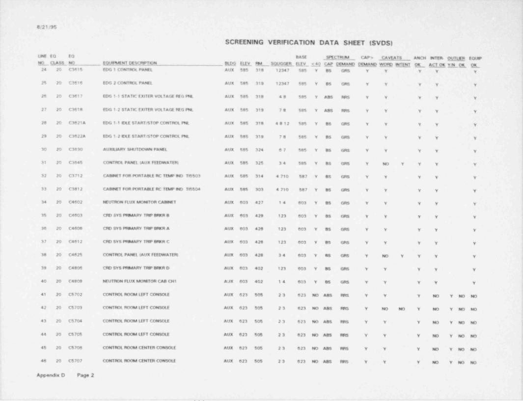
8/21/95
SCREENING VERIFICATION DATA SHEET (SVDS)
LINE EQ EO BASE SPECTRUM CAP > CAVEATS ANCN MTER OUTtKR EOUPE CLASS NO EOUfF9AENT DESCRIPTION M EL E fm4 SOUGGER ELEV M _ CAP DEMAND DDAAND WORD INTENT OK ACT OK YtM E OK_-
24 20 C3615 EDG 1 CONTROL PANEL AUX 585 318 12347 585 Y BS GRS Y Y Y Y Y
25 20 C3616 EDG 2 CONTROL PANEL AUX 585 319 12347 585 Y BS GRS Y Y Y Y Y
:26 20 C3617 EDG 1 1 STATIC EXITER VOLTAGE FIEG FNL AUX 585 318 48 585 Y ABS RRS Y Y Y Y Y
27 20 C3618 EDG 1-2 STATIC EXITER VOLTAGE REG PNL AUX 585 319 78 585 Y ABS RRS Y Y Y Y Y ,
i28 20 C3621A EDG 1-1 IDLE STARTISTOP CONTROL PNL AUX 585 318 4812 585 Y BS GRS Y Y Y Y Y
29 20 C3622A EDG 12 IDLE STARTISTOP CONTROL fHL AUX $95 319 78 585 Y BS GRS Y Y Y Y y
30 20 C3630 AUXRJARY SNUTDOWN PANEL AUX 585 324 67 585 Y BS GRS Y Y Y Y Y'
31 20 C3645 CONTROL PANEL (AUX FEEDWATEfy AUX 585 325 34 585 Y BS GRS Y NO Y Y Y Y
32 20 C3712 CABINET FOR PORTABLE RC TEMP IND T15503 AUX 585 314 4 710 587 Y BS GRS Y Y Y Y Y
33 20 C3812 CABINET FOR PORTABLE RC TEMP IND Tt5504 AUX 585 303 4 710 587 Y BS GRS Y Y Y Y Y
34 20 C4602 NEUTRDN FLUX MONITOR CABINET AUX 603 427 14 603 Y BS GRS Y Y Y Y Y
35 20 C4603 CRD SYS PRIMARY TRIP BRKR 9 AUX 603 429 123 603 Y BS GRS Y Y Y Y Y
36 20 C4606 CRD SYS PRIMARY TRIP BRKR A AUX 603 428 123 603 Y BS GRS Y Y Y Y Y
37 20 C4612 CRD SYS PfuAAPY Tf4P BRKR C AUX 603 428 123 603 Y BS GRS Y Y Y Y Y
38 20 C4625 CONTROL PANEL (AUX FEEDWATEfg AUX 603 428 34 603 Y BS GRS Y NO Y Y Y Y i
,[39 20 C4806 CfD SYS FHBAARY Tf4P BfRR D AUX 603 402 123 603 Y BS GRS Y Y Y Y Y
;40 20 C4808 NEUTRON FLUX MONITOR CAB CN1 A'JX 603 402 14 603 Y BS GRS Y Y Y Y Y
41 20 C5702 CONTROL ROOM LEFT CONSOLE AUX 623 505 23 623 NO ABS RRS Y Y Y NO Y NO NO ff
42 20 C5703 CONTROL ROOM LEFT CONSOLE AUX 623 505 23 623 NO ABS RRS Y NO NO Y NO Y NO NO fi
43 20 C5704 CONTROL ROOM LEFT CONSOLE AUX 623 505 23 623 NO ABS RRS Y Y Y NO Y NO NO fI44 20 C5705 CONTROL ROOM LEFT CONSOLE AUX 623 505 23 623 NO ABS RRS Y Y Y NO Y NO NO
45 20 C5706 CONTROL ROOM CENTER CONSOLE AUX 623 505 23 623 NO ABS RRS Y Y Y NO Y NO NO
46 20 C5707 CONTROL ROOM CENTER CONSOLE AUX 623 505 23 623 NO ABS RRS Y Y Y NO Y NO NO
!Appendix D Page 2
__ . . _ , - _ _. - _ - _ . _ . _ . - - - _ . _ - , . _ , - , . . . _ . . . , _ . _ _ _ . _ .

G/21/95
SCREENING VERIFICATION DATA SHEET (SVDS)s
LME EO EO BASE SPECTRUM CAP > CAVEATS ANCH MTER- OUTLIER EQUIPE CLASS NO EOUtRAENT DESCRPPTION BLD_G Q ftA SOUGGER ELEV <40 CAP DEMAND DEMAND WOfC MTENT OK OK_ ACT OK EOK_
47 20 C5709 CONTROL ROOM CENTER COMSOLE AUX 623 505 23 623 NO ABS RR$ Y Y Y NO Y NO NO
43 20 C5709 CONTROL ROOM CENTER CONSOLE AUX 623 505 23 623 NO ABS RR$ Y Y Y NO Y NO NO
49 20 C5710 CONTROL ROOM CENTER CONSOLE AUX 623 505 23 623 NO ABS RRS Y Y Y NO Y NO NO
50 20 C5712 CONTROL ROOM fuGHT CONSOLE AUX 623 505 23 623 NO ABS IES Y Y Y NO Y NO NO
51 20 C5715 CONT'iOL ROOM STATON ELEC. OtST. PANEL AUX 623 505 23 623 NO ABS RRS Y Y Y Y Y
52 20 C5716 CONTROL ROOM ENG. SAFETY FEAT. CON. PAN. AUX 623 505 23 623 NO ABS RRS Y Y Y Y Y
53 20 C5717 CONTROL ROOM ENG. SAFETY FEATR. CON. PAN AUX 623 505 23 623 NO ABS fES Y Y Y Y Y
54 20 C5719 CON FM REACTOR & STATION AUX CONT PANEL AUX 623 505 23 fl23 NO ABS RRS Y Y Y Y Y
55 20 C5720 CONTROL ROOM fEACTOR M STAT AUX CON PAN AUX 623 505 23 623 NO ABS RRS Y Y Y Y Y
50 20 C5721 CONTROL ROOM FEEDWATER CONTROL PANEL AUX 623 505 23 623 NO ABS RRS Y Y Y Y Y
57 20 C5755C SFAS CHANNEL 2 AUX 623 502 23 623 NO DOC RRS Y NO NO NO NO Y NO NO
58 20 C57550 SFAS CHANNEL 2 AUX 623 502 23 623 NO DOC RRS Y NO NO NO NO Y NO NO
59 20 C5755G FOST ACCOENT EQUIP RACK CH 4 AUX 623 502 24 623 NO ABS f4RS Y NO NO NO Y Y NO NO
60 20 C5756C SFAS CHANNEL 4 AUX 623 502 25 623 NO DOC firs Y NO NO NO NO Y NO NO
61 20 C5756D SFAS CHANNEL 4 AUX 623 502 25 623 NO DOC fES Y NO NO NO NO Y NO NO
' 62 20 C5759D CONTROL ROOM NON NUCLEAR INST-X AUX 623 502 27 623 NO U U NO NO NO U NO Y NO NO
!63 20 C5761A SFRCS ACTUATON CHANNEL 1 AUX 623 502 25 623 NO ABS RRS Y Y Y NO Y NO NO
i64 20 C5762A SFRCS ACTUATION CHANNEL 1 AUX 623 502 25 623 NO ABS RRS Y NO NO NO NO Y NO NO ()
65 20 C5762C SFAS CHANNEL 1 AUX 623 502 25 623 feO DOC RRS Y NO NO NO NO Y NO NO'
ISS 20 C5762D SFAS CHANNEL 1 AUX 623 502 25 623 NO DOC RRS Y NO NO NO NO Y NO NO |
67 20 C5763A POST ACCOENT EQUIP RACK CH4 AUX 623 502 67 623 NO ABS fES Y Y Y Y YI
69 20 C5763C SFAS CHANNEL 3 AUX 623 502 25 623 NO DOC RRS Y NO NO NO NO Y NO NO
69 20 C5763D SFAS CHANNEL 3 AUX 623 502 25 623 NO DOC RRS Y NO NO NO NO Y NO NO,
!Appendix D Page 3

_
Q/21/95
SCREENING VERIFICATION DATA SHEET (SVDS) v
UNE EQ EO BASE SPECTRUM CAPD CAVEATS ANO4 INTEf4 OUT1XR EQUIP iNO NO EQUlf%4ENT DESCRFTION M M ftA SOUGGER Q <40 CAP DEMAND ETMANO WOFC INTENT OK ACT OK Y/N OK E_ CLASS
70 20 C5792 SFRCS ACTUATION CHANNEL 2 AUX 623 502 25 523 NO ABS IWtS Y NO NO NO NO Y NO NO
71 20 C5792A SFRCS ACTUATION CHANNEL 2 AUX 623 502 25 623 NO ABS RRS Y NO NO NO NO Y NO NO
72 20 C5798 POST ACCIDENT INDICATING PANEL CH2 AUX 623 505 67 623 NO ABS CRS Y Y Y Y Y>
73 20 C5799 POST ACCIDENT INDICATING PAN CH1 AUX 623 505 67 623 NO ABS CRS Y Y Y Y Y I
74 20 C6708 CONTROL PANEL FOR CREVS STANDBY CON. AUX 638 603 189 633 NO ABS CRS Y Y Y Y Y
75 20 C6709 CTf9A EMER SYS STBY CON UNIT CTRL CABT AUX 638 603 79 638 NO ABS CRS Y Y Y Y Y
76 20 C6714 CREVS CONTROL PANEL AUX 638 603 79 638 NO ABS RRS Y Y Y Y Y
77 20 C6715 CREVS CONTROL PANEL AUX 638 603 79 638 NO ABS RRS Y Y Y Y Y
78 9 C71 1 LV.S.G. 75A VENT FAN 1-1 AUX 603 429 14 613 Y BS GRS Y Y Y Y Y
79 9 C73-1 AFP ROOM EXHAUST FAN AUX 565 237 67 585 Y ABS CRS Y NO NO NO Y Y Y Y
80 9 C73-2 AFP ROOM EXHAUST FAN AUX 565 238 67 585 Y ABS CRS Y NO NO NO Y Y Y Y
i'81 9 C75-1 CC PMP ftA VENT FAN 1-1 AUX 585 328 26 603 Y BS GRS Y Y Y Y Y
82 9 C75 2 CC PMP fue VENT FAN 1-2 AUX 585 328 26 603 Y BS GRS Y NO NO NO Y Y Y Y
83 9 C78-1 BATTERY ROOM VENT FAN 11 AUX 603 4298 24 613 Y BS GRS Y NO NO NO Y Y Y Y !
| '84 9 C78-2 BATTERY ROOM VENT FAN 1-2 AUX 603 428A 26 623 NO DOC RRS Y NO NO NO Y Y Y Y
, .
I 85 9 C99-1 EXHAUST FAN 1 1 ITK 585 52A 89 586 Y BS GRS Y Y Y Y Y
86 9 C99-2 EXHAUST FAN 1-2 ITK 585 52A 89 586 Y BS GRS Y Y Y Y Y
87 9 C99-3 EXHAUST FAN 13 ITK 585 52A 89 586 Y BS GRS Y Y Y Y Y,
88 9 C99-4 EXHAUST FAN 14 ITK 585 52A 89 586 Y B3 GRS Y Y Y Y Yi
!
; 89 7 CC-1467 CCW FftA DH WVL CLR 1 1.VLV AUX 545 113 1367 565 Y BS GRS Y NO Y N/A Y Y>
90 7 CC 1469 CCW Fft4 DH 194VL CLR 1-2_VLV AUX 545 113 1367 565 Y BS GRS Y NO Y N/A Y Y
91 7 CC 1471 CC Ffte EDG 1 1 SOL OUTLET VLV AUX 585 318 14 585 Y BS GRS Y Y N/A Y 'Yy
.
92 7 CC 1474 CC Ff5A EDG 12 SOL OUTLET VLV AUX 585 319 146 585 Y BS GRS Y Y N/A Y Y
'ApOendix D Page 4
!t
.._ , .

.
Cl21195 ?if
,
SCREENING VERIFICATION DATA SHEET (SVDS)
LJNE EO EQ BASE SPECTRUM CAP > CAVEATS ANO4 MTEE OUTUER EQUIP .E CLASS NO EQUIPMENT DESCRIPTION BLDG ELEV Fm4 SOUGGER ELEV <40 CAP DEMAND DEMAND WOfC INTENT L ACT OK YAO5. . E i
' '
93 8A CC5095 CC LN 1 DSCH ISO VALVE AUX 585' 328 67 585 Y BS GRS Y Y N/A Y Y
94 8A CC-5096 CC LN 2 DSCH ISO VALVE AUX 585 328 67 585 Y BS GRS Y Y N/A Y Y
95 20 CDE11C DSCONNECT SWITCH CABINET AUX 585 304 248 585 Y BS GRS Y Y Y Y Y,
96 20 CDE110 DISCONNECT SWITCH CABINET AUX 565 227 67 565 Y BS GRS Y NO NO Y NO Y NO NO
97 20 CDE12A1 DSCONNECT SWITCH CABINET AUX 603 429 1 3(489) 603 Y BS GRS Y Y Y Y Y
i98 20 CDE12C DtSCONNECT SWtiCH CA9dNET ITK 576 051 67 576 Y BS GRS Y Y Y Y Y
99 20 CDF11 A-2 DSCONNECT SWITCH CAB 8 MET AUX 603 427 67 603 Y BS GRS Y NO NO Y NO Y NO NO *
100 20 CDF11C DSCONNECT SWITCH CABINET AUX 565 236 67 565 Y BS GRS Y Y Y Y Y!-
101 20 CDF11D DISCONNECT SWITCH CAB 4 NET AUX 565 227 67 565 Y BS GRS Y Y Y Y Y I!-
102 20 CDF12A-2 DISCONNECT SWITCH CABINET AUX f03 428 67 603 Y BS GRS Y Y Y Y Y'
h103 20 CDF12A1 DSCONNECT SWITCH CABINET AUX 603 428 489 603 Y BS GRS Y Y Y Y Y
i104 20 CDF12B DISCONNECT SWITCH CABINET AUX 585 319 67 585 Y BS GRS Y Y Y Y Y t
105 4 CE1-1 4.16 KV 480V TRANSFOftAER AUX 603 429 69 603 Y BS GRS Y Y N/A Y Y [
, -' 106 8A CF 1 A CORE FLOOD TANK 2 ISO VLV CTM 565 217 145 585 Y BS GRS Y Y NiA ) Y
107 SA CF-1 B CORE FLOOO TANK 1 ISO VLV CTM 565 214 14 585 Y BS GRS Y Y N/A Y Y
108 3 D1 4.16 KV SWITCH GEAR AUX 585 323 2 11 585 Y ABS IWtS Y Y Y Y Y
109 14 D1N ESSEN DIST PNL * DIN" AUX 603 429A 23 603 Y BS GRS Y NO NO Y NO Y NO NO
110 1 DINA ESSENTIAL -125VDC DIST PNL CH1 AUX 603 429 23 603 Y BS GRS Y NO NO NO Y Y NO NO
111 14 DIP ESSEN DIST PNL * DIP" AUX 603 429 12347 603 Y BS GRS Y Y Y Y Y ;
k112 14 DIPA 125/250 VDC MCC AUX 603 429 24 603 Y BS GRS Y NO NO NO Y Y NO NO
[
113 3 D2 4.16 KV SWITCH GEAR 5UX 585 323 2 11 585 Y ABS RRS Y U U NO Y NO NO
114 14 D2N ESSEN DIST PNL D2N" AUX 603 428B 47 603 Y BS GR$ Y Y Y Y Y I
115 14 D2P ESSNTL + 125VDC DISTBTN PNL CH.2 AUX 603 428 23 603 Y BS GRS Y NO NO Y NO Y NO NO
Appendix D Page5
L
1
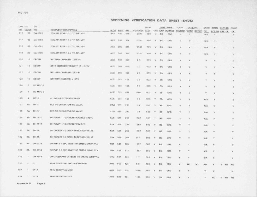
Q/21/95
SCREENING VERIFICATION DATA SHEET (SVDS)
LINE EQ EQ BASE SFYCTRUM CAP > CAVEATS ANCH MTEM OUTUER EQUIPNO EQUIRAENT DESCRPTfDN BLDG ELEY FM SOUGGER ELEV S4.0 M DEMAND DEMAND WO*C MTENT O_K ACTOE YIN OK E_ class NO116 88 DA-3783 EDG AR RCVR 1-1-1 TO AIFL.VLV AUX 585 318 12347 595 Y BS GRS Y Y N/A Y Y
117 88 DA-3 784 EDG AaR RCVR 1-12 TO AIR-.VLV AUX 585 318 12347 595 Y BS GRS Y Y N/A Y Y
118 88 DA-3785 EDG AE RCVR 1-21 TO AIR..VLV AUX 585 319 12347 595 Y BS GRS Y Y N/A Y Y
119 88 DA-3786 EDG AIR RCVR 1-2-2 TO AIR. VLV AUX 585 319 12347 595 Y BS GRS Y Y N/A Y YI
-120 16 DBC1N BATTERY CHARGER -125V de AUX 603 429 23 603 Y BS GRS Y Y Y Y Y;
l-121 16 DBCIP BAT T CHARGER FOR BATT 1P + 125V AUX 603 429 23 603 Y BS GRS Y Y Y Y Y
122 16 DOC 2N BATTERY CHARGER 125V de AUX 603 428 24 603 Y BS GRS Y Y Y Y Y
123 16 DBC2P BATTERY CHARGER +125V AUX 603 428 29 603 Y BS GRS Y Y Y Y Yi*
124 1 DC MCC 1 AUX 603 429 13 603 Y BS GRS Y Y Y Y Y
125 1 DC MCC 2 AUX 603 428 489 603 Y BS GRS Y Y Y Y Yr
126 4 DF12 4.16tV-480V TRANSFOf8AER AUX 603 428 78 603 Y BS GRS Y Y N/A Y Y
127 8A des 11 RCS TO DH SYSTEM ISO VALVE CTM 565 290 14 565 Y BS GRS Y Y N/A Y Y f
! 128 8A De&I 2 RCS TO DH SYSTEM ISO VALVE CTM 565 290 14 565 Y BS GRS Y Y N/A Y Y h.!
l129 BA DH 1517 DH FWP 1 1 SUCTION FROM RCS VALVE AUX 565 236 1367 565 Y BS GRS Y Y N/A Y Y
r
,
f130 8A De&1518 DH PUMP 12 SUCTION FROM RCS AUX 565 236 1367 565 Y BS GRS Y Y N/A Y Y f
131 8A Det1A DH COOLER 1-2 DISCH TO RCS ISO VALVE AUX 565 236 1367 565 Y BS GRS Y Y N/A Y Y
132 8A D6+18 DH COOLER 1-1 DISCH TO RCS ISO VALVE AUX 565 208 67 565 Y BS GRS Y Y N/A Y Yt
!i33 8A Dt&2733 DH PMP 1 1 SUC IBWST OR EMERG SUMP) VLV AUX 545 105 1367 565 Y BS GRS Y Y N/A Y Y
>
h134 8A Dt42734 DH FMP 1-2 SUC (BWST OR EMERG SUMP) VLV AUX 545 113 1367 565 Y BS GRS Y Y N/A Y Y k
135 7 DH-4849 DH COOLDOWN LN RELIEF TO EMERG SUMP VLV CTM 565 220 17 565 Y BS GRS Y Y N/A Y Y
i136 2 E1 ~ 480V ESSENTIAL UNIT SUBSTATION AUX 603 429 69 603 Y BS GRS Y NO NO NO Y Y NO NO Ii
[137 1 EllA 480V ESSENTIAL MCC AUX 565 209 1489 565 Y BS GRS Y Y Y Y Y [5
>
I'
138 1 E118 480V ESSENTIAL MCC AUX 585 304 1489 585 Y BS GRS Y Y Y NO Y NO NO L
IAppendiu D Page 6 .
'
i
6
. .. . . . . _ . . . . . . _ - _ _ - . - . . . . . , , - . . _ . . ,.e ... . -- . . m.,.,., m.m. m-~ , . - - - . ..-e.-______..e ,. .e -- - - ,,e- ___-e. - . - ~ , , , ~ +
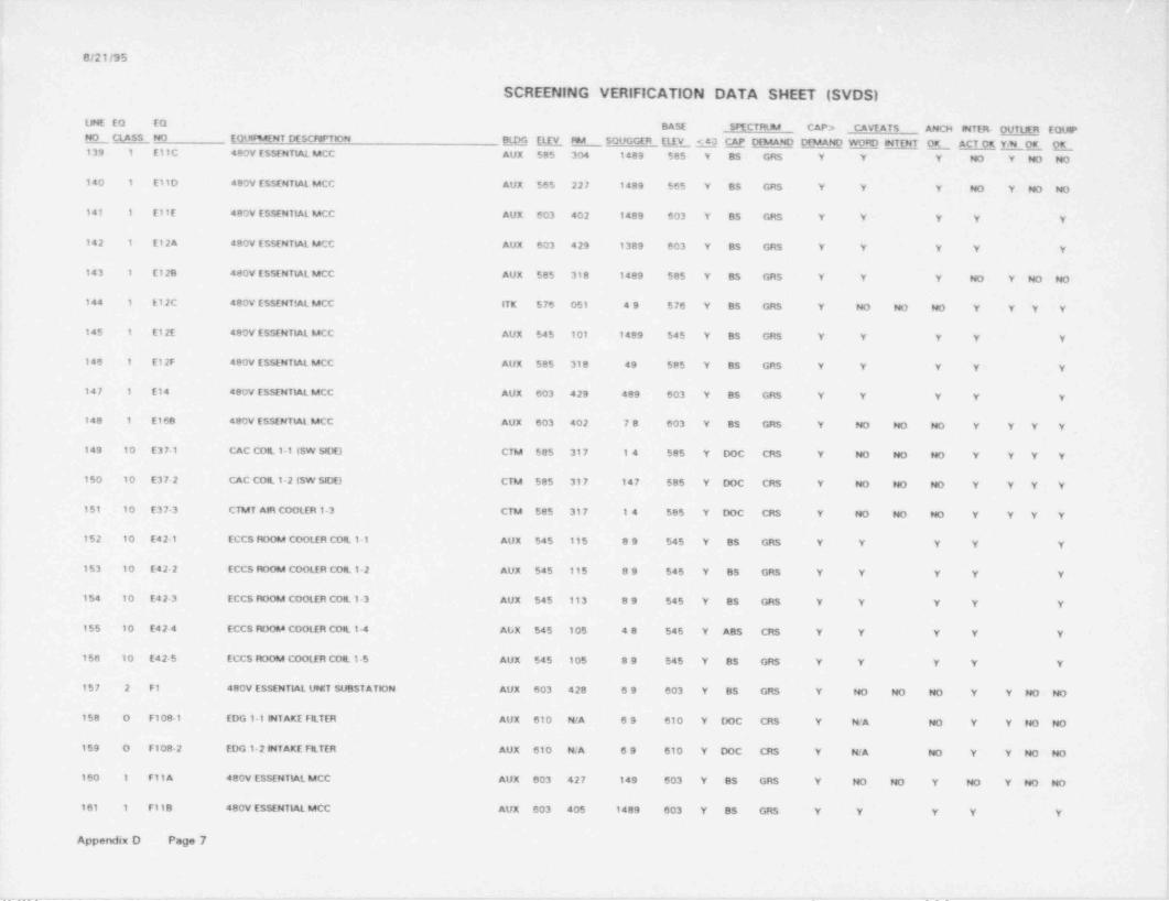
- s
. G/21/05!
SCREENING VERIFICATION DATA SHEET (SVDS) f
LME EQ EQ BASE SITCTRUM CAP > CAVEATS ANCH MTER OUTUER EOUPE CLASS NO EOUNENT DESCRrTION _EfLDG E Fe4 SOUGGER (LEV <40 CAP DEMAND DEMAND WORD MTENT OK ACT OK Y/N Oer O_K139 1 E11C 480V ESSENTIAL MCC AUX 585 304 1489 585 Y BS GRS Y Y Y NO Y NO NO i
I140 1 E11D 480V ESSENTIAL MCC AUX 565 227 1489 565 Y BS GRS Y Y Y NO Y NO NO!
t141 1 E11E 480V ESSEN1ML MCC AUX 603 402 1489 603 Y BS GRS Y Y Y Y Y
142 1 E124 480V ESSENTML MCC AUX 603 429 1389 603 Y BS GRS Y Y Y Y Y,
143 1 E128 480V ESSENTML MCC AUX 585 318 1499 585 Y BS GRS Y Y Y NO Y NO NO i
144 1 E12C 480V ESSENTML MCC ITK 576 051 49 576 Y BS GRS Y NO NO NO Y Y Y Y
145 1 E12E 480V ESSENTML MCC AUX 545 101 1489 545 Y BS GRS Y Y Y Y Y
tt146 1 E12F 480V ESSENTIAL MCC AUX 585 318 49 585 Y BS GRS Y Y Y Y Y 7
1
147 1 E14 480V ESSENTIAL MCC AUX 603 429 489 603 Y BS GRS Y Y Y Y Y(
i148 1 E168 480V ESSENTIAL MCC AUX 603 402 78 603 Y BS GRS Y NO NO NO Y Y Y Y I
149 10 E371 CAC COIL 1-1 (SW SIDE) CTM 585 317 14 585 Y DOC CRS Y NO NO NO Y Y Y Y
150 10 E37-2 CAC COIL I-2 (SW SIDE) CTM 585 317 147 585 Y DOC CRS Y NO NO NO Y Y Y Y [!t151 10 E37-3 CTMT AIR COOLER 13 CTM 585 317 14 585 Y DOC CRS Y NO NO NO Y Y Y Y
152 10 E42-1 ECCS ROOM COOLER COIL 1-1 AUX 545 115 89 545 Y BS GRS Y Y Y Y Y!t
153 to E42-2 ECCS RDOM COOLIR COtt 1-2 AUX 545 115 89 545 Y BS GRS Y Y Y Y Y j
$154 10 E42-3 ECCS ROOM COOLER Coll 1-3 AUX 545 113 89 545 Y BS GRS Y Y Y Y Y ;
.
155 10 E42 4 ECCS RDOM COOLIR COIL 1-4 AteX 545 105 48 545 Y ABS CRS Y Y Y Y Y Il
?156 to E42-5 ECCS ROOM COOLER COIL 15 AUX 545 105 89 545 Y 85 GR$ Y Y Y Y Y ;
157 2 F1 480V ESSENTML UNIT SUBSTATION AUX 603 428 69 603 Y BS GRS Y NO NO NO Y Y NO NO f!
i158 0 F108-1 EDG 1 1 MTAKE FILTER AUX 610 N/A 69 610 Y DOC CRS Y N/A NO Y Y NO NO '
i159 O F108-2 E.DG 12 MTAKE FILTER AUX 610 N/A 69 610 Y DOC CRS Y N/A NO Y Y NO NO [a
160 1 F11A 480V ESSENTML MCC AUX 603 427 149 603 Y BS GRS Y NO NO Y NO ' Y NO NO
161 1 F118 480V ESSENTIAL MCC AUX 603 405 1489 603 Y BS GRS Y Y Y Y Y
Appendix D Page 7i
(i
-_ _ - _ _ _ ._- . - , - - - - .- , - . . . . - _ - . . - . - - - - - _ , . . - _ . . .-. _- ._--._-. .. - - -

, . .
G/21/95
SCREENING VERIFICATION DATA SHEET (SVDS)
UNE EQ EQ BASE SIYCTRUM CAP > CAVEATS ANCH INTER- OUTLER EOUPMO NO EQUlm4ENT DESCRPTION M Q 794 SOUGGER ELEV S40 LAP DEMAND DEMAND WOfD SITENT OK ACTOK YN OK E !_ CLASS162 1 F11C 480V ESSENTIAL McC AUX 565 236 1489 565 Y BS GRS Y Y Y NO Y NO NO
i
|163 1 F11D 480V ESSENTIAL MCC AUX 565 227 149 565 Y BS GRS Y Y Y Y Y
.164 1 F11E 480V ESSENTIAL MCC AUX 545 101 1489 545 Y BS GRS Y Y Y Y YI
i165 1 F12A 480V ESSENTIAL MCC AUX 603 428 489 603 Y BS GRS Y Y Y Y Y it
166 1 F12B 480V ESSENTIAL MCC AUX 585 319 1489 585 Y BS GRS Y Y Y Y .Y
167 1 F12C 480V ESSENTIAL MCC ITK 576 052 149 576 Y BS GRS Y Y Y Y Yi
168 1 F12D 480V ESSENTIAL MCC ITK 576 052 149 575 Y BS GRS Y NO NO NO Y Y- Y Y '
|'
' 169 1 F14 480V ESSENTIAL MCC AUX 603 428 489 603 Y BS GRS Y Y Y Y Y
170 0 F15-1 SERVICE WATER STRAINER 1-1 ITK 576 052 127 576 Y DOC CRS Y N/A Y Y Y ;
171 O F15-2 SERVICE WATER STRAINER 1-2 ITK 576 052 127 576 Y DOC CRS Y N/A Y Y Y
172 1 F16A 480V ESSENTIAL MCC AUX 603 428 67 603 Y BS GRS Y NO NO NO Y Y Y Yi
; 173 18 FIS 1422C CC M4P 1 1 DISCH FLOW INDeC SW AUX 585 328 67 590 Y BS GRS Y' Y Y Y Yl
174 18 FIS 1422D CC PMP 1 1 OtSCH FLOW INDIC SW AUX 585 328 26 588 Y BS GRS Y Y Y Y Y iI
'
|175 18 FIS 1427C CC PMP 1-3 DISCH FLOW INDIC SW AUX 585 328 26 585 Y BS GRS Y Y Y Y Y *
176 18 FIS 1427D CC PMP 1-3 DISCH FLOW INDeC SW AUX 585 328 26 585 Y BS GRS Y Y Y Y Ye
,
f
.' 177 18 FIS 1432C CC FMP 12 DISCH FLOW INDIC SW AUX 585 328 26 588 Y BS GRS Y Y Y Y Y h
178 18 FIS 1432D CC PMP 1-2 DISCH FLOW INDIC SW AUX 585 328 67 587 Y BS GRS Y Y Y Y Y
L179 18 FT DH2A LO PRESSURE INJ LINE 2 FLOW TRANSMITTER AUX 565 236 78 570 Y BS GRS Y Y Y Y Y
!180 18 FT DH2B LP INJ LINE 1 FLOW TRANSMITTER AUX 545 105 58 549 Y BS GRS Y Y Y Y Y t
! 181 20 hts NC133 LOW VOLT. SWGR 794 VEN FAN 12 LCL AUX 603 428 67 607 Y BS GRS Y NO Y Y Y Y ri
'
182 20 hts NC251 EDG FD4 VENTRATION FAN 1 LCL AUX 585 318 14 589 Y BS GRS Y Y Y Y Y '
i183 20 HIS NC252 EDG 754 VENTRATION FAN 2 LCL AUX 585 318 14 589 Y BS GRS Y NO Y Y Y Y
i 184 20 HIS NC253 EDG 594 2 VNTL FAN 3 LCL HIS AUX 585 319 146 588 Y BS GRS Y NO Y Y Y YI
Appendix D Page 8y
,
-..-~.- ~ m.-~.,-.r -e-- -. . - . . - -,..~~*,e m - - - .-,,x+- c. ---.- - -+-w-- -- .#--.ev. - * - . - - - . - - + < . - ~ . , - - . - ~ . - - - . - , - .- -e.,-r.
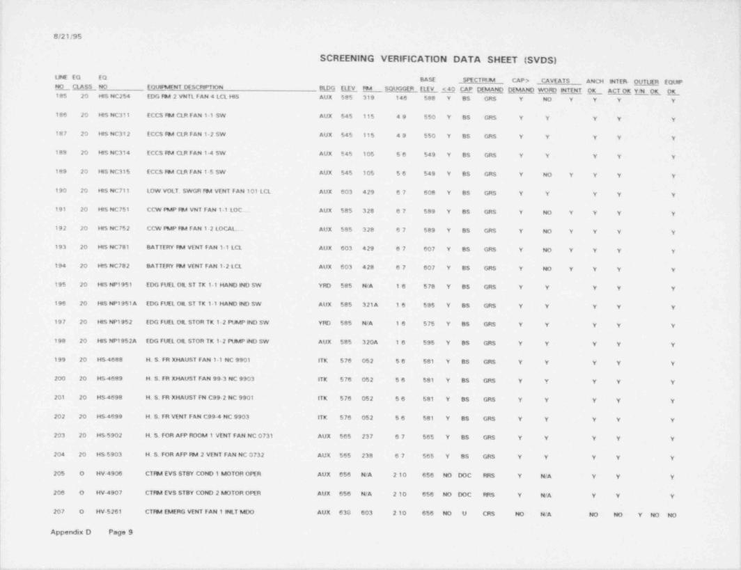
_ _ _ _ _ _ _ _ . _ _ _ _ _ _ _ _ _ _ _ - - _ _ _ _ _ _ _ _ _ _ _ - _ _ _ _ _ _ _ - - _ _ _ _ _
G/21/95 ~
SCREENING VERIFICATION DATA SHEET (SVDS)!
LINE EQ EQ BASE SPECTRtN CAP > CAVEATS ANCH piTERr OUTUER EQUIP_NOCLASS NO EQURAENT DESCRIPTION E ELEY FN SOUGGER E <40 CAP DEMAND DEMAND WORD INTENT OK_ ACT QK EE E g185 20 HIS NC254 EDG fW 2 VNTL FAN 4 LCL HIS AUX 585 319 146 588 Y BS GRS Y NO Y Y Y Y :
'.
186 20 hts NC311 ECCS IN CLR FAN 1 1 SW AUX 545 115 49 550 Y BS GRS Y Y Y Y Y
187 20 HIS NC312 ECCS IN CLR FAN 12 SW AUX 545 115 49 550 Y BS GRS Y Y Y Y Y
i 188 20 HIS NC314 ECCS IN CLR FAN 1-4 SW AUX 545 105 56 549 Y BS GRS Y Y Y Y Y
189 20 HIS NC315 ECCS fM CLR FAN 1-5 SW AUX 545 105 56 549 Y BS GRS Y NO Y Y' Y Y
190 20 hts NC711 LOW VOLT. SWGR FN VENT FAN 101 LCL AUX 603 429 67 608 Y BS GRS Y Y Y Y Y
!191 20 HIS NC751 CCW RAP fN VNT FAN 1-1 LOC... AUX 585 328 67 589 Y BS GRS Y NO Y Y Y Y t
192 20 HIS NC752 CCW PMP fN FAN 1-2 LOCAL AUX 585 328 67 589 Y BS GRS Y NO Y Y Y YI'
193 20 His NC781 BATTERY fN VENT FAN 1-1 LCL AUX 603 429 67 607 Y BS GRS Y NO Y Y Y Y
194 20 HfS NC782 BATTERY fN VENT FAN 1-2 LCL AUX 603 428 67 607 Y BS GRS Y NO Y Y Y Y
195 20 hts NP1951 EDG FUEL OIL ST TK 1-1 HAND IND SW YRD 585 N/A 16 578 Y BS GRS Y Y Y Y Y.!196 20 HIS NP1951 A EDG FUEL Ott ST TK 1 1 HAND IND SW AUX 585 321A 16 595 Y BS GRS Y Y Y Y Y
197 20 HIS NP1952 EDG FUEL OIL STOR TK 1-2 PUMP IND SW YRD 585 N/A 16 575 Y BS GRS Y Y Y Y Yt
198 20 HIS NP1952A EDG FUEL OIL STOR TK 12 PUMP 8ND SW AUX 585 320A 16 595 Y BS GRS Y Y Y Y Y
199 20 HS-4688 . H. S. FR XHAUST FAN 1 1 NC 9901 ITK 578 052 56 581 Y BS GRS Y Y Y Y Y |
200 20 HS-4689 H. S. FR XHAUST FAN 99-3 NC 9903 ITK 576 052 56 581 Y BS GRS Y Y Y Y Y,
I
201 20 HS.4698 H. S. FR XHAUST FN C99-2 NC 9901 ITK 576 052 56 581 Y BS GRS Y Y Y Y Y
202 20 HS-4699 H. S. FR VENT FAN C99-4 NC 9903 ITK 576 052 56 581 Y BS GRS Y Y Y Y Y
i203 20 HS-5902 H. S. FOR AFP ROOM 1 VENT FAN NC 0731 AUX 565 237 67 565 Y BS GRS Y Y Y Y Y I
204 20 HS-5903 H. S. FOR AFP fN 2 VENT FAN NC 0732 AUK 565 238 67 565 Y BS GRS Y Y Y Y Y !
205 0 HV4906 CTfN EVS ST8Y COND 1 MOTOR OPER AUX 656 N/A 210 656 NO DOC PRS Y N/A Y Y Y,
k206 O HV~4907 CTIN EVS STBY COND 2 MOTOR OPER AUX 656 N/A 2 10 656 NO DOC fRS Y N/A Y Y Y !!l207 0 HV-5261 CTIN EMERG VENT FAN 1 INLT MDO AUX 630 603 210 656 NO U CRS NO N/A NO NO Y NO NO f
Appendix D PageS f
;.. ..-._ .- .. .- . - . - - .- - - - . .. - - . - . - . . - - .. .-
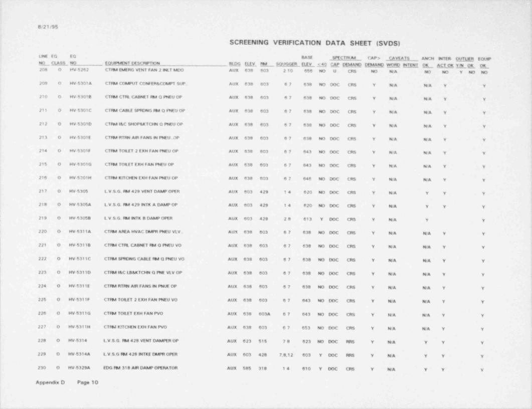
8/21/95
SCREENING VERIFICATION DATA SHEET (SVDS),
|
UNE EO EQ BASE SPECTRUM CAP > CAVEATS ANCH MTER- OUTUER EQUIPN_OCLASS NO EQtJ189AENT DESCRIPTION M E1EV FN SOUGGER El.EV <40 CAP DEMAND DEMANO WOfC NTENT OK ACT OK YH OK E208 O HV.5262 CTW EMERG VENT FAN 2 INLT MOO AUX 638 603 2 10 656 NO U CRS NO N/A NO NO Y NO NO
209 O HV.5301 A CTfN COMPUT CONFER & COMPT SUP.. AUX 638 603 67 638 NO DOC CRS Y NcA NA Y Y
210 0 HV-53018 CTfN CTRL CABNET IN O PNEU OP AUX 638 603 67 638 NO DOC CRS Y N/A N/A Y Y
211 O HV-5301C CTIN CABLE SPRDNG IN O FNEU OP AUX 638 603 67 638 HO DOC CRS Y N/A N/A Y Y- ,
212 O HV-5301D CTIN 1&C SHOP &KTCHN O PNEU OP AUX 638 603 67 638 NO DOC CRS Y N/A N/A Y Y
!213 0 HV-5301E CTIN RTRN AIR FANS N f9dEU. OP AUX 638 603 67 638 HO DOC CRS Y KA N/A Y Y *
214 O HV-5301F CTfN TOILET 2 EXH FAN PNEU OP AUX 638 603 67 643 NO DOC CRS Y WA WA Y Y
215 0 HV-5301G CTIN TORIT EXH FAN PNEU OP AUX 638 603 67 643 NO DOC CRS Y WA N/A Y Y
216 O HV 5301H CTIN KITCHEN EXH FAN PHEU OP AUX 638 603 67 646 NO DOC CRS Y N/A N/A Y Y
217 O HV-5305 LV.S G. IN 429 VENT DAMP OPER AUX 603 429 14 620 NO DOC CRS Y WA Y Y Y
I218 0 HV-5305A LV.S.G. IN 429 NTK A DAMP OP AUX 603 429 14 620 NO DOC CRS Y N/A Y Y Y
219 O HV-53058 LV.S.G. FN NTK B DAMP OPER AUX 603 429 28 613 Y DOC CRS Y N/A Y Y
220 0 HV-5311 A CTIN AREA HVAC DMPR fHEU VLV., AUX 638 603 67 638 NO DOC CRS Y N/A N/A Y Y
221 O HV-53118 CTfN CTRL CABNET FN O PNEU VO AUX 638 603 67 638 NO DOC CRS Y N/A N/A Y Y
222 O HV-5311C CTfN SPRDMG CABLE fW Q PNEU VO AUX 638 603 67 638 NO DOC CRS Y N/A N/A Y Y
223 0 HV-5311D CTFN l&C LB&KTCHN O PNE VLV OP AUX 638 603 67 638 NO DOC CRS Y N/A WA Y Y
224 0 HV-5311E CTfN RTRN AIR FANS M PNUE OP AUX 638 603 67 638 HO DOC CRS Y N/A N/A Y Y
225 O HV-5311F CTfN TOILET 2 EXH FAN PNEU VO AUX 638 603 67 643 NO DOC CRS Y MA N/A Y Y
226 O HV 5311G CTIN TOfLET EXH FAN PVO AUX 638 603A 67 643 NO DOC CRS Y N/A N/A Y Y
I227 O HV-5311H CT!%t K!TCHEN EXH FAN PVO AUX 638 603 67 653 NO DOC CRS Y N/A N/A Y Y
228 O HV-5314 LV.S.G. IN 428 VENT DAMPER OP AUX 623 515 78 623 NO DOC RRS Y N/A Y Y Y
229 O HV.5314A LV.S.G IN 428 NTKE DMPR OPER AUX 603 428 7,8,12 603 Y DOC RRS Y WA Y Y Y
230 0 HV-5329A EDG FN 318 AIR DAMP OPERATOR AUX 585 318 14 610 Y DOC CRS Y N/A Y Y Y l
Appendix D Page 10r
>
~ .-.e _. .- . . . . -- m-,-..-. , . . . . , , _ _ _ - _ , - , - . , ,- e - - ... , , , , , ,

.
G/21/95
SCREENING VERIFICATION DATA SHEET (SVDS)
LJNE EO EO BASE SPECTRUM CAP > CAVEATS ANCH INTER- OUTtlER EQUIPE CLASS NO EOURAENT DESCRPTION BLOG ELEY ftA SOUGGER ELEV <40 CAP DEMAND DEMAND WORD MTENT OK ACT OK YH OK OK_
231 O HV-53298 EDG ftA 318 AIFt DAMP OPERATOR AUX 585 318 14 610 Y DOC CRS Y N/A Y Y Y
232 O HV 5329C EDG 594 318 AIR DAMP OPERATOR AUX 585 318 14 610 Y DOC CRS Y N/A Y Y Y
233 O HV 5336A EDG ftA 2 OTSD AIR CTRL DAMP OP AUX 585 319 146 610 Y DOC C"tS Y N/A Y Y Y
234 O HV-53368 EDG ftA 2 RECIRC CTFE DAMP OPER AUX 585 318 146 610 Y DOC CRS Y N/A Y Y Y
235 0 HV 5336C EDG ftA 2 XHS1 AIR CTRL DAMP OP AUX 585 319 146 61C Y DOC CRS Y N/A Y. Y Y
236 0 HV-5361 A CABLE SPRDNG ftA DMPR INLT OfYR AUX 623 506 67 642 NO DOC CRS Y N/A Y Y Y4
237 O HV-53618 CA8tE SPRDMG ftA INLT DMPR OPER AUX 623 501 67 642 NO DOC CRS Y N/A Y Y Y
238 0 HV-5362A CABLE SPRDNG ftA DMPR OUTLT OPR AUX 623 506 67 642 NO DOC CRS Y N/A Y Y Y
239 0 HV-53628 CABLE SPRDNG RM OUTLT DMfH OPR AUX 623 501 67 642 NO DOC CRS Y N/A Y Y Yj
I: 240 0 HV-5443A CCP ftA VNT FN 1 ftA OUT DAMP OP AUX 585 328 678 595 Y DOC CRS Y N/A Y Y Yi
241 O HV 54438 CCP ftA VNT FM 1 ftA M DAMP OP AUX 585 328 678 595 Y DOC CRS. Y N/A Y Y Y
242 O HV-5443C CCP ftA VNT FN1-1 FDA IN DAMP OP AUX 585 328 16 603 Y DOC CRS Y N/A Y Y Y
243 O HV-5444A CCP ftA VNT FN 2 ftA OUT DAMP OP AUX 585 328 678 595 Y DOC CRS Y N/A Y Y Y
244 O HV-54448 CCP ftA VNT FN ftA INLT DAMP OPR AUX 585 328 678 595 Y DOC CRS Y N/A Y Y Y
| 245 0 HV-5444C CCP ftA VNT FN2 ftA INLY DAMP OP AUX 585 328 16 603 Y DOC CRS Y N/A Y Y Y
246 0 HV-5597 8AT ftA A VENT TO ATM DAMP OPER AUX 603 4298 24 615 Y DOC CRS Y N/A Y Y Y
247 O HV-5598 OPER,DMrH FftA BAT ftA VENT -ATM AUX 603 428A 28 623 NO DOC RRS Y N/A Y Y Y
248 18 M-630 IA PCV FOR MU66D AUX 565 208 567 565 Y BS GRS Y Y Y Y Y
249 18 M-636 M PCV FOR MU66A AUX 565 208 567 565 Y BS GRS Y Y Y Y Y
250 18 IA-648 IA PCV FOR MU38 AUX 565 208 567 565 Y BS GRS Y Y Y Y Y
251 18 IA-654 IA PCV FOR MU668 AUX 565 208 567 565 Y 85 GRS Y Y Y Y Y
252 18 IA-660 LA PCV FOR MU66C AUX 565 208 667 565 Y BS GRS Y Y 'Y Y Y
253 7 H S-11 A MS LINE 2 ATMOSPHERC VENT VALVE AUX 643 602 147 660 NO DOC CRS Y N/A N/A Y Y
Appendix D Page 11

G/21/95
SCREENING VERIFICATION DATA SMEET (SVDS)
LINE EQ EQ BASE SPECTRtmA CAP > CAVEATS ANCH INTER. OUTIER EQUIPR CLASS NO EQUlfMENT DESCRIPTION BLDG ELEY FSA SOUGGER ELEV <40 CAP DEMAND DEMAND WORD INTENT OK ACT OK YM CK OK254 7 8CS 118 MS UNE 1 ATMOSFHERIC VENT VALVE AUX 643 601 147 660 NO DOC CRS Y N'A N'A Y Y
255 20 JT-2703 TEFSAINAL BLOCK BOX FOR AFPT 1 AUX IELAY AUX 565 237 67 565 Y ABS CRS Y Y Y Y Y
256 20 JT-2704 TEFDAINAL BLOCK BOX FOR ATPT 2 AUX RELAY AUX 565 238 67 565 Y BS GRS Y Y Y Y Y
257 5 K 3- 1 AUX 10ARY FEED 79AP TURBfNE 1-1 AUX 565 237 17 565 Y BS GRS Y NO Y Y Y y
258 5 K3- 2 AUX 1UARY FEED FMP TURBtNE 1 2 AUX 565 237 17 565 Y BS GRS Y NO Y Y Y Y
259 17 K5-1 EDG 1-1 AUX 585 318 19 585 Y BS GRS Y Y Y Y Y
260 17 K 5- 2 EDG 1-2 AUX 585 319 69 585 Y BS GRS Y Y Y Y Y
261 18 LSH 1122 EDG DAY TANK 1 1 LVL SWtTCH Hi AUX 595 320A 1237 600 Y BS GRS Y Y N/A Y Y
262 18 LSH 1128 EDG DAY TANK 1 1 LVL SWITCH Hi AUX 595 321A 12347 600 Y BS GRS Y Y N/A Y Y
263 18 LSL 1122 EDG DAY TANK 1-2 LVL SWITCH LO AUX 595 320A 12347 000 Y 83 GRS Y Y N/A Y Y
264 18 LSL 1128 EDG DAY TANK 1 1 LVL SWTTCH LO AUX 595 321A 12347 600 Y BS GRS Y Y N/A Y Y
265 18 LT 1402 CC SRG TNK 1 1 SIDE 1 LV TRANS AUX 623 501 23 623 NO ABS CRS Y Y Y NO Y NO NO
266 18 LT 1403 CC SRG TNK 1 1 SfDE 2 Lv TRANS AUX 623 501 23 623 NO ABS CRS Y Y Y NO Y NO NO
267 18 LT 2787 EDG DAY TANK 1-1 LVL TRANSMITT AUX 585 318 12347 590 Y BS GR$ Y Y Y Y Y
268 18 LT-2788 EDG DAY TANK 12 LVL TRANSM6TT AUX 585 319 12347 590 Y BS GRS Y Y Y Y Y
269 18 LT MU16-1 BC MU TANK LVL TRANSMITTLR AUX 565 AB3 24 567 Y BS GRS Y Y Y Y Y
270 18 LT MU16-2 RC MUT LVL TRANSMITTER AUX 565 AB3 24 567 Y BS GRS Y Y Y Y Y
271 18 LT.RC14-1 RC PRESSURIZER CH 2 LEVEL TRANSMITTER CTM 585 317 145 593 Y BS GRS Y Y Y Y Y
272 18 LT RC14-3 RC PRESSURIZER CH 1 LEVEL TRANSMITTER CTM 585 317 145 589 Y BS GR$ Y Y Y Y Y
273 18 LT SP9A3 STEAM GEN 1-2 STARTUP LEVE1. TRANSMti 3 CTM 565 286 145 565 Y BS GRS Y Y Y Y Y
274 18 LT-SP983 STEAM GEN 1 STARTUP LEVEL TRANSMITTER CTM 565 285 145 565 Y BS GR$ Y Y Y Y Y
275 7 MS-100 MAIN STEAM UNE 2 ISO VALVE AUX 643 602 147 647 NO DOC CHS Y N/A N/A Y Y
276 7 MS 101 MS UNE 1 ISO VALVE AUX 643 601 147 647 NO DOC CRS Y N/A N/A Y Y
Appendix D Page 12

otatiss
SCREENING VERIFICATION DATA SHEET (SVDS)
LINE EO EQ BASE SPECTRUM CAP > CAVEATS ANCH MTER . M EQUIPNO NO EQUIF%4ENT DESCRIPTON ElpG ELEV FM SOUGGER ELEV <40 CAP DEMAND DEMANO WORD MTENT OK ACT OK Y94 OK OK'_ CLASS _
277 BA MS 106 MS LINE 1 TO AFP TURB 1-1 ISO VALVE AUX 623 500 23 623 NO DOC CRS Y WA WA Y Y
278 BA MS-107 MS LN 2 TO AFP TUfB 1-2 MTR CTRL ISO YLV AUX 623 501 23 623 NO DOC CRS Y WA N/A Y Y
279 7 MS5889A AFP TURB 1-1 STEAM ADMISSON VALVE AUX 565 237 36 585 Y BS GR$ Y Y WA Y Y
280 7 MS 58898 AFP TURB 1-2 STEAM ADMlSSON VALVE AUX 565 238 36 585 Y BS GRS Y Y WA Y Y
281 7 W19 RCP SEAL NJ FLOW CTRL VLV AUX 585 303 17 585 Y BS GRS Y NO Y NA Y Y
282 8A W1A Ftc LETDOWN COOLER 1-1 INLET ISO VALVE CTM 565 215 14 568 Y BS GRS Y Y NcA Y Y
283 BA W1B RC LETDOWN COOLFR 1-2 INLET ISO VALVE CTM 565 215 14 568 Y BS GR$ Y Y N 'A Y Y
284 7 W 23 BA PMP PNEUMATC DISCN CTRL VLV AUX $65 240 2to 571 Y BS GRS Y Y N/A Y Y
285 8A W 2B RC LITDOWN ISO VALVE CTM 565 216 14 565 Y BS GRS Y Y N/A Y Y
286 7 MU-32 MU FLOW CTRL VALVE AUX 565 225 36 568 Y BS GRS Y Y N/A Y Y,
287 7 W 38 RCP SEAL RETURN ISO VALVE AUX 565 208 567 565 Y BS GRS Y NO Y N/A Y Y
288 8A MS3971 MU PUMP 2 SUCTON 3 WAY MOV AUX 565 225 36 585 Y BS GRS Y Y N/A Y Y
289 8A W 40 BATCH FEED LME STOP ISO YLV AUX 565 211 18 568 Y BS GRS Y Y N/A Y Y
290 8A W 6405 RC MU f%AP1-13-WAY SUCTON VALVE AUX 565 225 36 5e5 Y BS GRS Y Y N/A Y Y
291 8A W 6419 NOfNAL MU TO RCS LOOP-1 ISOVLV AUX 565 208 67 565 Y BS GRS Y Y N/A Y Y
292 SA W 6421 MU TO RCS TRAN2 ISO VALVE AUX 565 208 67 565 Y BS GRS Y Y N'A Y Y
293 8A W 6422 NOfW MU TO RCP SEALS ISO VLV AUX 565 236 67 565 Y BS GRS Y Y N/A Y Y
294 7 W 66A RCPI 2-1 SEAL MJ FLOW ISO VLV AUX $65 208 67 565 Y BS GRS Y NO Y N/A Y Y
295 7 W 668 P1-2-2 SEAL MJ FLOW CNTf4. VLV AUX 565 208 87 565 Y BS GRS Y NO Y N/A Y Y
296 7 MU 66C RCP1 1 1 SEAL MJ FLOW ISO VLV AUX 565 208 67 565 Y BS GRS Y NO Y WA Y Y
297 7 W 660 RCPI 12 SEAL MJ FLOW ISO VLV AUX 565 208 67 565 Y BS GRS Y NO Y N/A Y Y
298 1 NP 1473 EDG 1-1 Oil PUMP CONT BOX CH A AUX 585 318 78 591 Y B3 GRS Y Y Y Y Y
299 1 NP 1474 EDG 12 OIL PUMP CONT BOX CH B AUX 585 319 78 591 Y BS GRS Y Y Y Y Y
Appendix D Page 13
-_ . - _ __ _ - _ _ _ _ _ _ _ _ - __~

- - - _ _ . - __-__ _
8/21/95
SCREENING VERIFICATION DATA SHEET (SVDS)
UNE EQ EQ BASE SDECTRUM CAP > CAVEATS ANCN INTER- OUTUER EQUIPNO CLASS NO EOUiNENT DESCRPTION BLDG ELEV RM SOUGGER ELEV <40 CAP DEMAND DEMAND WORD INTENT OK ACT OK Y.N OK OK300 20 NV 5305A LV S.G F9A DAMP CTRL STATION AUX 603 429 24 607 Y SS GR$ Y Y Y Y Y
301 20 NV-53058 LV.S.G N OAMP CTRL STATION AUX 603 429 24 607 Y BS GRS Y Y Y Y Y
302 IS NV 5314A LV.S.G. W 428 VENT AUX 603 428 1 10 608 Y BS GRS Y Y Y Y Y
303 20 NV 55970 BATT N 4298 DISCH DMPR LOC SW AUX 603 429 24 607 Y BS GRS Y Y Y Y Y
304 18 NY-55980 BATT N 428A DISCH DMPR LOC SW AUX 603 428 1 10 608 Y BS GRS Y NO Y Y Y Y
305 20 NY 58748 NEUTRON FLUX MONITORING AMPUGER CHI AUX 603 402 14 608 Y BS GRS Y Y Y Y Y
306 18 NY-58758 NEUTRON FLUX SIGNAL AMPLFtER AUX 603 427 14 603 Y BS GRS Y Y Y Y Y
307 5 P14-1 AUXIUARY f EEDWATER PUMP 1-1 AUX 565 237 17 565 Y BS GRS Y NO Y Y Y Y
303 5 P14-2 AUXiUARY FEEDWATER PUMP 1-2 AUX 565 238 17 565 Y BS GRS Y NO Y Y Y Y
309 6 P195-1 EDG FUEL Ott TRANSFER PUMP 1-1 YRD 585 N/A 46 578 Y DOC GRS Y N/A Y Y Y
310 6 P195-2 EDG FUEL OIL TRANSFER PUMP 12 YPD 585 N/A 46 578 Y DOC GRS Y N/A Y Y Y
311 6 P3- 1 SERVICE WATER PUMP 1 1 ITK 576 052 124 576 Y DOC RRS Y NO NO Y Y Y Y Y
312 6 P3-2 SERVICE WATER PUMP 12 ITK 576 052 24 576 Y DOC FIRS Y NO NO Y Y Y Y Y
313 5 P37-1 MAKEUP PUMP 1-1 AUX 565 225 14 565 Y BS GRS Y Y Y Y Y
314 5 P37-2 MAKEUP PUMP 1-2 AUX 565 225 14 565 Y BS GRS Y Y Y Y Y
315 5 P38-1 BORIC ACID PUMP 1-1 AUX 565 240 2 10 565 Y BS GRS Y Y WA Y Y
316 5 P38-2 BORIC ACID PUMP 1-2 AUX 565 240 210 565 Y BS GRS Y Y N/A Y Y
317 5 P421 DECAY HEAT PUMP 1-1 AUX 545 105 56 545 Y BS GRS Y Y Y Y Y
318 5 P4 2-2 DECAY HEAT PUMP 12 AUX 545 115 49 545 Y BS GR$ Y Y Y Y Y
319 5 P43-1 COMP COOUNG PUMP 1 1 AUX 585 328 1367 585 Y BS GRS Y Y Y Y Y
320 5 P43-2 COMPONENT COOUNG PUMP 12 AUX 585 328 1367 585 Y BS GRS Y Y Y Y Y
321 5 P43 3 CC PUMP 1-3 AUX 585 328 1367 585 Y BS GRS Y Y Y Y Y
322 5 PS6-1 CONTAlteAFMT SPRAY PUMP 1-1 AUX 545 105 56 545 Y BS GRS Y Y Y Y Y
Appendix D Page 14
_ _ _ _ _ - - _ - _ - _ _ _ _ - _ _ _ _ _ _ _ _ _ _ - _

8/21/95 i
+
SCREENING VERIFICATION DATA SHEET (SVDS)L
LNE EO EQ BASE SPECTFUM CAP > CAVEATS AMCH WTEf4 OUTUER EQUPNO NO EOUIFMENT DESCRPTON BLDG ELEV FN SOUGGER ELEV <40 QP DEMAND DEMAND WORD NTENT L ACT OK Y1E _OK_ CLASS323 5 P56-2 CONTADNENT SPRAY PUMP 1-2 AUX 545 115 49 545 Y- BS GRS Y Y Y Y Y
.
! '
324 5 P57 BORATED WATER RECFC PUMP 1-1 AUX 565 209 17 565 Y BS GRS Y Y Y Y Y
F' 325 5 P58-1 HI PRESSURE WJECTON PUMP 1-1 AUX 545 105 56 545 Y BS GRS Y Y Y Y Y n
326 5 P58-2 He fHES$URE WJECTON PUMP 12 AUX 545 115 49 545 Y BS GRS Y Y Y Y Y
327 18 PDIS 1379A SW STRNR 1-1 PFESS DeFF IND SW tTK 576 052 56 576 Y BS GRS Y Y Y Y Y'
328 18 PDtS1380A SW STRNR 1-2 PRESS DIFF IND SW ITK 576 052 56 576 Y BS GRS Y Y Y Y Y r
329 18 PDSH 3981 DG1 JKT CC OUT t% VLV PDSH AUX 585 318 14 589 Y BS GRS Y Y Y Y Yf
I330 18 PDSH 3982 DG2 JKT CC OUT ISO VLV PDSH AUX 585 319 146 589 Y BS GRS Y Y Y Y Y
331 18 POMU52A BA FMP 1 1 DISCH LN PRESS INDI AUX 565 241 4710 569 Y ABS CRS Y NO Y Y Y Y Ii
332 18 PtMU528 BA fMP 1-2 DISCH PRESS INDIC AUX 565 241 4710 569 Y ABS CRS Y NO Y Y Y Y
i!333 18 PS 3687A MS UNE 2 PRESS LO TO SFRCS CH 2 PRESS SW AUX 623 501 48 628 NO DOC CRS Y Y Y Y Y
334 ~ 18 PS 3687C MS UNE 1 PRESS LO TO SFRCS PRESS SW AUX 623 500 48 627 NO DOC CRS Y Y Y Y Y|
335 18 PS 3687E MS UNE 2 PRESS LO TO SFRCS CH 4 PESS SW AUX 623 501 48 628 NO DOC CRS Y Y Y Y Y I',
336 18 PS 3687G MS UNE 1 PfESS LO TO SFRCS CH4 PRESS SW AUX 623 500 48 627 NO DOC CRS Y Y Y Y Y
$337 18 PS 36898 MS UNE 1 PRESS LO TO SFRCS PfESS SW AUX 623 500 48 627 NO DOC CRS Y Y Y Y Y |
!
338 18 PS 36890 MS UNE 2 PRESS LO TO SFRCS CH 1 PfESS SW AUX 623 50' 48 628 NO DOC CRS Y Y Y Y Yl
339 18 PS 3689F MS UNE 1 PfESS LO TO SFRCS PRESS SW AUX 623 500 48 627 NO DOC CRS Y Y Y Y Y f
!340 18 PS 3689H MS UNE 2 PRESS LO TO SFRCS CH3 PRESS SW AUX 623 501 48 628 NO DOC CRS Y- Y Y Y Y!
341 18 PS 5301 CTFN H&V SFAS ACT ISO PRES SWT AUX 638 603 2 11 643 Y ABS RRS Y Y Y Y Y ;
342 18 PS 5311 CTIN H&V SFAS ACT ISO PRES SWT AUX 638 603 2 11 643 Y A8S RRS Y Y Y Y Y
343 18 PS MU102A MK-UP PMP2 OIL PRESS SWTCH AUX 565 225 79' 565 Y BS GRS Y Y Y Y Y
344 18 PS MU102A1 MK-UPIMP2 OIL PRESS SWTCH AUX $65 225 79 565 Y BS GRS Y Y Y Y Y
f345 0 PSE 226 PRESSUNZER QUENCH TANK RUPTURE DISK CTM 565 218 17 565 Y EJ EJ Y N/A N/A Y Y I
fAppendix D Page 15
|t
?
-
, , - , . - , , , m w c-~ w- - - m--,- - -w-- -n- - --o-- - a ~ ~ - - - - - - - --- - ----- - - -

G/21/95
SCREENING VERIFICATION DATA SHEET (SVDS)
LINE EO EO BASE SPECTRUM CAP > . CAVEATS ANCH INTER OUTUER EQUIPNO NO EQUIRAENT DESCRPTON M ELEV FM SOUGGER (LEV <40 CAP DEMANO DEMAND WORD INTENT O_K ACT OK Y1E O_K_ CLASS346 0 PSE $461 PRESSURIZER SAFETY VALVE RUPTURE DISK CTM 565 218 17 609 Y EJ EJ Y KA N'A Y Y
347 O PSE 5462 PRESSURIZER SAFETY VALVE RUPTURE DISK CTM 565 218 17 609 Y EJ EJ Y N/A N/A Y Y
348 0 PSE 5463 PMSSURIZER SAFETY VALVE RUPTURE DISK CTM 565 218 17 609 Y EJ EJ Y MA N/A Y Y
349 0 PSE 5464 PRES $URZER SAFETY VALVE RUPTURE OtSK CTM 565 218 17 609 Y EJ EJ Y N- A N/A Y Y
350 18 PSH 3711 LETDOWN COOLER 1 1 CCW SOE FHES SWITCH CTM 565 215 14 565 Y BS GRS Y Y Y Y Y
351 18 PSH 3712 SW SYS HEADER PRES SW CTM 565 215 14 565 Y BS GRS Y Y Y Y Y
352 18 PSH RC2B4 RC HOT LEG PRESSURE SWITCH CTM 603 410A 14 607 Y BS GRS Y Y Y Y Y
353 18 PSL 106A PRESS SWTCH LO FR AFP TURB 1 1 STM INLET AUX 565 237 27 569 Y BS GRS Y Y Y Y Y
354 18 PSL 106B PRESS EWITCH LOW AT AFP TURB 1-1 SUCTON AUX 565 237 27 570 Y BS GRS Y Y Y Y Y
355 18 PSL 106C PRESS SWITCH LOW FOR AFP TURB 1 1 INLET AUX 565 237 27 569 Y 83 GRS Y Y Y Y Y
356 18 PSL 1060 PRESS SWITCH LOW FOR AFP TURB 1-1 INLET AUX 565 237 27 570 Y BS GRS Y Y Y Y Y
357 18 PSL 107A AFP TURB 1-2 INLET PRESS SWITCH LOW AUX 565 238 27 569 Y BS GRS Y Y Y Y Y
358 18 PSL 1078 AFP TURB 12 INLET PRESS SWITCH LOW AUX 565 238 27 570 Y BS GRS Y Y Y Y Y
359 18 PSL 107C AFP TURB 12 INLET PRESS SWITCH LOW AUX 565 238 27 569 Y BS GR$ Y Y Y Y Y
360 18 PSL 1070 AFP TUfW 1-2 INLET PRESS SWITCH LOW AUX 565 238 27 569 Y BS GRS Y Y Y Y Y
361 18 PSL 1377A SW fwP 12 DCHG SRC TAP PMSS SWITCH LOW ITK 576 052 58 581 Y BS GRS Y Y Y Y Y
362 18 PSL 3783 EDG STRTNG AIR RCVR 1-1-1 TO AUX 585 318 14 804 V BS GRS Y Y Y Y Y
383 18 PSL 3784 EDG STRTNG AIR RCVR 1-1-2 TO.- AUX 585 318 14 604 Y BS GRS Y Y Y Y Y
364 18 PSL 3785 EDG STRTNG AIR RCVR 1-21 TO.. AUX 585 319 46 603 Y BS GRS Y Y Y Y Y
365 18 PSL 3786 EDG STRTNG AIR RCVR 12-2 TO AUX 585 319 46 603 Y BS GRS Y Y Y Y Y
366 18 PSL 4928A AFP 1 1 SUCTION BEFORE STRNR PRESS SWT LO AUX 565 237 18 565 Y BS GRS Y NO NO Y NO Y NO NO
367 18 PSL 49288 AFP 1-1 SUCTON BEFORE STRNR PRESS SWT LO AUX 565 237 18 565 Y BS GRS Y NO NO Y NO Y NO NO
368 18 PSL 4929A AFP 1-2 SUCTON BEFORE STRNR PRESS SWT LO AUX 565 238 18 565 Y BS GRS Y Y Y Y Y
Appendix D Page 16
- _ _ _ _ _ . _ _ . - - _ . . _. - _ _ _ - - -
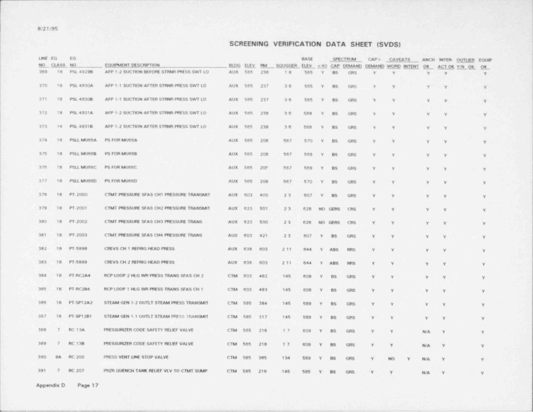
Gt21195
SCREENING VERIFICATION DATA SHEET (SVDS)
UNE EQ EQ BASE SPECTRUM CAP > CAYEATS ANCH MTER OUTLER EQUIPNO NO EOutPMENT DESCNPTON QLDG ELJ.V,, W SOUGGER ELEV S40 M DEMAND DEMAND WORD MTENT_ CLASS _ OK 1gjL OK__ ACT OK Y369 18 PSL 49299 AFP 12 SUCTON BEFOM STRNR fYESS SWT LO AUX 565 238 18 565 Y BS GRS Y Y Y Y Y
370 18 PSL 4930A AFP 1 1 SUCTON AFTER STRNR PRESS SWT LO AUX 565 237 36 565 Y BS GRS Y Y Y Y Y
371 18 PSL 49308 AFP 1 1 SUCTON AFTER STINR PRESS SWT LO AUX 565 237 36 565 Y BS GRS Y Y Y Y Y
372 18 PSL 4931 A AFP 1-2 SUCTON AFTER STRNR PRESS SWT LO AUX 565 238 36 568 Y BS GRS Y Y Y Y Y
373 18 PSL 49318 AFP 1-2 SUCTON AFTER STRNR PRESS SWT LO AUX 565 238 36 568 Y BS GRS Y Y Y Y Y
374 18 PSLL MU66A PS FOR MU66A AUX 565 208 567 570 Y BS GRS Y Y Y Y Y
375 18 PSLL MU668 PS FOR MU668 AUX 565 208 567 569 Y BS GRS Y Y Y Y Y
376 18 PSLL MU66C PS FOR MU66C AUX 565 20e 567 569 Y BS GRS Y Y Y Y Y
377 18 PSLL MU66D PS FOR MU66D AUX 565 208 567 570 Y BS GRS Y Y Y Y Y
378 18 PT-2000 CTMT PRESSURE SFAS CH1 PRESSURE TRANSMIT AUX 603 400 23 607 Y BS GRS Y Y Y Y Y
379 18 PT 2001 CTMT PRESSURE SFAS CH2 PRESSURE TRANSMIT AUX 623 501 23 628 NO GERS CRS Y Y Y Y Y
380 18 PT 2002 CTMT PRESSURE SFAS CH3 PMSSURE TRANS AUX 623 500 23 628 NO GERS CRS Y Y Y Y Y
381 18 PT-2003 CTMT PRESSURE SFAS CH4 PRESSURE TRANS AUX 603 421 23 607 Y BS GRS Y Y Y Y Y-
382 18 PT-5898 CREVS CH 1 MFMG HEAD PRESS AUX 638 603 2 11 644 Y ABS RRS Y Y Y Y Y
383 18 PT-5899 CREVS CH 2 NFMG HEAD PRESS AUX 638 603 2 11 644 Y ABS RR$ Y Y Y Y Y
384 18 PT-RC2A4 RCP LOOP 2 HLG WR 5HESS TRANS SFAS CH 2 CTM 603 482 145 608 Y BS GRS Y Y Y Y Y
385 18 PT RC284 RCP LOOP 1 HLG WR PRESS TRANS SFAS CH 1 CTM 603 483 145 608 Y BS GRS Y Y Y Y Y
380 18 PT-SP12A2 STEAM GEN 12 OUTLY STEAM PRESS TRANSMIT CTM $85 384 145 589 Y BS GRS Y Y Y Y Y
387 18 PT-SP1281 STEAM GEN 1-1 OUTLT STEAM PRESS TRANSMIT CTM 585 317 145 589 Y BS GRS Y Y Y Y Y
388 7 RC13A PRESSURZER CODE SAFETY MUEF VALVE CTM 565 218 17 609 Y BS GRS Y Y N/A Y Y
389 7 RC 138 PRESSURIZER CODE SAFETY REUEF VALVE CTM 565 218 17 609 Y BS GRS Y Y N/A Y Y
390 8A RC 200 PRESS VENT UNE STOP VALVE CTM 585 385 134 589 Y BS GRS Y NO Y N/A Y Y
391 7 RC 207 PR2R OVENCH TANK REUEP VLV TO CTMT SUMP CTM $85 218 145 585 Y BS GRS Y Y N/A Y Y
Appendix D Page 17

r
8/21/95
SCREENING VERIFICATION DATA SHEET (SVDS)
LNE EQ EQ BASE SMCTRUM CAP > _ CAVEATS ANCH NTER- OtTTLfER EQUIP_ CLASSNO NO EQUlF9AENT DESCRIPTION BLDG Et E V FDA SOUGGER ELEV <40 CAP DEMAND DEMAND WORD NTENT OK ACT OK YH OK OK392 BA RC 239A FRESS VAPOR PHASE SAMPLE ISO VALVE CTM 585 385 134 589 Y BS GRS Y NO Y NA Y Y
393 20 RC 2826 AUX NLAY CABINET CH B AUX 565 209 27 565 Y ABS CRS Y Y Y NO Y NO NO
394 0 RC 2A PRZR PWR NUEF VALVE (SOL F1 LOT OP) CTM 623 580 14 636 NO DOC RRS Y N/A HiA Y Y
395 20 RC 3004 NLAY CABWET FOR CH B ITK $65 053 2 11 566 Y ABS CRS Y Y Y NO Y NO NO
396 20 RC 3014 NLAY CAPsNET CH2 ITK 576 052 2 11 580 Y BS GRS Y Y Y Y Y
397 20 RC 3607 NLAY CABINET CHI AUX 585 325 2 7(189) 588 Y BS GRS Y Y Y Y Y
398 20 RC 3608 NLAY CABINET CH2 AUX $85 323 2 10 590 Y BS GR$ Y Y Y Y Y
399 20 RC 3701 AUX MLAY CABINET CHI AUX 585 314 27 585 Y BS GRS Y Y Y NO Y NO NO
400 20 RC 3702 AUX RELAY CABINET CH2 AUX 585 314 27 585 Y BS GRS Y Y Y Y Y
401 20 RC 3704 RELAY CABINET CHI AUX 585 314 210 590 Y BS GRS Y Y Y Y Y
402 20 RC 3705 NLAY CABINET CH2 AUX 585 314 2 to 590 Y BS GRS Y Y Y Y Y
403 20 RC 3715 NLAY CABWET AUX 585 313 27 585 Y ABS CRS Y Y Y Y Y
404 20 RC 4604 AUX RELAY CABWET CH 1 AUX 603 429 27 608 Y BS GRS Y Y Y Y Yl
| 405 20 RC 4605 RELAY CABNET CH2 AUX 603 428 27 608 Y BS GRS Y Y Y Y Y
406 20 RC 4606 NIAY CABWET CH2 AUX 603 428 27 603 Y BS GRS Y Y Y Y Y
407 20 RC 4607 NLAY CABINET CH2 FOR SV4632 AUX 603 427 27 603 Y BS GRS Y Y Y Y Y
408 20 RC 4801 NLAY CABNET CHI AUX 603 402 27 603 Y BS GRS Y Y Y Y Y
409 10 S33-1 CREVS WATER COOLED COND 1 AUX 638 603 2 11 638 NO ABS RRS Y NO NO Y Y Y NO NO
410 10 S33-2 CNVS WATER COOLED COND 2 AUX 638 603 2 11 638 NO ABS RRS Y NO NO Y Y Y NO NO
411 10 S61-1 CMVS AIR COOLED CONDENSER 1 AUX 660 N/A 2 11 660 NO DOC RRS Y Y Y Y Y
412 10 S61-2 CREVS AIR COOLED CONDENSER 2 AUX 660 N/A 2 11 660 NO DOC RRS Y Y Y Y Y
413 7 SP 17At MS UNE 2 CODE SAFETY VALVE (PSYSP17A1) AUX 643 602 69 660 NO DOC CRS Y NiA N/A Y Y
414 7 SP-17A2 MS LINE 2 CODE SAFETY VALVE (PSYSP17A2) AUX 643 602 69 660 NO DOC CRS Y N/A N/A Y Y
Appendix D Page 18

,
|,
.8/21/95
1
:
'
SCREENING VERIFICATION DATA SHEET (SVDS) - j
:UNE EQ EO BASE SPECTRUM CAP > CAVEATS ANCH ENTERr OUTUER EQUIPNO NO EOUlF9AENT DESCFUPTION BLDG ELEY FDA SOUGGER ELEY <40 CAP DEMAND DEMAND WORD INTENT OK ACT OK EOK OK_ CLASS415 7 SP-17A3 MS UNE 2 CODE SAFETY VALVE (PSYSP17A3) AUX 643 602 69 660 NO DOC CRS Y WA NA Y Y
!416 7 SP-17A4 MS UNE 2 CODE SAFETY VALVE (PSVSP17A4) AUX 643 602 69 660 NO DOC CRS Y WA N/A Y Y- ;
!
417 7 SP-17A5 MS UNE 2 CODE SAFETY VALVE (PSVSP17A5) AUX 643 602 69 660 NO DOC CRS Y WA N/A Y Y,
i418 7 SP-17A6 MS UNE 2 CODE SAFETY VALVE (PSYSP17AS) AUX 643 602 C9 660 NO DOC CRS Y NJA N'A Y Y
,
419 7 SP-17A 7 MS UNE 2 CODE SAFETY VALVE (PSYSP17A7) AUX 643 602 69 660 NO DOC CRS Y WA N/A Y Y
i420 7 SP 17AS MS UNE 2 CODE SAFETY VALVE (PSYSP17A81 AUX 643 602 69 660 NO DOC CRS Y N/A N/A Y Y ,
421 7 SP-17A9 MS UNE 2 CODE SAFETY VALVE (PSVSP17A9} AUX 643 602 69 660 NO DOC CRS Y WA N. A Y Y
422 7 $P-1781 MS UNE 1 CODE SAFETY VALVE (PSVSP1781) AUX 643 601 69 660 NO DOC CRS Y WA MA Y Y Is
423 7 SP-17B2 MS UNE 1 CODE SAFETY VALVE (PSVSP17B2) AUX 643 601 69 660 NO DOC CRS Y WA M'A Y Y
I424 7 SP-1783 MS UNE 1 CODE SAFETY VALVE (PSVSP1793) AUX 643 601 69 660 NO DOC CRS Y N/A N/A Y Y I!
425 7 $P 1784 MS UNE 1 CODE SAFETY VALVE (PSVSP17B4) AUX 643 601 69 660 NO DOC CRS Y N/A N/A Y Y'
426 7 $P-17B5 MS UNE 1 CODE SAFETY VALVE (PSVSP1785) AUX 643 601 69 660 NO DOC CRS Y N/A N/A Y Y'
427 7 SP 17B6 MS UNE 1 CODE SAFETY VALVE (PSYSP1796) AUX 643 601 69 660 NO DOC CRS Y N/A N>A Y Y
t428 7 SP 17B7 MS UNE 1 CODE SAFETY VALVE (PSVSP1787) AUX 643 601 69 600 NO DOC CRS Y N/A N/A Y Y !t
429 7 SP 17B8 MS UNE 1 CODE SAFETY VALVE (PSYSP1788) AUX 643 601 09 660 NO DOC CRS Y N/A N/A Y Ye
430 7 SP-17B9 MS UNE 1 CODE SAFETY VALVE (PSYSP1789) AUX 643 601 69 600 NO DOC CRS Y N/A N/A Y Y f
!431 7 SS-598 STEAM GEN 1-2 SAMPLE UNE CTMT ISO VALVE AUX 585 314 17 598 Y BS GRS Y NO Y N/A Y Y L
432 7 SS-607 STEAM GEN 1-1 SAMPLE UNE CTMT ISO VALVE AUX 585 314 17 598 Y BS GRS Y NO Y N/A Y Y
433 89 SV-5301 AUX BLDG CTFDA DMPR AIR SOL VLV AUX 638 603 24 648 NO GERS CRS Y Y Y Y Y
434 BB SV-5301 A CTFN COMP CONF fM& COMP..SOLVLV AUX 638 603 24 649 NO GERS CRS Y Y Y Y Y[
435 8B SV-5311 CTfN ISO DAMPERS SOL VALVE AUX 638 603 24 649 NO GERS CRS Y Y Y Y Y
436 89 SV-5311 A AUX BLDG CTfN DMPR AIR SOL VLV AUX 638 603 24 649 NO GERS CRS Y Y Y Y Yf
437 7 SW-1356 CAC 1 1 OUTLET TEMP CTIL VALVE AUX 585 314 67 585 Y BS GRS Y Y N/A Y Y ]
fAppendix D Page 19
ff,
s
, , - ,,.w. - - ~ - , - - . , - - , - . . v , . - , - . , ,.
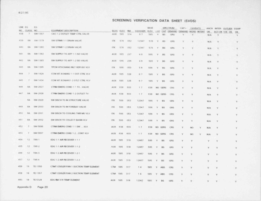
O/21/95
SCREENING VERIFICATION DATA SHEET (SVDS)
UNE EQ EO BASE SPECTRUM CAP > CAVEATS ANCH MTEf4 OUTLER EQUIPNO NO EQURAENT DESCRIPTION M ELEV W SOUGGER ELEV <40 CAP DEMANO DEMAND WORD MTENT O_K ACT OK, EOK OK_ CLASS '438 7 SW-1357 CAC 12 OUTLET TEMP CTTL VALVE AUX 585 314 67 585 Y BS GRS Y Y WA Y Y '
t439 8A SW-13 79 SW STRNR 1-1 DRAN VALVE ITK 576 052 12347 576 Y BS GRS Y Y NA Y Y
440 SA SW-1380 SW STRNR 1-2 DRAN VALVE ITK 576 052 12347 576 Y BS GRS Y Y RA Y Ys
441 8A SW-1382 SW SUFPLY TO AFP 1-1 ISO VALVE AUX 565 237 46 565 Y BS GRS Y Y N/A Y Y
442 8A SW 1383 SW SUPPLY TO AFP 12 ISO VALVE AUX 565 236 46 565 Y BS GRS Y Y KA Y Y
443 BA SW-1395 TPCW HTXCHANG INLY HDR ISO VLV ITK 566 053 56 566 Y BS GRS Y Y N/A Y Y
444 7 SW-1424 CCW HT XCHANG 1 1 OUT CTRL VLV AUX 585 328 87 585 Y BS GRS Y Y N. A Y Y i
445 7 SW-1434 CCW HT XCHANG1-2 OTLT CTRL VLV AUX 585 328 67 585 Y BS GR$ Y Y N/A Y Y[
446 8A SW-2927 CTW [MERG COND 1 1 TV... VALVE AUX 638 603 17 638 NO GERS CRS Y Y N/A Y Y
447 SA SW 2928 CTW EMERG COND 12 OUTLET TV AUX 638 603 17 638 HO GERS CRS Y Y N/A Y Y
' 9A SW-2929 SW DISCH TO M STRUCTURE VALVE ITK 566 053 12347 566 Y BS GRS Y Y KA Y Y
[ 449 SA SW-2330 SW DISO4 TO N FOREBAY VALVE ITK 566 053 12347 566 Y BS GRS Y Y WA Y Y,
450 8A SW-2331 SW DtSCH TO COOUNG TWR MU VLV 1TK $66 053 12347 566 Y BS GRS Y Y N/A Y Y !
451 SA SW-2932 SW DISCH TO COLLECT BASM VLV ITK 566 053 12347 566 Y BS GRS Y Y N/A Y Y ;
i452 7 SW-5896 CTitA EMERG COND 1-1 SW .VLV AUX 638 603 17 638 NO GERS CRS Y NO Y N/A Y Y |
1453 7 SW-5897 CTW EMERG COND 12. CONT VLV AUX 638 603 17 638 NO GERS CRS Y NO Y N/A Y Y I
i454 12 T86-1 EDG 1 1 AIR NCE1VER 1 1-1 AUX 585 318 12467 595 Y BS GRS Y Y Y Y Y I
i455 12 T86-2 EDG 1 1 AIR RECEIVER 1-1-2 AUX 585 318 12467 595 Y BS GRS Y Y Y Y Y *
456 12 T86-3 EDG 12 AIR MCEIVER 1-2-1 AUX 585 319 12467 595 Y BS GRS Y Y Y Y Y *
457 12 T86-4 EDG 12 AIR RECETVER 12-2 AUX 585 319 12467 595 Y BS GRS Y Y Y Y Yi
458 18 TE-1356 CTMT COOLER FAN 1 SUCTION TEMP ELEMENT CTM 585 317 14 585 Y ABS CRS Y Y Y y y
i459 18 TE 1357 CTMT COOLER FAN 2 SUCTION TEMP ELEMENT CTM 585 317 14 585 Y ABS CRS Y Y Y Y Y h
t
l 460 1'8 TE-5329 EDG W 318 TEMP ELEMENT AUX 585 318 1234,7 590 Y BS GRS Y Y Y Y Y h
i
l
Appendix D Page 20l I
i
,, . .. , - - - - . - , , ,- . -- - 4 - . .-- .- . - - . - o .-_____--____---________-_s

-
=
' Q/21/95 '
SCREENING VERIFICATION DATA SHEET (SVDS)i
; LINE EO EQ BASE _ SPECTRUM CAP > CAVEATS ANCH NTER. OUTUER EQUIPNO NO EOtMNENT DESCRIPTION BI:QG ELEV FN SOUGGER ELEV <40 CAP DEMAND DEMAND WORD INTENT OK ACTOKY95 OK E_ CLASS461 18 TE-5336 EDG IN 2 TEMP ELEMENT AUX 585 319 12347 590 Y BS GRS Y Y Y Y Yi
462 18 TE-5443 CC PMP 1 N TEMP ELEMENT AUX 585 328 67 595 Y BS GRS Y NO Y Y Y Y -
< >
I 463 18 TE-5444 CC PMP 1 RM TEMP ELEMENT AUX 585 328 67 596 Y BS GRS Y Y Y Y Y,
i464 19 TE NO7E INCOPE OUTLET E7 TEMP ELEMENT CTM 578 315 17 578 Y BS GRS Y Y EA Y Y
i465 19 TE NO7M INCORE OUTLET M7 TEMP ELEMENT CTM 578 315 17 578 Y BS GRS Y Y N:A Y Y
L
466 19 TE-RC3A6 RC LOOP 2 HLG WR TEMP ELEMENT CTM 630 218 147 641 NO DOC CRS Y Y N'A Y Y'
467 19 TE-RC365 RC LOOP 1 HLG WR TEMP ELEMENT CTM 565 216 14 641 NO DOC CRS Y Y MA Y Y
46e 19 TE-RC4A2 RCP 2-1 DISCH CLG WR TEMP ELEMENT CTM 565 218 1A5 571 Y BS GRS Y Y MA Y Y
i469 19 TE-RC482 RCP 1 1 DISCH CLG WR TEMP ELEMENT CTM 565 216 145 571 Y BS GRS Y Y NA Y Y
,
t'470 19 TE-SP11 A1 STEAM GEN 1-2 SHELL TEMP ELEMENT 1 CTM 565 218 14 630 NO DOC CRS Y Y KA Y Y
!+4 71 19 TE-SP11 A2 STEAM GEN 1-2 SHELL TEMP ELEMENT 2 CTM 585 218 14 630 NO DOC CRS Y Y N/A Y Yr
w 472 19 TE-SP11 A3 STEAM GEN 12 SHELL TEMP ELEMENT 3 ClM 585 218 14 630 NO DOC CRS Y Y N/A Y^ Y '
473 19 TE-SP11 A4 STEAM GEN 1-2 SHELL TEMP ELEMENT 4 CTM SO3 218 14 630 NO DOC CRS Y Y N/A Y Y ji
4 74 19 TE-SP11 A5 STEAM GEN 1-2 SHELL TEMP ELEMENT 5 CTM 603 218 14 630 NO DOC CRS Y Y N/A Y Y |
475 19 TE SP1181 STEAM GEN 1 1 SHELL TEMP ELEMENT 1 CTM 565 216 146 630 NO DOC CRS Y Y N/A Y Y f
476 19 TE-SP1182 STEAM GEN 1 1 SHELL TEMP ELEMENT 2 CTM 565 216 146 630 NO DOC CRS Y Y N/A Y Y |i
477 19 TE-SP1183 STEAM GEN 1-1 SHELL TEMP ELEMENT 3 CTM 565 216 146 630 NO DOC CRS Y Y N/A Y Y I
i478 19 TE-SP1184 STEAM GEN 1-1 SHELL TEMP ELEMENT 4 CTM 565 216 146 630 NO DOC CRS Y Y N/A Y Y'
479 19 TE-SP1185 STEAM GEN 31 SHELL TEMP ELEMENT 5 CTM 565 216 146 630 NO DOC CRS Y Y N/A Y Y i
ti 480 0 Tl5503 PORTABLE RC TEMPERATURE INDICATOR AUX 585 304 2 11 585 Y DOC CRS Y N/A N/A Y Y j
i
481 0 T15504 PORTABLE RC TEMPERATURE INDICATOR AUX 585 304 2 11 585 Y DOC CRS Y N/A N/A Y Y*
482 18 TIC 5443 CC PMP 1 M TEMP INDEX CONTROL AUX 585 328 67 585 Y BS GRS Y NO Y Y Y Y
483 18 TIC 5444 CC INP 2 FN TEMP INDEX CONTROL AUX 585 328 67 585 Y BS GRS Y NO Y Y Y Y
!Appendix D Page 21 i
!
.
&
w , ,.c.,. , - . - . - r - w+- - . - - m ~i. - w s _ _ _ _ _ , _ _ _ _ . + - . _ - _ _ _ _ _ _ _ _ . _ _ _ _ _ _ . - f

8/21/95
SCREENING VERIFICATION DATA SHEET (SVDS)
UNE EQ EQ BASE SPECTRUM CAP > CAVEATS ANCH INTERr OUTUER EOUPE CLASS NO LotM%4ENT DESCRIPTION M M fE4 SOUGGER Eliv <40 CAP DD4AND DEMAND WORD INTENT OK OK .OK__ ACT OK Y90484 18 TS 4688 TEMP SWT FR XHAUST FAN C99-1&2 ITK 576 052 56 580 Y BS GRS Y NO Y Y Y Y
485 18 TS 4689 TEMP SWT FR XHAUST FAN C99-3&4 ITK 576 052 56 582 Y BS GRS Y Y Y Y Y
486 18 TS-5135 TEMP SWITCH FOR AFP ROOM VENT FAN 1 1 AUX 565 237 27 570 Y BS GRS Y Y Y Y Y
487 18 TS-5136 AFP ROOM VENT FAN 2 TEMPERATURE SWITCH AUX 565 238 27 570 Y BS GRS Y Y Y Y Y
488 18 TS 5261 CTf94 EMERG VENT FAN 1 TEMP SWT AUX 638 603 17 638 NO ABS RRS Y Y Y Y Y
489 18 Ts5262 CTfmA EMERG VENT FAN 2 TEMP SWT AUX 638 603 17 638 HO ABS RRS Y Y Y NO Y NO NO
490 18 TS-5315 TEMP SWT FR LV.S.G.RM 428 VNT AUX 603 428 1 10 608 Y BS GRS Y Y Y Y Y
491 18 TS.5318 LV.S.G. It4 DAMP TEMP SWITCH AUX 603 429 24 607 Y BS GRS Y Y Y Y Y
492 18 TS-5443 CC FMP ft4 VNT FN 1 TEMP SWITCH AUX 585 328 87 595 Y BS GRS Y Y Y Y Y
493 18 TS-5444 CC f%4P VNT FN 794 2 TEMP SWITCH AUX 585 328 67 596 Y BS GRS Y Y Y Y Y
494 18 TS-559 7 TEMP SW FR BATT ft4 A THElm40 AUX 603 429 367 608 Y BS GRS Y Y Y Y Y
495 18 TS 5598 TEMP SW FR BATT PM B theft 40 AUX 603 428 367 608 Y BS GRS Y Y Y Y Y
496 18 TSH 1435 CC HX 2 CCW OUT TEMP SWTCH HI AUX 585 328 67 590 Y BS GRS Y Y Y Y Y
| 497 18 TSH 1483 CC HX CCW OUT TEMP SWICH NtGH AUX 585 328 67 595 Y BS GRS Y Y Y Y Y|
| 498 18 TSH 5421 ECCS 194 CtB FAN 1-5 TEMP SW AUX 545 105 56 549 Y BS GRS Y Y Y Y Y
499' 18 TSH 5422 ECCS Fm4 cut FAN 1-4 TEMP SW AUX 545 105 56 551 Y BS GRS Y Y Y Y Y
500 18 TSH $424 ECCS Im4 CLR FAN 1-2 TEMP SW AUX 545 115 49 558 Y BS GRS Y Y Y Y YI
! 501 18 TSH 5425 ECCS 794 cut F AN 1 1 TEMP SW AUX 545 115 49 557 Y BS GRS Y Y Y Y y
502 18 TSL 5421 ECCS FR4 CLR FAN 1-5 TEMP SW AUX 545 105 56 549 Y BS GRS Y Y Y Y Y
503 18 TSL 5422 ECCS FRA C1B FAN 1-4 TEMP SW AUX 545 105 56 549 Y BS GRS Y Y Y Y .Y
504 18 TSL 5424 ECCS FDA CLR FAN 12 TEMP SW AUX 545 115 49 558 Y BS GRS Y' Y Y Y Y
505 18 TSL 5425 ECCS Ime cut FAN 1 1 TEMP SW AUX 545 115 49 557 Y BS GRS Y Y Y Y Y
506 18 TT.1356 CTMT COOLER FAN 1 SUCTION TEMP TRANSMIT AUX 585 303 17 590 Y BS GRS Y NO NO NO Y Y NO NO
Appendix D Page 22
_ . _ _ _ . , ~ ~ _ ,- , - - - -- - -

.
j '
!
8/21/S5
SCREENING VERIFICATION DATA SHEET (SVDS)4
UNE EQ EQ BASE SPECTRUM CAPD CAVEATS ANCH WTER ETE EQUIP {E CLASS NO EQUIPMENT DESLN ELgG E fM SOUGGER ELEV <40 CAP DEMAND DEMAND WORD WTENT OK ACTOK YM OK E507 18 TT 1357 CTMT COOLER FAN 2 SUCTION TEMP TRANSMIT AUX $85 314 17 590 Y BS GRS Y Y Y Y Y
I508 18 TT 5443 CC INP 1 FN TEMP TRANSMITTER AUX 585 328 68 603 Y BS GRS Y NO. Y Y Y Y
.509 18 TT 5444 CC RAP 2 FN TEMP TRANSMITTER AUX 585 328 68 603 Y BS CRS Y Y Y Y Y
510 14 Y1 ESSEN NSTR DST PNL "Y1* AUX 603 429 23 603 Y BS GRS Y Y Y Y Y-
511 14 Y1A 120VAC ESSEN NST DST PANEL AUX 603 429 23 603 Y BS GRS Y Y Y Y Y
512 14 Y2 ESSEN MSTR DST PNL *Y2* 120V AUX 603 428 89 603 Y BS GRS Y Y Y Y Yr
513 14 Y2A 120VAC ESSEN NST DST PANEL AUX 603 428 19 603 Y BS GRS Y Y Y Y YE
514 14 Y3 ESSEN INSTR DST PNL 'Y3* 120V AUX 603 429A 23 603 Y BS GRS Y Y Y Y Y1
! 515 14 Y4 ESSEN MSTR DIST PNL *Y4* 120V AUX 603 428 489 603 Y BS GRS Y Y Y Y YIf
516 14 YAU UPS INSTR DIST PNL *YAU* AUX 603 429 489 603 Y BS GRS Y Y Y Y Y !i
ii 517 14 YBU UPS MSTR DST PNL 120V ac AUX 603 428 89 603 Y BS GRS Y Y Y Y Y
'
518 1 YE1 480/120 VAC MCCITRANSFOfMER AUX 585 318 1489 585 Y BS GRS Y Y Y NO Y NO NOjii519 1 YE2 240 VAC MCCITRANSFOfMER AUX 585 304 1489 $85 Y BS GRS Y Y Y Y Y j
,
!
520 4 YE2A 484240V TRANSFOfBAER AUX 603 405 1367 603 Y BS GRS Y Y Y Y Y|
| 521 1 YF1 484120V MCCITRANSFOfMER AUX 585 319 1489 585 Y BS GRS Y Y Y Y Y' ff
522 1 YF2 240 VAC MCCITRANSFOfMER AUX 603 427 489 585 Y BS GRS Y Y Y Y Y'
523 4 YF2A 480 240V TRANSFOfNER AUX 603 427 1367 603 Y BS GRS Y Y Y Y Y
t524 16 YV1 125VDCf120VAC INVERTER CH 1 AUX 603 429 237 603 Y BS GRS Y Y Y Y Y ;
i525 16 YV2 125VDC/120VAC INVERTER CH 2 AUX 603 428 23 603 Y BS GRS Y Y Y NO Y NO NO |V
t526 16 YV3 125VDC 120VAC WVERTER CH 3 AUX 603 429A 17 603 Y BS GRS Y Y Y NO Y NO NO |
527 16 YV4 125VDC/120VAC INVERTER CH 4 AUX 603 428 47 603 Y BS GRS Y Y Y NO Y NO NO
528 16 YVA UPS *YVA* lNVERTER AUX 603 429 46 603 Y ABS fWtS NO NO NO NO Y Y NO NO '
529 16 YVB UPS "YV8* MVERTER AUX- 603 428 16 603 Y ABS FWIS NO NO NO NO Y Y NO NO
Appendix D Page 23|;-
i. - , - - - . . . _ . . . . . . . . - - - . - - - - . - - - - - . .. . - . - - - _ - -- _ . - - ,. . - - -. - - - _ - - - _ . . . - - .- - - _ _ _ . _ _ _ _ -.

tt/21/95
SCREENING VERIFICATION DATA SHEET (SVDS)
UNE EQ EQ BASE . SPECTRLSA CAP > CAVEATS ANCH MTER OUTUER EOutPN_OCLASS NO EOt.M9MNT DESCMPTON BLDG ElfV FDA SOUGGER ELEV <40 CAP DEMAND DEMAND WO50 INTENT OK ACT OK YH OK OK530 18 ZC-6451 AFP 12 OtSCH CTRL VLV POSIT 0N CTfu AUX 565 238 46 569 Y BS GRS Y Y Y Y Y
531 18 ZC-6452 AFP 1 1 DISCH CTIL VLV POS CONTROLER AUX SS5 237 46 569 Y BS GRS Y Y Y Y Y
I
L
l
|
Appendix 0 Page 24
i
_ _ _

. _ . .. . . _ . _ _ _ _ . . _.
DAVIS-BESSE NUCLEAR POWER STATION
Unresolved Safety Issue (USI) A-46
Seismic Evaluation Report |
APPENDIX E
THIRD-PARTY AUDIT REPORT
||
l
1- _ _ _ _ - _ - _ _ _ _ _ ___
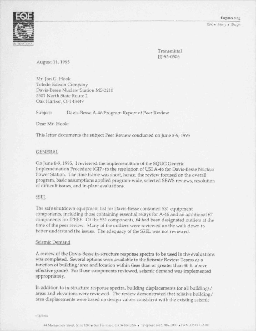
3 Eogineering
%sk n Safity a hsp
..
! Nit:2N Al H W A1
TransmittalJJJ-95-0506
August 11,1995
Mr. Jon G. HookToledo Edison CompanyDavis-Besse Nuclear Station MS-32105501 North State Route 2Oak Harbor, OH 43449
Subject: Davis-Besse A-46 Program Report of Peer Review
Dear Mr. Hook:
This letter documents the subject Peer Review conducted on June 8-9,1995
GENERAL
On June 8-9,1995, I reviewed the implementtition of the SQUG GenericImplementation Procedure (GIP) to the resolution of USI A-46 for Davis-Besse NuclearPower Station. The time frame was short, hence, the review focused on the overallprogram, basic assumptions applied program-wide, selected SEWS reviews, resolutionof difficult issues, and in-plant evaluations.
SSEL
The safe shutdown equipment list for Davis-Besse contained 531 equipmentcomponents, including those containing essential relays for A-46 and an additional 67components for IPEEE. Of the 531 components,64 had been designated outliers at thetime of the peer review. Many of the outliers were reviewed on the walk-down tobetter understand the issues. The adequacy of the SSEL was not reviewed.
Seismic Demand
A review of the Davis-Besse in-structure response spectra to be used in the evaluationswas completed. Several options were available to the Seismic Review Teants as afunction of building / area and location within (less than or greater than 40 ft. aboveeffective grade). For those components reviewed, seismic demand was implementedappropriately.
In addition to in-stmcture response spectra, building displacements for all buildings /areas and elevations were reviewed. The review demonstrated that relative building /area displacements were based on design values consistent with the existing seismic
csa % 4
44 Montromery Street. Suite 3200. San Franenco. CA 94104 Us A e Telephone (415) 989-2000 . F AX (415) 433-5107
. . _ . .

__ __ __
Mr. Jon Hook Transmittal NoAugust 11,1995 JJJ- 95-0506Page 2 of 3
design analyses denoted conservative design. The maximum relative displacementbetween buildings / areas was 0.28" horizontally between the Shield Bldg. and Area 6 atelevation 638' which bounds the cases ofinterest. At lower elevations and for other -buildings / areas, the maximum relative horizontal displacements are less and usuallysubstantially less. Vertical displacements are considerably less and warrant minimalconsideration. The in-plant evaluation examined many building boundaries to validatejudgments made in the field and documented in the SEWS. Those judgments werefound to be appropriate. In some instances, analyses were performed to demonstratethe adequacy of the installation to relative building motions, e.g., MCC F11B, MCCF11D. The in-office and in-plant evaluation concurred with the analysis and judgments.
SEWS Reviews
Selected SEWS reviews were performed focused on components with significantjudgment applied or difficult issues to be addressed. The major question examined wasnatural frequency estimation.
Natural Frequency Determination
Davis-Besse has plant specific in-situ frequency tests supplemented by generic datafrom EPRI and others to assist in estimating natural frequencies of electrical cabinetswith and without top bracing. Top bracing is provided by substantial conduit for whichinspections were made verifying the conduit attachment to the top of representativecabinets. Typically, front-to-back frequencies (those of most interest) increased by afactor of 2 or greater when top mounted substantial conduit is in place.
A recommendation to review those evaluations where in-situ test data and generic testdata were used to estimate natural frequencies was made during the June 8-9,1995evaluation. This recommendation was based on the complexity of the informationprovided by the testing firm and was intended to assure appropriate implementation.Follow-up to the on-site review, clarifications were sought and received from thetesting firm and implemented in the evaluations as appropriate.
Documentation
It was recommended, although not required, that SEWS back-up documentation, suchas calculations be maintained more formally with preparer / checker signatures anddates with revisions noted.
Seismic / Fire and Seismic / Flood Interaction for IPEEE -
The subject evaluations for IPEEE should be performed on area- by- area basis incoordination with the fire and flood evaluation teams.
I
ev %ke
.

Mr. Jon Hook Transmittal NoAugust 11,1995 JJJ- 95-0506Page 3 of 3
In-Plant Evaluations (Walkdown)
An area walkdown was performed on June 9,1995 walking-by as much equipment aspossible in the time available. Building / area separations were viewed at severalelevations and several locations in the complex.
Electrical cabinets, including MCCs, were exarnined to evaluate judgments madeconcerning impact between adjacent cabinets and walls, the robust nature of top bracingdue to channels bolted to cabinets and top mounted conduit, and attachment points tomultiple buildings / areas.
The emergency diesel generator rooms were visited. Fire protection system wasvisually inspected and clarified with operations personnel to be water-type, rather thanhalon or carbon dioxide. This eliminates one potential systems interaction issue. Theemergency diesel generator supply fans were reviewed. Capacity issues includedanchorage capacity, vibration isolators, and the capacity of the attaching bellows toresist shear and moment and displaces as required vertically or laterally. Thisevaluation was being completed at the time of the Peer Review. The issues were wellidentified and resolutions appeared imminent.
The control room was visited. The control room ceiling was inspected with theunderstanding some re-work is in order. Control room cabinets were inspected.Selected cabinets are to be bolted together.
SUMMARY
Cenerally, the Davis-Besse GIP implementation is being performed in an appropriateand adequate fashion.
For the sample considered, I concur with the final conclusions as stated.
Sincerely,EQE Internation
,_%Dr. amesJ.Johnsok i
Executive Vice Presic ent
JJJ:emb
o,%
L_________.__________________ _ _ _ _
Copyright © 2022 FDOKUMEN