The use of a field vane apparatus in sensitive clay Eden, WJ
Upload
khangminh22Category
view
1download
0
Central Washington University Central Washington University
ScholarWorks@CWU ScholarWorks@CWU
All Undergraduate Projects Undergraduate Student Projects
Spring 2016
Jeep WJ Multipurpose Oversize Spare Tire Carrier Jeep WJ Multipurpose Oversize Spare Tire Carrier
Caleb J. Marrs Central Washington University, [email protected]
Follow this and additional works at: https://digitalcommons.cwu.edu/undergradproj
Part of the Manufacturing Commons
Recommended Citation Recommended Citation Marrs, Caleb J., "Jeep WJ Multipurpose Oversize Spare Tire Carrier" (2016). All Undergraduate Projects. 8. https://digitalcommons.cwu.edu/undergradproj/8
This Dissertation/Thesis is brought to you for free and open access by the Undergraduate Student Projects at ScholarWorks@CWU. It has been accepted for inclusion in All Undergraduate Projects by an authorized administrator of ScholarWorks@CWU. For more information, please contact [email protected].

Jeep WJ Multipurpose Oversize Spare Tire Carrier By
Caleb Marrs
2
Abstract .............................................................................................................................. 5 Introduction ....................................................................................................................... 6 Motivation ...................................................................................................................................... 6 Function Statement........................................................................................................................ 6 Requirements ................................................................................................................................. 6 Success Criteria ................................................................................................................................ 7 Scope of Effort ................................................................................................................................ 7 Engineering Merit: ........................................................................................................................... 7 Success of Project ........................................................................................................................... 7 Design and Analysis ............................................................................................................7 Approach ......................................................................................................................................... 7 Design Description ......................................................................................................................... 8 Benchmark ...................................................................................................................................... 8 Technical Risk Analysis and Safety Factor ..................................................................................... 9 Performance Predictions .............................................................................................................. 10 Description of Analyses ................................................................................................................. 10 Scope of Testing and Evaluation ................................................................................................... 11 Analysis ........................................................................................................................................... 11 Design Issue ................................................................................................................................ 14 Failure Mode Analysis, Operation Limits ...................................................................................... 14 Methods and Construction .............................................................................................. 16 Description ..................................................................................................................................... 16 Discussion ...................................................................................................................................... 17 Drawing Tree and Drawing ID’s .................................................................................................... 19 Parts list: ....................................................................................................................................... 20 Manufacturing Issues: ................................................................................................................... 21 Assembly, Sub–assembly, Parts, Drawings .................................................................................. 21 Testing Method ................................................................................................................ 23 Introduction ................................................................................................................................... 23 Test Procedure .............................................................................................................................. 23 Deliverables ...................................................................................................................................24 Budget/Schedule/Project Management ........................................................................ 24 Proposed Budget ...........................................................................................................................24 Proposed Schedule........................................................................................................................24 Project Management .................................................................................................................... 25 Conclusion ......................................................................................................................... 25 Acknowledgements: ....................................................................................................... 26 References: ...................................................................................................................... 26 Appendix A – Analysis A1 ................................................................................................. 27 Appendix A – Analysis A2 ................................................................................................ 29

3
Appendix A – Analysis A 3 ............................................................................................... 30 Appendix A – Analysis A4 ................................................................................................ 31 Appendix A – Analysis A5 ................................................................................................. 32 Appendix A – Analysis A6 ............................................................................................... 34 Appendix A – Analysis A7 ................................................................................................. 35 Appendix A – Analysis A8 ............................................................................................... 36 Appendix A – Analysis A9 ................................................................................................ 41 Appendix A – Analysis A10 .............................................................................................. 42 Appendix A – Analysis A11 ............................................................................................... 44 Appendix A – Analysis A12 .............................................................................................. 45 Appendix A – Analysis A13 .............................................................................................. 46 Appendix A – Analysis A14 .............................................................................................. 50 Appendix B1 – Conceived Idea ......................................................................................... 51 Appendix B2 – Hitch Assembly ........................................................................................ 51 Appendix B3 – Trailer Hitch Receiver ............................................................................. 53 Appendix B4 – Device Reciever ...................................................................................... 54 Appendix B5 – Hitch Mount 1........................................................................................... 55 Appendix B6– Hitch Mount 2 ........................................................................................... 57 Appendix B7 – Hitch Cross Member Center .................................................................. 58 Appendix B8 – Hitch Cross Member passenger Side ................................................... 59 Appendix B9 – Hitch Cross Member Driver Side .......................................................... 60 Appendix B10 – Receiver Mount ..................................................................................... 61 Appendix B11 – Accessory Gate Assembly ..................................................................... 63 Appendix B12 – 5x5 Lug Mounting Plate ....................................................................... 64 Appendix B13 – Bearing Housing.................................................................................... 65 Appendix B14 – Accessory Gate Beam ........................................................................... 67 Appendix B15 – Support Arm 1 ....................................................................................... 68 Appendix B16 – Support Arm 2 ....................................................................................... 69 Appendix B17 – Triangle Plate ........................................................................................ 70 Appendix B18 – Spare Tire Extension Reciever .............................................................. 71

4
Appendix B18 – Spare Tire Extension ............................................................................. 73 Appendix B19 – Bike Carrier Beam Support .................................................................. 74 Appendix B20 – Bike Carrier Beam ................................................................................. 75 Appendix B21 – Bike Cradle Mounting Bracket ............................................................. 76 Appendix B22 – Pro Series Bike Cradle ........................................................................... 77 Appendix B23 – 5/8 Hitch Pin .......................................................................................... 78 Appendix B24 – Pin Safety Clip ...................................................................................... 79 Appendix C – Parts List ................................................................................................... 80 Appendix D – Budget ....................................................................................................... 81 Appendix E – Schedule .................................................................................................... 82 Appendix F - Expertise and Resources ........................................................................... 84 Appendix G –Testing Data / Testing Report .................................................................. 85 Appendix I – Resume ........................................................................................................ 91

5
Abstract OEM spare-tire wells have size limitations that only allow up to a certain size tire. However, the OEM tire well is not effective for the off-road enthusiast that needs an extra over size tire in case of an emergency. While off-roading it is important to be equipped with all the necessary tools and parts to get out safely because there is no roadside assistance off-road. The Jeep WJ is not a popular off road vehicle which means aftermarket accessories are not common. In order to optimize the space inside and out of the vehicle, a device is needed that will allow for the trunk space, roof rack, and trailer hitch to be free for other accessories. This device must carry an oversize spare tire, a gas tank, and at least two bikes. Thus, the objective of this project is to use skills gained in the Mechanical Engineering Technology curriculum at Central Washington University in order to design, build, and test a device that will solve this problem while optimizing available solutions. This problem was solved by the use of a curt trailer hitch multi-use receiver and the construction of a multipurpose spare tire carrier that mounts into the multi use receiver. This project was successful because it solved the problem and successfully carried an oversize spare tire, a gas can, and two bikes while being able to attach a trailer to the ball. The device was also successful because it was under the size and weight limitations. Keywords: <Jeep>, <Aftermarket>, <Spare-tire>

6
Introduction Motivation This project was motivated by the need for a multipurpose device to carry an oversize tire that leaves the trailer hitch and roof rack available for other uses because the OEM spare tire mount on a Jeep Grand Cherokee WJ (1999-2004) has size limitations and current options require use of a trailer hitch carrier, roof rack mount, or expensive custom bumper. Function Statement A device is needed to carry an oversize spare tire on a Jeep Grand Cherokee WJ. Requirements Therefore, a device is required that would: Be installed in under an hour Allowing for part time removal in less than 10 minutes Mount to Jeep Grand Cherokee existing equipment Maintain use of OEM bumper Store tire on rear face of vehicle Not exceed the height and width of the vehicle (4 feet high and five feet wide) Not obstruct more than 40 percent of the rear window visibility Be able to withstand impacts from off road driving, potholes, curbs etc. Not rattle or make noise while vehicle is in operation Be able to withstand corrosion from seaside environments Cost less than 700 dollars to manufacture Take less that 6-8 weeks to manufacture Have a total weight less than 200 pounds o Device weight: 100 pounds o Hitch assembly weight 100 pounds Have a total full load carrying capacity at least eight times the device weight Remains in closed position while driving Able to swing open with less than 10-lb force under full load Swing open 100 degrees with less than 0.5 in vertical deflection in gate Carry up to a 44 inch tire Have optional mounts for 1-2 gas cans and 2-4 bikes Have a mount for a safety flag mount for use in dunes Have a service life that must exceed 75,000 road miles or 900 open/close cycles Have the option to replace broken or failed parts Must meet SAE J684 standards for Class 3 Hitch/Coupling

7
Success Criteria Success of this project depends on the final performance of the device. This project will be considered successful if this device allows a Jeep Grand Cherokee WJ to tow a motorcycle trailer while carrying a spare tire carrier and two bikes, leaving the roof rack available for a roof top tent. Scope of Effort The scope of the project will be focused upon designing, building, and testing the Device mount (hitch assembly) and the frame of the spare tire structure ensuring they can support the required loads in all driving conditions without incurring failure. All the necessary hardware (i.e. bolts, bearings, and hydraulics) will be purchased from external resources. Engineering Merit: The engineering merit of this of this device is within the design that will require an analysis with in the mechanical engineering fields of strength and material selection. In order to create the lightest weight design there will be a focus on weight reduction within the structural analyses based on different design configurations and materials used. The materials selected will be based on the strength and structural analyses. The durability, expected life, of this device is going to be determined by the ability for the device materials to last under various load and environmental conditions. Success of Project This project will be considered successful if it gains interest from the automotive industry, off-road community and/ or other WJ owners. A survey will be conducted via off-road discussion board and off-road event to receive public input on the final design where each survey will offer the option to comment on design and rate the device on a scale of 1-10 for different categories based on the final design. A survey with an overall average overall score of 65% will be considered successful. (See Appendix G)
Design and Analysis Approach Requirements that support an application of engineering to this project are weight, load, range of motion, and rotational forces. Some types of engineering analysis that will be used comes from the Technical Dynamics textbook and the Statics and Strength of Materials text.
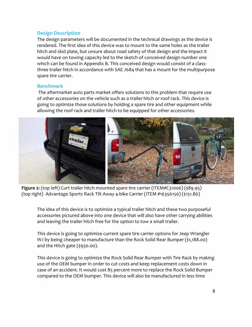
Design Description The design parameters will be documented in the technical drawings as the device is rendered. The first idea of this device was to mount to the same holes as the trailer hitch and skid plate, but unsure about road safwould have on towing capacity led to the sketch of conceived design number one which can be found in Appendix B. This conceived design would consist of a classthree trailer hitch in accordance with SAE J684 that has a spare tire carrier. Benchmark The aftermarket auto parts market offers solutions to this problem that require use of other accessories on the vehicle such as a trailer hitch or roof rack. This device is going to optimize those solutions by holding a spare tire and other equipment while allowing the roof rack and trailer hitch to be equipped for other accessories.
The idea of this device is to accessories pictured above into one device that will also have other carrying abilities and leaving the trailer hitch free for the option to tow a small trailer. This device is going to optimize current spare tire carrier options for Jeep Wrangler WJ by being cheaper to manufacture than the Rock Solid Rear Bumper ($1,188.00) and the Hitch gate ($930.00 This device is going to optimize the Rock Solid Rear Bumper with Tire Rack by making use of the OEM bumper in order to cut costs and keep replacement costs down in case of an accident. It would cost 85 percent more to replace the Rock Solid Bumper compared to the OEM bumper. This device will also be manufactured in less time
Figure 2: (top left) Curt trailer hitch mounted spare tire carrier (ITEM#C31006) ($89.95) (top right) Advantage Sports Rack Tilt Away 4
The design parameters will be documented in the technical drawings as the device is rendered. The first idea of this device was to mount to the same holes as the trailer hitch and skid plate, but unsure about road safety of that design and the impact it would have on towing capacity led to the sketch of conceived design number one which can be found in Appendix B. This conceived design would consist of a classthree trailer hitch in accordance with SAE J684 that has a mount for the multipurpose
The aftermarket auto parts market offers solutions to this problem that require use of other accessories on the vehicle such as a trailer hitch or roof rack. This device is olutions by holding a spare tire and other equipment while allowing the roof rack and trailer hitch to be equipped for other accessories.
The idea of this device is to optimize a typical trailer hitch and these two purposeful accessories pictured above into one device that will also have other carrying abilities the trailer hitch free for the option to tow a small trailer. This device is going to optimize current spare tire carrier options for Jeep Wrangler WJ by being cheaper to manufacture than the Rock Solid Rear Bumper ($1,188.00) ($930.00). This device is going to optimize the Rock Solid Rear Bumper with Tire Rack by making use of the OEM bumper in order to cut costs and keep replacement costs down in case of an accident. It would cost 85 percent more to replace the Rock Solid Bumper ared to the OEM bumper. This device will also be manufactured in less time
(top left) Curt trailer hitch mounted spare tire carrier (ITEM#C31006) ($89.95) ge Sports Rack Tilt Away 4-bike Carrier (ITEM #16356156) ($151.86)
8
The design parameters will be documented in the technical drawings as the device is rendered. The first idea of this device was to mount to the same holes as the trailer ety of that design and the impact it would have on towing capacity led to the sketch of conceived design number one which can be found in Appendix B. This conceived design would consist of a class-mount for the multipurpose
The aftermarket auto parts market offers solutions to this problem that require use of other accessories on the vehicle such as a trailer hitch or roof rack. This device is olutions by holding a spare tire and other equipment while allowing the roof rack and trailer hitch to be equipped for other accessories.
these two purposeful accessories pictured above into one device that will also have other carrying abilities
This device is going to optimize current spare tire carrier options for Jeep Wrangler WJ by being cheaper to manufacture than the Rock Solid Rear Bumper ($1,188.00)
This device is going to optimize the Rock Solid Rear Bumper with Tire Rack by making use of the OEM bumper in order to cut costs and keep replacement costs down in case of an accident. It would cost 85 percent more to replace the Rock Solid Bumper ared to the OEM bumper. This device will also be manufactured in less time
(top left) Curt trailer hitch mounted spare tire carrier (ITEM#C31006) ($89.95) bike Carrier (ITEM #16356156) ($151.86)

to be completed before it will ship to the customer.
This device is to exceed the carrying capacity of current tire carrier options such as the Hitch gate tire carrier while not exceeding the weight of the device is also going to out perform the inch tire, opening with less than 10lb force, and being capable of carrying other accessories such as gas cans, bikes, and a dune safety flag.Technical Risk Analysis and Safety FactorA device attached to a vehicle has a lot of techdrivers in risk. This device while go through multiple loading modes at various times due to towing and road conditions, so it is important that it will not fail on the road way. In order to manufacture a road worthyhitch test loads based on the gross vehicle weight rating and various loading conditions. To ensure a roadSAE test loads for a class three trailer hitch with a 7rating and a 750 pound vertical load on the hitch without a weight distribution device. A safety factor of 1.5 that the selected geometries and materials can withstand thloading without failure. In case of a failure, a safety chain will attach the device to the hitch assembly in order to prevent risk of an automobile accident.
Figure 3: Rock Solid Rear Bumper with Skid WJ (ITEM #: PF906) ($1,188.00) http://www.wildhorses4x4.com/product/WJ_Rock_Solid_Rear_Bumper_Skid_Plate_Tire_Ra
than this device as it takes an estimated 6-8 weeks for a Rock Solid Rear bumper
to be completed before it will ship
This device is to exceed the carrying capacity of current tire carrier options such as tire carrier while not exceeding the weight of the Hitch gatedevice is also going to out perform the Hitch gate by not rattling, allowing over a 40 inch tire, opening with less than 10lb force, and being capable of carrying other accessories such as gas cans, bikes, and a dune safety flag. Technical Risk Analysis and Safety Factor A device attached to a vehicle has a lot of technical risk as a failure could put other drivers in risk. This device while go through multiple loading modes at various times due to towing and road conditions, so it is important that it will not fail on the road way. In order to manufacture a road worthy hitch/device mount it must meet SAE hitch test loads based on the gross vehicle weight rating and various loading road worthy device a safety factor of 1.5 will be used on the SAE test loads for a class three trailer hitch with a 7500 pound gross vehicle weight vertical load on the hitch without a weight distribution of 1.5 will also be used on the material properties to ensure that the selected geometries and materials can withstand the maximum required In case of a failure, a safety chain will attach the device to the hitch assembly in order to prevent risk of an automobile accident.
Rock Solid Rear Bumper with Skid Plate & Tire Rack for 1999-2004 Grand Cherokee http://www.wildhorses4x4.com/product/WJ_Rock_Solid_Rear_Bumper_Skid_Plate_Tire_Ra
9
than this device as it takes an estimated 8 weeks for a Rock Solid Rear bumper
This device is to exceed the carrying capacity of current tire carrier options such as Hitch gate. This ng, allowing over a 40 inch tire, opening with less than 10lb force, and being capable of carrying other
nical risk as a failure could put other drivers in risk. This device while go through multiple loading modes at various times due to towing and road conditions, so it is important that it will not fail on the road hitch/device mount it must meet SAE hitch test loads based on the gross vehicle weight rating and various loading worthy device a safety factor of 1.5 will be used on the 500 pound gross vehicle weight vertical load on the hitch without a weight distribution will also be used on the material properties to ensure e maximum required In case of a failure, a safety chain will attach the device to the
2004 Grand Cherokee http://www.wildhorses4x4.com/product/WJ_Rock_Solid_Rear_Bumper_Skid_Plate_Tire_Ra

10
With every project comes the risk of the project going beyond the scope of the project exceeding time or cost restrictions. Project management tools and techniques will be used to ensure this project finishes on time, under budget, and within scope. (See Project management section) Performance Predictions Utilizing tools provided by CWU available to MET students such as SolidWorks, a 3d modeling program, the approximated mass of each part could be determined based off geometry and material selected for each part. The hitch assembly is approximated to weigh about 79 pounds, which is 21 pounds under the requirement. The device assembly is going to weigh about 80 pounds under no load. (See Appendix A14 for solid works mass calculations) With a 4 bike load concentrated on the end of the bike carrier made from A513 steel 1.5-inch square tubing with 0.065-inch walls the beam will experience a strain of 0.00102. If the project stays within scope, on budget and on schedule, this device will be manufactured in less than 6 weeks costing less than 700 dollars to manufacture. This device will meet all performance requirements for a class 3 coupling based on SAE J684 standards meaning it will support these loads without failure:
Test A: Vertical Force of 4005 lb Downward and Longitudinal Force of4005 lb Compressive Test B: Longitudinal Force of 3255 lb Tensile and Vertical Force 1125 lb Downward Test C: Longitudinal Force 3255 lb Compressive and Vertical Force 1125 lb Downward Test D: Transverse Trust of 2000 lb Leftward Test E: Transverse Thrust of 2000 lb Rightward
Description of Analyses The analysis of this design will begin with static equilibrium equations for the support system in order to ensure the design will withstand the expected resultant forces. If not, then modifications may be made in order to support the system. It is crucial to know the maximum forces applied at the support points so that the mounting brackets would be designed sufficient to support the load. Then based off of the mounting configuration the maximum loads could be calculated based on the mounting hardware’s shear and tensile capacities. The hardware must exceed the SAE test load requirements resulting forces to ensure a secure mount. Based on the analysis a material will be selected that proves sufficient to support the required loadings. After the device is designed it will be over looked to determine if

11
modifications could me made in order to cut the over all weight of the device without changing the limitations of the device. The design will also be over looked to see if the device could be optimized to perform better than expected by carrying a greater load than expected, opening with less force, or lasting longer than expected. Scope of Testing and Evaluation This device will be tested to ensure it meets are design requirements. This device will be tested to determine different load types until failure to ensure it meet the design requirements. This device will be tested to ensure it meets SAE standards for a Class III hitch classification. In order to test this device and meet SAE J684 standards a test fixture will be needed to determine the conformance of device to minimum strength test load requirements for different trailer classifications based on the gross vehicle weight rating. SAE J684 provides a testing procedure to determine the device load classification. The device will be go through different test loads at a safety factor of 1.5 to determine carrying capacity without experiencing failure. Torklift Central based out Kent, Washington, is a licensed trailer hitch manufacturer that designs trailer hitches to meet and exceed SAE J684, and have been contacted to see what it would take to assist with the testing in accordance with SAE J684. Torklift Central has recommended a company called Element materials Technology out of Seattle, Washington that exists to ensure the materials and products that are in some of the most advanced industrial sectors are always safe; quality; compliant and most of all are fit for purpose in their end application. Element aims to be the worlds most trusted testing partner. Element has been contacted to see what is necessary in order for the hitch to be tested in accordance with SAEJ684. A Finite Element Analysis (FEA) could be used to simulate various conditions the design could under go. A finite element analysis could be used to determine deformations, strains, stresses, and reaction forces. Analysis The first piece of analysis in Appendix A (A1) calculated the required test loads for a 7500 pound Gross Vehicle Wight Rating with a 750 pound tongue weight to meet the requirements for a Class 3 hitch based on SAE J684, which leads to the design of the hitch that will support these loads along with the device. Appendix A1.2 calculates SAE test loads with a safety factor of 1.5 on the required test loads. Forces and moments in equilibrium will be utilized to determine the reaction forces at the mounting points on vehicle. Resultant forces and resulting moments from a safety factor of 1.5 on all SAE test loads which includes downward vertical forces, compressive and tensile longitudinal forces, as well as rightward and leftward transverse thrust loadings will lead to the design of a hitch that will support the device and towing loads ensuring the structure will not experience failure in different load variations. The analysis was done to support a gross vehicle weight rating of 11,250 pounds, which is 1.5 times the 7500 pound gross vehicle weight rating that is
12
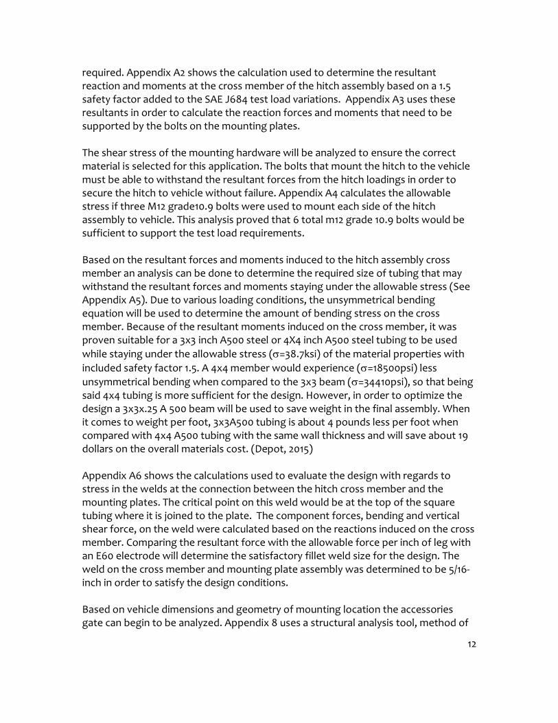
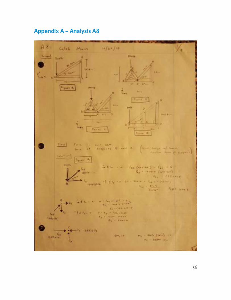
required. Appendix A2 shows the calculation used to determine the resultant reaction and moments at the cross member of the hitch assembly based on a 1.5 safety factor added to the SAE J684 test load variations. Appendix A3 uses these resultants in order to calculate the reaction forces and moments that need to be supported by the bolts on the mounting plates. The shear stress of the mounting hardware will be analyzed to ensure the correct material is selected for this application. The bolts that mount the hitch to the vehicle must be able to withstand the resultant forces from the hitch loadings in order to secure the hitch to vehicle without failure. Appendix A4 calculates the allowable stress if three M12 grade10.9 bolts were used to mount each side of the hitch assembly to vehicle. This analysis proved that 6 total m12 grade 10.9 bolts would be sufficient to support the test load requirements. Based on the resultant forces and moments induced to the hitch assembly cross member an analysis can be done to determine the required size of tubing that may withstand the resultant forces and moments staying under the allowable stress (See Appendix A5). Due to various loading conditions, the unsymmetrical bending equation will be used to determine the amount of bending stress on the cross member. Because of the resultant moments induced on the cross member, it was proven suitable for a 3x3 inch A500 steel or 4X4 inch A500 steel tubing to be used while staying under the allowable stress (=38.7ksi) of the material properties with included safety factor 1.5. A 4x4 member would experience (=18500psi) less unsymmetrical bending when compared to the 3x3 beam (=34410psi), so that being said 4x4 tubing is more sufficient for the design. However, in order to optimize the design a 3x3x.25 A 500 beam will be used to save weight in the final assembly. When it comes to weight per foot, 3x3A500 tubing is about 4 pounds less per foot when compared with 4x4 A500 tubing with the same wall thickness and will save about 19 dollars on the overall materials cost. (Depot, 2015) Appendix A6 shows the calculations used to evaluate the design with regards to stress in the welds at the connection between the hitch cross member and the mounting plates. The critical point on this weld would be at the top of the square tubing where it is joined to the plate. The component forces, bending and vertical shear force, on the weld were calculated based on the reactions induced on the cross member. Comparing the resultant force with the allowable force per inch of leg with an E60 electrode will determine the satisfactory fillet weld size for the design. The weld on the cross member and mounting plate assembly was determined to be 5/16-inch in order to satisfy the design conditions. Based on vehicle dimensions and geometry of mounting location the accessories gate can begin to be analyzed. Appendix 8 uses a structural analysis tool, method of

13
joints, in order to solve for the reaction forces in each member and support loadings. Appendix 8 gives four different gate variations, and with the method of joints equations of equilibrium were used in order to determine which accessories gate configuration would have the least reaction forces at the supports during a full load of 800 lbs. Gate formation from Figure B, Appendix 8, resulted in the smallest load at the supports BX=223.94-lbs and CX=223.94-lbs and FCB=CY=223-lbs. Figure A, Appendix 8, resulted in a much greater load at the supports BX=1385.64-lbs and CX=-1385.64-lbs and FCB=CY=800lb. Appendix 9 goes through the calculations to determine the minimum area of each member based on the selected gate geometry, resultant forces in each member, and allowable stress of optional materials. Appendix 9 also compares the stress induced on three different cross sectional areas that could be used for the accessories gate, square tubing, round tubing, and rectangular tubing all of the same material. The tubing with the largest moment of inertia will minimize bending and the largest cross sectional area will undergo the least amount of stress. Then in order to try and optimize the solution decreasing costs and weight 1.75 in outside diameter tubing with a 1.25in inside diameter tubing in aluminum and steel was compared with 1.75in outside diameter and 1.51-in inside diameter to determine which tubing would best fit the needs of the device while optimizing the previous solutions. Given a 4140 chromium-molybdenum alloy steel spindle with a 1.75-inch diameter and use of two tapered bearings to hold the accessory gate the max load capacity could be determined based on the shear strength of the spindle from the two reactions the bearings produce from the gate. The gate will also induce a resultant moment on the spindle when it is in the open position which allows the bending equation to solve for the maximum moment based off the allowable stress of the material, and this moment could be used to determine where the 800 pound load would produce the moment on the beam. A safety factory of 1.5 was used on the materials properties in order to calculate allowable stresses. The allowable stresses led to a 1.75 inch 4130 spindle being able to withstand a moment of 33,250-lb*in, and an 800-pound load on the beam would create this moment at a distance of 41.5 inches away from the hinge. Due to the vehicles dimensional limitations the accessory gate will only be 36 inches, and if the 800-lb load were at the far end of the beam away from the support a max moment of 28,800-lb-*in would be produced which stays under the allowable stress. (See Appendix A10) A hollow two-inch square tube with 0.25-inch walls was used to the spare tire carrier to the accessory gate with the use of a 5/8 pin. This configuration leaves a 1.5 inch square opening in the center of the tire carrier which will allow for the bike rack to mount inside of the 2 inch square tube and the sue of a 5/8 pin that was determined acceptable for required loadings. (See Appendix A11) Appendix A13 uses a 1.5-inch

14
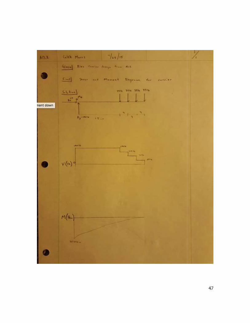
square tube with 0.12-inch walls and the allowable stress, 58-ksi, from a safety factor of 1.5 and A513 steel ultimate tensile strength of 87-ksi to calculate the maximum moment that could occur before failure from bending. This information was then used with typical dimensions of a four-bike carrier having a 36-inch length with a bike every seven inches from the end farthest from the support. Using an average weight of bike equal to 35 pounds and the given dimensions the actual moment the bike carrier would produce was calculated. The calculated moment produced on the bike carrier was 3570-lb*in, which is less than the allowable moment deeming this a suitable design. This information was then used in Appendix 13.2 to create shear and moment diagrams based on the bike carrier’s dimensions and loading. Design Issue The first issue in design was due to the cars mounting locations and the location of the gas tank which makes the hitch cross member dimensions have a bend in order to fit under the OEM bumper. This cross member will under go different loading conditions in three different modes making this a combined loading on a curved beam situation. In order to simplify calculations in the analysis of reaction forces at the supports was done neglecting the curve in the beam reducing it to a simple shape. Later on winter quarter, with skills from a Finite Elemental Analysis course an additional analysis will be done on the computer to supplement the original analysis. The second issue in design came up while designing the gate based on the minimal support reactions in Appendix A8 as it had two supports that held the gate while in the open, cantilever, position. However, this design was 24 inches tall at the support, which blocked the vehicles passenger side turn signal and brake light, which was unacceptable for on-road use. The support system of the gate was redesigned in Appendix 11 based on the allowable loadings from the analysis on the hinge shaft in Appendix A10. The new design allows for clearance of the rear door and leaves all lights 100 percent visible. The third issue in design is figuring out how to meet the requirement that says the device shall not rattle or make noise while in operation. In order to minimize the noise and help the device withstand impacts polyurethane stoppers will be used to separate the accessory gate from coming in contact with the metal surface of the mount. Failure Mode Analysis, Operation Limits During normal operation, the device will be under minimal stress compared to when the device is towing. When the device is in-tow a large amount of stress will be induced to the hitch receiver and the connection it makes with the cross member of the hitch assembly the resulting forces and moments from the three load conditions would most likely fail at the pin connection between the ball attachment and hitch receiver. The pin that will connect the hitch to the ball connection is a standard
15
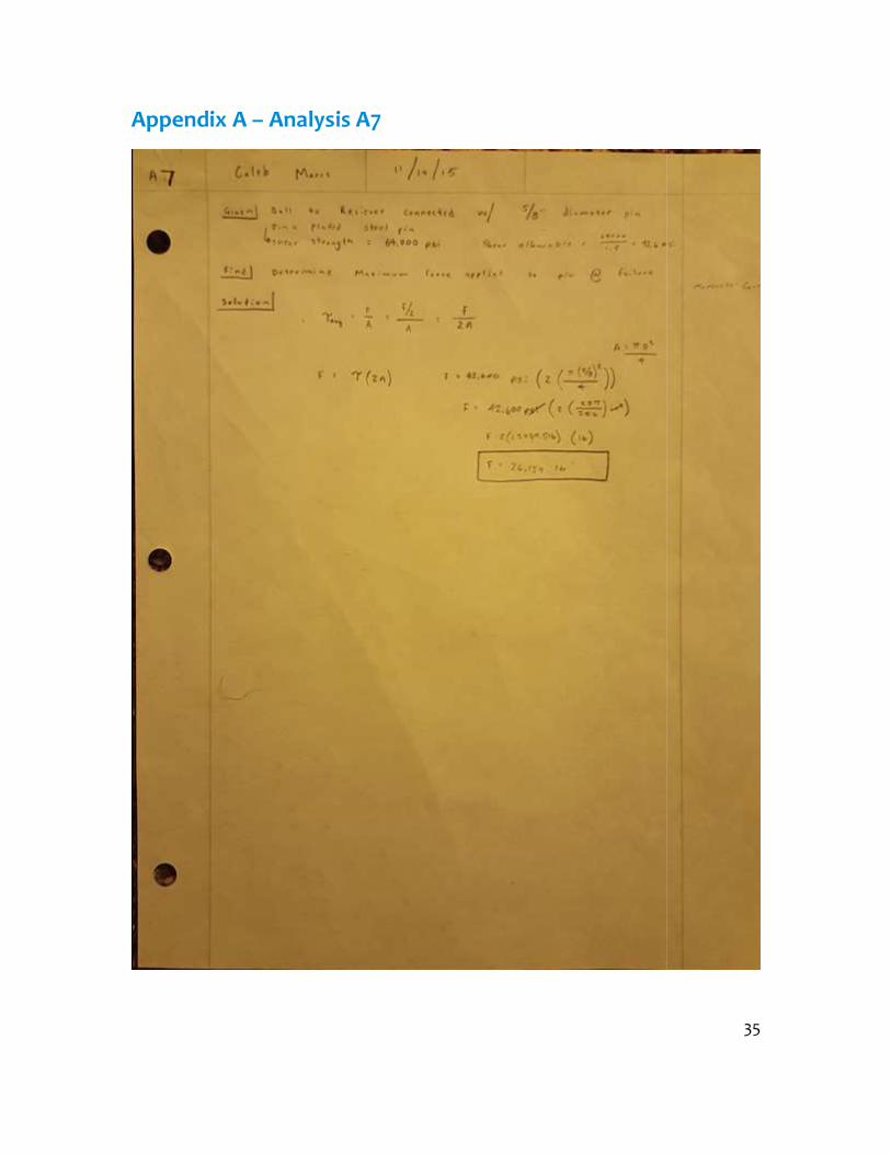
trailer hitch pin with a 5/8 inch diameter and was determined to fail once the load were to exceed 26,139lbs. (See Appendix A7) However, the vehicles suspension would fail before this load was applied to the hitch as a Jeep Grand Cherokee WJ has an 11,400-pound load rating. (Jeep Grand Cherokee Specifications, features, and options, 2002) The accessories gate will undergo the most stress while it is in the open position under full load as it acts like a cantilever beam. While in the open position the beam will undergo tension in the top portion of the beam and compression in the underside of the beam. While in the open position all load forces on the accessory gate would exert a resulting force and moment on the hinge spindle. The original choice for a hinge spindle was determined to handle a load of 800 pounds 18.5 inches away from the support. The spindle was upgraded to a 1.75-inch spindle which was determined to support more than twice the moment allowing for a larger load at the same position as the 1.5 inch spindle could, or the spare tire load of 800 pounds could be located further from the hinge support. When the 800-pound load is about 42 inches away from the spindle it would exceed the maximum moment the spindle could handle based off of the materials allowable bending stress. If the load were applied 36 inches away from the hinge support at the free end, then the hinge could only support up to a 923.5-lb load before exceeding the allowable bending stresses of the hinge shaft. It was determined that the shaft would fail due to bending stresses before it were to exceed the allowable stresses in shear or normal stress. (See Appendix A10) The bike carrier which is made from 1.5-inch square A513 tubing with 0.12-inch walls was determined to fail once the moment were to 16,382-lb*in. In order for this moment to be produced on a 36-inch cantilever beam then a 455-pound load would have to be applied at the far end of the beam away from the cantilever end. In order for a 455-pound load to be produced by 4 bikes, each bike would have to weigh about 115 pounds and this is not realistic as most bikes weigh from 25-45 pounds. In order to optimize this design and save weight a 1.5-inch square tube with thinner walls was analyzed in the same manner and was determined suitable for the design as the moment produced was under the max moment allowed based on design geometry and allowable stress. By selecting a design with thinner walls almost a pound per foot was saved on the bike carrier. Appendix A13.3 uses beam deflection formulas for cantilever beams and the selected beam geometry and average max loading in order to predict the max deflection in the end of the beam farthest from the supporting pin connection. With a 4 bike load concentrated on the end of the beam it should deflect about 0.6-inches. Based on all of the previous results from appendix 13 the strain experienced in the bike carrier support beam could be calculated with the strain equation ∈= . Where ε represents the strain, M is the

16
moment, c is the distance from the center of the beam to the outside surface where strain can be measured with strain gage, E is the modulus of elasticity, and I is the moment of inertia of the cross sectional area. Appendix 13.4 calculates the strain experienced in the member based on a 4-bike load concentrated at the end farthest from the pin support.
Methods and Construction Description This device will be a series of parts that will be manufactured or purchased and installed into the final assembly. Construction of this device will require necessary skills that need to be outsourced such as welding. Parts that need to be manufactured will be machined in the machine shop at Central Washington University with skills learned in the Basic Machining course. The final product design is made up of two sub assemblies: the hitch and the accessories gate. The hitch will be first constructed out of cardboard to ensure that it will fit to the vehicle allowing the OEM bumper to fit over it. It is important that the OEM bumper fits over the hitch as that is one of the requirements of the device. The hitch will be a sub assembly in the final device that is constructed of multiple parts. The hitch cross member will be constructed from A500 Grade B 3-inch by 3-inch by 0.25-inch tubing. The mounting brackets will be fabricated from 6-inch by 4-inch by 3/8-inch A36 Steel Angle. The other parts such as the trailer receiver, device receiver, and safety chain loop for the hitch assembly will be ordered from the available trailer hitch fabrication parts on etrailers.com. The hitch assembly will be welded together and then mounted to the vehicle with 8 zinc plated grade 10.9 M12x1.75x45 bolts. All welding will be done with an E60 electrode resulting in an allowable shear stress of 18ksi at the filet welds. The accessory gate will be a series of parts that will be manufactured from raw materials and pre made parts. The accessory gates hinge, bearings, and spindle will come from various gate fabrication parts offered by Synergy Manufacturing saving time in the construction process. Almost all of the accessory gate parts are made from raw tubing which was cut on a chop saw to size specifications and then all holes were drilled with an 18 speed drill press. All parts made from raw materials will be sprayed with a primer and then painted. Coatings solve problems of corrosion and wear helping extend the life of a product.

17
Discussion The 5x5 lug plate was to be machined in the machine shop on the lathe and mill, but with the assistance of Mathew Burvee and Trevor Reher it will be cut out on the plasma cutter saving about 5 hours in the machine shop. The accessory gate mount was originally designed to be constructed out of a steel c channel, but was designed with an unavailable size of channel. To solve this problem, the accessory gate beam support will be made from A36 steel angle, which accounts for a bottom and backside to the support. The portion that needs a c shape will have a piece of the angle flipped and welded to the original angle creating the original c channel design.
Figure 4: CWU Plasma table cutting out 5x5 lug plate (Appendix B12: Drawing)

Due to budget and schedule constraints the SAE J684 testing will not be performed on the hitch assembly which leaves the device useless as the hitch will not legally be allowed to tow anything. In order to solve this problem, a Curt Multiwill be used to mount the device to an existing OEM hitch. This device will impact the trailer hitch classification due to the resultant tongue weight induced by the device. This means the device and mounted accessories must weigh 250 lbs. or less in order for the trailer hitches to tow a trailer with GVWR of 5000lb and a tongue weight of 500lb. In order to mount the device assembly in the Curt Multidevice mount will be switched from a vertical position to a horizontal position on the device assembly. This switch in position will increase the amount of weld that holds the device mount to the beam support from 8 inches to 12 inches.
Figure 5: CURT Multi-Use Ball Mount The test fit/ test drive with device it was discovered that the device rattles within the Curt receiver, which attaches the device to the vehicle. However, this is a common problem with trailer hitches so there are multiple anti rattle devices available fpurchase from trailer hitch stores. receiver tube in order to prevent all movement between the device mount and Curt receiver.
d schedule constraints the SAE J684 testing will not be performed on the hitch assembly which leaves the device useless as the hitch will not legally be allowed to tow anything. In order to solve this problem, a Curt Multi-Use Ball Mount unt the device to an existing OEM hitch. This device will impact the trailer hitch classification due to the resultant tongue weight induced by the device. This means the device and mounted accessories must weigh 250 lbs. or less in order itches to tow a trailer with GVWR of 5000lb and a tongue weight of In order to mount the device assembly in the Curt Multi-Use Ball Mount the device mount will be switched from a vertical position to a horizontal position on the is switch in position will increase the amount of weld that holds the device mount to the beam support from 8 inches to 12 inches.
Use Ball Mount
The test fit/ test drive with device it was discovered that the device rattles within the Curt receiver, which attaches the device to the vehicle. However, this is a common problem with trailer hitches so there are multiple anti rattle devices available fpurchase from trailer hitch stores. An anti hitch rattle device will be attached to the receiver tube in order to prevent all movement between the device mount and Curt
Figure 6: Anti Rattle Device
18
d schedule constraints the SAE J684 testing will not be performed on the hitch assembly which leaves the device useless as the hitch will not legally be Use Ball Mount unt the device to an existing OEM hitch. This device will impact the trailer hitch classification due to the resultant tongue weight induced by the device. This means the device and mounted accessories must weigh 250 lbs. or less in order itches to tow a trailer with GVWR of 5000lb and a tongue weight of Use Ball Mount the device mount will be switched from a vertical position to a horizontal position on the is switch in position will increase the amount of weld that holds
The test fit/ test drive with device it was discovered that the device rattles within the Curt receiver, which attaches the device to the vehicle. However, this is a common problem with trailer hitches so there are multiple anti rattle devices available for anti hitch rattle device will be attached to the receiver tube in order to prevent all movement between the device mount and Curt

19
Drawing Tree and Drawing ID’s
Jeep WJ Multipurpose Oversize Spare Tire CarrierHitch Assembly
Mounting Bracket (driver-side)Mounting Bracket (passenger-side)
M12X1.75x45 M12 Washers Cross Member
Center Beam
3-inchX3-inchX0.25-inch Center Beam
3-inchX3-inchX0.25-inch Driver Beam
3-inchX3-inchX0.25-inch Passenger Beam
A36 Angle Iron Reciever Attachment
2-inch Hitch Receiver
2-inch Device Receiver
Safety Chain Loop
Device Assembly
Reciever Mount
2-in reciever
Gate Mount
Accesory Gate
Gate Beam
Hinge Housing
Support Arm 1
Support Arm 2
Triangle Plate
Spare Tire Carrier Reciever
SmittyBilt Jerry Can MountSpare Tire Carrier
2 in Square reciever
5x5 lug plate
lug nuts (x5)
lug studs (x5)
Bike Carrier
1.5-in square tube
Pro Series Replacement Bike Carriers (x4)

Parts list:
20

21
Manufacturing Issues: The hitch is an assembly of machined parts that will need to be joined together by welding, which leads to the first manufacturing issue. This manufacturing issue will be solved by outsourcing this portion of the project to complete all welding which will dig into the final budget of this project. Some of the manufacturing was to be completed at the Project Managers garage, but some equipment was old and hadn’t been maintained in awhile. There was unexpected maintenance done to the variable speed drill press as it had a broken built that needed replaced. Another manufacturing issue that was not accounted for was the need for specific tooling such as new chop saw blades, and certain size drill bits. These missing tools were a minor setback to the schedule, but they dig into the over all budget. See Appendix D for tooling costs. Assembly, Sub–assembly, Parts, Drawings The final product design is made up of two sub assemblies: the hitch and the accessories gate. A detailed parts list with all of the necessary parts and hardware will be found in Appendix C.
22

23
Testing Method Introduction The purpose of testing is to ensure the device designed meets all design requirement and performance predictions. Method/Approach The first test will ensure the device meets the weight requirements. The second test in the series of tests will measure the time to assemble and install the device. This test will also determine if the device manufactured fits the vehicle with the OEM bumper. One test will measure the required force to open the lift gate from closed position and the force required to close the gate from open position to determine if it meets the set performance predictions. The accessories gate will under the most stress while it is under a full load in the open position like a cantilever beam. The gate will be loaded to capacity and opened to measure the actual deflection experienced in order to compare it with the performance predictions. The bike carrier beam will be under the most stress when it is loaded up with bikes travelling down the road. The bike carrier beam will be loaded to capacity in order to measure the actual deflection experienced in order to compare it with the performance predictions. The tolerances on the bike beam and support pin/hole will be measured to ensure a rigid fit while travelling down the road in order to reduce all bouncing and vibrations. A survey will be conducted via an off-road forum on the Internet and on paper at a jeep event to evaluate others opinion on different aspects of the device such as aesthetics, design, performance, and performance compared to benchmarks. The survey that will be used can be found in Appendix G. Test Procedure The test procedure in full depth can be found in Appendix G. Testing will include: 1) Weight Requirement Test 2) Assembly/Fit Test 3) Opening/Closing Force Test 4) Impact Test 5) Bike Carrier Deflection Test 6) Strain 7) Scope

24
Deliverables All testing data will be recorded in a spreadsheet and provided in a test report to go along with the product. The test data sheet and testing report can be found in Appendix G.
Budget/Schedule/Project Management In order to keep the project on schedule, under budget, and within scope a budget and schedule have been implemented along with project management tools and techniques. Every project brings along risks and rewards that must be thoroughly analyzed to ensure a projects success, and this is where project management tools and techniques are helpful. Proposed Budget The proposed budget for this project is 600 dollars, which will include all costs such as raw materials, parts, labor, and necessary tooling. The goal of this project is to keep cost under the cost of the Rock Solid Rear Bumper at $1,188.00 and the Hitch gate at $980.00, which means that if the project exceeds the proposed budget while staying under the cost of the bench mark items then the project was successful. The breakdown of the budgets individual costs can be found in Appendix D1. The unexpected cost for SAE J684 testing has set the project over budget, but in order to cover the cost of testing a Go Fund Me has been initiated to raise funding from outside resources. Proposed Schedule There is a lot of risk in the project going beyond scope, so it is necessary that it stay on track. To ensure this project stays on track a schedule will be used to order functional tasks in an organized manner. The proposed schedule of this project can be viewed in more detail in Appendix E where it is broken down into a Gantt chart and WBS. The total estimated time in hours for completion of this project from start to finish is about 270 hours which includes the time necessary to write the proposal, analyze and design the project, manufacture and assemble all parts, as well as testing time. The proposed schedule is broken into three sections (Fall, Winter, and Spring) and with each section comes a deliverable. At the end of fall quarter the informal proposal is due, at the end of winter the device is to be constructed, and at the end of spring the testing report is to be included within the final project proposal. Fall quarter is where a project is selected, then analyses, which leads to the design of parts, that make up the device. As parts are analyzed then designed, proper materials can be selected to ensure strength of materials will meet or exceed the needs of the part. Once the analysis is completed and all parts are designed and defined to meet

25
performance predictions, then the proposal will be frozen leading to the manufacturing process of the device in Winter Quarter. It is estimated that 70 hours will be needed to complete the proposal. Winter quarter will focus on the manufacturing of the designed device where all parts will be purchased or manufactured, then assembled to create the final project. All necessary raw materials will need to be purchased in order to begin the parts fabrication process. Once all raw materials and parts have been delivered, then construction may begin. All parts must meet the set design specifications. Once all parts are to the proper dimensions and tolerances, then the components may be put together to create the sub assemblies, which will then be assembled into the final device assembly. Once the designed device is completely assembled then it may be looked over for flaws and imperfections that could be fixed before sending it to testing in the spring quarter. Spring quarter is set aside for the testing of projects that were designed and built in the previous quarters. Testing will be done on the final assembly with all parts intact in order to ensure it meets all design requirements. A performance analysis of the final product will be competed in order to see if it meets the performance predictions from the analysis. A successful project will meet the set performance predictions. The manufacturing practicability of this device will be determined and fine-tuned in order to create the most efficient and competitive spare tire device on the market for Jeep WJ’s. All of the testing information will be discussed in the testing method section, and all test data will be placed in data sheet found in Appendix E. Project Management A work break down structure will be used to define the scope of a project and help keep the project on track sticking to the budget and schedule while allowing for some changes to be made in the schedule in order to mange risks. In order for this project to be successful, risks will be managed with the identification of risks, analysis of risks, mitigation of risks, and control of risks.
Conclusion Using skills from the Mechanical Engineering Technology Curriculum offered At Central Washington University, a multipurpose oversize spare tire carrier for a Jeep Grand Cherokee WJ was conceived, analyzed, and designed meeting initial design requirements set. The drawings from this proposal were used with basic machining skills to fabricate most parts, which were then sent off to Dylan King for welding/assembly. Once welding was completed, the device was assembled and installed on the jeep. Spring quarter testing was completed; see testing report for more details. All in all, this project was a success and a lot was learned during the process.
26
Acknowledgements: I would like to acknowledge the professors within Central Washington Universities Mechanical Engineering Technology department for their support and guidance through the curriculum and on this project. Thank you: Craig Johnson, Charles Pringle, and Roger Beardsley. I appreciate Dylan King for all the hard work and effort put forth to help with welding, as this device would not have been possible without proper welds. I would also like to thank Mr.Burvee and Trevor Reher for helping save time during construction by using the plasma cutter to fabricate parts.
References: Depot, M. (2015). Square Steel Tube A513 / A500. Retrieved 10 10, 2015, from Metals Depot: http://www.metalsdepot.com/products/hrsteel2.phtml?page=sqtube&LimAcc=%20&aident= Etrailers. (2015). Hitch Fabrication Parts. Retrieved 10 20, 2015, from Etrailers: https://www.etrailer.com/s.aspx?qry=hitch+fabrication&furl=-pg-Hitch_Accessories-sf-Hitch_Fabrication_Parts Jeep Grand Cherokee Specifications, features, and options. (2002). Retrieved 11 15, 2015, from WJ Jeeps: http://www.wjjeeps.com/rus/dimensions.htm Mott, R. L. (2014). Machine Elements in Mechanical Design. Upper Saddle River, New Jersey: Pearson, Inc. R.C.Hibbeler. (2014). Statics & Mechanics of Materials (Vol. 4). Upper SAddle River, NJ, USA: Pearson Prentice Hall.

Appendix A – Analysi
Analysis A1
27

28

Appendix A – Analysi Analysis A2
29

Appendix A – Analysi
Analysis A 3
30

Appendix A – Analysi
Analysis A4
31

Appendix A – Analysi
Analysis A5
32

33

Appendix A – Analysi
Analysis A6
34
Appendix A – Analysi
Analysis A7
35
Appendix A – Analysi
Analysis A8
36

37

38

39

40

Appendix A – Analysi
Analysis A9
41

Appendix A – Analysi
Analysis A10
42

43

Appendix A – Analysi
Analysis A11
44

45
Appendix A – Analysis A12

Appendix A – Analysis
Analysis A13
46
47

48

49

Appendix A – Analysi
Figure A14.1: Mass of complete assembly (hitch+device)
Figure A14.2: Mass of device assembly
Figure A14.3: Mass of hitch assembly
Analysis A14
Figure A14.1: Mass of complete assembly (hitch+device)
Figure A14.2: Mass of device assembly
Figure A14.3: Mass of hitch assembly
50

51
Appendix B1 – Conceived Idea
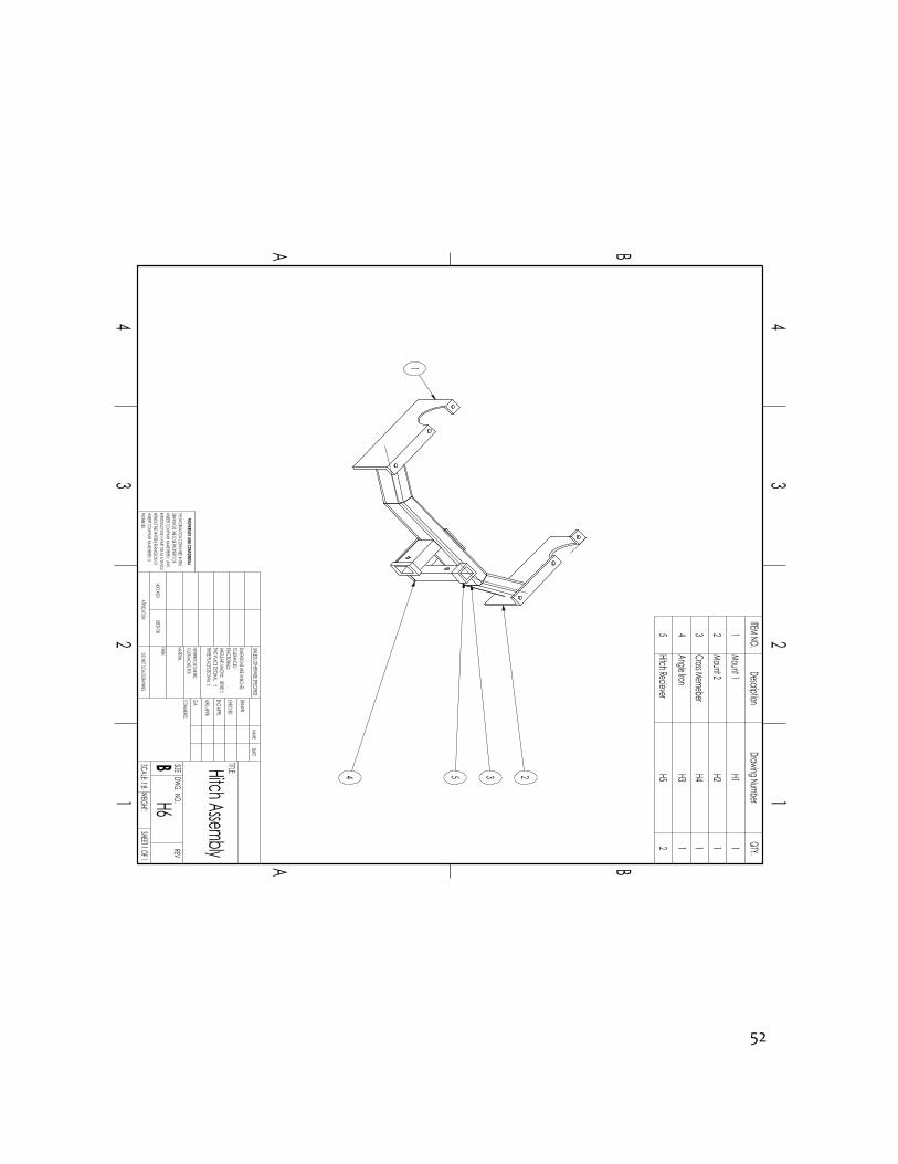
Appendix B2 – Hitch Assembly
Figure B1: Sketch Of conceived idea #2
52
4 235
1
NEXT ASSY
PROPRIETARY AND CONFIDENTIAL
THREE PLACE DECIMAL TWO PLACE DECIMAL
4
A
12
3
BBA
21
34
Hitch Assembly
DO NOT SCALE DRAWINGH6
SHEET 1 OF 1
UNLESS OTHERWISE SPECIFIED:
SCALE: 1:8WEIGHT:
REVDWG. NO.
B SIZE TITLE:NAME
DATE
COMMENTS:Q.A. MFG APPR.ENG APPR.
FINISH
MATERIAL
CHECKED
TOLERANCING PER:
USED ON
BEND
DRAWN
APPLICATION
INTERPRET GEOMETRIC
DIMENSIONS ARE IN INCHESTOLERANCES:FRACTIONALANGULAR: MACH
THE INFORMATION CONTAINED IN THISDRAWING IS THE SOLE PROPERTY OF<INSERT COMPANY NAME HERE>. ANY REPRODUCTION IN PART OR AS A WHOLEWITHOUT THE WRITTEN PERMISSION OF<INSERT COMPANY NAME HERE> IS PROHIBITED.
ITEM NO.Description
Drawing NumberQTY.
1Mount 1
H11
2Mount 2
H21
3Cross Memeber
H41
4Angle Iron
H31
5Hitch Reciever
H52
53
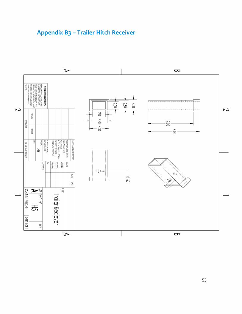
Appendix B3 – Trailer Hitch Receiver
NEXT ASSY
PROPRIETARY AND CONFIDENTIAL
TWO PLACE DECIMAL
21
A B
A B
12
A36
Trailer Reciever
DO NOT SCALE DRAWINGH5
SHEET 1 OF 1
UNLESS OTHERWISE SPECIFIED:
SCALE: 1:1WEIGHT:
REVDWG. NO.
A SIZE TITLE:NAME
DATE
COMMENTS:Q.A. MFG APPR.ENG APPR.
MATERIALINTERPRET GEOMETRIC
CHECKED BEND
USED ONAPPLICATION
THREE PLACE DECIMAL
DRAWN
FINISH
TOLERANCING PER:
DIMENSIONS ARE IN INCHESTOLERANCES: 0.125FRACTIONALANGULAR: MACH
THE INFORMATION CONTAINED IN THISDRAWING IS THE SOLE PROPERTY OF<INSERT COMPANY NAME HERE>. ANY REPRODUCTION IN PART OR AS A WHOLEWITHOUT THE WRITTEN PERMISSION OF<INSERT COMPANY NAME HERE> IS PROHIBITED.
2.00
2.50 3.00 2.00
2.50 3.00
7.00 8.00
.63

54
Appendix B4 – Device Reciever
2.50 3.00 2.00
21
A B
A B
12
A36
Device Reciever
DO NOT SCALE DRAWINGH6
SHEET 1 OF 1
UNLESS OTHERWISE SPECIFIED:
SCALE: 1:2WEIGHT:
REVDWG. NO.
A SIZE TITLE:NAME
DATE
COMMENTS:Q.A. MFG APPR.ENG APPR.CHECKEDDRAWN
FINISH
MATERIAL
BEND
TOLERANCING PER:INTERPRET GEOMETRIC
USED ON
TWO PLACE DECIMAL
APPLICATION
THREE PLACE DECIMAL
NEXT ASSY
PROPRIETARY AND CONFIDENTIAL
DIMENSIONS ARE IN INCHESTOLERANCES:0.025FRACTIONALANGULAR: MACH
THE INFORMATION CONTAINED IN THISDRAWING IS THE SOLE PROPERTY OF<INSERT COMPANY NAME HERE>. ANY REPRODUCTION IN PART OR AS A WHOLEWITHOUT THE WRITTEN PERMISSION OF<INSERT COMPANY NAME HERE> IS PROHIBITED.
6.00 5.00
.63
2.50

55
Appendix B5 – Hitch Mount 1

56
5.38
.38
5.00
1.13 13.03
2.03
.75 1.63
1.13
.88
2.25
1.00
1.13
4
A
12
3
BBA
21
34
A36
Mount 1
DO NOT SCALE DRAWINGH-1
SHEET 1 OF 1
UNLESS OTHERWISE SPECIFIED:
SCALE: 1:1WEIGHT:
REVDWG. NO.
B SIZE TITLE:NAME
DATE
COMMENTS:Q.A. MFG APPR.ENG APPR.CHECKEDDRAWN
FINISH THREE PLACE DECIMAL BEND
MATERIAL
APPLICATION
TWO PLACE DECIMAL
PROPRIETARY AND CONFIDENTIALINTERPRET GEOMETRICTOLERANCING PER:
USED ONNEXT ASSY
DIMENSIONS ARE IN INCHESTOLERANCES: 0.125inFRACTIONALANGULAR: MACH
THE INFORMATION CONTAINED IN THISDRAWING IS THE SOLE PROPERTY OF<INSERT COMPANY NAME HERE>. ANY REPRODUCTION IN PART OR AS A WHOLEWITHOUT THE WRITTEN PERMISSION OF<INSERT COMPANY NAME HERE> IS PROHIBITED.
20.50
R2.75

57
Appendix B6– Hitch Mount 2
20.50
R2.75
2.03
1.18 1.18
1.18
13.03
5.38
.38 5.00
4
A
12
3
BBA
21
34
A36
Mount 2
DO NOT SCALE DRAWINGH3
SHEET 1 OF 1
UNLESS OTHERWISE SPECIFIED:
SCALE: 1:1WEIGHT:
REVDWG. NO.
B SIZE TITLE:NAME
DATE
COMMENTS:Q.A. MFG APPR.ENG APPR.CHECKEDDRAWN
FINISH
MATERIAL
BEND
TOLERANCING PER:INTERPRET GEOMETRIC
USED ON
TWO PLACE DECIMAL
APPLICATION
THREE PLACE DECIMAL
NEXT ASSY
PROPRIETARY AND CONFIDENTIAL
DIMENSIONS ARE IN INCHESTOLERANCES: 0.125FRACTIONALANGULAR: MACH
THE INFORMATION CONTAINED IN THISDRAWING IS THE SOLE PROPERTY OF<INSERT COMPANY NAME HERE>. ANY REPRODUCTION IN PART OR AS A WHOLEWITHOUT THE WRITTEN PERMISSION OF<INSERT COMPANY NAME HERE> IS PROHIBITED.
58
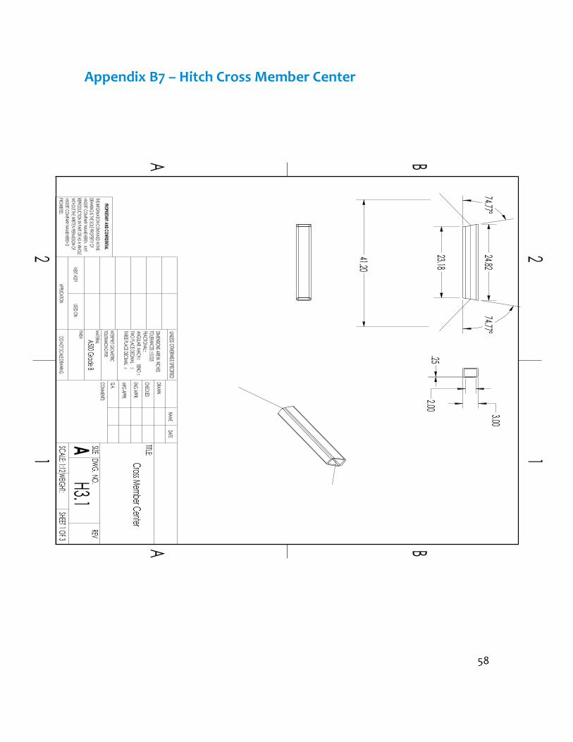
Appendix B7 – Hitch Cross Member Center
PROHIBITED.
21
A B
A B
12
A500 Grade B
Cross Member Center
DO NOT SCALE DRAWINGSHEET 1 OF 3
UNLESS OTHERWISE SPECIFIED:
SCALE: 1:12WEIGHT:
REVDWG. NO.
A SIZE TITLE:NAME
DATE
COMMENTS:Q.A. MFG APPR.ENG APPR.CHECKEDDRAWN
FINISH
MATERIALTOLERANCING PER:INTERPRET GEOMETRIC
NEXT ASSY
BEND
USED ON
TWO PLACE DECIMAL
APPLICATION
THREE PLACE DECIMAL
PROPRIETARY AND CONFIDENTIAL
DIMENSIONS ARE IN INCHESTOLERANCES:0.025FRACTIONALANGULAR: MACH
THE INFORMATION CONTAINED IN THISDRAWING IS THE SOLE PROPERTY OF<INSERT COMPANY NAME HERE>. ANY REPRODUCTION IN PART OR AS A WHOLEWITHOUT THE WRITTEN PERMISSION OF<INSERT COMPANY NAME HERE> IS
H3.1
74.77° 24.82
23.18
74.77°
41.20
3.00
2.00 .25

59
Appendix B8 – Hitch Cross Member passenger Side
21
A B
A B
12
THREE PLACE DECIMAL BEND
Passenger SideDO NOT SCALE DRAWING
H3.3SHEET 3 OF 3
UNLESS OTHERWISE SPECIFIED:
SCALE: 1:12WEIGHT:
REVDWG. NO.
A SIZE TITLE:NAME
DATE
COMMENTS:Q.A. MFG APPR.ENG APPR.CHECKEDDRAWN
FINISH A500 Grade B
Cross Member MATERIAL
APPLICATION
TWO PLACE DECIMAL
PROPRIETARY AND CONFIDENTIALINTERPRET GEOMETRICTOLERANCING PER:
USED ONNEXT ASSY
DIMENSIONS ARE IN INCHESTOLERANCES:0.025FRACTIONALANGULAR: MACH
THE INFORMATION CONTAINED IN THISDRAWING IS THE SOLE PROPERTY OF<INSERT COMPANY NAME HERE>. ANY REPRODUCTION IN PART OR AS A WHOLEWITHOUT THE WRITTEN PERMISSION OF<INSERT COMPANY NAME HERE> IS PROHIBITED.
59.53°
8.91
9.39
8.09 105.23°
10.34

60
Appendix B9 – Hitch Cross Member Driver Side
TWO PLACE DECIMAL
PROHIBITED.
21
A B
APROPRIETARY AND CONFIDENTIAL
THREE PLACE DECIMAL BEND
Driver SideDO NOT SCALE DRAWING
H3.2SHEET 2 OF 3
UNLESS OTHERWISE SPECIFIED:
SCALE: 1:12WEIGHT:
REVDWG. NO.
A SIZE TITLE:NAME
DATE
COMMENTS:Q.A. MFG APPR.ENG APPR.CHECKED
B
1
DRAWN
INTERPRET GEOMETRIC
NEXT ASSY
TOLERANCING PER:
USED ON
Cross Member FINISH
2
MATERIAL
APPLICATION
DIMENSIONS ARE IN INCHESTOLERANCES:0.025FRACTIONALANGULAR: MACH
THE INFORMATION CONTAINED IN THISDRAWING IS THE SOLE PROPERTY OF<INSERT COMPANY NAME HERE>. ANY REPRODUCTION IN PART OR AS A WHOLEWITHOUT THE WRITTEN PERMISSION OF<INSERT COMPANY NAME HERE> IS
A 500 Grade B
8.77
120.47°
10.34
9.39 74.77°
3.00 2.50 .25

61
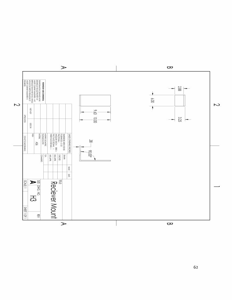
Appendix B10 – Receiver Mount
62
PROHIBITED.
2
A B
A B
12
A36
Reciever Mount
DO NOT SCALE DRAWINGH3
SHEET 1 OF 1
UNLESS OTHERWISE SPECIFIED:
REVDWG. NO.
A SIZE TITLE:NAME
DATE
COMMENTS:Q.A. MFG APPR.ENG APPR.CHECKED
BEND
NEXT ASSY
DRAWN
INTERPRET GEOMETRICTHREE PLACE DECIMAL
PROPRIETARY AND CONFIDENTIAL
FINISH
TOLERANCING PER:MATERIAL
USED ON
TWO PLACE DECIMAL
APPLICATION
DIMENSIONS ARE IN INCHESTOLERANCES: 0.125FRACTIONALANGULAR: MACH
THE INFORMATION CONTAINED IN THISDRAWING IS THE SOLE PROPERTY OF<INSERT COMPANY NAME HERE>. ANY REPRODUCTION IN PART OR AS A WHOLEWITHOUT THE WRITTEN PERMISSION OF<INSERT COMPANY NAME HERE> IS
SCALE: 1
.38 90.00°
10.00 9.63
6.00
3.25 2.88

63
Appendix B11 – Accessory Gate Assembly
APPLICATION USED ONNEXT ASSY
PROPRIETARY AND CONFIDENTIAL
TWO PLACE DECIMAL
4
A
12
3
DCB
2
CHECKEDDRAWN
FINISH
MATERIALINTERPRET GEOMETRICTHREE PLACE DECIMAL BEND
AssemblyDO NOT SCALE DRAWING
DSHEET 1 OF 1
UNLESS OTHERWISE SPECIFIED:
SCALE: 1:8WEIGHT:
REVDWG. NO.
C SIZE TITLE:NAME
DATE
COMMENTS:
14
Q.A.
B
TOLERANCING PER:
Device
C
MFG APPR.
3
ENG APPR.
A D
DIMENSIONS ARE IN INCHESTOLERANCES: 0.125FRACTIONALANGULAR: MACH
THE INFORMATION CONTAINED IN THISDRAWING IS THE SOLE PROPERTY OF<INSERT COMPANY NAME HERE>. ANY REPRODUCTION IN PART OR AS A WHOLEWITHOUT THE WRITTEN PERMISSION OF<INSERT COMPANY NAME HERE> IS PROHIBITED.
29
12
14
111 137
64
53
810
15
ITEM NO.PART NUMBER
DESCRIPTIONQTY.
1Hinge_Bearing Housing
12
Accesory Gate Beam1
3Support Arm
14
Spare Tire Extension Reciever
15
Extension Tube Plate Mount
16
Spare Tire Extension1
75X5_Lug
18
Comp4X4 Gate Latch1
9Beam Support
110
Latch bracket1
11Part2^Device Assembly
112
Device mount1
13Bike Carrier Beam
114
Bike Cradle3
15Cradle Mount Bracket
3

64
Appendix B12 – 5x5 Lug Mounting Plate
2.00 4.755
.50 X5
2.00
2.94
6.50
.50
6.50
TWO PLACE DECIMAL
21
A B
A B
12
A36
5X5_Lug
DO NOT SCALE DRAWINGD1
SHEET 1 OF 1
UNLESS OTHERWISE SPECIFIED:
SCALE: 1:2WEIGHT:
REVDWG. NO.
A SIZE TITLE:NAME
DATE
COMMENTS:Q.A. MFG APPR.ENG APPR.CHECKEDDRAWN
THREE PLACE DECIMAL
FINISH
PROPRIETARY AND CONFIDENTIAL
NEXT ASSY
TOLERANCING PER:MATERIAL
BEND
INTERPRET GEOMETRIC
APPLICATION USED ON
DIMENSIONS ARE IN INCHESTOLERANCES: 0.125FRACTIONALANGULAR: MACH
THE INFORMATION CONTAINED IN THISDRAWING IS THE SOLE PROPERTY OF<INSERT COMPANY NAME HERE>. ANY REPRODUCTION IN PART OR AS A WHOLEWITHOUT THE WRITTEN PERMISSION OF<INSERT COMPANY NAME HERE> IS PROHIBITED.

65
Appendix B13 – Bearing Housing

66
21
A B
A B
12
THREE PLACE DECIMAL BEND
HousingDO NOT SCALE DRAWING
D1SHEET 1 OF 1
UNLESS OTHERWISE SPECIFIED:
SCALE: 1:2WEIGHT:
REVDWG. NO.
A SIZE TITLE:NAME
DATE
COMMENTS:Q.A. MFG APPR.ENG APPR.CHECKEDDRAWN
FINISHA36
Hinge Bearing MATERIAL
APPLICATION
TWO PLACE DECIMAL
PROPRIETARY AND CONFIDENTIALINTERPRET GEOMETRICTOLERANCING PER:
USED ONNEXT ASSY
DIMENSIONS ARE IN INCHESTOLERANCES:0.125FRACTIONALANGULAR: MACH
THE INFORMATION CONTAINED IN THISDRAWING IS THE SOLE PROPERTY OF<INSERT COMPANY NAME HERE>. ANY REPRODUCTION IN PART OR AS A WHOLEWITHOUT THE WRITTEN PERMISSION OF<INSERT COMPANY NAME HERE> IS PROHIBITED.
4.00 3.88
R.06
2.75
1.75

67
Appendix B14 – Accessory Gate Beam
TWO PLACE DECIMAL
21
A B
A B
12
A500 Grade B
Accessory Gate Beam
DO NOT SCALE DRAWINGD2
SHEET 1 OF 1
UNLESS OTHERWISE SPECIFIED:
SCALE: 1:12WEIGHT:
REVDWG. NO.
A SIZE TITLE:NAME
DATE
COMMENTS:Q.A. MFG APPR.ENG APPR.CHECKEDDRAWN
THREE PLACE DECIMAL
FINISH
PROPRIETARY AND CONFIDENTIAL
NEXT ASSY
TOLERANCING PER:MATERIAL
BEND
INTERPRET GEOMETRIC
APPLICATION USED ON
DIMENSIONS ARE IN INCHESTOLERANCES:.125FRACTIONALANGULAR: MACH
THE INFORMATION CONTAINED IN THISDRAWING IS THE SOLE PROPERTY OF<INSERT COMPANY NAME HERE>. ANY REPRODUCTION IN PART OR AS A WHOLEWITHOUT THE WRITTEN PERMISSION OF<INSERT COMPANY NAME HERE> IS PROHIBITED.
3.00 R.25
2.75
.13 R.13
R1.38 35.06
.33 X4
1.63
35.06 1.50

68
Appendix B15 – Support Arm 1
2 1
A
B
A
B
12
A36 2in X 2in X 0.25in SQR
Support Arm1
DO NOT SCALE DRAWINGD3
SHEET 1 OF 2
UNLESS OTHERWISE SPECIFIED:
SCALE: 1:8 WEIGHT:
REVDWG. NO.ASIZE
TITLE:NAME DATE
COMMENTS:Q.A.MFG APPR.ENG APPR.CHECKEDDRAWN
FINISH
MATERIAL
BEND
TOLERANCING PER:INTERPRET GEOMETRIC
USED ON
TWO PLACE DECIMAL
APPLICATION
THREE PLACE DECIMAL
NEXT ASSY
PROPRIETARY AND CONFIDENTIAL
DIMENSIONS ARE IN INCHESTOLERANCES: 0.25FRACTIONALANGULAR: MACH
THE INFORMATION CONTAINED IN THISDRAWING IS THE SOLE PROPERTY OF<INSERT COMPANY NAME HERE>. ANY REPRODUCTION IN PART OR AS A WHOLEWITHOUT THE WRITTEN PERMISSION OF<INSERT COMPANY NAME HERE> IS PROHIBITED.
13.41
11.03 15.48
150.00°
63.82°
7.74

69
Appendix B16 – Support Arm 2
D42
1
A B
A B
12
A36 2in X 2in X 0.25in SQR
DO NOT SCALE DRAWINGSHEET 2 OF 2
UNLESS OTHERWISE SPECIFIED:
SCALE: 1:8WEIGHT:
REVDWG. NO.
A SIZE TITLE:NAME
DATE
COMMENTS:Q.A. MFG APPR.ENG APPR.CHECKEDDRAWN
PROHIBITED.
BEND TWO PLACE DECIMAL
FINISH
MATERIAL
THREE PLACE DECIMAL
TOLERANCING PER:INTERPRET GEOMETRIC
PROPRIETARY AND CONFIDENTIAL
NEXT ASSYAPPLICATION USED ON
DIMENSIONS ARE IN INCHESTOLERANCES:0.25FRACTIONALANGULAR: MACH
THE INFORMATION CONTAINED IN THISDRAWING IS THE SOLE PROPERTY OF<INSERT COMPANY NAME HERE>. ANY REPRODUCTION IN PART OR AS A WHOLEWITHOUT THE WRITTEN PERMISSION OF<INSERT COMPANY NAME HERE> IS
Support Arm 2
11.92 210.00°
56.18°
16.72 14.48

70
Appendix B17 – Triangle Plate
21
A B
A B
12
A 36 0.in thick plate
BEND
PlateDO NOT SCALE DRAWING
D8SHEET 1 OF 1
UNLESS OTHERWISE SPECIFIED:
SCALE: 1:4WEIGHT:
REVDWG. NO.
A SIZE TITLE:NAME
DATE
COMMENTS:Q.A. MFG APPR.ENG APPR.CHECKEDDRAWN
FINISH
MATERIAL
Extension Tube TOLERANCING PER:INTERPRET GEOMETRIC
USED ON
TWO PLACE DECIMAL
APPLICATION
THREE PLACE DECIMAL
NEXT ASSY
PROPRIETARY AND CONFIDENTIAL
DIMENSIONS ARE IN INCHESTOLERANCES:0.125FRACTIONALANGULAR: MACH
THE INFORMATION CONTAINED IN THISDRAWING IS THE SOLE PROPERTY OF<INSERT COMPANY NAME HERE>. ANY REPRODUCTION IN PART OR AS A WHOLEWITHOUT THE WRITTEN PERMISSION OF<INSERT COMPANY NAME HERE> IS PROHIBITED.
6.00 6.00
6.00
.25

71
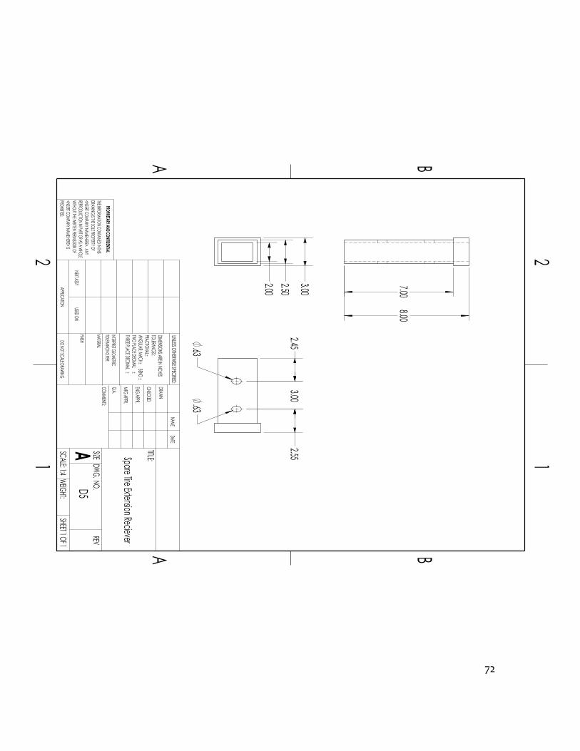
Appendix B18 – Spare Tire Extension Reciever
72
TWO PLACE DECIMAL
PROHIBITED.
Spare Tire Extension Reciever
21
A B
A B
12
DO NOT SCALE DRAWINGSHEET 1 OF 1
UNLESS OTHERWISE SPECIFIED:
SCALE: 1:4WEIGHT:
REVDWG. NO.
A SIZE TITLE:NAME
DATE
COMMENTS:Q.A. MFG APPR.ENG APPR.CHECKED
THREE PLACE DECIMAL INTERPRET GEOMETRIC
DRAWN
PROPRIETARY AND CONFIDENTIAL
USED ON
MATERIAL
APPLICATIONNEXT ASSY
TOLERANCING PER:
FINISH
BEND
DIMENSIONS ARE IN INCHESTOLERANCES:FRACTIONALANGULAR: MACH
THE INFORMATION CONTAINED IN THISDRAWING IS THE SOLE PROPERTY OF<INSERT COMPANY NAME HERE>. ANY REPRODUCTION IN PART OR AS A WHOLEWITHOUT THE WRITTEN PERMISSION OF<INSERT COMPANY NAME HERE> IS
D5
7.00 8.00
3.00 2.50 2.00
2.45 2.55
3.00 .63 .63
73
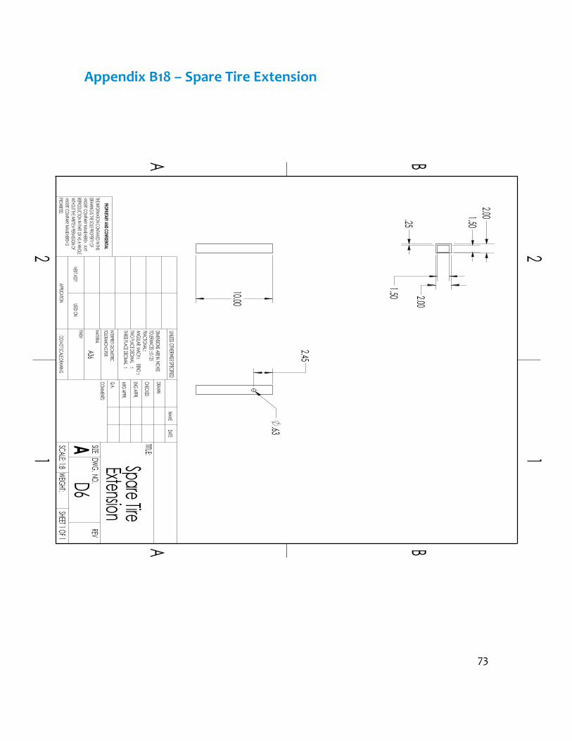
Appendix B18 – Spare Tire Extension
10.00
PROPRIETARY AND CONFIDENTIAL
TWO PLACE DECIMAL
21
A B
A B
INTERPRET GEOMETRICTHREE PLACE DECIMAL BEND
ExtensionDO NOT SCALE DRAWING
D6SHEET 1 OF 1
UNLESS OTHERWISE SPECIFIED:
SCALE: 1:8WEIGHT:
REVDWG. NO.
A SIZE TITLE:NAME
DATE
COMMENTS:Q.A. MFG APPR.ENG APPR.CHECKED
12
DRAWN
TOLERANCING PER:
NEXT ASSYUSED ON
Spare Tire FINISH
A36MATERIAL
APPLICATION
DIMENSIONS ARE IN INCHESTOLERANCES:0.125FRACTIONALANGULAR: MACH
THE INFORMATION CONTAINED IN THISDRAWING IS THE SOLE PROPERTY OF<INSERT COMPANY NAME HERE>. ANY REPRODUCTION IN PART OR AS A WHOLEWITHOUT THE WRITTEN PERMISSION OF<INSERT COMPANY NAME HERE> IS PROHIBITED.
2.00
2.00 .25
1.50
1.50
.63 2.45

Appendix B19 – Bike Carrier Beam
Bike Carrier Beam Support
74

75
Appendix B20 – Bike Carrier Beam
TWO PLACE DECIMAL
21
A B
A B
12
A513
Bike Carrier Beam
DO NOT SCALE DRAWINGD7
SHEET 1 OF 1
UNLESS OTHERWISE SPECIFIED:
SCALE: 1:16WEIGHT:
REVDWG. NO.
A SIZE TITLE:NAME
DATE
COMMENTS:Q.A. MFG APPR.ENG APPR.CHECKEDDRAWN
THREE PLACE DECIMAL
FINISH
PROPRIETARY AND CONFIDENTIAL
NEXT ASSY
TOLERANCING PER:MATERIAL
BEND
INTERPRET GEOMETRIC
APPLICATION USED ON
DIMENSIONS ARE IN INCHESTOLERANCES:0.125FRACTIONALANGULAR: MACH
THE INFORMATION CONTAINED IN THISDRAWING IS THE SOLE PROPERTY OF<INSERT COMPANY NAME HERE>. ANY REPRODUCTION IN PART OR AS A WHOLEWITHOUT THE WRITTEN PERMISSION OF<INSERT COMPANY NAME HERE> IS PROHIBITED.
1.5-in square A513 tubing (0.065-in wall)
1.50
1.50 .07 36.00
.63
2.45

76
Appendix B21 – Bike Cradle Mounting Bracket
21
A B
A B
12
6061 T6
Cradle Mount Bracket
DO NOT SCALE DRAWINGD6
SHEET 1 OF 1
UNLESS OTHERWISE SPECIFIED:
SCALE: 1:1WEIGHT:
REVDWG. NO.
A SIZE TITLE:NAME
DATE
COMMENTS:Q.A. MFG APPR.ENG APPR.CHECKEDDRAWN
FINISH THREE PLACE DECIMAL BEND
MATERIAL
APPLICATION
TWO PLACE DECIMAL
PROPRIETARY AND CONFIDENTIALINTERPRET GEOMETRICTOLERANCING PER:
USED ONNEXT ASSY
DIMENSIONS ARE IN INCHESTOLERANCES:0.125FRACTIONALANGULAR: MACH
THE INFORMATION CONTAINED IN THISDRAWING IS THE SOLE PROPERTY OF<INSERT COMPANY NAME HERE>. ANY REPRODUCTION IN PART OR AS A WHOLEWITHOUT THE WRITTEN PERMISSION OF<INSERT COMPANY NAME HERE> IS PROHIBITED.
1.50 .13
1.63 .13
.31 3.00
1.50
5.00
1.00 .50
1.00
.50 .31
1.00

77
Appendix B22 – Pro Series Bike Cradle
2.24 .06 69.44°
1.09
1.55
69.44°
2.75
2.75
.31 .31
3.00 8.50
.50
21
A B
A B
12
6061 T6
Bike Cradle
DO NOT SCALE DRAWINGD7
SHEET 1 OF 1
UNLESS OTHERWISE SPECIFIED:
SCALE: 1:4WEIGHT:
REVDWG. NO.
A SIZE TITLE:NAME
DATE
COMMENTS:Q.A. MFG APPR.ENG APPR.CHECKEDDRAWN
FINISH THREE PLACE DECIMAL BEND
MATERIAL
APPLICATION
TWO PLACE DECIMAL
PROPRIETARY AND CONFIDENTIALINTERPRET GEOMETRICTOLERANCING PER:
USED ONNEXT ASSY
DIMENSIONS ARE IN INCHESTOLERANCES:0.125FRACTIONALANGULAR: MACH
THE INFORMATION CONTAINED IN THISDRAWING IS THE SOLE PROPERTY OF<INSERT COMPANY NAME HERE>. ANY REPRODUCTION IN PART OR AS A WHOLEWITHOUT THE WRITTEN PERMISSION OF<INSERT COMPANY NAME HERE> IS PROHIBITED.

78
Appendix B23 – 5/8 Hitch Pin
Standard 5/8 inch hitch pin
NEXT ASSY
PROPRIETARY AND CONFIDENTIAL
THREE PLACE DECIMAL TWO PLACE DECIMAL
21
A B
A B
12
DO NOT SCALE DRAWINGHITCH PINSHEET 1 OF 1
UNLESS OTHERWISE SPECIFIED:
SCALE: 1:2WEIGHT:
REVDWG. NO.
A SIZE TITLE:NAME
DATE
COMMENTS:Q.A. MFG APPR.ENG APPR.
FINISH
MATERIAL
CHECKED
TOLERANCING PER:
USED ON
BEND
DRAWN
APPLICATION
INTERPRET GEOMETRIC
DIMENSIONS ARE IN INCHESTOLERANCES:FRACTIONALANGULAR: MACH
THE INFORMATION CONTAINED IN THISDRAWING IS THE SOLE PROPERTY OF<INSERT COMPANY NAME HERE>. ANY REPRODUCTION IN PART OR AS A WHOLEWITHOUT THE WRITTEN PERMISSION OF<INSERT COMPANY NAME HERE> IS PROHIBITED.

79
Appendix B24 – Pin Safety Clip
Standard .093x1 5/8 Hitch Pin Clip Zinc
PROPRIETARY AND CONFIDENTIAL
THREE PLACE DECIMAL TWO PLACE DECIMAL
21
A B
A B
12
DO NOT SCALE DRAWINGPIN LOCKSHEET 1 OF 1
UNLESS OTHERWISE SPECIFIED:
SCALE: 1:1WEIGHT:
REVDWG. NO.
A SIZE TITLE:NAME
DATE
COMMENTS:Q.A. MFG APPR.ENG APPR.CHECKED
MATERIALINTERPRET GEOMETRIC
DRAWN
NEXT ASSY
TOLERANCING PER:
FINISH
BEND
USED ONAPPLICATION
DIMENSIONS ARE IN INCHESTOLERANCES:FRACTIONALANGULAR: MACH
THE INFORMATION CONTAINED IN THISDRAWING IS THE SOLE PROPERTY OF<INSERT COMPANY NAME HERE>. ANY REPRODUCTION IN PART OR AS A WHOLEWITHOUT THE WRITTEN PERMISSION OF<INSERT COMPANY NAME HERE> IS PROHIBITED.

80
Appendix C – Parts List
Final Assembly Part 5/8 hitch pin (x3)Safety Clip (x3)
Hitch AssemblyMounting Bracket (Driver Side)Mounting Bracket (Passenger Side)Mounting Bolts (x6)Cross Member
Cross Member (Driver Side)Cross Member (Center)Cross Member (Passenger Side)
Reciever AttachmentHitch RecieverDevice RecieverSafet Chain Loop
Device AssemblyReciever Mount
2-in RecieverGate MountHydraulic
Accessory GateHinge KitGate BeamSupport Arm 1Support Arm 2Triangle PlateSpare Tire Carrier Extension Reciever
SmittyBilt jerry Can MountSpare Tire Carrier
2-in Reciever5x5 Lug Plate0.5-in lug studs (x5)Lug nuts (x5)
Bike Rack1.5 inch square beamBike Carrier Cradle (x3)Pro Series Bike Cradle (x3)
Parts ListJeep WJ Multipurpose Oversize Spare Tire Carrier

Appendix D – Budget
Budget
81

Appendix E – Schedule
Schedule
82

83
Figure E2 (top): Estimated and actual task times for fall quarter 2015 Figure E3 (middle): Estimated and actual task times for winter quarter 2016 Figure E4 (bottom): Estimated and actual task times for spring quarter 2016
Task # Description Estimated Time Actual Time 1 Resume and URL 1 hour 1.5 hours 2 Function Statement 1 hour 1.5 hours 3 Requirements 2 hours 3 hours 4 Analysis 20 hours 25 hours 4 Design 15 hours 15 hours 6 Drawings 15 hours 18 hours 7 Performance Predictions 3 hours 3 hours 8 Test Methods 3 hours 4 hours 9 Budget 2 hours 1.5 hours
10 Schedule 2 hours 3 hours 11 Drawings Tree 2 hours 1 hour 12 Parts List 2 hours 1.5 hours 13 Presentations 2 hours 0.5 hours 14 Proposal Rough Draft 2 hours 5 hours 15 Edit Proposal 3 hours 6 hours 16 Proposal Final Draft 3 hours 2 hours 17 Order Parts 1 hours 3 hours
Total Time 79 hours 94.5 hours Task # Description Estimated Time Actual Time
18-33 Hitch Construction 15 hours 20 hours 34-59 Device Construction 20 hours 22 hours
Test Fit 1 hours 2 hours 60 Welding 8 hours 15 hours 61 Powder Coating 3 hours 1 hour
Total Time 47 hours 60 hours Task # Description Estimated Time Actual Time
63 Weight Requirement Test 0.5 hours 1 hour 64 Assembly/Fit Test 2 hours 1 hour 65 Opening/Closing Force Test 2 hours 1.5 hour 66 Test Demo 1 1 hour 5.5 hours 67 Beam Deflection Test 0.5 hours 1 hour 68 Impact Test 10 hours 2 hours 69 Bike Carrier Strain Test 15 hours 70 Survey 2 hours 71 Test Demo 2 6 hours 7 hours 72 Test Report 2 hours 2.5 hours 73 Source 2 hours 3.5 hours 74 Final Presentation 2 hours 2 hours 75 Final Report 2 hours 3 hours
Total Time 46 hours 37 hours

Appendix F - Expertise and Resources
Expertise and Resources
84

85
Appendix G –Testing Data / Testing Report
Figure G1 (above): SAE J684 Testing Requirements (See Appendix A1.2 for test load values based on gross vehicle weight rating and safety factor of 1.5)
SAE J684
Guidelines Fifth Revision - August 2000 B3-5
TABLE 3—HITCH TEST LOADS (1)(2)
Step Weight Carrying Hitch Force, kN (lb)
Weight Carrying Hitch Direction
Weight Distributing Hitch Force, kN (lb)
Weight Distributing Hitch Direction
a V = 0.47R + 2.135 (480) L = 0.47R + 2.135 (480)
Downward Compressive
V = 0.045R + 7.339 (1650) M = 5762 (51 000)
Downward See Figure 2
B L = 0.23R + 6.805 (1530) V = 0.15R Tensile Downward L = 0.067R + 9.207 (2070) V = 0.15R Tensile Downward c L = 0.23R + 6.805 (1530)
V = 0.15R Compressive Downward
L = 0.067R + 9.207 (2070) V = 0.15R
Compressive Downward
d T = 0.20R + 2.24 (500) Leftward T = 0.20R + 2.224 (500) Leftward e T = 0.20R + 2.224 (500) Rightward T = 0.20R + 2.224 (500) Rightward f Not applicable Not applicable M = 2.367X + 2372 (93.2X + 21 000)
V = 0.15R See Figure 2 Downward
1. V = Vertical Force (N [lb])
L = Longitudinal Force (N [lb]) T = Transverse Force (N [lb]) M = Spring Bar Moment (N · m [in-lb]) (Leveling Force Couple) R = Hitch Rating in terms of trailer GVWR (N [lb]) (Gross Vehicle Weight Rating) X = Hitch Rating for Maximum Vertical Load on Hitch (N [lb]) (Tongue Weight)
2. Notes—Hitch Test Force Applications—(See Table 3 and Figure 2) Apply the forces in any sequence as follows: a. Apply the specified downward vertical force concurrently with the specified compressive longitudinal force or spring bar moment. b&c. Apply the specified tensile or compressive longitudinal force concurrently with the specified downward vertical force. d&e. Apply the specified transverse force. f. For hitches with weight distributing capability, apply the specified spring bar or leveling moment (leveling force couple) concurrently with the specified downward vertical force. All forces in steps (a) through (e) are to be applied along an axis which intersects the center of the ball. All forces are to be applied with an onset rate of not more than 0.667 kN/s (150 lb/s), and maintained at the maximum specified force level for at least 5 s.
FIGURE 2—HITCH TEST FORCES APPLICATION

86
Introduction The purpose of testing is to ensure the device designed meets all design requirement and performance predictions. In order to meet device requirements it must: Weigh less than 100 lbs. Swing open 100 degrees with less than 0.5 in vertical deflection in gate Able to swing open/closed with less than 10-lb force under full load Remains in closed position while driving
Utilizing tools provided by CWU available to MET students such as SolidWorks, a 3d modeling program, the approximated mass of each part could be determined based off geometry and material selected for each part. The device assembly is going to weigh about 80 pounds under no load. (See Appendix A14 for solid works mass calculations) If the project stays within scope, on budget and on schedule, this device will be manufactured in less than 6 weeks costing less than 700 dollars to manufacture. Method/Approach The first test will ensure the device meets the weight requirements. The second test in the series of tests will measure the time to assemble and install the device. This test will also determine if the device manufactured fits the vehicle with the OEM bumper. One test will measure the required force to open the lift gate from closed position and the force required to close the gate from open position to determine if it meets the set performance predictions. The accessories gate will under the most stress while it is under a full load in the open position like a cantilever beam. The gate will be loaded to capacity and opened to measure the actual deflection experienced in order to compare it with the performance predictions. The bike carrier beam will be under the most stress when it is loaded up with bikes travelling down the road. The bike carrier beam will be loaded to capacity in order to measure the actual deflection experienced in order to compare it with the performance predictions. The tolerances on the bike beam and support pin/hole will be measured to ensure a rigid fit while travelling down the road in order to reduce all bouncing and vibrations.

87
Test Procedure All Testing demos will be complete in the garage due to vehicle malfunctions All Testing will be completed with proper PPE (Eye protection) All data will be recorded manually with a word document 8) Weight Requirement
a) Gather required equipment (bathroom scale) b) Somebody will stand on scale
i) Measure and record weight on data sheet found in Appendix G c) The same person will then hold the device and multi-use ball mount while
standing on the scale i) Measure and record weight
d) The device weight can the be calculated by subtracting the measurement from step a from the measurement found in step b then subtract 12 pounds for the Curt Multi-Use Ball Mount
e) Record device weight on test data sheet 9) Assembly/Fit Test
a) Gather required equipment (device, hitch pins, anti-rattle device, 10mm deep socket
b) Measure the time it takes to complete the following tasks: i) Install Curt multipurpose hitch receiver
(1) Place two inch receiver in trailer hitch until pin holes line up (2) Insert hitch pin through hole (3) Attach safety pin retaining clip
ii) Install Device Assembly (1) Insert two inch receiver into the upper device mount on curt multipurpose
ball mount (2) Insert hitch pin through hole (3) Attach safety pin retaining clip (4) Place anti-rattle device U-bolt on the top side of two inch square receiver (5) Slide the bottom plate of the anti-rattle device onto the U-bolt from the
bottom side of the device receiver tube (6) Insert washer, lock washer, and nut onto the U-bolt holding the bottom
plate in place iii) Install spare tire
(1) Place the 5x5 lug plate in the spare tire lug holes (2) Place washer and nut on the other side of the wheel mounting the 5x5 lug
plate to the spare tire (3) Insert the 5x5 lug plate tube into the spare tire receiver on the device that
is mounted to the vehicle. (4) Insert hitch pin through hole on the spare tire receiver/mount (5) Attach safety pin retaining clip
iv) Record installation time on data sheet

88
c) Record fit test result as pass or fail on data sheet 10) Opening/Closing Force Test
a) Gather required equipment (spring scale) b) Opening
i) Attach hook to spring scale ii) Attach hook to accessory gate beam iii) Unlatch beam gate iv) Measure the force require to open accessories gate with spring scale v) Record the force required to open gate in data sheet vi) Compare with performance predictions
c) Closing i) Place the rod of spring scale on accessory gate beam ii) Push the accessory gate beam closed iii) Measure the force require to close accessories gate with spring scale iv) Record the force required to close gate in data sheet v) Compare with performance predictions
11) Impact Test a) Drive off road for five hours to ensure gat can withstand small impacts and
remain closed b) Record success if gate remained closed for the off road test
i) If not, record how many times if it opened during the off road test 12) Bike Carrier Deflection Test
a) Check tolerances on parts to ensure snug fit i) Record fit on data sheet
b) Load Bike Carrier with one bike and record deflection c) Load Bike Carrier with two bikes and record deflection d) Load Bike Carrier with three bikes and record deflection
13) Scope a) Record and report on data sheet if the project stayed within budget b) Record and report on data sheet if the project was manufactured within timeframe
set c) Record and report on data sheet for the project
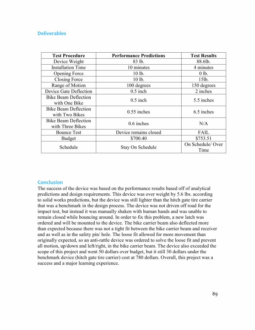
89
Deliverables
Conclusion The success of the device was based on the performance results based off of analytical predictions and design requirements. This device was over weight by 5.6 lbs. according to solid works predictions, but the device was still lighter than the hitch gate tire carrier that was a benchmark in the design process. The device was not driven off road for the impact test, but instead it was manually shaken with human hands and was unable to remain closed while bouncing around. In order to fix this problem, a new latch was ordered and will be mounted to the device. The bike carrier beam also deflected more than expected because there was not a tight fit between the bike carrier beam and receiver and as well as in the safety pin/ hole. The loose fit allowed for more movement than originally expected, so an anti-rattle device was ordered to solve the loose fit and prevent all motion, up/down and left/right, in the bike carrier beam. The device also exceeded the scope of this project and went 50 dollars over budget, but it still 30 dollars under the benchmark device (hitch gate tire carrier) cost at 780 dollars. Overall, this project was a success and a major learning experience.
Test Procedure Performance Predictions Test Results Device Weight 83 lb. 88.6lb.
Installation Time 10 minutes 4 minutes Opening Force 10 lb. 0 lb. Closing Force 10 lb. 15lb.
Range of Motion 100 degrees 150 degrees Device Gate Deflection 0.5 inch 2 inches Bike Beam Deflection
with One Bike 0.5 inch 5.5 inches Bike Beam Deflection
with Two Bikes 0.55 inches 6.5 inches Bike Beam Deflection
with Three Bikes 0.6 inches N/A Bounce Test Device remains closed FAIL
Budget $700.40 $753.51 Schedule Stay On Schedule On Schedule/ Over
Time

Lab View Front Panel: Strain Gauge Test 1
Lab View Block Diagram: Strain Gauge Test
Survey 1
90
]

Appendix I – Resume
Resume
91
Copyright © 2022 FDOKUMEN