Using CRD method for quantification of groundwater recharge in the Gaza Strip, Palestine
Upload
khangminh22Category
view
3download
0
The following pages are a "brain" dump of personal notes and copies of historic posts on Jeep KJ
CRD operation and maintenance from some 11 years of ownership. The bulk of the posts are
from the Liberty CRD...Love that Torque!!! forum. I offer these mainly because it's sometimes
hard to find old posts and when you find them sometimes the links to pictures no longer work.
Happy Jeeping.
papaindigo (a.k.a. Jim Stoutamire)
4 Wheel Drive shift cable per warp2diesel SEE ADDENDUM
Symptom - shifter feels like it's connected to nothing and it isn't because it's come loose from the transfer case shift lever due to a stupid little plastic part breaking. DCJ is their wisdom does not sell the plastic part separately so warp2diesel's fix is as follows. After considering some options, I went to ACE Hardware to get what I needed to make a clip. Then I looked in the bins and found a Stainless Steel 1/4" Axle Snap Nut for $0.35 plus $0.03 Sales Tax.
Held it on and shoved it on the rest of the way with my pry bar.
Done, but get a spare ADDENDUM - as of July 2012 the plastic bushing (68064273ab) is available for $0.63. Working in that area is pretty tight given the minimal length of shift cable available to work with. While replacement of the plastic bushing (use pliers to press bushing out of cable end; push new bushing onto stud on transfer case shift lever; and use long screwdriver to press/pry shift cable end onto new bushing) the whole process would be easier (not counting access would be much better on a lift) if one unclipped the cable housing from the retainer just forward of the transfer case shift lever. However, the cable housing is clipped into place with a plastic retaining clip that may be easily damaged so if you elect to go this route get a spare cable retaining clip (68018106aa) for $2.33. Nice that I could get out of my very helpful local dealer's parts counter for under $5 with the retaining clip, a bushing to use, and 2 spare bushings (1 for me and 1 for stoutdog or whomever)
Air box mode - V6 air box
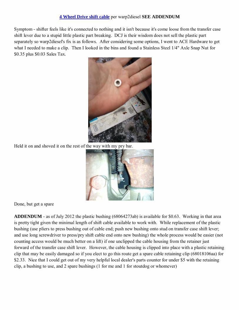
Pulling the old box out was no problem (as others have noted, just loosen the clamp holding your airbox top into the engine air duct, pull it off and set it aside, then gently pull the box bottom out). The new bottom was a bit of a pain, but only because it was hard to align the studs with the grommets in the dark. Here's the new box with the snorkel in place:
And here it is with the rain shield installed (note the stainless still screw and nylon lock nut holding it on):
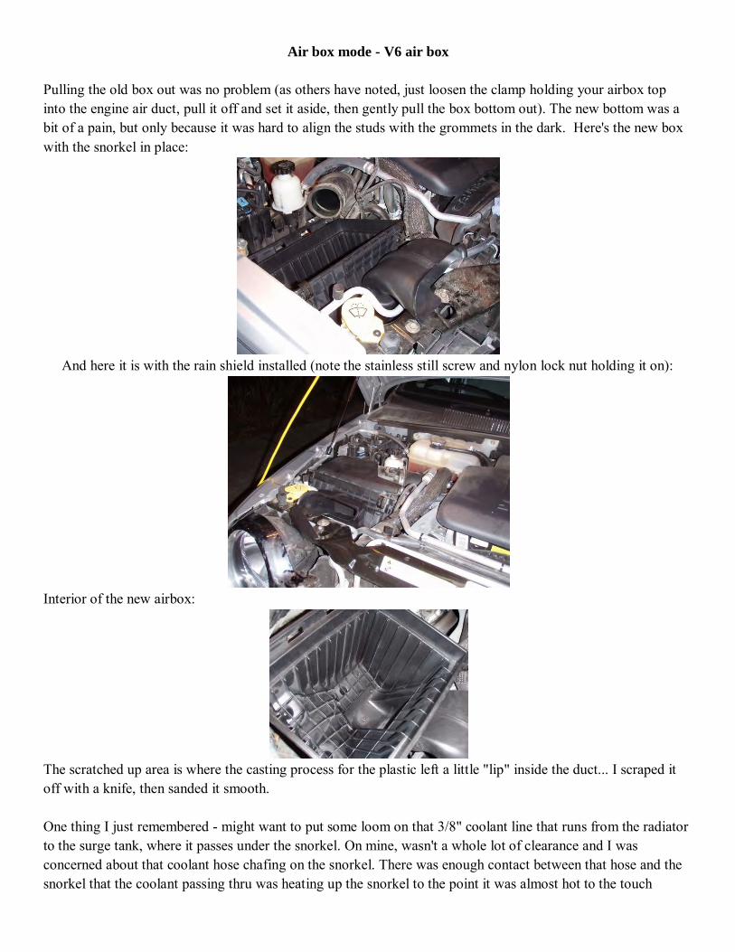
Interior of the new airbox:
The scratched up area is where the casting process for the plastic left a little "lip" inside the duct... I scraped it off with a knife, then sanded it smooth. One thing I just remembered - might want to put some loom on that 3/8" coolant line that runs from the radiator to the surge tank, where it passes under the snorkel. On mine, wasn't a whole lot of clearance and I was concerned about that coolant hose chafing on the snorkel. There was enough contact between that hose and the snorkel that the coolant passing thru was heating up the snorkel to the point it was almost hot to the touch
AC electric fan repair - turbobill
My electric fan burned out this spring. I found an OEM replacement at Moparpartsamerica.com for $284
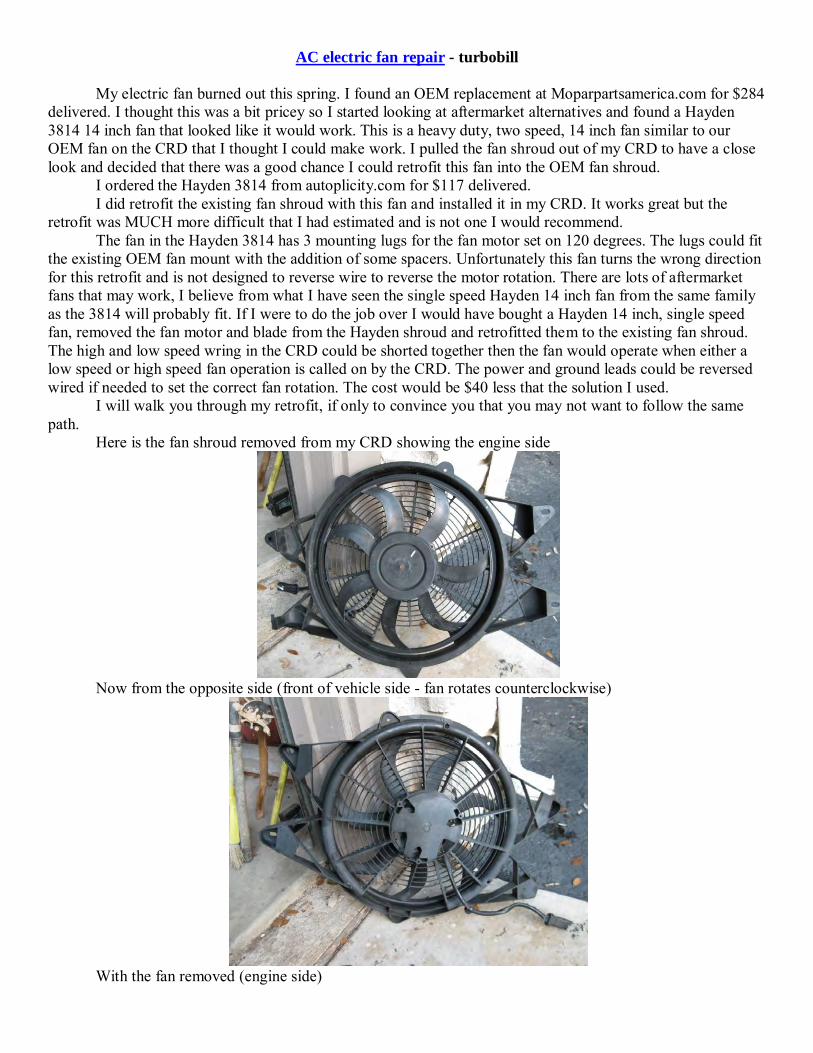
delivered. I thought this was a bit pricey so I started looking at aftermarket alternatives and found a Hayden 3814 14 inch fan that looked like it would work. This is a heavy duty, two speed, 14 inch fan similar to our OEM fan on the CRD that I thought I could make work. I pulled the fan shroud out of my CRD to have a close look and decided that there was a good chance I could retrofit this fan into the OEM fan shroud. I ordered the Hayden 3814 from autoplicity.com for $117 delivered. I did retrofit the existing fan shroud with this fan and installed it in my CRD. It works great but the retrofit was MUCH more difficult that I had estimated and is not one I would recommend. The fan in the Hayden 3814 has 3 mounting lugs for the fan motor set on 120 degrees. The lugs could fit the existing OEM fan mount with the addition of some spacers. Unfortunately this fan turns the wrong direction for this retrofit and is not designed to reverse wire to reverse the motor rotation. There are lots of aftermarket fans that may work, I believe from what I have seen the single speed Hayden 14 inch fan from the same family as the 3814 will probably fit. If I were to do the job over I would have bought a Hayden 14 inch, single speed fan, removed the fan motor and blade from the Hayden shroud and retrofitted them to the existing fan shroud. The high and low speed wring in the CRD could be shorted together then the fan would operate when either a low speed or high speed fan operation is called on by the CRD. The power and ground leads could be reversed wired if needed to set the correct fan rotation. The cost would be $40 less that the solution I used. I will walk you through my retrofit, if only to convince you that you may not want to follow the same path. Here is the fan shroud removed from my CRD showing the engine side
Now from the opposite side (front of vehicle side - fan rotates counterclockwise)
With the fan removed (engine side)

The fan (front of vehicle side). Notice the three lugs for mounting the fan
The Hayden 3814 fan. Notice the three fan lugs (white dots) on the Hayden match the OEM fan lugs but cannot be used because the fan would spin the wrong way.
The fan would fit inside the OEM fan shroud if I removed most of the Lugs from the Haden shroud and cut out the grill portion of the OEM shroud.
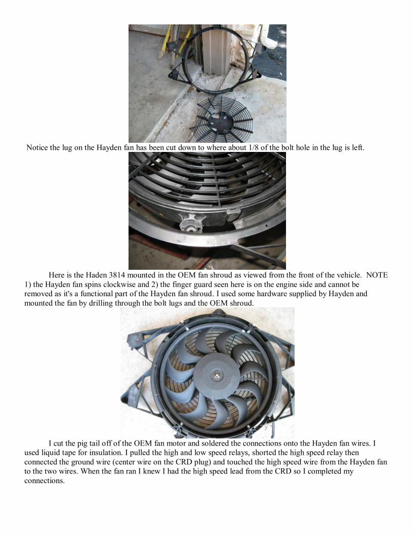
Notice the lug on the Hayden fan has been cut down to where about 1/8 of the bolt hole in the lug is left.
Here is the Haden 3814 mounted in the OEM fan shroud as viewed from the front of the vehicle. NOTE 1) the Hayden fan spins clockwise and 2) the finger guard seen here is on the engine side and cannot be removed as it's a functional part of the Hayden fan shroud. I used some hardware supplied by Hayden and mounted the fan by drilling through the bolt lugs and the OEM shroud.
I cut the pig tail off of the OEM fan motor and soldered the connections onto the Hayden fan wires. I used liquid tape for insulation. I pulled the high and low speed relays, shorted the high speed relay then connected the ground wire (center wire on the CRD plug) and touched the high speed wire from the Hayden fan to the two wires. When the fan ran I knew I had the high speed lead from the CRD so I completed my connections.

So far everything worked great. I then attempted to install the fan shroud and found that I had an interference with the hood latch hardware. I relieved this interference by cutting away a portion of the hardware and a portion of the Hayden fan shroud. The interference was overcome, but just barely (by ca. 1/8") and with more modifications than I am happy with. Here is the modified fan latch hardware and fan shroud.
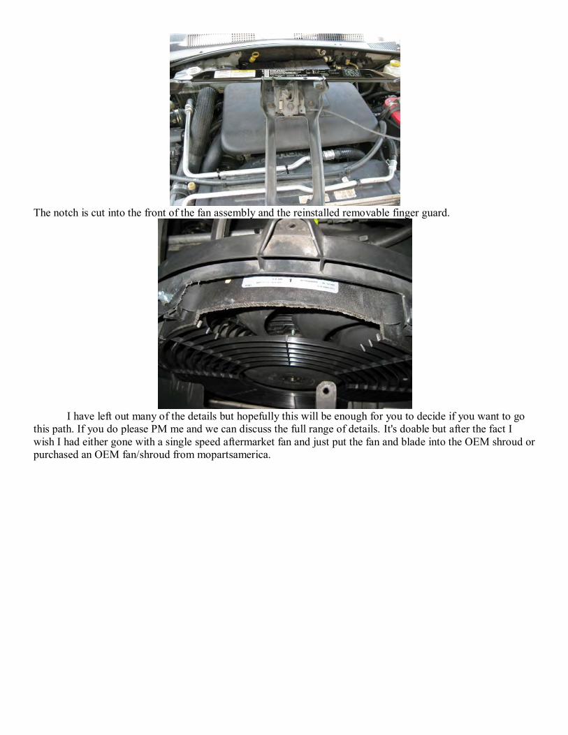
The notch is cut into the front of the fan assembly and the reinstalled removable finger guard.
I have left out many of the details but hopefully this will be enough for you to decide if you want to go this path. If you do please PM me and we can discuss the full range of details. It's doable but after the fact I wish I had either gone with a single speed aftermarket fan and just put the fan and blade into the OEM shroud or purchased an OEM fan/shroud from mopartsamerica.
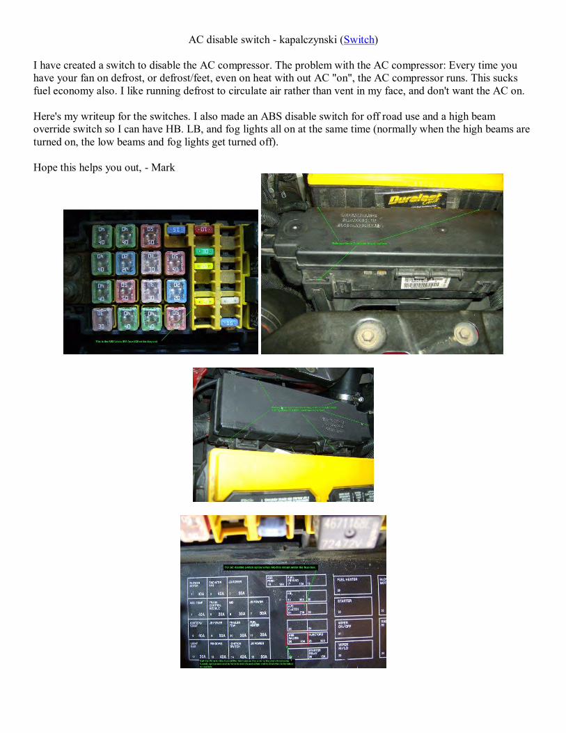
AC disable switch - kapalczynski (Switch) I have created a switch to disable the AC compressor. The problem with the AC compressor: Every time you have your fan on defrost, or defrost/feet, even on heat with out AC "on", the AC compressor runs. This sucks fuel economy also. I like running defrost to circulate air rather than vent in my face, and don't want the AC on. Here's my writeup for the switches. I also made an ABS disable switch for off road use and a high beam override switch so I can have HB. LB, and fog lights all on at the same time (normally when the high beams are turned on, the low beams and fog lights get turned off). Hope this helps you out, - Mark

AC mod by CHessMaster - (AC disable) I did mine a little different. A picture is attached so you can see if you want to do yours this way. This method has the advantage of there being nothing to wear out (like tape or plastic) and it is very easily reversible by soldering in a piece of wire where you cut. Remember, this has been done on a '06 Liberty, YMMV...

1) Remove the HVAC control head from the vehicle. Very easy to do, if you have problems with this part, stop here! 2) Remove the control head from the bezel by removing the 4 screws. 3) Remove the white cover from the back of the control head. DO NOT remove the vacuum switch attached to the back of the white cover, it will come off along with the cover just fine. There are 3 screws and about 8 snaps that you have to carefully work to remove the white cover. 3) Make 2 separate cuts in the copper strip where shown in the attached picture. I used a small pick to elevate the strips very slightly and cut them with wire cutters. Be careful not to rip the strip off the plastic attach points. I cut out a fairly large piece at each place, but it is up to you how big a chunk you want to cut out. 4) Solder an insulated wire from the post as shown on the picture, to a place just before where the connector is. Leave some room for when the white plastic cover is reinstalled. The wire shouldn't have to be a very heavy gage. I used a computer CD audio wire because of the nice cover on it. 5) Reinstall the white cover on the control unit, making sure the vacuum control valve is lined up and engaged properly. Make sure the wire that you just soldered in is not hitting any movable parts in the head, or is getting smashed into the top circuit board. 6) Reconnect all the HVAC control wiring (but not the vacuum lines) and test it's operation. You can do this without installing it onto the bezel for testing. The A/C compressor should now only come on when you press the A/C button, and not any other time. 7) If it works, reassemble the controller back into the bezel and the vehicle. If it doesn't work, check over all the steps carefully. Make sure the cuts and wire attach points look just like the picture. You can always solder your cuts closed and remove your installed wire to take it back to original operation. Just a word of warning if you do this mod. Make sure you periodically run your compressor throughout the winter months to make sure the seals in the A/C system get lubed and don't dry out!

Yesterday speeds 1 and 2 stopped working on the cabin heater/AC fan on my 06 CRD and I found this thread. Here's pictures of old (right) and new (left). I got mine at Advanced Autoparts and it's ceramic covered as mentioned. The brand is BWD and part number is RU1040 or Standard Motor Products (SMP) RU347 and is listed for a 2001-2004 Chrysler Sebring. To get to the resistor open the glove box then press inward on the latch arms on the left and right side to let it drop down further. The resistor is right there held on by two 5/16 hex head screws. You need to pull out on the red tab about 1/4" to push the release and it required some pressure to get the red tap to pull out.
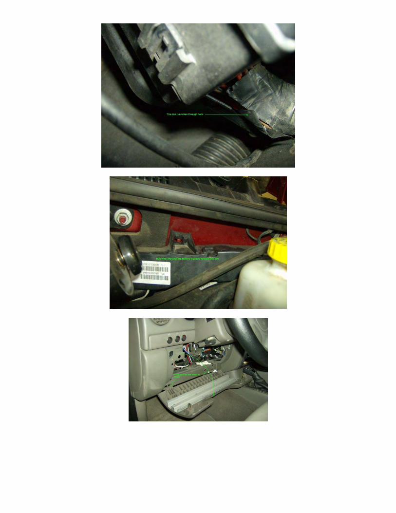
Center Console removal (02-04 should be similar for 05-06) - includes work on 4WD transmission position sensor (likely PN 5083138AA) to fix incorrect Full Time/Part Time dash light display - by
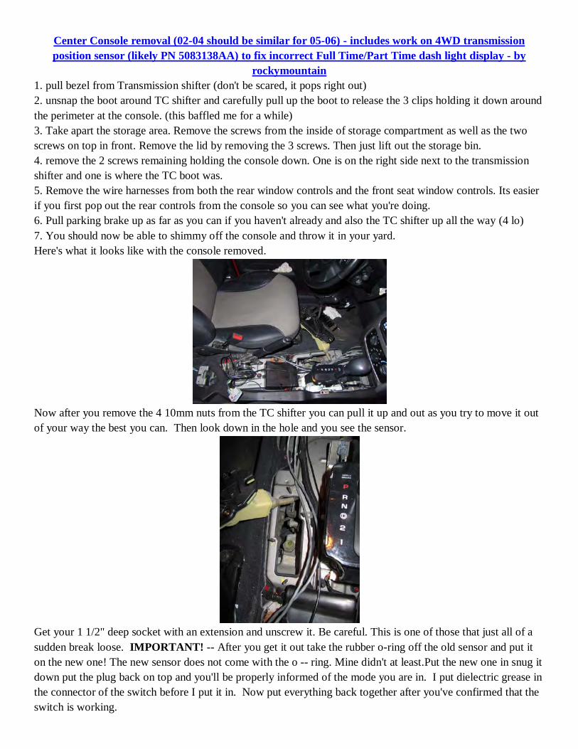
rockymountain 1. pull bezel from Transmission shifter (don't be scared, it pops right out) 2. unsnap the boot around TC shifter and carefully pull up the boot to release the 3 clips holding it down around the perimeter at the console. (this baffled me for a while) 3. Take apart the storage area. Remove the screws from the inside of storage compartment as well as the two screws on top in front. Remove the lid by removing the 3 screws. Then just lift out the storage bin. 4. remove the 2 screws remaining holding the console down. One is on the right side next to the transmission shifter and one is where the TC boot was. 5. Remove the wire harnesses from both the rear window controls and the front seat window controls. Its easier if you first pop out the rear controls from the console so you can see what you're doing. 6. Pull parking brake up as far as you can if you haven't already and also the TC shifter up all the way (4 lo) 7. You should now be able to shimmy off the console and throw it in your yard. Here's what it looks like with the console removed.
Now after you remove the 4 10mm nuts from the TC shifter you can pull it up and out as you try to move it out of your way the best you can. Then look down in the hole and you see the sensor.
Get your 1 1/2" deep socket with an extension and unscrew it. Be careful. This is one of those that just all of a sudden break loose. IMPORTANT! -- After you get it out take the rubber o-ring off the old sensor and put it on the new one! The new sensor does not come with the o -- ring. Mine didn't at least.Put the new one in snug it down put the plug back on top and you'll be properly informed of the mode you are in. I put dielectric grease in the connector of the switch before I put it in. Now put everything back together after you've confirmed that the switch is working.
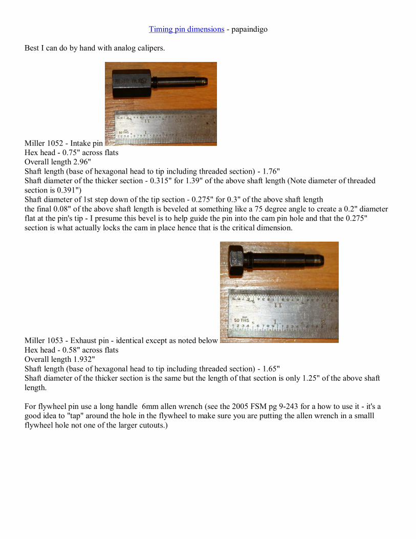
Timing pin dimensions - papaindigo Best I can do by hand with analog calipers.
Miller 1052 - Intake pin Hex head - 0.75" across flats Overall length 2.96" Shaft length (base of hexagonal head to tip including threaded section) - 1.76" Shaft diameter of the thicker section - 0.315" for 1.39" of the above shaft length (Note diameter of threaded section is 0.391") Shaft diameter of 1st step down of the tip section - 0.275" for 0.3" of the above shaft length the final 0.08" of the above shaft length is beveled at something like a 75 degree angle to create a 0.2" diameter flat at the pin's tip - I presume this bevel is to help guide the pin into the cam pin hole and that the 0.275" section is what actually locks the cam in place hence that is the critical dimension.
Miller 1053 - Exhaust pin - identical except as noted below Hex head - 0.58" across flats Overall length 1.932" Shaft length (base of hexagonal head to tip including threaded section) - 1.65" Shaft diameter of the thicker section is the same but the length of that section is only 1.25" of the above shaft length. For flywheel pin use a long handle 6mm allen wrench (see the 2005 FSM pg 9-243 for a how to use it - it's a good idea to "tap" around the hole in the flywheel to make sure you are putting the allen wrench in a smalll flywheel hole not one of the larger cutouts.)

2006 Jeep Liberty CRD timing belt/water pump change by Scott Allen Clark - Timing belt
You will need a 90 degrees after TDC pin VM.1089 and cam shaft locking pins VM.1053 and VM.1052. Or
you can make your own by grinding down bolts they don't look as nice but they work the same.
Other tools you will need.
Now let's get started first disconnect the battery
Then remove (NOTE - no real need to do this) the plastic grill. It's very easy to take it off this will keep it
from getting scratched up.

It just snaps off along the top no bolts...
After you get the top loose it just tilts out...
Set it aside some place safe...
Remove the oil cap...
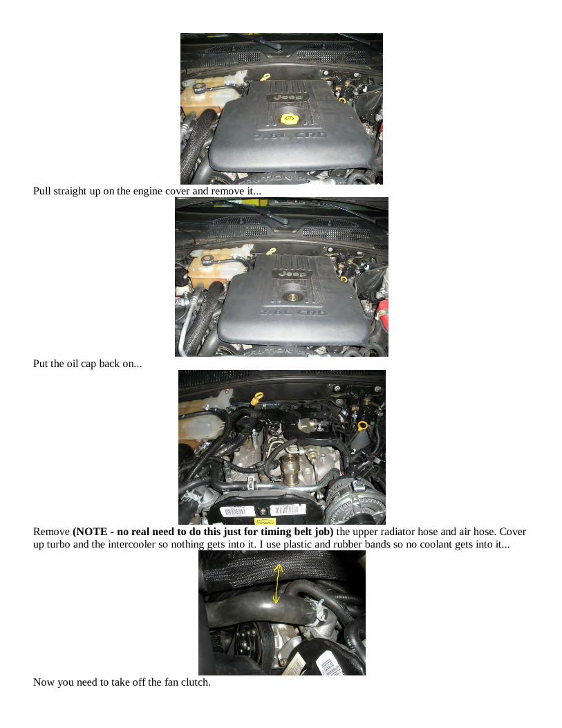
Pull straight up on the engine cover and remove it...
Put the oil cap back on...
Remove (NOTE - no real need to do this just for timing belt job) the upper radiator hose and air hose. Cover
up turbo and the intercooler so nothing gets into it. I use plastic and rubber bands so no coolant gets into it...
Now you need to take off the fan clutch.

You will need a large wrench and an Allen wrench (ca. 3/8" see below) and some kind of hammer to break it
loose.
I used a palm nailer to break it loose.
When you get it off just leave it in the shroud they have to come out together. (NOTE - probably a good idea
to put a towel between fan and radiator to prevent nicking radiator core and causing a leak)
Placement of the Allen wrench and hidden bolt behind fan pulley.
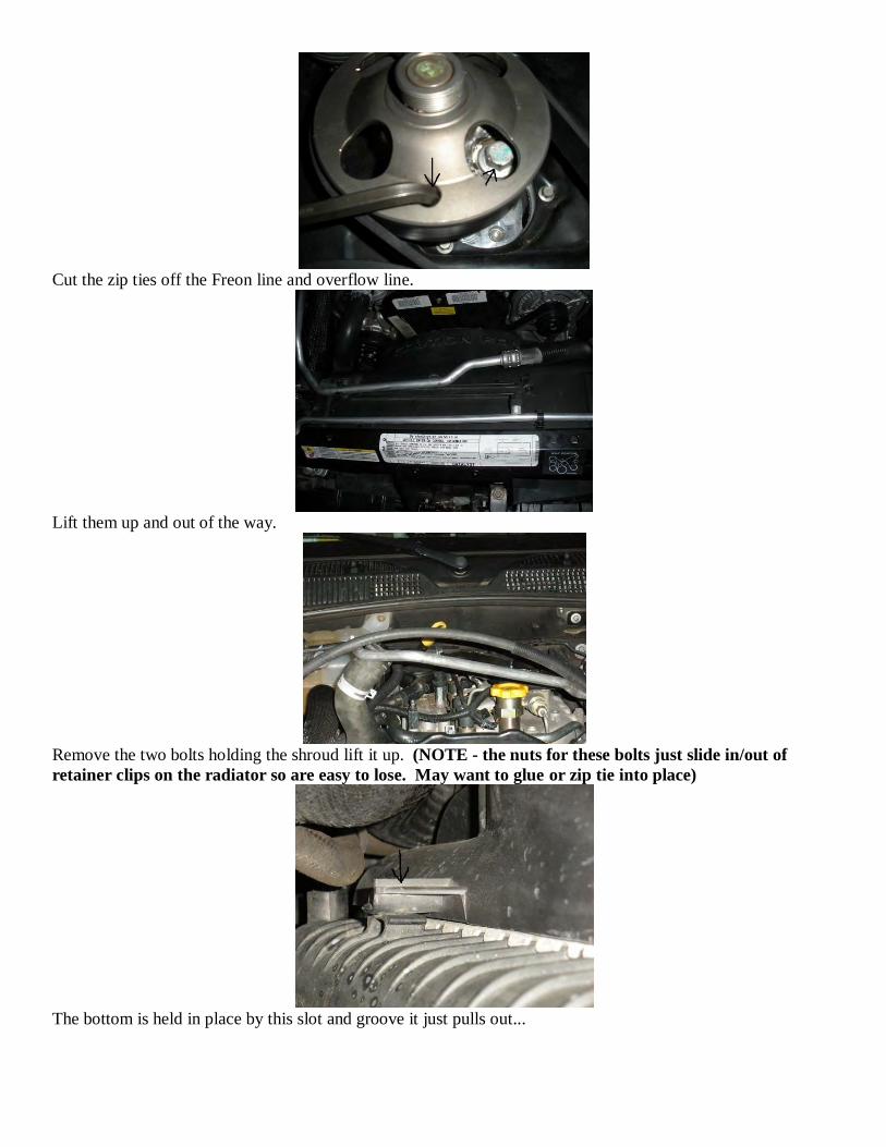
Cut the zip ties off the Freon line and overflow line.
Lift them up and out of the way.
Remove the two bolts holding the shroud lift it up. (NOTE - the nuts for these bolts just slide in/out of
retainer clips on the radiator so are easy to lose. May want to glue or zip tie into place)
The bottom is held in place by this slot and groove it just pulls out...
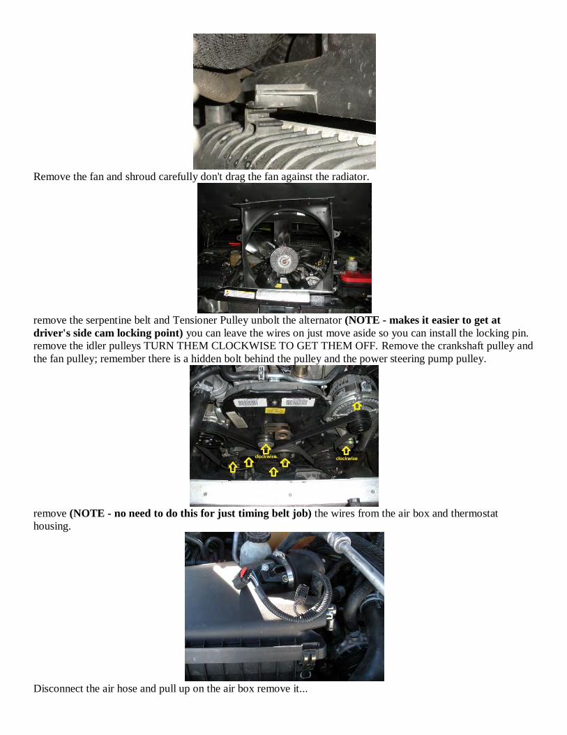
Remove the fan and shroud carefully don't drag the fan against the radiator.
remove the serpentine belt and Tensioner Pulley unbolt the alternator (NOTE - makes it easier to get at
driver's side cam locking point) you can leave the wires on just move aside so you can install the locking pin.
remove the idler pulleys TURN THEM CLOCKWISE TO GET THEM OFF. Remove the crankshaft pulley and
the fan pulley; remember there is a hidden bolt behind the pulley and the power steering pump pulley.
remove (NOTE - no need to do this for just timing belt job) the wires from the air box and thermostat
housing.
Disconnect the air hose and pull up on the air box remove it...
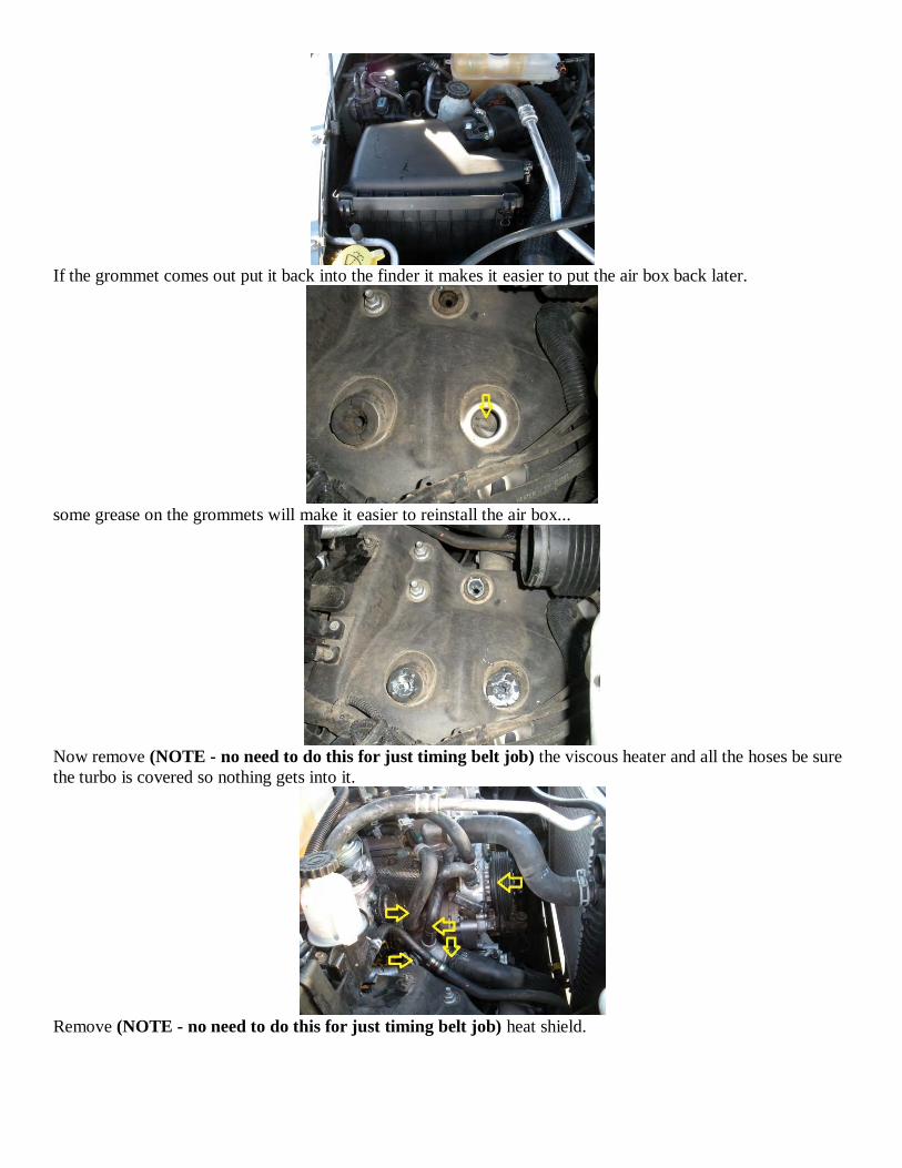
If the grommet comes out put it back into the finder it makes it easier to put the air box back later.
some grease on the grommets will make it easier to reinstall the air box...
Now remove (NOTE - no need to do this for just timing belt job) the viscous heater and all the hoses be sure
the turbo is covered so nothing gets into it.
Remove (NOTE - no need to do this for just timing belt job) heat shield.

After all the coolant is drained (NOTE - no need to do this for just timing belt job) from the hoses you can
remove the outer timing belt cover.
Find and remove the plugs in the valve cover. I had to use vice grips to break them loose the Allen wrench was
striping out.
Turn the engine clockwise only.
Remove the oil cap.
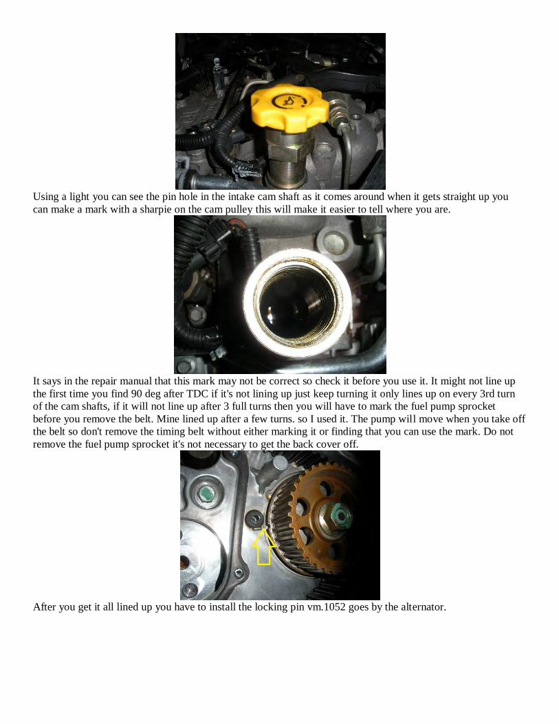
Using a light you can see the pin hole in the intake cam shaft as it comes around when it gets straight up you
can make a mark with a sharpie on the cam pulley this will make it easier to tell where you are.
It says in the repair manual that this mark may not be correct so check it before you use it. It might not line up
the first time you find 90 deg after TDC if it's not lining up just keep turning it only lines up on every 3rd turn
of the cam shafts, if it will not line up after 3 full turns then you will have to mark the fuel pump sprocket
before you remove the belt. Mine lined up after a few turns. so I used it. The pump will move when you take off
the belt so don't remove the timing belt without either marking it or finding that you can use the mark. Do not
remove the fuel pump sprocket it's not necessary to get the back cover off.
After you get it all lined up you have to install the locking pin vm.1052 goes by the alternator.
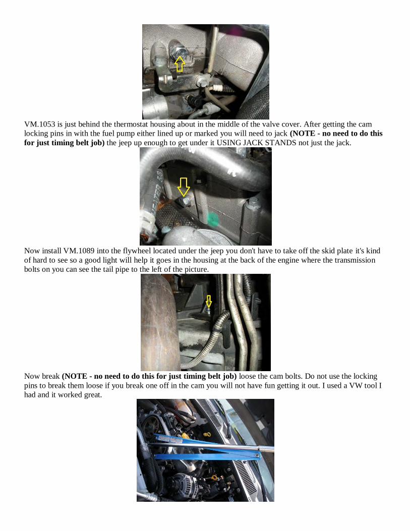
VM.1053 is just behind the thermostat housing about in the middle of the valve cover. After getting the cam
locking pins in with the fuel pump either lined up or marked you will need to jack (NOTE - no need to do this
for just timing belt job) the jeep up enough to get under it USING JACK STANDS not just the jack.
Now install VM.1089 into the flywheel located under the jeep you don't have to take off the skid plate it's kind
of hard to see so a good light will help it goes in the housing at the back of the engine where the transmission
bolts on you can see the tail pipe to the left of the picture.
Now break (NOTE - no need to do this for just timing belt job) loose the cam bolts. Do not use the locking
pins to break them loose if you break one off in the cam you will not have fun getting it out. I used a VW tool I
had and it worked great.

Just loosen up the bolts don't take them off yet.
Now remove the bolt on the tensioner and the tensioner then the timing belt and the cam sprockets and the two
idler pulleys TURN THEM CLOCKWISE TO REMOVE THEM. NOTE: the next picture shows the cam
ends with the sprockets removed. Notice the 2 notches in those cam ends that face each other with the
engine in time, same notches in same postion show in a picture from Eugene Buford who confirms that
his picture was taken with the 2 cam pins and the flywheel pin installed.
Remove the back cover.
These bolts are hard to see from above.

This one you can't see from above it's by the tensioner you will have to find it by feel.
Now on to the water pump...
You have to remove 4 nuts to get it off 3 are easy. If someone has a tool that can reach the nut with the red
arrow I will update this but for now here is how I did it...The top nut you can get with a socket. But the bottom
nut I had to use a flex gear wrench and an adjustable wrench to get it off.
The gear wrench was not strong enough though so it is slightly bent now but it did get the nut off.

The two on the front look like you could get them with an open end wrench but the nuts just started to round off
so it took a different approach.
So I just took the pump apart and then I had access to get them off with a 6 point socket. Replace the nuts with
new ones and clean the old gasket off. I use copper cote when reassembling on gaskets and hoses. If I was not
replacing the hoses then it would be easier to just take the new pump apart and bolt the front of the new one
onto the back of the old one. It would be nice if they sold just the front half with a new gasket I am not sure if
the gasket would work after the new pump was taken apart all of the moving parts are in the front half so it
would be just like replacing the whole thing. next time I will try to find that gasket and if I can then I will leave
the back on and all the hoses would not have to come off and the air box and air hoses could stay in place...
This hose is under the water pump and would be very hard to replace without taking out the pump so even if
you don't replace all the hoses you should get this one is a cheap hose and it would be a lot of work to replace it
later.
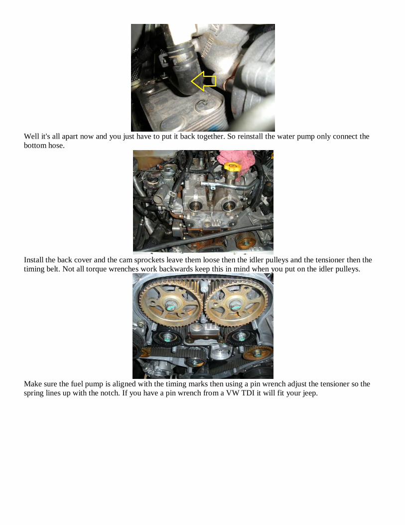
Well it's all apart now and you just have to put it back together. So reinstall the water pump only connect the
bottom hose.
Install the back cover and the cam sprockets leave them loose then the idler pulleys and the tensioner then the
timing belt. Not all torque wrenches work backwards keep this in mind when you put on the idler pulleys.
Make sure the fuel pump is aligned with the timing marks then using a pin wrench adjust the tensioner so the
spring lines up with the notch. If you have a pin wrench from a VW TDI it will fit your jeep.
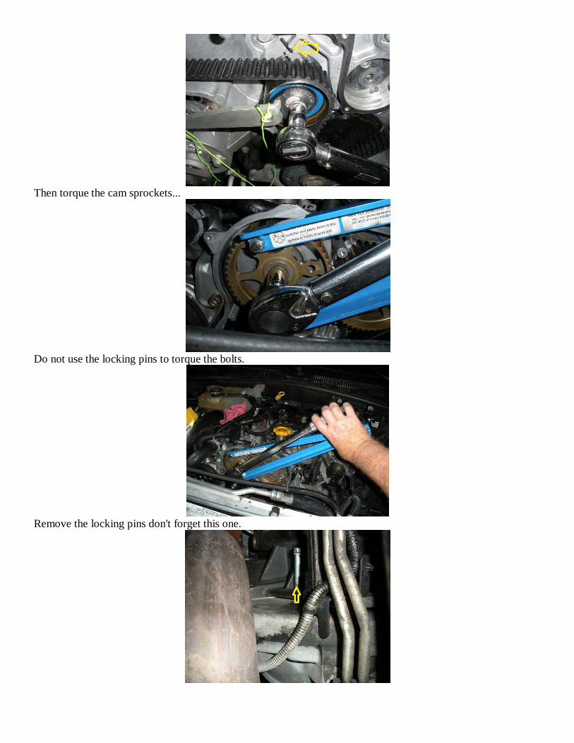
Then torque the cam sprockets...
Do not use the locking pins to torque the bolts.
Remove the locking pins don't forget this one.
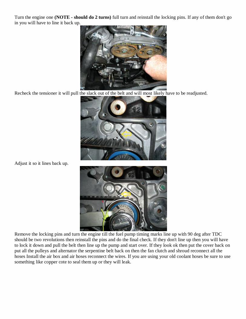
Turn the engine one (NOTE - should do 2 turns) full turn and reinstall the locking pins. If any of them don't go
in you will have to line it back up.
Recheck the tensioner it will pull the slack out of the belt and will most likely have to be readjusted.
Adjust it so it lines back up.
Remove the locking pins and turn the engine till the fuel pump timing marks line up with 90 deg after TDC
should be two revolutions then reinstall the pins and do the final check. If they don't line up then you will have
to lock it down and pull the belt then line up the pump and start over. If they look ok then put the cover back on
put all the pulleys and alternator the serpentine belt back on then the fan clutch and shroud reconnect all the
hoses Install the air box and air hoses reconnect the wires. If you are using your old coolant hoses be sure to use
something like copper cote to seal them up or they will leak.
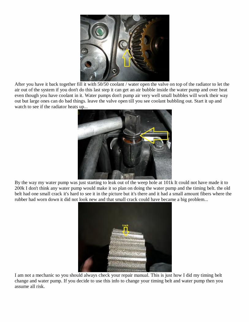
After you have it back together fill it with 50/50 coolant / water open the valve on top of the radiator to let the
air out of the system if you don't do this last step it can get an air bubble inside the water pump and over heat
even though you have coolant in it. Water pumps don't pump air very well small bubbles will work their way
out but large ones can do bad things. leave the valve open till you see coolant bubbling out. Start it up and
watch to see if the radiator heats up...
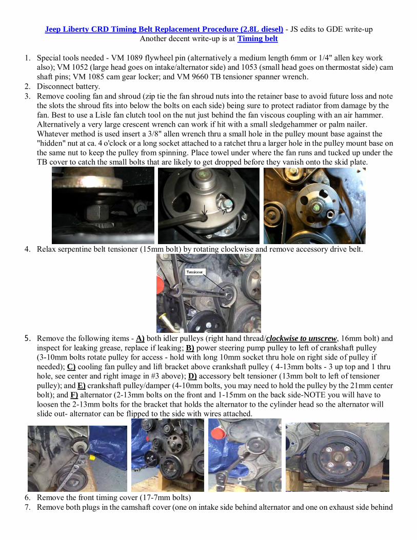
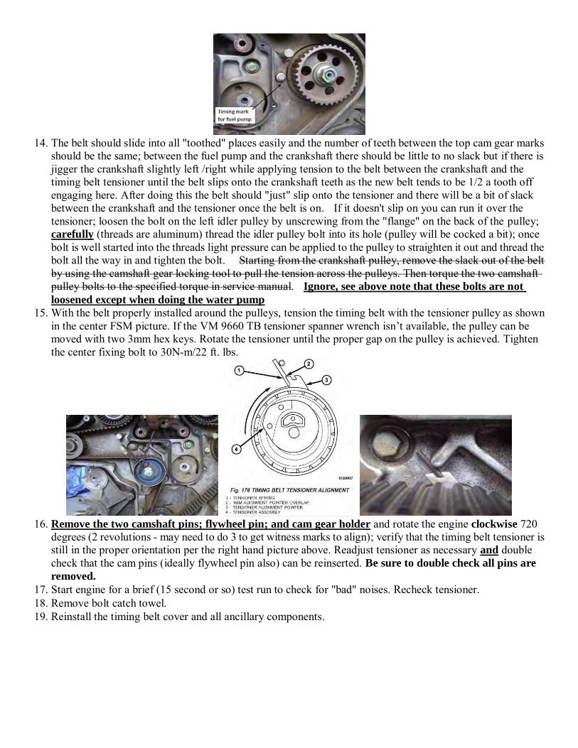
By the way my water pump was just starting to leak out of the weep hole at 101k It could not have made it to
200k I don't think any water pump would make it so plan on doing the water pump and the timing belt. the old
belt had one small crack it's hard to see it in the picture but it's there and it had a small amount fibers where the
rubber had worn down it did not look new and that small crack could have became a big problem...
I am not a mechanic so you should always check your repair manual. This is just how I did my timing belt
change and water pump. If you decide to use this info to change your timing belt and water pump then you
assume all risk.
Jeep Liberty CRD Timing Belt Replacement Procedure (2.8L diesel) - JS edits to GDE write-up Another decent write-up is at Timing belt
1. Special tools needed - VM 1089 flywheel pin (alternatively a medium length 6mm or 1/4" allen key work
also); VM 1052 (large head goes on intake/alternator side) and 1053 (small head goes on thermostat side) cam shaft pins; VM 1085 cam gear locker; and VM 9660 TB tensioner spanner wrench.
2. Disconnect battery. 3. Remove cooling fan and shroud (zip tie the fan shroud nuts into the retainer base to avoid future loss and note
the slots the shroud fits into below the bolts on each side) being sure to protect radiator from damage by the fan. Best to use a Lisle fan clutch tool on the nut just behind the fan viscous coupling with an air hammer. Alternatively a very large crescent wrench can work if hit with a small sledgehammer or palm nailer. Whatever method is used insert a 3/8" allen wrench thru a small hole in the pulley mount base against the "hidden" nut at ca. 4 o'clock or a long socket attached to a ratchet thru a larger hole in the pulley mount base on the same nut to keep the pulley from spinning. Place towel under where the fan runs and tucked up under the TB cover to catch the small bolts that are likely to get dropped before they vanish onto the skid plate.
4. Relax serpentine belt tensioner (15mm bolt) by rotating clockwise and remove accessory drive belt.
5. Remove the following items - A) both idler pulleys (right hand thread/clockwise to unscrew, 16mm bolt) and
inspect for leaking grease, replace if leaking; B) power steering pump pulley to left of crankshaft pulley (3-10mm bolts rotate pulley for access - hold with long 10mm socket thru hole on right side of pulley if needed); C) cooling fan pulley and lift bracket above crankshaft pulley ( 4-13mm bolts - 3 up top and 1 thru hole, see center and right image in #3 above); D) accessory belt tensioner (13mm bolt to left of tensioner pulley); and E) crankshaft pulley/damper (4-10mm bolts, you may need to hold the pulley by the 21mm center bolt); and F) alternator (2-13mm bolts on the front and 1-15mm on the back side-NOTE you will have to loosen the 2-13mm bolts for the bracket that holds the alternator to the cylinder head so the alternator will slide out- alternator can be flipped to the side with wires attached.
6. Remove the front timing cover (17-7mm bolts) 7. Remove both plugs in the camshaft cover (one on intake side behind alternator and one on exhaust side behind

thermostat area). Remove the plugs with a 5mm hex or vice grips if hex is rounded. 8. Rotate the engine clockwise only with a 21mm socket on the front of the crankshaft (see image in #9 below)
until a 6mm or 1/4" hex key engages the hole in the flex plate/flywheel; when using a hex key be sure to "tap" surface of the flywheel around the hole to make sure the hex key is being inserted into the small flywheel hole not a larger cutout. NOTE: you can also see the intake cam pin hole coming into place by looking down the oil filler hole.
9. Inspect the two openings in the camshaft cover to see if the holes in the camshafts align. If so, install the two
cam pins into the respective camshaft - VM 1052 (large head goes on intake/alternator side) and 1053 (small head goes on thermostat side). If not, remove flywheel pin rotate the engine 360 degrees at the crankshaft and re-inspect and install cam pins and reinstall flywheel pin. NOTE: the bolt holes on the crankshaft for the damper should align at 12/3/6/9 o'clock and the dimple/witness mark should be at 3 o'clock. Install cam gear locking tool. Add witness marks with a marking pen to 2 opposing cam gear teeth; an upper tooth on each cam gear and the adjacent housing; and a fuel pump tooth and adjacent housing and count the number of belt teeth between top cam gear marks.
10. Loosen the timing belt tensioner (remember it's likely that the tension bolt threads into a helicoiled hole so
don't loosen the bolt too much) and rotate counterclockwise by hand until slack is sufficient to remove the belt from the pulley. Remove the old timing belt; discard when the refitting operating is completed successfully.
11. Loosen both camshaft pulleys by rotating the bolt (17mm) counterclockwise. It is sufficient to have them loose; they do not need to be removed. Ideally do this although it's not critical - ASSUMES ENGINE IS
CORRECTLY TIMED WHEN WORK STARTS 12. See if the fuel pump pulley lines up with its timing mark - this is not critical as it only aligns every 3 or maybe
6 engine revolutions. However, the fuel pump pulley must be kept in alignment with the witness marks as the new belt is installed. NOTE - "timing" the fuel pump is probably desirable so options a) if it's in the same position relative to the timing belt as when it left the factory keep it in that position (what we did on my 05 and Williams 06) or b) when installing a new timing belt with pins in then line the marks up (see #14) which also works if you are dealing with an out of time engine.
13. Check the 2 idlers for leaking grease and replace if any is found. Right hand thread/clockwise to unscrew.
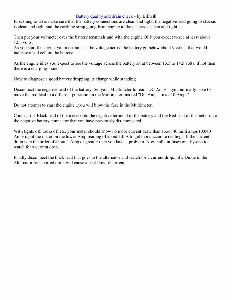
14. The belt should slide into all "toothed" places easily and the number of teeth between the top cam gear marks
should be the same; between the fuel pump and the crankshaft there should be little to no slack but if there is jigger the crankshaft slightly left /right while applying tension to the belt between the crankshaft and the timing belt tensioner until the belt slips onto the crankshaft teeth as the new belt tends to be 1/2 a tooth off engaging here. After doing this the belt should "just" slip onto the tensioner and there will be a bit of slack between the crankshaft and the tensioner once the belt is on. If it doesn't slip on you can run it over the tensioner; loosen the bolt on the left idler pulley by unscrewing from the "flange" on the back of the pulley; carefully (threads are aluminum) thread the idler pulley bolt into its hole (pulley will be cocked a bit); once bolt is well started into the threads light pressure can be applied to the pulley to straighten it out and thread the bolt all the way in and tighten the bolt. Starting from the crankshaft pulley, remove the slack out of the belt by using the camshaft gear locking tool to pull the tension across the pulleys. Then torque the two camshaft pulley bolts to the specified torque in service manual. Ignore, see above note that these bolts are not
loosened except when doing the water pump 15. With the belt properly installed around the pulleys, tension the timing belt with the tensioner pulley as shown
in the center FSM picture. If the VM 9660 TB tensioner spanner wrench isn’t available, the pulley can be moved with two 3mm hex keys. Rotate the tensioner until the proper gap on the pulley is achieved. Tighten the center fixing bolt to 30N-m/22 ft. lbs.
16. Remove the two camshaft pins; flywheel pin; and cam gear holder and rotate the engine clockwise 720
degrees (2 revolutions - may need to do 3 to get witness marks to align); verify that the timing belt tensioner is still in the proper orientation per the right hand picture above. Readjust tensioner as necessary and double check that the cam pins (ideally flywheel pin also) can be reinserted. Be sure to double check all pins are
removed. 17. Start engine for a brief (15 second or so) test run to check for "bad" noises. Recheck tensioner. 18. Remove bolt catch towel. 19. Reinstall the timing belt cover and all ancillary components.

Water pump removal tip from msilbernagel - Water pump removal
NOTE - if one really wants to do this that's fine but it's much easier to simply replace the
front 1/2 of the water pump as that's where all the WP moving parts are located.
Pulled the last trouble-maker today (water pump), that little bastard can be quite the bear to
remove. Turns out, it's a lot easier if you pull the item on the left (three holes) that bolts to the
back of the pump - clearing the way to reach the back two 13MM nuts/studs that attach the pump
to the block.
The three bolts on back, securing the manifold to the pump, are 8mm - and a 1/4 inch ratchet,
universal joint, and 8mm 6-point socket worked well enough to pull them. Used a short
extension to get a good angle on the top-rear bolt. Took a little juggling to get the right angles.
I'd left the hose to the oil cooler connected on the bottom - if I'd pulled it the bottom bolt
would've been easier to reach.
Tried to find a way to reach the 13mm nuts without pulling that back piece. I think the only
alternative there would've been to remove the bolts on the front of the pump itself and put the
new front w/impeller on the old back. It's got an o-ring so I think that'd save a lot of grief if you
were brave enough to try.
Battery quality and drain check - by Billwill First thing to do is make sure that the battery connections are clean and tight, the negative lead going to chassis is clean and tight and the earthing strap going from engine to the chassis is clean and tight! Then put your voltmeter over the battery terminals and with the engine OFF you expect to see at least about 12.5 volts. As you start the engine you must not see the voltage across the battery go below about 9 volts...that would indicate a bad cell on the battery. As the engine idles you expect to see the voltage across the battery sit at between 13.5 to 14.5 volts..if not then there is a charging issue. Now to diagnose a good battery dropping its charge while standing. Disconnect the negative lead of the battery. Set your MUltimeter to read "DC Amps"...you normally have to move the red lead to a different possition on the Multimeter marked "DC Amps...max 10 Amps" Do not attempt to start the engine...you will blow the fuse in the Multimeter. Connect the Black lead of the meter onto the negative terminal of the battery and the Red lead of the meter onto the negative battery connector that you have previously dis-connected. With lights off, radio off etc. your meter should show no more current draw than about 40 milli amps (0.040 Amps)..put the meter on the lower Amp reading of about 1.0 A to get more accurate readings. If the current drain is in the order of about 1 Amp or greater then you have a problem. Now pull out fuses one-by-one to watch for a current drop. Finally disconnect the thick lead that goes to the alternator and watch for a current drop....if a Diode in the Alternator has shorted out it will cause a backflow of current.
ARP one at a time stud upgrade per "geordi" Facebook post
As far as doing the studs one-at-a-time without disturbing the rest of the head gasket, this is the preferred method because there is less to worry about as far as procedure. The order in which you do the studs is unimportant if the rest of the bolts are still locked down. To do so: Remove a bolt of your choice. Use the ARP lube on the top 5-8 fine threads of the stud, on the inside of the nut, and on both faces of the washer and nut shoulders. You don't have to be juicy with it, but give it a decent coating. USE NOTHING ON THE WIDE THREADS. Assemble the stud and washer and nut with the nut flush to the top of the stud, and thread the assembly thru the head into the block hand tight with a hex driver, nut should remain flush to the top of the stud. Go to town with your torque wrench, you DO NOT need to do it in stages, ARP has approved the process of a one-step to full torque when the one-at-a-time procedure is done. Torque is 130 ft-lbs for the center rows, and 120 ft-lbs for the outer rows. Lather, rinse, and repeat for each of the remaining bolts.
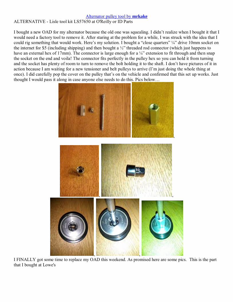
Alternator pulley tool by mrkake ALTERNATIVE - Lisle tool kit LS57650 at O'Reilly or ID Parts I bought a new OAD for my alternator because the old one was squealing. I didn’t realize when I bought it that I would need a factory tool to remove it. After staring at the problem for a while, I was struck with the idea that I could rig something that would work. Here’s my solution. I bought a “close quarters” ¼” drive 10mm socket on the internet for $5 (including shipping) and then bought a ½” threaded rod connector (which just happens to have an external hex of 17mm). The connector is large enough for a ¼” extension to fit through and then snap the socket on the end and voila! The connector fits perfectly in the pulley hex so you can hold it from turning and the socket has plenty of room to turn to remove the bolt holding it to the shaft. I don’t have pictures of it in action because I am waiting for a new tensioner and belt pulleys to arrive (I’m just doing the whole thing at once). I did carefully pop the cover on the pulley that’s on the vehicle and confirmed that this set up works. Just thought I would pass it along in case anyone else needs to do this. Pics below…
,
, ,
, , I FINALLY got some time to replace my OAD this weekend. As promised here are some pics. This is the part that I bought at Lowe's
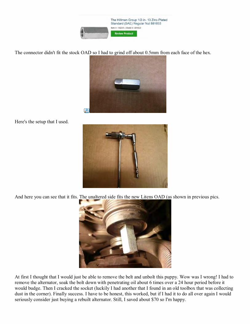
The connector didn't fit the stock OAD so I had to grind off about 0.5mm from each face of the hex.
Here's the setup that I used.
And here you can see that it fits. The unaltered side fits the new Litens OAD (as shown in previous pics.
At first I thought that I would just be able to remove the belt and unbolt this puppy. Wow was I wrong! I had to remove the alternator, soak the bolt down with penetrating oil about 6 times over a 24 hour period before it would budge. Then I cracked the socket (luckily I had another that I found in an old toolbox that was collecting dust in the corner). Finally success. I have to be honest, this worked, but if I had it to do all over again I would seriously consider just buying a rebuilt alternator. Still, I saved about $70 so I'm happy.
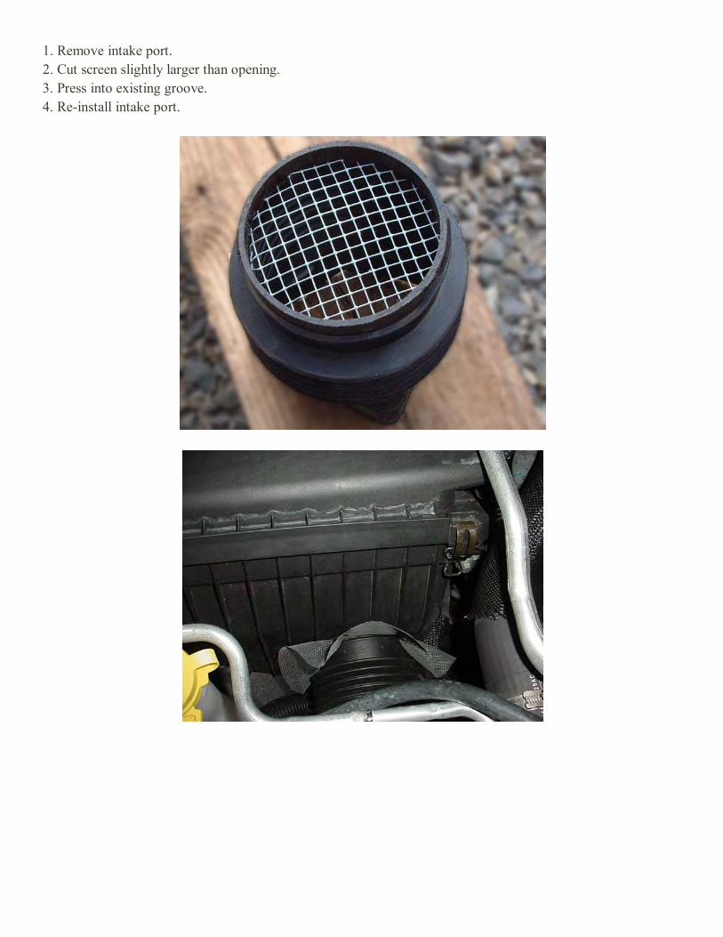
1. Remove intake port. 2. Cut screen slightly larger than opening. 3. Press into existing groove. 4. Re-install intake port.
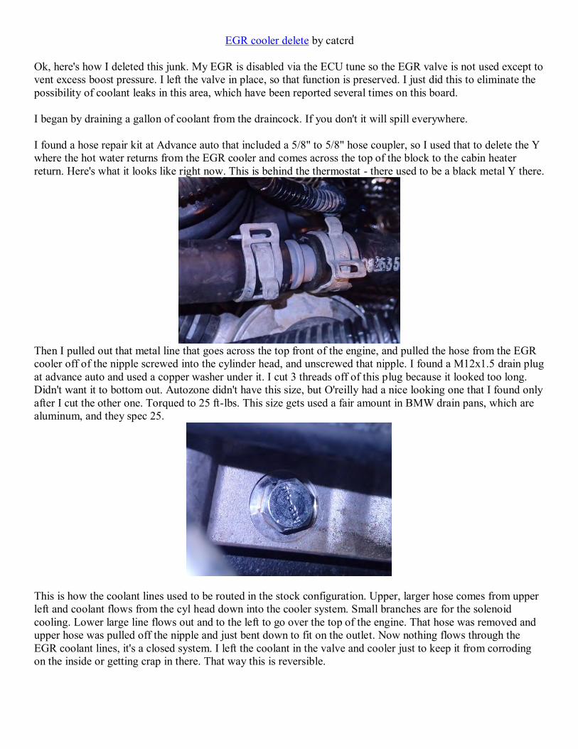
EGR cooler delete by catcrd Ok, here's how I deleted this junk. My EGR is disabled via the ECU tune so the EGR valve is not used except to vent excess boost pressure. I left the valve in place, so that function is preserved. I just did this to eliminate the possibility of coolant leaks in this area, which have been reported several times on this board. I began by draining a gallon of coolant from the draincock. If you don't it will spill everywhere. I found a hose repair kit at Advance auto that included a 5/8" to 5/8" hose coupler, so I used that to delete the Y where the hot water returns from the EGR cooler and comes across the top of the block to the cabin heater return. Here's what it looks like right now. This is behind the thermostat - there used to be a black metal Y there.
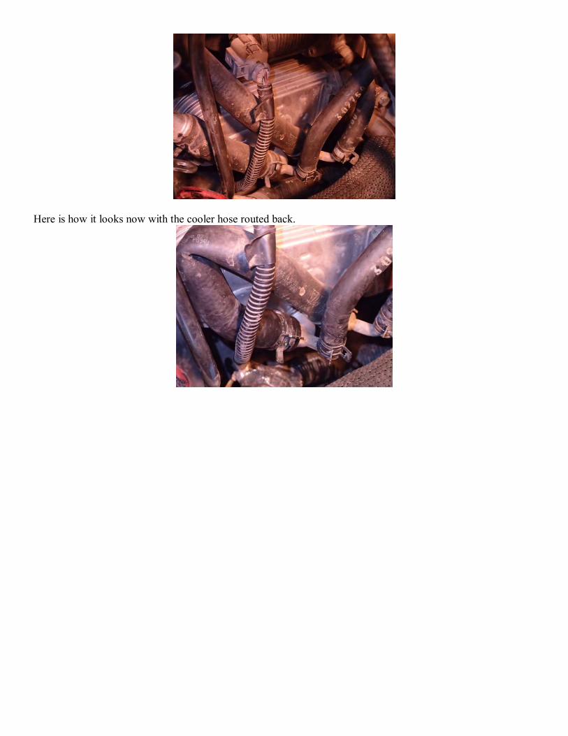
Then I pulled out that metal line that goes across the top front of the engine, and pulled the hose from the EGR cooler off of the nipple screwed into the cylinder head, and unscrewed that nipple. I found a M12x1.5 drain plug at advance auto and used a copper washer under it. I cut 3 threads off of this plug because it looked too long. Didn't want it to bottom out. Autozone didn't have this size, but O'reilly had a nice looking one that I found only after I cut the other one. Torqued to 25 ft-lbs. This size gets used a fair amount in BMW drain pans, which are aluminum, and they spec 25.
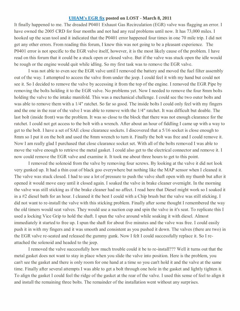
This is how the coolant lines used to be routed in the stock configuration. Upper, larger hose comes from upper left and coolant flows from the cyl head down into the cooler system. Small branches are for the solenoid cooling. Lower large line flows out and to the left to go over the top of the engine. That hose was removed and upper hose was pulled off the nipple and just bent down to fit on the outlet. Now nothing flows through the EGR coolant lines, it's a closed system. I left the coolant in the valve and cooler just to keep it from corroding on the inside or getting crap in there. That way this is reversible.
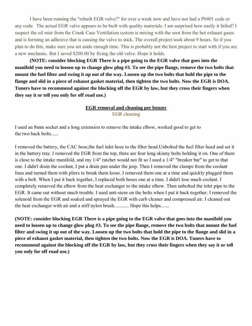
Here is how it looks now with the cooler hose routed back.
UHAM's EGR fix posted on LOST - March 8, 2011
It finally happened to me. The dreaded P0401 Exhaust Gas Recirculation (EGR) valve was flagging an error. I have owned the 2005 CRD for four months and not had any real problems until now. It has 73,000 miles. I hooked up the scan tool and it indicated that the P0401 error happened four times in one 70 mile trip. I did not get any other errors. From reading this forum, I knew this was not going to be a pleasant experience. The P0401 error is not specific to the EGR valve itself, however, it is the most likely cause of the problem. I have read on this forum that it could be a stuck open or closed valve. But if the valve was stuck open the idle would be rough or the engine would quit while idling. So my first task was to remove the EGR valve. I was not able to even see the EGR valve until I removed the battery and moved the fuel filter assembly out of the way. I attempted to access the valve from under the jeep. I could feel it with my hand but could not see it. So I decided to remove the valve by accessing it from the top of the engine. I removed the EGR Pipe by removing the bolts holding it to the EGR valve. No problems yet. Now I needed to remove the four 8mm bolts holding the valve to the intake manifold. This was a mechanical challenge. I could see the two outer bolts and was able to remove them with a 1/4" ratchet. So far so good. The inside bolts I could only feel with my fingers and the one in the rear of the valve I was able to remove with the 1/4" ratchet. It was difficult but doable. The last bolt (inside front) was the problem. It was so close to the block that there was not enough clearance for the ratchet. I could not get access to the bolt with a wrench. After about an hour of fiddling I came up with a way to get to the bolt. I have a set of SAE close clearance sockets. I discovered that a 5/16 socket is close enough to 8mm so I put it on the bolt and used the 8mm wrench to turn it. Finally the bolt was free and I could remove it. Now I am really glad I purchased that close clearance socket set. With all of the bolts removed I was able to move the valve enough to retrieve the metal gasket. I could also get to the electrical connector and remove it. I now could remove the EGR valve and examine it. It took me about three hours to get to this point. I removed the solenoid from the valve by removing four screws. By looking at the valve it did not look very gunked up. It had a thin coat of black goo everywhere but nothing like the MAP sensor when I cleaned it. The valve was stuck closed. I had to use a lot of pressure to push the valve shaft open with my thumb but after it opened it would move easy until it closed again. I soaked the valve in brake cleaner overnight. In the morning the valve was still sticking as if the brake cleaner had no affect. I read here that Diesel might work so I soaked it in a #2 diesel bath for an hour. I cleaned it the best I could with a Chip brush but the valve was still sticking. I did not want to re-install the valve with this sticking problem. Finally after some thought I remembered the way the old timers would seat valves. They would use a suction cup and spin the valve in it's seat. To replicate this I used a locking Vice Grip to hold the shaft. I spun the valve around while soaking it with diesel. Almost immediately it started to free up. I spun the shaft for about five minutes and the valve was free. I could easily push it in with my fingers and it was smooth and consistent as you pushed it down. The valves (there are two) in the EGR valve re-seated and released the gummy gunk. Now I felt I could successfully replace it. So I re-attached the solenoid and headed to the jeep. I removed the valve successfully how much trouble could it be to re-install??? Well it turns out that the metal gasket does not want to stay in place when you slide the valve into position. Here is the problem, you can't see the gasket and there is only room for one hand at a time so you can't hold it and the valve at the same time. Finally after several attempts I was able to get a bolt through one hole in the gasket and lightly tighten it. To align the gasket I could feel the ridge of the gasket at the rear of the valve. I used this sense of feel to align it and install the remaining three bolts. The remainder of the installation went without any surprises.
I have been running the "rebuilt EGR valve?" for over a week now and have not had a P0401 code or any code. The actual EGR valve appears to be built with quality materials. I am surprised how easily it failed? I suspect the oil mist from the Crank Case Ventilation system is mixing with the soot from the hot exhaust gases and is forming an adhesive that is causing the valve to stick. The overall project took about 9 hours. So if you plan to do this, make sure you set aside enough time. This is probably not the best project to start with if you are a new mechanic. But I saved $200.00 by fixing the old valve. Hope it holds.
(NOTE: consider blocking EGR There is a pipe going to the EGR valve that goes into the
manifold you need to loosen up to change glow plug #3. To see the pipe flange, remove the two bolts that
mount the fuel filter and swing it up out of the way. Loosen up the two bolts that hold the pipe to the
flange and slid in a piece of exhaust gasket material, then tighten the two bolts. Now the EGR is DOA.
Tuners have to recommend against the blocking off the EGR by law, but they cross their fingers when
they say it or tell you only for off road use.)
EGR removal and cleaning per benzer
EGR cleaning I used an 8mm socket and a long extension to remove the intake elbow, worked good to get to the two back bolts...... I removed the battery, the CAC hose,the fuel inlet hose to the filter head.Unbolted the fuel filter head and set it in the battery tray. I removed the EGR from the top, there are four long skinny bolts holding it on. One of them is close to the intake manifold, and my 1/4" ratchet would not fit so I used a 1/4" "breaker bar" to get to that one. I didn't drain the coolant, I put a drain pan under the jeep. Then I removed the clamps from the coolant lines and turned them with pliers to break them loose. I removed them one at a time and quickly plugged them with a bolt. When I put it back together, I replaced both hoses one at a time. I didn't lose much coolant. I completely removed the elbow from the heat exchanger to the intake elbow. Then unbolted the inlet pipe to the EGR. It came out without much trouble. I used anti-sieze on the bolts when I put it back together. I removed the solenoid from the EGR and soaked and sprayed the EGR with carb cleaner and compressed air. I cleaned out the heat exchanger with air and a stiff nylon brush............ Hope this helps....... (NOTE: consider blocking EGR There is a pipe going to the EGR valve that goes into the manifold you
need to loosen up to change glow plug #3. To see the pipe flange, remove the two bolts that mount the fuel
filter and swing it up out of the way. Loosen up the two bolts that hold the pipe to the flange and slid in a
piece of exhaust gasket material, then tighten the two bolts. Now the EGR is DOA. Tuners have to
recommend against the blocking off the EGR by law, but they cross their fingers when they say it or tell
you only for off road use.)
Head Gasket check - racertracer Have you ever found coolant on the right side of the expansion tank, the reservoir? Coolant in the reservoir indicates a head gasket leak. Here is a quick head gasket leak test.
1. Turn the engine off. 2. Remove the radiator cap located on top of the expansion tank to release any of the existing pressure that is in the system and then replace the cap. 3. Start the engine and let it run for no more than 60 seconds, then turn it off. 4. Remove the radiator cap again and be attentive to note if any pressure escapes from under it. Even the most miniscule amount of pressure escaping would indicate a HG leak.

Welcometo a technical overview of
Common Rail Diesel Fuel Systems
presented by
Tony Kitchen(AK Training)

ForewordTony Kitchen (AK Training) offers professional technical courses for those working in the motor industry wanting to improve their knowledge and skills and who are serious about personal development. Courses are based upon 25 years practical experience and extensive hands on technical knowledge of subject matter (not possible to obtain from reading a book or watching a CD)!
A comprehensive programme of courses is available from AK Training. Courses run from regular venues in the Milton Keynes, Northampton and Buckingham area. Courses can also be delivered on site at clients premises anywhere in the UK. Overseas training services are also available. This presentation forms the basis for a generic common rail diesel course which is now undergoing development and will be available in the near future.
For further information about courses, course dates, fees, venues and all other enquiries including on site and overseas training, please contact AK Training direct. In the meantime, please enjoy the following presentation for your technical information.
AK TrainingTelephone: 01908 579309 Mobile: 07968 842274
E-mail: [email protected] www.akautomotivetraining.co.ukIMI Awards Approved Assessment Centre IRTEC Approved Awards Assessment Centre
Motor Industry Professional Trainingand Development
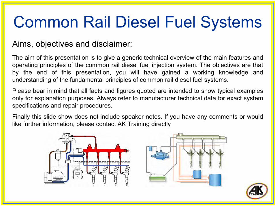
Aims, objectives and disclaimer:The aim of this presentation is to give a generic technical overview of the main features and operating principles of the common rail diesel fuel injection system. The objectives are that by the end of this presentation, you will have gained a working knowledge and understanding of the fundamental principles of common rail diesel fuel systems.
Please bear in mind that all facts and figures quoted are intended to show typical examples only for explanation purposes. Always refer to manufacturer technical data for exact system specifications and repair procedures.
Finally this slide show does not include speaker notes. If you have any comments or would like further information, please contact AK Training directly
Common Rail Diesel Fuel Systems

Advantages of common rail:
• Fuel pressure available on demand..... • Higher injection pressures and finer atomization of fuel.....• Injection pressure created independent of engine speed.....• Multiple injections per cylinder combustion are possible.
Common Rail Diesel Fuel Systems
Benefits of common rail:
• Reduction of overall exhaust emissions.....• Reduction of particulate emissions.....• Reduction of noise emissions.....• Improved fuel efficiency.....• Higher performance.
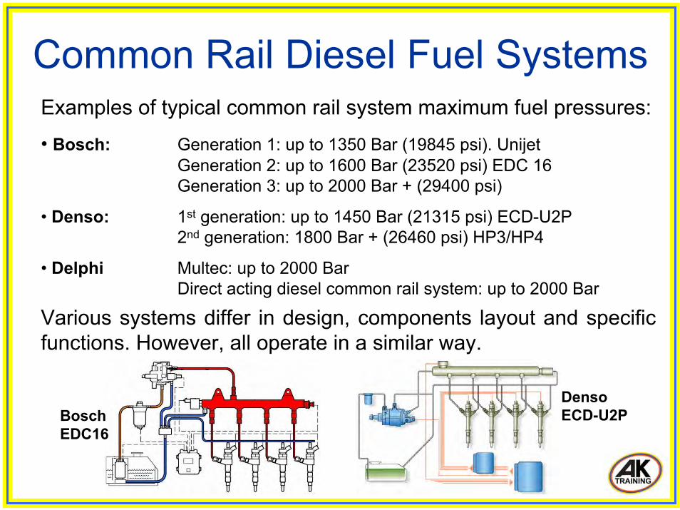
Common Rail Diesel Fuel Systems Examples of typical common rail system maximum fuel pressures:
• Bosch: Generation 1: up to 1350 Bar (19845 psi). UnijetGeneration 2: up to 1600 Bar (23520 psi) EDC 16Generation 3: up to 2000 Bar + (29400 psi)
• Denso: 1st generation: up to 1450 Bar (21315 psi) ECD-U2P2nd generation: 1800 Bar + (26460 psi) HP3/HP4
• Delphi Multec: up to 2000 BarDirect acting diesel common rail system: up to 2000 Bar
Various systems differ in design, components layout and specificfunctions. However, all operate in a similar way.
Bosch EDC16
Denso ECD-U2P

Common Rail Diesel Fuel Systems The fuel system can be divided into three basic circuits
• Low pressure supply circuit• High pressure delivery circuit• Fuel leak back and return
Low pressure supply
High pressure delivery
Fuel leak back and return
Example: Bosch EDC16
Common Rail Diesel Fuel Systems
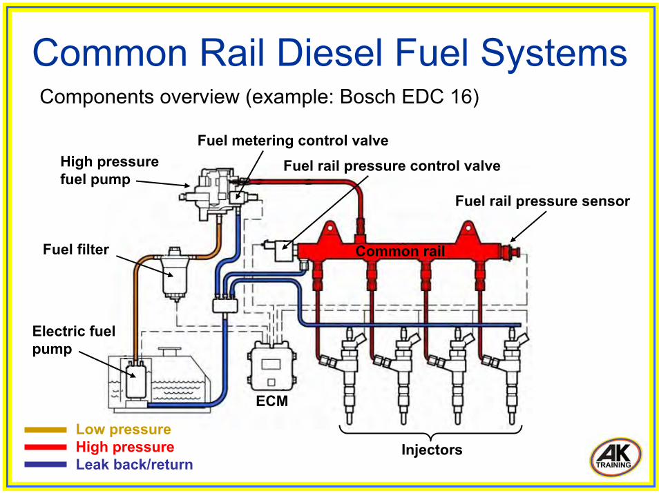
Electric fuel pump
Fuel filter
High pressure fuel pump
Fuel metering control valveFuel rail pressure control valve
Fuel rail pressure sensor
Common rail
Injectors
ECM
Low pressureHigh pressureLeak back/return
Components overview (example: Bosch EDC 16)
Denso HP4
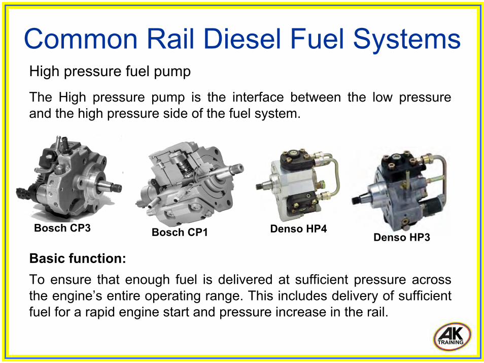
Common Rail Diesel Fuel Systems High pressure fuel pump
The High pressure pump is the interface between the low pressureand the high pressure side of the fuel system.
Bosch CP3Denso HP3Bosch CP1
Basic function:To ensure that enough fuel is delivered at sufficient pressure across the engine’s entire operating range. This includes delivery of sufficient fuel for a rapid engine start and pressure increase in the rail.
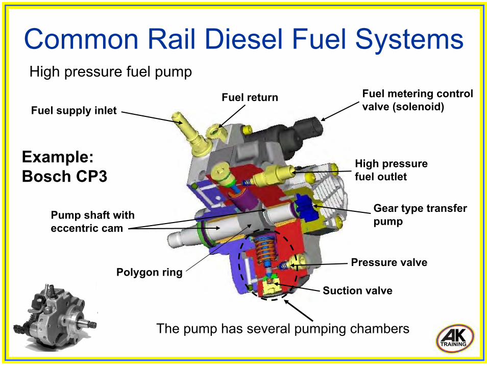
Common Rail Diesel Fuel Systems High pressure fuel pump
Fuel supply inletFuel metering control valve (solenoid)
High pressure fuel outlet
Gear type transfer pump
Pressure valve
Suction valve
Fuel return
Polygon ring
Pump shaft with eccentric cam
The pump has several pumping chambers
Example: Bosch CP3
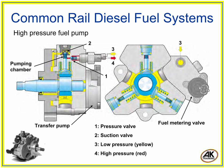
Common Rail Diesel Fuel Systems
1: Pressure valve
2: Suction valve
3: Low pressure (yellow)
4: High pressure (red)
1
2 33
4
High pressure fuel pump
Fuel metering valve
Pumping chamber
Transfer pump
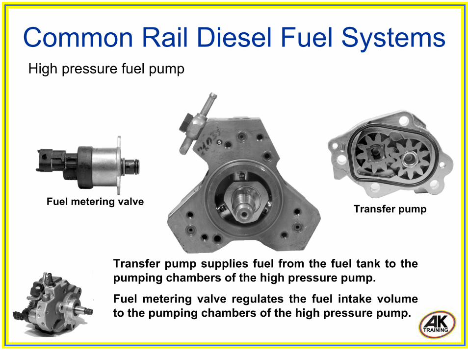
Transfer pump supplies fuel from the fuel tank to the pumping chambers of the high pressure pump.
Fuel metering valve regulates the fuel intake volume to the pumping chambers of the high pressure pump.
Common Rail Diesel Fuel Systems High pressure fuel pump
Transfer pumpFuel metering valve
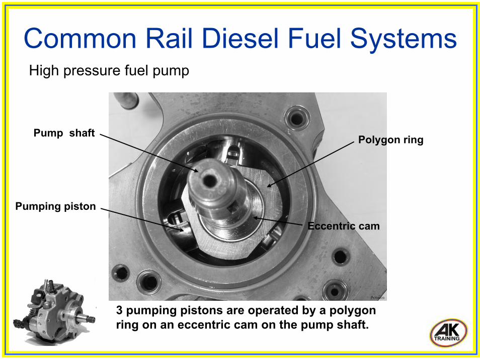
Common Rail Diesel Fuel Systems High pressure fuel pump
Pump shaft
Eccentric cam
Polygon ring
3 pumping pistons are operated by a polygon ring on an eccentric cam on the pump shaft.
Pumping piston
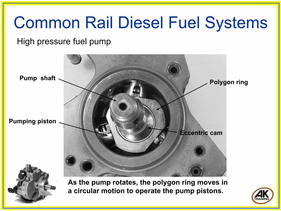
Common Rail Diesel Fuel Systems High pressure fuel pump
Pump shaft
Eccentric cam
Polygon ring
As the pump rotates, the polygon ring moves in a circular motion to operate the pump pistons.
Pumping piston

Common Rail Diesel Fuel Systems Transfer pump
Fuel inlet port
Fuel outlet port
An electric pre supply pump in fuel tank may be used instead of a transfer pump. Some systems may use a combination of electric pump and transfer pump.
Gear type (Bosch CP3)Trochoidal type (Denso HP3)

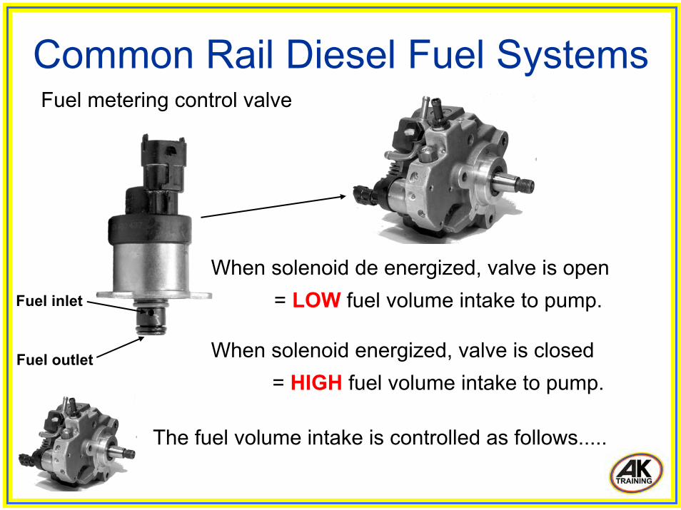
Common Rail Diesel Fuel Systems Fuel metering control valve
• Located at back of high pressure pump.• Controls the fuel intake volume to the pump.• Receives battery voltage supply from engine ECM.• Energized by ECM via negatively triggered PWM.• Operating frequency: approximately 180Hz.
Fuel inlet
Fuel outlet
Example: Bosch CP3
Common Rail Diesel Fuel Systems Fuel metering control valve
Fuel inlet
Fuel outlet
When solenoid de energized, valve is open= LOW fuel volume intake to pump.
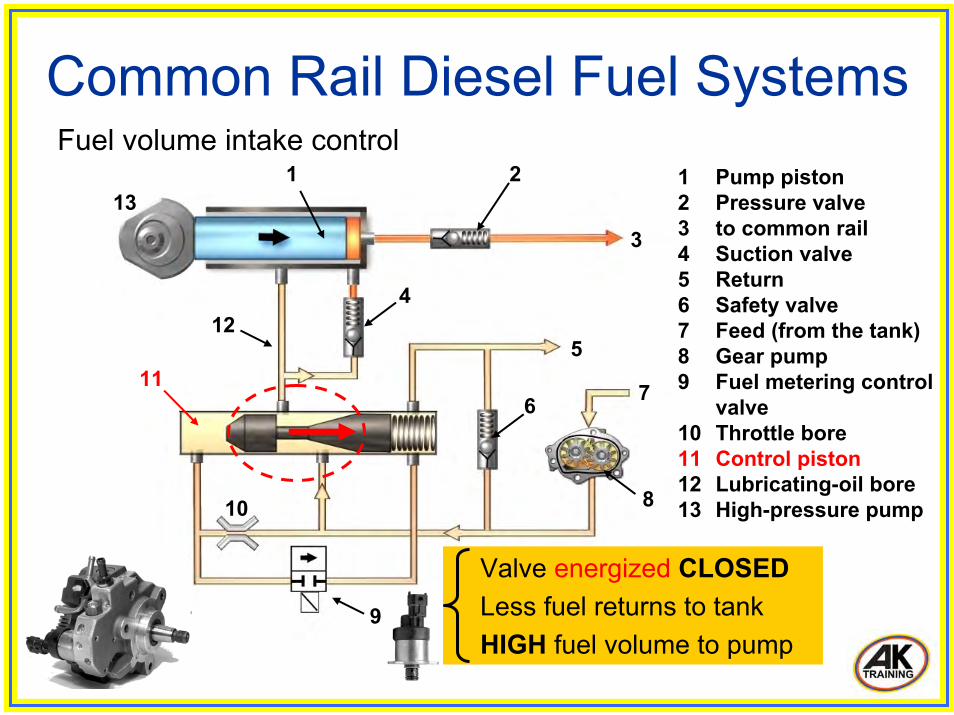
When solenoid energized, valve is closed= HIGH fuel volume intake to pump.
The fuel volume intake is controlled as follows.....
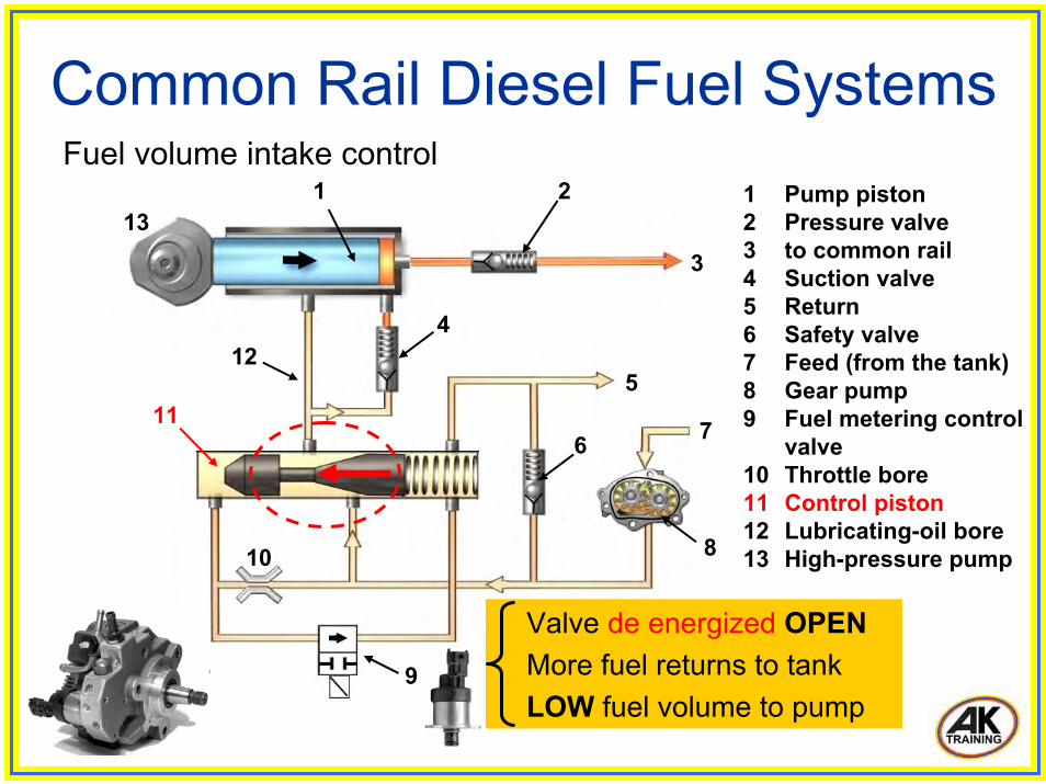
Valve de energized OPENMore fuel returns to tankLOW fuel volume to pump
1 2
6
5
4
3
7
8
9
10
11
12
13
Common Rail Diesel Fuel Systems Fuel volume intake control
1 Pump piston2 Pressure valve3 to common rail4 Suction valve5 Return6 Safety valve7 Feed (from the tank)8 Gear pump9 Fuel metering control
valve10 Throttle bore11 Control piston12 Lubricating-oil bore13 High-pressure pump
1 2
6
5
4
3
7
8
9
10
12
13
Common Rail Diesel Fuel Systems
11
Fuel volume intake control 1 Pump piston2 Pressure valve3 to common rail4 Suction valve5 Return6 Safety valve7 Feed (from the tank)8 Gear pump9 Fuel metering control
valve10 Throttle bore11 Control piston12 Lubricating-oil bore13 High-pressure pump
Valve energized CLOSEDLess fuel returns to tankHIGH fuel volume to pump
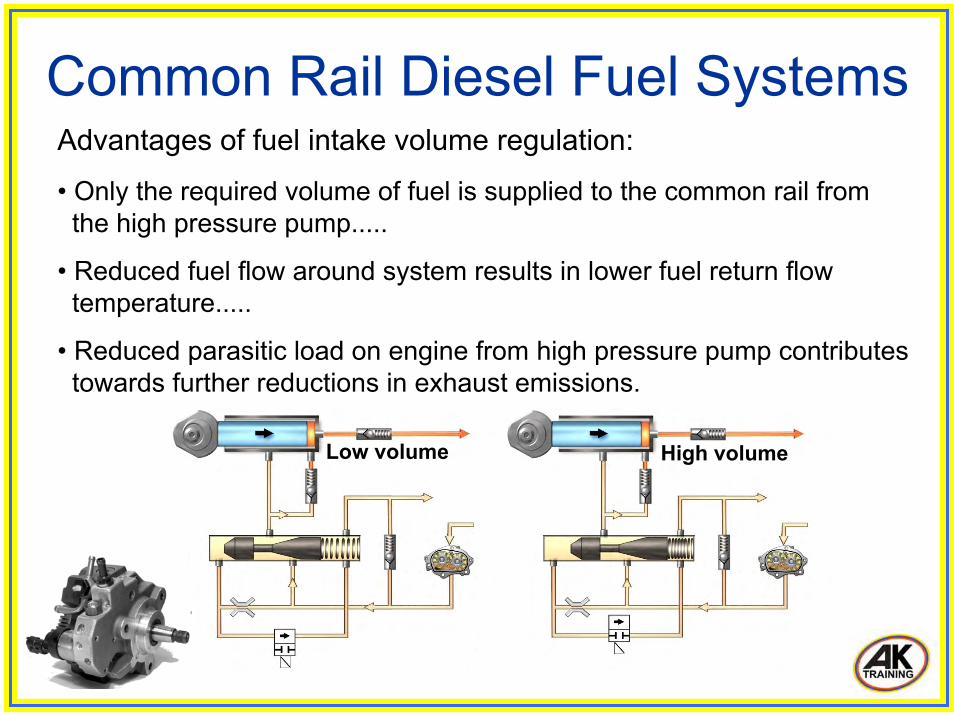
Advantages of fuel intake volume regulation:
• Only the required volume of fuel is supplied to the common rail fromthe high pressure pump.....
• Reduced fuel flow around system results in lower fuel return flow temperature.....
• Reduced parasitic load on engine from high pressure pump contributestowards further reductions in exhaust emissions.
Common Rail Diesel Fuel Systems
Low volume High volume
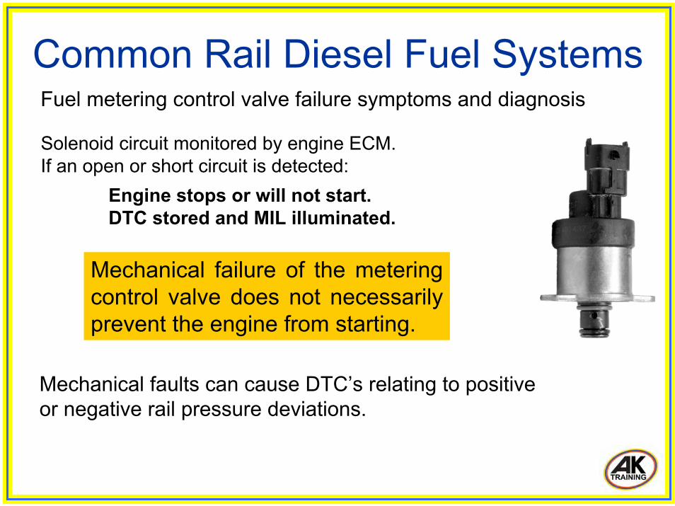
Solenoid circuit monitored by engine ECM. If an open or short circuit is detected:
Engine stops or will not start.DTC stored and MIL illuminated.
Mechanical failure of the metering control valve does not necessarily prevent the engine from starting.
Common Rail Diesel Fuel Systems Fuel metering control valve failure symptoms and diagnosis
Mechanical faults can cause DTC’s relating to positive or negative rail pressure deviations.

High pressure regulator valve
Fuel return (to fuel tank)
Low pressure fuel inlet (from fuel tank)
High pressure fuel delivery to common tail
Common Rail Diesel Fuel Systems High pressure regulator valve
System variant.
Fitted to back of HP pump.
Controls high pressure fuel delivery to common rail.
Excess fuel returns totank.
Fuel cooler required to cool return fuel flow.

Common Rail Diesel Fuel Systems
It also damps pressure vibrations caused by the high pressure pump and injection processes.
Typical volume of fuel held in common rail: 16 – 20cm³.
Fuel is supplied to the common rail at high pressure from the high pressure pump.
The rail stores the fuel and distributes it to the individual injectors.
High pressure accumulator (common rail)
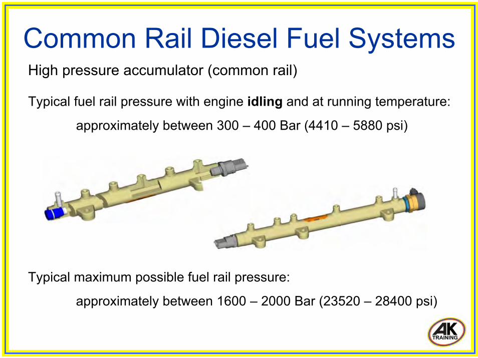
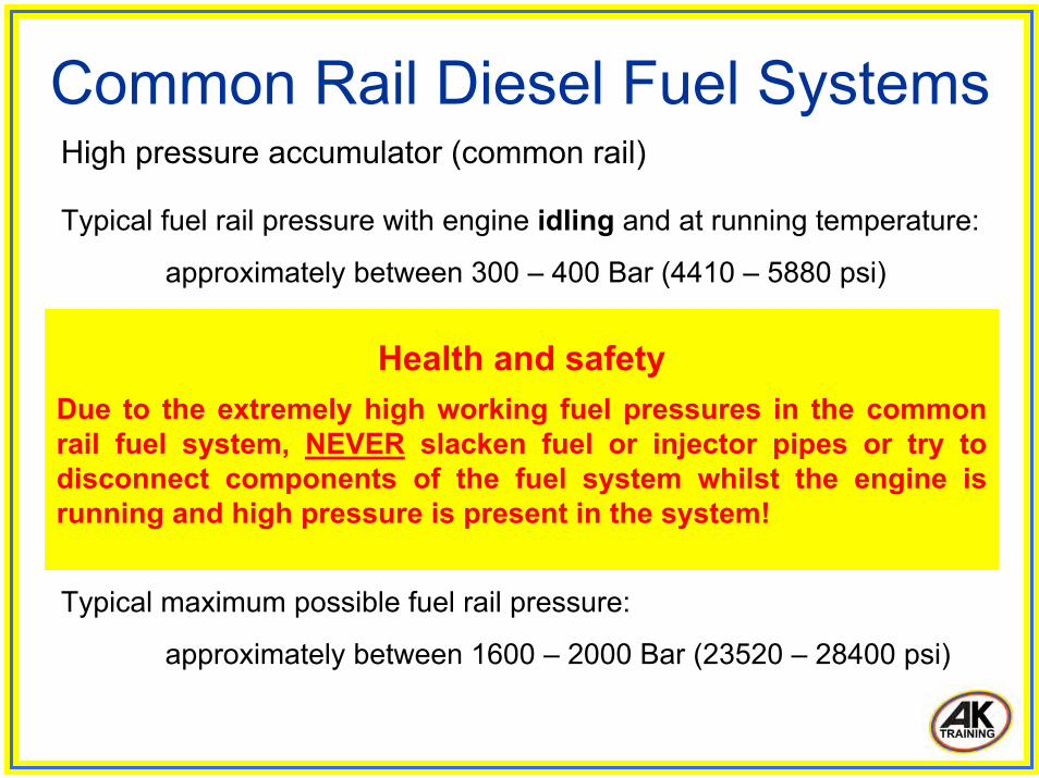
Common Rail Diesel Fuel Systems High pressure accumulator (common rail)
Typical fuel rail pressure with engine idling and at running temperature:
approximately between 300 – 400 Bar (4410 – 5880 psi)
Typical maximum possible fuel rail pressure:
approximately between 1600 – 2000 Bar (23520 – 28400 psi)
Health and safetyDue to the extremely high working fuel pressures in the common rail fuel system, NEVER slacken fuel or injector pipes or try to disconnect components of the fuel system whilst the engine is running and high pressure is present in the system!
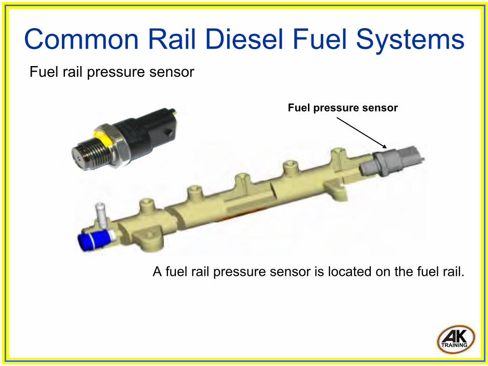
Common Rail Diesel Fuel Systems Fuel rail pressure sensor
Fuel pressure sensor
A fuel rail pressure sensor is located on the fuel rail.

Common Rail Diesel Fuel Systems Fuel rail pressure sensor
Monitors the fuel pressure in the common rail.
Typically a piezo resistive type sensor.
Three wires:
• 5 Volt supply from engine ECM.
• Sensor ground via engine ECM.
• Linear signal voltage output to ECM.Signal utilization:To enable the engine ECM to determine the fuel rail pressure.....Used by the ECM as part of the calculation for the % duty cycle applied to the rail pressure control solenoid and fuel metering solenoid.

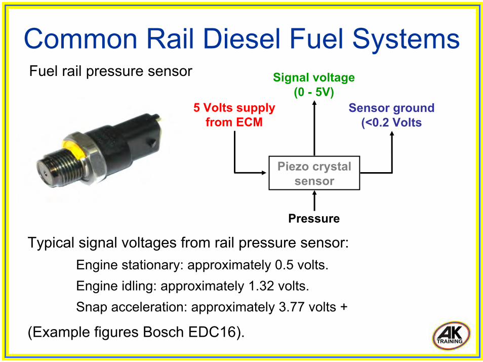
Common Rail Diesel Fuel Systems Fuel rail pressure sensor
Pressure
5 Volts supply from ECM
Piezo crystalsensor
Sensor ground(<0.2 Volts
Signal voltage (0 - 5V)
The engine ECM applies a stabilized 5 Volts supply to the signal wire of the fuel pressure sensor.....
The resistive value of the sensor creates a change in the voltage on the signal wire relative to the fuel rail pressure.
Common Rail Diesel Fuel Systems Fuel rail pressure sensor
Pressure
5 Volts supply from ECM
Piezo crystalsensor
Sensor ground(<0.2 Volts
Signal voltage (0 - 5V)
Typical signal voltages from rail pressure sensor:Engine stationary: approximately 0.5 volts.Engine idling: approximately 1.32 volts.Snap acceleration: approximately 3.77 volts +
(Example figures Bosch EDC16).
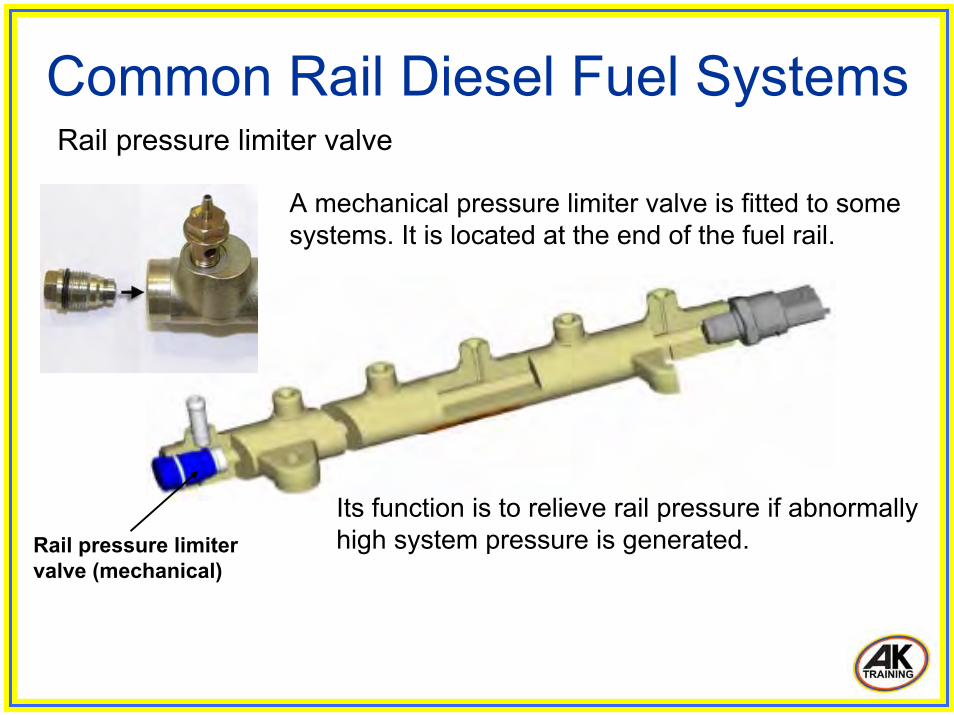
Common Rail Diesel Fuel Systems Rail pressure limiter valve
Rail pressure limiter valve (mechanical)
A mechanical pressure limiter valve is fitted to some systems. It is located at the end of the fuel rail.
Its function is to relieve rail pressure if abnormally high system pressure is generated.

Common Rail Diesel Fuel Systems Rail pressure limiter valve
If excessive fuel pressure is generated, the valve opens a fuel return port.
Fuel return
Rail pressure limiter valve (mechanical)
Excess fuel is relieved back to the fuel tank.

Common Rail Diesel Fuel Systems Rail pressure limiter valve
Example operating pressure of rail pressure limiter valve (Denso HP3 system):
valve opens at 230 MPa (2300 Bar)valve closes at 50 MPa (500 Bar)
Fuel return to fuel tank
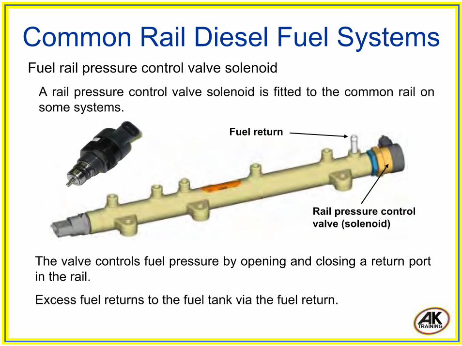
Common Rail Diesel Fuel Systems Fuel rail pressure control valve solenoid
Rail pressure control valve (solenoid)
Fuel return
The valve controls fuel pressure by opening and closing a return port in the rail.
Excess fuel returns to the fuel tank via the fuel return.
A rail pressure control valve solenoid is fitted to the common rail on some systems.

Common Rail Diesel Fuel Systems Rail pressure control valve solenoid
Operating frequency: approximately 1000Hz
Receives battery voltage supply from engine ECM.
Energized by engine ECM via a negatively triggered PWM.
Used in conjunction with fuel metering solenoid, the rail pressure solenoid provides more accurate and faster control of pressure, particularly when reducing rail pressure during overrun.

Common Rail Diesel Fuel Systems Rail pressure control valve de energized
A0 max.
300
600 9001200
15000Engine ECM
Rail pressure
Fuel return port
More fuel is returned to fuel tank via return port.Rail pressureDecreases.
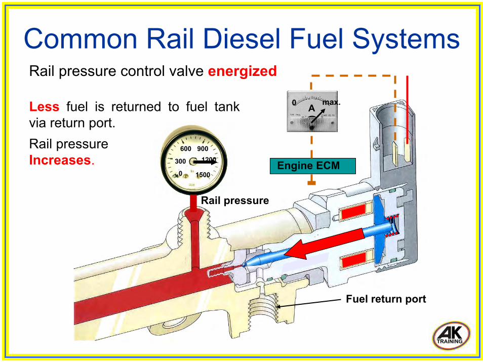
Common Rail Diesel Fuel Systems Rail pressure control valve energized
300
600 9001200
15000
A0 max.
Engine ECM
Rail pressure
Fuel return port
Less fuel is returned to fuel tank via return port.Rail pressureIncreases.
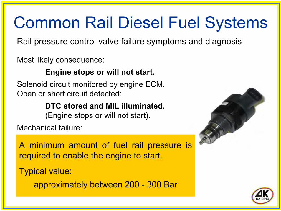
Common Rail Diesel Fuel Systems Rail pressure control valve failure symptoms and diagnosis
Most likely consequence:Engine stops or will not start.
Solenoid circuit monitored by engine ECM. Open or short circuit detected:
DTC stored and MIL illuminated.(Engine stops or will not start).
Mechanical failure:Valve stuck open = Low rail pressure. Engine stops or will not start.Valve stuck closed = High rail pressure.Engine stops or will not start.
A minimum amount of fuel rail pressure is required to enable the engine to start.
Typical value: approximately between 200 - 300 Bar

Common Rail Diesel Fuel Systems Rail pressure control valve failure symptoms and diagnosis
Most likely consequence:Engine stops or will not start.
Solenoid circuit monitored by engine ECM. Open or short circuit detected:
DTC stored and MIL illuminated.(Engine stops or will not start).
Mechanical failure:Valve stuck open = Low rail pressure. Engine stops or will not start.Valve stuck closed = High rail pressure.Engine stops or will not start.
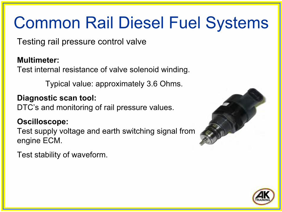
Common Rail Diesel Fuel Systems Testing rail pressure control valve
Multimeter:Test internal resistance of valve solenoid winding.
Typical value: approximately 3.6 Ohms.
Diagnostic scan tool:DTC’s and monitoring of rail pressure values.
Oscilloscope:Test supply voltage and earth switching signal from engine ECM.
Test stability of waveform.
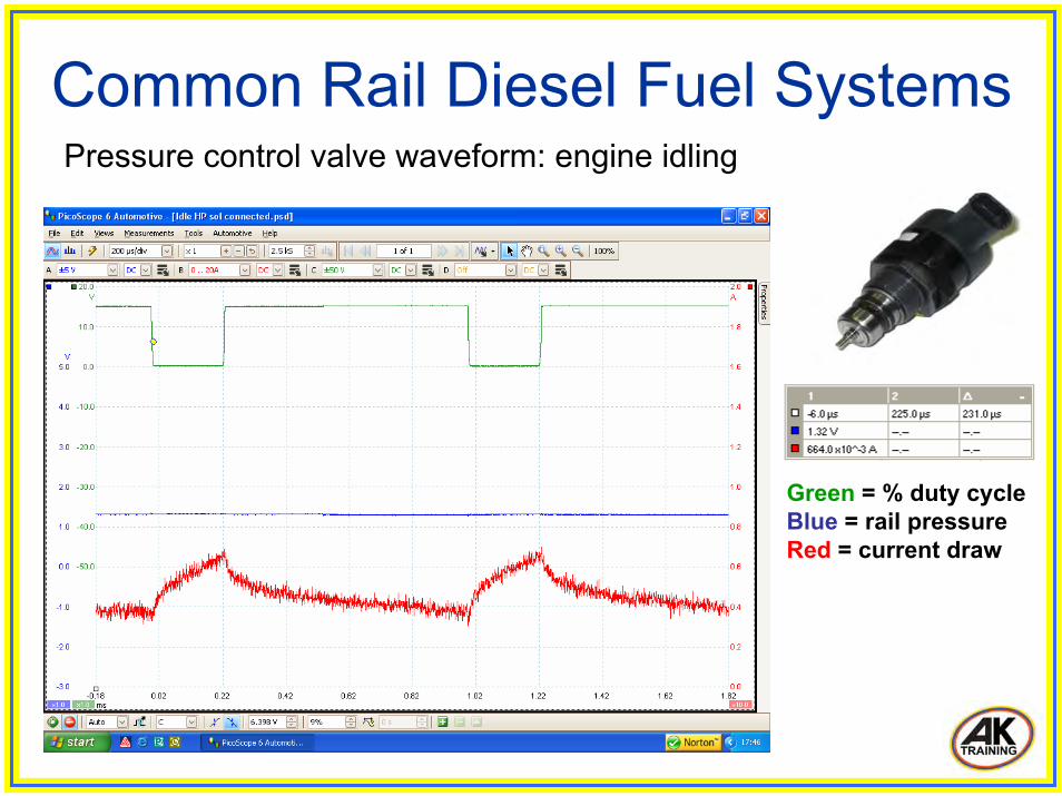
Common Rail Diesel Fuel Systems Pressure control valve waveform: engine idling
Green = % duty cycleBlue = rail pressureRed = current draw
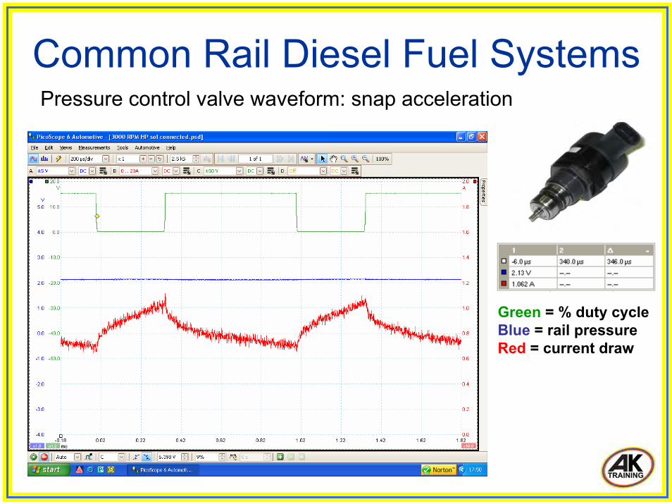
Common Rail Diesel Fuel Systems Pressure control valve waveform: snap acceleration
Green = % duty cycleBlue = rail pressureRed = current draw
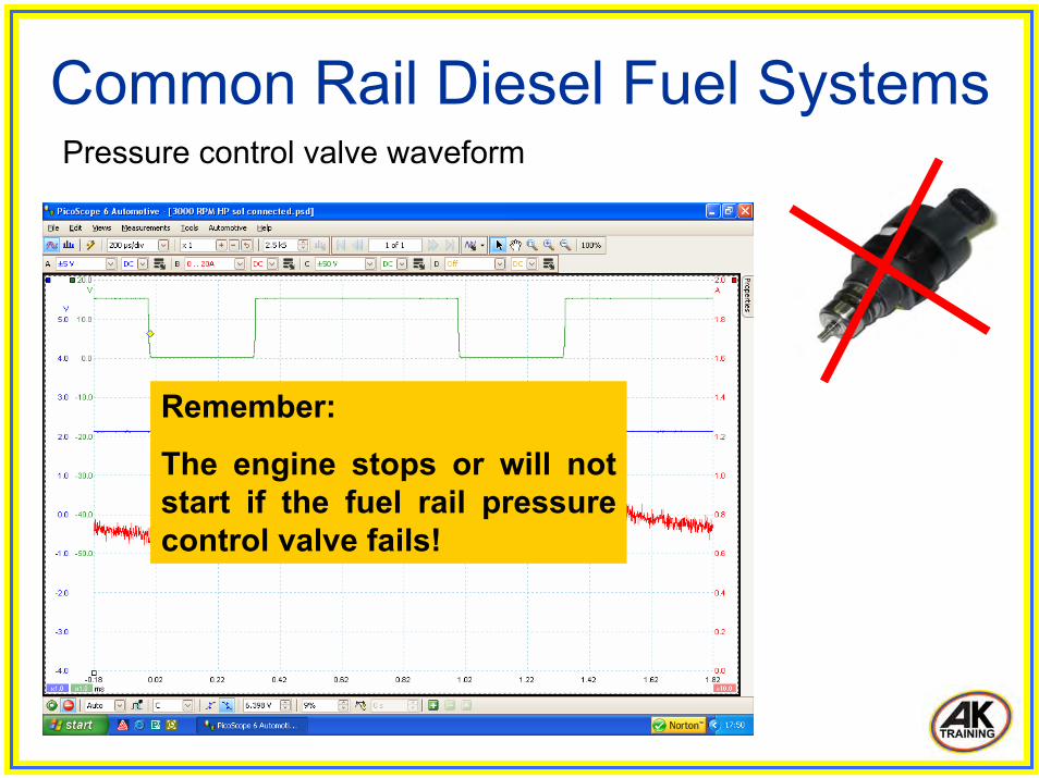
Common Rail Diesel Fuel Systems Pressure control valve waveform
Remember:
The engine stops or will not start if the fuel rail pressure control valve fails!
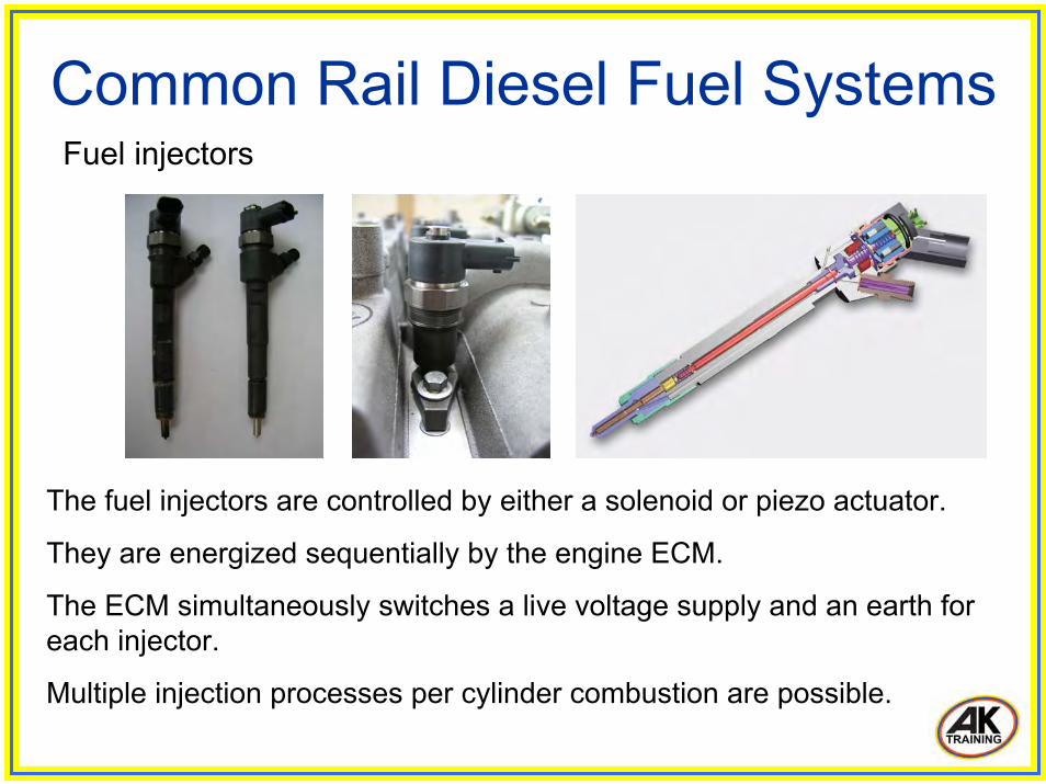
Common Rail Diesel Fuel Systems Fuel injectors
The fuel injectors are controlled by either a solenoid or piezo actuator.
They are energized sequentially by the engine ECM.
The ECM simultaneously switches a live voltage supply and an earth for each injector.
Multiple injection processes per cylinder combustion are possible.

Common Rail Diesel Fuel Systems Fuel injectors
Valve piston
Valve needle
Thrust piece
Nozzle springHigh pressure fuel inlet (from common rail)
Fuel leak back (return)
Electrical connection
Solenoid actuator
Injector valve

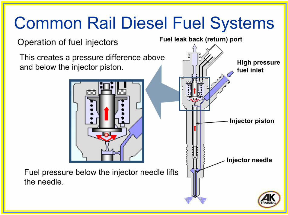
Common Rail Diesel Fuel Systems Operation of fuel injectors
O.Akadem
ie dra
wing A.K
herm
ayer
2/2003
Injector valve
High pressure fuel inlet
Fuel pressure is supplied to the injector needle seat area.....
Injector piston
and also to a small chamber above the injector piston via a calibrated inlet port.
Inlet port
Injector needle
Fuel leak back (return) port

O.Akadem
ie dra
wing A.K
herm
ayer
2/2003
Common Rail Diesel Fuel Systems
High pressure fuel inlet
Fuel leak back (return) port
Injector piston
Injector needle
Operation of fuel injectors
When the solenoid is energized, the injector valve opens.
Injector valveopens
Fuel pressure is relieved above the injector piston and returns to the fuel tank via the injector leak back (return) ports.
O.Akadem
ie dra
wing A.K
herm
ayer
2/2003
Common Rail Diesel Fuel Systems
High pressure fuel inlet
Injector piston
Injector needle
Operation of fuel injectors
Fuel pressure below the injector needle lifts the needle.
This creates a pressure difference above and below the injector piston.
Fuel leak back (return) port
O.Akadem
ie dra
wing A.K
herm
ayer
2/2003
Common Rail Diesel Fuel Systems
High pressure fuel inlet
Injector piston
Injector needle
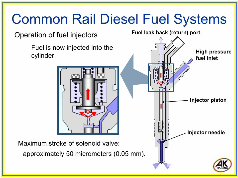
Operation of fuel injectors
Maximum stroke of solenoid valve:approximately 50 micrometers (0.05 mm).
Fuel is now injected into the cylinder.
Fuel leak back (return) port
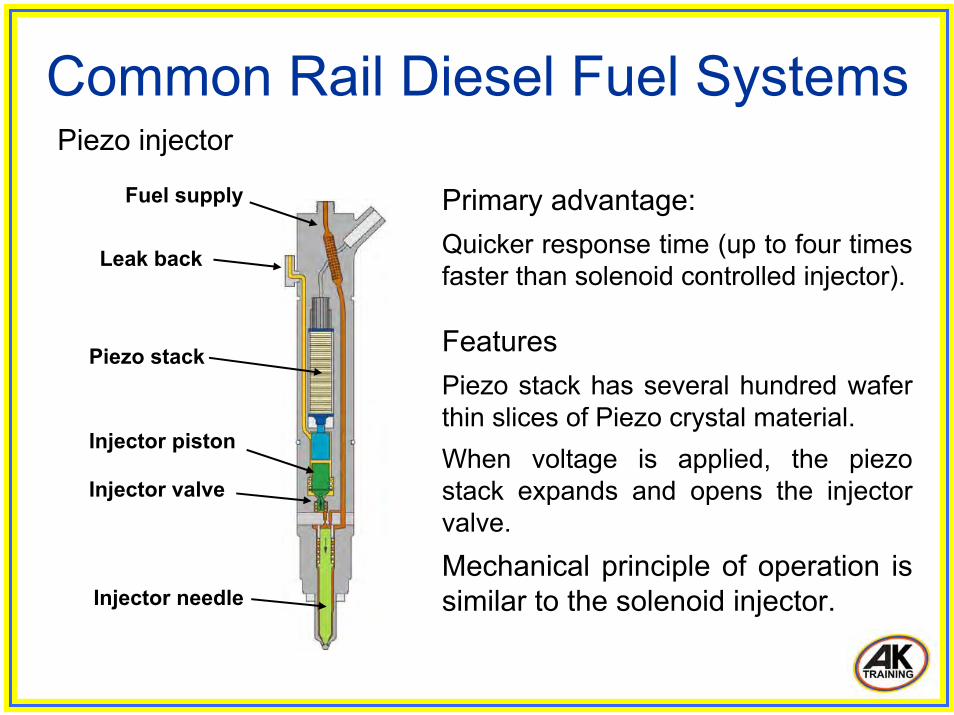
Common Rail Diesel Fuel Systems Piezo injector
Primary advantage:Quicker response time (up to four times faster than solenoid controlled injector).
FeaturesPiezo stack has several hundred wafer thin slices of Piezo crystal material.When voltage is applied, the piezo stack expands and opens the injector valve.Mechanical principle of operation is similar to the solenoid injector.
Piezo stack
Injector piston
Leak back
Injector valve
Injector needle
Fuel supply
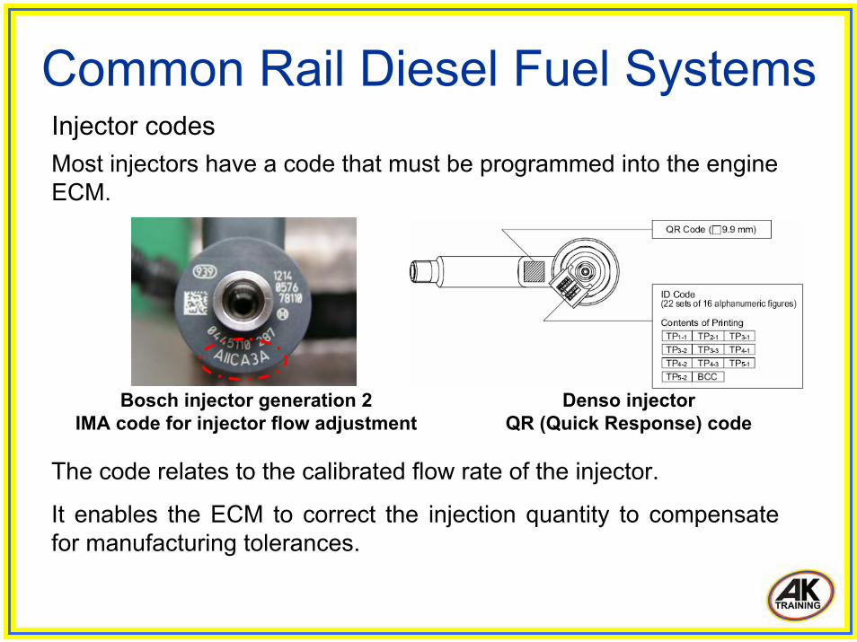
Common Rail Diesel Fuel Systems Injector codesMost injectors have a code that must be programmed into the engine ECM.
The code relates to the calibrated flow rate of the injector.
It enables the ECM to correct the injection quantity to compensate for manufacturing tolerances.
Bosch injector generation 2 IMA code for injector flow adjustment
Denso injector QR (Quick Response) code
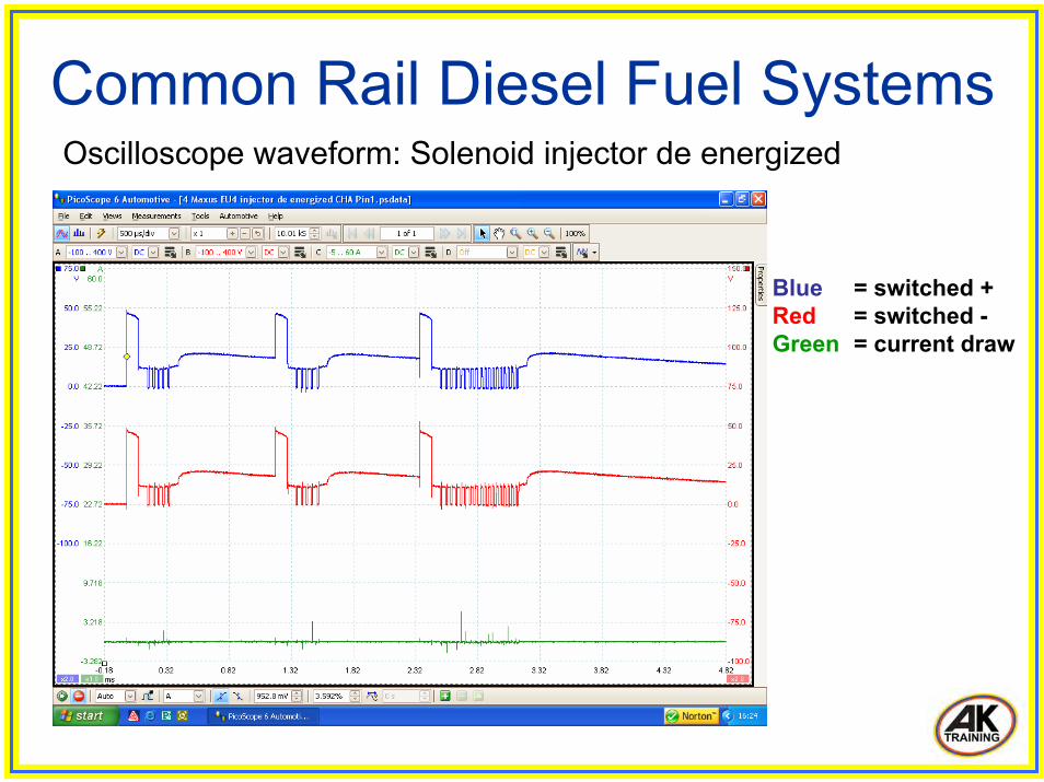
Common Rail Diesel Fuel Systems Oscilloscope waveform: Solenoid injector de energized
Blue = switched +Red = switched -Green = current draw
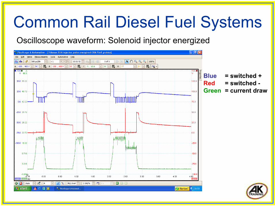
Common Rail Diesel Fuel Systems Oscilloscope waveform: Solenoid injector energized
Blue = switched +Red = switched -Green = current draw

Common Rail Diesel Fuel Systems Oscilloscope waveform: Piezo injector de energized
Blue = switched +Red = switched -Green = current draw
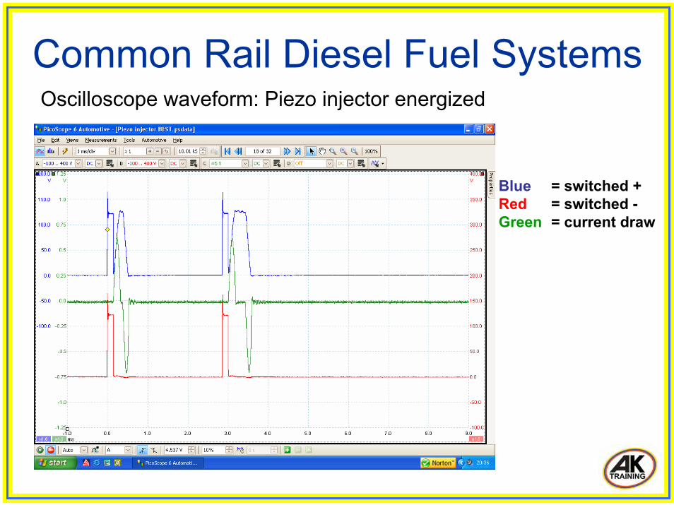
Common Rail Diesel Fuel Systems Oscilloscope waveform: Piezo injector energized
Blue = switched +Red = switched -Green = current draw
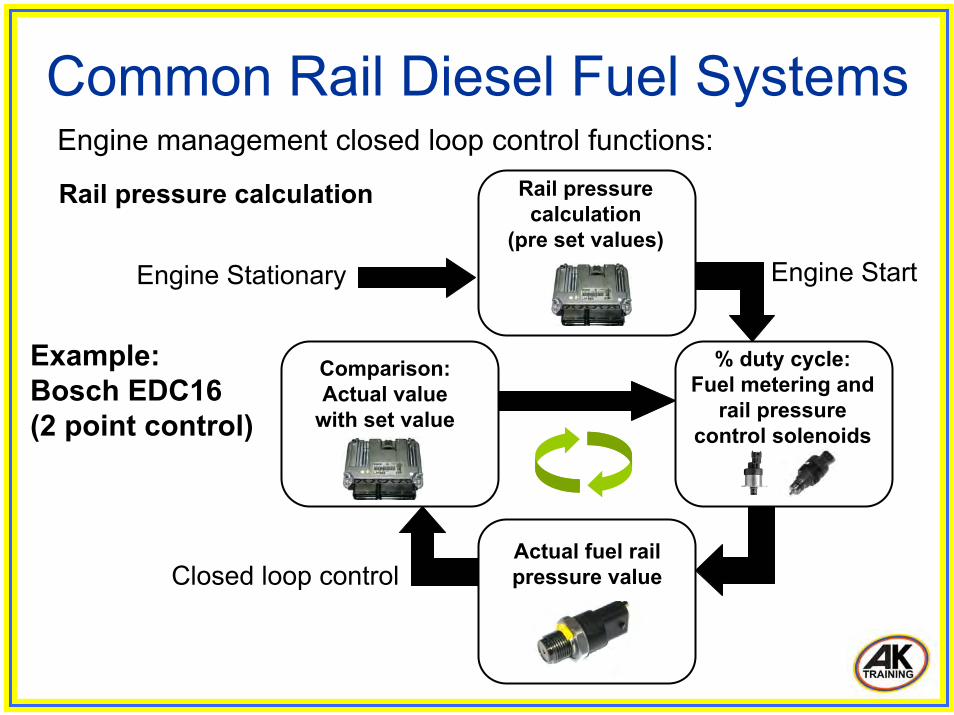
Common Rail Diesel Fuel Systems Engine management closed loop control functions:
Closed loop control
Rail pressure calculation
(pre set values)
% duty cycle: Fuel metering and
rail pressurecontrol solenoids
Actual fuel railpressure value
Comparison:Actual value
with set value
Engine StartEngine Stationary
Rail pressure calculation
Example: Bosch EDC16(2 point control)
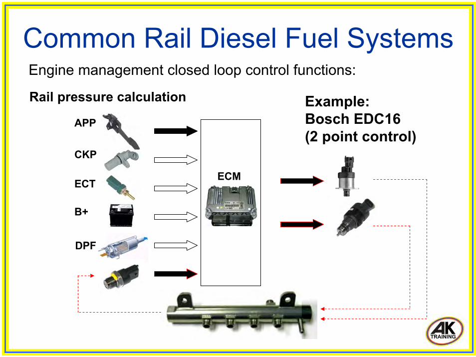
Common Rail Diesel Fuel Systems Engine management closed loop control functions:
APP
CKP
ECT
B+
DPF
ECM
Example: Bosch EDC16(2 point control)
Rail pressure calculation

Common Rail Diesel Fuel Systems Fuel system diagnosis
Common rail diesel fuel systems operate on a closed loop basis.
The system carries out a great many complex calculations to precisely control fuel quantity and injection timing.
A range of tools and test equipment is commercially available to assist with diagnosis of the system.
The following is a brief overview to highlight some of the basic tests that can be carried out to diagnose faults with the system.
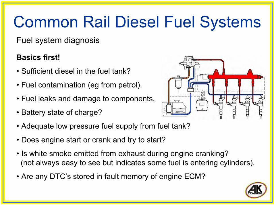
Common Rail Diesel Fuel Systems Fuel system diagnosis
Basics first!
• Sufficient diesel in the fuel tank?
• Fuel contamination (eg from petrol).
• Fuel leaks and damage to components.
• Battery state of charge?
• Adequate low pressure fuel supply from fuel tank?
• Does engine start or crank and try to start?
• Is white smoke emitted from exhaust during engine cranking?(not always easy to see but indicates some fuel is entering cylinders).
• Are any DTC’s stored in fault memory of engine ECM?
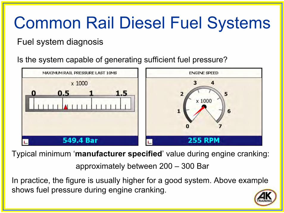
Common Rail Diesel Fuel Systems Fuel system diagnosis
Is the system capable of generating sufficient fuel pressure?
Typical minimum ‘manufacturer specified’ value during engine cranking: approximately between 200 – 300 Bar
In practice, the figure is usually higher for a good system. Above example shows fuel pressure during engine cranking.
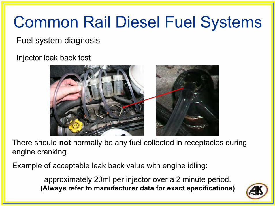
Common Rail Diesel Fuel Systems Fuel system diagnosis
Injector leak back test
There should not normally be any fuel collected in receptacles during engine cranking.
Example of acceptable leak back value with engine idling:
approximately 20ml per injector over a 2 minute period.(Always refer to manufacturer data for exact specifications)

Common Rail Diesel Fuel Systems Fuel system diagnosis
Maximum fuel pressure
Engine cranking(approx 500 Bar)
Engine idling(approx 362 Bar)
Snap acceleration(approx 1519 Bar)

Thank youfor attending a technical overview of
Common Rail Diesel Fuel Systems
presented by
Tony Kitchen(AK Training)
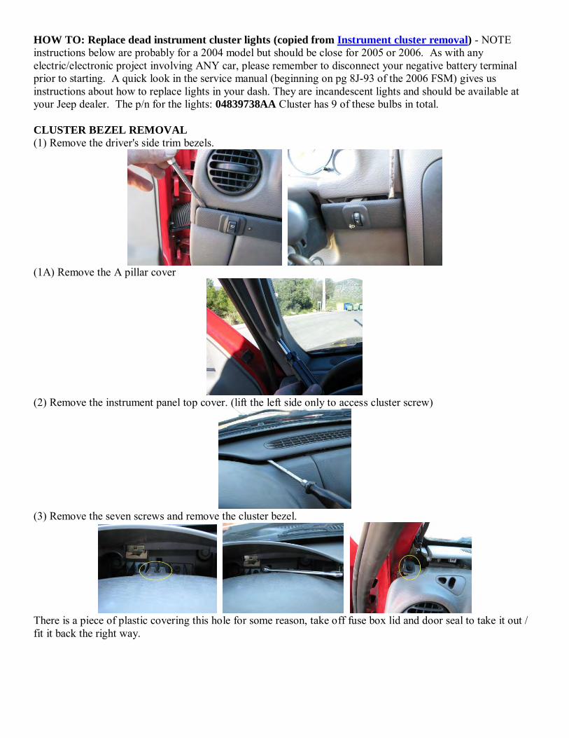
HOW TO: Replace dead instrument cluster lights (copied from Instrument cluster removal) - NOTE instructions below are probably for a 2004 model but should be close for 2005 or 2006. As with any electric/electronic project involving ANY car, please remember to disconnect your negative battery terminal prior to starting. A quick look in the service manual (beginning on pg 8J-93 of the 2006 FSM) gives us instructions about how to replace lights in your dash. They are incandescent lights and should be available at your Jeep dealer. The p/n for the lights: 04839738AA Cluster has 9 of these bulbs in total. CLUSTER BEZEL REMOVAL
(1) Remove the driver's side trim bezels.
(1A) Remove the A pillar cover
(2) Remove the instrument panel top cover. (lift the left side only to access cluster screw)
(3) Remove the seven screws and remove the cluster bezel.
There is a piece of plastic covering this hole for some reason, take off fuse box lid and door seal to take it out / fit it back the right way.
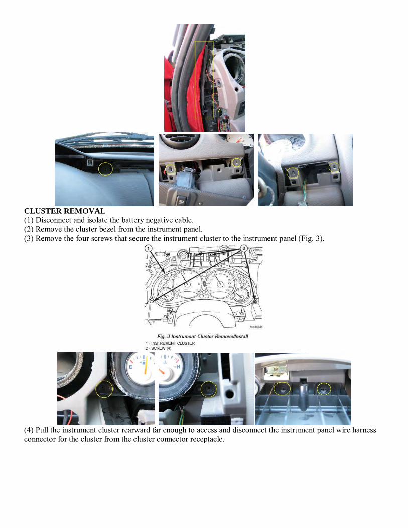
CLUSTER REMOVAL
(1) Disconnect and isolate the battery negative cable. (2) Remove the cluster bezel from the instrument panel. (3) Remove the four screws that secure the instrument cluster to the instrument panel (Fig. 3).
(4) Pull the instrument cluster rearward far enough to access and disconnect the instrument panel wire harness connector for the cluster from the cluster connector receptacle.
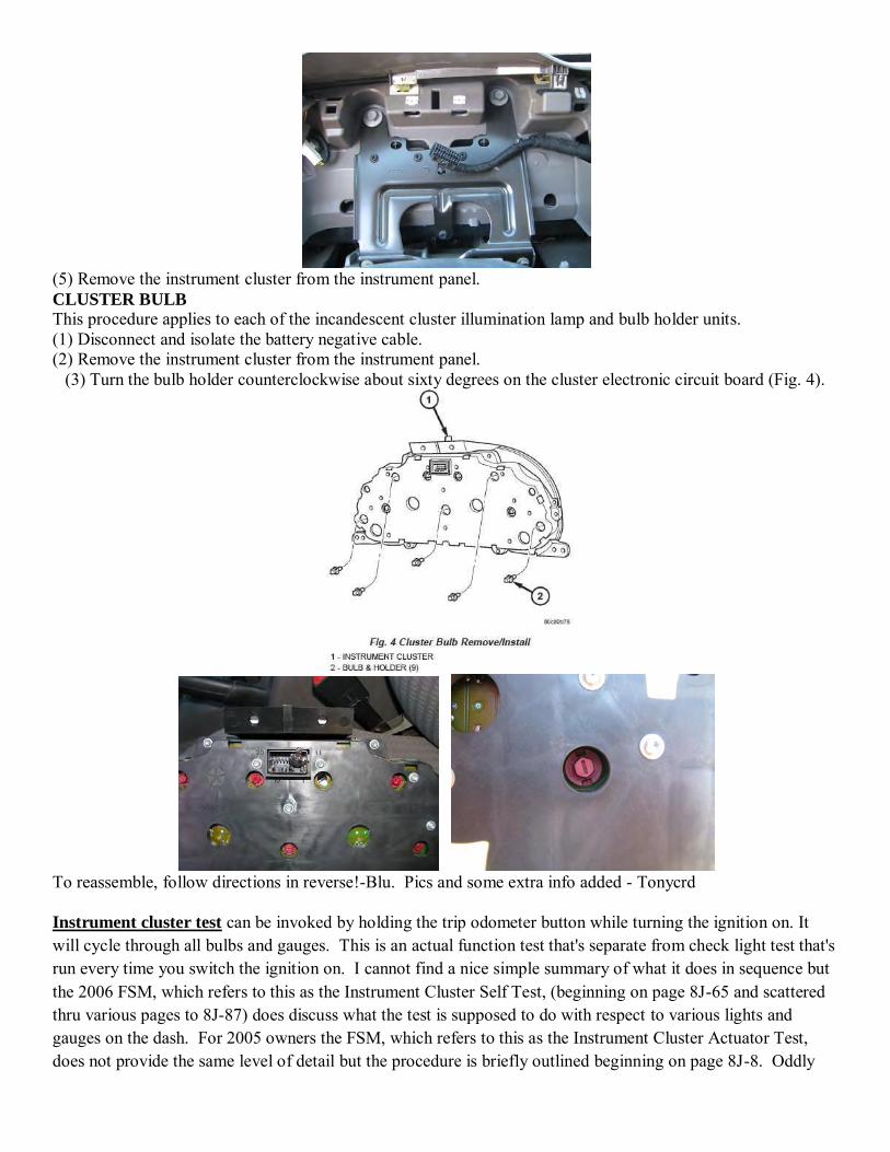
(5) Remove the instrument cluster from the instrument panel. CLUSTER BULB
This procedure applies to each of the incandescent cluster illumination lamp and bulb holder units. (1) Disconnect and isolate the battery negative cable. (2) Remove the instrument cluster from the instrument panel.
(3) Turn the bulb holder counterclockwise about sixty degrees on the cluster electronic circuit board (Fig. 4).
To reassemble, follow directions in reverse!-Blu. Pics and some extra info added - Tonycrd Instrument cluster test can be invoked by holding the trip odometer button while turning the ignition on. It will cycle through all bulbs and gauges. This is an actual function test that's separate from check light test that's run every time you switch the ignition on. I cannot find a nice simple summary of what it does in sequence but the 2006 FSM, which refers to this as the Instrument Cluster Self Test, (beginning on page 8J-65 and scattered thru various pages to 8J-87) does discuss what the test is supposed to do with respect to various lights and gauges on the dash. For 2005 owners the FSM, which refers to this as the Instrument Cluster Actuator Test, does not provide the same level of detail but the procedure is briefly outlined beginning on page 8J-8. Oddly

the separate 2005 KJ Body manual does have more detail and refers to the test as the Instrument Cluster Self Test. Go figure. Per lgoodbar the analog gauge needle postions in this test are: Fuel: E, 1/4, 1/2, 3/4, F Temp: C, 1/4, 1/2, 3/4, F Speedometer: 0, 30, 60, 90, 120 Tachometer: 0, 1000, 3000, 5000
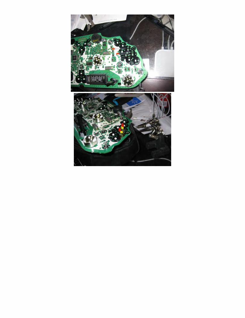
LED replacement notes per lgoodbar Apparently you have to remove at least some of the analog instruments and/or their needles to do the LED replacement. To replace the needles in the proper position turn the ignition switch ON and partially insert the temp, speedo, and tach needles at the "zero" position and the fuel needle where it was when removed. Run the above test to check postions, adjust at needed, and then fully seat the needles. To replace bad or removed LEDs. Remove any bad LED, may need to heat solder to remove LED legs; replace by soldering in the missing MIL and ABS LEDs using "regular" bulb-type LEDs (ultra-bright if possible). The anode (longer leg) goes on the top solder pad, and the cathode (shorter leg) on the bottom pad. Apparently square LEDs do better than bulb ones.
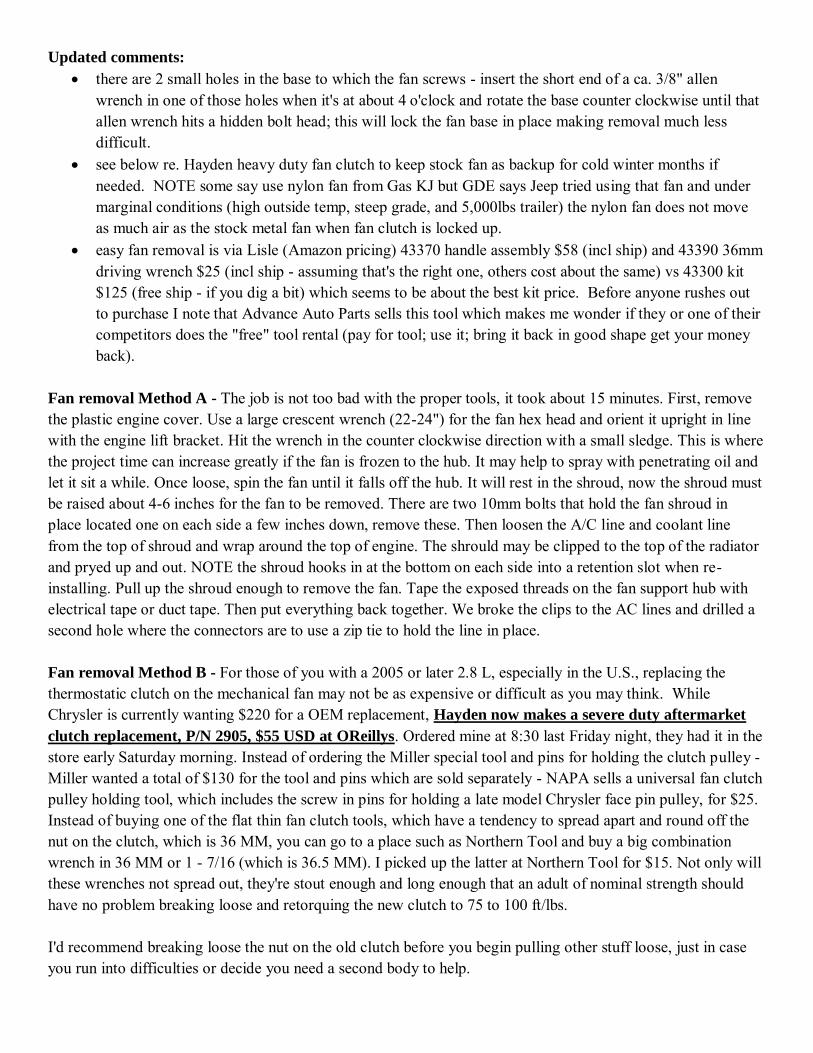
Updated comments: there are 2 small holes in the base to which the fan screws - insert the short end of a ca. 3/8" allen
wrench in one of those holes when it's at about 4 o'clock and rotate the base counter clockwise until that allen wrench hits a hidden bolt head; this will lock the fan base in place making removal much less difficult.
see below re. Hayden heavy duty fan clutch to keep stock fan as backup for cold winter months if needed. NOTE some say use nylon fan from Gas KJ but GDE says Jeep tried using that fan and under marginal conditions (high outside temp, steep grade, and 5,000lbs trailer) the nylon fan does not move as much air as the stock metal fan when fan clutch is locked up.
easy fan removal is via Lisle (Amazon pricing) 43370 handle assembly $58 (incl ship) and 43390 36mm driving wrench $25 (incl ship - assuming that's the right one, others cost about the same) vs 43300 kit $125 (free ship - if you dig a bit) which seems to be about the best kit price. Before anyone rushes out to purchase I note that Advance Auto Parts sells this tool which makes me wonder if they or one of their competitors does the "free" tool rental (pay for tool; use it; bring it back in good shape get your money back).
Fan removal Method A - The job is not too bad with the proper tools, it took about 15 minutes. First, remove the plastic engine cover. Use a large crescent wrench (22-24") for the fan hex head and orient it upright in line with the engine lift bracket. Hit the wrench in the counter clockwise direction with a small sledge. This is where the project time can increase greatly if the fan is frozen to the hub. It may help to spray with penetrating oil and let it sit a while. Once loose, spin the fan until it falls off the hub. It will rest in the shroud, now the shroud must be raised about 4-6 inches for the fan to be removed. There are two 10mm bolts that hold the fan shroud in place located one on each side a few inches down, remove these. Then loosen the A/C line and coolant line from the top of shroud and wrap around the top of engine. The shrould may be clipped to the top of the radiator and pryed up and out. NOTE the shroud hooks in at the bottom on each side into a retention slot when re-installing. Pull up the shroud enough to remove the fan. Tape the exposed threads on the fan support hub with electrical tape or duct tape. Then put everything back together. We broke the clips to the AC lines and drilled a second hole where the connectors are to use a zip tie to hold the line in place. Fan removal Method B - For those of you with a 2005 or later 2.8 L, especially in the U.S., replacing the thermostatic clutch on the mechanical fan may not be as expensive or difficult as you may think. While Chrysler is currently wanting $220 for a OEM replacement, Hayden now makes a severe duty aftermarket
clutch replacement, P/N 2905, $55 USD at OReillys. Ordered mine at 8:30 last Friday night, they had it in the store early Saturday morning. Instead of ordering the Miller special tool and pins for holding the clutch pulley - Miller wanted a total of $130 for the tool and pins which are sold separately - NAPA sells a universal fan clutch pulley holding tool, which includes the screw in pins for holding a late model Chrysler face pin pulley, for $25. Instead of buying one of the flat thin fan clutch tools, which have a tendency to spread apart and round off the nut on the clutch, which is 36 MM, you can go to a place such as Northern Tool and buy a big combination wrench in 36 MM or 1 - 7/16 (which is 36.5 MM). I picked up the latter at Northern Tool for $15. Not only will these wrenches not spread out, they're stout enough and long enough that an adult of nominal strength should have no problem breaking loose and retorquing the new clutch to 75 to 100 ft/lbs. I'd recommend breaking loose the nut on the old clutch before you begin pulling other stuff loose, just in case you run into difficulties or decide you need a second body to help.
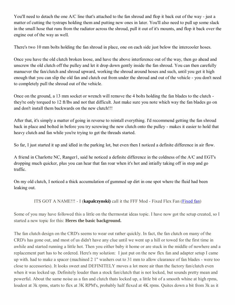
You'll need to detach the one A/C line that's attached to the fan shroud and flop it back out of the way - just a matter of cutting the tystraps holding them and putting new ones in later. You'll also need to pull up some slack in the small hose that runs from the radiator across the shroud, pull it out of it's mounts, and flop it back over the engine out of the way as well. There's two 10 mm bolts holding the fan shroud in place, one on each side just below the intercooler hoses. Once you have the old clutch broken loose, and have the above interference out of the way, then go ahead and unscrew the old clutch off the pulley and let it drop down gently inside the fan shroud. You can then carefully manuever the fan/clutch and shroud upward, working the shroud around hoses and such, until you get it high enough that you can slip the old fan and clutch out from under the shroud and out of the vehicle - you don't need to completely pull the shroud out of the vehicle. Once on the ground, a 13 mm socket or wrench will remove the 4 bolts holding the fan blades to the clutch - they're only torqued to 12 ft/lbs and not that difficult. Just make sure you note which way the fan blades go on and don't install them backwards on the new clutch!!! After that, it's simply a matter of going in reverse to reintall everything. I'd recommend getting the fan shroud back in place and bolted in before you try screwing the new clutch onto the pulley - makes it easier to hold that heavy clutch and fan while you're trying to get the threads started. So far, I just started it up and idled in the parking lot, but even then I noticed a definite difference in air flow. A friend in Charlotte NC, Ranger1, said he noticed a definite difference in the coldness of the A/C and EGT's dropping much quicker, plus you can hear that fan roar when it's hot and intially taking off in stop and go traffic. On my old clutch, I noticed a thick accumulation of gummed up dirt in one spot where the fluid had been leaking out.
ITS GOT A NAME!!! - I (kapalczynski) call it the FFF Mod - Fixed Flex Fan (Fixed fan) Some of you may have followed this a little on the thermostat ideas topic. I have now got the setup created, so I started a new topic for this: Heres the basic background. The fan clutch design on the CRD's seems to wear out rather quickly. In fact, the fan clutch on many of the CRD's has gone out, and most of us didn't have any clue until we went up a hill or towed for the first time in awhile and started running a little hot. Then you either baby it home or are stuck in the middle of nowhere and a replacement part has to be ordered. Here's my solution: I just put on the new flex fan and adapter setup I came up with. had to make a spacer (machined 2 1" washers out to 31 mm to allow clearance of fan blades - were too close to accessories). It looks sweet and DEFINITELY moves a lot more air than the factory fan/clutch even when it was locked up. Definitely louder than a stock fan/clutch that is not locked, but sounds pretty mean and powerful. About the same noise as a fan and clutch thats locked up, a little bit of a smooth whine at high rpms, loudest at 3k rpms, starts to flex at 3K RPM's, probably half flexed at 4K rpms. Quites down a bit from 3k as it
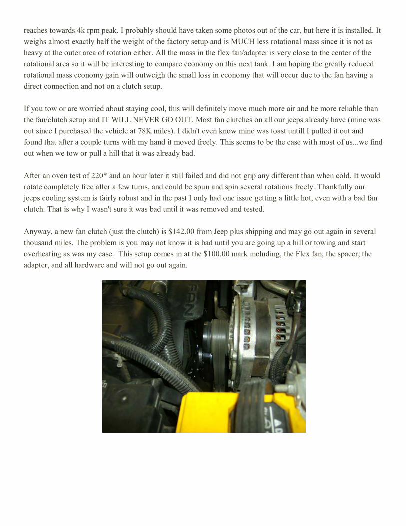
reaches towards 4k rpm peak. I probably should have taken some photos out of the car, but here it is installed. It weighs almost exactly half the weight of the factory setup and is MUCH less rotational mass since it is not as heavy at the outer area of rotation either. All the mass in the flex fan/adapter is very close to the center of the rotational area so it will be interesting to compare economy on this next tank. I am hoping the greatly reduced rotational mass economy gain will outweigh the small loss in economy that will occur due to the fan having a direct connection and not on a clutch setup. If you tow or are worried about staying cool, this will definitely move much more air and be more reliable than the fan/clutch setup and IT WILL NEVER GO OUT. Most fan clutches on all our jeeps already have (mine was out since I purchased the vehicle at 78K miles). I didn't even know mine was toast untill I pulled it out and found that after a couple turns with my hand it moved freely. This seems to be the case with most of us...we find out when we tow or pull a hill that it was already bad. After an oven test of 220* and an hour later it still failed and did not grip any different than when cold. It would rotate completely free after a few turns, and could be spun and spin several rotations freely. Thankfully our jeeps cooling system is fairly robust and in the past I only had one issue getting a little hot, even with a bad fan clutch. That is why I wasn't sure it was bad until it was removed and tested. Anyway, a new fan clutch (just the clutch) is $142.00 from Jeep plus shipping and may go out again in several thousand miles. The problem is you may not know it is bad until you are going up a hill or towing and start overheating as was my case. This setup comes in at the $100.00 mark including, the Flex fan, the spacer, the adapter, and all hardware and will not go out again.

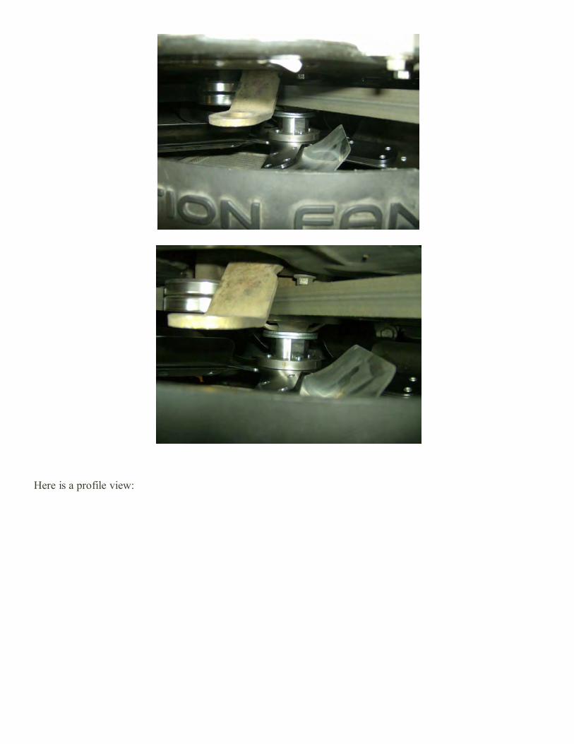
Here is a profile view:
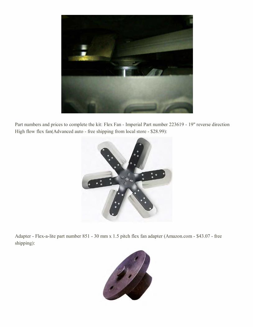
Part numbers and prices to complete the kit: Flex Fan - Imperial Part number 223619 - 19" reverse direction High flow flex fan(Advanced auto - free shipping from local store - $28.99):
Adapter - Flex-a-lite part number 851 - 30 mm x 1.5 pitch flex fan adapter (Amazon.com - $43.07 - free shipping):
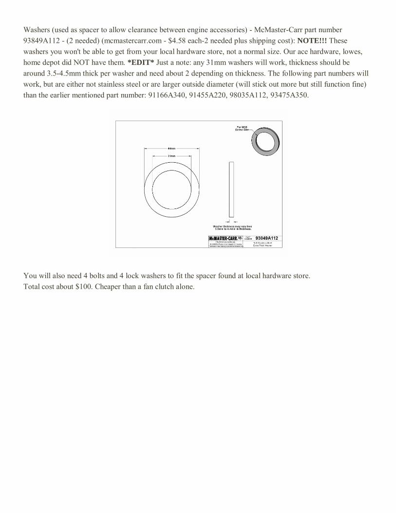
Washers (used as spacer to allow clearance between engine accessories) - McMaster-Carr part number 93849A112 - (2 needed) (mcmastercarr.com - $4.58 each-2 needed plus shipping cost): NOTE!!! These washers you won't be able to get from your local hardware store, not a normal size. Our ace hardware, lowes, home depot did NOT have them. *EDIT* Just a note: any 31mm washers will work, thickness should be around 3.5-4.5mm thick per washer and need about 2 depending on thickness. The following part numbers will work, but are either not stainless steel or are larger outside diameter (will stick out more but still function fine) than the earlier mentioned part number: 91166A340, 91455A220, 98035A112, 93475A350.
You will also need 4 bolts and 4 lock washers to fit the spacer found at local hardware store. Total cost about $100. Cheaper than a fan clutch alone.
How to fix fueling with gasoline - by geordi You won't be able to siphon it from the tank neck; there is an anti-siphon thing at the bottom which will block you. If you are game for a few bucks investment however, hit the local parts shack and get a "Mr Gasket" inline fuel pump. Ideally, you want the one that is about $60, and green for diesel. However, if all they have is the black and red one... Who cares. This is ONLY to suck out the tank. Also get a spool of 20 gauge wire, you will need about 30 feet or so to power the pump. Get about 7-10 feet of 5/16 fuel line and a couple hose clamps. Don't forget a bottle of Diesel 911, or if they don't have that, get 2 bottles (32 ounce size) of Power Service Silver Bottle, and a new fuel filter. Get under the back and have a look at the lines from the tank. The larger plastic line is the one you want, that is the suction line from the tank. Cut the plastic someplace convenient, bathe in fuel (don't worry, repairing this later is easy, and it is actually a small upgrade too) and shove the fuel line over the plastic tube and clamp it down. Out from under the CRD (This is why you want a long hose) connect the hose to the inlet side of the fuel pump. Maybe use a small length on the outlet side, you are going to want to put that into 5 gallon cans for a while, run the wire to the battery and let it rip. Yea, this is going to take a LONG time. But it is the fastest and cheapest way I know of to un-fuel a vehicle like the CRD when you've borked it. You can actually use the fuel in a gasoline vehicle without any problems, just mix it at about 2.5-gallons-into-15 to get rid of it. Believe it or not, but a lot of the fuel you buy is contaminated by other fuels to a small percentage, 5% or so shouldn't be any problem at all. You might notice a slight drop in mileage, but it will burn OK as a mix. Just not in a diesel! :) While the tank is draining, pull the filter off, pour it out... Throw it out. It is contaminated, and the percentage is too high in there to expect that you will be able to recover that. Pour the Diesel 911 DIRECTLY into the filter, and put it onto the mount. Don't worry about the fuel line back to the tank - You just drained it by removing the filter with the line cut. It is all over the driveway now. Oops. :) Once the tank is dry, put the fuel line back together by removing the quick-clip on the side heading to the engine... And cut a small length of that fuel hose to reach the bare metal of the connection - Hose clamp it in place, and you are now ready for fresh DIESEL in to the tank. Add the rest of the Diesel 911 (use the whole bottle) into the tank, OR both bottles FULL STRENGTH if you had to get the Power Service Silver. Once you have a few gallons of diesel in there, start it up (it should fire fairly quickly) and let it run with that mix for a good 10 minutes to really wash everything out. It should smooth out fairly quickly, but you want to give it a good washing with actual diesel. All in all, your CRD *should* be OK with this. I had a misfueling on my Jetta years ago, and it was fine too... After I did just about all this, except that I had easy access to the fuel tank TOP from under the seat. Had to throw out that shop-vac after tho.
Fault codes per gmctd B10B3-VISCOUS/CABIN HEATER RELAY CONTROL OPEN CIRCUIT . C100A–LEFT FRONT WHEEL SPEED SENSOR CIRCUIT. C1011–LEFT FRONT WHEEL SPEED SENSOR SIGNAL ERRATIC PERFORMANCE C1014–LEFT FRONT WHEEL SPEED COMPARATIVE PERFORMANCE C1015–RIGHT FRONT WHEEL SPEED SENSOR CIRCUIT. C101C–RIGHT FRONT WHEEL SPEED SENSOR SIGNAL ERRATIC PERFORMANCE. C101F–RIGHT FRONT WHEEL SPEED COMPARATIVE PERFORMANCE. C1020–LEFT REAR WHEEL SPEED SENSOR CIRCUIT. C1027–LEFT REAR WHEEL SPEED SENSOR SIGNAL ERRATIC PERFORMANCE. . C102A–LEFT REAR WHEEL SPEED COMPARATIVE PERFORMANCE. C102B–RIGHT REAR WHEEL SPEED SENSOR CIRCUIT. . C1032–RIGHT REAR WHEEL SPEED SENSOR SIGNAL ERRATIC PERFORMANCE. . C1035–RIGHT REAR WHEEL SPEED COMPARATIVE PERFORMANCE. C1041–LEFT FRONT TONE WHEEL PERFORMANCE C1042–RIGHT FRONT TONE WHEEL PERFORMANCE . C1043–LEFT REAR TONE WHEEL PERFORMANCE . C1044–RIGHT REAR TONE WHEEL PERFORMANCE . . . C1046–LEFT FRONT WHEEL PRESSURE PHASE MONITORING . C1047–RIGHT FRONT WHEEL PRESSURE PHASE MONITORING . . C1048–LEFT REAR WHEEL PRESSURE PHASE MONITORING . C1049–RIGHT REAR WHEEL PRESSURE PHASE MONITORING C1073–ABS PUMP MOTOR CONTROL CIRCUIT. . . C1078–TIRE REVOLUTIONS RANGE PERFORMANCE . C107C–BRAKE PEDAL SWITCH 1/2 STUCK C107D–BRAKE PEDAL SWITCH 1/2 CORRELATION. C1210–G SENSOR INPUT CIRCUIT PERFORMANCE . C1219–STEERING ANGLE SENSOR ERRATIC PERFORMANCE. C121A–STEERING ANGLE SENSOR NOT INITIALIZED. C121C–TORQUE REQUEST SIGNAL DENIED . C121D–BRAKE PRESSURE SENSOR CIRCUIT. C121E–BRAKE PRESSURE SENSOR COMPARATIVE PERFORMANCE . C1231–DRIVE TEST: STEERING ANGLE SENSOR. C1232–DRIVE TEST: PRESSURE SENSOR C1234–DRIVE TEST: SENSOR CLUSTER INSTALLATION. C1238-DRIVE TEST: UNSUCCESSFUL . C1239–EMISSIONS ROLLS TEST ACTIVE C123A–ESP SYSTEM SENSORS CALIBRATION. C123B–ESP SYSTEM CONTROL TOO LONG C123C–DYNAMICS SENSOR MOUNTING/INSTALLATION PERFORMANCE . C123F–STEERING ANGLE SENSOR COMPARATIVE PERFORMANCE C1240–STEERING ANGLE OVERTRAVEL PERFORMANCE. . C1242–GSENSOR INPUT SIGNAL PERFORMANCE
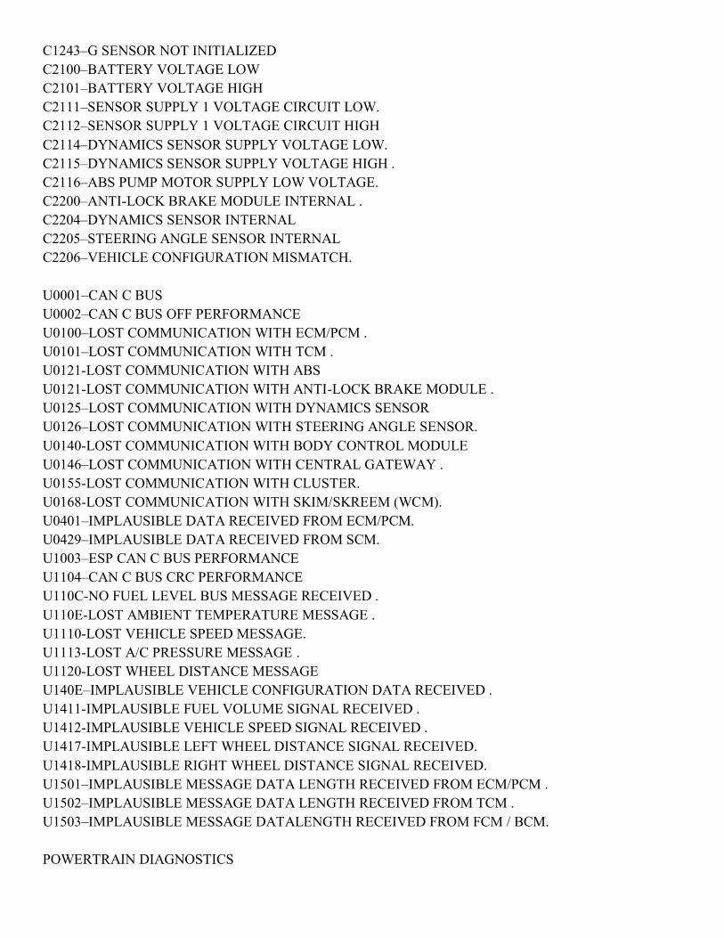
C1243–G SENSOR NOT INITIALIZED C2100–BATTERY VOLTAGE LOW C2101–BATTERY VOLTAGE HIGH C2111–SENSOR SUPPLY 1 VOLTAGE CIRCUIT LOW. C2112–SENSOR SUPPLY 1 VOLTAGE CIRCUIT HIGH C2114–DYNAMICS SENSOR SUPPLY VOLTAGE LOW. C2115–DYNAMICS SENSOR SUPPLY VOLTAGE HIGH . C2116–ABS PUMP MOTOR SUPPLY LOW VOLTAGE. C2200–ANTI-LOCK BRAKE MODULE INTERNAL . C2204–DYNAMICS SENSOR INTERNAL C2205–STEERING ANGLE SENSOR INTERNAL C2206–VEHICLE CONFIGURATION MISMATCH. U0001–CAN C BUS U0002–CAN C BUS OFF PERFORMANCE U0100–LOST COMMUNICATION WITH ECM/PCM . U0101–LOST COMMUNICATION WITH TCM . U0121-LOST COMMUNICATION WITH ABS U0121-LOST COMMUNICATION WITH ANTI-LOCK BRAKE MODULE . U0125–LOST COMMUNICATION WITH DYNAMICS SENSOR U0126–LOST COMMUNICATION WITH STEERING ANGLE SENSOR. U0140-LOST COMMUNICATION WITH BODY CONTROL MODULE U0146–LOST COMMUNICATION WITH CENTRAL GATEWAY . U0155-LOST COMMUNICATION WITH CLUSTER. U0168-LOST COMMUNICATION WITH SKIM/SKREEM (WCM). U0401–IMPLAUSIBLE DATA RECEIVED FROM ECM/PCM. U0429–IMPLAUSIBLE DATA RECEIVED FROM SCM. U1003–ESP CAN C BUS PERFORMANCE U1104–CAN C BUS CRC PERFORMANCE U110C-NO FUEL LEVEL BUS MESSAGE RECEIVED . U110E-LOST AMBIENT TEMPERATURE MESSAGE . U1110-LOST VEHICLE SPEED MESSAGE. U1113-LOST A/C PRESSURE MESSAGE . U1120-LOST WHEEL DISTANCE MESSAGE U140E–IMPLAUSIBLE VEHICLE CONFIGURATION DATA RECEIVED . U1411-IMPLAUSIBLE FUEL VOLUME SIGNAL RECEIVED . U1412-IMPLAUSIBLE VEHICLE SPEED SIGNAL RECEIVED . U1417-IMPLAUSIBLE LEFT WHEEL DISTANCE SIGNAL RECEIVED. U1418-IMPLAUSIBLE RIGHT WHEEL DISTANCE SIGNAL RECEIVED. U1501–IMPLAUSIBLE MESSAGE DATA LENGTH RECEIVED FROM ECM/PCM . U1502–IMPLAUSIBLE MESSAGE DATA LENGTH RECEIVED FROM TCM . U1503–IMPLAUSIBLE MESSAGE DATALENGTH RECEIVED FROM FCM / BCM. POWERTRAIN DIAGNOSTICS

B10B3-VISCOUS/CABIN HEATER RELAY CONTROL OPEN CIRCUIT . P0016–CRANKSHAFT / CAMSHAFT TIMING MISALIGNMENT. P0031-O2 SENSOR 1/1 HEATER CIRCUIT LOW. P0032-O2 SENSOR 1/1 HEATER CIRCUIT HIGH. P0037-O2 SENSOR 1/2 HEATER CIRCUIT LOW. P0038-O2 SENSOR 1/2 HEATER CIRCUIT HIGH. P0045-BOOST PRESSURE SOLENOID EXCESSIVE CURRENT. P0045-BOOST PRESSURE SOLENOID OPEN CIRCUIT . P0047-TURBOCHARGER BOOST PRESSURE SOLENOID SHORT TO GROUND. P0048-TURBOCHARGER BOOST CONTROLCIRCUIT SHORT CIRCUIT . P0051-O2 SENSOR 2/1 HEATER CIRCUIT LOW. P0052-O2 SENSOR 2/1 HEATER CIRCUIT HIGH. P0057-O2 SENSOR 2/2 HEATER CIRCUI LOW. P0058-O2 SENSOR 2/2 HEATER CIRCUIT HIGH. P0068-MANIFOLD PRESSURE/THROTTLE POSITION CORRELATION . P0069-BOOST KEY-ON RATIONALITY P0070-AMBIENT AIR TEMPERATURE SIGNAL VOLTAGE TOO HIGH . P0070-AMBIENT AIR TEMPERATURE SIGNAL VOLTAGE TOO LOW P0071-AMBIENT AIR TEMPERATURE SENSOR PERFORMANCE . P0072-AMBIENT AIR TEMPERATURE SENSOR CIRCUIT LOW. P0073–AMBIENT AIR TEMPERATUR SENSOR CIRCUIT HIGH P0087-FUEL RAIL PRESSURE MALFUNCTION PRESSURE TOO LOW. P0088-FUEL RAIL PRESSURE TOO HIGH . P0089-FUEL PRESSURE 1 CONTROL PERFORMANCE P0090-FUEL QUANTITY SOLENOID OPEN CIRCUIT P0091-FUEL QUANTITY SOLENOID SHORT TO GROUND . P0092-FUEL QUANTITY SOLENOID SHORT CIRCUIT. P0093 - FUEL RAIL PRESSURE MALFUNCTION POSITIVE PRESSURE DEVIATION. P009A-INTAKE AIR TEMP/ AMBIENT AIR TEMP PLAUSIBILITY . P0100-MAF SENSOR SIGNAL VOLTAGE TOO HIGH P0100-MAF SENSOR SIGNAL VOLTAGE TOO LOW . P0101-MAF SENSOR SIGNAL NEGATIVE DEVIATION. P0101-MAF SENSOR SIGNAL POSITIVE DEVIATION. P0105-INLET PRESSURE SENSOR SIGNAL PLAUSIBILITY. P0105-INLET PRESSURE SENSOR SIGNAL VOLTAGE TOO HIGH P0105-INLET PRESSURE SENSOR SIGNAL VOLTAGE TOO LOW P0107-MANIFOLD ABSOLUTE PRESSURE SENSOR CIRCUIT LOW. P0108-MANIFOLD ABSOLUTE PRESSURE SENSOR CIRCUIT HIGH. P0110-INTAKE AIR TEMP SENSOR SIGNAL VOLTAGE TOO HIGH P0110-INTAKE AIR TEMP SENSOR SIGNAL VOLTAGE TOO LOW . P0111-INTAKE AIR TEMPERATURE SENSOR RATIONALITY. P0112-INTAKE AIR TEMPERATURE SENSOR CIRCUIT LOW. P0113-INTAKE AIR TEMPERATURE SENSOR CIRCUIT HIGH. P0115-ENGINE COOLANT TEMP SENSOR SIGNAL VOLTAGE TOO HIGH .
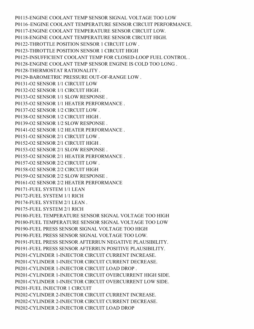
P0115-ENGINE COOLANT TEMP SENSOR SIGNAL VOLTAGE TOO LOW P0116–ENGINE COOLANT TEMPERATURE SENSOR CIRCUIT PERFORMANCE. P0117-ENGINE COOLANT TEMPERATURE SENSOR CIRCUIT LOW. P0118-ENGINE COOLANT TEMPERATURE SENSOR CIRCUIT HIGH. P0122-THROTTLE POSITION SENSOR 1 CIRCUIT LOW . P0123-THROTTLE POSITION SENSOR 1 CIRCUIT HIGH P0125-INSUFFICIENT COOLANT TEMP FOR CLOSED-LOOP FUEL CONTROL . P0128-ENGINE COOLANT TEMP SENSOR ENGINE IS COLD TOO LONG . P0128-THERMOSTAT RATIONALITY . P0129-BAROMETRIC PRESSURE OUT-OF-RANGE LOW . P0131-O2 SENSOR 1/1 CIRCUIT LOW P0132-O2 SENSOR 1/1 CIRCUIT HIGH . P0133-O2 SENSOR 1/1 SLOW RESPONSE . P0135-O2 SENSOR 1/1 HEATER PERFORMANCE . P0137-O2 SENSOR 1/2 CIRCUIT LOW . P0138-O2 SENSOR 1/2 CIRCUIT HIGH . P0139-O2 SENSOR 1/2 SLOW RESPONSE . P0141-O2 SENSOR 1/2 HEATER PERFORMANCE . P0151-O2 SENSOR 2/1 CIRCUIT LOW . P0152-O2 SENSOR 2/1 CIRCUIT HIGH . P0153-O2 SENSOR 2/1 SLOW RESPONSE . P0155-O2 SENSOR 2/1 HEATER PERFORMANCE . P0157-O2 SENSOR 2/2 CIRCUIT LOW . P0158-O2 SENSOR 2/2 CIRCUIT HIGH P0159-O2 SENSOR 2/2 SLOW RESPONSE . P0161-O2 SENSOR 2/2 HEATER PERFORMANCE P0171-FUEL SYSTEM 1/1 LEAN P0172-FUEL SYSTEM 1/1 RICH P0174-FUEL SYSTEM 2/1 LEAN . P0175-FUEL SYSTEM 2/1 RICH P0180-FUEL TEMPERATURE SENSOR SIGNAL VOLTAGE TOO HIGH P0180-FUEL TEMPERATURE SENSOR SIGNAL VOLTAGE TOO LOW P0190-FUEL PRESS SENSOR SIGNAL VOLTAGE TOO HIGH P0190-FUEL PRESS SENSOR SIGNAL VOLTAGE TOO LOW. P0191-FUEL PRESS SENSOR AFTERRUN NEGATIVE PLAUSIBILITY. P0191-FUEL PRESS SENSOR AFTERRUN POSITIVE PLAUSIBILITY. P0201-CYLINDER 1-INJECTOR CIRCUIT CURRENT INCREASE. P0201-CYLINDER 1-INJECTOR CIRCUIT CURRENT DECREASE. P0201-CYLINDER 1-INJECTOR CIRCUIT LOAD DROP . P0201-CYLINDER 1-INJECTOR CIRCUIT OVERCURRENT HIGH SIDE. P0201-CYLINDER 1-INJECTOR CIRCUIT OVERCURRENT LOW SIDE. P0201-FUEL INJECTOR 1 CIRCUIT P0202-CYLINDER 2-INJECTOR CIRCUIT CURRENT INCREASE. P0202-CYLINDER 2-INJECTOR CIRCUIT CURRENT DECREASE. P0202-CYLINDER 2-INJECTOR CIRCUIT LOAD DROP

P0202-CYLINDER 2-INJECTOR CIRCUIT OVERCURRENT HIGH SIDE. . P0202-CYLINDER 2-INJECTOR CIRCUIT OVERCURRENT LOW SIDE. P0202-FUEL INJECTOR 2 CIRCUIT . P0203-CYLINDER 3-INJECTOR CIRCUIT CURRENT INCREASE. P0203-CYLINDER 3-INJECTOR CIRCUIT CURRENT DECREASE. P0203-CYLINDER 3-INJECTOR CIRCUIT LOAD DROP P0203-CYLINDER 3-INJECTOR CIRCUIT OVERCURRENT HIGH SIDE . P0203-CYLINDER 3-INJECTOR CIRCUIT OVERCURRENT LOW SIDE. P0203-FUEL INJECTOR 3 CIRCUIT P0204-CYLINDER 4-INJECTOR CIRCUIT CURRENT INCREASE. P0204-CYLINDER 4-INJECTOR CIRCUIT CURRENT DECREASE. P0204-CYLINDER 4-INJECTOR CIRCUIT LOAD DROP P0204-CYLINDER 4-INJECTOR CIRCUIT OVERCURRENT HIGH SIDE. P0204-CYLINDER 4-INJECTOR CIRCUIT OVERCURRENT LOW SIDE P0204-FUEL INJECTOR 4 CIRCUIT P0205-FUEL INJECTOR 5 CIRCUIT P0206-FUEL INJECTOR 6 CIRCUIT P0234-BOOST PRESSURE SENSOR NEGATIVE DEVIATION. P0235-BOOST PRESSURE SENSOR PLAUSIBILITY. P0235-BOOST PRESSURE SENSOR SIGNAL VOLTAGE TOO HIGH . P0235-BOOST PRESSURE SENSOR SIGNAL VOLTAGE TOO LOW P0251-FUEL QUANTITY SOLENOID OPEN OR SHORT CIRCUIT . P0252-FUEL QUANTITY SOLENOID CIRCUIT MALFUNCTION P0253-FUEL QUANTITY SOLENOID SHORT TO GROUND . P0254-FUEL QUANTITY SOLENOID SHORT CIRCUIT. . . P0299-BOOST PRESSURE SENSOR POSITIVE DEVIATION P0300-MISFIRE DETECTED P0300-MULTIPLE CYLINDER MISFIRE . P0301-CYLINDER 1 MISFIRE . . . P0301-MISFIRE DETECTED CYLINDER #1 P0302-CYLINDER 2 MISFIRE . P0302-MISFIRE DETECTED CYLINDER #2 P0303-CYLINDER 3 MISFIRE . P0303-MISFIRE DETECTED CYLINDER #3 . P0304-CYLINDER 4 MISFIRE . . P0304-MISFIRE DETECTED CYLINDER #4 P0305-CYLINDER 5 MISFIRE . P0306-CYLINDER 6 MISFIRE . . . . . . P0315-NO CRANK SENSOR LEARNED . P0325-KNOCK SENSOR 1 CIRCUIT . P0330-KNOCK SENSOR 2 CIRCUIT . P0335-CRANKSHAFT POSITION SENSOR CIRCUIT INCORRECT OR MISSING SIGNAL P0335-CRANKSHAFT POSITION SENSOR CIRCUIT. P0339-CRANKSHAFT POSITION SENSOR CIRCUIT INTERMITTENT INCORRECT OR MISSING SIGNAL.
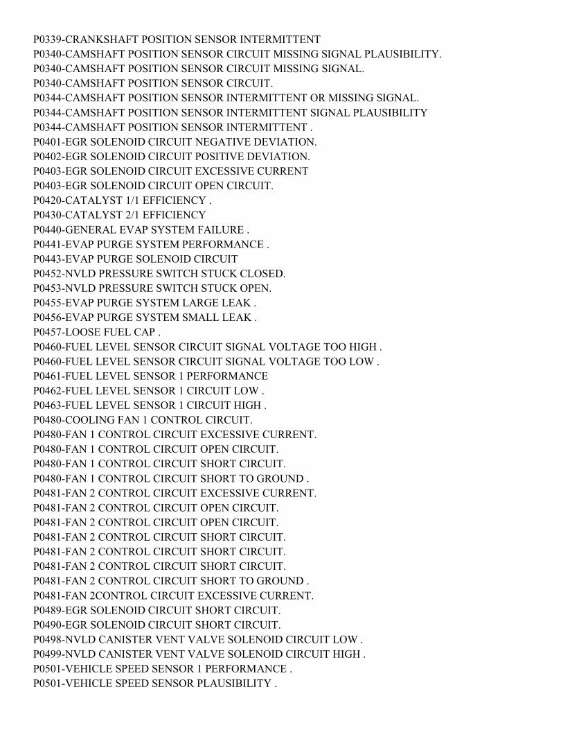
P0339-CRANKSHAFT POSITION SENSOR INTERMITTENT P0340-CAMSHAFT POSITION SENSOR CIRCUIT MISSING SIGNAL PLAUSIBILITY. P0340-CAMSHAFT POSITION SENSOR CIRCUIT MISSING SIGNAL. P0340-CAMSHAFT POSITION SENSOR CIRCUIT. P0344-CAMSHAFT POSITION SENSOR INTERMITTENT OR MISSING SIGNAL. P0344-CAMSHAFT POSITION SENSOR INTERMITTENT SIGNAL PLAUSIBILITY P0344-CAMSHAFT POSITION SENSOR INTERMITTENT . P0401-EGR SOLENOID CIRCUIT NEGATIVE DEVIATION. P0402-EGR SOLENOID CIRCUIT POSITIVE DEVIATION. P0403-EGR SOLENOID CIRCUIT EXCESSIVE CURRENT P0403-EGR SOLENOID CIRCUIT OPEN CIRCUIT. P0420-CATALYST 1/1 EFFICIENCY . P0430-CATALYST 2/1 EFFICIENCY P0440-GENERAL EVAP SYSTEM FAILURE . P0441-EVAP PURGE SYSTEM PERFORMANCE . P0443-EVAP PURGE SOLENOID CIRCUIT P0452-NVLD PRESSURE SWITCH STUCK CLOSED. P0453-NVLD PRESSURE SWITCH STUCK OPEN. P0455-EVAP PURGE SYSTEM LARGE LEAK . P0456-EVAP PURGE SYSTEM SMALL LEAK . P0457-LOOSE FUEL CAP . P0460-FUEL LEVEL SENSOR CIRCUIT SIGNAL VOLTAGE TOO HIGH . P0460-FUEL LEVEL SENSOR CIRCUIT SIGNAL VOLTAGE TOO LOW . P0461-FUEL LEVEL SENSOR 1 PERFORMANCE P0462-FUEL LEVEL SENSOR 1 CIRCUIT LOW . P0463-FUEL LEVEL SENSOR 1 CIRCUIT HIGH . P0480-COOLING FAN 1 CONTROL CIRCUIT. P0480-FAN 1 CONTROL CIRCUIT EXCESSIVE CURRENT. P0480-FAN 1 CONTROL CIRCUIT OPEN CIRCUIT. P0480-FAN 1 CONTROL CIRCUIT SHORT CIRCUIT. P0480-FAN 1 CONTROL CIRCUIT SHORT TO GROUND . P0481-FAN 2 CONTROL CIRCUIT EXCESSIVE CURRENT. P0481-FAN 2 CONTROL CIRCUIT OPEN CIRCUIT. P0481-FAN 2 CONTROL CIRCUIT OPEN CIRCUIT. P0481-FAN 2 CONTROL CIRCUIT SHORT CIRCUIT. P0481-FAN 2 CONTROL CIRCUIT SHORT CIRCUIT. P0481-FAN 2 CONTROL CIRCUIT SHORT CIRCUIT. P0481-FAN 2 CONTROL CIRCUIT SHORT TO GROUND . P0481-FAN 2CONTROL CIRCUIT EXCESSIVE CURRENT. P0489-EGR SOLENOID CIRCUIT SHORT CIRCUIT. P0490-EGR SOLENOID CIRCUIT SHORT CIRCUIT. P0498-NVLD CANISTER VENT VALVE SOLENOID CIRCUIT LOW . P0499-NVLD CANISTER VENT VALVE SOLENOID CIRCUIT HIGH . P0501-VEHICLE SPEED SENSOR 1 PERFORMANCE . P0501-VEHICLE SPEED SENSOR PLAUSIBILITY .

P0503-VEHICLE SPEED SENSOR 1 ERRATIC. P0504-BRAKE SWITCH SIGNAL CIRCUITS PLAUSIBILITY WITH REDUNDANT CONTACT . P0506-IDLE SPEED PERFORMANCE LOWER THAN EXCEPTED . P0507-IDLE SPEED PERFORMANCE HIGHER THAN EXCEPTED . P0508-IDLE AIR CONTROL VALVE SENSE CIRCUIT LOW. P0509-IDLE AIR CONTROL VALVE SENSE CIRCUIT HIGH P0513-INVALID SKIM KEY . P0513-SKIM SYSTEM INVALID KEY CODE RECEIVED P0513-SKIM SYSTEM READ ACCESS TO EEPROM FAILURE. P0513-SKIM SYSTEM WRITE ACCESS TOEEPROM FAILURE. P0513-SKIM SYSTEM WRITE ACCESS TO EEPROM FAILURE. P0520- OIL PRESS SENSOR CIRCUIT MALF PLAUSIBILITY. P0520-OIL PRESS SENSOR CKT MALF SIGNAL VOLTAGE TOO HIGH. P0520-OIL PRESS SENSOR CKT MALF SIGNAL VOLTAGE TOO LOW. P0522-OIL PRESSURE TOO LOW . P0530- A/C PRESS SENSOR CIRCUIT MALF PLAUSIBILITY. P0530- A/C PRESS SENSOR CIRCUIT VOLTAGE TOO HIGH P0530- A/C PRESS SENSOR CIRCUIT VOLTAGE TOO LOW . P0532-A/C PRESSURE SENSOR CIRCUIT LOW (ESP). P0533-A/C PRESSURE SENSOR CIRCUIT HIGH (ESP). P0560-ECM VOLTAGE TOO HIGH . P0560-ECM VOLTAGE TOO LOW . P0562-BATTERY VOLTAGE LOW . P0563-BATTERY VOLTAGE HIGH . P0564-S/C SWITCH #1 SIGNAL CIRCUIT PLAUSIBILITY . P0564-S/C SWITCH #1 SIGNAL CIRCUIT STUCK SWITCH. P0564-S/C SWITCH #1 SIGNAL CIRCUIT VOLTAGE TOO HIGH. P0564-S/C SWITCH #1 SIGNAL CIRCUIT VOLTAGE TOO LOW . P0571-BRAKE SWITCH 1 PERFORMANCE . P0572-BRAKE SWITCH 1 STUCK ON . P0573-BRAKE SWITCH 1 STUCK OFF . P0580-SPEED CONTROL SWITCH 1 CIRCUIT LOW. P0581-SPEED CONTROL SWITCH 1 CIRCUIT HIGH. P0582-SPEED CONTROL VACUUM CONTROL CIRCUIT. P0585-S/C SWITCH PLAUSIBILITY BETWEEN SWITCH #1 AND #2. P0586-SPEED CONTROL VENT CONTROL CIRCUIT. P0589-S/C SWITCH #2 SIGNAL CIRCUIT PLAUSIBILITY . P0589-S/C SWITCH #2 SIGNAL CIRCUIT STUCK SWITCH. P0589-S/C SWITCH #2 SIGNAL CIRCUI VOLTAGE TOO HIGH. P0589-S/C SWITCH #2 SIGNAL CIRCUIT VOLTAGE TOO LOW . P0594-SPEED CONTROL SERVO POWER RELAY CIRCUIT . P0600-ECM COMMUNICATION ERROR . P0600-ECM COMMUNICATION ERROR . P0600-ECM RECOVERY . P0600-SERIAL COMMUNICATION LINK .

P0601-INTERNAL MEMORY CHECKSUM INVALID. P0602-ECM INVALID CODE WORD P0606-ECM CHECKSUM ERROR P0606-ECM DEVIATION ERROR . P0606-ECM INTERNAL ERROR . P0606-INTERNAL ECM PROCESSOR . P0610-AUTOMATIC TRANSMISSION CODED AS MANUAL TRANSMISSION . P0610-MANUAL TRANSMISSION CODE AS AUTOMATIC TRANSMISSION . P0615-STARTER RELAY CIRCUIT EXCESSIVE CURRENT . P0615-STARTER RELAY CIRCUIT OPEN CIRCUIT . P0616-STARTER RELAY CIRCUIT SHORT TO GROUND. P0617-STARTER RELAY CIRCUIT SHORT CIRCUIT . P0622-GENERATOR FIELD CONTROL CIRCUIT. P0627-FUEL PUMP CONTROL CIRCUIT . P0630-VIN NOT PROGRAMMED IN PCM. P0632-ODOMETER NOT PROGRAMMED IN PCM . P0633-SKIM KEY NOT PROGRAMMED IN PCM . P0641-SENSOR SUPPLY 1 VOLTAGE TOO HIGH P0641-SENSOR SUPPLY 1 VOLTAGE TOO LOW P0645-A/C CLUTCH CONTROL CIRCUIT . P0645-A/C CLUTCH RELAY CIRCUIT EXCESSIVE CURRENT . P0645-A/C CLUTCH RELAY CIRCUIT OPEN CIRCUIT . P0645-A/C CLUTCH RELAY CIRCUIT SHORT TO GROUND. P0645-A/C CLUTCH RELAY SHORT CIRCUIT . P0651-SENSOR SUPPLY 2 VOLTAGE TOO HIGH. P0651-SENSOR SUPPLY 2 VOLTAGE TOO LOW. P0670-GLOW PLUG CONTROLLER CIRCUIT MALFUNCTION . P0671-GLOW PLUG 1 PLUG FAILURE . P0671-GLOW PLUG 1 PLUG SHORT CIRCUIT . P0672-GLOW PLUG 2 PLUG FAILURE . . P0672-GLOW PLUG 2 PLUG SHORT CIRCUIT . P0673-GLOW PLUG 3 PLUG FAILURE . P0673-GLOW PLUG 3 SHORT CIRCUIT . P0674-GLOW PLUG 4 PLUG FAILURE . P0674-GLOW PLUG 4 SHORT CIRCUIT . P0683-GLOW PLUG MODULE SIGNAL CIRCUIT MALFUNCTION . P0685-ASD RELAY CONTROL CIRCUIT SHUTS OFF TOO EARLY. P0685-ASD RELAY CONTROL CIRCUIT SHUTS OFF TOO LATE . P0685-AUTO SHUTDOWN CONTROL CIRCUIT. P0686-ECM VOLTAGE ERROR LOW . P0687-ECM VOLTAGE ERROR HIGH . P0688-AUTO SHUTDOWN SENSE CIRCUIT LOW . P0697-SENSOR SUPPLY 3 VOLTAGE TOO HIGH. P0697-SENSOR SUPPLY 3 VOLTAGE TOO LOW. P0700-TCM DTC .

P0700-TRANSMISSION CONTROL SYSTEM (MIL REQUEST). P0836-TRANSFER CASE POSITION SENSOR PLAUSIBILITY. P0836-TRANSFER CASE POSITION SENSOR SIGNAL VOLTAGE TOO HIGH P0836-TRANSFER CASE POSITION SIGNAL VOLTAGE TOO LOW. P0850-PARK/NEUTRAL SWITCH PERFORMANCE . P0864-TCM TORQUE REDUCTION SIGNAL ERROR. P1001-IGNITION KEY OFF TIMER PERFORMANCE - TOO FAST. P1002-IGNITION KEY OFF TIMER PERFORMANCE - TOO SLOW . P1101-ACM CRASH SIGNAL RECIEVED . P1102-VISCOUS/CABIN HEATER RELAY EXCESSIVE CURRENT . P1102-VISCOUS/CABIN HEATER RELAY OPEN CIRCUIT . P1102-VISCOUS/CABIN HEATER RELAY SHORT CIRCUIT . P1102-VISCOUS/CABIN HEATER RELAY SHORT TO GROUND. P1115-GENERAL TEMPERATURE RATIONALITY. P1131-GLOW PLUG MODULE INTERNAL FAULT . P1131-GLOW PLUG MODULE VOLTAGE SUPPLY. P1135-GLOW PLUG MODULE CONTROL CIRCUIT EXCESSIVE CURRENT. P1135-GLOW PLUG MODULE CONTROL CIRCUIT OPEN CIRCUIT. P1135-GLOW PLUG MODULE CONTROL CIRCUIT SHORTED TO GROUND P1135-GLOW PLUG MODULE CONTROL CIRCUIT SHORTED TO VOLTAGE . P1140-VACUUM RESERVOIR SOLENOID CIRCUIT SHORT TO GROUND . P1140-VACUUM RESERVOIR SOLENOID OPEN CIRCUIT . P1140-VACUUM RESERVOIR SOLENOID SHORT CIRCUIT .P1140 code FSM notwithstanding
probably relates to the FCV (flow control valve) which if failed open can be ignored (e.g. just drive with
the FCV failed open). As of July 2011 I don't know how to jigger the system to make the MIL/CEL go
away.
P1142-FUEL PRESSURE SOLENOID OPEN CIRCUIT . P1142-FUEL PRESSURE SOLENOID PLAUSIBILITY . P1142-FUEL PRESSURE SOLENOID SHORT CIRCUIT . P1143-FUEL RAIL PRESSURE MALFUNCTION POSITIVE PRESSURE DEVIATION . P1144-FUEL RAIL PRESSURE MALFUNCTION POSITIVE VOLUME DEVIATION . P1145– FUEL RAIL PRESSURE MALFUNCTION NEGATIVE PRESSURE DEVIATION . P1148-FUEL RAIL PRESSURE MALFUNCTION PRESSURE DROP IN OVERRUN P1151-FUEL RAIL PRESSURE MALFUNCTION MAXIMUM POSITIVE DEVIATION . P1152-FUEL RAIL PRESSURE MALFUNCTION POSITIVE DEV FUEL PRESS SOL SETPOINT. P1153-FUEL RAIL PRESSURE MALFUNCTION NEGATIVE DEV FUEL PRESS SOL SETPOINT. . P1154-FUEL RAIL PRESSURE MALFUNCTION RAIL PRESSURE IS TOO LOW. P1155-FUEL RAIL PRESSURE MALFUNCTION RAIL PRESSURE IS TOO HIGH. P1156-FUEL RAIL PRESSURE MALFUNCTION PLAUSIBILITY . P1159-IMPROPER START ATTEMPT P1160-IGN VOLTAGE . P1167-CAPACITOR VOLTAGE 1 . P1169-ECM A/D CONVERTER ERROR P1186 - per GDE is a plausibility fault on the airbox pressure sensor (on side of air box with little Mercedes logo). it most likely came unplugged. The connector retention clip is weak on this sensor and may break

P1202 - FUEL SYSTEM OVER-PRESSURE - Stuck Regulator (Diesel) P1250-VACUUM RESERVOIR SOLENOID OPEN CIRCUIT . P1251-VACUUM RESERVOIR SOLENOID SHORT TO GROUND. P1252-VACUUM RESERVOIR SOLENOID SHORT CIRCUIT . P1259 - glow plug module control over-current condition P1260 - glow plug #1 control circuit open P1261 - glow plug #1 control circuit low P1262 - glow plug #2 control circuit open P1263 - glow plug #2 control circuit low P1264 - glow plug #3 control circuit open P1265 - glow plug #3 control circuit low P1266 - glow plug #4 control circuit open P1267 - glow plug #4 control circuit low P1593-SPEED CONTROL SWITCH 1 STUCK. P1602–PCM NOT PROGRAMMED . P1603-PCM INTERNAL DUAL-PORT RAM COMMUNICATION FAILURE P1604-PCM INTERNAL DUAL-PORT RAM READ/WRITE INTEGRITY FAILURE . P1607-PCM INTERNAL SHUTDOWN TIMER RATIONALITY . P1696-EEPROM MEMORY WRITE DENIED/INVALID. P1697-EMR (SRI) MILEAGE NOT STORED . P2074-MANIFOLD PRESSURE/THROTTLE POSITION CORRELATION. P2096-DOWNSTREAM FUEL TRIM SYSTEM 1 LEAN. P2097-DOWNSTREAM FUEL TRIM SYSTEM 1 RICH. P2098-DOWNSTREAM FUEL TRIM SYSTEM 2 LEAN. P2099-DOWNSTREAM FUEL TRIM SYSTEM 2 RICH. P2101-EGR AIR FLOW CONTROL VALVE EXCESSIVE CURRENT . P2101-EGR AIR FLOW CONTROL VALVE OPEN CKT. P2120-ACC PEDAL POSITION SENSOR 1 CIRCUIT VOLTAGE TOO HIGH . P2120-ACC PEDAL POSITION SENSOR 1 CIRCUIT VOLTAGE TOO LOW. P2120-ACC PEDAL POSITION SENSOR 1 CKT PLAUSIBILITY . P2125-ACC PEDAL POSITION SENSOR 2 CKT PLAUSIBILITY . P2125-ACC PEDAL POSITION SENSOR 2 SIGNAL VOLTAGE TOO HIGH. P2125-ACC PEDAL POSITION SENSOR 2 SIGNAL VOLTAGE TOO LOW. P2141-EGR AIR FLOW CONTROL VALVE SHORT TO GROUND. P2142-EGR AIR FLOW CONTROL VALVE SHORT CIRCUIT . P2147 INJECTOR BANK 1 OPEN CIRCUIT . P2148-BANK 1-INJECTOR SHORT CIRCUIT . P2151-BANK 2 SHORT CIRCUIT . P2151-BANK 2- OPEN CIRCUIT . P2181-COOLING SYSTEM PERFORMANCE . P2226 BAROMETRIC PRESSURE CIRCUIT SIGNAL VOLTAGE TOO HIGH. P2264-WATER IN FUEL VOLTAGE ABOVE UPPER LIMIT . P2264-WATER IN FUEL VOLTAGE BELOW LOWER LIMIT . P2294-FUEL PRESSURE SOLENOID OPEN CIRCUIT . P2295-FUEL PRESSURE SOLENOID SHORT TO GROUND.

P2296-FUEL PRESSURE SOLENOID SHORT CIRCUIT . P2302-IGNITION COIL 1 SECONDARY CIRCUIT- INSUFFICIENT IONIZATION . P2305-IGNITION COIL 2 SECONDARY CIRCUIT- INSUFFICIENT IONIZATION . P2308-IGNITION COIL 3 SECONDARY CIRCUIT- INSUFFICIENT IONIZATION . P2311-IGNITION COIL 4 SECONDARY CIRCUIT- INSUFFICIENT IONIZATION . P2314-IGNITION COIL 5 SECONDARY CIRCUIT- INSUFFICIENT IONIZATION . P2317-IGNITION COIL 6 SECONDARY CIRCUIT- INSUFFICIENT IONIZATION P2503-CHARGING SYSTEM OUTPUT LOW . P2525-VACUUM RESERVOIR SOLENOID OPEN CIRCUIT . P2527-VACUUM RESERVOIR SOLENOID SHORT TO GROUND. P2528-VACUUM RESERVOIR SOLENOID SHORT CIRCUIT . POWERTRAIN VERIFICATION TEST . U0001–CAN C BUS . U0101–LOST COMMUNICATION WITH TCM . U0121-LOST COMMUNICATION WITH ANTI-LOCK BRAKE MODULE . U0140-LOST COMMUNICATION WITH BODY CONTROL MODULE . U0155-LOST COMMUNICATION WITH CLUSTER. U0168-LOST COMMUNICATION WITH SKIM/SKREEM (WCM). U110C-NO FUEL LEVEL BUS MESSAGE RECEIVED . U110E-LOST AMBIENT TEMPERATURE MESSAGE . U1110-LOST VEHICLE SPEED MESSAGE. U1113-LOST A/C PRESSURE MESSAGE . U1120-LOST WHEEL DISTANCE MESSAGE U1411-IMPLAUSIBLE FUEL VOLUME SIGNAL RECEIVED . U1412-IMPLAUSIBLE VEHICLE SPEED SIGNAL RECEIVED . U1417-IMPLAUSIBLE LEFT WHEEL DISTANCE SIGNAL RECEIVED. U1418-IMPLAUSIBLE RIGHT WHEEL DISTANCE SIGNAL RECEIVED. TRANSMISSION DIAGNOSTICS P0122-TPS/APP CIRCUIT LOW . P0123-TPS/APP CIRCUIT HIGH . P0124-TPS/APP INTERMITTENT P0218-HIGH TEMPERATURE OPERATION ACTIVATED. P0562-BATTERY VOLTAGE LOW . P0602-CONTROL MODULE PROGRAMMING ERROR/NOT PROGRAMMED . P0604-INTERNAL CONTROL MODULE RAM. P0605-INTERNAL CONTROL MODULE ROM . P0613-INTERNAL TCM . P0613-INTERNAL TRANSMISSION PROCESSOR . P0706-TRANSMISSION RANGE SENSOR RATIONALITY. P0711-TRANSMISSION TEMPERATURE SENSOR PERFORMANCE. P0712-TRANSMISSION TEMPERATURE SENSOR LOW . P0713-TRANSMISSION TEMPERATURE SENSOR HIGH. P0714-TRANSMISSION TEMPERATURE SENSOR INTERMITTENT .
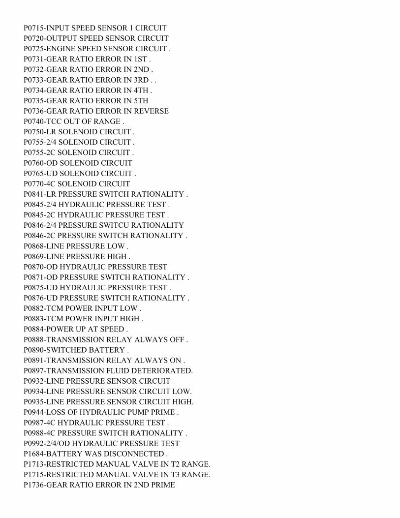
P0715-INPUT SPEED SENSOR 1 CIRCUIT P0720-OUTPUT SPEED SENSOR CIRCUIT P0725-ENGINE SPEED SENSOR CIRCUIT . P0731-GEAR RATIO ERROR IN 1ST . P0732-GEAR RATIO ERROR IN 2ND . P0733-GEAR RATIO ERROR IN 3RD . . P0734-GEAR RATIO ERROR IN 4TH . P0735-GEAR RATIO ERROR IN 5TH P0736-GEAR RATIO ERROR IN REVERSE P0740-TCC OUT OF RANGE . P0750-LR SOLENOID CIRCUIT . P0755-2/4 SOLENOID CIRCUIT . P0755-2C SOLENOID CIRCUIT . P0760-OD SOLENOID CIRCUIT P0765-UD SOLENOID CIRCUIT . P0770-4C SOLENOID CIRCUIT P0841-LR PRESSURE SWITCH RATIONALITY . P0845-2/4 HYDRAULIC PRESSURE TEST . P0845-2C HYDRAULIC PRESSURE TEST . P0846-2/4 PRESSURE SWITCU RATIONALITY P0846-2C PRESSURE SWITCH RATIONALITY . P0868-LINE PRESSURE LOW . P0869-LINE PRESSURE HIGH . P0870-OD HYDRAULIC PRESSURE TEST P0871-OD PRESSURE SWITCH RATIONALITY . P0875-UD HYDRAULIC PRESSURE TEST . P0876-UD PRESSURE SWITCH RATIONALITY . P0882-TCM POWER INPUT LOW . P0883-TCM POWER INPUT HIGH . P0884-POWER UP AT SPEED . P0888-TRANSMISSION RELAY ALWAYS OFF . P0890-SWITCHED BATTERY . P0891-TRANSMISSION RELAY ALWAYS ON . P0897-TRANSMISSION FLUID DETERIORATED. P0932-LINE PRESSURE SENSOR CIRCUIT P0934-LINE PRESSURE SENSOR CIRCUIT LOW. P0935-LINE PRESSURE SENSOR CIRCUIT HIGH. P0944-LOSS OF HYDRAULIC PUMP PRIME . P0987-4C HYDRAULIC PRESSURE TEST . P0988-4C PRESSURE SWITCH RATIONALITY . P0992-2/4/OD HYDRAULIC PRESSURE TEST P1684-BATTERY WAS DISCONNECTED . P1713-RESTRICTED MANUAL VALVE IN T2 RANGE. P1715-RESTRICTED MANUAL VALVE IN T3 RANGE. P1736-GEAR RATIO ERROR IN 2ND PRIME

P1745-TRANSMISSION LINE PRESSURE TOO HIGH FOR TOO LONG . P1775-SOLENOID SWITCH VALVE LATCHED IN TCC POSITION . P1776-SOLENOID SWITCH VALVE LATCHED IN LR POSITION. P1790-FAULT IMMEDIATELY AFTER SHIFT P1793-TRD LINK COMMUNICATION ERROR. P1794-SPEED SENSOR GROUND ERROR P1797-MANUAL SHIFT OVERHEAT P2700-INADEQUATE ELEMENT VOLUME LR. P2701-INADEQUATE ELEMENT VOLUME 2C. P2702-INADEQUATE ELEMENT VOLUME OD . P2703- INADEQUATE ELEMENT VOLUME UD . P2704-INADEQUATE ELEMENT VOLUME 4C P2706-MS SOLENOID CIRCUIT . U0002–CAN C BUS OFF PERFORMANCE . U0100 LOST COMMUNICATION WITH ECM/PCM. U0121 LOST COMMUNICATION WITH ABS .
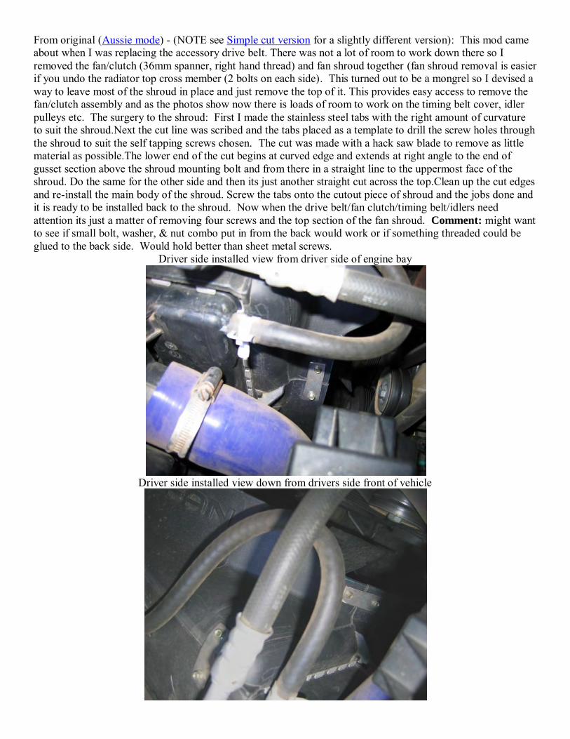
From original (Aussie mode) - (NOTE see Simple cut version for a slightly different version): This mod came about when I was replacing the accessory drive belt. There was not a lot of room to work down there so I removed the fan/clutch (36mm spanner, right hand thread) and fan shroud together (fan shroud removal is easier if you undo the radiator top cross member (2 bolts on each side). This turned out to be a mongrel so I devised a way to leave most of the shroud in place and just remove the top of it. This provides easy access to remove the fan/clutch assembly and as the photos show now there is loads of room to work on the timing belt cover, idler pulleys etc. The surgery to the shroud: First I made the stainless steel tabs with the right amount of curvature to suit the shroud.Next the cut line was scribed and the tabs placed as a template to drill the screw holes through the shroud to suit the self tapping screws chosen. The cut was made with a hack saw blade to remove as little material as possible.The lower end of the cut begins at curved edge and extends at right angle to the end of gusset section above the shroud mounting bolt and from there in a straight line to the uppermost face of the shroud. Do the same for the other side and then its just another straight cut across the top.Clean up the cut edges and re-install the main body of the shroud. Screw the tabs onto the cutout piece of shroud and the jobs done and it is ready to be installed back to the shroud. Now when the drive belt/fan clutch/timing belt/idlers need attention its just a matter of removing four screws and the top section of the fan shroud. Comment: might want to see if small bolt, washer, & nut combo put in from the back would work or if something threaded could be glued to the back side. Would hold better than sheet metal screws.
Driver side installed view from driver side of engine bay
Driver side installed view down from drivers side front of vehicle
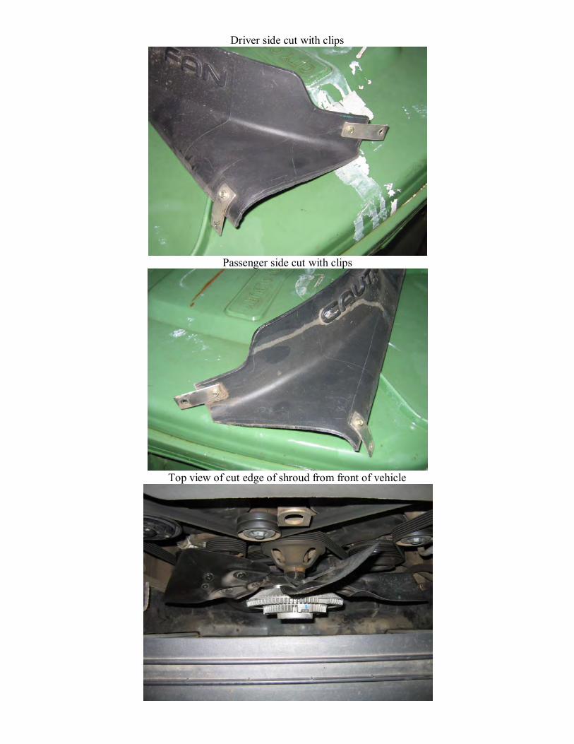
Driver side cut with clips
Passenger side cut with clips
Top view of cut edge of shroud from front of vehicle

Passenger side from front of vehicle
Screws
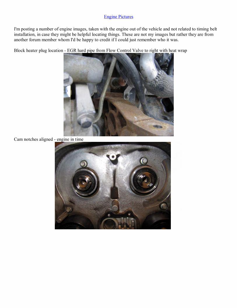
Engine Pictures I'm posting a number of engine images, taken with the engine out of the vehicle and not related to timing belt installation, in case they might be helpful locating things. These are not my images but rather they are from another forum member whom I'd be happy to credit if I could just remember who it was. Block heater plug location - EGR hard pipe from Flow Control Valve to right with heat wrap
Cam notches aligned - engine in time
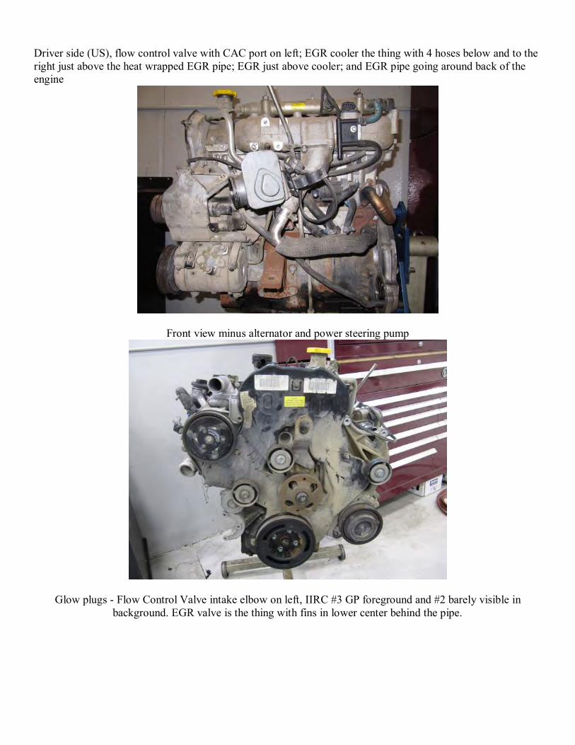
Driver side (US), flow control valve with CAC port on left; EGR cooler the thing with 4 hoses below and to the right just above the heat wrapped EGR pipe; EGR just above cooler; and EGR pipe going around back of the engine
Front view minus alternator and power steering pump
Glow plugs - Flow Control Valve intake elbow on left, IIRC #3 GP foreground and #2 barely visible in background. EGR valve is the thing with fins in lower center behind the pipe.
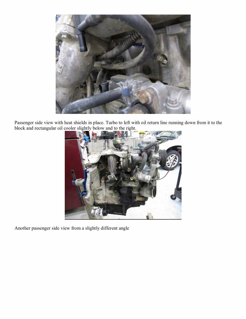
Passenger side view with heat shields in place. Turbo to left with oil return line running down from it to the block and rectangular oil cooler slightly below and to the right.
Another passenger side view from a slightly different angle
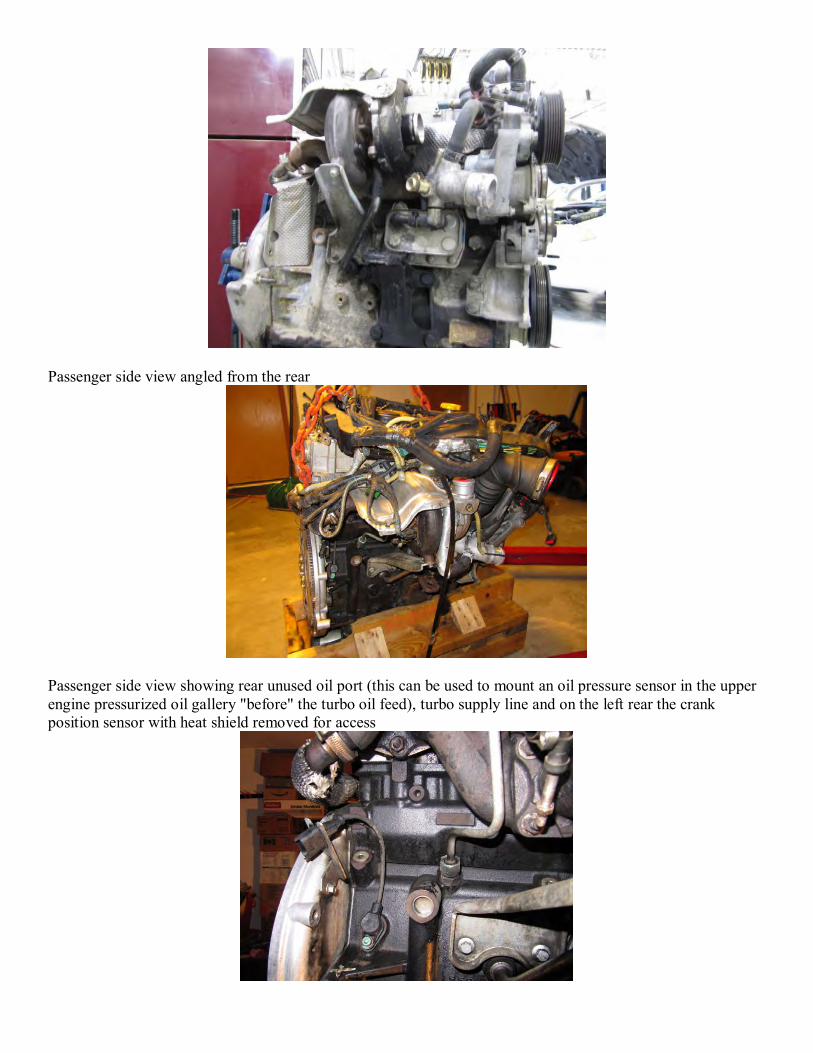
Passenger side view angled from the rear
Passenger side view showing rear unused oil port (this can be used to mount an oil pressure sensor in the upper engine pressurized oil gallery "before" the turbo oil feed), turbo supply line and on the left rear the crank position sensor with heat shield removed for access
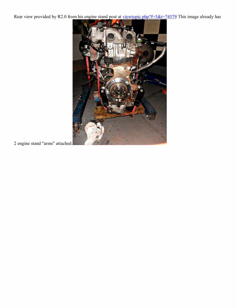
Rear view provided by R2.0 from his engine stand post at viewtopic.php?f=5&t=74579 This image already has
2 engine stand "arms" attached.

Posted by "sidebrake" on LOST at http://www.lostjeeps.com/forum/phpBB3/viewtopic.php?f=5&t=59446 with a link to https://docs.google.com/viewer?a=v&pid=explorer&chrome=true&srcid=0B8HRaBSyPdn1NWI3NjdjNzUtN2M1NS00YmY5LWFhZDUtOTMzOGZkNjIzZTUy&hl=en&authkey=CO3NyM4B Downloaded March 13, 2011

Ensure fuel supply is OK – see (1)
Fuel Supply
2005/06 Jeep Liberty (KJ) CRD Fuel System DiagnosticCommon symptoms: P0093 fault code, crank but no start, intermittent crank-no-start, loss of power/hesitation
Is fuel contaminated?
Flush tank and replace with known good
diesel, replace fuel filter
Yes Crank to purge lines of old fuel
Check fuel filter for proper flow Filter clogged? Replace filterYes/Unsure
Observe low pressure fuel lines for air leaks – see
(2) Low Pres. Lines
Can you see air bubbles in
fuel lines?
Purge air from fuel head using primer button and bleeder
valve
Resolved? EndYesStart Return to Start
Return to Start
No
Are bubbles before or after
fuel head?Yes
Inspect fuel head for cracks (esp.
around fuel heater plug)
Is fuel head cracked? Replace fuel head Return
to Start
Consider replacing fuel head
proactively
Is fuel head old design?Yes
No
Yes
No
No
Inspect fuel lines from fuel head
back to tank (esp. quick connects
near tank)
Are fuel lines leaking?
Replace fuel lines and/or quick
connects
Return to StartBefore/Both Yes
Consider installing in-tank lift pump
No/Unsure
Return to Start
Blue = StartGreen = EndRed = SolutionOrange = Optional
Check that fuel filter is tight and
only 1 gasket is in place
After
Is fuel filter attached correctly?
Correctly attach fuel filter to fuel
head
Return to Start
Replace fuel head
No
Yes
Consider installing in-tank lift pump
Inspect fuel line from fuel head to
CP3 pump
Is fuel line leaking?Replace fuel line
Return to Start
No/Issue reappeared
No
YesIs in-tank lift
pump installed?
No
Go to page 2
Yes
No See NoteNote: The most common problem with the KJ CRD fuel system is air in the lines. Do not move to page 2 unless you are certain this is not an issue for your vehicle. Many consider an in-tank lift pump as the best way to be sure, but it is not absolutely necessary.
Disclaimer: This document is not produced or endorsed by Chrysler LLC. It is intended to be used as a general guide for reference purpose only and its creator does not guarantee accuracy of the document. Working on high pressure diesel fuel systems can be extremely dangerous. Read and understand the High Fuel System Pressure Warning before using this guide.
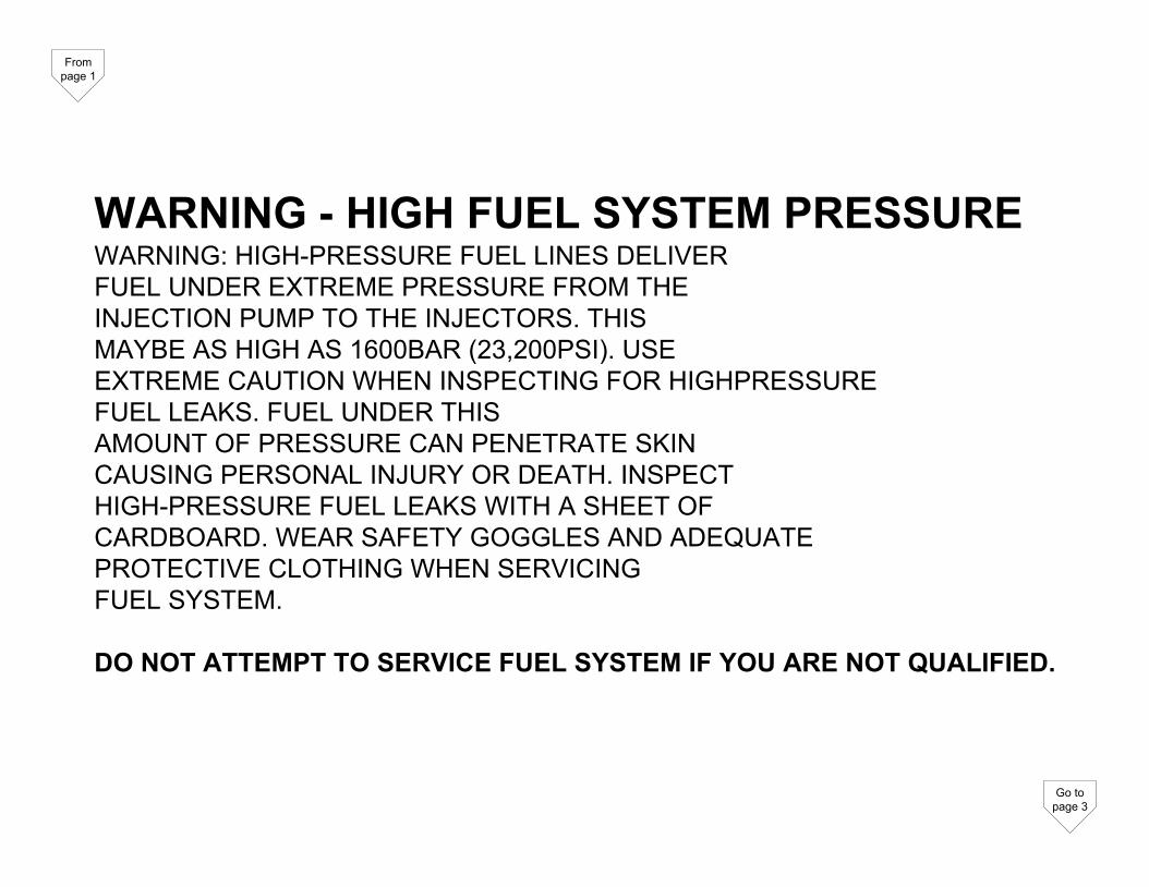
WARNING - HIGH FUEL SYSTEM PRESSUREWARNING: HIGH-PRESSURE FUEL LINES DELIVERFUEL UNDER EXTREME PRESSURE FROM THEINJECTION PUMP TO THE INJECTORS. THISMAYBE AS HIGH AS 1600BAR (23,200PSI). USEEXTREME CAUTION WHEN INSPECTING FOR HIGHPRESSUREFUEL LEAKS. FUEL UNDER THISAMOUNT OF PRESSURE CAN PENETRATE SKINCAUSING PERSONAL INJURY OR DEATH. INSPECTHIGH-PRESSURE FUEL LEAKS WITH A SHEET OFCARDBOARD. WEAR SAFETY GOGGLES AND ADEQUATEPROTECTIVE CLOTHING WHEN SERVICINGFUEL SYSTEM.
DO NOT ATTEMPT TO SERVICE FUEL SYSTEM IF YOU ARE NOT QUALIFIED.
From page 1
Go to page 3
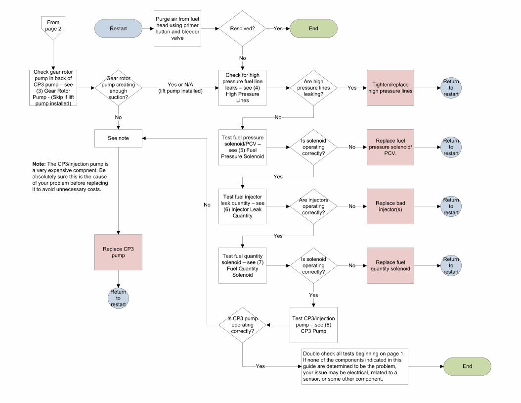
Restart
Purge air from fuel head using primer button and bleeder
valve
Resolved? EndYes
Check gear rotor pump in back of CP3 pump – see (3) Gear Rotor
Pump - (Skip if lift pump installed)
Gear rotor pump creating
enough suction?
Check for high pressure fuel line leaks – see (4) High Pressure
Lines
Test fuel quantity solenoid – see (7)
Fuel Quantity Solenoid
Test fuel pressure solenoid/PCV –
see (5) Fuel Pressure Solenoid
Test fuel injector leak quantity – see
(6) Injector Leak Quantity
Test CP3/injection pump – see (8)
CP3 Pump
Yes or N/A (lift pump installed)
No
Are high pressure lines
leaking?
Tighten/replace high pressure lines
Return to
restartYes
No
Is solenoid operating correctly?
Replace fuel pressure solenoid/
PCV.No
Return to
restart
Yes
Are injectors operating correctly?
Replace bad injector(s)
Return to
restartNo
Is solenoid operating correctly?
Yes
Replace fuel quantity solenoid
Return to
restartNo
Yes
See note
No
Is CP3 pump operating correctly?
No
Double check all tests beginning on page 1. If none of the components indicated in this guide are determined to be the problem, your issue may be electrical, related to a sensor, or some other component.
EndYes
Replace CP3 pump
Return to
restart
Note: The CP3/injection pump is a very expensive compnent. Be absolutely sure this is the cause of your problem before replacing it to avoid unnecessary costs.
From page 2

(1) Fuel SupplyThere are several ways to check if your diesel fuel is contaminated with water, gasoline, or other foreign substances. Below are a few suggestions:
- Remove the water in fuel (WIF) sensor plug at the bottom of the fuel filter and drain fuel into a clear container such as a jar. Set the fuel in a safe location where it will not be disturbed. Replace WIF sensor. Let the fuel settle for a few hours and look to see if there is any seperation. Water will sink to the bottom.
- Drain the fuel per the above steps and smell it. If it smells like gasoline, it is likely contaminated.
- Use fuel from a known good source for several weeks.
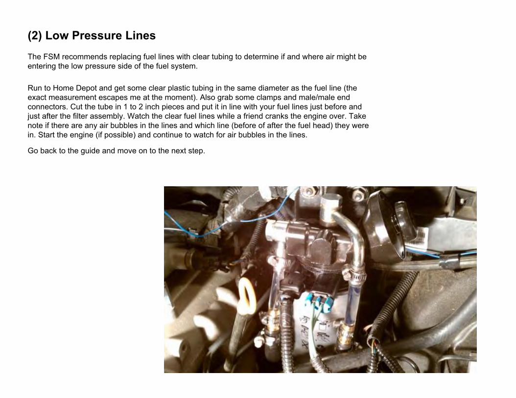
(2) Low Pressure LinesThe FSM recommends replacing fuel lines with clear tubing to determine if and where air might be entering the low pressure side of the fuel system.
Run to Home Depot and get some clear plastic tubing in the same diameter as the fuel line (the exact measurement escapes me at the moment). Also grab some clamps and male/male end connectors. Cut the tube in 1 to 2 inch pieces and put it in line with your fuel lines just before and just after the filter assembly. Watch the clear fuel lines while a friend cranks the engine over. Take note if there are any air bubbles in the lines and which line (before of after the fuel head) they were in. Start the engine (if possible) and continue to watch for air bubbles in the lines.
Go back to the guide and move on to the next step.
(3) Gear Rotor Pump
From the FSM:NOTE: The gear rotor pump in the back of the highpressure pump, draws fuel from the tank, throughthe filter, to the back of the high pressure pump.The gear rotor pump is capable of drawing up to 20in. of vacuum, depending on cranking speed. Aspecification of under 3 in. of vacuum reveals thehigh pressure pump suspect if there is no air intrusioninto the fuel system.
Test Set Up Assumptions for this test are that thefuel gauge is operating properly and that there isknow good fuel in the fuel tank.ᄇ Disconnect the camshaft position sensor to preventthe vehicle from starting.ᄇ Remove the bleeder screw on the fuel filter housingand install special tool fitting #9663 (Fig. 1).ᄇ Connect vacuum and pressure gauge # 6828 tothe #9663 fitting (Fig. 2).ᄇ Re-prime the fuel system to remove all air(Refer to 14 - FUEL SYSTEM/FUEL DELIVERY -STANDARD PROCEDURE).ᄇ Restrict the inlet side of the fuel filter by clampingthe inlet hose close to the filter assembly.ᄇ Crank the engine 3–4 times in 15 seconds intervalswhile monitoring the gauge.
The supply pump should draw at least 3in. of vacuum. If the supply pump was unable toreach 3 in. of vacuum, replace the high pressurepump
(4) High Pressure Lines
From the FSM: WARNING: HIGH - PRESSURE LINES DELIVER DIESELFUEL UNDER EXTREME PRESSURE FROMTHE INJECTION PUMP TO THE FUEL INJECTORS.THIS MAY BE AS HIGH AS 1600BAR (23,200 PSI.).USE EXTREME CAUTION WHEN INSPECTING FORHIGH - PRESSURE FUEL LEAKS. FUEL UNDERTHIS AMOUNT OF PRESSURE CAN PENETRATESKIN CAUSING PERSONAL INJURY OR DEATH.INSPECT FOR HIGH — PRESSURE FUEL LEAKSWITH A SHEET OF CARDBOARD. WEAR SAFETYGOGGLES AND ADEQUATE PROTECTIVE CLOTHINGWHEN SERVICING FUEL SYSTEM.
High-pressure fuel leaks can cause starting problemsand poor engine performance.Carefully place a piece of cardboard over the high pressurefuel lines or suspected area. Move your bodyand hands away from the area. Start the engine andrun till warm. TURN THE ENGINE OFF. Inspectthe piece of card board for witness marks. (Fig. 3). Ifa high-pressure line connection is leaking, replacedamaged, restricted or leaking high-pressure fuellines with the correct replacement line.
CAUTION: The high-pressure fuel lines cannot contacteach other or other components. Do notattempt to weld high-pressure fuel lines or to repairlines that are damaged. Only use the recommendedlines when replacement of high-pressure fuel line isnecessary.

(5) Fuel Pressure Solenoid/PCVThe fuel pressure solenoid should hold completely closed during start-up to allow maximum fuel pressure to be built. Once the engine is started, the solenoid will regulate rail pressure by allowing some fuel to flow out and back to the tank. If the solenoid is not holding closed during cranking, the rail will not be able to build enough pressure to start.
To test, replace the return fuel line coming from the rail pressure solenoid with a long, clear tube. Be sure to put the end of the tube in an approved fuel container to catch returning diesel. Have a friend crank the engine. No fuel should enter the clear tube until the engine starts. If fuel is entering the tube during cranking, the solenoid is bad and needs to be replaced.

(6) Injector Leak QuantityFrom the FSM:
NOTE: If an injector is found to be out of specification,repeat the test procedure after the injectorreplacement. Hydraulic flow will take the path ofleast resistance and multiple failures may be identified.Perform this test with the engine at operating temperature.This test will assist in determining a defectiveor internally leaking injector(s) is present bymeasuring the amount of fuel return.Cranking Test(1) Turn the ignition off.(2) Remove the engine cover.NOTE: DO NOT remove the return fuel line clipsretaining the return line to the injector. Push IN onthe clip to release the hose and then again to installthe test vials.(3) Disconnect the return fuel hose at the top ofeach of the injectors.NOTE: Care must be taken not to damage the returnline check valve between cylinder number fourinjector and the fuel rail.(4) Block off the disconnected return fuel hosebefore the fuel return junction on the left rear of thecylinder head cover (Fig. 6).(5) Disconnect the camshaft position sensor (CMP).NOTE: Attach special tool adaptor #9686 to the #4injector and fill with clean diesel fuel to purge the.
air from the adaptor, then install the test vial ontothe adaptor.(6) Install the test vials onto the injectors andsecure with the return hose clips (Fig. 6).(7) Crank the engine for ten seconds while monitoringeach inner test vial.(8) Evaluate the individual return quantities.The maximum permissible difference between thereturn quantity of the individual injectors and theinjector with the highest return quantity is 3 graduationmarks in the small vial.(9) Perform the cranking test after the repair toassure no other injectors are identified.Engine Running(1) Start the engine with the test vials in place(Fig. 6).(2) Run the engine until the top mark on one ofthe large graduated vials is obtained.(3) Turn engine off immediately.(4) Evaluate the individual return quantities.The maximum permissible difference betweenreturn quantities of the individual injectors, and theinjector with the highest return quantity, is 3 graduationmarks.(5) Perform the running test again after the repairto assure no other injectors are identified.
Note: It is not necessary to use the special tool. The same test can be performed using clear tubing. Mark the tubing at approximately 1 ml intervals.

(7) Fuel Quantity SolenoidNeed to determine a test for this component...
(8) CP3/Injection PumpNeed to determine a test for this component...
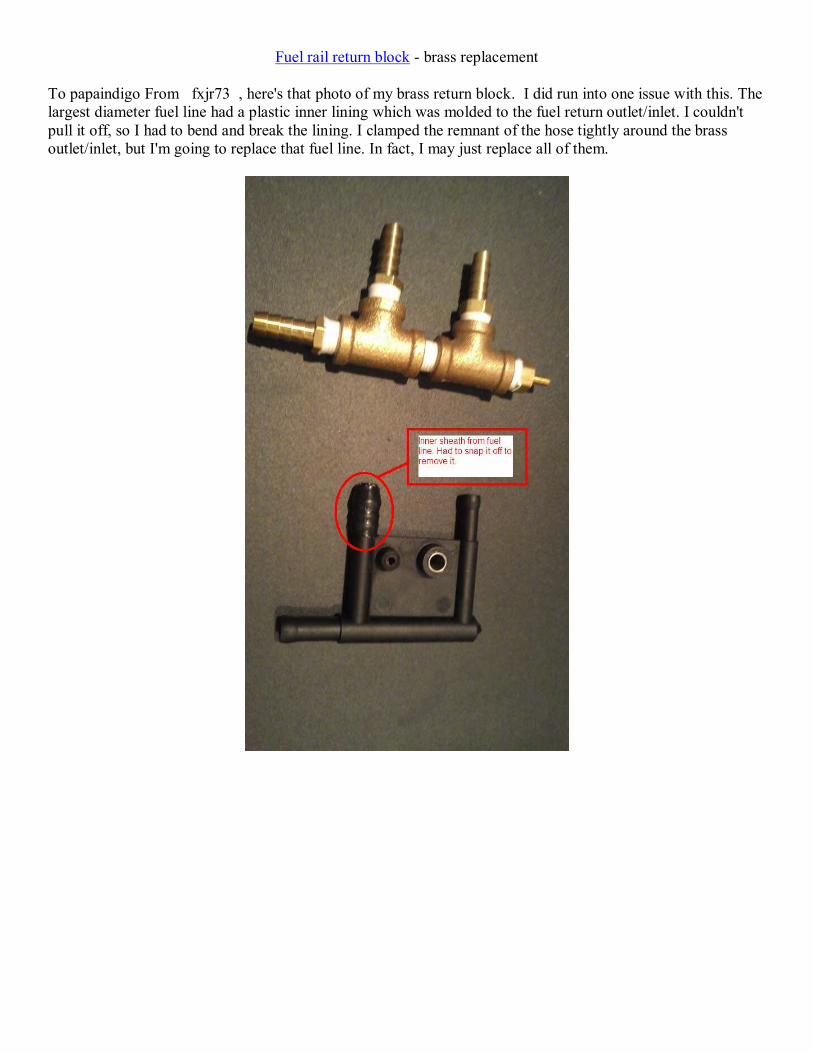
Fuel rail return block - brass replacement To papaindigo From fxjr73 , here's that photo of my brass return block. I did run into one issue with this. The largest diameter fuel line had a plastic inner lining which was molded to the fuel return outlet/inlet. I couldn't pull it off, so I had to bend and break the lining. I clamped the remnant of the hose tightly around the brass outlet/inlet, but I'm going to replace that fuel line. In fact, I may just replace all of them.
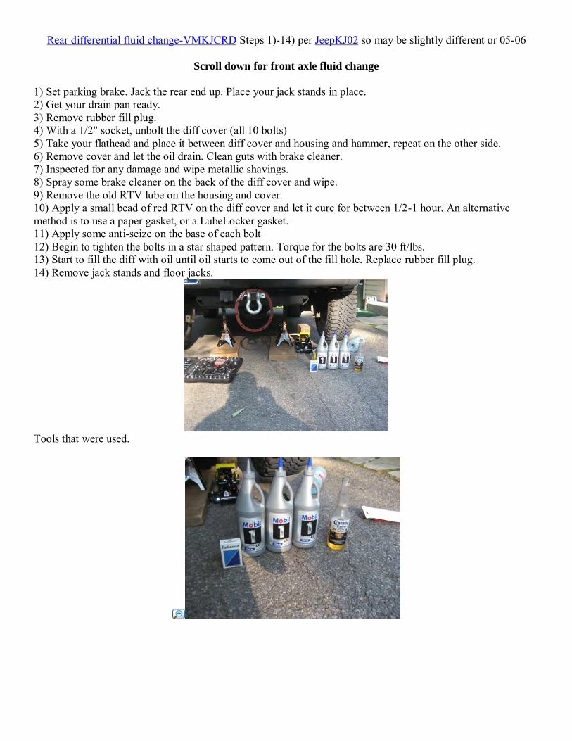
Rear differential fluid change-VMKJCRD Steps 1)-14) per JeepKJ02 so may be slightly different or 05-06
Scroll down for front axle fluid change
1) Set parking brake. Jack the rear end up. Place your jack stands in place. 2) Get your drain pan ready. 3) Remove rubber fill plug. 4) With a 1/2" socket, unbolt the diff cover (all 10 bolts) 5) Take your flathead and place it between diff cover and housing and hammer, repeat on the other side. 6) Remove cover and let the oil drain. Clean guts with brake cleaner. 7) Inspected for any damage and wipe metallic shavings. 8) Spray some brake cleaner on the back of the diff cover and wipe. 9) Remove the old RTV lube on the housing and cover. 10) Apply a small bead of red RTV on the diff cover and let it cure for between 1/2-1 hour. An alternative method is to use a paper gasket, or a LubeLocker gasket. 11) Apply some anti-seize on the base of each bolt 12) Begin to tighten the bolts in a star shaped pattern. Torque for the bolts are 30 ft/lbs. 13) Start to fill the diff with oil until oil starts to come out of the fill hole. Replace rubber fill plug. 14) Remove jack stands and floor jacks.
Tools that were used.
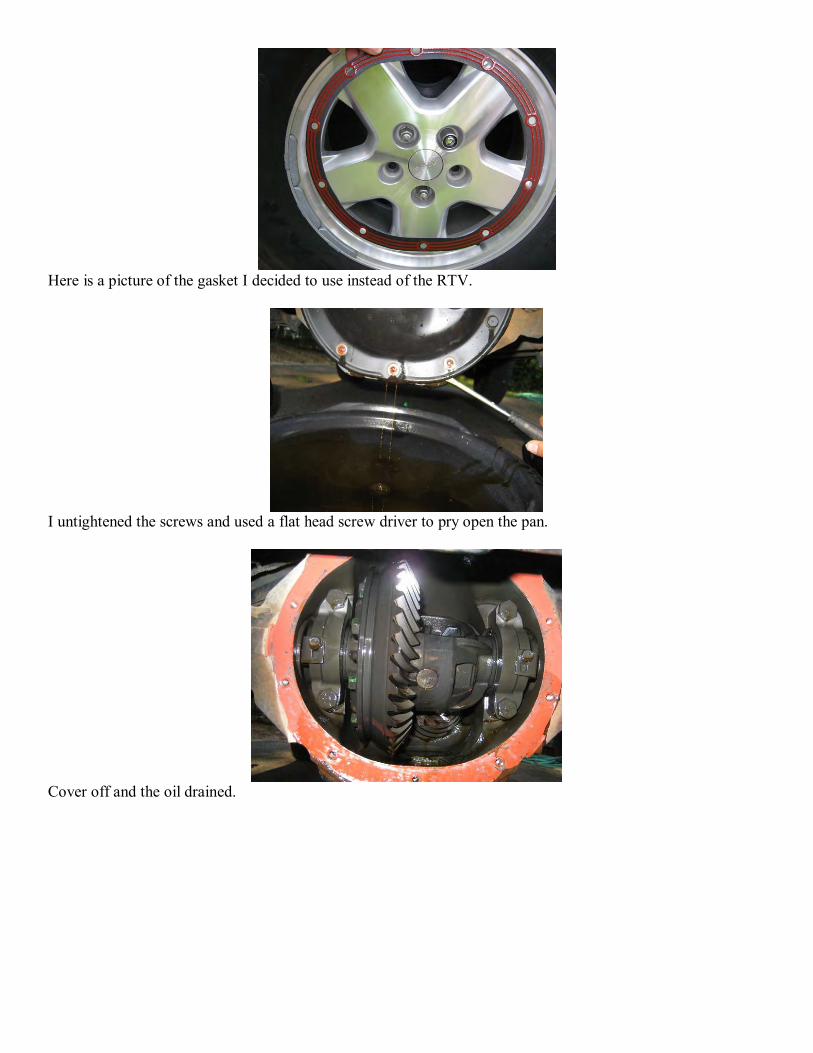
Here is a picture of the gasket I decided to use instead of the RTV.
I untightened the screws and used a flat head screw driver to pry open the pan.
Cover off and the oil drained.
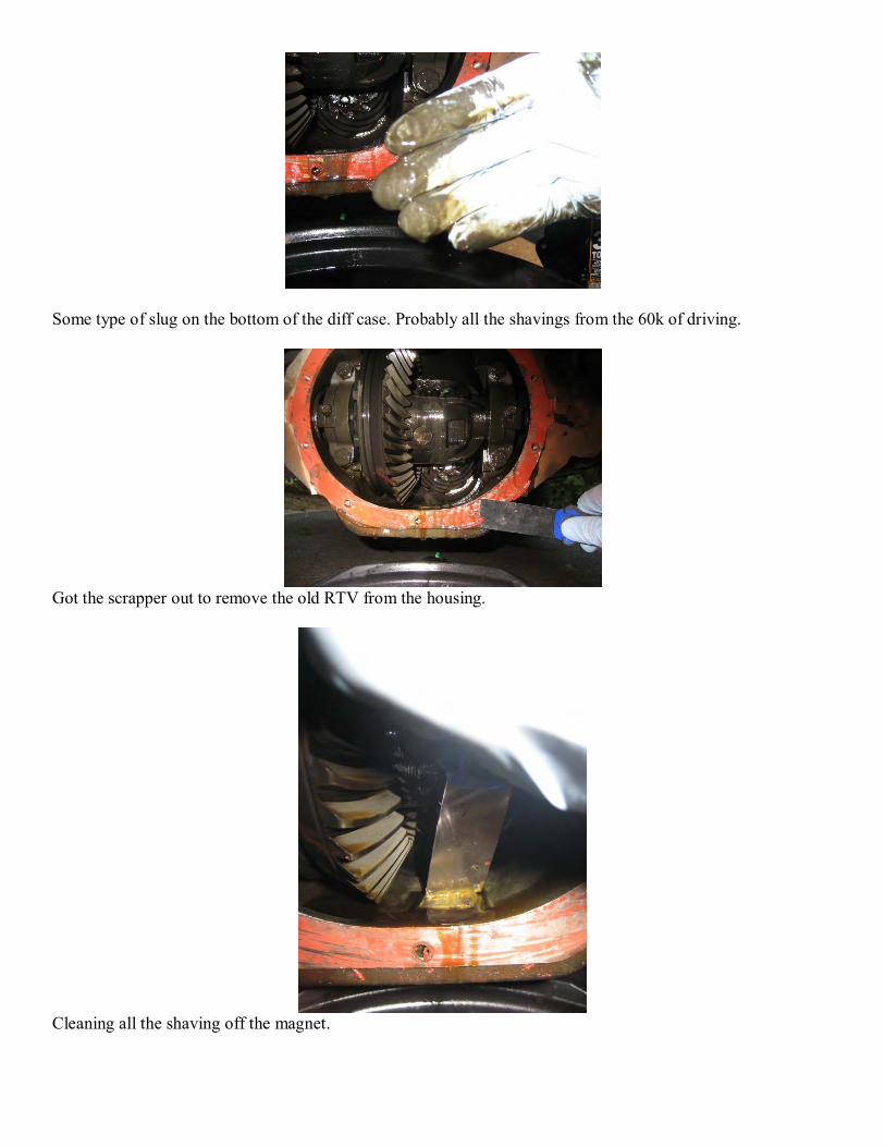
Some type of slug on the bottom of the diff case. Probably all the shavings from the 60k of driving.
Got the scrapper out to remove the old RTV from the housing.
Cleaning all the shaving off the magnet.
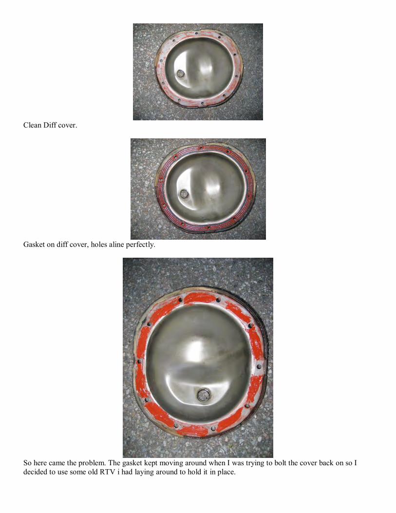
Clean Diff cover.
Gasket on diff cover, holes aline perfectly.
So here came the problem. The gasket kept moving around when I was trying to bolt the cover back on so I decided to use some old RTV i had laying around to hold it in place.

whooallaaa, no hands!
Put the cover back on and tightened as instructed.
Front differential fluid change-VMKJCRD Steps 1)-9) per JeepKJ02 so may be slightly different or 05-06
Front axle: (about 45 minutes) per 1) Set parking brake. Jack the front end up. Place your jack stands in place. 2) Remove skid plate (if applicable). There are four 15mm bolts on each corner. 3) Get your drain pan ready. 4) Take a 3/8" ratchet (without a socket) and remove the fill plug. 5) With your 8mm allen remove the drain plug. Let the diff completely drain out. 6) Replace the drain plug. Do not tighten this too much because this diff is make out of aluminum and will crack. 7) Start to fill the diff with oil with oil until oil starts to come out of the fill hole. 8) Replace the fill plug. 9) Replace the skid plate. Put some anti-seize on the threads of the bolts.
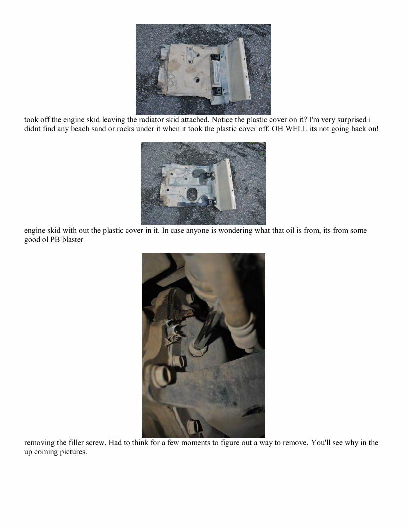
took off the engine skid leaving the radiator skid attached. Notice the plastic cover on it? I'm very surprised i didnt find any beach sand or rocks under it when it took the plastic cover off. OH WELL its not going back on!
engine skid with out the plastic cover in it. In case anyone is wondering what that oil is from, its from some good ol PB blaster
removing the filler screw. Had to think for a few moments to figure out a way to remove. You'll see why in the up coming pictures.
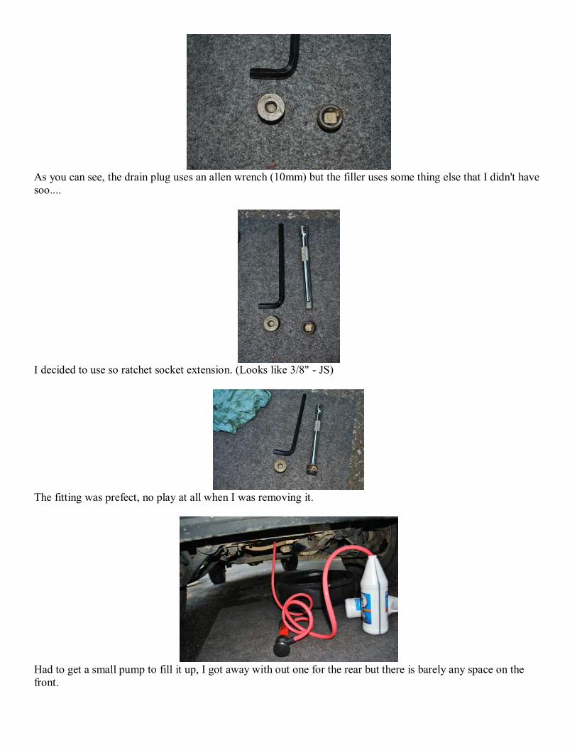
As you can see, the drain plug uses an allen wrench (10mm) but the filler uses some thing else that I didn't have soo....
I decided to use so ratchet socket extension. (Looks like 3/8" - JS)
The fitting was prefect, no play at all when I was removing it.
Had to get a small pump to fill it up, I got away with out one for the rear but there is barely any space on the front.

FCV disable per Geordi The best thing you can do for your engine is to take the FCV off the intake elbow and unscrew the big butterfly disc from the center of it. Now, it can never close again and fork up your engine. It has NOTHING to do with a 'soft shutdown' or doing anything at all to prevent a possible engine runaway. It COULD, but the requisite programming and sensors don't exist in our CRDs. It is ONLY there for the emissions control crap.
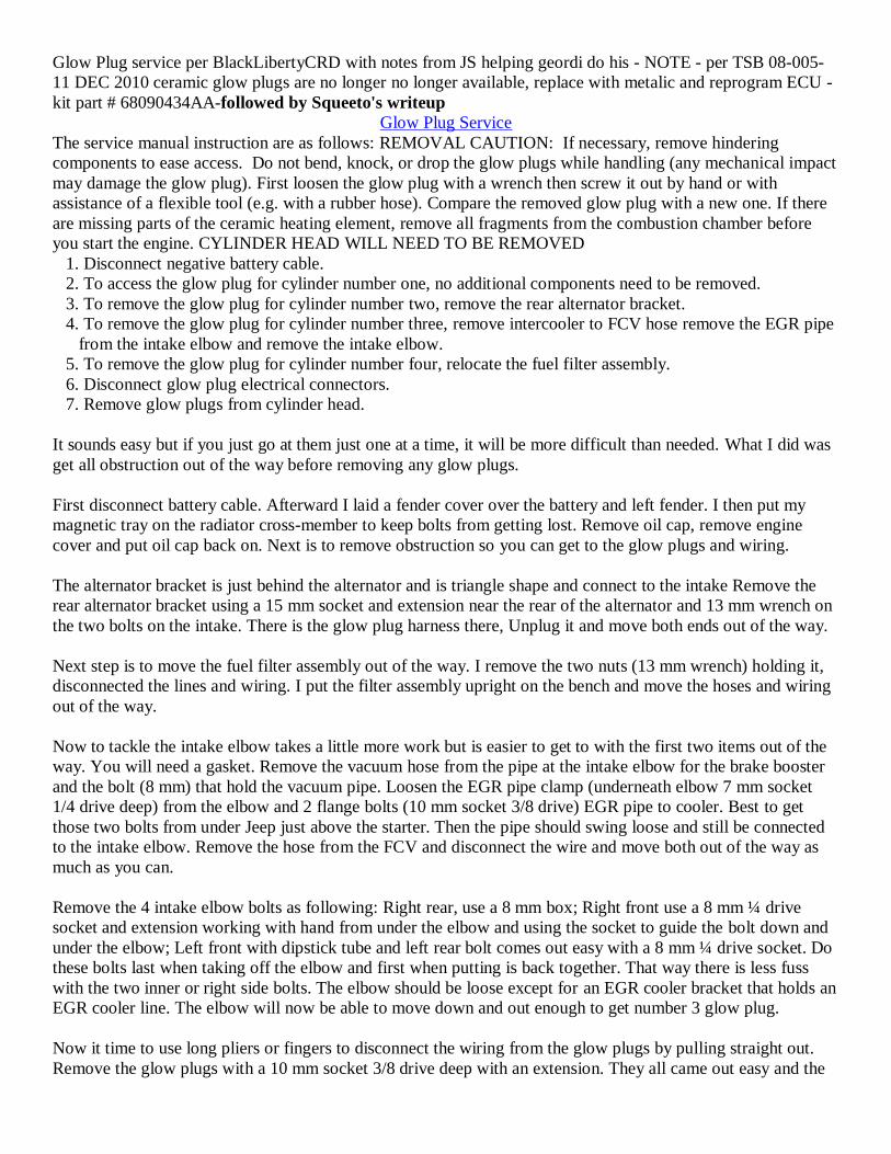
Glow Plug service per BlackLibertyCRD with notes from JS helping geordi do his - NOTE - per TSB 08-005-
11 DEC 2010 ceramic glow plugs are no longer no longer available, replace with metalic and reprogram ECU -
kit part # 68090434AA-followed by Squeeto's writeup
Glow Plug Service
The service manual instruction are as follows: REMOVAL CAUTION: If necessary, remove hindering
components to ease access. Do not bend, knock, or drop the glow plugs while handling (any mechanical impact
may damage the glow plug). First loosen the glow plug with a wrench then screw it out by hand or with
assistance of a flexible tool (e.g. with a rubber hose). Compare the removed glow plug with a new one. If there
are missing parts of the ceramic heating element, remove all fragments from the combustion chamber before
you start the engine. CYLINDER HEAD WILL NEED TO BE REMOVED
1. Disconnect negative battery cable.
2. To access the glow plug for cylinder number one, no additional components need to be removed.
3. To remove the glow plug for cylinder number two, remove the rear alternator bracket.
4. To remove the glow plug for cylinder number three, remove intercooler to FCV hose remove the EGR pipe
from the intake elbow and remove the intake elbow.
5. To remove the glow plug for cylinder number four, relocate the fuel filter assembly.
6. Disconnect glow plug electrical connectors.
7. Remove glow plugs from cylinder head.
It sounds easy but if you just go at them just one at a time, it will be more difficult than needed. What I did was
get all obstruction out of the way before removing any glow plugs.
First disconnect battery cable. Afterward I laid a fender cover over the battery and left fender. I then put my
magnetic tray on the radiator cross-member to keep bolts from getting lost. Remove oil cap, remove engine
cover and put oil cap back on. Next is to remove obstruction so you can get to the glow plugs and wiring.
The alternator bracket is just behind the alternator and is triangle shape and connect to the intake Remove the
rear alternator bracket using a 15 mm socket and extension near the rear of the alternator and 13 mm wrench on
the two bolts on the intake. There is the glow plug harness there, Unplug it and move both ends out of the way.
Next step is to move the fuel filter assembly out of the way. I remove the two nuts (13 mm wrench) holding it,
disconnected the lines and wiring. I put the filter assembly upright on the bench and move the hoses and wiring
out of the way.
Now to tackle the intake elbow takes a little more work but is easier to get to with the first two items out of the
way. You will need a gasket. Remove the vacuum hose from the pipe at the intake elbow for the brake booster
and the bolt (8 mm) that hold the vacuum pipe. Loosen the EGR pipe clamp (underneath elbow 7 mm socket
1/4 drive deep) from the elbow and 2 flange bolts (10 mm socket 3/8 drive) EGR pipe to cooler. Best to get
those two bolts from under Jeep just above the starter. Then the pipe should swing loose and still be connected
to the intake elbow. Remove the hose from the FCV and disconnect the wire and move both out of the way as
much as you can.
Remove the 4 intake elbow bolts as following: Right rear, use a 8 mm box; Right front use a 8 mm ¼ drive
socket and extension working with hand from under the elbow and using the socket to guide the bolt down and
under the elbow; Left front with dipstick tube and left rear bolt comes out easy with a 8 mm ¼ drive socket. Do
these bolts last when taking off the elbow and first when putting is back together. That way there is less fuss
with the two inner or right side bolts. The elbow should be loose except for an EGR cooler bracket that holds an
EGR cooler line. The elbow will now be able to move down and out enough to get number 3 glow plug.
Now it time to use long pliers or fingers to disconnect the wiring from the glow plugs by pulling straight out.
Remove the glow plugs with a 10 mm socket 3/8 drive deep with an extension. They all came out easy and the

threads were fairly clean as they should be. If fact they felt a little loose but was not leaking as far as I can see.
Be sure not to over torque the new ones.
The service manual instruction are as follows: INSTALLATION CAUTION: Before a new glow plug is
installed, make sure that the thread of glow plug and glow plug bore in the cylinder head is dry, clean, and
oil/grease-free. Check the resistance of the glow plug with an appropriate multi-meter, resistance should be less
than 0.8V for the original ceramic glow plugs (Note - may be value for the no longer available ceramic glow
plugs; metalic glow plug value may be different). Tighten the glow plug by hand or means of a flexible tool
(e.g. rubber hose) as far as possible and finish tightening with a correctly set torque wrench. Strictly observe the
required tightening torque. Do not bend, knock, or drop the glow plug while installing. CAUTION: If a
fragment of the ceramic heater (NA for metalic plugs) of the glow plug has fallen into the combustion chamber,
the cylinder head MUST be removed.
1. Install glow plugs all the way into cylinder head, hand tight, until the thread stops. CAUTION: Strictly
observe the required tightening torque. If tightening torque was too high, remove and replace the glow plug.
2. Tighten glow plugs to 12.5 Nm (110 in. lbs.).
3. Connect glow plug electrical connectors.
4. Install any components that were removed for access.
I used a long vacuum hose to install each glow plug by hand so there wasn't any possibility of dropping a glow
plug at over $30 apiece. Reverse the process to install all items removed to get to the glow plugs. Be sure to
bleed the filter assembly before trying to start engine.
Glow Plug Inspection, Remove and Replace-per Squeeto
Inspection: Good OEM 7v ceramic glow plugs are .5 to 1.5 ohms measured cold. The truck will throw trouble
codes P1260 to P1267 when the plugs go bad. Typically the bad plug will read in the hundreds of ohms. If you
suspect a bad glow plug, measure its resistance:
This is the glow plug controller situated between the battery and the master cylinder. Push down on the
tab and pull the connector apart.
Connect one lead of the ohm meter to the negative battery terminal and measure at the indicated terminals.
Unless the wiring harness is on backwards (can happen), the glow plugs should be 4-3-2-1 (left to right).
Remove and Replace: Warm up the truck so you have a hot engine. Remove engine cover. Remove the battery (10mm); you will
need the room (you must, at least, remove the positive terminal to the battery).
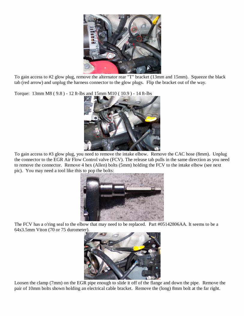
To gain access to #2 glow plug, remove the alternator rear "T" bracket (13mm and 15mm). Squeeze the black
tab (red arrow) and unplug the harness connector to the glow plugs. Flip the bracket out of the way.
Torque: 13mm M8 ( 9.8 ) - 12 ft-lbs and 15mm M10 ( 10.9 ) - 14 ft-lbs
To gain access to #3 glow plug, you need to remove the intake elbow. Remove the CAC hose (8mm). Unplug
the connector to the EGR Air Flow Control valve (FCV). The release tab pulls in the same direction as you need
to remove the connector. Remove 4 hex (Allen) bolts (5mm) holding the FCV to the intake elbow (see next
pic). You may need a tool like this to pop the bolts:
The FCV has a o'ring seal to the elbow that may need to be replaced. Part #05142806AA. It seems to be a
64x3.5mm Viton (70 or 75 durometer).
Loosen the clamp (7mm) on the EGR pipe enough to slide it off of the flange and down the pipe. Remove the
pair of 10mm bolts shown holding an electrical cable bracket. Remove the (long) 8mm bolt at the far right.

Remove the (short) 8mm bolt hidden underneath that the arrow points to. This bolt runs parallel to the EGR
pipe. And remove the (short) 8mm bolt above it.
Remove the 4 (long) 8mm bolts holding the elbow to the intake manifold. I couldn't get my fingers on the
inside front bolt and had to come from underneath. I will be re-installing it the same way.
Leave a couple loose bolts in the elbow and crack the gasket with a wood dowel and hammer. It should only
take one small blow. If you are careful, you can slide the elbow back and off of the top of the EGR pipe. You
then won't need to remove the 2 bolts at the bottom flange of the pipe.
For re-install, the EGR pipe should have high temperature RTV Silicone re-applied (Permatex Red, or Orange
as a 2nd choice).
Clean up the elbow and intake manifold that is accessible. The new gasket to the manifold is #05066946AA
(my dealer cost, Aug. 2012, $14.45!). The 8mm M6 (10.9) bolts should be torqued to 6 ft-lbs
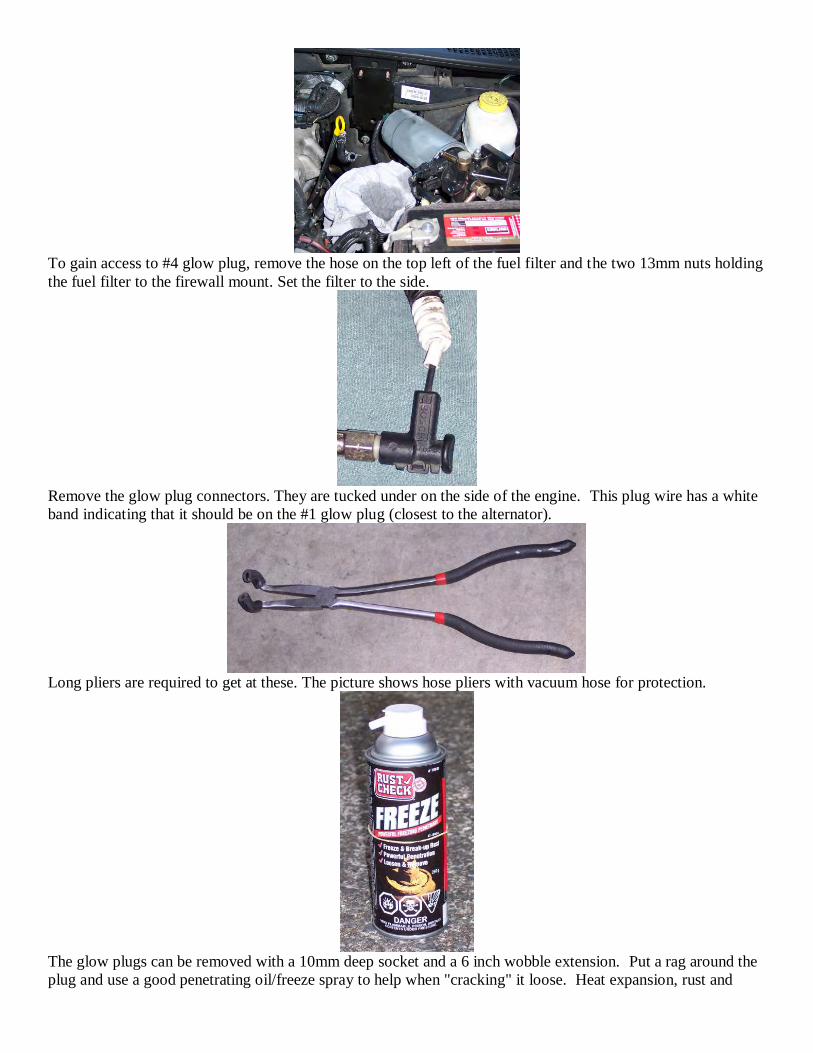
To gain access to #4 glow plug, remove the hose on the top left of the fuel filter and the two 13mm nuts holding
the fuel filter to the firewall mount. Set the filter to the side.
Remove the glow plug connectors. They are tucked under on the side of the engine. This plug wire has a white
band indicating that it should be on the #1 glow plug (closest to the alternator).
Long pliers are required to get at these. The picture shows hose pliers with vacuum hose for protection.
The glow plugs can be removed with a 10mm deep socket and a 6 inch wobble extension. Put a rag around the
plug and use a good penetrating oil/freeze spray to help when "cracking" it loose. Heat expansion, rust and
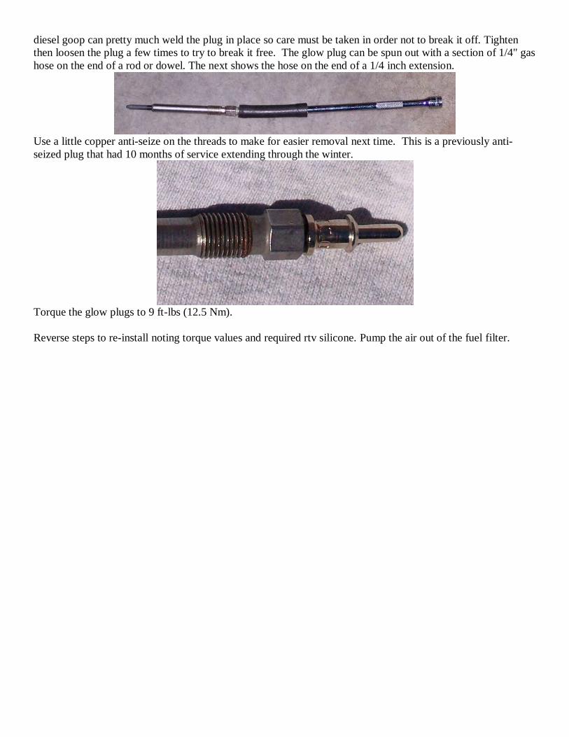
diesel goop can pretty much weld the plug in place so care must be taken in order not to break it off. Tighten
then loosen the plug a few times to try to break it free. The glow plug can be spun out with a section of 1/4" gas
hose on the end of a rod or dowel. The next shows the hose on the end of a 1/4 inch extension.
Use a little copper anti-seize on the threads to make for easier removal next time. This is a previously anti-
seized plug that had 10 months of service extending through the winter.
Torque the glow plugs to 9 ft-lbs (12.5 Nm).
Reverse steps to re-install noting torque values and required rtv silicone. Pump the air out of the fuel filter.
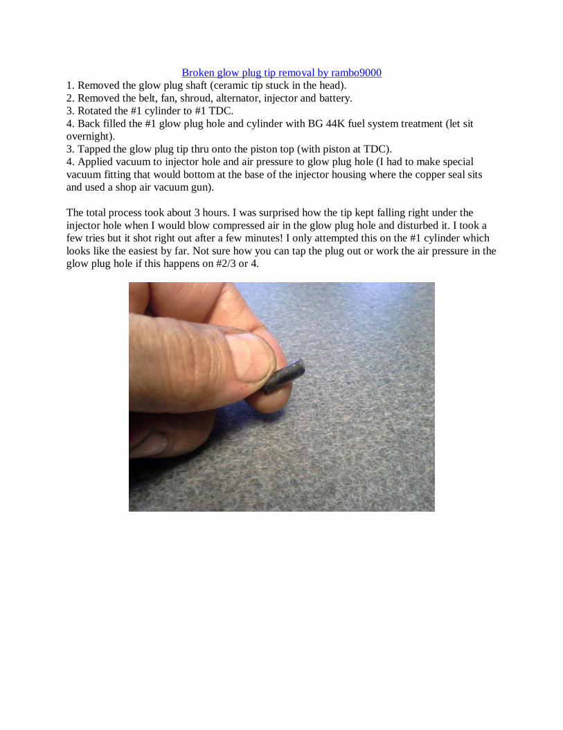
Broken glow plug tip removal by rambo9000
1. Removed the glow plug shaft (ceramic tip stuck in the head).
2. Removed the belt, fan, shroud, alternator, injector and battery.
3. Rotated the #1 cylinder to #1 TDC.
4. Back filled the #1 glow plug hole and cylinder with BG 44K fuel system treatment (let sit
overnight).
3. Tapped the glow plug tip thru onto the piston top (with piston at TDC).
4. Applied vacuum to injector hole and air pressure to glow plug hole (I had to make special
vacuum fitting that would bottom at the base of the injector housing where the copper seal sits
and used a shop air vacuum gun).
The total process took about 3 hours. I was surprised how the tip kept falling right under the
injector hole when I would blow compressed air in the glow plug hole and disturbed it. I took a
few tries but it shot right out after a few minutes! I only attempted this on the #1 cylinder which
looks like the easiest by far. Not sure how you can tap the plug out or work the air pressure in the
glow plug hole if this happens on #2/3 or 4.
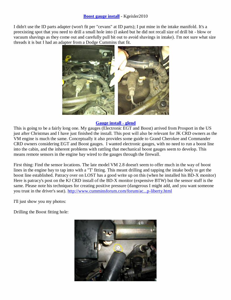
Boost gauge install - Kgeisler2010
I didn't use the ID parts adapter (won't fit per "cevans" at ID parts); I put mine in the intake manifold. It's a
preexisting spot that you need to drill a small hole into (I asked but he did not recall size of drill bit - blow or
vacuum shavings as they come out and carefully pull bit out to avoid shavings in intake). I'm not sure what size
threads it is but I had an adapter from a Dodge Cummins that fit.
Gauge install - glend
This is going to be a fairly long one. My gauges (Electronic EGT and Boost) arrived from Prosport in the US
just after Christmas and I have just finished the install. This post will also be relevant for JK CRD owners as the
VM engine is much the same. Conceptually it also provides some guide to Grand Cherokee and Commander
CRD owners considering EGT and Boost gauges. I wanted electronic gauges, with no need to run a boost line
into the cabin, and the inherent problems with rattling that mechanical boost gauges seem to develop. This
means remote sensors in the engine bay wired to the gauges through the firewall.
First thing: Find the sensor locations. The late model VM 2.8 doesn't seem to offer much in the way of boost
lines in the engine bay to tap into with a "T' fitting. This meant drilling and tapping the intake body to get the
boost line established. Patracy over on LOST has a good write up on this (when he installed his BD-X monitor)
Here is patracy's post on the KJ CRD install of the BD-X monitor (expensive BTW) but the sensor stuff is the
same. Please note his techniques for creating positive pressure (dangerous I might add, and you want someone
you trust in the driver's seat). http://www.cumminsforum.com/forum/ac...p-liberty.html
I'll just show you my photos:
Drilling the Boost fitting hole:
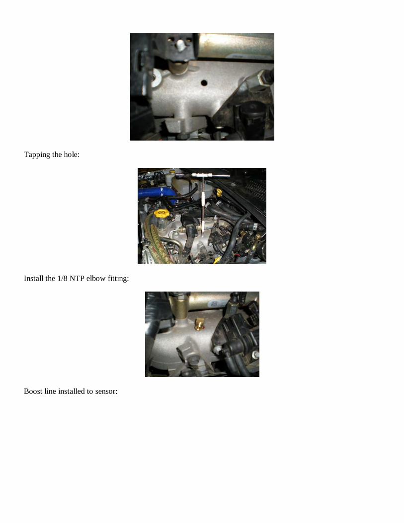
Tapping the hole:
Install the 1/8 NTP elbow fitting:
Boost line installed to sensor:
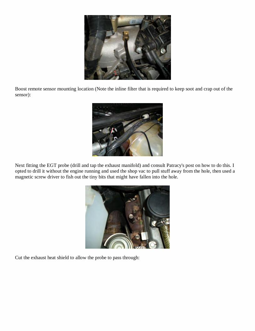
Boost remote sensor mounting location (Note the inline filter that is required to keep soot and crap out of the
sensor):
Next fitting the EGT probe (drill and tap the exhaust manifold) and consult Patracy's post on how to do this. I
opted to drill it without the engine running and used the shop vac to pull stuff away from the hole, then used a
magnetic screw driver to fish out the tiny bits that might have fallen into the hole.
Cut the exhaust heat shield to allow the probe to pass through:

Run the sensor wires through the firewall, and I thought the obvious place was what I assume to be the clutch
grommet (which is unused on my automatic).
Interior side of the grommet (just under the steering column and behind the carpet and sound insulation):
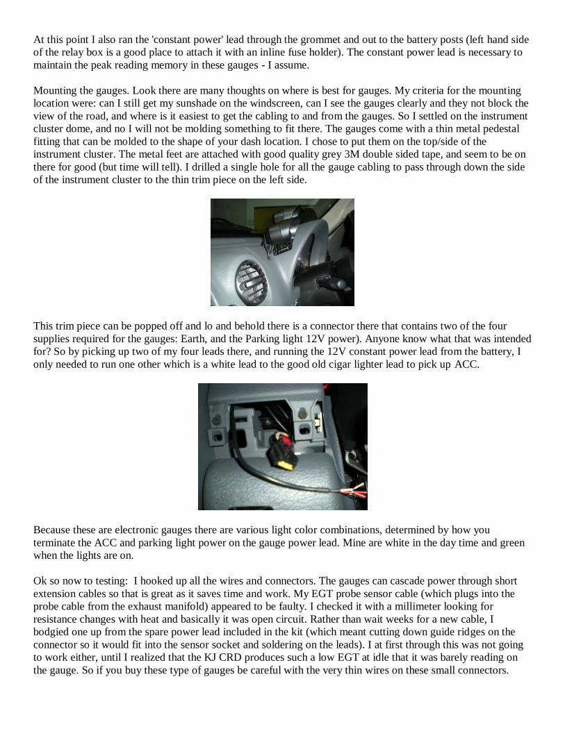
At this point I also ran the 'constant power' lead through the grommet and out to the battery posts (left hand side
of the relay box is a good place to attach it with an inline fuse holder). The constant power lead is necessary to
maintain the peak reading memory in these gauges - I assume.
Mounting the gauges. Look there are many thoughts on where is best for gauges. My criteria for the mounting
location were: can I still get my sunshade on the windscreen, can I see the gauges clearly and they not block the
view of the road, and where is it easiest to get the cabling to and from the gauges. So I settled on the instrument
cluster dome, and no I will not be molding something to fit there. The gauges come with a thin metal pedestal
fitting that can be molded to the shape of your dash location. I chose to put them on the top/side of the
instrument cluster. The metal feet are attached with good quality grey 3M double sided tape, and seem to be on
there for good (but time will tell). I drilled a single hole for all the gauge cabling to pass through down the side
of the instrument cluster to the thin trim piece on the left side.
This trim piece can be popped off and lo and behold there is a connector there that contains two of the four
supplies required for the gauges: Earth, and the Parking light 12V power). Anyone know what that was intended
for? So by picking up two of my four leads there, and running the 12V constant power lead from the battery, I
only needed to run one other which is a white lead to the good old cigar lighter lead to pick up ACC.
Because these are electronic gauges there are various light color combinations, determined by how you
terminate the ACC and parking light power on the gauge power lead. Mine are white in the day time and green
when the lights are on.
Ok so now to testing: I hooked up all the wires and connectors. The gauges can cascade power through short
extension cables so that is great as it saves time and work. My EGT probe sensor cable (which plugs into the
probe cable from the exhaust manifold) appeared to be faulty. I checked it with a millimeter looking for
resistance changes with heat and basically it was open circuit. Rather than wait weeks for a new cable, I
bodgied one up from the spare power lead included in the kit (which meant cutting down guide ridges on the
connector so it would fit into the sensor socket and soldering on the leads). I at first through this was not going
to work either, until I realized that the KJ CRD produces such a low EGT at idle that it was barely reading on
the gauge. So if you buy these type of gauges be careful with the very thin wires on these small connectors.
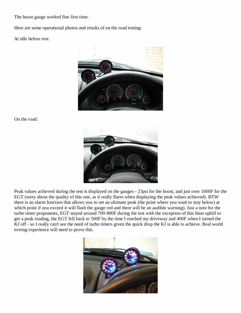
The boost gauge worked fine first time.
Here are some operational photos and results of on the road testing:
At idle before test:
On the road:
Peak values achieved during the test is displayed on the gauges - 23psi for the boost, and just over 1000F for the
EGT (sorry about the quality of this one, as it really flares when displaying the peak values achieved). BTW
there is an alarm function that allows you to set an ultimate peak (the point where you want to stay below) at
which point if you exceed it will flash the gauge red and there will be an audible warning). Just a note for the
turbo timer proponents, EGT stayed around 700-800F during the test with the exception of this blast uphill to
get a peak reading, the EGT fell back to 500F by the time I reached my driveway and 400F when I turned the
KJ off - so I really can't see the need of turbo timers given the quick drop the KJ is able to achieve. Real world
towing experience will need to prove this.
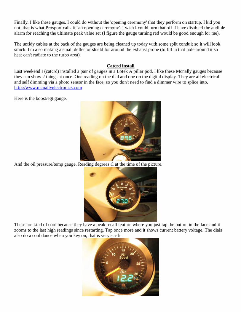
Finally. I like these gauges. I could do without the 'opening ceremony' that they perform on startup. I kid you
not, that is what Prosport calls it "an opening ceremony'. I wish I could turn that off. I have disabled the audible
alarm for reaching the ultimate peak value set (I figure the gauge turning red would be good enough for me).
The untidy cables at the back of the gauges are being cleaned up today with some split conduit so it will look
smick. I'm also making a small deflector shield for around the exhaust probe (to fill in that hole around it so
heat can't radiate to the turbo area).
Catcrd install
Last weekend I (catcrd) installed a pair of gauges in a Lotek A pillar pod. I like these Mcnally gauges because
they can show 2 things at once. One reading on the dial and one on the digital display. They are all electrical
and self dimming via a photo sensor in the face, so you don't need to find a dimmer wire to splice into.
http://www.mcnallyelectronics.com
Here is the boost/egt gauge.
And the oil pressure/temp gauge. Reading degrees C at the time of the picture.
These are kind of cool because they have a peak recall feature where you just tap the button in the face and it
zooms to the last high readings since restarting. Tap once more and it shows current battery voltage. The dials
also do a cool dance when you key on, that is very sci-fi.
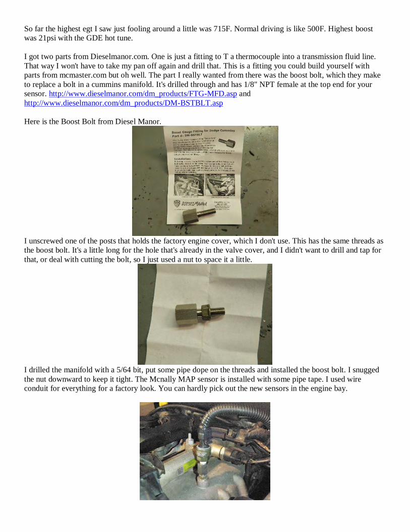
So far the highest egt I saw just fooling around a little was 715F. Normal driving is like 500F. Highest boost
was 21psi with the GDE hot tune.
I got two parts from Dieselmanor.com. One is just a fitting to T a thermocouple into a transmission fluid line.
That way I won't have to take my pan off again and drill that. This is a fitting you could build yourself with
parts from mcmaster.com but oh well. The part I really wanted from there was the boost bolt, which they make
to replace a bolt in a cummins manifold. It's drilled through and has 1/8" NPT female at the top end for your
sensor. http://www.dieselmanor.com/dm_products/FTG-MFD.asp and
http://www.dieselmanor.com/dm_products/DM-BSTBLT.asp
Here is the Boost Bolt from Diesel Manor.
I unscrewed one of the posts that holds the factory engine cover, which I don't use. This has the same threads as
the boost bolt. It's a little long for the hole that's already in the valve cover, and I didn't want to drill and tap for
that, or deal with cutting the bolt, so I just used a nut to space it a little.
I drilled the manifold with a 5/64 bit, put some pipe dope on the threads and installed the boost bolt. I snugged
the nut downward to keep it tight. The Mcnally MAP sensor is installed with some pipe tape. I used wire
conduit for everything for a factory look. You can hardly pick out the new sensors in the engine bay.
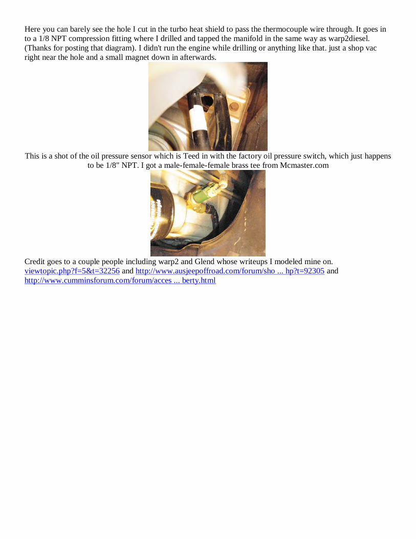
Here you can barely see the hole I cut in the turbo heat shield to pass the thermocouple wire through. It goes in
to a 1/8 NPT compression fitting where I drilled and tapped the manifold in the same way as warp2diesel.
(Thanks for posting that diagram). I didn't run the engine while drilling or anything like that. just a shop vac
right near the hole and a small magnet down in afterwards.
This is a shot of the oil pressure sensor which is Teed in with the factory oil pressure switch, which just happens
to be 1/8" NPT. I got a male-female-female brass tee from Mcmaster.com
Credit goes to a couple people including warp2 and Glend whose writeups I modeled mine on.
viewtopic.php?f=5&t=32256 and http://www.ausjeepoffroad.com/forum/sho ... hp?t=92305 and
http://www.cumminsforum.com/forum/acces ... berty.html
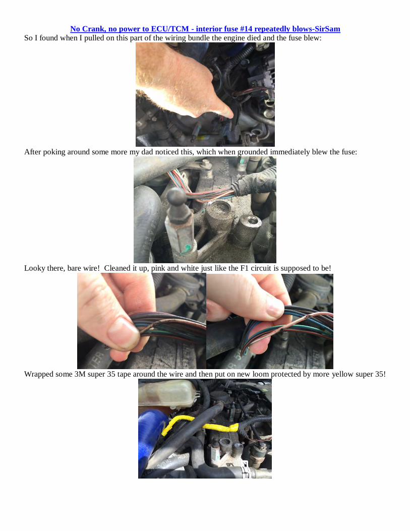
No Crank, no power to ECU/TCM - interior fuse #14 repeatedly blows-SirSam
So I found when I pulled on this part of the wiring bundle the engine died and the fuse blew:
After poking around some more my dad noticed this, which when grounded immediately blew the fuse:
Looky there, bare wire! Cleaned it up, pink and white just like the F1 circuit is supposed to be!
Wrapped some 3M super 35 tape around the wire and then put on new loom protected by more yellow super 35!
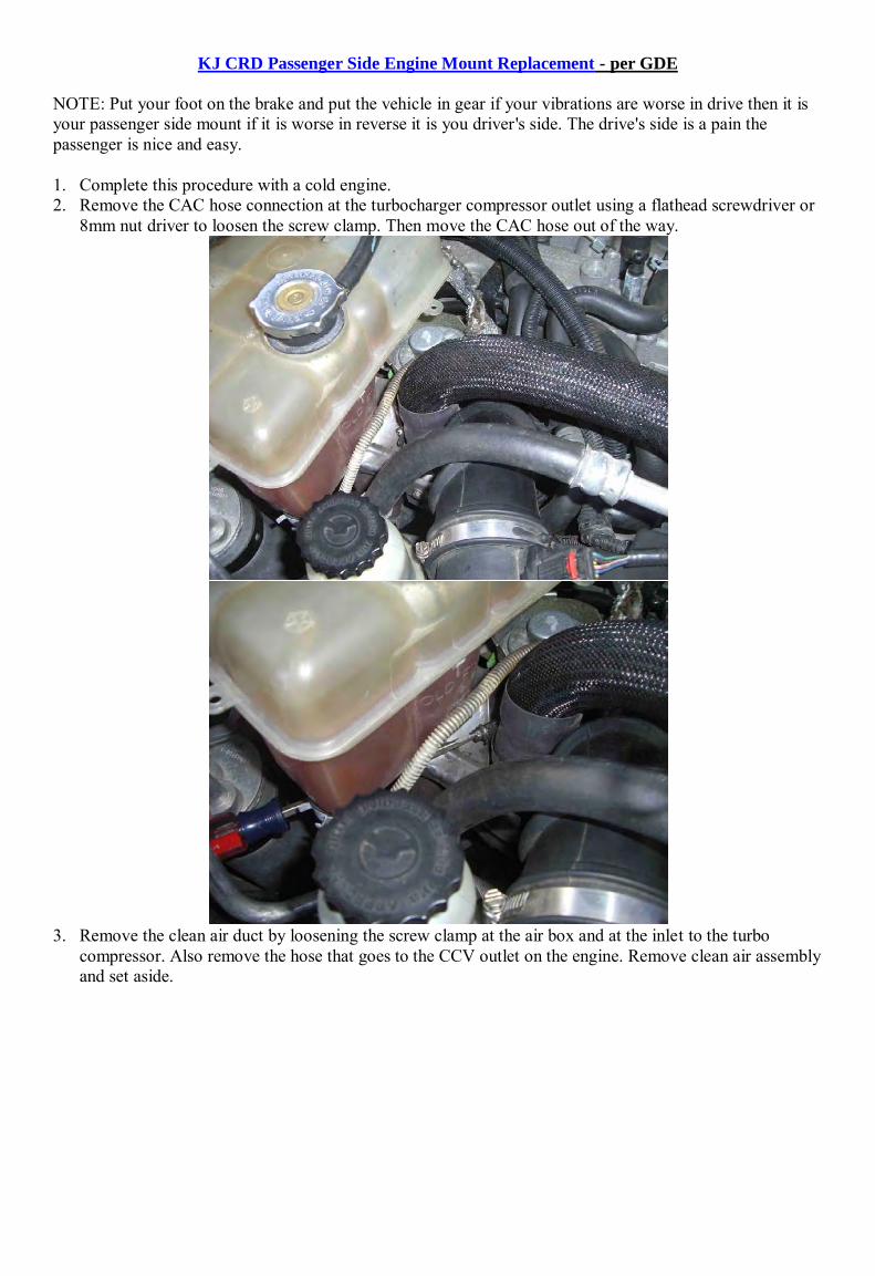
KJ CRD Passenger Side Engine Mount Replacement - per GDE NOTE: Put your foot on the brake and put the vehicle in gear if your vibrations are worse in drive then it is your passenger side mount if it is worse in reverse it is you driver's side. The drive's side is a pain the passenger is nice and easy. 1. Complete this procedure with a cold engine. 2. Remove the CAC hose connection at the turbocharger compressor outlet using a flathead screwdriver or
8mm nut driver to loosen the screw clamp. Then move the CAC hose out of the way.
3. Remove the clean air duct by loosening the screw clamp at the air box and at the inlet to the turbo
compressor. Also remove the hose that goes to the CCV outlet on the engine. Remove clean air assembly and set aside.
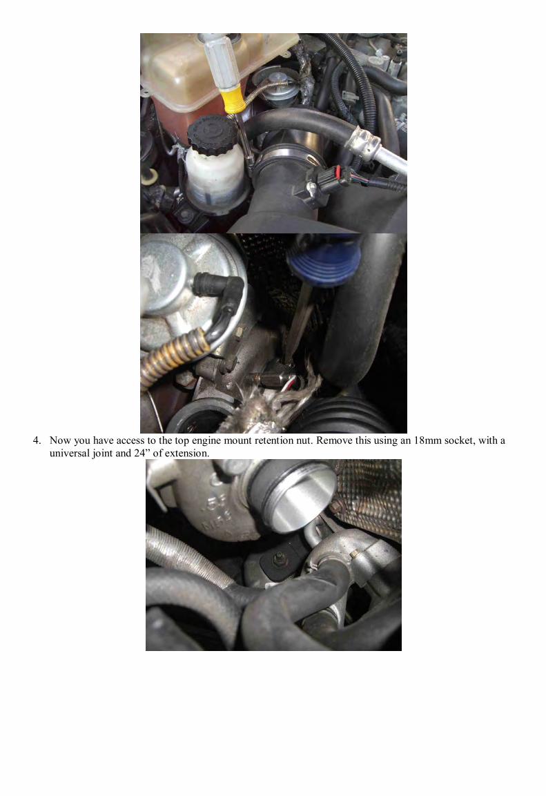
4. Now you have access to the top engine mount retention nut. Remove this using an 18mm socket, with a
universal joint and 24” of extension.
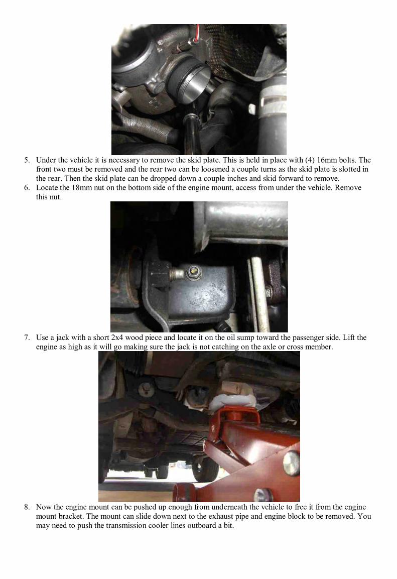
5. Under the vehicle it is necessary to remove the skid plate. This is held in place with (4) 16mm bolts. The
front two must be removed and the rear two can be loosened a couple turns as the skid plate is slotted in the rear. Then the skid plate can be dropped down a couple inches and skid forward to remove.
6. Locate the 18mm nut on the bottom side of the engine mount, access from under the vehicle. Remove this nut.
7. Use a jack with a short 2x4 wood piece and locate it on the oil sump toward the passenger side. Lift the
engine as high as it will go making sure the jack is not catching on the axle or cross member.
8. Now the engine mount can be pushed up enough from underneath the vehicle to free it from the engine
mount bracket. The mount can slide down next to the exhaust pipe and engine block to be removed. You may need to push the transmission cooler lines outboard a bit.

9. The engine mount heat shield needs to be removed and installed on the new mount prior to reassembly. 10. Reinstall everything in the reverse order and torque the engine mounts as tight as possible or 82 ft*lb as
specified in the 2005 KJ service manual.
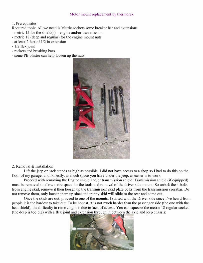
Motor mount replacement by thermorex 1. Prerequisites Required tools: All we need is Metric sockets some breaker bar and extensions - metric 15 for the shield(s) – engine and/or transmission - metric 18 (deep and regular) for the engine mount nuts - at least 2 feet of 1/2 in extension - 1/2 flex joint - rackets and breaking bars. - some PB blaster can help loosen up the nuts.
2. Removal & Installation
Lift the jeep on jack stands as high as possible. I did not have access to a shop so I had to do this on the floor of my garage, and honestly, as much space you have under the jeep, as easier is to work.
Proceed with removing the Engine shield and/or transmission shield. Transmission shield (if equipped) must be removed to allow more space for the tools and removal of the driver side mount. So unbolt the 4 bolts from engine skid, remove it then loosen up the transmission skid plate bolts from the transmission crossbar. Do not remove them, only loosen them up since the tranny skid will slide to the rear and come out.
Once the skids are out, proceed to one of the mounts, I started with the Driver side since I’ve heard from people it is the hardest to take out. To be honest, it is not much harder than the passenger side (the one with the heat shield), the difficulty in removing it is due to lack of access. You can squeeze the metric 18 regular socket (the deep is too big) with a flex joint and extension through in between the axle and jeep chassis:
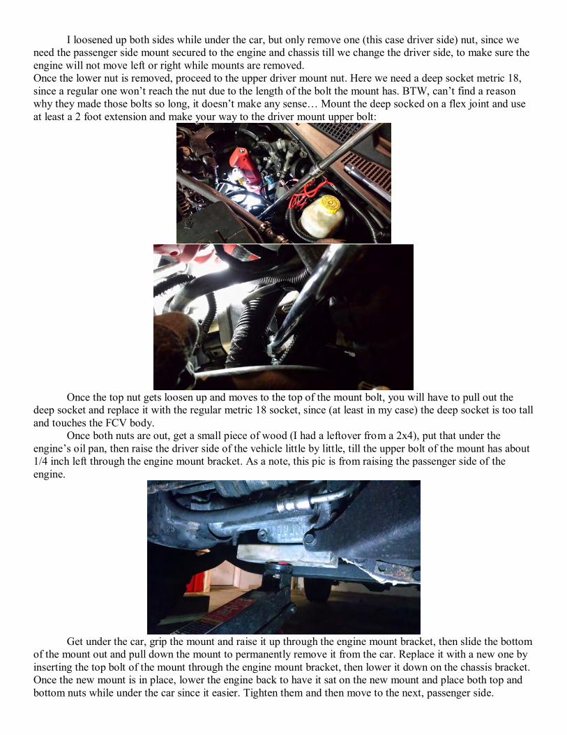
I loosened up both sides while under the car, but only remove one (this case driver side) nut, since we need the passenger side mount secured to the engine and chassis till we change the driver side, to make sure the engine will not move left or right while mounts are removed. Once the lower nut is removed, proceed to the upper driver mount nut. Here we need a deep socket metric 18, since a regular one won’t reach the nut due to the length of the bolt the mount has. BTW, can’t find a reason why they made those bolts so long, it doesn’t make any sense… Mount the deep socked on a flex joint and use at least a 2 foot extension and make your way to the driver mount upper bolt:
Once the top nut gets loosen up and moves to the top of the mount bolt, you will have to pull out the
deep socket and replace it with the regular metric 18 socket, since (at least in my case) the deep socket is too tall and touches the FCV body.
Once both nuts are out, get a small piece of wood (I had a leftover from a 2x4), put that under the engine’s oil pan, then raise the driver side of the vehicle little by little, till the upper bolt of the mount has about 1/4 inch left through the engine mount bracket. As a note, this pic is from raising the passenger side of the engine.
Get under the car, grip the mount and raise it up through the engine mount bracket, then slide the bottom
of the mount out and pull down the mount to permanently remove it from the car. Replace it with a new one by inserting the top bolt of the mount through the engine mount bracket, then lower it down on the chassis bracket. Once the new mount is in place, lower the engine back to have it sat on the new mount and place both top and bottom nuts while under the car since it easier. Tighten them and then move to the next, passenger side.
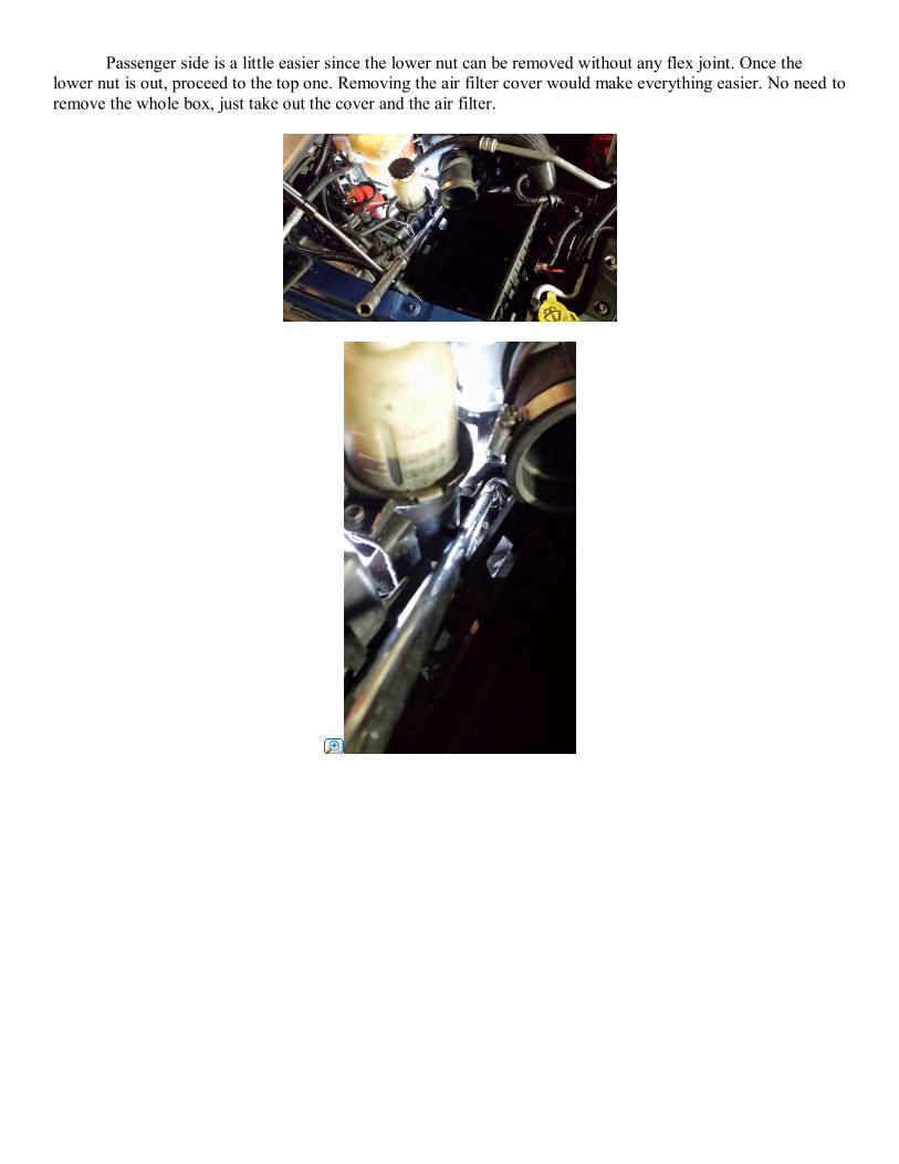
Passenger side is a little easier since the lower nut can be removed without any flex joint. Once the lower nut is out, proceed to the top one. Removing the air filter cover would make everything easier. No need to remove the whole box, just take out the cover and the air filter.
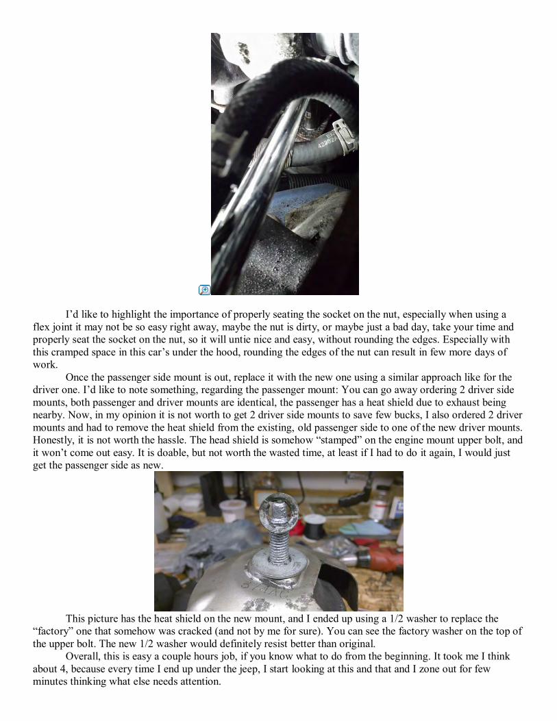
I’d like to highlight the importance of properly seating the socket on the nut, especially when using a flex joint it may not be so easy right away, maybe the nut is dirty, or maybe just a bad day, take your time and properly seat the socket on the nut, so it will untie nice and easy, without rounding the edges. Especially with this cramped space in this car’s under the hood, rounding the edges of the nut can result in few more days of work.
Once the passenger side mount is out, replace it with the new one using a similar approach like for the driver one. I’d like to note something, regarding the passenger mount: You can go away ordering 2 driver side mounts, both passenger and driver mounts are identical, the passenger has a heat shield due to exhaust being nearby. Now, in my opinion it is not worth to get 2 driver side mounts to save few bucks, I also ordered 2 driver mounts and had to remove the heat shield from the existing, old passenger side to one of the new driver mounts. Honestly, it is not worth the hassle. The head shield is somehow “stamped” on the engine mount upper bolt, and it won’t come out easy. It is doable, but not worth the wasted time, at least if I had to do it again, I would just get the passenger side as new.
This picture has the heat shield on the new mount, and I ended up using a 1/2 washer to replace the
“factory” one that somehow was cracked (and not by me for sure). You can see the factory washer on the top of the upper bolt. The new 1/2 washer would definitely resist better than original.
Overall, this is easy a couple hours job, if you know what to do from the beginning. It took me I think about 4, because every time I end up under the jeep, I start looking at this and that and I zone out for few minutes thinking what else needs attention.
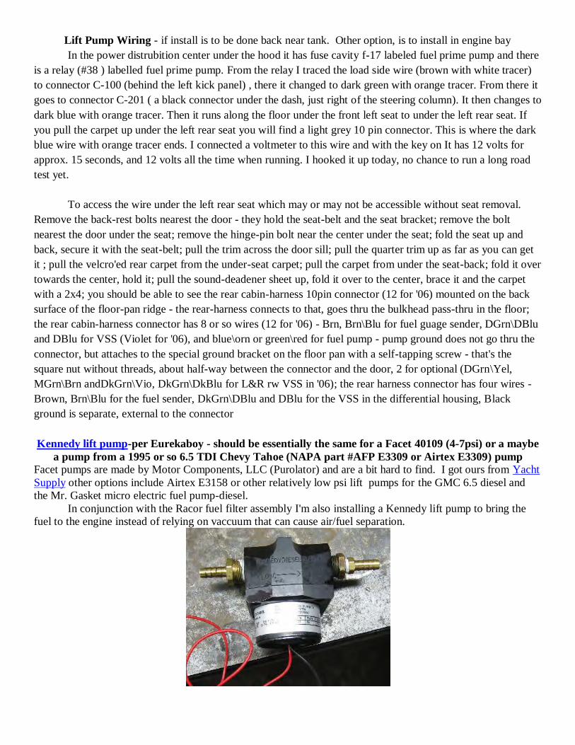
Lift Pump Wiring - if install is to be done back near tank. Other option, is to install in engine bay
In the power distrubition center under the hood it has fuse cavity f-17 labeled fuel prime pump and there
is a relay (#38 ) labelled fuel prime pump. From the relay I traced the load side wire (brown with white tracer)
to connector C-100 (behind the left kick panel) , there it changed to dark green with orange tracer. From there it
goes to connector C-201 ( a black connector under the dash, just right of the steering column). It then changes to
dark blue with orange tracer. Then it runs along the floor under the front left seat to under the left rear seat. If
you pull the carpet up under the left rear seat you will find a light grey 10 pin connector. This is where the dark
blue wire with orange tracer ends. I connected a voltmeter to this wire and with the key on It has 12 volts for
approx. 15 seconds, and 12 volts all the time when running. I hooked it up today, no chance to run a long road
test yet.
To access the wire under the left rear seat which may or may not be accessible without seat removal.
Remove the back-rest bolts nearest the door - they hold the seat-belt and the seat bracket; remove the bolt
nearest the door under the seat; remove the hinge-pin bolt near the center under the seat; fold the seat up and
back, secure it with the seat-belt; pull the trim across the door sill; pull the quarter trim up as far as you can get
it ; pull the velcro'ed rear carpet from the under-seat carpet; pull the carpet from under the seat-back; fold it over
towards the center, hold it; pull the sound-deadener sheet up, fold it over to the center, brace it and the carpet
with a 2x4; you should be able to see the rear cabin-harness 10pin connector (12 for '06) mounted on the back
surface of the floor-pan ridge - the rear-harness connects to that, goes thru the bulkhead pass-thru in the floor;
the rear cabin-harness connector has 8 or so wires (12 for '06) - Brn, Brn\Blu for fuel guage sender, DGrn\DBlu
and DBlu for VSS (Violet for '06), and blue\orn or green\red for fuel pump - pump ground does not go thru the
connector, but attaches to the special ground bracket on the floor pan with a self-tapping screw - that's the
square nut without threads, about half-way between the connector and the door, 2 for optional (DGrn\Yel,
MGrn\Brn andDkGrn\Vio, DkGrn\DkBlu for L&R rw VSS in '06); the rear harness connector has four wires -
Brown, Brn\Blu for the fuel sender, DkGrn\DBlu and DBlu for the VSS in the differential housing, Black
ground is separate, external to the connector
Kennedy lift pump-per Eurekaboy - should be essentially the same for a Facet 40109 (4-7psi) or a maybe
a pump from a 1995 or so 6.5 TDI Chevy Tahoe (NAPA part #AFP E3309 or Airtex E3309) pump
Facet pumps are made by Motor Components, LLC (Purolator) and are a bit hard to find. I got ours from Yacht
Supply other options include Airtex E3158 or other relatively low psi lift pumps for the GMC 6.5 diesel and
the Mr. Gasket micro electric fuel pump-diesel.
In conjunction with the Racor fuel filter assembly I'm also installing a Kennedy lift pump to bring the
fuel to the engine instead of relying on vaccuum that can cause air/fuel separation.

I ordered the Kennedy lift pump from Kennedy Diesel (the fittings weren't included). It is a centrifugal
type which won't cause a restriction if it fails.
Power for the pump is provided by Jeep and is located under the carpet just inside the left rear door. The
carpet is a pain to get up to gain enough room to work. The blue/orange wire is the power wire to the gasser's
in-tank fuel pump, and it is still in place on the diesel except for the last run to the tank. It is powered for 15-20
seconds when the key is turned on unless the the vehicle is running then it is powered continuously. The wire is
larger than most of the others and kind of stands out.
I spliced into the wire and ran the wire to the lift pump through the grommet under the left rear seat. It
can be fairly easily accessed by reaching under the carpet and running your hand 'uphill' under the seat.
I made a mounting bracket for the pump out of some scrap I had. It's not quite 1/8" thick. It's not gonna
be seen so beauty is not a concern.
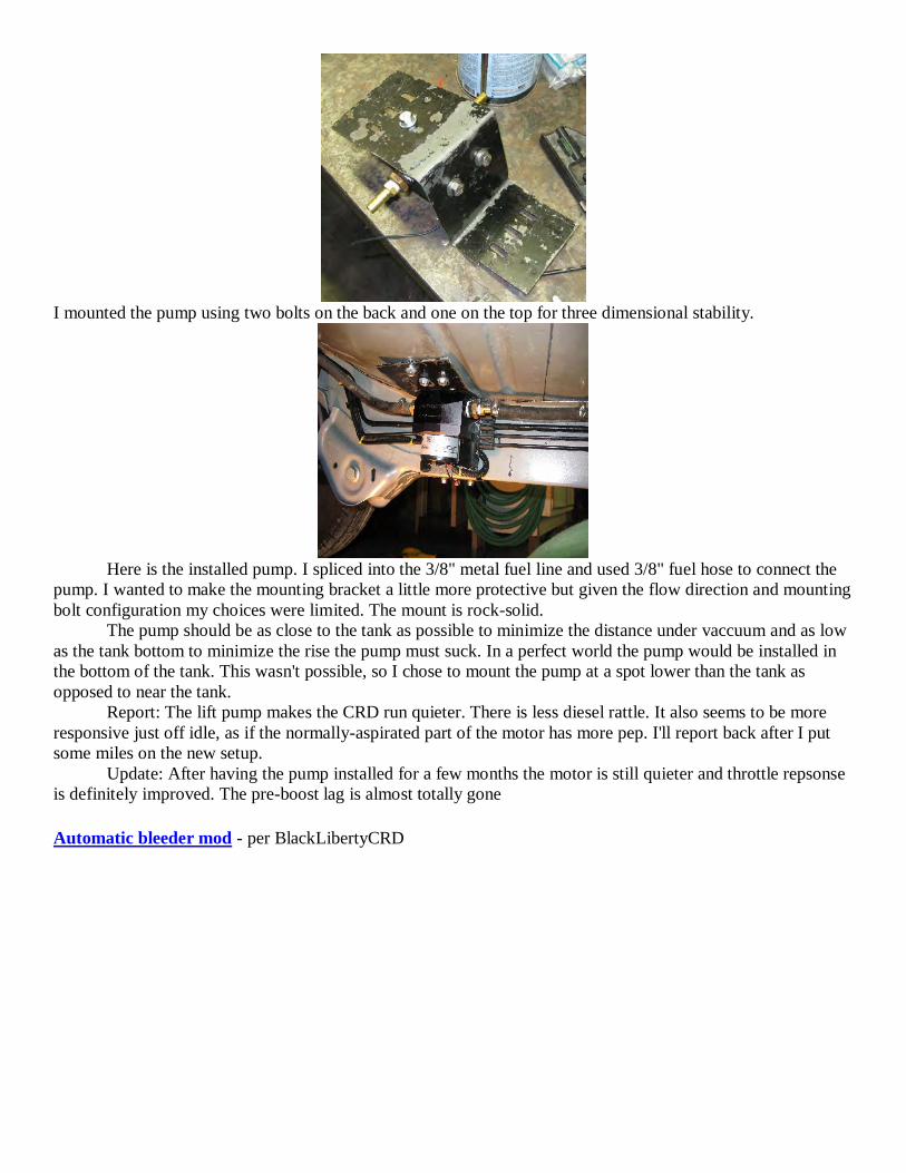
I mounted the pump using two bolts on the back and one on the top for three dimensional stability.
Here is the installed pump. I spliced into the 3/8" metal fuel line and used 3/8" fuel hose to connect the
pump. I wanted to make the mounting bracket a little more protective but given the flow direction and mounting
bolt configuration my choices were limited. The mount is rock-solid.
The pump should be as close to the tank as possible to minimize the distance under vaccuum and as low
as the tank bottom to minimize the rise the pump must suck. In a perfect world the pump would be installed in
the bottom of the tank. This wasn't possible, so I chose to mount the pump at a spot lower than the tank as
opposed to near the tank.
Report: The lift pump makes the CRD run quieter. There is less diesel rattle. It also seems to be more
responsive just off idle, as if the normally-aspirated part of the motor has more pep. I'll report back after I put
some miles on the new setup.
Update: After having the pump installed for a few months the motor is still quieter and throttle repsonse
is definitely improved. The pre-boost lag is almost totally gone
Automatic bleeder mod - per BlackLibertyCRD
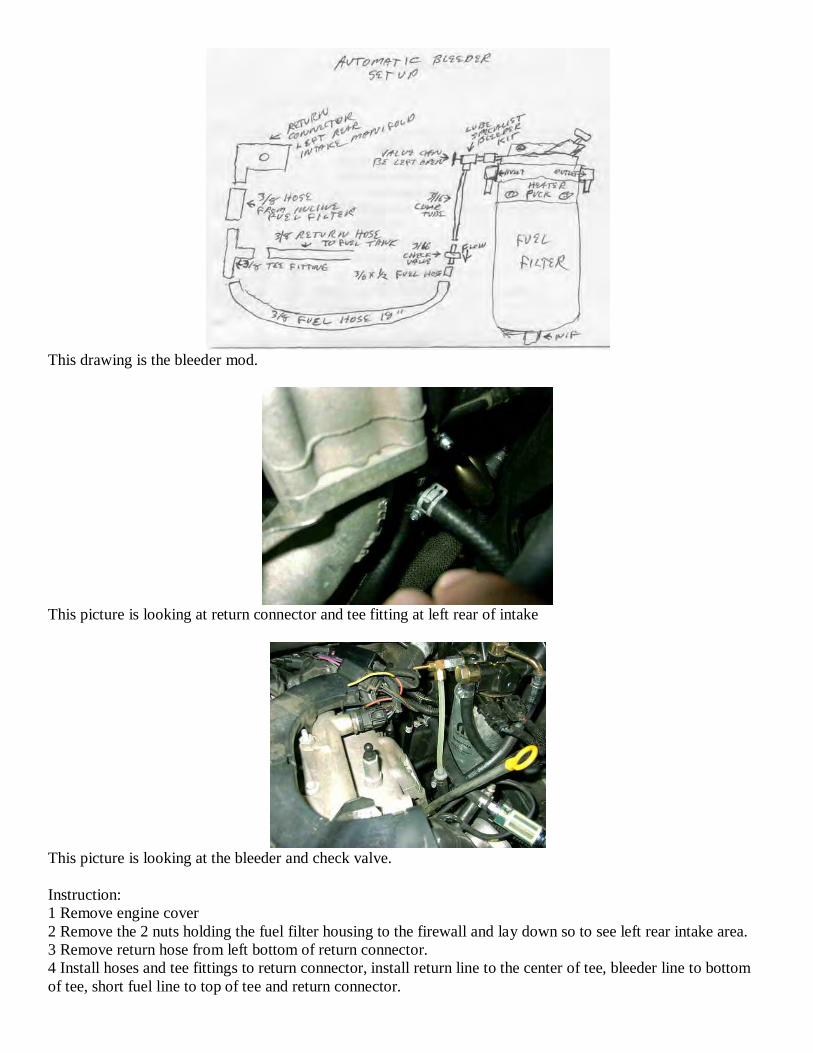
This drawing is the bleeder mod.
This picture is looking at return connector and tee fitting at left rear of intake
This picture is looking at the bleeder and check valve.
Instruction:
1 Remove engine cover
2 Remove the 2 nuts holding the fuel filter housing to the firewall and lay down so to see left rear intake area.
3 Remove return hose from left bottom of return connector.
4 Install hoses and tee fittings to return connector, install return line to the center of tee, bleeder line to bottom
of tee, short fuel line to top of tee and return connector.

5 Installed 3/16 x 1/2 hose to outlet of check valve. This act as a bushing to resize check to fit inside the 3/8 fuel
hose.
6 Install outlet of check valve to 3/8 hose
7 Reinstall fuel filter housing to firewall.
8 Install bleeder kit as per instruction from Lube Specialist.
9 Cut clear tube along side of fuel filter
10 Heat end of clear tube in hot water and push on inlet of check valve while still warm. Make sure that the
clear tube goes all the way on the check valve or it may leak.
11 Open bleeder valve about 10 turns
12 Pump filter head plunger to bleed the fuel filter through the tube to the return. You should see air bubbles
and fuel going through the clear tube. Keep pumping on the plunger until fuel is clear of air. When done you
can leave the valve open.
LIFT PUMP INSTALL - per BlackLibertyCRD
This drawing is the illustration of the lift pump install
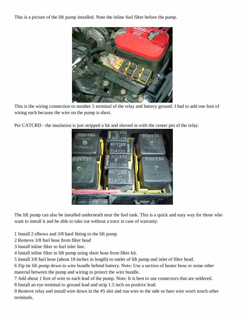
This is a picture of the lift pump installed. Note the inline fuel filter before the pump.
This is the wiring connection to number 5 terminal of the relay and battery ground. I had to add one foot of
wiring each because the wire on the pump is short.
Per CATCRD - the insulation is just stripped a bit and shoved in with the center pin of the relay.
The lift pump can also be installed underneath near the fuel tank. This is a quick and easy way for those who
want to install it and be able to take out without a trace in case of warranty.
1 Install 2 elbows and 3/8 bard fitting to the lift pump
2 Remove 3/8 fuel hose from filter head
3 Install inline filter to fuel inlet line.
4 Install inline filter to lift pump using short hose from filter kit.
5 Install 3/8 fuel hose (about 18 inches in length) to outlet of lift pump and inlet of filter head.
6 Zip tie lift pump down to wire bundle behind battery. Note: Use a section of heater hose or some other
material between the pump and wiring to protect the wire bundle.
7 Add about 1 foot of wire to each lead of the pump. Note: It is best to use connectors that are soldered.
8 Install an eye terminal to ground lead and strip 1.5 inch on positive lead.
9 Remove relay and install wire down in the #5 slot and run wire to the side so bare wire won't touch other
terminals.
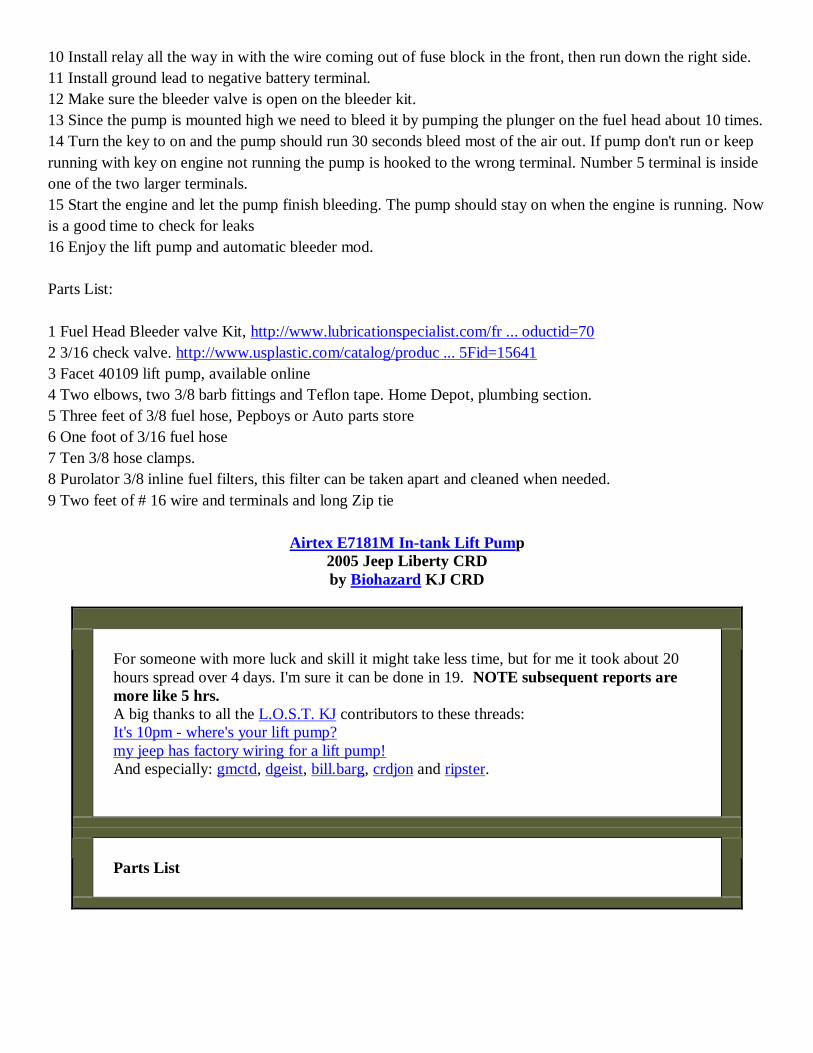
10 Install relay all the way in with the wire coming out of fuse block in the front, then run down the right side.
11 Install ground lead to negative battery terminal.
12 Make sure the bleeder valve is open on the bleeder kit.
13 Since the pump is mounted high we need to bleed it by pumping the plunger on the fuel head about 10 times.
14 Turn the key to on and the pump should run 30 seconds bleed most of the air out. If pump don't run or keep
running with key on engine not running the pump is hooked to the wrong terminal. Number 5 terminal is inside
one of the two larger terminals.
15 Start the engine and let the pump finish bleeding. The pump should stay on when the engine is running. Now
is a good time to check for leaks
16 Enjoy the lift pump and automatic bleeder mod.
Parts List:
1 Fuel Head Bleeder valve Kit, http://www.lubricationspecialist.com/fr ... oductid=70
2 3/16 check valve. http://www.usplastic.com/catalog/produc ... 5Fid=15641
3 Facet 40109 lift pump, available online
4 Two elbows, two 3/8 barb fittings and Teflon tape. Home Depot, plumbing section.
5 Three feet of 3/8 fuel hose, Pepboys or Auto parts store
6 One foot of 3/16 fuel hose
7 Ten 3/8 hose clamps.
8 Purolator 3/8 inline fuel filters, this filter can be taken apart and cleaned when needed.
9 Two feet of # 16 wire and terminals and long Zip tie
Airtex E7181M In-tank Lift Pump
2005 Jeep Liberty CRD
by Biohazard KJ CRD
For someone with more luck and skill it might take less time, but for me it took about 20
hours spread over 4 days. I'm sure it can be done in 19. NOTE subsequent reports are
more like 5 hrs.
A big thanks to all the L.O.S.T. KJ contributors to these threads:
It's 10pm - where's your lift pump?
my jeep has factory wiring for a lift pump!
And especially: gmctd, dgeist, bill.barg, crdjon and ripster.
Parts List
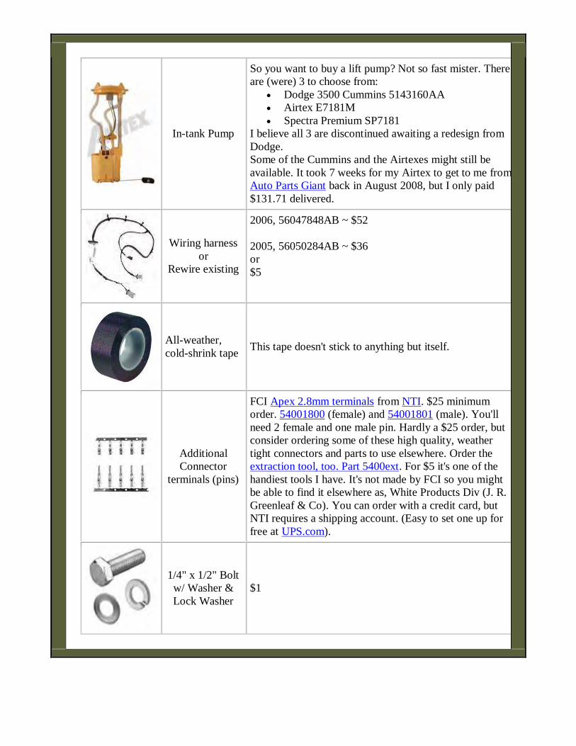
In-tank Pump
So you want to buy a lift pump? Not so fast mister. There
are (were) 3 to choose from:
Dodge 3500 Cummins 5143160AA
Airtex E7181M
Spectra Premium SP7181
I believe all 3 are discontinued awaiting a redesign from
Dodge.
Some of the Cummins and the Airtexes might still be
available. It took 7 weeks for my Airtex to get to me from
Auto Parts Giant back in August 2008, but I only paid
$131.71 delivered.
Wiring harness
or
Rewire existing
2006, 56047848AB ~ $52
2005, 56050284AB ~ $36
or
$5
All-weather,
cold-shrink tape This tape doesn't stick to anything but itself.
Additional
Connector
terminals (pins)
FCI Apex 2.8mm terminals from NTI. $25 minimum
order. 54001800 (female) and 54001801 (male). You'll
need 2 female and one male pin. Hardly a $25 order, but
consider ordering some of these high quality, weather
tight connectors and parts to use elsewhere. Order the
extraction tool, too. Part 5400ext. For $5 it's one of the
handiest tools I have. It's not made by FCI so you might
be able to find it elsewhere as, White Products Div (J. R.
Greenleaf & Co). You can order with a credit card, but
NTI requires a shipping account. (Easy to set one up for
free at UPS.com).
1/4" x 1/2" Bolt
w/ Washer &
Lock Washer
$1

Milk Crate Who "buys" these?
Cooler You've got one already. Not an excuse to get the stainless
steel one.
Step 0: Prep
Clean the underside of the carriage before starting. I wish I had.
Make sure your vehicle is safe to work under by reading and following all
instructions that came with any lifts, jacks or ramps.
Step 1: Lift Up Rear Seat and Pull Up Carpet
Better pictures than I have can be found here from dgeist.
And a good slide show of the whole process from Bill.Barg here.
Under the soundproofing layer you will find the connector with the pump wire.
The relay and fuse were already installed at the factory.
Step 2: Unplug Connector
1. Slide the red locking tab over.
2. Depress the latch, and
3. Pull apart.
Push the harness out through the floor pan.
Step 3: Disconnect Fuel Lines
First release the fuel lines from the fuel line hanger. I found this very hard to do even after
I'd figured out the release mechanism. Basically you drive something to the left of the right-
most opening in the top of the fitting. This will release the tab and allow you to pull the two
halves apart.
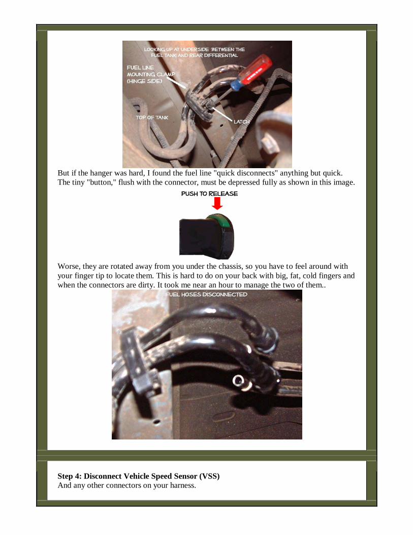
But if the hanger was hard, I found the fuel line "quick disconnects" anything but quick.
The tiny "button," flush with the connector, must be depressed fully as shown in this image.
Worse, they are rotated away from you under the chassis, so you have to feel around with
your finger tip to locate them. This is hard to do on your back with big, fat, cold fingers and
when the connectors are dirty. It took me near an hour to manage the two of them..
Step 4: Disconnect Vehicle Speed Sensor (VSS)
And any other connectors on your harness.

Slide red tab back fully..
Depress release tab fully.
Pull.
Step 5: Disconnect Fuel Filler Tube & Vent
I made the mistake of thinking the weight of the tank would pull the hose off the inlet. Not!
Disconnect the inlet as soon as you can.
There is also a vent tube to disconnect. Below is a picture shot below and behind the left
rear wheel well. As you can see, it's all open. The connector to undo is just out of view in
the channel to the right.
Step 6: Release Tank Straps & Drop Fuel Tank
I have the factory tow package and I was able to undo the bolts without removing the hitch
using a "wobble" extension on my socket wrench. I was also able to bend the straps to clear
the bumper. I supported the tank on two jacks (a cradle of some kind would be superior). I
then released only the rear bolts holding the straps on. This allows the tank to "ride" down
on the straps to the ground.
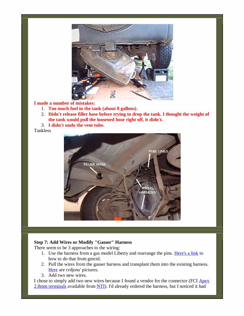
I made a number of mistakes:
1. Too much fuel in the tank (about 8 gallons).
2. Didn't release filler hose before trying to drop the tank. I thought the weight of
the tank would pull the loosened hose right off, it didn't.
3. I didn't undo the vent tube. Tankless
Step 7: Add Wires or Modify "Gasser" Harness
There seem to be 3 approaches to the wiring:
1. Use the harness from a gas model Liberty and rearrange the pins. Here's a link to
how to do that from gmctd.
2. Pull the wires from the gasser harness and transplant them into the existing harness.
Here are crdjons' pictures.
3. Add two new wires.
I chose to simply add two new wires because I found a vendor for the connector (FCI Apex
2.8mm terminals available from NTI). I'd already ordered the harness, but I noticed it had

an extra connector. Since it's a 2005, I also have the 5" problem. All-in-all I thought it
would be easier to simply add the two wires to the existing harness.
This involves partial disassembly of the harness by removing the hangers and untaping the
loom. Below illustrates two things.
One, using a pick tool to release the binding on a wire hanger, and
Two, why one should wash the undercarriage first.
Here are the two ends of the harness rewired. I used 18 gauge wire; gray for hot and black
for ground. As you can see, the 10-pin connector (right) is marked with pin #2 (the pump
hot side). It goes to pin #4 on the 4-pin connector that connects to the tank. The black
ground wire terminates in the passenger area and does not use the 10-pin connector.
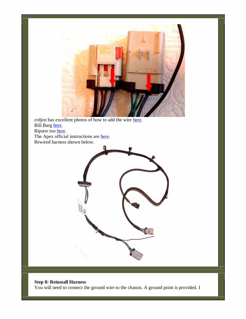
crdjon has excellent photos of how to add the wire here.
Bill.Barg here.
Ripster too here.
The Apex official instructions are here.
Rewired harness shown below.
Step 8: Reinstall Harness
You will need to connect the ground wire to the chassis. A ground point is provided. I
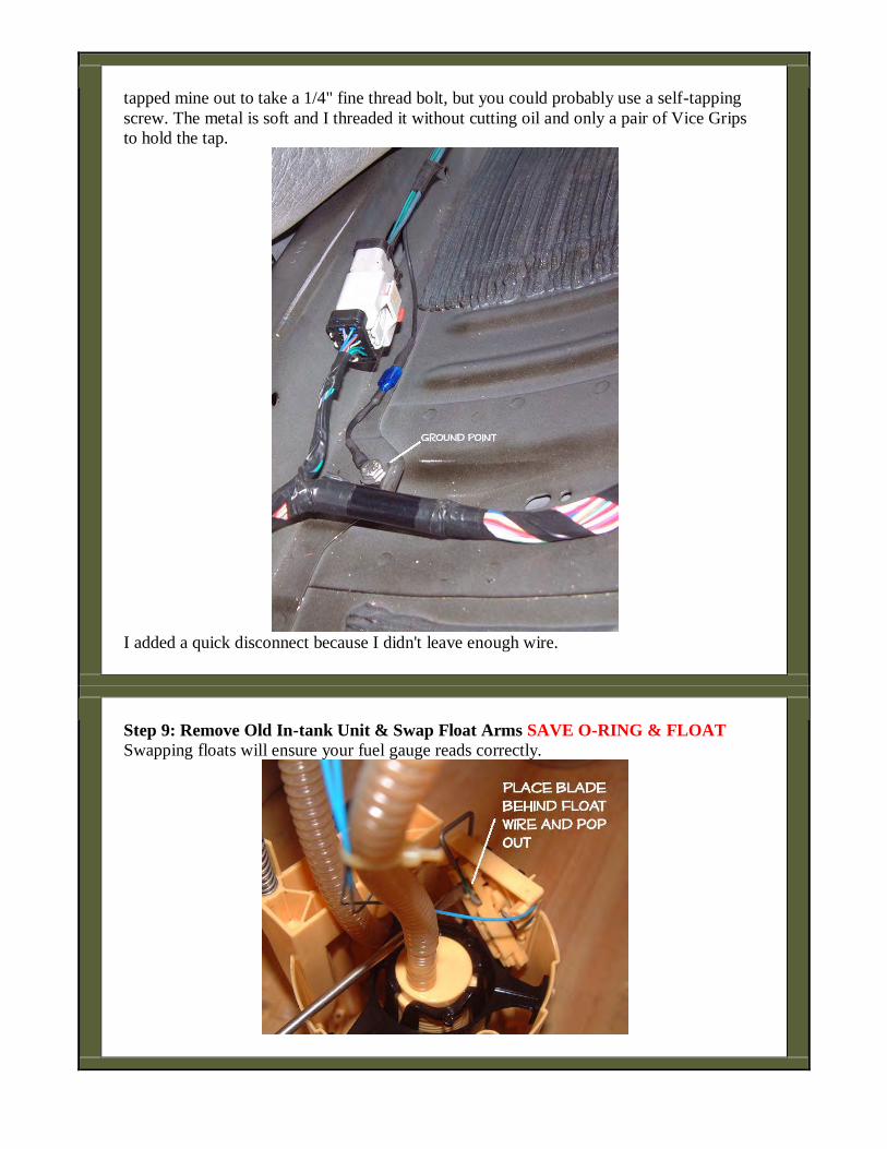
tapped mine out to take a 1/4" fine thread bolt, but you could probably use a self-tapping
screw. The metal is soft and I threaded it without cutting oil and only a pair of Vice Grips
to hold the tap.
I added a quick disconnect because I didn't leave enough wire.
Step 9: Remove Old In-tank Unit & Swap Float Arms SAVE O-RING & FLOAT
Swapping floats will ensure your fuel gauge reads correctly.
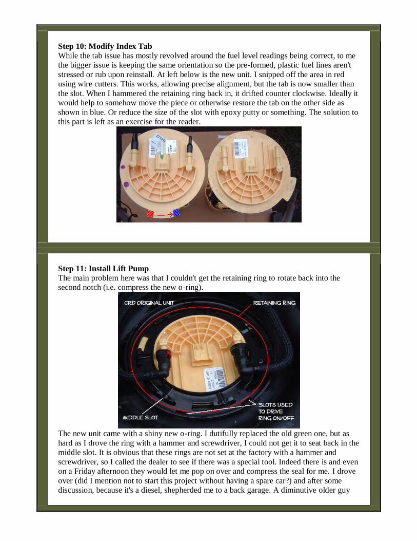
Step 10: Modify Index Tab
While the tab issue has mostly revolved around the fuel level readings being correct, to me
the bigger issue is keeping the same orientation so the pre-formed, plastic fuel lines aren't
stressed or rub upon reinstall. At left below is the new unit. I snipped off the area in red
using wire cutters. This works, allowing precise alignment, but the tab is now smaller than
the slot. When I hammered the retaining ring back in, it drifted counter clockwise. Ideally it
would help to somehow move the piece or otherwise restore the tab on the other side as
shown in blue. Or reduce the size of the slot with epoxy putty or something. The solution to
this part is left as an exercise for the reader.
Step 11: Install Lift Pump
The main problem here was that I couldn't get the retaining ring to rotate back into the
second notch (i.e. compress the new o-ring).
The new unit came with a shiny new o-ring. I dutifully replaced the old green one, but as
hard as I drove the ring with a hammer and screwdriver, I could not get it to seat back in the
middle slot. It is obvious that these rings are not set at the factory with a hammer and
screwdriver, so I called the dealer to see if there was a special tool. Indeed there is and even
on a Friday afternoon they would let me pop on over and compress the seal for me. I drove
over (did I mention not to start this project without having a spare car?) and after some
discussion, because it's a diesel, shepherded me to a back garage. A diminutive older guy
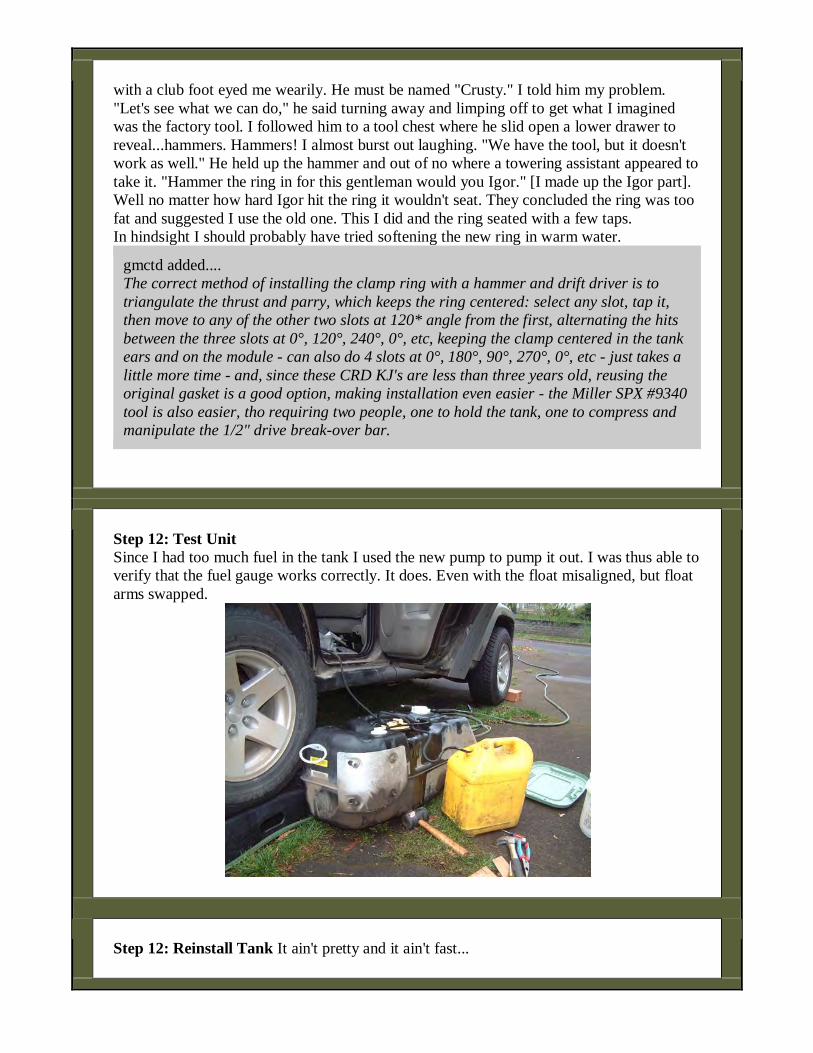
with a club foot eyed me wearily. He must be named "Crusty." I told him my problem.
"Let's see what we can do," he said turning away and limping off to get what I imagined
was the factory tool. I followed him to a tool chest where he slid open a lower drawer to
reveal...hammers. Hammers! I almost burst out laughing. "We have the tool, but it doesn't
work as well." He held up the hammer and out of no where a towering assistant appeared to
take it. "Hammer the ring in for this gentleman would you Igor." [I made up the Igor part].
Well no matter how hard Igor hit the ring it wouldn't seat. They concluded the ring was too
fat and suggested I use the old one. This I did and the ring seated with a few taps.
In hindsight I should probably have tried softening the new ring in warm water.
gmctd added....
The correct method of installing the clamp ring with a hammer and drift driver is to
triangulate the thrust and parry, which keeps the ring centered: select any slot, tap it,
then move to any of the other two slots at 120* angle from the first, alternating the hits
between the three slots at 0°, 120°, 240°, 0°, etc, keeping the clamp centered in the tank
ears and on the module - can also do 4 slots at 0°, 180°, 90°, 270°, 0°, etc - just takes a
little more time - and, since these CRD KJ's are less than three years old, reusing the
original gasket is a good option, making installation even easier - the Miller SPX #9340
tool is also easier, tho requiring two people, one to hold the tank, one to compress and
manipulate the 1/2" drive break-over bar.
Step 12: Test Unit
Since I had too much fuel in the tank I used the new pump to pump it out. I was thus able to
verify that the fuel gauge works correctly. It does. Even with the float misaligned, but float
arms swapped.
Step 12: Reinstall Tank It ain't pretty and it ain't fast...

This was tedious work. The more so because I thought I might break the plastic fuel lines,
so I didn't put them on until the tank was half way up. A difficult task in tight space.
Reconnect and re-hang:: Filler Hose, Vent Hose, Fuel Lines, Fuel Pump, VSS.
Step 13: Prime System
1. Turn key to the "ON" not "Start" then to "OFF". This initiates 20-seconds of pump
time. You should hear it whirring away.
2. Repeat.
3. Check to see if there is any air to purge from the fuel filter head.
o If yes, purge manually.
o If no, start your engine
Step 14: Test Drive & Leak Check
Postscript
It works and runs great. My motor used to go "takatakataka." Now it goes "tikatikatika." As
other have also reported my FM reception is greatly improved and my bald spot is growing
back in. A highly recommended mod.
Injector test method - from Green Diesel - 3/2/2011
If you have a scan tool that can clear the codes, here is a basic injector contribution test you can run:
1. Warm-up the engine with a short drive
2. Put in park and have someone press accelerator pedal to hold engine rpm at 2000.
3. Have a second person unplug one injector at a time and record the engine rpm...make sure the pedal %
does not move.
4. Repeat 3 times for comparison.
With each injector unplugged the drop in engine rpm should be similar. If one cylinder shows much less drop
than the others it is weak.
Injector test per bigbillyboy
Sorry for the delay, work has been busy. I'm not going to guarantee this is the approved troubleshooting
method, but it worked for me. First thing I did was upgeade filterhead and install lift pump to ensure no air in
fuel. Once I was. Positive there was no air in the system, I followed the following diagnostics, which was a
mixture of info from many different sources
Following a suggestion from the guys at the cummins commonrail forums, I shot a little either (reallly should
not do this) into the intake and cranked it over. Doing this, the liberty started and ran fine. Under heavy load
conditions, the jeep would defalt to limp mode, but it would still run.
Next step was to take off the fuel return rail and check for excessive return from one or several injectors. After
removing the fuel rail, (keep it in one piece and be very gentle with the plastic fittings that clip into the top of
the injector. If you break one, you get to buy the whole fuel rail for $45.00 - ask me how I know. Also, don't
drop any of the clips, as they are dealer only for $50/ea, and not available locally...) I insterted a 5" long piece
of clear vinyl tubing into the top of each of the injectors. I cranked for 10 seconds and looked at the levels in
each tube. They were all at the same level, and about 1/4" up the tube. Which is normal. If one or more is
significantly higher ( I read that it could be 3-4 inches of fuel after 10 second of cranking) then you have a
failed injector preventing rail pressure buildup. This was not the case for me. Also, don't break the plastic fuel
return junction (where all three fuel return lines join up) before heading to the tank, as it is dealer only and runs
$97 and not available for a week. I built one out of brass fittings from home depot for about $20. Much sturdier.
Next, I reinstalled the fuel return rail, and pulled the line off of the pressure control valve at the rear of the fuel
rail. I cranked for 10 seconds and had a significant amount of fuel drain out. While cranking, but not running,
this valve should be held shut preventing fuel from flowing at all. In my case, the valve had failed, once
replaced, the jeep started easily.
It is my understanding that if the PCV had been good, the only thing that could cause low pressure would be the
CP3 pump. From my reading, the pump itself rarely fails, but the MPROP valve bolted to it fails regularly.
I was able to give the part number off the PCV to a local diesel shop and they had the part next day for $449.
The dealer was a week out and $849.

I tested the components in this order as it was the best way I could figure out to determine with the highest
degree of certainty which component had failed without buying needless expensive components.
Fyi, that PCV valve is a very complex item. It is a normally closed valve. It is held shut with a spring, but gets
additional closing force from an electromagnet. The spring itself does not provide enough force to get the rail
pressure above 5000psi. The ECM varies the current to the PCV, the higher the current, the more closing force,
and the higher rail pressure. Somehow this works in balance with the ECM sending a signal to the MPROP
valve which both maintain predetermined rail pressure.
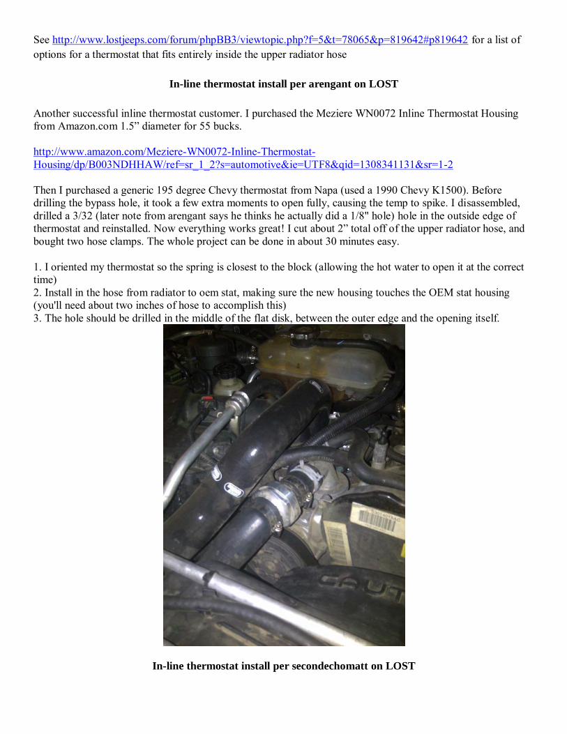
See http://www.lostjeeps.com/forum/phpBB3/viewtopic.php?f=5&t=78065&p=819642#p819642 for a list of options for a thermostat that fits entirely inside the upper radiator hose
In-line thermostat install per arengant on LOST
Another successful inline thermostat customer. I purchased the Meziere WN0072 Inline Thermostat Housing from Amazon.com 1.5” diameter for 55 bucks. http://www.amazon.com/Meziere-WN0072-Inline-Thermostat-Housing/dp/B003NDHHAW/ref=sr_1_2?s=automotive&ie=UTF8&qid=1308341131&sr=1-2 Then I purchased a generic 195 degree Chevy thermostat from Napa (used a 1990 Chevy K1500). Before drilling the bypass hole, it took a few extra moments to open fully, causing the temp to spike. I disassembled, drilled a 3/32 (later note from arengant says he thinks he actually did a 1/8" hole) hole in the outside edge of thermostat and reinstalled. Now everything works great! I cut about 2” total off of the upper radiator hose, and bought two hose clamps. The whole project can be done in about 30 minutes easy. 1. I oriented my thermostat so the spring is closest to the block (allowing the hot water to open it at the correct time) 2. Install in the hose from radiator to oem stat, making sure the new housing touches the OEM stat housing (you'll need about two inches of hose to accomplish this) 3. The hole should be drilled in the middle of the flat disk, between the outer edge and the opening itself.
In-line thermostat install per secondechomatt on LOST

Initial report: It works great! temp gauge was right where it needed to be, 12 o'clock as opposed to right at the 1/4 mark where it was. Heat was obnoxiously hot. I'll report back after a tank of fuel to see if it improved milage. The How to: Items Needed: 1. stant thermostat 2. gallon of coolant to replace what you are going to use 3. 2" hose clamp 4. a screw driver to tighten the clamp 5. pliers or a hose clamp tool. 6. 15 minutes. Procedure 1. Open hood and remove engine cover 2. Locate radiator hose going to thermostat. It is on the passenger side of the engine, right underneath the intercooler tube. 3. Disconnect radiator hose clamp. I have a tool designed for this, makes it easy, you could use a large set of pliers as well. 4. Remove radiator hose from thermostat housing. You will lose a bit of coolant, but not much as long as you immediately tip up the hose. 5. Remove radiator hose clamp and set aside for future use. 6. Insert thermostat into radiator hose, with the bulb facing towards the engine, bulb slightly (1/4" or so) protruding. You can't get more, as the hose won't go back on the housing. To get the thermostat seated fully, I used a screw driver and a hammer and LIGHTLY tapped it into place. If your rad hoses are old, this will be more difficult. *edit* after driving for a while, I saw the temp spike, then settle. So, I pulled the hose,
drilled a quick 1/8" hole in the skirt and put it back together. That fixed the spike, without affecting the
thermostat. 7. Place the worm clamp on the hose, around the wide part of the thermostat and tighten. I used just a plain 2" hose clamp. You can get fancy if you want. 8. Put the rad hose clamp back on the hose but don't tighten it yet. 9. Place the rad hose back on the thermostat housing and tighten the rad hose clamp. 10. Top off the coolant with an approved make. I used zerex g-05. 11. Put the engine cover back on and fire up the jeep. 12. Take it for a spin and watch your temp come back to what it should be, with a smile on your face realizing you bested the OEM's price by over a hundred dollars!
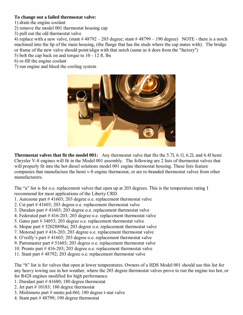
To change out a failed thermostat valve: 1) drain the engine coolant 2) remove the model 001 thermostat housing cap 3) pull out the old thermostat valve 4) replace with a new valve, (stant # 48792 – 203 degree; stant # 48799 – 190 degree) NOTE - there is a notch machined into the lip of the main housing, (the flange that has the studs where the cap mates with). The bridge or frame of the new valve should point/align with that notch (same as it does from the "factory") 5) bolt the cap back on and torque to 10 - 12 ft. lbs 6) re-fill the engine coolant 7) run engine and bleed the cooling system
Thermostat valves that fit the model 001: Any thermostat valve that fits the 5.7l, 6.1l, 6.2l, and 6.4l hemi Chrysler V-8 engines will fit in the Model 001 assembly. The following are 2 lists of thermostat valves that will properly fit into the hot diesel solutions model 001 engine thermostat housing. These lists feature companies that manufacture the hemi v-8 engine thermostat, or are re-branded thermostat valves from other manufacturers. The “a” list is for o.e. replacement valves that open up at 203 degrees. This is the temperature rating I recommend for most applications of the Liberty CRD. 1. Autozone part # 41603; 203 degree o.e. replacement thermostat valve 2. Cst part # 41603; 203 degree o.e. replacement thermostat valve 3. Duralast part # 41603; 203 degree o.e. replacement thermostat valve 4. Federated part # 416-203; 203 degree o.e. replacement thermostat valve 5. Gates part # 34053; 203 degree o.e. replacement thermostat valve 6. Mopar part # 52028898ai; 203 degree o.e. replacement thermostat valve 7. Motorad part # 416-203; 203 degree o.e. replacement thermostat valve 8. O’reilly’s part # 41603; 203 degree o.e. replacement thermostat valve 9. Partsmaster part # 51603; 203 degree o.e. replacement thermostat valve 10. Pronto part # 416-203; 203 degree o.e. replacement thermostat valve 11. Stant part # 48792; 203 degree o.e. replacement thermostat valve The “b” list is for valves that open at lower temperatures. Owners of a HDS Model 001 should use this list for any heavy towing use in hot weather, where the 203 degree thermostat valves prove to run the engine too hot, or for R428 engines modified for high performance. 1. Duralast part # 41680; 180 degree thermostat 2. Jet part # 10183; 180 degree thermostat 3. Mishimoto part # mmts-jed-06l; 180 degree t-stat valve 4. Stant part # 48799; 190 degree thermostat
Hardware for assembly and installation of your model 001: It has come to my attention that it is possible for someone to lose mounting and/or assembly hardware. God forbid, it is even possible to break one of the studs on a model 001, if you happen to run over it with a truck; or, more likely, strip the threads of the studs because your son is extremely ham-fisted, or has cross threaded the nut. Listed below is all of the hardware I have used in the manufacture of the HDS Model 001 thermostat assembly. It will be easier and less problematic sourcing your own hardware if any of the above unfortunate events occur to you. About the only things you would have to get from me - aside from machining a part yourself - is the housing, the cap, and the two aluminum hose barbs threaded into the housing. 1. 90 degree elbow hose barb; electroless nickel plated; 7/16”- 20unf “o” ring thread; air-way mfg part number n4601-6-4-nwo 2. 8mm x 30mm a2 stainless steel socket head cap screw; 1.25mm thread pitch 3. 8mm a2 stainless steel ready rod; 1.25mm thread pitch… for making studs 4. 8mm a2 stainless steel hex nut; 1.25mm thread pitch 5. 8mm a2 stainless steel lock washer 6. 8mm a2 stainless steel flat washer Extra parts that may be required when installing the model 001, or when changing out the thermostat
valve: 1) radiator hoses: chrysler part numbers 5142787aa and 5142788ab. 2) OEM temperature sending unit: chrysler part number 5066779aa or VM Motori part number 45962053f.
Liberty CRD OEM thermostat replacement instructions - Not sure who wrote this but Squeeto has a
good writeup with pictures
Just thought I'd confirm a few details that have already been discussed about the thermostat. First of all, there
are FOUR (4) bolts that physically hold the t-stat onto the engine. Three go through into the block, and the
fourth mounts the t-stat to the bracket on the top.
In my opinion, the easiest thing to do is to start disconnecting all the hoses from the t-stat and move them out of
the way, then I disconnected the CAC hose from the CAC side and folded it behind the turbo to get it out of the
way. I removed the air box. For those who haven't removed the stock air box: There are two sensors to unplug.
Then once you get the top lid of the airbox off, and remove the filter, the bottom section of the air box just pulls
upward. There are 3 rubber grommets that hold it in place (similar to the engine cover). It might take some
force...but if you pull it'll just pop off. Having the air box out of the way completely made the job much easier.
and the turbo inlet hose to make more space. I carefully stuffed a shop towel into the turbo to prevent any debris
or coolant from getting into it. I did not waste time partially draining the coolant. Whether you drain it or not,
you're going to have coolant pouring out when you pop the hoses off, so it's a waste of time to drain the radiator
down some first. You won't lose all that much coolant.
Once all the hoses are out of the way and everything is disconnected from the t-stat...you can unscrew the temp.
sensor from the back of the t-stat. This takes a 3/4 open end wrench. Then remove the 4 bolts holding the t-stat
onto the engine. This takes a 10mm socket and long extensions. The t-stat will then easily pop off with light
force.
The old gasket is tough to get off. I found that a razor blade was the easiest thing to use. My razor fits into a
pop-out knife kind of thing...so it was safer to grip the body of the knife and use the razor blade to peel the old
gasket off. I then spent about 15 minutes scraping the old gasket material off. Get as much of it off as you can.
Try not to let any of the old gasket fall into the engine.
Then I put a small amount of black silicone onto the new gasket to hold it onto the back of the new t-stat, and
bolted the new t-stat onto the engine. The rest is attaching all your hoses where they belong, reinstalling the
turbo hose after you pull the show towel out and make sure NONE of it was left inside the turbo, reinstalling the
airbox, and topping off the coolant.
I bought a gallon of Zerex G-05 at NAPA for $12 to top the coolant off with, and of course you top it off at the
reservoir on this Jeep, not at the radiator itself. Total job took almost 2 hours. Just make sure you remember
where all your hoses hook up before you start pulling them off. There are 5 connections to the t-stat altogether I
think.
NOTES - Jim Stoutamire
Radiator drain plug is on right lower rear, facing forward, of the radiator (under the location of the air filter
box. Squeeto suggests open it with 2 cms cut off of the handle of a 10mm "Allen" wrench. It is put in the
hollow head of the drain. Just turn it with the open end of a 10mm wrench. Alternatively with the air filter
box and front hose removed the plug can be accessed from above and turned a bit at a time with a 5/8" and
11/16" slightly offset open end wrench. The need for the two sizes is while the flats fit a 5/8" wrench two
of those flats have locator "bumps" on them that require the larger wrench although 3/4" might work better.

Next time I think I'll try Squeeto's method. If you don't go that route remember that the lower radiator
drain plug has 2 (one on each side) raised areas which makes using an open end wrench difficult at least on
those two "flats". In anycase when the plug is completely closed the 2 raised areas are dead vertical (1 up/1
down). Look up from the bottom to see what I mean before opening the valve. VERY IMPORTANT as
the white line up mark on the plug will wear off as you open and close and you do not want to over tighten,
just close the valve gently until it seats and one of the raised areas is "up" and the other is "down"
depending on which side you are working from.
I took a a quick look at the "lower" radiator hose, which is the one that runs across under the radiator in
front of the engine and connects to the radiator underneath the driver's side turbo hose. To disconnect the
upper end you would have to disconnect that turbo hose and maybe?? you can then remove the radiator
hose clamp and hose and then push the hose far enough down to drain it. If so you can probably slide it
back on for your quick brief engine run to circulate water without reinstalling the clamp BUT keep a sharp
eye that it doesn't pop off (shouldn't but I don't know how much pressure the system has). Clearly given
the hose route it will hold water as it's middle section is lower than the radiator drain valve. NOTE it
would be better to undo this hose at the engine rather than the radiator but I don't immediately see where it
connects to the engine.
The wiring plug to the temperature sending unit has a release tab that must be unlocked before the plug can
be removed. Mine was upside down so the release tab was hidden from view (e.g. the round locator tab
was up). I was able to pull the tstat with the wiring attached although with a right angle pick you might be
able to pop the release tab before removing the tstat. The latter would be important if the sending unit
needs replacement but the tstat does not. After cleaning off all the thread sealing pipe dope and reapplying
new pipe dope the sending unit reinstalled with the release tab accessible, seems to depend on where you
start threading.
The more hoses you remove or move out of the way the better including the turbo to intercooler hose and
the airbox to turbo hose.
The lower rear tstat bolt is extremely difficult to reach especially as the socket and extension have to clear
the bulge in the exhaust manifold. I'd suggest a thin wall socket or use a 1/4" drive with extension and a
1/4" drive 10mm socket rather than a standard 3/8" rig.
Used same razor rig to remove old gasket. Just shoved a small piece of paper towel into port to keep debris
out of the engine. There is a bit of gasket in the upper front corner below a casting flange that's a bit hard
to get unless you take the blade out of the holder and scrape from the back side.
The plug on the top (passenger side) of the radiator can be removed, which speeds up draining, by turning
it counter clockwise so the white line on the flange points to 4 o'clock and then pulling straight up.
When you are "rinsing" out the old or bad antifreeze with clean water. Drain, refill, idle with heater on no
more than 2-3 minutes just enough to circulate water some in the system, wait at least 30 min before
repeating. The engine won't heat up much in 2-3 minutes but it will heat up some so best to let it have a
chance to cool off before refilling with cold water or new antifreeze. After you have refilled with new a
new antifreeze/water mix, which should be to a level about 1" above the cold line on the reservoir (I'd say
fill to the hot line but I couldn't see one) you need to purge any air as you know. I like to be gentle doing
so by doing 3 drives as follows. 1 - just a mile or two or enough to get the temp needle to just start to come
up off the cold mark followed by a complete cool down (overnight if possible but if not 4 hrs should do it).
2 - a longer drive to get the temp needle up to about the 1/4 mark followed by a complete cool down. 3 - a
drive to full operating temp. like I did on the way to work and another complete cool down (in my case a
day at work). After cool downs 1 & 2 check fluid level and add enough to get it back to where you started.
After cool down 3 add fluid to a good visible mark on the bottle. Then drive like normal but keep a

reasonably close eye on the fluid level for the next tank or so. It should stay where you left it at cool down
3 but don't be surprised if you have to add a touch of fluid early in that tank but after that if you keep
having to add any quantity of fluid you have a leak as generally these closed systems almost never need
fluid added between fluid changes.
Keep in mind that our tstat functions upside down in the sense that it is the opening of the tstat that closes
off the bypass port. The tstat has 4 outflows and 1 inflow. The inflow is the rectangular hole in the head
where the tstat bolts on and ALL coolant passing thru the tstat comes thru there from the engine block.
Once coolant enters the body of the tstat the ports in the middle of the tstat body direct coolant flow,
regardless of tstat position, thru 1) the large plastic port to the viscous heater and then to the heater core
(before you ask yes per the FSM coolant circulates thru the heater core all the time) and 2) the small port
that is both the coolant overflow and degas (constant air bleed) port to the plastic tank on the firewall.
When the engine is cold and the tstat is closed (see the above upside down comment) a large portion of the
coolant is directly circulated out of 3) the bottom aluminum bypass port to the water pump inlet and then
forced by the water pump thru the block and a small portion thru 4) the large front facing port to the
radiator. As the coolant going thru the water pump directly to the engine warms up the tstat opens to
reduce and eventually close off the flow thru the bypass port so that all the flow now goes thru the 2 middle
ports (viscous heater and degas ports) and the front facing port to the radiator. As you can see if the tstat
fails open or by opening too early, as ours typically does, coolant flow is directed away from the bypass
port and to the radiator too early and is constantly over cooled hence the engine never fully warms up. In
my experience during the summer a failing but not failed tstat can be masked by higher ambient
temperatures and AC load.
In line tstat issues - On a cold engine an in line tstat will restrict the flow of coolant out that front facing
port to the radiator until the in line tstat opens. This would have a tendency to increase the temperature
within the block and tstat housing quicker at least until the bypass is closed or partially closed. However, as
noted above with a properly functioning OEM tstat on a cold engine some flow is already directed thru that
front facing port therefore IMHO if you are going to use an in line tstat it's important to do two things: 1)
provide a flow path thru the skirt of the in line tstat (on the upper edge to allow air to escape) to mimic that
OEM flow, ensure the inline warms up from that flow, and to prevent temperature spikes and 2) to place
the temperature sensitive portion of the in line tstat as close as physically possible to the OEM front facing
port and make sure it stays there. The obvious potential problem with an in line is the balance between flow
provided to the bypass port and flow to the radiator as too little flow to the radiator too late in the warm up
cycle could result in overheating/temp spikes. Keeping in mind that the temp gauge sensor is on the OEM
tstat housing I'd think excessive temperature should be virtually instantly visible and I'd also venture that if

you experience warm-up temps going more than 1 tick above vertical that the hole in the skirt of your in
line needs to be larger and I'd speculate that those using an in line in really hot areas like Tempe, AZ might
need a bigger hole in the tstat skirt.
Coolant capacity - My personal opinion is the capacity in liters (12.5L) is correct which translates to 13.2
qts so if you refill with 6-6.5qts of undiluted HOAT and then top up with water that should get you close to
a 50/50 antifreeze/water mix.
Replacement parts for kapalczynski's replacement for the OEM tstat - Water Outlet, 98-01 Kia Sephia,
1.8L DOHC; Thermostat 195 or 180 (Stant 35979-195 or 48469-190 - NOTE Kap prefers MotoRad tstats),
95-99 Hyundai Accent, 1.5L DOHC or SOHC (same); and Radiator Hose (upper), 93-97 Dodge Intrepid
(Gates 22000 cut to length) 3.3L
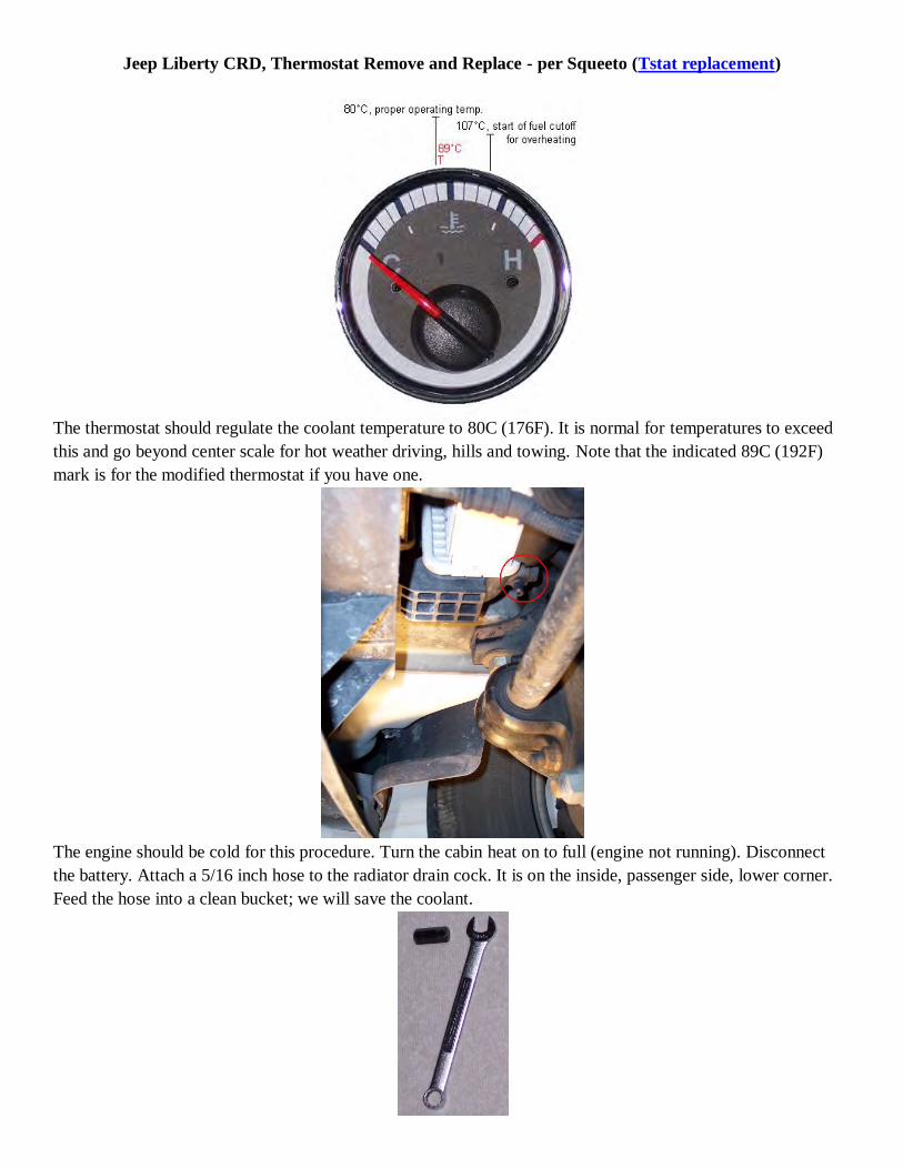
Jeep Liberty CRD, Thermostat Remove and Replace - per Squeeto (Tstat replacement)
The thermostat should regulate the coolant temperature to 80C (176F). It is normal for temperatures to exceed
this and go beyond center scale for hot weather driving, hills and towing. Note that the indicated 89C (192F)
mark is for the modified thermostat if you have one.
The engine should be cold for this procedure. Turn the cabin heat on to full (engine not running). Disconnect
the battery. Attach a 5/16 inch hose to the radiator drain cock. It is on the inside, passenger side, lower corner.
Feed the hose into a clean bucket; we will save the coolant.

The drain cock is plastic and easily damaged. The best way to crack it open is with a 10mm Allen wrench in its
hollow head. There is little clearance so I sacrificed 2 cms off of the handle of a Allen wrench and used a
open/box. Drain the coolant out of the expansion tank and then open the expansion tank cap. There is no need to
drain out all of the coolant. Feel the coolant drain from upper radiator hose and then wait a little longer. Close
the drain cock and remove the hose.
To get better access to the thermostat, we need to remove the engine air filter box. Pull up the red tab, squeeze
the black section and remove the plug to the Maf sensor. Squeeze the plug to the inlet pressure sensor (you can
see the catch tab lift at the front) and pull off. Loosen the hose clamp to the air intake and unclip the lid to the
airbox. Remove lid and air filter element.
Remove the intake duct from the airbox. You may need to spin it 90°.
Get your hand under the air box and pop out the bottommost tab. Pop out the other 2 and remove air box.
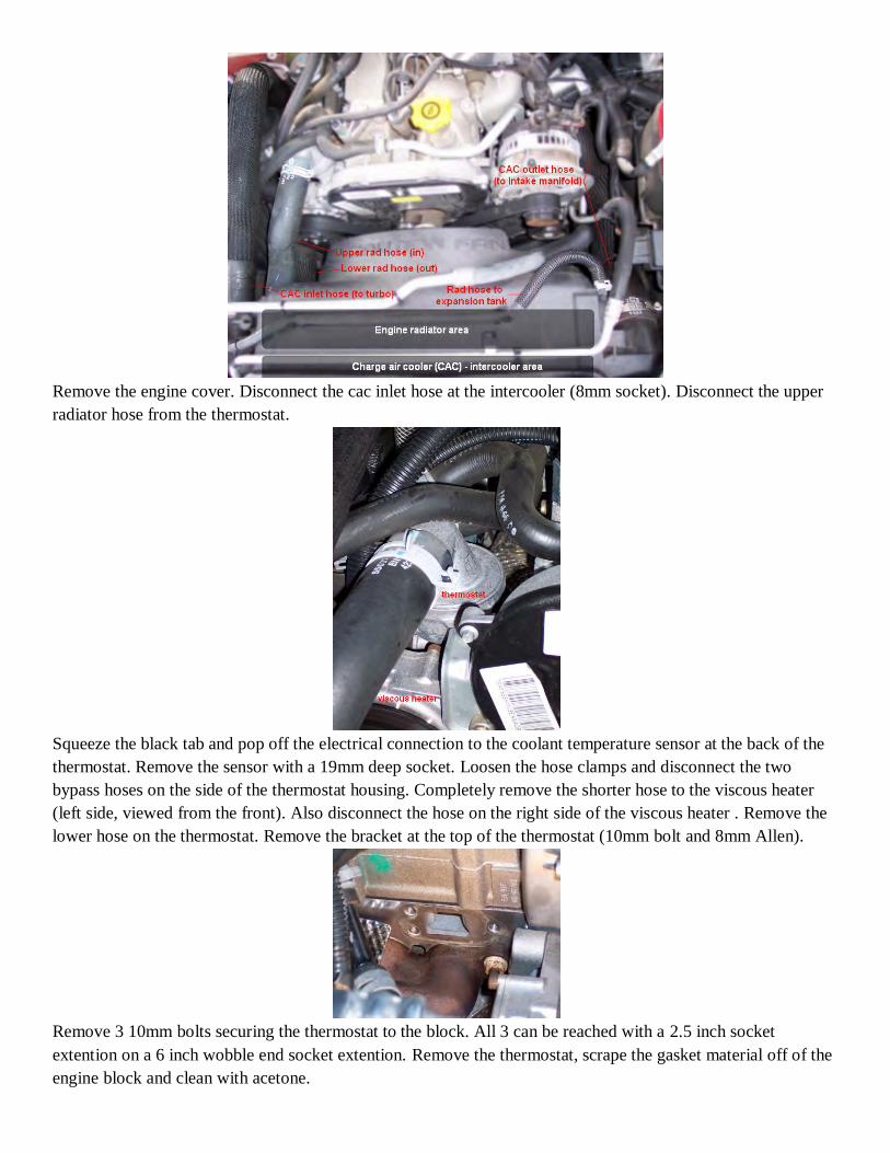
Remove the engine cover. Disconnect the cac inlet hose at the intercooler (8mm socket). Disconnect the upper
radiator hose from the thermostat.
Squeeze the black tab and pop off the electrical connection to the coolant temperature sensor at the back of the
thermostat. Remove the sensor with a 19mm deep socket. Loosen the hose clamps and disconnect the two
bypass hoses on the side of the thermostat housing. Completely remove the shorter hose to the viscous heater
(left side, viewed from the front). Also disconnect the hose on the right side of the viscous heater . Remove the
lower hose on the thermostat. Remove the bracket at the top of the thermostat (10mm bolt and 8mm Allen).
Remove 3 10mm bolts securing the thermostat to the block. All 3 can be reached with a 2.5 inch socket
extention on a 6 inch wobble end socket extention. Remove the thermostat, scrape the gasket material off of the
engine block and clean with acetone.
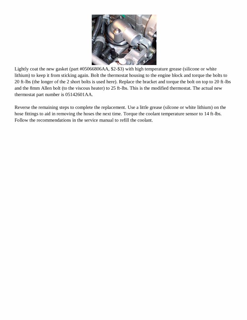
Lightly coat the new gasket (part #05066806AA, $2-$3) with high temperature grease (silicone or white
lithium) to keep it from sticking again. Bolt the thermostat housing to the engine block and torque the bolts to
20 ft-lbs (the longer of the 2 short bolts is used here). Replace the bracket and torque the bolt on top to 20 ft-lbs
and the 8mm Allen bolt (to the viscous heater) to 25 ft-lbs. This is the modified thermostat. The actual new
thermostat part number is 05142601AA.
Reverse the remaining steps to complete the replacement. Use a little grease (silcone or white lithium) on the
hose fittings to aid in removing the hoses the next time. Torque the coolant temperature sensor to 14 ft-lbs.
Follow the recommendations in the service manual to refill the coolant.
2005/06 Jeep KJ CRD Parts List - sorted by parts category such that related parts may be in different
sections (ex. water pump vs. water pump gasket)
Fluids
oil - 5W-40 (0W-40 if in a really cold area) full synthetic such as Mobil 1 Turbo Diesel or Shell Rotella
T6 - NOTE on some CRDs the oil dip stick level is questionable, correct fill amounts are 6.4qts/7qts on
stock/oversize filter, respectively. Also given the very small oil passages in the CRD extending oil and
filter change intervals past 6,000 miles is potential very risky.
antifreeze - HOAT only such as Mopar, Xerex G-05, or Motor Craft Premium Gold - NOTE use of
"green" or "universal" antifreezes is strongly discouraged and has been known to clog radiators.
transmission - ATF+4 - NOTE other fluids have been known to cause odd shifting problems
brake - any fluid that meets DOT 3 specifications and SAE J1703 standards
power steering - ATF+4 with same note as for transmission fluid
FRONT AXLE - 186FIA (Model 30) - MoparT Lubricant 80W-90 - REAR AXLE 8 1/4 - MoparT Gear
Lubricant 75W-90 (Trailer Towing - MoparT Synthetic Gear Lubricant 75W-140. NOTE Trac-lokT
equipped axles require 118 ml (4 ounces) of Limited Slip Additive be added to the lubricant but right
now I don't know if I have trac-lok which was apparently an option in 2005 but was not installed
in 2006 as it conflicts with the ESP system. Looking on-line it seems if you get the rear end in the
air and spin 1 tire by hand that if the other tire spins the same way you have trac-lok but if it spins
the opposite way you don't
transfer case - ATF+4
Battery - in recent years the durability of the standard Group 34R "RedTop" batteries has become
questionable. In general any Group 34 battery with posts centered between the long sides of the battery will
fit if, on a left hand drive KJ CRD, mounted with the + terminal on the driver side and will work just fine so
long as the CCA rating is 700+ (800+ preferred). Options that meet these criteria include Sears Platinum P-
1 (not the one with extra side terminals) or Interstate Mega-tron 85-month MTP-34 or equivalent. AGM
sealed batteries are generally preferred although lead acid "maintenance free" batteries with enough power
will work but best avoid batteries that are not "sealed".
Filters
boost pressure solenoid filter 5080374AA
transmission flat 5013470AD and spin-on 5179267AC - alternative WIX filter set with pan gasket
58843 - see flow control valve below.
oil stock size filters 05003558AA, WIX 51516, or NAPA Gold 1516 or oversize alternatives NAPA
Gold 1515 orWIX 51515
air WIX 42329
fuel 52129238AA - alternatives NAPA 3647 or WIX: 33647 - NOTE the 1s generation fuel filter head
is prone to a "burn" at the fuel heater plug which is a known source of fuel leaks and prone to inducing
air into the filter head that causes an engine stall shortly (e.g. seconds) after start-up. Thus it is highly
recommended that a 2n generation fuel filter head and new fuel heater wiring (68043089AA and
68043086AA, respectively) be installed. The distinguishing mark of a 2n generation fuel filter head is
the spliced in fuel heater wiring which usually has a bright blue plug cover and always has a plug-in that
is virtually the same width as the other electrical plug-in on the fuel filter head as opposed to noticeably
smaller. A new 2n generation fuel filter head comes with a new fuel filter and water in fuel sensor
installed, but it's a good idea to save your old WIF sensor as a spare.
Hoses
intercooler - turbo side 55038729AA or Samcos
intercooler - intake side 55037730AD or Samcos
air box to turbo 53013104AE
radiator - lower Gates 23071 and upper 22022
fuel - marine grade that meets SAE J1527 type A1-15 marine (USCG) specs or ISO 7840 Type A-1 such
as Shields Series 368 from West Marine
NOTE - if running Kapalczynski's custom replacement thermostat see below
Belts
serpentine 5072437AC - alternative Gates K061130
timing 5142579AA - alternative Gates T336
Tensioners, pulleys, bushings, and bearings
serpentine belt idlers (2) 5066938AA or newer # 68211444aa - alternative NAPA 36101 (just lose the
big washer) or Precision Parts EP101 - NOTE same part can replace the idler pulley portion of the
serpentine belt tensioner is only that part goes bad, see below, ALTHOUGH some say idler pulley is
NAPA 36141 - NOTE see "Jeep serpentine belt idler pulley repair.pdf" document.
serpentine belt tensioner - 5072440AB - NOTE if only the pulley is bad it may be replaced with a
serpentine idler pulley to do so Tigafila says "The bolt head you turn to release the belt tension is the
bolt that holds the pulley on the tensioner, it's a left hand thread like the idler pulleys iirc. No need to
remove the tensioner in fact I recommend you don't remove the tensioner. There are two holes in the
tensioner that line up when you crank it all the way. You can release the tension, keep going till the
tensioner stops, put a eighth inch punch through the two holes, screw the tensioner pulley bolt the
opposite direction and it's in your hand. Its that simple."
timing belt tensioner 5142798AA
timing belt idlers (2) 5142573AA
viscous heater pulley bearing only (Viscous heater) - 35mm ID X 52mm OD x 22mm thick - can be
used to replace a failed bearing - if heater clutch is also bad either replace entire viscous heater
(55037539AA) or just replace the bearing and disable the viscous heater by pulling relay R36 in the
Power Distribution Center for either model year
vibration dampner (aka crankshaft) pulley on serp belt - 5072669AA
alternator decoupler pulley 53013554AE or 53013554AF - alternative or Litens 920720 (920834 is a
grease filled updated version that is recommeded by Litens which should fit although it's 2.5mm smaller
in diameter) - NOTE some LOST members have reported issues resulting from the installation of
inexpensive decoupler pulleys by shops that are not up on the demands of the CRD engine
4-wheel drive shift lever bushing 68064273ab and cable retaining clip 68018106aa
rear axle (Chrysler 8.25") bearing Timken 6408
Gaskets and "O" rings
engine cover grommet - 68110855AA
timing belt cover 5066921AA - NOTE timing belt cover is really only a dust cover so this gasket does
not serve much function
water pump gasket 4864575
water pump "O" ring 5159019AA - probably comes with water pump
thermostat gasket - 5066806AA
intake elbow gasket if replacing glow plugs 5066946AA
valve cover gasket 5066786AA
injector crush washer 5072722AA and "O" ring 5069135AB
Valve stem seals 5066775AA
turbo to intake metal gasket 5142657AA
Cooling system
water pump 5142985AA - alternative O'Reilly Auto Parts Cardone remanufactured 58-656
thermostat
o thermostat - 5142601AA
o Kapalczynski's custom replacement - thermostat anywhere in 180-195 range (higher preferred per
GDE) for a 95-99 Hyundai Accent, 1.5L DOHC or SOHC (Duralast 3208/3209 or Stant 35979
(195)/48469(190)) or equivalents - Kap prefers MotoRad) - water Outlet for a 98-01 Kia Sephia 1.8L
DOHC (PN W0133-1891540); and upper radiator hose for a 93-97 Dodge Intrepid 3.3L (Gates
22000 cut to length)
AC fan behind grill - 5143021AA
Engine cooling fan

o fan clutch 55037733AD - alternative Hayden severe duty 2905 - NOTE the Hayden is a highly
recommended replacement which is cheap, much more durable, and engages earlier in an
overheating curve than the OEM fan clutch.
o nylon fan 52079654AD or 52079654AE for 2002-07 gas KJ latter # is most recent - NOTE GDE
says Jeep tried using that fan and under marginal conditions (high outside temp, steep grade, and
5,000 lbs trailer) the nylon fan does not move as much air as the stock metal fan when fan clutch is
locked up.
o Kapalczynski's fixed fan mode parts list - Imperial 223619 (19" reverse direction High flow flex fan
or equivalent); Flex-a-lite 851 (30 mm x 1.5 pitch flex fan adapter - available from Amazon); 2
washers McMaster-Carr 93849A112, (used as spacers on fan adapter to allow clearance between
engine accessories); and 4 bolts (stainless ideal) from any hardware store to bolt fan to fan adaptor.
Sensors, switches and solenoids
05 rear speed sensor (on differential) wiring kit - Mopar PN 05014002AA or industry PN DK44956W or
Dorman 970-069 and wiring pigtail (wiring tends to break inside insulation) Standard Motor Products
S799
ignition starter switch 4793576AB - alternative BWD CS812 or Airtex 1S5932
ignition switch actuator pin assembly Dorman # 924704 (see Video for how to remove and install) -
apparently no dealer equivalent
interior AC/heater fan resistor BWD RU1040 (listed for a 2001-2004 Chrysler Sebring) which is much
heavier duty than the OEM replacement for the KJ.
vacuum reservoir solenoid 4606226AC - there may be after market alternatives as the same solenoid is
used on other DCJ products
coolant temperature sensor (on back of OEM thermostat housing) 5066779AA - alternative Wells
SU8491
MAP (manifold absolute pressure - called air temperature/boost pressure sensor in parts manual) sensor
(back top of engine under wiring harness) old # 5140331AA new # 68031593AA - alternative Bosch 0
281 002 437 NOTE based on comments from MrMopar64 BOSCH # is 0 281 002 845 or GM PN
55206797 is an acceptable and cheaper substitute.
MAF (mass air flow - called air flow sensor in parts manual) sensor (airbox top next to airbox to turbo
hose) 53013733AB
IAP (inlet air pressure) sensor 5101120AB (pressure sensor on side of airbox)
tire pressure sensor (mounts on rim) 68001696AA - alternative Dorman 974-001 or Standard Motor
Products TPM17A
oil pressure 56028807AB - alternative Standard Motor Products PS317
fuel rail pressure sensor (assuming it's the sensor on the side of the fuel rail) 515963AA or Bosch
0281002534 or maybe a more recent Bosch #0281002921
fuel rail or fuel pressure solenoid/valve (assuming it's the one on the end of the fuel rail) 5159964AA or
Bosch 0281002705
crank position sensor - 5066882AA or Bosch 0281002434 also apparently Standard Motor Products
PC766 or Airtex 5S7000
cam position sensor - 05140332AA or Bosch 0281002667 also apparently Standard Motor Products
PC644 or Airtex 5S7046
flow control valve on transmission, may relate to drain back - 04799681
Lamps - from time to time there have been reports of burned out or destroyed (usually by someone trying to
hide a warning light on a vehicle for sale) instrument cluster lights. These lights are LED bulbs. Function
may be check by running an instrument cluster test by holding the trip odometer button while turning the
ignition on but not all the way to starting the engine. When 1st triggered all the warning lights will come on
including the glow plug light and then each of the analog gauges will do odd things with the needles (e.g.
placing the needle in different positions to verify calibration). Dealers will solve burned out LEDs by
replacing the entire cluster for $700 + labor or you can remove the cluster and buy replacement LEDs for ca.
$3@ which can be soldered in place of bad ones.
EGR related parts
EGR valve 5166555AB
exhaust to EGR valve pipe 5170765AA
EGR valve to intake pipe 5170787AA
FCV/AFC (EGR flow control valve) 5142799AA
Alternator with decoupler pulley (see separate listing just for decoupler) 56044672AB - alternatives
Autozone Duralast 15457 if available, AdvanceAutoParts PN 12668, or LOST members report good
service from Maniac Electric Motors in Dallas TX
Glow plugs
original OEM 7v ceramic glow plug - 5142577AA (Bosch: 80041) - no longer available new but some
LOST members have used ones available
updated OEM 7v ceramic glow plug controller 56044671AC
replacement OEM 5v metallic glow plug kit (4 plugs and controller) 68090434AA - NOTE requires a
flash of the ECU to deal with change from 7v to 5v glow plugs PRIOR to enabling the new glow plugs
Etecno1 7v glow plugs GX3123 - NOTE drop in replacement for 7v OEM ceramic glow plugs no ECU
flash required.
Motor and transmission mounts
driver side 52129011AD (may be used on passenger side if heat shield on existing mount is moved to
the new mount)
passenger side 52129374AC
Transmission mount / transmission cross member support # 52129170AH
V6 air filter box assembly - try junk yard
Torque convertor
"Euro" (OEM TC used after 2006 model year) torque converter 68037142AA now apparently available
only as a rebuild RL037142AA and as of 2/13/2013 maybe as R8037142AA or SunCoast or as of May
2012 Torqueconverter1 may be ok.
transmission pump - 68009879AB - NOTE 1st gen pump and gasket no longer available so if gasket is
leaking one must install this 2n gen pump
Engine
rockers and lifters - via Wobbly at Valve train stuff or more recently idParts
head bolts - replace with ARP studs kit #204-4706. Takes 2 kits to have enough studs with some extra.
Torque set 130 lb-ft for the bolts directly bordering the cylinders (two center rows) and 120 lb-ft for the
outside row.
block heater cord - NAPA KAT 28400
block heater element - 56044738AA
Suspension and drive train
OEM front springs are PN 52128880AA; aftermarket if you don't want any more height, you can go
with Moog 81144 springs/Bilstein 24-139168 shocks in front and Moog 81057/Bilstein 24-139175
shocks in the rear.
Front lower ball joints Moog K3199
Front upper control arm Moog K3198
Front CV joint rebuild kits
Brakes
NAPA Kit Part # is UP 3199 for the Parking Brake and is $18.79, this does both sides.
NAPA Rear Caliper part kit is UP 83836A and is $12.39, this does both sides as well
Fuel system, see also the Sensors/Switched/Solenoids section - NOTE consensus appears to be that any
supplemental fuel pump should supply fuel at a low pressure ca. 5-10 psi
in tank - per Sir Sam Airtex E7181M
in line - Facet 40109 or single Kennedy Duramax lift pump or probably a NAPA AFP E3309
CP3/fuel pump 5166083AA or Bosch CP3 - new 0445010104 - reman 0986437331
Fuel control actuator on back of CP3 5159964AA or Bosch 0928400822
Cascade/overflow valve that returns excess fuel to tank 5083711AA or Bosch F00N200798
Fuel injectors - lots of sources for new or reman or Bosch injectors - new 0445110217 - reman
0986435128
Fuel injector rail - there appears to be a couple of OEM #s 68000898AA in the 06 parts fiche and
5142817AA in other sources that cross to the "68...#" or Bosch 0445214068
Windshield washer parts from Autozone - OEM replacement
Windshield washer reservoir Part Number: 603-314.
Sensor - Windshield Washer Level Part Number: SU8548
Pump - Part Number: 8-581
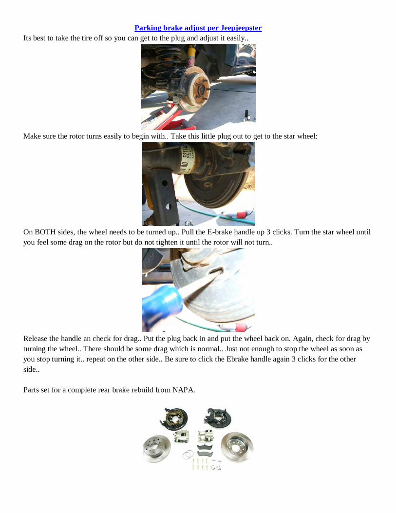
Parking brake adjust per Jeepjeepster
Its best to take the tire off so you can get to the plug and adjust it easily..
Make sure the rotor turns easily to begin with.. Take this little plug out to get to the star wheel:
On BOTH sides, the wheel needs to be turned up.. Pull the E-brake handle up 3 clicks. Turn the star wheel until
you feel some drag on the rotor but do not tighten it until the rotor will not turn..
Release the handle an check for drag.. Put the plug back in and put the wheel back on. Again, check for drag by
turning the wheel.. There should be some drag which is normal.. Just not enough to stop the wheel as soon as
you stop turning it.. repeat on the other side.. Be sure to click the Ebrake handle again 3 clicks for the other
side..
Parts set for a complete rear brake rebuild from NAPA.

Adjusting at parking brake lever end by Jeepjeepster
Ive been seeing alot of posts about the E-brake taking to many clicks to hold the Jeep in place. Ive personally
tried adjusting the E-brake pads, and while it helped some, it didnt do much at all. I believe you should still
adjust the pads to make sure they are both applying the same amount of torque to each side, but this method
works ALOT better. Anyway, mine has been getting worse and since I live on a hill, I always use the parking
brake. I could visually look down into the console and tell that there was slack in the cable because I could
move the handle a good inch before the cable would move. I also asked my father to get under the Jeep and look
at the rear brake mechanism to confirm the slack in the cable.
The first thing you need to do is to remove the lid for the center console, there are 3 screws that hold it on. Next,
take the two screws out of the bottom of the container and two on the top toward the front of the box. Pull that
out and you will be able to see the cable and the mechanism that SHOULD automatically adjust itself. Ive seen
alot of posts saying the Liberty e-brake does not adjust itself, well, it should. I tinkered with the thing until I
figured out how it works. Pull the ebrake up a few clicks, then grab the little tab(see pic below) while letting the
brake handle back down. Be sure NOT to take to much slack out which would cause the rear pads to drag. Do
this a couple times(If needed) until most of the slack is out of the cable. Its also best to jack up the rear end and
check the pads to make sure there isnt any drag. If there is drag, Im not sure how to let the slack back out. The
best way would be to adjust the pads at each wheel.
The tab is circled:
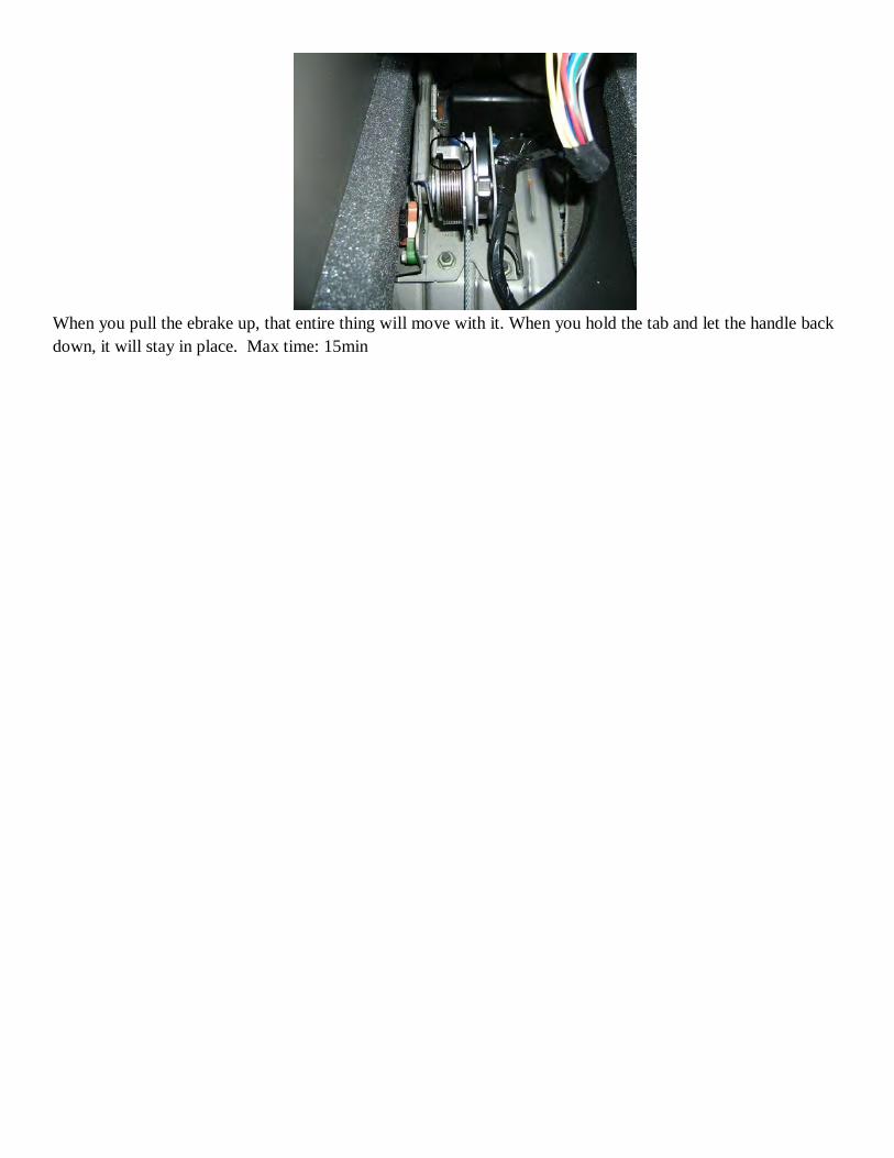
When you pull the ebrake up, that entire thing will move with it. When you hold the tab and let the handle back
down, it will stay in place. Max time: 15min
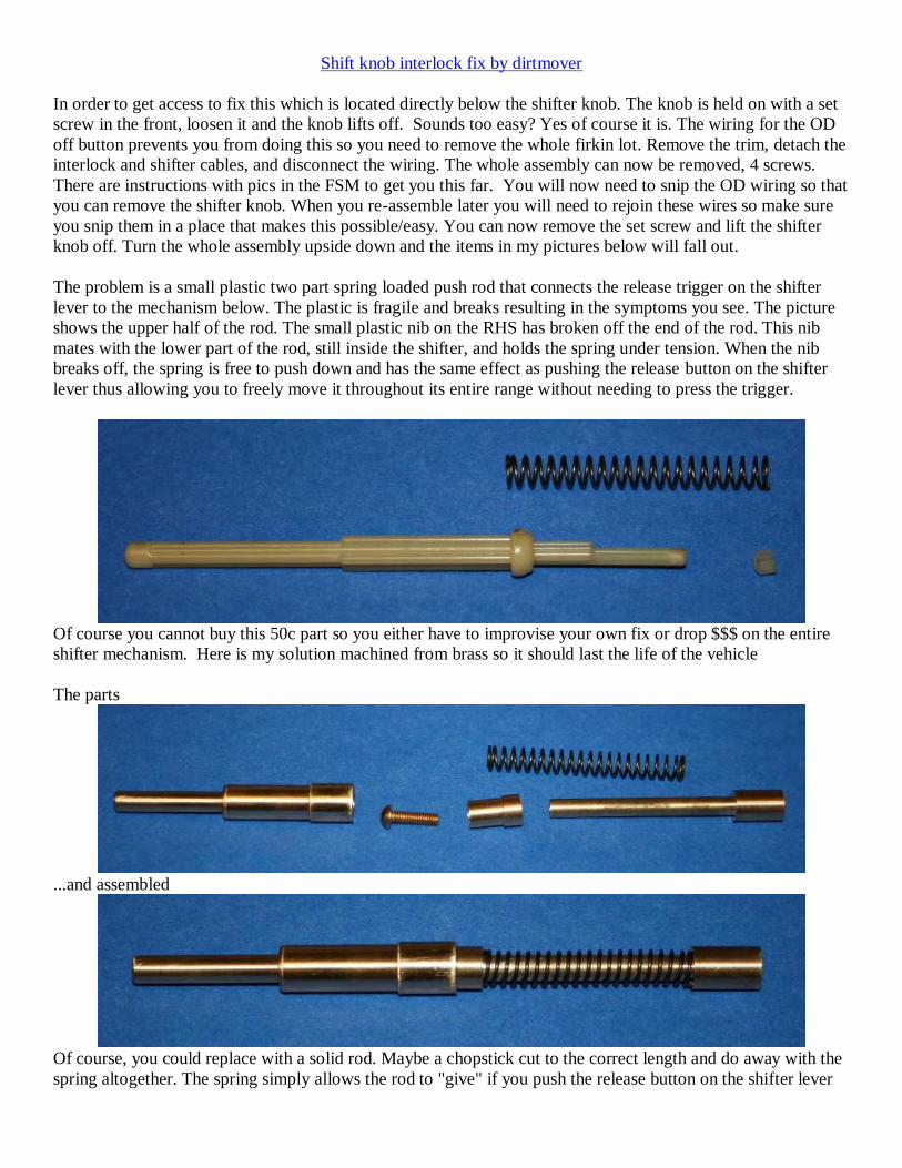
Shift knob interlock fix by dirtmover
In order to get access to fix this which is located directly below the shifter knob. The knob is held on with a set
screw in the front, loosen it and the knob lifts off. Sounds too easy? Yes of course it is. The wiring for the OD
off button prevents you from doing this so you need to remove the whole firkin lot. Remove the trim, detach the
interlock and shifter cables, and disconnect the wiring. The whole assembly can now be removed, 4 screws.
There are instructions with pics in the FSM to get you this far. You will now need to snip the OD wiring so that
you can remove the shifter knob. When you re-assemble later you will need to rejoin these wires so make sure
you snip them in a place that makes this possible/easy. You can now remove the set screw and lift the shifter
knob off. Turn the whole assembly upside down and the items in my pictures below will fall out.
The problem is a small plastic two part spring loaded push rod that connects the release trigger on the shifter
lever to the mechanism below. The plastic is fragile and breaks resulting in the symptoms you see. The picture
shows the upper half of the rod. The small plastic nib on the RHS has broken off the end of the rod. This nib
mates with the lower part of the rod, still inside the shifter, and holds the spring under tension. When the nib
breaks off, the spring is free to push down and has the same effect as pushing the release button on the shifter
lever thus allowing you to freely move it throughout its entire range without needing to press the trigger.
Of course you cannot buy this 50c part so you either have to improvise your own fix or drop $$$ on the entire
shifter mechanism. Here is my solution machined from brass so it should last the life of the vehicle
The parts
...and assembled
Of course, you could replace with a solid rod. Maybe a chopstick cut to the correct length and do away with the
spring altogether. The spring simply allows the rod to "give" if you push the release button on the shifter lever

while it is in park and the brake is not applied and thus prevents you from being able to apply too much force to
the brake interlock solenoid.
BTW, If you disconnect the interlock cable from the shifter end you will be able to remove the key.
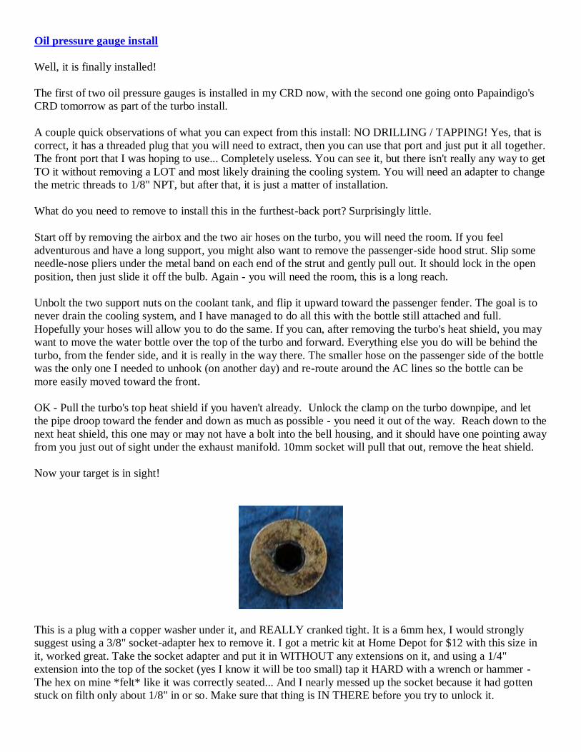
Oil pressure gauge install
Well, it is finally installed!
The first of two oil pressure gauges is installed in my CRD now, with the second one going onto Papaindigo's
CRD tomorrow as part of the turbo install.
A couple quick observations of what you can expect from this install: NO DRILLING / TAPPING! Yes, that is
correct, it has a threaded plug that you will need to extract, then you can use that port and just put it all together.
The front port that I was hoping to use... Completely useless. You can see it, but there isn't really any way to get
TO it without removing a LOT and most likely draining the cooling system. You will need an adapter to change
the metric threads to 1/8" NPT, but after that, it is just a matter of installation.
What do you need to remove to install this in the furthest-back port? Surprisingly little.
Start off by removing the airbox and the two air hoses on the turbo, you will need the room. If you feel
adventurous and have a long support, you might also want to remove the passenger-side hood strut. Slip some
needle-nose pliers under the metal band on each end of the strut and gently pull out. It should lock in the open
position, then just slide it off the bulb. Again - you will need the room, this is a long reach.
Unbolt the two support nuts on the coolant tank, and flip it upward toward the passenger fender. The goal is to
never drain the cooling system, and I have managed to do all this with the bottle still attached and full.
Hopefully your hoses will allow you to do the same. If you can, after removing the turbo's heat shield, you may
want to move the water bottle over the top of the turbo and forward. Everything else you do will be behind the
turbo, from the fender side, and it is really in the way there. The smaller hose on the passenger side of the bottle
was the only one I needed to unhook (on another day) and re-route around the AC lines so the bottle can be
more easily moved toward the front.
OK - Pull the turbo's top heat shield if you haven't already. Unlock the clamp on the turbo downpipe, and let
the pipe droop toward the fender and down as much as possible - you need it out of the way. Reach down to the
next heat shield, this one may or may not have a bolt into the bell housing, and it should have one pointing away
from you just out of sight under the exhaust manifold. 10mm socket will pull that out, remove the heat shield.
Now your target is in sight!
This is a plug with a copper washer under it, and REALLY cranked tight. It is a 6mm hex, I would strongly
suggest using a 3/8" socket-adapter hex to remove it. I got a metric kit at Home Depot for $12 with this size in
it, worked great. Take the socket adapter and put it in WITHOUT any extensions on it, and using a 1/4"
extension into the top of the socket (yes I know it will be too small) tap it HARD with a wrench or hammer -
The hex on mine *felt* like it was correctly seated... And I nearly messed up the socket because it had gotten
stuck on filth only about 1/8" in or so. Make sure that thing is IN THERE before you try to unlock it.

You WILL need a wobble head extension rod to get at it, and I would suggest at least 2 full 1-foot extensions to
get the wrench out to the hood line so you have the leverage you will need. You may also need to do what I did,
extending your socket handle using a cheater bar or large box wrench to get enough force. Once it cracks loose
however, it should come right out without fuss.
Now, you have this image in front of you!
Set your self up with the adapter, and then some of the following parts:
Note the plug in those two images, you can discard that now.
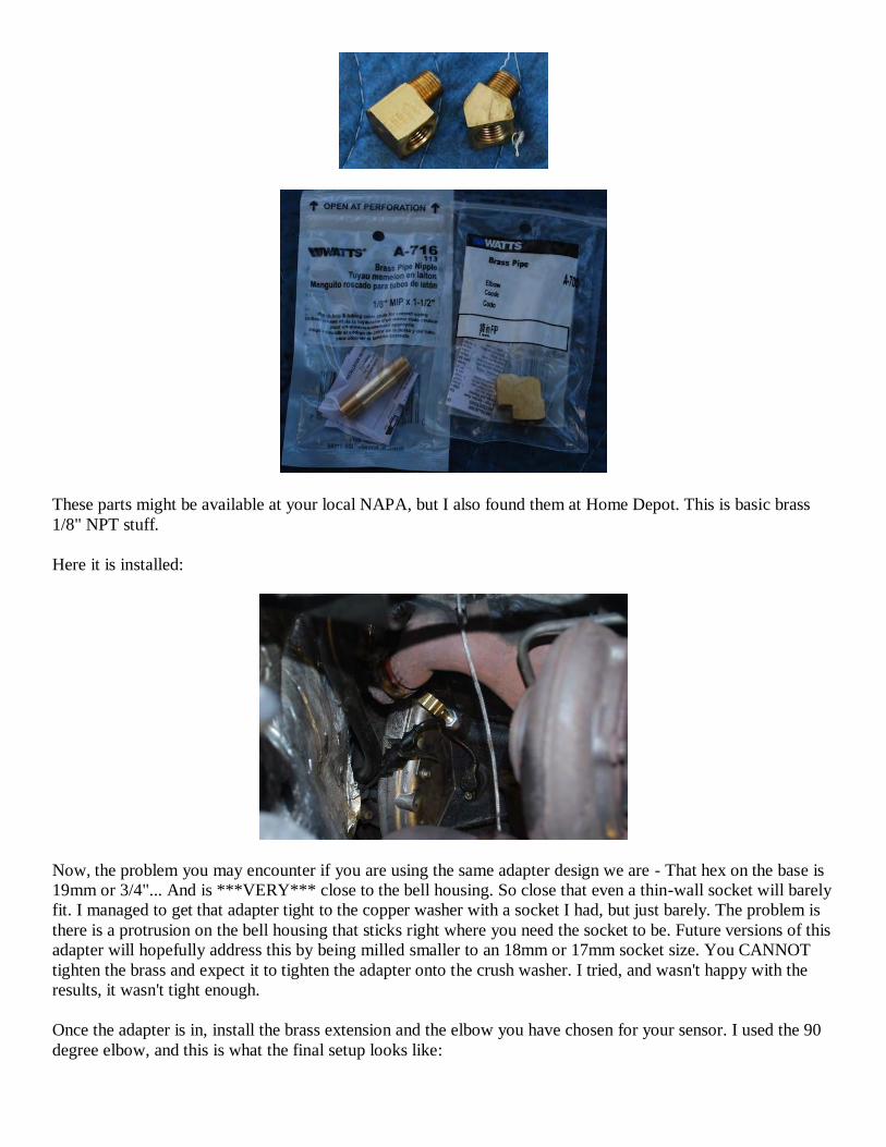
These parts might be available at your local NAPA, but I also found them at Home Depot. This is basic brass
1/8" NPT stuff.
Here it is installed:
Now, the problem you may encounter if you are using the same adapter design we are - That hex on the base is
19mm or 3/4"... And is ***VERY*** close to the bell housing. So close that even a thin-wall socket will barely
fit. I managed to get that adapter tight to the copper washer with a socket I had, but just barely. The problem is
there is a protrusion on the bell housing that sticks right where you need the socket to be. Future versions of this
adapter will hopefully address this by being milled smaller to an 18mm or 17mm socket size. You CANNOT
tighten the brass and expect it to tighten the adapter onto the crush washer. I tried, and wasn't happy with the
results, it wasn't tight enough.
Once the adapter is in, install the brass extension and the elbow you have chosen for your sensor. I used the 90
degree elbow, and this is what the final setup looks like:
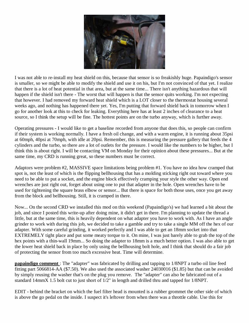
I was not able to re-install my heat shield on this, because that sensor is so freakishly huge. Papaindigo's sensor
is smaller, so we might be able to modify the shield and use it on his, but I'm not convinced of that yet. I realize
that there is a lot of heat potential in that area, but at the same time... There isn't anything hazardous that will
happen if the shield isn't there - The worst that will happen is that the sensor quits working. I'm not expecting
that however. I had removed my forward heat shield which is a LOT closer to the thermostat housing several
weeks ago, and nothing has happened there yet. Yes, I'm putting that forward shield back in tomorrow when I
go for another look at this to check for leaking. Everything here has at least 2 inches of clearance to a heat
source, so I think the setup will be fine. The hottest points are on the turbo anyway, which is further away.
Operating pressures - I would like to get a baseline recorded from anyone that does this, so people can confirm
if their system is working normally. I have a fresh oil change, and with a warm engine, it is running about 35psi
at 60mph, 40psi at 70mph, with idle at 20psi. Remember, this is measuring the pressure gallery that feeds the 4
cylinders and the turbo, so there are a lot of outlets for the pressure. I would like the numbers to be higher, but I
think this is about right. I will be contacting VM on Monday for their opinion about these pressures... But at the
same time, my CRD is running great, so these numbers must be correct.
Adaptors were problem #2, MASSIVE space limitations being problem #1. You have no idea how cramped that
spot is, not the least of which is the flipping bellhousing that has a molding sticking right out toward where you
need to be able to put a socket, and the engine block effectively cramping your style the other way. Open end
wrenches are just right out, forget about using one to put that adapter in the hole. Open wrenches have to be
used for tightening the square brass elbow or sensor... But there is space for both those uses, once you get away
from the block and bellhousing. Still, it is cramped in there.
Now... On the second CRD we installed this mod on this weekend (Papaindigo's) we had learned a bit about the
job, and since I posted this write-up after doing mine, it didn't get in there. I'm planning to update the thread a
little, but at the same time, this is heavily dependent on what adapter you have to work with. As I have an angle
grinder to work with during this job, we decided to take a gamble and try to take a single MM off the hex of our
adapter. With some careful grinding, it worked perfectly and I was able to get an 18mm socket into that
EXTREMELY tight place and put some meaty torque to it. On mine, I was just barely able to grab the top of the
hex points with a thin-wall 19mm... So doing the adapter to 18mm is a much better option. I was also able to get
the lower heat shield back in place by only using the bellhousing bolt hole, and I think that should do a fair job
of protecting the sensor from too much excessive heat. Time will determine.
papaindigo comment : The "adapter" was fabricated by drilling and tapping to 1/8NPT a turbo oil line feed
fitting part 5066814-AA ($7.50). We also used the associated washer 24030016 ($1.85) but that can be avoided
by simply reusing the washer that's on the plug you remove. The "adapter" can also be fabricated out of a
standard 14mmX 1.5 bolt cut to just short of 1/2" in length and drilled thru and tapped for 1/8NPT.
EDIT - behind the bracket on which the fuel filter head is mounted is a rubber grommet the other side of which
is above the go pedal on the inside. I suspect it's leftover from when there was a throttle cable. Use this for
routing wiring into the cab. BUT don't try to remove and reinstall the grommet; just cut an "X" in it with a skill
knife and route the cable. If water worries you seal with silicone.
UPDATE - R2.0 found that McMaster-Carr has a M14-1/4NPT adapter for about $7 (PN 4936K155). It
probably will work but may require a bit of grinding as geordi and I found clearance in there is really tight.
Shaving a bit off the head with a disc sander/cutoff blade to turn the 0.75"/19mm hex head into the next size
down made things a lot easier on my install. For what it's worth McMaster-Carr has as stainless steel thick wall
1.5" nipple PN 46755K22 and a stainless steel elbow PN 46755K22 for about $5@ if the use of brass plumbing
hardware worries you.
An alternative to placing the oil pressure sending unit at rear gallery port is to use a flexible line to allow it to be
placed remotely (away from the heat sources) and also reduce vibrations on the sending unit. As a bonus it will
still measure the pressure next to the turbo line.

Oil pan drain plug stripped - geordi's repair method
Spark-plug repair kit with solid threaded collars - $29 for the kit which includes the tap and the collars. Get the
M14x1.25 kit, which will then be your new drain plug size, you need a normal drain plug and an O-ring to make
the seal against the shoulders of the bolt and the pan.
Anyone pulling or replacing the entire pan b/c of this bad design is just NUTS - Half the car has to be removed
to pull that pan. Anything you drill will be stuck to the drill bit or the tap, OR will be sent directly into the filter
where it will never leave. The oil pump isn't a fragile thing, it is designed to suck up the worst of whatever is in
the pan normally and send it into the filter... A few small chips that I DOUBT would ever make it upwards
against gravity won't bother it and won't hurt your engine.
If you want to still spend that $1000... Send it to me for the lesson I just gave you. At least then you will know it
went to supporting Jeep-centric research and longevity projects that will benefit your Jeep in the future!


Hot No Start (Sensor)
Crankshaft Position/Speed Sensor. During two test drives today, the CRD has started great twelve times!! An
hour ago, I connected an Ohm meter to the old Crankshaft Sensor signal terminals and the laid the sensor on the
hot engine block. Within minutes the resistance of the sensor was all over the place, from high resistance to an
open circuit. Just to make sure of what I was seeing, I duplicated the test on the work bench with a heat gun
directed at the sensor, same results.
Take home. Bench test the sensor, per above, if bad replace.
Example from CATCRD
Here is the sequence of events:
My wife tells me one day she came back to start her jeep which was already hot. It took a long time
cranking but eventually fired up fine, with no codes.
1wk later, same thing.
1wk later, Jeep wouldn't start at all hot. Let it cool and all was fine.
1wk later, it almost died on me while in a drive thru. It was like all the injectors quit firing for a quarter
second, but afterwards kept running smooth and with no codes.
1wk later, while I was out of town, of course, it died on her at a stoplight. After cranking for a while it
started up and drove fine. After getting to her destination, it wouldn't start at all and she had to get a ride
home.
After reading jeepdan's saga, the first thing I suspected was the crankshaft position sensor. So I took it out and
did the same heat gun test on it. It started out at 1100 ohms and steady, but after only about 30 seconds the
resistance skyrocketed up to 40kohm and bounced around between there. It's silly that this doesn't throw a MIL
or something. It seems like this is going to be the year of the bad crank sensor here at LOST CRDs. I found a
couple other threads relating to that.
To remove the crank sensor, the best way is from under the passenger side. There is a small heatshield on the
block, below the turbo, which protects the sensor from heat off the downpipe. Remove the two 10mm bolts
holding it on and you can drop it out and see the sensor. An 8mm bolt holds the pigtail bracket to the engine, I
had to remove that just to squeeze the plug locking tab. Then a 5mm allen will remove the sensor from the
block, it sticks about 2 inches into the block and will come out oily.
Ignition key/No start
General preliminary diagnostic steps per "papaindigo" (Jim Stoutamire) on LOST - Intermittent non-start
can be a bad battery, bad ignition switch not to be confused with the key switch, or a failure of the start system
to recognize that the transmission is in park or neutral. An intermittent short between battery cells can cause
random start/no start. Either have the battery load tested or better yet if you have access to a known good
battery you can drop it in on a temp basis and see if the problem goes away. See Ignition Switch for a similar
problem that turned out to be the ignition switch (see the last post for the part that links to a BWD Ignition
Starter Switch Part No. CS812 at Autozone); apparently on modern car systems turning the key doesn't send
current directly to the starter it sends current to a separate switch that then "asks" the ECU for permission to
start the vehicle hence if that switch goes bad the ECU gets no "can I please start" signal. The same string has a
brief discussion about the transmission issue but I'm not sure what system Jeep uses to indicate the transmission
is in park or neutral. On older vehicles it was often a switch keyed to the gear shift lever position that can stick
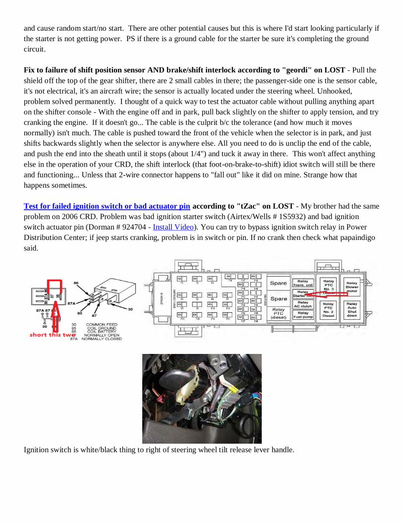
and cause random start/no start. There are other potential causes but this is where I'd start looking particularly if
the starter is not getting power. PS if there is a ground cable for the starter be sure it's completing the ground
circuit.
Fix to failure of shift position sensor AND brake/shift interlock according to "geordi" on LOST - Pull the
shield off the top of the gear shifter, there are 2 small cables in there; the passenger-side one is the sensor cable,
it's not electrical, it's an aircraft wire; the sensor is actually located under the steering wheel. Unhooked,
problem solved permanently. I thought of a quick way to test the actuator cable without pulling anything apart
on the shifter console - With the engine off and in park, pull back slightly on the shifter to apply tension, and try
cranking the engine. If it doesn't go... The cable is the culprit b/c the tolerance (and how much it moves
normally) isn't much. The cable is pushed toward the front of the vehicle when the selector is in park, and just
shifts backwards slightly when the selector is anywhere else. All you need to do is unclip the end of the cable,
and push the end into the sheath until it stops (about 1/4") and tuck it away in there. This won't affect anything
else in the operation of your CRD, the shift interlock (that foot-on-brake-to-shift) idiot switch will still be there
and functioning... Unless that 2-wire connector happens to "fall out" like it did on mine. Strange how that
happens sometimes.
Test for failed ignition switch or bad actuator pin according to "tZac" on LOST - My brother had the same
problem on 2006 CRD. Problem was bad ignition starter switch (Airtex/Wells # 1S5932) and bad ignition
switch actuator pin (Dorman # 924704 - Install Video). You can try to bypass ignition switch relay in Power
Distribution Center; if jeep starts cranking, problem is in switch or pin. If no crank then check what papaindigo
said.
Ignition switch is white/black thing to right of steering wheel tilt release lever handle.
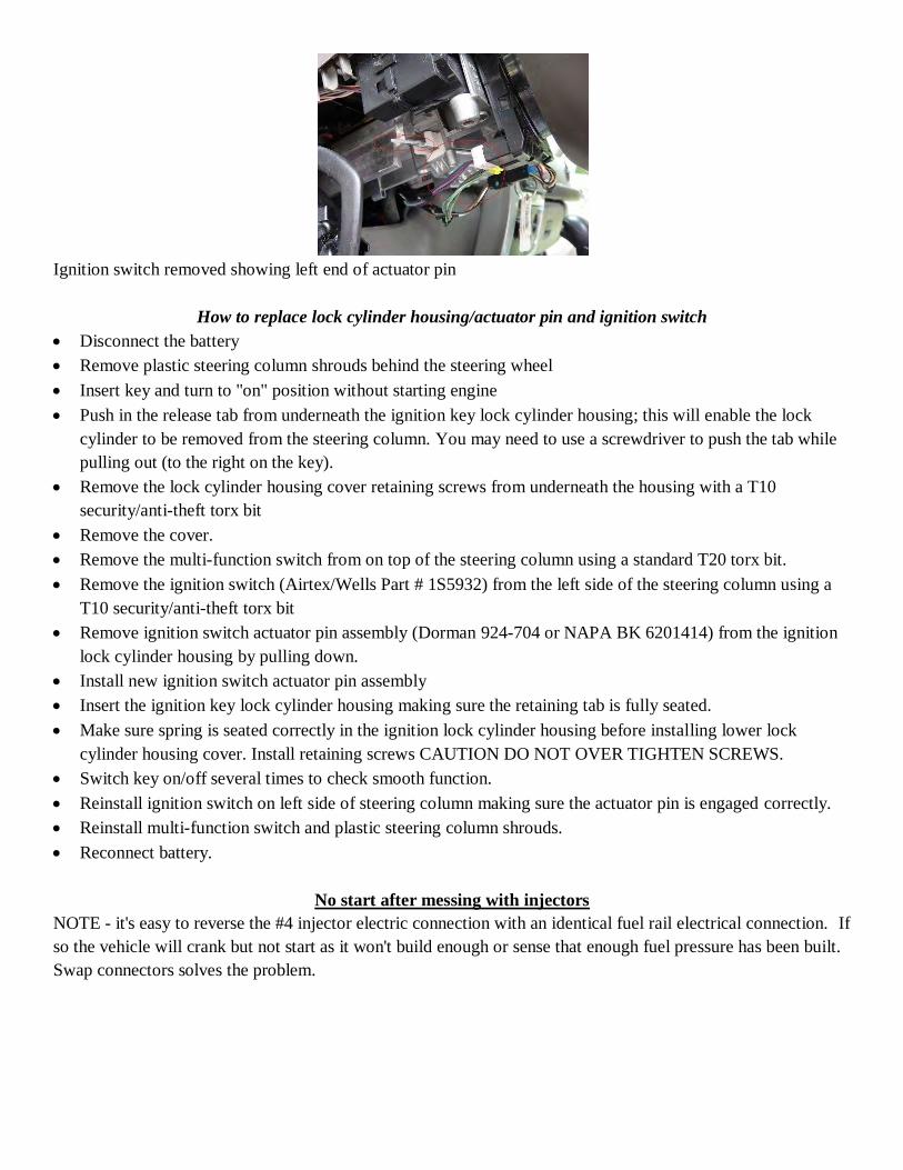
Ignition switch removed showing left end of actuator pin
How to replace lock cylinder housing/actuator pin and ignition switch
Disconnect the battery
Remove plastic steering column shrouds behind the steering wheel
Insert key and turn to "on" position without starting engine
Push in the release tab from underneath the ignition key lock cylinder housing; this will enable the lock
cylinder to be removed from the steering column. You may need to use a screwdriver to push the tab while
pulling out (to the right on the key).
Remove the lock cylinder housing cover retaining screws from underneath the housing with a T10
security/anti-theft torx bit
Remove the cover.
Remove the multi-function switch from on top of the steering column using a standard T20 torx bit.
Remove the ignition switch (Airtex/Wells Part # 1S5932) from the left side of the steering column using a
T10 security/anti-theft torx bit
Remove ignition switch actuator pin assembly (Dorman 924-704 or NAPA BK 6201414) from the ignition
lock cylinder housing by pulling down.
Install new ignition switch actuator pin assembly
Insert the ignition key lock cylinder housing making sure the retaining tab is fully seated.
Make sure spring is seated correctly in the ignition lock cylinder housing before installing lower lock
cylinder housing cover. Install retaining screws CAUTION DO NOT OVER TIGHTEN SCREWS.
Switch key on/off several times to check smooth function.
Reinstall ignition switch on left side of steering column making sure the actuator pin is engaged correctly.
Reinstall multi-function switch and plastic steering column shrouds.
Reconnect battery.
No start after messing with injectors
NOTE - it's easy to reverse the #4 injector electric connection with an identical fuel rail electrical connection. If
so the vehicle will crank but not start as it won't build enough or sense that enough fuel pressure has been built.
Swap connectors solves the problem.

Serpentine belt idler pulley repair by Camo
Just go to any auto parts store and get a 203 bearing, then go to Ace Hardware or NAPA or some such and get 3
M5-8 bolts, 3 M5 lock washers, 3 M5 nuts, and a small tube of blue thread lock. It should not cost more than 10
bucks. All you need to do then is remove the idler rivets (3) with a 4mm punch and a hammer, split the idler
apart, replace the bearing, install the M5 bolts with thread lock in place of the rivets, let cure for an hour or two,
and install the idler back again. It should be as good as new.
Serpentine belt tensioner pulley repair - NAPA pulley # 36101 - needs verification
I'm going to go out on a limb here and speculate. There is a good picture of the serp belt tensioner here
Tensioner on page 3. The wrench is on the "fake" 15mm nut machined into the front of the tensioner that's used
to rotate and relax the tensioner by rotating the wrench clockwise facing the engine (hold the wrench while
removing the serp belt and the slowly let the tensioner return to it's position - DO NOT let it slam back). The
bolt to the left is what holds the tensioner assembly to the block so remove that bolt, should be standard
counterclockwise to remove, to remove the tensioner assembly (on reinstall the FSM says torque is 47nm which
if correct equals ca. 65 ft lbs). FYI at this point you should be able to easily determine if you have a bad
tensioner pulley or a bad tensioner. Since the tensioner is essentially a tension spring and pulley the only ways I
can see it going bad are 1) loose tensioner retaining bolt; 2) weak or broken spring both should be obvious 3)
loose pulley bolt but I don't see that as likely; or 4) bad pulley bearing also obvious. Assuming it's the pulley
bearing then from here on I'm venturing a somewhat informed guess. Flip the tensioner assembly over and on
the back side of the idler pulley there should be a retaining bolt (parts manual appears to call it a "screw").
Since the belt rotates that idler pulley counterclockwise as viewed from the front then when viewed from the
back the rotation direction is clockwise so I "think" this bolt should be a standard counterclockwise to unscrew.
Replace the bad pulley with the new one minus the dust shield or what tigafila refers to as the large washer. I
have no clue as to the correct torque and can only observe that the 2 serp belt idler pulleys, per the FSM, are
torqued to the same spec as the tensioner retaining bolt.
Reassemble. Crank up engine and observe behavior of serp belt at idle. If it's steady and tensioner is not
bouncing your good to go but I'd keep and eye on things for the next 3-400 miles just to be sure.

Rocker arm replacement by thermorex There were a lot of us that had a rocker arm replacement, but we still don’t have a step-by-step walkthrough. This walkthrough addresses to the "regular handy guy-ish" that is not afraid to get his hands dirty but is not an experienced mechanic either. I had several engine rebuilds on my resume, but I have done this as a hobby, stimulated by the fact that with time and determination, what I do is better than what any other mechanic that charges by hour (and cant afford charging extra time for doing all kind of "side-job" tasks - like extra cleaning the intake, or putting anti-seize on every bolt, etc). Since I had done this rocker job myself, and I wasn't pressed by time constraints (so I could take few pictures while working), I thought to start putting together a walkthrough for Rocker Arm/Lifter replacement Job. I would greatly appreciate any suggestion on how to improve this process, the whole job had a happy end , jeep purrs like a kitten, but I bet there are things that can be improved. 1. Pre-Prerequisites I would like to start by saying that I did not have a rocker arm (or timing belt related) failure, I just wanted to replace them more due to “horror” stories with folks getting stuck in the middle of the road and thousands due for repair and mainly for my peace of mind. I did have though a significant mileage decrease over time, cumulated with a noise that seemed to be rocker arm/lifter related (even if our lifters are hydraulics (and they can’t be adjusted – like on other engines), it still sounded like having a “tic-tic-tic” noise). Another reason I started this was because at 100k (now I’m at about 125K), I did the timing belt without the water pump and also I haven’t replaced the glow plugs either. So this was a great time to do both. 2. Prerequisites Required tools: FSM doesn't do a good job naming the sizes of the bolts/nuts or any other required tools, except Miller tools. They also do not name any specific technique you should use, maybe because “DC Academy” should have taught mechanics how to do it (doubtfully…). I find this kind of stupid but in the same time this is how any FSM I saw is. Regardless, make sure you read the manual, there may be things in there I omitted in my walkthrough. It will also show you the torque order of the bolts for valve cover. Being an Italian engine, all nuts/bolts are metric. So have handy some 7, 8, 10, 13, 15, 17, 19, 22mm (I think this is only for crank shaft) sockets (regular and deep is best). I think 5mm and 8mm allen keys are also required. I do not remember the size of the map sensor retaining screw, it may be 4mm.

I used Watter Wetter since I replaced the water pump, and I like to keep things as cool as possible for the summer.
A pic with one of the old rocker:
It seems to be ok, it has a little play in the roller but not something that seems horrible. This rocker also has about 125-ish k miles. The new ones had no play, but they were also not broken in, and I do not know how the roller would look like or how much play will have after let's say 1000 miles (and I wont take the whole thing
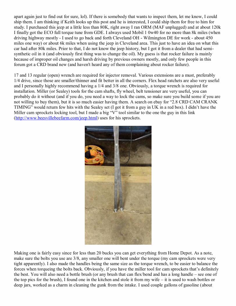
apart again just to find out for sure, lol). If there is somebody that wants to inspect them, let me know, I could ship them. I am thinking if Keith looks up this post and he is interested, I could ship them for free to him for study. I purchased this jeep at a little less than 80K, right away I ran ORM (MAF unplugged) and at about 120k I finally got the ECO full torque tune from GDE. I always used Mobil 1 0w40 for no more than 8k miles (when driving highway mostly - I used to go back and forth Cleveland OH - Wilmington DE for work - about 450 miles one way) or about 6k miles when using the jeep in Cleveland area. This just to have an idea on what this car had after 80k miles. Prior to that, I do not know the jeep history, but I got it from a dealer that had semi-synthetic oil in it (and obviously first thing was to change the oil). My guess is that rocker failure is mainly because of improper oil changes and harsh driving by previous owners mostly, and only few people in this forum got a CRD brand new (and haven't heard any of them complaining about rocker failure). 17 and 13 regular (open) wrench are required for injector removal. Various extensions are a must, preferably 1/4 drive, since those are smaller/thinner and fit better in all the corners. Flex head ratchets are also very useful and I personally highly recommend having a 1/4 and 3/8 one. Obviously, a torque wrench is required for installation. Miller (or Sealey) tools for the cam shafts, fly wheel, belt tensioner are very useful, you can probably do it without (and if you do, you need a way to lock the cams, so make sure you build some if you are not willing to buy them), but it is so much easier having them. A search on ebay for “2.8 CRD CAM CRANK TIMING” would return few hits with the Sealey set (I got it from a guy in UK in a red box). I didn’t have the Miller cam sprockets locking tool, but I made a big “V” tool similar to the one the guy in this link (http://www.beesvillebeefarm.com/jeep.html) uses for his sprockets.
Making one is fairly easy since for less than 20 bucks you can get everything from Home Depot. As a note, make sure the bolts you use are 3/8, any smaller one will bent under the torque (my cam sprockets were very tight apparently). I also made the handles being the same size as the torque wrench, to be easier to balance the forces when torqueing the bolts back. Obviously, if you have the miller tool for cam sprockets that’s definitely the best. You will also need a bottle brush (or any brush that can flex/bend and has a long handle – see one of the top pics for the brush), I found one in the kitchen and stole it from my wife – it is used to wash bottles or deep jars, worked as a charm in cleaning the gunk from the intake. I used couple gallons of gasoline (about

couple quarts each time) to dissolve the gunk that is left after scraping (cheaper than buying a gazillion spray bottles with intake/carb cleaner). Once intake is out, soak that sucker in gasoline after removing the bulk soot from it. Let it soak for 30-60 minutes, then start using the brush to clean it. 3. Removal – Start with Timing belt removal procedure (align the engine, use the miller/Sealey tools for cams and fly wheel, remove cac and turbo hoses, bla bla) There are numerous walkthroughs about timing belt (and water pump if required) replacement, I would just name Sir Sam’s video walkthrough (from sticky – Noob Guide) and this one (for those that don’t want to watch a video) http://www.beesvillebeefarm.com/jeep.html I find this walkthrough very useful and kudos for the author! As a side note, the only thing I would do different would be to just replace the front part of the water pump (or as some refer to it, just the first 1/2 or the mobile part), it is too much of a pain to replace the whole unit (Sir Sam mentions the same thing in his videos). If the crankshaft dampener is stuck, even after removing the bolts, use a pulley to get it unstuck, it should come down very easy.
Then continue with throttle body/FCV/Elbow removal from intake. For how to remove the throttle body, FCV and elbow from intake, read Squeeto’s glow plugs walkthrough, it is very useful for our job http://www.lostjeeps.com/forum/phpBB3/viewtopic.php?t=70159 As a side note, just replace the glow plugs (if haven’t done that prior) when the whole valve cover is out, it is much easier. Start by removing the alternator and fuel filter. Smaller sockets (meaning smaller drive, like 1/4 are best for this:
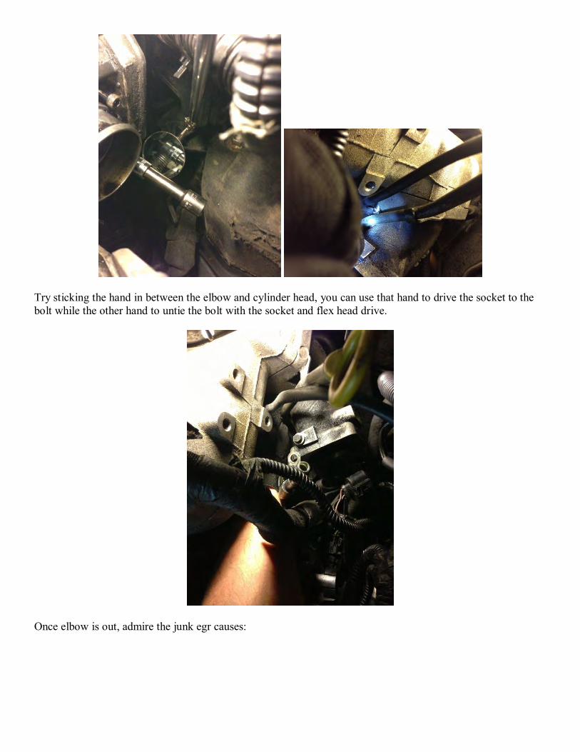
Try sticking the hand in between the elbow and cylinder head, you can use that hand to drive the socket to the bolt while the other hand to untie the bolt with the socket and flex head drive.
Once elbow is out, admire the junk egr causes:
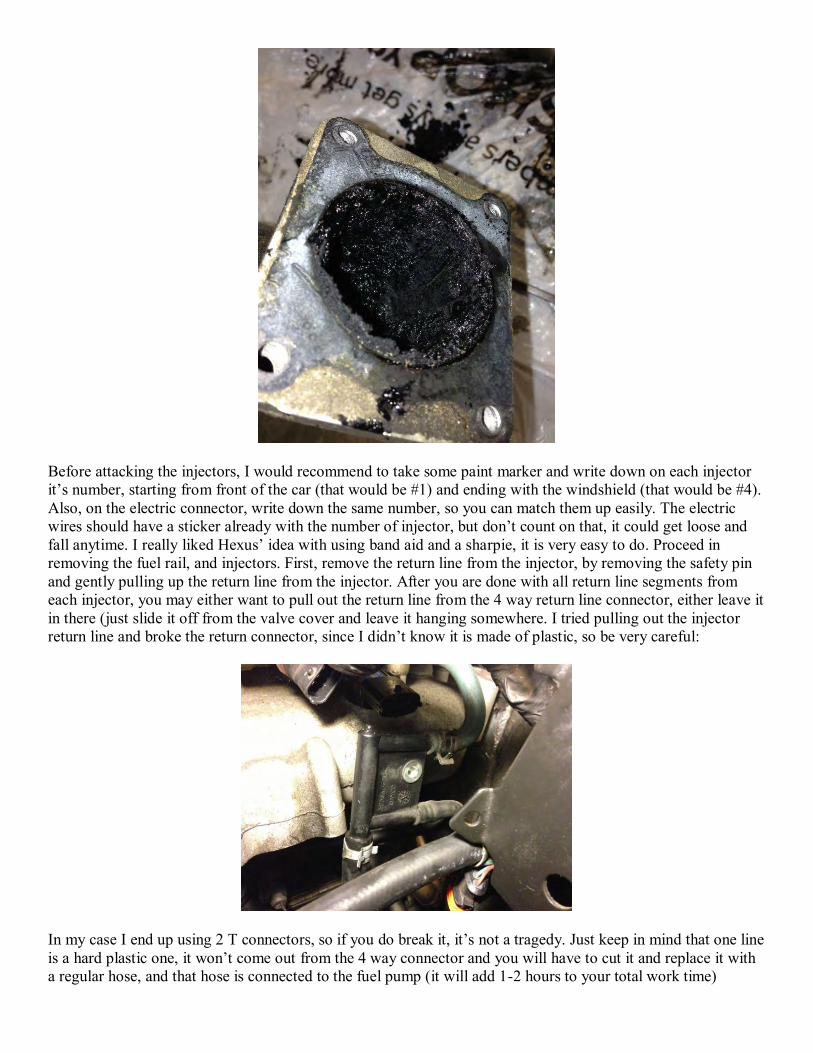
Before attacking the injectors, I would recommend to take some paint marker and write down on each injector it’s number, starting from front of the car (that would be #1) and ending with the windshield (that would be #4). Also, on the electric connector, write down the same number, so you can match them up easily. The electric wires should have a sticker already with the number of injector, but don’t count on that, it could get loose and fall anytime. I really liked Hexus’ idea with using band aid and a sharpie, it is very easy to do. Proceed in removing the fuel rail, and injectors. First, remove the return line from the injector, by removing the safety pin and gently pulling up the return line from the injector. After you are done with all return line segments from each injector, you may either want to pull out the return line from the 4 way return line connector, either leave it in there (just slide it off from the valve cover and leave it hanging somewhere. I tried pulling out the injector return line and broke the return connector, since I didn’t know it is made of plastic, so be very careful:
In my case I end up using 2 T connectors, so if you do break it, it’s not a tragedy. Just keep in mind that one line is a hard plastic one, it won’t come out from the 4 way connector and you will have to cut it and replace it with a regular hose, and that hose is connected to the fuel pump (it will add 1-2 hours to your total work time)
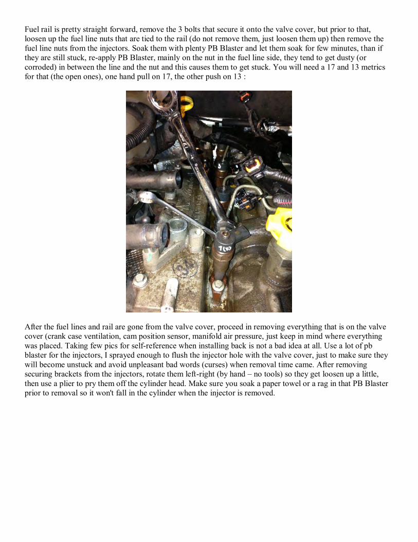
Fuel rail is pretty straight forward, remove the 3 bolts that secure it onto the valve cover, but prior to that, loosen up the fuel line nuts that are tied to the rail (do not remove them, just loosen them up) then remove the fuel line nuts from the injectors. Soak them with plenty PB Blaster and let them soak for few minutes, than if they are still stuck, re-apply PB Blaster, mainly on the nut in the fuel line side, they tend to get dusty (or corroded) in between the line and the nut and this causes them to get stuck. You will need a 17 and 13 metrics for that (the open ones), one hand pull on 17, the other push on 13 :
After the fuel lines and rail are gone from the valve cover, proceed in removing everything that is on the valve cover (crank case ventilation, cam position sensor, manifold air pressure, just keep in mind where everything was placed. Taking few pics for self-reference when installing back is not a bad idea at all. Use a lot of pb blaster for the injectors, I sprayed enough to flush the injector hole with the valve cover, just to make sure they will become unstuck and avoid unpleasant bad words (curses) when removal time came. After removing securing brackets from the injectors, rotate them left-right (by hand – no tools) so they get loosen up a little, then use a plier to pry them off the cylinder head. Make sure you soak a paper towel or a rag in that PB Blaster prior to removal so it won't fall in the cylinder when the injector is removed.

For the injector number 1, you can use a socket under the plier for a better angle. Once injectors are gone, proceed in removing the bolts from valve cover. You can reuse them at installation, but I’d recommend buying at least 2 long ones (id parts has them) since if you cut the bolt hex head, file that end a little, you can use them when installing back the valve cover:
To move away the wiring from the top of the head (visible in one of my pics), remove the wires from the plastic harness, use some cable ties to group them together, then tie them with an electric wire on one end, and the
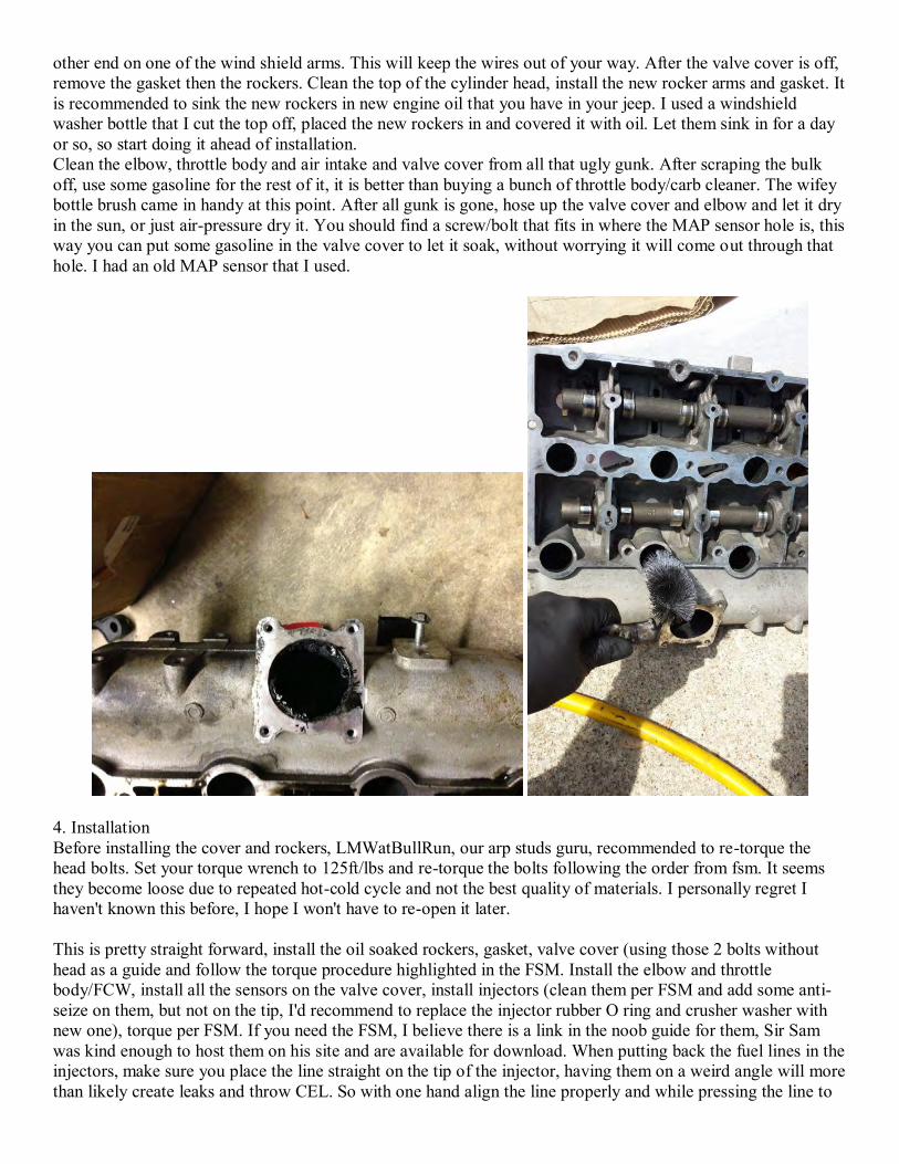
other end on one of the wind shield arms. This will keep the wires out of your way. After the valve cover is off, remove the gasket then the rockers. Clean the top of the cylinder head, install the new rocker arms and gasket. It is recommended to sink the new rockers in new engine oil that you have in your jeep. I used a windshield washer bottle that I cut the top off, placed the new rockers in and covered it with oil. Let them sink in for a day or so, so start doing it ahead of installation. Clean the elbow, throttle body and air intake and valve cover from all that ugly gunk. After scraping the bulk off, use some gasoline for the rest of it, it is better than buying a bunch of throttle body/carb cleaner. The wifey bottle brush came in handy at this point. After all gunk is gone, hose up the valve cover and elbow and let it dry in the sun, or just air-pressure dry it. You should find a screw/bolt that fits in where the MAP sensor hole is, this way you can put some gasoline in the valve cover to let it soak, without worrying it will come out through that hole. I had an old MAP sensor that I used.
4. Installation Before installing the cover and rockers, LMWatBullRun, our arp studs guru, recommended to re-torque the head bolts. Set your torque wrench to 125ft/lbs and re-torque the bolts following the order from fsm. It seems they become loose due to repeated hot-cold cycle and not the best quality of materials. I personally regret I haven't known this before, I hope I won't have to re-open it later. This is pretty straight forward, install the oil soaked rockers, gasket, valve cover (using those 2 bolts without head as a guide and follow the torque procedure highlighted in the FSM. Install the elbow and throttle body/FCW, install all the sensors on the valve cover, install injectors (clean them per FSM and add some anti-seize on them, but not on the tip, I'd recommend to replace the injector rubber O ring and crusher washer with new one), torque per FSM. If you need the FSM, I believe there is a link in the noob guide for them, Sir Sam was kind enough to host them on his site and are available for download. When putting back the fuel lines in the injectors, make sure you place the line straight on the tip of the injector, having them on a weird angle will more than likely create leaks and throw CEL. So with one hand align the line properly and while pressing the line to

the injector, use the other hand to screw the nut in the injector, and only release the pressure when the nut will not screw in anymore by hand.
Proceed with timing belt (again, watch Sir Sam’s video or follow the instructions available on the forum for this). If you leave loose the cam sprockets, you can also start from the crank shaft, moving your way over tensioner (make sure the tensioner is on the “loosest” position – like the belt would have slack if left like that) the water pump, cam sprockets, keep belt tensioned then move it over the injection pump, while keeping in mind not to mess up the marking for it. Then, when everything is in place, torque the cam sprockets per FMS specs:
Remove the pins from fly wheel and cams, test your timing for few complete turns and you’re good to go.
Make sure you let the air out before you start (air out the filter), and after few spins and if you didn’t forget to hook up a sensor of effed up something else the engine will start. Please feel free to add any suggestion/info to this walkthrough. I understand it isn’t perfect and I am willing to accept any improvement to it. I will do my best to keep this thread up to date. Some Helpful Part #'s: Rockers/Lifters (ID Parts has the best price as of 3-12-13, $340) Valve Cover Gasket - 5066786AA Fuel Injector O-Ring - 5069135AB Fuel Injector Crush Washer - 5072722AA FCV/EGR Gasket - 5066946AA [Right side of Valve Cover] You're going to need 2 Gallons of Zerex-5 HOAT Coolant, just buy it now because the coolant you drain out inevetably will get dirty somehow and you probably need to change it anyways. Get some Anti-Seize and use it on the Fuel Injectors, because they're going to get dirty. BUY - 2 Cans of PB Blaster, this stuff is magical, it is made out of Unicorn horns and frees up any rusty/stuck bolts in a matter of 40 seconds, my whole garage still smells like it. Blue Loc-Tite thread locker - The Inner Timing Belt Cover bolts all have it when you take it out, put it on when you put it back in, you'll need it for the fan nut if you're doing the Hayden clutch too, trust me. A Big Crescent wrench and 13mm socket works good to remove the radiator fan nut, but not so good putting it back on if you buy the Hayden Fan Clutch and 12 Blade Nylon Fan. NAPA sells a very nice, very thin, very strong Fan Removal Wrench that works wonders for about $26 and absolutely works taking off as well as putting back on. I strongly suggest getting one. Go ahead and get a tube of silicone, because inevitably you're going to get frustrated and break one of the darn connectors for the wiring harness you have to move out of the way, this will help seal it up once you plug it back together during your rebuild. Small Zip ties too, something will have to hold it together.
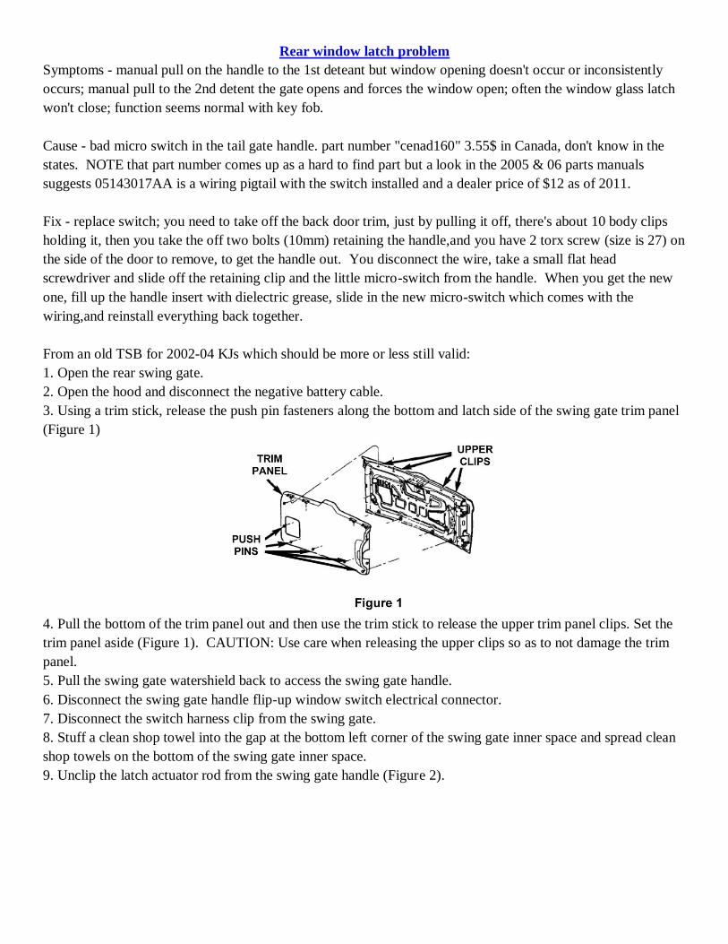
Rear window latch problem
Symptoms - manual pull on the handle to the 1st deteant but window opening doesn't occur or inconsistently
occurs; manual pull to the 2nd detent the gate opens and forces the window open; often the window glass latch
won't close; function seems normal with key fob.
Cause - bad micro switch in the tail gate handle. part number "cenad160" 3.55$ in Canada, don't know in the
states. NOTE that part number comes up as a hard to find part but a look in the 2005 & 06 parts manuals
suggests 05143017AA is a wiring pigtail with the switch installed and a dealer price of $12 as of 2011.
Fix - replace switch; you need to take off the back door trim, just by pulling it off, there's about 10 body clips
holding it, then you take the off two bolts (10mm) retaining the handle,and you have 2 torx screw (size is 27) on
the side of the door to remove, to get the handle out. You disconnect the wire, take a small flat head
screwdriver and slide off the retaining clip and the little micro-switch from the handle. When you get the new
one, fill up the handle insert with dielectric grease, slide in the new micro-switch which comes with the
wiring,and reinstall everything back together.
From an old TSB for 2002-04 KJs which should be more or less still valid:
1. Open the rear swing gate.
2. Open the hood and disconnect the negative battery cable.
3. Using a trim stick, release the push pin fasteners along the bottom and latch side of the swing gate trim panel
(Figure 1)
4. Pull the bottom of the trim panel out and then use the trim stick to release the upper trim panel clips. Set the
trim panel aside (Figure 1). CAUTION: Use care when releasing the upper clips so as to not damage the trim
panel.
5. Pull the swing gate watershield back to access the swing gate handle.
6. Disconnect the swing gate handle flip-up window switch electrical connector.
7. Disconnect the switch harness clip from the swing gate.
8. Stuff a clean shop towel into the gap at the bottom left corner of the swing gate inner space and spread clean
shop towels on the bottom of the swing gate inner space.
9. Unclip the latch actuator rod from the swing gate handle (Figure 2).

10. Remove the two (2) nuts and two (2) screws that attach the exterior handle to the swing gate and then
remove the handle assembly (Figure 2).
11. Remove the spring-loaded switch clip from the handle assembly by placing a flat blade screwdriver under
the left edge of the clip and prying the clip to the right (Figure 3). CAUTION: Pry against the switch under the
clip. Do NOT pry against the metal latch.
12. Hold the swing gate handle in the open position and remove the flip-up window switch from the handle
assembly.
13. Install the new flip-up window switch into the handle assembly (Figure 4). Tilt the switch so that the metal
clip on the switch goes under the metal door handle latch. Ensure that the round switch guides slide into the
mating groove on the handle.
14. Install the switch spring clip over the new switch. Make sure that the bottom left edge of the clip is flush
with the plastic edge on the handle and the clip barbs snap into place.
15. Install the handle assembly into the swing gate (Figure 2). Tighten the two (2) screws and two (2) nuts to 55
in-lbs (6 N·m).
16. Connect the latch actuator rod to the handle assembly.
17. Attach the switch harness clip to the swing gate.
18. Connect the switch electrical connector.
19. Remove the shop towels from the swing gate inner space.
20. Install the swing gate watershield.
21. Install the swing gate trim panel. Seat the upper clips first and then seat the lower push pin fasteners.
22. Close the swing gate.
23. Connect the negative battery cable.
Radiator replacement per irunmiles at Radiator replacement
The hardest part of replacing the fan clutch is removing the shroud, and in doing so I unknowingly poked two
holes in my radiator (probably with the plastic shroud). I didn't realize it until I got everything put back together
after replacing the fan clutch. I had to take it back apart after discovering the leaks.
Removal of the radiator is challenging. First remove the shroud, fan and clutch assembly. Empty the radiator by
opening the valve at the bottom passenger side. Remove the upper and lower radiator hoses, overflow hose, and
the CAC hose from each side of the intercooler (the silver radiator-looking thing in front of the radiator).
Remove the three bolts (all 10mm) from each side of the radiator top cross member, and the two bolts that hold
the hood latch mechanism to the bumper. The cross member and hood latch mechanism with cable attached can
be picked up and positioned to lean against the driver side fender. No need to remove the latch cable. Next pop
off the top plastic latches of the grill cover, and lean it forward to remove the bottom latches. Remove the star
screw from each turn signal and let them hang, and remove the single 10mm bolt that holds the plastic pieces
below each head light. Now you can create some space between the grill and CAC intercooler. No need to
remove the grill components or mechanical fan attached to the front of the intercooler. There is a long (~2")
10mm bolt that runs through a rubber grommet and attaches the intercooler to the frame on each side. You've
got to maneuver through a rubber shroud to get to the bolts with a socket. It's a tight fit, but once you get the
bolts removed, the intercooler is loosened.
On each side of the radiator bottom is a peg and rubber grommet. The peg fits in a hole in the frame. The
radiator and intercooler are connected together with hooks on the radiator and latches on the intercooler. These
are located about 5" from the bottom on each side. You can push the top of the radiator towards the engine to
see these connectors. Now that the intercooler is loosened, it can be gently picked up about 1.5" to raise the
latches off of the radiator hooks. (I cut off half the length of the radiator hooks before I reinstalled) While
raising the intercooler, use your third hand to slide the bottom of the radiator off the latches. I also removed the
hold-fasts and pushed aside as many hoses as I could. The radiator should finally lift out of the engine
compartment.
Now for radiator repair or replacement. I first ordered a new radiator from the internet, and was sent an
intercooler. The intercooler is mislabeled as the radiator in the Jeep parts manual and at all of the parts dealers. I
next explored getting my radiator holes repaired because another forum member said he had it done for $60.
Two repair shops told me it could not be welded because of the plastic side chambers. The third place said that I
was in luck because the holes were in the middle of the fin area and away from the plastic. It still cost me $100,
but they did it while I waited.
Installation is the reverse of removal (but easier). I bought two gallons of concentrated Zerex G05 from Napa
($17 each) and mixed it 50-50 with water. Total coolant replacement is 13 quarts, but my system only took ~11
quarts.
One more thought. While I had everything apart, I decided to replace the hard to access lower radiator hose with
a new Gates hose ($45). The original hose is thicker and has an internal spring support. The Gates hose does not
have the internal support. Although my original hose looked fine, I still replaced it because of the 185k miles it
has seen.
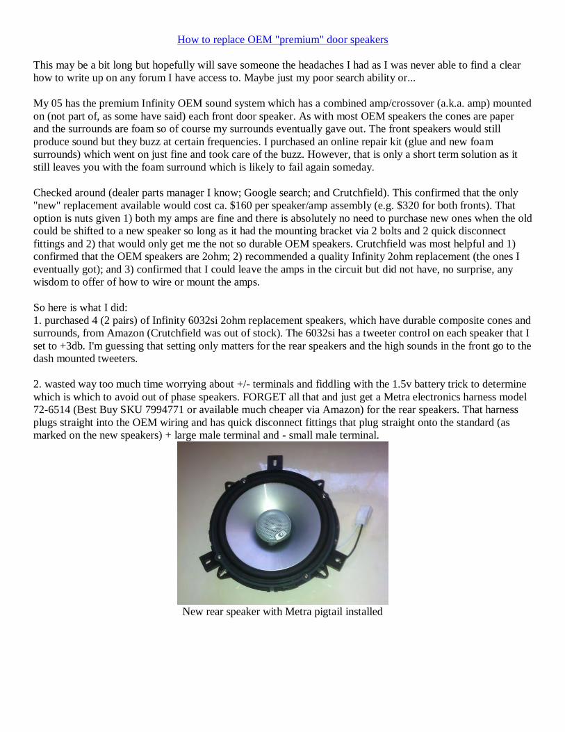
How to replace OEM "premium" door speakers
This may be a bit long but hopefully will save someone the headaches I had as I was never able to find a clear
how to write up on any forum I have access to. Maybe just my poor search ability or...
My 05 has the premium Infinity OEM sound system which has a combined amp/crossover (a.k.a. amp) mounted
on (not part of, as some have said) each front door speaker. As with most OEM speakers the cones are paper
and the surrounds are foam so of course my surrounds eventually gave out. The front speakers would still
produce sound but they buzz at certain frequencies. I purchased an online repair kit (glue and new foam
surrounds) which went on just fine and took care of the buzz. However, that is only a short term solution as it
still leaves you with the foam surround which is likely to fail again someday.
Checked around (dealer parts manager I know; Google search; and Crutchfield). This confirmed that the only
"new" replacement available would cost ca. $160 per speaker/amp assembly (e.g. $320 for both fronts). That
option is nuts given 1) both my amps are fine and there is absolutely no need to purchase new ones when the old
could be shifted to a new speaker so long as it had the mounting bracket via 2 bolts and 2 quick disconnect
fittings and 2) that would only get me the not so durable OEM speakers. Crutchfield was most helpful and 1)
confirmed that the OEM speakers are 2ohm; 2) recommended a quality Infinity 2ohm replacement (the ones I
eventually got); and 3) confirmed that I could leave the amps in the circuit but did not have, no surprise, any
wisdom to offer of how to wire or mount the amps.
So here is what I did:
1. purchased 4 (2 pairs) of Infinity 6032si 2ohm replacement speakers, which have durable composite cones and
surrounds, from Amazon (Crutchfield was out of stock). The 6032si has a tweeter control on each speaker that I
set to +3db. I'm guessing that setting only matters for the rear speakers and the high sounds in the front go to the
dash mounted tweeters.
2. wasted way too much time worrying about +/- terminals and fiddling with the 1.5v battery trick to determine
which is which to avoid out of phase speakers. FORGET all that and just get a Metra electronics harness model
72-6514 (Best Buy SKU 7994771 or available much cheaper via Amazon) for the rear speakers. That harness
plugs straight into the OEM wiring and has quick disconnect fittings that plug straight onto the standard (as
marked on the new speakers) + large male terminal and - small male terminal.
New rear speaker with Metra pigtail installed

New rear speaker mounted - Note "long" mounting tab on all speakers goes up.
For the front speakers I made a pigtail from a standard 2 wire flat plug (NAPA PN 755-1598 or any parts store)
and 1/4" for + and 3/16" for - crimp on quick disconnects (female on speaker side and male on amp side) from
Radio Shack (PN 6403132 and 6404040 respectively) to have enough working wire for installation and any
future removal and used that pigtail to connect the red=+ and black=- terminals coming out of the amp to the
speaker terminals. Be sure to wrap the amp side exposed portions of the quick disconnects with good quality
electricians tape (not cheap hardware stuff).
Amp side of front speaker pigtail
3. don't bother trying to see if there is enough "meat" to simply drill 4 new mounting holes in the door frame.
There isn't. Use the supplied adapter rings remembering that they are plastic and a bit fragile (yes I know now).
On the adapter rings that came with my speakers I noted 4 correctly spaced holes in the bracket that could be
threaded for a 6/32 stainless steel machine screw cut to 3/8" long which left just enough threads to add a nut,
with a drop of Loctite blue, on the door side; just run the bolt down until it lightly bottoms and then flip things
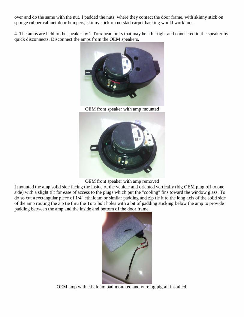
over and do the same with the nut. I padded the nuts, where they contact the door frame, with skinny stick on
sponge rubber cabinet door bumpers, skinny stick on no skid carpet backing would work too.
4. The amps are held to the speaker by 2 Torx head bolts that may be a bit tight and connected to the speaker by
quick disconnects. Disconnect the amps from the OEM speakers.
OEM front speaker with amp mounted
OEM front speaker with amp removed
I mounted the amp solid side facing the inside of the vehicle and oriented vertically (big OEM plug off to one
side) with a slight tilt for ease of access to the plugs which put the "cooling" fins toward the window glass. To
do so cut a rectangular piece of 1/4" ethafoam or similar padding and zip tie it to the long axis of the solid side
of the amp routing the zip tie thru the Torx bolt holes with a bit of padding sticking below the amp to provide
padding between the amp and the inside and bottom of the door frame.
OEM amp with ethafoam pad mounted and wireing pigtail installed.
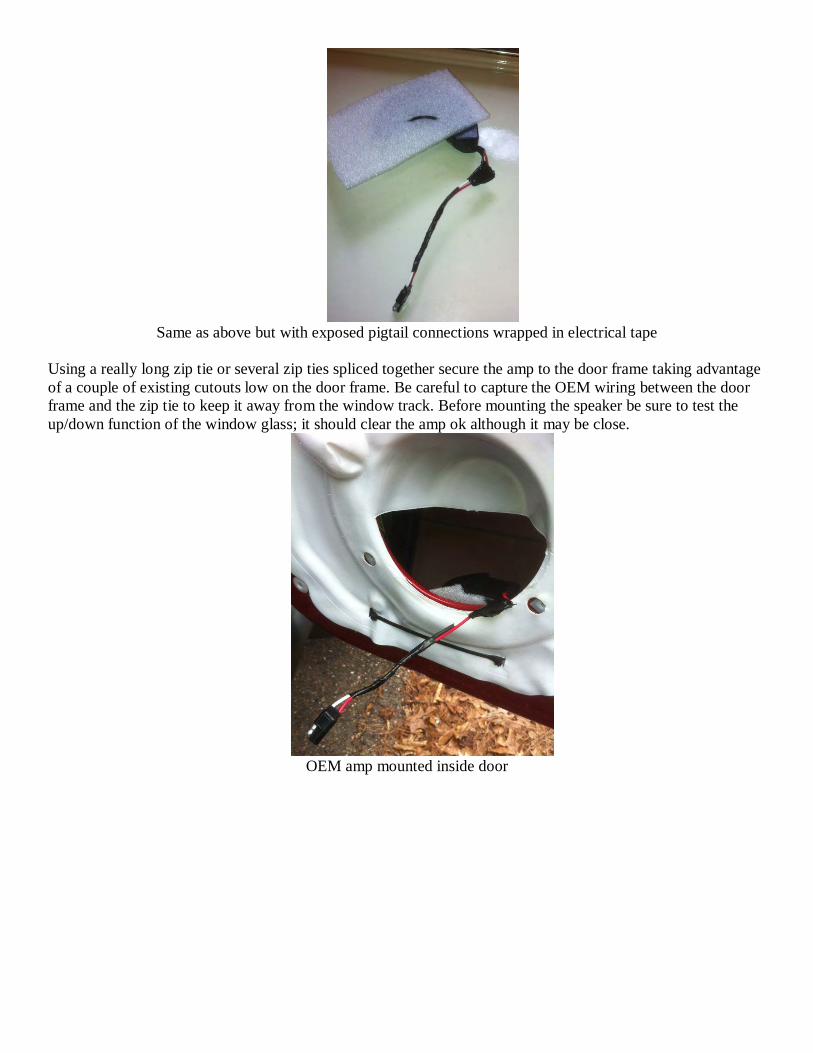
Same as above but with exposed pigtail connections wrapped in electrical tape
Using a really long zip tie or several zip ties spliced together secure the amp to the door frame taking advantage
of a couple of existing cutouts low on the door frame. Be careful to capture the OEM wiring between the door
frame and the zip tie to keep it away from the window track. Before mounting the speaker be sure to test the
up/down function of the window glass; it should clear the amp ok although it may be close.
OEM amp mounted inside door

New front speaker mounted in door
Worked out great and the new speakers are much better than stock. Setting aside the time wasted on trying to
figure out + vs. - and time invested in figuring out how to mount the amps I only had one problem. For reasons
that totally escape me when I first installed the new rear speakers (OEM fronts still in place) the sound was
dramatically muffled. I pulled the new rears and remounted the OEM rears and had the same problem. In all
honesty this condition may have existed for some time given my radio speaker settings and the lack of
passenger use of the rear seat. Not knowing any better I pulled my Sony MEX BT3900U radio and double
checked the wiring to the wiring pigtail Crutchfield had supplied when I bought the radio and cross checked that
wiring to the factory wiring diagram. All appeared perfect. Put everything back together and what the "F" the
muffled sound has been cured. No clue why or what as all I did was undo plugs and redo them; guess there must
have been an imperfect plug connection somewhere.
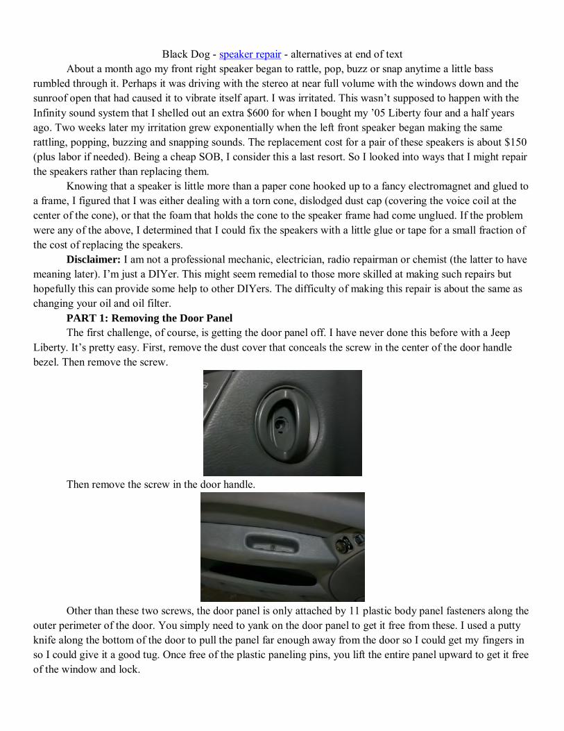
Black Dog - speaker repair - alternatives at end of text
About a month ago my front right speaker began to rattle, pop, buzz or snap anytime a little bass rumbled through it. Perhaps it was driving with the stereo at near full volume with the windows down and the sunroof open that had caused it to vibrate itself apart. I was irritated. This wasn’t supposed to happen with the Infinity sound system that I shelled out an extra $600 for when I bought my ’05 Liberty four and a half years ago. Two weeks later my irritation grew exponentially when the left front speaker began making the same rattling, popping, buzzing and snapping sounds. The replacement cost for a pair of these speakers is about $150 (plus labor if needed). Being a cheap SOB, I consider this a last resort. So I looked into ways that I might repair the speakers rather than replacing them. Knowing that a speaker is little more than a paper cone hooked up to a fancy electromagnet and glued to a frame, I figured that I was either dealing with a torn cone, dislodged dust cap (covering the voice coil at the center of the cone), or that the foam that holds the cone to the speaker frame had come unglued. If the problem were any of the above, I determined that I could fix the speakers with a little glue or tape for a small fraction of the cost of replacing the speakers. Disclaimer: I am not a professional mechanic, electrician, radio repairman or chemist (the latter to have meaning later). I’m just a DIYer. This might seem remedial to those more skilled at making such repairs but hopefully this can provide some help to other DIYers. The difficulty of making this repair is about the same as changing your oil and oil filter. PART 1: Removing the Door Panel The first challenge, of course, is getting the door panel off. I have never done this before with a Jeep Liberty. It’s pretty easy. First, remove the dust cover that conceals the screw in the center of the door handle bezel. Then remove the screw.
Then remove the screw in the door handle.
Other than these two screws, the door panel is only attached by 11 plastic body panel fasteners along the outer perimeter of the door. You simply need to yank on the door panel to get it free from these. I used a putty knife along the bottom of the door to pull the panel far enough away from the door so I could get my fingers in so I could give it a good tug. Once free of the plastic paneling pins, you lift the entire panel upward to get it free of the window and lock.
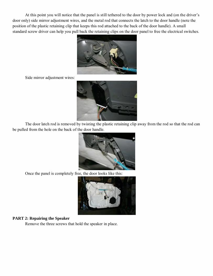
At this point you will notice that the panel is still tethered to the door by power lock and (on the driver’s door only) side mirror adjustment wires, and the metal rod that connects the latch to the door handle (note the position of the plastic retaining clip that keeps this rod attached to the back of the door handle). A small standard screw driver can help you pull back the retaining clips on the door panel to free the electrical switches.
Side mirror adjustment wires:
The door latch rod is removed by twisting the plastic retaining clip away from the rod so that the rod can be pulled from the hole on the back of the door handle.
Once the panel is completely free, the door looks like this:
PART 2: Repairing the Speaker Remove the three screws that hold the speaker in place.
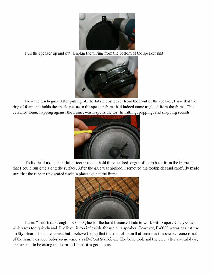
Pull the speaker up and out. Unplug the wiring from the bottom of the speaker unit.
Now the fun begins. After pulling off the fabric dust cover from the front of the speaker, I saw that the ring of foam that holds the speaker cone to the speaker frame had indeed come unglued from the frame. This detached foam, flapping against the frame, was responsible for the rattling, popping, and snapping sounds.
To fix this I used a handful of toothpicks to hold the detached length of foam back from the frame so that I could run glue along the surface. After the glue was applied, I removed the toothpicks and carefully made sure that the rubber ring seated itself in place against the frame.
I used “industrial strength” E-6000 glue for the bond because I hate to work with Super / Crazy Glue, which sets too quickly and, I believe, is too inflexible for use on a speaker. However, E-6000 warns against use on Styrofoam. I’m no chemist, but I believe (hope) that the kind of foam that encircles this speaker cone is not of the same extruded polystyrene variety as DuPont Styrofoam. The bond took and the glue, after several days, appears not to be eating the foam so I think it is good to use.
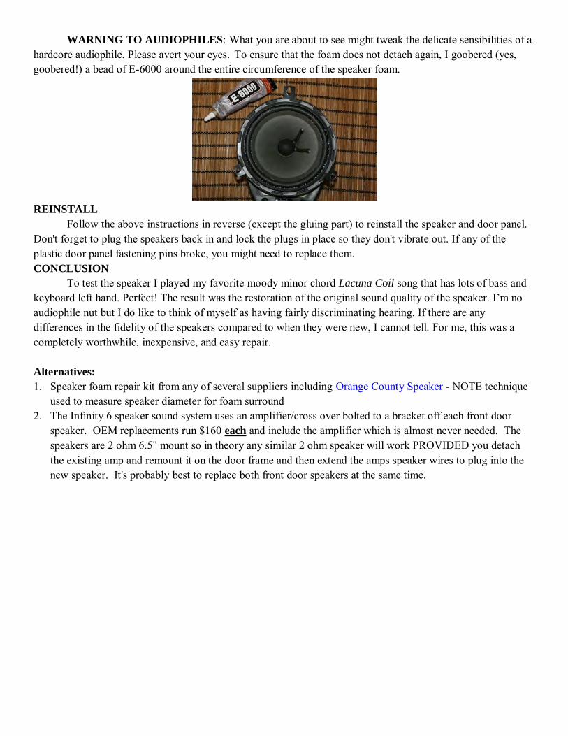
WARNING TO AUDIOPHILES: What you are about to see might tweak the delicate sensibilities of a hardcore audiophile. Please avert your eyes. To ensure that the foam does not detach again, I goobered (yes, goobered!) a bead of E-6000 around the entire circumference of the speaker foam.
REINSTALL Follow the above instructions in reverse (except the gluing part) to reinstall the speaker and door panel. Don't forget to plug the speakers back in and lock the plugs in place so they don't vibrate out. If any of the plastic door panel fastening pins broke, you might need to replace them. CONCLUSION To test the speaker I played my favorite moody minor chord Lacuna Coil song that has lots of bass and keyboard left hand. Perfect! The result was the restoration of the original sound quality of the speaker. I’m no audiophile nut but I do like to think of myself as having fairly discriminating hearing. If there are any differences in the fidelity of the speakers compared to when they were new, I cannot tell. For me, this was a completely worthwhile, inexpensive, and easy repair. Alternatives: 1. Speaker foam repair kit from any of several suppliers including Orange County Speaker - NOTE technique
used to measure speaker diameter for foam surround 2. The Infinity 6 speaker sound system uses an amplifier/cross over bolted to a bracket off each front door
speaker. OEM replacements run $160 each and include the amplifier which is almost never needed. The speakers are 2 ohm 6.5" mount so in theory any similar 2 ohm speaker will work PROVIDED you detach the existing amp and remount it on the door frame and then extend the amps speaker wires to plug into the new speaker. It's probably best to replace both front door speakers at the same time.
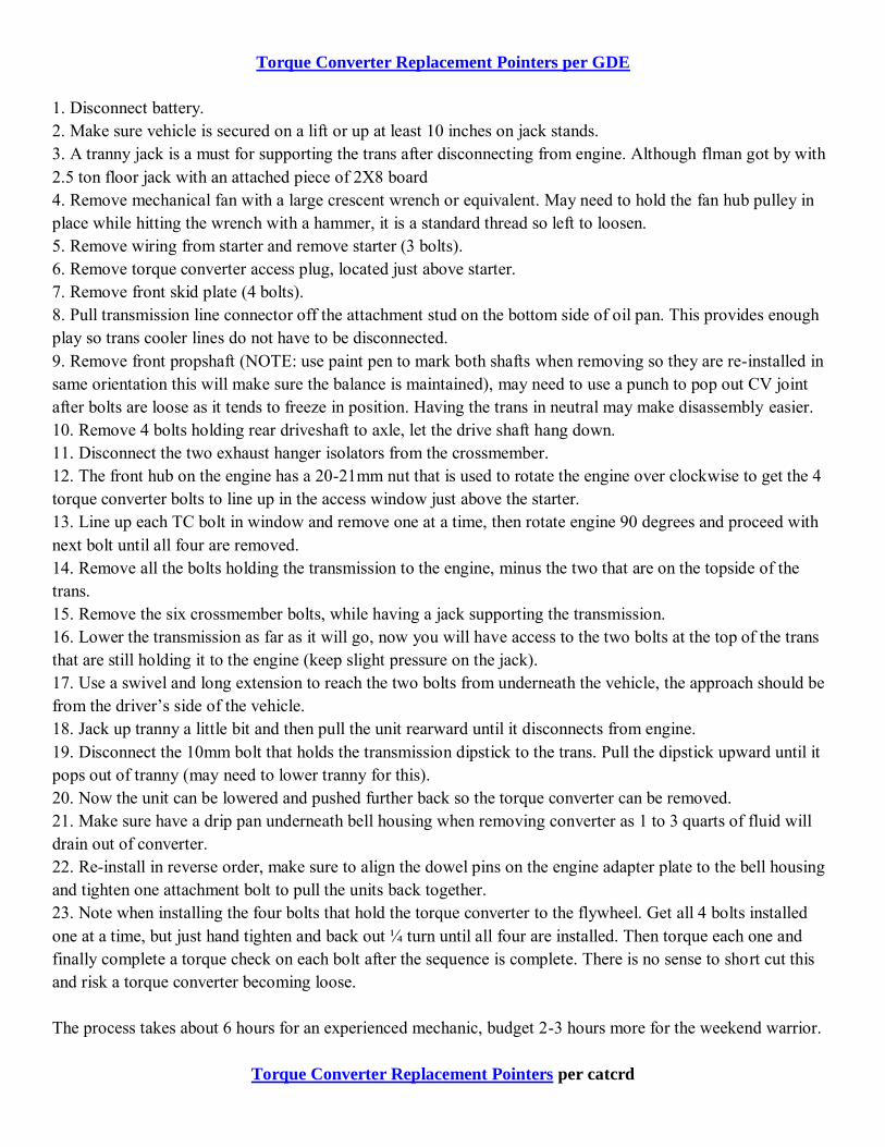
Torque Converter Replacement Pointers per GDE
1. Disconnect battery. 2. Make sure vehicle is secured on a lift or up at least 10 inches on jack stands. 3. A tranny jack is a must for supporting the trans after disconnecting from engine. Although flman got by with 2.5 ton floor jack with an attached piece of 2X8 board 4. Remove mechanical fan with a large crescent wrench or equivalent. May need to hold the fan hub pulley in place while hitting the wrench with a hammer, it is a standard thread so left to loosen. 5. Remove wiring from starter and remove starter (3 bolts). 6. Remove torque converter access plug, located just above starter. 7. Remove front skid plate (4 bolts). 8. Pull transmission line connector off the attachment stud on the bottom side of oil pan. This provides enough play so trans cooler lines do not have to be disconnected. 9. Remove front propshaft (NOTE: use paint pen to mark both shafts when removing so they are re-installed in same orientation this will make sure the balance is maintained), may need to use a punch to pop out CV joint after bolts are loose as it tends to freeze in position. Having the trans in neutral may make disassembly easier. 10. Remove 4 bolts holding rear driveshaft to axle, let the drive shaft hang down. 11. Disconnect the two exhaust hanger isolators from the crossmember. 12. The front hub on the engine has a 20-21mm nut that is used to rotate the engine over clockwise to get the 4 torque converter bolts to line up in the access window just above the starter. 13. Line up each TC bolt in window and remove one at a time, then rotate engine 90 degrees and proceed with next bolt until all four are removed. 14. Remove all the bolts holding the transmission to the engine, minus the two that are on the topside of the trans. 15. Remove the six crossmember bolts, while having a jack supporting the transmission. 16. Lower the transmission as far as it will go, now you will have access to the two bolts at the top of the trans that are still holding it to the engine (keep slight pressure on the jack). 17. Use a swivel and long extension to reach the two bolts from underneath the vehicle, the approach should be from the driver’s side of the vehicle. 18. Jack up tranny a little bit and then pull the unit rearward until it disconnects from engine. 19. Disconnect the 10mm bolt that holds the transmission dipstick to the trans. Pull the dipstick upward until it pops out of tranny (may need to lower tranny for this). 20. Now the unit can be lowered and pushed further back so the torque converter can be removed. 21. Make sure have a drip pan underneath bell housing when removing converter as 1 to 3 quarts of fluid will drain out of converter. 22. Re-install in reverse order, make sure to align the dowel pins on the engine adapter plate to the bell housing and tighten one attachment bolt to pull the units back together. 23. Note when installing the four bolts that hold the torque converter to the flywheel. Get all 4 bolts installed one at a time, but just hand tighten and back out ¼ turn until all four are installed. Then torque each one and finally complete a torque check on each bolt after the sequence is complete. There is no sense to short cut this and risk a torque converter becoming loose. The process takes about 6 hours for an experienced mechanic, budget 2-3 hours more for the weekend warrior.
Torque Converter Replacement Pointers per catcrd

These are to supplement the Factory Service Manual instructions. There are some mistakes in those, because it was written for the V6 KJ then modified a little for the diesel. Still, read them, because there are some things I may have left out of these, and its sections on driveshafts are helpful. Plus all the torque specs for the fasteners are in there. Tools needed: Sockets and wrenches in 8mm, 10, 13, 14, 15, 16, and 18 15/16" (24mm?) needlenose medium flathead screwdriver 3 to 4 ft of extensions u-joint extension Ratchets and breaker bars Impact wrench helps for the rear driveshaft Air ratchet helps Procedure: Disconnect battery! Remove tranny dipstick Raise the Jeep somehow Remove front 3 skid plates Mark then remove driveshafts Remove starter Remove rubber access port plug just above starter (about 2"x3") Use screwdriver to reach thru starter hole and rotate flexplate until 14mm bolt is visible thru access port Use 3/8" rachet and 14mm deep socket to remove the 4 bolts that hold flexplate to torque converter Remove tranny shift linkage and disconnect Disconnect 4wd cable Loosen exhaust-turbo band clamp Disconnect exhaust flange ahead of muffler, pull cat section off hanger. Remove bolt holding dipstick to tranny Leave crossmember & transfer case on together with tranny Get jack under tranny and preload a little Remove six bolts holding crossmember to frame Then lower rear end of tranny/transfer case Watch that your Fumoto or oversized oil filter don't hit front crossmember Undo cables, sensors, cooler lines (have something to plug them) from tranny The 2 little threaded plugs between the cooler line fittings may be in the way of your wrench, ok to remove them for now Yank dipstick tube out of tranny (it's in there deep!) Loosen bellhousing bolts and remove them (there are 3 that come in from the front) Back tranny off of engine and lower it down a little, torque converter will fall out if you let it, and it's 40lbs. Grab the torque converter and pull it straight out of the tranny, don't dump all the fluid out of it onto yourself Pour as much fluid out of it as you feel like into the new converter Make sure the o-ring is present on the new converter's snout

Slide it into the tranny and seat it. Should be at least 1/2" between its front edge and the front edge of tranny Push the tranny back up and onto the engine dowels. Make sure you don't pinch any cables or tubes between them Start installing bellhousing bolts Basically reverse the procedure from here Reach through the starter hole, behind the flexplate and rotate the converter to find the threaded holes. Make sure that first flexplate bolt thru hole is centered over the converter's threaded hole when you install it. If not and you torque it, you may not get the next three in. Remember to reconnect all plugs and lines to tranny and top up with fluid.
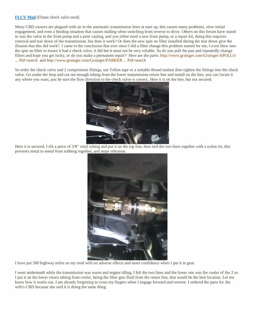
FLCV Mod (Flman check valve mod)
Many CRD owners are plagued with air in the automatic transmission lines at start up, this causes many problems, slow initial
engagement, and even a binding situation that causes stalling when switching from reverse to drive. Others on this forum have stated
in was the valve in the front pump and a poor casting, and you either need a new front pump, or a repair kit, doing this requires
removal and tear down of the transmission, but does it work? Or does the new spin on filter installed during the tear down give the illusion that this did work? I came to the conclusion that ever since I did a filter change this problem started for me, I even blew into
the spin on filter to insure it had a check valve, it did but it must not be very reliable. So do you pull the pan and repeatedly change
filters and hope you get lucky, or do you make a permanent repair? Here are the parts: http://www.grainger.com/Grainger/APOLLO
... Pid=search and http://www.grainger.com/Grainger/PARKER ... Pid=search
So order the check valve and 2 compression fittings, use Teflon tape or a suitable thread sealant then tighten the fittings into the check
valve. Go under the Jeep and cut out enough tubing from the lower transmission return line and install on the line, you can locate it
any where you want, just be sure the flow direction to the check valve is correct. Here it is on the line, but not secured.
Here it is secured, I slit a piece of 3/8" vinyl tubing and put it on the top line, then tied the two lines together with a nylon tie, this
prevents metal to metal from rubbing together, and stops vibration.
I have put 500 highway miles on my mod with no adverse effects and more confidence when I put it in gear.
I went underneath while the transmission was warm and engine idling, I felt the two lines and the lower one was the cooler of the 2 so
I put it on the lower return tubing from cooler, being the filter gets fluid from the return line, that would be the best location. Let me
know how it works out, I am already forgetting to cross my fingers when I engage forward and reverse. I ordered the parts for the
wife's CRD because she said it is doing the same thing.

DIY transmission flush by captaincrd
I have not changed by my transmission fluid and filters ever and as I approach 100,000 miles I thought I better
change out all of the ATF fluid. I didn't want to spend the money to take it to a shop with a flush machine. It
was actually pretty quick and easy to do myself. Total cost was about $127 for 15 litres of ATF + 4 and Fram
filters/gasket. I had enough extra fluid so I also change the transfer case oil at the same time. Thought someone
might find this useful so I posted it.
1. Dropped the pan and measured the fluid that came out (about 5 litres)
2. Put in the new Fram filters, cleaned up the gasket surfaces and installed the pan with the included gasket.
(Make sure the tube and bushing are completely seated. I had to fool around with it a bit to get it all the way in).
(NOTE Per amslube this is ok as the routing of fluid is such that old fluid is not circulated thru the filters. Per
oil filter comments on the LOST forum Fram filters may not be the best choice)
3. Add 5 litres through the dipstick tube.
4. Disconnect the passenger side transmission line where it attaches to the cooler. Access is pretty good to this
connection that is in front of the radiator down low. I used a small screwdriver to pop off the clip and then the
you just pull on the line and it detaches. It is a quick connect type fitting.
5. Attach a few feet of rubber hose to the line and run it into a container to catch the fluid. I used 4 litre plastic
milk jugs that I marked up every 1/2 litre with a sharpie so I could see how much fluid was going into the jug.
In a second clean plastic milk jug I filled it with clean new ATF + 4.
6. Started the jeep and as the dirty fluid filled the one jug I poured an equal amount of new ATF + 4 into the
dipstick tube. I stopped just before the dirty jug was full, emptied it did the whole thing over again. I took out
and added about 8 litres this way and the last fluid to come out was clean and new.
7. I reconnected the transmission line to the cooler and reinstalled the clip.
8. Ran the jeep for awhile and checked the fluid. I had to top it up a bit so have a bit of extra fluid around.
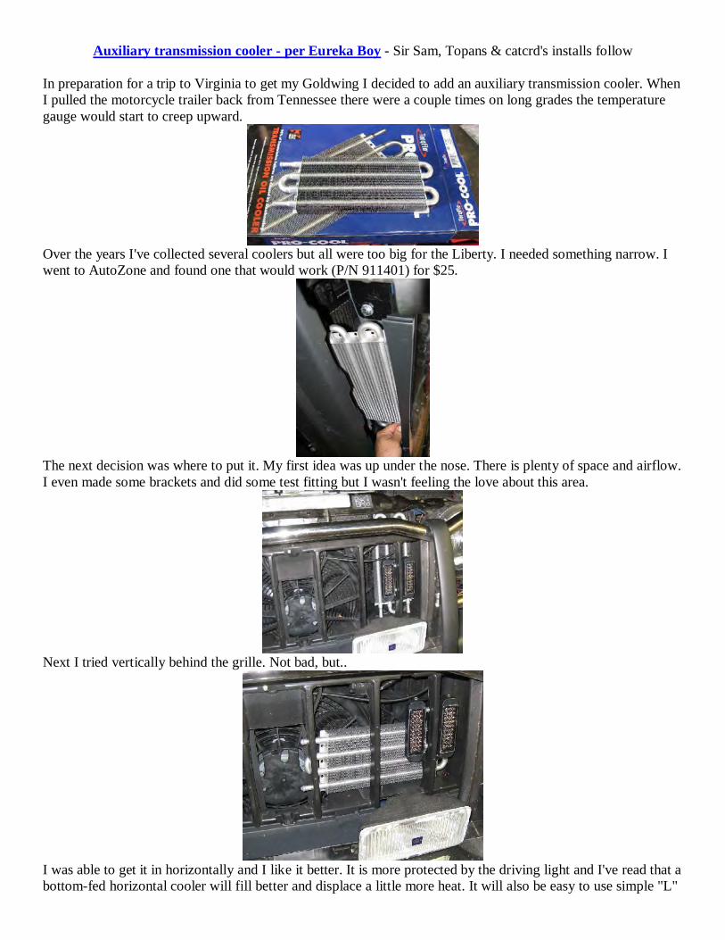
Auxiliary transmission cooler - per Eureka Boy - Sir Sam, Topans & catcrd's installs follow
In preparation for a trip to Virginia to get my Goldwing I decided to add an auxiliary transmission cooler. When
I pulled the motorcycle trailer back from Tennessee there were a couple times on long grades the temperature
gauge would start to creep upward.
Over the years I've collected several coolers but all were too big for the Liberty. I needed something narrow. I
went to AutoZone and found one that would work (P/N 911401) for $25.
The next decision was where to put it. My first idea was up under the nose. There is plenty of space and airflow.
I even made some brackets and did some test fitting but I wasn't feeling the love about this area.
Next I tried vertically behind the grille. Not bad, but..
I was able to get it in horizontally and I like it better. It is more protected by the driving light and I've read that a
bottom-fed horizontal cooler will fill better and displace a little more heat. It will also be easy to use simple "L"
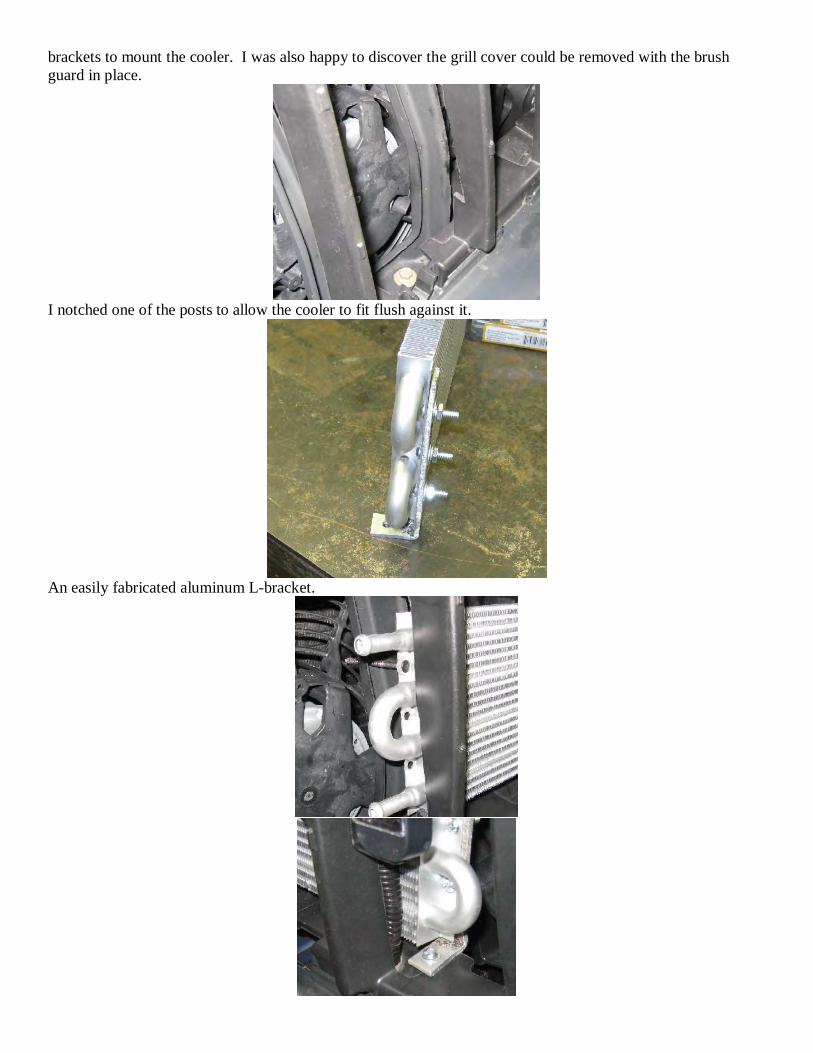
brackets to mount the cooler. I was also happy to discover the grill cover could be removed with the brush
guard in place.
I notched one of the posts to allow the cooler to fit flush against it.
An easily fabricated aluminum L-bracket.
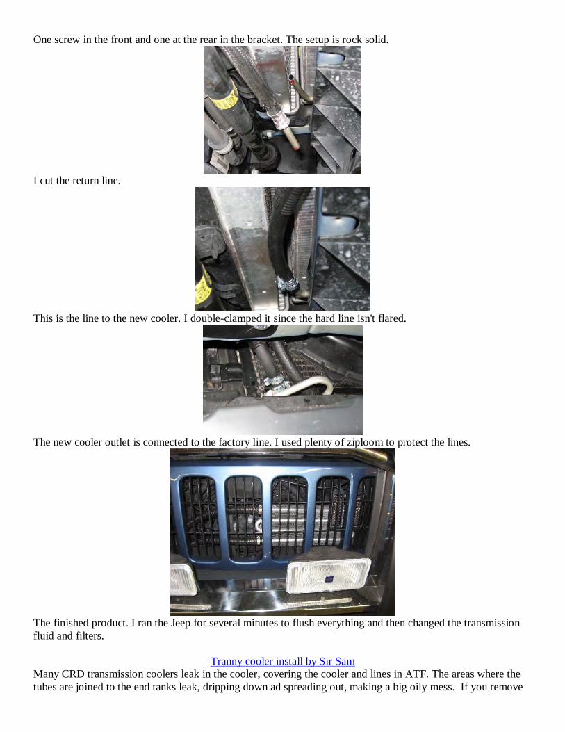
One screw in the front and one at the rear in the bracket. The setup is rock solid.
I cut the return line.
This is the line to the new cooler. I double-clamped it since the hard line isn't flared.
The new cooler outlet is connected to the factory line. I used plenty of ziploom to protect the lines.
The finished product. I ran the Jeep for several minutes to flush everything and then changed the transmission
fluid and filters.
Tranny cooler install by Sir Sam
Many CRD transmission coolers leak in the cooler, covering the cooler and lines in ATF. The areas where the
tubes are joined to the end tanks leak, dripping down ad spreading out, making a big oily mess. If you remove
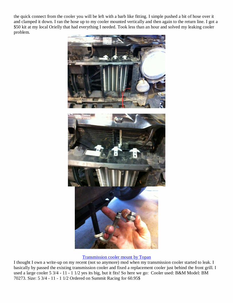
the quick connect from the cooler you will be left with a barb like fitting. I simple pushed a bit of hose over it
and clamped it down. I ran the hose up to my cooler mounted vertically and then again to the return line. I got a
$50 kit at my local Orielly that had everything I needed. Took less than an hour and solved my leaking cooler
problem.
Transmission cooler mount by Topan
I thought I own a write-up on my recent (not so anymore) mod when my transmission cooler started to leak. I
basically by passed the existing transmission cooler and fixed a replacement cooler just behind the front grill. I
used a large cooler 5 3/4 - 11 - 1 1/2 yes its big, but it fits! So here we go: Cooler used: B&M Model: BM
70273. Size: 5 3/4 - 11 - 1 1/2 Ordered on Summit Racing for 60.95$
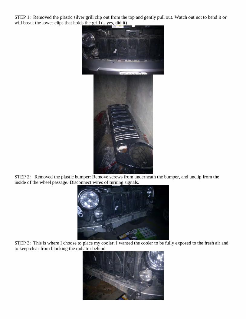
STEP 1: Removed the plastic silver grill clip out from the top and gently pull out. Watch out not to bend it or
will break the lower clips that holds the grill (...yes, did it)
STEP 2: Removed the plastic bumper: Remove screws from underneath the bumper, and unclip from the
inside of the wheel passage. Disconnect wires of turning signals.
STEP 3: This is where I choose to place my cooler. I wanted the cooler to be fully exposed to the fresh air and
to keep clear from blocking the radiator behind.
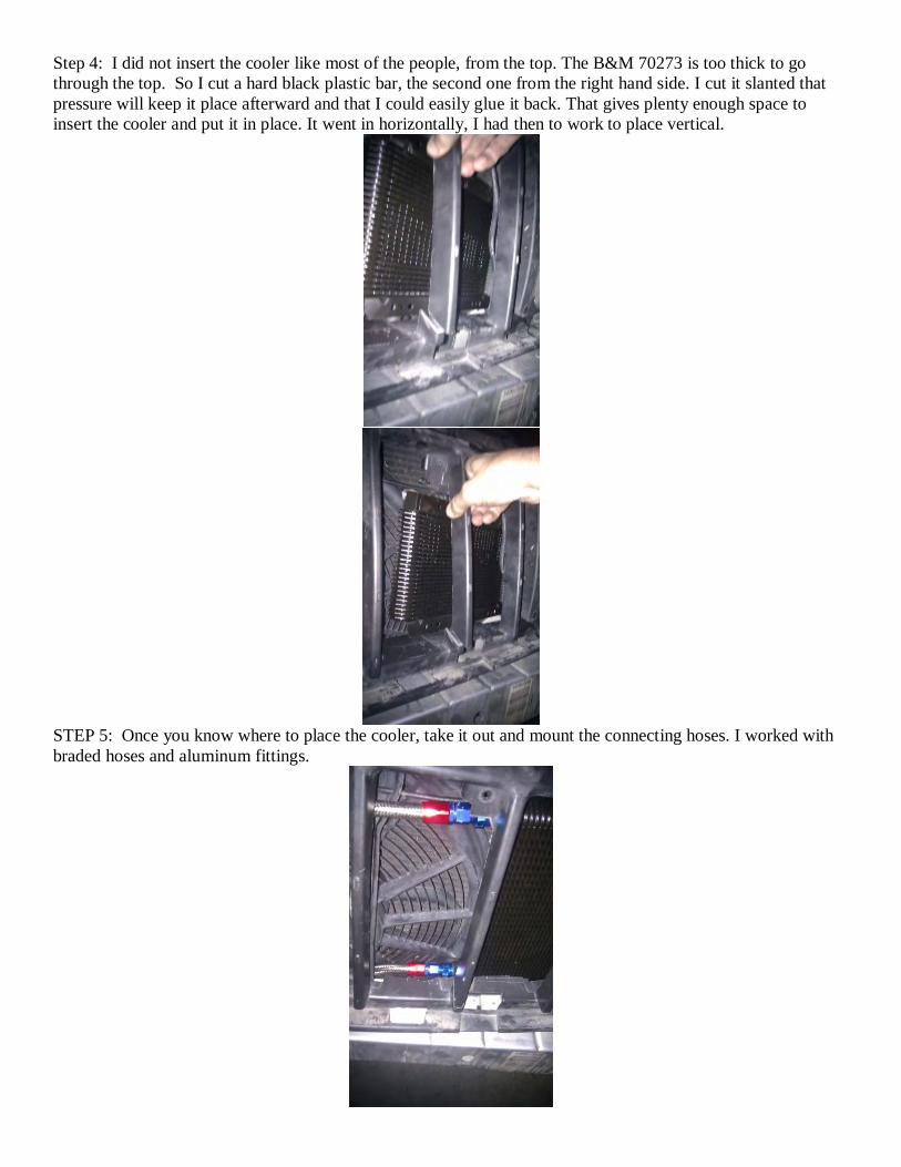
Step 4: I did not insert the cooler like most of the people, from the top. The B&M 70273 is too thick to go
through the top. So I cut a hard black plastic bar, the second one from the right hand side. I cut it slanted that
pressure will keep it place afterward and that I could easily glue it back. That gives plenty enough space to
insert the cooler and put it in place. It went in horizontally, I had then to work to place vertical.
STEP 5: Once you know where to place the cooler, take it out and mount the connecting hoses. I worked with
braded hoses and aluminum fittings.
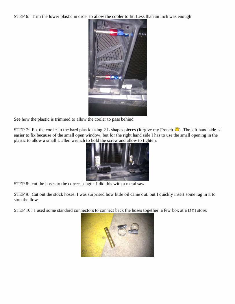
STEP 6: Trim the lower plastic in order to allow the cooler to fit. Less than an inch was enough
See how the plastic is trimmed to allow the cooler to pass behind
STEP 7: Fix the cooler to the hard plastic using 2 L shapes pieces (forgive my French ). The left hand side is
easier to fix because of the small open window, but for the right hand side I has to use the small opening in the
plastic to allow a small L allen wrench to hold the screw and allow to tighten.
STEP 8: cut the hoses to the correct length. I did this with a metal saw.
STEP 9: Cut out the stock hoses. I was surprised how little oil came out. but I quickly insert some rag in it to
stop the flow.
STEP 10: I used some standard connectors to connect back the hoses together. a few box at a DYI store.

STEP 11: I decided to connect the inflow to the lower inlet of the cooler. My logic is that the oil being pushed
up in the cooler has a tendency to spread in all the cooler circuit and give a better cooling effect... seems to
work out well so far.
STEP 12: I had to move the temperature sensor to the left of the hood hook. I found that it was too much
surrounded with hot stuff to tell the truth with the new cooler next to it. An electrical connector (sugar ??), 10
inches of electrical cable and a small drilling made the job.
STEP 13: Glue back the grill or just duck tape it. Mount everything back. (optional ... )
STEP 14: It took about 10 miles to really get the correct level of cooling oil.(ATF +). Drive- stop-check- refill-
drive- stop-.
Tranny cooler - catcrd
Here is how I mounted mine. It's a B&M 70268 in series after the stock cooler. It slid right in from above
without the need to notch or cut anything in the grille. I bent and used the metal mounting straps that came with
the cooler into brackets that mounted in the locations which hold the condensor. The outside temp sensor was
relocated a little to get into a stream of fresh air. I used 3/4" conduit to cover the hoses as they went up and
prevent chafing. The fluid fills it from the bottom so air is always pushed out. There are only the two brackets
that hold it. Otherwise it wedges in tight and is rock solid.
Looking down at top bracket:
Looking way down at bottom bracket:
Looking up at the two new hoses:

Before beginning this repair, I recommend holding the window switch in the “down” position for several seconds (oruntil the motor stops) and then hold it “up” for 1-2 seconds. If you hear any grinding or other unusual noises whiledoing this, release the switch immediately and do not continue to operate the motor. The reason for operating theswitch is to feed the spiral cable back inside of the guide rail. (When the window bracket breaks, there is usually apiece of plastic that remains attached to the end of the spiral cable. If this piece has fed into the main tube, it ispossible for it to become stuck and difficult to remove by hand, but the window motor often has enough power to pushit back into the guide rail where it belongs. Operating the switch in the “down” position will accomplish this. Thereason for reversing it back up for a couple of seconds afterwards is to lift the spiral cable up several inches, makingsure it is out of the way so that the window can be lifted high enough to gain access to the window bracket clips.)
The first step is to remove the door panel. There is a Phillips head screwin the armrest grab handle and another behind the door handle.(Figure 1) The screw behind the door handle is hidden by a small coverwhich you will need to gently pry out using a small flat head screwdriver.After removing both screws, you can disengage the door panel trim clipsby working your way around the edge of the door panel, pulling it awayfrom the door. You may need to pry something under the edge to get itstarted. Auto parts stores sell a special tool that is designed for thispurpose but a flat head screwdriver will also work. (If you use a tool ofsome type, be careful not to scratch or chip your paint.) There are eleventrim clips running around the perimeter of the panel - their locations areshown in Figure 3. Once you have pulled all of them loose, you can liftthe panel slightly to allow the top lip to clear the window slot.
You should now be able to pull the panel far enough away from the doorto reach behind it and disconnect the inside door handle actuating rod. Todo so, simply unclip and rotate the plastic lock which will allow the metalrod to slip down and out of the hole. (Figure 2) Unplug any electricalconnectors from the back of the switch module and then lift the door panelup off the door lock knob and set it aside. Remove the three Phillips headscrews holding the speaker in place (Figure 3), pull it away from the door,disconnect its electrical connector and then set the speaker aside.
The moisture barrier (Figure 3) is glued to the door using a non-hardening, tar-like sealant. You can remove the moisture barrier bysimply peeling it away from the door. Go slowly so that you don’t rip thebarrier and be careful not to get any of that sticky adhesive on your niceclean upholstery! Once you have peeled off the moisture barrier, lay itsomewhere out of the way with the adhesive side facing up. (If theadhesive becomes contaminated with dirt or dust, this will reduce itseffectiveness and make it more difficult to stick the barrier back on later.)
2002-2006 Jeep Liberty Front Door Power Window Regulator Repair KitThanks very much for purchasing this Steiger Performance window regulator repair kit! This kit is primarily designed to
work on any Jeep Liberty built prior to February 26, 2006. This covers all 2002-2005 Libertys as well as some 2006 and 2007models. (Please visit our web site for complete build date and compatibility information.) Part number SP13003 is for the rightfront window and SP13004 is for the left front window. In addition to the repair bracket and this installation guide, you shouldhave received a T-20 Torx tool as well as two #3-48 machine screws with two flat washers, one lock washer and one nut each.(You only need one of these machine screws but two are included because those parts are small and easy to lose.)
If you run into any problems or have questions or comments regarding this repair, please feel free to contact me viae-mail at [email protected] or by using the contact form on the web site. A copy of this installation guide is availablein Adobe PDF format on the Steiger Performance web site at http://www.steigerperformance.com
Tools required: T-20 Torx tool (included), 10mm hex socket or wrench, 3/16” hex socket or wrench (or pliers), small flat headscrewdriver, Phillips head screwdriver, pliers, hammer. Tape or a wedge would be helpful to hold the windowup while you remove the regulator from the door. You also need a drill, grinder or file to remove a small rivet.
(Note: For a diagram showing the window regulator parts referred to in this document, please see Figure 6 on the second page.)

Reach inside the door and lift the window up a bit so you can reach thetwo small metal clips in the white plastic window bracket. Using a flathead screwdriver or a hook tool, pull each clip to the side to remove itfrom the bracket. Be careful not to lose the clips – you will need tore-install them later. After removing the clips, you can disengage theglass from the window bracket. Raise the glass all the way to the top ofthe door and secure it by using tape or a wedge. (If you use tape,masking or painter’s tape works best for this because it does not leave asticky residue behind. Run a few strips from the inside of the glass overthe top of the door frame to the outside of the glass. Taping the front andrear edges of the glass to the window frame will also work.)
There are six bolts holding the window regulator in place: one at the top ofthe guide rail, two at the bottom and three on the window motor. Their locations are shown in Figure 4. Loosen thesebolts – you don’t need to remove them completely, just backing them out several turns is sufficient. Reach through thespeaker opening and disconnect the electrical connector from the motor by sliding the red lock on top to the side andthen depressing the plunger at the top rear of the connector while pulling the plug and socket apart. On the bottomedge of the large opening in the door, the runout tube is clipped to a hole in the inner door skin using a plastic anchor.(Figure 4) Disconnect it by squeezing the prongs of the anchor together and pushing it through the hole.
Slide the guide rail and motor up in their slots and allow their bolts to slipthrough the holes at the top of those slots. Pull the end of the runout tubethrough the large door opening and then rotate the window regulator andlay the guide rail down on the bottom of the door such that the top of theguide rail is as far to the bottom rear edge of the door as possible.(Figure 5) You should now be able to thread the rest of the runout tube,the motor and the main tube through the opening such that the only partstill inside the door is the metal guide rail. At this point, you can pull theguide rail out as well. The next step is to disassemble the regulator.
Figure 6 shows what thewindow regulator assemblylooks like when removedfrom the vehicle. Variousparts of the regulator arelabeled for your reference.
(For now, ignore the 4-7”measurement in Figure 6. Itwill not be relevant until youreach Figure 14.)
Use the Torx tool provided in this kit (or a T-20 Torx driver) to remove thethree motor housing screws (Figure 7) then set the motor and the motorbracket aside.
At the top of the guide rail (where the main tube attaches) you will find asmall rivet. (Figure 8) Remove the head of this rivet. You can use a drill,grinder, cutoff wheel, Dremel® tool or even a hand file if you have theelbow grease to spare, but whatever method you use, be careful to onlyremove the head of the rivet itself; do not damage the underlying metalguide rail.
Flip the guide rail over and bend up the two tabs that hold the main tubeto the guide rail. Once you have done this, you should be able toseparate the main tube from the guide rail. When bending the metal tabs,do not straighten them any further than is necessary to separate the guiderail from the main tube. These tabs can only be bent back and forth a fewtimes before the metal will fatigue and they will break off.
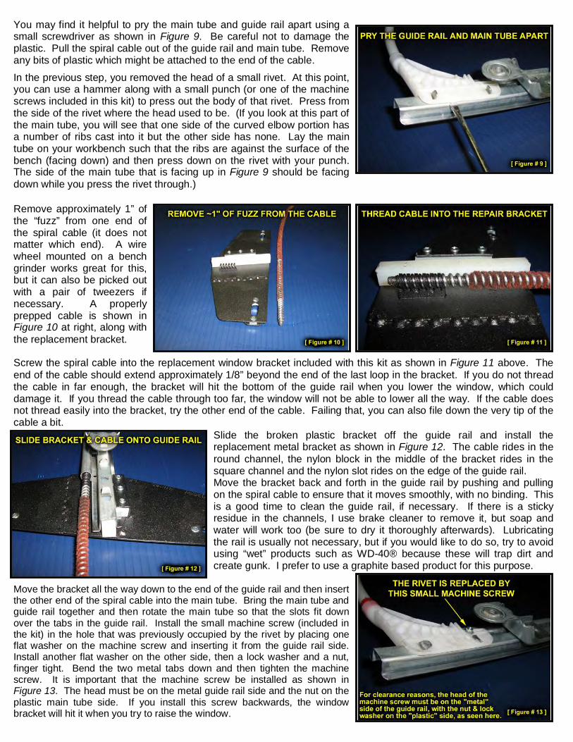
You may find it helpful to pry the main tube and guide rail apart using asmall screwdriver as shown in Figure 9. Be careful not to damage theplastic. Pull the spiral cable out of the guide rail and main tube. Removeany bits of plastic which might be attached to the end of the cable.
In the previous step, you removed the head of a small rivet. At this point,you can use a hammer along with a small punch (or one of the machinescrews included in this kit) to press out the body of that rivet. Press fromthe side of the rivet where the head used to be. (If you look at this part ofthe main tube, you will see that one side of the curved elbow portion hasa number of ribs cast into it but the other side has none. Lay the maintube on your workbench such that the ribs are against the surface of thebench (facing down) and then press down on the rivet with your punch.The side of the main tube that is facing up in Figure 9 should be facingdown while you press the rivet through.)
Remove approximately 1” ofthe “fuzz” from one end ofthe spiral cable (it does notmatter which end). A wirewheel mounted on a benchgrinder works great for this,but it can also be picked outwith a pair of tweezers ifnecessary. A properlyprepped cable is shown inFigure 10 at right, along withthe replacement bracket.
Screw the spiral cable into the replacement window bracket included with this kit as shown in Figure 11 above. Theend of the cable should extend approximately 1/8” beyond the end of the last loop in the bracket. If you do not threadthe cable in far enough, the bracket will hit the bottom of the guide rail when you lower the window, which coulddamage it. If you thread the cable through too far, the window will not be able to lower all the way. If the cable doesnot thread easily into the bracket, try the other end of the cable. Failing that, you can also file down the very tip of thecable a bit.
Slide the broken plastic bracket off the guide rail and install thereplacement metal bracket as shown in Figure 12. The cable rides in theround channel, the nylon block in the middle of the bracket rides in thesquare channel and the nylon slot rides on the edge of the guide rail.Move the bracket back and forth in the guide rail by pushing and pullingon the spiral cable to ensure that it moves smoothly, with no binding. Thisis a good time to clean the guide rail, if necessary. If there is a stickyresidue in the channels, I use brake cleaner to remove it, but soap andwater will work too (be sure to dry it thoroughly afterwards). Lubricatingthe rail is usually not necessary, but if you would like to do so, try to avoidusing “wet” products such as WD-40® because these will trap dirt andcreate gunk. I prefer to use a graphite based product for this purpose.
Move the bracket all the way down to the end of the guide rail and then insertthe other end of the spiral cable into the main tube. Bring the main tube andguide rail together and then rotate the main tube so that the slots fit downover the tabs in the guide rail. Install the small machine screw (included inthe kit) in the hole that was previously occupied by the rivet by placing oneflat washer on the machine screw and inserting it from the guide rail side.Install another flat washer on the other side, then a lock washer and a nut,finger tight. Bend the two metal tabs down and then tighten the machinescrew. It is important that the machine screw be installed as shown inFigure 13. The head must be on the metal guide rail side and the nut on theplastic main tube side. If you install this screw backwards, the windowbracket will hit it when you try to raise the window.
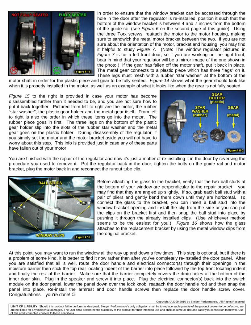
In order to ensure that the window bracket can be accessed through thehole in the door after the regulator is re-installed, position it such that thebottom of the window bracket is between 4 and 7 inches from the bottomof the guide rail (see Figure 6 on the second page of this guide). Usingthe three Torx screws, reattach the motor to the motor housing, makingsure to sandwich the metal motor bracket between the two. If you are notsure about the orientation of the motor, bracket and housing, you may findit helpful to study Figure 7. (Note: The window regulator pictured inFigure 7 is for a left front door, so if you are working on the right front,bear in mind that your regulator will be a mirror image of the one shown inthe photo.) If the gear has fallen off the motor shaft, put it back in place.The metal gear connects to a plastic piece which has three “legs” on it.These legs must mesh with a rubber “star washer” at the bottom of the
motor shaft in order for the plastic piece and gear to be fully seated. Figure 14 shows what the gear should look likewhen it is properly installed in the motor, as well as an example of what it looks like when the gear is not fully seated.
Figure 15 to the right is provided in case your motor has becomedisassembled further than it needed to be, and you are not sure how toput it back together. Pictured from left to right are the motor, the rubber“star washer”, the plastic gear holder and the metal gear itself. From leftto right is also the order in which these items go into the motor. Therubber piece goes in first. The three legs on the bottom of the plasticgear holder slip into the slots of the rubber star washer and the metalgear goes on the plastic holder. During disassembly of the regulator, ifyou simply set the motor and the motor bracket aside you will not have toworry about this step. This info is provided just in case any of these partshave fallen out of your motor.
You are finished with the repair of the regulator and now it’s just a matter of re-installing it in the door by reversing theprocedure you used to remove it. Put the regulator back in the door, tighten the bolts on the guide rail and motorbracket, plug the motor back in and reconnect the runout tube clip.
Before attaching the glass to the bracket, verify that the two ball studs atthe bottom of your window are perpendicular to the repair bracket – youmay find that they are angled up slightly. If so, grab each ball stud with apair of pliers and gently bend them down until they are horizontal. Toconnect the glass to the bracket, you can insert a ball stud into thewindow bracket opening and install the clip from the side or you can putthe clips on the bracket first and then snap the ball stud into place bypushing it through the already installed clips. (Use whichever methodseems to be the easiest for you.) Figure 16 shows how the glassattaches to the replacement bracket by using the metal window clips fromthe original bracket.
At this point, you may want to run the window all the way up and down a few times. This step is optional, but if there isa problem of some kind, it is better to find it now rather than after you’ve completely re-installed the door panel. Afteryou are satisfied that all is well, route the door handle and electrical connector(s) through their openings in themoisture barrier then stick the top rear locating indent of the barrier into place followed by the top front locating indentand finally the rest of the barrier. Make sure that the barrier completely covers the drain holes at the bottom of theinner door skin. Plug in the speaker and screw it into place. Plug the electrical connector(s) back into the switchmodule on the door panel, lower the panel down over the lock knob, reattach the door handle rod and then snap thepanel into place. Re-install the armrest and door handle screws then replace the door handle screw cover.Congratulations – you’re done!
Copyright © 2009-2010 by Steiger Performance. All Rights Reserved.
LIMIT OF LIABILITY: Should this product fail to perform as designed, Steiger Performance’s only obligation shall be to replace such quantity of the product proven to be defective; weare not liable for any incidental damages. The user shall determine the suitability of the product for their intended use and shall assume all risk and liability in connection therewith. Useof this product implies consent to these conditions.
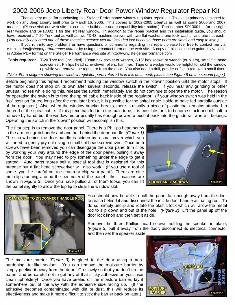
Before beginning this repair, I recommend holding the window switch in the “down” position until the motor stops. Ifthe motor does not stop on its own after several seconds, release the switch. If you hear any grinding or otherunusual noises while doing this, release the switch immediately and do not continue to operate the motor. The reasonfor operating the switch is to feed the spiral cable back inside of the regulator. (If your window switch was held in the“up” position for too long after the regulator broke, it is possible for the spiral cable inside to have fed partially outsideof the regulator.) Also, when the window bracket breaks, there is usually a piece of plastic that remains attached tothe end of the spiral cable. If this piece has fed into the main tube, it is possible for it to become stuck and difficult toremove by hand, but the window motor usually has enough power to push it back into the guide rail where it belongs.Operating the switch in the “down” position will accomplish this.
The first step is to remove the door panel. There is a Phillips head screwin the armrest grab handle and another behind the door handle. (Figure 1)The screw behind the door handle is hidden by a small cover which youwill need to gently pry out using a small flat head screwdriver. Once bothscrews have been removed you can disengage the door panel trim clipsby working your way around the edge of the door panel, pulling it awayfrom the door. You may need to pry something under the edge to get itstarted. Auto parts stores sell a special tool that is designed for thispurpose but a flat head screwdriver will also work. (If you use a tool ofsome type, be careful not to scratch or chip your paint.) There are ninetrim clips running around the perimeter of the panel - their locations areshown in Figure 3. Once you have pulled all of them loose, you can liftthe panel slightly to allow the top lip to clear the window slot.
You should now be able to pull the panel far enough away from the doorto reach behind it and disconnect the inside door handle actuating rod. Todo so, simply unclip and rotate the plastic lock which will allow the metalrod to slip down and out of the hole. (Figure 2) Lift the panel up off thedoor lock knob and then set it aside.
Remove the three Phillips head screws holding the speaker in place,(Figure 3) pull it away from the door, disconnect its electrical connectorand then set the speaker aside.
The moisture barrier (Figure 3) is glued to the door using a non-hardening, tar-like sealant. You can remove the moisture barrier bysimply peeling it away from the door. Go slowly so that you don’t rip thebarrier and be careful not to get any of that sticky adhesive on your niceclean upholstery! Once you have peeled off the moisture barrier, lay itsomewhere out of the way with the adhesive side facing up. (If theadhesive becomes contaminated with dirt or dust, this will reduce itseffectiveness and make it more difficult to stick the barrier back on later.)
2002-2006 Jeep Liberty Rear Door Power Window Regulator Repair KitThanks very much for purchasing this Steiger Performance window regulator repair kit! This kit is primarily designed to
work on any Jeep Liberty built prior to March 16, 2006. This covers all 2002-2005 Libertys as well as some 2006 and 2007models. (Please visit our web site for complete build date and compatibility information.) Part number SP13001 is for the rightrear window and SP13002 is for the left rear window. In addition to the repair bracket and this installation guide, you shouldhave received a T-20 Torx tool as well as two #3-48 machine screws with two flat washers, one lock washer and one nut each.(You actually only need one of these machine screws; two are included just because those parts are small and easy to lose.)
If you run into any problems or have questions or comments regarding this repair, please feel free to contact me viae-mail at [email protected] or by using the contact form on the web site. A copy of this installation guide is availablein Adobe PDF format on the Steiger Performance web site at http://www.steigerperformance.com
Tools required: T-20 Torx tool (included), 10mm hex socket or wrench, 3/16” hex socket or wrench (or pliers), small flat headscrewdriver, Phillips head screwdriver, pliers, hammer. Tape or a wedge would be helpful to hold the windowup while you remove the regulator from the door. You also need a drill, grinder or file to remove a small rivet.
(Note: For a diagram showing the window regulator parts referred to in this document, please see Figure 8 on the second page.)
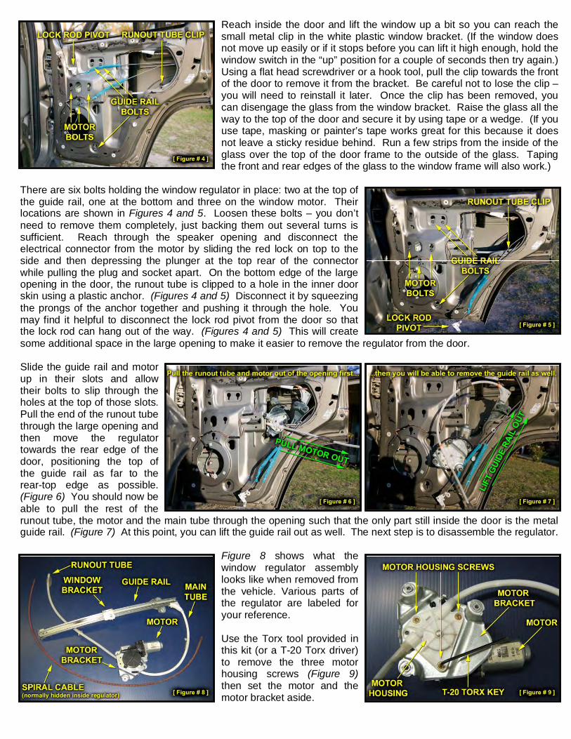
Reach inside the door and lift the window up a bit so you can reach thesmall metal clip in the white plastic window bracket. (If the window doesnot move up easily or if it stops before you can lift it high enough, hold thewindow switch in the “up” position for a couple of seconds then try again.)Using a flat head screwdriver or a hook tool, pull the clip towards the frontof the door to remove it from the bracket. Be careful not to lose the clip –you will need to reinstall it later. Once the clip has been removed, youcan disengage the glass from the window bracket. Raise the glass all theway to the top of the door and secure it by using tape or a wedge. (If youuse tape, masking or painter’s tape works great for this because it doesnot leave a sticky residue behind. Run a few strips from the inside of theglass over the top of the door frame to the outside of the glass. Tapingthe front and rear edges of the glass to the window frame will also work.)
There are six bolts holding the window regulator in place: two at the top ofthe guide rail, one at the bottom and three on the window motor. Theirlocations are shown in Figures 4 and 5. Loosen these bolts – you don’tneed to remove them completely, just backing them out several turns issufficient. Reach through the speaker opening and disconnect theelectrical connector from the motor by sliding the red lock on top to theside and then depressing the plunger at the top rear of the connectorwhile pulling the plug and socket apart. On the bottom edge of the largeopening in the door, the runout tube is clipped to a hole in the inner doorskin using a plastic anchor. (Figures 4 and 5) Disconnect it by squeezingthe prongs of the anchor together and pushing it through the hole. Youmay find it helpful to disconnect the lock rod pivot from the door so thatthe lock rod can hang out of the way. (Figures 4 and 5) This will createsome additional space in the large opening to make it easier to remove the regulator from the door.
Slide the guide rail and motorup in their slots and allowtheir bolts to slip through theholes at the top of those slots.Pull the end of the runout tubethrough the large opening andthen move the regulatortowards the rear edge of thedoor, positioning the top ofthe guide rail as far to therear-top edge as possible.(Figure 6) You should now beable to pull the rest of therunout tube, the motor and the main tube through the opening such that the only part still inside the door is the metalguide rail. (Figure 7) At this point, you can lift the guide rail out as well. The next step is to disassemble the regulator.
Figure 8 shows what thewindow regulator assemblylooks like when removed fromthe vehicle. Various parts ofthe regulator are labeled foryour reference.
Use the Torx tool provided inthis kit (or a T-20 Torx driver)to remove the three motorhousing screws (Figure 9)then set the motor and themotor bracket aside.

At the top of the guide rail (where the main tube attaches) you will find asmall rivet. (Figure 10) Remove the head of this rivet. You can use adrill, grinder, cutoff wheel, Dremel® tool or even a hand file if you have theelbow grease to spare, but whatever method you use, be careful to onlyremove the head of the rivet itself; do not damage the underlying metalguide rail.
Flip the guide rail over and bend up the two tabs that hold the main tube tothe guide rail. Once you have done this, you should be able to separatethe main tube from the guide rail. When bending the metal tabs, do notstraighten them any further than is necessary to separate the guide railfrom the main tube. These tabs can only be bent back and forth a fewtimes before the metal will fatigue and they will break off.
You may find it helpful to pry the main tube and guide rail apart using asmall screwdriver as shown in Figure 11. Be careful not to damage theplastic. Pull the spiral cable out of the guide rail and main tube. Removeany bits of plastic which might be attached to the end of the cable.
In the previous step, you removed the head of a small rivet. At this point,you can use a hammer along with a small punch (or one of the machinescrews included in this kit) to press out the body of that rivet. Press fromthe side of the rivet where the head used to be. (If you look at this part ofthe main tube, you will see that one side of the curved elbow portion hasa number of ribs cast into it but the other side has none. Lay the maintube on your workbench such that the ribs are against the surface of thebench (facing down) and then press down on the rivet with your punch.The side of the main tube that is facing up in Figure 11 should be facing down while you press the rivet through.)
Remove approximately 1” ofthe “fuzz” from one end ofthe spiral cable (it does notmatter which end). A wirewheel mounted on a benchgrinder works great for this,but it can also be picked outwith a pair of tweezers ifnecessary. A properlyprepped cable is shown inFigure 12 at right, along withthe replacement bracket.
Screw the spiral cable into the replacement window bracket included with this kit. The spiral cable should pass overthe oval hole in the bracket prior to threading into the bracket as shown in Figure 13 above. The end of the cableshould extend approximately 1/8” beyond the end of the last loop in the bracket. If you do not thread the cable in farenough, the bracket will hit the bottom of the guide rail when you lower the window, which could damage it. If youthread the cable through too far, the window will not be able to lower all the way. If the cable does not thread easilyinto the bracket, try the other end of the cable. Failing that, you can also file down the very tip of the cable a bit.
Slide the broken plastic bracket off the guide rail and install the new oneas shown in Figure 14. The cable rides in the round channel, the nylonblock in the middle of the bracket rides in the square channel and thenylon slot rides on the edge of the guide rail.Move the bracket back and forth in the guide rail by pushing and pullingon the spiral cable to ensure that it moves smoothly, with no binding. Thisis a good time to clean the guide rail, if necessary. If there is a stickyresidue in the channels, I use brake cleaner to remove it, but soap andwater will work too (be sure to dry it thoroughly afterwards). Lubricatingthe rail is usually not necessary, but if you would like to do so, try to avoidusing “wet” products such as WD-40® because these will trap dirt andcreate gunk. I prefer to use a graphite based product for this purpose.
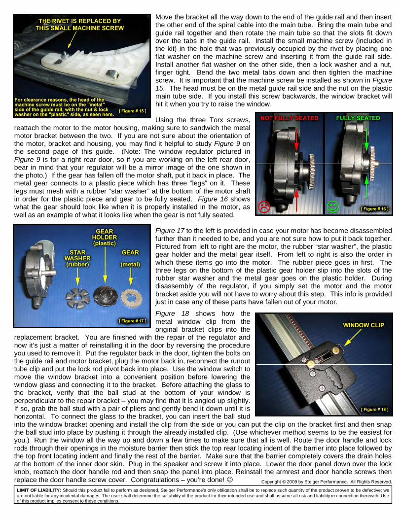
Move the bracket all the way down to the end of the guide rail and then insertthe other end of the spiral cable into the main tube. Bring the main tube andguide rail together and then rotate the main tube so that the slots fit downover the tabs in the guide rail. Install the small machine screw (included inthe kit) in the hole that was previously occupied by the rivet by placing oneflat washer on the machine screw and inserting it from the guide rail side.Install another flat washer on the other side, then a lock washer and a nut,finger tight. Bend the two metal tabs down and then tighten the machinescrew. It is important that the machine screw be installed as shown in Figure15. The head must be on the metal guide rail side and the nut on the plasticmain tube side. If you install this screw backwards, the window bracket willhit it when you try to raise the window.
Using the three Torx screws,reattach the motor to the motor housing, making sure to sandwich the metalmotor bracket between the two. If you are not sure about the orientation ofthe motor, bracket and housing, you may find it helpful to study Figure 9 onthe second page of this guide. (Note: The window regulator pictured inFigure 9 is for a right rear door, so if you are working on the left rear door,bear in mind that your regulator will be a mirror image of the one shown inthe photo.) If the gear has fallen off the motor shaft, put it back in place. Themetal gear connects to a plastic piece which has three “legs” on it. Theselegs must mesh with a rubber “star washer” at the bottom of the motor shaftin order for the plastic piece and gear to be fully seated. Figure 16 showswhat the gear should look like when it is properly installed in the motor, aswell as an example of what it looks like when the gear is not fully seated.
Figure 17 to the left is provided in case your motor has become disassembledfurther than it needed to be, and you are not sure how to put it back together.Pictured from left to right are the motor, the rubber “star washer”, the plasticgear holder and the metal gear itself. From left to right is also the order inwhich these items go into the motor. The rubber piece goes in first. Thethree legs on the bottom of the plastic gear holder slip into the slots of therubber star washer and the metal gear goes on the plastic holder. Duringdisassembly of the regulator, if you simply set the motor and the motorbracket aside you will not have to worry about this step. This info is providedjust in case any of these parts have fallen out of your motor.
Figure 18 shows how themetal window clip from theoriginal bracket clips into the
replacement bracket. You are finished with the repair of the regulator andnow it’s just a matter of reinstalling it in the door by reversing the procedureyou used to remove it. Put the regulator back in the door, tighten the bolts onthe guide rail and motor bracket, plug the motor back in, reconnect the runouttube clip and put the lock rod pivot back into place. Use the window switch tomove the window bracket into a convenient position before lowering thewindow glass and connecting it to the bracket. Before attaching the glass tothe bracket, verify that the ball stud at the bottom of your window isperpendicular to the repair bracket – you may find that it is angled up slightly.If so, grab the ball stud with a pair of pliers and gently bend it down until it ishorizontal. To connect the glass to the bracket, you can insert the ball studinto the window bracket opening and install the clip from the side or you can put the clip on the bracket first and then snapthe ball stud into place by pushing it through the already installed clip. (Use whichever method seems to be the easiest foryou.) Run the window all the way up and down a few times to make sure that all is well. Route the door handle and lockrods through their openings in the moisture barrier then stick the top rear locating indent of the barrier into place followed bythe top front locating indent and finally the rest of the barrier. Make sure that the barrier completely covers the drain holesat the bottom of the inner door skin. Plug in the speaker and screw it into place. Lower the door panel down over the lockknob, reattach the door handle rod and then snap the panel into place. Reinstall the armrest and door handle screws thenreplace the door handle screw cover. Congratulations – you’re done! Copyright © 2009 by Steiger Performance. All Rights Reserved.
LIMIT OF LIABILITY: Should this product fail to perform as designed, Steiger Performance’s only obligation shall be to replace such quantity of the product proven to be defective; weare not liable for any incidental damages. The user shall determine the suitability of the product for their intended use and shall assume all risk and liability in connection therewith. Useof this product implies consent to these conditions.
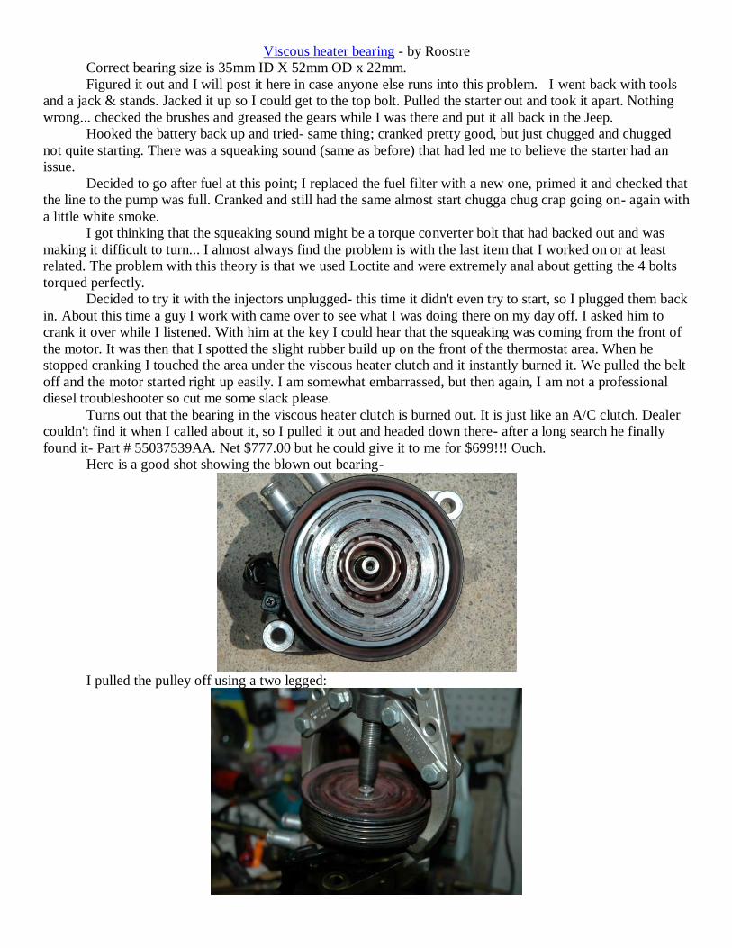
Viscous heater bearing - by Roostre
Correct bearing size is 35mm ID X 52mm OD x 22mm.
Figured it out and I will post it here in case anyone else runs into this problem. I went back with tools
and a jack & stands. Jacked it up so I could get to the top bolt. Pulled the starter out and took it apart. Nothing
wrong... checked the brushes and greased the gears while I was there and put it all back in the Jeep.
Hooked the battery back up and tried- same thing; cranked pretty good, but just chugged and chugged
not quite starting. There was a squeaking sound (same as before) that had led me to believe the starter had an
issue.
Decided to go after fuel at this point; I replaced the fuel filter with a new one, primed it and checked that
the line to the pump was full. Cranked and still had the same almost start chugga chug crap going on- again with
a little white smoke.
I got thinking that the squeaking sound might be a torque converter bolt that had backed out and was
making it difficult to turn... I almost always find the problem is with the last item that I worked on or at least
related. The problem with this theory is that we used Loctite and were extremely anal about getting the 4 bolts
torqued perfectly.
Decided to try it with the injectors unplugged- this time it didn't even try to start, so I plugged them back
in. About this time a guy I work with came over to see what I was doing there on my day off. I asked him to
crank it over while I listened. With him at the key I could hear that the squeaking was coming from the front of
the motor. It was then that I spotted the slight rubber build up on the front of the thermostat area. When he
stopped cranking I touched the area under the viscous heater clutch and it instantly burned it. We pulled the belt
off and the motor started right up easily. I am somewhat embarrassed, but then again, I am not a professional
diesel troubleshooter so cut me some slack please.
Turns out that the bearing in the viscous heater clutch is burned out. It is just like an A/C clutch. Dealer
couldn't find it when I called about it, so I pulled it out and headed down there- after a long search he finally
found it- Part # 55037539AA. Net $777.00 but he could give it to me for $699!!! Ouch.
Here is a good shot showing the blown out bearing-
I pulled the pulley off using a two legged:

The coil was eaten into and coming apart:
Here is just the viscous heater:
The bearing arrived today!!
I cleaned up the staking and pressed it in. Used an aluminum spacer I had lying around to support the
face. Used the old bearing outer race to press the new bearing in. It was a very tight fit; so much so that I started
to question my measurements.... but after a little maneuvering it dropped right in!
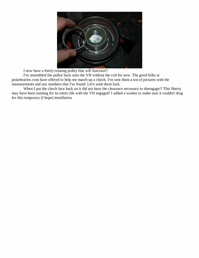
I now have a freely rotating pulley that will function!!
I've assembled the pulley back onto the VH without the coil for now. The good folks at
polarbearinc.com have offered to help me match up a clutch. I've sent them a ton of pictures with the
measurements and any numbers that I've found. Let's wish them luck.
When I put the clutch face back on it did not have the clearance necessary to disengage!! This liberty
may have been running for its entire life with the VH engaged! I added a washer to make sure it couldn't drag
for this temporary (I hope) installation.
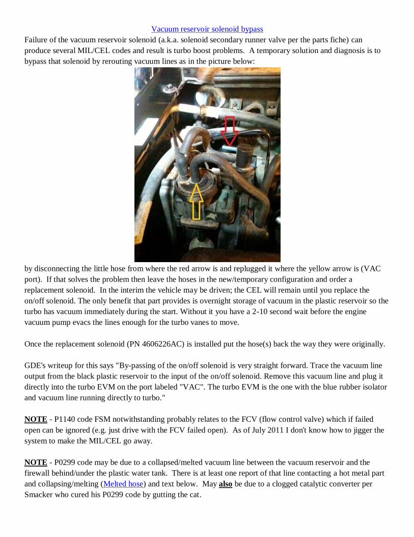
Vacuum reservoir solenoid bypass
Failure of the vacuum reservoir solenoid (a.k.a. solenoid secondary runner valve per the parts fiche) can
produce several MIL/CEL codes and result is turbo boost problems. A temporary solution and diagnosis is to
bypass that solenoid by rerouting vacuum lines as in the picture below:
by disconnecting the little hose from where the red arrow is and replugged it where the yellow arrow is (VAC
port). If that solves the problem then leave the hoses in the new/temporary configuration and order a
replacement solenoid. In the interim the vehicle may be driven; the CEL will remain until you replace the
on/off solenoid. The only benefit that part provides is overnight storage of vacuum in the plastic reservoir so the
turbo has vacuum immediately during the start. Without it you have a 2-10 second wait before the engine
vacuum pump evacs the lines enough for the turbo vanes to move.
Once the replacement solenoid (PN 4606226AC) is installed put the hose(s) back the way they were originally.
GDE's writeup for this says "By-passing of the on/off solenoid is very straight forward. Trace the vacuum line
output from the black plastic reservoir to the input of the on/off solenoid. Remove this vacuum line and plug it
directly into the turbo EVM on the port labeled "VAC". The turbo EVM is the one with the blue rubber isolator
and vacuum line running directly to turbo."
NOTE - P1140 code FSM notwithstanding probably relates to the FCV (flow control valve) which if failed
open can be ignored (e.g. just drive with the FCV failed open). As of July 2011 I don't know how to jigger the
system to make the MIL/CEL go away.
NOTE - P0299 code may be due to a collapsed/melted vacuum line between the vacuum reservoir and the
firewall behind/under the plastic water tank. There is at least one report of that line contacting a hot metal part
and collapsing/melting (Melted hose) and text below. May also be due to a clogged catalytic converter per
Smacker who cured his P0299 code by gutting the cat.

Per topan - I had checked only the vacuum hose from the solenoid to the EGR. I removed the one from the
solenoid to the back panel (slightly larger diameter) yesterday night, i could barely remove the braded protector
from the tube, both were welded together from the heat.... The tube was totally destroyed of course... hope you
can see from the piccs....
I ordered a new set from the US : 58$ plus USPS.... Also, i want to rebuilt a set myself out of metal pipe, i cant
be convinced that plastic pipes are doing fine in the hot environment of an engine bay...... Someone has done it
before ? Thanks to all of you !!! Again this forum has amazing members and resource !! And thanks for the
tips METCRD, the FCV butterfly was my next step, allthough i had already seen that it seems to work fine.
here are some aditional pics of the Line. it is the one with slighly larger diameter, which is connected to the
solenoid by downward U flexible tube. the point were it is melted is indicated by the knife:on that pic the 2 lines
from the solenoid are still taped together, the protectors are removed. the one damaged is the larger and shorter
line with the downward U at one end
.
and some closer look at the damage:
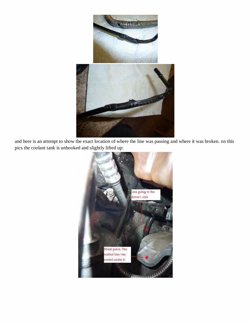
and here is an attempt to show the exact location of where the line was passing and where it was broken. on this
pics the coolant tank is unhooked and slightly lifted up:

Update - NHTSA 13V-252 - hitch replacement for "fire" safety - if vehicle has Mopar hitch dealer is
supposed to only apply a sticky label but if after market they are supposed to measure clearance and replace
hitch if needed.
Technical Service Bulletin and Recall Titles for 2005 Jeep Liberty 4WD L4-2.8L Turbo.
TSB Number & Issue Date TSB Title
F23 SEP 06 Recall - Front Lower Ball Joint Replacement
E14 NOV 05 Recall - A/T Parking Pawl Cup Plug Defect
F37 DEC 06 Recall - Torque Converter & Reprogram ECM/TCM - also referred to as TSB 18-023-06
L-27 ca. April 2012 (NTSB ID Number: 12V085000) Recall - replace real lower control arms on 04-05 KJs
originally sold in or currently registered in listed states that used corrosive chemicals on winter roads.
18-011-09 APR 09 Fuel System - Hard Or No Start/Rough Idle
21-021-08 SEP 08 A/T - Repair/Replacement Guidelines
26-002-08 FEB 08 Brakes - Parking Brake Adjustment Service Intervals
21-014-07 OCT 07 A/T - ATF + 4 Fluid Usage
23-036-07 AUG 07 Interior - Low Gloss Interior Trim Care Information
08-001-07B MAY 07 Air Bag System - Passenger Air Bag Deactivation
26-003-07 MAR 07 Maintenance - Fluid Flushing Recommendations
08-046-06 OCT 06 Audio System - Cell Phone Induced Clicking From Speakers
22-006-06 OCT 06 Tire Pressure Monitor - System Information
05-004-06A SEP 06 Brakes - Rear Brake Moan Upon Light Application
08-030-06A AUG 06 Engine Control - PCM Initialization Procedure
24-006-06 AUG 06 A/C - Musty Odors When Hot/Humid
21-010-06 APR 06 A/T - ATF+4 Fluid Usage/Applications
21-007-06 APR 06 - A/T - Delayed Shift Engagement/Related DTC's Set (fluid drain back)
23-015-06 MAR 06 - Interior - White Water Stain Mark On Cloth Seats
23-014-06 MAR 06 Wipers/Washers - Wipers Smear or Streak Winshield
14-001-06 JAN 06 Fuel System - MIL ON/DTC P0457 Set
18-038-05A DEC 05 Engine Controls - High Altitude Driveability/DTC P0504
22-001-05 DEC 05 Wheels - Caring for Chrome Wheels
19-008-05A NOV 05 Steering - Revised Power Steering Bleeding
25-001-05 REV. A - Emissions - MIL ON/DTC P0401 (EGR Solenoid) Set
18-037-05 OCT 05 Engine Controls - Flash Programming Failure Recovery
08-055-05 OCT 05 Audio System - Satellite Radio Static
08-013-05A OCT 05 Cell Phone - UConnect(R) Hands Free Phone Inoperative
21-015-05 SEP 05 A/T - 45RFE/545RFE Delayed Engagement After Filter R&R
08-048-05 SEP 05 Brakes/Drivetrain - MIL/ABS Lamps ON/Possible DTC P0501
08-043-05 AUG 05 - Instruments - Temperature Gauge Reads Higher Than Normal (gauge incorrectly
programmed for KJ gasser)
08-041-05 AUG 05 Battery - Spiral Cell Battery Service
21-013-05 AUG 05 M/T - NSG370 6 Speed, Vent Restriction Prevention
23-035-05 JUL 05 Body - Circular/Ring Marks on Glass
18-029-05 JUN 05 Engine Controls - Co-Pilot Support & Correct Cable Usage
08-029-05 JUN 05 Engine Controls - Intermittent 4WD Lamp or DTC P0573
18-018-05 MAY 05 Engine Controls - Engine Run-Up on Hot Re-Start
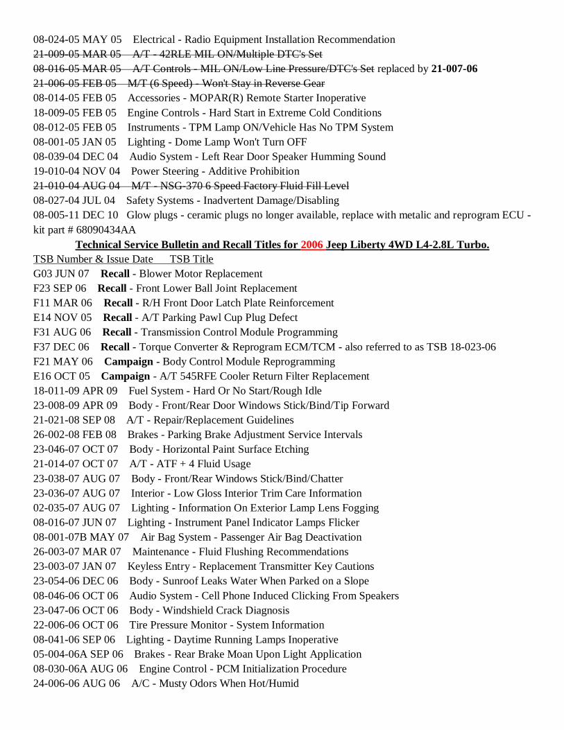
08-024-05 MAY 05 Electrical - Radio Equipment Installation Recommendation
21-009-05 MAR 05 A/T - 42RLE MIL ON/Multiple DTC's Set
08-016-05 MAR 05 A/T Controls - MIL ON/Low Line Pressure/DTC's Set replaced by 21-007-06
21-006-05 FEB 05 M/T (6 Speed) - Won't Stay in Reverse Gear
08-014-05 FEB 05 Accessories - MOPAR(R) Remote Starter Inoperative
18-009-05 FEB 05 Engine Controls - Hard Start in Extreme Cold Conditions
08-012-05 FEB 05 Instruments - TPM Lamp ON/Vehicle Has No TPM System
08-001-05 JAN 05 Lighting - Dome Lamp Won't Turn OFF
08-039-04 DEC 04 Audio System - Left Rear Door Speaker Humming Sound
19-010-04 NOV 04 Power Steering - Additive Prohibition
21-010-04 AUG 04 M/T - NSG-370 6 Speed Factory Fluid Fill Level
08-027-04 JUL 04 Safety Systems - Inadvertent Damage/Disabling
08-005-11 DEC 10 Glow plugs - ceramic plugs no longer available, replace with metalic and reprogram ECU -
kit part # 68090434AA
Technical Service Bulletin and Recall Titles for 2006 Jeep Liberty 4WD L4-2.8L Turbo.
TSB Number & Issue Date TSB Title
G03 JUN 07 Recall - Blower Motor Replacement
F23 SEP 06 Recall - Front Lower Ball Joint Replacement
F11 MAR 06 Recall - R/H Front Door Latch Plate Reinforcement
E14 NOV 05 Recall - A/T Parking Pawl Cup Plug Defect
F31 AUG 06 Recall - Transmission Control Module Programming
F37 DEC 06 Recall - Torque Converter & Reprogram ECM/TCM - also referred to as TSB 18-023-06
F21 MAY 06 Campaign - Body Control Module Reprogramming
E16 OCT 05 Campaign - A/T 545RFE Cooler Return Filter Replacement
18-011-09 APR 09 Fuel System - Hard Or No Start/Rough Idle
23-008-09 APR 09 Body - Front/Rear Door Windows Stick/Bind/Tip Forward
21-021-08 SEP 08 A/T - Repair/Replacement Guidelines
26-002-08 FEB 08 Brakes - Parking Brake Adjustment Service Intervals
23-046-07 OCT 07 Body - Horizontal Paint Surface Etching
21-014-07 OCT 07 A/T - ATF + 4 Fluid Usage
23-038-07 AUG 07 Body - Front/Rear Windows Stick/Bind/Chatter
23-036-07 AUG 07 Interior - Low Gloss Interior Trim Care Information
02-035-07 AUG 07 Lighting - Information On Exterior Lamp Lens Fogging
08-016-07 JUN 07 Lighting - Instrument Panel Indicator Lamps Flicker
08-001-07B MAY 07 Air Bag System - Passenger Air Bag Deactivation
26-003-07 MAR 07 Maintenance - Fluid Flushing Recommendations
23-003-07 JAN 07 Keyless Entry - Replacement Transmitter Key Cautions
23-054-06 DEC 06 Body - Sunroof Leaks Water When Parked on a Slope
08-046-06 OCT 06 Audio System - Cell Phone Induced Clicking From Speakers
23-047-06 OCT 06 Body - Windshield Crack Diagnosis
22-006-06 OCT 06 Tire Pressure Monitor - System Information
08-041-06 SEP 06 Lighting - Daytime Running Lamps Inoperative
05-004-06A SEP 06 Brakes - Rear Brake Moan Upon Light Application
08-030-06A AUG 06 Engine Control - PCM Initialization Procedure
24-006-06 AUG 06 A/C - Musty Odors When Hot/Humid
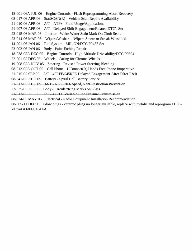
18-001-06A JUL 06 Engine Controls - Flash Reprogramming Abort Recovery
08-017-06 APR 06 StarSCAN(R) - Vehicle Scan Report Availability
21-010-06 APR 06 A/T - ATF+4 Fluid Usage/Applications
21-007-06 APR 06 A/T - Delayed Shift Engagement/Related DTC's Set
23-015-06 MAR 06 Interior - White Water Stain Mark On Cloth Seats
23-014-06 MAR 06 Wipers/Washers - Wipers Smear or Streak Winshield
14-001-06 JAN 06 Fuel System - MIL ON/DTC P0457 Set
23-003-06 JAN 06 Body - Paint Etching Repair
18-038-05A DEC 05 Engine Controls - High Altitude Driveability/DTC P0504
22-001-05 DEC 05 Wheels - Caring for Chrome Wheels
19-008-05A NOV 05 Steering - Revised Power Steering Bleeding
08-013-05A OCT 05 Cell Phone - UConnect(R) Hands Free Phone Inoperative
21-015-05 SEP 05 A/T - 45RFE/545RFE Delayed Engagement After Filter R&R
08-041-05 AUG 05 Battery - Spiral Cell Battery Service
21-013-05 AUG 05 M/T - NSG370 6 Speed, Vent Restriction Prevention
23-035-05 JUL 05 Body - Circular/Ring Marks on Glass
21-012-05 JUL 05 A/T - 42RLE Variable Line Pressure Transmission
08-024-05 MAY 05 Electrical - Radio Equipment Installation Recommendation
08-005-11 DEC 10 Glow plugs - ceramic plugs no longer available, replace with metalic and reprogram ECU -
kit part # 68090434AA
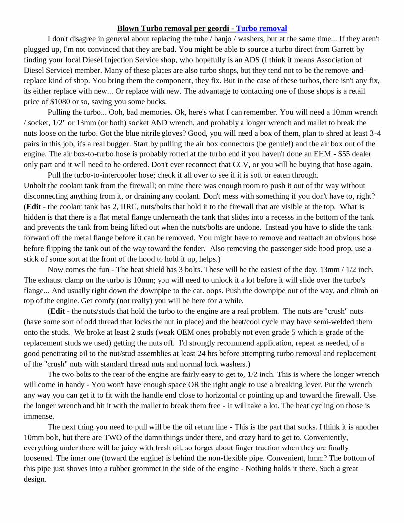
Blown Turbo removal per geordi - Turbo removal
I don't disagree in general about replacing the tube / banjo / washers, but at the same time... If they aren't
plugged up, I'm not convinced that they are bad. You might be able to source a turbo direct from Garrett by
finding your local Diesel Injection Service shop, who hopefully is an ADS (I think it means Association of
Diesel Service) member. Many of these places are also turbo shops, but they tend not to be the remove-and-
replace kind of shop. You bring them the component, they fix. But in the case of these turbos, there isn't any fix,
its either replace with new... Or replace with new. The advantage to contacting one of those shops is a retail
price of $1080 or so, saving you some bucks.
Pulling the turbo... Ooh, bad memories. Ok, here's what I can remember. You will need a 10mm wrench
/ socket, 1/2" or 13mm (or both) socket AND wrench, and probably a longer wrench and mallet to break the
nuts loose on the turbo. Got the blue nitrile gloves? Good, you will need a box of them, plan to shred at least 3-4
pairs in this job, it's a real bugger. Start by pulling the air box connectors (be gentle!) and the air box out of the
engine. The air box-to-turbo hose is probably rotted at the turbo end if you haven't done an EHM - $55 dealer
only part and it will need to be ordered. Don't ever reconnect that CCV, or you will be buying that hose again.
Pull the turbo-to-intercooler hose; check it all over to see if it is soft or eaten through.
Unbolt the coolant tank from the firewall; on mine there was enough room to push it out of the way without
disconnecting anything from it, or draining any coolant. Don't mess with something if you don't have to, right?
(Edit - the coolant tank has 2, IIRC, nuts/bolts that hold it to the firewall that are visible at the top. What is
hidden is that there is a flat metal flange underneath the tank that slides into a recesss in the bottom of the tank
and prevents the tank from being lifted out when the nuts/bolts are undone. Instead you have to slide the tank
forward off the metal flange before it can be removed. You might have to remove and reattach an obvious hose
before flipping the tank out of the way toward the fender. Also removing the passenger side hood prop, use a
stick of some sort at the front of the hood to hold it up, helps.)
Now comes the fun - The heat shield has 3 bolts. These will be the easiest of the day. 13mm / 1/2 inch.
The exhaust clamp on the turbo is 10mm; you will need to unlock it a lot before it will slide over the turbo's
flange... And usually right down the downpipe to the cat. oops. Push the downpipe out of the way, and climb on
top of the engine. Get comfy (not really) you will be here for a while.
(Edit - the nuts/studs that hold the turbo to the engine are a real problem. The nuts are "crush" nuts
(have some sort of odd thread that locks the nut in place) and the heat/cool cycle may have semi-welded them
onto the studs. We broke at least 2 studs (weak OEM ones probably not even grade 5 which is grade of the
replacement studs we used) getting the nuts off. I'd strongly recommend application, repeat as needed, of a
good penetrating oil to the nut/stud assemblies at least 24 hrs before attempting turbo removal and replacement
of the "crush" nuts with standard thread nuts and normal lock washers.)
The two bolts to the rear of the engine are fairly easy to get to, 1/2 inch. This is where the longer wrench
will come in handy - You won't have enough space OR the right angle to use a breaking lever. Put the wrench
any way you can get it to fit with the handle end close to horizontal or pointing up and toward the firewall. Use
the longer wrench and hit it with the mallet to break them free - It will take a lot. The heat cycling on those is
immense.
The next thing you need to pull will be the oil return line - This is the part that sucks. I think it is another
10mm bolt, but there are TWO of the damn things under there, and crazy hard to get to. Conveniently,
everything under there will be juicy with fresh oil, so forget about finger traction when they are finally
loosened. The inner one (toward the engine) is behind the non-flexible pipe. Convenient, hmm? The bottom of
this pipe just shoves into a rubber grommet in the side of the engine - Nothing holds it there. Such a great
design.

Might as well pull the banjo bolt from the top too, there is a copper washer above and below the center
section. Don't forget that when reinstalling it, it will be messy. Don't ask how I know that.
Now the real fun. The other two bolts are BURIED in between the two sections of the turbo housing.
This is where the socket comes in; you can't reach the upper one without it. Use the bigger wrench on the socket
wrench handle to make a breaking bar to pop these two. Congratulations, the turbo is loose. Pull it out, marvel
at what a pain in the arse this job is... And plan on how drunk you will get after putting the new one back in by
reversing the process.
Restarting your engine. I let mine idle for 20 minutes after the first time I lost a turbo, and I had had a
small ticking noise at that point that went away. 10 miles later on the test drive, my engine went away too. So if
it makes any noises that you haven't heard before after you have filled it back up completely... SHUT IT OFF
AND DO NOT DRIVE IT. What may be damaged - The crank bearings on the bottoms of the rods, particularly
the #1 and #2 cylinders. Depending on how low on oil it got, you may be fine... You might not. But rebuilding
the bottom end of the engine is going to be cheaper than replacing the entire engine.

GDE Turbo Kit Installation Procedure - see end for kit information Comments based on 3/24-25/2012 install on papaindigo's 2005 KJ CRD with geordi's assistance the major difference is that this install was done under shelter but without the aid of a lift. As a
result, except for brief use of a floor jack during welding, the vehicle was flat on the ground. Use of front wheel ramps might provide better under vehicle clearance but would make access to the engine compartment extremely difficult without something to stand on.
in this type of installation steps 13-16, 32, 37, 39 are not necessary 1. Make sure vehicle is off and no key in ignition. Disconnecting the battery is optional, but advisable. 2. Remove coolant bottle cap (cold engine) and drain coolant by opening the drain on the radiator. Drain is
located on the passenger side of the radiator at the bottom. It can be difficult to turn. Drain coolant into a pan to reuse after the swap is completed. 2cms cut off of a 10mm Allen wrench will fit inside the drain and make turning it easy. If one
elects to drain the coolant bottle access to this drain plug may be easier once the air box is removed.
draining is not necessary as the coolant bottle (with fluid) can be simply moved around as need to be out of the way although the bottle's left top hose may need to be removed and rerouted/reinstalled to provide more freedom of movement.
3. Remove the turbo to CAC/intercooler hose using an 8mm socket with extension.
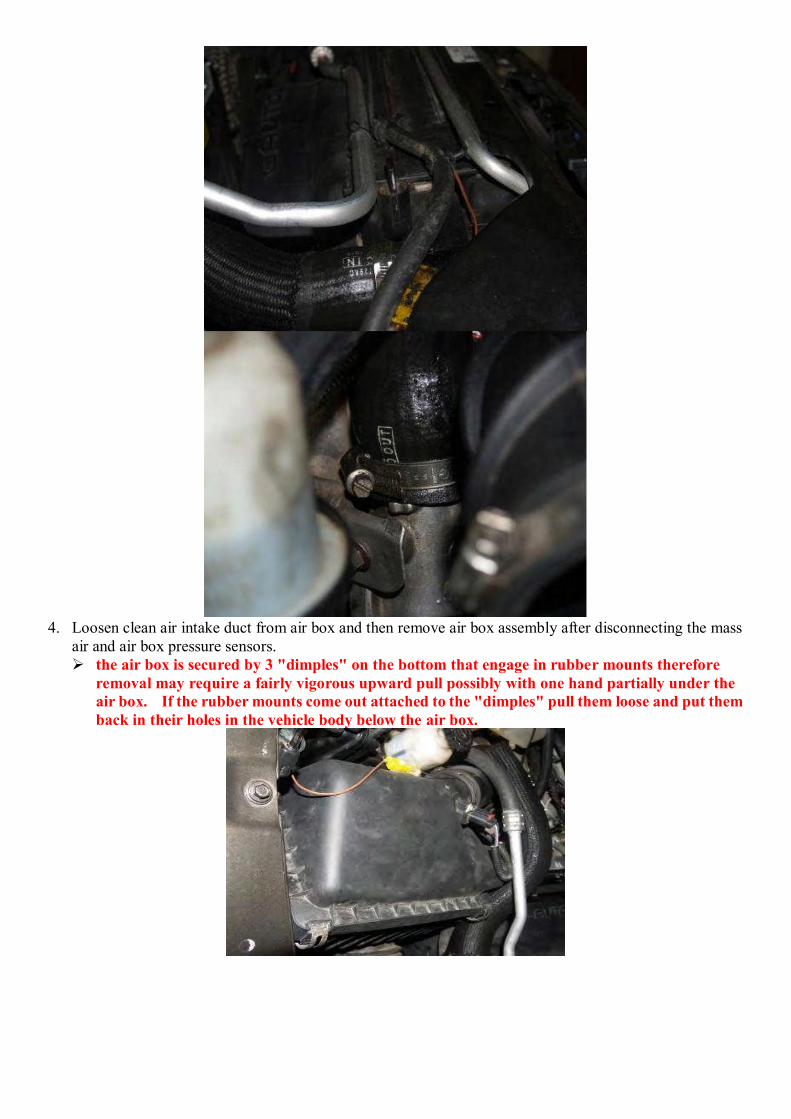
4. Loosen clean air intake duct from air box and then remove air box assembly after disconnecting the mass
air and air box pressure sensors. the air box is secured by 3 "dimples" on the bottom that engage in rubber mounts therefore
removal may require a fairly vigorous upward pull possibly with one hand partially under the air box. If the rubber mounts come out attached to the "dimples" pull them loose and put them back in their holes in the vehicle body below the air box.
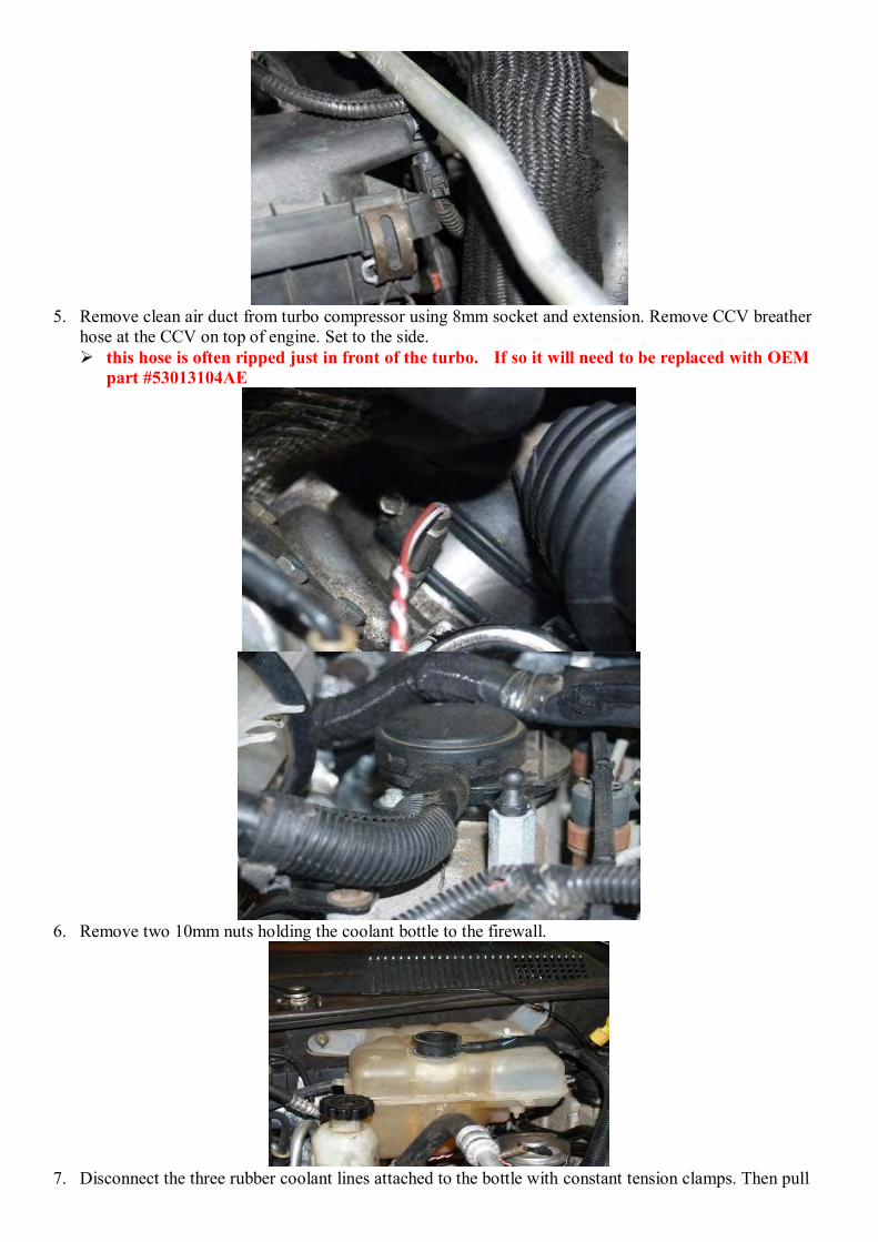
5. Remove clean air duct from turbo compressor using 8mm socket and extension. Remove CCV breather
hose at the CCV on top of engine. Set to the side. this hose is often ripped just in front of the turbo. If so it will need to be replaced with OEM
part #53013104AE
6. Remove two 10mm nuts holding the coolant bottle to the firewall.
7. Disconnect the three rubber coolant lines attached to the bottle with constant tension clamps. Then pull
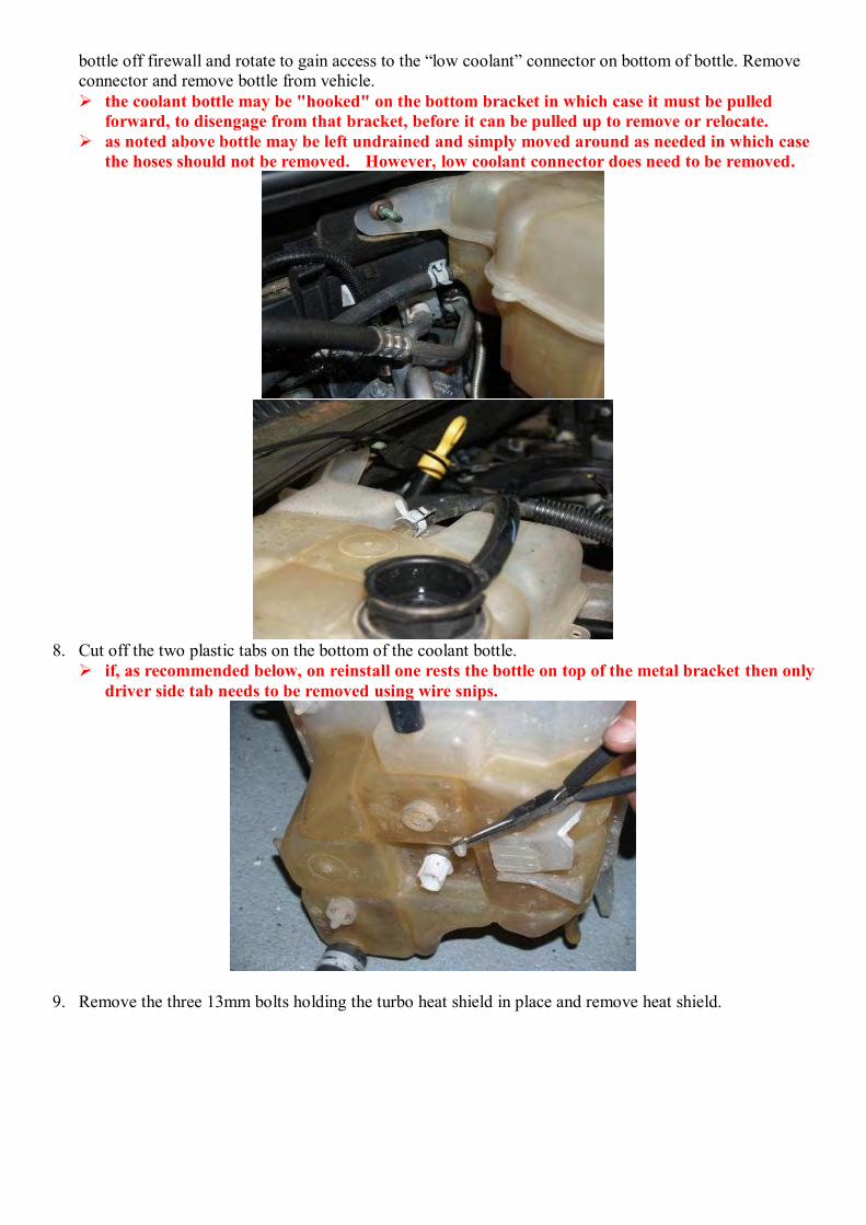
bottle off firewall and rotate to gain access to the “low coolant” connector on bottom of bottle. Remove connector and remove bottle from vehicle. the coolant bottle may be "hooked" on the bottom bracket in which case it must be pulled
forward, to disengage from that bracket, before it can be pulled up to remove or relocate. as noted above bottle may be left undrained and simply moved around as needed in which case
the hoses should not be removed. However, low coolant connector does need to be removed.
8. Cut off the two plastic tabs on the bottom of the coolant bottle.
if, as recommended below, on reinstall one rests the bottle on top of the metal bracket then only driver side tab needs to be removed using wire snips.
9. Remove the three 13mm bolts holding the turbo heat shield in place and remove heat shield.
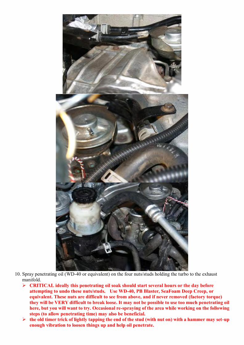
10. Spray penetrating oil (WD-40 or equivalent) on the four nuts/studs holding the turbo to the exhaust
manifold. CRITICAL ideally this penetrating oil soak should start several hours or the day before
attempting to undo these nuts/studs. Use WD-40, PB Blaster, SeaFoam Deep Creep, or equivalent. These nuts are difficult to see from above, and if never removed (factory torque) they will be VERY difficult to break loose. It may not be possible to use too much penetrating oil here, but you will want to try. Occasional re-spraying of the area while working on the following steps (to allow penetrating time) may also be beneficial.
the old timer trick of lightly tapping the end of the stud (with nut on) with a hammer may set-up enough vibration to loosen things up and help oil penetrate.
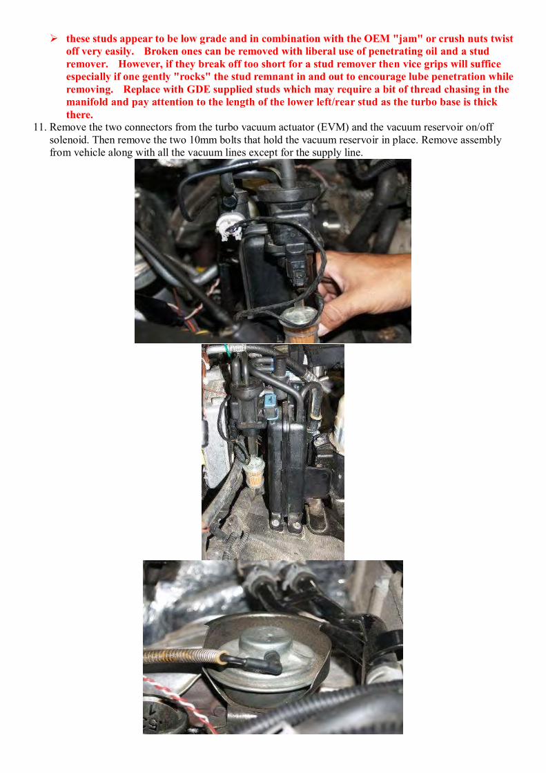
these studs appear to be low grade and in combination with the OEM "jam" or crush nuts twist off very easily. Broken ones can be removed with liberal use of penetrating oil and a stud remover. However, if they break off too short for a stud remover then vice grips will suffice especially if one gently "rocks" the stud remnant in and out to encourage lube penetration while removing. Replace with GDE supplied studs which may require a bit of thread chasing in the manifold and pay attention to the length of the lower left/rear stud as the turbo base is thick there.
11. Remove the two connectors from the turbo vacuum actuator (EVM) and the vacuum reservoir on/off solenoid. Then remove the two 10mm bolts that hold the vacuum reservoir in place. Remove assembly from vehicle along with all the vacuum lines except for the supply line.
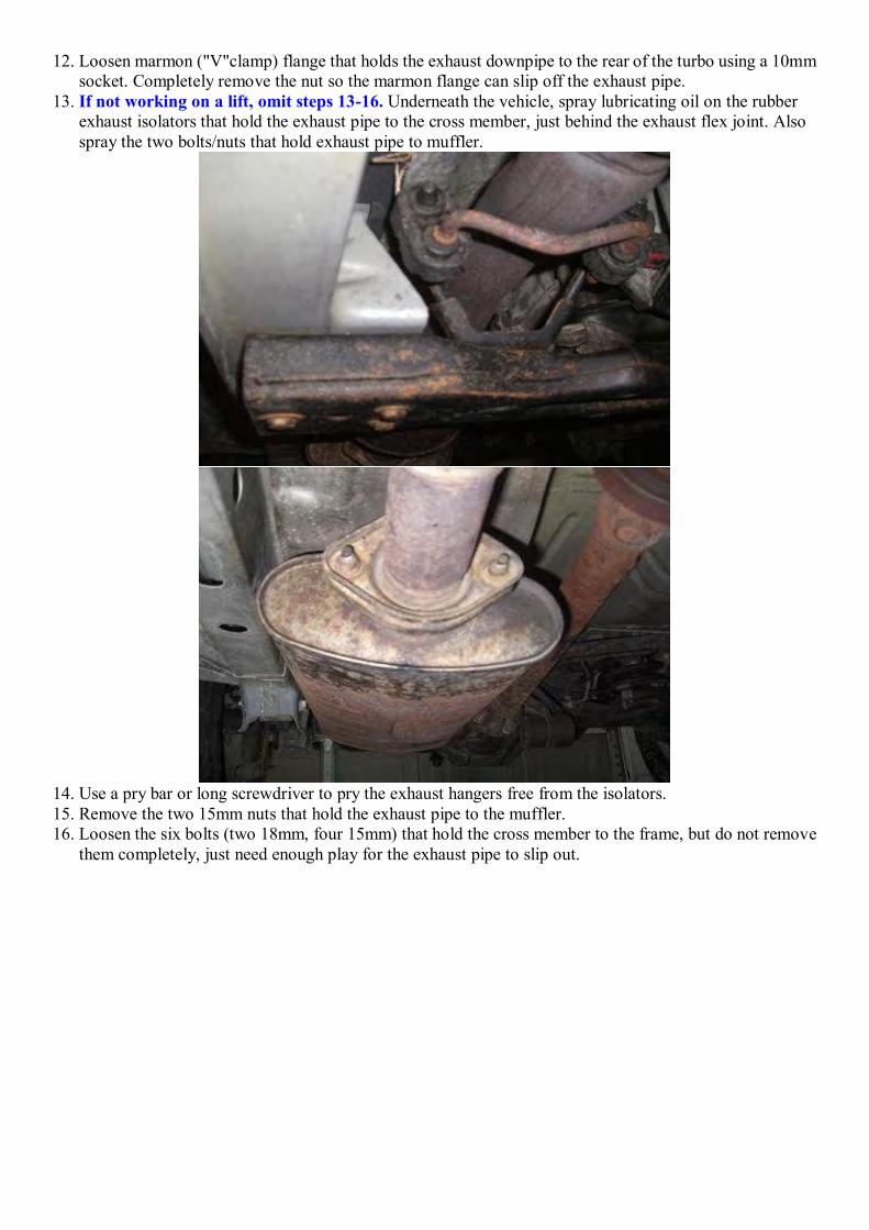
12. Loosen marmon ("V"clamp) flange that holds the exhaust downpipe to the rear of the turbo using a 10mm socket. Completely remove the nut so the marmon flange can slip off the exhaust pipe.
13. If not working on a lift, omit steps 13-16. Underneath the vehicle, spray lubricating oil on the rubber exhaust isolators that hold the exhaust pipe to the cross member, just behind the exhaust flex joint. Also spray the two bolts/nuts that hold exhaust pipe to muffler.
14. Use a pry bar or long screwdriver to pry the exhaust hangers free from the isolators. 15. Remove the two 15mm nuts that hold the exhaust pipe to the muffler. 16. Loosen the six bolts (two 18mm, four 15mm) that hold the cross member to the frame, but do not remove
them completely, just need enough play for the exhaust pipe to slip out.
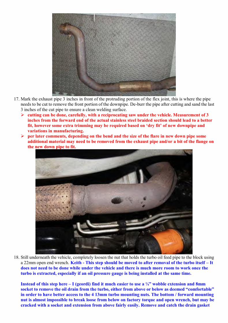
17. Mark the exhaust pipe 3 inches in front of the protruding portion of the flex joint, this is where the pipe
needs to be cut to remove the front portion of the downpipe. De-burr the pipe after cutting and sand the last 3 inches of the cut pipe to ensure a clean welding surface. cutting can be done, carefully, with a reciprocating saw under the vehicle. Measurement of 3
inches from the forward end of the actual stainless steel braided section should lead to a better fit, however some extra trimming may be required based on ‘dry fit’ of new downpipe and variations in manufacturing.
per later comments, depending on the bend and the size of the flare in new down pipe some additional material may need to be removed from the exhaust pipe and/or a bit of the flange on the new down pipe to fit.
18. Still underneath the vehicle, completely loosen the nut that holds the turbo oil feed pipe to the block using
a 22mm open end wrench. Keith - This step should be moved to after removal of the turbo itself – It does not need to be done while under the vehicle and there is much more room to work once the turbo is extracted, especially if an oil pressure gauge is being installed at the same time. Instead of this step here – I (geordi) find it much easier to use a ¼” wobble extension and 8mm socket to remove the oil drain from the turbo, either from above or below as deemed “comfortable” in order to have better access to the 4 13mm turbo mounting nuts. The bottom / forward mounting nut is almost impossible to break loose from below on factory torque and open wrench, but may be cracked with a socket and extension from above fairly easily. Remove and catch the drain gasket

and drain line. 19. Remove the twothree 10mm bolts that hold the turbo support bracket to the engine block and bottom of the
turbo.
20. On the topside, remove the bolt holding the turbo oil supply to the turbo using a 14mm socket. Make sure
to keep the two copper washers that seal the banjo fitting (top and bottom). Keith - the comment about saving these two copper washers appears to be outdated as new
washers are in the kit and step #30 says to use those new washers. 21. Remove the four 13mm nuts that hold the turbo to the exhaust manifold.
see comments above about stud breakage, removal and replacement. The rear-upper nut can be cracked by using a box-end wrench over the nut at approximately
the 10 o’clock position, and placing a large open-end wrench into the other end pointing straight up. This will create a long arm which you can then tap with a mallet. Hard. If the oil has done its job, the nut should break free on the first hit without too much force. If the drain line has been removed, all the rest of the nuts can be removed with a socket wrench and extension, using the large wrench on the handle of the socket wrench as a breaking bar (the long handle pipe trick)
22. Pull the turbo off the studs making sure to pull the turbo oil drain out from the rubber slip fitting on the block at the same time. Remove turbo from vehicle.
23. Unpack turbo kit and lay the parts out for easy viewing. 24. All remaining steps will use parts from kit. 25. Install a plug into the vacuum supply port at the "T" on the firewall that leads to the vacuum reservoir.
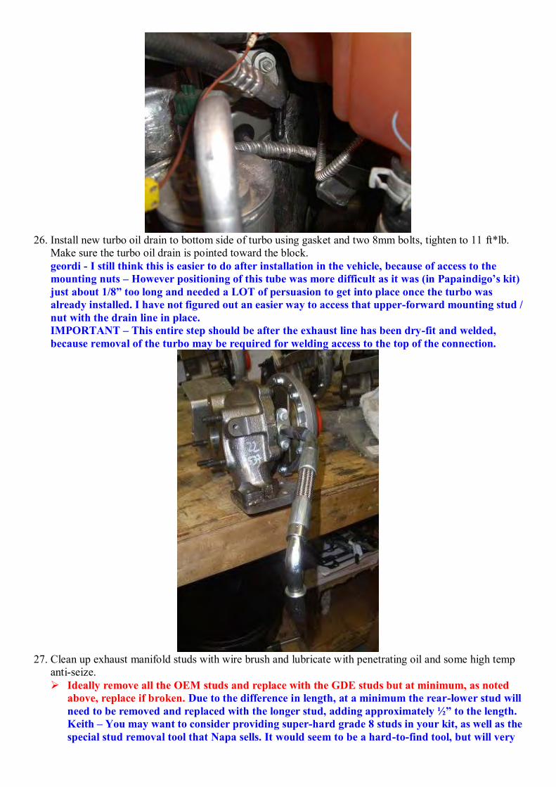
26. Install new turbo oil drain to bottom side of turbo using gasket and two 8mm bolts, tighten to 11 ft*lb.
Make sure the turbo oil drain is pointed toward the block. geordi - I still think this is easier to do after installation in the vehicle, because of access to the mounting nuts – However positioning of this tube was more difficult as it was (in Papaindigo’s kit) just about 1/8” too long and needed a LOT of persuasion to get into place once the turbo was already installed. I have not figured out an easier way to access that upper-forward mounting stud / nut with the drain line in place. IMPORTANT – This entire step should be after the exhaust line has been dry-fit and welded, because removal of the turbo may be required for welding access to the top of the connection.
27. Clean up exhaust manifold studs with wire brush and lubricate with penetrating oil and some high temp
anti-seize. Ideally remove all the OEM studs and replace with the GDE studs but at minimum, as noted
above, replace if broken. Due to the difference in length, at a minimum the rear-lower stud will need to be removed and replaced with the longer stud, adding approximately ½” to the length. Keith – You may want to consider providing super-hard grade 8 studs in your kit, as well as the special stud removal tool that Napa sells. It would seem to be a hard-to-find tool, but will very
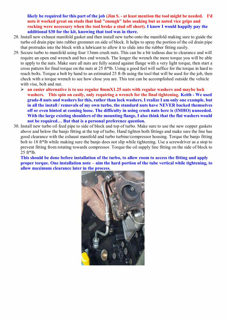
likely be required for this part of the job (Jim S. - at least mention the tool might be needed. I'd note it worked great on studs that had "enough" lube soaking but as noted vice grips and rocking were necessary when the tool broke a stud off short). I know I would happily pay the additional $30 for the kit, knowing that tool was in there.
28. Install new exhaust manifold gasket and then install new turbo onto the manifold making sure to guide the turbo oil drain pipe into rubber grommet on side of block. It helps to spray the portion of the oil drain pipe that protrudes into the block with a lubricant to allow it to slide into the rubber fitting easily.
29. Secure turbo to manifold using four 13mm crush nuts. This can be a bit tedious due to clearance and will require an open end wrench and box end wrench. The longer the wrench the more torque you will be able to apply to the nuts. Make sure all nuts are fully seated against flange with a very light torque, then start a cross pattern for final torque on the nuts at 25 ft*lb. Using a good feel will suffice for the torque in hard to reach bolts. Torque a bolt by hand to an estimated 25 ft-lb using the tool that will be used for the job, then check with a torque wrench to see how close you are. This test can be accomplished outside the vehicle with vise, bolt and nut. an easier alternative is to use regular 8mmX1.25 nuts with regular washers and maybe lock
washers. This spin on easily, only requiring a wrench for the final tightening. Keith - We used grade-8 nuts and washers for this, rather than lock washers. I realize I am only one example, but in all the install / removals of my own turbo, the standard nuts have NEVER backed themselves off or even hinted at coming loose. The difficulty in using crush nuts here is (IMHO) unneeded. With the large existing shoulders of the mounting flange, I also think that the flat washers would not be required… But that is a personal preference question.
30. Install new turbo oil feed pipe to side of block and top of turbo. Make sure to use the new copper gaskets above and below the banjo fitting at the top of turbo. Hand tighten both fittings and make sure the line has good clearance with the exhaust manifold and turbo turbine/compressor housing. Torque the banjo fitting bolt to 18 ft*lb while making sure the banjo does not slip while tightening. Use a screwdriver as a stop to prevent fitting from rotating towards compressor. Torque the oil supply line fitting on the side of block to 25 ft*lb. This should be done before installation of the turbo, to allow room to access the fitting and apply proper torque. One installation note – aim the hard portion of the tube vertical while tightening, to allow maximum clearance later in the process.

31. Slide the gasket on the studs at the rear of turbo for downpipe. 32. Install the cut exhaust pipe back underneath the vehicle and hand tighten the cross member, one bolt on
each side. Then attach the hangers to the isolators, but not all the way on as it will need to be removed one more time for welding. Make sure the end of the pipe is on the studs to the muffler.
33. Install the new exhaust downpipe and secure with one 13mm nut (non crush style). Then slip the exhaust pipe into the slip joint on the new downpipe. Make sure everything is lined up and freely floating, no binding. Then mark a circle around the end of the slip joint where it ends on the exhaust pipe. Also mark a couple lines axially on the slip joint and exhaust pipe to ensure the proper orientation. Make sure to use a permanent marker for this task. NOTE: The slip fit is fairly tight and you could use a clamp if so desired. We did this at first, but there was some exhaust gas leakage around the clamp. Due to the high strength of the stainless steel exhaust, it is very difficult for a clamp to provide enough pressure for a tight seal. some additional cutting on the OEM exhaust pipe and/or the new pipe may be needed
depending on how the new pipe bend fits. ‘Dry fit’ everything first before final assembly with the gasket in place. This would also be a good time to partially weld the connection in place, along the bottom accessible sections of the connection In addition it may be necessary to use part of the old cutoff OEM pipe to "round" out the flare in the new pipe and then drum sand the interior of the flange on the new pipe to relieve the very tight fit. A chain wrench will be very helpful in this “rounding out” if you do not have access to an exhaust flaring tool.
Keith – Is it possible to extend the flared section of the new pipe deeper toward the first bend, so that in the event of differences in fit, some can be trimmed from the end of the new pipe? Our issue was that the flare wasn’t deep enough, and the old exhaust ‘bottomed out’ in the flare. Yes, I probably could have cut it shorter, but that is where things get dicey… You can always cut it shorter… Until you need that extra 1/4” of length.
34. Now the downpipe and exhaust pipe can be removed from the vehicle, set in a jig or vise matching the locating mark locating marks and welded 360 degrees using a MIG, TIG or standard arc welder. if you lack a lift then the welding may be done under the vehicle with the careful use of a floor
jack to gain any need clearance. Weld as much as is possible before jacking, to ensure the parts do not somehow shift positions once lifted. To weld the top of the pipe, it will be necessary to remove the turbo from the vehicle (or remove the studs from the exhaust flange) and slide the pipe past the turbo to lower it for welding access to the top of the connection.
35. Underneath the vehicle install the new turbo support bracket to block and turbo using two 10mm bolts (off old bracket). Make sure the angled bend is against the bottom of the turbo and hand tighten both nuts to ensure good seating, then torque to 25 ft*lb. This step should be after the exhaust pipe is completed, turbo removal may be required to complete welding.
36. Install finished exhaust pipe onto vehicle. Torque two nuts on the muffler flange to 30 ft*lb. Then torque the four 13mm nuts and one bolt onto the turbo turbine flange to 25 ft*lb. if you welded the new down pipe on without removing it from the vehicle then clearing the
exhaust mounting studs on the turbo is not possible but this is easily solved by using a 5mm socket to spin the studs out of that flange, slide the pipe into place, and then install stud/gasket/nuts.

37. Tighten the six cross member bolts to 30 ft*lb, then reattach the exhaust hangers to the rubber isolators. 38. Cut the original heat shield as shown with a set of tin snips or equivalent, de-burr the edges with a file or
sandpaper. Install heat shield using two of the old 13mm bolts to the exhaust manifold.
39. Remove the black coolant bottle support from the fire wall using a 10mm socket. Drill out the holes to
form a slot, the bracket will need to be mounted 1/4 inch outboard from stock. Reattach the bracket to the firewall and then apply upward pressure to the cantilevered portion to bend it up about a ½ inch or so. as briefly and indirectly mentioned earlier the coolant bottle can simply rest on top of this
support in which case the support does not need to be relocated or bent.
40. Tape the grey connector that was for the vacuum on/off solenoid to seal it up from the elements. 41. The wiring connectors have the pins number on each connector, may be hard to see on the EVM
connector, but it is there. 42. Cut the wire on the #1 pin (brown/pink) on the black connector that was used to power the EVM and
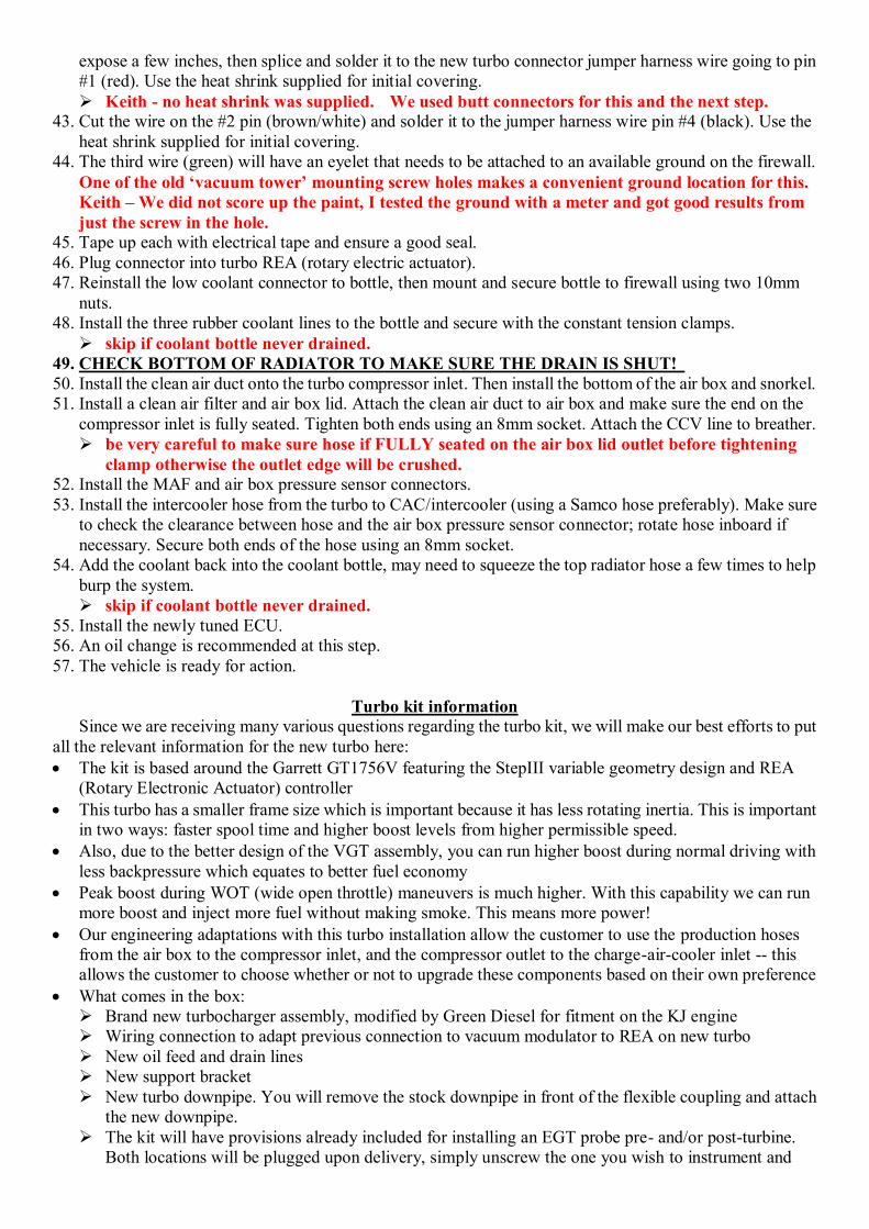
expose a few inches, then splice and solder it to the new turbo connector jumper harness wire going to pin #1 (red). Use the heat shrink supplied for initial covering. Keith - no heat shrink was supplied. We used butt connectors for this and the next step.
43. Cut the wire on the #2 pin (brown/white) and solder it to the jumper harness wire pin #4 (black). Use the heat shrink supplied for initial covering.
44. The third wire (green) will have an eyelet that needs to be attached to an available ground on the firewall. One of the old ‘vacuum tower’ mounting screw holes makes a convenient ground location for this. Keith – We did not score up the paint, I tested the ground with a meter and got good results from just the screw in the hole.
45. Tape up each with electrical tape and ensure a good seal. 46. Plug connector into turbo REA (rotary electric actuator). 47. Reinstall the low coolant connector to bottle, then mount and secure bottle to firewall using two 10mm
nuts. 48. Install the three rubber coolant lines to the bottle and secure with the constant tension clamps.
skip if coolant bottle never drained. 49. CHECK BOTTOM OF RADIATOR TO MAKE SURE THE DRAIN IS SHUT! 50. Install the clean air duct onto the turbo compressor inlet. Then install the bottom of the air box and snorkel. 51. Install a clean air filter and air box lid. Attach the clean air duct to air box and make sure the end on the
compressor inlet is fully seated. Tighten both ends using an 8mm socket. Attach the CCV line to breather. be very careful to make sure hose if FULLY seated on the air box lid outlet before tightening
clamp otherwise the outlet edge will be crushed. 52. Install the MAF and air box pressure sensor connectors. 53. Install the intercooler hose from the turbo to CAC/intercooler (using a Samco hose preferably). Make sure
to check the clearance between hose and the air box pressure sensor connector; rotate hose inboard if necessary. Secure both ends of the hose using an 8mm socket.
54. Add the coolant back into the coolant bottle, may need to squeeze the top radiator hose a few times to help burp the system. skip if coolant bottle never drained.
55. Install the newly tuned ECU. 56. An oil change is recommended at this step. 57. The vehicle is ready for action.
Turbo kit information Since we are receiving many various questions regarding the turbo kit, we will make our best efforts to put
all the relevant information for the new turbo here: The kit is based around the Garrett GT1756V featuring the StepIII variable geometry design and REA
(Rotary Electronic Actuator) controller This turbo has a smaller frame size which is important because it has less rotating inertia. This is important
in two ways: faster spool time and higher boost levels from higher permissible speed. Also, due to the better design of the VGT assembly, you can run higher boost during normal driving with
less backpressure which equates to better fuel economy Peak boost during WOT (wide open throttle) maneuvers is much higher. With this capability we can run
more boost and inject more fuel without making smoke. This means more power! Our engineering adaptations with this turbo installation allow the customer to use the production hoses
from the air box to the compressor inlet, and the compressor outlet to the charge-air-cooler inlet -- this allows the customer to choose whether or not to upgrade these components based on their own preference
What comes in the box: Brand new turbocharger assembly, modified by Green Diesel for fitment on the KJ engine Wiring connection to adapt previous connection to vacuum modulator to REA on new turbo New oil feed and drain lines New support bracket New turbo downpipe. You will remove the stock downpipe in front of the flexible coupling and attach
the new downpipe. The kit will have provisions already included for installing an EGT probe pre- and/or post-turbine.
Both locations will be plugged upon delivery, simply unscrew the one you wish to instrument and

install your thermocouple. For validation testing GDE installed the EGT probe approximately 6 inches after the turbo outlet flange in the exhaust downpipe. We also installed an EGT probe upstream of the turbo in the exhaust manifold for correlation. The temperature drop across the turbo between the two thermocouples is about 180 F (100 C) while testing peak power. For customer vehicles we recommend installing one EGT probe downstream of the turbo in the exhaust system, this is much easier to install and there is no need to worry about metal shavings with tapping the pipe. As long as the EGTs after the turbo stay below 700 C (1292 F) the system is working properly
New ECU tune (this is mandatory and is included in the price of the kit). No other tune (our Eco-tune, OEM, etc) will be compatible with this turbocharger.
Front View of the turbo assembly, with optional speed sensor installed.
Side view of the turbo assembly. Whole-system view showing the turbocharger (bolted to exhaust manifold) and downpipe placement.
Not seen is the support bracket for the turbocharger. Up-close of turbocharger compressor housing with optional speed sensor installed.
Up-close of modified turbine housing. This shows where a new flange corresponding to the KJ
manifold (cut on waterjet machine) has been tig-welded onto the housing to properly orient the turbocharger once installed on the engine. This picture does not show it, but the throat of the housing (just after the flange) will be drilled and tapped for a thermocouple probe installation (all units will be

delivered with this feature). New downpipe included with kit. The flange for attachment at the turbocharger is 5-bolts and cut on
waterjet machine. A bung has already been installed in the downpipe for thermocouple probe installation (gauges, etc) at the prescribed distance/location for proper measurement of temperatures. All piping is mandrel bent, and the end is designed for a slip fit over the stub of pipe coming out of the
flex coupling.
Turbo vane check per GDE
You can check the vane functionality at idle in park. Underneath the vacuum actuator on the
turbo is rod extending downward connected to the vane mechanism. If you pull off the vacuum
line at the turbo, the arm should drop about 1/2 inch and then raise back up after reconnecting the
vacuum line. It is a bit difficult to see the rod, but this is the easiest method to check for proper
VGT vane movement.
Turbo check
Per warp2diesel - one check is to remove the intake hose and with a clean hand washed with
detergent or soap that has no grit, grasp the turbo intake with the tip of your index finger and
thumb. A little play in the shaft is OK, but not enough to have the blades of the turbine touch the
housing. Any rub marks, you should plan on a replacement. Next check to make sure the turbine
spins freely. The final check is to make sure the veins connected to the actuator that change pitch
and give our turbo the great performance can be moved without binding. TDI forums are full of
tricks to free up the veins if they get stuck. If the veins are stuck and you free them up, you have
fixed a problem and saved yourself some cash. Dealers and Turbo rebuilders will not free up
stuck veins since they make big bucks replacing or rebuilding the turbo, some will try to scare
you into not freeing up the stuck veins. Sometimes spraying a little PB Blaster (a brand of
penetrating lube) on the part of the turbo where the actuator moves the veins is all it takes. To
protect your Turbo, install an exhaust gas temperature EGT gauge and avoid driving in ways that
will destroy the turbo like climbing steep grades pulling a heavy trailer load and using cruise
control. If I remember right, geordi installed an EGT gauge after his first turbo failure so it
would not happen again. I installed mine before I hooked up my trailer, to play it safe. I back off
if the temp hits 1250F-1300F and never let it spike over 1400F.
Browse through the TDI websites, they have lots of info on the turbos the TDIs use that are a lot
like ours, no sense repeating all that info. The vanes are on the inside of the turbo but the
actuator is on the outside of the turbo and is connected with a link. If the link moves, the veins
move too and all should be OK. If the veins don't move, the turbo performance will suck too.
Copyright © 2022 FDOKUMEN


![gfj}kj vuUr dqEHk fuf/k vf/kfu;e] 2003 - India Code](https://static.fdokumen.com/doc/165x107/63183bd571e3f2062907133f/gfjkj-vuur-dqehk-fufk-vfkfue-2003-india-code.jpg)