WIRING DIAGRAMS - Jeep Wrangler YJ Forum
348
WIRING DIAGRAMS CONTENTS page page FUSE CHARTS AND RELAY BANKS ......... 8 GENERAL INFORMATION .................. 1 SPLICE LOCATIONS ..................... 53 WIRING AND COMPONENT IDENTIFICATION . 13 WIRING DIAGRAMS XJ .................. 149 WIRING DIAGRAMS XJ RHD ............. 271 WIRING DIAGRAMS YJ .................. 73 GENERAL INFORMATION INDEX page page Circuit Identification ........................ 2 Component Identification .................... 2 Connector and Terminal Assembly Replacement ..5 Connector Replacement .................... 4 Connectors .............................. 3 Fusible Link Replacement ................... 4 Fusible Links ............................. 3 Locating A System ........................ 2 Secondary Ignition Wiring ................... 1 Splice Locations .......................... 2 Symbols, Fuses and Abbreviations ............ 6 Terminal Replacement ...................... 5 Troubleshooting Wiring Problems .............. 3 Wire Code Identification .................... 2 Wiring Diagram Sheets and Indexes ........... 1 Wiring Repair ............................ 4 The wiring diagrams contain the latest information at the time of publication. Throughout this group references may be made to a particular vehicle by letter or number designation. A chart showing the breakdown of these designations is included in the Introduction Section at the front of this service manual. SECONDARY IGNITION WIRING Secondary ignition wiring is shown in Figures 1 and 2. For additional information on ignition systems or distributor operation refer to Group 8D Ignition Systems. WIRING DIAGRAM SHEETS AND INDEXES The diagrams are organized to show the basic ve- hicle and all of its options. Add-on or non-factory op- tions are not covered. The diagram pages are identified by a sheet number which is located at the lower right or left hand corner of each sheet. Page numbers at the top of each page do not apply to diagram sheets. Diagram sheets show all information relating to the system. This includes feeds, grounds, switch in- ternal circuity, connectors, splices, and pin identifica- tion for controllers and modules. All components, switches, and relays are shown in the at rest position with the key removed from the ignition and the doors closed. In certain instances a wire may be referenced to another sheet. When this happens, the wire will be identified as to where it is going. The index used for the diagrams is located at the beginning of the section. The main system and all re- lated components are covered. Fig. 1 Secondary Ignition Wiring 2.5L J WIRING DIAGRAMS 8W - 1
-
Upload
khangminh22 -
Category
Documents
-
view
0 -
download
0
Transcript of WIRING DIAGRAMS - Jeep Wrangler YJ Forum

WIRING DIAGRAMS
CONTENTS
page page
FUSE CHARTS AND RELAY BANKS . . . . . . . . . 8GENERAL INFORMATION . . . . . . . . . . . . . . . . . . 1SPLICE LOCATIONS . . . . . . . . . . . . . . . . . . . . . 53WIRING AND COMPONENT IDENTIFICATION . 13
WIRING DIAGRAMS XJ . . . . . . . . . . . . . . . . . . 149WIRING DIAGRAMS XJ RHD . . . . . . . . . . . . . 271WIRING DIAGRAMS YJ . . . . . . . . . . . . . . . . . . 73
GENERAL INFORMATION
INDEX
page page
Circuit Identification . . . . . . . . . . . . . . . . . . . . . . . . 2Component Identification . . . . . . . . . . . . . . . . . . . . 2Connector and Terminal Assembly Replacement . . 5Connector Replacement . . . . . . . . . . . . . . . . . . . . 4Connectors . . . . . . . . . . . . . . . . . . . . . . . . . . . . . . 3Fusible Link Replacement . . . . . . . . . . . . . . . . . . . 4Fusible Links . . . . . . . . . . . . . . . . . . . . . . . . . . . . . 3Locating A System . . . . . . . . . . . . . . . . . . . . . . . . 2
Secondary Ignition Wiring . . . . . . . . . . . . . . . . . . . 1Splice Locations . . . . . . . . . . . . . . . . . . . . . . . . . . 2Symbols, Fuses and Abbreviations . . . . . . . . . . . . 6Terminal Replacement . . . . . . . . . . . . . . . . . . . . . . 5Troubleshooting Wiring Problems . . . . . . . . . . . . . . 3Wire Code Identification . . . . . . . . . . . . . . . . . . . . 2Wiring Diagram Sheets and Indexes . . . . . . . . . . . 1Wiring Repair . . . . . . . . . . . . . . . . . . . . . . . . . . . . 4
The wiring diagrams contain the latest informationat the time of publication.
Throughout this group references may be made toa particular vehicle by letter or number designation.A chart showing the breakdown of these designationsis included in the Introduction Section at the front ofthis service manual.
SECONDARY IGNITION WIRINGSecondary ignition wiring is shown in Figures 1
and 2. For additional information on ignition systemsor distributor operation refer to Group 8D IgnitionSystems.
WIRING DIAGRAM SHEETS AND INDEXESThe diagrams are organized to show the basic ve-
hicle and all of its options. Add-on or non-factory op-tions are not covered. The diagram pages areidentified by a sheet number which is located at thelower right or left hand corner of each sheet. Pagenumbers at the top of each page do not apply todiagram sheets.
Diagram sheets show all information relating tothe system. This includes feeds, grounds, switch in-ternal circuity, connectors, splices, and pin identifica-tion for controllers and modules. All components,
switches, and relays are shown in the at rest positionwith the key removed from the ignition and the doorsclosed.
In certain instances a wire may be referenced toanother sheet. When this happens, the wire will beidentified as to where it is going.
The index used for the diagrams is located at thebeginning of the section. The main system and all re-lated components are covered.
Fig. 1 Secondary Ignition Wiring 2.5L
J WIRING DIAGRAMS 8W - 1

WIRE CODE IDENTIFICATIONEach wire shown in the diagrams contains a code
(Fig. 3) which identifies the main circuit, part of themain circuit, gauge of wire, and color. The color isshown as a two letter code which can be identified byreferring to the Wire Color Code Chart (Fig. 4). If thewire has a tracer and it is a standard color an aster-isk will follow the main wire color. If the tracer isnon-standard the main wire color will have a slash (/)after it followed by the tracer color.
CIRCUIT IDENTIFICATIONAll circuits in the diagrams use an alpha/numeric
code to identify the wire and its function. To identifywhich circuit code applies to a system, refer to theCircuit Identification Code Chart. This chart showsthe main circuits only and does not show the second-ary codes that may apply to some models.
LOCATING A SYSTEMTo locate a system or component in the diagrams,
refer to the alphabetical index at the front of the di-agrams. Determine the diagram sheet number. Sheetnumbers are located at the lower right or left hand
corner of each sheet. Page numbers at the top ofthe page do not apply to diagram sheets.
The index identifies the main system and all com-ponents that relate to that system. There are alsosections of the index that identify specific compo-nents only (for example modules, lamps, etc.). Referto a components name in the index if you are unclearas to what a system may be called.
Diagram sheets are arranged starting with the bat-tery and fuses. Then working into charging, starting,and ignition systems. After this they start at thefront of the vehicle and work to rear. The diagramsend with connector identification pages.
COMPONENT IDENTIFICATIONWhen looking for a components location in the vehicle
refer to the Component Identification section index.This section shows the wire harness routing and thecomponents location in the vehicle. When using this sec-tion refer to the wiring diagrams for the general loca-tion of the component. Then use the componentidentification index to locate the proper figure number.
SPLICE LOCATIONSSplice locations are indicated in the diagrams by a
diamond with a splice circuit code within it (Fig. 5example 1). If there is more than one splice per cir-cuit a small box will be connected to it with thesplice number in it (Fig. 5 example 2).
To locate a splice in the wiring harness determinethe splice number from the wiring diagrams then re-fer to the splice location index. This section showsthe general location of the splice in the harness.
Fig. 2 Secondary Ignition Wiring 4.0L
Fig. 3 Wire Color Code Identification
Fig. 4 Wire Color Code Chart
8W - 2 WIRING DIAGRAMS J

CONNECTORSThe connectors shown in the diagram sheets are
viewed from the terminal end unless otherwise speci-fied. For viewing bulkhead, powertrain control module,and transmission control module connectors refer to therear of the wiring diagrams. This area shows major con-nectors and identifies pin and cavity information.
The connectors shown in the diagrams are identi-fied in two ways. The first is an actual view of theconnector. This view shows the connector and whichcavity the wire is in.
The second way is with the use of arrows to indicatethe connector. This is done when the connector is tolarge to be shown on the diagram page. A box placednext to the connector identifies the connector and thecavity the wire is in. In certain instances there may bemore than one connector in the same location. Whenthis happens the connector identification box will have anumber placed in it. Refer to the rear of the diagramsfor a complete pin out of the connector.
TROUBLESHOOTING WIRING PROBLEMSWhen troubleshooting wiring problems there are
six steps which can aid in the procedure. The stepsare listed and explained below.
(1) Verify the problem.(2) Verify any related symptoms. Do this by per-
forming operational checks on components that arein the same circuit as the problem area. Refer to thewiring diagrams fuse application chart for circuitidentification.
(3) Analyze the symptoms. Use the wiring dia-grams to determine what the circuit is doing, wherethe problem most likely is occurring and where thediagnosis will continue.
(4) Isolate the problem area.(5) Repair the problem.(6) Verify proper operation. For this step check for
proper operation of all items on the circuit repaired.Refer to the wiring diagram fuse application chart forcircuit identification.
FUSIBLE LINKSVehicle wiring harnesses are equipped with fusible
links to protect against harness damage in the eventof a short in the system. Fusible links are color codedto indicate wire gauge and size. Refer to the fusiblelink chart for color and gauge identification (Fig. 6).
Fig. 5 Wiring Splice Examples
Fig. 6 Fusible Link Chart
J WIRING DIAGRAMS 8W - 3

FUSIBLE LINK REPLACEMENT
CAUTION: Do not replace blown fusible links with astandard wire. Only use fusible type wire with hypa-lon insulation or damage to the electrical systemcould occur. Also make sure correct gauge of wir-ing is used. Refer to the wiring diagrams for propergauge and color.
When a fusible link blows it is important to findout what the problem is. They are placed in the elec-trical system for protection against shorts to ground.This can be caused by a component failure or variouswiring failures. Do not just replace the fusiblelink to correct the problem.
When diagnosing a faulty fusible link it is impor-tant to check the wire carefully. In some instancesthe link may be blown and it will not show throughthe insulation, the wire should be checked over itsentire length for internal breaks.
(1) Disconnect battery negative cable.(2) Cut out the blown portion of the fusible link.(3) Strip 1 inch of insulation from each end of the
existing fusible link.(4) Place a piece of heat shrink tubing over one
side of the fusible link. Make sure the tubing will belong enough to cover and seal the entire repair area.
(5) Cut a replacement piece of fusible link approx-imately two inches longer than the piece removed.
(6) Remove one inch of insulation from each end ofthe replacement fusible link.
(7) Spread the strands of wire apart on each of theexposed wires (Fig. 7 example 1).
(8) Push the two ends of the wire together untilthe strands of wire are close to the insulation (Fig. 7example 2).
(9) Twist the wires together (Fig. 7 example 3).(10) Solder the wires together using rosin core type
solder only. Do not use acid core type solder.(11) Center the heat shrink tubing over the joint
and heat using a heat gun. Heat the joint until thetubing is tightly sealed and sealant comes out of bothends of the tubing.
(12) Secure the fusible link to the existing ones toprevent chafing or damage to the insulation.
(13) Connect battery and test affected systems.
WIRING REPAIRWhen replacing or repairing a wire, it is important
that the correct gauge be used as shown in the wir-ing diagrams. The wires must also be held securelyin place to prevent damage to the insulation.
(1) Disconnect battery negative cable.(2) Remove 1 inch of insulation from each end of
the wire.(3) Place a piece of heat shrink tubing over one
side of the wire. Make sure the tubing will be longenough to cover and seal the entire repair area.
(4) Spread the strands of the wire apart on each ofthe exposed wires (Fig. 7 example 1).
(5) Push the two ends of wire together until thestrands of wire are close to the insulation (Fig. 7 ex-ample 2).
(6) Twist the wires together (Fig. 7 example 3).(7) Solder the connection together using rosin core
type solder only. Do not use acid core solder.(8) Center the heat shrink tubing over the joint
and heat using a heat gun. Heat the joint until thetubing is tightly sealed and sealant comes out of bothends of the tubing.
(9) Secure the wire to the existing ones to preventchafing or damage to the insulation.
(10) Connect battery and test affected systems.
CONNECTOR REPLACEMENT(1) Disconnect battery.(2) Disconnect the connector to be repaired from its
mating half.(3) Remove connector locking wedge (Fig. 8).(4) Position the connector locking finger away from
the terminal while pulling on the wire to remove theterminal from the connector (Fig. 9).
(5) Reset the terminal locking tang, if it has one.(6) Insert the removed wire in the same cavity on
the repair connector.(7) Repeat steps four through six for each wire in
the connector, being sure that all wires are insertedinto the proper cavities. For additional connector pinout identification refer to the wiring diagrams.
(8) Insert the connector locking wedge into the re-paired connector.
(9) Connect connector to its mating half.
Fig. 7 Wire Repair
8W - 4 WIRING DIAGRAMS J

(10) Connect battery and test affected systems.
CONNECTOR AND TERMINAL ASSEMBLYREPLACEMENT
(1) Disconnect Battery.(2) Disconnect the connector being repaired from
its mating half.(3) Cut off the existing wire connector directly be-
hind the insulator and remove six inches of tape fromthe harness.
(4) Stagger cut all wires on the harness side about1/2 inch apart (Fig. 10).
(5) Remove 1 inch of insulation from each wire onthe harness side.
(6) Stagger cut the matching wires on the repairconnector assembly in the opposite order as was doneon the harness side of the repair (allow extra lengthfor soldered connections). Check that the overalllength is the same as the original (Fig. 10).
(7) Remove 1 inch of insulation from each wire.
(8) Place a piece of heat shrink tubing over oneside of the wire. Make sure the tubing will be longenough to cover and seal the entire repair area.
(9) Spread the strands of the wire apart on each ofthe exposed wires (Fig. 7 example 1).
(10) Push the two ends of wire together until thestrands of wire are close to the insulation (Fig. 7 ex-ample 2).
(11) Twist the wires together (Fig. 7 example 3).(12) Solder the connection together using rosin
core type solder only. Do not use acid core solder.(13) Center the heat shrink tubing over the joint
and heat using a heat gun. Heat the joint until thetubing is tightly sealed and sealant comes out of bothends of the tubing.
(14) Repeat steps 8 through 13 for each wire.(15) Re-tape the wire harness starting 1-1/2 inches
behind the connector and 2 inches past the repair.(16) Reconnect the repaired connector.(17) Connect battery and test affected systems.
TERMINAL REPLACEMENT(1) Disconnect battery.(2) Disconnect the connector being repaired from
its mating half.(3) Remove connector locking wedge (Fig. 8).(4) Position the connector locking finger away from
the terminal while pulling on the wire to remove theterminal from the connector (Fig. 9).
(5) Cut the wire 6 inches from the back of the con-nector.
(6) Remove 1 inch of insulation from the wire onthe harness side.
(7) Select a wire from the terminal repair assemblythat best matches the color wire being repaired.
(8) Cut the repair wire to the proper length and re-move 1 inch of insulation.
(9) Place a piece of heat shrink tubing over oneside of the wire. Make sure the tubing will be longenough to cover and seal the entire repair area.
Fig. 8 Connector Locking Wedge Tab (Typical)
Fig. 9 Connector Locking Finger and LockingWedge (Typical)
Fig. 10 Stagger Cutting Wires
J WIRING DIAGRAMS 8W - 5

(10) Spread the strands of the wire apart on eachof the exposed wires (Fig. 7 example 1).
(11) Push the two ends of wire together until thestrands of wire are close to the insulation (Fig. 7 ex-ample 2).
(12) Twist the wires together (Fig. 7 example 3).(13) Solder the connection together using rosin
core type solder only. Do not use acid core solder.(14) Center the heat shrink tubing over the joint
and heat using a heat gun. Heat the joint until thetubing is tightly sealed and sealant comes out of bothends of the tubing.
(15) Insert the repaired wire into the connector.(16) Install the connector locking wedge and recon-
nect the connector to its mating half.(17) Re-tape the wire harness starting 1-1/2 inches
behind the connector and 2 inches past the repair.
(18) Connect battery and test affected systems.
SYMBOLS, FUSES AND ABBREVIATIONSVarious symbols are used throughout the wiring di-
agrams. These symbols can be identified by referringto the symbol identification chart (Fig. 11).
Certain abbreviations are also used in the dia-grams. These have been developed in such a waythat there meaning should be clear. For fuse block,relay bank, and power distribution center informa-tion refer to the fuse charts and relay bank index.
CAUTION: When replacing a blown fuse it is impor-tant to replace it with a fuse having the correct am-perage rating. The use of a fuse with a rating otherthan indicated may result in an electrical overload.If a proper rated fuse continues to blow, it indicatesa problem that should be corrected.
8W - 6 WIRING DIAGRAMS J

Fig. 11 Symbol Identification
J WIRING DIAGRAMS 8W - 7

FUSE CHARTS AND RELAY BANKS
INDEX
Fig. Fig.
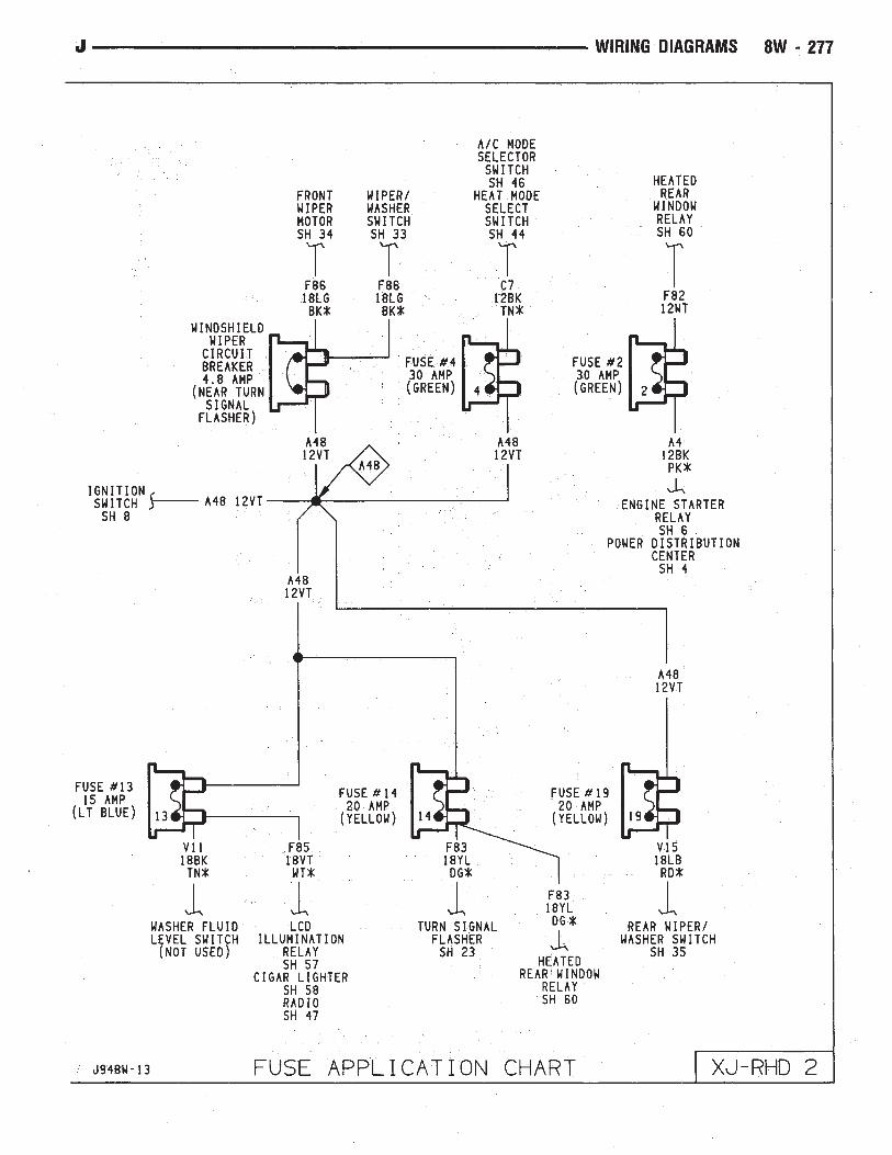
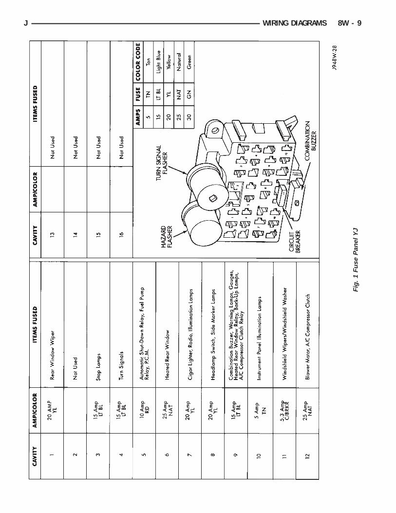
Fuse Panel XJ . . . . . . . . . . . . . . . . . . . . . . . . . . . 2Fuse Panel YJ . . . . . . . . . . . . . . . . . . . . . . . . . . . 1
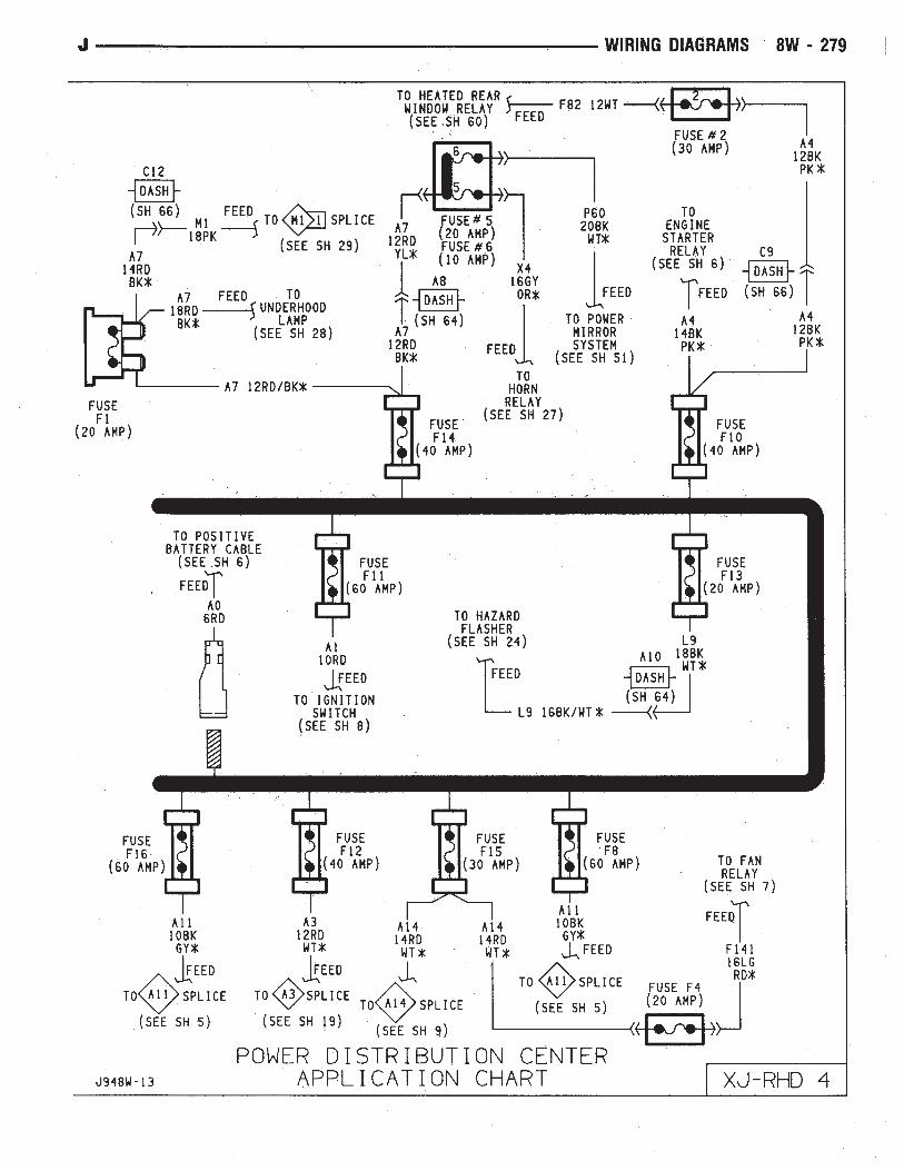
Power Distribution Center YJ . . . . . . . . . . . . . . . . . 3Power Distribution Center XJ . . . . . . . . . . . . . . . . . 4
8W - 8 WIRING DIAGRAMS J
Fig
.1
Fus
eP
anel
YJ
J WIRING DIAGRAMS 8W - 9

Fig
.2
Fus
eP
anel
XJ
8W - 10 WIRING DIAGRAMS J

Fig. 3 Power Distribution Center YJ
Fig. 4 Power Distribution Center XJ
J WIRING DIAGRAMS 8W - 11

8W - 12 WIRING DIAGRAMS J

WIRING AND COMPONENT IDENTIFICATION
CONTENTS
page page
XJ . . . . . . . . . . . . . . . . . . . . . . . . . . . . . . . . . . . 25XJ RHD . . . . . . . . . . . . . . . . . . . . . . . . . . . . . . . 43
YJ . . . . . . . . . . . . . . . . . . . . . . . . . . . . . . . . . . . 13
The wiring and components shown in this sectionare divided into sections by vehicle line. When locat-ing a specific wire routing or component, first turn tothe appropriate index, then look up the figure num-ber that refers to the component. Page numbers atthe top of the page do not refer to figure num-bers.
YJ
Caption Fig.Battery and Starter Wiring . . . . . . . . . . . . . . . . . . . . . . .8Body Wiring . . . . . . . . . . . . . . . . . . . . . . . . . . . . . . .1, 2Chassis Wiring . . . . . . . . . . . . . . . . . . . . . . . . . . . . . . .3Engine Compartment Wiring . . . . . . . . . . . . . . . . . . . . . .7Engine Wiring 2.5L . . . . . . . . . . . . . . . . . . . . . . . . . . .10
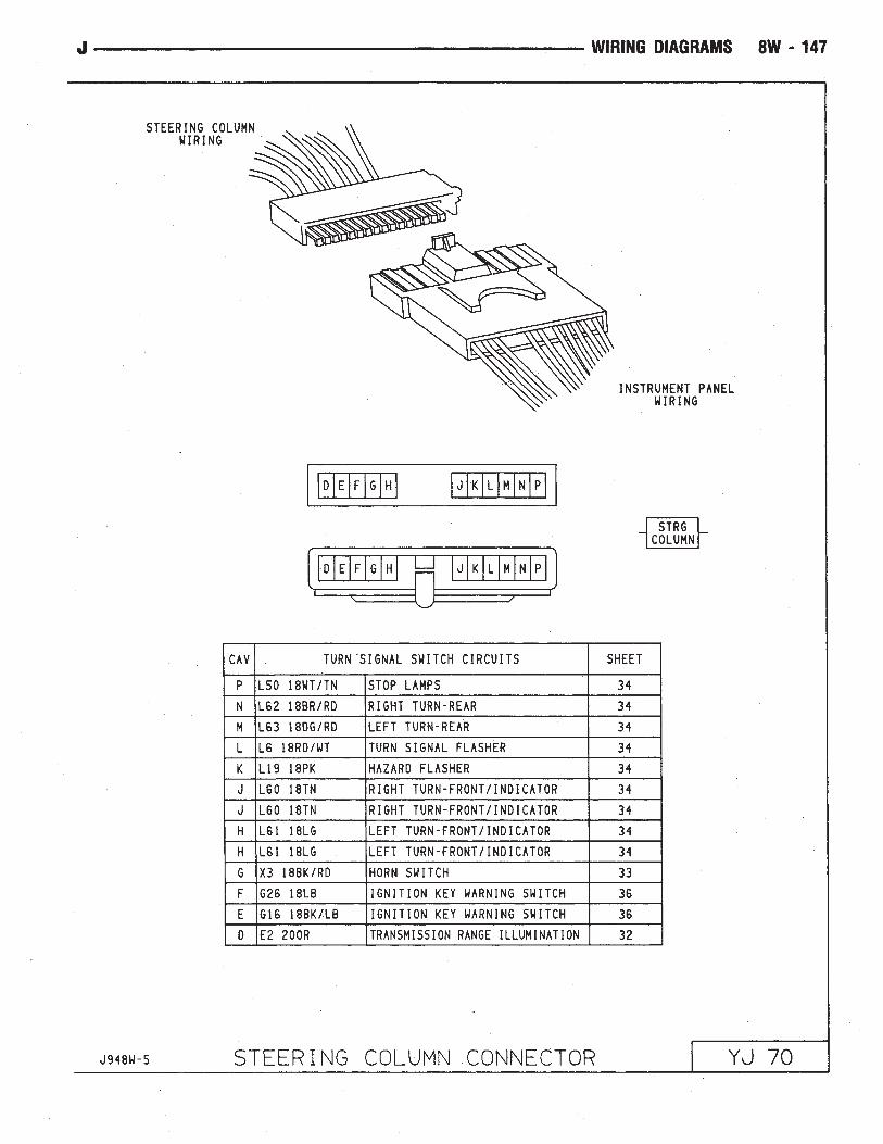
Caption Fig.Engine Wiring 4.0L . . . . . . . . . . . . . . . . . . . . . . . . . . .11Front End Wiring . . . . . . . . . . . . . . . . . . . . . . . . . . . . .12Instrument Panel Wiring . . . . . . . . . . . . . . . . . . . . . . .5, 6Steering Column Wiring . . . . . . . . . . . . . . . . . . . . . . . . .4Transmission Wiring . . . . . . . . . . . . . . . . . . . . . . . . . . .9
J WIRING AND COMPONENT IDENTIFICATION 8W - 13

Fig
.1
Bod
yW
iring
YJ
8W - 14 WIRING AND COMPONENT IDENTIFICATION J

Fig
.2
Bod
yW
iring
YJ
J WIRING AND COMPONENT IDENTIFICATION 8W - 15

Fig. 3 Chassis Wiring YJ
Fig. 4 Steering Column Wiring YJ
8W - 16 WIRING AND COMPONENT IDENTIFICATION J

Fig
.5
Inst
rum
ent
Pan
elW
iring
YJ
J WIRING AND COMPONENT IDENTIFICATION 8W - 17

Fig
.6
Inst
rum
ent
Pan
elW
iring
YJ
8W - 18 WIRING AND COMPONENT IDENTIFICATION J

Fig
.7
Eng
ine
Com
part
men
tW
iring
YJ
J WIRING AND COMPONENT IDENTIFICATION 8W - 19
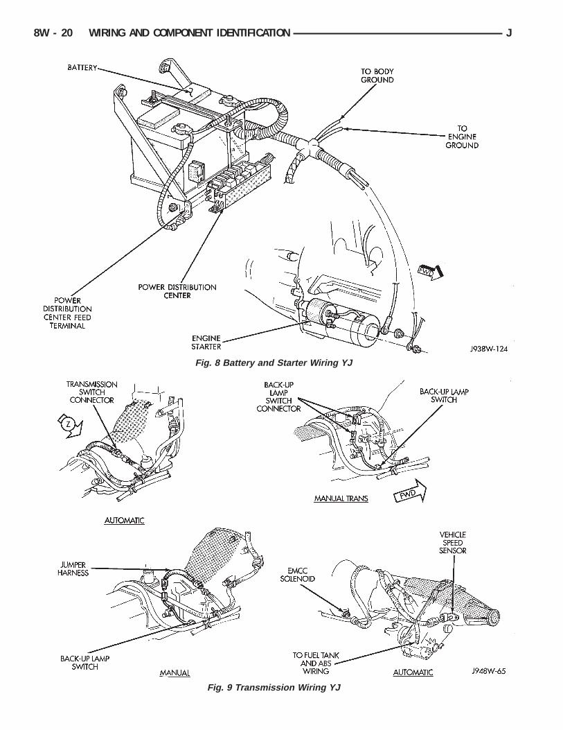
Fig. 8 Battery and Starter Wiring YJ
Fig. 9 Transmission Wiring YJ
8W - 20 WIRING AND COMPONENT IDENTIFICATION J
Fig
.10
Eng
ine
Wiri
ng2.
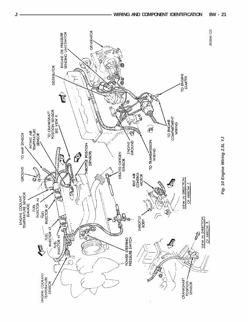
5LY
J
J WIRING AND COMPONENT IDENTIFICATION 8W - 21

Fig
.11
Eng
ine
Wiri
ng4.
0LY
J
8W - 22 WIRING AND COMPONENT IDENTIFICATION J

Fig
.12
Fro
ntE
ndW
iring
YJ
J WIRING AND COMPONENT IDENTIFICATION 8W - 23

8W - 24 WIRING AND COMPONENT IDENTIFICATION J

XJ
Caption Fig.Anti-Lock Brake System Wiring XJ . . . . . . . . . . . . . . . . . .3Body Wiring XJ . . . . . . . . . . . . . . . . . . . . . . . . . . . .7, 8Door Wiring (Front) XJ . . . . . . . . . . . . . . . . . . . . . . . . .11Engine Compartment Wiring 2.5L XJ . . . . . . . . . . . . . . . .17Engine Compartment Wiring 4.0L XJ . . . . . . . . . . . . .18, 19Engine Wiring 2.5L XJ . . . . . . . . . . . . . . . . . . . . . . . . .21Engine Wiring 4.0L XJ . . . . . . . . . . . . . . . . . . . . . . . . .22Front Cross-body Wiring XJ . . . . . . . . . . . . . . . . . . . . . .4Front End Wiring XJ . . . . . . . . . . . . . . . . . . . . . . . . . .16Instrument Panel to Body Wiring XJ . . . . . . . . . . . . . . . .14
Caption Fig.Instrument Panel Wiring XJ . . . . . . . . . . . . . . . . . . .12, 13Liftgate Wiring XJ . . . . . . . . . . . . . . . . . . . . . . . . . . . . .1Power Seat Wiring XJ . . . . . . . . . . . . . . . . . . . . . . . . .15Rear Door Wiring XJ . . . . . . . . . . . . . . . . . . . . . . . . . . .6Roof Wiring (Rear) XJ . . . . . . . . . . . . . . . . . . . . . . . . . .9Roof Wiring XJ . . . . . . . . . . . . . . . . . . . . . . . . . . . . . .5Steering Column Wiring XJ . . . . . . . . . . . . . . . . . . . . . .10Trailer Tow Wiring XJ . . . . . . . . . . . . . . . . . . . . . . . . . .2Transmission Wiring XJ . . . . . . . . . . . . . . . . . . . . . . . .20
J WIRING AND COMPONENT IDENTIFICATION 8W - 25

Fig. 1 Liftgate Wiring XJ
Fig. 2 Trailer Tow Wiring XJ
8W - 26 WIRING AND COMPONENT IDENTIFICATION J

Fig. 3 Anti-Lock Brake System Wiring XJ
Fig. 4 Front Cross-body Wiring XJ
J WIRING AND COMPONENT IDENTIFICATION 8W - 27

Fig
.5
Roo
fW
iring
XJ
8W - 28 WIRING AND COMPONENT IDENTIFICATION J

Fig
.6
Rea
rD
oor
Wiri
ngX
J
J WIRING AND COMPONENT IDENTIFICATION 8W - 29
Fig
.7
Bod
yW
iring
XJ
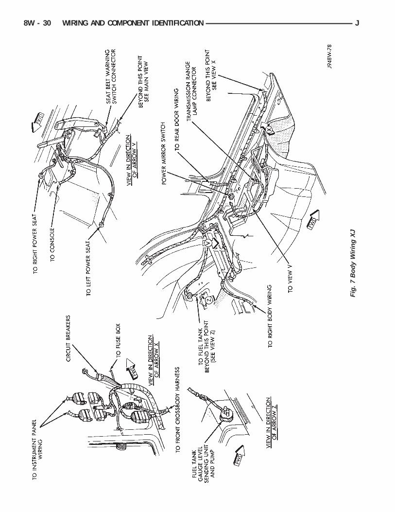
8W - 30 WIRING AND COMPONENT IDENTIFICATION J
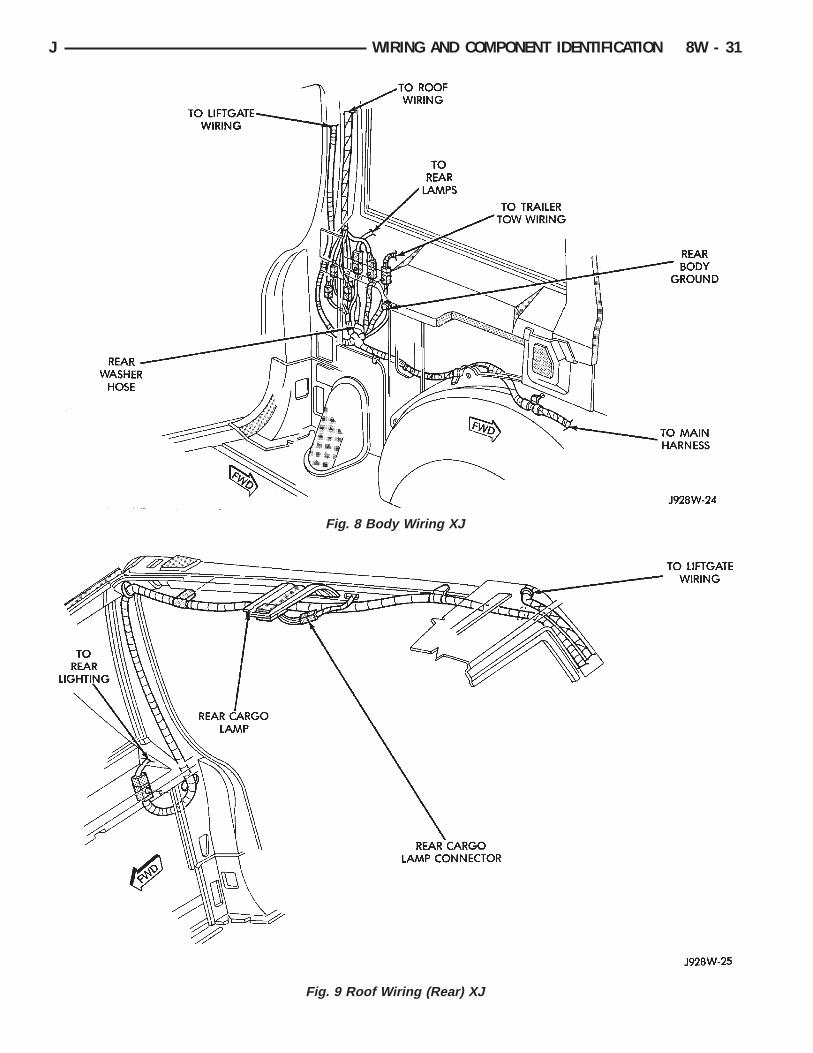
Fig. 8 Body Wiring XJ
Fig. 9 Roof Wiring (Rear) XJ
J WIRING AND COMPONENT IDENTIFICATION 8W - 31

Fig. 10 Steering Column Wiring XJ
Fig. 11 Door Wiring (Front) XJ
8W - 32 WIRING AND COMPONENT IDENTIFICATION J

Fig
.12
Inst
rum
ent
Pan
elW
iring
XJ
J WIRING AND COMPONENT IDENTIFICATION 8W - 33
Fig
.13
Inst
rum
ent
Pan
elW
iring
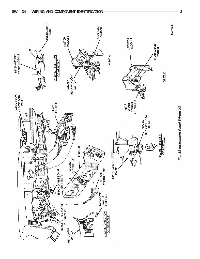
XJ
8W - 34 WIRING AND COMPONENT IDENTIFICATION J

Fig
.14
Inst
rum
ent
Pan
elto
Bod
yW
iring
XJ
J WIRING AND COMPONENT IDENTIFICATION 8W - 35

Fig. 15 Power Seat Wiring XJ
Fig. 16 Front End Wiring XJ
8W - 36 WIRING AND COMPONENT IDENTIFICATION J
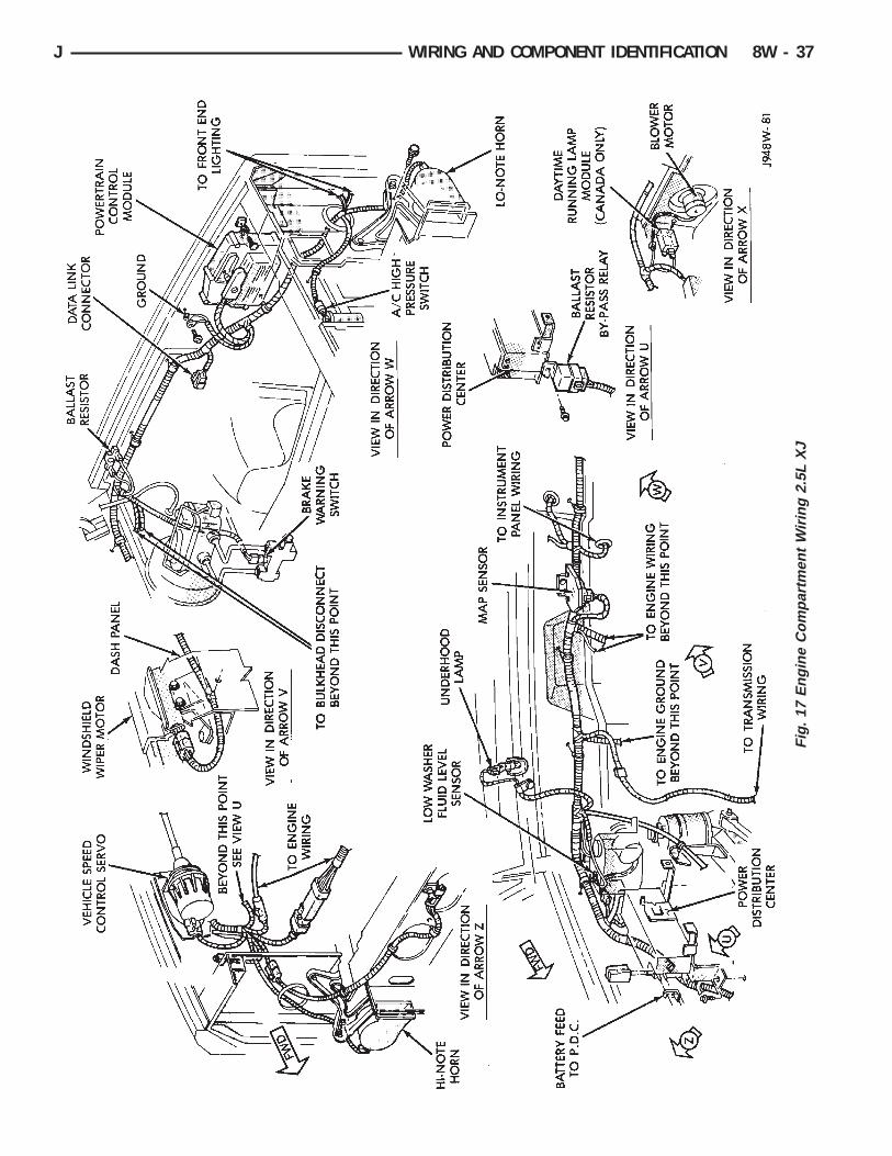
Fig
.17
Eng
ine
Com
part
men
tW
iring
2.5L
XJ
J WIRING AND COMPONENT IDENTIFICATION 8W - 37

Fig
.18
Eng
ine
Com
part
men
tW
iring
4.0L
XJ
8W - 38 WIRING AND COMPONENT IDENTIFICATION J

Fig
.19
Eng
ine
Com
part
men
tW
iring
4.0L
XJ
J WIRING AND COMPONENT IDENTIFICATION 8W - 39

Fig
.20
Tran
smis
sion
Wiri
ngX
J
8W - 40 WIRING AND COMPONENT IDENTIFICATION J

Fig
.21
Eng
ine
Wiri
ng2.
5LX
J
J WIRING AND COMPONENT IDENTIFICATION 8W - 41
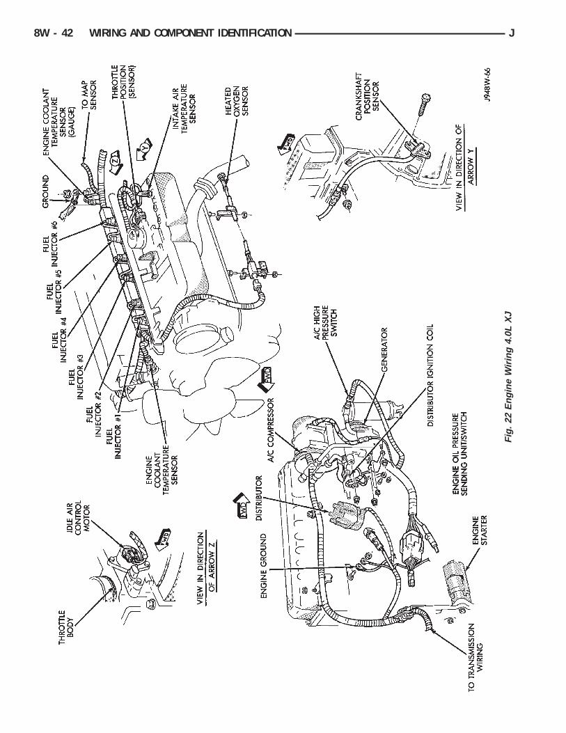
Fig
.22
Eng
ine
Wiri
ng4.
0LX
J
8W - 42 WIRING AND COMPONENT IDENTIFICATION J

XJ RHD
Caption Fig.Body Wiring . . . . . . . . . . . . . . . . . . . . . . . . . . . . . . . .3Door Wiring . . . . . . . . . . . . . . . . . . . . . . . . . . . . . . . . .5Engine Compartment Wiring . . . . . . . . . . . . . . . . . . . .9, 10Engine Wiring 4.0L . . . . . . . . . . . . . . . . . . . . . . . . . . .11Front End Wiring . . . . . . . . . . . . . . . . . . . . . . . . . . . . .8
Caption Fig.Instrument Panel Wiring-Connections . . . . . . . . . . . . . . . .7Instrument Panel Wiring-Routing . . . . . . . . . . . . . . . . . . .6Liftgate Wiring . . . . . . . . . . . . . . . . . . . . . . . . . . . . . . .1Roof Wiring (Rear) . . . . . . . . . . . . . . . . . . . . . . . . . . . .2Steering Column Wiring . . . . . . . . . . . . . . . . . . . . . . . . .4
J WIRING AND COMPONENT IDENTIFICATION 8W - 43

Fig. 1 Liftgate Wiring (RHD)
Fig. 2 Roof Wiring (Rear) (RHD)
8W - 44 WIRING AND COMPONENT IDENTIFICATION J

Fig
.3
Bod
yW
iring
(RH
D)
J WIRING AND COMPONENT IDENTIFICATION 8W - 45

Fig. 4 Steering Column Wiring (RHD)
Fig. 5 Door Wiring (RHD)
8W - 46 WIRING AND COMPONENT IDENTIFICATION J
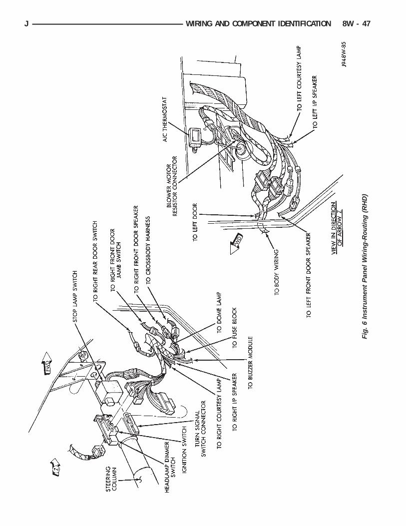
Fig
.6
Inst
rum
ent
Pan
elW
iring
-Rou
ting
(RH
D)
J WIRING AND COMPONENT IDENTIFICATION 8W - 47

Fig. 7 Instrument Panel Wiring-Connections (RHD)
Fig. 8 Front End Wiring (RHD)
8W - 48 WIRING AND COMPONENT IDENTIFICATION J

Fig
.9
Eng
ine
Com
part
men
tW
iring
(RH
D)
J WIRING AND COMPONENT IDENTIFICATION 8W - 49

Fig
.10
Eng
ine
Com
part
men
tW
iring
(RH
D)
8W - 50 WIRING AND COMPONENT IDENTIFICATION J

Fig
.11
Eng
ine
Wiri
ng4.
0L(R
HD
)
J WIRING AND COMPONENT IDENTIFICATION 8W - 51

8W - 52 WIRING AND COMPONENT IDENTIFICATION J

SPLICE LOCATIONS
CONTENTS
page page
XJ SPLICE LOCATIONS . . . . . . . . . . . . . . . . . . . 59XJ RHD SPLICE LOCATIONS . . . . . . . . . . . . . . 67
YJ SPLICE LOCATIONS . . . . . . . . . . . . . . . . . . . 53
The splice locations shown in this section are di-vided into sections by vehicle line. When locating aspecific splice first, turn to the appropriate index,then look up the figure number that refers to thesplice. Page numbers at the top of the page donot refer to figure numbers.
YJ SPLICE LOCATIONS
Splice Number Fig.A6 . . . . . . . . . . . . . . . . . . . . . . . . . . . . . . . . . . . . . . .2A11 . . . . . . . . . . . . . . . . . . . . . . . . . . . . . . . . . . . . . .4A142 . . . . . . . . . . . . . . . . . . . . . . . . . . . . . . . . . . . . .3A142-1 . . . . . . . . . . . . . . . . . . . . . . . . . . . . . . . . . . . .3B15 . . . . . . . . . . . . . . . . . . . . . . . . . . . . . . . . . . . . . .4E2 . . . . . . . . . . . . . . . . . . . . . . . . . . . . . . . . . . . . . . .2F15 . . . . . . . . . . . . . . . . . . . . . . . . . . . . . . . . . . . . . .4F30 . . . . . . . . . . . . . . . . . . . . . . . . . . . . . . . . . . . . . .2G5 . . . . . . . . . . . . . . . . . . . . . . . . . . . . . . . . . . . . . . .2G7 . . . . . . . . . . . . . . . . . . . . . . . . . . . . . . . . . . . . . . .3G19 . . . . . . . . . . . . . . . . . . . . . . . . . . . . . . . . . . . . . .4G50 . . . . . . . . . . . . . . . . . . . . . . . . . . . . . . . . . . . . . .4K4 . . . . . . . . . . . . . . . . . . . . . . . . . . . . . . . . . . . . . . .3K4-1 . . . . . . . . . . . . . . . . . . . . . . . . . . . . . . . . . . . . .3K6 . . . . . . . . . . . . . . . . . . . . . . . . . . . . . . . . . . . . . . .3K7 . . . . . . . . . . . . . . . . . . . . . . . . . . . . . . . . . . . . . . .3L1 . . . . . . . . . . . . . . . . . . . . . . . . . . . . . . . . . . . . . . .1L3 Canada Only . . . . . . . . . . . . . . . . . . . . . . . . . . . . . .5L4 Canada Only . . . . . . . . . . . . . . . . . . . . . . . . . . . . . .6L7 . . . . . . . . . . . . . . . . . . . . . . . . . . . . . . . . . . . . . . .2
Splice Number Fig.L7-1 . . . . . . . . . . . . . . . . . . . . . . . . . . . . . . . . . . . . . .5L7-2 . . . . . . . . . . . . . . . . . . . . . . . . . . . . . . . . . . . . . .1L39 . . . . . . . . . . . . . . . . . . . . . . . . . . . . . . . . . . . . . .6L39-1 . . . . . . . . . . . . . . . . . . . . . . . . . . . . . . . . . . . . .2M1 . . . . . . . . . . . . . . . . . . . . . . . . . . . . . . . . . . . . . .2M1-1 . . . . . . . . . . . . . . . . . . . . . . . . . . . . . . . . . . . . .4M2 . . . . . . . . . . . . . . . . . . . . . . . . . . . . . . . . . . . . . .2Z1 . . . . . . . . . . . . . . . . . . . . . . . . . . . . . . . . . . . . . . .2Z1-2 . . . . . . . . . . . . . . . . . . . . . . . . . . . . . . . . . . . . . .2Z1-3 . . . . . . . . . . . . . . . . . . . . . . . . . . . . . . . . . . . . . .2Z1-4 . . . . . . . . . . . . . . . . . . . . . . . . . . . . . . . . . . . . . .1Z1-5 . . . . . . . . . . . . . . . . . . . . . . . . . . . . . . . . . . . . . .1Z1-6 . . . . . . . . . . . . . . . . . . . . . . . . . . . . . . . . . . . . . .1Z1-7 . . . . . . . . . . . . . . . . . . . . . . . . . . . . . . . . . . . . . .3Z1-8 . . . . . . . . . . . . . . . . . . . . . . . . . . . . . . . . . . . . . .4Z1-9 . . . . . . . . . . . . . . . . . . . . . . . . . . . . . . . . . . . . . .5Z1-10 . . . . . . . . . . . . . . . . . . . . . . . . . . . . . . . . . . . . .5Z2 . . . . . . . . . . . . . . . . . . . . . . . . . . . . . . . . . . . . . . .3Z12 . . . . . . . . . . . . . . . . . . . . . . . . . . . . . . . . . . . . . .4
J SPLICE LOCATIONS 8W - 53

Fig. 1 Body Splices YJ
Fig. 2 Instrument Panel Splices YJ
8W - 54 SPLICE LOCATIONS J

Fig
.3
Eng
ine
Wiri
ngS
plic
esY
J
J SPLICE LOCATIONS 8W - 55

Fig. 4 Dash Panel Splices YJ
Fig. 5 Front End Splices YJ
8W - 56 SPLICE LOCATIONS J

Fig. 6 Front End Splices YJ
J SPLICE LOCATIONS 8W - 57

8W - 58 SPLICE LOCATIONS J
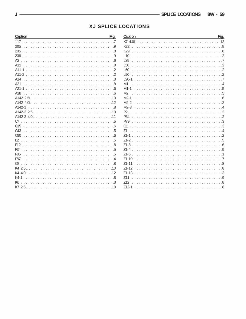
XJ SPLICE LOCATIONS
Caption Fig.117 . . . . . . . . . . . . . . . . . . . . . . . . . . . . . . . . . . . . . .7205 . . . . . . . . . . . . . . . . . . . . . . . . . . . . . . . . . . . . . .9235 . . . . . . . . . . . . . . . . . . . . . . . . . . . . . . . . . . . . . .8236 . . . . . . . . . . . . . . . . . . . . . . . . . . . . . . . . . . . . . .9A3 . . . . . . . . . . . . . . . . . . . . . . . . . . . . . . . . . . . . . . .6A11 . . . . . . . . . . . . . . . . . . . . . . . . . . . . . . . . . . . . . .8A11-1 . . . . . . . . . . . . . . . . . . . . . . . . . . . . . . . . . . . . .2A11-2 . . . . . . . . . . . . . . . . . . . . . . . . . . . . . . . . . . . . .2A14 . . . . . . . . . . . . . . . . . . . . . . . . . . . . . . . . . . . . . .8A21 . . . . . . . . . . . . . . . . . . . . . . . . . . . . . . . . . . . . . .8A21-1 . . . . . . . . . . . . . . . . . . . . . . . . . . . . . . . . . . . . .6A38 . . . . . . . . . . . . . . . . . . . . . . . . . . . . . . . . . . . . . .6A142 2.5L . . . . . . . . . . . . . . . . . . . . . . . . . . . . . . . . .10A142 4.0L . . . . . . . . . . . . . . . . . . . . . . . . . . . . . . . . .12A142-1 . . . . . . . . . . . . . . . . . . . . . . . . . . . . . . . . . . . .8A142-2 2.5L . . . . . . . . . . . . . . . . . . . . . . . . . . . . . . . .10A142-2 4.0L . . . . . . . . . . . . . . . . . . . . . . . . . . . . . . . .11C7 . . . . . . . . . . . . . . . . . . . . . . . . . . . . . . . . . . . . . . .5C15 . . . . . . . . . . . . . . . . . . . . . . . . . . . . . . . . . . . . . .6C43 . . . . . . . . . . . . . . . . . . . . . . . . . . . . . . . . . . . . . .5C90 . . . . . . . . . . . . . . . . . . . . . . . . . . . . . . . . . . . . . .6E2 . . . . . . . . . . . . . . . . . . . . . . . . . . . . . . . . . . . . . . .5F12 . . . . . . . . . . . . . . . . . . . . . . . . . . . . . . . . . . . . . .8F34 . . . . . . . . . . . . . . . . . . . . . . . . . . . . . . . . . . . . . .5F85 . . . . . . . . . . . . . . . . . . . . . . . . . . . . . . . . . . . . . .5F87 . . . . . . . . . . . . . . . . . . . . . . . . . . . . . . . . . . . . . .4G7 . . . . . . . . . . . . . . . . . . . . . . . . . . . . . . . . . . . . . . .8K4 2.5L . . . . . . . . . . . . . . . . . . . . . . . . . . . . . . . . . . .10K4 4.0L . . . . . . . . . . . . . . . . . . . . . . . . . . . . . . . . . . .12K4-1 . . . . . . . . . . . . . . . . . . . . . . . . . . . . . . . . . . . . .8K6 . . . . . . . . . . . . . . . . . . . . . . . . . . . . . . . . . . . . . . .8K7 2.5L . . . . . . . . . . . . . . . . . . . . . . . . . . . . . . . . . . .10
Caption Fig.K7 4.0L . . . . . . . . . . . . . . . . . . . . . . . . . . . . . . . . . . .12K22 . . . . . . . . . . . . . . . . . . . . . . . . . . . . . . . . . . . . . .8K29 . . . . . . . . . . . . . . . . . . . . . . . . . . . . . . . . . . . . . .8L10 . . . . . . . . . . . . . . . . . . . . . . . . . . . . . . . . . . . . . .2L39 . . . . . . . . . . . . . . . . . . . . . . . . . . . . . . . . . . . . . .7L50 . . . . . . . . . . . . . . . . . . . . . . . . . . . . . . . . . . . . . .2L60 . . . . . . . . . . . . . . . . . . . . . . . . . . . . . . . . . . . . . .2L90 . . . . . . . . . . . . . . . . . . . . . . . . . . . . . . . . . . . . . .2L90-1 . . . . . . . . . . . . . . . . . . . . . . . . . . . . . . . . . . . . .7M1 . . . . . . . . . . . . . . . . . . . . . . . . . . . . . . . . . . . . . .4M1-1 . . . . . . . . . . . . . . . . . . . . . . . . . . . . . . . . . . . . .5M2 . . . . . . . . . . . . . . . . . . . . . . . . . . . . . . . . . . . . . .5M2-1 . . . . . . . . . . . . . . . . . . . . . . . . . . . . . . . . . . . . .6M2-2 . . . . . . . . . . . . . . . . . . . . . . . . . . . . . . . . . . . . .2M2-3 . . . . . . . . . . . . . . . . . . . . . . . . . . . . . . . . . . . . .4P2 . . . . . . . . . . . . . . . . . . . . . . . . . . . . . . . . . . . . . . .2P34 . . . . . . . . . . . . . . . . . . . . . . . . . . . . . . . . . . . . . .2P79 . . . . . . . . . . . . . . . . . . . . . . . . . . . . . . . . . . . . . .3Q1 . . . . . . . . . . . . . . . . . . . . . . . . . . . . . . . . . . . . . . .3Z1 . . . . . . . . . . . . . . . . . . . . . . . . . . . . . . . . . . . . . . .4Z1-1 . . . . . . . . . . . . . . . . . . . . . . . . . . . . . . . . . . . . . .2Z1-2 . . . . . . . . . . . . . . . . . . . . . . . . . . . . . . . . . . . . . .5Z1-3 . . . . . . . . . . . . . . . . . . . . . . . . . . . . . . . . . . . . . .6Z1-4 . . . . . . . . . . . . . . . . . . . . . . . . . . . . . . . . . . . . . .9Z1-5 . . . . . . . . . . . . . . . . . . . . . . . . . . . . . . . . . . . . . .1Z1-10 . . . . . . . . . . . . . . . . . . . . . . . . . . . . . . . . . . . . .7Z1-11 . . . . . . . . . . . . . . . . . . . . . . . . . . . . . . . . . . . . .8Z1-12 . . . . . . . . . . . . . . . . . . . . . . . . . . . . . . . . . . . . .8Z1-13 . . . . . . . . . . . . . . . . . . . . . . . . . . . . . . . . . . . . .3Z11 . . . . . . . . . . . . . . . . . . . . . . . . . . . . . . . . . . . . . .9Z12 . . . . . . . . . . . . . . . . . . . . . . . . . . . . . . . . . . . . . .8Z12-1 . . . . . . . . . . . . . . . . . . . . . . . . . . . . . . . . . . . . .8
J SPLICE LOCATIONS 8W - 59

Fig. 1 Liftgate Splices XJ
Fig. 2 Body Splices XJ
8W - 60 SPLICE LOCATIONS J

Fig. 3 Cross-body Splices XJ
Fig. 4 Roof Splices XJ
J SPLICE LOCATIONS 8W - 61

Fig. 5 Instrument Panel Splices XJ
Fig. 6 Instrument Panel Splices XJ
8W - 62 SPLICE LOCATIONS J

Fig. 7 Front End Splices XJ
Fig. 8 Engine Compartment Splices XJ
J SPLICE LOCATIONS 8W - 63

Fig. 9 Engine Compartment Splices XJ
Fig. 10 Engine Splices 2.5L XJ
8W - 64 SPLICE LOCATIONS J

Fig. 11 Engine Splices 4.0L XJ
Fig. 12 Engine Splices 4.0L XJ
J SPLICE LOCATIONS 8W - 65

8W - 66 SPLICE LOCATIONS J
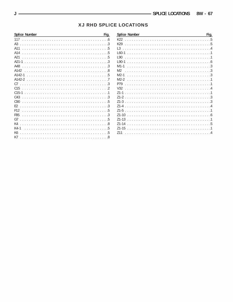
XJ RHD SPLICE LOCATIONS
Splice Number Fig.117 . . . . . . . . . . . . . . . . . . . . . . . . . . . . . . . . . . . . . .6A3 . . . . . . . . . . . . . . . . . . . . . . . . . . . . . . . . . . . . . . .3A11 . . . . . . . . . . . . . . . . . . . . . . . . . . . . . . . . . . . . . .5A14 . . . . . . . . . . . . . . . . . . . . . . . . . . . . . . . . . . . . . .5A21 . . . . . . . . . . . . . . . . . . . . . . . . . . . . . . . . . . . . . .5A21-1 . . . . . . . . . . . . . . . . . . . . . . . . . . . . . . . . . . . . .3A48 . . . . . . . . . . . . . . . . . . . . . . . . . . . . . . . . . . . . . .3A142 . . . . . . . . . . . . . . . . . . . . . . . . . . . . . . . . . . . . .8A142-1 . . . . . . . . . . . . . . . . . . . . . . . . . . . . . . . . . . . .5A142-2 . . . . . . . . . . . . . . . . . . . . . . . . . . . . . . . . . . . .7C7 . . . . . . . . . . . . . . . . . . . . . . . . . . . . . . . . . . . . . . .3C15 . . . . . . . . . . . . . . . . . . . . . . . . . . . . . . . . . . . . . .2C15-1 . . . . . . . . . . . . . . . . . . . . . . . . . . . . . . . . . . . . .1C43 . . . . . . . . . . . . . . . . . . . . . . . . . . . . . . . . . . . . . .3C90 . . . . . . . . . . . . . . . . . . . . . . . . . . . . . . . . . . . . . .5E2 . . . . . . . . . . . . . . . . . . . . . . . . . . . . . . . . . . . . . . .3F12 . . . . . . . . . . . . . . . . . . . . . . . . . . . . . . . . . . . . . .5F85 . . . . . . . . . . . . . . . . . . . . . . . . . . . . . . . . . . . . . .3G7 . . . . . . . . . . . . . . . . . . . . . . . . . . . . . . . . . . . . . . .5K4 . . . . . . . . . . . . . . . . . . . . . . . . . . . . . . . . . . . . . . .8K4-1 . . . . . . . . . . . . . . . . . . . . . . . . . . . . . . . . . . . . .5K6 . . . . . . . . . . . . . . . . . . . . . . . . . . . . . . . . . . . . . . .5K7 . . . . . . . . . . . . . . . . . . . . . . . . . . . . . . . . . . . . . . .8
Splice Number Fig.K22 . . . . . . . . . . . . . . . . . . . . . . . . . . . . . . . . . . . . . .5K29 . . . . . . . . . . . . . . . . . . . . . . . . . . . . . . . . . . . . . .5L3 . . . . . . . . . . . . . . . . . . . . . . . . . . . . . . . . . . . . . . .4L60-1 . . . . . . . . . . . . . . . . . . . . . . . . . . . . . . . . . . . . .1L90 . . . . . . . . . . . . . . . . . . . . . . . . . . . . . . . . . . . . . .1L90-1 . . . . . . . . . . . . . . . . . . . . . . . . . . . . . . . . . . . . .6M1-1 . . . . . . . . . . . . . . . . . . . . . . . . . . . . . . . . . . . . .3M2 . . . . . . . . . . . . . . . . . . . . . . . . . . . . . . . . . . . . . .3M2-1 . . . . . . . . . . . . . . . . . . . . . . . . . . . . . . . . . . . . .3M2-2 . . . . . . . . . . . . . . . . . . . . . . . . . . . . . . . . . . . . .1P79 . . . . . . . . . . . . . . . . . . . . . . . . . . . . . . . . . . . . . .1V32 . . . . . . . . . . . . . . . . . . . . . . . . . . . . . . . . . . . . . .4Z1-1 . . . . . . . . . . . . . . . . . . . . . . . . . . . . . . . . . . . . . .1Z1-2 . . . . . . . . . . . . . . . . . . . . . . . . . . . . . . . . . . . . . .3Z1-3 . . . . . . . . . . . . . . . . . . . . . . . . . . . . . . . . . . . . . .3Z1-4 . . . . . . . . . . . . . . . . . . . . . . . . . . . . . . . . . . . . . .4Z1-5 . . . . . . . . . . . . . . . . . . . . . . . . . . . . . . . . . . . . . .1Z1-10 . . . . . . . . . . . . . . . . . . . . . . . . . . . . . . . . . . . . .6Z1-13 . . . . . . . . . . . . . . . . . . . . . . . . . . . . . . . . . . . . .1Z1-14 . . . . . . . . . . . . . . . . . . . . . . . . . . . . . . . . . . . . .5Z1-15 . . . . . . . . . . . . . . . . . . . . . . . . . . . . . . . . . . . . .1Z11 . . . . . . . . . . . . . . . . . . . . . . . . . . . . . . . . . . . . . .4
J SPLICE LOCATIONS 8W - 67

Fig. 1 Rear Body Splices
Fig. 2 Cross-body Splices
8W - 68 SPLICE LOCATIONS J
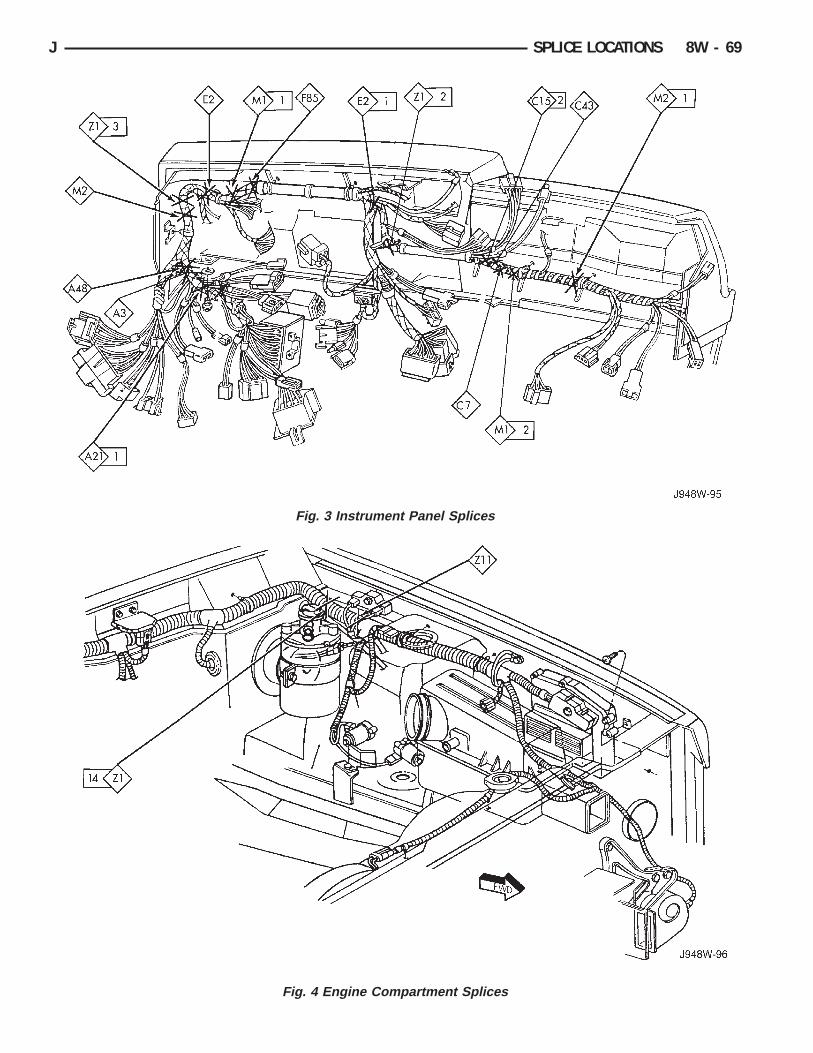
Fig. 3 Instrument Panel Splices
Fig. 4 Engine Compartment Splices
J SPLICE LOCATIONS 8W - 69

Fig. 5 Engine Compartment Splices
Fig. 6 Front End Splices
8W - 70 SPLICE LOCATIONS J

Fig. 7 Engine Splices 4.0L
Fig. 8 Engine Splices 4.0L
J SPLICE LOCATIONS 8W - 71

8W - 72 SPLICE LOCATIONS J

WIRING DIAGRAMS YJ
ALPHABETICAL INDEX
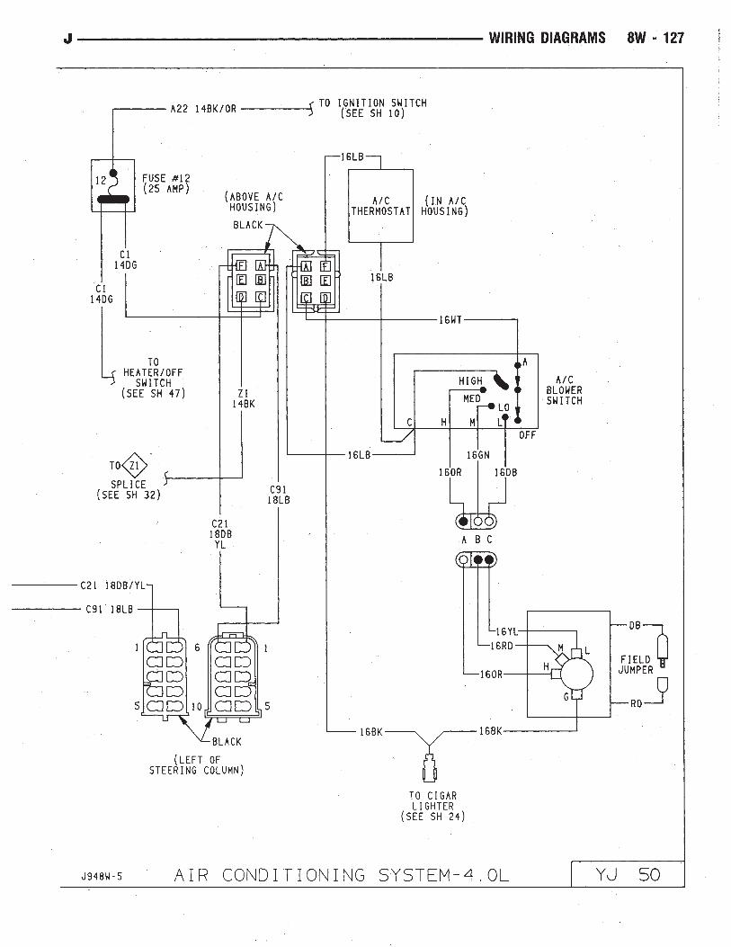
Wiring Diagram Name Sheet NumberABS Accelerator Sensor . . . . . . . . . . . . . . . . . . . . . . . .59ABS Control Module . . . . . . . . . . . . . . . . . . . . .57, 58, 59ABS Control Module Connector . . . . . . . . . . . . . . . . . . .60ABS Motor Pump Relay . . . . . . . . . . . . . . . . . . . . . . . .57ABS Power Relay . . . . . . . . . . . . . . . . . . . . . . . . . . . .57A/C Blower Switch . . . . . . . . . . . . . . . . . . . . . . . . . . . .50A/C Compressor . . . . . . . . . . . . . . . . . . . . . . . . . . . . .49A/C Low Pressure Switch . . . . . . . . . . . . . . . . . . . . . . .49A/C Relay . . . . . . . . . . . . . . . . . . . . . . . . . . . . . . . . .49A/C Thermostat . . . . . . . . . . . . . . . . . . . . . . . . . . . . . .50Accessory Illumination . . . . . . . . . . . . . . . . . . . . . . . . .32Air Conditioning System (4.0L) . . . . . . . . . . . . . . . . .49, 50
A/C Blower Switch . . . . . . . . . . . . . . . . . . . . . . . . . .50A/C Compressor . . . . . . . . . . . . . . . . . . . . . . . . . . . .49A/C Low Pressure Switch . . . . . . . . . . . . . . . . . . . . .49A/C Relay . . . . . . . . . . . . . . . . . . . . . . . . . . . . . . . .49A/C Thermostat . . . . . . . . . . . . . . . . . . . . . . . . . . . .50Field Jumper . . . . . . . . . . . . . . . . . . . . . . . . . . . . . .50Powertrain Control Module . . . . . . . . . . . . . . . . . . . . .49
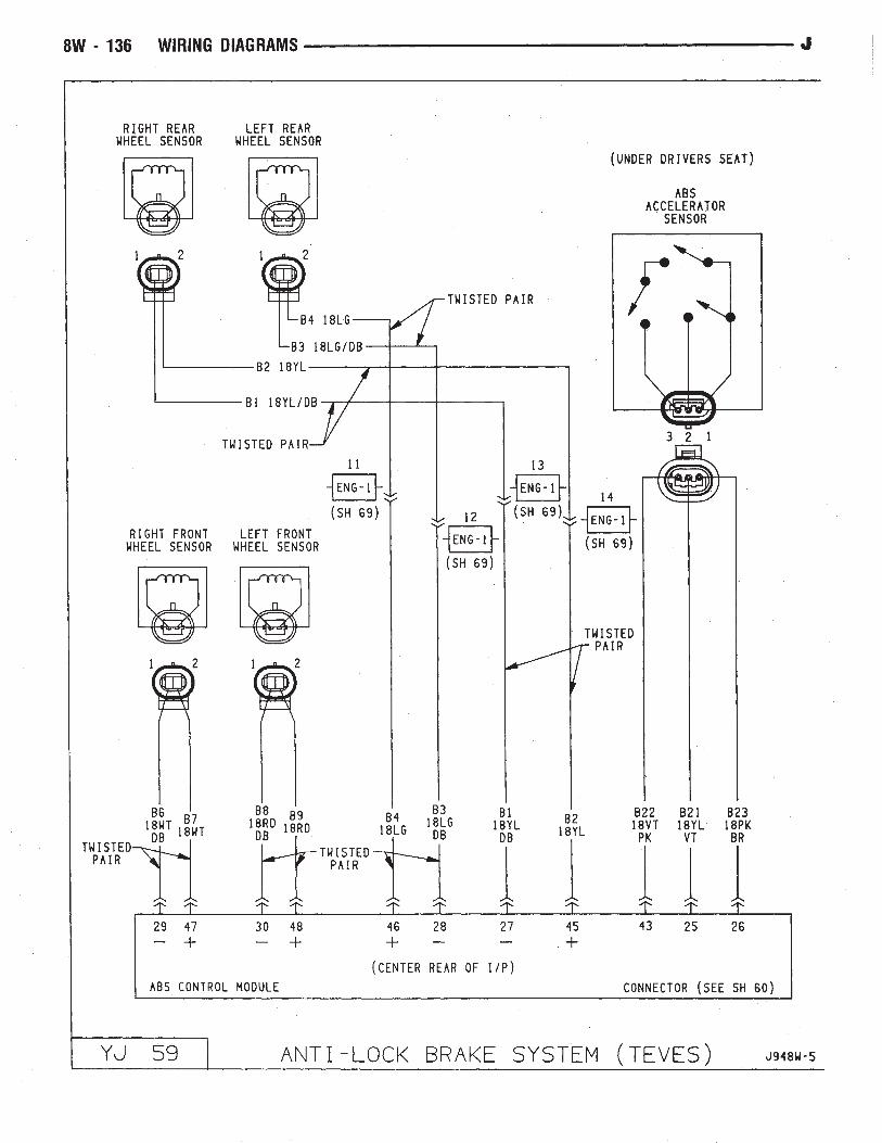
Anti-Lock Brake System (TEVES) . . . . . . . . . . . . .57, 58, 59ABS Accelerator Sensor . . . . . . . . . . . . . . . . . . . . . . .59ABS Control Module . . . . . . . . . . . . . . . . . . . .57, 58, 59ABS Motor Pump Relay . . . . . . . . . . . . . . . . . . . . . . .57ABS Power Relay . . . . . . . . . . . . . . . . . . . . . . . . . . .57Brake Pedal Travel Sensor . . . . . . . . . . . . . . . . . . . . .57Data Link Connector . . . . . . . . . . . . . . . . . . . . . . . . .57Diode . . . . . . . . . . . . . . . . . . . . . . . . . . . . . . . . . .58Hydraulic Actuation Unit . . . . . . . . . . . . . . . . . . . . . .58Left Front Wheel Sensor . . . . . . . . . . . . . . . . . . . . . .59Left Rear Wheel Sensor . . . . . . . . . . . . . . . . . . . . . . .59Power Distribution Center . . . . . . . . . . . . . . . . . . . . .57Pump Motor . . . . . . . . . . . . . . . . . . . . . . . . . . . . . .57Pump Motor Sensor . . . . . . . . . . . . . . . . . . . . . . . . .57Right Front Wheel Sensor . . . . . . . . . . . . . . . . . . . . .59Right Rear Wheel Sensor . . . . . . . . . . . . . . . . . . . . . .59
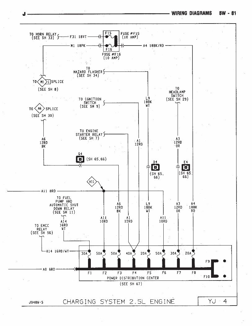
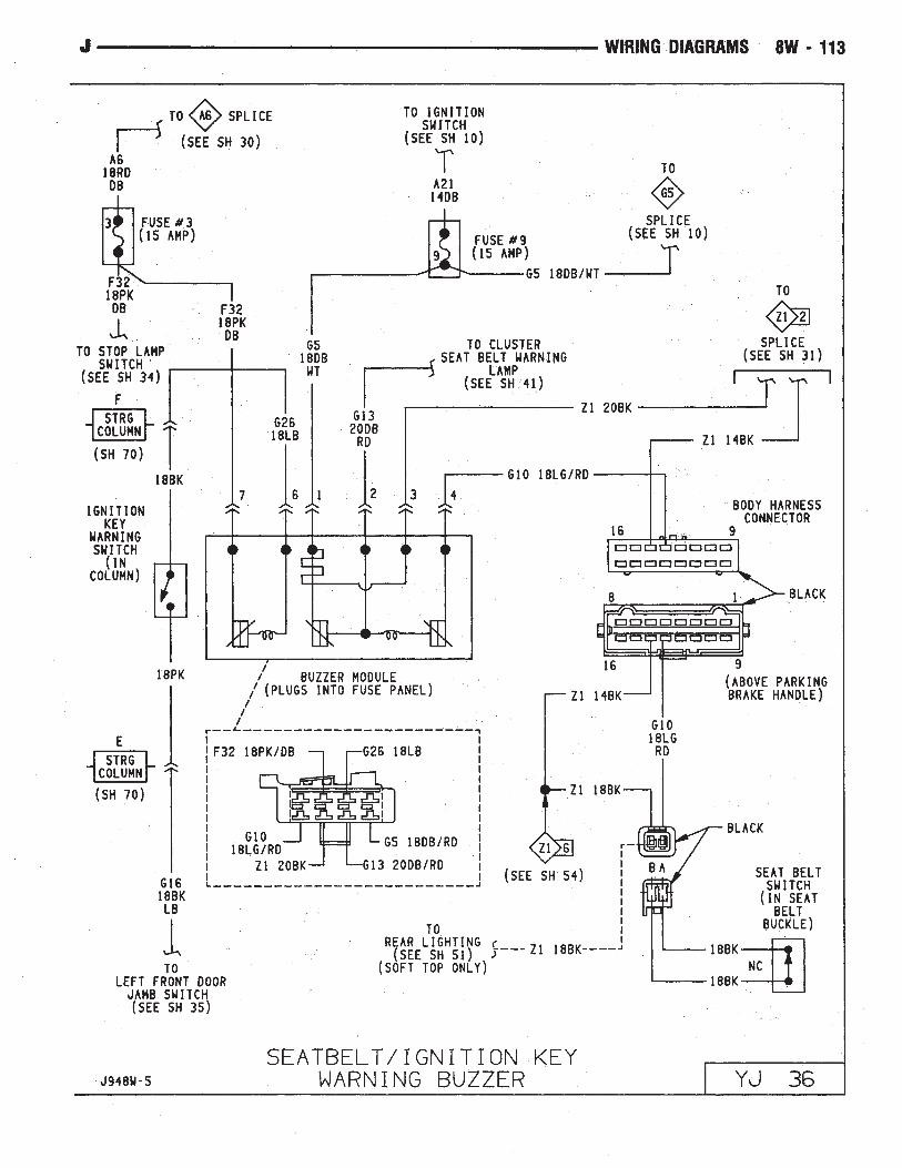
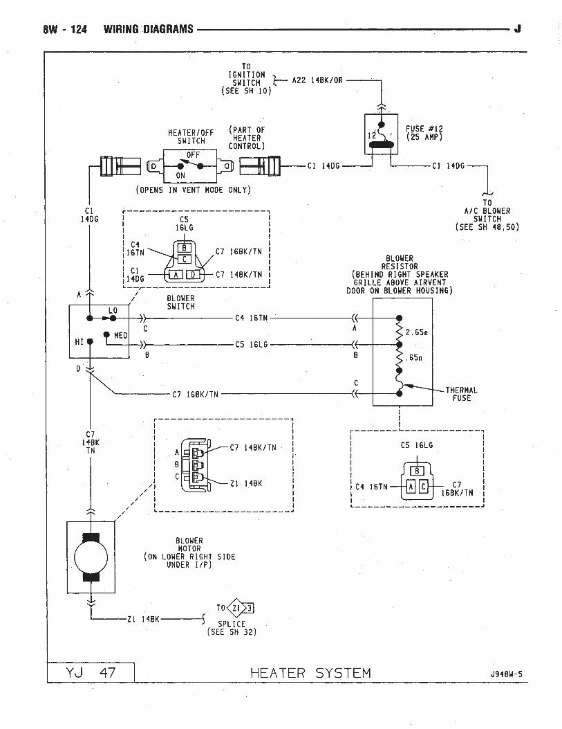
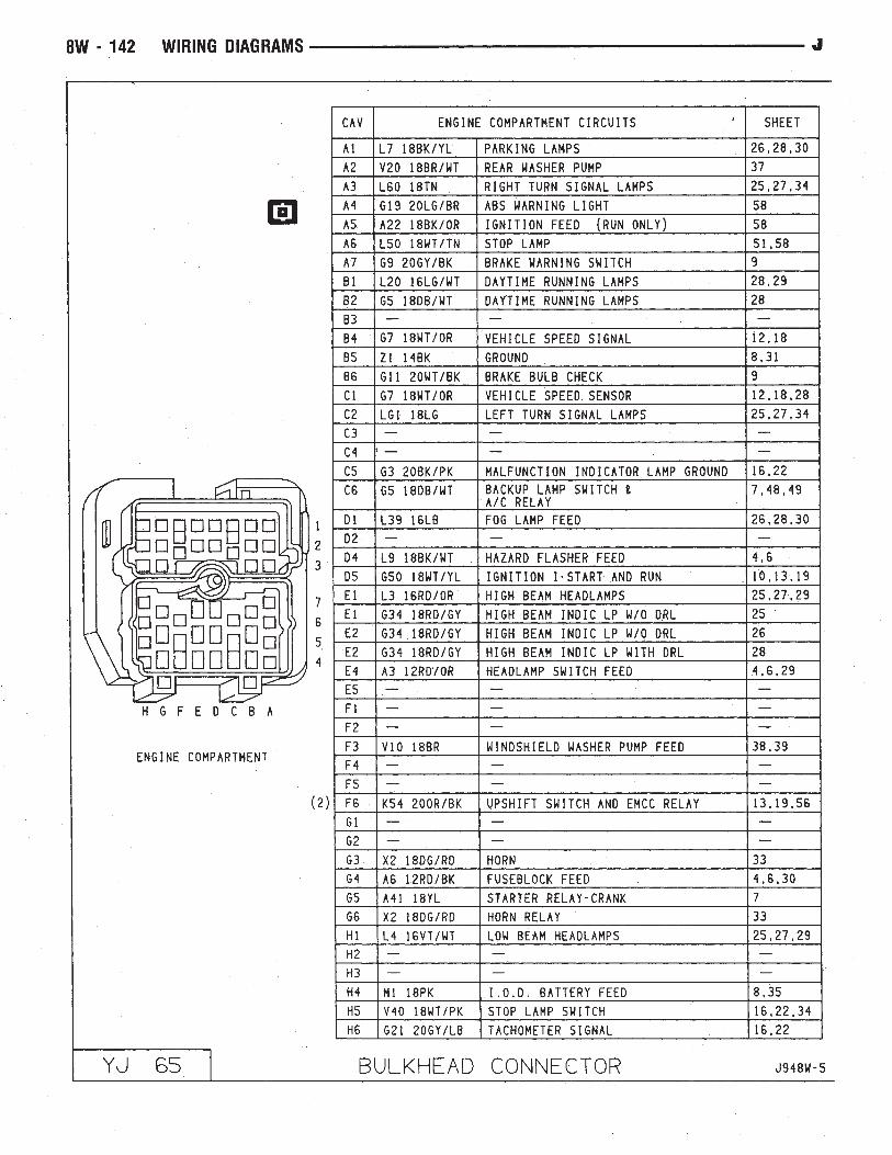
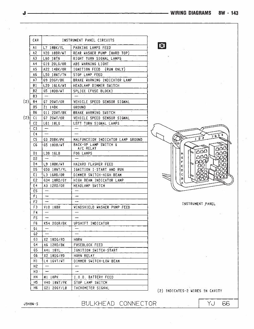
Automatic Shut-Down Relay . . . . . . . . . . . . . . . . . . .11, 17Back-Up Lamps . . . . . . . . . . . . . . . . . . . . . . . . . . .51, 52Back-Up Lamp Switch . . . . . . . . . . . . . . . . . . . . . . . . . .7Battery . . . . . . . . . . . . . . . . . . . . . . . . . . . . . . . .1, 3, 5Blower Motor . . . . . . . . . . . . . . . . . . . . . . . . . . . . . . .47Blower Resistor . . . . . . . . . . . . . . . . . . . . . . . . . . . . .47Blower Switch . . . . . . . . . . . . . . . . . . . . . . . . . . . . . .47Body Harness Connector . . . . . . . . . . . . . . . . . . . . . . . .36Brake Pedal Travel Sensor . . . . . . . . . . . . . . . . . . . . . . .57Brake Warning Switch . . . . . . . . . . . . . . . . . . . . . . . . . .9Bulkhead Connector . . . . . . . . . . . . . . . . . . . . . . . .65, 66Buzzer Module . . . . . . . . . . . . . . . . . . . . . . . . . . . . . .36Camshaft Position Sensor . . . . . . . . . . . . . . . . . . . .12, 18Center High Mounted Stop Lamp . . . . . . . . . . . . . . . . . .52Charging System 2.5L Engine . . . . . . . . . . . . . . . . . . .3, 4
Battery . . . . . . . . . . . . . . . . . . . . . . . . . . . . . . . . . .3Generator . . . . . . . . . . . . . . . . . . . . . . . . . . . . . . . . .3Power Distribution Center . . . . . . . . . . . . . . . . . . . . . .4
Wiring Diagram Name Sheet NumberCharging System 4.0L Engine . . . . . . . . . . . . . . . . . . .5, 6
Battery . . . . . . . . . . . . . . . . . . . . . . . . . . . . . . . . . .5Generator . . . . . . . . . . . . . . . . . . . . . . . . . . . . . . . . .5Power Distribution Center . . . . . . . . . . . . . . . . . . . . . .6
Cigar Lighter . . . . . . . . . . . . . . . . . . . . . . . . . . . . . . .24Circuit Breakers
Headlamp Switch . . . . . . . . . . . . . . . . . . . . . . . . .1, 29#11 (W/Wiper) . . . . . . . . . . . . . . . . . . . . .2, 10, 38, 39
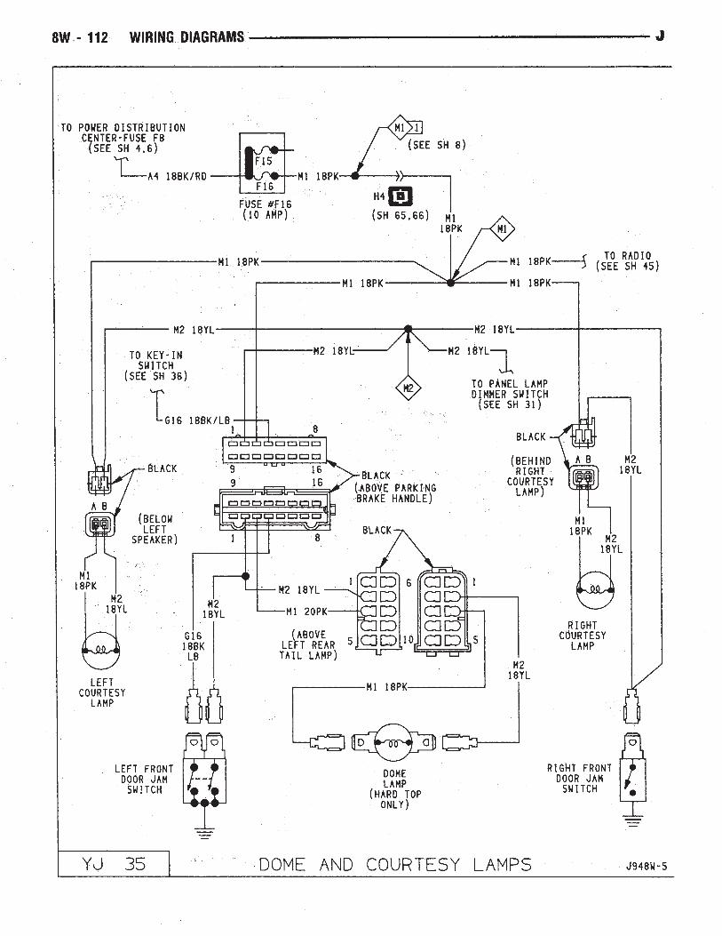
Clock . . . . . . . . . . . . . . . . . . . . . . . . . . . . . . . . . . . .45Cluster Connector . . . . . . . . . . . . . . . . . . . . . . . . . . . .41Crankshaft Position Sensor . . . . . . . . . . . . . . . . . . .12, 18Data Link Connector . . . . . . . . . . . . . . . . . . . . .13, 19, 57Daytime Running Lamp Module . . . . . . . . . . . . . . . . . . .28Dimmer Switch . . . . . . . . . . . . . . . . . . . . . . . . . . . .1, 29Dome and Courtesy Lamps . . . . . . . . . . . . . . . . . . . . . .35
Dome Lamp . . . . . . . . . . . . . . . . . . . . . . . . . . . . . .35Left Courtesy Lamp . . . . . . . . . . . . . . . . . . . . . . . . .35Left Front Door Jamb Switch . . . . . . . . . . . . . . . . . . .35Right Courtesy Lamp . . . . . . . . . . . . . . . . . . . . . . . .35Right Front Door Jamb Switch . . . . . . . . . . . . . . . . . .35
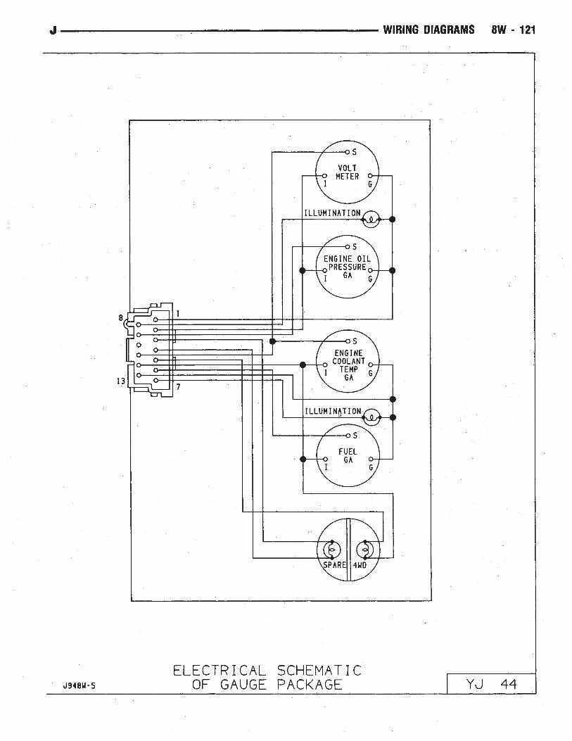
Dome Lamp . . . . . . . . . . . . . . . . . . . . . . . . . . . . . . . .35Electrically Tuned Radio with Clock . . . . . . . . . . . . . . . . .45Electrical Schematic of Cluster . . . . . . . . . . . . . . . . . . . .42Electrical Schematic of Gauge Package . . . . . . . . . . . . . .44Electronic Speedometer . . . . . . . . . . . . . . . . . . . . . . . . .42Electronic Tachometer . . . . . . . . . . . . . . . . . . . . . . . . . .42Engine Coolant Temp Gauge . . . . . . . . . . . . . . . . . . . . .44Engine Coolant Temperature Sensor . . . . . . . . . . . . . .15, 21Engine Oil Pressure and Temperature System . . . . . . . . . .23
Engine Coolant Temperature Sending Unit . . . . . . . . . . .23Engine Oil Pressure Sending Unit . . . . . . . . . . . . . . . .23
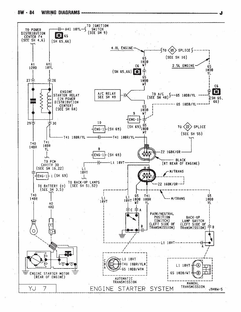
Engine Oil Pressure Gauge . . . . . . . . . . . . . . . . . . . . . .44Engine Starter System . . . . . . . . . . . . . . . . . . . . . . . .2, 7
Back-Up Lamp Switch . . . . . . . . . . . . . . . . . . . . . . . .7Engine Starter Motor . . . . . . . . . . . . . . . . . . . . . . . . .7Engine Starter Relay . . . . . . . . . . . . . . . . . . . . . . . . . .7Park/Neutral Position Switch . . . . . . . . . . . . . . . . . . . .7
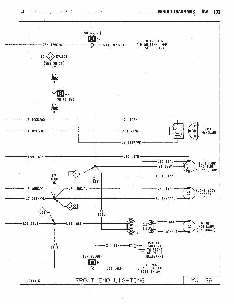
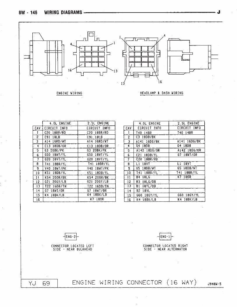
Engine Wiring Connector (16 Way) . . . . . . . . . . . . . . . . .694-WD Command Trac Switch . . . . . . . . . . . . . . . . . . . . . .8Field Jumper . . . . . . . . . . . . . . . . . . . . . . . . . . . . . . .50Fog Lamp Relays . . . . . . . . . . . . . . . . . . . . . . . . . . . .30Fog Lamp Switch . . . . . . . . . . . . . . . . . . . . . . . . . . . .30Front End Lighting . . . . . . . . . . . . . . . . . . . . . . . . .25, 26
Left Fog Lamp . . . . . . . . . . . . . . . . . . . . . . . . . . . . .25Left Headlamp . . . . . . . . . . . . . . . . . . . . . . . . . . . . .25Left Park and Turn Signal Lamp . . . . . . . . . . . . . . . . .25Left Side Marker Lamp . . . . . . . . . . . . . . . . . . . . . . .25Right Fog Lamp . . . . . . . . . . . . . . . . . . . . . . . . . . . .26Right Headlamp . . . . . . . . . . . . . . . . . . . . . . . . . . . .26Right Park and Turn Signal Lamp . . . . . . . . . . . . . . . .26Right Side Marker Lamp . . . . . . . . . . . . . . . . . . . . . .26
Front End Lighting (Canada) . . . . . . . . . . . . . . . . . . .27, 28Daytime Running Lamp Module . . . . . . . . . . . . . . . . .28
J WIRING DIAGRAMS 8W - 73

Wiring Diagram Name Sheet NumberLeft Fog Lamp . . . . . . . . . . . . . . . . . . . . . . . . . . . . .27Left Headlamp . . . . . . . . . . . . . . . . . . . . . . . . . . . . .27Left Park and Turn Signal Lamp . . . . . . . . . . . . . . . . .27Left Side Marker Lamp . . . . . . . . . . . . . . . . . . . . . . .27Right Fog Lamp . . . . . . . . . . . . . . . . . . . . . . . . . . . .28Right Headlamp . . . . . . . . . . . . . . . . . . . . . . . . . . . .28Right Park and Turn Signal Lamp . . . . . . . . . . . . . . . .28Right Side Marker Lamp . . . . . . . . . . . . . . . . . . . . . .28
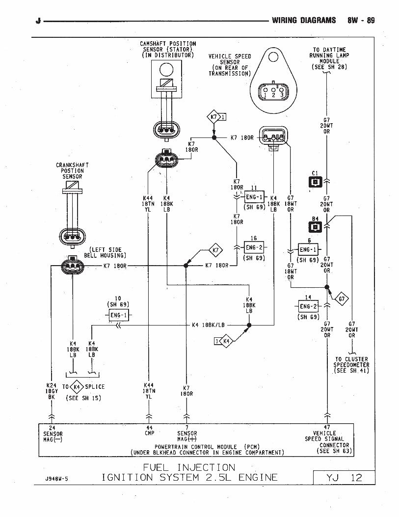
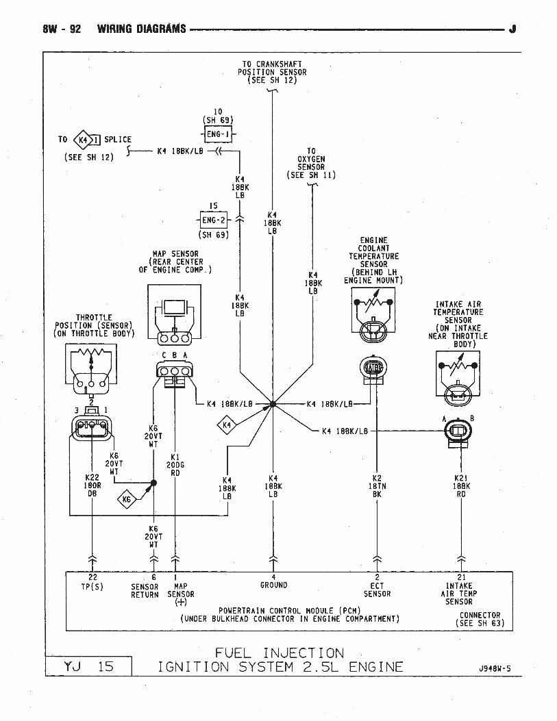
Fuel Gauge . . . . . . . . . . . . . . . . . . . . . . . . . . . . . . . .44Fuel Injection Ignition System
2.5L Engine . . . . . . . . . . . . . . . . .11, 12, 13, 14, 15, 16Automatic Shut Down Relay . . . . . . . . . . . . . . . . . . . .11Camshaft Position Sensor . . . . . . . . . . . . . . . . . . . . .12Crankshaft Position Sensor . . . . . . . . . . . . . . . . . . . . .12Data Link Connector . . . . . . . . . . . . . . . . . . . . . . . . .13Engine Coolant Temperature Sensor . . . . . . . . . . . . . . .15Fuel Injectors . . . . . . . . . . . . . . . . . . . . . . . . . . . . .14Fuel Pump Relay . . . . . . . . . . . . . . . . . . . . . . . . . . .11Heated Oxygen Sensor . . . . . . . . . . . . . . . . . . . . . . .11Idle Air Control Motor . . . . . . . . . . . . . . . . . . . . . . . .14Ignition Coil . . . . . . . . . . . . . . . . . . . . . . . . . . . . . .13Intake Air Temperature Sensor . . . . . . . . . . . . . . . . . .15MAP Sensor . . . . . . . . . . . . . . . . . . . . . . . . . . . . . .15Power Steering Switch . . . . . . . . . . . . . . . . . . . . . . .14Powertrain Control Module (PCM) . . .11, 12, 13, 14, 15, 16Throttle Position (Sensor) . . . . . . . . . . . . . . . . . . . . .15Vehicle Speed Sensor . . . . . . . . . . . . . . . . . . . . . . . .12
Fuel Injection Ignition System4.0L Engine . . . . . . . . . . . . . . . . .17, 18, 19, 20, 21, 22Automatic Shut Down Relay . . . . . . . . . . . . . . . . . . . .17Camshaft Position Sensor . . . . . . . . . . . . . . . . . . . . .18Crankshaft Position Sensor . . . . . . . . . . . . . . . . . . . . .18Data Link Connector . . . . . . . . . . . . . . . . . . . . . . . . .19Engine Coolant Temperature Sensor . . . . . . . . . . . . . . .21Fuel Injectors . . . . . . . . . . . . . . . . . . . . . . . . . . . . .20Fuel Pump Relay . . . . . . . . . . . . . . . . . . . . . . . . . . .17Heated Oxygen Sensor . . . . . . . . . . . . . . . . . . . . . . .17Idle Air Control Motor . . . . . . . . . . . . . . . . . . . . . . . .20Ignition Coil . . . . . . . . . . . . . . . . . . . . . . . . . . . . . .19Intake Air Temperature Sensor . . . . . . . . . . . . . . . . . .21MAP Sensor . . . . . . . . . . . . . . . . . . . . . . . . . . . . . .21Powertrain Control Module (PCM) . . .17, 18, 19, 20, 21, 22Throttle Position (Sensor) . . . . . . . . . . . . . . . . . . . . .21Vehicle Speed Sensor . . . . . . . . . . . . . . . . . . . . . . . .18
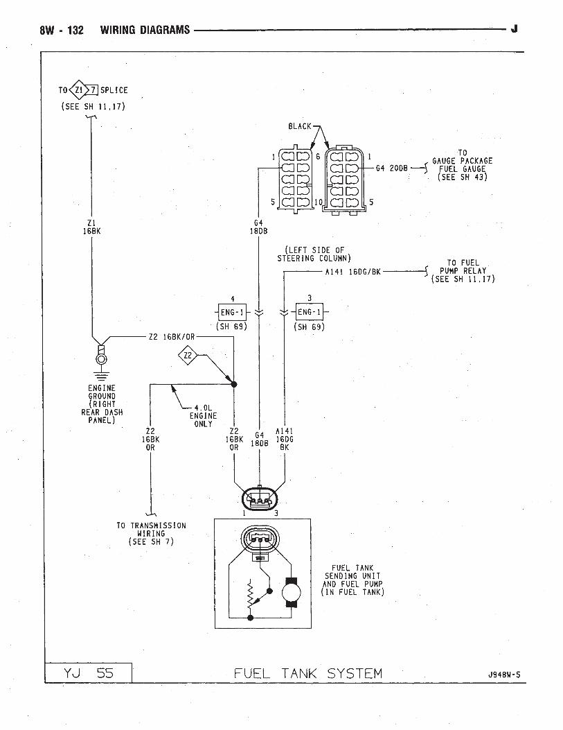
Fuel Injectors . . . . . . . . . . . . . . . . . . . . . . . . . . . .14, 20Fuel Pump Relay . . . . . . . . . . . . . . . . . . . . . . . . . .11, 17Fuel Tank System . . . . . . . . . . . . . . . . . . . . . . . . . . . .55Fuel Tank Sending Unit . . . . . . . . . . . . . . . . . . . . . . . . .55Fuse Application Chart . . . . . . . . . . . . . . . . . . . . . . . .1, 2Fuses
1 . . . . . . . . . . . . . . . . . . . . . . . . . . . . . . . . .2, 10, 373 . . . . . . . . . . . . . . . . . . . . . . . . . . . . . .1, 30, 34, 364 . . . . . . . . . . . . . . . . . . . . . . . . . . . . . . . . .2, 10, 345 . . . . . . . . . . . . . . . . . . . . . . . . . . . . . .2, 10, 13, 196 . . . . . . . . . . . . . . . . . . . . . . . . . . . . . . . . .1, 30, 537 . . . . . . . . . . . . . . . . . . . . . . . . . . . . . .2, 10, 24, 468 . . . . . . . . . . . . . . . . . . . . . . . . . . . . . . . . . . .1, 299 . . . . . . . . . . . . . . . . . . . . . . . . . . . . . . . . .2, 10, 36
Wiring Diagram Name Sheet Number10 . . . . . . . . . . . . . . . . . . . . . . . . . . . . . . . . . . .1, 3111 . . . . . . . . . . . . . . . . . . . . . . . . . . . . .2, 10, 38, 3912 . . . . . . . . . . . . . . . . . . . . . . . . . . .2, 10, 47, 48, 50F13 . . . . . . . . . . . . . . . . . . . . . . . . . . . . . . . . . .2, 58F15 . . . . . . . . . . . . . . . . . . . . . . . . . . . . . .2, 4, 6, 33F16 . . . . . . . . . . . . . . . . . . . . . . . . . . . .2, 4, 6, 8, 35
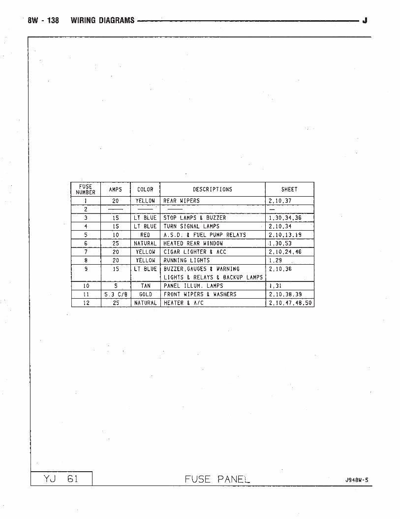
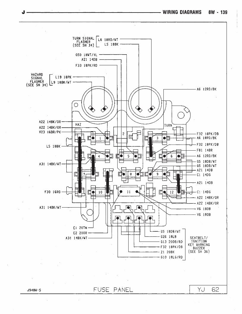
Fuse Panel . . . . . . . . . . . . . . . . . . . . . . . . . . . . . .61, 62Gauge Package Connector . . . . . . . . . . . . . . . . . . . . . . .43Gauges
Electronic Speedometer . . . . . . . . . . . . . . . . . . . . . . .42Electronic Tachometer . . . . . . . . . . . . . . . . . . . . . . . .42Engine Coolant Temperature Gauge . . . . . . . . . . . . . . .44Engine Oil Pressure Gauge . . . . . . . . . . . . . . . . . . . . .44Fuel Gauge . . . . . . . . . . . . . . . . . . . . . . . . . . . . . . .44Voltmeter . . . . . . . . . . . . . . . . . . . . . . . . . . . . . . . .44
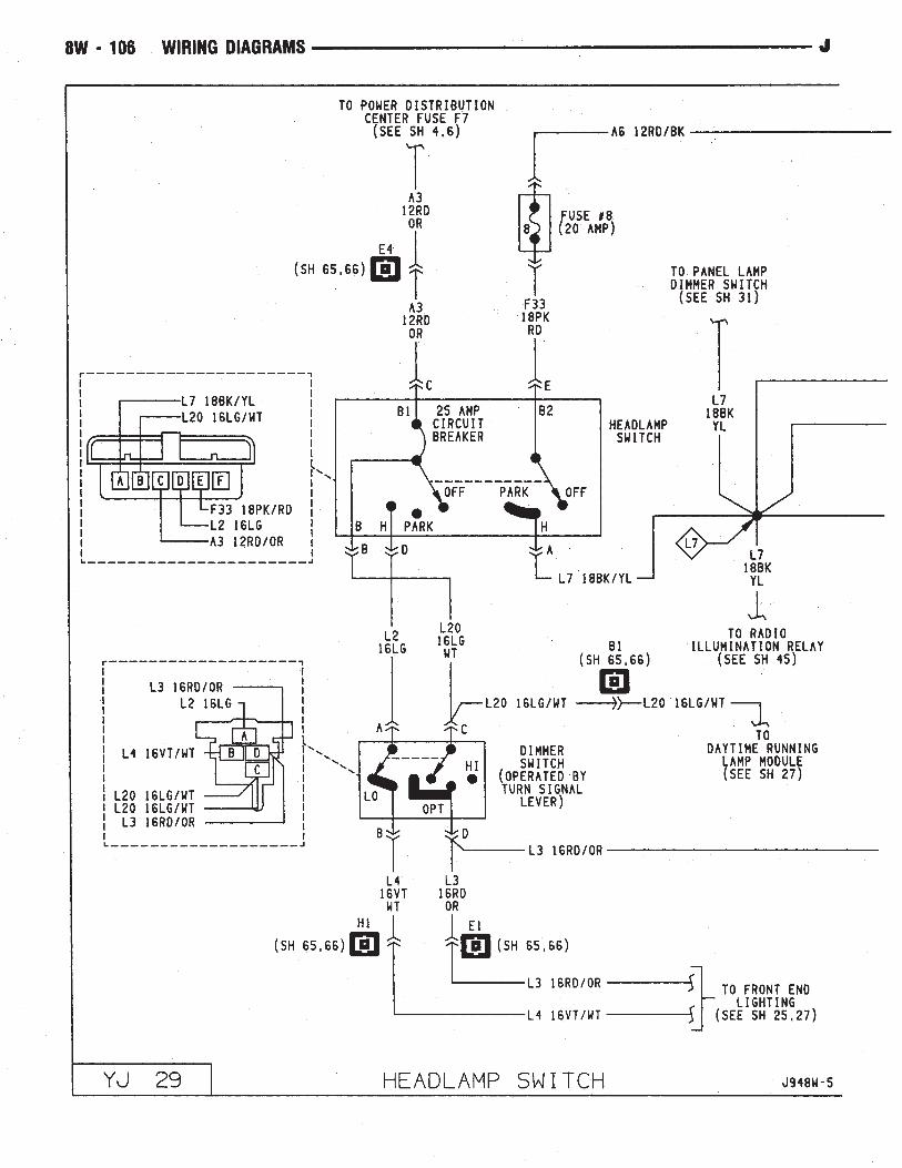
Generator . . . . . . . . . . . . . . . . . . . . . . . . . . . . . . . .3, 5Hazard Signal Flasher . . . . . . . . . . . . . . . . . . . . . . . . . .34Headlamps . . . . . . . . . . . . . . . . . . . . . . . . .25, 26, 27, 28Headlamp Switch . . . . . . . . . . . . . . . . . . . . . . . .1, 29, 30
Dimmer Switch . . . . . . . . . . . . . . . . . . . . . . . . . . . .29Headlamp Switch . . . . . . . . . . . . . . . . . . . . . . . . . . .29
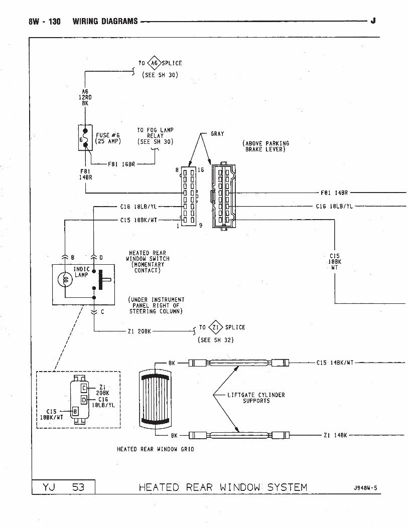
Heated Oxygen Sensor . . . . . . . . . . . . . . . . . . . . . .11, 17Heated Rear Window Relay . . . . . . . . . . . . . . . . . . . . . .54Heated Rear Window Switch . . . . . . . . . . . . . . . . . . . . .53Heated Rear Window System . . . . . . . . . . . . . . . . . .53, 54
Heated Rear Window Grid . . . . . . . . . . . . . . . . . . . . .53Heated Rear Window Relay . . . . . . . . . . . . . . . . . . . .54Heated Rear Window Switch . . . . . . . . . . . . . . . . . . . .53Timer . . . . . . . . . . . . . . . . . . . . . . . . . . . . . . . . . .54
Heater Control Panel Illumination . . . . . . . . . . . . . . . . . .32Heater System . . . . . . . . . . . . . . . . . . . . . . . . . . . . . .47
Blower Motor . . . . . . . . . . . . . . . . . . . . . . . . . . . . .47Blower Resistor . . . . . . . . . . . . . . . . . . . . . . . . . . . .47Blower Switch . . . . . . . . . . . . . . . . . . . . . . . . . . . . .47Heater/Off Switch . . . . . . . . . . . . . . . . . . . . . . . . . . .47
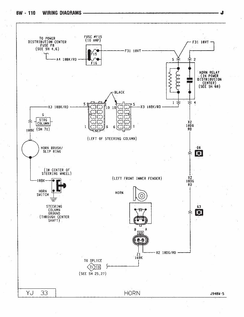
Horn . . . . . . . . . . . . . . . . . . . . . . . . . . . . . . . . . . . . .33Horn Brush/Slip Ring . . . . . . . . . . . . . . . . . . . . . . . .33Horn Relay . . . . . . . . . . . . . . . . . . . . . . . . . . . . . . .33Horn Switch . . . . . . . . . . . . . . . . . . . . . . . . . . . . . .33
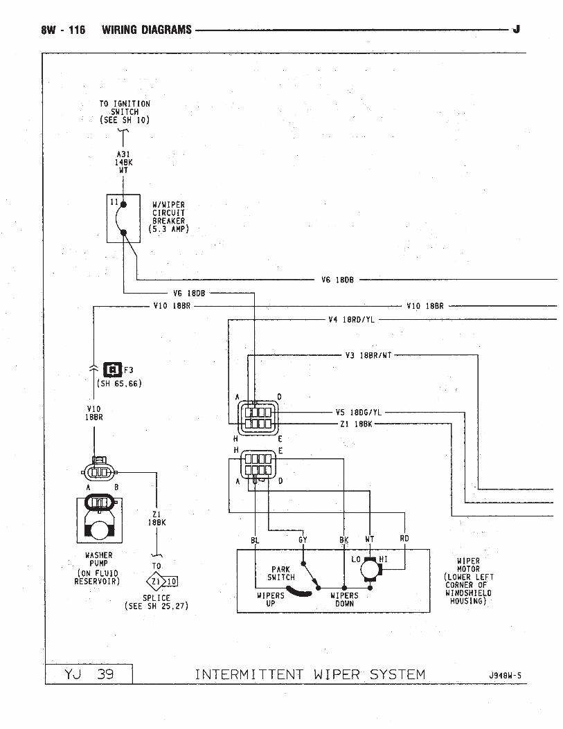
Hydraulic Actuation Unit . . . . . . . . . . . . . . . . . . . . . . . .58Idle Air Control Motor . . . . . . . . . . . . . . . . . . . . . . .14, 20Ignition Coil . . . . . . . . . . . . . . . . . . . . . . . . . . . . .13, 19Ignition Key Warning Switch . . . . . . . . . . . . . . . . . . . . .36Ignition Switch . . . . . . . . . . . . . . . . . . . . . . . . . .2, 9, 10Instrument Panel Illumination Lamps . . . . . . . . . . . . . . . .32Intake Air Temperature Sensor . . . . . . . . . . . . . . . . .15, 21Intermittent Wiper Module . . . . . . . . . . . . . . . . . . . . . . .40Intermittent Wiper System . . . . . . . . . . . . . . . . . . . .39, 40
Intermittent Wiper Module . . . . . . . . . . . . . . . . . . . . .40Park Switch . . . . . . . . . . . . . . . . . . . . . . . . . . . . . .39Washer Pump . . . . . . . . . . . . . . . . . . . . . . . . . . . . .39Wiper Motor . . . . . . . . . . . . . . . . . . . . . . . . . . . . . .39Wiper/Washer Switch . . . . . . . . . . . . . . . . . . . . . . . .40W/Wiper Circuit Breaker (5.3 Amp) . . . . . . . . . . . . . . .39
LampsCenter High Mounted Stop Lamps . . . . . . . . . . . . . . . .52Dome Lamp . . . . . . . . . . . . . . . . . . . . . . . . . . . . . .35Instrument Panel Illumination Lamp . . . . . . . . . . . . . . .32
8W - 74 WIRING DIAGRAMS J

Wiring Diagram Name Sheet NumberLeft Back-Up Lamp . . . . . . . . . . . . . . . . . . . . . . . . . .51Left Courtesy Lamp . . . . . . . . . . . . . . . . . . . . . . . . .35Left Fog Lamp . . . . . . . . . . . . . . . . . . . . . . . . . .25, 27Left Headlamp . . . . . . . . . . . . . . . . . . . . . . . . . .25, 27Left Park and Turn Signal Lamp . . . . . . . . . . . . . .25, 27Left Side Marker Lamp . . . . . . . . . . . . . . . . . . . .25, 27Left Tail, Stop and Turn Signal Lamp . . . . . . . . . . . . . .51Right Back-Up Lamp . . . . . . . . . . . . . . . . . . . . . . . . .52Right Courtesy Lamp . . . . . . . . . . . . . . . . . . . . . . . .35Right Fog Lamp . . . . . . . . . . . . . . . . . . . . . . . . .26, 28Right Headlamp . . . . . . . . . . . . . . . . . . . . . . . . .26, 28Right Park and Turn Signal Lamp . . . . . . . . . . . . .26, 28Right Side Marker Lamp . . . . . . . . . . . . . . . . . . .26, 28Right Tail, Stop and Turn Signal Lamp . . . . . . . . . . . . .52Underhood Lamp . . . . . . . . . . . . . . . . . . . . . . . . . . . .8
Left Back-Up Lamps . . . . . . . . . . . . . . . . . . . . . . . . . .51Left Courtesy Lamp . . . . . . . . . . . . . . . . . . . . . . . . . . .35Left Fog Lamp . . . . . . . . . . . . . . . . . . . . . . . . . . .25, 27Left Front Door Jamb Switch . . . . . . . . . . . . . . . . . . . . .35Left Front Speaker . . . . . . . . . . . . . . . . . . . . . . . . . . . .46Left Halo Speaker . . . . . . . . . . . . . . . . . . . . . . . . . . . .46Left Headlamp . . . . . . . . . . . . . . . . . . . . . . . . . . . .25, 27Left Park and Turn Signal Lamp . . . . . . . . . . . . . . . .25, 27Left Side Marker Lamp . . . . . . . . . . . . . . . . . . . . . .25, 27Left Tail, Stop and Turn Signal Lamp . . . . . . . . . . . . . . .51MAP Sensor . . . . . . . . . . . . . . . . . . . . . . . . . . . . .15, 21Mercury Switch . . . . . . . . . . . . . . . . . . . . . . . . . . . . . .8Modules
ABS Control Module . . . . . . . . . . . . . . . . . . . .57, 58, 59Buzzer Module . . . . . . . . . . . . . . . . . . . . . . . . . . . . .36Daytime Running Lamp Module . . . . . . . . . . . . . . . . .28Intermittent Wiper Module . . . . . . . . . . . . . . . . . . . . .40
MotorsBlower Motor . . . . . . . . . . . . . . . . . . . . . . . . . . . . .47Engine Starter Motor . . . . . . . . . . . . . . . . . . . . . . . . .7Idle Air Control Motor . . . . . . . . . . . . . . . . . . . . .14, 20Rear Wiper Motor . . . . . . . . . . . . . . . . . . . . . . . . . .37Wiper Motor . . . . . . . . . . . . . . . . . . . . . . . . . . .38, 39
Oil Pressure and Temp System . . . . . . . . . . . . . . . . . . .23Panel Lamp Dimmer Switch . . . . . . . . . . . . . . . . . . . . . .1Panel Lamps . . . . . . . . . . . . . . . . . . . . . . . . . . . . .31, 32
Accessory Illumination . . . . . . . . . . . . . . . . . . . . . . . .32Heater Control Panel Illumination . . . . . . . . . . . . . . . . .32Panel Lamp Dimmer Switch . . . . . . . . . . . . . . . . . . . .31Transmission Range Illumination . . . . . . . . . . . . . . . . .32
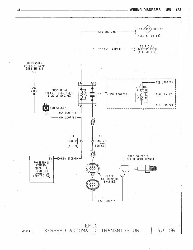
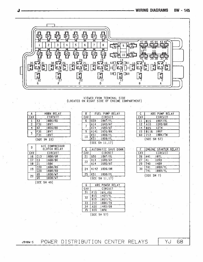
Park Brake Switch . . . . . . . . . . . . . . . . . . . . . . . . . . . . .9Park/Neutral Position Switch . . . . . . . . . . . . . . . . . . . . . .7Part Throttle EMCC 3-Speed Automatic Transmission . . . . .56Part Throttle EMCC Relay . . . . . . . . . . . . . . . . . . . . . . .56Part Throttle EMCC Solenoid . . . . . . . . . . . . . . . . . . . . .56Power Distribution Center . . . . . . . . . . . . . . . . .1, 4, 6, 57Power Distribution Center Identification Cover . . . . . . . . . .67Power Distribution Center Relays . . . . . . . . . . . . . . . . . .68Power Steering Switch . . . . . . . . . . . . . . . . . . . . . . . . .14Powertrain Control Module . . . . . . . . . . . .11-22, 48, 49, 56Powertrain Control Module Connector (2.5L Engine) . . . . . .63Powertrain Control Module Connector (4.0L Engine) . . . . . .64Provisions for A/C (2.5L) . . . . . . . . . . . . . . . . . . . . . . .48
Wiring Diagram Name Sheet NumberRadio Illumination Relay . . . . . . . . . . . . . . . . . . . . . . . .45Radio System . . . . . . . . . . . . . . . . . . . . . . . . . . . .45, 46
Electrically Tuned Radio with Clock . . . . . . . . . . . . . . .45Left Front Speaker . . . . . . . . . . . . . . . . . . . . . . . . . .46Left Halo Speaker . . . . . . . . . . . . . . . . . . . . . . . . . . .46Radio Illumination Relay . . . . . . . . . . . . . . . . . . . . . .45Right Front Speaker . . . . . . . . . . . . . . . . . . . . . . . . .46Right Halo Speaker . . . . . . . . . . . . . . . . . . . . . . . . . .46
Rear Lighting . . . . . . . . . . . . . . . . . . . . . . . . . . . .51, 52Center High Mounted Stop Lamp . . . . . . . . . . . . . . . .52Left Back-Up Lamp . . . . . . . . . . . . . . . . . . . . . . . . . .51Left Tail, Stop & Turn Signal Lamp & License Lamp . . . .51Right Back-Up Lamp . . . . . . . . . . . . . . . . . . . . . . . . .52Right Tail, Stop & Turn Signal Lamp . . . . . . . . . . . . . .52
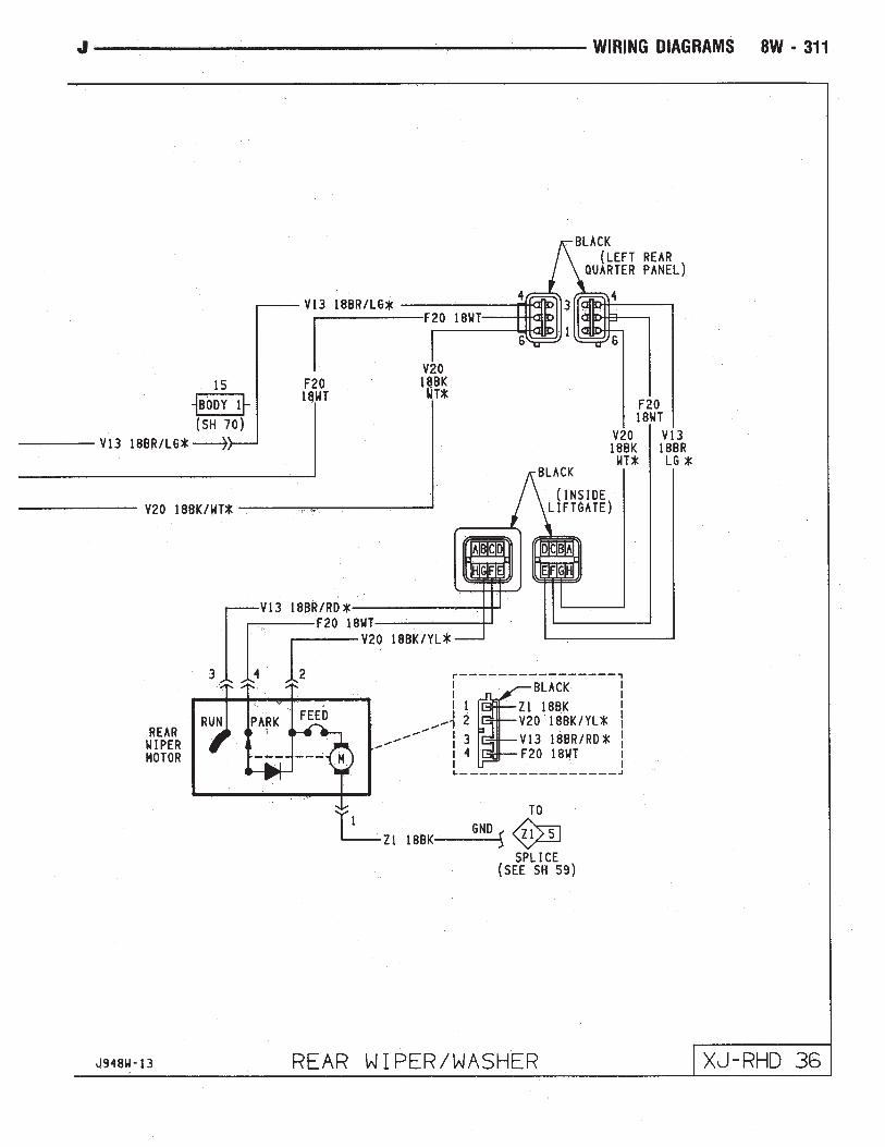
Rear Wiper/Washer System . . . . . . . . . . . . . . . . . . . . . .37Rear Wiper Motor . . . . . . . . . . . . . . . . . . . . . . . . . .37Rear Wiper Switch . . . . . . . . . . . . . . . . . . . . . . . . . .37Washer Pump . . . . . . . . . . . . . . . . . . . . . . . . . . . . .37
RelaysA/C . . . . . . . . . . . . . . . . . . . . . . . . . . . . . . . . . . . .49ABS Motor Pump Relay . . . . . . . . . . . . . . . . . . . . . . .57ABS Power Relay . . . . . . . . . . . . . . . . . . . . . . . . . . .57Automatic Shut Down Relay . . . . . . . . . . . . . . . . .11, 17EMCC . . . . . . . . . . . . . . . . . . . . . . . . . . . . . . . . . . .56Engine Starter Relay . . . . . . . . . . . . . . . . . . . . . . . . . .7Fog Lamp Relays . . . . . . . . . . . . . . . . . . . . . . . . . . .30Fuel Pump Relay . . . . . . . . . . . . . . . . . . . . . . . .11, 17Heated Rear Window Relay . . . . . . . . . . . . . . . . . . . .54Horn Relay . . . . . . . . . . . . . . . . . . . . . . . . . . . . . . .33Radio Illumination Relay . . . . . . . . . . . . . . . . . . . . . .45
Right Back-Up Lamp . . . . . . . . . . . . . . . . . . . . . . . . . .52Right Courtesy Lamp . . . . . . . . . . . . . . . . . . . . . . . . . .35Right Fog Lamp . . . . . . . . . . . . . . . . . . . . . . . . . . .26, 28Right Front Door Jamb Switch . . . . . . . . . . . . . . . . . . . .35Right Front Speaker . . . . . . . . . . . . . . . . . . . . . . . . . . .46Right Halo Speaker . . . . . . . . . . . . . . . . . . . . . . . . . . .46Right Headlamp . . . . . . . . . . . . . . . . . . . . . . . . . . .26, 28Right Park and Turn Signal . . . . . . . . . . . . . . . . . . .26, 28Right Side Marker Lamp . . . . . . . . . . . . . . . . . . . . .26, 28Right Tail, Stop and Turn Signal Lamp . . . . . . . . . . . . . .52Seat Belt/Ignition Key Warning Buzzer . . . . . . . . . . . . . . .36Seat Belt Switch . . . . . . . . . . . . . . . . . . . . . . . . . . . . .36Sensors
ABS Accelerator Sensor . . . . . . . . . . . . . . . . . . . . . . .59Brake Pedal Travel Sensor . . . . . . . . . . . . . . . . . . . . .57Camshaft Position Sensor . . . . . . . . . . . . . . . . . . .12, 18Crankshaft Position Sensor . . . . . . . . . . . . . . . . . .12, 18Engine Coolant Temperature Sensor . . . . . . . . . . . .15, 21Heated Oxygen Sensor . . . . . . . . . . . . . . . . . . . . .11, 17Intake Air Temperature Sensor . . . . . . . . . . . . . . . .15, 21MAP Sensor . . . . . . . . . . . . . . . . . . . . . . . . . . .15, 21Pump Motor Sensor . . . . . . . . . . . . . . . . . . . . . . . . .57Throttle Position (Sensor) . . . . . . . . . . . . . . . . . . .15, 21Vehicle Speed Sensor . . . . . . . . . . . . . . . . . . . . .12, 18Wheel Sensors . . . . . . . . . . . . . . . . . . . . . . . . . . . .59
Speakers . . . . . . . . . . . . . . . . . . . . . . . . . . . . . . . . . .46Speedometer . . . . . . . . . . . . . . . . . . . . . . . . . . . . . . .42
J WIRING DIAGRAMS 8W - 75
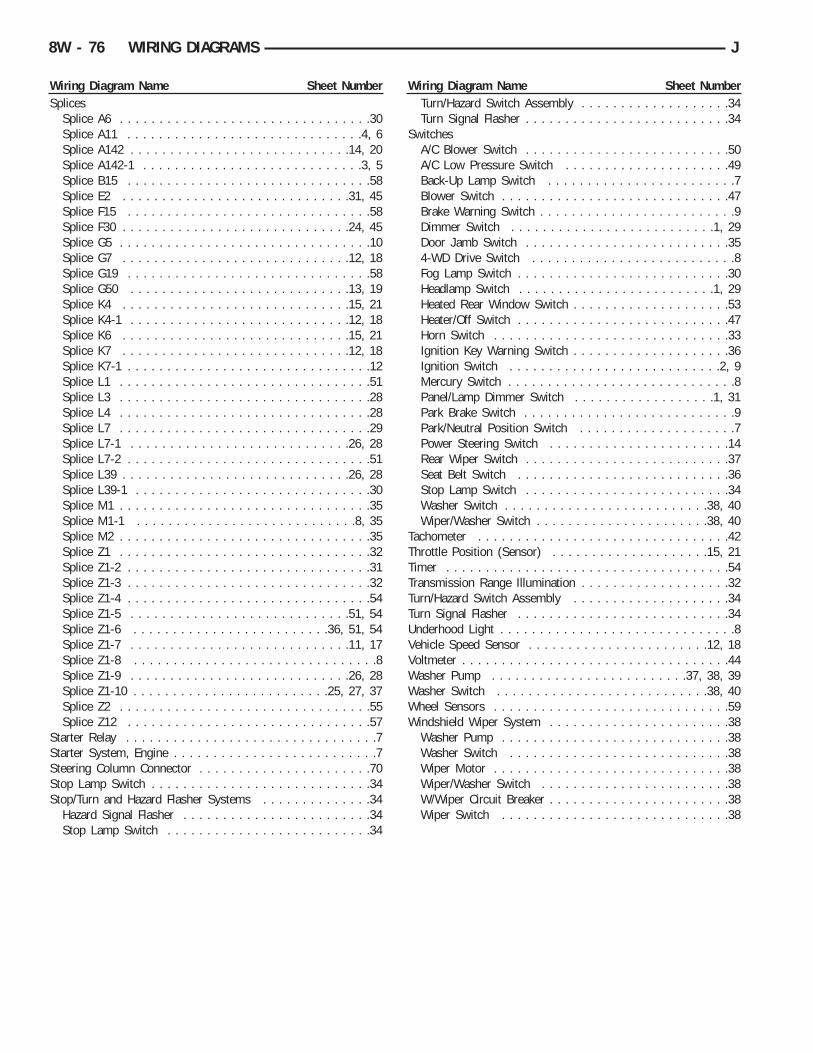
Wiring Diagram Name Sheet NumberSplices
Splice A6 . . . . . . . . . . . . . . . . . . . . . . . . . . . . . . . .30Splice A11 . . . . . . . . . . . . . . . . . . . . . . . . . . . . . .4, 6Splice A142 . . . . . . . . . . . . . . . . . . . . . . . . . . . .14, 20Splice A142-1 . . . . . . . . . . . . . . . . . . . . . . . . . . . .3, 5Splice B15 . . . . . . . . . . . . . . . . . . . . . . . . . . . . . . .58Splice E2 . . . . . . . . . . . . . . . . . . . . . . . . . . . . .31, 45Splice F15 . . . . . . . . . . . . . . . . . . . . . . . . . . . . . . .58Splice F30 . . . . . . . . . . . . . . . . . . . . . . . . . . . . .24, 45Splice G5 . . . . . . . . . . . . . . . . . . . . . . . . . . . . . . . .10Splice G7 . . . . . . . . . . . . . . . . . . . . . . . . . . . . .12, 18Splice G19 . . . . . . . . . . . . . . . . . . . . . . . . . . . . . . .58Splice G50 . . . . . . . . . . . . . . . . . . . . . . . . . . . .13, 19Splice K4 . . . . . . . . . . . . . . . . . . . . . . . . . . . . .15, 21Splice K4-1 . . . . . . . . . . . . . . . . . . . . . . . . . . . .12, 18Splice K6 . . . . . . . . . . . . . . . . . . . . . . . . . . . . .15, 21Splice K7 . . . . . . . . . . . . . . . . . . . . . . . . . . . . .12, 18Splice K7-1 . . . . . . . . . . . . . . . . . . . . . . . . . . . . . . .12Splice L1 . . . . . . . . . . . . . . . . . . . . . . . . . . . . . . . .51Splice L3 . . . . . . . . . . . . . . . . . . . . . . . . . . . . . . . .28Splice L4 . . . . . . . . . . . . . . . . . . . . . . . . . . . . . . . .28Splice L7 . . . . . . . . . . . . . . . . . . . . . . . . . . . . . . . .29Splice L7-1 . . . . . . . . . . . . . . . . . . . . . . . . . . . .26, 28Splice L7-2 . . . . . . . . . . . . . . . . . . . . . . . . . . . . . . .51Splice L39 . . . . . . . . . . . . . . . . . . . . . . . . . . . . .26, 28Splice L39-1 . . . . . . . . . . . . . . . . . . . . . . . . . . . . . .30Splice M1 . . . . . . . . . . . . . . . . . . . . . . . . . . . . . . . .35Splice M1-1 . . . . . . . . . . . . . . . . . . . . . . . . . . . .8, 35Splice M2 . . . . . . . . . . . . . . . . . . . . . . . . . . . . . . . .35Splice Z1 . . . . . . . . . . . . . . . . . . . . . . . . . . . . . . . .32Splice Z1-2 . . . . . . . . . . . . . . . . . . . . . . . . . . . . . . .31Splice Z1-3 . . . . . . . . . . . . . . . . . . . . . . . . . . . . . . .32Splice Z1-4 . . . . . . . . . . . . . . . . . . . . . . . . . . . . . . .54Splice Z1-5 . . . . . . . . . . . . . . . . . . . . . . . . . . . .51, 54Splice Z1-6 . . . . . . . . . . . . . . . . . . . . . . . . .36, 51, 54Splice Z1-7 . . . . . . . . . . . . . . . . . . . . . . . . . . . .11, 17Splice Z1-8 . . . . . . . . . . . . . . . . . . . . . . . . . . . . . . .8Splice Z1-9 . . . . . . . . . . . . . . . . . . . . . . . . . . . .26, 28Splice Z1-10 . . . . . . . . . . . . . . . . . . . . . . . . .25, 27, 37Splice Z2 . . . . . . . . . . . . . . . . . . . . . . . . . . . . . . . .55Splice Z12 . . . . . . . . . . . . . . . . . . . . . . . . . . . . . . .57
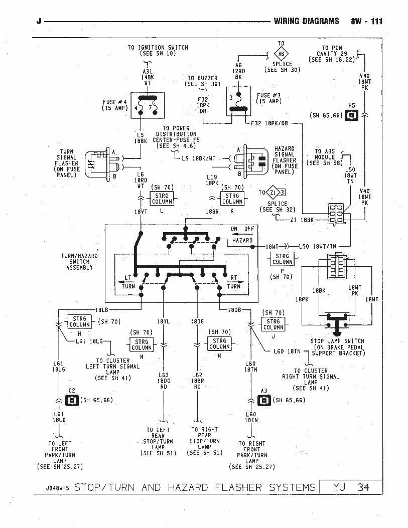
Starter Relay . . . . . . . . . . . . . . . . . . . . . . . . . . . . . . . .7Starter System, Engine . . . . . . . . . . . . . . . . . . . . . . . . . .7Steering Column Connector . . . . . . . . . . . . . . . . . . . . . .70Stop Lamp Switch . . . . . . . . . . . . . . . . . . . . . . . . . . . .34Stop/Turn and Hazard Flasher Systems . . . . . . . . . . . . . .34
Hazard Signal Flasher . . . . . . . . . . . . . . . . . . . . . . . .34Stop Lamp Switch . . . . . . . . . . . . . . . . . . . . . . . . . .34
Wiring Diagram Name Sheet NumberTurn/Hazard Switch Assembly . . . . . . . . . . . . . . . . . . .34Turn Signal Flasher . . . . . . . . . . . . . . . . . . . . . . . . . .34
SwitchesA/C Blower Switch . . . . . . . . . . . . . . . . . . . . . . . . . .50A/C Low Pressure Switch . . . . . . . . . . . . . . . . . . . . .49Back-Up Lamp Switch . . . . . . . . . . . . . . . . . . . . . . . .7Blower Switch . . . . . . . . . . . . . . . . . . . . . . . . . . . . .47Brake Warning Switch . . . . . . . . . . . . . . . . . . . . . . . . .9Dimmer Switch . . . . . . . . . . . . . . . . . . . . . . . . . .1, 29Door Jamb Switch . . . . . . . . . . . . . . . . . . . . . . . . . .354-WD Drive Switch . . . . . . . . . . . . . . . . . . . . . . . . . .8Fog Lamp Switch . . . . . . . . . . . . . . . . . . . . . . . . . . .30Headlamp Switch . . . . . . . . . . . . . . . . . . . . . . . . .1, 29Heated Rear Window Switch . . . . . . . . . . . . . . . . . . . .53Heater/Off Switch . . . . . . . . . . . . . . . . . . . . . . . . . . .47Horn Switch . . . . . . . . . . . . . . . . . . . . . . . . . . . . . .33Ignition Key Warning Switch . . . . . . . . . . . . . . . . . . . .36Ignition Switch . . . . . . . . . . . . . . . . . . . . . . . . . . .2, 9Mercury Switch . . . . . . . . . . . . . . . . . . . . . . . . . . . . .8Panel/Lamp Dimmer Switch . . . . . . . . . . . . . . . . . .1, 31Park Brake Switch . . . . . . . . . . . . . . . . . . . . . . . . . . .9Park/Neutral Position Switch . . . . . . . . . . . . . . . . . . . .7Power Steering Switch . . . . . . . . . . . . . . . . . . . . . . .14Rear Wiper Switch . . . . . . . . . . . . . . . . . . . . . . . . . .37Seat Belt Switch . . . . . . . . . . . . . . . . . . . . . . . . . . .36Stop Lamp Switch . . . . . . . . . . . . . . . . . . . . . . . . . .34Washer Switch . . . . . . . . . . . . . . . . . . . . . . . . . .38, 40Wiper/Washer Switch . . . . . . . . . . . . . . . . . . . . . .38, 40
Tachometer . . . . . . . . . . . . . . . . . . . . . . . . . . . . . . . .42Throttle Position (Sensor) . . . . . . . . . . . . . . . . . . . .15, 21Timer . . . . . . . . . . . . . . . . . . . . . . . . . . . . . . . . . . . .54Transmission Range Illumination . . . . . . . . . . . . . . . . . . .32Turn/Hazard Switch Assembly . . . . . . . . . . . . . . . . . . . .34Turn Signal Flasher . . . . . . . . . . . . . . . . . . . . . . . . . . .34Underhood Light . . . . . . . . . . . . . . . . . . . . . . . . . . . . . .8Vehicle Speed Sensor . . . . . . . . . . . . . . . . . . . . . . .12, 18Voltmeter . . . . . . . . . . . . . . . . . . . . . . . . . . . . . . . . . .44Washer Pump . . . . . . . . . . . . . . . . . . . . . . . . .37, 38, 39Washer Switch . . . . . . . . . . . . . . . . . . . . . . . . . . .38, 40Wheel Sensors . . . . . . . . . . . . . . . . . . . . . . . . . . . . . .59Windshield Wiper System . . . . . . . . . . . . . . . . . . . . . . .38
Washer Pump . . . . . . . . . . . . . . . . . . . . . . . . . . . . .38Washer Switch . . . . . . . . . . . . . . . . . . . . . . . . . . . .38Wiper Motor . . . . . . . . . . . . . . . . . . . . . . . . . . . . . .38Wiper/Washer Switch . . . . . . . . . . . . . . . . . . . . . . . .38W/Wiper Circuit Breaker . . . . . . . . . . . . . . . . . . . . . . .38Wiper Switch . . . . . . . . . . . . . . . . . . . . . . . . . . . . .38
8W - 76 WIRING DIAGRAMS J

J WIRING DIAGRAMS 8W - 77


8W - 148 WIRING DIAGRAMS J

WIRING DIAGRAMS XJ
INDEX
Wiring Diagram Name Sheet NumberA/C Compressor Clutch Relay . . . . . . . . . . . . . . . . . . .3,69A/C Compressor Clutch . . . . . . . . . . . . . . . . . . . . . . . .69A/C Heater Blower Motor . . . . . . . . . . . . . . . . . . . . . . .70A/C Low Pressure Switch . . . . . . . . . . . . . . . . . . . . . . .69A/C Mode Select Switch . . . . . . . . . . . . . . . . . . . . . . . .70A/C Thermostat . . . . . . . . . . . . . . . . . . . . . . . . . . . . . .69ABS Diode . . . . . . . . . . . . . . . . . . . . . . . . . . . . . . . . .33ABS Green Indicator Lamp . . . . . . . . . . . . . . . . . . . . . .57ABS Hydraulic Actuation Unit . . . . . . . . . . . . . . . . . . . . .33ABS #1 Relay . . . . . . . . . . . . . . . . . . . . . . . . . . . . .3,31ABS #2 Relay . . . . . . . . . . . . . . . . . . . . . . . . . . . . .3,31ABS Pump Motor . . . . . . . . . . . . . . . . . . . . . . . . . . . .30ABS Red Indicator Lamp . . . . . . . . . . . . . . . . . . . . . . .57Ambient Temperature Sensor . . . . . . . . . . . . . . . . . . . . .53Antenna . . . . . . . . . . . . . . . . . . . . . . . . . . . . . . . . . . .71Antenna Mast . . . . . . . . . . . . . . . . . . . . . . . . . . . . . . .71Anti-Lock Brake Control Module Connector . . . . . . . . . . .109Anti-Lock Braking System . . . . . . . . . . . . . . .29,30,31,32,33
ABS Diode . . . . . . . . . . . . . . . . . . . . . . . . . . . . . . .33ABS Relays . . . . . . . . . . . . . . . . . . . . . . . . . . . . . . .31Anti-Lock Pump Motor . . . . . . . . . . . . . . . . . . . . . . .30Anti-Lock Brake System Module . . . . . . . . .29,30,31,32,33Data Link Connector . . . . . . . . . . . . . . . . . . . . . . . . .32G Sensor . . . . . . . . . . . . . . . . . . . . . . . . . . . . . . . .30Hydraulic Actuation Unit . . . . . . . . . . . . . . . . . . . . . .33Left Front Wheel Sensor . . . . . . . . . . . . . . . . . . . . . .29Left Rear Wheel Sensor . . . . . . . . . . . . . . . . . . . . . . .29Pedal Travel Sensor . . . . . . . . . . . . . . . . . . . . . . . . .30Right Front Wheel Sensor . . . . . . . . . . . . . . . . . . . . .29Right Rear Wheel Sensor . . . . . . . . . . . . . . . . . . . . . .29
Anti-Lock Brake System Module . . . . . . . . . . .29,30,31,32,33Anti-Lock Pump Motor . . . . . . . . . . . . . . . . . . . . . . . . .30Anti-Lock Relay . . . . . . . . . . . . . . . . . . . . . . . . . . . . . .31Ashtray Lamp . . . . . . . . . . . . . . . . . . . . . . . . . . . . . . .48Automatic Shut Down Relay . . . . . . . . . . . . . . . . . .3,12,17Automatic Transmission Control System (2.5L) . . . . . . . . .27
Front Axle Lock-Up Switch . . . . . . . . . . . . . . . . . . . . .27EMCC Relay . . . . . . . . . . . . . . . . . . . . . . . . . . . . . .27EMCC Solenoid . . . . . . . . . . . . . . . . . . . . . . . . . . . .27
Back-Up Lamp Switch . . . . . . . . . . . . . . . . . . . . . . . . .25Ballast Resistor . . . . . . . . . . . . . . . . . . . . . . . . . . . . . .89Battery . . . . . . . . . . . . . . . . . . . . . . . . . . . . . . . . . .1,7,8Blower Motor . . . . . . . . . . . . . . . . . . . . . . . . . . . . .68,70Blower Resistors . . . . . . . . . . . . . . . . . . . . . . . . . . .68,70Blower Switch . . . . . . . . . . . . . . . . . . . . . . . . . . . .68,70Body Ground . . . . . . . . . . . . . . . . . . . . . . . . . . . . . . .44Brake Warning Switch . . . . . . . . . . . . . . . . . . . . . . . . .67Bulkhead Disconnect . . . . . . . . . . . . . . . . .101,102,103,104Camshaft Position Sensor . . . . . . . . . . . . . . . . . . . . .11,20Cargo Lamp . . . . . . . . . . . . . . . . . . . . . . . . . . . . . . . .50Center High Mounted Stop Lamp . . . . . . . . . . . . . . . . . .98Charging System 2.5L . . . . . . . . . . . . . . . . . . . . . . . . . .5
Generator . . . . . . . . . . . . . . . . . . . . . . . . . . . . . . . . .5
Wiring Diagram Name Sheet NumberCharging System 4.OL . . . . . . . . . . . . . . . . . . . . . . . . . .6
Generator . . . . . . . . . . . . . . . . . . . . . . . . . . . . . . . . .6Chime Module . . . . . . . . . . . . . . . . . . . . . . . . . . . . . .74
Ignition Key Warning Switch . . . . . . . . . . . . . . . . . . . .74Seat Belt Switch . . . . . . . . . . . . . . . . . . . . . . . . . . .74
Cigar Lighter . . . . . . . . . . . . . . . . . . . . . . . . . . . . . . .37Cigar Lighter Lamp . . . . . . . . . . . . . . . . . . . . . . . . . . .48Circuit Breakers
In Line Circuit Breaker . . . . . . . . . . . . . . . . . . . . . . . .2Trailer Tow In-Line Circuit Breaker . . . . . . . . . . . . . . . .97Windshield Wiper Circuit Breaker . . . . . . . . . . . . . . .63,64
ConnectorsAnti-Lock Brake Control Module Connector . . . . . . . . .109Data Link Connector . . . . . . . . . . . . . . . . . . .16,18,25,32Instrument Cluster Connector . . . . . . . . . . . . . . . .55,108Main Body Connectors . . . . . . . . . . . . . . . . . . . . . . .112Power Mirror Connector . . . . . . . . . . . . . . . . . . . . . .110Powertrain Control Module Connector . . . . . . . . . . . . .111Remote Keyless Entry Module Connector . . . . . . . . . . .114Steering Column Connector . . . . . . . . . . . . . . . . . . .106Telltale Connector . . . . . . . . . . . . . . . . . . . . . . . .56,107Trailer Tow Connector . . . . . . . . . . . . . . . . . . . . . . . .93Transmission Control Module Connector . . . . . . . . . . .105
Cooling Fan Relay . . . . . . . . . . . . . . . . . . . . . . . . . . .3,23Courtesy Lamp . . . . . . . . . . . . . . . . . . . . . . . . . . . . . .49Crankshaft Position Sensor . . . . . . . . . . . . . . . . . . . .11,20Data Link Connector . . . . . . . . . . . . . . . . . . . .16,18,25,32Daytime Running Lamp Module (DRL) . . . . . . . . . . . . . . .38Daytime Running Lamp System . . . . . . . . . . . . . . . . . . .38Diode,ABS . . . . . . . . . . . . . . . . . . . . . . . . . . . . . . . . .33Distributor Ignition Coil . . . . . . . . . . . . . . . . . . . . . . .16,18Dome Lamp . . . . . . . . . . . . . . . . . . . . . . . . . . . . . . . .51Dome And Courtesy Lamps . . . . . . . . . . . . . . . . . .49,50,51
Cargo Lamp . . . . . . . . . . . . . . . . . . . . . . . . . . . . . .50Dome Lamp . . . . . . . . . . . . . . . . . . . . . . . . . . . . . .51Dome/Reading Lamp . . . . . . . . . . . . . . . . . . . . . . . . .51Glove Box Lamp . . . . . . . . . . . . . . . . . . . . . . . . . . .49Left Courtesy Lamp . . . . . . . . . . . . . . . . . . . . . . . . .49Reading Lamp . . . . . . . . . . . . . . . . . . . . . . . . . . . . .51Right Courtesy Lamp . . . . . . . . . . . . . . . . . . . . . . . .49Vanity Lamps . . . . . . . . . . . . . . . . . . . . . . . . . . . . .51
Dome Reading Lamp . . . . . . . . . . . . . . . . . . . . . . . . . .51Door Jamb Switch System . . . . . . . . . . . . . . . . . . . .75,76
Left Front Door Jamb Switch . . . . . . . . . . . . . . . . . . .75Left Rear Door Jamb Switch . . . . . . . . . . . . . . . . . . .75Liftgate Switch . . . . . . . . . . . . . . . . . . . . . . . . . . . .76Right Front Door Jamb Switch . . . . . . . . . . . . . . . . . .76Right Rear Door Jamb Switch . . . . . . . . . . . . . . . . . .76
EMCC Relay . . . . . . . . . . . . . . . . . . . . . . . . . . . . . . .3,27EMCC Solenoid . . . . . . . . . . . . . . . . . . . . . . . . . . . . . .27Engine Block Coolant Heater/Cigar Lighter . . . . . . . . . . . .37
Cigar Lighter . . . . . . . . . . . . . . . . . . . . . . . . . . . . . .37Engine Block Coolant Heater . . . . . . . . . . . . . . . . . . . .37
J WIRING DIAGRAMS 8W - 149

Wiring Diagram Name Sheet NumberEngine Block Heater . . . . . . . . . . . . . . . . . . . . . . . . .37Wall Plug . . . . . . . . . . . . . . . . . . . . . . . . . . . . . . . .37
Engine Coolant Temperature Sending Unit . . . . . . . . . . . . .24Engine Coolant Temperature Sensor . . . . . . . . . . . . . .14,19Engine Coolant Temperature Switch . . . . . . . . . . . . . . . . .24Engine Oil Pressure and Temperature System . . . . . . . . . .24
Engine Coolant Temperature Switch . . . . . . . . . . . . . . .24Engine Oil Pressure Sending Unit . . . . . . . . . . . . . . . .24Engine Oil Pressure Switch . . . . . . . . . . . . . . . . . . . .24
Engine Starter Motor . . . . . . . . . . . . . . . . . . . . . . . . . .7,8Engine Starter Relay . . . . . . . . . . . . . . . . . . . . . . . . .3,7,8Engine Starter System (2.5L) . . . . . . . . . . . . . . . . . . . . . .7
Battery . . . . . . . . . . . . . . . . . . . . . . . . . . . . . . . . . .7Engine Starter Motor . . . . . . . . . . . . . . . . . . . . . . . . .7Engine Starter Relay . . . . . . . . . . . . . . . . . . . . . . . . . .7Park/Neutral Position Switch . . . . . . . . . . . . . . . . . . . .7
Engine Starter System (4.OL) . . . . . . . . . . . . . . . . . . . . .8Battery . . . . . . . . . . . . . . . . . . . . . . . . . . . . . . . . . .8Engine Starter Motor . . . . . . . . . . . . . . . . . . . . . . . . .8Engine Starter Relay . . . . . . . . . . . . . . . . . . . . . . . . . .8
Fan Control Relay . . . . . . . . . . . . . . . . . . . . . . . . . . . .23Fog Lamp Illumination . . . . . . . . . . . . . . . . . . . . . . .42,47Fog Lamps . . . . . . . . . . . . . . . . . . . . . . . . . . . . . .39,40Fog Lamp Switch . . . . . . . . . . . . . . . . . . . . . . . . . . . .42Front Axle Switch . . . . . . . . . . . . . . . . . . . . . . . . . .26,27Front Door Lock and Window Switch Functions . . . . . . . . .87Front End Lighting . . . . . . . . . . . . . . . . . . . . . . . . . .39,40
High Beam Relay . . . . . . . . . . . . . . . . . . . . . . . . . . .40Left Fog Lamp . . . . . . . . . . . . . . . . . . . . . . . . . . . . .39Left Headlamp . . . . . . . . . . . . . . . . . . . . . . . . . . . . .39Left Park/Turn Signal Lamp . . . . . . . . . . . . . . . . . . . .39Left Side Marker Lamp . . . . . . . . . . . . . . . . . . . . . . .39Park Lamp Relay . . . . . . . . . . . . . . . . . . . . . . . . . . .39Right Fog Lamp . . . . . . . . . . . . . . . . . . . . . . . . . . . .40Right Headlamp . . . . . . . . . . . . . . . . . . . . . . . . . . . .40Right Park/Turn Signal Lamp . . . . . . . . . . . . . . . . . . .40Right Side Marker Lamp . . . . . . . . . . . . . . . . . . . . . .40
Front Washer Pump . . . . . . . . . . . . . . . . . . . . . . . . .63,64Front Wiper Motor . . . . . . . . . . . . . . . . . . . . . . . . . .63,64Front Wipers/Washer (Intermittent) . . . . . . . . . . . . . . . . .64
Front Washer Pump . . . . . . . . . . . . . . . . . . . . . . . . .64Front Wiper Motor . . . . . . . . . . . . . . . . . . . . . . . . . .64Wiper/Washer Switch . . . . . . . . . . . . . . . . . . . . . . . .64Intermittent Wiper Module . . . . . . . . . . . . . . . . . . . . .64
Front Wiper/Washer (Standard) . . . . . . . . . . . . . . . . . . . .63Front Washer Pump . . . . . . . . . . . . . . . . . . . . . . . . .63Front Wiper Motor . . . . . . . . . . . . . . . . . . . . . . . . . .63Wiper/Washer Switch . . . . . . . . . . . . . . . . . . . . . . . .63
Fuel Injection Ignition System (2.5L) . . . . . .11,12,13,14,15,16Automatic Shut Down Relay . . . . . . . . . . . . . . . . . . . .12Camshaft Position Sensor . . . . . . . . . . . . . . . . . . . . .11Crankshaft Position Sensor . . . . . . . . . . . . . . . . . . . . .11Data Link Connector . . . . . . . . . . . . . . . . . . . . . . . . .16Distributor Ignition Coil . . . . . . . . . . . . . . . . . . . . . . .16Engine Coolant Temperature Sensor . . . . . . . . . . . . . . .14Fuel Pump Relay . . . . . . . . . . . . . . . . . . . . . . . . . . .12Heated Oxygen Sensor . . . . . . . . . . . . . . . . . . . . . . .13Idle Air Control Motor . . . . . . . . . . . . . . . . . . . . . . . .15
Wiring Diagram Name Sheet NumberInjectors . . . . . . . . . . . . . . . . . . . . . . . . . . . . . . . . .15Intake Air Temperature Sensor . . . . . . . . . . . . . . . . . .14MAP Sensor . . . . . . . . . . . . . . . . . . . . . . . . . . . . . .14Power Steering Pressure Switch . . . . . . . . . . . . . . . . .15Powertrain Control Module . . . . . . . . . . .11,12,13,14,15,16Throttle Position Sensor . . . . . . . . . . . . . . . . . . . . . .14Vehicle Speed Sensor . . . . . . . . . . . . . . . . . . . . . . . .11
Fuel Injection Ignition System (4.OL) . . . . . .17,18,19,20,21,22Automatic Shut Down Relay . . . . . . . . . . . . . . . . . . . .17Camshaft Position Sensor . . . . . . . . . . . . . . . . . . . . .20Crankshaft Position Sensor . . . . . . . . . . . . . . . . . . . . .20Data Link Connector . . . . . . . . . . . . . . . . . . . . . . . . .18Distributor Ignition Coil . . . . . . . . . . . . . . . . . . . . . . .18Engine Coolant Temperature Sensor . . . . . . . . . . . . . . .19Fuel Pump Relay . . . . . . . . . . . . . . . . . . . . . . . . . . .17Heated Oxygen Sensor . . . . . . . . . . . . . . . . . . . . . . .21Idle Air Control Motor . . . . . . . . . . . . . . . . . . . . . . . .22Intake Air Temperature Sensor . . . . . . . . . . . . . . . . . .19Injectors . . . . . . . . . . . . . . . . . . . . . . . . . . . . . . . . .22MAP Sensor . . . . . . . . . . . . . . . . . . . . . . . . . . . . . .19Powertrain Control Module . . . . . . . . . . .17,18,19,20,21,22Throttle Position Sensor . . . . . . . . . . . . . . . . . . . . . .19Vehicle Speed Sensor . . . . . . . . . . . . . . . . . . . . . . . .20
Fuel Injector(s) . . . . . . . . . . . . . . . . . . . . . . . . . . . .15,22Fuel Pump Relay . . . . . . . . . . . . . . . . . . . . . . . . .3,12,17Fuel Tank Level Gauge Sending Unit . . . . . . . . . . . . . . . .90Fuel Tank System . . . . . . . . . . . . . . . . . . . . . . . . . .89,90
Ballast Resistor . . . . . . . . . . . . . . . . . . . . . . . . . . . .89Fuel Tank Level Gauge Sending Unit . . . . . . . . . . . . . .90
Full Time Indicator Lamp . . . . . . . . . . . . . . . . . . . . .57,58Fuse Application Chart . . . . . . . . . . . . . . . . . . . . . . . . .1,2Fuse Panel . . . . . . . . . . . . . . . . . . . . . . . . . . . . . .99,100Fuses
F1 . . . . . . . . . . . . . . . . . . . . . . . . . . . . . . . . . . . .3,4F2 . . . . . . . . . . . . . . . . . . . . . . . . . . . . . . . .3,4,12,17F3 . . . . . . . . . . . . . . . . . . . . . . . . . . . . . . . . . . . .3,4F4 . . . . . . . . . . . . . . . . . . . . . . . . . . . . . . . . . . . .3,4F5 . . . . . . . . . . . . . . . . . . . . . . . . . . . . . . . . . . . .3,4F6 . . . . . . . . . . . . . . . . . . . . . . . . . . . . . . . . . . . .3,4F7 . . . . . . . . . . . . . . . . . . . . . . . . . . . . . . . . . . . .3,4F8 . . . . . . . . . . . . . . . . . . . . . . . . . . . . . . . . . . . .3,4F9 . . . . . . . . . . . . . . . . . . . . . . . . . . . . . . . . . . . .3,4F10 . . . . . . . . . . . . . . . . . . . . . . . . . . . . . . . . . . .3,4F11 . . . . . . . . . . . . . . . . . . . . . . . . . . . . . . . . . . .3,4F12 . . . . . . . . . . . . . . . . . . . . . . . . . . . . . . . . . . .3,4F13 . . . . . . . . . . . . . . . . . . . . . . . . . . . . . . . . . . .3,4F14 . . . . . . . . . . . . . . . . . . . . . . . . . . . . . . . . . . .3,4F15 . . . . . . . . . . . . . . . . . . . . . . . . . . . . . . . . . . .3,4F16 . . . . . . . . . . . . . . . . . . . . . . . . . . . . . . . . . . .3,4Fuse #1 . . . . . . . . . . . . . . . . . . . . . . . . . . . . . .2,10,65Fuse #2 . . . . . . . . . . . . . . . . . . . . . . . . . . . . .2,9,37,71Fuse #4 . . . . . . . . . . . . . . . . . . . . . . . . . . . . . . . .1,41Fuse #5 . . . . . . . . . . . . . . . . . . . . . . . . . .2,63,64,68,70Fuse #7 . . . . . . . . . . . . . . . . . . . . . . . . . . . . . .2,10,32Fuse #8 . . . . . . . . . . . . . . . . . . . . . . . . . . . . . .2,45,66Fuse #9 . . . . . . . . . . . . . . . . . . . . . . . . . . . . . . .1,4,49Fuse #11 . . . . . . . . . . . . . . . . . . . . . . . . . . . . .1,43,83Fuse #13 . . . . . . . . . . . . . . . . . . . . . . . . . . . . .1,43,83
8W - 150 WIRING DIAGRAMS J

Wiring Diagram Name Sheet NumberFuse #15 . . . . . . . . . . . . . . . . . . . . . . . . . . . . . . .1,41Fuse #17 . . . . . . . . . . . . . . . . . . . . . . . . . . .2,10,55,74Fuse #18 . . . . . . . . . . . . . . . . . . . . . . . . . . . . . . .1,66Fuse #19 . . . . . . . . . . . . . . . . . . . . . . . . . . . . .1,41,47
GaugesEngine Coolant Temperature Gauge . . . . . . . . . . .59,60,61Engine Oil Pressure Gauge . . . . . . . . . . . . . . . . .59,60,61Fuel Gauge . . . . . . . . . . . . . . . . . . . . . . . . . . .59,60,61
G Sensor . . . . . . . . . . . . . . . . . . . . . . . . . . . . . . . . . .30Generator . . . . . . . . . . . . . . . . . . . . . . . . . . . . . . . . .5,6Glove Box Lamp . . . . . . . . . . . . . . . . . . . . . . . . . . . . .49Hazard Flasher . . . . . . . . . . . . . . . . . . . . . . . . . . . .35,46Headlamp Delay Module . . . . . . . . . . . . . . . . . . . . . . . .43Headlamp Dimmer Switch . . . . . . . . . . . . . . . . . . . . . . .41Headlamp Switch . . . . . . . . . . . . . . . . . . . . . . . . . . .41,42
Fog Lamp Illumination . . . . . . . . . . . . . . . . . . . . . . . .42Fog Lamp Switch . . . . . . . . . . . . . . . . . . . . . . . . . . .42Headlamp Dimmer Switch . . . . . . . . . . . . . . . . . . . . .41Headlamp Switch . . . . . . . . . . . . . . . . . . . . . . . . . . .41
Headlamps . . . . . . . . . . . . . . . . . . . . . . . . . . . . . . .39,40Heat Mode Select Switch . . . . . . . . . . . . . . . . . . . . . . .68Heated Oxygen Sensor . . . . . . . . . . . . . . . . . . . . . . .13,21Heated Rear Window . . . . . . . . . . . . . . . . . . . . . . . . . .66
Relay . . . . . . . . . . . . . . . . . . . . . . . . . . . . . . . . . . .66Grid . . . . . . . . . . . . . . . . . . . . . . . . . . . . . . . . . . .66Switch . . . . . . . . . . . . . . . . . . . . . . . . . . . . . . . . . .66
Heated Rear Window Switch Lamp . . . . . . . . . . . . . . . . .47Heater A/C Panel Lamp . . . . . . . . . . . . . . . . . . . . . . . .47Heater and A/C System . . . . . . . . . . . . . . . . . . . . . .69,70
A/C Mode Selector Switch . . . . . . . . . . . . . . . . . . . . .70A/C Compressor Clutch . . . . . . . . . . . . . . . . . . . . . . .69A/C Compressor Clutch Relay . . . . . . . . . . . . . . . . . . .69A/C Heater Blower Motor . . . . . . . . . . . . . . . . . . . . . .70A/C Thermostat . . . . . . . . . . . . . . . . . . . . . . . . . . . .69A/C Low Pressure Switch . . . . . . . . . . . . . . . . . . . . .69Blower Resistor . . . . . . . . . . . . . . . . . . . . . . . . . . . .70Blower Switch . . . . . . . . . . . . . . . . . . . . . . . . . . . . .70Powertrain Control Module . . . . . . . . . . . . . . . . . . . . .69
Heat Mode Select Switch . . . . . . . . . . . . . . . . . . . . . . .68Heater Blower Motor . . . . . . . . . . . . . . . . . . . . . . . . . .68Heater,Engine Block . . . . . . . . . . . . . . . . . . . . . . . . . . .37Heater System . . . . . . . . . . . . . . . . . . . . . . . . . . . . . .68
Blower Resistor . . . . . . . . . . . . . . . . . . . . . . . . . . . .68Blower Switch . . . . . . . . . . . . . . . . . . . . . . . . . . . . .68Heater Blower Motor . . . . . . . . . . . . . . . . . . . . . . . . .68Heater Mode Select Switch . . . . . . . . . . . . . . . . . . . .68
Heavy Duty Cooling 4.OL . . . . . . . . . . . . . . . . . . . . . . .23Fan Control Relay . . . . . . . . . . . . . . . . . . . . . . . . . . .23Powertrain Control Module . . . . . . . . . . . . . . . . . . . . .23Radiator Fan Motor . . . . . . . . . . . . . . . . . . . . . . . . .23
High Beam Indicator Lamp . . . . . . . . . . . . . . . . . .59,60,61High Beam Relay . . . . . . . . . . . . . . . . . . . . . . . . . . . .40Hi-Line Instrument Cluster . . . . . . . . . . . . . . . . . . . . . . .61Horn Brush/Slip Ring . . . . . . . . . . . . . . . . . . . . . . . . . .34Horn Relay . . . . . . . . . . . . . . . . . . . . . . . . . . . . . . . .34Horn Switch . . . . . . . . . . . . . . . . . . . . . . . . . . . . . . . .34Horns . . . . . . . . . . . . . . . . . . . . . . . . . . . . . . . . . . . .34Hydraulic Actuation Unit, ABS . . . . . . . . . . . . . . . . . . . .33
Wiring Diagram Name Sheet NumberIdle Air Control Motor . . . . . . . . . . . . . . . . . . . . . . .15,22Ignition Key Warning Switch . . . . . . . . . . . . . . . . . . . . .74Ignition Switch . . . . . . . . . . . . . . . . . . . . . . . . . . . . . .2,9Ignition System . . . . . . . . . . . . . . . . . . . . . . . . . . . .9,10Injectors . . . . . . . . . . . . . . . . . . . . . . . . . . . . . . . .15,22In Line Circuit Breaker . . . . . . . . . . . . . . . . . . . . . . . . . .2Instrument Cluster . . . . . . . . . . . . . . . . . . . . . . . . . . . .55
Powertrain Control Module . . . . . . . . . . . . . . . . . . . . .55Washer Fluid Level Switch . . . . . . . . . . . . . . . . . . . . .55
Instrument Cluster (Hi-Line) . . . . . . . . . . . . . . . . . . . . . .61Instrument Cluster (Lo-Line) . . . . . . . . . . . . . . . . . . . . .60Instrument Cluster (Standard) . . . . . . . . . . . . . . . . . . . .59Instrument Cluster Connector . . . . . . . . . . . . . . . . . .55,108Instrument Cluster Printed Circuit Board (W/ABS) . . . . . . .57Instrument Cluster Printed Circuit Board (W/O ABS) . . . . . .58Instrument Cluster Indicators . . . . . . . . . . . . . . . . . . . . .56Instrument Panel Ground . . . . . . . . . . . . . . . . . . . . . . .62Instrument Panel Illumination . . . . . . . . . . . . . . . . . . .47,48
Ashtray Lamp . . . . . . . . . . . . . . . . . . . . . . . . . . . . .48Cigar Lighter Lamp . . . . . . . . . . . . . . . . . . . . . . . . . .48Fog Lamp Illumination . . . . . . . . . . . . . . . . . . . . . . . .47Heater A/C Panel Lamp . . . . . . . . . . . . . . . . . . . . . . .47Heater Rear Window Switch Lamp . . . . . . . . . . . . . . . .47Rear Wiper Wash Switch Lamp . . . . . . . . . . . . . . . . . .47Transfer Case Lamp . . . . . . . . . . . . . . . . . . . . . . . . .48Transmission Range Switch Lamp . . . . . . . . . . . . . . . .48
Intake Air Temperature Sensor . . . . . . . . . . . . . . . . . .14,19Intermittent Front Wipers/Washers . . . . . . . . . . . . . . . . .64Intermittent Wiper Module . . . . . . . . . . . . . . . . . . . . . . .64Lamps
ABS Green Indicator Lamp . . . . . . . . . . . . . . . . . . . . .57ABS Red Indicator Lamp . . . . . . . . . . . . . . . . . . . . . .57Ashtray Lamp . . . . . . . . . . . . . . . . . . . . . . . . . . . . .48Cargo Lamp . . . . . . . . . . . . . . . . . . . . . . . . . . . . . .50Center High Mounted Stop Lamps . . . . . . . . . . . . . . . .98Cigar Lighter Lamp . . . . . . . . . . . . . . . . . . . . . . . . . .48Dome Lamp . . . . . . . . . . . . . . . . . . . . . . . . . . . . . .51Dome/Reading Lamp . . . . . . . . . . . . . . . . . . . . . . . . .51Fog Lamp Illumination . . . . . . . . . . . . . . . . . . . . . . . .474WD Indicator Lamp . . . . . . . . . . . . . . . . . . . . .26,57,58Full Time Indicator Lamp . . . . . . . . . . . . . . . . . . . .57,58Glove Box Lamp . . . . . . . . . . . . . . . . . . . . . . . . . . .49Heated Rear Window Switch Lamp . . . . . . . . . . . . . . .47Heater A/C Panel Lamp . . . . . . . . . . . . . . . . . . . . . . .47High Beam Indicator Lamp . . . . . . . . . . . . . . . . .59,60,61Indicator Lamp 4WD . . . . . . . . . . . . . . . . . . . . . . .57,58Instrument Cluster Illumination Lamps . . . . . . . . .59,60,61Left Back-Up Lamp . . . . . . . . . . . . . . . . . . . . . . . .91,93Left Courtesy Lamp . . . . . . . . . . . . . . . . . . . . . . . . .49Left Fog Lamp . . . . . . . . . . . . . . . . . . . . . . . . . . . . .39Left Headlamp . . . . . . . . . . . . . . . . . . . . . . . . . . . . .39Left Park/Turn Signal Lamp . . . . . . . . . . . . . . . . . . . .39Left Side Marker Lamp (Front) . . . . . . . . . . . . . . . . . .39Left Side Marker Lamp (Rear) . . . . . . . . . . . . . . . .91,93Left Tail/Stop Lamp . . . . . . . . . . . . . . . . . . . . . . .91,93Left Turn Indicator Lamp . . . . . . . . . . . . . . . . . .59,60,61Left Turn Lamp (Amber) . . . . . . . . . . . . . . . . . . . .91,93Left Vanity Lamp . . . . . . . . . . . . . . . . . . . . . . . . . . .51
J WIRING DIAGRAMS 8W - 151

Wiring Diagram Name Sheet NumberLicense Lamp . . . . . . . . . . . . . . . . . . . . . . . . . . .91,95Low Washer Indicator Lamp . . . . . . . . . . . . . . . . . .57,58Malfunction Indicator Lamp . . . . . . . . . . . . . . . . . .57,58Maintenance Required Indicator Lamp . . . . . . . . . . .57,58Park Brake Indicator Lamp . . . . . . . . . . . . . . . . . . . . .58Reading Lamp . . . . . . . . . . . . . . . . . . . . . . . . . . . . .51Rear Wiper/Wash Switch Lamp . . . . . . . . . . . . . . . . . .47Right Back-Up Lamp . . . . . . . . . . . . . . . . . . . . . . .92,96Right Courtesy Lamp . . . . . . . . . . . . . . . . . . . . . . . .49Right Fog Lamp . . . . . . . . . . . . . . . . . . . . . . . . . . . .40Right Headlamp . . . . . . . . . . . . . . . . . . . . . . . . . . . .40Right Park/Turn Signal Lamp . . . . . . . . . . . . . . . . . . .40Right Side Marker Lamp (Front) . . . . . . . . . . . . . . . . .40Right Side Marker (Rear) . . . . . . . . . . . . . . . . . . . .92,96Right Tail/Stop Lamp . . . . . . . . . . . . . . . . . . . . . .92,96Right Turn Indicator Lamp . . . . . . . . . . . . . . . . .59,60,61Right Turn Lamp (Amber) . . . . . . . . . . . . . . . . . . .92,96Right Vanity Lamp . . . . . . . . . . . . . . . . . . . . . . . . . .51Seat Belt Warning Indicator Lamp . . . . . . . . . . . . . .57,58Transfer Case Lamp . . . . . . . . . . . . . . . . . . . . . . . . .48Transmission Range Switch Lamp . . . . . . . . . . . . . . . .48Underhood Lamp . . . . . . . . . . . . . . . . . . . . . . . . . . .34Upshift Indicator Lamp . . . . . . . . . . . . . . . . . . . . .57,58Vanity Lamps . . . . . . . . . . . . . . . . . . . . . . . . . . .51,53
L.C.D. Illumination Relay . . . . . . . . . . . . . . . . . . . . . . . .52Left Front Door Connector And Door Lock Switch
Function Chart . . . . . . . . . . . . . . . . . . . . . . . . . . . . .87Left Front Door Connector and Widow Lift Switch
Function Chart . . . . . . . . . . . . . . . . . . . . . . . . . . . . .87Left Front Door Jamb Switch . . . . . . . . . . . . . . . . . . . . .75Left Front Door Lock Motor . . . . . . . . . . . . . . . . . . . . . .86Left Front Door Speaker . . . . . . . . . . . . . . . . . . . . . . . .71Left Front Wheel Sensor . . . . . . . . . . . . . . . . . . . . . . . .29Left Instrument Panel Speaker . . . . . . . . . . . . . . . . . . . .71Left Liftgate Speaker . . . . . . . . . . . . . . . . . . . . . . . . . .72Left Power Seat Motor Assembly . . . . . . . . . . . . . . . . . .77Left Power Seat Switch . . . . . . . . . . . . . . . . . . . . . . . .77Left Rear Door Connector and Window Lift Switch
Function Chart . . . . . . . . . . . . . . . . . . . . . . . . . . . . .88Left Rear Door Jamb Switch . . . . . . . . . . . . . . . . . . . . .75Left Rear Door Window Switch . . . . . . . . . . . . . . . . . . .82Left Rear Wheel Sensor . . . . . . . . . . . . . . . . . . . . . . . .29Left Turn Relay . . . . . . . . . . . . . . . . . . . . . . . . . . . . . .97Liftgate Switch . . . . . . . . . . . . . . . . . . . . . . . . . . . . . .76Liftgate Lock motor . . . . . . . . . . . . . . . . . . . . . . . . . . .86Lo-Line Instrument Cluster Printed Circuit Board . . . . . . . .60Low Fuel Warning Module . . . . . . . . . . . . . . . . . . .59,60,61Low Washer Indicator Lamp . . . . . . . . . . . . . . . . . . .57,58Main Body Connectors . . . . . . . . . . . . . . . . . . . . . . . .112Maintenance Required Indicator Lamp . . . . . . . . . . . . .57,58Malfunction Indicator Lamp . . . . . . . . . . . . . . . . . . . .57,58Map Sensor . . . . . . . . . . . . . . . . . . . . . . . . . . . . . .14,19Modules
Anti-Lock Brake System Module . . . . . . . . .29,30,31,32,33Chime Module . . . . . . . . . . . . . . . . . . . . . . . . . . . . .74Daytime Running Lamp Module . . . . . . . . . . . . . . . . .38Headlamp Delay Module . . . . . . . . . . . . . . . . . . . . . .43Intermittent Wiper Module . . . . . . . . . . . . . . . . . . . . .64
Wiring Diagram Name Sheet NumberLow Fuel Warning Module . . . . . . . . . . . . . . . . .59,60,61Powertrain Control Module . . . .11,12,13,14,15,16,17, 18,19,
20,21,22,23,35,36,45,55,69Remote Keyless Entry Module . . . . . . . . . . . . . . . . . . .28Transmission Control Module . . . . . . . . . . . . . . . . .25,26
MotorsABS Pump Motor . . . . . . . . . . . . . . . . . . . . . . . . . . .30A/C Heater Blower Motor . . . . . . . . . . . . . . . . . . . . . .70Engine Starter Motor . . . . . . . . . . . . . . . . . . . . . . . .7,8Front Wiper Motor . . . . . . . . . . . . . . . . . . . . . . . .63,64Heater Blower Motor . . . . . . . . . . . . . . . . . . . . . . . . .68Idle Air Control Motor . . . . . . . . . . . . . . . . . . . . . .15,22Left Front Door Lock Motor . . . . . . . . . . . . . . . . . . . .86Left Front Door Window Motor . . . . . . . . . . . . . . . . . .81Left Power Mirror . . . . . . . . . . . . . . . . . . . . . . . . . .73Left Power Seat Motor Assembly . . . . . . . . . . . . . . . .77Left Rear Door Lock Motor . . . . . . . . . . . . . . . . . . . .86Left Rear Door Window Motor . . . . . . . . . . . . . . . . . .82Liftgate Lock Motor . . . . . . . . . . . . . . . . . . . . . . . . .86Radiator Fan Motor . . . . . . . . . . . . . . . . . . . . . . . . .23Rear Wiper Motor . . . . . . . . . . . . . . . . . . . . . . . . . .65Right Front Door Lock Motor . . . . . . . . . . . . . . . . . . .86Right Front Door Window Motor . . . . . . . . . . . . . . . . .81Right Power Mirror . . . . . . . . . . . . . . . . . . . . . . . . .73Right Rear Door Lock Motor . . . . . . . . . . . . . . . . . . .86Right Rear Door Window Motor . . . . . . . . . . . . . . . . .82
Oil Pressure Switch . . . . . . . . . . . . . . . . . . . . . . . . . . .24Overhead Console System . . . . . . . . . . . . . . . . . . . . .53,54
Ambient Temperature Sensor . . . . . . . . . . . . . . . . . . .53Overhead Console . . . . . . . . . . . . . . . . . . . . . . . . . .53Vanity Lamps . . . . . . . . . . . . . . . . . . . . . . . . . . . . .53
Park Brake Switch . . . . . . . . . . . . . . . . . . . . . . . . . . . .67Park Brake Indicator Lamp . . . . . . . . . . . . . . . . . . . . . .58Parking Brake Switch . . . . . . . . . . . . . . . . . . . . . . . . . .67Park Lamp Relay . . . . . . . . . . . . . . . . . . . . . . . . . . . . .39Park/Neutral Position Switch . . . . . . . . . . . . . . . . . . . . . .7Pedal Travel Sensor . . . . . . . . . . . . . . . . . . . . . . . . . . .30Power Distribution Center . . . . . . . . . . . . . . . . . . . .1,2,3,4Power Distribution Center Application Chart . . . . . . . . . . . .4Power Distribution Center Identification . . . . . . . . . . . . . . .3Power Door Locks . . . . . . . . . . . . . . . . . . . . . .83,84,85,86
Left Door Lock Switch . . . . . . . . . . . . . . . . . . . . . . .85Left Front Door Lock Motor . . . . . . . . . . . . . . . . . . . .86Left Rear Door Lock Motor . . . . . . . . . . . . . . . . . . . .86Liftgate Lock Motor . . . . . . . . . . . . . . . . . . . . . . . . .86Power Door Lock Relay . . . . . . . . . . . . . . . . . . . . . . .83Power Door Unlock Relay . . . . . . . . . . . . . . . . . . . . .83Right Door Lock Switch . . . . . . . . . . . . . . . . . . . . . .85Right Front Door Lock Motor . . . . . . . . . . . . . . . . . . .86Right Rear Door Lock Motor . . . . . . . . . . . . . . . . . . .86
Power Door Lock Relay . . . . . . . . . . . . . . . . . . . . . . . .83Power Door Unlock Relay . . . . . . . . . . . . . . . . . . . . . . .83Power Mirror Connector . . . . . . . . . . . . . . . . . . . . . . .110Power Mirror Connector and Switch Function Chart . . . . . .88Power Mirror Switch Assembly . . . . . . . . . . . . . . . . . . .73Power Mirror System . . . . . . . . . . . . . . . . . . . . . . . . . .73
Left Power Mirror . . . . . . . . . . . . . . . . . . . . . . . . . .73Power Mirror Switch Assembly . . . . . . . . . . . . . . . . . .73
8W - 152 WIRING DIAGRAMS J

Wiring Diagram Name Sheet NumberRight Power Mirror . . . . . . . . . . . . . . . . . . . . . . . . .73Power Mirrors . . . . . . . . . . . . . . . . . . . . . . . . . . . . .73
Power Seat . . . . . . . . . . . . . . . . . . . . . . . . . . . . . .77,78Left Power Seat Motor Assembly . . . . . . . . . . . . . . . .77Left Power Seat Switch . . . . . . . . . . . . . . . . . . . . . . .78
Power Steering Pressure Switch . . . . . . . . . . . . . . . . . . .15Powertrain Control Module . . . . . .11,12,13,14,15,16,17,18,19,
20,21,22,23,35,36,45,55,69Powertrain Control Module (PCM) Connector . . . . . . . . . .111Power Windows . . . . . . . . . . . . . . . . . . . . . . .79,80,81,82
Left Front Door Window Motor . . . . . . . . . . . . . . . . . .81Left Rear Door Window Motor . . . . . . . . . . . . . . . . . .82Left Rear Door Window Switch . . . . . . . . . . . . . . . . . .82Power Window Switch . . . . . . . . . . . . . . . . . . . . . . .79Right Front Door Window Switch . . . . . . . . . . . . . . . .81Right Front Door Window Motor . . . . . . . . . . . . . . . . .81Right Rear Door Window Motor . . . . . . . . . . . . . . . . .82Right Rear Door Window Switch . . . . . . . . . . . . . . . . .82
Power Window Switch . . . . . . . . . . . . . . . . . . . . . . . . .79Printed Circuit Boards . . . . . . . . . . . . . . . . .57,58,59,60,61Pumps
Front Washer . . . . . . . . . . . . . . . . . . . . . . . . . . .63,64Rear Washer . . . . . . . . . . . . . . . . . . . . . . . . . . . . . .65
Radiator Fan Motor . . . . . . . . . . . . . . . . . . . . . . . . . . .23Radio . . . . . . . . . . . . . . . . . . . . . . . . . . . . . . . . . . . .71
Antenna Mast . . . . . . . . . . . . . . . . . . . . . . . . . . . . .71Left Front Door Speaker . . . . . . . . . . . . . . . . . . . . . .71Left Instrument Panel Speaker . . . . . . . . . . . . . . . . . .71Left Liftgate Speaker . . . . . . . . . . . . . . . . . . . . . . . . .72Right Front Door Speaker . . . . . . . . . . . . . . . . . . . . .72Right Instrument Panel Speaker . . . . . . . . . . . . . . . . .72Right Liftgate Speaker . . . . . . . . . . . . . . . . . . . . . . . .72
Reading Lamps . . . . . . . . . . . . . . . . . . . . . . . . . . . . . .51Rear Lighting . . . . . . . . . . . . . . . . . . .91,92,93,94,95,96,97
Left Back-Up Lamp . . . . . . . . . . . . . . . . . . . . . . . .91,93Left Side Marker Lamp (Rear) . . . . . . . . . . . . . . . .91,93Left Tail/Stop Lamp . . . . . . . . . . . . . . . . . . . . . . .91,93Left Turn Lamp (Amber) . . . . . . . . . . . . . . . . . . . .91,93Left Turn Relay . . . . . . . . . . . . . . . . . . . . . . . . . . . .97License Lamp . . . . . . . . . . . . . . . . . . . . . . . . . . .91,95Right Back-Up Lamp . . . . . . . . . . . . . . . . . . . . . . .92,96Right Side Marker Lamp (Rear) . . . . . . . . . . . . . . .92,96Right Tail/Stop Lamp . . . . . . . . . . . . . . . . . . . . . .92,96Right Turn Lamp (Amber) . . . . . . . . . . . . . . . . . . .92,96Right Turn Relay . . . . . . . . . . . . . . . . . . . . . . . . . . .97Stop Lamp Relay . . . . . . . . . . . . . . . . . . . . . . . . . . .97Trailer Tow Connector . . . . . . . . . . . . . . . . . . . . . . . .93Trailer Tow In-Line Circuit Breaker . . . . . . . . . . . . . . . .97
Rear Lighting With Trailer Tow . . . . . . . . . . . .93,94,95,96,97Rear Lighting Without Trailer Tow . . . . . . . . . . . . . . . .91,92Rear Washer Pump . . . . . . . . . . . . . . . . . . . . . . . . . . .65Rear Wiper Motor . . . . . . . . . . . . . . . . . . . . . . . . . . . .65Rear Wiper/Washer Motor . . . . . . . . . . . . . . . . . . . . . . .65Rear Washer Pump . . . . . . . . . . . . . . . . . . . . . . . . . . .65Rear Wiper Motor . . . . . . . . . . . . . . . . . . . . . . . . . . . .65Rear Wiper/Washer Switch . . . . . . . . . . . . . . . . . . . . . .65Rear Wiper/Washer Switch Lamp . . . . . . . . . . . . . . . . . .47Reed Switch . . . . . . . . . . . . . . . . . . . . . . . . . . . . . . . .26
Wiring Diagram Name Sheet NumberRelays
ABS #1 Relay . . . . . . . . . . . . . . . . . . . . . . . . . . . .3,31ABS #2 Relay . . . . . . . . . . . . . . . . . . . . . . . . . . . .3,31A/C Compressor Clutch Relay . . . . . . . . . . . . . . . . . .3,69Automatic Shut Down Relay . . . . . . . . . . . . . . . . .3,12,17Cooling Fan Relay . . . . . . . . . . . . . . . . . . . . . . . . . . .3EMCC Relay . . . . . . . . . . . . . . . . . . . . . . . . . . . . .3,27Engine Starter Relay . . . . . . . . . . . . . . . . . . . . . . .3,7,8Fan Control Relay . . . . . . . . . . . . . . . . . . . . . . . . . . .23Fuel Pump Relay . . . . . . . . . . . . . . . . . . . . . . . .3,12,17Heated Rear Window Relay . . . . . . . . . . . . . . . . . . . .66High Beam Relay . . . . . . . . . . . . . . . . . . . . . . . . . . .40Horn Relay . . . . . . . . . . . . . . . . . . . . . . . . . . . . . . .34L.C.D. Illumination Relay . . . . . . . . . . . . . . . . . . . . . .52Left Turn Relay . . . . . . . . . . . . . . . . . . . . . . . . . . . .97Park Lamp Relay . . . . . . . . . . . . . . . . . . . . . . . . . . .39Power Door Lock Relay . . . . . . . . . . . . . . . . . . . . . . .83Power Door Unlock Relay . . . . . . . . . . . . . . . . . . . . .83Right Turn Relay . . . . . . . . . . . . . . . . . . . . . . . . . . .97Stop Lamp Relay . . . . . . . . . . . . . . . . . . . . . . . . . . .97
Relay Center Identification . . . . . . . . . . . . . . . . . . . . . .113Remote Keyless Entry System . . . . . . . . . . . . . . . . . . . .28
Remote Keyless Entry Module . . . . . . . . . . . . . . . . . . .28Remote Keyless Entry Module Connector . . . . . . . . . . .114
Resistor,Ballast . . . . . . . . . . . . . . . . . . . . . . . . . . . . . .39Resistor,Blower . . . . . . . . . . . . . . . . . . . . . . . . . . . . . .68Right Front Door Jamb Switch . . . . . . . . . . . . . . . . . . . .76Right Front Door Speaker . . . . . . . . . . . . . . . . . . . . . . .72Right Front Door Window Switch . . . . . . . . . . . . . . . . . .81Right Front Wheel Sensor . . . . . . . . . . . . . . . . . . . . . . .29Right Front Door Connector and Door Lock Switch
Function Chart . . . . . . . . . . . . . . . . . . . . . . . . . . . . .87Right Front Door Lock Motor . . . . . . . . . . . . . . . . . . . . .86Right Instrument Panel Speaker . . . . . . . . . . . . . . . . . . .72Right Liftgate Speaker . . . . . . . . . . . . . . . . . . . . . . . . .72Right Front Door Window Connector and Window Lift
Switch Function Chart . . . . . . . . . . . . . . . . . . . . . . . .87Right Rear Door Jamb Switch . . . . . . . . . . . . . . . . . . . .76Right Rear Door Window Connector and Window Lift
Function Chart . . . . . . . . . . . . . . . . . . . . . . . . . . . . .88Right Rear Wheel Sensor . . . . . . . . . . . . . . . . . . . . . . .29Right Turn Relay . . . . . . . . . . . . . . . . . . . . . . . . . . . . .97Seat Belt Switch . . . . . . . . . . . . . . . . . . . . . . . . . . . . .74Seat Belt Warning Indicator Lamp . . . . . . . . . . . . . . . .57,58Sensors
Ambient Temperature Sensor . . . . . . . . . . . . . . . . . . .53Camshaft Position Sensor . . . . . . . . . . . . . . . . . . .11,20Crankshaft Position Sensor . . . . . . . . . . . . . . . . . . .11,20Engine Coolant Temperature Sensor . . . . . . . . . . . . .14,19G Sensor . . . . . . . . . . . . . . . . . . . . . . . . . . . . . . . .30Heated Oxygen Sensor . . . . . . . . . . . . . . . . . . . . .13,21Intake Air Temperature Sensor . . . . . . . . . . . . . . . .14,19Left Front Wheel Sensor . . . . . . . . . . . . . . . . . . . . . .29Left Rear Wheel Sensor . . . . . . . . . . . . . . . . . . . . . . .29MAP Sensor . . . . . . . . . . . . . . . . . . . . . . . . . . . .14,19Pedal Travel Sensor . . . . . . . . . . . . . . . . . . . . . . . . .30Right Front Wheel Sensor . . . . . . . . . . . . . . . . . . . . .29Right Rear Wheel Sensor . . . . . . . . . . . . . . . . . . . . . .29
J WIRING DIAGRAMS 8W - 153

Wiring Diagram Name Sheet NumberThrottle Position Sensor . . . . . . . . . . . . . . . . . . . .14,19Vehicle Speed Sensor . . . . . . . . . . . . . . . . . . . . . .11,20
Speakers . . . . . . . . . . . . . . . . . . . . . . . . . . . . . . . .71,72Left Front Door Speaker . . . . . . . . . . . . . . . . . . . . . .71Left Instrument Panel Speaker . . . . . . . . . . . . . . . . . .71Left Liftgate Speaker . . . . . . . . . . . . . . . . . . . . . . . . .72Right Front Door Speaker . . . . . . . . . . . . . . . . . . . . .72Right Instrument Panel Speaker . . . . . . . . . . . . . . . . .72Right Liftgate Speaker . . . . . . . . . . . . . . . . . . . . . . . .72
Speedometer . . . . . . . . . . . . . . . . . . . . . . . . . . .59,60,61Splices
Splice A3 . . . . . . . . . . . . . . . . . . . . . . . . . . . . . . .1,41Splice A11 . . . . . . . . . . . . . . . . . . . . . . . . . . . . . . .5,6Splice A11-1 . . . . . . . . . . . . . . . . . . . . . . . . . . . . . .78Splice A11-2 . . . . . . . . . . . . . . . . . . . . . . . . . . . . . .97Splice A14 . . . . . . . . . . . . . . . . . . . . . . . . . . . . .12,17Splice A21 . . . . . . . . . . . . . . . . . . . . . . . . . . . .2,12,17Splice A21-1 . . . . . . . . . . . . . . . . . . . . . . . . . . . . .2,10Splice A38 . . . . . . . . . . . . . . . . . . . . . . . . . . . . . .2,10Splice A142 . . . . . . . . . . . . . . . . . . . . . . . . . . . .15,22Splice A142-1 . . . . . . . . . . . . . . . . . . . . . . . . . . .15,22Splice A142-2 . . . . . . . . . . . . . . . . . . . . .5,6,15,16,18,22Splice C7 . . . . . . . . . . . . . . . . . . . . . . . . . . . . . . . .70Splice C15 . . . . . . . . . . . . . . . . . . . . . . . . . . . . . . .66Splice C43 . . . . . . . . . . . . . . . . . . . . . . . . . . . . .68,70Splice C90 . . . . . . . . . . . . . . . . . . . . . . . . . . . . . . .69Splice E2 . . . . . . . . . . . . . . . . . . . . . . . . . . . . . . . .47Splice F12 . . . . . . . . . . . . . . . . . . . . . . . . . . .16,18,69Splice F34 . . . . . . . . . . . . . . . . . . . . . . . . . . . . . . .41Splice F85 . . . . . . . . . . . . . . . . . . . . . . . . . . . . .37,71Splice F87 . . . . . . . . . . . . . . . . . . . . . . . . . . . . . . .54Splice G7 . . . . . . . . . . . . . . . . . . . . . . . . . . . . . .11,20Splice K4 . . . . . . . . . . . . . . . . . . . . . . . . . . . . . .14,19Splice K4-1 . . . . . . . . . . . . . . . . . . . . . . . . . . . . .14,19Splice K6 . . . . . . . . . . . . . . . . . . . . . . . . . . . . . .14,19Splice K7 . . . . . . . . . . . . . . . . . . . . . . . . . . . . . .11,20Splice K22 . . . . . . . . . . . . . . . . . . . . . . . . . . . . . . .19Splice K29 . . . . . . . . . . . . . . . . . . . . . . . . . . . . . . .46Splice L10 . . . . . . . . . . . . . . . . . . . . . . . . . . . . .92,96Splice L39 . . . . . . . . . . . . . . . . . . . . . . . . . . . . . . .40Splice L50 . . . . . . . . . . . . . . . . . . . . . . . . . . . . .91,95Splice L60 . . . . . . . . . . . . . . . . . . . . . . . . . . . . .92,96Splice L90 . . . . . . . . . . . . . . . . . . . . . . . . . . . . .91,95Splice L90-1 . . . . . . . . . . . . . . . . . . . . . . . . . . . . . .40Splice L90-2 . . . . . . . . . . . . . . . . . . . . . . . . . . . .92,96Splice L90-3 . . . . . . . . . . . . . . . . . . . . . . . . . . . .91,93Splice M1 . . . . . . . . . . . . . . . . . . . . . . . . . . . . . .51,53Splice M1-1 . . . . . . . . . . . . . . . . . . . . . . . . . . . . . .49Splice M2 . . . . . . . . . . . . . . . . . . . . . . . . . . . . . . . .50Splice M2-1 . . . . . . . . . . . . . . . . . . . . . . . . . . . . . .49Splice M2-2 . . . . . . . . . . . . . . . . . . . . . . . . . . . .50,75Splice M2-3 . . . . . . . . . . . . . . . . . . . . . . . . . . . .51,54Splice Q1 . . . . . . . . . . . . . . . . . . . . . . . . . . . . . . . .80Splice P2 . . . . . . . . . . . . . . . . . . . . . . . . . . . . . . . .86Splice P34 . . . . . . . . . . . . . . . . . . . . . . . . . . . . . . .86Splice P79 . . . . . . . . . . . . . . . . . . . . . . . . . . . . . . .73Splice Z0 . . . . . . . . . . . . . . . . . . . . . . . . . . . . . . . . .5Splice Z1 . . . . . . . . . . . . . . . . . . . . . . . . . . . . . .51,54
Wiring Diagram Name Sheet NumberSplice Z1-1 . . . . . . . . . . . . . . . . . . . . . . . . . . . . . . .44Splice Z1-2 . . . . . . . . . . . . . . . . . . . . . . . . . . . . . . .42Splice Z1-3 . . . . . . . . . . . . . . . . . . . . . . . . . . . . . . .62Splice Z1-4 . . . . . . . . . . . . . . . . . . . . . . . . . . . . .63,64Splice Z1-5 . . . . . . . . . . . . . . . . . . . . . . . . . . . . .44,66Splice Z1-6 . . . . . . . . . . . . . . . . . . . . . . . . . . . . .91,93Splice Z1-7 . . . . . . . . . . . . . . . . . . . . . . . . . . . . .92,96Splice Z1-10 . . . . . . . . . . . . . . . . . . . . . . . . . . . . . .40Splice Z1-11 . . . . . . . . . . . . . . . . . . . . . . . . . . . . . .33Splice Z1-12 . . . . . . . . . . . . . . . . . . . . . . . . . . . . . .34Splice Z1-13 . . . . . . . . . . . . . . . . . . . . . . . . . . . . . .73Splice Z1-14 . . . . . . . . . . . . . . . . . . . . . . . . . . . . . .97Splice Z11 . . . . . . . . . . . . . . . . . . . . . . . . . . . . .16,18Splice Z12 . . . . . . . . . . . . . . . . . . . . . . . . . . . . . . .31Splice Z12-1 . . . . . . . . . . . . . . . . . . . . . . . . . . . .13,21Splice 117 . . . . . . . . . . . . . . . . . . . . . . . . . . . . .92,96Splice 205 . . . . . . . . . . . . . . . . . . . . . . . . . . . . . . .32Splice 235 . . . . . . . . . . . . . . . . . . . . . . . . . . . . . . .33Splice 236 . . . . . . . . . . . . . . . . . . . . . . . . . . . . . . .32Splice 465 . . . . . . . . . . . . . . . . . . . . . . . . . . . . . . .38
Standard Instrument Cluster Printed Circuit Board . . . . . . .59Steering Column Connector . . . . . . . . . . . . . . . . . . . . .106Stop Lamp Relay . . . . . . . . . . . . . . . . . . . . . . . . . . . .97Stop/Turn Hazard Systems . . . . . . . . . . . . . . . . . . . . .45,46
Hazard Flasher . . . . . . . . . . . . . . . . . . . . . . . . . . . . .46Hazard Switch . . . . . . . . . . . . . . . . . . . . . . . . . . . . .46Powertrain Control Module . . . . . . . . . . . . . . . . . . . . .45Stop Lamp Switch . . . . . . . . . . . . . . . . . . . . . . . . . .46Turn and Hazard Flasher Switch . . . . . . . . . . . . . . . . .46Turn Signal Flasher . . . . . . . . . . . . . . . . . . . . . . . . . .45
SwitchesA/C Low Pressure Switch . . . . . . . . . . . . . . . . . . . . .69A/C Mode Select Switch . . . . . . . . . . . . . . . . . . . . . .70Back-Up Lamp Switch . . . . . . . . . . . . . . . . . . . . . . . .25Blower Switch . . . . . . . . . . . . . . . . . . . . . . . . . . .68,70Brake Warning Switch . . . . . . . . . . . . . . . . . . . . . . . .67Engine Cooling Temperature Switch . . . . . . . . . . . . . . .24Engine Oil Pressure Switch . . . . . . . . . . . . . . . . . . . .24Fog Lamp Switch . . . . . . . . . . . . . . . . . . . . . . . . . . .42Front Axle Switch . . . . . . . . . . . . . . . . . . . . . . . . .26,27Hazard Switch . . . . . . . . . . . . . . . . . . . . . . . . . . . . .46Headlamp Dimmer Switch . . . . . . . . . . . . . . . . . . . . .41Headlamp Switch . . . . . . . . . . . . . . . . . . . . . . . . . .1,41Heat Mode Select Switch . . . . . . . . . . . . . . . . . . . . . .68Heated Rear Window Switch . . . . . . . . . . . . . . . . . . . .66Horn Switch . . . . . . . . . . . . . . . . . . . . . . . . . . . . . .34Ignition Key Warning Switch . . . . . . . . . . . . . . . . . . . .74Ignition Switch . . . . . . . . . . . . . . . . . . . . . . . . . . . .2,9Left Door Lock Switch . . . . . . . . . . . . . . . . . . . . . . .85Left Front Door Jamb Switch . . . . . . . . . . . . . . . . . . .75Left Front Door Window Switch . . . . . . . . . . . . . . . . .87Left Power Seat Switch . . . . . . . . . . . . . . . . . . . . . . .77Left Rear Door Jamb Switch . . . . . . . . . . . . . . . . . . .75Left Rear Door Window Switch . . . . . . . . . . . . . . . . . .82Liftgate Switch . . . . . . . . . . . . . . . . . . . . . . . . . . . .76Park Brake Switch . . . . . . . . . . . . . . . . . . . . . . . . . .67Park/Neutral Position Switch . . . . . . . . . . . . . . . . . . . .7Power Mirror Switch Assembly . . . . . . . . . . . . . . . . . .73
8W - 154 WIRING DIAGRAMS J
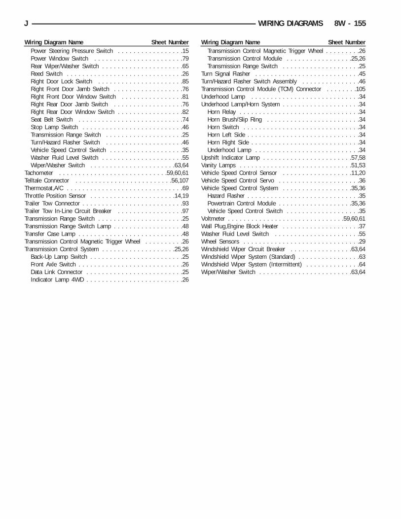
Wiring Diagram Name Sheet NumberPower Steering Pressure Switch . . . . . . . . . . . . . . . . .15Power Window Switch . . . . . . . . . . . . . . . . . . . . . . .79Rear Wiper/Washer Switch . . . . . . . . . . . . . . . . . . . . .65Reed Switch . . . . . . . . . . . . . . . . . . . . . . . . . . . . . .26Right Door Lock Switch . . . . . . . . . . . . . . . . . . . . . .85Right Front Door Jamb Switch . . . . . . . . . . . . . . . . . .76Right Front Door Window Switch . . . . . . . . . . . . . . . .81Right Rear Door Jamb Switch . . . . . . . . . . . . . . . . . .76Right Rear Door Window Switch . . . . . . . . . . . . . . . . .82Seat Belt Switch . . . . . . . . . . . . . . . . . . . . . . . . . . .74Stop Lamp Switch . . . . . . . . . . . . . . . . . . . . . . . . . .46Transmission Range Switch . . . . . . . . . . . . . . . . . . . .25Turn/Hazard Flasher Switch . . . . . . . . . . . . . . . . . . . .46Vehicle Speed Control Switch . . . . . . . . . . . . . . . . . . .35Washer Fluid Level Switch . . . . . . . . . . . . . . . . . . . . .55Wiper/Washer Switch . . . . . . . . . . . . . . . . . . . . . .63,64
Tachometer . . . . . . . . . . . . . . . . . . . . . . . . . . . .59,60,61Telltale Connector . . . . . . . . . . . . . . . . . . . . . . . . .56,107Thermostat,A/C . . . . . . . . . . . . . . . . . . . . . . . . . . . . . .69Throttle Position Sensor . . . . . . . . . . . . . . . . . . . . . .14,19Trailer Tow Connector . . . . . . . . . . . . . . . . . . . . . . . . . .93Trailer Tow In-Line Circuit Breaker . . . . . . . . . . . . . . . . .97Transmission Range Switch . . . . . . . . . . . . . . . . . . . . . .25Transmission Range Switch Lamp . . . . . . . . . . . . . . . . . .48Transfer Case Lamp . . . . . . . . . . . . . . . . . . . . . . . . . . .48Transmission Control Magnetic Trigger Wheel . . . . . . . . . .26Transmission Control System . . . . . . . . . . . . . . . . . . .25,26
Back-Up Lamp Switch . . . . . . . . . . . . . . . . . . . . . . . .25Front Axle Switch . . . . . . . . . . . . . . . . . . . . . . . . . . .26Data Link Connector . . . . . . . . . . . . . . . . . . . . . . . . .25Indicator Lamp 4WD . . . . . . . . . . . . . . . . . . . . . . . . .26
Wiring Diagram Name Sheet NumberTransmission Control Magnetic Trigger Wheel . . . . . . . . .26Transmission Control Module . . . . . . . . . . . . . . . . .25,26Transmission Range Switch . . . . . . . . . . . . . . . . . . . .25
Turn Signal Flasher . . . . . . . . . . . . . . . . . . . . . . . . . . .45Turn/Hazard Flasher Switch Assembly . . . . . . . . . . . . . . .46Transmission Control Module (TCM) Connector . . . . . . . .105Underhood Lamp . . . . . . . . . . . . . . . . . . . . . . . . . . . .34Underhood Lamp/Horn System . . . . . . . . . . . . . . . . . . . .34
Horn Relay . . . . . . . . . . . . . . . . . . . . . . . . . . . . . . .34Horn Brush/Slip Ring . . . . . . . . . . . . . . . . . . . . . . . .34Horn Switch . . . . . . . . . . . . . . . . . . . . . . . . . . . . . .34Horn Left Side . . . . . . . . . . . . . . . . . . . . . . . . . . . . .34Horn Right Side . . . . . . . . . . . . . . . . . . . . . . . . . . . .34Underhood Lamp . . . . . . . . . . . . . . . . . . . . . . . . . . .34
Upshift Indicator Lamp . . . . . . . . . . . . . . . . . . . . . . .57,58Vanity Lamps . . . . . . . . . . . . . . . . . . . . . . . . . . . . .51,53Vehicle Speed Control Sensor . . . . . . . . . . . . . . . . . .11,20Vehicle Speed Control Servo . . . . . . . . . . . . . . . . . . . . .36Vehicle Speed Control System . . . . . . . . . . . . . . . . . .35,36
Hazard Flasher . . . . . . . . . . . . . . . . . . . . . . . . . . . . .35Powertrain Control Module . . . . . . . . . . . . . . . . . . .35,36Vehicle Speed Control Switch . . . . . . . . . . . . . . . . . . .35
Voltmeter . . . . . . . . . . . . . . . . . . . . . . . . . . . . . .59,60,61Wall Plug,Engine Block Heater . . . . . . . . . . . . . . . . . . . .37Washer Fluid Level Switch . . . . . . . . . . . . . . . . . . . . . .55Wheel Sensors . . . . . . . . . . . . . . . . . . . . . . . . . . . . . .29Windshield Wiper Circuit Breaker . . . . . . . . . . . . . . . .63,64Windshield Wiper System (Standard) . . . . . . . . . . . . . . . .63Windshield Wiper System (Intermittent) . . . . . . . . . . . . . .64Wiper/Washer Switch . . . . . . . . . . . . . . . . . . . . . . . .63,64
J WIRING DIAGRAMS 8W - 155


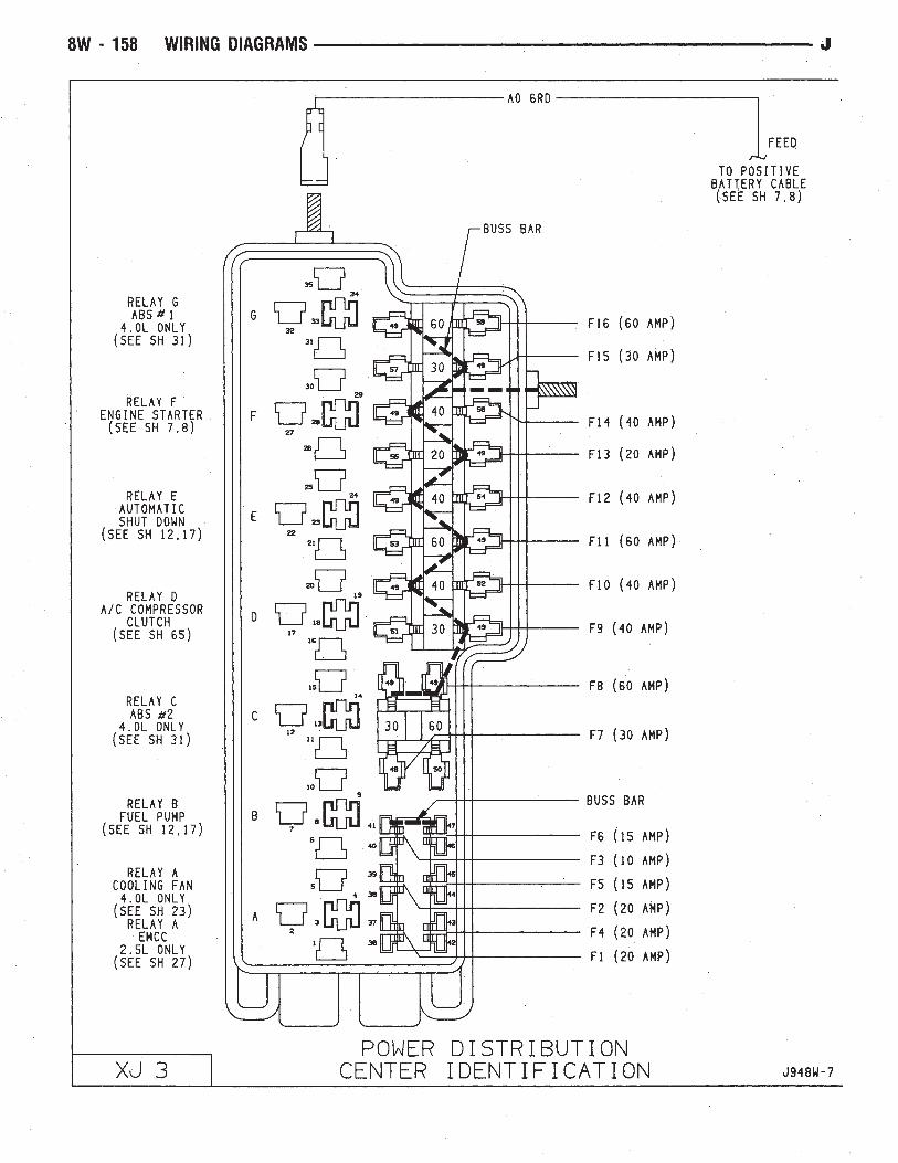


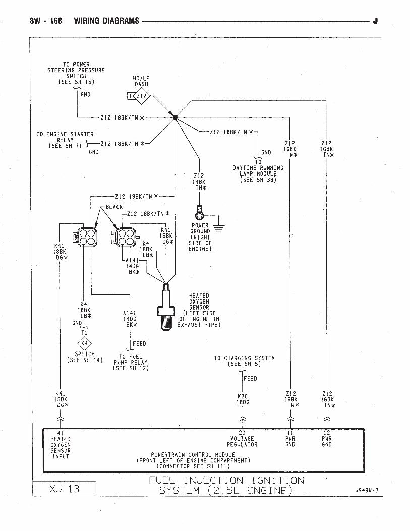


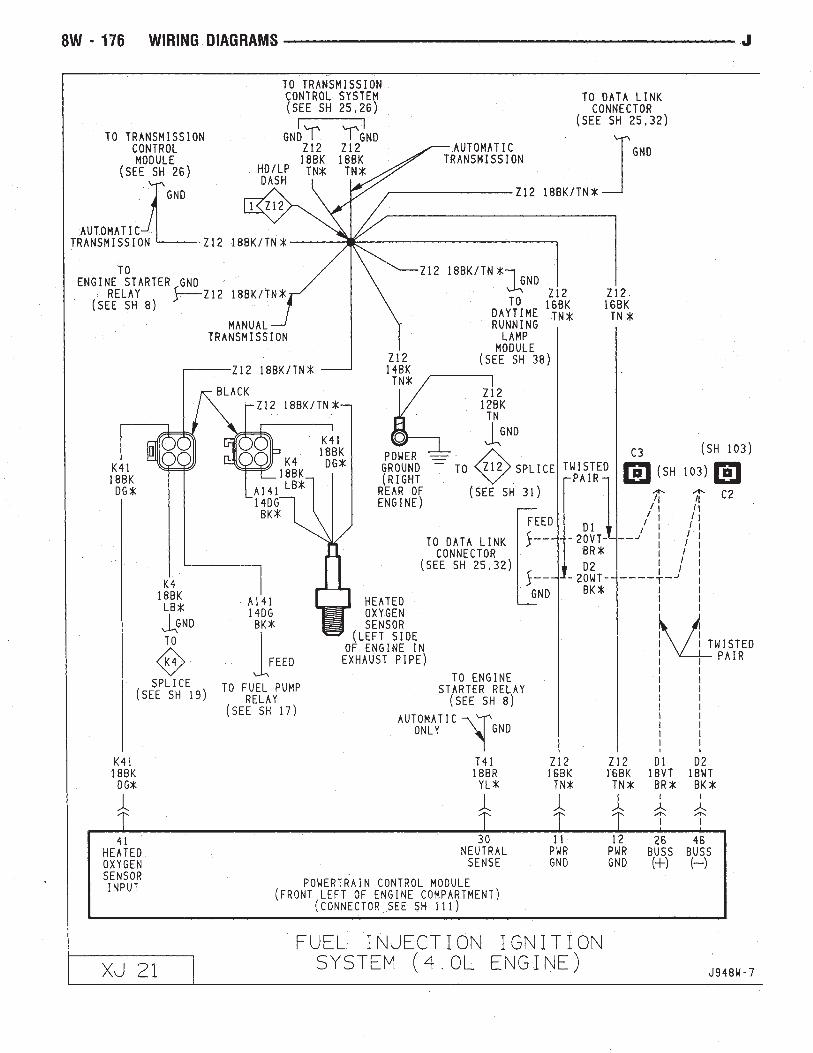


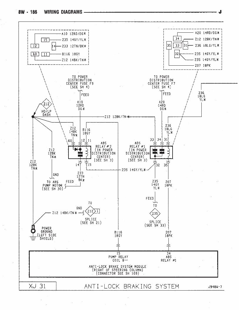


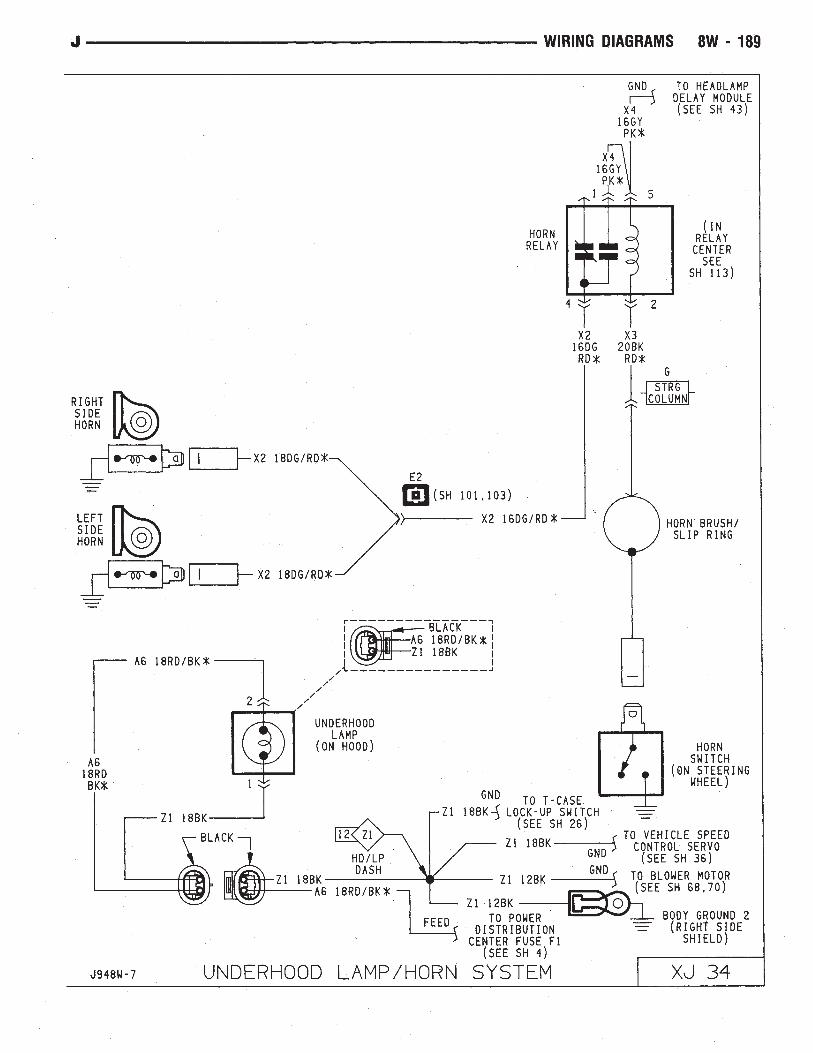


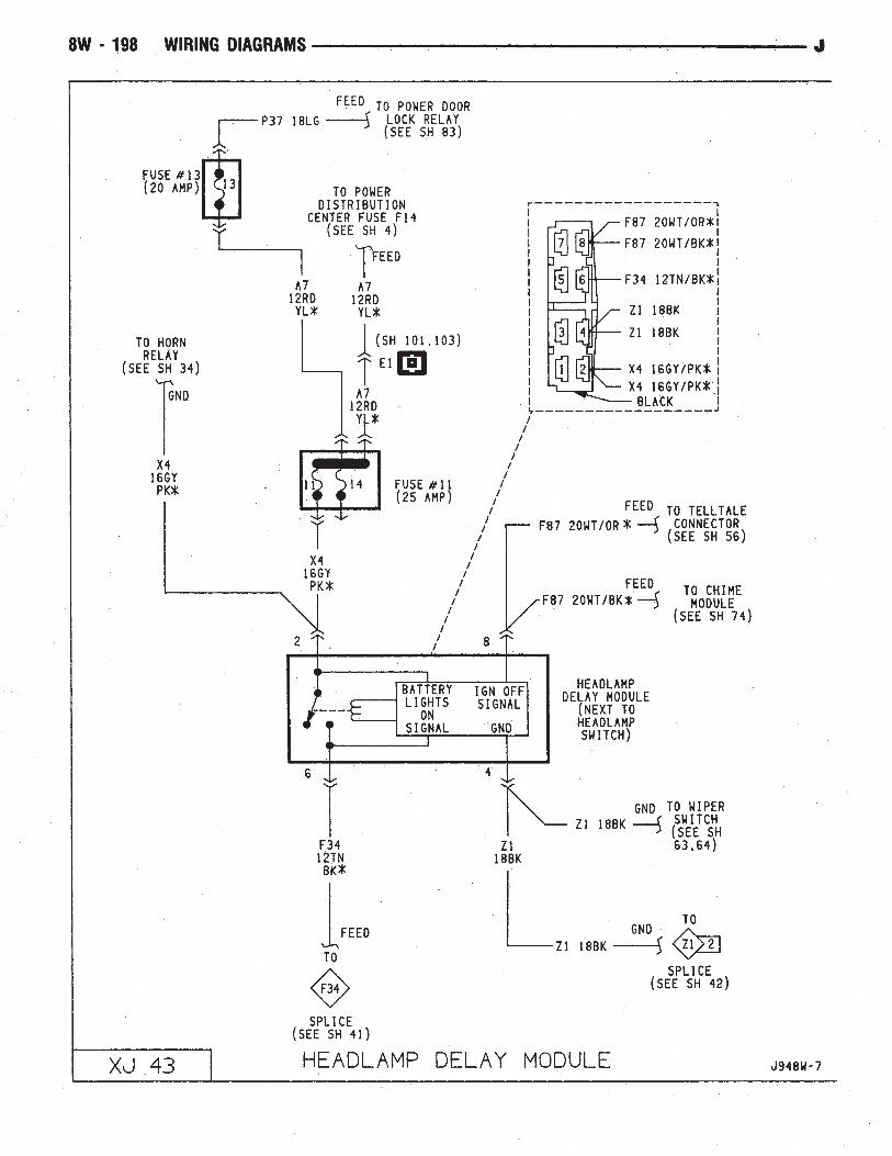


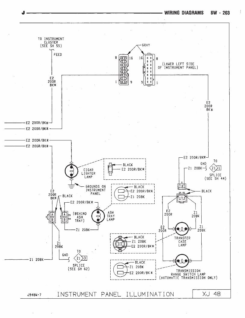

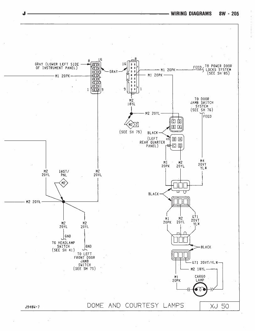


1994 JeepPublication No. 81-370-4146TSB 08-09-94 February 18, 1994
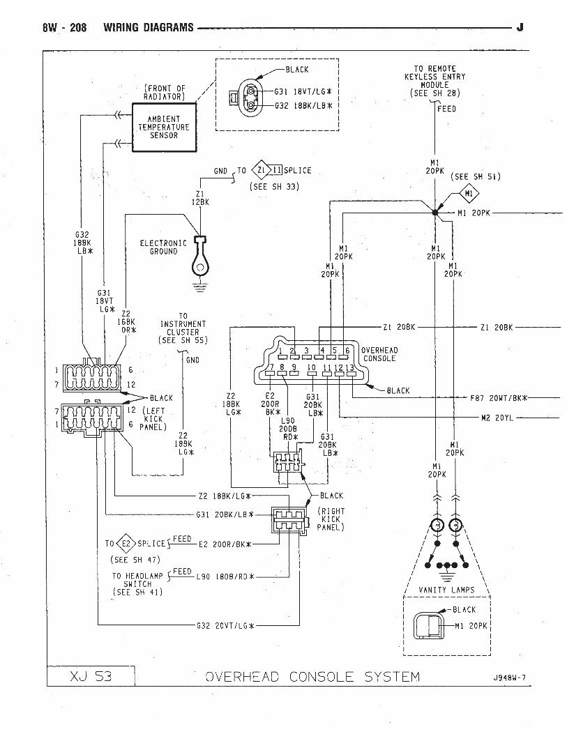


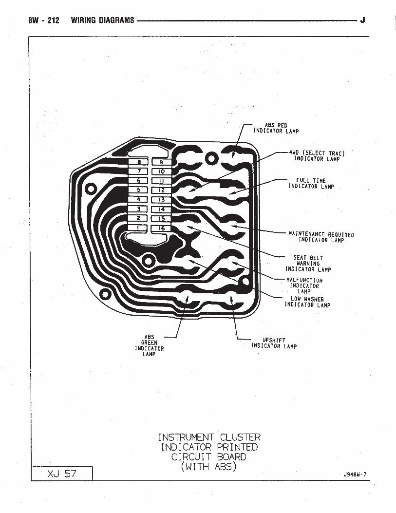


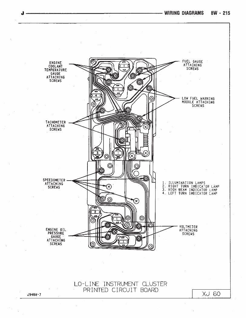
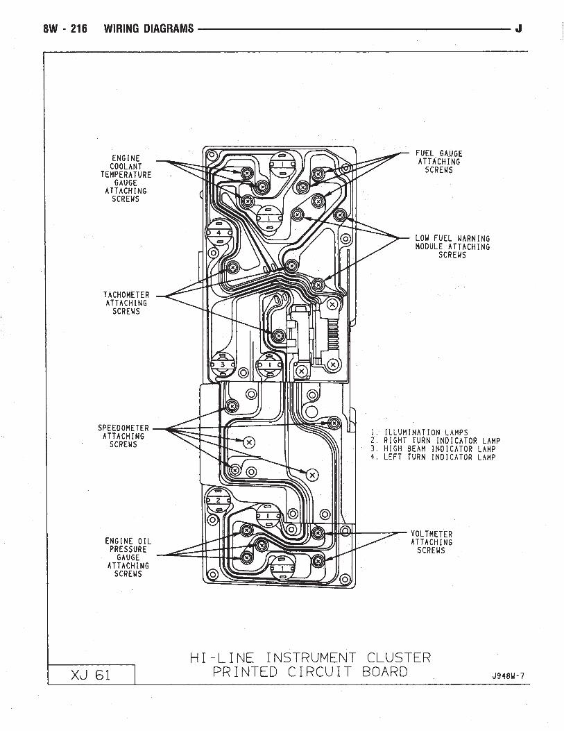


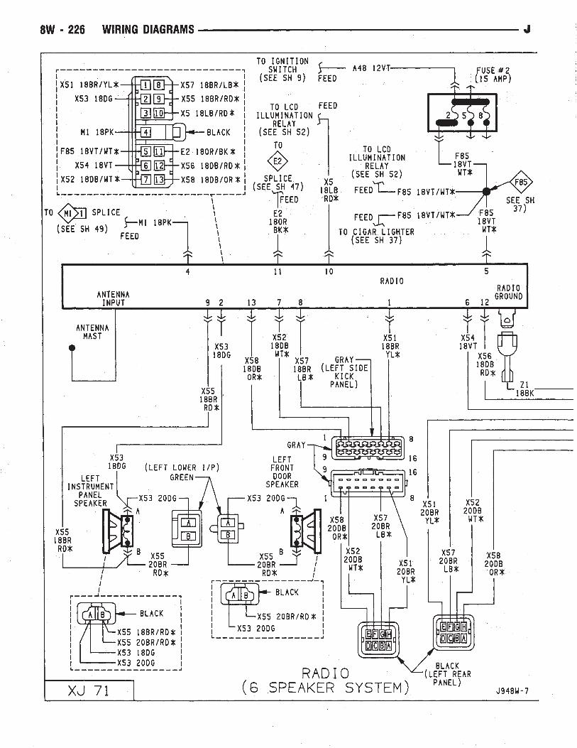
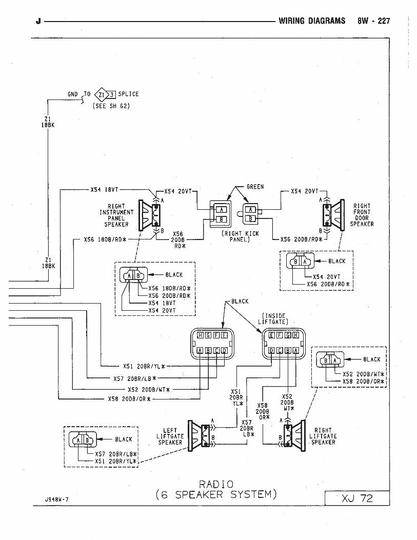

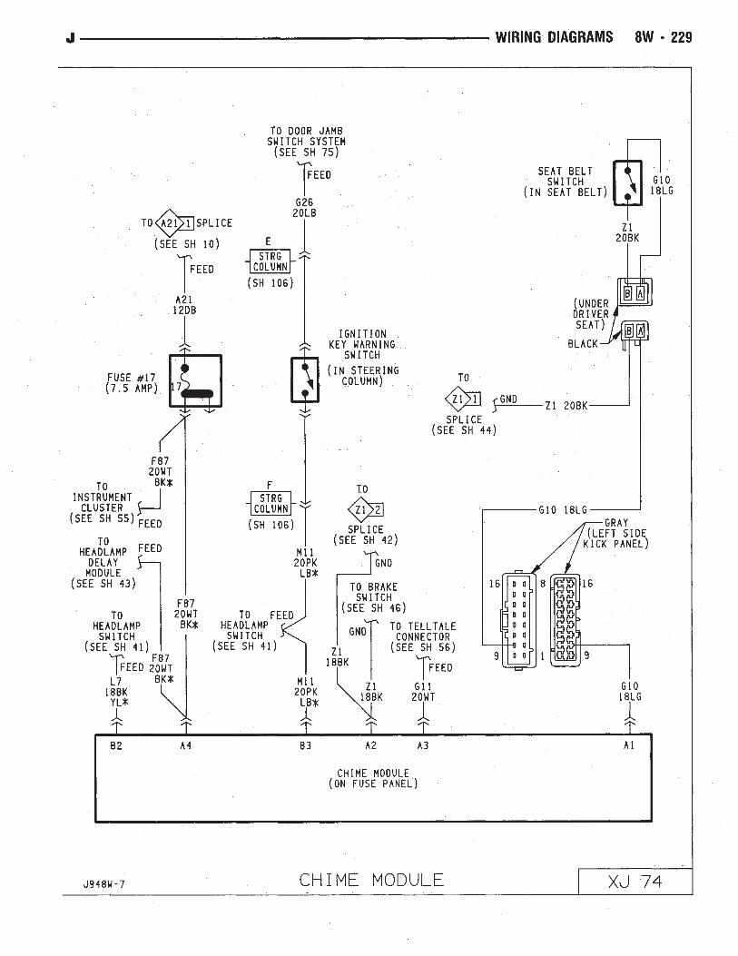
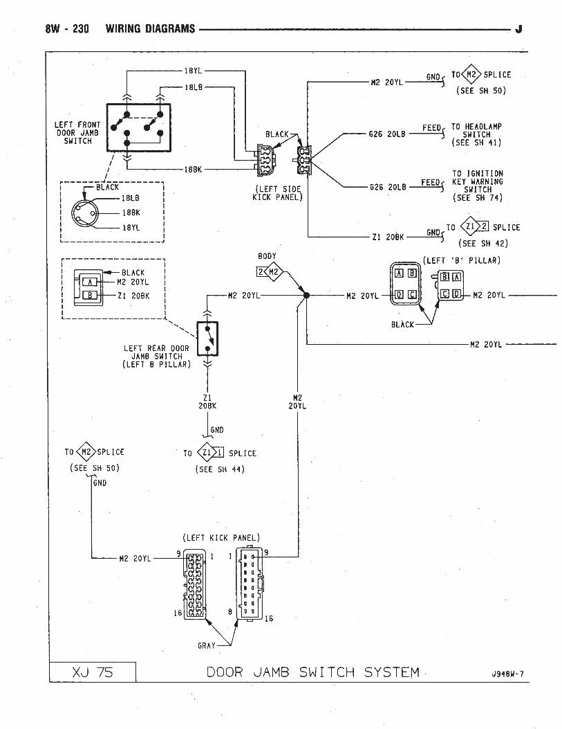


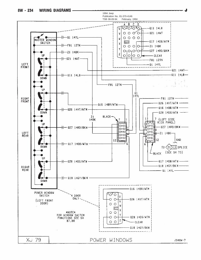
1994 JeepPublication No. 81-370-4146TSB 08-09-94 February, 1994
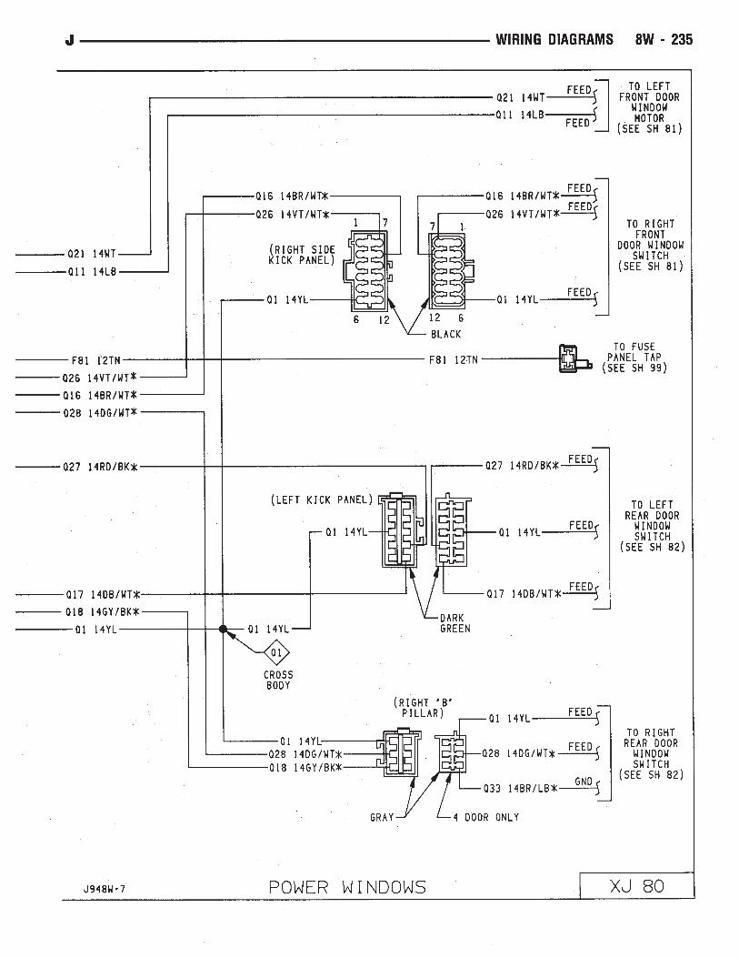
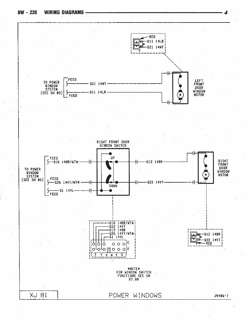


1994 JeepPublication No. 81-370-4146TSB 08-09-94 February 18, 1994
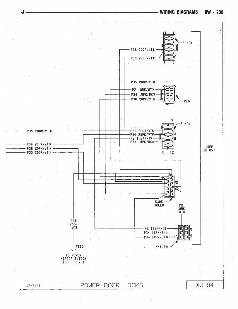


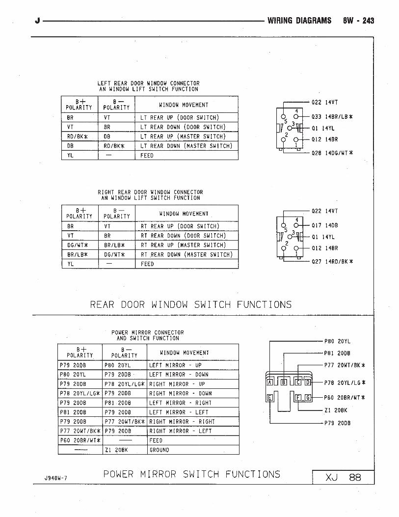


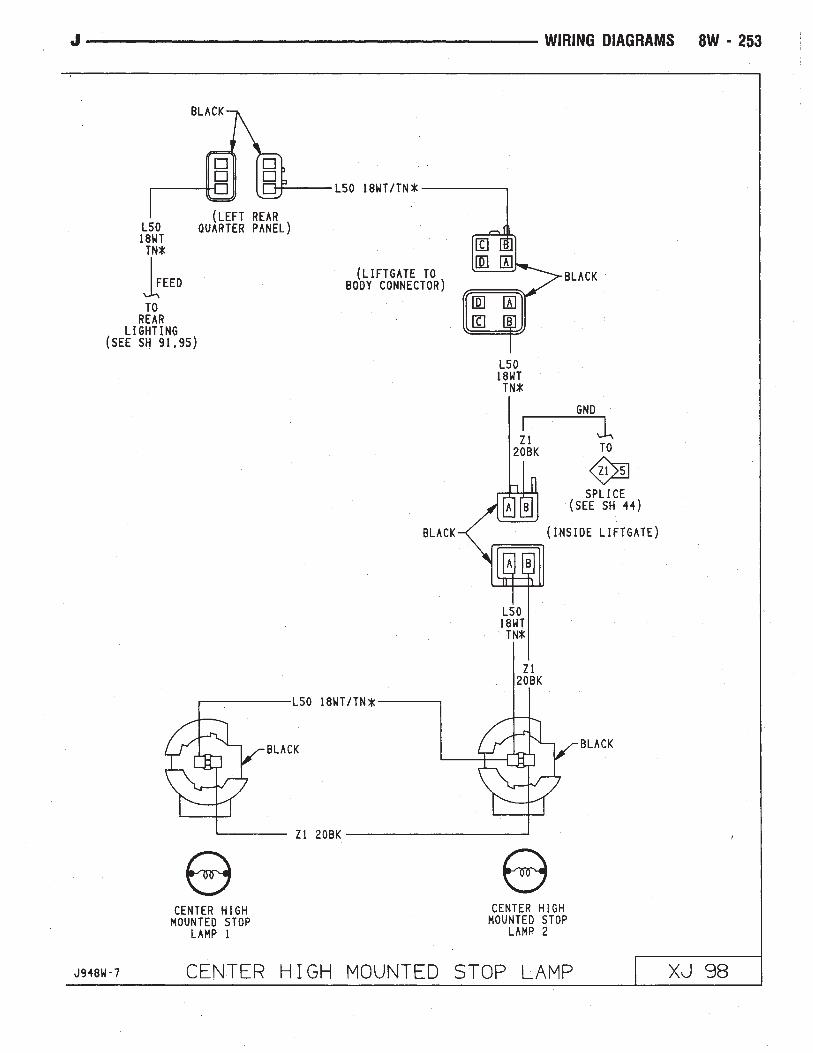


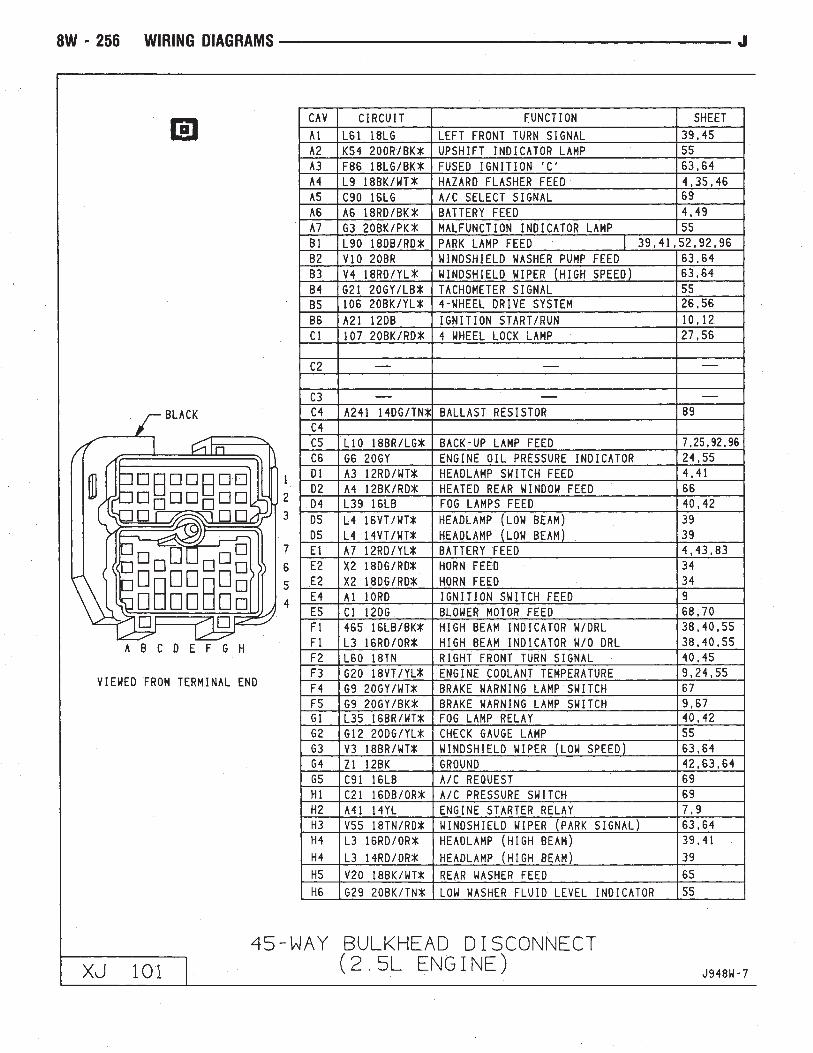


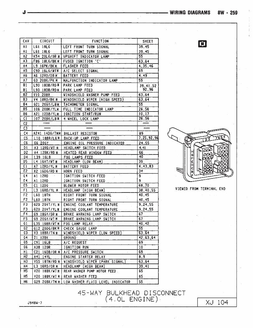


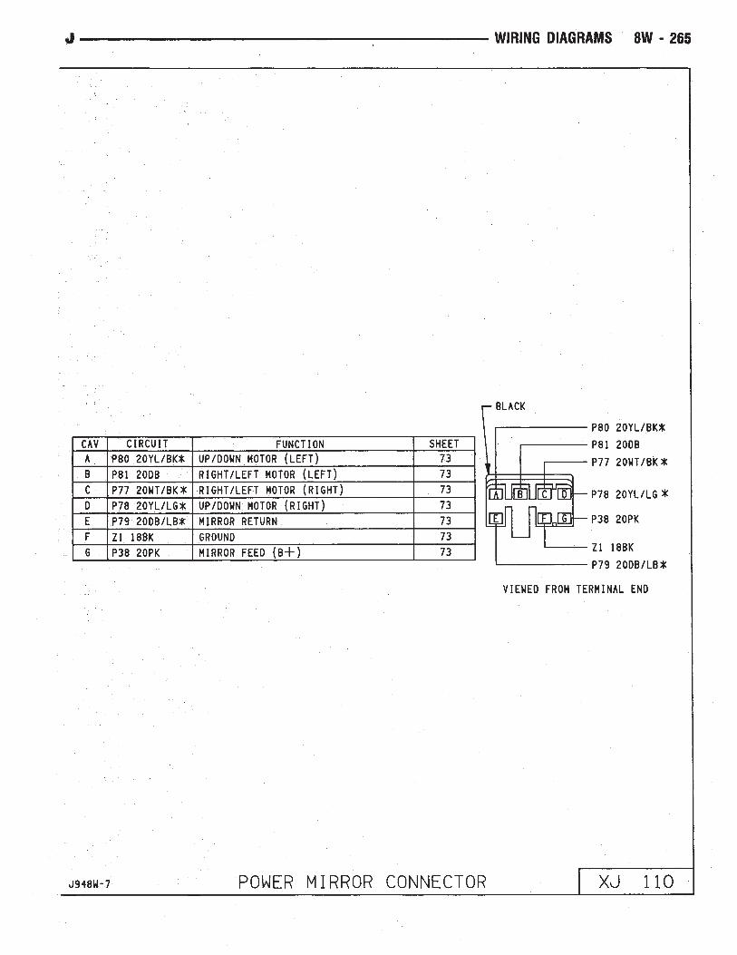

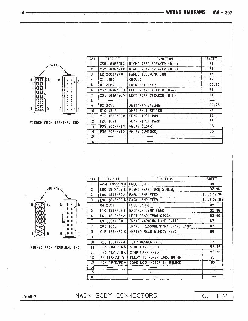
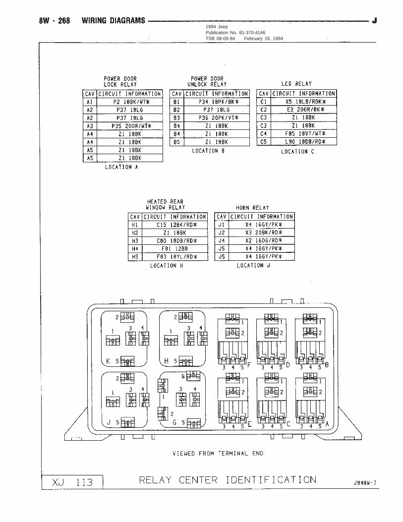
1994 JeepPublication No. 81-370-4146TSB 08-09-94 February 18, 1994


8W - 270 WIRING DIAGRAMS J

WIRING DIAGRAMS XJ-RHD
INDEX
Wiring Diagram Name Sheet NumberA/C Compressor Clutch . . . . . . . . . . . . . . . . . . . . . . . .45A/C Compressor Clutch Relay . . . . . . . . . . . . . . . . . . . .45A/C Heater Blower Motor . . . . . . . . . . . . . . . . . . . . . . .46A/C Low Pressure Switch . . . . . . . . . . . . . . . . . . . . . . .45A/C Mode Selector Switch . . . . . . . . . . . . . . . . . . . . . . .46A/C System . . . . . . . . . . . . . . . . . . . . . . . . . . . . .45, 46A/C Thermostat . . . . . . . . . . . . . . . . . . . . . . . . . . . . . .45Antenna Mast . . . . . . . . . . . . . . . . . . . . . . . . . . . . . . .47Ashtray Illumination Lamp . . . . . . . . . . . . . . . . . . . . . . .26Automatic Shut Down Relay . . . . . . . . . . . . . . . . . . . . . .9Back-up Lamp Switch . . . . . . . . . . . . . . . . . . . . . . . . .16Battery . . . . . . . . . . . . . . . . . . . . . . . . . . . . . . . . . . . .6Blower Motor . . . . . . . . . . . . . . . . . . . . . . . . . . . .44, 46Blower Resistor . . . . . . . . . . . . . . . . . . . . . . . . . . .44, 46Blower Switch . . . . . . . . . . . . . . . . . . . . . . . . . . . .44, 46Body Ground . . . . . . . . . . . . . . . . . . . . . . . . . . . . . . .59Brake Warning Switch . . . . . . . . . . . . . . . . . . . . . . . . .42Camshaft Position Sensor . . . . . . . . . . . . . . . . . . . . . . .12Cargo Lamp . . . . . . . . . . . . . . . . . . . . . . . . . . . . . . . .30Charging System . . . . . . . . . . . . . . . . . . . . . . . . . . . . .5
Generator . . . . . . . . . . . . . . . . . . . . . . . . . . . . . . . . .5Check Engine Indicator Lamp . . . . . . . . . . . . . . . . . .39, 40Chime Module . . . . . . . . . . . . . . . . . . . . . . . . . . . . . .43Chime Module Connector . . . . . . . . . . . . . . . . . . . . . . .71Cigar Lighter . . . . . . . . . . . . . . . . . . . . . . . . . . . . . . .58Circuit Breakers
Windshield Wiper Circuit Breaker . . . . . . . . . . . . . . .2, 33Connectors
Chime Module Connector . . . . . . . . . . . . . . . . . . . . . .71Dash to Instrument Panel Connector A . . . . . . . . . . . . .64Dash to Instrument Panel Connector B . . . . . . . . . . . . .65Dash to Instrument Panel Connector C . . . . . . . . . . . . .66Data Link Connector . . . . . . . . . . . . . . . . . . . . . . . . .10Instrument Cluster Connector 16 Way . . . . . . . . . . .37, 69Main Body Connector 1 . . . . . . . . . . . . . . . . . . . . . . .70Power Mirror Connector . . . . . . . . . . . . . . . . . . . . . .61Powertrain Control Module Connector . . . . . . . . . . . . . .73Steering Column Connector 11 Way . . . . . . . . . . . . . . .67Telltale Connector . . . . . . . . . . . . . . . . . . . . . . . .38, 68Transmission Control Module Connector . . . . . . . . . . . .72Transmission Data Link Connector . . . . . . . . . . . . . . . .17
Coolant Temperature Switch . . . . . . . . . . . . . . . . . . . . . .16Crankshaft Position Sensor . . . . . . . . . . . . . . . . . . . . . .12Dash to Instrument Panel Connector A . . . . . . . . . . . . . .64Dash to Instrument Panel Connector B . . . . . . . . . . . . . .65Dash to Instrument Panel Connector C . . . . . . . . . . . . . .66Data Link Connector . . . . . . . . . . . . . . . . . . . . . . . . . .10Distributor Ignition Coil . . . . . . . . . . . . . . . . . . . . . . . .10Dome Lamp . . . . . . . . . . . . . . . . . . . . . . . . . . . . . . . .31Dome and Courtesy Lamps . . . . . . . . . . . . . . . . .29, 30, 31
Cargo Lamp . . . . . . . . . . . . . . . . . . . . . . . . . . . . . .30Dome Lamp . . . . . . . . . . . . . . . . . . . . . . . . . . . . . .31
Wiring Diagram Name Sheet NumberDome/Reading Lamp . . . . . . . . . . . . . . . . . . . . . . . . .31Glove Box Lamp . . . . . . . . . . . . . . . . . . . . . . . . . . .29Reading Lamp . . . . . . . . . . . . . . . . . . . . . . . . . . . . .31Vanity Lamps . . . . . . . . . . . . . . . . . . . . . . . . . . . . .31
Dome/Reading Lamp . . . . . . . . . . . . . . . . . . . . . . . . . .31Door Jamb Switch System . . . . . . . . . . . . . . . . . . . .49, 50
Left Front Door Jamb Switch . . . . . . . . . . . . . . . . . . .50Left Rear Door Jamb Switch . . . . . . . . . . . . . . . . . . .50Liftgate Switch . . . . . . . . . . . . . . . . . . . . . . . . . . . .46Right Front Door Jamb Switch . . . . . . . . . . . . . . . . . .49Right Rear Door Jamb Switch . . . . . . . . . . . . . . . . . .49
Electronic Fuel InjectionIgnition System . . . . . . . . . . . . . . . .9, 10, 11, 12, 13, 14Automatic Shut Down Relay . . . . . . . . . . . . . . . . . . . . .9Camshaft Position Sensor . . . . . . . . . . . . . . . . . . . . .12Crankshaft Position Sensor . . . . . . . . . . . . . . . . . . . . .12Data Link Connector . . . . . . . . . . . . . . . . . . . . . . . . .10Distributor Ignition Coil . . . . . . . . . . . . . . . . . . . . . . .10Engine Coolant Temperature Sensor . . . . . . . . . . . . . . .11Fuel Injectors . . . . . . . . . . . . . . . . . . . . . . . . . . . . .14Fuel Pump Relay . . . . . . . . . . . . . . . . . . . . . . . . . . . .9Heated Oxygen Sensor . . . . . . . . . . . . . . . . . . . . . . .13Idle Air Control Motor . . . . . . . . . . . . . . . . . . . . . . . .14Intake Air Temp Sensor . . . . . . . . . . . . . . . . . . . . . . .11Map Sensor . . . . . . . . . . . . . . . . . . . . . . . . . . . . . .11Powertrain Control Module . . . . . . . .9, 10, 11, 12, 13, 14Throttle Position (Sensor) . . . . . . . . . . . . . . . . . . . . .11
Engine Block Heater . . . . . . . . . . . . . . . . . . . . . . . . . . .58Engine Coolant Temperature Sensor . . . . . . . . . . . . . . . .11Engine Coolant Temperature Switch . . . . . . . . . . . . . . . . .15Engine Oil Pressure and Temperature System . . . . . . . . . .15Engine Oil Pressure Switch . . . . . . . . . . . . . . . . . . . . . .15Engine Starter System . . . . . . . . . . . . . . . . . . . . . . . . . .6
Battery . . . . . . . . . . . . . . . . . . . . . . . . . . . . . . . . . .6Engine Starter Motor . . . . . . . . . . . . . . . . . . . . . . . . .6Engine Starter Relay . . . . . . . . . . . . . . . . . . . . . . . . . .6
Fan Control Relay . . . . . . . . . . . . . . . . . . . . . . . . . . .3, 7Fog Lamp Illumination Lamp . . . . . . . . . . . . . . . . . . . . .20Fog Lamp Relay . . . . . . . . . . . . . . . . . . . . . . . . . . . . .21Fog Lamp Switch . . . . . . . . . . . . . . . . . . . . . . . . . . . .204WD Select Trac Indicator Lamp . . . . . . . . . . . . . . . .39, 40Front Axle Switch . . . . . . . . . . . . . . . . . . . . . . . . . . . .16Front End Lighting . . . . . . . . . . . . . . . . . . . . . . . . .21, 22
Fog Lamp Relay . . . . . . . . . . . . . . . . . . . . . . . . . . .21Left Fog Lamp . . . . . . . . . . . . . . . . . . . . . . . . . . . . .21Left Headlamp . . . . . . . . . . . . . . . . . . . . . . . . . . . . .21Left Park/Turn Signal Lamp . . . . . . . . . . . . . . . . . . . .21Left Side Marker Lamp . . . . . . . . . . . . . . . . . . . . . . .21Right Fog Lamp . . . . . . . . . . . . . . . . . . . . . . . . . . . .22Right Headlamp . . . . . . . . . . . . . . . . . . . . . . . . . . . .22Right Park/Turn Signal Lamp . . . . . . . . . . . . . . . . . . .22Right Side Marker Lamp . . . . . . . . . . . . . . . . . . . . . .22
Front Wipers/Washer - Intermittent . . . . . . . . . . . . . .33, 34
J WIRING DIAGRAMS 8W - 271
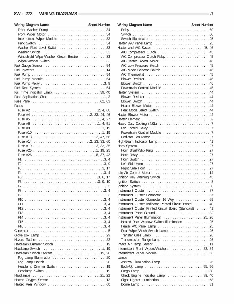
Wiring Diagram Name Sheet NumberFront Washer Pump . . . . . . . . . . . . . . . . . . . . . . . . .34Front Wiper Motor . . . . . . . . . . . . . . . . . . . . . . . . . .34Intermittent Wiper Module . . . . . . . . . . . . . . . . . . . . .33Park Switch . . . . . . . . . . . . . . . . . . . . . . . . . . . . . .34Washer Fluid Level Switch . . . . . . . . . . . . . . . . . . . . .33Washer Switch . . . . . . . . . . . . . . . . . . . . . . . . . . . .33Windshield Wiper/Washer Circuit Breaker . . . . . . . . . . .33Wiper/Washer Switch . . . . . . . . . . . . . . . . . . . . . . . .33
Fuel Gauge Sensor . . . . . . . . . . . . . . . . . . . . . . . . . . .54Fuel Injectors . . . . . . . . . . . . . . . . . . . . . . . . . . . . . . .14Fuel Pump . . . . . . . . . . . . . . . . . . . . . . . . . . . . . . . . .54Fuel Pump Module . . . . . . . . . . . . . . . . . . . . . . . . . . .54Fuel Pump Relay . . . . . . . . . . . . . . . . . . . . . . . . . . . .3, 9Fuel Tank System . . . . . . . . . . . . . . . . . . . . . . . . . . . .54Full Time Indicator Lamp . . . . . . . . . . . . . . . . . . . . .39, 40Fuse Application Chart . . . . . . . . . . . . . . . . . . . . . . . .1, 2Fuse Panel . . . . . . . . . . . . . . . . . . . . . . . . . . . . . .62, 63Fuses
Fuse #2 . . . . . . . . . . . . . . . . . . . . . . . . . . . . .2, 4, 60Fuse #4 . . . . . . . . . . . . . . . . . . . . . . . . . .2, 33, 44, 46Fuse #5 . . . . . . . . . . . . . . . . . . . . . . . . . . . . .1, 4, 27Fuse #6 . . . . . . . . . . . . . . . . . . . . . . . . . . . . .1, 4, 51Fuse #9 . . . . . . . . . . . . . . . . . . . . . . . . . . . . . . .1, 19Fuse #10 . . . . . . . . . . . . . . . . . . . . . . . . . . . . . .1, 19Fuse #13 . . . . . . . . . . . . . . . . . . . . . . . . . . . .2, 47, 58Fuse #14 . . . . . . . . . . . . . . . . . . . . . . . . .2, 23, 33, 60Fuse #19 . . . . . . . . . . . . . . . . . . . . . . . . . . . .2, 33, 35Fuse #25 . . . . . . . . . . . . . . . . . . . . . . . . . . . .1, 19, 25Fuse #26 . . . . . . . . . . . . . . . . . . . . . . . . . .1, 8, 37, 43F1 . . . . . . . . . . . . . . . . . . . . . . . . . . . . . . . . . . .3, 4F2 . . . . . . . . . . . . . . . . . . . . . . . . . . . . . . . . . . .3, 9F3 . . . . . . . . . . . . . . . . . . . . . . . . . . . . . . . . . . .3, 17F4 . . . . . . . . . . . . . . . . . . . . . . . . . . . . . . . . . . .3, 4F5 . . . . . . . . . . . . . . . . . . . . . . . . . . . . . . . . .3, 6, 17F6 . . . . . . . . . . . . . . . . . . . . . . . . . . . . . . . . .3, 9, 10F7 . . . . . . . . . . . . . . . . . . . . . . . . . . . . . . . . . . . . .3F8 . . . . . . . . . . . . . . . . . . . . . . . . . . . . . . . . . . .3, 4F9 . . . . . . . . . . . . . . . . . . . . . . . . . . . . . . . . . . . . .3F10 . . . . . . . . . . . . . . . . . . . . . . . . . . . . . . . . . . .3, 4F11 . . . . . . . . . . . . . . . . . . . . . . . . . . . . . . . . . . .3, 4F12 . . . . . . . . . . . . . . . . . . . . . . . . . . . . . . . . . . .3, 4F13 . . . . . . . . . . . . . . . . . . . . . . . . . . . . . . . . . . .3, 4F14 . . . . . . . . . . . . . . . . . . . . . . . . . . . . . . . . . . .3, 4F15 . . . . . . . . . . . . . . . . . . . . . . . . . . . . . . . . . . .3, 4F16 . . . . . . . . . . . . . . . . . . . . . . . . . . . . . . . . . . .3, 4
Generator . . . . . . . . . . . . . . . . . . . . . . . . . . . . . . . . . .5Glove Box Lamp . . . . . . . . . . . . . . . . . . . . . . . . . . . . .29Hazard Flasher . . . . . . . . . . . . . . . . . . . . . . . . . . . . . .32Headlamp Dimmer Switch . . . . . . . . . . . . . . . . . . . . . . .19Headlamp Switch . . . . . . . . . . . . . . . . . . . . . . . . . . .1, 19Headlamp Switch System . . . . . . . . . . . . . . . . . . . . .19, 20
Fog Lamp Illumination . . . . . . . . . . . . . . . . . . . . . . . .20Fog Lamp Switch . . . . . . . . . . . . . . . . . . . . . . . . . . .20Headlamp Dimmer Switch . . . . . . . . . . . . . . . . . . . . .19Headlamp Switch . . . . . . . . . . . . . . . . . . . . . . . . . . .19
Headlamps . . . . . . . . . . . . . . . . . . . . . . . . . . . . . .21, 22Heated Oxygen Sensor . . . . . . . . . . . . . . . . . . . . . . . . .13Heated Rear Window . . . . . . . . . . . . . . . . . . . . . . . . . .60
Wiring Diagram Name Sheet NumberRelay . . . . . . . . . . . . . . . . . . . . . . . . . . . . . . . . . . .60Switch . . . . . . . . . . . . . . . . . . . . . . . . . . . . . . . . . .60Switch Illumination . . . . . . . . . . . . . . . . . . . . . . . . . .25
Heater A/C Panel Lamp . . . . . . . . . . . . . . . . . . . . . . . .25Heater and A/C System . . . . . . . . . . . . . . . . . . . . . .45, 46
A/C Compressor Clutch . . . . . . . . . . . . . . . . . . . . . . .45A/C Compressor Clutch Relay . . . . . . . . . . . . . . . . . . .45A/C Heater Blower Motor . . . . . . . . . . . . . . . . . . . . . .46A/C Low Pressure Switch . . . . . . . . . . . . . . . . . . . . .45A/C Mode Selector Switch . . . . . . . . . . . . . . . . . . . . .46A/C Thermostat . . . . . . . . . . . . . . . . . . . . . . . . . . . .45Blower Resistor . . . . . . . . . . . . . . . . . . . . . . . . . . . .46Blower Switch . . . . . . . . . . . . . . . . . . . . . . . . . . . . .46Powertrain Control Module . . . . . . . . . . . . . . . . . . . . .45
Heater System . . . . . . . . . . . . . . . . . . . . . . . . . . . . . .44Blower Resistor . . . . . . . . . . . . . . . . . . . . . . . . . . . .44Blower Switch . . . . . . . . . . . . . . . . . . . . . . . . . . . . .44Heater Blower Motor . . . . . . . . . . . . . . . . . . . . . . . . .44Heat Mode Select Switch . . . . . . . . . . . . . . . . . . . . . .44
Heater Blower Motor . . . . . . . . . . . . . . . . . . . . . . . . . .44Heater Element . . . . . . . . . . . . . . . . . . . . . . . . . . . . . .52Heavy Duty Cooling (4.0L) . . . . . . . . . . . . . . . . . . . . . . .7
Fan Control Relay . . . . . . . . . . . . . . . . . . . . . . . . . . .7Powertrain Control Module . . . . . . . . . . . . . . . . . . . . .7Radiator Fan Motor . . . . . . . . . . . . . . . . . . . . . . . . . .7
High-Beam Indicator Lamp . . . . . . . . . . . . . . . . . . . . . .41Horn System . . . . . . . . . . . . . . . . . . . . . . . . . . . . . . .27
Horn Brush/Slip Ring . . . . . . . . . . . . . . . . . . . . . . . .27Horn Relay . . . . . . . . . . . . . . . . . . . . . . . . . . . . . . .27Horn Switch . . . . . . . . . . . . . . . . . . . . . . . . . . . . . .27Left Side Horn . . . . . . . . . . . . . . . . . . . . . . . . . . . . .27Right Side Horn . . . . . . . . . . . . . . . . . . . . . . . . . . . .27
Idle Air Control Motor . . . . . . . . . . . . . . . . . . . . . . . . .14Ignition Key Warning Switch . . . . . . . . . . . . . . . . . . . . .43Ignition Switch . . . . . . . . . . . . . . . . . . . . . . . . . . . . . . .8Ignition System . . . . . . . . . . . . . . . . . . . . . . . . . . . . . .8Instrument Cluster . . . . . . . . . . . . . . . . . . . . . . . . . . . .37Instrument Cluster Connector . . . . . . . . . . . . . . . . . . . . .37Instrument Cluster Connector 16 Way . . . . . . . . . . . . . . .69Instrument Cluster Indicator Printed Circuit Board . . . . . . .40Instrument Cluster Printed Circuit Board (Standard) . . . . . .41Instrument Panel Ground . . . . . . . . . . . . . . . . . . . . . . .32Instrument Panel Illumination . . . . . . . . . . . . . . . . . .25, 26
Heated Rear Window Switch Illumination . . . . . . . . . . .25Heater A/C Panel Lamp . . . . . . . . . . . . . . . . . . . . . . .25Rear Wiper/Wash Switch Lamp . . . . . . . . . . . . . . . . . .26Transfer Case Lamp . . . . . . . . . . . . . . . . . . . . . . . . .26Transmission Range Lamp . . . . . . . . . . . . . . . . . . . . .26
Intake Air Temp Sensor . . . . . . . . . . . . . . . . . . . . . . . .11Intermittent Front Wipers/Washers . . . . . . . . . . . . . . .33, 34Intermittent Wiper Module . . . . . . . . . . . . . . . . . . . . . . .33Lamps
Ashtray Illumination Lamp . . . . . . . . . . . . . . . . . . . . .26Back-Up Lamp . . . . . . . . . . . . . . . . . . . . . . . . . .55, 56Cargo Lamp . . . . . . . . . . . . . . . . . . . . . . . . . . . . . .30Check Engine Indicator Lamp . . . . . . . . . . . . . . . .39, 40Cigar Lighter Illumination . . . . . . . . . . . . . . . . . . . . . .58Dome Lamp . . . . . . . . . . . . . . . . . . . . . . . . . . . . . .31
8W - 272 WIRING DIAGRAMS J
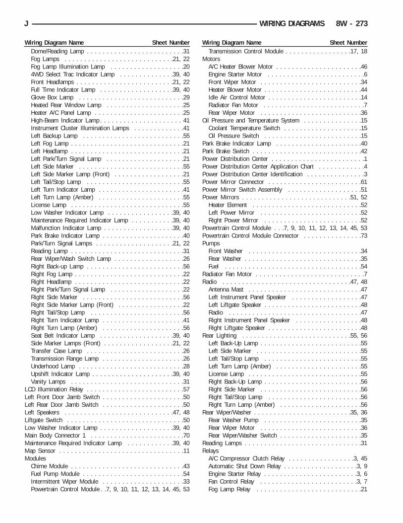
Wiring Diagram Name Sheet NumberDome/Reading Lamp . . . . . . . . . . . . . . . . . . . . . . . . .31Fog Lamps . . . . . . . . . . . . . . . . . . . . . . . . . . . .21, 22Fog Lamp Illumination Lamp . . . . . . . . . . . . . . . . . . .204WD Select Trac Indicator Lamp . . . . . . . . . . . . . .39, 40Front Headlamps . . . . . . . . . . . . . . . . . . . . . . . . .21, 22Full Time Indicator Lamp . . . . . . . . . . . . . . . . . . .39, 40Glove Box Lamp . . . . . . . . . . . . . . . . . . . . . . . . . . .29Heated Rear Window Lamp . . . . . . . . . . . . . . . . . . . .25Heater A/C Panel Lamp . . . . . . . . . . . . . . . . . . . . . . .25High-Beam Indicator Lamp . . . . . . . . . . . . . . . . . . . . . 41Instrument Cluster Illumination Lamps . . . . . . . . . . . . .41Left Backup Lamp . . . . . . . . . . . . . . . . . . . . . . . . . .55Left Fog Lamp . . . . . . . . . . . . . . . . . . . . . . . . . . . . .21Left Headlamp . . . . . . . . . . . . . . . . . . . . . . . . . . . . .21Left Park/Turn Signal Lamp . . . . . . . . . . . . . . . . . . . .21Left Side Marker . . . . . . . . . . . . . . . . . . . . . . . . . . .55Left Side Marker Lamp (Front) . . . . . . . . . . . . . . . . . .21Left Tail/Stop Lamp . . . . . . . . . . . . . . . . . . . . . . . . .55Left Turn Indicator Lamp . . . . . . . . . . . . . . . . . . . . . .41Left Turn Lamp (Amber) . . . . . . . . . . . . . . . . . . . . . .55License Lamp . . . . . . . . . . . . . . . . . . . . . . . . . . . . .55Low Washer Indicator Lamp . . . . . . . . . . . . . . . . .39, 40Maintenance Required Indicator Lamp . . . . . . . . . . .39, 40Malfunction Indicator Lamp . . . . . . . . . . . . . . . . . .39, 40Park Brake Indicator Lamp . . . . . . . . . . . . . . . . . . . . .40Park/Turn Signal Lamps . . . . . . . . . . . . . . . . . . . .21, 22Reading Lamp . . . . . . . . . . . . . . . . . . . . . . . . . . . . .31Rear Wiper/Wash Switch Lamp . . . . . . . . . . . . . . . . . .26Right Back-up Lamp . . . . . . . . . . . . . . . . . . . . . . . . .56Right Fog Lamp . . . . . . . . . . . . . . . . . . . . . . . . . . . .22Right Headlamp . . . . . . . . . . . . . . . . . . . . . . . . . . . .22Right Park/Turn Signal Lamp . . . . . . . . . . . . . . . . . . .22Right Side Marker . . . . . . . . . . . . . . . . . . . . . . . . . .56Right Side Marker Lamp (Front) . . . . . . . . . . . . . . . . .22Right Tail/Stop Lamp . . . . . . . . . . . . . . . . . . . . . . . .56Right Turn Indicator Lamp . . . . . . . . . . . . . . . . . . . . .41Right Turn Lamp (Amber) . . . . . . . . . . . . . . . . . . . . .56Seat Belt Indicator Lamp . . . . . . . . . . . . . . . . . . .39, 40Side Marker Lamps (Front) . . . . . . . . . . . . . . . . . .21, 22Transfer Case Lamp . . . . . . . . . . . . . . . . . . . . . . . . .26Transmission Range Lamp . . . . . . . . . . . . . . . . . . . . .26Underhood Lamp . . . . . . . . . . . . . . . . . . . . . . . . . . .28Upshift Indicator Lamp . . . . . . . . . . . . . . . . . . . . .39, 40Vanity Lamps . . . . . . . . . . . . . . . . . . . . . . . . . . . . .31
LCD Illumination Relay . . . . . . . . . . . . . . . . . . . . . . . . .57Left Front Door Jamb Switch . . . . . . . . . . . . . . . . . . . . .50Left Rear Door Jamb Switch . . . . . . . . . . . . . . . . . . . . .50Left Speakers . . . . . . . . . . . . . . . . . . . . . . . . . . . .47, 48Liftgate Switch . . . . . . . . . . . . . . . . . . . . . . . . . . . . . .50Low Washer Indicator Lamp . . . . . . . . . . . . . . . . . . .39, 40Main Body Connector 1 . . . . . . . . . . . . . . . . . . . . . . . .70Maintenance Required Indicator Lamp . . . . . . . . . . . .39, 40Map Sensor . . . . . . . . . . . . . . . . . . . . . . . . . . . . . . . .11Modules
Chime Module . . . . . . . . . . . . . . . . . . . . . . . . . . . . .43Fuel Pump Module . . . . . . . . . . . . . . . . . . . . . . . . . .54Intermittent Wiper Module . . . . . . . . . . . . . . . . . . . . .33Powertrain Control Module . .7, 9, 10, 11, 12, 13, 14, 45, 53
Wiring Diagram Name Sheet NumberTransmission Control Module . . . . . . . . . . . . . . . . .17, 18
MotorsA/C Heater Blower Motor . . . . . . . . . . . . . . . . . . . . . .46Engine Starter Motor . . . . . . . . . . . . . . . . . . . . . . . . .6Front Wiper Motor . . . . . . . . . . . . . . . . . . . . . . . . . .34Heater Blower Motor . . . . . . . . . . . . . . . . . . . . . . . . .44Idle Air Control Motor . . . . . . . . . . . . . . . . . . . . . . . .14Radiator Fan Motor . . . . . . . . . . . . . . . . . . . . . . . . . .7Rear Wiper Motor . . . . . . . . . . . . . . . . . . . . . . . . . .36
Oil Pressure and Temperature System . . . . . . . . . . . . . . .15Coolant Temperature Switch . . . . . . . . . . . . . . . . . . . .15Oil Pressure Switch . . . . . . . . . . . . . . . . . . . . . . . . .15
Park Brake Indicator Lamp . . . . . . . . . . . . . . . . . . . . . .40Park Brake Switch . . . . . . . . . . . . . . . . . . . . . . . . . . . .42Power Distribution Center . . . . . . . . . . . . . . . . . . . . . . . .1Power Distribution Center Application Chart . . . . . . . . . . . .4Power Distribution Center Identification . . . . . . . . . . . . . . .3Power Mirror Connector . . . . . . . . . . . . . . . . . . . . . . . .61Power Mirror Switch Assembly . . . . . . . . . . . . . . . . . . .51Power Mirrors . . . . . . . . . . . . . . . . . . . . . . . . . . . .51, 52
Heater Element . . . . . . . . . . . . . . . . . . . . . . . . . . . .52Left Power Mirror . . . . . . . . . . . . . . . . . . . . . . . . . .52Right Power Mirror . . . . . . . . . . . . . . . . . . . . . . . . .52
Powertrain Control Module . . .7, 9, 10, 11, 12, 13, 14, 45, 53Powertrain Control Module Connector . . . . . . . . . . . . . . .73Pumps
Front Washer . . . . . . . . . . . . . . . . . . . . . . . . . . . . .34Rear Washer . . . . . . . . . . . . . . . . . . . . . . . . . . . . . .35Fuel . . . . . . . . . . . . . . . . . . . . . . . . . . . . . . . . . . .54
Radiator Fan Motor . . . . . . . . . . . . . . . . . . . . . . . . . . . .7Radio . . . . . . . . . . . . . . . . . . . . . . . . . . . . . . . . .47, 48
Antenna Mast . . . . . . . . . . . . . . . . . . . . . . . . . . . . .47Left Instrument Panel Speaker . . . . . . . . . . . . . . . . . .47Left Liftgate Speaker . . . . . . . . . . . . . . . . . . . . . . . . .48Radio . . . . . . . . . . . . . . . . . . . . . . . . . . . . . . . . . .47Right Instrument Panel Speaker . . . . . . . . . . . . . . . . .48Right Liftgate Speaker . . . . . . . . . . . . . . . . . . . . . . . .48
Rear Lighting . . . . . . . . . . . . . . . . . . . . . . . . . . . .55, 56Left Back-Up Lamp . . . . . . . . . . . . . . . . . . . . . . . . . .55Left Side Marker . . . . . . . . . . . . . . . . . . . . . . . . . . .55Left Tail/Stop Lamp . . . . . . . . . . . . . . . . . . . . . . . . .55Left Turn Lamp (Amber) . . . . . . . . . . . . . . . . . . . . . .55License Lamp . . . . . . . . . . . . . . . . . . . . . . . . . . . . .55Right Back-Up Lamp . . . . . . . . . . . . . . . . . . . . . . . . .56Right Side Marker . . . . . . . . . . . . . . . . . . . . . . . . . .56Right Tail/Stop Lamp . . . . . . . . . . . . . . . . . . . . . . . .56Right Turn Lamp (Amber) . . . . . . . . . . . . . . . . . . . . .56
Rear Wiper/Washer . . . . . . . . . . . . . . . . . . . . . . . . .35, 36Rear Washer Pump . . . . . . . . . . . . . . . . . . . . . . . . .35Rear Wiper Motor . . . . . . . . . . . . . . . . . . . . . . . . . .36Rear Wiper/Washer Switch . . . . . . . . . . . . . . . . . . . . .35
Reading Lamps . . . . . . . . . . . . . . . . . . . . . . . . . . . . . .31Relays
A/C Compressor Clutch Relay . . . . . . . . . . . . . . . . .3, 45Automatic Shut Down Relay . . . . . . . . . . . . . . . . . . .3, 9Engine Starter Relay . . . . . . . . . . . . . . . . . . . . . . . .3, 6Fan Control Relay . . . . . . . . . . . . . . . . . . . . . . . . .3, 7Fog Lamp Relay . . . . . . . . . . . . . . . . . . . . . . . . . . .21
J WIRING DIAGRAMS 8W - 273

Wiring Diagram Name Sheet NumberFuel Pump Relay . . . . . . . . . . . . . . . . . . . . . . . . . .3, 9Heated Rear Window Relay . . . . . . . . . . . . . . . . . . . .60Horn Relay . . . . . . . . . . . . . . . . . . . . . . . . . . . . . . .27LCD Illumination Relay . . . . . . . . . . . . . . . . . . . . . . .57
Right Front Door Jamb Switch . . . . . . . . . . . . . . . . . . . .49Right Rear Door Jamb Switch . . . . . . . . . . . . . . . . . . . .49Right Speaker . . . . . . . . . . . . . . . . . . . . . . . . . . . . . . .48Seat Belt Switch . . . . . . . . . . . . . . . . . . . . . . . . . . . . .43Seat Belt Indicator Lamp . . . . . . . . . . . . . . . . . . . . .39, 40Sensors
Camshaft Position Sensor . . . . . . . . . . . . . . . . . . . . .12Crankshaft Position Sensor . . . . . . . . . . . . . . . . . . . . .12Engine Coolant Temperature Sensor . . . . . . . . . . . . . . .11Fuel Gauge Sensor . . . . . . . . . . . . . . . . . . . . . . . . . .54Heated Oxygen Sensor . . . . . . . . . . . . . . . . . . . . . . .13Intake Air Temperature Sensor . . . . . . . . . . . . . . . . . .11Map Sensor . . . . . . . . . . . . . . . . . . . . . . . . . . . . . .11Throttle Position Sensor . . . . . . . . . . . . . . . . . . . . . .11Vehicle Speed Sensor . . . . . . . . . . . . . . . . . . . . . . . .16
Speakers, Radio . . . . . . . . . . . . . . . . . . . . . . . . . . .47, 48Splices
Splice A3 . . . . . . . . . . . . . . . . . . . . . . . . . . . . . .1, 19Splice A11 . . . . . . . . . . . . . . . . . . . . . . . . . . . . . . . .5Splice A14 . . . . . . . . . . . . . . . . . . . . . . . . . . . . . . . .9Splice A21 . . . . . . . . . . . . . . . . . . . . . . . . . . . . . . . .9Splice A21-1 . . . . . . . . . . . . . . . . . . . . . . . . . . . .8, 43Splice A48 . . . . . . . . . . . . . . . . . . . . . . . . . . . . .2, 33Splice A142 . . . . . . . . . . . . . . . . . . . . . . . . . . . . . .14Splice A142-1 . . . . . . . . . . . . . . . . . . . . . . . . . . . . .14Splice A142-2 . . . . . . . . . . . . . . . . . . . . . . . . .5, 10, 14Splice C7 . . . . . . . . . . . . . . . . . . . . . . . . . . . . . . . .46Splice C15 . . . . . . . . . . . . . . . . . . . . . . . . . . . . . . .52Splice C15-1 . . . . . . . . . . . . . . . . . . . . . . . . . . . . . .52Splice C43 . . . . . . . . . . . . . . . . . . . . . . . . . . . .44, 46Splice C90 . . . . . . . . . . . . . . . . . . . . . . . . . . . . . . .45Splice E2 . . . . . . . . . . . . . . . . . . . . . . . . . . . . . . . .25Splice F12 . . . . . . . . . . . . . . . . . . . . . . . . . . . . . . .10Splice F85 . . . . . . . . . . . . . . . . . . . . . . . . . . . . .47, 58Splice G7 . . . . . . . . . . . . . . . . . . . . . . . . . . . . .12, 16Splice K4 . . . . . . . . . . . . . . . . . . . . . . . . . . . . . . . .11Splice K4-1 . . . . . . . . . . . . . . . . . . . . . . . . . . . . . . .11Splice K6 . . . . . . . . . . . . . . . . . . . . . . . . . . . . . . . .11Splice K7 . . . . . . . . . . . . . . . . . . . . . . . . . . . . . . . .12Splice K22 . . . . . . . . . . . . . . . . . . . . . . . . . . . . . . .11Splice K29 . . . . . . . . . . . . . . . . . . . . . . . . . . . . . . . .9Splice L3 . . . . . . . . . . . . . . . . . . . . . . . . . . . . . . . .21Splice L90 . . . . . . . . . . . . . . . . . . . . . . . . . . . . . . .55Splice L90-1 . . . . . . . . . . . . . . . . . . . . . . . . . . . . . .22Splice L90-2 . . . . . . . . . . . . . . . . . . . . . . . . . . . . . .56Splice L90-3 . . . . . . . . . . . . . . . . . . . . . . . . . . . . . .55Splice M1 . . . . . . . . . . . . . . . . . . . . . . . . . . . . . . . .31Splice M1-1 . . . . . . . . . . . . . . . . . . . . . . . . . . . . . .29Splice M2 . . . . . . . . . . . . . . . . . . . . . . . . . . . . . . . .30Splice M2-1 . . . . . . . . . . . . . . . . . . . . . . . . . . . . . .29Splice M2-2 . . . . . . . . . . . . . . . . . . . . . . . . . . . . . .30Splice P79 . . . . . . . . . . . . . . . . . . . . . . . . . . . . . . .51Splice V32 . . . . . . . . . . . . . . . . . . . . . . . . . . . . . . .53Splice Z1-1 . . . . . . . . . . . . . . . . . . . . . . . . . . . . . . .59
Wiring Diagram Name Sheet NumberSplice Z1-2 . . . . . . . . . . . . . . . . . . . . . . . . . . . . . . .20Splice Z1-3 . . . . . . . . . . . . . . . . . . . . . . . . . . . . . . .32Splice Z1-4 . . . . . . . . . . . . . . . . . . . . . . . . . . . . . . .28Splice Z1-5 . . . . . . . . . . . . . . . . . . . . . . . . . . . .59, 60Splice Z1-6 . . . . . . . . . . . . . . . . . . . . . . . . . . . . . . .55Splice Z1-7 . . . . . . . . . . . . . . . . . . . . . . . . . . . . . . .56Splice Z1-10 . . . . . . . . . . . . . . . . . . . . . . . . . . . . . .22Splice Z1-13 . . . . . . . . . . . . . . . . . . . . . . . . . . . . . .51Splice Z1-14 . . . . . . . . . . . . . . . . . . . . . . . . . . . . . . .7Splice Z1-15 . . . . . . . . . . . . . . . . . . . . . . . . . . . . . .59Splice Z1-16 . . . . . . . . . . . . . . . . . . . . . . . . . . . . . .16Splice Z11 . . . . . . . . . . . . . . . . . . . . . . . . . . . . . . .10Splice Z12-1 . . . . . . . . . . . . . . . . . . . . . . . . . . . . . .13Splice 117 . . . . . . . . . . . . . . . . . . . . . . . . . . . . . . .21
Starter System . . . . . . . . . . . . . . . . . . . . . . . . . . . . . . .6Battery . . . . . . . . . . . . . . . . . . . . . . . . . . . . . . . . . .6Engine Starter Motor . . . . . . . . . . . . . . . . . . . . . . . . .6Engine Starter Relay . . . . . . . . . . . . . . . . . . . . . . . . . .6
Steering Column Connector 11 Way . . . . . . . . . . . . . . . .67Stop Lamp Switch . . . . . . . . . . . . . . . . . . . . . . . . . . . .24Stop/Turn and Hazard System . . . . . . . . . . . . . . . . . .23, 24
Hazard Flasher . . . . . . . . . . . . . . . . . . . . . . . . . . . . .24Hazard Switch . . . . . . . . . . . . . . . . . . . . . . . . . . . . .24Stop Lamp Switch . . . . . . . . . . . . . . . . . . . . . . . . . .24Turn and Hazard Flasher Switch . . . . . . . . . . . . . . . . .24Turn Signal Flasher . . . . . . . . . . . . . . . . . . . . . . . . . .23
SwitchesA/C Low Pressure Switch . . . . . . . . . . . . . . . . . . . . .45A/C Mode Selector Switch . . . . . . . . . . . . . . . . . . . . .46Back-Up Lamp Switch . . . . . . . . . . . . . . . . . . . . . . . .16Blower Switch . . . . . . . . . . . . . . . . . . . . . . . . . .44, 46Brake Warning Switch . . . . . . . . . . . . . . . . . . . . . . . .42Engine Coolant Temperature Switch . . . . . . . . . . . . . . .15Engine Oil Pressure Switch . . . . . . . . . . . . . . . . . . . .15Fog Lamp Switch . . . . . . . . . . . . . . . . . . . . . . . . . . .20Front Axle Switch . . . . . . . . . . . . . . . . . . . . . . . . . . .16Hazard Switch . . . . . . . . . . . . . . . . . . . . . . . . . . . . .24Headlamp Dimmer Switch . . . . . . . . . . . . . . . . . . . . .19Headlamp Switch . . . . . . . . . . . . . . . . . . . . . . . . .1, 19Heated Rear Window Switch . . . . . . . . . . . . . . . . . . . .60Heat Mode Select Switch . . . . . . . . . . . . . . . . . . . . . .44Horn Switch . . . . . . . . . . . . . . . . . . . . . . . . . . . . . .27Ignition Key Warning Switch . . . . . . . . . . . . . . . . . . . .43Ignition Switch . . . . . . . . . . . . . . . . . . . . . . . . . . . . .8Left Front Door Jamb Switch . . . . . . . . . . . . . . . . . . .50Left Rear Door Jamb Switch . . . . . . . . . . . . . . . . . . .50Liftgate Switch . . . . . . . . . . . . . . . . . . . . . . . . . . . .50Oil Pressure Switch . . . . . . . . . . . . . . . . . . . . . . . . .15Park Brake Switch . . . . . . . . . . . . . . . . . . . . . . . . . .42Park Switch (Wiper) . . . . . . . . . . . . . . . . . . . . . . . . .34Power Mirror Switch . . . . . . . . . . . . . . . . . . . . . . . . .51Rear Wiper/Washer Switch . . . . . . . . . . . . . . . . . . . . .35Reed Switch . . . . . . . . . . . . . . . . . . . . . . . . . . . . . .18Right Front Door Jamb Switch . . . . . . . . . . . . . . . . . .49Right Rear Door Jamb Switch . . . . . . . . . . . . . . . . . .49Seat Belt Switch . . . . . . . . . . . . . . . . . . . . . . . . . . .43Stop Lamp Switch . . . . . . . . . . . . . . . . . . . . . . . . . .24Transmission Range Switch . . . . . . . . . . . . . . . . . . . .17
8W - 274 WIRING DIAGRAMS J

Wiring Diagram Name Sheet NumberTurn/Hazard Flasher Switch . . . . . . . . . . . . . . . . . . . .24Vehicle Speed Control Switch . . . . . . . . . . . . . . . . . . .53Washer Switch . . . . . . . . . . . . . . . . . . . . . . . . . . . .33Washer Fluid Level Switch . . . . . . . . . . . . . . . . . . . . .33Wiper/Washer Switch . . . . . . . . . . . . . . . . . . . . . . . .33
Telltale Connector . . . . . . . . . . . . . . . . . . . . . . . . . .38, 68Telltale Printed Circuit Board . . . . . . . . . . . . . . . . . . . . .38Throttle Position (Sensor) . . . . . . . . . . . . . . . . . . . . . . .11Transfer Case Lamp . . . . . . . . . . . . . . . . . . . . . . . . . . .26Transmission Control Magnetic Trigger Wheel . . . . . . . . . .17Transmission Control Module . . . . . . . . . . . . . . . . . .17, 18Transmission Control Module Connector . . . . . . . . . . . . . .72Transmission Control System . . . . . . . . . . . . . . .16, 17, 18
Back-Up Lamp Switch . . . . . . . . . . . . . . . . . . . . . . . .16Front Axle Switch . . . . . . . . . . . . . . . . . . . . . . . . . . .16Reed Switch . . . . . . . . . . . . . . . . . . . . . . . . . . . . . .18
Transmission Data Link Connector . . . . . . . . . . . . . . . . .17
Wiring Diagram Name Sheet NumberTransmission Range Lamp . . . . . . . . . . . . . . . . . . . . . .26Transmission Range Switch . . . . . . . . . . . . . . . . . . . . . .17Trigger Wheel . . . . . . . . . . . . . . . . . . . . . . . . . . . . . . .18Vehicle Speed Sensor (VSS) . . . . . . . . . . . . . . . . . . . . .16Turn Signal Flasher . . . . . . . . . . . . . . . . . . . . . . . . . . .23Underhood Lamp . . . . . . . . . . . . . . . . . . . . . . . . . . . .28Upshift Indicator Lamp . . . . . . . . . . . . . . . . . . . . . .39, 40Vanity Lamps . . . . . . . . . . . . . . . . . . . . . . . . . . . . . . .31Vehicle Speed Control Servo . . . . . . . . . . . . . . . . . . . . .53Vehicle Speed Control Switch . . . . . . . . . . . . . . . . . . . . .53Vehicle Speed Control System . . . . . . . . . . . . . . . . . . . .53Vehicle Speed Sensor (VSS) . . . . . . . . . . . . . . . . . . . . .16Wall Plug, Engine Block Heater . . . . . . . . . . . . . . . . . . .58Washer Fluid Level Switch . . . . . . . . . . . . . . . . . . . . . .33Windshield Wiper Circuit Breaker . . . . . . . . . . . . . . . .2, 33Wiper/Washer Switch . . . . . . . . . . . . . . . . . . . . . . . . . .33Windshield Wiper System (Intermittent) . . . . . . . . . . .33, 34
J WIRING DIAGRAMS 8W - 275