Legrand Wiring Accessories brochure - Electrika
112
POWERED BY SPECIALISTS WIRING ACCESSORIES PRODUCT GUIDE
-
Upload
khangminh22 -
Category
Documents
-
view
1 -
download
0
Transcript of Legrand Wiring Accessories brochure - Electrika

P O W E R E D B Y S P E C I A L I S T S
WIRINGACCESSORIES PRODUCT GUIDE

Legrand is the global specialist in
electrical and digital building
infrastructures. Innovation is the
driving force behind its development.
With an increasing investment in research and
development (circa 5% of sales) and more than 4,000
active patents, the Legrand Group is focused on
maintaining a high rate of new product launches that
present innovative solutions to the market.
built on localknowledge
RESIDENTIAL
HOSPITALITY
CORPORATE
LEISURE AND RETAIL
Global strength
CSRUSERS- Provide sustainable solutions- Play a driving role in
the electrical sector
SOCIETY- Act ethically- Ensure responsible purchasing- Enable access to electricity for all
EMPLOYEES- Respect human rights- Guarantee health and safety at work- Develop skills and promote diversity
ENVIRONMENT- Reduce the Group’s
environmental footprint- Innovate for a circular
economy
CORPORATE SOCIAL RESPONSIBILITY
Legrand’s 2014-2018 CSR roadmap is a natural extension
to the governance and sustainable development
approach in which the company has been engaged for
many years. The CSR roadmap firmly asserts Legrand’s
ongoing commitment to sustainable development.

1
ARTEOR™
Introduction 2-5
Product selection 6-45
SYNERGY®
Introduction 46-49
Product selection 50-85
SYNERGY® GRID
Introduction 86-87
Product selection 88-93
CLIPPER
Introduction 94
Product selection 95
ELECTRAK®
Introduction 96
Product selection 97
PLEXO
Introduction 98
Product selection 99-101
OTHER ITEMS
Ceiling switches & accessories 102-103
Bulkhead lighting 103
Tenby earth clamps 104-105
CO
NTE
NTS
WIRING ACCESSORIESfrom a global leaderFrom simple switches and sockets, to flexible grid systems and
building automation functions, Legrand offers a full range of
standard and bespoke solutions to cater for any installation.

2
the ultimate
choice
ARTEORTM
Versatility, style and functionality
make Arteor the innovative answer to
the increasingly complex demands
of modern buildings.
Much more than just a wiring accessory, Arteor is the
ideal choice for any residential or commercial project.
From the simplicity of white moulded plastic to the
sophisticated style of woven steel, Arteor offers an
array of stylish finishes that flow from its wiring
accessories range through to automation devices.
Arteor... Flow of energies Flow of energies

3
All rockers and modules in the Arteor range are
available in round or square, white or magnesium,
with a choice of 17 different fi nishes.
The perfect finish
whatever your style
Arteor offers designers and end users
endless options in terms of style
and functionality.
NEUTRAL TATTOO MIRROR
WOOD BRUSHED METAL
GRAPHIC
LEATHER
SIGNATURE
White Edition 1 Mirror White
Pearl Alu Mirror Taupe
Graphite Mirror Red
Casual
Stainless Steel Light Oak
Formal
Gold Brass Wenge Style
Mirror Black
Club
Galuchat
Woven MetalW M t l

4
Versatility & modularity for
unrivalled flexibility
MODULARArteor is a modular range offering
maximum fl exibility in terms of installation
and confi guration. Support frames can
be used with any fi nish and with both
round and square rockers and modules.

5
FROM A SINGLE SWITCH TO FULL BUILDING AUTOMATION
Arteor extends from wiring accessories,
through innovative radio automation options, up
to fully networked building automation systems
based on BUS/SCS technology, which can
also be integrated into third party solutions.
While similar in design to the standalone
accessories, Legrand's automation devices
provide a greater range of technological
features, from lighting, heating and blind
automation to full scenario control.
Visit www.legrand.co.uk
HOTEL EQUIPMENT
Legrand's range of wiring accessories and
automation devices for hotels provide
enhanced comfort for the customer through
convenient control of their room, and wider
control of the building for the hotel owner.
Find out more at www.legrand.co.uk

Mechanisms supplied complete with incorporated support frames and rocker platesRocker plates in white or magnesium, square or round versionsSuitable for 25 mm 1 gang boxesTo be equipped with surround plates p. 32-45
Triple pole switch
5 5720 58 5725 58 Monobloc mechanism supplied
with incorporated support frame To be equipped with 2 module
surround plate p. 32-45 Suitable for 25 mm 1 gang box
White Magnesium
6
ArteorTM monoblocmechanical switches, triple pole switch
Surround plates selection charts p. 32-35
Pack Cat. Nos. Switches - square version
10 AX - 250 V± 10 5720 39 5725 39 1 gang intermediate switch
20 AX - 250 V± 10 5720 12 5725 12 2 way - 1 gang
10 5720 45 5725 45 2 way - 2 gang
10 5720 61 5725 61 2 way - 3 gang
Pack Cat. Nos. Switches - round version
10 AX - 250 V± 10 5730 64 5731 64 1 gang intermediate switch
20 AX - 250 V± 10 5730 29 5731 29 2 way - 1 gang
10 5730 74 5731 74 2 way - 2 gang
10 5730 93 5731 93 2 way - 3 gang
White Magnesium White Magnesium
5720 39 5725 45 5720 61 5731 74 5730 93

Mechanisms supplied with white or magnesium interiorsTo be equipped with surround plates p. 32-45
Mechanisms supplied with white or magnesium interiorsTo be equipped with surround plates p. 32-45
Pack Cat. Nos. Double pole switches - 250 VA Conform to EN 60669-1 : 2000
Captive terminal screwsInstallation in fl ush mounting box min. depth 48 mm
45 A - 250 VA 5 5720 80 5725 80 Double pole switch with red
indicator, indicator supplied 2 gangUse BS plate 2 gang - 3 modules
5 5720 87 5725 87 Double pole switch with red indicator, indicator supplied1 gangUse BS plate 1 gang - 2 modules
Cooker control unit - 250 VA Conform to BS 4177 : 1992 Use surround plate p. 36 5 5720 88 45 A double pole switch with
indicator + 13 A double pole switched socket outlet with indicator
White
White Magnesium
5725 80 5720 88
Pack Cat. Nos. Shaver sockets Conform to BS EN 61558-2-5. IP 24
For use with European, British, American, Australian 2-pin plugsScrewless live and neutral terminals Double wound isolating transformerAutomatic self-resetting overload feature Plug insertion operates micro-switch which energises transformerTo be equipped with BS 2 gang - 3 module surround plates p. 32-45For fl ush mounting boxes, use BS 2 gang box depth 48 mmPower supply : 230 V - 50/60 Hz
3 modules 22.5 x 45 mm
1 5721 53 5726 53 230 V / 120-230 VWith earth connector
White Magnesium
120V230V
5721 53
7
ArteorTM monoblocdouble pole switches, cooker control unit
ArteorTM monoblocshaver sockets
Surround plates selection charts p. 32-35 Surround plates selection charts p. 32-35

Mechanisms supplied with white or magnesium interiorsTo be equipped with surround plates p. 32-45
Pack Cat. Nos. Fused connection units Double pole fused 13 A (fuse supplied)
Flex outlet knockout and cord gripCaptive fuse carrier (padlockable)Captive terminal screwsUse surround plates p. 32-45Conform to BS 1363 : Part 4
5 5721 50 5726 50 Switched
5 5721 51 5726 51 Switched + LED
10 5721 57 5726 57 Unswitched
White Magnesium
Pack Cat. Nos. Single pole socket outlets 13 A - 250 VA
Shuttered for child safetyASTA licenceUse surround plates p. 32-45
13 A - 1 gang Conform to BS 1363 : Part 2
10 5721 43 5726 43 2P + E - switched 10 5721 44 5726 44 2P + E - switched + LED
13 A - 2 gang Conform to BS 1363 : Part 2
5 5721 45 5726 45 2P + E - switched 5 5721 46 5726 46 2P + E - switched + LED
Double pole socket outlets - 250 VA Shuttered for child safety
Use surround plates p. 32-45 5 A - 1 gang Conform to BS 546
10 5721 40 5726 40 2P + E - switched
13 A - 1 gang Conform to BS 1363 : Part 2
ASTA licence
5 5721 47 5726 47 2P + E - switched
13 A - 2 gang Conform to BS 1363 : Part 2
ASTA licence
5 5721 49 5726 49 2P + E - switched twin earth
5 5721 41 2P + E - switched for standard and clean earth applicationsNon standard pin confi guration
White Magnesium
White Magnesium
5726 43 5721 49 5726 50
Blanking cover plates For 1 gang box 5 5751 30 White
5 5751 31 Pearl Alu
5 5751 32 Graphite
For 2 gang box 5 5751 40 White
5 5751 41 Pearl Alu
5 5751 42 Graphite
Cable outlet
Square version mechanisms
5 5723 21 45 A cable outlet - BS 1 gangSupplied with white cover plateFor fl ush mounting back box min. depth 45 mm
White
5751 31
White
8
ArteorTM monoblocsocket outlets, cable outlets and blanking cover plates
Surround plates selection charts p. 32-35

Pack Cat. Nos. Switches 10 AX - 250 VA
Single module mechanisms 1 module 22.5 x 45 mm
10 5720 05 5725 05 2 way switch
5 5720 08 5725 08 Intermediate switch
10 5720 06 5725 06 2 way switch with indicatorTo be equipped with LED p. 17
10 5724 50 1 way switch red rocker plate
Two module mechanisms 2 modules 22.5 x 45 mm
10 5720 35 5725 35 2 way switch
10 5720 38 5725 38 Intermediate switch
5 5720 36 5725 36 2 way switch with indicator To be equipped with LED p. 17
5 5720 37 5725 37 2 way switch with indicator and label holderTo be equipped with LED p. 17
10 5 5720 40 5725 40 Double pole switch
Mechanisms supplied with white, magnesium or red square rocker platesTo be equipped with support frames p. 31 and surround plates p. 32-45
Pack Cat. Nos. Switches 20 AX - 250 VA
Single module mechanisms 1 module 22.5 x 45 mm
10 5720 10 5725 10 2 way switch
10 5 5720 11 5725 11 2 way switch with indicatorTo be equipped with LED p. 17
5 5720 13 5725 13 1 way double pole switch
5 5720 14 5725 14 1 way double pole switch with indicator - Red LED supplied
5 5724 51 Double pole switch red rocker plate
Two module mechanisms 2 modules 22.5 x 45 mm
10 5 5720 42 5725 42 2 way switch with indicatorTo be equipped with LED p. 17
10 5720 43 5725 43 1 way switch - 3 gang
10 5720 44 5725 44 2 x 2 way switch + 1 way switch 3 gang
10 5720 46 5725 46 1 way - double pole switch
10 5720 48 5725 48 2 way - double pole switch
10 5720 47 5725 47 1 way - double pole switch with indicator - Red LED supplied
10 5720 49 5725 49 1 way - double pole switch with indicator and "WATER HEATER" marking - Red LED supplied
45 A double pole switches, cooker units p. 7
White Magnesium White Magnesium
Red
White Magnesium
Red
White Magnesium
5724 50 back view
5724 50 5725 36 5725 11 5720 43
9
ArteorTM mechanical switchessquare version
Support frames and surround plates selection charts p. 32-35
Support frames and surround platesp. 31-45

Mechanisms supplied with white or magnesium round rocker platesTo be equipped with support frames p. 31 and surround plates p. 32-45
Pack Cat. Nos. Switches 10 AX - 250 VA
Two module mechanisms 2 modules 22.5 x 45 mm
10 5730 61 5731 61 2 way switch
10 5 5730 63 5731 63 Intermediate switch
Pack Cat. Nos. Switches 20 AX - 250 VA (continued)
Two module mechanisms 2 modules 22.5 x 45 mm
5 5730 71 5731 71 2 way switch with indicatorTo be equipped with LED p. 17
10 5 5730 72 5731 72 1 way switch - 3 gang
10 5 5730 73 5731 73 2 x 2 way switch + 1 way switch - 3 gang
10 5730 75 5731 75 1 way - double pole switch
10 5730 76 5731 76 1 way - double pole switch with indicator - Red LED supplied
10 5730 78 5731 78 1 way - double pole switch with indicator and "WATER HEATER" marking - Red LED supplied
Switches 20 AX - 250 VA
Single module mechanisms 1 module 22.5 x 45 mm
10 5730 23 5731 23 2 way switch - left module
10 5730 24 5731 24 2 way switch - middle module
10 5730 25 5731 25 2 way switch - right module
5 5730 26 5731 26 2 way switch with indicator left moduleTo be equipped with LED p. 17
5 5730 27 5731 27 2 way switch with indicator middle module To be equipped with LED p. 17
5 5730 28 5731 28 2 way switch with indicator right module To be equipped with LED p. 17
5 5730 30 5731 30 Double pole switch - left module
5 5730 31 5731 31 Double pole switch - right module
White Magnesium White Magnesium
White Magnesium
5731 235730 61 5731 24 5731 25 5731 26 5731 27 5731 28 5730 72
10
ArteorTM mechanical switchesround version
Support frames and surround plates selection charts p. 32-35
11
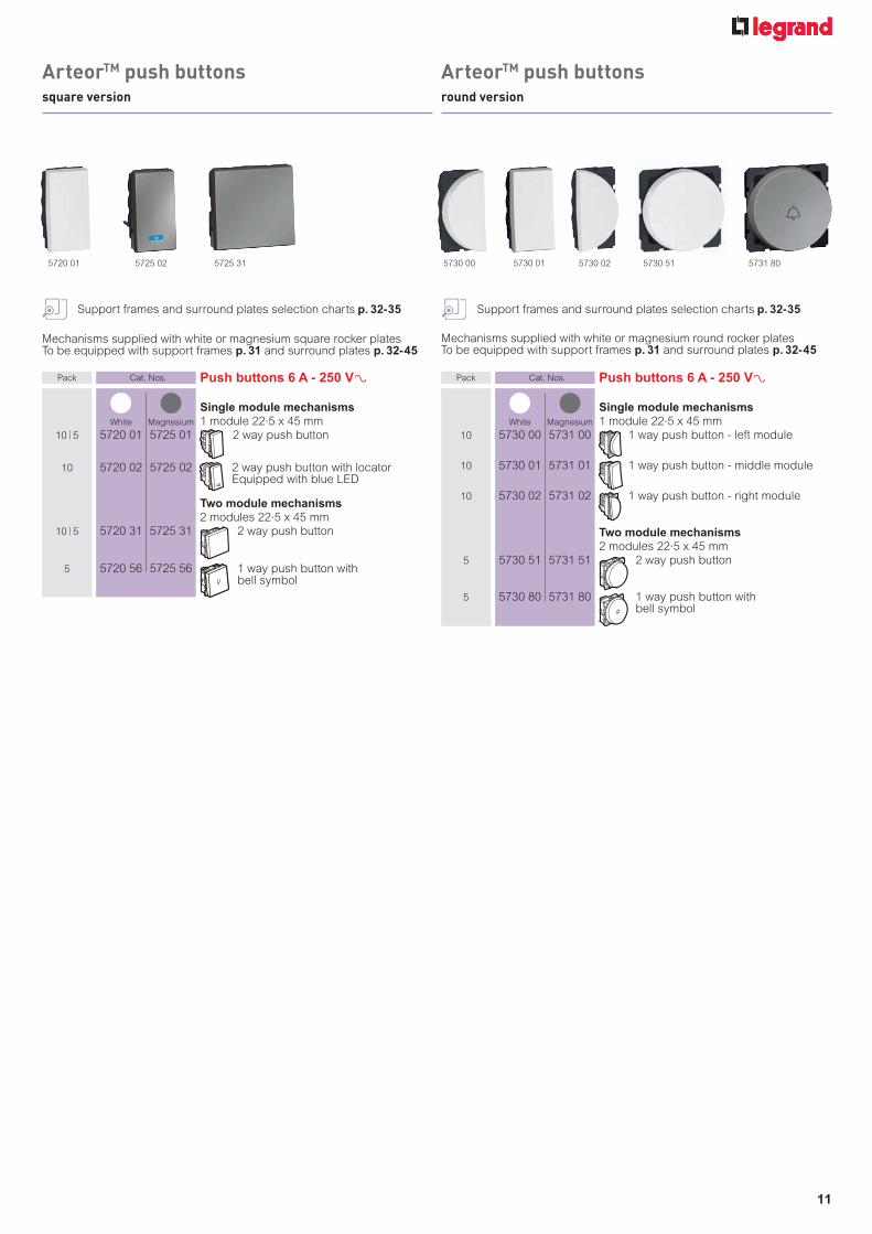
Mechanisms supplied with white or magnesium square rocker platesTo be equipped with support frames p. 31 and surround plates p. 32-45
Pack Cat. Nos. Push buttons 6 A - 250 VA
Single module mechanisms 1 module 22.5 x 45 mm
10 5 5720 01 5725 01 2 way push button
10 5720 02 5725 02 2 way push button with locatorEquipped with blue LED
Two module mechanisms 2 modules 22.5 x 45 mm
10 5 5720 31 5725 31 2 way push button
5 5720 56 5725 56 1 way push button with bell symbol
Pack Cat. Nos. Push buttons 6 A - 250 VA
Single module mechanisms 1 module 22.5 x 45 mm
10 5730 00 5731 00 1 way push button - left module
10 5730 01 5731 01 1 way push button - middle module
10 5730 02 5731 02 1 way push button - right module
Two module mechanisms 2 modules 22.5 x 45 mm
5 5730 51 5731 51 2 way push button
5 5730 80 5731 80 1 way push button with bell symbol
Mechanisms supplied with white or magnesium round rocker platesTo be equipped with support frames p. 31 and surround plates p. 32-45
White Magnesium White Magnesium
5720 01 5725 02 5725 31 5730 00 5730 01 5730 02 5730 51 5731 80
ArteorTM push buttonssquare version
ArteorTM push buttonsround version
Support frames and surround plates selection charts p. 32-35 Support frames and surround plates selection charts p. 32-35

12
Mechanisms supplied with white or magnesium square rocker platesTo be equipped with support frames p. 31 and surround plates p. 32-45
Support frames and surround plates selection charts p. 32-35Loads selection chart p. 15
Support frames and surround plates selection charts p. 32-35Loads selection chart p. 15
Pack Cat. Nos. Micropush switches - 100/240 VA
2 modules 22.5 x 45 mm
Without neutral 1 5740 04 5740 54 2 way switch
400 W
1 5740 02 5740 52 2 way switch2 x 400 W with LED locatorWith magnesium push controlSupplied with support frame
With neutral With magnesium push control
1 5740 03 5740 53 2 way switch1 000 W with LED locatorTo be mounted on 2 module support frame
1 5740 00 5740 50 2 way switch2 x 1 000 W with LED locatorTo be mounted on 2 module support frame
1 5740 01 5740 51 2 way switch3 x 1 000 W with LED locatorTo be mounted on 2 module support frame
Sensitive switches - 100/240 VA
1 5720 51 5734 55 For controlling light sources by simply passing the hand in front of the switchUp to 5 sensitive switches can
be combined to control the same lighting circuitSupplied with LED indicator light2 modules 22.5 x 45 mm
Pack Cat. Nos. Micropush switches - 100/240 VA
2 modules 22.5 x 45 mm
Without neutral 1 5743 04 5743 54 2 way switch
400 W
1 5743 02 5743 52 2 way switch2 x 400 W with LED locatorWith magnesium circular push controlSupplied with support frame
With neutral With magnesium circular push control
1 5743 03 5743 53 2 way switch1 000 W with LED locatorTo be mounted on 2 module support frame
1 5743 00 5743 50 2 way switch2 x 1 000 W with LED locatorTo be mounted on 2 module support frame
1 5743 01 5743 51 2 way switch3 x 1 000 W with LED locatorTo be mounted on 2 module support frame
Sensitive switches - 100/240 VA
1 5725 51 5736 55 For controlling light sources by simply passing the hand in front of the switch
Up to 5 sensitive switches can be combined to control the same lighting circuitSupplied with LED indicator light2 modules 22.5 x 45 mm
White Magnesium
White Black
White Magnesium
White Black
White Magnesium White Magnesium
Mechanisms supplied with white or magnesium round rocker platesTo be equipped with support frames p. 31 and surround plates p. 32-45
5740 03 5740 01 5734 55 5743 00 5743 51 5736 55
ArteorTM electronic switchessquare version
ArteorTM electronic switchesround version

5722 11 5722 39
Mechanisms supplied with white or magnesium square cover platesTo be equipped with support frames p. 31 and surround plates p. 32-45
Mechanisms supplied with white or magnesium round rocker platesTo be equipped with support frames p. 31 and surround plates p. 32-45
Pack Cat. Nos. Dimmers 100/240 VA - 50/60 Hz
Resistive/inductive loads touch dimmers 1 5722 111 5727 111 Without neutral, 2 wire - 600 W
Push button dimmer2 modules 22.5 x 45 mmTo be mounted on 3 module support frame
Leading/trailing edge dimmers 1 5740 071 5740 571 2 x 400 W
Push button dimmerWith magnesium push control2 modules 22.5 x 45 mm
Supplied with support frame
Universal dimmers 1 5722 391 5727 391 Without neutral, 2 wires
Push button dimmer for all types of lamps: - Dimmable LEDs : 75 W
- Dimmable compact fl uorescent lamps : 75 W - Halogen with transformer : 400 VA - Fluorescent tube : 200 VA - Halogen 230 V and incandescent : 400 W
Can be associated with one or several push-buttons without neon, for ON/OFF or dimming controlLights come on again at the same lighting level as before they were last switched off 2 modules 22.5 x 45 mmTo be mounted on 2 module support frame
Dimmers 0-10 V 1 5722 381 5727 381 For ballasts 0-10 V
Push button dimmerWith magnesium push control2 modules 22.5 x 45 mm
To be mounted on 2 module support frame
Pack Cat. Nos. Dimmers 100/240 VA - 50/60 Hz
Resistive/inductive loads touch dimmers 1 5743 051 5743 551 Without neutral, 2 wire - 600 W
Push button dimmer2 modules 22.5 x 45 mmTo be mounted on 3 module support frame
Leading/trailing edge dimmers 1 5743 071 5743 571 2 x 400 W
Push button dimmerWith magnesium circular push control2 modules 22.5 x 45 mm
Supplied with support frame
Universal dimmers 1 5743 191 5743 391 Without neutral, 2 wires
Push button dimmer for all types of lamps :
- Dimmable LEDs : 75 W - Dimmable compact fl uorescent lamps : 75 W - Halogen with transformer : 400 VA - Fluorescent tube : 200 VA - Halogen 230 V and incandescent : 400 W
Can be associated with one or several push buttons without neon, for ON/OFF or dimming controlLights come on again at the same lighting level as before they were last switched off2 modules 22.5 x 45 mmTo be mounted on 2 module support frame
Dimmers 0-10 V 1 5743 181 5743 381 For ballasts 0-10 V
Push button dimmerWith magnesium circular push control
2 modules 22.5 x 45 mmTo be mounted on 2 module support frame
White Magnesium
White Magnesium
White Black
5743 55 5743 19 5743 38
White Magnesium
White Magnesium
White Black
1 : 2 way dimmer option available using additional push button p. 11
1 : 2 way dimmer option available using additional push button p. 11
13
Support frames and surround plates selection charts p. 32-35Loads selection chart p. 15
Support frames and surround plates selection charts p. 32-35Loads selection chart p. 15
ArteorTM dimmerssquare version
ArteorTM dimmersround version

Mechanism supplied complete with white or magnesium square cover plate, flush mounting box, support frame and surround plate
Pack Cat. Nos. Lighting environment controller
1 5740 101 5740 602 Main controller3 x 1 000 WParticularly suitable for controlling lighting environments in conference rooms, meeting rooms, restaurants, showrooms, etc.
Possible applications :- control of 3 lighting circuits in one room- control of lighting environments by dimming polychromatic lamps (red / green / blue or warm white / cold white)Sources supported per circuit :- 1 000 W for incandescent and halogen 230 VA,- 1 000 VA for fl uorescent tubes with 0-10 V ballast,- 1 000 VA for ELV halogen lamps with ferromagnetic or electronic transformerThe cumulative load of the 3 circuits must not exceed 2 200 WDALI input ballast and 0-10 V ballasts can be controlledControls on front face :- 6 push buttons for on/off / dimming control of each of the 3 lighting circuits- 3 sets of 5 LEDs displaying the current level of each circuit- 4 push buttons for memorising and controlling lighting environments
1 : Supplied with white plate2 : Supplied with mirror black plate
White Magnesium
■ Lighting environment controller
Wiring principleWith 0-10 V ballasts
A B
C D
L
L
N
3 2 1 N
Choice of scenes : (factory configuration) A : 100 % C : OFFB : 66 % D : 33 %
Manual setting on each of 3 channels :light dimming / switching ON/OFF
By controlling the RGB proportions, you can create scenes favouring warm or cold colours or scenes with dominant colours
The possibilities and results are identical using LED (lights) piloted by 0-10 V ballast
Possibility to mix channels with different types of lamps (example : 1 channel for 0-10 V ballast, 2 channels with incandescent lamp dimmer)
5740 60
14
ArteorTM dimmerslighting environment controller
ArteorTM dimmerslighting environment controller
Loads selection chart p. 15

■ Electronic switches, dimmers, lighting environment controller max. loadsUniversal
Leading edge Trailing edge
Cat. Nos.
Incandescent lamp Halogen lamp ELV halogen with ferromagnetic transformer
ELV halogen with electronic transformer
110 V 230 V 110 V 230 V 110 V 230 V 110 V 230 V
Micropush switches
5740 04/545743 04/54 200 W 400 W 200 W 400 W 200 VA 400 VA 200 VA 400 VA
5740 03/535743 03/53 500 W 1 000 W 500 W 1 000 W 250 VA 500 VA 250 VA 500 VA
5740 00/505743 00/50
2 x 500 W
2 x 1 000 W
2 x 500 W
2 x 1 000 W
2 x 250 VA
2 x 500 VA
2 x 250 VA
2 x 500 VA
5740 01/515743 01/51
3 x 500 W
3 x 1 000 W
3 x 500 W
3 x 1 000 W
3 x 250 VA
3 x 500 VA
3 x 250 VA
3 x 500 VA
5740 02/525743 02/52
2 x 200 W
2 x 400 W
2 x 200 W
2 x 400 W
2 x 200 VA
2 x 400 VA
2 x 200 VA
2 x 400 VA
Sensitive switches
5720 515734 555725 515736 55
500 W 1 000 W 500 W 1 000 W 250 VA 500 VA 250 VA 500 VA
Dimmers
5722 115727 11
5743 05/55300 W 600 W 300 W 600 W 300 VA 600 VA – –
5722 395727 39
5743 19/39200 W 400 W 200 W 400 W 200 VA 400 VA 200 VA 400 VA
5740 07/575743 07/57
2 x 200 W
2 x 400 W
2 x 200 W
2 x 400 W
2 x 200 VA
2 x 400 VA
2 x 200 VA
2 x 400 VA
5740 10/60 1 100 W 2 200 W 1 100 W 2 200 W 1 100 VA 2 200 VA 1 100 VA 2 200 VA
Cat. Nos.
Ballasts 0-10 V Ballasts DALI Reducer motor for shutters110 V 230 V 110 V 230 V 110 V 230 V
Micropush switches
5740 03/535743 03/53 – – – – 50 VA 100 VA
5740 00/505743 00/50 – – – – 2 x 50 VA 2 x 100 VA
5740 01/515743 01/51 – – – – 3 x 50 VA 3 x 100 VA
Sensitive switches
5720 515734 555725 515736 55
– – – – 50 VA 100 VA
Dimmers
5722 385727 38
5743 18/38300 VA 40 mA
600 VA 40 mA
– – – –
5740 10/60 1 100 VA50 mA
2 200 VA50 mA
60 ballast 60 ballast – –
Universal
Cat. Nos.
Fluorescent tube Compact fl uorescent lamp LED110 V 230 V 110 V 230 V 110 V 230 V
Micropush switches
5740 03/535743 03/53 250 VA 500 VA 250 VA 500 VA 250 VA 500 VA
5740 00/505743 00/50 2 x 250 VA 2 x 500 VA 2 x 250 VA 2 x 500 VA 2 x 250 VA 2 x 500 VA
5740 01/515743 01/51 3 x 250 VA 3 x 500 VA 3 x 250 VA 3 x 500 VA 3 x 250 VA 3 x 500 VA
Sensitive switches
5720 515734 555725 515736 55
250 VA 500 VA 250 VA 500 VA 250 VA 500 VA
Dimmers5722 395727 39
5743 19/39100 VA 200 VA
Dimmable37 W
10 lampsmax
Dimmable75 W
10 lampsmax
Dimmable37 W
10 lampsmax
Dimmable75 W
10 lampsmax
15
ArteorTM
loads selection chart

pour exemple : xxxxxxxxxxxxxxx
Pack Cat. Nos. Automatic switches - 100/240 VA IR detection Adjustable detection distance from 3 to 10 m
Horizontal detection angle : 180°Adjustable luminosity threshold : 3 to 1 000 luxTime delay adjustable from 1 sec. to 16 mins.Cycle repeated as long as movement is detectedPossible remote manual control with N/C push buttonIntegrated self-protection against overloads and short-circuitsInstallation in box min. depth 40 mm recommended2 modules 22.5 x 45 mm
With neutral, 3 wire - 1 000 W 1 5720 53 5740 61 Operates :
- up to 1 000 W incandescent and halogen lamps
- up to 500 VA ELV halogen lamps with ferromagnetic or electronic transformer, fl uorescent tubes and compact fl uorescent lamps
Without neutral, 2 wire - 400 W 1 5720 52 5740 62 Operates :
- up to 400 W incandescent and halogen lamps - up to 400 VA ELV halogen lamps with ferromagnetic or electronic transformer
Mechanisms supplied with white or magnesium square cover platesTo be equipped with support frames p. 31 and surround plates p. 32-45
White Magnesium
5720 53 5740 62
16
Up to 20% of a building’s electricity bill can be attributed to lighting. Legrand’s occupancy sensors can help cut this cost.With a positive effect on the environment... and on the wallet... occupancy sensors automatically switch off lighting when it’s not needed.
PIR • ULTRASONIC • DUAL TECHNOLOGYThree different technologies are available, each offering simple installation and maintenance.
Lighting:put a stop toenergy waste
energy saving
ArteorTM automatic switches
Support frames and surround plates selection charts p. 32-35
Visit : www.legrand.co.uk to fi nd out more.

Key switches Supplied with key 1 module 22.5 x 45 mm
10 5722 32 5727 32 2 way
10 5722 33 5727 33 Double pole
Mechanisms supplied with white or magnesium square cover platesTo be equipped with support frames p. 31 and surround plates p. 32-45
Pack Cat. Nos. Time delay switches
Interference suppression conforming to standard EN 55022
1 5720 55 5740 84 For timer control of a circuit with the following loads :- 1 000 W incandescent and halogen 230 VA
- 2 300 W resistive (heating)- 400 VA fl uorescent and ELV halogenAdjustable from 25 secs. to 15 mins.It is possible to install a number of timer switches in parallel on the same circuit2 wire installation in box min. depth 40 mmWith integrated LED2 modules 22.5 x 45 mm
Mechanisms supplied with white or magnesium square cover platesTo be equipped with support frames p. 31 and surround plates p. 32-45
Skirting lights 2 modules 22.5 x 45 mm
For installation close to obstacles
Standard With LED 230 V - 0.2 or 1 W
1 5722 21 5740 82 Square version
With motion detector 100-240 V With IR detection cell and LED
When a person passes, the mechanism detects the presence and lights the obstacleThe function is equipped with an audible signal that can be disengaged
1 5722 26 5727 26 Square version
Illuminated lighting unit
10 5724 52 230 V - 1 WSupplied with 4 coloured labels1 module 22.5 x 45 mm
Pack Cat. Nos. Miniature emergency lighting unit
1 5722 22 Illuminates automatically upon power failureUnclips from frame to become
portable Can be permanently attached to frame LEDs indicating mains and charging status
Overdoor lighting units Supplied with diffusers and LED
2 modules : 22.5 x 45 mm
10 5724 53 Red diffuser
10 5722 23 White diffuser
Lamps 10 5724 56 LED 230 V for locator switch - blue
10 5724 55 LED 230 V for indicator switch - red
10 5724 54 LED 12 V for indicator switch - red
White Magnesium
White Magnesium
White Magnesium
White
White
White
5720 55 5727 26 5724 52 5724 23
Single pole latching relays
1 5722 27 5727 27 10 A - 250 VA - 50/60 Hz With integrated push button Intensity 0.04 A2 modules 22.5 x 45 mm
White Magnesium
17
Lighting managementvisit : www.legrand.co.uk
ArteorTM lighting control ArteorTM visual indication
Support frames and surround plates selection charts p. 32-35 Support frames and surround plates selection charts p. 32-35

Mechanisms supplied with white or magnesium square rocker platesTo be equipped with support frames p. 31 and surround plates p. 32-45
Pack Cat. Nos. Electric roller blind control - 250 VA
Push buttons Double push button - 6 A
For control via automatic box (N/O mechanism)
2 modules 22.5 x 45 mm
10 5722 19 5727 19 Square version
10 5732 19 5737 19 Round version
Switches Double switch - 10 A
For direct control of a motor (mechanism with fi xed positions)
2 modules 22.5 x 45 mm
10 5722 20 5727 20 Square version
10 5732 20 5737 20 Round version
Mechanisms supplied with white or magnesium square cover platesTo be equipped with support frames p. 31 and surround plates p. 32-45
Pack Cat. Nos. Fan controller
2 modules 22.5 x 45 mm
1 5722 18 5727 18 Rotary speed controller for fanOperates 40 to 400 VA limit switch For progressive speed control of ceiling fan
Thermostats 2 modules 22.5 x 45 mm
Electronic room thermostat 1 5722 03 5727 03 Control dial with index and
adjustable segments for min. and max. settingsAdjustable range from 5 °C to 30 °C
(+/- 0.5 °C)Power supply : 230 VA - 50/60 HzOne potential free changeover contact outputSuitable for controlling heated ceilings and underfl oor heating- LV use breaking capacity :8 A - 250 VA - resistive inductive circuit2 A - 250 VA - inductive circuit- ELV use breaking capacity : 12 to 48 VA - 12 to 24 V=, from 1 mA min. to 500 mA max.
Thermostat for electric fl oor heating 1 5722 63 5727 63 With one potential free N/O contact
and LED 16 A - 230 VAAdjustable range from 10 °C to 60 °CWith probe
White Magnesium White Magnesium
White Magnesium
Curtain control
1 module 22.5 x 45 mm
5 5722 02 5727 02 Curtain switch centre off
5 5722 01 5727 01 Curtain switch centre retract
White Magnesium
5722 195722 035722 18 5727 205737 19 5722 02
18
ArteorTM electric roller blind andcurtain control
ArteorTM ventilation andheating control
Support frames and surround plates selection charts p. 32-35 Support frames and surround plates selection charts p. 32-35

5732 84 5737 855737 22 5737 355733 82 5732 955732 34
Mechanisms supplied with white or magnesium round rocker platesTo be equipped with support frames p. 31 and surround plates p. 32-45
Mechanisms supplied with white or magnesium square rocker platesTo be equipped with support frames p. 31 and surround plates p. 32-45
Pack Cat. Nos. Lighting control with specifi c marking
Master controls 10 5732 84 5737 84 Master switch
2 way double pole 20 AX - 250 V± for general control : all ON / all OFF
2 modules 22.5 x 45 mm
10 5732 86 5737 86 Master push button2 way - 6 A - 250 V± for general control : all ON / all OFF2 modules 22.5 x 45 mm
Controls for bed lights 10 5732 94 5737 94 2 x 2 way switch
10 AX - 250 V±2 x 1 module 22.5 x 45 mm
10 5732 96 5737 96 2 x 2 way push button 6 A - 250 V±2 x 1 module 22.5 x 45 mm
Controls for desk and entrance lights 10 5733 82 5738 82 2 x 2 way switch
10 AX - 250 V±2 x 1 module 22.5 x 45 mm
10 5733 84 5738 84 2 x 2 way push button6 A - 250 V±2 x 1 module 22.5 x 45 mm
Electric roller blind control with specifi c marking - 250 V±
10 5732 22 5737 22 Double switch - 10 A For direct control of a motor (mechanism with fi xed positions)
Roller blinds marking2 modules 22.5 x 45 mm
10 5732 24 5737 24 Double push button - 6 A For control via automatic box (N/O mechanism)
Roller blinds marking2 modules 22.5 x 45 mm
Electric roller blind control with specifi c marking - 250 V±
10 5732 23 5737 23 Double switch - 10 A For direct control of a motor (mechanism with fi xed positions)
Roller blinds marking 2 modules 22.5 x 45 mm
10 5732 25 5737 25 Double push button - 6 A For control via automatic box (N/O mechanism)
Roller blinds marking 2 modules 22.5 x 45 mm
Curtain control with specifi c marking - 250 V±
10 5732 34 5737 34 Double switch - 10 A For direct control of a motor (mechanism with fi xed positions)
Curtain marking 2 modules 22.5 x 45 mm
10 5732 36 5737 36 Double push button - 6 AFor control via automatic box (N/O mechanism)
Curtain marking 2 modules 22.5 x 45mm
Curtain control with specifi c marking - 250 V±
10 5732 35 5737 35 Double switch - 10 A For direct control of a motor (mechanism with fi xed positions)
Curtain marking 2 modules 22.5 x 45 mm
10 5732 37 5737 37 Double push button - 6 AFor control via automatic box (N/O mechanism)
Curtain marking 2 modules 22.5 x 45mm
White Magnesium
White Magnesium White Magnesium
White Magnesium White Magnesium
Pack Cat. Nos. Lighting control with specifi c marking
Master controls 10 5732 85 5737 85 Master switch
2 way double pole 20 AX - 250 V± for general control : all ON / all OFF
2 modules 22.5 x 45 mm
10 5732 87 5737 87 Master push button2 way - 6 A - 250 V± for general control : all ON / all OFF
2 modules 22.5 x 45 mm
Controls for bed lights 10 5732 95 5737 95 2 x 2 way switch
10 AX - 250 V±2 x 1 module 22.5 x 45 mm
10 5732 97 5737 97 2 x 2 way push button6 A - 250 V±2 x 1 module 22.5 x 45 mm
Controls for desk and entrance lights 10 5733 83 5738 83 2 x 2 way switch
10 AX - 250 V±2 x 1 module 22.5 x 45 mm
10 5733 85 5738 85 2 x 2 way push button6 A - 250 V±2 x 1 module 22.5 x 45 mm
White Magnesium
MASTER
MASTER
MASTER
MASTER
19
ArteorTM hotel equipmentsquare version – lighting, electric roller blind and curtain control
ArteorTM hotel equipmentround version – lighting, electric roller blind and curtain control
Support frames and surround plates selection charts p. 32-35 Support frames and surround plates selection charts p. 32-35

Mechanisms supplied with white or magnesium square cover platesTo be equipped with support frames p. 31 and surround plates p. 32-45
Mechanisms supplied with white or magnesium square cover platesTo be equipped with support frames p. 31 and surround plates p. 32-45
Pack Cat. Nos. Key card switches Energise a circuit by inserting a key card or
fob (e.g. hotel room, meeting room) Time-delay of approx. 30 secs. after card removal 2 modules 22.5 x 45 mm
Mechanical key card switches 1 5722 30 5727 30 Key fob switches 230 V
Use with key fob Cat. Nos. 5722 59 and 5727 59 or a smart card (access card for a hotel room)
1 5722 31 5734 93 Key card switches 12-24 V To be equipped with single pole latching relay Cat. Nos. 5722 27 and 5727 27 p. 17
Key card switches RFID Works only with ISO type contactless key card Cat. Nos. 0767 11 or other ISO type 13.56 MHz key card
1 5722 53 5727 53 Key card switches RFID Low capacity contact 230 V - 30 VA Lighting of the slot by LED
Key fobs and key card For mechanical key card switches
10 5722 59 5727 59 Key fob
Enables use of key fob switches in hotels with key locks Supplied complete with a label holder for individual hotel identifi cation
For RFID key card switches 10 0767 11 MIFARE contactless badge card ISO format (50 x 80 mm) Chip: 13.56 MHz Standard 1 KB memory
White Magnesium
White Magnesium
White Magnesium
Pack Cat. Nos. Shaver sockets Conform to BS EN 61558-2-5. IP 24
For use with European, British, American, Australian 2-pin plugsScrewless live and neutral terminals Double wound isolating transformerAutomatic self-resetting overload feature Plug insertion operates micro-switch which energises transformerTo be equipped with BS 2 gang - 3 module plates p. 32-35For fl ush mounting boxes, use BS 2 gang box depth 48 mm, US type, Italian type boxes depth 48 mmPower supply : 230 V - 50/60 Hz
3 modules 22.5 x 45 mm
1 5721 53 5726 53 230 V / 120-230 VWith earth connector
White Magnesium
120V230V
5727 30 5721 53
20
ArteorTM hotel equipmentkey fob switches
ArteorTM hotel equipmentshaver sockets
Support frames and surround plates selection charts p. 32-35Support frames and surround plates selection charts p. 32-35

Mechanisms supplied with white or magnesium round rocker platesTo be equipped with support frames p. 31 and surround plates p. 32-45
Mechanisms supplied with white or magnesium square rocker platesTo be equipped with support frames p. 31 and surround plates p. 32-45
Buzzers
10 5722 07 5722 47
230 V2 modules 22.5 x 45 mm
Buzzers
10 5722 08 5722 48
230 V2 modules 22.5 x 45 mm
Illuminated signs Mechanisms integrating LEDs and a
pivoting window that can take customised labels (printed using a simple text editor on transparent printing paper)2 modules 22.5 x 45 mm
Green or Red 5 5722 24 5727 24 Sign with 2-state LEDs with choice
of green or red confi gurable on the mechanism1 W
Blue 5 5722 25 5727 22 Sign with blue LED
A choice of 2 power levels : 0.2 or 1 W
Illuminated signs Mechanisms integrating LEDs and a
pivoting window that can take customised labels (printed using a simple text editor on transparent printing paper)2 modules 22.5 x 45 mm
Green or Red 5 5727 25 Sign with 2-state LEDs with choice
of green or red confi gurable on the mechanism1 W
Blue 5 5727 23 Sign with blue LED
A choice of 2 power levels : 0.2 or 1 W
White Magnesium White Magnesium
White Magnesium
Pack Cat. Nos. Hotel bedroom call indicators Enables the resident to inform hotel staff
of the room statusTwo settings are possible :- Do not disturb- Please clean the room1 + 1 modules 22.5 x 45 mm
Indicator 5 5720 57 5725 57 Indicator lamp and bell push
Installed in the corridor, display calls
Supplied with LEDs
Internal control unit 5 5720 54 5725 54 Allows the user to select the
desired settingSupplied with LEDs
White Magnesium
5720 57 5725 54 5722 24
Magnesium
Pack Cat. Nos. Hotel bedroom call indicators Enables the resident to inform hotel staff
of the room statusTwo settings are possible :- Do not disturb- Please clean the room1 + 1 modules 22.5 x 45 mm
Indicator 5 5720 67 5725 67 Indicator lamp and bell push
Installed in the corridor, display calls
Supplied with LEDs
Internal control unit 5 5720 74 5725 74 Allows the user to select the
desired settingSupplied with LEDs
White Magnesium
5725 67 5725 74
21
ArteorTM hotel equipmentsquare version – call indicators, illuminated signs, buzzers
ArteorTM hotel equipmentround version – call indicators, illuminated signs, buzzers
Support frames and surround plates selection charts p. 32-35 Support frames and surround plates selection charts p. 32-35

22
Pack Cat. Nos. USB power suppliesFor recharging portable devices Conform to IEC 62684-2011-01Consumption in passive mode < 0·3 W2P + E tap-off connection via 2·5 mm2 screw terminalsSupplied cordless
Double USB sockets - 5 V - 1 500 mAFor fast-charging telephones, smartphones, MP3/MP4 players and tablet PC
5/1 5720 78 5725 78 2 modules
Single USB sockets - 5 V - 750 mA
10 5720 71 5725 71
For Smartphone
1 module
Support for portable device on chargePrevents device from any fall risk and allows secure use of device while chargingWall mountingFixing tools supplied
1 0803 99 For 1 portable device
Pack Cat. Nos. USB power suppliesFor recharging portable devices Conform to IEC 62684-2011-01Consumption in passive mode < 0.3 W2P + E tap-off connection via 2.5 mm2 screw terminalsSupplied cordless
Double USB sockets - 5 V - 1 500 mAFor fast-charging telephones, smartphones, MP3/MP4 players and tablet PC
1 5724 88 5733 98 2 modules
Support for portable device on chargePrevents device from any fall risk and allows secure use of device while chargingWall mountingFixing tools supplied
1 0803 99 For 1 portable device
Mechanisms supplied with rocker plates, to be equipped with support frames p. 31 and surround plates p. 32-45Average charging time for devices equipped with lithium-ion polymer batteries :- 80 % charged < 2 h- 100 % charged < 4 hNo specifi c constraint : no need to wait for the battery to be fl at before charging, or to have it fully charged before use
Mechanisms supplied with rocker plates, to be equipped with support frames p. 31 and surround plates p. 32-45Average charging time for devices equipped with lithium-ion polymer batteries :- 80 % charged < 2 h- 100 % charged < 4 hNo specifi c constraint : no need to wait for the battery to be fl at before charging, or to have it fully charged before use
5724 885720 715720 78
Technical information p. 23Support frames and surround plates selection charts p. 32-35
Technical information p. 23Support frames and surround plates selection charts p. 32-35
White Magnesium White Magnesium
ArteorTM USB chargerssquare version
ArteorTM USB chargersround version

23
■ InstallationBy simple tap-off on 2P + E socket Wiring 1.5 or 2.5 mm2
Class II product which does not require earthingReleases a 2P + E socket recess
■ Universal power suppliesThe fl ush mounting charger is always available for use, providing freedom from the restrictions of a mobile charger and extending battery life for users on the move
1 500 mA version : can simultaneously charge two mobile terminals conforming to EN 62684 or PC tablet (fast charging)
750/1 500 mA version : ideal for everyday needs
Environment : Helps to reduce waste associated with the discarding of mobile chargers that have become unusable (50 000 tonnes/year) and thus the associated greenhouse gas emissions (13.5 million tonnes equivalent)Reduces standby consumption by more than 50% in comparison with a mobile chargerPerformance required by standard EN 62684 : 0.5 WLegrand performance : < 0.3 W
BBzzzzz
ArteorTM USB chargers

Mechanisms supplied with white or magnesium square cover platesTo be equipped with support frames p. 31 and surround plates p. 32-45
Pack Cat. Nos. Data sockets
RJ 45 tool-less system - CAT 6 10 5723 14 5728 14 Rapid connection socket. No tool
required UTP - 8 contacts2 modules 22.5 x 45 mm
USB female data sockets Used to bring connections closer to the
userFor connecting USB devices
(scanner-printer, external hard disk)Recommended cable : USB A max. cable length 5 m
Cross-section 1 mm² 1 5722 75 5727 75 Connection via screw terminals
1 module 22.5 x 45 mm
1 5720 94 5727 94 Preconnected Equipped with a 15 cm cord
1 module 22.5 x 45 mm
Audio and video sockets
2 x female RCA 1 5722 72 5727 72 For the stereo audio connection
of any DVD drive, camera, video recorder, etc. type peripheral
Recommended cable : 1 shielded audio pair1 module 22.5 x 45 mm
3 x female RCA 1 5722 73 5727 73 For the composite video and stereo
audio connection of a DVD drive, camera, video recorder, video
conference equipment etc.Recommended cable : 1 shielded audio pair + 1 x 3 mm mini-coaxial1 module 22.5 x 45 mm
YUV 1 5722 71 5727 71 For analogue high defi nition connection
of a DVD, PC monitor, plasma screen, video projector, graphic paintbox, etc.
Recommended cable : 3 x 3 mm mini-coaxial (max. cable length 25 m) or 3 x RG59 coaxial (max. cable length 50 m)1 module 22.5 x 45 mm
Female 3.5 mm jack For stereo audio connection from a
portable source Recommended cable : 1 x 0.22 mm2 shielded audio pair
1 5722 74 5727 74 Connection on screw terminals1 module 22.5 x 45 mm
Pack Cat. Nos. Audio and video sockets (continued) Female HD 15 For VGA, XGA or VESA connection of a PC
monitor, plasma screen, video projector, graphic paintbox, etc.Recommended cable Cat. No. 0327 81Max. cable length 25 m (beyond this a VGA amplifi er is recommended)
1 5722 82 5727 82 Connection on screw terminals 2 modules 22.5 x 45 mm
1 5722 79 5727 79 Solder connection 1 module 22.5 x 45 mm
HDMI 1 5722 81 5727 81 For digital high defi nition audio
and video connection of a PC monitor, plasma screen, video projector, graphic paintbox, etc.
Recommended cable Cat. No. 0327 802 modules 22.5 x 45 mm
1 5720 96 5725 96 Preconnected Equipped with a 15 cm cord
1 module 22.5 x 45 mm
S-Video socket (4-pin mini-DIN) 1 5744 01 5744 51 1 gang
Provides the YC video link for any peripheral device such as a DVD
drive, camera, video recorder, videoconferencing, etc1 module 22.5 x 45 mm
Female BNC 75 1 5722 76 5727 76 For the composite video connection
of any DVD drive, camera, video recorder, etc.
Recommended cable : RG59 coaxialMax. cable length : 10 m1 module 22.5 x 45 mm
Cables for connecting 2 sockets HDMI cable 1 0327 80 Length 20 m
For connecting HDMI sockets at a distance of up to 10 m
VGA cable 1 0327 81 Length 20 m
For connecting full pin HD 15 sockets at a distance of up to 20 m
White Magnesium
5727 75 5722 72 5727 73 5722 74 5722 79 5722 81 5744 01 5722 76
White Magnesium
White Magnesium
24
ArteorTM data, audio and video socketssquare version
Support frames and surround plates selection charts p. 32-35

Mechanisms supplied with white or magnesium square cover platesTo be equipped with support frames p. 31 and surround plates p. 32-45
Cable for connecting 2 sockets HDMI cable 1 0327 80 Length 20 m
For connecting HDMI sockets at a distance of up to 10 m
Pack Cat. Nos. Data sockets
RJ 45 tool-less system - CAT 6 10 5723 24 5728 24 Rapid connection socket. No tool
required UTP - 8 contacts2 modules 22.5 x 45 mm
USB sockets Used to bring connections closer to the
userFor connecting USB devices (scanner-printer, external hard disk)
Recommended cable : USB A max. cable length 5 m
1 5732 74 5737 74 Connection via screw terminals Cross-section 1 mm²
2 modules 22.5 x 45 mm
1 5724 74 5733 74 Preconnected Equipped with a 15 cm cord
2 modules 22.5 x 45 mm
Audio and video sockets
2 x female RCA 1 5732 72 5737 72 For the stereo audio connection
of any DVD drive, camera, video recorder, etc. type peripheralRecommended cable : 1 shielded
audio pair2 modules 22.5 x 45 mm
3 x female RCA 1 5732 73 5737 73 For the composite video and stereo
audio connection of a DVD drive, camera, video recorder, video conference equipment etc.
Recommended cable : 1 shielded audio pair + 1 x 3 mm mini-coaxial2 modules 22.5 x 45 mm
White Magnesium
White Magnesium
Pack Cat. Nos. Audio and video sockets (continued)
HDMI 1 5722 85 5727 85 For digital high defi nition audio
and video connection of a PC monitor, plasma screen, video projector, graphic paintbox, etc.
Recommended cable Cat. No. 0327 802 modules 22.5 x 45 mm
1 5724 76 5735 96 Preconnected Equipped with a 15 cm cord
1 module 22.5 x 45 mm
S-Video socket (4-pin mini-DIN) 1 5745 01 5745 51 1 gang
Provides the YC video link for any peripheral device such as a DVD drive, camera, video recorder,
videoconferencing, etc2 modules 22.5 x 45 mm
White Magnesium
5728 24 5732 74 5737 73 5727 85 5745 01
25
ArteorTM data, audio and video socketsround version
Support frames and surround plates selection charts p. 32-35
More television, telephone, data, audio and video socketsp. 26

Mechanisms supplied with white or magnesium square cover platesTo be equipped with support frames p. 31 and surround plates p. 32-45
Pack Cat. Nos. Television sockets For aerial and satellite installation (with
individual demodulator)DTT and HDTV compatibleTV : male connector (Ø9.5 mm) attenuation ≤ 1.5 dbR : female connector (Ø9.5 mm) attenuation ≤ 1.5 dbSAT : "F" type connector attenuation ≤ 2 dbRecommended coaxial cable : 17/19 VATC
TV sockets 10 5721 63 5726 63 TV single shielded "F" type with screws
0-2400 MHz1 module 22.5 x 45 mm
10 5721 71 5726 71 TV single shielded male Ø9.5 mm 0-2400 MHz1 module 22.5 x 45 mm
TV-R socket 10 5721 70 5726 70 TV-R shielded socket female-male
Ø9.5 mm2 modules 22.5 x 45 mm
TV-R-SAT socket 10 5721 72 5726 72 TV-R-SAT shielded socket
0-2400 MHz2 modules 22.5 x 45 mm
White Magnesium
Television socket (Ø 9/9.5 female) TV 0-860 MHz
20 5721 73 5726 73 TV singleNon-isolated
Telephone sockets With IDC connection
10 5723 101 5728 101 Single master2 modules 22.5 x 45 mm
5 5723 011 5728 011 Single secondary 1 module 22.5 x 45 mm
5721 72 5726 72
Mechanisms supplied with white or magnesium square cover platesTo be equipped with support frames p. 31 and surround plates p. 32-45Certified as conforming to standards ISO 11801 ed. 2.0, EN 50173-1 and EIA/TIA 568Contacts marked with 568 A and B dual colour code and numbersConnectors with self-stripping terminalsPossibility of re-wiring in the event of errorMultidirectional cable entry
Pack Cat. Nos. RJ 45 - tool-less system Rapid connection sockets. No tool required
10 Giga Supports 10 G base-T applications up to
100 m in a channel conforming to ISO/IEC TIA TSB 155 and IEEE 802.3an
10 5723 06 5728 06 STP/FTP - 9 contacts, shielded folded metal1 module 22.5 x 45 mm
CAT 6 10 5723 23 5728 23 STP - 9 contacts, shielded folded
metal1 module 22.5 x 45 mm
10 5723 22 5728 22 FTP - 9 contacts1 module 22.5 x 45 mm
10 5723 02 5728 02 UTP - 8 contacts1 module 22.5 x 45 mm
10 5723 24 5728 24 UTP - 8 contacts 2 modules 22.5 x 45 mm Round version
CAT 5e 10 5723 04 5728 04 FTP - 9 contacts
1 module 22.5 x 45 mm
10 5723 03 5728 03 UTP - 8 contacts1 module 22.5 x 45 mm
Rear pluggable RJ 45 sockets Connection to boxes via RJ 45-RJ 45
dedicated cordsUsed to create CAT 6 and CAT 5e links in accordance with standards2 modules 22.5 x 45 mm
CAT 6 10 5723 31 5728 31 UTP
10 5723 33 5728 33 FTP
Telephone/Ethernet wiring splitters Provide increased security against theft
and damage to double connectorsProvide a rate of 10/100 MbpsMultidirectional cable entryCan be installed in all supports min. depth 35 mmTelephone and Ethernet applications marked on the protective cap1 module 22.5 x 45 mm
10 5723 35 5728 35 UTP double connector 8 contacts
White Magnesium
White Magnesium
White Magnesium
5723 06 5723 315728 02 5728 35
White Magnesium
White Magnesium
RJ 11 sockets Equipped with modular jack connector
with 1/4 turn terminal for fast connection(possible looping)
10 5723 00 5728 00 4 contacts 1 module 22.5 x 45 mm
White Magnesium
5723 00
1 : Not suitable for use in the ROI
26
ArteorTM data sockets and wiring splitterArteorTM television and telephone sockets
Support frames and surround plates selection charts p. 32-35 Support frames and surround plates selection charts p. 32-35

Pack Cat. Nos. USB female sockets Used to bring connections closer to the user
For connecting USB devices (scanner-printer, external hard disk)Connection via screw terminals cross-section 1 mm²Recommended cable : USB A
1 5722 75 5727 75 Square version1 module 22.5 x 45 mm
1 5732 74 5737 74 Round version2 modules 22.5 x 45 mm
Adaptors and mechanisms supplied with white or magnesium cover plateTo be equipped with support frames p. 31 and surround plates p. 32-45 and connector (for adaptors)
Adaptors and mechanisms supplied with white or magnesium cover plateTo be equipped with support frames p. 31 and surround plates p. 32-45 and connector (for adaptors)
Pack Cat. Nos. Adaptors for data sockets
Equipped with transparent label holder
Ortronics 10 5723 05 5728 05 Adaptor for single Clarity TRACKJACK
connector Straight plug
1 module 22.5 x 45 mm
10 5723 34 5728 34 Adaptor for single Clarity TRACKJACK connector Inclined plug2 modules 22.5 x 45 mm
10 5723 18 5728 18 Adaptor for single Clarity Rear load connector Straight plug
1 module 22.5 x 45 mm
Keystone 10 5723 37 5728 37 Adaptor for single connector
2 modules 22.5 x 45 mm
Systimax 10 5723 38 5728 38 Adaptor for single connector
2 modules 22.5 x 45 mm
White Magnesium
White Magnesium
5723 05 5727 755728 38 5732 74
27
ArteorTM adaptors for data sockets ArteorTM USB sockets
Support frames and surround plates selection charts p. 32-35 Support frames and surround plates selection charts p. 32-35

Mechanisms supplied with square cover platesTo be equipped with support frames p. 31 and surround plates p. 32-45
Pack Cat. Nos. RCBO
1 5723 60 Single pole + neutral - 30 mA16 A - 230 VAThe RCBO is used to protect people (premises with a conductive
fl oor, presence of water, etc...) against direct contact with live parts or leakages to earth With test button2 modules 22.5 x 45 mm
White
5723 60
Fuse carrier units
1 6870 48 6829 10 For fuses 5 x 20 mm - 6.3 x 32 mm max. 10 A - 250 V
White Anthracite
28
ArteorTM RCBO and fuse carrier units
Support frames and surround plates selection charts p. 32-35
Loudspeaker sockets
10 5722 70 5727 70 4 mm2 terminals 1 module 22.5 x 45 mm
10 5722 80 5727 80 4 mm2 terminals 2 modules 22.5 x 45 mm
Pack Cat. Nos. Attenuator
1 5722 84 5727 84 100 V - 25 WAllow to adjust power to 25 W from a balanced 100 V loudspeaker line2 modules 22.5 x 45 mm
3-pole XLR sockets For the stereo connection of any
peripheral, microphone, mixing consoleRecommended microphone cable : 1 x 0.22 mm2 shielded audio pairRecommended speaker cable : 1 x 1.5 mm2 audio pair (will take 2.5 mm2)Max. cable length : 50 m (beyond this an audio amplifi er is recommended) 2 modules 22.5 x 45 mm
1 5722 83 5727 83 Neutrik female
1 5722 77 5727 77 Neutrik male
Home cinema loudspeaker sockets
10 5722 90 5727 90 2 connectors2 modules 22.5 x 45 mm
5 5722 91 5727 91 4 connectors3 modules 22.5 x 45 mm
Mechanisms supplied with white or magnesium square cover plateTo be equipped with support frames p. 31 and surround plates p. 32-45
White Magnesium
White Magnesium
White Magnesium
White Magnesium
5722 70 5722 905722 84 5722 83
ArteorTM attenuator and loudspeaker sockets
Support frames and surround plates selection charts p. 32-35

Pack Cat. Nos. British standard socket outlets Shuttered for child safety
Use 2 or 3 module plates and support frames p. 31-45
5 A Conform to BS 546
10 5721 10 5726 10 2P + E2 modules 22.5 x 45 mm
13 A Conform to BS 1363 : Part 2
10 5721 111 5726 111 2P + EASTA licence2 modules 22.5 x 45 mm
5 5721 30 5726 30 2P + E switchedASTA licence3 modules 22.5 x 45 mm
5 5724 67 2P + E switched - dedicated non-standard pin3 modules 22.5 x 45 mm
15 A Conform to BS 546
5 5721 32 5726 32 2P + E switched3 modules 22.5 x 45 mm
Red
White Magnesium
White Magnesium
5721 10
American 15 A - 127 V
10 5721 17 5726 17 2P + E2 modules 22.5 x 45 mm
South African 16 A Conform to SANS 164
Shuttered for child safety
5 5721 32 5726 32 2P + E switched3 modules 22.5 x 45 mm
Mechanisms supplied with white, magnesium or red square cover platesTo be equipped with support frames p. 31 and surround plates p. 32-45
Mechanisms supplied with white, magnesium or red square cover platesTo be equipped with support frames p. 31 and surround plates p. 32-45
German
16 A
10 5721 18 5726 18 2P + EShuttered for child safety2 modules 22.5 x 45 mm
10 5721 19 5726 19 2P + E with cover2 modules 22.5 x 45 mm
French 10/16 A
10 5720 21 5725 21 2P + E shuttered for child safety 2 modules 22.5 x 45 mm
5721 18 5721 17
Italian 10/16 A
10 5721 03 5726 03 2P + E shuttered for child safety
Switzerland
10 A
Shuttered for child safety
10 5721 15 2P + EType 13 - 2 modules 22.5 x 45 mm
China 10 A
Shuttered for child safety
10 5721 13 5726 13 2P + E2 modules 22.5 x 45 mm
White
White Magnesium
White Magnesium
Pack Cat. Nos. International standards socket outlets
Not suitable for domestic installations in the UK and Ireland
29
1 : when using two or more Arteor unswitched 13 A sockets (5721 11/5726 11) next to each other, it is necessary to separate the sockets with a 1 module spacer (5723 41/5728 41) p. 30.
ArteorTM British standardsocket outlets
ArteorTM International standardsocket outlets
Support frames and surround plates selection charts p. 32-35 Support frames and surround plates selection charts p. 32-35

Mechanisms supplied with white or magnesium cover platesTo be equipped with support frames p. 31 and surround plates p. 32-45
Square version plates3 finishes : White, Pearl Alu and Graphite
Pack Cat. Nos. Blanking cover plates
For 1 gang box
5 5751 30 White
5 5751 31 Pearl Alu
5 5751 32 Graphite
For 2 gang box
5 5751 40 White
5 5751 41 Pearl Alu
5 5751 42 Graphite
Cable outlets
Square version mechanisms
10 5723 20 20 A cable outlet for junction2 modules 22.5 x 45 mm
5 5723 21 45 A cable outlet - BS 1 gangSupplied with white cover plateFor fl ush mounting back box min. depth 45 mm
Cord outlets
Square version mechanisms
10 5723 07 Cord outlet with Ø8 mm entry1 module 22.5 x 45 mm
10 5723 19 Cord outlet2 modules 22.5 x 45 mm
Pack Cat. Nos. Blank modules
Square version
10 5723 41 5728 41 1 module 22.5 x 45 mm
10 5723 42 5728 42 2 modules 22.5 x 45 mm
Round version
10 5730 86 5731 86 2 modules 22.5 x 45 mm
White Magnesium
White
White
5728 41 5731 86 5723 21 5751 31
30
ArteorTM blanking cover platesArteorTM ancillary mechanisms
Support frames and surround plates selection charts p. 32-35 Support frames and surround plates selection charts p. 32-35

Pack Cat. Nos. Support frames for BS type boxes60.3 mm fi xing centres
Screw mounting (screws supplied)Accept mechanisms horizontally or vertically
For 1 gang box
10 5760 03 Square - for 1 or 2 modules
5 5760 01 Square - for 3 modules
For 2 gang box
10 5760 02 Rectangular - for 3 modules
10 5760 00 Rectangular - for 2 x 2 modules
5760 03 5760 01
5760 00
Panel mounting supports
For 1 to 3 mm thick panels
10 5760 15 For 1 module 22.5 x 45 mmClips into a 28 x 53.5 mm aperture
10 5760 16 For 2 modules 22.5 x 45 mmClips into a 58 x 53.5 mm aperture
Modular support
10 5760 13 For mounting 2 module mechanisms on symmetrical rail
5760 16
Pack Cat. Nos. Surface mounting boxes
For British, German and French standards
10 5723 90 For 2 modules - 1 gang38 mm depth
5 5723 92 For 4 horizontal modules2 x 2 modules - 2 gang48 mm depth (suitable for shaver socket)
1 5723 96 For 2 x 6 modules38 mm depth
IP 44 plate
For British and German standards
5 5751 90 For mounting in 1 gang boxSupport frame supplied96 x 94 mm
Flush mounting galvanised steelback boxes
Depth 42 mm
1 6890 27 For 6 module plate assembliesDimensions : 72 x 212 mm
1 6890 28 For 12 module plate assembliesDimensions : 143 x 212 mm
1 0818 56 For 18 module plate assemblies(fi tted with voltage separation barrier)Dimensions : 212 x 212 mm
1 6890 38 For 8 module plate assembliesDimensions : 72 x 227 mm
5723 90
5723 92
5751 90
31
ArteorTM back boxes and IP 44 plateArteorTM support frames
Support frames and surround plates selection charts p. 32-35 Support frames and surround plates selection charts p. 32-35
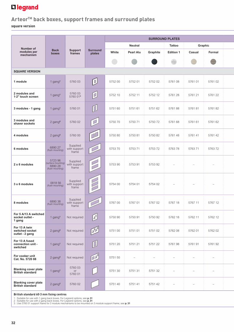
Number ofmodules permechanism
Backboxes
Support frames
Surround plates
SURROUND PLATES
Neutral Tattoo Graphic
White Pearl Alu Graphite Edition 1 Casual Formal
SQUARE VERSION
1 module 1 gang1 5760 03 5752 00 5752 01 5752 02 5761 08 5761 01 5761 02
2 modules and 1.2" touch screen
1 gang1 5760 035760 013 5752 10 5752 11 5752 12 5761 28 5761 21 5761 22
3 modules - 1 gang 1 gang1 5760 01 5751 60 5751 61 5751 62 5761 88 5761 81 5761 82
3 modules and shaver sockets
2 gang2 5760 02 5750 70 5750 71 5750 72 5761 68 5761 61 5761 62
4 modules 2 gang2 5760 00 5750 80 5750 81 5750 82 5761 48 5761 41 5761 42
6 modules 6890 27(flush mounting)
Supplied with support
frame5753 70 5753 71 5753 72 5763 78 5763 71 5763 72
2 x 6 modules
5723 96(surface mounting)
6890 28(flush mounting)
Supplied with support
frame5753 90 5753 91 5753 92 – – –
3 x 6 modules 0818 56(flush mounting)
Supplied with support
frame5754 00 5754 01 5754 02 – – –
8 modules 6890 38(flush mounting)
Supplied with support
frame5767 00 5767 01 5767 02 5767 18 5767 11 5767 12
For 5 A/13 A switched socket outlet -1 gang
1 gang1 Not required 5750 90 5750 91 5750 92 5762 18 5762 11 5762 12
For 13 A twin switched socket outlet - 2 gang
2 gang2 Not required 5751 00 5751 01 5751 02 5762 08 5762 01 5762 02
For 13 A fused connection unit - switched
1 gang1 Not required 5751 20 5751 21 5751 22 5761 98 5761 91 5761 92
For cooker unit Cat. No. 5720 88
2 gang2 Not required 5751 50 – – – – –
Blanking cover plateBritish standard
1 gang1
5760 03or
5760 015751 30 5751 31 5751 32 – – –
Blanking cover plateBritish standard
2 gang2 5760 02 5751 40 5751 41 5751 42 – – –
British standard 60.3 mm fi xing centres
1 : Suitable for use with 1 gang back boxes. For Legrand options, see p. 312 : Suitable for use with 2 gang back boxes. For Legrand options, see p. 313 : Use 5760 01 support frame for 2 module mechanisms to be mounted on 3 module support frame, see p. 31
32
ArteorTM back boxes, support frames and surround platessquare version

SURROUND PLATES
Mirror Brushed metal Wood Leather Signature
Mirror white
Mirror black
Mirror red
Mirror taupe
Stainless steel
Gold brass
Wenge style
Lightoak
Club Galuchat Woven metal
5752 04 5752 03 5761 06 5761 05 5752 06 5761 00 5752 05 5761 09 5761 03 5761 04 5761 07
5752 14 5752 13 5761 26 5761 25 5752 16 5761 20 5752 15 5761 29 5761 23 5761 24 5761 27
5751 64 5751 63 5761 86 5761 85 5751 66 5761 80 5751 65 5761 89 5761 83 5761 84 5761 87
5750 74 5750 73 5761 66 5761 65 5750 76 5761 60 5750 75 5761 69 5761 63 5761 64 5761 67
5750 84 5750 83 5761 46 5761 45 5750 86 5761 40 5750 85 5761 49 5761 43 5761 44 5761 47
5753 74 5753 73 5763 76 5763 75 5753 76 5763 70 5753 75 5763 79 5763 73 5763 74 5763 77
– – – – – – – – – – –
– – – – – – – – – – –
5767 04 5767 03 5767 16 5767 15 5767 06 5767 10 5767 05 5767 19 5767 13 5767 14 5767 17
5750 94 5750 93 5762 16 5762 15 5750 96 5762 10 5750 95 5762 19 5762 13 5762 14 5762 17
5751 04 5751 03 5762 06 5762 05 5751 06 5762 00 5751 05 5762 09 5762 03 5762 04 5762 07
5751 24 5751 23 5761 96 5761 95 5751 26 5761 90 5751 25 5761 99 5761 93 5761 94 5761 97
– – – – – – – – – – –
– – – – – – – – – – –
– – – – – – – – – – –
33

Number ofmodules permechanism
Back boxes
Support frames
Surround plates
SURROUND PLATES
Neutral Tattoo Graphic
White Pearl Alu Graphite Edition 1 Casual Formal
ROUND VERSION
2 modules 1 gang1 5760 03 5756 10 5756 11 5756 12 5761 18 5761 11 5761 12
3 modules 2 gang2 5760 02 5755 40 5755 41 5755 42 5761 58 5761 51 5761 52
3 modules - 1 gang 1 gang1 5760 01 5755 60 5755 61 5755 62 5761 78 5761 71 5761 72
4 modules 2 gang2 5760 00 5755 50 5755 51 5755 52 5761 38 5761 31 5761 32
6 modules 6890 27(flush mounting)
Supplied with support
frame5767 40 5767 41 5767 42 5767 58 5767 51 5767 52
2 x 6 modules 6890 28(flush mounting)
Supplied with support
frame5756 90 5756 91 5756 92 – – –
8 modules 6890 38(flush mounting)
Supplied with support
frame5766 80 5766 81 5766 82 5766 98 5766 91 5766 92
British standard 60.3 mm fi xing centres
1 : Suitable for use with 1 gang back boxes. For Legrand options, see p. 312 : Suitable for use with 2 gang back boxes. For Legrand options, see p. 31
34
ArteorTM back boxes, support frames and surround platesround version

SURROUND PLATES
Mirror Brushed metal Wood Leather Signature
Mirror white
Mirror black
Mirror red
Mirror taupe
Stainless steel
Gold brass
Wenge style
Lightoak
Club Galuchat Woven metal
5756 14 5756 13 5761 16 5761 15 5756 16 5761 10 5756 15 5761 19 5761 13 5761 14 5761 17
5755 44 5755 43 5761 56 5761 55 5755 46 5761 50 5755 45 5761 59 5761 53 5761 54 5761 57
5755 64 5755 63 5761 76 5761 75 5755 66 5761 70 5755 65 5761 79 5761 73 5761 74 5761 77
5755 54 5755 53 5761 36 5761 35 5755 56 5761 30 5755 55 5761 39 5761 33 5761 34 5761 37
5767 44 5767 43 5767 56 5767 55 5767 46 5767 50 5767 45 5767 59 5767 53 5767 54 5767 57
– – – – – – – – – – –
5766 84 5766 83 5766 96 5766 95 5766 86 5766 90 5766 85 5766 99 5766 93 5766 94 5766 97
35

pour exemple : xxxxxxxxxxxxxxx
5752 00 5750 80 5756 10 5755 40 5755 605750 90
Pack Cat. Nos. Neutral
Dimensions British standard in mm
10 5752 00 1 module 92 x 92
10 5752 10 2 modules 92 x 92
5 5750 70 3 modules 157 x 92
5 5751 60 3 modules 1 gang horizontal 92 x 92and vertical mounting
5 5750 80 4 modules 157 x 92
5 5753 70 6 modules 237.5 x 92Supplied with support frame
2 5753 90 2 x 6 modules 237.5 x 178Supplied with support frame
2 5754 00 3 x 6 modules 237.5 x 246Supplied with support frame
2 5767 00 8 modules 252.5 x 92Supplied with support frame
10 5750 90 For 5 A/13 A switched 92 x 92socket outlet - 1 gang
10 5751 00 For 13 A twin switched 157 x 92socket outlet - 2 gang
5 5751 20 For 13 A fused connection unit 92 x 92switched
5 5751 50 Plate for cooker unit 157 x 92Cat. No. 5720 88 p. 7
Pack Cat. Nos. Neutral
Dimensions British standard in mm
10 5756 10 2 modules 92 x 92
5 5755 40 3 modules 157 x 92
5 5755 60 3 modules 1 gang horizontal 92 x 92and vertical mounting
5 5755 50 4 modules 157 x 92
2 5767 40 6 modules 237.5 x 92Supplied with support frame
2 5756 90 2 x 6 modules 237.5 x 178Supplied with support frame
2 5766 80 8 modules 252.5 x 92Supplied with support frame
White White
36
ArteorTM surround platessquare version
ArteorTM surround platesround version
Support frames and surround plates selection charts p. 32-35 Support frames and surround plates selection charts p. 32-35
White blanking cover platesp. 30

pour exemple : xxxxxxxxxxxxxxx
Pack Cat. Nos. Neutral
Dimensions British standard in mm
10 5752 01 5752 02 1 module 92 x 92
10 5752 11 5752 12 2 modules 92 x 92
5 5750 71 5750 72 3 modules 157 x 92
5 5751 61 5751 62 3 modules 1 gang 92 x 92horizontal andvertical mounting
5 5750 81 5750 82 4 modules 157 x 92
5 5753 71 5753 72 6 modules 237.5 x 92Supplied withsupport frame
2 5753 91 5753 92 2 x 6 modules 237.5 x 178Supplied withsupport frame
2 5754 01 5754 02 3 x 6 modules 237.5 x 246Supplied withsupport frame
2 5767 01 5767 02 8 modules 252.5 x 92Suppliedwith support frame
10 5750 91 5750 92 For 5 A/13 A 92 x 92switched socket outlet1 gang
10 5751 01 5751 02 For 13 A twin 157 x 92switched socketoutlet 2 gang
5 5751 21 5751 22 For 13 A fused 92 x 92connection unitswitched
Pack Cat. Nos. Neutral
Dimensions British standard in mm
10 5756 11 5756 12 2 modules 92 x 92
5 5755 41 5755 42 3 modules 157 x 92
5 5755 61 5755 62 3 modules 1 gang 92 x 92horizontal andvertical mounting
5 5755 51 5755 52 4 modules 157 x 92
2 5767 41 5767 42 6 modules 237.5 x 92Supplied withsupport frame
2 5756 91 5756 92 2 x 6 modules 237.5 x 178Supplied withsupport frame
2 5766 81 5766 82 8 modules 252.5 x 92Suppliedwith support
frame
Pearl Alu Graphite Pearl Alu Graphite
5752 11 5752 12 5751 62 5756 11 5755 61 5755 62
37
ArteorTM surround platessquare version
ArteorTM surround platesround version
Support frames and surround plates selection charts p. 32-35 Support frames and surround plates selection charts p. 32-35
Pearl alu and graphite blanking cover platesp. 30

Pack Cat. Nos. Tattoo
Dimensions British standard in mm
5 5761 08 1 module 92 x 92
5 5761 28 2 modules 92 x 92
5 5761 68 3 modules 157 x 92
5 5761 88 3 modules 1 gang horizontal 92 x 92and vertical mounting
5 5761 48 4 modules 157 x 92
5 5763 78 6 modules 237.5 x 92Supplied with support frame
2 5767 18 8 modules 252.5 x 92Supplied withsupport frame
1 5762 18 For 5 A/13 A switched 92 x 92socket outlet - 1 gang
1 5762 08 For 13 A twin switched 157 x 92socket outlet - 2 gang
1 5761 98 For 13 A fused connection 92 x 92unit switched
Pack Cat. Nos. Tattoo
Dimensions British standard in mm
5 5761 18 2 modules 92 x 92
5 5761 58 3 modules 157 x 92
5 5761 78 3 modules 1 gang horizontal 92 x 92and vertical mounting
5 5761 38 4 modules 157 x 92
2 5767 58 6 modules 237.5 x 92Supplied with support frame
2 5766 98 8 modules 252.5 x 92Supplied withsupport frame
5761 28 5761 48 5762 18 5761 585761 18
Edition 1 Edition 1
38
pour exemple : xxxxxxxxxxxxxxx
ArteorTM surround platessquare version
ArteorTM surround platesround version
Support frames and surround plates selection charts p. 32-35 Support frames and surround plates selection charts p. 32-35

Pack Cat. Nos. Graphic
Dimensions British standard in mm
1 5761 01 5761 02 1 module 92 x 92
1 5761 21 5761 22 2 modules 92 x 92
1 5761 61 5761 62 3 modules 157 x 92
1 5761 81 5761 82 3 modules 1 gang 92 x 92horizontal andvertical mounting
1 5761 41 5761 42 4 modules 157 x 92
1 5763 71 5763 72 6 modules 237.5 x 92Supplied with support frame
1 5767 11 5767 12 8 modules 252.5 x 92Supplied with support frame
1 5762 11 5762 12 For 5 A/13 A 92 x 92switched socket outlet1 gang
1 5762 01 5762 02 For 13 A twin 157 x 92switched socketoutlet - 2 gang
1 5761 91 5761 92 For 13 A fused 92 x 92connection unitswitched
Pack Cat. Nos. Graphic
Dimensions British standard in mm
1 5761 11 5761 12 2 modules 92 x 92
1 5761 51 5761 52 3 modules 157 x 92
1 5761 71 5761 72 3 modules 1 gang 92 x 92horizontal andvertical mounting
1 5761 31 5761 32 4 modules 157 x 92
1 5767 51 5767 52 6 modules 237.5 x 92Supplied with support frame
1 5766 91 5766 92 8 modules 252.5 x 92Supplied with support frame
Casual Formal Casual Formal
5761 715761 125761 115761 21 5761 22 5761 81
39
pour exemple : xxxxxxxxxxxxxxx
ArteorTM surround platessquare version
ArteorTM surround platesround version
Support frames and surround plates selection charts p. 32-35 Support frames and surround plates selection charts p. 32-35

Pack Cat. Nos. Mirror
Dimensions British standard in mm
1 5752 04 5752 03 1 module 92 x 92
1 5752 14 5752 13 2 modules 92 x 92
1 5750 74 5750 73 3 modules 157 x 92
1 5751 64 5751 63 3 modules 1 gang 92 x 92horizontal andvertical mounting
1 5750 84 5750 83 4 modules 157 x 92
1 5753 74 5753 73 6 modules 237.5 x 92Supplied with support frame
1 5767 04 5767 03 8 modules 252.5 x 92Supplied with support frame
1 5750 94 5750 93 For 5 A/13 A 92 x 92switched socket outlet1 gang
1 5751 04 5751 03 For 13 A twin 157 x 92switched socketoutlet 2 gang
1 5751 24 5751 23 For 13 A fused 92 x 92connection unitswitched
Pack Cat. Nos. Mirror
Dimensions British standard in mm
1 5756 14 5756 13 2 modules 92 x 92
1 5755 44 5755 43 3 modules 157 x 92
1 5755 64 5755 63 3 modules 1 gang 92 x 92horizontal andvertical mounting
1 5755 54 5755 53 4 modules 157 x 92
1 5767 44 5767 43 6 modules 237.5 x 92Supplied with support frame
1 5766 84 5766 83 8 modules 252.5 x 92Supplied with support frame
Mirror Mirror white black
Mirror Mirror white black
5752 03 5756 145752 14 5755 43 5755 635750 93
40
pour exemple : xxxxxxxxxxxxxxx
ArteorTM surround platessquare version
ArteorTM surround platesround version
Support frames and surround plates selection charts p. 32-35 Support frames and surround plates selection charts p. 32-35

Pack Cat. Nos. Mirror
Dimensions British standard in mm
1 5761 06 5761 05 1 module 92 x 92
1 5761 26 5761 25 2 modules 92 x 92
1 5761 66 5761 65 3 modules 157 x 92
1 5761 86 5761 85 3 modules 1 gang 92 x 92horizontal andvertical mounting
1 5761 46 5761 45 4 modules 157 x 92
1 5763 76 5763 75 6 modules 237.5 x 92Supplied withsupport frame
1 5767 16 5767 15 8 modules 252.5 x 92Supplied withsupport frame
1 5762 16 5762 15 For 5 A/13 A switched 92 x 92socket outlet1 gang
1 5762 06 5762 05 For 13 A twin 157 x 92switched socketoutlet 2 gang
1 5761 96 5761 95 For 13 A fused 92 x 92connection unitswitched
Pack Cat. Nos. Mirror
Dimensions British standard in mm
1 5761 16 5761 15 2 modules 92 x 92
1 5761 56 5761 55 3 modules 157 x 92
1 5761 76 5761 75 3 modules 1 gang 92 x 92horizontal andvertical mounting
1 5761 36 5761 35 4 modules 157 x 92
1 5767 56 5767 55 6 modules 237.5 x 92Supplied with support frame
1 5766 96 5766 95 8 modules 252.5 x 92Supplied with support frame
5761 255761 26 5761 16 5761 15 5761 75
Mirror Mirror red taupe
Mirror Mirror red taupe
41
pour exemple : xxxxxxxxxxxxxxx
ArteorTM surround platessquare version
ArteorTM surround platesround version
Support frames and surround plates selection charts p. 32-35 Support frames and surround plates selection charts p. 32-35

Pack Cat. Nos. Brushed metal
Dimensions British standard in mm
1 5761 00 5752 06 1 module 92 x 92
1 5761 20 5752 16 2 modules 92 x 92
1 5761 60 5750 76 3 modules 157 x 92
1 5761 80 5751 66 3 modules 1 gang 92 x 92horizontal andvertical mounting
1 5761 40 5750 86 4 modules 157 x 92
1 5763 70 5753 76 6 modules 237.5 x 92Supplied with support frame
1 5767 10 5767 06 8 modules 252.5 x 92Supplied with support frame
1 5762 10 5750 96 For 5 A and 13 A 92 x 92switched socket outlet1 gang
1 5762 00 5751 06 For 13 A twin 157 x 92switched socketoutlet 2 gang
1 5761 90 5751 26 For 13 A fused 92 x 92connection unit1 gang
Pack Cat. Nos. Brushed metal
Dimensions British standard in mm
1 5761 10 5756 16 2 modules 92 x 92
1 5761 50 5755 46 3 modules 157 x 92
1 5761 70 5755 66 3 modules 1 gang 92 x 92horizontal andvertical mounting
1 5761 30 5755 56 4 modules 157 x 92
1 5767 50 5767 46 6 modules 237.5 x 92Supplied with support frame
1 5766 90 5766 86 8 modules 252.5 x 92Supplied with support frame
Gold Stainless brass steel
Gold Stainless brass steel
5761 20 5752 16 5761 10 5761 70 5755 46
42
pour exemple : xxxxxxxxxxxxxxx
ArteorTM surround platessquare version
ArteorTM surround platesround version
Support frames and surround plates selection charts p. 32-35 Support frames and surround plates selection charts p. 32-35

Pack Cat. Nos. Wood
Dimensions British standard in mm
1 5752 05 5761 09 1 module 92 x 92
1 5752 15 5761 29 2 modules 92 x 92
1 5750 75 5761 69 3 modules 157 x 92
1 5751 65 5761 89 3 modules 1 gang 92 x 92horizontal andvertical mounting
1 5750 85 5761 49 4 modules 157 x 92
1 5753 75 5763 79 6 modules 237.5 x 92Supplied withsupport frame
1 5767 05 5767 19 8 modules 252.5 x 92Supplied with support frame
1 5750 95 5762 19 For 5 A/13 A 92 x 92switched socket outlet1 gang
1 5751 05 5762 09 For 13 A twin 157 x 92switched socketoutlet 2 gang
1 5751 25 5761 99 For 13 A fused 92 x 92connection unitswitched
Pack Cat. Nos. Wood
Dimensions British standard in mm
1 5756 15 5761 19 2 modules 92 x 92
1 5755 45 5761 59 3 modules 157 x 92
1 5755 65 5761 79 3 modules 1 gang 92 x 92horizontal andvertical mounting
1 5755 55 5761 39 4 modules 157 x 92
1 5767 45 5767 59 6 modules 237.5 x 92Supplied with support frame
1 5766 85 5766 99 8 modules 252.5 x 92Supplied with support frame
Wenge Light style oak
Wenge Light style oak
5752 15 5761 29 5761 195756 15
43
pour exemple : xxxxxxxxxxxxxxx
ArteorTM surround platessquare version
ArteorTM surround platesround version
Support frames and surround plates selection charts p. 32-35 Support frames and surround plates selection charts p. 32-35

Pack Cat. Nos. Leather
Dimensions British standard in mm
1 5761 03 5761 04 1 module 92 x 92
1 5761 23 5761 24 2 modules 92 x 92
1 5761 63 5761 64 3 modules 127 x 92
1 5761 83 5761 84 3 modules 1 gang 92 x 92horizontal andvertical mounting
1 5761 43 5761 44 4 modules 157 x 92
1 5763 73 5763 74 6 modules 237.5 x 92Supplied withsupport frame
1 5767 13 5767 14 8 modules 252.5 x 92Supplied with support frame
1 5762 13 5762 14 For 5 A and 13 A 92 x 92switched socket outlet1 gang
1 5762 03 5762 04 For 13 A twin 157 x 92switched socketoutlet 2 gang
1 5761 93 5761 94 For 13 A fused 92 x 92connection unit1 gang
Pack Cat. Nos. Leather
Dimensions British standard in mm
1 5761 13 5761 14 2 modules 92 x 92
1 5761 53 5761 54 3 modules 127 x 92
1 5761 73 5761 74 3 modules 1 gang 92 x 92horizontal andvertical mounting
1 5761 33 5761 34 4 modules 157 x 92
1 5767 53 5767 54 6 modules 237.5 x 92Supplied with support frame
1 5766 93 5766 94 8 modules 252.5 x 92Supplied with support frame
Club Galuchat Club Galuchat
5761 23 5761 845761 24 5761 145761 13 5761 73
44
pour exemple : xxxxxxxxxxxxxxx
ArteorTM surround platessquare version
ArteorTM surround platesround version
Support frames and surround plates selection charts p. 32-35 Support frames and surround plates selection charts p. 32-35

Pack Cat. Nos. Signature
Dimensions British standard in mm
1 5761 07 1 module 92 x 92
1 5761 27 2 modules 92 x 92
1 5761 67 3 modules 157 x 92
1 5761 87 3 modules 1 gang horizontal 92 x 92and vertical mounting
1 5761 47 4 modules 157 x 92
1 5763 77 6 modules 237.5 x 92Supplied with support frame
1 5767 17 8 modules 252.5 x 92Supplied with support frame
1 5762 17 For 5 A/13 A switched 92 x 92socket outlet - 1 gang
1 5762 07 For 13 A twin switched 157 x 92socket outlet - 2 gang
1 5761 97 For 13 A fused connection 92 x 92unit switched
Pack Cat. Nos. Signature
Dimensions British standard in mm
1 5761 17 2 modules 92 x 92
1 5761 57 3 modules 157 x 92
1 5761 77 3 modules 1 gang horizontal 92 x 92and vertical mounting
1 5761 37 4 modules 157 x 92
2 5767 57 6 modules 237.5 x 92Supplied with support frame
2 5766 97 8 modules 252.5 x 92Supplied withsupport frame
Woven metal Woven metal
5761 27 5761 87 5761 17 5761 77
45
pour exemple : xxxxxxxxxxxxxxx
ArteorTM surround platessquare version
ArteorTM surround platesround version
Support frames and surround plates selection charts p. 32-35 Support frames and surround plates selection charts p. 32-35

46
form & function in perfect
harmony
SYNERGY®
Whatever the application, residential
or commercial, Synergy offers a
great blend of style, choice and
functionality, together with countless
features designed to make the
installer’s life easier...
THE PERFECT FINISH
■ Synergy White - slim faceplates with optional
screw covers and triple indicator LEDs
■ Synergy Modern - slim contour faceplates
with no visible screws and matching rockers
■ Synergy Traditional - raised faceplates
with visible screws and white rockers
■ Synergy Metaclad - unique clam-type fit
■ Synergy Grid - build your own system
with a multitude of finishes and functions
Synergy White Synergy Modern

47
DESIGN THAT IS MUCH MORE THAN SKIN DEEP
Synergy’s quality is reflected in
everything from its components
and design through to its ease
of installation... including a
complete range of compatible
surface mounting boxes, compact
mechanisms that maximise wiring
space, large angled terminal
entries with backed off screws
and clear laser marking.
Optional
screw cover
Elegant slim
profiles
Compact
mechanisms
maximise
wiring space
Gently
contoured
rockers
Clear,
comprehensive
marking
Optional triple LED, in
red for power indication
or green for location
Supplied with captive
backed off screws
Large angled
terminal entries
for easy wiring
Just one of Synergy’s unique features...
optional triple LED packs provide
location or power indication.
Synergy Metaclad offers a unique
clam-type fit with a metallic
colour co-ordinated back box.
Synergy Grid
Synergy Traditional

48
Integrate Synergy style with Arteor
functionality to create an enhanced
range of matching wiring accessories.
With a wide selection of modular Arteor functions
available (including international sockets, USB
chargers, dimmers, wide rockers and thermostats)
installations can be designed and adapted in line with
end user requirements and future trends.
MODULAR OPTIONS
■ Modular interface and control options
■ Flush mounting options
■ A range of metallic finishes
■ Socket design accepts moulded plugs
For Arteor
modules
see p. 9-29
your choices
extendingextendingextending
through innovationthrough innovationthrough innovationyour choices
SYNERGY®

49
BESPOKE SERVICE
Unique designs, colours to match any
specification and special engraving... Legrand’s
bespoke service turns the standard wiring
accessory into a tailor-made solution.
For bespoke solutions, contact us on
+44 (0) 345 605 4333
SPECIALIST APPLICATIONSLegrand offers a variety of socket
outlets and wide rocker switches, for
specialist applications such as
MEIGaN (Medical Electrical Installation
Guidance Notes).

50
Switches
10 AX switch 1 x 1 way 7300 00 7310 00 7312 00
10 AX switch 1 x 2 way 7300 01 7310 01 7312 01
10 AX switch 1 x intermediate 7300 05 7310 05 7312 05
10 AX switch 2 x 2 way 7300 02 7310 02 7312 02
10 AX switch 3 x 2 way 7300 03 7310 03 7312 03
10 AX switch 4 x 2 way 7300 04 7310 04 7312 04
10 AX switch 6 x 2 way 7300 06 – –
20 AX switch 1 x 1 way 7301 30 – –
20 AX switch 1 x 2 way 7301 31 7311 31 7313 31
20 AX switch 2 x 2 way 7301 32 7311 32 7313 32
20 AX switch 3 x 2 way 7301 33 7311 33 7313 33
10 A 1 x 2 way push switch 7300 07 7310 07 7312 07
10 A 1 x 2 way push switch marked ‘PRESS’ 7300 11 – –
10 AX switch - key 1 x 2 way 7300 08 – –
10 A 3 pole fan switch 7300 09 7310 09 7312 09
Dimmer units
Dimmer 1 x 2 way - 400 W push on/off rotary 7300 48 – –
Dimmer 1 x 2 way LV - 250 W push on/off rotary 7300 46 7310 46 7312 46
Dimmer 2 x 2 way LV - 250 W push on/off rotary 7300 47 7310 47 7312 47
Dimmer - electronic 1 x 2 way - 400 W push on/off rotary 7301 56 7311 56 7313 56
Dimmer - electronic 2 x 2 way LV - 400 W push on/off rotary 7301 57 7311 57 7313 57
Dimmer - electronic 4 x 2 way LV - 400 W push on/off rotary 7300 49 – –
Socket outlets
Socket 13 A switched 1 gang DP 7300 60 7310 60 7312 60
Socket 13 A switched 1 gang DP with red rocker 7301 62 – –
Socket 13 A switched 1 gang DP + indicator 7300 61 7310 61 7312 61
Socket 13 A switched 1 gang DP (clean earth) 7300 64 – –
Socket 13 A switched 1 gang DP non-standard earth pin 7300 67 – –
Socket 13 A switched 2 gang DP 7300 70 7310 70 7312 70
Socket 13 A switched 2 gang DP with red rockers 7301 61 – –
Socket 13 A switched 2 gang DP + indicators 7300 71 7310 71 7312 71
Socket 13 A switched 2 gang outboard DP (clean earth) 7300 74 – –
Socket 13 A switched 2 gang DP non-standard earth pin 7300 77 – –
Socket 13 A switched 1 gang SP 7300 66 – –
Socket 13 A switched 2 gang SP 7300 76 – –
Socket 13 A unswitched 1 gang 7300 65 7310 65 7312 65
Socket 13 A unswitched 2 gang 7300 75 7310 75 7312 75
Socket 13 A 2 gang single socket with key switch 8200 74 – –
FUNCTIONS WHITE MODERN
See catalogue pages for full product specifications
NickelSilver
Synergy® functions and finishesselection chart

51
7330 00 7332 00 7338 00
7330 01 7332 01 7338 01
7330 05 7332 05 7338 05
7330 02 7332 02 7338 02
7330 03 7332 03 7338 03
7330 04 7332 04 –
– – –
– – –
7331 31 7333 31 –
7331 32 7333 32 –
7331 33 7333 33 –
7330 07 7332 07 –
– – –
– – –
7330 09 7332 09 –
– – –
7330 46 7332 46 –
7330 47 7332 47 –
7331 56 7333 56 –
7331 57 7333 57 –
– – –
7330 60 7332 60 7338 60
– – –
7330 61 7332 61 7338 61
– – –
– – –
7330 70 7332 70 7338 70
– – –
7330 71 7332 71 7338 71
7330 74 7332 74 –
– – –
– – –
– – –
7330 65 7332 65 7338 65
7330 75 7332 75 7338 75
8200 71 8200 72 8200 73
TRADITIONAL METALCLAD
Brushed stainless steel Polished stainless steel
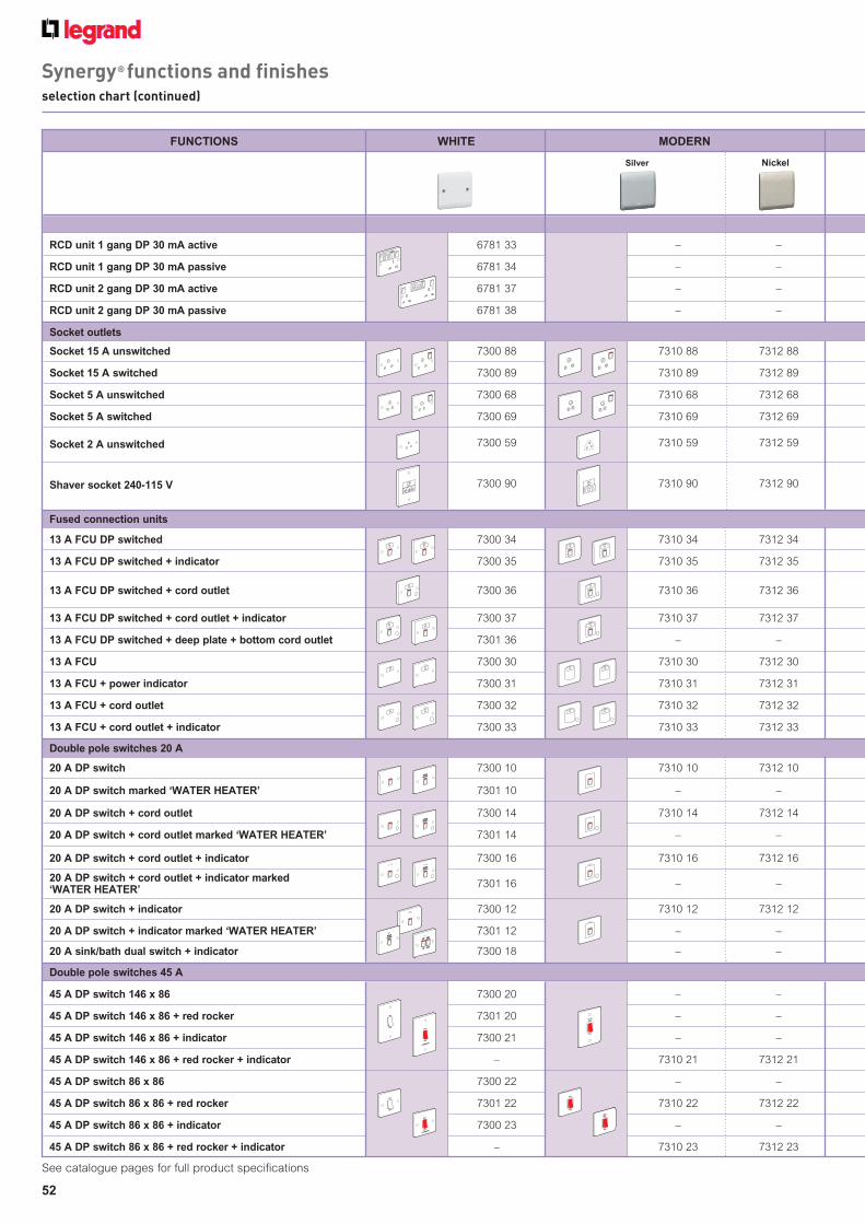
RCD sockets
RCD unit 1 gang DP 30 mA active 6781 33 – –
RCD unit 1 gang DP 30 mA passive 6781 34 – –
RCD unit 2 gang DP 30 mA active 6781 37 – –
RCD unit 2 gang DP 30 mA passive 6781 38 – –
Socket outlets
Socket 15 A unswitched 7300 88 7310 88 7312 88
Socket 15 A switched 7300 89 7310 89 7312 89
Socket 5 A unswitched 7300 68 7310 68 7312 68
Socket 5 A switched 7300 69 7310 69 7312 69
Socket 2 A unswitched 7300 59 7310 59 7312 59
Shaver socket 240-115 V 7300 90 7310 90 7312 90
Fused connection units
13 A FCU DP switched 7300 34 7310 34 7312 34
13 A FCU DP switched + indicator 7300 35 7310 35 7312 35
13 A FCU DP switched + cord outlet 7300 36 7310 36 7312 36
13 A FCU DP switched + cord outlet + indicator 7300 37 7310 37 7312 37
13 A FCU DP switched + deep plate + bottom cord outlet 7301 36 – –
13 A FCU 7300 30 7310 30 7312 30
13 A FCU + power indicator 7300 31 7310 31 7312 31
13 A FCU + cord outlet 7300 32 7310 32 7312 32
13 A FCU + cord outlet + indicator 7300 33 7310 33 7312 33
Double pole switches 20 A
20 A DP switch 7300 10 7310 10 7312 10
20 A DP switch marked ‘WATER HEATER’ 7301 10 – –
20 A DP switch + cord outlet 7300 14 7310 14 7312 14
20 A DP switch + cord outlet marked ‘WATER HEATER’ 7301 14 – –
20 A DP switch + cord outlet + indicator 7300 16 7310 16 7312 16
20 A DP switch + cord outlet + indicator marked ‘WATER HEATER’
7301 16 – –
20 A DP switch + indicator 7300 12 7310 12 7312 12
20 A DP switch + indicator marked ‘WATER HEATER’ 7301 12 – –
20 A sink/bath dual switch + indicator 7300 18 – –
Double pole switches 45 A
45 A DP switch 146 x 86 7300 20 – –
45 A DP switch 146 x 86 + red rocker 7301 20 – –
45 A DP switch 146 x 86 + indicator 7300 21 – –
45 A DP switch 146 x 86 + red rocker + indicator – 7310 21 7312 21
45 A DP switch 86 x 86 7300 22 – –
45 A DP switch 86 x 86 + red rocker 7301 22 7310 22 7312 22
45 A DP switch 86 x 86 + indicator 7300 23 – –
45 A DP switch 86 x 86 + red rocker + indicator – 7310 23 7312 23
See catalogue pages for full product specifications
52
O∆N30mA RCD ELR 2G
Test each time
before use
DO NOT USE if
RCD does not
trip after test
ON
TRIPPEDTest
I Reset
WATERWATER
HEATERHEATER
WATERWATER
HEATERHEATER
WATERWATER
HEATERHEATER
WATERWATER
HEATERHEATER
WATERWATER
HEATERHEATEROFFOFF SINKSINK
ONON BATHBATH
120V230V
FUNCTIONS WHITE MODERN
NickelSilver
120V230V
Synergy® functions and finishesselection chart (continued)
O∆N30mA RCD ELR 1G
DO NOT USE if RCD does not trip after test
TEST each time
beforeuse
ON
TRIPPEDTest
I
Reset

– – –
– – –
– – –
– – –
7330 88 7332 88 7338 88
7330 89 7332 89 7338 89
7330 68 7332 68 –
7330 69 7332 69 –
7330 59 7332 59 –
7330 90 7332 90 –
7330 34 7332 34 7338 34
7330 35 7332 35 7338 35
– – 7338 36
7330 37 7332 37 7338 37
– – –
7330 30 7332 30 7338 30
7330 31 7332 31 7338 31
7330 32 7332 32 7338 32
7330 33 7332 33 7338 33
7330 10 7332 10 7338 10
– – –
7330 14 7332 14 7338 14
– –
7330 16 7332 16 7338 16
– – –
7330 12 7332 12 7338 12
– – –
– – –
– – –
– – 7338 20
– – –
7330 21 7332 21 7338 21
– – –
7330 22 7332 22 –
– – –
7330 23 7332 23 –
53
TRADITIONAL METALCLAD
Brushed stainless steel Polished stainless steel

Cooker control units
Cooker unit DP switch with DP switched socket 7300 28 – –
Cooker unit DP switch with DP switched socket + indicator 7300 29 7310 29 7312 29
Cable outlets
Cable outlet 20 A terminal block 7300 19 7310 19 7312 19
Cable outlet 45 A terminal block 7300 26 7310 26 7312 26
TV, radio and satellite sockets
Screened TV single male 7300 40 7310 40 7312 40
Screened TV single female 7301 40 – –
Screened satellite 7300 41 7310 41 7312 41
Screened TV/FM 7300 42 7310 42 7312 42
Screened TV/FM/satellite 7300 43 7310 43 7312 43
Quad outlet TV/FM / 2 x Satellite/TV return/phone 7300 451 7310 45 7312 45
Telephone sockets
Telephone socket single master 7300 501 7310 50
1 7312 50
1
Telephone socket single secondary 7300 511 7310 51
1 7312 51
1
Telephone socket RJ11/12 single 7300 54 7310 54 7312 54
Data sockets
Data outlet RJ45 single - CAT 6 UTP 7300 56 7310 56 7312 56
Data outlet RJ45 double - CAT 6 UTP 7300 57 7310 57 7312 57
Media plates
Media plates (monobloc) 8201 42 8201 46 8201 45
Accessories
Blanking plate 1 gang 7300 95 7310 95 7312 95
Blanking plate 2 gang 7300 96 7310 96 7312 96
Outlet plate 1 gang 7300 52 7310 52 7312 52
Cord outlet accessory box 7300 53 – –
Spacer frame 1 gang 7301 95 – –
Spacer frame 2 gang 7301 96 – –
Carrier plates
Carrier plate 1 gang 1 Arteor module 7300 91 7310 91 7312 91
Carrier plate 1 gang 2 Arteor modules 7300 92 7310 92 7312 92
Carrier plate 2 gang 3 Arteor modules 7300 93 7310 93 7312 93
Carrier plate 2 gang 4 Arteor modules 7300 94 7310 94 7312 94
Euro module plates
1 gang 2 Arteor modules 7300 99 – –
2 gang 4 Arteor modules 7301 00 – –
See catalogue pages for full product specifications
54
FUNCTIONS WHITE MODERN
NickelSilver
1 : Not suitable for use in the ROI
Cooker control units
Cable outlets
TV, radio and satellite sockets
Telephone sockets
Data sockets
Media plates
Accessories
Carrier plates
Euro module plates
Synergy® functions and finishesselection chart (continued)

– – –
7330 29 7332 29 –
7330 19 7332 19 7338 19
7330 26 7332 26 –
7330 40 7332 40 7338 40
– – –
7330 41 7332 41 7338 41
7330 42 7332 42 –
7330 43 7332 43 –
7330 45 7332 45 –
7330 501 7332 50
1 7338 50
1
7330 511 7332 51
1 7338 51
1
7330 54 7332 54 –
7330 56 7332 56 7338 56
7330 57 7332 57 7338 57
8201 43 8201 44 –
7330 95 7332 95 7338 95
7330 96 7332 96 7338 96
7330 52 7332 52 –
– – –
– – –
– – –
7330 91 7332 91 7338 91
7330 92 7332 92 7338 92
7330 93 7332 93 7338 93
7330 94 7332 94 7338 94
– – –
– – –
55
TRADITIONAL METALCLAD
Brushed stainless steel Polished stainless steel

56
Front plate material
White : 1 to 4 modules - thermoset; 8-18 modules - stainless steelTraditional : All modules - stainless steelMetalclad : 1 to 4 modules - mild steel; 8 to 18 modules - stainless steelModern : 1 to 4 modules - die cast alloy; 8 to 18 modules - stainless steel
1 : Supplied with back box2 : Screw free clip-on surround plate3 : Phase barrier variant shown
1 gang 1 gang 2 gang 2 gang 2 x 2 gang 3 x 3 gang
Grid support frame complete – – – – with Arteor module carrier
Clip-in carrier plate - no support frame required Support frame required SURROUND PLATES
Pack 1 module
GRID SUPPORT FRAMES for 2 x 2 and 3 x 3 gang surround plates
Dimensions (mm) 86 x 86 86 x 86 86 x 146 86 x 146 146 x 146 267 x 206
White 10 7300 91 10 7300 92 10 7300 93 10 7300 94 1 7301 88 1 7301 90
Traditional brushed stainless steel 1 7330 91 1 7330 92 1 7330 93 1 7330 94 1 7331 88 1 7331 90
Traditional polished stainless steel 1 7332 91 1 7332 92 1 7332 93 1 7332 94 – – – –
Metalclad 5 7338 911 5 7338 921 5 7338 931 5 7338 941 – – – –
Dimensions (mm) 89 x 892 89 x 892 89 x 1492 89 x 1492 146 x 146 267 x 206
Modern silver 1 7310 91 1 7310 92 1 7310 93 1 7310 94 1 7311 88 1 7311 90
Modern nickel 1 7312 91 1 7312 92 1 7312 93 1 7312 94 – – – –
BACK BOXES
FLUSH MOUNTING
SURROUND PLATES FOR ARTEOR MODULES
1 2 x 7354 74 1 3 x 7354 76
Dimensions (mm) 35 mm depth 35 mm depth 35 mm depth 35 mm depth 137 x 137 x 43 254 x 194 x 56
Flush 50 0891 13 50 0891 13 40 0891 14 40 0891 14 1 0818 52 1 0818 54
Flush with phase barriers – – – – – 1 0818 58
Dimensions (mm) 86 x 86 x 47 86 x 86 x 47 86 x 146 x 47 86 x 146 x 47
Surface white for white only 10 7364 07 10 7364 07 5 7364 11 5 7364 11 – –
Dimensions (mm) 86 x 86 x 37 86 x 86 x 37 86 x 146 x 37 146 x 146 x 37 146 x 146 x 37
Surface steel with knockouts 10 7364 00 10 7364 00 5 7364 01 5 7364 01 1 7364 18 –
Surface steel without knockouts 10 7364 20 10 7364 20 5 7364 21 5 7364 21 1 7364 22 –
Pack 2 modules Pack 3 modules Pack 4 modules Pack 8 modules Pack 18 modules
+ =
Arteor mechanisms p. 9-29
SURFACE MOUNTING
3
Synergy®
for Arteor modules

Front plates : white thermosetTerminal screws captive and backed off ready for cablingSupplied with optional faceplate screw caps
Pack Cat. Nos. Single pole plate switches 10 AX - 250 V± Conform to BS EN 60669-1 : 2000
Optional Red LED ‘power on’ indicator and green LED ‘locator’ upgrade packs available Flush mounting back box : min. 16 mm deep Nominal plate dimensions : 1, 2 and 3 gang - 86 x 86 mm 4 and 6 gang - 86 x 146 mm
10 7300 00 1 gang – 1 way 10 7300 01 1 gang – 2 way 10 7300 05 1 gang – intermediate
10 7300 02 2 gang – 2 way
10 7300 03 3 gang – 2 way
5 7300 04 4 gang – 2 way
5 7300 06 6 gang – 2 way
7300 087300 07
7300 06
7300 02 7300 00 + optional locator LED (Cat. No. 7301 58)
7300 00 + optional screw caps (included)
7300 097301 33
Single pole key switch 10 AX - 250 V± Conforms to BS EN 60669-1 : 2000
Optional Red LED ‘power on’ indicator and green LED ‘locator’ upgrade packs available Key supplied Flush mounting back box : min. 16 mm deep Nominal plate dimensions : 86 x 86 mm
10 7300 08 1 gang – 2 way
5 0811 77 Spare key for above
7300 00
Single pole plate switches 20 AX - 250 V± Conform to BS EN 60669-1 : 2000
Optional Red LED ‘power on’ indicator and green LED ‘locator’ upgrade packs available Flush mounting back box : min. 25 mm deep Nominal plate dimensions : 86 x 86 mm
10 7301 30 1 gang – 1 way 10 7301 31 1 gang – 2 way
10 7301 32 2 gang – 2 way
10 7301 33 3 gang – 2 way
3 pole fan switch 10 A - 250 V± Conforms to BS EN 60669-1 : 2000
With integrated padlockable safety block in OFF position Flush mounting back box : min. 25 mm deep Nominal plate dimensions : 86 x 86 mm
10 7300 09 3 pole fan switch
Pack Cat. Nos. Single pole push switches 10 A - 250 V± Conform to BS EN 60669-1 : 2000
Optional Red LED ‘power on’ indicator and green LED ‘locator’ upgrade packs available Flush mounting back box : min. 16 mm deep Nominal plate dimensions : 86 x 86 mm
5 7300 07 1 gang – 2 way push switch
5 7300 11 1 gang – 2 way push switch marked “PRESS”
57
Synergy® whiteswitches
Flush and surface mountingback boxes p. 65
Green locator LED pack or red power indicator pack p. 64

58
Pack Cat. Nos. Dimmer units - 230 V± Conform to BS EN 60669-2-1 : 2000 and BS EN 55015
Rotary dimming and push on/off For use with 230 V AC Not suitable for fluorescent load Flush mounting back box : min. 25 mm deep Nominal plate dimensions : 86 x 86 mm
Dimmers for use with tungsten filament lamps and good quality GU10 halogen lamps
1 7300 48 1 gang – 2 way 50 Hz 60 W-400 W push on/off rotary
Dimmers for use with tungsten filament lamps, GU10 halogen lamps and low voltage systems using appropriate transformer
1 7300 46 1 gang – 2 way 50 Hz 40 W-250 W push on/off rotary
1 7300 47 2 gang – 2 way 50 Hz 40 W-250 W push on/off rotary
For non-rotary dimmers, use Arteor modules with Synergy carrier plates (p. 13 and 56 respectively)
Front plates : white thermosetTerminal screws captive and backed off ready for cablingSupplied with faceplate screw caps
Pack Cat. Nos. Dimmer units - 230 V± - electronic type
Conform to BS EN 60669-2-1 : 2000 and BS EN 55015
Rotary dimming and push on/off For use with 230 V AC - 50-60 Hz Not suitable for fluorescent load Flush mounting back box : min. 25 mm deep
Dimmers for use with tungsten filament lamps, good quality wire-wound transformers for low voltage loads
Nominal plate dimensions : 86 x 86 mm
1 7301 56 1 gang – 2 way 50 Hz 40 W-400 W push on/off rotary
1 7301 57 2 gang – 2 way 50 Hz 40 W-400 W push on/off rotary
Nominal plate dimensions : 86 x 146 mm
1 7300 49 4 gang – 2 way 50 Hz 40 W-400 W push on/off rotary
7300 497300 477300 46
Synergy® whitedimmers
Flush and surface mountingback boxes p. 65

59
7300 747301 62
7300 707300 60
Front plates : white thermosetTerminal screws captive and backed off ready for cablingSupplied with optional faceplate screw caps
Pack Cat. Nos. Double pole socket outlets 13 A - 250 V± Conform to BS 1363 - Part 2 : 1995
Options available as standard with red ‘power on’ LED indicator Red LED ‘power on’ upgrade pack also available 2 earth terminals Flush mounting back box : min. 25 mm deep Nominal plate dimensions : 1 gang - 86 x 86 mm 2 gang - 86 x 146 mm
10 7300 60 1 gang – switched
10 7301 62 1 gang – switched with red rocker
10 7300 61 1 gang – switched with red LED power indicator
10 7300 64 1 gang – switched for standard and clean earth applications
10 7300 67 1 gang – switched non-standard earth pin for standard and clean earth applications
5 7300 70 2 gang – switched
5 7301 61 2 gang – switched with red rocker
5 7300 71 2 gang – switched with red LED power indicator
5 7300 74 2 gang – switched outboard for standard and clean earth applications
5 7300 77 2 gang – switched non-standard earth pin for standard and clean earth applications
7300 76
7300 757300 65
7300 66
Pack Cat. Nos. Single pole socket outlets 13 A - 250 V± Conform to BS 1363 - Part 2 : 1995
Options available as standard with red ‘power on’ LED indicator Red LED ‘power on’ upgrade pack also available Conventional earth pin release shutter Single earth terminal Flush mounting back box : min. 25 mm deep Nominal plate dimensions : 1 gang - 86 x 86 mm 2 gang - 86 x 146 mm
10 7300 66 1 gang – switched
5 7300 76 2 gang – switched
Unswitched and key switched socket outlets 13 A - 250 V±
Conform to BS 1363 - Part 2 : 1995
Optional red LED ‘power on’ upgrade pack available (not applicable to key switched sockets) 2 earth terminals Flush mounting back box : min. 25 mm deep Nominal plate dimensions : 1 gang - 86 x 86 mm 2 gang - 86 x 146 mm
10 7300 65 1 gang – unswitched
5 7300 75 2 gang – unswitched
1 8200 74 2 gang single socket with DP key switch1
1 : Flush mounting back box : min. 35 mm deep
Synergy® whitesocket outlets
Flush and surface mountingback boxes p. 65
Green locator LED pack or red power indicator pack p. 64

60
Socket outlets 5 A - 250 V± Conform to BS 546 : 1950
Optional red LED ‘power on’ upgrade pack available 2 earth terminals Flush mounting back box : min. 25 mm deep Nominal plate dimensions : 86 x 86 mm
10 7300 68 1 gang – unswitched
10 7300 69 1 gang – switched
7300 69
6781 38
Pack Cat. Nos. Socket outlets 15 A - 250 V± Conform to BS 546 : 1950
Optional red LED ‘power on’ upgrade pack available Flush mounting back box : min. 35 mm deep Nominal plate dimensions : 86 x 86 mm
10 7300 88 1 gang – unswitched
10 7300 89 1 gang – switched
7300 89
Socket outlet 2 A - 250 V± Conforms to BS 546 : 1950
Optional red LED ‘power on’ upgrade pack available Conventional earth pin shutter release Flush mounting back box : min. 25 mm deep Nominal plate dimensions : 86 x 86 mm
10 7300 59 1 gang – unswitched
7300 59
RCD sockets 13 A - 250 V± Conform to BS 7288 : 1990 and BS 1363 - Part 2 : 1995
Terminal screws captive and backed off ready for cabling Conventional earth pin release shutter Maximum operating current 16 A Incorporate a “test and reset” button Flush mounting back box : min. 25 mm deep Nominal plate dimensions : 86 x 146 mm
Active (electronically latched)- trips in the event of a power failure- suitable in applications where automatic restoration of supply would be hazardous, e.g. machinery, power tools
1 6781 33 RCD unit 1 gang DP 30 mA active
1 6781 37 RCD unit 2 gang DP 30 mA active
Passive (mechanically latched) - does not trip in the event of a power failure - suitable in applications where automatic restoration of supply is required, e.g. fridge, freezer, unmanned areas
1 6781 34 RCD unit 1 gang DP 30 mA passive
1 6781 38 RCD unit 2 gang DP 30 mA passive
O∆N30mA RCD ELR 2G
Test each time
before use
DO NOT USE if
RCD does not
trip after test
ON
TRIPPEDTest
I Reset
O∆N30mA RCD ELR 2G
Test each time
before use
DO NOT USE if
RCD does not
trip after test
ON
TRIPPEDTest
I Reset
Front plates : white thermosetTerminal screws captive and backed off ready for cablingSupplied with faceplate screw caps
Pack Cat. Nos. Shaver socket
Conforms to BS EN 61558-2-5 : 1998 IP 24
For use with European, British, American and Australian 2 pin plugs Screwless live and neutral terminals Double wound isolating transformer Automatic self-resetting overload feature Plug insertion operates microswitch which energises transformer Flush mounting back box : min. 47 mm deep Nominal plate dimensions : 146 x 86 mm
1 7300 90 Supply : 230 V - 50/60 Hz Output : 230/120 V - 20 VA max.
7300 90
120V230V
Red power indicator LED pack p. 64
Synergy® whitesocket outlets (continued)
Flush and surface mountingback boxes p. 65
O∆N30mA RCD ELR 1G
DO NOT USE if RCD does not trip after test
TEST each time
beforeuse
ON
TRIPPEDTest
I
Reset
O∆N30mA RCD ELR 1G
DO NOT USE if RCD does not trip after test
TEST each time
beforeuse
ON
TRIPPEDTest
I
Reset

61
Front plates : white thermosetTerminal screws captive and backed off ready for cablingSupplied with faceplate screw caps
Pack Cat. Nos. Fused connection units 13 A - 250 V± Conform to BS 1363 - Part 4 : 1995
Options available as standard with red ‘power on’ LED indicator LED ‘power on’ upgrade pack also available Fused 13 A (fuse supplied) Fuse drawer retained by quarter turn catch, drawer padlockable in open position for safety To obtain flush to wall external cord connection on standard depth Cat. Nos. use cord outlet accessory box Cat. No. 7300 53 p. 64 Flush mounting back box : min. 25 mm deep Nominal plate dimensions : 86 x 86 mm
Switched
10 7300 34 Switched, DP
10 7300 35 Switched, DP with red LED power indicator
10 7300 36 Switched, DP with cord outlet
10 7300 37 Switched, DP with cord outlet + red LED power indicator
10 7301 36 Switched, DP - deep plate with bottom cord outlet
Pack Cat. Nos. Fused connection units 13 A - 250 V± (continued)
Unswitched
10 7300 30 Unswitched
10 7300 31 Unswitched with red LED power indicator
10 7300 32 Unswitched with cord outlet
10 7300 33 Unswitched with cord outlet + red LED power indicator
7300 36 7301 36
7300 30
7300 33
7300 34
Bespoke andstandard engraving available p. 67
Red power indicator LED pack p. 64
Red power indicator LED pack p. 64
Synergy® whitefused connection units
7300 35 + optional red LED power indicator (Cat. No. 7301 58)
Flush and surface mountingback boxes p. 65

62
Cable outlet 20 A - 250 V± Conforms to BS 5733 : 1995 Flush mounting back box : min. 25 mm deep Nominal plate dimensions : 86 x 86 mm
10 7300 19 20 A – with terminal block and outlet gland
Front plates : white thermosetTerminal screws captive and backed off ready for cablingSupplied with faceplate screw caps
Pack Cat. Nos. Double pole switches 20 A - 250 V±1
Conform to BS EN 60669-1 : 2000 Options available as standard with red ‘power on’ LED indicator LED ‘power on’ upgrade pack also available Use cord outlet accessory box Cat. No. 7300 53 for flush to wall external cord connection p. 64 Flush mounting back box : min. 25 mm deep Nominal plate dimensions : 86 x 86 mm
10 7300 10 20 A DP
10 7301 10 20 A DP marked “WATER HEATER”
10 7300 14 20 A DP with cord outlet
10 7301 14 20 A DP with cord outlet marked “WATER HEATER” 10 7300 16 20 A DP with cord outlet + red LED power indicator 10 7301 16 20 A DP with cord outlet marked “WATER HEATER” + red LED power indicator
10 7300 12 20 A DP + red LED power indicator
10 7301 12 20 A DP marked “WATER HEATER” + red LED power indicator
10 7300 18 20 A sink/bath dual switch + red LED power indicator
7300 19
Cable outlet 45 A - 250 V± Conforms to BS 5733 : 1995 2 piece design for safety Flush mounting back box : min. 48 mm deep Nominal plate dimensions : 86 x 86 mm
5 7300 26 45 A – with terminal block
WATERWATER
HEATERHEATER
WATERWATER
HEATERHEATER
WATERWATER
HEATERHEATER
WATERWATER
HEATERHEATER
Pack Cat. Nos. Double pole switches 45 A - 250 V± Conform to BS EN 60669-1 : 2000 Options available as standard with red ‘power on’ LED indicator LED ‘power on’ upgrade pack also available Flush mounting back box : min. 48 mm deep Nominal plate dimensions : 2 gang - 146 x 86 mm 1 gang - 86 x 86 mm
5 7300 20 45 A DP
5 7301 20 45 A DP with red rocker marked “COOKER”
5 7300 21 45 A DP + red LED power indicator
10 7300 22 45 A DP
10 7301 22 45 A DP with red rocker marked “COOKER”
10 7300 23 45 A DP + red LED power indicator
7300 10 7301 10
7300 18 7300 29
7300 23
7301 20
Cooker control units 45 A - 250 V± Conform to BS 4177 : 1992 Options available as standard with red ‘power on’ LED indicator LED ‘power on’ upgrade pack also available 45 A - 250 V± double pole switch with 13 A - 250 V± double pole switched socket outlet Flush mounting back box : min. 48 mm deep Nominal plate dimensions : 86 x 146 mm
5 7300 28 DP with DP switched socket
5 7300 29 DP with DP switched socket + red LED power indicator
OFFOFF SINKSINK
ONON BATHBATH
1 : Range of engraving available on most products, see table on p. 67
Red power indicator LED pack p. 64
Synergy® whitecontrol switches
Flush and surface mountingback boxes p. 65

63
Telephone sockets
Shuttered Flush mounting back box : min. 35 mm deep Nominal plate dimensions : 86 x 86 mm
10 7300 501 Single master
10 7300 511 Single secondary
10 7300 54 Single RJ11/12
Pack Cat. Nos. Data sockets
CAT 6 compliant UTP Rapid cable connection Flush mounting back box : min. 35 mm deep Nominal plate dimensions : 86 x 86 mm
1 7300 56 RJ45 – single
1 7300 57 RJ45 – double
Also available :
Euro module plates for 25 x 50 mm data modules p. 64
Media plate (monobloc)
Comprising 2 x independent satellite feeds, 1 x terrestrial TV socket suitable for analogue and digital signals, 1 x video return, 1 x secondary telephone point, 2 x Synergy 2 gang switched DP 13 A sockets To be used with back box Cat. No. 8204 58 below Dimensions : 206 x 267 mm Material : stainless steel
1 8201 42 White (metal)
Back box for media plate
Dimensions : 194 x 254 x 35 mm With phase barrier Material : grey epoxy coated steel
1 8204 58 35 mm deep box
8201 427300 57
7300 50
Front plates : white thermosetSupplied with faceplate screw caps
Pack Cat. Nos. TV, radio and satellite sockets
Flush mounting back box : min. 35 mm deep Nominal plate dimensions : 1 gang - 86 x 86 mm 2 gang - 86 x 146 mm
10 7300 40 Screened TV – single, male Non-isolated
10 7301 40 Screened TV – single, female Non-isolated
1 7300 41 Screened satellite – single, ‘F’ type
10 7300 42 Screened TV + FM Isolated
1 7300 43 Screened TV + FM + satellite, ‘F’ type
1 7300 451 Quad outlet, TV, radio + 2 satellite + TV return with secondary telephone outlet
7300 40 7300 42
7300 43 7300 45
1 : Not suitable for use in the ROI
Synergy® whiteTV, telephone and data sockets
Flush and surface mountingback boxes p. 65

64
Arteor modules p. 9-29
Carrier plates for Arteor modules (square)
No additional support frame required Enable a Synergy installation to benefit from the additional functionality of Arteor, such as international sockets etc
10 7300 91 1 gang - 86 x 86 mm 1 Arteor module
10 7300 92 1 gang - 86 x 86 mm 2 Arteor modules
10 7300 93 2 gang - 86 x 146 mm 3 Arteor modules
10 7300 94 2 gang - 86 x 146 mm 4 Arteor modules
1 and 2 gang front plates for grid modules
Must be used with support frames, see below
10 7301 91 1 gang - 86 x 86 mm 1 small aperture module
10 7301 92 1 gang - 86 x 86 mm 2 small aperture modules
10 7301 93 2 gang - 86 x 146 mm 3 small aperture modules
10 7301 94 2 gang - 86 x 146 mm 4 small aperture modules
1 and 2 gang support frames for grid modules
10 7354 90 1 gang 1 module
10 7354 91 1 gang 2 modules
10 7354 92 2 gang 3/4 modules
7300 99
7354 917301 91 7301 94
7300 95 7300 96
7301 58
Pack Cat. Nos. Accessories
Blanking plates
10 7300 95 1 gang - 86 x 86 mm
10 7300 96 2 gang - 86 x 146 mm
LED packs Relevant Synergy functions are designed to accept the LED packs for fitting at time of installation or retrospectively by a qualified person Compatible with fluorescent loads
10 7301 58 Electronic LED locator pack – green diodes : max. current 0·2 mA provides illumination to locate function such as switches in low light
10 7300 58 Electronic LED power indicator pack – red diodes : nominal current 2 mA provides indication of ‘power on’ condition in such functions as sockets and control switches
Outlet plate - VDI/low voltage
10 7300 52 1 gang - 86 x 86 mm with cable clamp and outlet gland
Contrast frames
Aid Part M compliance when using Synergy White wiring accessories
10 8218 46 1 gang contrast frame
10 8218 47 2 gang contrast frame
Accessory frames
10 7300 53 1 gang - 86 x 86 x 11 mm with bottom cord outlet For flush to wall external cord connection suitable for use with 13 A and 20 A control switches and other relevant 86 x 86 mm functions Integral cord grip
10 7301 95 1 gang - 86 x 86 x 7 mm spacer frame
5 7301 96 2 gang - 86 x 146 x 7 mm spacer frame
Spare screw cap covers
10 7301 53 Pack of 50 caps to cover mounting screws
Grid selection charts p. 92-93Grid modules p. 88-90Arteor modules p. 9-29
Complete range of gridfront plates and modulesp. 88-93
Pack Cat. Nos. Euro module front plates
Suitable for use with standard 25 x 50 mm euro data module inserts
10 7300 99 1 gang - 86 x 86 mm 2 modules - aperture size 50 x 50 mm
10 7301 00 2 gang - 86 x 146 mm 4 modules - aperture size 50 x 100 mm
Synergy® whiteaccessories
For German standardsocket outlet useCat. Nos. 7300 92 + 5711 18

65
Architrave back boxes
Depth 30 mm
10 7364 05 Dimensions : 86 x 36 mm
5 7364 04 Dimensions : 146 x 36 mm
Pack Cat. Nos. Surface mounting moulded boxes - thermoset
Conform to BS 5733 Material : white thermoset Mini trunking knockouts located around periphery of boxes
Dimensions : 1 gang - 87 x 87 mm 2 gang - 87 x 147 mm
Depth 16 mm
10 7364 03 1 gang With earth terminal
Depth 35 mm
10 7364 06 1 gang
5 7364 10 2 gang
5 7364 13 2 x 1 gang
Depth 47 mm
10 7364 07 1 gang
5 7364 11 2 gang
7364 11 7364 13
7364 06 7364 07
Architrave back boxes
Depth 26 mm
5 7364 40 Dimensions : 82 x 28 mm
5 7364 41 Dimensions : 142 x 28 mm
Pack Cat. Nos. Flush mounting back boxes - steel
Conform to BS 4662 Material : galvanised steel Top, side and back knockout entries according to type of box
Depth 16 mm
100 0891 09 1 gang with 1 fixed lug, 1 adjustable lug and 1 earth terminal
Depth 25 mm
50 0891 10 1 gang with 3 fixed lugs, 1 adjustable lug and 1 earth terminal
10 0891 11 2 gang with 1 fixed lug, 1 adjustable lug and 1 earth terminal
Depth 35 mm
50 0891 13 1 gang with 3 fixed lugs, 1 adjustable lug and 1 earth terminal
40 0891 14 2 gang with 1 fixed lug, 1 adjustable lug and 1 earth terminal
40 0891 40 Dual box with 2 earth terminals Accepts 2 single gang accessories
Depth 48 mm
25 0891 17 1 gang with 3 fixed lugs, 1 adjustable lug and 1 earth terminal
20 0891 18 2 gang with 1 fixed lug, 1 adjustable lug and 1 earth terminal
0891 130891 10
0891 11
surface mounting moulded back boxes flush mounting steel back boxes

66
■ LED power and locator indicators
Power indicator Cat. No. 7300 58 (red) and locator indicator Cat. No. 7301 58 (green)
These LED packs can be fitted as an option to a range of Synergy White functions including :
• 10 A switches 1 gang • 5 A, 13 A and 15 A socket outlets• 13 A connection units• 20 A and 45 A double pole control switches
The LED packs are wired in alternative ways for different functionality. Factory fitted LEDs can be re-configured on site
■ Sample wiring schemes
Switch 10 A
Green LED locator Red LED power indicator
11
LL
7301 58 7301 58
N
1L
7300 58
N
Socket 13 A switched
Green LED locator Red LED power indicator
7301 58
L N
Socket 13 A unswitched
Green LED locator
L N
7301 587300 58
L N
13 A fused connection unitwith front cable outlet 13 A fused connection unit
with deep plate and bottom cable outlet
13 A fused connection unitno external cable outlet
Additionally the use of cord outlet accessory box Cat. No. 7300 53, enables a flush-to-wall cable outlet optionThe outlet box dimensions are nominally 86 x 86 mm and 14 mm deepThe outlet box is supplied with the necessary longer installation screws and has an integral automatic cable restraint
14 mm
86 m
m
86 mm
■ Cable outlet options : 13 A connection units and 20 A double pole control switches
These devices are available in three cable outlet variants :
• Without provision for an external cable outlet (i.e. for internal cabling)• With a cable outlet in the front plate supplied with an integral screw type cable clamp and outlet cover plug• With a bottom cord outlet on a deep plate
Synergy® white

67
20A DP SWITCHES 13A FUSED CONNECTION UNITS
Engraving Switched
Switched Without cable outlet
without cable outlet without cable outlet
with indicator
CENTRAL HEATING 7300 10CG 7300 34CG 7300 35CG
COOKER HOOD 7300 10CH 7300 34CH 7300 35CH
DISHWASHER 7300 10DW 7300 34DW 7300 35DW
EXTRACTOR 7300 10EX 7300 34EX 7300 35EX
EXTRACTOR HOOD 7300 10EH 7300 34EH 7300 35EH
FAN 7300 10FN 7300 34FN 7300 35FN
FRIDGE 7300 10FR 7300 34FR 7300 35FR
FRIDGE FREEZER 7300 10FF 7300 34FF 7300 35FF
HEATER 7300 10HR 7300 34HR 7300 35HR
HOB 7300 10HB 7300 34HB 7300 35HB
MICROWAVE 7300 10MW 7300 34MW 7300 35MW
OVEN 7300 10OV 7300 34OV 7300 35OV
TOWEL RAIL 7300 10TR 7300 34TR 7300 35TR
TUMBLE DRYER 7300 10TD 7300 34TD 7300 35TD
WASHING MACHINE 7300 10WM 7300 34WM 7300 35WM
LEGRAND SYNERGY STANDARD ENGRAVING
Full box quantities only - Pack quantity 10
Bespoke engraving available on request.
Engraving markings differ slightly from pad printed markings appearing elsewhere in the catalogueFor lead times of above engravings, please contact us on +44 (0) 345 605 4333 or email [email protected]
Synergy® whitestandard engraving

68
Pack Cat. Nos. Single pole plate switches 10 AX - 250 V± Conform to BS EN 60669-1 : 2000
Flush mounting back box : min. 16 mm deep Nominal plate dimensions : 1, 2 and 3 gang - 89 x 89 mm Silver Nickel 4 and 6 gang - 89 x 149 mm
1 7310 00 7312 00 1 gang – 1 way 1 7310 01 7312 01 1 gang – 2 way 1 7310 05 7312 05 1 gang – intermediate
1 7310 02 7312 02 2 gang – 2 way
1 7310 03 7312 03 3 gang – 2 way
1 7310 04 7312 04 4 gang – 2 way
Front plates : clip on die cast plate with high quality satin finish; anthracite interiors; matching decorative rockers (except where indicated)Terminal screws captive and backed off ready for cablingHidden screws
Single pole push switches 10 A - 250 V± Conform to BS EN 60669-1 : 2000
Flush mounting back box : min. 16 mm deep Silver Nickel Nominal plate dimensions : 89 x 89 mm
1 7310 07 7312 07 1 gang – 2 way push switch
7312 027310 00
7312 077310 03
Single pole plate switches 20 AX - 250 V± Conform to BS EN 60669-1 : 2000
Flush mounting back box : min. 25 mm deep Silver Nickel Nominal plate dimensions : 89 x 89 mm
1 7311 31 7313 31 1 gang – 2 way
1 7311 32 7313 32 2 gang – 2 way
1 7311 33 7313 33 3 gang – 2 way
7312 097310 09
7312 477310 46
Pack Cat. Nos. Dimmer units - 230 V±
Conform to BS EN 60669-2-1 : 2000
Not suitable for fluorescent load Flush mounting back box : min. 25 mm deep Nominal plate dimensions : 89 x 89 mm
Dimmers for use with tungsten filament lamps, GU10 halogen lamps and low voltage Silver Nickel systems using appropriate transformer
1 7310 46 7312 46 1 gang – 2 way 50 Hz 40 W-250 W push on/off rotary
1 7310 47 7312 47 2 gang – 2 way 50 Hz 40 W-250 W push on/off rotary
3 pole fan switches 10 A - 250 V± Conform to BS EN 60669-1 : 2000
White rocker with integrated padlockable safety block in OFF position Flush mounting back box : min. 25 mm deep Silver Nickel Nominal plate dimensions : 89 x 89 mm
1 7310 09 7312 09 3 pole fan switch
Dimmer units - 230 V± - electronic type
Conform to BS EN 60669-2-1 : 2000
Not suitable for fluorescent load Flush mounting back box : min. 25 mm deep Nominal plate dimensions : 89 x 89 mm
Dimmers for use with tungsten filament lamps, good quality wire-wound transformers for Silver Nickel low voltage loads
1 7311 56 7313 56 1 gang – 2 way 50-60 Hz 40 W-400 W push on/off rotary
1 7311 57 7313 57 2 gang – 2 way 50-60 Hz 40 W-400 W push on/off rotary
Synergy® modernswitches and dimmers
Flush mounting back boxes p. 85

69
Front plates : clip on die cast plate with high quality satin finish; anthracite interiors; matching decorative rockers (except where indicated)Terminal screws captive and backed off ready for cabling
7310 65 7312 75
Pack Cat. Nos. Double pole socket outlets 13 A - 250 V± Conform to BS 1363 - Part 2 : 1995
2 earth terminals Flush mounting back box : min. 25 mm deep Nominal plate dimensions : 1 gang - 89 x 89 mm Silver Nickel 2 gang - 89 x 149 mm
1 7310 60 7312 60 1 gang – switched
1 7310 61 7312 61 1 gang – switched + red LED power indicator
1 7310 70 7312 70 2 gang – switched
1 7310 71 7312 71 2 gang – switched + red LED power indicator
7312 717310 60
7310 59 7312 90
7310 89
Unswitched socket outlets 13 A - 250 V± Conform to BS 1363 - Part 2 : 1995
2 earth terminals Flush mounting back box : min. 25 mm deep Nominal plate dimensions : 1 gang - 89 x 89 mm Silver Nickel 2 gang - 89 x 149 mm
1 7310 65 7312 65 1 gang – unswitched
1 7310 75 7312 75 2 gang – unswitched
Pack Cat. Nos. Socket outlets 15 A - 250 V± Conform to BS 546 : 1950
Flush mounting back box : min. 35 mm deep Silver Nickel Nominal plate dimensions : 89 x 89 mm
1 7310 88 7312 88 1 gang – unswitched
1 7310 89 7312 89 1 gang – switched
Socket outlets 2 A - 250 V± Conform to BS 546 : 1950
Flush mounting back box : min. 25 mm deep Silver Nickel Nominal plate dimensions : 89 x 89 mm
1 7310 59 7312 59 1 gang – unswitched
Socket outlets 5 A - 250 V± Conform to BS 546 : 1950
Flush mounting back box : min. 25 mm deep Silver Nickel Nominal plate dimensions : 89 x 89 mm
1 7310 68 7312 68 1 gang – unswitched
1 7310 69 7312 69 1 gang – switched
Shaver sockets
Conform to BS EN 61558-2-5 : 1998 IP 24
For use with European, British, American and Australian 2 pin plugs Screwless live and neutral terminals Double wound isolating transformer Automatic self-resetting overload feature Plug insertion operates microswitch which energises transformer Flush mounting back box : min. 47 mm deep Silver Nickel Nominal plate dimensions : 149 x 89 mm
1 7310 90 7312 90 Supply : 230 V - 50/60 Hz Output : 230/120 V - 20 VA max.
120V230V
Synergy® modernsocket outlets and shaver sockets
Flush mounting back boxes p. 85

70
Front plates : clip on die cast plate with high quality satin finish; anthracite interiors; matching decorative rockers (except where indicated)Terminal screws captive and backed off ready for cabling
7312 327310 35
Pack Cat. Nos. Fused connection units 13 A - 250 V± Conform to BS 1363 - Part 4 : 1995
Fuse drawer retained by quarter turn catch, drawer padlockable in open position for safety Flush mounting back box : min. 25 mm deep Nominal plate dimensions : 89 x 89 mm
Silver Nickel Switched
1 7310 34 7312 34 Switched, DP
1 7310 35 7312 35 Switched, DP + red LED power indicator
1 7310 36 7312 36 Switched, DP with cord outlet
1 7310 37 7312 37 Switched, DP with cord outlet + red LED power indicator
Pack Cat. Nos. Fused connection units 13 A - 250 V± (continued)
Conform to BS 1363 - Part 4 : 1995
Fuse drawer retained by quarter turn catch, drawer padlockable in open position for safety Flush mounting back box : min. 25 mm deep Nominal plate dimensions : 89 x 89 mm
Silver Nickel Unswitched
1 7310 30 7312 30 Unswitched
1 7310 31 7312 31 Unswitched + red LED power indicator
1 7310 32 7312 32 Unswitched with cord outlet
1 7310 33 7312 33 Unswitched with cord outlet + red LED power indicator
7310 37 7312 36 7310 31
7310 30
7312 33
7312 34
Red LED power indicator
Synergy® modernfused connection units
Flush mounting back boxes p. 85

71
Pack Cat. Nos. Double pole switches 20 A - 250 V± Conform to BS EN 60669-1 : 2000
Flush mounting back box : min. 25 mm deep Silver Nickel Nominal plate dimensions : 89 x 89 mm
1 7310 10 7312 10 20 A DP
1 7310 14 7312 14 20 A DP with cord outlet
1 7310 16 7312 16 20 A DP with cord outlet + red LED power indicator
1 7310 12 7312 12 20 A DP + red LED power indicator
7310 10 7312 12
7310 29
7310 23 7312 22
Front plates : clip on die cast plate with high quality satin finish; anthracite interiors; matching decorative rockers (except where indicated)Terminal screws captive and backed off ready for cabling
Pack Cat. Nos. Double pole switches 45 A - 250 V± Conform to BS EN 60669-1 : 1995
Red rocker Flush mounting back box : min. 48 mm deep Silver Nickel Nominal plate dimensions : 89 x 89 mm
1 7310 22 7312 22 45 A DP
1 7310 23 7312 23 45 A DP with red power indicator
Nominal plate dimensions : 146 x 86 mm
1 7310 21 7312 21 45 A DP with red power indicator Stainless steel plate with fixing screws
Cable outlets 20 A - 250 V± Conform to BS 5733 : 1995
Flush mounting back box : min. 25 mm deep Silver Nickel Nominal plate dimensions : 86 x 86 mm
1 7310 19 7312 19 20 A – with terminal block and outlet gland
Cable outlets 45 A - 250 V± Conform to BS 5733 : 1995
2 piece design for safety Stainless steel plate with fixing screws Flush mounting back box : min. 48 mm deep Silver Nickel Nominal plate dimensions : 86 x 86 mm
1 7310 26 7312 26 45 A – with terminal block
Cooker control units 45 A - 250 V± Conform to BS 4177 : 1992
Red rocker Flush mounting back box : min. 47 mm deep Silver Nickel Nominal plate dimensions : 89 x 149 mm
1 7310 29 7312 29 45 A DP switch + 13 A DP switched socket outlet
7310 16 7312 14
Red LED power indicator
Synergy® moderncontrol switches
Flush mounting back boxes p. 85

72
Back box for media plate
Dimensions : 194 x 254 x 35 mm With phase barrier Material : grey epoxy coated steel
1 8204 58 35 mm deep box
8201 45
Pack Cat. Nos. Media plate (monobloc)
Comprising 2 x independent satellite feeds, 1 x terrestrial TV socket suitable for analogue and digital signals, 1 x video return, 1 x secondary telephone point, 2 x Synergy 2 gang switched DP 13 A socketsTo be used with back box Cat. No. 8204 58 below
Dimensions : 206 x 267 mm Silver Nickel Material : stainless steel
1 8201 46 8201 45 Media plate
Pack Cat. Nos. TV, radio and satellite sockets
Flush mounting back box : min. 35 mm deep Nominal plate dimensions : 89 x 89 mm
Silver Nickel
1 7310 40 7312 40 Screened TV – single, male Non-isolated
1 7310 41 7312 41 Screened satellite – single, ‘F’ type
1 7310 42 7312 42 Screened TV + FM Isolated
1 7310 43 7312 43 Screened TV + FM + satellite, ‘F’ type
Nominal plate dimensions : 86 x 146 mm
1 7310 451 7312 451 Quad outlet, TV, radio + 2 satellite + TV return with secondary telephone outlet2
Telephone sockets
Flush mounting back box : min. 35 mm deep Nominal plate dimensions : 89 x 89 mm
Silver Nickel
1 7310 501 7312 501 Single master
1 7310 511 7312 511 Single secondary
1 7310 54 7312 54 Single RJ11/12
Data sockets
CAT 6 compliant UTP Rapid cable connection
Flush mounting back box : min. 35 mm deep Silver Nickel Nominal plate dimensions : 89 x 89 mm
1 7310 56 7312 56 RJ45 – single
1 7310 57 7312 57 RJ45 – double
7312 43
7312 567310 50
7310 42
Front plates : clip on die cast plate with high quality satin finish; anthracite interiorsTerminal screws captive and backed off ready for cabling
1 : Not suitable for use in the ROI2 : Stainless steel plate with fixing screws
Synergy® modernTV, telephone and data sockets
Flush mounting back boxes p. 85

73
Pack Cat. Nos. 1 and 2 gang front plates for grid modules
For support frames, see below Silver Nickel
1 7311 91 7313 91 1 gang - 89 x 89 mm 1 small aperture module
1 7311 92 7313 92 1 gang - 89 x 89 mm 2 small aperture modules
1 7311 93 7313 93 2 gang - 89 x 149 mm 3 small aperture modules
1 7311 94 7313 94 2 gang - 89 x 149 mm 4 small aperture modules
1 and 2 gang support frames for grid modules
To suit modern front plates only
10 7354 81 1 gang 1/2 modules
10 7354 82 2 gang 3/4 modules
7311 91 7313 93
7313 947311 92
7310 95
7310 92 + international socket Cat. No. 5721 18
Pack Cat. Nos. Accessories
Blanking plates
Silver Nickel
1 7310 95 7312 95 1 gang - 89 x 89 mm
1 7310 96 7312 96 2 gang - 89 x 149 mm
Outlet plates - VDI/low voltage
1 7310 52 7312 52 1 gang - 89 x 89 mm with cable clamp and outlet gland
Carrier plates for Arteor modules (square)
No additional support frame required Enable a Synergy installation to benefit from
the additional functionality of Arteor, such as international sockets etc
Silver Nickel
1 7310 91 7312 91 1 gang - 89 x 89 mm 1 Arteor module
1 7310 92 7312 92 1 gang - 89 x 89 mm 2 Arteor modules
1 7310 93 7312 93 2 gang - 89 x 149 mm 3 Arteor modules
1 7310 94 7312 94 2 gang - 89 x 149 mm 4 Arteor modules
7312 96
7312 93
Front plates : clip on die cast plate with high quality satin finish; anthracite interiorsTerminal screws captive and backed off ready for cabling
Grid selection charts p. 92-93Grid modules p. 88-90Arteor modules p. 9-29
Complete rangeof grid front platesand modulesp. 88-93
Synergy® modernplates and support frames
Flush mounting back boxes p. 85

Brushed stainless steel front plates : brushed stainless steel with clear epoxy satin lacquer coatingPolished stainless steel front plates : electroplated stainless steel plate with trivalent chrome for mirror finishWhite interiors and rockersTerminal screws captive and backed off ready for cabling
74
Pack Cat. Nos. Dimmer units - 230 V±
Conform to BS EN 60669-2-1 : 2000 and BS EN 55015
Not suitable for fluorescent load
Flush mounting back box : min. 25 mm deep Nominal plate dimensions : 86 x 86 mm
Dimmers for use with tungsten filament lamps, GU10 halogen lamps and low voltage Brushed Polished systems using appropriate transformer
1 7330 46 7332 46 1 gang – 2 way 50 Hz 40 W-250 W push on/off rotary
1 7330 47 7332 47 2 gang – 2 way 50 Hz 40 W-250 W push on/off rotary
Dimmer units - 230 V± - electronic type
Conform to BS EN 60669-2-1 : 2000 and BS EN 55015
Not suitable for fluorescent load
Flush mounting back box : min. 25 mm deep Nominal plate dimensions : 86 x 86 mm
Dimmers for use with tungsten filament lamps, good quality wire-wound transformers for Brushed Polished low voltage loads
1 7331 56 7333 56 1 gang – 2 way 50-60 Hz 40 W-400 W push on/off rotary
1 7331 57 7333 57 2 gang – 2 way 50-60 Hz 40 W-400 W push on/off rotary
7332 47
7332 097330 09
7330 46
Pack Cat. Nos. Single pole plate switches 10 AX - 250 V± Conform to BS EN 60669-1 : 2000 Stainless steel Flush mounting back box : min. 16 mm deep Nominal plate dimensions : 1, 2 and 3 gang - 86 x 86 mm Brushed Polished 4 gang - 86 x 146 mm
1 7330 00 7332 00 1 gang – 1 way 1 7330 01 7332 01 1 gang – 2 way 1 7330 05 7332 05 1 gang – intermediate
1 7330 02 7332 02 2 gang – 2 way
1 7330 03 7332 03 3 gang – 2 way
1 7330 04 7332 04 4 gang – 2 way
7332 07
7332 02
7330 04
7330 00
Single pole push switches 10 A - 250 V± Conform to BS EN 60669-1 : 2000 Flush mounting back box : min. 16 mm deep Brushed Polished Nominal plate dimensions : 86 x 86 mm
1 7330 07 7332 07 1 gang – 2 way push switch
Stainless steel
Single pole plate switches 20 AX - 250 V± Conform to BS EN 60669-1 : 2000 Flush mounting back box : min. 25 mm deep Brushed Polished Nominal plate dimensions : 86 x 86 mm
1 7331 31 7333 31 1 gang – 2 way
1 7331 32 7333 32 2 gang – 2 way
1 7331 33 7333 33 3 gang – 2 way
Stainless steel
Stainless steel
Stainless steel
3 pole fan switches 10 A - 250 V± Conform to BS EN 60669-1 : 2000
With integrated padlockable safety block in OFF position
Flush mounting back box : min. 25 mm deep
Brushed Polished Nominal plate dimensions : 86 x 86 mm
1 7330 09 7332 09 3 pole fan switch
Stainless steel
Synergy® traditionalswitches and dimmers
Flush and surface mountingback boxes p. 85

Brushed stainless steel front plates : brushed stainless steel with clear epoxy satin lacquer coatingPolished stainless steel front plates : electroplated stainless steel plate with trivalent chrome for mirror finishWhite interiors and rockersTerminal screws captive and backed off ready for cabling
75
Unswitched socket outlets 13 A - 250 V±
Conform to BS 1363 - Part 2 : 1995
2 earth terminals Flush mounting back box : min. 25 mm deep Nominal plate dimensions : 1 gang - 86 x 86 mm Brushed Polished 2 gang - 86 x 146 mm
1 7330 65 7332 65 1 gang – unswitched
1 7330 75 7332 75 2 gang – unswitched
Pack Cat. Nos. Double pole socket outlets 13 A - 250 V±
Conform to BS 1363 - Part 2 : 1995
2 earth terminals Flush mounting back box : min. 25 mm deep Nominal plate dimensions : 1 gang - 86 x 86 mm Brushed Polished 2 gang - 86 x 146 mm
1 7330 60 7332 60 1 gang – switched
1 7330 61 7332 61 1 gang – switched + red LED power indicator
1 7330 70 7332 70 2 gang – switched
1 7330 71 7332 71 2 gang – switched + red LED power indicator
1 7330 74 7332 74 2 gang – switched outboard for standard and clean earth applications
7332 61
7332 747330 71
7330 70
Socket outlets 15 A - 250 V±
Conform to BS 546 : 1950
Flush mounting back box : min. 35 mm deep Brushed Polished Nominal plate dimensions : 86 x 86 mm
1 7330 88 7332 88 1 gang – unswitched
1 7330 89 7332 89 1 gang – switched
Pack Cat. Nos. Key switched socket 13 A - 250 V±
Conform to BS 1363 - part 2 : 1995
Flush mounting back box : min. 35 mm deep
Brushed Polished
Nominal plate dimensions : 86 x 146 mm
1 8200 71 8200 72 2 gang single socket with DP key switch
Socket outlets 2 A - 250 V±
Conform to BS 546 : 1950
Flush mounting back box : min. 25 mm deep
Brushed Polished Nominal plate dimensions : 86 x 86 mm
1 7330 59 7332 59 1 gang – unswitched
7332 597330 59
7330 89
Stainless steel
Stainless steel
Stainless steel
Stainless steel
Stainless steel
Red LED power indicator
Synergy® traditionalsocket outlets
Flush and surface mountingback boxes p. 85

76
7332 30
7332 32
7330 35
7330 37
Pack Cat. Nos. Fused connection units 13 A - 250 V±
Conform to BS 1363 - Part 4 : 1995
Fuse drawer retained by quarter turn catch, drawer padlockable in open position for safety Flush mounting back box : min. 25 mm deep Nominal plate dimensions : 86 x 86 mm
Brushed Polished Switched
1 7330 34 7332 34 Switched, DP
1 7330 35 7332 35 Switched, DP with red LED power indicator
1 7330 37 7332 37 Switched, DP with cord outlet + red LED power indicator
Unswitched
1 7330 30 7332 30 Unswitched
1 7330 31 7332 31 Unswitched with red LED power indicator
1 7330 32 7332 32 Unswitched with cord outlet
1 7330 33 7332 33 Unswitched with cord outlet + red LED power indicator
7330 90
Shaver sockets
Conform to BS EN 61558-2-5 : 1998 IP 24
For use with European, British, American and Australian 2 pin plugs Screwless live and neutral terminals Double wound isolating transformer Automatic self-resetting overload feature Plug insertion operates microswitch which energises transformer Flush mounting back box : min. 47 mm deep Brushed Polished Nominal plate dimensions : 146 x 86 mm
1 7330 90 7332 90 Supply : 230 V - 50/60 Hz Output : 230/120 V - 20 VA max.
Pack Cat. Nos. Socket outlets 5 A - 250 V±
Conform to BS 546 : 1950
Flush mounting back box : min. 25 mm deep Brushed Polished Nominal plate dimensions : 86 x 86 mm
1 7330 68 7332 68 1 gang – unswitched
1 7330 69 7332 69 1 gang – switched
7330 69
7330 68
Stainless steel
Stainless steel
Brushed stainless steel front plates : brushed stainless steel with clear epoxy satin lacquer coatingPolished stainless steel front plates : electroplated stainless steel plate with trivalent chrome for mirror finishWhite interiors and rockersTerminal screws captive and backed off ready for cabling
Stainless steel
Red LED power indicator
Flush and surface mountingback boxes p. 85
Synergy® traditionalsocket outlets (continued) and fused connection units

77
7332 16
7332 10
7330 12
7330 14
Pack Cat. Nos. Double pole switches 20 A - 250 V±
Conform to BS EN 60669-1 : 2000
Flush mounting back box : min. 25 mm deep Brushed Polished Nominal plate dimensions : 86 x 86 mm
1 7330 10 7332 10 20 A DP
1 7330 14 7332 14 20 A DP with cord outlet
1 7330 16 7332 16 20 A DP with cord outlet + red LED power indicator
1 7330 12 7332 12 20 A DP with red LED power indicator
Stainless steel
Pack Cat. Nos. Double pole switches 45 A - 250 V±
Conform to BS EN 60669-1 : 2000
Red rocker Flush mounting back box : min. 48 mm deep Nominal plate dimensions : 2 gang - 146 x 86 mm Brushed Polished 1 gang - 86 x 86 mm
1 7330 21 7332 21 45 A DP with red LED power indicator
1 7330 22 7332 22 45 A DP 1 7330 23 7332 23 45 A DP with red LED power indicator
Cooker control units 45 A - 250 V±
Conform to BS 4177 : 1992
45 A - 250 V± DP switch with 13 A - 250 V± DP switched socket outlet Red rocker Flush mounting back box : min. 48 mm deep Brushed Polished Nominal plate dimensions : 86 x 146 mm
1 7330 29 7332 29 DP with DP switched socket + red LED power indicators
7332 29
7330 22
7330 23
7332 22
Stainless steel
Stainless steel
Cable outlets 20 A - 250 V±
Conform to BS 5733 : 1995
Flush mounting back box : min. 25 mm deep Brushed Polished Nominal plate dimensions : 86 x 86 mm
1 7330 19 7332 19 20 A – with terminal block and outlet gland
Stainless steel
Cable outlets 45 A - 250 V±
Conform to BS 5733 : 1995
2 piece design for safety Flush mounting back box : min. 48 mm deep Brushed Polished Nominal plate dimensions : 86 x 86 mm
1 7330 26 7332 26 45 A – with terminal block
Stainless steel
Brushed stainless steel front plates : brushed stainless steel with clear epoxy satin lacquer coatingPolished stainless steel front plates : electroplated stainless steel plate with trivalent chrome for mirror finishWhite interiors and rockers (red rockers for specific items)Terminal screws captive and backed off ready for cabling
Red LED power indicator
Flush and surface mountingback boxes p. 85
Synergy® traditionalcontrol switches

78
Back box for media plate
Dimensions : 194 x 254 x 35 mm With phase barrier Material : grey epoxy coated steel
1 8204 58 35 mm deep box
8201 43
Pack Cat. Nos. Media plates (monobloc)
Comprising 2 x independent satellite feeds, 1 x terrestrial TV socket suitable for analogue and digital signals, 1 x video return, 1 x secondary telephone point, 2 x Synergy 2 gang switched DP 13 A socketsTo be used with back box Cat. No. 8204 58 below
Dimensions : 206 x 267 mm Brushed Polished Material : stainless steel
1 8201 43 8201 44 Media plate
Stainless steel
Pack Cat. Nos. TV, radio and satellite sockets
Flush mounting back box : min. 35 mm deep
Brushed Polished
Nominal plate dimensions : 86 x 86 mm
1 7330 40 7332 40 Screened TV – single, male Non-isolated
1 7330 41 7332 41 Screened satellite – single, ‘F’ type
1 7330 42 7332 42 Screened TV + FM Isolated
1 7330 43 7332 43 Screened TV + FM + satellite, ‘F’ type
1 7330 451 7332 451 Quad outlet, TV, radio + 2 satellite + TV return with secondary telephone outlet2
Telephone sockets
Flush mounting back box : min. 35 mm deep
Brushed Polished Nominal plate dimensions : 86 x 86 mm
1 7330 501 7332 501 Single master
1 7330 511 7332 511 Single secondary
1 7330 54 7332 54 Single RJ11/12
Data sockets
CAT 6 compliant UTP Rapid cable connection
Flush mounting back box : min. 35 mm deep Brushed Polished Nominal plate dimensions : 86 x 86 mm
1 7330 56 7332 56 RJ45 – single
1 7330 57 7332 57 RJ45 – double
7332 42
7332 577330 50
7330 43
Stainless steel
Stainless steel
Stainless steel
1 : Not suitable for use in the ROI2 : Stainless steel plate with fixing screws
Brushed stainless steel front plates : brushed stainless steel with clear epoxy satin lacquer coatingPolished stainless steel front plates : electroplated stainless steel plate with trivalent chrome for mirror finishWhite interiors and rockersTerminal screws captive and backed off ready for cabling
Flush and surface mountingback boxes p. 85
Synergy® traditionalTV, telephone and data sockets

79
Pack Cat. Nos. 1 and 2 gang front plates for grid modules
For support frames, see below
Brushed Polished
1 7331 91 7333 91 1 gang - 86 x 86 mm 1 small aperture module
1 7331 92 7333 92 1 gang - 89 x 89 mm 2 small aperture modules
1 7331 93 7333 93 2 gang - 86 x 146 mm 3 small aperture modules
1 7331 94 7333 94 2 gang - 86 x 146 mm 4 small aperture modules
7331 91 7333 93
7354 90 7354 91
1 and 2 gang support frames for grid modules
10 7354 90 1 gang 1 module
10 7354 91 1 gang 2 modules
10 7354 92 2 gang 3/4 modules
7332 96
7330 91
7330 95
7332 94
Pack Cat. Nos. Accessories
Blanking plates
Brushed Polished
1 7330 95 7332 95 1 gang - 86 x 86 mm
1 7330 96 7332 96 2 gang - 86 x 146 mm
Outlet plates - VDI/low voltage
1 7330 52 7332 52 1 gang - 86 x 86 mm with cable clamp and outlet gland
Carrier plates for Arteor modules (square)
No additional support frame required Enable a Synergy installation to benefit from
the additional functionality of Arteor, such as international sockets etc
Brushed Polished
1 7330 91 7332 91 1 gang - 86 x 86 mm 1 Arteor module
1 7330 92 7332 92 1 gang - 86 x 86 mm 2 Arteor modules
1 7330 93 7332 93 2 gang - 86 x 146 mm 3 Arteor modules
1 7330 94 7332 94 2 gang - 86 x 146 mm 4 Arteor modules
Brushed stainless steel front plates : brushed stainless steel with clear epoxy satin lacquer coatingPolished stainless steel front plates : electroplated stainless steel plate with trivalent chrome for mirror finishTerminal screws captive and backed off ready for cabling
Stainless steel Stainless steel
Stainless steel
Synergy® traditionalplates and support frames
Complete range of grid front plates and modulesp. 88-93
Arteor modules p. 9-29
Grid selection charts p. 92-93Grid modules p. 88-90Arteor modules p. 9-29

80
8204 50
8204 53
MEDICAL EQUIPMENT ONLY
MEDICAL
EQUIPMENT ONLY
MEDICAL EQUIPMENT ONLY
MEDICAL
EQUIPMENT ONLY
For use in healthcare establishmentsEngraved in white lettering ‘MEDICAL EQUIPMENT ONLY’Blue coated stainless steel front platesWhite interiors and rockersTerminal screws captive and backed off ready for cabling
Pack Cat. Nos. Double pole switched socket outlets 13 A - 250 V± Conform to BS 1363 - Part 2 : 1995 Patented 3 pin safety shutter mechanism 2 earth terminals Flush mounting back box : min. 25 mm deep Nominal plate dimensions : 1 gang : 86 x 86 mm Blue/White 2 gang : 86 x 146 mm
1 8204 50 1 gang – switched for clean earth applications
1 8204 51 2 gang – switched outboard for clean earth applications
Unswitched socket outlets 13 A - 250 V± Conform to BS 1363 - Part 2 : 1995 Patented 3 pin safety shutter mechanism 2 earth terminals Flush mounting back box : min. 25 mm deep Nominal plate dimensions : 1 gang : 86 x 86 mm Blue/White 2 gang : 86 x 146 mm
1 8204 52 1 gang – unswitched for clean earth applications
1 8204 53 2 gang – unswitched for clean earth applications
Matching blue accessories available on request via our bespoke products service Contact us on +44 (0) 345 605 4333
Healthcare organisations have clear guidelines regarding electrical installations within their establishments.To meet these exacting requirements, Legrand offers a selection of corresponding blue socket outlets with white engraved lettering indicating MEDICAL EQUIPMENT ONLY.Manufactured from high quality stainless steel for strength and durability, the following configurations are available :• 1 gang - switched or unswitched (clean earth)• 2 gang - switched or unswitched (clean earth)
MEIGaN
socket outlets
Flush and surface mountingback boxes p. 85
Synergy® MEIGaNsocket outlets

81
Finish : grey epoxy coated steelTerminal screws captive and backed off ready for cablingSupplied complete with close fit surface mounting back box with knockouts
Pack Cat. Nos. Single pole plate switches 10 AX - 250 V± Conform to BS EN 60669-1 : 2000
Nominal dimensions : 86 x 86 x 43 mm
5 7338 00 1 gang – 1 way 5 7338 01 1 gang – 2 way 5 7338 05 1 gang – intermediate
5 7338 02 2 gang – 2 way
5 7338 03 3 gang – 2 way
7338 03
7338 02 7338 70
7338 717338 61
7338 00
Double pole socket outlets 13 A - 250 V± Conform to BS 1363 - Part 2 : 1995
2 earth terminals Nominal dimensions : 86 x 86 x 43 mm
5 7338 60 1 gang – switched
5 7338 61 1 gang – switched + red LED power indicator
Nominal dimensions : 86 x 146 x 43 mm
5 7338 70 2 gang – switched
5 7338 71 2 gang – switched + red LED power indicator
Pack Cat. Nos. Unswitched and key switched socket outlets 13 A - 250 V±
Conform to BS 1363 - Part 2 : 1995
2 earth terminals Nominal plate dimensions : 1 gang - 86 x 86 mm 2 gang - 86 x 146 mm
10 7338 65 1 gang – unswitched
5 7338 75 2 gang – unswitched
1 8200 73 2 gang single socket with DP key switch
Socket outlets 15 A - 250 V± Conform to BS 546 : 1950
Nominal dimensions : 86 x 86 x 43 mm
5 7338 88 1 gang – unswitched
5 7338 89 1 gang – switched
7338 65
7338 89
Red LED power indicator
Synergy® metalcladswitches and socket outlets
Surface mounting back boxeswith or without knockouts p. 85

Double pole switches 45 A - 250 V± Conform to BS EN 60669-1 : 2000
Red rocker Nominal dimensions : 146 x 86 x 43 mm
5 7338 20 45 A DP
5 7338 21 45 A DP + red LED power indicator
Cable outlet 20 A - 250 V± Conforms to BS 5733 : 1995
Nominal dimensions : 86 x 86 x 43 mm
5 7338 19 20 A – with terminal block and outlet gland
7338 19 7338 21
7338 377338 34
Pack Cat. Nos. Fused connection units 13 A - 250 V± Conform to BS 1363 - Part 4 : 1995
Fused 13 A (fuse supplied) Fuse drawer retained by quarter turn catch, drawer padlockable in open position for safety Nominal dimensions : 86 x 86 x 43 mm
Switched
5 7338 34 Switched, DP
5 7338 35 Switched, DP with red LED power indicator
5 7338 36 Switched, DP with cord outlet
5 7338 37 Switched, DP with cord outlet + red LED power indicator
Unswitched
5 7338 30 Unswitched
5 7338 31 Unswitched with red LED power indicator
5 7338 32 Unswitched with cord outlet
5 7338 33 Unswitched with cord outlet + red LED power indicator
Pack Cat. Nos. Double pole switches 20 A - 250 V± Conform to BS EN 60669-1 : 2000
Nominal dimensions : 86 x 86 x 43 mm
5 7338 10 20 A DP
5 7338 14 20 A DP with cord outlet
5 7338 16 20 A DP with cord outlet + red LED power indicator
5 7338 12 20 A DP + red LED power indicator
Finish : grey epoxy coated steelTerminal screws captive and backed off ready for cablingSupplied complete with close fit surface mounting back box with knockouts
7338 31 7338 32
7338 12
82
Red LED power indicator
Synergy® metalcladfused connection units and control switches
Surface mounting back boxeswith or without knockouts p. 85
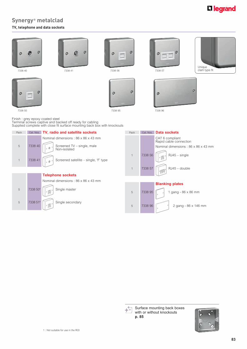
83
Finish : grey epoxy coated steelTerminal screws captive and backed off ready for cablingSupplied complete with close fit surface mounting back box with knockouts
Blanking plates
5 7338 95 1 gang - 86 x 86 mm
5 7338 96 2 gang - 86 x 146 mm
Pack Cat. Nos. TV, radio and satellite sockets
Nominal dimensions : 86 x 86 x 43 mm
5 7338 40 Screened TV – single, male Non-isolated
1 7338 41 Screened satellite – single, ‘F’ type
Telephone sockets
Nominal dimensions : 86 x 86 x 43 mm
5 7338 501 Single master
5 7338 511 Single secondary
Pack Cat. Nos. Data sockets
CAT 6 compliant Rapid cable connection
Nominal dimensions : 86 x 86 x 43 mm
1 7338 56 RJ45 – single
1 7338 57 RJ45 – double
7338 41
7338 50 7338 95 7338 96
7338 577338 567338 40
1 : Not suitable for use in the ROI
Uniqueclam type fi t
Synergy® metalcladTV, telephone and data sockets
Surface mounting back boxeswith or without knockouts p. 85

84
Pack Cat. Nos. 1 and 2 gang plates for grid modules
For support frames, see below
1 7339 91 1 gang - 86 x 86 mm 1 small aperture module
1 7339 92 1 gang - 86 x 86 mm 2 small aperture modules
1 7339 93 2 gang - 86 x 146 mm 3 small aperture modules
1 7339 94 2 gang - 86 x 146 mm 4 small aperture modules
7338 92
Pack Cat. Nos. Carrier plates for Arteor modules (square)
No additional support frame required Enable a Synergy installation to benefit from the
additional functionality of Arteor, such asinternational sockets etc
5 7338 91 1 gang - 86 x 86 mm 1 Arteor module
5 7338 92 1 gang - 86 x 86 mm 2 Arteor modules
5 7338 93 2 gang - 86 x 146 mm 3 Arteor modules
5 7338 94 2 gang - 86 x 146 mm 4 Arteor modules 1 and 2 gang support frames for
grid modules
10 7354 90 1 gang 1 module
10 7354 91 1 gang 2 modules
10 7354 92 2 gang 3/4 modules
7339 94
7354 90 7354 927338 92 + international socket Cat. No. 5721 18
Complete range of grid front plates and modulesp. 88-93
Arteor modules p. 9-29
Grid selection charts p. 92-93Grid modules p. 88-90Arteor modules p. 9-29
Synergy® metalcladplates and support frames

Architrave back boxes
Depth 26 mm
5 7364 40 Dimensions : 82 x 28 mm
5 7364 41 Dimensions : 142 x 28 mm
85
Pack Cat. Nos. Surface mounting metal back boxes
Only suitable for use with Synergy traditional and metalclad finishes and Synergy grid Conform to BS 5733 where applicable Material : grey epoxy coated steel
Depth 37 mm
Dimensions : 86 x 86 mm
10 7364 00 1 gang With knockouts
10 7364 20 1 gang Without knockouts
Dimensions : 86 x 146 mm
5 7364 01 2 gang With knockouts
5 7364 21 2 gang Without knockouts
Dimensions : 146 x 146 mm
1 7364 18 6/8 module grid With knockouts
1 7364 22 6/8 module grid Without knockouts
Dimensions : 207 x 146 mm
1 7364 28 9/12 module grid With knockouts
1 7364 32 9/12 module grid Without knockouts
7364 00
7364 01
Pack Cat. Nos. Flush mounting back boxes
Conform to BS 4662 Material : galvanised steel Top, side and back knockout entries according to type of box
Depth 16 mm
100 0891 09 1 gang with 1 fixed lug, 1 adjustable lug and 1 earth terminal
Depth 25 mm
50 0891 10 1 gang with 3 fixed lugs, 1 adjustable lug and 1 earth terminal
10 0891 11 2 gang with 1 fixed lug, 1 adjustable lug and 1 earth terminal
Depth 35 mm
50 0891 13 1 gang with 3 fixed lugs, 1 adjustable lug and 1 earth terminal
40 0891 14 2 gang with 1 fixed lug, 1 adjustable lug and 1 earth terminal
40 0891 40 Dual box with 2 earth terminals Accepts 2 single gang accessories
Depth 48 mm
25 0891 17 1 gang with 3 fixed lugs, 1 adjustable lug and 1 earth terminal
20 0891 18 2 gang with 1 fixed lug, 1 adjustable lug and 1 earth terminal
0891 130891 10
0891 11
flush mounting steel back boxes surface mounting metal back boxes
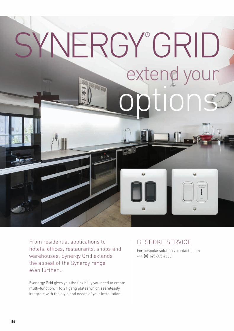
86
From residential applications to
hotels, offices, restaurants, shops and
warehouses, Synergy Grid extends
the appeal of the Synergy range
even further...
Syenergy Grid gives you the flexibility you need to create
multi-function, 1 to 24 gang plates which seamlessly
integrate with the style and needs of your installation.
BESPOKE SERVICE
For bespoke solutions, contact us on
+44 (0) 345 605 4333
extend your
options
SYNERGY®
GRID

87
THE FUNCTIONS YOU NEED, THE FINISH YOU WANT IN A SINGLE MODULAR SOLUTION
A vast selection of function modules,
available in white and anthracite,
and a complete range of finishes
make Synergy Grid the flexible
solution for any residential or
commercial application.
UNRIVALLED VERSATILITY WITHOUT COMPROMISE
In addition to a complete selection of switch
modules, including key and push switches,
the Synergy Grid range also incorporates
communication modules for TV, audio and
networking functions, plus an enhanced range
of electronic dimmers and time delay switches.
The ‘mix and match’ versatility of Synergy Grid
provides almost limitless options.
For example:
■ a white surround plate with anthracite
modules creates an instant solution to the
visual contrast requirements of Part M of the
Building Regulations
■ venture beyond the capabilities of the
standard wiring accessory using a
combination of specialist functions within
one plate
■ choose standard or bespoke engravings to
match any specification via our bespoke
service

88
Modules mount from front into grid support framesIndividually removable without disturbing grid
Pack Cat. Nos. Single pole switch modules 10 AX - 250 V±
White Anthracite
Conform to BS EN 60669-1
10 7354 00 7355 00 1 way switch
10 7354 01 7355 01 1 way switch + red LED power indicator
10 7354 03 7355 03 2 way switch
10 7354 07 7355 07 Intermediate switch
Single pole push switch modules 10 A - 250 V± White Anthracite Conform to BS EN 60669-1
10 7354 05 7355 05 2 way push switch
1 7354 05PE 7355 05PE 2 way push switch marked “PRESS TO EXIT”
1 7354 06 7355 06 2 way push switch marked “BELL”
Pack Cat. Nos. Double pole switch modules 20 AX - 250 V±
White Anthracite
Conform to BS EN 60669-1
10 7354 20 7355 20 Switch
10 7354 21 7355 21 Switch + red LED power indicator
10 7354 22 7355 22 Push to make1
1 7354 25 7355 25 Push to break1
Double pole key switch modules 20 AX - 250 V± Conform to BS EN 60669-1 White Anthracite Key supplied
10 7354 23 7355 23 Key switch 10 7354 23ET 7355 23ET Key switch marked “EMERGENCY LIGHT TEST”
10 7354 24 7355 24 Key switch + red LED power indicator
Spare key
5 0811 77 Spare key for Synergy key switch functions
Single pole key switch modules 20 AX - 250 V± Conform to BS EN 60669-1 White Anthracite Key supplied
10 7354 16 7355 16 2 way key switch 10 7354 17 7355 17 2 way key switch retractive centre off1
7354 00 7355 01 7354 21
PRESSTO
EXIT
BELL
Single pole switch modules 20 AX - 250 V± White Anthracite Conform to BS EN 60669-1
10 7354 10 7355 10 1 way switch
1 7354 11 7355 11 1 way switch + red LED power indicator
10 7354 12 7355 12 2 way switch 10 7354 13 7355 13 2 way centre off1 10 7354 14 7355 14 2 way retractive centre off1 1 7354 14AR 7355 14AR 2 way retractive centre off
marked with up + down arrows1
10 7354 15 7355 15 2 way push switch1
10 7354 18 7355 18 Intermediate switch
1 : 20 A rated only
1 : 20 A rated only
7355 177354 11
Installation options p. 91Grid selection charts p. 92-93
Synergy® grid systemswitch modules
Decorative rockers p. 90

89
Pack Cat. Nos. Ancillary modules
White Anthracite
1 7354 50 7355 50 Telephone socket - single master 1 7354 51 7355 51 Telephone socket - single secondary
10 7352 56 7353 56 RJ 45 data outlet CAT 6 compliant Rapid cable connection UTP 8 contact
10 7354 40 7355 40 Screened TV - single Non-isolated male Ø9.5 mm
10 7354 41 7355 41 Screened satellite
10 7352 65 7353 65 Hi-fi outlet - screw terminal
20 7354 36 7355 36 Blank module
7355 48 7351 62 7352 56 7355 417350 30 7352 65
Modules mount from front into grid support framesIndividually removable without disturbing grid
Pack Cat. Nos. Dimmer unit modules 100 - 240 V± 50/60 Hz
White Anthracite
Conform to BS EN 60669-2-1
1 7354 46 7355 46 Dimmer for use with tungsten filament lamps, good quality wire-wound transformers and compatible electronic transformers for low voltage loads1
40 - 300 W
Not suitable for fluorescent loads
Fuse carrier modules 13 A - 250 V± White Anthracite Conform to BS 5733
10 7350 30 7351 30 Fuse module fitted with BS 1362 13 A fuse
White Anthracite
Indicator modules - 250 V± Conform to BS 5733
1 7350 60 7351 60 Indicator - red LEDs 1 7350 62 7351 62 Indicator - green LEDs
Time delay switch 100 - 240 V± 50/60 Hz
White Anthracite Conform to BS EN 60669-2-3
1 7354 47 7355 47 Multiple way soft start time delay switch Push operated delay pre-set for 3, 10
or 30 minutes 40 - 400 W
Not suitable for fluorescent loads
Dimmer unit modules - dimmable HF ballast fluorescent 100 - 240 V± 50/60 Hz
White Anthracite Conform to BS EN 60669-2-1 1 7354 48 7355 48 Leading edge dimmer for potentiometer 0-10 V
1 : Can be used in conjunction with compatible electronic transformers for low voltage loads. It will be necessary to test that the dimmer mechanism is compatible with the electronic transformer identified for installation
Installation options p. 91Grid selection charts p. 92-93
Synergy® grid systemdimmer, fuse carrier and ancillary modules
Complete range of grid front plates and support frames p. 92-93

90
MODERNSILVER
MODERNNICKEL DECORATIVE ROCKERS
FUNCTIONS
10 AX switch 1 x 1 way 1 7355 00MS 7355 00MN
10 AX switch 1 x 2 way 1 7355 03MS 7355 03MN
10 AX switch 1 x intermediate 1 7355 07MS 7355 07MN
10 A push switch 1 x 2 way 1 7355 05MS 7355 05MN
20 AX SP switch 1 way 1 7355 10MS 7355 10MN
20 AX SP switch 2 way 1 7355 12MS 7355 12MN
20 AX SP switch 2 way centre off 1 7355 13MS 7355 13MN
20 AX SP switch 2 way retractive centre off 1 7355 14MS 7355 14MN
20 AX SP push switch 2 way 1 7355 15MS 7355 15MN
20 AX SP intermediate switch 1 7355 18MS 7355 18MN
20 AX DP switch 1 7355 20MS 7355 20MN
20 AX DP push to make switch 1 7355 22MS 7355 22MN
20 AX DP SWITCH20 AX DP SWITCH +
RED LED POWER INDICATOR MODULES
BOILER 1 7354 20BL 7355 20BL 7354 21BL 7355 21BL
COOKER HOOD 1 7354 20CH 7355 20CH 7354 21CH 7355 21CH
DISH WASHER 1 7354 20DW 7355 20DW 7354 21DW 7355 21DW
EXTRACTOR 1 7354 20EX 7355 20EX 7354 21EX 7355 21EX
EXTRACTOR FAN 1 7354 20EF 7355 20EF 7354 21EF 7355 21EF
EXTRACTOR HOOD 1 7354 20EH 7355 20EH 7354 21EH 7355 21EH
FAN 1 7354 20FN 7355 20FN 7354 21FN 7355 21FN
FREEZER 1 7354 20FZ 7355 20FZ 7354 21FZ 7355 21FZ
FRIDGE 1 7354 20FR 7355 20FR 7354 21FR 7355 21FR
FRIDGE FREEZER 1 7354 20FF 7355 20FF 7354 21FF 7355 21FF
HEATER 1 7354 20HR 7355 20HR 7354 21HR 7355 21HR
HOB 1 7354 20HB 7355 20HB 7354 21HB 7355 21HB
HOOD 1 7354 20HD 7355 20HD 7354 21HD 7355 21HD
LIGHTS 1 7354 20LG 7355 20LG 7354 21LG 7355 21LG
MICROWAVE 1 7354 20MW 7355 20MW 7354 21MW 7355 21MW
OVEN 1 7354 20OV 7355 20OV 7354 21OV 7355 21OV
PLINTH HEATER 1 7354 20PH 7355 20PH 7354 21PH 7355 21PH
TOWEL RAIL 1 7354 20TR 7355 20TR 7354 21TR 7355 21TR
TUMBLE DRYER 1 7354 20TD 7355 20TD 7354 21TD 7355 21TD
WASHING MACHINE 1 7354 20WM 7355 20WM 7354 21WM 7355 21WM
WASTE DISPOSAL 1 7354 20WD 7355 20WD 7354 21WD 7355 21WD
WATER HEATER 1 7354 20WH 7355 20WH 7354 21WH 7355 21WH
SYNERGY GRID MODULES ENGRAVED WITH APPLIANCE MARKINGS
SYNERGY GRID MODULES WITH DECORATIVE ROCKERS
ROCKER MARKINGS
White Anthracite White Anthracite
Pack
Pack
Complete range of Synergy Modern p. 68-73
For other engraving requirements not listed please contact us on +44 (0) 345 605 4333
Synergy® grid systemdecorative rockers and rocker markings

91
■ Flush mounting installation examples
■ Surface mounting installations
Surface mounting of Synergy grid modules can be achieved by using components illustrated in the table below
■ Support frame selection for front plates (1-4 modules)
Support frames required for clip-on plates differ from support frames for screw-attached faceplatesSupport frames required for Modern clip-on plates are Cat. Nos. 7354 81 (1 or 2 modules) and 7354 82 (3 or 4 modules)Support frames required for white, traditional and metalclad plates (screw attached) are Cat. Nos. 7354 90 (1 module), 7354 91 (2 modules), and 7354 92 (3 or 4 modules)
0891 1335 mm depth
7354 91 7301 92
7354 00 x 2
0818 5243 mm depth
7354 92 x 2 7301 83
7354 00 x 8
2 modules
8 modules
18 modules
Back box
Back box
Back box
Support frame
Support frames
Support frames
Modules
Modules
Modules
Frontplate
Frontplate
Frontplate
0818 5456 mm depth
7354 93 x 3 7301 86
7354 00 x 18
1 or 2 modules 3 or 4 modules 6 or 8 modules 9 or 12 modules
Box dimensions
Surface box (no knockouts)
7364 00 7364 01 7364 18 7364 28
Surface box (with knockouts)
7364 20 7364 21 7364 22 7364 32
86 x 86 x 37 86 x 146 x 37 146 x 146 x 37 207 x 146 x 37
Synergy® grid systeminstallation options : flush and surface mounting

92
ARCHITRAVES
1 gang 2 gang
FRONT PLATES WITH SMALL APERTURES
1 gang 2 gang
1 module
PLATE FINISH
2 modules 1 module 2 modules 3 modules 4 modules FRONT PLATES
GRID SUPPORT FRAMES 1 x 1 x 1 x 1 x 1 x 1 x
BACK BOXES
FLUSH MOUNTING
Dimensions (mm) 86 x 36 146 x 36 86 x 86 86 x 86 86 x 146 86 x 146
White 10 7301 80 10 7301 81 10 7301 91 10 7301 92 10 7301 93 10 7301 94
Traditional brushed stainless steel 1 7331 80 1 7331 81 1 7331 91 1 7331 92 1 7331 93 1 7331 94
Traditional polished stainless steel 1 7333 80 1 7333 81 1 7333 91 1 7333 92 1 7333 93 1 7333 94
Metalclad – – – 1 7339 91 1 7339 92 1 7339 93 1 7339 94
Dimensions (mm) 89 x 891 89 x 891 89 x 1491 89 x 1491
Modern silver – – – 1 7311 91 1 7311 92 1 7311 93 1 7311 94
Modern nickel – – – 1 7313 91 1 7313 92 1 7313 93 1 7313 94
For white, traditional and metalclad 1 7354 95 1 7354 96 10 7354 90 10 7354 91 10 7354 92 10 7354 92
For modern – – – 10 7354 81 10 7354 81 10 7354 82 10 7354 82
Front plate material
White : 1 to 8 modules - thermoset; 9 to 24 modules - stainless steelTraditional : All modules - stainless steelMetalclad : 1 to 4 modules - mild steel; 6 to 24 modules - stainless steelModern : 1 to 4 modules - die cast alloy; 6 to 8 modules - stainless steel
1 : Screw free clip-on front plate
Dimensions (mm) 82 x 28 x 26 142 x 28 x 26 35 mm depth 35 mm depth 35 mm depth 35 mm depth
Flush 5 7364 40 5 7364 41 50 0891 13 50 0891 13 40 0891 14 40 0891 14
Flush with phase barriers – – – – – – – – – – – –
Dimensions (mm) 86 x 86 x 47 86 x 86 x 47 86 x 146 x 47 86 x 146 x 47
Surface white for white only – – – 10 7364 07 10 7364 07 5 7364 11 5 7364 11
Dimensions (mm) 86 x 86 x 37 86 x 86 x 37 86 x 146 x 37 86 x 146 x 37
Surface steel with knockouts – – – 10 7364 00 10 7364 00 5 7364 01 5 7364 01
Surface steel without knockouts – – – 10 7364 20 10 7364 20 5 7364 21 5 7364 21
GRID MODULES
Pack Pack Pack Pack Pack Pack
SURFACE MOUNTING
Synergy® grid system
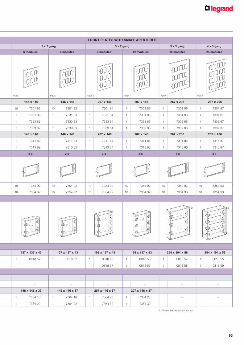
93
FRONT PLATES WITH SMALL APERTURES
2 x 2 gang
6 modules 8 modules
3 x 2 gang
9 modules 12 modules
3 x 3 gang 4 x 3 gang
18 modules 24 modules
2 x 2 x 3 x 3 x 3 x 4 x
146 x 146 146 x 146 207 x 146 207 x 146 267 x 206 267 x 206
10 7301 82 10 7301 83 1 7301 84 1 7301 85 1 7301 86 1 7301 87
1 7331 82 1 7331 83 1 7331 84 1 7331 85 1 7331 86 1 7331 87
1 7333 82 1 7333 83 1 7333 84 1 7333 85 1 7333 86 1 7333 87
1 7339 82 1 7339 83 1 7339 84 1 7339 85 1 7339 86 1 7339 87
146 x 146 146 x 146 207 x 146 207 x 146 267 x 206 267 x 206
1 7311 82 1 7311 83 1 7311 84 1 7311 85 1 7311 86 1 7311 87
1 7313 82 1 7313 83 1 7313 84 1 7313 85 1 7313 86 1 7313 87
10 7354 92 10 7354 92 10 7354 92 10 7354 92 10 7354 93 10 7354 93
10 7354 92 10 7354 92 10 7354 92 10 7354 92 10 7354 93 10 7354 93
2 : Phase barrier variant shown
137 x 137 x 43 137 x 137 x 43 198 x 137 x 43 198 x 137 x 43 254 x 194 x 56 254 x 194 x 56
1 0818 52 1 0818 52 1 0818 53 1 0818 53 1 0818 54 1 0818 55
– – 1 0818 57 1 0818 57 1 0818 58 1 0818 59
– – – – – –
146 x 146 x 37 146 x 146 x 37 207 x 146 x 37 207 x 146 x 37
1 7364 18 1 7364 18 1 7364 28 1 7364 28 – –
1 7364 22 1 7364 22 1 7364 32 1 7364 32 – –
Pack Pack Pack Pack Pack Pack
2 2

94
Marrying smooth curves with a slim
profile and no visible screws,
Legrand’s Clipper range has a simple,
understated appearance.
Its larger rocker, contrast colour frames and neon
surrounds make it the ideal choice for assisted living
installations and to aid with Part M compliance.
CLIPPER a fresh look for a much loved classic
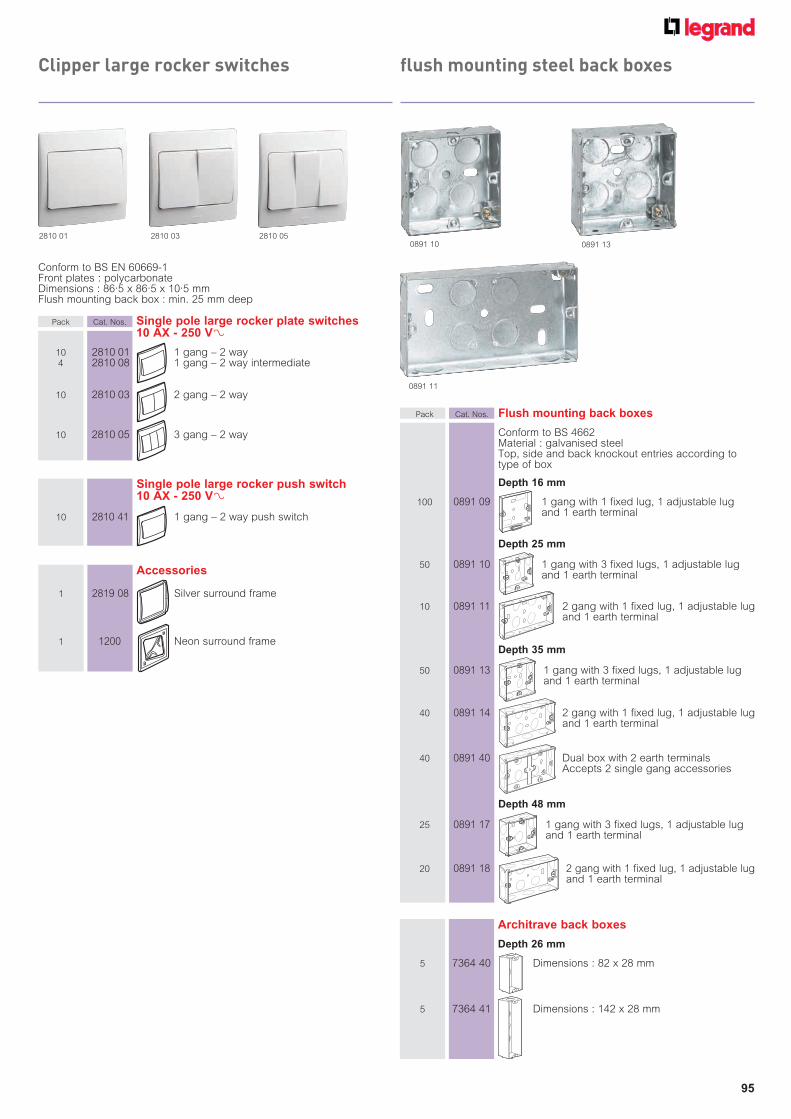
95
Conform to BS EN 60669-1Front plates : polycarbonateDimensions : 86.5 x 86.5 x 10.5 mmFlush mounting back box : min. 25 mm deep
Pack Cat. Nos. Single pole large rocker plate switches 10 AX - 250 V±
10 2810 01 1 gang – 2 way 4 2810 08 1 gang – 2 way intermediate
10 2810 03 2 gang – 2 way
10 2810 05 3 gang – 2 way
Single pole large rocker push switch 10 AX - 250 V±
10 2810 41 1 gang – 2 way push switch
Accessories
1 2819 08 Silver surround frame
1 1200 Neon surround frame
2810 01 2810 03 2810 05
Architrave back boxes
Depth 26 mm
5 7364 40 Dimensions : 82 x 28 mm
5 7364 41 Dimensions : 142 x 28 mm
Pack Cat. Nos. Flush mounting back boxes
Conform to BS 4662 Material : galvanised steel Top, side and back knockout entries according to type of box
Depth 16 mm
100 0891 09 1 gang with 1 fixed lug, 1 adjustable lug and 1 earth terminal
Depth 25 mm
50 0891 10 1 gang with 3 fixed lugs, 1 adjustable lug and 1 earth terminal
10 0891 11 2 gang with 1 fixed lug, 1 adjustable lug and 1 earth terminal
Depth 35 mm
50 0891 13 1 gang with 3 fixed lugs, 1 adjustable lug and 1 earth terminal
40 0891 14 2 gang with 1 fixed lug, 1 adjustable lug and 1 earth terminal
40 0891 40 Dual box with 2 earth terminals Accepts 2 single gang accessories
Depth 48 mm
25 0891 17 1 gang with 3 fixed lugs, 1 adjustable lug and 1 earth terminal
20 0891 18 2 gang with 1 fixed lug, 1 adjustable lug and 1 earth terminal
0891 130891 10
0891 11
Clipper large rocker switches flush mounting steel back boxes

96
Electrak’s range of non standard
unswitched twin socket outlets
combined with their unique ‘key plugs’,
offer a convenient and safe method
of preventing unauthorised
disconnection or use of equipment.
Easy to wire key plugs twist fit into the
double shuttered safety socket, removing
the risk of accidental unplugging.
Key plugs twist fi t
into the socket,
removing the
risk of accidental
unplugging
ELECTRAK®
Setting the standard for non standard applications
AVAILABLE IN THREE TYPES
■ Clean earth
■ Electronic point of sale (EPOS)
■ Uninterrupted power supply (UPS)

97
T.S.O. Rating 240 V AC 26 A (2 x 13 A) 50 HzCable capacity 3 x 2.5 or 2 x 4mm2
Electrak accessories are ASTA Approved to BS 5733
Conductor :High conductivity copperInsulator - Noryl ENV 130Brass terminals
Plug :Fitted with BS 1362 fuseBrass pins and terminalsPolycarbonate plug housingPolyester plug entry box
Socket :Polycarbonate cover plate
Pack Cat. Nos. Unswitched twin socket outlets
Unswitched twin socket
1 AZ0010 Alternative to conventional socket outlets where non-standard applications are beneficial such as computer integrity, electronic equipment or just for the safety of the unique simple twist action double shutter access
For use with Cat. No. AP13-WH plug below
Unswitched twin socket - clean earth
1 CZ9010 Non-interchangeable
Plugs
13 A fused plug
1 AP13-WH Easy to wire ‘key plugs’ simply twist into the double shuttered safety sockets and are fitted with standard 13 A BS 1362 fuses
BS 1362 fuses less than 13 A may be fitted by the user to suit the recommended fuse size for each appliance
1 EP13 Red 13 A fused plug - clean earth
Accessory
1 AZ0050 Electrak to 3 pin (BS 1363) socket converter
Pack Cat. Nos. EPOS packs (Electronic Point of Sale)
EPOS packs
The twin socket outlet is unique and the key plugs are non-interchangeable with other socket outlets which stops unauthorised use of equipment
Moulded in red polycarbonate For use with Cat. No. EP2000 plug below
1 ES6000 Includes : unswitched twin socket and 2 x 5 A fused plugs
1 ES6005 Includes : unswitched twin socket and 1 x 5 A fused plug
Plug
1 EP2000 EPOS 5 A fused plug
UPS packs (Uninterruptible Power Suppy)
UPS packs
The twin socket outlet is unique and the key plugs are non-interchangeable with other socket outlets which stops unauthorised use of equipment
Moulded in blue polycarbonate For use with Cat. No. UPS200 plug below
1 UPS600 Includes : unswitched twin socket and 2 x 3 A fused plugs
1 UPS615 Includes : unswitched twin socket and 1 x 3 A fused plug
Plug
1 UPS200 UPS 3 A fused plug
AP13-WH
AZ0010
ES6000 UPS600
White
Red
Red
Blue
Electrak®
wiring accessories

98
Whatever the weather, Plexo offers
maintained and non-maintained IP55
and IP66 solutions to meet the specific
requirements of outdoor installations.
PERFECT PROTECTION, WHEN YOU NEED IT
Together, Plexo’s IP55 and IP66 ranges provide a
complete weatherproof solution. Additional functionality
is also available with a selection of modular housings
that accommodate Arteor modular devices.
For Arteor
modules
see p. 9-29
1 2 3 4
Safety in numbersIP55 & IP66 rated fi ttings
Safety in numbers
MODULAR OPTIONS
1 Surface mounting options
1 Flush mounting options
1 Silicon groove and flexible cable entry
4 Socket design accepts moulded plugs
PLEXO

99
IP 66 - IK 08Grey RAL 7016 / TO 29Polypropylene/ABS housingTemperature rating : –20 to +40 °C (+50 °C for short periods) Provision for 20 mm dia. conduit entries (side and rear)Stainless steel captive terminal screws supplied in backed-off position
Pack Cat. Nos. Switches - 250 V± 20 A switches
Conform to BS EN 60669-1 Grey Fitted with rear gasket with groove to deposit silicone
1 6846 03 1 gang – 2 way SP
1 6846 04 2 gang – 2 way SP
13 A - 250 V± socket outlets
Conform to BS 1363 : Part 2 Fitted with rear gasket with groove to deposit silicone
Grey
1 6846 19 1 gang unswitched
1 6846 29 2 gang switched
6846 03
6846 19
5721 116846 36 + 5721 11
Pack Cat. Nos. 13 A - 250 V± fused spur unit
Conforms to BS 1363 : Part 4 Fitted with rear gasket with groove to deposit silicone
Grey
1 6846 45 1 gang DP switched
Adaptors for Arteor modules
Fitted with rear gasket with groove to deposit silicone No additional support frame required
Grey
1 6846 36 2 module adaptor with semi-transparent lid
1 6846 38 3 module adaptor with semi-transparent lid
British Standard 13 A socket
Shuttered for child safety 13 A - BS 1363 : Part 2
Fits into Arteor module adaptors (Cat. Nos. 6846 36 and 6846 38 above)
10 5721 11 2 P + T ASTA approved
ISO M20 cable gland
25 0980 03 Cable gland IP 68
6846 29
PlexoIP 66 weatherproof wiring devices
Arteor modules p. 9-29

100
0695 47
0695 34
IP 55 - IK 07Grey RAL 7035 / 7016 Polycarbonate mechanisms/ABS frames polypropylene housingTemp. rating : –20 to +40 °C (+50 °C for short periods)Supplied with direct piercing gland
Pack Cat. Nos. Switches 10 A - 250 V± Supplied with screwless terminals Conform to BS EN 60669-1 10 0697 11 1 gang – 2 way SP
10 0697 15 2 gang – 2 way SP
10 0697 10 1 gang – 2 way SP + lens1
10 0697 17 1 gang – 1 way DP
5 0697 16 1 gang – SP intermediate
Push button - 250 V± Supplied with screwless terminals
10 0697 20 2 way push button
Socket outlets 13 A - 250 V± Captive terminal screws supplied in backed off position IP 55 - IK 07 to BS EN 60529 Conform to BS 1363 : Part 2
10 0697 32 1 gang – 13 A socket 2P + E screw terminals
5 0697 39 2 gang – two 13 A sockets 2P + E screw terminals
0697 10
0697 39
0697 11
1 : Use lamps Cat. Nos. 0694 97/98
PlexoIP 55 weatherproof wiring accessories
PlexoIP 55 modular mechanisms
Surface mounting boxes and flush mountingsupport frames for Plexo modular mechanismsp. 101
IP 55 - IK 07Grey RAL 7035 / 7016 Polycarbonate/polypropylene housingTemp. rating : –20 to +40 °C (+50 °C for short periods)Supplied with direct piercing glandInstallation with surface mounting boxes or flush mounting frames
Pack Cat. Nos. Illuminating time lag switch - 250 V± Captive terminal screws supplied in backed off position
5 0695 04 Electronic - IP55 2 wire connection Supplied with lamp Temporization : 25 s to 15 min. Max. loads : - 1 000 W incandescent and halogen 230 V± - 400 W halogen 130 V - 400 VA ELV halogen lamps - 400 VA fluorescent lamps - 2 300 W resistive (heating)
Emergency stop functions 3 A - 230 V± Supplied with “emergency stop” label in 8 languages Yellow cover plate, red button
Grey/Yellow
1 0695 47 Emergency stop button 1 N/C contact 1 pole
1 0695 48 Emergency stop with key for reset N/O + N/C contact Key RONIS No. 455 supplied Key removable in 0 position
1 0695 49 Emergency stop - stay put 1/4 turn release N/O + N/C contact Key removable in 0 position
Key operated switches 3 A - 250 V± Supplied with RONIS key No. 455 Grey Key removable in all positions
1 0695 34 2 positions marked “0 – I” 2 N/O contacts
1 0695 35 2 positions marked “I - 0 - II” 2 N/O contacts

101
IP 55 - IK 07Grey RAL 7035 / 7016 Polycarbonate/polypropylene housingTemp. rating : –20 to +40 °C (+50 °C for short periods)Supplied with 1 flat + 1 stepped glandCaptive terminal screws supplied in backed-off positionInstallation with surface mounting boxes or flush mounting frames
Pack Cat. Nos. Pilot light
10 0695 83 Accepts E10 lamps - 5 W max. Supplied with lamp Cat. No. 0898 40
Supplied without diffusers (see below)
Diffusers for pilot light
10 0695 88 Colourless 10 0695 89 Green 10 0695 90 Orange 10 0695 91 Red
Light sensitive switches - 230 V± Light sensitive switch 1 function IP 55 - IP 07
5 0695 17 Can be used to switch a lighting circuit “ON” and “OFF” based on light conditions (nightfall, daybreak) Supplied in one piece, including photo electric cell Maximum load : - 1 400 W incandescent and halogen lamps 230 V± - 400 VA fluorescent tubes Luminosity threshold : 0.5 to 1 500 lux
Photo-electric cell IP 55
5 0695 18 For use with modular Microlux D light sensitive switch Cat. No. 4126 26 (see below)
0696 51
Pack Cat. Nos. Back boxes and support frames
Surface mounting boxes with membrane glands
Equipped with removable membrane glands Direct entry of cables Grey (No need to be cut)
10 0696 51 1 gang - 1 entry
5 0696 72 2 gang - 1 entry
Surface mounting boxes with membrane glands
Grey
5 0696 56 1 gang - 1 entry
5 0696 78 2 gang, horizontal mounting - 2 entries (2 top)
Flush mounting support frame
10 0696 81 1 gang For Plexo modular mechanisms
Accessories
Modular back box IP 55 - IK 05
To receive Arteor modules (max. 2 modules)
10 0695 80 Adaptor with smoked polycarbonate flap
Lamps
10 0694 98 230 V - 1 mA orange (indicator) 10 0694 97 230 V - 0.5 mA green (locator)
E10 for pilot light
10 0898 40 230 V - 5 W
0696 720695 91 0695 17 0898 400695 80
Socket outlet 13 A - 250 V± 10 0695 85 Panel mounting 1 gang – 13 A socket 2P + E screw terminals
Microlux D light sensitive switch
Can be used to switch a lighting circuit “ON” and “OFF” based on light conditions (nightfall, daybreak)
Supplied with IP 65 weatherproof photoelectric cell Power supply : 230 V± - 50/60 Hz
Standard
1 4126 26 56 programmes possible : daily, weekly or yearly programmes Output 16 A - 250 V± - µ cos ϕ = 1 2 000 W incandescent
2 000 VA series compensated fluorescent 1 000 W energy-saving bulb Integrated hour counter High precision clock : + 0.1 sec per day at 25°C Working reserve : 5 years Adjustable from 3 to 100 000 lux Automatic changeover between summer/winter time Number of modules : 2 Programmed using programme transfer key Cat. No. 4128 72 Supplied with IP 65 photoelectric cell Cat. No. 4128 58
L N S SM
PlexoIP 55 modular mechanisms (continued)
For Microlux D light sensitive switch programme transferkey and software, contact us on+44 (0) 345 605 4333

102
1 : PET – Polyethylene Terephthalate
Pack Cat. Nos. Energy-saving pendant set
Conforms to EN 61000-3-2, EN 50082-1, EN 55015, EN 60929, EN 61547, EN 60928 and BS 67
Supply voltage 230 - 240 V Mains frequency 50 Hz To be used with 13/18 W 4 pin plug-in lamps only Lamp fitting type GX24q-1 Dimming is not possible Ceiling rose has angled terminal block with clear polycarbonate shroud 8 in-line terminals with captive screws and White earth terminal
1 6603 07 3 inch drop – energy-saving 13/18 W pendant set Lamp not supplied
Safety lampholders
T2 rated to BS 7895
Heat resistant glass fibre reinforced PET1
one-piece lampholder body Safety lampholders feature automatic isolation of brass plungers following lamp removal Plungers cannot be made live again unless White lamp is in place
20 0600 81 B22 lampholder – short skirt
Pack Cat. Nos. Safety batten lampholders
T2 rated to BS 7895
Incorporate previous safety lampholders, plus : Angled terminal block with clear polycarbonate shroud White Heat resistant tails to IEC 60227
10 0600 85 B22 lampholder – straight/short skirt 8 in-line terminals with captive screws plus earth
10 0600 86 B22 lampholder – straight/H.O. skirt 8 in-line terminals with captive screws plus earth
Safety pendant sets
T2 rated to BS 7895
Combination of ceiling rose and previous safety lampholder with length of two core
0·75 mm2 PVC circular flexible cable, plus : Angled terminal block with clear polycarbonate shroud 8 in-line terminals with captive screws and White Heat resistant tails to IEC 60227
10 0600 89 6 inch drop – short skirt lampholder
10 0600 90 6 inch drop – H.O. skirt lampholder
Safety lampholder + tails
White T2 rated to BS 7895
20 8204 90 Safety lampholder + 6 inch tails
6603 07
0600 81
0600 908204 90
0600 85
0600 86
ceiling accessoriessafety lampholders and pendant sets

103
Pack Cat. Nos. Ceiling switches Conform to BS EN 60669-1 Clearly embossed terminal markings Thermoplastic material resulting in increased
mechanical strength Quick snap on cover mouldings with easily detachable cord for installation/security
Dimensions : 80 mm diameter Fixing centres : 50·8 mm
Mains voltage – white
10 0611 10 6 A – 250 V± SP one way with 1·5 m white cord
10 0611 11 6 A – 250 V± SP two way with 1·5 m white cord
10 0611 30 16 A – 250 V± DP one way with 1·5 m white cord
Extra low voltage (cord not supplied)
10 0611 25 Pull to make/pull to break (non-latching)1
10 0611 26 Pull to make/pull to break with 28 V indicator and orange lens (non-latching)1
0611 26 +8204 60
1 : Outside the scope of BS EN 60669-1
0611 10
Ceiling switch 50 A DP - 250 V± Conforms to BS 3676 Positive ON/OFF flag indicator Red neon indicator Suitable for ceiling or wall mounting
For flush mounting, use box Cat. No. 0891 17 p. 85 Dimensions : 86 x 86 mm Fixing centres : 60·3 mm
10 7545 50 A DP ceiling switch
10 7768 Surface box for Cat. No. 7545 - depth 47 mm
Accessories
10 0611 49 White replacement cord 1·5 m 10 8204 60 Orange cord 2·3 m and orange acorn 250 8204 69 White adaptor
7545 7768
ceiling switches utility weatherproofbuklhead lighting
Pack Cat. Nos. Weatherproof round bulkhead lights
IP 44 Conform to IS EN 60598-1 B22 lampholder Class II O (double insulated) White base
Multi-purpose low profile bulkhead suitable for indoor or outdoor applicationTwist and lock closing
Lamp not supplied
100 W incandescent
5 0604 50 With glass diffuser
10 0604 58 With polycarbonate diffuser
0604 50
Plexo weatherproof bulkhead lights
IP 55 - IK 08B22 lampholder
Hinged polycarbonate diffuserTop/bottom reversible openingLamp not supplied
75 W incandescent
5 6604 17 With clear diffuser
1 6604 18 With red diffuser
6604 17 6604 18
110
4 5
95
107 3
40
227
■ Weatherproof round bulkhead lights
■ Plexo weatherproof bulkhead lights
All dimensions in mm (nominal)
Ø 70 max. Ø 50 min.
20
5
12
6
140
72
21
9
29
113

104
Tenby Rapid Clamp Ultra creates
earthing connections with a simple
fixing method that makes fitting them in
hard to reach areas easier than ever,
in new and existing installations.
The unique ‘twist’ fixing method is up to 5 times faster
when compared with traditional clamps. So for
mains incomer pipes, boiler replacement, special
locations or supplementary bonding in pre-17th Edition
installations, earthing is a whole lot easier with Tenby!
TENBY
Fast & reliable wiring connections
1 2 3 4
®
Fast & reliableFast & reliableFast & reliableFast & reliable
EASY TO FIT
1 Simply 'twist' the clamp to attach it
to the pipe
2 The clamp is locked into positon
in under a second
3 Screw down the clamp to secure the
fitting in 6 seconds
4 Finally attach the earthing wire to
complete the installation in
10 seconds

105
Conform to BS 951 : 2009Available in three types :Red (EC14) for dry, non corrosive atmospheresBlue (EC15) for corrosive or humid conditionsGreen (EC16) for corrosive or humid conditions, large earth conductors5 standard band lengths to suit pipe Ø of 12-32 mm, 32-50 mm, 50-75 mm, up to 100 mm and up to 150 mm
EC14
EC15/2
EC16/3
Pack Cat. Nos. Earth clamps for dry conditions
Terminal size : A – D (2·5 – 10 mm2 )
Maximum earth conductor 1 x 10 mm2
20 EC14 For pipe Ø 12 – 32 mm
20 EC14/2 For pipe Ø 32 – 50 mm
20 EC14/3 For pipe Ø 50 – 75 mm
Earth clamps for all conditions
Terminal size : A – D (2·5 – 10 mm2 )
Maximum earth conductor 1 x 10 mm2
20 EC15 For pipe Ø 12 – 32 mm
20 EC15/2 For pipe Ø 32 – 50 mm
20 EC15/3 For pipe Ø 50 – 75 mm
20 EC15/4 For pipe Ø up to 100 mm
20 EC15/6 For pipe Ø up to 150 mm
Terminal size : A – E (2·5 – 16 mm2 )
Maximum earth conductor 2 x 16 mm2
20 EC16 For pipe Ø 12 – 32 mm
20 EC16/2 For pipe Ø 32 – 50 mm
20 EC16/3 For pipe Ø 50 – 75 mm
Pack Cat. Nos. Earth clamps for all conditions
Terminal size : A – D (2·5 – 10 mm2 )
Maximum earth conductor 1 x 10 mm2
Pipe Ø Connection cross-section
Ø min. (mm) Ø max. (mm) min. (mm2) max. (mm2)
20 0343 85 12 16 2.5 16
10 0343 86 18 22 2.5 16
10 0343 87 28 32 2.5 16
0343 85
0343 86
0343 87
Conform to BS 951 : 2009Available in three sizesSuitable for dry, non corrosive atmospheres and corrosive or humid conditionsResistance of incandescent wire 960 °CResistivity of 0.4 mΩColour : grey PolyamideSafe, intuitive 1/4 turn mounting ensuring an excellent, lasting equipotential link
Tenby® Rapid Clamp Ultraearth clamps
Tenby® Rapid Clampearth clamps

Cat. Nos.
Page No.
Cat. Nos.
Page No.
Cat. Nos.
Page No.
Cat. Nos.
Page No.
Cat. Nos.
Page No.
Cat. Nos.
Page No.
Cat. Nos.
Page No.
106
Cat. Nos.
Page No.
0010 00
1200 95 7545 103 7768 –
0300 00
0327 80 24 0327 81 – 0343 85 105 0343 86 – 0343 87 – 0600 81 102 0600 85 – 0600 86 – 0600 89 – 0600 90 – 0604 50 103 0604 58 – 0611 10 – 0611 11 – 0611 25 – 0611 26 – 0611 30 – 0611 49 – 0694 97 101 0694 98 – 0695 04 100 0695 17 101 0695 18 – 0695 34 100 0695 35 – 0695 47 – 0695 48 – 0695 49 – 0695 80 101 0695 83 – 0695 85 – 0695 88 – 0695 89 – 0695 90 – 0695 91 – 0696 51 – 0696 56 – 0696 72 – 0696 78 – 0696 81 – 0697 10 100 0697 11 – 0697 15 – 0697 16 – 0697 17 – 0697 20 – 0697 32 – 0697 39 – 0767 11 20 0803 99 22 0811 77 57 0818 52 56 0818 53 93 0818 54 56 0818 55 93 0818 56 31 0818 57 93 0818 58 56 0818 59 93 0891 09 65
0891 10 65 0891 11 – 0891 13 – 0891 14 – 0891 17 – 0891 18 – 0891 40 – 0898 40 101 0980 03 99
2000 00
2810 01 95 2810 03 – 2810 05 – 2810 08 – 2810 41 – 2819 08 –
4000 00
4126 26 101
5000 00
5720 01 11 5720 02 – 5720 05 9 5720 06 – 5720 08 – 5720 10 – 5720 11 – 5720 12 6 5720 13 9 5720 14 – 5720 21 29 5720 31 11 5720 35 9 5720 36 – 5720 37 – 5720 38 – 5720 39 6 5720 40 9 5720 42 – 5720 43 – 5720 44 – 5720 45 6 5720 46 9 5720 47 – 5720 48 – 5720 49 – 5720 51 12 5720 52 16 5720 53 – 5720 54 21 5720 55 17 5720 56 11 5720 57 21 5720 58 6 5720 61 – 5720 67 21 5720 71 22 5720 74 21 5720 78 22 5720 80 7 5720 87 – 5720 88 – 5720 94 24 5720 96 – 5721 03 29 5721 10 –
5721 11 29 5721 13 – 5721 15 – 5721 17 – 5721 18 – 5721 19 – 5721 30 – 5721 32 – 5721 40 8 5721 41 – 5721 43 – 5721 44 – 5721 45 – 5721 46 – 5721 47 – 5721 49 – 5721 50 – 5721 51 – 5721 53 7 5721 57 8 5721 63 26 5721 70 – 5721 71 – 5721 72 – 5721 73 – 5722 01 18 5722 02 – 5722 03 – 5722 07 21 5722 08 – 5722 11 13 5722 18 18 5722 19 – 5722 20 – 5722 21 17 5722 22 – 5722 23 – 5722 24 21 5722 25 – 5722 26 17 5722 27 – 5722 30 20 5722 31 – 5722 32 17 5722 33 – 5722 38 13 5722 39 – 5722 47 21 5722 48 – 5722 53 20 5722 59 – 5722 63 18 5722 70 28 5722 71 24 5722 72 – 5722 73 – 5722 74 – 5722 75 – 5722 76 – 5722 77 28 5722 79 24 5722 80 28 5722 81 24 5722 82 – 5722 83 28 5722 84 – 5722 85 25
5722 90 28 5722 91 – 5723 00 26 5723 01 – 5723 02 – 5723 03 – 5723 04 – 5723 05 27 5723 06 26 5723 07 30 5723 10 26 5723 14 24 5723 18 27 5723 19 30 5723 20 – 5723 21 8 5723 22 26 5723 23 – 5723 24 25 5723 31 26 5723 33 – 5723 34 27 5723 35 26 5723 37 27 5723 38 – 5723 41 30 5723 42 – 5723 60 28 5723 90 31 5723 92 – 5723 96 – 5724 50 9 5724 51 – 5724 52 17 5724 53 – 5724 54 – 5724 55 – 5724 56 – 5724 67 29 5724 74 25 5724 76 – 5724 88 22 5725 01 11 5725 02 – 5725 05 9 5725 06 – 5725 08 – 5725 10 – 5725 11 – 5725 12 6 5725 13 9 5725 14 – 5725 21 29 5725 31 11 5725 35 9 5725 36 – 5725 37 – 5725 38 – 5725 39 6 5725 40 9 5725 42 – 5725 43 – 5725 44 – 5725 45 6 5725 46 9 5725 47 – 5725 48 –
5725 49 9 5725 51 12 5725 54 21 5725 56 11 5725 57 21 5725 58 6 5725 61 – 5725 67 21 5725 71 22 5725 74 21 5725 78 22 5725 80 7 5725 87 – 5725 94 24 5725 96 – 5726 03 29 5726 10 – 5726 11 – 5726 13 – 5726 17 – 5726 18 – 5726 19 – 5726 30 – 5726 32 – 5726 40 8 5726 43 – 5726 44 – 5726 45 – 5726 46 – 5726 47 – 5726 49 – 5726 50 – 5726 51 – 5726 53 7 5726 57 8 5726 63 26 5726 70 – 5726 71 – 5726 72 – 5726 73 – 5727 01 18 5727 02 – 5727 03 – 5727 11 13 5727 18 18 5727 19 – 5727 20 – 5727 22 21 5727 23 – 5727 24 – 5727 25 – 5727 26 17 5727 27 – 5727 30 20 5727 32 17 5727 33 – 5727 38 13 5727 39 – 5727 53 20 5727 59 – 5727 63 18 5727 70 28 5727 71 24 5727 72 – 5727 73 – 5727 74 – 5727 75 –
5727 76 24 5727 77 28 5727 79 24 5727 80 28 5727 81 24 5727 82 – 5727 83 28 5727 84 – 5727 85 25 5727 90 28 5727 91 – 5728 00 26 5728 01 – 5728 02 – 5728 03 – 5728 04 – 5728 05 27 5728 06 26 5728 10 – 5728 14 24 5728 18 27 5728 22 26 5728 23 – 5728 24 25 5728 31 26 5728 33 – 5728 34 27 5728 35 26 5728 37 27 5728 38 – 5728 41 30 5728 42 – 5730 00 11 5730 01 – 5730 02 – 5730 23 10 5730 24 – 5730 25 – 5730 26 – 5730 27 – 5730 28 – 5730 29 6 5730 30 10 5730 31 – 5730 51 11 5730 61 10 5730 63 – 5730 64 6 5730 71 10 5730 72 – 5730 73 – 5730 74 6 5730 75 10 5730 76 – 5730 78 – 5730 80 11 5730 86 30 5730 93 6 5731 00 11 5731 01 – 5731 02 – 5731 23 10 5731 24 – 5731 25 – 5731 26 – 5731 27 – 5731 28 –
5731 29 6 5731 30 10 5731 31 – 5731 51 11 5731 61 10 5731 63 – 5731 64 6 5731 71 10 5731 72 – 5731 73 – 5731 74 6 5731 75 10 5731 76 – 5731 78 – 5731 80 11 5731 86 30 5731 93 6 5732 19 18 5732 20 – 5732 22 19 5732 23 – 5732 24 – 5732 25 – 5732 34 – 5732 35 – 5732 36 – 5732 37 – 5732 72 25 5732 73 – 5732 74 – 5732 84 19 5732 85 – 5732 86 – 5732 87 – 5732 94 – 5732 95 – 5732 96 – 5732 97 – 5733 74 25 5733 82 19 5733 83 – 5733 84 – 5733 85 – 5733 98 22 5734 55 12 5734 93 20 5735 96 25 5736 55 12 5737 19 18 5737 20 – 5737 22 19 5737 23 – 5737 24 – 5737 25 – 5737 34 – 5737 35 – 5737 36 – 5737 37 – 5737 72 25 5737 73 – 5737 74 – 5737 84 19 5737 85 – 5737 86 – 5737 87 – 5737 94 – 5737 95 –
5737 96 19 5737 97 – 5738 82 – 5738 83 – 5738 84 – 5738 85 – 5740 00 12 5740 01 – 5740 02 – 5740 03 – 5740 04 – 5740 07 13 5740 10 14 5740 50 12 5740 51 – 5740 52 – 5740 53 – 5740 54 – 5740 57 13 5740 60 14 5740 61 16 5740 62 – 5740 82 17 5740 84 – 5743 00 12 5743 01 – 5743 02 – 5743 03 – 5743 04 – 5743 05 13 5743 07 – 5743 18 – 5743 19 – 5743 38 – 5743 39 – 5743 50 12 5743 51 – 5743 52 – 5743 53 – 5743 54 – 5743 55 13 5743 57 – 5744 01 24 5744 51 – 5745 01 25 5745 51 – 5750 70 36 5750 71 37 5750 72 – 5750 73 40 5750 74 – 5750 75 43 5750 76 42 5750 80 36 5750 81 37 5750 82 – 5750 83 40 5750 84 – 5750 85 43 5750 86 42 5750 90 36 5750 91 37 5750 92 – 5750 93 40 5750 94 – 5750 95 43 5750 96 42

Cat. Nos.
Page No.
Cat. Nos.
Page No.
Cat. Nos.
Page No.
Cat. Nos.
Page No.
Cat. Nos.
Page No.
Cat. Nos.
Page No.
Cat. Nos.
Page No.
Cat. Nos.
Page No.
107
Cat. Nos.
Page No.
Cat. Nos.
Page No.
Cat. Nos.
Page No.
Cat. Nos.
Page No.
Cat. Nos.
Page No.
Cat. Nos.
Page No.
Cat. Nos.
Page No.
Cat. Nos.
Page No.
5751 00 36 5751 01 37 5751 02 – 5751 03 40 5751 04 – 5751 05 43 5751 06 42 5751 20 36 5751 21 37 5751 22 – 5751 23 40 5751 24 – 5751 25 43 5751 26 42 5751 30 8 5751 31 – 5751 32 – 5751 40 – 5751 41 – 5751 42 – 5751 50 36 5751 60 – 5751 61 37 5751 62 – 5751 63 40 5751 64 – 5751 65 43 5751 66 42 5751 90 31 5752 00 36 5752 01 37 5752 02 – 5752 03 40 5752 04 – 5752 05 43 5752 06 42 5752 10 36 5752 11 37 5752 12 – 5752 13 40 5752 14 – 5752 15 43 5752 16 42 5753 70 36 5753 71 37 5753 72 – 5753 73 40 5753 74 – 5753 75 43 5753 76 42 5753 90 36 5753 91 37 5753 92 – 5754 00 36 5754 01 37 5754 02 – 5755 40 36 5755 41 37 5755 42 – 5755 43 40 5755 44 – 5755 45 43 5755 46 42 5755 50 36 5755 51 37 5755 52 – 5755 53 40
5755 54 40 5755 55 43 5755 56 42 5755 60 36 5755 61 37 5755 62 – 5755 63 40 5755 64 – 5755 65 43 5755 66 42 5756 10 36 5756 11 37 5756 12 – 5756 13 40 5756 14 – 5756 15 43 5756 16 42 5756 90 36 5756 91 37 5756 92 – 5760 00 31 5760 01 – 5760 02 – 5760 03 – 5760 13 – 5760 15 – 5760 16 – 5761 00 42 5761 01 39 5761 02 – 5761 03 44 5761 04 – 5761 05 41 5761 06 – 5761 07 45 5761 08 38 5761 09 43 5761 10 42 5761 11 39 5761 12 – 5761 13 44 5761 14 – 5761 15 41 5761 16 – 5761 17 45 5761 18 38 5761 19 43 5761 20 42 5761 21 39 5761 22 – 5761 23 44 5761 24 – 5761 25 41 5761 26 – 5761 27 45 5761 28 38 5761 29 43 5761 30 42 5761 31 39 5761 32 – 5761 33 44 5761 34 – 5761 35 41 5761 36 – 5761 37 45 5761 38 38 5761 39 43
5761 40 42 5761 41 39 5761 42 – 5761 43 44 5761 44 – 5761 45 41 5761 46 – 5761 47 45 5761 48 38 5761 49 43 5761 50 42 5761 51 39 5761 52 – 5761 53 44 5761 54 – 5761 55 41 5761 56 – 5761 57 45 5761 58 38 5761 59 43 5761 60 42 5761 61 39 5761 62 – 5761 63 44 5761 64 – 5761 65 41 5761 66 – 5761 67 45 5761 68 38 5761 69 43 5761 70 42 5761 71 39 5761 72 – 5761 73 44 5761 74 – 5761 75 41 5761 76 – 5761 77 45 5761 78 38 5761 79 43 5761 80 42 5761 81 39 5761 82 – 5761 83 44 5761 84 – 5761 85 41 5761 86 – 5761 87 45 5761 88 38 5761 89 43 5761 90 42 5761 91 39 5761 92 – 5761 93 44 5761 94 – 5761 95 41 5761 96 – 5761 97 45 5761 98 38 5761 99 43 5762 00 42 5762 01 39 5762 02 – 5762 03 44 5762 04 – 5762 05 41 5762 06 –
5762 07 45 5762 08 38 5762 09 43 5762 10 42 5762 11 39 5762 12 – 5762 13 44 5762 14 – 5762 15 41 5762 16 – 5762 17 45 5762 18 38 5762 19 43 5763 70 42 5763 71 39 5763 72 – 5763 73 44 5763 74 – 5763 75 41 5763 76 – 5763 77 45 5763 78 38 5763 79 43 5766 80 36 5766 81 37 5766 82 – 5766 83 40 5766 84 – 5766 85 43 5766 86 42 5766 90 – 5766 91 39 5766 92 – 5766 93 44 5766 94 – 5766 95 41 5766 96 – 5766 97 45 5766 98 38 5766 99 43 5767 00 36 5767 01 37 5767 02 – 5767 03 40 5767 04 – 5767 05 43 5767 06 42 5767 10 – 5767 11 39 5767 12 – 5767 13 44 5767 14 – 5767 15 41 5767 16 – 5767 17 45 5767 18 38 5767 19 43 5767 40 36 5767 41 37 5767 42 – 5767 43 40 5767 44 – 5767 45 43 5767 46 42 5767 50 – 5767 51 39 5767 52 –
5767 53 44 5767 54 – 5767 55 41 5767 56 – 5767 57 45 5767 58 38 5767 59 43
6000 00
6603 07 102 6604 17 103 6604 18 – 6781 33 60 6781 34 – 6781 37 – 6781 38 – 6829 10 28 6846 03 99 6846 04 – 6846 19 – 6846 29 – 6846 36 – 6846 38 – 6846 45 – 6870 48 28 6890 27 31 6890 28 – 6890 38 –
7000 00
7300 00 57 7300 01 – 7300 02 – 7300 03 – 7300 04 – 7300 05 – 7300 06 – 7300 07 – 7300 08 – 7300 09 – 7300 10 62 7300 10CG 67 7300 10CH – 7300 10DW – 7300 10EH – 7300 10EX – 7300 10FF – 7300 10FN – 7300 10FR – 7300 10HB – 7300 10HR – 7300 10MW – 7300 10OV – 7300 10TD – 7300 10TR – 7300 10WM – 7300 11 57 7300 12 62 7300 14 – 7300 16 – 7300 18 – 7300 19 – 7300 20 – 7300 21 – 7300 22 – 7300 23 – 7300 26 –
7300 28 62 7300 29 – 7300 30 61 7300 31 – 7300 32 – 7300 33 – 7300 34 – 7300 34CG 67 7300 34CH – 7300 34DW – 7300 34EH – 7300 34EX – 7300 34FF – 7300 34FN – 7300 34FR – 7300 34HB – 7300 34HR – 7300 34MW – 7300 34OV – 7300 34TD – 7300 34TR – 7300 34WM – 7300 35 61 7300 35CG 67 7300 35CH – 7300 35DW – 7300 35EH – 7300 35EX – 7300 35FF – 7300 35FN – 7300 35FR – 7300 35HB – 7300 35HR – 7300 35MW – 7300 35OV – 7300 35TD – 7300 35TR – 7300 35WM – 7300 36 61 7300 37 – 7300 40 63 7300 41 – 7300 42 – 7300 43 – 7300 45 – 7300 46 58 7300 47 – 7300 48 – 7300 49 – 7300 50 63 7300 51 – 7300 52 64 7300 53 – 7300 54 63 7300 56 – 7300 57 – 7300 58 64 7300 59 60 7300 60 59 7300 61 – 7300 64 – 7300 65 – 7300 66 – 7300 67 – 7300 68 60 7300 69 – 7300 70 59
7300 71 59 7300 74 – 7300 75 – 7300 76 – 7300 77 – 7300 88 60 7300 89 – 7300 90 – 7300 91 64 7300 92 – 7300 93 – 7300 94 – 7300 95 – 7300 96 – 7300 99 – 7301 00 – 7301 10 62 7301 12 – 7301 14 – 7301 16 – 7301 20 – 7301 22 – 7301 30 57 7301 31 – 7301 32 – 7301 33 – 7301 36 61 7301 40 63 7301 53 64 7301 56 58 7301 57 – 7301 58 64 7301 61 59 7301 62 – 7301 80 92 7301 81 – 7301 82 93 7301 83 – 7301 84 – 7301 85 – 7301 86 – 7301 87 – 7301 88 56 7301 90 – 7301 91 64 7301 92 – 7301 93 – 7301 94 – 7301 95 – 7301 96 – 7310 00 68 7310 01 – 7310 02 – 7310 03 – 7310 04 – 7310 05 – 7310 07 – 7310 09 – 7310 10 71 7310 12 – 7310 14 – 7310 16 – 7310 19 – 7310 21 – 7310 22 – 7310 23 – 7310 26 –
7310 29 71 7310 30 70 7310 31 – 7310 32 – 7310 33 – 7310 34 – 7310 35 – 7310 36 – 7310 37 – 7310 40 72 7310 41 – 7310 42 – 7310 43 – 7310 45 – 7310 46 68 7310 47 – 7310 50 72 7310 51 – 7310 52 73 7310 54 72 7310 56 – 7310 57 – 7310 59 69 7310 60 – 7310 61 – 7310 65 – 7310 68 – 7310 69 – 7310 70 – 7310 71 – 7310 75 – 7310 88 – 7310 89 – 7310 90 – 7310 91 73 7310 92 – 7310 93 – 7310 94 – 7310 95 – 7310 96 – 7311 31 68 7311 32 – 7311 33 – 7311 56 – 7311 57 – 7311 82 93 7311 83 – 7311 84 – 7311 85 – 7311 86 – 7311 87 – 7311 88 56 7311 90 – 7311 91 73 7311 92 – 7311 93 – 7311 94 – 7312 00 68 7312 01 – 7312 02 – 7312 03 – 7312 04 – 7312 05 – 7312 07 – 7312 09 – 7312 10 71 7312 12 –

Cat. Nos.
Page No.
Cat. Nos.
Page No.
Cat. Nos.
Page No.
Cat. Nos.
Page No.
Cat. Nos.
Page No.
Cat. Nos.
Page No.
Cat. Nos.
Page No.
Cat. Nos.
Page No.
108
Cat. Nos.
Page No.
Cat. Nos.
Page No.
Cat. Nos.
Page No.
Cat. Nos.
Page No.
Cat. Nos.
Page No.
Cat. Nos.
Page No.
Cat. Nos.
Page No.
Cat. Nos.
Page No.
7312 14 71 7312 16 – 7312 19 – 7312 21 – 7312 22 – 7312 23 – 7312 26 – 7312 29 – 7312 30 70 7312 31 – 7312 32 – 7312 33 – 7312 34 – 7312 35 – 7312 36 – 7312 37 – 7312 40 72 7312 41 – 7312 42 – 7312 43 – 7312 45 – 7312 46 68 7312 47 – 7312 50 72 7312 51 – 7312 52 73 7312 54 72 7312 56 – 7312 57 – 7312 59 69 7312 60 – 7312 61 – 7312 65 – 7312 68 – 7312 69 – 7312 70 – 7312 71 – 7312 75 – 7312 88 – 7312 89 – 7312 90 – 7312 91 73 7312 92 – 7312 93 – 7312 94 – 7312 95 – 7312 96 – 7313 31 68 7313 32 – 7313 33 – 7313 56 – 7313 57 – 7313 82 93 7313 83 – 7313 84 – 7313 85 – 7313 86 – 7313 87 – 7313 91 73 7313 92 – 7313 93 – 7313 94 – 7330 00 74 7330 01 – 7330 02 – 7330 03 –
7330 04 74 7330 05 – 7330 07 – 7330 09 – 7330 10 77 7330 12 – 7330 14 – 7330 16 – 7330 19 – 7330 21 – 7330 22 – 7330 23 – 7330 26 – 7330 29 – 7330 30 76 7330 31 – 7330 32 – 7330 33 – 7330 34 – 7330 35 – 7330 37 – 7330 40 78 7330 41 – 7330 42 – 7330 43 – 7330 45 – 7330 46 74 7330 47 – 7330 50 78 7330 51 – 7330 52 79 7330 54 78 7330 56 – 7330 59 75 7330 60 – 7330 61 – 7330 65 – 7330 68 76 7330 69 – 7330 70 75 7330 71 – 7330 74 – 7330 75 – 7330 88 – 7330 89 – 7330 90 76 7330 91 79 7330 92 – 7330 93 – 7330 94 – 7330 95 – 7330 96 – 7331 31 74 7331 32 – 7331 33 – 7331 56 – 7331 57 – 7331 80 92 7331 81 – 7331 82 93 7331 83 – 7331 84 – 7331 85 – 7331 86 – 7331 87 – 7331 88 56
7331 90 56 7331 91 79 7331 92 – 7331 93 – 7331 94 – 7332 00 74 7332 01 – 7332 02 – 7332 03 – 7332 04 – 7332 05 – 7332 07 – 7332 09 – 7332 10 77 7332 12 – 7332 14 – 7332 16 – 7332 19 – 7332 21 – 7332 22 – 7332 23 – 7332 26 – 7332 29 – 7332 30 76 7332 31 – 7332 32 – 7332 33 – 7332 34 – 7332 35 – 7332 37 – 7332 40 78 7332 41 – 7332 42 – 7332 43 – 7332 45 – 7332 46 74 7332 47 – 7332 50 78 7332 51 – 7332 52 79 7332 54 78 7332 56 – 7332 57 – 7332 59 75 7332 60 – 7332 61 – 7332 65 – 7332 68 76 7332 69 – 7332 70 75 7332 71 – 7332 74 – 7332 75 – 7332 88 – 7332 89 – 7332 90 76 7332 91 79 7332 92 – 7332 93 – 7332 94 – 7332 95 – 7332 96 – 7333 31 74 7333 32 – 7333 33 – 7333 56 –
7333 57 74 7333 80 92 7333 81 – 7333 82 93 7333 83 – 7333 84 – 7333 85 – 7333 86 – 7333 87 – 7333 91 79 7333 92 – 7333 93 – 7333 94 – 7338 00 81 7338 01 – 7338 02 – 7338 03 – 7338 05 – 7338 10 82 7338 12 – 7338 14 – 7338 16 – 7338 19 – 7338 20 – 7338 21 – 7338 30 – 7338 31 – 7338 32 – 7338 33 – 7338 34 – 7338 35 – 7338 36 – 7338 37 – 7338 40 83 7338 41 – 7338 50 – 7338 51 – 7338 56 – 7338 57 – 7338 60 81 7338 61 – 7338 65 – 7338 70 – 7338 71 – 7338 75 – 7338 88 – 7338 89 – 7338 91 84 7338 92 – 7338 93 – 7338 94 – 7338 95 83 7338 96 – 7339 82 93 7339 83 – 7339 84 – 7339 85 – 7339 86 – 7339 87 – 7339 91 84 7339 92 – 7339 93 – 7339 94 – 7350 30 89 7350 60 – 7350 62 –
7351 30 89 7351 60 – 7351 62 – 7352 56 – 7352 65 – 7353 56 – 7353 65 – 7354 00 88 7354 01 – 7354 03 – 7354 05 – 7354 05PE – 7354 06 – 7354 07 – 7354 10 – 7354 11 – 7354 12 – 7354 13 – 7354 14 – 7354 14AR – 7354 15 – 7354 16 – 7354 17 – 7354 18 – 7354 20 – 7354 20BL 90 7354 20CH – 7354 20DW – 7354 20EF – 7354 20EH – 7354 20EX – 7354 20FF – 7354 20FN – 7354 20FR – 7354 20FZ – 7354 20HB – 7354 20HD – 7354 20HR – 7354 20LG – 7354 20MW – 7354 20OV – 7354 20PH – 7354 20TD – 7354 20TR – 7354 20WD – 7354 20WH – 7354 20WM – 7354 21 88 7354 21BL 90 7354 21CH – 7354 21DW – 7354 21EF – 7354 21EH – 7354 21EX – 7354 21FF – 7354 21FN – 7354 21FR – 7354 21FZ – 7354 21HB – 7354 21HD – 7354 21HR – 7354 21LG – 7354 21MW – 7354 21OV – 7354 21PH – 7354 21TD –
7354 21TR 90 7354 21WD – 7354 21WH – 7354 21WM – 7354 22 88 7354 23 – 7354 23ET – 7354 24 – 7354 25 – 7354 36 89 7354 40 – 7354 41 – 7354 46 – 7354 47 – 7354 48 – 7354 50 – 7354 51 – 7354 74 56 7354 76 – 7354 81 73 7354 82 – 7354 90 64 7354 91 – 7354 92 – 7354 93 93 7354 95 92 7354 96 – 7355 00 88 7355 00MN 90 7355 00MS – 7355 01 88 7355 03 – 7355 03MN 90 7355 03MS – 7355 05 88 7355 05MN 90 7355 05MS – 7355 05PE 88 7355 06 – 7355 07 – 7355 07MN 90 7355 07MS – 7355 10 88 7355 10MN 90 7355 10MS – 7355 11 88 7355 12 – 7355 12MN 90 7355 12MS – 7355 13 88 7355 13MN 90 7355 13MS – 7355 14 88 7355 14AR – 7355 14MN 90 7355 14MS – 7355 15 88 7355 15MN 90 7355 15MS – 7355 16 88 7355 17 – 7355 18 – 7355 18MN 90 7355 18MS – 7355 20 88 7355 20BL 90
7355 20CH 90 7355 20DW – 7355 20EF – 7355 20EH – 7355 20EX – 7355 20FF – 7355 20FN – 7355 20FR – 7355 20FZ – 7355 20HB – 7355 20HD – 7355 20HR – 7355 20LG – 7355 20MN – 7355 20MS – 7355 20MW – 7355 20OV – 7355 20PH – 7355 20TD – 7355 20TR – 7355 20WD – 7355 20WH – 7355 20WM – 7355 21 88 7355 21BL 90 7355 21CH – 7355 21DW – 7355 21EF – 7355 21EH – 7355 21EX – 7355 21FF – 7355 21FN – 7355 21FR – 7355 21FZ – 7355 21HB – 7355 21HD – 7355 21HR – 7355 21LG – 7355 21MW – 7355 21OV – 7355 21PH – 7355 21TD – 7355 21TR – 7355 21WD – 7355 21WH – 7355 21WM – 7355 22 88 7355 22MN 90 7355 22MS – 7355 23 88 7355 23ET – 7355 24 – 7355 25 – 7355 36 89 7355 40 – 7355 41 – 7355 46 – 7355 47 – 7355 48 – 7355 50 – 7355 51 – 7364 00 85 7364 01 – 7364 03 65 7364 04 – 7364 05 –
7364 06 65 7364 07 – 7364 10 – 7364 11 – 7364 13 – 7364 18 – 7364 20 – 7364 21 – 7364 22 – 7364 28 – 7364 32 – 7364 40 65 7364 41 –
8000 00
8200 71 75 8200 72 – 8200 73 81 8200 74 59 8201 42 63 8201 43 78 8201 44 – 8201 45 72 8201 46 – 8204 50 80 8204 51 – 8204 52 – 8204 53 – 8204 58 63 8204 60 103 8204 69 – 8204 90 102 8218 46 64 8218 47 –
A
AP13-WH 97 AZ0010 – AZ0050 –
C
CZ9010 97
E
EC14 105 EC14/2 – EC14/3 – EC15 – EC15/2 – EC15/3 – EC15/4 – EC15/6 – EC16 – EC16/2 – EC16/3 – EP13 Red 97 EP2000 – ES6000 – ES6005 –
U
UPS200 97 UPS600 – UPS615 –

Protection classificationsProtection against solid bodies and liquids : Index of protection - IP xx Protection against mechanical impact :
Index of protection - IK
1st figure :protection against solid bodies
IP tests
0 No protection
1
2
3
4
5
6
Ø 50 mm
Ø 12·5 mm
Ø 2·5 mm
Ø 1 mm�
Protected against solidbodies of 50 mm andgreater (e.g. accidental contact with the hand)
Protected against solidbodies of 12·5 mm and greater (e.g. finger)
Protected against solidbodies of 2·5 mm and greater (e.g. tools, wires)
Protected against dust(no harmful deposit)
Completely protected against dust
Protected against solidbodies larger than 1 mm(e.g. thin tools andfine wires)
2nd figure :protection against liquids
IP tests
0 No protection
1
2
3
4
5
6
7
8
15°
60°
Protected againstvertically falling dropsof water (condensation)
Protected against drops of water falling up to 15° from the vertical
Protected against water sprayed up to 60° from the vertical
Protected againstsplashing water from all directions
Protected against jets of water from all directions
Protected against powerful jets of water from all directions
15 c
m�
min
.1 m
Protected against the effects of temporary immersion in water
m
Protected against thecontinuous effects ofimmersion in water having regard to specific conditions
The contents of the Protection Classifications charts are for guidance only. If you have any doubt as to the interpretation of the information contained therein, please refer either to the standard itself or contact Legrand.
Statement to Purchasers and Prospective Purchasers1. Section 6 of this Act provides that manufacturers, designers, importers or suppliers of articles for use at work have a dutyto ensure so far as is reasonably practical, that the article will be safe and without risk to health when properly used. An article is not regarded as being ‘properly used’ if it is used without regard to any relevant information or advice relating to its use made available by the manufacturer, designer, importer or supplier.
2. With regard to these provisions the following is given as a guide to the information which is readily available to you. This information relates to those products detailed in our catalogue(s) or associated literature or may be obtained by specific request to the Company.
3. All products should be installed and maintained in accordance with good engineering practice and relevant British or
other applicable standards, regulations for the installation of equipment by the Institute of Electrical Engineers or any other applicable Codes of Practice.
Health and Safety at Work Act
The Electricity at WorkRegulations, 1989
1. All installations and maintenance should be carried out within the provision of the above Act and by persons so qualified as defined in the Act.
2. Information and advice on the suitability of our products can be obtained from Legrand Electric Limited on specific request.
Conditions of salePlease consult our current price list
According to standards IEC 62262 andBS EN 62262
For information concerning wiring device standards outside the UK contact :
BSI
Customer Services
09:00 to 17:00 – Monday to Friday
Tel : +44 (0) 20 8996 9001
Fax : +44 (0) 20 8996 7001
Email : [email protected]
marking appears on electrical or electronic products from Legrand and enables the circulation of goods outside the UK.
Health and Safety at Work, etc. Act. 1974
In accordance with its policy of continuous improvement the Company reserves the right to change specifications and designs without notice. All illustrations, descriptions, dimensions and weights in this catalogue are for guidance and cannot be held binding on the Company.
75 mm0.2 kg
100 mm0.2 kg
175 mm0.2 kg
250 mm0.2 kg
350 mm0.2 kg
200 mm0.5 kg
400 mm0.5 kg
295 mm1.7 kg
200 mm5 kg
5 kg400 mm
IK TestsImpactenergy
(in Joules)
IK 00
IK 01
IK 02
IK 03
IK 04
IK 05
IK 06
IK 07
IK 08
IK 09
IK 10
0
0·15
0·2
0·35
0·5
0·7
1
2
5
10
20
(1) A product previously classed as IP xx-7 can be assumed to fulfill the conditions of an IP xx - IK 08
This table can be used to ascertain the resistance of a product to an impact given in Joules from the IK code (graduated from 00 to 10).It can also be used to ascertain the correspondence with the old IP code 3rd digit and the corresponding external “Ag” conditions.
Degree of protection of enclosures of electrical equipment in accordance with standards IEC 60529, BS EN 60529Up to 1 000 V and 1 500 V

Contact detailsUnited KingdomGreat King Street North,Birmingham, B19 2LF
Customer Services:Tel: +44 (0) 345 605 4333 Fax: +44 (0) 345 605 4334E-mail: [email protected]
Quotations and Technical Support:Tel: +44 (0) 370 608 9020 Fax: +44 (0) 370 608 9021E-mail: [email protected]
Republic of Ireland:Tel: 01 295 9673 Fax: 01 295 4671E-mail: [email protected]
Head offi ce (UK and Ireland):Legrand Electric LimitedGreat King Street North, Birmingham, B19 2LFTel: +44 (0) 370 608 9000 Fax: +44 (0) 370 608 9004Website: www.legrand.co.uk
9995
18 W
irin
g ac
cess
orie
s pr
oduc
t gui
de 0
1/20
16.5
k
FOLLOW US AT
This document is printed on sustainably sourced paper. Please recycle.The Legrand logo is a registered trademarkof the Legrand group of companies.
www.legrand.co.ukwww.legrand.iewww.youtube.com/legrandtvukwww.voltimum.co.ukwww.voltimum.ie
member of
In accordance with its policy of continuous improvement, theCompany reserves the right to change specifi cations and designswithout notice. All illustrations, descriptions, dimensions and weightsin this catalogue are for guidance and cannot be held binding onthe Company. All contents and design presentation included in thispublication are © Legrand Electric Limited. All rights reserved. 2016