WIRING HARNESS CONFIGURATION DIAGRAMS
44
1-1 GROUP 1 WIRING HARNESS CONFIGURATION DIAGRAMS CONTENTS OVERALL WIRING DIAGRAM . . . . . 1-2 OVERALL WIRING DIAGRAM <L.H. drive vehicles>. . . . . . . . . . . . . . . . . . 1-2 OVERALL WIRING DIAGRAM <R.H. drive vehicles> . . . . . . . . . . . . . . . . . 1-3 ENGINE COMPARTMENT. . . . . . . . . 1-4 ENGINE COMPARTMENT <L.H. drive vehicles>. . . . . . . . . . . . . . . . . . 1-4 ENGINE COMPARTMENT <R.H. drive vehicles> . . . . . . . . . . . . . . . . . 1-6 ENGINE AND TRANSMISSION. . . . . 1-8 ENGINE AND TRANSMISSION <4G63> . . . . . . . . . . . . . . . . . . . . . . . . . . . . 1-8 ENGINE AND TRANSMISSION <4G69 (L.H. drive vehicles)> . . . . . . . . . . . 1-12 ENGINE AND TRANSMISSION <4G69 (R.H. drive vehicles)> . . . . . . . . . . . 1-16 DASH PANEL . . . . . . . . . . . . . . . . . . . 1-20 DASH PANEL <L.H. drive vehicles> . . . . . . 1-20 DASH PANEL <R.H. drive vehicles>. . . . . . 1-28 FLOOR AND ROOF . . . . . . . . . . . . . . 1-36 FLOOR AND ROOF <L.H. drive vehicles> . 1-36 FLOOR AND ROOF <R.H. drive vehicles> . 1-38 DOOR . . . . . . . . . . . . . . . . . . . . . . . . . 1-40 DOOR <L.H. drive vehicles> . . . . . . . . . . . . 1-40 DOOR <R.H. drive vehicles>. . . . . . . . . . . . 1-42 TAILGATE. . . . . . . . . . . . . . . . . . . . . . 1-44
-
Upload
khangminh22 -
Category
Documents
-
view
4 -
download
0
Transcript of WIRING HARNESS CONFIGURATION DIAGRAMS

1-1
GROUP 1
WIRING HARNESS CONFIGURATION
DIAGRAMSCONTENTS
OVERALL WIRING DIAGRAM . . . . . 1-2OVERALL WIRING DIAGRAM<L.H. drive vehicles>. . . . . . . . . . . . . . . . . . 1-2OVERALL WIRING DIAGRAM<R.H. drive vehicles> . . . . . . . . . . . . . . . . . 1-3
ENGINE COMPARTMENT. . . . . . . . . 1-4ENGINE COMPARTMENT<L.H. drive vehicles>. . . . . . . . . . . . . . . . . . 1-4ENGINE COMPARTMENT<R.H. drive vehicles> . . . . . . . . . . . . . . . . . 1-6
ENGINE AND TRANSMISSION. . . . . 1-8ENGINE AND TRANSMISSION<4G63> . . . . . . . . . . . . . . . . . . . . . . . . . . . . 1-8ENGINE AND TRANSMISSION<4G69 (L.H. drive vehicles)> . . . . . . . . . . . 1-12
ENGINE AND TRANSMISSION<4G69 (R.H. drive vehicles)> . . . . . . . . . . . 1-16
DASH PANEL . . . . . . . . . . . . . . . . . . . 1-20DASH PANEL <L.H. drive vehicles> . . . . . . 1-20DASH PANEL <R.H. drive vehicles>. . . . . . 1-28
FLOOR AND ROOF . . . . . . . . . . . . . . 1-36FLOOR AND ROOF <L.H. drive vehicles> . 1-36FLOOR AND ROOF <R.H. drive vehicles> . 1-38
DOOR . . . . . . . . . . . . . . . . . . . . . . . . . 1-40DOOR <L.H. drive vehicles> . . . . . . . . . . . . 1-40DOOR <R.H. drive vehicles>. . . . . . . . . . . . 1-42
TAILGATE. . . . . . . . . . . . . . . . . . . . . . 1-44

OVERALL WIRING DIAGRAMWIRING HARNESS CONFIGURATION DIAGRAMS1-2
OVERALL WIRING DIAGRAMOVERALL WIRING DIAGRAM
M3010000100385
L.H. drive vehicles
NOTE: .1. This illustration shows only major wiring harnesses.2. *: also equipped at the right side.
AC211751AB
Battery wiringharness
Front wiringharness (RH)
Control wiringharness
Instrument panelwiring harness
Roof wiringharness
Floor wiringharness (RH)
Tailgate wiringharness
Rear doorwiring harness
Fuel wiringharness
Floor wiringharness (LH)
Front doorwiring harness
Front wiringharness (LH)
*
*

OVERALL WIRING DIAGRAMWIRING HARNESS CONFIGURATION DIAGRAMS 1-3
OVERALL WIRING DIAGRAMM3010000100404
R.H. drive vehicles
NOTE: .1. This illustration shows only major wiring harnesses.2. *: also equipped at the right side.
AC207934AB
Battery wiringharness
Front wiringharness (RH)
Control wiringharness
Instrument panelwiring harness
Roof wiringharness
Floor wiringharness (RH)
Tailgatewiring harness
Rear doorwiring harness
Fuel wiringharness
Floor wiringharness (LH)
Front doorwiring harness
Front wiringharness (LH)
*
*

ENGINE COMPARTMENTWIRING HARNESS CONFIGURATION DIAGRAMS1-4
ENGINE COMPARTMENTENGINE COMPARTMENT
M3010000301003
L.H. drive vehicles
AC207937AB
A-28
A-27
A-03A-02A-01
A-31
A-30
A-29
A-26
A-24 A-23
Y
Front wiringharness (RH)
1
A-25
Connectorsymbol
A
Connector colourcodeB : BlackBR : BrownG : Green GR : GrayL : BlueNone : Milk whiteO : OrangeR : RedV : VioletY : Yellow
A-01 (2-GR) Side turn signal lamp (RH)A-02 (3-B) A/C pressure sensorA-03 (4-B) No connectionA-04 (2-GR) Side turn signal lamp (LH)A-05X (4) Front fog lamp relay or spare
connector (for front fog lamp relay)A-06X (4) Horn relayA-07X (4) Accessory socket relayA-08X (4) Wiper deicer relay
A-10X (4) Fan control relayA-11X (11) Front-ECUA-12X (11) Front-ECUA-13 (2-B) Wheel speed sensor (Front: LH)A-14 (17-GR) Front wiring harness (LH) and control
wiring harness combinationA-15 (3-B) Headlamp (LH)A-16 (6-B) Headlamp assembly (LH)

ENGINE COMPARTMENTWIRING HARNESS CONFIGURATION DIAGRAMS 1-5
AC207938
Earthcable A-04
A-05X A-10X A-06X A-11XA-07X A-12XA-08X
A-13
A-14
A-15
A-16
A-17Y
Front wiringharness (LH)
A-19A-20A-21A-22AC
11
A-18
A-17 (2-Y) Front impact sensor (LH)A-18 (2-BR) Outside thermo sensorA-19 (2-B) Front fog lamp (LH) or spare
connector (for front fog lamp)A-20 (3-GR) Fan controller A-21 (2-BR) No connectionA-22 (1-B) Horn (HI)A-23 (1-B) Horn (LO)A-24 (2-B) Front fog lamp (RH) or spare
connector (for front fog lamp)
A-25 (2-B) Headlamp washer motorA-26 (2) Windshield washer motorA-27 (2-G) Rear washer motorA-28 (2-Y) Front impact sensor (RH)A-29 (6-B) Headlamp assembly (RH)A-30 (3-B) Headlamp (RH)A-31 (2-B) Wheel speed sensor (Front: RH)

ENGINE COMPARTMENTWIRING HARNESS CONFIGURATION DIAGRAMS1-6
ENGINE COMPARTMENTM3010000301058
R.H. drive vehicles
AC307665AB
A-28
A-27
A-02A-01
A-31
A-30
A-29
A-26
A-24 A-23
Y
Front wiringharness (RH)
1
A-25
Connectorsymbol
A
Connector colourcodeB : BlackBR : BrownG : Green GR : GrayL : BlueNone : Milk whiteO : OrangeR : RedV : VioletY : Yellow
A-01 (2-GR) Side turn signal lamp (RH)A-02 (3-B) A/C pressure sensorA-04 (2-GR) Side turn signal lamp (LH)A-05X (4) Front fog lamp relayA-06X (4) Horn relayA-07X (4) Accessory socket relayA-08X (4) Wiper deicer relayA-10X (4) Fan control relay
A-11X (11) Front-ECUA-12X (11) Front-ECUA-13 (2-B) Wheel speed sensor (Front: LH)A-14 (17-GR) Front wiring harness (LH) and control
wiring harness combinationA-15 (3-B) Headlamp (LH)A-16 (6-B) Headlamp assembly (LH)

ENGINE COMPARTMENTWIRING HARNESS CONFIGURATION DIAGRAMS 1-7
AC207938
Earthcable A-04
A-05X A-10X A-06X A-11XA-07X A-12XA-08X
A-13
A-14
A-15
A-16
A-17Y
Front wiringharness (LH)
A-19A-20A-21A-22AD
11
A-18
A-17 (2-Y) Front impact sensor (LH)A-18 (2-BR) Outside thermo sensorA-19 (2-B) Front fog lamp (LH)A-20 (3-GR) Fan controller A-21 (2-BR) No connectionA-22 (1-B) Horn (HI)A-23 (1-B) Horn (LO)A-24 (2-B) Front fog lamp (RH)
A-25 (2-B) Headlamp washer motorA-26 (2) Windshield washer motorA-27 (2-G) Rear washer motorA-28 (2-Y) Front impact sensor (RH)A-29 (6-B) Headlamp assembly (RH)A-30 (3-B) Headlamp (RH)A-31 (2-B) Wheel speed sensor (Front: RH)

ENGINE AND TRANSMISSIONWIRING HARNESS CONFIGURATION DIAGRAMS1-8
ENGINE AND TRANSMISSIONENGINE AND TRANSMISSION
M3010000400405
4G63
AC307812
B-01 B-02B-03 B-04
B-31
B-30
B-29 B-28 B-27
AB
Batterywiringharness
Controlwiringharness
2
Connectorsymbol
-01thru-32B
Connector colourcodeB : BlackBR : BrownG : Green GR : GrayL : BlueNone : Milk whiteO : OrangeR : RedV : VioletY : Yellow
B-01 (2-GR) Injector 1B-02 (2-GR) Injector 2B-03 (28-GR) ABS-ECUB-04 (2-GR) Injector 3B-05 (2-GR) Injector 4B-06 (4-B) Throttle position sensor
B-07 (5-GR) Windshield wiper motorB-08 (7-B) Air flow sensorB-09 (2-GR) Brake fluid level switchB-11X (1) Engine speed detection connectorB-17X (4) Engine control relayB-18X (4) A/C compressor relay

ENGINE AND TRANSMISSIONWIRING HARNESS CONFIGURATION DIAGRAMS 1-9
AC307667AB
B-06 B-05 B-07 B-08 B-09
B-11XB-17XB-18X
B-19
B-24B-25B-26
B-32
B-19 (6-B) Control wiring harness and battery wiring harness combination
B-24 (1-B) Oil pressure switchB-25 (1) StarterB-26 (1-B) StarterB-27 (1-B) A/C compressor assembly
B-28 (1-B) Power steering fluid pressure switchB-29 (3-B) Crank angle sensorB-30 (4-GR) AlternatorB-31 (1) AlternatorB-32 (2-B) Wiper deicer

ENGINE AND TRANSMISSIONWIRING HARNESS CONFIGURATION DIAGRAMS1-10
ENGINE AND TRANSMISSION <4G63> (CONTINUED)
AC307812AC
B-102 B-101 B-119
B-111
Connectorsymbol
-101thru-121B
Controlwiringharness
Batterywiringharness
Connector colourcodeB : BlackBR : BrownG : Green GR : GrayL : BlueNone : Milk whiteO : OrangeR : RedV : VioletY : Yellow
2
B-101 (2-B) Purge control solenoid valveB-102 (2-GR) Detonation sensorB-106 (3-B) Camshaft position sensorB-107 (1-B) Capacitor
B-108 (2-B) Engine coolant temperature sensorB-109 (1-B) Engine coolant temperature gauge
unitB-110 (3-GR) Ignition coil 1

ENGINE AND TRANSMISSIONWIRING HARNESS CONFIGURATION DIAGRAMS 1-11
AC307667AC
B-120 B-106 B-109 B-115
B-121B-110 B-108
B-107
B-114
B-111 (3-GR) Ignition coil 2B-114 (2-B) Back-up lamp switchB-115 (3-B) Vehicle speed sensor
B-119 (2-BR) EGR control solenoid valveB-120 (6-B) Idle speed control servoB-121 (4-B) Oxygen sensor (Front)

ENGINE AND TRANSMISSIONWIRING HARNESS CONFIGURATION DIAGRAMS1-12
ENGINE AND TRANSMISSIONM3010000400438
4G69 <L.H. drive vehicles>
AC307669
B-04B-03B-02B-01
Control wiringharness
B-31
B-30
B-29 B-37B-27
Batterywiringharness
AB
B-39
B-38
Connectorsymbol
-01thru-39B
Connector colourcodeB : BlackBR : BrownG : Green GR : GrayL : BlueNone : Milk whiteO : OrangeR : RedV : VioletY : Yellow
B-01 (2-GR) Injector 1B-02 (2-GR) Injector 2B-03 (28-GR) ABS-ECUB-04 (2-GR) Injector 3B-05 (2-GR) Injector 4B-06 (4-B) Throttle position sensorB-07 (5-GR) Windshield wiper motorB-08 (7-B) Air flow sensor
B-09 (2-GR) Brake fluid level switchB-11X (1) Engine speed detection connectorB-14X (4) Throttle valve control servo relayB-16X (4) A/T control relayB-17X (4) Engine control relayB-18X (4) A/C compressor relayB-19 (6-B) Control wiring harness and battery
wiring harness combination

ENGINE AND TRANSMISSIONWIRING HARNESS CONFIGURATION DIAGRAMS 1-13
AC307670
B-05 B-06 B-07 B-08 B-09
B-11XB-14XB-16XB-17XB-18X
B-19
B-33
B-34B-35B-36B-24B-25B-26
AB
10
9
12
3
2
B-32
B-24 (1-B) Oil pressure switchB-25 (1) StarterB-26 (1-B) StarterB-27 (1-B) A/C compressor assemblyB-29 (3-GR) Crank angle sensorB-30 (4-GR) AlternatorB-31 (1) AlternatorB-32 (2-B) Wiper deicer
B-33 (3-GR) Output shaft speed sensorB-34 (10-GR) A/T control solenoid valve assemblyB-35 (10-B) Inhibitor switchB-36 (3-B) Input shaft speed sensorB-37 (1-B) Power steering fluid pressure switchB-38 (4-B) No.1, 4 cylinder oxygen sensor (Rear)B-39 (4-GR) No.1, 4 cylinder oxygen sensor (Front)
ENGINE AND TRANSMISSIONWIRING HARNESS CONFIGURATION DIAGRAMS1-14
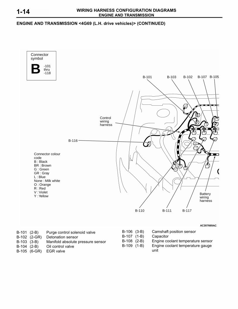
ENGINE AND TRANSMISSION <4G69 (L.H. drive vehicles)> (CONTINUED)
AC307669
Batterywiringharness
Control wiringharness
B-101
B-110
B-103 B-102 B-105
AC
B-107
B-116
B-117B-111
Connectorsymbol
-101thru-118B
Connector colourcodeB : BlackBR : BrownG : Green GR : GrayL : BlueNone : Milk whiteO : OrangeR : RedV : VioletY : Yellow
B-101 (2-B) Purge control solenoid valveB-102 (2-GR) Detonation sensorB-103 (3-B) Manifold absolute pressure sensorB-104 (2-B) Oil control valveB-105 (6-GR) EGR valve
B-106 (3-B) Camshaft position sensorB-107 (1-B) CapacitorB-108 (2-B) Engine coolant temperature sensorB-109 (1-B) Engine coolant temperature gauge
unit

ENGINE AND TRANSMISSIONWIRING HARNESS CONFIGURATION DIAGRAMS 1-15
AC307670AC
B-108
B-115
B-109B-118 B-112 B-113
B-106B-104
B-114
B-110 (3-GR) Ignition coil 1B-111 (3-GR) Ignition coil 2B-112 (4-GR) No.2, 3 cylinder oxygen sensor (Front)B-113 (4-B) No.2, 3 cylinder oxygen sensor (Rear)B-114 (2-B) Back-up lamp switch <M/T>
B-115 (3-B) Vehicle speed sensor <M/T>B-116 (8-GR) Accelerator pedal position sensorB-117 (3-GR) Ignition coil 3B-118 (3-GR) Ignition coil 4

ENGINE AND TRANSMISSIONWIRING HARNESS CONFIGURATION DIAGRAMS1-16
ENGINE AND TRANSMISSIONM3010000400449
4G69 <R.H. drive vehicles>
AC307674
B-04B-02B-01
Control wiringharness
B-31
B-30
B-29 B-37B-27
Batterywiringharness
AB
B-39
B-38
B-07B-09
Connectorsymbol
-01thru-39B
Connector colourcodeB : BlackBR : BrownG : Green GR : GrayL : BlueNone : Milk whiteO : OrangeR : RedV : VioletY : Yellow
B-01 (2-GR) Injector 1B-02 (2-GR) Injector 2B-03 (28-GR) ABS-ECUB-04 (2-GR) Injector 3B-05 (2-GR) Injector 4B-06 (4-B) Throttle position sensorB-07 (5-GR) Windshield wiper motorB-08 (7-B) Air flow sensor
B-09 (2-GR) Brake fluid level switchB-11X (1) Engine speed detection connectorB-14X (4) Throttle valve control servo relayB-16X (4) A/T control relayB-17X (4) Engine control relayB-18X (4) A/C compressor relayB-19 (6-B) Control wiring harness and battery
wiring harness combination
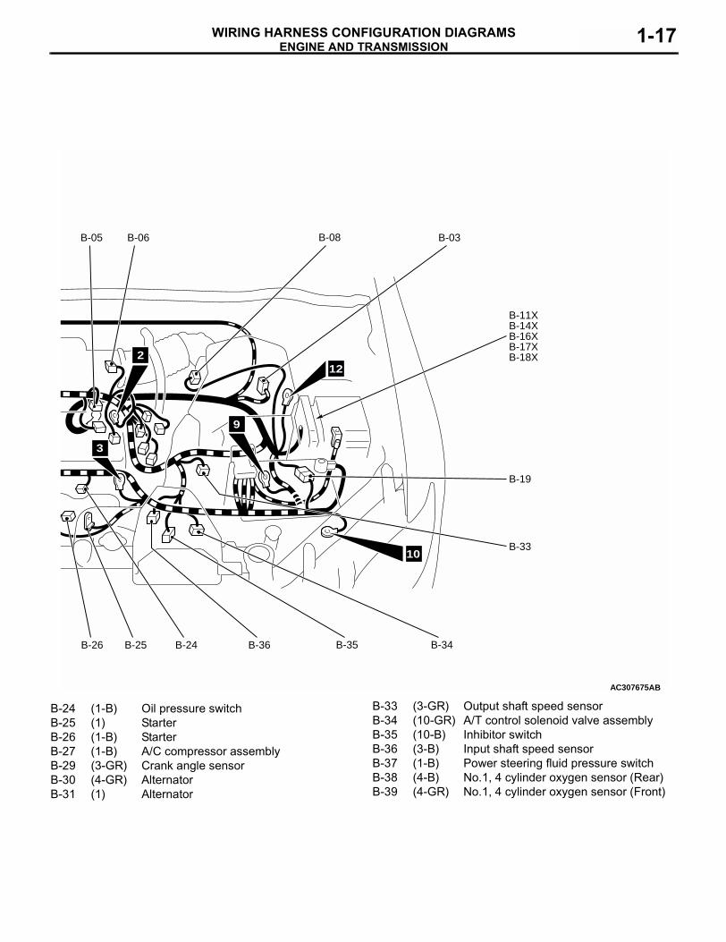
ENGINE AND TRANSMISSIONWIRING HARNESS CONFIGURATION DIAGRAMS 1-17
AC307675
B-05 B-06 B-08 B-03
B-11XB-14XB-16XB-17XB-18X
B-19
B-33
B-34B-35B-36B-24B-25B-26
AB
10
9
12
3
2
B-24 (1-B) Oil pressure switchB-25 (1) StarterB-26 (1-B) StarterB-27 (1-B) A/C compressor assemblyB-29 (3-GR) Crank angle sensorB-30 (4-GR) AlternatorB-31 (1) Alternator
B-33 (3-GR) Output shaft speed sensorB-34 (10-GR) A/T control solenoid valve assemblyB-35 (10-B) Inhibitor switchB-36 (3-B) Input shaft speed sensorB-37 (1-B) Power steering fluid pressure switchB-38 (4-B) No.1, 4 cylinder oxygen sensor (Rear)B-39 (4-GR) No.1, 4 cylinder oxygen sensor (Front)

ENGINE AND TRANSMISSIONWIRING HARNESS CONFIGURATION DIAGRAMS1-18
ENGINE AND TRANSMISSION <4G69 (R.H. drive vehicles)> (CONTINUED)
AC307674
Batterywiringharness
Control wiringharness
B-101
B-110
B-103 B-102 B-105
AC
B-107
B-116
B-117B-111
Connectorsymbol
-101thru-118B
Connector colourcodeB : BlackBR : BrownG : Green GR : GrayL : BlueNone : Milk whiteO : OrangeR : RedV : VioletY : Yellow
B-101 (2-B) Purge control solenoid valveB-102 (2-GR) Detonation sensorB-103 (3-B) Manifold absolute pressure sensorB-104 (2-B) Oil control valve
B-105 (6-GR) EGR valveB-106 (3-B) Camshaft position sensorB-107 (1-B) CapacitorB-108 (2-B) Engine coolant temperature sensor

ENGINE AND TRANSMISSIONWIRING HARNESS CONFIGURATION DIAGRAMS 1-19
AC307675AC
B-108
B-109B-118 B-112 B-113
B-106B-104
B-109 (1-B) Engine coolant temperature gauge unit
B-110 (3-GR) Ignition coil 1B-111 (3-GR) Ignition coil 2B-112 (4-GR) No.2, 3 cylinder oxygen sensor (Front)
B-113 (4-B) No.2, 3 cylinder oxygen sensor (Rear)B-116 (8-GR) Accelerator pedal position sensorB-117 (3-GR) Ignition coil 3B-118 (3-GR) Ignition coil 4

DASH PANELWIRING HARNESS CONFIGURATION DIAGRAMS1-20
DASH PANELDASH PANEL
M3010000600205
L.H. drive vehicles
AC211754
C-01 C-02 C-03 C-04 C-05
C-25
C-24 C-23 C-22AB
Junctionblock
15
14
6
Connectorsymbol
-01thru-36C
18
Connector colourcodeB : BlackBR : BrownG : Green GR : GrayL : BlueNONE : Milk whiteO : OrangeR : RedV : VioletY : Yellow
C-01 (33) J/C (4)C-02 (33) J/C (3)C-03 (6) Fog lamp switch or spare connector
(for fog lamp switch)C-04 (22) Combination meterC-05 (22-L) Combination meterC-06 (16-B) A/C-ECU <Manual A/C>C-07 (4) ClockC-08 (6) Blower switch <Manual A/C>
C-09 (2-R) Air bag module (squib) (passenger's side)
C-10 (7) Instrument panel wiring harness and A/C wiring harness combination <Manual A/C>
C-11 (4) Resistor <Manual A/C>C-12 (2) Blower motor <Manual A/C>C-13 (15-L) Instrument panel wiring harness and
floor wiring harness (RH) combination

DASH PANELWIRING HARNESS CONFIGURATION DIAGRAMS 1-21
AC307677ABC-21 C-20 C-18 C-17 C-16 C-15
C-14
C-13
C-12C-32
Control wiringharness
C-11
C-10C-36
C-09
Instrument panelwiring harness
C-08C-26C-07
C-06C-27
5
4
13
Y
Y
Y
C-14 (10) Instrument panel wiring harness and front wiring harness (RH) combination
C-15 (19-GR) Instrument panel wiring harness and front door wiring harness (RH) combination
C-16 (22-L) J/C (1)C-17 (13-GR) J/C (2)C-18 (4) Oxygen sensor (Rear) <4G63>C-20 (1) Cigarette lighterC-21 (1-B) Cigarette lighterC-22 (4) Hazard warning switch
C-23 (13) Diagnosis connectorC-24 (16-B) Diagnosis connectorC-25 (11) Remote controlled mirror switchC-26 (16-B) A/C-ECU <Automatic A/C>C-27 (20-B) A/C-ECU <Automatic A/C>C-32 (6) Blower linear controller <Automatic
A/C>C-36 (13) Instrument panel wiring harness and
A/C wiring harness combination <Automatic A/C>

DASH PANELWIRING HARNESS CONFIGURATION DIAGRAMS1-22
DASH PANEL <L.H. drive vehicles> (CONTINUED)
AC211754 AC
C-101
JunctionblockC-108
C-118
C-117
C-116
Instrument panelwiring harness
15
14
6
Connectorsymbol
-101thru-143C
C-119
18
Connector colourcodeB : BlackBR : BrownG : Green GR : GrayL : BlueNONE : Milk whiteO : OrangeR : RedV : VioletY : Yellow
C-123 C-127
C-101 (4) Stop lamp switchC-102 (14) Spare connector (for audio)C-103 (2-B) Cigarette lighter illumination lampC-104 (16-B) Instrument panel wiring harness and
control wiring harness combinationC-105 (22) Instrument panel wiring harness and
control wiring harness combinationC-106 (19-GR) Instrument panel wiring harness and
control wiring harness combinationC-107 (2-B) Glove box lamp
C-108 (6-GR) Headlamp leveling switchC-114 (22-Y) SRS-ECUC-115 (20-Y) SRS-ECUC-116 (43) Instrument panel wiring harness and
front wiring harness (LH) combinationC-117 (38) Instrument panel wiring harness and
floor wiring harness (LH) combinationC-118 (32) Instrument panel wiring harness and
front door wiring harness (LH) combination

DASH PANELWIRING HARNESS CONFIGURATION DIAGRAMS 1-23
AC307677AC
C-115 C-114 C-138
Controlwiringharness C-137
C-142
C-136C-141
C-135C-140
C-107C-106C-105C-104C-103C-102
5
13
4C-134C-139
C-143
C-133 C-121
Y
Y
Y
C-119 (6-L) RheostatC-121 (1) Antenna amplifireC-123 (2) Photo sensor <Automatic A/C>C-127 (2) Interior temperature sensor
<Automatic A/C>C-133 (1-B) Spare connector (for audio)C-134 (26) Engine-ECU <4G63>C-135 (16) Engine-ECU <4G63>C-136 (12) Engine-ECU <4G63>C-137 (22) Engine-ECU <4G63>C-138 (26-GR) Engine-ECU <4G69-M/T>
Engine-A/T-ECU <4G69-A/T>
C-139 (27-GR) Engine-ECU <4G69-M/T>Engine-A/T-ECU <4G69-A/T>
C-140 (28-GR) Engine-ECU <4G69-M/T>Engine-A/T-ECU <4G69-A/T>
C-141 (29-GR) Engine-ECU <4G69-M/T>Engine-A/T-ECU <4G69-A/T>
C-142 (30-GR) Engine-ECU <4G69-M/T>Engine-A/T-ECU <4G69-A/T>
C-143 (6) Shift switch assembly

DASH PANELWIRING HARNESS CONFIGURATION DIAGRAMS1-24
DASH PANEL <L.H. drive vehicles> (CONTINUED)
AC207947
C-201 C-202 C-203
C-204
C-205
C-206
C-207
C-208C-209C-210C-211
C-212
C-213
C-214
C-215
C-216
AB
JUNCTION BLOCK (FRONT VIEW)
Connectorsymbol
-201thru-220C
Fuses
C-201 (13) Instrument panel wiring harness and J/B combination
C-202 (14) Instrument panel wiring harness and J/B combination
C-203 (6) Instrument panel wiring harness and J/B combination
C-204 (1-B) Instrument panel wiring harness and J/B combination
C-205 (28) Instrument panel wiring harness and J/B combination
C-206 (5) Defogger relayC-207 (5) Blower relayC-208 (5) Power window relayC-209 (15) Floor wiring harness (LH) and J/B
combination
DASH PANELWIRING HARNESS CONFIGURATION DIAGRAMS 1-25
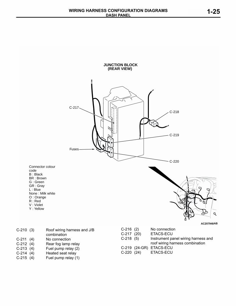
AC207948AB
C-217
C-220
C-219
C-218
JUNCTION BLOCK (REAR VIEW)
Fuses
Connector colourcodeB : BlackBR : BrownG : Green GR : GrayL : BlueNone : Milk whiteO : OrangeR : RedV : VioletY : Yellow
C-210 (3) Roof wiring harness and J/B combination
C-211 (4) No connectionC-212 (4) Rear fog lamp relayC-213 (4) Fuel pump relay (2)C-214 (4) Heated seat relayC-215 (4) Fuel pump relay (1)
C-216 (2) No connectionC-217 (20) ETACS-ECUC-218 (5) Instrument panel wiring harness and
roof wiring harness combinationC-219 (24-GR) ETACS-ECUC-220 (24) ETACS-ECU

DASH PANELWIRING HARNESS CONFIGURATION DIAGRAMS1-26
DASH PANEL <L.H. drive vehicles> (CONTINUED)
AC211756 AB
C-310
Y
C-308
C-307 C-306 C-305 C-304
Instrument panelwiring harness
C-303
Clock spring
STEERING COLUMN
Connectorsymbol
-303thru-316C
C-303 (6) Ignition switchC-304 (7) Key reminder switchC-305 (1) Horn switchC-306 (2) Air bag module (squib) (driver's side)
C-307 (4-Y) Clock springC-308 (6) Clock springC-310 (10) Column switch

DASH PANELWIRING HARNESS CONFIGURATION DIAGRAMS 1-27
AC207956
HEATER UNIT ASSEMBLY
<Manual A/C> <Automatic A/C>
Air thermo sensor(Inlet side)
Air thermo sensor(Outlet side)
C-311 C-311 C-316
C-313 C-314 C-315
AB
A/C wiringharness
C-311 (7) Outside/inside air selection damper control motor
C-313 (6) Air mixing damper control motor and potentiometer <Automatic A/C>
C-314 (2) Heater water temperature sensor <Automatic A/C>
C-315 (6) Mode selection damper control motor and potentiometer <Automatic A/C>
C-316 (2) Air thermo sensor <Automatic A/C>

DASH PANELWIRING HARNESS CONFIGURATION DIAGRAMS1-28
DASH PANELM3010000600238
R.H. drive vehicles
AC307681AB
C-07C-27C-26
C-09
C-36
C-34
C-32
C-17 C-16
1314
15Y
Y
18
Connectorsymbol
-02thru-36C
Instrument panelwiring harness
5
C-28C-29
C-02 (33) J/C (3)C-03 (6) Fog lamp switch or spare connector
(for fog lamp switch)C-04 (22) Combination meterC-05 (22-L) Combination meterC-07 (4) ClockC-09 (2-R) Air bag module (squib) (passenger's
side)C-13 (15-L) Instrument panel wiring harness and
floor wiring harness (RH) combination
C-14 (10) Instrument panel wiring harness and front wiring harness (RH) combination
C-15 (16) Instrument panel wiring harness and front door wiring harness (RH) combination
C-16 (22-L) J/C (1)C-17 (13-GR) J/C (2)C-22 (4) Hazard warning switch
DASH PANELWIRING HARNESS CONFIGURATION DIAGRAMS 1-29
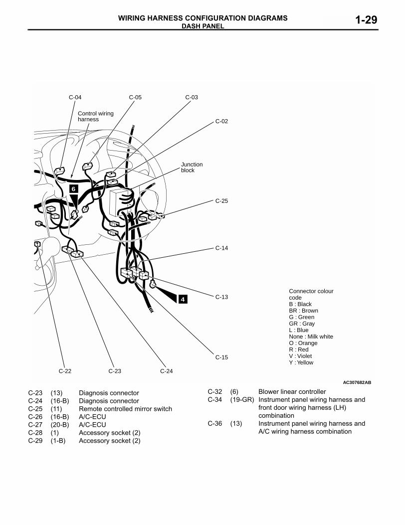
AC307682AB
4
C-04 C-05 C-03
C-02
C-14
C-13
C-15
C-24C-23C-22
C-25
Control wiringharness
Junctionblock
6
Connector colourcodeB : BlackBR : BrownG : Green GR : GrayL : BlueNone : Milk whiteO : OrangeR : RedV : VioletY : Yellow
C-23 (13) Diagnosis connectorC-24 (16-B) Diagnosis connectorC-25 (11) Remote controlled mirror switchC-26 (16-B) A/C-ECUC-27 (20-B) A/C-ECUC-28 (1) Accessory socket (2)C-29 (1-B) Accessory socket (2)
C-32 (6) Blower linear controllerC-34 (19-GR) Instrument panel wiring harness and
front door wiring harness (LH) combination
C-36 (13) Instrument panel wiring harness and A/C wiring harness combination

DASH PANELWIRING HARNESS CONFIGURATION DIAGRAMS1-30
DASH PANEL <R.H. drive vehicles> (CONTINUED)
AC307681AC
Y
C-121 C-102
C-139
C-140 C-141 C-142 C-130 C-129 C-115C-138 C-114
14
15
Y
18
Connectorsymbol
-101thru-142C
C-106C-105C-104
Instrument panelwiring harness
C-107
C-117
C-116
13
5
C-133
C-101 (4) Stop lamp switchC-102 (14) Spare connector (for audio)C-104 (16-B) Instrument panel wiring harness and
control wiring harness combinationC-105 (22) Instrument panel wiring harness and
control wiring harness combinationC-106 (19-GR) Instrument panel wiring harness and
control wiring harness combinationC-107 (2-B) Glove box lamp
C-108 (6-GR) Headlamp leveling switchC-114 (22-Y) SRS-ECUC-115 (20-Y) SRS-ECUC-116 (43) Instrument panel wiring harness and
front wiring harness (LH) combinationC-117 (38) Instrument panel wiring harness and
floor wiring harness (LH) combinationC-119 (6-L) RheostatC-121 (1) Antenna amplifire

DASH PANELWIRING HARNESS CONFIGURATION DIAGRAMS 1-31
AC307682AC
C-123
C-101
C-119
C-108
C-127C-128
4Connector colourcodeB : BlackBR : BrownG : Green GR : GrayL : BlueNone : Milk whiteO : OrangeR : RedV : VioletY : Yellow
Controlwiringharness
Junctionblock
C-122
C-124
6
C-122 (2) Instrument panel wiring harness and control wiring harness combination
C-123 (2) Photo sensorC-124 (2) Instrument panel wiring harness and
control wiring harness combinationC-127 (2) Interior temperature sensorC-128 (1) Parking brake switchC-129 (6) Shift switch assembly
C-130 (2-B) Ashtray illumination lampC-133 (1-B) Spare connector (for audio)C-138 (26-GR) Engine-A/T-ECUC-139 (27-GR) Engine-A/T-ECUC-140 (28-GR) Engine-A/T-ECUC-141 (29-GR) Engine-A/T-ECUC-142 (30-GR) Engine-A/T-ECU

DASH PANELWIRING HARNESS CONFIGURATION DIAGRAMS1-32
DASH PANEL <R.H. drive vehicles> (CONTINUED)
AC207953
C-201 C-202 C-203
C-204
C-205
C-206
C-207
C-208C-221C-210C-211
C-212
C-213
C-214
C-215
C-216
AB
JUNCTION BLOCK (FRONT VIEW)
Connectorsymbol
-201thru-221C
Fuses
C-201 (13) Instrument panel wiring harness and J/B combination
C-202 (14) Instrument panel wiring harness and J/B combination
C-203 (6) Instrument panel wiring harness and J/B combination
C-204 (1-B) Instrument panel wiring harness and J/B combination
C-205 (28) Instrument panel wiring harness and J/B combination
C-206 (5) Defogger relayC-207 (5) Blower relayC-208 (5) Power window relayC-210 (3) Roof wiring harness and J/B
combination

DASH PANELWIRING HARNESS CONFIGURATION DIAGRAMS 1-33
AC207954AB
C-218
C-220
C-219
C-217
JUNCTION BLOCK (REAR VIEW)
Fuses
Connector colourcodeB : BlackBR : BrownG : Green GR : GrayL : BlueNone : Milk whiteO : OrangeR : RedV : VioletY : Yellow
C-211 (4) No connectionC-212 (4) Rear fog lamp relayC-213 (4) Fuel pump relay (2)C-214 (4) No connectionC-215 (4) Fuel pump relay (1)C-216 (2) No connectionC-217 (20) ETACS-ECU
C-218 (5) Instrument panel wiring harness and roof wiring harness combination
C-219 (24-GR) ETACS-ECUC-220 (24) ETACS-ECUC-221 (15) Floor wiring harness (RH) and J/B
combination

DASH PANELWIRING HARNESS CONFIGURATION DIAGRAMS1-34
DASH PANEL <R.H. drive vehicles> (CONTINUED)
AC308210AB
C-305
C-308C-307
C-304
C-303
C-310
Y
Connectorsymbol
-303thru-316C STEERING COLUMN
Clock spring
Instrument panelwiring harness C-306
C-303 (6) Ignition switchC-304 (7) Key reminder switchC-305 (1) Horn switchC-306 (2) Air bag module (squib) (driver's side)
C-307 (4-Y) Clock springC-308 (6) Clock springC-310 (10) Column switch

DASH PANELWIRING HARNESS CONFIGURATION DIAGRAMS 1-35
AC308211
HEATER UNIT ASSEMBLY
C-311 C-316
C-313 C-314 C-315
AB
A/C wiringharness
C-311 (7) Outside/inside air selection damper control motor
C-313 (6) Air mixing damper control motor and potentiometer
C-314 (2) Heater water temperature sensor
C-315 (6) Mode selection damper control motor and potentiometer
C-316 (2) Air thermo sensor

FLOOR AND ROOFWIRING HARNESS CONFIGURATION DIAGRAMS1-36
FLOOR AND ROOFFLOOR AND ROOF
M3010000900659
L.H. drive vehicles
AC211757AB
Connectorsymbol
D
Y
Y
Floor wiringharness (RH)
Y
Y
D-09D-08D-06D-05D-02
D-43
D-42
D-41
D-40
D-39
D-37 D-35 D-32 D-31D-33
16D-38
Control wiringharness
D-02 (8) Floor wiring harness (RH) and rear door wiring harness (RH) combination
D-05 (2) Front room lampD-06 (6-B) Sunroof switchD-08 (2-R) Side air bag module (squib) (LH)D-09 (10) Sunroof motor assemblyD-10 (3) Rear door switch (RH)D-11 (2-GR) Rear room lampD-12 (2) Fuel gauge unit (sub) <4WD>D-13 (2-B) Wheel speed sensor (Rear: RH)
D-14 (6) Rear combination lamp (RH)D-15 (3-B) Fuel gauge unit <2WD>D-16 (5-GR) Fuel pump <2WD> or fuel pump and
gauge unit (main) <4WD>D-17 (1) Accessory socket (1)D-18 (1-B) Accessory socket (1)D-19 (6) Rear combination lamp (LH)D-20 (3) Rear door switch (LH)D-22 (2-B) Wheel speed sensor (Rear: LH)

FLOOR AND ROOFWIRING HARNESS CONFIGURATION DIAGRAMS 1-37
AC211758AB
D-10 D-11 D-12 D-13
Roof wiringharness
D-14 D-15 D-16
D-17
D-18
D-19
Floor wiringharness (LH)
17
D-20
Fuel wiringharness
D-22D-24D-26D-27D-28D-29
Y
Y
7
Connector colourcodeB : BlackBR : BrownG : Green GR : GrayL : BlueNone : Milk whiteO : OrangeR : RedV : VioletY : Yellow
D-24 (8) Floor wiring harness (LH) and fuel wiring harness combination
D-26 (8) Floor wiring harness (LH) and rear door wiring harness (LH) combination
D-27 (2) Side impact sensor (LH)D-28 (3) Front door switch (LH)D-29 (2-B) Seat belt pre-tensioner (LH)D-31 (12-B) Floor wiring harness (RH) and floor
wiring harness (LH) combinationD-32 (3-B) Heated seat assembly (LH)
D-33 (1-B) Parking brake switchD-35 (3-B) G sensorD-37 (2) No connectionD-38 (9) Heated seat switchD-39 (3-B) Heated seat assembly (RH)D-40 (2-R) Side air bag module (squib) (RH)D-41 (2) Side impact sensor (RH)D-42 (3) Front door switch (RH)D-43 (2-B) Seat belt pre-tensioner (RH)

FLOOR AND ROOFWIRING HARNESS CONFIGURATION DIAGRAMS1-38
FLOOR AND ROOFM3010000900671
R.H. drive vehicles
AC307684AB
Connectorsymbol
D
Floor wiringharness (RH)
Y
D-09D-06D-05D-02
D-43
D-42
D-41
D-40
D-08 D-44
16
D-35
Y
Y
Roof wiringharness
D-02 (8) Floor wiring harness (RH) and rear door wiring harness (RH) combination
D-05 (2) Front room lampD-06 (6-B) Sunroof switchD-08 (2-R) Side air bag module (squib) (LH)D-09 (10) Sunroof motor assemblyD-10 (3) Rear door switch (RH)D-11 (2-GR) Rear room lampD-12 (2) Fuel gauge unit (sub)
D-13 (2-B) Wheel speed sensor (Rear: RH)D-14 (6) Rear combination lamp (RH)D-15 (3-B) Fuel gauge unitD-16 (5-GR) Fuel pump and gauge unit (main)D-17 (1) Accessory socket (1)D-18 (1-B) Accessory socket (1)D-19 (6) Rear combination lamp (LH)D-20 (3) Rear door switch (LH)D-22 (2-B) Wheel speed sensor (Rear: LH)

FLOOR AND ROOFWIRING HARNESS CONFIGURATION DIAGRAMS 1-39
AC307685AB
D-10 D-12
D-13
D-15
D-17
Floor wiringharness (LH)
17
D-18
D-20
Fuel wiringharness
D-22D-24D-26D-27D-28D-29
YY
7
Connector colourcodeB : BlackBR : BrownG : Green GR : GrayL : BlueNone : Milk whiteO : OrangeR : RedV : VioletY : Yellow
D-11
D-14
D-19
D-16
D-24 (8) Floor wiring harness (LH) and fuel wiring harness combination
D-26 (8) Floor wiring harness (LH) and rear door wiring harness (LH) combination
D-27 (2) Side impact sensor (LH)D-28 (3) Front door switch (LH)D-29 (2-B) Seat belt pre-tensioner (LH)
D-35 (3-B) G sensorD-40 (2-R) Side air bag module (squib) (RH)D-41 (2) Side impact sensor (RH)D-42 (3) Front door switch (RH)D-43 (2-B) Seat belt pre-tensioner (RH)D-44 (4B) Floor wiring harness (RH) and floor
wiring harness (LH) combination

DOORWIRING HARNESS CONFIGURATION DIAGRAMS1-40
DOORDOOR
M3010001400367
L.H. drive vehicles
AC207961
Connectorsymbol
EE-01 E-03 E-05 E-06 E-07
E-14E-13E-12
Front doorwiringharness (LH)
E-11E-10E-09
Rear doorwiringharness (LH)
E-08
AD
Driver's side
E-01 (8) Power window sub switch (Rear: LH)E-03 (6-GR) Power window motor (Rear: LH)E-05 (14) Power window main switchE-06 (7) Remote controlled mirror (LH)E-07 (2) Tweeter (LH)E-08 (6-B) Door lock actuator (Rear: LH)E-09 (8) Rear door wiring harness (LH) and
rear door sub wiring harness (LH) combination
E-10 (2) Rear door speaker (LH)E-11 (6-B) Door lock actuator (Front: LH)E-12 (16) Front door wiring harness (LH) and
front door sub wiring harness (LH) combination
E-13 (6-GR) Power window motor (Front: LH)

DOORWIRING HARNESS CONFIGURATION DIAGRAMS 1-41
AC207962AD
Front doorwiringharness (RH)
E-15 E-16 E-17 E-18
E-25E-24E-23E-22 E-26 E-27
Rear doorwiringharness (RH)
E-28
E-20 E-21
Passenger's side
E-14 (2) Front door speaker (LH)E-15 (2) Tweeter (RH)E-16 (7) Remote controlled mirror (RH)E-17 (8) Power window sub switch (Front: RH)E-18 (3-B) Door lock key cylinder switch (RH)E-20 (6-GR) Power window motor (Rear: RH)E-21 (8) Power window sub switch (Rear: RH)E-22 (2) Front door speaker (RH)E-23 (6-GR) Power window motor (Front: RH)
E-24 (8) Front door wiring harness (RH) and front door sub wiring harness (RH) combination
E-25 (6-B) Door lock actuator (Front: RH)E-26 (2) Rear door speaker (RH)E-27 (8) Rear door wiring harness (RH) and
rear door sub wiring harness (RH) combination
E-28 (6-B) Door lock actuator (Rear: RH)

DOORWIRING HARNESS CONFIGURATION DIAGRAMS1-42
DOORM3010001400390
R.H. drive vehicles
AC207963AC
Front doorwiringharness (RH)
E-15 E-16
E-25E-32E-23E-22 E-26 E-27
Rear doorwiringharness (RH)
E-28
Driver's side
E-05
E-20 E-21
Connectorsymbol
E
E-01 (8) Power window sub switch (Rear: LH)E-03 (6-GR) Power window motor (Rear: LH)E-04 (3-B) Door lock key cylinder switch (LH)E-05 (14) Power window main switchE-06 (7) Remote controlled mirror (LH)E-07 (2) Tweeter (LH)E-08 (6-B) Door lock actuator (Rear: LH)E-09 (8) Rear door wiring harness (LH) and
rear door sub wiring harness (LH) combination
E-10 (2) Rear door speaker (LH)E-11 (6-B) Door lock actuator (Front: LH)E-13 (6-GR) Power window motor (Front: LH)E-14 (2) Front door speaker (LH)E-15 (2) Tweeter (RH)
DOORWIRING HARNESS CONFIGURATION DIAGRAMS 1-43
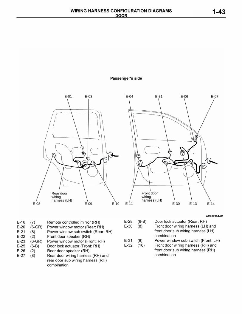
AC207964
E-01 E-03 E-04 E-31 E-06 E-07
E-14E-13E-30
Front doorwiringharness (LH)
E-11E-10E-09
Rear doorwiringharness (LH)
E-08
AC
Passenger's side
E-16 (7) Remote controlled mirror (RH)E-20 (6-GR) Power window motor (Rear: RH)E-21 (8) Power window sub switch (Rear: RH)E-22 (2) Front door speaker (RH)E-23 (6-GR) Power window motor (Front: RH)E-25 (6-B) Door lock actuator (Front: RH)E-26 (2) Rear door speaker (RH)E-27 (8) Rear door wiring harness (RH) and
rear door sub wiring harness (RH) combination
E-28 (6-B) Door lock actuator (Rear: RH)E-30 (8) Front door wiring harness (LH) and
front door sub wiring harness (LH) combination
E-31 (8) Power window sub switch (Front: LH)E-32 (16) Front door wiring harness (RH) and
front door sub wiring harness (RH) combination

TAILGATEWIRING HARNESS CONFIGURATION DIAGRAMS1-44
TAILGATEM3010001900243
AC211759AB
F-01 F-02 F-03 F-04
Floor wiringharness (LH)
F-05
F-06
F-12 F-09 F-08 F-07
Tailgatewiringharness
Rear bumperwiringharness
Defoggerearth
8
Connectorsymbol
F
F-10
Connector colourcodeB : BlackBR : BrownG : Green GR : GrayL : BlueNone : Milk whiteO : OrangeR : RedV : VioletY : Yellow
Floor wiringharness (LH)
F-01 (1) Defogger (−)F-02 (4) Rear wiper motorF-03 (2) High-mounted stop lampF-04 (1-B) Defogger (+)F-05 (10) Floor wiring harness (LH) and tailgate
wiring harness combinationF-06 (6-B) Tailgate lock actuator
F-07 (1-B) Tailgate switchF-08 (2-GR) Licence plate lamp (RH)F-09 (4-GR) Floor wiring harness (LH) and rear
bumper wiring harness combinationF-10 (2-GR) Licence plate lamp (LH)F-12 (2-B) Rear fog lamp