CATIA Electrical Harness Design - Wichita State University
37
CATIA Electrical Harness Design CATIA® V5R30 TABLE OF CONTENTS Introduction .............................................................. 1 Electrical Harness Design ............................................. 2 Electrical Harness Assembly Workbench ................................. 4 Bottom Toolbar ..................................................... 5 Measure ..................................................... 5 Electrical Harness Design ................................................... 7 Defining Geometric Bundles ........................................... 7 Installing Geometric Bundles ......................................... 17 Defining Geometric Bundles in Context ................................. 21 Defining Geometric Bundles on Surfaces ................................ 31 Multiple Bundle Segments within a Geometric Bundle ..................... 43 Defining Multi-Branchable Bundles .................................... 51 Bundle Profiles .................................................... 62 Bundles on Curves .................................................. 78 Modifying Multi-Branchables ......................................... 81 Supports .......................................................... 95 Supports inside the Geometrical Bundle ........................... 95 Supports Outside the Geometrical Bundle ......................... 101 Adding Supports ............................................ 107 Removing Supports .......................................... 117 Multi-Position Supports ....................................... 120 Adaptive Supports ........................................... 125 Position Bundles in Supports ................................... 132 Local Slack ................................................ 147 Protective Coverings ............................................... 153 Modifying Protective Covering ................................. 160 Protective Covering with Supports .............................. 162 Protective Covering with Adaptive Supports ...................... 166 Adjusting Protective Coverings ................................. 168 FLEX Algorithm ............................................ 172 FLEX Algorithm with Constrained Length ........................ 179 Geometrical Bundle Analysis ........................................ 183 Related Objects ............................................. 183 Inertia Measurements ......................................... 190 Geometrical Bundle Equivalents ................................ 192 Clash Analysis .............................................. 194 Modifying Geometric Bundles ....................................... 198 Table of Contents, Page i © Wichita State University
-
Upload
khangminh22 -
Category
Documents
-
view
1 -
download
0
Transcript of CATIA Electrical Harness Design - Wichita State University

CATIA Electrical Harness Design CATIA® V5R30
TABLE OF CONTENTS
Introduction . . . . . . . . . . . . . . . . . . . . . . . . . . . . . . . . . . . . . . . . . . . . . . . . . . . . . . . . . . . . . . 1Electrical Harness Design . . . . . . . . . . . . . . . . . . . . . . . . . . . . . . . . . . . . . . . . . . . . . 2Electrical Harness Assembly Workbench . . . . . . . . . . . . . . . . . . . . . . . . . . . . . . . . . 4Bottom Toolbar . . . . . . . . . . . . . . . . . . . . . . . . . . . . . . . . . . . . . . . . . . . . . . . . . . . . . 5
Measure . . . . . . . . . . . . . . . . . . . . . . . . . . . . . . . . . . . . . . . . . . . . . . . . . . . . . 5
Electrical Harness Design . . . . . . . . . . . . . . . . . . . . . . . . . . . . . . . . . . . . . . . . . . . . . . . . . . . 7Defining Geometric Bundles . . . . . . . . . . . . . . . . . . . . . . . . . . . . . . . . . . . . . . . . . . . 7Installing Geometric Bundles . . . . . . . . . . . . . . . . . . . . . . . . . . . . . . . . . . . . . . . . . 17Defining Geometric Bundles in Context . . . . . . . . . . . . . . . . . . . . . . . . . . . . . . . . . 21Defining Geometric Bundles on Surfaces . . . . . . . . . . . . . . . . . . . . . . . . . . . . . . . . 31Multiple Bundle Segments within a Geometric Bundle . . . . . . . . . . . . . . . . . . . . . 43Defining Multi-Branchable Bundles . . . . . . . . . . . . . . . . . . . . . . . . . . . . . . . . . . . . 51Bundle Profiles . . . . . . . . . . . . . . . . . . . . . . . . . . . . . . . . . . . . . . . . . . . . . . . . . . . . 62Bundles on Curves . . . . . . . . . . . . . . . . . . . . . . . . . . . . . . . . . . . . . . . . . . . . . . . . . . 78Modifying Multi-Branchables . . . . . . . . . . . . . . . . . . . . . . . . . . . . . . . . . . . . . . . . . 81Supports . . . . . . . . . . . . . . . . . . . . . . . . . . . . . . . . . . . . . . . . . . . . . . . . . . . . . . . . . . 95
Supports inside the Geometrical Bundle . . . . . . . . . . . . . . . . . . . . . . . . . . . 95Supports Outside the Geometrical Bundle . . . . . . . . . . . . . . . . . . . . . . . . . 101Adding Supports . . . . . . . . . . . . . . . . . . . . . . . . . . . . . . . . . . . . . . . . . . . . 107Removing Supports . . . . . . . . . . . . . . . . . . . . . . . . . . . . . . . . . . . . . . . . . . 117Multi-Position Supports . . . . . . . . . . . . . . . . . . . . . . . . . . . . . . . . . . . . . . . 120Adaptive Supports . . . . . . . . . . . . . . . . . . . . . . . . . . . . . . . . . . . . . . . . . . . 125Position Bundles in Supports . . . . . . . . . . . . . . . . . . . . . . . . . . . . . . . . . . . 132Local Slack . . . . . . . . . . . . . . . . . . . . . . . . . . . . . . . . . . . . . . . . . . . . . . . . 147
Protective Coverings . . . . . . . . . . . . . . . . . . . . . . . . . . . . . . . . . . . . . . . . . . . . . . . 153Modifying Protective Covering . . . . . . . . . . . . . . . . . . . . . . . . . . . . . . . . . 160Protective Covering with Supports . . . . . . . . . . . . . . . . . . . . . . . . . . . . . . 162Protective Covering with Adaptive Supports . . . . . . . . . . . . . . . . . . . . . . 166Adjusting Protective Coverings . . . . . . . . . . . . . . . . . . . . . . . . . . . . . . . . . 168FLEX Algorithm . . . . . . . . . . . . . . . . . . . . . . . . . . . . . . . . . . . . . . . . . . . . 172FLEX Algorithm with Constrained Length . . . . . . . . . . . . . . . . . . . . . . . . 179
Geometrical Bundle Analysis . . . . . . . . . . . . . . . . . . . . . . . . . . . . . . . . . . . . . . . . 183Related Objects . . . . . . . . . . . . . . . . . . . . . . . . . . . . . . . . . . . . . . . . . . . . . 183Inertia Measurements . . . . . . . . . . . . . . . . . . . . . . . . . . . . . . . . . . . . . . . . . 190Geometrical Bundle Equivalents . . . . . . . . . . . . . . . . . . . . . . . . . . . . . . . . 192Clash Analysis . . . . . . . . . . . . . . . . . . . . . . . . . . . . . . . . . . . . . . . . . . . . . . 194
Modifying Geometric Bundles . . . . . . . . . . . . . . . . . . . . . . . . . . . . . . . . . . . . . . . 198
Table of Contents, Page i© Wichita State University

CATIA Electrical Harness Design CATIA® V5R30
Electrical Flattening . . . . . . . . . . . . . . . . . . . . . . . . . . . . . . . . . . . . . . . . . . . . . . . . . . . . . . 219Harness Flattening Parameters . . . . . . . . . . . . . . . . . . . . . . . . . . . . . . . . . . . . . . . . 219Extracting . . . . . . . . . . . . . . . . . . . . . . . . . . . . . . . . . . . . . . . . . . . . . . . . . . . . . . . . 226
Extract with Supports . . . . . . . . . . . . . . . . . . . . . . . . . . . . . . . . . . . . . . . . . 229Flattening . . . . . . . . . . . . . . . . . . . . . . . . . . . . . . . . . . . . . . . . . . . . . . . . . . . . . . . . 234Flattening Orientation . . . . . . . . . . . . . . . . . . . . . . . . . . . . . . . . . . . . . . . . . . . . . . 249Flattening Scaling . . . . . . . . . . . . . . . . . . . . . . . . . . . . . . . . . . . . . . . . . . . . . . . . . 252Roll - Rotate - Scale . . . . . . . . . . . . . . . . . . . . . . . . . . . . . . . . . . . . . . . . . . . . . . . . 256Synchronization . . . . . . . . . . . . . . . . . . . . . . . . . . . . . . . . . . . . . . . . . . . . . . . . . . . 290
Problems . . . . . . . . . . . . . . . . . . . . . . . . . . . . . . . . . . . . . . . . . . . . . . . . . . . . . . . . . . . . . . 303Problem #1.0 . . . . . . . . . . . . . . . . . . . . . . . . . . . . . . . . . . . . . . . . . . . . . . . . . . . . . 303Problem #2.0 . . . . . . . . . . . . . . . . . . . . . . . . . . . . . . . . . . . . . . . . . . . . . . . . . . . . . 304Problem #3.0 . . . . . . . . . . . . . . . . . . . . . . . . . . . . . . . . . . . . . . . . . . . . . . . . . . . . . 305
Appendix A . . . . . . . . . . . . . . . . . . . . . . . . . . . . . . . . . . . . . . . . . . . . . . . . . . . . . . . . . . . . 307Equipment & Systems - Electrical Harness Discipline - Electrical Assembly Design
- General . . . . . . . . . . . . . . . . . . . . . . . . . . . . . . . . . . . . . . . . . . . . . . . . . . 307Equipment & Systems - Electrical Harness Discipline - Electrical Assembly Design
- Electrical Library Access . . . . . . . . . . . . . . . . . . . . . . . . . . . . . . . . . . . . 308Equipment & Systems - Electrical Harness Discipline - Electrical Harness
Installation - Harness Management . . . . . . . . . . . . . . . . . . . . . . . . . . . . . . 309Equipment & Systems - Electrical Harness Discipline - Electrical Harness Flattening
- General . . . . . . . . . . . . . . . . . . . . . . . . . . . . . . . . . . . . . . . . . . . . . . . . . . 312
Table of Contents, Page ii ©Wichita State University

CATIA Electrical Harness Design CATIA® V5R30
IntroductionCATIA Version 5 Electrical Harness DesignUpon completion of this course the student should have a full understanding of thefollowing topics:
- Define geometric bundles
- Define complete harnesses of a dynamic length
- Define complete harnesses of a static length
- Develop harnesses within the context of a product
- Develop and utilize a harness in multiple products
Introduction, Page 1© Wichita State University

CATIA Electrical Harness Design CATIA® V5R30
Electrical Harness DesignDefining an electrical harness requires two steps. You must first define the requiredconnectors and connection points. Once you have these connections, you are ready to begindefining the geometric bundle that links the various connection points. These geometricbundles will behave as a space reservation for the wiring they will contain. In this sectionof the course, you will not be defining the actual wires within the geometric bundle, butrather just the overall size and shape of the geometric bundle that will contain the wiring.
There are two workbenches involved in electrical harness design. They are the ElectricalHarness Assembly and the Electrical Harness Installation workbenches. The ElectricalHarness Assembly workbench will allow you to work with the geometric bundle as a whole. The Electrical Harness Installation workbench will allow you to define the specific bundlesegment and route the bundle. The two workbenches are used simultaneously to define thegeometric bundle. Although the Electrical Harness Installation workbench is a separateworkbench, it is generally only accessed through the Electrical Harness Assemblyworkbench when defining a specific bundle segment. This is a similar behavior to theSketcher and Part Design workbenches. You generally do not access the sketcherworkbench directly, but instead you access sketcher through the Part Design workbench. Inour case, the Electrical Harness Assembly workbench works in the product environment,whereas the Electrical Harness Installation workbench works with a specific branchablepart in the product.
In this course, you will not be defining the specific wires within the geometric bundle. Instead, you will be defining the bundle as a whole for space reservation and connectivityinformation and not to define pin to pin connectivity. To define pin to pin connectivity, youwill need to study the Electrical Wire Routing workbench. With that said, keep in mind,you can always define a geometric bundle per wire if desired. This will emulate definingspecific connectivity, but you will find that it requires a lot of time and work when dealingwith smaller wires.
Introduction, Page 2 ©Wichita State University

CATIA Electrical Harness Design CATIA® V5R30
Electrical Harness Installation Workbench
Selection options
Exits the Electrical HarnessInstallation workbench back tothe Electrical Harness Assemblyworkbench
Defines a bundle segment
Defines a branch
Adds a branch point
Removes a branch point
Creates a point
Creates a line
Creates a plane
Deletes a bundle
Light Protective Covering
Introduction, Page 3© Wichita State University

CATIA Electrical Harness Design CATIA® V5R30
Electrical Harness Assembly Workbench
Selection options
Product selection options
Creates a geometrical bundle
Creates a multi-branchablebundle segment
Creates a bundle segment
Adds local slack to bundle
Adds a protective covering to abundle
Deletes a bundle
Links a bundle
Unlinks a bundle
Adds a support
Removes a support
Splits a bundle
Adds a branch point
Removes a branch point
Transfers branches
Duplicates a harness
Adjusts a bundle
Arranges bundle segments withina support
Copies a bundle segment’sposition from one support toanother
Updates a bundle from thesupport
Allows changes in the branchroute for a more realisticcurvature
Displays the related objects to aselected electrical device
Introduction, Page 4 ©Wichita State University

CATIA Electrical Harness Design CATIA® V5R30
Bottom ToolbarThese options appear when you are in the Electrical Harness Assembly workbench.
MeasureThere is only one new icon within this toolbar.
Measures the inertia of a geometrical bundle
Introduction, Page 5© Wichita State University

CATIA Electrical Harness Design CATIA® V5R30
This page is intentionally left blank.
Introduction, Page 6 ©Wichita State University

CATIA Electrical Harness Design CATIA® V5R30
Electrical Harness DesignIn this section, you will look at developing a simple single branch harness. Keep in mind,you will be using both the Electrical Harness Assembly and Electrical Harness Installationworkbenches. These two workbenches work together to define the harness and the bundles.
Defining Geometric BundlesIn this first exercise, you are going to look at creating a basic geometric bundle betweentwo connectors. As you continue through this book, you will find the harnesses andbundles becoming more and more complex as the options are covered in more detail.
Create a new product named Harness 1. This new product will serve as your firstharness.
If not already there, switch to the Electrical Harness Assembly workbench. This willallow you to build the electrical harness. It is available under the Equipment & Systemssolution and the Electrical Harness Discipline.
Notice there is not an icon to insert an existing component into the product. This is not anissue since you can use the Insert pull down menu or right click on the product.
Right click on Harness 1 in the specification tree and select Components, ExistingComponent. This will display the File Selection window.
Single Bundles, Page 7© Wichita State University
CATIA Electrical Harness Design CATIA® V5R30
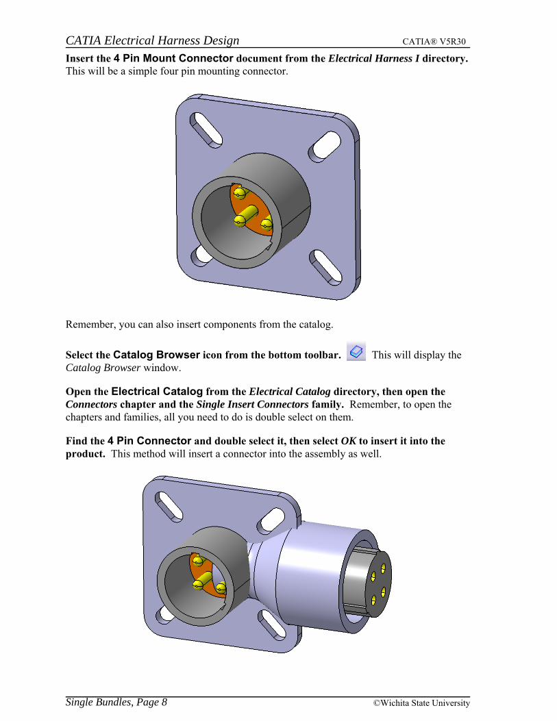
Insert the 4 Pin Mount Connector document from the Electrical Harness I directory. This will be a simple four pin mounting connector.
Remember, you can also insert components from the catalog.
Select the Catalog Browser icon from the bottom toolbar. This will display theCatalog Browser window.
Open the Electrical Catalog from the Electrical Catalog directory, then open theConnectors chapter and the Single Insert Connectors family. Remember, to open thechapters and families, all you need to do is double select on them.
Find the 4 Pin Connector and double select it, then select OK to insert it into theproduct. This method will insert a connector into the assembly as well.
Single Bundles, Page 8 ©Wichita State University
CATIA Electrical Harness Design CATIA® V5R30
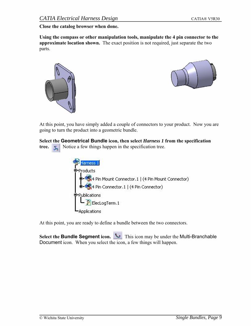
Close the catalog browser when done.
Using the compass or other manipulation tools, manipulate the 4 pin connector to theapproximate location shown. The exact position is not required, just separate the twoparts.
At this point, you have simply added a couple of connectors to your product. Now you aregoing to turn the product into a geometric bundle.
Select the Geometrical Bundle icon, then select Harness 1 from the specificationtree. Notice a few things happen in the specification tree.
At this point, you are ready to define a bundle between the two connectors.
Select the Bundle Segment icon. This icon may be under the Multi-BranchableDocument icon. When you select the icon, a few things will happen.
Single Bundles, Page 9© Wichita State University

CATIA Electrical Harness Design CATIA® V5R30
By selecting on the Bundle Segment icon, you will automatically be switched into theElectrical Harness Installation workbench, as well as have a bundle segment created in thespecification tree.
Single Bundles, Page 10 ©Wichita State University

CATIA Electrical Harness Design CATIA® V5R30
At this point, you are ready to define the bundle segment. Take a moment to examine theBundle Segment Definition window.
Name Specifies the name of the bundle
Diameter Specifies the outside diameter of the bundle
Section Specifies the cross sectional area of the bundle
Bend Radius Specifies the minimum bend radius allowed for the bundle
Bend Radius Ratio Defines the bend radius based on the diameter of the bundle. A ratioof 1 will set the Bend Radius to the same size as the bundle Diameter.
Build Mode
Mode
Slack Bundles are computed with a minimum distance, andthen a percentage of slack is added to the bundle
Length Bundles are a set length, regardless of the amount ofslack
Bend CATIA will compute the minimum length possiblewhile respecting the Bend Radius
Slack (%) Defines the percentage of slack between connection points. Although 0% is allowed, there needs to be a slack of at least.1% to avoid update errors with Harness Flattening tools.
Single Bundles, Page 11© Wichita State University
CATIA Electrical Harness Design CATIA® V5R30
Length Defines the length of the bundle when in Length mode. Thelength must be as long, or longer than the distance betweenthe two connection points.
Route Definition Defines the bundle route
Bundle Segment... Allows for the bundle to swap sides of a surface that is attached tothe bundle
External Curve Allows selection of a curve to define the bundle route
Many of these parameters will be tested further once the route is defined.
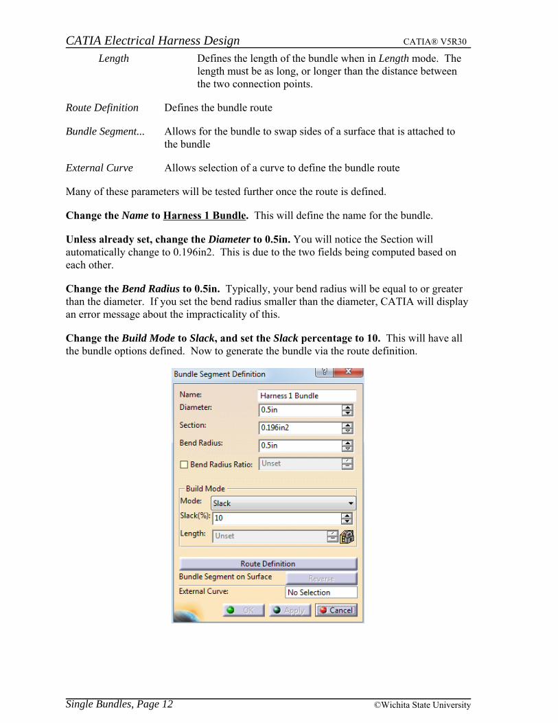
Change the Name to Harness 1 Bundle. This will define the name for the bundle.
Unless already set, change the Diameter to 0.5in. You will notice the Section willautomatically change to 0.196in2. This is due to the two fields being computed based oneach other.
Change the Bend Radius to 0.5in. Typically, your bend radius will be equal to or greaterthan the diameter. If you set the bend radius smaller than the diameter, CATIA will displayan error message about the impracticality of this.
Change the Build Mode to Slack, and set the Slack percentage to 10. This will have allthe bundle options defined. Now to generate the bundle via the route definition.
Single Bundles, Page 12 ©Wichita State University

CATIA Electrical Harness Design CATIA® V5R30
Select Route Definition. This will allow you to define the route for the bundle. The RouteDefinition window will display. Take a quick look at the various options in the RouteDefinition window.
Routed Objects / Tangent Dir. This area displays the objects and points for the routedefinition
Add after Adds points and connection points after the selectedpoint
Add before Adds points and connection points before the selectedpoint
Replace Replaces the selected point with another selection
Remove Removes the selected point
Geometry on support Allows bundles to be placed on surfaces or othersupport parts
Single Bundles, Page 13© Wichita State University

CATIA Electrical Harness Design CATIA® V5R30
By selecting the More>> button, you get a few additional options.
Tangent management
Constraint type Defines the type of tangency to be defined
Explicit Tangency is defined via a manual vector definition. Tangency definition is defined through a right click in theTangent Direction field.
From curve Tangency is defined from a curve or line selection. WhenFrom curve is selected, the Tangent direction changes toElement.
Slack management, Ignore Slack Ignores or removes slack between points
Single Bundles, Page 14 ©Wichita State University

CATIA Electrical Harness Design CATIA® V5R30
Offset Management at Creation
Automatic Lays the bundle on the surface
Automatic with Safety Margin Lays the bundle on the surface with anadditional offset of the safety margin distance
Manual Allows you to specify a specific distance forthe bundle to exist off the surface
Now you are ready to define the route.
Select the 4 Pin Mount Connector. Notice the connector is automatically added to theRoute Definition window, as well as the bundle connection point is automatically defined.
Anytime you select an electrical device with a bundle connection point, the connectionpoint will automatically be selected and the tangent direction will automatically be definedin the Initial Condition direction defined in the bundle connection point’s placementconstraints.
Select the 4 Pin Connector. This connector will also be defined in the routed objects. Notice the bundle is now present.
Note: The physical shape of the bundle may vary based on the position of the twoconnectors.
Single Bundles, Page 15© Wichita State University

CATIA Electrical Harness Design CATIA® V5R30
Select OK to the Route Definition window. This will take you back to the Bundle SegmentDefinition.
Select OK to the Bundle Segment Definition window. The bundle is defined.
Notice that you are still in the Electrical Harness Installation workbench.
Select the Exit icon. This will take you back to the Electrical Harness Assemblyworkbench.
Save your harness. When you save, you will be prompted to save the Harness 1 Bundle aswell. Be sure you save the bundle into the same directory. Save Management would be agood option to use when saving your bundles. Leave your harness open, it will be used inthe next section.
Single Bundles, Page 16 ©Wichita State University

CATIA Electrical Harness Design CATIA® V5R30
Defining Multi-Branchable BundlesAlthough single branch bundles are very useful for simple geometric bundles, you willoften find that you are not able to create the necessary bundles with just a single bundle. The most common type of bundle used, even for a simple straight geometric bundle, is amulti-branchable bundle.
Open the Multi-Branchable 1 document from the Multi-Branchable 1 directory. Youwill create a multi-branchable document of a simple harness of three connectors in a “Y”configuration.
If not already there, switch to the Electrical Harness Assembly workbench. Defining amulti-branchable bundle initially is going to be no different than a single branchabledocument.
Select the Geometrical Bundle icon, then select the Multi-Branchable 1 product. This will convert the entire product into a geometric bundle.
At this point, you are ready to define the bundle segment.
Multi-Branchable Bundles, Page 51© Wichita State University

CATIA Electrical Harness Design CATIA® V5R30
Select the Multi-Branchable Document icon. This will start a multi-branchablebundle segment. You will notice the branch definition is very similar to the bundle segmentdefinition used before. Also, take note that you were automatically switched into theElectrical Harness Installation workbench, just as before. Take a moment to notice the fewdifferences.
Bundle Segment Definition This will allow you to control each specific bundlesegment. This option is only available after youdefine the route of the branch.
Change the Name of the branch to Main Branch. This will set the name of the firstbranch you are going to create.
Change the Diameter to 0.5in and the Bend Radius to 1.0in. Just as the single bundlesegment, it is a good rule of thumb to make sure that your bend radius is larger than yourbundle diameter.
With the Build Mode set to Slack, set the Slack percentage to 5.0. Now you are ready todefine the route.
Multi-Branchable Bundles, Page 52 ©Wichita State University
CATIA Electrical Harness Design CATIA® V5R30
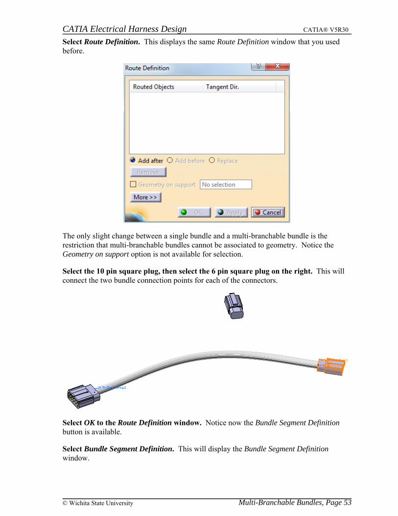
Select Route Definition. This displays the same Route Definition window that you usedbefore.
The only slight change between a single bundle and a multi-branchable bundle is therestriction that multi-branchable bundles cannot be associated to geometry. Notice theGeometry on support option is not available for selection.
Select the 10 pin square plug, then select the 6 pin square plug on the right. This willconnect the two bundle connection points for each of the connectors.
Select OK to the Route Definition window. Notice now the Bundle Segment Definitionbutton is available.
Select Bundle Segment Definition. This will display the Bundle Segment Definitionwindow.
Multi-Branchable Bundles, Page 53© Wichita State University

CATIA Electrical Harness Design CATIA® V5R30
Take a moment to look over the various options.
1 – Bundle Segment Definition This area allows you to view the various bundlesegments in a multi-branchable geometric bundle
Name Specifies the name of the bundle segment
Diameter Specifies the diameter of the bundle segment
Color Specifies the color of the bundle segment
Extremity Management
Start point Defines the ratio of the curve the branch point starts
End point Defines the ratio of the curve length the branch pointends
Visualization Management
Reframe on Selection Reframes and fits the bundle segment in the display
Add Branch Point Creates an additional branch point along the curve. Displays the Create Branch Point window when abundle is selected
Multi-Branchable Bundles, Page 54 ©Wichita State University

CATIA Electrical Harness Design CATIA® V5R30
Support Defines the bundle segment selected
Reference Defines the reference point the ratio or length is derived from
Other Extremity Changes extremity used when referencing the endpoints of abundle segment
Distance to reference object
Length Defines the distance along the curve the branch pointwill exist
Ratio Defines a percentage distance along a curve thebranch point exists
Invert Orientation Inverts and reverses the reference direction
Remove Branch Point Removes branch points in a bundle
At this point, you are ready to define the branch point.
Change the Name of the bundle segment to Segment 1. You will notice this changes thename of the bundle segment in the bundle segment definition area.
Change the Color to light blue. The exact shade of blue is not important, you just want tosee that the color of the bundle can be changed.
Now to add a branch point.
Multi-Branchable Bundles, Page 55© Wichita State University

CATIA Electrical Harness Design CATIA® V5R30
Select the Add a Branch Point icon. Once you select the icon, the system will waituntil you select the bundle segment you want to add the branch point in.
Select your blue bundle segment near the 10 pin square plug. This will display theCreate Branch Point window, as well as show the reference point and reference direction.
Select Other Extremity. This will switch sides of the reference point.
At this point, you need to determine how you want the branch point defined. In this case,assume you want the branch point defined a particular distance away from the otherconnector.
Change the Distance to reference object definition to Length, then set a Length of 6.0in. This will set the distance exactly to 6 inches. Now, no matter how long the geometricbundle becomes when you install it, the distance to the break point will always be 6 inches. If you were to set it to a ratio, then the distance would adjust based on the length of thebundle.
Multi-Branchable Bundles, Page 56 ©Wichita State University

CATIA Electrical Harness Design CATIA® V5R30
Select OK when done. This will split the bundle into two segments. Notice your bundlesegment was renamed back to the default naming scheme.
With the first bundle segment selected in the window, change the Color to yellow. Thiswill help you keep track of the various bundle segments.
Also, notice the start and end points in the Extremity Management. These values are nowaccessible to adjust the start and end locations of the bundle segments.
Select bundle No 2 and change the Diameter to 0.375in. You may need to select Apply toget the bundle to update properly.
Select OK to the Bundle Segment Definition window. This will have the new bundlesegment defined.
Multi-Branchable Bundles, Page 57© Wichita State University

CATIA Electrical Harness Design CATIA® V5R30
Select OK to the Branch Definition window. This will create the bundle.
While in the Electrical Harness Installation workbench, select the Branch Definitionicon. This will allow you to create a new branch within the bundle.
Change the Name to Side Branch, then set the Diameter to 0.375in. Now you are readyto define the route for the side branch.
Select Route Definition. At this point, you can select any of the connectors or branchpoints to start the route. When you select a branch point, the bundle you select will helpdetermine what extremity the branch will associate to.
Select the yellow bundle near the split. Notice a point and arrow is shown on the bundle.
Multi-Branchable Bundles, Page 58 ©Wichita State University

CATIA Electrical Harness Design CATIA® V5R30
Select the other 6 pin square plug. This will add the branch.
Look closely at the specification tree.
Both the part instance and the branch itself have an exclamation point with a yellow ovalaround it to indicate that the bend radius might not have been respected. This is not acritical error, but it is something you will want to watch for when you install the harnessinto your assembly. If you find that you still have radius issues at installation, then youmay need to look at adjusting the branch point or adding additional slack.
Select OK to the Route Definition window and the Branch Definition window. This willhave the next bundle segment defined.
Exit the Electrical Harness Installation workbench, then save and close yourdocument.
Multi-Branchable Bundles, Page 59© Wichita State University

CATIA Electrical Harness Design CATIA® V5R30
Open the Connections product in the Multi-Branchable 1 Installation directory. Thisis a simple box to put the wire harness you just created into.
With the right mouse button, select on the Connections product from the specificationtree. Select Components, Existing Component. This will display the File Selectionwindow to allow you to insert your harness.
Select the wire harness you just created. You could also select the Multi-Branchable 1product from the Multi-Branchable 1 Installation directory. This is the same product youjust created.
At this point, you are ready to begin making the necessary connections to install the harnessinto the box.
If not already there, switch to the Electrical Assembly Design workbench. Since youare connecting two electrical connectors together, you can use the assemble electricaldevices tools from the electrical assembly design workbench.
Select the Connect Electrical Devices icon, then select the connector on the bluebundle segment. This will indicate what connector you are going to connect first.
Select the left connector. This connector is shown here.
Multi-Branchable Bundles, Page 60 ©Wichita State University

CATIA Electrical Harness Design CATIA® V5R30
You may get a Computation Warning Report, close it
Take note of the resulting wire bundle.
Notice the bundle split. Since you defined the split point to be 6 inches from the end of theblue bundle, no matter how long the main bundle segment becomes, the split point willalways be 6 inches from that end. The white and yellow bundle segments will dynamicallyresize since they were not limited by length.
Select the Disconnect Electrical Devices icon, then select the two connectors youjust attached together. This will electrically disconnect the two connections.
Select the Connect Electrical Devices icon again, then select the connector on theblue bundle segment and the right hand connector. This will connect it to theother connector.
Multi-Branchable Bundles, Page 61© Wichita State University

CATIA Electrical Harness Design CATIA® V5R30
Connect the other connectors. It should appear as shown.
Notice the twisted bundle. This will get fixed as you begin adding supports and other linksto your bundles.
Save and close your document.
Bundle ProfilesAlthough currently you are solely working with round bundles, you will have situationswhere you want to work with different shaped bundles. CATIA will allow you toautomatically generate a few different shaped profiles.
Open the Flat Bundle product from the Flat Bundle directory. This will be a simplestraight bundle segment from one flat connector to another.
In this exercise, you are going to make a simple flat bundle from one connector to the other. In order to make your bundles a different shape, other than round, you must set a Tools,Option that allows this to happen.
Multi-Branchable Bundles, Page 62 ©Wichita State University

CATIA Electrical Harness Design CATIA® V5R30
When you are finished your model should look similar to the picture below.
Double select the Flattening Parameters and select the Flattening Scaling tab.
Under the Apply factor to area, select the Additional length > Limited length option. This option changes the scaling so that a scaled segment will never be shorter than a nonscaled segment. If the Additional length > Limited length option is checked, then CATIAwill take the amount that the segment is over the Limited length divided by two and add itback to the Limited length. For example: For a 9 inch segment with a 6 inch Limited length,the segment is three inches over the limit length. Half of three inches is 1.5 and 1.5 plus 6yields a final bundle segment length of 7.5 inches. Using this option guarantees that longerbundle segments will not end up shorter than original bundle segments. In the aboveexample, with the Bundle segment whole length option, a nine inch segment becomes 4.5inches and would be shorter than a 5 inch segment that was flattened and scaled at the sametime. This might cause visualization problems.
Change the Limited length to 8.0in and select OK.
Select the Flatten icon and select Geometrical Bundle3.1 from the specification tree. This will specify that the entire bundle should be flattened.
Electrical Flattening, Page 254 ©Wichita State University

CATIA Electrical Harness Design CATIA® V5R30
Select OK. Notice the model is flattened and scaled, while the dimensions and connectorsremain in their original locations.
Notice the bundle that was under 8in remained the same length while the others werescaled.
Double select the Flattening Parameters again and select the Flattening Scaling tab. Notice that the measurements all update so you will have two identical measurements ofeach length.
Select the If the bundle segment length is greater than option. This option will changeany segment that is greater than the set length back to the set length.
Enter a value of 8.0in and select OK.
Select the Flatten icon and select the geometrical bundle from the specification treeand select OK. The bundle should be scaled down smaller than it was for the firstscaling. In this manner you can scale geometric bundles more than once and you can alsoscale just one segment at a time by selecting the segments in the graphical display. Themodel should appear as shown.
Save and close your document.
Electrical Flattening, Page 255© Wichita State University

CATIA Electrical Harness Design CATIA® V5R30
Roll - Rotate - ScaleOnce a bundle has been flattened it may need to be modified to fit within a certain area likea form board. The following options will help orient a flattened bundle.
Open the Roll - Rotate - Scale document from the Roll - Rotate - Scale directory. Itshould appear as shown.
Flatten the geometrical bundle. The model should appear as shown.
Select the Arrange Junction - Umbrella-Like icon.
Select the junction as shown above. The Arrange Junction definition window will appear.
Electrical Flattening, Page 256 ©Wichita State University

CATIA Electrical Harness Design CATIA® V5R30
The angle entered will be the angle from one to two and two to three. The graphical areawill have a preview of how the harness will be modified.
Change the value to 30deg and select OK. The segments will move to the locationsindicated in orange above.
Select the Arrange Junction - Equal Angle icon. This icon is located under theArrange Junction - Umbrella-Like icon.
Select the geometric bundle in the same location selected previously. There is nodefinition window for this icon but the graphical area will still give a preview of what isgoing to happen. If the displayed result is not the desired result select escape on thekeyboard twice.
Electrical Flattening, Page 257© Wichita State University

CATIA Electrical Harness Design CATIA® V5R30
Select in space. Since there is no definition window there is not an OK button. Selecting inspace is confirming that the displayed action is the desired action. There is no history in thespecification tree for this workbench, but if the result is not acceptable undo will remove thelast action. Your model should look like it started.
Select the Rotate icon. You are going to rotate a branch so that it will point inanother direction.
Select the branch as shown. Make sure you select just the branch.
Electrical Flattening, Page 258 ©Wichita State University

CATIA Electrical Harness Design CATIA® V5R30
The Rotate window appears along with a green arrow in the display.
Through an angle Bases the rotation off one of the ends of the bundle segment
Along direction Specifies the direction you want the bundle segment to go
Angle
User value Defines the angle the bundle will be rotated from where itstarted
Measured between Defines the angle based on selections
First/Second direction Specifies the two lines which will define theangle
Select the Through an angle option and enter a value of -45deg. If you are havingtrouble determining the positive and negative side select the tab key on the keyboard andthe arrow will update to indicate the direction the segment will be moved to.
Electrical Flattening, Page 259© Wichita State University

CATIA Electrical Harness Design CATIA® V5R30
Select OK. The bundle will move to the desired location.
Select the Rotate icon and select the branch as shown.
Select the Along Direction option and select in the Along Direction box.
Electrical Flattening, Page 260 ©Wichita State University