Creating a Drawing - CATIA V5 Basics –
41
CATIA V5 Basics – A guide for modeling in CATIA V5. Creating a Drawing – Drafting Tashia Hall CATIA User Guide 2015
-
Upload
khangminh22 -
Category
Documents
-
view
0 -
download
0
Transcript of Creating a Drawing - CATIA V5 Basics –

CATIA V5 Basics –A guide for modeling in CATIA V5.
Creating a Drawing – Drafting Tashia Hall
CATIA User Guide2015

To Begin launch CATIA by opening the 42015BA-INSTL01 CATIA Product from it’s saved location and open the drafting workbench.

1. From this screen CATIA will generate views for you2. I will be using the blank page and generating my own views3. Press OK

1. A new window will open2. To begin we will set up our title block3. Press Edit4. Sheet Background

1. Select the title block as illustrated.
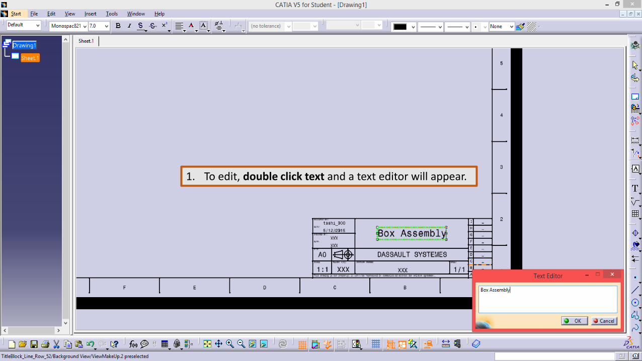
1. To edit, double click text and a text editor will appear.

1. Revise text as illustrated.

1. Switch back to Working Views.

1. Select Front View2. Switch back to Product Window

1. Select Surface as illustrated.

1. Rotate View Using the compass, set to 0

1. View should appear similar to this

1. Create a side and top view

1. Select the offset section view command to create additional views from side view

1. Create view as illustrated by dragging section cut into position and clicking in space.

1. Create another view as illustrated.2. Double click Section Cut definition line to refine cut location.

1. Create views as illustrated

1. Select the view clipping command to clip view

1. Edit clipping view properties as illustrated.

1. Arrange Views as illustrated. 2. Save Progress

1. Edit view properties as illustrated.2. It’s important to always lock views
when you have finished editing them.

1. Create new detail sheet

1. Copy and Paste 2D Component2. Double click to activate and move to side.3. These 2D Components will be used to identify
the assembly components of the Box.

1. Create 2D Component as illustrated.

1. Select the instantiate 2D Component command.

1. Switch to detail Sheet and select 2D component.

1. Instantiate 2D Component as illustrated.2. Notice the Tools Palette3. Click in space when positioned.

1. Instantiate 2D Component as illustrated.2. You can now instantiate this 2D component in multiple locations from this window.3. Select the component4. Select the instantiate 2D Component command5. Position around the Box Walls.

1. Use Text with Leader Command to add text.

1. Revise leader by right clicking yellow leader tab.

1. Create Dimension as illustrated using the dimension command.

1. Create Dimension as illustrated

1. When finished editing use properties to lock View.

1. Create 2D Component as illustrated.

1. Instantiate 2D Component as illustrated.2. Revising scale to 1/4

1. Instantiate 2D Component as illustrated.

1. To add an additional leader right click text and select as illustrated.

1. Edit Views and 2D Component Properties as illustrated.

1. Instantiate 2D Component in the sheet background as illustrated.

1. Save Progress
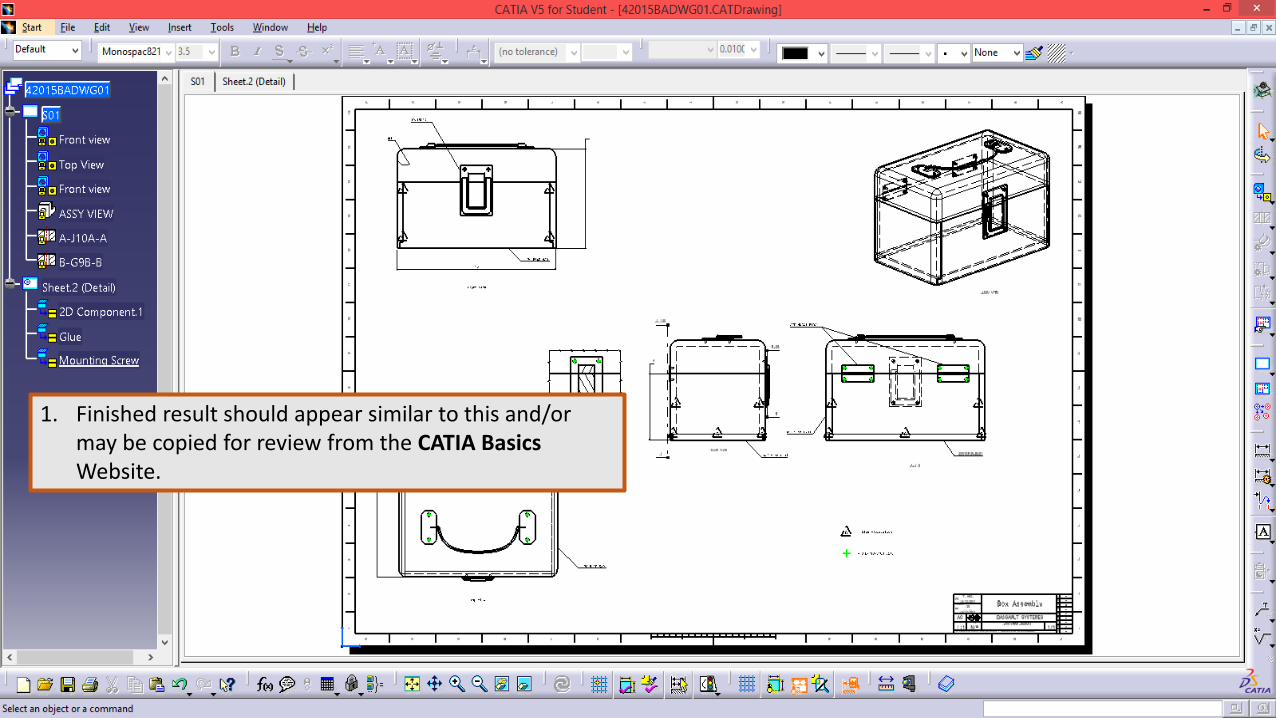
1. Finished result should appear similar to this and/or may be copied for review from the CATIA BasicsWebsite.