Electrak underfloor to workstation - Electrika
56
UNDERFLOOR TO WORKSTATION POWER AND DATA DISTRIBUTION SYSTEMS THE GLOBAL SPECIALIST IN ELECTRICAL AND DIGITAL BUILDING INFRASTRUCTURES POWERING THE WORKSTATION
-
Upload
khangminh22 -
Category
Documents
-
view
3 -
download
0
Transcript of Electrak underfloor to workstation - Electrika

UNDERFLOOR TO WORKSTATION POWER AND DATA DISTRIBUTION SYSTEMS
THE GLOBAL SPECIALIST
IN ELECTRICAL AND DIGITAL BUILDING INFRASTRUCTURES
POWERING THEWORKSTATION

XX
Legrand is the global specialist in electrical and digital
building infrastructures. Innovation is the driving force
behind its development. With an increasing investment
in research and development (circa 5% of sales) and
more than 4,000 active patents, the Legrand Group
is focused on maintaining a high rate of new product
launches that present innovative solutions to the market.
LEGRAND’S POWER DISTRIBUTION BUSINESS UNIT
From Zucchini transformers, through high power
distribution and rising main busbar to Electrak
powertrack, desk modules and lighting control,
Legrand’s power distribution business unit provides
market leading solutions to the increasing demands
of today’s buildings.
SUSTAINABLE DEVELOPMENT From design through to manufacturing,
the Legrand Group selects materials and
processes that respect people and the
environment.
• Eficient and environmentally aware product design
• Product functions that help to avoid energy waste
• Management of manufacturing and logistics sites
• Integration of environmental concerns and
ISO 14001 procedures at the Group’s global sites*
* 84% of sites are ISO 14001:2004 accredited including all UK sites.
Global strength
built on local knowledge

WWW.LEGRAND.CO.UK/ELECTRAK
UNDERFLOOR TO WORKSTATION SYSTEM GUIDE 1
POWERTRACK Overview 6 Ordering information 8 Technical information 17
FLOOR BOXESOverview 22 Ordering information 24 Technical information 29
GROMMETSOverview 30 Ordering information 32 Technical information 33
INTERSOC-ROverview 34 Ordering information 38 Technical information 42
INTERSOC ON-DESKOverview 46 Ordering information 50 Technical information 52
CONTENTS

2
Electrak®
... the specialist in power distribution throughout the workplaceElectrak, a brand of the Legrand Group in the UK, is a leading name in power distribution and lighting control solutions. Electrak busbar systems, loor boxes, grommets, desk modules and lighting control ranges are installed in high speciication ofices around the world.

WWW.LEGRAND.CO.UK/ELECTRAK
UNDERFLOOR TO WORKSTATION SYSTEM GUIDE 3
POWERING THE WORKSTATION
POWER TRACK See page 6
GROMMETS See page 30
BUSCOM power and data backbone
CAVITY FLOOR BOXES See page 22
INTERSOC-R See page 34
INTERSOC ON-DESK See page 46
LIGHTRAK lighting control system
UNDERFLOOR POWER Electrak’s power track system is perfect for supplying underfloor power in cavity
floor installations. With minimal parts, push-fit assembly and a complementary
range of floor boxes, this flexible, easy to install system can be reconfigured as
office layouts evolve.
WORKSTATION POWER Electrak’s access grommets provide the gateway for power to feed from the
underfloor power track network to the workstation, where all desk power
requirements are met with our new range of desk modules, Intersoc-R and
Intersoc on-desk.
FULLY ADDRESSABLE LIGHTING CONTROLDesigned to work in harmony with Electrak’s buscom trunking, Lightrak’s
lighting control system offers high end sophistication with unbeatable
flexibility and speed of installation.
Find out more at www.legrand.co.uk/electrak

4
OVER 30 YEARS OF EXPERIENCELegrand’s cost-effective Electrak systems have
been designed and manufactured to distribute
power and data reliably and safely throughout
the workplace. The original underloor busbar
system, invented by Electrak in the 1980s, sets the
benchmark for lexible power distribution.
INDUSTRY EXPERTS As part of its ongoing commitment to research
and development, Legrand continually evolves its
product ranges to ensure it develops the best and
most innovative solutions available on the market.
Legrand takes pride in its enviable reputation for
market leading customer service, industry
knowledge and product expertise.
QUALITY ASSURED UK MANUFACTURINGWith its Electrak ranges manufactured from its
UK manufacturing base situated in the North
East of England, Legrand adapts to the changing
demands of projects by providing a rapid production
process whilst ensuring quality meets the highest
standards.
Electrak®
... UK manufacturing. Global recognition

WWW.LEGRAND.CO.UK/ELECTRAK
UNDERFLOOR TO WORKSTATION SYSTEM GUIDE 5
Trusted throughout the UK and across the world
UNITED KINGDOM
• Morgan Stanley, Canary Wharf• Media City, Manchester• JP Morgan, Canary Wharf• RBS, Edinburgh• Bridgewater Place, Leeds• Network Rail, Nationwide• Swiss Re, City of London• Amazon, Swansea• Heathrow Airport, London• Fort Dunlop, Birmingham• Royal Bank of Canada,
City of London• Snow Hill, Birmingham• Barclays Capital, Canary Wharf• Temple Back, Bristol• Standard Chartered Bank,
City of London• London Underground• BBC, White City• Mann Island, Liverpool
MIDDLE EAST & INDIA
• ADMA-OPCO HQ, Dubai• Internet City, Dubai• Burjuman Centre, Dubai• ADIC/Al Bahr Towers, Abu Dhabi• Al Dar HQ, Abu Dhabi• Central Bank of Kuwait• Ministry of Education, Kuwait• PIFFS Aridya, Kuwait• PAAET, Kuwait• Qatar News Agency• Barclays, Chennai, India• Barclays, Pune, India• Barclays, Andheri, India• Barclays, Mumbai, India• RBS, Delhi, India• Fidelity, Delhi, India
ASIA PACIFIC
• Credit Suisse, ICC I, Hong Kong• Deutsche Bank, ICC I, Hong Kong• Barclays Capital, Cheung
Kong Centre• Customs Headquarters,
North Point, Hong Kong• Standard Chartered Bank,
IFC II, Hong Kong• Citi Bank Tower, Hong Kong• Macquarie Bank, IFC I, Hong Kong• UBS Bank, IFC II, Hong Kong• JP Morgan, Hong Kong• Standard Chartered Bank, Marina
Bay, Singapore• Barclays Capital, Marina Bay, Singapore• Nomura Bank, Marina Bay, Singapore• Credit Suisse, Serangoon Road,
Singapore• ABN Amro, One Rafles Quay, Singapore• RBS, One George Street, Singapore• Barclays Capital, Shanghai• Standard Chartered Bank, Shanghai• UBS Bank, Shanghai

6

WWW.LEGRAND.CO.UK/ELECTRAK
UNDERFLOOR TO WORKSTATION SYSTEM GUIDE 7
THE INDUSTRY STANDARD IN UNDERFLOOR POWERElectrak powertrack / underloor busbar is perfect for cavity
loor installations. With minimal parts, push-it assembly and a
complementary range of loor boxes and grommets, this lexible,
easy to install system can be reconigured as ofice layouts evolve.
The system consists of continuous lengths of track which are fed via
a feed unit and can be installed in loor voids as low as 48mm.
• 63 A rated, IP 40 protection
• Available in ive versions: single phase, clean earth, dual circuit,
three phase and auxiliary earth
• Tinned busbar version available for use within Abu Dhabi
(see page 15)
• Available in 1.2m, 1.8m, 2.4m and 3.6m lengths
• Tap-off outlets are located at every 300 or 600mm pitch
• Floor mountable (stand-off brackets also available)
Integral track connector plugs into feed unit Lengths simply push-fit together
Integral fixing brackets for rapid installation Tap-offs plug in to shuttered socket outlets and lock on to track body
Powertrack... adaptable, reliable underfloor power

8
Electrak® powertrack / underfloor busbarselection chart
Description Length (m)
Track lengths with 300 mm socket centres
4 outlets 1·2
6 outlets 1·8
8 outlets 2·4
12 outlets 3·6
Track feeds
–
Excluding cables and conduit
Fexible metal conduit
Fexible metal conduit
Standard tap-off / auxillary earth tap-off
32 A unfused 16 mm Ø L, N, PE3
5
13 A fused 16 mm Ø L, N, PE3
5
13 A 543·7 fused 16 mm Ø L, N, PE3
5
Low noise / clean earth tap-off
32 A unfused 16 mm Ø CE, L, N, PE3
5
13 A fused 16 mm Ø CE, L, N, PE3
5
13 A 543·7 fused 16 mm Ø CE, L, N, PE3
5
Dual circuit tap-off
32 A unfused 20 mm Ø CE, L1, N1 L2, N2, PE
3
5
3 phase tap-off
32 A 415 V 3 phase 20 mm Ø L1, L2, L3, N, PE3
5
32 A L1 unfused reconfigurable live pin 16 mm Ø L1, N, PE3
5
32 A L2 unfused reconfigurable live pin 16 mm Ø L2, N, PE3
5
32 A L3 unfused reconfigurable live pin 16 mm Ø L3, N, PE3
5
Key code / Busbar arrangement
008_009_Electrak 2014 v3.indd 8 27/08/2014 13:07

9
1 : All NP tap-offs are reconfigurable between L1, L2 or L3 for 3 phase track
ELECTRAK 24
Standard system (white)
ELECTRAK 25
Low noise / clean earth system (green)
ELECTRAK 26
Dual circuit system (dark green)
ELECTRAK 27
3 phase system (grey)
ELECTRAK 28
Auxillary earth system (red)
DA1123 JA2123 KA3123 NA4123 YA5123
DA1183 JA2183 KA3183 NA4183 YA5183
DA1243 JA2243 KA3243 NA4243 YA5243
DA1363 JA2363 KA3363 NA4363 YA5363
DF1010 JF2010 KF3010 NF4010 YF5010
DW1000 JW2000 KW3000 NW4000 YW5000
DW1010 JW2010 KW3010 NW4010 YW5010
DW1020 JW2020 KW3020 NW4020 YW5020
DP1332 – DP1332 – YP5332
DP1532 – DP1532 – YP5532
DP1313 – DP1313 – YP5313
DP1513 – DP1513 – YP5513
DP1327 – DP1327 – YP5327
DP1527 – DP1527 – YP5527
– JP2332 JP2332 – –
– JP2532 JP2532 – –
– JP2313 JP2313 – –
– JP2513 JP2513 – –
– JP2327 JP2327 – –
– JP2527 JP2527 – –
– – KP3328 – –
– – KP3528 – –
– – – NZ4331 –
– – – NZ4531 –
– – – NP43321 –
– – – NP45321 –
– – – NP43021 –
– – – NP45021 –
– – – NP43031 –
– – – NP45031 –
PE N2 L2 PE CE N1 L1 PE CE N1 L1 N2 L2 PE N L1 L2 L3 PE N1 L1
008_009_Electrak 2014 v3.indd 9 27/08/2014 13:05

10
Pack Cat. Nos. Tap-off units
Tap-off length is determined by the cable and not the conduit length, e.g. a 3 m tap-off has 3 m of cable and 2·6 m of flexible metal conduit1
Tap-off units in excess of 3 m should only be used if they contain a fuse or if the power track is protected by a protective device not exceeding 32 A
32 A unfused
16 mm Ø‚ L, N, PE
1 DP1332 3 m 1 DP1532 5 m
13 A fused
16 mm Ø‚ L, N, PE
1 DP1313 3 m 1 DP1513 5 m
13 A 543·7 fused - high integrity
16 mm Ø‚ L, N, PE
1 DP1327 3 m 1 DP1527 5 m
Pack Cat. Nos. Track system components
Electrak 24 standard track lengths
Track lengths fit together using the integral connectors on each length Track lengths should always be secured using the integral floor fixing brackets 300 mm socket centres
1 DA1123 1·2 m, 4 outlets, 2 floor fixing brackets 1 DA1183 1·8 m, 6 outlets, 2 floor fixing brackets 1 DA1243 2·4 m, 8 outlets, 2 floor fixing brackets 1 DA1363 3·6 m, 12 outlets, 3 floor fixing brackets
Track feed unit
1 DF1010 With one 25 mm diameter hole suitable for MICC, armoured cables or single core cables in conduit
Flexible interlinks
Can be used to overcome obstructions or as corners where required
1 DW1000 Excluding cables and conduit 1 DW1010 1·2 m flexible metal conduit 1 DW1020 2·4 m flexible metal conduit
Special fixing brackets
Required when track is raised off surface level Brackets raise track by 21 mm and should be spaced 600 mm apart
1 DZ1210 For fitting under track body and track feed 1 DZ1230 For fitting under integral track connectors
Approved to ASTA Standard 138 and ISO 9001 : 2008 Conforms to BS EN 60439-2 : 2008. Fully complies with the requirements of BS 7671 : 2008 IEE Wiring Regulations A compact system that can be installed in floor voids as low as 48 mm
DF1010
DW1010
DP1332DA1123
1 : Tap-offs are supplied as standard with flexible metal conduit
For alternative wiring solutions, contact us on +44 (0) 845 600 6266
- -
-/-
- -
Electrak® 24 powertrack / underfloor busbar systemstandard system (white)
Selection charts p. 8-9Dimensions and technical information p. 17-21
010_011_Electrak 2014 v2.indd 10 27/08/2014 12:44

11
Pack Cat. Nos. Tap-off units
Tap-off length is determined by the cable and not the conduit length, e.g. a 3 m tap-off has 3 m of cable and 2·6 m of flexible metal conduit1
Tap-off units in excess of 3 m should only be used if they contain a fuse or if the power track is protected by a protective device not exceeding 32 A
32 A unfused
16 mm Ø‚ CE, L, N, PE
1 JP2332 3 m 1 JP2532 5 m
13 A fused
16 mm Ø‚ CE, L, N, PE
1 JP2313 3 m 1 JP2513 5 m
13 A 543·7 fused - high integrity
16 mm Ø‚ CE, L, N, PE
1 JP2327 3 m 1 JP2527 5 m
Pack Cat. Nos. Track system components
Electrak 25 low noise / clean earth track lengths
Track lengths fit together using the integral connectors on each length Track lengths should always be secured using the integral floor fixing brackets 300 mm socket centres
1 JA2123 1·2 m, 4 outlets, 2 floor fixing brackets 1 JA2183 1·8 m, 6 outlets, 2 floor fixing brackets 1 JA2243 2·4 m, 8 outlets, 2 floor fixing brackets 1 JA2363 3·6 m, 12 outlets, 3 floor fixing brackets
Track feed unit
1 JF2010 With one 25 mm diameter hole suitable for MICC, armoured cables or single core cables in conduit
Flexible interlinks
Can be used to overcome obstructions or as corners where required
1 JW2000 Excluding cables and conduit 1 JW2010 1·2 m flexible metal conduit 1 JW2020 2·4 m flexible metal conduit
Special fixing brackets
Required when track is raised off surface level Brackets raise track by 21 mm and should be spaced 600 mm apart
1 DZ1210 For fitting under track body and track feed 1 DZ1230 For fitting under integral track connectors
Approved to ASTA Standard 138 and ISO 9001 : 2008 Conforms to BS EN 60439-2 : 2008. Fully complies with the requirements of BS 7671 : 2008 IEE Wiring Regulations A compact system that can be installed in floor voids as low as 48 mm
JF2010
JW2010
JP2332JA2123
- -
-/-
- -
1 : Tap-offs are supplied as standard with flexible metal conduit
For alternative wiring solutions, contact us on +44 (0) 845 600 6266
Electrak® 25 powertrack / underfloor busbar systemlow noise / clean earth system (green)
Selection charts p. 8-9Dimensions and technical information p. 17-21
010_011_Electrak 2014 v2.indd 11 27/08/2014 12:44

12
Pack Cat. Nos. Tap-off units
Tap-off length is determined by the cable and not the conduit length, e.g. a 3 m tap-off has 3 m of cable and 2·6 m of flexible metal conduit1
Tap-off units in excess of 3 m should only be used if they contain a fuse or if the power track is protected by a protective device not exceeding 32 A
Standard 32 A unfused
16 mm Ø‚ L, N, PE
1 DP1332 3 m 1 DP1532 5 m
Standard 13 A fused
16 mm Ø‚ L, N, PE
1 DP1313 3 m 1 DP1513 5 m
Standard 13 A 543·7 fused
16 mm Ø‚ L, N, PE
1 DP1327 3 m 1 DP1527 5 m
Low noise / clean earth 32 A unfused
16 mm Ø‚ CE, L, N, PE
1 JP2332 3 m 1 JP2532 5 m
Low noise / clean earth 13 A fused
16 mm Ø‚ CE, L, N, PE
1 JP2313 3 m 1 JP2513 5 m
Low noise / clean earth 13 A 543·7 fused
16 mm Ø‚ CE, L, N, PE
1 JP2327 3 m 1 JP2527 5 m
Dual circuit 32 A unfused
20 mm Ø‚ CE, L1, N1, L2, N2,PE
1 KP3328 3 m 1 KP3528 5 m
Pack Cat. Nos. Track system components
The dual power track system has both standard and low noise / clean earth systems incorporated
Electrak 26 dual circuit track lengths
Track lengths fit together using the integral connectors on each length Track lengths should always be secured using the integral floor fixing brackets 300 mm socket centres
1 KA3123 1·2 m, 4 outlets, 2 floor fixing brackets 1 KA3183 1·8 m, 6 outlets, 2 floor fixing brackets 1 KA3243 2·4 m, 8 outlets, 2 floor fixing brackets 1 KA3363 3·6 m, 12 outlets, 3 floor fixing brackets
Track feed unit
1 KF3010 With two 25 mm diameter holes suitable for MICC, armoured cables or single core cables in conduit
Flexible interlinks
Can be used to overcome obstructions or as corners where required
1 KW3000 Excluding cables and conduit 1 KW3010 1·2 m flexible metal conduit 1 KW3020 2·4 m flexible metal conduit
Special fixing brackets
Required when track is raised off surface level Brackets raise track by 21 mm and should be spaced 600 mm apart
1 DZ1210 For fitting under track body and track feed 1 DZ1230 For fitting under integral track connectors
Approved to ASTA Standard 138 and ISO 9001 : 2008 Conforms to BS EN 60439-2 : 2008. Fully complies with the requirements of BS 7671 : 2008 IEE Wiring Regulations A compact system that can be installed in floor voids as low as 48 mm
KF3010
KW3010
KP3328KA3123
- -
-/-
- -
1 : Tap-offs are supplied as standard with flexible metal conduit
For alternative wiring solutions, contact us on +44 (0) 845 600 6266
Electrak® 26 powertrack / underfloor busbar systemdual circuit system (dark green)
Selection charts p. 8-9Dimensions and technical information p. 17-21
012_013_Electrak 2014 v2.indd 12 27/08/2014 12:45

13
Pack Cat. Nos. Tap-off units
Tap-off length is determined by the cable and not the conduit length, e.g. a 3 m tap-off has 3 m of cable and 2·6 m of flexible metal conduit1
Tap-off units in excess of 3 m should only be used if they contain a fuse or if the power track is protected by a protective device not exceeding 32 A
32 A 415 V 3 phase
20 mm Ø‚ L1, L2, L3, N, PE
1 NZ4331 3 m 1 NZ4531 5 m
32 A L12 unfused
Unfused Reconfigurable live pin
16 mm Ø‚ L, N, PE
1 NP4332 3 m 1 NP4532 5 m
32 A L22 unfused
Unfused Reconfigurable live pin
16 mm Ø‚ L, N, PE
1 NP4302 3 m 1 NP4502 5 m
32 A L32 unfused
Unfused Reconfigurable live pin
16 mm Ø‚ L, N, PE
1 NP4303 3 m 1 NP4503 5 m
Pack Cat. Nos. Track system components
Electrak 27 3 phase track lengths
Track lengths fit together using the integral connectors on each length Track lengths should always be secured using the integral floor fixing brackets 300 mm socket centres
1 NA4123 1·2 m, 4 outlets, 2 floor fixing brackets 1 NA4183 1·8 m, 6 outlets, 2 floor fixing brackets 1 NA4243 2·4 m, 8 outlets, 2 floor fixing brackets 1 NA4363 3·6 m, 12 outlets, 3 floor fixing brackets
Track feed unit
1 NF4010 With one 25 mm diameter hole suitable for MICC, armoured cables or single core cables in conduit
Flexible interlinks
Can be used to overcome obstructions or as corners where required
1 NW4000 Excluding cables and conduit 1 NW4010 1·2 m flexible metal conduit 1 NW4020 2·4 m flexible metal conduit
Special fixing brackets
Required when track is raised off surface level Brackets raise track by 21 mm and should be spaced 600 mm apart
1 DZ1210 For fitting under track body and track feed 1 DZ1230 For fitting under integral track connectors
Approved to ASTA Standard 138 and ISO 9001 : 2008 Conforms to BS EN 60439-2 : 2008. Fully complies with the requirements of BS 7671 : 2008 IEE Wiring Regulations A compact system that can be installed in floor voids as low as 48 mm
NF4010
NW4010
NZ4331NA4123
- -
-/-
- -
1 : Tap-offs are supplied as standard with flexible metal conduit
For alternative wiring solutions, contact us on +44 (0) 845 600 6266
2 : All NP tap-offs are reconfigurable between L1, L2, or L3 for
3 phase track
Electrak® 27 powertrack / underfloor busbar system3 phase system (grey)
Selection charts p. 8-9Dimensions and technical information p. 17-21
012_013_Electrak 2014 v2.indd 13 27/08/2014 12:45

14
Pack Cat. Nos. Tap-off units
Tap-off length is determined by the cable and not the conduit length, e.g. a 3 m tap-off has 3 m of cable and 2·6 m of flexible metal conduit1
Tap-off units in excess of 3 m should only be used if they contain a fuse or if the power track is protected by a protective device not exceeding 32 A
32 A unfused
16 mm Ø‚ L, N, PE
1 YP5332 3 m 1 YP5532 5 m
13 A fused
16 mm Ø‚ L, N, PE
1 YP5313 3 m 1 YP5513 5 m
13 A 543·7 fused - high integrity
16 mm Ø‚ L, N, PE
1 YP5327 3 m 1 YP5527 5 m
Pack Cat. Nos. Track system components
Electrak 28 auxiliary earth track lengths
Track lengths fit together using the integral connectors on each length Track lengths should always be secured using the integral floor fixing brackets 300 mm socket centres
1 YA5123 1·2 m, 4 outlets, 2 floor fixing brackets 1 YA5183 1·8 m, 6 outlets, 2 floor fixing brackets 1 YA5243 2·4 m, 8 outlets, 2 floor fixing brackets 1 YA5363 3·6 m, 12 outlets, 3 floor fixing brackets
Track feed unit
1 YF5010 With one 25 mm diameter hole suitable for MICC, armoured cables or single core cables in conduit
Flexible interlinks
Can be used to overcome obstructions or as corners where required
1 YW5000 Excluding cables and conduit 1 YW5010 1·2 m flexible metal conduit 1 YW5020 2·4 m flexible metal conduit
Special fixing brackets
Required when track is raised off surface level Brackets raise track by 21 mm and should be spaced 600 mm apart
1 DZ1210 For fitting under track body and track feed 1 DZ1230 For fitting under integral track connectors
Approved to ASTA Standard 138 and ISO 9001 : 2008 Conforms to BS EN 60439-2 : 2008. Fully complies with the requirements of BS 7671 : 2008 IEE Wiring Regulations A compact system that can be installed in floor voids as low as 48 mm
YF5010
YW5010
YP5332YA5123
1 : Tap-offs are supplied as standard with flexible metal conduit
For alternative wiring solutions, contact us on +44 (0) 845 600 6266
- -
-/-
- -
Electrak® 28 powertrack / underfloor busbar systemauxiliary earth system (red)
Selection charts p. 8-9Dimensions and technical information p. 17-21
014_Electrak 2014 v2.indd 14 27/08/2014 12:46

WWW.LEGRAND.CO.UK/ELECTRAK
UNDERFLOOR TO WORKSTATION SYSTEM GUIDE 15
The Electrak 28R powertrack range is a single phase system and therefore adopts red (L), black (N), and green/yellow (E) cables to meet with the requirments of The Regulation and Supervision Bureau of the Water, Wastewater and Electricity Sector in the Emirate of Abu Dhabi.
Guideline For Design, Testing and Installation Of Busways GL.GN.01. Issued by: Abu Dhabi Distribution Co. Low Voltage Switchgear Committee Issue: 2, Revision: 1, effective 01/02/2012
16. Lighting & Small Power Busways & Modular Wiring Lighting & Power Socket bus duct and modular wiring are considered part of building wiring and regulated by the Electricity Wiring Regulation issued by RSB. It shall comply with respective specifications under the Wiring regulation. ADDC LVSGC approves these methods in principle provided that the RSB set aspects are incorporated (like tinning of copper, colour coding etc.).
Developed to meet the ADDC requirements for busways, this specially designed range sees all busbars tinned along their entire length, and all busbar connectors and tap-off blades plated.
Approved to ASTA standard 138 and designed to be in accordance with the requirements of BS EN 60439-2: 2000 and BS EN 61534-22: 2009 (IEC 61534: 2009).
The Electrical Wiring Regulations 2007 Issued by: The Regulation and Supervision Bureau for the Water, Wastewater and Electricity Sector in the Emirate of Abu Dhabi. Revision 1, January 2009
7.7 Busways, bus ducts ad busbar risers 7.7.6 Busways, bus ducts and busbar risers shall have neutral conductors of equal size to the phase conductors and shall have a dedicated Earth Conductor. The use of the metal casing as an earth conductor permitted only for Earth Leakage Protected Installations, and with the prior approval of the Distribution Company.
The Electrak powertrack system uses equal size tinned copper busbars for live, neutral and earth conductors to meet with the requirements of The Regulation and Supervision Bureau of the Water, Wastewater and Electricity Sector in the Emirate of Abu Dhabi.
Electrak 28R tinned powertrack...Designed to meet local standards
As a specific requirement for use within Abu Dhabi, Legrand has developed a ‘tinned’ busbar which has been designed in line with the guidance for busways outlined by the Abu Dhabi Distribution Company (ADDC), as detailed below.
Electrak 28R tinned busbar connectors
Appendix 9. Capacity of conduits and trunking
Appendix 8. Colour identification for cables
Electrak 28R tinned tap-offs
The tap-offs contain a maximum of 3 x 4mm2 conductors housed in as 20mm ø metal lexible conduit to meet the requirements of The Regulation and Supervision Bureau of the Water, Wastewater and Electricity Sector in the Emirate of Abu Dhabi.
NOTE: When designing installations in regions with higher ambient temperatures than 35ºC, de-rating factors may need to be applied. Please refer to the table on page 21 for details.
Guideline For Design, Testing and Installation Of Busways GL.GN.01 Copyright Abu Dhabi Distribution Co.
The Electrical Wiring Regulations 2007 - Copyright The Regulation and Supervision Bureau (RSB)
Phase 1
Phase 2
Phase 3
Neutral
Earth conductors
Red
Yellow
Blue
Black
Green / yellow
Conductor Colour
Non-lexible ixed wiring and all 3 phase cables:
1.5
2.5
4.0
7
5
3
12
9
6
-
12
9
20 25 32
Maximum number of conductors
Diameter of Conduit (mm2)Conduit (mm2)

16
Pack Cat. Nos. Tap-off units
Tap-off length is determined by the cable and not the conduit length, e.g. a 3 m tap-off has 3 m of cable and 2·6 m of flexible metal conduit1
Tap-off units in excess of 3 m should only be used if they contain a fuse or if the busbar run is protected by a protective device not exceeding 32 A
32 A unfused
20 mm Ø‚ L, N, PE (4 mm2)
1 YP5332R 3 m 1 YP5532R 5 m
13 A 543·7 fused - high integrity
20 mm Ø‚ L, N (2·5 mm2), PE (4 mm2)
1 YP5327R 3 m 1 YP5527R 5 m
Pack Cat. Nos. Busbar system components
63A auxiliary earth busbar lengths
Busbar lengths fit together using the integral connectors on each length Lengths should always be secured using the integral floor fixing brackets 300 mm socket centres
1 YA5123R 1·2 m, 4 outlets, 2 floor fixing brackets 1 YA5183R 1·8 m, 6 outlets, 2 floor fixing brackets 1 YA5243R 2·4 m, 8 outlets, 2 floor fixing brackets 1 YA5363R 3·6 m, 12 outlets, 3 floor fixing brackets
Feed unit
1 YF5010R With one 25 mm diameter hole suitable for MICC, armoured cables or single core cables in conduit
Flexible interlinks
Can be used to overcome obstructions or as corners where required
1 YW5000R Excluding cables and conduit 1 YW5010R 1·2 m flexible metal conduit 1 YW5020R 2·4 m flexible metal conduit
Special fixing brackets
Required when busbar is raised off surface level Brackets raise the system by 21 mm and should be spaced 600 mm apart
1 DZ1210 For fitting under lengths and feed units 1 DZ1230 For fitting under integral connectors
Approved to ASTA Standard 138 and ISO 9001 : 2008 Conforms to BS EN 60439-2 : 2008. Fully complies with the requirements of BS 7671 : 2008 IEE Wiring Regulations A compact system that can be installed in floor voids as low as 48 mm
YF5010R
YW5010R
YP5332RYA5123R
1 : Tap-offs are supplied as standard with flexible metal conduit
For alternative wiring solutions, contact us on +44 (0) 845 600 6266
- -
-/-
- -
Electrak® 28R tinned powertrack / underfloor busbar systemauxiliary earth system (red)
Selection charts p. 8-9Dimensions and technical information p. 17-21
016_Electrak 2014 v2.indd 16 27/08/2014 14:33

17
Electrak® powertrack / underfloor busbardesign and installation
7593
2 x 25 Ø
46
25 Ø
46
250
47
109118
32
15
68
65
End view A
92
End view B
Integral fixing bracket fixing centres
All dimensions (mm) are nominal
n General installation notes
Electrak power track is a compact system that can be installed in floor voids as low as 48 mm
Feed units are provided with one or two 25 mm diameter holes suitable for MICC, armoured cables or single core cables in conduitTrack lengths connect together and to feed units using the integral connectors on each length
Lengths should always be secured using the integral floor fixing brackets ; three on the 3·6 m length and two on 2·4 m, 1·8 m or 1·2 m lengths
Access to power is provided along the busbar length by simply plugging tap-off units into shuttered socket outlets. These tap-off units feed all types of conventional floor service outlet boxes or feed workstations directly through the floor via insulated conductors contained in flexible metal or VO rated nylon conduit. When connecting tap-offs directly through the floor via grommet outlets to workstations care must be taken to ensure that the tap-off length is adequate
The dual system has both standard and low noise / clean earth systems incorporated. As well as dual tap-offs, both standard and low noise / clean earth tap-offs can be plugged into any socket outlet along the busbar length. The dual tap-off incorporates both standard and low noise cables
Optimum layout flexibility is achieved by positioning busbar lengths a maximum of 5·2 m apart and 2·5 m from the wall, and by connecting the 3 m tap-off units to floor outlet boxes. This means every part of the floor area can be served. Flexible interlinks can be used to overcome obstructions or used as corners if required
n Special fixing brackets
Electrak special fixing brackets are available to raise the system by 21 mm. Ensure brackets are spaced 600 mm apart and always have support under the integral connectors and feed units. Failure to do so may undermine the integrity of the system
Cat. No. DZ1210 raised off-floor fixing brackets are spaced at 600 mm centres along the busbar run. Also use bottom half of bracket under feed unit and flexible interlinkCat. No. DZ1230 raised off-floor fixing brackets are always used under integral connectors. Busbar is secured to raised brackets using the integral fixing bracket
50 mm
99 mm
7 mm Ø
Cat. No. DZ121021 mm to underside and
36 mm to top of busbar length
Integral connector
Cat. No. DZ1230
185 mm
7 mm Ø
Integral fixing bracket
screws to special bracket
n Dimensions
Example floor layout
2·5
m5
·2 m
5·2
m
feed unit
5·2
m 3 m flexible
tap-off unit
floor service
outlet box
integralconnectors
socket outlet points every
300 or 600 mm along
busbar run
017_019_Electrak 2014 v3.indd 17 27/08/2014 12:48

18
n Product configuration
Flexible interlink Tap-off connection
Flexible interlink boxes must be securely fixed inline to surface so no movement can take place after fixing
Feed unit protective earth terminal and earth bond
Lift terminal tab to access terminal screws and close after use
Lift lid
Protective earth must always be connected via the earth terminal block
Close lid and secure with lid fixing screw before power up
25 mm Ø cable conduit fixing hole
Depress tap-off side clips and push down
Make sure both tap-off side clips are fully pushed home on both
sides of tthe bar
Tap-off
Side clip
Push down
Interlink feed entry socket. Remove dust cover label
Remove dust cover from end entry socket before use
Screw fix to surface
Feed unit (Cat. No. DF1010) Sub-cabling Tap-off connection
Tap-off metal flexible conduit
20 mm Ø conduit fitting. Tighten back nut securely
Feed unit protective earth terminal and earth bond
Clean earth
Connector terminals
Connector terminals
Lift terminal tab to access terminal screws and close after use
Lift lid
Protective earth must always be connected via the earth terminal block
Close lid and secure with lid fixing screw before power up
25 mm Ø cable conduit fixing hole
Feed unit (Cat. No. JF2010) Sub-cabling Tap-off connection
Tap-off metal flexible conduit
20 mm Ø conduit fitting Tighten back nut securely
Electrak® powertrack / underfloor busbar systemdesign and installation (continued)
All dimensions (mm) are nominal
017_019_Electrak 2014 v3.indd 18 27/08/2014 12:48

19
Feed unit protective earth terminal and earth bond
Connector terminals
Lift terminal tab to access terminal screws and close after use
Lift lid
Protective earth must always be connected via the earth terminal block
Close lid and secure with lid fixing screw before power up
25 mm Ø cable conduit fixing hole
Feed unit (Cat. No. NF4010) Sub-cabling 3 phase tap-off connection
Tap-off metal flexible conduit
20 mm Ø conduit fitting Tighten back nut securely
Feed unit protective earth terminal and earth bond
Connector terminals
Lift terminal tab to access terminal screws and close after use
Lift lid
Protective earth must always be connected via the earth terminal block
Close lid and secure with lid fixing screw before power up
25 mm Ø cable conduit fixing hole
Feed unit (Cat. No. YF5010 and YF5010R) Sub-cabling Tap-off connection
Tap-off metal flexible conduit
20 mm Ø conduit fitting Tighten back nut securely
Clean earth
ConnectionsL1, N1, CE = low noise L2, N2, PE = standard
ConnectionsL1, N1, CE = low noise L2, N2, PE = standard
Connector terminals
Lift terminal tab to access terminal screws and close after use
Lift lidProtective earth must always be connected via the earth terminal block
Close lid and secure with lid fixing screw before power up
2 x 25 mm Ø cable conduit fixing hole
Feed unit (Cat. No. KF3010) Sub-cabling Dual tap-off connection (dark green)
Tap-off metal flexible conduit
20 mm Ø conduit fitting Tighten back nut securely
Feed unit protective earth terminal and earth bond
All dimensions (mm) are nominal
017_019_Electrak 2014 v3.indd 19 27/08/2014 12:49

20
1 Fix feed unit to surface
Pull out fixing bracket lugs and screw fix on both sides
Tap-off outlets reusable plastic dust covers
First fixing bracket
Additional length
Busbar length
Feed unitMake chalk line to align busbar lengths
Direction of busbar run
Integral connector
Push down
Push down
Remove dust cover
Feed unit
Remove dust cover before connecting additional lengths
Make sure connector clips are fully pushed home on both sides
All integral fixing brackets must be fixed to surface at 1·2 m fixing centres from first bracket on each busbar length
2 Connect busbar length to feed unit
3 Connect additional busbar lengths
4 Secure busbar lengths to surface
All dimensions (mm) are nominal
Electrak® powertrack / underfloor busbar systeminstallation (continued)
020_021_Electrack 2014 v2.indd 20 27/08/2014 12:50

21
Electrak® powertrack / underfloor busbar systemtechnical data
n Ambient temperature rating factorsThe current carrying capacity for a powertrack / underfloor busbar (In) is affected by the ambient temperatureFor Electrak powertrack / underfloor busbar the ambient rating factor Ka is equal to 1 for ambient temperatures up to and including 35° C
Iz = Ka In
Where : Iz = effective current carrying capacity for continuous service under particular
installation conditionsKa = ambient temperature factorIn = nominal current carrying capacityFor ambient temperatures exceeding 35° C the values of Ka and Iz are given in the following tables
n Standards
Approved to ASTA Standard 138 BS EN 60439-2 : 2000, BS EN 61534-22 : 2009 and IEC 61534-22 : 2009Manufactured within an approved ISO 9001 : 2008 and ISO 14001 : 2004 facility Assessed Quality Assurance Certificate No. 2029 Electrak powertrack / underfloor busbar fully complies with the requirements of BS 7671 : 2008 + A1 : 2011 (IET Wiring Regulations)
References :
BS 7671 : 2008 incorporating amendment No. 1 : 2011
Appendix 8 – Current carrying capacity for powertrack systems
Appendix 4 – Table 4B1 Rating factors for thermosetting cables
Appendix 4 – Table 4E1A – Single core 90°C thermosetting insulated cables (non-armoured)
Ambient 20°C 25°C 30°C 35°C 40°C 45°C 50°C
Ka 1 0·95 0·85 0·80
Iz 63 A 59 A 53 A 50 A
Powertrack / underfloor busbar system
Ambient 20°C 25°C 30°C 35°C 40°C 45°C 50°C
Ka 1 0·95 0·85 0·80
Iz 32 A 30 A 27 A 25 A
32 A unfused tap-off (using thermosetting 90°C cables)
Ambient 20°C 25°C 30°C 35°C 40°C 45°C 50°C
Ka 1
Iz 13 A
13 A fused tap-off (using 2·5 mm2 thermosetting 90°C cables)
Rated current 63 A
Rated voltage 230/400 V~
Frequency 50/60 Hz
Conductor resistance - live and neutral 3·0 mΩ/m
Conductor impedance 1·5 mΩ/m
Electrical test data
Busbars 3·0 mV/A/m
Cable connector 0·4 mV/A
Integral connector 0·4 mV/A
32 A tap-off 0·4 mV/A
+ 4 mm2 cable 11 mV/A/m
Flexible corner assembly 1·5 mV/A
+ 10 mm2 cable 4·0 mV/A/m
Volt drops (live and neutral)
Phase busbar 1·5 mΩ/m
Earth busbar 1·5 mΩ/m
Earth housing 1·1 mΩ/m
Earth busbar and housing 0·8 mΩ/m
Cable connector 0·4 mΩ Integral connector 0·6 mΩ 32 A tap-off 0·6 mΩ + 4 mm2 cable 11 mΩ/m
Flexible corner assembly 1·5 mΩ + 10 mm2 cable 4·0 mΩ/m
Rated conditional short-circuit current 16 KA
Ambient temperature 25˚C
Earth fault loop impedance
Housing - busbar lengths Galvanised steel, natural finish
Busbars
High conductivity copper (Tinned version is electro-tin plated)
Busbar insulator PTFE
Integral connectors / Tap-off outlets Flame retardant polycarbonate
Tap-off outlet entry shutter Acetal
Tap-off housing Flame retardant polycarbonate
Integral connector blades Copper (Tinned version is plated)
Tap-off blades Copper (Tinned version is plated)
Tap-off/flexible corner conduit, metal Electro-galvanised steel
Tap-off cable LSOH to BS 7211
Flexible interlink cable Tri-rated to BS 6231
Feed box/flexible interlink boxes Galvanised steel
Feed connector terminals/earth block Brass (Tinned version is plated)
Fixing brackets Galvanised steel
13 A tap-off, fuse To BS 1362, ASTA approved
Material specifications
n Earth fault loop impedanceBS 7671 : 2008 + A1 : 2011 IET Wiring Regulations require accurate determination of the total earth loop impedance, which must be sufficiently low to allow the protective device to operate within the specified time, which for socket outlets is 0·4 seconds. The values relevant to Electrak for calculating the earth fault loop impedance are shown in the electrical test data table, see opposite
n DurabilityElectrak systems are superbly designed and extremely robust. They can be expected to stand up to all normal site conditions. Electrak powertrack / underfloor busbar has been short circuit strength tested by ASTA
n Installations with high protective conductor currentsAll unfused tap-offs comply with Regulation 543·7 without the need for additional earth conductors. Regulation 543·7·1·103 (ii) states “a single copper protective conductor having a cross-sectional area of not less than 4 mm2, complying with the requirements of Regulations 543·2 and 543·3, the protective conductor being enclosed to provide additional protection against mechanical damage, for example, within a flexible conduit”For installations with high protective conductor currents requiring fused tap-offs, a 543·7 compliant tap-off must be used. Normally fused tap-offs incorporate 1·5 m2 (2·5 m2 for tinned system) conductors, however in the fused 543·7 tap-offs, the 1·5 m2 (2·5 m2 for tinned system) earth conductor is replaced with a 4 mm2 conductor and therefore complies with Section 543·7·1·103 (ii)
n 32 A tap-off unitThe 3 m 32 A tap-off unit comprises an unfused tap-off with 2·6 m of flexible metal conduit with integral 4 mm2 LSOH conductors
These units are designed to comply with regulation 434·2·1 of the IET Wiring Regulations by virtue of the following :• maximum length of cable is 3 m • it is factory assembled and fully tested item with cable installed in high quality flexible conduit
Fault condition protection for the tap-off assembly and the floor box socket outlets is delivered by the circuit protection device Disconnection time for socket outlets is 0·4 seconds (Regulation 411·3·2·2). The Electrak system meets this requirement
Tap-off units in excess of 3 m should only be used if they contain a fuse or the busbar run is protected by a protective device not exceeding 32 A
All dimensions (mm) are nominal
Number of conductors 3-6 3
Busbar conductor cross sectional area 13 mm2 13 mm2
Housing cross sectional area (copper equivalent) 13 mm2 13 mm2
Cable terminal capacity 16 mm2 16 mm2
Tap-off cable 32 A 4 mm2 4 mm2
Tap-off cable 13 A fused 1·5 mm2 2·5 mm2
Tap-off conduit, up to 4 conductors 16 mmØ 20 mmØ
Tap-off conduit, 5 and 6 conductors 20 mm2 N/A
Flexible corner cable (tri-rated, high temperature) 10 mm2 10 mm2
Flexible corner conduit 25 mmØ 25 mmØ
IP rating 40 40
Mechanical data E24 – E28 E28R
020_021_Electrack 2014 v2.indd 21 27/08/2014 12:50

22
Floor boxes... choice, flexibility and easy installation
2, 3 and 4 compartment raised access
loor boxes and slab boxes offer complete
versatility. Floor boxes are available pre-wired
with power track tap-off, or supplied empty
(unassembled), with a choice of single or
separate compartment bases and three depth
options. With a vast selection of power and
data plates available, boxes can be tailored
to the speciic requirements of each ofice
installation.

WWW.LEGRAND.CO.UK/ELECTRAK
UNDERFLOOR TO WORKSTATION SYSTEM GUIDE 23
Various RCD protection options available
Rapid fit push lock secures base in floor aperture
Single or separate compartment bases
Three depth options: 75mm, 85mm, 110mm
Durable ABS trim and lid surround
Rapid fit /remove mechanism adjusts for flooring thickness
Available in 2, 3 and 4 compartments and with a choice of
three depths, Electrak loor boxes have been developed
with a host of special features:
• Available pre-wired with tap-off or supplied unassembled
• A vast selection of power and data plates,
including RCD options
• Single or separate compartment bases for ease of data
cabling
• Rapid installation and fast ratchet mechanism which
adjusts to loor inish thickness
Quick-fit, reversible lid for rapid installation
Available pre-wired with tap-off

24
100 mm width plates
100 mm width plates
75 mm width plates
To configure boxes as required, select :
1. Box depth2. Number of compartments required3. Desired accessory plates
4 compartment
230 m
m
366 mm
3 compartment
230 m
m
366 mm
2 compartment
230 m
m
290 mm
CR2001 CR011 CR4001
CR2002 CR012 CR4002
CR2003 CR013 CR4003
CR2004 CR014 CR4004
CR2005 CR015 CR4005
CR2006 CR016 CR4006
CR5102 CR5202 CR5302 CR5402
CR020 CR4100
CR022 CR4101
CR023 CR4102
CR027 CR4103
CR029 CR4104
CR030 CR4105
CR044 CR4118
CR036 CR4111
CR043 CR4117
CR026 –
CR028 –
CR042 CR4115
CR031 CR4106
CR033 CR4108
CR024 CR4112
CR025 CR4113
Single base – 75 mm depth
Single base – 85 mm depth (standard box)
Single base – 110 mm depth
Separate compartment base – 75 mm depth
Separate compartment base – 85 mm depth
Separate compartment base – 110 mm depth
Fix directly onto floor slab (supplied empty)
Blank plate
2 gang switched socket outlet
2 gang switched socket outlet, low noise / clean earth
2 gang non-standard switched socket outlet
2 gang unswitched socket outlet
3 gang unswitched socket outlet
3 gang unswitched socket outlet,low noise / clean earth
2 gang RCD socket outlet
2 gang RCD socket outlet, low noise / clean earth
Punched plate for 2 x 1 gang accessories (60·3 mm fixing centres)
Punched plate for 2 gang accessories (120·6 mm fixing centres)
Angled punched plate for 4 x RJ45 sockets(37 mm x 22 mm cut-outs)
2 x LJ2 accessory plate (50 mm fixing centres)
4 x BNC connector plate
4 x Data / telecoms plate (37 mm x 22 mm cut-outs)
6 x Data / telecoms plate (37 mm x 22 mm cut-outs)
Empty boxes Example
Accessory plates For 1, 2 and 3 compartment boxes For 4 compartment boxes
Slab boxes 2 compartment 3 compartment 4 compartment1 compartment
access floor service outlet and slab mounted floor boxesempty boxes and accessory plates
024_Electrak 2014 v1.indd 24 27/08/2014 12:51

25
Includes 1 x twin switched socket outlet
Pre-wired service outlet boxes with Electrak tap-offs
1. Select power track tap-off and desired configuration2. Select additional accessory plates (if required)
3 compartment
Additional plates for 3 compartment boxes
CR020
CR026
CR028
CR042
Blank plate
Punched plate for 2 x 1 gang accessories (60·3 mm fixing centres)
Punched plate for 2 gang accessories (120·6 mm fixing centres)
Angled punched plate for 4 xRJ45 sockets (37 mm x 22 mm cut-outs)
Includes 2 x twin switched socket outlet
Includes 1 x 2 gang RCD socket outlet
Includes 2 x 2 gang RCD socket outlet
Electrak 24 - standard tap-off
Electrak 25 - low noise / clean earth tap-off
Electrak 28 - auxiliary earth tap-off
DP1332 - 3 m CR100 CR102 CR100R CR102R
DP1532 - 5 m CR101 CR103 CR101R CR103R
JP2332 - 3 m CR110 CR112 CR110R CR112R
JP2532 - 5 m CR111 CR113 CR111R CR113R
YP5332 - 3 m CR104 CR106 CR104R CR106R
YP5532 - 5 m CR105 CR107 CR105R CR107R
Blank plate
Angled punched plate for 4 x RJ45 sockets (37 mm x 22 mm cut-outs)
2 x LJ2 accessory plate (50 mm fixing centres)
CR4100
CR4115
CR4106
DP1332 - 3 m CR120 CR122 CR120R CR122R CR4402
DP1532 - 5 m CR121 CR123 CR121R CR123R CR4403
JP2332 - 3 m CR130 CR132 CR130R CR132R CR4412
JP2532 - 5 m CR131 CR133 CR131R CR133R CR4413
YP5332 - 3 m CR124 CR126 CR124R CR126R CR4406
YP5532 - 5 m CR125 CR127 CR125R CR127R CR4407
230 m
m
366 mm
230 m
m
366 mm
CR031
CR033
CR024
CR025
2 x LJ2 accessory plate (50 mm fixing centres)
4 x BNC connector plate
4 x Data / telecoms plate (37 mm x 22 mm cut-outs)
6 x Data / telecoms plate (37 mm x 22 mm cut-outs)
4 x BNC connector plate
4 x Data / telecoms plate (37 mm x 22 mm cut-outs)
6 x Data / telecoms plate (37 mm x 22 mm cut-outs)
CR4108
CR4112
CR4113
4 compartment
Electrak 24 - standard tap-off
Electrak 25 - low noise / clean earth tap-off
Electrak 28 - auxiliary earth tap-off
Includes 1 x twin switched socket
outlet
Includes 2 x twin switched socket
outlet
Includes 1 x 2 gang RCD socket outlet
Includes 2 x 2 gang RCD socket outlet
Modular RCD protecting 2 x twin switched socket
outlets and 1 spare compartment
Additional plates for 4 compartment boxes
access floor pre-wired service outlet boxesand accessory plates
025_Electrak 2014 v1.indd 25 27/08/2014 12:51

26
Pack Cat. Nos. 2 compartment floor boxes
Empty boxes
100 mm compartment widths
1 CR2001 Single base - 75 mm depth
1 CR2002 Single base - 85 mm depth (standard box)
1 CR2003 Single base - 110 mm depth
1 CR2004 Separate compartment base - 75 mm depth
1 CR2005 Separate compartment base - 85 mm depth
1 CR2006 Separate compartment base - 110 mm depth
3 compartment floor boxes
Empty boxes
100 mm compartment widths
1 CR011 Single base - 75 mm depth
1 CR012 Single base - 85 mm depth (standard box)
1 CR013 Single base - 110 mm depth
1 CR014 Separate compartment base - 75 mm depth
1 CR015 Separate compartment base - 85 mm depth
1 CR016 Separate compartment base - 110 mm depth
4 compartment floor boxes
Empty boxes
75 mm compartment widths
1 CR4001 Single base - 75 mm depth
1 CR4002 Single base - 85 mm depth (standard box)
1 CR4003 Single base - 110 mm depth
1 CR4004 Separate compartment base - 75 mm depth
1 CR4005 Separate compartment base - 85 mm depth
1 CR4006 Separate compartment base - 110 mm depth
Lid and trim mouldings are precision engineered from hard wearing durable ABS. The lid is reinforced with a galvanised mild steel plate Mounting frame and box base - 0·9 mm thick galvanised steel Each compartment has 2 entries for 20 mm and 2 entries for 25 mm flexible conduits Grey mouldings. Alternative colours available to special order. Goosewing grey plates 2, 3 and 4 compartment boxes are also available with separate individual compartment base units for convenient offsite pre-wiring Supplied in parts or fully assembled and configured to customer specification Conform to IEC-61534-22
CR4002
CR012
Pack Cat. Nos. Slab floor boxes
Fixes directly onto floor slab Fast and efficient installation with integrated fixing plates
Wide range of power and data accessory plates Manufactured from 0·9 mm thick galvanised steel Each compartment has 2 entries for 20 mm and
2 entries for 25 mm flexible conduits
100 mm compartment widths
Use plates from the 1, 2 and 3 compartment floor box section p. 24
1 CR5102 1 compartment slab floor box
1 CR5202 2 compartment slab floor box
1 CR5302 3 compartment slab floor box
75 mm compartment widths
Use plates from the 4 compartment floor box section p. 24
1 CR5402 4 compartment slab floor box
Electrak slab floor boxes are an ideal solution for underfloor power and data requirementsUsed in conjunction with Electrak floor grommets, slab boxes prevent unwanted access to power and data connections
CR5102
3 compartment slab floor box shown with two twin switched socket outlets, punched data plate and a power track tap-off
CR5302
access floor service outlet boxesempty boxes
Selection charts p. 24Dimensions and technical information p. 29
slab mounted floor boxesempty boxes
Screed / edge trim boxes, and metal or lockable lids are available to ordercontact us on +44 (0) 845 600 6266
Selection charts p. 24Dimensions and technical information p. 29
026_027_Electrak v1.indd 26 27/08/2014 13:59

27
Pack Cat. Nos. 4 compartment accessory plates
75 mm compartment widths
1 CR4100 Blank plate
1 CR4101 2 gang switched socket outlet
1 CR4102 2 gang switched socket outlet, low noise / clean earth
1 CR4103 2 gang non-standard switched socket outlet
1 CR4104 2 gang unswitched socket outlet
1 CR4105 3 gang unswitched socket outlet
CR4118 3 gang unswitched socket outlet, low noise / clean earth
1 CR4111 2 gang RCD socket outlet
1 CR4117 2 gang RCD socket outlet, low noise / clean earth
1 CR4115 Angled punched plate for 4 x RJ45 (37 mm x 22 mm cut-outs)
1 CR4106 2 x LJ2 accessory plate (50 mm fixing centres)
1 CR4108 4 x BNC connector plate
1 CR4112 4 x Data / telecoms plate (37 mm x 22 mm cut-outs)
1 CR4113 6 x Data / telecoms plate (37 mm x 22 mm cut-outs)
Pack Cat. Nos. 1, 2 and 3 compartment accessory plates
100 mm width
1 CR020 Blank plate
1 CR022 2 gang switched socket outlet
1 CR023 2 gang switched socket outlet, low noise / clean earth
1 CR027 2 gang non-standard switched socket outlet
1 CR029 2 gang unswitched socket outlet
1 CR030 3 gang unswitched socket outlet
CR044 3 gang unswitched socket outlet, low noise / clean earth
1 CR036 2 gang RCD socket outlet
1 CR043 2 gang RCD socket outlet, low noise / clean earth
1 CR026 Punched plate for 2 x 1 gang accessories (60·3 mm fixing centres)
1 CR028 Punched plate for 2 gang accessories (120·6 mm fixing centres)
1 CR042 Angled punched plate for 4 x RJ45 (37 mm x 22 mm cut-outs)
1 CR031 2 x LJ2 accessory plate (50 mm fixing centres)
1 CR033 4 x BNC connector plate
1 CR024 4 x Data / telecoms plate (37 mm x 22 mm cut-outs)
1 CR025 6 x Data / telecoms plate (37 mm x 22 mm cut-outs)
Lid and trim mouldings are precision engineered from hard wearing durable ABS. Lid is reinforced with a galvanised mild steel plate Mounting frame and box base - 0·9 mm thick galvanised steel Each compartment has 2 entries for 20 mm and 2 entries for 25 mm flexible conduits Grey mouldings. Alternative colours available to special order. Goosewing grey plates 2, 3 and 4 compartment boxes are also available with separate individual compartment base units for convenient offsite pre-wiring Supplied in parts or fully assembled and configured to customer specification Conform to IEC-61534-22
Ancillary items for service outlet boxes
1 CR0001 Floor tile cut-out template – 2 compartment
1 CR0003 Floor tile cut-out template – 3/4 compartment
10 CR0000 Cable outlet flap
10 CR0010 Cable routers
50 CR0011 Screws for accessory plates
1 CR0012 Pack of 5 keys for use with lockable floor boxes
1 CR0002 Lid – 2 compartment box
1 CR0004 Lid – 3/4 compartment box
1 CR0005 Mounting frame for vinyl floor. For 2 compartment box Replaces mounting frame attached to base
1 CR0006 Mounting frame for vinyl floor. For 3/4 compartment box. Replaces mounting frame attached to base
10 CR0007 Floor box lid handle
1 CR0020 Metal lid and trim - replacement for 3 and 4 compartment boxes - powder coated grey
Electrak tap-offs p. 10-14, 16
access floor service outlet boxesaccessory plates and ancillary items
Selection charts p. 24-25Dimensions and technical information p. 29
026_027_Electrak v1.indd 27 27/08/2014 12:52

28
Pack Cat. Nos. 3 compartment pre-wired boxes with 1 x TSSO
100 mm compartment widths
Single base – 85 mm depth, pre-wired with :
1 CR100 3 m Electrak 24 standard tap-off Cat. No. DP1332
1 CR101 5 m Electrak 24 standard tap-off Cat. No. DP1532
1 CR110 3 m Electrak 25 low noise / clean earth tap-off Cat. No. JP2332
1 CR111 5 m Electrak 25 low noise / clean earth tap-off Cat. No. JP2532
1 CR104 3 m Electrak 28 auxiliary earth tap-off Cat. No. YP5332
1 CR105 5 m Electrak 28 auxiliary earth tap-off Cat. No. YP5532
3 compartment pre-wired boxes with 2 x TSSO
100 mm compartment widths
Single base – 85 mm depth, pre-wired with :
1 CR102 3 m Electrak 24 standard tap-off Cat. No. DP1332
1 CR103 5 m Electrak 24 standard tap-off Cat. No. DP1532
1 CR112 3 m Electrak 25 low noise / clean earth tap-off Cat. No. JP2332
1 CR113 5 m Electrak 25 low noise / clean earth tap-off Cat. No. JP2532
1 CR106 3 m Electrak 28 auxiliary earth tap-off Cat. No. YP5332
1 CR107 5 m Electrak 28 auxiliary earth tap-off Cat. No. YP5532
Pack Cat. Nos. 4 compartment pre-wired boxes with 1 x TSSO
75 mm compartment widths
Single base – 85 mm depth, pre-wired with :
1 CR120 3 m Electrak 24 standard tap-off Cat. No. DP1332
1 CR121 5 m Electrak 24 standard tap-off Cat. No. DP1532
1 CR130 3 m Electrak 25 low noise / clean earth tap-off Cat. No. JP2332
1 CR131 5 m Electrak 25 low noise / clean earth tap-off Cat. No. JP2532
1 CR124 3 m Electrak 28 auxiliary earth tap-off Cat. No. YP5332
1 CR125 5 m Electrak 28 auxiliary earth tap-off Cat. No. YP5532
4 compartment pre-wired boxes with 2 x TSSO
75 mm compartment widths
Single base – 85 mm depth, pre-wired with :
1 CR122 3 m Electrak 24 standard tap-off Cat. No. DP1332
1 CR123 5 m Electrak 24 standard tap-off Cat. No. DP1532
1 CR132 3 m Electrak 25 low noise / clean earth tap-off Cat. No. JP2332
1 CR133 5 m Electrak 25 low noise / clean earth tap-off Cat. No. JP2532
1 CR126 3 m Electrak 28 auxiliary earth tap-off Cat. No. YP5332
1 CR127 5 m Electrak 28 auxiliary earth tap-off Cat. No. YP5532
Electrak floor boxes can be supplied pre-wired to power track tap-offs with any variation of sockets, tap-offs, depth or other configuration
CR122CR100
Pre-wired floor boxes can be supplied with RCD rather than standard
sockets. Add an R to the end of the part numbers for an RCD version.
For example CR100R is a 3 compartment floor box with a twin RCD
socket and a DP1332 tap-off
access floor pre-wired service outlet boxes3 and 4 compartment
Dimensions and technical information p. 29
Also available : - pre-wired boxes with fused tap-offs - shallow or deep versions - separate compartment basescontact us on +44 (0) 845 600 6266
028_Electrak 2014 v1.indd 28 27/08/2014 12:53

29
n Floor boxes
To fit carpet : Detach lid and trim assembly by lifting the blue locking handles and lifting out. Cut and fit carpet. Push lid and trim assembly back into place
Cut hole in raised floor tile, lower complete box into aperture and push firmly down
DimensionsLid can accommodate carpets up to 6 mm depthAccessory plates are 172 mm long, with 162 mm fixing centres
MaterialsLid and trim mouldings are precision engineered from hard wearing durable ABS. Lid is reinforced with a galvanised mild steel plateMounting frame and box base – 0·9 mm thick galvanised steelFloor service unit conforms to IEC-61534-22
WiringEach compartment has 2 entries for 20 mm and 2 entries for 25 mm flexible conduits
ColourGrey mouldings. Alternative colours available to special orderGoosewing grey plates
Floor tile cut-out dimensions2 compartment : 263 mm x 203 mm1
3 and 4 compartment : 340 mm x 203 mm1
Floor cut-out aperture is the same for single base or separate compartment base
1 : The aperture dimension 203 mm has a fixing tolerance between 203 to 205 mm
A
C
B
Dimensions from top of floor tile into floor void
A B C Accessory Underside lid to top of box depth accessory (plug clearance) (mm) (mm) (mm)
75 35 35
85 45 35
110 45 60
n To install box
Pack Cat. Nos. Floor boxes with RCD protection and 2 x TSSO
Boxes contain 1 spare 75 mm width compartment
1 CR4400 Includes standard sockets
1 CR4401 Includes low noise sockets
Pre-wired RCD protected floor boxes
Boxes contain RCD and 2 x TSSO with 1 spare 75 mm compartment
1 CR4402 Pre-wired with Cat. No. DP1332 tap-off
1 CR4403 Pre-wired with Cat. No. DP1532 tap-off
1 CR4412 Pre-wired with Cat. No. JP2332 tap-off
1 CR4413 Pre-wired with Cat. No. JP2532 tap-off
Electrak floor boxes are available with various RCD protection options and can be supplied pre-wired to power track tap-offs
CR4401
access floor service outlet boxeswith RCD protection
Selection charts p. 24-25Dimensions and technical information (opposite)
access floor service outlet boxestechnical information
029_Electrak 2014 v1.indd 29 27/08/2014 12:54

30
ACCESS GROMMETSThe Electrak range of simple to install access grommets
allow cables and conduit to link between underloor
power and desk power systems
• Ranging from 144mm to 232mm in diameter
• 169mm diameter grommet can accommodate up to 3 x
32mm conduits - perfectly balancing capacity and size
• Push-it lid with optional screw ixing to prevent
unauthorised access
Floor grommets...perfectly balancing capacity and size

WWW.LEGRAND.CO.UK/ELECTRAK
UNDERFLOOR TO WORKSTATION SYSTEM GUIDE 31
POWER AND DATA GROMMETSThe Electrak range of cleaner’s grommets are the latest
addition to its power and data grommets range. Within
their 169mm diameter, the grommet can house a lat
RCD socket and provide ample space for the user to plug
in or unplug equipment.
• Cleaner’s grommet with lat mounted RCD socket
or standard socket options
• Push-it lid with cable lap feature
• Spring loaded screws for rapid installation
• Available pre-wired to power track tap-offs
NEW 169mm diameter provides the perfect balance between size and capacity
Cable flap allows permanent connection of services
Spring loaded screws for rapid installation
Available pre-wired to power track tap-offs
Removable inlay for optional carpet fitting
Flat mounted RCD socket

32
Pack Cat. Nos. Plastic access grommets
Quick fit installation Precision engineered from hard wearing durable ABS Grey mouldings. Other colours available to special order Grommets conform to IEC-61534-22
Simply secured by pushing down the spring-loaded screws and rotating a quarter turn
1 EG0010 144 mm Ø – cut-out size 127 mm Ø
Can accomodate all cable types or three metal conduits up to a 20 mm Ø or 25 mm without foam
1 EG0030 169 mm Ø – cut-out size 152 mm Ø
Allows power, data and flexible conduit up to 32 mm to pass through raised access floor
Lid can be locked with screw (included) Maximum number of conduits :
9 x 20 mm Ø 5 x 25 mm Ø 3 x 32 mm Ø
1 EG0055 232 mm Ø – cut-out size 215 mm Ø
High capacity grommet Recommended for installation in light traffic areas
Aluminium access grommet
Body – cast aluminium Lid – injection moulded plastic Nylon 66 with neoprene cable gasket Secured by quarter-turn fasteners Floor depth 25 to 55 mm Access grommet depth 60 mm (95 mm when back box included)
1 EG0015 144 mm Ø – cut-out size 127 mm Ø
Allows power, data and flexible conduit up to 25 mm to pass through raised access floor
Aluminium power grommet
1 EG0025 13 A power grommet
Supplied complete with 13 A unswitched socket
Pack Cat. Nos. Plastic power and data grommets
169 mm Ø – cut-out size 152 mm Ø
Quick fit installation Precision engineered from hard wearing durable ABS Grey mouldings. Other colours available to special order. Conform to IEC-61534-22 Removable carpet recess Cable flap feature so grommet lid can be closed while in use Simply secured by pushing down the spring loaded screws and rotating a quarter turn
1 EG0040 13 A power grommet Supplied complete with
13 A unswitched socket
1 EG0045 RCD power grommet Supplied complete with 13 A RCD socket
1 EG0051 13 A power/data grommet Supplied complete with 13 A socket and
1 x 37 x 22 mm cut-out
1 EG0052 Data grommet Supplied complete with data plate
2 x 37 x 22 mm cut-out
Pre-wired power grommets
169 mm Ø – cut-out size 152 mm Ø
Cleaners socket version 1 EG0041 DP1332 - 3 m unfused 1 EG0042 DP1532 - 5 m unfused 1 EG0043 DP1313 - 3 m 13 A fused 1 EG0044 DP1513 - 5 m 13 A fused
RCD socket version 1 EG0046 DP1332 - 3 m unfused 1 EG0047 DP1532 - 5 m unfused 1 EG0048 DP1313 - 3 m 13 A fused 1 EG0049 DP1513 - 5 m 13 A fused
EG0040
EG0030
EG0045
EG0010
floor grommetsaccess / power and data
Dimensions and technical information p. 33
032_Electrak 2014 v2.indd 32 27/08/2014 12:55

33
B
Wing
Push grommet into raised floor tile aperturePush down spring loaded screws and rotate quarter turn to secureEnsure wings are located under floor panelFor honeycombed floor panels one wing should face downwards and one wing should face upwards
n 144 mm Ø plastic floor grommet
Dimensions
55 mm
144 mm Ø144 mm grommet EG0010
n 232 mm Ø plastic floor grommet
Dimensions
Large quick fit grommet Cat. No. EG0055
58 mm
232 mm Ø
213 mm min215 mm max
Floor panel cut-out diameter
Recommended hole cutter is aadjustable hole saw blade withØ range of 40 mm - 300 mm
n To install plastic floor grommet
Lift handle and pull to remove lid
A
Slide lid into lug holes
D E
(1) Push down lid to close (2) If grommet is not in use, replace cable access insert
12
Drop cable access insert into housing opening
Cable access insert
C
125 mm min
Floor panel cut-out diameter
Recommended holecutter is a 5"/127 mmhole saw blade
127 mm min
Power grommet
n 169 mm Ø plastic floor grommets
Access grommet
55
148
169Ø
Ø
102
148Ø169Ø
Cat. No. EG0030
Recommended hole cutter is a 6’’/152 mm hole saw blade
13 A power grommet
144
60
9540
n 144 mm Ø aluminium grommets
Access grommet
60
90
Recommended hole cutter is a 5’’/127 mm hole saw blade
Cat. No. EG0015
Cat. No. EG0025
floor grommetstechnical information
All dimensions (mm) are nominal
033_Electrak 2014 v4.indd 33 27/08/2014 12:56

34
WWW.LEGRAND.CO.UK/ELECTRAK
UNDERFLOOR TO WORKSTATION SYSTEM GUIDE
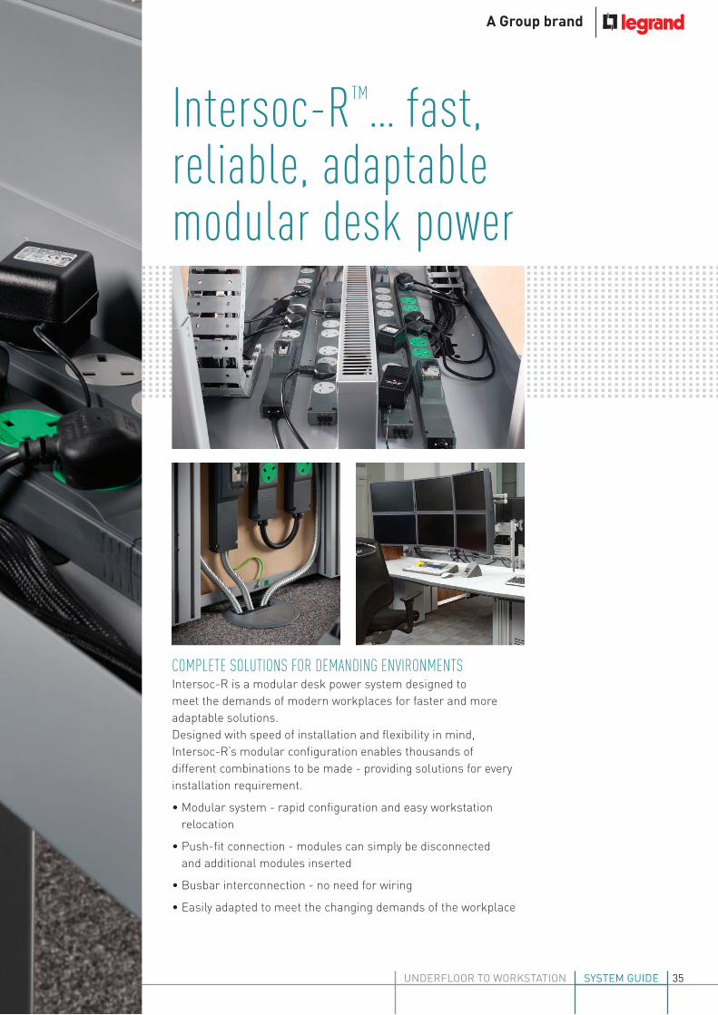
COMPLETE SOLUTIONS FOR DEMANDING ENVIRONMENTSIntersoc-R is a modular desk power system designed to
meet the demands of modern workplaces for faster and more
adaptable solutions.
Designed with speed of installation and lexibility in mind,
Intersoc-R’s modular coniguration enables thousands of
different combinations to be made - providing solutions for every
installation requirement.
• Modular system - rapid coniguration and easy workstation
relocation
• Push-it connection - modules can simply be disconnected
and additional modules inserted
• Busbar interconnection - no need for wiring
• Easily adapted to meet the changing demands of the workplace
Intersoc-RTM... fast, reliable, adaptable modular desk power
35

NEW Intersoc On-deskPersonal power and data systemFind out more on page 46
Available in standard and clean earth versions, with ixed
or rotatable socket options and a safe shuttered electrical
connection, Intersoc-R is the next generation of power
distribution...
• Simple push-it, module connection with auto-lock mechanism
creates robust joints and makes installation quicker and easier
• 32 A system with safe shuttered electrical connections for
additional safety, meets the requirements of BS 7671 : 2008
(including section 543.7)
• MCB, RCD and RCBO modules, with reversible hinged covers,
provide a full range of circuit protection options
• 2, 3 or 4 gang British standard socket modules with ixed or
rotatable, fused or unfused (BS 6396) sockets options - all the
options you need to meet the requirements of any installation
• 8 international socket options make Intersoc-R ideal for
installations across the globe
• Outgoing connections: lexible interlink or end cap with ST
or GST options
The next generation of power distribution
36

WWW.LEGRAND.CO.UK/ELECTRAK
UNDERFLOOR TO WORKSTATION SYSTEM GUIDE

38
Pack Cat. Nos. 16 A feed modules pre-wired to 13 A fused plug
1 IAB002A With 2 m 1·5 mm2 cable 1 IAB003A With 3 m 1·5 mm2 cable 1 IAB005A With 5 m 1·5 mm2 cable
16 A rewirable feed modules
1 IAB201A Rewirable feed module (for cable)
16 A feed units with in-built GST connector
1 IAB660B Compact feed module with male GST connector 1 IAB201B Feed module with male GST and earth bond lead
16 A pre-wired connection leads
13 A fused plug pre-wired to GST connector
1 IAB002B With 2 m 1·5 mm2 cable 1 IAB003B With 3 m 1·5 mm2 cable 1 IAB005B With 5 m 1·5 mm2 cable
GST to GST connection leads
1 IAB610BB 1 m length 1 IAB620BB 2 m length 1 IAB630BB 3 m length
Pack Cat. Nos. 32 A pre-wired feed modules
Standard earth tap-offs (E24 - White tap-off)
1 IAB311A 3 m unfused metal tap-off Cat. No. DP1332 1 IAB312A 5 m unfused metal tap-off Cat. No. DP1532 1 IAB315A 3 m 13 A fused 543·7 metal tap-off Cat. No. DP1327 1 IAB316A 5 m 13 A fused 543·7 metal tap-off Cat. No. DP1527
Low noise / clean earth tap-offs (E25 - Green tap-off)
1 IAC311A 3 m unfused metal tap-off Cat. No. JP2332 1 IAC312A 5 m unfused metal tap-off Cat. No. JP2532 1 IAC315A 3 m 13 A fused 543·7 metal tap-off Cat. No. JP2327 1 IAC316A 5 m 13 A fused 543·7 metal tap-off Cat. No. JP2527
Auxiliary earth tap-offs (E28 - Red tap-off)
1 IAF311A 3 m unfused metal tap-off Cat. No. YP5332 1 IAF312A 5 m unfused metal tap-off Cat. No. YP5532 1 IAF315A 3 m 13 A fused 543·7 metal tap-off Cat. No. YP5327 1 IAF316A 5 m 13 A fused 543·7 metal tap-off Cat. No. YP5527
32 A re-wirable feed modules
1 IAB301A Standard earth (for flexible conduit) 1 IAC301A Low noise (for flexible conduit)
32 A feed units with in-built Neutrik connectors
1 IAB301E Standard earth 1 IAC301E Low noise
32 A tap-offs pre-wired to Neutrik connectors
Standard earth tap-offs (E24)
1 IAB311E 3 m unfused metal tap-off Cat. No. DP1332 1 IAB312E 5 m unfused metal tap-off Cat. No. DP1532 1 IAB315E 3 m 13 A fused 543·7 metal tap-off Cat. No. DP1327 1 IAB316E 5 m 13 A fused 543·7 metal tap-off Cat. No. DP1527
Low noise / clean earth tap-offs (E25)
1 IAC311E 3 m unfused metal tap-off Cat. No. JP2332 1 IAC312E 5 m unfused metal tap-off Cat. No. JP2532 1 IAC315E 3 m 13 A fused 543·7 metal tap-off Cat. No. JP2327 1 IAC316E 5 m 13 A fused 543·7 metal tap-off Cat. No. JP2527
Intersoc-R features fast modular connection with push-fit auto lock mechanism, safe shuttered electrical connections and a robustly designed rigid joint between modules. Available in standard and clean earth versionsIndependently approved by Intertek. Complies with BS 5733 and the relevant parts of BS 1363 part 2. Manufactured in an approved ISO 9001 : 2008 facility. Meets the requirements of BS 7671 : 2008 for high integrity earthing (section 543·7)
IAB301A
IAB660B
IAB002A
IAB610BB
IAB312A
Intersoc-RTM desk moduleselectrical supply
Dimensions and technical information p. 42-45
038_039_Electrak 2014 v2.indd 38 27/08/2014 12:56

39
Pack Cat. Nos. Socket modules – low noise / clean earth (green sockets) (continued)
3 gang unfused
1 IAC503F Fixed sockets 1 IAC503R Rotatable sockets
3 gang individually fused
1 IAC533F 3·15 A – fixed sockets 1 IAC533R 3·15 A – rotatable sockets
4 gang unfused
1 IAC504F Fixed sockets 1 IAC504R Rotatable sockets
4 gang individually fused
1 IAC534F 3·15 A – fixed sockets 1 IAC534R 3·15 A – rotatable
End cap
1 IAZ001A Blank end cap
Intersoc to intersoc pre-wired interconnection
16 A
1 IAB603A 0·3 m length 1 IAB605A 0·5 m length 1 IAB610A 1 m length 1 IAB620A 2 m length 1 IAB630A 3 m length 1 IAB650A 5 m length
32 A
1 IAB703A 0·3 m length 1 IAB705A 0·5 m length 1 IAB710A 1 m length 1 IAB720A 2 m length 1 IAB730A 3 m length 1 IAB750A 5 m length
Power out end caps 16 A
Without flex
1 IAB600B End cap with female GST connector 1 IAB600C End cap with female ST connector
With flex to female GST connector
1 IAB610B 1 m length 1 IAB620B 2 m length 1 IAB630B 3 m length
Pack Cat. Nos. Protection and switching modules
1 IAB401A With 13 A fuse 1 IAB402A With 13 A fuse and sw/neon 1 IAB403A With 13 A fuse and neon 1 IAB404A 32 A max. single isolation module 1 IAB405A With 30 mA RCD 1 IAB408A With neon indicator 1 IAB420A With 16 A MCB 1 IAB430A With 20 A MCB 1 IAB440A With 32 A MCB 1 IAB450A With 16 A RCBO 1 IAB460A With 20 A RCBO 1 IAB470A With 32 A RCBO
Socket modules – standard (grey sockets)
2 gang unfused
1 IAB502F Fixed sockets 1 IAB502R Rotatable sockets
2 gang individually fused
1 IAB532F 3·15 A – fixed sockets 1 IAB532R 3·15 A – rotatable sockets
3 gang unfused
1 IAB503F Fixed sockets 1 IAB503R Rotatable sockets
3 gang individually fused
1 IAB533F 3·15 A – fixed sockets 1 IAB533R 3·15 A – rotatable sockets
4 gang unfused
1 IAB504F Fixed sockets 1 IAB504R Rotatable sockets
4 gang individually fused
1 IAB534F 3·15 A – fixed sockets 1 IAB534R 3·15 A – rotatable sockets
Socket modules – low noise / clean earth (green sockets)
2 gang unfused
1 IAC502F Fixed sockets 1 IAC502R Rotatable sockets
2 gang individually fused
1 IAC532F 3·15 A – fixed sockets 1 IAC532R 3·15 A – rotatable sockets
The BS version is available with fixed or rotatable sockets. Individually fused sockets are available to meet the requirements of BS 6396 : 2008 (5 x 20 mm anti-surge ceramic fuses)A wide range of interconnection solutions are available. When 16 A cabling interconnection is used with 32 A under desk solutions, suitable de-rating protection devices must be incorporated to protect the cablesAll protection and switching modules, end caps and interlinks are universally compatible with standard and clean earth / low noise systems
IAB504R
IAB533F
IAB600B
IAB703A
IAB610B
IAC502R IAZ001AIAB402A
IAB450A
Intersoc-RTM desk modulesprotection, BS sockets, end caps and interlinks
Dimensions and technical information p. 42-45
038_039_Electrak 2014 v2.indd 39 27/08/2014 12:57

40
Pack Cat. Nos. 5 A Indian socket modules
2 gang – grey socket outlets
1 IAB5P2A 90° angled sockets 1 IAB5P2B 45° angled sockets
4 gang – grey socket outlets
1 IAB5P4A 90° angled sockets 1 IAB5P4B 45° angled sockets
2 gang – green socket outlets
1 IAC5P2A 90° angled sockets 1 IAC5P2B 45° angled sockets
4 gang – green socket outlets
1 IAC5P4A 90° angled sockets 1 IAC5P4B 45° angled sockets
15 A South African socket modules
2 gang – grey socket outlets
1 IAB5Q2A 90° angled sockets 1 IAB5Q2B 45° angled sockets
4 gang – grey socket outlets
1 IAB5Q4A 90° angled sockets 1 IAB5Q4B 45° angled sockets
2 gang – green socket outlets
1 IAC5Q2A 90° angled sockets 1 IAC5Q2B 45° angled sockets
4 gang – green socket outlets
1 IAC5Q4A 90° angled sockets 1 IAC5Q4B 45° angled sockets
Pack Cat. Nos. Schuko socket modules
2 gang – grey socket outlets
1 IAB5N2A 90° angled sockets 1 IAB5N2B 45° angled sockets
4 gang – grey socket outlets
1 IAB5N4A 90° angled sockets 1 IAB5N4B 45° angled sockets
2 gang – red socket outlets
1 IAF5N2A 90° angled sockets 1 IAF5N2B 45° angled sockets
4 gang – red socket outlets
1 IAF5N4A 90° angled sockets 1 IAF5N4B 45° angled sockets
French/Belgium socket modules
2 gang – grey socket outlets
1 IAB5U2A 90° angled sockets 1 IAB5U2B 45° angled sockets
4 gang – grey socket outlets
1 IAB5U4A 90° angled sockets 1 IAB5U4B 45° angled sockets
2 gang – red socket outlets
1 IAF5U2A 90° angled sockets 1 IAF5U2B 45° angled sockets
4 gang – red socket outlets
1 IAF5U4A 90° angled sockets 1 IAF5U4B 45° angled sockets
The Intersoc 32 A under-desk range is a complete modular power system. Intersoc offers a wide range of international socket options.The Intersoc modular system features safe shuttered electrical connections and a robustly designed rigid joint between modules. All modules connect with single push-fit action and auto lock
IAB5N4A
IAF5N2A IAC5P2A
IAB5P4A
Intersoc® international rangeinternational socket options
Dimensions and technical information p. 42-45
040_Electrak 2014 v1.indd 40 27/08/2014 12:57

41
Pack Cat. Nos. 15 A USA socket modules
2 gang – grey socket outlets
1 IAB5S2A 90° angled sockets 1 IAB5S2B 45° angled sockets
4 gang – grey socket outlets
1 IAB5S4A 90° angled sockets 1 IAB5S4B 45° angled sockets
2 gang – green socket outlets
1 IAC5S2A 90° angled sockets 1 IAC5S2B 45° angled sockets
4 gang – green socket outlets
1 IAC5S4A 90° angled sockets 1 IAC5S4B 45° angled sockets
20 A USA socket modules
2 gang – grey socket outlets
1 IAB5T2A 90° angled sockets 1 IAB5T2B 45° angled sockets
4 gang – grey socket outlets
1 IAB5T4A 90° angled sockets 1 IAB5T4B 45° angled sockets
2 gang – green socket outlets
1 IAC5T2A 90° angled sockets 1 IAC5T2B 45° angled sockets
4 gang – green socket outlets
1 IAC5T4A 90° angled sockets 1 IAC5T4B 45° angled sockets
Pack Cat. Nos. Australian/Chinese socket modules
2 gang – grey socket outlets
1 IAB5R2A 90° angled sockets 1 IAB5R2B 45° angled sockets
4 gang – grey socket outlets
1 IAB5R4A 90° angled sockets 1 IAB5R4B 45° angled sockets
2 gang – green socket outlets
1 IAC5R2A 90° angled sockets 1 IAC5R2B 45° angled sockets
4 gang – green socket outlets
1 IAC5R4A 90° angled sockets 1 IAC5R4B 45° angled sockets
The Intersoc 32 A under-desk range is a complete modular power system. Intersoc offers a wide range of international socket options.The Intersoc modular system features safe shuttered electrical connections and a robustly designed rigid joint between modules. All modules connect with single push-fit action and auto lock
IAB5S4AIAB5R4A
IAC5R2A IAC5S2A
Intersoc® international range international socket options (continued)
Dimensions and technical information p. 42-45
041_Electrak 2014 v1.indd 41 27/08/2014 12:58

42
Intersoc-RTM desk modulestechnical information
n Under-desk dimensions (mm)
110·5
4 socket module
272·5
32
60
12
Blank end cap
MCB, RCD protection module
174·5
60
Protection module
115·5
60
50 77·5
Interconnection
All dimensions (mm) are nominal
2 socket module
156·5
60
37·9
60
3 socket module
214·5
Fixed –end view
Rotatable –end view
1
1 : 84·5 mm depth
Compact and GST feed unit Feed unit
1 1
1
1 : Dimensions only apply to BS sockets and not the international range
50
GST interconnectmale
75
042_045_Electrak 2014 v3.indd 42 27/08/2014 12:59

43
n Testing and accreditation n British Standards
BS 6396 : 2008 Electrical Systems in Office Furniture and Educational Furniture Specification
BS 7671 : 2008 incorporating amendment No. 1 : 2011. Requirements for Electrical Installation (IET Wiring Regulations 17th Edition)
Electricity at Work Regulations 1989
Health & Safety Legislation
Below is a brief outline of the main criteria within the standards :
BS 6396 : 2008 was published with regard to the use of electrical equipment within general office and educational furniture. This standard sets out in its scope the use and testing of electrical socket outlets and associated wiring when used together with a 13 A BS 1363 fused plug for mains supply and makes provision for the routing of cables through furniture
For compliance with this standard, socket outlet configurations of up to 4 outlets should be individually fused at 5 A and up to 6 outlets individually fused at 3·15 A
A note on individual socket fusing – BS 6396 Compliance :
The standard requires individual socket fusing (as per the table below)
Meets the requirements of BS 7671 : 2008 (2011) (17th Edition) The Health and Safety Executive states that installations which conform to the standards laid down in BS 7671 : 2008 (2011) are regarded by the HSE as likely to achieve conformity with the relevant parts of the Electricity at Work Regulations 1989
Special note should be taken of regulation 543·7 within BS 7671 : 2008 - Earthing requirements for the installation of equipment having high protective conductor currents
Regulation 543·7 has particular importance when there is a requirement for a quantity of information technology equipment being supplied from a final circuit in a location where the sum of their protective currents exceeds 10 mA in normal use. Due to current in the protective conductor arising from the use of IT equipment, there is a requirement to provide mechanically protected 4 mm2 conductor (543·7·1·103 (ii)). Intersoc achieves this when wired in accordance with the installation sheets by providing mechanically protected 5 mm2 protective conductors within the product
Electrical test data
Rated current up to 32 A
Rated voltage 250 V ~
Frequency 50/60 Hz
Volt drop
Live and neutral
2 socket module 1·5 m V/A
4 socket module 3·0 m V/A
Protection module 4·0 m V/A
(depending on device)
In-feeds :
16 A 4·0 m V/A
+1·5 mm2 29 m V/A/m
32 A 2·0 m V/A
+4 mm2 11 m V/A/m
Interconnections :
16 A/32 A 2·0 m V/A
+1·5 mm2 29 m V/A/m
+4 mm2 11 m V/A/m
Earth fault loop impedance
2 socket module 1·5 mΩ4 socket module 3·0 mΩProtection module 4·0 mΩ (depending on device)
In-feeds :
16 A 2·0 mΩ+1·5 mm2 29 mΩ/m
32 A 2·0 mΩ+4 mm2 11 mΩ/m
Interconnections :
16 A/32 A 4·0 m V/A+1·5 mm2 29 mΩ/m
+4 mm2 11 mΩ/m
Mechanical data
Number of conductors 3
Busbar conductor cross-sectional area 5 mm2
16 A rewirable in-feed terminal capacity 10 mm2
32 A rewirable in-feed terminal capacity 10 mm2
Total number of sockets
2, 3 or 4 sockets
5 or 6 sockets
Individually fused at
5 A
3·15 A
Independently approved by IntertekComplies with BS 5733 and relevant parts of BS 1363-2 Manufactured within an approved ISO 9001 : 2008 and ISO 14001 : 2004 facilityAssessed quality assurance certificate No. 2029
Module housing Heat resistant ABS
Socket outlets polycarbonate
Busbars high conductivity copper CW004A (C101)
Other metalwork phosphor bronze CW451K (PB102), CW452K (PB103)
brass CW507L (CZ107), CW508L (CZ108)
high conductivity copper CW004A (C101)1
Material specification
Conductor resistance at 20°C Fixed Rotatable
1 : European grades with nearest British Standard shown in brackets
2 socket module 0·8 mΩ 0·9 mΩ4 socket module 1·6 mΩ 1·7 mΩ
042_045_Electrak 2014 v3.indd 43 27/08/2014 13:00

44
Intersoc-RTM desk modules
installation and configuration
n Installation
Module self-locking latch
Underside of
modules shown
Slide green latch Blank end cap
2 socket module
To connect and disconnect Intersoc modules
1. Connection / disconnection to be made by a competent person
2. Before connecting modules ensure they are the correct way up and in line
3. Push modules together one at a time
4. Modules self-lock when fully pushed together
5. To disconnect modules slide green latch to unlock module and pull apart
6. Always end module run with blank end cap or interconnect
To fix modules to surface
1. Insert through all fixing holes no. 8 pozi-pan screw or M4 bolt to required length
2. Tighten screw / bolt down to mounting surface
All dimensions (mm) are nominal
042_045_Electrak 2014 v3.indd 44 27/08/2014 13:00

45
1. Select the type of distribution system - standard, or low noise / clean earth
2. Select the means of powering the system - cable or power track tap-off
3. Select the type of in-feed module to match the cable capacity - 16 A or 32 A
4. Select the means of protection
5. Select the number of socket modules from the 2, 3 or 4 gang range (individually fused or unfused)
6. Select fixed or rotatable sockets
7. Select the interconnection units if required
8. Finish system with the end cap
(All modules push fit and lock together on-site or can be factory assembled to customer requirement)
n Product configuration
1 2
llllllllllllllllllllllllllllllllllllllllllllllllllllll
lllllllllllllllllllllllllll
lllllllllllllllllllllllllllllll
iiiiiilRaised floor Floor grommet
In-feed and power module push together and self-lock when fully pushed home
Tap-off and in-feed pulled through floor grommet after testing and when required
32 A in-feed connected to tap-off and left underfloor until required
Underfloor power track
Tap-off
All dimensions (mm) are nominal
042_045_Electrak 2014 v3.indd 45 27/08/2014 13:00

XX

WWW.LEGRAND.CO.UK/ELECTRAK
UNDERFLOOR TO WORKSTATION SYSTEM GUIDE
Intersoc® on-desk... power and data for modern workspacesThe new Electrak Intersoc on-desk range brings power, data
and rapid USB charging capability to the modern workstation.
With its contoured edges, clean lines and stylish aluminium and
mirror white inish, Intersoc on-desk blends in perfectly
with contemporary ofice design schemes and enhances the
functionality of the desk space.
47

Intersoc® on-desk... del rapid USB char
The fast pace of modern work practices, combined with the need for instant connectivity
is placing an ever greater reliance on the use of multiple devices, whether it be at our
workstation or whilst we’re on the move. The new range of Intersoc on-desk modules offers
a convenient answer to the growing demand for user-specific desk power and data access,
no matter what the technology requirements.
RAPID USB CHARGING
With an impressive 3.1 Amp dual charging facility, Intersoc on-desk’s twin USB modules
offer a high speciication, rapid charge facility that keeps your mobile devices ready should
you need to work on the move. Up to two devices (e.g. tablet and smart phone) can be
simultaneously charged at a faster rate than common, lower output chargers.
SUPERCHARGEDCHARGINGTwin USB charging modules offer a high specification, rapid charge facility
48

WWW.LEGRAND.CO.UK/ELECTRAK
UNDERFLOOR TO WORKSTATION SYSTEM GUIDE
ivering power, data and ging to the workstation
HIGH PERFORMANCE DATA
CAT 6A keystone jack modules offer high performance data and are supplied via
cables which neatly feed through the rear of the unit. CAT 6 modules are also
available with simple RJ45 connection at both the front and rear of the unit.
TAILORED TO YOUR REQUIREMENTS
Coniguring Intersoc on-desk modules to your exact requirements couldn’t be
simpler. Choose from: lat (horizontal) or angled (vertical) mounted units; select
any combination of power and data, and further enhance functionality with single
or double Euro modules or any device from within Legrand’s Arteor modular
wiring accessories range.
Putting ‘personal’ back into desk power and data... Intersoc on-desk can be tailored to the demands of any workstation.
Left: Power is fed to the Intersoc on-desk unit via a choice of
13 A pre-wired plug, GST connector, or Intersoc-R under-desk
connector
Above left: On-desk units are available in flat mounted (pictured)
and angle mounted versions (data options are not available with
horizontal units)
Above: High specification CAT 6A keystone jacks can be supplied
with performance certificates. Easy to fix brackets are supplied
with protective pads that won’t damage the desk
Left hand page: Convenient personal power and data ports for
laptops, with CAT 5 / CAT 6 RJ45 feed neatly nestling to the rear
of the unit, plus dual USB charging facility
49

50
Intersoc® on-desk modules
Pre-wired with
3 m fl ex and
BS 1363 plug
Pre-wired with
1·5 m fl ex and
GST connector
Pre-wired with
1·5 m fl ex and
Intersoc-R connector
Description Cat. No. Cat. No. Cat. No.
Horizontal unit with 2 x sockets individually fused at 3·15 A
HA3320AA HB1320AA HD1320AA
Horizontal unit with 3 x sockets individually fused at 3·15A
HA3330AA HB1330AA HD1330AA
Horizontal unit with 4 x sockets individually fused at 3·15 A
HA3340AA HB1340AA HD1340AA
Vertical unit with 2 x sockets individually fused at 3·15 A
VA3320AA VB1320AA VD1320AA
Vertical unit with 3 x sockets individually fused at 3·15 A
VA3330AA VB1330AA VD1330AA
Vertical unit with 4 x sockets individually fused at 3·15 A
VA3340AA VB1340AA VD1340AA
Vertical unit with 2 x sockets individually fused at 3·15 A plus 1 x rear pluggable CAT 5 / CAT 6 RJ45 outlet
VA3320AB VB1320AB VD1320AB
Vertical unit with 2 x sockets individually fused at 3·15 A plus 2 x rear pluggable CAT 5 / CAT 6 RJ45 outlets
VA3320AC VB1320AC VD1320AC
Vertical unit with 2 x sockets individually fused at 3·15 A plus 1 x rear pluggable data USB outlet
VA3320AD VB1320AD VD1320AD
Vertical unit with 2 x sockets individually fused at 3·15 A plus 2 x rear pluggable data USB outlets
VA3320AE VB1320AE VD1320AE
Vertical unit with 2 x sockets individually fused at 3·15 A plus 1 x CAT 6A RJ45 outlet with 3 m data lead
VA3320AF VB1320AF VD1320AF
Vertical unit with 2 x sockets individually fused at 3·15 A plus 2 x CAT 6A RJ45 outlets with 3 m data leads
VA3320AG VB1320AG VD1320AG
Vertical unit with 2 x sockets individually fused at 3·15 A plus carrier to accept 1 x Euro Module (25 x 50 mm)
VA3320AK VB1320AK VD1320AK
Vertical unit with 2 x sockets individually fused at 3·15 A plus carrier to accept 2 x Euro Modules (50 x 50 mm)
VA3320AL VB1320AL VD1320AL
Vertical unit with 3 x sockets individually fused at 3·15 A plus 1 x rear pluggable CAT 5 / CAT 6 RJ45 outlet
VA3330AB VB1330AB VD1330AB
Vertical unit with 3 x sockets individually fused at 3·15 A plus 2 x rear pluggable CAT 5 / CAT 6 RJ45 outlets
VA3330AC VB1330AC VD1330AC
Vertical unit with 3 x sockets individually fused at 3·15 A plus 1 x rear pluggable data USB outlet
VA3330AD VB1330AD VD1330AD
Vertical unit with 3 x sockets individually fused at 3·15 A plus 2 x rear pluggable data USB outlets
VA3330AE VB1330AE VD1330AE
Fixings
Description Cat. No.
Long desk clamp for mounting horizontal units fl at on the desk H010
Adhesive fi xing strips for mounting horizontal units H002
Long desk clamp for mounting vertical units at an angle on desk V010
050_051 Electrak 2014 v2.indd 50 27/08/2014 14:51

51
Note:
All sockets are individually fused at 3·15 A and mounted at 45° (except units with a single socket outlet which will be unfused and mounted at 90°).
Other options are available to special order. Contact us on +44(0) 845 600 6266
CAT 5 / CAT 6 outlets have a rear facing RJ45 that will accept either CAT 5 or CAT 6 data cabling (no data cabling is included with the product)
CAT 6A outlets are supplied with 3 m pre-wired lead and performance certifi cate
The twin outlet charging USB can supply 3·1 A shared between the 2 outlets
The data USB outlets have a short fl ying lead and type-A receptacle at the rear for USB connection to the PC (no USB cabling is included with the product)
Units supplied with carriers to accept Euro modules will be supplied with apertures at the rear for the passing of data or AV cables
Intersoc® on-desk moduleswith twin outlet USB charger (3·1 A)
Pre-wired with
3 m fl ex and
BS 1363 plug
Pre-wired with
1·5 m fl ex and
GST connector
Pre-wired with
1·5 m fl ex and
Intersoc-R connector
Description Cat. No. Cat. No. Cat. No.
Horizontal unit with 1 x unfused socket plus twin outlet USB charger
HA3012AA HB1012AA HD1012AA
Horizontal unit with 2 x sockets individually fused at 3·15 A plus twin outlet USB charger
HA3322AA HB1322AA HD1322AA
Horizontal unit with 3 x sockets individually fused at 3·15 A plus twin outlet USB charger
HA3332AA HB1332AA HD1332AA
Vertical unit with 1 x unfused socket plus twin outlet USB charger
VA3012AA VB1012AA VD1012AA
Vertical unit with 2 x sockets individually fused at 3·15 A plus twin outlet USB charger
VA3322AA VB1322AA VD1322AA
Vertical unit with 3 x sockets individually fused at 3·15 A plus twin outlet USB charger
VA3332AA VB1332AA VD1332AA
Vertical unit with 1 x unfused socket, twin outlet USB charger plus 1 x rear pluggable CAT 5 / CAT 6 RJ45 outlet
VA3012AB VB1012AB VD1012AB
Vertical unit with 1 x unfused socket, twin outlet USB charger plus 2 x rear pluggable CAT 5 / CAT 6 RJ45 outlets
VA3012AC VB1012AC VD1012AC
Vertical unit with 1 x unfused socket, twin outlet USB charger plus 1 x rear pluggable data USB outlet
VA3012AD VB1012AD VD1012AD
Vertical unit with 1 x unfused socket, twin outlet USB charger plus 2 x rear pluggable data USB outlets
VA3012AE VB1012AE VD1012AE
Vertical unit with 2 x sockets individually fused at 3·15 A, twin outlet USB charger plus 1 x rear pluggable CAT 5 / CAT 6 RJ45 outlet
VA3322AB VB1322AB VD1322AB
Vertical unit with 2 x sockets individually fused at 3·15 A, twin outlet USB charger plus 2 x rear pluggable CAT 5 / CAT 6 RJ45 outlets
VA3322AC VB1322AC VD1322AC
Vertical unit with 2 x sockets individually fused at 3·15 A, twin outlet USB charger plus 1 x rear pluggable data USB outlet
VA3322AD VB1322AD VD1322AD
Vertical unit with 2 x sockets individually fused at 3·15 A, twin outlet USB charger plus 2 x rear pluggable data USB outlets
VA3322AE VB1322AE VD1322AE
Vertical unit with 2 x sockets individually fused at 3·15 A, twin outlet USB charger plus 1 x CAT 6A RJ45 outlet with 3 m data lead
VA3322AF VB1322AF VD1322AF
Vertical unit with 2 x sockets individually fused at 3·15 A, twin outlet USB charger plus 2 x CAT 6A RJ45 outlets with 3 m data leads
VA3322AG VB1322AG VD1322AG
Vertical unit with 2 x sockets individually fused at 3·15 A, twin outlet USB charger plus carrier to accept 1 x Euro Module (25 x 50 mm)
VA3322AK VB1322AK VD1322AK
Vertical unit with 2 x sockets individually fused at 3·15 A, twin outlet USB charger plus double carrier to accept 2 x Euro Modules (50 x 50 mm)
VA3322AL VB1322AL VD1322AL
050_051 Electrak 2014 v2.indd 51 27/08/2014 14:52

52
Intersoc® on-desk modules
technical information
n On-desk dimensions (mm)
Unit with 2 x sockets
All dimensions (mm) are nominal
130
178
195
243
260
308
182·5
230·5
205
253
185
178
Unit with 3 x sockets
Unit with 4 x sockets
100
40
Horizontal units
100
50
30°
Vertical units
Unit with 2 x sockets plus twin outlet USB charger
Unit with 2 x sockets plus 1 x CAT 5 / CAT 6 RJ45 outlet
Unit with 2 x sockets plus 2 x CAT 5 / CAT 6 RJ45 outlets
052_053 Electrak 2014 v2.indd 52 27/08/2014 13:01

53
n Testing and accreditation
n BS 6396 : 2008
Electrical Systems in Office Furniture and Educational Furniture Specification
Below is a brief outline of the main criteria within the standard :
BS 6396 : 2008 was published with regard to the use of electrical equipment within general office and educational furniture. This standard sets out in its scope the use and testing of electrical socket outlets and associated wiring when used together with a 13 A BS 1363 fused plug for mains supply and makes provision for the routing of cables through furniture
For compliance with this standard, socket outlet configurations of up to 4 outlets should be individually fused at 5 A and up to 6 outlets individually fused at 3·15 A
A note on individual socket fusing – BS 6396 Compliance :
The standard requires individual socket fusing (as per the table below)
Total number of sockets
2, 3 or 4 sockets
5 or 6 sockets
Individually fused at
5 A
3·15 A
Complies with BS 5733 and relevant parts of BS 1363-2 Manufactured within an approved ISO 9001 : 2008 and ISO 14001 : 2004 facility
Module housing aluminium
Module fascia polycarbonate
Socket outlets polycarbonate
End caps flame retardant ABS
Material specification
190
238
215
263
260
308
n On-desk dimensions (mm) (continued)
205
253
Unit with 2 x sockets plus 1 x CAT 6A RJ45 outlet
Unit with 2 x sockets plus 2 x CAT 6A RJ45 outlets
Unit with 2 x sockets plus carrier for Euro Module (25 x 50 mm)
Unit with 2 x sockets plus carrier for Euro Modules (50 x 50 mm)
All dimensions (mm) are nominal
Supply voltage (nominal) 230 V (AC)
Supply current 1·3 mA
Power consumption (max.) 0·3 W
Frequency 50 Hz
Output voltage +5·0 V ± 0·25 (DC)
Output current : 3 A
Output power : 15 W (max.)
Over current protection : 3·8 A (max.)
Output connector : 2 x USB Type A sockets
Current per socket : 2 A (max.)
USB charger module specification
052_053 Electrak 2014 v2.indd 53 27/08/2014 13:02

Ele
ctra
k w
ork
sta
tio
n p
ow
er
syst
em
gu
ide
08
/20
14
.5K
Head office (UK and Ireland):
Legrand Electric LimitedGreat King Street North, Birmingham, B19 2LFTel: 0870 608 9000 Fax: 0870 608 9004Website: www.legrand.co.uk
The Legrand logo is a registered trademark of the Legrand group of companies.This document is printed on sustainably sourced paper. Please recycle.
Contact details
Quotations and Technical Support: Legrand Electric Ltd. Great King Street North, Birmingham, B19 2LF
Tel: +44 (0) 845 600 6266 Fax: +44 (0) 845 600 6760 E-mail: [email protected]
Customer Services: Legrand Electric Ltd. No. 1 Industrial Estate, Medomsley Road, Consett, County Durham, DH8 6SR
Tel: +44 (0) 845 600 6266 Fax: +44 (0) 845 600 6366 E-mail: [email protected]
Accounts: Legrand Electric Ltd. Great King Street North, Birmingham, B19 2LF
Tel: +44 (0) 870 608 9000 Fax: +44 (0) 870 608 9004
FOLLOW
US AT
www.legrand.co.ukwww.legrand.ie
www.youtube.com/legrandtvuk
www.twitter.com/legranduk
www.voltimum.co.ukwww.voltimum.ie