Voyager-DE™ STR Biospectrometry™ Workstation
263
Voyager-DE ™ STR Biospectrometry ™ Workstation Version 5 Series Software Service Reference and Troubleshooting Guide This Document Contains CONFIDENTIAL Material of Applied Biosystems. For Internal Use Only - No Unauthorized Copying Permitted
-
Upload
khangminh22 -
Category
Documents
-
view
1 -
download
0
Transcript of Voyager-DE™ STR Biospectrometry™ Workstation

Voyager-DE™ STR Biospectrometry™ WorkstationVersion 5 Series Software
Service Reference and Troubleshooting GuideThis Document Contains CONFIDENTIAL Material of Applied Biosystems.
For Internal Use Only - No Unauthorized Copying Permitted

This is the back side of the front cover.
Voyager-DE™ STR Biospectrometry™ WorkstationVersion 5 Series Software
Service Reference and Troubleshooting GuideThis Document Contains CONFIDENTIAL Material of Applied Biosystems
For Internal Use Only - No Unauthorized Copying Permitted

© Copyright 2001, Applied Biosystems
All rights reserved
For Research Use Only. Not for use in diagnostic procedures.
Information in this document is subject to change without notice. Applied Biosystems assumes no responsibility for any errors that may appear in this document. This document is believed to be complete and accurate at the time of publication. In no event shall Applied Biosystems be liable for incidental, special, multiple, or consequential damages in connection with or arising from the use of this document.
ABI PRISM and its Design, Applied Biosystems, Aquapore, AmpliCover, Anitron, Biobytes, Brownlee, Delayed Extraction, FastPhoramidite, GeneScan, Genotyper, HLP, INHERIT, MicroAmp, MicroCoat, MPLC, NEWGUARD, ONESTEP, OPC, PCR-MATE, Phosphalink, POLYPORE, Precipitette, PerSeptive Biosystems and the fractal icon, ProBlott, PROCISE, ProFocus, ProSort, ProSpin, SeqEd, Sequence Navigator, SPHERI5, SPHERI10, StockMarks, Stretch, Synergy, SynthAssist, and VeloSep are registered trademarks of Applera Corporation or its subsidiaries in the U.S. and certain other countries.Data Explorer,
AB (Design), ABI, ABI Masterpiece, Applera, AutoAssembler, BaseSprinter, Biospectrometry, CATALYST, Data Explorer, GeneAssist, LV40, MatchMaker, PDQ, Primer Express, ProSorb, Sequazyme, and Voyager-DE are trademarks of Applera Corporation or its subsidiaries in the U.S. and certain other countries.
3Com is a registered trademark of 3Com Corporation.
Acqiris is a registered trademark of Acqiris SA.
Acrobat and Adobe are registered trademarks of Adobe Systems Incorporated.
Altera is a registered trademark of Altera Corporation.
AmpErase, AmpliTaq, AmpliTaq Gold, EnviroAmp, GeneAmp, and TaqMan are registered trademarks of Roche Molecular Systems, Inc.
AppleScript and Macintosh are registered trademarks of Apple, Inc.
IBM is a registered trademark of International Business Machines.
LeCroy is a registered trademark of LeCroy Corporation.
Lexan is a registered trademark of General Electric Co. Corp.
Lotus is a registered trademark of Lotus Development Corporation.
Microsoft, MS, MS-DOS, Windows, and Windows NT are registered trademarks of Microsoft Corporation.
Mini-Fit and Mini-Fit, Jr. are trademarks of Molex Incorporated.
MTA is a trademark of Amp Incorporated.
Pentium is a registered trademark of Intel Corporation.
Tektronix is a registered trademark of Tektronix, Inc.
All other trademarks are the sole property of their respective owners.
Printed in the USA, 04/2001Part Number Hardcopy 4319245 Rev. APart Number CD 4327166 Rev. B

Table of Contents
iii
Table of Contents
Safety and Compliance Information ................................................vii
How to Use This Guide ................................................................. xvii
Chapter 1 System Overview1.1 Voyager-DE™ STR Biospectrometry™ Workstation Overview ........................................ 1-2
1.2 Voyager-DE™ STR Laser Safety ................................................................................... 1-4
1.3 Voyager-DE STR Workstation Components ................................................................. 1-6
1.3.1 Sample Loading Chamber .............................................................................1-7
1.3.2 Main Source Chamber .................................................................................. 1-8
1.3.3 Laser System .............................................................................................. 1-11
1.3.4 Flight Tube (Drift Tube) ............................................................................... 1-15
1.3.5 Mirror Chamber ........................................................................................... 1-16
1.3.6 Digitizer ....................................................................................................... 1-19
1.3.7 Computer and Video Systems ..................................................................... 1-19
1.4 Voyager-DE STR Workstation Supporting Systems.................................................... 1-20
Chapter 2 Voyager-DE STR Workstation Electronics Theory2.1 Electronics Theory Overview ....................................................................................... 2-2
2.2 Electronics Common in Most Voyager-DE STR Instruments ........................................ 2-4
2.2.1 AC Distribution Board (V750053) ..................................................................2-5
2.2.2 DAC (Digital-to-Analog Converter) Board (V750025) ..................................... 2-9
2.2.3 DC Distribution Board (V750034) ................................................................ 2-11
2.2.4 Low-Mass Gate Delay Timer Board (V750069, V750073) ............................ 2-15
2.2.5 Low-Mass Gate Driver Boxes (V700635, V700643) and Detector Filter Bias (V750032) .................................................................................. 2-20
2.2.6 Timed Ion Selector (TIS) Assembly (V700471) ............................................ 2-26
2.2.7 TTL Output Opto-Trigger Board (V750065) ................................................. 2-31
2.3 Electronics Only in Newer Model Instruments ............................................................ 2-33
2.3.1 Beam-Steering Board (V750091) ................................................................. 2-33
2.3.2 DE Switch Box V725115/V725125 ............................................................... 2-37
2.3.3 Einzel Lens Electronics (Voltage Divider Box, 4317251) .............................. 2-44
2.3.4 48-Bit I/O Board with Game Port (V750033) ................................................ 2-45
2.3.5 MALDI Control Board (V750082 and V750102-001, V750102-002, V7502-003) ................................................................................................. 2-47
This Document Contains CONFIDENTIAL Material of Applied BiosystemsFor Internal Use Only - No Unauthorized Copying Permitted

Table of Contents
iv
2.4 Electronics Only in Earlier Instruments ...................................................................... 2-59
2.4.1 Flight-Tube (Drift-Tube) Power Supply (V750061) ....................................... 2-60
2.4.2 Pulse Generator Board (V750063) .............................................................. 2-63
Chapter 3 Before Servicing the Workstation3.1 Voyager Laser Safety .................................................................................................. 3-2
3.1.1 Overview of Laser Safety .............................................................................. 3-2
3.1.2 Required Customer-Provided YAG Laser Safety Measures ........................... 3-3
3.2 Venting the Voyager DE-STR Workstation ................................................................... 3-4
3.2.1 Preparing to Vent .......................................................................................... 3-4
3.2.2 Venting to Air ................................................................................................ 3-5
3.2.3 Purging the System to N2 ............................................................................. 3-5
3.3 Powering Up After Venting .......................................................................................... 3-6
Chapter 4 Diagnostics Software4.1 Overview ...................................................................................................................... 4-2
4.2 Voyager Software Compatibility .................................................................................... 4-2
4.3 Accessing the Diagnostics Software ............................................................................. 4-3
4.4 Diagnostics Software Features ..................................................................................... 4-5
4.1.1 Control Pages ............................................................................................... 4-5
4.1.2 Status Bar ....................................................................................................4-11
Chapter 5 Troubleshooting by Components5.1 Troubleshooting Overview ........................................................................................... 5-2
5.2 Sample Loading Chamber ........................................................................................... 5-7
5.2.1 Vacuum System Interaction .......................................................................... 5-7
5.2.2 Internal Interlocks Operation ......................................................................... 5-9
5.2.3 Camera .......................................................................................................5-11
5.2.4 Grabber, Linear Actuators, and Valves .........................................................5-11
5.2.5 Load/Eject Cycles ....................................................................................... 5-13
5.2.6 Vacuum Faults ............................................................................................ 5-15
5.2.7 Mechanical Control Page Errors and Warnings ........................................... 5-16
5.3 Main Source Chamber ............................................................................................. 5-18
5.3.1 Source Clips ............................................................................................... 5-23
5.3.2 Source Pedestal ......................................................................................... 5-24
5.3.3 Stepper Motor Feedthroughs ...................................................................... 5-26
5.3.4 Sample Plate and Grid Voltage ................................................................... 5-30
5.3.5 Internal High-Voltage Cable ........................................................................ 5-30
5.3.6 Operation Mode .......................................................................................... 5-31
5.3.7 Delayed-Extraction Ion Source ................................................................... 5-32
This Document Contains CONFIDENTIAL Material of Applied BiosystemsFor Internal Use Only - No Unauthorized Copying Permitted
Table of Contents
v
5.3.8 Source, Grid, and Mirror Voltages ............................................................... 5-33
5.3.9 Delayed Extraction, Low-Mass Gate and Timed Ion Selector Delay Times ... 5-35
5.3.10 DE Switch Box Control ................................................................................ 5-36
5.4 Laser System ............................................................................................................ 5-38
5.4.1 Laser Firing, Repetition Rate, and Re-initialization ...................................... 5-38
5.4.2 Laser Attenuation ........................................................................................ 5-40
5.5 Flight Tube and Mirror Chamber ................................................................................ 5-42
5.5.1 Timed Ion Selector ...................................................................................... 5-42
5.5.2 Flight-Tube (Drift-tube) Power Supply ......................................................... 5-43
5.6 Computer and Video Systems.................................................................................... 5-43
5.7 Vacuum System......................................................................................................... 5-44
5.7.1 Vacuum Gauges and Pumps ....................................................................... 5-44
5.7.2 Multigauge Controller .................................................................................. 5-45
5.7.3 Multigauge Controller, Computer, and Workstation Interaction .................... 5-47
Chapter 6 Troubleshooting by Symptoms6.1 Troubleshooting Tables ................................................................................................ 6-2
6.1.1 Spectral Problems ......................................................................................... 6-2
6.1.2 Sample Loading and Main Source Chamber ................................................. 6-4
6.1.3 Computer System and Software .................................................................... 6-9
6.1.4 Power Supplies and Circuit Boards ............................................................. 6-10
6.1.5 Vacuum System .......................................................................................... 6-11
6.2 Multigauge Controller Common Error Codes.............................................................. 6-16
6.3 LED Indicators ........................................................................................................... 6-18
Appendix A, Technical Support and Training .............................. A-1
Appendix B, Assembly Drawings ................................................. B-1
Appendix C, Electronic Drawings ................................................ C-1
Appendix D, Isolating Components Using Direct Bus Access........ D-1
Index
This Document Contains CONFIDENTIAL Material of Applied BiosystemsFor Internal Use Only - No Unauthorized Copying Permitted

Table of Contents
vi
This Document Contains CONFIDENTIAL Material of Applied BiosystemsFor Internal Use Only - No Unauthorized Copying Permitted

Safety and Compliance Information
Safety and Compliance Information
This section includes:
• Instrument safety• Safety and EMC standards• Laser safety
Instrument Safety
In This SectionThis section includes:
• Notes, Hints, Cautions, and Warnings• Safety symbols• Before operating this instrument• Material Safety Data Sheets (MSDSs)• General Warnings
Notes, Hints, Cautions, and WarningsNotes, Hints, Cautions, and Warnings are used in this document as follows.
A Note provides important information to the operator and appears as:
NOTE: If you are prompted to insert the boot diskette into the drive, insert it, and then press any key.
A Hint provides helpful suggestions not essential to the use of the system and appears as:
Hint: To avoid complicated file naming, use Save First to Pass or Save Best Only modes.
A Caution provides information to avoid damage to the system or loss of data and appears as:
CAUTION
Do not touch the lamp. This may damage the lamp.
A Warning provides specific information essential to the safety of the operator and appears as:
WARNING
CHEMICAL HAZARD. Wear appropriate personal protection and always observe safe laboratory practices when operating your system.
This Document Contains CONFIDENTIAL Material of Applied BiosystemsFor Internal Use Only - No Unauthorized Copying Permitted
vii

Safety and Compliance Information
viii
Remarques, recommandations et avertissementsUne remarque fournit une information importante à l’opérateur er se présente ainsi:
REMARQUE: Si on vous demande d’insérer la disquette de démarrage dans le lecteur, insérez-la puis appuyez sur n’importe quelle touche.
Une recommandation fournit une information destinée à éviter des détériorations du système ou la perte de données:
RECOMMANDATION La lampe peut être endommagée. N’y touchez pas.
Un avertissement fournit une information indispensable à la sécurité de l’operateur et se présente ainsi:
AVERTISSEMENT
Conformez-vous toujours aux règlements du laboratoire quand vous utilisez votre système.
Safety Symbols The following symbols may be displayed on the system. These symbols may also appear next to associated warnings in this document.
Electrical SymbolsThe following chart is an illustrated glossary of electrical symbols that may be displayed on your instrument. Whenever such symbols appear on instruments, please observe appropriate safety procedures.
This symbol indicates the on position of the main power switch.
This symbol indicates the off position of the main power switch.
This symbol indicates the on/off position of a push-push main power switch.
This symbol indicates that a terminal may be connected to another instrument’s signal ground reference. This is not a protected ground terminal.
This symbol indicates that this is a protective grounding terminal that must be connected to earth ground before any other electrical connections are made to the instrument.
A terminal marked with this symbol either receives or delivers alternating current or voltage.~
This Document Contains CONFIDENTIAL Material of Applied BiosystemsFor Internal Use Only - No Unauthorized Copying Permitted

Safety and Compliance Information
Non-electrical Symbols The following is an illustrated glossary of non-electrical safety alert symbols that may be displayed on your instrument.
Symboles des Alertes de SécuritéLes symboles suivants peuvent être affichés sur le système. Dans ce document, ces symboles peuvent aussi apparaître à côté des avertissements auxquels ils s’associent.
Symboles ÉlectriquesLe tableau suivant donne la signification de tous les symboles électriques qui figurent sur les appareils. En présence de l’un de ces symboles, il est impératif de se conformer aux consignes de sécurité appropriées.
A terminal marked with this symbol can receive or supply an alternating and a direct current or voltage.
This symbol appears next to the values of the fuses required by the system.
WARNING: This symbol indicates the presence of high voltage and warns the user to proceed with caution.
WARNING: This symbol alerts you to consult the manual for further information and to proceed with caution.
WARNING: This symbol illustrates a heater hazard. Proceed with caution when working around these areas to avoid being burned by hot components.
This symbol indicates that a laser is present inside the instrument.
Position MARCHE de l’interrupteur d’alimentation principal.
Position ARRÊT de l’interrupteur d’alimentation principal.
Positions MARCHE-ARRÊT de l’interrupteur d’alimentation principal à bouton poussoir.
Borne pouvant être reliée à la mise à la terre d’un autre appareil. Ce n’est pas une borne de mise à la terre protégée.
~
This Document Contains CONFIDENTIAL Material of Applied BiosystemsFor Internal Use Only - No Unauthorized Copying Permitted
ix

Safety and Compliance Information
x
Symboles Non ÉlectriquesLe tableau suivant donne la signification des symboles d’alertes de sécurité non électriques qui figurent sur les appareils.
Before Operating This InstrumentEnsure that anyone involved with the operation of the instrument is instructed in both general safety practices for laboratories and specific safety practices for the instrument. Make sure you have read and understood all related Material Safety Data Sheets.
Material Safety Data Sheets (MSDSs)Some of the chemicals that may be used with your system are listed as hazardous by their manufacturer. When hazards exist, they are prominently displayed on the labels of all chemicals. In addition, MSDSs supplied by the chemical manufacturer provide information about:
• Physical characteristics• Safety precautions• Health hazards• First-aid• Spill clean-up• Disposal procedures
Borne de mise à la terre de protection devant être reliée à la terre avant d’effectuer tout autre raccordement électrique à l’appareil.
Borne recevant ou fournissant une tension ou un courant de type alternatif.
Borne pouvant recevoir ou fournir une tension ou un courant de types alternatif et continu.
Ce symbole apparaît à côté des valeurs des fusibles requis par le système.
AVERTISSEMENT: Indique la présence d’une haute tension et avertit l’utilisateur de procéder avec précaution.
AVERTISSEMENT: Avertit l’utilisateur de la nécessité de consulter le manuel pour obtenir davantage d’informations et de procéder avec précaution.
AVERTISSEMENT: Danger associé à la présence d’un appareil de chauffage. Procéder avec précaution pour éviter de se brûler au contact de pièces ou d’éléments chauds.
Indique que l’appareil renferme un laser.
~~
This Document Contains CONFIDENTIAL Material of Applied BiosystemsFor Internal Use Only - No Unauthorized Copying Permitted

Safety and Compliance Information
WARNING
CHEMICAL HAZARD. Familiarize yourself with the MSDSs before using reagents or solvents.
AVERTISSEMENT
RISQUE CHIMIQUE. Il convient de se familiariser avec la MSDS (feuille de données concernant la sécurité des matériaux) avant d’utiliser des réactifs ou des solvants.
General Warnings
WARNING
FIRE HAZARD. Using a fuse of the wrong type or rating can cause a fire. Replace fuses with those of the same type and rating.
AVERTISSEMENT
DANGER D’INCENDIE. L’usage d’un fusible de type ou de valeur nominale différents risque de provoquer un incendie. Il convient donc de remplacer les fusibles usagés par des fusibles du même type et de la même valeur nominale.
WARNING
LASER HAZARD. The laser emits ultraviolet radiation. Lasers can burn the retina and leave permanent blind spots. Do not remove instrument front or side panels or look directly into the laser beam or allow a reflection of the beam to enter your eyes. Wear proper eye protection if front or side panels are removed for service.
AVERTISSEMENT
DANGER LASER. Le laser émet des radiations ultraviolettes. Les lasers peuvent brûler la rétine et laisser des points aveugles permanents. Il convient de ne pas retirer le panneau avant ou les panneaux latéraux de l’appareil et de ne pas regarder directement dans le faisceau laser ou laisser une réflexion du faisceau entrer dans les yeux. Portez des protections adéquates pour les yeux si le panneau avant ou les panneaux latéraux ont été retirés afin d’effectuer l’entretien.
This Document Contains CONFIDENTIAL Material of Applied BiosystemsFor Internal Use Only - No Unauthorized Copying Permitted
xi
Safety and Compliance Information
xii
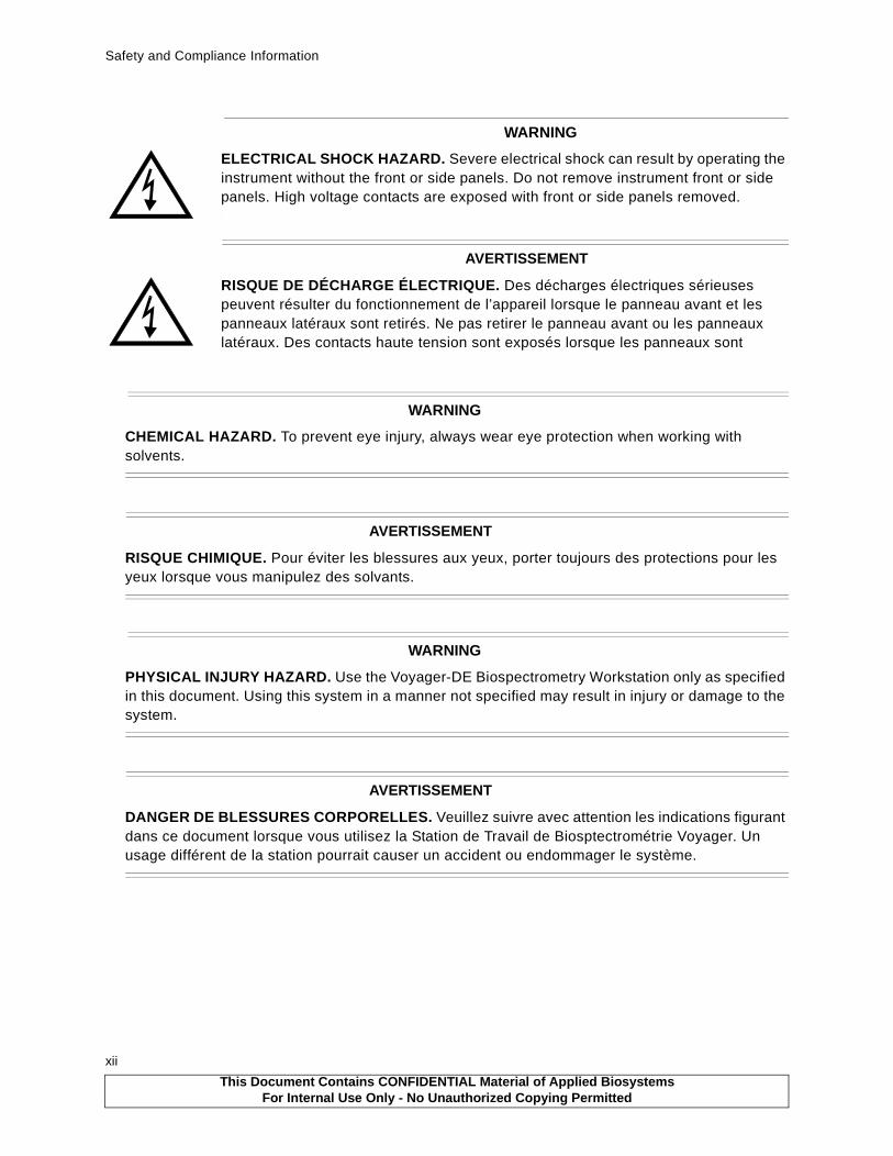
WARNING
CHEMICAL HAZARD. To prevent eye injury, always wear eye protection when working with solvents.
AVERTISSEMENT
RISQUE CHIMIQUE. Pour éviter les blessures aux yeux, porter toujours des protections pour les yeux lorsque vous manipulez des solvants.
WARNING
PHYSICAL INJURY HAZARD. Use the Voyager-DE Biospectrometry Workstation only as specified in this document. Using this system in a manner not specified may result in injury or damage to the system.
AVERTISSEMENT
DANGER DE BLESSURES CORPORELLES. Veuillez suivre avec attention les indications figurant dans ce document lorsque vous utilisez la Station de Travail de Biosptectrométrie Voyager. Un usage différent de la station pourrait causer un accident ou endommager le système.
WARNING
ELECTRICAL SHOCK HAZARD. Severe electrical shock can result by operating the instrument without the front or side panels. Do not remove instrument front or side panels. High voltage contacts are exposed with front or side panels removed.
AVERTISSEMENT
RISQUE DE DÉCHARGE ÉLECTRIQUE. Des décharges électriques sérieuses peuvent résulter du fonctionnement de l’appareil lorsque le panneau avant et les panneaux latéraux sont retirés. Ne pas retirer le panneau avant ou les panneaux latéraux. Des contacts haute tension sont exposés lorsque les panneaux sont
This Document Contains CONFIDENTIAL Material of Applied BiosystemsFor Internal Use Only - No Unauthorized Copying Permitted

Safety and Compliance Information
WARNING
CHEMICAL HAZARD. Before handling any chemicals, refer to the Material Safety Data Sheet provided by the manufacturer, and observe all relevant precautions.
AVERTISSEMENT
RISQUE CHIMIQUE. Avant de manipuler des produits chimiques, veuillez consulter la fiche de sécurité du matériel fournie par le fabricant, et observer les mesures de précaution qui s’imposent.
Safety and EMC (Electromagnetic Compliance) Standards
US Safety Standards SafetyThis instrument has been tested to and complies with standard ANSI/UL 3101-1, “Electrical Equipment for Laboratory Use; Part 1: General Requirements”, 1st Edition. It is an ETL Testing Laboratories listed product.
WARNING
Changes or modifications to this unit not expressly approved by the party responsible for compliance could void the user’s authority to operate the equipment.
Canadian Safety and EMC StandardsSafety
This instrument has been tested to and complies with standard CSA 1010, “Safety Requirements for Electrical Equipment for Measurement, Control, and Laboratory Use; Part 1: General Requirements”. It is an ETL Testing Laboratories listed product.
Sécurité
Cet instrument a été vérifié avec la norme CSA 1010, «Spécifications de sécurité du matériel électrique utilisé pour les mesures, les contrôles et dans les laboratoires ; Partie 1 : Spécifications générales», et il est conforme à cette norme. C’est un produit homologué par les ETL Testing Laboratories.
EMC
This Class A digital apparatus meets all requirements of the Canadian Interference-Causing Equipment Regulations.
Cet appareil numérique de la classe A respecte toutes les exigences du Règlement sur le materiel brouilleur du Canada.
This Document Contains CONFIDENTIAL Material of Applied BiosystemsFor Internal Use Only - No Unauthorized Copying Permitted
xiii

Safety and Compliance Information
xiv
Safety
This instrument meets European requirements for safety (EMC Directive 73/23/EEC). This instrument has been tested to and complies with standard EN61010-1 “Safety Requirements for Electrical Equipment for Measurement, Control and Laboratory Use”.
EMC
This instrument meets European requirements for emission and immunity (EMC Directive 98/336/EEC). This product has been evaluated to the EN55011:1992, Group 1, Class B “Radiated Emissions”, and EN50082-1:1992, “Generic Immunity”.
Laser Safety
Laser ClassificationThe Voyager-DE™ Biospectrometry™ Workstation uses a standard nitrogen laser and an optional Nd:YAG laser. Under normal operating conditions, the instrument laser is categorized as a Class I laser. Under certain conditions during servicing, when interlocks have been circumvented, the lasers fall into the following categories and can cause permanent eye damage:
• Nitrogen—Class IIIb• Nd:YAG—Class IV
The Voyager-DE Biospectrometry Workstation complies with Title 21, U.S. Government DHEW/BRH Performance Standards, Chapter 1, Subchapter J, Section 1040, as applicable.
Laser Safety FeaturesThe following safety features are included on the Voyager-DE Biospectrometry Workstation:
• Cabinet is designed to prevent access to collateral laser radiation exceeding the accessible emission limits in Performance Standards for Laser Products, 21 CFR 1040.10.
• Top, front, back, and side panels have interlock switches that disable the laser when panels are opened or removed.
• Safety labels for Class I standards are affixed to the unit.
Laser Safety RequirementsTo ensure safe laser operation, note the following:
• The system must be installed and maintained by an Applied Biosystems Technical Representative.
• Top, front, back, and side panels must be installed during instrument operation. When front and side panels are installed, there should be no detectable radiation present. If front or side panels are removed when the laser is operational, you may be exposed to laser emissions in excess of Class 1 rating.
• Do not remove labels or disable safety interlocks.
Additional Safety InformationRefer to the user manual provided with the laser for additional information on government and industry safety regulations.
European Safety and EMC Standards
This Document Contains CONFIDENTIAL Material of Applied BiosystemsFor Internal Use Only - No Unauthorized Copying Permitted

Safety and Compliance Information
Required Customer-Provided YAG Laser Safety MeasuresBefore servicing a system using the YAG laser, the customer is required to provide safety precautions. The YAG accessory supplied with the Voyager-DE STR is a class I laser, which is considered not capable of producing damaging radiation levels during operation. When maintenance requires an Applied Biosystems field service engineer to defeat the interlocks protection system for the instrument, the YAG laser is classified as a class IV laser. A class IV laser poses hazards to the eye and skin not only from the direct beam but in some cases also from the diffuse reflection. These lasers can be considered a fire hazard and may also produce laser-generated air contaminants and hazardous plasma radiation.
Therefore before you can perform maintenance or service on the YAG Laser while at the customer facility, the customer must:
• Provide the appropriate Laser Warning Signs. These signs shall be conspicuously displayed in a location where they will best serve to warn any and all onlookers.
• Provide the appropriate safety glasses/goggles to their employees if they are in the area while the laser is being serviced. The safety glasses/goggles must be rated for a YAG laser with a wavelength of 355 nm.
• Provide and document laser safety training to their employees on the hazards associated with a YAG laser.
• Remove all employees from the area where maintenance to the YAG laser is being performed.
In addition, all customers must be in compliance with the ANSI standard Z136.1-1993, American National Standard for the Safe Use of Lasers.
This Document Contains CONFIDENTIAL Material of Applied BiosystemsFor Internal Use Only - No Unauthorized Copying Permitted
xv

Safety and Compliance Information
xvi
This Document Contains CONFIDENTIAL Material of Applied BiosystemsFor Internal Use Only - No Unauthorized Copying Permitted

How to Use This Guide
How to Use This Guide
Purpose of This GuideThe Applied Biosystems Voyager-DE Biospectrometry Workstation Service Reference and Troubleshooting Guide provides the following:
• Reference information such as theory and circuit board functionality
• Troubleshooting procedures and tables
• Contact information
AudienceThis guide is intended for novice and experienced Voyager workstation field service engineers, technical support, and technical trainers.
Structure of This GuideThe Applied Biosystems Voyager-DE Biospectrometry Workstation Service Reference and Troubleshooting Guide is divided into chapters and appendices. Each chapter page is marked with a tab and a header to help you locate information within the chapter.
The table below describes the material covered in each chapter and appendix.
Chapter Contents
Chapter 1, System Overview Describes the parts of the system and software.
Chapter 2, Voyager-DE STR Workstation Electronics Theory
Describes the function, theory, and specifications for each Voyager workstation circuit board. Also includes tables of connectors, switches, and test points.
Chapter 3, Before Servicing the Workstation
Provides laser safety information, procedures for venting and powering up after venting.
Chapter 4, Voyager Diagnostics Software
Introduces the Voyager 32-Bit Diagnostic Software for Windows NT® platform.
Chapter 5, Troubleshooting by Components
Includes step-by-step procedures for troubleshooting and using the Diagnostics software for selected components.
Chapter 6, Troubleshooting by Symptoms
Provides symptoms, error codes, possible causes, and corrective actions.
Appendix A, Technical Support and Training
Describes how to contact Technical Support. Also includes how to obtain technical documents and customer training.
Appendix B, Assembly Drawings Shows the locations of many components. Provides detailed drawings of some components.
Appendix C, Electronic Drawings Electronic interconnect diagrams and circuit board drawings
Appendix D, Isolating Components Using Direct Bus Access
Describes how to write data directly to the bus through the Diagnostics Software Direct Bus Access control page.
This Document Contains CONFIDENTIAL Material of Applied BiosystemsFor Internal Use Only - No Unauthorized Copying Permitted
xvii

How to Use This Guide
xviii
Related DocumentationThese related documents are shipped with each Voyager-DE STR system:
• Voyager-DE™ Biospectrometry™ Workstation User Guide—Refer to this guide for detailed procedures and reference information on using the Voyager-DE Biospectrometry Workstation.
• Voyager-DE™ Biospectrometry™ Workstation Getting Started Guide—Use this guide to learn the basics of operating the system. It provides step-by-step information for running your first experiment.
• Data Explorer™ Software User Guide—Use this guide to learn how to use the Data Explorer software to process and analyze data.
• GPMAW General Protein/Mass Analyzer for Windows—Use this booklet to learn how to use the GPMAW software.
• Acqiris® Digitizers User Manual—If the system includes an Acqiris digitizer, use this document to learn about this digitizer’s functions that are not described in this document or in the Voyager-DE Biospectrometry Workstation User Guide.
• LeCroy®—If the system includes a LeCroy digitizer, use this document to learn about functions that are not described in this document or in the Voyager-DE Biospectrometry Workstation User Guide.
• Tektronix® TDS 520A, 524A, 540A, and 544A Digitizing Oscilloscope User Manual—If your system includes an Tektronix oscilloscope, use this document to learn about functions not described in the Voyage-DE Biospectrometry Workstation User Guide.
• Printer documentation (depends on the printer customer purchases)—Use this documentation to set up and service the printer.
• Microsoft ® Windows NT® User Guide and related documents—Use this guide to learn detailed information about the Microsoft Windows NT user interface.
Reference DocumentationThese reference documents are shipped with each Voyager-DE STR system:
• Varian Turbopump Instruction Manual• Varian Turbocontroller Instruction Manual• Varian Multigauge Controller Manual• Mechanical Pump Operating Instructions• LSI Nitrogen Laser Manual• Omega DIO-PC-48 Manual • Power I Single Output SPL Series Data Sheet• GAST Compressor Operating and Maintenance Instructions
The customer also receives the appropriate manual for the digitizer included with the system:
• LeCroy™ Embedded Signal Analysis Products Operator’s Manual LSA1000 Series and LeCroy™ Embedded Signal Analysis Products Remote Control Manual LSA1000 Series
• GPIB Software Reference Manual + Tek Manuals
This Document Contains CONFIDENTIAL Material of Applied BiosystemsFor Internal Use Only - No Unauthorized Copying Permitted

How to Use This Guide
Send Us Your CommentsThe Technical Communication Department welcomes your suggestions for improving our manuals. You can send us your comments in two ways:
• Use the Technical Publications Customer Survey at:
http://www.appliedbiosystems.com/contact.html
• Send e-mail to:
This Document Contains CONFIDENTIAL Material of Applied BiosystemsFor Internal Use Only - No Unauthorized Copying Permitted
xix

How to Use This Guide
xx
This Document Contains CONFIDENTIAL Material of Applied BiosystemsFor Internal Use Only - No Unauthorized Copying Permitted
1 System Overview
1-1
This chapter contains the following sections:1.1 Voyager-DE™ STR Biospectrometry™
Workstation Overview ........................................... 1-2
1.2 Voyager-DE™ STR Laser Safety............................ 1-4
1.3 Voyager-DE STR Workstation Components .......... 1-6
1.3.1 Sample Loading Chamber .......................... 1-7
1.3.2 Main Source Chamber ............................... 1-8
1.3.3 Laser System ........................................... 1-11
1.3.4 Flight Tube (Drift Tube) ............................ 1-15
1.3.5 Mirror Chamber ........................................ 1-16
1.3.6 Digitizer ................................................... 1-19
1.3.7 Computer and Video Systems .................. 1-19
1.4 Voyager-DE STR Workstation Supporting Systems ............................................................. 1-20
This Document Contains CONFIDENTIAL Material of Applied BiosystemsFor Internal Use Only - No Unauthorized Copying Permitted

Chapter 1 System Overview
1
1-2
1.1 Voyager-DE™ STR Biospectrometry™ Workstation Overview
The Voyager-DE™ STR Biospectrometry™ Workstation (Figure 1-1) is a floor-standing MALDI-TOF mass spectrometer that includes a reflector analyzer.
Figure 1-1 Voyager-DE STR Biospectrometry Workstation
Workstation ComponentsMajor components of the Voyager-DE STR Biospectrometry Workstation include a:
• Mass spectrometer—A time-of-flight mass spectrometer, described in Section 1.3, Voyager-DE STR Workstation Components. See the Voyager User Guide for more information.
TheVoyager workstation uses a 337-nm wavelength nitrogen laser.
• Computer/Data system—A computer that operates the Voyager workstation control software and the Voyager processing software. You control the mass spectrometer using the computer.
• Digitizer—An analog-to-digital converter that allows the signals from the mass spectrometer to be transferred to the computer.
• Video monitor—A monitor that displays a real-time video image of the sample spot on the sample plate in the mass spectrometer.
• Control stick—A peripheral device that allows you to control the position of the sample plate in the mass spectrometer and to start and stop acquisition. The control stick allows you to:
—Align a sample plate in the path of the laser
—Start and stop acquisition
—Save data
PB100427
Computer/
Video
Control stick
Massspectrometer
Computermonitor monitor
Electronics
Data system(inside cabinet)
(inside cabinets)
External digitizer
components
This Document Contains CONFIDENTIAL Material of Applied BiosystemsFor Internal Use Only - No Unauthorized Copying Permitted

Voyager-DE™ STR Biospectrometry™ Workstation Overview
1
Accessories and OptionsCustomers can purchase the following Voyager workstation options from Applied Biosystems:
• CID—Collision-induced dissociation capability to enhance fragmentation in Post-Source Decay (PSD) analysis. For more information, see the Voyager User Guide, Enhancing Fragmentation with CID. The hardware needed for the CID option is factory-installed. However, the workstations are plumbed for CID only when the customer orders this option.
• Nd:YAG—An integrated external 355-nm wavelength neodymium yttrium aluminum-garnet laser. The Nd:YAG Laser Option is compatible with any Voyager-DE STR workstation with a serial number of 4154 or later.
• GPMAW (General Protein Mass Analysis for Windows®)—A factory-installed software package useful for protein-specific applications, theoretical digest, and post source decay (PSD) fragmentation.
• CD-ROM Reader/Recorder—A device for storing or backing up data on CD-ROM media.
• Test standards kits—Useful for Voyager workstation optimization and applications. Kits available include:
—Sequazyme™ Peptide Mass Standards Kit
—Sequazyme™ C-Peptide Sequencing Kit
—Sequazyme™ Oligonucleotide Sequencing Kit
This Document Contains CONFIDENTIAL Material of Applied BiosystemsFor Internal Use Only - No Unauthorized Copying Permitted
1-3

Chapter 1 System Overview
1
1-4
1.2 Voyager-DE™ STR Laser Safety
Laser ClassificationThe Voyager-DE™ Biospectrometry™ Workstation uses a standard nitrogen laser and an optional Nd:YAG laser. Under normal operating conditions, the instrument laser is categorized as a Class I laser. Under certain conditions during servicing, when interlocks have been circumvented, the lasers fall into the following categories and can cause permanent eye damage:
• Nitrogen—Class IIIb• Nd:YAG—Class IV
The Voyager-DE Biospectrometry Workstation complies with Title 21, U.S. Government DHEW/BRH Performance Standards, Chapter 1, Subchapter J, Section 1040, as applicable.
Laser Safety FeaturesThe following safety features are included on the Voyager-DE Biospectrometry Workstation:
• Cabinet is designed to prevent access to collateral laser radiation exceeding the accessible emission limits in Performance Standards for Laser Products, 21 CFR 1040.10.
• Top, front, back, and side panels have interlock switches that disable the laser when panels are opened or removed.
• Safety labels for Class I standards are affixed to the unit.
WARNING
ELECTRICAL SHOCK AND LASER HAZARD. In External Trigger mode, the nitrogen laser energy storage capacitors are charged, and the laser is ready to fire at any time. When you perform service on the laser in External Trigger mode, remove jewelry and other items that can reflect the beam into your eyes or the eyes of others. Wear laser safety goggles and protect others from exposure to the beam. Post a laser warning sign.
WARNING
ELECTRICAL SHOCK AND LASER HAZARD. When instrument covers are removed, high voltage contacts are exposed, and the laser emits ultraviolet radiation. Wear laser safety goggles and post a laser warning sign at the entrance to the laboratory when you remove covers for service.
WARNING
LASER HAZARD. Exposure to direct or reflected laser light can burn the retina and leave permanent blind spots. Never look directly into the laser beam. Remove jewelry and other items that can reflect the beam into your eyes. Wear laser safety goggles during laser alignment. Protect others from exposure to the beam. Post a laser warning sign while performing service.
This Document Contains CONFIDENTIAL Material of Applied BiosystemsFor Internal Use Only - No Unauthorized Copying Permitted

Voyager-DE™ STR Laser Safety
1
Laser Safety RequirementsTo ensure safe laser operation, note the following:
• The system must be installed and maintained by an Applied Biosystems Technical Representative.
• Top, front, back, and side panels must be installed during instrument operation. When front and side panels are installed, there should be no detectable radiation present. If front or side panels are removed when the laser is operational, you may be exposed to laser emissions in excess of Class 1 rating.
• Do not remove labels or disable safety interlocks.
Additional Safety InformationRefer to the user manual provided with the laser for additional information on government and industry safety regulations.
Required Customer-Provided YAG Laser Safety MeasuresBefore servicing a system using the YAG laser, the customer is required to provide safety precautions. The YAG accessory supplied with the Voyager-DE STR is a class I laser, which is considered not capable of producing damaging radiation levels during operation. When maintenance requires an Applied Biosystems field service engineer to defeat the interlocks protection system for the instrument, the YAG laser is classified as a class IV laser. A class IV laser poses hazards to the eye and skin not only from the direct beam but in some cases also from the diffuse reflection. These lasers can be considered a fire hazard and may also produce laser-generated air contaminants and hazardous plasma radiation.
Therefore before you can perform maintenance or service on the YAG Laser while at the customer facility, the customer must:
• Provide the appropriate Laser Warning Signs. These signs shall be conspicuously displayed in a location where they will best serve to warn any and all onlookers.
• Provide the appropriate safety glasses/goggles to their employees if they are in the area while the laser is being serviced. The safety glasses/goggles must be rated for a YAG laser with a wavelength of 355 nm.
• Provide and document laser safety training to their employees on the hazards associated with a YAG laser.
• Remove all employees from the area where maintenance to the YAG laser is being performed.
In addition, all customers must be in compliance with the ANSI standard Z136.1-1993, American National Standard for the Safe Use of Lasers.
This Document Contains CONFIDENTIAL Material of Applied BiosystemsFor Internal Use Only - No Unauthorized Copying Permitted
1-5

Chapter 1 System Overview
1
1-6
1.3 Voyager-DE STR Workstation Components
Components OverviewThe components of the Voyager-DE STR Biospectrometry workstation (shown in Figure 1-2 and described in the sections that follow) are the:
• Sample loading chamber
• Main source chamber
• Laser system
• Flight tube
• Mirror chamber
• Digitizer
• Computer system, video system, and Voyager software
Figure 1-2 Voyager-DE STR Workstation
Mainsource
Video
Laser
Laserattenuator
Flighttube
Lineardetector
camera
Ion path in reflector mode
Sampleloadingchamber
chamber
Laser path
Prism
Computer,
Digitizer
Electronic connection
Mirror chamber
and monitor
Monitor
data system,
Reflectordetector
This Document Contains CONFIDENTIAL Material of Applied BiosystemsFor Internal Use Only - No Unauthorized Copying Permitted

Voyager-DE STR Workstation Components
1
1.3.1 Sample Loading ChamberOverviewThe sample loading chamber (Figure 1-3) transports the sample plate between vacuum chambers at various pressures.
Figure 1-3 Voyager-DE STR Workstation Sample Loading Chamber
The sample loading chamber system consists of:
• Linear actuators—Two pneumatic actuators that control the load/eject movement of the sample plate.
Linear 1 actuator, with a magnetic grabber, transports the sample plate between the sample loading chamber and the main source chamber. It places the sample plate on and removes the sample plate from the sample stage.
Linear 2 actuator, with its sample transporter, transports the sample plate into and out of the sample loading chamber.
• Flap door actuators—Two pneumatic actuators that control the opening of the flap doors that maintain vacuum pressure.
Flap Door 1 separates the sample loading chamber and the main source chamber. Flap Door 1 is spring-loaded. The spring maintains positive pressure in the closed (extended) position, maintaining integrity of the seal when the compressor is off.
Flap Door 2 separates the external atmosphere and the sample loading chamber.
Pneumatic SystemAn on-board air compressor provides up to 60 PSI (4.13 bar) to the pneumatic system that controls the sample-handling actuators and flap-door valves. For the actuators to operate correctly, a minimum of 15 PSI (1.03 bar) is needed. The integrated compressor is activated only during plate ejection and loading.
PB100855
Linear 2 actuator Linear 1 actuator
Flap Door 2 (shown closed)
Flap Door 1 actuator Flap Door 2 actuator
Flap Door 1(not visible, attached
To atmosphereTo main
to source housing)
source chamber
This Document Contains CONFIDENTIAL Material of Applied BiosystemsFor Internal Use Only - No Unauthorized Copying Permitted
1-7

Chapter 1 System Overview
1
1-8
1.3.2 Main Source Chamber
The main source chamber houses the ion source, a high-voltage region for ionizing, desorbing, and accelerating ions. Figure 1-4 shows the main source chamber for systems with serial numbers 4154 and later.
Figure 1-4 Voyager-DE STR Workstation Main Source Chamber (Top View)
Figure 1-5 shows typical voltages applied for main source chamber components of Voyager-DE STR instruments with serial numbers of 4154 and later.
Figure 1-5 Typical Voltages of Source Chamber Components
For more information, see the following sections in the Voyager User Guide:
• Optimizing Acquisition Settings• Setting Accelerating Voltage, and Optimizing Grid Voltage%
Einzel lens
Beam- steering plate
Variable-voltage
Sample
Sampleloadingchamber
Groundgrid
plate
grid
Collision cell option
Laser
Variable-voltage gridTypically ~60–95% of source
To detector
To sample loading chamber
Ground grid
Sample plate(source, max. 25,000 kV)
Einzel lens~50% of source voltage
Beam-steering plate
Laser
Collision cell
This Document Contains CONFIDENTIAL Material of Applied BiosystemsFor Internal Use Only - No Unauthorized Copying Permitted

Voyager-DE STR Workstation Components
1
For Voyager-DE STR instruments with a serial number of 4154 and later, the main source chamber includes a:
• Sample plate and sample stage—The source of ions. The sample plate and sample stage (Figure 1-3 on page 1-7) are supplied with voltage (source, up to 25,000 V) for acceleration of ions into the flight tube.
• Variable-voltage grid—A grid supplied with voltage to fine-tune ion acceleration. Typical voltage settings are shown in the following table:
When the Delayed-Extraction switch is open in Delayed-Extraction mode, the source plate and variable-voltage grid have approximately the same voltage. When the Delayed-Extraction switch is closed, the sample source plate has higher voltage than the variable-voltage grid. This causes ions of the same polarity to accelerate out of the main source chamber.
• Ground grid—The ground surface for formation of the potential gradient to the variable-voltage grid. Charged ions stop accelerating at the ground grid, but retain their initial velocity. After the ground grid, the ions enter the field-free region of the analyzer.
• Collision cell—A chamber available as the collision-induced dissociation (CID) option for enhanced fragmentation in PSD analysis.
• Einzel lens—A three-element (Figure 1-6), cylindrical, electrostatic lens (Figure 1-7) designed to organize the stream of ions into a narrow, straight beam. Electrostatic lenses focus charged particles in the same way as optical lenses focus light.
Figure 1-6 Potentials Configuration of an Einzel Lens (Cross Section)
ModeTypical Variable-Voltage Grid Settings
(Percent of Source Voltage)
Linear, Delayed-Extraction mode ~94 to 95%
Reflector mode ~65 to 75% (higher with PSD)
V3 V2 V1
Ion flow
V3 = V1 Typically V2 > V1
This Document Contains CONFIDENTIAL Material of Applied BiosystemsFor Internal Use Only - No Unauthorized Copying Permitted
1-9

Chapter 1 System Overview
1
1-10
Figure 1-7 Einzel Lens Assembly Expanded View
The potentials of the first and third elements are the same. As the ion stream passes through the einzel lens, the ions are repelled toward the center of the cylinder, forming a collimated beam at a focal distance farther down the flight path. The focal length depends on the dimensions of and the potentials applied to the lens elements.
• Beam-steering plates—Two pairs of parallel plates that maintain the correct path (horizontal and vertical) for the beam to strike the detector. You tune the beam voltage to optimize ion focusing.
Einzel lens assembly
Ionflow
V1V2V3
CID cell
This Document Contains CONFIDENTIAL Material of Applied BiosystemsFor Internal Use Only - No Unauthorized Copying Permitted

Voyager-DE STR Workstation Components
1
1.3.3 Laser SystemLaser System OverviewThe standard laser is a 337.1 nm-beam nitrogen laser. It produces 3-ns-wide pulses at up to 20 pulses per second. For Voyager workstation with serial numbers 4154 and later, an optional 355 nm wavelength Nd:YAG laser unit can be purchased.
When all the Voyager workstation covers (top, front, side, back, and rear covers) are installed, no detectable radiation is present, and the nitrogen laser is classified as a Class 1 laser. Similarly, if all Voyager workstation covers and the YAG laser unit covers are installed, the YAG laser unit is classified as a Class 1 laser.
The Voyager workstation covers have interlock switches that disable the laser when the covers are removed.
When maintenance requires a field service engineer to defeat the interlock protection system, the radiation may be present in excess of Class 1 limits. Under certain conditions during servicing, when interlocks have been circumvented, the lasers can cause permanent eye damage and therefore are classified in the following categories:
• Nitrogen laser—Class IIIb• Nd:YAG laser—Class IV
A class IV laser poses hazards to the eye and skin not only from the direct beam but, in some cases, also from diffuse reflection. These lasers can be considered fire hazards, which also may produce laser-generated air contaminants and hazardous plasma radiation. See the Safety and Compliance Information section in the front of this manual for safety precautions to be taken by the customer before performing service on the YAG Laser.
For more safety information, see the Safety and Compliance Information section in the front of this manual and the documentation provided by the laser manufacturer.
WARNING
ELECTRICAL SHOCK AND LASER HAZARD. When instrument covers are removed, high voltage contacts are exposed, and the laser emits ultraviolet radiation. Wear laser safety goggles and post a laser warning sign at the entrance to the laboratory when you remove covers for service.
WARNING
LASER HAZARD. Exposure to direct or reflected laser light can burn the retina and leave permanent blind spots. Never look directly into the laser beam. Remove jewelry and other items that can reflect the beam into your eyes. Wear laser safety goggles during laser alignment. Protect others from exposure to the beam. Post a laser warning sign while performing the alignment.
This Document Contains CONFIDENTIAL Material of Applied BiosystemsFor Internal Use Only - No Unauthorized Copying Permitted
1-11
Chapter 1 System Overview
1
1-12
Nitrogen Laser StructureComponents of the nitrogen laser module include the:
• Shutter (manual slide mechanism)• Plasma cartridge module • Low-voltage power supplies• High-voltage power supplies• Trigger transformer board
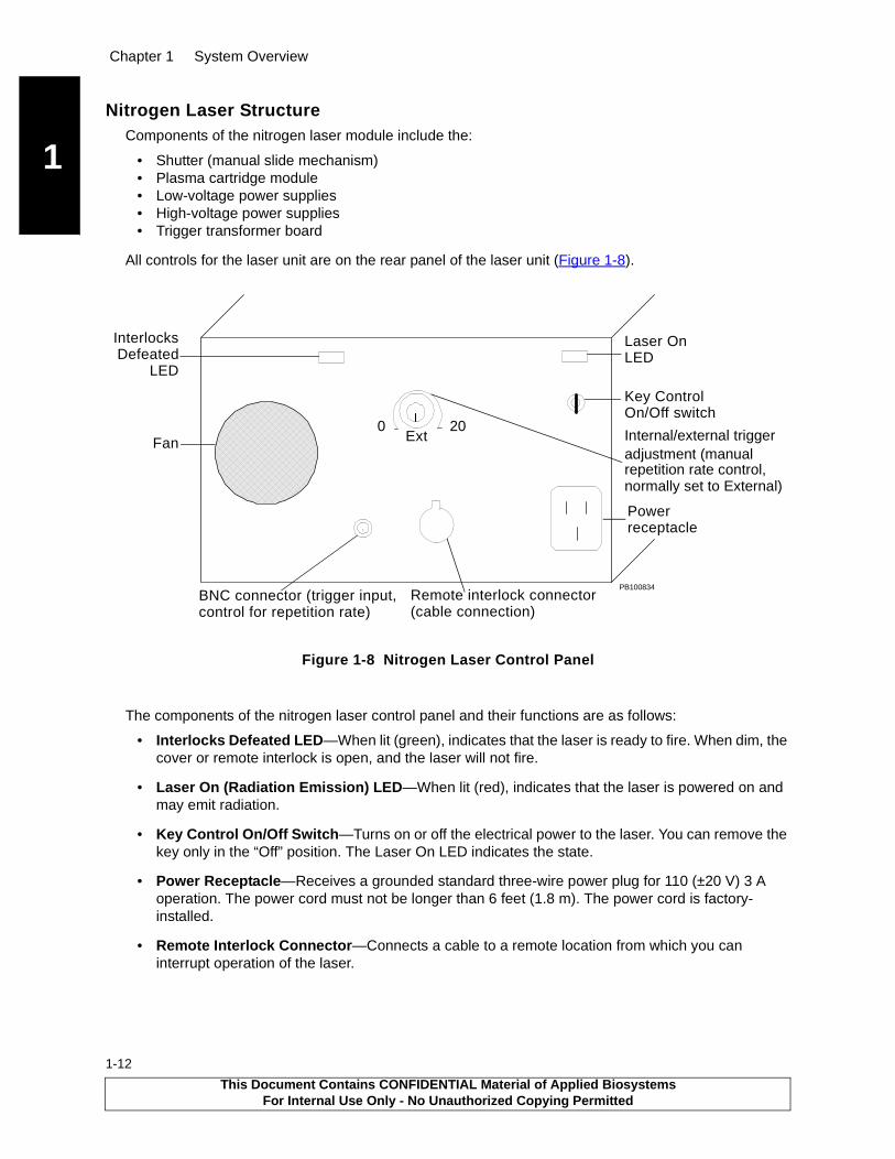
All controls for the laser unit are on the rear panel of the laser unit (Figure 1-8).
Figure 1-8 Nitrogen Laser Control Panel
The components of the nitrogen laser control panel and their functions are as follows:
• Interlocks Defeated LED—When lit (green), indicates that the laser is ready to fire. When dim, the cover or remote interlock is open, and the laser will not fire.
• Laser On (Radiation Emission) LED—When lit (red), indicates that the laser is powered on and may emit radiation.
• Key Control On/Off Switch—Turns on or off the electrical power to the laser. You can remove the key only in the “Off” position. The Laser On LED indicates the state.
• Power Receptacle—Receives a grounded standard three-wire power plug for 110 (±20 V) 3 A operation. The power cord must not be longer than 6 feet (1.8 m). The power cord is factory-installed.
• Remote Interlock Connector—Connects a cable to a remote location from which you can interrupt operation of the laser.
.
PB100834Remote interlock connector(cable connection)
Fan
Key Control
Power receptacle
Laser OnLED
InterlocksDefeated
LED
Internal/external trigger
repetition rate control,
200Ext
normally set to External)
adjustment (manual
BNC connector (trigger input,control for repetition rate)
On/Off switch
This Document Contains CONFIDENTIAL Material of Applied BiosystemsFor Internal Use Only - No Unauthorized Copying Permitted

Voyager-DE STR Workstation Components
1
• Internal/External Trigger Adjustment—Provides control of internal manual and external trigger pulse-repetition rate.
Internal Trigger mode allows you to manually vary the pulse-repetition rate continuously from 0 to 20 pulses per second. To increase the pulse repetition rate, you turn the knob clockwise. Use Internal Trigger mode for diagnostic purposes only.
External Trigger mode is the standard mode for Voyager workstation operation. In this mode, external electrical signals are sent through the BNC trigger input connector to set the pulse-repetition rate up. To set External Trigger mode, turn the knob fully counterclockwise until you feel a switch action.
WARNING
ELECTRICAL SHOCK AND LASER HAZARD. In External Trigger mode, the nitrogen laser energy storage capacitors are charged, and the laser is ready to fire at any time. When you perform service on the laser in External Trigger mode, remove jewelry and other items that can reflect the beam into your eyes or the eyes of others. Wear laser safety goggles and protect others from exposure to the beam. Post a laser warning sign.
• BNC Connector (Trigger Input) —The external trigger requires a TTL signal of 1 microsecond or longer. The input of the trigger is protected with an opto-isolator that minimizes EMI/RF interferences. The cable is an RG58C/U BNC cable, 4 feet (1.2 m) or shorter.
• Fan—Moderates the temperature of the nitrogen laser unit.
WARNINGWARNING
LASER BURN HAZARD. An overheated laser can cause severe burns if it contacts skin. DO NOT operate the laser when it cannot be cooled by its cooling fan. Always wear laser safety goggles.
This Document Contains CONFIDENTIAL Material of Applied BiosystemsFor Internal Use Only - No Unauthorized Copying Permitted
1-13
Chapter 1 System Overview
1
1-14
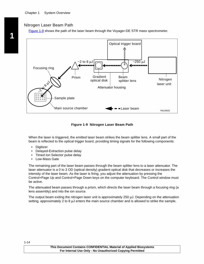
Nitrogen Laser Beam PathFigure 1-9 shows the path of the laser beam through the Voyager-DE STR mass spectrometer.
Figure 1-9 Nitrogen Laser Beam Path
When the laser is triggered, the emitted laser beam strikes the beam splitter lens. A small part of the beam is reflected to the optical trigger board, providing timing signals for the following components:
• Digitizer• Delayed-Extraction pulse delay• Timed Ion Selector pulse delay• Low-Mass Gate
The remaining part of the laser beam passes through the beam splitter lens to a laser attenuator. The laser attenuator is a 0 to 3 OD (optical density) gradient optical disk that decreases or increases the intensity of the laser beam. As the laser is firing, you adjust the attenuation by pressing the Control+Page Up and Control+Page Down keys on the computer keyboard. The Control window must be active.
The attenuated beam passes through a prism, which directs the laser beam through a focusing ring (a lens assembly) and into the ion source.
The output beam exiting the nitrogen laser unit is approximately 250 µJ. Depending on the attenuation setting, approximately 2 to 8 µJ enters the main source chamber and is allowed to strike the sample.
PB100832
Optical trigger board
Nitrogen Gradient Prism
Focusing ring
Main source chamber
Sample plate
laser unit
Laser beam
Beam optical disk
Attenuator housing
splitter lens
~2 to 8 µJ
~2 to
8 µ
J
~250 µJ
This Document Contains CONFIDENTIAL Material of Applied BiosystemsFor Internal Use Only - No Unauthorized Copying Permitted
Voyager-DE STR Workstation Components
1
1.3.4 Flight Tube (Drift Tube)OverviewThe flight tube is free of electromagnetic fields (no accelerating forces are present), allowing ions to drift at a velocity inversely proportional to the square root of their masses. (That is, the lighter an ion, the faster it drifts; the heavier an ion, the slower it drifts.) The flight tube is also referred to as the drift tube.
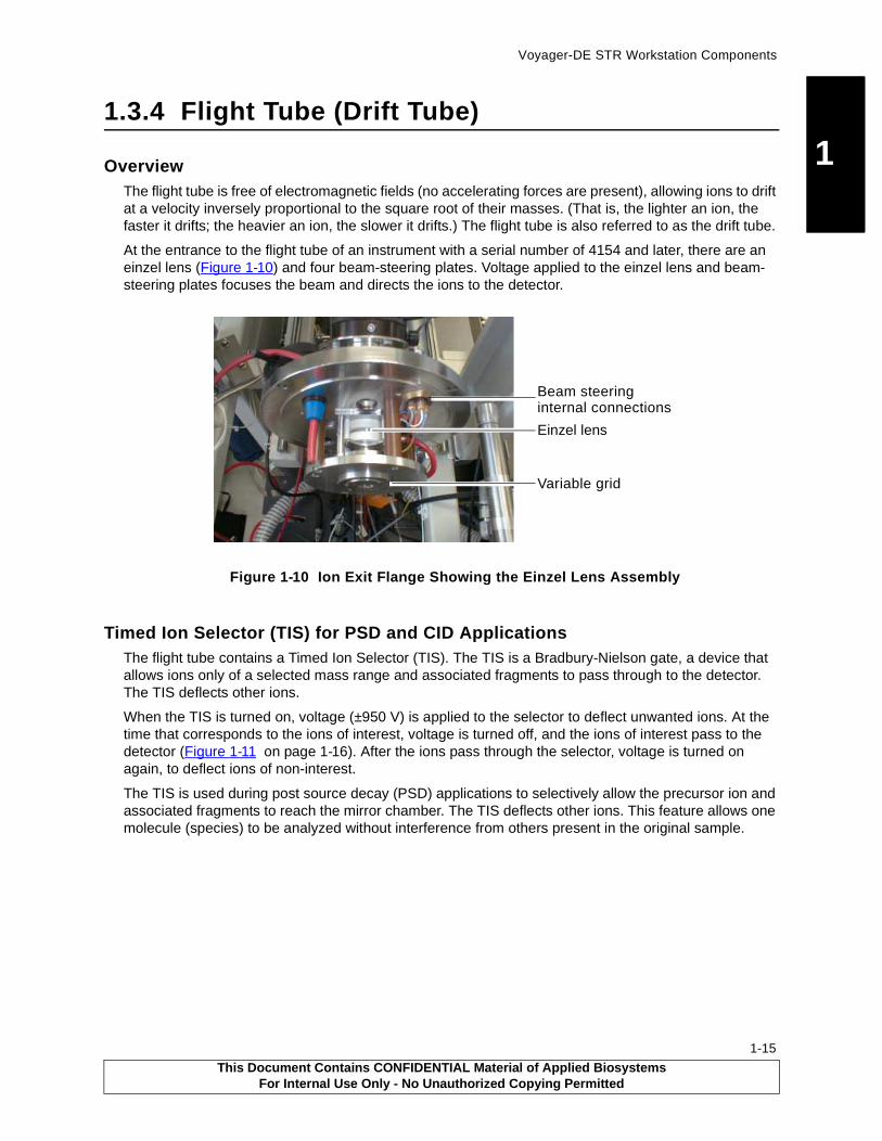
At the entrance to the flight tube of an instrument with a serial number of 4154 and later, there are an einzel lens (Figure 1-10) and four beam-steering plates. Voltage applied to the einzel lens and beam-steering plates focuses the beam and directs the ions to the detector.
Figure 1-10 Ion Exit Flange Showing the Einzel Lens Assembly
Timed Ion Selector (TIS) for PSD and CID ApplicationsThe flight tube contains a Timed Ion Selector (TIS). The TIS is a Bradbury-Nielson gate, a device that allows ions only of a selected mass range and associated fragments to pass through to the detector. The TIS deflects other ions.
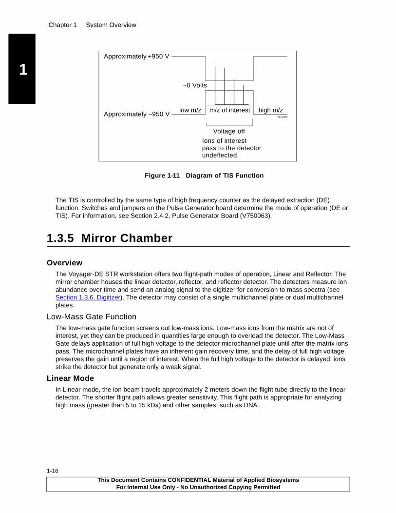
When the TIS is turned on, voltage (±950 V) is applied to the selector to deflect unwanted ions. At the time that corresponds to the ions of interest, voltage is turned off, and the ions of interest pass to the detector (Figure 1-11 on page 1-16). After the ions pass through the selector, voltage is turned on again, to deflect ions of non-interest.
The TIS is used during post source decay (PSD) applications to selectively allow the precursor ion and associated fragments to reach the mirror chamber. The TIS deflects other ions. This feature allows one molecule (species) to be analyzed without interference from others present in the original sample.
Einzel lens
Beam steeringinternal connections
Variable grid
This Document Contains CONFIDENTIAL Material of Applied BiosystemsFor Internal Use Only - No Unauthorized Copying Permitted
1-15
Chapter 1 System Overview
1
1-16
Figure 1-11 Diagram of TIS Function
The TIS is controlled by the same type of high frequency counter as the delayed extraction (DE) function. Switches and jumpers on the Pulse Generator board determine the mode of operation (DE or TIS). For information, see Section 2.4.2, Pulse Generator Board (V750063).
1.3.5 Mirror Chamber
OverviewThe Voyager-DE STR workstation offers two flight-path modes of operation, Linear and Reflector. The mirror chamber houses the linear detector, reflector, and reflector detector. The detectors measure ion abundance over time and send an analog signal to the digitizer for conversion to mass spectra (see Section 1.3.6, Digitizer). The detector may consist of a single multichannel plate or dual multichannel plates.
Low-Mass Gate FunctionThe low-mass gate function screens out low-mass ions. Low-mass ions from the matrix are not of interest, yet they can be produced in quantities large enough to overload the detector. The Low-Mass Gate delays application of full high voltage to the detector microchannel plate until after the matrix ions pass. The microchannel plates have an inherent gain recovery time, and the delay of full high voltage preserves the gain until a region of interest. When the full high voltage to the detector is delayed, ions strike the detector but generate only a weak signal.
Linear ModeIn Linear mode, the ion beam travels approximately 2 meters down the flight tube directly to the linear detector. The shorter flight path allows greater sensitivity. This flight path is appropriate for analyzing high mass (greater than 5 to 15 kDa) and other samples, such as DNA.
PB100835
+950 V
–950 V
~0 Volts
Approximately
Approximately
Ions of interest
Voltage off
pass to the detectorundeflected.
low m/z m/z of interest high m/z
This Document Contains CONFIDENTIAL Material of Applied BiosystemsFor Internal Use Only - No Unauthorized Copying Permitted

Voyager-DE STR Workstation Components
1
The linear detector:
• Measures ion abundance over time.
• Is used in Linear mode only; it is not used in Reflector or PSD mode.
• Is the most sensitive mode. Fragments, neutral molecules, and molecular ions arrive at the detector at the same time and less sample fragmentation is observed.
• Is a hybrid high-current detector (HCD). The HCD (Figure 1-12) consists of a single microchannel plate, a fast scintillator, and a photomultiplier. Earlier instruments (serial numbers 4115, 4114, 4111 and earlier) can be upgraded with HCD.
Figure 1-12 High-Current Detector
Reflector ModeIn Reflector mode, the ion beam travels approximately 2 meters down the flight tube to the reflector mirror where the beam is reflected an additional meter to the reflector detector. Reflector mode offers higher resolution and greater mass accuracy because of the longer flight path and action of the reflector. Reflector mode is commonly used for analyzing lower mass ions and in PSD analysis.
The reflector is a single-stage, gridded mirror that focuses energy and reverses the direction of the ions. Ion reflection:
• Filters out neutral molecules• Corrects time dispersion due to initial kinetic energy distribution• Provides greater mass accuracy and resolution
The reflector (Figure 1-13 on page 1-18) is a series of parallel, equally-spaced disks with coaxial holes, separated by insulators. Figure 1-14 on page 1-18 shows the time-focusing of ions of identical mass (and energy) within the mirror. Time-focusing results in improved resolution.
Bottom View Top View
This Document Contains CONFIDENTIAL Material of Applied BiosystemsFor Internal Use Only - No Unauthorized Copying Permitted
1-17

Chapter 1 System Overview
1
1-18
Figure 1-13 Reflector
Figure 1-14 Reflector Cross Section Diagram
The disk potentials are determined by the reflector voltage and series resistor network, such that their potentials gradually increase as the ions penetrate farther into the mirror. The final disk has a potential that is slightly higher than the source (accelerating) voltage, so that all charged ions are forced to reverse direction before they reach the back of the mirror. Neutral molecules are not deflected.
The Voyager-DE STR workstation reflector is tilted down one degree off axis. The slight tilt allows the reflector detector to be placed off-axis to avoid blocking incoming ions and minimize incidental collisions. This configuration also ensures that the paths of incoming and reflected ions do not overlap.
The reflector detector:
• Measures the abundance of reflected ions over time
• Is a dual microchannel plate optimized for response time
• Has a grounded shield to protect the ions from stray electromagnetic fields
• Is positioned perpendicular to the ion beam for improved performance
Reflector detector
0 V +20-25 kV
Faster ion takes longer path
Slower ion takesshorter path
~
Linear detector
This Document Contains CONFIDENTIAL Material of Applied BiosystemsFor Internal Use Only - No Unauthorized Copying Permitted
Voyager-DE STR Workstation Components
1
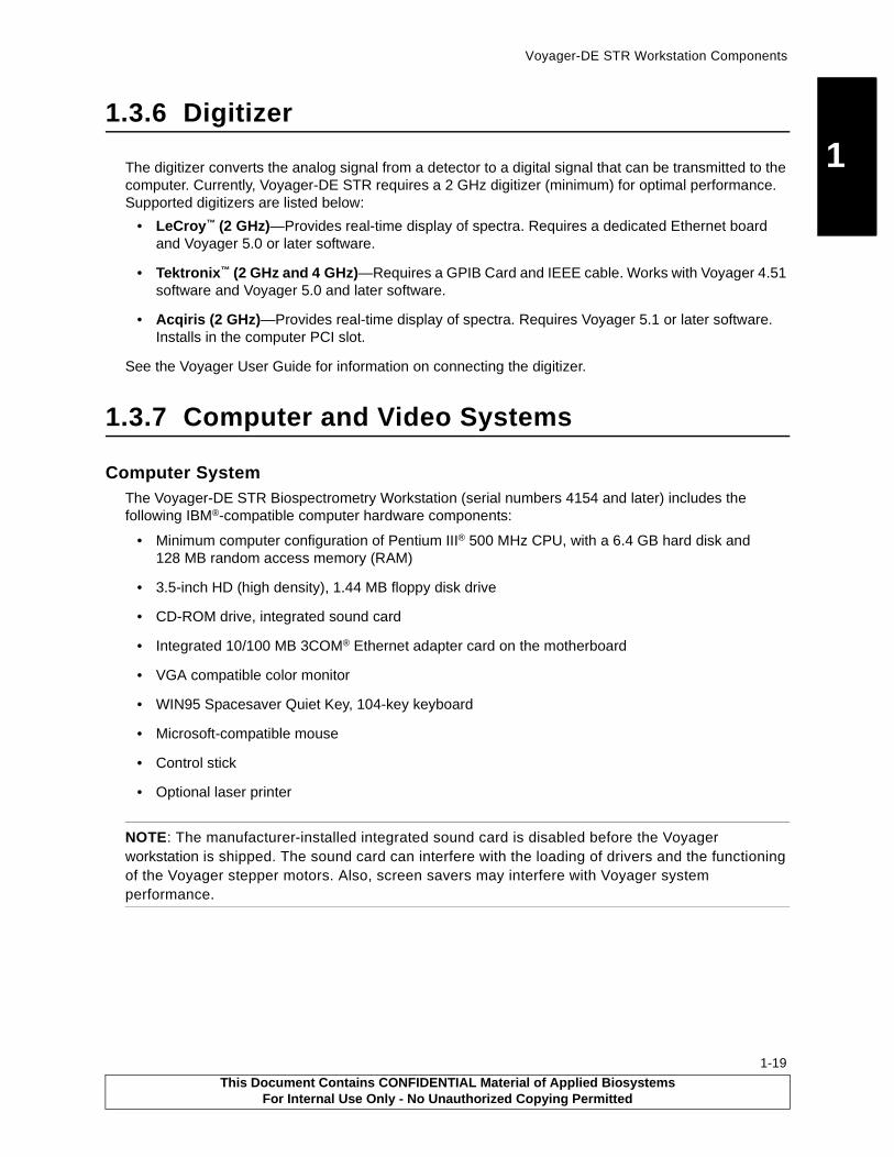
1.3.6 DigitizerThe digitizer converts the analog signal from a detector to a digital signal that can be transmitted to the computer. Currently, Voyager-DE STR requires a 2 GHz digitizer (minimum) for optimal performance. Supported digitizers are listed below:
• LeCroy™ (2 GHz)—Provides real-time display of spectra. Requires a dedicated Ethernet board and Voyager 5.0 or later software.
• Tektronix™ (2 GHz and 4 GHz)—Requires a GPIB Card and IEEE cable. Works with Voyager 4.51 software and Voyager 5.0 and later software.
• Acqiris (2 GHz)—Provides real-time display of spectra. Requires Voyager 5.1 or later software. Installs in the computer PCI slot.
See the Voyager User Guide for information on connecting the digitizer.
1.3.7 Computer and Video Systems
Computer SystemThe Voyager-DE STR Biospectrometry Workstation (serial numbers 4154 and later) includes the following IBM®-compatible computer hardware components:
• Minimum computer configuration of Pentium III® 500 MHz CPU, with a 6.4 GB hard disk and 128 MB random access memory (RAM)
• 3.5-inch HD (high density), 1.44 MB floppy disk drive
• CD-ROM drive, integrated sound card
• Integrated 10/100 MB 3COM® Ethernet adapter card on the motherboard
• VGA compatible color monitor
• WIN95 Spacesaver Quiet Key, 104-key keyboard
• Microsoft-compatible mouse
• Control stick
• Optional laser printer
NOTE: The manufacturer-installed integrated sound card is disabled before the Voyager workstation is shipped. The sound card can interfere with the loading of drivers and the functioning of the Voyager stepper motors. Also, screen savers may interfere with Voyager system performance.
This Document Contains CONFIDENTIAL Material of Applied BiosystemsFor Internal Use Only - No Unauthorized Copying Permitted
1-19

Chapter 1 System Overview
1
1-20
Computer monitorTo produce the spectral trace displayed on the computer monitor, m/z values are plotted against intensity (Figure 1-15). The Voyager software calculates m/z from the measured drift time. Intensity is calculated from the number of ions reaching the detector at a given time. Intensity is referred to as ion intensity (abundance) or signal intensity.
Figure 1-15 Time-of-Flight Analysis
Video SystemThe Voyager-DE STR video monitor displays a black and white real-time sample image (100 times magnification) of the sample spot in the sample chamber as viewed through the video camera. The camera turns on when the vacuum system is started.
1.4 Voyager-DE STR Workstation Supporting Systems
Electronics Electronics (including circuit boards and power supplies) are described in Chapter 2, Voyager-DE STR Workstation Electronics Theory.
Power SuppliesThe Voyager-DE STR workstation operates with two power supply systems: low voltage and high voltage. For more information, see Chapter 2, Voyager-DE STR Workstation Electronics Theory.
Vacuum SystemThe vacuum system uses multiple pumps and valves to create and maintain a sealed vacuum environment. See Section 6.1.5, Vacuum System, for more information.
Voyager Software The Voyager-DE STR software is bidirectional and communicates with the hardware and software.
Through the control stick and mouse, the Voyager control software to allows you to:
• Align a sample plate in the path of the laser• Start and stop acquisition• Save and transfer data to the processing software
Voyager software and computer systems have evolved from using Microsoft® Windows® 3.11 to Microsoft Windows NT® 4.0 platforms (32-bit structure).
+ ++
+
Heavierions
Lighterions
Relative Distance/Timem/z
Inte
nsi
ty
+ +
+
+ ++
++
+ +++
Lighterions
Heavierions
This Document Contains CONFIDENTIAL Material of Applied BiosystemsFor Internal Use Only - No Unauthorized Copying Permitted

Voyager-DE STR Workstation Supporting Systems
1
For newer Voyager-DE STR workstations, the Dell computer is shipped from the factory with:
• Microsoft Windows NT 4.0• Voyager software (includes Voyager version 5.0 and later Instrument Control Panel and Sequence
Control Panel, and Data Explorer™ version 3.4 and later software)• Microsoft Office 2000 (Small Office Suite)• NT Service Pack 5• Internet Explorer
Software FeaturesVoyager version 5.0 and later software includes:
• Voyager Instrument Control Panel—Controls the mass spectrometer for calibration and data acquisition.
• Voyager Sequence Control Panel—Works with the Instrument Control Panel and Data Explorer. Allows you to acquire and process data automatically. You can acquire multiple samples using the same or different instrument settings (.BIC) files.
• Data Explorer Software—Allows post-processing analysis of mass spectral data. Replaces the GRAMS software.
• Instrument Hardware Controller (IHC)—For instruments running Voyager software versions 5.0 and later, runs in the background to record errors in the NT event log. Interfaces with instrument control and data acquisition software.
In manual mode, you start the computer then manually launch the IHC from the Windows NT control panel. In automatic mode, the IHC launches when you start the computer.
• Voyager Diagnostics Software—Provides diagnostic system status and manual operation of Voyager-DE STR hardware. Allows you to troubleshoot or isolate electrical, mechanical, and vacuum problems or to test the system after repairing or replacing parts. See Chapter 4, Voyager Diagnostics Software for an overview of the diagnostics software. Using each control page during troubleshooting is detailed in various sections in Chapter 5, Troubleshooting by Components, and in Appendix D, Isolating Components Using Direct Bus Access.
The Voyager Diagnostics software for NT platform enables you to control the hardware components when the Instrument Hardware Controller (IHC) and Instrument Control Panel (ICP) are shut down. You can run the diagnostics software whether the instrument is operating under vacuum or at atmosphere (ATM).
This Document Contains CONFIDENTIAL Material of Applied BiosystemsFor Internal Use Only - No Unauthorized Copying Permitted
1-21

Chapter 1 System Overview
1
1-22
This Document Contains CONFIDENTIAL Material of Applied BiosystemsFor Internal Use Only - No Unauthorized Copying Permitted

2Chapter
2 Voyager-DE STR Workstation Electronics Theory
2-1
This chapter contains the following sections:2.1 Electronics Theory Overview ................................ 2-2
2.2 Electronics Common in Most Voyager-DESTR Instruments................................................... 2-4
2.2.1 AC Distribution Board (V750053) ............... 2-5
2.2.2 DAC (Digital-to-Analog Converter) Board (V750025) ...................... 2-9
2.2.3 DC Distribution Board (V750034) ............. 2-11
2.2.4 Low-Mass Gate Delay Timer Board(V750069, V750073) ................................ 2-15
2.2.5 Low-Mass Gate Driver Boxes (V700635, V700643) and Detector Filter Bias (V750032) ................................................ 2-20
2.2.6 Timed Ion Selector (TIS) Assembly (V700471) ................................................ 2-26
2.2.7 TTL Output Opto-Trigger Board (V750065) 2-31
2.3 Electronics Only in Newer Model Instruments ..... 2-33
2.3.1 Beam-Steering Board (V750091) ............. 2-33
2.3.2 DE Switch Box V725115/V725125 ............ 2-37
2.3.3 Einzel Lens Electronics (Voltage Divider Box, 4317251) ................ 2-44
2.3.4 48-Bit I/O Board with Game Port (V750033) ................................................ 2-45
2.3.5 MALDI Control Board (V750082 and V750102-001, V750102-002, V7502-003) .............................................. 2-47
2.4 Electronics Only in Earlier Instruments ............... 2-59
2.4.1 Flight-Tube (Drift-Tube) Power Supply (V750061) .......................... 2-60
2.4.2 Pulse Generator Board (V750063) ........... 2-63
This Document Contains CONFIDENTIAL Material of Applied BiosystemsFor Internal Use Only - No Unauthorized Copying Permitted
Chapter 2 Electronics
2
2-2
2.1 Electronics Theory Overview
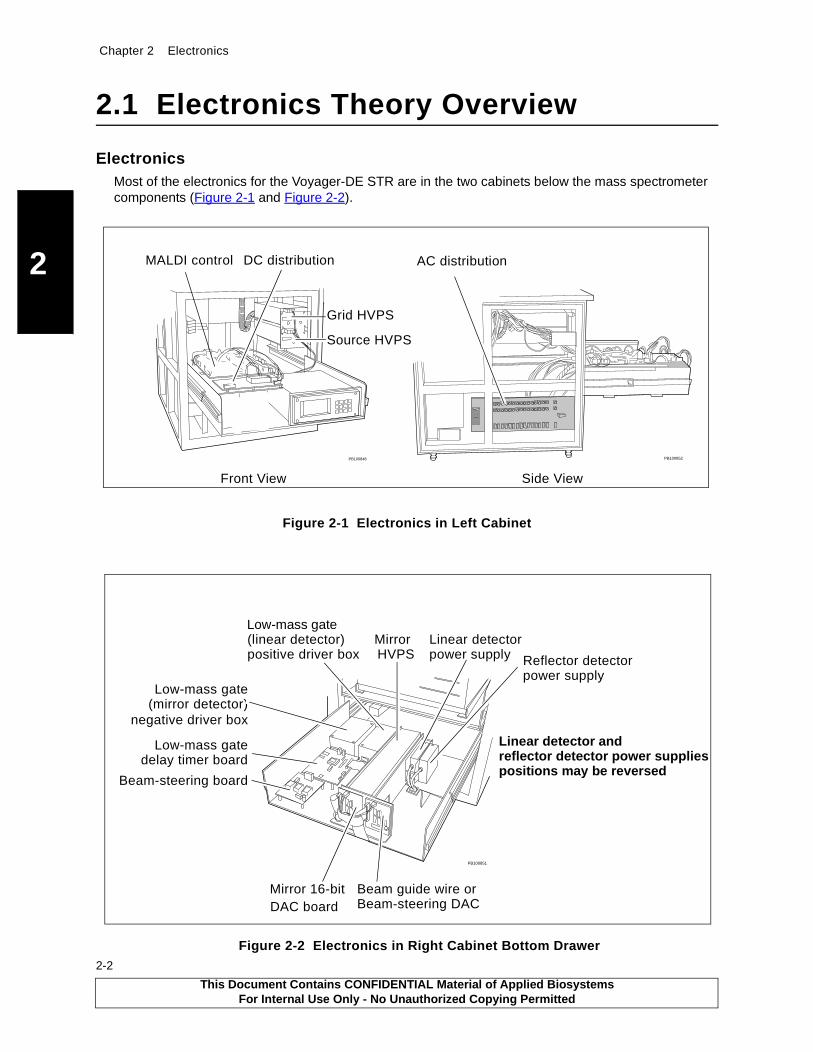
ElectronicsMost of the electronics for the Voyager-DE STR are in the two cabinets below the mass spectrometer components (Figure 2-1 and Figure 2-2).
Figure 2-1 Electronics in Left Cabinet
Figure 2-2 Electronics in Right Cabinet Bottom Drawer
PB100848
Front View Side View
PB100852
AC distributionDC distribution
Grid HVPS
Source HVPS
MALDI control
PB100851
Beam-steering board
Low-mass gatedelay timer board
Mirror 16-bit
Low-mass gate
negative driver box(mirror detector)
(linear detector)positive driver box
Linear detectorpower supply Reflector detector
power supply
Mirror
Beam guide wire orBeam-steering DAC
HVPS
DAC board
Linear detector and reflector detector power supplies positions may be reversed
Low-mass gate
This Document Contains CONFIDENTIAL Material of Applied BiosystemsFor Internal Use Only - No Unauthorized Copying Permitted

Electronics Theory Overview
2
Two circuit boards, the 48-bit I/O board and stepper motor board, are within the computer (Figure 2-3). The computer is housed on the top drawer of the right cabinet.
Figure 2-3 Circuit Boards in the Computer (Right Cabinet, Top Drawer, Rear View)
Circuit Board DescriptionsThe circuit board descriptions in this chapter detail the:
• Logic
• Specifications
• Connections, Switches, and Test points
Interconnect DiagramAn overall cable connection diagram that shows how the electronics interact with each other is available in Appendix C, Electronic Drawings.
Additional Electronics InformationAdditional information is available on the MALDI Product Support web site of the Applied Biosystems intranet. The MALDI Product Support web site path is: https://gene.peintranet.net/ (login to the intranet is needed), Departments, Product Support, Voyager Support.
The table below provides paths to electronic schematics, bulletins, and recently-encountered problems.
Information Path from Voyager Support Web Site Home Page
Circuit board schematics Service Documentation, Service Training Schematics
Service bulletins Alerts-Bulletins-Notes, Voyager Electronics
Electronics problems recently-encountered by field service engineers
Link to the MALDI ******Knowledge database****** . At the MALDI Knowledge database, select Electronics
���������
48-bit I/O boardStepper
motor boardComputer boards not shown:Internal digitizer cardNetwork cardsSCSI boardOptional CPIB
This Document Contains CONFIDENTIAL Material of Applied BiosystemsFor Internal Use Only - No Unauthorized Copying Permitted
2-3

Chapter 2 Electronics
2
2-4
2.2 Electronics Common in Most Voyager-DE STR Instruments
Most Voyager-DE STR instruments have the following electronics:
• AC Distribution V750053
• DAC Board V750025
• DC Distribution Board V750034
• Low-Mass Gate: positive, negative, and detector filter bias
• Timed Ion Selector (TIS) Assembly V700471
• TTL Output Opto-Trigger PCA V750065
Figure 2-4 shows the housing of these electronics.
Figure 2-4 Housing of Electronics Common in Most Instruments
PB100427
Left cabinet
Low-Mass Gate positiveLow-Mass Gate negativeDAC boards
AC DistributionDC Distribution
Right cabinet
TTL output opto trigger board
detector filter bias
TIS assembly
Low-Mass GateIn rear:
This Document Contains CONFIDENTIAL Material of Applied BiosystemsFor Internal Use Only - No Unauthorized Copying Permitted
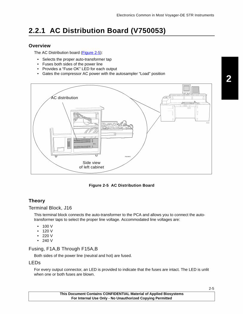
Electronics Common in Most Voyager-DE STR Instruments
2
2.2.1 AC Distribution Board (V750053)
OverviewThe AC Distribution board (Figure 2-5):
• Selects the proper auto-transformer tap• Fuses both sides of the power line• Provides a “Fuse OK” LED for each output• Gates the compressor AC power with the autosampler “Load” position
Figure 2-5 AC Distribution Board
Theory
Terminal Block, J16This terminal block connects the auto-transformer to the PCA and allows you to connect the auto-transformer taps to select the proper line voltage. Accommodated line voltages are:
• 100 V• 120 V• 220 V• 240 V
Fusing, F1A,B Through F15A,BBoth sides of the power line (neutral and hot) are fused.
LEDsFor every output connector, an LED is provided to indicate that the fuses are intact. The LED is unlit when one or both fuses are blown.
PB100427
Side view
PB100852
AC distribution
of left cabinet
This Document Contains CONFIDENTIAL Material of Applied BiosystemsFor Internal Use Only - No Unauthorized Copying Permitted
2-5

Chapter 2 Electronics
2
2-6
Compressor Relay and DiodesJ15, the output connector for the compressor, is gated through a relay. This relay allows only J15 power when the autosampler is in the Load Position (both the x-load and y-load microswitches are closed). The diodes are necessary so the “ground” that is present in the Load Position is seen by both the compressor relay and control board logic.
Output ConnectorsAll fifteen output connectors (except J15, the compressor power) are identically powered.
LabelA label on the board provides the current revision of the board, fuse values, and the destination of each output connector.
This Document Contains CONFIDENTIAL Material of Applied BiosystemsFor Internal Use Only - No Unauthorized Copying Permitted

Electronics Common in Most Voyager-DE STR Instruments
2
Figure 2-6 AC Distribution Board Block Diagram
Auto-transformerconnections Voltage
select
F1A,B
F2A,B
F3A,B
F4A,B
F5A,B
F6A,B
F7A,B
F8A,B
F9A,B
F10A,B
F11A,B
F12A,B
F13A,B
F14A,B
F15A,B
TerminalStrip - J16
DS1
DS2
DS3
DS4
DS5
DS6
DS7
DS8
DS9
DS10
DS11
DS12
DS13
DS14
DS15
J1
J2
J3
J4
J5
J6
J7
J8
J9
J10
J11
J12
J13
J14
J15
J17
From loadpositionswitches
Loadposition to
controlboard
K1 - CompressorRelay
FusesFuse "OK"
LEDsOutput
Connectors
PB100838
Fore (roughing) pump
Fans
Not used
Laser
Optional turbo
Computer
12 V power supply
Not used
Not used
Quad power supply
110 V power, Vacuum gauge control
24 V power supply
Turbo mirror controller
Turbo source controller
Compressor
Voltage selection
controlCompressor
This Document Contains CONFIDENTIAL Material of Applied BiosystemsFor Internal Use Only - No Unauthorized Copying Permitted
2-7

Chapter 2 Electronics
2
2-8
Connectors and LEDs
Table 2-1 Connectors and LEDs on the AC Distribution Board
Item Name Function Type
Connectors J1–J14 Output connectors 3-position MATE-N-LOK
J15 Compressor power 3-position MATE-N-LOK
J16 Terminal block 2 × 8 terminal block
J17 “Load Position” in, out 4-position Mini-Fit™
LEDs DS1–DS15 Fuse “OK” LEDs LED
This Document Contains CONFIDENTIAL Material of Applied BiosystemsFor Internal Use Only - No Unauthorized Copying Permitted
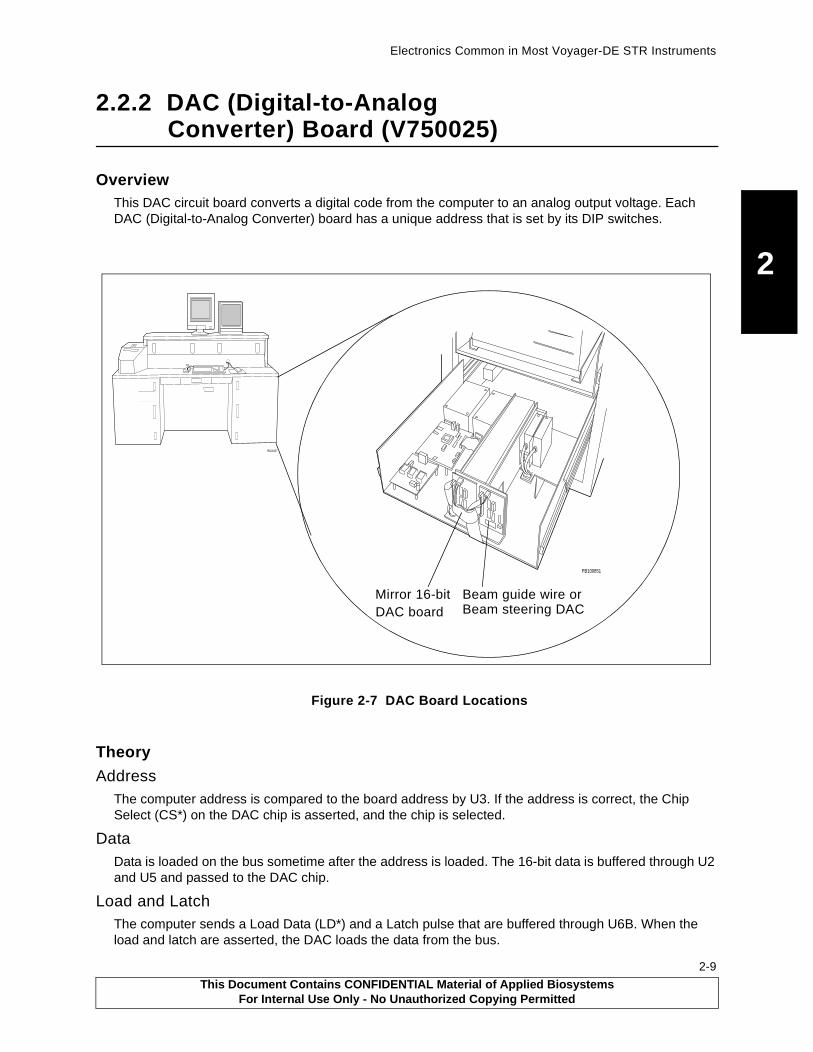
Electronics Common in Most Voyager-DE STR Instruments
2
2.2.2 DAC (Digital-to-Analog Converter) Board (V750025)
OverviewThis DAC circuit board converts a digital code from the computer to an analog output voltage. Each DAC (Digital-to-Analog Converter) board has a unique address that is set by its DIP switches.
Figure 2-7 DAC Board Locations
Theory
AddressThe computer address is compared to the board address by U3. If the address is correct, the Chip Select (CS*) on the DAC chip is asserted, and the chip is selected.
DataData is loaded on the bus sometime after the address is loaded. The 16-bit data is buffered through U2 and U5 and passed to the DAC chip.
Load and LatchThe computer sends a Load Data (LD*) and a Latch pulse that are buffered through U6B. When the load and latch are asserted, the DAC loads the data from the bus.
PB100427
PB100851
Mirror 16-bit Beam guide wire orBeam steering DACDAC board
This Document Contains CONFIDENTIAL Material of Applied BiosystemsFor Internal Use Only - No Unauthorized Copying Permitted
2-9

Chapter 2 Electronics
2
2-10
DACThe DAC uses a 5 V reference generated by the U4 regulator.
Voltage out is 0 to 10 V analog.
ConnectorsTable 2-2 describes the connectors.
t
Table 2-2 Connectors on the DAC PCA Board
Item Name Function Type
Connectors J1 Bus connection 34-pin ribbon
J2 DAC Vout 4-pin MTA
J3 Power +5V, +15 V, –15 V 5-pin MTA
J4 Power +5 V, +15 V, –15 V 6-pin Mini-Fit
J5 DAC Vout 2-pin Mini-Fit
This Document Contains CONFIDENTIAL Material of Applied BiosystemsFor Internal Use Only - No Unauthorized Copying Permitted

Electronics Common in Most Voyager-DE STR Instruments
2
2.2.3 DC Distribution Board (V750034)
OverviewThe DC Distribution board distributes the following DC voltages from the power supplies to individual circuit boards: +5 V, –5.2, +12 V, ±15 V, and +24 V.
Figure 2-8 DC Distribution Board Location
TheoryOlder versions of the Voyager-DE STR have three power supplies connected to this board:
• Quad supply (+5 V, –5.2 V, ±15 V)• 12 V supply (+12 V)• 24 V supply (+24 V)
More recent versions have a single power supply that provides +5 V, ±15 V, and +24 V.
PB100427
PB100848DCdistributionboard
This Document Contains CONFIDENTIAL Material of Applied BiosystemsFor Internal Use Only - No Unauthorized Copying Permitted
2-11
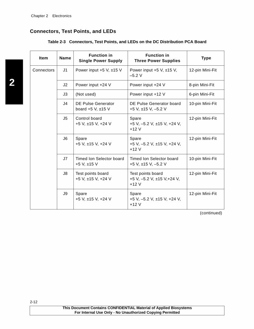
Chapter 2 Electronics
2
2-12
Connectors, Test Points, and LEDs
Table 2-3 Connectors, Test Points, and LEDs on the DC Distribution PCA Board
Item NameFunction in
Single Power Supply Function in
Three Power Supplies Type
Connectors J1 Power input +5 V, ±15 V Power input +5 V, ±15 V, –5.2 V
12-pin Mini-Fit
J2 Power input +24 V Power input +24 V 8-pin Mini-Fit
J3 (Not used) Power input +12 V 6-pin Mini-Fit
J4 DE Pulse Generator board +5 V, ±15 V
DE Pulse Generator board +5 V, ±15 V, –5.2 V
10-pin Mini-Fit
J5 Control board +5 V, ±15 V, +24 V
Spare +5 V, –5.2 V, ±15 V, +24 V, +12 V
12-pin Mini-Fit
J6 Spare +5 V, ±15 V, +24 V
Spare +5 V, –5.2 V, ±15 V, +24 V, +12 V
12-pin Mini-Fit
J7 Timed Ion Selector board +5 V, ±15 V
Timed Ion Selector board +5 V, ±15 V, –5.2 V
10-pin Mini-Fit
J8 Test points board +5 V, ±15 V, +24 V
Test points board +5 V, –5.2 V, ±15 V,+24 V, +12 V
12-pin Mini-Fit
J9 Spare +5 V, ±15 V, +24 V
Spare +5 V, –5.2 V, ±15 V, +24 V, +12 V
12-pin Mini-Fit
(continued)
This Document Contains CONFIDENTIAL Material of Applied BiosystemsFor Internal Use Only - No Unauthorized Copying Permitted
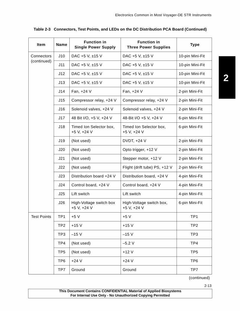
Electronics Common in Most Voyager-DE STR Instruments
2
Connectors (continued)
J10 DAC +5 V, ±15 V DAC +5 V, ±15 V 10-pin Mini-Fit
J11 DAC +5 V, ±15 V DAC +5 V, ±15 V 10-pin Mini-Fit
J12 DAC +5 V, ±15 V DAC +5 V, ±15 V 10-pin Mini-Fit
J13 DAC +5 V, ±15 V DAC +5 V, ±15 V 10-pin Mini-Fit
J14 Fan, +24 V Fan, +24 V 2-pin Mini-Fit
J15 Compressor relay, +24 V Compressor relay, +24 V 2-pin Mini-Fit
J16 Solenoid valves, +24 V Solenoid valves, +24 V 2-pin Mini-Fit
J17 48 Bit I/O, +5 V, +24 V 48-Bit I/O +5 V, +24 V 6-pin Mini-Fit
J18 Timed Ion Selector box, +5 V, +24 V
Timed Ion Selector box,+5 V, +24 V
6-pin Mini-Fit
J19 (Not used) DVDT, +24 V 2-pin Mini-Fit
J20 (Not used) Opto trigger, +12 V 2-pin Mini-Fit
J21 (Not used) Stepper motor, +12 V 2-pin Mini-Fit
J22 (Not used) Flight (drift tube) PS, +12 V 2-pin Mini-Fit
J23 Distribution board +24 V Distribution board, +24 V 4-pin Mini-Fit
J24 Control board, +24 V Control board, +24 V 4-pin Mini-Fit
J25 Lift switch Lift switch 4-pin Mini-Fit
J26 High-Voltage switch box +5 V, +24 V
High-Voltage switch box, +5 V, +24 V
6-pin Mini-Fit
Test Points TP1 +5 V +5 V TP1
TP2 +15 V +15 V TP2
TP3 –15 V –15 V TP3
TP4 (Not used) –5.2 V TP4
TP5 (Not used) +12 V TP5
TP6 +24 V +24 V TP6
TP7 Ground Ground TP7
(continued)
Table 2-3 Connectors, Test Points, and LEDs on the DC Distribution PCA Board (Continued)
Item NameFunction in
Single Power Supply Function in
Three Power Supplies Type
This Document Contains CONFIDENTIAL Material of Applied BiosystemsFor Internal Use Only - No Unauthorized Copying Permitted
2-13
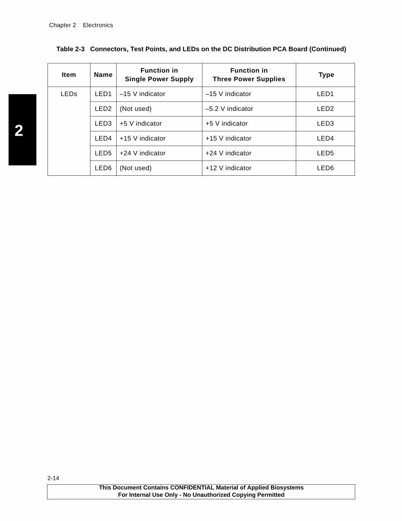
Chapter 2 Electronics
2
2-14
LEDs LED1 –15 V indicator –15 V indicator LED1
LED2 (Not used) –5.2 V indicator LED2
LED3 +5 V indicator +5 V indicator LED3
LED4 +15 V indicator +15 V indicator LED4
LED5 +24 V indicator +24 V indicator LED5
LED6 (Not used) +12 V indicator LED6
Table 2-3 Connectors, Test Points, and LEDs on the DC Distribution PCA Board (Continued)
Item NameFunction in
Single Power Supply Function in
Three Power Supplies Type
This Document Contains CONFIDENTIAL Material of Applied BiosystemsFor Internal Use Only - No Unauthorized Copying Permitted

Electronics Common in Most Voyager-DE STR Instruments
2
2.2.4 Low-Mass Gate Delay Timer Board (V750069, V750073)
OverviewThe Low-Mass Gate Delay Timer (Detector Voltage Delay Timer, DVDT) PCA is used to delay application of full high voltage to the detector MCP (microchannel plate) until the matrix ions pass. The microchannel plates have an inherent gain recovery time, and the delay of full high voltage preserves the gain until a region of interest.
Figure 2-9 Low-Mass Gate Driver Boxes and Delay Timer Board Locations
During instrument operation, the board:
• Captures an input trigger• Counts off a fixed delay, then counts off a a pre-programmed delay corresponding to the Low-Mass
Gate value• Outputs a pulse of fixed width
The circuit has 222-ns resolution and an 8-bit maximum delay with an 8-µs offset, which corresponds to a delay range of 8-to-65 µs.
TheoryThe low-mass gate delay timer circuit can be divided into the following blocks (Figure 2-10):
• 18 MHz clock• Trigger buffer and sync• Latches• Counters (used as delays)• Address decoder• Integrator• Regulators• Drivers
PB100427
PB100851
Low-mass gatedelay timer board
Low-mass gatedriver boxes
negativepositive
This Document Contains CONFIDENTIAL Material of Applied BiosystemsFor Internal Use Only - No Unauthorized Copying Permitted
2-15

Th
is Do
cum
ent C
on
tains C
ON
FID
EN
TIA
L M
aterial of A
pp
lied B
iosystem
sF
or In
ternal U
se On
ly - No
Un
auth
orized
Co
pyin
g P
ermitted
2-16
Chapte
r 2E
lectron
ics
2
unterown
er)
latch
reset
DriversPulseOut
PB100842
Fig
ure 2-10 L
ow
-Mass G
ate Delay T
imer B
oard
Blo
ck Diag
ram
Trigger Buffer
8-bit StartRegister
8-bitsStart Counter(8-bit Down
Counter)
End Co(13-bit D
Count
8us Delay(6-bit Down
Counter)
data bus
DE-Trigger
reset
reset
reset
12-volt regulator,(’073 only)
5-volt regulator,(’069 and ’073)
18 Mhz Clock Divide-by-4
Synch
Temporary Latch
Digital IntegratorAddressDecoder
ValidLoad
5-bits
Load
Clock
Clock
Buffer
Buffer
+24v (’073) +5v
+12v (’069)
+12v
addressbus
load
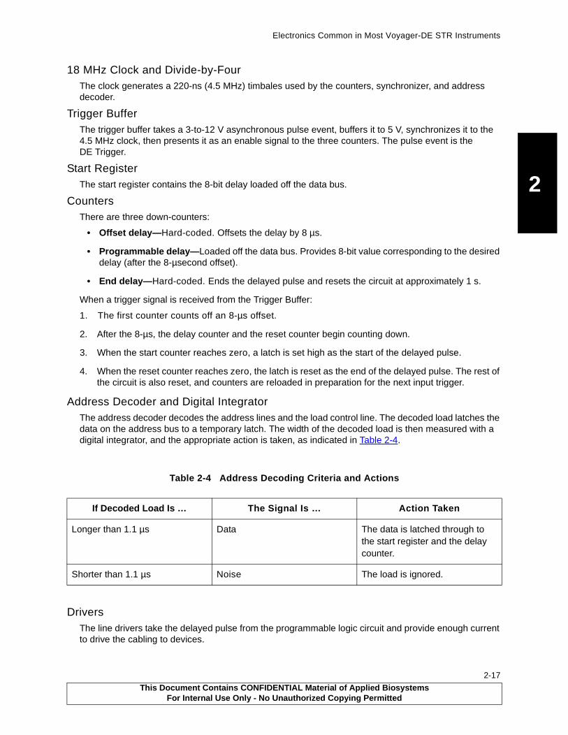
Electronics Common in Most Voyager-DE STR Instruments
2
18 MHz Clock and Divide-by-FourThe clock generates a 220-ns (4.5 MHz) timbales used by the counters, synchronizer, and address decoder.
Trigger BufferThe trigger buffer takes a 3-to-12 V asynchronous pulse event, buffers it to 5 V, synchronizes it to the 4.5 MHz clock, then presents it as an enable signal to the three counters. The pulse event is the DE Trigger.
Start RegisterThe start register contains the 8-bit delay loaded off the data bus.
CountersThere are three down-counters:
• Offset delay—Hard-coded. Offsets the delay by 8 µs.
• Programmable delay—Loaded off the data bus. Provides 8-bit value corresponding to the desired delay (after the 8-µsecond offset).
• End delay—Hard-coded. Ends the delayed pulse and resets the circuit at approximately 1 s.
When a trigger signal is received from the Trigger Buffer:
1. The first counter counts off an 8-µs offset.
2. After the 8-µs, the delay counter and the reset counter begin counting down.
3. When the start counter reaches zero, a latch is set high as the start of the delayed pulse.
4. When the reset counter reaches zero, the latch is reset as the end of the delayed pulse. The rest of the circuit is also reset, and counters are reloaded in preparation for the next input trigger.
Address Decoder and Digital IntegratorThe address decoder decodes the address lines and the load control line. The decoded load latches the data on the address bus to a temporary latch. The width of the decoded load is then measured with a digital integrator, and the appropriate action is taken, as indicated in Table 2-4.
DriversThe line drivers take the delayed pulse from the programmable logic circuit and provide enough current to drive the cabling to devices.
Table 2-4 Address Decoding Criteria and Actions
If Decoded Load Is … The Signal Is … Action Taken
Longer than 1.1 µs Data The data is latched through to the start register and the delay counter.
Shorter than 1.1 µs Noise The load is ignored.
This Document Contains CONFIDENTIAL Material of Applied BiosystemsFor Internal Use Only - No Unauthorized Copying Permitted
2-17
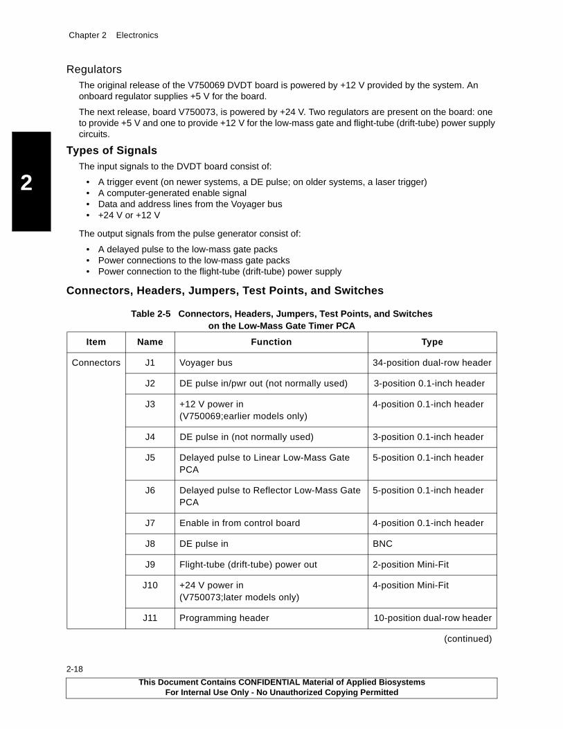
Chapter 2 Electronics
2
2-18
RegulatorsThe original release of the V750069 DVDT board is powered by +12 V provided by the system. An onboard regulator supplies +5 V for the board.
The next release, board V750073, is powered by +24 V. Two regulators are present on the board: one to provide +5 V and one to provide +12 V for the low-mass gate and flight-tube (drift-tube) power supply circuits.
Types of SignalsThe input signals to the DVDT board consist of:
• A trigger event (on newer systems, a DE pulse; on older systems, a laser trigger)• A computer-generated enable signal• Data and address lines from the Voyager bus• +24 V or +12 V
The output signals from the pulse generator consist of:
• A delayed pulse to the low-mass gate packs• Power connections to the low-mass gate packs• Power connection to the flight-tube (drift-tube) power supply
Connectors, Headers, Jumpers, Test Points, and Switches
Table 2-5 Connectors, Headers, Jumpers, Test Points, and Switches on the Low-Mass Gate Timer PCA
Item Name Function Type
Connectors J1 Voyager bus 34-position dual-row header
J2 DE pulse in/pwr out (not normally used) 3-position 0.1-inch header
J3 +12 V power in (V750069;earlier models only)
4-position 0.1-inch header
J4 DE pulse in (not normally used) 3-position 0.1-inch header
J5 Delayed pulse to Linear Low-Mass Gate PCA
5-position 0.1-inch header
J6 Delayed pulse to Reflector Low-Mass Gate PCA
5-position 0.1-inch header
J7 Enable in from control board 4-position 0.1-inch header
J8 DE pulse in BNC
J9 Flight-tube (drift-tube) power out 2-position Mini-Fit
J10 +24 V power in (V750073;later models only)
4-position Mini-Fit
J11 Programming header 10-position dual-row header
(continued)
This Document Contains CONFIDENTIAL Material of Applied BiosystemsFor Internal Use Only - No Unauthorized Copying Permitted
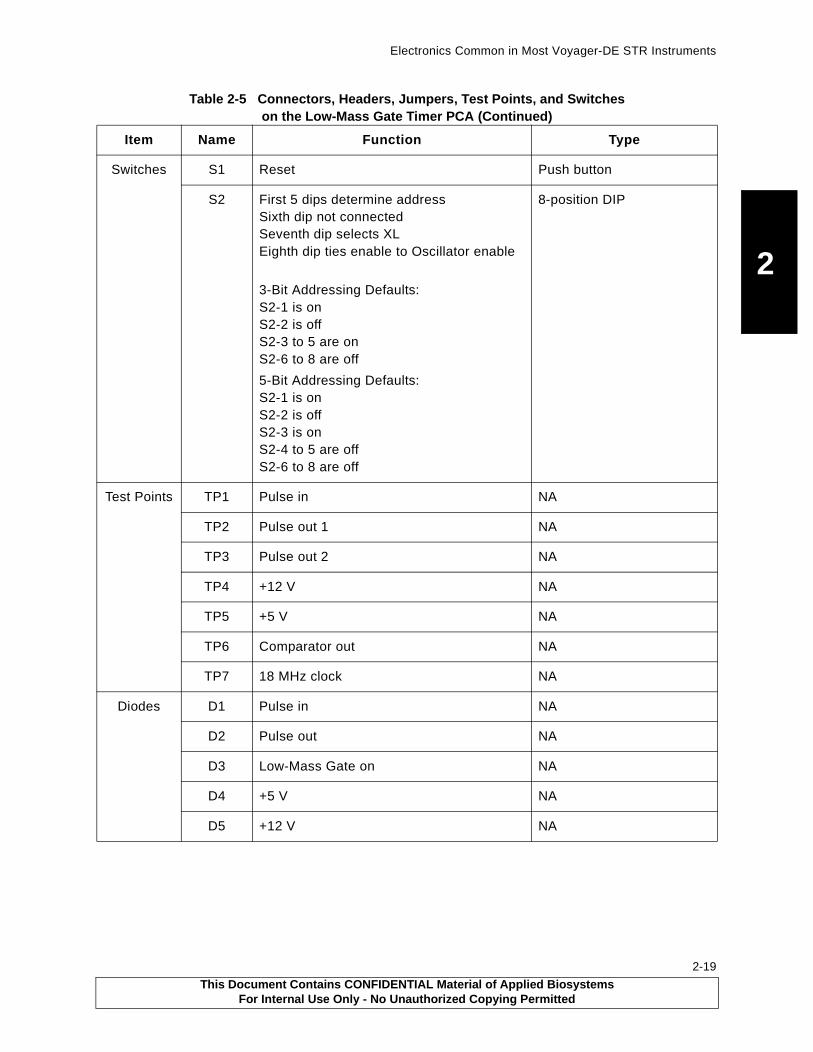
Electronics Common in Most Voyager-DE STR Instruments
2
Switches S1 Reset Push button
S2 First 5 dips determine addressSixth dip not connectedSeventh dip selects XLEighth dip ties enable to Oscillator enable
3-Bit Addressing Defaults:S2-1 is onS2-2 is offS2-3 to 5 are onS2-6 to 8 are off
5-Bit Addressing Defaults:S2-1 is onS2-2 is offS2-3 is onS2-4 to 5 are offS2-6 to 8 are off
8-position DIP
Test Points TP1 Pulse in NA
TP2 Pulse out 1 NA
TP3 Pulse out 2 NA
TP4 +12 V NA
TP5 +5 V NA
TP6 Comparator out NA
TP7 18 MHz clock NA
Diodes D1 Pulse in NA
D2 Pulse out NA
D3 Low-Mass Gate on NA
D4 +5 V NA
D5 +12 V NA
Table 2-5 Connectors, Headers, Jumpers, Test Points, and Switches on the Low-Mass Gate Timer PCA (Continued)
Item Name Function Type
This Document Contains CONFIDENTIAL Material of Applied BiosystemsFor Internal Use Only - No Unauthorized Copying Permitted
2-19

Chapter 2 Electronics
2
2-20
2.2.5 Low-Mass Gate Driver Boxes (V700635, V700643) and Detector Filter Bias (V750032)
OverviewLow-mass ions from the matrix usually are not of interest, yet they can be produced in such large quantities that they may overload the detector. The Low-Mass Gate (LMG) is used to delay applying full high voltage to the detector microchannel plate until the matrix ions pass. The microchannel plates have an inherent gain recovery time, and the delay of full voltage preserves the gain until a region of interest. During the period the full voltage to the detector is delayed, ions strike the detector but only a weak signal is generated.
There are two versions of the LMG. Figure 2-10 and Figure 2-11 show the locations of the circuit appropriate boards. The two versions are:
• Positive Pulse PCA—Mounted in a box that has two MHV (Medium High Voltage) connectors (Figure 2-13). This PCA controls a single plate MCP (microchannel plate) detector associated with the High Current Detector.
• Negative Pulse PCA—Mounted in a box that has three MHV (Medium High Voltage) connectors (Figure 2-14). This PCA controls a dual MCP (chevron) detector and is associated with the Detector Filter Bias (DFB) PCA.
Figure 2-11 Low-Mass Gate Driver Boxes and Delay Timer Board Locations
Figure 2-12 Detector Filter Bias
PB100427
PB100851
Low-mass gatedelay timer board
Low-mass gatenegative
driver boxesand positive
TIS assembly
This Document Contains CONFIDENTIAL Material of Applied BiosystemsFor Internal Use Only - No Unauthorized Copying Permitted

Th
is Do
cum
ent C
on
tains C
ON
FID
EN
TIA
L M
aterial of A
pp
lied B
iosystem
sF
or In
ternal U
se On
ly - No
Un
auth
orized
Co
pyin
g P
ermitted
Electronics C
omm
on in Most V
oyager-D
ES
TR
Instruments
2-21
2
(HV)
(Pulse in)
Programmable0 to 3kV P.S.Negative Gnd
-
+
Single MCP
.
Scintillator
Photomultiplier
.
.
(ions)
(electrons)
(photons)
High-CurrentDetector
DigitizerInput
Signal
+
+--2kV
15kV
G Positive Box AssyLMG Positive
B LMG Pos/Negl Assy DVD LMG
(HV)
(Pulse in)
Programmable0 to 3kV P.S.Negative Gnd
-
+
Single MCP
.
Scintillator
Photomultiplier
.
.
(ions)
(electrons)
(photons)
High-CurrentDetector
DigitizerInput
Signal
+
+--2kV
15kV
G Positive Box AssyLMG Positive
B LMG Pos/Negl Assy DVD LMG
Fig
ure 2-13 B
lock D
iagram
of th
e Lo
w-M
ass Gate P
ositive P
ulse
High Voltage
Control & Power
Legend:
InputTransistors
CommonMode
InductorDC/DC Isolation
Optical CouplerSwitchDriver
Low VoltageInput Side
High VoltageOutput Side
Rs = 4.7 Mohm
Rd = 300
Rf1 = 4.7 Mohm
Rf2 = 4.7 Mohm
.SignalGnd
HVGnd
Gnd Jmpr JPR1
12 V dc Pwr In12 V dc Float Out
TP1
TP2
Jmpr for "ON"
+12 V dc Pwr In
PulseIn
Enb.In
(J1-15)
(J1-14)
(J1-2)
(J1-3)
J3-2
J3-1(J1-1)
J3-3
J3-4(J1-4)
J3-5(J1-5)
J2
J1
(HV in)
(HV Pulse out)
Jx-y = PCB Pin Assign.
(Jx-y) = Assy Pin Assign.
=
=
+12 V dc Rtn
+12VDCFloat
+12VDCFloat Rtn
.
V700643 DVD LMV750066 PCA
V107049 PCV775029 Cb
Enable
in
Pulse
in

Th
is Do
cum
ent C
on
tains C
ON
FID
EN
TIA
L M
aterial of A
pp
lied B
iosystem
sF
or In
ternal U
se On
ly - No
Un
auth
orized
Co
pyin
g P
ermitted
2-22
Chapte
r 2E
lectron
ics
2
.
.
-
+
Dual MCPChevron
Anode
DigitizerInput
SignalC=0.1F
Ra=10M
Rb=1M
J2
4
1
) (HV)
out) (Bias in)
e out) (Pulse in)
Detector FilterBias Board
V750032 PCA Det. FltrV107025 PCB Det. Fltr
Programmable0 to 3kV P.S.Positive Gnd
(ions)
(electrons)+-
-
+182V
1818V
LMG Negative Box AssyCA LMG Negative9 PCB LMG Pos/Neg9 Cbl Assy DVD LMG
Fig
ure 2-14 B
lock D
iagram
of th
e Lo
w-M
ass Gate N
egative P
ulse
High Voltage
Control & Power
Legend:
InputTransistors
CommonMode
InductorDC/DC Isolation
Optical CouplerSwitchDriver
Low VoltageInput Side
High VoltageOutput Side
.
Rs = 4.7M
Rd = 300
Rf1 = 4.7M
Rf2 = 4.7M
.SignalGnd
HVGnd
Gnd Jmpr JPR1
12VDC Pwr In12VDC Float Out
TP1
TP2
Jmpr for "ON"
+12VDC Pwr In
EnableIn
PulseIn
(J1-15)
(J1-14)
(J1-2)
(J1-3)
J3-2
J3-1(J1-1)
J3-3
J3-4(J1-4)
J3-5(J1-5)
J
J
(HV in
(HV Bias
(HV Puls
Jx–y = PCB Pin Assign.
(Jx–y) = Assy Pin Assign.
=
=
+12VDC Rtn
+12VDCFloat
+12VDCFloat Rtn
V700635 DVDV750060 P
V10704V77502

Electronics Common in Most Voyager-DE STR Instruments
2
A configurable PCB is used to assemble both the positive and the negative LMG units. Both boxes also use the same internal cable. The following chart relates the part numbers for these three options.
Theory
WARNING
ELECTRICAL SHOCK HAZARD. Potentials in the order of 3000 V dc are present on these boards. Safe operating procedures and proper use of equipment are the responsibility of the authorized and qualified service person. Precautions must be taken to protect against possible serious and/or fatal bodily injury.
Low-Mass Gate SwitchesThe Voyager Low-Mass Gate options convert a TTL input pulse into a floating high-voltage pulse. The Positive Pulse and Negative Pulse block diagrams illustrate how the TTL input logic is isolated from the floating high-voltage output circuits by the optical signal coupler and the DC/DC isolation converter. A common mode inductor chokes transient ground currents resulting from rapid high-voltage switching. The output switch is a 1 kV MOSFET. The HV voltage divider resistors are configured for positive or negative operation by jumpers on the PCB.
There are two identical inputs:
• Pin 2—Receives the TTL pulse. The LMG enables the detector for the duration of the pulse.
• Pin 3—Enables or disables the LMG function. If high, it enables the MOSFET switch continuously and the detector generates signal during the entire spectrum.
NOTE: For the detector to function properly, you must have input to either Pin 2 or Pin 3. Failure to provide this input prevents the detector from generating a signal.
LMG Positive LMG Negative Detector Filter Bias
V700643 DVD LMG Box Assembly, Positive (contains 2 MHV connectors)
V700635 DVD LMG Box Assembly, Negative (contains 3 MHV connectors)
N/A
V750066 PCA LMG Positive V750060 PCA LMG Negative V750032 PCA Detector Filter Bias Board
V107049 PCB LMG V107049 PCB LMG V107025 PCB PCA Detector Filter Bias Board
V775029 CBL Assembly, DVD LMG (internal to box assembly)
V775029 CBL Assembly, DVD LMG (internal to box assembly)
N/A
This Document Contains CONFIDENTIAL Material of Applied BiosystemsFor Internal Use Only - No Unauthorized Copying Permitted
2-23
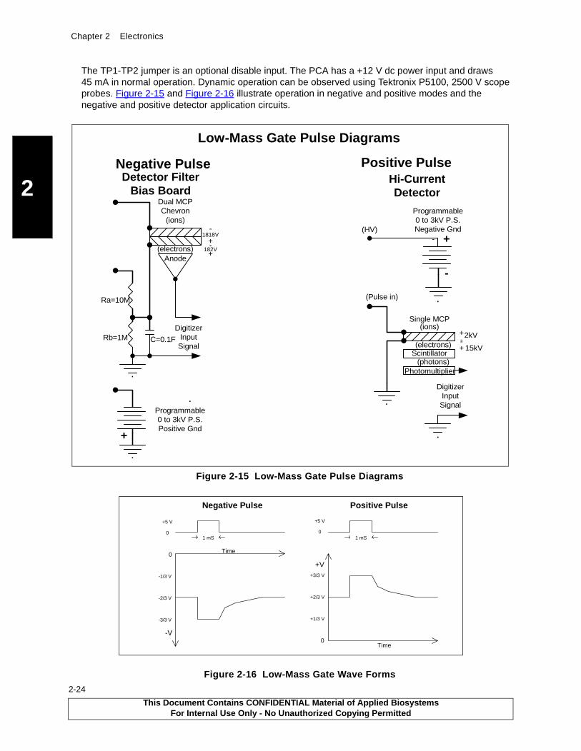
Chapter 2 Electronics
2
2-24
The TP1-TP2 jumper is an optional disable input. The PCA has a +12 V dc power input and draws 45 mA in normal operation. Dynamic operation can be observed using Tektronix P5100, 2500 V scope probes. Figure 2-15 and Figure 2-16 illustrate operation in negative and positive modes and the negative and positive detector application circuits.
Figure 2-15 Low-Mass Gate Pulse Diagrams
Figure 2-16 Low-Mass Gate Wave Forms
DigitizerInputSignal
.
.
.
+
Dual MCPChevron
Anode
C=0.1F
Ra=10M
Rb=1M
Negative PulseDetector Filter
Bias Board
Programmable0 to 3kV P.S.Positive Gnd
(ions)
(electrons)+-+
182V
1818V- (HV)
(Pulse in)
Low-Mass Gate Pulse Diagrams
Programmable0 to 3kV P.S.Negative Gnd
-
+
Single MCP
.
Scintillator
Photomultiplier
.
.
(ions)
(electrons)
(photons)
Hi-CurrentDetector
DigitizerInputSignal
+
+--2kV
15kV
-
Positive Pulse
+V
Time
Time0
+1/3 V
+2/3 V
+3/3 V
1 mS0
1 mS
+5 V
Negative Pulse Positive Pulse
0
-2/3 V
-3/3 V
-1/3 V
0
+5 V
-V
This Document Contains CONFIDENTIAL Material of Applied BiosystemsFor Internal Use Only - No Unauthorized Copying Permitted

Electronics Common in Most Voyager-DE STR Instruments
2
ApplicationsThe following describes the applications for negative and positive pulse.
Detector Filter Bias Board (Negative Pulse)The Detector Filter Bias board provides a method of tapping-off 1/11 of the full negative voltage to make the Anode slightly positive relative to the dual microchannel plate detector. When the ions strike the microchannel plate, electrons are liberated and attracted to the Anode by the positive bias. The resulting signal is applied to the digitizer input.
High Current Detector (Positive Pulse)The positive version of the LMG is used to polarize a single microchannel plate that converts ion collisions to free electrons. The electrons are attracted to a scintillator by a 15 kV bias voltage. The scintillator converts electron collisions to light (photons). The photons strike a photomultiplier unit that converts the information back to an electrical signal that is applied to the digitizer input.
SpecificationsPower
Power is +12 V dc at approximately 37 mA idle and 45 mA switching.
InputThe TTL gate pulse input impedance is 10 Mohm resistive.
OutputThe external programmable power supplies provide either zero to +3 kV or zero to –3 kV. When the input signal is low, two-thirds of the programmed voltage appears on the J2 pulse output. When the input is high, the full-programmed voltage appears on the J2 output.
ConnectorsThe following table describes the connectors.
Name Function Connector Type
J1 PCB HV Input HV = 0 to ± 3000 V dc PCB internal
MHV external
J2 PCB HB Pulse Output 2/3 HV to full HV PCB internal
MHV external
J3-1 PCB (J1-1 external)
J3-2 PCB (J1-2 external)
J3-3 PCB (J1-3 external)
J3-4 PCB (J1-4 external)
J3-5 PCB (J1-5 external)
Ground
TTL Enable Input
TTL Signal Input
Ground
+12 V dc Power Input
PCB internal
DB15 Male external
J4 PCB HV Bias Output HV = 0 to ± 3000 V dc PCB internal
MHV external
This Document Contains CONFIDENTIAL Material of Applied BiosystemsFor Internal Use Only - No Unauthorized Copying Permitted
2-25
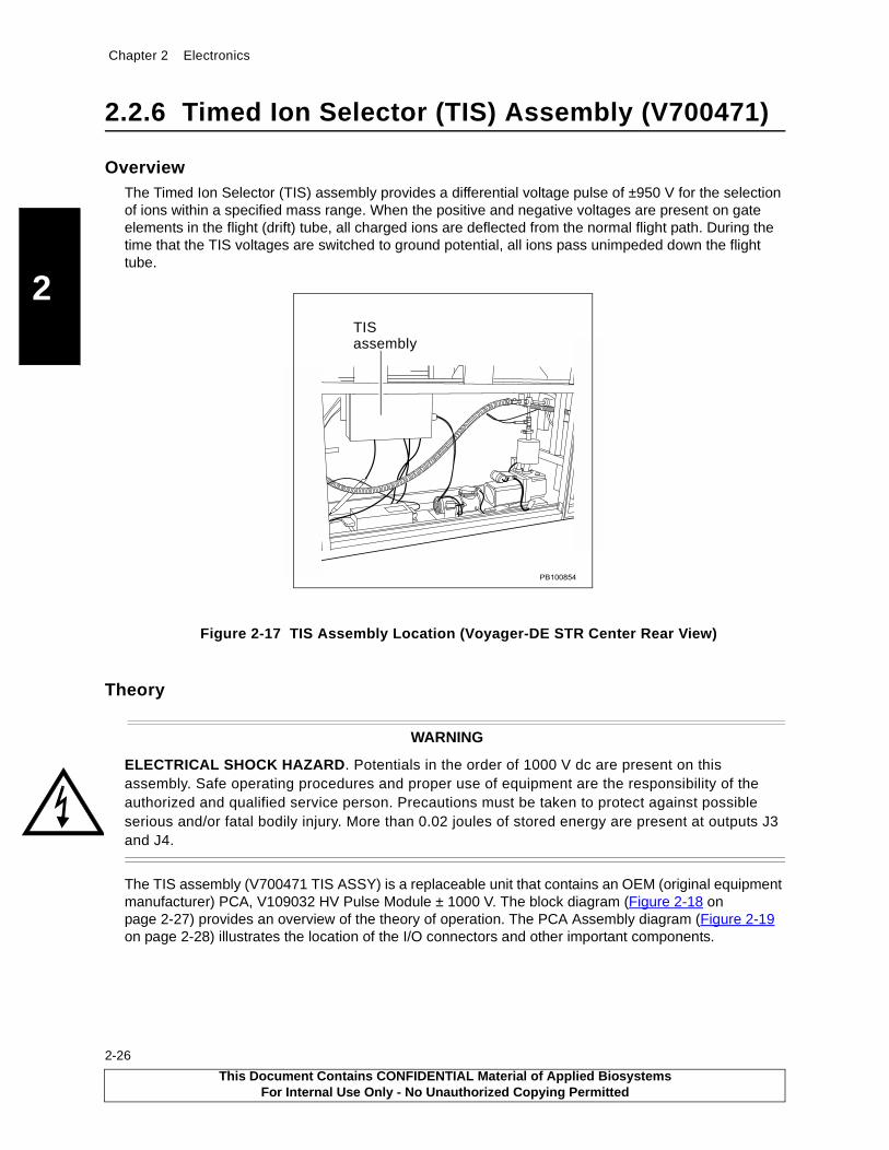
Chapter 2 Electronics
2
2-26
2.2.6 Timed Ion Selector (TIS) Assembly (V700471)
OverviewThe Timed Ion Selector (TIS) assembly provides a differential voltage pulse of ±950 V for the selection of ions within a specified mass range. When the positive and negative voltages are present on gate elements in the flight (drift) tube, all charged ions are deflected from the normal flight path. During the time that the TIS voltages are switched to ground potential, all ions pass unimpeded down the flight tube.
Figure 2-17 TIS Assembly Location (Voyager-DE STR Center Rear View)
Theory
WARNING
ELECTRICAL SHOCK HAZARD. Potentials in the order of 1000 V dc are present on this assembly. Safe operating procedures and proper use of equipment are the responsibility of the authorized and qualified service person. Precautions must be taken to protect against possible serious and/or fatal bodily injury. More than 0.02 joules of stored energy are present at outputs J3 and J4.
The TIS assembly (V700471 TIS ASSY) is a replaceable unit that contains an OEM (original equipment manufacturer) PCA, V109032 HV Pulse Module ± 1000 V. The block diagram (Figure 2-18 on page 2-27) provides an overview of the theory of operation. The PCA Assembly diagram (Figure 2-19 on page 2-28) illustrates the location of the I/O connectors and other important components.
��������
TIS assembly
This Document Contains CONFIDENTIAL Material of Applied BiosystemsFor Internal Use Only - No Unauthorized Copying Permitted
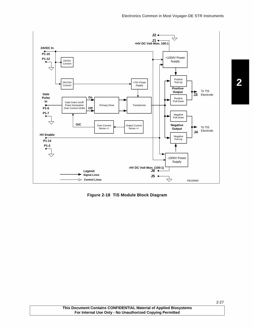
Electronics Common in Most Voyager-DE STR Instruments
2
Figure 2-18 TIS Module Block Diagram
24V/5VConvert
24V/15VConvert
Gate Invert on/offPulse Generation
Over Current InhibitPrimary Drive Transformer
+75V PowerSupply
Over CurrentSense +/-
Output CurrentSense +/-
+1000V PowerSupply
PositivePull-Up
PositivePull-Down
NegativePull-Down
NegativePull-Up
-1000V PowerSupply
24VDC In
GatePulse
In
HV Enable
On
Off
O/C
PositiveOutput
NegativeOutput
J3
J4
P1-15
P1-12
P1-6
P1-7
P1-14
P1-2
+HV DC Volt Mon. 100:1
-HV DC Volt Mon. (100:1)
J5
J6
J1
J2
Signal Lines
PB100839Control Lines
Legend:
To TISElectrode
To TISElectrode
This Document Contains CONFIDENTIAL Material of Applied BiosystemsFor Internal Use Only - No Unauthorized Copying Permitted
2-27
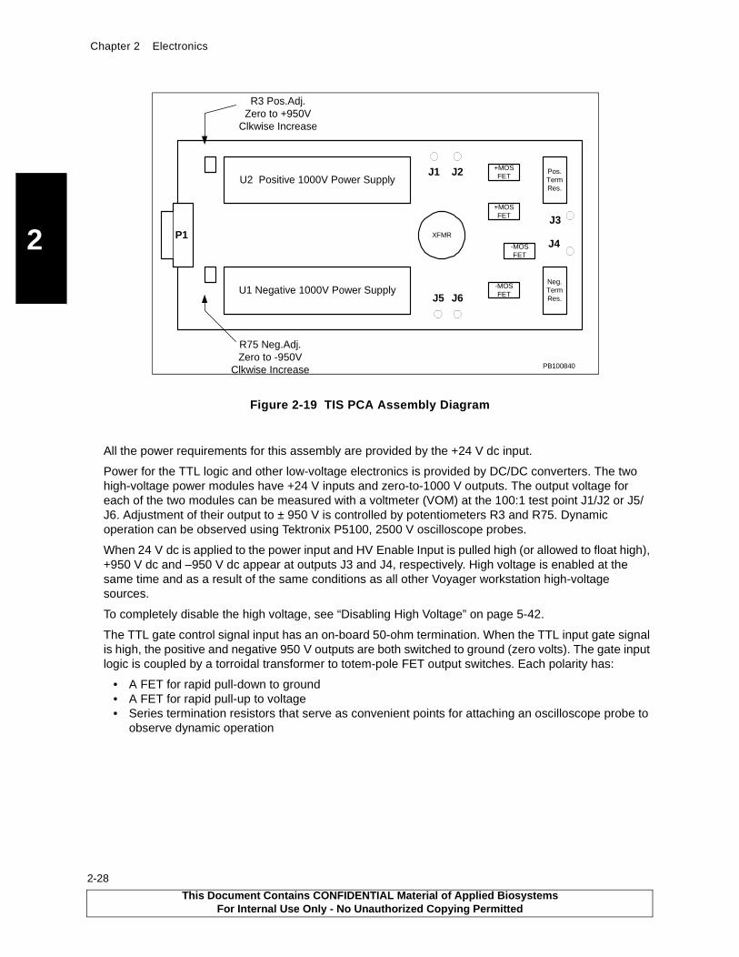
Chapter 2 Electronics
2
2-28
Figure 2-19 TIS PCA Assembly Diagram
All the power requirements for this assembly are provided by the +24 V dc input.
Power for the TTL logic and other low-voltage electronics is provided by DC/DC converters. The two high-voltage power modules have +24 V inputs and zero-to-1000 V outputs. The output voltage for each of the two modules can be measured with a voltmeter (VOM) at the 100:1 test point J1/J2 or J5/J6. Adjustment of their output to ± 950 V is controlled by potentiometers R3 and R75. Dynamic operation can be observed using Tektronix P5100, 2500 V oscilloscope probes.
When 24 V dc is applied to the power input and HV Enable Input is pulled high (or allowed to float high), +950 V dc and –950 V dc appear at outputs J3 and J4, respectively. High voltage is enabled at the same time and as a result of the same conditions as all other Voyager workstation high-voltage sources.
To completely disable the high voltage, see “Disabling High Voltage” on page 5-42.
The TTL gate control signal input has an on-board 50-ohm termination. When the TTL input gate signal is high, the positive and negative 950 V outputs are both switched to ground (zero volts). The gate input logic is coupled by a torroidal transformer to totem-pole FET output switches. Each polarity has:
• A FET for rapid pull-down to ground• A FET for rapid pull-up to voltage• Series termination resistors that serve as convenient points for attaching an oscilloscope probe to
observe dynamic operation
Pos.TermRes.
U2 Positive 1000V Power Supply
U1 Negative 1000V Power Supply
XFMR
Neg.TermRes.
P1-MOSFET
-MOSFET
+MOSFET
+MOSFETJ1 J2
J5 J6
J3
J4
R3 Pos.Adj.Zero to +950V
Clkwise Increase
R75 Neg.Adj.Zero to -950V
Clkwise Increase PB100840
This Document Contains CONFIDENTIAL Material of Applied BiosystemsFor Internal Use Only - No Unauthorized Copying Permitted

Electronics Common in Most Voyager-DE STR Instruments
2
SpecificationsSpecifications are summarized in the following table:
Normal operation is at ±950 V dc. The TIS gates draw no current other than the instantaneous current required to switch a capacitive load. Output short-circuit protection is provided on the PCA.
Item Comment
Input power +24 V dc at approximately 200 mA
Gate Pulse TTL gate pulse input impedance, 50 ohms resistive
Output
J3
J4
0 to +1000 V dc
0 to –1000 V dc
This Document Contains CONFIDENTIAL Material of Applied BiosystemsFor Internal Use Only - No Unauthorized Copying Permitted
2-29
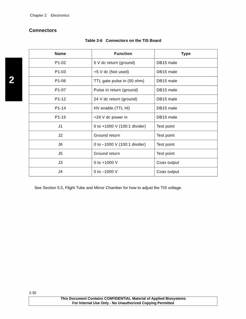
Chapter 2 Electronics
2
2-30
Connectors
See Section 5.5, Flight Tube and Mirror Chamber for how to adjust the TIS voltage.
Table 2-6 Connectors on the TIS Board
Name Function Type
P1-02 5 V dc return (ground) DB15 male
P1-03 +5 V dc (Not used) DB15 male
P1-06 TTL gate pulse in (50 ohm) DB15 male
P1-07 Pulse in return (ground) DB15 male
P1-12 24 V dc return (ground) DB15 male
P1-14 HV enable (TTL Hi) DB15 male
P1-15 +24 V dc power in DB15 male
J1 0 to +1000 V (100:1 divider) Test point
J2 Ground return Test point
J6 0 to –1000 V (100:1 divider) Test point
J5 Ground return Test point
J3 0 to +1000 V Coax output
J4 0 to –1000 V Coax output
This Document Contains CONFIDENTIAL Material of Applied BiosystemsFor Internal Use Only - No Unauthorized Copying Permitted
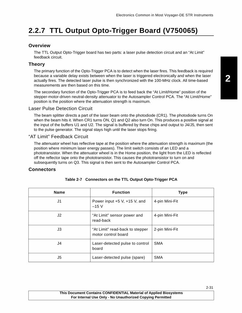
Electronics Common in Most Voyager-DE STR Instruments
2
2.2.7 TTL Output Opto-Trigger Board (V750065)
OverviewThe TTL Output Opto-Trigger board has two parts: a laser pulse detection circuit and an “At Limit” feedback circuit.
TheoryThe primary function of the Opto-Trigger PCA is to detect when the laser fires. This feedback is required because a variable delay exists between when the laser is triggered electronically and when the laser actually fires. The detected laser pulse is then synchronized with the 100-MHz clock. All time-based measurements are then based on this time.
The secondary function of the Opto-Trigger PCA is to feed back the “At Limit/Home” position of the stepper-motor-driven neutral-density attenuator to the Autosampler Control PCA. The “At Limit/Home” position is the position where the attenuation strength is maximum.
Laser Pulse Detection CircuitThe beam splitter directs a part of the laser beam onto the photodiode (CR1). The photodiode turns On when the beam hits it. When CR1 turns ON, Q1 and Q2 also turn On. This produces a positive signal at the input of the buffers U1 and U2. The signal is buffered by these chips and output to J4/J5, then sent to the pulse generator. The signal stays high until the laser stops firing.
“AT Limit” Feedback CircuitThe attenuator wheel has reflective tape at the position where the attenuation strength is maximum (the position where minimum laser energy passes). The limit switch consists of an LED and a phototransistor. When the attenuator wheel is in the Home position, the light from the LED is reflected off the reflector tape onto the phototransistor. This causes the phototransistor to turn on and subsequently turns on Q3. This signal is then sent to the Autosampler Control PCA.
Connectors
Table 2-7 Connectors on the TTL Output Opto-Trigger PCA
Name Function Type
J1 Power input +5 V, +15 V, and –15 V
4-pin Mini-Fit
J2 “At Limit” sensor power and read-back
4-pin Mini-Fit
J3 “At Limit” read-back to stepper motor control board
2-pin Mini-Fit
J4 Laser-detected pulse to control board
SMA
J5 Laser-detected pulse (spare) SMA
This Document Contains CONFIDENTIAL Material of Applied BiosystemsFor Internal Use Only - No Unauthorized Copying Permitted
2-31

Chapter 2 Electronics
2
2-32
This page intentionally left blank.
This Document Contains CONFIDENTIAL Material of Applied BiosystemsFor Internal Use Only - No Unauthorized Copying Permitted
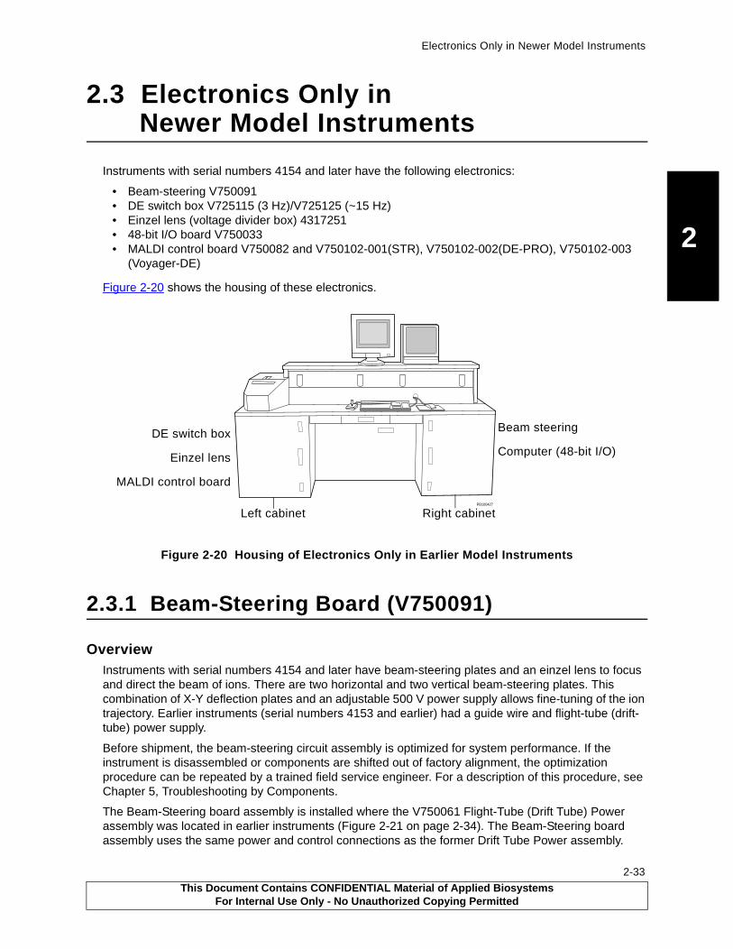
Electronics Only in Newer Model Instruments
2
2.3 Electronics Only in Newer Model Instruments
Instruments with serial numbers 4154 and later have the following electronics:
• Beam-steering V750091• DE switch box V725115 (3 Hz)/V725125 (~15 Hz)• Einzel lens (voltage divider box) 4317251• 48-bit I/O board V750033• MALDI control board V750082 and V750102-001(STR), V750102-002(DE-PRO), V750102-003
(Voyager-DE)
Figure 2-20 shows the housing of these electronics.
Figure 2-20 Housing of Electronics Only in Earlier Model Instruments
2.3.1 Beam-Steering Board (V750091)
OverviewInstruments with serial numbers 4154 and later have beam-steering plates and an einzel lens to focus and direct the beam of ions. There are two horizontal and two vertical beam-steering plates. This combination of X-Y deflection plates and an adjustable 500 V power supply allows fine-tuning of the ion trajectory. Earlier instruments (serial numbers 4153 and earlier) had a guide wire and flight-tube (drift-tube) power supply.
Before shipment, the beam-steering circuit assembly is optimized for system performance. If the instrument is disassembled or components are shifted out of factory alignment, the optimization procedure can be repeated by a trained field service engineer. For a description of this procedure, see Chapter 5, Troubleshooting by Components.
The Beam-Steering board assembly is installed where the V750061 Flight-Tube (Drift Tube) Power assembly was located in earlier instruments (Figure 2-21 on page 2-34). The Beam-Steering board assembly uses the same power and control connections as the former Drift Tube Power assembly.
PB100427
Beam steering
Computer (48-bit I/O)
DE switch box
Einzel lens
MALDI control board
Right cabinetLeft cabinet
This Document Contains CONFIDENTIAL Material of Applied BiosystemsFor Internal Use Only - No Unauthorized Copying Permitted
2-33

Chapter 2 Electronics
2
2-34
Figure 2-21 Beam Steering Board Location
Operation of the beam-steering voltage is transparent to the user. When acceleration voltage is changed, beam-steering voltage tracks in a linear fashion.
TheoryThe beam-steering assembly consists of X-Y deflection plates and an adjustable/programmable dual power supply board (Figure 2-22).
Figure 2-22 Beam-Steering Board Block Diagram
PB100427
PB100851
Beam-steering board
HorizontalDC/DC
12V to 500V
VerticalDC/DC
12V to 500V
PolarityReverse
Relay
HV PwrEnableRelay
PolarityReverse
Relay
PolarityReverse
Relay
PolarityReverse
Relay
J3+12VPwr
J4DACInput
J2 HV Enb
&Polarity
HorizontalSwitch
VerticalOutput
J1Horizontal
Output
VerticalAdjust
VerticalSwitch
Horiz.Adjust
Pw On
DAC Out0 to +10V
+12VDC +12VDC when Pwr is Enabled
+V-V
+H-H
Polarity Change
0 to 500V
0 to 500V
0 to 500V
0 to 500V
Control Lines
Signal LinesLegend:
PB100836
This Document Contains CONFIDENTIAL Material of Applied BiosystemsFor Internal Use Only - No Unauthorized Copying Permitted

Electronics Only in Newer Model Instruments
2
The X-Y plates are positioned early in the ion flight path. They interface to the outside via a 4-wire high-voltage vacuum feedthrough. Two twisted pair of 600 V wire connect the feedthrough to the board assembly.
The voltage applied to each plate is proportional to the ion acceleration voltage. A polarity switch and a trim pot (trimmer potentiometer) tailor each beam axis control to the individual instrument.
The deflection voltages are automatically reversed when the instrument is reconfigured from positive ion mode to negative ion mode. The deflection voltages are also automatically enabled and disabled along with the other system high voltages.
The Beam-Steering DAC address is at the same address as the Source Power Supply DAC address (address 7, 3-bit mode; address 31, 5-bit mode). Therefore, changing the source power voltage makes the same change to the beam-steering board voltage. In earlier instruments containing a guide wire, when the source voltage changed, the guide wire voltage tracked the source voltage, based on a percentage.
Before shipment, the system is optimized for performance. During final test, the optimum polarity is selected by actuating the slide switches, and the optimum voltage scaling for each axis is determined by adjusting the potentiometers while running a prescribed sequence of test samples. The values are documented on a label adhered to the right drawer base, next to the beam steering board. The values are based on an acceleration/source voltage of 25 kV.
Specifications
Power Power to the five relays is supplied by +24 V dc at approximately 30 mA. Power to the two 12 V-to-500 V programmable DC/DC converters is suppled by +12 V dc at approximately 40 mA from the DVDT PCA. The converters specify a no-load to full 2 mA load current requirement of 16 mA to 150 mA. The deflector plates are essentially no-load devices.
InputInput impedance load presented to the DAC is 3.6 K resistive. An input divider scales the DAC output of 0 to 10 V to match the DC/DC converter requirement of 0 to 5 V.
Output Each axis has available 0 to 500 V dc. For the deflector plates, however, the output is current limited to 400 µA, so no damage results from a continuous short circuit. The DC/DC converters specify a no-load ripple of less than 0.002% or 20 ppm. Load regulation for 0 to 100% current is 0.01%, and line regulation from 11.5 V to 16.0 V input is 0.1%.
Connectors, Switches, and Test Points
Table 2-8 Connectors, Switches, and Test Points on the Beam-Steering Board
Item Name Function Type
Connectors J1 Power output:
Horizontal 0 to 500 V and Return
Vertical 0 to 500 V and Return
14-pin Mini-Fit™
J2 HV Enable, Post/Leg Ion Polarity, +24 V Relay Power
8-pin MTA™ locking header,0.1-inch spacing
J3 +12 V power for dual DC/DC 500 V converters
2-pin MTA locking header,0.1-inch spacing
This Document Contains CONFIDENTIAL Material of Applied BiosystemsFor Internal Use Only - No Unauthorized Copying Permitted
2-35

Chapter 2 Electronics
2
2-36
J4 DC/DC program input from DAC 4-pin MTA locking header,0.1-inch spacing
Switches SW1 VERTICAL (+ and –)
Vertical deflection polarity switch SPDT
SW2 HORIZONTAL (+ and –)
Horizontal deflection polarity switch
SPDT
Test Points HPOS1, HNEG1
Positive and negative test points for digital voltmeter
Test point
VPOS1, VNEG1
Positive and negative test points for digital voltmeter
Test point
Table 2-8 Connectors, Switches, and Test Points on the Beam-Steering Board (Continued)
Item Name Function Type
This Document Contains CONFIDENTIAL Material of Applied BiosystemsFor Internal Use Only - No Unauthorized Copying Permitted

Electronics Only in Newer Model Instruments
2
2.3.2 DE Switch Box V725115/V725125
The DE switch box (Figure 2-23) provides a very fast and stable high-voltage pulse to accelerate the sample ions after they are desorbed by a laser pulse.
Figure 2-23 DE Switch Box Location
The DE switch box operates in conjunction with two programmable HV (high voltage) power supplies. When the laser pulse fires, one supply is providing a fixed “grid” rest value so that the ions do not see a voltage gradient until the DE switch box fires. The other supply is providing a higher “source”, so when the switch box fires, the ion group accelerates past the grid and down the flight tube.
Theory
WARNING
ELECTRICAL SHOCK HAZARD. Potentials up to 30,000 V dc are present in this assembly. Safe operating procedures and proper use of equipment are the responsibility of the authorized and qualified service person. Precautions must be taken to protect against possible serious and/or fatal bodily injury. In excess of 4 joules of stored energy may be present inside the enclosure and at the external terminals. This energy may remain stored in the capacitors for some time after all external connectors have been removed.
The DE switch box is comprised of:
• A 6.25 in. × 6.25 in. × 12.5 in Lexan® enclosure
• An HV solid-state switch
• Associated components necessary to provide the sample plate with voltage pulses to accelerate ions
Three HV relays are included, which, in conjunction with reversible power supplies, permit operation in either positive ion or negative ion mode.
������
DEswitchbox
This Document Contains CONFIDENTIAL Material of Applied BiosystemsFor Internal Use Only - No Unauthorized Copying Permitted
2-37

Chapter 2 Electronics
2
2-38
Figure 2-24 shows two basic versions of the DE switch.
Figure 2-24 DE Switch Box Block Diagrams
GridPowerSupply
FAST DE SWITCHV725125
BLOCK DIAGRAM
SourcePowerSupply
4700 pF Source 4700 pF Grid
400
200M
300K 1M
BehlkeSwitch
GridPowerSupply
DE SWITCHV725115/V725059BLOCK DIAGRAM
SourcePowerSupply
4700 pF Source 4700 pF Grid
400 3M 1M
BehlkeSwitch
401M
2000M
This Document Contains CONFIDENTIAL Material of Applied BiosystemsFor Internal Use Only - No Unauthorized Copying Permitted

Electronics Only in Newer Model Instruments
2
The series of events are as follows:
1. Immediately after the laser ionizes the sample, the Behlke input receives a 2 µS TTL-level pulse, then the output closes for 10 µS. 10 µS is enough time to launch all the ions generated by the laser pulse.
2. The 4700 pF capacitance is briefly placed in parallel with the source capacitance.
The voltage across the source quickly jumps to a value only slightly less than the initial value across the 4700 pF capacitor.
3. The diode is reversed-biased to disconnect the source from the grid power supply.
4. The Behlke switch opens. The elevated source voltage exponentially decays through the parallel 200 Mohm resistor.
5. When it decays to the original grid rest voltage level, the diode again conducts and the grid power supply again maintains the source at the grid rest voltage.
Component Comment
Source power The source power supply is always set higher than the grid power supply. The source voltage appears across the adjacent 4700 pF capacitor.
Behlke switch The Behlke switch is an extremely fast HV electronic switch.
Grid power supply The grid power supply provides a potential to the grid. The forward-biased diode also provides the same grid rest potential to the source.
Source (the sample plate)
The source and the control grid are both represented as small capacitances of approximately 40 pF.
This Document Contains CONFIDENTIAL Material of Applied BiosystemsFor Internal Use Only - No Unauthorized Copying Permitted
2-39

Chapter 2 Electronics
2
2-40
Table 2-9 describes the characteristics of each DE switch box model.
1Instruments S/N 4154 through 4160 may have been upgraded from V725115 to V725125.2This circuit board also includes a 24 V-to-5 V dc/dc converter to supply the 5 V dc required by the Behlke switch.
The new model, V725125, can be used only on newer Voyager workstations that contain a MALDI Consolidated Control Board. This board provides switch-selectable firmware for compatibility with the old and new DE switches. In these systems, the laser pulse rate is further limited by the digitizer speed and the maximum pulse rate of the laser itself.
Table 2-9 Characteristics of the Three DE Switch Box Models
Feature/Condition V725059 V725115 V725125
Serial numbers of Voyager on which installed
NA STR 4142-41601
DE-Pro 6056-6130
Voyager-DE 1143-1170
STR 4161 and laterDE-Pro 6131 and later
Voyager-DE 1171 and later
Laser pulse rate 3 Hz 3 Hz 3 to 100 Hz(with grid voltage to source voltage ratio of 67% or greater)
Source pulse voltage isolation from the grid rest voltage
401 Mohmresistor network
401 Mohmresistor network
Diode
HV terminals 3 4 4
Damping resistors in the grid cables
This resistance is required
This resistance is included in the 3 Mohm and 1 Mohm resistors.
This resistance is included in the 3 Mohm and 1 Mohm resistors.
Small wire harness Bottom of the box Bottom of the box Replaced by green V750074 printed circuit relay control board.2
Power required 24 V and 5 V 24 V and 5 V 24 V dc only
This Document Contains CONFIDENTIAL Material of Applied BiosystemsFor Internal Use Only - No Unauthorized Copying Permitted

Electronics Only in Newer Model Instruments
2
Figure 2-25 illustrates operation on the V725125 operating at a pulse rate of 100 Hz.
Figure 2-25 DE Switch Waveforms
Figure 2-25 A illustrates voltage vs. distance. Note that the grid potential remains fixed while the source or sample potential is pulsed above the grid potential to launch the ions.
Figure 2-25 B illustrates source voltage vs. time. Each time the Behlke switch receives a TTL level pulse, the source voltage pulses to the higher level, then exponentially decays to the grid rest voltage level.
Figure 2-25 C is an expanded voltage vs. time diagram showing the leading edge of a single source pulse. Approximately 120 ns after the leading edge of the TTL level control pulse, the source voltage pulses from the rest grid level to the source pulse level. The rise time of the HV pulse is typically 50 ns.
A Tektronix P6015A HV probe connected to a special HV “Y” adapter cable is required to view these waveforms.
DISTANCE
VOLTAGE
V
Vgrid
source
source grid ground
TIME
VOLTAGE
TIME
V
V
grid
source
TTL Pulse
VOLTAGE
V
V
grid
source
TTL Pulse
(5 mS per division)
(1 uS per division)
Fig. 1
Fig. 2
Fig. 3
A
Figure B
Figure C
B
C
This Document Contains CONFIDENTIAL Material of Applied BiosystemsFor Internal Use Only - No Unauthorized Copying Permitted
2-41
Chapter 2 Electronics
2
2-42
Specifications
Power
InputInput impedance expects TTL level pulse generator capable of driving a 50 ohms load.
OutputMaximum source pulse level of 30 kV. Grid rest level must be at least 67% of source level.
Connectors
Table 2-10 Low-Voltage Power Requirements
Switch Assembly +5 V dc Requirements +24 V dc Requirements
V725125 None 100 mA to 700 mA
V725115 400 mA 0 mA to 600 mA
V725059 400 mA 0 mA to 600 mA
Table 2-11 High-Voltage Power Requirements
Supply Voltage Current
Source power supply 0 to +30 kV or 0 to –30 kV 0 to 400 µA
Grid power supply 0 to +30 kV or 0 to –30 kV 0 to 400 µA
Table 2-12 Connectors on the V750074 Board Within the DE Switch Box
Name Function Type
J1 Low-voltage power input, relay control input, and TTL pulse input
Amphenol 206486-1
J2 Source HV power supply input Alden B102
J3 Grid feedthrough (Grid HV potential) Alden B102
J4 Source feedthrough (Source HV pulse output)
Alden B102
J6 Grid HV power supply input Alden B102
This Document Contains CONFIDENTIAL Material of Applied BiosystemsFor Internal Use Only - No Unauthorized Copying Permitted
Electronics Only in Newer Model Instruments
2
Firmware Configuration (MALDI Consolidated Control Board)
AThe four positions are numbered 0 through 3. Therefore, the fourth dipswitch position is named Position 3.
LEDsLED indicators on the bottom of the DE box high-voltage relays indicate relay actuation. Table 2-14 illustrates the LED pattern for each Voyager workstation operation mode. Note that the green PCB on the bottom of the V725125 box assembly also has an orange LED to indicate that the 24 V to 5 V dc/dc converter is operating correctly. Voyager workstation mode indication is also is provided on the V750082 MALDI Control Board at location D3 by LEDs labeled RLY1, RLY2, and RLY3.
Table 2-13 Firmware Configuration
Switch Box Assembly
SchematicMALDI Consolidated Control Board
Switch S1, Position 3A
V725125 V750095 On 3 Hz to 100 Hz
V725115 V750075 Off 3 Hz
V725059 V725059 Off 3Hz
Table 2-14 DE Switch Box LED Displays
Switch Assembly
Voyager Workstation Mode
5 V dcOrange
Relay-1Yellow
Relay-2 Green
Relay-3Red
V725125 DE Positive On Off Off Off
DE Negative On On On On
Continuous Positive On On Off Off
Continuous Negative On On Off On
V725115 DE Positive N/A Off Off Off
DE Negative N/A On On Off
Continuous Positive N/A On Off On
Continuous Negative N/A On Off On
V725059 DE Positive N/A Off Off Off
DE Negative N/A On On Off
Continuous Positive N/A On Off On
Continuous Negative N/A On Off On
This Document Contains CONFIDENTIAL Material of Applied BiosystemsFor Internal Use Only - No Unauthorized Copying Permitted
2-43

Chapter 2 Electronics
2
2-44
2.3.3 Einzel Lens Electronics (Voltage Divider Box, 4317251)
OverviewThis assembly is a resistive tap off the source power supply that provides 50% of the source voltage to the einzel lens. The Voltage Divider box is mounted on the side of the DE switch box enclosure (Figure 2-26).
Figure 2-26 Voltage Divider Box Location (Voyager-DE STR Left Cabinet Rear View)
TheoryThe Voltage Divider box consists of an epoxy-potted plastic or metal box with two series-500 Mohm resistors. The one end (top) of the resistors is connected to two HVPS (high voltage power supply)-type Alden connectors. The other end (bottom) of the resistors is tied to the Voltage Divider Box ground lug. The Voltage Divider Box ground is tied to the instrument frame ground through a braided cable.
WARNING
ELECTRICAL SHOCK HAZARD. Severe electrical shock can occur if the Voltage Divider box ground lug is not grounded to the instrument frame. The ground lug carries high voltage unless grounded. Failure to properly ground the ground lug can also damage the einzel lens.
The middle (50%) of the resistors is brought out to another HVPS-type Alden connector.
The two connectors at the top of the Voltage Divider Box (Figure 2-27 on page 2-45) allow you to connect the source HVPS to the Voltage Divider Box and also to the DE switch box. The connector on the bottom of the box provides a connection to the einzel lens.
PB100853
DEswitchbox
Voltage divider box
side the DE switch box)(not visible, along
This Document Contains CONFIDENTIAL Material of Applied BiosystemsFor Internal Use Only - No Unauthorized Copying Permitted

Electronics Only in Newer Model Instruments
2
Figure 2-27 Voltage Divider Box Connectors
Connectors
Function Type
Source HVPS Alden HV 40 kV
DE switchbox source PS Alden HV 40 kV
Einzel lens Alden HV 40 kV
Ground lug 10-32 and hardware
PB100837
To DE switch box sourceFrom source HVPS
Ground lug
500 Mohm
500 Mohm
To einzel lens
Connectors
Connector
This Document Contains CONFIDENTIAL Material of Applied BiosystemsFor Internal Use Only - No Unauthorized Copying Permitted
2-45

Chapter 2 Electronics
2
2-46
2.3.4 48-Bit I/O Board with Game Port (V750033)
OverviewThis I/O board has a dual function:
• It interfaces the input and output control signals between the computer and the other system components
• It interfaces, processes, and controls Game Port functions.
Figure 2-28 48-bit I/O Board in the Computer (Rear view)
TheoryThe I/O board has three 8255 parallel interface adapter (PIA) chips. Each chip has an 8-bit data bus, 2-bit addressing, a chip select, and a read/write line, all of which are connected to the computer data bus. In addition each chip has three 8-bit I/O ports. Only two of the three chips are used; U38 is a spare.
All inputs and outputs to the 8255 chips are optically isolated through an HCPL-2630 chip. The isolators prevent noise on the computer bus and offer protection from high-voltage arcs in the system.
NOTE: +5 V (5 B on older schematics) was supplied from the Voyager workstation system (DC Distribution PCA) in older systems. In newer systems, this +5 V cable is not connected to the card, nor required, and the buffered 5 V and grounds are jumped to obtain power from the computer. Adding jumpers JP2 2-4, 6-8 and JP3 2-4 and 6-8 enables this.
ConnectorsTable 2-15 Connectors on the 48-Bit I/O Board
Connector Function Type
J0 Enable, address, and I/O 26-pin ribbon
J1 Data and I/O 26-pin ribbon
J3 +5 V (5 B on older schematics) power Plug
���������
48-bit I/O board
This Document Contains CONFIDENTIAL Material of Applied BiosystemsFor Internal Use Only - No Unauthorized Copying Permitted

Electronics Only in Newer Model Instruments
2
LEDsThe I/O Board has one LED, the +5 V LED. The function is Buffered 5 V.
2.3.5 MALDI Control Board (V750082 and V750102-001, V750102-002, V7502-003)
OverviewThe MALDI consolidated control board consolidates discrete logic functions previously found on the:
• Pulse Generator (Timed Ion Selector) Board
• DAC (source, grid, reflector and Beam Guide) Boards
• Old-style TTL MALDI Control and Distribution Boards
Figure 2-29 MALDI Control Board Location
J4 (Not used) NA
J5 (Not used) NA
J6 Game port 16-pin ribbon
Table 2-15 Connectors on the 48-Bit I/O Board (Continued)
Connector Function Type
PB100427
MALDIcontrolboard
PB100848
This Document Contains CONFIDENTIAL Material of Applied BiosystemsFor Internal Use Only - No Unauthorized Copying Permitted
2-47

Chapter 2 Electronics
2
2-48
Table 2-17 on page 2-52 and Figure 2-30 on page 2-58 present the highlights of the MALDI control board.
Systems controlled by this board include the pumps, voltages, and vacuum system. MALDI consolidated control board functions to controls the:
• DE switch box
• High-voltage power supply (DAC control and enable, polarity)
• Timed-Ion Selector
• Delayed pulse generator
• Laser trigger
• Interlock sensor
Functions not controlled by the MALDI Control Board are listed in Table 2-16.
aTo provide use of an external laser, the MALDI Control Board is connected directly to the 48-bit IO PCA in the system computer, and the stepper motor signals for the laser attenuator are switched through the Control Board.
TheoryAll the MALDI Control Board logic functions are in Altera complex programmable logic devices (CPLDs). All signals to and from the CPLDs are isolated by buffers or drivers.
The buffer section receives 40 bits of control from the computer 48-bit I/O card and supplies 8 bits back. All 48-bits to and from the 48-bit I/O card are immediately buffered (U1, U2, U3, U13, U14, U17).
The 40 bits designated as inputs to the control board are further divided into the Voyager Bus and Discrete IO.
Voyager BusThe unidirectional Voyager Bus consists of:
• A 16-bit data bus
• Either a 3 or 5-bit address bus
• Two control bits (Load and Latch)
Table 2-16 Functions Excluded from the MALDI Control Board
Functions Excluded from MALDI Control Board
Voyager STR Voyager-DE or DE-Pro
Stepper controlA Stepper controla
DVDT (Low-Mass Gate timer) functions DVDT (low-mass gate timer) functions
Reflector DAC
Beam guide (or beam steering) DAC
This Document Contains CONFIDENTIAL Material of Applied BiosystemsFor Internal Use Only - No Unauthorized Copying Permitted
Electronics Only in Newer Model Instruments
2
The bus is capable only of receiving data from the computer; it cannot be read from the computer. The Voyager Bus is used in three places:
• Internally to the CPLDs (for trigger generation and DE/TIS pulse generators),
• On the control board itself (for 16-bit DACs)
• As a buffered output from the Control Board to drive external DAC PCAs (reflector and Beam Guide in a STR) and the DVDT PCA (Detector Voltage Delay Timer or Low-Mass Gate delay timer).
DAC/HVPS control
The MALDI consolidated board contains up to four 16-bit DACs (U16, U22, U27, U44) and associated control signals to control high-voltage power supplies (HVPSs). The DACs, which are controlled via the Voyager bus, output a 0 to 10 V signal to control the HVPSs.
The V750102-001 configuration (STR configuration) has two populated DACs, U16 (source control DAC) and U22 (grid control DAC). The other two DACs are unpopulated because beam steering and mirror HVPSs are controlled by discrete DAC PCAs. See Section 2.2.2, DAC (Digital-to-Analog Converter) Board (V750025).
In addition to the DACs, two discrete outputs are associated with HVPS control: Enable and Polarity.
U19, a precision voltage source, generates a 5 V reference for the 16-bit DACs.
Laser trigger generation
Laser trigger is generated from one of two sources:
• Legacy discrete IC/trigger generator—A 555-based oscillator controlled by pot R 46. To select this circuit, set dipswitch S1 to LASTRGOLD. This circuit can be set from 1 Hz to 200 Hz, but is not programmable by the software.
Output from this circuit runs through the Altera firmware, to line driver U6, and out SMA connector J6 (TP26).
If an external laser is present and selected, the corresponding laser trigger line driver is U5 (TP25).
• CPLD-based digital divider trigger generator—Available with 5-bit addressing and can be programmed to an optimal setting by the software.
To generate a trigger, two programmable down-counters are preloaded via the Voyager bus. When the laser trigger is enabled (by software):
1. The first counter is enabled, driven by a 63-kHz clock.
2. The first counter counts down from the preloaded value to zero.
3. When the first counter reaches zero, an output is generated, triggering the second counter.
4. The first counter reloads and starts again.
5. The second counter generates the laser trigger leading edge and starts counting down from the preloaded value.
6. When the second counter counts down to zero, it generates the laser trigger trailing edge.
7. The second counter then reloads.
This Document Contains CONFIDENTIAL Material of Applied BiosystemsFor Internal Use Only - No Unauthorized Copying Permitted
2-49
Chapter 2 Electronics
2
2-50
The first counter generates a laser trigger frequency calculated by the following equation.
F=63kHz/[N+X]
Where:
N = preloaded 16-bit number
X = overhead clock ticks = 1
For example, if N is 63 k, then F equals approximately 1 Hz.
As in the legacy trigger generator, output from this circuit runs through the Altera firmware to line driver U6, and out SMA connector J6 (TP26).
DE and Timed Ion pulse generators
The 15-bit pulse generators are firmware based and are functionally identical to the stand alone pulse generator described in Section 2.4.4, Pulse Generator PCA V750063.
The DE pulse generator provides triggers to the:
• DE switch box
• Digitizer
• Low-Mass Gate delay timer
• Timed-Ion selector
• Pulse generator
The Timed-Ion pulse generator provides a trigger to the Timed Ion Selector (TIS) Assembly V700471.
Discrete I/OInput
Input for the consolidated control board from the instrument consists of 8 bits that reflect the state of the linear actuators, flap valves, and load position of the sample stage.
Inputs specify the following conditions:
• Linear 1 actuator extended
• Linear 1 actuator retracted
• Linear 2 actuator retracted
• Flap Door 1 open
• Flap Door 1 closed
• Flap Door 2 closed
• Load Position
• Interlock Status
You can view the state of these signals using the MALDI consolidated control board LEDs D6 and D11.
This Document Contains CONFIDENTIAL Material of Applied BiosystemsFor Internal Use Only - No Unauthorized Copying Permitted

Electronics Only in Newer Model Instruments
2
Output
Discrete outputs from the computer via the MALDI consolidated control board are interlocked through the firmware, buffered, and then sent to drivers that drive the relays and solenoids.
Output are to the:
• Foreline Solenoids 1 and 2
• Vent Solenoid
• Linear Actuators
• Polarity and High-Voltage Enable
• Linear Detector Enable
• Mirror HVPS Enable
• Turbo Pump Delay/Enable
• Camera and Camera lamp
• Timed-Ion Selector control (from Voyager bus)
• DE Switch Box Control (from Voyager bus)
• Laser Interlock
Linear Actuators and Flap Doors
The linear actuators and flap door switches are magnetic reed switches that complete the 5 V interlock circuit.
Interlock Status (System Interlock)
The system interlock consists of a series chain of panel switches. The panel switches, when made, provide a ground to relay K9. When K9 is activated, 24 V switched is available for HVPS and the laser interlock relay, and a signal is sent to the computer via U13-18
Load Position
The Load Position consists of two limit switches, one on the X-axis and one on the Y-axis. The switches are wired in series to ground and when made, present this ground to the computer via U13-3 to signify the sample stage is in the load position.
Turbo 2-Minute Delay
IC U40 provides a 2-minute inhibit signal to the turbo controllers. This delay allows time to generate a rough vacuum.
Polarity, High-Voltage Enable, Linear Detector Enable, Mirror HVPS Enable
The Polarity bit is applied to the source, grid, and mirror HVPSs. The High-Voltage Enable bit is applied to the source and grid power supplies, but not the mirror power supply. The Linear Detector Enable bit enables the linear detector power supply and the Mirror HVPS bit enables the mirror HVPS and the mirror detector power supply.
This Document Contains CONFIDENTIAL Material of Applied BiosystemsFor Internal Use Only - No Unauthorized Copying Permitted
2-51
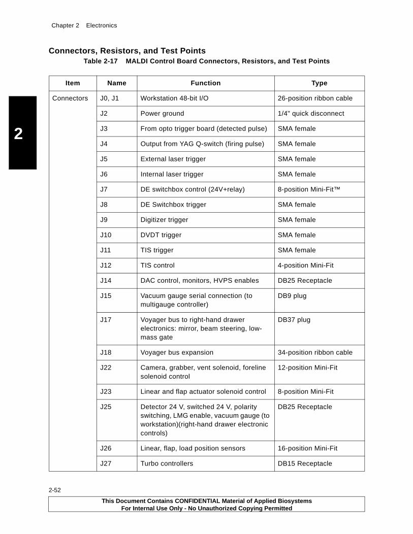
Chapter 2 Electronics
2
2-52
Connectors, Resistors, and Test PointsTable 2-17 MALDI Control Board Connectors, Resistors, and Test Points
Item Name Function Type
Connectors J0, J1 Workstation 48-bit I/O 26-position ribbon cable
J2 Power ground 1/4" quick disconnect
J3 From opto trigger board (detected pulse) SMA female
J4 Output from YAG Q-switch (firing pulse) SMA female
J5 External laser trigger SMA female
J6 Internal laser trigger SMA female
J7 DE switchbox control (24V+relay) 8-position Mini-Fit™
J8 DE Switchbox trigger SMA female
J9 Digitizer trigger SMA female
J10 DVDT trigger SMA female
J11 TIS trigger SMA female
J12 TIS control 4-position Mini-Fit
J14 DAC control, monitors, HVPS enables DB25 Receptacle
J15 Vacuum gauge serial connection (to multigauge controller)
DB9 plug
J17 Voyager bus to right-hand drawer electronics: mirror, beam steering, low-mass gate
DB37 plug
J18 Voyager bus expansion 34-position ribbon cable
J22 Camera, grabber, vent solenoid, foreline solenoid control
12-position Mini-Fit
J23 Linear and flap actuator solenoid control 8-position Mini-Fit
J25 Detector 24 V, switched 24 V, polarity switching, LMG enable, vacuum gauge (to workstation)(right-hand drawer electronic controls)
DB25 Receptacle
J26 Linear, flap, load position sensors 16-position Mini-Fit
J27 Turbo controllers DB15 Receptacle
This Document Contains CONFIDENTIAL Material of Applied BiosystemsFor Internal Use Only - No Unauthorized Copying Permitted

Electronics Only in Newer Model Instruments
2
Connectors (continued)
J28 Laser control from stepper motor PCBA 8-position Mini-Fit
J29 To I/O Internal laser attenuator 8-position Mini-Fit
J30 To external laser attenuator 12-position Mini-Fit
J31 Internal laser interlock 2-position Mini-Fit
J32 Interlock switches 2-position Mini-Fit
J34 Power in +5, +24, +15, –15 V 12-position Mini-Fit
JU1 Analog-Digital ground (normally open) 2-position 0.1-inch header
JU2 Legacy trigger frequency (normally jumped)
2-position 0.1-inch header
JU3 Auto-Manual laser type select (normally 1-2)
3-position Mini-Fit
JU4 Stepper PCB 5 V select (normally 1-2) 3-position Mini-Fit
JU5 Stepper PCB ground select (normally 1-2) 3-position Mini-Fit
JU6 3.3-5.0 V select U46 (normally 2-3) 3-position Mini-Fit
JU7-10 Open (not used) 2-position Mini-Fit
Pots R24 DAC 5 V reference monitor at TP9 Potentiometer
R46 3 Hz adjust “old laser trigger” (direct monitor at pin 3, U39)
Potentiometer
Test Points TP1 External laser in NA
TP2 DE box trigger NA
TP3 TIS trigger NA
TP4 Internal laser in NA
TP5 Internal laser in, Comparator Signal NA
TP6 External laser in, Comparator Signal NA
TP7 Source DAC command NA
TP8 Source DAC monitor Test point
TP9 5 V reference Test point
Table 2-17 MALDI Control Board Connectors, Resistors, and Test Points (Continued)
Item Name Function Type
This Document Contains CONFIDENTIAL Material of Applied BiosystemsFor Internal Use Only - No Unauthorized Copying Permitted
2-53

Chapter 2 Electronics
2
2-54
Test Points(continued)
TP10 Source DAC Return Test point
TP11 Spare DAC monitor Test point
TP12 Grid DAC command Test point
TP13 Grid DAC monitor Test point
TP14 Grid DAC Return Test point
TP15 Spare DAC command Test point
TP16 Spare DAC Return Test point
TP17 +15 V Test point
TP18 –15 V Test point
TP19 +24 V Test point
TP20 +5 V Test point
TP21 Ground, DC return Test point
TP22 +12 V Test point
TP23 Spare 2 DAC command Test point
TP24 Spare 2 DAC return, Test point
TP25 External laser trigger Test point
TP26 N2 laser trigger Test point
TP27 +3.3 V Test point
TP28 Mirror DAC monitor (DE + DE-Pro only) Test point
Table 2-17 MALDI Control Board Connectors, Resistors, and Test Points (Continued)
Item Name Function Type
This Document Contains CONFIDENTIAL Material of Applied BiosystemsFor Internal Use Only - No Unauthorized Copying Permitted
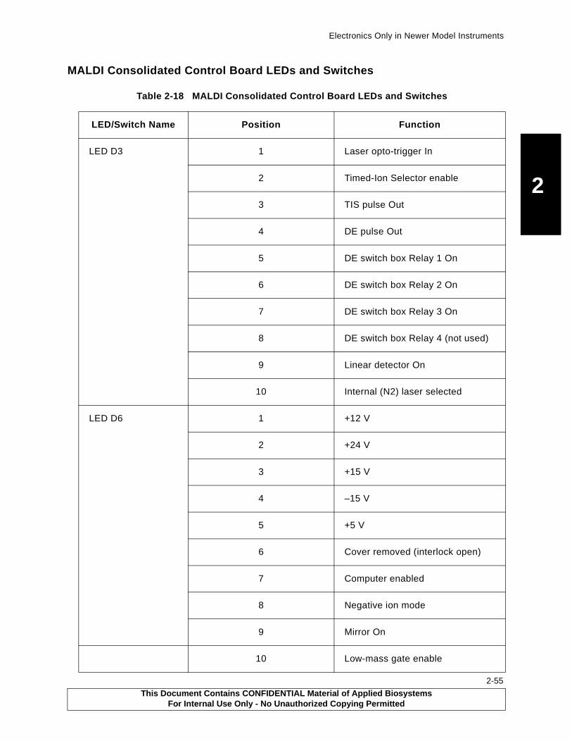
Electronics Only in Newer Model Instruments
2
MALDI Consolidated Control Board LEDs and Switches
Table 2-18 MALDI Consolidated Control Board LEDs and Switches
LED/Switch Name Position Function
LED D3 1 Laser opto-trigger In
2 Timed-Ion Selector enable
3 TIS pulse Out
4 DE pulse Out
5 DE switch box Relay 1 On
6 DE switch box Relay 2 On
7 DE switch box Relay 3 On
8 DE switch box Relay 4 (not used)
9 Linear detector On
10 Internal (N2) laser selected
LED D6 1 +12 V
2 +24 V
3 +15 V
4 –15 V
5 +5 V
6 Cover removed (interlock open)
7 Computer enabled
8 Negative ion mode
9 Mirror On
10 Low-mass gate enable
This Document Contains CONFIDENTIAL Material of Applied BiosystemsFor Internal Use Only - No Unauthorized Copying Permitted
2-55

Chapter 2 Electronics
2
2-56
LED D11 1 Linear 1 actuator extended
2 Linear 1 actuator retracted
3 Linear 2 actuator retracted
4 Flap Door 1 open
5 Flap Door 1 closed
6 Flap Door 2 open
7 Flap Door 2 closed
8 Sample stage at load position
9 3.3 V
10 Mirror detector On
LED D18 1 Linear 1 solenoid On
2 Linear 2 solenoid On
3 Flap Door 1 solenoid On
4 Flap Door 2 solenoid On
5 Foreline 1 solenoid On
6 Foreline 2 solenoid On
7 Vent solenoid
8 Camera power On
9 Grabber solenoid On
10 5 V stepper
Table 2-18 MALDI Consolidated Control Board LEDs and Switches (Continued)
LED/Switch Name Position Function
This Document Contains CONFIDENTIAL Material of Applied BiosystemsFor Internal Use Only - No Unauthorized Copying Permitted

Electronics Only in Newer Model Instruments
2
Switch 1 1 Source turbo On (normally On)
2 Mirror turbo On (normally On)
3 Not used (spare turbo)
4 old "3 Hz" DE box: Off,new: On
5 not used
6 Laser trigger select (old/new)
7 3-5 bit addressing (3-bit, 5-bit)
8 Internal/External laser manual select (normally "IntLas")
Table 2-18 MALDI Consolidated Control Board LEDs and Switches (Continued)
LED/Switch Name Position Function
This Document Contains CONFIDENTIAL Material of Applied BiosystemsFor Internal Use Only - No Unauthorized Copying Permitted
2-57

Chapter 2 Electronics
2
2-58
Figure 2-30 MALDI Control Board
J34J33
J32J31
J30J29
J28
J26J23
J22
J25
R51
K7
K8
K9
R46
J278 1
15 9
131
14 25
119
37 20J17
51
69
J15 J1
J0
2
1
26
25
2
1
26
25
J2P
OW
ER
GN
DP
E B
iosystem
sVo
yager C
on
trol B
oard
J16
U18
U15
U39
HUENABLED
INTERLOCKOK
D91
J14 J1213
1425
J11
J10
J9
J8
J6
J7
J4
J3
J5
123
R24
123
TP27
TP18
TP17
TP20
TP21
TP19
TP9
TP6
TP5
TP4
TP1
TP25
TP2
TP3
TP8
TP12
TP13
TP16
TP23
TP11TP10
TP15TP14
TP24
TP7
U5
288
1156
157
185
184
52
53
288
1156
157
185
1845354
TP26
D10
J18
R40
D18
D11
S2 Reset
JU2
D6 D3
J21
2 1
16 15
D12
S1
JU4JU3 JU5
JU6
U44 U27 U22 U19
8 7 6 5 4 3 2 1
TP22
1 33
342
PB100859
Ground
This Document Contains CONFIDENTIAL Material of Applied BiosystemsFor Internal Use Only - No Unauthorized Copying Permitted
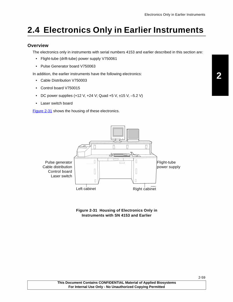
Electronics Only in Earlier Instruments
2
2.4 Electronics Only in Earlier Instruments
OverviewThe electronics only in instruments with serial numbers 4153 and earlier described in this section are:
• Flight-tube (drift-tube) power supply V750061
• Pulse Generator board V750063
In addition, the earlier instruments have the following electronics:
• Cable Distribution V750003
• Control board V750015
• DC power supplies (+12 V, +24 V; Quad +5 V, ±15 V, –5.2 V)
• Laser switch board
Figure 2-31 shows the housing of these electronics.
Figure 2-31 Housing of Electronics Only in Instruments with SN 4153 and Earlier
PB100427
Left cabinet
Flight-tube power supply
Pulse generatorCable distribution
Control boardLaser switch
Right cabinet
This Document Contains CONFIDENTIAL Material of Applied BiosystemsFor Internal Use Only - No Unauthorized Copying Permitted
2-59

Chapter 2 Electronics
2
2-60
2.4.1 Flight-Tube (Drift-Tube) Power Supply (V750061)
OverviewVoyager-DE STR instruments with serial numbers 4153 and earlier have a guide wire strung along the center axis of the flight tube to organize the stream of ions into a narrow, straight beam.
The V750061 Flight Tube Power Supply is a programmable dual-polarity power supply board (Figure 2-32) that provides a programmable potential to the wire.
Figure 2-32 Flight (Drift)-Tube Power Supply Block Diagram
0 to +100VNeg. Ion Mode
0 to -100VPos. Ion Mode
InvertOpAmpGain=10
InvertOpAmpGain=1
J1 BNCOutput
J4DACInput
J2 HV Enb
&Polarity
Neg.Offset
OutputFltr/Enb
Pos.Offset
Neg/PosRelay
HV PwrEnableRelay
J3+12VPwr
DC/DC+/-100V
DC/DC-12V
Ground Guide Wire when Pwr is notEnabled
+12VDC to OpAmps when Pwr isEnabled
Pwr On
Polarity Change
DAC Out0 to +10V
Pos. Ion Input
Neg. Ion Input
0 to -10V Out
+12VDC
0 to +10VPos. Ion Mode
0 to -10VNeg. Ion Mode
Signal Lines
Control Lines
Legend:
PB100841
This Document Contains CONFIDENTIAL Material of Applied BiosystemsFor Internal Use Only - No Unauthorized Copying Permitted

Electronics Only in Earlier Instruments
2
TheoryIons of polarity opposite to the wire potential are drawn to the center of the flight tube by their attraction to the wire. Polarity applications are summarized in the following table.
The Neg/Pos relay (controlled by J2) directs the 0 to 10 V signal from the guide wire DAC output to the power amplifier. The power amplifier amplifies the signal by a factor of 10, providing 0 to +100 V.
Connector J2 also provides a signal to activate the HV Power Enable relay. This relay has two outputs:
• High Voltage disabled output—Connects the guide wire to ground when high voltage is not enabled.
• High Voltage enabled output—Provides +12 V dc power to the two operational amplifiers when high voltage is enabled. The gain = 1 OpAmp receives +12 V directly from the relay and receives -12 V from a small DC/DC converter. The gain = 10 OpAmp receives +100 V and –100 V from a DC/DC converter powered by the same +12 V line.
The High Voltage Enable function operates with the “High Voltage Enable” on the Voyager software menu and is disabled by the Voyager hardware interlock.
See Section 5.5, Flight Tube and Mirror Chamber, for the steps to set the output to zero.
An earlier version of the Flight-Tube Power board has the same functionality and cable connections as the V750061 PCA. The earlier board has two relays and two programmable 100 V DC/DC power supplies. One relay provides High Voltage Enable and the other relay selects the output from either the Positive 100 V converter or the Negative 100 V converter. This PCA also has a potentiometer to adjust scale and can be replaced by the newer V750061 PCA.
Specifications
Power Power specifications are:
• +24 V dc at approximately 20 mA to power the two relays
• +12 V dc at approximately 250 mA to power the two DC/DC converters and associated operational amplifiers
The guide wire is essentially a no-load device.
Input Input impedance load presented to the DAC is approximately 10 K resistive.
Output The guide wire receives 0.0 to –100 V dc in positive ion mode, and 0.0 to +100 V dc in negative ion mode. The output OpAmp is protected by an 100 ohm series resistor and by an internal thermal shutdown circuit. Ripple consists of approximately 5 mV peak-to-peak switching noise that can be measured with a coax cable directly connected to an oscilloscope.
Mode/Ions Attracted to Wire Wire Potential
Positive ion Negative
Negative ion Positive
This Document Contains CONFIDENTIAL Material of Applied BiosystemsFor Internal Use Only - No Unauthorized Copying Permitted
2-61
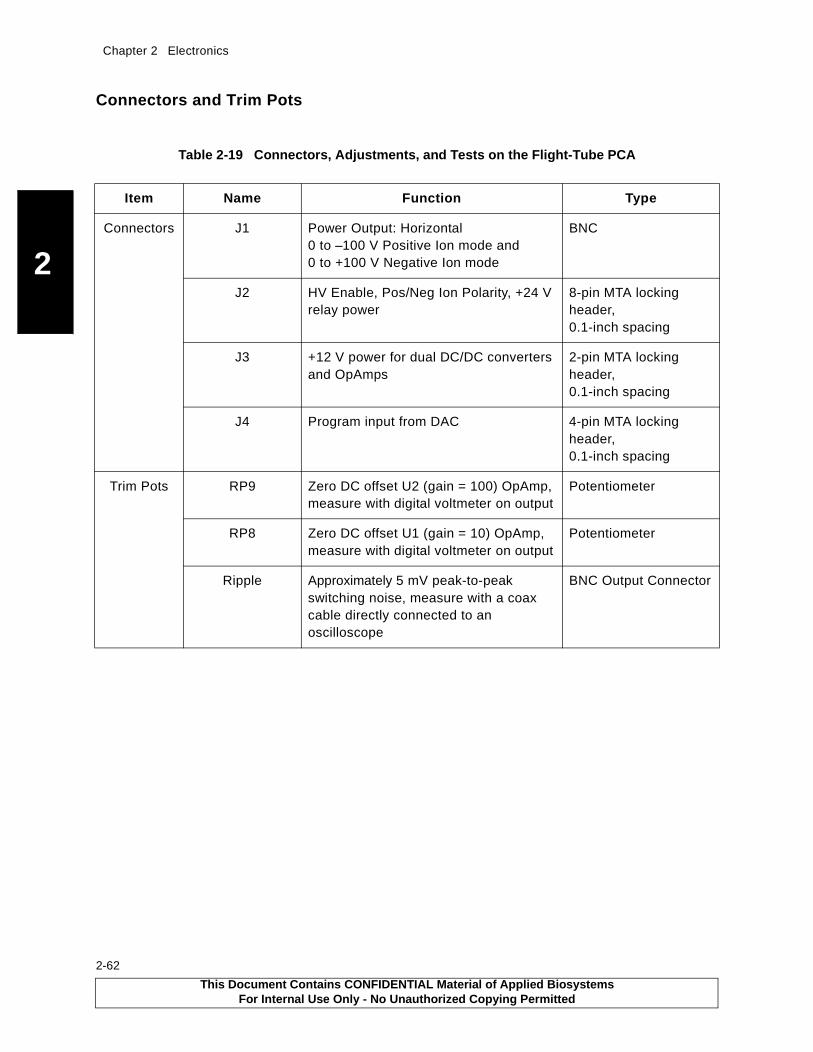
Chapter 2 Electronics
2
2-62
Connectors and Trim Pots
Table 2-19 Connectors, Adjustments, and Tests on the Flight-Tube PCA
Item Name Function Type
Connectors J1 Power Output: Horizontal 0 to –100 V Positive Ion mode and 0 to +100 V Negative Ion mode
BNC
J2 HV Enable, Pos/Neg Ion Polarity, +24 V relay power
8-pin MTA locking header, 0.1-inch spacing
J3 +12 V power for dual DC/DC converters and OpAmps
2-pin MTA locking header, 0.1-inch spacing
J4 Program input from DAC 4-pin MTA locking header, 0.1-inch spacing
Trim Pots RP9 Zero DC offset U2 (gain = 100) OpAmp, measure with digital voltmeter on output
Potentiometer
RP8 Zero DC offset U1 (gain = 10) OpAmp, measure with digital voltmeter on output
Potentiometer
Ripple Approximately 5 mV peak-to-peak switching noise, measure with a coax cable directly connected to an oscilloscope
BNC Output Connector
This Document Contains CONFIDENTIAL Material of Applied BiosystemsFor Internal Use Only - No Unauthorized Copying Permitted
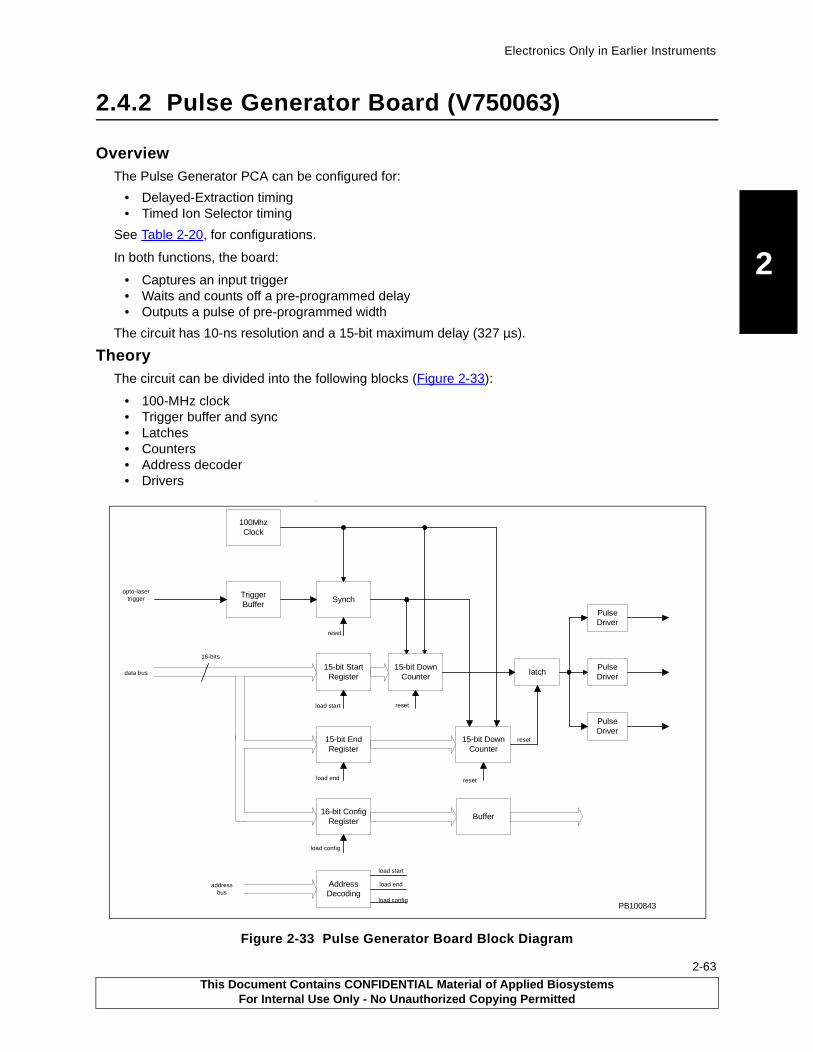
Electronics Only in Earlier Instruments
2
2.4.2 Pulse Generator Board (V750063)
OverviewThe Pulse Generator PCA can be configured for:
• Delayed-Extraction timing• Timed Ion Selector timing
See Table 2-20, for configurations.
In both functions, the board:
• Captures an input trigger• Waits and counts off a pre-programmed delay• Outputs a pulse of pre-programmed width
The circuit has 10-ns resolution and a 15-bit maximum delay (327 µs).
TheoryThe circuit can be divided into the following blocks (Figure 2-33):
• 100-MHz clock• Trigger buffer and sync• Latches• Counters• Address decoder• Drivers
.
Figure 2-33 Pulse Generator Board Block Diagram
TriggerBuffer
100MhzClock
15-bit EndRegister
15-bit StartRegister
16-bit ConfigRegister
16-bits
15-bit DownCounter
15-bit DownCounter
latch
Synch
PulseDriver
PulseDriver
PulseDriver
AddressDecoding
Buffer
data bus
opto-lasertrigger
addressbus
load start
load end
load config
load config
load end
load start
reset
reset
reset
reset
PB100843
This Document Contains CONFIDENTIAL Material of Applied BiosystemsFor Internal Use Only - No Unauthorized Copying Permitted
2-63

Chapter 2 Electronics
2
2-64
100-MHz ClockThe clock generates a 10-ns time base used by the counters, synchronizer, and address decoder.
Trigger BufferThe trigger buffer takes a 3 to 12 V asynchronous pulse event, buffers it to 5 V, synchronizes it to the 100 MHz clock, then presents it as an enable signal to the two 15-bit counters.
RegistersThere are three registers in the circuit:
• Start-pulse register—Loaded off the data bus with a 15-bit value that determines the start of the delayed output pulse. Along with the end-pulse register, this register determines the pulse delay and the pulse width.
• End-pulse register—Loaded off the data bus with a 15-bit value that determines the end of the delayed output pulse. Along with the start-pulse register, this register determines the pulse delay and the pulse width.
• Configuration register—Loaded off the data bus with a 16-bit value whose bits control logic functions and relays, such as Timed-Ion-Selector high voltage enable and control, DE box relays, and pulse generator enables.
CountersThere are two 15-bit down-counters loaded from the start- and end-count registers. These counters are pre-loaded at the same time the start- and end-count registers are loaded. When an enable signal is received from the Trigger buffer, the counters start counting down from their preset values.
When the start and end counters reach zero, the following occurs.
• Start counter—A latch is set high as the start of the delayed pulse.
• End counter—The latch is reset low as the end of the delayed pulse. The rest of the circuit is also reset and waits for the next input trigger.
Address DecoderThe address decoder decodes the address lines and the load control line, then loads the correct register, and presets the corresponding counter with the value on the data bus.
DriversThe line drivers take the delayed pulse from the programmable logic circuit and provide enough current to drive the cabling to devices.
Types of SignalsThe input signals to the pulse generator are:
• A trigger event• Data and address lines from the Voyager bus• Power
The output signals to the pulse generator are:
• A delayed pulse• Configuration and control lines for relays and devices
This Document Contains CONFIDENTIAL Material of Applied BiosystemsFor Internal Use Only - No Unauthorized Copying Permitted
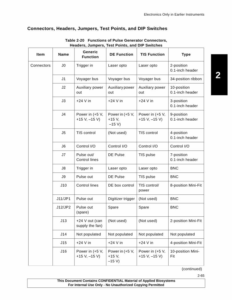
Electronics Only in Earlier Instruments
2
Connectors, Headers, Jumpers, Test Points, and DIP Switches
Table 2-20 Functions of Pulse Generator Connectors, Headers, Jumpers, Test Points, and DIP Switches
Item NameGeneric Function
DE Function TIS Function Type
Connectors J0 Trigger in Laser opto Laser opto 2-position 0.1-inch header
J1 Voyager bus Voyager bus Voyager bus 34-position ribbon
J2 Auxiliary power out
Auxiliary power out
Auxiliary power out
10-position 0.1-inch header
J3 +24 V in +24 V in +24 V in 3-position 0.1-inch header
J4 Power in (+5 V, +15 V, –15 V)
Power in (+5 V, +15 V, –15 V)
Power in (+5 V, +15 V, –15 V)
9-position 0.1-inch header
J5 TIS control (Not used) TIS control 4-position 0.1-inch header
J6 Control I/O Control I/O Control I/O Control I/O
J7 Pulse out/Control lines
DE Pulse TIS pulse 7-position0.1-inch header
J8 Trigger in Laser opto Laser opto BNC
J9 Pulse out DE Pulse TIS pulse BNC
J10 Control lines DE box control TIS control/power
8-position Mini-Fit
J11/JP1 Pulse out Digitizer trigger (Not used) BNC
J12/JP2 Pulse out (spare)
Spare Spare BNC
J13 +24 V out (can supply the fan)
(Not used) (Not used) 2-position Mini-Fit
J14 Not populated Not populated Not populated Not populated
J15 +24 V in +24 V in +24 V in 4-position Mini-Fit
J16 Power in (+5 V, +15 V, –15 V)
Power in (+5 V, +15 V,–15 V)
Power in (+5 V, +15 V, –15 V)
10-position Mini-Fit
(continued)
This Document Contains CONFIDENTIAL Material of Applied BiosystemsFor Internal Use Only - No Unauthorized Copying Permitted
2-65
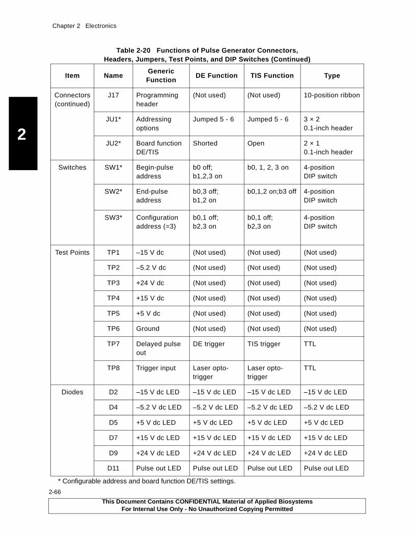
Chapter 2 Electronics
2
2-66
* Configurable address and board function DE/TIS settings.
Connectors (continued)
J17 Programming header
(Not used) (Not used) 10-position ribbon
JU1* Addressing options
Jumped 5 - 6 Jumped 5 - 6 3 × 2 0.1-inch header
JU2* Board function DE/TIS
Shorted Open 2 × 1 0.1-inch header
Switches SW1* Begin-pulse address
b0 off; b1,2,3 on
b0, 1, 2, 3 on 4-position DIP switch
SW2* End-pulse address
b0,3 off; b1,2 on
b0,1,2 on;b3 off 4-position DIP switch
SW3* Configuration address (=3)
b0,1 off; b2,3 on
b0,1 off; b2,3 on
4-position DIP switch
Test Points TP1 –15 V dc (Not used) (Not used) (Not used)
TP2 –5.2 V dc (Not used) (Not used) (Not used)
TP3 +24 V dc (Not used) (Not used) (Not used)
TP4 +15 V dc (Not used) (Not used) (Not used)
TP5 +5 V dc (Not used) (Not used) (Not used)
TP6 Ground (Not used) (Not used) (Not used)
TP7 Delayed pulse out
DE trigger TIS trigger TTL
TP8 Trigger input Laser opto-trigger
Laser opto-trigger
TTL
Diodes D2 –15 V dc LED –15 V dc LED –15 V dc LED –15 V dc LED
D4 –5.2 V dc LED –5.2 V dc LED –5.2 V dc LED –5.2 V dc LED
D5 +5 V dc LED +5 V dc LED +5 V dc LED +5 V dc LED
D7 +15 V dc LED +15 V dc LED +15 V dc LED +15 V dc LED
D9 +24 V dc LED +24 V dc LED +24 V dc LED +24 V dc LED
D11 Pulse out LED Pulse out LED Pulse out LED Pulse out LED
Table 2-20 Functions of Pulse Generator Connectors, Headers, Jumpers, Test Points, and DIP Switches (Continued)
Item NameGeneric Function
DE Function TIS Function Type
This Document Contains CONFIDENTIAL Material of Applied BiosystemsFor Internal Use Only - No Unauthorized Copying Permitted
3 Before Servicing the Workstation
3-1
This chapter contains the following sections:3.1 Voyager Laser Safety............................................ 3-2
3.1.1 Overview of Laser Safety .......................... 3-2
3.1.2 Required Customer-Provided YAG Laser Safety Measures ........................................3-3
3.2 Venting the Voyager DE-STR Workstation ............ 3-4
3.2.1 Preparing to Vent ...................................... 3-4
3.2.2 Venting to Air ............................................ 3-5
3.2.3 Purging the System to N2 ......................... 3-5
3.3 Powering Up After Venting.................................... 3-6
This Document Contains CONFIDENTIAL Material of Applied BiosystemsFor Internal Use Only - No Unauthorized Copying Permitted
Chapter 3 Before Servicing the Workstation
3
3-2
3.1 Voyager Laser Safety
3.1.1 Overview of Laser Safety
Laser ClassificationThe Voyager-DE™ Biospectrometry™ Workstation uses a standard nitrogen laser and an optional Nd:YAG laser. Under normal operating conditions, the instrument laser is categorized as a Class I laser. Under certain conditions during servicing, when interlocks have been circumvented, the lasers fall into the following categories and can cause permanent eye damage:
• Nitrogen—Class IIIb• Nd:YAG—Class IV
The Voyager-DE Biospectrometry Workstation complies with Title 21, U.S. Government DHEW/BRH Performance Standards, Chapter 1, Subchapter J, Section 1040, as applicable.
Laser Safety FeaturesThe following safety features are included on the Voyager-DE Biospectrometry Workstation:
• Cabinet is designed to prevent access to collateral laser radiation exceeding the accessible emission limits in Performance Standards for Laser Products, 21 CFR 1040.10.
• Top, front, back, and side panels have interlock switches that disable the laser when panels are opened or removed.
• Safety labels for Class I standards are affixed to the unit.
WARNING
ELECTRICAL SHOCK AND LASER HAZARD. In External Trigger mode, the nitrogen laser energy storage capacitors are charged, and the laser is ready to fire at any time. When you perform service on the laser in External Trigger mode, remove jewelry and other items that can reflect the beam into your eyes or the eyes of others. Wear laser safety goggles and protect others from exposure to the beam. Post a laser warning sign.
WARNING
ELECTRICAL SHOCK AND LASER HAZARD. When instrument covers are removed, high voltage contacts are exposed, and the laser emits ultraviolet radiation. Wear laser safety goggles and post a laser warning sign at the entrance to the laboratory when you remove covers for service.
WARNING
LASER HAZARD. Exposure to direct or reflected laser light can burn the retina and leave permanent blind spots. Never look directly into the laser beam. Remove jewelry and other items that can reflect the beam into your eyes. Wear laser safety goggles during laser alignment. Protect others from exposure to the beam. Post a laser warning sign while performing service.
This Document Contains CONFIDENTIAL Material of Applied BiosystemsFor Internal Use Only - No Unauthorized Copying Permitted
Voyager Laser Safety
3
Laser Safety RequirementsTo ensure safe laser operation, note the following:
• The system must be installed and maintained by an Applied Biosystems Technical Representative.
• Top, front, back, and side panels must be installed during operation. When front and side panels are installed, there should be no detectable radiation present. If front or side panels are removed when the laser is operational, you may be exposed to laser emissions in excess of Class 1 rating.
• Do not remove labels or disable safety interlocks.
Additional Safety InformationRefer to the user manual provided with the laser for additional information on government and industry safety regulations.
3.1.2 Required Customer-Provided YAG Laser Safety Measures
Before servicing a system using the YAG laser, the customer is required to provide safety precautions. The YAG accessory supplied with the Voyager-DE STR is a class I laser, which is considered not capable of producing damaging radiation levels during operation. When maintenance requires an Applied Biosystems field service engineer to defeat the interlocks protection system for the instrument, the YAG laser is classified as a class IV laser. A class IV laser poses hazards to the eye and skin not only from the direct beam but in some cases also from the diffuse reflection. These lasers can be considered a fire hazard and may also produce laser-generated air contaminants and hazardous plasma radiation.
Therefore before you can perform maintenance or service on the YAG Laser while at the customer facility, the customer must:
• Provide the appropriate Laser Warning Signs. These signs shall be conspicuously displayed in a location where they will best serve to warn any and all onlookers.
• Provide the appropriate safety glasses/goggles to their employees if they are in the area while the laser is being serviced. The safety glasses/goggles must be rated for a YAG laser with a wavelength of 355 nm.
• Provide and document laser safety training to their employees on the hazards associated with a YAG laser.
• Remove all employees from the area where maintenance to the YAG laser is being performed.
In addition, all customers must be in compliance with the ANSI standard Z136.1-1993, American National Standard for the Safe Use of Lasers.
This Document Contains CONFIDENTIAL Material of Applied BiosystemsFor Internal Use Only - No Unauthorized Copying Permitted
3-3
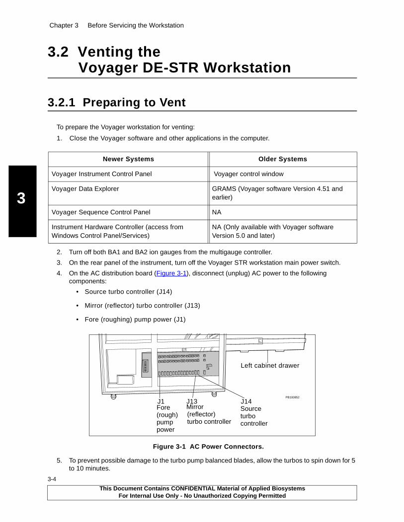
Chapter 3 Before Servicing the Workstation
3
3-4
3.2 Venting the Voyager DE-STR Workstation
3.2.1 Preparing to Vent
To prepare the Voyager workstation for venting:
1. Close the Voyager software and other applications in the computer.
2. Turn off both BA1 and BA2 ion gauges from the multigauge controller.
3. On the rear panel of the instrument, turn off the Voyager STR workstation main power switch.
4. On the AC distribution board (Figure 3-1), disconnect (unplug) AC power to the following components:
• Source turbo controller (J14)
• Mirror (reflector) turbo controller (J13)
• Fore (roughing) pump power (J1)
Figure 3-1 AC Power Connectors.
5. To prevent possible damage to the turbo pump balanced blades, allow the turbos to spin down for 5 to 10 minutes.
Newer Systems Older Systems
Voyager Instrument Control Panel Voyager control window
Voyager Data Explorer GRAMS (Voyager software Version 4.51 and earlier)
Voyager Sequence Control Panel NA
Instrument Hardware Controller (access from Windows Control Panel/Services)
NA (Only available with Voyager software Version 5.0 and later)
PB100852
J1 J13 J14
Left cabinet drawer
Source turbo controller
Mirror(reflector)turbo controller
Fore(rough)pump power
This Document Contains CONFIDENTIAL Material of Applied BiosystemsFor Internal Use Only - No Unauthorized Copying Permitted
Venting the Voyager DE-STR Workstation
3
3.2.2 Venting to Air
Allow air to flow into the chamber slowly as described in the following table. As air flows into the vacuum chamber, you hear a slight hissing indicating atmosphere is seeping into the vacuum chamber.
When the system is vented, the ion detector is exposed to the atmosphere. If the detector is exposed for more than 24 hours, the following problems may occur:
• A film of water and other molecules may form on the surface of the detector. The film can cause arcs across the surface of the detector when full voltages are applied.
• The detector may absorb moisture and may swell and crack.
For systems that will be at atmosphere for more than 24 hours, purge the system to N2. Purging to N2 protects detector integrity as well as minimizes pump down time. Pump down time is the time needed to return the system to vacuum after venting. The length of time the system was at atmosphere determines the pump down time. To estimate pump down time, multiply the time the system was at atmosphere by three.
3.2.3 Purging the System with N2
To purge newer systems with N2 gas:
1. Connect the N2 gas tank to the filter on the source turbo venting valve. Connect one end of the regulator to the vent filter using a 3/8” O.D. clear PVC tubing and connect the other end of the regulator to the nitrogen drop line.
2. Preset pressure on the regulator to 5 psig.
3. Open the valve on the N2 gas tank.
4. Lift up the lever attached to the turbo vent valve, allowing N2 to flow into the chamber slowly.
5. Close the turbo vent valve when the sound of flowing N2 has stopped completely.
6. Close the gas valve on the N2 tank.
7. Disconnect the clear PVC tubing from the filter on the turbo venting valve.
Step Newer Systems Older Systems
1 Locate the filter mounted on the vent valve of the source turbo and mirror turbo.
Locate the small knurled vent screw on the side of the turbo.
2 Lift up the lever attached to the turbo vent valve to open the valve.
Loosen the vent screw slowly. CAUTION. DO NOT loosen the vent screw completely. The small knob may become lost and the vent screw O-ring may become detached.
3 When the sound of flowing air has stopped completely, close the turbo vent valve lever.
When the sound of flowing air has stopped completely, re-tighten the knurled vent screw by hand.CAUTION. When tightening the knurled vent screw, DO NOT over tighten it.
This Document Contains CONFIDENTIAL Material of Applied BiosystemsFor Internal Use Only - No Unauthorized Copying Permitted
3-5
Chapter 3 Before Servicing the Workstation
3
3-6
3.3 Powering Up After Venting
Before powering up the Voyager workstation after venting:
1. Close all open vent valves.
2. Reconnect and secure all vacuum connections.
3. Switch on the Voyager workstation main power.
Once the valves are closed, vacuum connectors are secure, and the Voyager workstation main power is on:
1. On the AC distribution board, connect (plug in) the fore pump to the J1 connector (Figure 3-1 on page 3-4).
2. Monitor the TC2 vacuum reading on the multigauge controller. (For information, see Section 5.7.2, Multigauge Controller.)
3. When the reading reaches below 3 × 10⁻¹
torr, reconnect the following cables to the AC distribution board (Figure 3-1 on page 3-4):
• The source turbo controller (J14)
• The mirror turbo controller (J13)
4. Observe the turbo status indicator lights on the Voyager workstation top panel LED display or the D12 LEDs on the MALDI control board. Both of the status indicator lights on the turbos should display the following sequence of colors:
• Yellow for about 1 minute—Indicating initial startup
• Yellow and green briefly—Indicating turbo reached 80% of full speed
• Green only—Indicating the turbo is at normal operating condition (56 krpm)
Red indicates a fault.
5. Wait an additional 10 to 30 minutes.
After the turbo has stabilized:
1. Using the multigauge controller, turn on the BA1 and BA2 gauges. (For information, see Section 5.7.2, Multigauge Controller.)
Both vacuum readings should be below 8 × 10⁻⁵
torr, or you should see indications that the system is pumping down to a lower level.
2. Allow the system to pump down further to reach system operational pressures. Normally, BA1 should be below 9 × 10
–7 torr. BA2, the mirror, is typically 10 times lower, 9 × 10
–8 torr.
NOTE: To achieve a pressure below 9 × 10⁻⁷
torr may take the system a day or more.
3. When the system pressure readings are 9 × 10⁻⁶
torr or less, reboot the computer and launch the Voyager control panel.
This Document Contains CONFIDENTIAL Material of Applied BiosystemsFor Internal Use Only - No Unauthorized Copying Permitted

4 Voyager Diagnostics Software
4-1
This chapter contains the following sections:4.1 Overview .............................................................. 4-2
4.2 Voyager Software Compatibility ............................ 4-2
4.3 Accessing the Diagnostics Software ..................... 4-3
4.4 Diagnostics Software Features ............................. 4-5
4.4.1 Control Pages ............................................4-5
4.4.2 Status Bar ................................................ 4-11
This Document Contains CONFIDENTIAL Material of Applied BiosystemsFor Internal Use Only - No Unauthorized Copying Permitted
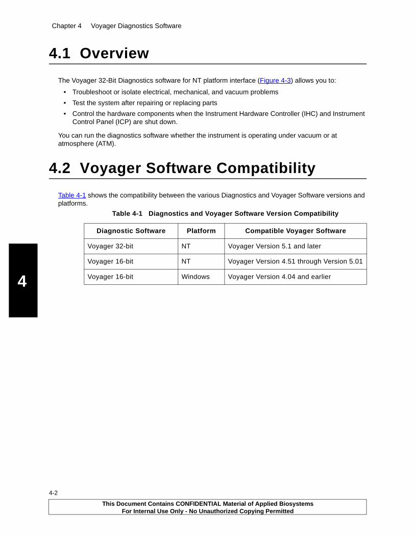
Chapter 4 Voyager Diagnostics Software
4
4-2
4.1 Overview
The Voyager 32-Bit Diagnostics software for NT platform interface (Figure 4-3) allows you to:
• Troubleshoot or isolate electrical, mechanical, and vacuum problems
• Test the system after repairing or replacing parts
• Control the hardware components when the Instrument Hardware Controller (IHC) and Instrument Control Panel (ICP) are shut down.
You can run the diagnostics software whether the instrument is operating under vacuum or at atmosphere (ATM).
4.2 Voyager Software Compatibility
Table 4-1 shows the compatibility between the various Diagnostics and Voyager Software versions and platforms.
Table 4-1 Diagnostics and Voyager Software Version Compatibility
Diagnostic Software Platform Compatible Voyager Software
Voyager 32-bit NT Voyager Version 5.1 and later
Voyager 16-bit NT Voyager Version 4.51 through Version 5.01
Voyager 16-bit Windows Voyager Version 4.04 and earlier
This Document Contains CONFIDENTIAL Material of Applied BiosystemsFor Internal Use Only - No Unauthorized Copying Permitted
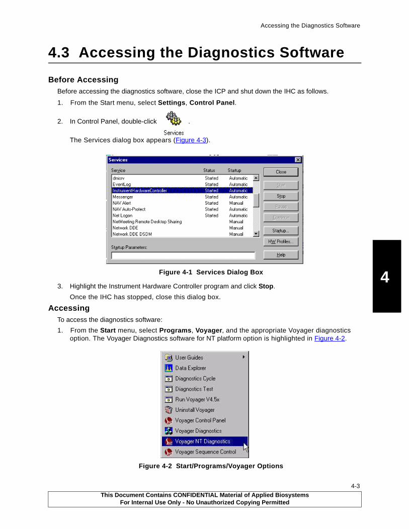
Accessing the Diagnostics Software
4
4.3 Accessing the Diagnostics Software
Before AccessingBefore accessing the diagnostics software, close the ICP and shut down the IHC as follows.
1. From the Start menu, select Settings, Control Panel.
2. In Control Panel, double-click .
The Services dialog box appears (Figure 4-3).
Figure 4-1 Services Dialog Box
3. Highlight the Instrument Hardware Controller program and click Stop.
Once the IHC has stopped, close this dialog box.
AccessingTo access the diagnostics software:
1. From the Start menu, select Programs, Voyager, and the appropriate Voyager diagnostics option. The Voyager Diagnostics software for NT platform option is highlighted in Figure 4-2.
Figure 4-2 Start/Programs/Voyager Options
This Document Contains CONFIDENTIAL Material of Applied BiosystemsFor Internal Use Only - No Unauthorized Copying Permitted
4-3

Chapter 4 Voyager Diagnostics Software
4
4-4
2. Use the View menu or click individual tabs to access the component control pages
Figure 4-3 Voyager 32-Bit Diagnostics Software for NT Platform Window
3. To restart the IHC, you can do one of the following:
• Manually restart through the Services dialog box
• Reboot the computer system
• Launch the Instrument Control Panel
Diagram window
Menus
TabsControl pages
Status bar
(display only)
This Document Contains CONFIDENTIAL Material of Applied BiosystemsFor Internal Use Only - No Unauthorized Copying Permitted
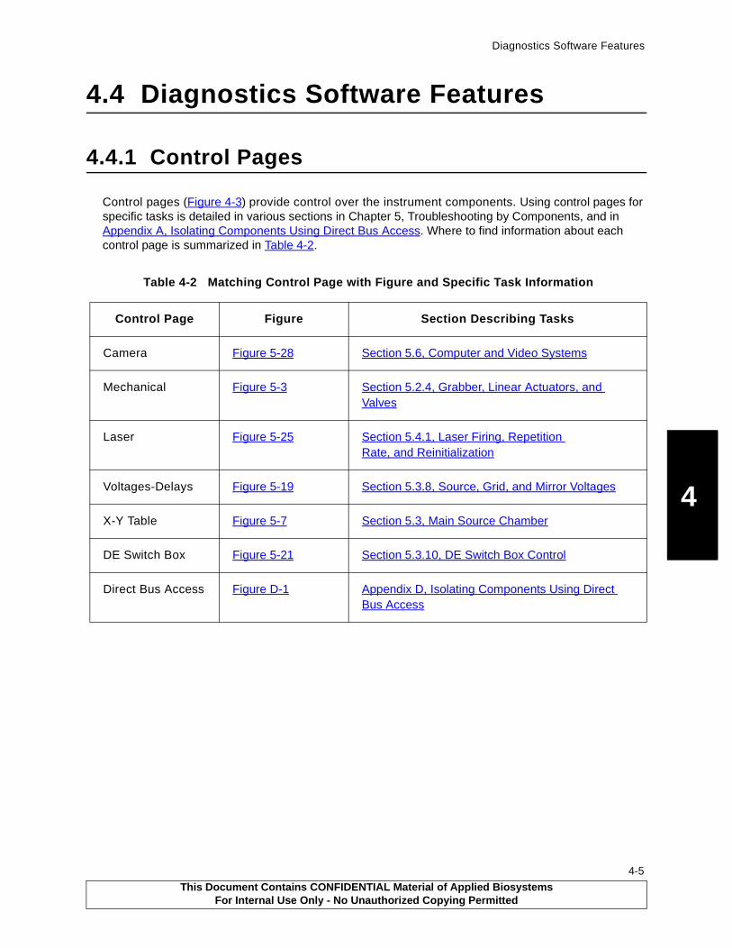
Diagnostics Software Features
4
4.4 Diagnostics Software Features
4.4.1 Control Pages
Control pages (Figure 4-3) provide control over the instrument components. Using control pages for specific tasks is detailed in various sections in Chapter 5, Troubleshooting by Components, and in Appendix A, Isolating Components Using Direct Bus Access. Where to find information about each control page is summarized in Table 4-2.
Table 4-2 Matching Control Page with Figure and Specific Task Information
Control Page Figure Section Describing Tasks
Camera Figure 5-28 Section 5.6, Computer and Video Systems
Mechanical Figure 5-3 Section 5.2.4, Grabber, Linear Actuators, and Valves
Laser Figure 5-25 Section 5.4.1, Laser Firing, Repetition Rate, and Reinitialization
Voltages-Delays Figure 5-19 Section 5.3.8, Source, Grid, and Mirror Voltages
X-Y Table Figure 5-7 Section 5.3, Main Source Chamber
DE Switch Box Figure 5-21 Section 5.3.10, DE Switch Box Control
Direct Bus Access Figure D-1 Appendix D, Isolating Components Using Direct Bus Access
This Document Contains CONFIDENTIAL Material of Applied BiosystemsFor Internal Use Only - No Unauthorized Copying Permitted
4-5

Chapter 4 Voyager Diagnostics Software
4
4-6
Table 4-3 summarizes the functions of each control page. To find the control page and troubleshooting sections applicable to a specific workstation component, refer to Table 5-1, Matching Components with Control Page and Troubleshooting Information.
Table 4-3 Summary of Diagnostics Software Control Pages
Fields and Actions Status Indicators Comment
Camera Control Page—Powers-on and powers-off the camera
Camera Off/On None By default, the Camera control page appears and powers on the camera and video lamps when you start the Voyager diagnostics software for NT platform.
Mechanical Control Page—Opens and closes the valves, extends and retracts the linear actuators, turns the grabber on and off, runs single or multiple load/eject cycles, and restarts faulted vacuum gauges
Valves Close/Open:Flap Door #1, 2 Foreline Valve #1, 2Vent valve
Actuators Retract/Extend:Linear #1Linear #2
Flap Door #1 Closed/OpenFlap Door #2 Open
Linear #1 Retracted/ExtendedLinear #2 Retracted
Allows you to manually open and close the doors and valves to remove a stuck sample plate.Note: You can activate the flap doors and linear actuators only when the air compressor is running. The air compressor runs only when the sample stage is in the load region.
Grabber Off/On Under normal operating conditions, the grabber powers on just before the Linear 1 actuator starts to extend or retract (if ejecting), and it powers off just after the Linear 1 actuator has fully retracted.
(continued)
This Document Contains CONFIDENTIAL Material of Applied BiosystemsFor Internal Use Only - No Unauthorized Copying Permitted
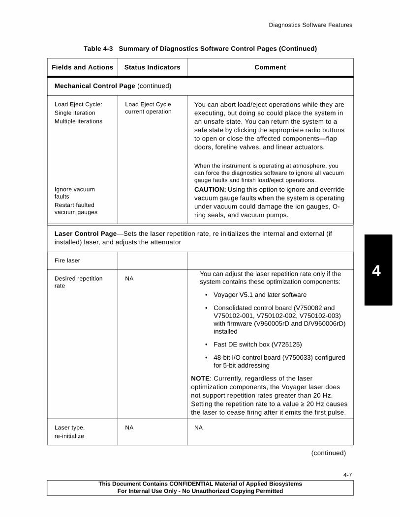
Diagnostics Software Features
4
Mechanical Control Page (continued)
Load Eject Cycle:
Single iterationMultiple iterations
Ignore vacuum faults
Restart faulted vacuum gauges
Load Eject Cycle current operation
You can abort load/eject operations while they are executing, but doing so could place the system in an unsafe state. You can return the system to a safe state by clicking the appropriate radio buttons to open or close the affected components—flap doors, foreline valves, and linear actuators.
When the instrument is operating at atmosphere, you can force the diagnostics software to ignore all vacuum gauge faults and finish load/eject operations.
CAUTION: Using this option to ignore and override vacuum gauge faults when the system is operating under vacuum could damage the ion gauges, O-ring seals, and vacuum pumps.
Laser Control Page—Sets the laser repetition rate, re initializes the internal and external (if installed) laser, and adjusts the attenuator
Fire laser
Desired repetition rate
NAYou can adjust the laser repetition rate only if the system contains these optimization components:
• Voyager V5.1 and later software
• Consolidated control board (V750082 and V750102-001, V750102-002, V750102-003) with firmware (V960005rD and D/V960006rD) installed
• Fast DE switch box (V725125)
• 48-bit I/O control board (V750033) configured for 5-bit addressing
NOTE: Currently, regardless of the laser optimization components, the Voyager laser does not support repetition rates greater than 20 Hz. Setting the repetition rate to a value ≥ 20 Hz causes the laser to cease firing after it emits the first pulse.
Laser type,
re-initialize
NA NA
(continued)
Table 4-3 Summary of Diagnostics Software Control Pages (Continued)
Fields and Actions Status Indicators Comment
This Document Contains CONFIDENTIAL Material of Applied BiosystemsFor Internal Use Only - No Unauthorized Copying Permitted
4-7
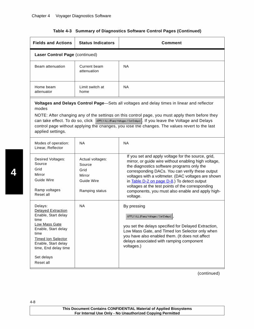
Chapter 4 Voyager Diagnostics Software
4
4-8
Laser Control Page (continued)
Beam attenuation Current beam attenuation
NA
Home beam attenuator
Limit switch at home
NA
Voltages and Delays Control Page—Sets all voltages and delay times in linear and reflector modes
NOTE: After changing any of the settings on this control page, you must apply them before they can take effect. To do so, click . If you leave the Voltage and Delays control page without applying the changes, you lose the changes. The values revert to the last applied settings.
Modes of operation:Linear, Reflector
NA NA
Desired Voltages:Source
GridMirror
Guide Wire
Ramp voltagesReset all
Actual voltages:Source
GridMirrorGuide Wire
Ramping status
If you set and apply voltage for the source, grid, mirror, or guide wire without enabling high voltage, the diagnostics software programs only the corresponding DACs. You can verify these output voltages with a voltmeter. (DAC voltages are shown in Table D-2 on page D-8.) To detect output voltages at the test points of the corresponding components, you must also enable and apply high-voltage.
Delays:Delayed ExtractionEnable, Start delay timeLow Mass GateEnable, Start delay time
Timed Ion SelectorEnable, Start delay time, End delay time
Set delays
Reset all
NA By pressing
,
you set the delays specified for Delayed Extraction, Low Mass Gate, and Timed Ion Selector only when you have also enabled them. (It does not affect delays associated with ramping component voltages.)
(continued)
Table 4-3 Summary of Diagnostics Software Control Pages (Continued)
Fields and Actions Status Indicators Comment
This Document Contains CONFIDENTIAL Material of Applied BiosystemsFor Internal Use Only - No Unauthorized Copying Permitted

Diagnostics Software Features
4
X-Y Table Control Page—Moves the sample stage, resets home and load positionsBefore you can access the functions on this control page, you must click to move the sample stage to its home position (0,0). This initializes the diagnostics software controls, enabling the software to calculate all other positions, including load position.
Sample stage X, Y position: scroll bar desired position (counts or microns)
Current position One step equals 3.175 µm. You can use either unit and switch back and forth between them. The diagnostics software performs the necessary conversions automatically. The micron is used in the NT Registry editor.
Move to:desired
homeload
Limit switches:home
load
NA
Set load position NA NOTE: The SET Load Position button on the X-Y Table control page initiates a data write to the Registry file. The next time it is accessed, the Voyager Instrument Control Panel reads the new X,Y coordinates from the Registry file to determine the sample stage load position. Record the old coordinates in case you need to revert to them.
DE Switch Box Control—Checks the control wiring on the DE switch box
Check control wiring test
Check Control Wiring test steps through expected voltage readings and instructions
Before you begin, assemble your voltmeter and meter probes, and access the DE switch box.
This test checks the operative states of the three high-voltage kilovac relays by looking at resistance between J2 and J4 and the admittance between J3 and J2/Gnd.
DE Switch Box type NA V725059Three-connector, high-voltage switch box in Voyager-DE STR workstation with serial numbers 4147 and earlier
V725115Four-connector, high-voltage switch box in systems with serial numbers 4148 through 4160V725125Four-connector fast DE switch box in systems with serial numbers 4161 and later
(continued)
Table 4-3 Summary of Diagnostics Software Control Pages (Continued)
Fields and Actions Status Indicators Comment
This Document Contains CONFIDENTIAL Material of Applied BiosystemsFor Internal Use Only - No Unauthorized Copying Permitted
4-9

Chapter 4 Voyager Diagnostics Software
4
4-10
Direct Bus Access Control Page—
Writes data directly to the various DACs, pulse generators, and ion source pulsar control register. For information, see Appendix D, Isolating Components Using Direct Bus Access. You cannot enable high-voltage or the Low Mass Gate using direct bus access. With direct bus access, you can only set the output voltage at the DACs and the Low Mass Gate value.
Before you write data to any component, make sure you have appropriately connected or disconnected the high-voltage lines and connected meter probes or voltmeters to the appropriate DACs.
WARNING. ELECTRICAL SHOCK HAZARD. Safe operating procedures and proper use of equipment are the responsibility of the authorized and qualified service person. Precautions must be taken to protect against possible serious and/or fatal bodily injury.
Write address directly to the data bus for the:
Source DACMirror DACGrid DACBeam guide DACControl register
LMG delayDE delayTIS delay
NA Set value as decimal, hexadecimal, or binary
Table 4-3 Summary of Diagnostics Software Control Pages (Continued)
Fields and Actions Status Indicators Comment
This Document Contains CONFIDENTIAL Material of Applied BiosystemsFor Internal Use Only - No Unauthorized Copying Permitted

Diagnostics Software Features
4
4.4.2 Status Bar
Use the Diagnostics Software window status bar (expanded drawing shown in Figure 4-4) to check the items described in Table 4-4.
Figure 4-4 System Status Bar (Shown in Two Parts for Clarity)
Table 4-4 Diagnostics Software Status Bar Indicators
Component Status
High Voltage Indicates whether the high voltage is ON or OFF
Interlock Indicates if the Voyager workstation covers (top, front, side, and rear panels) are locked in place. When the covers are securely in place, the interlock LED remains lit. If the interlocks are breached during normal operation, the system automatically disables the lasers and high-voltage supplies. For example, if the panels are off or ajar, the lasers, high-voltages, and the interlock and high-voltage LEDs remain off until the panels are secured. To operate the system with the panels removed during servicing, you can bypass the interlocks.
X Displays the current X coordinate position of the sample stage
Y Displays the current Y coordinate position of the sample stage
XY Status Indicates whether the sample stage is currently in the load, home, or other (None) position
Laser Indicates whether the laser is ON or OFF
Src Pres (BA1) Displays the current pressure (in torr) in the main source chamber
Mir Pres (BA2) Displays the current pressure (in torr) in the reflector mirror chamber
Smp Pres (TC2) Displays the current pressure (in torr) in the sample-loading chamber
This Document Contains CONFIDENTIAL Material of Applied BiosystemsFor Internal Use Only - No Unauthorized Copying Permitted
4-11

Chapter 4 Voyager Diagnostics Software
4
4-12
This Document Contains CONFIDENTIAL Material of Applied BiosystemsFor Internal Use Only - No Unauthorized Copying Permitted

5 Troubleshooting by Components
5-1
This chapter contains the following sections:5.1 Troubleshooting Overview ..................................................... 5-2
5.2 Sample Loading Chamber ..................................................... 5-7
5.2.1 Vacuum System Interaction ..................................... 5-7
5.2.2 Internal Interlocks Operation ................................... 5-9
5.2.3 Camera .................................................................. 5-11
5.2.4 Grabber, Linear Actuators, and Valves ...................5-11
5.2.5 Load/Eject Cycles ...................................................5-13
5.2.6 Vacuum Faults ........................................................5-15
5.2.7 Mechanical Control Page Errors and Warnings .......5-16
5.3 Main Source Chamber ........................................................ 5-18
5.3.1 Source Clips ...........................................................5-23
5.3.2 Source Pedestal .....................................................5-24
5.3.3 Stepper Motor Feedthroughs ..................................5-26
5.3.4 Sample Plate and Grid Voltage ...............................5-30
5.3.5 Internal High-Voltage Cable ....................................5-30
5.3.6 Operation Mode ......................................................5-31
5.3.7 Delayed-Extraction Ion Source ...............................5-32
5.3.8 Source, Grid, and Mirror Voltages ...........................5-33
5.3.9 Delayed Extraction, Low-Mass Gate and Timed Ion Selector Delay Times .............................5-35
5.3.10 DE Switch Box Control ...........................................5-36
5.4 Laser System....................................................................... 5-38
5.4.1 Laser Firing, Repetition Rate, and Reinitialization ........................................................5-38
5.4.2 Laser Attenuation ...................................................5-40
5.5 Flight Tube and Mirror Chamber .......................................... 5-42
5.5.1 Timed Ion Selector .................................................5-42
5.5.2 Flight-Tube (Drift-tube) Power Supply .....................5-43
5.6 Computer and Video Systems.............................................. 5-43
5.7 Vacuum System ................................................................... 5-44
5.7.1 Vacuum Gauges and Pumps ..................................5-44
5.7.2 Multigauge Controller .............................................5-45
5.7.3 Multigauge Controller, Computer, and Workstation Interaction ..........................................5-47
This Document Contains CONFIDENTIAL Material of Applied BiosystemsFor Internal Use Only - No Unauthorized Copying Permitted
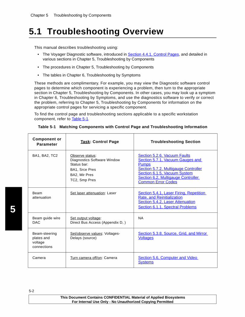
Chapter 5 Troubleshooting by Components
5
5-2
5.1 Troubleshooting Overview
This manual describes troubleshooting using:
• The Voyager Diagnostic software, introduced in Section 4.4.1, Control Pages, and detailed in various sections in Chapter 5, Troubleshooting by Components
• The procedures in Chapter 5, Troubleshooting by Components
• The tables in Chapter 6, Troubleshooting by Symptoms
These methods are complimentary. For example, you may view the Diagnostic software control pages to determine which component is experiencing a problem, then turn to the appropriate section in Chapter 5, Troubleshooting by Components. In other cases, you may look up a symptom in Chapter 6, Troubleshooting by Symptoms, and use the diagnostics software to verify or correct the problem, referring to Chapter 5, Troubleshooting by Components for information on the appropriate control pages for servicing a specific component.
To find the control page and troubleshooting sections applicable to a specific workstation component, refer to Table 5-1.
Table 5-1 Matching Components with Control Page and Troubleshooting Information
Component or Parameter
Task: Control Page Troubleshooting Section
BA1, BA2, TC2 Observe status:Diagnostics Software Window Status bar:BA1, Srce Pres
BA2, Mir PresTC2, Smp Pres
Section 5.2.6, Vacuum FaultsSection 5.7.1, Vacuum Gauges and PumpsSection 5.7.2, Multigauge ControllerSection 6.1.5, Vacuum SystemSection 6.2, Multigauge Controller Common Error Codes
Beam attenuation
Set laser attenuation: Laser Section 5.4.1, Laser Firing, Repetition Rate, and ReinitializationSection 5.4.2, Laser AttenuationSection 6.1.1, Spectral Problems
Beam guide wire DAC
Set output voltage: Direct Bus Access (Appendix D, )
NA
Beam-steering plates and voltage connections
Set/observe values: Voltages-Delays (source)
Section 5.3.8, Source, Grid, and Mirror Voltages
Camera Turn camera off/on: Camera Section 5.6, Computer and Video Systems
This Document Contains CONFIDENTIAL Material of Applied BiosystemsFor Internal Use Only - No Unauthorized Copying Permitted
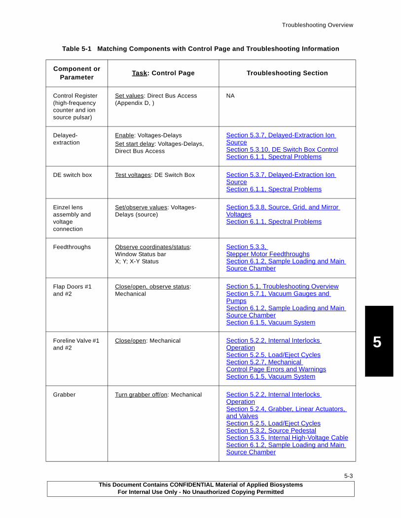
Troubleshooting Overview
5
Control Register (high-frequency counter and ion source pulsar)
Set values: Direct Bus Access (Appendix D, )
NA
Delayed-extraction
Enable: Voltages-DelaysSet start delay: Voltages-Delays, Direct Bus Access
Section 5.3.7, Delayed-Extraction Ion SourceSection 5.3.10, DE Switch Box ControlSection 6.1.1, Spectral Problems
DE switch box Test voltages: DE Switch Box Section 5.3.7, Delayed-Extraction Ion SourceSection 6.1.1, Spectral Problems
Einzel lens assembly and voltage connection
Set/observe values: Voltages-Delays (source)
Section 5.3.8, Source, Grid, and Mirror VoltagesSection 6.1.1, Spectral Problems
Feedthroughs Observe coordinates/status: Window Status barX; Y; X-Y Status
Section 5.3.3, Stepper Motor FeedthroughsSection 6.1.2, Sample Loading and Main Source Chamber
Flap Doors #1 and #2
Close/open, observe status: Mechanical
Section 5.1, Troubleshooting OverviewSection 5.7.1, Vacuum Gauges and PumpsSection 6.1.2, Sample Loading and Main Source ChamberSection 6.1.5, Vacuum System
Foreline Valve #1 and #2
Close/open: Mechanical Section 5.2.2, Internal Interlocks OperationSection 5.2.5, Load/Eject CyclesSection 5.2.7, Mechanical Control Page Errors and WarningsSection 6.1.5, Vacuum System
Grabber Turn grabber off/on: Mechanical Section 5.2.2, Internal Interlocks OperationSection 5.2.4, Grabber, Linear Actuators, and ValvesSection 5.2.5, Load/Eject CyclesSection 5.3.2, Source PedestalSection 5.3.5, Internal High-Voltage CableSection 6.1.2, Sample Loading and Main Source Chamber
Table 5-1 Matching Components with Control Page and Troubleshooting Information
Component or Parameter
Task: Control Page Troubleshooting Section
This Document Contains CONFIDENTIAL Material of Applied BiosystemsFor Internal Use Only - No Unauthorized Copying Permitted
5-3

Chapter 5 Troubleshooting by Components
5
5-4
Grid DAC Set output voltage: Direct Bus Access
Section 5.3.8, Source, Grid, and Mirror VoltagesSection 5.3.10, DE Switch Box Control
Grid Voltage Set values: Voltages-Delays
Test high voltages: DE Switch Box
Section 5.3.8, Source, Grid, and Mirror VoltagesSection 5.3.10, DE Switch Box Control
Guide wire voltage
Set values: Voltages-DelaysTest high voltages: DE Switch Box
NA
High voltages Observe statusDiagnostics Software Window Status bar: High VoltageEnable: Voltages-DelaysTest: DE Switch Box
Section 5.3.4Section 5.3.5Section 5.3.7Section 5.3.8Section 5.3.10Section 5.5.1Section 6.1.1Section 6.1.4
Home position Home sample stage: X-Y Table see X and Y feedthroughs
Laser Observe statusDiagnostics Software Window Status bar: LaserFire, set repetition rate, attenuation, and laser type: Laser
Section 5.4Section 6.1.1Section 6.1.3
Limit switches, microswitches
Observe status: Mechanical Section 5.2.4Section 5.3Section 5.3.3Section 6.1.2Section 6.1.3
Linear actuators Retract/extend: Mechanical Section 5.2Section 5.2.1Section 5.2.4Section 5.3Section 5.3.2Section 6.1.2Section 6.1.5
Linear mode Set mode: Voltages-Delays Section 5.3.7Section 5.3.8Section 6.1.1
Table 5-1 Matching Components with Control Page and Troubleshooting Information
Component or Parameter
Task: Control Page Troubleshooting Section
This Document Contains CONFIDENTIAL Material of Applied BiosystemsFor Internal Use Only - No Unauthorized Copying Permitted
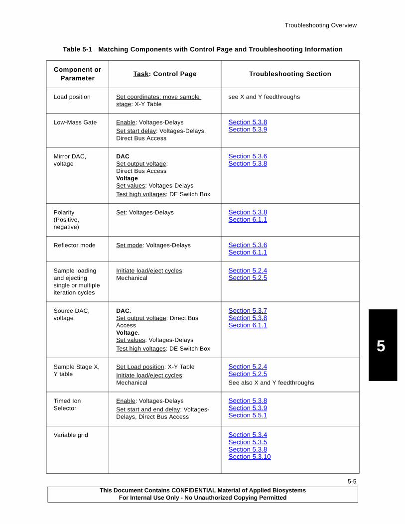
Troubleshooting Overview
5
Load position Set coordinates; move sample stage: X-Y Table
see X and Y feedthroughs
Low-Mass Gate Enable: Voltages-DelaysSet start delay: Voltages-Delays, Direct Bus Access
Section 5.3.8Section 5.3.9
Mirror DAC, voltage
DACSet output voltage: Direct Bus AccessVoltageSet values: Voltages-DelaysTest high voltages: DE Switch Box
Section 5.3.6Section 5.3.8
Polarity (Positive, negative)
Set: Voltages-Delays Section 5.3.8Section 6.1.1
Reflector mode Set mode: Voltages-Delays Section 5.3.6Section 6.1.1
Sample loading and ejecting single or multiple iteration cycles
Initiate load/eject cycles: Mechanical
Section 5.2.4Section 5.2.5
Source DAC, voltage
DAC.Set output voltage: Direct Bus AccessVoltage.Set values: Voltages-Delays
Test high voltages: DE Switch Box
Section 5.3.7Section 5.3.8Section 6.1.1
Sample Stage X, Y table
Set Load position: X-Y TableInitiate load/eject cycles: Mechanical
Section 5.2.4Section 5.2.5See also X and Y feedthroughs
Timed Ion Selector
Enable: Voltages-DelaysSet start and end delay: Voltages-Delays, Direct Bus Access
Section 5.3.8Section 5.3.9Section 5.5.1
Variable grid Section 5.3.4Section 5.3.5Section 5.3.8Section 5.3.10
Table 5-1 Matching Components with Control Page and Troubleshooting Information
Component or Parameter
Task: Control Page Troubleshooting Section
This Document Contains CONFIDENTIAL Material of Applied BiosystemsFor Internal Use Only - No Unauthorized Copying Permitted
5-5

Chapter 5 Troubleshooting by Components
5
5-6
1The multigauge controller in the Voyager system monitors the vacuum system thermocouple (TC2) and Bayard-Alpert gauges (BA1 and BA2).
Additional ResourcesIn addition to this manual and the Voyager Diagnostics Software, you can access information in two databases:
• The Voyager (MALDI) Product Support web site—Provides standard information such as Service Bulletins, Service Notes, and support contact information.
• The Voyager (MALDI) knowledge database—Allows an exchange information with other service engineers.
You can review the web site and the knowledge database 24 hours/day, 7 days a week. Each database is fully text searchable and is individually replicated on Lotus Notes.You can also call on the Regional Specialist, the Field Service Technical Specialist, and the Product Support Specialist. For information, see Appendix A, Technical Support and Training.
Vent valve Close/open: Mechanical Section 5.2.2Section 5.2.4Section 5.2.7
X and Y feedthroughs; Home and Load positions
Set load position: X-Y Table Section 5.3Section 5.3.3Section 6.1.2Section 6.1.3
Table 5-1 Matching Components with Control Page and Troubleshooting Information
Component or Parameter
Task: Control Page Troubleshooting Section
This Document Contains CONFIDENTIAL Material of Applied BiosystemsFor Internal Use Only - No Unauthorized Copying Permitted

Sample Loading Chamber
5
5.2 Sample Loading Chamber
When loading a sample plate, the sample plate is transported from the outside holder, into the sample loading chamber, then into the main source chamber through vacuum chambers at various pressures. The sample loading chamber (Figure 5-1) transports the sample plate between these areas using linear actuators, flap door actuators, and stepper motors.
Figure 5-1 Voyager-DE STR Workstation Sample Loading Chamber
5.2.1 Vacuum System Interaction
The actuators operate with a minimum of 15 PSI (1.03 bar). An integrated compressor supplies pneumatic energy to:
• Open and close the flap doors
• Extend and retract the linear actuators
NOTE: You can activate the flap doors and linear actuators only when the air compressor is running. The air compressor runs only when the sample stage is in the load region.
Because the linear and flap door actuators are pneumatically controlled, the performance of the sample loading chamber may be affected by problems in the vacuum system (Figure 5-2 on page 5-8).
PB100855
Linear 2 actuator Linear 1 actuator
Flap Door 2 (shown closed)
Flap Door 1 actuator Flap Door 2 actuator
Flap Door 1(not visible, attached
To atmosphereTo main
to source housing)
Flap valve
source chamber
block
This Document Contains CONFIDENTIAL Material of Applied BiosystemsFor Internal Use Only - No Unauthorized Copying Permitted
5-7
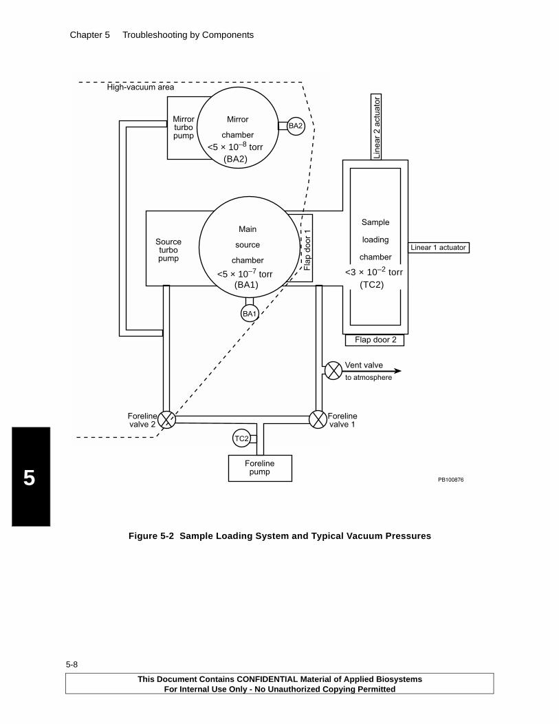
Chapter 5 Troubleshooting by Components
5
5-8
Figure 5-2 Sample Loading System and Typical Vacuum Pressures
���
���
��
�������������
������������
����������
����� �����
!���������"������
���� �� �
�
!�����
��"������
#�����
"���$��
#���
����"�
"���$��
%�����
��� ��&
"���$��
���������������
���������������
'�&�(��"��������
#��������$�����
%���"����$�����
��������
<3 × 10⁻² torr (TC2)
<5 × 10⁻⁷ torr (BA1)
<5 × 10⁻⁸ torr (BA2)
This Document Contains CONFIDENTIAL Material of Applied BiosystemsFor Internal Use Only - No Unauthorized Copying Permitted
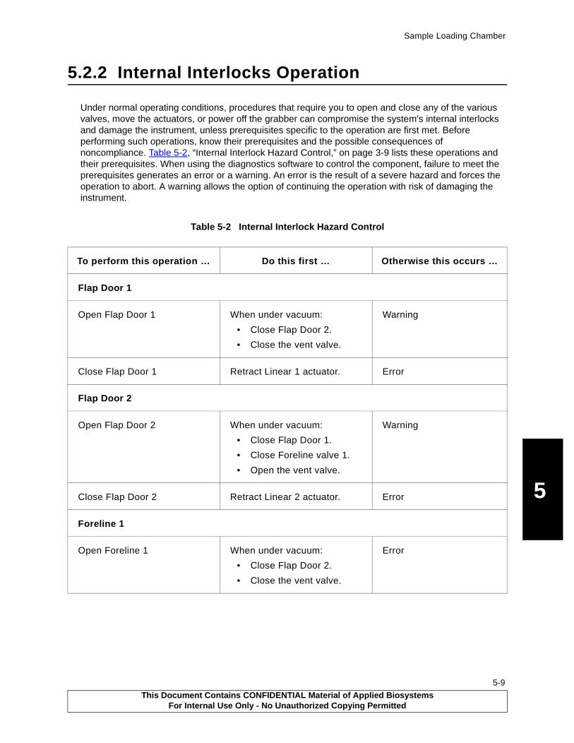
Sample Loading Chamber
5
5.2.2 Internal Interlocks Operation
Under normal operating conditions, procedures that require you to open and close any of the various valves, move the actuators, or power off the grabber can compromise the system’s internal interlocks and damage the instrument, unless prerequisites specific to the operation are first met. Before performing such operations, know their prerequisites and the possible consequences of noncompliance. Table 5-2, “Internal Interlock Hazard Control,” on page 3-9 lists these operations and their prerequisites. When using the diagnostics software to control the component, failure to meet the prerequisites generates an error or a warning. An error is the result of a severe hazard and forces the operation to abort. A warning allows the option of continuing the operation with risk of damaging the instrument.
Table 5-2 Internal Interlock Hazard Control
To perform this operation … Do this first … Otherwise this occurs …
Flap Door 1
Open Flap Door 1 When under vacuum:
• Close Flap Door 2.
• Close the vent valve.
Warning
Close Flap Door 1 Retract Linear 1 actuator. Error
Flap Door 2
Open Flap Door 2 When under vacuum:
• Close Flap Door 1.
• Close Foreline valve 1.
• Open the vent valve.
Warning
Close Flap Door 2 Retract Linear 2 actuator. Error
Foreline 1
Open Foreline 1 When under vacuum:
• Close Flap Door 2.
• Close the vent valve.
Error
This Document Contains CONFIDENTIAL Material of Applied BiosystemsFor Internal Use Only - No Unauthorized Copying Permitted
5-9

Chapter 5 Troubleshooting by Components
5
5-10
Foreline 2
Open Foreline 2 When under vacuum, close Foreline valve 1.
OR
1. Close the vent value and Flap Door 2
2. Open Foreline valve 1
3. Wait until TC2 reads less than 8 x 10⁻² torr*.
Warning
*CAUTION: After you vent the sample-loading chamber, close the vent valve. Open Foreline valve 1. Wait to open Foreline valve 2 until TC2 reads less than 8 x 10⁻² torr. If you open Foreline valve 2 before the foreline pump has reestablished a vacuum in the sample-loading chamber, you create a pressure burst that impacts the back of the turbo pumps. The burst may shut down the ion gauges (BA1 and BA2). You can restart the ion gauges after approximately 10 seconds. However, the vacuum system takes some time to stabilize.
Vent valve
Open the vent valve Close Flap Door 1.
Close Foreline Valve 1.
Error
Close the vent valve Close Flap Door 2. Warning
Linear 1 actuator
Extend Linear 1 actuator When under vacuum:
• Open Flap Door 1.
• Retract Linear 2 actuator.
• Have the sample stage in Load position.
Error
In addition:
• Close Flap Door 2.
• Close the vent valve.
No error message occurs if these conditions are not meet, but controls are disabled.
Table 5-2 Internal Interlock Hazard Control (Continued)
To perform this operation … Do this first … Otherwise this occurs …
This Document Contains CONFIDENTIAL Material of Applied BiosystemsFor Internal Use Only - No Unauthorized Copying Permitted
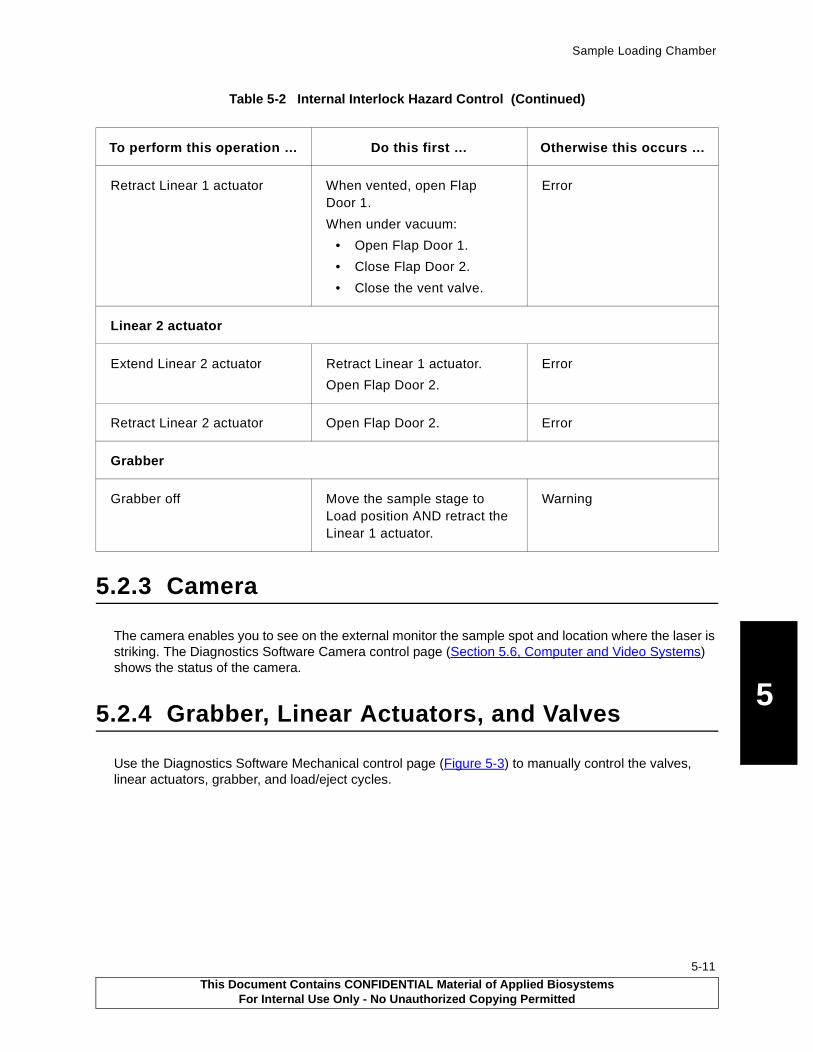
Sample Loading Chamber
5
5.2.3 Camera
The camera enables you to see on the external monitor the sample spot and location where the laser is striking. The Diagnostics Software Camera control page (Section 5.6, Computer and Video Systems) shows the status of the camera.
5.2.4 Grabber, Linear Actuators, and Valves
Use the Diagnostics Software Mechanical control page (Figure 5-3) to manually control the valves, linear actuators, grabber, and load/eject cycles.
Retract Linear 1 actuator When vented, open Flap Door 1.
When under vacuum:
• Open Flap Door 1.
• Close Flap Door 2.
• Close the vent valve.
Error
Linear 2 actuator
Extend Linear 2 actuator Retract Linear 1 actuator.
Open Flap Door 2.
Error
Retract Linear 2 actuator Open Flap Door 2. Error
Grabber
Grabber off Move the sample stage to Load position AND retract the Linear 1 actuator.
Warning
Table 5-2 Internal Interlock Hazard Control (Continued)
To perform this operation … Do this first … Otherwise this occurs …
This Document Contains CONFIDENTIAL Material of Applied BiosystemsFor Internal Use Only - No Unauthorized Copying Permitted
5-11

Chapter 5 Troubleshooting by Components
5
5-12
Figure 5-3 Mechanical Control Page
Opening and Closing Doors and ValvesYou may need to manually open and close the doors and valves (in conjunction with the actuators and grabber) to remove a sample plate lodged in the main source chamber. To do so, click the Open or Close radio button of the respective valve. Observe the “Do This First” conditions in Table 5-2, “Internal Interlock Hazard Control,” on page 3-9.
Extending and Retracting Linear ActuatorsTo extend or retract a linear actuator, click the Retract or Extend radio button of the particular actuator. Observe the perquisites listed in Table 5-2, “Internal Interlock Hazard Control,” on page 5-9.
The check boxes under Limit Switches indicate when the linear actuators have fully retracted or extended.
Powering the Grabber On and OffTo turn the magnetic grabber (Figure 5-4) on or off, click the ON or OFF radio button. Remember that:
• The magnetic grabber is connected to the end of the Linear 1 actuator. The grabber attaches to the handle end of the sample plate to transport it into and out of the main source chamber. (If the sample plate is inserted backward, the grabber has no suitable surface to magnetize and cannot eject the plate.)
• Under normal operating conditions, the grabber powers on just before the Linear 1 actuator starts to extend or retract (if ejecting), and it powers off just after the Linear 1 actuator has fully retracted.
• If the Linear 1 actuator is extended, the grabber remains powered on and the sample stage is in any position other than Load.
This Document Contains CONFIDENTIAL Material of Applied BiosystemsFor Internal Use Only - No Unauthorized Copying Permitted
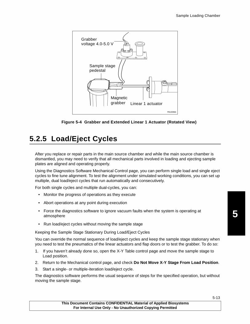
Sample Loading Chamber
5
Figure 5-4 Grabber and Extended Linear 1 Actuator (Rotated View)
5.2.5 Load/Eject Cycles
After you replace or repair parts in the main source chamber and while the main source chamber is dismantled, you may need to verify that all mechanical parts involved in loading and ejecting sample plates are aligned and operating properly.
Using the Diagnostics Software Mechanical Control page, you can perform single load and single eject cycles to fine tune alignment. To test the alignment under simulated working conditions, you can set up multiple, dual load/eject cycles that run automatically and consecutively.
For both single cycles and multiple dual-cycles, you can:
• Monitor the progress of operations as they execute
• Abort operations at any point during execution
• Force the diagnostics software to ignore vacuum faults when the system is operating at atmosphere
• Run load/eject cycles without moving the sample stage
Keeping the Sample Stage Stationary During Load/Eject Cycles
You can override the normal sequence of load/eject cycles and keep the sample stage stationary when you need to test the pneumatics of the linear actuators and flap doors or to test the grabber. To do so:
1. If you haven’t already done so, open the X-Y Table control page and move the sample stage to Load position.
2. Return to the Mechanical control page, and check Do Not Move X-Y Stage From Load Position.
3. Start a single- or multiple-iteration load/eject cycle.
The diagnostics software performs the usual sequence of steps for the specified operation, but without moving the sample stage.
PB100866
Linear 1 actuator
Grabber
Sample stagepedestal
voltage 4.0-5.0 V
grabberMagnetic
This Document Contains CONFIDENTIAL Material of Applied BiosystemsFor Internal Use Only - No Unauthorized Copying Permitted
5-13

Chapter 5 Troubleshooting by Components
5
5-14
Initiating Load/Eject Cycles
To start a single load cycle, click . To start a single eject cycle, click .
To set up multiple load/eject cycles, set the number of load/eject cycles you want to run in Total Number of Complete Load/Eject Cycles to Run, then click .
Table 5-3 lists the order of operations in load and eject cycles.
Monitoring the Progress of Load/Eject Cycles
The status field (Figure 5-5) displays which operation in the load or eject cycle is currently executing.
Figure 5-5 Load or Eject Cycle Status Display
Table 5-3 Order of Operations in Single Load and Eject Cycles
Eject Cycle Load Cycle
Step Operation Step Operation
1 Open Flap Door 1 1 Retract Linear 2 actuator
2 Extend Linear 1 actuator 2 Close Flap Door 2
3 Turn grabber on 3 Close foreline valve 2
4 Retract Linear 1 actuator 4 Close vent valve
5 Turn grabber off 5 Open foreline valve 1
6 Close Flap Door 1 6 Wait 10-15 seconds
7 Close foreline valve 1 7 Check sample loading chamber pressure(TC2 reads <8 x 10⁻² torr)
8 Open vent valve 8 After verifying TC2 reads <8 x 10⁻² torr, open foreline valve 2
9 Wait 5 seconds 9 Open Flap Door 1
10 Check sample loading chamber pressure
10 Turn grabber on
11 Open Flap Door 2 11 Extend Linear 1 actuator
12 Extend Linear 2 actuator 12 Turn grabber off
13 Retract Linear 1 actuator
14 Close Flap Door 1
15 Check source chamber pressure
16 Move sample stage to default position
This Document Contains CONFIDENTIAL Material of Applied BiosystemsFor Internal Use Only - No Unauthorized Copying Permitted

Sample Loading Chamber
5
Aborting Load/Eject Cycles.
You can abort load/eject operations while they are executing, but doing so could place the system in an unsafe state. You can return the system to a safe state by clicking the appropriate radio buttons to open or close the affected components—flap doors, foreline valves, and linear actuators.
To abort the currently executing load/eject operation, click .
5.2.6 Vacuum Faults
When testing the system using the Diagnostics Software Mechanical control page, you develop a vacuum fault. Options for responding to vacuum faults depend on whether the system is in a load/eject cycle. If not in a load/eject cycle, and the ion gauges shut down due to a stability fault, a message is displayed that allows you to choose to restart the gauges or not.
If the system is in a load/eject cycle, during most cycle steps no message is displayed. Faults are displayed in the status bar.
However, in some cycle steps the cycle cannot progress until the vacuum pressures are below a safe threshold pressure. Under these conditions, an error condition may occur where the ion gauges shut down and a message is displayed that allows you to choose to restart the gauges or not.
If an error condition continues and the safe threshold is not attained before a Registry-specified timeout period expires, the load or eject cycle will stop. A message is displayed indicating you can recover from the error by backtracking the cycle steps. You backtrack until the instrument is back to a safe initial state.
Overriding Vacuum FaultsChecking the IGNORE VACUUM FAULTS check box allows the system to ignore all vacuum gauge faults and continue the load/eject cycle even if gauge errors or high pressures present. The system continues on to the next step once the safe threshold pressure is attained or the Registry-specified timeout period expires.
You should ignore vacuum faults only when the system is vented (operating at atmosphere). When vented, ion gauge (and BA2) values are irrelevant. After you’ve started to bring the system back up under vacuum, you can restart the gauges when TC2 (Smp. Pres: in the system status bar) reaches <8 × 10⁻² torr.
Under normal operation, when vacuum gauges TC2, BA1, or BA2 reports a fault during a load or an eject cycle, the diagnostics software:
• Turns off the ion vacuum gauges.• Stops the operation.• Displays a message describing the fault, and asks whether you want to restart the gauges if they
are off. • Pauses, waiting for the timeout period specified in the Registry to expire.• Depending on your input, the software either aborts or completes the operation.
A vacuum fault occurs when the sensors detect pressure greater than the pressure specified for operation:
• Over pressure Pressures >8 × 10⁻² (sample loading chamber); >9 × 10⁻⁶ (main source chamber).
• Persistent Over pressure Over pressure that persists longer than a Registry-specified timeout period
(typically 120 seconds). Shuts down the ion gauges.• Stability fault Over pressure that far exceeds the limit. Shuts down the ion gauges.
This Document Contains CONFIDENTIAL Material of Applied BiosystemsFor Internal Use Only - No Unauthorized Copying Permitted
5-15
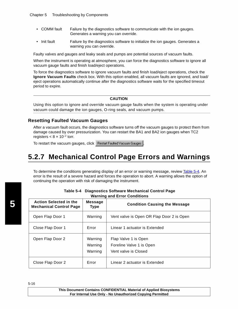
Chapter 5 Troubleshooting by Components
5
5-16
• COMM fault Failure by the diagnostics software to communicate with the ion gauges. Generates a warning you can override.
• Init fault Failure by the diagnostics software to initialize the ion gauges. Generates a warning you can override.
Faulty valves and gauges and leaky seals and pumps are potential sources of vacuum faults.
When the instrument is operating at atmosphere, you can force the diagnostics software to ignore all vacuum gauge faults and finish load/eject operations.
To force the diagnostics software to ignore vacuum faults and finish load/eject operations, check the Ignore Vacuum Faults check box. With this option enabled, all vacuum faults are ignored, and load/eject operations automatically continue after the diagnostics software waits for the specified timeout period to expire.
CAUTION
Using this option to ignore and override vacuum gauge faults when the system is operating under vacuum could damage the ion gauges, O-ring seals, and vacuum pumps.
Resetting Faulted Vacuum GaugesAfter a vacuum fault occurs, the diagnostics software turns off the vacuum gauges to protect them from damage caused by over pressurization. You can restart the BA1 and BA2 ion gauges when TC2 registers < 8 × 10⁻² torr.
To restart the vacuum gauges, click .
5.2.7 Mechanical Control Page Errors and Warnings
To determine the conditions generating display of an error or warning message, review Table 5-4. An error is the result of a severe hazard and forces the operation to abort. A warning allows the option of continuing the operation with risk of damaging the instrument.
Table 5-4 Diagnostics Software Mechanical Control Page Warning and Error Conditions
Action Selected in the Mechanical Control Page
Message Type
Condition Causing the Message
Open Flap Door 1 Warning Vent valve is Open OR Flap Door 2 is Open
Close Flap Door 1 Error Linear 1 actuator is Extended
Open Flap Door 2 Warning
Warning
Warning
Flap Valve 1 is Open
Foreline Valve 1 is Open
Vent valve is Closed
Close Flap Door 2 Error Linear 2 actuator is Extended
This Document Contains CONFIDENTIAL Material of Applied BiosystemsFor Internal Use Only - No Unauthorized Copying Permitted
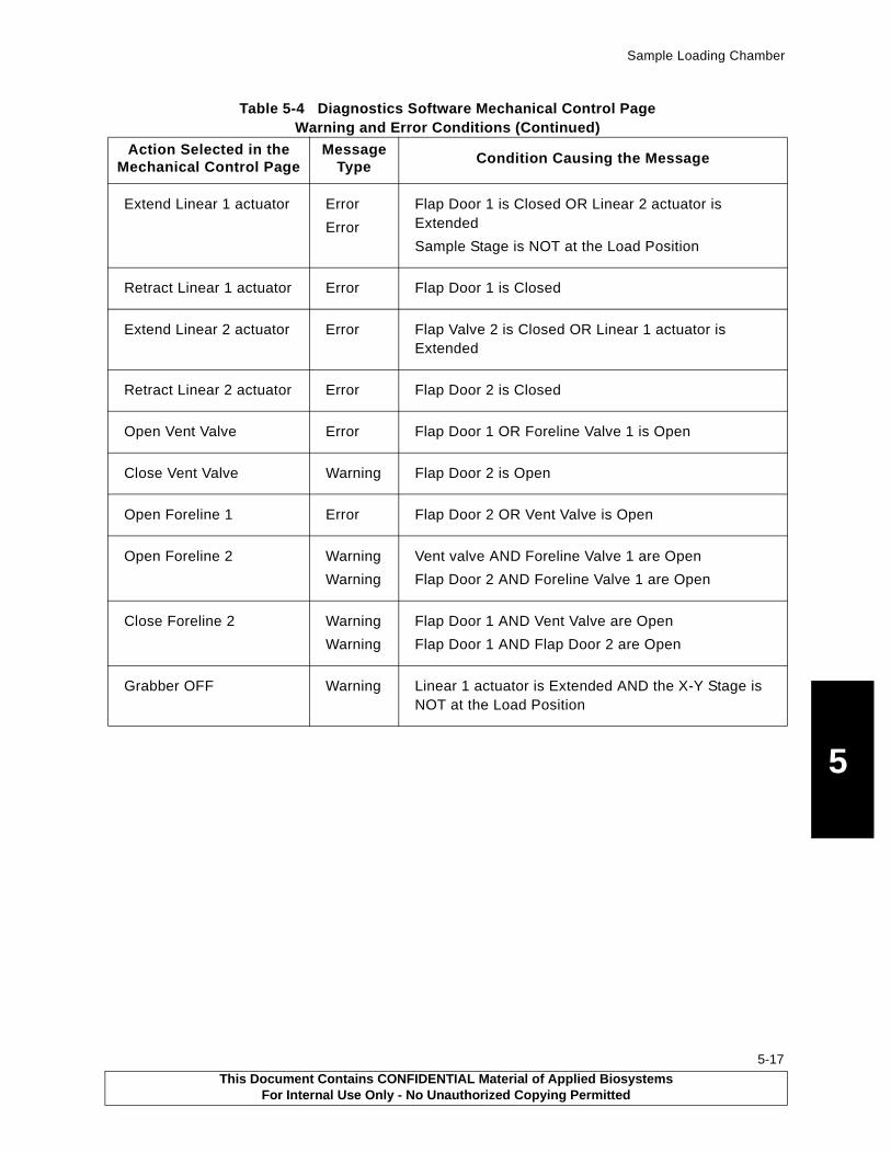
Sample Loading Chamber
5
Extend Linear 1 actuator Error
Error
Flap Door 1 is Closed OR Linear 2 actuator is Extended
Sample Stage is NOT at the Load Position
Retract Linear 1 actuator Error Flap Door 1 is Closed
Extend Linear 2 actuator Error Flap Valve 2 is Closed OR Linear 1 actuator is Extended
Retract Linear 2 actuator Error Flap Door 2 is Closed
Open Vent Valve Error Flap Door 1 OR Foreline Valve 1 is Open
Close Vent Valve Warning Flap Door 2 is Open
Open Foreline 1 Error Flap Door 2 OR Vent Valve is Open
Open Foreline 2 Warning
Warning
Vent valve AND Foreline Valve 1 are Open
Flap Door 2 AND Foreline Valve 1 are Open
Close Foreline 2 Warning
Warning
Flap Door 1 AND Vent Valve are Open
Flap Door 1 AND Flap Door 2 are Open
Grabber OFF Warning Linear 1 actuator is Extended AND the X-Y Stage is NOT at the Load Position
Table 5-4 Diagnostics Software Mechanical Control Page Warning and Error Conditions (Continued)
Action Selected in the Mechanical Control Page
Message Type
Condition Causing the Message
This Document Contains CONFIDENTIAL Material of Applied BiosystemsFor Internal Use Only - No Unauthorized Copying Permitted
5-17

Chapter 5 Troubleshooting by Components
5
5-18
5.3 Main Source Chamber
The main source chamber (Figure 5-6) has the:
• Sample stage (source pedestal and X-Y table)
• Variable-voltage grid
• Delayed-Extraction (DE) switch box
• Two 30 kV high-voltage power supplies (located in the left cabinet) and associated high-voltage cables
Figure 5-6 Voyager-DE STR Ion Source Components
The source pedestal receives the sample plate from the sample loading chamber and is attached to the X-Y table. The X-Y table moves the source pedestal to the desired spot location and between the Home and Load positions. Microswitches on the X-Y table feedthroughs provides the status of the source pedestal Home and Load position.
Sample Stage (Load Position)Use the X-Y Table control page (Figure 5-7) to recalibrate the load position of the sample stage and to move the sample stage to the load position before you open the Mechanical control page (see “Keeping the Sample Stage Stationary During Load/Eject Cycles” on page -13).
Variable-
Sample
Sampleloadingchamber
stage and plate
grid
Laser
Laser attenuator
Mainsource
chamber
(J2)
(source, J4)
voltage
J2, J4 = Delayed-extractionswitch box and high-voltage connections
This Document Contains CONFIDENTIAL Material of Applied BiosystemsFor Internal Use Only - No Unauthorized Copying Permitted
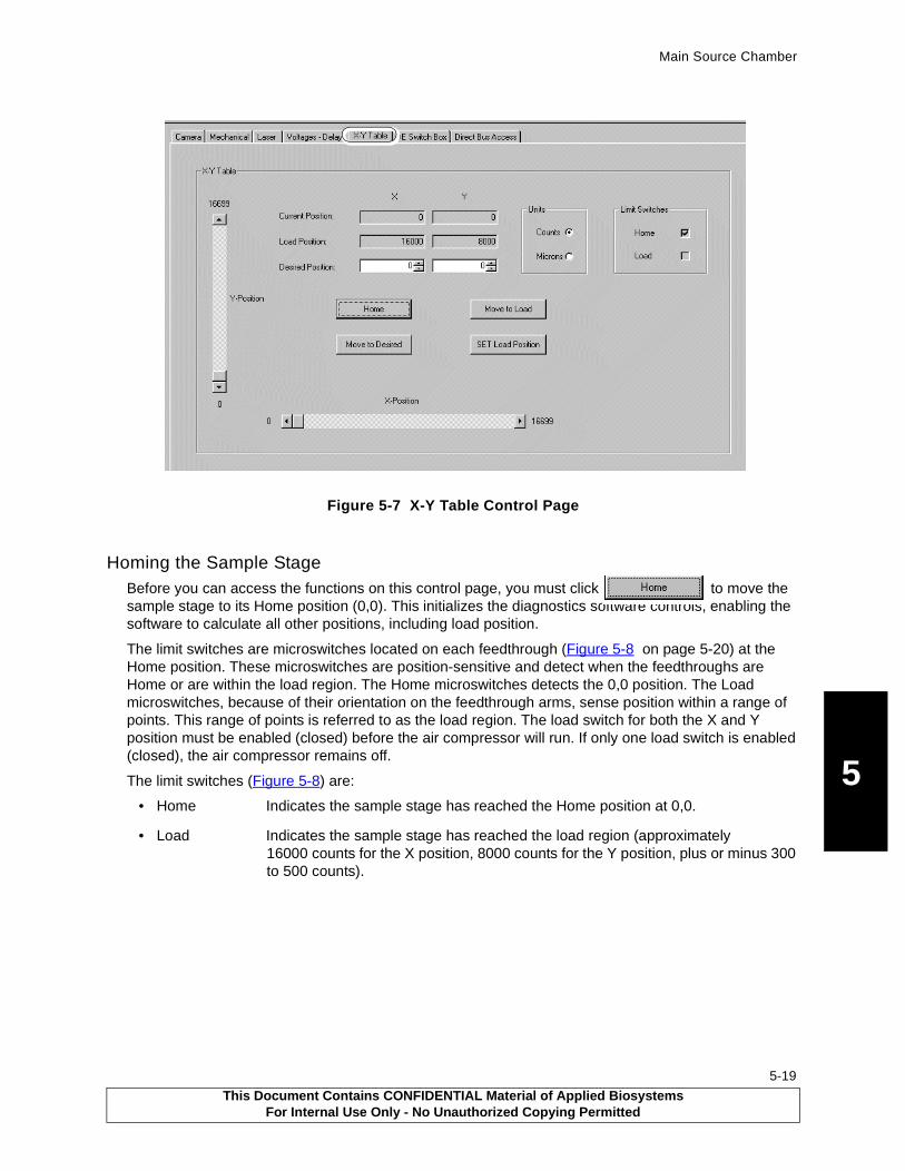
Main Source Chamber
5
Figure 5-7 X-Y Table Control Page
Homing the Sample StageBefore you can access the functions on this control page, you must click to move the sample stage to its Home position (0,0). This initializes the diagnostics software controls, enabling the software to calculate all other positions, including load position.
The limit switches are microswitches located on each feedthrough (Figure 5-8 on page 5-20) at the Home position. These microswitches are position-sensitive and detect when the feedthroughs are Home or are within the load region. The Home microswitches detects the 0,0 position. The Load microswitches, because of their orientation on the feedthrough arms, sense position within a range of points. This range of points is referred to as the load region. The load switch for both the X and Y position must be enabled (closed) before the air compressor will run. If only one load switch is enabled (closed), the air compressor remains off.
The limit switches (Figure 5-8) are:
• Home Indicates the sample stage has reached the Home position at 0,0.
• Load Indicates the sample stage has reached the load region (approximately 16000 counts for the X position, 8000 counts for the Y position, plus or minus 300 to 500 counts).
This Document Contains CONFIDENTIAL Material of Applied BiosystemsFor Internal Use Only - No Unauthorized Copying Permitted
5-19
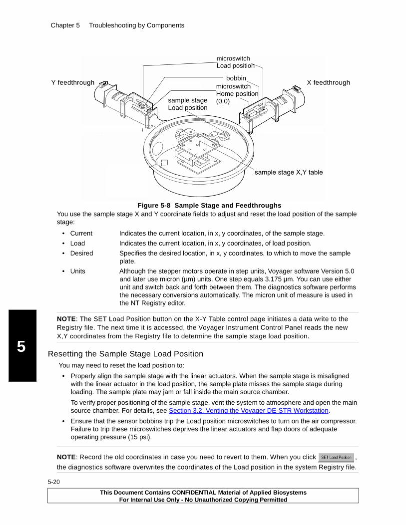
Chapter 5 Troubleshooting by Components
5
5-20
Figure 5-8 Sample Stage and FeedthroughsYou use the sample stage X and Y coordinate fields to adjust and reset the load position of the sample stage:
• Current Indicates the current location, in x, y coordinates, of the sample stage.
• Load Indicates the current location, in x, y coordinates, of load position.
• Desired Specifies the desired location, in x, y coordinates, to which to move the sample plate.
• Units Although the stepper motors operate in step units, Voyager software Version 5.0 and later use micron (µm) units. One step equals 3.175 µm. You can use either unit and switch back and forth between them. The diagnostics software performs the necessary conversions automatically. The micron unit of measure is used in the NT Registry editor.
NOTE: The SET Load Position button on the X-Y Table control page initiates a data write to the Registry file. The next time it is accessed, the Voyager Instrument Control Panel reads the new X,Y coordinates from the Registry file to determine the sample stage load position.
Resetting the Sample Stage Load Position You may need to reset the load position to:
• Properly align the sample stage with the linear actuators. When the sample stage is misaligned with the linear actuator in the load position, the sample plate misses the sample stage during loading. The sample plate may jam or fall inside the main source chamber.
To verify proper positioning of the sample stage, vent the system to atmosphere and open the main source chamber. For details, see Section 3.2, Venting the Voyager DE-STR Workstation.
• Ensure that the sensor bobbins trip the Load position microswitches to turn on the air compressor. Failure to trip these microswitches deprives the linear actuators and flap doors of adequate operating pressure (15 psi).
NOTE: Record the old coordinates in case you need to revert to them. When you click ,
the diagnostics software overwrites the coordinates of the Load position in the system Registry file.
)������������������*������������������
��"����������� ���������
��"���������������������+�,�-
�������$�$$��
����������&��),*���$��
����������&���� ���������
����������&��������������+�,�-
X feedthroughY feedthrough
microswitchLoad position
microswitchHome position(0,0)sample stage
Load position
bobbin
This Document Contains CONFIDENTIAL Material of Applied BiosystemsFor Internal Use Only - No Unauthorized Copying Permitted
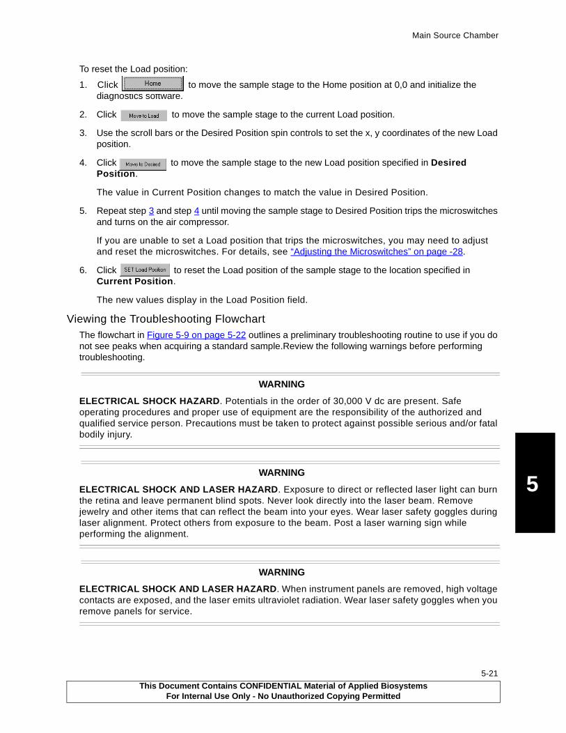
Main Source Chamber
5
To reset the Load position:
1. Click to move the sample stage to the Home position at 0,0 and initialize the diagnostics software.
2. Click to move the sample stage to the current Load position.
3. Use the scroll bars or the Desired Position spin controls to set the x, y coordinates of the new Load position.
4. Click to move the sample stage to the new Load position specified in Desired Position.
The value in Current Position changes to match the value in Desired Position.
5. Repeat step 3 and step 4 until moving the sample stage to Desired Position trips the microswitches and turns on the air compressor.
If you are unable to set a Load position that trips the microswitches, you may need to adjust and reset the microswitches. For details, see “Adjusting the Microswitches” on page -28.
6. Click to reset the Load position of the sample stage to the location specified in Current Position.
The new values display in the Load Position field.
Viewing the Troubleshooting FlowchartThe flowchart in Figure 5-9 on page 5-22 outlines a preliminary troubleshooting routine to use if you do not see peaks when acquiring a standard sample.Review the following warnings before performing troubleshooting.
WARNING
ELECTRICAL SHOCK HAZARD. Potentials in the order of 30,000 V dc are present. Safe operating procedures and proper use of equipment are the responsibility of the authorized and qualified service person. Precautions must be taken to protect against possible serious and/or fatal bodily injury.
WARNING
ELECTRICAL SHOCK AND LASER HAZARD. Exposure to direct or reflected laser light can burn the retina and leave permanent blind spots. Never look directly into the laser beam. Remove jewelry and other items that can reflect the beam into your eyes. Wear laser safety goggles during laser alignment. Protect others from exposure to the beam. Post a laser warning sign while performing the alignment.
WARNING
ELECTRICAL SHOCK AND LASER HAZARD. When instrument panels are removed, high voltage contacts are exposed, and the laser emits ultraviolet radiation. Wear laser safety goggles when you remove panels for service.
This Document Contains CONFIDENTIAL Material of Applied BiosystemsFor Internal Use Only - No Unauthorized Copying Permitted
5-21
Chapter 5 Troubleshooting by Components
5
5-22
Figure 5-9 Source Troubleshooting Flowchart
Review safety warnings on page -21 and in Safety and Compliance Information
see Table D-2, “Voltage Values,” on page D-8 for DAC output voltage
To be provided
This Document Contains CONFIDENTIAL Material of Applied BiosystemsFor Internal Use Only - No Unauthorized Copying Permitted
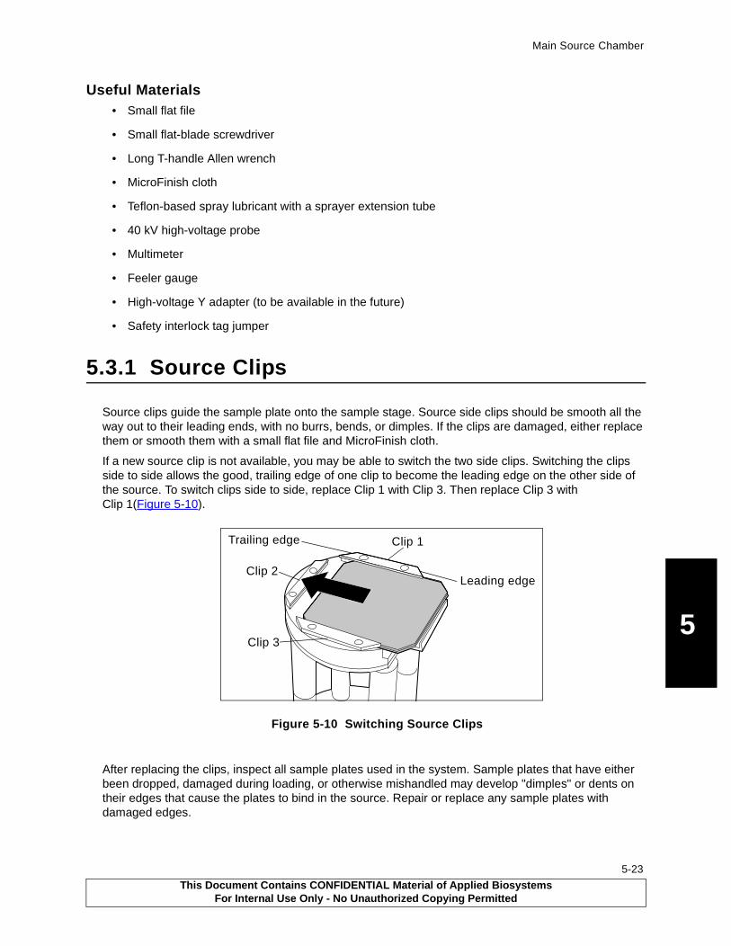
Main Source Chamber
5
Useful Materials• Small flat file
• Small flat-blade screwdriver
• Long T-handle Allen wrench
• MicroFinish cloth
• Teflon-based spray lubricant with a sprayer extension tube
• 40 kV high-voltage probe
• Multimeter
• Feeler gauge
• High-voltage Y adapter (to be available in the future)
• Safety interlock tag jumper
5.3.1 Source Clips
Source clips guide the sample plate onto the sample stage. Source side clips should be smooth all the way out to their leading ends, with no burrs, bends, or dimples. If the clips are damaged, either replace them or smooth them with a small flat file and MicroFinish cloth.
If a new source clip is not available, you may be able to switch the two side clips. Switching the clips side to side allows the good, trailing edge of one clip to become the leading edge on the other side of the source. To switch clips side to side, replace Clip 1 with Clip 3. Then replace Clip 3 with Clip 1(Figure 5-10).
Figure 5-10 Switching Source Clips
After replacing the clips, inspect all sample plates used in the system. Sample plates that have either been dropped, damaged during loading, or otherwise mishandled may develop "dimples" or dents on their edges that cause the plates to bind in the source. Repair or replace any sample plates with damaged edges.
Leading edge
Trailing edge Clip 1
Clip 3
Clip 2
This Document Contains CONFIDENTIAL Material of Applied BiosystemsFor Internal Use Only - No Unauthorized Copying Permitted
5-23
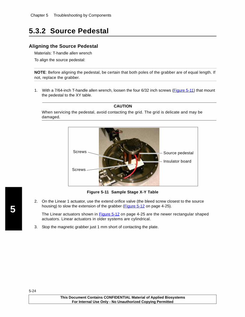
Chapter 5 Troubleshooting by Components
5
5-24
5.3.2 Source Pedestal
Aligning the Source PedestalMaterials: T-handle allen wrench
To align the source pedestal:
NOTE: Before aligning the pedestal, be certain that both poles of the grabber are of equal length. If not, replace the grabber.
1. With a 7/64-inch T-handle allen wrench, loosen the four 6/32 inch screws (Figure 5-11) that mount the pedestal to the XY table.
CAUTION
When servicing the pedestal, avoid contacting the grid. The grid is delicate and may be damaged.
Figure 5-11 Sample Stage X-Y Table
2. On the Linear 1 actuator, use the extend orifice valve (the bleed screw closest to the source housing) to slow the extension of the grabber (Figure 5-12 on page 4-25).
The Linear actuators shown in Figure 5-12 on page 4-25 are the newer rectangular shaped actuators. Linear actuators in older systems are cylindrical.
3. Stop the magnetic grabber just 1 mm short of contacting the plate.
Screws
Screws
Source pedestal
Insulator board
This Document Contains CONFIDENTIAL Material of Applied BiosystemsFor Internal Use Only - No Unauthorized Copying Permitted
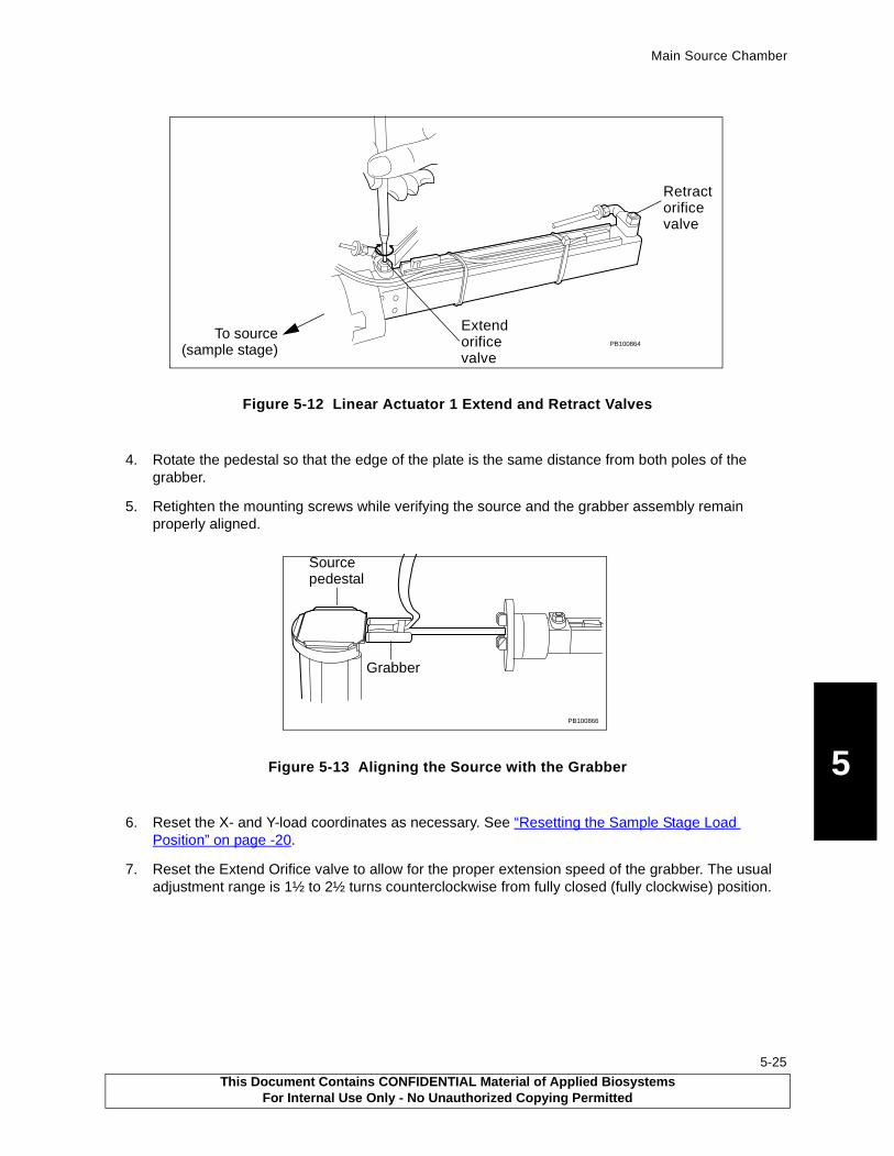
Main Source Chamber
5
Figure 5-12 Linear Actuator 1 Extend and Retract Valves
4. Rotate the pedestal so that the edge of the plate is the same distance from both poles of the grabber.
5. Retighten the mounting screws while verifying the source and the grabber assembly remain properly aligned.
Figure 5-13 Aligning the Source with the Grabber
6. Reset the X- and Y-load coordinates as necessary. See “Resetting the Sample Stage Load Position” on page -20.
7. Reset the Extend Orifice valve to allow for the proper extension speed of the grabber. The usual adjustment range is 1½ to 2½ turns counterclockwise from fully closed (fully clockwise) position.
PB100864To source
Retract orifice
(sample stage)
Extend orifice
valve
valve
PB100866
Grabber
Sourcepedestal
This Document Contains CONFIDENTIAL Material of Applied BiosystemsFor Internal Use Only - No Unauthorized Copying Permitted
5-25

Chapter 5 Troubleshooting by Components
5
5-26
5.3.3 Stepper Motor Feedthroughs
The stepper motor feedthroughs provide detection of the Home and load positions (Figure 5-14). Figure 5-15 on page 4-27 shows the feedthrough interconnects.
Figure 5-14 Stepper Motor Feedthroughs in Load and Home Positions
PB100861PB100862
Load Position Home Position
XYXY
This Document Contains CONFIDENTIAL Material of Applied BiosystemsFor Internal Use Only - No Unauthorized Copying Permitted
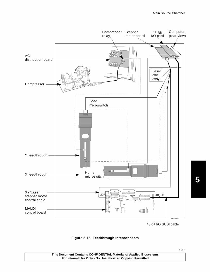
Main Source Chamber
5
Figure 5-15 Feedthrough Interconnects
J31J30
J29J28
J26J23
J22
J25
R51131
14 25
119
37 20
J17
51
69
J15 J1
J0
2
1
26
25
2
1
26
25
J2P
OW
ER
GN
DP
E B
iosystem
sVo
yager C
on
trol B
oard
J16
U18
U15
J18(not used)
R40
D18
D11
S2 Reset
PB100858
Computer48-Bit Stepper motor board
Compressor
X feedthrough
Y feedthrough
I/O card (rear view)
XY/Laser
AC
Compressorrelay
distribution board
MALDI control board
Loadmicroswitch
Homemicroswitch
J0, J1J28
Laserattn.assy
stepper motorcontrol cable
48-bit I/O SCSI cable
This Document Contains CONFIDENTIAL Material of Applied BiosystemsFor Internal Use Only - No Unauthorized Copying Permitted
5-27

Chapter 5 Troubleshooting by Components
5
5-28
Lubricating the X and Y FeedthroughsUseful Materials
• Silicon-or PTFE-based spray lubricant
• Lubricant extension tube with a 90° bend. The bend allows perpendicular access to the feedthrough worm gear.
A grinding noise or erratic binding when the bobbin is moving indicates the feedthroughs need lubrication. To lubricate the X and Y feedthroughs:
1. Expose the worm gear (drive screw) by moving both feedthroughs to their Home positions (fully extended). See “Homing the Sample Stage” on page 5-19.
2. With the lubricant sprayer extension tube inserted into the feedthrough worm gear slot, lubricate the worm gear along its entire length.
Figure 5-16 Lubricating the Feedthrough Worm Gear
3. Repeatedly move the source between sample plate spot position 91 and position 10 until the grinding noise or erratic binding subsides. Also cycle repeatedly from Home to Load Position.
4. If the grinding noise or erratic binding continues, repeat lubrication or replace the feedthrough, if necessary.
Adjusting the MicroswitchesThe stepper motor feedthroughs (Figure 5-17 on page 4-29) have two switches:
• Home—Triggering the Home Position switch occurs when the linear actuators are fully extended. Due to its mounting configuration, the Home switch has very little wear and rarely needs replacement. However, if you replace a Home switch, the respective X or Y load coordinate will need to be adjusted (“Resetting the Sample Stage Load Position” on page 5-20).
• Load—Triggering the Load Position switch retracts the linear actuator. Check the Load Position switch as part of the preventative maintenance schedule and replace if necessary.
PB100863
10
150
48
1216
2024
2832
3640
4448
MM
2.0
0
IN
Lubricate
(drive screw)worm gear
This Document Contains CONFIDENTIAL Material of Applied BiosystemsFor Internal Use Only - No Unauthorized Copying Permitted

Main Source Chamber
5
Figure 5-17 Stepper Motor Feedthrough Load and Home Position Switches
Occasionally, an error message is displayed during plate loading or ejection indicating that the source is not in the load position, even though the compressor is energized.
Both the 5 V logic for the load position sensing and the 24 V for the compressor relay use the same load position microswitches on the sides of the linear feedthroughs. If the switches are not adjusted to provide sufficient pressure on the switch button, a resistance (usually about 10 to 20 ohms) will occur in the switch contacts. This resistance is sufficient to drop the 5 V logic signal low enough to cause the 5 V load logic to fail, but not enough to cause the 24 V compressor control to fail. As such, the compressor runs, but the logic faults.
To adjust the load position microswitch:
1. Move the Load Switch bracket (Figure 5-17) closer to the feedthrough sensor bobbin.
CAUTION
Moving the switch too close to the bobbin may cause excessive wear and premature switch failure.
2. Adjust the Load Switch bracket such that the switch and the bobbin are centered (Figure 5-18 on page 5-29) and close enough that the switch is activated by contact with the bobbin.
Figure 5-18 Adjusting the Load Position Microswitch (Top View)
If the problem persists, replace the switch.
PB100861PB100862
XYXY
Load position microswitches Home position microswitches
Bracket
PB100860
Correct alignment
Microswitch
Bobbin
This Document Contains CONFIDENTIAL Material of Applied BiosystemsFor Internal Use Only - No Unauthorized Copying Permitted
5-29

Chapter 5 Troubleshooting by Components
5
5-30
5.3.4 Sample Plate and Grid Voltage
The ion source can be relatively easy to troubleshoot if high voltage is present at the sample plate and the grid assembly. However, measuring and verifying these voltages can be difficult because the power supplies are safety interlocked and isolated to prevent accidental exposure to potentially lethal high voltages.
You can measure source and grid voltages directly or indirectly:
• Directly—Vent the instrument and disable the vacuum system. Use a high-voltage probe to measure the voltages.
• Indirectly—Use a high-voltage Y adapter
Before optimizing the variable-voltage grid setting (Grid Voltage%), adjust laser intensity until you obtain a signal-to-noise ratio of approximately 50:1.
5.3.5 Internal High-Voltage Cable
You can test the integrity of the high-voltage (HV) cable with the system under vacuum. This process takes advantage of the Linear Actuator 1 being grounded.
In this test, you determine if the internal high-voltage cable feedthrough is maintained from the sample plate to the high-voltage connectors.
Using the 16-bit Diagnostic SoftwareTo test the HV cable using the 16-bit diagnostics software:
1. Load the sample plate into the sample plate holder.
2. Exit Voyager Control software and manually turn off the ion gauge tubes.
3. Start the service mode software.
4. Initialize the autosampler, then move the sample plate to the load position.
5. Close Foreline Valve 1.
6. Open Flap Door 1 and extend the Linear 1 actuator. This completes the circuit.
As you extend the Linear 1 actuator, watch the video monitor. If you see movement of the plate, the grabber assembly is touching the plate.
7. Connect a small feeler gauge to the shaft of the Linear 1 actuator and the high-voltage feedthrough.
8. With the multimeter set for Ohms, measure resistance from the high-voltage feedthrough to the shaft of the Linear 1 actuator.
9. If open (infinite resistance is observed), the internal high-voltage connection cable is defective or dislodged. Vent the system, then replace or reconnect the cable.
Using the 32-Bit Diagnostic SoftwareTo test the HV cable using the 32-bit diagnostics software:
1. Load the sample plate into the sample plate holder.
2. Exit Voyager Control software and manually turn off the ion gauge tubes.
This Document Contains CONFIDENTIAL Material of Applied BiosystemsFor Internal Use Only - No Unauthorized Copying Permitted

Main Source Chamber
5
3. Shut down the Instrument Hardware Controller and start the 32-bit diagnostics software. For information see Chapter 4, Voyager Diagnostics Software.
4. Select the XY tab. Initialize the autosampler by clicking Home.
5. Click Move to Load.
6. Select the Mechanical tab.
7. Close Foreline Valve 1.
8. Open Flap Door 1 and extend the Linear 1 actuator. This completes the circuit.
As you extend the Linear 1 actuator, watch the video monitor. If you see movement of the plate, the grabber assembly is touching the plate.
9. Connect a small feeler gauge to the shaft of the Linear 1 actuator and the high-voltage feedthrough. Measure resistance (Ohm) flows from the high-voltage feedthrough to the shaft of the Linear 1 actuator.
10. If open (infinite resistance is observed), the internal high-voltage connection cable is defective or dislodged. Vent the system, then replace or reconnect the cable.
5.3.6 Operation Mode
The Voyager-DE STR workstation offers two flight path modes of operation, Linear and Reflector. When set to Linear and Reflector mode:
• Linear The mirror voltage is inoperative, and the Timed Ion Selector delay time ignored.
• Reflector All voltages and delay times apply.
To set the instrument mode using the Diagnostics Software Voltage and Delays control page,
1. click the Linear or Reflector radio button next to Mode of Operation and apply.
2. Click . If you leave the Voltage and Delays control page without applying the changes, you will lose the changes. The values revert to the last applied settings.
5.3.7 Delayed-Extraction Ion Source
To troubleshoot the ion source in Delayed-Extraction mode, do the following:
1. When the laser is not firing:
• Verify source voltage is less than the grid voltage.
• Verify all switch box relay LEDs are off when the system is in positive ion mode. See the schematic for appropriate LED states for other modes.
2. Fire the laser.
3. Observe the source voltage and the DE Timer switch box for pulses. If pulses are present or the source voltage is not pulsing, replace the switch box.
This Document Contains CONFIDENTIAL Material of Applied BiosystemsFor Internal Use Only - No Unauthorized Copying Permitted
5-31

Chapter 5 Troubleshooting by Components
5
5-32
WARNING
ELECTRICAL SHOCK HAZARD. High-voltage contacts are exposed with front or side panels removed. Because the DE switch box uses 30 kV, disable the high voltages before servicing the DE switch box. Servicing the DE switch box when the high voltages on, severe electrical shock can result. Wear proper eye protection.
Set the system to Continuous Linear Mode and acquire a standard sample. If you still do not see peaks when acquiring a standard sample, check the following:
• Source DAC output—Source DAC output voltage is at expected value. Calculate the expected value by dividing the accelerating voltage by 3,000. For example, a 15,000 V accelerating voltage equals a 5 V expected reading; A 20,000 V accelerating voltage equals a 6.66 V expected reading.
• Grid DAC output—Grid voltage for Continuous Extraction is at expected value, 75% of DAC output. For example, for a 20,000 V accelerating voltage, 75% of the 6.66 V DAC outputs equals a trim pot 5.0 V reading.
• 30 kV High-Voltage power supply—Current “I” trumpet is set at 3 turns counterclockwise or counterclockwise from the x stop point. Check that the polarity is correct. If the current “I” pot and polarity are set correctly and no voltage is present, replace the power supply.
• High-voltage cable—Connection to source pedestal is secure
• Laser—Laser is delivering adequate power and is positioned correctly
• Delayed-Extraction switch box—Switch Box is functioning properly in Delayed-Extraction and Continuous Linear mode
• Delayed-Extraction Timer circuit board—Output for older systems with the ECL logic board is -5.2 V. (Newer systems with TTL boards and the MALDI consolidated control board do not use -5.2 V.)
This Document Contains CONFIDENTIAL Material of Applied BiosystemsFor Internal Use Only - No Unauthorized Copying Permitted

Main Source Chamber
5
5.3.8 Source, Grid, and Mirror Voltages
Use the Diagnostics Software Voltages-Delays control page (Figure 5-19) to set system voltage parameters and timing delays.
Figure 5-19 Voltage-Delays Control Page
Applying the SettingsAfter changing any of the settings on this control page, you must apply them before they can take effect.
To do so, click . If you leave the Voltage and Delays control page without
applying the changes, you will lose the changes. The values revert to the last applied settings.
If you set and apply voltage for the source, grid, mirror, or guide wire without enabling high-voltage, the diagnostics software programs only the corresponding DACs. You can verify these output voltages with a voltmeter. (DAC voltages are shown in Table D-2, “Voltage Values,” on page D-8.) To detect output voltages at the test points of the corresponding components, you must also enable and apply high-voltage.
By pressing , you set the delays specified for Delayed Extraction, Low-Mass Gate, and Timed Ion Selector only when you have also enabled them. (It does not affect delays associated with ramping component voltages.)
The status field (Figure 5-20) tracks the state of the voltages.
Figure 5-20 Voltages Status Display
This Document Contains CONFIDENTIAL Material of Applied BiosystemsFor Internal Use Only - No Unauthorized Copying Permitted
5-33
Chapter 5 Troubleshooting by Components
5
5-34
Setting the VoltagesThe voltage options provide complete control of the high-voltage components. You can:
• Enable/disable high-voltage for all components the DACs control
• Set the voltage polarity
• Ramp each DAC to a specified voltage
• Enable and set specific delays for voltages applied to Delayed Extraction, the Low-Mass Gate, and the Timed Ion Selector
Turning the High-Voltages On and OffTo power the high-voltages on or off, click the Off or On radio button next to HV Enable and click apply.
• If you set DAC voltages without enabling HV, only the corresponding DACs output voltages are detectable with a voltmeter (DAC voltages are shown in Table D-2, “Voltage Values,” on page D-8).
• Enabling/disabling HV turns high-voltage on and off for all HV components (source, grid, mirror, and guide wire).
Setting the Voltage PolarityTo set the voltage polarity, click the Positive or Negative radio button next to Polarity, and click apply.
• Positive polarity is the instrument default setting.
• The polarity setting determines which ions (+ or –) are repelled from the sample plate and accelerated down the flight tube.
Ramping the DAC VoltagesTo set DAC voltages, under Desired, increase or decrease the appropriate spin button, or enter a value in the appropriate field.
• Source 0 to 20 kV range. For the STR, usually set to 20,000.0 V. The source voltage defaults to 20000.0 when the Voltage and Delays control page opens.
Changing this voltage automatically changes the voltage of the beam-steering plates and the Einzel lens, which receives approximately 50% of the source voltage.
You must set and apply the source and grid voltages at the same time.
• Grid 0 to 20 kV range. Set as a percentage of the source voltage, it must be within 10 kV of the source voltage; typically about 65% to 95% of source voltage. The grid voltage defaults to 15000.0 when the Voltage and Delays control page opens.
You must set and apply the source and grid voltages at the same time.
• Mirror 0 to 30 kV range. Reflector mode only (ignored in linear mode). The mirror voltage defaults to 22000.0 when the Voltage and Delays control page opens.
When changing from reflector to linear mode, diagnostics software waits 5 seconds for the mirror high-voltage supply to fully discharge.
• Guide Wire Ignored in Voyager-DE STR workstation with serial numbers 4154 and later.
Resetting All Voltages and Delay TimesClick to disable all high-voltages, reset all DAC voltage values to 0.0 V, and disable all delay timing options.
This Document Contains CONFIDENTIAL Material of Applied BiosystemsFor Internal Use Only - No Unauthorized Copying Permitted

Main Source Chamber
5
5.3.9 Delayed Extraction, Low-Mass Gate and Timed Ion Selector Delay Times
Use the Diagnostics Software Voltages-Delays control page (Figure 5-19) timing delays.
To enable DE, the LMG, or the TIS, click the radio button of the function you want to enable. To set delay times (defined in Table 5-5), increase or decrease the counter (start and end delay times) to set the delay.
Resetting All Voltages and Delay TimesTo disable all high-voltages, reset all DAC voltage values to 0.0 V, and disable all delay timing options, Click (Figure 5-19).
Table 5-5 DE. LMG, and TIS Delay Times
ParameterClock cycle
Start Delay End Delay
DE 10 ns How long accelerating voltage is withheld after the laser fires.Values range from 10 to 32,768 ns.
NA
LMG 222-ns steps
How long the detector is deactivated, reducing its sensitivity to low-mass ions.Values range from 8,000 to 65,000 ns.
NA
TIS 10 ns Determines when the TIS is deactivated (voltage turned off) to pass the ions of interest. Values range from 10 to 327,670 ns.
Determines when the TIS is reactivated (voltage applied) to deflect unwanted ions.
This Document Contains CONFIDENTIAL Material of Applied BiosystemsFor Internal Use Only - No Unauthorized Copying Permitted
5-35
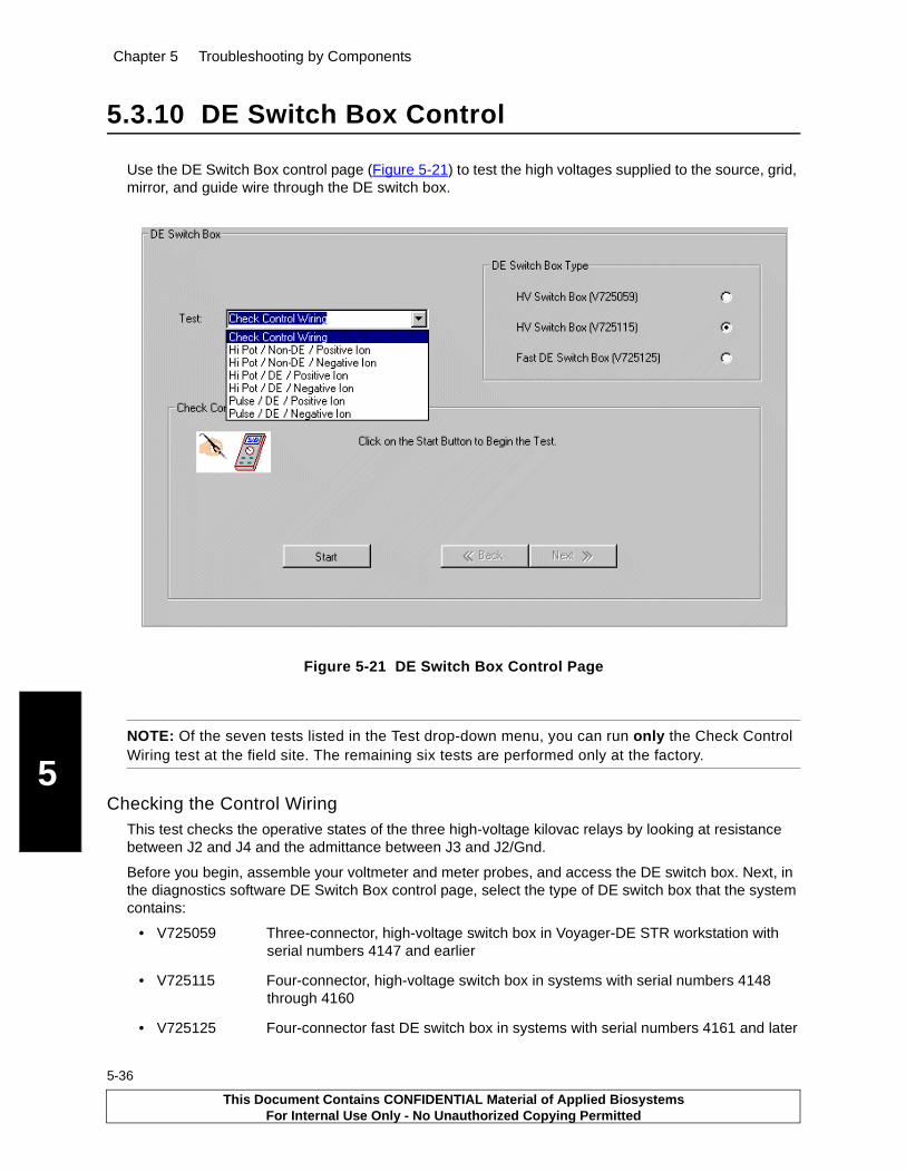
Chapter 5 Troubleshooting by Components
5
5-36
5.3.10 DE Switch Box Control
Use the DE Switch Box control page (Figure 5-21) to test the high voltages supplied to the source, grid, mirror, and guide wire through the DE switch box.
Figure 5-21 DE Switch Box Control Page
NOTE: Of the seven tests listed in the Test drop-down menu, you can run only the Check Control Wiring test at the field site. The remaining six tests are performed only at the factory.
Checking the Control WiringThis test checks the operative states of the three high-voltage kilovac relays by looking at resistance between J2 and J4 and the admittance between J3 and J2/Gnd.
Before you begin, assemble your voltmeter and meter probes, and access the DE switch box. Next, in the diagnostics software DE Switch Box control page, select the type of DE switch box that the system contains:
• V725059 Three-connector, high-voltage switch box in Voyager-DE STR workstation with serial numbers 4147 and earlier
• V725115 Four-connector, high-voltage switch box in systems with serial numbers 4148 through 4160
• V725125 Four-connector fast DE switch box in systems with serial numbers 4161 and later
This Document Contains CONFIDENTIAL Material of Applied BiosystemsFor Internal Use Only - No Unauthorized Copying Permitted
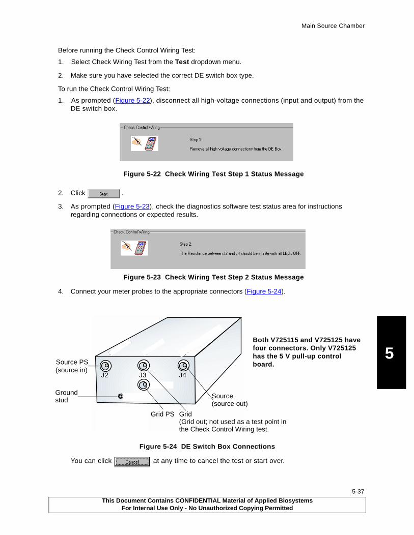
Main Source Chamber
5
Before running the Check Control Wiring Test:
1. Select Check Wiring Test from the Test dropdown menu.
2. Make sure you have selected the correct DE switch box type.
To run the Check Control Wiring Test:
1. As prompted (Figure 5-22), disconnect all high-voltage connections (input and output) from the DE switch box.
Figure 5-22 Check Wiring Test Step 1 Status Message
2. Click .
3. As prompted (Figure 5-23), check the diagnostics software test status area for instructions regarding connections or expected results.
Figure 5-23 Check Wiring Test Step 2 Status Message
4. Connect your meter probes to the appropriate connectors (Figure 5-24).
Figure 5-24 DE Switch Box Connections
You can click at any time to cancel the test or start over.
.��/�%���"����
.�/�0�� ���
.1�/�%���"�����
0� ����
0�� ����
%���"
� ��
0�� ��
%���"� ��� Both V725115 and V725125 have
four connectors. Only V725125 has the 5 V pull-up control board.Source PS
(source in)
Source(source out)
Grid PS Grid
Ground stud
(Grid out; not used as a test point in
J2 J3 J4
the Check Control Wiring test.
This Document Contains CONFIDENTIAL Material of Applied BiosystemsFor Internal Use Only - No Unauthorized Copying Permitted
5-37
Chapter 5 Troubleshooting by Components
5
5-38
5. Click when you are ready to continue.
6. Continue to check the test status area for expected voltage readings and instructions each time you click .
7. If the test results in mismatched values, run the test again.
5.4 Laser System
The nitrogen laser is replaced as a unit. You cannot replace the plasma cartridge because it must be aligned by the manufacturer.
The beam steering plates work in conjunction with the laser position. After adjusting the laser position, beam steering plates often require re-optimization.
5.4.1 Laser Firing, Repetition Rate, and Reinitialization
Use the Diagnostics Software Laser control page (Figure 5-25) to fire the internal or external (if present) laser, set its repetition rate, re-initialize it, and adjust its attenuator (intensity). You cannot use the joystick to control either the internal or the external laser. Instead, you must use
the button on the control page.
WARNING
ELECTRICAL SHOCK AND LASER HAZARD. In External Trigger mode, the nitrogen laser energy storage capacitors are charged, and the laser is ready to fire at any time. When you perform service on the laser in External Trigger mode, remove jewelry and other items that can reflect the beam into your eyes or the eyes of others. Wear laser safety goggles and protect others from exposure to the beam. Post a laser warning sign.
WARNING
ELECTRICAL SHOCK AND LASER HAZARD. When instrument covers are removed, high voltage contacts are exposed, and the laser emits ultraviolet radiation. Wear laser safety goggles and post a laser warning sign at the entrance to the laboratory when you remove covers for service.
WARNING
LASER HAZARD. Exposure to direct or reflected laser light can burn the retina and leave permanent blind spots. Never look directly into the laser beam. Remove jewelry and other items that can reflect the beam into your eyes. Wear laser safety goggles during laser alignment. Protect others from exposure to the beam. Post a laser warning sign while performing service.
This Document Contains CONFIDENTIAL Material of Applied BiosystemsFor Internal Use Only - No Unauthorized Copying Permitted

Laser System
5
Figure 5-25 Laser Control Page
Firing the LaserTo fire the laser:
1. Select Laser Type by clicking the appropriate radio button.
2. If you switched lasers in step 1, click (for details, see “Re-initializing the Laser” on page -40).
3. Click to set the attenuator at minimum intensity (0%) and initialize the diagnostics software.
4. Set the laser repetition rate and attenuator (%) as needed (for details, see “Adjusting the Attenuator Position” on page -41).
You can adjust the laser repetition rate only if the system contains laser optimization components (for details, see “Setting the Laser Repetition Rate” on page -39).
5. Click .
The laser pulses continuously.
6. To stop the laser pulsing, click again.Setting the Laser Repetition Rate
Setting the Laser Repetition RateYou can adjust the laser repetition rate only if the system contains these optimization components:
• Voyager Version 5.1 and later software
• Consolidated control board (V750082 and V750102-001, V750102-002, V750102-003) with firmware (V960005rD and D/V960006rD) installed
• Fast DE switch box (V725125)
• 48-bit I/O control board (V750033) configured for 5-bit addressing
This Document Contains CONFIDENTIAL Material of Applied BiosystemsFor Internal Use Only - No Unauthorized Copying Permitted
5-39
Chapter 5 Troubleshooting by Components
5
5-40
To set the laser repetition rate:
1. If necessary, select the laser and re-initialize it. For details, see Re-initializing the Laser.
2. Set the repetition rate by increasing or decreasing the value in Desired Repetition Rate.
NOTE: Currently, regardless of the laser optimization components, the Voyager laser does not support repetition rates greater than 20 Hz. Setting the repetition rate to a value ≥ 20 Hz causes the laser to cease firing after it emits the first pulse.
Re-initializing the LaserAfter switching lasers, you need to re-initialize the newly-selected laser before use. This procedure resets the transmission path for control signaling to the newly-selected laser.
Reinitialization stops the laser from firing, homes the laser attenuator, and resets the attenuator minimum and maximum values to those stored in the Registry file.
Under Laser Type, select the laser you are switching to (Internal or External) and then click .
5.4.2 Laser Attenuation
The attenuator of the internal laser is an optical disk with a 360° gradient of optical density (Figure 5-26 on page -41) positioned between the laser and the prism. The laser attenuator decreases or increases the intensity of the laser beam. As the laser is triggering, you adjust the attenuation by pressing the Control+Page Up and Control+Page Down keys with the Voyager Software Instrument Control Panel window active. This rotates the laser attenuator to set the degree of optical density at the point the laser beam enters the attenuator. The optical density determines the amount of energy that is delivered to the sample spot.
Attenuation is controlled by a stepper motor and is adjustable using the Voyager Control Panel laser step controls. For information on setting the step size, see the Voyager User Guide, Digitizer/Laser Parameters.
This Document Contains CONFIDENTIAL Material of Applied BiosystemsFor Internal Use Only - No Unauthorized Copying Permitted
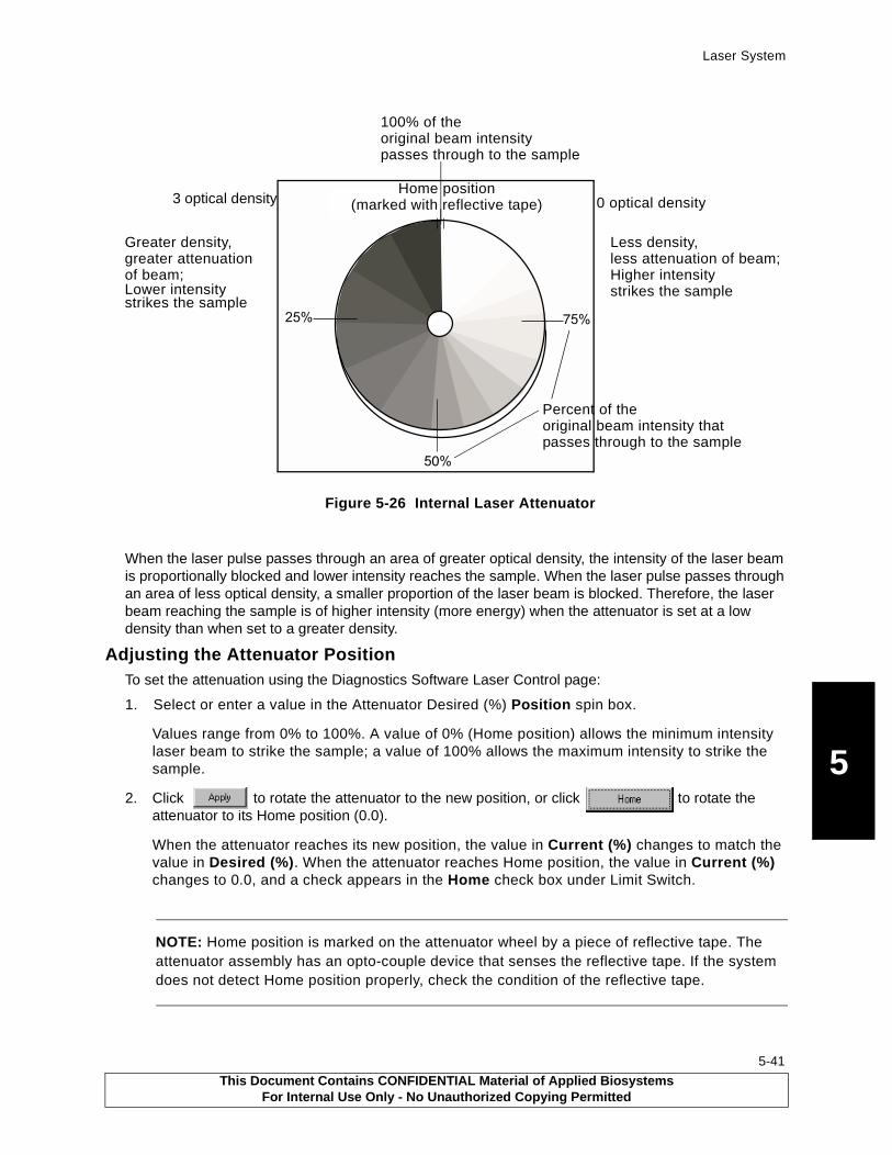
Laser System
5
Figure 5-26 Internal Laser Attenuator
When the laser pulse passes through an area of greater optical density, the intensity of the laser beam is proportionally blocked and lower intensity reaches the sample. When the laser pulse passes through an area of less optical density, a smaller proportion of the laser beam is blocked. Therefore, the laser beam reaching the sample is of higher intensity (more energy) when the attenuator is set at a low density than when set to a greater density.
Adjusting the Attenuator PositionTo set the attenuation using the Diagnostics Software Laser Control page:
1. Select or enter a value in the Attenuator Desired (%) Position spin box.
Values range from 0% to 100%. A value of 0% (Home position) allows the minimum intensity laser beam to strike the sample; a value of 100% allows the maximum intensity to strike the sample.
2. Click to rotate the attenuator to the new position, or click to rotate the attenuator to its Home position (0.0).
When the attenuator reaches its new position, the value in Current (%) changes to match the value in Desired (%). When the attenuator reaches Home position, the value in Current (%) changes to 0.0, and a check appears in the Home check box under Limit Switch.
NOTE: Home position is marked on the attenuator wheel by a piece of reflective tape. The attenuator assembly has an opto-couple device that senses the reflective tape. If the system does not detect Home position properly, check the condition of the reflective tape.
�2��+����- ���3
�3
�3
�3
Greater density,greater attenuation
Less density, less attenuation of beam;Higher intensity strikes the sampleLower intensity
strikes the sample
0 optical density3 optical density
Percent of theoriginal beam intensity thatpasses through to the sample
of beam;
100% of theoriginal beam intensitypasses through to the sample
Home position(marked with reflective tape)
This Document Contains CONFIDENTIAL Material of Applied BiosystemsFor Internal Use Only - No Unauthorized Copying Permitted
5-41
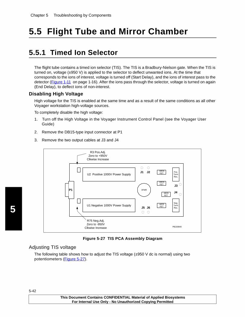
Chapter 5 Troubleshooting by Components
5
5-42
5.5 Flight Tube and Mirror Chamber
5.5.1 Timed Ion Selector
The flight tube contains a timed ion selector (TIS). The TIS is a Bradbury-Nielson gate. When the TIS is turned on, voltage (±950 V) is applied to the selector to deflect unwanted ions. At the time that corresponds to the ions of interest, voltage is turned off (Start Delay), and the ions of interest pass to the detector (Figure 1-11 on page 1-16). After the ions pass through the selector, voltage is turned on again (End Delay), to deflect ions of non-interest.
Disabling High VoltageHigh voltage for the TIS is enabled at the same time and as a result of the same conditions as all other Voyager workstation high-voltage sources.
To completely disable the high voltage:
1. Turn off the High Voltage in the Voyager Instrument Control Panel (see the Voyager User Guide)
2. Remove the DB15-type input connector at P1
3. Remove the two output cables at J3 and J4
Figure 5-27 TIS PCA Assembly Diagram
Adjusting TIS voltageThe following table shows how to adjust the TIS voltage (±950 V dc is normal) using two potentiometers (Figure 5-27).
Pos.TermRes.
U2 Positive 1000V Power Supply
U1 Negative 1000V Power Supply
XFMR
Neg.TermRes.
P1-MOSFET
-MOSFET
+MOSFET
+MOSFETJ1 J2
J5 J6
J3
J4
R3 Pos.Adj.Zero to +950V
Clkwise Increase
R75 Neg.Adj.Zero to -950V
Clkwise Increase PB100840
This Document Contains CONFIDENTIAL Material of Applied BiosystemsFor Internal Use Only - No Unauthorized Copying Permitted
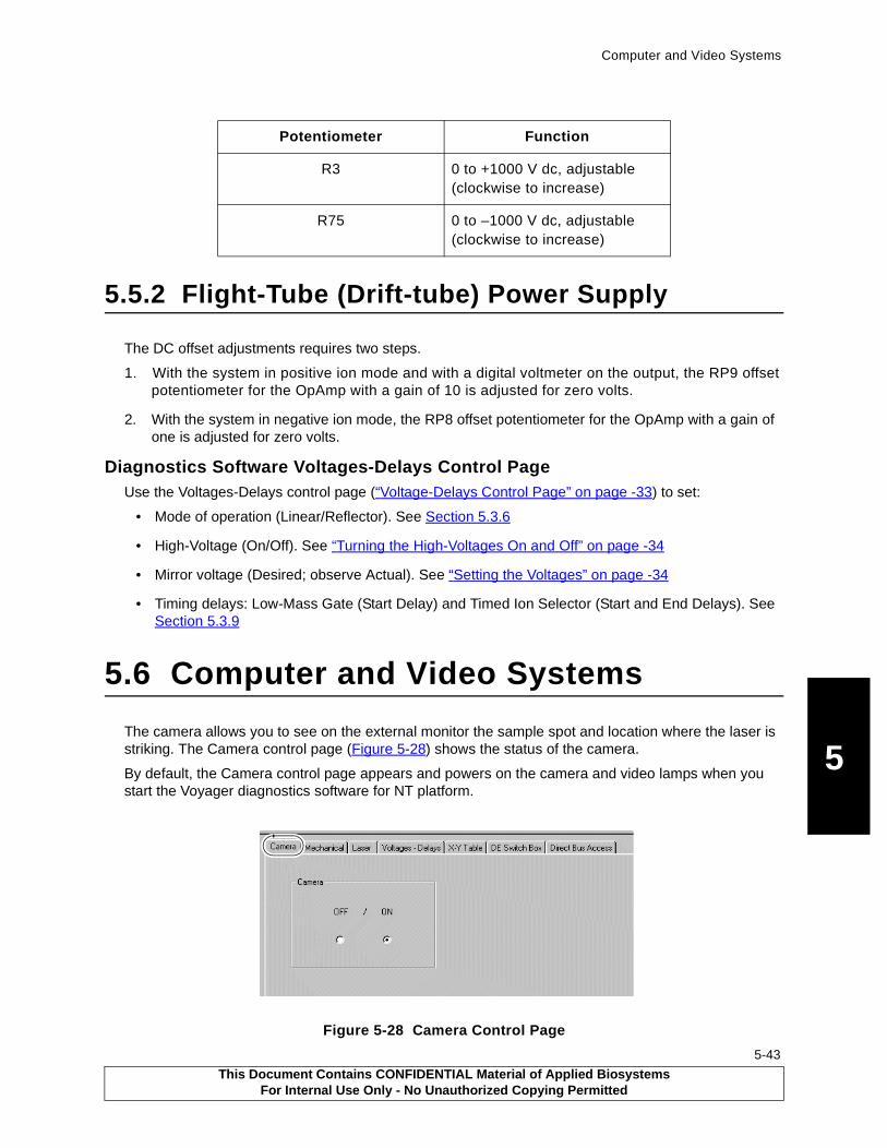
Computer and Video Systems
5
5.5.2 Flight-Tube (Drift-tube) Power Supply
The DC offset adjustments requires two steps.
1. With the system in positive ion mode and with a digital voltmeter on the output, the RP9 offset potentiometer for the OpAmp with a gain of 10 is adjusted for zero volts.
2. With the system in negative ion mode, the RP8 offset potentiometer for the OpAmp with a gain of one is adjusted for zero volts.
Diagnostics Software Voltages-Delays Control PageUse the Voltages-Delays control page (“Voltage-Delays Control Page” on page -33) to set:
• Mode of operation (Linear/Reflector). See Section 5.3.6
• High-Voltage (On/Off). See “Turning the High-Voltages On and Off” on page -34
• Mirror voltage (Desired; observe Actual). See “Setting the Voltages” on page -34
• Timing delays: Low-Mass Gate (Start Delay) and Timed Ion Selector (Start and End Delays). See Section 5.3.9
5.6 Computer and Video Systems
The camera allows you to see on the external monitor the sample spot and location where the laser is striking. The Camera control page (Figure 5-28) shows the status of the camera.
By default, the Camera control page appears and powers on the camera and video lamps when you start the Voyager diagnostics software for NT platform.
Figure 5-28 Camera Control Page
Potentiometer Function
R3 0 to +1000 V dc, adjustable (clockwise to increase)
R75 0 to –1000 V dc, adjustable (clockwise to increase)
This Document Contains CONFIDENTIAL Material of Applied BiosystemsFor Internal Use Only - No Unauthorized Copying Permitted
5-43

Chapter 5 Troubleshooting by Components
5
5-44
5.7 Vacuum System
This section includes a description of the vacuum gauges and multigauge controller
Additional information is provided in Section 3, Before Servicing the Workstation:
• A procedure for venting the system to air
• A procedure for purging the system to N2
• A procedure for powering up the workstation after venting
5.7.1 Vacuum Gauges and Pumps
The vacuum system (Figure 5-2 on page 5-8) uses multiple pumps to create and maintain a sealed high-vacuum environment for unobstructed ion drift.
The Voyager-DE STR has three vacuum chambers and three pumps, as described in the following table:
The fore pump, or roughing pump, creates a lower-than-atmospheric-pressure condition before the turbo pumps start, and provides backing pressure to the turbo pumps. The fore pump can reduce pressures down to the 10–3 torr range.
Valves and Flap DoorsVacuum is maintained in the main source chamber and sample loading chamber by valves and flap doors that isolate the chambers. Vacuum differential between the main source and mirror chambers is maintained by a differential pumping baffle.
GaugesTwo types of gauges monitor vacuum pressures, one thermocouple (TC2) gauge and two ion gauges (Bayard-Alpert gauges, BA1 and BA2). To monitor these gauges, you use a multigauge controller. See Section 5.7.2, Multigauge Controller.
The following table summarizes the gauges and corresponding measurement ranges:
Vacuum Chamber Vacuum Range Typical Pressure Vacuum Pump
Sample loading chamber
Lower-than-atmospheric-pressure
<3 × 10⁻² torr (TC2) Fore pump
Main source chamber High vacuum <5 × 10⁻⁷ torr (BA1) Turbo pump 1
Mirror chamber (analyzer)
High vacuum <5 × 10⁻⁸ torr (BA2) Turbo pump 2
This Document Contains CONFIDENTIAL Material of Applied BiosystemsFor Internal Use Only - No Unauthorized Copying Permitted

Vacuum System
5
.
5.7.2 Multigauge Controller
The multigauge controller in the Voyager system monitors the vacuum system thermocouple (TC2) and Bayard-Alpert gauges (BA1 and BA2). The multigauge controller is located in the left cabinet (Figure 5-29).
Figure 5-29 Location of the Multigauge Controller in Left Cabinet (Front View)
Use the multigauge controller to:
• Verify the status of the BA1 and BA2 gauges
• Verify the status of the TC2 gauge
• Degas the BA1 and BA2 gauges
• Verify the baud rate
You access the multigauge controller functions and parameters through the front panel keyboard (Figure 5-30). The readings, prompts, and error messages are displayed on the liquid crystal display (LCD). Pressing the F(unction) key before pressing another key accesses the second function of the next key you press.
Gauge Type Gauge Range Gauge Name Comment
Thermocouple Gauge Atmospheric pressure (7.6 × 10+2 torr) to 1 × 10⁻³ torr
TC2 On initial pumpdown, the turbo pumps start 2 minutes after AC power is supplied to the instrument.
Ion Gauge (Bayard-Alpert Gauge)
9.9 × 10⁻⁴ torr to
1.0 × 10⁻⁸ torr
BA1, BA2 You can enable high-voltage power only when BA1 reads 9.0 × 10⁻⁶ torr or less.
PB100848
Multigaugecontroller
This Document Contains CONFIDENTIAL Material of Applied BiosystemsFor Internal Use Only - No Unauthorized Copying Permitted
5-45
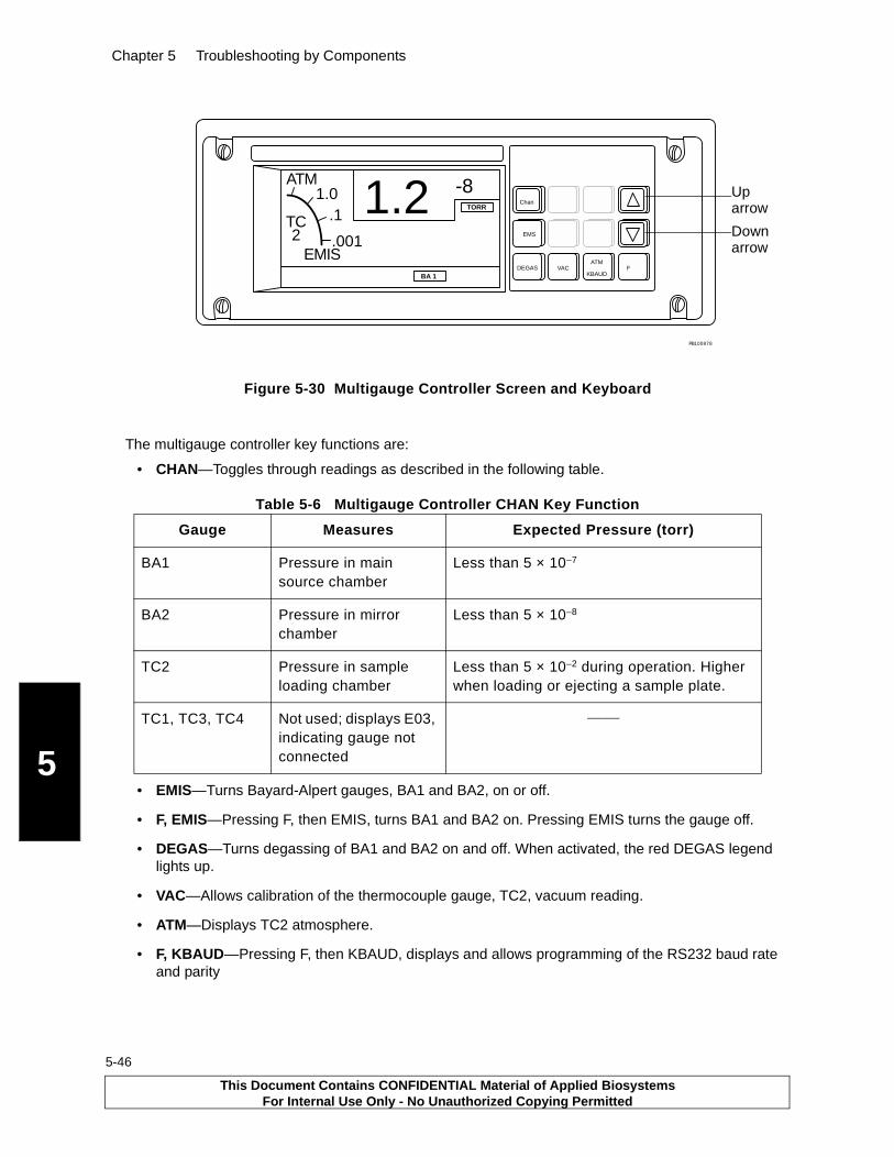
Chapter 5 Troubleshooting by Components
5
5-46
Figure 5-30 Multigauge Controller Screen and Keyboard
The multigauge controller key functions are:
• CHAN—Toggles through readings as described in the following table.
• EMIS—Turns Bayard-Alpert gauges, BA1 and BA2, on or off.
• F, EMIS—Pressing F, then EMIS, turns BA1 and BA2 on. Pressing EMIS turns the gauge off.
• DEGAS—Turns degassing of BA1 and BA2 on and off. When activated, the red DEGAS legend lights up.
• VAC—Allows calibration of the thermocouple gauge, TC2, vacuum reading.
• ATM—Displays TC2 atmosphere.
• F, KBAUD—Pressing F, then KBAUD, displays and allows programming of the RS232 baud rate and parity
Table 5-6 Multigauge Controller CHAN Key Function
Gauge Measures Expected Pressure (torr)
BA1 Pressure in main source chamber
Less than 5 × 10⁻⁷
BA2 Pressure in mirror chamber
Less than 5 × 10⁻⁸
TC2 Pressure in sample loading chamber
Less than 5 × 10⁻² during operation. Higher when loading or ejecting a sample plate.
TC1, TC3, TC4 Not used; displays E03, indicating gauge not connected
______
1.2 -8Chan
EMS
TORR
BA 1
.001
.11.0
ATM
EMIS
TC2
DEGAS VACATM
KBAUDF
PB100878
Uparrow
Downarrow
This Document Contains CONFIDENTIAL Material of Applied BiosystemsFor Internal Use Only - No Unauthorized Copying Permitted

Vacuum System
5
• Up arrow—Increments digits when you enter parameters.
• Down arrow—Decrements digits when you enter parameters.
• F—The F key has several functions:
—Accesses the second function of a subsequently pressed key when pressed. —Advances from one flashing digit to another when pressed when entering parameters. —Fast-forwards to the end of the procedure when pressed and held.
The multigauge controller requires:
• Two fuses—AC distribution board fuses F11A and F11B. The fuse OK indicator is DS11 (Figure 5-31).
• 110 V power—From the AC distribution board connection J11. If the power does not turn on, check that the main power switch on the back of the multigauge controller is in the On position.
Figure 5-31 Multigauge Controller AC Distribution Board Connection and Fuses
See the Varian Multigauge Controller Manual shipped with each Voyager-DE STR system for detailed information about the functioning of this unit.
5.7.3 Multigauge Controller, Computer, and Workstation Interaction
Baud RateThe multigauge controller-to-Voyager connection uses RS232 technology. The Voyager workstation, computer serial ports, and the multigauge controller communicate bidirectionally at 9600 baud (decimal).
The baud rate sets the number of bits per second that can be transmitted to the computer system. If the baud rate is set incorrectly, the multigauge controller can not communicate with the Voyager software, and the Voyager software will not initialize the vacuum system.
PB100852
DS11
J11
Left cabinet drawer
F11BF11A
(Side view)
This Document Contains CONFIDENTIAL Material of Applied BiosystemsFor Internal Use Only - No Unauthorized Copying Permitted
5-47

Chapter 5 Troubleshooting by Components
5
5-48
The Voyager baud rate is factory-set and is displayed on the multigauge controller as 9.6 kBaud.
Verifying and Resetting the Baud RateOccasionally the Voyager software displays a Vacuum Gauge Communication Failure error message upon initialization. This error can occur if the baud rate is set correctly in the multigauge controller, but is set incorrectly in the Voyager external computer registry.
Verify that the baud rate setting on the multigauge controller is 9.6 kBaud. If the multigauge controller baud rate is correct, verify the Voyager computer registry baud rate. To verify the baud rate on the multigauge controller, press Function-kBaud. A blinking number is displayed. If necessary, you can change the number to 9.6 by pressing the arrow keys. To enter and apply the number, press the Function key. Press the Function key again to return to the pressure display.
Accessing the Voyager Computer Registry Keys
You can verify and reset baud rate and other Voyager registry keys. To access the registry keys:
• On the Voyager computer desktop, select Start, then Run.
• In the run dialog box, type regedt32 or select regedt32 from the drop-down list.
• Click OK. The Registry Editor is displayed.
Verifying and Resetting Baud Rate in the Voyager Registry
Verify the Voyager computer registry baud rate as follows:
1. Access the Voyager computer registry (Voyager vacuum monitor baud) as described in Accessing the Voyager Computer Registry Keys above.
2. Check the Voyager vacuum monitor baud rate setting in the registry by the selecting the following path in the left panel of the Registry Editor window (Figure 5-32 on page 4-49):
HKEY_LOCAL_MACHINESOFTWARE
PerSeptiveBiosystemsMaldi
ServerHiVolt
Vacuum MonitorVacuum Monitor Baud Rate
3. In the Registry Editor window right panel, double-click default.
The DWORD Editor box is displayed.
4. In the DWORD Editor box, select Decimal.
5. If the baud rate registry setting is other than 9600, type 9600 in the Data field.
6. Click OK.
7. Close the Registry Editor window.
This Document Contains CONFIDENTIAL Material of Applied BiosystemsFor Internal Use Only - No Unauthorized Copying Permitted

Vacuum System
5
Figure 5-32 Path to the Vacuum Monitor Baud Registry Setting
This Document Contains CONFIDENTIAL Material of Applied BiosystemsFor Internal Use Only - No Unauthorized Copying Permitted
5-49
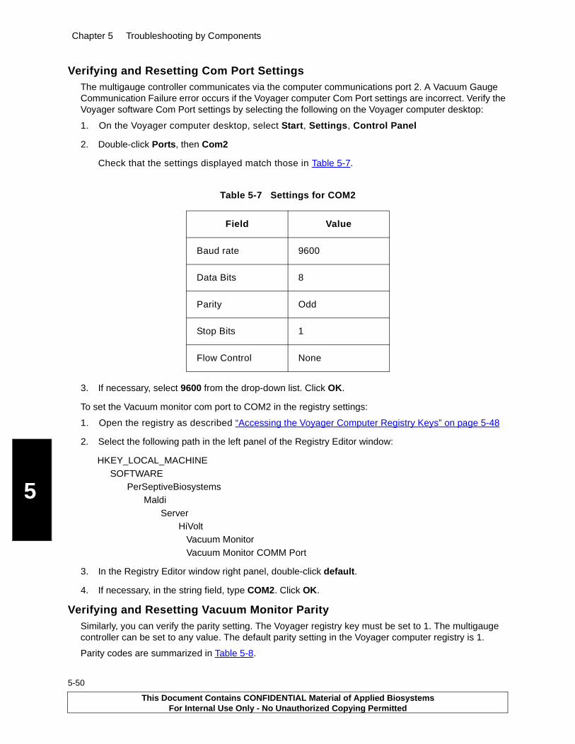
Chapter 5 Troubleshooting by Components
5
5-50
Verifying and Resetting Com Port SettingsThe multigauge controller communicates via the computer communications port 2. A Vacuum Gauge Communication Failure error occurs if the Voyager computer Com Port settings are incorrect. Verify the Voyager software Com Port settings by selecting the following on the Voyager computer desktop:
1. On the Voyager computer desktop, select Start, Settings, Control Panel
2. Double-click Ports, then Com2
Check that the settings displayed match those in Table 5-7.
3. If necessary, select 9600 from the drop-down list. Click OK.
To set the Vacuum monitor com port to COM2 in the registry settings:
1. Open the registry as described “Accessing the Voyager Computer Registry Keys” on page 5-48
2. Select the following path in the left panel of the Registry Editor window:
HKEY_LOCAL_MACHINESOFTWARE
PerSeptiveBiosystemsMaldi
ServerHiVolt
Vacuum MonitorVacuum Monitor COMM Port
3. In the Registry Editor window right panel, double-click default.
4. If necessary, in the string field, type COM2. Click OK.
Verifying and Resetting Vacuum Monitor ParitySimilarly, you can verify the parity setting. The Voyager registry key must be set to 1. The multigauge controller can be set to any value. The default parity setting in the Voyager computer registry is 1.
Parity codes are summarized in Table 5-8.
Table 5-7 Settings for COM2
Field Value
Baud rate 9600
Data Bits 8
Parity Odd
Stop Bits 1
Flow Control None
This Document Contains CONFIDENTIAL Material of Applied BiosystemsFor Internal Use Only - No Unauthorized Copying Permitted
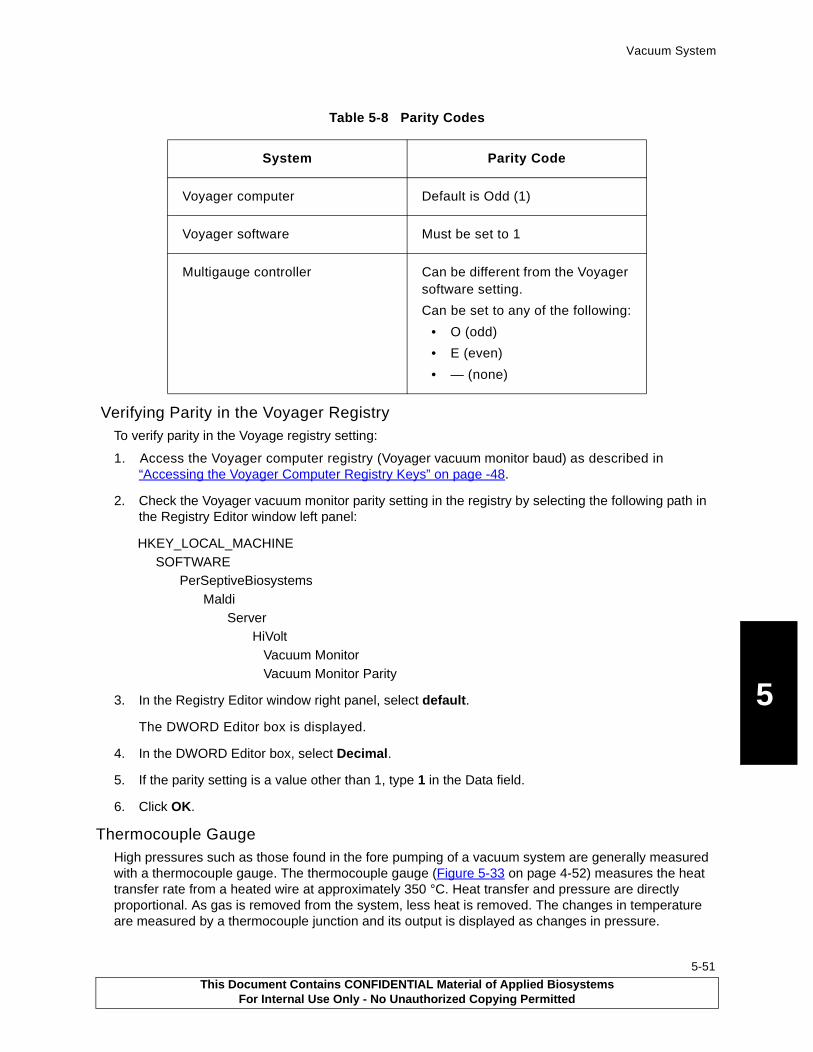
Vacuum System
5
Verifying Parity in the Voyager RegistryTo verify parity in the Voyage registry setting:
1. Access the Voyager computer registry (Voyager vacuum monitor baud) as described in “Accessing the Voyager Computer Registry Keys” on page -48.
2. Check the Voyager vacuum monitor parity setting in the registry by selecting the following path in the Registry Editor window left panel:
HKEY_LOCAL_MACHINESOFTWARE
PerSeptiveBiosystemsMaldi
ServerHiVolt
Vacuum MonitorVacuum Monitor Parity
3. In the Registry Editor window right panel, select default.
The DWORD Editor box is displayed.
4. In the DWORD Editor box, select Decimal.
5. If the parity setting is a value other than 1, type 1 in the Data field.
6. Click OK.
Thermocouple GaugeHigh pressures such as those found in the fore pumping of a vacuum system are generally measured with a thermocouple gauge. The thermocouple gauge (Figure 5-33 on page 4-52) measures the heat transfer rate from a heated wire at approximately 350 °C. Heat transfer and pressure are directly proportional. As gas is removed from the system, less heat is removed. The changes in temperature are measured by a thermocouple junction and its output is displayed as changes in pressure.
Table 5-8 Parity Codes
System Parity Code
Voyager computer Default is Odd (1)
Voyager software Must be set to 1
Multigauge controller Can be different from the Voyager software setting.
Can be set to any of the following:
• O (odd)
• E (even)
• — (none)
This Document Contains CONFIDENTIAL Material of Applied BiosystemsFor Internal Use Only - No Unauthorized Copying Permitted
5-51

Chapter 5 Troubleshooting by Components
5
5-52
Figure 5-33 Thermocouple (TC2) Gauge (Voyager-STR Workstation Rear View)
Because factors other than pressure affect the thermocouple reading, the thermocouple gauge provides an indication of the vacuum pressure rather than an accurate measurement of it. In general, the true pressure is within approximately 30% of the measured value.
Inaccuracies in pressure readings result when the dissipation of heat occurs at a different rate than expected. Factors affecting the thermocouple accuracy are: I
• Presence of a gas other than air—The system is calibrated for air. If the residual gas in the vacuum system is a different gas, the dissipation of heat occurs at a different rate. For example, hydrogen or helium in the system causes the heat to be conducted away from the thermocouple more rapidly than air, resulting in a higher than actual pressure reading.
• Contaminants on the surface of the thermocouple and heater
Calibrating the Thermocouple GaugeBefore using the thermocouple, select TC2 using the CHAN key. Set the atmosphere and vacuum by using the ATM and VAC keys (Table 5-9).
PB100854
TC2
Fore pump
This Document Contains CONFIDENTIAL Material of Applied BiosystemsFor Internal Use Only - No Unauthorized Copying Permitted

Vacuum System
5
Ion GaugeThe ion gauge (Figure 5-34 on page 5-53) consists of a collector, grid, and filament. Figure 5-35 on page 5-54 shows the location of BA1 within the Voyager-DE STR.
Figure 5-34 Bayard-Alpert (BA1, BA2) Ion Gauge
Table 5-9 Setting Atmosphere and Vacuum
To Set Do This
Atmosphere 1. Expose TC2 to atmospheric pressure.
2. Press the ATM key.
The main display reads 760 torr.
Vacuum 1. Expose TC2 to a known vacuum pressure (10–3 torr range).
2. Press the VAC key.
The display shows the most recent vacuum setting with the most significant digit flashing.
3. Set the display to the vacuum level desired.
TC2 is now calibrated.
PB100877
Grid
Grid
FilamentCollectorFilament
This Document Contains CONFIDENTIAL Material of Applied BiosystemsFor Internal Use Only - No Unauthorized Copying Permitted
5-53
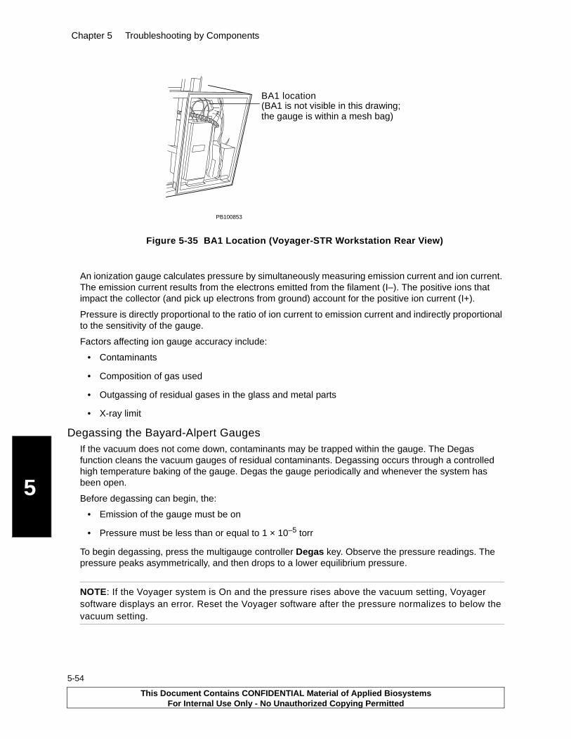
Chapter 5 Troubleshooting by Components
5
5-54
Figure 5-35 BA1 Location (Voyager-STR Workstation Rear View)
An ionization gauge calculates pressure by simultaneously measuring emission current and ion current. The emission current results from the electrons emitted from the filament (I–). The positive ions that impact the collector (and pick up electrons from ground) account for the positive ion current (I+).
Pressure is directly proportional to the ratio of ion current to emission current and indirectly proportional to the sensitivity of the gauge.
Factors affecting ion gauge accuracy include:
• Contaminants
• Composition of gas used
• Outgassing of residual gases in the glass and metal parts
• X-ray limit
Degassing the Bayard-Alpert GaugesIf the vacuum does not come down, contaminants may be trapped within the gauge. The Degas function cleans the vacuum gauges of residual contaminants. Degassing occurs through a controlled high temperature baking of the gauge. Degas the gauge periodically and whenever the system has been open.
Before degassing can begin, the:
• Emission of the gauge must be on
• Pressure must be less than or equal to 1 × 10⁻⁵ torr
To begin degassing, press the multigauge controller Degas key. Observe the pressure readings. The pressure peaks asymmetrically, and then drops to a lower equilibrium pressure.
NOTE: If the Voyager system is On and the pressure rises above the vacuum setting, Voyager software displays an error. Reset the Voyager software after the pressure normalizes to below the vacuum setting.
PB100853
BA1 location(BA1 is not visible in this drawing; the gauge is within a mesh bag)
This Document Contains CONFIDENTIAL Material of Applied BiosystemsFor Internal Use Only - No Unauthorized Copying Permitted
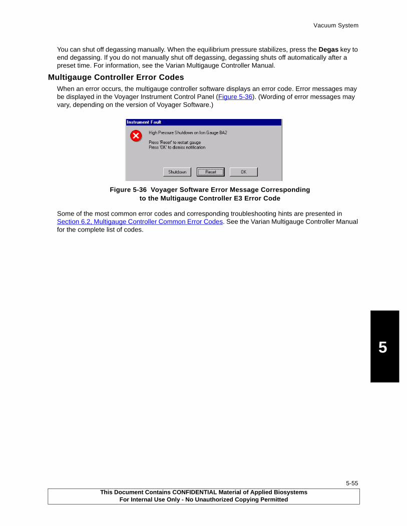
Vacuum System
5
You can shut off degassing manually. When the equilibrium pressure stabilizes, press the Degas key to end degassing. If you do not manually shut off degassing, degassing shuts off automatically after a preset time. For information, see the Varian Multigauge Controller Manual.
Multigauge Controller Error CodesWhen an error occurs, the multigauge controller software displays an error code. Error messages may be displayed in the Voyager Instrument Control Panel (Figure 5-36). (Wording of error messages may vary, depending on the version of Voyager Software.)
Figure 5-36 Voyager Software Error Message Corresponding to the Multigauge Controller E3 Error Code
Some of the most common error codes and corresponding troubleshooting hints are presented in Section 6.2, Multigauge Controller Common Error Codes. See the Varian Multigauge Controller Manual for the complete list of codes.
This Document Contains CONFIDENTIAL Material of Applied BiosystemsFor Internal Use Only - No Unauthorized Copying Permitted
5-55

Chapter 5 Troubleshooting by Components
5
5-56
This Document Contains CONFIDENTIAL Material of Applied BiosystemsFor Internal Use Only - No Unauthorized Copying Permitted
6 Troubleshooting by Symptoms
6-1
This chapter contains the following sections:6.1 Troubleshooting Tables......................................... 6-2
6.1.1 Spectral Problems ......................................6-2
6.1.2 Sample Loading and Main Source Chamber .................................................... 6-4
6.1.3 Computer System and Software ................. 6-9
6.1.4 Power Supplies and Circuit Boards .......... 6-10
6.1.5 Vacuum System ....................................... 6-11
6.2 Multigauge Controller Common Error Codes ...... 6-16
6.3 LED Indicators.................................................... 6-18
This Document Contains CONFIDENTIAL Material of Applied BiosystemsFor Internal Use Only - No Unauthorized Copying Permitted

Chapter 6 Troubleshooting by Symptoms
6
6-2
6.1 Troubleshooting TablesThis section includes symptoms, possible causes, and actions to troubleshoot the:
• Spectral problems
• Sample Loading and Main Source Chamber
• Computer and software
• Power supply
• Vacuum system
For additional information, see the Voyager User Guide.
6.1.1 Spectral Problems
Table 6-1 Spectral Troubleshooting
Item Symptom Possible Cause Action
Continuous Mode
1 In linear mode, flat signal on oscilloscope or Monitor window for matrix and sample region when in positive ion mode. Same result when switched to reflector mode.
A Defective fuse or DAC board.
Check fuse. Replace if defective.
Check that source and grid DAC output is correct. Replace if defective.
B Einzel lens is wrong polarity or is shorted to ground.
Check einzel lens polarity. Check for shorts.
C High-voltage connection to the sample plate is broken or disconnected.
Adjust or replace connection.
D High-voltage power supply is defective.
Replace high-voltage power supply.
E Laser beam is not striking the sample with adequate intensity.
Check the attenuator functioning. See “Adjusting the Attenuator Position” on page 5-41.
For the Nitrogen laser, verify laser output is >200 µJ.
F Linear detector is defective.
Troubleshoot the linear detector.
This Document Contains CONFIDENTIAL Material of Applied BiosystemsFor Internal Use Only - No Unauthorized Copying Permitted

Troubleshooting Tables
6
1 In linear mode, flat signal onoscilloscope or Monitor window for matrix and sample region when in positive ion mode. Same result when switched to reflector mode. (continued)
G Reflector detector is defective.
Troubleshoot the reflector detector.
H Digitizer or one of its channels is deflective.
Troubleshoot the digitizer.
Delayed-Extraction Mode
2 Flat signal on oscilloscope or monitor window for matrix and sample region when in linear or reflective mode. Peaks display when switched to continuous mode.
A Delayed-extraction switch box is defective.
Verify source voltage output is rising when the laser is firing.
Verify all DE switch box LEDs are unlit.
Check the +5 at connector on DE switch box. Adjust.
Check control wiring.
Replace DE switch box.
Warning: Before servicing the DE switch box, disable high-voltages.
B Delayed-extraction timer pulse generator board is defective.
Check for –5.2 V. Replace DE timer pulse generator board.
Note: In one version of the Quad power supply, the –5.2 V is not present on the pulse generator board.
Table 6-1 Spectral Troubleshooting (Continued)
Item Symptom Possible Cause Action
This Document Contains CONFIDENTIAL Material of Applied BiosystemsFor Internal Use Only - No Unauthorized Copying Permitted
6-3

Chapter 6 Troubleshooting by Symptoms
6
6-4
6.1.2 Sample Loading and Main Source Chamber
Table 6-2 includes troubleshooting symptoms related to the sample load and eject mechanisms such as the following components:
• Flap doors• Linear actuators• Magnetic grabber• Sample plate• Source pedestal and clips• XY feedthroughs• XY microswitches
Error and warning messages displayed when using the Diagnostics Mechanical control page are explained in Section 5.2.7. Also, because the linear and flap door actuators are pneumatically controlled, the performance of the sample loading chamber may be affected by problems in the vacuum system.
Table 6-2 Source and Sample Loading Chamber Troubleshooting
Item Symptom Possible Cause Action
1 When the system covers are removed and the source is in motion, a loud grinding or squeaking noise can be heard in the source area; or the source sticks when trying to achieve desired location.
A X and/or Y feedthoughs need lubrication.
Lubricate feedthroughs. (See “Lubricating the X and Y Feedthroughs” on page 5-28.)
2 Sample plate either occasionally or consistently falls off the grabber during sample plate loading
A The magnetic grabber failed.
With the grabber attached to circuit, check that voltage to the grabber switches properly:
From a low +5 V logic state when the grabber is off to a high +5 V logic state when energized.
If the voltage is not switching properly, check for continuity through grabber coils.
B The Y-load coordinate is misaligned.
With the source open, adjust the alignment of the Y-coordinate by varying the Y-load coordinate value in the diagnostics software. Use a mirror and a small light to verify distance from edge of sample plate to inside edges of source, not to source clips.
This Document Contains CONFIDENTIAL Material of Applied BiosystemsFor Internal Use Only - No Unauthorized Copying Permitted
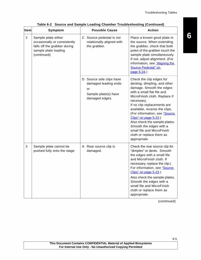
Troubleshooting Tables
6
2 Sample plate either occasionally or consistently falls off the grabber during sample plate loading(continued)C Source pedestal is not rotationally aligned with the grabber.
Place a known good plate in the source. When extending the grabber, check that both poles of the grabber touch the sample plate simultaneously. If not, adjust alignment. (For information, see “Aligning the Source Pedestal” on page 5-24.)
D Source side clips have damaged leading ends.
or
Sample plate(s) have damaged edges.
Check the clip edges for denting, dimpling, and other damage. Smooth the edges with a small flat file and MicroFinish cloth. Replace if necessary. If no clip replacements are available, reverse the clips. (For information, see “Source Clips” on page 5-23.)Also check the sample plates. Smooth the edges with a small file and MicroFinish cloth or replace them as appropriate.
3 Sample plate cannot be pushed fully onto the stage
A Rear source clip is damaged.
Check the rear source clip for "dimples" or dents. Smooth the edges with a small file and MicroFinish cloth. If necessary, replace the clip.( For information, see “Source Clips” on page 5-23.)
Also check the sample plates. Smooth the edges with a small file and MicroFinish cloth or replace them as appropriate.
(continued)
Table 6-2 Source and Sample Loading Chamber Troubleshooting (Continued)
Item Symptom Possible Cause Action
This Document Contains CONFIDENTIAL Material of Applied BiosystemsFor Internal Use Only - No Unauthorized Copying Permitted
6-5
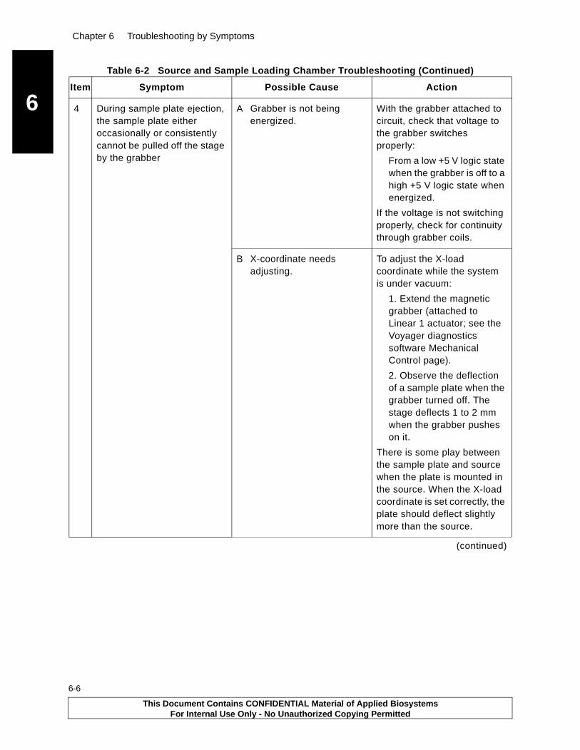
Chapter 6 Troubleshooting by Symptoms
6
6-6
4 During sample plate ejection, the sample plate either occasionally or consistently cannot be pulled off the stage by the grabber
A Grabber is not being energized.
With the grabber attached to circuit, check that voltage to the grabber switches properly:
From a low +5 V logic state when the grabber is off to a high +5 V logic state when energized.
If the voltage is not switching properly, check for continuity through grabber coils.
B X-coordinate needs adjusting.
To adjust the X-load coordinate while the system is under vacuum:
1. Extend the magnetic grabber (attached to Linear 1 actuator; see the Voyager diagnostics software Mechanical Control page).
2. Observe the deflection of a sample plate when the grabber turned off. The stage deflects 1 to 2 mm when the grabber pushes on it.
There is some play between the sample plate and source when the plate is mounted in the source. When the X-load coordinate is set correctly, the plate should deflect slightly more than the source.
(continued)
Table 6-2 Source and Sample Loading Chamber Troubleshooting (Continued)
Item Symptom Possible Cause Action
This Document Contains CONFIDENTIAL Material of Applied BiosystemsFor Internal Use Only - No Unauthorized Copying Permitted

Troubleshooting Tables
6
4 During sample plate ejection, the sample plate either occasionally or consistently cannot be pulled off the stage by the grabber. (continued)C Source pedestal is not rotationally aligned with the grabber.
Place a known good plate in the source. Verify the grabber poles are of equal length. If necessary, replace the grabber poles.
When extending the grabber, check that both poles of the grabber touch the sample plate simultaneously. If not, adjust alignment. (For information, see “Aligning the Source Pedestal” on page 5-24.)
D Linear 1 retract speed is too fast.The retract speed control valve (bleed screw) on the end of Linear actuator 1 (farthest away from the source housing) may be set improperly. The actuator may retract too quickly, breaking the magnetic connection between the sample plate and grabber.
Adjust the retraction rate to a slower speed by turning the retract speed control valve clockwise. (See Figure 5-12 on page 5-25.)
E Detent balls on source are binding because sample contamination is getting into the holes where the balls are mounted.
If the detent balls provide too much resistance to compression, the grabber may have insufficient force to pull the plate from the source. To break the resistance, press down on the balls with an Allen wrench or similar tool. If necessary, disassemble and clean or replace the source.
F Springs are too stiff. Press down on the balls with an Allen wrench or similar tool.
(continued)
Table 6-2 Source and Sample Loading Chamber Troubleshooting (Continued)
Item Symptom Possible Cause Action
This Document Contains CONFIDENTIAL Material of Applied BiosystemsFor Internal Use Only - No Unauthorized Copying Permitted
6-7

Chapter 6 Troubleshooting by Symptoms
6
6-8
4 During sample plate ejection, the sample plate either occasionally or consistently cannot be pulled off the stage by the grabber
(continued)
G Defects on plate edges not allowing plate to release from detent balls or source edge clips.
Check the edges of all sample plates in use for damage. Smooth the edges with a small flat file and MicroFinish cloth. If necessary, replace the sample plate.
H Contamination on sample plate.
Check the bottoms and edges of all sample plates in use for contamination. Clean. If necessary, replace the sample plate.
5 Grabber not contacting plate during loading or ejection
Insufficient X-load adjustment available to enable plate to be adequately contacted by the grabber during plate loading or ejection.Linear 1 actuator shaft is too short for system tolerances. (More often seen with older Bimba style actuators.)
Unscrew the grabber approximately 3/32" (roughly two turns) back on actuator shaft. Leave enough threads available on actuator shaft to securely attach the jam nut (cap) back onto shaft. To prevent the grabber and cap from loosening, place a small amount of thread sealant (such as LockTite) on the actuator shaft threads.
6 X or Y load coordinates require continual adjustment
Or
The X or Y home switches are moving
The X and Y home switch brackets are loose.
Tighten such that when the linear feedthroughs are fully extended to the home position, you see no movement of the home switches.
Table 6-2 Source and Sample Loading Chamber Troubleshooting (Continued)
Item Symptom Possible Cause Action
This Document Contains CONFIDENTIAL Material of Applied BiosystemsFor Internal Use Only - No Unauthorized Copying Permitted
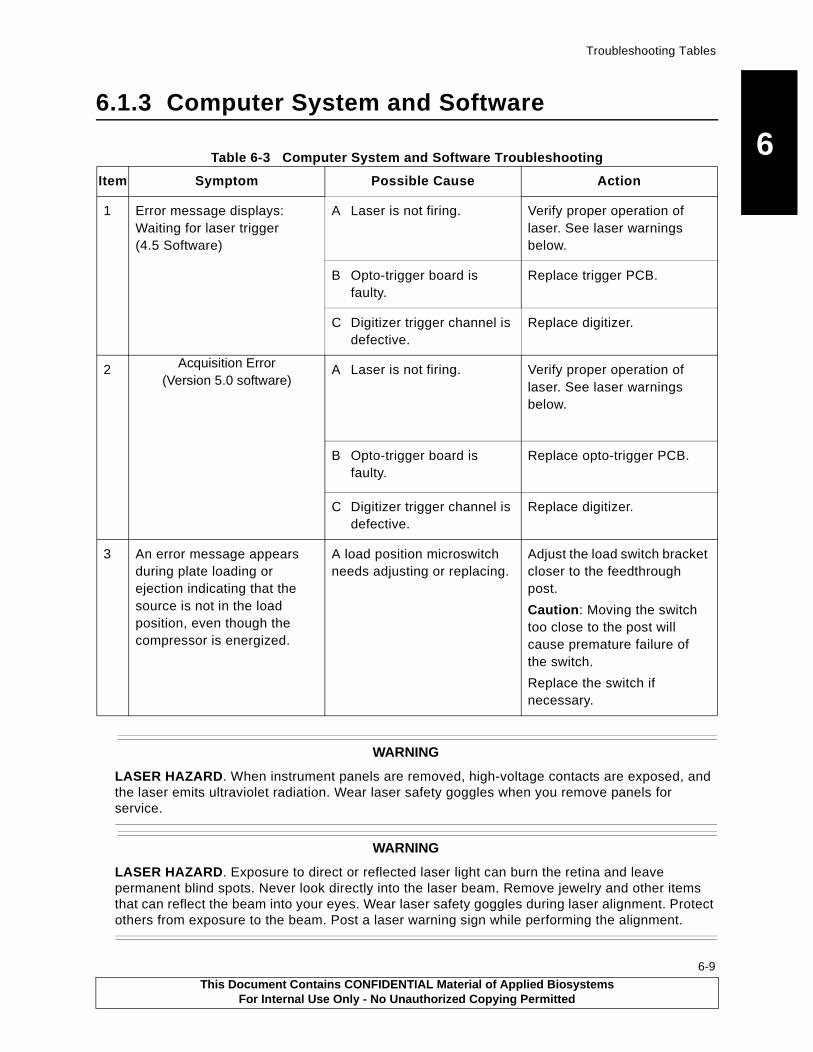
Troubleshooting Tables
6
6.1.3 Computer System and SoftwareTable 6-3 Computer System and Software Troubleshooting
Item Symptom Possible Cause Action
1 Error message displays: Waiting for laser trigger (4.5 Software)
A Laser is not firing. Verify proper operation of laser. See laser warnings below.
B Opto-trigger board is faulty.
Replace trigger PCB.
C Digitizer trigger channel is defective.
Replace digitizer.
2 Acquisition Error (Version 5.0 software)
A Laser is not firing. Verify proper operation of laser. See laser warnings below.
B Opto-trigger board is faulty.
Replace opto-trigger PCB.
C Digitizer trigger channel is defective.
Replace digitizer.
3 An error message appears during plate loading or ejection indicating that the source is not in the load position, even though the compressor is energized.
A load position microswitch needs adjusting or replacing.
Adjust the load switch bracket closer to the feedthrough post.
Caution: Moving the switch too close to the post will cause premature failure of the switch.
Replace the switch if necessary.
WARNING
LASER HAZARD. When instrument panels are removed, high-voltage contacts are exposed, and the laser emits ultraviolet radiation. Wear laser safety goggles when you remove panels for service.
WARNING
LASER HAZARD. Exposure to direct or reflected laser light can burn the retina and leave permanent blind spots. Never look directly into the laser beam. Remove jewelry and other items that can reflect the beam into your eyes. Wear laser safety goggles during laser alignment. Protect others from exposure to the beam. Post a laser warning sign while performing the alignment.
This Document Contains CONFIDENTIAL Material of Applied BiosystemsFor Internal Use Only - No Unauthorized Copying Permitted
6-9
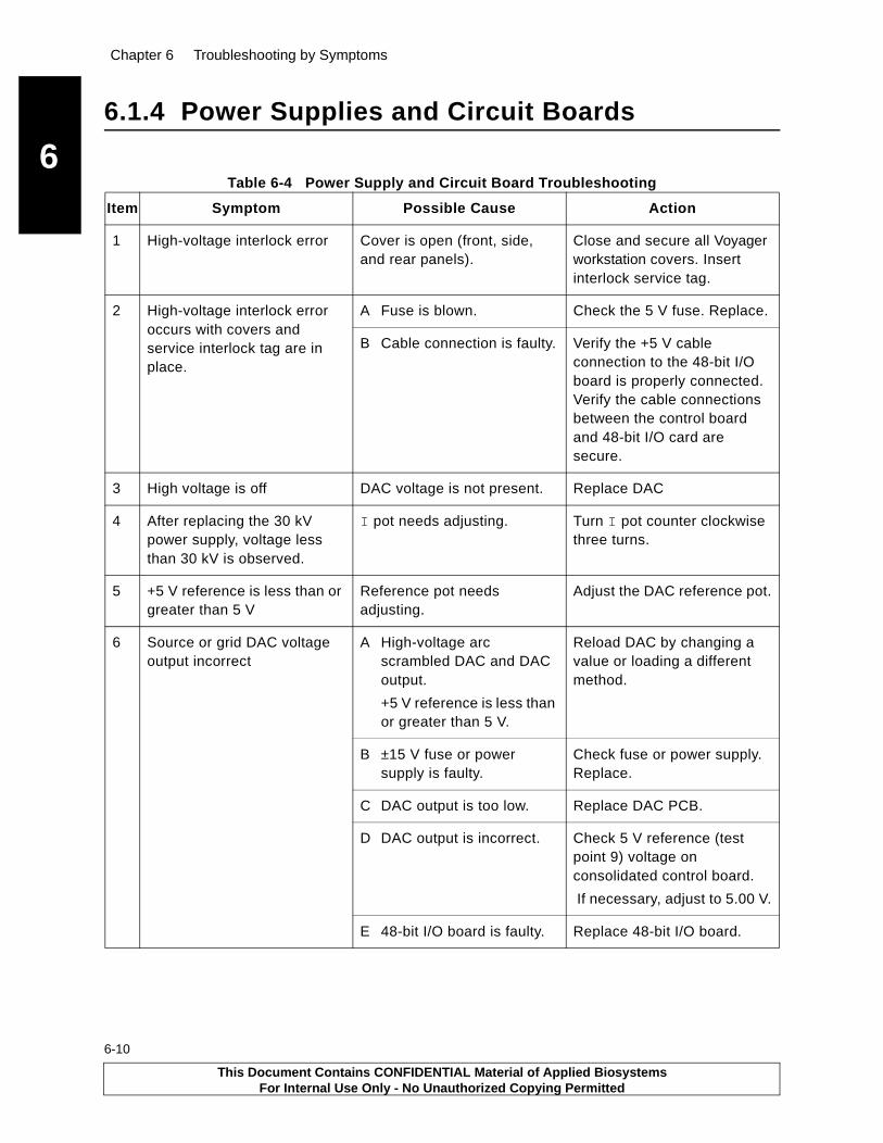
Chapter 6 Troubleshooting by Symptoms
6
6-10
6.1.4 Power Supplies and Circuit Boards
Table 6-4 Power Supply and Circuit Board Troubleshooting
Item Symptom Possible Cause Action
1 High-voltage interlock error Cover is open (front, side, and rear panels).
Close and secure all Voyager workstation covers. Insert interlock service tag.
2 High-voltage interlock error occurs with covers and service interlock tag are in place.
A Fuse is blown. Check the 5 V fuse. Replace.
B Cable connection is faulty. Verify the +5 V cable connection to the 48-bit I/O board is properly connected. Verify the cable connections between the control board and 48-bit I/O card are secure.
3 High voltage is off DAC voltage is not present. Replace DAC
4 After replacing the 30 kV power supply, voltage less than 30 kV is observed.
I pot needs adjusting. Turn I pot counter clockwise three turns.
5 +5 V reference is less than or greater than 5 V
Reference pot needs adjusting.
Adjust the DAC reference pot.
6 Source or grid DAC voltage output incorrect
A High-voltage arc scrambled DAC and DAC output.
+5 V reference is less than or greater than 5 V.
Reload DAC by changing a value or loading a different method.
B ±15 V fuse or power supply is faulty.
Check fuse or power supply. Replace.
C DAC output is too low. Replace DAC PCB.
D DAC output is incorrect. Check 5 V reference (test point 9) voltage on consolidated control board.
If necessary, adjust to 5.00 V.
E 48-bit I/O board is faulty. Replace 48-bit I/O board.
This Document Contains CONFIDENTIAL Material of Applied BiosystemsFor Internal Use Only - No Unauthorized Copying Permitted

Troubleshooting Tables
6
6.1.5 Vacuum System“Multigauge Controller Common Error Codes” on page -16 lists the error codes displayed by the Multigauge controller, possible causes, and actions.
Table 6-5 Vacuum System Troubleshooting
Item Symptom Possible Cause Action
1 TC2 reading shows higher than normal pressure (i.e. TC2 reading shows atmospheric pressure); It takes a long time to pump down after plate loading.
A Vent valve is stuck open after loading or ejecting the sample plate.
Close the vent valve.
Check that 24 V is present to operate the vent valve.
Clean or replace the vent valve if it is malfunctioning.
B Flap Door 2 is not closing properly.
Check that Flap Door 2 actuator is operating properly. Close Flap Door 2.
Check Flap Door 2 O-ring for any cracks or damages. If it is damaged, replace the O-ring.
C A sample plate that was improperly loaded in the transporter and has jammed is interfering with Flap Door 2 closure.
If possible, eject the transporter out. Reseat the plate properly.
D The fore pump is not pumping efficiently.
Check the pump oil level and color. Refill oil or replace the oil if the oil color is dark (ice tea color).
Replace pump if it is malfunctioning.
E Gas flows at vacuum hose connections.
Check the gasket on the clamps. Replace the gasket if it is damaged.
Tighten the clamps.
(continued)
This Document Contains CONFIDENTIAL Material of Applied BiosystemsFor Internal Use Only - No Unauthorized Copying Permitted
6-11

Chapter 6 Troubleshooting by Symptoms
6
6-12
1 TC2 reading shows higher than normal pressure (i.e. TC2 reading shows atmospheric pressure);It takes a long time to pump down after plate loading. (continued).
F Flap Door 2 is not sealed properly.
Check that the Flap Door and the O-ring are free of dust and fibers. If necessary, clean up any dust or fibers using a laboratory wipe moistened with ethanol (100%). Replace the O-ring if it is damaged.
Check that the Flap Valve presses evenly on the O-ring, with the face of the valve being parallel to the face of the Sample Loading Chamber when closed. If it is not parallel, adjust the Flap Valve hinge bar.
G Leaking from the knurled nut on Linear 1 actuator.
Finger-tighten the nut. Do not over-tighten it.
H Leaking from the knurled nut on Linear 2 actuator.
Finger-tighten the nut. Do not over-tighten it.
I Leaking from the knurled nut on Flap Door 1.
Finger-tighten the nut. Do not over-tighten it.
J Samples on the plate are not completely dry.
Dry the samples completely before loading sample plate.
! WARNING! CHEMICAL HAZARD. Ethanol is a flammable liquid and vapor. It may
cause eye, skin, and upper respiratory tract irritation. Prolonged or repeated contact may
dry skin. Exposure may cause central nervous system depression and liver damage.
Please read the MSDS and follow the handling instructions. Wear appropriate protective
eyewear, clothing, and gloves.
(continued)
Table 6-5 Vacuum System Troubleshooting (Continued)
Item Symptom Possible Cause Action
This Document Contains CONFIDENTIAL Material of Applied BiosystemsFor Internal Use Only - No Unauthorized Copying Permitted

Troubleshooting Tables
6
2 BA1 ion gauge shut downwith E09 displayed on Multigauge controller display after plate loading/ejecting
A Flap Door 1 is improperly closing.
Check that the sample plate is not stuck at Flap Door 1.
Make sure the Flap Door 1 actuator works properly.
B Flap Door 1 is improperly sealing.
Align Flap Door 1
Replace damaged O-ring.
C Samples on the plate are not completely dry.
Dry the samples completely before loading sample plate.
D Foreline Valve 2 is improperly sealing.
Replace Foreline Valve 2 assembly.
E Linear 1 actuator is leaking at its O-ring seal.
—The knurled nut may be slightly loose; try tightening. —The O-ring seal under the knurled nut may be binding and in need of lubrication.—The Linear actuator shaft may be scratched or nicked, allowing an air burst to enter the Sample Loading Chamber when the actuator is being extended during the plate loading/ejection process.
(continued)
Table 6-5 Vacuum System Troubleshooting (Continued)
Item Symptom Possible Cause Action
This Document Contains CONFIDENTIAL Material of Applied BiosystemsFor Internal Use Only - No Unauthorized Copying Permitted
6-13
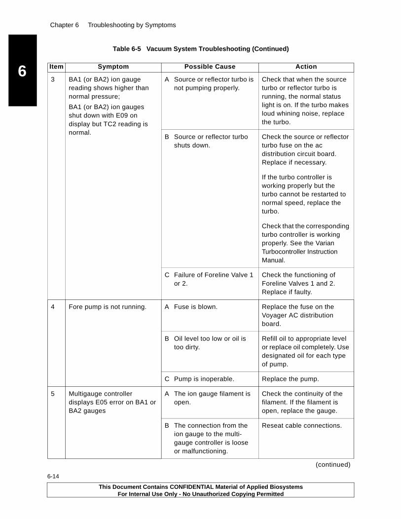
Chapter 6 Troubleshooting by Symptoms
6
6-14
3 BA1 (or BA2) ion gauge reading shows higher than normal pressure;
BA1 (or BA2) ion gauges shut down with E09 on display but TC2 reading is normal.
A Source or reflector turbo is not pumping properly.
Check that when the source turbo or reflector turbo is running, the normal status light is on. If the turbo makes loud whining noise, replace the turbo.
B Source or reflector turbo shuts down.
Check the source or reflector turbo fuse on the ac distribution circuit board. Replace if necessary.
If the turbo controller is working properly but the turbo cannot be restarted to normal speed, replace the turbo.
Check that the corresponding turbo controller is working properly. See the Varian Turbocontroller Instruction Manual.
C Failure of Foreline Valve 1 or 2.
Check the functioning of Foreline Valves 1 and 2. Replace if faulty.
4 Fore pump is not running. A Fuse is blown. Replace the fuse on the Voyager AC distribution board.
B Oil level too low or oil is too dirty.
Refill oil to appropriate level or replace oil completely. Use designated oil for each type of pump.
C Pump is inoperable. Replace the pump.
5 Multigauge controller displays E05 error on BA1 or BA2 gauges
A The ion gauge filament is open.
Check the continuity of the filament. If the filament is open, replace the gauge.
B The connection from the ion gauge to the multi-gauge controller is loose or malfunctioning.
Reseat cable connections.
(continued)
Table 6-5 Vacuum System Troubleshooting (Continued)
Item Symptom Possible Cause Action
This Document Contains CONFIDENTIAL Material of Applied BiosystemsFor Internal Use Only - No Unauthorized Copying Permitted
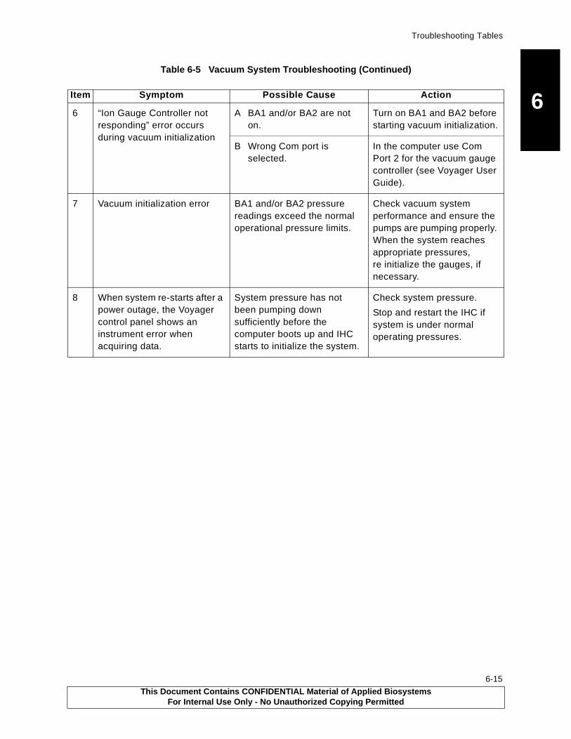
Troubleshooting Tables
6
6 “Ion Gauge Controller notresponding” error occurs during vacuum initialization
A BA1 and/or BA2 are not on.
Turn on BA1 and BA2 before starting vacuum initialization.
B Wrong Com port is selected.
In the computer use Com Port 2 for the vacuum gauge controller (see Voyager User Guide).
7 Vacuum initialization error BA1 and/or BA2 pressure readings exceed the normal operational pressure limits.
Check vacuum system performance and ensure the pumps are pumping properly. When the system reaches appropriate pressures, re initialize the gauges, if necessary.
8 When system re-starts after a power outage, the Voyager control panel shows an instrument error when acquiring data.
System pressure has not been pumping down sufficiently before the computer boots up and IHC starts to initialize the system.
Check system pressure.
Stop and restart the IHC if system is under normal operating pressures.
Table 6-5 Vacuum System Troubleshooting (Continued)
Item Symptom Possible Cause Action
This Document Contains CONFIDENTIAL Material of Applied BiosystemsFor Internal Use Only - No Unauthorized Copying Permitted
6-15

Chapter 6 Troubleshooting by Symptoms
6
6-16
6.2 Multigauge Controller Common Error Codes
Table 6-6 Multigauge Controller Common Error Codes
Error Code
Possible Error Source
Possible Cause Action
E02 Microburst Wet sample plate. Recalibrate microburst tolerance setting to the default by pressing:
F, Vac, then A52.
E03 Ion gauge connection broken or disconnected.
The Voyager Control panel displays an error message indicating a high pressure shut down on the ion gauge.
No current. If resetting the Voyager software clears the error, the problem was between the software and the multigauge controller.If the error persists, the problem is between the Voyager hardware and multigauge controller.
Collector cable connection is bad or dislodged.
Replace or reconnect the cable.
E04 Filament BA gauge filament is over current or shorted. Commonly, filament is shorted to the grid.
Measure filament-to-grid with an ohm meter. If the reading is not open, replace the BA gauge.
If reading is open, move the BA board to an open slot on the multigauge controller mother board.
If the board fails in the new slot, replace the BA board.
(continued)
This Document Contains CONFIDENTIAL Material of Applied BiosystemsFor Internal Use Only - No Unauthorized Copying Permitted
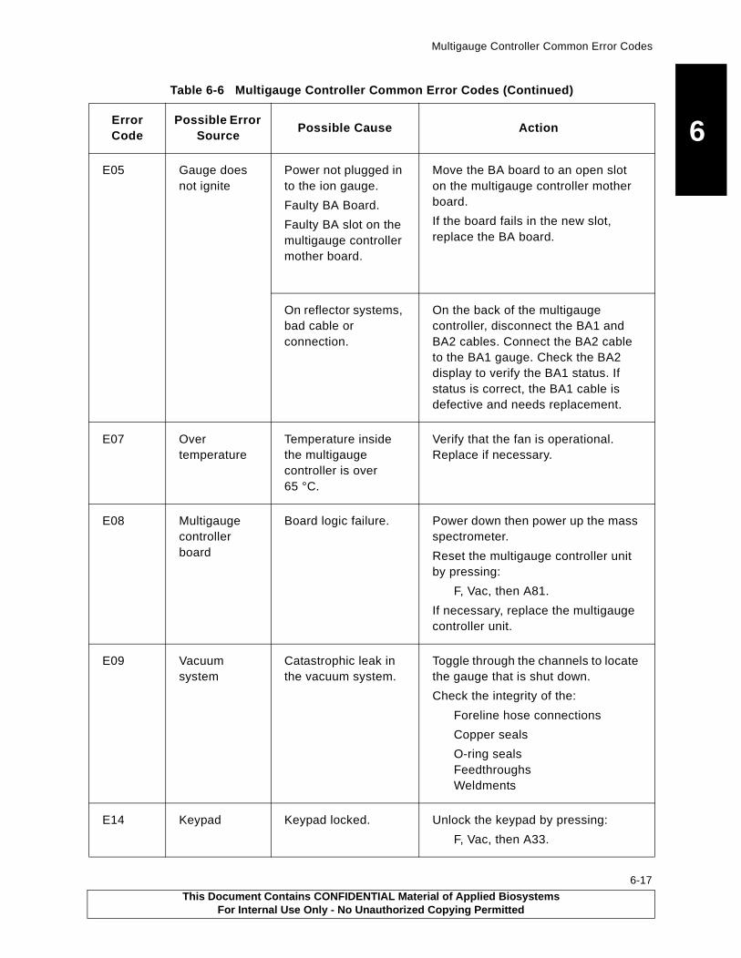
Multigauge Controller Common Error Codes
6
E05 Gauge doesnot ignitePower not plugged in to the ion gauge.
Faulty BA Board.
Faulty BA slot on the multigauge controller mother board.
Move the BA board to an open slot on the multigauge controller mother board.
If the board fails in the new slot, replace the BA board.
On reflector systems, bad cable or connection.
On the back of the multigauge controller, disconnect the BA1 and BA2 cables. Connect the BA2 cable to the BA1 gauge. Check the BA2 display to verify the BA1 status. If status is correct, the BA1 cable is defective and needs replacement.
E07 Over temperature
Temperature inside the multigauge controller is over 65 °C.
Verify that the fan is operational. Replace if necessary.
E08 Multigauge controller board
Board logic failure. Power down then power up the mass spectrometer.
Reset the multigauge controller unit by pressing:
F, Vac, then A81.
If necessary, replace the multigauge controller unit.
E09 Vacuum system
Catastrophic leak in the vacuum system.
Toggle through the channels to locate the gauge that is shut down.
Check the integrity of the:
Foreline hose connections
Copper seals
O-ring sealsFeedthroughsWeldments
E14 Keypad Keypad locked. Unlock the keypad by pressing:
F, Vac, then A33.
Table 6-6 Multigauge Controller Common Error Codes (Continued)
Error Code
Possible Error Source
Possible Cause Action
This Document Contains CONFIDENTIAL Material of Applied BiosystemsFor Internal Use Only - No Unauthorized Copying Permitted
6-17

Chapter 6 Troubleshooting by Symptoms
6
6-18
6.3 LED Indicators
LED indicators reflect the status of the system. Table 6-7 describes LED states and any actions needed to correct the fault.
Table 6-7 LED Indicators
LED LocationLED State
System Status Comment
Voyager workstation top panelor
D12 on MALDI Consolidated Control Board
Yellow Turbo initial start-up
Turbos initiated.
Yellow and green
Turbo building up speed
Turbo is at 80% of full speed.
Green Turbo at full speed
Turbo is at normal operating conditions (56 krpm).
Red Turbo fault Unplug the turbo pump and plug it in again.
If the fault persists, check the:
• Turbo pump for turbo failure
• Turbo pump for turbo controller failure
• Vacuum system for a severe vacuum leak
This Document Contains CONFIDENTIAL Material of Applied BiosystemsFor Internal Use Only - No Unauthorized Copying Permitted

This Document Contains CONFIDENTIAL Material of Applied BiosystemsFor Internal Use Only - No Unauthorized Copying Permitted
A
Technical Support and Training AThis appendix contains the following:
Technical Service Resources . . . . . . . . . . . . . . . . . . . . . . . . . . A-2
Contacting Technical Support . . . . . . . . . . . . . . . . . . . . . . . . . . A-5
Obtaining Technical Documents . . . . . . . . . . . . . . . . . . . . . . . A-10
Obtaining Customer Training Information . . . . . . . . . . . . . . . . A-11
A-1
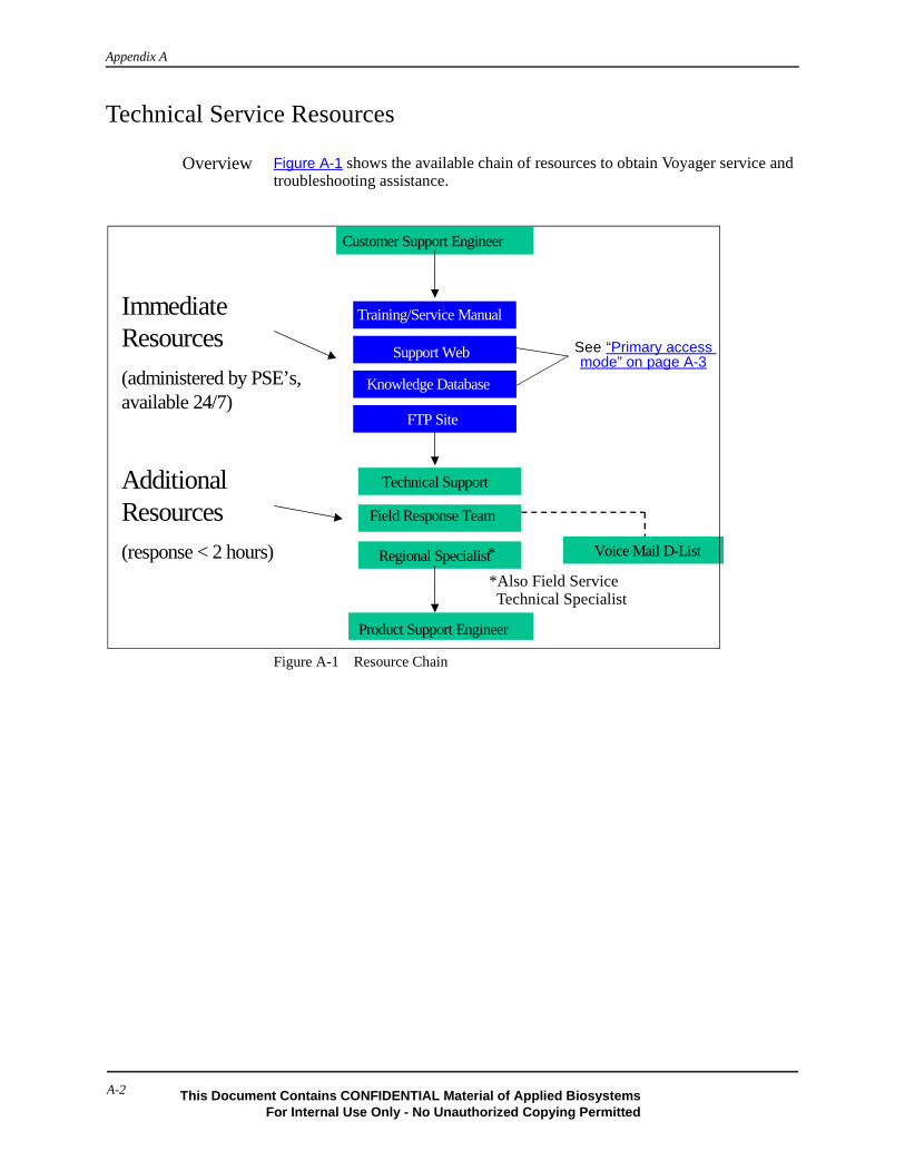
Appendix A
Technical Service Resources
Overview Figure A-1 shows the available chain of resources to obtain Voyager service and troubleshooting assistance.
Figure A-1 Resource Chain
Support Web
Knowledge Database
Training/Service Manual
FTP Site
Technical Support
Regional Specialist
Field Response Team
Product Support Engineer
Voice Mail D-List
Customer Support Engineer
ImmediateResources
(administered by PSE’s,available 24/7)
AdditionalResources
(response < 2 hours) *
*Also Field ServiceTechnical Specialist
See “Primary access mode” on page A-3
A-2 This Document Contains CONFIDENTIAL Material of Applied BiosystemsFor Internal Use Only - No Unauthorized Copying Permitted

Voyager SupportDatabase
Field service engineers can review the Voyager (MALDI) Product Support web site and the Voyager (MALDI) Knowledge Database 24 hours/day, 7 days a week. Each database is a repository of information that is fully text searchable and is individually replicated on Notes.
The following table describes the information available and how to access each database.
Applied Biosystems Voyager (MALDI) Support Web Site
Voyager (MALDI) Knowledge Database
Purpose To provide released documents from Houston
To provide communication tool for FSE to share facts, questions, and new technical information
Categories Installation documentsParts listService bulletins, service manual, service notesShareware, software and soft-ware installation documentsSupport contact informationGuides and related manualsUtility programs
ElectronicsGeneralInstallation and operationMechanicalService bulletins and notesSoftwareSpare parts
Primary access mode
Through the internet, go to:
http://usfosdws03/intranet/pbiosupportweb.nsf/docs/4LFFAJRMIR?opendocument
Through Lotus Notes desktop, go to:
File-Database-OpenServer: USFOSDWS03/FOS/PECDatabase: MSGBOARDSFolder:VOYAGER
Additional access modes
• Through the Applied Biosystems intranet, go to:
https://gene.peintranet.net/ (login to the intranet is needed)Select: Departments, Product Sup-port, Voyager Support
• Through Lotus Notes desktop, go to:
File-Database-OpenServer: USFOSDWS03/FOS/PECDatabase: INTRANETFolder: PBIOSUPPORT.NSF
• Through the internet, go to:
http://167.116.75.148/msgboards/Voyager.nsf/all?OpenView
• Through the Applied Biosystems intranet, go to:
https://gene.peintranet.net/ (login to the intranet is needed)Select: Departments, Product Support, Link to the MALDI ******Knowledge Database******
A-3
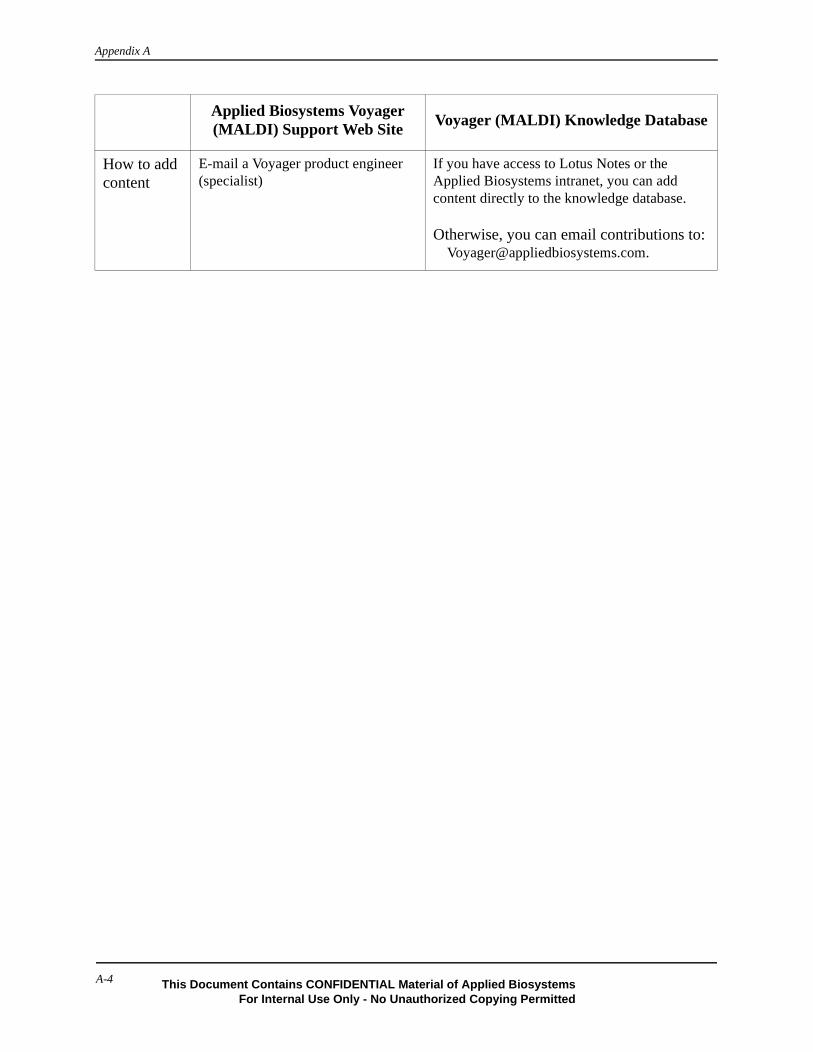
Appendix A
How to add content
E-mail a Voyager product engineer (specialist)
If you have access to Lotus Notes or the Applied Biosystems intranet, you can add content directly to the knowledge database. Otherwise, you can email contributions to:
Applied Biosystems Voyager (MALDI) Support Web Site
Voyager (MALDI) Knowledge Database
A-4 This Document Contains CONFIDENTIAL Material of Applied BiosystemsFor Internal Use Only - No Unauthorized Copying Permitted

Contacting Technical Support
Overview You can contact Applied Biosystems for technical support:
• By e-mail• By telephone or fax• Through the Applied Biosystems Technical Support web site
Note: For information on obtaining technical documents such as Applied Biosystems user documents, MSDSs, and certificates of analysis, see “Obtaining Technical Documents” on page A-10.
By E-Mail You can contact technical support by e-mail for help in the product areas listed below.
By Telephone orFax
In North America
To contact Applied Biosystems Technical Support in North America, use the telephone or fax numbers in the table below.
Note: To schedule a service call for other support needs, or in case of an emergency, dial 1.800.831.6844, then press 1.
Product/Product Area E-Mail Address
Genetic Analysis (DNA Sequencing) [email protected]
Sequence Detection Systems and PCR [email protected]
Protein Sequencing, Peptide, and DNA Synthesis
• Biochromatography• PerSeptive DNA, PNA and Peptide
Synthesis systems• FMAT 8100 HTS System• CytoFluor® 4000 Fluorescence Plate
Reader• Mariner Mass Spectrometers• MassGenotyping Solution 1™
(MGS1) System• Voyager Mass Spectrometers
LC/MS (Applied Biosystems/MDS Sciex)
Chemiluminescence (Tropix) [email protected]
Product/Product Area Telephone Fax
ABI PRISM® 3700 DNA Analyzer 1.800.831.6844, then press 8a 1.650.638.5981
DNA Synthesis 1.800.831.6844, press 2, then
press 1a1.650.638.5981
A-5
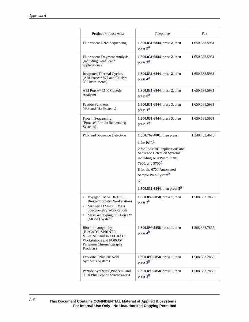
Appendix A
Fluorescent DNA Sequencing 1.800.831.6844, press 2, then
press 2a1.650.638.5981
Fluorescent Fragment Analysis (including GeneScan® applications)
1.800.831.6844, press 2, then
press 3a1.650.638.5981
Integrated Thermal Cyclers (ABI PRISM® 877 and Catalyst 800 instruments)
1.800.831.6844, press 2, then
press 4a1.650.638.5981
ABI PRISM® 3100 Genetic Analyzer
1.800.831.6844, press 2, then
press 6a1.650.638.5981
Peptide Synthesis (433 and 43x Systems)
1.800.831.6844, press 3, then
press 1a1.650.638.5981
Protein Sequencing (Procise® Protein Sequencing Systems)
1.800.831.6844, press 3, then
press 2a1.650.638.5981
PCR and Sequence Detection 1.800.762.4001, then press:
1 for PCRa
2 for TaqMan® applications and Sequence Detection Systems including ABI Prism‚ 7700,
7900, and 5700a
6 for the 6700 Automated
Sample Prep Systema
or
1.800.831.6844, then press 5a
1.240.453.4613
• Voyager MALDI-TOF Biospectrometry Workstations
• Mariner ESI-TOF Mass Spectrometry Workstations
• MassGenotyping Solution 1™ (MGS1) System
1.800.899.5858, press 1, then press 3b
1.508.383.7855
Biochromatography (BioCAD®, SPRINT , VISION , and INTEGRAL® Workstations and POROS® Perfusion Chromatography Products)
1.800.899.5858, press 1, then
press 4b1.508.383.7855
Expedite Nucleic Acid Synthesis Systems
1.800.899.5858, press 1, then
press 5b1.508.383.7855
Peptide Synthesis (Pioneer and 9050 Plus Peptide Synthesizers)
1.800.899.5858, press 1, then
press 5b1.508.383.7855
Product/Product Area Telephone Fax
A-6 This Document Contains CONFIDENTIAL Material of Applied BiosystemsFor Internal Use Only - No Unauthorized Copying Permitted
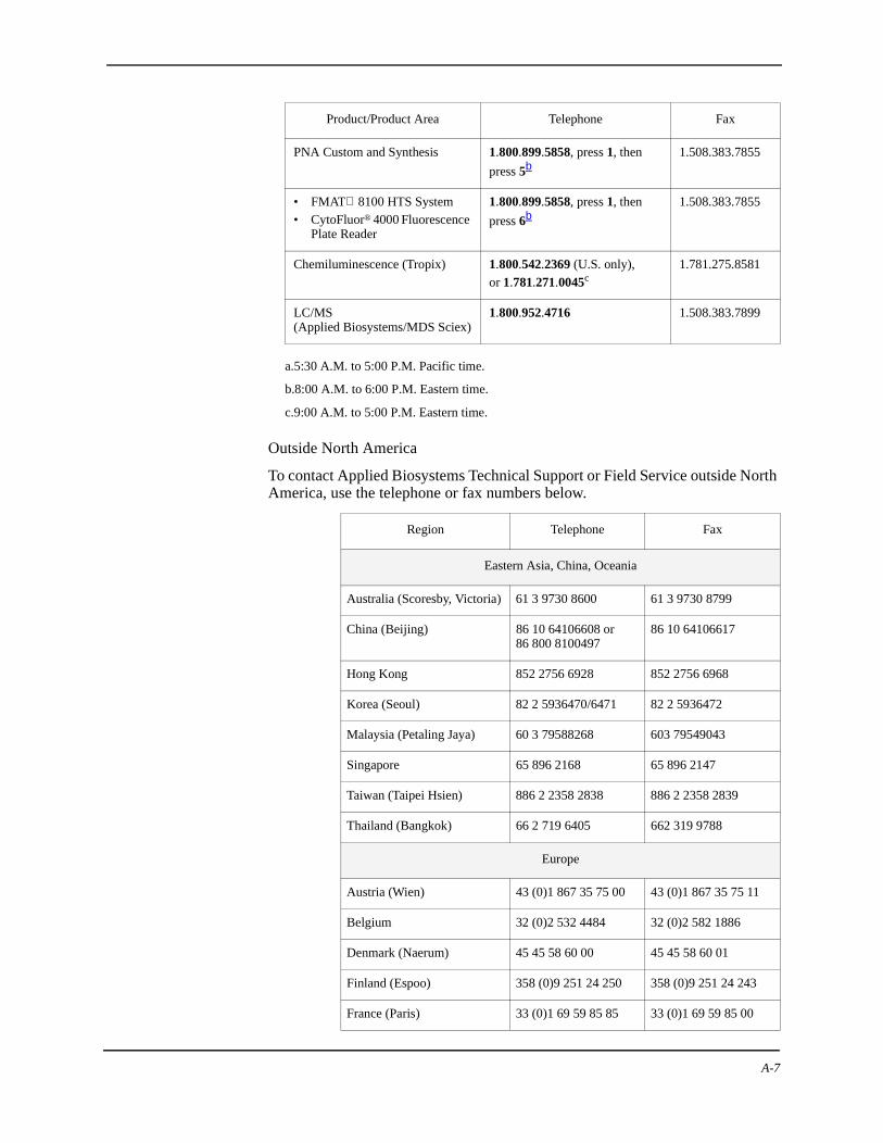
Outside North America
To contact Applied Biosystems Technical Support or Field Service outside North America, use the telephone or fax numbers below.
PNA Custom and Synthesis 1.800.899.5858, press 1, then
press 5b1.508.383.7855
• FMAT 8100 HTS System• CytoFluor® 4000 Fluorescence
Plate Reader
1.800.899.5858, press 1, then
press 6b1.508.383.7855
Chemiluminescence (Tropix) 1.800.542.2369 (U.S. only),or 1.781.271.0045c
1.781.275.8581
LC/MS (Applied Biosystems/MDS Sciex)
1.800.952.4716 1.508.383.7899
a.5:30 A.M. to 5:00 P.M. Pacific time.
b.8:00 A.M. to 6:00 P.M. Eastern time.
c.9:00 A.M. to 5:00 P.M. Eastern time.
Region Telephone Fax
Eastern Asia, China, Oceania
Australia (Scoresby, Victoria) 61 3 9730 8600 61 3 9730 8799
China (Beijing) 86 10 64106608 or86 800 8100497
86 10 64106617
Hong Kong 852 2756 6928 852 2756 6968
Korea (Seoul) 82 2 5936470/6471 82 2 5936472
Malaysia (Petaling Jaya) 60 3 79588268 603 79549043
Singapore 65 896 2168 65 896 2147
Taiwan (Taipei Hsien) 886 2 2358 2838 886 2 2358 2839
Thailand (Bangkok) 66 2 719 6405 662 319 9788
Europe
Austria (Wien) 43 (0)1 867 35 75 00 43 (0)1 867 35 75 11
Belgium 32 (0)2 532 4484 32 (0)2 582 1886
Denmark (Naerum) 45 45 58 60 00 45 45 58 60 01
Finland (Espoo) 358 (0)9 251 24 250 358 (0)9 251 24 243
France (Paris) 33 (0)1 69 59 85 85 33 (0)1 69 59 85 00
Product/Product Area Telephone Fax
A-7

Appendix A
Germany (Weiterstadt) 49 (0) 6150 101 0 49 (0) 6150 101 101
Italy (Milano) 39 (0)39 83891 39 (0)39 838 9492
Norway (Oslo) 47 23 12 06 05 47 23 12 05 75
Portugal (Lisboa) 351.(0)22.605.33.14 351.(0)22.605.33.15
Spain (Tres Cantos) 34.(0)91.806.1210 34.(0)91.806.12.06
Sweden (Stockholm) 46 (0)8 619 4400 46 (0)8 619 4401
Switzerland (Rotkreuz) 41 (0)41 799 7777 41 (0)41 790 0676
The Netherlands (Nieuwerkerk a/d IJssel)
31 (0)180 392400 31 (0)180 392409 or31 (0)180 392499
United Kingdom (Warrington, Cheshire)
44 (0)1925 825650 44 (0)1925 282502
European Managed Territories (EMT)
Africa, English speaking (Johannesburg, South Africa)
27 11 478 0411 27 11 478 0349
Africa, French speaking (Paris, France)
33 1 69 59 85 11 33 1 69 59 85 00
India (New Delhi) 91 11 653 3743
91 11 653 3744
91 11 653 3138
Poland, Lithuania, Latvia, and Estonia (Warszawa)
48 22 866 4010 48 22 866 4020
For all other EMT countries not listed (Central and southeast Europe, CIS, Middle East, and West Asia
44 1925 282481 44 1925 282509
Japan
Japan (Hacchobori, ChuoKu, Tokyo)
81 3 5566 6230 81 3 5566 6507
Latin America
Caribbean countries, Mexico, and Central America
52 55 35 3610 52 55 66 2308
Brazil 0 800 704 9004 or 55 11 5070 9654
55 11 5070 9694/95
Argentina 800 666 0096 55 11 5070 9694/95
Chile 1230 020 9102 55 11 5070 9694/95
Uruguay 0004 055 654 55 11 5070 9694/95
Region Telephone Fax
A-8 This Document Contains CONFIDENTIAL Material of Applied BiosystemsFor Internal Use Only - No Unauthorized Copying Permitted

Through theTechnical Support
Web Site
T
To contact Technical Support through the Applied Biosystems web site:
1. Access the Applied Biosystems Technical Support web site at www.appliedbiosystems.com/techsupp.
2. Under the Troubleshooting heading, click Support Request Forms, then select the support region for the product area of interest.
3. In the Personal Assistance form, enter the requested information and your question, then click Ask Us RIGHT NOW.
4. In the Customer Information form, enter the requested information, then click Ask Us RIGHT NOW.
Within 24 to 48 hours, you will receive an e-mail reply to your question from an Applied Biosystems technical expert.
A-9
Appendix A
Obtaining Technical Documents
Overview You can obtain technical documents, such as Applied Biosystems user documents, MSDSs, certificates of analysis, and other related documents for free, 24 hours a day. You can obtain documents:
• By telephone• Through the Applied Biosystems Technical Support web site
OrderingDocuments by
Telephone
ObtainingDocuments Through
the Web Site
To order documents by telephone:
1. From the U.S. or Canada, dial 1.800.487.6809, or from outside the U.S. and Canada, dial 1.858.712.0317.
2. Follow the voice instructions to order documents (for delivery by fax).
Note: There is a limit of five documents per fax request.
To view, download, or order documents through the Applied Biosystems Technical Support web site:
1. Access the Applied Biosystems Technical Support web site at www.appliedbiosystems.com/techsupp.
2. Under the Resource Libraries heading, select the type of technical document you want.
3. In the search form, enter or select search criteria, then click Search.
4. In the results screen, do any of the following:
• Click to view a PDF version of the document.
• Right-click , then select Save Target As to download a copy of the PDF file.
• Select the Fax check box, then click Deliver Selected Documents Now to have the document faxed to you.
• Select the Email check box, then click Deliver Selected Documents Now to have the document (PDF format) e-mailed to you.
Note: There is a limit of five documents per fax request, but no limit on the number of documents per e-mail request.
A-10 This Document Contains CONFIDENTIAL Material of Applied BiosystemsFor Internal Use Only - No Unauthorized Copying Permitted

Obtaining Customer Training Information
The Applied Biosystems Training web site at www.appliedbiosystems.com/techsupp/training.html provides course descriptions, schedules, and other training-related information.
A-11

Appendix A
A-12 This Document Contains CONFIDENTIAL Material of Applied BiosystemsFor Internal Use Only - No Unauthorized Copying Permitted

This Document Contains CONFIDENTIAL Material of Applied BiosystemFor Internal Use Only - No Unauthorized Copying Permitted
This appendix contains the following:
Finding Components . . . . . . . . . . . . . . . . . . . . . . . . . . . . . .
Relative Assembly Locations . . . . . . . . . . . . . . . . . . . . . . .
BA
Assembly Drawings B
B-1s
. . . B-2
. . . B-3

Appendix B
Finding Components
Table B-1 provides figure numbers showing the listed component.
.
Table B-1 Component Diagrams
Component See Figure
Beam-steering plates and voltage connections Figure B-5, Figure B-6
Einzel lens assembly and voltage connection Figure B-5, Figure B-6, Figure B-7
Feedthroughs Figure B-8
Flap doors Figure B-9
Flap valve block Figure B-9
Ion exit aperture Figure B-5
Linear actuators Figure B-9
Sample loading chamber Figure B-9
Stage X, Y table; load position Figure B-8
Variable grid Figure B-6
X and Y feedthroughs; home and load positions Figure B-8
B-2 This Document Contains CONFIDENTIAL Material of Applied BiosystemsFor Internal Use Only - No Unauthorized Copying Permitted

Relative Assembly Locations
Figure B-1 Voyager-DE STR Biospectrometry Workstation
Figure B-2 Voyager-DE STR Left Cabinet Rear View
PB100427
Computer/
Video
Control stick
Massspectrometer
Computermonitor monitor
Electronics
Data system(inside cabinet)
(inside cabinets)
External digitizer
components
PB100853
BA1 location(BA1 is not visible is this drawing, the gauge is within a mesh bag)
DE switch box
Voltage divider box(not visible, along side the DE switch box)
PB100853
BA1 location(BA1 is not visible is this drawing, the gauge is within a mesh bag)
DE switch box
Voltage divider box(not visible, along side the DE switch box)
PB100853
BA1 location(BA1 is not visible is this drawing, the gauge is within a mesh bag)
DE switch box
Voltage divider box(not visible, along side the DE switch box)
PB100853
BA1 location(BA1 is not visible is this drawing; the gauge is within n mesh bag)
DE switch box
Voltage divider box(not visible, along side the DE switch box)
B-3This Document Contains CONFIDENTIAL Material of Applied BiosystemsFor Internal Use Only - No Unauthorized Copying Permitted

Appendix B
Figure B-3 Voyager-DE STR Center Rear View
��������
Mechanical sieve
Fore
Foreline CID
pump(rough)
TC2
Valve 2quick disconnect
Compressor
Mirror
controllerturbo
TIS assembly (High-voltageswitch box)
B-4 This Document Contains CONFIDENTIAL Material of Applied BiosystemsFor Internal Use Only - No Unauthorized Copying Permitted
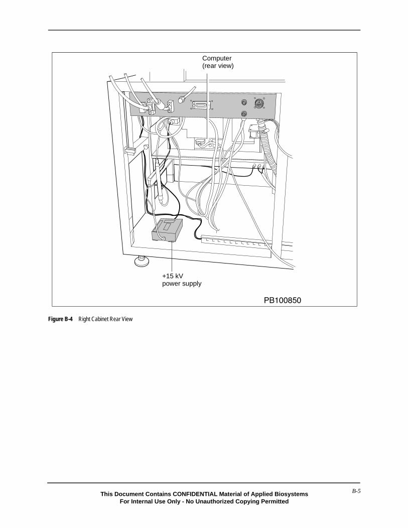
Figure B-4 Right Cabinet Rear View
�������
+15 kV power supply
Computer(rear view)
B-5This Document Contains CONFIDENTIAL Material of Applied BiosystemsFor Internal Use Only - No Unauthorized Copying Permitted
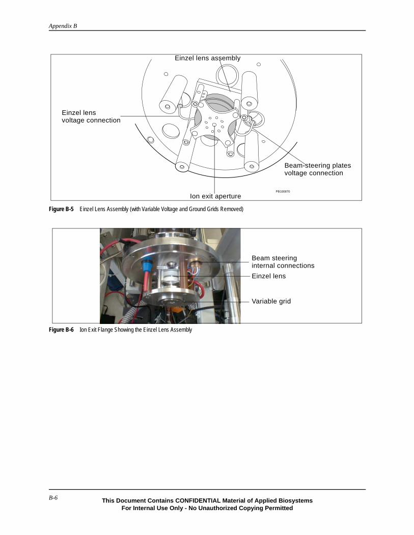
Appendix B
Figure B-5 Einzel Lens Assembly (with Variable Voltage and Ground Grids Removed)
Figure B-6 Ion Exit Flange Showing the Einzel Lens Assembly
PB100870
Einzel lens assembly
Beam-steering platesvoltage connection
Ion exit aperture
Einzel lensvoltage connection
Einzel lens
Beam steeringinternal connections
Variable grid
B-6 This Document Contains CONFIDENTIAL Material of Applied BiosystemsFor Internal Use Only - No Unauthorized Copying Permitted

Figure B-7 Einzel Lens Assembly
To detector
Beam steering plates Einzel lens assembly CID cellAperature
Ion flow
Grids
B-7This Document Contains CONFIDENTIAL Material of Applied BiosystemsFor Internal Use Only - No Unauthorized Copying Permitted

Appendix B
Figure B-8 Feedthroughs and Sample Stage
Figure B-9 Sample Loading Chamber
������
)������������������*������������������
��"����������� ���������
��"���������������������+�,�-
�������$�$$��
����������&��),*���$��
����������&���� ���������
����������&��������������+�,�-
X feedthroughY feedthrough
microswitchload position
microswitchhome position(0,0)sample stage
load position
bobbin
PB100847
PB100855
Linear 2 actuator Linear 1 actuator
Flap Door 2 (shown closed)
Flap Door 1 actuator Flap Door 2 actuator
Flap Door 1(not visible, attached
To atmosphereTo main
to source housing)
source chamber
B-8 This Document Contains CONFIDENTIAL Material of Applied BiosystemsFor Internal Use Only - No Unauthorized Copying Permitted

This Document Contains CONFIDENTIAL Material of Applied BiosystemFor Internal Use Only - No Unauthorized Copying Permitted
C
Electronic Drawings CThis appendix contains the following:
Locations of Electronic Components . . . . . . . . . . . . . . . . . . . . C-2
Pin 1 Connector Locations . . . . . . . . . . . . . . . . . . . . . . . . . . . . C-4
Interconnects . . . . . . . . . . . . . . . . . . . . . . . . . . . . . . . . . . . . . . . C-5
MALDI Consolidated Control Board . . . . . . . . . . . . . . . . . . . . C-7
C-1
s

Appendix C
Locations of Electronic Components
Use the following figures to locate electronic components. For more information about Voyager workstation electronics, see the circuit board schematics posted on the MALDI knowledge database and review Chapter 2, Voyager-DE STR Workstation Electronics Theory in this manual.
Figure C-1 Electronics in Left Cabinet (Front View)
Figure C-2 Electronics in the Left Cabinet (Side View)
PB100848
DC distribution
Grid HVPS
Source HVPS
MALDI control
Vacuum multigauge controller
�������J1 J13 J14
Source turbo controller
Mirror(reflector)turbo controller
Fore(rough)pump power
Main transformer
J11Vacuummultigaugecontroller,110 V power
DS11
F11BF11A
Left cabinet drawer(Side view)
AC distribution board
C-2This Document Contains CONFIDENTIAL Material of Applied Biosystems
For Internal Use Only - No Unauthorized Copying Permitted
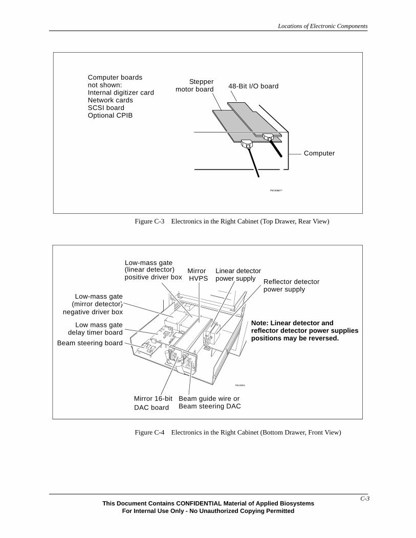
Locations of Electronic Components
Figure C-3 Electronics in the Right Cabinet (Top Drawer, Rear View)
Figure C-4 Electronics in the Right Cabinet (Bottom Drawer, Front View)
���������
48-Bit I/O boardStepper
motor board
Computer
Computer boards not shown:Internal digitizer cardNetwork cardsSCSI boardOptional CPIB
PB100851
Beam steering board
Low mass gatedelay timer board
Mirror 16-bit
Low-mass gate
negative driver box(mirror detector)
(linear detector)positive driver box
Linear detectorpower supply Reflector detector
power supply
Mirror
Beam guide wire orBeam steering DAC
HVPS
DAC board
Note: Linear detector and reflector detector power supplies positions may be reversed.
Low-mass gate
C-3This Document Contains CONFIDENTIAL Material of Applied Biosystems
For Internal Use Only - No Unauthorized Copying Permitted
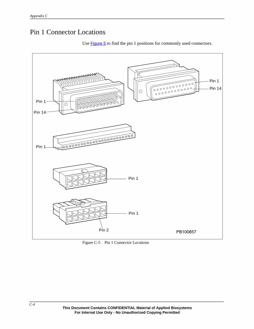
Appendix C
Pin 1 Connector Locations
Use Figure 5 to find the pin 1 positions for commonly used connectors.
Figure C-5 Pin 1 Connector Locations
�������
Pin 1
Pin 14
Pin 1
Pin 14
Pin 1
Pin 2
Pin 1
Pin 1
C-4This Document Contains CONFIDENTIAL Material of Applied Biosystems
For Internal Use Only - No Unauthorized Copying Permitted

C-5
Interconnect
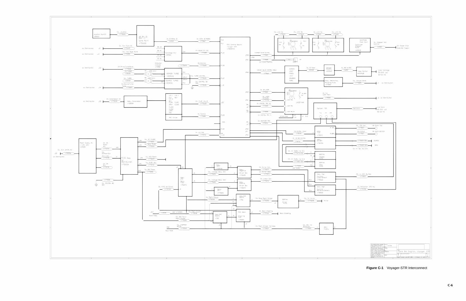
C-6
Figure C-1 Voyager-STR Interconnect

C-7
MALDIConsolidated
ControlBoard

C-8
Figure C-2 Consolidated MALDI Control Board
J30J29
J28
J26J23
J22
J25
R51
131
14 25
119
37 20J17
51
69
J15 J1
J0
2
1
26
25
2
1
26
25
J2P
OW
ER
GN
DP
E B
iosystem
sVo
yager C
on
trol B
oard
J16
U18
U15
1J14 J12
3
145
J11
J10
J9
J8
J6
J7
J4
J3
J5
123
R24
TP9
TP6
TP5
TP4
TP1
TP25
TP2
TP3
TP8
TP12
TP13
TP16
TP11TP10
TP15TP14
TP7
U5
288
1156
157
185
184
52
53
TP26
J18
R40
D18
S2 Reset
D6 D3
JU4JU3 JU5
U22 U19
1 33
342
PB100859
J34J33
J32J31
K7
K8
K9
R46
J278 1
15 9
U39
HUENABLED
INTERLOCKOK
D91
2
123
TP27
TP18
TP17
TP20
TP21
TP19
TP23TP24
288
1156
157
185
1845354
D10
D11
JU2
J21
2 1
16 15
D12
S1
JU6
U44 U27
8 7 6 5 4 3 2 1
TP22
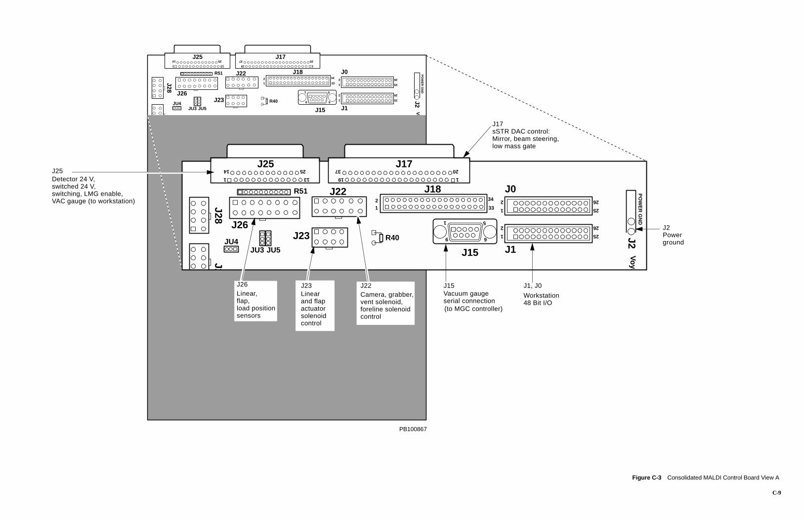
C-9
Figure C-3 Consolidated MALDI Control Board View A
J28
J26J23
J22
J25
R51
131
14 25
119
37 20J17
51
69
J15 J1
J0
2
1
26
25
2
1
26
25
J2P
OW
ER
GN
DP
E B
iosystem
sVo
yager C
on
trol B
oard
J18
R40JU4JU3 JU5
1 33
342
1
20
51
69
J15 J1
J0
2
1
26
25
2
1
26
25
J2P
OW
ER
GN
DP
Voya
8
33
34
J17sSTR DAC control:Mirror, beam steering,low mass gate
J15Vacuum gauge
(to MGC controller)serial connection
J1, J0
Workstation48 Bit I/O
J2Powerground
PB100867
J2J28
J26J23
J22
J25
R51
131
14 25
19
37 J17
J1
R40JU4JU3 JU5
12
J23Linearand flapactuatorsolenoidcontrol
J22Camera, grabber,vent solenoid,foreline solenoid control
J25 Detector 24 V,switched 24 V,switching, LMG enable,VAC gauge (to workstation)
J26 Linear,flap,load positionsensors
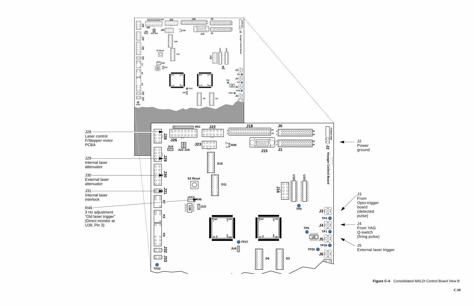
C-10
Figure C-4 Consolidated MALDI Control Board View B
J32J31
J30J29
J28
J26J23
J22R51
K7
K8
K9
R46
131 119
51
69
J15 J1
J0
2
1
26
25
2
1
26
25
J2P
OW
ER
GN
DP
E B
iosystem
sVo
yager C
on
trol B
oard
J16
U18
U15
U39
J4
J3
J5
123
TP27
TP6
TP5
TP4
TP1
TP25
U5
288
1156
157
185
184
52
53
288
1156
157
185
1845354
TP26
J18
R40
D18
D11
S2 Reset
JU2
JU4JU3 JU5
JU6
1 33
342
51
69
J15 J1
J0
2
1
26
25
2
1
26
25
J2P
OW
ER
GN
DP
E B
iosystem
sVo
yager C
on
trol B
oard
J16
U18
U15
J6
J7
J4
J3
J5
TP6
TP5
TP4
TP1
TP25
U5
288
1156
157
185
184
52
53
TP26
D6 D3
33
34
J2Powerground
J3FromOpto-triggerboard
pulse)(detected
J4From YAGQ-switch(firing pulse)
J5External laser trigger
J33
J6
J7
D6 D3
TP22
J33J32
J31J30
J29J28
J26J23
J22R51
K7
K8
K9
R46
U39
123
TP27
288
1156
157
185
1845354
J18
R40
D18
D11
S2 Reset
JU2
JU4JU3 JU5
JU6
TP22
12J28
Laser controlF/Stepper motorPCBA
J29Internal laserattenuator
J30External laserattenuator
J31Internal laserinterlock
R463 Hz adjustment“Old laser trigger”(Direct monitor atU39, Pin 3)
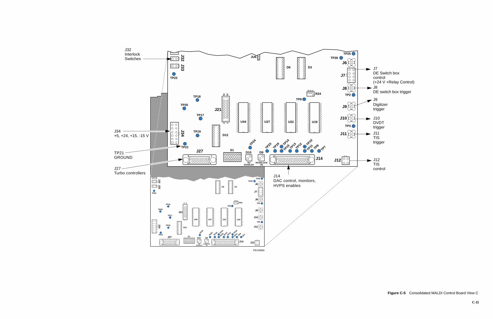
C-11
Figure C-5 Consolidated MALDI Control Board View C
J33J32
K
1J14 J12
13
1425
J11
J10
J9
J8
J6
J7
123
R24TP18
TP9
TP25
TP2
TP3
TP8
TP12
TP13
TP16
TP23
TP11TP10
TP15TP14
TP7
TP26
D6 D3
16 15
JU6
27 U22 U19
TP22
J32InterlockSwitches
J7DE Switch boxcontrol (+24 V +Relay Control)J8DE switch box trigger
J9Digitizertrigger
J10DVDTtrigger
J11TIStrigger
DAC control, monitors,HVPS enables
J14
J12TIScontrol
J34J33
J32K
9
J278 1
15 9 HUENABLED
INTERLOCKOK
D91
J14 J1213
1425
J11
J10
J9
J8
J6
J7
123
R24TP18
TP17
TP20
TP21
TP19
TP9
TP25
TP2
TP3
TP8
TP12
TP13
TP16
TP23
TP11TP10
TP15TP14
TP24
TP7
TP26
D10
D6 D3
J21
2 1
16 15
D12
S1
U44 U27 U22 U19
8 7 6 5 4 3 2 1
TP22
PB100869
J34
J278 1
15 9 HUENABLED
INTERLOCOK
D9
TP17
TP20
TP21
TP19
TP24
D10
J21
2 1
D12
S1
U44 U
8 7 6 5 4 3 2 1
J34+5, +24, +15, -15 V
TP21GROUND
J27Turbo controllers

This page intentionally left blank.
C-12
This Document Contains CONFIDENTIAL Material of Applied BiosystemFor Internal Use Only - No Unauthorized Copying Permitted
D
Isolating Components Using Direct Bus Access DThis appendix contains the following:
Diagnostics Software Direct Bus Access Control Page . . . . . . D-2
Writing Data Directly Over the Data Bus . . . . . . . . . . . . . . . . D-3
Data Values for Direct Access . . . . . . . . . . . . . . . . . . . . . . . . . D-5
Setting the Low-Mass Gate Delay Time . . . . . . . . . . . . . . . . . D-9
Setting and Disabling Delayed Extraction . . . . . . . . . . . . . . . D-10
Setting the Timed Ion Selector . . . . . . . . . . . . . . . . . . . . . . . . D-1
D-1s

Appendix D Isolating Components Using Direct Bus Access
Diagnostics Software Direct Bus Access Control Page
Use the Direct Bus Access control page (Figure D-1) to write data directly to selected components over the data bus. Use this method if you do not want to use the individual component control page—Laser, Voltages and Delays, and DE Switch Box.
Figure D-1 Direct Bus Access Control Page
You cannot enable high-voltage or the Low Mass Gate using direct bus access. With direct bus access, you can only set the output voltage at the DACs and the Low Mass Gate value.
D-2This Document Contains CONFIDENTIAL Material of Applied Biosystems
For Internal Use Only - No Unauthorized Copying Permitted
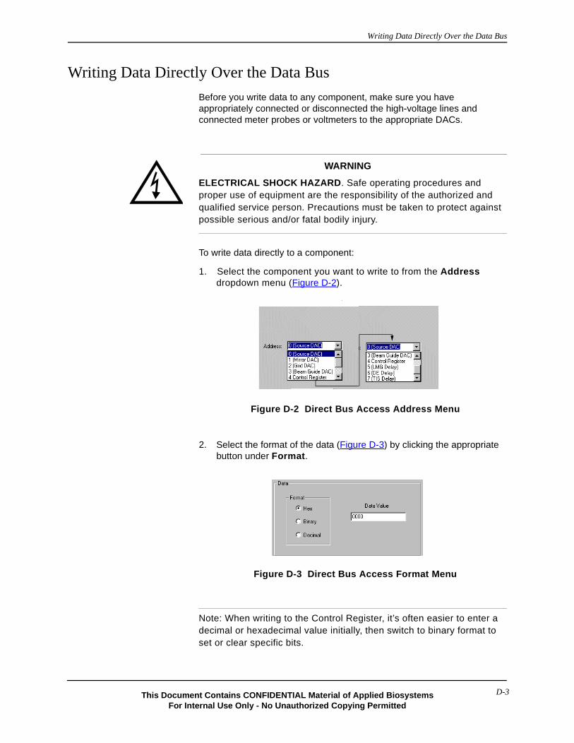
Writing Data Directly Over the Data Bus
Writing Data Directly Over the Data Bus
Before you write data to any component, make sure you have appropriately connected or disconnected the high-voltage lines and connected meter probes or voltmeters to the appropriate DACs.
WARNING
ELECTRICAL SHOCK HAZARD. Safe operating procedures and proper use of equipment are the responsibility of the authorized and qualified service person. Precautions must be taken to protect against possible serious and/or fatal bodily injury.
To write data directly to a component:
1. Select the component you want to write to from the Address dropdown menu (Figure D-2).
.
Figure D-2 Direct Bus Access Address Menu
2. Select the format of the data (Figure D-3) by clicking the appropriate button under Format.
Figure D-3 Direct Bus Access Format Menu
Note: When writing to the Control Register, it’s often easier to enter a decimal or hexadecimal value initially, then switch to binary format to set or clear specific bits.
D-3This Document Contains CONFIDENTIAL Material of Applied BiosystemsFor Internal Use Only - No Unauthorized Copying Permitted

Appendix D Isolating Components Using Direct Bus Access
3. Enter a 16-bit data value in the Data Value field.The value you enter depends on the component you are programming. For details, see Table D-1 on page D-5.
When you write directly to the Control Register, you must write the entire sixteen data bits even if you want to change only some of the register bit values.
Only the corresponding DACs output voltages are detectable with a voltmeter when you set their voltages without enabling high-voltage. (DAC voltages are shown in Table D-2 on page D-8.)
4. Click to transmit the data over the data bus.
D-4This Document Contains CONFIDENTIAL Material of Applied Biosystems
For Internal Use Only - No Unauthorized Copying Permitted
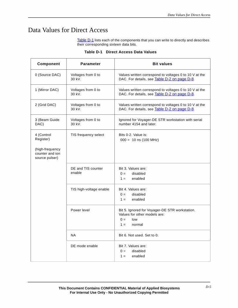
Data Values for Direct Access
Data Values for Direct Access
Table D-1 lists each of the components that you can write to directly and describes their corresponding sixteen data bits.
Table D-1 Direct Access Data Values
Component Parameter Bit values
0 (Source DAC) Voltages from 0 to 30 kV.
Values written correspond to voltages 0 to 10 V at the DAC. For details, see Table D-2 on page D-8.
1 (Mirror DAC) Voltages from 0 to 30 kV.
Values written correspond to voltages 0 to 10 V at the DAC. For details, see Table D-2 on page D-8.
2 (Grid DAC) Voltages from 0 to 30 kV.
Values written correspond to voltages 0 to 10 V at the DAC. For details, see Table D-2 on page D-8.
3 (Beam Guide DAC)
Voltages from 0 to 30 kV.
Ignored for Voyager-DE STR workstation with serial number 4154 and later.
4 (Control Register)
(high-frequency counter and ion source pulser)
TIS frequency select Bits 0-2. Value is:000 = 10 ns (100 MHz)
DE and TIS counter enable
Bit 3. Values are:0 = disabled1 = enabled
TIS high-voltage enable Bit 4. Values are:
0 = disabled1 = enabled
Power level Bit 5. Ignored for Voyager-DE STR workstation. Values for other models are:0 = low
1 = normal
NA Bit 6. Not used. Set to 0.
DE mode enable Bit 7. Values are:0 = disabled
1 = enabled
D-5This Document Contains CONFIDENTIAL Material of Applied BiosystemsFor Internal Use Only - No Unauthorized Copying Permitted
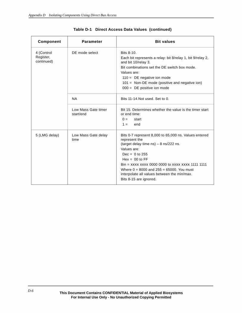
Appendix D Isolating Components Using Direct Bus Access
4 (Control Register, continued)
DE mode select Bits 8-10. Each bit represents a relay: bit 8/relay 1, bit 9/relay 2, and bit 10/relay 3.Bit combinations set the DE switch box mode.Values are:
110 = DE negative ion mode101 = Non-DE mode (positive and negative ion)000 = DE positive ion mode
NA Bits 11-14.Not used. Set to 0.
Low Mass Gate timer start/end
Bit 15. Determines whether the value is the timer start or end time:
0 = start1 = end
5 (LMG delay) Low Mass Gate delay time
Bits 0-7 represent 8,000 to 65,000 ns. Values entered represent the (target delay time ns) – 8 ns/222 ns.
Values are:Dec = 0 to 255Hex = 00 to FF
Bin = xxxx xxxx 0000 0000 to xxxx xxxx 1111 1111Where 0 = 8000 and 255 = 65000. You must interpolate all values between the min/max.Bits 8-15 are ignored.
Table D-1 Direct Access Data Values (continued)
Component Parameter Bit values
D-6This Document Contains CONFIDENTIAL Material of Applied Biosystems
For Internal Use Only - No Unauthorized Copying Permitted

Data Values for Direct Access
Table D-2 lists the voltages and the data bits that program them.
6 (DE delay) Delayed Extraction delay time
Bits 0-14 represent 10 to 32,768 ns. Values entered represent the target time divided by the TIS clock frequency in ns—10 ns. Bit 15 selects start/end time:
0 = start1 = end
Valid start times (correspond to values ranging from 10 to 32,767) are:Dec = 0 to 32767
Hex = 0000 to 7FFFBin = 0000 0000 0000 0000 to 0111 1111 1111 1111
Where 0 = 10 ns and 32767 = 327670 ns at the DAC. You must interpolate all values between the min/max.Valid end times (correspond to values ranging from 10 to 32,768) are:Dec = 32768 to 65535
Hex = 8000 to FFFFBin = 1000 0000 0000 0000 to 1111 1111 1111 1111
Where 32768 = 10 ns and 65535 = 327680 ns at the DAC. You must interpolate all values between the min/max.
7 (TIS delay) Timed Ion Selector delay time
Bits 0-14 represent 10 to 32,768 ns. Values entered represent the:(target time/ TIS clock frequency ns)—10 ns.
Bit 15.Sets start/end time:0 = start1 = end
Valid start times* (correspond to values from 10 to 32767) are:
Dec = 0 to 32767Hex = 0000 to 7FFFBin = 0000 0000 0000 0000 to 0111 1111 1111 xxxx
Where 0 = 10 ns and 32767 = 327670 ns at the DAC. You must interpolate all values between the min/max.
Valid end times* (correspond to values ranging from 10 to 32768) are:
Dec = 32768 to 65535Hex = 8000 to FFFFBin = 1000 0000 0000 0000 to 1111 1111 1111 xxxx
Where 32768 = 10 ns and 65535 = 327680 ns at the DAC. You must interpolate all values between the
* Not all values in the range are valid; do not write all 1s to the low four bits of the data value.
Table D-1 Direct Access Data Values (continued)
Component Parameter Bit values
D-7This Document Contains CONFIDENTIAL Material of Applied BiosystemsFor Internal Use Only - No Unauthorized Copying Permitted
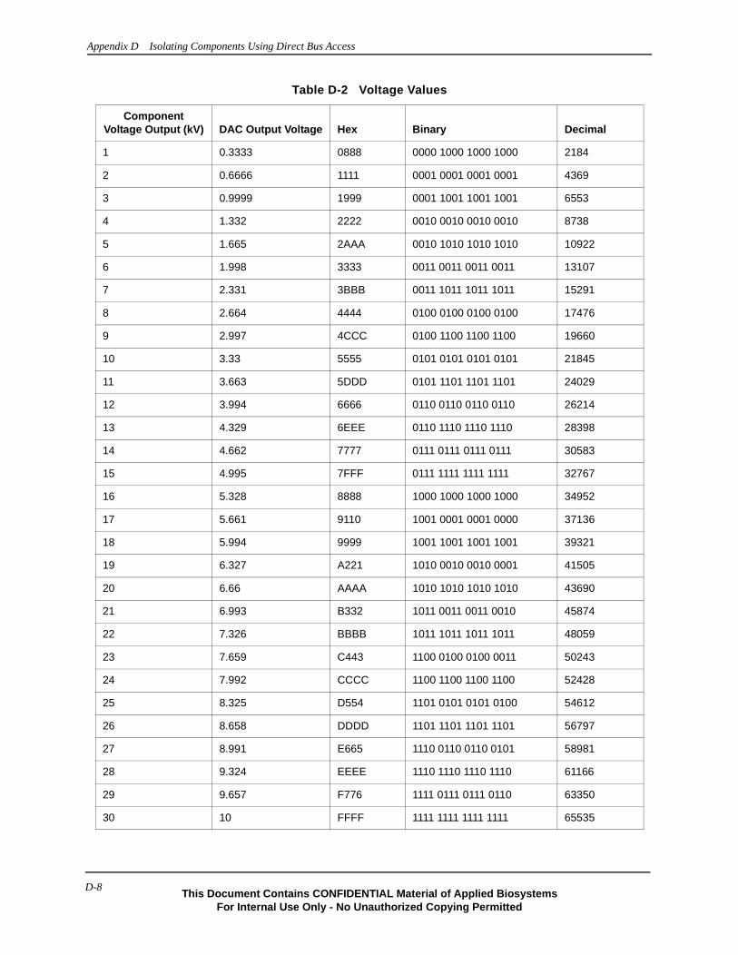
Appendix D Isolating Components Using Direct Bus Access
Table D-2 Voltage Values
Component Voltage Output (kV) DAC Output Voltage Hex Binary Decimal
1 0.3333 0888 0000 1000 1000 1000 2184
2 0.6666 1111 0001 0001 0001 0001 4369
3 0.9999 1999 0001 1001 1001 1001 6553
4 1.332 2222 0010 0010 0010 0010 8738
5 1.665 2AAA 0010 1010 1010 1010 10922
6 1.998 3333 0011 0011 0011 0011 13107
7 2.331 3BBB 0011 1011 1011 1011 15291
8 2.664 4444 0100 0100 0100 0100 17476
9 2.997 4CCC 0100 1100 1100 1100 19660
10 3.33 5555 0101 0101 0101 0101 21845
11 3.663 5DDD 0101 1101 1101 1101 24029
12 3.994 6666 0110 0110 0110 0110 26214
13 4.329 6EEE 0110 1110 1110 1110 28398
14 4.662 7777 0111 0111 0111 0111 30583
15 4.995 7FFF 0111 1111 1111 1111 32767
16 5.328 8888 1000 1000 1000 1000 34952
17 5.661 9110 1001 0001 0001 0000 37136
18 5.994 9999 1001 1001 1001 1001 39321
19 6.327 A221 1010 0010 0010 0001 41505
20 6.66 AAAA 1010 1010 1010 1010 43690
21 6.993 B332 1011 0011 0011 0010 45874
22 7.326 BBBB 1011 1011 1011 1011 48059
23 7.659 C443 1100 0100 0100 0011 50243
24 7.992 CCCC 1100 1100 1100 1100 52428
25 8.325 D554 1101 0101 0101 0100 54612
26 8.658 DDDD 1101 1101 1101 1101 56797
27 8.991 E665 1110 0110 0110 0101 58981
28 9.324 EEEE 1110 1110 1110 1110 61166
29 9.657 F776 1111 0111 0111 0110 63350
30 10 FFFF 1111 1111 1111 1111 65535
D-8This Document Contains CONFIDENTIAL Material of Applied Biosystems
For Internal Use Only - No Unauthorized Copying Permitted

Setting the Low-Mass Gate Delay Time
Setting the Low-Mass Gate Delay Time
To set the low-mass gate delay time, you write a delay time. You then have the optional to write to the Control register to specify whether the value is the start or end delay time. To set delay times:
1. From the Address pulldown menu, select 5 (LMG delay).
2. Enter an 8-bit value in the Data Value text field for the start delay time.
Values range from 0 to 255 (decimal) and represent 8,000 to 65,000 ns.
3. Click .
The remaining steps are optional. Because you cannot enable the Low Mass Gate timers, it makes no difference whether the delay time you write is the start or end time.
4. From the Address pulldown menu, select 4 (Control Register).
5. Enter a 16-bit value in Data Value text field.
Clear bit 15 (LMG enable) to specify that the data value previously written is the start time for the delay. The remaining bits do not affect the Low Mass Gate circuitry.
Remember, you must write the entire sixteen bits of the control register, so enter a value that sets all components the control register configures (including TIS and DE parameters) appropriately.
6. Click .
7. Repeat steps 1 through 6, but specify the end delay time in step 5 by setting bit 15 to 1.
D-9This Document Contains CONFIDENTIAL Material of Applied BiosystemsFor Internal Use Only - No Unauthorized Copying Permitted
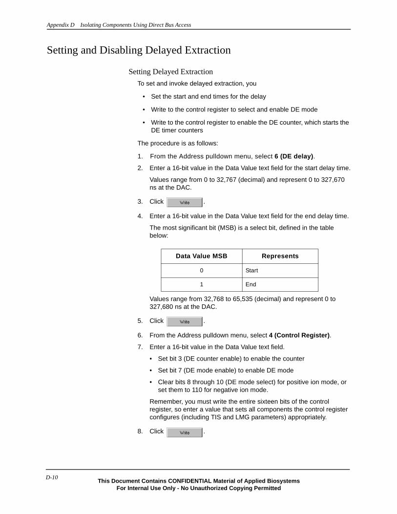
Appendix D Isolating Components Using Direct Bus Access
Setting and Disabling Delayed Extraction
Setting Delayed Extraction
To set and invoke delayed extraction, you
• Set the start and end times for the delay
• Write to the control register to select and enable DE mode
• Write to the control register to enable the DE counter, which starts the DE timer counters
The procedure is as follows:
1. From the Address pulldown menu, select 6 (DE delay).
2. Enter a 16-bit value in the Data Value text field for the start delay time.
Values range from 0 to 32,767 (decimal) and represent 0 to 327,670 ns at the DAC.
3. Click .
4. Enter a 16-bit value in the Data Value text field for the end delay time.
The most significant bit (MSB) is a select bit, defined in the table below:
Values range from 32,768 to 65,535 (decimal) and represent 0 to 327,680 ns at the DAC.
5. Click .
6. From the Address pulldown menu, select 4 (Control Register).
7. Enter a 16-bit value in the Data Value text field.
• Set bit 3 (DE counter enable) to enable the counter
• Set bit 7 (DE mode enable) to enable DE mode
• Clear bits 8 through 10 (DE mode select) for positive ion mode, or set them to 110 for negative ion mode.
Remember, you must write the entire sixteen bits of the control register, so enter a value that sets all components the control register configures (including TIS and LMG parameters) appropriately.
8. Click .
Data Value MSB Represents
0 Start
1 End
D-10This Document Contains CONFIDENTIAL Material of Applied Biosystems
For Internal Use Only - No Unauthorized Copying Permitted
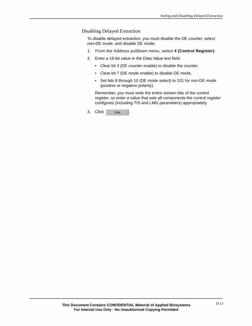
Setting and Disabling Delayed Extraction
Disabling Delayed Extraction
To disable delayed extraction, you must disable the DE counter, select non-DE mode, and disable DE mode:
1. From the Address pulldown menu, select 4 (Control Register).
2. Enter a 16-bit value in the Data Value text field.
• Clear bit 3 (DE counter enable) to disable the counter.
• Clear bit 7 (DE mode enable) to disable DE mode.
• Set bits 8 through 10 (DE mode select) to 101 for non-DE mode (positive or negative polarity).
Remember, you must write the entire sixteen bits of the control register, so enter a value that sets all components the control register configures (including TIS and LMG parameters) appropriately.
3. Click .
D-11This Document Contains CONFIDENTIAL Material of Applied BiosystemsFor Internal Use Only - No Unauthorized Copying Permitted

Appendix D Isolating Components Using Direct Bus Access
Setting the Timed Ion Selector
To set up and invoke the Timed Ion Selector, you:
• Set the start and end times for the delay.
• Write to the Control register to set the TIS frequency.
• Enable TIS high-voltage. (For non-STR systems, you also set the TIS power level.)
• Enable the TIS counter.
To set the TIS counter:
1. From the Address pulldown menu, select 7 (TIS delay).
2. Enter a 16-bit value in the Data Value text field for the start delay time.
Values range from 0 to 32,767 (decimal) and represent 0 to 327,670 ns at the DAC.
However, because of a limitation of the pulse generator, you cannot write all 1s to the low four bits of the data value.
3. Click .
4. Enter a 16-bit value in the Data Value text field for the end delay time.
Values range from 32,768 to 65,535 (decimal) and represent 0 to 327,670 ns at the DAC.
Although values range from 32,768 to 65,535, a limitation of the pulse generator prevents you from writing all 1s to the low four bits of the data value.
5. Click .
6. From the Address pulldown menu, select 4 (Control Register).
7. Enter a 16-bit value in the Data Value text field.
• Clear bits 2-0 (TIS frequency select) to select a frequency of 100 MHz.
• Set bit 4 (TIS high-voltage enable) to enable high-voltage.
• Set bit 3 (TIS counter enable) to enable the counter, which starts the TIS timer counters and activates the Timed Ion Selector.
Remember, you must write the entire sixteen bits of the Control register, so enter a value that sets all components the Control register configures (including DE and LMG parameters) appropriately.
8. Click .
D-12This Document Contains CONFIDENTIAL Material of Applied Biosystems
For Internal Use Only - No Unauthorized Copying Permitted
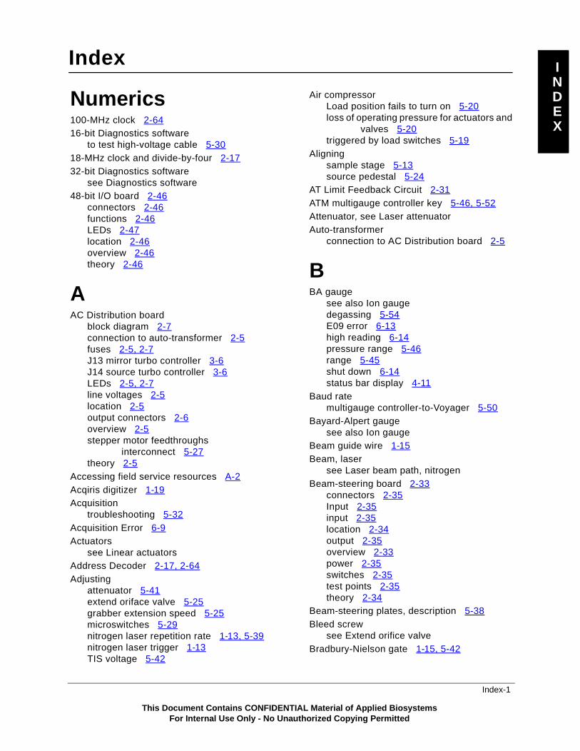
Index I
DEX
N
Numerics100-MHz clock 2-6416-bit Diagnostics softwareto test high-voltage cable 5-3018-MHz clock and divide-by-four 2-1732-bit Diagnostics software
see Diagnostics software48-bit I/O board 2-46
connectors 2-46functions 2-46LEDs 2-47location 2-46overview 2-46theory 2-46
AAC Distribution board
block diagram 2-7connection to auto-transformer 2-5fuses 2-5, 2-7J13 mirror turbo controller 3-6J14 source turbo controller 3-6LEDs 2-5, 2-7line voltages 2-5location 2-5output connectors 2-6overview 2-5stepper motor feedthroughs
interconnect 5-27theory 2-5
Accessing field service resources A-2Acqiris digitizer 1-19Acquisition
troubleshooting 5-32Acquisition Error 6-9Actuators
see Linear actuatorsAddress Decoder 2-17, 2-64Adjusting
attenuator 5-41extend oriface valve 5-25grabber extension speed 5-25microswitches 5-29nitrogen laser repetition rate 1-13, 5-39nitrogen laser trigger 1-13TIS voltage 5-42
Air compressorLoad position fails to turn on 5-20loss of operating pressure for actuators and
valves 5-20triggered by load switches 5-19
Aligningsample stage 5-13source pedestal 5-24
AT Limit Feedback Circuit 2-31ATM multigauge controller key 5-46, 5-52Attenuator, see Laser attenuatorAuto-transformer
connection to AC Distribution board 2-5
BBA gauge
see also Ion gaugedegassing 5-54E09 error 6-13high reading 6-14pressure range 5-46range 5-45shut down 6-14status bar display 4-11
Baud ratemultigauge controller-to-Voyager 5-50
Bayard-Alpert gaugesee also Ion gauge
Beam guide wire 1-15Beam, laser
see Laser beam path, nitrogenBeam-steering board 2-33
connectors 2-35Input 2-35input 2-35location 2-34output 2-35overview 2-33power 2-35switches 2-35test points 2-35theory 2-34
Beam-steering plates, description 5-38Bleed screw
see Extend orifice valveBradbury-Nielson gate 1-15, 5-42
This Document Contains CONFIDENTIAL Material of Applied BiosystemsFor Internal Use Only - No Unauthorized Copying Permitted
Index-1

I
DEX
N
Index
CCable
for nitrogen laser external trigger 1-13high-voltage, testing 5-30, 5-31
CalculatingDAC board grid expected output
voltage 5-32calculating DAC board source expected output
voltage 5-32Calibrating
load positionthermocouple (TC2) gauge 5-52
Camera control page 5-11, 5-43see also Diagnostics software 4-6function 4-6
Certificates of analysisobtaining A-10
CHAN 5-45CHAN multigauge controller key 5-46
calibrating TC2 using 5-52Check Control Wiring Test
see DE switch box control pageCID 1-3Circuit board connectors
48-bit I/O 2-46beam-steering 2-35DAC 2-10DC distribution 2-12flight tube 2-62Pulse Generator PCA 2-65Timed Ion Selector 2-30TTL Output Opto-trigger 2-31voltage divider box (einzel lens) 2-45
Circuit boards 2-248-bit I/O 2-46AC Distribution 2-5beam-steering 2-33Control board 2-47DAC 2-9DC Distribution board 2-11flight-tube power supply 2-61in earlier Voyagers 2-59in most Voyagers 2-4in newer Voyagers 2-33Low-Mass Gate Delay Timer 2-15MALDI control 2-47pulse generator 2-63Timed Ion Selector 2-26 (continued)
Circuit boards (continued)TTL output opto-trigger 2-31voltage divider box (einzel lens) 2-45
Collision celldescription 1-9
Com Port 2 settingsparity 5-50, 5-51resetting 5-50verifying 5-48, 5-50
COMM fault 5-16Communication failure
diagnostics software and ion gauge 5-16overriding COMM fault 5-16
Compressor relay and diodes 2-6Computer system 1-19
Ethernet adapter card 1-19minimum requirements 1-19screen saver interference 1-19software shipped with 1-21sound card interference 1-19troubleshooting tables 6-9
Connectorssee also Circuit board connectorsand LEDs 2-8
Control pages, Diagnostics softwareCamera 4-6, 5-11, 5-43DE switch box 4-9, 5-36Direct Bus Access 4-10, D-2function summary 4-6Laser 4-7, 5-39Mechanical 4-6, 5-12, 5-16, 5-31overview 4-5resources summary 4-5troubleshooting summary 5-2Voltages-Delays 4-8, 5-33, 5-43X-Y Table 4-9, 5-19
Control stick description 1-2Counters 2-17, 2-64Customer training information A-11
Index-2This Document Contains CONFIDENTIAL Material of Applied Biosystems
For Internal Use Only - No Unauthorized Copying Permitted
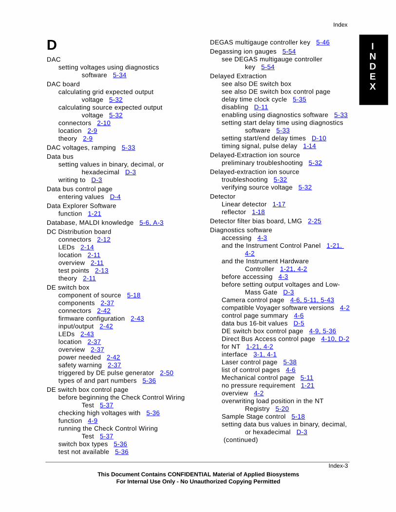
I
DEX
N
Index
DDAC
setting voltages using diagnostics software 5-34
DAC boardcalculating grid expected output
voltage 5-32calculating source expected output
voltage 5-32connectors 2-10location 2-9theory 2-9
DAC voltages, ramping 5-33Data bus
setting values in binary, decimal, or hexadecimal D-3
writing to D-3Data bus control page
entering values D-4Data Explorer Software
function 1-21Database, MALDI knowledge 5-6, A-3DC Distribution board
connectors 2-12LEDs 2-14location 2-11overview 2-11test points 2-13theory 2-11
DE switch boxcomponent of source 5-18components 2-37connectors 2-42firmware configuration 2-43input/output 2-42LEDs 2-43location 2-37overview 2-37power needed 2-42safety warning 2-37triggered by DE pulse generator 2-50types of and part numbers 5-36
DE switch box control pagebefore beginning the Check Control Wiring
Test 5-37checking high voltages with 5-36function 4-9running the Check Control Wiring
Test 5-37switch box types 5-36test not available 5-36
DEGAS multigauge controller key 5-46Degassing ion gauges 5-54
see DEGAS multigauge controller key 5-54
Delayed Extractionsee also DE switch boxsee also DE switch box control pagedelay time clock cycle 5-35disabling D-11enabling using diagnostics software 5-33setting start delay time using diagnostics
software 5-33setting start/end delay times D-10timing signal, pulse delay 1-14
Delayed-Extraction ion sourcepreliminary troubleshooting 5-32
Delayed-extraction ion sourcetroubleshooting 5-32verifying source voltage 5-32
DetectorLinear detector 1-17reflector 1-18
Detector filter bias board, LMG 2-25Diagnostics software
accessing 4-3and the Instrument Control Panel 1-21,
4-2and the Instrument Hardware
Controller 1-21, 4-2before accessing 4-3before setting output voltages and Low-
Mass Gate D-3Camera control page 4-6, 5-11, 5-43compatible Voyager software versions 4-2control page summary 4-6data bus 16-bit values D-5DE switch box control page 4-9, 5-36Direct Bus Access control page 4-10, D-2for NT 1-21, 4-2interface 3-1, 4-1Laser control page 5-38list of control pages 4-6Mechanical control page 5-11no pressure requirement 1-21overview 4-2overwriting load position in the NT
Registry 5-20Sample Stage control 5-18setting data bus values in binary, decimal,
or hexadecimal D-3 (continued)
This Document Contains CONFIDENTIAL Material of Applied BiosystemsFor Internal Use Only - No Unauthorized Copying Permitted
Index-3

I
DEX
N
Index
Diagnostics software (continued)setting laser attenuation with 5-41setting Linear or Reflector mode 5-31setting output voltages and Low-Mass
Gate 4-10, D-2status bar indicators described 4-11testing high voltages 5-36uses of 4-2Voltages-Delays control page 5-33, 5-35,
5-43writing to data bus with D-2X-Y Table control page 5-18
DigitizerAcqiris 1-19descriptionfunction 1-19LeCroy 1-19minimum 2 GHz 1-19supported 1-19Tektronix 1-19timing signal 1-14triggered by DE pulse generator 2-50
Direct Bus Access control pagesee also Diagnostics softwarecomparing output to set values D-4data bus 16-bit values D-5disabling Delayed-Extraction D-11format of values D-3function 4-10overview D-2procedure for writing to the data bus D-3setting Delayed-Extraction start/end
times D-10setting Low-Mass Gate delay time D-9setting Timed Ion Selector start/end
times D-12Doors
see flap doorsDown key, multigauge controller key 5-47Drift-Tube, see Flight tube 2-60
EE09 multigauge controller error 6-14Einzel lens
see also Voltage Divider Box 2-44description 1-10
Electrical shock warning 5-38Electromagnetic compatibility compliance xiii
Electronicssee Voyager electronics
E-mailcontacting technical support A-5
EMC standards xiiiEMIS multigauge controller key
primary function 5-45, 5-46secondary function 5-45, 5-46
Errorsacquisition error 6-9high voltage interlock 6-10Ion gauge not responding 6-15vacuum initialization 6-15
Extend orifice valveadjustment range for Linear 1
actuator 5-25location on Linear 1 actuator 5-24
FF multigauge controller key 5-47Fan, nitrogen laser 1-13Field Service in North America, contacting A-5Field service resources, accessing A-2Firing the laser 5-39Flap Door 1
see also Flap doorsconditions to meet before opening/
closing 5-9description 1-7
Flap Door 2see also Flap doorsconditions to meet before opening/
closing 5-9description 1-7
Flap doorsconditions to meet before opening/
closing 5-9diagnosing using Mechanical control
page 5-11error message in Mechanical control
page 5-16indicators 5-11keeping stationary when testing 5-13loss of operating pressure 5-20manually opening/closing 5-12operating pressure 5-20warning message displayed in Mechanical
control page 5-16Warning messages Mechanical control
page 5-16
Index-4This Document Contains CONFIDENTIAL Material of Applied Biosystems
For Internal Use Only - No Unauthorized Copying Permitted

I
DEX
N
Index
Flap valvesdescription 1-7
Flat signal 6-2, 6-3Flight tube
description 1-15function 1-15
Flight tube power supplyinput 2-61power 2-61
Flight-tube power supplyoutput 2-61theory 2-61
FlowchartSource troubleshooting 5-21
Fore pumpfailure 6-14function 5-44pressure range 5-44typical pressure 5-44
Foreline valve 1conditions to meet before opening or
closing 5-9, 5-10relative location in the vacuum system 5-8
Foreline valve 2conditions to meet before opening or
closing 5-10relative location in the vacuum system 5-8TC2 pressure to meet before
opening 5-10Foreline valves
conditions to meet before opening or closing 5-10
error message displayed in Mechanical control page 5-17
Mechanical control page error and warning messages 5-17
warning message displayed in Mechanical control page 5-17
FusesAC Distribution board 2-5, 2-7
Fusing, F1A,B Through F15A,B 2-5
GGrabber
and Linear 1 actuator 5-12and sample plate 5-12and source pedestal alignment 5-24conditions to meet before powering
off 5-11error message displayed in Mechanical
control page 5-17fails to contact sample plate 6-8fails to hold sample plate 6-4fails to pull sample plate during
ejection 6-6keeping stationary when testing 5-13Mechanical control page error and warning
messages 5-17powering on/off 5-12remains powered on 5-12testing alignment 5-13voltage 5-13warning message displayed in Mechanical
control page 5-17when to replace 5-24
GRAMS software 1-21Grid DAC
incorrect voltage 6-10Grid voltage
and source voltage 5-34diagnostics software values 5-34enabling using diagnostics software 5-34setting using diagnostics software 5-33,
5-34testing high voltage 5-36
Grids in source 1-9Grids in source, measuring voltage 5-30Guide wire voltage
enabling using diagnostics software 5-34invalid in some systems 5-34setting using diagnostics software 5-33,
5-34testing using diagnostics software 5-36
This Document Contains CONFIDENTIAL Material of Applied BiosystemsFor Internal Use Only - No Unauthorized Copying Permitted
Index-5

I
DEX
N
Index
HHigh Current detector, LMG 2-25High voltage
direct measurement 5-30disabling 5-42indirect measurement 5-30Measuring at sample plate and grid 5-30off 6-10status bar display 4-11
High voltage interlock errorpossible causes 6-10
High voltage, sourceI pot setting of 3 turns ccw 5-32troubleshooting 5-32when to replace power supply 5-32
High voltagespowering on/off using diagnostics
software 5-34verifying 5-34
High-current detectorcomponents of 1-17description 1-17
High-voltage cabletesting internal 5-30testing with 32-bit Diagnostics
Software 5-31testing with system under vacuum 5-30
high-voltage cableusing 16-bit Diagnostics Software to
test 5-30High-voltage cables 5-18High-voltage power supplies, nitrogen
laser 1-12Home position
see Microswitchsee Sample stage
How to use this guide xvii
II pot
source voltage power supply setting of 3 turns ccw 5-32
ICP, see Instrument Control PanelIHC, see Instrument Hardware ControllerInit fault
diagnostics software and Ion gauge 5-16overriding warning 5-16
Instrument Hardware Controllerfunction 1-21restarting 4-4
Intensity, signaldefinition 1-20
Interconnect Diagram 2-3Interlocks
avoiding errors and warnings 5-9status bar display 4-11
Interlocks defeated LED, nitrogen laser 1-12Interlocks, internal
error message 5-9hazard control 5-9potential damage if compromised 5-9prerequisites 5-9warning message 5-9
Internal high-voltage cablesee high-voltage cable
Internal/external trigger adjustment, nitrogen laser 1-13
Ion beampath in linear mode 1-16
Ion gaugesee also BA gauge 5-53BA gauge 5-45Bayard-Alpert 5-45components 5-53conditions damaging to 5-16conditions potential damaging to 5-16factors affecting accuracy 5-54function 5-45, 5-53ion emission and pressure 5-54pressure bursts shuts down 5-10process when faults during a load/eject
cycle 5-15range 5-45restarting 5-10restarting after a fault 5-16restarting during load/eject cycles 5-15safely ignoring 5-15shuts down due to over pressure 5-15theory 5-54when irrelevant 5-15
Ion Gauge Controller not responding errorpossible causes 6-15
Ion sourcesee Source
Index-6This Document Contains CONFIDENTIAL Material of Applied Biosystems
For Internal Use Only - No Unauthorized Copying Permitted

I
DEX
N
Index
JJoy stick
see Control stick
KKBAUD multigauge controller key
secondary function 5-46Key control, nitrogen laser 1-12Knowledge database, MALDI 5-6, A-3
LLabel 2-6Laser
see also NdYAG 1-11adjusting the attenuator 5-38class rating 1-11diagnosing using Laser control page 5-38emission danger 1-11external mode warning 5-38firing 5-38, 5-39firing prevented 5-40optional laser, Voyager serial numbers
compatible with 1-11potential eye damage 5-38re-initializing 5-38reinitializing process 5-40safety information xiv, 1-4, 3-2setting repetition rate 5-39, 5-40status bar display 4-11stop firing 5-40stops firing after first pulse 5-40UV radiation warning xiwarning 1-11
Lasersee also Nitrogen laser 1-11
Laser attenuatoradjusting 5-41home position 5-41home position improperly detected 5-41home position reflective tape 5-41homing 5-40keyboard control 5-40optical density 5-41opto-couple device 5-41resetting to Registry file values 5-40setting using diagnostics software 5-41stepper motor 5-40theory of operation 5-41
Laser beam pathnitrogen 1-14
Laser control page 5-38see also Diagnostics software
Laser control page, function 4-7Laser emissions, ratings 1-11Laser hazard warning 1-4, 1-11, 3-2, 5-21,
5-38, 6-9cooling fan 1-13laser charged in external trigger
mode 1-4, 1-13, 3-2, 5-38Laser intensity, nitrogen
energy striking the sample 1-14Laser Pulse Detection Circuit 2-31Laser trigger
malfunctioning 6-9LeCroy digitizer 1-19LEDs 2-5, 2-47
48-bit I/O 2-47AC Distribution board 2-5, 2-7MALDI control board 6-18Voyager workstation top panel 6-18
Limit switches, see Microswitches 5-19Line voltages
AC Distribution board 2-5Linear 1 actuator
bleed screw 5-24conditions to meet before extending or
retracting 5-10description 1-7extend orifice valve 5-24extend orifice valve adjustment
range 5-25see also Linear actuators 5-11
Linear 2 actuatorconditions to meet before extending or
retracting 5-11description 1-7
Linear actuatorsconditions to meet before extending or
retracting 5-10diagnosing using Mechanical control
page 5-11error message displayed in Mechanical
control page 5-17extending or retracting 5-12function 1-7Home microswitch 5-29indicators 5-11 (continued)
This Document Contains CONFIDENTIAL Material of Applied BiosystemsFor Internal Use Only - No Unauthorized Copying Permitted
Index-7
I
DEX
N
Index
Linear actuators (continued)keeping stationary when testing 5-13Load microswitch 5-29loss of operating pressure 5-20Mechanical control page error and warning
messages 5-17microswitches 5-29operating pressure 5-20troubleshooting 5-29warning message displayed in Mechanical
control page 5-17Linear detector
description 1-17function 1-16, 5-31high current 1-17within mirror chamber 1-16, 5-31
Linear modeallowing high-voltage supply to
discharge 5-34beam path 1-16compared to reflector mode 5-31delay when changing from reflector
mode 5-34detector 1-17length of beam path 1-16mirror voltage and Timed Ion Selector delay
time invalid 5-31sensitivity relative to other modes 1-16when to use 1-16
Linear 1 actuatorand grabber 5-12
Load and eject cycles 5-13aborting 5-15backtracking to a safe state 5-15conditions to avoid 5-15continuing despite gauge errors and high
pressures 5-15determining current operation 5-14diagnosing using Mechanical control
page 5-11ending before cycle completes 5-15initiating 5-14initiating multiple 5-14monitoring 5-14multiple iterations 5-11order of operations 5-14overriding vacuum faults 5-15running using Mechanical control
page 5-11single iteration 5-11status display 5-14stop prematurely 5-15
Load and Latch signals 2-9Load position
see Microswitchsee Sample stagenot reached although compressor
energized 5-29Low-Mass Gate
delay time clock cycle 5-35enabling using diagnostics software 5-33function 1-16setting delay time D-9setting start delay time 5-33timing signal 1-14
Low-Mass Gate Delay Timer boardconnectors 2-18diodes 2-19Drivers 2-17drivers 2-17functions 2-15headers 2-18input/output signals 2-18jumpers 2-18location 2-15overview 2-15regulators 2-18start register 2-17switches 2-18, 2-19test points 2-18, 2-19theory 2-15
Low-Mass Gate Delay timer boardtriggered by DE pulse generator 2-50
Low-Mass Gate driver boxesconfigurations 2-23connectors 2-25detector filter bias board 2-25input/output 2-25negative 2-20positive 2-20power 2-25pulse diagrams 2-24switches 2-23types of 2-23
Low-voltage power supplies, nitrogen laser 1-12
Index-8This Document Contains CONFIDENTIAL Material of Applied Biosystems
For Internal Use Only - No Unauthorized Copying Permitted
I
DEX
N
Index
MMain source chamber
diagram of 1-8diagram of typical voltages 1-8Over pressure vacuum fault 5-15overview 1-8performing load/eject cycles 5-13tools to troubleshooting 5-23typical voltages applied to 1-8
MALDI Control boardbus 2-48connectors 2-52functions 2-47input/output 2-50LEDs 2-55location 2-47overview 2-47pots 2-53simplified drawing 2-58switches 2-57test points 2-53
MALDI knowledge database 5-6, A-3MALDI product support web site 5-6, A-3MALDI-TOF definition 1-2Mass spectrometer
see also Voyager-DE STR Biospectrometry Workstation
components of Voyager-DE STR overview 1-6
diagram of Voyager-DE STR components 1-6, 5-18
parts of, Voyager-DE STR 1-2, 1-6Mass standards kit 1-3Mechanical control page 4-6, 5-11, 5-13
see also Diagnostics software 4-6error messages 5-16function 4-6warning messages 5-16
Microchannel platein linear detector 1-17
Microswitchesadjusting 5-29feedthrough limit switches 5-19Home 5-29Home (0,0) position 5-19linear actuators 5-29Load 5-29load position not tripping 5-21load position, linear actuator, and flap door
interaction 5-20Load region 5-19 (continued)
Microswitches (continued)Load region typical counts 5-19shorting to run the air compressor 5-19troubleshooting 5-29
Mirrorsee reflector
Mirror chambercomponents within 1-16, 5-31function 1-16
Mirror turbo controllerJ13 AC Distribution board 3-6
Mirror voltageand mode of operation 5-34diagnostics software values 5-34enabling using diagnostics software 5-34setting using diagnostics software 5-33,
5-34testing high voltage 5-36
MSDSs, obtaining A-10Multigauge Controller
description 5-45Multigauge controller
baud rate 5-48, 5-50baud rate required 5-47Com Port 3 5-48, 5-50functions 5-45fuse LED location 5-47fuses 5-47gauges monitored 5-45key functions 5-45keys, accessing second functions with F
key 5-45location 5-45overview 5-45parity 5-48, 5-50parity setting 5-50power source 5-47requirements 5-47RS232 connection to Voyager 5-48, 5-50uses 5-45using to calibrate the thermocouple
gauge 5-52Multigauge controller error code
E02 6-16, 6-17E03 6-16E04 6-16E05 6-14, 6-17E08 6-17E09 6-13, 6-14, 6-17E14 6-17overview 5-55table of common 5-55
This Document Contains CONFIDENTIAL Material of Applied BiosystemsFor Internal Use Only - No Unauthorized Copying Permitted
Index-9
I
DEX
N
Index
NNdYAG laser
355 nm wavelength 1-11Voyager serial numbers compatible
with 1-11Negative drive assembly 2-20Nitrogen laser
337.1 nm wavelength 1-11attenuation of beam 1-14, 5-40beam path 1-14beam path through Voyager-DE STR 1-14beam splitter 1-14component functions 1-12components of 5-38control panel diagram 1-12controls 1-12energy striking the sample 1-14external trigger connection 1-13external trigger setting 1-4, 1-11, 1-13,
3-2, 5-38fan 1-13high-voltage power supplies 1-12Interlocks Defeated LED 1-12Internal/External Trigger Adjustment 1-13Key Control 1-12low-voltage power supplies 1-12manual pulse repetition rate
adjustment 1-13plasma cartridge 1-12plasma cartridge replacement 1-12, 5-38power receptacle 1-12pulse width 1-11rear panel 1-12remote interlock connector 1-12repetition rate adjustment 5-39replacement of 1-12, 5-38Trigger input 1-13trigger transformer board 1-12
Nitrogen laser attenuatoradjusting laser intensity 1-14, 5-40step controls 5-40
Nitrogen laser beam pathdescription 1-14, 5-40focusing ring 1-14prism 1-14
Nitrogen laser, connectors 1-12Nitrogen plasma cartridge
alignment needed in laser unit 1-12, 5-38replacement of laser unit 1-12, 5-38
Noises, in source area, 6-4
NT Registryload/home positions in microns 5-20overwriting load position using diagnostics
software 5-20writing load position to using diagnostics
software 5-20
OO-ring seals
conditions damaging to 5-16Oscilloscope
see DigitizerOver pressure
far exceeds limit 5-15Over pressure vacuum fault 5-15
PParity
accepted values 5-50codes 5-50resetting 5-50resetting in Voyager registry 5-51verifying 5-48, 5-50verifying in Voyager registry 5-51
Peaksdo not appear in spectrum 5-32
Photomultiplierin linear detector 1-17
Plasma cartridgeNitrogen plasma cartridge 1-12see Nitrogen plasma cartridge
Pneumatic actuatorsflap valve movement 1-7for sample plate movement 1-7linear 1-7
Pneumatic systemcompressor activation 1-7pressure available 1-7pressure needed for actuator control 1-7
Positive drive assembly 2-20Posting a laser warning sign 5-38Power receptacle, nitrogen laser 1-12Power supply
Source 5-18
Index-10This Document Contains CONFIDENTIAL Material of Applied Biosystems
For Internal Use Only - No Unauthorized Copying Permitted
I
DEX
N
Index
Powering upVacuum system 3-6Voyager-DE STR Biospectrometry
Workstation 3-6Preface xviiPressure ranges for vacuum gauges 5-46Product support web site 5-6, A-3Pulse Generator 2-63Pulse generator
triggered by DE pulse generator 2-50Pulse Generator board
drivers 2-64Pulse generator board
drivers 2-64registers 2-64theory 2-63
Pulse Generator PCAconnectors 2-65DIP switches 2-65headers 2-65jumpers 2-65test points 2-65
Pump downtakes too long 6-11, 6-12troubleshooting 6-11, 6-12
Purging to nitrogen 3-5
RRatings, laser 1-11Reflection mode
function 1-17Reflector
description 1-17detector, description 1-18disk potentials 1-18how it works 1-18tilt 1-18
Reflector detector 1-18description 1-18function 1-16, 1-18, 5-31position 1-18within mirror chamber 1-16, 5-31
Reflector modecompared to linear mode 5-31description 1-17ion beam path in 1-17superior resolution and mass
accuracy 1-17when to use 1-17
Registry Editorpath to vacuum monitor baud rate
setting 5-48path to vacuum monitor Comm port
setting 5-50path to vacuum monitor parity setting 5-51
Related documents xviiiRemote interlock connector, nitrogen
laser 1-12Repetition rate, laser
adjusting, components required for 5-39maximum value of 20 Hz 5-40setting 5-39, 5-40
Resourcesaccessing A-2
Rough pumpsee fore pump
SSafety information, laser xiv, 1-4, 3-2Safety standards
see Warnings, safety xiiiSample loading chamber
description 1-7diagram of 1-7, 5-7, 5-24, 5-25, B-8flap valves 1-7linear actuators 1-7overview 1-7, 5-7troubleshooting 5-7troubleshooting symptoms 6-4
Sample loading, diagnosing using Mechanical control page 5-11
Sample platedescription 1-9falling of the grabber 6-4grabber fails to contact 6-8not loading onto the stage 6-5stays on sample stage during ejection 6-6testing alignment 5-13troubleshooting E09 error when
ejecting 6-13troubleshooting E09 error when
loading 6-13voltage, measuring 5-30
Sample plate holder 5-18
This Document Contains CONFIDENTIAL Material of Applied BiosystemsFor Internal Use Only - No Unauthorized Copying Permitted
Index-11
I
DEX
N
Index
Sample stageand air compressor 5-20description 1-9homing to initialize diagnostics software X-
Y table 4-9, 5-19keeping stationary when testing
pneumatics 5-13load position microswitch not tripping 5-21load position recalibration 5-19load position, linear actuator, and flap door
interaction 5-20not moving 5-13sample plate misses during loading 5-20selecting units, steps/microns 5-20typical voltage applied 1-9when to reset load position 5-20writing load position to the NT
Registry 5-20X coordinate display 4-11X coordinate scroll bar 5-19Y coordinate display 4-11Y coordinate scroll bar 5-19
Scintillatorin linear detector 1-17
Sequencing kit 1-3Source
cannot reach position set 6-4component grid 5-18components of 5-18DE switch box 5-18Delayed-Extraction 5-32description 1-9, 5-18enabling voltage using diagnostics
software 5-34error message when loading or
ejecting 6-9grids in 5-30power supply 5-18sample plate holder 5-18setting voltage using diagnostics
software 5-33troubleshooting 5-18troubleshooting Delayed-Extraction 5-32troubleshooting flowchart 5-21troubleshooting symptoms 6-4
Source clipschecking for damage 5-23imperfections 5-23
Source DAC, calculating expected output voltage 5-32
Source pedestalaligning 5-24and grabber alignment 5-24
Source turbo controllerreconnecting 3-6
Source voltageand grid voltages 5-34diagnostics software values 5-34effect on beam-steering plates/einzel
lens 5-34setting using diagnostics software 5-34testing using diagnostics software 5-36
Spectrahow trace produced 1-20instrument error 6-15troubleshooting symptoms 6-2
Stability fault 5-15Start register, Low-Mass Gate Delay Timer
board 2-17Status bar, diagnostics software display 4-11
see also BA, TC2 gaugecomponent states shown 4-11high voltage status 4-11Interlocks status 4-11Laser status 4-11mirror (BA2) pressure 4-11sample loading chamber (TC2)
pressure 4-11sample stage X coordinate 4-11sample stage Y coordinate 4-11source (BA1) pressure 4-11
Status, load and eject cycles 5-14Stepper motor feedthroughs
adjusting 6-8binding 5-28grinding noise 5-28home switches, adjusting if loose 6-8interconnects 5-27lubricating 5-28microswitches 5-26troubleshooting 5-26, 5-28
Switch boxsee DE switch box
Index-12This Document Contains CONFIDENTIAL Material of Applied Biosystems
For Internal Use Only - No Unauthorized Copying Permitted

I
DEX
N
Index
TTC1, TC3, TC4 5-46TC2
see also thermocouple gaugecalibrating 5-52high reading 6-11, 6-12pressure range 5-45, 5-46reading normal, but BA gauge shuts
down 6-14Technical documents, obtaining A-10Technical Support, contacting
through the Technical Support web site A-9
Technical support, contactingEastern Asia, China, Oceania A-7e-mail A-5Japan A-8Latin America A-8telephone or fax in North America A-5telephone or fax outside North
America A-7Tektronix digitizer 1-19Testing high-voltage cable function 5-30Thermocouple gauge
see also TC2calibrating 5-52expected accuracy 5-52factors affecting accuracy 5-52function 5-45, 5-51heat transfer and pressure 5-51junction 5-51location 5-51output display 5-51range 5-45TC2 5-45wire temperature 5-51
Timed Ion Selectoradjusting voltage 5-42disabling high voltage 5-42enabling using diagnostics software 5-33function 1-15location 2-26setting start/end delay times D-12setting start/end delay times using
diagnostics software 5-33theory 2-26timing signal 1-14triggered by DE pulse generator 2-50uses 1-15voltage 1-15, 5-42
Timing delays, setting using diagnostics software 5-33, 5-35, 5-43
Timing signals, nitrogen laser 1-14TIS, see Timed Ion SelectorTriangle multigauge controller key 5-47Trigger buffer 2-17, 2-64Trigger input, nitrogen laser 1-13Trigger transformer board, nitrogen laser 1-12Troubleshooting
source 5-23Source flowchart 5-21with system under vacuum 5-30
TTL Output Opto-Trigger boardconnectors 2-31overview 2-31theory 2-31
Turbo pumpfault 6-18function 5-44LED states 6-18MALDI control board LEDs 3-6status when powering up 3-6typical pressure 5-44workstation top panel LEDs 3-6
Types of signals 2-18, 2-64
UUp key, multigauge controller key 5-47
VVAC multigauge controller key 5-46, 5-52Vacuum faults
conditions for safely overriding 5-15conditions that trigger 5-15ignoring 5-16over pressure 5-15overriding during load/eject cycles 5-15overriding in diagnostics software 5-15persistent over pressure 5-15potential sources of 5-16
Vacuum gauge panelsee also Multigauge controller
Vacuum pumpsconditions damaging to 5-16
This Document Contains CONFIDENTIAL Material of Applied BiosystemsFor Internal Use Only - No Unauthorized Copying Permitted
Index-13

I
DEX
N
Index
Vacuum systemsee also Multigauge controllerchambers 5-44description 5-44gauge 5-44initialization error 6-15overriding vacuum faults in diagnostics
software 5-15powering up after venting 3-6pressure ranges 5-46pumping baffle to maintain differential
pressure 5-44pumps 5-44purging with nitrogen 3-5typical pressures 5-44valves to isolate chambers 5-44venting 3-4venting to air 3-5Voyager-DE STR 1-8
Valvessee also Flap valvessee Flap valves, Vent valvediagnosing using Mechanical control
page 5-11Variable-voltage grid
and Delayed-Extraction 1-9component of source 5-18description 1-9typical voltage applied to 1-9
Vent valveconditions to meet before opening/
closing 5-10diagnosing using Mechanical control
page 5-11error message in Mechanical control
page 5-17manually opening/closing 5-12Mechanical control page error and warning
messages 5-17warning message in Mechanical control
page 5-17Venting
see Vacuum systemVideo camera monitor
initialization 1-20magnification 1-20
Video monitor, description 1-2Voltage
+5 voltage low or high 6-10see also high voltage (continued)
Voltage (continued)adjusting Timed Ion Selector 5-42calculating expected Grid DAC
voltage 5-32Grid DAC voltage incorrect 6-10low 30 kV power supply
measurement 6-10measuring directly 5-30measuring indirectly 5-30see also high voltagesetting component using diagnostics
software 5-33, 5-43setting using diagnostics software 5-35source DAC voltage incorrect 6-10testing cable with system under
vacuum 5-30Voltage Divider box (einzel lens)
location 2-44theory 2-44
Voltage, source DACcalculating expected output voltage 5-32
Voltagessee also Grid, Guide wire, Mirror, Source
voltagecontrolling using Voltages-Delays control
page 5-34diagnosing using Voltages-Delays control
page 5-34grabber 5-13setting DAC using diagnostics
software 5-34setting polarity using diagnostics
software 5-34typical main source chamber 1-8
Voltages-Delays control page 5-33, 5-35, 5-43see also Diagnostics softwareapplying delay times 5-33applying values 5-31, 5-33disabling delay time options 5-34, 5-35disabling high voltage 5-34, 5-35function 4-8options for controlling voltage 5-34ramp stage status 5-33resetting DAC voltages 5-34, 5-35reverting to last applied settings 5-31,
5-33saving values 5-31, 5-33setting Linear or Reflector mode 5-31values lost 5-31, 5-33verifying output values set 5-33when to enable high voltages 5-33
Index-14This Document Contains CONFIDENTIAL Material of Applied Biosystems
For Internal Use Only - No Unauthorized Copying Permitted

I
DEX
N
Index
Voyager Diagnostics software, see Diagnostics software
Voyager electronicscircuit board locations 2-2in earlier Voyagers 2-59in most Voyagers 2-4in newer Voyagers 2-33overview 2-2see also circuit boards 2-1
Voyager Instrument Control Panel 1-21Voyager registry
path to vacuum monitor baud rate setting 5-48
path to vacuum monitor Com Port 2 setting registry key 5-50
path to vacuum monitor parity setting 5-51resetting parity in 5-51
Voyager Sequence Control Panel 1-21Voyager software
compatible Diagnostics software versions 4-2
features 1-21function 1-2, 1-20parity setting 5-50platform 1-20troubleshooting tables 6-9
Voyager-DE STR Biospectrometry Workstationaccessories 1-3CID option 1-3components overview 1-6computer system 1-19description 1-2diagram 1-2, B-3diagram of mass spectrometer
components 1-6, 5-18GPMAW option 1-3laser option 1-3nitrogen laser beam 1-14options 1-3overview 1-2, 1-7, 5-7powering up 3-6test standard kits 1-3
WWarnings, safety
cooling fan 1-13DE switch box high voltage 2-37ethanol chemical hazard 6-12high voltage xii, 5-32high voltages present 5-38 (continued)
Warnings, safety (continued)laser always ready to fire in external
mode 5-38laser beam hazard 1-4, 1-11, 1-13, 3-2,
5-21, 5-38, 6-9laser burn hazard 1-13laser charged in external trigger
mode 1-4, 1-13, 3-2, 5-38laser emission 1-11laser emits radiation 5-38laser potentially damaging the eyes 5-38laser radiation hazard 1-4, 1-11, 3-2, 5-21,
5-38, 6-9nitrogen laser overheating 1-13posting a laser warning sign 5-38posting laser warning sign 5-38remove reflective items before
servicing 5-38removing instrument covers xii, 5-32safety standards xiiistorage capacitors charge when laser in
external mode 5-38symbols on system viiiUV radiation from laser xi
Web site, MALDI product support 5-6, A-3
XX coordinate
see Sample stageX feedthrough
see Stepper motor feedthroughsXY Status display 4-11X-Y Table control page 5-19
see also Diagnostics softwarefunction 4-9overview 4-9, 5-18setting load position 5-19testing alignment 5-13writing load position to the NT
Registry 5-20
YY coordinate
see Sample stageY feedthrough
see Stepper motor feedthroughs
This Document Contains CONFIDENTIAL Material of Applied BiosystemsFor Internal Use Only - No Unauthorized Copying Permitted
Index-15

I
DEX
N
Index
Index-16This Document Contains CONFIDENTIAL Material of Applied Biosystems
For Internal Use Only - No Unauthorized Copying Permitted
Headquarters850 Lincoln Centre DriveFoster City, CA 94404 USA
Phone: +1 650.638.5800Toll Free (In North America): +1 800.345.5224Fax: +1 650.638.5884
Worldwide Sales and SupportApplied Biosystems vast distribution and service network, composed of highly trained
support and applications personnel, reaches into 150 countries on six continents. For sales office locations and technical support, please call our local office or refer to our web site at www.appliedbiosystems.com or to the Technical Support and Training appendix in this
document.
www.appliedbiosystems.com
Applera Corporation is committed to providing the world’s leading technology and information for life scientists. Applera Corporation consists of the Applied Biosystems and Celera Genomics businesses.
Printed in the USA, 04/2001Part Number Hardcopy 4319245 Rev. APart Number CD 4327166 Rev. B