E5714/E5740-xxx DSNG, E5750 DENG Voyager Encoder (Sv ...
314
ST.RE.E10076.3 Issue 3 ENGLISH (UK) REFERENCE GUIDE E5714/E5740-xxx DSNG, E5750 DENG Voyager Encoder Build Version 3.6.0 and later 1U Encoder 2U Encoder
-
Upload
khangminh22 -
Category
Documents
-
view
3 -
download
0
Transcript of E5714/E5740-xxx DSNG, E5750 DENG Voyager Encoder (Sv ...

ST.RE.E10076.3 Issue 3
ENGLISH (UK)
REFERENCE GUIDE
E5714/E5740-xxx DSNG, E5750 DENG Voyager Encoder
Build Version 3.6.0 and later
1U Encoder
2U Encoder

Preliminary Pages
Page ii Reference Guide: E57xx DSNG and DENG Voyager Encoder ST.RE.E10076.3
Issue 3 first published in 2005 by: TANDBERG TELEVISION LTD REGISTERED ADDRESS: UNIT 2 STRATEGIC PARK, COMINES WAY, HEDGE END, SOUTHAMPTON, HAMPSHIRE, SO30 4DA Registered Company Number 03695535
This document and the information contained in it is the property ofTANDBERG Television Ltd and may be the subject of patentspending and granted. It must not be used for commercial purposesnor copied, disclosed, reproduced, stored in a retrieval system ortransmitted in any form or by any means (electronic, mechanical,photocopying, recording or otherwise), whether in whole or in part,without TANDBERG Television’s prior written agreement. 2004 - 2005 TANDBERG Television Ltd. All rights reserved.
SVENSKA LÄS DETTA FÖRST!
Om Ni inte förstår informationen i denna handbok ARBETA DÅ INTE MED DENNA UTRUSTNING.
En översättning till detta språk av denna handbok kan också anskaffas, på
Er bekostnad.
ENGLISH (UK) READ THIS FIRST!
If you do not understand the contents of this manual DO NOT OPERATE THIS EQUIPMENT.
Also, translation into any EC official language of this manual can be made
available, at your cost.
ÅËËÇÍÉÊÁ ÄÉÁÂÁÓÔÅ ÐÑÙÔÁ ÁÕÔÏ!
Áí äåí êáôáëÜâåôå ôï ðåñéå÷üìåíï áõôïý ôïõ âïçèÞìáôïò/åã÷åéñéäßïõ ÌÇÍ ËÅÉÔÏÕÑÃÇÓÅÔÅ ÁÕÔÏÍ ÔÏÍ ÅÎÏÐËÉÓÌÏ.
Åðßóçò, áõôü ôï åã÷åéñßäéï åßíáé äéáèÝóéìï óå ìåôÜöñáóç
óå áõôÞ ôç ãëþóóá êáé ìðïñåßôå íá ôï áãïñÜóåôå.
DEUTSCH LESEN SIE ZUERST DIESEN HINWEIS!
Sollte Ihnen der Inhalf dieses Handbuches nicht klar verständlich sein, dann
BEDIENEN SIE DIESE GERÄTE NICHT!
Eine Übersetzung des Handbuches in diese Sprache ist gegen
Berechnung lieferbar.
ESPAÑOL LEA ESTE AVISO PRIMERO!
Si no entiende el contenido de este manual NO OPERE ESTE EQUIPO.
Podemos asimismo suministrarle una traducción de este manual al
(idioma) previo pago de una cantidad adicional que deberá abonar usted mismo.
FRANÇAIS AVANT TOUT, LISEZ CE QUI SUIT!
Si vous ne comprenez pas les instructions contenues dans ce manuel NE FAITES PAS FONCTIONNER CET APPAREIL.
En outre, nous pouvons vous proposer, à vos frais, une version française
de ce manuel.
ITALIANO LEGGERE QUESTO AVVISO PER PRIMO!
Se non si capisce il contenuto del presente manuale NON UTILIZZARE L’APPARECCHIATURA.
È anche disponibile la versione italiana di questo manuale, ma il costo è a
carico dell’utente.
PORTUGUÊS LEIA O TEXTO ABAIXO ANTES DE MAIS NADA!
Se não compreende o texto deste manual NÃO UTILIZE O EQUIPAMENTO.
O utilizador poderá também obter uma tradução do manual para o
português à própria custa.
NEDERLANDS LEES DIT EERST!
Als u de inhoud van deze handleiding niet begrijpt STEL DEZE APPARATUUR DAN NIET IN WERKING.
U kunt tevens, op eigen kosten, een vertaling van deze handleiding
krijgen.
DANSK LÆS DETTE FØRST! Udstyret må ikke betjenes
MEDMINDRE DE TIL FULDE FORSTÅR INDHOLDET AF DENNE HÅNDBOG.
Vi kan også for Deres regning levere en dansk oversættelse af denne håndbog.
SUOMI LUE ENNEN KÄYTTÖÄ!
Jos et ymmärrä käsikirjan sisältöä ÄLÄ KÄYTÄ LAITETTA.
Käsikirja voidaan myös suomentaa asiakkaan kustannuksella.

Preliminary Pages
Reference Guide: E57xx DSNG and DENG Voyager Encoder Page iii ST.RE.E10076.3
List of Contents
Chapter 1: Introduction to the Basic Encoder Gives a general description of the equipment and its main features and functions. Identifies the controls, indicators and connectors on the front and rear panels.
Chapter 2: Installing the Equipment Provides a guide to the suitability of an installation and gives detailed procedures for the preparation and installation of the equipment. Also details the external connectors and provides important safety information.
Chapter 3: Options and Upgrades This chapter describes the options and upgrades available for the E57xx series of Encoder models.
Chapter 4: Operating the Equipment Locally Describes local control in detail. Provides the power-up/power-down procedures and other general operating/control/set-up procedures.
Chapter 5: Web Browser Interface Details how to access and use the Web Browser Interface for a range of diagnostic and other utilities.
Chapter 6: Preventive Maintenance and Fault-finding Details routine maintenance tasks to be performed by the operator and provides general servicing advice and fault-finding information. Provides information regarding warranty and maintenance available from Customer Services. Gives relevant disposal information.
Annex A: Glossary
Annex B: Technical Specification
Annex C: Language Abbreviations
Annex D: Creating and Downloading a Logo
Annex E: Band Plans
Annex F: Audio Modes
Annex G: Accuracy of Frequency Sources
Annex H: Use of Remux Card in ATSC
Annex I: EDH Capability for E57xx Encoders

Preliminary Pages
Page iv Reference Guide: E57xx DSNG and DENG Voyager Encoder ST.RE.E10076.3
About this Reference Guide This Reference Guide provides instructions and information for the installation, operation of the Encoder.
This Reference Guide should be kept in a safe place for reference for the life of the equipment. It is not intended that this Reference Guide will be amended by the issue of individual pages. Any revision will be by a complete reissue. Further copies of this Reference Guide can be ordered from the address shown on page viii. If passing the equipment to a third party, also pass the relevant documentation.
Issues of this Reference Guide are listed below:
Issue Date Build Version Comments 1 June 2003 3.2 Initial release. 2 June 2004 3.5 and later 3 January 2005 3.6.0 Include functionality of SV 3.6.0. Delete obsolete options. Add
new Satmod, L-band and GPI cards.
NOTE… The Build Version in the table refers to an overall number which encompasses all the various software/firmware versions of video, audio, etc in the Encoder.
The following documents are also associated with this equipment:
• ST.US.E10076: User Guide
• ST.TS.SNMP.E10074: Simple Network Management Protocol
• ST.TS.E10074 Remote Control Protocol
• ST.AN.1094: Video Noise Reduction and Compression
• ST.AN.1110: Near Loss-less MPEG Concatenation Without Helper Signals
• ST.AN.BW.E10074: Variable Bandwidth Feature of E57xx Encoders
Nomenclature The terms RS-232 and RS-422 have been superseded by EIA-232 and EIA-422. However, because the original names are inscribed on the Encoder the original terms are used in the text of this Reference Guide.

Preliminary Pages
Reference Guide: E57xx DSNG and DENG Voyager Encoder Page v ST.RE.E10076.3
Acknowledgements
General All best endeavours have been made to acknowledge registered trademarks and trademarks used throughout this Reference Guide. Any notified omissions will be rectified in the next issue of this Reference Guide. Some trademarks may be registered in some countries but not in others.
Registered trademarks and trademarks used are acknowledged below and marked with their respective symbols. However, they are not marked within the text of this Reference Guide.
Registered Trademarks AC-3®, Dolby Digital® and Pro Logic® are registered trademarks of Dolby Laboratories Licensing Corporation.
Musicam® is a registered trademark of Thomson and Télédiffusion de France (TDF), Europe, and is a registered trademark of CCS (now Musicam USA Incorporated), USA.
Ethernet® is a registered trademark of Xerox Corporation.
XILINX® is a registered trademark of Xilinx Inc.
Trademarks Pozidriv™ is a trademark of European Industrial Services.
Reflex™ is a trademark of TANDBERG Television.
Windows NT™ is a trademark of Microsoft Corporation.
STREAMS™ is a trademark of TANDBERG Television.
NDS™ is a trademark of NDS Limited.

Preliminary Pages
Page vi Reference Guide: E57xx DSNG and DENG Voyager Encoder ST.RE.E10076.3
Warnings, Cautions and Notes
Heed Warnings All warnings on the product and in the operating instructions should be adhered to. The manufacturer can not be held responsible for injuries or damage where warnings and cautions have been ignored or taken lightly.
Read Instructions All the safety and operating instructions should be read before this product is operated.
Follow Instructions All operating and use instructions should be followed.
Retain Instructions The safety and operating instructions should be retained for future reference.
WARNINGS... WARNINGS GIVE INFORMATION WHICH, IF STRICTLY OBSERVED, WILL PREVENT PERSONAL
INJURY OR DEATH, OR DAMAGE TO PERSONAL PROPERTY OR THE ENVIRONMENT. THEY ARE BOXED AND SHADED FOR EMPHASIS, AS IN THIS EXAMPLE, AND ARE PLACED
IMMEDIATELY PRECEDING THE POINT AT WHICH THE READER REQUIRES THEM.
CAUTIONS... Cautions give information which, if strictly followed, will prevent damage to equipment or other goods. They are boxed for emphasis, as in this example, and are placed immediately preceding the point at
which the reader requires them.
NOTES... Notes provide supplementary information. They are highlighted for emphasis, as in this example, and are placed immediately after the relevant text.
EMC Compliance This equipment is certified to the EMC requirements detailed in Annex B, Technical Specification. To maintain this certification, only use the leads supplied or if in doubt contact Customer Services.

Preliminary Pages
Reference Guide: E57xx DSNG and DENG Voyager Encoder Page vii ST.RE.E10076.3
Contact Information
TANDBERG Television Customer Services
Support Services
Our primary objective is to provide first class customer care that is tailored to your specific business and operational requirements. All levels are supported by one or more service performance reviews to ensure the perfect partnership between TANDBERG Television and your business.
Warranty
All TANDBERG Products and Systems are designed and built to the highest standards and are covered under a comprehensive 12 month warranty.
Levels of Continuing TANDBERG Television Service Support
For stand-alone equipment, then TANDBERG Television BASIC Advantage is the value for money choice for you. BASIC provides you with year-by-year Service long after the warranty has expired.
For systems support you can choose either Gold or Silver Advantage. These packages are designed to save you costs and protect your income through enlisting the help of TANDBERG Television support specialists.
VOYAGER Advantage is the truly mobile service solution. This provides a package specifically designed to keep you mobile and operational.
Call TANDBERG Sales for more details.
Where to Find Us
Europe, Middle East +44 (0) 23 8048 4455 and Africa: Fax: +44 (0) 23 8048 4467 [email protected]
Americas: +1 (321) 308 0470 [email protected]
China: +86 10 6856 0260 (Beijing)
+852 2530 3215 (Hong Kong) [email protected]
Australia/NZ: +612 8923 0450 [email protected]
Internet Address: http://www.tandbergtv.com

Preliminary Pages
Page viii Reference Guide: E57xx DSNG and DENG Voyager Encoder ST.RE.E10076.3
Technical Training
Training Courses
TANDBERG Television provides a wide range of training courses on the operation and maintenance of our products and on their supporting technologies. TANDBERG can provide both regularly scheduled courses and training tailored to individual needs. Courses can be run either at your premises or at one of our dedicated training facilities.
Where to Find Us
For further information on TANDBERG Television's training programme please contact us:
International Telephone: +44 23 8048 4229 International Facsimile +44 23 8048 4467
E-mail Address: [email protected] Internet Address http://www.tandbergtv.com
Customer Services and Technical Training Postal Address Tandberg Television Unit 2 Strategic Park Comines Way Hedge End Southampton Hampshire SO30 4DA United Kingdom
Return of Equipment If you need to return equipment for repair, please contact the Customer Services Helpdesk on +44 (0) 23 8048 4455. A Returns Authorisation Number (RAN) will be issued and full details of the unit will be logged. Please ensure the RAN number is clearly marked on the packaging of the unit. The unit should then be sent to the following address:
Tandberg Television – Customer Services Unit 1 Strategic Park Comines Way Hedge End Southampton Hampshire SO30 4DA United Kingdom
Technical Publications If you need to contact TANDBERG Television Technical Publications regarding this publication, e-mail: [email protected].

Reference Guide: E57xx DSNG and DENG Voyager Encoder Page 1-1 ST.RE.E10076.3
Chapter 1 1. Introduction to the Basic Encoder
Contents 1.1 Scope of this Reference Guide ................................. 1-3
1.1.1 Who Should Use This Reference Guide....... 1-3 1.1.2 Build Version ................................................ 1-3 1.1.3 What Equipment is Covered by This
Reference Guide .......................................... 1-3 Equipment Models........................................ 1-3
1.2 Role of the Encoder in a System............................... 1-4 1.2.1 Typical System ............................................. 1-4 1.2.2 DSNG Systems ............................................ 1-5
Overview....................................................... 1-5 E5714 ........................................................... 1-6 E5740/E5760................................................ 1-6
1.2.3 DENG Systems ............................................ 1-6 1.3 Summary of Features ............................................... 1-7
1.3.1 Video Encoding ............................................ 1-7 MPEG-2 Encoding........................................ 1-7 Video Encoding Modes................................. 1-7 Video Inputs.................................................. 1-7 Video Input Types......................................... 1-7 Serial Digital Video Input Error Detection and Handling (EDH) ..................................... 1-7 Video Encoding Functions............................ 1-7 Motion Estimation ......................................... 1-8 Variable Video Bit-rate.................................. 1-8 Coding Resolutions ...................................... 1-8 Internal Frame Synchroniser ........................ 1-8 Output on Video Loss ................................... 1-9
1.3.2 Audio Encoding ............................................ 1-9 General......................................................... 1-9 Audio Inputs.................................................. 1-9 Audio Channels .......................................... 1-10 Output on Digital Audio Loss ...................... 1-10
MPEG Encoding Modes..............................1-10 Dolby Digital (AC-3) Encoding Modes.........1-10 Test Tones ..................................................1-10 Audio Variable Bit-rate ................................1-10 Dolby Digital (AC-3) ....................................1-11
1.3.3 Vertical Blanking Interval (VBI) Line Processing Modes.......................................1-11 Introduction .................................................1-11 VBI in Picture ..............................................1-11 VBI User Data .............................................1-11 VBI in PID ...................................................1-11 Teletext Extraction ......................................1-12
1.3.4 Data Channels ............................................1-12 1.3.5 Outputs .......................................................1-12 1.3.6 IF Modulation ..............................................1-13
E5714..........................................................1-13 E5740..........................................................1-13 E5750..........................................................1-13
1.3.7 Control and Monitoring................................1-13 1.3.8 Options and Upgrades ................................1-13
1.4 Guided Tour ............................................................1-14 1.4.1 Enclosure ....................................................1-14 1.4.2 Front Panel Description ..............................1-14
Front Panel Display, Navigation Keys, Softkeys, Keyboard.....................................1-14 Power Supply Stand-by Switch...................1-14
1.4.3 Rear Panel Description ...............................1-15 Introduction .................................................1-15
1.4.4 Boards in the Basic Encoder.......................1-16

Introduction to the Basic Encoder
Page 1-2 Reference Guide: E57xx DSNG and DENG Voyager Encoder ST.RE.E10076.3
List of Figures Figure 1.1: 1U Encoder Front View ............................................... 1-4 Figure 1.2: 2U Encoder Front View ............................................... 1-4 Figure 1.3: Typical DSNG Encoder Configuration......................... 1-5 Figure 1.4: Typical DENG System Configuration .......................... 1-6 Figure 1.5: 1U Encoder Front Panel Indicators ........................... 1-14 Figure 1.6: Stand-by Switch ........................................................ 1-15 Figure 1.7: 2U Encoder Front Panel Indicators ........................... 1-15 Figure 1.8: E5750 (2U) Rear Panel Component Parts and
Connectors................................................................. 1-15
List of Tables Table 1.1: Build Version ................................................................ 1-3 Table 1.2: Equipment Model Descriptions..................................... 1-4 Table 1.3: Video Bit-rate Range ................................................... 1-8 Table 1.4: Front Panel Indicators ................................................ 1-14 Table 1.5: Boards in the Basic Encoder ...................................... 1-16

Introduction to the Basic Encoder
Reference Guide: E57xx DSNG and DENG Voyager Encoder Page 1-3 ST.RE.E10076.3
1.1 Scope of this Reference Guide
1.1.1 Who Should Use This Reference Guide This Reference Guide is written for operators/users of the 1U and 2U Voyager Encoders to assist in the installation, operation and day-to-day care. These Encoders are referred to throughout this Reference Guide as ‘Encoder(s)’ unless there is a specific difference, where they will be referred to by the model number.
WARNING… DO NOT REMOVE THE COVERS OF THIS EQUIPMENT. HAZARDOUS VOLTAGES ARE PRESENT
WITHIN THIS EQUIPMENT AND MAY BE EXPOSED IF THE COVERS ARE REMOVED. ONLY TANDBERG TELEVISION TRAINED AND APPROVED SERVICE ENGINEERS ARE PERMITTED TO
SERVICE THIS EQUIPMENT.
CAUTION… Unauthorised maintenance or the use of non-approved replacements may affect the equipment
specification and invalidate any warranties.
This Reference Guide does not include any maintenance information or procedures which would require the removal of covers.
1.1.2 Build Version This Reference Guide has been written to cover the functionality in Table 1.1.
Table 1.1: Build Version
E5714, E5740, E5750 Build Version 3.6.0 and later
The Build version indicates the status of the Encoder and refers to an overall number which encompasses all the various software/firmware versions of video, audio, etc. in the Base Board.
The current Build version can be found in the Build Menu (see Chapter 4, Operating the Equipment Locally, Figure 4.9). This number should be quoted in all correspondence with TANDBERG Television.
1.1.3 What Equipment is Covered by This Reference Guide
Equipment Models
Each model of Encoder comprises an enclosure with a Base Board and Modulator fitted as standard. The E5714 and E5740 are fitted with a Satellite Modulator; the E5750 is fitted with an OFDM Modulator.
There are vacant slots for option modules; one in the E5714; three in the E5760; four in the E5740; five in the E5750. These slots can be occupied by any combinations of modules shown in Chapter 3, Options and Upgrades.

Introduction to the Basic Encoder
Page 1-4 Reference Guide: E57xx DSNG and DENG Voyager Encoder ST.RE.E10076.3
Figure 1.1: 1U Encoder Front View
Figure 1.2: 2U Encoder Front View
Table 1.2: Equipment Model Descriptions
Model Number
Marketing Code
Description
E5714 Encoder M2/VOY/E5714 1U MPEG-2 DSNG Encoder with QPSK modulator. Has 4:2:0/4:2:21 video encoding mode and fully exhaustive motion estimation.
E5740 Encoder M2/VOY/E5740 2U MPEG-2 DSNG Encoder with IF output satellite modulator. Has 4:2:0/4:2:21 video encoding mode and fully exhaustive motion estimation.
E5740 Encoder M2/VOY/E5740-LBAND
2U MPEG-2 DSNG Encoder with L-band output Satellite Modulator. Has 4:2:0/4:2:21 video encoding mode and fully exhaustive motion estimation.
E5750 Encoder M2/VOY/E5750 2U MPEG-2 DENG Encoder with OFDM modulator. Has 4:2:0/4:2:21 video encoding mode and fully exhaustive motion estimation.
1.2 Role of the Encoder in a System
1.2.1 Typical System The Encoder is a transportable digital exciter designed specifically for mobile contribution applications. It is compact and lightweight, fully MPEG-2 and DVB or ATSC compliant and has high performance for the transmission of studio-quality video material. The equipment is designed to be suitable for both flyaway use (within an appropriate flight case) and truck installation.
The E5714 and E5740 contain the same high performance Encoder. The E5714 is a 1U chassis housing the Encoder and a QPSK Satellite Modulator. The E5740 is a 2U chassis housing the Encoder, and a Satellite Modulator capable of QPSK, 8PSK2 and 16QAM3 modulation.
1 4:2:2 is only available when software option M2/ESO2/422 is purchased. 2 8PSK is only available when software option M2/ESO2/SM38PSK is purchased. 3 16QAM is only available when software option M2/ESO2/SM316QAM is purchased.

Introduction to the Basic Encoder
Reference Guide: E57xx DSNG and DENG Voyager Encoder Page 1-5 ST.RE.E10076.3
The Encoder has one card, containing a single video encoder, two stereo audio encoders (dual standard MPEG-1 (layer 2)/Dolby Digital (AC-3)4), composite video decoder, CA5, data input and general purpose VBI extraction and encoding circuitry. It also contains either a satellite modulator or an OFDM modulator.
High quality 4:2:0 or 4:2:26 video encoding is ensured by the inclusion of digital noise reduction techniques7 and many other proprietary algorithms as well as standard MPEG compression techniques. Fully Exhaustive motion estimation is also used.
Video can be input to the unit in serial digital component (SDI) format or composite analogue (PAL/NTSC). There is also a logo overlay facility allowing broadcasters to trademark material.
The audio functionality supports multiple sampling frequencies, bit-rates and coding modes. Audio can be input in balanced analogue, digital AES/EBU input as a discrete channel or embedded on serial digital video. Various coding standards are supported, including Linear PCM. Additional audio channels can be accommodated by purchasing the option module M2/EOM2/AUDLIN2.
Unit functionality can be further extended with option modules (see Chapter 3, Options and Upgrades).
1.2.2 DSNG Systems
Overview
Figure 1.3: Typical DSNG Encoder Configuration
4 Dolby Digital (AC-3) is only available when software option M2/ESO2/AC3 is purchased. 5 CA relates to RAS and BISS. RAS and BISS are only available when software options M2/ESO2/RAS and M2/EDCOM2/BISS are purchased. A E57xx Encoder may be fitted with both RAS and BISS options but only one scrambling format can be used at any one time. BISS is available from Build version 2.1.0 but BISS- is not supported before Build version 2.2.0. 6 4:2:2 is only available when software option M2/ESO2/422 is purchased. 7 Noise reduction is only available when software option M2/ESO2/NR is purchased.
Tx Rx
Up-link equipment(including Up-converter
and High Power Amplifier)
Down-link equipment (including Low Noise Block and Down-converter)
IF VIDEO AUDIO ASYNC DATA SYNC DATA Encoder Modulator
VIDEO (ANALOGUE)VIDEO (DIGITAL)
AUDIOSYNC DATA
ASYNC DATA
DSNG Encoder
ALARM REMOTE CNTRL AUTHORIZED LOCK
STATUS BER STATUS MULTIFUNCTIONAL DISPLAY
ALTEIA
Satellite Receiver

Introduction to the Basic Encoder
Page 1-6 Reference Guide: E57xx DSNG and DENG Voyager Encoder ST.RE.E10076.3
E5714
The satellite modulator within the E5714 supports QPSK modulation in accordance with EN 300 421 (DVB-S). It provides a main and monitoring IF Output. The IF frequency can be tuned between 50 MHz and 90 MHz, or 950 – 1750 MHz on the E5714 L-band.
E5740/E5760
The satellite modulator fitted within the E5740 is capable of QPSK modulation in accordance with EN 300 421 (DVB-S), and is also capable of 8PSK and 16QAM modulation in accordance with EN 301 210 (DVB-DSNG). It is available in two variants. One provides an IF output tuneable in the range 50 MHz to 180 MHz. The other provides an L-band output tuneable in the range 950 MHz to 1750 MHz.
1.2.3 DENG Systems
E5715/E5750Encoder Radio Tx Radio Rx Rec / Mon
Equipment
70 MHz IF
Figure 1.4: Typical DENG System Configuration
The OFDM modulator fitted in the E5750 takes the Encoder’s output transport stream, and uses Coded Orthogonal Frequency Division Multiplexing (COFDM) to spread the data over 1705 carriers (2k mode) or 6817 carriers (8k mode). This means that relatively low data rates can be used on each carrier frequency, and any multipath effects (ghosting) which occur affects only a small amount of data.
The carriers are closely spaced so that their sidebands overlap, but due to the orthogonal relationship between carrier frequencies they do not interfere with each other. This makes the system spectrally efficient.
Noise, multipath effects, co-channel interference and other impairments can cause some bits to be received in error. Therefore, Forward Error Correction (FEC) consisting of Reed-Solomon (RS) coding followed by convolution coding is used to add extra bits to the transmitted signal. This allows a large number of errors at the receive end to be corrected by convolutional (Viterbi) decoding followed by RS decoding.
Five convolutional rates are available: ½, 2/3, ¾, 5/6 and 7/8. These provide different compromises between bit-rate and ruggedness.
The modulation scheme used on each carrier can either be QPSK, 16QAM, or 64QAM. These also provide different compromises between bit-rate and ruggedness, QPSK being the most rugged.
Four guard intervals are available 1/32, 1/16, 1/8, and ¼. These are used to reduce the effects of intersymbol interference at the receive end caused by multipath propagation.
The output of the modulator is 70 MHz IF for connection to a suitable radio transmitter.

Introduction to the Basic Encoder
Reference Guide: E57xx DSNG and DENG Voyager Encoder Page 1-7 ST.RE.E10076.3
1.3 Summary of Features
1.3.1 Video Encoding
MPEG-2 Encoding
The Encoder processes a broadcast-standard video signal into a compressed encoded bit-stream in accordance with:
• The MPEG-2 Main profile @ Main level (MP@ML) specification (ISO/IEC 13818)
• The MPEG-2 4:2:28 profile @ Main Level (422P@ML) specification (ISO/IEC 13818)
Video Encoding Modes
Either the 4:2:0 or 4:2:28 video encoding modes can be selected. The coding mode selected affects the compression techniques, encoder delay and rate control.
Video Inputs
The standard video inputs are:
• SDI - Serial Digital Interface - ITU-R BT.656-4, part 3 (D1 serial format) – SMPTE 259 (component only)
• Composite Analogue (PAL/NTSC)
Video Input Types
The video input types which are supported are:
• 625-line composite PAL-B, -D, -G, -H or -I (ITU-R BT. 624-4)
• 525-line composite NTSC-M (with and without pedestal) or PAL-M (ITU-R BT. 624-4)
• Serial digital (ITU-R BT.656-4, part 3) input (D1 serial format) and (ANSI/SMPTE 259M) (component only)
• Internal test pattern function
Serial Digital Video Input Error Detection and Handling (EDH)
The serial digital video input supports error detection and handling (EDH)9 as defined by the specification SMPTE RP 165-1994, ‘Error Detection Checkwords and Status Flags for Use in Bit Serial Digital Interfaces for Television’.
Video Encoding Functions
The standard video encoding functions include:
• Support for all MP@ML and 422P@ML8 standard coding modes
• Selectable bit-rate operation, <1.5 Mbit/s - 50 Mbit/s (see Table 1.3)10
• Support for the standard set of video picture resolutions (720, 704, 640, 544, 480, 352) in both 625 and 525 line operation. 352 supports full and half-vertical resolution in both 625 and 525 line operation
8 4:2:2 is only available when software option M2/ESO2/422 is purchased. 9 Error detection and handling is not currently supported. 10 Bit-rates lower than 1.5 Mbit/s are only available when the software option M2/ESO2/PU is purchased.
Introduction to the Basic Encoder
Page 1-8 Reference Guide: E57xx DSNG and DENG Voyager Encoder ST.RE.E10076.3
• Fully exhaustive motion estimation
• An internal frame synchroniser (see Internal Frame Synchroniser on Page 1-8)
• Support for Active Format Descriptor (AFD) (see Chapter 4, Operating the Equipment Locally, Table 4.36)
• Support for a variety of Group of Pictures (GOP) structures with a variable number of B frames
• Built-in patented adaptive noise reduction circuitry11
• A logo overlay facility whereby the Encoder is able to overlay broadcasters trademarks/logos onto the active video
Motion Estimation
Fully Exhaustive motion estimation is used. It takes a macro block of 16 pixels x 16 pixels and then performs an exhaustive search without subsampling.
Variable Video Bit-rate
The MPEG-2 compression algorithm uses adaptive field/frame coding, forward and backward predictive processing with motion estimation and compensation to reduce the bit-rate to the range shown in Table 1.3.
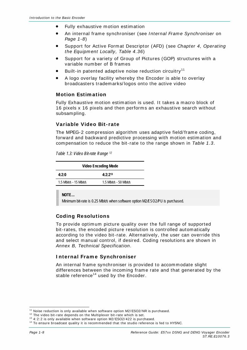
Table 1.3: Video Bit-rate Range 12
Video Encoding Mode
4:2:0 4:2:213 1.5 Mbit/s - 15 Mbit/s 1.5 Mbit/s - 50 Mbit/s
NOTE… Minimum bit-rate is 0.25 Mbit/s when software option M2/ESO2/PU is purchased.
Coding Resolutions
To provide optimum picture quality over the full range of supported bit-rates, the encoded picture resolution is controlled automatically according to the video bit-rate. Alternatively, the user can override this and select manual control, if desired. Coding resolutions are shown in Annex B, Technical Specification.
Internal Frame Synchroniser
An internal frame synchroniser is provided to accommodate slight differences between the incoming frame rate and that generated by the stable reference14 used by the Encoder.
11 Noise reduction is only available when software option M2/ESO2/NR is purchased. 12 The video bit-rate depends on the Multiplexer bit-rate which is set. 13 4:2:2 is only available when software option M2/ESO2/422 is purchased. 14 To ensure broadcast quality it is recommended that the studio reference is fed to HYSNC.

Introduction to the Basic Encoder
Reference Guide: E57xx DSNG and DENG Voyager Encoder Page 1-9 ST.RE.E10076.3
Output on Video Loss
The Encoder can be software-configured to show, in the event of video input loss, either:
• A test pattern (with or without ident text)
• A freeze frame (with or without ident text)
• Cut to a black screen (with or without ident text)
• Drop the video PID
• Turn off the ASI output of the Encoder
1.3.2 Audio Encoding
General
Audio can be encoded to:
• MPEG-1 Audio (layer 2) standard (sampling rate 32 kHz or 48 kHz).
• Dolby Digital (AC-3)15 (sampling rate 32 kHz or 48 kHz)16.
Output bit-rate is selectable in the range 32 kbit/s - 384 kbit/s (dependent on configuration) for MPEG-1 Audio (layer 2) and 56 kbit/s - 640 kbit/s (dependent on configuration) for Dolby Digital (AC-3) coding mode selectable between 1/0 and 2/0.
• Dolby Digital (AC-3) pre-encoded audio (IEC 61937 specification) in pass-through mode is also available (it only operates at 48 kHz). This is where an audio stream has already been encoded externally, prior to entering the Encoder.
• Linear PCM16 (SMPTE 302M).
• Dolby E Pass-thru16
• DTS Pass-thru16.
NOTES… 1. See Annex F, Audio Modes for details of setting up the audio. 2. MPEG-1 audio sampling rate is fixed at 48 kHz when controlled from the front panel.
Audio Inputs
The standard audio input is:
• AUDIO IN – 15-way male D-type - software selectable balanced analogue or digital AES/EBU, with AES/EBU on left only. A break-out cable is supplied which plugs into this connector and provides a more convenient means of connecting the audio inputs via five connectors. There are four XLR female connectors, with the fifth cable being a BNC which provides an AES/EBU 75 Ω digital reference output.
• Alternatively, audio can be input embedded as AES/EBU on the serial digital interface (SDI). In this mode a maximum of four stereo pairs can be extracted from any two Data Identifiers (DIDs). Audio may be converted to either of the standard output sampling frequencies, 32 kHz or 48 kHz, by use of the built-in asynchronous sample rate converters. This applies only to audio which is not pre-encoded.
15 Dolby Digital (AC-3) is only available when software option M2/ESO2/AC3 is purchased. 16 To achieve lip sync in all modes the audio option M2/EOM2/AUDLIN2 must be used.

Introduction to the Basic Encoder
Page 1-10 Reference Guide: E57xx DSNG and DENG Voyager Encoder ST.RE.E10076.3
Audio Channels
The Encoder Base Board is capable of processing two stereo pairs, from any of the following17:
• SDI Embedded source
• Digital source AES/EBU
• Analogue source, termination impedance 600 Ω or 20 kΩ
These signals may be processed using the encoding modes in the following section.
Output on Digital Audio Loss
The Encoder can be software-configured, in the event of loss of digital audio input lock loss, to either:
• Code an audio stream of silence
• Drop the audio PID
• Turn off the ASI output of the Encoder
MPEG Encoding Modes
The two stereo pairs may be configured in various encoding modes:
• Single mono: either the left or the right channel is encoded - the signal is output to both XLR connectors at the receiving end. Not available in Linear PCM.
• Dual mono: the left and right signals are encoded and carried in the transport stream as a single Packetised Elementary Stream (PES) data stream. The way that the left and right signals are output from the Receiver is dependent on how the routing is set up on the Receiver. Both the left and the right may be output, or the left only, or the right only. This is typically used for multilingual services. Available in MPEG-1 (layer 2) and Linear PCM.
• Stereo: A stereo pair is coded as two mono signals - the two signals are output as stereo at the receiving end.
• Joint stereo: A stereo pair is coded taking advantage of the stereo nature of the channels - the two signals are output as stereo at the receiving end. Available in MPEG-1 (layer 2) only.
• Audio Description Service
Dolby Digital (AC-3) Encoding Modes • 1/0: centre
• 2/0: left and right
Test Tones
The equipment can be configured to generate a test tone for alignment purposes. Refer to Annex B, Technical Specification for level and frequency.
Audio Variable Bit-rate
MPEG-1 audio output bit-rate (see Annex B, Technical Specification) is selectable in the range 32 kbit/s -384 kbit/s (dependent on configuration).
17 See Annex F, Audio Modes for details of setting up the audio.
Introduction to the Basic Encoder
Reference Guide: E57xx DSNG and DENG Voyager Encoder Page 1-11 ST.RE.E10076.3
Dolby Digital (AC-3)
Dolby Digital (AC-3) audio encoding incorporates digital normalisation, preprocessing (filtering), dynamic range compression and the addition of bit-stream information.
Dolby Pro Logic audio can be carried as stereo audio through the Encoder as long as a suitably high bit-rate is selected (see Annex B, Technical Specification).
1.3.3 Vertical Blanking Interval (VBI) Line Processing Modes
Introduction
The Encoder has three modes for processing VBI lines.
NOTE… A maximum of eight VBI lines per field may be extracted. This limit does not apply to Teletext.
VBI in Picture
By selecting the VBI in Picture extended active picture format available in the MPEG 4:2:2 specification the Encoder compresses and transmits the VBI data as part of the active picture. This mode requires up to 3 Mbit/s of extra bit-rate, depending on the amount and complexity of the VBI present.
NOTES… 1. VBI in Picture transmits the VBI waveform as part of the picture and as such will be subject to
some distortion. Most analogue VBI types are robust against this type of distortion but others, e.g. video index, are intended for SDI transmission and will not survive MPEG coding/decoding in VBI in Picture mode. VITS test signal and ghost cancellation signal will become corrupted.
2. VBI in Picture is not supported when 3:2 Pulldown is active.
VBI User Data
Closed Caption data, together with other formats such as VITC and AFD, can be transmitted in the user data field of the video or relevant part of the video stream.
VBI in PID
The Encoder has the ability to extract and transmit a wide variety of VBI line formats. Circuitry on the front end of the equipment incorporates a number of general purpose line grabbers so that known formats of VBI data can be extracted.
The following VBI data formats are supported:
• Line 21 (field 1 and field 2) data Services EIA-608 (Closed Caption and V-chip)
• Neilson AMOL 1, Neilson AMOL 11

Introduction to the Basic Encoder
Page 1-12 Reference Guide: E57xx DSNG and DENG Voyager Encoder ST.RE.E10076.3
• VITC18 (EBU and SMPTE) VITC extraction from line 16 or 22 for 625-line systems (EBU definitions), or line 14 for 525-line systems is supported.
• Programme Delivery Control (PDC), via ITU-R System B Teletext extension data packets of type 8/30, format 2 and Line 16 Video Programme System (VPS). Video Programming Teletext (VPT) and VPS are trade names
• Wide Screen Signalling (WSS) (line 23) ETS 300 294
• Gemstar2x
• EIA516 (NABTS)
• Video Index (for Pan Scan, Aspect Ratio and Active Format Descriptor)
• The supported VBI line number range is 10-22 and 272-285 for 525 lines and 6-22 and 318-334 for 625 lines
Teletext Extraction
The Encoder supports internal Teletext data extraction (Teletext drop) from the VBI of a video input and formats this data into a transport packet, as specified in the DVB specification EN300-472. The Encoder can extract up to 18 lines of Teletext from each field of the video frame.
Line filters can be invoked to selectively disable any individual lines in this range. The filters are provided to allow the user to ensure that non-Teletext lines (e.g. ITS lines) are not erroneously extracted. The extracted Teletext lines are formatted into PES packets according to the DVB specification. The Teletext PES packets are time-stamped to allow correct alignment of subtitling captions with decoded video.
The following Teletext services are extractable:
• Sytem B (WST) Teletext
• Video Programming Teletext (VPT), PDC (Packet 8/30 format 2)
• Inverted Teletext
• EIA516 (NABTS)
1.3.4 Data Channels The basic Encoder supports two data channels, an asynchronous RS-232 and a synchronous RS-442. These are provided as data pipes only, they are not time-stamped.
1.3.5 Outputs Three ASI-C (copper) outputs supplying a DVB and ATSC19 MPEG-2 transport stream are supplied as standard.
18 VITC: Only timecode is extracted. 19 ATSC internal PSIP generation is not supported in Build versions 2.1.0 and 2.2.0.
Introduction to the Basic Encoder
Reference Guide: E57xx DSNG and DENG Voyager Encoder Page 1-13 ST.RE.E10076.3
1.3.6 IF Modulation
E5714
The internal satellite modulator within the E5714 supports QPSK modulation in accordance with EN 300 421 (DVB-S). It provides a main and monitoring IF Output. The IF frequency can be tuned between 50 MHz and 90 MHz in steps of 125 kHz. The maximum symbol rate is 30 Msym/s from 60 MHz to 80 MHz (20 Msym/s at 50 MHz and 90 MHz). Also 950 – 1750 MHz in 1 kHz steps available.
E5740
The satellite modulator fitted within the E5740 is capable of QPSK modulation in accordance with EN 300 421 (DVB-S), and is also capable of 8PSK and 16QAM modulation in accordance with EN 301 210 (DVB-DSNG). It is available with either IF outputs, or L-band outputs.
The IF output frequency can be tuned between 50 MHz and 180 MHz in 1 kHz steps. The L-band output frequency can be tuned between 950 MHz and 1750 MHz in 1 kHz steps. The maximum symbol rate is 66 Msym/s.
E5750
The OFDM modulator fitted within the E5750 provides an IF output at 70 MHz and 0dBm. It is capable of operating in 2k carriers, or 8k carriers transmission modes. It supports FEC rates of ½, 2/3, ¾, 5/6 and 7/8, and guard intervals of 1/32, 1/16, 1/8, and ¼. It can provide QPSK, 16QAM, or 64QAM modulation schemes.
1.3.7 Control and Monitoring Remote control of the Encoder is via the Ethernet network running the Simple Network Management Protocol (SNMP) protocol or via the RS-232/RS-485 remote control port.
Alternatively, Local control is implemented through the front panel keypad and display.
1.3.8 Options and Upgrades Options and Upgrades are described in Chapter 3, Options and Upgrades.

Introduction to the Basic Encoder
Page 1-14 Reference Guide: E57xx DSNG and DENG Voyager Encoder ST.RE.E10076.3
1.4 Guided Tour
1.4.1 Enclosure There are two sizes of enclosure, 1U and 2U versions. The enclosure is used as a stand-alone unit. All inputs and outputs are via rear panel connectors.
1.4.2 Front Panel Description
Front Panel Display, Navigation Keys, Softkeys, Keyboard
The 1U Encoder provides navigation keys to access and input data. The 2U Encoder provides a keypad and softkeys to access and input data. There are two LED indicators, located on the left of the front panel (see Figure 1.5 and Figure 1.7).
The front panel display and navigation keys/softkeys/keyboard are used as a local control method to set up and configure the Encoder (see Chapter 4, Operating the Equipment Locally). They can also be used as quick method for accessing the status of the equipment.
Table 1.4: Front Panel Indicators
Indicator Colour Description
Alarm Red This LED is lit when an alarm condition has been detected by the Encoder.
Power Green This LED is lit when power is being received by the Encoder.
Figure 1.5: 1U Encoder Front Panel Indicators
Power Supply Stand-by Switch
The use of this switch puts the Encoder into stand-by mode. It powers down the supply rails of the display and internal circuits within the unit. The switch type avoids accidental powering-down of the Encoder. For normal use ensure that the I is always at the top (see Figure 1.6).
WARNING… THIS IS NOT A MAINS SWITCH AND DOES NOT ISOLATE THE ENCODER FROM THE POWER
SUPPLY.
Navigation keys, to select options
Alarm (red)
Power (green) Enter Cancel

Introduction to the Basic Encoder
Reference Guide: E57xx DSNG and DENG Voyager Encoder Page 1-15 ST.RE.E10076.3
NOTE… Current versions of the 1U Encoder may not have this switch fitted.
Figure 1.6: Stand-by Switch
Figure 1.7: 2U Encoder Front Panel Indicators
1.4.3 Rear Panel Description
Introduction The Encoder provides connectors at the rear panel. All, except the power connector, are physically located on the separate modules which comprise the Encoder.
Figure 1.8: E5750 (2U) Rear Panel Component Parts and Connectors
On position
Stand-by position
Alarm (red)
Power (green)
Softkeys, to select options
Power Supply Stand-by Switch
Option Slot 1-3
Option Slots 4-5
Base Board
Option Slot 1
Option Slot 4 Option Slot 5
Option Slot 3
Audio In and Audio Reference Out
H Sync
CompositeVideo
ASI Outputs RS-232 Data
RS-422 Data
Alarm
RS-232/ RS-485 Remote Control
SDI In
Ethernet
IF OUT 1
Option Slot 2
IF OUT 2

Introduction to the Basic Encoder
Page 1-16 Reference Guide: E57xx DSNG and DENG Voyager Encoder ST.RE.E10076.3
1.4.4 Boards in the Basic Encoder The basic Encoder contains two boards mounted horizontally in the enclosure (see Table 1.5). Option modules can be fitted in the remaining slots (see Equipment Models on page 1-3 and Chapter 3, Options and Upgrades).
Table 1.5: Boards in the Basic Encoder
Model Number Card E5714 S11171 Encoder Base Board
S12376 Tuneable QPSK Modulator
E5740-IF S11171 Encoder Base Board
S13716 70/140 MHz Satellite Modulator
E5714-LBAND S11171 Encoder Base Board
S13499 L-Band Satellite Modulator
E5740-LBAND S11171 Encoder Base Board
S13719 L-Band Satellite Modulator
E5750 S11171 Encoder Base Board
S12524 OFDM Modulator
Access to the modules or boards in the basic Encoder is not required for normal operation and may invalidate the warranty.

Reference Guide: E57xx DSNG and DENG Voyager Encoder Page 2-1 ST.RE.E10076.3
Chapter 2 2. Installing the Equipment
Contents 2.1 Introduction ............................................................... 2-3
2.1.1 Read This First! ............................................ 2-3 2.1.2 General......................................................... 2-3 2.1.3 Site Requirements ........................................ 2-3
Power Supplies............................................. 2-3 Environment ................................................. 2-3 Lightning Protection...................................... 2-3
2.1.4 EMC Compliance Statements ...................... 2-3 EN 55022 / AS/NZS 3548............................. 2-3 FCC .............................................................. 2-4
2.2 Preliminary Checks ................................................... 2-4 2.2.1 Mechanical Inspection .................................. 2-4 2.2.2 Moving the Equipment Safely ....................... 2-4
2.3 Installing the Equipment............................................ 2-4 2.3.1 Fixing Method ............................................... 2-4 2.3.2 Cable Routing............................................... 2-5 2.3.3 Equipment Access........................................ 2-5 2.3.4 Ventilation..................................................... 2-5
2.4 AC Mains Operating Voltage and Earthing ............... 2-7 2.4.1 AC Power Supply ......................................... 2-7 2.4.2 Power Cable and Earthing............................ 2-7
General......................................................... 2-7 Protective Earth/Technical Earth .................. 2-7 Connecting the Encoder to the AC Power Supply........................................................... 2-8
2.5 -48 Vdc Power Supply............................................... 2-9 2.5.1 DC Power Supply ......................................... 2-9 2.5.2 Location of the DC Input Connector ............. 2-9 2.5.3 Connecting the Equipment to the DC
Power Supply ............................................. 2-10 2.5.4 Protective Earth/Technical Earth ................ 2-10
2.6 Signal Connections For the Basic Unit ....................2-11 2.6.1 Introduction .................................................2-11 2.6.2 Connecting Up the Basic Encoder ..............2-12 2.6.3 Power Supply..............................................2-13 2.6.4 Technical Earth ...........................................2-13 2.6.5 Video Inputs ................................................2-14
SDI IN .........................................................2-14 H SYNC ......................................................2-14 COMP VIDEO .............................................2-14
2.6.6 Audio Inputs ................................................2-15 2.6.7 ASI OUT 1, 2 and 3 Outputs .......................2-16 2.6.8 Control Interfaces........................................2-16
Connection..................................................2-16 Ethernet #1 and #2 .....................................2-16 Alarm...........................................................2-16 Remote Control...........................................2-17
2.6.9 Data ............................................................2-18 RS-232 Connector ......................................2-18 RS-422 Connector ......................................2-18 Voyager Modulator Cards ...........................2-19
2.6.10 Satellite Modulator IF Output (E5714 and E5740 IF) ....................................................2-20 IF Out (Main)...............................................2-20 IF Out (Monitor)...........................................2-20
2.6.11 Satellite Modulator L-Band Output (E5740 LBAND and E5714)........................2-20 L-Band In ....................................................2-20 L-Band Out (Main) ......................................2-21 L-Band Out (Monitor) ..................................2-21 ASI Input .....................................................2-21
2.6.12 OFDM Modulator Outputs (E5750) .............2-22 IF Out 1 .......................................................2-22 IF Out 2 .......................................................2-22

Installing the Equipment
Page 2-2 Reference Guide: E57xx DSNG and DENG Voyager Encoder ST.RE.E10076.3
2.7 Powering Up/Down..................................................2-23 2.7.1 Before Powering Up....................................2-23 2.7.2 Powering Up ...............................................2-23 2.7.3 Powering Down...........................................2-23
2.8 Setting the Encoder IP Address ..............................2-23 2.8.1 Methods of Changing the Encoder IP
Address.......................................................2-23 2.8.2 From the Front Panel Menus ......................2-24 2.8.3 Via Telnet ....................................................2-24
List of Figures Figure 2.1: Fitting the Encoder into a Rack ................................... 2-5 Figure 2.2: Air Path Through the 2U Enclosure............................. 2-6 Figure 2.3: Connector Block for -48 Vdc Input .............................. 2-9 Figure 2.4: E5714 (1U) Rear Panel Component Parts and
Connectors................................................................. 2-11 Figure 2.5: E5740-IF (2U) Rear Panel Component Parts and
Connectors................................................................. 2-11 Figure 2.6: E5740-L-Band (2U) Rear Panel Component Parts
and Connectors.......................................................... 2-12 Figure 2.7: E5750 (2U) Rear Panel Component Parts and
Connectors................................................................. 2-12 Figure 2.8: Equipment Connections for the Basic Unit................ 2-13 Figure 2.9: Main Telnet Menu...................................................... 2-24
List of Tables Table 2.1: Supply Cable Wiring Colours........................................ 2-7 Table 2.2: SDI Connector ............................................................ 2-14 Table 2.3: H SYNC Connector .................................................... 2-14 Table 2.4: COMP VIDEO Connector ........................................... 2-15 Table 2.5: Audio In Connector..................................................... 2-15 Table 2.6: ASI OUT 1, 2 and 3 Connectors................................. 2-16 Table 2.7: Ethernet Connector .................................................... 2-16 Table 2.8: Alarm Connector......................................................... 2-17 Table 2.9: Remote Control Connector (RS-232/ RS-485) ........... 2-17 Table 2.10: RS-232 Data Connector (Base Board) -
Asynchronous ............................................................ 2-18 Table 2.11: RS-422 Data Connector (Base Board) -
Synchronous .............................................................. 2-18 Table 2.12: Voyager Modulator Cards......................................... 2-19 Table 2.13: IF Out Connector (Main)........................................... 2-20 Table 2.14: IF Output Connector (Monitor).................................. 2-20 Table 2.15: L-band In Connector................................................. 2-20 Table 2.16: L-band Out (Main) Connector................................... 2-21 Table 2.17: L-band Out (Monitor) Connector............................... 2-21 Table 2.18: ASI Input ................................................................... 2-22 Table 2.19: IF Out 1 Connector ................................................... 2-22 Table 2.20: IF Out 2 Connector ................................................... 2-22

Installing the Equipment
Reference Guide: E57xx DSNG and DENG Voyager Encoder Page 2-3 ST.RE.E10076.3
2.1 Introduction
2.1.1 Read This First! The Encoder must be handled carefully and thoughtfully to prevent safety hazards and damage. It is usually supplied as part of a system installed by TANDBERG Television engineers. In any case, ensure the personnel designated to install the unit have the appropriate skills and knowledge. If in any doubt, contact Customer Services.
Follow the instructions for installation and only use installation accessories recommended by the manufacturers.
2.1.2 General Installation of the Encoder is normally performed by TANDBERG Television personnel. This chapter provides configuration and connection information for planning installations, checking the final set-up in the event of a fault, modifying the requirements or moving the equipment to another location. In the event of problems, contact Customer Services.
2.1.3 Site Requirements
Power Supplies
See Annex B, Technical Specification for a full specification.
Environment
See Annex B, Technical Specification for a full specification.
Do not install this product in areas of high humidity or where there is danger of water ingress.
Lightning Protection
WARNING… IF THE ENCODER HAS BEEN SUBJECT TO A LIGHTNING STRIKE OR POWER SURGE WHICH HAS STOPPED IT WORKING, DISCONNECT THE POWER IMMEDIATELY. DO NOT REAPPLY POWER UNTIL IT HAS BEEN CHECKED FOR SAFETY. IF IN DOUBT, CONTACT TANDBERG
TELEVISION CUSTOMER SERVICES.
Where appropriate, ensure this product has an adequate level of lightning protection. Alternatively, during a lightning storm or when it is left unattended and unused for long periods of time, unplug it from the supply outlet and disconnect the output equipment. This prevents damage to the product due to lightning and power line surges.
2.1.4 EMC Compliance Statements1
EN 55022 / AS/NZS 3548
This equipment is a Class A product. In a domestic environment this product may cause radio interference in which case the user may be required to take adequate measures.
1 The EMC information was correct at the time of manufacture. The EMC tests were performed with the Technical earth attached.
Installing the Equipment
Page 2-4 Reference Guide: E57xx DSNG and DENG Voyager Encoder ST.RE.E10076.3
FCC
This equipment has been tested and found to comply with the limits for a Class A digital device, pursuant to Part 15 of the FCC Rules. These limits are designed to provide reasonable protection against harmful interference when the equipment is operated in a commercial environment.
This equipment generates, uses, and can radiate radio frequency energy and, if not installed and used in accordance with the instruction manual, may cause harmful interference to radio communications. Operation of this equipment in a residential area is likely to cause harmful interference in which case the user will be required to correct the interference at his own expense.
2.2 Preliminary Checks
2.2.1 Mechanical Inspection When taking delivery of an Encoder, check the equipment items delivered against the enclosed delivery note. Inspect the equipment for damage in transit. If in doubt, contact Customer Services (see Preliminary Pages).
NOTE… Do not remove the covers of this equipment as doing so may invalidate any warranties, cause a safety hazard and/or affect the EMC performance. It may also invalidate any safety tests. Check with Customer Services beforehand.
2.2.2 Moving the Equipment Safely
Do not place this product on an unstable cart, stand, bracket, or table. The product may fall, causing serious injury and serious damage to the product. Use only with a cart, stand, bracket or table recommended by TANDBERG Television.
An appliance and cart combination should be moved with care. Quick stops, excessive force, and uneven surfaces may cause the appliance and cart combination to overturn.
Do not move or carry the equipment whilst it is still connected to the supply or other leads, is live or is in operation.
2.3 Installing the Equipment
2.3.1 Fixing Method The Encoder can be operated mounted in a 19-inch rack. Ensure that it is firmly and safely located and has an adequate through-flow of air.
Slide the Encoder onto the chassis supports and affix to the rack by means of an M6 x 18 mm panhead screw in each corner (see Figure 2.1).
Do not use this product as a support for any other equipment.

Installing the Equipment
Reference Guide: E57xx DSNG and DENG Voyager Encoder Page 2-5 ST.RE.E10076.3
Figure 2.1: Fitting the Encoder into a Rack
NOTE… Current versions are not fitted with the Standby switch shown above.
2.3.2 Cable Routing Power supply cables should be routed so that they are not likely to be walked on or pinched by items placed upon or against them. Pay particular attention to cables at plugs, convenience receptacles, and the point where they exit from the appliance.
Do not run ac power cables in the same duct as signal leads.
2.3.3 Equipment Access
WARNING... BERYLLIUM COPPER FINGER STRIPS ARE USED IN THIS EQUIPMENT TO SEAL THE
ENCLOSURE FOR EMI PROTECTION. THIS ARRANGEMENT IS PERFECTLY SAFE DURING NORMAL OPERATION. DO NOT FILE THE STRIPS OR OTHERWISE CAUSE THEM TO PRODUCE
DUST OR PARTICLES. ANY CUTS CAUSED BY THE STRIP SHOULD BE TREATED APPROPRIATELY.
Ensure that the Encoder is installed in such a way as to allow access to the rear of the unit and the connectors.
2.3.4 Ventilation
WARNING... NEVER PUSH OBJECTS OF ANY KIND INTO THIS EQUIPMENT THROUGH OPENINGS AS THEY
MAY TOUCH DANGEROUS VOLTAGE POINTS OR SHORT-OUT PARTS THAT COULD RESULT IN A FIRE OR ELECTRIC SHOCK. NEVER SPILL LIQUID OF ANY KIND ON THE PRODUCT.
CAUTIONS... 1. Openings in the cabinet are provided for ventilation and to ensure reliable operation of the product
and to protect it from overheating, and these openings must not be blocked or covered. This product should never be placed near or over a radiator or heat register. This product should not be placed in a built-in installation such as a rack unless proper ventilation is provided or the instructions have been adhered to.
2. Do not install equipment so that the air intake of one aligns with the outlet on another. Provide baffles and adequate spacing.
3. The fans contained within this unit are not fitted with a dust/insect filter. Pay particular attention to the environment in which it is to be used.
Location of screws to attachEncoder to rack.
Same at the opposite side ofthe Encoder.
Installing the Equipment
Page 2-6 Reference Guide: E57xx DSNG and DENG Voyager Encoder ST.RE.E10076.3
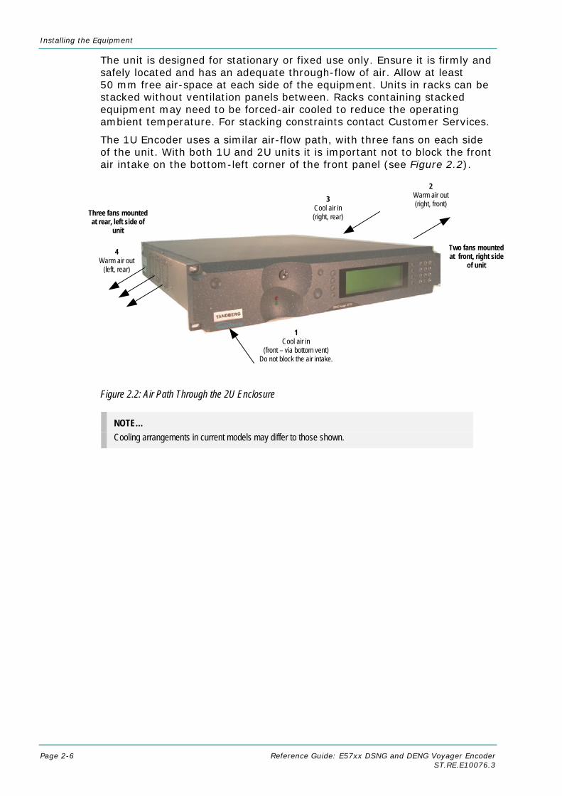
The unit is designed for stationary or fixed use only. Ensure it is firmly and safely located and has an adequate through-flow of air. Allow at least 50 mm free air-space at each side of the equipment. Units in racks can be stacked without ventilation panels between. Racks containing stacked equipment may need to be forced-air cooled to reduce the operating ambient temperature. For stacking constraints contact Customer Services.
The 1U Encoder uses a similar air-flow path, with three fans on each side of the unit. With both 1U and 2U units it is important not to block the front air intake on the bottom-left corner of the front panel (see Figure 2.2).
Figure 2.2: Air Path Through the 2U Enclosure
NOTE… Cooling arrangements in current models may differ to those shown.
2 Warm air out (right, front)
4 Warm air out
(left, rear)
1 Cool air in
(front – via bottom vent) Do not block the air intake.
Two fans mounted at front, right side
of unit
3 Cool air in (right, rear) Three fans mounted
at rear, left side of unit

Installing the Equipment
Reference Guide: E57xx DSNG and DENG Voyager Encoder Page 2-7 ST.RE.E10076.3
2.4 AC Mains Operating Voltage and Earthing
2.4.1 AC Power Supply
CAUTION... This product should be operated only from the type of power source indicated on the marking label. If you are not sure of the type of power supply to your business, consult a qualified electrical engineer or
your local power company.
See Annex B, Technical Specification for a full power supply specification. There are no links or switches to be altered for operation from different ac supplies.
2.4.2 Power Cable and Earthing
General
Check that the ac power cable is suitable for the country in which the Encoder is to be used.
WARNINGS... 1. IF THE MOULDED PLUG FITTED TO THE MAINS CABLE SUPPLIED WITH THIS UNIT IS NOT
REQUIRED, PLEASE DISPOSE OF IT SAFELY. FAILURE TO DO THIS MAY ENDANGER LIFE AS LIVE ENDS MAY BE EXPOSED IF THE REMOVED PLUG IS INSERTED INTO A MAINS OUTLET.
2. POWER-SUPPLY CORDS SHOULD BE ROUTED SO THAT THEY ARE NOT LIKELY TO BE WALKED ON OR PINCHED BY ITEMS PLACED UPON OR AGAINST THEM, PAYING PARTICULAR ATTENTION TO CORDS AT PLUGS, CONVENIENCE RECEPTACLES, AND THE POINT WHERE THEY EXIT FROM THE APPLIANCE.
The unit is supplied with three, detachable mains-supply cables fitted with moulded plugs suitable for the USA, UK or Europe.
The wires in the mains cable are coloured in accordance with the wire colour code shown in Table 2.1.
Table 2.1: Supply Cable Wiring Colours
UK (BS 1363)
EUROPE (CEE 7/7)
USA (NEMA 5-15P)
Earth: Green-and-yellow Green-and-yellow Green
Neutral: Blue Blue White
Live: Brown Brown Black
Protective Earth/Technical Earth
WARNINGS... 1. THIS UNIT MUST BE CORRECTLY EARTHED THROUGH THE MOULDED PLUG SUPPLIED.
IF THE LOCAL MAINS SUPPLY DOES NOT HAVE AN EARTH CONDUCTOR DO NOT CONNECT THE UNIT. CONTACT CUSTOMER SERVICES FOR ADVICE.
2. BEFORE CONNECTING THE UNIT TO THE SUPPLY, CHECK THE SUPPLY REQUIREMENTS IN ANNEX B.

Installing the Equipment
Page 2-8 Reference Guide: E57xx DSNG and DENG Voyager Encoder ST.RE.E10076.3
The unit has a Technical earth terminal (marked with ) located at the rear panel. Its use is recommended. This is NOT a Protective earth for electric shock protection. The terminal is provided to:
1. Ensure all equipment chassis fixed within a rack are at the same Technical earth potential. To do this, connect a wire between the Technical earth terminal and a suitable point on the rack.
2. Eliminate the migration of stray charges when connecting between equipment.
WARNING... IF THE TERMINAL SCREW HAS TO BE REPLACED, USE THE FOLLOWING:
1U ENCODER - M4 X 10 mm LONG POZIDRIV PANHEAD. 2U ENCODER - M5 X 12mm LONG POZIDRIV PANHEAD.
USING A LONGER SCREW MAY CAUSE A SAFETY HAZARD.
Connecting the Encoder to the AC Power Supply
WARNINGS... 1. DO NOT OVERLOAD WALL OUTLETS AND EXTENSION CORDS AS THIS CAN RESULT IN A
RISK OF FIRE OR ELECTRIC SHOCK. 2. AS NO MAINS SWITCH IS FITTED TO THIS UNIT, ENSURE THE LOCAL AC POWER SUPPLY
IS SWITCHED OFF BEFORE CONNECTING THE SUPPLY CORD. 3. THE ENCODER IS NOT FITTED WITH AN ON/OFF SWITCH. ENSURE THAT THE SOCKET-
OUTLET IS INSTALLED NEAR THE EQUIPMENT SO THAT IT IS EASILY ACCESSIBLE. FAILURE TO ISOLATE THE EQUIPMENT PROPERLY MAY CAUSE A SAFETY HAZARD.
To connect the unit to the local ac power supply:
1. Ensure the local ac supply is switched OFF.
2. Ensure the correct fuse type and rating has been fitted to both the equipment and the ac power cable.
3. Connect the ac power lead to the Encoder mains input connector and then to the local mains supply.

Installing the Equipment
Reference Guide: E57xx DSNG and DENG Voyager Encoder Page 2-9 ST.RE.E10076.3
2.5 -48 Vdc Power Supply
2.5.1 DC Power Supply
NOTE… Only model M2/VOY/E5750/48V uses a dc power supply.
CAUTION... This product should be operated only from the type of power source indicated on the marking label. If you are not sure of the type of power supply to your business, consult a qualified electrical engineer.
This product uses a –48 Vdc power supply source (see Annex B, Technical Specification for a full power supply specification.
2.5.2 Location of the DC Input Connector The connector is located at the right-hand rear of the equipment.
WARNING… THE –48 VDC ENCODER IS NOT FITTED WITH AN ON/OFF SWITCH. ENSURE THAT THE SUPPLY
HAS A SUITABLE MEANS OF ISOLATION WHICH IS EASILY ACCESSIBLE. FAILURE TO ISOLATE THE EQUIPMENT PROPERLY MAY CAUSE A SAFETY HAZARD.
Figure 2.3: Connector Block for -48 Vdc Input
The equipment fuse is held in an integral fuse carrier at the dc power inlet at the rear of the Encoder. See Annex B, Technical Specification for dc fuse information.
— +
Technical Earth
Fuse Carrier
Connector Block
Supply Side
Equipment Side — +
Connector Block
Fuse6.3A
—48 V 0 V
1U Encoder
2U Encoder
Technical Earth

Installing the Equipment
Page 2-10 Reference Guide: E57xx DSNG and DENG Voyager Encoder ST.RE.E10076.3
2.5.3 Connecting the Equipment to the DC Power Supply Connect the Encoder to the local dc power supply as follows.
1. Local DC Power Supply Ensure the local dc supply is isolated.
2. Encoder Ensure the correct fuse is fitted.
3. Supply Cord Connect the dc lead to the Encoder input connector and then to the local dc power supply. Switch on the dc power supply.
2.5.4 Protective Earth/Technical Earth The unit has a Technical earth terminal (marked with ) located at the rear panel (see Figure 2.3). Its use is recommended. This is NOT a Protective earth for electric shock protection. The terminal is provided to:
• Ensure all equipment chassis fixed within a rack are at the same Technical earth potential. To do this, connect a wire between the Technical earth terminal and a suitable point on the rack.
• Eliminate the migration of stray charges when connecting between equipment.
WARNING... IF THE TERMINAL SCREW HAS TO BE REPLACED, USE THE FOLLOWING:
1U ENCODER - M4 X 10 mm LONG POZIDRIV PANHEAD. 2U ENCODER - M5 X 12mm LONG POZIDRIV PANHEAD.
USING A LONGER SCREW MAY CAUSE A SAFETY HAZARD.

Installing the Equipment
Reference Guide: E57xx DSNG and DENG Voyager Encoder Page 2-11 ST.RE.E10076.3
2.6 Signal Connections For the Basic Unit
2.6.1 Introduction All signal connectors are located at the rear panel of the Encoder. For a detailed interface specification see Annex B, Technical Specification.
Always use the specified cables supplied for signal integrity and compliance with EMC requirements (see Annex B, Technical Specification).
Figure 2.4: E5714 (1U) Rear Panel Component Parts and Connectors
Figure 2.5: E5740-IF (2U) Rear Panel Component Parts and Connectors
Option Slot 2
Audio In and
Audio Reference Out
H Sync Composite Video
ASI Outputs Ethernet RS-232 Data
RS-422 Data
Alarm RS-232/ RS-485Remote Control
SDI In
Base Board
Technical EarthIF Out Main IF Out Monitor
Technical Earth
Option Slot 1
Option Slot 4 Option Slot 5 Option Slot 6
Option Slot 1
Audio In and
Audio Reference Out Composite
Video
ASI Outputs
Alarm
RS-232/RS-485 Remote Control
SDI In Ethernet
Option Slots 4-6
Base Board
IF Out Main
IF Out Monitor
TANDBERG Television use
only
H Sync
RS-232 Data
RS-422 Data

Installing the Equipment
Page 2-12 Reference Guide: E57xx DSNG and DENG Voyager Encoder ST.RE.E10076.3
Figure 2.6: E5740-L-Band (2U) Rear Panel Component Parts and Connectors
Figure 2.7: E5750 (2U) Rear Panel Component Parts and Connectors
2.6.2 Connecting Up the Basic Encoder Once the unit has been installed in its intended operating position, it is ready to be connected up to the rest of the system equipment (see Figure 2.8), providing it too has been installed (see the following for pin-out details of the connectors).
Technical Earth
Option Slot 1
Option Slot 4 Option Slot 5 Option Slot 6
Option Slot 1
Audio In and
Audio Reference OutCompositeVideo
ASI Outputs
Alarm
RS-232/RS-485Remote Control SDI InEthernet
Option Slots 4-6
Base Board
L-Band In L-Band Out TANDBERG Television use
only
H Sync
RS-232Data
RS-422Data
Technical Earth
Option Slot 1
Option Slot 4 Option Slot 5
Option Slot 1
Audio In and
Audio Reference OutCompositeVideo
ASI Outputs
Alarm
RS-232/RS-485Remote Control
SDI InEthernet
Option Slots 4-5
Base Board
L-Band In L-Band Out
H Sync
RS-232Data
RS-422Data

Installing the Equipment
Reference Guide: E57xx DSNG and DENG Voyager Encoder Page 2-13 ST.RE.E10076.3
Figure 2.8: Equipment Connections for the Basic Unit
Do not move or install equipment whilst it is still attached to the mains supply. Ensure ESD precautions are observed whilst interconnecting equipment.
NOTE… See Chapter 3 for information relating to Options and Upgrades.
2.6.3 Power Supply Section 2.4, AC Mains Operating Voltage and Earthing provides details of power supply connection, Protective earthing and safety. Read all the instructions carefully and take note of all warnings and cautions.
2.6.4 Technical Earth Connect the Encoder's Technical earth to a suitable point.
Encoder
Video Input SDI IN H SYNC COMP VIDEO
Audio input
AES/EBU Reference
ETHERNET #1 ETHERNET #2 REMOTE CONTROL
Audio Input
Control
RS-232 data input
RS-422 data input
Alarm
DVB/ATSC Transport stream output
Output
Alarm
ASI OUT 1
ASI OUT 2
ASI OUT 3
ALARM
10BaseT
10BaseT
RS-232/RS-485
AUDIO IN
DVB/ATSC Transport stream output DVB/ATSC Transport stream output
Serial Digital Interface
Analogue composite video
Studio Black and Burst
Data
RS-232 DATA RS-422 DATA
Main Output
Modulator (IF) [E5740-IF]
OUT MAIN
OUT MONITOR Monitor Output
L-Band In
Modulator (L-band) [E5740-L Band]
L-BAND IN
L-BAND OUT MAIN
L-BAND OUT MONITOR
L-Band Monitor Output L-Band Main Output

Installing the Equipment
Page 2-14 Reference Guide: E57xx DSNG and DENG Voyager Encoder ST.RE.E10076.3
2.6.5 Video Inputs
SDI IN A 75 Ω BNC connector provides a serial digital video input to the unit. See Chapter 4, Operating the Equipment Locally, Video Input Option for the types of video and selection method. This input is terminated in 75 Ω.
The serial input supports error detection and handling (EDH) as defined by the specification SMPTE RP 165-1994, ‘Error Detection Checkwords and Status Flags for Use in Bit Serial Digital Interfaces for Television’.
For more information about EDH refer to Annex I, EDH Capability for E57xx Encoders.
Table 2.2: SDI Connector
Pin Signal Centre Video Input
Screen Ground
Impedance 75 Ω
H SYNC Studio Black and Burst should be fed to the 75 Ω BNC connector (H SYNC). This will then genlock the Encoder to the Studio system. This method may be required with some audio formats, or for locking Encoders to an evolution 5000 Multiplexer. For details on the genlocking system see Annex F, Audio Modes.
Table 2.3: H SYNC Connector
Pin Signal Centre Video Input
Screen Ground
Impedance 75 Ω
COMP VIDEO A 75 Ω BNC connector provides a high quality analogue video input to the unit. See Chapter 4, Operating the Equipment Locally, Video Input Option for the types of video and selection method.
NOTE… The input is differential to prevent 50 Hz/60 Hz hum.

Installing the Equipment
Reference Guide: E57xx DSNG and DENG Voyager Encoder Page 2-15 ST.RE.E10076.3
Table 2.4: COMP VIDEO Connector
Pin Signal Centre Video Input
Screen Video Input Return
Impedance 75 Ω
2.6.6 Audio Inputs Connect the audio cable to the AUDIO IN connector. The 15-way, D-type male connector is used in different ways according to the audio input and the encoding configuration selected.
The connector provides two stereo pairs. They may be independently configured as either analogue or digital. The left channel is used to input digital audio. The Encoder is supplied with a break-out cable which plugs into this connector, and provides a more convenient means of connecting the audio signals via five connectors. There are four XLR female connectors, with the fifth cable being a BNC which provides an AES/EBU 75 Ω digital reference output. Table 2.5: Audio In Connector
Pin Signal Pin Signal
Analogue Digital Analogue Digital
1 Left Channel A (+) AES/EBU (A) (+) 9 Left Channel A (-) AES/EBU (A) (-)
2 Not connected 10 Right Channel A (+)
3 Right Channel A (-) 11 Not connected
4 Left Channel B (+) AES/EBU (B) (+) 12 Left Channel B (-) AES/EBU (B) (-)
5 Not connected 13 Right Channel B (+)
6 Right Channel B (-) 14 Not connected
7 AES/EBU Reference (Signal)
15 AES/EBU Reference (Ground)
8 Not connected
NOTES… 1. In analogue mode termination is either 20 kΩ or 600 Ω. 2. In AES/EBU mode termination is 110 Ω. 3. When the Encoder is powered down the digital channel is selected with 110 Ω termination. 4. The digital audio input does not support SPDIF. 5. In order to comply with EMC regulations, use the audio break-out cable supplied with the unit.

Installing the Equipment
Page 2-16 Reference Guide: E57xx DSNG and DENG Voyager Encoder ST.RE.E10076.3
2.6.7 ASI OUT 1, 2 and 3 Outputs Connect the Multiplexer or Modulator ASI cable to the appropriate ASI OUT connector, using good quality 75 Ω coaxial cable (for example, BBC PSF 1/3).
A 75 Ω BNC connector provides the output from the Encoder.
Table 2.6: ASI OUT 1, 2 and 3 Connectors
Pin Signal Centre Signal
Screen Ground
2.6.8 Control Interfaces
Connection
Operation of the Encoder from a TANDBERG Television control system is via the Ethernet network running the Simple Network Management Protocol (SNMP) protocol. Connect the ETHERNET connector to the controller (for example, MEM). Local control is implemented through the front panel keypad and display. See Chapter 4, Operating the Equipment Locally for details of how to access the front panel menus.
Ethernet #1 and #2
An 8-way, RJ-45 connector provides a 10BaseT Ethernet interface for communications with the MEM for control and monitoring. The Encoder has a single switched Ethernet channel. Ethernet#1 is selected as default at power-up. If a carrier is not detected on Ethernet#1 then the input switches to Ethernet#2. This gives a redundant Ethernet control via two hubs.
Table 2.7: Ethernet Connector
Pin Signal Pin Signal 1 Tx Out (+) 4-5 Not connected
2 Tx Out (-) 6 Rx In (-)
3 Rx In (+) 7-8 Not connected
Alarm
If required, connect an external status monitoring device to the ALARM connector.
A 9-way, D-type male connector provides an alarm relay interface which can be used to send a signal to remote equipment.

Installing the Equipment
Reference Guide: E57xx DSNG and DENG Voyager Encoder Page 2-17 ST.RE.E10076.3
Table 2.8: Alarm Connector
Pin Signal Pin Signal 1 Ground 6 Fail (NO)
2 Fail (common) 7 Fail (NC)
3 Alarm (NO) 8 Alarm (common)
4 Alarm (+) (NC) 9 Reset 2 (internally grounded)
5 Reset 1 (internally pulled to 3.3 Vdc via 10 kΩ)
NOTE… NC = Normally Closed, NO = Normally Open, and refers to the relay contacts. Refer to Annex B for details of the relay contact rating.
Remote Control
A 9-way, D-type male connector provides an RS-232/RS-485 port for remote control of the Encoder (see Serial Protocol Option). This connector is wired as a DTE.
Table 2.9: Remote Control Connector (RS-232/ RS-485)
Remote (DTE) Encoder (DTE) Remote Control
Signal Name Signal Direction Pin Signal Name 1 Not connected Transmit Data 2 Received Data (RS-232) Received Data 3 Transmit Data (RS-232) 4 Not connected Signal Ground 5 Signal Ground Transmit Data B 6 Received Data B (RS-485) Received Data A 7 Transmit Data A (RS-485) Received Data B 8 Transmit Data B (RS-485) Transmit Data A 9 Received Data A (RS-485)
NOTES… 1. Signal names are with respect to a DTE in accordance with the RS-232 and RS-485
specification. A is positive and B is negative. 2. A null modem connection must be used when connecting DTE together.
Alarm Common
Fail (NC) Fail (NO)
Alarm (NC) Alarm (NO)
Fail Common
Reset 1 Reset 2
3.3 V
10 kΩ

Installing the Equipment
Page 2-18 Reference Guide: E57xx DSNG and DENG Voyager Encoder ST.RE.E10076.3
2.6.9 Data
RS-232 Connector
RS-232 data is available on the Base Board.
Table 2.10: RS-232 Data Connector (Base Board) - Asynchronous
Remote (DTE) Male Encoder RS-232 (DTE) Female
Signal Name Pin Signal Direction Pin Signal Name 1 1 Not connected Received Data 2 2 Received Data Transmit Data 3 3 Transmit Data 4 4 Not connected Signal Ground 5 5 Signal Ground 6, 7, 8, 9 6, 7, 8, 9 Not connected
NOTES… 1. Signal names are with respect to a DTE in accordance with the RS-232 specification. 2. Remote pin numbers only apply to a 9-way D-type connector. 3. 25-way connectors have Received Data on pin 3 and Transmit Data on pin 2 (see RS –232
specification). 4. XON/OFF flow control may be used with this port.
RS-422 Connector
A 15-way, D-type female connector provides an RS-422 synchronous, serial communications data input interface.
Table 2.11: RS-422 Data Connector (Base Board) - Synchronous
Remote (DTE) Encoder RS-422 (DCE)
Signal Name Signal Direction Pin Signal Name 1 Not connected Transmit Data A 2 Transmit Data A 3, 4, 5, 6 Not connected 4 Not connected 5 Not connected 6 Not connected Transmit Clock A 7 Transmit Clock A Signal Ground 8 Signal Ground Transmit Data B 9 Transmit Data B 10, 11,
12, 13 Not connected
Transmit Clock B 14 Transmit Clock B 15 Not connected

Installing the Equipment
Reference Guide: E57xx DSNG and DENG Voyager Encoder Page 2-19 ST.RE.E10076.3
NOTE… Signal names are with respect to a DTE in accordance with the RS-422 specification. A is positive and B is negative.
Voyager Modulator Cards
Table 2.12 shows the modulator cards and associated Encoder Models.
Table 2.12: Voyager Modulator Cards
Encoder Product (Marketing Code)
Size S Number and Marketing Code Number of Modulator Option Card
Number of ASI Inputs
Rate Adaptation Available
Modulation Schemes
24 Vdc BUC Power Available
E5714 (M2/VOY/E5714 IF)
1U S12376 1/3 Width IF (M2/EOM2/QPSK2)
0 No BPSK/QPSK N/A
E5714 (M2/VOY/E5714 LBAND
1U S13499 1/3 Width L-Band (M2/EOM2/QPSKLBAND)
1 Yes BPSK/QPSK No
E5740 (M2/VOY/E5740 IF)
2U S13716 2/3 Width IF (M2/EOM2/SM3IF)
2 No BPSK/QPSK 8BPSK/16QAM
N/A
E5740 (M2/VOY/E5740 LBAND)
2U S13719 2/3 Width L-Band (M2/EOM2/SM3LBAND)
2 No BPSK/QPSK 8BPSK/16QAM
Yes
E5745 (M2/VOY/E5745/IF)
2U S12376 1/3 Width IF (M2/EOM2/QPSK2)
0 No BPSK/QPSK N/A
E5745 L-Band (M2/EOM2/E5745/LBAND)
2U S13499 1/3 Width L-Band (M2/EOM2/QPSKLBAND)
1 Yes BPSK/QPSK yes
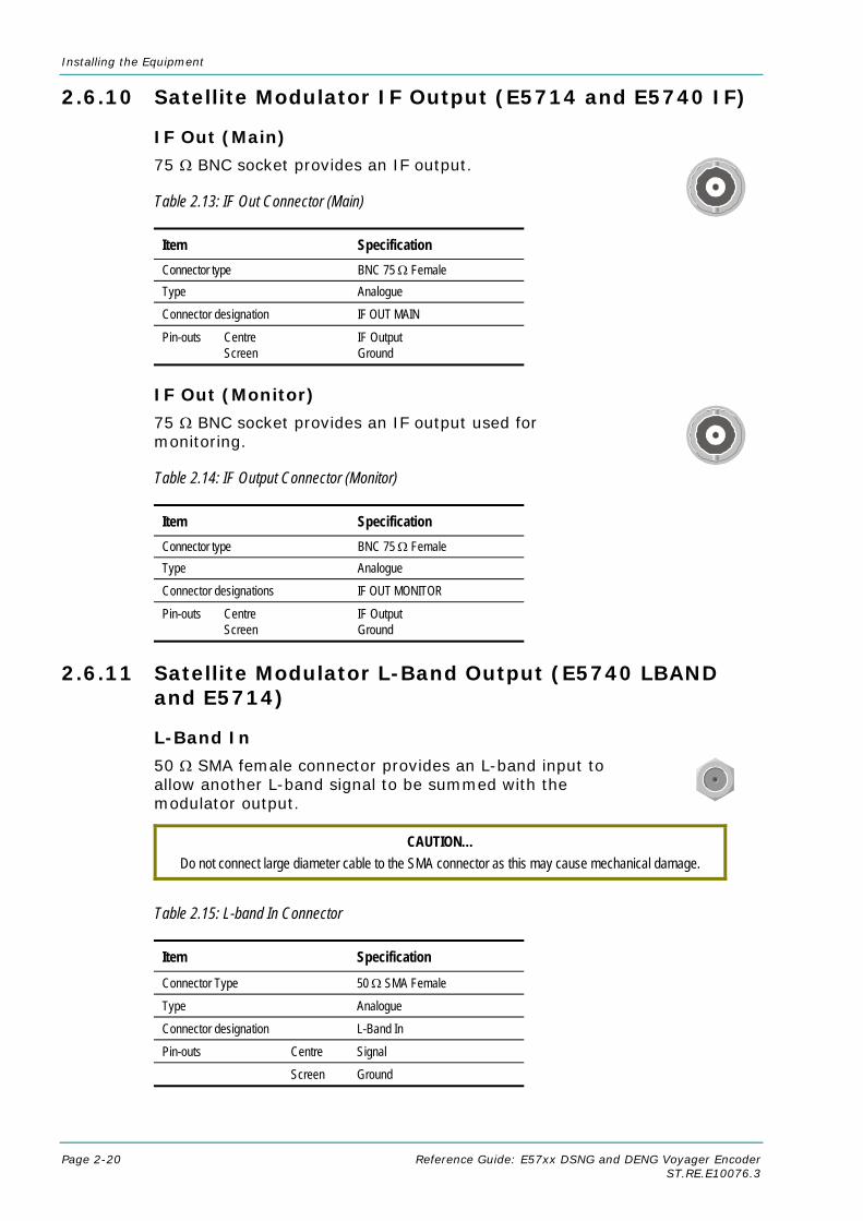
Installing the Equipment
Page 2-20 Reference Guide: E57xx DSNG and DENG Voyager Encoder ST.RE.E10076.3
2.6.10 Satellite Modulator IF Output (E5714 and E5740 IF)
IF Out (Main)
75 Ω BNC socket provides an IF output.
Table 2.13: IF Out Connector (Main)
Item Specification Connector type BNC 75 Ω Female Type Analogue Connector designation IF OUT MAIN
Pin-outs Centre Screen
IF Output Ground
IF Out (Monitor)
75 Ω BNC socket provides an IF output used for monitoring.
Table 2.14: IF Output Connector (Monitor)
Item Specification Connector type BNC 75 Ω Female Type Analogue Connector designations IF OUT MONITOR
Pin-outs Centre Screen
IF Output Ground
2.6.11 Satellite Modulator L-Band Output (E5740 LBAND and E5714)
L-Band In
50 Ω SMA female connector provides an L-band input to allow another L-band signal to be summed with the modulator output.
CAUTION… Do not connect large diameter cable to the SMA connector as this may cause mechanical damage.
Table 2.15: L-band In Connector
Item Specification Connector Type 50 Ω SMA Female
Type Analogue
Connector designation L-Band In
Pin-outs Centre Signal
Screen Ground

Installing the Equipment
Reference Guide: E57xx DSNG and DENG Voyager Encoder Page 2-21 ST.RE.E10076.3
L-Band Out (Main)
50 Ω SMA female connector provides the main L-band output. Both models can provide a 10 MHz reference frequency output and the E5740 can also source +24 Vdc at up to 500 mA to power a block up-converter (BUC) An LED is illuminated when the +24 Vdc up-converter power is switched on.
CAUTION… Do not connect large diameter cable to the SMA connector as this mat cause mechanical damage.
Please use the cable provided (part number S12696).
NOTE… DC supply not available in 1U L Band version.
Table 2.16: L-band Out (Main) Connector
Item Specification Connector Type 50 Ω SMA Female
Type Analogue
Connector designation L-Band Out Main
Pin-outs Centre Signal
Screen Ground
CAUTION… A 24 V dc voltage is present at the L-BAND OUT MAIN connector when the up-converter dc power is switched on. Do not connect this output directly to a spectrum analyser or other sensitive equipment.
The use of a dc block is recommended.
L-Band Out (Monitor)
75 Ω F-type female provides an L-band monitoring output which is –30 dB relative to the main output.
Table 2.17: L-band Out (Monitor) Connector
Item Specification Connector Type 75 Ω F-type Female
Type Analogue
Connector designation L-Band Out Monitor
Pin-outs Centre Signal
Screen Ground
ASI Input
This connector is available with the following models: E5740-IF and L-Band, and the E5714 L-band (when fitted with the S13716/S13719).
Connector details for the ASI input are given in Table 2.18.

Installing the Equipment
Page 2-22 Reference Guide: E57xx DSNG and DENG Voyager Encoder ST.RE.E10076.3
Table 2.18: ASI Input
Item Specification Connector Type 75 Ω BNC Female
Type Analogue
Connector designation ASI IN 1, ASI IN 2
Pin-outs Centre Signal
Screen Ground
2.6.12 OFDM Modulator Outputs (E5750)
IF Out 1
A 75 Ω BNC socket provides a 70 MHz IF output.
Table 2.19: IF Out 1 Connector
Item Specification Connector Type BNC 75 Ω Female
Type Analogue
Connector designation IF Out 1
Pin-outs Centre Signal
Screen Ground
IF Out 2
A 75 Ω BNC socket provides a 70 MHz IF output used for monitoring.
Table 2.20: IF Out 2 Connector
Item Specification Connector Type BNC 75 Ω Female
Type Analogue
Connector designation IF Out 2
Pin-outs Centre Signal
Screen Ground

Installing the Equipment
Reference Guide: E57xx DSNG and DENG Voyager Encoder Page 2-23 ST.RE.E10076.3
2.7 Powering Up/Down
2.7.1 Before Powering Up Before powering up the Encoder, check that:
1. The unit has been installed in a suitable location.
2. The unit has been connected to external equipment and power supply, as required.
3. The power supply has been checked and a good earth provided.
4. The correct fuse type and rating has been fitted to the equipment and, for the ac supply version, the ac power cable.
2.7.2 Powering Up To power up the Encoder:
1. Turn on the local power supply. The Encoder executes a series of power-up initialisation and self-test routines.
2. Confirm that the green Power LED is lit and that the red Alarm LED is unlit.
3. Ensure that the Stand-by switch, if fitted, is set to On (see Chapter 1, Introduction, Figure 1.8).
After the boot period the Encoder Input Monitor screen is displayed.
NOTES… 1. The fans on the Encoder can be temperature controlled so may not be on if the ambient
temperature is low. Refer to Annex B, Technical Specification for more information. 2. During initialisation invalid PIDs may appear momentarily in the transport stream.
2.7.3 Powering Down To power down the Encoder remove the power supply connection at the rear of the unit.
2.8 Setting the Encoder IP Address
2.8.1 Methods of Changing the Encoder IP Address If, for any reason, the IP address has to be changed, this can be achieved via the front panel menus (see Section 4.7.4 Remote Control Menu) or by Telnet (see Section 2.8.3, Via Telnet). The user may also set the network mask.
NOTE… The new IP address is only accepted after the Encoder is repowered.

Installing the Equipment
Page 2-24 Reference Guide: E57xx DSNG and DENG Voyager Encoder ST.RE.E10076.3
2.8.2 From the Front Panel Menus To access the IP Address option from the front panel menus, press the IP Address softkey in the Remote Control Menu. Edit the IP address via the keypad and then press the Enter softkey.
IP Address ← Left Encoder IP Address : + → Right `172.16.248.91’ — O Enter O Update using softkeys Quit
2.8.3 Via Telnet A Telnet program is supplied with Microsoft Windows. To communicate with the Encoder through Telnet:
1. From DOS, type telnet <IP address>.
2. Press Enter for the user name, and press Enter for the password.
3. The Main Telnet Menu is displayed.
Figure 2.9: Main Telnet Menu
4. Press <a> System, <b> Remote Control, <a> IP Address.
5. Enter the new value and press Enter.
6. Reset the Encoder.

Reference Guide: E57xx DSNG and DENG Voyager Encoder Page 3-1 ST.RE.E10076.3
Chapter 3 3. Options and Upgrades
Contents 3.1 What’s Available........................................................ 3-3
3.1.1 Option Functions .......................................... 3-3 3.1.2 Limitations on Number of Option Modules
(2U Only) ...................................................... 3-4 Overview....................................................... 3-4 E5740 Option Slots....................................... 3-4 E5750 Option Slots....................................... 3-4
3.1.3 Limitations on Use of Option Modules.......... 3-4 3.1.4 How to See Which Options are
Fitted/Enabled .............................................. 3-5 3.2 Bit-rate Limits With Reflex Licence and/or
Performance Upgrade............................................... 3-5 3.3 Basic Interoperable Scrambling System - BISS
(M2/EDCOM2/BISS) ................................................. 3-5 3.4 Additional Audio and Linear PCM Option
(M2/EOM2/AUDLIN2) ............................................... 3-6 3.4.1 Overview....................................................... 3-6 3.4.2 Assembly ...................................................... 3-7
Rear Panel.................................................... 3-7 Audio In Connector....................................... 3-7
3.5 Remux Option (M2/EOM2/REMUX) ......................... 3-9 3.5.1 Overview....................................................... 3-9 3.5.2 Assembly ...................................................... 3-9
Rear Panel.................................................... 3-9 DVB ASI IN 1, 2 and 3 Connectors ............ 3-10 DVB ASI OUT 1 Connector ........................ 3-10
3.5.3 Stages of Remultiplexing............................ 3-10 3.5.4 Function of Remultiplexer ........................... 3-12 3.5.5 Using the Remultiplexer ............................. 3-13 3.5.6 ATSC Remultiplexing ................................. 3-13 3.5.7 Setting Bit-rates and Avoiding Overflow ..... 3-13 3.5.8 What to do if Overflow Occurs.................... 3-14
3.6 SD Decoder Option (M2/EOM2/DEC) .....................3-14 3.6.1 Overview .....................................................3-14 3.6.2 Assembly.....................................................3-15
Rear Panel ..................................................3-15 ASI Out .......................................................3-15 SDI Video Out .............................................3-15 Composite Video Output.............................3-16 Audio Output ...............................................3-16 RS-232/RS-422 Data Output ......................3-17
3.7 QPSK Demodulator (M2/EOM2/QPSKDEMOD).....3-17 3.7.1 Overview .....................................................3-17 3.7.2 Assembly.....................................................3-18
Rear Panel ..................................................3-18 IF In.............................................................3-18 RF In ...........................................................3-18 ASI In ..........................................................3-18
3.8 16QAM Demodulator (M2/EOM2/SATDEMOD)......3-19 3.8.1 Overview .....................................................3-19 3.8.2 Assembly.....................................................3-19
Rear Panel ..................................................3-19 L-Band Inputs..............................................3-19
3.9 IP Output Card (M2/EOM2/IP) ................................3-19 3.9.1 Overview .....................................................3-19 3.9.2 Assembly.....................................................3-20
Rear Panel ..................................................3-20 ASI In ..........................................................3-20 RS-232 Control ...........................................3-21 ASI Out .......................................................3-21 Ethernet Output...........................................3-21
3.10 Vocality Card Option (M2/EOM2/COMMS/FXS and M2/EOM2/COMMS/FXO).................................3-22
Options and Upgrades
Page 3-2 Reference Guide: E57xx DSNG and DENG Voyager Encoder ST.RE.E10076.3
3.10.1 Overview .....................................................3-22 3.10.2 Assembly.....................................................3-23
Rear Panel ..................................................3-23 Telephone Line Connectors........................3-23 Data Connector ...........................................3-24 Supervisor Port Connector..........................3-24 Link Connector ............................................3-25 LAN Connector ...........................................3-25
3.10.3 Connecting the DSNG Communications Card to the Encoder....................................3-25
3.10.4 Configuring the Encoder for the DSNG Communications Card.................................3-26
3.11 GPI Card (M2/EOM2/GPI).......................................3-26 3.11.1 Overview .....................................................3-26 3.11.2 Assembly (1U Panel Version Shown) .........3-27 3.11.3 Connector ...................................................3-27
3.12 Triax Option (M2/EOM2/TRIAX)..............................3-28 3.12.1 Introduction .................................................3-28 3.12.2 Description ..................................................3-28
3.13 Software Options.....................................................3-29 3.13.1 M2/ESO2/NR ..............................................3-29 3.13.2 M2/ESO2/PU ..............................................3-29 3.13.3 M2/ESO2/VBR ............................................3-29 3.13.4 M2/ESO2/422 .............................................3-29 3.13.5 M2/ESO2/RAS ............................................3-29 3.13.6 M2/ESO2/ACON .........................................3-29 3.13.7 M2/ESO2/AC3 ............................................3-29 3.13.8 M2/ESO2/SM38PSK...................................3-29 3.13.9 M2/ESO2/SM316QAM................................3-29 3.13.10 M2/ESO2/8PSKDEMOD.............................3-29 3.13.11 M2/ESO2/16QAMDEMOD..........................3-29 3.13.12 M2/ESO2/LSYM..........................................3-30 3.13.13 M2/ESO2/DVB-MHP...................................3-30 3.13.14 M2/ESO2/DTS ............................................3-30 3.13.15 M2/ESO2/525VBIDATA ..............................3-30 3.13.16 M2/ESO2/SCTE-35 SPLICE POINTS ........3-30
List of Figures Figure 3.1: Additional Audio and Linear PCM Option
(M2/EOM2/AUDLIN2) .................................................. 3-7 Figure 3.2: Remux Option (M2/EOM2/REMUX)............................ 3-9 Figure 3.3: Block Diagram – One Stage of Remultiplexing ......... 3-11 Figure 3.4: Block Diagram – Two Stages of Remultiplexing ....... 3-11 Figure 3.5: Remultiplexer Block Diagram.................................... 3-12 Figure 3.6: IP Output Protocol Stack ........................................... 3-20 Figure 3.7: DSNG Comms Card Interconnections ...................... 3-22 Figure 3.8: Vocality Card Option (M2/EOM2/COMMS/FXS
and M2/EOM2/COMMS/FXO).................................... 3-23 Figure 3.9: DSNG Comms Card Connections............................. 3-26 Figure 3.10: General Purpose Interface M2/EOM2/GPI.............. 3-27 List of Tables Table 3.1: Hardware Option Module Positions .............................. 3-3 Table 3.2: Software Options .......................................................... 3-4
Table 3.3: Minimum Bit-rates With and Without Performance Upgrade........................................................................ 3-5
Table 3.4: Audio In Connector....................................................... 3-8 Table 3.5: DVB ASI In Connector................................................ 3-10 Table 3.6: DVB ASI Out Connector ............................................. 3-10 Table 3.7: ASI Out Connector ..................................................... 3-15 Table 3.8: SDI Video Out Connector ........................................... 3-16 Table 3.9: Composite Video Connector....................................... 3-16 Table 3.10: Audio Output Connector ........................................... 3-16 Table 3.11: RS-232/RS-422 Data Output Connector .................. 3-17 Table 3.12: IF In Connector......................................................... 3-18 Table 3.13 RF In Connector ........................................................ 3-18 Table 3.14: ASI In Connector ...................................................... 3-18 Table 3.15: L-Band Input Connector ........................................... 3-19 Table 3.16: ASI In Connector ...................................................... 3-20 Table 3.17: ASI Out Connector ................................................... 3-21 Table 3.18: RJ-45 Connector ...................................................... 3-21 Table 3.19: Telephone/Line Connector ....................................... 3-24 Table 3.20: Data Connector ........................................................ 3-24 Table 3.21: Supervisor Connector............................................... 3-25 Table 3.22: Link Connector ......................................................... 3-25 Table 3.23: LAN Connector ......................................................... 3-25 Table 3.24: GPI Connector.......................................................... 3-27

Options and Upgrades
Reference Guide: E57xx DSNG and DENG Voyager Encoder Page 3-3 ST.RE.E10076.3
3.1 What’s Available
3.1.1 Option Functions The basic Encoder functionality can be enhanced with the inclusion of options, hardware and software.
Each hardware option module consists of a horizontally mounted PCB with rear panel connector space (except the M2/EDCOM2/BISS which has no external connectors and does not occupy an option slot). At reset, the software of the Encoder detects which modules are fitted and configures them as necessary. The modules can be fitted into the positions indicated in Table 3.1.
When the appropriate software option has been purchased it is enabled in the Encoder, which resets and displays the appropriate menu items. See Table 3.2 for the software options.
Table 3.1: Hardware Option Module Positions
Marketing Code Name Assembly Part No
Card Part No
Slot No. in 1U
Slot No. in 2U
Max No. of Cards in 2U
Daughter Card Options M2/EDCOM2/BISS BISS1 scrambling
option - Mode 0, 1 and BISS-E only - with secure key entry
S12284 S11484 — —
Hardware Options M2/EOM2/AUDLIN2 Additional Audio +
Linear PCM S13181 S13167 2 1, 4, 5 3
M2/EOM2/REMUX (supported by Encoder software version 2.2 and later)
Remux Option Module
S12449 S10655 2 1 1
M2/EOM2/DEC SD Decoder Card S11753 S11385 - 6 1
M2/EOM2/QPSK DEMOD
QPSK Demod Card
S11852 - - 5 1
M2/EOM2/SAT DEMOD
16QAM Demod Card
S12640 - - 5 1
M2/EOM2/IP IP Output Card S12794 S12822 1 3, 5, 6 1
M2/EOM2/COMMS/FXS DSNG Comms card (FXS)
S13117 - - 1 and 4 1
M2/EOM2/COMMS/FXO DSNG Comms card (FXO)
S13217 - - 1 and 4 1
M2/EOM2/GPI GPI Card S13586 1, 2 1, 2, 3, 4, 5, 6 1 M2/EOM2/TRIAX TRIAX Card - - - - -
NOTE… Empty option slots must be fitted with a blanking plate.
1 BISS is implemented according to Tech 3290 March 2000 and BISS-E is implemented according to Tech 3292 April 2001.

Options and Upgrades
Page 3-4 Reference Guide: E57xx DSNG and DENG Voyager Encoder ST.RE.E10076.3
Table 3.2: Software Options
Marketing Code Name Used in 1U
Used in 2U
M2/ESO2/NR Noise Reduction M2/ESO2/PU Performance Upgrade/Bit-rate <1.5 Mbit/s M2/ESO2/VBR VBR Licence M2/ESO2/422 4:2:2 M2/ESO2/RAS RAS (Remote Authorisation System) M2/ESO2/ACON Auto Concatenation M2/ESO2/AC3 Dolby Digital (AC-3) M2/ESO2/SM38PSK 8PSK Modulation E5714-LBAND M2/ESO2/SM316QAM 16QAM Modulation E5714-LBAND M2/ESO2/8PSKDEMOD 8PSK Demodulation (only applicable if M2/EOM2/SAT
DEMOD is fitted) —
M2/ESO2/16QAM DEMOD
16QAM Demodulation (only applicable if M2/EOM2/SATDEMOD is fitted)
—
M2/ESO2/LSYM Low Symbol Rate operation (minimum reduced to 300 ksym/s)
(not E5714 IF)
M2/ESO2/DVB-MHP MHP Timing Events
M2/ESO2/DTS DTS Audio
M2/ESO2/525VBIDATA NABTS and GEMSTAR 2.0 VBI extraction
M2/ESO2/SCTE-35 SPLICE POINTS
SCTE35 DPI
3.1.2 Limitations on Number of Option Modules (2U Only)
Overview
If the Remux option is not fitted then there can be a maximum of three option modules.
If the Remux option module is fitted there can be a maximum of two other option modules.
E5740 Option Slots
Base Board Option Slot 4 Option Slot 5 Option Slot 6 Option Slot 1 Satellite Modulator
E5750 Option Slots
Base Board Option Slot 4 Option Slot 5 OFDM Modulator Option Slot 1 Option Slot 2 Option Slot 3
3.1.3 Limitations on Use of Option Modules Although both BISS (M2/EDCOM2/BISS) and RAS (M2/ESO2/RAS) may be present in the Encoder, only one may be used at a time.

Options and Upgrades
Reference Guide: E57xx DSNG and DENG Voyager Encoder Page 3-5 ST.RE.E10076.3
3.1.4 How to See Which Options are Fitted/Enabled The Encoder has a number of hardware and software options (see Table 3.1 and Table 3.2). To see which are fitted/enabled refer to the Build Menu (see Chapter 4, Operating the Equipment Locally, Figure 4.9).
3.2 Bit-rate Limits With Reflex Licence and/or Performance Upgrade A user with a REFLEX licence (M2/ESO2/VBR) but no Performance Upgrade (M2/ESO2/PU) will be able to get lower bit-rates than 1.5 Mbit/s. This only occurs in Seamless modes. However, because the Performance Upgrade has not been bought the picture quality will be reduced (see Table 3.3).
Table 3.3: Minimum Bit-rates With and Without Performance Upgrade
Performance Upgrade
Reflex Licence
Bmin Non-seamless Modes
Bmin Seamless Modes (Front Panel, SNMP)
Bmin Seamless Modes (Reflex, MEM)
1.5 Mbit/s 1.5 Mbit/s2 Not Possible 1.5 Mbit/s 1.5 Mbit/s2 Depends on Coding Mode
0.256 Mbit/s Depends on Coding Mode Not Possible
0.256 Mbit/s Depends on Coding Mode Depends on Coding Mode
NOTE… Bmin is the minimum bit-rate that can be set.
3.3 Basic Interoperable Scrambling System - BISS (M2/EDCOM2/BISS) With the appropriate configuration, the Encoder can use the Basic Interoperable Scrambling System (BISS3) to scramble the outgoing transport stream. This system has been developed by the European Broadcasting Union (EBU) as an open scrambling system.
BISS has three main levels of operation: Mode 1, Mode 2 and Mode 3. Mode 0 corresponds to no scrambling. BISS-E is also available in Build version 2.2.0 and later.
NOTE… Only Modes 0 and 1 are available at Build version 2.1.0. Modes 2 and 3 are not supported.
BISS Mode 1 operation uses a fixed value for the control word to scramble the services in the transport stream from the Encoder. To descramble the transmission, the Decoder needs to have the matching control word value.
2 1.5 Mbit/s, but possibly higher if limited by Coding Mode. 3 BISS is implemented according to EBU Tech 3292 May 2002. BISS-E is available from Build version 2.2.0 and later.

Options and Upgrades
Page 3-6 Reference Guide: E57xx DSNG and DENG Voyager Encoder ST.RE.E10076.3
The BISS Module (M2/EDCOM2/BISS) comprises Assembly S12284 and Card S11484.
NOTES… 1. This option module is installed as a daughter card to the Base Board, with no external
connectors and does not use an option slot 2. The BISS software must also be enabled in the Encoder (see Customer Services).
BISS scrambling (when fitted) is enabled and controlled via the Setup/Mux Menu (see Chapter 4, Operating the Equipment Locally, Section 4.12.14).
3.4 Additional Audio and Linear PCM Option (M2/EOM2/AUDLIN2)
3.4.1 Overview The Additional Audio option module supplements the audio encoding functionality of the Encoder. This module supports audio standards MPEG-1 (layer 2), Dolby Digital (AC-3), Linear PCM, Dolby Digital (AC-3) Pass-through, Dolby E Pass-through and DTS Pass-through. The module can take in audio as either stereo analogue or digital AES/EBU (on left channel only) via a 15-way D-type connector provided on its rear panel.
Alternatively, any two of the four pairs of embedded AES/EBU channels extracted from the video can be routed to the module for encoding. This option supports all the standard bit-rates and encoding modes associated with each compression standard.
M2/EOM2/AUDLIN2 supports 12 dB, 15 dB, 18 dB and 24 dB audio clip level.
The Audio Menu associated with this option is described in Chapter 4, Operating the Equipment Locally, Section 4.9. In the Audio Setup Menu additional options are displayed for Audio XA and Audio XB, where X is the option slot number where the module is fitted.
Refer to Annex F, Audio Modes for details of Encoder locking to ensure correct performance.

Options and Upgrades
Reference Guide: E57xx DSNG and DENG Voyager Encoder Page 3-7 ST.RE.E10076.3
3.4.2 Assembly
Rear Panel
NOTE… The AES/EBU reference signal is provided for backwards compatibility only. When using E57xx Encoders use the reference signal provided by the Base Board.
Figure 3.1: Additional Audio and Linear PCM Option (M2/EOM2/AUDLIN2)
The Additional Audio option module comprises Assembly S13181 and Card S13167. See Table 3.1 for the slots that it can be installed in.
Audio In Connector
Connect the audio cable to the AUDIO IN connector. The 15-way, D-type male connector is used in different ways according to the audio input and the encoding configuration selected.
The connector provides two stereo pairs. They may be independently configured as either analogue or digital. The left channel is used to input digital audio.
Analogue Composite VideoSerial Digital Interface
Audio Input
Additional Audio Option
Pins 7, 15
Pins 1, 9
Pins 4, 12
AES/EBU Digital A
AES/EBU Digital B
Digital Audio Inputs
AES/EBU reference
Encoder
Additional Audio Option
Pins 3, 10
Pins 1, 9
Pins 6, 13
Pins 4, 12
Mono 1 / Stereo 1 RightMono 2 / Stereo 1 Left
Mono 3 / Stereo 2 RightMono 4 / Stereo 2 Left
Output Transport Stream Output Transport Stream Output Transport Stream
COMP VIDEO
SDI IN AUDIO IN
ASI OUT 1
ASI OUT 2
ASI OUT 3

Options and Upgrades
Page 3-8 Reference Guide: E57xx DSNG and DENG Voyager Encoder ST.RE.E10076.3
Table 3.4: Audio In Connector
Pin Signal Pin Signal
Analogue Digital Analogue Digital 1 Left Channel A (+) AES/EBU (A) (+) 9 Left Channel A (-) AES/EBU (A) (-)
2 Not connected 10 Right Channel A (+)
3 Right Channel A (-) 11 Not connected
4 Left Channel B (+) AES/EBU (B) (+) 12 Left Channel B (-) AES/EBU (B) (-)
5 Not connected 13 Right Channel B (+)
6 Right Channel B (-) 14 Not connected
7 AES/EBU Reference (Output Signal)
15 AES/EBU Reference (Ground)
8 Not connected
NOTES… 3. In analogue mode termination is either 20 kΩ or 600 Ω. 4. In AES/EBU mode termination is 110 Ω (default). 5. When the Encoder is powered down the digital channel is selected with 110 Ω termination. 6. The digital audio input does not support SPDIF.
CAUTION… To ensure EMC compliance, use the audio connector supplied with the Encoder.

Options and Upgrades
Reference Guide: E57xx DSNG and DENG Voyager Encoder Page 3-9 ST.RE.E10076.3
3.5 Remux Option (M2/EOM2/REMUX)
3.5.1 Overview
NOTE… The M2/EOM2/REMUX Remux Option Module is supported by Build version 2.2.0 and later.
The Remux option module is capable of accepting up to three separate transport streams via ASI connectors, and one transport stream from the host Encoder. The maximum permissible data rate of each input transport stream is 50 Mbit/s. Some or all of the services in the input transport streams are then multiplexed together to produce a Multiple Channels Per Carrier (MCPC) output at up to 50 Mbit/s. For a specification of this interface see Annex B, Technical Specification
3.5.2 Assembly
Rear Panel
The Remux option module comprises assembly S12449 and Card S10655. See Table 3.1 for the slots that it can be installed in.
CAUTION… When remultiplexing, be aware that both PIDs and Service Names will be remapped according to the
Host Encoder input used.
Figure 3.2: Remux Option (M2/EOM2/REMUX)
DVB-ASI OUT is disabled.
Encoder [Host]
Remux Option DVB ASI IN 1
DVB ASI IN 2
DVB ASI IN 3
DVB ASI OUT 1
Output is disabled
Input Transport Stream 1Input Transport Stream 2Input Transport Stream 3
Output Transport Stream Output Transport Stream Output Transport Stream
ASI OUT 1
ASI OUT 2
ASI OUT 3
Analogue Composite VideoSerial Digital Interface
Audio Input
COMP VIDEO
SDI IN AUDIO IN
The output is a multiplex of the three input transport streams of the Remux option and the transport stream produced by the host Encoder.
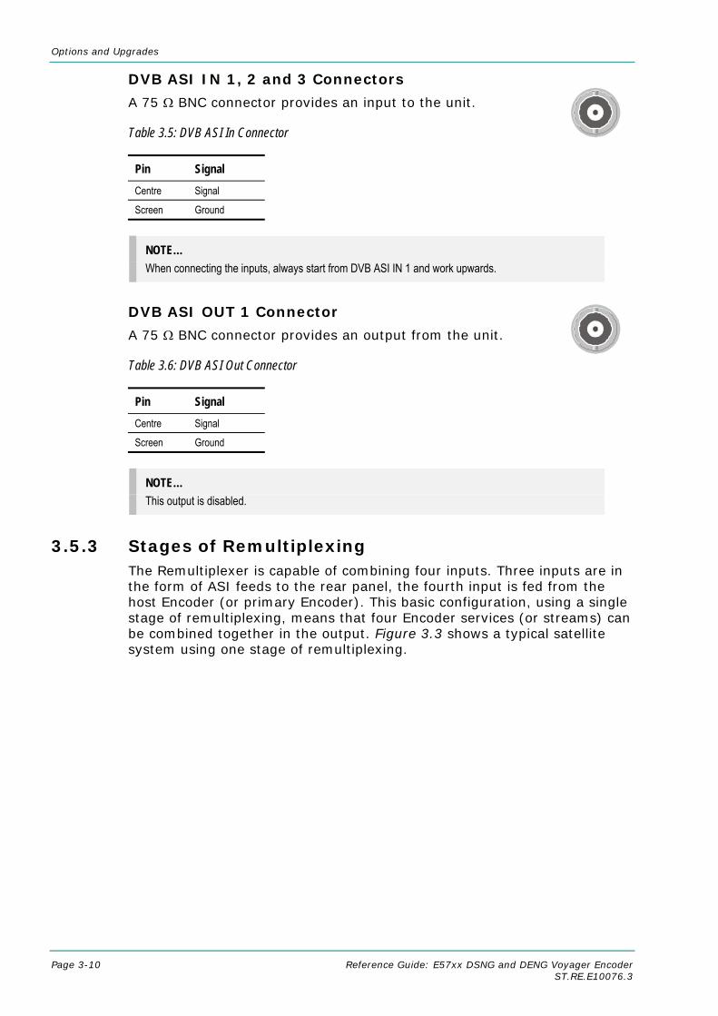
Options and Upgrades
Page 3-10 Reference Guide: E57xx DSNG and DENG Voyager Encoder ST.RE.E10076.3
DVB ASI IN 1, 2 and 3 Connectors
A 75 Ω BNC connector provides an input to the unit.
Table 3.5: DVB ASI In Connector
Pin Signal Centre Signal
Screen Ground
NOTE… When connecting the inputs, always start from DVB ASI IN 1 and work upwards.
DVB ASI OUT 1 Connector
A 75 Ω BNC connector provides an output from the unit.
Table 3.6: DVB ASI Out Connector
Pin Signal Centre Signal
Screen Ground
NOTE… This output is disabled.
3.5.3 Stages of Remultiplexing The Remultiplexer is capable of combining four inputs. Three inputs are in the form of ASI feeds to the rear panel, the fourth input is fed from the host Encoder (or primary Encoder). This basic configuration, using a single stage of remultiplexing, means that four Encoder services (or streams) can be combined together in the output. Figure 3.3 shows a typical satellite system using one stage of remultiplexing.

Options and Upgrades
Reference Guide: E57xx DSNG and DENG Voyager Encoder Page 3-11 ST.RE.E10076.3
Figure 3.3: Block Diagram – One Stage of Remultiplexing
Similarly, if two stages of remultiplexing are introduced, thirteen Encoders can be combined, providing up to thirteen services in the remultiplexed output. This is the maximum number of services that can be provided using this system, see Figure 3.4.
Figure 3.4: Block Diagram – Two Stages of Remultiplexing
Tx
Up-link equipment (including Up-converter and High Power Amplifier)
IF Output Service 1
Service 2 VIDEO (ANALOGUE)
VIDEO (DIGITAL)AUDIO
SYNC DATAASYNC DATA
Contributing Encoders
ASI
ASI
ASI
Primary (Master) Encoder with
Remux
Service 3 VIDEO (ANALOGUE)
VIDEO (DIGITAL)AUDIO
SYNC DATAASYNC DATA
Service 4 VIDEO (ANALOGUE)
VIDEO (DIGITAL)AUDIO
SYNC DATAASYNC DATA
VIDEO (ANALOGUE)VIDEO (DIGITAL)
AUDIOSYNC DATA
ASYNC DATA
NOTE…
IF Output contains 4 services: Service 1 + Service 2 + Service 3 + Service 4.
Tx
Up-link equipment (including Up-converter and High Power Amplifier)
IF Output Service 1
Service 3
Contributing Encoders
ASI (x3)
Encoder with Remux
Service 2 Service 4
Service 5
Service 7
Contributing Encoders
ASI (x3)
Encoder with Remux
Service 6 Service 8
Service 9
Service 11
Contributing Encoders
ASI (x3)
Encoder with Remux
Service 10 Service 12
Service 13
Encoder with Remux
ASI (x4)
ASI (x4)
ASI (x4)
NOTE…
IF Output contains 13 services.
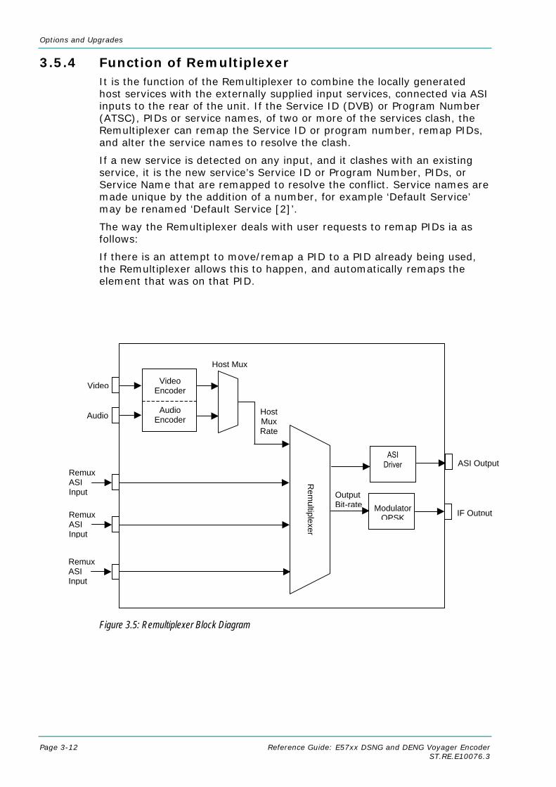
Options and Upgrades
Page 3-12 Reference Guide: E57xx DSNG and DENG Voyager Encoder ST.RE.E10076.3
3.5.4 Function of Remultiplexer It is the function of the Remultiplexer to combine the locally generated host services with the externally supplied input services, connected via ASI inputs to the rear of the unit. If the Service ID (DVB) or Program Number (ATSC), PIDs or service names, of two or more of the services clash, the Remultiplexer can remap the Service ID or program number, remap PIDs, and alter the service names to resolve the clash.
If a new service is detected on any input, and it clashes with an existing service, it is the new service’s Service ID or Program Number, PIDs, or Service Name that are remapped to resolve the conflict. Service names are made unique by the addition of a number, for example ‘Default Service’ may be renamed ‘Default Service [2]’.
The way the Remultiplexer deals with user requests to remap PIDs ia as follows:
If there is an attempt to move/remap a PID to a PID already being used, the Remultiplexer allows this to happen, and automatically remaps the element that was on that PID.
Figure 3.5: Remultiplexer Block Diagram
Dual Port Ram
IF Output
Remux ASI Input
Modulator QPSK
Rem
ultiplexer
Video Video Encoder
Audio
Encoder Audio
Host Mux
Host MuxRate
Remux ASI Input
Remux ASI Input
Output Bit-rate
ASI Driver ASI Output

Options and Upgrades
Reference Guide: E57xx DSNG and DENG Voyager Encoder Page 3-13 ST.RE.E10076.3
3.5.5 Using the Remultiplexer Set the output bit-rate to the required value in the Setup/Mux Menu.
Connect transport streams that are to be combined (remultiplexed) with the host Encoder’s services to the ASI inputs on the rear of the unit.
NOTE… It is possible to remultiplex any DVB or ATSC compliant transport stream but at the time of publication, only transport streams generated by TANDBERG Television equipment are guaranteed to work when fed to the Remultiplexing module.
The equipment will automatically detect the services on these inputs. The list of detected services is displayed in the Setup/Mux Menu.
Each service can be individually switched ‘Off’, ‘On’, or ‘On with scrambling’. If the service is set to ‘Off’, then there is no trace of the service in the output transport stream. New services can be set to default to either Off or On. If it was connected to the Remultiplexer the last time the Encoder was powered, then it assumes its previous state.
It is possible to remultiplex transport streams that have already been scrambled by BISS encryption, but it is not possible to remultiplex transport streams that have already been scrambled using RAS encryption. Also it is not possible to scramble a service that has already been scrambled.
3.5.6 ATSC Remultiplexing The Remultiplexer can work with ATSC compliant transport streams. It remaps the services following the ATSC program paradigm.
The Encoder can be configured to generate the PSIP for the output transport stream. It generates the minimum number of tables to give an ATSC compliant output transport stream, i.e. Event Information Tables (EIT) 0, 1, 2 and 3, the System Time Table (STT), the Rating Region Table (RRT), the Master Guide Table (MGT), and either the Cable Virtual Channel Table (CVCT) or the Terrestrial Virtual Channel Table (TVCT), depending on the delivery descriptor set. It will not pass through any tables that are present on the ASI input transport streams.
Alternatively, an external PSIP generator can be connected to one of the Remultiplexer inputs and the remultiplexer programmed to pass through a range of PIDs, thus inserting the PSIP into the output transport stream.
For more information about using the Remux card in ATSC with internal and external PSIP see Annex H, Use of Remux Card in ATSC.
3.5.7 Setting Bit-rates and Avoiding Overflow Overflow is the condition in which the total of the contributing service bit-rates, (including the host mux), exceeds the output bit-rate of the primary remultiplexing unit.
NOTE… Only useful packets (e.g. video, audio and data, etc) count towards the bit-rate of the contributing service bit-rates, not null packets.

Options and Upgrades
Page 3-14 Reference Guide: E57xx DSNG and DENG Voyager Encoder ST.RE.E10076.3
The easiest way to configure the bit-rates to avoid overflow, is as follows:
1. Divide the 188 byte output bit-rate of the primary (master) remultiplexing unit, (this can be found in the Setup/Mux/Remux Module/Output Bit-rate), by the number of contributing services (including the primary service). Such that:
O/P Rate (188) / N = Host Rate (188)
[Where N = number of services to be combined including primary]
2. Then set the Host Rates (188) of each contributing unit and the master unit to equal the calculated Host Rate.
If the above procedure is followed, an equal bit-rate is allocated to each contributing unit. By setting the host rates, the video and audio bit-rates will be automatically adjusted to suit.
The amount of spare bit-rate and input bit-rate that has been used in the Remultiplexer can be monitored using the bar graph indicators in the Setup/Mux/Remux Module Menu.
3.5.8 What to do if Overflow Occurs If an ‘Overflow Error’ is indicated on the equipment, then the incoming contributing bit-rate exceeds the outgoing bit-rate. To avoid corruption reduce the incoming bit-rate by either removing services, (turn the service Off or remove the ASI input), or reduce the bit-rate of the incoming service.
3.6 SD Decoder Option (M2/EOM2/DEC)
3.6.1 Overview
NOTES… 1. The M2/EOM2/DEC SD Decoder Option is supported by Build version 3.1 and later. 2. This option module only fits into option slot 6 in the E5740, and must always be accompanied by
a demodulator option module in slot 5.
This option module is a complete MPEG-2 standard definition decoder, capable of decoding 422P@ML and MP@ML. It can provide analogue or digital video and audio outputs, as well as synchronous and asynchronous data outputs. In conjunction with a demodulator option module, it provides a complete satellite monitoring receiver within the E5740 Encoder.

Options and Upgrades
Reference Guide: E57xx DSNG and DENG Voyager Encoder Page 3-15 ST.RE.E10076.3
3.6.2 Assembly
Rear Panel
ASI Out
A 75 Ω female BNC connector provides an ASI output of the transport stream being decoded by the SD Decoder.
NOTE… If the 16QAM demodulator is being used the ASI Out will be in burst mode.
Table 3.7: ASI Out Connector
Item Specification Connector Type 75 Ω BNC Female
Connector designation ASI Out
Pin-outs Centre Signal
Screen Ground
SDI Video Out
A 75 Ω female BNC connector provides an SDI video output that conforms to ITU-R BT.656.

Options and Upgrades
Page 3-16 Reference Guide: E57xx DSNG and DENG Voyager Encoder ST.RE.E10076.3
Table 3.8: SDI Video Out Connector
Item Specification Connector Type 75 Ω BNC Female
Connector designation SDI Out
Pin-outs Centre Signal
Screen Ground
Composite Video Output
A 75 Ω female BNC connector provides a composite video output. See Annex B, Technical Specification for a list of supported video standards.
Table 3.9: Composite Video Connector
Item Specification Connector Type 75 Ω BNC Female
Connector designation COMP VIDEO
Pin-outs Centre Signal
Screen Ground
Audio Output
A 15-way D-type socket provides the audio output.
Table 3.10: Audio Output Connector
Item Specification Connector Type 15-way D-type Socket
Connector designation AUDIO OUT
Pin-outs 1 Ch 1 Left Analogue+/Ch 1 Digital+
2 Analogue Ground
3 Ch 1 Right Analogue -
4 Ch 2 Left Analogue+/Ch 2 Digital+
5 Analogue Ground
6 Ch 2 Right Analogue -
7 Reserved
8 Analogue Ground
9 Ch 1 Left Analogue-/Ch 1 Digital-
10 Ch 1 Right Analogue +
11 Analogue Ground
12 Ch 2 Left Analogue-/Ch 2 Digital-
13 Ch 2 Right Analogue +
14 Analogue Ground
15 Reserved

Options and Upgrades
Reference Guide: E57xx DSNG and DENG Voyager Encoder Page 3-17 ST.RE.E10076.3
RS-232/RS-422 Data Output
A 9-way D-type socket provides the data outputs.
Table 3.11: RS-232/RS-422 Data Output Connector
Item Specification Connector Type 9-way D-type Socket
Connector designation RS232/RS422 DATA
Pin-outs 1 RS422_CLK_A
2 RS232_RXD
3 RS232_TXD
4 No Connection
5 Ground
6 RS422_CLK_B
7 No Connection
8 RS422_DATA_A
9 RS422_DATA_B
3.7 QPSK Demodulator (M2/EOM2/QPSKDEMOD)
3.7.1 Overview
NOTE… The M2/EOM2/QPSKDEMOD QPSK Demodulator Option is supported by Build version 3.1 and later.
The module allows the Encoder to receive and demodulate satellite transmissions that comply to EN 300 421 (DVB-S). It must be used with an SD Decoder Module (M2/EOM2/DEC), which takes and decodes the transport stream produced by the demodulator.
The module has three inputs; an IF input that operates over a frequency range of 50 MHz to 180 MHz, and –20 dBm to –40 dBm input power, and two L-Band inputs that operate over a frequency range of 950 MHz to 2150 MHz, and –25 dBm to –65 dBm input power.
It can normally receive signals with symbol rates in the range 1 to 45 Msymbol/s, but if the low symbol rate option (M2/EOS2/LSYM) is purchased this can be expanded to cover 0.3 to 45 Msymbol/s.

Options and Upgrades
Page 3-18 Reference Guide: E57xx DSNG and DENG Voyager Encoder ST.RE.E10076.3
3.7.2 Assembly
Rear Panel
Ω
IF In
A 75 Ω female BNC connector provides an IF Input.
Table 3.12: IF In Connector
Item Specification Connector Type 75 Ω BNC Female
Connector designation IF IN
Pin-outs Centre Signal
Screen Ground
RF In
Two 75 Ω F-type female connectors provide RF inputs.
Table 3.13 RF In Connector
Item Specification Connector Type 75 Ω F-type Female
Connector designation RF 1, RF 2
Pin-outs Centre Signal
Screen Ground
ASI In
A 75 Ω female BNC connector provides an ASI input.
Table 3.14: ASI In Connector
Item Specification Connector Type 75 Ω BNC Female
Connector designation ASI IN
Pin-outs Centre Signal
Screen Ground
ASI IN

Options and Upgrades
Reference Guide: E57xx DSNG and DENG Voyager Encoder Page 3-19 ST.RE.E10076.3
3.8 16QAM Demodulator (M2/EOM2/SATDEMOD)
3.8.1 Overview The module allows the Encoder to receive and demodulate satellite transmissions that comply to EN 300 421 (DVB-S), and EN 301 210 (DVB-DSNG). It must be used with an SD Decoder Module (M2/EOM2/DEC), which takes and decodes the transport stream produced by the demodulator. The module has two L-band inputs that operate over a frequency range of 950 MHz to 2150 MHz, and –25 dBm to –65 dBm input power. It can decode signals with symbol rates in the range 1 to 45 Msymbol/s. It is capable of demodulating 8PSK, and 16QAM transmissions, as well as QPSK transmissions, but these are software options.
3.8.2 Assembly
Rear Panel
L-Band Inputs
Two 75 Ω F-type female connectors provide L-band inputs.
Table 3.15: L-Band Input Connector
Item Specification Connector Type 75 Ω F-type Female
Connector designation L-Band Input 1, L-Band Input 2
Pin-outs Centre Signal
Screen Ground
3.9 IP Output Card (M2/EOM2/IP)
3.9.1 Overview The IP Output card provides a 10/100 BaseT Ethernet port, out of which the transport stream generated by the Encoder can be output in UDP packets at up to 50 Mbit/s.
The mapping of MPEG-2 transport stream packets into IP data frames is done according to the protocol stack shown in Figure 3.6.
NOTE… More support has been given in V2.8.x of the IP Output Card in V3.6.x of the Encoder. This is accessed using menu items on the IP menu tree from the front panel, telnet and web interfaces. The IP output can be turned off using the “IP Output” menu item. A “Line Mode” menu item allows the setting to be either “Fixed” or “Auto”.

Options and Upgrades
Page 3-20 Reference Guide: E57xx DSNG and DENG Voyager Encoder ST.RE.E10076.3
Figure 3.6: IP Output Protocol Stack
Between one and seven MPEG-2 transport stream packets can be put in each UDP packet. The data link layer is Ethernet according to IEEE 802.3/802.3u (auto-sensing 10/100 Mbit/s, twisted pair, via RJ-45 connector).
3.9.2 Assembly
Rear Panel
ASI In
A 75 Ω female BNC connector provides an ASI input.
NOTE… This connector is not used.
Table 3.16: ASI In Connector
Item Specification Connector Type 75 Ω BNC Female
Connector designation ASI IN
Pin-outs Centre Signal
Screen Ground
MPEG-2/DVB Layer
UDP – User Datagram Protocol TCP/UDP
Transport Layer - IP
Link Layer – 10/100-baseT Ethernet
MPEG- 2 Transport Stream

Options and Upgrades
Reference Guide: E57xx DSNG and DENG Voyager Encoder Page 3-21 ST.RE.E10076.3
RS-232 Control
A 3.5mm socket provides a debug interface.
NOTE… This connector is for TANDBERG Television use only.
ASI Out
A 75 Ω female BNC connector provides an ASI output.
NOTE… This connector is not used.
Table 3.17: ASI Out Connector
Item Specification Connector Type 75 Ω BNC Female
Connector designation ASI OUT
Pin-outs Centre Signal
Screen Ground
Ethernet Output
An RJ-45 connector provides a 10/100 BaseT Ethernet port.
Table 3.18: RJ-45 Connector
Item Specification Connector Type RJ-45
Connector designation 10/100 BT
Pin-out 1 Tx Out (+)
2 Tx Out (-)
3 Rx In (+)
4 Not Connected
5 Not Connected
6 Rx In (-)
7 Not Connected
8 Not Connected

Options and Upgrades
Page 3-22 Reference Guide: E57xx DSNG and DENG Voyager Encoder ST.RE.E10076.3
3.10 Vocality Card Option (M2/EOM2/COMMS/FXS and M2/EOM2/COMMS/FXO)
3.10.1 Overview The DSNG Communications Card adds bi-directional telephone, data and IP interfaces to an E5740 Encoder. There are two variants of the card, one provides FXS connectivity, which allows standard telephones to be plugged into the unit. The other provides FXO connectivity, which allows the unit to be connected to a PABX. Normally an FXS variant would be deployed in the field, with an FXO variant being used at the downlink site to connect into the office telephone system. Both variants allow the first four channels to be alternatively configured to operate as four-wire, Tie-line interfaces. The cards are four channel as standard but can be software upgraded to provide eight telephone channels. See Table 3.1 for the slots that it can be installed in.
Figure 3.7: DSNG Comms Card Interconnections
The card multiplexes all the input channels into a single synchronous RS-422 data channel that is connected to the Encoder’s RS-422 data input, and then put into the transport stream transmitted via the satellite modulator. The E5740 must also be fitted with a satellite demodulator and SD Decoder to provide a return data path. The RS-422 data from the SD Decoder is demultiplexed by the DSNG communications card to provide return data for all the telephone, data and IP interfaces.
OMT & Waveguide Switch
HPA
Upconverter
LNB
L-Band Splitter
Sat Modulator Demodulator
SD Decoder
EncoderDSNG Comms
Card
E5740
Telephone, RS422 Data & IP
OMT & Waveguide Switch
HPA
Upconverter
LNB
L-Band Splitter
Sat Modulator Demodulator
SD Decoder
EncoderDSNG Comms
Card
E5740
Telephone, RS422 Data & IP

Options and Upgrades
Reference Guide: E57xx DSNG and DENG Voyager Encoder Page 3-23 ST.RE.E10076.3
For details regarding configuring this card via the supervisor port refer to the DSNG Comms card documentation provided on the Reference CD.
3.10.2 Assembly
Rear Panel
Figure 3.8: Vocality Card Option (M2/EOM2/COMMS/FXS and M2/EOM2/COMMS/FXO)
Telephone Line Connectors
Eight 8-way RJ-45 connectors provide the analogue voice/fax telephone lines. In the four channel variant the top four connectors are not activated.
With the FXS variant, telephone lines 1 to 4 can be configured to operate in either FXS or E&M (Tie-line) mode. Telephone Lines 5 to 8 can only operate in FXS mode.
With the FXO variant, telephone lines 1 to 4 can be configured to operate in either FXO or E&M (Tie-line) mode. Telephone Lines 5 to 8 can only operate in FXO mode.
FXS mode is used to connect to a circuit that requires a ringing voltage (a subscriber port). This may be a telephone or PABX trunk port, which operates on 2-wire circuits. For UK users, a British Telecommunications master Socket must be connected to the port in order to ring standard UK telephones, since no ring capacitor is included in the interface.
Interfaces to subscriber telephones of other countries usually can be connected directly to the SNG Comms card, since the telephones have an integral ringing capacitor.
FXO mode configures the interface to accept DC current or ring voltages, and so allows it to be connected to a PABX. Tie-line mode allows the telephone line to be connected to the Tie-line card of a PABX via a four-wire speech interface together with four wires for the E&M interface.
WARNING…
THE TELEPHONE LINE CONNECTORS HAVE A SAFETY STATUS OF TNV (EN 60950-1:2001 SECTION 2.3). THESE MAY ONLY BE CONNECTED TO PORTS OF A SIMILAR SAFETY STATUS.
DUE TO THE HAZARDOUS VOLTAGES THAT CAN OCCUR ON TELEPHONE LINES, IT IS ESSENTIAL THAT THE ENCODER CHASSIS IS EARTHED BEFORE CONNECTING TO THE
TELEPHONE LINE.
VOCALITY INTERNATIONAL
DAT
COMMSMODULE
TEL/LIN
765
21 3 4
8
STATUS
SUPERVISO
VI68900
LA
LIN

Options and Upgrades
Page 3-24 Reference Guide: E57xx DSNG and DENG Voyager Encoder ST.RE.E10076.3
Table 3.19: Telephone/Line Connector
4-Wire Tie-line Mode 2-Wire FXS/FXO Mode Pin Signal Signal
1 MREF
2 M
3 RXA
4 TXRXA TIP
5 TXRXB RING
6 RXB
7 E
8 EREF
Data Connector
A 15-way, D-type female connector provides a data port that supports a number of different serial interface standards (see Table 3.20 and the Vocality documentation). The data port can be software configured as either a DTE or a DCE.
Table 3.20: Data Connector
Pin Signal Name DTE DCE
V.11 RS449 V.35 RS530 V.24 Shield Shield Shield Shield Shield Shield C C 1 GND GND GND GND GND C C 2 T(A) SDA SDA SDA TXD O I 3 CA) RSTA DTR RSTA DTR O I 4 R(A) RDA RDA RDA RXD I O 5 I(A) RRA DCD RRA DCD I O 6 S(A) RTA SCRA SCRA RXC I O 7 - STA SCTA SCTA TXC I O 8 - TTA SCTEA SCTEA EXTXC O I 9 T(B) SDB SDB SDB - O I 10 C(B) RSTB - RSTB - O I 11 R(B) RDB RDB RDB - I O 12 I(B) RRB - RRB - I O 13 S(B) RTB SCRB SCRB - I O 14 - STB SCTB SCTB - I O 15 - TTB SCTEB SCTEB - O I
Supervisor Port Connector
A 3-way, 3.5mm socket provides an RS-232 supervisor port, which allows a PC to configure the card, (see Vocality document for details).
The supervisor port operates at 9600 baud, 8 data bits, no parity, one stop bit with no flow control.

Options and Upgrades
Reference Guide: E57xx DSNG and DENG Voyager Encoder Page 3-25 ST.RE.E10076.3
Table 3.21: Supervisor Connector
Pin Signal 1 (Tip) Transmit (Out)
2 (Ring) Receive In)
3 (Shield) Ground
Link Connector
A 15-way, D-type female connector provides the RS-422 interface to the Encoder motherboard and the SD Decoder.
Table 3.22: Link Connector
Pin Signal 1
2
3 Transmit Data A
4
5
6
7 Transmit Clock A
8 Ground
9 Transmit Data B
10
11
12
13
14 Transmit Clock B
15
LAN Connector
An 8-way RJ-45 connector provides a 10/100baseT Ethernet port. The card acts as a static IP router.
Table 3.23: LAN Connector
Pin Signal 1 Tx+
2 Tx-
3 Rx+
4 Shield
5 Shield
6 Rx-
7 Shield
8 Shield
3.10.3 Connecting the DSNG Communications Card to the
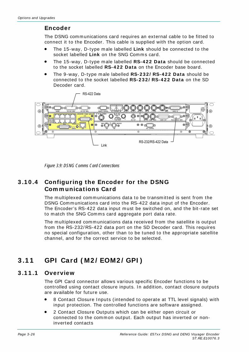
Options and Upgrades
Page 3-26 Reference Guide: E57xx DSNG and DENG Voyager Encoder ST.RE.E10076.3
Encoder The DSNG communications card requires an external cable to be fitted to connect it to the Encoder. This cable is supplied with the option card.
• The 15-way, D-type male labelled Link should be connected to the socket labelled Link on the SNG Comms card.
• The 15-way, D-type male labelled RS-422 Data should be connected to the socket labelled RS-422 Data on the Encoder base board.
• The 9-way, D-type male labelled RS-232/RS-422 Data should be connected to the socket labelled RS-232/RS-422 Data on the SD Decoder card.
Figure 3.9: DSNG Comms Card Connections
3.10.4 Configuring the Encoder for the DSNG Communications Card The multiplexed communications data to be transmitted is sent from the DSNG Communications card into the RS-422 data input of the Encoder. The Encoder’s RS-422 data input must be switched on, and the bit-rate set to match the SNG Comms card aggregate port data rate.
The multiplexed communications data received from the satellite is output from the RS-232/RS-422 data port on the SD Decoder card. This requires no special configuration, other than to be tuned to the appropriate satellite channel, and for the correct service to be selected.
3.11 GPI Card (M2/EOM2/GPI)
3.11.1 Overview The GPI Card connector allows various specific Encoder functions to be controlled using contact closure inputs. In addition, contact closure outputs are available for future use.
• 8 Contact Closure Inputs (intended to operate at TTL level signals) with input protection. The controlled functions are software assigned.
• 2 Contact Closure Outputs which can be either open circuit or connected to the common output. Each output has inverted or non-inverted contacts
Link
RS-422 Data
RS-232/RS-422 Data

Options and Upgrades
Reference Guide: E57xx DSNG and DENG Voyager Encoder Page 3-27 ST.RE.E10076.3
3.11.2 Assembly (1U Panel Version Shown)
Figure 3.10: General Purpose Interface M2/EOM2/GPI
3.11.3 Connector
Table 3.24: GPI Connector
Item Specification Item Specification Connector Type 15-way D-type Male Connector designation GPI
Pin-out 1 Input 0 Pin-out 9 GND
2 Input 1 10 Output 1 NI
3 Input 2 11 Output 1 Common
4 Input 3 12 Output 1 I
5 Input 4 13 Output 2 NI
6 Input 5 14 Output 2 Common
7 Input 6 15 Output 2 I
8 Input 7
Encoder (1U Slot: 1, 2
2U Slot: 1, 2, 4, 5)
GPI Card Option
GPI
Output Transport Stream Output Transport Stream Output Transport Stream
ASI OUT 1
ASI OUT 2
ASI OUT 3
Analogue Composite VideoSerial Digital Interface
Audio Input
COMP VIDEO
SDI IN AUDIO IN
Contact Closure Inputs and Outputs - 2 Contact Closure Outputs - 8 Sensed Inputs
GPI Connector

Options and Upgrades
Page 3-28 Reference Guide: E57xx DSNG and DENG Voyager Encoder ST.RE.E10076.3
3.12 Triax Option (M2/EOM2/TRIAX)
3.12.1 Introduction This option is for the E5750 Encoder only.
The card is designed to work in conjunction with the COFDM Modulator fitted to the E5750 Encoder in order to provide a TRIAX connection to external equipment.
3.12.2 Description The card takes in 70 MHz IF from the modulator and the 48 Vdc power from an external power supply. It also accepts control information from the control bus of the E5750.
The 70 MHz signal is passed through onto the TRIAX output connector. The DC power is added to this so that external, downstream equipment (SHF up-converter and power amplifier) that is typically mounted close to the transmit antenna can be powered.
Additionally, the TRIAX adaptor also makes it possible to control the external equipment from the front panel of the E5750. This is achieved using a data carrier at 400 MHz. Modems are fitted internally within the TRIAX adaptor and the external equipment, making it possible to set the final up-converter frequency directly from the front panel of the E5750.

Options and Upgrades
Reference Guide: E57xx DSNG and DENG Voyager Encoder Page 3-29 ST.RE.E10076.3
3.13 Software Options
3.13.1 M2/ESO2/NR This purchasable option upgrades the Encoder to include noise reduction mode. Contact Customer Services for details.
3.13.2 M2/ESO2/PU This purchasable option upgrades the performance of the Encoder. Contact Customer Services for details.
3.13.3 M2/ESO2/VBR This purchasable option upgrades the Encoder to include variable bit-rate. Contact Customer Services for details.
3.13.4 M2/ESO2/422 This purchasable option upgrades the Encoder to include 4:2:2 video encoding mode. Contact Customer Services for details.
3.13.5 M2/ESO2/RAS This purchasable option upgrades the Encoder to include RAS mode. Contact Customer Services for details.
3.13.6 M2/ESO2/ACON This purchasable option upgrades the Encoder to include auto concatenation. Contact Customer Services for details.
3.13.7 M2/ESO2/AC3 This purchasable option allows the Encoder to provide Dolby Digital (AC-3) audio. Contact Customer Services for details.
3.13.8 M2/ESO2/SM38PSK This purchasable option allows the E5740 and E5714-LBAND to provide 8PSK modulation. Contact Customer Services for details.
3.13.9 M2/ESO2/SM316QAM This purchasable option allows the E5740 and E5714-LBAND to provide 16QAM modulation. Contact Customer Services for details.
3.13.10 M2/ESO2/8PSKDEMOD This purchasable option allows an E5740 fitted with M2/EOM2/DEC SD decoder and M2/EOM2/SATDEMOD demodulator to receive 8PSK modulated signals. Contact Customer Services for details.
3.13.11 M2/ESO2/16QAMDEMOD This purchasable option allows an E5740 fitted with M2/EOM2/DEC SD decoder and M2/EOM2/SATDEMOD demodulator to receive 16QAM modulated signals. Contact Customer Services for details.

Options and Upgrades
Page 3-30 Reference Guide: E57xx DSNG and DENG Voyager Encoder ST.RE.E10076.3
3.13.12 M2/ESO2/LSYM This purchasable option allows an E5740 and an M2/EOM2/QPSKDEMOD, if fitted, to work at low symbol rates (300 ksym/s minimum). Contact Customer Services for details.
3.13.13 M2/ESO2/DVB-MHP This purchasable option allows the Encoder to provide MHP timing Events. Contact Customer Services for details.
3.13.14 M2/ESO2/DTS This purchasable option allows the Encoder to provide DTS Audio. Contact Customer Services for details.
3.13.15 M2/ESO2/525VBIDATA This purchasable option allows the Encoder to provide NABTS and GEMSTAR 2.0 VBI extraction. Contact Customer Services for details
3.13.16 M2/ESO2/SCTE-35 SPLICE POINTS This purchasable licence key allows the GPI purchasable option module to provide an SCTE35 splicing. Contact Customer Services for details.

Reference Guide: E57xx DSNG and DENG Voyager Encoder Page 4-1 ST.RE.E10076.3
Chapter 4 4. Operating the Equipment Locally
Contents 4.1 Introduction ............................................................... 4-9 4.2 Establishing Local Control (1U)................................. 4-9 4.3 Navigating the Display Screens (1U) ........................ 4-9
4.3.1 Introduction................................................... 4-9 4.3.2 Navigating the Menus (1U)......................... 4-10 4.3.3 Changing a Setting (1U) ............................. 4-10
Overview..................................................... 4-10 For Multiple Choice Entry ........................... 4-11 For Text or Numeric Entry .......................... 4-11
4.3.4 Line Up Menu ............................................. 4-11 4.3.5 A(udio)/V(ideo) Menu (1U) ......................... 4-11
4.4 Establishing Local Control (2U)............................... 4-12 4.4.1 Input Monitor............................................... 4-12 4.4.2 Summary Screen........................................ 4-12 4.4.3 A(udio)/V(ideo) Menu (2U) ......................... 4-13 4.4.4 Keyboard Lock (2U).................................... 4-13
4.5 Navigating the Display Screens (2U) ...................... 4-13 4.5.1 Moving Through the Menu Screens ........... 4-13 4.5.2 How to Use the Keypad.............................. 4-14 4.5.3 How to Use the Functions Associated
with Softkeys .............................................. 4-15 4.5.4 Display Screens.......................................... 4-15 4.5.5 Menu Formats ............................................ 4-15 4.5.6 Summary Screen and Advanced Menus .... 4-17
4.6 Setup Menu............................................................. 4-17 4.7 System Menu .......................................................... 4-17
4.7.1 Introduction................................................. 4-17 4.7.2 Service Info Menu (Syntax = ATSC)........... 4-19
Overview..................................................... 4-19 Short Channel Name Option ...................... 4-19
Long Channel Name Option .......................4-19 Syntax Option .............................................4-19 SI Level Option ...........................................4-19 Ext. PSIP Source Option.............................4-20 PSIP Status.................................................4-20 PSIP Min PID ..............................................4-20 PSIP Max PID .............................................4-20 Major Channel Option .................................4-20 Minor Channel Option .................................4-20 Program Number Option.............................4-20 Service Type Option ...................................4-20 Transport Stream Id Option ........................4-20 Program Paradigm Option ..........................4-21 PMT PID Option..........................................4-21 Broadcast Flag............................................4-21 Daylight Saving ...........................................4-21 DST Start Date and DST End Date Options........................................................4-21
4.7.3 Service Info Menu (Syntax = DVB) .............4-21 Overview .....................................................4-21 Network Name Option.................................4-21 Service Provider Option ..............................4-21 Service Name Option..................................4-22 Syntax Option .............................................4-22 SI Level Option ...........................................4-22 Network Id Option .......................................4-22 Service Id Option ........................................4-22 Transport Stream Id Option ........................4-22 Service Type Option ...................................4-23 PMT PID Option..........................................4-23 Stream ID Descriptor Option.......................4-23 Dolby AC-3 Descriptor Option.....................4-23 Logical Chan Desc Option ..........................4-23

Operating the Equipment Locally
Page 4-2 Reference Guide: E57xx DSNG and DENG Voyager Encoder ST.RE.E10076.3
Logical Channel Option...............................4-23 4.7.4 Remote Control Menu.................................4-23
Overview .....................................................4-23 IP Address Option.......................................4-24 MAC Address Option ..................................4-24 Network Mask Option..................................4-24 Gateway Address Option ............................4-24 Set Community Name Option .....................4-24 SNMP Master Option ..................................4-24 Last SNMP Master Option ..........................4-24 Last SNMP Poll Option ...............................4-24 SNMP Trap IP Option .................................4-24 Trap Level Report Option............................4-24 Browser User Name Option ........................4-24 Browser Password Option ..........................4-24 SNTP Server Option ...................................4-25 Ethernet Bandwidth Option .........................4-25 SABus Address Option ...............................4-25 Serial Protocol Option .................................4-25 SABus Baud Rate Option............................4-25 SABus Data Bits Option..............................4-25
4.7.5 General Menu .............................................4-26 Overview .....................................................4-26 Model Number Option.................................4-26 Config Name Option ...................................4-26 Local Time Option.......................................4-26 Local Date Option .......................................4-26 UTC Offset Option ......................................4-26 Temperature Option....................................4-26 Screen Saver Option...................................4-26 Keypress Beep Option ................................4-27 Power Dip Recovery Option........................4-27 Upgrade Encoder Option ............................4-27 Software Release Option ............................4-27 Fan Control Option......................................4-27
4.7.6 Time and Date ............................................4-28 4.7.7 Advanced Menu ..........................................4-28
Overview .....................................................4-28 Setup Password Option ..............................4-28 Current Password Option............................4-28 Display Errors Option..................................4-28 System Control Option................................4-28 Action On PID Error Option.........................4-29 SNMP Control Option .................................4-29 Display Contrast Option ..............................4-29 No. Services Option ....................................4-29 Mbd. Service PIDs Option...........................4-30 Reset On Download Option ........................4-30 Reset Encoder Option.................................4-30
4.7.8 Digital Programme Insertion (DPI) Menu ....4-30 4.7.9 Build Menu ..................................................4-30 4.7.10 Additional Services (Mbd Services Menu) ..4-30
Overview .....................................................4-30
Host Service 1 ............................................ 4-30 4.8 Video Menu............................................................. 4-32
4.8.1 Introduction................................................. 4-32 4.8.2 Video Source Menu.................................... 4-32
Overview..................................................... 4-32 Video Input Option...................................... 4-32 Input Source Select .................................... 4-34 Frame Rate Option..................................... 4-34 Video Locked Option .................................. 4-34 Ident Text Option........................................ 4-34 Text Colour Option ..................................... 4-34 Background Colour Option ......................... 4-35 Video Bandwidth Option............................. 4-35 OP Video Loss Option................................ 4-35 Input Termination Option............................ 4-35 Noise Reduction Option.............................. 4-36 Logo Option (When Logo Downloaded into Unit) ..................................................... 4-36 Max Still Period Option ............................... 4-36 If set to a value greater than zero it triggers a ‘Freeze Frame On Video Input’ alarm if it detects no movement in the source video for the defined number of seconds. ..................................................... 4-36 Default 625 ................................................. 4-37 Default 525 ................................................. 4-37 I/P Monitor Refresh Option......................... 4-37 Time Code Option ...................................... 4-37
4.8.3 Video Encoder Menu.................................. 4-37 Overview..................................................... 4-37 Profile/Level Option .................................... 4-37 Compression Mode Option......................... 4-38 Bit-rate Option ............................................ 4-39 Delay Option............................................... 4-40 VBR Mode Option....................................... 4-40 Vertical and Horizontal Resolution Options ....................................................... 4-41 Aspect Ratio Option.................................... 4-42 AFD Option................................................. 4-42 GOP Structure Option ................................ 4-43 GOP Length Option.................................... 4-43 Long GOPs Option ..................................... 4-44 Adaptive GOP............................................. 4-44 Field/Frame Option..................................... 4-44 3:2 Pulldown Option ................................... 4-44 Concatenation Option................................. 4-45 PID Option.................................................. 4-45 Component Tag Option .............................. 4-45 Reflex Enable Option.................................. 4-45 Indicated Bit-rate Option............................. 4-45 Copyright Option......................................... 4-45 Original Option............................................ 4-45 Insert VBV Delay Option............................. 4-46 PES Header Option.................................... 4-46

Operating the Equipment Locally
Reference Guide: E57xx DSNG and DENG Voyager Encoder Page 4-3 ST.RE.E10076.3
AFD Location.............................................. 4-46 Encoder Type Option.................................. 4-46 S/W Release Option ................................... 4-46
4.8.4 Vertical Blanking Interval (VBI) Menu......... 4-46 Overview..................................................... 4-46 VBI Menu (25 Hz Frame Rate) ................... 4-46 VBI Menu (29.97 Hz Frame Rate) .............. 4-52
4.9 Audio Menu............................................................. 4-55 4.9.1 Overview..................................................... 4-55 4.9.2 Audio A / B Menus – MPEG Layer 2 .......... 4-55
Introduction................................................. 4-55 Source Option............................................. 4-55 Coding Standard Option ............................. 4-55 Input Level L Option ................................... 4-57 Input Level R Option................................... 4-57 Audio Bit-rate Option .................................. 4-57 Coding Mode Option................................... 4-57 Auto Lip Sync Option.................................. 4-58 Lip Sync Offset Option................................ 4-58 Language or Language Left/Right Option .. 4-58 Copyright Option......................................... 4-58 Original Option............................................ 4-58 Embedded 1-2 DID Option ......................... 4-59 Embedded 3-4 DID Option ......................... 4-59 Audio PID Option........................................ 4-59 Component Tag Option .............................. 4-59 PCR On Audio PID Option ......................... 4-59 OP Digital Loss........................................... 4-59 Hardware Release Option .......................... 4-60 Software Release Option............................ 4-60 Audio Delay Option..................................... 4-60 Actual Audio Delay ..................................... 4-60 Clip Level Option ........................................ 4-60 Impedance Option ...................................... 4-60 Deemphasis Option .................................... 4-60
4.9.3 Audio (Dolby Digital (AC-3) Menu) ............. 4-61 Source Option............................................. 4-61 Coding Standard Option ............................. 4-61 Input Level L Option ................................... 4-61 Input Level R Option................................... 4-61 Audio Bit-rate Option .................................. 4-61 Coding Mode Option................................... 4-62 Auto Lip Sync Option.................................. 4-62 Lip Sync Offset Option................................ 4-63 Audio Delay Option..................................... 4-63 Actual Audio Delay ..................................... 4-63 Sampling Rate Option ................................ 4-63 Clip Level Option ........................................ 4-63 Impedance Option ...................................... 4-63 Language Option ........................................ 4-64 Bit-stream Mode Option.............................. 4-64 Dialogue Level Option ................................ 4-64 Dolby Srnd Mode Option ............................ 4-64
Production Info Option ................................4-65 Mixing Level Option.....................................4-65 Room Type Option......................................4-65 Copyright Option .........................................4-65 Original Option ............................................4-65 Dynamic Range Option...............................4-65 RF Protection Option ..................................4-66 Deemphasis Option ....................................4-66 DC Filter Option ..........................................4-66 Low Pass Filter Option................................4-66 Embedded 1-2 DID Option..........................4-67 Embedded 3-4 DID Option..........................4-67 Audio PID Option ........................................4-67 Component Tag Option...............................4-67 PCR On Audio PID Option..........................4-67 OP Digital Loss ...........................................4-67 Hardware Release Option...........................4-67 Software Release Option ............................4-67
4.9.4 Audio (Dolby (AC-3) Pass-thru, Dolby E Pass-thru and DTS Pass-thru) Menu..........4-68 Source Option .............................................4-68 Coding Standard Option .............................4-68 Audio Bit-rate Option...................................4-68 Auto Lip Sync Option ..................................4-68 Lip Sync Offset Option ................................4-69 Audio Delay Option .....................................4-69 Actual Audio Delay......................................4-69 External Delay Option .................................4-69 Language Option ........................................4-69 SMPTE 302M Standard Option ..................4-69 Channel Option ...........................................4-70 Embedded 1-2 DID Option..........................4-70 Embedded 3-4 DID Option..........................4-70 Audio PID Option ........................................4-70 Component Tag Option...............................4-70 PCR On Audio PID Option..........................4-71 OP Digital Loss ...........................................4-71 Hardware Release Option...........................4-71 Software Release Option ............................4-71
4.9.5 Audio (Linear PCM) Menu ..........................4-71 Source Option .............................................4-71 Coding Standard Option .............................4-72 Input Level L Option....................................4-72 Input Level R Option ...................................4-72 Coding Mode Option ...................................4-72 Auto Lip Sync Option ..................................4-72 Lip Sync Offset Option ................................4-72 Audio Delay Option .....................................4-73 Actual Audio Delay......................................4-73 Clip Level Option.........................................4-73 Impedance Option.......................................4-73 Language or Language Left/Right Option...4-73 SMPTE 302M Standard Option ..................4-74

Operating the Equipment Locally
Page 4-4 Reference Guide: E57xx DSNG and DENG Voyager Encoder ST.RE.E10076.3
Channel Option ...........................................4-74 Embedded 1-2 DID Option..........................4-74 Embedded 3-4 DID Option..........................4-74 Audio PID Option ........................................4-74 Component Tag Option...............................4-75 PCR On Audio PID Option..........................4-75 OP Digital Loss ...........................................4-75 Hardware Release Option...........................4-75 Software Release Option ............................4-75
4.9.6 Audio Languages Menu ..............................4-75 4.10 Data Menu...............................................................4-75
4.10.1 Introduction .................................................4-75 4.10.2 Data A - RS232 Menu.................................4-76
Encoding Option..........................................4-76 Baud Rate Option .......................................4-76 RS232 PID Option ......................................4-77 Buffer Data Option ......................................4-77 Component Tag Option...............................4-77 Delay Option ...............................................4-77 SNMP oid index Option...............................4-77 O/P Bit-rate Option......................................4-77
4.10.3 Data B - RS422 Menu.................................4-77 Encoding Option..........................................4-77 Bit-rate Option.............................................4-78 RS422 PID Option ......................................4-78 Component Tag Option...............................4-78 Test Mode Option .......................................4-78 Delay Option ...............................................4-78 D Mode Option............................................4-78 SNMP oid index Option...............................4-78 Version Option ............................................4-78
4.11 Output Menu............................................................4-78 4.11.1 Overview .....................................................4-78 4.11.2 Output Format Option .................................4-79 4.11.3 Delivery Descriptor Menu............................4-79 4.11.4 Descriptor Type Option ...............................4-79 4.11.5 Descriptor Type = Terrestrial ......................4-81
Band Plan Option........................................4-81 Channel Option ...........................................4-81 Frequency Option .......................................4-81 Bandwidth Option........................................4-82 Modulation Type Option..............................4-82 Hierarchy Option .........................................4-82 FEC (HP) and FEC (LP) Options ................4-83 Guard Interval Option..................................4-83 Carriers Options..........................................4-83 Other Frequency Option .............................4-84
4.11.6 Descriptor Type = Cable .............................4-84 Frequency Option .......................................4-84 Modulation Type Option..............................4-84 FEC (Outer) Option.....................................4-84 FEC (Inner) Option......................................4-85
Symbol Rate Option ................................... 4-85 4.11.7 Descriptor Type = Satellite ......................... 4-85
Frequency Option....................................... 4-85 Modulation Type Option ............................. 4-85 FEC (Inner) Option ..................................... 4-86 Symbol Rate ............................................... 4-86 Orbital Position Option................................ 4-86 West East Option........................................ 4-86 Polarisation Option ..................................... 4-86
4.11.8 Output Format = Satellite Modulator (IF Output) ....................................................... 4-87 TS Input Source.......................................... 4-87 IF Output Option......................................... 4-87 IF Power Option ......................................... 4-87 IF Frequency Option................................... 4-87 Modulation Option ...................................... 4-87 Mod Type Option........................................ 4-87 Symbol Rate Option ................................... 4-88 FEC Rate Option ........................................ 4-88 Spectrum Sense Option ............................. 4-88 Roll Off Factor Option................................. 4-89 Tx Bandwidth Factor Option....................... 4-89 Tx Bandwidth Option .................................. 4-89 Bit-rate (188) Option................................... 4-89 Bit-rate (204) Option................................... 4-89 Preset Pwr Low Option............................... 4-89 Preset Pwr Norm Option ............................ 4-89 BUC DC Power Option............................... 4-90 Sat Deliv Freq Option ................................. 4-90 Sat Orb Pos Option .................................... 4-90 Sat West/East Option ................................. 4-90 Polarisation Option ..................................... 4-90 Status Only Options for the Satellite Modulator Menu.......................................... 4-91 Transmit Frequency.................................... 4-91 BUC 10 MHz Ref O/P Option ..................... 4-91
4.11.9 Output Format = Satellite Modulator (L-Band Output) .............................................. 4-91 TS Input Source.......................................... 4-91 Rate Adaptation Option .............................. 4-92 L-Band Output Option ................................ 4-92 L-Band Power Option ................................. 4-92 Frequency Option....................................... 4-92 Modulation Option ...................................... 4-92 Mod Type Option........................................ 4-92 Symbol Rate Option ................................... 4-92 FEC Rate Option ........................................ 4-92 Spectrum Sense Option ............................. 4-92 Roll Off Factor Option................................. 4-93 Tx Bandwidth Factor Option....................... 4-93 Tx Bandwidth Option .................................. 4-93 Bit-rate (188) Option................................... 4-93 Bit-rate (204) Option................................... 4-93 Preset Pwr Low Option............................... 4-93

Operating the Equipment Locally
Reference Guide: E57xx DSNG and DENG Voyager Encoder Page 4-5 ST.RE.E10076.3
Preset Pwr Norm Option15 .......................... 4-93 BUC DC Power Option15 ............................ 4-93 Sat Deliv Freq Option ................................. 4-93 Sat Orb Pos Option .................................... 4-94 Sat West/East Option ................................. 4-94 Polarisation Option ..................................... 4-94 Status Only Options for the Satellite Modulator Menu.......................................... 4-94
4.11.10 Output Format = OFDM Modulator............. 4-94 Output Option ............................................. 4-94 Bandwidth Option ....................................... 4-94 Modulation Mode Option ............................ 4-94 Guard Interval Option ................................. 4-95 FEC Rate Option ........................................ 4-95 Transmission Option................................... 4-95 Spectral Pol Option..................................... 4-95 Centre Frequency Option ........................... 4-95 IF Output Frequency................................... 4-96 Bit-rate (188)............................................... 4-96 Bit-rate (204)............................................... 4-96 OFDM S/W Release ................................... 4-96
4.11.11 Output Format = IP Streamer ..................... 4-96 Own IP Address Option .............................. 4-96 Network Mask Option ................................. 4-96 Router IP Address Option........................... 4-96 IP Output .................................................... 4-96 Destination IP Address Option ................... 4-96 Protocol/FEC Option................................... 4-97 Destination UDP Port Option...................... 4-97 TS Pkts/UDP Frm Option ........................... 4-97 Forward MCast IP Address Option............. 4-97 Time To Live Option ................................... 4-97 Type of Service Option ............................... 4-98 Line Mode................................................... 4-98
4.12 Mux Menu ............................................................... 4-98 4.12.1 Overview..................................................... 4-98 4.12.2 Mux Output, no Remux Card...................... 4-98 4.12.3 Mux Output, With Remux Card................... 4-98 4.12.4 Packet Length Option ............................... 4-101 4.12.5 On Air Option............................................ 4-101 4.12.6 Bit-rate (188) and Bit-rate (204) Option .... 4-101 4.12.7 Clock......................................................... 4-101 4.12.8 PCR PID Option ....................................... 4-102 4.12.9 FPGA Firmware........................................ 4-102 4.12.10 RAS Firmware .......................................... 4-102 4.12.11 BISS Hardware......................................... 4-102 4.12.12 BISS Firmware ......................................... 4-102 4.12.13 RAS Options Enabled............................... 4-102
Scramble Option....................................... 4-102 SNG Key (RAS1) Option .......................... 4-103
4.12.14 BISS Options Enabled.............................. 4-103 Overview................................................... 4-103 Scramble Option....................................... 4-104
Session Word Option ................................4-104 Enc Session Word Option.........................4-104 BISS-E Injected Id Option .........................4-105
4.13 Remux 4-105 4.13.1 Introduction ...............................................4-105 4.13.2 Addition to Mux Menu When Remux
Fitted .........................................................4-105 Host Bit-rate Option ..................................4-105
4.13.3 Remux Module Menu................................4-105 PID Remap ...............................................4-105 Packet Length Option ...............................4-106 Bit-rate Option...........................................4-106 Status Only Options for the Remux Module Menu ............................................4-106
4.13.4 1.Service/2.Service Menu .........................4-107 Output Option............................................4-107 Source (BNC) Option ................................4-107 Short Name In Option ...............................4-107 Short Name Out Option ............................4-107 Name (In) Option ......................................4-107 Name Out Option ......................................4-108 Service Prov (In) Option............................4-108 Service Provider Option ............................4-108 Service Id (Out) Option .............................4-108 Program Number (Out) Option..................4-108 Major Channel Option ...............................4-108 Minor Channel Option ...............................4-108 Logical Channel Option.............................4-109 CA Input Option ........................................4-109 BISS Key Code Option .............................4-109 Enc Session Word Option.........................4-109 Session Word Option ................................4-109 PMT PID Option........................................4-109 PCR PID Option........................................4-109 Video Option .............................................4-110 ECM (CA) PID Option ...............................4-110 VBI PID Option..........................................4-110 Audio (Type of Audio) Option....................4-111 Data (Type of Data) Option.......................4-111 Teletext Option..........................................4-111
4.14 IRD Menu ..............................................................4-112 4.14.1 Overview ...................................................4-112 4.14.2 IRD Mode Option ......................................4-112 4.14.3 IRD TS Source Option ..............................4-114 4.14.4 IRD Demod Menu .....................................4-114
Frequency Option .....................................4-114 Symbol Rate Option..................................4-114 FEC Rate Option.......................................4-114 Polarisation Option....................................4-115 Sat Input Option ........................................4-115 Modulation Option.....................................4-115 LNB Option ...............................................4-115 LNB Lo Freq Option ..................................4-115

Operating the Equipment Locally
Page 4-6 Reference Guide: E57xx DSNG and DENG Voyager Encoder ST.RE.E10076.3
LNB Hi Freq Option...................................4-116 LNB Switch Freq Option ...........................4-116 LNB Supply ...............................................4-116 Search Range Option ...............................4-116 BER Threshold Option ..............................4-116 Status Only Options for the IRD Demod Menu .........................................................4-116
4.14.5 Service List Menu......................................4-117 4.14.6 IRD Video Menu........................................4-117
Stop Mode Option .....................................4-117 Aspect Ratio Option ..................................4-117 Video Output Source Option .....................4-117 525 Line Composite Option.......................4-117 625 Line Composite Option.......................4-118 Rate Buffer Mode Option ..........................4-118 Video Default Output Option .....................4-118 EDH Enable Option...................................4-118 Embedded Audio Mode Option.................4-118 Embed Data ID Option..............................4-119 Video PID..................................................4-119
4.14.7 IRD Audio 1 and Audio 2 Menus...............4-119 Audio Stream ............................................4-119 Audio Routing Option................................4-119 Default Language Option ..........................4-120 Downmix Mode Option..............................4-120 Mute State Option .....................................4-120 Audio Output Option .................................4-120 Left Sys Clip Option ..................................4-121 Right Sys Clip Option................................4-121 Status Only Options for the IRD Audio Menu .........................................................4-121
4.14.8 IRD CA Menu............................................4-121 Overview ...................................................4-121 DSNG Key Option.....................................4-121 BISS Mode Option ....................................4-121 Session Word Option ................................4-121 Enc Session Word Option.........................4-121
4.14.9 IRD VBI Menu ...........................................4-122 VITS Enable Option ..................................4-122 CCVC Enable Option ................................4-122 VITC Enable Option ..................................4-122 GCR Enable Option ..................................4-122 Status Only Options for the IRD VBI Menu .........................................................4-122
4.14.10 IRD Data Menu .........................................4-123 Async Stream Option ................................4-123 Async Baudrate.........................................4-123 Sync Stream Option..................................4-123 Sync Bitrate...............................................4-123 Subtitle Stream Option..............................4-123 Subtitles Language Option........................4-123 Subtitles Type Option................................4-123 Subtitles Enable Option.............................4-123 Teletext Stream Option .............................4-123
4.14.11 IRD System Status Menu ......................... 4-124 4.15 Vocality Menu ....................................................... 4-124 4.16 Digital Programme Insertion (DPI) Menu.............. 4-125
4.16.1 Option Availability ..................................... 4-125 4.16.2 Overview................................................... 4-125 4.16.3 DPI Initiated by GPI .................................. 4-125 4.16.4 DPI Initiated by DVS525........................... 4-125 4.16.5 Menu Structure......................................... 4-125
4.17 Errors Menu .......................................................... 4-127 4.17.1 Overview................................................... 4-127 4.17.2 Active Errors Option ................................. 4-127 4.17.3 Error Masks Menu .................................... 4-127
Status of Error Masks............................... 4-127 4.17.4 Ignored Errors .......................................... 4-127 4.17.5 Error Masks Menu .................................... 4-127
Status of Error Masks............................... 4-127 Restore Defaults....................................... 4-127
4.17.6 Masked Active Errors ............................... 4-128 4.18 Diagnostics Menu ................................................. 4-128 4.19 Configs Menu........................................................ 4-129
4.19.1 Accessing the Menu ................................. 4-129 4.19.2 Overview................................................... 4-129 4.19.3 Active Configuration ................................. 4-129 4.19.4 User Configurations.................................. 4-130 4.19.5 Backup Configurations ............................. 4-130 4.19.6 Factory Default Configurations................. 4-130 4.19.7 Configuration, Write-Protection ................ 4-130 4.19.8 Quick Configuration From the Summary
Screen ...................................................... 4-131 4.19.9 Load Active Config Option........................ 4-131 4.19.10 Store Active Config Option ....................... 4-131 4.19.11 Load Configs From Backup Option .......... 4-131 4.19.12 Store Configs in Backup Option ............... 4-132 4.19.13 Factory 525 Defaults Option..................... 4-132 4.19.14 Factory 625 Defaults Option..................... 4-132

Operating the Equipment Locally
Reference Guide: E57xx DSNG and DENG Voyager Encoder Page 4-7 ST.RE.E10076.3
List of Figures Figure 4.1: 1U Summary Screen ................................................... 4-9 Figure 4.2: 1U Navigation Keys and Buttons............................... 4-10 Figure 4.3: 2U Input Monitor ........................................................ 4-12 Figure 4.4: 2U Summary Screen ................................................. 4-12 Figure 4.5: Keyboard Lock .......................................................... 4-13 Figure 4.6: 2U Keypad and Display Functions ............................ 4-14 Figure 4.7: Accessing Inscriptions on the Keypad....................... 4-14 Figure 4.8: Menu Hierarchy – Summary Screen and
Advanced Menus ....................................................... 4-16 Figure 4.9: Menu Hierarchy – Setup/System Menu..................... 4-18 Figure 4.10: Menu Hierarchy – Setup/Video Menu ..................... 4-33 Figure 4.11: VBI Structure Implemented by TANDBERG for
525-line Systems........................................................ 4-50 Figure 4.12: VBI Structure Implemented by TANDBERG for
625-line Systems........................................................ 4-51 Figure 4.13: Menu Hierarchy – Setup/Audio Menu ..................... 4-56 Figure 4.14: Menu Hierarchy – Setup/Data Menu ....................... 4-76 Figure 4.15: Menu Hierarchy – Setup/Output Menu.................... 4-80 Figure 4.16: Menu Hierarchy – Setup/Mux Menu (DVB) ............. 4-99 Figure 4.17: Menu Hierarchy – Setup/Mux Menu (ATSC)......... 4-100 Figure 4.18: Menu Hierarchy – Setup/IRD Menu ...................... 4-113 Figure 4.19: Menu Hierarchy – Digital Programme Insertion
DPI Menu (GPI Initiated) .......................................... 4-125 Figure 4.20: Menu Hierarchy – Error Masks Menu.................... 4-128 Figure 4.21: Configuration, Graphical Explanation.................... 4-129 List of Tables Table 4.1: Keypad Key Assignments........................................... 4-14 Table 4.2: Syntax Options ........................................................... 4-19 Table 4.3: SI Level Options ......................................................... 4-19 Table 4.4: Syntax Options ........................................................... 4-22 Table 4.5: SI Level Options ......................................................... 4-22 Table 4.6: Audio AC-3 Descriptor Options .................................. 4-23 Table 4.7: UTC Offset Options .................................................... 4-26 Table 4.8: Screen Saver Options ................................................ 4-27 Table 4.9: Keypress Beep Options.............................................. 4-27 Table 4.10: Power Dip Recovery Options ................................... 4-27 Table 4.11: Fan Control Options ................................................. 4-28 Table 4.12: System Control Options............................................ 4-28 Table 4.13: Action on PID Error Options ..................................... 4-29 Table 4.14: SNMP Control Options ............................................. 4-29 Table 4.15: Video Input Options .................................................. 4-32 Table 4.16: Input Source Select Options..................................... 4-34 Table 4.17: Frame Rate Options ................................................. 4-34 Table 4.18: Text Colour Options.................................................. 4-34 Table 4.19: Background Colour Options ..................................... 4-35 Table 4.20: Video Bandwidth Options ......................................... 4-35 Table 4.21: OP Video Loss Options ............................................ 4-35 Table 4.22: Noise Reduction Options.......................................... 4-36 Table 4.23: Default 625 Options ............................................ 4-37 Table 4.24: Default 525 Options ............................................ 4-37 Table 4.25: Profile/Level Options ................................................ 4-38 Table 4.26: Compression Mode Options.............................. 4-38 Table 4.27: Seamless Mode Bit-rate (Full Resolution Only)........ 4-38 Table 4.28: Resolution Options ................................................... 4-41 Table 4.29: Aspect Ratio Options................................................ 4-42
Table 4.30: AFD Options ............................................................. 4-42 Table 4.31: AFD Information........................................................ 4-42 Table 4.32: Group of Pictures Structure Options......................... 4-43 Table 4.33: Group of Pictures Length Options (Long GOPs
Disabled) .................................................................... 4-43 Table 4.34: Field/Frame Options ................................................. 4-44 Table 4.35: VBI in Picture Options............................................... 4-48 Table 4.36: VBI - Line ‘n’ Options ................................................ 4-49 Table 4.37: VBI in Picture Options............................................... 4-52 Table 4.38: Source Options ......................................................... 4-55 Table 4.39: Coding Standard Options ......................................... 4-55 Table 4.40: Audio Bit-rate Options............................................... 4-57 Table 4.41: Coding Mode Options (MPEG-2).............................. 4-58 Table 4.42: Lip Sync Offset Options............................................ 4-58 Table 4.43: Embedded 1-2 DID Options...................................... 4-59 Table 4.44: OP Digital Loss Options ........................................... 4-59 Table 4.45: Audio Delay Options ................................................. 4-60 Table 4.46: Clip Level Options..................................................... 4-60 Table 4.47: Source Options ......................................................... 4-61 Table 4.48: Audio Bit-rate Options (Dolby Digital (AC-3)) ........... 4-62 Table 4.49: Coding Mode Options ............................................... 4-62 Table 4.50: Lip Sync Offset Options............................................ 4-63 Table 4.51: Audio Delay Options ................................................. 4-63 Table 4.52: Clip Level Options..................................................... 4-63 Table 4.53: Bit Stream Mode Options.......................................... 4-64 Table 4.54: Dialogue Level Options............................................. 4-64 Table 4.55: Dolby Srnd Mode Options......................................... 4-64 Table 4.56: Mixing Level Options ................................................ 4-65 Table 4.57: Room Type Options.................................................. 4-65 Table 4.58: Dynamic Range Options........................................... 4-66 Table 4.59: Embedded 1-2 DID Options...................................... 4-67 Table 4.60: Source Options ......................................................... 4-68 Table 4.61: Coding Standard Options ......................................... 4-68 Table 4.62: Lip Sync Offset Options............................................ 4-69 Table 4.63: Audio Delay Options ................................................. 4-69 Table 4.64: External Delay Options............................................. 4-69 Table 4.65: SMPTE 302M Standard Options .............................. 4-70 Table 4.66: Channel Options ....................................................... 4-70 Table 4.67: Embedded 1-2 DID Options...................................... 4-70 Table 4.68: Source Options ......................................................... 4-71 Table 4.69: Coding Standard Options ......................................... 4-72 Table 4.70: Coding Mode Options (Linear PCM)......................... 4-72 Table 4.71: Lip Sync Offset Options............................................ 4-73 Table 4.72: Audio Delay Options ................................................. 4-73 Table 4.73: Clip Level Options..................................................... 4-73 Table 4.74: SMPTE 302M Standard Options .............................. 4-74 Table 4.75: Channel Options ....................................................... 4-74 Table 4.76: Embedded 1-2 DID Options...................................... 4-74 Table 4.77: Encoding Option Modes ........................................... 4-76 Table 4.78: Baud Rate Options ................................................... 4-76 Table 4.79: SNMP oid index Options........................................... 4-77 Table 4.80: Bit-rate Options......................................................... 4-78 Table 4.81: Descriptor Type Options........................................... 4-79 Table 4.82: Band Plan Options.................................................... 4-81 Table 4.83: Channel Options ....................................................... 4-81 Table 4.84: Frequency Options ................................................... 4-82 Table 4.85: Bandwidth Options.................................................... 4-82 Table 4.86: Modulation Type Options.......................................... 4-82
Operating the Equipment Locally
Page 4-8 Reference Guide: E57xx DSNG and DENG Voyager Encoder ST.RE.E10076.3
Table 4.87: Hierarchy Options..................................................... 4-82 Table 4.88: FEC (HP) and FEC (LP) Options ............................. 4-83 Table 4.89: Guard Interval Options ............................................. 4-83 Table 4.90: Carriers Options ....................................................... 4-84 Table 4.91: Other Frequency Options ......................................... 4-84 Table 4.92: Modulation Type Options.......................................... 4-84 Table 4.93: FEC (Outer) Options................................................. 4-84 Table 4.94: FEC (Inner) Options ................................................. 4-85 Table 4.95: Symbol Rate Options................................................ 4-85 Table 4.96: Modulation Type Options.......................................... 4-85 Table 4.97: Orbital Position Options............................................ 4-86 Table 4.98: West East Options.................................................... 4-86 Table 4.99: Polarisation Options ................................................. 4-86 Table 4.100: TS Input Source Options ........................................ 4-87 Table 4.101: IF Power Options.................................................... 4-87 Table 4.102: IF Frequency Options ............................................. 4-87 Table 4.103: Modulation Type Options........................................ 4-88 Table 4.104: Symbol Rate Options.............................................. 4-88 Table 4.105: FEC Rate Options .................................................. 4-88 Table 4.106: Tx Bandwidth Factor Options ................................. 4-89 Table 4.107: Preset Pwr Low Options ......................................... 4-89 Table 4.108: Preset Pwr Norm Options....................................... 4-89 Table 4.109: Sat Deliv Freq Options ........................................... 4-90 Table 4.110: Sat Orb Pos Options............................................... 4-90 Table 4.111: Sat West/East Options ........................................... 4-90 Table 4.112: Polarisation Options ............................................... 4-91 Table 4.113: TS Input Source Options ........................................ 4-92 Table 4.114: L-Band Power Options ........................................... 4-92 Table 4.115: Frequency Options ................................................. 4-92 Table 4.116: Bandwidth Options ................................................. 4-94 Table 4.117: Modulation Mode Options....................................... 4-94 Table 4.118: Guard Interval Options ........................................... 4-95 Table 4.119: FEC Rate Options .................................................. 4-95 Table 4.120: Transmission Options............................................. 4-95 Table 4.121: Spectral Polarity Options ........................................ 4-95 Table 4.122: Centre Frequency Options ..................................... 4-96 Table 4.123: Packet Length Options ......................................... 4-101 Table 4.124: On Air Options ...................................................... 4-101 Table 4.125: Bit-rate (188) and Bit-rate (204) Options .............. 4-101 Table 4.126: Clock Options ....................................................... 4-102 Table 4.127: PCR PID Options.................................................. 4-102 Table 4.128: Scramble Options (RAS) ...................................... 4-103 Table 4.129: Scramble Options (BISS) ..................................... 4-104 Table 4.130: Host Bit-rate Options ............................................ 4-105 Table 4.131: PID Remap Options.............................................. 4-106 Table 4.132: Output Options ..................................................... 4-107 Table 4.133: Source (BNC) Options.......................................... 4-107 Table 4.134: Service Id (Out)Options ........................................ 4-108 Table 4.135: Program Number (Out) Options ........................... 4-108 Table 4.136: PMT PID Options.................................................. 4-109 Table 4.137: PCR PID Options.................................................. 4-110 Table 4.138: Video Options ....................................................... 4-110 Table 4.139: ECM (CA) PID Options......................................... 4-110 Table 4.140: VBI PID Options ................................................... 4-110 Table 4.141: Audio (Type of Audio) Options ............................. 4-111 Table 4.142: Data (Type of Data) Options................................. 4-111 Table 4.143: Teletext Options ................................................... 4-111 Table 4.144: IRD Mode Options ................................................ 4-112
Table 4.145: IRD TS Source Options ........................................ 4-114 Table 4.146: Symbol Rate Options............................................ 4-114 Table 4.147: FEC Rate Options ................................................ 4-114 Table 4.148: Polarisation Options ............................................. 4-115 Table 4.149: Sat Input Options.................................................. 4-115 Table 4.150: Modulation Options............................................... 4-115 Table 4.151: LNB Options ......................................................... 4-115 Table 4.152: LNB Supply Options ............................................. 4-116 Table 4.153: Search Range Options ......................................... 4-116 Table 4.154: Stop Mode Options............................................... 4-117 Table 4.155: Aspect Ratio Options............................................ 4-117 Table 4.156: Video Output Source Options............................... 4-117 Table 4.157: 525 Line Composite Options ................................ 4-117 Table 4.158: 625 Line Composite Options ................................ 4-118 Table 4.159: Rate Buffer Mode Options .................................... 4-118 Table 4.160: Video Default Output Options............................... 4-118 Table 4.161: EDH Enable Options ............................................ 4-118 Table 4.162: Embedded Audio Mode Options........................... 4-119 Table 4.163: Embed Data ID Options........................................ 4-119 Table 4.164: Audio Routing Options.......................................... 4-119 Table 4.165: Downmix Mode Options ....................................... 4-120 Table 4.166: Audio Output Options ........................................... 4-120 Table 4.167: BISS Mode Options .............................................. 4-121 Table 4.168: VITS Enable Options ............................................ 4-122 Table 4.169: Subtitles Enable Options ...................................... 4-123 Table 4.170: DPI Options (DPI Mode= GPI SCTE 35).............. 4-126

Operating the Equipment Locally
Reference Guide: E57xx DSNG and DENG Voyager Encoder Page 4-9 ST.RE.E10076.3
4.1 Introduction The front panel display and keypad are used to configure, control and monitor the Encoder. The control interface is a structured menu which gives access to the various options. This chapter describes the menu hierarchy and menu items in detail.
NOTES… 1. The configuration of the Encoder after booting is the same as when power was removed, with
the following exceptions: The satellite modulator output is switched off. The modulation of the IF carrier is switched on. The output power level is set to low. 2. If the Encoder configuration after power-up, matches the required configuration, then to
re-enable transmission the satellite modulator output must be switched on, and the output power level must be set to its previous setting.
4.2 Establishing Local Control (1U) At switch-on the Encoder runs through a boot sequence (boot time without any option modules is approximately 45 seconds). A typical Summary Screen is displayed.
Figure 4.1: 1U Summary Screen
4.3 Navigating the Display Screens (1U)
4.3.1 Introduction The menu items on the display are selected and amended by one of the four navigation keys (shown as left, right, up and down arrows) and Enter and Cancel buttons (see Figure 4.2). Most of the screens displayed in this manual are for the 2U Encoder and are accessed in a different way (see Section 4.5, Navigating the Display Screens (2U)) but the menu options are the same for both the 1U and 2U Encoders.
The function of the navigation keys depends where you are in the menu structure. See the following sections for details.
Default Service (On Air) 204 Bytes 40.000 Mbit/s Serial Digital
Any of the following can be displayed: Initialising Only shown when the Encoder is booting On Air Outputs are on Off Air Outputs are off Scrambled Outputs are on and transport stream being
scrambled with selected CA standard
188 or 204 byte transport packet output mode
Output transport stream bit-rate (at whichever packet length has been selected)
Video source selected
Service name

Operating the Equipment Locally
Page 4-10 Reference Guide: E57xx DSNG and DENG Voyager Encoder ST.RE.E10076.3
Figure 4.2: 1U Navigation Keys and Buttons
NOTE… The navigation keys are referred to as LEFT, RIGHT, UP and DOWN, indicating the direction of the arrows.
From the Summary Screen select the Main Menu by pressing ENTER, RIGHT, UP or DOWN.
Return to the Summary Screen from the Main Menu by pressing LEFT.
The top line of the display shows the menu name and path currently selected. Two characters on the bottom left and right corners of the display indicate which arrow keys are active at any time. These show either an arrow (up, down, left or right) if the key is active, or a dot (.) if the key has no action.
4.3.2 Navigating the Menus (1U) To navigate the menus:
• DOWN Scrolls down to next option in current menu
• UP Scrolls up to previous option in current menu
• RIGHT Advances to next menu level in hierarchy or selects an item for editing
• LEFT Reverts to previous menu level in hierarchy
• ENTER No action
• CANCEL No action
4.3.3 Changing a Setting (1U)
Overview
Once an item has been selected for editing with the RIGHT key, the setting can be changed (see For Multiple Choice Entry on page 4-11 or For Text or Numeric Entry on page 4-11). Press ENTER to confirm or CANCEL to discard a new setting.
ENTER button
CANCEL button
Navigation keys

Operating the Equipment Locally
Reference Guide: E57xx DSNG and DENG Voyager Encoder Page 4-11 ST.RE.E10076.3
For Multiple Choice Entry • DOWN Scrolls down to next option
• UP Scrolls up to previous option
• RIGHT No action
• LEFT No action
• ENTER Accepts new setting
• CANCEL Leaves setting unchanged
For Text or Numeric Entry
The character list for text entry contains the following characters:
space ABCDEFGHIJKLMNOPQRSTUVWXYZabcdefghijklmnopqrstuvwxyz 0123456789/+-=.,:;_!$%^&*()[]@’#<>?|
For numeric entry only 0-9 are displayed.
• DOWN Scrolls down through character list
• UP Scrolls up through character list
• RIGHT Moves cursor one character right
• LEFT Moves cursor one character left
• ENTER Accepts new setting
• CANCEL Leaves setting unchanged
• Hold ENTER for two seconds to insert space for a character or digit
• Hold CANCEL for two seconds to delete a space, character or digit
NOTE… If the number being entered can be negative then a minus sign can be inserted by pressing LEFT when the cursor is on the left-most digit. This can then be toggled between plus and minus by pressing the UP/DOWN keys.
4.3.4 Line Up Menu This menu brings together various functions associated with the modulated output. There is also an approximate graphical representation of the Encoder’s modulated output. At a glance, it is easy to see if the carrier is present and being modulated with a signal. It also shows the approcximate RF power (which can be adjusted using this screen.
4.3.5 A(udio)/V(ideo) Menu (1U) The A/V Menu is designed to give the user fast access to basic audio and video input settings, and operates in a slightly different way to other menus.
The menu gives a list of video and audio settings and the audio input levels. Any of the settings can be changed by pressing ENTER to cycle through the options. Each time ENTER is pressed the new setting is updated and actioned immediately by the Encoder.
Only those video input selections compatible with the currently selected frame rate can be chosen from this menu. For example, if the current selection is PAL-B/G/H/I (frame rate 25 Hz) then any format except PAL-M or NTSC-M can be selected (29.97 Hz only).

Operating the Equipment Locally
Page 4-12 Reference Guide: E57xx DSNG and DENG Voyager Encoder ST.RE.E10076.3
4.4 Establishing Local Control (2U)
4.4.1 Input Monitor At power-on the Encoder runs through a boot sequence (boot time with Remux option module is approximately 90 seconds). An initial Input Monitor screen is shown. This displays a picture of the currently selected video source, the service name of the video channel being encoded, the audio A and B channels in the form of bargraphs, and the multiplexer and video bit-rates.
NOTE… The screen may vary slightly in detail between Encoders.
Figure 4.3: 2U Input Monitor
Pressing the More softkey displays the Summary Screen (see Section 4.4.2, Summary Screen).
Pressing the A/V softkey displays the A(udio)/V(ideo) Menu (see Section 4.4.3, A(udio)/V(ideo) Menu).
4.4.2 Summary Screen
NOTE… The screen may vary slightly in detail between Encoders.
Figure 4.4: 2U Summary Screen
NOTE… The Configurations Menu can also be accessed through the Advanced Menu (see Figure 4.8).
Press More softkey to access the Advanced (Top Level) menu
This gives quick access to the Configurations menu
Clear or Scrambled. Indicates whether or not the output is scrambled.
On or Off Air. Indicates whether or not the mux On Air option is set to on or off.
Will say Host Service if the Remux option is fitted.
Press the Ops softkey to access the Operations menu (where available)

Operating the Equipment Locally
Reference Guide: E57xx DSNG and DENG Voyager Encoder Page 4-13 ST.RE.E10076.3
4.4.3 A(udio)/V(ideo) Menu (2U) The A/V Menu contains some basic video and audio options. They can all be changed with the exception of the audio input levels. These are only indicators of the current audio input level and are status only.
Only those video input selections compatible with the currently selected frame rate can be chosen from this menu. For example, if the current selection is PAL-B/G/H/I (frame rate 25 Hz) then any format except PAL-M or NTSC-M can be selected (29.97 Hz only).
4.4.4 Keyboard Lock (2U) The softkeys can be locked out to prevent inadvertent operation (see the key icon in Figure 4.5).
Figure 4.5: Keyboard Lock
Press the softkey adjacent to the key icon. This shows the Keyboard Lock screen. Press the Yes softkey to disable the softkeys. They are all disabled with the exception of Unlock.
To enable and restore the softkey functions, press the Unlock softkey. This shows the Keyboard Lock screen. Press the Yes softkey.
4.5 Navigating the Display Screens (2U)
4.5.1 Moving Through the Menu Screens Each of the menu items on the display has a connection to a softkey (see Figure 4.6). Press the associated softkey to select the required option. Use the + and – softkeys to scroll through the choices in the option or use the keypad on the far right of the display to change options (unless indicated otherwise in the display). The last item in the right-hand corner of each menu is Quit. This causes the display to revert to the previous menu in the hierarchy. The screens displayed in this manual are only representations - there might be differences between equipment, depending upon the options chosen.
NOTE… In the 2U Encoder menus when it states that you may “update using softkeys” you can use both softkeys and keyboard keys for some options.
Key icon

Operating the Equipment Locally
Page 4-14 Reference Guide: E57xx DSNG and DENG Voyager Encoder ST.RE.E10076.3
Figure 4.6: 2U Keypad and Display Functions
4.5.2 How to Use the Keypad Each key on the keypad has more than one inscription. One press of a key makes the number appear on the display screen, two quick presses makes the first letter appear etc. All keys are cyclic, displaying their assigned characters in sequence. In certain options only letters or numbers may be available.
Table 4.1: Keypad Key Assignments
Keypad Button 1 Press 2 Presses 3 Presses 4 Presses 1 1 ( : ) 2 2 A B C 3 3 D E F 4 4 G H I 5 5 J K L 6 6 M N 6 7 7 P R S 8 8 T U V 9 9 W X Y 0 0 Space 0 Space . . O Q Z
+ + / - +
Figure 4.7 gives details of how to access the inscriptions.
Figure 4.7: Accessing Inscriptions on the Keypad
Each softkey on each side of the display is used to access, select and sometimes amend the menu item associated with it.
Where there is a +/- sign associated with a softkey, this scrolls through a set of options.
This keypad is used to amend the menu option which has been selected (unless indicated otherwise).
Press the key twice in rapid succession for an A to appear on the display screen
Press the key three times in rapid succession to have a B appear on the display screen
Press the key once to have a 2 appear on the display screen
Press the key four times in rapid succession to have a C appear on the display screen
2 ABC

Operating the Equipment Locally
Reference Guide: E57xx DSNG and DENG Voyager Encoder Page 4-15 ST.RE.E10076.3
4.5.3 How to Use the Functions Associated with Softkeys The following display screens show the different functions associated with the options.
NOTE… A black diagonal cross enclosed by a white circle ( ) means that the Encoder is under remote control and the user does not have access to change that parameter.
4.5.4 Display Screens The display screens shown in Section 4.5.3, How to Use the Functions Associated with Softkeys are identical to those seen on the Encoder front panel display screen. The remainder of the display screens in this chapter are representations and may differ slightly.
4.5.5 Menu Formats All menus generally conform to the following format. Some of the menus provide access to sub-menus.
A clear circle indicates no further access and is for information only. A black circle indicates further menus or options.
On Air / Off Air indicates whether the mux On Air option is set to on or off.
Press + and - to scroll through the choices in the option.
Press Left and Rightto move the
underscore to the nextletter that you want to
change.
Softkeys mean those at the side of the screen and those on the keypad.
Press Enter to accept the option choice.
Scrambled means that scrambling is enabled. Clear means that it is not.
Press Ins to insert a space where the
underscore is.
Press Del to delete where the
underscore is.
Press PgUp and PgDn to scroll up and down to show more options in the menu.
Press Quit to revert to previous menu.
Indicates the number of screens in the menu.
A clear circle indicates that the option cannot be accessed and is for information only.

Operating the Equipment Locally
Page 4-16 Reference Guide: E57xx DSNG and DENG Voyager Encoder ST.RE.E10076.3
Figure 4.8: Menu Hierarchy – Summary Screen and Advanced Menus
— Active Errors… — Ignored Errors… — Error Masks… — Masked Active Errors — Quit
Config Menu
Operations Menu
From the Input Monitor Screen, see the (Operations) Ops Menu
Summary Screen
Input MonitorScreen
— Ops.... — Line — Up.... — A/V.... — More.... Operations
Menu
— IF Output — Modulation — IF Power — FEC Rate — Bit-rate (188) — Symbol Rate — IF Frequency
Audio/Video Menu
— Video Input — Profile/Level — Compression Mode — Ident Text — Audio A — Input Level L — Input Level R — Audio B — Input Level L — Input Level R
Line Up Menu
— Power -20 dBm — Modulation Off — Carrier Off — Quit
— Ops.... — Cfgs.... — More.... — Quit.
— Load Active Config.... — Store Active Config... — Load Configs from Backup — Store Configs in Backup — Factory 525 Defaults — Factory 625 Defaults — Write Protect Configs — Quit
Setup Menu
Errors Menu
Advanced Menu
— Setup… — Errors… — Diagnostics… — Ops… — Configs… — Quit
— System...See Figure 4.9 — Video… See Figure 4.10 — Audio… See Figure 4.13 — Data… See Figure 4.14 — Output… See Figure 4.15 — Mux… See Figure 4.16 (DVB) See Figure 4.17 (ATSC) — IRD… See Figure 4.18 — Quit
From the Summary Screen, see the Config Menu
From the Input Monitor Screen, see the (Operations) Ops Menu
Operations Menu
Config Menu
Front Panel Diagnostics
Menu
— LCD Display — Keyboard — Fail Relay — Alarm Relay — Alarm LED — Buzzer — Quit
Operating the Equipment Locally
Reference Guide: E57xx DSNG and DENG Voyager Encoder Page 4-17 ST.RE.E10076.3
4.5.6 Summary Screen and Advanced Menus See Figure 4.8, for the top-level menu hierarchy. Access the Advanced Menu from the Summary Screen. The Advanced Menu provides options for configuring and testing the Encoder.
4.6 Setup Menu The Setup Menu can be selected from the Advanced Menu (see Figure 4.8 for menu structure). The menu provides access to configuration and operating features and predefined configurations. If the password option has been set in the System/Advanced Menu (see page 4-28) then a password will be asked for to access and change a parameter.
4.7 System Menu
4.7.1 Introduction The System Menu is selected from the Setup Menu (see Figure 4.9 for menu structure).
This menu permits the selection of system information. Any option with a clear circle next to it cannot be accessed and changed. It is for status information only.

Operating the Equipment Locally — System Menu
Page 4-18 Reference Guide: E57xx DSNG and DENG Voyager Encoder ST.RE.E10076.3
Figure 4.9: Menu Hierarchy – Setup/System Menu
Remote Control Menu
Menu options depend onSyntax selected
Shaded options are showing status and cannot be changed.
1 Some of these relate to software options whichare enabled when the appropriate option isPurchased. Some options are not available forEncoders.Contact Customer Services for details.
2 Only shown if Logical Chan. Desc = On3 Not shown if the Encoder is set to generate
PSIP externally or is under MEM control.
Build Menu
DVB
— Build Version — Model Number — PCB Serial — Number — Box Serial Number — Board Ref. — PCB Issue — H/W Mod Strike — F/W Release — S/W Release — S/W Build Date — AC3 Audio1 — 422P@ML1 — Reflex1 — Noise Reduction1 — Advanced VBI — Performance Upgrade1 — Main Data Input — Composite Video In — RAS1 — SATMOD31 — 16QAM1 — ATM1 — OFDM1 — Remux1 — PSIP Insertion1 — BISS1 — VBI in Picture — 8PSK1 — Auto Concatenation — Backplane — Backplane PCB Issue — Backplane F/W — Mux F/W — RAS F/W — BISS H/W1 — BISS F/W1 — Video Encoder — Video S/W — Video FPGA — Audio A — Audio A S/W — Audio B — Audio B S/W — Opt 11 — Opt 1 Release1
ATSC — Short Channel Name — Long Channel Name — Syntax — SI Level — Ext PSIP Source — PSIP Status — PSIP Min PID — PSIP Max PID — Major Channel — Minor Channel — Program Number — Service Type — Transport Stream ID — Program Paradigm — PMT PID — Broadcast Flag — Daylight Saving — DST Start Date — DST End Date
Default Service… Default Service…
These menus are mainly for TANDBERG Television use for testing purposes.
The Mdb Services and Default Service menus are only only available if, in the Advanced
Menu, the number of Services is set to more than one.
.
4 Digital Program Insertion (DPI) is only availablewhen M2/ESO2/SCTE35 Licence is purchased.
— Model Number — Config Name — Local Time — Local Date — UTC Offset — Temperature — Screen Saver — Keypress Beep — Power Dip Recovery — Upgrade Encoder — Software Release — Fan Control
— IP Address — MAC Address — Network Mask — Gateway Address — SNTP Server — Set Community Name— SNMP Master — Last SNMP Master — Last SNMP Poll — SNMP Trap IP — Trap Level Report — Ethernet Bandwidth — SABus Address — Serial Protocol — SABus Baud Rate — SABus Data Bits
General Menu
Service Info Menu
— Network Name — Service Provider — Service Name — Syntax — SI Level — Network ID3 — Service ID3 — Transport Stream ID3 — Service Type — PMT PID — Stream ID Descriptor — Dolby AC-3 Descriptor — Logical Can Desc — Logical Channel2
Advanced Menu
Default Menu
Mbd Menu
— Setup Password — Current Password — Display Errors — System Control — Action on PID Error — SNMP Control — Display Contrast — No. Services… — Reset On — Reset Encoder
— Scramble — Name — Service ID — Logical Channel — Service Type — Enc Session Word — Session Word — PMT PID — PCR PID — Video/Audio/Data
Setup Menu
System Menu
— Service Info… — Remote Control… — General… — Advanced… — Dig Program Insertion (DPI)4… — Mbd Services… — Build… — Quit

Operating the Equipment Locally — System Menu Service Info Menu (Syntax = ATSC)
Reference Guide: E57xx DSNG and DENG Voyager Encoder Page 4-19 ST.RE.E10076.3
4.7.2 Service Info Menu (Syntax = ATSC1)
Overview
This menu provides options for configuring the Service Information (SI) parameters transmitted in the output transport stream. The options available depend on whether the syntax is set to DVB or ATSC.
See Figure 4.9 for the menu structure when the Syntax option has been set to ATSC. For information regarding ATSC program and system information protocol refer to ATSC Standard Doc A/65A Program and System Information Protocol for Terrestrial Broadcast and Cable.
Short Channel Name Option
This option is associated with the field short_name and is a seven character name for the channel The information is included in the Virtual Channel Table (VCT).
Long Channel Name Option
This is associated with the field extended_channel_name and gives the full name of the channel.
Syntax Option
This enables the syntax to be specified.
Table 4.2: Syntax Options
Selected Option Description Comments ATSC Advanced Television Standards Committee. DVB Digital Video Broadcasting. See page 4-21
SI Level Option
This enables the service information level to be specified.
Table 4.3: SI Level Options
Selected Option Description PAT/PMT/CAT only Program Association Table/ Program Map Table/ Conditional
Access Table. PAT/PMT only Program Association Table/ Program Map Table. Off Elementary streams only. On (PSIP) PAT/PMT/CAT/STT/VCT/MGT/RRT/EIT – minimum ATSC On (No EIT) PAT/PMT/CAT/STT/VCT/MGT/RRT On (Ext. PSIP) PAT/PMT/CAT. Other PIDs passed through remux card
according to PSIP min/max PID setting. Off (Ext.PSIP/PSI) Elementary streams only. PIDs 0 (PAT), 1 (CAT) & 0x1FFB
(ATSC tables) passed through remux card, in addition to PID range set up by PSIP min/max PID.
1 For further information refer to ATSC Standard Doc A/65 Program and System Information Protocol for Terrestrial Broadcast and Cable - Annex D.

Operating the Equipment Locally — System Menu Service Info Menu (Syntax = ATSC)
Page 4-20 Reference Guide: E57xx DSNG and DENG Voyager Encoder ST.RE.E10076.3
Ext. PSIP Source Option
This option only applies if the SI level has been set to On (Ext. PSIP). It specifies the Remux input through which the external PSIP is to be received.
PSIP Status
This option only applies if the SI level has been set to On (Ext. PSIP). It reports the range of PIDs that will be passed through the external PSIP input.
PSIP Min PID
This option only applies if the SI level has been set to On (Ext. PSIP). This sets the minimum PID value that will be passed through the external PSIP input.
PSIP Max PID
This option only applies if the SI level has been set to On (Ext. PSIP). This sets the maximum PID value that will be passed through the external PSIP input.
Major Channel Option
This is associated with the field major_channel_number and is used to group all channels that are to be identified as belonging to a particular broadcast corporation.
Minor Channel Option
This is associated with the field minor_channel_number and is used to identify a particular channel within the major_channel_number group of channels.
Program Number Option
This enables the Program Number to be specified. In ATSC this is used as the basis of the PMT PID (same as Service ID in DVB). The information is included in the Program Association Table (PAT), Program Map Table (PMT) and VCT.
NOTE… This option is not displayed if the unit is set to generate PSIP externally or it is under MEM control.
Service Type Option
The Service Type identifies the type of service carried in this virtual channel. The options are; Analog TV, ATSC Digital TV, ATSC Audio only, and ATSC Data Broadcast.
Transport Stream Id Option
This sets the Transport Stream ID value for the transport stream output from the Encoder.

Operating the Equipment Locally — System Menu Service Info Menu (Syntax = ATSC)
Reference Guide: E57xx DSNG and DENG Voyager Encoder Page 4-21 ST.RE.E10076.3
NOTE… This option is not displayed if the unit is set to generate PSIP externally or it is under MEM control.
Program Paradigm Option
This option determines whether PIDs are assigned in accordance with the ATSC Program Paradigm or not.
PMT PID Option
This option shows the Program Map Table Packet Identifier.
Broadcast Flag
When set to ‘on’, the Redistribution Control Descriptor is put in to the PMT and EIT. When set to ‘off’, the descriptor is not generated.
Daylight Saving
This option determines whether daylight saving is enabled. Select Observed to enable it and NOT Observed to disregard it.
DST Start Date and DST End Date Options
These tell the Encoder the start and end dates for daylight saving. This information is used in conjunction with the Encoder’s current date to calculate to the next change in daylight saving. This time is put in the System Time Table (STT). Changes can be made in the Time and Date Menu.
4.7.3 Service Info Menu (Syntax = DVB)
Overview
The Service Info Menu is selected from the System Menu by pressing the Service Info softkey. This menu provides options for configuring the Service Information (SI) parameters transmitted in the output transport stream.
The options available depend on whether the syntax is set to DVB or ATSC. See Figure 4.9 for the menu structure when the Syntax option has been set to DVB.
For information regarding DVB Service Information refer to ETSI EN 300 468 Digital Video Broadcasting (DVB); Specification for Service Information (SI) in DVB Systems.
Network Name Option
This option allows the network name to be changed. The information is included in the Network Information Table (NIT).
Service Provider Option
This option allows the service provider name to be changed. The information is included in the Service Description Table (SDT).

Operating the Equipment Locally — System Menu Service Info Menu (Syntax = DVB)
Page 4-22 Reference Guide: E57xx DSNG and DENG Voyager Encoder ST.RE.E10076.3
Service Name Option
This option allows the service name to be changed. The information is included in the SDT.
Syntax Option
This enables the syntax to be specified.
Table 4.4: Syntax Options
Selected Option Description ATSC Advanced Television Standards Committee. DVB Digital Video Broadcasting.
SI Level Option
This enables the service information level to be specified.
Table 4.5: SI Level Options
Selected Option Description PAT/PMT/CAT only Program Association Table/ Program Map
Table/ Conditional Access Table. PAT/PMT only Program Association Table/ Program Map
Table. Off On On (No EIT)
Network Id Option
This enables the Network Identity to be specified. The information is included in the NIT.
NOTE… This option is not displayed if the unit is set to generate PSIP externally or it is under MEM control.
Service Id Option
This option ties the SDT to the PMT and is the same as the Program Number in ATSC. This enables the Service Identity to be specified. The information is included in the PAT, PMT, SDT, EIT and NIT.
NOTE… This option is not displayed if the unit is set to generate PSIP externally or it is under MEM control.
Transport Stream Id Option
This sets the Transport Stream ID value for the transport stream output from the Encoder.
NOTE… This option is not displayed if the unit is set to generate PSIP externally or it is under MEM control.

Operating the Equipment Locally — System Menu Service Info Menu (Syntax = DVB)
Reference Guide: E57xx DSNG and DENG Voyager Encoder Page 4-23 ST.RE.E10076.3
Service Type Option
The service type identifies the type of service carried. The options are: Analog TV, Digital TV, Digital Radio, Teletext, and Data Broadcast. The information is included in the SDT.
PMT PID Option
This shows the Program Map Table Packet Identifier.
Stream ID Descriptor Option
This option turns on or off the insertion of a stream identifier descriptor within the PMT.
Dolby AC-3 Descriptor Option
This allows a user to specify only the DVB, only the ATSC, or both the ATSC and DVB descriptors for use with audio streams.
It is necessary because the ATSC descriptor existed prior to the DVB descriptor and some Decoders (e.g. early Alteias) used the AC-3 descriptor for identifying Dolby Digital AC-3 streams.
NOTE… This is only available when the syntax is set to DVB.
Table 4.6: Audio AC-3 Descriptor Options
Selected Option Description DVB & ATSC Both the ATSC and DVB descriptors are used with the audio streams. DVB only Only the DVB descriptors are used with the audio streams. ATSC only Only the ATSC descriptors are used with the audio streams.
Logical Chan Desc Option
This enables the Logical Channel Descriptor to be turned On or Off. The information is included in the NIT (for Australia mainly).
Logical Channel Option
NOTE… This option is only shown if the Logical Chan Desc option is set to On.
This enables a number to be given to the Logical Channel.
4.7.4 Remote Control Menu
Overview
The Encoder can be controlled remotely via either an RS-232 or a RS-485 serial link, or alternatively via Ethernet using either SNMP, or a web browser. The Remote Control Menu provides options for configuring these interfaces. See Figure 4.9 for the Remote Control Menu structure.

Operating the Equipment Locally — System Menu Remote Control Menu
Page 4-24 Reference Guide: E57xx DSNG and DENG Voyager Encoder ST.RE.E10076.3
IP Address Option
This option allows the IP Address to be changed.
MAC Address Option
The MAC Address cannot be changed.
Network Mask Option
This option allows the Network Mask to be changed.
Gateway Address Option
This gives the default gateway address used on the Ethernet network interface connected via the 10BaseT socket. Any communications to network hosts not on the local IP network will be sent to this address.
Set Community Name Option
This option allows the SNMP Community Name to be changed.
SNMP Master Option
This gives the SNMP Master’s IP address. If this is set, only one SNMP controller will be allowed access to the Encoder. It can be set to 000.000.000.000 to allow any controller access.
Last SNMP Master Option
This gives the last SNMP Master’s IP address. It cannot be changed.
Last SNMP Poll Option
The Last SNMP Poll option cannot be changed
SNMP Trap IP Option
SNMP Traps are a way of reporting status information to a control system, but not all control systems can handle them. This option sets the IP address to which the trap messages will be sent. If it is set to 000.000.000.000 then the trap messages will be sent to the last SNMP master.
Trap Level Report Option
This enables the type of events reported via SNMP traps. The options are; Start Msgs only, Fail & Start Msgs or All Traps, which will mean all failures, warnings and start messages will be reported.
Browser User Name Option
This option is only available from the front panel. The Encoder can be controlled via a web browser, but to prevent unauthorised control of the Encoder a user name and password must be supplied to ‘log on’ to the Encoder. This option enables the web browser user name to be set.
Browser Password Option
This option is only available from the front panel. This option allows the web browser password to be set. To prevent unauthorised knowledge of the password it cannot be read back from the Encoder.

Operating the Equipment Locally — System Menu Remote Control Menu
Reference Guide: E57xx DSNG and DENG Voyager Encoder Page 4-25 ST.RE.E10076.3
SNTP Server Option
This option sets the IP address of a Simple Network Time Protocol (SNTP) server, which the Encoder will then synchronise it’s clock to. If the SNTP Server is set to 000.000.000.000 the Encoder will not try and access an SNTP server.
Ethernet Bandwidth Option
Problems can be experienced with Ethernet control of the Encoder if the available network bandwidth is low. This option provides a low and a high network bandwidth setting. The low bandwidth setting limits the packet size, which can prevent problems with low bandwidth networks, but at the cost of speed of communications.
SABus Address Option
The SABus protocol is multi-drop, and has an address byte for differentiating between the devices on the SABus (the address option).
The Encoder can be controlled via an RS-232 or RS-485 serial interface using a SABus protocol (see ST.TS.E10074 for details). The SABus protocol is multi-drop, and has an address byte for differentiating between devices. This option sets the address of the Encoder, which must be in the range 49 to 127.
Serial Protocol Option
This option selects whether the Encoder will respond to commands via its RS-232 interface, or via its RS-485 control interface.
SABus Baud Rate Option
This option enables the SABus Baud Rate to be set.
This option sets the Baud rate for the SABus interface. The Baud rates supported are; 1200, 2400, 4800, 9600, 19200 and 38400 Baud.
SABus Data Bits Option
This determines whether the SABus interface is expecting 8 data bits (1 stop bit), or 7 data bits (2 stop bits).

Operating the Equipment Locally — System Menu General Menu
Page 4-26 Reference Guide: E57xx DSNG and DENG Voyager Encoder ST.RE.E10076.3
4.7.5 General Menu
Overview
The General Menu provides options for configuring the general parameters of the Encoder such as the time and date, screen savers, and fan control. See Figure 4.9 for the General Menu structure.
Model Number Option
The model number of the Encoder is reported and cannot be changed. Whilst the Encoder is initialising this value may be incorrect because all the option cards may not have been identified yet.
Config Name Option
This option allows a name to be assigned to the current Encoder configuration. It is this name that is used if the configuration is stored (see Section 4.19, Configs Menu).
Local Time Option
This option is status only. It gives the local time on the Encoder.
Local Date Option
This option is for status only. It gives the local date on the Encoder.
UTC Offset Option
The Universal Time Co-ordinate (UTC) is effectively the same as Greenwich Mean Time (GMT). When including SI in the output transport stream the Encoder is required to output a Time and Date Table (TDT). This uses UTC. Therefore, as the local time is input on the front panel a UTC offset is needed so that the UTC time for the TDT table is generated.
Table 4.7: UTC Offset Options
Selected Option Description Min: –12 Hours Max: 15 Hours Step Size: 1 Hour
UTC offset. A positive value indicates East of Greenwich, and a negative value indicates West of Greenwich.
If the specified UTC offset is outside the valid input range, a confirmation screen is displayed which shows the minimum/maximum value allowed.
Temperature Option
The Temperature option indicates the current internal temperature.
Screen Saver Option
This option enables the Screen Saver to be set.

Operating the Equipment Locally — System Menu Geneal Menu
Reference Guide: E57xx DSNG and DENG Voyager Encoder Page 4-27 ST.RE.E10076.3
Table 4.8: Screen Saver Options
Selected Option Description Top Level Menu Van Service Name Off
If no changes have been made to the Encoder for five minutes (no softkey has been pressed) the chosen screen saver appears on the front panel display.
Keypress Beep Option
This option enables the Keypress Beep to be set.
Table 4.9: Keypress Beep Options
Selected Option Description On A beep sounds every time that a key is pressed. Off There is silence every time that a key is pressed.
Power Dip Recovery Option
This option enables the Power Dip Recovery to be set. It determines the state of the satellite modulator outputs (if fitted).
Table 4.10: Power Dip Recovery Options
Selected Option Description On The outputs are restored following a power dip. Off The outputs are not restored following a power dip.
Upgrade Encoder Option
There are a number of features which are not enabled by default. Refer to Chapter 3, Options and Upgrades, Table 3.1 for details.
This shows the serial number of the box, which is in the range of 0 to 65535. Send this number to TANDBERG Customer Services and they will return a software licence key to enter via the front panel to enable the features.
NOTE… These software options must be purchased before the software licence key is sent.
Software Release Option
The software release cannot be changed.
Fan Control Option
Refer to Annex B, Technical Specification for more information about the temperatures at which fans activate and deactivate.

Operating the Equipment Locally — System Menu General Menu
Page 4-28 Reference Guide: E57xx DSNG and DENG Voyager Encoder ST.RE.E10076.3
Table 4.11: Fan Control Options
Selected Option Description Auto (Temp. control) The fans are activated automatically when a defined temperature is reached. On The fans are activated all the time.
4.7.6 Time and Date This option sets the local time and date. In ATSC, daylight saving time can be set.
4.7.7 Advanced Menu
Overview
The Advanced Menu is selected from the System Menu by pressing the Advanced softkey. This menu provides options for the advanced parameters of the Encoder. See Figure 4.9 for the Advanced Menu structure.
Setup Password Option
This option is only available from the front panel. If the Setup Password option is set to On then a password is required to change any parameters.
Current Password Option
This option is only available from the front panel and allows the current password to be changed.
NOTE… For forgotten passwords, contact Customer Services.
Display Errors Option
This option either enables or disables the display of error or alarm messages on the front panel.
System Control Option
This option enables the type of system control specified in the SI to be set.
Table 4.12: System Control Options
Selected Option Description MEM Control of the video/audio delay (lip sync) is via the MEM. Local Control of the video/audio delay (lip sync) is within the Encoder2. External (SNMP) Control of the video/audio delay (lip sync) is via the SNMP protocol.
2 To ensure correct lip sync when working with linear or pre-encoded audio, the option card M2/EOM2/AUDLIN2 should be used.
Operating the Equipment Locally — System Menu Advanced Menu
Reference Guide: E57xx DSNG and DENG Voyager Encoder Page 4-29 ST.RE.E10076.3
If the control equipment is a TT7000 System Manager, ensure that the Auto Lip Sync option is turned on (see Auto Lip Sync Option on page 4-58). The TT7000 does not have a lip sync function therefore the Encoder has to provide this.
Action On PID Error Option
This option enables the Action On PID Error to be set.
Table 4.13: Action on PID Error Options
Selected Option Description Raise Alarm An error message is displayed if a PID error is found. Auto Correct If a PID error is found it is automatically corrected.
SNMP Control Option
This option enables the SNMP Control to be set.
Table 4.14: SNMP Control Options
Selected Option Description Wait for Initialisation No SNMP reply during initialisation. From Power On Reply as modules start to appear.
Display Contrast Option
NOTE… When this softkey is pressed, the display changes immediately.
This option allows the contrast ratio of the LCD display to be set. The contrast range is: Very Light, Light, Medium, Dark, Very Dark. As the key is pressed the display changes.
If the background is set to very dark or very light, the text may not be visible. In this instance, view the display at an acute angle, this should enable the text to be seen enough to change the contrast.
No. Services Option
This option is only available if the syntax is set to DVB. It defines how many services (up to eight) the Encoder can generate in the output transport stream. If the number of services is greater than one then there is an additional menu Mbd Services which allows the additional services to be defined (see Section 4.7.10) In ATSC only one motherboard service is possible

Operating the Equipment Locally — System Menu Advanced Menu
Page 4-30 Reference Guide: E57xx DSNG and DENG Voyager Encoder ST.RE.E10076.3
Mbd. Service PIDs Option
This option is only available if the number of services is greater than one. The motherboard service PIDs option defines whether the PIDs assigned to a service are unique, or can be duplicated between services. If the option is set to unique PIDs, then an elementary stream such as video can only be assigned to one service. Alternatively, if duplicate PIDs are allowed, then an elementary stream can be shared by services, but this does mean that both services must have the same scrambling setting.
Reset On Download Option
The option can be Yes or No. If Yes, the Encoder automatically reboots following a download, keeping the current configuration. If No, the Encoder keeps working normally.
Reset Encoder Option
A confirmation message appears “Reset Encoder – Are you sure?”. If Yes is selected the Encoder immediately reboots, keeping the current configuration. If No, the Encoder keeps working normally.
CAUTION… The Reset Encoder option is not normally used.
One example of its use is when code has been downloaded in background mode (such as Base Board code or Video Compression Module (VCM) code) and you want to reset the Encoder, to action the new
code.
4.7.8 Digital Programme Insertion (DPI) Menu The Digital Programme Insertion (DPI) Menu is only available when the M2/ESO2/SCTE35 SCTE35 SPLICE POINTS Licence key is purchased and is selected from the System Menu. The available options are described in Section 4.16. DPI can be initiated via the M2/EOM2/GPI card or by the DVS 525 protocol.
4.7.9 Build Menu The Build Menu is selected from the System Menu. The Build Menu shows the status of the options shown in Figure 4.9. They cannot be changed.
4.7.10 Additional Services (Mbd Services Menu)
Overview
The Mbd Services Menu is only available if the number of services (defined in the Advanced Menu) has been set to greater than one. The menu has an entry for each service, to allow the service to be configured.
The number of Host Service Menus correspond to the number set in the No. Services option of the Advanced Menu. The maximum number of host services is eight.
Host Service 1
Configure Menu
There will be a configure menu for each of the services.

Operating the Equipment Locally — System Menu Advanced Menu
Reference Guide: E57xx DSNG and DENG Voyager Encoder Page 4-31 ST.RE.E10076.3
Scramble Option
This option controls whether the service is in the clear (no scrambling) or the type of scrambling applied to it.
Name Option
This option sets the service name for the service.
Service ID Option
This option sets the service ID for the service, which is used to uniquely identify it in the PAT, PMT, SDT, EIT and NIT. The valid range is 0 to 65535.
Logical Channel Option
This option defines the logical channel number to be given to the service. This information is included in the NIT. The valid range is 1 to 1023
Service Type Option
The service type identifies the type of service carried. The options are: Analog TV, Digital TV, Digital Radio, Teletext, and Data Broadcast. The information is included in the SDT.
Enc Session Word Option
This sets the encrypted session word to be used to scramble the service if the scramble option has been set to BISS-E scrambling.
Session Word Option
This sets the session word to be used to scramble the service if the scramble option has been set to BISS Mode 1 scrambling.
PMT PID Option
This defined the Packet Identifier (PID) to be used for the Program Map Table (PMT) associated with the service.
PCR PID
This is a status display of the PCR PID, it cannot be changed.
Video/Audio/VBI Data Options
There is a menu item for each elementary stream, such as video or audio, which allows the elementary stream to be defined as part of the service. The PID value of the elementary stream is shown for information.
If the Motherboard Service PIDs option in the Advanced Menu has been set to ‘Unique PIDs’, then an elementary stream can only be used in one service. If the elementary stream has already selected as part of another service, selecting it as part of this service will automatically remove it from the other service.

Operating the Equipment Locally — Video Menu: Video Source Menu
Page 4-32 Reference Guide: E57xx DSNG and DENG Voyager Encoder ST.RE.E10076.3
4.8 Video Menu
4.8.1 Introduction The Video Menu is selected from the Setup Menu. This menu permits the selection of video parameters (see Figure 4.10 for menu structure).
4.8.2 Video Source Menu
Overview
This menu permits the selection of video source parameters. The screens vary according to the type of video source selected.
Video Input Option
This option enables the Video Input to be set.
Table 4.15: Video Input Options
Video Type Selected Option Description None Off Video input switched off.
PAL-B/G/H/I PAL-B/G/H/I composite video input on COMP VIDEO connector. PAL-D PAL-D composite video input on COMP VIDEO connector. PAL-M PAL-M composite video input on COMP VIDEO connector. PAL-N (Jamaica) PAL- N (Jamaica) composite video input on COMP VIDEO connector.
Analogue Composite
PAL-N PAL- N composite video input on COMP VIDEO connector.
Serial Digital Serial digital video input on SDI IN connector.
Bars & Red Colour bars and red internal test pattern.
Black Black internal test pattern.
Moving Pattern Moving internal test pattern.
Ident, Digital and Internal Test Pattern Video Sources
Ident Video Source which allows the user to superimpose identification text on the video. Mainly used for test purposes.

Operating the Equipment Locally — Video Menu: Video Source Menu
Reference Guide: E57xx DSNG and DENG Voyager Encoder Page 4-33 ST.RE.E10076.3
Figure 4.10: Menu Hierarchy – Setup/Video Menu
Only shown if the logo has previously been downloaded
VBI in Picture is only available when the Profile/Level is
Video Source....Video Encoder....VBI....Reflex
Setup Menu
1
set to 422P@ML. 2 Only shown if M2/ESO2/VBR option enabled. 3 3:2 Pulldown is only available for 525 line 29.97 Hz
inputs.4 Only shown if M2/ESO2/NR option enabled. 5
into the Encoder.
25 Hz29.97 Hzany PAL source
any NTSC sourceDigital
any test patternIdent
— Video Input — Frame Rate — Input Source Select — Video Locked — Ident Text — Video Bandwidth — OP Video Loss — Noise Reduction 4 — Max Still Period — Default 625 — Default 525 — I/P Monitor Refresh — Text Colour — Background Colour — Logo 5 — Time Code
— Video Input — Video Locked — Ident Text — Video Bandwidth — OP Video Loss — Input Termination — Noise Reduction 4 — Default 625 — Default 525 — Text Colour — Background Colour — Logo 5 — Time Code
— Profile/Level — Compression Mode — Bit-Rate — Delay — Vertical Resolution — Horizontal Resolution — Auto Horizontal Res — Aspect Ratio — AFD — GOP Structure — GOP Length — Long GOPs — Adaptive GOP — 3:2 Pulldown 3 — Field/Frame — Concatenation — PID — Component Tag — Indicated Bit-Rate — Reflex Enable 2 — Copyright — Original — Insert VBV Delay — PES Header — AFD Location — Encoder Type — S/W Release
6 Only shown if Closed Caption option selected. Shaded options are showing status and cannot be changed.
— VITC on PES — VBI on PID — VBI PID — VBI Component Tag — VBI in Picture1 — Closed Caption — CC Format6 — CC Descriptor6 — CC Font6 — CC Pen Size6 — CC Foreground Size6 — CC Background Size6 — SMPTE-333M Port6 — CC Packet Size6 — Auto Detect VITC — VBI Line 10 to — VBI Line 22 — VBI Line 272 to — VBI Line 285
Video Menu
VBI Menu
Video Encoder
Menu
Video Source Menu
— Teletext (All lines) — Teletext Data Out — Teletext PID — Teletext Tag — VITC on PES — VBI on PID — VBI PID — VBI Component Tag — VBI in Picture1 — VPS (Line 16) — WSS (Line 23) — Blank Line 23 — Auto Detect VITC — VBI Line 7 to — VBI Line 24 — VBI Line 319 to — VBI Line 336
Menu options depend on Frame Rate selected (In Video Source
Menu when Video Input is Digital
Menu Options depend on Video Source
Selected

Operating the Equipment Locally — Video Menu: Video Source Menu
Page 4-34 Reference Guide: E57xx DSNG and DENG Voyager Encoder ST.RE.E10076.3
Input Source Select
This allows the enabling or disabling of automatic frame rate detection.
Table 4.16: Input Source Select Options
Selected Option Description Manual The frame rate must be set via the Frame rate option.
Auto Frame Rate The frame rate is automatically detected.
Auto Config Switch The frame rate is automatically detected, and the Encoder loads the appropriate config defined by Default 525 Config and Default 625 Config.
Frame Rate Option
NOTE… The frame rate is only shown when the video input is Serial Digital, any Test Pattern or Off.
This option enables the Frame Rate to be set.
Table 4.17: Frame Rate Options
Selected Option Description 29.97 Hz Used in 525 lines (NTSC-M + PAL-M).
25 Hz Used in 625 lines (PAL).
Video Locked Option
This option indicates whether the video is locked. It is for status only and cannot be changed.
Ident Text Option
This is the text that is displayed if the video output is lost (see OP Video Loss Option, on page 4-35).
Text Colour Option
This option defines the text colour for any on-screen messages generated by the Encoder (e.g. by the Ident test pattern).
Table 4.18: Text Colour Options
Available Options White Blue Magenta Yellow Green Pink
Black Red Orange Grey Cyan

Operating the Equipment Locally — Video Menu: Video Source Menu
Reference Guide: E57xx DSNG and DENG Voyager Encoder Page 4-35 ST.RE.E10076.3
Background Colour Option
This option defines the background colour for any on-screen messages generated by the Encoder (e.g. by the Ident test pattern).
CAUTION… Make the background colour a contrast to the text otherwise the text will not be seen!
Table 4.19: Background Colour Options
Available Options White Blue Magenta Yellow Green Pink
Black Red Orange Grey Cyan
Video Bandwidth Option
The Video Bandwidth Option controls the filtering of the video before it is compressed. Reducing the bandwidth requires slightly less bits in the compressed bit-stream. Refer to ST.AN.BW.E10074 for more information.
Table 4.20: Video Bandwidth Options
Selected Option Description Sharp Filter is at the maximum bandwidth possible for the resolution selected.
Medium Slightly reduced bandwidth.
Soft Reduced a little further.
Auto Automatically adjusts the bandwidth depending on the video bit-rate and resolution settings.
OP Video Loss Option
This option gives the choice of what is displayed on the television screen in the event of losing video input.
Table 4.21: OP Video Loss Options
Selected Option Description Freeze Frame The last video frame received is encoded if the video input is lost.
Black A black screen is encoded if the video input is lost.
Bars & Red Bars and red test pattern is encoded if the video input is lost.
Freeze + Ident The last video frame received is encoded if the video input is lost. Text message is superimposed.
Black + Ident A black screen is encoded if the video input is lost. Text message is superimposed.
Bars & Red + Ident Bars and red test pattern is encoded if the video input is lost. Text message is superimposed.
No Video PID The video PID is no longer transmitted, but it is still referenced in the SI.
No ASI O/P The ASI output is turned off
Input Termination Option
This enables the termination of the analogue video input to be switched On or Off.
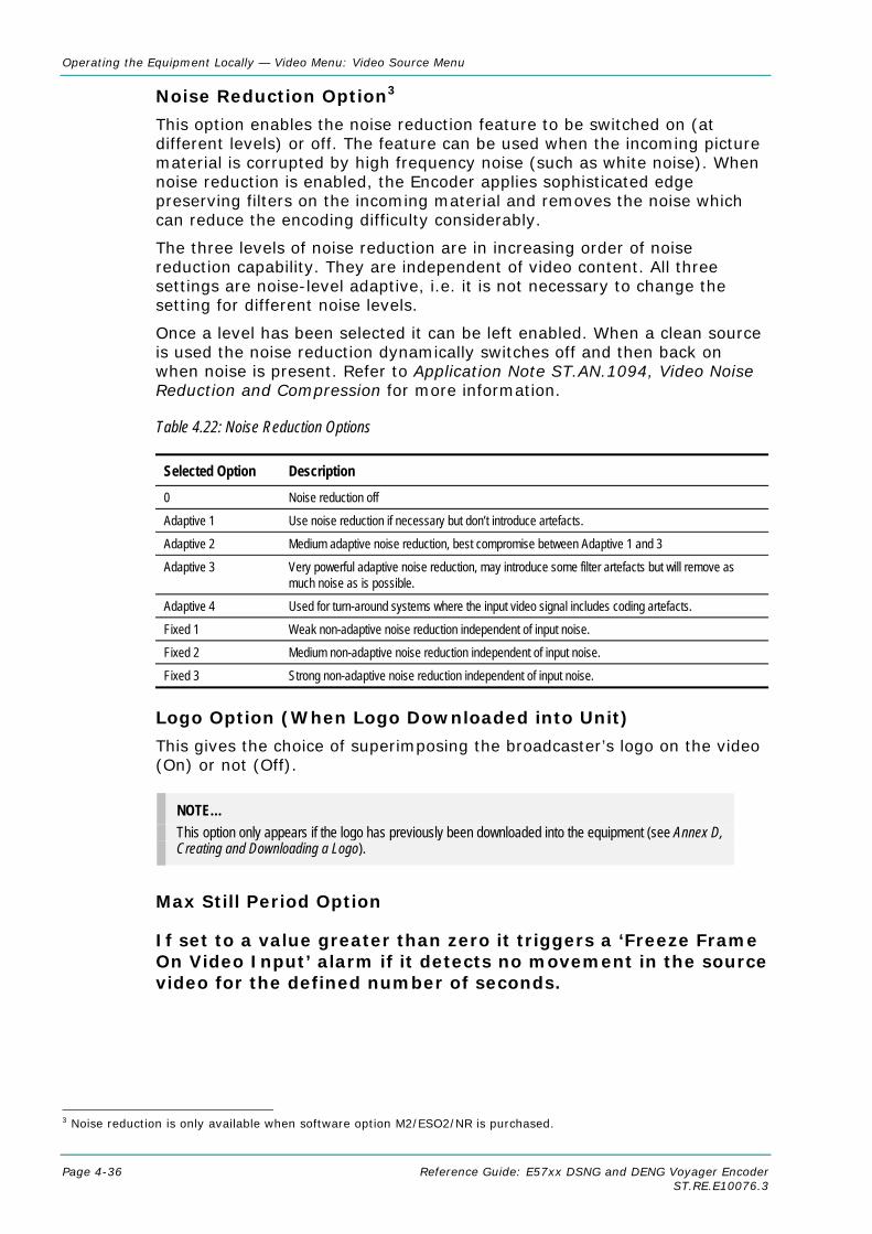
Operating the Equipment Locally — Video Menu: Video Source Menu
Page 4-36 Reference Guide: E57xx DSNG and DENG Voyager Encoder ST.RE.E10076.3
Noise Reduction Option3
This option enables the noise reduction feature to be switched on (at different levels) or off. The feature can be used when the incoming picture material is corrupted by high frequency noise (such as white noise). When noise reduction is enabled, the Encoder applies sophisticated edge preserving filters on the incoming material and removes the noise which can reduce the encoding difficulty considerably.
The three levels of noise reduction are in increasing order of noise reduction capability. They are independent of video content. All three settings are noise-level adaptive, i.e. it is not necessary to change the setting for different noise levels.
Once a level has been selected it can be left enabled. When a clean source is used the noise reduction dynamically switches off and then back on when noise is present. Refer to Application Note ST.AN.1094, Video Noise Reduction and Compression for more information.
Table 4.22: Noise Reduction Options
Selected Option Description 0 Noise reduction off
Adaptive 1 Use noise reduction if necessary but don’t introduce artefacts.
Adaptive 2 Medium adaptive noise reduction, best compromise between Adaptive 1 and 3
Adaptive 3 Very powerful adaptive noise reduction, may introduce some filter artefacts but will remove as much noise as is possible.
Adaptive 4 Used for turn-around systems where the input video signal includes coding artefacts.
Fixed 1 Weak non-adaptive noise reduction independent of input noise.
Fixed 2 Medium non-adaptive noise reduction independent of input noise.
Fixed 3 Strong non-adaptive noise reduction independent of input noise.
Logo Option (When Logo Downloaded into Unit)
This gives the choice of superimposing the broadcaster’s logo on the video (On) or not (Off).
NOTE… This option only appears if the logo has previously been downloaded into the equipment (see Annex D, Creating and Downloading a Logo).
Max Still Period Option
If set to a value greater than zero it triggers a ‘Freeze Frame On Video Input’ alarm if it detects no movement in the source video for the defined number of seconds.
3 Noise reduction is only available when software option M2/ESO2/NR is purchased.

Operating the Equipment Locally — Video Menu: Video Source Menu
Reference Guide: E57xx DSNG and DENG Voyager Encoder Page 4-37 ST.RE.E10076.3
Default 625
This sets the default for the 625 Line standard.
Table 4.23: Default 625 Options
Selected Option Description
PAL-B/G/H/I
PAL-D
PAL-M (Jaimaca)
PAL-M
Default 525
This sets the default for the 625 Line standard.
Table 4.24: Default 525 Options
Selected Option Description
NTSC with pedestal
PAL-M
NTSC no pedestal
I/P Monitor Refresh Option
This sets the update rate of the input video monitor on the front panel, and the web browser monitor.
Time Code Option
This option indicates the time given by the Vertical Interval Time Code (VITC) or generated by the Encoder. It is for status only and cannot be changed.
4.8.3 Video Encoder Menu
Overview
The Video Encoder Menu is selected from the Video Menu by pressing the Video Encoder softkey. This menu permits the selection of video encoding parameters.
Profile/Level Option
NOTE… This option is always MP@ML and cannot be changed unless the M2/ESO2/422 software option is enabled.
This option enables the Profile/Level to be set.

Operating the Equipment Locally — Video Menu: Video Encoder Menu
Page 4-38 Reference Guide: E57xx DSNG and DENG Voyager Encoder ST.RE.E10076.3
Table 4.25: Profile/Level Options
Selected Option Description MP@ML Main Profile @ Main Level. Typically used in 4:2:0 direct to home.
422P@ML 4:2:2 Profile @ Main Level. Typically used in 4:2:2 contribution feed.4
Compression Mode Option
This enables various compression modes to be selected in which some encoding parameters are automatically controlled depending on the selected encoding delay.
NOTES… 1. Changing compression causes a change to GOP structure and length. 2. Picture quality may decrease with reduced delay.
Table 4.26: Compression Mode Options
Selected Option Description Seamless 1
Seamless 2
Seamless 3
Seamless 4
This gives a fixed delay which allows the bit-rate to be changed, over the permitted range, without a break in transmission.
Seamless 5
Seamless 6
In the following modes the delay is a function of the bit-rate selected. If the bit-rate is changed there is a break in transmission.
Mega Low Delay The generated transport stream is not fully DVB compliant and may not work with all Decoders. The delay is reduced by not allowing B frames but using field pictures and other techniques.
Very Low Delay Delay is reduced using the same techniques as Low Delay mode. GOP structure used is IP and field pictures are used.
Low Delay Delay is reduced by reducing the size of the video rate buffer. This compromises video quality in some circumstances.
Standard The normal mode, with no special techniques or fixed settings to reduce encoding delay.
NOTE… See Chapter 3, Options and Upgrades, Section 3.2, Bit-rate Limits With Reflex Licence and/or Performance Upgrade for possible differences with different combinations of Performance Upgrade (M2/ESO2/PU) and Reflex/VBR Licence (M2/ESO2/VBR).
Table 4.27: Seamless Mode Bit-rate (Full Resolution Only)
Profile Seamless 1 (Mbit/s)
Seamless 2 (Mbit/s)
Seamless 3 (Mbit/s)
Seamless 4 (Mbit/s)
Seamless 5 (Mbit/s)
Seamless 6 (Mbit/s)
4:2:0 0.8 - 10 1.5 - 10 2 - 15 0.4 - 10 1 - 12 1.3 - 10
4:2:2 1.5 - 13 3 - 27 5 - 33 0.7 - 10 2.1 – 2.5 2.5 - 20
Rate Buffer delay 2.5 s 1.2 s 1 s 3.3 s 1.3 s 1 s 4 4:2:2 is not available unless the M2/ESO2/422 software option is enabled.
Operating the Equipment Locally — Video Menu: Video Encoder Menu
Reference Guide: E57xx DSNG and DENG Voyager Encoder Page 4-39 ST.RE.E10076.3
Seamless 1 mode can use video bit-rates from 0.8 Mbit/s to 10 Mbit/s, with the actual limits depending on video standard and resolution. This would be used for 4:2:0 DTH statistical multiplexing applications. The Encoder delay is approximately 2.5 seconds.
Seamless 2 mode emulates System 3000 6U and 6U+ Encoders. Video bit-rate can be between 1.5 Mbit/s and 10 Mbit/s. Actual minimum and maximum rates depend on video standard and resolution.
Seamless 3 mode operates between 5 Mbit/s and 33 Mbit/s, with the actual limits depending on video standard and resolution. It would usually be used in 4:2:2 statistical multiplexing applications. The Encoder delay is approximately 1.1 seconds.
Seamless 4 mode has a very low Bmin. Actual minimum and maximum depend on the video standard and resolution. This mode would typically be used for 4:2:0 DTH statistical multiplexing applications.
Seamless 5 mode minimum and maximum depend on the video standard and resolution.
Seamless 6 mode is typically used with 4:2:2 statistical multiplexing and a low Bmin. Actual minimum and maximum depend on the video standard and resolution.
NOTE… In Seamless Modes 4, 5 and 6 coding performance is compromised a little to achieve lower Bmins.
Bit-rate Option
This option enables the Bit-rate to be set. An error message is shown with the correct range of bit-rates if the wrong rate is entered.
If the video bit-rate is set to its maximum then video bit-rate tracking is automatically switched on. In this mode, any changes which cause the mux bit-rate to increase ordecrease will cause the video rate to always fill the available mux bit-rate. Changes which cause the mux rate to change include varying audio bit-rate, RS-232 data bit-rate, changing symbol-rate (on Voyager units).
NOTE… On an Encoder fitted with a Remux card, only changes to the Host Bit-rate will cause the video rate to track. Increasing the final bit-rate (e.g. by changing the symbol=rate) will NOT cause the video=rate of the local service to increase. This is to allow the final rate to be increased to accommodate more Remux services.
Video bit-rate tracking is switched off by manually settingthe video bit-rate to any value lower than the maximum.
NOTE… High bit-rates in low resolutions cannot always generate sufficient bits to match the requested bit-rate. However, a valid picture will still be produced.
CAUTION… When using the Encoder with a PRO IRD M2/PSR/3/422BAS in 4:2:2 mode the upper video bit-rate limit
of the IRD is 25 Mbit/s.
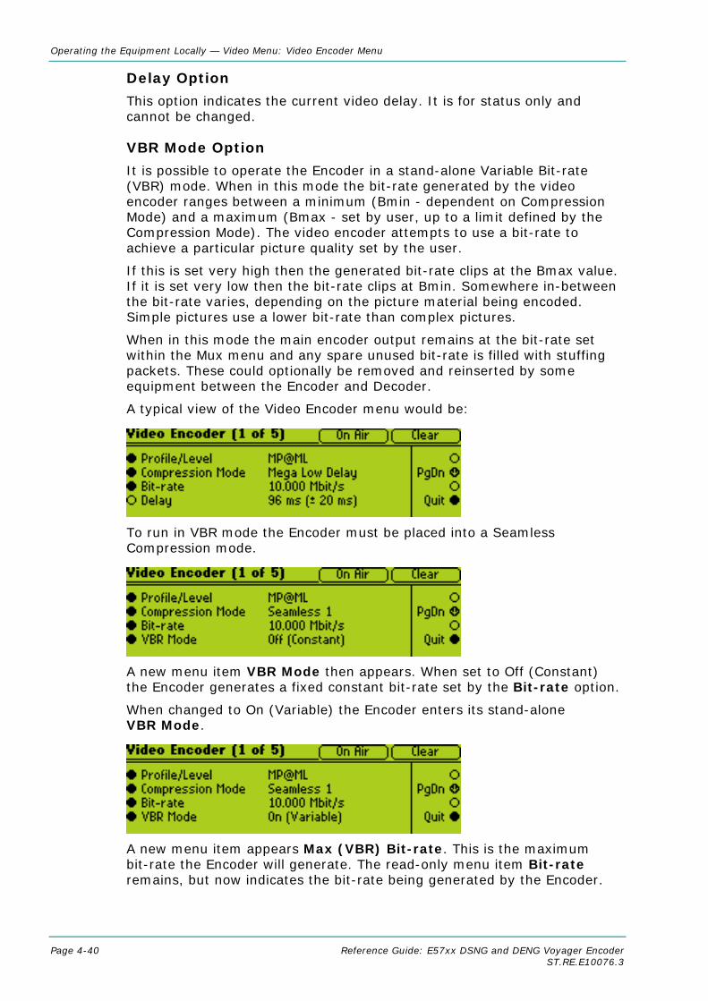
Operating the Equipment Locally — Video Menu: Video Encoder Menu
Page 4-40 Reference Guide: E57xx DSNG and DENG Voyager Encoder ST.RE.E10076.3
Delay Option
This option indicates the current video delay. It is for status only and cannot be changed.
VBR Mode Option
It is possible to operate the Encoder in a stand-alone Variable Bit-rate (VBR) mode. When in this mode the bit-rate generated by the video encoder ranges between a minimum (Bmin - dependent on Compression Mode) and a maximum (Bmax - set by user, up to a limit defined by the Compression Mode). The video encoder attempts to use a bit-rate to achieve a particular picture quality set by the user.
If this is set very high then the generated bit-rate clips at the Bmax value. If it is set very low then the bit-rate clips at Bmin. Somewhere in-between the bit-rate varies, depending on the picture material being encoded. Simple pictures use a lower bit-rate than complex pictures.
When in this mode the main encoder output remains at the bit-rate set within the Mux menu and any spare unused bit-rate is filled with stuffing packets. These could optionally be removed and reinserted by some equipment between the Encoder and Decoder.
A typical view of the Video Encoder menu would be:
To run in VBR mode the Encoder must be placed into a Seamless Compression mode.
A new menu item VBR Mode then appears. When set to Off (Constant) the Encoder generates a fixed constant bit-rate set by the Bit-rate option.
When changed to On (Variable) the Encoder enters its stand-alone VBR Mode.
A new menu item appears Max (VBR) Bit-rate. This is the maximum bit-rate the Encoder will generate. The read-only menu item Bit-rate remains, but now indicates the bit-rate being generated by the Encoder.
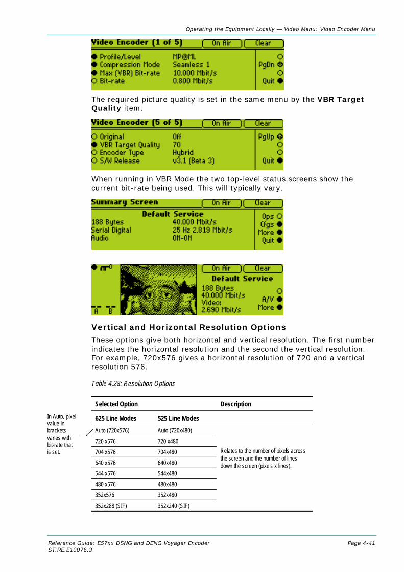
Operating the Equipment Locally — Video Menu: Video Encoder Menu
Reference Guide: E57xx DSNG and DENG Voyager Encoder Page 4-41 ST.RE.E10076.3
The required picture quality is set in the same menu by the VBR Target Quality item.
When running in VBR Mode the two top-level status screens show the current bit-rate being used. This will typically vary.
Vertical and Horizontal Resolution Options
These options give both horizontal and vertical resolution. The first number indicates the horizontal resolution and the second the vertical resolution. For example, 720x576 gives a horizontal resolution of 720 and a vertical resolution 576.
Table 4.28: Resolution Options
Selected Option Description
625 Line Modes 525 Line Modes Auto (720x576) Auto (720x480)
720 x576 720 x480
704 x576 704x480
640 x576 640x480
544 x576 544x480
480 x576 480x480
352x576 352x480
352x288 (SIF) 352x240 (SIF)
Relates to the number of pixels across the screen and the number of lines down the screen (pixels x lines).
In Auto, pixelvalue in brackets varies with bit-rate that is set.

Operating the Equipment Locally — Video Menu: Video Encoder Menu
Page 4-42 Reference Guide: E57xx DSNG and DENG Voyager Encoder ST.RE.E10076.3
Aspect Ratio Option
This option does not affect the image processing.
Table 4.29: Aspect Ratio Options
Selected Option Description 1, 0 Video image is encoded at 1:1 aspect ratio. Not currently used. 4:3 Video image is encoded at 4:3 aspect ratio. Default. 16:9 Video image is encoded at 16:9 aspect ratio. 2.21:1 Video image is encoded at 2.21:1 aspect ratio. Not currently used.
AFD Option
Active Format Descriptor (AFD) uses three bits of video index to define the video format. This information is encoded into user data and can then be used by a Decoder for wide-screen switching.
Table 4.30: AFD Options
Selected Option Description Off No AFD data output. On Output AFD value zero if input is lost. On (No Action on Error) If the input is lost, carry on outputting last valid data.
NOTE… 625 line – with AFD set to On, lines 11 and 324 will be set to Video Index. 525 line – with AFD set to On, lines 14 and 277 will be set to Video Index.
Table 4.31: AFD Information
Video Input
Encoder Video Index Extraction
Encoder AFD off Encoder AFD on Encoder AFD on (No action on Error)
Sequence_header aspect_ratio_information
AFD user_data() active_format
sequence_header aspect_ratio_information
AFD user_data() active_format
sequence_header aspect_ratio_information
AFD user_data() active_format
Present ON Aspect ratio from Video Index
Not present Aspect ratio from Video Index
AFD value from Video Index
Aspect ratio from Video Index
AFD value from Video Index
Present OFF Encoder setting Not present Encoder setting 0 (Active region is the same as encoded frame)
Stays at last aspect ratio extracted from Video Index
Stays at last value extracted from Video Index (This could be 0)
No input or Present but no Video Index data
ON Encoder setting Not present Encoder setting 0 (Active region is the same as encoded frame)
Stays at last aspect ratio extracted from Video Index
Stays at last value extracted from Video Index (This could be 0)

Operating the Equipment Locally — Video Menu: Video Encoder Menu
Reference Guide: E57xx DSNG and DENG Voyager Encoder Page 4-43 ST.RE.E10076.3
No input or Present but no Video Index data
OFF Encoder setting Not present Encoder setting 0 (Active region is the same as encoded frame)
Stays at last aspect ratio extracted from Video Index
Stays at last value extracted from Video Index (This could be 0)
GOP Structure Option
This option enables the GOP Structure to be set.
Table 4.32: Group of Pictures Structure Options
Selected Option Description IBBBP (IBBBPBBBPBBBI).
IBBP for successive B frames (IBBPBBPBBPBBPI) – default.
IBP for operation with B frames (IBPBPBPBPBPI).
IP for non-B frame operation (IPPPPPPPPPPI) - default for low delay mode.
IBBB (IBBBIBBBIBBBIBBB) - professional editing standard.
IBB IBBIBBIBBIBBIBBIBBI) - professional editing standard.
IB (IBIBIBIBIBIBIBIBIB) - a professional editing standard.
I-Frame (IIIIIIIIIIIIIII) - for precise editing and compression.
NOTE… For some GOP changes operation can be seamless but this is not guaranteed.
GOP Length Option
This enables the video GOP structure length to be set. The structure length determines how regularly an I frame is transmitted. The I frame provides a regular reference from which predicted frames can be generated, thereby ensuring that predictions do not become wildly inaccurate.
NOTE… Some of the settings may not be available if they are not valid for use with other current encoding parameters. Also, changing the GOP structure automatically changes the GOP length if the current GOP length is not compatible with the selected structure.
Table 4.33: Group of Pictures Length Options (Long GOPs Disabled)
Valid Input Range Description Min: 1 Max: 15
GOP lengths available depend on GOP structure selected and the frame rate. Maximum GOP lengths are 12 for 25 Hz and 15 for 29.97 Hz. I-Frame and IP encoding have 1, 2, 3, 4, 5, 6, 7, 8, 9, 10, 11, 12, 13, 14, 15. IBP and IB have 2, 4, 6, 8, 10, 12, 14. IBBP and IBB have 3, 6, 9, 12, 15. IBBBP and IBBB have 4, 8, 12.
Operating the Equipment Locally — Video Menu: Video Encoder Menu
Page 4-44 Reference Guide: E57xx DSNG and DENG Voyager Encoder ST.RE.E10076.3
Long GOPs Option
NOTE… Only available if M2/ESO2/PU has been purchased.
This is used to enable or disable the use of GOP structures that are longer than 500 ms in duration.
Long GOP structures can improve video encoding performance, particularly at low bit-rates. However, it can lead to compression artefacts being visible on scene cuts, and a periodic build-up and removal of noise at the I-frame rate.
NOTE… Long GOPs are not DVB compliant, and should be used with caution.
Adaptive GOP
The GOP structure is adapted in regard to the number of B and P frames according to the motion detected in the video. It should be left ON unless there is a compatibility issue with the receiver population.
Field/Frame Option
This enables the choice of field or frame based pictures.
MPEG-2 encodes video at the field/frame level in what are known as pictures. These are coding units within the hierarchy of the spec. Pictures can be used in two ways, frame pictures and field pictures.
With frame pictures a frame of a field 1 and field 2 is encoded as a single unit. With field pictures each individual field of video is encoded as a single unit, but must be followed or preceded by another field picture relating to its matching field.
Table 4.34: Field/Frame Options
Selected Option Description Fields Field based pictures. Frames Frame based pictures. Auto Automatically chooses the correct option on a frame by frame basis.
3:2 Pulldown Option
This enables 3:2 pulldown (film) mode to be switched On and Off.
NOTES… 1. This option is only available if a 525 line 29.97 Hz video source is selected. 2. VBI in Picture is not supported when 3:2 Pulldown is active. 3. 3:2 Pulldown is not valid for Very Low Delay and Mega Low Delay coding modes. 4. It is recommended to set this option to On.

Operating the Equipment Locally — Video Menu: Video Encoder Menu
Reference Guide: E57xx DSNG and DENG Voyager Encoder Page 4-45 ST.RE.E10076.3
The option should be switched on if the video material originated on film and has been converted from the 24 frames per second film rate to the 29.97 frames per second NTSC rate. This enables the Encoder to increase the video compression by only including a flag in the transport stream to represent a repeated field (when detected), rather than compressing the repeated fields.
Concatenation Option5
Use this option if the signal has been coded, then decoded and is about to be coded again. It reduces picture degradation associated with multiple generation compression encoding. Setting this option may give better results as it tries to line up the I-frames. Only available to video via the SDI input. See Application Note, ST.AN.1110, Near Loss-less MPEG Concatenation Without Helper Signals.
PID Option
The option is used for entering or updating video PIDs, as required. Enter a PID then press the Enter softkey to accept it.
To be DVB compliant, PIDs below 32 are reserved. Therefore PIDs 32 to 8191 are available for use. In the event of a clash, one of the PIDs will be changed by the Encoder’s internal checking algorithm.
Component Tag Option
This item defines the optional component tag to be assigned to this video stream.
Reflex Enable Option
The option is used to enable (On) or disable (Off) Reflex.
Indicated Bit-rate Option
This option controls the video bit-rate that is signalled in the transport stream. If set to 'Max Value' the maximum possible bit-rate for the profile and encoding mode is signalled. This is the way all previous generations of TANDBERG Encoders have operated. If set to 'Actual Value', and the encoding mode is not a seamless mode, then the bit-rate signalled is the actual video bit-rate set on the Encoder.
Copyright Option
This option indicates whether the information in the bit-stream is shown to be protected by copyright. It is for status only and cannot be changed.
Original Option
This option indicates whether the bit-stream is an original or a copy of an original bit-stream. It is for status only and cannot be changed.
5 Auto Concatenation is only available when software option M2/ESO2/ACON is purchased.
Operating the Equipment Locally — Video Menu: Video Encoder Menu
Page 4-46 Reference Guide: E57xx DSNG and DENG Voyager Encoder ST.RE.E10076.3
Insert VBV Delay Option
If this option is turned on the Encoder will insert vbv_delay values into the picture header. This is required by some older set-top boxes. The default value is off.
PES Header Option
This option controls how often the Encoder inserts a PES header into the transport stream. The default option is ‘per GOP’, when the Encoder will insert a PES header at the start of every GOP. The alternative is ‘per Picture’, when the Encoder will insert a PES header at the start of every picture. The PES header contains the PTS (Presentation Time Stamp), and some set-top boxes require this to be sent more frequently than once every GOP, hence the PES per Picture option.
AFD Location
This option indicates where the AFD information is transmitted. The options are: Sequence Header; Picture Header.
Encoder Type Option
This option indicates the type of Encoder. It is for status only and cannot be changed.
S/W Release Option
This option indicates the software release of the Video Compression Module. It is for status only and cannot be changed.
4.8.4 Vertical Blanking Interval (VBI) Menu
Overview
The VBI Menu permits the selection of Vertical Blanking Interval (VBI) parameters. The Encoder can extract a maximum of eight VBI lines per field. However, this limit does not apply to Teletext. The VBI options that are available are dependent on the frame rate of the video.
VBI Menu (25 Hz Frame Rate)
Teletext (All lines) Option
This option provides a quick way of configuring the Encoder to the most common Teletext configuration. When turned On, it enables extraction of Teletext System B (WST) data from lines 7 to 22 and 320 to 335. It is possible to extract Teletext from lines 6, 318 and 319 as well, but these lines must be individually configured.
Teletext Data Out Option
This option indicates whether the Encoder is currently outputting Teletext data. It is for status only and cannot be changed.
Teletext PID Option
This option defines the PID to be used for Teletext data.

Operating the Equipment Locally — Video Menu: Vertical Blanking Interval (VBI) Menu
Reference Guide: E57xx DSNG and DENG Voyager Encoder Page 4-47 ST.RE.E10076.3
Teletext Tag Option
This option sets the component tag for the Teletext stream. The valid range is 0 to 255.
VITC on PES Option
Extraction of VITC data from VBI lines as shown in Table 4.36 on Page 4-49. Enabling this option will disable VBI on PID.
VBI on PID Option
This option allows the transmission of VBI data on its own PID to be turned On or Off.
VBI PID Option
This option defines the PID to be used for VBI data.
VBI Component Tag Option
This option sets the component tag for the VBI stream. The valid range is 0 to 255.

Operating the Equipment Locally — Video Menu: Vertical Blanking Interval (VBI) Menu
Page 4-48 Reference Guide: E57xx DSNG and DENG Voyager Encoder ST.RE.E10076.3
VBI In Picture Option
NOTES… 1. The VBI in Picture option is only accessible if the selected video profile/level is 422P@ML6. 2. VBI in Picture transmits the VBI waveform as part of the picture and as such will be subject to
some distortion. Most analogue VBI types are robust against this type of distortion but others, e.g. video index and ITS, are intended for SDI transmission and will not survive MPEG coding/decoding in VBI in Picture mode.
This enables the extended picture format available in the MPEG 4:2:2 specification to be selected. When selected, the Encoder compresses and transmits the VBI data as part of the active picture. This mode requires up to 3 Mbit/s of bit-rate, depending on the amount and complexity of the VBI present. It may be necessary to increase the video bit-rate accordingly to maintain picture quality.
NOTE… When encoding VBI in this way 3:2 Pulldown should be switched off. If it is not, then occasionally fields may not be encoded because of the inverse pulldown process. This results in some VBI lines not being transmitted.
When this option is not selected (or when 4:2:0 format video is used), VBI data must be transmitted in its original digital form either in an independent data stream (in the case of Teletext) or in user data fields within the MPEG video transport stream.
Table 4.35: VBI in Picture Options
Selected Option Description On VBI is coded as active video. Off Off (Bit-rate too low) Insufficient bit-rate.
VPS (Line 16) Option
This enables or disables the extraction of VPS (Video Programming System) data from line 16 of the video input.
WSS (Line 23) Option
NOTES… 1. Aspect ratio changes when WSS is enabled. 2. If the PES Header option in the Video Encoder menu is set to PES per picture, any aspect ratio
changes will be signalled frame accurately.
This enables or disables the extraction of WSS (Wide Screen Signalling) data from line 23 of the video input. The WSS format can either be in accordance with ETSI 300 294, or can be in the proprietary WSS-AFD format.
6 4:2:2 is only available when software option M2/ESO2/422 is purchased.

Operating the Equipment Locally — Video Menu: Vertical Blanking Interval (VBI) Menu
Reference Guide: E57xx DSNG and DENG Voyager Encoder Page 4-49 ST.RE.E10076.3
Blank Line 23 Option
This option controls the blanking of line 23. The options are off or whole line blanked. The option is provided to enable line 23 VBI signals to be removed if it is found that set-top boxes are not correctly removing it when displaying in ‘letter box’ format. In most situations line 23 blanking should be disabled.
Auto Detect VITC Option
If this option is enabled the Encoder automatically detects the presence of Vertical Interval Time Code (VITC) data. The Encoder examines each VBI line, and its equivalent in the other field, for VITC signals. If it finds a VITC signal it stops searching and decodes VITC from that pair of lines. It does not look for VITC on VBI lines that are not configured to Off. VBI Line ‘n’ Option
NOTE… To autodetect VITC the lines within the VBI line option must be set to VITC.
Each VBI line can be individually configured as to the format of VBI data that should be extracted from that line. However, a maximum of eight VBI lines can be processed per field (this does not include Teletext lines). Refer to Table 4.36 for the options available for a frame rate of 25 Hz.
Table 4.36: VBI - Line ‘n’ Options
Option Description Frame Rate = 29.97 Hz Off VBI data is not extracted from the line. Vertical Interval Time Code VITC data extracted from the line. Video Index Closed Caption The setting cannot be selected on this screen, but is set by setting the Closed Caption
option to On [SMPTE 333M], On [video 21 & 284] or On [video line 21]. It indicates that closed captioning data is extracted from the line. Setting Line 21 back to Off or VITC resets the Closed Caption option back to Off (see also page 4-53).
Neilsen AMOL 1 Neilsen AMOL 1 data is extracted from the line. Neilsen AMOL11 Neilsen AMOL 11 data is extracted from the line. NABTS (EIA516) NABTS data is extracted Gemstar2x Gemstar2x Data is extracted Frame Rate = 25 Hz Off VBI data is not extracted from the line. Vertical Interval Time Code VITC data extracted from the line. Only the timecode part of VITC is extracted. Video Index Aspect ratio will be affected (see Table 4.31). Teletext System B (World System Teletext)
Teletext System B data extracted from the line.
Inverted Teletext Inverted Teletext is extracted from the line. Wide Screen Signalling
The setting cannot be selected on this screen, but is set by setting the WSS (Line 23) option to On. It indicates that WSS data is extracted from the line. Setting Line 23 back to Off, VITC or Teletext System B resets the WSS (Line 23) option back to Off.
Closed Caption Closed Caption data is extracted from the line (see also page 4-53). Video Programming System
The setting cannot be selected on this screen, but is set by setting the VPS (Line 16) option to On. It indicates that VPS data is extracted from the line. Setting Line 16 back to Off, VITC or Teletext System B resets the VPS (Line 16) option back to Off.

Operating the Equipment Locally — Video Menu: Vertical Blanking Interval (VBI) Menu
Page 4-50 Reference Guide: E57xx DSNG and DENG Voyager Encoder ST.RE.E10076.3
NOTES… 1. VITC is carried as timecode in the video stream rather than as a separate PES stream. If VITC is
not present, a locally generated timecode is sent instead. 2. From SV 3.6.0, VITC data can be carried in PES.
When operating in ATSC mode and Closed Captions, the language of the descriptors is set by the Encoder.
When switching the Encoder from DVB to ATSC mode the PIDs are remapped. The remapping would be specified by the program paradigm. Switching back to DVB would invoke the original PIDs.
FIELD 1 FIELD 2
272 9 Same options as line 10
10 VITC (SMPTE), Video Index, Off, Closed Caption, Nielsen/AMOL 1, Nielsen/AMOL 11
273 10 Same options as line 10
11 11 Same options as line 10 274 11 Same options as line 10
12 12 Same options as line 10 275 12 Same options as line 10
13 13 Same options as line 10 276 13 Same options as line 10
14 14 Same options as line 10 277 14 Same options as line 10
15 15 Same options as line 10 278 15 Same options as line 10
16 16 Same options as line 10 279 16 Same options as line 10
17 17 Same options as line 10 280 17 Same options as line 10
18 18 Same options as line 10 281 18 Same options as line 10
19 19 Same options as line 10 282 19 Same options as line 10
20 20 Same options as line 10 283 20 Same options as line 10
21 21 Same options as line 10 284 21 Same options as line 10
22 22 Same options as line 10 285 22 Same options as line 10
23 - 262
23 - 262
ACTIVE VIDEO Start of coded video. 286 - 525
23 - 262
ACTIVE VIDEO Start of coded video.
263 263 ACTIVE VIDEO / Equalising pulses
Line N
umbe
r (wh
ole fr
ame)
Line N
umbe
r (fie
ld by
field)
Line N
umbe
r (wh
ole fr
ame)
Line N
umbe
r (fie
ld by
field)
NOTES… 1. In 525-line systems, fields start on the first full line after the end of the picture period. Therefore,
field 1 is 262 lines long and field 2 is 263 lines long. 2. An MPEG frame is 480 lines when formatting 525-line format pictures. 3. For compatibility with some older Receivers the start of coded video may need to begin at
line 22. Contact Customer Services for details.
Figure 4.11: VBI Structure Implemented by TANDBERG for 525-line Systems

Operating the Equipment Locally — Video Menu: Vertical Blanking Interval (VBI) Menu
Reference Guide: E57xx DSNG and DENG Voyager Encoder Page 4-51 ST.RE.E10076.3
FIELD 1 FIELD 2
6 Teletext System B or Inverted Teletext, VITC, Video Index, Closed Caption, Wide Screen Signalling (WSS), Off, Video Programming System (VPS)
318 Same options as line 6
7 Same options as line 6 319 Same options as line 6
8 Same options as line 6 320 Same options as line 6
9 Same options as line 6 321 Same options as line 6
10 Same options as line 6 322 Same options as line 6
11 Same options as line 6 323 Same options as line 6
12 Same options as line 6 324 Same options as line 6
13 Same options as line 6 325 Same options as line 6
14 Same options as line 6 326 Same options as line 6
15 Same options as line 6 327 Same options as line 6
16 Same options as line 6 328 Same options as line 6
17 Same options as line 6 329 Same options as line 6
18 Same options as line 6 330 Same options as line 6
19 Same options as line 6 331 Same options as line 6
20 Same options as line 6 332 Same options as line 6
21 Same options as line 6 333 Same options as line 6
22 Same options as line 6 334 Same options as line 6
23 Same options as line 6 Start of coded video. 335 Same options as line 6
24 ACTIVE VIDEO 336 Same options as line 6 Start of coded video.
25 - 310
ACTIVE VIDEO 337 - 622
ACTIVE VIDEO
311 - 312
Equalising Pulses 623 ACTIVE VIDEO / Equalising Pulses
313 Equalising Pulses (part) 624 - 625
Equalising Pulses
NOTES… 1. Any type of valid VBI can be on any line, even if it is not usually associated with that line. 2. 625-line fields start on the leading edge of the first vertical sync (broad) pulse. Therefore, the first
half of line 313 is in field 1 and the second half is in field 2. 3. An MPEG frame is 576 lines when formatting 625-line format pictures. 4. Line 23 is the Wide Screen Signalling line. It carries information which defines the picture Aspect
Ratio. 5. ETS 300 294 is the specification which describes WSS. 6. EN 300 472 is the specification associated with System B Teletext (World System Teletext).
Figure 4.12: VBI Structure Implemented by TANDBERG for 625-line Systems
Operating the Equipment Locally — Video Menu: Vertical Blanking Interval (VBI) Menu
Page 4-52 Reference Guide: E57xx DSNG and DENG Voyager Encoder ST.RE.E10076.3
VBI Menu (29.97 Hz Frame Rate)
VITC on PES Option
Extraction of VITC data from Line 16 or 22 for 625-line systems (EBU definitions) or Line 14 for 525-line systems. Enabling this option will disable VBI on PID.
VBI on PID Option
This option allows the transmission of VBI data on its own PID to be turned On or Off.
VBI PID Option
This option defines the PID to be used for VBI data.
VBI Component Tag Option
This option sets the component tag for the VBI stream (range is 0 to 255).
VBI In Picture Option
NOTES… 1. The VBI in Picture option is only accessible if the selected video profile/level is 422P@ML7. 2. VBI in Picture transmits the VBI waveform as part of the picture and as such will be subject to
some distortion. Most analogue VBI types are robust against this type of distortion but others, e.g. video index and ITS, are intended for SDI transmission and will not survive MPEG coding/decoding in VBI in Picture mode.
This enables the extended picture format available in the MPEG 4:2:2 specification to be selected. When selected, the Encoder compresses and transmits the VBI data as part of the active picture. This mode requires up to 3 Mbit/s of bit-rate, depending on the amount and complexity of the VBI present. It may be necessary to increase the video bit-rate accordingly to maintain picture quality.
NOTE… When encoding VBI in this way 3:2 Pulldown should be switched off. If it is not, then occasionally fields may not be encoded because of the inverse pulldown process. This results in some VBI lines not being transmitted.
When this option is not selected (or when 4:2:0 format video is used), VBI data must be transmitted in its original digital form either in an independent data stream (in the case of Teletext) or in user data fields within the MPEG video transport stream.
Table 4.37: VBI in Picture Options
Selected Option Description On VBI is coded as active video. Off Off (Bit-rate too low) Insufficient bit-rate.
7 4:2:2 is only available when software option M2/ESO2/422 is purchased.

Operating the Equipment Locally — Video Menu: Vertical Blanking Interval (VBI) Menu
Reference Guide: E57xx DSNG and DENG Voyager Encoder Page 4-53 ST.RE.E10076.3
Closed Caption Option
This option controls the extraction and processing of closed caption data by the Encoder. Closed caption data can be obtained from: video line 21, video lines 21 and 284, or be received in accordance with SMPTE 333M.
CC Format Option
This inserts the closed captions as user data in the video stream in the selected format.
This controls the format used to insert the closed captions as user data in the video stream. The options are ATSC, proprietary TANDBERG/NDS, SCTE 20 & 21, SCTE 21 or SCTE 20 format.
CC Descriptor Option
This option is only available if the CC format is set to ATSC. The option controls the CC Descriptor type that the Encoder generates. The options are ‘Line 21 only’, ‘Line 21 and Advanced’, and ‘Advanced only’.
CC Font Option
This option is only available if the CC Format is ATSC, and Closed Captions are being extracted from line 21 or lines 21 and 284. It defines the font to be used for displaying the closed caption text.
CC Pen Size
This option is only available if the CC Format is ATSC, and Closed Captions are being extracted from line 21 or lines 21 and 284. It defines the pen size to be used for displaying the closed caption text.
CC Foreground Size
This option is only available if the CC Format is ATSC, and Closed Captions are being extracted from line 21 or lines 21 and 284. It defines the foreground colour to be used for displaying the closed captions.
CC Background Size
This option is only available if the CC Format is ATSC, and Closed Captions are being extracted from line 21 or lines 21 and 284. It defines the background colour to be used for displaying the closed captions.
SMPTE 333M Port Option
This option is only displayed if the Closed Captions are set to SMPTE 333M input. It controls which RS-232 interface is used for receiving the closed caption data.
CC Packet Size Option
This option is only displayed if the Closed Captions are set to SMPTE 333M input. It controls the size of closed caption packet the Encoder requests from the closed caption server via the SMPTE 333M interface.
Operating the Equipment Locally — Video Menu: Vertical Blanking Interval (VBI) Menu
Page 4-54 Reference Guide: E57xx DSNG and DENG Voyager Encoder ST.RE.E10076.3
Auto Detect VITC Option
If this option is enabled the Encoder automatically detects the presence of Vertical Interval Time Code (VITC) data. The Encoder examines each VBI line, and its equivalent in the other field, for VITC signals. If it finds a VITC signal it stops searching and decodes VITC from that pair of lines. It does not look for VITC on VBI lines that are not configured to Off.
VBI Line ‘n’ Option
NOTE… To autodetect VITC the lines within the VBI line option must be set to VITC.
Each VBI line can be individually configured as to the format of VBI data that should be extracted from that line. However, a maximum of eight VBI lines can be processed per field (this does not include Teletext lines). Refer to Table 4.36 for the options available for a frame rate of 29.97 Hz.

Operating the Equipment Locally — Audio Menu: MPEG Layer 2
Reference Guide: E57xx DSNG and DENG Voyager Encoder Page 4-55 ST.RE.E10076.3
4.9 Audio Menu
4.9.1 Overview The Encoder can process two stereo pairs as standard, but with the addition of Audio Option Cards it can process more. The control menu for each stereo pair is essentially the same, but the options available are dependent on the audio coding standard selected. See Figure 4.13 for the menu structure.
4.9.2 Audio A / B Menus – MPEG Layer 2
Introduction
Audio A and B have the same menu options, depending upon the Coding Standard selected. Audio A Menus are shown as examples. This menu permits the selection of individual channel audio parameters.
Source Option
This option defines the audio source.
Table 4.38: Source Options
Selected Option Description Off No audio packets are sent in the transport stream and audio is removed from the SI. Mute Audio silence. Test Tone An internally generated test tone is used as the audio source. The bit-rate automatically changes to 96 kbit/s. Analogue Analogue audio input on AUDIO IN connector. Digital Digital audio input on AUDIO IN connector. SDI Embedded 1 Digital audio de-embedded from digital video input using DID 0x2FF. SDI Embedded 2 Digital audio de-embedded from digital video input using DID 0x2FF. SDI Embedded 3 Digital audio de-embedded from digital video input using DID 0x1FD. SDI Embedded 4 Digital audio de-embedded from digital video input using DID 0x1FD.
Coding Standard Option
This option controls the audio coding standard. The options available in the audio menu are dependent on the coding standard selected.
Table 4.39: Coding Standard Options
Selected Option Description MPEG Layer 2 MPEG Layer 2 audio coding standard.
AC-3 Pass-Thru Pre-encoded (in Dolby encoder) AC-3 audio coding standard. See Annex F, Audio Modes, for information when using this mode.
Dolby E Pass-Thru Dolby E audio coding standard (pre-encoded in Dolby encoder). See Annex F, Audio Modes, for information when using this mode.
DTS Pass-Thru DTS audio coding standard (pre-encoded in DTS encoder). See Annex F, Audio Modes, for information when using this mode.
Dolby Digital (AC-3) Dolby Digital (AC-3) audio coding standard.
Linear PCM Linear PCM audio coding standard. See Annex F, Audio Modes, for information when using this mode.
These are default DIDs

Operating the Equipment Locally — Audio Menu: MPEG Layer 2
Page 4-56 Reference Guide: E57xx DSNG and DENG Voyager Encoder ST.RE.E10076.3
Figure 4.13: Menu Hierarchy – Setup/Audio Menu
— Source — Coding Standard — Input Level L — Input Level R 6 — Audio Bit-rate — Coding Mode — Auto Lip Sync — Lip Sync Offset 4 — Audio Delay 5 — Actual Audio Delay — Sampling Rate — Clip Level 1 — Impedance 1 — Language — Bit Stream Mode — Dialogue Level — Dolby Srnd Mode — Production Info — Mixing Level 7 — Room Type 7
— Copyright — Original — Dynamic Range — RF Protection — Deemphasis — DC Filter — Low Pass Filter — Embedded 1-2 DID — Embedded 3-4 DID — Audio PID — Component Tag — PCR on Audio PID — OP Digital Loss — Hardware Release — Software Release
— Source — Coding Standard — Input Level L — Input Level R 6 — Audio Bit-rate — Coding Mode — Auto Lip Sync — Lip Sync Offset 4 — Audio Delay 5 — Actual Audio Delay — Clip Level 1 — Impedance 1 — Language Left 2 — Language Right 2 — Deemphasis — Copyright — Original — Embedded 1-2 DID — Embedded 3-4 DID — Audio PID — Component Tag — PCR on Audio PID — OP Digital Loss — Hardware Release — Software Release
— Source — Coding Standard — Audio Bit-rate — Coding Mode — Auto Lip Sync — Audio Delay 5 — Actual Audio Delay — Lip Sync Offset 4 — External Delay — Language — Bit Stream Mode — Embedded 1-2 DID — Embedded 3-4 DID — Audio PID — Component Tag — PCR on Audio PID — OP Digital Loss — Hardware Release — Software Release
Audio Menu
Audio A....Audio B....Audio
Menu options depend onCoding Standard selected
Audio A Menu
Audio B Menu
Setup Menu
Shaded options are showing status and cannot bechanged.
AC-3 Pass-Thru Dolby Digital (AC3) only shown if
M2/ESO2/AC3 option enabled
Dolby E Pa— ss-Thru DTS Pass-Thru MPEG Layer 2 Linear PCM
Audio Language
Menu
1 Only shown if Source/Input Format = Analogue2 Only shown if Coding Mode = Dual Mono3 Status only. Only shown if the Encoder has aviable source from a Dolby Encoder.4 Only shown if Auto Lip Sync = On.
— Source — Coding Standard — Auto Lip Sync — Lip Sync Offset 4 — Audio Delay 5 — Actual Audio Delay — External Delay — Language — SMPTE 302M Stnd — Standard — Embedded 1-2 DID — Embedded 3-4 DID — Audio PID — Component Tag — PCR on Audio PID — OP Digital Loss — Hardware Release — Software Release
Refer to Annex C
5 Only shown if Auto Lip Sync = Off.6 Only shown if in two-channel mode.7 Only shown if Production Info = Yes.
— Source — Coding Standard — Input Level L — Input Level R 6 — Coding Mode — Auto Lip Sync — Lip Sync Offset 4 — Audio Delay 5 — Actual Audio Delay — Clip Level 1 — Impedance 1 — Language Left 2 — Language Right 2 — SMPTE 302M Stnd — Channel — Embedded 1-2 DID — Embedded 3-4 DID — Audio PID — Component Tag — PCR on Audio PID — OP Digital Loss — Hardware Release — Software Release

Operating the Equipment Locally — Audio Menu: MPEG Layer 2
Reference Guide: E57xx DSNG and DENG Voyager Encoder Page 4-57 ST.RE.E10076.3
Input Level L Option
This indicates the input level of the left audio channel. It is for status only and cannot be changed.
Input Level R Option
This indicates the input level of the right audio channel. It is for status only and cannot be changed.
Audio Bit-rate Option
This option sets the audio bit-rate of this audio channel.
Table 4.40: Audio Bit-rate Options
Available Settings
MPEG Layer 2 Coding
Mono
Dual Mono
Stereo
Joint Stereo
32 kbit/s 48 kbit/s 56 kbit/s 64 kbit/s 80 kbit/s 96 kbit/s 112 kbit/s 128 kbit/s 160 kbit/s 192 kbit/s 224 kbit/s 256 kbit/s 320 kbit/s 384 kbit/s 448 kbit/s 512 kbit/s 576 kbit/s 640 kbit/s
Coding Mode Option
This option sets the audio coding mode. If the current audio bit-rate is outside the bit-rate range supported by the new coding mode, the bit-rate is automatically changed to the lowest value within the supported range.
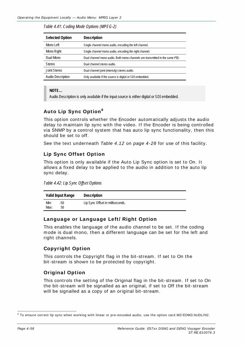
Operating the Equipment Locally — Audio Menu: MPEG Layer 2
Page 4-58 Reference Guide: E57xx DSNG and DENG Voyager Encoder ST.RE.E10076.3
Table 4.41: Coding Mode Options (MPEG-2)
Selected Option Description Mono Left Single channel mono audio, encoding the left channel.
Mono Right Single channel mono audio, encoding the right channel.
Dual Mono Dual channel mono audio. Both mono channels are transmitted in the same PID.
Stereo Dual channel stereo audio.
Joint Stereo Dual channel joint (intensity) stereo audio.
Audio Description Only available if the source is digital or SDI embedded.
NOTE… Audio Description is only available if the input source is either digital or SDI embedded.
Auto Lip Sync Option8
This option controls whether the Encoder automatically adjusts the audio delay to maintain lip sync with the video. If the Encoder is being controlled via SNMP by a control system that has auto lip sync functionality, then this should be set to off.
See the text underneath Table 4.12 on page 4-28 for use of this facility.
Lip Sync Offset Option
This option is only available if the Auto Lip Sync option is set to On. It allows a fixed delay to be applied to the audio in addition to the auto lip sync delay.
Table 4.42: Lip Sync Offset Options
Valid Input Range Description Min: -50 Max: 50
Lip Sync Offset in milliseconds.
Language or Language Left/Right Option
This enables the language of the audio channel to be set. If the coding mode is dual mono, then a different language can be set for the left and right channels.
Copyright Option
This controls the Copyright flag in the bit-stream. If set to On the bit-stream is shown to be protected by copyright.
Original Option
This controls the setting of the Original flag in the bit-stream. If set to On the bit-stream will be signalled as an original, if set to Off the bit-stream will be signalled as a copy of an original bit-stream.
8 To ensure correct lip sync when working with linear or pre-encoded audio, use the option card M2/EOM2/AUDLIN2.

Operating the Equipment Locally — Audio Menu: MPEG Layer 2
Reference Guide: E57xx DSNG and DENG Voyager Encoder Page 4-59 ST.RE.E10076.3
Embedded 1-2 DID Option
This option defines the DID to be de-embedded to obtain the audio source for SDI Embedded 1 and SDI Embedded 2. If this is set to 1024, then the default DID will be used. Refer to Annex F, Audio Modes for information about DIDs.
Table 4.43: Embedded 1-2 DID Options
Selected Option Description Min: 0 Max: 1023 Other: >1023
Off Select DID Default DID
Embedded 3-4 DID Option
This option defines the DID to be de-embedded to obtain the audio source for SDI Embedded 3 and SDI Embedded 4. If this is set to 1024, then the default DID will be used. Refer to Annex F, Audio Modes for information about DIDs.
Audio PID Option
This option sets the PID to be used for the audio channel. In the event of a PID clash, one of the PIDs will be changed by the Encoder’s internal checking algorithm.
To be DVB compliant the audio PID should not be less than 32. However it is possible to set the PID to less than 32, but in the event of a PID clash the Encoder’s internal checking algorithm will not resolve the conflict.
Component Tag Option
This item defines the optional component tag to be assigned to this audio stream.
PCR On Audio PID Option
This option controls whether PCR should be signalled on the audio PID. This may be necessary if an audio only service is being generated. The default setting is Off.
OP Digital Loss
This option controls behaviour digital audio is not locked.
Table 4.44: OP Digital Loss Options
Selected Option Description Silence Valid PES stream containing silence.
No PID No Audio PES stream (though stream is still refernced in SI)
No ASI O/P The ASI output of the Encoder is turned off.

Operating the Equipment Locally — Audio Menu: MPEG Layer 2
Page 4-60 Reference Guide: E57xx DSNG and DENG Voyager Encoder ST.RE.E10076.3
Hardware Release Option
This option indicates the hardware version of this audio encode channel. It is for status only and cannot be changed.
Software Release Option
This option indicates the software version of this audio encoder channel. It is for status only and cannot be changed.
Audio Delay Option
This option is only available if the Auto Lip Sync option is set to Off. It sets the delay that should be applied to the audio.
Table 4.45: Audio Delay Options
Valid Input Range Description Min: 111 Max: 3540
Audio Delay in milliseconds.
Actual Audio Delay
Shows the actual audio delay. It is for status only and cannot be changed.
Clip Level Option
This option is only displayed if the audio source is set to analogue. It enables the audio clip level to be set. That is, the head room above 0 dBu prior to the audio being clipped.
NOTE… The clip levels available depend on the hardware issue of the Encoder.
Table 4.46: Clip Level Options
Selected Option Description 12 dB 12 dB audio clipping level. 15 dB 15 dB is only available with PCB issue 4 and later. 18 dB 18 dB audio clipping level.
Impedance Option
This option is only displayed if the audio source is set to analogue. It enables the input impedance of the analogue audio input to be set to either 600 Ω or 20 kΩ.
Deemphasis Option
This option is turned on in order to de-emphasise pre-emphasised audio input into the Encoder.
To meet the MPEG Layer 2 audio encoding algorithm specification, the audio must not have pre-emphasis applied. If the input signal does have pre-emphasis applied, a de-emphasis filtering process must be applied prior to encoding.

Operating the Equipment Locally — Audio Menu: MPEG Layer 2
Reference Guide: E57xx DSNG and DENG Voyager Encoder Page 4-61 ST.RE.E10076.3
For a digital audio input, pre-emphasis detection is typically achieved by monitoring the pre-emphasis flags within the channel status data of the incoming digital audio signal. The de-emphasis is automatically adjusted when the Encoder is set to Auto.
For an analogue audio signal, the user must manually select the appropriate de-emphasis filter.
4.9.3 Audio (Dolby Digital (AC-3) Menu)
Source Option
This option defines the audio source.
Table 4.47: Source Options
Selected Option Description Off No audio packets are sent in the transport stream and audio is removed from the SI. Mute Audio silence. Test Tone An internally generated test tone is used as the audio source. The bit-rate automatically changes
to 96 kbit/s. Analogue Analogue audio input on AUDIO IN connector. Digital Digital audio input on AUDIO IN connector. SDI Embedded 1 Digital audio de-embedded from digital video input using DID 0x2FF. SDI Embedded 2 Digital audio de-embedded from digital video input using DID 0x2FF. SDI Embedded 3 Digital audio de-embedded from digital video input using DID 0x1FD. SDI Embedded 4 Digital audio de-embedded from digital video input using DID 0x1FD.
Coding Standard Option
This option controls the audio coding standard. The options available in the audio menu are dependent on the coding standard selected.
Input Level L Option
This indicates the input level of the left audio channel. It is for status only and cannot be changed.
Input Level R Option
This indicates the input level of the right audio channel. It is for status only and cannot be changed.
Audio Bit-rate Option
This option sets the audio bit-rate of this audio channel.
These are default DIDs

Operating the Equipment Locally — Audio Menu: Dolby Digital (AC-3) Menu
Page 4-62 Reference Guide: E57xx DSNG and DENG Voyager Encoder ST.RE.E10076.3
Table 4.48: Audio Bit-rate Options (Dolby Digital (AC-3))
Available Settings
Dolby Digital
1/0(C)
2/0(L,R)
32 kbit/s 48 kbit/s 56 kbit/s 64 kbit/s 80 kbit/s 96 kbit/s 112 kbit/s 128 kbit/s 160 kbit/s 192 kbit/s 224 kbit/s 256 kbit/s 320 kbit/s 384 kbit/s 448 kbit/s 512 kbit/s 576 kbit/s 640 kbit/s
Coding Mode Option
This option sets the audio coding mode. If the current audio bit-rate is outside the bit-rate range supported by the new coding mode, the bit-rate is automatically changed to the lowest value within the supported range.
Table 4.49: Coding Mode Options
Selected Option Description 1/0(C) (Left) Single channel mono audio, encoding the left channel. 1/0(C) (Right) Single channel mono audio, encoding the right channel. 2/0(L,R) Dual channel stereo audio coding.
Auto Lip Sync Option9
This option controls whether the Encoder automatically adjusts the audio delay to maintain lip sync with the video. If the Encoder is being controlled via SNMP by a control system that has auto lip sync functionality, then this should be set to off.
See the text underneath Table 4.12 on page 4-28 for use of this facility.
9 To ensure correct lip sync when working with linear or pre-encoded audio, use the option card M2/EOM2/AUDLIN2.

Operating the Equipment Locally — Audio Menu: Dolby Digital (AC-3) Menu
Reference Guide: E57xx DSNG and DENG Voyager Encoder Page 4-63 ST.RE.E10076.3
Lip Sync Offset Option
This option is only available if the Auto Lip Sync option is set to On. It allows a fixed delay to be applied to the audio in addition to the auto lip sync delay.
Table 4.50: Lip Sync Offset Options
Valid Input Range Description Min: -50 Max: 50
Lip Sync Offset in milliseconds.
Audio Delay Option
This option is only available if the Auto Lip Sync option is set to Off. It sets the delay that should be applied to the audio.
Table 4.51: Audio Delay Options
Valid Input Range Description Min: 111 Max: 3540
Audio Delay in milliseconds.
Actual Audio Delay
Shows the actual audio delay. It is for status only and cannot be changed.
Sampling Rate Option
This option controls the audio sampling rate.
Clip Level Option
This option is only displayed if the audio source is set to analogue. It enables the audio clip level to be set. That is the head room above 0 dBu prior to the audio being clipped.
NOTE… The clip levels available depend on the hardware issue of the Encoder.
Table 4.52: Clip Level Options
Selected Option Description 12 dB 12 dB audio clipping level. 15 dB 15 dB is only available with PCB issue 4 and later. 18 dB 18 dB audio clipping level.
Impedance Option
This option is only displayed if the audio source is set to analogue. It enables the input impedance of the analogue audio input to be set to either 600 Ω or 20 kΩ.

Operating the Equipment Locally — Audio Menu: Dolby Digital (AC-3) Menu
Page 4-64 Reference Guide: E57xx DSNG and DENG Voyager Encoder ST.RE.E10076.3
Language Option
This enables the language of the audio channel to be set.
Bit-stream Mode Option
This option sets the bit-stream mode that is signalled in the bit-stream. It is used to indicate the type of service the bit-stream conveys.
Table 4.53: Bit Stream Mode Options
Selected Option Description Complete Main
Music & Effects
Visually impaired
Hearing impaired
Dialogue
Commentary
Emergency
Reserved
Voice Over/Karaoke In Dolby Digital when the coding mode is 1/0 this option appears as “Voice Over” otherwise as “Karaoke”.
Dialogue Level Option
This option sets the dialogue level that the Encoder will signal in the bit-stream. The dialogue level indicates how far the average dialogue level is below digital 100%. It is not used by the AC-3 decoder, but may be used by other parts of the sound reproduction system.
Table 4.54: Dialogue Level Options
Selected Option Description –1 dB to –31 dB Dialogue levels between –1 dB to –31 dB.
Dolby Srnd Mode Option
This option is only available if the coding mode is 2/0(L,R). It determines whether the bit-stream is signalled as conveying a Dolby Surround encoded program or not. This information is not used by the AC-3 Decoder, but may be used by other parts of the sound reproduction system.
Table 4.55: Dolby Srnd Mode Options
Selected Option Description Not indicated It is not known if the bit-stream is conveying a Dolby Surround
encoded program.
Not Dolby Surround The bit-stream is not conveying a Dolby Surround encoded program.
Dolby Surround The bit-stream is conveying a Dolby Surround encoded program.

Operating the Equipment Locally — Audio Menu: Dolby Digital (AC-3) Menu
Reference Guide: E57xx DSNG and DENG Voyager Encoder Page 4-65 ST.RE.E10076.3
Production Info Option
This option indicates whether the Mixing Level and Room Type parameters exist within the bit-stream.
Mixing Level Option
This option is only available if the Production Info option is set to On. This parameter indicates the acoustic sound pressure level of the dialogue level during the final audio mixing session. This makes it possible for the program to be replayed at the same loudness, or at a known difference from the original. Refer to ATSC Doc. A52 for further details.
Table 4.56: Mixing Level Options
Selected Option Description 0 dB to 31 dB Mixing levels between 0 dB to 31 dB.
Room Type Option
This option is only available if the Production Info option is set to On. This parameter indicates the type and calibration of the mixing room used for the final audio mixing session. Refer to ATSC Doc. A52 for further details.
Table 4.57: Room Type Options
Selected Option Description Not Indicated
Small, Flat Mon Type and calibration of the mixing room used
Large, X Curve Mon for the final audio mixing session.
Copyright Option
This controls the Copyright flag in the bit-stream. If set to On the bit-stream is shown to be protected by copyright.
Original Option
This controls the setting of the Original flag in the bit-stream. If set to On the bit-stream will be signalled as an original, if set to Off the bit-stream will be signalled as a copy of an original bit-stream.
Dynamic Range Option
The dynamic range of audio material can vary according to its origin. This function determines which compression profile is applied to the encoding process.
The dynamic range compression profile determines the characteristic curve of the dynamic range compression algorithm (each profile has its own boost, null-band and cut parameters).

Operating the Equipment Locally — Audio Menu: Dolby Digital (AC-3) Menu
Page 4-66 Reference Guide: E57xx DSNG and DENG Voyager Encoder ST.RE.E10076.3
Table 4.58: Dynamic Range Options
Selected Option Description None Program reproduction with the original dynamic range.
Film Standard
Film Light
Music Standard
Music Light
Speech
RF Protection Option
This option enables or disables RF Overmodulation Protection. It is used in situations where the audio signal of a decoded AC-3 bit-stream is delivered via a link with very restricted dynamic range. One example is the case of a television broadcast, where sound is modulated onto an RF channel and delivered to a low cost television Receiver.
In this situation it is necessary to restrict the maximum peak output level to a known value with respect to dialogue level, in order to prevent overmodulation.
Deemphasis Option
This option is turned on in order to de-emphasise pre-emphasised audio input into the Encoder.
To meet the MPEG Layer 2 audio encoding algorithm specification, the audio must not have pre-emphasis applied. If the input signal does have pre-emphasis applied, a de-emphasis filtering process must be applied prior to encoding.
For a digital audio input, pre-emphasis detection is typically achieved by monitoring the pre-emphasis flags within the channel status data of the incoming digital audio signal. The de-emphasis is automatically adjusted when the Encoder is set to Auto.
For an analogue audio signal, the user must manually select the appropriate de-emphasis filter.
DC Filter Option
This option turns on or off a dc high pass filter in the input channel. Removing the dc component can allow more efficient coding. However, there is a risk that signals that do not reach 100% PCM level before high pass filtering, will exceed 100% level after filtering and therefore be clipped.
Low Pass Filter Option
This option is used to enable or disable a low-pass filter in the audio input which has a cut-off near the specified bandwidth of the audio channel.

Operating the Equipment Locally — Audio Menu: Dolby Digital (AC-3) Menu
Reference Guide: E57xx DSNG and DENG Voyager Encoder Page 4-67 ST.RE.E10076.3
Embedded 1-2 DID Option
This option defines the DID to be de-embedded to obtain the audio source for SDI Embedded 1 and SDI Embedded 2. If this is set to 1024, then the default DID will be used. Refer to Annex F, Audio Modes for information about DIDs.
Table 4.59: Embedded 1-2 DID Options
Selected Option Description Min: 0 Max: 1023 Other: >1023
Off Select DID Default DID
Embedded 3-4 DID Option
This option defines the DID to be de-embedded to obtain the audio source for SDI Embedded 3 and SDI Embedded 4. If this is set to 1024, then the default DID will be used. Refer to Annex F, Audio Modes for information about DIDs.
Audio PID Option
This option sets the PID to be used for the audio channel. In the event of a PID clash, one of the PIDs will be changed by the Encoder’s internal checking algorithm.
To be DVB compliant the audio PID should not be less than 32. However it is possible to set the PID to less than 32, but in the event of a PID clash the Encoder’s internal checking algorithm will not resolve the conflict.
Component Tag Option
This item defines the optional component tag to be assigned to this audio stream.
PCR On Audio PID Option
This option controls whether PCR should be signalled on the audio PID. This may be necessary if an audio only service is being generated. The default setting is Off.
OP Digital Loss
This option controls behaviour digital audio is not locked. See Table 4.44 for options.
Hardware Release Option
This option indicates the hardware version of this audio encoder channel. It is for status only and cannot be changed.
Software Release Option
This option indicates the software version of this audio encoder channel. It is for status only and cannot be changed.
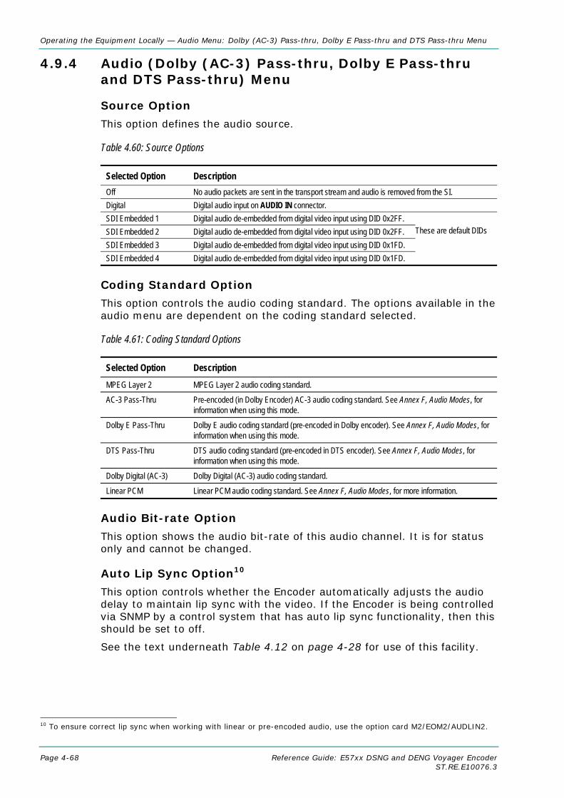
Operating the Equipment Locally — Audio Menu: Dolby (AC-3) Pass-thru, Dolby E Pass-thru and DTS Pass-thru Menu
Page 4-68 Reference Guide: E57xx DSNG and DENG Voyager Encoder ST.RE.E10076.3
4.9.4 Audio (Dolby (AC-3) Pass-thru, Dolby E Pass-thru and DTS Pass-thru) Menu
Source Option
This option defines the audio source.
Table 4.60: Source Options
Selected Option Description Off No audio packets are sent in the transport stream and audio is removed from the SI. Digital Digital audio input on AUDIO IN connector. SDI Embedded 1 Digital audio de-embedded from digital video input using DID 0x2FF. SDI Embedded 2 Digital audio de-embedded from digital video input using DID 0x2FF. SDI Embedded 3 Digital audio de-embedded from digital video input using DID 0x1FD. SDI Embedded 4 Digital audio de-embedded from digital video input using DID 0x1FD.
Coding Standard Option
This option controls the audio coding standard. The options available in the audio menu are dependent on the coding standard selected.
Table 4.61: Coding Standard Options
Selected Option Description MPEG Layer 2 MPEG Layer 2 audio coding standard.
AC-3 Pass-Thru Pre-encoded (in Dolby Encoder) AC-3 audio coding standard. See Annex F, Audio Modes, for information when using this mode.
Dolby E Pass-Thru Dolby E audio coding standard (pre-encoded in Dolby encoder). See Annex F, Audio Modes, for information when using this mode.
DTS Pass-Thru DTS audio coding standard (pre-encoded in DTS encoder). See Annex F, Audio Modes, for information when using this mode.
Dolby Digital (AC-3) Dolby Digital (AC-3) audio coding standard.
Linear PCM Linear PCM audio coding standard. See Annex F, Audio Modes, for more information.
Audio Bit-rate Option
This option shows the audio bit-rate of this audio channel. It is for status only and cannot be changed.
Auto Lip Sync Option10
This option controls whether the Encoder automatically adjusts the audio delay to maintain lip sync with the video. If the Encoder is being controlled via SNMP by a control system that has auto lip sync functionality, then this should be set to off.
See the text underneath Table 4.12 on page 4-28 for use of this facility.
10 To ensure correct lip sync when working with linear or pre-encoded audio, use the option card M2/EOM2/AUDLIN2.
These are default DIDs

Operating the Equipment Locally — Audio Menu: Dolby (AC-3) Pass-thru, Dolby E Pass-thru and DTS Pass-thru Menu
Reference Guide: E57xx DSNG and DENG Voyager Encoder Page 4-69 ST.RE.E10076.3
Lip Sync Offset Option
This option is only available if the Auto Lip Sync option is set to On. It allows a fixed delay to be applied to the audio in addition to the auto lip sync delay.
Table 4.62: Lip Sync Offset Options
Valid Input Range Description Min: -50 Max: 50
Lip Sync Offset in milliseconds.
Audio Delay Option
This option is only available if the Auto Lip Sync option is set to Off. It sets the delay that should be applied to the audio.
Table 4.63: Audio Delay Options
Valid Input Range Description Min: 111 Max: 3540
Audio Delay in milliseconds.
Actual Audio Delay
Shows the actual audio delay. It is for status only and cannot be changed.
External Delay Option
This option is used to compensate for external delays in the overall system.
Table 4.64: External Delay Options
Valid Input Range Description Min: 0 ms Max: 450 ms
Language Option
This enables the language of the audio channel to be set.
SMPTE 302M Standard Option
This option is only available if the coding standard is Dolby E Pass-thru or DTS Pass-thru. SMPTE 302M defines the mapping of AES3 data into an MPEG-2 transport stream. Problems may be experienced with some Receivers if the Encoder and Receiver are not using the same version of SMPTE 302M. This option allows the Encoder to be configured to work in either the 1998 or the 2000 version of SMPTE 302M.

Operating the Equipment Locally — Audio Menu: Dolby (AC-3) Pass-thru, Dolby E Pass-thru and DTS Pass-thru Menu
Page 4-70 Reference Guide: E57xx DSNG and DENG Voyager Encoder ST.RE.E10076.3
Table 4.65: SMPTE 302M Standard Options
Selected Option Description 1998 Standard Refers to the 1998 SMPTE 302M standard. 2000 Standard Refers to the 2000 SMPTE 302M standard.
Channel Option
This option is only available if the coding standard is Dolby E Pass-thru or DTS Pass-thru. It controls the value written to the channel identification field in the (SMPTE 302M) AES3 data elementary stream header.
Table 4.66: Channel Options
Valid Input Range Description Min: 0 Max: 15
This value is written to the channel identification field in the (SMPTE 302M) AES3 data elementary stream header.
Embedded 1-2 DID Option
This option defines the DID to be de-embedded to obtain the audio source for SDI Embedded 1 and SDI Embedded 2. If this is set to 1024, then the default DID will be used. Refer to Annex F, Audio Modes for information about DIDs.
Table 4.67: Embedded 1-2 DID Options
Selected Option Description Min: 0 Max: 1023 Other: >1023
Off Select DID Default DID
Embedded 3-4 DID Option
This option defines the DID to be de-embedded to obtain the audio source for SDI Embedded 3 and SDI Embedded 4. If this is set to 1024, then the default DID will be used. Refer to Annex F, Audio Modes for information about DIDs.
Audio PID Option
This option sets the PID to be used for the audio channel. In the event of a PID clash, one of the PIDs will be changed by the Encoder’s internal checking algorithm.
To be DVB compliant the audio PID should not be less than 32. However it is possible to set the PID to less than 32, but in the event of a PID clash the Encoder’s internal checking algorithm will not resolve the conflict.
Component Tag Option
This item defines the optional component tag to be assigned to this audio stream.
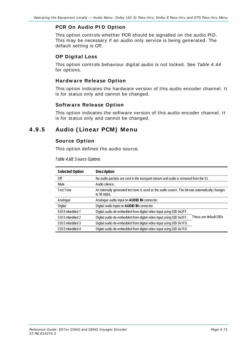
Operating the Equipment Locally — Audio Menu: Dolby (AC-3) Pass-thru, Dolby E Pass-thru and DTS Pass-thru Menu
Reference Guide: E57xx DSNG and DENG Voyager Encoder Page 4-71 ST.RE.E10076.3
PCR On Audio PID Option
This option controls whether PCR should be signalled on the audio PID. This may be necessary if an audio only service is being generated. The default setting is Off.
OP Digital Loss
This option controls behaviour digital audio is not locked. See Table 4.44 for options.
Hardware Release Option
This option indicates the hardware version of this audio encoder channel. It is for status only and cannot be changed.
Software Release Option
This option indicates the software version of this audio encoder channel. It is for status only and cannot be changed.
4.9.5 Audio (Linear PCM) Menu
Source Option
This option defines the audio source.
Table 4.68: Source Options
Selected Option Description Off No audio packets are sent in the transport stream and audio is removed from the SI. Mute Audio silence. Test Tone An internally generated test tone is used as the audio source. The bit-rate automatically changes
to 96 kbit/s. Analogue Analogue audio input on AUDIO IN connector. Digital Digital audio input on AUDIO IN connector. SDI Embedded 1 Digital audio de-embedded from digital video input using DID 0x2FF. SDI Embedded 2 Digital audio de-embedded from digital video input using DID 0x2FF. SDI Embedded 3 Digital audio de-embedded from digital video input using DID 0x1FD. SDI Embedded 4 Digital audio de-embedded from digital video input using DID 0x1FD.
These are default DIDs

Operating the Equipment Locally — Audio Menu: Linear PCM Menu
Page 4-72 Reference Guide: E57xx DSNG and DENG Voyager Encoder ST.RE.E10076.3
Coding Standard Option
This option controls the audio coding standard. The options available in the audio menu are dependent on the coding standard selected.
Table 4.69: Coding Standard Options
Selected Option Description MPEG Layer 2 MPEG Layer 2 audio coding standard.
AC-3 Pass-Thru Pre-encoded (in Dolby Encoder) AC-3 audio coding standard. See Annex F, Audio Modes, for information when using this mode.
Dolby E Pass-Thru Dolby E audio coding standard (pre-encoded in Dolby encoder). See Annex F, Audio Modes, for information when using this mode.
DTS Pass-Thru DTS audio coding standard (pre-encoded in DTS encoder). See Annex F, Audio Modes, for information when using this mode.
Dolby Digital (AC-3) Dolby Digital (AC-3) audio coding standard.
Linear PCM Linear PCM audio coding standard. See Annex F, Audio Modes, for information when using this mode.
Input Level L Option
This indicates the input level of the left audio channel. It is for status only and cannot be changed.
Input Level R Option
This indicates the input level of the right audio channel. It is for status only and cannot be changed.
Coding Mode Option
This option sets the audio coding mode. If the current audio bit-rate is outside the bit-rate range supported by the new coding mode, the bit-rate is automatically changed to the lowest value within the supported range. Table 4.70: Coding Mode Options (Linear PCM)
Selected Option Description Dual Mono Dual channel mono audio. Both mono channels are transmitted in the same PID.
Stereo Dual channel stereo audio.
Auto Lip Sync Option11
This option controls whether the Encoder automatically adjusts the audio delay to maintain lip sync with the video. If the Encoder is being controlled via SNMP by a control system that has auto lip sync functionality, then this should be set to off.
See the text underneath Table 4.12 on page 4-28 for use of this facility.
Lip Sync Offset Option
This option is only available if the Auto Lip Sync option is set to On. It allows a fixed delay to be applied to the audio in addition to the auto lip sync delay.
11 To ensure correct lip sync when working with linear or pre-encoded audio, use the option card M2/EOM2/AUDLIN2.

Operating the Equipment Locally — Audio Menu: Linear PCM Menu
Reference Guide: E57xx DSNG and DENG Voyager Encoder Page 4-73 ST.RE.E10076.3
Table 4.71: Lip Sync Offset Options
Valid Input Range Description Min: -50 Max: 50
Lip Sync Offset in milliseconds.
Audio Delay Option
This option is only available if the Auto Lip Sync option is set to Off. It sets the delay that should be applied to the audio.
Table 4.72: Audio Delay Options
Valid Input Range Description Min: 111 Max: 3540
Audio Delay in milliseconds.
Actual Audio Delay
Shows the actual audio delay. It is for status only and cannot be changed.
Clip Level Option
This option is only displayed if the audio source is set to analogue. It enables the audio clip level to be set. That is, the head room above 0 dBu prior to the audio being clipped.
NOTE… The clip levels available depend on the hardware issue of the Encoder.
Table 4.73: Clip Level Options
Selected Option Description 12 dB 12 dB audio clipping level. 15 dB 15 dB is only available with PCB issue 4 and later. 18 dB 18 dB audio clipping level.
Impedance Option
This option is only displayed if the audio source is set to analogue. It enables the input impedance of the analogue audio input to be set to either 600 Ω or 20 kΩ.
Language or Language Left/Right Option
This enables the language of the audio channel to be set. If the coding mode is dual mono, then a different language can be set for the left and right channels.

Operating the Equipment Locally — Audio Menu: Linear PCM Menu
Page 4-74 Reference Guide: E57xx DSNG and DENG Voyager Encoder ST.RE.E10076.3
SMPTE 302M Standard Option
SMPTE 302M defines the mapping of AES3 data in to an MPEG-2 transport stream. Problems may be experienced with some Receivers if the Encoder and Receiver are not using the same version of SMPTE 302M. This option allows the Encoder to be configured to work in either the 1998 or the 2000 version of SMPTE 302M.
Table 4.74: SMPTE 302M Standard Options
Selected Option Description 1998 Standard Refers to the 1998 SMPTE 302M standard. 2000 Standard Refers to the 2000 SMPTE 302M standard.
Channel Option
This option controls the value written to the channel identification field in the (SMPTE 302M) AES3 data elementary stream header.
Table 4.75: Channel Options
Valid Input Range Description Min: 0 Max: 15
This value is written to the channel identification field in the (SMPTE 302M) AES3 data elementary stream header.
Embedded 1-2 DID Option
This option defines the DID to be de-embedded to obtain the audio source for SDI Embedded 1 and SDI Embedded 2. If this is set to 1024, then the default DID will be used. Refer to Annex F, Audio Modes for information about DIDs.
Table 4.76: Embedded 1-2 DID Options
Selected Option Description Min: 0 Max: 1023 Other: >1023
Off Select DID Default DID
Embedded 3-4 DID Option
This option defines the DID to be de-embedded to obtain the audio source for SDI Embedded 3 and SDI Embedded 4. If this is set to 1024, then the default DID will be used. Refer to Annex F, Audio Modes for information about DIDs.
Audio PID Option
This option sets the PID to be used for the audio channel. In the event of a PID clash, one of the PIDs will be changed by the Encoder’s internal checking algorithm.
To be DVB compliant the audio PID should not be less than 32. However it is possible to set the PID to less than 32, but in the event of a PID clash the Encoder’s internal checking algorithm will not resolve the conflict.

Operating the Equipment Locally — Audio Menu: Linear PCM Menu
Reference Guide: E57xx DSNG and DENG Voyager Encoder Page 4-75 ST.RE.E10076.3
Component Tag Option
This item defines the optional component tag to be assigned to this audio stream.
PCR On Audio PID Option
This option controls whether PCR should be signalled on the audio PID. This may be necessary if an audio only service is being generated. The default setting is Off.
OP Digital Loss
This option controls behaviour digital audio is not locked. See Table 4.44 for options.
Hardware Release Option
This option indicates the hardware version of this audio encode channel. It is for status only and cannot be changed.
Software Release Option
This option indicates the software version of this audio encoder channel. It is for status only and cannot be changed.
4.9.6 Audio Languages Menu The Audio Languages Menu is selected from the Audio Menu. This menu permits the selection of languages used in the MPEG broadcast.
English is the default language and cannot be changed. Those other languages which have an asterisk (*) next to them are selected for use, those without an asterisk are not. To select/deselect a language press the softkey nearest to it. The asterisk is turned on and off. There are over forty languages to choose from in addition to two User Defined Language options where the User can input and use their own 3 letter codes.
4.10 Data Menu
4.10.1 Introduction The Data Menu is selected from the Setup Menu. This menu permits the selection of RS-232 asynchronous data and RS-422 synchronous data channel parameters. If M2/EOM2/DAT is fitted there are additional menus for RS-422 data and for RS-232 asynchronous data.
See Figure 4.14 for the menu structure.
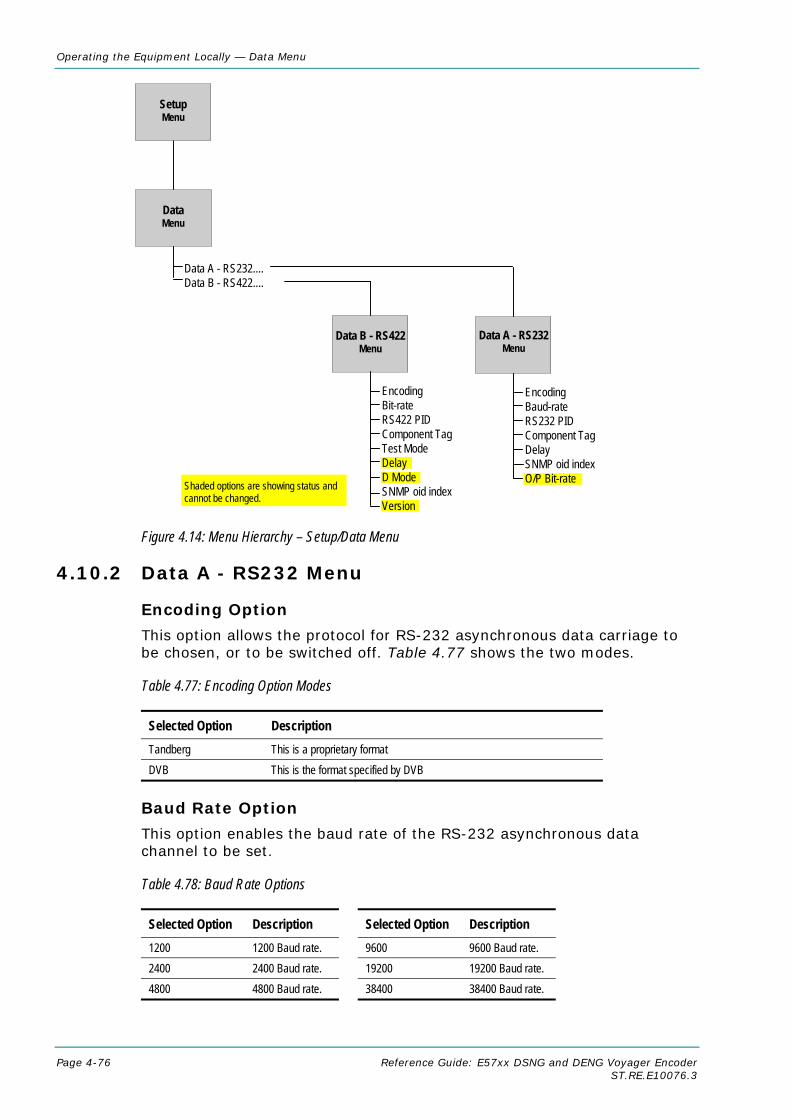
Operating the Equipment Locally — Data Menu
Page 4-76 Reference Guide: E57xx DSNG and DENG Voyager Encoder ST.RE.E10076.3
Figure 4.14: Menu Hierarchy – Setup/Data Menu
4.10.2 Data A - RS232 Menu
Encoding Option
This option allows the protocol for RS-232 asynchronous data carriage to be chosen, or to be switched off. Table 4.77 shows the two modes.
Table 4.77: Encoding Option Modes
Selected Option Description Tandberg This is a proprietary format DVB This is the format specified by DVB
Baud Rate Option
This option enables the baud rate of the RS-232 asynchronous data channel to be set.
Table 4.78: Baud Rate Options
Selected Option Description Selected Option Description 1200 1200 Baud rate. 9600 9600 Baud rate. 2400 2400 Baud rate. 19200 19200 Baud rate. 4800 4800 Baud rate. 38400 38400 Baud rate.
Data Menu
Data A - RS232....Data B - RS422....
Setup Menu
Shaded options are showing status andcannot be changed.
Data B - RS422Menu
Data A - RS232Menu
EncodingBaud-rateRS232 PIDComponent TagDelaySNMP oid indexO/P Bit-rate
EncodingBit-rateRS422 PIDComponent TagTest ModeDelayD ModeSNMP oid indexVersion

Operating the Equipment Locally — Data Menu
Reference Guide: E57xx DSNG and DENG Voyager Encoder Page 4-77 ST.RE.E10076.3
RS232 PID Option
This option is used for entering or updating data PIDs. To be DVB compliant, PIDs below 32 are reserved. Therefore PIDs 32 to 8191 are available for use. In the event of a clash, one of the PIDs will be changed by the Encoder’s internal checking algorithm.
Buffer Data Option
Send immediately: Whenever data is available at the RS232 port it is sent in the output transport stream.
NOTE… Can result in wasted bandwidth due to low packet occupancy. Also results in a higher packet rate. This may cause some receivers to overflow.
Wait 1 Second: Data is buffered until enough has arrived to fill a transport packet or 1 second elapses, whichever occurs first.
Component Tag Option
This item defines the optional component tag to be assigned to this data stream.
Delay Option
This option enables the Delay to be set. The option cannot be changed.
SNMP oid index Option
All option modules have the same SNMP oid (object identifier) with the exception of one byte which identifies which slot the module is in. An MEM expects the data module to be in slot two or three in the previous version of the Encoder. Therefore, slots one and two in this Encoder have been allocated to correspond directly to slots two and three in the previous Encoder.
In this Encoder the data module can be allocated to slot one, making it inaccessible to an MEM. This variable allows the on-board data module to be apparently moved around - to a slot in which it may be referenced by the MEM.
Table 4.79: SNMP oid index Options
Selected Option Description Min: 1 Max: 7
Oid index
O/P Bit-rate Option
This option is for status only and indicates the output bit-rate.
4.10.3 Data B - RS422 Menu
Encoding Option
This option enables the RS-422 synchronous data channel to be switched On or Off.

Operating the Equipment Locally — Data Menu
Page 4-78 Reference Guide: E57xx DSNG and DENG Voyager Encoder ST.RE.E10076.3
Bit-rate Option
This option enables the bit-rate of the RS-422 synchronous data channel to be set.
Table 4.80: Bit-rate Options
Selected Option Description Settings cycle from 56 to 1792 in steps of 56 then from 64 to 2048 in steps of 64, then back to 56
RS-422 synchronous data channel bit-rate.
RS422 PID Option
This option is used for entering or updating data PIDs. To be DVB compliant, PIDs below 32 are reserved. Therefore PIDs 32 to 8191 are available for use. In the event of a clash, one of the PIDs will be changed by the Encoder’s internal checking algorithm.
Component Tag Option
This item defines the optional component tag to be assigned to this data stream.
Test Mode Option
This option is used for turning the test mode On and Off.
Delay Option
The Delay option cannot be changed.
D Mode Option
The D Mode option cannot be changed.
SNMP oid index Option
See SNMP oid index Option on page 4-77 for details of this option.
Version Option
This option indicates the version of the data. It is for status only and cannot be changed.
4.11 Output Menu
4.11.1 Overview The Output Menu is selected from the Setup Menu. This menu permits the selection of the output parameters. See Figure 4.15 for the menu structure.

Operating the Equipment Locally — Output Menu
Reference Guide: E57xx DSNG and DENG Voyager Encoder Page 4-79 ST.RE.E10076.3
4.11.2 Output Format Option Access the Output Format option from the Output Menu. The menus available depend upon which option cards are fitted to the unit.
If the Output Format option = ASI then the following menu option is Delivery Descriptor, otherwise it is the menu associated with the output format selected, i.e. satellite modulator, OFDM modulator or IP Output.
4.11.3 Delivery Descriptor Menu Access the Delivery Descriptor Menu from the Output Menu. The screens in this menu vary according to the Descriptor Type selected.
4.11.4 Descriptor Type Option Access the Descriptor Type option from the Delivery Descriptor Menu. This enables the descriptor type to be specified.
Table 4.81: Descriptor Type Options
Selected Option Description Comments Satellite Descriptor type set to Satellite.
Terrestrial Descriptor type set to Terrestrial.
None
Cable Descriptor type set to Cable.
The type of delivery descriptor selected affects the remaining options shown on the Delivery Descriptor Menu.

Operating the Equipment Locally — Descriptor Type = Terrestrial Menu
Page 4-80 Reference Guide: E57xx DSNG and DENG Voyager Encoder ST.RE.E10076.3
7
Figure 4.15: Menu Hierarchy – Setup/Output Menu
.
Setup Menu
Satellite Modulator Menu
Descriptor Type Menu options depend on Descriptor Type Selected
Cable Terrestrial Satellite
Output Format... Delivery Descriptor
Output Format... Satellite Modulator
Output OFDM
Output Format... IP Streamer
IP Streamer Menu
1 This option is status only
Manual
has been selected in the Band Plan
Shaded options are showing status cannot be changed.
— Output — Bandwidth — Modulation Mode — Guard Interval — FEC Rate — Transmission — Spectral Pol — Centre Frequency — IF Output Frequency — Bit-rate (188) — Bit-rate (204) — OFDM S/W Release
— Band Plan — Channel — Frequency1 — Bandwidth1
— Modulation Type — Hierarchy — FEC (HP) — FEC (LP) — Guard Interval — Carriers — Other Frequency
Output Menu
— Frequency
— Modulation Type — FEC (Outer) — FEC (Inner) — Symbol Rate
— Frequency
— Modulation Type — FEC (Inner) — Symbol Rate — Orbital Position — West East — Polarisation
— Own IP Address — Network Mask — Router IP Address — IP Output — Destination IP Address — Protocol/FEC — Destination UDP Port — TS Pkts/UDP Frm — Forward Mcast IP Address — Time to Live — Type of Service — Line Mode — Software Version
— TS Input Source — Rate Adaptation — L-Band Output — L-Band Power — L-Band Frequency — Modulation — Mod Type — Symbol Rate — FEC Rate — Spectrum Sense — Roll Off Factor — Tx Bandwidth Factor — Tx Bandwidth — Bit-rate (188) — Bit-rate (204) — Preset Pwr Low — Preset Pwr Norm — BUC DC Power — Sat Deliv Freq — Sat Orb Pos — Sat West/East — Polarisation — Baseband (BB) Card — BB PCB Revision — BB Mod Status — BB Serial No. — BB S/W Release — BB CPLD F/W Release — BB DSP F/W Release — BB RNF F/W Release — L-Band Card Type — DPC Card — BUC LO Frequency — Transmit Frequency — BUC 10 MHz Ref O/P
L-Band Output IF Output — TS Input Source — IF Output — IF Power — IF Frequency — Modulation — Mod Type — Symbol Rate — FEC Rate — Spectrum Sense — Roll Off Factor — Tx Bandwidth Factor — Tx Bandwidth — Bit-rate (188) — Bit-rate (204) — Preset Pwr Low — Preset Pwr Norm — Sat Deliv Freq — Sat Orb Pos — Sat West/East — Polarisation — Baseband (BB) Card — BB PCB Revision — BB Mod Status — BB Serial No. — BB S/W Release — BB CPLD F/W Release — BB DSP F/W Release — BB RNF F/W Release — IF Card Type — DPC Card Type
Delivery Descriptor Menu
OFDM Modulator Menu

Operating the Equipment Locally — Output Menu
Reference Guide: E57xx DSNG and DENG Voyager Encoder Page 4-81 ST.RE.E10076.3
4.11.5 Descriptor Type = Terrestrial
Band Plan Option
Access the Band Plan option from the Delivery Descriptor Menu.
Once a country has been selected then the required channel should be selected in the Channel option. Each channel number corresponds to a particular frequency (see Annex E, Band Plans).
Table 4.82: Band Plan Options
Selected Option Selected Option Australia Ireland Europe VHF South Africa Europe CATV French Overseas PIA Italy France Morocco Japan New Zealand USA China CCIR12 OIRT13 Manual
Channel Option
Access the Channel option from the Delivery Descriptor Menu. Each channel number corresponds to a particular frequency (see Annex E, Band Plans).
Table 4.83: Channel Options
Valid Input Range Description Depends upon the country selected.
See Annex E, Band Plans for the frequencies associated with particular countries.
Frequency Option
Access the Frequency option from the Delivery Descriptor Menu. This enables the carrier frequency of the transmitter to be specified.
NOTES… 1. This option is not displayed if the unit is set to generate PSIP externally or it is under MEM
control. 2. This option is status only unless Manual has been selected in the Band Plan option.
12 CCIR is now know as International Telecommunications Union-Radiocommunications Study Groups. 13 Organisation that co-ordinated TV standards and programme interchange among the Eastern–block countries of Europe.

Operating the Equipment Locally — Output Menu: Descriptor Type = Terrestrial
Page 4-82 Reference Guide: E57xx DSNG and DENG Voyager Encoder ST.RE.E10076.3
Table 4.84: Frequency Options
Selected Option Description Min: 0.0001 MHz Max: 42949.6729 MHz Step Size: 0.0001 MHz
Carrier frequency of transmitter.
Bandwidth Option
Access the Bandwidth option from the Delivery Descriptor Menu. This enables the channel spacing of the terrestrial transmitter to be specified.
NOTE… This option is status only unless Manual has been selected in the Band Plan option.
Table 4.85: Bandwidth Options
Selected Option Description 6 MHz Terrestrial transmitter channel spacing is 6 MHz. 7 MHz Terrestrial transmitter channel spacing is 7 MHz. 8 MHz Terrestrial transmitter channel spacing is 8 MHz. 10 MHz Terrestrial transmitter channel spacing is 10 MHz. 12 MHz Terrestrial transmitter channel spacing is 12 MHz.
Modulation Type Option
Access the Modulation Type option from the Delivery Descriptor Menu. This enables the type of modulation used to be specified.
Table 4.86: Modulation Type Options
Selected Option Description QPSK Terrestrial transmitter uses QPSK modulation. 16QAM Terrestrial transmitter uses 16QAM modulation. 64QAM Terrestrial transmitter uses 64QAM modulation.
Hierarchy Option
Access the Hierarchy option from the Delivery Descriptor Menu. This screen enables the hierarchy of the terrestrial transmission to be specified.
Table 4.87: Hierarchy Options
Selected Option Description Non-Hierarchical Terrestrial transmission is not hierarchical. Alpha=1 Terrestrial transmission is hierarchical, and the α value = 1. Alpha=2 Terrestrial transmission is hierarchical, and the α value = 2. Alpha=4 Terrestrial transmission is hierarchical, and the α value = 4.

Operating the Equipment Locally — Output Menu: Descriptor Type = Terrestrial
Reference Guide: E57xx DSNG and DENG Voyager Encoder Page 4-83 ST.RE.E10076.3
FEC (HP) and FEC (LP) Options
Access the FEC (HP) or the FEC (LP) option from the Delivery Descriptor Menu. These screens enable the inner FEC schemes used by the terrestrial transmitter to be specified.
NOTE… If the Hierarchy option is set to Non-Hierarchical, then only the FEC Rate parameter is used and shown on the display.
If the Hierarchy option is set to Alpha=n, then the FEC (HP) and FEC (LP) parameters provide two levels of modulation. Transmission starts with the code rate for the HP level of modulation and ends with the code rate for the LP level.
The screen for the FEC (LP) option is the same except that (LP) replaces (HP).
Table 4.88: FEC (HP) and FEC (LP) Options
Selected Option Description 1/2 Terrestrial transmitter FEC rate HP/LP is 1/2. 2/3 Terrestrial transmitter FEC rate HP/LP is 2/3. 3/4 Terrestrial transmitter FEC rate HP/LP is 3/4. 5/6 Terrestrial transmitter FEC rate HP/LP is 5/6. 7/8 Terrestrial transmitter FEC rate HP/LP is 7/8.
Guard Interval Option
Access the Guard Interval option from the Delivery Descriptor Menu. This enables the guard interval of the terrestrial transmitter to be specified.
Table 4.89: Guard Interval Options
Selected Option Description 1/4 Terrestrial transmitter guard interval is 1/4. 1/8 Terrestrial transmitter guard interval is 1/8. 1/16 Terrestrial transmitter guard interval is 1/16. 1/32 Terrestrial transmitter guard interval is 1/32.
Carriers Options
Access the Carriers option from the Delivery Descriptor Menu. This enables the transmission mode (i.e. number of carriers in an OFDM frame) used by the terrestrial transmitter to be specified.

Operating the Equipment Locally — Output Menu: Descriptor Type = Terrestrial
Page 4-84 Reference Guide: E57xx DSNG and DENG Voyager Encoder ST.RE.E10076.3
Table 4.90: Carriers Options
Selected Option Description 2k Mode Terrestrial transmitter uses 2k transmission mode
(2k carriers in an OFDM frame). 8k Mode Terrestrial transmitter uses 8k transmission mode
(8k carriers in an OFDM frame).
Other Frequency Option
Access the Other Frequency option from the Delivery Descriptor Menu. This enables the flag which specifies whether other frequencies are in use or not to be set.
Table 4.91: Other Frequency Options
Selected Option Description None No other frequency is in use. in use One or more other frequencies are in use.
4.11.6 Descriptor Type = Cable
Frequency Option
See Frequency Option on page 4-81.
Modulation Type Option
Access the Modulation Type option from the Delivery Descriptor Menu. This screen enables the type of modulation used by the cable channel to be specified.
Table 4.92: Modulation Type Options
Selected Option Description 16QAM Cable channel uses 16QAM modulation. 32QAM Cable channel uses 32QAM modulation. 64QAM Cable channel uses 64QAM modulation. 128QAM Cable channel uses 128QAM modulation. 256QAM Cable channel uses 256QAM modulation.
FEC (Outer) Option
Access the FEC (Outer) option from the Delivery Descriptor Menu. This screen enables the outer FEC rate used by the cable channel to be specified.
Table 4.93: FEC (Outer) Options
Selected Option Description No outer FEC coding Cable channel does not use outer FEC. RS(204/188)

Operating the Equipment Locally — Output Menu: Descriptor Type = Cable
Reference Guide: E57xx DSNG and DENG Voyager Encoder Page 4-85 ST.RE.E10076.3
FEC (Inner) Option
Access the FEC (Inner) option from the Delivery Descriptor Menu. This screen enables the inner FEC rate used by the cable channel to be specified.
Table 4.94: FEC (Inner) Options
Selected Option Description No conv. coding Cable channel does not use inner FEC rate. 1/2 Cable channel uses inner FEC rate of 1/2. 2/3 Cable channel uses inner FEC rate of 2/3. 3/4 Cable channel uses inner FEC rate of 3/4. 5/6 Cable channel uses inner FEC rate of 5/6. 7/8 Cable channel uses inner FEC rate of 7/8. 8/9 Cable channel uses inner FEC rate of 8/9.
Symbol Rate Option
Access the Symbol Rate option from the Delivery Descriptor Menu.
Table 4.95: Symbol Rate Options
Valid Input Range Description Min: 0.4688 Msym/s Max: 30.0000 Msym/s Step Size: 0.0001 Msym/s
Symbol rate. Changing the symbol rate affects the automatic Tx bandwidth, video bit-rate and video resolution calculations.
4.11.7 Descriptor Type = Satellite
Frequency Option
See Frequency Option on page 4-81.
Modulation Type Option
Access the Modulation Type option from the Delivery Descriptor Menu. This enables the type of modulation used by the satellite transponder to be specified.
Table 4.96: Modulation Type Options
Selected Option Description 8PSK14 Satellite transponder uses 8PSK modulation. 16QAM14 Satellite transponder uses 16QAM modulation. BPSK Satellite transponder uses BPSK modulation. QPSK Satellite transponder uses QPSK modulation.
14 8PSK and 16QAM not available with 1U L-band option.

Operating the Equipment Locally — Output Menu: Descriptor Type = Satellite
Page 4-86 Reference Guide: E57xx DSNG and DENG Voyager Encoder ST.RE.E10076.3
FEC (Inner) Option
Access the FEC (Inner) option from the Delivery Descriptor Menu. This screen enables the inner FEC rate used by the satellite transponder to be specified. See FEC (Inner) Option, page 4-85 for further details.
Symbol Rate
See Symbol Rate Option on page 4-85.
Orbital Position Option
Access the Orbital Position option from the Delivery Descriptor Menu. This enables the orbital position of the satellite to be specified.
Table 4.97: Orbital Position Options
Valid Input Range Description Min: 0.0° Max: 360.0° Step Size: 0.1°
If the specified orbital position is outside the valid input range, a confirmation screen is displayed which shows the maximum/minimum value allowed.
West East Option
Access the West East option from the Delivery Descriptor Menu. This enables the satellite west/east flag to be specified to indicate whether the satellite position is in the western or eastern part of the orbit.
Table 4.98: West East Options
Selected Option Description West Satellite position is in western part of the orbit. East Satellite position is in the eastern part of the orbit.
Polarisation Option
Access the Polarisation option from the Delivery Descriptor Menu. This enables the polarisation of the satellite transponder to be specified.
Table 4.99: Polarisation Options
Selected Option Description Linear - Horizontal Satellite transponder uses linear horizontal polarisation. Linear - Vertical Satellite transponder uses linear vertical polarisation. Circular - Left Satellite transponder uses circular left polarisation. Circular - Right Satellite transponder uses circular right polarisation.

Operating the Equipment Locally — Output Menu: Output Format = Satellite Modulator (IF Output)
Reference Guide: E57xx DSNG and DENG Voyager Encoder Page 4-87 ST.RE.E10076.3
4.11.8 Output Format = Satellite Modulator (IF Output)
TS Input Source
This option determines the source of the transport stream.
Table 4.100: TS Input Source Options
Selected Option Description Backplane ASI1 ASI2
Only available in the E5740.
IF Output Option
Access the IF Output option from the Satellite Modulator Menu. This enables the IF output to be switched On or Off.
IF Power Option
Access the IF Power option from the Satellite Modulator Menu.
Table 4.101: IF Power Options
Valid Input Range Description Min: –20 dBm Max: 5 dBm
IF Frequency Option
Access the IF Frequency option from the Satellite Modulator Menu. This setting allows the centre frequency of the IF output to be changed.
Table 4.102: IF Frequency Options
Valid Input Range Description 1U Min: 50 MHz Max: 90 MHz
2U Min: 50 MHz Max: 180 MHz
Modulation Option
Access the Modulation option from the Satellite Modulator Menu. This enables the Modulation to be switched On or Off.
Mod Type Option
Access the Mod(ulation) Type option from the Satellite Modulator Menu. This enables the type of modulation used by the Satellite Modulator to be specified.

Operating the Equipment Locally — Output Menu: Output Format = Satellite Modulator (IF Output)
Page 4-88 Reference Guide: E57xx DSNG and DENG Voyager Encoder ST.RE.E10076.3
Table 4.103: Modulation Type Options
Selected Option Description BPSK Satellite modulator uses BPSK modulation. QPSK Satellite Modulator uses QPSK modulation. 8PSK Satellite Modulator uses 8PSK modulation. 16QAM Satellite Modulator uses 16QAM modulation.
NOTE… 8PSK and 16QAM are only available in the 2U and 1U L-band Encoders. The following software options must be purchased to enable the different modulation types; M2/ESO2/SM38PSK for 8PSK, M2/ESO2/SM316QAM for 16QAM.
Symbol Rate Option
Access the Symbol Rate option from the Satellite Modulator Menu.
Table 4.104: Symbol Rate Options
Valid Input Range Description 1U IF Min: Max: Step Size:
0.4688 Msym/s 30.0000 Msym/s 0.0001 Msym/s
When the IF frequency is 60 MHz to 80 MHz the maximum symbol rate is 30 Msym/s. When the IF frequency is 50 MHz or 90 MHz the maximum symbol rate is 20 Msym/s.
2U + 1U L-Band Min (Low Sym Rate): Min: Max: Step Size:
0.3000 Msym/s 1.0000 Msym/s 66.0000 Msym/s 0.0001 Msym/s
Minimum with low symbol rate option M2/ES02/LSYM. Changing the symbol rate affects the automatic Tx bandwidth, video bit-rate and video resolution calculations.
FEC Rate Option
Access the FEC Rate option from the Satellite Modulator Menu.
Table 4.105: FEC Rate Options
Selected Option Description 1/2 Satellite Modulator uses FEC rate of 1/2. 2/3 Satellite Modulator uses FEC rate of 2/3. 3/4 Satellite Modulator uses FEC rate of 3/4. 5/6 Satellite Modulator uses FEC rate of 5/6. 7/8 Satellite Modulator uses FEC rate of 7/8. 8/9 Satellite Modulator uses FEC rate of 8/9.
NOTE… Only certain combinations of Modulation Type and FEC Rate are valid.
Spectrum Sense Option
Access the Spectrum Invert option from the Satellite Modulator Menu. This allows the spectrum sense to be normal or inverted.

Operating the Equipment Locally — Output Menu: Output Format = Satellite Modulator (IF Output)
Reference Guide: E57xx DSNG and DENG Voyager Encoder Page 4-89 ST.RE.E10076.3
Roll Off Factor Option
The Roll Off Factor option is to do with the bandwidth of the modulated output and how quickly the output level rolls off with frequency. There are two values, 25% and 35%. Only 35% is allowed for QPSK but both 25% and 35% are available in 8PSK and 16QAM.
Tx Bandwidth Factor Option
Access the Tx Bandwidth Factor option from the Satellite Modulator Menu. This option is used to calculate the Tx Bandwidth based upon the Symbol Rate.
Bandwidth = Factor x Symbol Rate
Table 4.106: Tx Bandwidth Factor Options
Valid Input Range Description Min: 1 Max: 2 Step Size: 0.01
Tx Bandwidth Option
The Tx Bandwidth option value cannot be updated. It should only be used as an approximate value as it depends on the performance of external equipment as well.
Bit-rate (188) Option
The Bit-rate (188) option value cannot be updated.
Bit-rate (204) Option
The Bit-rate (204) option value cannot be updated.
Preset Pwr Low Option
Access the Preset Pwr Low option from the Satellite Modulator Menu.
Table 4.107: Preset Pwr Low Options
Valid Input Range Description Min: -20.0 dBm Max: 0.0 dBm Step Size: 0.1 dBm
Preset Pwr Norm Option
Access the Preset Pwr Norm option from the Satellite Modulator Menu.
Table 4.108: Preset Pwr Norm Options
Valid Input Range Description Min: -20.0 dBm Max: 5.0 dBm Step Size: 0.1 dBm

Operating the Equipment Locally — Output Menu: Output Format = Satellite Modulator (IF Output)
Page 4-90 Reference Guide: E57xx DSNG and DENG Voyager Encoder ST.RE.E10076.3
BUC DC Power Option
CAUTION… The modulator provides dc power to drive an up-converter. Do not connect equipment to the main output
which might be damaged by dc power without protecting with a suitable dc block.
Refer to page 4-93 for details.
Sat Deliv Freq Option
Access the Sat Deliv Freq option from the Satellite Modulator Menu.
Table 4.109: Sat Deliv Freq Options
Valid Input Range Description Min: 0.0000 GHz Max: 999.9999 GHz Step Size: 0.0001 GHz
Sat Orb Pos Option
Access the Sat Orb Pos option from the Satellite Modulator Menu. This enables the orbital position of the satellite to be specified.
Table 4.110: Sat Orb Pos Options
Valid Input Range Description Min: 0.0° Max: 360.0° Step Size: 0.1°
If the specified orbital position is outside the valid input range, a confirmation screen is displayed which shows the maximum/minimum value allowed.
Sat West/East Option
Access the Sat West/East option from the Satellite Modulator Menu. This enables the satellite west/east flag to be specified, indicating whether the satellite position is in the western or eastern part of the orbit.
Table 4.111: Sat West/East Options
Selected Option Description West Satellite position is in western part of the orbit. East Satellite position is in the eastern part of the orbit.
Polarisation Option
Access the Polarisation option from the Satellite Modulator Menu. This enables the polarisation of the satellite transponder to be specified.
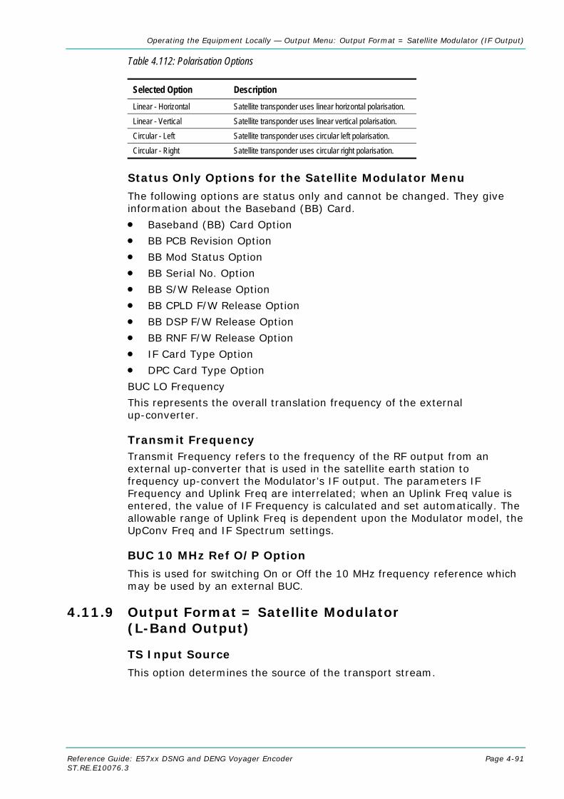
Operating the Equipment Locally — Output Menu: Output Format = Satellite Modulator (IF Output)
Reference Guide: E57xx DSNG and DENG Voyager Encoder Page 4-91 ST.RE.E10076.3
Table 4.112: Polarisation Options
Selected Option Description Linear - Horizontal Satellite transponder uses linear horizontal polarisation. Linear - Vertical Satellite transponder uses linear vertical polarisation. Circular - Left Satellite transponder uses circular left polarisation. Circular - Right Satellite transponder uses circular right polarisation.
Status Only Options for the Satellite Modulator Menu
The following options are status only and cannot be changed. They give information about the Baseband (BB) Card.
• Baseband (BB) Card Option
• BB PCB Revision Option
• BB Mod Status Option
• BB Serial No. Option
• BB S/W Release Option
• BB CPLD F/W Release Option
• BB DSP F/W Release Option
• BB RNF F/W Release Option
• IF Card Type Option
• DPC Card Type Option
BUC LO Frequency
This represents the overall translation frequency of the external up-converter.
Transmit Frequency Transmit Frequency refers to the frequency of the RF output from an external up-converter that is used in the satellite earth station to frequency up-convert the Modulator’s IF output. The parameters IF Frequency and Uplink Freq are interrelated; when an Uplink Freq value is entered, the value of IF Frequency is calculated and set automatically. The allowable range of Uplink Freq is dependent upon the Modulator model, the UpConv Freq and IF Spectrum settings.
BUC 10 MHz Ref O/P Option
This is used for switching On or Off the 10 MHz frequency reference which may be used by an external BUC.
4.11.9 Output Format = Satellite Modulator (L-Band Output)
TS Input Source
This option determines the source of the transport stream.

Operating the Equipment Locally — Output Menu: Output Format = Satellite Modulator (IF Output)
Page 4-92 Reference Guide: E57xx DSNG and DENG Voyager Encoder ST.RE.E10076.3
Table 4.113: TS Input Source Options
Selected Option Description Backplane ASI1 ASI2
Only available in the E5740.
Rate Adaptation Option
Function not currently available on 2/3 width modulator modules (S13716 & S13719).
L-Band Output Option
Access the L-Band Output option from the Satellite Modulator Menu. This enables the L-Band output to be switched On or Off.
L-Band Power Option
Access the L-Band Power option from the Satellite Modulator Menu.
Table 4.114: L-Band Power Options
Valid Input Range Description Min: Max:
-20.0 dBm +5.0 dBm
Frequency Option
Access the Frequency option from the Satellite Modulator Menu.
Table 4.115: Frequency Options
Valid Input Range Description Min: Max:
950 MHz 1750 MHz
Modulation Option
Access the Modulation option from the Satellite Modulator Menu. This enables the modulation to be switched On or Off.
Mod Type Option
Refer to Mod Type Option on page 4-87 for details.
Symbol Rate Option
Refer to Symbol Rate Option on page 4-88 for details.
FEC Rate Option
Refer to FEC Rate Option on page 4-88 for details.
Spectrum Sense Option
Refer to Spectrum Sense Option on page 4-88 for details.

Operating the Equipment Locally — Output Menu: Output Format = Satellite Modulator (L-Band Output)
Reference Guide: E57xx DSNG and DENG Voyager Encoder Page 4-93 ST.RE.E10076.3
Roll Off Factor Option
In the L-band option, only 35% is allowed for QPSK and BPSK.
Refer to Roll Off Factor Option on page 4-89 for details.
Tx Bandwidth Factor Option
Refer to Tx Bandwidth Factor Option on page for details.
Tx Bandwidth Option
The Tx Bandwidth option value cannot be updated. It should only be used as an approximate value as it depends on the performance of external equipment as well.
Bit-rate (188) Option
The Bit-rate (188) option value cannot be updated.
Bit-rate (204) Option
The Bit-rate (204) option value cannot be updated.
Preset Pwr Low Option15
Refer to Preset Pwr Low Option on page 4-89 for details.
Preset Pwr Norm Option15
Refer to Preset Pwr Norm Option on page 4-89 for details.
BUC DC Power Option15
CAUTION… The modulator provides dc power to drive an up-converter. Do not connect equipment to the main output
which might be damaged by dc power without protecting with a suitable dc block.
Access the Upconverter Power option from the Satellite Modulator Menu. This option allows the +24 Vdc power on the L-Band Modulator Main output to be either Enabled or Disabled.
NOTE… This option is only available on 2U Models.
Sat Deliv Freq Option
Refer to BUC DC Power Option
CAUTION… The modulator provides dc power to drive an up-converter. Do not connect equipment to the main output
which might be damaged by dc power without protecting with a suitable dc block.
Refer to page 4-93 for details.
Sat Deliv Freq Option on page 4-90 for details.
15 Preset Power Low, Preset Power Normal and BUC Power not available in 1U L-band model.

Operating the Equipment Locally — Output Menu: Output Format = Satellite Modulator (L-Band Output)
Page 4-94 Reference Guide: E57xx DSNG and DENG Voyager Encoder ST.RE.E10076.3
Sat Orb Pos Option
Refer to Sat Orb Pos Option on page 4-90 for details.
Sat West/East Option
Refer to Sat West/East Option on page 4-90 for details.
Polarisation Option
Refer to Polarisation Option on page 4-90 for details. Status Only Options for the Satellite Modulator Menu
The following options are for status only and cannot be changed.
• Baseband (BB) Card Option
• BB PCB Revision Option
• BB Mod Status Option
• BB Serial No. Option
• BB S/W Release Option
• BB CPLD F/W Release Option
• BB DSP F/W Release Option
• BB RNF F/W Release Option
• L-Band Output Card Type Option
• DPC Card Type Option
4.11.10 Output Format = OFDM Modulator
Output Option
Access the Output option from the OFDM Modulator Menu. This enables the modulator outputs to be switched On or Off.
Bandwidth Option
Access the Bandwidth option from the OFDM Modulator Menu.
Table 4.116: Bandwidth Options
Selected Option Description 6 MHz 6 MHz transmission bandwidth
7 MHz 7 MHz transmission bandwidth
8 MHz 8 MHz transmission bandwidth
Modulation Mode Option
Access the Modulation Mode option from the OFDM Modulator Menu.
Table 4.117: Modulation Mode Options
Selected Option Description QPSK OFDM Modulator uses QPSK modulation
16QAM OFDM Modulator uses 16QAM modulation
64QAM OFDM Modulator uses 64QAM modulation

Operating the Equipment Locally — Output Menu: Output Format = OFDM Modulator
Reference Guide: E57xx DSNG and DENG Voyager Encoder Page 4-95 ST.RE.E10076.3
Guard Interval Option
Access the Guard Interval option from the OFDM Modulator Menu.
Table 4.118: Guard Interval Options
Selected Option Description 1/32 OFDM Modulator uses 1/32 Guard Interval
1/16 OFDM Modulator uses 1/16 Guard Interval
1/8 OFDM Modulator uses 1/8 Guard Interval
1/4 OFDM Modulator uses 1/4 Guard Interval
FEC Rate Option
Access the FEC Rate option from the OFDM Modulator Menu.
Table 4.119: FEC Rate Options
Selected Option Description 1/2 OFDM Modulator uses 1/2 FEC Rate
2/3 OFDM Modulator uses 2/3 FEC Rate
3/4 OFDM Modulator uses 3/4 FEC Rate
5/6 OFDM Modulator uses 5/6 FEC Rate
7/8 OFDM Modulator uses 7/8 FEC Rate
Transmission Option
Access the Transmission option from the OFDM Modulator Menu.
Table 4.120: Transmission Options
Selected Option Description 2k Mode OFDM Modulator uses 2k carriers
8k Mode OFDM Modulator uses 8k carriers
Spectral Pol Option
Access the Spectral Pol option from the OFDM Modulator Menu.
Table 4.121: Spectral Polarity Options
Selected Option Description High Side IF The spectrum is inverted, thus allowing a subsequent
up-converter LO to be on the high side of the spectrum.
Low Side IF The spectrum is not inverted, thus allowing a subsequent up-converter LO to be on the low side of the spectrum.
Centre Frequency Option
Access the Centre Frequency option from the OFDM Modulator Menu. This is the centre frequency to be put in the SI of the output transport stream.

Operating the Equipment Locally — Output Menu: Output Format = OFDM Modulator
Page 4-96 Reference Guide: E57xx DSNG and DENG Voyager Encoder ST.RE.E10076.3
Table 4.122: Centre Frequency Options
Valid Input Range Description Min: 0 MHz
Max: 4294.967295 MHz
IF Output Frequency
The IF output frequency is fixed at 70 MHz.
Bit-rate (188)
The Bit-rate (188) option value cannot be updated.
Bit-rate (204)
The Bit-rate (204) option value cannot be updated.
OFDM S/W Release
The OFDM S/W Release value cannot be updated. It is the version of the software and firmware loaded on the OFDM modulator.
4.11.11 Output Format = IP Streamer
Own IP Address Option
Access the Own IP Address option from the IP Streamer Menu. This is the local IP address associated with the 100 Mbit/s Ethernet video output interface.
Network Mask Option
Access the Network Mask option from the IP Streamer Menu. This is the network mask setting corresponding to the Own IP address.
Router IP Address Option
Access the Router IP Address option from the IP Streamer Menu. If the Destination IP Address setting indicates an IP address not residing on the local net segment, the video traffic is forwarded to this gateway.
IP Output
This option allows the User to switch off or on the IP streamed video output.
NOTE… This parameter is only available from Encoder Release 3.6.
Destination IP Address Option
Access the Destination IP Address option from the IP Streamer Menu.

Operating the Equipment Locally — Mux Menu
Reference Guide: E57xx DSNG and DENG Voyager Encoder Page 4-97 ST.RE.E10076.3
This is the IP address to which the video stream should be sent. It can either be a unicast IP address or it can be a class D multicast address (224.0.0.1-239.255.255.255). Choosing a multicast IP address enables IGMPv2 support. Configuring a normal IP address turns off the IGMPv2 support again.
In some cases when running multicast traffic, you may want to forward the IP frames to a multicast relay agent. Configuring a unicast IP address here ensures that the IP Output card forwards the outgoing IP multicast packets to the MAC address corresponding to the chosen IP address.
If the address 172.21.207.1 is put here, the module would resolve the MAC address corresponding to this IP address instead of using the static multicast MAC address mapping specified in RFC1112 (the 23 bits etc). To turn off this feature again, type in 0.0.0.0
Protocol/FEC Option
This sets the protocol to be used for the IP Frame. It establishes the IP frame structure to be either: UDP, UDP plus the RTP Header or UDP, the RTP Header, the FEC Header and 16 Reed-Solomon Bytes after each 188 byte payload packets. The possible settings are: UDP, RTP, RTP/FEC0, RTP/FEC1, RTP/FEC2, RTP/FEC3 and RTP/FEC4.
NOTE: This parameter is only available from Encoder Release 3.2.
Destination UDP Port Option
Access the Destination UDP Port option from the IP Streamer Menu. This configures the UDP destination port field in the outgoing UDP frames.
TS Pkts/UDP Frm Option
Access the TS Pkts/UDP Frm (TS Packets/UDP Frame) option from the IP Streamer Menu.
This configures how many 188-byte MPEG-2 Transport Stream packets are mapped into each UDP frame. Valid values are between 1 and 7. For bit-rates in excess of 15 Mbit/s it is recommended to use the maximum setting of 7.
Forward MCast IP Address Option
In some cases when running multicast traffic, you may want to forward the IP frames to a multicast relay agent. Configuring a unicast IP address here ensures that the IP Output card forwards the outgoing IP multicast packets to the MAC address corresponding to the chosen IP address.
If the address 172.21.207.1 is put here, the module would resolve the MAC address corresponding to this IP address instead of using the static multicast MAC address mapping specified in RFC1112 (the 23 bits etc). To turn off this feature again, type in 0.0.0.0
Time To Live Option
Access the Time To Live option from the IP Streamer Menu.

Operating the Equipment Locally — Output Format = IP Streamer
Page 4-98 Reference Guide: E57xx DSNG and DENG Voyager Encoder ST.RE.E10076.3
This is the Time-to-Live setting as specified in RFC-791. The Time-to-Live setting is decremented by one for each Router hop the IP frame does. When 0 (zero) is reached, the packet is discarded by the network. A value greater than one is recommended.
Type of Service Option
Access the Type of Service option from the IP Streamer Menu.
This parameter is the byte value of the Type-of-Service (TOS) field in the IP header as specified in RFC-791. It is used for Class-of-service prioritisation. It depends on the Router honouring this field. This is normally set to one.
Line Mode
This option allows the User to allow the IP Streamer card to automatically (Auto) negotiate the port speed and mode as the port automatically advertises its maximum capabilities. If set to Fixed, the line speed is fixed to 100 Mbits/s Full Duplex mode. Auto is the default and preferred setting.
NOTE… This parameter is only available from Encoder Release 3.6.
4.12 Mux Menu
4.12.1 Overview Access the Mux Menu from the Setup Menu. This menu permits the selection of Multiplexer output parameters, Remux (if enabled), RAS scrambling options (if enabled) and BISS scrambling options (if enabled). See Figure 4.16 for details when Syntax = DVB. See Figure 4.17 for details when Syntax = ATSC.
4.12.2 Mux Output, no Remux Card To obtain various outputs when no Remux card is fitted:
• Basic mux output, no scrambling and no Remux – see Section 4.12.4, Packet Length Option, to Section 4.12.12, BISS Firmware.
• RAS scrambling – see basic mux output + Section 4.12.13, RAS Options Enabled.
• BISS scrambling – see basic mux output + Section 4.12, Mux Menu.
4.12.3 Mux Output, With Remux Card To obtain an output when a Remux card is fitted, set the options in the following menus:
• Host Bit-rate Option on page 4-105
• Remux Module menu – see Section 4.13.3, Remux Module Menu
• Host and Incoming Services – Section 4.13.4, 1.Service/2.Service Menu

Operating the Equipment Locally — Mux Menu
Reference Guide: E57xx DSNG and DENG Voyager Encoder Page 4-99 ST.RE.E10076.3
Figure 4.16: Menu Hierarchy – Setup/Mux Menu (DVB)
— Output — Source (BNC) — Name (In) — Name Out — Service Prov (in) — Service Id (Out) — Logical Channel — CA Input — BISS Key Code5 — Enc Session Word4 — Session Word3
— PMT PID — PCR PID — Video — ECM (CA) — VBI — Audio (type of audio) — Data (type of data)
Shaded options are showing status and cannot be changed.
— Mux… — Remux… — 1.Service2… — 2.Service (1) up to — 13.Service2… — 1(Mdb) Service… up to — 4(Mdb) Service…
Mux Menu
— Packet Length — On Air — Bit-rate (188) — Bit-rate (204)1
— Host Bit-rate6 — Scramble — BISS Key Entry5 — Session Word3 — Enc Session Word4 — BISS-E Injected Id4 — Clock — PCR PID — FPGA Firmware — BISS Hardware — BISS Firmware
When BISS scrambling has been enabled .
1Bit-Rate (204) is only available when the Packet Length isset to 204.2This name changes to be the same as the Service Name.There could be more menus, depending upon the numberof inputs to the Remux card.3 Only available when BISS Mode 1 is selected as theScrambling mode. Available in Build version 2.2 and later.4 Only available when BISS-E is selected as the Scramblingmode. Available in Build version 2.2 and later.5 This option is not available from Build version 2.2.6 Only available when the Remux card is fitted and enabled.
— Packet Length — On Air — Bit-rate (188) — Bit-rate (204)1
— Host Bit-rate (188)6 — Scramble — SNG Key (RAS 1) — Clock — PCR PID — FPGA Firmware — RAS Firmware — BISS Hardware — BISS Firmware
When RAS scrambling
has been enabled — Packet Length — On Air — Bit-rate (188) — Bit-rate (204)1
— Host Bit-rate (188)6 — Clock — PCR PID — FPGA Firmware — BISS Hardware — BISS Firmware
Mux Menu
Setup Menu
Remux ModuleMenu
2.Service Menu
(when there is an incoming service)
1.Service Menu
— Output — Source (BNC) — Name Out — Service Provider — Service Id (Out) — Logical Channel — BISS Key Code5 — Enc Session Word4 — Session Word3
— PMT PID — PCR PID — Video — ECM (CA) PID — Audio (type of audio) — Data (type of data) — PMT PID
— PID Remap — Packet Length — Bit-rate (188) — Spare Bit-rate — Input Bit-rate — Output Bit-rate — Host TS Output Rate — Host Data Rate — Input TS 1 (188) — Data Rate 1 (188) — Input TS 2 (188) — Data Rate (188) — Input TS 3 (188) — Data Rate 3 (188) — Software Release
1-4[Mdb] Service Menu
— Name Out — Service Id — Service Type — PMT PID — PCR PID — Video — Audio A — Audio B — Data A
This menu is mainly for TANDBERG Television
use for testing purposes.

Operating the Equipment Locally — Mux Menu
Page 4-100 Reference Guide: E57xx DSNG and DENG Voyager Encoder ST.RE.E10076.3
Figure 4.17: Menu Hierarchy – Setup/Mux Menu (ATSC)
— Output — Source (BNC) — Short Name In — Short Name Out — Name In — Name Out — Program Number (Out) — Major Channel — Minor Channel — CA Input — Enc Session Word4 — Session Word3
— PMT PID — PCR PID — Video — Audio (type of audio)
Shaded options are showing status and cannot be changed.
Mux....Remux Module....2.Service2, 7…3.Program 2 (1)....up toxxxx.Service2…
Mux Menu
— Packet Length — On Air — Bit-rate (188) — Bit-rate (204)1
— Host Bit-rate6 — Scramble — BISS Key Entry5 — Session Word3 — Enc Session Word4 — BISS-E Injected Id4 — Clock — PCR PID — FPGA Firmware — BISS Hardware — BISS Firmware
When BISS scrambling has been enabled .
1Bit-Rate (204) is only available when the Packet Length isset to 204.2This name changes to be the same as the Service Name.There could be more menus, depending upon the numberof inputs to the Remux card.3 Only available when BISS Mode 1 is selected as theScrambling mode. Available in Build version 2.2 and later.4 Only available when BISS-E is selected as the Scramblingmode. Available in Build version 2.2 and later.5 This option is not available from Build version 2.2.6 Only available when the Remux card is fitted and enabled.
— Packet Length — On Air — Bit-rate (188) — Bit-rate (204)1
— Host Bit-rate (188)6 — Scramble — SNG Key (RAS 1) — Clock — PCR PID — FPGA Firmware — RAS Firmware — BISS Hardware — BISS Firmware
When RAS scrambling
has been enabled — Packet Length — On Air — Bit-rate (188) — Bit-rate (204)1
— Host Bit-rate (188)6 — Clock — PCR PID — FPGA Firmware — BISS Hardware — BISS Firmware
Mux Menu
Setup Menu
Remux Module Menu
3.Program 2 (1) Menu
(when there is an incoming service)
2.Default Service Menu
When ATSC has been enabled
(Incoming Service)
When ATSC has been enabled
(Host Encoder) — Output — Source (BNC) — Short Name In — Short Name Out — Name Out — Program Number (Out) — Major Channel — Minor Channel — Enc Session Word4 — Session Word3
— PMT PID — PCR PID — Video — ECM (CA) PID — Audio (type of audio) — Data (type of data)
— PID Remap — Packet Length — Bit-rate (188) — Spare Bit-rate — Input Bit-rate — Output Bit-rate — Host TS Output Rate — Host Data Rate — Input TS 1 (188) — Data Rate 1 (188) — Input TS 2 (188) — Data Rate (188) — Input TS 3 (188) — Data Rate 3 (188) — Software Release

Operating the Equipment Locally — Mux Menu
Reference Guide: E57xx DSNG and DENG Voyager Encoder Page 4-101 ST.RE.E10076.3
4.12.4 Packet Length Option This option enables the Packet Length to be set.
Table 4.123: Packet Length Options
Selected Option Description 188 bytes Uses 188 byte packet format.
204 bytes Uses 204 byte packet format.
4.12.5 On Air Option This option determines whether the output of the Encoder is sent to the Multiplexer.
Table 4.124: On Air Options
Selected Option Description On Multiplexer output is switched on. Off Multiplexer output is switched off.
4.12.6 Bit-rate (188) and Bit-rate (204) Option
NOTE… If the Packet Length option is set to 188 bytes then only the Bit-rate (188) option is displayed. If the Packet Length option is set to 204 bytes then both the Bit-rate (188) and Bit-rate (204) options are displayed.
Both the Bit-rate (188) and the Bit-rate (204) can be in the range of 0 Mbit/s to 50 Mbit/s.
Table 4.125: Bit-rate (188) and Bit-rate (204) Options
Selected Option Description 188 / 204 Min: 0.0000 Mbit/s Max (without Remux):110.0000 Mbit/s Max (with Remux): 50.0000 Mbit/s Step Size: 0.0001 Mbit/s
Multiplexer output bit-rate when in baseband output format and ASI output mode. Changing the bit-rate affects the automatic video bit-rate and video resolution calculations.
If the specified bit-rate is outside the valid input range, a confirmation screen is displayed which shows the maximum/minimum value allowed.
4.12.7 Clock
NOTE… This option indicates the origin of the clock. It must be set to a video or external source before attempting to change the clock value or it will default to Local Oscillator.
This option enables the Clock to be set.
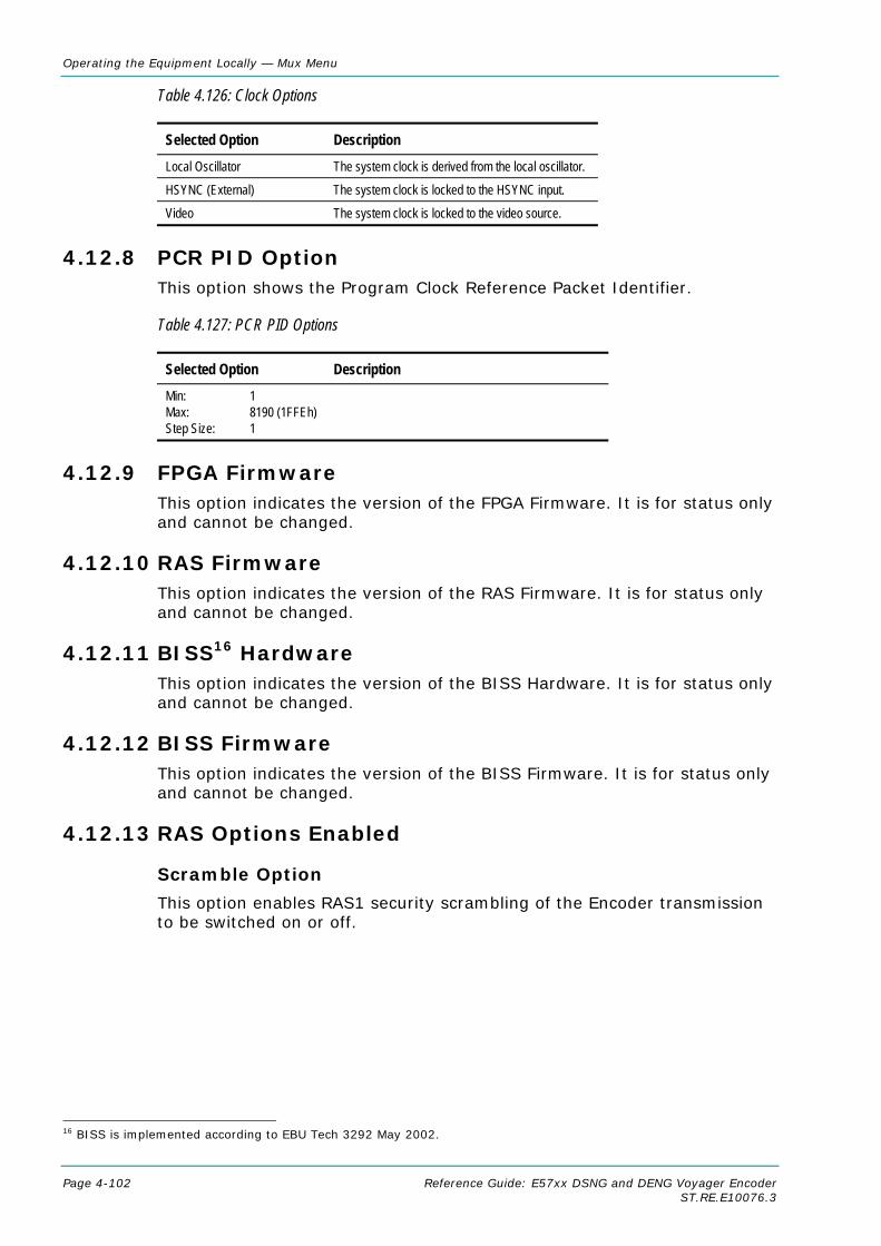
Operating the Equipment Locally — Mux Menu
Page 4-102 Reference Guide: E57xx DSNG and DENG Voyager Encoder ST.RE.E10076.3
Table 4.126: Clock Options
Selected Option Description Local Oscillator The system clock is derived from the local oscillator.
HSYNC (External) The system clock is locked to the HSYNC input.
Video The system clock is locked to the video source.
4.12.8 PCR PID Option This option shows the Program Clock Reference Packet Identifier.
Table 4.127: PCR PID Options
Selected Option Description Min: 1 Max: 8190 (1FFEh) Step Size: 1
4.12.9 FPGA Firmware This option indicates the version of the FPGA Firmware. It is for status only and cannot be changed.
4.12.10 RAS Firmware This option indicates the version of the RAS Firmware. It is for status only and cannot be changed.
4.12.11 BISS16 Hardware This option indicates the version of the BISS Hardware. It is for status only and cannot be changed.
4.12.12 BISS Firmware This option indicates the version of the BISS Firmware. It is for status only and cannot be changed.
4.12.13 RAS Options Enabled
Scramble Option
This option enables RAS1 security scrambling of the Encoder transmission to be switched on or off.
16 BISS is implemented according to EBU Tech 3292 May 2002.
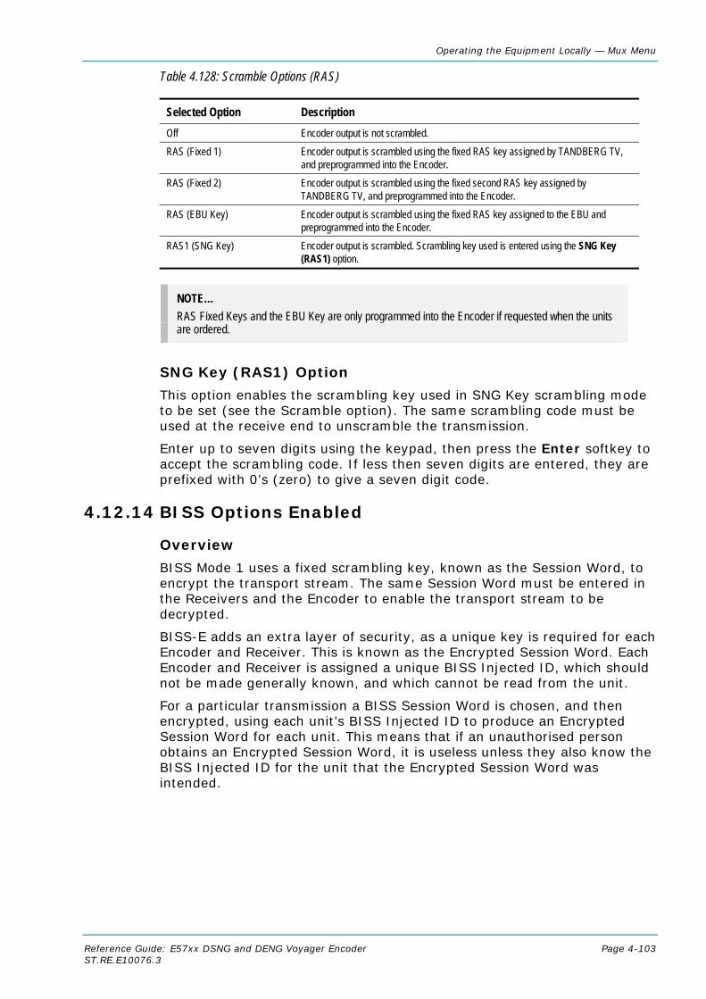
Operating the Equipment Locally — Mux Menu
Reference Guide: E57xx DSNG and DENG Voyager Encoder Page 4-103 ST.RE.E10076.3
Table 4.128: Scramble Options (RAS)
Selected Option Description Off Encoder output is not scrambled. RAS (Fixed 1) Encoder output is scrambled using the fixed RAS key assigned by TANDBERG TV,
and preprogrammed into the Encoder. RAS (Fixed 2) Encoder output is scrambled using the fixed second RAS key assigned by
TANDBERG TV, and preprogrammed into the Encoder. RAS (EBU Key) Encoder output is scrambled using the fixed RAS key assigned to the EBU and
preprogrammed into the Encoder. RAS1 (SNG Key) Encoder output is scrambled. Scrambling key used is entered using the SNG Key
(RAS1) option.
NOTE… RAS Fixed Keys and the EBU Key are only programmed into the Encoder if requested when the units are ordered.
SNG Key (RAS1) Option
This option enables the scrambling key used in SNG Key scrambling mode to be set (see the Scramble option). The same scrambling code must be used at the receive end to unscramble the transmission.
Enter up to seven digits using the keypad, then press the Enter softkey to accept the scrambling code. If less then seven digits are entered, they are prefixed with 0’s (zero) to give a seven digit code.
4.12.14 BISS Options Enabled
Overview
BISS Mode 1 uses a fixed scrambling key, known as the Session Word, to encrypt the transport stream. The same Session Word must be entered in the Receivers and the Encoder to enable the transport stream to be decrypted.
BISS-E adds an extra layer of security, as a unique key is required for each Encoder and Receiver. This is known as the Encrypted Session Word. Each Encoder and Receiver is assigned a unique BISS Injected ID, which should not be made generally known, and which cannot be read from the unit.
For a particular transmission a BISS Session Word is chosen, and then encrypted, using each unit’s BISS Injected ID to produce an Encrypted Session Word for each unit. This means that if an unauthorised person obtains an Encrypted Session Word, it is useless unless they also know the BISS Injected ID for the unit that the Encrypted Session Word was intended.

Operating the Equipment Locally — Mux Menu
Page 4-104 Reference Guide: E57xx DSNG and DENG Voyager Encoder ST.RE.E10076.3
Scramble Option
Access the Scramble option from the Mux Menu. This enables security scrambling of the Encoder transmission to be switched on or off.
NOTE… If the scrambling is switched between BISS Mode 1 and BISS-E, the session word, or the encrypted session word must be re-entered.
Table 4.129: Scramble Options (BISS)
Selected Option Description BISS Mode 1 Encoder output is scrambled. Scrambling key used is
entered using the Session Word option. BISS-E Encoder output is scrambled. Scrambling key used is
entered using the Enc Session Word option. Off Encoder output is not scrambled.
Session Word Option
Access the Session Word option from the Mux Menu. A Session Word is the 48-bit code used to generate the 64-bit Control Word that is used to encrypt and decrypt the transport stream.
The sender and receiver(s) of the transmission share the Session Word, so that only the intended parties receive the transmission. The same Session Word must be used at the receive end.
If the Session Words are the same, then the IRDs are able to decrypt the broadcast. If the Session Words are different, the broadcast is not received.
NOTE… Take precautions to avoid general knowledge of the Session Word.
The Session Word relates to the different types of BISS as follows:
• BISS Mode 1: All components are scrambled by a fixed control word, derived from a clear Session Word.
• BISS-E: All components are scrambled by a fixed control word, derived from an Encrypted Session Word.
Enc Session Word Option
Access the Enc Session Word option from the Mux Menu. This is used with BISS-E. An Enc(rypted) Session Word is a 64-bit number that is transformed by the Encoder into a Session Word used to encrypt and decrypt the transport stream.
NOTE… Take precautions to avoid general knowledge of the Encrypted Session Word.
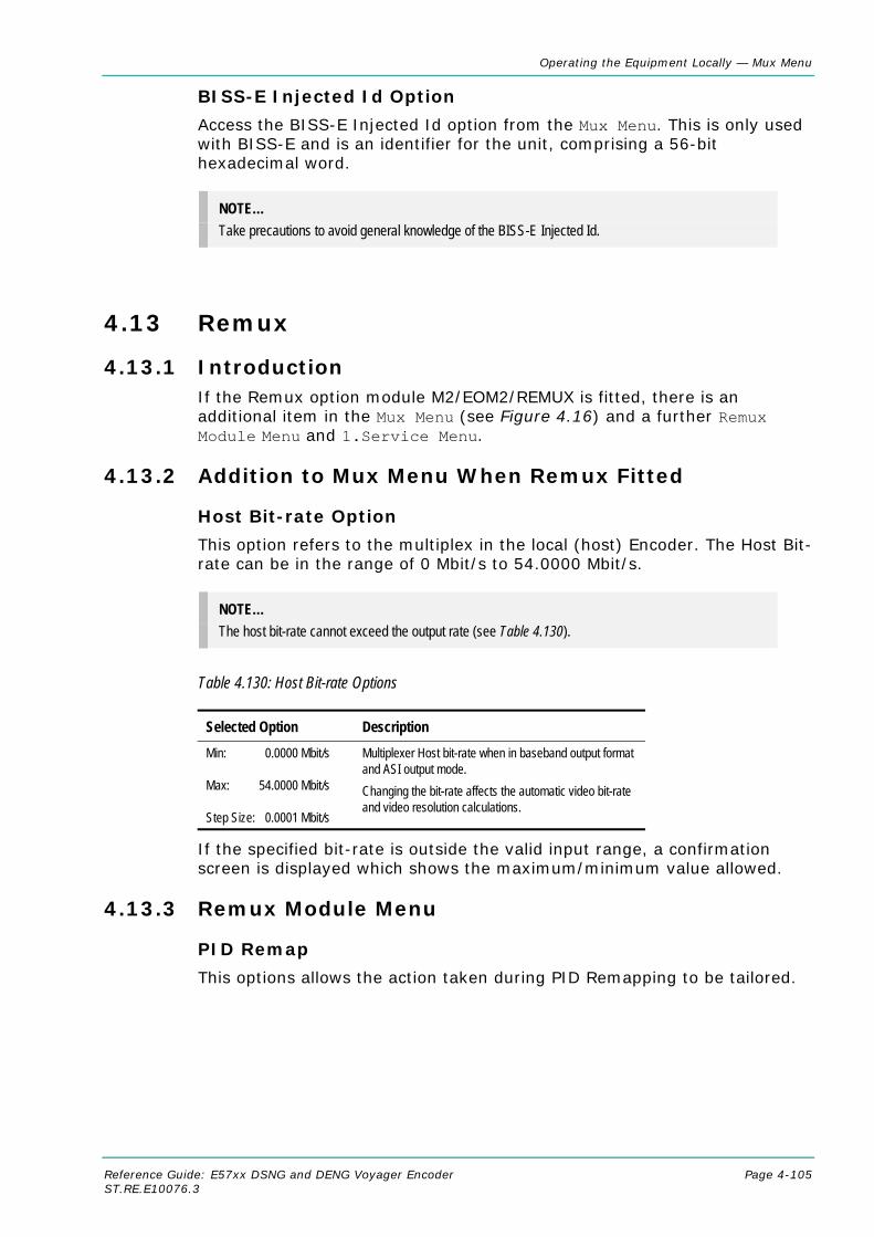
Operating the Equipment Locally — Mux Menu
Reference Guide: E57xx DSNG and DENG Voyager Encoder Page 4-105 ST.RE.E10076.3
BISS-E Injected Id Option
Access the BISS-E Injected Id option from the Mux Menu. This is only used with BISS-E and is an identifier for the unit, comprising a 56-bit hexadecimal word.
NOTE… Take precautions to avoid general knowledge of the BISS-E Injected Id.
4.13 Remux
4.13.1 Introduction If the Remux option module M2/EOM2/REMUX is fitted, there is an additional item in the Mux Menu (see Figure 4.16) and a further Remux Module Menu and 1.Service Menu.
4.13.2 Addition to Mux Menu When Remux Fitted
Host Bit-rate Option
This option refers to the multiplex in the local (host) Encoder. The Host Bit-rate can be in the range of 0 Mbit/s to 54.0000 Mbit/s.
NOTE… The host bit-rate cannot exceed the output rate (see Table 4.130).
Table 4.130: Host Bit-rate Options
Selected Option Description Min: 0.0000 Mbit/s Max: 54.0000 Mbit/s Step Size: 0.0001 Mbit/s
Multiplexer Host bit-rate when in baseband output format and ASI output mode. Changing the bit-rate affects the automatic video bit-rate and video resolution calculations.
If the specified bit-rate is outside the valid input range, a confirmation screen is displayed which shows the maximum/minimum value allowed.
4.13.3 Remux Module Menu
PID Remap
This options allows the action taken during PID Remapping to be tailored.
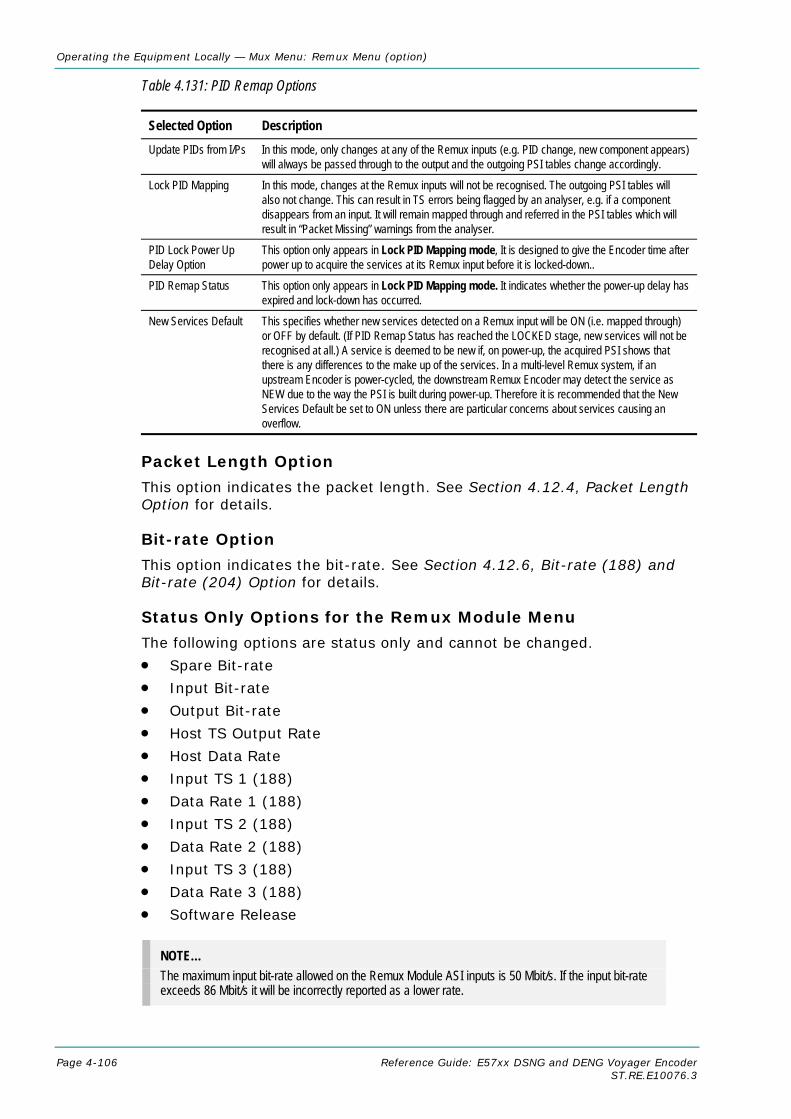
Operating the Equipment Locally — Mux Menu: Remux Menu (option)
Page 4-106 Reference Guide: E57xx DSNG and DENG Voyager Encoder ST.RE.E10076.3
Table 4.131: PID Remap Options
Selected Option Description Update PIDs from I/Ps In this mode, only changes at any of the Remux inputs (e.g. PID change, new component appears)
will always be passed through to the output and the outgoing PSI tables change accordingly.
Lock PID Mapping In this mode, changes at the Remux inputs will not be recognised. The outgoing PSI tables will also not change. This can result in TS errors being flagged by an analyser, e.g. if a component disappears from an input. It will remain mapped through and referred in the PSI tables which will result in “Packet Missing” warnings from the analyser.
PID Lock Power Up Delay Option
This option only appears in Lock PID Mapping mode, It is designed to give the Encoder time after power up to acquire the services at its Remux input before it is locked-down..
PID Remap Status This option only appears in Lock PID Mapping mode. It indicates whether the power-up delay has expired and lock-down has occurred.
New Services Default This specifies whether new services detected on a Remux input will be ON (i.e. mapped through) or OFF by default. (If PID Remap Status has reached the LOCKED stage, new services will not be recognised at all.) A service is deemed to be new if, on power-up, the acquired PSI shows that there is any differences to the make up of the services. In a multi-level Remux system, if an upstream Encoder is power-cycled, the downstream Remux Encoder may detect the service as NEW due to the way the PSI is built during power-up. Therefore it is recommended that the New Services Default be set to ON unless there are particular concerns about services causing an overflow.
Packet Length Option
This option indicates the packet length. See Section 4.12.4, Packet Length Option for details.
Bit-rate Option
This option indicates the bit-rate. See Section 4.12.6, Bit-rate (188) and Bit-rate (204) Option for details.
Status Only Options for the Remux Module Menu
The following options are status only and cannot be changed.
• Spare Bit-rate
• Input Bit-rate
• Output Bit-rate
• Host TS Output Rate
• Host Data Rate
• Input TS 1 (188)
• Data Rate 1 (188)
• Input TS 2 (188)
• Data Rate 2 (188)
• Input TS 3 (188)
• Data Rate 3 (188)
• Software Release
NOTE… The maximum input bit-rate allowed on the Remux Module ASI inputs is 50 Mbit/s. If the input bit-rate exceeds 86 Mbit/s it will be incorrectly reported as a lower rate.

Operating the Equipment Locally — Mux Menu: Remux Menu (option)
Reference Guide: E57xx DSNG and DENG Voyager Encoder Page 4-107 ST.RE.E10076.3
4.13.4 1.Service/2.Service Menu
Output Option
This option enables the Output to be set.
Table 4.132: Output Options
Selected Option Description Off The service is not included in the output.
On The service is included in the output, unscrambled.
On (RAS) The service is included in the output, scrambled and using RAS.
On (BISS Mux Key) The service is included in the output, scrambled and the Session Word entered in the Mux Menu.
On (BISS Mode 1) The service is included in the output, scrambled, using BISS Mode 1 and the Session Word entered in this menu.
On (BISS-E) The service is included in the output, scrambled, using BISS-E and the Enc(rypted) Session Word entered in this menu.
Source (BNC) Option
This option indicates the source of the input. It is for status only. Table 4.133 indicates what is shown for the various inputs.
Table 4.133: Source (BNC) Options
Selected Option Description 0 Host Encoder.
1, 2, 3 Remux inputs 1 to 3.
Short Name In Option
NOTE… This option is only shown in ATSC mode.
This option allows the Short Name In to be changed. Short Name Out Option
NOTE… This option is only shown in ATSC mode.
This option allows the Short Name Out to be changed.
Name (In) Option
NOTE… This option is only shown on an incoming Service menu (2-13.Service Menu).
This option indicates the input service name. It is status only and cannot be changed.

Operating the Equipment Locally — Mux Menu: Remux Menu (option)
Page 4-108 Reference Guide: E57xx DSNG and DENG Voyager Encoder ST.RE.E10076.3
Name Out Option
This option allows the service output name to be changed.
Service Prov (In) Option
NOTE… This option is only shown on an incoming Service menu (2-13.Service Menu).
This option indicates the input service provider’s name. It is set for status only and cannot be changed.
Service Provider Option
This option relates to the output service provider and allows the name to be changed.
Service Id (Out) Option
This option enables the output Service Identity to be specified. It is the number at the start of the remuxxed services.
Table 4.134: Service Id (Out)Options
Selected Option Description Min: 1 Max: 65535 Step Size: 1
Service identity number.
Program Number (Out) Option
NOTE… This option is only shown in ATSC mode.
This option enables the output program number to be specified.
Table 4.135: Program Number (Out) Options
Selected Option Description Min: 1 Max: 65535 Step Size: 1
Program Number.
Major Channel Option
NOTE… This option is only shown in ATSC mode.
This option enables the major channel to be specified.
Minor Channel Option
NOTE… This option is only shown in ATSC mode.

Operating the Equipment Locally — Mux Menu: Remux Menu (option)
Reference Guide: E57xx DSNG and DENG Voyager Encoder Page 4-109 ST.RE.E10076.3
This option enables the minor channel to be specified.
Logical Channel Option
This option enables a number to be given to the Logical Channel.
CA Input Option
NOTE… This option is only shown if there are incoming services.
This option indicates the type of CA present on the input. It is set for status only and cannot be changed.
BISS Key Code Option
NOTE… This option is not available from Build version 2.2.
This option enables the scrambling key used in BISS scrambling mode to be set. The same scrambling code must be used at the receive end to unscramble the transmission.
Enter up to 12 digits. If less then seven digits are entered, they are prefixed with 0s (zero) to give a seven digit code.
Enc Session Word Option
Refer to Enc Session Word Option on page 4-104 for details.
Session Word Option
Refer to Session Word Option on page 4-104 for details.
PMT PID Option
NOTE… This option is status only for the Host Encoder but can be changed for incoming services.
This option shows the Program Map Table Packet Identifier.
Table 4.136: PMT PID Options
Selected Option Description Min: 32 Max: 8190 (1FFEh) Step Size: 1
Program Map Table Packet Identifier (PMT PID).
PCR PID Option
NOTE… This option is status only for the Host Encoder but can be changed for incoming services.
This option shows the Program Clock Reference Packet Identifier.

Operating the Equipment Locally — Mux Menu: Remux Menu (option)
Page 4-110 Reference Guide: E57xx DSNG and DENG Voyager Encoder ST.RE.E10076.3
Table 4.137: PCR PID Options
Selected Option Description Min: 1 Max: 8190 (1FFEh) Step Size: 1
Video Option
NOTE… This option is status only for the Host Encoder but can be changed for incoming services.
This option shows the Video PID.
Table 4.138: Video Options
Selected Option Description Min: 1 Max: 8190 (1FFEh) Step Size: 1
ECM (CA) PID Option
NOTE… This option is status only for the Host Encoder but can be changed for incoming services.
This option shows the Entitlement Control Message (Conditional Access) Packet Identifier (PID).
Table 4.139: ECM (CA) PID Options
Selected Option Description Min: 1 Max: 8190 (1FFEh) Step Size: 1
VBI PID Option
NOTE… This option is status only for the Host Encoder but can be changed for incoming services. Available prior to Build version 2.2.0.
This option is used for entering or updating the VBI PID.
Table 4.140: VBI PID Options
Selected Option Description Min: 1 Max: 8190 (1FFEh) Step Size: 1

Operating the Equipment Locally — Mux Menu: Remux Menu (option)
Reference Guide: E57xx DSNG and DENG Voyager Encoder Page 4-111 ST.RE.E10076.3
Audio (Type of Audio) Option
NOTES… 1. This option is status only for the Host Encoder but can be changed for incoming services. 2. The option could be Audio (MPEG-2), Audio (Dolby Digital) etc. The words in the brackets
change according to the type of audio that was previously selected.
This option is used for entering or updating audio PIDs.
To be DVB compliant, PIDs below 32 are reserved. Therefore PIDs 32 to 8191 are available for use. In the event of a clash, one of the PIDs will be changed by the Encoder’s internal checking algorithm
Table 4.141: Audio (Type of Audio) Options
Selected Option Description Min: 1 Max: 8190 (1FFEh) Step Size: 1
Data (Type of Data) Option
NOTES… 1. This option is status only for the Host Encoder but can be changed for incoming services. 2. The option could be Data (RS-232), Data (RS-422) etc. The words in the brackets change
according to the type of data that was previously selected.
This option is used for entering or updating data PIDs. Table 4.142: Data (Type of Data) Options
Selected Option Description Min: 1 Max: 8190 (1FFEh) Step Size: 1
Teletext Option
NOTE… This option is status only for the Host Encoder but can be changed for incoming services.
This option is used for entering or updating Teletext PIDs.
Table 4.143: Teletext Options
Selected Option Description Min: 1 Max: 8190 (1FFEh) Step Size: 1

Operating the Equipment Locally — Mux Menu: Remux Menu (option)
Page 4-112 Reference Guide: E57xx DSNG and DENG Voyager Encoder ST.RE.E10076.3
4.14 IRD Menu
4.14.1 Overview The IRD Menu is selected from the Setup Menu. The menu controls the internal receiver decoder (IRD), if it is fitted. The IRD consists of the SD Decoder option M2/EOM2/DEC and either of the following demodulator options, M2/EOM2/QPSKDEMOD or M2/EOM2/SATDEMOD.
4.14.2 IRD Mode Option Access the IRD Mode option from the IRD Menu.
Table 4.144: IRD Mode Options
Selected Option Description Independent The IRD operates completely independently from the Encoder.
Tracking The IRD tracks, as far as is possible, the modulator settings, minimising the amount of set-up required to monitor the local modulator output.

Operating the Equipment Locally — IRD Menu
Reference Guide: E57xx DSNG and DENG Voyager Encoder Page 4-113 ST.RE.E10076.3
SetupMenu
IRDMenu
IRD Mode
IRD TS Source
IRD Demod (If Fitted)....
Service List....
IRD Video....
IRD Audio1....
IRD Audio2....
IRD VBI....
IRD CA....
IRD Data....
IRD System Status....
IRD VBIMenu
VITS EnableCCVC EnableVITC EnableGCR EnableCCVC StatusVBI StatusInput Line 11
Output Line 11Input Line 23
toOutput Line 23
to
IRD CAMenu
IRD DataMenu
Async StreamAsync BaudrateSync StreamSync BitrateSubtitle StreamSubtitles LanguageSubtitles Type
Teletext StreamSubtitles Enable
IRDSystemStatus
TSNetwork NameNetwork IDServicesCurrent Service IDCurrent TS IDCurrent ON ID
Part NumberApp Version
IRD AudioMenu
Audio StreamAudio RoutingDefault Language
IRD DemodMenu
FrequencySymbol RateFEC RatePolarisationSat InputModulationLNBLNB Lo FreqLNB Hi FreqLNB Switch FreqLNB SupplySearch Range +/-BER Error ThresholdLNB Fault StatusDemod StatusPart NumberCode Version
IRD VideoMenu
Stop ModeAspect RatioVideo Output Source525 Line Composite625 Line CompositeRate Buffer ModeVideo Default OutputEDH EnableEmbedded Audio ModeEmbed Data ID
DSNG KeyBISS ModeSession Word
Shaded options are status only and cannot be changed.
Available from Build Version 3.1.0 and later.
Mute StateAudio OutputLeft Sys ClipRight Sys Clip
Audio PIDAudio x Status
Audio Sample RateAudio Type
Downmix Mode
Video PID
Enc Session Word
Figure 4.18: Menu Hierarchy – Setup/IRD Menu

Operating the Equipment Locally — IRD Menu
Page 4-114 Reference Guide: E57xx DSNG and DENG Voyager Encoder ST.RE.E10076.3
4.14.3 IRD TS Source Option Access the IRD TS Source option from the IRD Menu.
Table 4.145: IRD TS Source Options
Selected Option Description IRD Demod The IRD will decode the transport stream from the demodulator. Internal TS The IRD will decode the host Encoder’s internal transport stream. Demod ASI Input The IRD will decode the transport stream from the ASI input on the Demod Card.
4.14.4 IRD Demod Menu
Frequency Option
Access the Frequency option from the IRD Demod Menu.
This value is either the L-Band frequency for the demodulator to tune to if the LNB option is set to ‘Direct RF’, or it is the satellite frequency to tune to if the LNB option is set to ‘Active’. If the demodulator is M2/EOM2/QPSKDEMOD, and the IF input is selected, then this value is the IF frequency to tune to.
Symbol Rate Option
Access the Symbol Rate option from the IRD Demod Menu. If the IRD is in tracking mode then this value is tied to that set for the satellite modulator, and cannot be altered.
Table 4.146: Symbol Rate Options
Valid Input Range Description Min (Low Sym Rate) 0.3000 Msym/s Minimum with low symbol rate option M2/ES02/LSYM
Min 1.0000 Msym/s
Max 30.0000 Msym/s
Stepsize 0.0001 Msym/s
FEC Rate Option
Access the FEC Rate option from the IRD Demod Menu. If the IRD is in tracking mode this value is tied to that set for the satellite modulator, and cannot be altered.
Table 4.147: FEC Rate Options
Selected Option Description 1/2 IRD uses 1/2 FEC Rate
2/3 IRD uses 2/3 FEC Rate
3/4 IRD uses 3/4 FEC Rate
5/6 IRD uses 5/6 FEC Rate
7/8 IRD uses 7/8 FEC Rate
8/9 IRD uses 8/9 FEC Rate - only applicable if the modulation type is 8PSK

Operating the Equipment Locally — IRD Menu
Reference Guide: E57xx DSNG and DENG Voyager Encoder Page 4-115 ST.RE.E10076.3
Polarisation Option
Access the Polarisation option from the IRD Demod Menu.
Table 4.148: Polarisation Options
Selected Option Description Horizontal If LNB power is enabled, output +18V to signal horizontal polarisation. Vertical If LNB power is enabled, output +13V to signal vertical polarisation.
Sat Input Option
Access the Sat Input option from the IRD Demod Menu.
Table 4.149: Sat Input Options
Selected Option Description RF 1 Use Demod L-Band Input 1
RF 2 Use Demod L-Band Input 2
IF Use Demod IF input (M2/EOM2/QPSKDEMOD only).
Modulation Option
Access the Modulation option from the IRD Demod Menu. If the IRD is in tracking mode this value is tied to that set for the Satellite Modulator, and cannot be altered.
Table 4.150: Modulation Options
Selected Option Description BPSK M2/EOM2/QPSKDEMOD and M2/ESO2/LSYM required.
QPSK
8PSK M2/EOM2/SATDEMOD and M2/ESO2/8PSKDEMOD required.
16QAM M2/EOM2/SATDEMOD and M2/ESO2/16QAMDEMOD required.
LNB Option
Access the LNB option from the IRD Demod Menu.
Table 4.151: LNB Options
Selected Option Description Active There is an LNB present.
Direct RF The Demod is being fed direct RF.
LNB Lo Freq Option
Access the LNB Lo Freq option from the IRD Demod Menu.
This value should be set to the LNB’s lower local oscillator frequency. If the LNB has only one local oscillator then both the LNB Lo and LNB Hi Freq options should be set to that value.
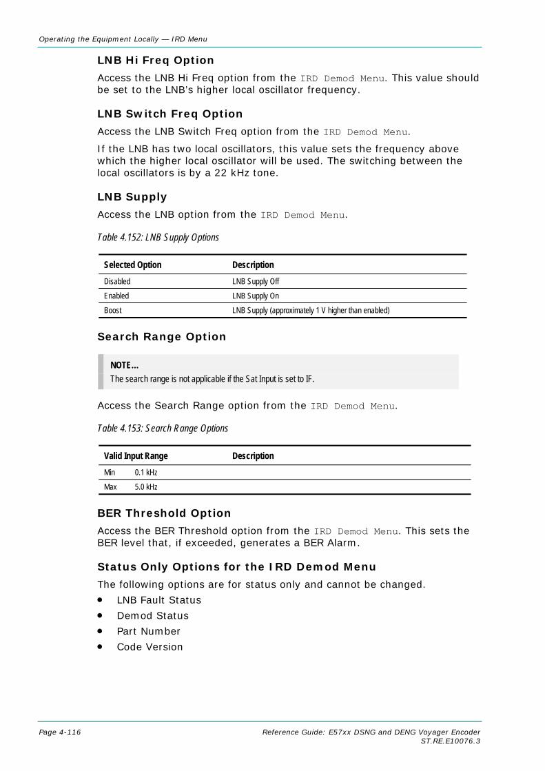
Operating the Equipment Locally — IRD Menu
Page 4-116 Reference Guide: E57xx DSNG and DENG Voyager Encoder ST.RE.E10076.3
LNB Hi Freq Option
Access the LNB Hi Freq option from the IRD Demod Menu. This value should be set to the LNB’s higher local oscillator frequency.
LNB Switch Freq Option
Access the LNB Switch Freq option from the IRD Demod Menu.
If the LNB has two local oscillators, this value sets the frequency above which the higher local oscillator will be used. The switching between the local oscillators is by a 22 kHz tone.
LNB Supply
Access the LNB option from the IRD Demod Menu.
Table 4.152: LNB Supply Options
Selected Option Description Disabled LNB Supply Off
Enabled LNB Supply On
Boost LNB Supply (approximately 1 V higher than enabled)
Search Range Option
NOTE… The search range is not applicable if the Sat Input is set to IF.
Access the Search Range option from the IRD Demod Menu.
Table 4.153: Search Range Options
Valid Input Range Description Min 0.1 kHz
Max 5.0 kHz
BER Threshold Option
Access the BER Threshold option from the IRD Demod Menu. This sets the BER level that, if exceeded, generates a BER Alarm.
Status Only Options for the IRD Demod Menu
The following options are for status only and cannot be changed.
• LNB Fault Status
• Demod Status
• Part Number
• Code Version

Operating the Equipment Locally — IRD Menu
Reference Guide: E57xx DSNG and DENG Voyager Encoder Page 4-117 ST.RE.E10076.3
4.14.5 Service List Menu Access the Service List Menu from the IRD Menu.
This lists all the services found in the current transport stream and allows the user to select which one is to be decoded, if there is more than one.
4.14.6 IRD Video Menu
Stop Mode Option
Access the Stop Mode option from the IRD Video Menu.
Table 4.154: Stop Mode Options
Selected Option Description Blank Outputs a blank screen if the video fails.
Freeze Freezes on the last picture if the video fails.
Aspect Ratio Option
Access the Aspect Ratio option from the IRD Video Menu.
Table 4.155: Aspect Ratio Options
Selected Option Description 4:3 Set if the video monitor aspect ratio is 4:3.
16:9 Set if the video monitor aspect ratio is 16:9.
Video Output Source Option
Access the Video Output Source option from the IRD Video Menu.
Table 4.156: Video Output Source Options
Selected Option Description Normal Video The decoded video stream is output.
Various 525 and 625 test patterns
The selected test pattern is output.
525 Line Composite Option
Access the 525 Line Composite option from the IRD Video Menu.
Table 4.157: 525 Line Composite Options
Selected Option Description 525 NTSC M The composite output standard for a 525 line input is NTSC M.
525 NTSC M No Pedestal The composite output standard for a 525 line input is NTSC M with no pedestal.
525 PAL M The composite output standard for a 525 line input is PAL M.
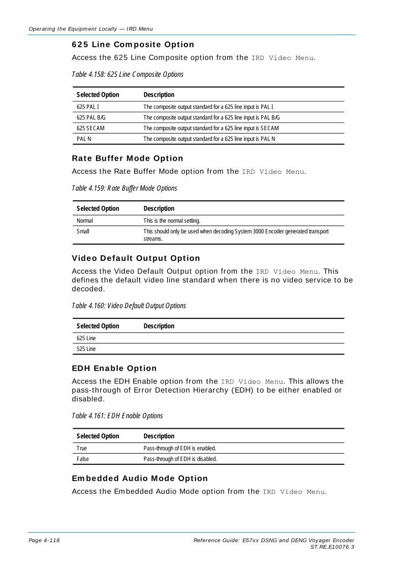
Operating the Equipment Locally — IRD Menu
Page 4-118 Reference Guide: E57xx DSNG and DENG Voyager Encoder ST.RE.E10076.3
625 Line Composite Option
Access the 625 Line Composite option from the IRD Video Menu.
Table 4.158: 625 Line Composite Options
Selected Option Description 625 PAL I The composite output standard for a 625 line input is PAL I
625 PAL B/G The composite output standard for a 625 line input is PAL B/G
625 SECAM The composite output standard for a 625 line input is SECAM
PAL N The composite output standard for a 625 line input is PAL N
Rate Buffer Mode Option
Access the Rate Buffer Mode option from the IRD Video Menu.
Table 4.159: Rate Buffer Mode Options
Selected Option Description Normal This is the normal setting.
Small This should only be used when decoding System 3000 Encoder generated transport streams.
Video Default Output Option
Access the Video Default Output option from the IRD Video Menu. This defines the default video line standard when there is no video service to be decoded.
Table 4.160: Video Default Output Options
Selected Option Description 625 Line
525 Line
EDH Enable Option
Access the EDH Enable option from the IRD Video Menu. This allows the pass-through of Error Detection Hierarchy (EDH) to be either enabled or disabled.
Table 4.161: EDH Enable Options
Selected Option Description True Pass-through of EDH is enabled.
False Pass-through of EDH is disabled.
Embedded Audio Mode Option
Access the Embedded Audio Mode option from the IRD Video Menu.
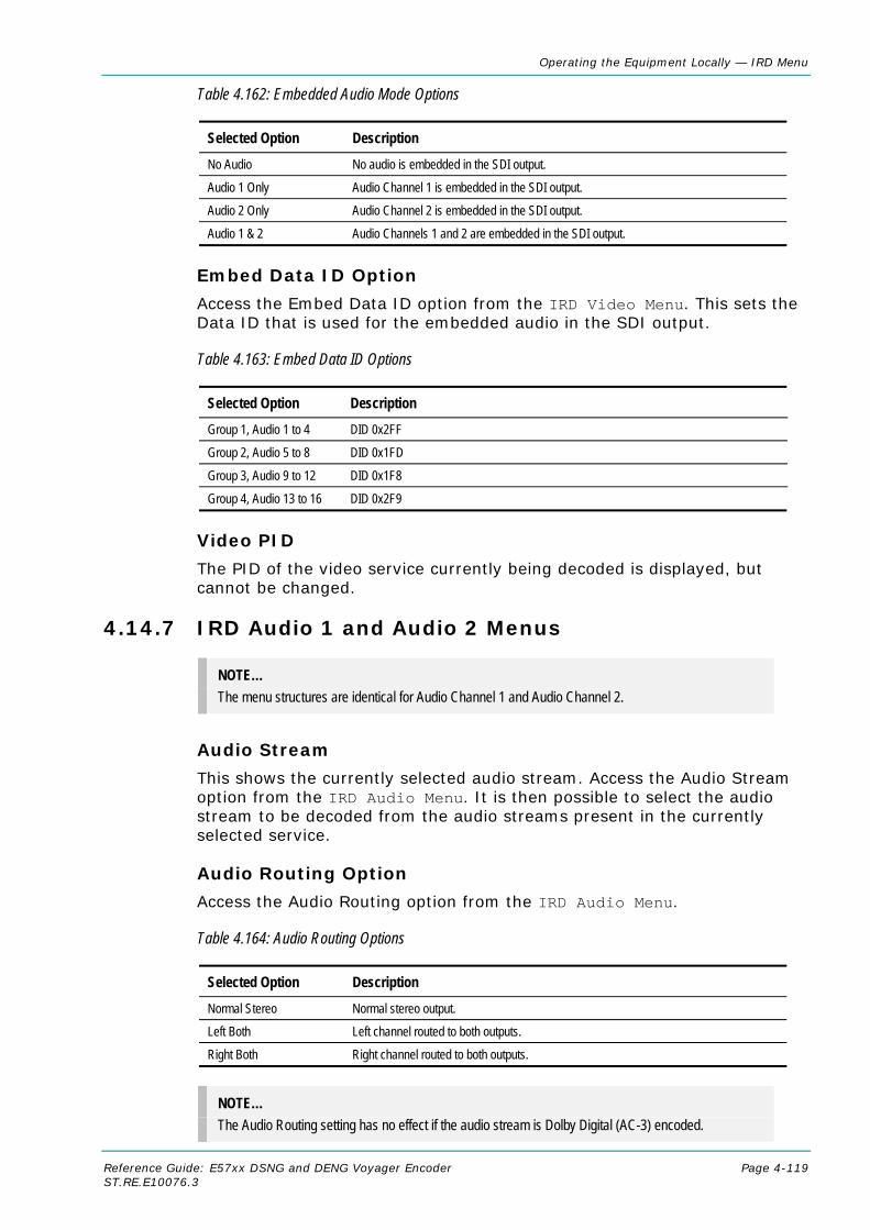
Operating the Equipment Locally — IRD Menu
Reference Guide: E57xx DSNG and DENG Voyager Encoder Page 4-119 ST.RE.E10076.3
Table 4.162: Embedded Audio Mode Options
Selected Option Description No Audio No audio is embedded in the SDI output.
Audio 1 Only Audio Channel 1 is embedded in the SDI output.
Audio 2 Only Audio Channel 2 is embedded in the SDI output.
Audio 1 & 2 Audio Channels 1 and 2 are embedded in the SDI output.
Embed Data ID Option
Access the Embed Data ID option from the IRD Video Menu. This sets the Data ID that is used for the embedded audio in the SDI output.
Table 4.163: Embed Data ID Options
Selected Option Description Group 1, Audio 1 to 4 DID 0x2FF
Group 2, Audio 5 to 8 DID 0x1FD
Group 3, Audio 9 to 12 DID 0x1F8
Group 4, Audio 13 to 16 DID 0x2F9
Video PID
The PID of the video service currently being decoded is displayed, but cannot be changed.
4.14.7 IRD Audio 1 and Audio 2 Menus
NOTE… The menu structures are identical for Audio Channel 1 and Audio Channel 2.
Audio Stream
This shows the currently selected audio stream. Access the Audio Stream option from the IRD Audio Menu. It is then possible to select the audio stream to be decoded from the audio streams present in the currently selected service.
Audio Routing Option
Access the Audio Routing option from the IRD Audio Menu.
Table 4.164: Audio Routing Options
Selected Option Description Normal Stereo Normal stereo output.
Left Both Left channel routed to both outputs.
Right Both Right channel routed to both outputs.
NOTE… The Audio Routing setting has no effect if the audio stream is Dolby Digital (AC-3) encoded.

Operating the Equipment Locally — IRD Menu
Page 4-120 Reference Guide: E57xx DSNG and DENG Voyager Encoder ST.RE.E10076.3
Default Language Option
Access the Default Language option from the IRD Audio Menu. If a service contains more than one audio stream, the decoder defaults to the first audio stream of the default language.
NOTE… If the service contains two audio components, each with the same language descriptor, then selecting Miscellaneous as the preferred language for Audio 2 will force the IRD to select the second audio component in the PMT.
Downmix Mode Option
NOTE… This option is only applicable with Dolby AC-3 audio services.
Access the Downmix Mode option from the IRD Audio Menu.
If the AC-3 service has more than two channels the audio decoder downmixes to produce a stereo pair. The AC-3 standard allows for downmixing to either a Dolby Pro Logic compatible stereo signal (designated LT RT) or a conventional stereo signal (designated LO RO).
Table 4.165: Downmix Mode Options
Selected Option Description Stereo Pair
Dolby Pro Logic Stereo
Mute State Option
Access the Mute State option from the IRD Audio Menu. The Mute State can either be set ‘On’, i.e. no audio output, or ‘Off’, audio output present.
Audio Output Option
Access the Audio Output option from the IRD Audio Menu.
Table 4.166: Audio Output Options
Selected Option Description Analogue Output Analogue Audio on both left and right channels.
IEC958 Consumer Uncompressed stereo on right output that conforms to SPDIF formatting.
IEC958 Pro (AES/EBU) Uncompressed stereo on right output that conforms to AES/EBU formatting.
AC-3 as IEC958 Consumer Compressed up to 5 + 1 on right output only. Only if the input stream is Dolby Digital (AC-3) encoded.
NOTE… To obtain a linear PCM digital output the Audio Output must be set to IEC 958 Prof.

Operating the Equipment Locally — IRD Menu
Reference Guide: E57xx DSNG and DENG Voyager Encoder Page 4-121 ST.RE.E10076.3
Left Sys Clip Option
Access the Left Sys Clip option from the IRD Audio Menu. This sets the audio clip level of the left channel between 6 dBm and 18 dBm.
Right Sys Clip Option
Access the Right Sys Clip option from the IRD Audio Menu. This sets the audio clip level of the right channel between 6 dBm and 18 dBm.
Status Only Options for the IRD Audio Menu
The following options are for status only and cannot be changed.
• Audio Status
• Audio PID
• Audio Sample Rate
• Audio Type
4.14.8 IRD CA Menu
Overview
If the IRD is operating in tracking mode, then the IRD CA menu has no options because the CA is automatically configured to match the settings of the host Encoder.
DSNG Key Option
Access the DSNG Key option from the IRD CA Menu. This sets the TANDBERG RAS DSNG key, which is a seven digit number.
BISS Mode Option
Access the BISS Mode option from the IRD CA Menu.
Table 4.167: BISS Mode Options
Selected Option Description Off BISS descrambling is off.
BISS Mode 1 BISS descrambling using the entered session word is on.
BISS-E BISS descrambling using the entered encrypted session word together with the Encoder’s injected BISS ID.
Session Word Option
This option is only visible if the BISS mode has been set to BISS Mode 1. Access the Session Word option from the IRD CA Menu. This sets the 12-digit BISS session word to be used by the IRD. For security, the entered session word cannot be read back.
Enc Session Word Option
This option is only visible if the BISS mode has been set to BISS-E. Access the Enc Session Word option from the IRD CA Menu. This sets the 16 digit encrypted BISS session word to be used by the IRD. For security the entered encrypted session word cannot be read back.

Operating the Equipment Locally — IRD Menu
Page 4-122 Reference Guide: E57xx DSNG and DENG Voyager Encoder ST.RE.E10076.3
4.14.9 IRD VBI Menu
VITS Enable Option
Access the VITS Enable option from the IRD VBI Menu.
Table 4.168: VITS Enable Options
Selected Option Description Disabled VITS test signal insertion disabled.
CCIR CCIR[ITU-R] VITS inserted on lines 17/18/329/330 (625 Lines).
FCC/UK 525 Line: FCC VITS inserted on lines 17/280 625 Line: UK standard VITS inserted on lines 19, 20, 332, 333
CCVC Enable Option
Access the CCVC Enable option from the IRD VBI Menu. This can either enable or disable the reinsertion of Closed Caption or VCHIP data in to the VBI.
VITC Enable Option
Access the VITC Enable option from the IRD VBI Menu. This can either enable or disable the insertion of the VITC signal.
GCR Enable Option
Access the GCR Enable option from the IRD VBI Menu. This can either enable or disable the insertion of the Ghost Cancellation Reference (GCR) signal on line 19 for 525 line signals, or line 318 for 625 line signals.
NOTE… The GCR signal only appears on the SDI output NOT the analogue output.
Status Only Options for the IRD VBI Menu
The following options are for status only and cannot be changed.
• CCVC Status: present or not present on the input signal.
• VBI Status: present or not present on the input signal.
• Input Lines: what, if any VBI is present on each input line.
• Output Lines: what, if any VBI is present on each line output.

Operating the Equipment Locally — IRD Menu
Reference Guide: E57xx DSNG and DENG Voyager Encoder Page 4-123 ST.RE.E10076.3
4.14.10 IRD Data Menu
Async Stream Option
Access the Async Stream option from the IRD Data Menu. This is used to select the asynchronous data stream to be decoded, from those present in the selected service.
Async Baudrate
This gives the baud-rate of the selected asynchronous data stream.
Sync Stream Option
Access the Sync Stream option from the IRD Data Menu. This is used to select the synchronous data stream to be decoded, from those present in the selected service.
Sync Bitrate
This gives the bit-rate of the selected synchronous data stream.
Subtitle Stream Option
Access the Subtitle Stream option from the IRD Data Menu. This is used to select the subtitle stream to be decoded, from those present in the selected service.
Subtitles Language Option
Access the Subtitles Language option from the IRD Data Menu. This is used to select the subtitles default language. When a service is selected, the IRD defaults to decoding the subtitles stream with the default language, if one is present.
Subtitles Type Option
Access the Subtitles Type option from the IRD Data Menu. This is used to select the subtitles default type. When a service is selected, the IRD will default to decoding the subtitles stream with the default language, and of the default type, if one is present.
Subtitles Enable Option
Access the Subtitles Enable option from the IRD Data Menu. This can be set to enable or disable the reinsertion of subtitles in to the VBI.
Table 4.169: Subtitles Enable Options
Selected Option Description True Enable the reinsertion of subtitles in to the VBI.
False Disable the reinsertion of subtitles in to the VBI
Teletext Stream Option
Access the Teletext Stream option from the IRD Data Menu. This is used to select the Teletext stream to be decoded, from those present in the selected service.

Operating the Equipment Locally — IRD Menu
Page 4-124 Reference Guide: E57xx DSNG and DENG Voyager Encoder ST.RE.E10076.3
4.14.11 IRD System Status Menu The IRD System Status Menu has a number of options which are status only and cannot be changed:
• TS
• Network Name
• Network ID
• Services
• Current Service ID
• Current TS ID
• Current ON ID
• App Version
• Part Number
4.15 Vocality Menu There are no menus associated with the Vocality card. Refer to the Vocality documentation.

Operating the Equipment Locally — Digital Programme Insertion (DPI) Menu
Reference Guide: E57xx DSNG and DENG Voyager Encoder Page 4-125 ST.RE.E10076.3
4.16 Digital Programme Insertion (DPI) Menu
4.16.1 Option Availability This option is only available from the Systems Menu when the M2/ESO2/SCTE35 SPLICE POINTS licence key is purchased. DPI can be triggered either by GPI contact closure or by the DVS525 protocol.
4.16.2 Overview Splicing is used to insert Digital Programme (e.g. advertisements) into an MPEG-2 transport stream. SCTE-35 has been written to support splicing information for Cable systems.
4.16.3 DPI Initiated by GPI Only one of the card’s eight inputs is used. This is configured to be a straight Open/Close switch. The switch is then able to activate/deactivate the splicing message insertion.
The GPI card is used as an interface between the Encoder and an Automation System. The System dictates when the Encoder is to send SCTE-35 messages by changing the state of the GPI card’s input switch. Before the command can be executed, some Encoder parameters need to be set.
4.16.4 DPI Initiated by DVS525 The number of options available through this method are shown in Table 4.170. In this mode, the Encoder responds to messages received via Ethernet adhering to the DVS 525 protocol.
4.16.5 Menu Structure Figure 4.19 shows the options available from the menu.
Figure 4.19: Menu Hierarchy – Digital Programme Insertion DPI Menu (GPI Initiated)
Digital Programme Insertion (DPI)....….
System Menu
….
— Dig Program Ins (DPI) — DPI Mode — GPI Input Pin — GPI OutofNet Polarity — Return to Network — Avail Descriptor — Provider Avail ID — DPI info PID — Component Tag — OUT Pre-roll — Return Pre-roll — Nbr Out Msg — Nbr Return Msg — Splice Duration — Fixed Delay — Splice ID Increment Mode
Ext ControlAuto Return
— Present— Off
— DVS 525 COMPEL — DVS 525 SCTE 3535— GPI SCTE 35

Operating the Equipment Locally — Digital Programme Insertion (DPI) Menu
Page 4-126 Reference Guide: E57xx DSNG and DENG Voyager Encoder ST.RE.E10076.3
NOTES… 1. Some of the options may be different or unavailable in other DPI modes. 2. The stream carrying the splice information is referenced in PMT as Private Data.
Table 4.170: DPI Options (DPI Mode= GPI SCTE 35)
Menu Item
GPI
DVS
525
Description
DPI Program Ins (DPI) On/Off DPI Mode GPI SCTE 35: GPI card triggers SCTE 35 splice DVS 525 SCTE 35: DVS 525 messages triggers SCTE 35 splice.
DVS 525 COMPEL: DVS 525 triggers splice. DVS 525 version compatible
with Wegener Compel unit – Compel Control DPI Monitor version R3.15.32.
Return to Network If set to Auto, no return messages are sent out and “Auto Return” flag in the message is set to 1.
Avail Descriptor Present/Off Provider Avail ID 0 - FFFFFFFF DPI info PID PID in which the splice messages are carried. Out Pre-roll 0, 4 – 100 s (0 indicates immediate) Return Pre-roll 0, 4 – 100 s (0 indicates immediate) Nbr Out Msg Only single is possible. Nbr Return Msg Only single is possible. Nbr Splice Msg Only single is possible. Splice Duration If non-zero, “Break duration” structure is included in the splice message. Fixed Delay Added to both Out and Return pre-roll. Splice ID Increment mode Determines whether splice_event_id is incremented for each splice
message or only for an out/return message pair. TCP port Port number on which to receive DVS 525 messages. Component Tag The value for component tag oin the “stream identification descriptor” in
the PMT. Synchronisation Sync to Alive/Do not sync. Most installations should choose “Sync to Alive”
so that splice times are accurate. Pre-roll Adjuster [DVS 525 Compel mode] Compel protocol enables pre-roll in steps of one
second only. Users can enter a constant milli-second offset here to get sub-second accuracy.
GPI Input Pin Physical pin on GPI connector to be monitored. GPI OutofNet Polarity Whether an open or close will trigger Out of Network.

Operating the Equipment Locally — Digital Programme Insertion (DPI) Menu
Reference Guide: E57xx DSNG and DENG Voyager Encoder Page 4-127 ST.RE.E10076.3
4.17 Errors Menu
4.17.1 Overview From the 2U Encoder the Errors Menu can be selected from the Advanced Menu. From the 1U Encoder the Errors Menu can be selected from the Main Menu.
New errors are reported to the front panel display approximately every 30 seconds.
4.17.2 Active Errors Option Access the Active Errors option from the Errors Menu. This gives a list of any current errors.
4.17.3 Error Masks Menu
Status of Error Masks
Access the Error Masks option from the Error Masks Menu. This allows any of the error messages to be masked. There are three states for the error message: Alm, Fail or Off.
• Alm (Alarm) shows the error message and triggers the alarm relay
• Fail shows the error message and triggers both the fail and alarm relays
• Off does not show the error message and does not trigger any relays
Press the softkey next to a message. As the key is pressed the status of the message changes.
4.17.4 Ignored Errors Errors flagged as “Ignored Errors” are displayed in the Ignored list and aren’t passed onto to any other equipment.
4.17.5 Error Masks Menu
Status of Error Masks
This option allows any of the error messages to be masked. There are three states for the error message: Alm, Fail or Off.
• Alm (Alarm) shows the error message and triggers the alarm relay
• Fail shows the error message and triggers both the fail and alarm relays
• Off does not show the error message and does not trigger any relays
Press the softkey next to a message. As the key is pressed the status of the message changes.
Restore Defaults
This option sets alarm, fail and error messages to the factory defaults.

Operating the Equipment Locally — Configs Menu
Page 4-128 Reference Guide: E57xx DSNG and DENG Voyager Encoder ST.RE.E10076.3
Active ErrorsError Masks....Quit
Error MasksMenu
ErrorsMenu
Refer to Annex H, Error Messages for details ofall the error messages.
Figure 4.20: Menu Hierarchy – Error Masks Menu
4.17.6 Masked Active Errors If an active error is masked, it appears in the Masked list where the error is noted and may be passed to a controlling GUI but doesn't generate an error. Off and Masked are two of the same thing.
4.18 Diagnostics Menu See Chapter 6, Preventive Maintenance and Fault-finding for information about the Diagnostics Menu.

Operating the Equipment Locally — Errors Menu / Diagnostics Menu
Reference Guide: E57xx DSNG and DENG Voyager Encoder Page 4-129 ST.RE.E10076.3
4.19 Configs Menu
4.19.1 Accessing the Menu Access the Configs Menu from the Summary Screen or from the Advanced Menu.
4.19.2 Overview The Encoder has a set of 16 default configurations for both 525 and 625 line standards. These configurations provide the basis for quick and easy configuration of the operating parameters for common set-ups, without having to enter all parameters individually. The default configurations can be used as they are, or loaded as the active configuration and edited as required.
The Encoder normally holds the following configurations:
• One Active Configuration (it runs the Encoder)
• Sixteen User configurations (in the User FLASH)
• Sixteen Backup configurations (in Backup FLASH)
• Sixteen 525 factory default configurations
• Sixteen 625 factory default configurations
Figure 4.21: Configuration, Graphical Explanation.
4.19.3 Active Configuration This is the configuration that the Encoder is currently using. It is loaded from one of the 16 user configuration locations (Load Active Config). It can be edited at any time and also stored back as one of the user configurations (Store Active Config).
Password required here Load Factory 525 Defaults
Factory 525 Defaults (x16)
Factory 625 Defaults (x16)
Backup FLASH
Backup Configs (x16)
Load Configs from Backup
Load Factory 625 Defaults
Store Configs in Backup
Store Active Config Load Active Config
User FLASH
User Configs (x16)
Any or all Configs can be Password Write-protected
Config editing takes place here. Active Config
User Editable Config (x1)

Operating the Equipment Locally — Configs Menu
Page 4-130 Reference Guide: E57xx DSNG and DENG Voyager Encoder ST.RE.E10076.3
4.19.4 User Configurations Configurations loaded into the user FLASH become user configurations. Any one of the user configurations can be loaded as an active configuration (Load Active Config). A modified active configuration can be copied back into one of the user FLASH locations (Store Active Config) where it can be password write-protected. A user configuration that is write-protected cannot be overwritten. The 16 user configurations can be saved in the backup FLASH (Store Configs in Backup).
CAUTION… Any user configuration that is not write-protected, will be overwritten
when Factory Default or Backup configurations are loaded to the user FLASH.
4.19.5 Backup Configurations Backup FLASH stores a copy of each of the 16 user configurations when you select Store Configs in Backup, you will be asked for the password here.
If unsure of the user configurations or they become inadvertently modified, the user configurations can be returned to a known state at any time by the command Load Configs from Backup. This loads the 16 backup configurations to the User FLASH, overwriting all user configurations that are not write-protected. Individual configurations cannot be selected for loading to the User FLASH.
The active (current) configuration is unaltered when you select Load Configs from Backup.
4.19.6 Factory Default Configurations There are 16 default configurations for both 525 and 625 line standards. They are provided as examples and can be used as they are, if their settings suit your needs. They are non-editable. The 16 default configurations (525 or 625) can be loaded to the user FLASH at any time by selecting Factory 525 (or 625) Defaults. This will overwrite all user configurations that are not write-protected. Individual configurations cannot be selected for loading to the User FLASH.
4.19.7 Configuration, Write-Protection Any or all of the 16 user configurations can be write-protected by selecting Write Protect Configs. A password is asked for. With the correct password entered, the question Write protect Which Configs? appears. Select which configurations to protect by pressing the associated softkey in each case. This toggles the write-protect condition (On or Off) for each individual configuration. The letter R when shown to the left of the config number, indicates that the configuration is read-only (write-protected).
Any configuration that is write-protected will be displayed as read-only if attempting to overwrite it.

Operating the Equipment Locally — Configs Menu
Reference Guide: E57xx DSNG and DENG Voyager Encoder Page 4-131 ST.RE.E10076.3
4.19.8 Quick Configuration From the Summary Screen The sixteen predefined user configurations are a quick and easy way to configure the Encoder without having to enter individual parameters. The Config Menu can be accessed directly from the summary screen (see Section 4.4.2, Summary Screen) by pressing the Cfgs softkey. Press the Load Active Config softkey (see Load Active Config Option on page 4-131) and a list of configurations is shown. Select the required one by pressing the associated softkey. Nothing more need be done. The Encoder is ready for use.
This menu provides options for loading and storing predefined configurations and updating and restoring backup configurations.
4.19.9 Load Active Config Option Access the Load Active Config option from the Config Menu. Use the softkeys to select the required configuration to be loaded.
4.19.10 Store Active Config Option Access the Store Active Config option from the Config Menu. Use the softkeys to select the position where the configuration is to be stored.
NOTE… There is no confirmation screen, the configuration is overwritten immediately the softkey indicating the storage position is selected.
4.19.11 Load Configs From Backup Option This option enables the 16 user configurations to be overwritten with the 16 backup configurations. To update the backup configurations access the Load Configs from Backup option in the Config Menu.
NOTE… The 16 backup configurations are loaded immediately the Load Configs from Backup softkey is pressed although the current Encoder configuration remains unchanged.
Press the Cfgs softkey for quick access to the Config menu
Operating the Equipment Locally — Configs Menu
Page 4-132 Reference Guide: E57xx DSNG and DENG Voyager Encoder ST.RE.E10076.3
4.19.12 Store Configs in Backup Option This enables the 16 user configurations to be stored in the backup, and may be password protected. Access the Store Configs in Backup from the Config Menu.
NOTE… The 16 backup configurations are stored immediately the Store Configs in Backup softkey is pressed.
4.19.13 Factory 525 Defaults Option This option enables the 16 user configurations to be overwritten by the factory default settings for 525 line/29.97 Hz video operation. Access the Factory 525 Defaults from the Config Menu.
NOTE… The Factory 525 Defaults option is activated immediately.
4.19.14 Factory 625 Defaults Option The Factory 625 Defaults option is very similar to the Factory 525 Defaults option, except that it overwrites the 16 user configurations with the factory default settings for 625 line/25 Hz video operation. Access the Factory 625 Defaults option from the Config Menu.
NOTE… The Factory 625 Defaults option is activated immediately.

Reference Guide: E57xx DSNG and DENG Voyager Encoder Page 5-1 ST.RE.E10076.3
Chapter 5 5. Web Browser Interface
Contents 5.1 Introduction ............................................................... 5-3 5.2 How to Set Up Internet Explorer For the Web
Browser Interface...................................................... 5-3 5.3 Web Browser Interface Options ................................ 5-6 5.4 Fault Reporting.......................................................... 5-8
List of Figures Figure 5.1: Internet Options Dialog Box ........................................ 5-3 Figure 5.2: Settings Dialog Box ..................................................... 5-4 Figure 5.3: Connections Tab ......................................................... 5-4 Figure 5.4: Local Area Network (LAN) Settings Dialog Box .......... 5-5 Figure 5.5: Proxy Settings Dialog Box........................................... 5-5

Web Browser Interface
Page 5-2 Reference Guide: E57xx DSNG and DENG Voyager Encoder ST.RE.E10076.3
BLANK

Web Browser Interface
Reference Guide: E57xx DSNG and DENG Voyager Encoder Page 5-3 ST.RE.E10076.3
5.1 Introduction There is a range of diagnostic and other utilities that can be accessed via a web browser, such as Internet Explorer. Before these can be accessed it is important to ensure that the Internet Explorer is correctly set up for the web browser.
NOTE… Netscape not currently supported.
5.2 How to Set Up Internet Explorer For the Web Browser Interface To set up Internet Explorer proceed as follows:
1. In Internet Explorer version 6, on the menu bar click Tools, Internet Options. This displays the Internet Options dialog box with tabs across the top.
2. In the General tab click Settings (see Figure 5.1).
Figure 5.1: Internet Options Dialog Box
3. This opens the Settings dialog box (see Figure 5.2).
Settings

Web Browser Interface
Page 5-4 Reference Guide: E57xx DSNG and DENG Voyager Encoder ST.RE.E10076.3
Figure 5.2: Settings Dialog Box
4. For Check for newer versions of stored pages, select Every visit to the page or any changes made to the pages will not be displayed. Click OK to save the changes and return to the Internet Options dialog box.
5. If Internet Explorer currently connects to the internet via a proxy server then it must be reconfigured to connect directly to the Encoder, bypassing the proxy server. Click the Connections tab (see Figure 5.3).
Figure 5.3: Connections Tab
Every visit to the page
LAN Settings

Web Browser Interface
Reference Guide: E57xx DSNG and DENG Voyager Encoder Page 5-5 ST.RE.E10076.3
6. Click LAN Settings to open the Local Area Network (LAN) Settings dialog box (see Figure 5.4).
Figure 5.4: Local Area Network (LAN) Settings Dialog Box
7. Click Advanced to open the Proxy Settings dialog box (see Figure 5.5).
Figure 5.5: Proxy Settings Dialog Box
8. In the Exceptions area type the IP address of the Encoder.
Advanced
Type the IP address of the Encoder
Web Browser Interface
Page 5-6 Reference Guide: E57xx DSNG and DENG Voyager Encoder ST.RE.E10076.3
9. Click OK as many times as necessary to close all dialog boxes until only the Internet Explorer window is open.
For Internet Explorer version 4 the same selections must be made, but the process starts from the View menu.
Once Explorer has been set up, type the IP address of the Encoder to be accessed in the address bar (e.g. http://172.16.197.245), press Return and a connection is established. After a few seconds, a welcome screen appears followed by a window.
5.3 Web Browser Interface Options The web browser gives access to all functions available on the front panel. Status information is always displayed on the left pane along with a picture showing the video signal present at the Encoder input.
Tabbed dialogs give access to various information and allow configuration of the Encoder.
• Status
Detailed current status of Encoder including current active alarms.
• Device Info
Display and set various information. Allows alarm masks to be set and display of current, masked and latched alarms
• Support
Displays various information about the Encoder useful when reporting a fault.
Version Info
Gives full information on the build status of the Encoder
Release Notes.
The software releases are very useful in identifying any known defects and the various code releases which fixed them.
Backplane Modes
The various backplane modes are shown. These indicate all the combinations of option modules allowed.
Customer Support
Links to the Tandberg Television internet site.
Licenced Features – shows a list of all the features which are, and can be, enabled when the appropriate licence is purchased.
Installed Modules – gives details of which options are installed in the Encoder.
Event Log – shows the events and tests which have been performed since the Encoder was last switched on.
NV Event Log - shows the actions which have been performed since the Encoder was last switched on
External Controller – gives the IP addresses of external equipment which can control the Encoder.

Web Browser Interface
Reference Guide: E57xx DSNG and DENG Voyager Encoder Page 5-7 ST.RE.E10076.3
• Engineering
Symbol Rate Calculator
The Modulation Help allows you to see the difference that various parameters have upon the symbol rate and bandwidth.
OFDM Bit-rate Calculator
The Bit-rate Calculator allows you to enter various parameters and the optimal bit-rate (Mbit/s) is automatically calculated for 204 bytes and 188 bytes.
Encoder List
Shows a list of the Encoders on the network together with various parameters.
• Configure
Shows all the menus relevant to the Encoder and allows it to be set up.
• Errors
Current Errors - shows a list of Active Errors, Masked Active Errors and Latched Errors.
Masks
- All Modules – allows you to set the alarm error masks to Masked, Alarm, Fail or Ignore.
- Modules - allows you to set the alarm error masks for each individual module to Masked, Alarm, Fail or Ignore.
• Stored Configs
Load Config
Gives a list of preconfigured settings.
Save Config
Saves the current setting to an existing prenamed configuration.
• Save / Load
Save configuration to file
This saves a file containing an XML description of the current Encoder settings. Forward this file to tech support in the event of a problem.
OSD
Download Utilities – allows you to download an osd.zip file which consists of an OSD Creator (Creator.exe) and OSD Loader (OSD.exe). There is a logo overlay facility allowing broadcasters to trademark material whereby the Encoder is able to overlay broadcasters trademarks/logos onto the active video See Annex D, Creating and Downloading a Logo for information on how to use the programs.

Web Browser Interface
Page 5-8 Reference Guide: E57xx DSNG and DENG Voyager Encoder ST.RE.E10076.3
SNMP MIB
This option is password protected. It allows the Simple Network Management Protocol (SNMP) Management Information Base (MIB1) files to be downloaded from the Encoder to the PC. The password is available from TANDBERG Television Customer Services under a non-disclosure agreement (NDA).
5.4 Fault Reporting In the support menu, click “Version Info”. When this I displayed, from ‘Edit’ menu on Explorer, click “Select All” and then “Copy”. Open notepad and paste this in. Save the notepad file. Repeat this for “Event Log” and “NV Event Log”
Also, send an XML configuration file of the Encoder configuration. See Save/Load in Section 5.3 for details.
1 A definition of management items for some network component that can be accessed by a network manager. A MIB includes the names of objects it contains and the type of information retained.
Reference Guide: E57xx DSNG and DENG Voyager Encoder Page 6-1 ST.RE.E10076.3
Chapter 6 6. Preventive Maintenance and
Fault-finding
Contents 6.1 Introduction ............................................................... 6-3
6.2 Preventive Maintenance............................................ 6-3 6.2.1 Routine Inspection - Cooling Fans ............... 6-3 6.2.2 Cleaning ....................................................... 6-3 6.2.3 Servicing....................................................... 6-3
Damage Requiring Service........................... 6-3 Replacement Parts ....................................... 6-4 Checks on Completion of Servicing.............. 6-4
6.3 Maintenance and Support Services .......................... 6-4 6.3.1 Introduction................................................... 6-4 6.3.2 Warranty ....................................................... 6-4 6.3.3 Levels of Continuing TANDBERG
Television Service Support ........................... 6-4
6.4 Errors and Diagnostics Menus – When to Use Them ...................................................................... 6-5 6.4.1 Error Messages ............................................ 6-5 6.4.2 Diagnostics Menu ......................................... 6-5
Introduction................................................... 6-5 LCD Display Test.......................................... 6-6 Keyboard Test .............................................. 6-6 Fail Relay Test.............................................. 6-6 Alarm Relay Test .......................................... 6-6 Alarm LED Test ............................................ 6-6 Buzzer Test .................................................. 6-7
6.5 Fault-finding .............................................................. 6-7 6.5.1 Fault-finding Philosophy ............................... 6-7 6.5.2 Preliminary Checks....................................... 6-7 6.5.3 User Accessible Fuse Replacement............. 6-8 6.5.4 Video Fault-finding........................................ 6-9
Fault Symptoms ............................................6-9 Breaks in Transmission.................................6-9 Noise Reduction............................................6-9
6.5.5 Audio Fault-finding ......................................6-10 6.5.6 Mux Fault-finding ........................................6-10
6.6 Rate Buffer Setting ..................................................6-10
6.7 Field/Frame Pictures ...............................................6-10
6.8 Power Supply Problems/Green LED on Front Panel Unlit ...............................................................6-11 6.8.1 Symptoms ...................................................6-11 6.8.2 Power LED Unlit..........................................6-11 6.8.3 Fan(s) Not Working/Overheating ................6-11
6.9 Disposing of This Equipment...................................6-12 6.9.1 General .......................................................6-12 6.9.2 Lithium Batteries .........................................6-12
List of Figures Figure 6.1: Finding the Errors Menu.............................................. 6-5 Figure 6.2: Finding the Diagnostics Menu ..................................... 6-6 Figure 6.3: Orientation of Fuse Carrier .......................................... 6-9
List of Tables Table 6.1: Video Fault-finding........................................................ 6-9 Table 6.2: Rate Buffer Settings.................................................... 6-10 Table 6.3: Power LED Unlit Fault-finding..................................... 6-11 Table 6.4: Fans Not Working/Overheating .................................. 6-12

Preventive Maintenance and Fault-finding
Page 6-2 Reference Guide: E57xx DSNG and DENG Voyager Encoder ST.RE.E10076.3
BLANK

Preventive Maintenance and Fault-finding
Reference Guide: E57xx DSNG and DENG Voyager Encoder Page 6-3 ST.RE.E10076.3
6.1 Introduction This chapter provides the schedules and instructions, where applicable, for routine inspection, cleaning and maintenance of the equipment which should be performed by an operator. There are also some basic fault-finding procedures to follow in the event of a suspected Encoder failure.
6.2 Preventive Maintenance
6.2.1 Routine Inspection - Cooling Fans The fans on the Encoder can be temperature controlled so may not be on if the ambient temperature is low. Refer to Annex B, Technical Specification, Table B.29 for more information.
NOTE... Failure to ensure a free flow of air around the unit may cause overheating. This condition is detected by a temperature sensor on the Base Board which causes the alarm relay to be energised.
6.2.2 Cleaning Unplug the Encoder from the wall outlet before cleaning the exterior with a damp cloth. Do not use liquid cleaners or aerosol cleaners.
NOTE… Only the exterior of the case should be cleaned.
6.2.3 Servicing
Damage Requiring Service
WARNING… DO NOT ATTEMPT TO SERVICE THIS PRODUCT AS OPENING OR REMOVING COVERS MAY
EXPOSE DANGEROUS VOLTAGES OR OTHER HAZARDS. REFER ALL SERVICING TO SERVICE PERSONNEL WHO HAVE BEEN AUTHORISED BY TANDBERG TELEVISION.
Unplug the equipment from the wall outlet and refer servicing to qualified service personnel under the following conditions:
1. When the power supply cord or plug is damaged
2. If liquid has been spilled, or objects have fallen into the product
3. If the product has been exposed to rain or water
4. If the product does not operate normally by following the operating instructions
5. If the product has been dropped or the case has been damaged
6. When the product exhibits a distinct change in performance

Preventive Maintenance and Fault-finding
Page 6-4 Reference Guide: E57xx DSNG and DENG Voyager Encoder ST.RE.E10076.3
Replacement Parts
When replacement parts are required, be sure the service technician has used parts specified by the manufacturer or which have the same characteristics as the original part. Unauthorised substitutions may result in fire, electric shock or other hazards.
Checks on Completion of Servicing
Upon completion of any service or repairs to this product, ask the service technician to perform safety checks to determine that the product is in a safe operating condition. Also, performance and EMC checks may be required.
6.3 Maintenance and Support Services
6.3.1 Introduction TANDBERG Television is a leader in the design, integration and implementation of digital broadcasting products and systems. It has a large team dedicated to keeping our customers on air 24 hours a day, 365 days a year.
With regional offices worldwide, and ultra-modern specialist service facilities in the US, UK, Hong Kong and Australia, TANDBERG Television covers the world. There is a customer service centre open round the clock, every day of the year, in your time zone.
TANDBERG’s years of design and support experience enable it to offer a range of service options that will meet your needs at a price that makes sense.
It’s called the TANDBERG Advantage.
6.3.2 Warranty All TANDBERG Products and Systems are designed and built to the highest standards and are covered under a comprehensive 12 month warranty.
6.3.3 Levels of Continuing TANDBERG Television Service Support For stand-alone equipment, then TANDBERG Television BASIC Advantage is the value for money choice for you. BASIC provides you with year-by-year Service long after the warranty has expired.
For systems support you can choose either Gold or Silver Advantage. These packages are designed to save you costs and protect your income through enlisting the help of TANDBERG Television support specialists.
VOYAGER Advantage is the truly mobile service solution. This provides a package specifically designed to keep you mobile and operational.
Call TANDBERG Sales for more details.

Preventive Maintenance and Fault-finding
Reference Guide: E57xx DSNG and DENG Voyager Encoder Page 6-5 ST.RE.E10076.3
6.4 Errors and Diagnostics Menus – When to Use Them
6.4.1 Error Messages
Figure 6.1: Finding the Errors Menu
Investigate any run-time errors by pressing the Active Errors softkey in the Errors Menu (see Figure 6.1). Current errors are displayed.
NOTES… 1. This function can be used with the Encoder still in service. 2. If an error reoccurs within approximately 30 seconds then it does not 'interrupt' the front panel
display. This avoids swamping the front panel display with error messages should an intermittent error occur.
CAUTION… It does not mean that the Encoder is fully functional if the Error option does not produce any results.
Some processes cannot be tested on-line.
6.4.2 Diagnostics Menu
Introduction
The Diagnostics Menu is selected from the Advanced Menu by pressing the Diagnostics softkey. This menu (see Figure 6.2) has a selection of diagnostic tests which allow the operator to test the individual component parts of the equipment.
Also, option 8, the event log, on the web browser interface (see Chapter 5, Web Browser Interface) shows the events and tests which have been performed since the Encoder was last switched on.
Diagnostics
Setup Errors...
Ops Config
More Advanced Menu
Front Panel Diagnostics Menu
Summary Screen
Ops
Quit
QuitLCD Display Keyboard Fail Relay Alarm Relay Alarm LED Buzzer Quit
Errors Menu
Active Errors Ignored Errors Error Masks Masked Active Errors Quit
Cfg

Preventive Maintenance and Fault-finding
Page 6-6 Reference Guide: E57xx DSNG and DENG Voyager Encoder ST.RE.E10076.3
Figure 6.2: Finding the Diagnostics Menu
LCD Display Test
Press the LCD Display softkey to access the option and then press any key to cycle through the test patterns and to return to the menu.
Keyboard Test
Press the Keyboard softkey to access the option and then press each softkey and keypad key in turn. The display shows the name of each key pressed. Press the Quit softkey to return to the menu.
Fail Relay Test
Press the Fail Relay softkey to access the option and then press any key (except the Quit softkey) to toggle the fail relay on and off. Press the Quit softkey to return to the menu. The relay can usually be heard clicking as it changes state. The relay is connected to the rear panel ALARM connector – see Chapter 2, Installing the Equipment for the connector pin-out details.
Alarm Relay Test
Press the Alarm Relay softkey to access the option and then press any key (except the Quit softkey) to toggle the alarm relay on and off. Press the Quit softkey to return to the menu. The relay can usually be heard clicking as it changes state. The relay is connected to the rear panel ALARM connector – see Chapter 2, Installing the Equipment for the connector pin-out details.
Alarm LED Test
Press the Alarm LED softkey to access the option and then press any key (except the Quit softkey) to toggle the front panel Alarm LED on and off. Press the Quit softkey to return to the menu.
Diagnostics
Setup Errors...
Ops Config
More Advanced Menu
Front Panel Diagnostics Menu
Summary Screen
Ops
Quit
QuitLCD Display Keyboard Fail Relay Alarm Relay Alarm LED Buzzer Quit
Errors Menu
Active Errors Error Masks Quit
Cfg
Preventive Maintenance and Fault-finding
Reference Guide: E57xx DSNG and DENG Voyager Encoder Page 6-7 ST.RE.E10076.3
Buzzer Test
Press the Buzzer softkey to access the option which immediately causes a buzzer to sound. Press any key (except the Quit softkey) to turn the buzzer off. Press the Quit softkey to return to the menu.
6.5 Fault-finding
6.5.1 Fault-finding Philosophy It is the objective of this chapter to provide sufficient information to enable the operator to rectify apparent faults or else to identify the suspect module, where possible. Some basic procedures are provide to follow in the event of a suspected Encoder failure. It is assumed that fault-finding has already been performed at a system level and that other equipment units have been eliminated as the possible cause of the failure (see relevant System Manual).
WARNING… DO NOT REMOVE THE COVERS OF THIS EQUIPMENT. HAZARDOUS VOLTAGES ARE PRESENT
WITHIN THIS EQUIPMENT AND MAY BE EXPOSED IF THE COVERS ARE REMOVED. ONLY TANDBERG TELEVISION TRAINED AND APPROVED SERVICE ENGINEERS ARE PERMITTED TO
SERVICE THIS EQUIPMENT.
CAUTION… Do not remove the covers of this equipment. Unauthorised maintenance or the use of non-approved
replacements may affect the equipment specification and invalidate any warranties.
This manual does not include any maintenance information or procedures which would require the removal of covers.
If the following information fails to clear the abnormal condition, call a Service Engineer or contact Customer Services using the information given in the preliminary pages of this manual.
6.5.2 Preliminary Checks Always investigate the failure symptoms fully, prior to taking remedial action. Fault diagnosis for the equipment operator is limited to the following tasks, since the operator should NOT remove the covers of the equipment:
1. Check the front panel Power LED. If this is not lit:
a) Replace the fuse in the power connector at the rear panel (see Section 6.5.3, User Accessible Fuse Replacement).
NOTE… Only replace the fuse once. If it blows again contact Customer Services.
b) Replace external equipment, power source and cables by substitution to check their performance.
Preventive Maintenance and Fault-finding
Page 6-8 Reference Guide: E57xx DSNG and DENG Voyager Encoder ST.RE.E10076.3
2. Confirm that the equipment hardware configuration is suitable for the purpose and has been correctly installed and connected (see Chapter 2, Installing the Equipment).
3. Confirm that inappropriate operator action is not causing the problem, and that the equipment software set-up is capable of performing the task being asked of it. If the validity of the configuration, set-up or operation is in doubt, check it (see Chapter 4, Operating the Encoder Locally).
4. Check that the fans are unobstructed and working correctly.
When the failure condition has been fully investigated, and the symptoms are known, proceed with fault-finding according to the observed symptoms. If the fault persists, and cannot be rectified using the instructions given in this manual, contact Customer Services. Switch off the equipment if it becomes unusable, or to protect it from further damage.
6.5.3 User Accessible Fuse Replacement A fuse is held in an integral fuse carrier at the ac power inlet at the rear panel.
NOTE… Refer to Annex B, Section B.5, Power Supply for more information about the fuse details.
To replace the ac power fuse:
WARNING… BEFORE REPLACING THE REAR PANEL FUSE, DISCONNECT THE UNIT FROM THE SUPPLY. FAILURE TO DO THIS MAY EXPOSE HAZARDOUS VOLTAGES. UNPLUG THE UNIT FROM THE
LOCAL SUPPLY SOCKET.
1. Ensure that power is turned off and the power cable is disconnected from the ac power inlet.
2. Ease out the fuse carrier by placing a small, flat-bladed screwdriver in the notch at the top of the carrier.
CAUTION... When replacing the power input fuse, always ensure that a fuse of the correct type and rating, is fitted.
Failure to do so results in inadequate protection.
3. Replace the fuse in the carrier.
4. Insert the fuse carrier back in the ac power inlet.

Preventive Maintenance and Fault-finding
Reference Guide: E57xx DSNG and DENG Voyager Encoder Page 6-9 ST.RE.E10076.3
Figure 6.3: Orientation of Fuse Carrier
If the replacement fuse also blows, do not continue. Disconnect the equipment and contact Customer Services for advice.
6.5.4 Video Fault-finding
Fault Symptoms
Table 6.1: Video Fault-finding
Problem What to do Video input lock error Check video input.
Video - wrong line standard Check which video format is selected.
VCM stopped Reboot.
Bad parameters Check set-up.
Breaks in Transmission
If a transitory break in transmission occurs then check the encoding mode option of the Encoder (see Chapter 4, Operating the Equipment Locally).
In the standard delay, low delay, very low delay and mega low delay the following are not seamless: encoding modes, bit-rate and GOP changes. This is because the Encoder tries to maintain minimal end-to-end delay (latency) and that means buffer sizes must be as small as possible. In the standard delay, low delay, very low delay and mega low delay encoding modes the buffer size is selected by the video bit-rate. Changing the bit-rate changes the buffer size, requiring a reset of the coding process.
For reflex operation video bit-rate changes must be seamless as the bit-rate varies continuously. All the seamless modes are seamless only for video bit-rate changes. However, for some GOP changes operation can be seamless, but this aspect is not guaranteed.
Noise Reduction
Where incoming picture material is corrupted by high frequency noise (such as white noise) it is advisable to make use of the noise reduction process. Noise reduction can be selected at the front panel.
AC Power Inlet If required, use a small flat-bladed screwdriver in the notch at the top of the carrier to ease it out.
Fuse Carrier

Preventive Maintenance and Fault-finding
Page 6-10 Reference Guide: E57xx DSNG and DENG Voyager Encoder ST.RE.E10076.3
6.5.5 Audio Fault-finding If having problems when using the Dolby E Pass-thru or DTS Pass-thru coding modes then refer to Annex G, Audio Modes, for information about using this mode.
6.5.6 Mux Fault-finding If there is no output from the ASI connectors, check the following:
1. The bit-rate - if it is too low then the video etc. is automatically switched off.
2. The packet length - should be 188 or 204 bytes depending upon configuration.
6.6 Rate Buffer Setting The Encoders, when running in 4:2:21 mode, have two software selectable rate buffer modes; small and medium.
When transmitting 4:2:21 mode into systems using the earlier System 3000 PRO IRD M2/PSR/3/422BAS then the rate buffer mode of the Encoder must be set to 'small'.
However, when operating into an Alteia the rate buffer mode of the Encoder must be set to ‘medium’ (default size).
When operating in mixed environments, both the Alteia and the Encoder must be changed to small buffer mode.
NOTE… Contact Customer Services for advice about changing the settings (see Preliminary Pages).
Table 6.2: Rate Buffer Settings
E5710/E5720 Setting Alteia Setting PRO IRD SMALL -
Alteia only MEDIUM MEDIUM
Alteia and PRO IRD SMALL SMALL
6.7 Field/Frame Pictures Some Receivers are unable to decode field pictures. Select Frames in the Field/Frame Option. Does the fault clear? If not, contact Customer Services.
1 4:2:2 is only available when software option M2/ESO2/422 is purchased.

Preventive Maintenance and Fault-finding
Reference Guide: E57xx DSNG and DENG Voyager Encoder Page 6-11 ST.RE.E10076.3
6.8 Power Supply Problems/Green LED on Front Panel Unlit
6.8.1 Symptoms
WARNING... DO NOT ATTEMPT TO SERVICE THE POWER SUPPLY UNIT AS OPENING OR REMOVING
COVERS MAY EXPOSE DANGEROUS VOLTAGES OR OTHER HAZARDS. REFER ALL SERVICING TO SERVICE PERSONNEL WHO HAVE BEEN AUTHORISED BY TANDBERG
TELEVISION.
Use the following techniques to fault-find the Encoder according to the observed symptom(s) when a power supply failure is suspected.
6.8.2 Power LED Unlit If the Encoder Power LED is unlit, fault-find the problem as detailed in Table 6.3.
Table 6.3: Power LED Unlit Fault-finding
Step Action If Result of Action is Yes… If Result of Action is No…
1 Check the Stand-by Switch. Is the ‘I’ at the top?
The problem lies within the Encoder. Rotate the Stand-by Switch so that the ‘I’ is at the top. If the problem persists proceed to next step.
2 Check Power LED. Is the Encoder still working?
If the Encoder is clearly working normally then the Power LED itself is probably at fault. Call a Service Engineer.
Proceed to next step.
3 Check Power Source. Connect a known-working piece of equipment to the power source outlet. Does it work?
The problem lies within the Encoder or power cable. Proceed to next step.
The problem lies with the power source. Check building circuit breakers, fuse boxes, etc. If problem persists, contact the electricity supplier.
4 Check Power Cable and Fuse. Unplug the power connector from the Encoder and try it in another piece of equipment. Does it work?
The problem lies within the Encoder. Proceed to next step.
The problem lies with either the cable itself, or with the fuse in the plug. Replace the fuse or try to substitute another cable.
5 Check PSU Module and Fuse. Ensure the power connector is unplugged. Remove the fuse from the rear panel connector and inspect it. Has the fuse blown?
Replace the fuse with one of the correct type and rating (see Annex B Technical Specification). If the PSU still does not work, unplug the power cable and call a Service Engineer.
Possible problem with the PSU module. Call a Service Engineer.
6.8.3 Fan(s) Not Working/Overheating The fans can be disabled at low temperatures to allow the unit to quickly attain operational temperature. In the event of overheating problems, refer to Table 6.4.
NOTE… Failure to ensure a free air flow around the unit may cause overheating. This condition is detected by a temperature sensor on the Base Board which may be used to trigger an automatic alarm.

Preventive Maintenance and Fault-finding
Page 6-12 Reference Guide: E57xx DSNG and DENG Voyager Encoder ST.RE.E10076.3
Table 6.4: Fans Not Working/Overheating
Step Action If Result of Action is Yes… If Result of Action is No…
1 Check Fan Rotation. Inspect the fans located at the sides of the enclosure. Are the fans rotating? Check Base Board temperature and fan (see the Build Menu in Figure 4.9).
Check that the Encoder has been installed with sufficient space allowed for air flow (see Chapter 2, Installing the Equipment). If the ambient air is too hot, additional cooling may be required.
Possible break in the dc supply from the PSU module to the suspect fan(s). Call a Service Engineer.
6.9 Disposing of This Equipment
6.9.1 General Dispose of this equipment safely at the end of its life. Local codes and/or environmental restrictions may affect its disposal. Regulations, policies and/or environmental restrictions differ throughout the world. Contact your local jurisdiction or local authority for specific advice on disposal.
6.9.2 Lithium Batteries The equipment uses the Dallas Semiconductor NVRAM DS1746WP which contains a Dallas DS9034PCX Power Cap Lithium battery. This cell is not a USA Environmental Protection Agency listed hazardous waste. It is fully encapsulated and should not be tampered with.

Reference Guide: E57xx DSNG and DENG Voyager Encoder Page A-1 ST.RE.E10076.3
Annex A A. Glossary
The following list covers most of the abbreviations, acronyms and terms as used in TANDBERG Television Limited Manuals. All terms may not be included in this manual. µm Micrometre (former name - micron): a unit of length equal to one millionth (10-6) of a metre. 3:2 pulldown A technique used when converting film material (which operates at 24 pictures per second) to 525-line video
(operating at 30 pictures per second). 4:2:0 Digital video coding method in which the colour difference signals are sampled on alternate lines at half the
luminance rate. 4:2:2 Digital video coding method in which the colour difference signals are sampled on all lines at half the luminance
rate. 422P@ML 422 Profile at Main Level: A subset of the MPEG-2 standard, which supports digital video storage (DVD etc.) and
transmissions up to 50 Mbit/s over various mediums. Used for Contribution and Distribution applications. 5B6B 5 Binary Bits Encoded to 6 Binary Bits: Block code. AC-3 Audio Coding algorithm number 3 (See Dolby Digital). ACC Authorisation Control Computer. ADPCM Adaptive Differential Pulse Code Modulation: An advanced PCM technique that reduces the bit-rate by coding
the difference values between successive samples rather than the absolute value of each sample. ADT Audio, Data And Teletext. AFC Automatic Frequency Control. AFS Automation File Server. AGC Automatic Gain Control. AMOL I and II Automatic Measure of Line-ups I and II: Used by automated equipment to measure programme-viewing ratings. ASI Asynchronous Serial Interface. ASIC Application-Specific Integrated Circuit: A customised chip designed to perform a specific function. Async Asynchronous. ATM Asynchronous Transfer Mode: A connection orientated, cell based, data transport technology designed for
Broadband ISDN (B-ISDN). It provides a circuit-switched bandwidth-on-demand carrier system, with the flexibility of packet switching. It offers low end-to-end delays and (negotiable on call set-up) Quality of Service guarantees. Asynchronous refers to the sporadic nature of the data being transmitted. Cells are transmitted only when data is to be sent; therefore the time interval between cells varies according to the availability of data.
ATSC Advanced Television Standards Committee: An organisation founded in 1983 to research and develop a digital TV standard for the U.S.A. In late 1996, the FCC adopted the ATSC standard, the digital counterpart of the NTSC standard.
Glossary
Page A-2 Reference Guide: E57xx DSNG and DENG Voyager Encoder ST.RE.E10076.3
B3ZS Bipolar with Three Zero Substitution: A method of eliminating long zero strings in a transmission. It is used to ensure a sufficient number of transitions to maintain system synchronisation when the user data stream contains an insufficient number of 1s to do so. B3ZS is the North American equivalent of the European HDB3.
Backward Compatibility Refers to hardware or software that is compatible with earlier versions. BAT Bouquet Association Table: Part of the service information data. The BAT provides information about bouquets.
It gives the name of the bouquet and a list of associated services. baud rate The rate of transfer of digital data when the data comprises information symbols that may consist of a number of
possible states. Equivalent to bit-rate when the symbols only have two states (1 and 0). Measured in Baud. BER Bit Error Rate: A measure of transmission quality. The rate at which errors occur in the transmission of data bits
over a link. It is generally shown as a negative exponent, (e.g. 10-7 means that 1 in 10,000,000 bits are in error). BISS Basic Interoperable Scrambling System: Non-proprietary encryption from EBU (Tech3290). Bit-rate The rate of transfer of digital data when the data comprises two logic states, 1 and 0. Measured in bit/s. Block; Pixel Block An 8-row by 8-column matrix of luminance sample values, or 64 DCT coefficients (source, quantised, or
dequantised). Bouquet A collection of services (TV, radio, and data, or any combination of the three) grouped and sold together, and
identified in the SI as a group. A single service may be in several bouquets. B-Picture; B-Frame Bi-directionally Predictive Coded Picture/Frame: A picture that is coded using motion-compensated prediction
from previous I or P frames (forward prediction) and/or future I or P frames (backward prediction). B frames are not used in any prediction.
BPSK Binary Phase Shift Keying: A data modulation technique. Buffer A memory store used to provide a consistent rate of data flow. BW Bandwidth: The transmission capacity of an electronic line such as (among others) a communications network,
computer bus, or broadcast link. It is expressed in bits per second, bytes per second or in Hertz (cycles per second). When expressed in Hertz, the frequency may be a greater number than the actual bits per second, because the bandwidth is the difference between the lowest and highest frequencies transmitted. High bandwidth allows fast transmission or high-volume transmission.
Byte-mode Each byte is delivered separately in the ASI Transport Stream, with stuffing data added between the Bytes to increase the data rate to 270 Mbit/s. See DVB Document A010 rev. 1, Section B3.3, (ASI) Layer-2 Transport Protocol.
CA Conditional Access: The technology used to control the access to viewing services to authorised subscribers through the transmission of encrypted signals and the programmable regulation of their decryption by a system such as viewing cards.
CAT Conditional Access Table: Part of the MPEG-2 Program Specific Information (PSI) data. Mandatory for MPEG-2 compliance if CA is in use.
C-Band The portion of the electromagnetic spectrum, which spans the frequency range of approximately 4 GHz to 6 GHz. Used by communications satellites. Preferred in tropical climates because it is not susceptible to fading.
CCIR See: ITU-R. CCITT See: ITU-T. Channel A narrow range of frequencies, part of a frequency band, for the transmission of radio and television signals
without interference from other channels. In the case of OFDM, a large number of carriers spaced apart at precise frequencies are allocated to a channel.
Channel Coding A way of encoding data in a communications channel that adds patterns of redundancy into the transmission path in order to improve the error rate. Such methods are widely used in wireless communications.
Chrominance The colour part of a TV picture signal, relating to the hue and saturation but not to the luminance (brightness) of the signal. In a composite-coded colour system, the colour information (chrominance, often referred to as chroma) is modulated onto a high frequency carrier and added to the monochrome-format video signal carrying the luminance (Y). In a component-coded colour system, the two colour-difference signals (R-Y)(B-Y) usually referred to as CRCB (digital) or PRPB (analogue), are used to convey colour information. When CRCB (PRPB) is added to the luminance (Y), the complete picture information is conveyed as YCRCB (YPRPB).
Closed Captioning A TV picture subtitling system used with 525-line analogue transmissions. CODE Create Once Distribute Everywhere. Codec The combination of an Encoder and a complementary Decoder located respectively at the input and output of a
transmission path. COFDM Coded OFDM: COFDM adds forward error correction to the OFDM transmission consisting of Reed-Solomon
(RS) coding followed by convolutional coding to add extra bits to the transmitted signal. This allows a large number of errors at the receive end to be corrected by convolutional (Viterbi) decoding followed by RS decoding.
Glossary
Reference Guide: E57xx DSNG and DENG Voyager Encoder Page A-3 ST.RE.E10076.3
Compression Reduction in the number of bits used to represent the same information. For the purposes of a broadcast system, it is the process of reducing digital picture information by discarding redundant portions of information that are not required when reconstituting the picture to produce viewing clarity. Compression allows a higher bite-rate to be transmitted through a given bandwidth.
Compression System Responsible for compressing and multiplexing the video / audio / data bit-streams, together with the authorisation stream. The multiplexed data stream is then ready for transmission.
CRCB Digital Colour difference signals. These signals, in combination with the luminance signal (Y), define the colour and brightness of each picture element (pixel) on a TV line. See: Chrominance
CRC Cyclic Redundancy Check: A mathematical algorithm that computes a numerical value based on the bits in a block of data. This number is transmitted with the data and the receiver uses this information and the same algorithm to ensure the accurate delivery of data by comparing the results of algorithm and the number received. If a mismatch occurs, an error in transmission is presumed.
CVCT Cable Virtual Channel Table (ATSC). dB Decibels: A ratio of one quantity to another using logarithmic scales to give results related to human aural or
visual perception. dB is a ratio whereas dBm, for example, is an absolute value, quoted as a ratio to a fixed point of 0 dBm. 0 dBm is 1 mW at 1 kHz terminated in 600Ω. 0 dBmV is 1 mV terminated in 75Ω.
DCE Data Communications Equipment: Typically a modem. It establishes, maintains and terminates a session on a network but in itself is not the source (originator) or destination (end receiving unit) of signals (e.g. a computer, see DTE). A DCE device may also convert signals to comply with the transmission path (network) format.
DCT Discrete Cosine Transform: A technique for expressing a waveform as a weighted sum of cosines. Raw video data is not readily compressible. DCT is not in itself a compression technique but is used to process the video data so that it is compressible by an encoder. DCT processes the picture on an 8x8-pixel block basis, converting the data from an uncompressible X Y form (as displayed by an oscilloscope) to a compressible frequency domain form (as displayed by a spectrum analyser). Can be forward DCT or inverse DCT.
DDS Direct Digital Synthesiser. Decoder The unit containing the electronic circuitry necessary to decode encrypted signals. Some Decoders are separate
from the receiver but in satellite TV broadcasting, the term is often used interchangeably as a name for an Integrated Receiver Decoder (IRD). The term IRD, or IRD / Decoder, is usually associated with satellite TV broadcasting while Cable systems are based on Converters or on Set-Top Boxes / Converters.
Decoding Time-stamp A field that may be present in a PES packet header that indicates the time that an access unit is to be decoded in the system target Decoder.
DID Data Identifier. Differential Coding Method of coding using the difference between the value of a sample and a predicted value. DIL Dual In Line: The most common type of package for small and medium scale integrated circuits. The pins hang
vertically from the two long sides of the rectangular package, spaced at intervals of 0.1 inch. DIN Deutsches Institut für Normung: German Standards Institute. Dolby Digital Formerly AC-3. An audio coding system based on transform coding techniques and psychoacoustic principles. Downlink The part of the satellite communications circuit that extends from the satellite to an Earth station. Downconvert The process by which the frequency of a broadcast transport stream is shifted to a lower frequency range. DPCM Differential Pulse Code Modulation: An audio digitisation technique that codes the difference between samples
rather than coding an absolute measurement at each sample point. DPI Digital Programme Insertion. Associated with the splicing of digital programme content into transport streams,
for example, to provide local advertisements etc. DSNG Digital Satellite News-Gathering. DSP Digital Signal Processor. DTE Data circuit Terminating Equipment: A communications device that originates (is the source) or is the end
receiving unit (destination) of signals on a network. It is typically a terminal or computer. DTH Direct To Home. The term used to describe uninterrupted transmission from the satellite directly to the subscriber,
that is, no intermediary cable or terrestrial network utilised. DTS Digital Theater Systems: A motion picture digital sound system. DVB Digital Video Broadcasting: A European project which has defined transmission standards for digital
broadcasting systems using satellite (DVB-S), cable (DVB-C) and terrestrial (DVB-T) medium, created by the EP-DVB group and approved by the ITU. Specifies modulation, error correction, etc. (see EN 300 421 for satellite, EN 300 429 for cable and EN 300 744 for terrestrial).
DVB SI Digital Video Broadcasting Service Information.

Glossary
Page A-4 Reference Guide: E57xx DSNG and DENG Voyager Encoder ST.RE.E10076.3
DVB-PI DVB-Professional Interfaces: TTV Lan search shows – DVB Physical Interfaces Earth Technical Earth: Ensures that all equipment chassis within a rack are at the same potential, usually by
connecting a wire between the Technical earth terminal and a suitable point on the rack. This is sometimes known as a Functional earth. Protective Earth: Used for electric shock protection. This is sometimes known as a safety earth.
EBU European Broadcast Union. ECM Entitlement Control Message. EDI Ethernet Data Input EIA Electronics Industries Association (USA). EIT Event Information Table: Equipment: A component of the DVB-Service Information (SI) stream generated within
an Encoder, containing information about events or programmes such as event name, start time, duration, etc. System: EIT (Present/Following) contains the name of the current and next event. It may include an optional descriptor (synopsis) giving brief details of content. EIT (Schedule) is used to produce a full EPG. The EIT is the only DVB-SI table, which can be encrypted.
Elementary Stream A generic term for a coded bit-stream, be it video, audio or other. EMC Electromagnetic Compatibility. EMM Entitlement Management Message. Encryption Encoding of a transmission to prevent access without the appropriate decryption equipment and authorisation. EPG Electronic Programme Guide: On-screen programme listing using thumbnail pictures and/or text. Ethernet The most widely used local area network (LAN) defined by the IEEE as the 802.3 standard. Transmission speeds
vary according to the configuration. Ethernet uses copper or fibre-optic cables. ETS European Telecommunications Standard. ETSI European Telecommunications Standards Institute. FCC Federal Communications Commission. FDM Frequency Division Multiplex: A common communication channel for a number of signals, each with its own
allotted frequency. FEC Forward Error Correction: A method of catching errors in a transmission. The data is processed through an
algorithm that adds extra bits and sends these with the transmitted data. The extra bits are then used at the receiving end to check the accuracy of the transmission and correct any errors.
FFT Fast Fourier Transformation: A fast algorithm for performing a discrete Fourier transform. FIFO First In, First Out: A data structure or hardware buffer from which items are taken out in the same order they
were put in. Also known as a shelf from the analogy with pushing items onto one end of a shelf so that they fall off the other. A FIFO is useful for buffering a stream of data between a sender and receiver that are not synchronised - i.e. they not sending and receiving at exactly the same rate.
Footprint The area of the Earth’s surface covered by a satellite’s downlink transmission. Also (generally) the area from which the satellite can receive uplink transmissions.
FTP File Transfer Protocol: A protocol used to transfer files over a TCP/IP network (Internet, UNIX, etc.). For example, after developing the HTML pages for a Web site on a local machine, they are typically uploaded to the Web server, using FTP. Unlike e-mail programs in which graphics and program files have to be attached, FTP is designed to handle binary files directly and does not add the overhead of encoding and decoding the data.
G.703 The ITU-T standard which defines the physical and electrical characteristics of hierarchical digital interfaces. GOP Group of Pictures: MPEG video compression works more effectively by processing a number of video frames as
a block. The TANDBERG Television Encoder normally uses a 12 frame GOP; every twelfth frame is an I frame. GPI General Purpose Interface. A TANDBERGTV card used to control various specific functions of TTV encoders
using a contact closure input. In addition contact closure outputs are provided. GUI Graphical User Interface: The use of pictures rather than just words to represent the input and output of a
program. A program with a GUI runs under a windowing system and has a screen interface capable of displaying graphics in the form of icons, drop-down menus and a movable pointer. The on-screen information is usually controlled / manipulated by a mouse or keyboard.
HDTV High Definition Television. HPA High Power Amplifier: Used in the signal path to amplify the modulated and up-converted broadcast signal for
feeding to the uplink antenna. HSYNC Horizontal (line) SYNCs. Hub A device in a multipoint network at which branch nodes interconnect.

Glossary
Reference Guide: E57xx DSNG and DENG Voyager Encoder Page A-5 ST.RE.E10076.3
ICAM Integrated Conditional Access Module: Embedded in the IRD and responsible for descrambling, plus packet filtering and reception. It also contains the physical interface to the subscriber’s viewing card.
IEC International Electrotechnical Committee. IF Intermediate Frequency: Usually refers to the 70 MHz or 140 MHz output of the Modulator in cable, satellite and
terrestrial transmission applications. Interframe Coding Compression coding involving consecutive frames. When consecutive frames are compared, temporal redundancy
is used to remove common elements (information) and arrive at difference information. MPEG-2 uses B and P frames, but since they are individually incomplete and relate to other adjacent frames, they cannot be edited independently.
Intraframe Coding Compression coding involving a single frame. Redundant information is removed on a per frame basis. All other frames are ignored. Coding of a macroblock or picture that uses information only from that macroblock or picture. Exploits spatial redundancy by using DCT to produce I frames; these are independent frames and can be edited.
IP Internet Protocol: The IP part of TCP/IP. IP implements the network layer (layer 3) of the protocol, which contains a network address and is used to route a message to a different network or sub-network. IP accepts packets from the layer 4 transport protocol (TCP or UDP), adds its own header to it and delivers a datagram to the layer 2 data link protocol. It may also break the packet into fragments to support the Maximum Transmission / Transfer Unit (MTU) of the network.
I-picture; I-frame Intracoded Picture/Frame: A picture / frame, which is coded using purely intracoding with reference to no other field or frame information. The I frame is used as a reference for other compression methods.
IPPV Impulse Pay Per View: One-time events, purchased at home (on impulse) using a prearranged SMS credit line. IRD Integrated Receiver Decoder: The Receiver with an internal MPEG Decoder, which is connected to the
subscriber’s TV. The IRD is responsible for receiving and de-multiplexing all signals. The unit receives the incoming signal and if CA is active, decodes the signal when provided with a control word by the viewing card. Domestic IRDs are also known as Set-Top Units or Set-Top Boxes.
IRE Institute of Radio Engineers: No longer in existence but the name lives on as a unit of video amplitude measurement. This unit is 1% of the range between blanking a peak white for a standard amplitude signal.
ISDN Integrated Services Digital Network: The basic ISDN service is BRI (Basic Rate Interface), which is made up of two 64 kbit/s B channels and one 16 kbit/s D channel (2B+D). If both channels are combined into one, called bonding, the total data rate becomes 128 kbit/s and is four and a half times the bandwidth of a V.34 modem (28.8 kbit/s). The ISDN high-speed service is PRI (Primary Rate Interface). It provides 23 B channels and one 64 kbit/s D channel (23B+D), which is equivalent to the 24 channels of a T1 line. When several channels are bonded together, high data rates can be achieved. For example, it is common to bond six channels for quality videoconferencing at 384 kbit/s. In Europe, PRI includes 30 B channels and one D channel, equivalent to an E1 line.
ISO International Standards Organisation. ISOG Inter-union Satellite Operations Group. ITS Insertion Test Signal: A suite of analogue test signals placed on lines in the VBI. Also known as VITS. ITT Invitation To Tender. ITU-R International Telecommunications Union - Radiocommunications Study Groups (was CCIR). ITU-T International Telecommunications Union - Telecommunications Standardisation Sector (was CCITT). JPEG Joint Photographic Experts Group: ISO/ITU standard for compressing still images. It has a high compression
capability. Using discrete cosine transform, it provides user specified compression ratios up to around 100:1 (there is a trade-off between image quality and file size).
kbit/s 1000 bits per second. Kbit 1024 bits, usually refers to memory capacity or allocation. Ku-band The portion of the electromagnetic spectrum, which spans the frequency range of approximately 12 GHz to
14 GHz. Used by communications satellites. Preferred for DTH applications because this range of frequency is less susceptible to interference.
LAN Local Area Network: A network, which provides facilities for communications within a defined building or group of buildings in close proximity.
L-band The frequency band from 950 MHz to 2150 MHz, which is the normal input-frequency-range of a domestic IRD. The incoming signal from the satellite is down-converted to L-band by the LNB.
LED Light Emitting Diode. LNB Low Noise Block Down-Converter: The component of a subscriber satellite transmission receiving dish which
amplifies the incoming signal and down-converts it to a suitable frequency to input to the IRD (typically 950 MHz - 1600 MHz).

Glossary
Page A-6 Reference Guide: E57xx DSNG and DENG Voyager Encoder ST.RE.E10076.3
LO Local Oscillator. LSB Least significant bit. Luminance The television signal representing brightness, or the amount of light at any point in a picture. The Y in YCRCB. LVDS Low Voltage Differential Signal: LVDS is a generic multi-purpose Interface standard for high speed / low power
data transmission. It was standardised in ANSI/TIA/EIA-644-1995 Standard (aka RS-644). Macroblock A 16x16-pixel area of the TV picture. Most processing within the MPEG domain takes place with macro blocks.
These are converted to four 8x8 blocks using either frame DCT or field DCT. Four 8 x 8 blocks of luminance data and two (4:2:0 chrominance format), four (4:2:2) or eight (4:4:4) corresponding 8 x 8 blocks of chrominance data coming from a 16 x 16 section of the luminance component of the picture. Macroblock can be used to refer to the sample data and to the coded representation of the sample values and other data elements.
Mbit/s Million bits per second. MCC Multiplex Control Computer: A component of a System 3000 compression system. The MCC sets up the
configuration for the System 3000 Multiplexers under its control. The MCC controls both the main and backup Multiplexer for each transport stream.
MCPC Multiple Channels Per Carrier. MEM Multiplex Element Manager: A GUI based control system, part of the range of TANDBERG Television
compression system control element products. The evolution 5000 MEM holds a model of the system hardware. Using this model, it controls the individual system elements to configure the output multiplexes from the incoming elementary streams. The MEM monitors the equipment status and controls any redundancy switching.
MMDS Multichannel Microwave Distribution System: A terrestrial microwave direct-to-home broadcast transmission system.
Motion Compensation The use of motion vectors to improve the efficiency of the prediction of sample values. The prediction uses motion vectors to provide offsets into the past and/or future reference frames or fields containing previously decoded sample values that are used to form the prediction error signal.
Motion Estimation The process of estimating motion vectors in the encoding process. Motion Vector A two-dimensional vector used for motion compensation that provides an offset from the co-ordinate position in the
current picture or field to the co-ordinates in a reference frame or field. MP@ML Main Profile at Main Level: A subset of the MPEG-2 standard, which supports digital video storage (DVD etc.)
and transmissions up to 15 Mbit/s over various mediums. MP@HL Main Profile at High Level: A subset of the MPEG-2 standard, which supports digital video storage (DVD etc.)
and transmissions up to 80 Mbit/s over various mediums. MPEG Moving Pictures Experts Group: The name of the ISO/IEC working group, which sets up the international
standards for digital television source coding. MPEG-2 Industry standard for video and audio source coding using compression and multiplexing techniques to minimise
video signal bit-rate in preparation for broadcasting. Specified in ISO/IEC 13818. The standard is split into layers and profiles defining bit-rates and picture resolutions.
MSB Most significant bit. Msymbol/s (Msym/s) Mega (million) Symbols per second (106 Symbols per second). Multiplex A number of discrete data streams (typically 8 to 12), from encoders, that are compressed together in a single
DVB compliant transport stream for delivery to a Modulator. MUSICAM Masking pattern adapted Universal Sub-band Integrated Coding And Multiplexing: An audio bit-rate
reduction system relying on sub-band coding and psychoacoustic masking. Mux Multiplexer: Transmission Multiplexer: receives EMMs from the ACC, ECMs from the BCC, video/audio data from
the encoders, and the SI stream from the SIC. It then multiplexes them all into a single DVB-compliant transport stream, and delivers the signal to the uplink after modulation. The Multiplexer also contains the cypher card, which scrambles the services according to the control words supplied by the BCC.
Network In the context of broadcasting: a collection of MPEG-2 transport stream multiplexes transmitted on a single delivery system, for example, all digital channels on a specific cable system.
NICAM Near Instantaneously Companded Audio Multiplex: Official name is NICAM 728. Used for digital stereo sound broadcasting in the UK employing compression techniques to deliver very near CD quality audio. 728 refers to the bit-rate in kbit/s.
NIT Network Information Table: Part of the service information data. The NIT provides information about the physical organisation of each transport stream multiplex, and the characteristics of the network itself (such as the actual frequencies and modulation being used).

Glossary
Reference Guide: E57xx DSNG and DENG Voyager Encoder Page A-7 ST.RE.E10076.3
nm Nanometre: a unit of length equal to one thousand millionth (10-9) of a metre. NTSC National Television Systems Committee: The group, which developed analogue standards used in television
broadcast systems in the United States. Also adopted in other countries (e.g. Mexico, Canada, Japan). This system uses 525 picture lines and a 59.97 Hz field frequency.
NVOD Near Video On Demand: Method of offering multiple showings of movies or events. The showings are timed to start at set intervals, determined by the broadcaster. Each showing of a movie or event can be sold to subscribers separately.
NVRAM Non-volatile Random Access Memory: Memory devices (permitting random read / write access) that do not lose their information when power is removed. Stores the default configuration parameters set by the user.
OFDM Orthogonal FDM: A modulation technique used for digital TV transmission in Europe, Japan and Australia; more spectrally efficient than FDM. In OFDM, data is distributed over a large number of carriers spaced apart at precise frequencies. The carriers are arranged with overlapping sidebands in such a way that the signals can be received without adjacent channel interference.
OPPV Order ahead Pay Per View: An advance purchase of encrypted one-time events with an expiry date. OSD On-screen display: Messages and graphics, typically originating from the SMS, and displayed on the subscriber’s
TV screen by the IRD, to inform the subscriber of problems or instruct the subscriber to contact the SMS. Packet A unit of data transmitted over a packet-switching network. A packet consists of a header followed by a number of
contiguous bytes from an elementary data stream. PAL Phase Alternating Line: A colour TV broadcasting system where the phase of the R-Y colour-difference signal is
inverted on every alternate line to average out errors providing consistent colour reproduction. PAT Program Association Table: Part of the MPEG-2 Program Specific Information (PSI) data and is mandatory for
MPEG-2 compliance. The PAT points (maps) to the PMT. PCM Pulse Code Modulation: A process in which a signal is sampled, each sample is quantised independently of
other samples, and the resulting succession of quantised values is encoded into a digital signal. PCR Program Clock Reference: A time-stamp in the transport stream from which the Decoder timing is derived. PDC Programme Delivery Control (VBI): A Teletext service allowing simple programming (i.e. VideoPlus) of VCR
recording times. If the desired program is rescheduled, PDC updates the programming information in the VCR. Pel Picture Element: Also known as a pixel. The smallest resolvable rectangular area of an image either on a screen
or stored in memory. On screen, pixels are made up of one or more dots of colour. Monochrome and grey-scale systems use one dot per pixel. For grey-scale, the pixel is energised with different intensities, creating a range from dark to light (a scale of 0-255 for an eight-bit pixel). Colour systems use a red, green and blue dot per pixel, each of which is energised to different intensities, creating a range of colours perceived as the mixture of these dots. If all three dots are dark, the result is black. If all three dots are bright, the result is white.
PES Packetised Elementary Stream: A sequential stream of data bytes that has been converted from original elementary streams of audio and video access units and transported as packets. Each PES packet consists of a header and a payload of variable length and subject to a maximum of 64 kbytes. A time-stamp is provided by the MPEG-2 systems layer to ensure correct synchronisation between related elementary streams at the Decoder.
PID Packet Identifier: The header on a packet in an elementary data stream, which identifies that data stream. An MPEG-2 / DVB standard.
PIN Personal Identification Number: A password used to control access to programming and to set purchase limits. Each subscriber household can activate several PINs and may use them to set individual parental rating or spending limits for each family member.
Pixel PIX (picture) Element: The digital representation of the smallest area of a television picture capable of being delineated by the bit-stream. See Pel for more information.
pk-pk peak to peak: Measurement of a signal or waveform from its most negative point to its most positive point. PLL Phase-Locked Loop. A phase-locked loop is a control system which controls the rotation of an object by
comparing its rotational position (phase) with another rotating object as in the case of a sine wave or other repeating signal. This type of control system can synchronise not only the speed, but also the angular position of two waveforms that are not derived from the same source.
PMT Program Map Table: Part of the MPEG-2 Program Specific Information (PSI) data and is mandatory for MPEG-2 compliance. Each service has a PMT, which lists the component parts (elementary streams of video, audio, etc.) for the various services being transmitted.
P-picture/P-frame A picture / frame produced using forward prediction. It contains predictions from either previous I frames or previous P frames. The P frame is used as a reference for future P or B frames.
ppm Parts per million.

Glossary
Page A-8 Reference Guide: E57xx DSNG and DENG Voyager Encoder ST.RE.E10076.3
PPV Pay Per View: A system of payment for viewing services based on a usage / event basis rather than on on-going subscription. Subscribers must purchase viewing rights for each PPV event that they wish to view. PPV events may be purchased as IPPV or OPPV.
Program PC - A sequence of instructions for a computer. TV - A concept having a precise definition within ISO 13818-1 (MPEG-2). For a transport stream, the timebase is defined by the PCR. The use of the PCR for timing information creates a virtual channel within the stream.
Programme A linking of one or more events under the control of a broadcaster. For example, football match, news, film show. In the MPEG-2 concept, the collection of elementary streams comprising the programme, have a common start and end time. A series of programmes are referred to as events.
PRPB Analogue Colour difference signals. Refer to CRCB for an explanation. PROM Programmable Read-Only Memory: A device, which may be written once with data for permanent storage, and
then read whenever required. Special types of PROM permit the erasure of all data by Ultraviolet light (EPROM) or by application of an electronic signal (EEPROM).
PS Program Stream: A combination of one or more PESs with a common timebase. PSI Program Specific Information: Consists of normative data, which is necessary for the demultiplexing of transport
streams and the successful regeneration of programs. (See also: SI). PSIP Program System Information Protocol: The ATSC equivalent of SI for DVB. PSK Phase Shift Keying: A method of modulating digital signals particularly suited to satellite transmission. PSR Professional Satellite Receiver: See also: IRD. PSU Power Supply Unit. PTS Presentation Time Stamp (ATSC). QAM Quadrature Amplitude Modulation: A method of modulating digital signals, which uses combined techniques of
phase modulation and amplitude modulation. It is particularly suited to cable networks. QPSK Quadrature Phase Shift Keying: A form of phase shift keying modulation using four states. QSIF Quarter Screen Image Format. Quantise A process of converting analogue waveforms to digital information. 8-bit quantisation as set out in ITU-R Rec. 601.
uses 256 levels in the range 0 – 255 to determine the analogue waveform value at any given point. The value is then converted to a digital number for processing in the digital domain.
RAM Random Access Memory: A volatile storage device for digital data. Data may be written to, or read from, the device as often as required. When power is removed, the data it contains is lost.
RAS Remote Authorization System: A TANDBERG TV proprietary public-key encryption system used to prevent unauthorized viewing of a TV programme or programmes.
RF Radio Frequency. ROM Read Only Memory: A non-volatile storage device for digital data. Data has been stored permanently in this
device. No further information may be stored (written) there and the data it holds cannot be erased. Data may be read as often as required.
RS Reed-Solomon coding: An error detection and correction, coding system. 16 bytes of Reed-Solomon Forward Error Correction code are appended to the packet before transmission, bringing the packet length to 204 bytes. The 16 bytes are used at the receiving end to correct any errors. Up to eight corrupted bytes can be corrected.
RLC Run Length Coding: Minimisation of the length of a bit-stream by replacing repeated characters with an instruction of the form ‘repeat character x y times’.
SCPC Single Channel Per Carrier. Spectral Scrambling A process (in digital transmission) used to combine a digital signal with a pseudo-random sequence, producing a
randomised digital signal that conveys the original information in a form optimised for a broadcast channel. Scrambling Alteration of the characteristics of a television signal in order to prevent unauthorised reception of the information
in clear form. SCTE Society of Cable and Telecommunications Engineers. SCTE 35 defines a means for inserting digital cue tones
into an Encoder’s output so affiliates can trigger switches from the network feed to a local content. SDI Serial Digital Interface. SDT Service Description Table: Provides information in the SI stream about the services in the system; for example,
the name of the service, the service provider, etc. SELV Safety Extra Low Voltage (EN 60950).

Glossary
Reference Guide: E57xx DSNG and DENG Voyager Encoder Page A-9 ST.RE.E10076.3
STB Set-Top Box: A box that sits on top of a television set and is the interface between the home television and the cable TV company. New technologies evolving for set-top boxes are video-on-demand, video games, educational services, database searches, and home shopping. The cable equivalent of the IRD.
STT System Time Table (ATSC). SFN Single Frequency Network: The SFN technique allows large geographic areas to be served with a common
transmission multiplex. All transmitters in the network are synchronously modulated with the same signal and they all radiate on the same frequency. Due to the multi-path capability of the multi-carrier transmission system (COFDM), signals from several transmitters arriving at a receiving antenna may contribute constructively to the total wanted signal. The SFN technique is not only frequency efficient but also power efficient because fades in the field strength of one transmitter may be filled by another transmitter.
SI Service Information: Digital information describing the delivery system, content and scheduling (timing) of broadcast data streams. DVB-SI data provides information to enable the IRD to automatically demultiplex and decode the various streams of programmes within the multiplex. Specified in ISO/IEC 13818[1]. (DVB)
Single Packet Burst Mode A burst of ASI bytes (either 188 or 204, depending on packet length) is contiguously grouped into an MPEG-2 Transport Stream packet. Stuffing data is added between the packets to increase the data rate to 270 Mbit/s. See DVB Document A010 rev. 1, Section B3.3, (ASI) Layer-2 Transport Protocol.
Smart Card A plastic card with a built-in microprocessor and memory used for identification, financial transactions or other authorising data transfer. When inserted into a reader, data is transferred to and from the host machine or a central computer. It is more secure than a magnetic stripe card and it can be disabled if the wrong password is entered too many times. As a financial transaction card, it can be loaded with digital money and used in the same way as cash until the balance reaches zero. The file protocol is specific to its intended application.
SMATV Satellite Mast Antenna Television: A distribution system, which provides sound and television signals to the households of a building or group of buildings, typically used to refer to an apartment block.
SMPTE Society of Motion Picture and Television Engineers. SMS Subscriber Management System: A system which handles the maintenance, billing, control and general
supervision of subscribers to conditional access technology viewing services provided through cable and satellite broadcasting. An SMS can be an automatic (e.g. Syntellect) system where subscribers order entitlements by entering information via a telephone. Alternatively, an SMS can be a manual system, which requires subscribers to speak with an operator who then manually enters their entitlement requests. Some systems support multiple SMSs.
SNG Satellite News-Gathering. SNMP Simple Network Management Protocol. Spatial Redundancy Information repetition due to areas of similar luminance and/or chrominance characteristics within a single frame.
Removed using DCT and Quantisation (Intra-Frame Coding). SPI Synchronous Parallel Interface. Statistical Redundancy Data tables are used to assign fewer bits to the most commonly occurring events, thereby reducing the overall
bit-rate. Removed using Run Length Coding and Variable Length Coding. TAXI Transparent Asynchronous Tx / Rx Interface: A proprietary high-speed data interface. TCP / IP Transmission Control Protocol/Internet Protocol: A set of communications protocols that may be used to
connect different types of computers over networks. TDM Time Division Multiplex: One common, communications channel carrying a number of signals, each with its own
allotted time slot. TDT Time and Date Table: Part of the DVB Service Information. The TDT gives information relating to the present time
and date. Temporal Redundancy Information repetition due to areas of little or no movement between successive frames. Removed using motion
estimation and compensation (Inter-Frame Coding). Time-stamp A term that indicates the time of a specific action such as the arrival of a byte or the presentation of a presentation
unit. TOT Time Offset Table: This optional SI table supports the use of local offsets as well as the UTC time/date
combination. The purpose of the table is to list by country the current offset from UTC and the next expected change to that offset (to track when daylight saving occurs). The offset resolution is to within 1 minute over a range of ±12 hours from UTC.
Transport Stream A set of packetised elementary data streams and SI streams, which may comprise more than one programme, but with common synchronisation and error protection. The data structure is defined in ISO/IEC 13818-1 [1] and is the basis of the ETSI Digital Video Broadcasting standards.

Glossary
Page A-10 Reference Guide: E57xx DSNG and DENG Voyager Encoder ST.RE.E10076.3
Transport Stream Packet Header
A data structure used to convey information about the transport stream payload.
TS Transport Stream. TSDT Transport Stream Descriptor Table: A component of the MPEG-2 PSI data. This table describes which type of
Transport stream it is in (i.e. DVB, ATSC etc.). It may also contain other descriptors. TSP Transport Stream Processor. TVCT Terrestrial Virtual Channel Table (ATSC). U 44.45 mm (rack height standard). UART Universal Asynchronous Receiver Transmitter: A device providing a serial interface for transmitting and
receiving data. UHF Ultra High Frequency: A portion of the electromagnetic spectrum covering 300 MHz to 3000 MHz (3 GHz). Upconvert The process by which the frequency of a broadcast transport stream is shifted to a higher frequency range. Uplink The part of the communications satellite circuit that extends from the Earth to the satellite. UPS Uninterruptable Power Supply: A method of supplying backup power when the electrical power fails or drops to
an unacceptable voltage level. Small UPS systems provide battery power for a few minutes; enough to power down the computer in an orderly manner. This is particularly important where write back cache is used. Write back cache is where modified data intended for the disk, is temporarily stored in RAM and can be lost in the event of a power failure. Sophisticated systems are tied to electrical generators that can provide power for days. UPS systems typically provide surge suppression and may provide voltage regulation.
UTC Universal Time Co-ordinate: An internationally agreed basis for timekeeping introduced in 1972 and based on international atomic time (corresponds to Greenwich Mean Time or GMT).
VCT Virtual Channel Table (ATSC). VHF Very High Frequency: A portion of the electromagnetic spectrum covering 30 MHz to 300 MHz. VITC Vertical Interval Time Code. VITS Vertical Interval Test Signal: See: ITS. VPS Video Programming System: A German precursor to PDC WSS Wide Screen Switching: Data used in wide-screen analogue services, which enables a receiver to select the
appropriate picture display mode. WST World System Teletext: System B Teletext. Used in 625 line / 50 Hz television systems (ITU-R 653). XILINX A type of programmable Integrated Circuit. Y (Luminance) Defines the brightness of a particular point on a TV line. The only signal required for black and white pictures.
Reference Guide: E57xx DSNG and DENG Voyager Encoder Page B-1 ST.RE.E10076.3
Annex B B. Technical Specification
Contents B.1 Inputs B-3
B.1.1 Video ............................................................B-3 SDI................................................................B-3 H SYNC ........................................................B-3 Analogue Video Specification .......................B-4 Encoder Settings for PAL/NTSC Video Performance Figures ....................................B-4 PAL Video Performance Figures ..................B-5 NTSC Video Performance Figures ...............B-5 Teletext Extraction........................................B-6 International Television Standards ...............B-6 Video Coding Resolutions ............................B-6
B.1.2 Audio ............................................................B-7 Analogue and Digital Audio ..........................B-7 Embedded Audio (Via SDI) ..........................B-9 MPEG-1 Audio Encoding Bit-rates ...............B-9 Dolby Digital Audio Encoding Bit-rates.......B-10
B.1.3 RS-232 Data...............................................B-10 B.1.4 RS-422 Data...............................................B-11 B.1.5 Modulator DVB ASI Electrical Inputs
(E5740 and E5714-LBAND) .......................B-11 B.1.6 L-Band Input (1U, E5714-LBAND/2U,
E5740-LBAND)...........................................B-12 B.2 Test Tones ..............................................................B-12 B.3 Outputs ...................................................................B-13
B.3.1 IF Outputs (1U, E5714) ..............................B-13 B.3.2 IF Outputs (E5740-IF).................................B-15
IF OUT (Main).............................................B-15 IF OUT Monitor...........................................B-16
B.3.3 L-Band Outputs (E5740-LBAND) ...............B-16 Reference Frequency Output .....................B-17 DC Power Output .......................................B-17
B.3.4 L-Band Outputs (1U E5714-LBAND) ......... B-18 Reference Frequency Output..................... B-19
B.3.5 OFDM Modulator Outputs (E5750) ............ B-19 B.3.6 ASI Out 1, ASI Out 2, ASI Out 3 Outputs... B-20
B.4 Control and Monitoring ........................................... B-21 B.4.1 Remote Control - Ethernet 1 and 2 ............ B-21 B.4.2 Local Control .............................................. B-21 B.4.3 Alarm.......................................................... B-21 B.4.4 Remote Control.......................................... B-21
B.5 Power Supply ......................................................... B-22 B.5.1 AC Power Input.......................................... B-22 B.5.2 DC Supply Input (-48 Vdc Version) ............ B-23
B.6 Physical Details ...................................................... B-24 B.7 Environmental Conditions....................................... B-24 B.8 Compliance............................................................. B-25
B.8.1 Safety......................................................... B-25 B.8.2 EMC ........................................................... B-25 B.8.3 Shock and Vibration................................... B-26 B.8.4 CE Marking ................................................ B-26 B.8.5 C-Tick Mark................................................ B-26
B.9 Cable Types ........................................................... B-27 B.10 Option Modules ...................................................... B-27
B.10.1 M2/EOM2/AUDLIN2 Additional Audio and Linear PCM Option Module........................ B-27
B.10.2 M2/EOM2/REMUX Remux Option Module ....................................................... B-27 Connectors................................................. B-27 LEDs .......................................................... B-28
B.10.3 M2/EOM2/DEC, SD Decoder Card Option ........................................................ B-29

Technical Specification
Page B-2 Reference Guide: E57xx DSNG and DENG Voyager Encoder ST.RE.E10076.3
B.10.4 M2/EOM2/QPSKDEMOD, QPSK Demodulator Card Option .......................... B-31
B.10.5 M2/EOM2/SATDEMOD, 16QAM Demodulator Card Option .......................... B-32
B.10.6 M2/EOM2/IP, IP Output Card Option......... B-32 B.10.7 M2/EOM2/COMS/FXS and
M2/EOM2/COMS/FXO Vocality Card Option ........................................................ B-33
B.10.8 General Purpose Interface Card (M2/EOM2/GPI) ......................................... B-34
B.10.9 Triax Card (M2/EOM2/TRIAX) ................... B-34
List of Tables Table B.1: Serial Digital Video Specification ................................. B-3 Table B.2: H SYNC Specification .................................................. B-3 Table B.3: Analogue Video Specification ...................................... B-4 Table B.4: Encoder Settings for PAL/NTSC Video
Performance Figures.................................................... B-4 Table B.5: PAL System Video Performance Figures .................... B-5 Table B.6: NTSC System Video Performance Figures ................. B-5 Table B.7: International Television Standards............................... B-6 Table B.8: Video Coding Resolutions............................................ B-6 Table B.9: Analogue and Digital Audio Specification .................... B-7 Table B.10: MUSICAM Analogue Test Specification..................... B-8 Table B.11: Embedded Audio Specification .................................. B-9 Table B.12: MPEG-1 Audio Encoding Bit-rates............................. B-9 Table B.13: Dolby Digital Audio Encoding Bit-rates .................... B-10 Table B.14: RS-232 Asynchronous Data Input Specification ...... B-10 Table B.15: RS-422 Data Specification ....................................... B-11 Table B.16: DVB ASI IN Specification......................................... B-11 Table B.17: L-BAND IN Specification.......................................... B-12 Table B.18: Modulator ASI Input Bit-rate Ranges ....................... B-12 Table B.19: Test Tones Specification.......................................... B-12 Table B.20: IF OUT MAIN Specification (1U, E5714) ................. B-13 Table B.21: IF Monitor Output Specification (1U, E5714) ........... B-14 Table B.22: IF OUT MAIN Specification (E5740-IF).................... B-15 Table B.23: IF OUT MONITOR Specification (E5740-IF)............ B-16 Table B.24: L-Band Out Main Specification (E5740-Lband)........ B-16 Table B.25: L-Band Monitor Output Specification (E5740-
Lband) ........................................................................B-17 Table B.26: Reference Frequency Output Specification .............B-17 Table B.27: DC Power Output Specification................................B-17 Table B.28: L-Band Out Main Specification (E5714-Lband)........B-18 Table B.29: L-Band Monitor Output Specification (E5714-
Lband) ........................................................................B-19 Table B.30: Reference Frequency Output Specification .............B-19 Table B.31: OFDM IF Out 1 Specification (E5750) .....................B-19 Table B.32: OFDM IF Out 2 Specification (E5750) .....................B-20 Table B.33: ASI Out Specification ...............................................B-20 Table B.34: Ethernet Specification ..............................................B-21 Table B.35: Alarm Specification ..................................................B-21 Table B.36: Remote Control Specification...................................B-21 Table B.37: AC Power Supply Specification................................B-22 Table B.38: DC Power Supply Specification ...............................B-23 Table B.39: Physical Details........................................................B-24 Table B.40: Environmental Specification.....................................B-24 Table B.41: Suitable Signal Cable Types ....................................B-27 Table B.42: DVB ASI In 1, 2 and 3 Connector ............................B-27 Table B.43: DVB ASI Out 1 Connector (Disabled) ......................B-28 Table B.44: DVB ASI In 1, 2 and 3 - LED Indications..................B-28 Table B.45: DVB ASI Out 1 - LED Indications.............................B-28 Table B.46: ASI Output (SD Decoder).........................................B-29 Table B.47: Composite Video Output (SD Decoder) ...................B-29 Table B.48: Digital Video Output (SD Decoder) ..........................B-29 Table B.49: Audio Output (SD Decoder) .....................................B-30 Table B.50: Data Output (SD Decoder).......................................B-30 Table B.51: IF In (QPSK Demodulator) .......................................B-31 Table B.52: RF In (QPSK Demodulator) .....................................B-31 Table B.53: ASI In Connector......................................................B-31 Table B.54: L-band Inputs (16QAM Demodulator) ......................B-32 Table B.55: Ethernet Port (IP Output Card).................................B-32 Table B.56: Telephone Line Connector (FXS Card)....................B-33 Table B.57: Telephone Line Connector (FXO Card) ...................B-33 Table B.58: Data Connector (FXO and FXS Cards)....................B-33 Table B.59: Supervisory Port (FXO and FXS Cards) ..................B-33 Table B.60: Link Connector (FXO and FXS Cards).....................B-33 Table B.61: LAN Connector (FXO and FXS Cards) ....................B-34 Table B.62: GPI Connector .........................................................B-34
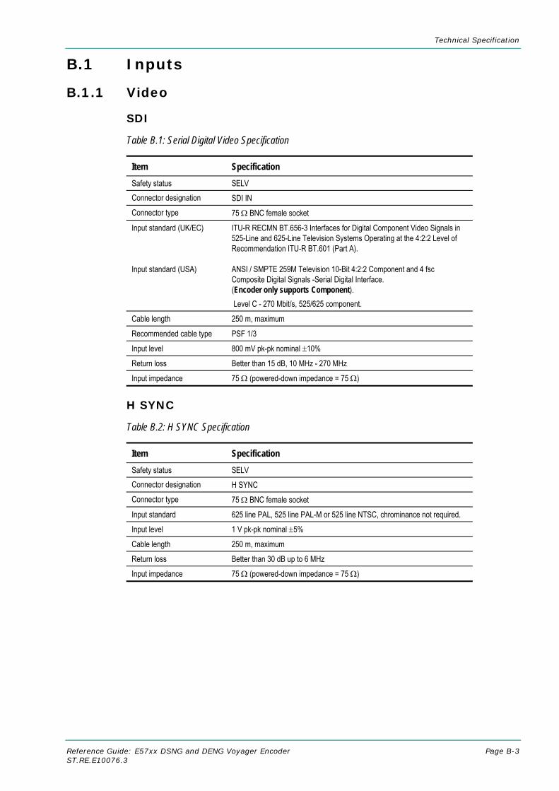
Technical Specification
Reference Guide: E57xx DSNG and DENG Voyager Encoder Page B-3 ST.RE.E10076.3
B.1 Inputs
B.1.1 Video
SDI
Table B.1: Serial Digital Video Specification
Item Specification Safety status SELV Connector designation SDI IN Connector type 75 Ω BNC female socket
Input standard (UK/EC) Input standard (USA)
ITU-R RECMN BT.656-3 Interfaces for Digital Component Video Signals in 525-Line and 625-Line Television Systems Operating at the 4:2:2 Level of Recommendation ITU-R BT.601 (Part A).
ANSI / SMPTE 259M Television 10-Bit 4:2:2 Component and 4 fsc Composite Digital Signals -Serial Digital Interface. (Encoder only supports Component). Level C - 270 Mbit/s, 525/625 component.
Cable length 250 m, maximum
Recommended cable type PSF 1/3
Input level 800 mV pk-pk nominal ±10%
Return loss Better than 15 dB, 10 MHz - 270 MHz
Input impedance 75 Ω (powered-down impedance = 75 Ω)
H SYNC
Table B.2: H SYNC Specification
Item Specification Safety status SELV Connector designation H SYNC Connector type 75 Ω BNC female socket
Input standard 625 line PAL, 525 line PAL-M or 525 line NTSC, chrominance not required.
Input level 1 V pk-pk nominal ±5%
Cable length 250 m, maximum
Return loss Better than 30 dB up to 6 MHz
Input impedance 75 Ω (powered-down impedance = 75 Ω)

Technical Specification
Page B-4 Reference Guide: E57xx DSNG and DENG Voyager Encoder ST.RE.E10076.3
Analogue Video Specification
Table B.3: Analogue Video Specification
Item Specification
Analogue input 625 line composite PAL-B, -D, -G, -H, -I 525 line composite NTSC-M, PAL-M as specified in ITU-R report 624-4, Characteristics of Television Systems (NTSC with and without set-up of 7.5 IRE)
Connector designation COMP VIDEO
Connector type 75 Ω BNC socket
Input level 1 V pk-pk nominal ±5%
Return loss Better than 30 dB up to 6 MHz (when impedance is set to 75 Ω)
Input impedance 75 Ω/High Z switchable (powered-down impedance = 75 Ω)
Sampling Sampled with a 10 bit ADC
NOTE… The inputs are isolated from the chassis to prevent 50 Hz/60 Hz hum.
Encoder Settings for PAL/NTSC Video Performance Figures
The Encoder settings for the PAL/NTSC video performance figures are shown in Table B.4.
NOTE… The PAL and NTSC video performance figures are measured when the Encoder is connected to a calibrated Receiver.
Table B.4: Encoder Settings for PAL/NTSC Video Performance Figures
Item Specification Noise reduction Off Video bit-rate 8 Mbit/s Resolution 720 x 576 GOP IBBP Profile 422P@ML Packet length 188 Mux Bit-rate 40 Mbit/s

Technical Specification
Reference Guide: E57xx DSNG and DENG Voyager Encoder Page B-5 ST.RE.E10076.3
PAL Video Performance Figures
Table B.5: PAL System Video Performance Figures
Pattern Item Specification Input return loss 30 dB
VITS Line 17 Bar amplitude ref (bp) 700 mV ± 7 mV
VITS Line 17 Jitter 5 ns pk-pk
VITS Line 17 Luminance bar tilt ±0.2%
VITS Line 17 2T pulse K-rating ±1.0% KF
VITS Line 17 Pulse/bar K-rating ± 0.5% KF
VITS line 17 P-B ratio 99% - 101%
VITS Line 17 Chrom/lum delay ±20 ns
VITS Line 17 Chrom/lum gain 95 – 105%
100% Luma Ramp Luma noise weighted Filters: tilt null, unified weighting, 5 MHz LPF, Fsc trap, 100 kHz HP
≤ -60 dB
5-step staircase - modulated Differential gain ± 1.5%
5-step staircase - modulated Differential phase ± 1°
5-step staircase - no modulation
Luma non-linearity ≤ 5%
Flat field Red 75% Chroma noise AM Chroma noise PM Filters: HPF - 10 kHz, LPF 500 kHz Reference – fixed; single line, Field 1
≤ -58 dB ≤ -58 dB
Multiburst VITS line 18 Frequency response
0.5 MHz ±0.2 dB 1.0 MHz ±0.2 dB 2.0 MHz ±0.2 dB 4.0 MHz ±0.2 dB 4.8 MHz ±0.5 dB 5.8 MHz - 0 to –2.5 dB
NTSC Video Performance Figures
Table B.6: NTSC System Video Performance Figures
Pattern Item Specification Input return loss 30 dB NTC-7 Composite Jitter ± 5 ns NTC-7 Composite Bar amplitude ref (bp) 100 ±1.5 IRE NTC-7 Composite 2T pulse K-rating ±1% KF NTC-7 Composite Chrom/lum delay ± 20 ns NTC-7 Composite Chrom/lum gain 90 - 110%

Technical Specification
Page B-6 Reference Guide: E57xx DSNG and DENG Voyager Encoder ST.RE.E10076.3
Pattern Item Specification 100% Luma Ramp Luma noise weighted
Filters: tilt null, unified weighting, 5 MHz LPF, Fsc trap, 100 kHz HP
≤ -60 dB
5-step staircase - modulated Differential gain ±1.5% 5-step staircase - modulated Differential phase ±1°
Teletext Extraction
Teletext is extracted from the Vertical Blanking Interval (VBI).
International Television Standards
Table B.7 shows television standards appropriate to the Encoder.
Table B.7: International Television Standards
As indicated in Menus M M B G H I D
Region USA/Japan ----- Europe / Asia ---- UK
Standard NTSC ------------------------------------------- PAL ---------------------------------
Lines / frame 525 525 625 625 625 625 625
Fields / second 60 60 50 50 50 50 50
Interlace 2/1 2/1 2/1 2/1 2/1 2/1 2/1
Frames / second 30 (29.97) 30 (29.97) 25 25 25 25 25
Lines / second 15 750 15 750 15 625 15 625 15 625 15 625 15 625
Aspect ratio 4 / 3 4 / 3 4 / 3 4 / 3 4 / 3 4 / 3 4/3
Video band (MHz) 4.2 4.2 5.0 5.0 5.0 5.5 6
Video Coding Resolutions
Table B.8: Video Coding Resolutions
625 Line Modes 525 Line Modes
720 pixels x 576 lines 720 pixels x 480 lines
704 pixels x 576 lines 704 pixels x 480 lines
640 pixels x 576 lines 640 pixels x 480 lines
544 pixels x 576 lines 544 pixels x 480 lines
480 pixels x 576 lines 480 pixels x 480 lines
352 pixels x 576 lines 352 pixels x 480 lines
352 pixels x 288 lines 352 pixels x 240 lines

Technical Specification
Reference Guide: E57xx DSNG and DENG Voyager Encoder Page B-7 ST.RE.E10076.3
B.1.2 Audio
Analogue and Digital Audio
Table B.9: Analogue and Digital Audio Specification
Item Specification Safety status SELV Connector designation AUDIO IN Connector type 15-way, D-type male connector Input standard (analogue) Balanced analogue Clip level 12 dB, 15 dB or 18 dB
(15 dB available with PCB issue 4 and later) Sampling rate 32/48 kHz (selectable) Input impedance 600 Ω or 20 kΩ (selectable). 20 kΩ = default Input standard (digital) AES/EBU digital Termination 110 Ω Sampling rate 32/48 kHz (selectable) Input rate 32, 44.1, 48 kHz Output (digital) ref AES/EBU digital Impedance 75 Ω Sampling rate 48 kHz Coding Standards Coding standard Supported coding modes Supported coded data rate
MPEG-1 Layer 2 (ISO/IEC 11172) Single Mono, Dual Mono, Joint Stereo, Stereo 32 kbit/s - 384 kbit/s
Coding standard Supported coding modes Supported coded data rate
Dolby Digital (AC-3) (ATSC A/52, DVB TR 102 154) 1/0, 2/0 56 k - 640 kbit/s
Coding standard Dolby Digital AC-3 Pass-through (ATSC A/52, DVB TR 102 154) (see Note 1, after Table)
Coding standard Linear PCM/Dolby E Pass-through (SMPTE 302M) (see Note 1, after Table)
Coding Standard DTS Pass-through (see Note 1, after Table)
NOTES… 1. Refer to Annex F, Audio Modes when using these coding standards. 2. Problems may be experienced with some Receivers if the Encoder and Decoder are not using the
same version of SMPTE 302M specification, e.g. either 1998 or 2000. The Encoder can be set up to work in either standard.
3. The digital audio input does not support SPDIF.
CAUTION… When the unit is not powered the audio input defaults to digital with 110 Ω termination.

Technical Specification
Page B-8 Reference Guide: E57xx DSNG and DENG Voyager Encoder ST.RE.E10076.3
Table B.10: MUSICAM Analogue Test Specification
Item Specification
Set-up of Alteia Receiver
Audio Format MPEG
Output Analogue
Clip Level 18 dB
Set-up of Audio Encoder
Input Analogue
Clip Level 18 dB
Sampling Frequency 48 kHz
Coding Standard MUSICAM, MPEG 1 (Layer 2)
Coding Mode Stereo
Bit-rate 384 k bit/s
Set-up of Lindos Audio Oscillator
Sequence TPBDLKZ
Test Tolerance for Left and Right Legs for Channel (A) and Channel (B) Test Level T
1 kHz @ 0 dB ± 0.2 dB
Sweep 20 Hz - 20 kHz @ -20 dB P
20 Hz – 63 Hz +0.0 to - 0.5 dB
100 Hz – 10 kHz +0.2 to - 0.3 dB
12.5 Hz – 18 kHz +0.2 to - 0.5 dB
20 kHz 0 to -1.5 dB
Crosstalk @ 0 dBs B
100 Hz 72 dB
1 kHz 74 dB
6.3 kHz 67.5 dB
10 kHz 63 dB
Distortion + noise @ +8 dB D
100 Hz 68 dB
1 kHz 70 dB
Noise RMS L
A-weighted 68 dB
Unweighted 68 dB
User Levels @ 1 kHz (0 to 50 dB) K
+10 dB ±0.2 dB
-10 dB ±0.2 dB
-20 dB ±0.2 dB
-30 dB ±0.2 dB
-40 dB ±0.3 dB
-50 dB 0 to -2 dB
Phase @ 0 dBs Z
40 Hz ±2°
100 Hz ±2°

Technical Specification
Reference Guide: E57xx DSNG and DENG Voyager Encoder Page B-9 ST.RE.E10076.3
Item Specification
315 Hz ±2°
1 kHz ±2°
6.3 kHz ±2°
10 kHz ±2°
15 kHz ±2°
Embedded Audio (Via SDI)
Audio embedded on the serial digital interface can also be extracted. Up to four stereo pairs of audio can be extracted from the SDI. The Encoder can extract two DIDs at once, giving four stereo pairs.
Table B.11: Embedded Audio Specification
Item Specification Serial Digital Interface Safety status SELV Connector designation SDI IN Connector type BNC female connector Input standard ITU-R RECMN BT.656-3
SMPTE 272M-A
MPEG-1 Audio Encoding Bit-rates
Table B.12: MPEG-1 Audio Encoding Bit-rates
Bit-rate (kbit/s)
Single Channel Mono
Dual Mono
Stereo Joint Stereo
32 - - - 48 - - - 56 - - - 64 80 - - - 96 112 128 160 192 224 - 256 - 320 - 384 -
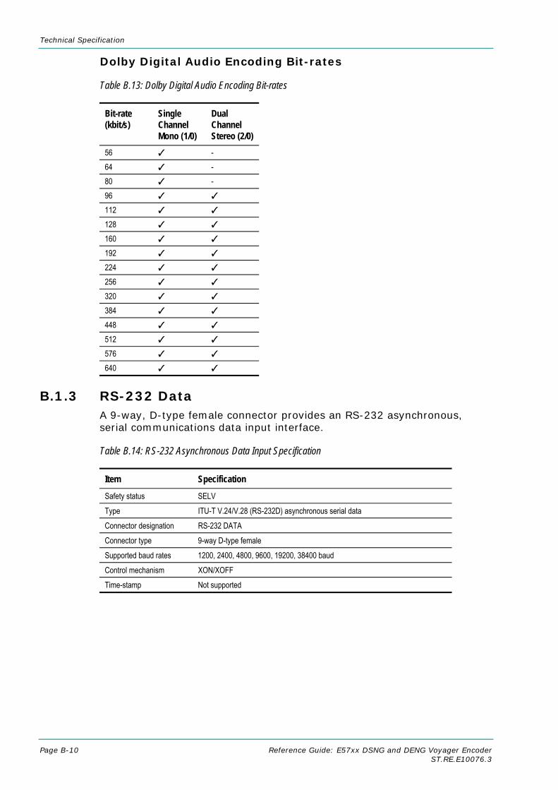
Technical Specification
Page B-10 Reference Guide: E57xx DSNG and DENG Voyager Encoder ST.RE.E10076.3
Dolby Digital Audio Encoding Bit-rates
Table B.13: Dolby Digital Audio Encoding Bit-rates
Bit-rate (kbit/s)
Single Channel Mono (1/0)
Dual Channel Stereo (2/0)
56 - 64 - 80 - 96 112 128 160 192 224 256 320 384 448 512 576 640
B.1.3 RS-232 Data A 9-way, D-type female connector provides an RS-232 asynchronous, serial communications data input interface.
Table B.14: RS-232 Asynchronous Data Input Specification
Item Specification Safety status SELV
Type ITU-T V.24/V.28 (RS-232D) asynchronous serial data
Connector designation RS-232 DATA
Connector type 9-way D-type female
Supported baud rates 1200, 2400, 4800, 9600, 19200, 38400 baud
Control mechanism XON/XOFF
Time-stamp Not supported

Technical Specification
Reference Guide: E57xx DSNG and DENG Voyager Encoder Page B-11 ST.RE.E10076.3
B.1.4 RS-422 Data This provides an RS-422 synchronous, serial communications data input interface.
Table B.15: RS-422 Data Specification
Item Specification Safety status SELV
Type ITU-T V.11 (RS-422), synchronous serial data and external clock
Connector designation RS-422 DATA
Connector type 15-way D-type female
Clock frequencies n x 64 kbit/s from 64 kbit/s to 2048 kbit/s (selectable) or
n x 56 kbit/s from 56 kbit/s to 1792 kbit/s (selectable)
Time-stamp Not supported
Operation modes Bit-pipe - Transport packet alignment and byte alignment relative to the incoming bit-stream are arbitrary.
B.1.5 Modulator DVB ASI Electrical Inputs (E5740 and E5714-LBAND) Two DVB ASI electrical inputs are provided as standard. One of the two inputs is selected under user control as the input to the IF/L-band modulator section.
Table B.16: DVB ASI IN Specification
Item Specification Safety status: SELV
Connector type: BNC 75 Ω
Connector designation: ASI IN 1 and 2 (SM66XX/HWO/ASI-SPI option not fitted) ASI IN 3 and 4 (SM66XX/HWO/ASI-SPI option fitted)
Compliance: EN 50083-9, June 1998: Section 4.4
Input bit-rate range: Defined by symbol rate range, modulation format, FEC code rate and input packet size as per and Table B.18, Modulator ASI Input Bit-rate Ranges.
Byte stuffing modes: Byte and Single Packet Burst modes

Technical Specification
Page B-12 Reference Guide: E57xx DSNG and DENG Voyager Encoder ST.RE.E10076.3
B.1.6 L-Band Input (1U, E5714-LBAND/2U, E5740-LBAND) This input provides a carrier combining facility for summing an externally generated carrier into the L-band output.
Table B.17: L-BAND IN Specification
Item Specification Safety status: SELV
Connector type: SMA female 50 Ω
Connector designation: L-BAND IN
Input impedance: 50 Ω
Gain to L-BAND OUT MAIN output:
0 dB ±2 dB
Input power: +5 dBm max
Return loss: >14 dB, 950-1750 MHz
Table B.18: Modulator ASI Input Bit-rate Ranges
Bit-rate R188 Bit-rate R204 Modulation Format
FEC Code Rate
Min Max Min Max
1/2 0.092157 30.411765 0.100000 33.000000
2/3 0.122876 40.549020 0.133333 44.000000
3/4 0.138235 45.617647 0.150000 49.500000
5/6 0.153595 50.686275 0.166667 55.000000
BPSK
7/8 0.161275 53.220588 0.175000 57.750000
1/2 0.184314 60.823529 0.200000 66.000000
2/3 0.245752 81.098039 0.266667 88.000000
3/4 0.276471 91.235294 0.300000 99.000000
5/6 0.307190 101.372549 0.333333 110.000000
QPSK
7/8 0.322549 106.441176 0.350000 115.500000
2/3 0.368627 121.647059 0.400000 132.000000
5/6 0.460784 152.058824 0.500000 165.000000
8PSK
8/9 0.491503 162.196078 0.533333 176.000000
3/4 0.552941 182.470588 0.600000 198.000000 16QAM
7/8 0.645098 212.882353 0.700000 213.000000
B.2 Test Tones
Table B.19: Test Tones Specification
Item Specification
Level 0 dB relative to FSR 18 dB
Frequency 1 kHz at 48 kHz sampling frequency
Bit-rate 96 kbit/s

Technical Specification
Reference Guide: E57xx DSNG and DENG Voyager Encoder Page B-13 ST.RE.E10076.3
B.3 Outputs
B.3.1 IF Outputs (1U, E5714) Table B.20 parameters are with the S12376 Card fitted.
Table B.20: IF OUT MAIN Specification (1U, E5714)
Item Specification Safety status: SELV Connector designation: IF OUT MAIN Connector type: BNC, female 75 Ω Output impedance: 75 Ω Return loss: >18 dB, 35 < f < 105 MHz Output power: –20 to +5 dBm in 0.1 dB steps Power level stability: ±0.5 dB Signal type: QPSK per EN 300 421 Symbol-rate (minimum) 0.46875 Msymbol/s
Fc (MHz) 50-60 60-80 80-90 Symbol rate (maximum) vs carrier frequency Fc: Symbol-rate
Msymbol/s Fc – 30 30 110 – Fc
Convolutional FEC rates: 1/2, 2/3, 3/4, 5/6 and 7/8 Bit-rate (204 byte format:) 2 x Rs x FEC Mbit/s
where Rs = Symbol-rate (Msymbol/s) FEC = FEC ratio (values listed above)
Power spectrum: Square root raised cosine, α = 0.35 per EN 300 421 Power spectrum (detail, nominal): Bandwidth/Rs ratio (BW/Rs) at power spectral density Co values (dB)
relative to the power spectral density Coo at the carrier (centre) frequency: Co-Coo (dB) BW/Rs -3 1.0 -6 1.13 -10 1.21 -20 1.32 -30 1.37
Carrier frequency Fc: 50 – 90 MHz Carrier frequency step: 125 kHz Carrier frequency accuracy: Within ± 7.5 kHz Carrier suppression: >40 dB IF spectrum sense: Selectable Normal/Inverted Residual carrier, carrier OFF state:
< -70 dBm
Spurious outputs, modulated carrier:
< -60 dBc/4 kHz relative to unmodulated carrier, 0 < f < 500 MHz excluding ±1.06 × Symbol Rate about the carrier frequency
Spurious outputs, unmodulated carrier
< – 50 dBc < - 55 dBc typical 0 < f < 500 MHz, each component
Carrier phase noise: Phase noise density (dBc/Hz) Frequency offset from carrier < –83 100 Hz < –85 1 kHz < –95 10 kHz < –110 100 kHz
Transmission modes: Modulation on/off Carrier on/off

Technical Specification
Page B-14 Reference Guide: E57xx DSNG and DENG Voyager Encoder ST.RE.E10076.3
Table B.21: IF Monitor Output Specification (1U, E5714)
Item Specification Safety status: SELV Connector designation: IF OUT MONITOR
Connector type: BNC, female 75 Ω This connector is normally dedicated to output the IF monitoring feed to the Receiver.
Output impedance: 75 Ω
Return loss: >20 dB, 49.75 < f < 90.25 MHz
Output power: –20 dB ±2 dB referenced to main IF output (IF OUT MAIN)
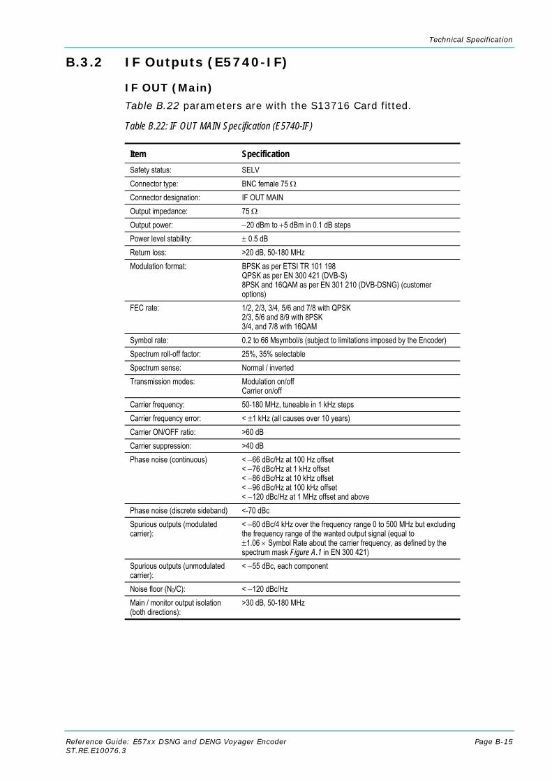
Technical Specification
Reference Guide: E57xx DSNG and DENG Voyager Encoder Page B-15 ST.RE.E10076.3
B.3.2 IF Outputs (E5740-IF)
IF OUT (Main)
Table B.22 parameters are with the S13716 Card fitted.
Table B.22: IF OUT MAIN Specification (E5740-IF)
Item Specification Safety status: SELV Connector type: BNC female 75 Ω Connector designation: IF OUT MAIN Output impedance: 75 Ω Output power: −20 dBm to +5 dBm in 0.1 dB steps Power level stability: ± 0.5 dB Return loss: >20 dB, 50-180 MHz Modulation format: BPSK as per ETSI TR 101 198
QPSK as per EN 300 421 (DVB-S) 8PSK and 16QAM as per EN 301 210 (DVB-DSNG) (customer options)
FEC rate: 1/2, 2/3, 3/4, 5/6 and 7/8 with QPSK 2/3, 5/6 and 8/9 with 8PSK 3/4, and 7/8 with 16QAM
Symbol rate: 0.2 to 66 Msymbol/s (subject to limitations imposed by the Encoder) Spectrum roll-off factor: 25%, 35% selectable Spectrum sense: Normal / inverted Transmission modes: Modulation on/off
Carrier on/off Carrier frequency: 50-180 MHz, tuneable in 1 kHz steps Carrier frequency error: < ±1 kHz (all causes over 10 years) Carrier ON/OFF ratio: >60 dB Carrier suppression: >40 dB Phase noise (continuous) < −66 dBc/Hz at 100 Hz offset
< −76 dBc/Hz at 1 kHz offset < −86 dBc/Hz at 10 kHz offset < −96 dBc/Hz at 100 kHz offset < −120 dBc/Hz at 1 MHz offset and above
Phase noise (discrete sideband) <-70 dBc Spurious outputs (modulated carrier):
< −60 dBc/4 kHz over the frequency range 0 to 500 MHz but excluding the frequency range of the wanted output signal (equal to ±1.06 × Symbol Rate about the carrier frequency, as defined by the spectrum mask Figure A.1 in EN 300 421)
Spurious outputs (unmodulated carrier):
< −55 dBc, each component
Noise floor (N0/C): < −120 dBc/Hz Main / monitor output isolation (both directions):
>30 dB, 50-180 MHz

Technical Specification
Page B-16 Reference Guide: E57xx DSNG and DENG Voyager Encoder ST.RE.E10076.3
IF OUT Monitor
Table B.23: IF OUT MONITOR Specification (E5740-IF)
Item Specification Safety status: SELV Connector type: BNC female 75 Ω Connector designation: IF OUT MONITOR
Output impedance: 75 Ω
Output power: −20 dB ±2 dB relative to main IF output power
Return loss: >20 dB, 50-180 MHz
B.3.3 L-Band Outputs (E5740-LBAND) Table B.24 parameters are with S13719 2/3 width card fitted.
Table B.24: L-Band Out Main Specification (E5740-Lband)
Item Specification Safety Status: SELV
Connector Type: SMA Female
Connector Designation: L-Band Out Main
Output Impedance: 50 Ω
Output Power: -20 dBm to +5 dBm in 0.1 dB steps.
Output Power Ramp Rate 9 dB/s over operational power level range
Power Level Stability: ±0.5dB
Return Loss: >14 dB, 950 MHz to 1750 MHz
Modulation format: BPSK as per ETSI TR 101 198 QPSK as per EN 300 421 (DVB-S) 8PSK, 16QAM as per EN 301 210 (DVB-DSNG) (option)
FEC Rate: 1/2, 2/3, 3/4, 5/6, 7/8 with BPSK and QPSK 2/3, 5/6, 8/9 with 8PSK 3/4, 7/8 with 16QAM
Symbol Rate: 0.2 – 66 Msym/s (Subject to limitations imposed by the Encoder).
Spectrum roll-off factor: 25%, 35% selectable
Spectrum sense: Normal/Inverted
Transmission Modes: Modulation on/off Carrier on/off
Carrier Frequency: 950 MHz to 1750 MHz in 1 kHz steps
Carrier Frequency Error: <± 35 Hz versus temperature <± 1 kHz ageing over 10 years
Carrier ON/OFF Ratio >60 dB
Carrier Suppression >35 dB
Phase Noise (continuou) <-46 dBc at 10 Hz offset <-66 dBc at 100 Hz offset <-76 dBc at 1 kHz offset <-86 dBc at 10 kHz offset <-96 dBc at 100 kHz offset <-120 dBc at 1 MHz offset
Phase Noise (discrete sidebands) <-70 dBc Spurious Output:s <-60 dBc/4 kHz over the frequency range 500 MHz to 25 MHz but

Technical Specification
Reference Guide: E57xx DSNG and DENG Voyager Encoder Page B-17 ST.RE.E10076.3
Item Specification (modulated carrier) excluding the frequency range of the wanted signal (equal to
±1.06 x Symbol Rate about the carrier frequency, as defined by the spectrum mask Figure A.1 in EN 300 421)
Spurious Outputs (Unmodulated Carrier)
<-55 dBc over the frequency range 500 – 2500 MHz, each component
Noise Floor (No/C): <-120 dBc/Hz
Main/monitor Output Isolation (both directions)
>30 dB, 950 – 1750 MHz
Table B.25: L-Band Monitor Output Specification (E5740-Lband)
Item Specification Safety Status: SELV
Connector Type: F-type Female 75 Ω
Connector Designation: L-Band Out Monitor
Output Impedance: 75 Ω
Output Power: - 30 dB nominal relative to main output
Return Loss: >10 dB, 950 MHz to 1750 MHz
Reference Frequency Output
A reference frequency output is provided via the L-BAND OUT MAIN connector, intended for use by an external frequency up-converter.
Table B.26: Reference Frequency Output Specification
Item Specification Output power: 0 dBm ±3 dB sine-wave into 50 Ω load
Switchable on/off
Frequency: 10 MHz
Frequency stability: < ±0.2 Hz versus temperature < ±1 Hz ageing over 1 year < ±5.5 Hz ageing over 10 years
Phase noise: −110 dBc/Hz at 10 Hz offset −135 dBc/Hz at 100 Hz offset −155 dBc/Hz at 1 kHz offset −160 dBc/Hz at 10 kHz offset
DC Power Output
A dc power output is provided via the L-BAND OUT MAIN connector, intended for powering an external frequency up-converter.
Table B.27: DC Power Output Specification
Item Specification Voltage (open circuit): +24 V nominal, switchable on/off
Output resistance: 1 Ω nominal
Ripple: <100 mV pk-pk (depends on Encoder PSU)
Rated current: 500 mA max, short-circuit protected

Technical Specification
Page B-18 Reference Guide: E57xx DSNG and DENG Voyager Encoder ST.RE.E10076.3
Item Specification Short-circuit current: <1 A
Short-circuit duration: Indefinite (automatic shutdown after approx. 2s)
B.3.4 L-Band Outputs (1U E5714-LBAND) Table B.28 parameters with S13719 2/3 Width Card fitted.
Table B.28: L-Band Out Main Specification (E5714-Lband)
Item Specification Safety Status: SELV
Connector Type: SMA Female
Connector Designation: L-Band Out Main
Output Impedance: 50 Ω
Output Power: -20 dBm to +5 dBm in 0.1 dB steps.
Output Power Ramp Rate 9 dB/s over operational power level range
Power Level Stability: ±0.5dB
Return Loss: >14 dB, 950 MHz to 1750 MHz
Modulation format: BPSK as per ETSI TR 101 198 QPSK as per EN 300 421 (DVB-S) 8PSK and 16QAM as per EN 301 210 (DVB-DSNG) (options)
FEC Rate: 1/2, 2/3, 3/4, 5/6 and 7/8 with QPSK 2/3, 5/6 and 8/9 with 8PSK 3/4 and 7/8 with 16QAM
Symbol Rate: 0.2 – 30 Msym/s (Subject to limitations imposed by the Encoder)
Spectrum roll-off factor: 25%, 35% selectable (Subject to limitations imposed by the Encoder)
Spectrum sense: Normal/Inverted
Transmission Modes: Modulation on/off Carrier on/off
Carrier frequency: 950 MHz to 1750 MHz in 1 kHz steps
Carrier Frequency Error: <± 35 Hz versus temperature <± 1 kHz ageing over 10 years
Phase Noise: <-46 dBc at 10 Hz offset <-66 dBc at 100 Hz offset <-76 dBc at 1 kHz offset <-86 dBc at 10 kHz offset <-96 dBc at 100 kHz offset <-120 dBc at 1 MHz offset
Phase Noise (Discrete sidebands)
<-70 dBc
Spurious Output:s (Modulated Carrier)
<-60 dBc/4 kHz over the frequency range 500 MHz to 25 MHz but excluding the frequency range of the wanted signal (equal to ±1.06 x Symbol Rate about the carrier frequency, as defined by the spectrum mask Figure A.1 in EN 300 421)
Spurious Outputs (Unmodulated Carrier)
<-55 dBc over the frequency range 500 – 2500 MHz, each component
Noise Floor (No/C): <-120 dBc/Hz
Main/monitor Output Isolation (both directions)
>30 dB, 950 – 1750 MHz

Technical Specification
Reference Guide: E57xx DSNG and DENG Voyager Encoder Page B-19 ST.RE.E10076.3
Table B.29: L-Band Monitor Output Specification (E5714-Lband)
Item Specification Safety Status: SELV
Connector Type: F-type Female
Connector Designation: L-Band Out Monitor
Output Impedance: 75 Ω
Output Power: - 30 dB nominal relative to main output
Return Loss: >10 dB, 950 MHz to 1750 MHz
Reference Frequency Output
A reference frequency output is provided via the L-BAND OUT MAIN connector, intended for use by an external frequency up-converter.
Table B.30: Reference Frequency Output Specification
Item Specification Output power: 0 dBm ±3 dB sine-wave into 50 Ω load
Switchable on/off
Frequency: 10 MHz
Frequency stability: < ±0.2 Hz versus temperature < ±1 Hz ageing over 1 year < ±5.5 Hz ageing over 10 years
Phase noise: −110 dBc/Hz at 10 Hz offset −135 dBc/Hz at 100 Hz offset −155 dBc/Hz at 1 kHz offset −160 dBc/Hz at 10 kHz offset
B.3.5 OFDM Modulator Outputs (E5750)
Table B.31: OFDM IF Out 1 Specification (E5750)
Item Specification Safety Status: SELV
Connector Type: BNC Female
Connector Designation: IF Out 1 Main
Output Impedance: 75 Ω
Output Power: 0 dBm
IF Frequency: 70 MHz
Bandwidth: 6 MHz, 7 MHz, or 8 MHz
Modulation: QPSK, 16QAM or 64QAM
Guard Interval: 1/32, 1/16, 1/8 or 1/4
FEC Rate: 1/2, 2/3, 3/4, 4/5, 5/6 or 7/8
Spectrum sense: Normal/Inverted
Transmission Modes: 2k mode or 8k mode

Technical Specification
Page B-20 Reference Guide: E57xx DSNG and DENG Voyager Encoder ST.RE.E10076.3
Table B.32: OFDM IF Out 2 Specification (E5750)
Item Specification Safety Status: SELV
Connector Type: BNC Female
Connector Designation: IF Out 2
Output Impedance: 75 Ω
Output Power: - 10 dB relative to IF output 1
B.3.6 ASI Out 1, ASI Out 2, ASI Out 3 Outputs
Table B.33: ASI Out Specification
Item Specification Safety status: SELV Connector type: BNC 75 Ω Connector designation: ASI OUT 1, ASI OUT 2, ASI OUT 3

Technical Specification
Reference Guide: E57xx DSNG and DENG Voyager Encoder Page B-21 ST.RE.E10076.3
B.4 Control and Monitoring
B.4.1 Remote Control - Ethernet 1 and 2
Table B.34: Ethernet Specification
Item Specification Safety status SELV
Connector designation ETHERNET#1 and ETHERNET#2
Connector type 8-way RJ-45 socket, 10BaseT (ISO 882/3)
B.4.2 Local Control Local control is by means of the front panel keypad and LCD display.
B.4.3 Alarm
Table B.35: Alarm Specification
Item Specification Safety status SELV
Connector designation ALARM
Connector type 9-way D-type male
Alarm contacts Change-over contacts (5 Ω in common)
Fail contacts Change-over contacts (5 Ω in common)
Reset contacts Short pins 9 and 5 (resets the Encoder)
Relay Contact Rating Maximum switching power 30 W
Maximum switching voltage 110 V
Maximum switching current 1 A
B.4.4 Remote Control This connector provides an RS-232/RS-485 user interface control port that allows the unit to be controlled by an external master.
Table B.36: Remote Control Specification
Item Specification Safety status SELV Connector designation REMOTE CONTROL Connector type 9-way D-type male
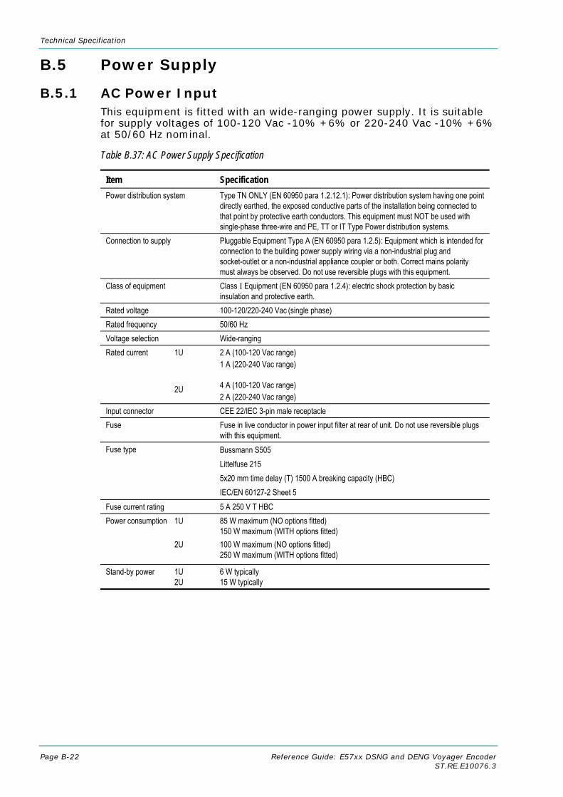
Technical Specification
Page B-22 Reference Guide: E57xx DSNG and DENG Voyager Encoder ST.RE.E10076.3
B.5 Power Supply
B.5.1 AC Power Input This equipment is fitted with an wide-ranging power supply. It is suitable for supply voltages of 100-120 Vac -10% +6% or 220-240 Vac -10% +6% at 50/60 Hz nominal.
Table B.37: AC Power Supply Specification
Item Specification Power distribution system
Type TN ONLY (EN 60950 para 1.2.12.1): Power distribution system having one point directly earthed, the exposed conductive parts of the installation being connected to that point by protective earth conductors. This equipment must NOT be used with single-phase three-wire and PE, TT or IT Type Power distribution systems.
Connection to supply Pluggable Equipment Type A (EN 60950 para 1.2.5): Equipment which is intended for connection to the building power supply wiring via a non-industrial plug and socket-outlet or a non-industrial appliance coupler or both. Correct mains polarity must always be observed. Do not use reversible plugs with this equipment.
Class of equipment Class I Equipment (EN 60950 para 1.2.4): electric shock protection by basic insulation and protective earth.
Rated voltage 100-120/220-240 Vac (single phase) Rated frequency 50/60 Hz Voltage selection Wide-ranging Rated current 1U 2U
2 A (100-120 Vac range) 1 A (220-240 Vac range) 4 A (100-120 Vac range) 2 A (220-240 Vac range)
Input connector CEE 22/IEC 3-pin male receptacle Fuse Fuse in live conductor in power input filter at rear of unit. Do not use reversible plugs
with this equipment. Fuse type Bussmann S505
Littelfuse 215 5x20 mm time delay (T) 1500 A breaking capacity (HBC) IEC/EN 60127-2 Sheet 5
Fuse current rating 5 A 250 V T HBC Power consumption 1U 2U
85 W maximum (NO options fitted) 150 W maximum (WITH options fitted) 100 W maximum (NO options fitted) 250 W maximum (WITH options fitted)
Stand-by power 1U 2U
6 W typically 15 W typically
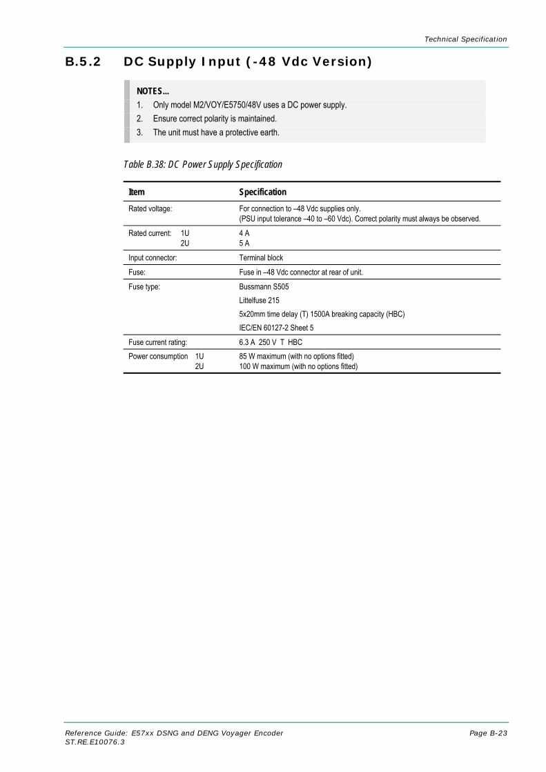
Technical Specification
Reference Guide: E57xx DSNG and DENG Voyager Encoder Page B-23 ST.RE.E10076.3
B.5.2 DC Supply Input (-48 Vdc Version)
NOTES... 1. Only model M2/VOY/E5750/48V uses a DC power supply. 2. Ensure correct polarity is maintained. 3. The unit must have a protective earth.
Table B.38: DC Power Supply Specification
Item Specification Rated voltage: For connection to –48 Vdc supplies only.
(PSU input tolerance –40 to –60 Vdc). Correct polarity must always be observed.
Rated current: 1U 2U
4 A 5 A
Input connector: Terminal block
Fuse: Fuse in –48 Vdc connector at rear of unit.
Fuse type: Bussmann S505 Littelfuse 215 5x20mm time delay (T) 1500A breaking capacity (HBC) IEC/EN 60127-2 Sheet 5
Fuse current rating: 6.3 A 250 V T HBC Power consumption 1U 2U
85 W maximum (with no options fitted) 100 W maximum (with no options fitted)

Technical Specification
Page B-24 Reference Guide: E57xx DSNG and DENG Voyager Encoder ST.RE.E10076.3
B.6 Physical Details Table B.39: Physical Details
Item Specification Height 1U, 44.5 mm chassis
2U, 88.9 mm chassis Width 1U, 442.5 mm excluding fixing brackets
2U, 442.5 mm excluding fixing brackets Overall width 1U, 482.6 mm including fixing brackets
2U, 482.6 mm including fixing brackets Depth 1U, 545 mm excluding rear connector clearance
2U, 545 mm excluding rear connector clearance Approximate weight 1U, 7.5 kg (16.5 lbs)
2U, 11.5 kg (25.3 lbs)
B.7 Environmental Conditions
Table B.40: Environmental Specification
Item Specification
Operational Temperature -10°C to +50°C (14°F to 122°F) ambient with free air-flow
Over temperature alarm generated at >= 55°C
Under temperature alarm generated at < 0°C
Temperature checked Once every 30 seconds
All fans switched off at < 10°C (when set to auto)
Half the fans switched off at < 20°C (when set to auto)
All fans on at >= 20°C (when set to auto)
Relative humidity 0% to 90% (non-condensing)
Cooling requirements Front section: Cool air input from front panel, exhaust from right side of unit Rear section: Cool air input from right side of unit, exhaust from left side of unit See Chapter 2, Installing the Equipment, Figure 2.2
Handling/movement Designed for stationary or fixed use when in operation
Storage/Transportation
Temperature -20°C to +70°C (-4°F to 158°F)
Relative humidity 0% to 90% (non-condensing)

Technical Specification
Reference Guide: E57xx DSNG and DENG Voyager Encoder Page B-25 ST.RE.E10076.3
B.8 Compliance1
B.8.1 Safety This equipment has been designed and tested to meet the requirements of the following:
EN 60950 European Safety of information technology equipment.
IEC 60950
International Safety of information technology equipment.
In addition, the equipment has been designed to meet the following:
UL 60950
USA Safety of information technology equipment.
B.8.2 EMC2 The equipment has been designed and tested to meet the following:
EN 55022 and CISPR22
European International
Emission Standard Limits and methods of measurement of radio frequency interference characteristics of information technology equipment - Class A.
EN 61000-3-23 European Electromagnetic Compatibility (EMC), Part 3 Limits; Section 2. Limits for harmonic current emissions (equipment input current ≤ 16 A per phase).
EN 61000-3-33 European Electromagnetic Compatibility (EMC), Part 3. Limits; Section 3. Limitation of voltage fluctuations and flicker in low voltage supply systems for equipment with rated current ≤ 16 A.
EN 55024:1998 European Information technology equipment - Immunity characteristics - Limits and methods of measurement.
FCC USA Conducted and radiated emission limits for a Class A digital device, pursuant to the Code of Federal Regulations (CFR) Title 47-Telecommunications, Part 15: Radio frequency devices, subpart B - Unintentional Radiators.
1 The version of the standards shown is that applicable at the time of manufacture. 2 The EMC tests were performed with the Technical Earth attached, and configured using recommended cables (see Table B.41). 3 Applies only to models of the Encoder using mains (ac) power sources.

Technical Specification
Page B-26 Reference Guide: E57xx DSNG and DENG Voyager Encoder ST.RE.E10076.3
B.8.3 Shock and Vibration The Encoder and Receiver chassis complies with the requirements of ETS 300-019-2-5 Table 2, for both non-operational and operational states, without any special mounting or casing requirements over and above the standard mounting requirements specified.
ETS 300-019-2-5 European Equipment Engineering (EE): Environmental conditions and environmental tests for telecommunications equipment Part 2-5: Specification of environmental tests Ground Vehicle Installations. Table 2.
B.8.4 CE Marking
The CE mark is affixed to indicate compliance with the following directives:
89/336/EEC of 3 May 1989 on the approximation of the laws of the Member States relating to electromagnetic compatibility.
73/23/EEC of 19 February 1973 on the harmonisation of the laws of the Member States relating to electrical equipment designed for use within certain voltage limits.
1999/5/EC of 9 March 1999 on radio equipment and telecommunications terminal equipment and the mutual recognition of their conformity. (If fitted with telecom type interface modules).
NOTE... The CE mark was first affixed to this product in 2001.
B.8.5 C-Tick Mark
The C-Tick mark is affixed to denote compliance with the Australian Radiocommunications (Compliance and Labelling – Incidental Emissions) Notice made under s.182 of Radiocommunications Act 1992.
NOTE... The C-Tick mark was first affixed to this product in 2001.
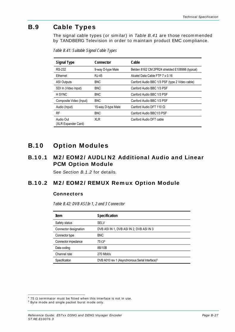
Technical Specification
Reference Guide: E57xx DSNG and DENG Voyager Encoder Page B-27 ST.RE.E10076.3
B.9 Cable Types The signal cable types (or similar) in Table B.41 are those recommended by TANDBERG Television in order to maintain product EMC compliance.
Table B.41: Suitable Signal Cable Types
Signal Type Connector Cable RS-232 9-way D-type Male Belden 8162 CM 2PR24 shielded E108998 (typical)
Ethernet RJ-45 Alcatel Data Cable FTP 7 x 0.16
ASI Outputs BNC Canford Audio BBC 1/3 PSF (type 2 Video cable)
SDI In (Video Input) BNC Canford Audio BBC 1/3 PSF
H SYNC BNC Canford Audio BBC 1/3 PSF
Composite Video (Input) BNC Canford Audio BBC 1/3 PSF
Audio (Input) 15-way D-type Male Canford Audio DFT 110 Ω
RF BNC Canford Audio BBC1/3 PSF
Audio Out (XLR Expander Card)
XLR Canford Audio DFT cable
B.10 Option Modules
B.10.1 M2/EOM2/AUDLIN2 Additional Audio and Linear PCM Option Module See Section B.1.2 for details.
B.10.2 M2/EOM2/REMUX Remux Option Module
Connectors
Table B.42: DVB ASI In 1, 2 and 3 Connector
Item Specification Safety status SELV
Connector designation DVB ASI IN 1, DVB ASI IN 2, DVB ASI IN 3
Connector type BNC
Connector impedance 75 Ω4
Data coding 8B/10B
Channel rate 270 Mbit/s
Specification DVB A010 rev 1 (Asynchronous Serial Interface)5
4 75 Ω terminator must be fitted when this interface is not in use. 5 Byte mode and single packet burst mode only.

Technical Specification
Page B-28 Reference Guide: E57xx DSNG and DENG Voyager Encoder ST.RE.E10076.3
Table B.43: DVB ASI Out 1 Connector (Disabled)
Item Specification Safety status SELV
Connector designation DVB ASI OUT 1
Connector type BNC
Connector impedance 75 Ω4
Data coding 8B/10B
Channel rate 270 Mbit/s
Specification DVB A010 rev 1 (Asynchronous Serial Interface)5
LEDs
Table B.44: DVB ASI In 1, 2 and 3 - LED Indications
Item Specification Red LED Input ASI lock On No lock on ASI (8B/10B coding) Off Input ASI lock OK
Green LED Packet size Off Not locked to MPEG packets
Flash (1:3 mark:space) 188 byte packets
Flash (3:1 mark:space) 204 byte packets
Table B.45: DVB ASI Out 1 - LED Indications
Item Specification
Red LED
On Output disabled
Off Output enabled
Green LED
Off Output not in use
Flash (1:3 mark:space) 188 byte packets output
Flash (3:1 mark:space) 204 byte packets output

Technical Specification
Reference Guide: E57xx DSNG and DENG Voyager Encoder Page B-29 ST.RE.E10076.3
B.10.3 M2/EOM2/DEC, SD Decoder Card Option
NOTE… The M2/EOM2/DEC, SD Decoder Card Option is supported by Encoder software version 3.1 and later.
Table B.46: ASI Output (SD Decoder)
Item Specification Safety Status: SELV
Connector Type: BNC Female
Connector Designation: ASI Out (Located on the adjacent demod option card)
Output Impedance: 75 Ω
Data Coding: 8B/10B
Channel Rate: 270 Mbit/s
Specification: DVB A1010 rev 1 (Byte mode only)
Table B.47: Composite Video Output (SD Decoder)
Item Specification Safety Status: SELV
Connector Type: BNC Female
Connector Designation: Composite
Output Impedance: 75 Ω
Video Standards: PAL–N, -B, -G, or –I, or NTSC–M with or without pedestal
Composite Video Level: 1V pk-pk in 75 Ω nominal
Table B.48: Digital Video Output (SD Decoder)
Item Specification Safety Status: SELV
Connector Type: BNC Female
Connector Designation: SDI
Output Impedance: 75 Ω
Video Standards: ITU-R BT.656 digital output at 270 MHz
Composite Video Level: 800mV ± 10 mV pk-pk in 75 Ω nominal
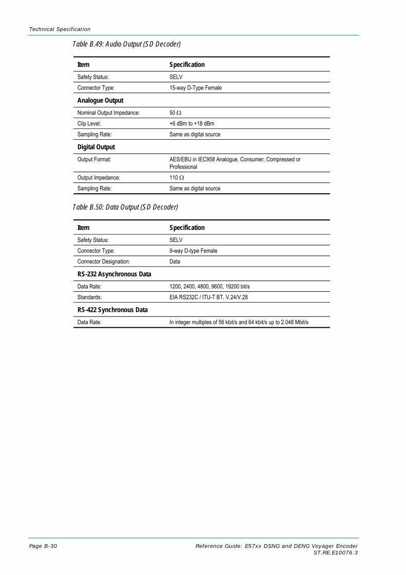
Technical Specification
Page B-30 Reference Guide: E57xx DSNG and DENG Voyager Encoder ST.RE.E10076.3
Table B.49: Audio Output (SD Decoder)
Item Specification Safety Status: SELV
Connector Type: 15-way D-Type Female
Analogue Output Nominal Output Impedance: 50 Ω
Clip Level: +6 dBm to +18 dBm
Sampling Rate: Same as digital source
Digital Output Output Format: AES/EBU in IEC958 Analogue, Consumer, Compressed or
Professional
Output Impedance: 110 Ω
Sampling Rate: Same as digital source
Table B.50: Data Output (SD Decoder)
Item Specification Safety Status: SELV
Connector Type: 9-way D-type Female
Connector Designation: Data
RS-232 Asynchronous Data Data Rate: 1200, 2400, 4800, 9600, 19200 bit/s
Standards: EIA RS232C / ITU-T BT. V.24/V.28
RS-422 Synchronous Data Data Rate: In integer multiples of 56 kbit/s and 64 kbit/s up to 2.048 Mbit/s

Technical Specification
Reference Guide: E57xx DSNG and DENG Voyager Encoder Page B-31 ST.RE.E10076.3
B.10.4 M2/EOM2/QPSKDEMOD, QPSK Demodulator Card Option
NOTE… The M2/EOM2/QPSKDEMOD, QPSK Demodulator Card Option is supported by Encoder software version 3.1 and later.
Table B.51: IF In (QPSK Demodulator)
Item Specification Safety Status: SELV
Connector Type: BNC Female
Connector Designation: IF IN
Input Impedance: 75 Ω
Input Power: -20 dBm to –40 dBm
Input Frequency: 50 MHz to 180 MHz
Capture Range: Up to ± 5 MHz
Signal Type: BPSK as per ETSI TR 101 198 (option) / QPSK as per EN 300 421 (DVB-S)
Symbol Rate: 1 – 45 Msym/s (0.3 – 45 Msym/s optionally)
Table B.52: RF In (QPSK Demodulator)
Item Specification Safety Status: SELV
Connector Type: F-type Female
Connector Designation: RF1, RF 2
Input Impedance: 75 Ω
Input Power: -25 dBm to –65 dBm
Input Frequency: 950 MHz to 2150 MHz
Capture Range: Up to ± 5 MHz
Signal Type: BPSK as per ETSI TR 101 198 (option) / QPSK as per EN 300 421 (DVB-S)
Symbol Rate: 1 – 45 Msym/s (0.3 – 45 Msym/s optionally)
Table B.53: ASI In Connector
Item Specification
Safety status SELV
Connector designation ASI IN
Connector type BNC
Connector impedance 75 Ω6
Data coding 8B/10B
Channel rate 270 Mbit/s
Specification DVB A010 rev 1 (Asynchronous Serial Interface)7
6 75 Ω terminator must be fitted when this interface is not in use. 7 Byte mode and single packet burst mode only.

Technical Specification
Page B-32 Reference Guide: E57xx DSNG and DENG Voyager Encoder ST.RE.E10076.3
B.10.5 M2/EOM2/SATDEMOD, 16QAM Demodulator Card Option
NOTE… The M2/EOM2/SATDEMOD, 16QAM Demodulator Card Option is supported by Encoder software version 3.1 and later.
Table B.54: L-band Inputs (16QAM Demodulator)
Item Specification Safety Status: SELV
Connector Type: F-type Female
Connector Designation: L-Band Input 1, L-Band Input 2
Input Impedance: 75 Ω
Input Power (maximum): -25 dBm
Capture Range: Up to ± 3.5 MHz
Signal Type: QPSK as per EN 300 421 (DVB-S) BPSK/16QAM as per EN 301 210 (DVB-DSNG) (option)
Symbol Rate: 1 – 45 Msym/s
B.10.6 M2/EOM2/IP, IP Output Card Option
NOTE… The M2/EOM2/IP, IP Output Card Option is supported by Encoder software version 3.1 and later.
Table B.55: Ethernet Port (IP Output Card)
Item Specification Safety Status: SELV
Connector Type: 8-way RJ-45
Connector Designation: 10/100 BT
Signal Type: 10/100BASE-T Ethernet (IEEE 802.3/802.3u)
Transport Stream Rate: Up to 50 Mbit/s

Technical Specification
Reference Guide: E57xx DSNG and DENG Voyager Encoder Page B-33 ST.RE.E10076.3
B.10.7 M2/EOM2/COMS/FXS and M2/EOM2/COMS/FXO Vocality Card Option
NOTE… This option is not available for the E5714 Encoder.
Table B.56: Telephone Line Connector (FXS Card)
Item Specification Safety Status: TNV-2
Connector Type: 8-way RJ-45
Connector Designation: TEL/LINE
Signal Type: 2-wire FXS for connection to telephone/trunk port with ring voltage/cadence generation and dial pulse/ring trip detection
Table B.57: Telephone Line Connector (FXO Card)
Item Specification Safety Status: TNV-2
Connector Type: 8-way RJ-45
Connector Designation: TEL/LINE
Signal Type: 2-wire FXO for connection to extension port with ring detection, loop hold and programmable impedance and termination for international compliance
Table B.58: Data Connector (FXO and FXS Cards)
Item Specification Safety Status: SELV
Connector Type: 15-way, D-type, female
Connector Designation: Data
Signal Type: RS-422 DCE or DTE
Table B.59: Supervisory Port (FXO and FXS Cards)
Item Specification Safety Status: SELV
Connector Type: 3.5 mm stereo jack
Connector Designation: SUPERVISOR
Signal Type: RS-232 DCE
Table B.60: Link Connector (FXO and FXS Cards)
Item Specification Safety Status: SELV
Connector Type: 15-way, D-type, female
Connector Designation: Link
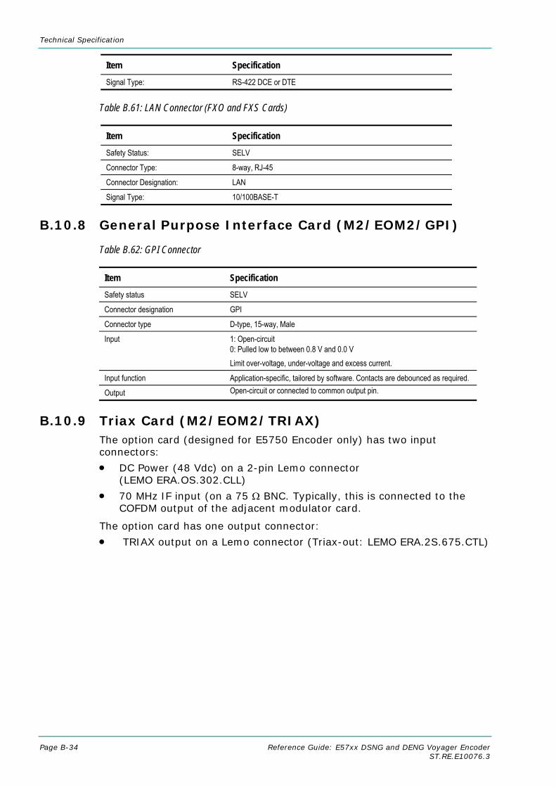
Technical Specification
Page B-34 Reference Guide: E57xx DSNG and DENG Voyager Encoder ST.RE.E10076.3
Item Specification Signal Type: RS-422 DCE or DTE
Table B.61: LAN Connector (FXO and FXS Cards)
Item Specification Safety Status: SELV
Connector Type: 8-way, RJ-45
Connector Designation: LAN
Signal Type: 10/100BASE-T
B.10.8 General Purpose Interface Card (M2/EOM2/GPI)
Table B.62: GPI Connector
Item Specification Safety status SELV
Connector designation GPI
Connector type D-type, 15-way, Male
Input 1: Open-circuit 0: Pulled low to between 0.8 V and 0.0 V Limit over-voltage, under-voltage and excess current.
Input function Application-specific, tailored by software. Contacts are debounced as required.
Output Open-circuit or connected to common output pin.
B.10.9 Triax Card (M2/EOM2/TRIAX) The option card (designed for E5750 Encoder only) has two input connectors:
• DC Power (48 Vdc) on a 2-pin Lemo connector (LEMO ERA.OS.302.CLL)
• 70 MHz IF input (on a 75 Ω BNC. Typically, this is connected to the COFDM output of the adjacent modulator card.
The option card has one output connector:
• TRIAX output on a Lemo connector (Triax-out: LEMO ERA.2S.675.CTL)

Reference Guide: E57xx DSNG and DENG Voyager Encoder Page C-1 ST.RE.E10076.3
Annex C C. Language Abbreviations
Languages are shown in alphabetical order.
LANGUAGE ABBREVIATION
Afrikaans afr
Albanian alb
Arabic ara
Auxiliary two
Basa bas
Basque baq
Bengali ben
Breton bre
Bulgarian bul
Burmese bur
Catalan cat
Chinese chi
Czech cze
Danish dan
Dutch dut
English eng
Estonian est
Finnish fin
French fre
Fulani ful
Gaelic (Scots) gae
German ger
Greek gre
Gujarati guj
Hausa hau
Hindi hin
Hungarian hun
LANGUAGE ABBREVIATION
Ibo ibo
Icelandic ice
Indonesian ind
Irish iri
Italian ita
Japanese jpn
Javanese jav
Kannada kan
Korean kor
Latvian lav
Lithuanian lit
Macedonian mac
Main one
Malayalam mal
Malay msa
Marathi mar
Miscellaneous mis
Multiple languages mul
Ndebele (North) nde
Norwegian nor
Oriya ori
Persian per
Polish pol
Portugese por
Punjabi pan
Romanian rum
Russian rus
Serbo-Croat SCR
Slovak slk

Language Abbreviations
Page C-2 Reference Guide: E57xx DSNG and DENG Voyager Encoder ST.RE.E10076.3
LANGUAGE ABBREVIATION
Somali som
Spanish spa
Swahili swa
Swedish swe
Tagalog tgl
Tamil tam
Telugu tel
Thai tha
Tibetan tib
Turkish tur
Ukranian ukr
Undefined und
Urdu urd
Vietnamese vie
Welsh cym
Xhosa xho
Yoruba yor
Zulu zul
There is the facility to enter a User specified abbreviation. This is performed by entering a 3 letter code for the User Defined Language 1 or 2 entry in the menu. Once this has been carried out, the code appears against the User Defined 1 or 2 options and it is these entries that are used for language code insertion.

Reference Guide: E57xx DSNG and DENG Voyager Encoder Page D-1 ST.RE.E10076.3
Annex D D. Creating and Downloading a Logo
Contents D.1 Introduction ...............................................................D-3
D.2 Summary of Features ...............................................D-3
D.3 OSD Programs Built Into the Encoder ......................D-3
D.4 Creating a Logo Using OSD Creator ........................D-5
D.5 Using OSD Creator ...................................................D-5 D.5.1 Overview.......................................................D-5 D.5.2 Loading a .bmp File ......................................D-6 D.5.3 Creating Transparency .................................D-6
Overview.......................................................D-6 Adding Transparency Manually ....................D-7 Adding Transparency Using a Key File ........D-7 Editing the Palette ........................................D-8 Palette Reallocation......................................D-8
D.5.4 Downsampling ..............................................D-8 D.5.5 Saving the .osd File ......................................D-8
D.6 Downloading a Logo Using OSD Loader ..................D-9
D.7 Using the OSD Loader ............................................. D-9 D.7.1 Start-up ........................................................ D-9 D.7.2 Download an .osd File ............................... D-10 D.7.3 Show and Hide Regions ............................ D-12 D.7.4 Multiple Regions......................................... D-12 D.7.5 Region Interference ................................... D-12
D.8 Fault-finding............................................................ D-13
List of Tables Table D.1: Resolution Modes ......................................................D-10
List of Figures Figure D.1: Web Browser Interface ...............................................D-4 Figure D.2: File Download Dialog Box...........................................D-4 Figure D.3: Files for OSD Creator and Loader ..............................D-5 Figure D.4: OSD Creator Screen Showing Example Logo............D-6 Figure D.5: OSD Loader Screen Showing Example Logo.............D-9 Figure D.6: 625 Line, OSD Co-ordinates in Active Picture..........D-11 Figure D.7: 525 Line, OSD Co-ordinates in Active Picture..........D-11

Creating and Downloading a Logo
Page D-2 Reference Guide: E57xx DSNG and DENG Voyager Encoder ST.RE.E10076.3
BLANK

Creating and Downloading a Logo
Reference Guide: E57xx DSNG and DENG Voyager Encoder Page D-3 ST.RE.E10076.3
D.1 Introduction The Encoder includes a logo overlay facility whereby an image can be overlaid onto the active video prior to encoding. This enables broadcasters to trademark or brand their material with a logo.
To overlay the material with a logo, the logo must first be downloaded into the equipment using the Ethernet TFTP protocol. Once this has been done the logo can be enabled or disabled. Contact TANDBERG Television for further details.
D.2 Summary of Features Up to 13 logos can be overlaid onto the active video. The space each logo occupies is referred to as a region. If two logo regions share a horizontal line they may interfere with each other, so this should be avoided, (see Section D.7.5). i.e. logos may be placed adjacent vertically, but not horizontally. Logos cannot be overlapped.
One logo can be downloaded into Flash memory and will still be present after the Encoder has been powered OFF. All other logos are stored in volatile memory and will be lost when the Encoder is powered OFF.
To create and download logos to the Encoder, two Windows applications are required, Osd Creator and Osd Loader. Once a logo has been downloaded to Flash it can be enabled/disabled from the front panel menu: Setup/Video/Video source/Stored OSD. Logos downloaded to volatile memory can only be controlled by the OSD Loader application running from a PC.
Logos are defined at pixel resolution and include a red, green, blue and transparency component. Logos can be positioned anywhere in the active video and can be any size from 1x1 pixel to the full size of the active picture (720x576 or 720x480 pixels). Logos are limited to a maximum of 256 colours, including different levels of transparency.
The logo is overlaid onto the active picture prior to horizontal and vertical down-sampling, noise reduction and video bandwidth filtering, if these are used.
D.3 OSD Programs Built Into the Encoder Two Windows applications are required for creating and downloading logos to the Encoder, namely Osd Creator and Osd Loader. These programs are stored permanently in the Encoder where they can be downloaded via the Web Browser Interface. Further information is available in Chapter 5, Web Browser Interface. These applications must be unzipped and saved to a PC prior to use. This requires WinZip to be installed on the PC.
Using the Web Browser interface, see Figure D.1, select Option 2 Tools, OSD Toolkit.

Creating and Downloading a Logo
Page D-4 Reference Guide: E57xx DSNG and DENG Voyager Encoder ST.RE.E10076.3
Figure D.1: Web Browser Interface
The dialog box, see Figure D.2, will be displayed.
Figure D.2: File Download Dialog Box
Clicking on option Open this file from its current location and Clicking OK will open the .zip file, see Figure D.3. Clicking on option Save this file to disk will allow the user to install the files on their local drive and then open the .zip file as in Figure D.3.

Creating and Downloading a Logo
Reference Guide: E57xx DSNG and DENG Voyager Encoder Page D-5 ST.RE.E10076.3
Figure D.3: Files for OSD Creator and Loader
D.4 Creating a Logo Using OSD Creator Osd Creator (creator.exe) is an application for creating logo files (.osd format) for use with the Osd Loader application (osd.exe) to download them to the Encoder. It accepts Windows Bitmap (.bmp) format files as input. It includes the facility to introduce a mix component into the image, so that when the image is superimposed onto video, some areas appear to be transparent.
The application also includes the facility to downsample the image to the desired size.
The application runs under Windows NT.
NOTE… The OSD Creator program only has limited features for the manipulation of images. It is wise to carry out any complex image editing using dedicated graphics software prior to importing the .bmp image file into the OSD Creator.
D.5 Using OSD Creator
D.5.1 Overview To create a logo (.osd) file:
1. Load a Bitmap (.bmp) file.
2. Add transparency in the desired areas.
3. Downsample to the desired size.
4. Save as an .osd file.

Creating and Downloading a Logo
Page D-6 Reference Guide: E57xx DSNG and DENG Voyager Encoder ST.RE.E10076.3
An example of a logo is shown in Figure D.4.
Figure D.4: OSD Creator Screen Showing Example Logo
D.5.2 Loading a .bmp File Select File/Open from the menu, and choose a file with a .bmp extension. The image is displayed in its own window. The application does not accept compressed bitmaps or multi-planed bitmaps. If a 24-bit colour bitmap image is loaded into Osd Creator it will be automatically converted down to a 256 colour palette.
D.5.3 Creating Transparency
Overview
Each pixel in a .bmp file is represented by a red, green and blue component, each with a value 0 to 255. Osd Creator adds a fourth component for the transparency of the pixel. This is referred to as a mix or transparency (T) value and is displayed in the bottom right status panel. The transparency component also has a range of 0 to 255, where 0 is fully transparent and 255 is fully opaque.
Left Mouse ButtonTransparency
Value
Right MouseButton
TransparencyValue
Change Background Colour
ZoomView
TransparencyComponent
Of Pixel
Image PropertiesRed
ComponentOf Pixel
BlueComponent
Of PixelGreenComponent
Of Pixel
Transparency Brush Size

Creating and Downloading a Logo
Reference Guide: E57xx DSNG and DENG Voyager Encoder Page D-7 ST.RE.E10076.3
Osd Creator uses a colour palette with a maximum of 256 entries. Each pixel in the image is mapped to an entry in the palette, which holds a value for the red, green and blue and transparency component. The transparency (or mix) is treated as a colour component, so for two colours with identical red, green and blue values, but different transparency levels, two entries will be generated in the palette.
When a bitmap image is loaded, all colours have a transparency value of 255 (opaque).
The area of the image that is to remain opaque is referred to as the active area. The area of the image that is to be made transparent is called the inactive area. Transparency can added manually, with a brush, or by using a key file.
Adding Transparency Manually
The background colour within Osd Creator can be changed with the black, red, green and blue buttons on the toolbar. This changes the background colour of the editor window on which the logo is overlaid and not the logo itself, which remains unaffected. This facility is useful to show the transparency of different colours. It is best to start with a background colour that contrasts sharply with the whole of the source image.
Using the options immediately below the toolbar, the mouse pointer can be used as a brush to add transparency to an area. The left mouse button will apply the transparency value set for the LButton Mix and the right mouse button will apply the transparency value set for the RbuttonMix. At start-up these are set so LButton Mix is 0, to make an area transparent, and RButton Mix is 255, to make it opaque.
Different mix levels can be entered for intermediate levels of transparency. Selecting a brush size from the drop-down list determines the size of the area that is changed.
If the Changes Affect Palette box is checked, changing the transparency of a pixel on the image also changes the palette entry on which the pixel is based, and all the pixels that share that palette entry.
If the inactive area is mainly one colour, check the Changes Affect Palette box, and left-click in the inactive area. All pixels of that colour should become background-coloured. Repeat until the whole of the inactive area is transparent. If parts of the active area have become transparent, uncheck the Changes Affect Palette box, and paint with the right button to correct these areas. Zoom in if necessary.
If there is no general colour for the inactive area, uncheck the Changes Affect Palette box and paint the inactive area manually with the left mouse button. Use the right button to correct mistakes. Trace around the edge of the area with a medium brush, then use the large brush for wide areas. Zoom in to do the fine corrections.
Adding Transparency Using a Key File
A key file is a Bitmap (.bmp) file of the same size as the source file, with the active area of the image coloured white, the inactive area coloured black, and intermediate levels of transparency coloured grey.
Create the key file using a drawing package. Colour the active area white, and the inactive area black. Save as a .bmp file.

Creating and Downloading a Logo
Page D-8 Reference Guide: E57xx DSNG and DENG Voyager Encoder ST.RE.E10076.3
Click the Key File toolbar button. Select the key file. The inactive area of the image should now be transparent (background-coloured). Change the background colour to verify that the correct area is transparent.
Editing the Palette
The palette may be displayed alongside the image by clicking the Show/Hide Palette toolbar button. The transparency of each palette entry may be altered in the same way as the image itself, using the left and right mouse buttons. Changes to the palette are shown immediately on the image.
The Red, Green, Blue and Mix component of the pixel or palette entry under the cursor can be seen on the status bar at the bottom of the screen.
Palette Reallocation
When the level of transparency of a pixel in the image is changed, a new colour is effectively created. Whenever the image is downsampled or saved, the palette is rebuilt to reflect the actual colours in the image. As part of this process, pixels which have a mix value of zero are mapped to palette entry zero, which is defined as Red = Green = Blue = Mix = 0. The original colour information is lost and the right mouse button will not change the pixel back to its original colour.
To rebuild the palette during editing, click the Reallocate Palette toolbar button.
D.5.4 Downsampling Click the Downsample toolbar button. A dialog box appears asking for a downsampling ratio. This can be specified directly, or by entering the desired image size. Click OK to downsample the image. The downsampling algorithm includes a filter, so the boundary between the active and inactive areas softens slightly. Zoom in and check that the correct areas are transparent, and make corrections if necessary.
NOTE… Once the image has been downsampled, the process cannot be reversed to change the image back to its original size.
D.5.5 Saving the .osd File Select File/Save As/OSD file from the menu. Saving is possible at any time, and it is advisable to save the image often while editing is in progress. The file may also be saved in .bmp format, but this file will not contain transparency information.
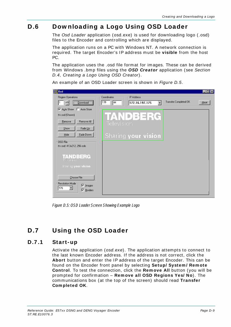
Creating and Downloading a Logo
Reference Guide: E57xx DSNG and DENG Voyager Encoder Page D-9 ST.RE.E10076.3
D.6 Downloading a Logo Using OSD Loader The Osd Loader application (osd.exe) is used for downloading logo (.osd) files to the Encoder and controlling which are displayed.
The application runs on a PC with Windows NT. A network connection is required. The target Encoder's IP address must be visible from the host PC.
The application uses the .osd file format for images. These can be derived from Windows .bmp files using the OSD Creator application (see Section D.4, Creating a Logo Using OSD Creator).
An example of an OSD Loader screen is shown in Figure D.5.
Figure D.5: OSD Loader Screen Showing Example Logo
D.7 Using the OSD Loader
D.7.1 Start-up Activate the application (osd.exe). The application attempts to connect to the last known Encoder address. If the address is not correct, click the Abort button and enter the IP address of the target Encoder. This can be found on the Encoder front panel by selecting Setup/System/Remote Control. To test the connection, click the Remove All button (you will be prompted for confirmation – Remove all OSD Regions Yes/No). The communications box (at the top of the screen) should read Transfer Completed OK.
Creating and Downloading a Logo
Page D-10 Reference Guide: E57xx DSNG and DENG Voyager Encoder ST.RE.E10076.3
The Resolution Mode must be set to match the video resolution being used. This adjusts the preview screen to the dimensions of the active video.
Table D.1: Resolution Modes
Resolution Mode Video Standard 576 Standard Definition 625 line
480 Standard Definition 525 line
480p Not Supported
576p Not Supported
720p Not Supported
1080i Not Supported
D.7.2 Download an .osd File Choose an On-screen Display file with the Choose File button. You will be prompted for a file with an .osd extension. The image will be displayed in the OSD File box.
Position the image on the screen by dragging the white cursor box around the main placement window. The position can also be adjusted by editing the co-ordinates boxes.
A logo can be overlaid anywhere in the digital active picture. When a logo is positioned in the main placement window, the co-ordinates are shown for the top left corner of the logo. The co-ordinates that the Osd Loader uses include an offset. Figure D.6 and Figure D.7 illustrate how these co-ordinates relate to the active picture.
When the logo is correctly positioned, click the Download button. Transferring Data… appears in the communications box. The image will be displayed in the main window. Wait for Transfer Completed OK to appear in the communications box. After a short delay, the image should appear on the output from the Receiver.
If the Auto Store box is checked, when the logo is downloaded to the Encoder, it will be stored in Flash memory and will still be present after the Encoder has been powered off. Only one logo can be stored in Flash at any time. The maximum logo file size that can be stored in Flash is 65 279 bytes. The file size will be affected by the size of the logo and its complexity (number of colours and levels of transparency). For example this is roughly equivalent to a logo 200 x 145 pixels with 256 colours (62 567 bytes).
If the Auto Store box is left unchecked, the downloaded logo will be stored in volatile memory and will be lost when power is removed from the Encoder.

Creating and Downloading a Logo
Reference Guide: E57xx DSNG and DENG Voyager Encoder Page D-11 ST.RE.E10076.3
576Lines
1 720
720 Pixels Digital Active Picture
702 Pixels Analogue Active Picture
Pixel1 2
Line
Field
23336
337
338
24
25
623310
OSD Loader Co-ordinates (858,619)
OSD Loader Co-ordinates (139,44)
OSD Loader Co-ordinates (148,44)
Figure D.6: 625 Line, OSD Co-ordinates in Active Picture
480Lines
1 720
720 Pixels Digital Active Picture
702 Pixels Analogue Active Picture
Pixel1 2
Line
Field
23286
287
288
24
25
525262
OSD Loader Co-ordinates (852,517)
OSD Loader Co-ordinates (133,38)
OSD Loader Co-ordinates (142,38)
Figure D.7: 525 Line, OSD Co-ordinates in Active Picture

Creating and Downloading a Logo
Page D-12 Reference Guide: E57xx DSNG and DENG Voyager Encoder ST.RE.E10076.3
D.7.3 Show and Hide Regions The Download button defines a Region in the Encoder, which remains until the Encoder is turned off, the Remove button is clicked, or the Region is Downloaded again. The Region may be in the Shown or Hidden state, which determines whether it appears in the video stream. If the Auto Show box is checked, the initial state is Shown. Use the Show, Hide, Fade Up and Fade Down buttons to change the state of the region. Shown regions have a green border in the main window, Hidden regions have a red border.
NOTE… Remove or Remove all does not erase a logo that has been stored in Flash memory. It will be removed from the video picture, but will still be available from the front panel Stored OSD On/Off menu option.
D.7.4 Multiple Regions Multiple Regions may be displayed. To define an additional Region, change the Region Number at the top of the Region Operations box, and repeat the Download procedure. Buttons in the Region Operations box only affect the current Region number (with the exception of Remove All). The current Region can also be changed by double-clicking on the image in the main window. The current region has a brighter border in the main window. Uncheck the Images box to display the Region number in the main window instead of the image.
D.7.5 Region Interference If two Regions share a horizontal line, they may interfere. This means that when both Regions are Shown, only one actually appears in the video stream. The application warns if this is the case. When one of the Regions is Hidden, the other may be Shown as normal.

Creating and Downloading a Logo
Reference Guide: E57xx DSNG and DENG Voyager Encoder Page D-13 ST.RE.E10076.3
D.8 Fault-finding If there appears to be a problem creating or downloading a logo check the following:
• If the Communications box reads "Error Creating Socket", there may be a problem with the PC's network set-up, or another application may be using the TFTP socket number.
• If the Communications box reads "Waiting For Response" for a long time, the target Encoder is either busy or not visible on the network. Abort the transfer before changing the IP address.
• Large images take time to appear due to network transfer rates and image processing.
• If the download completes, but the OSD image does not appear on video, the image may be too near the edge of the screen – try moving it towards the centre. Make sure the correct line standard is selected.
• Make sure the image is visible on a typical domestic television. Make a note of the co-ordinates where the image is required.
• If precise timing is required, Download the image in advance with Auto Show off, then click Show when display is required.
• To move the current Region, reposition the white cursor, check that the OSD File box has the correct image, and click Download.

Creating and Downloading a Logo
Page D-14 Reference Guide: E57xx DSNG and DENG Voyager Encoder ST.RE.E10076.3
BLANK

Reference Guide: E57xx DSNG and DENG Voyager Encoder Page E-1 ST.RE.E10076.3
Annex E E. Band Plans
Contents E.1 Channels and Centre Frequencies ...........................E-3
List of Tables Table E.1: Australia .......................................................................E-3 Table E.2: Europe VHF .................................................................E-4 Table E.3: EuropeCATV ................................................................E-4 Table E.4: Italy...............................................................................E-4 Table E.5: Morocco .......................................................................E-4 Table E.6: New Zealand ................................................................E-5 Table E.7: China............................................................................E-5
Table E.8: OIRT.............................................................................E-5 Table E.9: Ireland ..........................................................................E-6 Table E.10: South Africa................................................................E-6 Table E.11: French Overseas PIA.................................................E-6 Table E.12: France ........................................................................E-7 Table E.13: Japan..........................................................................E-7 Table E.14: USA............................................................................E-8 Table E.15: CCIR...........................................................................E-8

Band Plans
Page E-2 Reference Guide: E57xx DSNG and DENG Voyager Encoder ST.RE.E10076.3
BLANK

Band Plans
Reference Guide: E57xx DSNG and DENG Voyager Encoder Page E-3 ST.RE.E10076.3
E.1 Channels and Centre Frequencies The Output Menu has options called Band Plan and Channel (see Chapter 4, Operating the Equipment Locally).
Once a country has been selected in the Band Plan option then the required channel should be selected in the Channel option. Each channel number corresponds to a particular frequency.
NOTE… Only those frequencies associated with a channel number can be selected.
This Annex contains the channel IDs and centre frequencies for the band plans in the Output Menu.
If the Manual band plan option is selected then the required frequency must be selected manually.
Table E.1: Australia
UHF Channel
Centre Frequency in MHz
UHF Channel
Centre Frequency in MHz
UHF Channel
Centre Frequency in MHz
0 48.500 32 557.500 52 697.500 1 59.500 33 564.500 53 704.500 2 66.500 34 571.500 54 711.500 3 88.00 35 578.500 55 718.500 4 97.500 36 585.500 56 725.500 5 104.500 37 592.500 57 732.500 5A 140.500 38 599.500 58 739.500 6 177.500 39 606.500 59 746.500 7 184.500 40 613.500 60 753.500 8 191.500 41 620.500 61 760.500 9 198.500 42 627.500 62 767.500 9A 205.500 43 634.500 63 774.500 10 212.500 44 641.500 64 781.500 11 219.500 45 648.500 65 788.500 12 226.500 46 655.500 66 795.500 27 523.500 47 662.500 67 802.500 28 529.500 48 669.500 68 809.500 29 536.500 49 676.500 69 816.500 30 543.500 50 683.500 31 550.500 51 690.500

Band Plans
Page E-4 Reference Guide: E57xx DSNG and DENG Voyager Encoder ST.RE.E10076.3
Table E.2: Europe VHF
UHF Channel
Centre Frequency in MHz
UHF Channel
Centre Frequency in MHz
E 2 50.500 E 8 198.500 E 3 57.500 E 9 205.500 E 4 64.500 E 10 212.500 E 5 177.500 E 11 219.500 E 6 184.500 E 12 226.500 E 7 191.500
Table E.3: EuropeCATV
UHF Channel
Centre Frequency in MHz
UHF Channel
Centre Frequency in MHz
S 4 128.500 S 13 247.500 S 5 135.500 S 14 254.500 S 6 142.500 S 15 261.500 S 7 149.500 S 16 268.500 S 8 156.500 S 17 275.500 S 9 163.500 S 18 282.500 S 10 170.500 S 19 289.500 S 11 233.500 S 20 296.500 S 12 240.500
Table E.4: Italy
UHF Channel
Centre Frequency in MHz
UHF Channel
Centre Frequency in MHz
A 56.000 F 194.500 B 64.500 G 203.500 C 84.500 H 212.500 D 177.500 H1 219.500 E 186.000 H2 226.500
Table E.5: Morocco
UHF Channel
Centre Frequency in MHz
UHF Channel
Centre Frequency in MHz
M 4 165.500 M 8 197.500 M 5 173.500 M 9 205.500 M 6 181.500 M 10 213.500 M 7 189.500

Band Plans
Reference Guide: E57xx DSNG and DENG Voyager Encoder Page E-5 ST.RE.E10076.3
Table E.6: New Zealand
UHF Channel
Centre Frequency in MHz
UHF Channel
Centre Frequency in MHz
1 47.500 6 191.500 2 57.500 7 198.500 3 64.500 8 205.500 4 177.500 9 212.500 5 184.500 10 219.500
Table E.7: China
UHF Channel
Centre Frequency in MHz
UHF Channel
Centre Frequency in MHz
UHF Channel
Centre Frequency in MHz
UHF Channel
Centre Frequency in MHz
1 52.500 18 514.000 35 690.000 52 826.000 2 60.500 19 522.000 36 698.000 53 834.000 3 68.500 20 530.000 37 706.000 54 842.000 4 80.000 21 538.000 38 714.000 55 850.000 5 88.000 22 546.000 39 722.000 56 858.000 6 171.000 23 554.000 40 730.000 57 866.000 7 179.000 24 562.000 41 738.000 58 874.000 8 187.000 25 610.000 42 746.000 59 882.000 9 195.000 26 618.000 43 754.000 60 890.000 10 203.000 27 626.000 44 762.000 61 898.000 11 211.000 28 634.000 45 770.000 62 906.000 12 219.000 29 642.000 46 778.000 13 474.000 30 650.00 47 786.000 14 482.000 31 658.000 48 794.000 15 490.000 32 666.000 49 802.000 16 498.000 33 674.000 50 810.000 17 506.000 34 682.000 51 818.000
Table E.8: OIRT1
UHF Channel
Centre Frequency in MHz
UHF Channel
Centre Frequency in MHz
R I 52.500 R VII 186.000 R II 62.000 R VIII 194.000 R III 80.000 R IX 202.000 R IV 88.000 R X 210.000 R V 96.000 R XI 218.000
R VI 178.000 R XII 226.000
1 Organisation that co-ordinated TV standards and programme interchange among the Eastern–block countries of Europe.

Band Plans
Page E-6 Reference Guide: E57xx DSNG and DENG Voyager Encoder ST.RE.E10076.3
Table E.9: Ireland
UHF Channel
Centre Frequency in MHz
UHF Channel
Centre Frequency in MHz
I A 48.500 I F 194.000 I B 56.500 I G 202.000 I C 64.500 I H 210.000 I D 178.000 I J 218.000 I E 186.000
Table E.10: South Africa
UHF Channel
Centre Frequency in MHz
UHF Channel
Centre Frequency in MHz
4 178.000 9 218.000 5 186.000 10 226.000 6 194.000 11 234.000 7 202.000 (12) 242.000 8 210.000 13 250.180
Table E.11: French Overseas PIA
UHF Channel
Centre Frequency in MHz
UHF Channel
Centre Frequency in MHz
4 178.000 7 202.000 5 186.000 8 210.000 6 194.000 9 218.000

Band Plans
Reference Guide: E57xx DSNG and DENG Voyager Encoder Page E-7 ST.RE.E10076.3
Table E.12: France
UHF Channel
Centre Frequency in MHz
UHF Channel
Centre Frequency in MHz
A 45.000 2 186.750 B 53.000 3 194.750 C 61.000 4 202.750 C1 57.750 5 210.750 1 178.750 6 218.750
Table E.13: Japan
UHF Channel
Centre Frequency in MHz
UHF Channel
Centre Frequency in MHz
UHF Channel
Centre Frequency in MHz
UHF Channel
Centre Frequency in MHz
J 1 93.000 18 503.000 35 605.000 52 707.000 J 2 99.000 19 509.000 36 611.000 53 713.000 J 3 105.000 20 515.000 37 617.000 54 719.000 J 4 173.000 21 521.000 38 623.000 55 725.000 J 5 179.000 22 527.000 39 629.000 56 731.000 J 6 185.000 23 533.000 40 635.000 57 737.000 J 7 191.000 24 539.000 41 641.000 58 743.000 J 8 195.000 25 545.000 42 647.000 59 749.000 J 9 201.000 26 551.000 43 653.000 60 755.000 J 10 207.000 27 557.000 44 659.000 61 761.000 J 11 213.000 28 563.000 45 665.000 62 767.000
J 12 219.000 29 569.000 46 671.000 63 773.000
13 473.000 30 575.000 47 677.000 14 479.000 31 581.000 48 683.000 15 485.000 32 587.000 49 689.000 16 491.000 33 593.000 50 695.000 17 497.000 34 599.000 51 701.000

Band Plans
Page E-8 Reference Guide: E57xx DSNG and DENG Voyager Encoder ST.RE.E10076.3
Table E.14: USA
UHF Channel
Centre Frequency in MHz
UHF Channel
Centre Frequency in MHz
UHF Channel
Centre Frequency in MHz
UHF Channel
Centre Frequency in MHz
A 02 57.000 23 527.000 44 653.000 65 779.000 A 03 63.000 24 533.000 45 659.000 66 785.000 A 04 69.000 25 539.000 46 665.000 67 791.000 A 05 79.000 26 545.000 47 671.000 68 797.000 A 06 85.000 27 551.000 48 677.000 69 803.000 A 07 177.000 28 557.000 49 683.000 70 809.000 A 08 183.000 29 563.000 50 689.000 71 815.000 A 09 189.000 30 569.000 51 695.000 72 821.000 A 10 195.000 31 575.000 52 701.000 73 827.000 A 11 201.000 32 581.000 53 707.000 74 833.000 A 12 207.000 33 587.000 54 713.000 75 839.000 A 13 213.000 34 593.000 55 719.000 76 845.000 14 473.000 35 599.000 56 725.000 77 851.000 15 479.000 36 605.000 57 731.000 78 857.000 16 485.000 37 611.000 58 737.000 79 863.000 17 491.000 38 617.000 59 743.000 80 869.000 18 497.000 39 623.000 60 749.000 81 875.000 19 503.000 40 629.000 61 755.000 82 881.000 20 509.000 41 635.000 62 761.000 83 887.000 21 515.000 42 641.000 63 767.000 22 521.000 43 647.000 64 773.000
Table E.15: CCIR2
UHF Channel
Centre Frequency in MHz
UHF Channel
Centre Frequency in MHz
UHF Channel
Centre Frequency in MHz
21 474.000 38 610.000 55 746.000 22 482.000 39 618.000 56 754.000 23 490.000 40 626.000 57 762.000 24 498.000 41 634.000 58 770.000 25 506.000 42 642.000 59 778.000 26 514.000 43 650.000 60 786.000 27 522.000 44 658.000 61 794.000 28 530.000 45 666.000 62 802.000 29 538.000 46 674.000 63 810.000 30 546.000 47 682.000 64 818.000 31 554.000 48 690.000 65 826.000 32 562.000 49 698.000 66 834.000 33 570.000 50 706.000 67 842.000 34 578.000 51 714.000 68 850.000 35 586.000 52 722.000 69 858.000 36 594.000 53 730.000 37 602.000 54 738.000
2 CCIR is now know as International Telecommunications Union-Radiocommunications Study Groups.

Reference Guide: E57xx DSNG and DENG Voyager Encoder Page F-1 ST.RE.E10076.3
Annex F F. Audio Modes
Contents F.1 Analogue Audio.........................................................F-3
F.2 Digital Audio ..............................................................F-3
F.3 Embedded Audio on the SDI.....................................F-4
F.4 Detail of Encoder Operation......................................F-5
List of Figures Figure F.1: Analogue Audio Modes ............................................... F-3 Figure F.2: Digital Audio Modes .................................................... F-4 Figure F.3: Embedded Audio and Stereo Pairs ............................. F-5

Audio Modes
Page F-2 Reference Guide: E57xx DSNG and DENG Voyager Encoder ST.RE.E10076.3
BLANK

Audio Modes
Reference Guide: E57xx DSNG and DENG Voyager Encoder Page F-3 ST.RE.E10076.3
F.1 Analogue Audio Figure F.1 shows the coding methods that may be used with the analogue audio input.
Analogue AudioCode to LinearPCM
Linear PCM
Internal Coding
MUSICAM
Dolby (AC-3)
Independent of Encoder Clock Source
Figure F.1: Analogue Audio Modes
F.2 Digital Audio When a digital audio source is used, consideration must be given to the choice of clock source used by the Encoder. To ensure correct operation the Encoder and the audio may need to be genlocked. Figure F.2 shows the clock source that is appropriate for a given audio coding mode. The two main clock sources are internal and external (derived from the H SYNC input).

Audio Modes
Page F-4 Reference Guide: E57xx DSNG and DENG Voyager Encoder ST.RE.E10076.3
Figure F.2: Digital Audio Modes
F.3 Embedded Audio on the SDI Figure F.3 shows the audio signal flow on the Base Board. While six audio stereo pairs are available, only two stereo pairs can be processed by the Base Board at any one time.
Audio can be embedded on a SDI video feed. The specified groups are: 1, 2, 3, 4. Each group contains two stereo pairs, hence each SDI can carry a maximum of 2 x 4 = 8 stereo pairs, or 16 mono channels.
Each group has an associated Data Identifier (DID). The standard DIDs are typically:
• Group 1 = 0x2FF
• Group 2 = 0x1FD
• Group 3 = 0x1FB
• Group 4 = 0x2F9
Other DIDs are possible. Refer to the SMPTE 272M specification for more details. DID 1F4 is reserved for EDH error packets.
Digital Audio
Embedded (SDI)
Pre-encoded
Dolby E DTS
MUSICAM
Dolby (AC-3)
1 Entire system must be genlocked to studio reference black and burst. 2 Set Encoder clock source to HSYNC. 3 Feed Dolby (AC-3) coder from genlocked output of the audio A/D.
Lock Dolby (AC-3) Encoder to AES/EBU reference from Encoder. Independent of Encoder clock
Independent of Encoder clock source
Dolby (AC-3)
Linear PCM
Linear PCM
Internal Coding
Audio Port AES/EBU
Pre-encoded
Dolby E DTS
Dolby (AC-3)
Linear PCM Linear PCM
Internal Coding
or
*
*
*
MUSICAM
Dolby (AC-3)
*
*

Audio Modes
Reference Guide: E57xx DSNG and DENG Voyager Encoder Page F-5 ST.RE.E10076.3
F.4 Detail of Encoder Operation The Encoder can de-embed any two DID s at any one time, thus giving a total of four embedded audio sources: embedded audio 1-4.
The default DID for embedded audio 1-2 is 2FFh (Group 1).
The default DID for embedded audio 3-4 is 1FDh (Group 2).
The DIDs are located in ancillary packets in the data stream.
NOTE… Default DIDs are selected when a DID value ≥1024 is set.
Figure F.3: Embedded Audio and Stereo Pairs
4:1
4:1
Group 1Group 2Group 3Group 4
Group 1Group 2Group 3Group 4
SDI Embedded 1 SDI Embedded 2 Audio
Router
Stereo Pair A
SDI Embedded 4
De-embedder 1
De-embedder 2
Interfaceand
ConversionStereo Pair B
AudioChannel A
AudioChannel B
Channel A Audio
Channel B Audio
SDI Embedded 3
nTo Option
Modules
Base Card Audio
User DID Selection(Default=0x1FD)
User DID Selection(Default=0x2FF)
15-way D-typeConnector
Audio option module (M2/EOM2/AUDLIN2) is required if more than two channels of audio require processing.
Audio groups taken from SDI.

Audio Modes
Page F-6 Reference Guide: E57xx DSNG and DENG Voyager Encoder ST.RE.E10076.3
BLANK

Reference Guide: E57xx DSNG and DENG Voyager Encoder Page G-1 ST.RE.E10076.3
Annex G G. Accuracy of Frequency Sources
This equipment is based around ISO/IEC 13818 specifications (commonly known as MPEG-2) and within these specifications all timing is derived from a 27 MHz system clock. The system clock is required to have an accuracy of better than ±30 ppm.
An oven-controlled crystal oscillator (OCXO) within this equipment achieves the ±30 ppm accuracy within five minutes of applying power. This accuracy is maintained over the specified operating temperature range for the life of the product without further adjustment.
Composite television systems such as PAL and NTSC have traditionally used high precision oscillators for colour sub-carrier. Many different specifications are in common use and a required accuracy in the range ±0.2 ppm to ±2 ppm is common. Typically an entire TV studio runs from a central frequency standard, with all equipment being fed with a Black and Burst reference signal.
Generally, individual items of equipment are not capable of the required accuracy in the absence of this reference. Where a suitable reference is not available (e.g. outside broadcast or intercontinental programme exchange) the specifications allow a relaxed accuracy.
When this equipment is used to source a timing reference which is used to generate a composite video output (for instance the PAL or NTSC output of a TANDBERG Television Receiver/Decoder) the accuracy of the resultant sub-carrier is directly traceable to the 27 MHz system clock in this equipment.
To ensure continuing accuracy, the system clock in this equipment can be locked to an appropriate frequency reference by feeding a Black and Burst signal to the H SYNC input. Alternatively, the system clock can be locked to the video input. In either case, the system clock is frequency-locked to the source sync pulses, and hence the composite video sub-carrier is as accurate as the frequency reference.
Where an accurate reference signal is not available, the OCXO in this equipment must be used. The OCXO is adjusted to better than ±0.2 ppm during manufacture, but due to natural ageing of the OCXO, regular calibration is required to keep the OXCO within ±0.2 ppm if composite video accuracy is to be maintained. Calibration intervals depend on the requirements of the particular composite video specification in force. Please contact TANDBERG Television Customer Services for advice.

Accuracy of Frequency Sources
Page G-2 Reference Guide: E57xx DSNG and DENG Voyager Encoder ST.RE.E10076.3
BLANK

Reference Guide: E57xx DSNG and DENG Voyager Encoder Page H-1 ST.RE.E10076.3
Annex H H. Use of Remux Card in ATSC
Contents H.1 Remux Card In ATSC With Internal PSIP.................H-3
H.2 Remux Card In ATSC With External PSIP................H-3

Use of Remux Card in ATSC
Page H-2 Reference Guide: E57xx DSNG and DENG Voyager Encoder ST.RE.E10076.3
BLANK

Use of Remux Card in ATSC
Reference Guide: E57xx DSNG and DENG Voyager Encoder Page H-3 ST.RE.E10076.3
H.1 Remux Card In ATSC With Internal PSIP The Encoder automatically remuxes ATSC streams arriving at its inputs, as in DVB. The Encoder uses the PAT (Program Association Table) and PMT (Program Map Table) to work out all the associated PIDs (Packet Identifier), and attempt to extract the short name, the long name, and the Service Type from the VCT (Virtual Channel Table).
NOTE… If more than one program is present on any input the Encoder may be unable to extract any information from the VCT on that input.
The Encoder then maps the PIDs using the program paradigm based upon the program number. If possible, the program number of the input is preserved. In Intelligent mode the Encoder automatically remaps the program number/PIDs if a clash occurs. If an active program is overwritten by another, the program number/PIDs of the first program are changed to non-clashing values. In Dumb mode the Encoder requires a user to remap clashing program numbers/PIDs to prevent overwriting an active program.
The Encoder generates all PSIP (Program System Information Protocol) tables for the output stream. It generates a minimum set of tables containing a minimum amount of data. The tables constructed are the:
• MGT (Master Guide Table)
• CVCT (Cable Virtual Channel Table) or
• TVCT (Terrestrial Virtual Channel Table)
• STT (System Time Table)
• RRT (Rating Region Table)
• EIT (Event Information Table) 0, 1, 2, and 3
• PAT
• CAT (Conditional Access Table)
• PMT
The program paradigm is applied to any input program which has a program number of less than 256. If the program number is greater than 255 any PID may be used for each stream. If a non-ATSC service is detected then that may also be passed through the Remux card as an ATSC program. The program paradigm will be applied to such a service if possible and if the program number is less than 256.
H.2 Remux Card In ATSC With External PSIP The Encoder only provides a minimum amount of information within the PSIP tables. If more sophisticated tables are required then the PSIP may be fed in externally using an ASI input on the Remux card. The user is able to specify a PID range via a minimum and maximum PID. The user then selects a port to use and chooses a Service Info level of ‘On (Ext. PSIP)’. All PIDS between the maximum and minimum are then mapped directly to the output.

Use of Remux Card in ATSC
Page H-4 Reference Guide: E57xx DSNG and DENG Voyager Encoder ST.RE.E10076.3
In this configuration the Encoder generates the PAT, CAT and PMT for all programs but it is the responsibility of the user to provide all the PSIP for the associated programs. Any programs present on the same input as the external PSIP are not detected and are not referenced in the PAT.
There is also a mode “Off (Ext. PSIP)”. In this configuration, the Encoder does not generate any SI tables. All tables must be fed in via an external PSIP generator.
CAUTION… It is the operator’s responsibility to ensure the Encoder is set to generate elementary streams according
to the SI tables that are fed in.
PIDs 0,1 and 0x1FFB are automatically mapped through in this mode. Other PIDs can be passed by specifying the min and max PID range as above.
This mode may be also be used for passing data through the Remux card.
NOTE… It can take a long time to map a range of PIDs using the Remux card, and for usability the range should be kept to a minimum. For instance, it takes approximately 80 seconds to map 4000 PIDs.
If the External PSIP input port is changed, the Encoder may fail to correctly map the PIDs on the new port. This can be resolved by rebooting the Encoder.

Reference Guide: E57xx DSNG and DENG Voyager Encoder Page I-1 ST.RE.E10076.3
Annex I I. EDH Capability for E57xx Encoders
Contents I.1 EDH Capability for E57xx Encoders .......................... I-3
List of Tables Table I.1: EDH Capability Matrix for E57xx Encoders .................... I-3

EDH Capability for E57xx Encoders
Page I-2 Reference Guide: E57xx DSNG and DENG Voyager Encoder ST.RE.E10076.3
BLANK

EDH Capability for E57xx Encoders
Reference Guide: E57xx DSNG and DENG Voyager Encoder Page I-3 ST.RE.E10076.3
I.1 EDH Capability for E57xx Encoders Table I.1 contains EDH capability for different mux firmware versions. To find the mux firmware version for a particular Encoder refer to Summary Screen/More/Advanced/Setup/System/Build Menu.
Table I.1: EDH Capability Matrix for E57xx Encoders
Mux F/W V14 and below Mux F/W V15
Base Card Not Modified
Base Card Modified
Base Card H/W Mod Strike 11 and below Base Card H/W Mod Strike 12 and above
Software versions 2.0.0 and above (excluding 3.0.1)
EDH does not work, no errors reported
• Software aware that EDH is not supported
EDH works, but unreliably
• EDH support only partially implemented in software
EDH works, but unreliably
• EDH support only partially implemented in software
Software versions 3.0.1 and above
EDH does not work, no errors reported
• Software aware that EDH is not supported
• Various EDH status flags available in the menus (all inactive)
• UES (Unknown Error Status) flags active
EDH works partially, converts edh errors to eda, does not report all errors
• Gennum chip modifies EDH data in incoming SDI stream
• If EDH is not present in incoming stream, Gennum chip inserts it; therefore the Encoder thinks EDH was there all along. Error detection in this case is unreliable as the CRCs and checksums are calculated AFTER the errors have occurred.
• If EDH is present in incoming stream (the most likely scenario) the Gennum chip detects CRC and checksum errors (edh), turns those errors into edas and recalculates CRCs. In this case the Encoder reports the wrong type of errors, which would make fault-finding very confusing for an operator trying to find a fault in the SDI chain.
EDH works as per specifications

EDH Capability for E57xx Encoders
Page I-4 Reference Guide: E57xx DSNG and DENG Voyager Encoder ST.RE.E10076.3
BLANK