CD522 Encoder, counter and PWM module - ABB
17
DATA SHEET CD522 Encoder, counter and PWM module 1 Ordering data Part no. Description Product life cycle phase *) 1SAP 260 300 R0001 CD522, encoder & PWM module, 2 encoder inputs, 2 PWM outputs, 2 digital inputs 24 V DC, 8 digital outputs 24 V DC Active 1SAP 460 300 R0001 CD522-XC, encoder & PWM module, 2 encoder inputs, 2 PWM outputs, 2 digital inputs 24 V DC, 8 digital outputs 24 V DC, XC version Active *) Modules in lifecycle Classic are available from stock but not recommended for planning and commissioning of new installations. Ordering data 2022/01/31 3ADR010026, 8, en_US 1
-
Upload
khangminh22 -
Category
Documents
-
view
4 -
download
0
Transcript of CD522 Encoder, counter and PWM module - ABB

DATA SHEET
CD522Encoder, counter and PWM module
1 Ordering dataPart no. Description Product life cycle phase *)1SAP 260 300 R0001 CD522, encoder & PWM module,
2 encoder inputs, 2 PWM outputs,2 digital inputs 24 V DC, 8 digital outputs24 V DC
Active
1SAP 460 300 R0001 CD522-XC, encoder & PWM module,2 encoder inputs, 2 PWM outputs,2 digital inputs 24 V DC, 8 digital outputs24 V DC, XC version
Active
*) Modules in lifecycle Classic are available from stock but not recommended forplanning and commissioning of new installations.
Ordering data
2022/01/31 3ADR010026, 8, en_US 1

2 Dimensions
1 Din rail 15 mm2 Din rail 7.5 mm
The dimensions are in mm and in brackets in inch.
3 Technical dataThe system data of AC500 and S500 Ä Chapter 4 “System data AC500” on page 8 are applicableto the standard version.The system data of AC500-XC Ä Chapter 5 “System data AC500-XC” on page 12 are applicable tothe XC version.Only additional details are therefore documented below.The technical data are also applicable to the XC version.
Parameter ValueProcess supply voltage
Connections Terminals 1.8, 2.8, 3.8 and 4.8 for UP (+24 V DC) and 1.9,2.9, 3.9 and 4.9 for ZP (0 V)
Protection against reversevoltage
Yes
Rated protection fuse at UP 10 A fast
Technical data
2022/01/313ADR010026, 8, en_US2

Parameter Value Rated value 24 V DC
Max. ripple 5 %
Current consumption
From UP 0.07 A + max. 0.008 A per input + max. 0.5 A per output +0.01 A for A, B and Z inputs
Via I/O bus Ca. 5 mA
Inrush current from UP (atpower-up)
0.04 A²s
Galvanic isolation Yes, per module
Max. power dissipation within themodule
6 W (outputs unloaded)
Weight (without terminal unit) Ca. 125 g
Mounting position Horizontal mounting or vertical with derating (output loadreduced to 50 % at 40 °C)
Cooling The natural convection cooling must not be hindered by cableducts or other parts in the switchgear cabinet.
NOTICE! Attention:All I/O channels (digital and analog) are protected against reverse polarity, reversesupply, short circuit and continuous overvoltage up to 30 V DC.
Multiple overloadsNo effects of multiple overloads on isolated multi-channel modules occur, as everychannel is protected individually by an internal smart high-side switch.
Parameter ValueNumber of channels 2 + 8 configurable digital inputs/outputs
Reference potential for all inputs Terminals 1.9...4.9 (negative pole of the process supply voltage,signal name ZP)
Galvanic isolation From the rest of the module
Indication of the input signals 1 yellow LED per channel, the LED is ON when the input signalis high (signal 1)
Input type acc. to EN 61131-2 Type 1
Input delay (0->1 or 1->0) Typ. 8 ms, configurable from 0.1 to 32 ms
Input data length 24 bytes
Input signal voltage 24 V DC
Signal 0 -3 V...+5 V *
Undefined signal > +5 V...< +15 V
Signal 1 +15 V...+30 V
Ripple with signal 0 Within -3 V...+5 V *
Technical dataof the digitalinputs/outputs ifused asstandard inputs
2022/01/31 3ADR010026, 8, en_US 3

Parameter ValueRipple with signal 1 Within +15 V...+30 V
Input current per channel
Input voltage +24 V Typ. 5 mA
Input voltage +5 V > 1 mA
Input voltage +15 V > 5 mA
Input voltage +30 V < 8 mA
Max. cable length
Shielded 1000 m
Unshielded 600 m
* Due to the direct connection to the output, the demagnetizing varistor is also effective at the input(see figure) above. This is why the difference between UPx and the input signal must not exceedthe clamp voltage of the varistor. The varistor limits the clamp voltage to approx. 36 V. Consequently,the input voltage must range from -12 V to +30 V when UPx = 24 V and from -6 V to +30 V whenUPx = 30 V.
Parameter ValueNumber of channels 8 configurable digital inputs/outputs
Reference potential for all outputs Terminals 1.9...4.9 (negative pole of the processsupply voltage, signal name ZP)
Common power supply voltage For all outputs: terminals 1.8...4.8 (positive pole ofthe process supply voltage, signal name UP)
Output voltage for signal 1 UP (-0.8 V)
Output delay (0->1 or 1->0) Typ. 10 µs
Output data length 32 bytes
Output current
Rated value, per channel 500 mA at UP = 24 V
Maximum value (all channels together,PWM included)
8 A
Leakage current with signal 0 < 0.5 mA
Rated protection fuse on UP 10 A fast
Demagnetization when inductive loads areswitched off
With varistors integrated in the module (see figurebelow)
Switching frequency
With resistive load On request
With inductive loads Max. 0.5 Hz
With lamp loads Max. 11 Hz with max. 5 W
Short-circuit-proof / overload-proof Yes
Overload message (I > 0.7 A) Yes, after ca. 100 ms
Output current limitation Yes, automatic reactivation after short circuit/over-load
Resistance to feedback against 24 V signals Yes
Max. cable length
Technical dataof the digitalinputs/outputs ifused asstandard out-puts
2022/01/313ADR010026, 8, en_US4
Parameter Value Shielded 1000 m
Unshielded 600 m
Fig. 1: Circuitry of a digital input/output with the varistors for demagnetization when inductive loadsare switched off
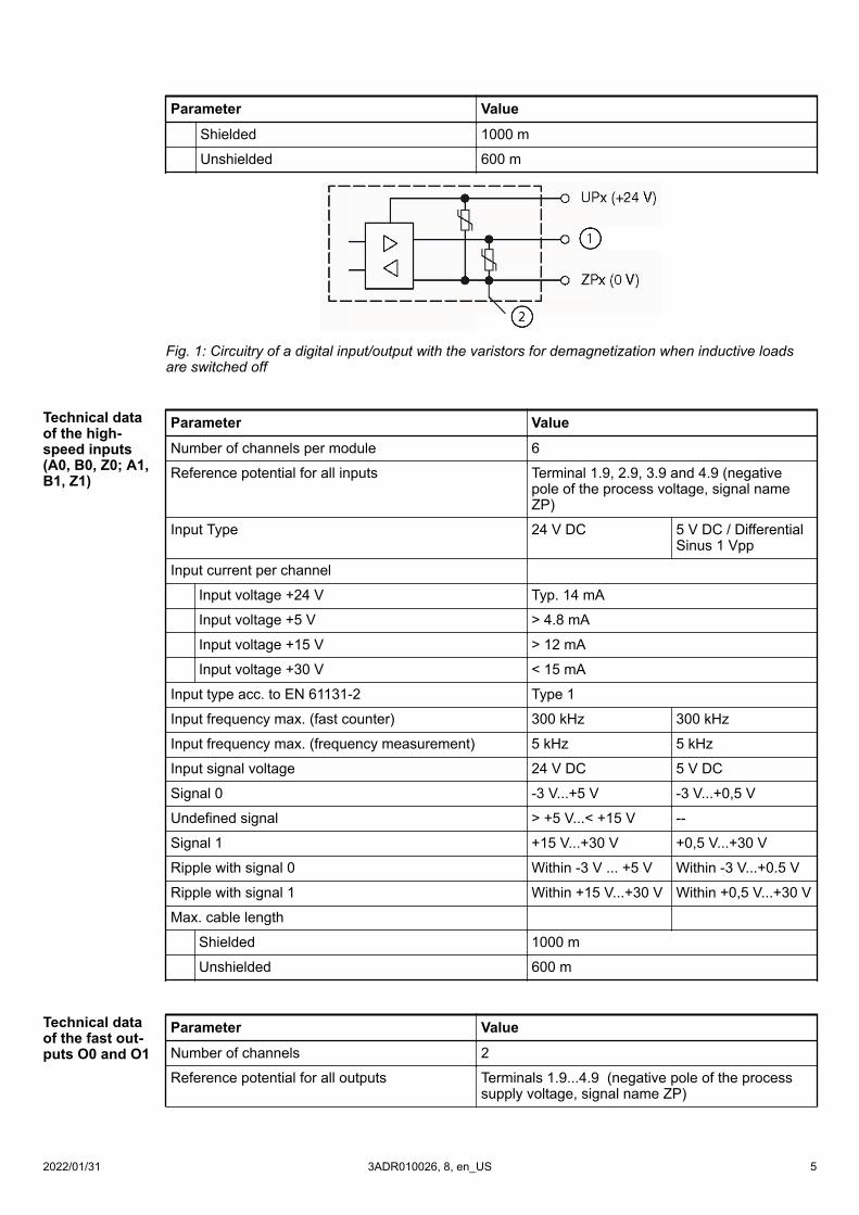
Parameter ValueNumber of channels per module 6
Reference potential for all inputs Terminal 1.9, 2.9, 3.9 and 4.9 (negativepole of the process voltage, signal nameZP)
Input Type 24 V DC 5 V DC / DifferentialSinus 1 Vpp
Input current per channel
Input voltage +24 V Typ. 14 mA
Input voltage +5 V > 4.8 mA
Input voltage +15 V > 12 mA
Input voltage +30 V < 15 mA
Input type acc. to EN 61131-2 Type 1
Input frequency max. (fast counter) 300 kHz 300 kHz
Input frequency max. (frequency measurement) 5 kHz 5 kHz
Input signal voltage 24 V DC 5 V DC
Signal 0 -3 V...+5 V -3 V...+0,5 V
Undefined signal > +5 V...< +15 V --
Signal 1 +15 V...+30 V +0,5 V...+30 V
Ripple with signal 0 Within -3 V ... +5 V Within -3 V...+0.5 V
Ripple with signal 1 Within +15 V...+30 V Within +0,5 V...+30 V
Max. cable length
Shielded 1000 m
Unshielded 600 m
Parameter ValueNumber of channels 2
Reference potential for all outputs Terminals 1.9...4.9 (negative pole of the processsupply voltage, signal name ZP)
Technical dataof the high-speed inputs(A0, B0, Z0; A1,B1, Z1)
Technical dataof the fast out-puts O0 and O1
2022/01/31 3ADR010026, 8, en_US 5

Parameter ValueCommon power supply voltage For all outputs: terminals 1.8...4.8 (positive pole of
the process supply voltage, signal name UP)
Indication of the output signals Brightness of the LED depends on the number ofpulses emitted (0 % to 100 %) (pulse output modeonly)
Output voltage for signal 1 UP (-0.1 V)
Output voltage for signal 0 ZP (+0.3 V)
Output delay (0->1 or 1->0) Typ. 1 µs
Output current
Rated value, per channel 100 mA at UP = 24 V
Maximum value (all channels together,configurable outputs included))
8 A
Leakage current with signal 0 < 0.5 mA
Rated protection fuse on UP 10 A fast
De-magnetization when inductive loads areswitched off
With varistors integrated in the module (see figureabove)
Switching frequency PWM: up to 100 kHz (min. step for PWM value: 2µs)Pulse: up to 15 kHz
Short-circuit-proof / overload-proof Yes
Overload message (I > 0.1x A) Yes, after ca. 100 ms
Output current limitation Yes, automatic reactivation after short-circuit/over-load
Resistance to feedback against 24 V signals Yes
Resistance to feedback against reversepolarity
No
Max. cable length
Shielded 1000 m
Unshielded 600 m
Parameter ValueNumber of channels 2
Reference potential for all outputs Terminals 1.9...4.9 (negative pole of the processsupply voltage, signal name ZP)
Common power supply voltage For all outputs: terminals 1.8...4.8 (positive poleof the process supply voltage, signal name UP)
Output voltage for signal 0 ≤ 1.5 V at 10 mA
Output delay (0->1 or 1->0) Typ. 0.3 µs
Output current ≤ 10 mA
Switching frequency < 1 MHz (depending on firmware)
Short-circuit-proof / overload-proof Yes
Output current limitation Yes, automatic reactivation after short cir-cuit/overload
Resistance to feedback against 24 V signals Yes
Technical dataof the fast out-puts (SSI CLKoutput B0, B1for optical inter-face)
2022/01/313ADR010026, 8, en_US6

Parameter ValueResistance to feedback against reverse polarity No
Max. cable length (shielded) Typ. 12.5 m at 500 kHz (depending on sensor)
Parameter ValueNumber of channels 2
Reference potential for all outputs Terminals 1.9...4.9 (negative pole of the processsupply voltage, signal name ZP)
Common power supply voltage For all outputs: terminals 1.8...4.8 (positive poleof the process supply voltage, signal name UP)
Output voltage for signal 1 ≥ 2.9 V at 10 mA
Output voltage for signal 0 ≤ 1.3 V at 10 mA
Output delay (0->1 or 1->0) Typ. 0.3 µs
Output current ≤ 10 mA
Switching frequency < 1 MHz (depending on firmware)
Short-circuit-proof / overload-proof Yes
Overload message (I > 0.1x A) Yes, after ca. 100 ms
Output current limitation Yes, automatic reactivation after short-cir-cuit/overload
Resistance to feedback against 24V signals Yes
Resistance to feedback against reverse polarity No
Max. cable length (shielded) 100 m
Parameter ValueNumber of supplies 2, independently configuration
Voltage supply (outputs unloaded) 5 V DC +/- 5%
Resistance to feedback against reverse polarity No
Output current 100 mA max. (independently)200 mA max. (parallel use)
Output diagnosis Yes, with diagnosis LED and error message
Parameter ValueNumber of reference inputs (internally con-nected to ZP through internal fuse)
6
Max. current per connection 0.5 A
Internal fuse protection
Terminals 1.4 and 1.6 2 A
Terminals 3.4 to 3.7 2 A
Technical dataof the fast out-puts (SSI CLKOutput Differen-tial)
Technical dataof the 5 Vsensor supply
Technical dataof the 0 V refer-ence input
2022/01/31 3ADR010026, 8, en_US 7

4 System data AC5004.1 Environmental conditions
Table 1: Process and supply voltagesParameter Value24 V DC
Voltage 24 V (-15 %, +20 %)
Protection against reverse polarity Yes
120 V AC
Voltage 120 V (-15 %, +10 %)
Frequency 50/60 Hz (-6 %, +4 %)
230 V AC
Voltage 230 V AC (-15 %, +10 %)
Frequency 50/60 Hz (-6 %, +4 %)
120 V AC...240 V AC wide-range supply
Voltage 120 V...240 V (-15 %, +10 %)
Frequency 50/60 Hz (-6 %, +4 %)
Allowed interruptions of power supply, according to EN 61131-2
DC supply Interruption < 10 ms, time between 2 interrup-tions > 1 s, PS2
AC supply Interruption < 0.5 periods, time between 2 inter-ruptions > 1 s
NOTICE!Exceeding the maximum power supply voltage for process or supply voltages couldlead to unrecoverable damage of the system. The system might be destroyed.
NOTICE!Improper voltage level or frequency range which cause damage of AC inputs:– AC voltage above 264 V– Frenquency below 47 Hz or above 62.4 Hz
NOTICE!Improper connection leads cause overtemperature on terminals.PLC modules may be destroyed by using wrong cable type, wire size and cabletemperature classification.
Parameter ValueTemperature
Operating 0 °C...+60 °C: Horizontal mounting of modules.0 °C...+40 °C: Vertical mounting of modules.Output load reduced to 50 % per group.
Storage -40 °C...+70 °C
System data AC500Environmental conditions
2022/01/313ADR010026, 8, en_US8
Parameter Value Transport -40 °C...+70 °C
Humidity Max. 95 %, without condensation
Air pressure
Operating > 800 hPa / < 2000 m
Storage > 660 hPa / < 3500 m
Ingress protection IP20
4.2 Creepage distances and clearancesThe creepage distances and clearances meet the requirements of the overvoltage category II, pollu-tion degree 2.
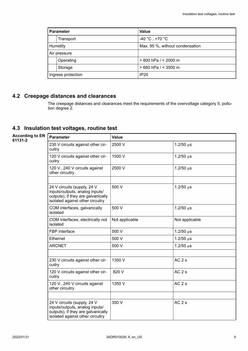
4.3 Insulation test voltages, routine testParameter Value230 V circuits against other cir-cuitry
2500 V 1.2/50 µs
120 V circuits against other cir-cuitry
1500 V 1.2/50 µs
120 V...240 V circuits againstother circuitry
2500 V 1.2/50 µs
24 V circuits (supply, 24 Vinputs/outputs, analog inputs/outputs), if they are galvanicallyisolated against other circuitry
500 V 1.2/50 µs
COM interfaces, galvanicallyisolated
500 V 1.2/50 µs
COM interfaces, electrically notisolated
Not applicable Not applicable
FBP interface 500 V 1.2/50 µs
Ethernet 500 V 1.2/50 µs
ARCNET 500 V 1.2/50 µs
230 V circuits against other cir-cuitry
1350 V AC 2 s
120 V circuits against other cir-cuitry
820 V AC 2 s
120 V...240 V circuits againstother circuitry
1350 V AC 2 s
24 V circuits (supply, 24 Vinputs/outputs, analog inputs/outputs), if they are galvanicallyisolated against other circuitry
350 V AC 2 s
According to EN61131-2
Insulation test voltages, routine test
2022/01/31 3ADR010026, 8, en_US 9

Parameter ValueCOM interfaces, galvanicallyisolated
350 V AC 2 s
COM interfaces, electrically notisolated
Not applicable Not applicable
FBP interface 350 V AC 2 s
Ethernet 350 V AC 2 s
ARCNET 350 V AC 2 s
4.4 Power supply unitsFor the supply of the modules, power supply units according to SELV or PELV specifications must beused.
Safety Extra Low Voltage (SELV) and Protective Extra Low Voltage (PELV)To ensure electrical safety of AC500/AC500-eCo extra low voltage circuits, 24 V DCsupply, communication interfaces, I/O circuits, and all connected devices must bepowered from sources meeting requirements of SELV, PELV, class 2, limited voltageor limited power according to applicable standards.
WARNING!Improper installation can lead to death by touching hazardous voltages!To avoid personal injury, safe separation, double or reinforced insulation and separa-tion of the primary and secondary circuit must be observed and implemented duringinstallation.– Only use power converters for safety extra-low voltages (SELV) with safe galvanic
separation of the primary and secondary circuit.– Safe separation means that the primary circuit of mains transformers must be
separated from the secondary circuit by double or reinforced insulation. The pro-tective extra-low voltage (PELV) offers protection against electric shock.
4.5 Electromagnetic compatibilityTable 2: Range of useParameter ValueIndustrial applications Yes
Domestic applications No
Table 3: Immunity against electrostatic discharge (ESD), according to IEC 61000-4-2, zone B, crite-rion BParameter ValueElectrostatic voltage in case of air discharge 8 kV
Electrostatic voltage in case of contact discharge 4 kV, in a closed switchgear cabinet 6 kV 1)
Electromagnetic compatibility
2022/01/313ADR010026, 8, en_US10

Parameter ValueESD with communication connectors In order to prevent operating malfunctions, it is
recommended, that the operating personnel dis-charge themselves prior to touching communica-tion connectors or perform other suitable meas-ures to reduce effects of electrostatic discharges.
ESD with connectors of terminal bases The connectors between the Terminal Bases andprocessor modules or Communication Modulesmust not be touched during operation. The sameis valid for the I/O bus with all modules involved.
1) High requirement for shipping classes are achieved with additional specific measures (see specificdocumentation).
Table 4: Immunity against the influence of radiated (CW radiated), according to IEC 61000-4-3, zoneB, criterion AParameter ValueTest field strength 10 V/m
Table 5: Immunity against fast transient interference voltages (burst), according to IEC 61000-4-4,zone B, criterion BParameter ValueSupply voltage units (DC) 2 kV
Supply voltage units (AC) 2 kV
Digital inputs/outputs (24 V DC) 1 kV
Digital inputs/outputs (120 V AC...240 V AC) 2 kV
Analog inputs/outputs 1 kV
CS31 bus 1 kV
Serial RS-485 interfaces (COM) 1 kV
Serial RS-232 interfaces (COM, not for PM55xand PM56x)
1 kV
ARCNET 1 kV
FBP 1 kV
Ethernet 1 kV
I/O supply (DC-out) 1 kV
Table 6: Immunity against the influence of line-conducted interferences (CW conducted), according toIEC 61000-4-6, zone B, criterion AParameter ValueTest voltage 3V zone B, 10 V is also met.
High energy surges According to IEC 61000-4-5, zone B, criterion B
Power supply DC 1 kV CM / 0.5 kV DM ²)
DC I/O supply 0.5 kV CM / 0.5 kV DM ²)
Communication Lines, shielded 1 kV CM ²)
AC I/O unshielded 3) 2 kV CM / 1 kV DM ²)
Electromagnetic compatibility
2022/01/31 3ADR010026, 8, en_US 11

Parameter Value I/O analog, I/O DC unshielded 3) 1 kV CM / 0.5 kV DM ²)
Radiation (radio disturbance) According to IEC 55011, group 1, class A
²) CM = Common Mode, DM = Differential Mode3) When DC I/O inputs are used with AC voltage, external filters limiting high energy surges to 1 kVCM / 0.5 DM are required to meet requirements according IEC 61131-2.
4.6 Mechanical dataParameter ValueMounting Horizontal
Degree of protection IP 20
Housing Classification V-2 according to UL 94
Vibration resistance acc. to EN 61131-2 all three axes2 Hz...8.4 Hz, continuous 3.5 mm8.4 Hz...150 Hz, continuous 1 g (higher valueson request)
Shock test All three axes15 g, 11 ms, half-sinusoidal
Mounting of the modules:DIN rail according to DIN EN 50022 35 mm, depth 7.5 mm or 15 mm
Mounting with screws Screws with a diameter of 4 mm
Fastening torque 1.2 Nm
4.7 Approvals and certificationsInformation on approvals and certificates can be found in the corresponding chapter of the Maincatalog, PLC Automation.
5 System data AC500-XC
Assembly, construction and connection of devices of the variant AC500-XC is iden-tical to AC500 (standard). The following description provides information on generaltechnical data of AC500-XC system.
5.1 Environmental conditionsTable 7: Process and supply voltagesParameter Value24 V DC
Voltage 24 V (-15 %, +20 %)
System data AC500-XCEnvironmental conditions
2022/01/313ADR010026, 8, en_US12
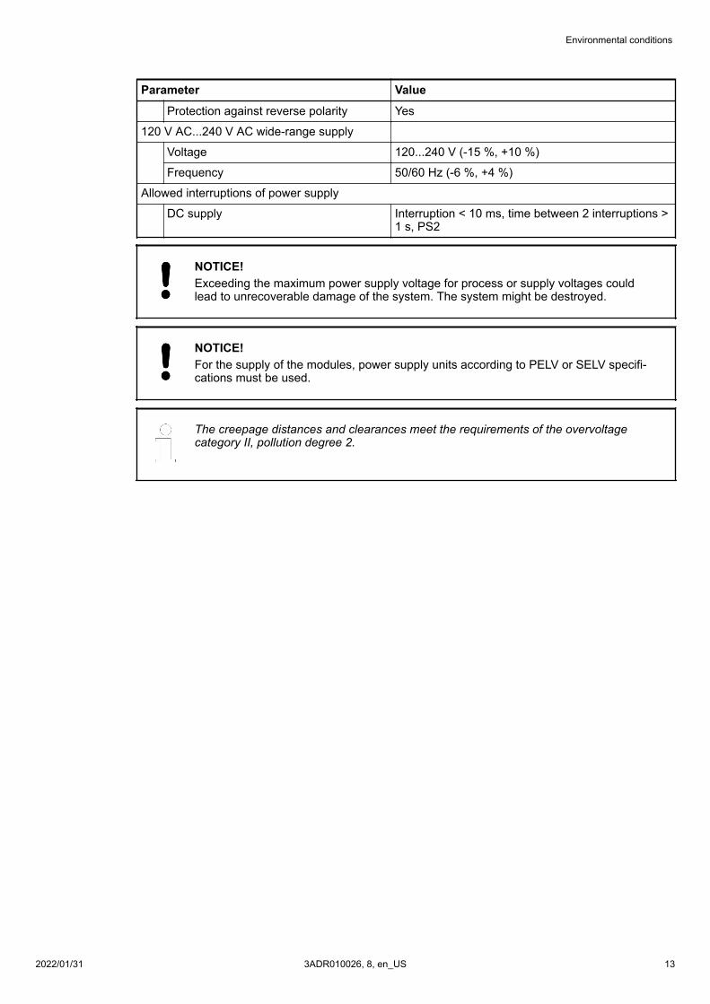
Parameter ValueProtection against reverse polarity Yes
120 V AC...240 V AC wide-range supply
Voltage 120...240 V (-15 %, +10 %)
Frequency 50/60 Hz (-6 %, +4 %)
Allowed interruptions of power supply
DC supply Interruption < 10 ms, time between 2 interruptions >1 s, PS2
NOTICE!Exceeding the maximum power supply voltage for process or supply voltages couldlead to unrecoverable damage of the system. The system might be destroyed.
NOTICE!For the supply of the modules, power supply units according to PELV or SELV specifi-cations must be used.
The creepage distances and clearances meet the requirements of the overvoltagecategory II, pollution degree 2.
Environmental conditions
2022/01/31 3ADR010026, 8, en_US 13

Parameter ValueTemperature
Operating -40 °C...+70 °C-40 °C...-30 °C: Proper start-up of system; tech-nical data not guaranteed-40 °C...0 °C: Due to the LCD technology, thedisplay might respond very slowly.-40 °C...+40 °C: Vertical mounting of modulespossible, output load limited to 50 % per group+60 °C...+70 °C with the following deratings:● System is limited to max. 2 communication
modules per terminal base● Applications certified for cULus up to +60 °C● Digital inputs: maximum number of simultane-
ously switched on input channels limited to75 % per group (e.g. 8 channels => 6 chan-nels)
● Digital outputs: output current maximumvalue (all channels together) limited to 75 %per group (e.g. 8 A => 6 A)
● Analog outputs only if configured asvoltage output: maximum total output cur-rent per group is limited to 75 %(e.g. 40 mA => 30 mA)
● Analog outputs only if configured as currentoutput: maximum number of simultaneouslyused output channels limited to 75 % pergroup (e.g. 4 channels => 3 channels)
Storage / Transport -40 °C...+85 °C
Humidity Operating / Storage: 100 % r. H. with condensa-tion
Air pressure Operating:-1000 m....4000 m (1080 hPa...620 hPa)> 2000 m (< 795 hPa):● max. operating temperature must be reduced
by 10 K (e.g. 70 °C to 60°C)● I/O module relay contacts must be operated
with 24 V nominal only
Immunity to corrosive gases Operating: Yes, according to:ISA S71.04.1985 Harsh group A, G3/GXIEC 60721-3-3 3C2 / 3C3
Immunity to salt mist Operating: Yes, horizontal mounting only,according to IEC 60068-2-52 severity level: 1
NOTICE!Risk of corrosion!Unused connectors and slots may corrode if XC devices are used in salt-mist environ-ments.Protect unused connectors and slots with TA535 protective caps for XC devices.
Environmental conditions
2022/01/313ADR010026, 8, en_US14

Table 8: Electromagnetic compatibilityParameter ValueDevice suitable for:
Industrial applications Yes
Domestic applications No
Radiated emission (radio disturbances) Yes, according to:CISPR 16-2-3
Conducted emission (radio disturbances) Yes, according to:CISPR 16-2-1, CISPR16-1-2
Electrostatic discharge (ESD) Yes, according to:IEC 61000-4-2, zone B, cri-terion B
Fast transient interference voltages (burst) Yes, according to:IEC 61000-4-4, zone B, cri-terion B
High energy transient interference voltages (surge) Yes, according to:IEC 61000-4-5, zone B, cri-terion B
Influence of radiated disturbances Yes, according to:IEC 61000-4-3, zone B, cri-terion A
Influence of line-conducted interferences Yes, according to:IEC 61000-4-6, zone B, cri-terion A
Influence of power frequency magnetic fields Yes, according to:IEC 61000-4-8, zone B, cri-terion A
In order to prevent malfunctions, it is recommended, that the operating personneldischarge themselves prior to touching communication connectors or perform othersuitable measures to reduce effects of electrostatic discharges.
NOTICE!Risk of malfunctions!Unused slots for communication modules are not protected against accidental phys-ical contact.– Unused slots for communication modules must be covered with dummy communi-
cation modules to achieve IP20 rating.– I/O bus connectors must not be touched during operation.
Environmental conditions
2022/01/31 3ADR010026, 8, en_US 15

5.2 Mechanical dataParameter ValueWiring method Spring terminals
Degree of protection IP 20
Vibration resistance Yes, according to:IEC 61131-2IEC 60068-2-6IEC 60068-2-64
Shock resistance Yes, according to:IEC 60068-2-27
Assembly position HorizontalVertical (no application in salt mist environment)
Assembly on DIN rail
DIN rail type According to IEC 6071535 mm, depth 7.5 mm or 15 mm
Assembly with screws
Screw diameter 4 mm
Fastening torque 1.2 Nm
5.3 Environmental testsParameter ValueStorage IEC 60068-2-1 Test Ab: cold withstand test -40 °C / 16 h
IEC 60068-2-2 Test Bb: dry heat withstand test +85 °C / 16 h
Humidity IEC 60068-2-30 Test Db: Cyclic (12 h / 12 h) damp-heat test 55 °C,93 % r. H. / 25 °C, 95 % r. H., 6 cyclesIEC 60068-2-78, stationary humidity test: 40 °C, 93 % r. H., 240 h
Insulation Test IEC 61131-2
Vibration resistance IEC 61131-2 / IEC 60068-26: 5 Hz...500 Hz, 2 g (with memory cardinserted)IEC 60068-2-64: 5 Hz...500 Hz, 4 g rms
Shock resistance IEC 60068-2-27: all 3 axes 15 g, 11 ms, half-sinusoidal
Table 9: EMC immunityParameter ValueElectrostatic discharge (ESD) Electrostatic voltage in case of air discharge: 8 kV
Electrostatic voltage in case of contact discharge: 6 kV
Fast transient interference voltages(burst)
Supply voltage units (DC): 4 kVDigital inputs/outputs (24 V DC): 2 kVAnalog inputs/outputs: 2 kVCommunication lines shielded: 2 kVI/O supply (DC-out): 2 kV
Environmental tests
2022/01/313ADR010026, 8, en_US16

Parameter ValueHigh energy transient interferencevoltages (surge)
Supply voltage units (DC): 1 kV CM *) / 0.5 kV DM *)Digital inputs/outputs (24 V DC): 1 kV CM *) / 0.5 kV DM *)Digital inputs/outputs (AC): 4 kVAnalog inputs/outputs: 1 kV CM *) / 0.5 kV DM *)Communication lines shielded: 1 kV CM )*I/O supply (DC-out): 0,5 kV CM *) / 0.5 kV DM *)
Influence of radiated disturbances Test field strength: 10 V/m
Influence of line-conducted interfer-ences
Test voltage: 10 V
Power frequency magnetic fields 30 A/m 50 Hz30 A/m 60 Hz
*) CM = Common Mode, * DM = Differential Mode
—ABB AGEppelheimer Str. 8269123 Heidelberg, GermanyTelephone: +49 (0)6221 701 1444E-mail: [email protected]/plcabb.com/automationbuilderabb.com/contacts
—© Copyright 2017-2022 ABB.We reserve all rights in this document and in the information containedtherein. Reproduction, use or disclosure to third parties without expressauthority is strictly forbidden.
Environmental tests
2022/01/31 3ADR010026, 8, en_US 17