SAP AFS and Warehouse Management Equipment at Samsonite Agenda
Upload
khangminh22Category
view
6download
0
O P E R A T I N G I N S T R U C T I O N S
AFS/AFM60 PROFINET Absolute Encoder

2 OPERATING INSTRUCTIONS | AFS60/AFM60 PROFINET 8015078/1EF3/2021-12-13 | SICK STEGMANN
Subject to change without notice
Described product
AFS60/AFM60 PROFINET
Manufacturer
SICK AG Erwin-Sick-Str. 1 79183 Waldkirch
Germany
Legal information
This work is protected by copyright. Any rights derived from the copyright shall be reserved for SICK AG. Reproduction of this document or parts of this document is only permissible within the limits of the legal determination of Copyright Law. Any modification, abridgment or translation of this document is prohibited without the express written permission of SICK AG.
The trademarks stated in this document are the property of their respective owner.
© SICK AG. All rights reserved.
Original document
This document is an original document of SICK AG.
CONTENTS
8015078/1EF3/2021-12-13 | SICK STEGMANN OPERATING INSTRUCTIONS | AFS60/AFM60 PROFINET 3
Subject to change without notice
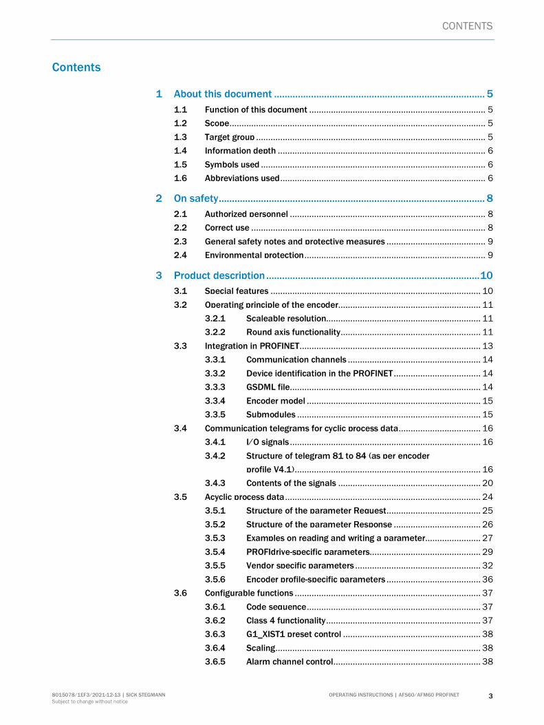
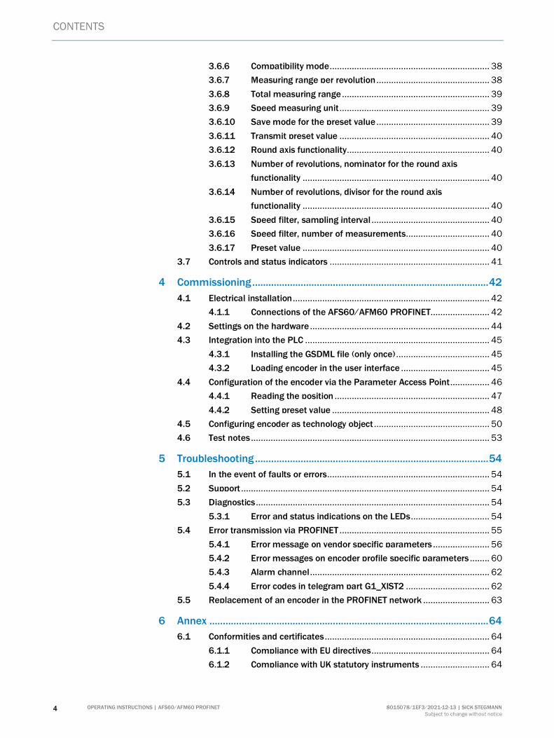
Contents
1 About this document ................................................................................ 5
1.1 Function of this document ......................................................................... 5
1.2 Scope .......................................................................................................... 5
1.3 Target group ............................................................................................... 5
1.4 Information depth ...................................................................................... 6
1.5 Symbols used ............................................................................................. 6
1.6 Abbreviations used ..................................................................................... 6
2 On safety ..................................................................................................... 8
2.1 Authorized personnel ................................................................................. 8
2.2 Correct use ................................................................................................. 8
2.3 General safety notes and protective measures ......................................... 9
2.4 Environmental protection ........................................................................... 9
3 Product description ................................................................................. 10
3.1 Special features ....................................................................................... 10
3.2 Operating principle of the encoder........................................................... 11
3.2.1 Scaleable resolution................................................................ 11
3.2.2 Round axis functionality .......................................................... 11
3.3 Integration in PROFINET ........................................................................... 13
3.3.1 Communication channels ....................................................... 14
3.3.2 Device identification in the PROFINET .................................... 14
3.3.3 GSDML file............................................................................... 14
3.3.4 Encoder model ........................................................................ 15
3.3.5 Submodules ............................................................................ 15
3.4 Communication telegrams for cyclic process data .................................. 16
3.4.1 I/O signals ............................................................................... 16
3.4.2 Structure of telegram 81 to 84 (as per encoder
profile V4.1) ............................................................................. 16
3.4.3 Contents of the signals ........................................................... 20
3.5 Acyclic process data ................................................................................. 24
3.5.1 Structure of the parameter Request ....................................... 25
3.5.2 Structure of the parameter Response .................................... 26
3.5.3 Examples on reading and writing a parameter....................... 27
3.5.4 PROFIdrive-specific parameters.............................................. 29
3.5.5 Vendor specific parameters .................................................... 32
3.5.6 Encoder profile-specific parameters ....................................... 36
3.6 Configurable functions ............................................................................. 37
3.6.1 Code sequence ........................................................................ 37
3.6.2 Class 4 functionality ................................................................ 37
3.6.3 G1_XIST1 preset control ......................................................... 38
3.6.4 Scaling ..................................................................................... 38
3.6.5 Alarm channel control ............................................................. 38
CONTENTS
4 OPERATING INSTRUCTIONS | AFS60/AFM60 PROFINET 8015078/1EF3/2021-12-13 | SICK STEGMANN
Subject to change without notice
3.6.6 Compatibility mode ................................................................. 38
3.6.7 Measuring range per revolution .............................................. 38
3.6.8 Total measuring range ............................................................ 39
3.6.9 Speed measuring unit ............................................................. 39
3.6.10 Save mode for the preset value .............................................. 39
3.6.11 Transmit preset value ............................................................. 40
3.6.12 Round axis functionality .......................................................... 40
3.6.13 Number of revolutions, nominator for the round axis
functionality ............................................................................ 40
3.6.14 Number of revolutions, divisor for the round axis
functionality ............................................................................ 40
3.6.15 Speed filter, sampling interval ................................................ 40
3.6.16 Speed filter, number of measurements .................................. 40
3.6.17 Preset value ............................................................................ 40
3.7 Controls and status indicators ................................................................. 41
4 Commissioning ........................................................................................ 42
4.1 Electrical installation ................................................................................ 42
4.1.1 Connections of the AFS60/AFM60 PROFINET ........................ 42
4.2 Settings on the hardware ......................................................................... 44
4.3 Integration into the PLC ........................................................................... 45
4.3.1 Installing the GSDML file (only once) ...................................... 45
4.3.2 Loading encoder in the user interface .................................... 45
4.4 Configuration of the encoder via the Parameter Access Point ................ 46
4.4.1 Reading the position ............................................................... 47
4.4.2 Setting preset value ................................................................ 48
4.5 Configuring encoder as technology object ............................................... 50
4.6 Test notes ................................................................................................. 53
5 Troubleshooting ....................................................................................... 54
5.1 In the event of faults or errors .................................................................. 54
5.2 Support ..................................................................................................... 54
5.3 Diagnostics ............................................................................................... 54
5.3.1 Error and status indications on the LEDs ................................ 54
5.4 Error transmission via PROFINET ............................................................. 55
5.4.1 Error message on vendor specific parameters ....................... 56
5.4.2 Error messages on encoder profile specific parameters ........ 60
5.4.3 Alarm channel ......................................................................... 62
5.4.4 Error codes in telegram part G1_XIST2 .................................. 62
5.5 Replacement of an encoder in the PROFINET network ........................... 63
6 Annex ........................................................................................................ 64
6.1 Conformities and certificates ................................................................... 64
6.1.1 Compliance with EU directives ................................................ 64
6.1.2 Compliance with UK statutory instruments ............................ 64
ABOUT THIS DOCUMENT 1
8015078/1EF3/2021-12-13 | SICK STEGMANN OPERATING INSTRUCTIONS | AFS60/AFM60 PROFINET 5
Subject to change without notice
1 About this document
Please read this chapter carefully before working with this documentation and the AFS60/AFM60 PROFINET Absolute Encoder.
1.1 Function of this document
This technical information is designed to address the technical personnel of the machine manufacturer or the machine operator in regards to correct configuration, electrical installation, commissioning, operation and maintenance of the AFS60/AFM60 PROFINET Absolute Encoder.
1.2 Scope
NOTE
This technical information applies to the AFS60/AFM60 PROFINET Absolute Encoder with the following type codes:
Singleturn Encoder Advanced = AFS60A-xxNx262144 Multiturn Encoder Advanced = AFM60A-xxNx018x12
1.3 Target group
This technical information is addressed at the planners, developers and operators of systems in which one or more AFS60/AFM60 PROFINET Absolute Encoders are to be integrated. It also addresses people who initialize the use of the AFS60/AFM60 PROFINET or who are in charge of servicing and maintaining the device.
These instructions are written for trained persons who are responsible for the in-stallation, mounting and operation of the AFS60/AFM60 PROFINET in an industrial environment.
1 ABOUT THIS DOCUMENT
6 OPERATING INSTRUCTIONS | AFS60/AFM60 PROFINET 8015078/1EF3/2021-12-13 | SICK STEGMANN
Subject to change without notice
1.4 Information depth
This technical information contains information on the AFS60/AFM60 PROFINET Absolute Encoder on the following subjects:
Product features Electrical installation Putting into operation and
configuration
Troubleshooting Conformity
This technical information does not contain any information on the mounting of the AFS60/AFM60 PROFINET. You will find this information in the mounting instructions included with the device.
It also does not contain any information on technical specifications, dimensional drawings, ordering information or accessories. You will find this information in the data sheet for the AFS60/AFM60 PROFINET.
Planning and using measurement systems such as the AFS60/AFM60 PROFINET also requires specific technical skills beyond the information in the operating instructions and mounting instructions. The information required to acquire these specific skills is not contained in this document.
When operating the AFS60/AFM60 PROFINET, the national, local and statutory rules and regulations must be observed.
Further information
PROFINET/PROFIBUS Nutzerorganisation e.V. (PNO), Haid-und-Neu-Str. 7, D76131 Karlsruhe Web: www.profinet.com www.profinet.de
1.5 Symbols used
NOTE
Refer to notes for special features of the device.
LED symbols describe the state of a diagnostics LED. Examples:
The LED is illuminated constantly.
The LED is flashing.
The LED is off.
Instructions for taking action are shown by an arrow. Read carefully and follow the instructions for action.
WARNING
Warning!
A warning notice indicates an actual or potential risk or health hazard. They are designed to help you to prevent accidents.
Read carefully and follow the warning notices.
1.6 Abbreviations used
Customized Number of Revolutions, Divisor = divisor of the customized number of revolutions
, ,
Take action …
CNR_D
CNR_N
ABOUT THIS DOCUMENT 1
8015078/1EF3/2021-12-13 | SICK STEGMANN OPERATING INSTRUCTIONS | AFS60/AFM60 PROFINET 7
Subject to change without notice
Customized Number of Revolutions, Nominator = nominator of the customized number of revolutions
Counts Per Revolution
Electrically Erasable Programmable Read-only Memory
Field Programmable Gate Array = electronic component that can be programmed to provide an application-specific circuit
Generic Station Description Markup Language = electronic device data sheet based on XML
Input and Output Data = input and output data
Link Layer Discovery Protocol
Least Significant Double Word
Least Significant Word
Media Access Control
Module Access Point
Counts per Measuring Range
Most Significant Double Word
Most Significant Word
Programmable Logic Controller
Physical Measuring Range
Process Field Network
Programmable Logic Controller
Transmission Control Protocol/Internet Protocol
User Datagram Protocol (connectionless network protocol)/Internet Protocol
CPR
EEPROM
FPGA
GSDML
I/O
LLDP
LSDW
LSW
MAC
MAP
MR
MSDW
MSW
PLC
PMR
PROFINET
SPS
TCP/IP
UDP/IP
2 ON SAFETY
8 OPERATING INSTRUCTIONS | AFS60/AFM60 PROFINET 8015078/1EF3/2021-12-13 | SICK STEGMANN
Subject to change without notice
2 On safety
This chapter deals with your own safety and the safety of the equipment operators.
Please read this chapter carefully before working with the AFS60/AFM60 PROFINET or with the machine or system in which the AFS60/AFM60 PROFINET is used.
2.1 Authorized personnel
The AFS60/AFM60 PROFINET Absolute Encoder must only be installed, commissioned and serviced by authorized personnel.
NOTE
Repairs to the AFS60/AFM60 PROFINET are only allowed to be undertaken by trained and authorized service personnel from SICK AG.
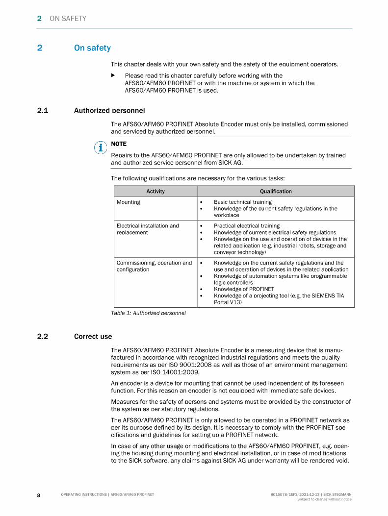
The following qualifications are necessary for the various tasks:
Activity Qualification
Mounting Basic technical training Knowledge of the current safety regulations in the
workplace
Electrical installation and replacement
Practical electrical training Knowledge of current electrical safety regulations Knowledge on the use and operation of devices in the
related application (e.g. industrial robots, storage and conveyor technology)
Commissioning, operation and configuration
Knowledge on the current safety regulations and the use and operation of devices in the related application
Knowledge of automation systems like programmable logic controllers
Knowledge of PROFINET Knowledge of a projecting tool (e.g. the SIEMENS TIA
Portal V13)
Table 1: Authorized personnel
2.2 Correct use
The AFS60/AFM60 PROFINET Absolute Encoder is a measuring device that is manu-factured in accordance with recognized industrial regulations and meets the quality requirements as per ISO 9001:2008 as well as those of an environment management system as per ISO 14001:2009.
An encoder is a device for mounting that cannot be used independent of its foreseen function. For this reason an encoder is not equipped with immediate safe devices.
Measures for the safety of persons and systems must be provided by the constructor of the system as per statutory regulations.
The AFS60/AFM60 PROFINET is only allowed to be operated in a PROFINET network as per its purpose defined by its design. It is necessary to comply with the PROFINET spe-cifications and guidelines for setting up a PROFINET network.
In case of any other usage or modifications to the AFS60/AFM60 PROFINET, e.g. open-ing the housing during mounting and electrical installation, or in case of modifications to the SICK software, any claims against SICK AG under warranty will be rendered void.
ON SAFETY 2
8015078/1EF3/2021-12-13 | SICK STEGMANN OPERATING INSTRUCTIONS | AFS60/AFM60 PROFINET 9
Subject to change without notice
2.3 General safety notes and protective measures
WARNING
Please observe the following procedures in order to ensure the correct and safe use
of the AFS60/AFM60 PROFINET!
The encoder is to be installed and maintained by trained and qualified personnel with knowledge of electronics, precision mechanics and control system programming. It is necessary to comply with the related standards covering the technical safety stipulations.
The safety regulations are to be met by all persons who are tasked with the installation, the operation or the maintenance of the device:
The technical information must always be available and must always be followed. Unqualified personnel are not allowed to be present in the vicinity of the system
during installation. The system is to be installed in accordance with the applicable safety stipulations
and the mounting instructions. All work safety regulations of the applicable countries are to be followed during
installation. Failure to follow all applicable health and safety regulations may result in injury or
damage to the system. The current and voltage sources in the encoder are designed in accordance with
all applicable technical regulations.
2.4 Environmental protection
Please note the following information on disposal.
Assembly Material Disposal
Packaging Cardboard Waste paper
Shaft Stainless steel Scrap metal
Flange Aluminium Scrap metal
Housing Aluminium die cast Scrap metal
Electronic assemblies Various Electronic waste
Table 2: Disposal of the assemblies
3 PRODUCT DESCRIPTION
10 OPERATING INSTRUCTIONS | AFS60/AFM60 PROFINET 8015078/1EF3/2021-12-13 | SICK STEGMANN
Subject to change without notice
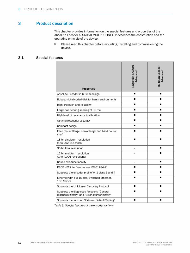
3 Product description
This chapter provides information on the special features and properties of the Absolute Encoder AFS60/AFM60 PROFINET. It describes the construction and the operating principle of the device.
Please read this chapter before mounting, installing and commissioning the device.
3.1 Special features
Properties
Sin
gle
turn
En
co
de
r A
dva
nce
d
Mu
ltit
urn
En
co
der
Ad
van
ce
d
Absolute Encoder in 60 mm design
Robust nickel coded disk for harsh environments
High precision and reliability
Large ball bearing spacing of 30 mm
High level of resistance to vibration
Optimal rotational accuracy
Compact design
Face mount flange, servo flange and blind hollow shaft
18 bit singleturn resolution (1 to 262,144 steps)
30 bit total resolution –
12 bit multiturn resolution (1 to 4,096 revolutions)
–
Round axis functionality –
PROFINET interface (as per IEC 61784-2)
Supports the encoder profile V4.1 class 3 and 4
Ethernet with Full Duplex, Switched Ethernet, 100 Mbit/s
Supports the Link Layer Discovery Protocol
Supports the diagnostic functions “General diagnosis history” and “Error counter history”
Supports the function “External Default Setting”
Table 3: Special features of the encoder variants
PRODUCT DESCRIPTION 3
8015078/1EF3/2021-12-13 | SICK STEGMANN OPERATING INSTRUCTIONS | AFS60/AFM60 PROFINET 11
Subject to change without notice
3.2 Operating principle of the encoder
The sensing system in the AFS60/AFM60 PROFINET Absolute Encoder is based on absolute acquisition of revolutions without an external power supply or battery.
The AFS60/AFM60 PROFINET acquires the position of rotating axes and outputs the position in the form of a unique digital numeric value. The number of steps in a turn is acquired optically via an internal code disk. The number of turns is acquired using a magnetic gearbox.
The AFS60 PROFINET is a singleturn encoder
Singleturn encoders are used if absolute acquisition of the rotation of a shaft is required.
The AFM60 PROFINET is a multiturn encoder
Multiturn encoders are used if more than one shaft revolution must be acquired absolutely.
3.2.1 Scaleable resolution
The steps per revolution and the total resolution can be scaled and adapted to the related application.
The steps per revolution can be scaled from 1 … 262,144 as an integer. The total re-solution of the AFS60/AFM60 PROFINET must be 2ⁿ times the resolution per revolu-tion. This restriction is not relevant if the round axis functionality is activated.
3.2.2 Round axis functionality
The encoder supports the function for round axes. During this process, the steps per revolution are set as a fraction (see section 3.6.12 on page 40). As a result, the total resolution does not have to be configured to 2ⁿ times the resolution per revolution and can also be a decimal number (e.g. 12.5).
NOTE
The output position value is adjusted with the zero point correction, the counting direction set and the gearbox parameters entered.

3 PRODUCT DESCRIPTION
12 OPERATING INSTRUCTIONS | AFS60/AFM60 PROFINET 8015078/1EF3/2021-12-13 | SICK STEGMANN
Subject to change without notice
Example with transmission ratio
A rotary table for a filling system is to be controlled. The resolution per revolution is pre-defined by the number of filling stations. There are nine filling stations. For the precise measurement of the distance between two filling stations, 1,000 steps are required.
Figure 1: Example position measurement on a rotary table with transmission ratio
The number of revolutions is pre-defined by the transmission ratio = 12.5 of the rotary table gearing.
The total resolution is then 9 × 1,000 = 9,000 steps, to be realized in 12.5 revolutions of the encoder. This ratio cannot be realized via the steps per revolution and the total resolution, as the total resolution is not 2ⁿ times the steps per revolution.
The application problem can be solved using the round axis functionality. Here the resolution per revolution is ignored. The total resolution as well as the nominator and divisor for the number of revolutions are configured.
9,000 steps are configured as the total resolution.
For the nominator for the number of revolutions 125 is configured, 10 as the divisor (125/10 = 12.5).
After 12.5 revolutions (that is after one complete revolution of the rotary table) the encoder reaches the total resolution of 9,000.
125
10
Rotary table with nine filling
stations
Encoder

PRODUCT DESCRIPTION 3
8015078/1EF3/2021-12-13 | SICK STEGMANN OPERATING INSTRUCTIONS | AFS60/AFM60 PROFINET 13
Subject to change without notice
Example without transmission ratio
Figure 2: Example position measurement on a rotary table without transmission ratio
The encoder is mounted directly on the rotary table. The transmission ratio is 1:1.
The rotary table has 9 filling stations. The encoder must be configured such that it starts to count with 0 at one filling station and counts to 999 on moving to the next filling station position.
1,000 steps are configured as the total resolution.
For the nominator for the number of revolutions 1 is configured, 9 as the divisor (1/9
revolutions = 1,000).
After 1/9 revolutions of the encoder shaft there are 1,000 steps, then the encoder starts to count at 0 again.
3.3 Integration in PROFINET
PROFINET is a communication protocol that is based on the open Ethernet standard as per IEEE 802.3.
PROFINET defines the real-time communication for the fast transmission of process data.
The AFS60/AFM60 PROFINET is a PROFINET peripheral device and is integrated in a PROFINET network as a slave.
The encoder is an input/output device. This means that the encoder uses data from the master on the PROFINET (output data) and also produces data for the PROFINET itself (input data).
The AFS60/AFM60 PROFINET complies with the guidelines of the encoder profile version 4.1 class 3 with the encoder profile number 3D00h.
1,000 steps
Rotary table with nine filling stations
Encoder
3 PRODUCT DESCRIPTION
14 OPERATING INSTRUCTIONS | AFS60/AFM60 PROFINET 8015078/1EF3/2021-12-13 | SICK STEGMANN
Subject to change without notice
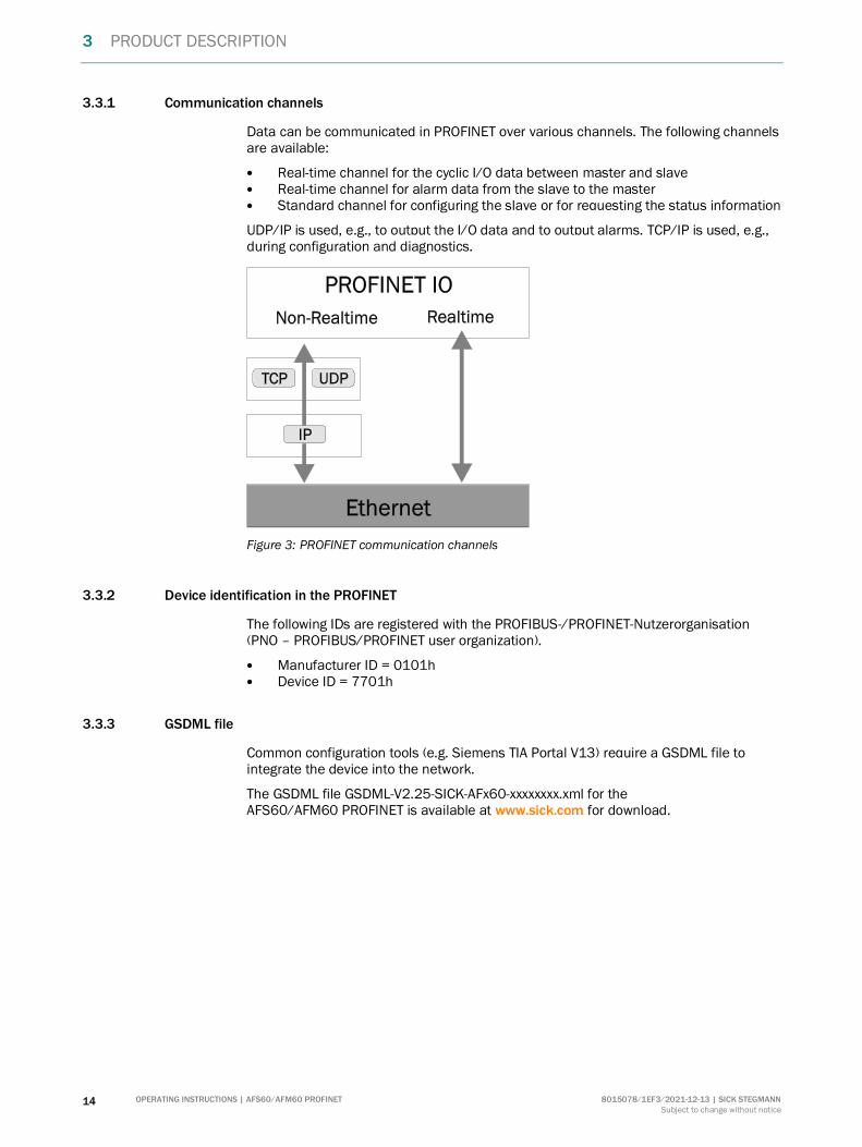
3.3.1 Communication channels
Data can be communicated in PROFINET over various channels. The following channels are available:
Real-time channel for the cyclic I/O data between master and slave Real-time channel for alarm data from the slave to the master Standard channel for configuring the slave or for requesting the status information
UDP/IP is used, e.g., to output the I/O data and to output alarms. TCP/IP is used, e.g., during configuration and diagnostics.
Figure 3: PROFINET communication channels
3.3.2 Device identification in the PROFINET
The following IDs are registered with the PROFIBUS-/PROFINET-Nutzerorganisation (PNO – PROFIBUS/PROFINET user organization).
Manufacturer ID = 0101h Device ID = 7701h
3.3.3 GSDML file
Common configuration tools (e.g. Siemens TIA Portal V13) require a GSDML file to integrate the device into the network.
The GSDML file GSDML-V2.25-SICK-AFx60-xxxxxxxx.xml for the AFS60/AFM60 PROFINET is available at www.sick.com for download.
PRODUCT DESCRIPTION 3
8015078/1EF3/2021-12-13 | SICK STEGMANN OPERATING INSTRUCTIONS | AFS60/AFM60 PROFINET 15
Subject to change without notice
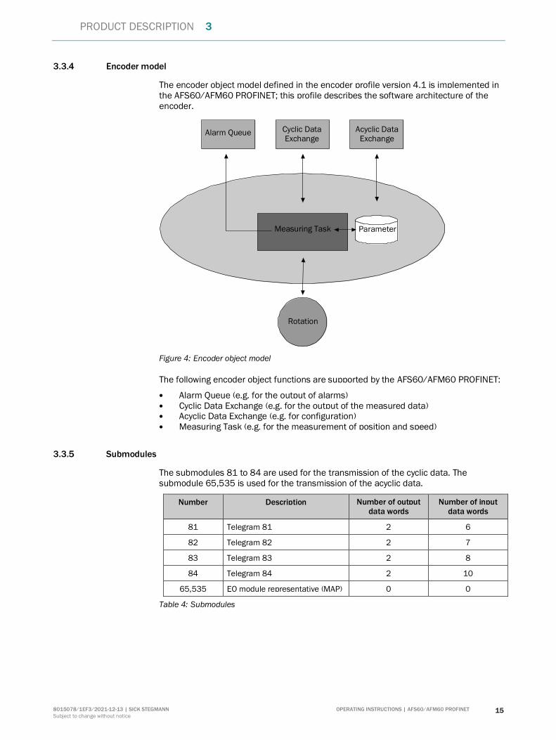
3.3.4 Encoder model
The encoder object model defined in the encoder profile version 4.1 is implemented in the AFS60/AFM60 PROFINET; this profile describes the software architecture of the encoder.
Figure 4: Encoder object model
The following encoder object functions are supported by the AFS60/AFM60 PROFINET:
Alarm Queue (e.g. for the output of alarms) Cyclic Data Exchange (e.g. for the output of the measured data) Acyclic Data Exchange (e.g. for configuration) Measuring Task (e.g. for the measurement of position and speed)
3.3.5 Submodules
The submodules 81 to 84 are used for the transmission of the cyclic data. The submodule 65,535 is used for the transmission of the acyclic data.
Number Description Number of output data words
Number of input data words
81 Telegram 81 2 6
82 Telegram 82 2 7
83 Telegram 83 2 8
84 Telegram 84 2 10
65,535 EO module representative (MAP) 0 0
Table 4: Submodules
Rotation
Measuring Task
Alarm Queue Cyclic Data Exchange
Acyclic Data Exchange
Parameter
3 PRODUCT DESCRIPTION
16 OPERATING INSTRUCTIONS | AFS60/AFM60 PROFINET 8015078/1EF3/2021-12-13 | SICK STEGMANN
Subject to change without notice
3.4 Communication telegrams for cyclic process data
3.4.1 I/O signals
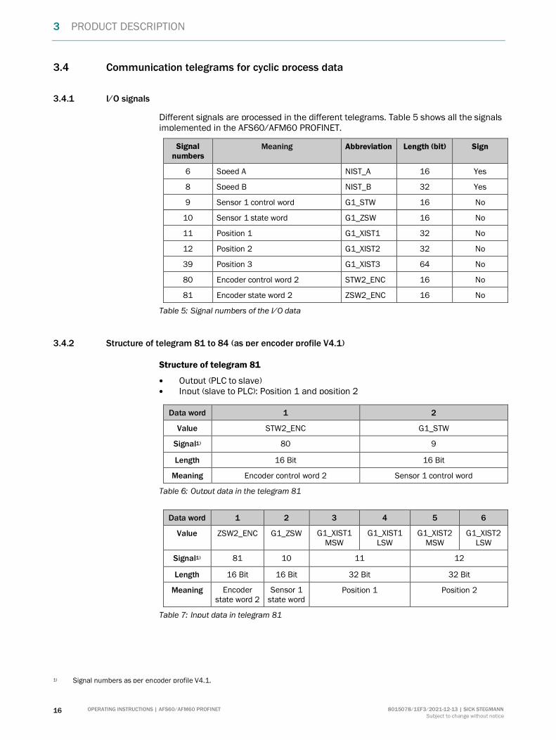
Different signals are processed in the different telegrams. Table 5 shows all the signals implemented in the AFS60/AFM60 PROFINET.
Signal numbers
Meaning Abbreviation Length (bit) Sign
6 Speed A NIST_A 16 Yes
8 Speed B NIST_B 32 Yes
9 Sensor 1 control word G1_STW 16 No
10 Sensor 1 state word G1_ZSW 16 No
11 Position 1 G1_XIST1 32 No
12 Position 2 G1_XIST2 32 No
39 Position 3 G1_XIST3 64 No
80 Encoder control word 2 STW2_ENC 16 No
81 Encoder state word 2 ZSW2_ENC 16 No
Table 5: Signal numbers of the I/O data
3.4.2 Structure of telegram 81 to 84 (as per encoder profile V4.1)
Structure of telegram 81
Output (PLC to slave) Input (slave to PLC): Position 1 and position 2
Data word 1 2
Value STW2_ENC G1_STW
Signal1) 80 9
Length 16 Bit 16 Bit
Meaning Encoder control word 2 Sensor 1 control word
Table 6: Output data in the telegram 81
Data word 1 2 3 4 5 6
Value ZSW2_ENC G1_ZSW G1_XIST1 MSW
G1_XIST1 LSW
G1_XIST2 MSW
G1_XIST2 LSW
Signal1) 81 10 11 12
Length 16 Bit 16 Bit 32 Bit 32 Bit
Meaning Encoder state word 2
Sensor 1 state word
Position 1 Position 2
Table 7: Input data in telegram 81
1) Signal numbers as per encoder profile V4.1.

PRODUCT DESCRIPTION 3
8015078/1EF3/2021-12-13 | SICK STEGMANN OPERATING INSTRUCTIONS | AFS60/AFM60 PROFINET 17
Subject to change without notice
Structure of telegram 82
Output (PLC to slave) Input (slave to PLC): Position 1 and position 2 as well as speed A
Data word 1 2
Value STW2_ENC G1_STW
Signal2) 80 9
Length 16 Bit 16 Bit
Meaning Encoder control word 2 Sensor 1 control word
Table 8: Output data in the telegram 82
Data word 1 2 3 4 5 6 7
Value ZSW2_ENC G1_ZSW G1_XIST1 MSW
G1_XIST1 LSW
G1_XIST2 MSW
G1_XIST2 LSW
NIST_A
Signal2) 81 10 11 12 6
Length 16 Bit 16 Bit 32 Bit 32 Bit 16 Bit
Meaning Encoder state word
2
Sensor 1 state word
Position 1 Position 2 Speed A
Table 9: Input data in telegram 82
2) Signal numbers as per encoder profile V4.1.
3 PRODUCT DESCRIPTION
18 OPERATING INSTRUCTIONS | AFS60/AFM60 PROFINET 8015078/1EF3/2021-12-13 | SICK STEGMANN
Subject to change without notice
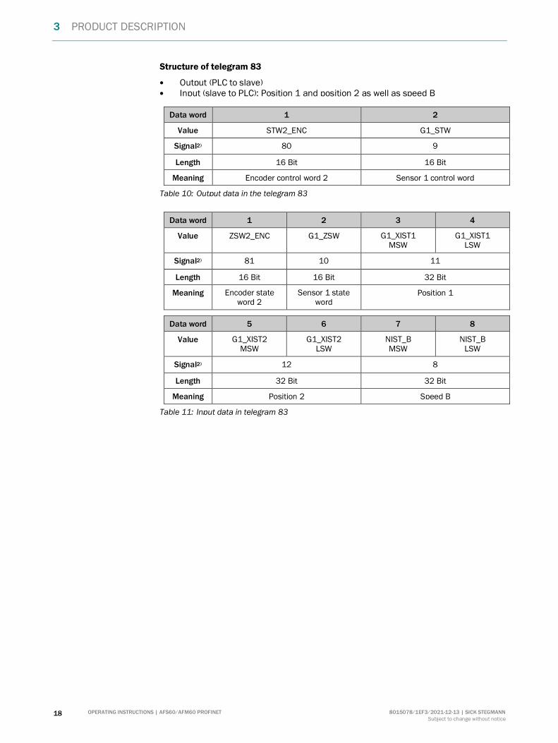
Structure of telegram 83
Output (PLC to slave) Input (slave to PLC): Position 1 and position 2 as well as speed B
Data word 1 2
Value STW2_ENC G1_STW
Signal2) 80 9
Length 16 Bit 16 Bit
Meaning Encoder control word 2 Sensor 1 control word
Table 10: Output data in the telegram 83
Data word 1 2 3 4
Value ZSW2_ENC G1_ZSW G1_XIST1 MSW
G1_XIST1 LSW
Signal2) 81 10 11
Length 16 Bit 16 Bit 32 Bit
Meaning Encoder state word 2
Sensor 1 state word
Position 1
Data word 5 6 7 8
Value G1_XIST2 MSW
G1_XIST2 LSW
NIST_B MSW
NIST_B LSW
Signal2) 12 8
Length 32 Bit 32 Bit
Meaning Position 2 Speed B
Table 11: Input data in telegram 83

PRODUCT DESCRIPTION 3
8015078/1EF3/2021-12-13 | SICK STEGMANN OPERATING INSTRUCTIONS | AFS60/AFM60 PROFINET 19
Subject to change without notice
Structure of telegram 84
Output (PLC to slave) Input (slave to PLC): Position 2 and position 3 as well as speed B
Data word 1 2
Value STW2_ENC G1_STW
Signal3) 80 9
Length 16 Bit 16 Bit
Meaning Encoder control word 2 Sensor 1 control word
Table 12: Output data in the telegram 84
Data word 1 2
Value ZSW2_ENC G1_ZSW
Signal3) 81 10
Length 16 Bit 16 Bit
Meaning Encoder state word 2 Sensor 1 state word
Data word 3 4 5 6
Value G1_XIST3 MSW
G1_XIST3
G1_XIST3 G1_XIST3 LSW
Signal3) 39
Length 64 Bit
Meaning Position 3
Data word 7 8 9 10
Value G1_XIST2 MSW
G1_XIST2 LSW
NIST_B MSW
NIST_B LSW
Signal3) 12 8
Length 32 Bit 32 Bit
Meaning Position 2 Speed B
Table 13: Input data in telegram 84
3) Signal numbers as per encoder profile V4.1.
3 PRODUCT DESCRIPTION
20 OPERATING INSTRUCTIONS | AFS60/AFM60 PROFINET 8015078/1EF3/2021-12-13 | SICK STEGMANN
Subject to change without notice
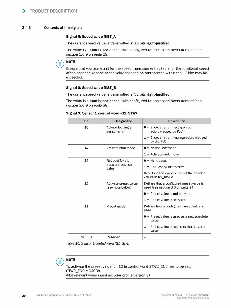
3.4.3 Contents of the signals
Signal 6: Speed value NIST_A
The current speed value is transmitted in 16 bits right-justified.
The value is output based on the units configured for the speed measurement (see section 3.6.9 on page 39).
NOTE
Ensure that you use a unit for the speed measurement suitable for the rotational speed of the encoder. Otherwise the value that can be represented within the 16 bits may be exceeded.
Signal 8: Speed value NIST_B
The current speed value is transmitted in 32 bits right-justified.
The value is output based on the units configured for the speed measurement (see section 3.6.9 on page 39).
Signal 9: Sensor 1 control word (G1_STW)
Bit Designation Description
15 Acknowledging a sensor error
0 = Encoder error message not acknowledged by PLC
1 = Encoder error message acknowledged by the PLC
14 Activate park mode 0 = Normal operation
1 = Activate park mode
13 Request for the absolute position value
0 = No request
1 = Request by the master
Results in the cyclic output of the position values in G1_XIST2
12 Activate preset value (see note below)
Defines that a configured preset value is used (see section 3.5 on page 24)
0 = Preset value is not activated
1 = Preset value is activated
11 Preset mode Defines how a configured preset value is used
0 = Preset value is used as a new absolute value
1 = Preset value is added to the previous value
10 … 0 Reserved –
Table 14: Sensor 1 control word (G1_STW)
NOTE
To activate the preset value, bit 10 in control word STW2_ENC has to be set: STW2_ENC = 0400h (Not relevant when using encoder profile version 3)

PRODUCT DESCRIPTION 3
8015078/1EF3/2021-12-13 | SICK STEGMANN OPERATING INSTRUCTIONS | AFS60/AFM60 PROFINET 21
Subject to change without notice
Signal 10: Sensor 1 state word (G1_ZSW)
Bit Designation Description
15 Encoder error 0 = No error
1 = Error
The error code is output in G1_XIST2.
14 Park mode activated 0 = Normal operation
1 = Park mode activated
Feedback based on G1_STW bit 14:
No output of position data G1_XIST1 and G1_XIST2
13 Transmission of absolute position value
0 = No transmission
1 = Position value is output in G1_XIST2
12 Status of the Preset function (set/shift of home position executed)
0 = No Preset function active
1 = Preset function is run
Feedback based on G1_STW bit 12:
New position value is output in G1_XIST1 and G1_XIST2.
On conclusion of the preset function the bit is set to 0.
11 Requirement of error acknowledgement detected
0 = No return acknowledgement of encoder error
1 = Requirement of error acknowledgement detected
Reaction to bit 15 in the sensor control word 1 G1_STW is acknowledged (see Table 14)
10 Reserved –
9 … 0 Not supported –
Table 15: Sensor 1 state word (G1_ZSW)
3 PRODUCT DESCRIPTION
22 OPERATING INSTRUCTIONS | AFS60/AFM60 PROFINET 8015078/1EF3/2021-12-13 | SICK STEGMANN
Subject to change without notice
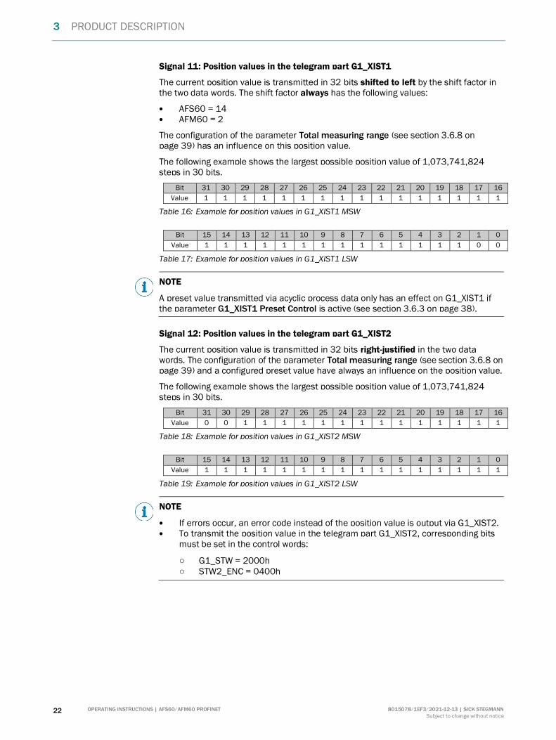
Signal 11: Position values in the telegram part G1_XIST1
The current position value is transmitted in 32 bits shifted to left by the shift factor in the two data words. The shift factor always has the following values:
AFS60 = 14 AFM60 = 2
The configuration of the parameter Total measuring range (see section 3.6.8 on page 39) has an influence on this position value.
The following example shows the largest possible position value of 1,073,741,824 steps in 30 bits.
Bit 31 30 29 28 27 26 25 24 23 22 21 20 19 18 17 16
Value 1 1 1 1 1 1 1 1 1 1 1 1 1 1 1 1
Table 16: Example for position values in G1_XIST1 MSW
Bit 15 14 13 12 11 10 9 8 7 6 5 4 3 2 1 0
Value 1 1 1 1 1 1 1 1 1 1 1 1 1 1 0 0
Table 17: Example for position values in G1_XIST1 LSW
NOTE
A preset value transmitted via acyclic process data only has an effect on G1_XIST1 if the parameter G1_XIST1 Preset Control is active (see section 3.6.3 on page 38).
Signal 12: Position values in the telegram part G1_XIST2
The current position value is transmitted in 32 bits right-justified in the two data words. The configuration of the parameter Total measuring range (see section 3.6.8 on page 39) and a configured preset value have always an influence on the position value.
The following example shows the largest possible position value of 1,073,741,824 steps in 30 bits.
Bit 31 30 29 28 27 26 25 24 23 22 21 20 19 18 17 16
Value 0 0 1 1 1 1 1 1 1 1 1 1 1 1 1 1
Table 18: Example for position values in G1_XIST2 MSW
Bit 15 14 13 12 11 10 9 8 7 6 5 4 3 2 1 0
Value 1 1 1 1 1 1 1 1 1 1 1 1 1 1 1 1
Table 19: Example for position values in G1_XIST2 LSW
NOTE
If errors occur, an error code instead of the position value is output via G1_XIST2. To transmit the position value in the telegram part G1_XIST2, corresponding bits
must be set in the control words:
○ G1_STW = 2000h ○ STW2_ENC = 0400h

PRODUCT DESCRIPTION 3
8015078/1EF3/2021-12-13 | SICK STEGMANN OPERATING INSTRUCTIONS | AFS60/AFM60 PROFINET 23
Subject to change without notice
Signal 39: Position values in the telegram part G1_XIST3
The current position value is transmitted in 64 bits right-justified. The configuration of the parameter Total measuring range (see section 3.6.8 on page 39) and a configured preset value have always an influence on the position value.
The following example shows the largest possible position value of 1,073,741,824 steps in 30 bits.
Bit 63 62 61 60 59 58 57 56 55 54 53 52 51 50 49 48
Value 0 0 0 0 0 0 0 0 0 0 0 0 0 0 0 0
Bit 47 46 45 44 43 42 41 40 39 38 37 36 35 34 33 32
Value 0 0 0 0 0 0 0 0 0 0 0 0 0 0 0 0
Bit 31 30 29 28 27 26 25 24 23 22 21 20 19 18 17 16
Value 0 0 1 1 1 1 1 1 1 1 1 1 1 1 1 1
Bit 15 14 13 12 11 10 9 8 7 6 5 4 3 2 1 0
Value 1 1 1 1 1 1 1 1 1 1 1 1 1 1 1 1
Table 20: Example for position values in G1_XIST3
Signal 80: Encoder control word 2 (STW2_ENC)
Bit Designation Description
15 … 12 Master’s Sign-of-Life (not relevant)
–
10 Control by PLC 0 = No control by the PLC
1 = Control by the PLC Enables the PLC by using control words to activate / deactivate encoder functions
7 Fault acknowledge Error-buffer handling not supported
11, 9, 8, 6 … 0 Reserved –
Table 21: Encoder control word 2 (STW2_ENC)
Signal 81: Encoder state word 2 (ZSW2_ENC)
Bit Designation Description
15 … 12 Encoder’s Sign-of-Life (not relevant)
–
11, 10 Reserved –
9 Control requested 0 = No control by the PLC requested
1 = Control by the PLC requested
8 … 0 Reserved –
Table 22: Encoder state word 2 (ZSW2_ENC)
3 PRODUCT DESCRIPTION
24 OPERATING INSTRUCTIONS | AFS60/AFM60 PROFINET 8015078/1EF3/2021-12-13 | SICK STEGMANN
Subject to change without notice
3.5 Acyclic process data
The acyclic process data are processed in parallel and in addition to the cyclic process data transmission. The acyclic process data are normally not used continuously, but only as required. They are used to configure the encoder or for requesting its status information.
The acyclic process data essentially comprise the services Read and Write with which the master can obtain read or write access to data blocks in the PROFINET slave.
The access to the acyclic process data in the AFS60/AFM60 PROFINET has been implemented in accordance with the PROFIdrive profile. For the access to these data the profile uses the client-server model. Communication is undertaken using the Request parameter and the Response parameter.
A write or read task for one or more parameters is transmitted in the Request parameter. The Response parameter then contains the response to a request.
The profile provides various indices for the data access:
Record Data Object MAP index
Start-up configuration BF00h
Start-up configuration vendor specific 1000h
Base mode parameter access B02Eh
I&M0 parameters AFF0h
Table 23: Indices for the data access
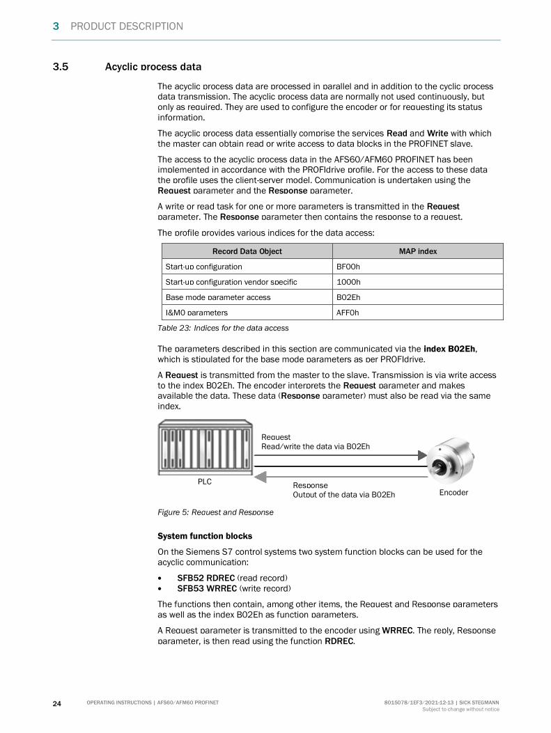
The parameters described in this section are communicated via the index B02Eh, which is stipulated for the base mode parameters as per PROFIdrive.
A Request is transmitted from the master to the slave. Transmission is via write access to the index B02Eh. The encoder interprets the Request parameter and makes available the data. These data (Response parameter) must also be read via the same index.
Figure 5: Request and Response
System function blocks
On the Siemens S7 control systems two system function blocks can be used for the acyclic communication:
SFB52 RDREC (read record) SFB53 WRREC (write record)
The functions then contain, among other items, the Request and Response parameters as well as the index B02Eh as function parameters.
A Request parameter is transmitted to the encoder using WRREC. The reply, Response parameter, is then read using the function RDREC.
Response Output of the data via B02Eh
Request Read/write the data via B02Eh
PLC
Encoder
PRODUCT DESCRIPTION 3
8015078/1EF3/2021-12-13 | SICK STEGMANN OPERATING INSTRUCTIONS | AFS60/AFM60 PROFINET 25
Subject to change without notice
SICK function blocks
Function blocks for STEP 7 and the TIA Portal are available for download at www.sick.com.
Enter the seven-digit part number for your encoder in the I am looking for ... field.
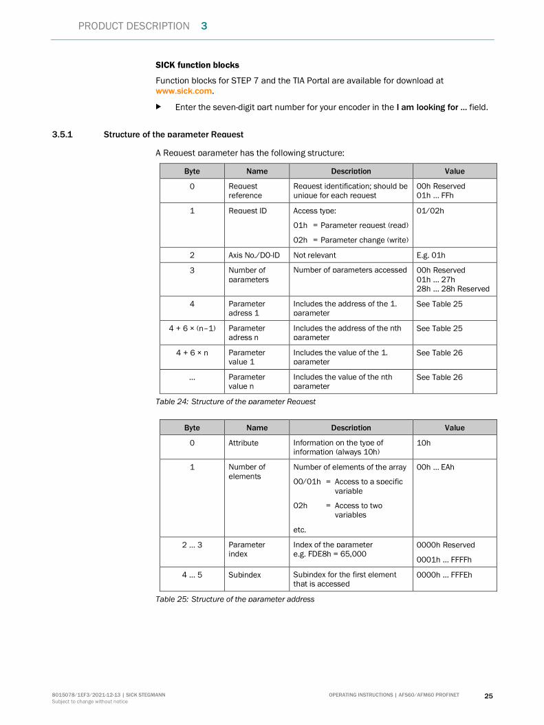
3.5.1 Structure of the parameter Request
A Request parameter has the following structure:
Byte Name Description Value
0 Request reference
Request identification; should be unique for each request
00h Reserved 01h … FFh
1 Request ID Access type:
01h = Parameter request (read)
02h = Parameter change (write)
01/02h
2 Axis No./DO-ID Not relevant E.g. 01h
3 Number of parameters
Number of parameters accessed 00h Reserved 01h … 27h 28h … 28h Reserved
4 Parameter adress 1
Includes the address of the 1. parameter
See Table 25
4 + 6 × (n–1) Parameter adress n
Includes the address of the nth parameter
See Table 25
4 + 6 × n Parameter value 1
Includes the value of the 1. parameter
See Table 26
… Parameter value n
Includes the value of the nth parameter
See Table 26
Table 24: Structure of the parameter Request
Byte Name Description Value
0 Attribute Information on the type of information (always 10h)
10h
1 Number of elements
Number of elements of the array
00/01h = Access to a specific variable
02h = Access to two variables
etc.
00h … EAh
2 … 3 Parameter index
Index of the parameter e.g. FDE8h = 65,000
0000h Reserved
0001h … FFFFh
4 … 5 Subindex Subindex for the first element that is accessed
0000h … FFFEh
Table 25: Structure of the parameter address

3 PRODUCT DESCRIPTION
26 OPERATING INSTRUCTIONS | AFS60/AFM60 PROFINET 8015078/1EF3/2021-12-13 | SICK STEGMANN
Subject to change without notice
Byte Name Description Value
0 Format Data type
41h = Byte
42h = WORD
43h = DOUBLE WORD
41h … 43h
1 Number of elements
Number of values that follow 00h … EAh
2 … x Values Values of the parameter
Table 26: Structure of the parameter value
3.5.2 Structure of the parameter Response
A Response parameter has the following structure:
Byte Name Description Value
0 Request reference
Request identification; should be unique for each request
00h reserved 01h … FFh
1 Request ID Access type:
01h = Parameter request successful
02h = Parameter change successful
81h = Parameter request failed
82h = Parameter change failed
01/02h
2 Axis No./DO-ID Returns the same value that the request contains
E.g. 01h
3 Number of parameters
Number of parameters accessed 00h reserved 01h … 27h 28h … 28h reserved
4 Parameter value 1
Includes the value of the 1. parameter or an error message
See Table 28
4 + n Parameter value n
Includes the value of the nth parameter or an error message
See Table 28
Table 27: Structure of the parameter Response
Byte Name Description Value
0 Format Data type
0Ah = OCTET STRING
41h = Byte
42h = WORD
43h = DOUBLE WORD
44h = Error message
0Ah, 41h … 44h
1 Number of elements
Number of values that follow 00h … EAh
2 … x Values Values of the parameter –
Table 28: Structure of the parameter value
PRODUCT DESCRIPTION 3
8015078/1EF3/2021-12-13 | SICK STEGMANN OPERATING INSTRUCTIONS | AFS60/AFM60 PROFINET 27
Subject to change without notice
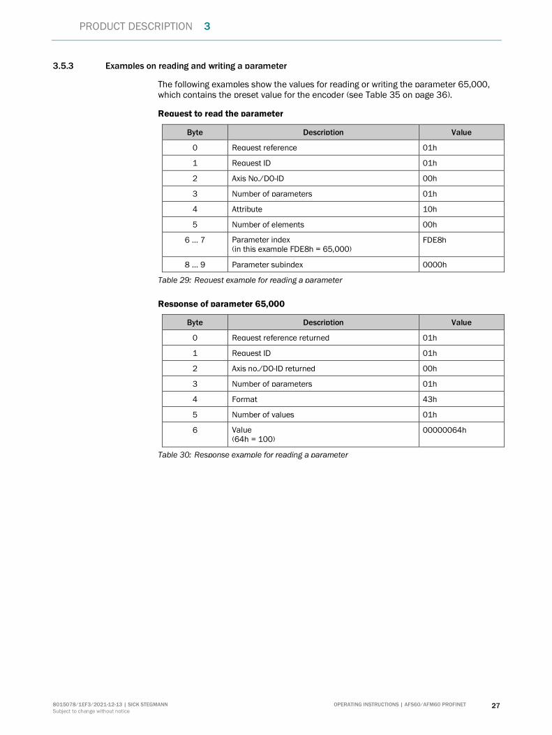
3.5.3 Examples on reading and writing a parameter
The following examples show the values for reading or writing the parameter 65,000, which contains the preset value for the encoder (see Table 35 on page 36).
Request to read the parameter
Byte Description Value
0 Request reference 01h
1 Request ID 01h
2 Axis No./DO-ID 00h
3 Number of parameters 01h
4 Attribute 10h
5 Number of elements 00h
6 … 7 Parameter index (in this example FDE8h = 65,000)
FDE8h
8 … 9 Parameter subindex 0000h
Table 29: Request example for reading a parameter
Response of parameter 65,000
Byte Description Value
0 Request reference returned 01h
1 Request ID 01h
2 Axis no./DO-ID returned 00h
3 Number of parameters 01h
4 Format 43h
5 Number of values 01h
6 Value (64h = 100)
00000064h
Table 30: Response example for reading a parameter
3 PRODUCT DESCRIPTION
28 OPERATING INSTRUCTIONS | AFS60/AFM60 PROFINET 8015078/1EF3/2021-12-13 | SICK STEGMANN
Subject to change without notice
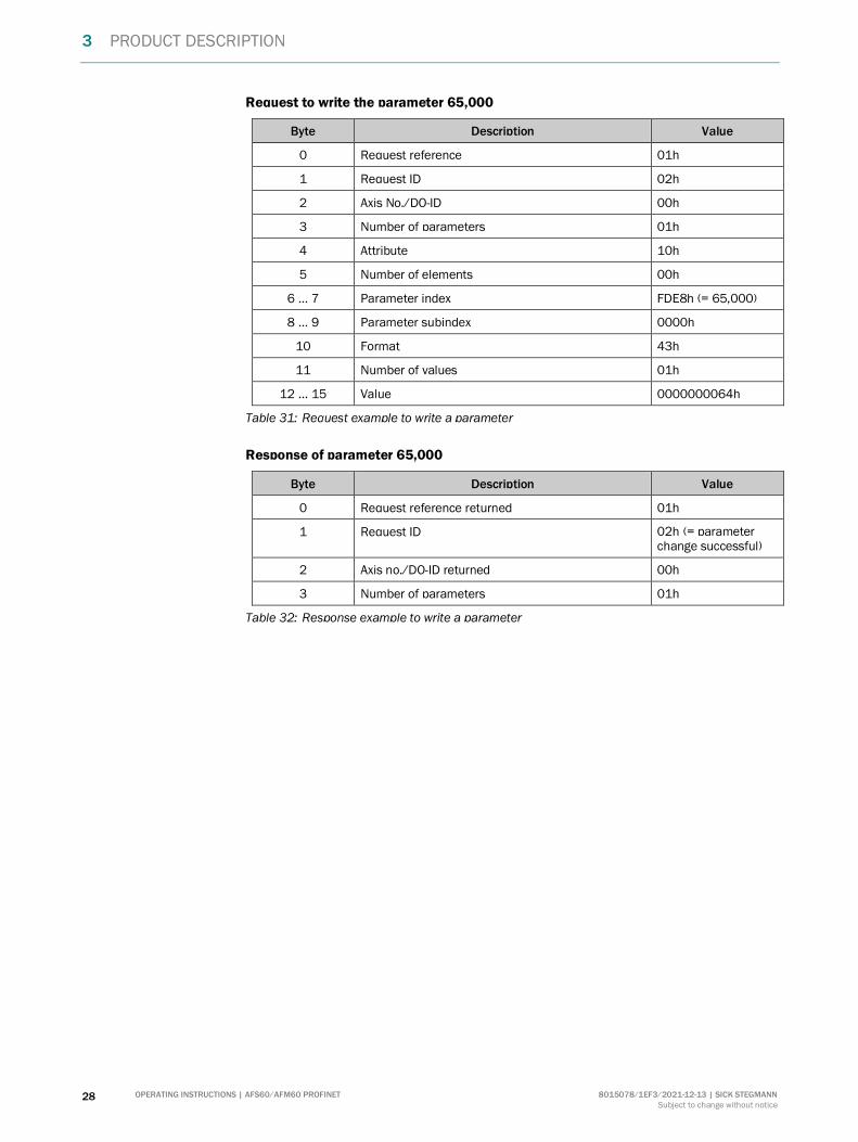
Request to write the parameter 65,000
Byte Description Value
0 Request reference 01h
1 Request ID 02h
2 Axis No./DO-ID 00h
3 Number of parameters 01h
4 Attribute 10h
5 Number of elements 00h
6 … 7 Parameter index FDE8h (= 65,000)
8 … 9 Parameter subindex 0000h
10 Format 43h
11 Number of values 01h
12 … 15 Value 0000000064h
Table 31: Request example to write a parameter
Response of parameter 65,000
Byte Description Value
0 Request reference returned 01h
1 Request ID 02h (= parameter change successful)
2 Axis no./DO-ID returned 00h
3 Number of parameters 01h
Table 32: Response example to write a parameter

PRODUCT DESCRIPTION 3
8015078/1EF3/2021-12-13 | SICK STEGMANN OPERATING INSTRUCTIONS | AFS60/AFM60 PROFINET 29
Subject to change without notice
3.5.4 PROFIdrive-specific parameters
Index Subindex
Description Access4) Data type Data values
922 Telegram currently used in the process data
R UINT-16
81, 82, 83, 84
964 Device identification R Array [0 … 5] UINT-16
.0 Manufacturer ID 01.01h (= 257)
.1 Object type (vendor specific) 41.46h
.2 Firmware version xx.xx
.3 Firmware date (year) yyyy
.4 Firmware date (day.month) dd.mm
.5 Number of drive objects Fixed to 00.01h
965 Encoder profile number Depending on the configuration of the parameter Compatibility mode (see section 3.6.6 on page 38)
R UINT-16 3D.29h or 3D.1Fh
971 Data transfer to the non-volatile memory
00h = No save
01h = Parameters are saved (then the parameter 971 is set to 00h again)
W UINT-16
975 Encoder object identification R Array [0 … 6] UINT-16
.0 Manufacturer ID 01.01h 257
.1 Object type (vendor specific) 41.46h
.2 Firmware version xx.xx
.3 Firmware date (year) yyyy
.4 Firmware date (day.month) dd.mm
.5 PROFIdrive DO type classification 5 = Encoder
00.05h
.6 PROFIdrive DO subclassification 1 Bit 14 = 1: Encoder Class 3
40.00h 01000000.0000000
4) R = Read access, W = Write access.
3 PRODUCT DESCRIPTION
30 OPERATING INSTRUCTIONS | AFS60/AFM60 PROFINET 8015078/1EF3/2021-12-13 | SICK STEGMANN
Subject to change without notice
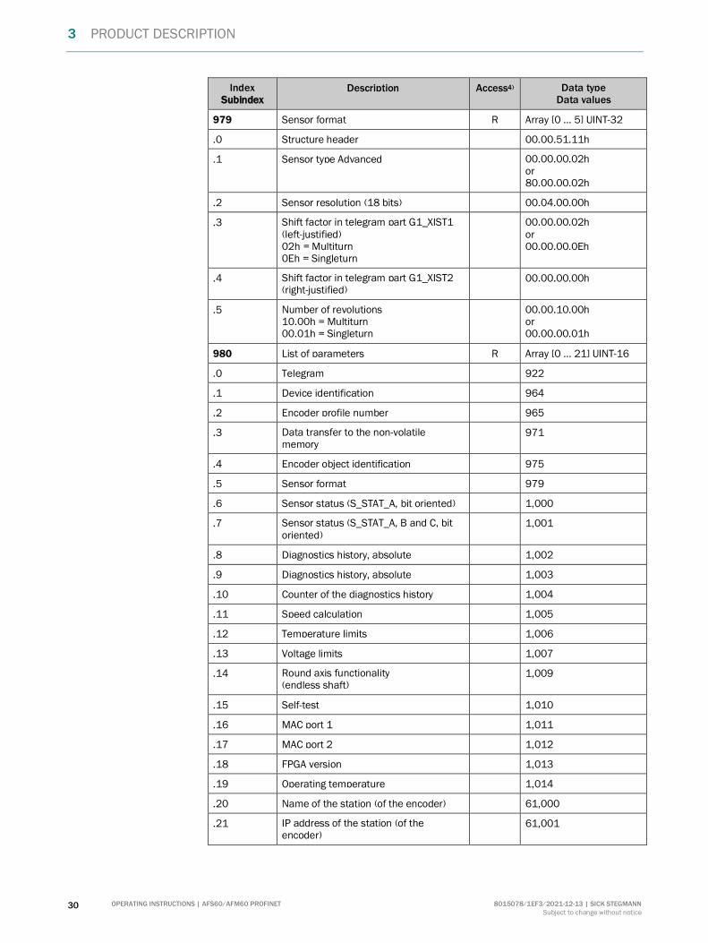
Index Subindex
Description Access4) Data type Data values
979 Sensor format R Array [0 … 5] UINT-32
.0 Structure header 00.00.51.11h
.1 Sensor type Advanced 00.00.00.02h or 80.00.00.02h
.2 Sensor resolution (18 bits) 00.04.00.00h
.3 Shift factor in telegram part G1_XIST1 (left-justified) 02h = Multiturn 0Eh = Singleturn
00.00.00.02h or 00.00.00.0Eh
.4 Shift factor in telegram part G1_XIST2 (right-justified)
00.00.00.00h
.5 Number of revolutions 10.00h = Multiturn 00.01h = Singleturn
00.00.10.00h or 00.00.00.01h
980 List of parameters R Array [0 … 21] UINT-16
.0 Telegram 922
.1 Device identification 964
.2 Encoder profile number 965
.3 Data transfer to the non-volatile memory
971
.4 Encoder object identification 975
.5 Sensor format 979
.6 Sensor status (S_STAT_A, bit oriented) 1,000
.7 Sensor status (S_STAT_A, B and C, bit oriented)
1,001
.8 Diagnostics history, absolute 1,002
.9 Diagnostics history, absolute 1,003
.10 Counter of the diagnostics history 1,004
.11 Speed calculation 1,005
.12 Temperature limits 1,006
.13 Voltage limits 1,007
.14 Round axis functionality (endless shaft)
1,009
.15 Self-test 1,010
.16 MAC port 1 1,011
.17 MAC port 2 1,012
.18 FPGA version 1,013
.19 Operating temperature 1,014
.20 Name of the station (of the encoder) 61,000
.21 IP address of the station (of the encoder)
61,001

PRODUCT DESCRIPTION 3
8015078/1EF3/2021-12-13 | SICK STEGMANN OPERATING INSTRUCTIONS | AFS60/AFM60 PROFINET 31
Subject to change without notice
Index Subindex
Description Access4) Data type Data values
.22 MAC address of the station (of the encoder)
61,002
.23 Default gateway of the station (of the encoder)
61,003
.24 Subnet mask of the station (of the encoder)
61,004
.25 Preset value (is saved in EEPROM) 65,000
.26 Operating status 65,001
.27 End of the list 0
Table 33: PROFIdrive-specific parameters

3 PRODUCT DESCRIPTION
32 OPERATING INSTRUCTIONS | AFS60/AFM60 PROFINET 8015078/1EF3/2021-12-13 | SICK STEGMANN
Subject to change without notice
3.5.5 Vendor specific parameters
Index Subindex
Description Access5) Data type Data values
1,000 Sensor status (bit oriented) R UINT-16
1,001 Sensor status (S_STAT_A, B and C, bit oriented)
R Array [0 … 2] UINT-16
.0 Contains the values of sensor status S_STAT-A
See Table 44 on page 57
.1 Contains the values of sensor status S_STAT-B
See Table 45 on page 58
.2 Contains the values of sensor status S_STAT-C
See Table 46 on page 59
1,002 Service log history information, absolute values
R Array [0 … 12] UINT-32
.0 Power up counter 1 … n
.1 Operating time in seconds 0 … n
.2 Maximum speed in rpm since the encoder has been in operation
1 … 9,000
.3 Counter for forward rotation 1 … n
.4 Counter for reverse rotation 1 … n
.5 Counter for direction change
The counter increments if the encoder changes direction of rotation.
1 … n
.6 Motion time in seconds (is incremented in case of movement with at least 6 rpm)
0 … n
.7 Current acceleration in rpm/s 0 … n
.8 Maximum internal LED current for the sensor in µA
0 … FF.FF.FF.FFh
.9 Minimum internal LED current for the sensor in µA
0 … FF.FF.FF.FFh
.10 Maximum operating voltage in volts 0 … FF.FF.FF.FFh
.11 Maximum operating temperature in °C 0 … FF.FF.FF.FFh
.12 Minimum operating temperature in °C (must be interpreted as INT-32)
0 … FF.FF.FF.FFh
5) R = Read access, W = Write access.

PRODUCT DESCRIPTION 3
8015078/1EF3/2021-12-13 | SICK STEGMANN OPERATING INSTRUCTIONS | AFS60/AFM60 PROFINET 33
Subject to change without notice
Index Subindex
Description Access5) Data type Data values
1,003 Service log history information, relative values
The values of the parameter can be reset.
R Array [0 … 12] UINT-32
.0 Power up counter 1 … n
.1 Operating time in seconds 0 … n
.2 Maximum speed in rpm since the encoder has been in operation
1 … 9,000
.3 Counter for forward rotation 1 … n
.4 Counter for reverse rotation 1 … n
.5 Counter for direction change
The counter increments if the encoder changes direction of rotation.
1 … n
.6 Motion time in seconds (is incremented in case of movement with at least 6 rpm)
0 … n
.7 Current acceleration in rpm/s 0 … n
.8 Maximum internal LED current for the sensor in µA
0 … FF.FF.FF.FFh
.9 Minimum internal LED current for the sensor in µA
0 … FF.FF.FF.FFh
.10 Maximum operating voltage in volts 0 … FF.FF.FF.FFh
.11 Maximum operating temperature in °C 0 … FF.FF.FF.FFh
.12 Minimum operating temperature in °C (must be interpreted as INT-32)
0 … FF.FF.FF.FFh
1,004 Counter of the diagnostics history
Counts the errors and warnings that have occurred in the individual bits of the sensor status S_STAT_A (see
Table 44 on page 57)
R Array [0 … 15] UINT-16
.0 Bit 1 1 … 255
.1 Bit 2 1 … 255
.2 Bit 3 1 … 255
.3 Bit 4 1 … 255
.4 Bit 5 1 … 255
.5 Bit 6 1 … 255
.6 Bit 7 1 … 255
.7 Bit 8 1 … 255
.8 Bit 9 1 … 255
.9 Bit 10 1 … 255
.10 Bit 11 1 … 255
.11 Bit 12 1 … 255

3 PRODUCT DESCRIPTION
34 OPERATING INSTRUCTIONS | AFS60/AFM60 PROFINET 8015078/1EF3/2021-12-13 | SICK STEGMANN
Subject to change without notice
Index Subindex
Description Access5) Data type Data values
.12 Bit 13 1 … 255
.13 Bit 14 1 … 255
.14 Bit 15 1 … 255
1,005 Speed calculation R Array [0 … 15] UINT-16
.0 Mode for the speed calculation 0 Not active
1 Active
.1 Speed measuring unit 0 steps/s
1 steps/100ms
2 steps/10ms
3 rpm
4 rps
.2 T1 – Refresh time in ms AFS60 = 2
AFM60 = 1 … 50
.3 T2 – Integration time dependent of the refresh time
The speed is calculated from the average of several measurements. The integration value T2 defines the number of values from which the average is calculated. The refresh time T1 defines the time between the individual measurements.
Example: If T1 = 2 ms and T2 = 200, then the speed is calculated from the last 0.4 s.
1 … 200
1,006 Limits of the operating temperature allowed
R/W Array [0 … 1] UINT-16
.0 Defines the lower limit for the operating temperature allowed in °C
–40
+80
.1 Defines the upper limit for the operating temperature allowed in °C
–20
+120
1,007 Limit of the supply voltage allowed R/W Array [0 … 1] UINT-16
.0 Defines the lower limit for the supply voltage allowed in mV
9,000
24,000
.1 Defines the upper limit for the supply voltage allowed in mV
10,000
30,000

PRODUCT DESCRIPTION 3
8015078/1EF3/2021-12-13 | SICK STEGMANN OPERATING INSTRUCTIONS | AFS60/AFM60 PROFINET 35
Subject to change without notice
Index Subindex
Description Access5) Data type Data values
1,009 Round axis functionality (endless shaft)
R/W Array [0 … 10] UINT-32
.0 Operating mode 1 = Off
2 = On
.1 Input CNR_N Nominator for the number of revolutions
1 … 00.01.00.00h
.2 Input CNR_D Divisor for the number of revolutions
1 … 00.01.00.00h
.3 Input CMR Total resolution
1 … 40.00.00.00h
.4 Range offset (saved in EEPROM) 1 … 80.00.00.00h
.5 Internal shift value 1 … FF.FF.FF.FFh
.6 Output CNR-N Nominator for the number of revolutions
See subindex .1
.7 Output CNR-D Divisor for the number of revolutions
See subindex .2
.8 Output CMR Total resolution
See subindex .3
.9 CPR Steps per revolution, digits before the decimal separator
Ex.: at 1.555 = 1
.10 CPR Steps per revolution, digits after the decimal separator
Ex.: at 1.555 = 555
1,010 Reserved – –
1,011 MAC address of Ethernet port 1 R OCTET STRING [6]
1,012 MAC address of Ethernet port 2 R OCTET STRING [6]
1,013 FPGA version R UINT-32
.0 Example:
Value = 00010200h
Version = 1.2.0
R DWORD
1,014 Operating temperature R INT-16
.0 Current operating temperature in °C R WORD
Table 34: Vendor specific parameters

3 PRODUCT DESCRIPTION
36 OPERATING INSTRUCTIONS | AFS60/AFM60 PROFINET 8015078/1EF3/2021-12-13 | SICK STEGMANN
Subject to change without notice
3.5.6 Encoder profile-specific parameters
Index/ Subindex
Description Access6) Data type Data values
61,000 Name of the station (of the encoder) R OCTET STRING [240]
61,001 IP address of the station (of the encoder)
R UINT-32
61,002 MAC address of the station (of the encoder)
R OCTET STRING [6]
61,003 Default gateway of the station (of the encoder)
R UINT-32
61,004 Subnet mask of the station (of the encoder)
R UINT-32
65,000 Preset value (can be saved in the EEPROM with the aid of parameter 971, see Table 33 on page 31)
R/W UINT-32
65,001 Operating status R Array [0 … 11] UINT-32
.0 Structure header 00.0B.01.01h 0B = 11 entries
.1 Operating status See Table 36 on page 37
.2 Current errors See Table 47 on page 60
.3 Supported error messages See Table 48 on page 60
.4 Current warnings See Table 49 on page 61
.5 Supported warnings See Table 50 on page 61
.6 Version of the encoder profile 00.00.04.01h
.7 Operating time (value × 0.1 h) 1 … 00.00.00.00h
.8 Offset value (saved in EEPROM) 1 … 00.00.00.00h
.9 CPR Resolution per revolution
1 … 00.04.00.00h 1 … 262,144
.10 CMR Total resolution
1 … 40.00.00.00h 1 … 1,073,741,824
.11 Speed measuring unit 0 = steps/s
1 = steps/100 ms
2 = steps/10 ms
3 = rpm
Table 35: Encoder profile-specific parameters
6) R = Read access, W = Write access.
PRODUCT DESCRIPTION 3
8015078/1EF3/2021-12-13 | SICK STEGMANN OPERATING INSTRUCTIONS | AFS60/AFM60 PROFINET 37
Subject to change without notice
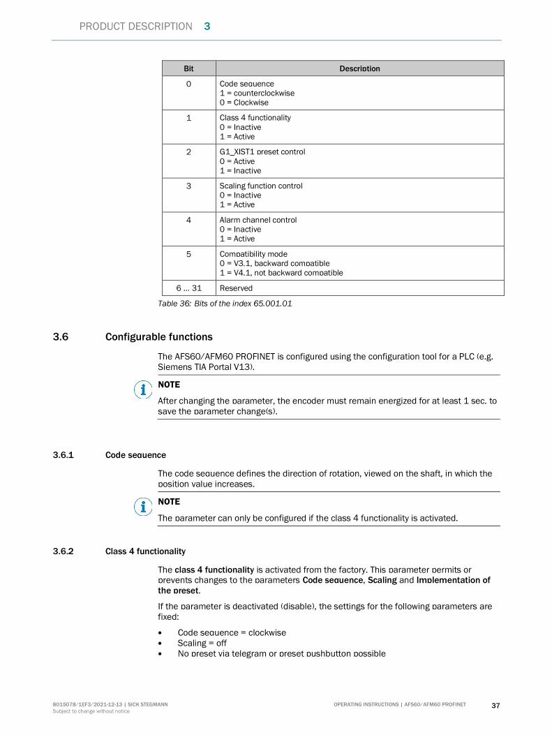
Bit Description
0 Code sequence 1 = counterclockwise 0 = Clockwise
1 Class 4 functionality 0 = Inactive 1 = Active
2 G1_XIST1 preset control 0 = Active 1 = Inactive
3 Scaling function control 0 = Inactive 1 = Active
4 Alarm channel control 0 = Inactive 1 = Active
5 Compatibility mode 0 = V3.1, backward compatible 1 = V4.1, not backward compatible
6 … 31 Reserved
Table 36: Bits of the index 65.001.01
3.6 Configurable functions
The AFS60/AFM60 PROFINET is configured using the configuration tool for a PLC (e.g. Siemens TIA Portal V13).
NOTE
After changing the parameter, the encoder must remain energized for at least 1 sec. to save the parameter change(s).
3.6.1 Code sequence
The code sequence defines the direction of rotation, viewed on the shaft, in which the position value increases.
NOTE
The parameter can only be configured if the class 4 functionality is activated.
3.6.2 Class 4 functionality
The class 4 functionality is activated from the factory. This parameter permits or prevents changes to the parameters Code sequence, Scaling and Implementation of the preset.
If the parameter is deactivated (disable), the settings for the following parameters are fixed:
Code sequence = clockwise Scaling = off No preset via telegram or preset pushbutton possible
3 PRODUCT DESCRIPTION
38 OPERATING INSTRUCTIONS | AFS60/AFM60 PROFINET 8015078/1EF3/2021-12-13 | SICK STEGMANN
Subject to change without notice
3.6.3 G1_XIST1 preset control
The parameter defines whether the preset function affects the telegram part G1_XIST1. Otherwise the preset only acts on G1_XIST2.
NOTE
The parameter can only be configured if the class 4 functionality is activated.
3.6.4 Scaling
The parameter Scaling makes it possible to scale the resolution per revolution and the total resolution.
NOTE
Only if the Scaling parameter is activated (enable), the values entered for the resolution and total resolution are applied to the configuration. Otherwise the values will be ignored!
3.6.5 Alarm channel control
NOTE
The parameter can only be deactivated (disable) if the parameter Compatibility mode is activated (enable).
Alarm channel control – active The diagnostic data are transmitted as per encoder profile V4.1.
Alarm channel control – inactive No “Alarms” are transmitted.
3.6.6 Compatibility mode
Using this parameter the encoder can be configured such that it operates as per encoder profile V3.1 and not as per V4.1. This parameter also affects the following functions:
Alarm channel control The parameter can be configured inactive in the compatibility mode.
In addition it is assumed that the bit Control by PLC in the telegram part STW2_ENC is permanently set to 1, as if the control system is constantly requesting control.
3.6.7 Measuring range per revolution
The measuring range per revolution is stated in two parameters, as Least Significant Double Word (LSDW) and as Most Significant Double Word (MSDW).
The resolution is max. 262,144 steps per revolution. The resolution can be scaled from 1 … 262,144 as an integer.
NOTE
The parameter is not used if the round axis functionality (see 3.6.12 on page 40) is activated.
PRODUCT DESCRIPTION 3
8015078/1EF3/2021-12-13 | SICK STEGMANN OPERATING INSTRUCTIONS | AFS60/AFM60 PROFINET 39
Subject to change without notice
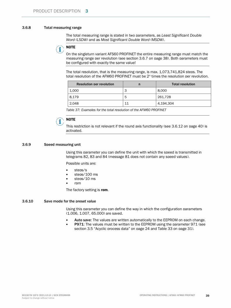
3.6.8 Total measuring range
The total measuring range is stated in two parameters, as Least Significant Double Word (LSDW) and as Most Significant Double Word (MSDW).
NOTE
On the singleturn variant AFS60 PROFINET the entire measuring range must match the measuring range per revolution (see section 3.6.7 on page 38). Both parameters must be configured with exactly the same value!
The total resolution, that is the measuring range, is max. 1,073,741,824 steps. The total resolution of the AFM60 PROFINET must be 2n times the resolution per revolution.
Resolution per revolution n Total resolution
1,000 3 8,000
8,179 5 261,728
2,048 11 4,194,304
Table 37: Examples for the total resolution of the AFM60 PROFINET
NOTE
This restriction is not relevant if the round axis functionality (see 3.6.12 on page 40) is activated.
3.6.9 Speed measuring unit
Using this parameter you can define the unit with which the speed is transmitted in telegrams 82, 83 and 84 (message 81 does not contain any speed values).
Possible units are:
steps/s steps/100 ms steps/10 ms rpm
The factory setting is rpm.
3.6.10 Save mode for the preset value
Using this parameter you can define the way in which the configuration parameters (1.006, 1.007, 65.000) are saved.
Auto save: The values are written automatically to the EEPROM on each change. P971: The values must be written to the EEPROM using the parameter 971 (see
section 3.5 “Acyclic process data” on page 24 and Table 33 on page 31).
3 PRODUCT DESCRIPTION
40 OPERATING INSTRUCTIONS | AFS60/AFM60 PROFINET 8015078/1EF3/2021-12-13 | SICK STEGMANN
Subject to change without notice
3.6.11 Transmit preset value
Using this parameter you can define whether the preset value (see section 3.6.17 on page 40) is transmitted on switching on or initializing the encoder. You will find an example for setting a preset value in section 4.4.2 from page 48.
Enable: The preset value is transmitted on switching on or initializing the encoder into the parameter 65.000. The preset value can be changed in operation via acyclic process data (see section 3.5 on page 24 and Table 35 on page 36).
Disable: The parameter is not transmitted on switching on or initializing the encoder.
The preset value is only used when the related bits of the sensor 1 control word G1_STW are set (see Table 14 on page 20) and bit 10 in control word STW2_ENC is set (see Table 21 on page 23).
3.6.12 Round axis functionality
The round axis functionality removes the restriction that the total resolution must be 2ⁿ times the Steps per revolution. The shaft is considered as an endless shaft.
The steps per revolution are not configured directly, instead the nominator and divisor for the number of revolutions are defined.
The total measuring range can be scaled from 1 … 1,073,741,824 as an integer.
3.6.13 Number of revolutions, nominator for the round axis functionality
The nominator can be scaled from 1 … 2,048 as an integer. The default factory setting for the nominator is 2,048.
3.6.14 Number of revolutions, divisor for the round axis functionality
The divisor can be scaled from 1 … 65,535 as an integer. The default factory setting for the divisor is 1.
3.6.15 Speed filter, sampling interval
The speed value is calculated as an average value and output. The sampling interval defines the time between measurements and how measurements are made. It can be between 1 and 100 ms.
3.6.16 Speed filter, number of measurements
The number of measurements defines the number of measured values from which the average speed is calculated. The number can be 1 to 200.
3.6.17 Preset value
The Preset value parameter contains the value that is transmitted to the encoder with the parameter Transmit preset value (see section 3.6.11 on page 40).
PRODUCT DESCRIPTION 3
8015078/1EF3/2021-12-13 | SICK STEGMANN OPERATING INSTRUCTIONS | AFS60/AFM60 PROFINET 41
Subject to change without notice
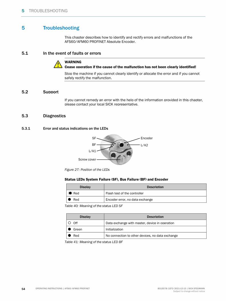
3.7 Controls and status indicators
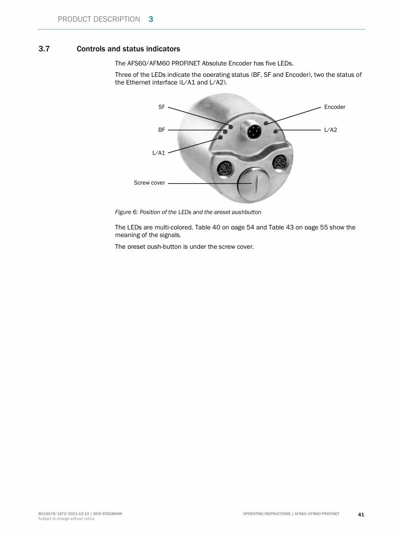
The AFS60/AFM60 PROFINET Absolute Encoder has five LEDs.
Three of the LEDs indicate the operating status (BF, SF and Encoder), two the status of the Ethernet interface (L/A1 and L/A2).
Figure 6: Position of the LEDs and the preset pushbutton
The LEDs are multi-colored. Table 40 on page 54 and Table 43 on page 55 show the meaning of the signals.
The preset push-button is under the screw cover.
L/A1
Encoder
L/A2 BF
SF
Screw cover

4 COMMISSIONING
42 OPERATING INSTRUCTIONS | AFS60/AFM60 PROFINET 8015078/1EF3/2021-12-13 | SICK STEGMANN
Subject to change without notice
4 Commissioning
This chapter provides information on the electrical installation, configuration and commissioning of the Absolute Encoder AFS60/AFM60 PROFINET.
Please read this chapter before mounting, installing and commissioning the device.
4.1 Electrical installation
WARNING
Switch the power supply off!
The machine/system could unintentionally start up while you are connecting the devices.
Ensure that the entire machine/system is disconnected during the electrical installation.
For the electrical installation you will need connection plugs and sockets (see the data sheet of the AFS60/AFM60 PROFINET).
4.1.1 Connections of the AFS60/AFM60 PROFINET
The connections of the AFS60/AFM60 PROFINET are on the back.
Figure 7: Position of the connections of the AFS60/AFM60 PROFINET
Port 1
M12 × 4, female connector Voltage supply M12 × 4, plug
Port 2 M12 × 4, female connector
Figure 8: Connections of the AFS60/AFM60 PROFINET
Port 1
Voltage supply
Port 2
COMMISSIONING 4
8015078/1EF3/2021-12-13 | SICK STEGMANN OPERATING INSTRUCTIONS | AFS60/AFM60 PROFINET 43
Subject to change without notice
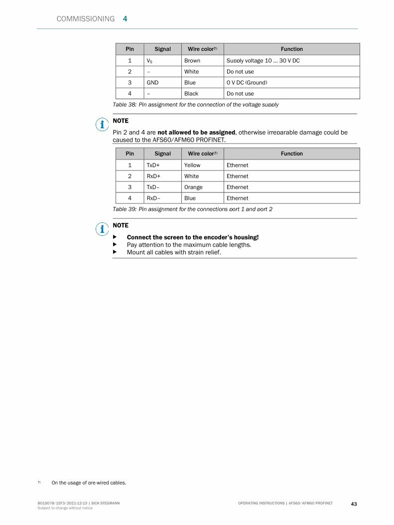
Pin Signal Wire color7) Function
1 VS Brown Supply voltage 10 … 30 V DC
2 – White Do not use
3 GND Blue 0 V DC (Ground)
4 – Black Do not use
Table 38: Pin assignment for the connection of the voltage supply
NOTE
Pin 2 and 4 are not allowed to be assigned, otherwise irreparable damage could be caused to the AFS60/AFM60 PROFINET.
Pin Signal Wire color7) Function
1 TxD+ Yellow Ethernet
2 RxD+ White Ethernet
3 TxD– Orange Ethernet
4 RxD– Blue Ethernet
Table 39: Pin assignment for the connections port 1 and port 2
NOTE
Connect the screen to the encoder’s housing! Pay attention to the maximum cable lengths. Mount all cables with strain relief.
7) On the usage of pre-wired cables.

4 COMMISSIONING
44 OPERATING INSTRUCTIONS | AFS60/AFM60 PROFINET 8015078/1EF3/2021-12-13 | SICK STEGMANN
Subject to change without notice
4.2 Settings on the hardware
There are the following controls for making settings under the screw cover:
Three address switches Preset push-button
Open the screw cover using a screwdriver for slot-head screws with a blade width of min. 10.0 mm.
Figure 9: Position of the controls
Preset pushbutton
Address switches
COMMISSIONING 4
8015078/1EF3/2021-12-13 | SICK STEGMANN OPERATING INSTRUCTIONS | AFS60/AFM60 PROFINET 45
Subject to change without notice
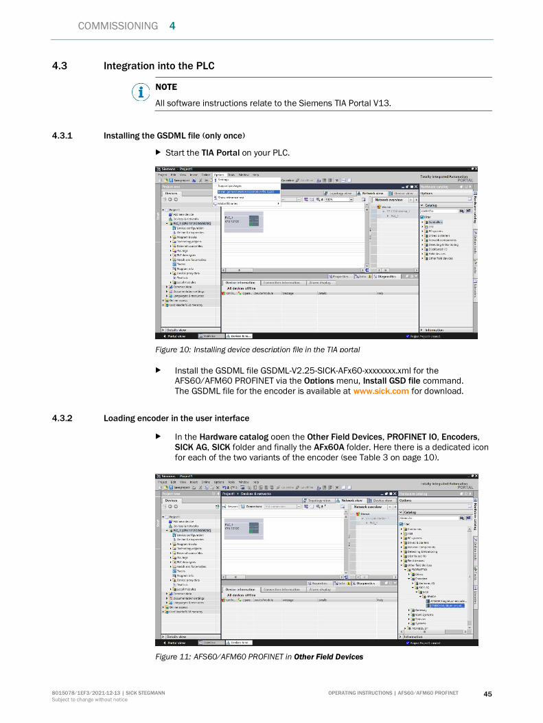
4.3 Integration into the PLC
NOTE
All software instructions relate to the Siemens TIA Portal V13.
4.3.1 Installing the GSDML file (only once)
Start the TIA Portal on your PLC.
Figure 10: Installing device description file in the TIA portal
Install the GSDML file GSDML-V2.25-SICK-AFx60-xxxxxxxx.xml for the AFS60/AFM60 PROFINET via the Options menu, Install GSD file command. The GSDML file for the encoder is available at www.sick.com for download.
4.3.2 Loading encoder in the user interface
In the Hardware catalog open the Other Field Devices, PROFINET IO, Encoders, SICK AG, SICK folder and finally the AFx60A folder. Here there is a dedicated icon for each of the two variants of the encoder (see Table 3 on page 10).
Figure 11: AFS60/AFM60 PROFINET in Other Field Devices

4 COMMISSIONING
46 OPERATING INSTRUCTIONS | AFS60/AFM60 PROFINET 8015078/1EF3/2021-12-13 | SICK STEGMANN
Subject to change without notice
Add the device AFS60A or AFM60A to the Network view using drag-and-drop.
Figure 12: Connection from the PLC to AFS60A or AFM60A
Using the mouse, drag a connection from the control system icon to the encoder icon.
4.4 Configuration of the encoder via the Parameter Access Point
Mark the encoder icon and in the Device view, change the configuration data and the vendor specific configuration data in the middle window at the bottom in Parameter Access Point. For the possible parameter settings, see section 3.6 on page 37.
Configuration data
Figure 13: Configuration data
The AFS60/AFM60 PROFINET is supplied with the configuration data shown.

COMMISSIONING 4
8015078/1EF3/2021-12-13 | SICK STEGMANN OPERATING INSTRUCTIONS | AFS60/AFM60 PROFINET 47
Subject to change without notice
Vendor specific configuration data
Figure 14: Vendor specific configuration data
The AFS60/AFM60 PROFINET is supplied with the vendor specific configuration data shown.
4.4.1 Reading the position
To read from position 2 (the right-justified position value) in the input data for telegrams 81 to 84, select STW2_ENC (encoder control word 2) and G1_STW (sensor 1 control word) (see section 3.4.2 on page 16).
Figure 15: Reading the position
Set bit 10 of the control word STW2_ENC to 1 (= 0400h, see Table 21 on page 23).
Set bit 13 of the control word G1_STW to 1 (= 2000h). This results in the cyclic output of the position value in G1_XIST2 (see Table 14 on page 20).
4 COMMISSIONING
48 OPERATING INSTRUCTIONS | AFS60/AFM60 PROFINET 8015078/1EF3/2021-12-13 | SICK STEGMANN
Subject to change without notice
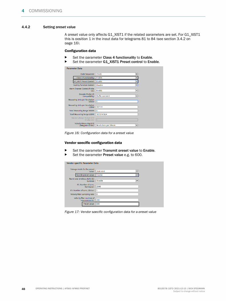
4.4.2 Setting preset value
A preset value only affects G1_XIST1 if the related parameters are set. For G1_XIST1 this is position 1 in the input data for telegrams 81 to 84 (see section 3.4.2 on page 16).
Configuration data
Set the parameter Class 4 functionality to Enable. Set the parameter G1_XIST1 Preset control to Enable.
Figure 16: Configuration data for a preset value
Vendor specific configuration data
Set the parameter Transmit preset value to Enable. Set the parameter Preset value e.g. to 600.
Figure 17: Vendor specific configuration data for a preset value
COMMISSIONING 4
8015078/1EF3/2021-12-13 | SICK STEGMANN OPERATING INSTRUCTIONS | AFS60/AFM60 PROFINET 49
Subject to change without notice
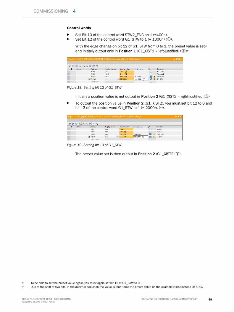
Control words
Set Bit 10 of the control word STW2_ENC on 1 (=400h). Set Bit 12 of the control word G1_STW to 1 (= 1000h) ().
With the edge change on bit 12 of G1_STW from 0 to 1, the preset value is set8)
and initially output only in Position 1 (G1_XIST1 – left-justified) ()9).
Figure 18: Setting bit 12 of G1_STW
Initially a position value is not output in Position 2 (G1_XIST2 – right-justified ().
To output the position value in Position 2 (G1_XIST2), you must set bit 12 to 0 and bit 13 of the control word G1_STW to 1 (= 2000h, ).
Figure 19: Setting bit 13 of G1_STW
The preset value set is then output in Position 2 (G1_XIST2 ().
8) To be able to set the preset value again, you must again set bit 12 of G1_STW to 0. 9) Due to the shift of two bits, in the decimal depiction the value is four times the preset value (in the example 2400 instead of 600).

4 COMMISSIONING
50 OPERATING INSTRUCTIONS | AFS60/AFM60 PROFINET 8015078/1EF3/2021-12-13 | SICK STEGMANN
Subject to change without notice
4.5 Configuring encoder as technology object
The encoder can be configured as a technology object. It is a prerequisite that the encoder is integrated into the PLC (see section 4.3 on page 45).
Figure 20: Project navigation in the TIA Portal
In Technology objects, select the command Add new object (). The Add new object dialog box is opened.
Figure 21: Add new object dialog box
As Motion Control choose TO_ExternalEncoder () (for an external encoder). If necessary, enter a type code for the encoder in the Type field () (e.g. AFx60). Click OK ().

COMMISSIONING 4
8015078/1EF3/2021-12-13 | SICK STEGMANN OPERATING INSTRUCTIONS | AFS60/AFM60 PROFINET 51
Subject to change without notice
The encoder is added as an ExternalEncoder in Technology objects in the Project tree.
In the Project tree select the point Configuration () under the newly added encoder. The Basic parameters of the encoder are displayed.
Figure 22: Configuring the basic parameters
In Basic parameters select the option Rotary (). Accept the message that the configuration will be set to the default values using
Yes (). As a consequence any parameters configured previously will be lost.
Figure 23: Configuring the hardware interface
Select Hardware interface (). Choose the PROFIdrive encoder on PROFINET/PROFIBUS option (). Click the Encoder... list box ().

4 COMMISSIONING
52 OPERATING INSTRUCTIONS | AFS60/AFM60 PROFINET 8015078/1EF3/2021-12-13 | SICK STEGMANN
Subject to change without notice
Figure 24: Selecting AFM60A
Select AFM60A (). Select EO_Multiturn_1 (). Click on the green checkmark ().
Figure 25: Data exchange
Select Data exchange (). In Telegram () select the telegram for the exchange of data. You must select the
same telegram that was selected during the integration of the encoder. Only telegrams 81 and 83 are supported.
In Encoder type () select the option Rotary absolute. In the Steps per revolution field enter 262144 () and in the Number of
revolutions field enter 4096 (). Enter the following values in the Bits in incr. actual value (Gn_XIST1) () field:
○ AFS60 = 14 ○ AFM60 = 2
In the Bits in incr. actual value (Gn_XIST2) () field enter the value 0. Then click Device configuration ().
COMMISSIONING 4
8015078/1EF3/2021-12-13 | SICK STEGMANN OPERATING INSTRUCTIONS | AFS60/AFM60 PROFINET 53
Subject to change without notice
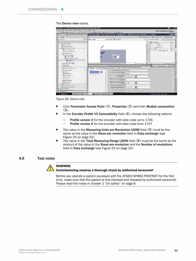
The Device view opens.
Figure 26: Device view
Click Parameter Access Point (), Properties () and then Module parameters ().
In the Encoder Profile V3 Compatibility field (), choose the following options:
○ Profile version 3 for the encoder with date code up to 1706 ○ Profile version 4 for the encoder with date code from 1707
The value in the Measuring Units per Revolution LSDW field () must be the same as the value in the Steps per revolution field in Data exchange (see Figure 25 on page 52).
The value in the Total Measuring Range LSDW field () must be the same as the product of the value in the Steps pre revolution and the Number of revolutions field in Data exchange (see Figure 25 on page 52).
4.6 Test notes
WARNING
Commissioning requires a thorough check by authorized personnel!
Before you operate a system equipped with the AFS60/AFM60 PROFINET for the first time, make sure that the system is first checked and released by authorized personnel. Please read the notes in chapter 2 “On safety” on page 8.
5 TROUBLESHOOTING
54 OPERATING INSTRUCTIONS | AFS60/AFM60 PROFINET 8015078/1EF3/2021-12-13 | SICK STEGMANN
Subject to change without notice
5 Troubleshooting
This chapter describes how to identify and rectify errors and malfunctions of the AFS60/AFM60 PROFINET Absolute Encoder.
5.1 In the event of faults or errors
WARNING
Cease operation if the cause of the malfunction has not been clearly identified!
Stop the machine if you cannot clearly identify or allocate the error and if you cannot safely rectify the malfunction.
5.2 Support
If you cannot remedy an error with the help of the information provided in this chapter, please contact your local SICK representative.
5.3 Diagnostics
5.3.1 Error and status indications on the LEDs
Figure 27: Position of the LEDs
Status LEDs System Failure (SF), Bus Failure (BF) and Encoder
Display Description
Red Flash test of the controller
Red Encoder error, no data exchange
Table 40: Meaning of the status LED SF
Display Description
Off Data exchange with master, device in operation
Green Initialization
Red No connection to other devices, no data exchange
Table 41: Meaning of the status LED BF
L/A1
Encoder
L/A2 BF
SF
Screw cover
TROUBLESHOOTING 5
8015078/1EF3/2021-12-13 | SICK STEGMANN OPERATING INSTRUCTIONS | AFS60/AFM60 PROFINET 55
Subject to change without notice
Display Description
Off No operating voltage
Red/green Self-test/initialization
Green Encoder in operation
Red/green Below or above limits (speed, temperature, LED current, operating voltage)
Red Position or memory-related error
Orange Invalid preset value or invalid value for the configuration parameters
Green Encoder manually reset to factory settings (see section 5.5 on page 63). Necessary to switch off and switch on again the operating voltage
Table 42: Meaning of the status LED Encoder
Ethernet Link LEDs L/A1 and L/A2
The Ethernet Link LEDs L/A1 and L/A2 display the status of the physical connection on the Ethernet interfaces. L/A1 shows the status of the Ethernet interface 1, L/A2 the status of the Ethernet interface 2 (see Figure 7 on page 42).
Display Description
Off No operating voltage
or
No Ethernet connection
Green Ethernet connection established
Green Data transmission
Orange Data transmission at 100 Mbit/s
Table 43: Meaning of the LEDs L/A1 and L/A2
5.4 Error transmission via PROFINET
PROFINET provides diagnostics features that help you to locate a problem if the cause of the error is unclear or if there are availability problems. The following diagnostic features are available:
Error messages via parameter 65,001 Error messages via the alarm channel Error codes in telegram part G1_XIST2
NOTE
The function of the encoder corresponds to encoder profile version 4.1 for PROFIBUS and PROFINET. Accordingly the encoder must enter an error state in the event of a brief fault on the bus. Such brief faults can be triggered by electromagnetic interference, particularly by transient overvoltages.
An error state must be acknowledged by the control system, only then does the encoder output valid values in the telegram part G1_XIST2 on the bus.
This aspect must be taken into account in the implementation of the control system.
After the error has been detected by the control system, it can be reset using bit 15 of the sensor 1 control word (G1_STW). This is only possible if the cause of the error has been rectified and the status of the encoder is within the defined limits.
5 TROUBLESHOOTING
56 OPERATING INSTRUCTIONS | AFS60/AFM60 PROFINET 8015078/1EF3/2021-12-13 | SICK STEGMANN
Subject to change without notice
5.4.1 Error message on vendor specific parameters
The status of the encoder can be read via the parameter 1,001. The individual bits in the subindex .0 to .2 indicate the nature of the error.
Subindex .0 – Sensor status (S_STAT-A)
Bit Designation Description
15 EEPROM_DATA_CHKS Memory error:
Invalid EEPROM checksum on initialization
14 I2C_COMM_SENS_DEV Position error:
Invalid communication with the I2C device10) in
the sensor module
13 – Reserved
12 POS_SYNC_MULTCNT_UPDATE Position error:
Invalid EEPROM checksum
or
Invalid internal SSI communication (MFP4 signal11))
11 POS_SYNC_MULTITURN Position error:
Invalid synchronization or no synchronization of MA sensor12) with the LY singleturn position13)
10 POS_CALC_SINGL Position error:
The error register in LY is activated (MFP5 signal11)).
or
Invalid internal SSI communication (MFP4 signal11))
9 POS_VECTORLEN_MULTI Position error:
Error on the calculation of the vector length Sin² + Cos² in the multiturn stage
8 POS_VECTORLEN_SINGL Position error:
Error on the calculation of the vector length Sin² + Cos² in the singleturn stage
7 I2C_COMM_EEPROM Position and memory error:
Invalid communication with the I2C device in the main unit
6 POS_AMPLITUDE_SINGL Position error:
Error on the calculation of the amplitude values Sin + Cos in the singleturn stage
10) Internal interface between EEPROM and sensor for the encoder. 11) Output signal from the encoder sensor. 12) Internal Hall sensor that determines the multiturn position magnetically. 13) LY = internal sensor for the singleturn position.
TROUBLESHOOTING 5
8015078/1EF3/2021-12-13 | SICK STEGMANN OPERATING INSTRUCTIONS | AFS60/AFM60 PROFINET 57
Subject to change without notice
Bit Designation Description
5 ENC_SPEED_OUTSIDE_LIM Warning in relation to the speed:
Current measured value outside of the minimum or maximum limit
4 POS_AMPLITUDE_MULTI Position error:
Error on the calculation of the amplitude values Sin + Cos in the multiturn stage
3 ENC_VOLT_OUTSIDE_LIM Warning in relation to the supply voltage:
Current measured value outside of the minimum or maximum limit
2 ENC_LED_CURRENT_CRIT Warning, sensor LED current critical:
Current measured value outside of the minimum or maximum limit
1 ENC_TEMP_OUTSIDE_LIM Warning in relation to the temperature:
Current measured value outside of the minimum or maximum limit
0 – Warning:
General start-up error at power-on
Table 44: Subindex .0 – Sensor status (S_STAT-A)

5 TROUBLESHOOTING
58 OPERATING INSTRUCTIONS | AFS60/AFM60 PROFINET 8015078/1EF3/2021-12-13 | SICK STEGMANN
Subject to change without notice
Subindex .1 – Sensor status (S_STAT-B)
Bit Designation Description 15 INVALID_PARA_SENS_EEP Memory error caused by invalid checksum on
reading the EEPROM during encoder initialization:
In the area of the sensor configuration data
14 INVALID_ARA_DEV_CONFIG In the area of the device configuration data
13 INVALID_DIAG_PROC_B In the area of the diagnostics of the basic process data
12 INVALID_DIAG_SERV_A In the area of the diagnostics of the service data
11 INVALID_PARA_COMM_X In the area of the user configuration, communication mapping
10 – Reserved
9 – Reserved
8 INVALID_PARA_BAS In the area of the user configuration, basic parameters
7 – Reserved
6 – Reserved
5 FREQUENCY_WARN Warning, speed exceeds configured maximum value
4 INVALID_PRESET_OPER Warning, triggered on executing the preset function. The preset value is outside the measuring range (CMR).
3 – Reserved
2 – Reserved
1 INVALID_PARAM_BAS Warning, occurred on changing or writing parameter values:
In the area of the encoder profile specific objects
0 – Reserved
Table 45: Subindex .1 – Sensor status (S_STAT-B)

TROUBLESHOOTING 5
8015078/1EF3/2021-12-13 | SICK STEGMANN OPERATING INSTRUCTIONS | AFS60/AFM60 PROFINET 59
Subject to change without notice
Subindex .2 – Sensor status (S_STAT-C)
Bit Designation Description
15 OPER_RT-SYNC Information:
Encoder in the Synchronous operating mode. The formation of the position is synchronized with the process data cycle of the master
14 OPER_FREE-RUN Information:
Encoder in the Free Run operating mode. The formation of the position is not synchronized with the process data cycle of the master
13 – Reserved
12 HOME_POS_ACK Preset function has been triggered and accepted
11 … 5 – Reserved
4 FLICKER_MODE_1 Reserved
3 – Status information on saving internal diagnostic data:
Bit 3 = 1 and Bit 2 = 0: Save operation complete
Bit 3 = 0 and Bit 2 = 1: Save operation requested and operation in progress
2
1 – Saving the configuration data using the Save command:
Bit 1 = 1 and Bit 0 = 0: Save operation complete
Bit 1 = 0 and Bit 0 = 1: Save operation requested and operation in progress
0
Table 46: Subindex .2 – Sensor status (S_STAT-C)

5 TROUBLESHOOTING
60 OPERATING INSTRUCTIONS | AFS60/AFM60 PROFINET 8015078/1EF3/2021-12-13 | SICK STEGMANN
Subject to change without notice
5.4.2 Error messages on encoder profile specific parameters
The status of the encoder can be read via the parameter 65,001. The individual bits in the subindex indicate the nature of the error (see Table 47 to Table 50).
Subindex .2 – Current errors
Bit Designation Data values
31 … 6 Reserved –
5 Memory error 0 = Not active
1 = Active
4 Diagnostics during commissioning 0 = Not active
1 = Active
3 Reserved –
2 Overvoltage 0 = Not active
1 = Active
1 Undervoltage 0 = Not active
1 = Active
0 Position error 0 = Not active
1 = Active
Table 47: Subindex .2 – Current errors
Subindex .3 – Supported error messages
Bit Designation Data values
31 … 6 Reserved –
5 Memory error 1 = Supported
4 Diagnostics during commissioning 1 = Supported
3 Short-circuit 0 = Not supported
2 Overvoltage 1 = Supported
1 Undervoltage 1 = Supported
0 Position error 1 = Supported
Table 48: Subindex .3 – Supported error messages
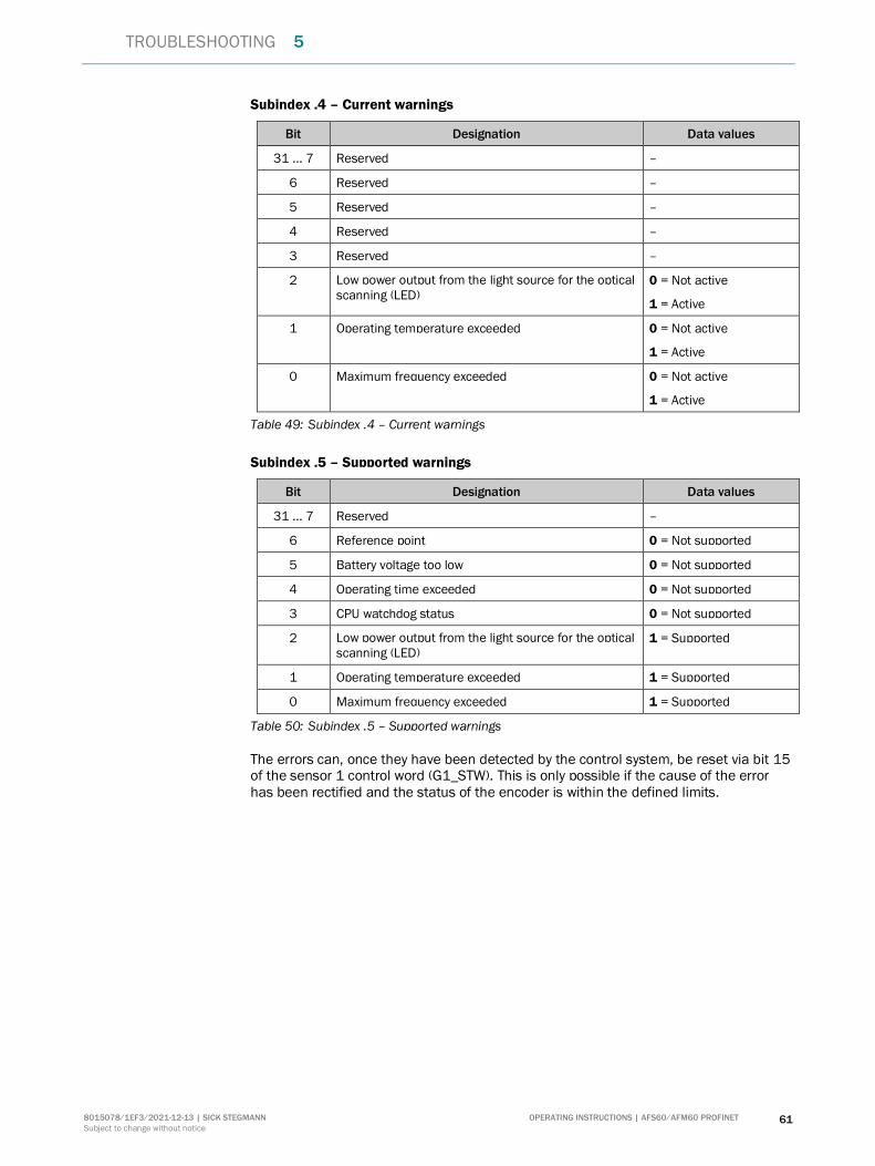
TROUBLESHOOTING 5
8015078/1EF3/2021-12-13 | SICK STEGMANN OPERATING INSTRUCTIONS | AFS60/AFM60 PROFINET 61
Subject to change without notice
Subindex .4 – Current warnings
Bit Designation Data values
31 … 7 Reserved –
6 Reserved –
5 Reserved –
4 Reserved –
3 Reserved –
2 Low power output from the light source for the optical scanning (LED)
0 = Not active
1 = Active
1 Operating temperature exceeded 0 = Not active
1 = Active
0 Maximum frequency exceeded 0 = Not active
1 = Active
Table 49: Subindex .4 – Current warnings
Subindex .5 – Supported warnings
Bit Designation Data values
31 … 7 Reserved –
6 Reference point 0 = Not supported
5 Battery voltage too low 0 = Not supported
4 Operating time exceeded 0 = Not supported
3 CPU watchdog status 0 = Not supported
2 Low power output from the light source for the optical scanning (LED)
1 = Supported
1 Operating temperature exceeded 1 = Supported
0 Maximum frequency exceeded 1 = Supported
Table 50: Subindex .5 – Supported warnings
The errors can, once they have been detected by the control system, be reset via bit 15 of the sensor 1 control word (G1_STW). This is only possible if the cause of the error has been rectified and the status of the encoder is within the defined limits.
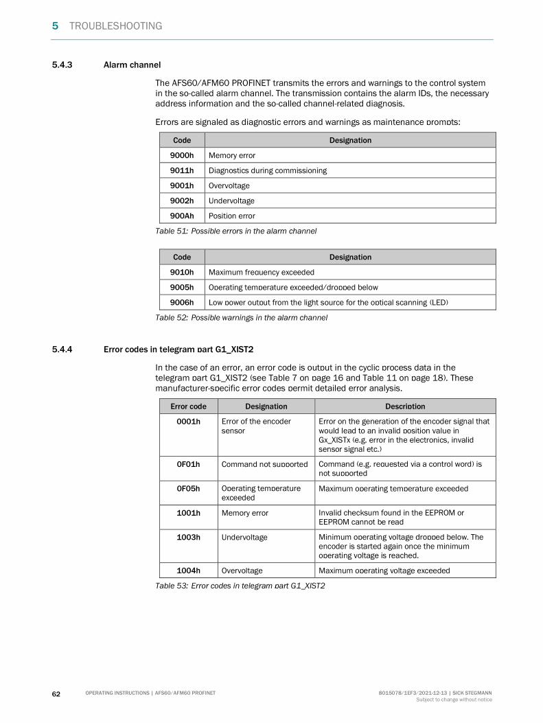
5 TROUBLESHOOTING
62 OPERATING INSTRUCTIONS | AFS60/AFM60 PROFINET 8015078/1EF3/2021-12-13 | SICK STEGMANN
Subject to change without notice
5.4.3 Alarm channel
The AFS60/AFM60 PROFINET transmits the errors and warnings to the control system in the so-called alarm channel. The transmission contains the alarm IDs, the necessary address information and the so-called channel-related diagnosis.
Errors are signaled as diagnostic errors and warnings as maintenance prompts:
Code Designation
9000h Memory error
9011h Diagnostics during commissioning
9001h Overvoltage
9002h Undervoltage
900Ah Position error
Table 51: Possible errors in the alarm channel
Code Designation
9010h Maximum frequency exceeded
9005h Operating temperature exceeded/dropped below
9006h Low power output from the light source for the optical scanning (LED)
Table 52: Possible warnings in the alarm channel
5.4.4 Error codes in telegram part G1_XIST2
In the case of an error, an error code is output in the cyclic process data in the telegram part G1_XIST2 (see Table 7 on page 16 and Table 11 on page 18). These manufacturer-specific error codes permit detailed error analysis.
Error code Designation Description
0001h Error of the encoder sensor
Error on the generation of the encoder signal that would lead to an invalid position value in Gx_XISTx (e.g. error in the electronics, invalid sensor signal etc.)
0F01h Command not supported Command (e.g. requested via a control word) is not supported
0F05h Operating temperature exceeded
Maximum operating temperature exceeded
1001h Memory error Invalid checksum found in the EEPROM or EEPROM cannot be read
1003h Undervoltage Minimum operating voltage dropped below. The encoder is started again once the minimum operating voltage is reached.
1004h Overvoltage Maximum operating voltage exceeded
Table 53: Error codes in telegram part G1_XIST2
TROUBLESHOOTING 5
8015078/1EF3/2021-12-13 | SICK STEGMANN OPERATING INSTRUCTIONS | AFS60/AFM60 PROFINET 63
Subject to change without notice
5.5 Replacement of an encoder in the PROFINET network
If a device in the PROFINET is replaced with a new device (e.g. after a fault), the new device must have the same device name as the old device.
You will need corresponding access rights on the PLC to configure the device name.
Replacement without corresponding access rights
The AFS60/AFM60 PROFINET supports the Link Layer Discovery Protocol (LLDP). With this protocol the configuration data for the old encoder are loaded onto the new encoder after the replacement of the encoder.
The following requirements must be met:
All devices in the network support LLDP. LLDP is activated in the PLC. The new encoder has no device name.
NOTE
The device names AFS60A or AFM60A are pre-configured in the factory. For this reason the device name on the new encoder must be deleted using the following procedure.
How to replace the encoder:
Remove all three connecting cables from the old encoder. Replace the encoder with a new encoder. Only connect the cable for the power supply to the new encoder. Set the three address switches to 888 (see 4.2 on page 44). Press the Preset push-button for 5 seconds.
The encoder LED flashes green. Switch the voltage supply off and on again.
The encoder is reset to the factory settings and the device name is deleted. Connect the two Ethernet cables to the encoder.
The configuration from the old encoder is loaded onto the new encoder.

6 ANNEX
64 OPERATING INSTRUCTIONS | AFS60/AFM60 PROFINET 8015078/1EF3/2021-12-13 | SICK STEGMANN
Subject to change without notice
6 Annex
6.1 Conformities and certificates
You can obtain declarations of conformity, certificates, and the current operating instructions for the product at www.sick.com. To do so, enter the product part number in the search field (part number: see the entry in the “P/N” or “Ident. no.” field on the type label).
6.1.1 Compliance with EU directives
EU declaration of conformity (excerpt)
The undersigned, representing the manufacturer, herewith declares that the product is in conformity with the provisions of the following EU directive(s) (including all applicable amendments), and that the standards and/or technical specifications stated in the EU declaration of conformity have been used as a basis for this.
6.1.2 Compliance with UK statutory instruments
UK declaration of conformity (extract)
The undersigned, representing the following manufacturer herewith declares that this declaration of conformity is issued under the sole responsibility of the manufacturer. The product of this declaration is in conformity with the provisions of the following relevant UK Statutory Instruments (including all applicable amendments), and the respective standards and/or technical specifications have been used as a basis.
SICK AG | Waldkirch | Germany | www.sick.com
8015078/1EF3/2021-12
-13
∙ LF_07
∙ A4
4c in
t49
Detailed addresses and further locations at www.sick.com
Australia Phone +61 (3) 9457 0600
1800 33 48 02 – tollfree E-Mail [email protected] Phone +43 (0) 2236 62288-0 E-Mail [email protected]/Luxembourg Phone +32 (0) 2 466 55 66 E-Mail [email protected] Phone +55 11 3215-4900 E-Mail [email protected] Phone +1 905.771.1444 E-Mail [email protected] Republic Phone +420 234 719 500 E-Mail [email protected] Phone +56 (2) 2274 7430 E-Mail [email protected] Phone +86 20 2882 3600 E-Mail [email protected] Phone +45 45 82 64 00 E-Mail [email protected] Phone +358-9-25 15 800 E-Mail [email protected] Phone +33 1 64 62 35 00 E-Mail [email protected] Phone +49 (0) 2 11 53 010 E-Mail [email protected] Phone +30 210 6825100 E-Mail [email protected] Kong Phone +852 2153 6300 E-Mail [email protected]
Hungary Phone +36 1 371 2680 E-Mail [email protected] Phone +91-22-6119 8900 E-Mail [email protected] Phone +972 97110 11 E-Mail [email protected] Phone +39 02 27 43 41 E-Mail [email protected] Phone +81 3 5309 2112 E-Mail [email protected] Phone +603-8080 7425 E-Mail [email protected] Phone +52 (472) 748 9451 E-Mail [email protected] Phone +31 (0) 30 229 25 44 E-Mail [email protected] Zealand Phone +64 9 415 0459
0800 222 278 – tollfree E-Mail [email protected] Phone +47 67 81 50 00 E-Mail [email protected] Phone +48 22 539 41 00 E-Mail [email protected] Phone +40 356-17 11 20 E-Mail [email protected] Phone +7 495 283 09 90 E-Mail [email protected] Phone +65 6744 3732 E-Mail [email protected]
Slovakia Phone +421 482 901 201 E-Mail [email protected] Phone +386 591 78849 E-Mail [email protected] Africa Phone +27 10 060 0550 E-Mail [email protected] Korea Phone +82 2 786 6321/4 E-Mail [email protected] Spain Phone +34 93 480 31 00 E-Mail [email protected] Phone +46 10 110 10 00 E-Mail [email protected] Phone +41 41 619 29 39 E-Mail [email protected] Phone +886-2-2375-6288 E-Mail [email protected] Phone +66 2 645 0009 E-Mail [email protected] Phone +90 (216) 528 50 00 E-Mail [email protected] Arab Emirates Phone +971 (0) 4 88 65 878 E-Mail [email protected] Kingdom Phone +44 (0)17278 31121 E-Mail [email protected] Phone +1 800.325.7425 E-Mail [email protected] Phone +65 6744 3732 E-Mail [email protected]
Copyright © 2022 FDOKUMEN


![AfS]ZT ecR_da`ce d``_+ 8RU\RcZ0RVW ZDQWHG +L]EXO](https://static.fdokumen.com/doc/165x107/631cd669b8a98572c10d156a/afszt-ecrdace-d-8rurcz0rvw-zdqwhg-lexo.jpg)