
Visualization tool SICK LaserView Customer Edition
47
Operating instructions Visualization tool SICK LaserView Customer Edition Configurations software for LD-MRS laser sensor
-
Upload
khangminh22 -
Category
Documents
-
view
1 -
download
0
Transcript of Visualization tool SICK LaserView Customer Edition
O p e r a t i n g i n s t r u c t i o n s
Visualization toolSICK LaserView Customer Edition
Configurations software for LD-MRS laser sensor
Operating instructions
LaserView visualization tool
2 © SICK AG · Germany · All rights reserved · Subject to change 8013787/YDB5/2014-09-30
Software version
Software version described
Copyright
Copyright 2009 - 2014SICK AG WaldkirchAuto Ident, Werk ReuteNimburger Straße 1179276 ReuteGermany
Trademarks
Windows XPTM and Windows VistaTM are registered trademarks or trademarks of Microsoft Corporation in the USA and other countries.
Adobe Reader is a registered trademark of Adobe Systems Incorporated.
Version of these operating instructions
The latest version of these operating instructions can be obtained as PDF at www.sick.com.
Device/Software/Tool Function Status
LaserView Configuration software and visualization tool for mea-surement operating mode
V. 1.12
Operating instructions
LaserView
8013787/YDB5/2014-09-30 © SICK AG · Germany · All rights reserved · Subject to change without notice 3
Table of contents
Table of contents1 About this document ........................................................................................................ 5
1.1 Function................................................................................................................. 51.2 Target group.......................................................................................................... 51.3 Depth of information ........................................................................................... 51.4 Symbology used ................................................................................................... 6
2 For your safety ................................................................................................................... 72.1 Authorised personnel .......................................................................................... 72.2 Correct use ............................................................................................................ 82.3 General safety notes and protective measures............................................... 8
3 Configuration and Visualization...................................................................................... 93.1 Overview of the commissioning steps .............................................................. 93.2 Quick start with default settings........................................................................ 93.3 LaserView visualization tool .............................................................................113.4 Basic settings......................................................................................................32
Operating instructions
LaserView visualization tool
4 © SICK AG · Germany · All rights reserved · Subject to change 8013787/YDB5/2014-09-30
Directories
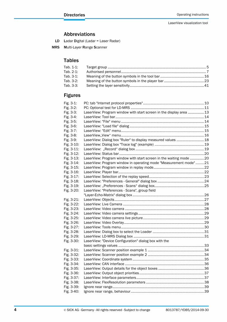
AbbreviationsLD Ladar Digital (Ladar = Laser Radar)
MRS Multi-Layer Range Scanner
TablesTab. 1-1: Target group ....................................................................................................... 5Tab. 2-1: Authorised personnel......................................................................................... 7Tab. 3-1: Meaning of the button symbols in the tool bar ..............................................16Tab. 3-2: Meaning of the button symbols in the player bar ..........................................23Tab. 3-3: Setting the layer sensitivity..............................................................................41
FiguresFig. 3-1: PC: tab "Internet protocol properties"................................................................10Fig. 3-2: PC: Optional test for LD-MRS .............................................................................11Fig. 3-3: LaserView: Program window with start screen in the display area .................13Fig. 3-4: LaserView: Tool bar.............................................................................................14Fig. 3-5: LaserView: "File" menu .......................................................................................14Fig. 3-6: LaserView: "Load file" dialog ..............................................................................15Fig. 3-7: LaserView: "Edit" menu.......................................................................................15Fig. 3-8: LaserView„View“ menu.......................................................................................16Fig. 3-9: LaserView: Dialog box "Ruler" to display measured values .............................18Fig. 3-10: LaserView: Dialog box "Trace log" (example) ....................................................19Fig. 3-11: LaserView: „Record“ dialog box ........................................................................19Fig. 3-12: LaserView: Status bar .........................................................................................20Fig. 3-13: LaserView: Program window with start screen in the waiting mode ...............20Fig. 3-14: LaserView: Program window in operating mode "Measurement mode" .........21Fig. 3-15: LaserView: Program window in replay mode.....................................................22Fig. 3-16: LaserView: Player bar..........................................................................................22Fig. 3-17: LaserView: Selection of the replay speed..........................................................23Fig. 3-18: LaserView: "Preferences - General" dialog box .................................................24Fig. 3-19: LaserView: „Preferences - Scans“ dialog box....................................................25Fig. 3-20: LaserView: "Preferences - Scans", group field
"Layer-Echo-Matrix" dialog box ...........................................................................26Fig. 3-21: LaserView: Objects..............................................................................................27Fig. 3-22: LaserView: Live Camera .....................................................................................28Fig. 3-23: LaserView: Video camera ...................................................................................28Fig. 3-24: LaserView: Video camera settings .....................................................................29Fig. 3-25: LaserView: Video camera live picture................................................................29Fig. 3-26: LaserView: Video Overlay....................................................................................29Fig. 3-27: LaserView: Tools menu.......................................................................................30Fig. 3-28: LaserView: Dialog box to select the Loader ......................................................31Fig. 3-29: LaserView: LD-MRS Dialog box ..........................................................................31Fig. 3-30: LaserView: "Device Configuration" dialog box with the
basic settings values ..........................................................................................33Fig. 3-31: LaserView: Scanner position example 1 ...........................................................34Fig. 3-32: LaserView: Scanner position example 2 ...........................................................34Fig. 3-33: LaserView: Coordinate system ...........................................................................35Fig. 3-34: LaserView: CAN interface ...................................................................................36Fig. 3-35: LaserView: Output details for the object boxes ................................................36Fig. 3-36: LaserView: Output object priorities....................................................................37Fig. 3-37: LaserView: Interface parameters.......................................................................37Fig. 3-38: LaserView: FlexResolution parameters .............................................................38Fig. 3-39: Ignore near range................................................................................................39Fig. 3-40: Ignore near range, behaviour.............................................................................39
Operating instructions
LaserView
Directories
8013787/YDB5/2014-09-30 © SICK AG · Germany · All rights reserved · Subject to change 5
Fig. 3-41: Near range clutter .............................................................................................. 40Fig. 3-42: Layer position left side upside down installation,
right side normal mounting................................................................................ 40Fig. 3-43: LaserView: "Device Configuration" to modify the
parameter values dialog box ............................................................................. 42
Chapter 1 Operating instructions
LaserView visualization tool
6 © SICK AG · Germany · All rights reserved · Subject to change 8013787/YDB5/2014-09-30
About this document
1 About this document
1.1 Function
These operating instructions are designed to address the technical personnel in regards to configure the LD-MRS laser scanner for measurement operating mode and to visualize the measured data using the LaserView View visualization tool.
The document contains information about the
installation of the visualization tool
configuration of the LD-MRS
configuration of the object data of the LD-MRS 400xxx.S01
visualization of the measured data
All tasks are described step by step.
Important In the following, the LaserView Customer Edition visualization tool is termed "LaserView" for short.
1.2 Target group
The intended target group for this document is people in the following positions:
1.3 Depth of information
This document contains all information required for installation and application of LaserView.
The features of the LD-MRS laser scanner as well as the mounting and electrical installation are described in the LD-MRS operating instructions (part no. 8012948, English edition).
Further information about laser measurement technology is available from SICK AG, Divi-sion Auto Ident, and on the internet at www.sick.com.
All variants of the LD-MRS (4000001.xxx and 400102) are referred to as "LD-MRS" for short. The device designation will be given in full, if necessary.
Activities Target group
Commissioning, configuration Qualified personnel, e.g. technicians, engineers
Tab. 1-1: Target group

Operating instructions chapter 1
LaserView
About this document
8013787/YDB5/2014-09-30 © SICK AG · Germany · All rights reserved · Subject to change 7
1.4 Symbology used
Recommendation Recommendations are designed to give you assistance in the decision-making process with respect to a certain function or a technical measure.
Important Sections marked “Important” provide information about special features of the device.
Explanation Explanations provide background knowledge on technical relationships.
MENU COMMAND This typeface indicates a term in the LaserView user interface.
Terminal output This typeface indicates messages that the LaserView outputs via its interfaces.
Take action … Here you must do something. This symbol indicates an instruction to perform an action that contains only one action or actions in warnings where a specific sequence does not need to be followed. Instructions to perform actions that contain several steps in a specific se-quence are numbered.
This symbol refers to additionally available documentation.
Software notes show where you can make the appropriate settings and adjustments in the LaserView configuration software.
Note!
A note provides indicates potential hazards that could involve damage or degradation of the functionality of the LaserView or other devices.
Warning!
A warning indicates an actual or potential hazard. They are designed to help you to prevent accidents.
The safety symbol beside the warning indicates the nature of the risk of accident, e.g. due to electricity. The warning category (DANGER, WARNING, CAUTION) indicates the severity of the hazard.
Read carefully and follow the warning notices!
Chapter 2 Operating instructions
LaserView visualization tool
8 © SICK AG · Germany · All rights reserved · Subject to change 8013787/YDB5/2014-09-30
For your safety
2 For your safety
This chapter deals with your own safety and the safety of the equipment operators.
Please read this chapter carefully before working with the LaserView.
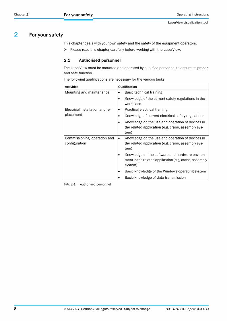
2.1 Authorised personnel
The LaserView must be mounted and operated by qualified personnel to ensure its proper and safe function.
The following qualifications are necessary for the various tasks:
Activities Qualification
Mounting and maintenance Basic technical training
Knowledge of the current safety regulations in the workplace
Electrical installation and re-placement
Practical electrical training
Knowledge of current electrical safety regulations
Knowledge on the use and operation of devices in the related application (e.g. crane, assembly sys-tem)
Commissioning, operation and configuration
Knowledge on the use and operation of devices in the related application (e.g. crane, assembly sys-tem)
Knowledge on the software and hardware environ-ment in the related application (e.g. crane, assembly system)
Basic knowledge of the Windows operating system
Basic knowledge of data transmission
Tab. 2-1: Authorised personnel
Operating instructions chapter 2
LaserView
For your safety
8013787/YDB5/2014-09-30 © SICK AG · Germany · All rights reserved · Subject to change 9
2.2 Correct use
LaserView is used to configure the LD-MRS for measurement operating mode and to display the measured data and object data.
Furthermore, measurements can be recorded and reproduced and then used for diagnostic purposes.
2.3 General safety notes and protective measures
Read the general safety notes carefully and strictly observe them in when working at or with the LD-MRS. Also observe the warning notes printed before the instructions in the individual chapters of this document.
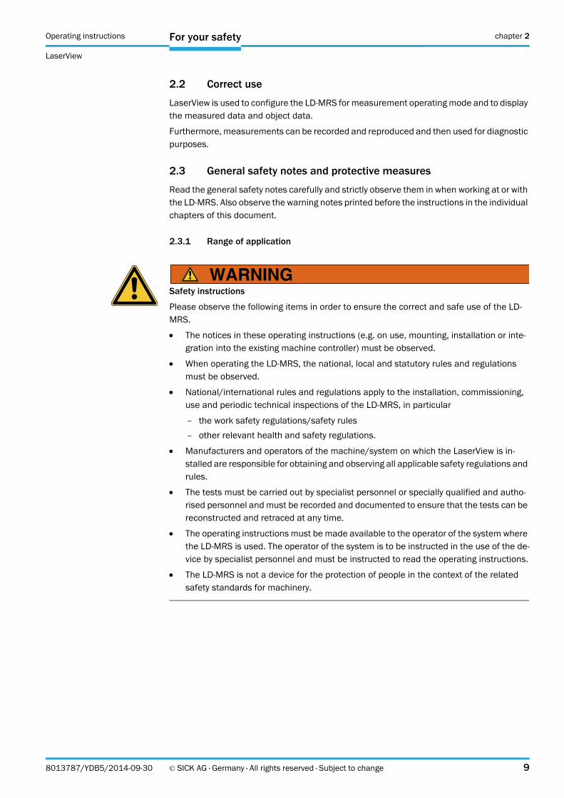
2.3.1 Range of application
Safety instructions
Please observe the following items in order to ensure the correct and safe use of the LD-MRS.
The notices in these operating instructions (e.g. on use, mounting, installation or inte-gration into the existing machine controller) must be observed.
When operating the LD-MRS, the national, local and statutory rules and regulations must be observed.
National/international rules and regulations apply to the installation, commissioning, use and periodic technical inspections of the LD-MRS, in particular
– the work safety regulations/safety rules
– other relevant health and safety regulations.
Manufacturers and operators of the machine/system on which the LaserView is in-stalled are responsible for obtaining and observing all applicable safety regulations and rules.
The tests must be carried out by specialist personnel or specially qualified and autho-rised personnel and must be recorded and documented to ensure that the tests can be reconstructed and retraced at any time.
The operating instructions must be made available to the operator of the system where the LD-MRS is used. The operator of the system is to be instructed in the use of the de-vice by specialist personnel and must be instructed to read the operating instructions.
The LD-MRS is not a device for the protection of people in the context of the related safety standards for machinery.
Chapter 3 Operating instructions
LaserView visualization tool
10 © SICK AG · Germany · All rights reserved · Subject to change 8013787/YDB5/2014-09-30
Configuration and Visualization
3 Configuration and Visualization
Commissioning requires a thorough check by qualified personnel!
Before you operate a system equipped with the LD-MRS for the first time, make sure that the system is first checked and released by qualified personnel.
On this issue, observe the notes in Chapter 2 Safety information of the LD-MRS operat-ing instructions (part no. 8012948, English edition).
Commissioning and configuration of the LD-MRS are done with LaserView.
In normal operation, the LD-MRS is fully-automatic and does not require any operator inter-vention.
3.1 Overview of the commissioning steps
Take the LD-MRS into operation with the factory defaults
Install LaserView visualization tool on the PC
Connect PC to LD-MRS
To optimize the LD-MRS functionality, adjust the LD-MRS and adapt the configurationof the LD-MRS
Test LD-MRS for correct functionality
3.2 Quick start with default settings
Ensure that the Ethernet interface of the computer used for receiving data from the LD-MRS is not blocked by other data transmission processes.
1. Switch on the supply voltage for the LD-MRS. The LD-MRS starts.
2. Connect the LD-MRS via the Ethernet data cable to the PC, see Chapter 5 Electrical Installation of the LD-MRS operating instructions (part no. 8012948, English edition).
3. Switch on the PC and launch WindowsTM (minimum requirement Windows XPTM).
4. Prepare the network interface of the PC.
– For the default IP address of the LD-MRS (e. g. 192.168.0.1, subnet mask 255.255.255.0) see Section "Data interface" in Chapter 3 Product description of the LD-MRS operating instructions (part no. 8012948, English edition).
Operating instructions chapter 3
LaserView
Configuration and Visualization
8013787/YDB5/2014-09-30 © SICK AG · Germany · All rights reserved · Subject to change 11
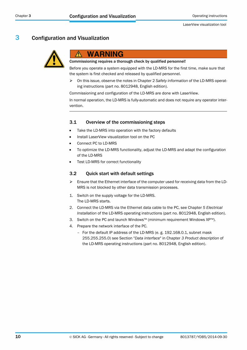
5. Configure the PC network so that the LD-MRS can be accessed.Abb. 3-1 shows a dialog box to set up the network settings for a Windows operating sys-tem. If necessary, consult the system administrator.
– Subnet mask 255.255.255.0
– IP address range 192.168.0.2 … 192.168.0.254
– IP addresses may only be assigned to one device within a network
– Gateway, DNS etc. may not be modified
With LaserView, it is also possible to configure a different IP address.
If the current address of the scanner is not known, the connected scanner can search for the current IP address using "Tools" > "Connection Wizard" for this to be adjusted manually.
Fig. 3-1: PC: tab "Internet protocol properties"
Chapter 3 Operating instructions
LaserView visualization tool
12 © SICK AG · Germany · All rights reserved · Subject to change 8013787/YDB5/2014-09-30
Configuration and Visualization
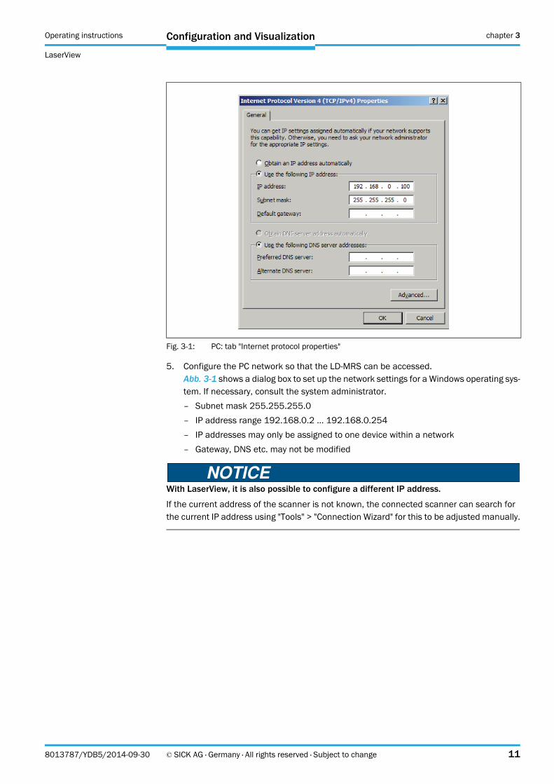
6. Test the configuration.Call up the Windows prompt (cmd.exe).
7. Into the prompt field, enter "ping <IP address>": e. g. "ping 192.168.0.1".
– If the LD-MRS answers, the configuration was successful.The LD-MRS is operational.
– If the LD-MRS does not respond, repeat the process from step 1 onwards.
3.3 LaserView visualization tool
LaserView is the visualization tool for configuration and visualization of the scan data of the LD-MRS.
There are three operating modes:
waiting mode
operating mode measurement
replay mode
With LaserViewView, the LD-MRS is adjusted to the situation on site. This process bases onthe factory default settings or on a user-specific parameter set that has already been createdfor the LD-MRS, see chapter 3.4 Basic settings, page 33
Fig. 3-2: PC: Optional test for LD-MRS
Operating instructions chapter 3
LaserView
Configuration and Visualization
8013787/YDB5/2014-09-30 © SICK AG · Germany · All rights reserved · Subject to change 13
3.3.1 System requirements for the PC
recommendation: CPU 1.4 GHz, 1 GB RAM, CD-ROM drive, Ethernet interface, video board with OpenGL support and 512 MB RAM, mouse (recommended) and color monitor
operating system Windows XPTM or higher
free memory on the hard drive: approx. 45 MB for the LaserView visualization tool
cables, see LD-MRS product information (part no. 8012945) on the provided CD-ROM "Manuals & Software LD-MRS".
3.3.2 Installation of the LD-MRS View visualization toolLaserView
The scope of delivery of the LD-MRS includes LaserView View delivery on CD-ROM.
During the installation of "LaserView Setup", the installation program creates a main direc-tory "LaserView Setup" with the required links.
1. Switch on the PC and insert the installations CD.
2. If the installation does not start automatically, call up "setup.exe" on the CD.
3. To complete the installation, follow the instructions.
Chapter 3 Operating instructions
LaserView visualization tool
14 © SICK AG · Germany · All rights reserved · Subject to change 8013787/YDB5/2014-09-30
Configuration and Visualization
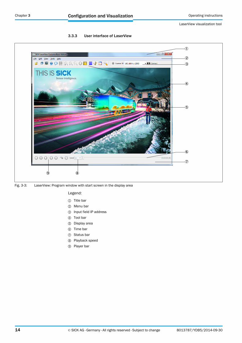
3.3.3 User interface of LaserView
Legend:
1 Title bar
2 Menu bar
3 Input field IP address
4 Tool bar
5 Display area
6 Time bar
7 Status bar
8 Playback speed
9 Player bar
Fig. 3-3: LaserView: Program window with start screen in the display area
Operating instructions chapter 3
LaserView
Configuration and Visualization
8013787/YDB5/2014-09-30 © SICK AG · Germany · All rights reserved · Subject to change 15
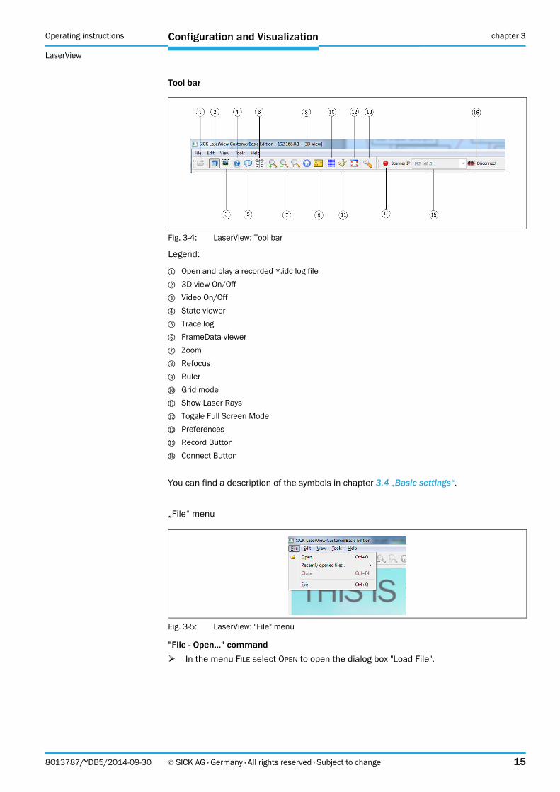
Tool bar
Legend:
1 Open and play a recorded *.idc log file
2 3D view On/Off
3 Video On/Off
4 State viewer
5 Trace log
6 FrameData viewer
7 Zoom
8 Refocus
9 Ruler
bl Grid mode
bm Show Laser Rays
bn Toggle Full Screen Mode
bo Preferences
bo Record Button
bq Connect Button
You can find a description of the symbols in chapter 3.4 „Basic settings“.
„File“ menu
"File - Open..." command
In the menu FILE select OPEN to open the dialog box "Load File".
Fig. 3-4: LaserView: Tool bar
Fig. 3-5: LaserView: "File" menu

Chapter 3 Operating instructions
LaserView visualization tool
16 © SICK AG · Germany · All rights reserved · Subject to change 8013787/YDB5/2014-09-30
Configuration and Visualization
In the dialog box "Load File" an existing *.idc file with recorded scan data can be opened
"Edit" menu
Fig. 3-6: LaserView: "Load file" dialog
Fig. 3-7: LaserView: "Edit" menu
Operating instructions chapter 3
LaserView
Configuration and Visualization
8013787/YDB5/2014-09-30 © SICK AG · Germany · All rights reserved · Subject to change 17
„Edit - Ruler“ command
In the menu EDIT select RULER to activate the ruler,see also the button under chapter 3.3.4 Tool bar, page 17.
„Edit - Device Preferences“ command
In the menu EDIT select PREFERENCES to view the settings,see also button under chapter 3.3.4 Tool bar, page 17, and chapter 3.3.15 Preferences, page 25.
„Edit - Device Configuration“ command
In the menu EDIT select DEVICE CONFIGURATION to view the device settings and to modify them, if necessary, see section chapter 3.4.5 Changing and saving the device configuration of the LD-MRS, page 42.
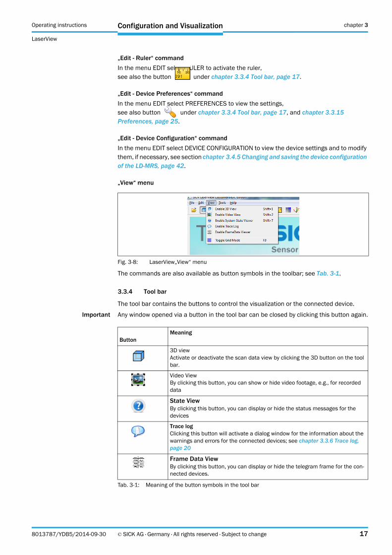
„View“ menu
The commands are also available as button symbols in the toolbar; see Tab. 3-1.
3.3.4 Tool bar
The tool bar contains the buttons to control the visualization or the connected device.
Important Any window opened via a button in the tool bar can be closed by clicking this button again.
Fig. 3-8: LaserView„View“ menu
ButtonMeaning
3D viewActivate or deactivate the scan data view by clicking the 3D button on the tool bar.
Video ViewBy clicking this button, you can show or hide video footage, e.g., for recorded data
State ViewBy clicking this button, you can display or hide the status messages for the devices
Trace logClicking this button will activate a dialog window for the information about the warnings and errors for the connected devices; see chapter 3.3.6 Trace log, page 20
Frame Data ViewBy clicking this button, you can display or hide the telegram frame for the con-nected devices.
Tab. 3-1: Meaning of the button symbols in the tool bar
Chapter 3 Operating instructions
LaserView visualization tool
18 © SICK AG · Germany · All rights reserved · Subject to change 8013787/YDB5/2014-09-30
Configuration and Visualization
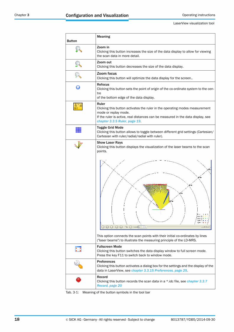
Zoom inClicking this button increases the size of the data display to allow for viewing the scan data in more detail.
Zoom outClicking this button decreases the size of the data display.
Zoom focusClicking this button will optimize the data display for the screen..
RefocusClicking this button sets the point of origin of the co-ordinate system to the cen-treof the bottom edge of the data display.
RulerClicking this button activates the ruler in the operating modes measurementmode or replay mode.If the ruler is active, real distances can be measured in the data display, see chapter 3.3.5 Ruler, page 19.
Toggle Grid ModeClicking this button allows to toggle between different grid settings (Cartesian/Cartesian with ruler/radial/radial with ruler).
Show Laser RaysClicking this button displays the visualization of the laser beams to the scanpoints.
This option connects the scan points with their initial co-ordinates by lines ("laser beams") to illustrate the measuring principle of the LD-MRS.
Fullscreen ModeClicking this button switches the data display window to full screen mode.Press the key F11 to switch back to window mode.
PreferencesClicking this button activates a dialog box for the settings and the display of the data in LaserView, see chapter 3.3.15 Preferences, page 25.
RecordClicking this button records the scan data in a *.idc file, see chapter 3.3.7 Record, page 20
ButtonMeaning
Tab. 3-1: Meaning of the button symbols in the tool bar
Operating instructions chapter 3
LaserView
Configuration and Visualization
8013787/YDB5/2014-09-30 © SICK AG · Germany · All rights reserved · Subject to change 19
Press the Shift key and move the mouse in the Y direction to gain a 3D view.
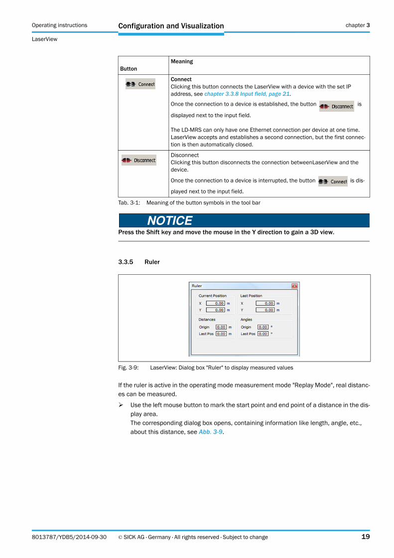
3.3.5 Ruler
If the ruler is active in the operating mode measurement mode "Replay Mode", real distanc-es can be measured.
Use the left mouse button to mark the start point and end point of a distance in the dis-play area.The corresponding dialog box opens, containing information like length, angle, etc., about this distance, see Abb. 3-9.
ConnectClicking this button connects the LaserView with a device with the set IP address, see chapter 3.3.8 Input field, page 21.
Once the connection to a device is established, the button is
displayed next to the input field.
The LD-MRS can only have one Ethernet connection per device at one time.LaserView accepts and establishes a second connection, but the first connec-tion is then automatically closed.
DisconnectClicking this button disconnects the connection betweenLaserView and the device.
Once the connection to a device is interrupted, the button is dis-
played next to the input field.
Fig. 3-9: LaserView: Dialog box "Ruler" to display measured values
ButtonMeaning
Tab. 3-1: Meaning of the button symbols in the tool bar
Chapter 3 Operating instructions
LaserView visualization tool
20 © SICK AG · Germany · All rights reserved · Subject to change 8013787/YDB5/2014-09-30
Configuration and Visualization
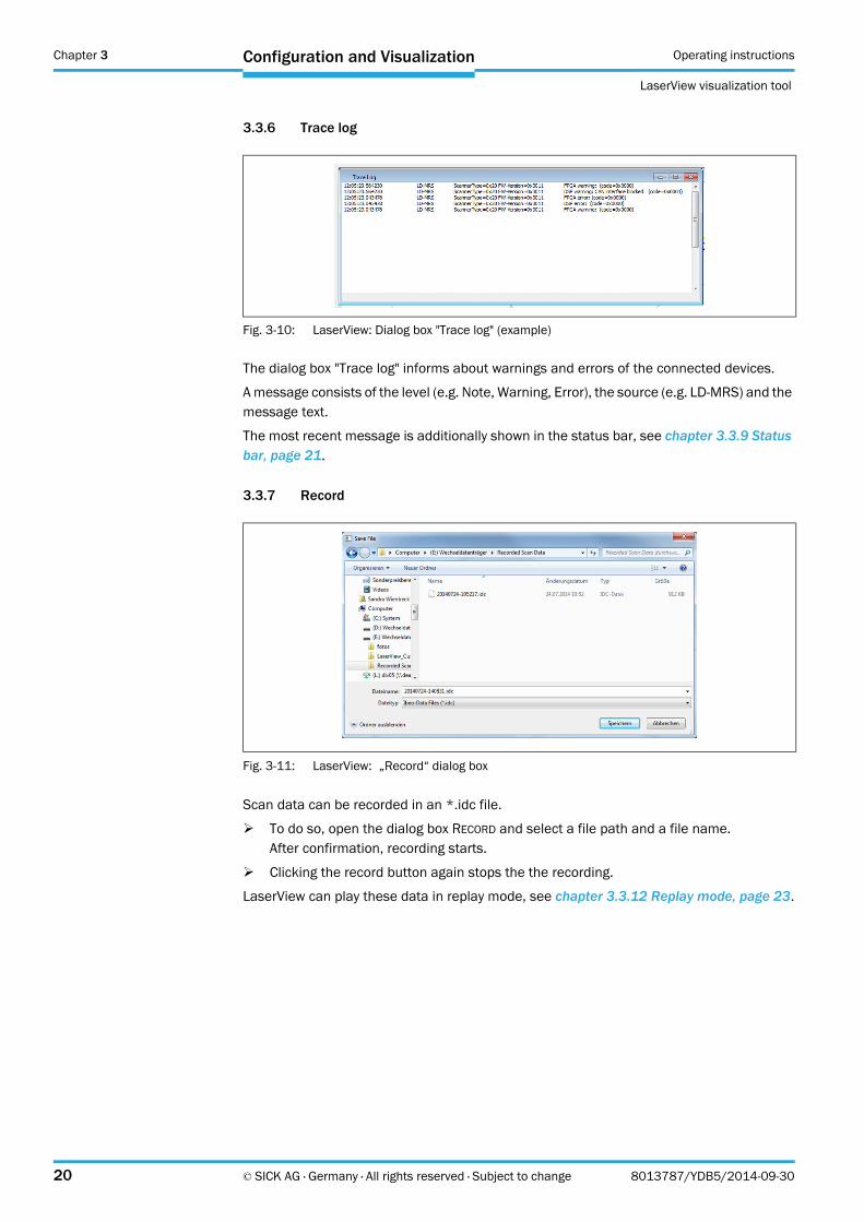
3.3.6 Trace log
The dialog box "Trace log" informs about warnings and errors of the connected devices.
A message consists of the level (e.g. Note, Warning, Error), the source (e.g. LD-MRS) and the message text.
The most recent message is additionally shown in the status bar, see chapter 3.3.9 Status bar, page 21.
3.3.7 Record
Scan data can be recorded in an *.idc file.
To do so, open the dialog box RECORD and select a file path and a file name.After confirmation, recording starts.
Clicking the record button again stops the the recording.
LaserView can play these data in replay mode, see chapter 3.3.12 Replay mode, page 23.
Fig. 3-10: LaserView: Dialog box "Trace log" (example)
Fig. 3-11: LaserView: „Record“ dialog box
Operating instructions chapter 3
LaserView
Configuration and Visualization
8013787/YDB5/2014-09-30 © SICK AG · Germany · All rights reserved · Subject to change 21
3.3.8 Input field
In the input field "Scanner IP:" enter the IP-address of the device that LaserView shall con-nect to, in order to receive data and to display them in the display area.
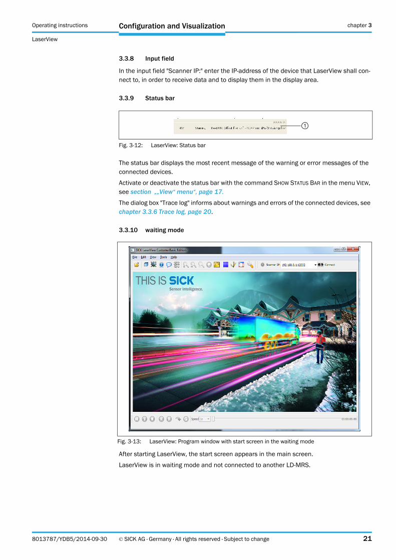
3.3.9 Status bar
The status bar displays the most recent message of the warning or error messages of the connected devices.
Activate or deactivate the status bar with the command SHOW STATUS BAR in the menu VIEW, see section „„View“ menu“, page 17.
The dialog box "Trace log" informs about warnings and errors of the connected devices, see chapter 3.3.6 Trace log, page 20.
3.3.10 waiting mode
After starting LaserView, the start screen appears in the main screen.
LaserView is in waiting mode and not connected to another LD-MRS.
Fig. 3-12: LaserView: Status bar
1
Fig. 3-13: LaserView: Program window with start screen in the waiting mode
Chapter 3 Operating instructions
LaserView visualization tool
22 © SICK AG · Germany · All rights reserved · Subject to change 8013787/YDB5/2014-09-30
Configuration and Visualization
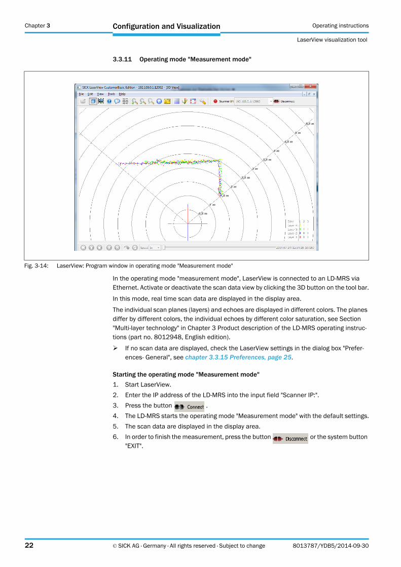
3.3.11 Operating mode "Measurement mode"
In the operating mode "measurement mode", LaserView is connected to an LD-MRS via Ethernet. Activate or deactivate the scan data view by clicking the 3D button on the tool bar.
In this mode, real time scan data are displayed in the display area.
The individual scan planes (layers) and echoes are displayed in different colors. The planes differ by different colors, the individual echoes by different color saturation, see Section "Multi-layer technology" in Chapter 3 Product description of the LD-MRS operating instruc-tions (part no. 8012948, English edition).
If no scan data are displayed, check the LaserView settings in the dialog box "Prefer-ences- General", see chapter 3.3.15 Preferences, page 25.
Starting the operating mode "Measurement mode"
1. Start LaserView.
2. Enter the IP address of the LD-MRS into the input field "Scanner IP:".
3. Press the button .
4. The LD-MRS starts the operating mode "Measurement mode" with the default settings.
5. The scan data are displayed in the display area.
6. In order to finish the measurement, press the button or the system button "EXIT".
Fig. 3-14: LaserView: Program window in operating mode "Measurement mode"
Operating instructions chapter 3
LaserView
Configuration and Visualization
8013787/YDB5/2014-09-30 © SICK AG · Germany · All rights reserved · Subject to change 23
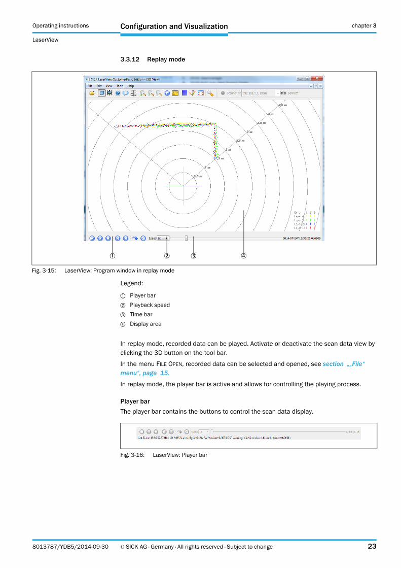
3.3.12 Replay mode
Legend:
1 Player bar
2 Playback speed
3 Time bar
4 Display area
In replay mode, recorded data can be played. Activate or deactivate the scan data view by clicking the 3D button on the tool bar.
In the menu FILE OPEN, recorded data can be selected and opened, see section „„File“ menu“, page 15.
In replay mode, the player bar is active and allows for controlling the playing process.
Player bar
The player bar contains the buttons to control the scan data display.
Fig. 3-15: LaserView: Program window in replay mode
Fig. 3-16: LaserView: Player bar
Chapter 3 Operating instructions
LaserView visualization tool
24 © SICK AG · Germany · All rights reserved · Subject to change 8013787/YDB5/2014-09-30
Configuration and Visualization
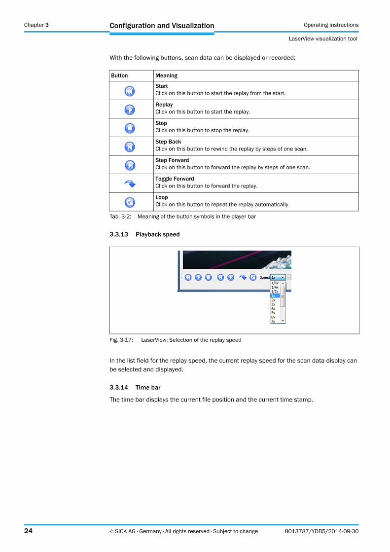
With the following buttons, scan data can be displayed or recorded:
3.3.13 Playback speed
In the list field for the replay speed, the current replay speed for the scan data display can be selected and displayed.
3.3.14 Time bar
The time bar displays the current file position and the current time stamp.
Button Meaning
StartClick on this button to start the replay from the start.
ReplayClick on this button to start the replay.
StopClick on this button to stop the replay.
Step BackClick on this button to rewind the replay by steps of one scan.
Step ForwardClick on this button to forward the replay by steps of one scan.
Toggle ForwardClick on this button to forward the replay.
LoopClick on this button to repeat the replay automatically.
Tab. 3-2: Meaning of the button symbols in the player bar
Fig. 3-17: LaserView: Selection of the replay speed

Operating instructions chapter 3
LaserView
Configuration and Visualization
8013787/YDB5/2014-09-30 © SICK AG · Germany · All rights reserved · Subject to change 25
3.3.15 Preferences
With different settings the dialog of LaserView regarding the scan data display can be con-trolled. This is done in the dialog box "Preferences".
The dialog box "Preferences" consists of five tabs
General
Scans
Objects
Live Camera
Video Overlay
3.3.16 Tab "Preferences - General"
In the dialog box "Preferences - General" the general display can be set.
Fig. 3-18: LaserView: "Preferences - General" dialog box

Chapter 3 Operating instructions
LaserView visualization tool
26 © SICK AG · Germany · All rights reserved · Subject to change 8013787/YDB5/2014-09-30
Configuration and Visualization
3.3.17 „Preferences-Scans“ tab
In the dialog box "Preferences-Scans" the type of display of the scan points in the display area can be selected.
Preferences Scans
Point Size
Defines the size of the visualized measurement point.
Deinterlaced Method:
Measurements on the front and back of the rotary mirror are shown continuously to achieve a uniform display.
Echo Pulse Width:
Length display of the echo amplitude per angular step.
Full:
Displays the echo amplitude in full.
Half:
Optimized view of the echo amplitude (half length).
Each scan point has a label (valid, ground or clutter).
In the group field PREPROCESSING LABELS can be specified which scan points to display.
Preprocessing Labels
Show valid:
Only valid measurement are shown. If not selected, invalid measurements (low echo or beyond range) are displayed.
Fig. 3-19: LaserView: „Preferences - Scans“ dialog box

Operating instructions chapter 3
LaserView
Configuration and Visualization
8013787/YDB5/2014-09-30 © SICK AG · Germany · All rights reserved · Subject to change 27
Show ground:
Activating this button displays all scan points marked as ground (brown) by the sensor.
Show Clutter:
Displays the measurements. If this button is activated, the scan points marked by the sensor as being measurements with a lowered threshold, e.g. because of dust or rain, are displayed.
Color
This setting determines the coloring of the scan data in the display.
Layer Color:
Displays the four layers in 4 colors: red (bottom layer), blue, green, and yellow (top lay-er).
Preprocessing Color:
Displays the measurement points according to the result of the filter defined by “Pre-processing Labels”
Mirror-Side:
Indicate in green and red which side of the mirror is actually presented.
In the group field LAYER-ECHO-MATRIXCOLOR can be specified which layer and echoes (Show Layer / Echos) to display.
Fig. 3-20: LaserView: "Preferences - Scans", group field "Layer-Echo-Matrix" dialog box
Chapter 3 Operating instructions
LaserView visualization tool
28 © SICK AG · Germany · All rights reserved · Subject to change 8013787/YDB5/2014-09-30
Configuration and Visualization
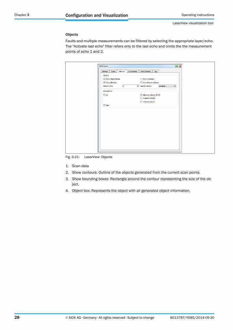
Objects
Faults and multiple measurements can be filtered by selecting the appropriate layer/echo. The "Activate last echo" filter refers only to the last echo and omits the the measurement points of echo 1 and 2.
1. Scan data
2. Show contours: Outline of the objects generated from the current scan points.
3. Show bounding boxes: Rectangle around the contour representing the size of the ob-ject.
4. Object box: Represents the object with all generated object information.
Fig. 3-21: LaserView: Objects
Operating instructions chapter 3
LaserView
Configuration and Visualization
8013787/YDB5/2014-09-30 © SICK AG · Germany · All rights reserved · Subject to change 29
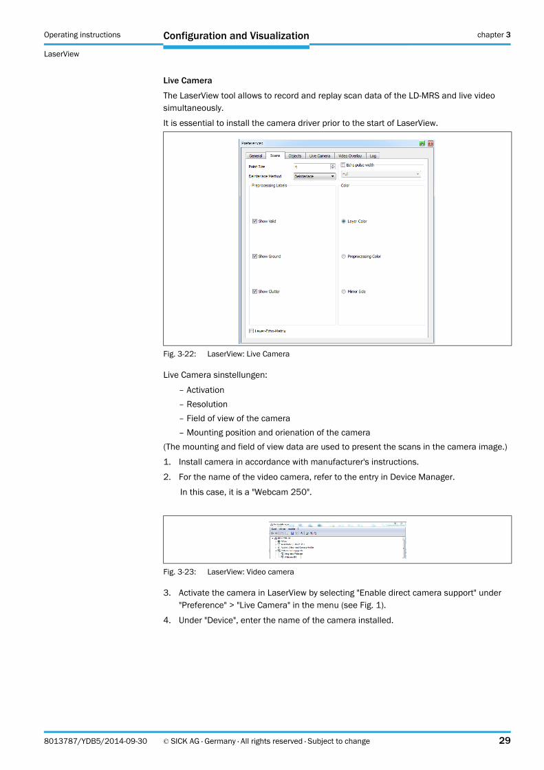
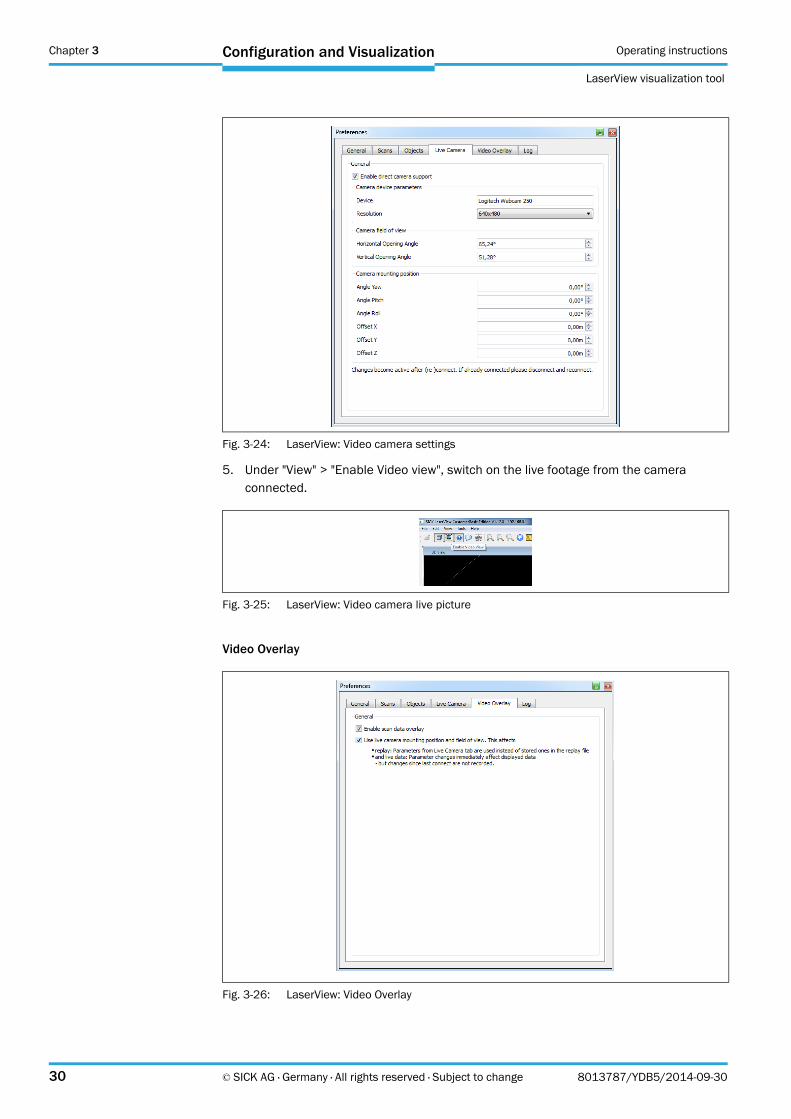
Live Camera
The LaserView tool allows to record and replay scan data of the LD-MRS and live video simultaneously.
It is essential to install the camera driver prior to the start of LaserView.
Live Camera sinstellungen:
– Activation
– Resolution
– Field of view of the camera
– Mounting position and orienation of the camera
(The mounting and field of view data are used to present the scans in the camera image.)
1. Install camera in accordance with manufacturer's instructions.
2. For the name of the video camera, refer to the entry in Device Manager.
In this case, it is a "Webcam 250".
3. Activate the camera in LaserView by selecting "Enable direct camera support" under "Preference" > "Live Camera" in the menu (see Fig. 1).
4. Under "Device", enter the name of the camera installed.
Fig. 3-22: LaserView: Live Camera
Fig. 3-23: LaserView: Video camera
Chapter 3 Operating instructions
LaserView visualization tool
30 © SICK AG · Germany · All rights reserved · Subject to change 8013787/YDB5/2014-09-30
Configuration and Visualization
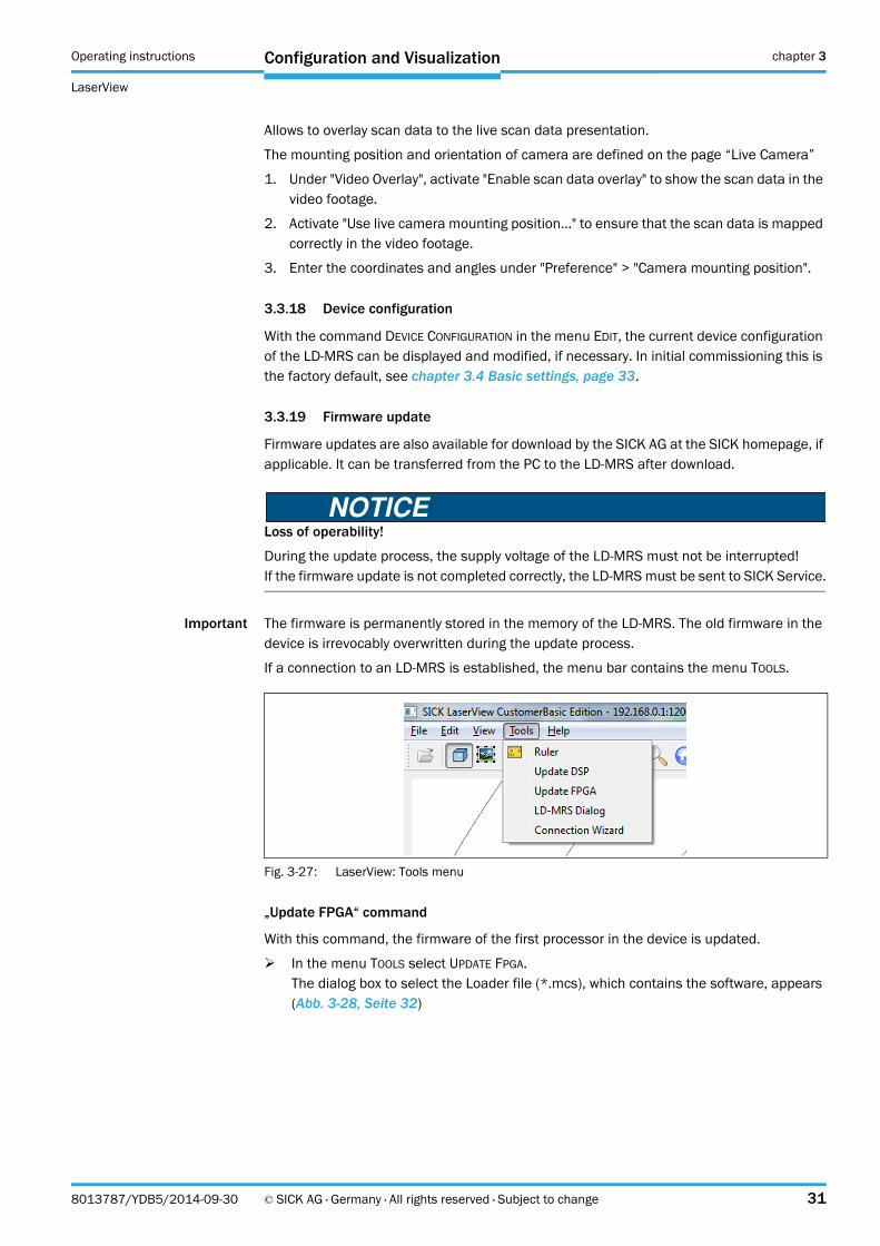
5. Under "View" > "Enable Video view", switch on the live footage from the camera connected.
Video Overlay
Fig. 3-24: LaserView: Video camera settings
Fig. 3-25: LaserView: Video camera live picture
Fig. 3-26: LaserView: Video Overlay
Operating instructions chapter 3
LaserView
Configuration and Visualization
8013787/YDB5/2014-09-30 © SICK AG · Germany · All rights reserved · Subject to change 31
Allows to overlay scan data to the live scan data presentation.
The mounting position and orientation of camera are defined on the page “Live Camera”
1. Under "Video Overlay", activate "Enable scan data overlay" to show the scan data in the video footage.
2. Activate "Use live camera mounting position..." to ensure that the scan data is mapped correctly in the video footage.
3. Enter the coordinates and angles under "Preference" > "Camera mounting position".
3.3.18 Device configuration
With the command DEVICE CONFIGURATION in the menu EDIT, the current device configuration of the LD-MRS can be displayed and modified, if necessary. In initial commissioning this is the factory default, see chapter 3.4 Basic settings, page 33.
3.3.19 Firmware update
Firmware updates are also available for download by the SICK AG at the SICK homepage, if applicable. It can be transferred from the PC to the LD-MRS after download.
Loss of operability!
During the update process, the supply voltage of the LD-MRS must not be interrupted!If the firmware update is not completed correctly, the LD-MRS must be sent to SICK Service.
Important The firmware is permanently stored in the memory of the LD-MRS. The old firmware in the device is irrevocably overwritten during the update process.
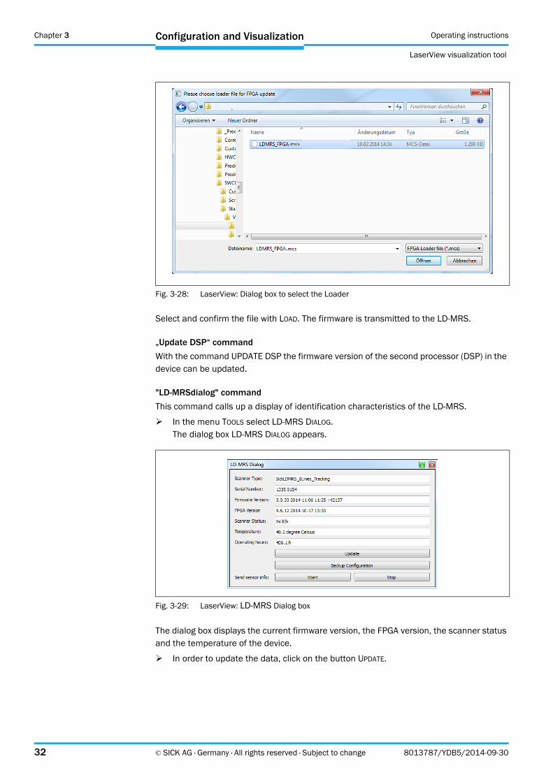
If a connection to an LD-MRS is established, the menu bar contains the menu TOOLS.
„Update FPGA“ command
With this command, the firmware of the first processor in the device is updated.
In the menu TOOLS select UPDATE FPGA.The dialog box to select the Loader file (*.mcs), which contains the software, appears (Abb. 3-28, Seite 32)
Fig. 3-27: LaserView: Tools menu
Chapter 3 Operating instructions
LaserView visualization tool
32 © SICK AG · Germany · All rights reserved · Subject to change 8013787/YDB5/2014-09-30
Configuration and Visualization
Select and confirm the file with LOAD. The firmware is transmitted to the LD-MRS.
„Update DSP“ command
With the command UPDATE DSP the firmware version of the second processor (DSP) in the device can be updated.
"LD-MRSdialog" command
This command calls up a display of identification characteristics of the LD-MRS.
In the menu TOOLS select LD-MRS DIALOG.The dialog box LD-MRS DIALOG appears.
The dialog box displays the current firmware version, the FPGA version, the scanner status and the temperature of the device.
In order to update the data, click on the button UPDATE.
Fig. 3-28: LaserView: Dialog box to select the Loader
Fig. 3-29: LaserView: LD-MRS Dialog box

Operating instructions chapter 3
LaserView
Configuration and Visualization
8013787/YDB5/2014-09-30 © SICK AG · Germany · All rights reserved · Subject to change 33
"Wizard" command
The Wizard helps you to set up a connection to the connected devices.
"Scan" starts the Wizard's search for connected devices and lists them in the window.
To connect to the device, the corresponding line must be marked in the list and connected with "connect".
Communication settings such as IP address, port and mask for the device can be updated manually. Enter the desired values in advance and confirm these by pressing the 'change' button. This may be of significance if, for example, the IP address does not match the IP ad-dress of the PC when you want to connect the device to a network.
Default settings:
IP address: 192.168.0.1
Port: 12001
Mask: 255.255.255.0
3.4 Basic settings
3.4.1 LD-MRS basic settings (factory default)
The factory default settings of the device configuration of the LD-MRS have been defined to allow using the device without changing any settings, see chapter 3.2 Quick start with de-fault settings, page 10.
Important At initial commissioning, LaserView displays the basic settings. After changing the parame-ter values with LaserView, these settings can only be restored manually.
The parameters can also be changed via the telegram; see telegram listing "Document Name Ethernet Protocol".
Chapter 3 Operating instructions
LaserView visualization tool
34 © SICK AG · Germany · All rights reserved · Subject to change 8013787/YDB5/2014-09-30
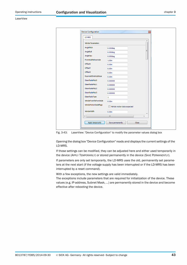
Configuration and Visualization
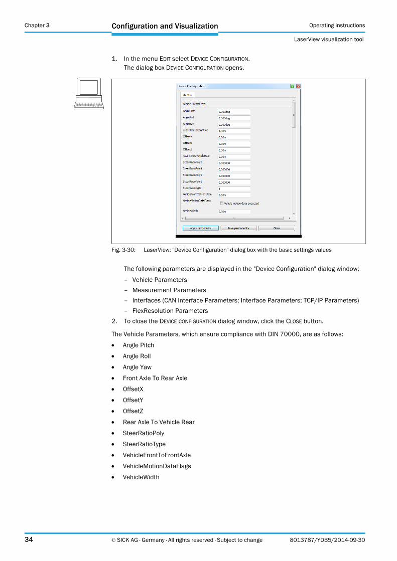
1. In the menu EDIT select DEVICE CONFIGURATION.The dialog box DEVICE CONFIGURATION opens.
The following parameters are displayed in the "Device Configuration" dialog window:
– Vehicle Parameters
– Measurement Parameters
– Interfaces (CAN Interface Parameters; Interface Parameters; TCP/IP Parameters)
– FlexResolution Parameters
2. To close the DEVICE CONFIGURATION dialog window, click the CLOSE button.
The Vehicle Parameters, which ensure compliance with DIN 70000, are as follows:
Angle Pitch
Angle Roll
Angle Yaw
Front Axle To Rear Axle
OffsetX
OffsetY
OffsetZ
Rear Axle To Vehicle Rear
SteerRatioPoly
SteerRatioType
VehicleFrontToFrontAxle
VehicleMotionDataFlags
VehicleWidth
Fig. 3-30: LaserView: "Device Configuration" dialog box with the basic settings values
Operating instructions chapter 3
LaserView
Configuration and Visualization
8013787/YDB5/2014-09-30 © SICK AG · Germany · All rights reserved · Subject to change 35
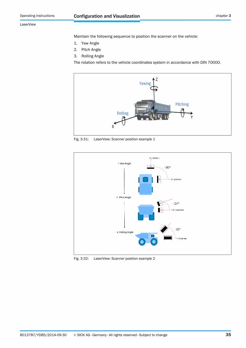
Maintain the following sequence to position the scanner on the vehicle:
1. Yaw Angle
2. Pitch Angle
3. Rolling Angle
The rotation refers to the vehicle coordinates system in accordance with DIN 70000.
Fig. 3-31: LaserView: Scanner position example 1
Fig. 3-32: LaserView: Scanner position example 2
Chapter 3 Operating instructions
LaserView visualization tool
36 © SICK AG · Germany · All rights reserved · Subject to change 8013787/YDB5/2014-09-30
Configuration and Visualization
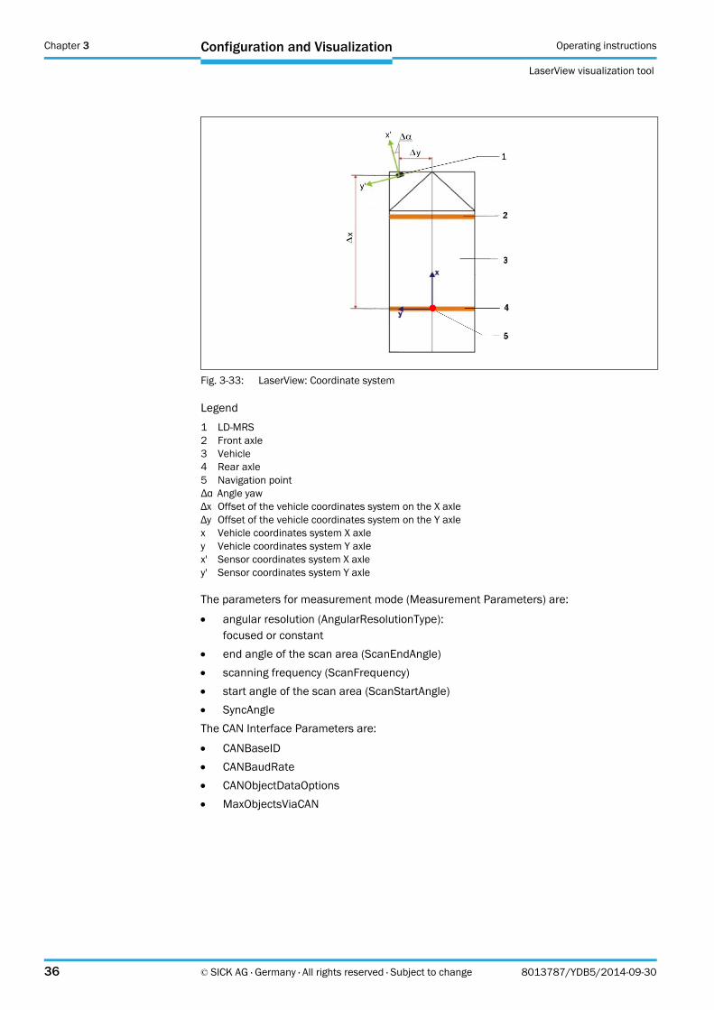
Legend
1 LD-MRS2 Front axle3 Vehicle4 Rear axle5 Navigation pointΔα Angle yawΔx Offset of the vehicle coordinates system on the X axleΔy Offset of the vehicle coordinates system on the Y axlex Vehicle coordinates system X axley Vehicle coordinates system Y axlex' Sensor coordinates system X axley' Sensor coordinates system Y axle
The parameters for measurement mode (Measurement Parameters) are:
angular resolution (AngularResolutionType):focused or constant
end angle of the scan area (ScanEndAngle)
scanning frequency (ScanFrequency)
start angle of the scan area (ScanStartAngle)
SyncAngle
The CAN Interface Parameters are:
CANBaseID
CANBaudRate
CANObjectDataOptions
MaxObjectsViaCAN
Fig. 3-33: LaserView: Coordinate system
Operating instructions chapter 3
LaserView
Configuration and Visualization
8013787/YDB5/2014-09-30 © SICK AG · Germany · All rights reserved · Subject to change 37
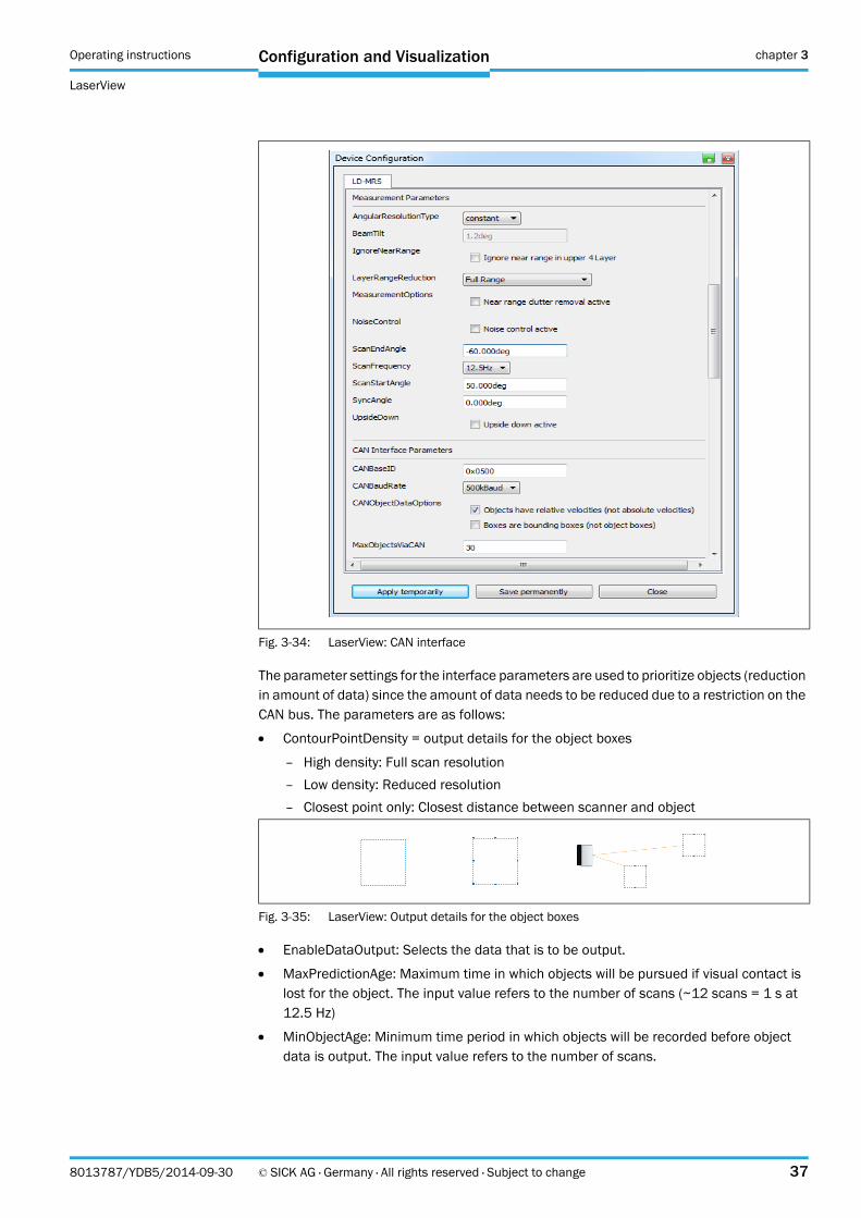
The parameter settings for the interface parameters are used to prioritize objects (reduction in amount of data) since the amount of data needs to be reduced due to a restriction on the CAN bus. The parameters are as follows:
ContourPointDensity = output details for the object boxes
– High density: Full scan resolution
– Low density: Reduced resolution
– Closest point only: Closest distance between scanner and object
EnableDataOutput: Selects the data that is to be output.
MaxPredictionAge: Maximum time in which objects will be pursued if visual contact is lost for the object. The input value refers to the number of scans (~12 scans = 1 s at 12.5 Hz)
MinObjectAge: Minimum time period in which objects will be recorded before object data is output. The input value refers to the number of scans.
Fig. 3-34: LaserView: CAN interface
Fig. 3-35: LaserView: Output details for the object boxes
Chapter 3 Operating instructions
LaserView visualization tool
38 © SICK AG · Germany · All rights reserved · Subject to change 8013787/YDB5/2014-09-30
Configuration and Visualization
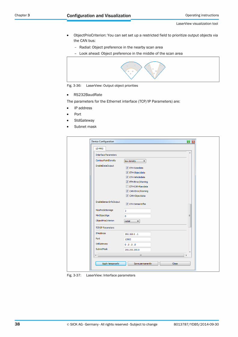
ObjectPrioCriterion: You can set set up a restricted field to prioritize output objects via the CAN bus:
– Radial: Object preference in the nearby scan area
– Look ahead: Object preference in the middle of the scan area
RS232BaudRate
The parameters for the Ethernet interface (TCP/IP Parameters) are:
IP address
Port
StdGateway
Subnet mask
Fig. 3-36: LaserView: Output object priorities
Fig. 3-37: LaserView: Interface parameters
Operating instructions chapter 3
LaserView
Configuration and Visualization
8013787/YDB5/2014-09-30 © SICK AG · Germany · All rights reserved · Subject to change 39
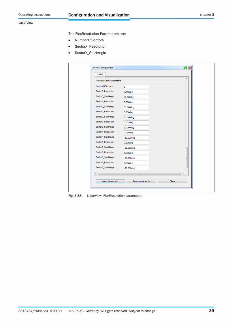
The FlexResolution Parameters are:
NumberOfSectors
SectorX_Resolution
SectorX_StartAngle
Fig. 3-38: LaserView: FlexResolution parameters
Chapter 3 Operating instructions
LaserView visualization tool
40 © SICK AG · Germany · All rights reserved · Subject to change 8013787/YDB5/2014-09-30
Configuration and Visualization
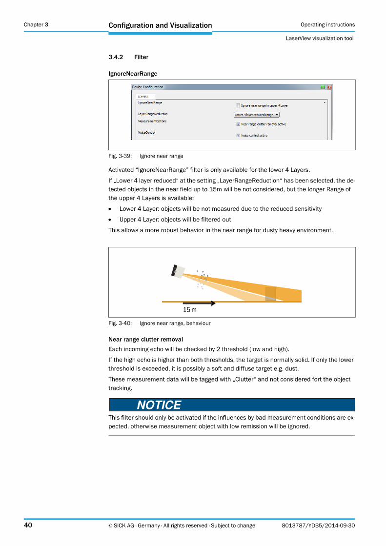
3.4.2 Filter
IgnoreNearRange
Activated “IgnoreNearRange” filter is only available for the lower 4 Layers.
If „Lower 4 layer reduced“ at the setting „LayerRangeReduction“ has been selected, the de-tected objects in the near field up to 15m will be not considered, but the longer Range of the upper 4 Layers is available:
Lower 4 Layer: objects will be not measured due to the reduced sensitivity
Upper 4 Layer: objects will be filtered out
This allows a more robust behavior in the near range for dusty heavy environment.
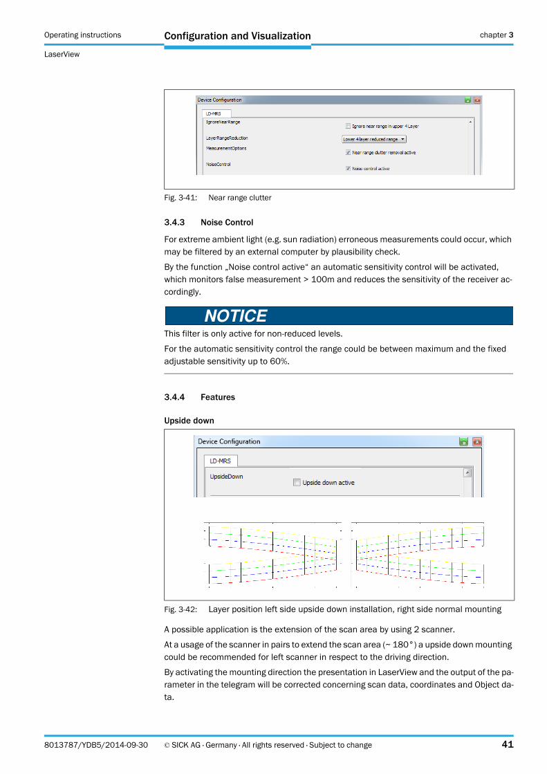
Near range clutter removal
Each incoming echo will be checked by 2 threshold (low and high).
If the high echo is higher than both thresholds, the target is normally solid. If only the lower threshold is exceeded, it is possibly a soft and diffuse target e.g. dust.
These measurement data will be tagged with „Clutter“ and not considered fort the object tracking.
This filter should only be activated if the influences by bad measurement conditions are ex-pected, otherwise measurement object with low remission will be ignored.
Fig. 3-39: Ignore near range
Fig. 3-40: Ignore near range, behaviour
Operating instructions chapter 3
LaserView
Configuration and Visualization
8013787/YDB5/2014-09-30 © SICK AG · Germany · All rights reserved · Subject to change 41
3.4.3 Noise Control
For extreme ambient light (e.g. sun radiation) erroneous measurements could occur, which may be filtered by an external computer by plausibility check.
By the function „Noise control active“ an automatic sensitivity control will be activated, which monitors false measurement > 100m and reduces the sensitivity of the receiver ac-cordingly.
This filter is only active for non-reduced levels.
For the automatic sensitivity control the range could be between maximum and the fixed adjustable sensitivity up to 60%.
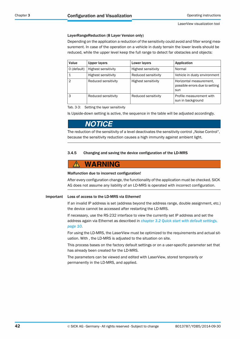
3.4.4 Features
Upside down
A possible application is the extension of the scan area by using 2 scanner.
At a usage of the scanner in pairs to extend the scan area (~ 180°) a upside down mounting could be recommended for left scanner in respect to the driving direction.
By activating the mounting direction the presentation in LaserView and the output of the pa-rameter in the telegram will be corrected concerning scan data, coordinates and Object da-ta.
Fig. 3-41: Near range clutter
Fig. 3-42: Layer position left side upside down installation, right side normal mounting
Chapter 3 Operating instructions
LaserView visualization tool
42 © SICK AG · Germany · All rights reserved · Subject to change 8013787/YDB5/2014-09-30
Configuration and Visualization
LayerRangeReduction (8 Layer Version only)
Depending on the application a reduction of the sensitivity could avoid and filter wrong mea-surement. In case of the operation on a vehicle in dusty terrain the lower levels should be reduced, while the upper level keep the full range to detect far obstacles and objects:
Is Upside-down setting is active, the sequence in the table will be adjusted accordingly.
The reduction of the sensitivity of a level deactivates the sensitivity control „Noise Control“, because the sensitivity reduction causes a high immunity against ambient light.
3.4.5 Changing and saving the device configuration of the LD-MRS
Malfunction due to incorrect configuration!
After every configuration change, the functionality of the application must be checked. SICK AG does not assume any liability of an LD-MRS is operated with incorrect configuration.
Important Loss of access to the LD-MRS via Ethernet!
If an invalid IP address is set (address beyond the address range, double assignment, etc.)the device cannot be accessed after restarting the LD-MRS.
If necessary, use the RS-232 interface to view the currently set IP address and set theaddress again via Ethernet as described in chapter 3.2 Quick start with default settings, page 10.
For using the LD-MRS, the LaserView must be optimized to the requirements and actual sit-uation. With , the LD-MRS is adjusted to the situation on site.
This process bases on the factory default settings or on a user-specific parameter set thathas already been created for the LD-MRS.
The parameters can be viewed and edited with LaserView, stored temporarily or permanently in the LD-MRS, and applied.
Value Upper layers Lower layers Application
0 (default) Highest sensitivity Highest sensitivity Normal
1 Highest sensitivity Reduced sensitivity Vehicle in dusty environment
2 Reduced sensitivity Highest sensitivity Horizontal measurement, possible errors due to setting sun
3 Reduced sensitivity Reduced sensitivity Profile measurement with sun in background
Tab. 3-3: Setting the layer sensitivity
Operating instructions chapter 3
LaserView
Configuration and Visualization
8013787/YDB5/2014-09-30 © SICK AG · Germany · All rights reserved · Subject to change 43
Opening the dialog box "Device Configuration" reads and displays the current settings of the LD-MRS.
If those settings can be modified, they can be adjusted here and either used temporarily inthe device (APPLY TEMPORARILY) or stored permanently in the device (SAVE PERMANENTLY).
If parameters are only set temporarily, the LD-MRS uses the old, permanently set parame-ters at the next start (if the voltage supply has been interrupted or if the LD-MRS has been interrupted by a reset command).
With a few exceptions, the new settings are valid immediately.The exceptions include parameters that are required for initialization of the device. These values (e.g. IP-address, Subnet Mask, …) are permanently stored in the device and become effective after rebooting the device.
Fig. 3-43: LaserView: "Device Configuration" to modify the parameter values dialog box
Chapter 3 Operating instructions
LaserView visualization tool
44 © SICK AG · Germany · All rights reserved · Subject to change 8013787/YDB5/2014-09-30
Configuration and Visualization
Parameters of measurement mode (Measurement Parameters)
By modifying the following parameters, the measuring properties of the LD-MRS can be in-fluenced.
Angular resolution (AngularResolutionType): focused or constant focused:Only at a scanning frequency of 12.5 Hz, the angular resolution can be set to be opti-mized towards the front.Constant:The angular resolution is constant, see Section "Angular resolution and scanning fre-quency" in Chapter 3 Product description of the LD-MRS operating instructions (part no. 8012948, English edition).
End angle of the scan range (ScanEndAngle)The end angle of the scan range must always be smaller than the start angle of the sen-sor co-ordinate system.The minimum value is -60°.
Scanning frequency (ScanFrequency)Scanning frequencies of 12.5 Hz, 25 Hz and 50 Hz are possible, however, the available angular resolutions depend on the scanning frequency, see Section "Angular resolution and scanning frequency" in Chapter 3 Product description of the LD-MRS operating in-structions (part no. 8012948, English edition).
Start angle of the scan range (ScanStartAngle)The start angle of the scan range must always be greater than the end angle of the sen-sor co-ordinate system.The maximum value is +50°.
SyncAngleAngle under which the LD-MRS measures at the time of the sync pulse.
Operating instructions chapter 3
LaserView
Configuration and Visualization
8013787/YDB5/2014-09-30 © SICK AG · Germany · All rights reserved · Subject to change 45
Parameters of the interfaces (TCP/IP Parameters)
The interfaces provide specific and general configuration options.
IP addressHere the pre-set IP address can be modified and adjusted to the needs.
PortHere the port can be modified and adjusted.
StdGatewayHere the standard gateway can be modified and adjusted.
Subnet maskPlease make sure that the selected subnet mask matches your network or the IP rangeused by the application.
To modify the parameter values of the LD-MRS and store them in the LD-MRS, proceed asfollows:
1. In the menu EDIT select DEVICE CONFIGURATION.The dialog box "Device Configuration" opens.
2. Modify the parameter values
3. Click on the button APPLY TEMPORARILY to transmit the modified parameter values tem-porarilyto the LD-MRS.
4. To apply the modifications permanently, click on the button SAVE PERMANENTLY.

Chapter 3 Operating instructions
LaserView visualization tool
46 © SICK AG · Germany · All rights reserved · Subject to change 8013787/YDB5/2014-09-30
Configuration and Visualization
Notes:

SICK AG | Waldkirch | Germany | www.sick.com
AustraliaPhone +61 3 9497 4100
1800 33 48 02 – tollfreeE-Mail [email protected]
Belgium/LuxembourgPhone +32 (0)2 466 55 66E-Mail [email protected]
BrasilPhone +55 11 3215-4900E-Mail [email protected]
Ceská RepublikaPhone +420 2 57 91 18 50E-Mail [email protected]
ChinaPhone +852-2763 6966E-Mail [email protected]
DanmarkPhone +45 45 82 64 00E-Mail [email protected]
DeutschlandPhone +49 211 5301-301E-Mail [email protected]
EspañaPhone +34 93 480 31 00E-Mail [email protected]
FrancePhone +33 1 64 62 35 00E-Mail [email protected]
Great BritainPhone +44 (0)1727 831121E-Mail [email protected]
IndiaPhone +91–22–4033 8333E-Mail [email protected]
IsraelPhone +972-4-999-0590E-Mail [email protected]
ItaliaPhone +39 02 27 43 41E-Mail [email protected]
JapanPhone +81 (0)3 3358 1341E-Mail [email protected]
NederlandsPhone +31 (0)30 229 25 44E-Mail [email protected]
Norge Phone +47 67 81 50 00E-Mail [email protected]
ÖsterreichPhone +43 (0)22 36 62 28 8-0E-Mail [email protected]
PolskaPhone +48 22 837 40 50E-Mail [email protected]
Republic of KoreaPhone +82-2 786 6321/4E-Mail [email protected]
Republika SlovenijaPhone +386 (0)1-47 69 990E-Mail [email protected]
RomâniaPhone +40 356 171 120 E-Mail [email protected]
RussiaPhone +7 495 775 05 34E-Mail [email protected]
SchweizPhone +41 41 619 29 39E-Mail [email protected]
SingaporePhone +65 6744 3732E-Mail [email protected]
SuomiPhone +358-9-25 15 800E-Mail [email protected]
SverigePhone +46 10 110 10 00E-Mail [email protected]
TaiwanPhone +886 2 2375-6288E-Mail [email protected]
TürkiyePhone +90 216 587 74 00E-Mail [email protected]
United Arab EmiratesPhone +971 4 8865 878E-Mail [email protected]
USA/Canada/MéxicoPhone +1(952) 941-6780 1 800-325-7425 – tollfreeE-Mail [email protected]
More representatives and agencies in all major industrial nations at www.sick.com
8013
787/
2014
-09-
11∙5
M/M
C/TE
O <F
M10
∙A4
4c in
t35