Chapter 5 Workstation Design: The Sub-Micro-Space ...
22
Chapter5 Workstation Design: The Sub-Micro-Space-Plan Written by William Nelson Sub-micro, orworkstation, design is the final space planninglevel. This is where the firm adds value to its product. The process involves examining tasks,operators, and tools; allocating tasks between the operators and machinesl and selecting or designing tools and fixtures. During the process, optimum physical arrangements are developed. Classical workstation designfocusedon the output of individual workstations with singleoperators. Today'sdesign requires a broader view. An optimum workstation design considers: productiviry, integration, operator comfort, operator variety, and safety. Productivity is the efficient transformation of materials and data into a product or service. It is the primary reason for a workstation to exist and, as such,is a primary design consideration. Integration-technical, psychological, and social-fits the workstation into a larger production system. Tecbnical integration allowsthe occupant(s) of the workstation to perform work at a speed and in a manner that fits with prior and subsequentprocesses. Psychological integration allows the workstation to meet the psychological needs of the operatorso that he or shehassomecontrol over his or her effort. It givesmeaning to the work. socialintegration in the workstation de sign allowsthe operatorto meshwell with other people in the productionsystem. Operator comfort is important. Comfortableoperators are inclined to work better. They are more likely to ensurequality output and are more likely to remain in their jobs. Perhaps more importantly,
-
Upload
khangminh22 -
Category
Documents
-
view
1 -
download
0
Transcript of Chapter 5 Workstation Design: The Sub-Micro-Space ...
Chapter 5
Workstation Design:The Sub-Micro-Space-PlanWritten by
William Nelson
Sub-micro, orworkstation, design is the final space planninglevel. Thisis where the firm adds value to its product. The process involvesexamining tasks, operators, and tools; allocating tasks between theoperators and machinesl and selecting or designing tools and fixtures.During the process, optimum physical arrangements are developed.
Classical workstation design focused on the output of individualworkstations with single operators. Today's design requires a broaderview. An optimum workstation design considers: productiviry,integration, operator comfort, operator variety, and safety.
Productivity is the efficient transformation of materials and datainto a product or service. It is the primary reason for a workstation toexist and, as such, is a primary design consideration.
Integration-technical, psychological, and social-fits theworkstation into a larger production system. Tecbnical integrationallows the occupant(s) of the workstation to perform work at a speedand in a manner that fits with prior and subsequent processes.Psychological integration allows the workstation to meet thepsychological needs of the operator so that he or she has some controlover his or her effort. It gives meaning to the work. social integrationin the workstation de sign allows the operator to mesh well with otherpeople in the production system.
Operator comfort is important. Comfortable operators are inclinedto work better. They are more likely to ensure quality output and aremore likely to remain in their jobs. Perhaps more importantly,

162 Faci l i t iesPlanning
comfortable workstations are less likely to damage the human bodywith cumulative traumas such as calpal tunnel syndrome.
Most workstations rarely accommodate operators as individuals.Yet, the workplace is awash with a wide mix of diverse individuals,genJers, and races. Sound design based on operator variety provideseasy adjustments to accommodate each operator-shift to shift and taskto task. This is the designer's challenge.
The contemporary regulatory climate demands more attention tosafery and health. In addition, the legal and insurance system canimpose severe fines on employers that ignore the safety and health ofworkers. Cumulative trauma disorder (CTD) has become one of themost important areas of occupational health. Preventing CTD is oftenan important factor in workstation design.
Integration, comfort, variefy, and safety are often seen asincompatible with productivity. However, productivity rarely needs tobe sacrificed to attain these other design goals. A safe, comfortableworkstation that fits well into the larger production system is usuallyhighly productive.
In this chapter, several areas thatprovide the necessarybackgroundknowledge forworkstation design will be reviewed. These are: allocationoffunctions, motion economy, ergonomics, andworker selection. Thisknowledge will then be applied in a structured and systematic way. Amodel project plan similar to the plans in other chapters is provided, andan example from Diamond Products illustrates the application.
The information in this chapter demonstrates how to designworkstations that optimize productivity, integrate with one another,and improve the work experience. Such workstations contribute tothe overall goal-ensuring a productive, comfortable, safe, andhealthy workplace.
Allocation of functionsAllocation of functions divides workbetween people and machines. Itdetermines, to a large extent, the quality of the operator's workexperience. A well-thought-out allocation optimizes the interaction ofpeople and machine elements.
In space planning, allocation occurs at several levels. During themacro-space-planning, a process is selected that implicitly allocatesmany functions. During the work cell design (Level 4), the process isrefined and more explicit allocations are made. At the workstationdesign level, space planners should review these previous allocations.
In a human-machine system, one or more equipment displaysshow the operator the internal equipment status. He or she processes

Workstation Design: The Sub-Micro-Space Plan 163
the information and makes decisions. Using motor responses, theoperator alters control settings to change the machine. Continuingobservation allows the determination of the effect of altering controls.Figure 5.1 illustrates.
Person-machine systems are pervasive in everydaylife. For example,the driver ofan automobile depresses the accelerator. He or she obseryesthe speedometer display to ascertain proper speed. If the speed needsadjusting, the driver modifies the depression of the accelerator.Achievement of system goals necessitates the driver's attention. A lapsemay result in flashing red or blue lights in the rearview display. Theselights signif' a failure to achieve at least one system goal-maintenanceof speed at or below the posted limit.
In the above example, the system designers allocated speedcontrol to the person. Cruise control reassigns this function underfavorable conditions, lessening the driver's workload and achievinganother system goal-avoiding speeding citations.
An allocation has three objectives:. achieve system goals;. give the worker a coherent set of functionsl and. provide the worker with a reasonable workload.
Some designers tend to allocate functions to people whenever amechanized solution is not readily apparent. Sometimes, what mayseem to be an over-allocation ofwork to a person in the end providesvariety and job enrichment. The variety may prevent injuries fromrepetitive motion and reduce the cost of workers' compensationinsurance and claims. This is an example of an apparently less-than-optimum local system actually bringing increased performance to ^larger business system.
Other designers and managers have an inordinate faith inautomation. They inappropriately allocate fu nctions to machines; thatis, they over-automate.
Automation, or predominantly mechanical allocation, has manybenefits and many drawbacl.rs. NASA s industryworkshop on automationreported by Boehm-Davis, Curry, Wiener, and Harrison (1983)identified five problems associated with automation:1. Newly automated systems seldom provide all anticipated benefits.
2. Failure of automated equipment reduces credibility. Operatorsmay not rely on equipment they do not trust.
3. Automation often increases the need for training. The user mustlearn to operate the equipment in both automated and manual

164 Faci l i t iesPlanning
$t l\ r
Figure 5.1 - An Exomple of o Percon-Mochine Systern

Workstation Design: The Sub-Micro-Space plan 165
modes because the equipment may fail at some later date. Increasedcomplexity, common to automated systems, also may increase thetraining time.
4. System designers seldom anticipate problems created by the auto-mation. They have focused mainly on the benefits of the new system.
5. Automation may transform operators into monitors rather thansystem controllers. As a result, the operator may not be prepared totake control suddenly if the system fails.
Awide range ofallocation options should be considered. This prevenrsthe designer from latching onto an initial concept and ignoring others.
Motion economyMotion economy helps achieve productivity and reduce CTD. Itshortens the human time and effort required to accomplish a task. Theprinciples of motion economy (fig. 5.2) list steps and procedures thatsimpli$, and improve manual work.
The fourth principle, body segment class, classifies movement withbodyjoints. Each movement after class 1 involves body parts from theprevious class(es), and more of the bodyparticipates in ihe motion. Itis desirable to accomplish tasks with the lowest possible motion class.The best way to do ihis is to place everything n.", the operator. Inaddition, items should be close together, lightweight, and easilypositioned at the end of the motion.
To apply the principles of motion economy, iteration or synthesismay be used. Iteration involves examining an existing or prorog?eworkstation, analyzingrhemotions, identi$ring and implementing improve-me nts, and reanalyzing the work. Several repetitions may be necessary.
Synthesis uses predetermined time standard systems such asmethods-time-measuremenr (MTM) and avoids protoryping. Thesesystems refer activities to a standard set of well-defined elementalmotions and associated execution times.
The concept of motion economy has limitations. Both iterativeand synthetic methods assume workers are not fatigued. Performancecan abate over time due to an activity's demands. Motion economy alsodoes not account for physical limitations or differences in operators.Moreover, a movement that appears ineffective from a motion economyperspective actually may prevent fatigue and possible injury from staticposture loading. To overcome these limitations, ergonomic principlesshould be applied.

1 6 6 Facilities Planning
1.0 us€ of Human BodvThe trc hards shouH begin 6 rell 6@mpbte their mtiore at th6 sare tim.Th6 trc hands sh@H ml be idb at the samtire €x@pt durirE .est psrbds.
Motiore ol th6 arro shouu be made in oppositeand symretriEl dir€ctiore and shouH be madesimultffiouslyHand mtioN should be @nfimd to the lore3tclssification with which it is possible to porfomthe rcrk salblactorilyMorentum shouh be €mpbyed to sist thercrker wherever poasble, ard it shdld beredred to a minimum il it must b€ ovemmby mslil efiort.Sruth @ntiMus mtions ol the hards ar6p€f6rabb to zigzag mtioG or straight-limrctioN involving sudden a.d shap char€es indireclion.Ballistb mvemnts ilg faster. 66i€r. atdmr6 ffirale thil BstrH€d(fxation) or'ontEll€d mvomnla.Rhythm is esntid to ihs s|mih ardiltomatic perbmam ol il oporatbn, ard thercrk should be dmng€d to psmil6sy andnatural rhythm whoBvsr possblo.
2.0 Arrang€rmnt of,wort Plac€There shouH be a definit€ and tx€d pl@ lor allt@b and materials.Tmls. malariab. and @ntmls stuld b6 local€ddo* in and dicctly in foni ol th€ op€ralor.
Gravity hodbiB ard @ntaimB shilld b€ us€dwhGnover posible.
Dm dglivors should ba usd whonevorrebh.Mat€rials and t@ls shouH bo bcat€d to psmitthe bost sequem of mibre.Provisiore shoH be made for adeflate@nditioB for sirE. G@d ilbmination is th€first .eqJiGrenl br Eatistaclory vigualpgrGption.
. The height ot the rcrkpl@ and the charshould pElenbly be arangod so that altematssitting ard standir€ at mrk are esily po$ible.
. A chair of th6 type and h€ight to pomit goodpostuc chould ba provkt€d for evary rcrksr.
a. Deslcn of Tools and Equlpmefi. The hard6 shouH be Bliev€d of all mrk that
mn be dom mE advantagsusly by a jb. afixtum, or a foot oparalBd device.
. Trc or m6 t6b should b6 ombimdwh6mv6r posible.
. Tmls and materials shouu bE prepositbredwherev€r poasblg.
. Wher6 eeh firEer porloms sre spocificmvemnt, such I in typewriting, the loadshould b6 dbtrihrted in a@rdre with theinhoEnt capsities of th6 fnge6.
. Hardl$. such c thos u$d on crilks ardlarge $rcudrivec, sheH pemit 6 much ofthe sud@ of the hand to @m in ontact withths handl€ s posible. Thb is panicularly truewhan consirerabl6 tor€ is ererted in usirE thehandl6. For light asrbly rcrk ths $rewdrivsrhardle 8hsH be s shap€d thal it is small6r atthe bottom thil at th€ lop.
. LevsE. ffibars. ard handwhsls EhouH belocded in srch posilirB that th€ op€ralor @msipulate them with th€ lesl charu6 in bodypGitbn and with th3 gca!6Et ffihanicdadvantagg.
Body sl€gment qassGs
:ls. Sody Jolnt Body S.gm.ni.
$uckl€ ;inqd
Vrist {and, Fingm
:tbw or€m, Hand, Fingoc
ihould.r ,ppd Am, For.am, Hand,:inoffi
Figure 5.2 - Principles of Motion Economy
ErgonomicsErgonomics is the study ofwork as it relates to the human body and itslimits. The usual goal is maximizing outputwithout physically harmingthe operator. To achieve this goal, designers adapt tasks and theworkstation to individuals, not vice versa. Physiology, biomecbanics, andanthropometrics arethe areas of ergonomics most useful to the designerof workstations.
PhysiologyIn some respects, the body is analogous to an automobile. In the human
Workstation Design: The Sub-Micro-Space Plan 167
machine, muscle s are both cylinders and pistons, and bones andjoints arethe gears. The muscles oxidize nutrients (fuel) and give up energy, whilegenerating metabolic byproducts (waste). Physiotogy studies this process.
Two categories of physiological demands usually are relevantduring work: static and dynamic. Most activities combine static anddynamic postures. While some muscle groups have a static posture,others have dynamic postures.
Static work occurs when the body is in a stationary position for anextended period. The musculoskeletafsystem is unsuited for proiongedstatic work because the body cannot supply fresh nutrients to thestressed tissues. In addition, waste products remain at the stressed site.Muscles and tendons can become inflamed. Even at static loads as lowas 30 percent of maximum strength, fatigue develops rapidly.
In dynamic work, the body is in motion. Nutrients and wasteproducts move to and from the muscles. Consequently, the muscles canwork for extended periods if the maximum load on the body issignificantlyless than the maximum static capability. Endurance usuallylimits dynamic work when loads are not extreme.
Usually, tasks should not require operators to exert more than 30percent oftheir maximum muscle force in aprolonged orrepetitiveway.A1l muscular exertions beyond 50 percent ofthe maximum level shouldbe avoided.
BiomechanicsBiomechanics is the study of mechanical forces in human movement,including the interaction berween individuals and their physicalenvironment. Biomechanical principles primarily are used to minimizedamage to muscles, joints, and tissues. This damage may come from aone-time force, such as lifting an object that is too heavy or moving anobject from an awlaarard position. Damage also can come from anaccumulation of small, repetitive forces-CTD.
There are three actions in the work place that can cause damage:extremejoint movements, excessive force, and higtrlyrepetitive movements.
Extreme joint movements, such as bending the wrist, amplify theforces placed on the joint. They mayprevent the operator from appb'rngmaximum force and increase damage that results from the force that theoperator does use.
Excessive force used forlifting, squeezing, orpushingis aprimarycause ofinjury. Often, such excessive force combines with repetition orextreme joint movement. A need for excessive force does not alwaysarise from a workstation's design: it may come from poor maintenanceof tools and equipment or from operator practice or ignorance.

168 Faci l i t iesPlanning
Repetition increases the damaging effect of muscular forces. The
more frequent and constant the repetition, the greater the damage.
Eve n the s mall force of operating a keyboard can produce the debilitating
effects of carpal tunnel syndrome.Frgure 5.3 recommends methods for reducing and avoiding these actiors.
AnthropometryAnthropometry studies the dimensions, weights, and strengths of
human body segments. Anthropometric data aid in designing the
workstation to the operator's dimensions.Anthropometry uses static (structural) and dynamic (functional)
1.0 Extngm€ Jolnt llovem€nts . Provile handles. Dasign For minimum mslil etfort. Porerwith mtots mre lhil with muscl€s. Berd ihs t6l ard mt the wrist. K@p the olioclive reight ol th€ t@l low. Align the t@l @nter ol gravity and th€ 6nler ol
the g.6Fing har|d. Ue pbtol grip6 ryhen th€ tml ais i8 horizontal. Us straiSht Srip6 wh€n ths t@l ab b vertical. Us tnggsr leveE nther than trigger hJtlore.. oesiqn sp6cial us tmb it md€d. 06sign tmh for u$ by either hand. Us A Minimm handle lenqth Ol 4'. Uss proper size griFE which mmmodate
diffoEnt size hands. Spring bad plieG and sis€. Us mn-porcus, rcn-slip, and [email protected]
snps. T@ls shouH reigh les lhil 9 lbs. Suspend heavy or awkward t@ls
6.0 Posltbn
Use a standing position when:. Krc Cbilffi ls Unavailable. ThaOpoBlor Lifts More thil 10 Poundso There are high, low, or 6rt6Idod reach€s. The Operator Ex€rts DowNard tor€s
(wrapping and packing). Th6 Operator N€eds irobility
Use A svstand position when:. Rspslilive oporatbre have frequent rerches
beyond zoms 1. The Operalor perlom both sining and
standing tasks. The T8k R€quiBs Pmbng€d Static E fort
Use a sitting positbn when:. lt6ro for a rcpetitivo, short cycle re in saled
rcft3p@.. Hands rcrk ls$ than 6' abov6 lhs surl@. L4ge lo@ is mt required; Hardlins reiSht b les tha 10 lbs. Th€ t6k is fine asmbry orwriting. Th€ op€rator re6ds body stability and
eqlililxilm. Th6 isk reqjiros prtrise f@t @nlrol
hs extended tire in a
. Alter the tml or @ntrol- bend the lool or handleinstoad ot ths wrist
. Move the part- rctate ihe part in fronl of thercrlcr to keep the wrist straight
. Move th6 Wo|ker- char€e the rcrke/s positionrelative to th6 pad
. Avoil eaching above shouHer level
. Avoid rerching behind the body
. Ksp dbore cbss to the sides
. Plm th6 rcrk aca abod 2'4' bebw theelbow whsn standing or sat€d in m ercclm8$16
. For prcise or delicate t6ks, d# thercfisurfae 4'-8" above elbow h€ight.
. For heavy manual 6smbly, pl@ thercrksurtac 415' b€bw ehow height.
. Slad your d€sign trom the.rcrkirE point whercth6 haffi sGtr mst ot tnetr um
2.0 Exc€sslv€ Force. [email protected] dttiru €dges sharp and t@ls w€ll
maintaired.. SDred Fo@- Altomat6 hands, us l6voG
iBtead ol hJtlom.. lrcroe Mehani:dAdvantags- Us strcrE8r
mu*le groupe and bng hatdlos. Us ji$ and ftdu€s whsmver possibls. Solect glov€s @efully. They m r€d@ gri)
streruth up to l50/6.
5.O R€p€tltlv€ Movem€nt. Tsk Enlarg€mnt- Giw rc*ere larger and
mG viliodt4ks and i|m&qyclotim.. Mshanizatior Usa sD6cial tools with Etchets
or Dorer driv€E,Automatbr Allocal6 Ropetitiv€ lo mhimgGive the opstdor a mutra! poqluB.Allow vilialion ot mthod to prev€nt a staticpGhJE lor enandod perir&.Pemit sev€ral rcrkir€ posilioreRe-sqEE jobs to rcdue rcPelition
4.O PhYsblooy. Allow sff p*irE of rcrk when po$ible. Allow frequeni rest lor mst ac{iv€ mu$les. Starl mw emdoy@s at a sbrer rate
5.0 Hand Tools
Figure 5.3 - Principles of Ergonomics

Workstation Design: The Sub-Micro-Space Plan 169
measurements. Static dimensions are the measurements between specificanatomical landmarks. Examples include stature, arm length, andshoulderbreadth. Dynamic dimensions relate to functional movement.Both measurements are important. For example, static data mightrepresent a person's reach when his or her shoulders and trunk arestationary. Dynamic measurementwould add the length ofthat person'sreach from extended shoulders and trunk. In many cases, staticdimensions maybe adapted to a specific problem. Dynamic dimensions,on the other hand, are better representations ofreality.
The basis of the data should always be kept in mind. Does itinclude clothing and shoes? What specific population was included?What about those with disabilities? Designers should use intuition andexperience as well as raw data.
Classicaldesignconsidered the average male the standard. Today'sdesigners may need to consider everyone from the smallest female up tothe largest male. Different ethnic populations should also be included.The range of anthropometric data is great. Designers must determinewhich criteria apply to the problem at hand.
Dimensions for several groups of males and females are given intable 5.1. How theywere taken is shown in figure 5.4. Several of thesedata groups were based on U.S. Air Force flying personnel; therefore,very large and very small people probably are not represented.
There are four constraints ofergonomic anthropometry: clearance,reach, posture, and strength. Clearance providgs adequate clearance forthose in the workstation. This includes headroom, elbow room, legroom, and handle space on a hand tool.
Clearances are designed for the maximum. For example, if thetallest person in a group has clearance, shorter people will have it also.Figure 5.5 shows several typical workplace clearances. In most of theexamples, three values in inches are given. The first is the minimumnormal clearance, the second is the clearance with normal clothing, andthe third is the clearance required with heavy winter clothing.
Reaching is a common workplace activity. Workers reach for parts,tools, and controls. Reach consffaints determine the maximum acceptabledistance of the item-an example of designing for the minimum. If theindividual with the shortest reach can grasp, those with longer reach canalso grasp. The distances in figure 5.4 include static reaches. Figure 5.6shows reach zones thatvary according to difficulty.
Postural constraints often are difficult to identify because theydepend on the size ofthe person, his or her position, and the equipmentdimensions. The height of a work surface, for example, depends on theheight ofthe worker and the height ofthe worker's chair. With postural

17O Faci l i t iesPlanning
:E
=E.
C F .
(/) ^-. 9 ;
n
^ !
d \ + P L: + - - d \
: c ( o y ; 6;i iu (4 (, .-
- = P - - =
: v ) - - -
v - - - \ v- = L L A
E E R & == h = ^ U
^ - X . L \ l g* - i
o o . #Y ' : 0 ) o =
> 0 ) i - :
P > d d i iY c c c o )
. 9 . 9 . ( o . 9 c o
L > > > ! r, / \ . \ . \ , :o o ) @ c \ | . ' r
i ; 5 t s i 6 d +O - s t - - Of -
9 l l l l l( 9 o - o o E o )
c(o
F C@ ; \
a ? >(D
i\
€ E A( U -; (/) =:-.6 ; 6 . -l _ - C = -
i . ? = Yo o ! l J / ( ot r r 6 , < l -: x ' o ( o r
1 1 ; ! o xX i - e 6 5 1 -
; , t 3 r . d: : = . r - - v , X
; ; Q E U ; v; ( v F =
237 ,5
( D ( J ! ( D ( D E O
r \ N C ' ) $ ( O@ N o + oN N N
q)
Tc9
o ? q o ?c o o ) o @I \ - C \ -
N - @o c i N =LO
@ N s c r )n c ' ! q c 2( \ - r e
q(,
xG=
.=E
oo
N $ ( o @ ( o N N ( o - ( o -c . i c . i + r o = N d N o i + + c c t
a ? \ 4 2 q \ n@ o ) L o @ o L oN CY)
o ) ( O $ F - N C \ O )N O ) O O S O O @r j d i i o - c ' j o
( o @ C O @ - l t * c D @ - - ( O - @ N N NN N = Lri cci + N oj er s N N c"j + c.i o x c.tF \ ( \ \ \ r r @ c 9 - C ! N N N - S C ! N
a q o ? n c . . t q q \ n q n a ? a a a qO) $ N @ = o) @ l-. (O CD Lr) @ LO l-- @ O) @ LOr l ) - r r o c { N - -
xo
=
^ € ^ P ^
! h L ; . *
8 , 9 ; , 9 - ! a , I E Ce = = = f - f ^ E E E s * s E ' F :- i i 5 5 6 s ! K R + v 9 ) E 9 r * - o ); i 6 6 6 c ) Q e l < P t r l , F t F . = ; i ' ^
E = ^ g ^ g g d - " & l ; g F E i P ' i ? = iPd-o--o--o-E F E 9 E 9 E E E E 3 d Ef 5 r r . 3 i & 6 f I A 3 5 8 , i 5 3
- o ) o ? c ! q a a q a q q o ? \ a aO) t'- LO cD cD cD O st o) cD @ cY) @ = O (O cD O)
t\ co - N - \r - co c! -
(o (o-O (o (o (U (U! (g (U (o_o (o ( ! ( ! (o_o
$ ; = R b E 3 3 s e 6 8 E E S R s EN o - o o o N - o o o - c i c i o - - o
< co O O O O Lu u- (9 f - --) v --: 2 Z a- O
- CD LO LO LO Oi = O \t O O) CD sf lr) @ N (O (ON
TABLE 5. I
c,9CL
(,ttoo
ee

Workstation Design: The Sub-Micro-Space Plan '17'l
B ,
Figure 5.4 - Typicol Anthropometric Dirnensions
EE' t72021Dimonsions ln Inch6s
Minimum/Rccommond6dHcavt CtothingAdaoled Fromr Mccormick. 1064
96
Figure 5.5 - Typicol Work Clearance
172 Faci l i t iesPlanning
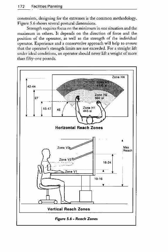
constraints, designing for the extremes is the common methodolog'y.Figure 5.6 shows several postural dimensions.
Strength requires focus on the minimum in one situation and themaximum in others. It depends on the direction of force and theposition of the operator, as well as the strength of the individualoperator. Experience and a conservative approach will help to ensurethat the operator's strength limits are not exceeded. For a straight liftunder ideal conditions, an operator should never lift a weight of morethan fifry-one pounds.
Zone H1445 si
Horizontal Reach Zones
Vert ical Reach Zones
Figure 5.6 - Reoch Zones

Workstation Design: The Sub-Micro-Space plan 1 7 3
Specialtopicsseveral specific topics arise repeatedly in the ergonomics ofworkstationdesign. Among these are band tools, material ltandling, zuork positions,and seating.In addition to the discussion below, figure 5.3 containsprinciples that apply to these areas.
Hand tool selection, design, and use are important elements ofmanyworkstation designs. The use ofthe correct hand tools contributesto productivity and quality and can prevent CTD and other injuries.
Almost everyworkplace requires some form ofmaterial handling.Injuries caused by maneuvering materials manually cost industries wellover $15 billion annually in direct expenses. The indirect costs ̂ re anestimated at $60 to fi75 billion. Productivitylosses from poor handlingmethods are probably even greater. Any tasks that require manualmaterial handling should be carefully reviewed. Refer to the NationalInstitute for Occupational Safety and Health's (NIOSH) RevisedLifting Equation (1991).
Operators may sit, stand, or both. Work positions that combinesitting and standing permit operators to shift their postures. This helpsreduce muscle fatigue fromprolonged static effort. Figure 5.7 summarizesthe relationship between several workplace variables and preferredseating positions.
Heavy Load/Forces
lntermit tent Work .A)
Extended work Envelop. XQrcVariable Tasks X,
\ B
Var iable Surface Height PSXIlDxBxc/
,c)Repeti t ive Movement
/nVn\/n\ IE Position
Fine Manipulat ion XO)A Sland
B Sil/Stand
ru, c Stand. Chair AvailableD sil
Figure 5.7 -Work Positions

1 7 4 Facilities Planning
Researchers have studied seats extensively, and most designershave broad, practical experience with seats. In general, a seat that iscomfortable for the task and positions the arms prope rly is ergonomicallysatisfactory.
Only the most important ergonomic factors in workstation designhave been covered. Lighting, vibration, temperature, noise, and shiftwork also affect the design. For further information, see Salvendy'sHandbook of Human Factors and McCormick's Human Factors InE ngine ering an d D esign.
Worker selectionThe physical demands ofeveryjob differ, as do the physical, mental, andtemperamental characteristics ofeach person that performs a job. For opti-mum performance, these characteristics and capabilities should match.
An employer should identify characteristics required for each job
and identifr minimum criteria for those who might be selected for it.This will ensure an appropriate match. In some cases, the identificationof characteristics may result in a job redesign to accommodate a largerpartofthe available candidates. At minimum, employers should ensurethat the people in a particularjob do not incur physical harm becauseof a mismatch between job requirements and worker characteristics.
The Americans with Disabilities Act (ADA) is another reason toperform this analysis. This act requires employers to accommodate,within reason, people with disabilities who can perform the essentialfunctions of a job. To do so means that the essential functions and theworker characteristics needed to perform them must be identified.
The workstation space planThe tasks for preparing a workstation are illustrated in figure 5.8. Task05.01 sets out a plan for the design project. The plan includes identifyingparticipants in the design project as well as tasks and their sequence. Asimple and informal plan usually works well at this level.
The modelprojectplanuses these fundamental space plan elements:SPUs, affinities, space, and constraints. SPUs include operators, tools,parts, and machine elements. Affinities evolve from the movement ofparts, movement of hands, and the ne cessity for observation, and otherindirect factors. Each SPU requires space, but in aworkstation, verticalspace is more important than it is at other levels. Constraints have adifferent quality. They now include an operator's dimensional andphysiological limits and, possibly, regulatory limits. Process constraintsmay play an important role.
In Task 05.02, designers bring together the necessary information.

Workstation Design: The Sub-Micro-Space Plan 175
3oG
oooC,oo-
tro
oc
OilE
Figure 5.8 - Workstation Model'Project
This includes a layout ofthe area, a process chart for the overall process,information on the people who willwork at the station, parts lists, toollists, and equipmentlists. Iftheworkstation design follows a cell design,much ofthe necessaryinformation may aheady exist. Ifnot, itwill haveto be obtained or generated. Chapter 4 shows how to acquire thisinformation.

176 Faci l i t iesPlanning
Next, a detailed process chart for,workstation ^ctivity is created(Task 05.03). Figure 5.9 is the workstation process for the headsubassembly of the diaphragm pump described in Chapter 4. The cell-level chart identified this subassembly as a single operation. Now, it isexploded into the next level of detail, and each component and eachoperation that uses a separate tool or instrument are documented. Inservice environments, information items go into the chart.
T able 5 .2 includes a list ofparts and tools for the head subassembly.This spreadsheet is the heart of the layout analysis. As the designproceeds, the other information and calculations will be described.
Task 05.04 allocates functions to people or machines. For thehead subassembly, most functions go to the operator. The designvolume is eighty-eight pumps per day or about eleven pumps e ach hour.
oE)
L
q
-)a
o@oT
i r !I:O D >
t : . i! i - !o o o
c
; : = Es r ; f i
6 U i : i i 5 r
E
- g : ; E ^9 3 E ' i; s : i i !
o
O
o@
o
L
co
€uioo
Figure 5.9 - Operotion Process Chort

Workstation Design: The Sub-Micro-Space Plan 177
trR-a *Nr)<t
crj$
N
NN
oI
06 1- a
U
a {- l
!? F o I (E) q s a9 s $ (o (o \r !? !? !q !r sf <f s !9 !9 !9 (o @ @ I sr <c) c, ct (f) o)(t K) LO(r)ct 6 (r) (f)(9 c') O 6 b CDCDC"i Ct Ct(f)rO l.c) K
H E O R R R g R E E R R E R R R H E E E R R R R R R E E S
s
- - - r - e e N N N N N N N N N! > > > > > > >ts N N N N N N N N N N N N N N N > CDCDC9 CDC9CD(f) (9(9 C.) (f) C'I I I I I I I I - I I T - I I I - - I - I I - - r j j t f
= 1 6
g . o < $ $ $ ( D ( ' C D C D e ) C D C ) ( 9 C D C D N N N N N N N N N N N N N T \ - F
< C O N ( o ( o ( o @ $ = t s t r i t < t N O O O O @ @ @ @ @ @ C O C O ( O N N o> N N o j c i c i N N N N 6 i c i N N N N 6 j + F r d + + + + + _ - + r
z 6 $ o o o o o o o o o o o o o o o o o o o o o o o o o o o c
= = EO N r st <i- <' r (f) (9 Ct CD Ct N $ S $ - O O O C, (t (9 CD CD N O O C
- F = ==E< , ti t -g ? go o o N r r o N - r r r @ N r F - o , ^ , ^ ^ N - - . . - O . ^ . ^ ^
o c t c i c i c i c i N d d c i c i c i c i c i o d 6 i d c i c i c i o o c i c t c t o d c
^ t * *- - < c
r u
$ $ <T (9 (f) (f) C' CD C' CD Cf) CD CD N N N N CD CD (f) N N N N N N N N 6
Q @ @ c o c o c o c o 6 @ @ @ @ @ o o o o @ @ c o o o o o o o o o c*co co(o @(o(o(o (o (o(o(o (oNN N N<)<)<) NNNN NN N N 6
^ lT l O
t -t _
\ J 'EUz
- < hz -(J
ou t O
O
L a q < u ? q q q L q q l l ] u ? a a r ] Q u ) o u ) l o 6 r ) r ) r ) | . c ) n 6 r o r o r rN C " i > N N N < i N r r N F - N N r . . N d r . . r . . N N r . - n s : s : n : N n s
9 9 < q q a 9 q 9 g q q q a q q q q q a q Q q q Q Q q q cS c D > s $ $ c D s t ( o @ $ { @ $ $ $ 9 ( o @ @ S $ < f s s S @ @ ( c
Q q < o o o o o Q o o o o o o o o o o o o o o o o o o o cS p2<o <ocoo<o S S @<ct S dc td
RN g : S dcocod < ;d g ! g 5
e . { Q Q $ e r r N N r N N N $ - r r N N N N N N - - ez =z -z Y z z z z z z z z z v z z z z z z z. z z z z z.co coocoo d l6com cococom ococod coco coco 6cooco co
=(9zF
. > e' i l F- l u
III
Il g
DEF.o
_ l o- l
@ @ @ @ a @ a Q @ @ @ @ @ o o o o c o @ @ o o o o o o o o@ @ @ @ @ @ ( o @ @ @ ( o ( o ( o N N N N @ ( o c o N N N N N N - N
U t . F L I J r
g icx8H 9#, " ' ' <u *+
5 =rgE!*sEfi-3tEErt,"53sEE-rr! , r q F = = H t # f i E q E E { ' r E 5 = _ b { = n t r i ! t rf , ur Z dS+d f -* 5 d=dg tZd; dtr ;E >';=aa?2€ H # f - - o - - q ) ! \ r ! ) @ N s r o - r o ( 9 @ o ) N 6 @ N $ c D c t< vJ = (o F- tr\ (O CO (O (O <) F\ (O (O N f- (O (O N (O (O (o @ @ N @ (o r
H E i p p e p e i p p p e i + + + i P i e p i i i i e e{basBsssssBsssEEEsBststsstssEEER R N - P = - o N r , c o S s o R N S - P - N 9 p N K t r 9 R
$ @ @ o o
>::5I I I I
m
cO
d
)@
? o q " r q o -x o o o
FI
t t r . . v>r.'TtEi#H;+5P
TABLE 5.2

178 Faci l i t iesPlanning
Moreover, two sizes make up this volume. In the designer's judgment,automationwas impractical at this volume. The onlymachine assignmentis the tightening of fittings. The operator uses an air wrench to do this.
Tasls 05.05 through 05.08 address affinities. Most affinities arisefrom reaching, grasping, and moving. The operator may interact in thismanner with parts, tools, or controls. A reach, followed by a grasp, isone of the most common workplace activities. Operators reach andgrasp parts, tools and controls. Frequency, handling difficulty, andweight affect the reach affinity.
Affinities also arise from other factors. The operator may need tose e objects or displays, so they should be within the operator's visual field.Some items are more important than others. For example, an emergencycutoffcontrol is used only infrequently but is very important. Developingaffinities also involves: the amount of accurary required, duration ofuse,safety, the amount of force required, and operator preferences.
The various tools, parts, displays, and controls compete forlocations close to the operator and within his or her optimum visual andreach zones. These zones have limits.
Figure 5.6 shows the horizontal and vertical zones for a typicaloperator. These are designated with an "H" or "V' for horizontal orvertical. Designers then can assign items to both ahorizontd.and verticalznne according to their relative affinity needs and the space available.
Horizontal affinity znne 1 (H1) is closest to the operator and canbe reached comfortablywhen elbows are on the work surface. The zonearch is about 15 to 17 inches from the surface edge. A line extending 45degrees from the shoulders bounds the zone laterally. This zone is themost comfortable, offering the least stress and quickest access time. Itshould be reserved for the tasks and items with the highest priority.
Horiznntal affinity zone 2 (H2) is the area an operator cancomfortably reach by extending an arm with his or her trunk stationary.The zone arc is about 27 inches from the work surface edge. It ends whenthe arm is at 45 degrees above the horizontal plane. This zone requiresminimal access time. However, extensive time in this position leads torapid fatigue and upper musculoskeletal stress. Use this zone for lightobjects that the operator can grasp easily before returning to zone H1.
Horizontal affinity zone 3 (H3) is reached by extending an armwith full trunk flexion. The arc is about 42 to 44 inches from the worksurface edge. It ends when the arm reaches 45 degrees above thehorizontal plane. This zone has significantly greater access time andcorresponding reduction in efficiency, productivity, and effectiveness.Operators must move their heads to see the task, a movement thatinterrupts concentration. This zone should be used for infrequent

W o r k s t a t i o n D e s i g n : T h e S u b - M i c r o - S p a c e P l a n 1 7 g
reaches with low priority.Horizo ntal affinity zo ne 4 (H 4) re quire s fu ll bo dy move m e nt an d,
possibly, one or two side steps. The operator expends considerableenerg'y to reach this zone. Access time is significantly greater than otherzones. It should only be used for tasks with the lowest priority.
Vertical affinity zone ! (V1) extends from the work surftce toabout 10 to 16 inches above the seat pan. It is about heart level, has thelowest access time, and is the most comfortable. It should be used fortasks with the highest prioriry.
Vertical affinity zone 2 (V2) begins where zone VI ends. Itextends to the operator's shoulders, about 16 to 24 inches above thework surface. This zone is used for items and tasks that support primarytasks. Access time is minimal, but extensive time in this zone causesearly fatigue and musculoskeletal stress.
Vertical affinity zone 3 (V3) extends from the base of znneY2 tothe maximum reach level. It may require upper trunk movement as wellas head movement, which reduces concentration and increases accesstime. Using this zone interrupts vision and forces the operator torefocus. It is the least efficient vertical affinity zone and should bereserved for tasks with the lowest priority.
The first task for affinity development concerns reaches andfrequency. From the initial information, designers should compile a listofitems. In table 5.2, this list is in column B. Next, designers should useP-V information, the process chart, and bills of materials to determinethe number of times each day an operator reaches each item. In table5.2, this is column I. The frequencies derive from the quantity per unit(column C) and the expected daily production (Column D).
Column J is an affinity rating that uses the 0 to 4 weightednumeric scale. The rating is identified on a ranked bar graph, a processsimilar to that used for rating material flow affinities discussed inchapter 3. To construct this graph, the spreadsheet on column I issorted in descending order. Column I is plotted on the vertical axiswhile the identifiing number, column A, is plotted on the horizontalaxis. The next step involves assigning 0 to 4 or AEIOU to the affinitiesand recording them in column J of the spreadsheet.
The weight of each object, if significant, adds to the difficulty ofa reach. Column K lists the weight carried for each item, which is thenrated by the coresponding affinities (column L). Difficulty of a reach-grasp also depends on the shape, size, and delicacy of each item. Thisaffinity is rated in column M. For the diaphragm pump, the valves areparticularly small and delicate. Consequently, they carry a handlingaffinity of 4. Small washers carry a 3 affinity.

180 Faci l i t iesPlanning
For the head subassembly of the diaphragm pump; no otheraffiniry factors were identified. In different situations, this categorycould include the necessity to see gauges or controls. It could includemany factors peculiar to each circumstance. Using the procedures forTask03.14 outlined in chapter 3, affinities are merged. Attheworkstationlevel, this is Task 05.09. Each affinity is assigned a ratingweight. Table5.2 shows these weights at lower left. Each affinity rating is multipliedby the corresponding weight and placed in column O. Next, the valuesin column O are plotted on a ranked bar graph, and the total affinitiesare rated and are placed in column P.
Task 05.10 calculates the space for each item in the list. Table 5 .2has dimensional information in columns F through H. Column Eshows a container code. For example, the BN1 container is an open-front parts bin with dimensions of 6 inches by 7.5 inches by 12 inches.The spreadsheet formula calculates horrzontal space and places it incolumn R. The face area for each item is shown in column S. Theformula adds 20 percent for unusable space and clearances.
Task 05.11 assigns each item an affinity zone. This balances theneed for affinity with available space. Starting with the highest valueaffinities, each item is assigned to the most desirable zone. For the headsubassembly, zone H1V1 was reserved for the work fixture andsurrounding work space. The lower middle section of table 5.2 showsthe approximate space available in each zone. Because the total amountof space needed exceeds the space available in all the V1 zones, thedesigners use an elevated shelf in zoneH2V2 to store some parts.
In this situation, horizontal space dominates. In other situations,such as in an aircraft cockpit, the vertical space might dominate. For thisexample, affinities between elements other than the operator have beenignored. Such affinities might have importance in special situations. Insuch cases, designers develop an affinity diagram like that used inChapters 3 and 4.
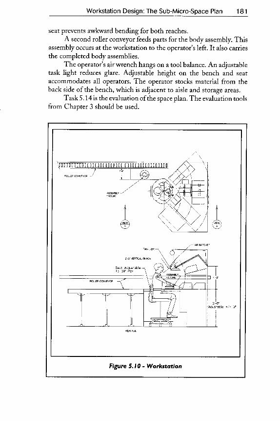
Task 05.13 creates space plan options. One option for the headsubassembly is in figure 5.10. The designers used figure 5.7 to select aposition for the operator. In this case, the operator assembles heads andbodies. The operator also stocks material and occasionally assists otherpeople in the work cell. The sit and stand position offers mobility butalso allows rest and variation.
Figure 5.10 shows howthe operatorcan assemble eitherofthe twopump sizes without set-up. This precludes batching. At completion,the parts go on a roller conveyor at the operator's left. The rollerconveyor and one-part container are in Zone 4, outside the usualafftnity zones. The operator uses these only once for each item. A swivel
Workstation Design: The Sub-Micro-Space Plan
seat prevents awlanrard bending for both reaches.A second roller conveyor feeds parts for the body assembly. This
assembly occurs at the workstation to the operator's left. It also carriesthe completed body assemblies.
The operator's airwrench hangs on a tool balance. An adjustabletask light reduces glare. Adjustable height on the bench and seataccommodates all operators. The operator stocks material from theback side of the bench, which is adjacent to aisle and storage areas.
Task 5.14 is the evaluation of the space plan. The evaluation toolsfrom Chapter 3 should be used.
tAw
Figure 5,10 - Worlstotion
1 8 1

182 Facilities Planning
SummalyA well-thought-out workstation optimizes productivity both withinitself and in the larger production system. It improves the workexperience for everyone. It ensures continued health and safety. Suchworkstations are an essential part of a wodd-class operations strateg'y.A structured and systematic approach will ensure consistent and high-quality workstation design.