HikCentral-Workstation Control Client User Manual - Hikvision
261
HikCentral-Workstation Control Client User Manual
-
Upload
khangminh22 -
Category
Documents
-
view
2 -
download
0
Transcript of HikCentral-Workstation Control Client User Manual - Hikvision

HikCentral-Workstation Control Client
User Manual

HikCentral-Workstation Control Client User Manual
i
Legal Information
© 2021 Hangzhou Hikvision Digital Technology Co., Ltd. All rights reserved.
About this Manual
The Manual includes instructions for using and managing the Product. Pictures, charts, images and all other information hereinafter are for description and explanation only. The information contained in the Manual is subject to change, without notice, due to firmware updates or other reasons. Please find the latest version of this Manual at the Hikvision website (https://www.hikvision.com/). Please use this Manual with the guidance and assistance of professionals trained in supporting the Product.
Trademarks
and other Hikvision's trademarks and logos are the properties of
Hikvision in various jurisdictions. Other trademarks and logos mentioned are the properties of their respective owners.
Disclaimer
TO THE MAXIMUM EXTENT PERMITTED BY APPLICABLE LAW, THIS MANUAL AND THE PRODUCT DESCRIBED, WITH ITS HARDWARE, SOFTWARE AND FIRMWARE, ARE PROVIDED "AS IS" AND "WITH ALL FAULTS AND ERRORS". HIKVISION MAKES NO WARRANTIES, EXPRESS OR IMPLIED, INCLUDING WITHOUT LIMITATION, MERCHANTABILITY, SATISFACTORY QUALITY, OR FITNESS FOR A PARTICULAR PURPOSE. THE USE OF THE PRODUCT BY YOU IS AT YOUR OWN RISK. IN NO EVENT WILL HIKVISION BE LIABLE TO YOU FOR ANY SPECIAL, CONSEQUENTIAL, INCIDENTAL, OR INDIRECT DAMAGES, INCLUDING, AMONG OTHERS, DAMAGES FOR LOSS OF BUSINESS PROFITS, BUSINESS INTERRUPTION, OR LOSS OF DATA, CORRUPTION OF SYSTEMS, OR LOSS OF DOCUMENTATION, WHETHER BASED ON BREACH OF CONTRACT, TORT (INCLUDING NEGLIGENCE), PRODUCT LIABILITY, OR OTHERWISE, IN CONNECTION WITH THE USE OF THE PRODUCT, EVEN IF HIKVISION HAS BEEN ADVISED OF THE POSSIBILITY OF SUCH DAMAGES OR LOSS. YOU ACKNOWLEDGE THAT THE NATURE OF THE INTERNET PROVIDES FOR INHERENT SECURITY RISKS, AND HIKVISION SHALL NOT TAKE ANY RESPONSIBILITIES FOR ABNORMAL OPERATION, PRIVACY LEAKAGE OR OTHER DAMAGES RESULTING FROM CYBER-ATTACK, HACKER ATTACK, VIRUS INFECTION, OR OTHER INTERNET SECURITY RISKS; HOWEVER, HIKVISION WILL PROVIDE TIMELY TECHNICAL SUPPORT IF REQUIRED. YOU AGREE TO USE THIS PRODUCT IN COMPLIANCE WITH ALL APPLICABLE LAWS, AND YOU ARE SOLELY RESPONSIBLE FOR ENSURING THAT YOUR USE CONFORMS TO THE APPLICABLE LAW. ESPECIALLY, YOU ARE RESPONSIBLE, FOR USING THIS PRODUCT IN A MANNER THAT DOES NOT INFRINGE ON THE RIGHTS OF THIRD PARTIES, INCLUDING WITHOUT LIMITATION, RIGHTS OF PUBLICITY, INTELLECTUAL PROPERTY RIGHTS, OR DATA PROTECTION AND OTHER PRIVACY RIGHTS. YOU SHALL NOT USE THIS PRODUCT FOR ANY PROHIBITED END-USES, INCLUDING THE DEVELOPMENT OR PRODUCTION OF WEAPONS OF MASS DESTRUCTION, THE DEVELOPMENT OR

HikCentral-Workstation Control Client User Manual
ii
PRODUCTION OF CHEMICAL OR BIOLOGICAL WEAPONS, ANY ACTIVITIES IN THE CONTEXT RELATED TO ANY NUCLEAR EXPLOSIVE OR UNSAFE NUCLEAR FUEL-CYCLE, OR IN SUPPORT OF HUMAN RIGHTS ABUSES. IN THE EVENT OF ANY CONFLICTS BETWEEN THIS MANUAL AND THE APPLICABLE LAW, THE LATTER PREVAILS.

HikCentral-Workstation Control Client User Manual
iii
Symbol Conventions
The symbols that may be found in this document are defined as follows.
Symbol Description
Danger
Indicates a hazardous situation which, if not avoided, will or could result in death or serious injury.
Caution
Indicates a potentially hazardous situation which, if not avoided, could result in equipment damage, data loss, performance degradation, or unexpected results.
Note
Provides additional information to emphasize or supplement important points of the main text.

HikCentral-Workstation Control Client User Manual
iv
Contents
Chapter 1 About Control Client ............................................................................................................ 1
1.1 Product Scopes and Functional Differences .......................................................................... 1
Chapter 2 Login .................................................................................................................................... 3
2.1 First Time Login ...................................................................................................................... 3
2.2 Normal Login (Not First Time) ................................................................................................ 4
2.3 Change Password for Reset User and Login .......................................................................... 6
Chapter 3 Home Page Overview .......................................................................................................... 8
3.1 Customize Control Panel ...................................................................................................... 11
3.2 Customize Navigation Bar .................................................................................................... 13
Chapter 4 Manage View ..................................................................................................................... 15
Chapter 5 Live View ........................................................................................................................... 17
5.1 Start Live View in Area Mode ............................................................................................... 18
5.2 Start Live View in View Mode .............................................................................................. 19
5.3 Auto-Switch Cameras in an Area ......................................................................................... 20
5.4 PTZ Control ........................................................................................................................... 21
5.4.1 Configure Preset........................................................................................................ 23
5.4.2 Configure Patrol ........................................................................................................ 24
5.4.3 Configure Pattern ...................................................................................................... 25
5.5 Manual Recording and Capture ........................................................................................... 26
5.5.1 Manual Recording ..................................................................................................... 26
5.5.2 View Manually Recorded Videos .............................................................................. 27
5.5.3 Capture Pictures ........................................................................................................ 28
5.5.4 View Captured Pictures ............................................................................................. 29
5.6 View Dewarped Live View of Fisheye Camera ..................................................................... 30
5.7 Perform Manual Panorama Tracking ................................................................................... 32
5.8 Create Zooming Area to View Detailed Live View ............................................................... 33
5.9 View Detected Event in Live View........................................................................................ 35
5.10 More Functions .................................................................................................................. 37
5.11 Customize Icons on Live View Window ............................................................................. 37

HikCentral-Workstation Control Client User Manual
v
Chapter 6 Real-Time Temperature and People Counting Monitoring .............................................. 41
Chapter 7 Playback ............................................................................................................................. 43
7.1 Normal Playback .................................................................................................................. 43
7.1.1 Search Video File ....................................................................................................... 43
7.1.2 Play Video File ........................................................................................................... 44
7.2 Start Playback in View Mode ............................................................................................... 45
7.3 Synchronous Playback .......................................................................................................... 45
7.4 Fisheye Playback .................................................................................................................. 46
7.5 Create Zooming Area to View Detailed Playback ................................................................ 46
7.6 Customize Icons on Playback Window ................................................................................. 49
Chapter 8 Visual Tracking ................................................................................................................... 52
8.1 Perform Visual Tracking in Live View ................................................................................... 52
8.2 View Visual Tracking Video .................................................................................................. 53
Chapter 9 Manage Favorites .............................................................................................................. 56
Chapter 10 Add Web Page to Display Window ................................................................................. 58
Chapter 11 Customize Intelligent Monitoring Contents .................................................................... 59
Chapter 12 Video Search .................................................................................................................... 63
12.1 Search Video Footages by Time Range .............................................................................. 63
12.2 Search Tagged Video Footages .......................................................................................... 67
12.3 Search Locked Video Footages .......................................................................................... 69
12.4 Search Transaction Event Triggered Video Footage .......................................................... 71
12.5 Search ATM Event Triggered Video Footage ..................................................................... 73
12.6 Search VCA Event Related Video ....................................................................................... 75
Chapter 13 Manage Downloading Tasks ........................................................................................... 79
Chapter 14 Map Management ........................................................................................................... 81
14.1 Operate Hot Spot ............................................................................................................... 81
14.1.1 Preview Hot Spot .................................................................................................... 81
14.1.2 Arm or Disarm Hot Spot .......................................................................................... 83
14.1.3 View History Alarm ................................................................................................. 83
14.2 Preview Hot Region ............................................................................................................ 83
14.3 Preview Resource Group.................................................................................................... 84

HikCentral-Workstation Control Client User Manual
vi
14.4 Operate Map ...................................................................................................................... 85
Chapter 15 Access Control ................................................................................................................. 86
15.1 Control Door Status in Live View ....................................................................................... 86
15.2 Search Access Records ....................................................................................................... 90
15.3 Search Data Recorded on Device ....................................................................................... 93
15.4 Open Door for Multi-Factor Authentication ...................................................................... 94
15.5 Handle Opening Door Request from Video Access Control Terminal ............................... 96
15.6 Perform Entry & Exit Counting ........................................................................................... 96
Chapter 16 Video Intercom ................................................................................................................ 98
16.1 Call Indoor Station .............................................................................................................. 98
16.2 Answer Call ......................................................................................................................... 99
Chapter 17 Vehicle ........................................................................................................................... 101
17.1 View ANPR Camera's Live Video ...................................................................................... 101
17.2 Entrance & Exit Control .................................................................................................... 103
17.2.1 View Passing Vehicle Information ......................................................................... 104
17.2.2 Automatically Open Barrier for Vehicles .............................................................. 107
17.2.3 Manually Open Barrier for Vehicles ...................................................................... 109
17.2.4 Correct License Plate Number .............................................................................. 113
17.2.5 Manually Control Barrier ...................................................................................... 113
17.2.6 Hand Over Shifts ................................................................................................... 114
17.3 Parking Space Monitoring ................................................................................................ 115
17.4 Add Recognized Vehicle to Vehicle List ........................................................................... 117
17.5 Vehicle and Record Search ............................................................................................... 119
17.5.1 Search for Vehicle Passing Records ...................................................................... 120
17.5.2 Search for Payment Records ................................................................................. 123
17.5.3 Search for Parked Vehicles.................................................................................... 124
17.5.4 Search for Parking Records ................................................................................... 127
17.5.5 Search for Multiple Vehicles Under One Account Status ..................................... 129
Chapter 18 Face and Body Recognition ........................................................................................... 131
18.1 View Detected and Matched Face in Live View ............................................................... 131
18.2 Add Mismatched Person to Person Group ...................................................................... 133

HikCentral-Workstation Control Client User Manual
vii
18.3 Face Search ...................................................................................................................... 135
18.3.1 Search Captured Face Pictures and Related Videos ............................................. 136
18.3.2 Search Face Pictures by Picture ............................................................................ 140
18.3.3 Search Matched Faces .......................................................................................... 144
18.3.4 Search Persons by Frequency ............................................................................... 146
Chapter 19 Security Control ............................................................................................................. 150
19.1 Start Live View of Radar's Calibrated Camera ................................................................. 150
19.2 Perform Arming Control for Resources ........................................................................... 151
19.3 Handle Panic Alarm from Panic Alarm Station ................................................................ 153
Chapter 20 Check Alarm and Event ................................................................................................. 155
20.1 View Resources' Real-Time Alarms .................................................................................. 155
20.2 View Pop-up Window Triggered by Alarm ....................................................................... 160
20.3 Manually Trigger User-Defined Event .............................................................................. 162
20.4 Perform Arming Control for Alarms ................................................................................. 163
20.5 Event and Alarm Search ................................................................................................... 165
20.5.1 Alarm Overview..................................................................................................... 165
20.5.2 Search Event and Alarm Logs ................................................................................ 166
Chapter 21 Smart Wall ..................................................................................................................... 169
21.1 Manage Smart Wall (Decoding Device) ........................................................................... 169
21.1.1 Decode and Display Directly ................................................................................. 172
21.1.2 View Settings ......................................................................................................... 175
21.1.3 Set View Auto-Switch Interval .............................................................................. 177
21.1.4 Auto-Switch Cameras in One Window .................................................................. 178
21.1.5 Auto-Switch Cameras in Multiple Windows ......................................................... 179
21.1.6 Create a Roaming Window ................................................................................... 180
21.1.7 View Alarm's Related Video on Smart Wall .......................................................... 181
21.1.8 View and Export Window No. and Camera ID ...................................................... 182
21.2 Manage Smart Wall (Graphic Card) ................................................................................. 183
21.2.1 Display Contents on Smart Wall in Smart Wall Mode .......................................... 183
21.2.2 Display Contents on Smart Wall in Live View Mode ............................................. 185
21.2.3 Display Alarm's Related Video on Smart Wall ...................................................... 188

HikCentral-Workstation Control Client User Manual
viii
21.2.4 Display Health Monitoring Page on Smart Wall ................................................... 191
21.2.5 Display Desktop on Smart Wall ............................................................................. 192
Chapter 22 Intelligent Analysis Report ............................................................................................ 194
22.1 Customize Report Dashboard .......................................................................................... 194
22.2 Generate People Counting Report ................................................................................... 196
22.3 Generate Heat Analysis Report ........................................................................................ 199
22.4 Generate Person Feature Analysis Report ....................................................................... 203
22.5 Generate Skin-Surface Temperature Analysis Report ..................................................... 206
Chapter 23 Maintenance ................................................................................................................. 209
23.1 Health Monitoring ............................................................................................................ 209
23.1.1 Real-Time Health Status Overview ....................................................................... 209
23.1.2 Real-Time Health Status Overview (Topology) ..................................................... 212
23.1.3 Historical Health Data Overview ........................................................................... 219
23.2 Resource Status ................................................................................................................ 222
23.3 Log Search ........................................................................................................................ 226
23.3.1 Search for Server Logs ........................................................................................... 226
23.3.2 Search for Online/Offline Logs of Device .............................................................. 228
23.3.3 Search for Logs Stored on Device ......................................................................... 229
23.3.4 Search for Online/Offline Logs of Resource .......................................................... 231
23.3.5 Search for Recording Status of Resource .............................................................. 232
Chapter 24 Tools .............................................................................................................................. 238
24.1 Play Video via VSPlayer .................................................................................................... 238
24.2 Perform Two-Way Audio ................................................................................................. 239
24.3 Broadcast to Connected Devices ..................................................................................... 239
24.4 Control Alarm Output ...................................................................................................... 240
24.5 Record Screen .................................................................................................................. 240
Chapter 25 System Settings ............................................................................................................. 241
25.1 Set General Parameters ................................................................................................... 241
25.2 Set Video Parameters....................................................................................................... 243
25.2.1 Set Network Parameters ....................................................................................... 243
25.2.2 Set File Parameters ............................................................................................... 244

HikCentral-Workstation Control Client User Manual
ix
25.2.3 Set Display Parameters ......................................................................................... 244
25.2.4 Set Audio Parameters ........................................................................................... 245
25.2.5 Set Keyboard and Joystick Parameters ................................................................. 246
25.3 Set Linkage Action Parameters ........................................................................................ 246
25.4 Set Alarm Sound ............................................................................................................... 247
25.5 Customize Icons on Alarm Center .................................................................................... 247
25.6 Set Health Status Parameters .......................................................................................... 249
25.7 Set Screen Position........................................................................................................... 249
25.8 Enable Printing Parking Free Receipts ............................................................................. 249
25.9 Switch Home Page Mode ................................................................................................. 250
25.10 Set Ringtone for Calling .................................................................................................. 250

HikCentral-Workstation Control Client User Manual
1
Chapter 1 About Control Client
As one of the key components of the system, the Control Client provides multiple operating functionalities, including real-time live view, PTZ control, video playback and downloading, alarm receiving, log search, and so on. This user manual describes the function, configuration, and operation steps of the Control Client. To ensure the proper usage and stability of the client, refer to the contents below and read the manual carefully before operation.
Note
The functions on the Control Client vary with the License you purchased. For detailed information, contact our technical support.
1.1 Product Scopes and Functional Differences
This manual is available for the following server models. And the supported functions among different models are different.
Product Scopes
● HikCentral-Workstation/32 with Intel(R) Core(TM) i3 ● HikCentral-Workstation/64 with Intel(R) Core(TM) i3 ● HikCentral-Workstation/64 with Intel(R) Core(TM) i5 ● HikCentral-Workstation/128 with Intel(R) Core(TM) i5
Functional Differences Among Four Server Models
Table 1-1 Functional Differences Among Four Server Models
Advanced Function
HikCentral-Workstation/32 with Intel(R) Core(TM)
i3
HikCentral-Workstation/64 with Intel(R) Core(TM)
i3
HikCentral-Workstation/64 with Intel(R) Core(TM)
i5
HikCentral-Workstation/128 with Intel(R) Core(TM)
i5
Smart Wall Not Support Not Support Not Support Support
Intelligent Analysis: People Counting
Not Support Not Support Support Support
Intelligent Analysis: Heat Analysis
Not Support Not Support Not Support Support
Intelligent Not Support Not Support Support Support

HikCentral-Workstation Control Client User Manual
2
Advanced Function
HikCentral-Workstation/32 with Intel(R) Core(TM)
i3
HikCentral-Workstation/64 with Intel(R) Core(TM)
i3
HikCentral-Workstation/64 with Intel(R) Core(TM)
i5
HikCentral-Workstation/128 with Intel(R) Core(TM)
i5
Analysis: Person Feature Analysis
Time & Attendance
Not Support Not Support Support Support
Visitor Not Support Not Support Support Support

HikCentral-Workstation Control Client User Manual
3
Chapter 2 Login
Log in to the system via the Control Client for operations.
2.1 First Time Login
When normal user (except admin user) logs into the system for the first time, he/she should change the initial password and set a new password for login.
Before You Start
When you log into the system for the first time, you are required to create a password for the system pre-defined administrator user (named admin) on the Web Client before you can properly configure and operate the system.
Perform the following steps when you access the system via the Control Client for the first time as a normal user (except admin).
Steps
1. Double-click on the desktop to run the Control Client.
Figure 2-1 Login Page
2. Enter the server parameters.
Note
You can click Hide Server Address or Show Server Address to hide or show the server network information.

HikCentral-Workstation Control Client User Manual
4
Server Address
Enter the address (IP address or domain name) of the server that running the SYS service you want to connect to.
Port
Enter the port No. of the server where the SYS service is running. The default port No. is 80. 3. Enter the user name and password of the HikCentral-Workstation.
Note
● Contact the administrator for the user name and initial password. ● For domain user account, you can check Auto-Launch so that you will not need to manually
start the Control Client next time you start your computer.
4. Click Log In. 5. Click Close in the pop-up dialog to continue. 6. Set a new password and confirm the password.
Caution
The password strength of the device can be checked by the system. We highly recommend you change the password of your own choosing (using a minimum of 8 characters, including at least three kinds of following categories: upper case letters, lower case letters, numbers, and special characters) in order to increase the security of your product. And we recommend you reset your password regularly, especially in the high security system, resetting the password monthly or weekly can better protect your product. Proper configuration of all passwords and other security settings is the responsibility of the installer and/or end-user.
7. Click Log In to change the password. You enter the Control Client home page after you change the password.
2.2 Normal Login (Not First Time)
Normally, you can log into the platform with the user name and password of HikCentral-Workstation as a normal user.
Steps
1. Double-click on the desktop to run the Control Client.

HikCentral-Workstation Control Client User Manual
5
Figure 2-2 Login Page
2. Enter the server parameters.
Note
You can click Hide Server Address or Show Server Address to hide or show the server network information.
Server Address
Enter the address (IP address or domain name) of the server that running the SYS service that you want to connect to.
Port
Enter the port No. of the server where the SYS service is running. The default port No. is 80. 3. Enter the user name and password of the HikCentral-Workstation. 4. Optional: Check Remember Password checkbox to keep the password. 5. Optional: Check Enable Auto-login checkbox to log in to the software automatically for the next
login.
Note
For domain user account, you can check Auto-Launch so that you will not need to manually start the Control Client next time you start your computer.
6. Click Log In.
Note
● If an failed password attempt of current user is detected, you are required to enter the verification code before you can log in. The failed password attempt from current client, other client and other address will all require the verification code.

HikCentral-Workstation Control Client User Manual
6
● The failed password attempt from current client, other client (e.g., Control Client) and other address will all be accumulated. Your IP address will be locked for a specified period of time after specific number of failed password or verification code attempts. For detailed settings of failed login attempts and locking duration, refer to the User Manual of HikCentral-Workstation Web Client.
● The account will be frozen for 30 minutes after 5 failed password attempts. The failed password attempt from current client, other client (e.g., Control Client) and other address will all be accumulated.
● The password strength can be checked by the system and should meet the system requirements. If password strength is lower than the required minimum strength, you will be asked to change your password. For detailed settings of minimum password strength, refer to the User Manual of HikCentral-Workstation Web Client.
● If your password has expired, you should change the password when logging in. For detailed settings of maximum password age, refer to the User Manual of HikCentral-Workstation Web Client.
Enter the Control Client home page.
2.3 Change Password for Reset User and Login
If the normal user's password is reset to the initial password by the administrator, he/she should change the initial password and set a new password when logging in again.
Steps
1. Double-click on the desktop to run the Control Client.
Figure 2-3 Login Page

HikCentral-Workstation Control Client User Manual
7
2. Enter the server parameters.
Server Address
Enter the address (IP address or domain name) of the server that runs the SYS you want to connect to.
Port
Enter the port No. of the server where the SYS is running. The default port No. is 80.
Note
You can click Hide Server Address or Show Server Address to hide or show the server network information.
3. Enter the user name and password of the HikCentral-Workstation.
Note
● Contact the administrator for the user name and initial password. ● For domain user account, you can check Auto-Launch so that you will not need to manually
start the Control Client next time you start your computer.
4. Click Log In. 5. Click Close in the pop-up dialog to continue. 6. Set a new password and confirm the password.
Caution
The password strength of the device can be checked by the system. We highly recommend you change the password of your own choosing (using a minimum of 8 characters, including at least three kinds of following categories: upper case letters, lower case letters, numbers, and special characters) in order to increase the security of your product. And we recommend you reset your password regularly, especially in the high security system, resetting the password monthly or weekly can better protect your product. Proper configuration of all passwords and other security settings is the responsibility of the installer and/or end-user.
7. Click Log In to change the password. You enter the Control Client home page after you change the password.

HikCentral-Workstation Control Client User Manual
8
Chapter 3 Home Page Overview
The default Home page shows a control panel which provides an overview of navigation about the function modules in a visible way, i.e., Alarm Monitoring, Health Status, and Map, for quick and convenient access.
Note
● You can customize the control panel inthe default Home page mode and adjust the module arrangement as you desired. For details, refer to Customize Control Panel.
● The default mode of the Home page is Visualization Mode. For the first time login, a prompt will appear at the top of the Home page, you can click Switch to switch the mode to Menu Mode. If you want to restore to the default mode, you can go to the System page and set. For details, refer to Switch Home Page Mode.
HikCentral-Workstation Control Client is composed of the following function modules by default.
Table 3-1 Function Modules of Control Client
Section Module Description
Surveillance
Monitoring
The Monitoring module provides live view, playback, smart wall (graphic card), view management, favorites management, and map management, and supports some basic operations, such as PTZ control, picture capturing, adding web page window, etc.
For more details, refer to Manage View, Live View, Playback, Map Management, Manage Smart Wall (Graphic Card), Manage Favorites, Add Web Page to Display Window, and so on.
Parking Lot
The Parking Lot module provides entry and exit control for the detected vehicles. The system will automatically open the barrier according to the settings on the Web Client. If the barrier is not open, you can also open the barrier by pressing a button manually to allow the vehicle to pass.
For more details, refer to Entrance & Exit Control.
Intelligent Monitoring
The Intelligent Monitoring module provides the display of today's event statistics, real-time captured pictures (of faces, human bodies, and vehicles), and real-time events triggered by vehicles and persons. You can customize the contents to be displayed in this module.
For more details, refer to Customize Intelligent

HikCentral-Workstation Control Client User Manual
9
Section Module Description
Monitoring Contents.
Alarm Center
The Alarm Center module provides the display and management of alarm/event information received by the Control Client.
For more details, refer to Check Alarm and Event.
Investigation
Event & Alarm Search
The Event & Alarm Search module provides the function of searching for event and alarm logs.
For more details, refer to Search Event and Alarm Logs.
Video Search
The Video Search module provides the function of searching for video footage, video on device, or VCA event related video.
For more details, refer to Video Search.
Face Search
The Face Search module provides searching for captured/matched/frequently appeared person's/rarely appeared person's face pictures and related videos.
For more details, refer to Face Search.
Access Control Retrieval
The Access Control Retrieval module provides searching for access records and entry & exit counting.
For more details, refer to Search Access Records and Perform Entry & Exit Counting.
Vehicle Search
The Vehicle Search module provides searching for related vehicle passing information.
For more details, refer to Search for Vehicle Passing Records.
Intelligent Analysis
Intelligent Analysis Overview
The Intelligent Analysis Overview module provides customizing and viewing reports.
For more details, refer to Customize Report Dashboard.
People Analysis
The People Analysis module provides reports for people counting, heat analysis, and person feature analysis.
For more details, refer to Generate People Counting Report, Generate Heat Analysis Report, and Generate Person Feature Analysis Report.
Maintenance Health Monitoring
The Health Monitoring module provides real-time overview and history overview of the resources and service status.

HikCentral-Workstation Control Client User Manual
10
Section Module Description
For more details, refer to Real-Time Health Status Overview and Historical Health Data Overview.
Resource Status
The Resource Status module provides the status of the resources.
For more details, refer to Resource Status.
System Log
The System Log module provides searching, viewing, and backing up the log files.
For more details, refer to Log Search.
Tool
Smart Wall
The Smart Wall module provides the function of displaying the decoded video on smart wall.
For more details, refer to Manage Smart Wall (Decoding Device)
Arming Control
The Arming Control module provides arming and disarming of the resources managed in the system.
For more details, refer to Perform Arming Control for Alarms.
Video Intercom
The Video Intercom module provides voice talk with residents by calling their indoor stations.
For more details, refer to Video Intercom.
VSPlayer
In the VSPlayer module, you can run the software and play video files stored in the local PC.
For more details, refer to Play Video via VSPlayer.
Two-Way Audio
The Two-Way Audio module provides the function of voice talk between the Control Client and devices, and supports getting and playing the real-time audio on the Control Client.
For more details, refer to Perform Two-Way Audio.
Broadcasting
The Broadcasting module provides the function of distributing the audio content to the added device if the device has an audio output.
For more details, refer to Broadcast to Connected Devices
Alarm Output Control
The Alarm Output Control module provides the function of controlling the alarm output remotely by the Control Client.

HikCentral-Workstation Control Client User Manual
11
Section Module Description
For more details, refer to Control Alarm Output.
Record
The Record tool is used to record operations on the screens.
For more details, refer to Record Screen.
Management
System
The System module provides basic settings and application settings.
For more details, refer to System Settings.
Help The Help module provides help information, such as user manual, license details, and software version of the Control Client.
Download Center
The Download Center module supports viewing and managing the downloading tasks.
For more details, refer to Manage Downloading Tasks.
Local Picture The Local Picture module provides the search and management of local pictures.
Local Recording The Local Recording module provides the search and management of local video files.
3.1 Customize Control Panel
You can select modules to display on the control panel and customize the module arrangement.
Steps
1. In the top left corner of the control panel, click My Control Panel to unfold the drop-down list. 2. Click Add Control Panel in the drop-down list to start customizing a control panel.

HikCentral-Workstation Control Client User Manual
12
Figure 3-1 Customize Control Panel
3. In the top left corner of the control panel adding page, enter a name for the control panel. 4. On the right panel, select a window. 5. On the left panel, click a module name to show the module configuration panel on the left. 6. Select and drag/double click a camera/map/web page, or set module parameters and click Save.
Note
● When adding the Camera or Map module, you can edit the added modules. But when adding other modules (except the Camera and Map modules), you cannot edit the added modules.
● When adding the Health Monitoring module, setting module parameters is not required. After clicking the module name, the module will be directly added and displayed in the selected window.
● When adding the Web Page module, you can enter the URL or IP address of the web page in the input field in the top right corner of the window and press Enter on the keyboard to go to the web page.
The module is added to the selected window and displayed in a visualized way. 7. Optional: Perform the following operation(s).
Edit Module Parameters
Click in the top right corner of the window to edit the module parameters.
Remove Module Click in the top right corner of the window to remove the module from the window.

HikCentral-Workstation Control Client User Manual
13
Customize Module Arrangement
Drag the module to the desired window to customize the module arrangement on the control panel.
8. Optional: In the top right corner of the control panel adding page, click Cancel to cancel customizing the control panel.
9. Optional: In the top right corner of the control panel adding page, click Restore Default to restore to the default control panel.
10. In the top right corner of the control panel adding page, click Save to save the custom control panel.
11. Optional: Perform the following operation(s).
Edit Control Panel In the top right corner of the Control Client, click Edit Control Panel to edit the control panel.
Switch to Full Screen In the top right corner of the Control Client, click Full Screen to display the control panel in full screen mode.
Open Auxiliary Screen
In the top right corner of the Control Client, click to display the control panel on the auxiliary screen.
3.2 Customize Navigation Bar
To conveniently access some frequently used or important modules, you can customize the navigation bar.
Steps
1. In the top left corner of the Client, select → All Modules to display the navigation bar andthe All Modules pane.

HikCentral-Workstation Control Client User Manual
14
Figure 3-2 Navigation Bar and All Modules Panel
2. On the All Modules panel, drag the modules to the desired area to customize the module arrangement.
3. On the All Modules panel, move the cursor to a module item. An icon appears beside the module name.
4. Click to add the selected module to the navigation bar. The icon of the corresponding module turns to .
5. Optional: Click to remove the module from the navigation bar.

HikCentral-Workstation Control Client User Manual
15
Chapter 4 Manage View
A view is a window division with resource channels (e.g., cameras and access points) linked to each window. View mode enables you to save the window division and the correspondence between cameras and windows (or correspondence between map and window) as the default so that you can quickly access these channels and/or map later. For example, you can link camera 1, camera 2, and camera 3 located in your office to the certain display windows and save them as a view called office. Then, you can access the view office and these cameras will display in the linked window quickly.
Perform this task when you need to get quick access to a certain set of channels for live view or playback.
Note
● For live view, the view mode can save resource type, resource ID, stream type, position, and scale after digital zoom, preset No., and fisheye dewarping status.
● For playback, the view mode can save resource type, resource ID, position, and scale after digital zoom, and fisheye dewarping status.
Steps
1. Click Monitoring on My Dashboard to enter Monitoring page. 2. Click to enter the View page. 3. Optional: Add a custom view group.
1) Select Public View or Private View to add the view group.
Note
The view groups and views that belong to the private view group are hidden from the other users.
2) Click . 3) Create a name for the group or use the default name. 4) Click OK to add this view group.
4. Add a view. 1) Select a view group. 2) Click . 3) Create a name for the view or use the default name. 4) Click Add to select cameras. 5) Select a stream type for each camera in the Stream Type column, or you can click Set Stream
Type to select a stream type. 6) Select a preset you want to switch to for each camera. 7) Optional: Click Up or Down to adjust the camera order. 8) Optional: Select camera(s) and click Delete to delete them.

HikCentral-Workstation Control Client User Manual
16
9) Select a layout for the view. 10) Select a switching interval or click Custom Time Interval to set the switching interval among
the selected cameras. 11) Click Add to add this view.
5. Optional: You can also Drag the channels to the window or double-click the channels to start live view or playback. Save the view with the displayed view division and channels. – Click → Save View to save the current window division mode and displayed channels and
(or) map as the selected view. – Click → Save as View to save the current window division mode and displayed channels
and (or) map as a new view by creating view name (optional) and selecting the view saving path.
Note
If the added view is not selected before, you can also save the current window division and displayed channels as a new view.
6. Optional: Perform the following operations after adding the view.
Edit View Click to edit the view settings, such as the view name and camera's stream type.
Add Camera/Map to the Existing View
1. Go to Monitoring. 2. Select camera(s) or map.
Note
You can press Ctrl on the keyboard to select multiple cameras.
Click → Save View to save the camera(s) or map to an existing view.
Delete Camera/Map from View
1. Move the cursor to a camera or a map in a view. 2. Click to close the current camera or map window. Click → Save View to save the current view.
Live View/Playback in View Mode
Select a view, and click → Play to start live view or playback in view mode. See Start Live View in View Mode and Start Playback in View Mode for details.
Delete View or View Group
Click to delete the custom view or view group.
Reset View Click to restore the view to its initial settings.
Search View Click , and enter keywords in the search box to search for target view(s).

HikCentral-Workstation Control Client User Manual
17
Chapter 5 Live View
You can view live video of the connected cameras using Live View. During live view, you can control PTZ cameras, record video clips, capture images, view instant playback, add cameras to Favorites, etc. For the ANPR camera, you can view the recognized license plate number. For the face recognition device, you can view the face comparison information of the detected faces. For the access points that are related to cameras, you can control the access point status in real-time and check the card swiping records. Also, you can enter smart wall (graphic card) mode and display the resources on the smart wall.
Navigation Panel
Monitoring Show live-view-available resources that are grouped in areas.
Real-Time People Counting
View real-time people counting status of each people counting group.
Favorites View Favorites created by you and Favorites shared by others. You can quickly access the cameras that are added in Favorites.
View
Create custom view groups and views of available channels.
Edit existing view groups and views.
Face Comparison View the face comparison information between the detected faces and the face pictures in a face comparison group.
Smart Wall
Enter Smart Wall (Graphic Card) Mode.
Set window division and adjust display window on smart wall.
Note
● For more details, refer to Display Contents on Smart Wall in Smart Wall Mode.
● The Smart Wall function is only supported by HikCentral-Workstation/128 with Intel(R) Core(TM) i5.
PTZ Control Control a PTZ camera.
Create presets for PTZ cameras.

HikCentral-Workstation Control Client User Manual
18
Create patrols for PTZ cameras.
Create patterns for PTZ cameras.
Add Web Page Window
Add web page(s) to the Live View or Playback window.
Note
For details, refer to Add Web Page to Display Window.
5.1 Start Live View in Area Mode
You can start the live view of cameras grouped in an area.
Before You Start
Make sure you have grouped cameras into areas via the Web Client. For details, refer to the User Manual of HikCentral-Workstation Web Client.
Steps
1. In the top left corner of Control Client, select → All Modules → Surveillance → Monitoring. The areas which the current user has permission to access are listed and the resources which the user has permission to access are shown in the corresponding areas.
Note
For setting the user permission, refer to User Manual of HikCentral-Workstation Web Client.
2. Optional: Click in the upper-right corner to change live view window division.
Average
All the divided windows are distributed in average.
Highlighted
The highlighted window is used to display the live video of the critical camera.
Horizontal
The divided windows are distributed horizontally in the window.
Vertical
The divided windows are distributed vertically in the window.
Others
Other types of window division besides the types above. 3. Start live view.
For One Camera Drag a camera to the display window to start the live view of the

HikCentral-Workstation Control Client User Manual
19
camera, or double-click the camera to start the live view in a free display window.
For All Cameras in The Same Area
Drag an area to a display window, and click Play in Batch, or double-click the area to start the live view of all camera in the area.
Note
The display windows automatically adapt to the number of cameras in the area.
4. Optional: Perform further operations after starting live view.
Operations on Live View Toolbar
Move the mouse cursor to the lower edge of the live view window and perform more operations.
Note
For details about the functions of different icons, refer to Customize Icons on Live View Window.
View Alarm Information and Acknowledge Alarm
When an alarm is triggered on a resource, the title bar of the resource's live view window will turn red. Click the red title bar to view the alarm information and acknowledge the alarm.
Stop Live View Click that appears in the upper-right corner when the mouse pointer is over the display window. You can also click above the display window to stop the live view of all the display windows.
5.2 Start Live View in View Mode
You can quickly start the live view of the cameras managed in a view.
Before You Start
Make sure you have added at least a view. Refer to Manage View for details.
Steps
1. In the top left corner of Control Client, select → All Modules → Surveillance → Monitoring. 2. Select View on the left. 3. Start the live view of the cameras related to the view.
– Double click a view. – Move the mouse cursor to a view, and click → Play beside the view name.

HikCentral-Workstation Control Client User Manual
20
Note
You can switch the added views from the drop-down list above the live view window.
4. Optional: Perform further operations after starting live view.
Operations on Live View Toolbar
Move the mouse cursor to the lower edge of the live view window and perform more operations.
Note
For details about the functions of different icons, refer to Customize Icons on Live View Window.
View Alarm Information
When an alarm is triggered on a resource, the title bar of the resource's live view window will turn red. Click the red title bar to view the alarm information and acknowledge alarm.
Adjust Windows' Sequence
Drag the windows to adjust the sequences.
Note
The changed sequence will be restored after restarting live view in view mode.
Stop Live View Click that appears in the upper-right corner when the mouse pointer is over the display window. You can also click above the display window to stop the live view of all the display windows.
5.3 Auto-Switch Cameras in an Area
You can play the live view of all cameras in an area in turn in one window and perform further operations after auto-switch starts.
Steps
1. In the top left corner of Control Client, select → All Modules → Surveillance → Monitoring. The areas which the current user has permission to access are listed and cameras which the user has permission to access are shown in each area.
Note
For setting the user permission, refer to User Manual of HikCentral-Workstation Web Client.
2. Start auto-switch in the area.

HikCentral-Workstation Control Client User Manual
21
– Drag an area to the live view window and select Single-Screen Auto-Switch to start the auto-switch the cameras of the area in the selected display window.
– Click on the right side of the area name and click Area Auto-Switch to switch the cameras of the area in the live view window.
3. Optional: Move the cursor to the live view window and perform further operations after auto-switch starts.
Adjust Switching Interval
Click or in the lower-left corner of the live view window to adjust the interval of the auto-switch.
View Previous or Next Camera
Click or in the lower-left corner of the live view window to go to the previous or next camera.
Pause Click in the lower-left corner of the live view window to pause the auto-switch.
4. Optional: Move the cursor to the display window to access the icons for further operations.
Note
For details about these icons, refer to Customize Icons on Live View Window.
5.4 PTZ Control
The Control Client provides PTZ control for cameras with pan/tilt/zoom functionality. You can set the preset, patrol and pattern for the cameras on the PTZ control panel.
Note
The PTZ control function should be supported by the camera.

HikCentral-Workstation Control Client User Manual
22
Figure 5-1 PTZ Control Panel
The following buttons are available on the PTZ control panel:
Lock the PTZ for a designated time period. When the PTZ is locked, users with lower PTZ control permission levels cannot change the PTZ controls.
Note
For details about setting the PTZ control permission level, refer to the User Manual of HikCentral-Workstation Web Client.
Cancel the PTZ lock.

HikCentral-Workstation Control Client User Manual
23
Direction Button, Auto-scan and PTZ speed.
/ Zoom in or out the video for cameras that do not have their own optical zoom capabilities. Click again to disable the function.
/ Used for adjusting the luminance of the image. The larger the iris is, the more the light enters, and the brighter the image will be.
/ Click Focus + move the focal point forward, and click Focus - to move the focal point backward.
In the live video display window, you can also click the icon to enable window PTZ control. Move the cursor to the direction you desired and click on the image to pan or tilt. You can also click and drag the cursor with a white arrows to the direction you desired for a quick direction control.
5.4.1 Configure Preset
A preset is a predefined image position which contains configuration parameters for pan, tilt, zoom, focus and other parameters. You can also set a virtual preset after enabling digital zoom.
Steps
1. In the top left corner of Control Client, select → All Modules → Surveillance → Monitoring. 2. Start live view of the PTZ camera. 3. Click to enter the PTZ Control mode. 4. Click to enter the PTZ preset configuration panel. 5. Use the direction buttons and other buttons to control the PTZ movement. 6. Select a PTZ preset number from the preset list and click . 7. Create a name for the preset in the pop-up window. 8. Click OK to save the settings.
Note
● Up to 256 presets can be added. ● The unconfigured preset is gray. ● The configured preset is highlighted.
9. Optional: After adding the preset, you can do one or more of the followings:
Call Preset Double-click the preset, or select the preset and click .
Edit Preset Select the preset from the list and click .
Delete Preset Select the preset from the list and click .

HikCentral-Workstation Control Client User Manual
24
5.4.2 Configure Patrol
A patrol is a scanning track specified by a group of user-defined presets (including virtual presets), with the scanning speed between two presets and the dwell time of the preset separately programmable.
Before You Start
Two or more presets for one PTZ camera need to be added. Refer to Configure Preset for details about adding a preset.
Steps
1. In the top left corner of Control Client, select → All Modules → Surveillance → Monitoring. 2. Start live view of the PTZ camera. 3. Click to enter the PTZ Control mode. 4. Click to enter the PTZ patrol configuration panel. 5. Add presets to the patrol.
1) Click on the right side of a patrol. 2) Select Device Preset or Virtual Preset as the preset type. 3) Click to add a configured preset, and set the dwell time and patrol speed.
Note
● The preset dwell time ranges from 15 to 30s. ● The patrol speed ranges from 1 to 40. ● The unconfigured patrol is gray. ● The configured patrol is highlighted.
4) Repeat the above steps to add other presets to the patrol.
Note
By default, the first preset is added to the patrol list. Double-click the preset, speed, and dwell time to access a drop-down configuration list.
Figure 5-2 Configure Patrol
6. Optional: Perform the following operations after you add the preset.

HikCentral-Workstation Control Client User Manual
25
Edit Added Preset Double-click the corresponding field of the preset to edit the settings.
Remove Preset from Patrol
Click to remove the preset from the patrol.
Adjust Preset Sequence
Click or to adjust the presets sequence.
7. Click OK to save the patrol settings.
Note
Up to 8 patrols can be configured.
8. Optional: After setting the patrol, you can do one or more of the followings:
Call Patrol Click to start the patrol.
Note
When the patrol is working, it will stop if you start performing PTZ control including direction button control, zoom in/out, focus +/-, iris +/-, etc. The patrol will continue working after you have stopped PTZ control for 15 seconds.
Stop Calling Patrol Click to stop the patrol.
5.4.3 Configure Pattern
Patterns can be set to record the movement of the PTZ.
Steps
1. In the top left corner of Control Client, select → All Modules → Surveillance → Monitoring. 2. Start live view of the PTZ camera. 3. Click to enter the PTZ Control mode. 4. Click to enter the PTZ pattern configuration panel. 5. Click to start recording the movement path of the pattern. 6. Use the direction buttons and other buttons to control the PTZ movement. 7. Click to stop and save the pattern recording.
Note
Only one pattern can be configured, and the newly-defined pattern will overwrite the previous one.

HikCentral-Workstation Control Client User Manual
26
8. Optional: After setting the pattern, you can do one or more of the followings:
Call Pattern Click to call the pattern.
Note
When the pattern is working, it will stop if you perform PTZ control including direction button control, zoom in/out, focus +/-, iris +/-, etc. The pattern will continue working after you have stopped PTZ control for 15 seconds.
Stop Calling Pattern Click to stop calling the pattern.
Delete Pattern Click to clear the recorded pattern.
5.5 Manual Recording and Capture
You can record video files and capture pictures manually during live view.
Manual Recording
Record the live video during live view if needed and store the video files in the local PC.
Capture
Capture pictures during live view if needed and store the pictures in the local PC.
5.5.1 Manual Recording
During live view, you can record the live video manually.
Follow the steps to record video during live view.
Steps
1. In the top left corner of Control Client, select → All Modules → Surveillance → Monitoring. 2. Move the cursor to the live view display window to show the toolbar. 3. Click in the toolbar of the display window to start the manual recording. The icon turns to
.
Note
During the manual recording, Recording... will display in the upper-right corner of the display window.
4. Click to stop recording. A dialog directing to the saving location of the file pops up.

HikCentral-Workstation Control Client User Manual
27
Note
● You can change the saving path of video files in System. For details, see Set General Parameters.
● The video cannot be saved if the free space on your disk is less than 2 GB.
5. Optional: Perform further operations in the pop-up dialog box after manually recording.
Open Folder Click Open Folder to access the video file folder.
Save As Click Save As and specify file saving path to change the saving location for the recorded video files.
5.5.2 View Manually Recorded Videos
The manually recorded files during live view are stored on the PC on which the Control Client is running. You can search and check the video files in Local Recoding.
Follow the steps to view the recorded videos.
Steps
1. In the top left corner of Control Client, select → All Modules → Management → Local Recording.
2. In the Camera field, click to select the camera(s) that you want to search video recordings in the area list.
3. In the Time field, set the time range for this search. 4. Click Search.
Video files recorded between the start time and end time are shown on the right.
Figure 5-3 Local Recording

HikCentral-Workstation Control Client User Manual
28
5. To play a video file using the VSPlayer, click on the video file.
Note
For detailed instructions about VSPlayer, click and select User Manual to see the User Manual of VSPlayer.
6. Optional: Select video files and perform further operations on the files.
Save Video File to Local PC
Click Save As and then specify a local path to save the selected video file(s).
Delete Video File Click Delete to delete the selected video file(s).
5.5.3 Capture Pictures
During live view, you can take a quick snapshot of the live video via the Control Client.
Steps
1. In the top left corner of Control Client, select → All Modules → Surveillance → Monitoring. 2. Move the cursor to the live view display window to show the toolbar. 3. Click in the toolbar to capture a picture.
A dialog box directing to the saving location pops up.
Note
● You can change the saving path for captured pictures in System. For details, see Set General Parameters.
● The picture cannot be saved if the free space on your disk is less than 512 MB.
4. Optional: After the dialog box popped up, perform the following operation(s).
Check Picture Click Open Folder in the dialog box to open the folder where the captured pictures stored to and view pictures.
Edit Picture 1. Click Edit in the dialog box to open the Capture window.

HikCentral-Workstation Control Client User Manual
29
Figure 5-4 Capture Window
2. Press and move the cursor on the picture to draw. For example, you can mark the suspicious persons in the picture.
3. Click Save As and specify the path to save the edited picture.
Note
The picture cannot be saved if the free space on your disk is less than 512 MB.
Search by Picture Click Search by Picture to open video search window. Refer to Search Captured Face Pictures and Related Videos for more details.
5.5.4 View Captured Pictures
The captured pictures in live view are stored on the PC on which the Control Client is running. You can search and check the picture files in Local Picture.
Follow the steps to view the captured pictures.
Steps
1. In the top left corner of Control Client, select → All Modules → Management → Local Picture.
2. In the Camera field, click to select the camera(s) that you want to search captured pictures in the area list.
3. In the Time field, set the time range for this search. 4. Click Search.
Pictures captured between the start time and end time are shown on the right.

HikCentral-Workstation Control Client User Manual
30
Figure 5-5 Local Picture
5. Optional: Double-click a picture for a larger view. 6. Optional: Select picture(s) and perform further operations.
Print Pictures Click Print to print the selected pictures.
Save Picture to Local PC
Click Save As and then specify a local path to save the selected picture(s).
Delete Picture Click Delete to delete the selected picture(s).
5.6 View Dewarped Live View of Fisheye Camera
You can set center calibration and view dewarped live view of a fisheye camera in the client. Dewarping refers to the process of perspective correction of an image, to reverse the effects of geometric distortion caused by the fisheye camera lens. It allows the user to cover a wide area with a single device and have a "normal" view of an otherwise distorted or reversed image. Also, during live view, you can perform more operations such as adjusting view angle and zooming in/out view.
Steps
1. Start live view of a fisheye camera.
Note
For details, refer to Start Live View in Area Mode and Start Live View in View Mode.
2. Optional: Set center calibration of the fisheye camera to calibrate the center of fisheye image. 1) On the toolbar of display window, click → to open center calibration window.

HikCentral-Workstation Control Client User Manual
31
Figure 5-6 Center Calibration Window
2) Move or adjust the size of the rectangle in red dashed line on the video to calibrate the center of camera view as desired.
Note
Center calibration should be operated within proper scope, otherwise it will fail.
3) Click Save. 3. On the toolbar of display window, click to enter the fisheye dewarping mode and view live
view.

HikCentral-Workstation Control Client User Manual
32
Figure 5-7 Fisheye Dewarping
4. Optional: Perform the following operations as desired.
Adjust View Angle Put the cursor on the live video, and drag the video to adjust the view angle.
Zoom in/out View Put the cursor on the live video, and scroll the mouse wheel to zoom in or out the view.
Perform PTZ control Use the PTZ panel on the left side to perform PTZ control of the camera.
Note
Setting pattern is not supported by fisheye cameras.
5.7 Perform Manual Panorama Tracking
During live view, you can enable the panorama tracking manually to locate or track the target

HikCentral-Workstation Control Client User Manual
33
appeared in the view of bullet or box camera with a linked speed dome. You can also check and test the calibration results about panorama tracking settings for auto-tracking.
Before You Start
Make sure you have configured the panorama tracking rules for the box or bullet camera on Web Client. For more details, refer to User Manual of HikCentral-Workstation Web Client.
Steps
1. In the top left corner of Control Client, select → All Modules → Surveillance → Monitoring. 2. Start the live view of box/bullet camera, and linked speed dome. 3. Click on toolbar of box/bullet camera to enable manual panorama tracking.
Note
If you choose to enable manual panorama tracking, the auto panorama tracking will not take effect; if you choose not to enable manual panorama tracking and enable Auto-Tracking when configuring panorama tracking on the Web Client, when the configured VCA event is triggered by target, the linked speed dome will perform the automatic panorama tracking.
4. Click or draw a rectangle on the live view image of the box/bullet camera, and the speed dome will switch to the close-up view.
Figure 5-8 Manual Panorama Tracking
5.8 Create Zooming Area to View Detailed Live View
You can play the full-frame live view of a camera and zoomed-in parts side by side at the same time by creating zooming areas.
Before You Start
Make sure you have added camera(s) via the Web Client.
Steps
1. In the top left corner of Control Client, select → All Modules → Surveillance → Monitoring. 2. Start the live view of a camera. See detailed instructions in Start Live View in Area Mode. 3. Create a zooming area in the full-frame live view of the camera to view details of this area in a
new display window.

HikCentral-Workstation Control Client User Manual
34
– For a normal camera, click and draw a rectangle on the video.
Figure 5-9 Zooming Area Window (Normal Camera)
Note
Up to 5 zooming areas can be added.
– For a fisheye camera, click and draw a rectangle on the video.
Figure 5-10 Dewarped Zooming Area Window (Fisheye Camera)
Note
● Up to 8 zooming areas can be added. ● For fisheye cameras, you can view the dewardped zooming image in the new live view
window.
Live view of zooming area(s) you create will play in the new live view window(s). 4. Optional: Perform further operations after creating a zooming area.
Delete Zooming Area Move the cursor to a zooming area on the main live view window, and click to delete the area.

HikCentral-Workstation Control Client User Manual
35
Edit Zooming Area Drag the edge of a zooming area to adjust the size of the area.
Stop Live View On the live view window of a zooming area, click in the upper right corner to close the live view window.
Note
If you want to show the live view window of the zooming area again, you need to click / on the toolbar of the main live view window, and the area to a live view window.
Adjust Window Sequence
Drag the live view windows to adjust their sequences.
5.9 View Detected Event in Live View
The detected events, including ANPR events, face comparison events, access events, and passing vehicle records can be displayed in real-time during live view. You can view the event details, filter the events, and clear the events.
Before You Start
Make sure you have added devices and events.
Steps
1. In the top left corner of Control Client, select → All Modules → Surveillance → Monitoring. 2. Start the live view. See detailed instructions in Start Live View in Area Mode. 3. Click at the bottom of the client to show the event list. 4. Select All/Face Comparison/Access Control/Vehicle Record tab to view the corresponding
event information.
Figure 5-11 Event List
Face Comparison

HikCentral-Workstation Control Client User Manual
36
A face comparison event refers to any event involving a camera with face recognition capability.
Access Control
An access control event refers to any events with an access point involved. Click Access Control to go through access control events, and on the right pane, you can view the person details.
Vehicle Record
A vehicle record refers to any passing vehicle information captured by an ANPR camera. 5. Optional: Perform further operations.
View Event Details Click to view the event details.
Add to List ● If the client recognizes a person that is not in the person list, you can add the person to the face comparison group by clicking . See details in View Detected and Matched Face in Live View.
● If the client recognizes a vehicle license plate that is not in the vehicle list, you can add it to the vehicle list by clicking . See details in Add Recognized Vehicle to Vehicle List.
Forgive Anti-Passback Violation
When a person attempts to use a card out of anti-passback rule's sequence, the access will be denied. This is called "Anti-Passback Violation". When anti-passback violation occurs, no entry is allowed unless the anti-passback violation event is forgiven. In the Access Control event list, you can forgive an anti-passback event by clicking in the Operation column.
Search Access Records
For visitor access events, click to go to Access Record Retrieval page to search access records of the visitor by customizing searching conditions.
Search Events For door events, click to go to Event & Alarm Search page to search event by customizing searching conditions.
Subscribe All Face Comparison Events
In the Face Comparison event list, check Subscribe All so that the current Control Client can receive events from all the face comparison groups and display the events in the event list.
Subscribe All Vehicle Records
In the Vehicle Records list, check Subscribe All so that the current Control Client can receive all passing vehicle records from ANPR cameras and display the records in the list.
Filter Event Click to select the resource to filter the related event.
Clear Event Click to clear all the detected events.

HikCentral-Workstation Control Client User Manual
37
5.10 More Functions
There are more other functions supported during the live view, including batch starting wipers, opening auxiliary screen(s), etc.
Third-Party Integrated Resource
Click to control the third-party resource(s).
Batch Start Wipers
Click and select cameras to start wipers of the selected cameras in a batch. Click the button again to stop their wipers in a batch.
Customize Live View and Playback Toolbar
Click → Video → Toolbar to customize the icons on the Live View and Playback toolbar.
Note
For details about the different functions of the icons, refer to Customize Icons on Live View Window and Customize Icons on Playback Window.
Add to Favorites
Click to add the camera to Favorites. You can click Create Favorites to create a new Favorites.
Open Auxiliary Screen
Live video can be displayed on different auxiliary screens to monitor multiple scenes. Click above the display window area to open an auxiliary screen. Up to 4 auxiliary screens for live view are supported.
5.11 Customize Icons on Live View Window
You can customize the icons on the toolbar of the live view window, adjust the icon order, and control whether to always show toolbar on the live view window or not.
Steps
1. In the top left corner of Control Client, select → All Modules → Management → System. 2. Select Video → Toolbar. 3. In Live View Toolbar section, add or remove the icons to show or hide the icons on the live view
toolbar. 4. Drag the icons in the icon list to adjust the order.
Table 5-1 Icons on Live View Toolbar
Audio Control Turn off/on the sound and adjust the volume.
Capture Take a snapshot of the current video and save it to the

HikCentral-Workstation Control Client User Manual
38
current PC.
Note
After capturing a picture, a thumbnail will pop up on the upper-right corner. You can click Search by Picture to search the captured picture.
Take a snapshot of the current video and print it.
Note
You can enter some descriptive information of the picture to be printed.
Record Start manual recording. The video file will be stored in local PC.
Instant Playback Switch to instant playback mode to view the recorded video files.
Two-Way Audio Start two-way audio with the camera to get the real-time audio from the device to realize voice talk with the person at the device.
Digital Zoom Zoom in or out the video for cameras that do not have their own optical zoom capabilities. Click again to disable the function.
PTZ Control Activate the PTZ icons on the image to pan, tilt, or zoom the image.
Fisheye Expansion
Available for fisheye camera. In the fisheye dewarping mode, the Control Client will correct the video image and reverse the effects of geometric distortions caused by the fisheye camera lens. See View Dewarped Live View of Fisheye Camera for details.
Camera Status Show the camera's recording status, signal status, connection number, etc.
Arming Control Open the arming control window of the camera to arm or disarm the camera's event. The Control Client can receive the armed events or alarms.
Switch Stream Type Switch the live view stream to main stream, sub-stream

HikCentral-Workstation Control Client User Manual
39
(if supported), or smooth stream (if supported).
Note
The smooth stream will show if device supports. You can switch to smooth stream when in low bandwidth situation to make live view more fluent.
Display on Smart Wall Display the live video on the smart wall. See Manage Smart Wall (Decoding Device) for details.
VCA Search
Display the VCA Search window. You can set VCA rule to search video files and filter the videos by VCA event types. Refer to Search VCA Event Related Video for details.
Alarm Output Display the Alarm Output Control page and turn on/off the alarm outputs of the connected camera. See Control Alarm Output for details.
Add Tag Add a tag for the video footage in a selected time range during live view. See More Functions for details.
Visual Tracking
Track an individual (such as a suspect) across different areas without losing sight of the individual. See User Manual of HikCentral-Workstation Web Client and Visual Tracking for details.
Create Zooming Area Create zooming area(s) on the video image to view detailed live view. See Create Zooming Area to View Detailed Live View for details.
Create Dewarped Zooming Area
Create dewardped zooming area(s) on the video image to view detailed live view. See Create Zooming Area to View Detailed Live View for details.
Search by Picture Search for the target person by the captured pictures. See Search Captured Face Pictures and Related Videos for details.
Manual Smart Linkage Locate or track the target appeared in the view of bullet or box camera with a linked speed dome. See for details.
Broadcast Start broadcasting to the connected devices.
Video Enhancement Adjust the video image including brightness, saturation, etc.
Rotate Image Rotate a image.

HikCentral-Workstation Control Client User Manual
40
Park Action
Click the icon and the speed dome will save the current view to the preset No.32. The device starts to park at preset No. 32 automatically after a period of inactivity (park time).
Note
The icons on the toolbar in the live view window vary with the device's capabilities.
5. Optional: Check Always Display Toolbar to always show the toolbar on the live view window. 6. Click Save.

HikCentral-Workstation Control Client User Manual
41
Chapter 6 Real-Time Temperature and People Counting Monitoring
With people counting analysis function, you can monitor the people stayed in an area while monitoring their features (including skin-surface temperature, wearing mask or not, similarity with already-added persons, etc.). On the Control Panel, click → All Modules → Surveillance → Monitoring → People Counting Analysis.
Figure 6-1 Real-Time Temperature and People Counting Monitoring
Real-Time Temperature Screening
On the Monitoring page, after starting live view of a skin-surface screening point, you can view the latest skin-surface temperature information on the right. Persons with different features will be marked by different colors. Green color indicates the detected person's skin-surface temperature is normal and the person is wearing a mask. Orange indicates a person with normal skin-surface temperature wears no mask. Red indicates a person with abnormal skin-surface temperature. If there are persons whose skin-surface temperatures are abnormal, you will know at the first time. Besides, you will be able to quickly locate the persons according to the displayed screening point name. Also, you can go to the People Counting Analysis page and drag the current camera's corresponding people counting group to the live view area. In this way, you can monitor the

HikCentral-Workstation Control Client User Manual
42
people counting data during live view.
Real-Time People Counting
On the left, all the people counting groups are displayed. Drag one or more people counting group to the live view area to show the real-time people counting data. The real-time people counting data include people stayed and remaining entries of the monitored area, and whether more people are allowed to enter. Go to the Logical Resource page and start live view of skin-surface temperature screening camera(s) that monitoring the same area with the above-mentioned people counting group. In this way, while monitoring the people amount in the monitored area, you can view the live view of the monitored area to get person information, including face picture, skin-surface temperature, wearing mask or not, etc. The latest person information will be displayed on the right in thumbnail format.
People Stayed
The amount of people who are currently inside the monitored area.
Remaining Capacity
The amount of people that can enter the monitored area. If the people stayed amount exceeds the number set when adding a people counting group, no people will be allowed to enter, and the green icon will turn to red for notification.
Edit Displayed Information
Hover the cursor on the people counting analysis window and click to correct stayed people amount or edit descriptions and headlines. ● Correct People Amount: If the actual number of people stayed is different from the number
displayed on the Control Client, you can enter the right people amount in the Correct People Number in Headline 01 field.
● Second Language: the Control Client supports displaying descriptions and headlines in two languages. Besides English, you can enter the descriptions and headlines in another language to display the information in two languages simultaneously.

HikCentral-Workstation Control Client User Manual
43
Chapter 7 Playback
You can view the recorded video files on the Monitoring module of the Control Client.
7.1 Normal Playback
You can search video files by area or camera for the Normal Playback and download found video files to local PC. You can also add a tag to mark important video footage, and so on.
Note
● You can search video files by the time of the time zone where the device locates in, or by the time of the time zone where the PC running the Control Client locates in.
● Automatically converting daylight saving time to standard time is supported, or vice versa. ● Synchronous playback or asynchronous playback of devices in different time zones are
supported.
7.1.1 Search Video File
You can search video files by camera, by area, or by time for normal playback. And you can also filter the searched video files by recording type, tag type, target type and storage location.
Steps
1. In the top left corner of Control Client, select → All Modules → Surveillance → Monitoring. 2. Click Playback to enter the playback page. 3. Drag the camera or area to the display window, or double-click the camera or area to play the
recording of the specified camera(s) in selected window.
Note
The playback window supports up to 16 channels.
Today's recorded video files of the selected camera will be played. 4. Click on the toolbar to set the date and time.
Note
In the calendar, the date with video files will be marked with a triangle.
After selecting the date and time, the matched video files will start playing in the display window.
5. Optional: Click on the toolbar to select recording type, tag type, target type and storage location for playback.

HikCentral-Workstation Control Client User Manual
44
Note
To set the storage location for recording, refer to User Manual of HikCentral-Workstation Web Client.
7.1.2 Play Video File
After searching the video files for the normal playback, you can play the video via timeline or thumbnails.
Steps
1. In the top left corner of Control Client, select → All Modules → Surveillance → Monitoring. 2. Click the Playback tab to enter the playback page. 3. Select a date with videos to start playing video and show the timeline after searching the video
files.
Note
The video files of different types are displayed in different colors on the timeline.
4. Play video in specified time period by timeline or thumbnails. – Drag the timeline forward or backward to position the desired video segment. – Move the cursor over the timeline to take a quick view of video thumbnails (if supported by
the device) and click the appearing thumbnail to play the specific video segment.
Note
● Click / on the right of the timeline bar, or use the mouse wheel to zoom in or zoom out the timeline.
● Click / to show or hide the thumbnail bar. ● Move the cursor to the top border of the thumbnail bar and drag to adjust the height of the
thumbnails when the cursor changes into . You can also click to lock the thumbnail bar above the playback timeline, and click to hide the thumbnail bar automatically.
5. Optional: Move the cursor to the lower edge of the playback window to access the icons for further operations.
Note
For details, refer to Customize Icons on Playback Window.

HikCentral-Workstation Control Client User Manual
45
7.2 Start Playback in View Mode
You can quickly access the playback of the cameras managed in a view.
Before You Start
Make sure you have added a view. For details, refer to Manage View.
Steps
1. In the top left corner of Control Client, select → All Modules → Surveillance → Monitoring. 2. Click View on the left navigation bar. 3. Click the Playback tab to enter the playback page. 4. Click a view to quickly start the playback of all the cameras related to the view.
Note
You can also quickly switch the added view from the drop-down view list above the display windows.
7.3 Synchronous Playback
You can play the video files of different cameras synchronously. Synchronous playback allows you to synchronize the display of video from multiple cameras.
Steps
Note
Video files from up to 16 cameras can be played simultaneously.
1. In the top left corner of Control Client, select → All Modules → Surveillance → Monitoring. 2. Click the Playback tab to enter the playback page. 3. Start normal playback of at least two cameras.
Note
For detailed configuration about normal playback and playback control, refer to Normal Playback. Some icons may not be available for synchronous playback.
4. Click Synchronous Playback on the playback toolbar to enable the synchronous playback. The cameras displayed in Playback will start synchronous playback.
5. Optional: Click Asynchronous Playback on the playback toolbar to disable synchronous playback.
6. Optional: Click and to perform normal and reverse playback. 7. Optional: Click and to perform single-frame normal and reverse playback.

HikCentral-Workstation Control Client User Manual
46
Note
● No more than 16 cameras are allowed in single-frame normal and reverse playback. ● If you pause one camera, others will be paused in the synchronous playback mode.
8. Optional: Move the cursor to the lower edge of the playback window to access the icons for further operations.
Note
For details, refer to Customize Icons on Playback Window.
7.4 Fisheye Playback
Fisheye playback function allows you to play the fisheye camera's video in fisheye dewarping mode. Fisheye dewarping mode refers to the process of perspective correction of an image, to reverse the effects of geometric distortions caused by the fisheye camera lens. Dewarping allows you to cover a wide area with a single device and have a normal view of an otherwise distorted or reversed image.
Steps
1. In the top left corner of Control Client, select → All Modules → Surveillance → Monitoring. 2. Click the Playback tab to enter the playback page. 3. Select a fisheye camera from the camera list to start playback.
Note
For detailed configuration about playback and playback control, refer to Normal Playback.
4. Move the cursor to the display window, and click on the appearing toolbar to enter the fisheye dewarping mode.
5. Drag on the video to adjust the view angle. 6. Scroll the mouse wheel to zoom in or zoom out the view.
7.5 Create Zooming Area to View Detailed Playback
You can create a zooming area on the playback window (main window) and then the created area will be displayed in a new window beside. After that, you can view the overall playback image in the main window and view more detailed image of the created area in the new window.
Before You Start
You have added camera(s) to the Web Client. For details, refer to User Manual of HikCentral-Workstation Web Client.

HikCentral-Workstation Control Client User Manual
47
Steps
1. In the top left corner of Control Client, select → All Modules → Surveillance → Monitoring. 2. Click Monitoring on the left navigation bar. 3. Click the Playback tab to enter the playback page. 4. Select an camera from camera list.
Note
You can enter a key word (supports fuzzy search) in the search box to search the target camera(s) quickly.
5. Drag or double click the selected camera to the display window to view playback. 6. Create a zooming area on the video to view detailed playback in a new window.
– For a normal camera, click and draw a rectangle on the video.
Figure 7-1 Zooming Area Window (Normal Camera)
Note
Up to 5 rectangles can be added.
– For a fisheye camera, click and draw a rectangle on the video.

HikCentral-Workstation Control Client User Manual
48
Figure 7-2 Dewarped Zooming Area Window (Fisheye Camera)
Note
● Up to 8 rectangles can be added. ● For fisheye cameras, you can view the dewarped zooming image in the new playback
window.
Zooming area(s) you have created will be displayed in the new playback window(s). 7. Optional: Perform following operations according to your needs.
Add Zooming Area Put the cursor on the main playback window and draw a new rectangle as desired.
Delete Zooming Area Move the cursor to a rectangle on the main playback window, and click to delete the related zooming area.
Edit Zooming Area Move the cursor to a rectangle on the main playback window, and drag its edge when the cursor turns to a double-headed arrow to adjust the size of zooming area.
Stop Playback On the zooming area window, click on the upper right corner to close the playback window.
Note
If you want to show the zooming area window again, you should click / on the toolbar of the main playback window, and then drag
the corresponding rectangle to a new playback window as desired.
Adjust Window Sequence
Drag the playback windows to the desired locations to adjust their sequences.

HikCentral-Workstation Control Client User Manual
49
7.6 Customize Icons on Playback Window
You can customize the icons shown on the toolbar of the playback window, adjust the icon order and set whether to always display toolbar on the playback window.
Steps
1. In the top left corner of Control Client, select → All Modules → Management → System. 2. Select Video → Toolbar. 3. In Playback Toolbar section, add or remove the icons to show or hide the icons on the live view
toolbar. 4. Customize playback toolbar.
– Click an icon in the list to add it to the gray frame below to hide the icon. Icons in the gray frame will be hidden in the toolbar of the playback window.
– Click the icon in the gray frame to add it back to the playback toolbar to show an icon on the toolbar.
5. Drag the icons in the icon list to adjust icon order.
Table 7-1 Icons on Playback Toolbar
Audio Control Turn off/on the sound and adjust the volume.
Capture
Take a snapshot of the current video and save in the current PC.
Note
After capturing a picture, a thumbnail will pop up on the upper-right corner. You can click Search by Picture to search the captured picture.
Take a snapshot of the current video and print it.
Note
You can enter some descriptive information of the picture to be printed.
Clip
Clip the video files for current playback and save in the current PC. You can set the saving path for the clipped video files. For details about setting saving path, see Manual Recording.
Add Tag Add custom tag for the video file to mark the important video point. You can also edit the tag or go to the tag

HikCentral-Workstation Control Client User Manual
50
position conveniently.
Lock Video Lock the video file and set the locking duration to avoid deleting the video file and protect the video file from being overwritten when the HDD is full.
Digital Zoom
Zoom in or out the video for cameras that do not have their own optical zoom capabilities. Click again to disable the function.
Note
When in software decoding mode, you can also capture the zoomed in picture after enabling digital zoom function.
Export
Export the video files of the camera and save them to your PC or connected USB device. You can also set saving path for the video files. For details about setting saving path, see Manual Recording.
Fisheye Expansion Available for fisheye camera for entering the fisheye dewarping mode. See Fisheye Playback.
VCA Search
Display the VCA Search window. You can set VCA rule to search video files and filter the videos by VCA event types, including VCA Search, Intrusion Detection, and Line Crossing Detection. Refer to Search VCA Event Related Video for more details.
Camera Status Show the camera's recording status, signal status, connection number, etc.
Stream Switch
Switch the stream to main stream, sub-stream (if supported), or smooth stream (if supported).
If the device supports transcoding playback, start transcoding and you need to set the resolution, frame rate and bitrate for transcoding.
Note
● The smooth stream will show if device supports. You can switch to smooth stream when in low bandwidth situation to make playback more fluent.
● Only video files stored in DVR and I-series NVR support transcoding playback.

HikCentral-Workstation Control Client User Manual
51
Display on Smart Wall Click to view the playback on smart wall. See Manage Smart Wall (Decoding Device) for details.
Frame-Extracting Playback Extract frames from the video and play the extracted images (frames) one by one.
Visual Tracking
Track an individual (such as a suspect) across different areas without losing sight of the individual. See User Manual of HikCentral-Workstation Web Client and Visual Tracking for details about setting and performing visual tracking.
Create Zooming Area Create zooming area(s) on the video image to view detailed playback. See Create Zooming Area to View Detailed Playback for details.
Create Dewarped Zooming Area
Create dewardped zooming area(s) on the video image to view detailed playback. See Create Zooming Area to View Detailed Playback for details.
Search by Picture Search for the target person by the captured pictures. See Search Captured Face Pictures and Related Videos for details.
Video Enhancement Adjust the video image including brightness, saturation, etc.
Two-Way Audio Start two-way audio with the camera to get the real-time audio from the device to realize voice talk with the person at the device.
Rotate Image Rotate a image.
Note
The icons shown on the toolbar in the display window will vary with the device's capabilities.
6. Optional: Check Always Display Toolbar to always display the toolbar on the playback window. 7. Click Save to save the above settings.

HikCentral-Workstation Control Client User Manual
52
Chapter 8 Visual Tracking
Visual tracking allows you to track an individual (such as a suspect) across different areas without losing sight of the individual. You can perform visual tracking in both live view and playback. After entering the visual tracking mode, icons of associated cameras will be overlaid on the video image. Each icon corresponds to one adjacent camera that you can jump to. For details about setting the camera's associated cameras for visual tracking, refer to the User Manual of HikCentral-Workstation Web Client.
8.1 Perform Visual Tracking in Live View
During live view, if the camera is configured with associated cameras for visual tracking, you can easily track the individual appeared by accessing the live video of adjacent cameras directly.
Steps
1. Enter the Monitoring module. 2. Start live view of one camera which is configured with visual tracking. 3. On the live view toolbar, click to enter the visual tracking mode.
The live view of the current camera and the associated cameras will be displayed. 4. When the individual moves out of the camera's field of view, click the associated camera icon
representing a link to jump to the live view of the associated camera.
Figure 8-1 Visual Tracking in Live View
The live view of the associated camera will be displayed in the middle. Meanwhile, the live view

HikCentral-Workstation Control Client User Manual
53
of the associated cameras (if configured) of this associated camera will show. 5. Optional: You can perform the following operations during visual tracking.
Stop Recording On the toolbar, click to stop recording video footage for the camera in the middle.
Note
By default, video recording automatically starts when entering visual tracking.
Capture a Picture On the toolbar, click to capture a picture for the camera in the middle. After capture, you can click Search by Picture to perform further search. For searching captured picture, refer to Search Captured Face Pictures and Related Videos.
Show/Hide Camera Icon
On the toolbar, click / to show or hide the icons of the associated cameras.
Jump to Previous/Next Camera
Click ← Previous or Next → to jump to the live view of previous or next camera.
6. Click Exit in the upper-right corner to exit the visual tracking mode.
Note
In the pop-up window, you can click OK to save the recorded video file. Click Cancel or to discard the recorded video file and back to the live view window.
8.2 View Visual Tracking Video
During playback, if the camera is configured with associated cameras for visual tracking, you can easily track the individual appeared by accessing the recorded video of adjacent cameras directly.
Steps
1. Enter the Monitoring module. 2. Start playback of the camera. Currently, you can access visual tracking during playback in the
following modules: – In the Playback module, start playback of the camera which is configured with visual tracking
and recording schedule. For details about starting playback, refer to Playback. – During live view, start instant playback of the camera which is configured with visual tracking

HikCentral-Workstation Control Client User Manual
54
and recording schedule. For details about starting instant playback, refer to Live View. – In the Video Search module, after searching the video footage of the camera which is
configured with visual tracking and recording schedule, start playing the videos. For details, refer to Video Search.
– In the Alarm Center module, when checking the related video of the alarm source, start playback of the camera which is configured with visual tracking and recording schedule. For details, refer to Check Alarm and Event.
– In the Access Record Retrieval module, when checking the related video of the access point, start playback of the camera which is configured with visual tracking and recording schedule. For details, refer to Search Access Records.
3. On the playback toolbar, click to enter the visual tracking mode. The recorded video of the current camera and the associated cameras will be displayed.
4. When the individual moves out of the camera's field of view, click the associated camera icon representing a link to the next camera.
Figure 8-2 Visual Tracking in Playback
The recorded video of the associated camera will be displayed in the middle. Meanwhile, the recorded video of the associated cameras of this associated camera will show.
5. Optional: You can perform the following operations during visual tracking.
Stop Clipping On the toolbar, click to stop clipping the video footage for the camera in the middle.
Note
By default, video clipping automatically starts when entering visual tracking.

HikCentral-Workstation Control Client User Manual
55
Capture a Picture On the toolbar, click to capture a picture for the camera in the middle. After capture, you can click Search by Picture to perform further search. For searching captured picture, refer to Search Captured Face Pictures and Related Videos.
Show/Hide Camera Icon
On the toolbar, click / to show or hide the icons of the associated cameras.
Jump to Previous/Next Camera
Click ← Previous or Next → to jump to the playback of previous or next camera.
6. Click Exit in the upper-right corner to exit the visual tracking mode.
Note
In the pop-up window, you can click OK to save the clipped video file. Click Cancel or to discard the clipped video file and back to the playback window.

HikCentral-Workstation Control Client User Manual
56
Chapter 9 Manage Favorites
You can add and manage Favorites on the client. For camera(s) added to the Favorites, you can quickly view the live view or start the playback.
Before You Start
Make sure you have added camera(s) to area(s). Refer to the User Manual of HikCentral-Workstation Web Client for details.
Steps
1. In the top left corner of Control Client, select → All Modules → Surveillance → Monitoring. 2. Click Favorites on the left navigation bar.
Note
In the Favorites list, two default root Favorites (Favorites and Favorites Shared by Others) are displayed. You can click to view the sub Favorites and cameras added in these two root Favorites.
3. Select a parent Favorites.
Note
You can either select the root Favorites or the sub Favorites added under the root one.
4. Add a Favorites under the parent Favorites. 1) Click . 2) Enter the name for Favorites. 3) Optional: Select a parent node from the drop-down list. 4) Optional: Check Online Resource Only to display online resources only on the list. 5) Select the camera(s) to be added to Favorites. 6) Click Save.
Note
Up to 5 levels of Favorites can be added.
5. Optional: Perform the following operations.
Edit Favorites Select a Favorites, and click → Edit on the right side of Favorites' name to edit its name and add more camera(s) to it if needed.
Share Favorites Select a Favorites, and click → Share on the right side of Favorites' nameto share it with others.

HikCentral-Workstation Control Client User Manual
57
Note
For details about adding user(s), refer to the User Manual of HikCentral-Workstation Web Client.
Delete Favorites Select a Favorites, and there are two methods to delete it. ● Click on the top of the Favorites list, and click OK. ● Click → Delete on the right side of Favorites' name.
View Live View/Playback of All Cameras
● When in Live View window, select a Favorites, and click → Play All to start viewing the live view of all the camera(s) added in Favorites.
● When in Playback window, select a Favorites, and click → Play All to start viewing the playback of all the camera(s) added in Favorites.
Search Camera in Favorites
Enter keywords in the search box above the Favorites list to search for the target camera(s) or Favorites.
Delete Camera in Favorites
Select a camera in Favorites, and click to delete it.

HikCentral-Workstation Control Client User Manual
58
Chapter 10 Add Web Page to Display Window
During the live view and video playback or when customizing the Control Panel, you can add web page(s) to a display window to view the online news, log into HikCentral-Workstation Web Client, etc.
Steps
1. In the top left corner of Control Client, select → All Modules → Surveillance → Monitoring.
Note
For adding a web page when customizing the Control Panel, refer to Customize Control Panel.
2. Click Add Web Page Window on the left navigation bar. 3. In the Web Page window, enter the web site in the address bar. 4. Press the Enter key to enter the corresponding web page. 5. Browse the contents on the web page. 6. Optional: Perform the following operations.
Add More Web Page Click Add Web Page Window on the navigation bar to add more web page(s).
Note
Up to 64 web pages can be added.
Refresh Web Page Click to refresh the web page if needed.
Add Web Page to Favorites
Click → Add to Favorites, enter the name for Favorites, and click Add to add the current web page to Favorites.
Note
You can check Set as Default Web Page to set the current web page as a default web page, and then when you add a new web page the next time, the default web page will pop up.
Adjust Web Page Size
Click a web page, move the cursor to the boundary of the web page, drag the cursor when it turns to double arrow to adjust the size of web page.
Close Web Page Click to close the current web page.

HikCentral-Workstation Control Client User Manual
59
Chapter 11 Customize Intelligent Monitoring Contents
Intelligent Monitoring displays the real-time captured pictures (of faces, human bodies, and vehicles) and the real-time events triggered by vehicles and persons. You can customize the contents to be displayed on this page.
Before You Start
Make sure you have added smart cameras to the Web Client. For details, refer to the User Manual of HikCentral-Workstation Web Client.
Steps
1. In the upper-left corner of Control Client, select → All Modules → Surveillance → Intelligent Monitoring to enter the Intelligent Monitoring page.
2. Click Set in the upper-right corner to show the Settings Panel. 3. Click Display Settings, and configure the related parameters.
Captured Object
Select Face and/or Human Body and/or Vehicle as captured object(s).
Event Settings
Events Triggered by Persons
Switch on Events Triggered by Persons, and select the event types such as Captured Face and Matched Face.
Note
When selecting Matched Face as the event type, you should select one or more face comparison groups from the list below. For details about adding face comparison groups, refer to the User Manual of HikCentral-Workstation Web Client.
Events Triggered by Vehicles
Switch on Events Triggered by Vehicles, and select the event types including Vehicle Matched and Vehicle Mismatched.
Note
When selecting Vehicle Matched as the event type, you should select one or more vehicle lists. For details about adding vehicle lists, refer to the User Manual of HikCentral-Workstation Web Client.
Pop-up Window
Switch on Pop-up Window, and select the needed condition(s) to enable pop-up notifications. For example, if you check Abnormal Temperature, a window will pop up in

HikCentral-Workstation Control Client User Manual
60
the middle of the Intelligent Monitoring page when the device detects a person with abnormal temperature.
4. Click Feature Display, and configure the related parameters.
Person Features
Select what person feature(s) will be displayed in capture details. You can select up to 6 features (including features of human face and human body).
Vehicle Features
Select what vehicle feature(s) will be displayed in capture details. You can select up to 3 features.
5. Optional: Click Monitoring Area → , and select the specific camera(s) from the list to view the captured pictures and events of the selected camera(s).
Note
● By default, all resources are selected. ● You can also view the live view of the corresponding camera(s) in Live View.
Figure 11-1 Live View

HikCentral-Workstation Control Client User Manual
61
6. Click Save to save the above settings. You can view the real-time Today's Statistics on the top of the page, view the real-time captured pictures of persons and vehicles (if configured) on the left side of page, and view the person-triggered events and vehicle-triggered events (if configured) on the right side of the page.
Note
The rule of counting Today's Statistics is as follows: Once there is a face, a human body, or a vehicle captured by the cameras, the number of faces, human bodies, and vehicles adds 1 in the platform. The same applies to the four types of events (Face Match Event, License Plate Matched, Frequently Appeared Persons, and Intelligent Cameras). Once a certain event is triggered, its number adds 1 in the platform.
7. Optional: Click a captured picture of a person or a vehicle to view its details (such as camera
name and captured time), and perform more operations.
Table 11-1 Person Details
Operation Function
Add Person Add the person to the person list. For details, refer to Add Mismatched Person to Person Group.
Search by Picture Search for the person in the captured pictures. For details, refer to Search Face Pictures by Picture.
Related Captures Search for the related captures and videos. For details, refer to Search Captured Face Pictures and Related Videos.
More → Download Download the pictures and videos. For details, refer to Manage Downloading Tasks.
Table 11-2 Vehicle Details
Operation Function
License Plate Retrieval Search for vehicle passing records via the license plate number. For details, refer to Search for Vehicle Passing Records.
Download Download the pictures and videos. For details, refer to Manage Downloading Tasks.

HikCentral-Workstation Control Client User Manual
62
8. Optional: Click an event triggered by persons or vehicles to view its details (such as camera and capture time), and perform more operations.
Note
Refer to the previous step for details.
9. Optional: Click in the upper-right corner to view the real-time captured pictures and events on an auxiliary screen.

HikCentral-Workstation Control Client User Manual
63
Chapter 12 Video Search
The video files stored on local devices can be searched.
12.1 Search Video Footages by Time Range
You can search video footages by time range. Before search, you can configure the video segmentation settings to segment the matched video footage if the original video footage lasts too long. The segmented video files are shorter in terms of duration, which makes it easier for locating specific video information such as a recorded criminal incident. After search, you can export the matched video files to the local PC.
Steps
1. In the top left corner of the Control Client, select → All Modules → Investigation → Video Search.
2. Click Search Video Footage on the left. 3. Select Time Range as the search type. 4. Set the time period for search in Time field.
– Select the predefined time period in the drop-down list. – Select Custom Time Interval to specify the start time and end time for the search.
5. Select cameras. 1) Click in the camera panel. 2) Check one or multiple cameras. 3) Click outside of the list to confirm.
Note
Up to 16 resources can be selected for search at one time.
6. Optional: Move the cursor to the selected camera and click to switch the stream type and storage location among Main Stream/Main Storage, Sub Stream/Main Storage, Main Stream/Auxiliary Storage, or Sub Stream/Auxiliary Storage.
Note
You can move the cursor to and batch switch the search condition, including stream type and storage location. If the configured stream type or the storage location is not supported, it will not take effect.
7. Optional: Switch on Target Type and select the target type(s) as needed.

HikCentral-Workstation Control Client User Manual
64
8. Optional: Switch on Video Segmentation to segment the matched video footage of each selected camera.
Segment
Set the number of video clips for equally segmenting the video footage of each selected camera. For example, if you set the segment value to 5, the matched video footage of each selected camera will be divided into 5 segments, each of which equals in terms of time duration.
Interval (s)
The matched video footage of each selected camera will be segmented into video clips by the duration (unit: second) you set. For example, if you set 60 seconds as the duration for video segmentation, the matched video footage of each camera will be segmented into clips which last 60 seconds each.
Interval (min)
The matched video footage of each selected camera will be segmented into video clips by the duration (unit: minute) you set. For example, if you set 2 minutes as the duration for video segmentation, the matched video footage of each camera will be segmented into clips which last 2 minutes.
Note
A few clip(s) may last less than the duration you set.
9. Click Search to find the related video footage. The search results will be displayed and grouped by different cameras. You can switch between thumbnail and list mode to view.
10. Optional: Segment the matched video footage of a specific camera if the video footage is still too long for locating the target video information. 1) Click to display the matched video footage in thumbnail mode, and then hover the cursor
onto the thumbnail to show the Video Segmentation window. 2) Hover the cursor onto the Video Segmentation window.
The field for setting the number of the segmented parts will be displayed.

HikCentral-Workstation Control Client User Manual
65
Figure 12-1 Segment Matched Video Footage of a Specific Camera
3) Set the number of the segmented parts of the video footage, and then click Video Segmentation to segment the footage.
Note
You can segment the video footage to up to 100 parts.
11. Optional: Start remote playback of the searched video footage. – For list mode, click the item in Time Range column. – For thumbnail mode, click the image of the found result.
Play the previous video footage among the searched results.
Play the next video footage among the searched results.
Play in Order
After playing the current video footage, continue to play the next one automatically.
Note
● Refer to Normal Playback for more details about playback. ● On the playback toolbar, click to enter the visual tracking mode. For details, refer to View
Visual Tracking Video.

HikCentral-Workstation Control Client User Manual
66
12. Optional: Export the matched video footage to local storage. – During playback, click on the toolbar to export the current video footage. – Select the video footage and click Export to export all the selected video footage. 1) Optional: For downloading single video footage, set the time range of the video footage to
download. 2) Set the file format of the exported file.
MP4
MP4 format supports encryption. You can set a password to encrypt the video footage for security purpose. Only VSPlayer supports playing video footage in MP4 format. You can check Download VSPlayer to download the player when exporting video footage.
AVI
Besides VSPlayer, other players also support playing the video footage in AVI format. You can check Download VSPlayer to download the player when exporting the video footage.
EXE
Package the video footage with the VSPlayer into one EXE file. The selected video footage of one camera will be merged to one MP4 file. After downloading, double-click the EXE file and the VSPlayer will launch. The merged video footage of different cameras will be displayed in the playlist.
Note
Up to 16 cameras can be selected to export their video footage in EXE format for one time.
3) Optional: If you select the format as MP4 or AVI, you can check Merge Video Files to merge the selected video footage of the same camera to one video file.
Note
Up to 2 GB of video footage can be merged.
4) Set the saving path to store the exported video footage. 5) Click Save to add the exporting task to the download center.
Note
For details about managing the exporting tasks, refer to Manage Downloading Tasks.

HikCentral-Workstation Control Client User Manual
67
12.2 Search Tagged Video Footages
You can search for the camera's tagged video footage. After search, you can export the matched video footage to the local PC.
Steps
Note
For adding tag to the video file, refer to Play Video File.
1. In the top left corner of Control Client, select → All Modules → Investigation → Video Search.
2. Click Search Video Footage on the left. 3. Select Tag as the search type. 4. Set the time period for search in Time field.
– Select the predefined time period in the drop-down list. – Select Custom Time Interval to specify the start time and end time for the search.
5. Select cameras. 1) Click in the camera panel. 2) Check one or multiple cameras. 3) Click outside of the list to confirm.
Note
Up to 16 resources can be selected for search at the same time.
6. Optional: Move the cursor to the selected camera and click to switch the stream type and storage location among Main Stream/Main Storage, Sub Stream/Main Storage, Main Stream/Auxiliary Storage, or Sub Stream/Auxiliary Storage.
Note
You can move the cursor to and batch switch the search condition, including stream type and storage location. If the configured stream type or the storage location is not supported, it will not take effect.
7. Select the tag type.
Manually Added Tag
The custom tag which is added during video playback.
Event Triggered Tag

HikCentral-Workstation Control Client User Manual
68
The tag which is created when a certain event happens.
Note
Before selecting this tag type, you should have configured the linkage action (creating tag) for certain events. For details, refer to the user manual of the Web Client.
8. Optional: Enter a keyword of the tag name. 9. Click Search to find the related video footage.
The search results will be displayed and grouped by different cameras. You can switch between thumbnail and list mode to view.
10. Optional: Start remote playback of the searched video footage. – For list mode, click the item in Time Range column. – For thumbnail mode, click the image of the found result.
Play the previous video footage among the searched results.
Play the next video footage among the searched results.
Play in Order
After playing the current video footage, continue to play the next one automatically.
Note
● Refer to Normal Playback for more details about playback. ● On the playback toolbar, click to enter the visual tracking mode. For details, refer to View
Visual Tracking Video.
11. Optional: Export the found video footage to local storage. – During playback, click to export the current video footage. – Select the video footage and click Export to export all the selected video footage. 1) Optional: For exporting single video footage, set the time range of the video footage for
export. 2) Set the file format of the exported file.
MP4
MP4 format supports encryption. You can set a password to encrypt the video footage for security purpose. Only VSPlayer supports playing video footage in MP4 format. You can check Download VSPlayer to download the player when exporting video footage.
AVI
Besides VSPlayer, other players also support playing the video footage in AVI format. You can check Download VSPlayer to download the player when exporting the video footage.

HikCentral-Workstation Control Client User Manual
69
EXE
Package the video footage with the VSPlayer into one EXE file. The selected video footage of one camera will be merged to one MP4 file. After downloading, double-click the EXE file and the VSPlayer will launch. The merged video footage of different cameras will be displayed in the playlist.
Note
Up to 16 cameras can be selected to export their video footage in EXE format for one time.
3) Optional: If you select MP4 or AVI as the format, you can check Merge Video Files to merge the selected video footage of the same camera to one video file.
Note
Up to 2 GB of video footage can be merged.
4) Set the saving path to store the exported video footage. 5) Click Save to add the exporting task to the download center.
Note
For details about managing the exporting tasks, refer to Manage Downloading Tasks.
12.3 Search Locked Video Footages
You can search for the camera's locked video footage. After search, you can export the matched video footage to the local PC.
Steps
Note
For locking the video file, refer to Normal Playback.
1. In the top left corner of the Control Client, select → All Modules → Investigation → Video Search.
2. Click Search Video Footage on the left. 3. Select Locked as the search type. 4. Set the time period for search in Time field.
– Select the predefined time period in the drop-down list. – Select Custom Time Interval to specify the start time and end time for search.
5. Select cameras. 1) Click in the camera panel. 2) Check one or multiple cameras. 3) Click outside of the list to confirm.

HikCentral-Workstation Control Client User Manual
70
Note
Up to 16 resources can be selected for search at the same time.
6. Optional: Move the cursor to the selected camera and click to switch the stream type and storage location among Main Stream/Main Storage, Sub Stream/Main Storage, Main Stream/Auxiliary Storage, or Sub Stream/Auxiliary Storage.
Note
You can move the cursor to and batch switch the search condition, including stream type and storage location. If the configured stream type or the storage location is not supported, it will not take effect.
7. Click Search to find the related video footage. The search results will be displayed and grouped by different cameras. You can switch between thumbnail and list mode to view.
8. Optional: Start remote playback of the searched video footage. – For list mode, click the item in Time Range column. – For thumbnail mode, click the image of the searched result.
Play the previous video footage among the searched results.
Play the next video footage among the searched results.
Play in Order
After playing the current video footage, continue to play the next one automatically.
Note
● Refer to Normal Playback for more details about playback. ● On the playback toolbar, click to enter the visual tracking mode. For details, refer to View
Visual Tracking Video.
9. Optional: Export the found video footage to local storage. – During playback, click to export the current video footage. – Select the video footage and click Export at the upper-right side to export all the selected
video footage. 1) Optional: For exporting single video footage, set the time range of the video footage for
export.

HikCentral-Workstation Control Client User Manual
71
2) Set the file format of the exported file.
MP4
MP4 format supports encryption. You can set a password to encrypt the video footage for security purpose. Only VSPlayer supports playing video footage in MP4 format. You can check Download VSPlayer to download the player when exporting the video footage.
AVI
Besides VSPlayer, other players also support playing the video footage in AVI format. You can check Download VSPlayer to download the player when exporting the video footage.
EXE
Package the video footage with the VSPlayer into one EXE file. The selected video footage of one camera will be merged to one MP4 file. After exporting, double-click the EXE file, and then the VSPlayer will launch. The merged video footage of different cameras will be displayed in the playlist.
Note
Up to 16 cameras can be selected to export their video footage in EXE format for one time.
3) Optional: If you select the format as MP4 or AVI, you can check Merge Video Files to merge the selected video footage of the same camera to one video file.
Note
Up to 2 GB of video footage can be merged.
4) Set the saving path to store the exported video footage. 5) Click Save to add the exporting task to the download center.
Note
For details about managing the exporting tasks, refer to Manage Downloading Tasks.
12.4 Search Transaction Event Triggered Video Footage
You can search for the video footage triggered by transaction event which contains POS information. After search, you can export the matched video footage to the local PC.
Steps
1. In the top left corner of Control Client, select → All Modules → Investigation → Video Search.
2. Click Search Video on Device on the left. 3. Select Transaction Event as the search type.

HikCentral-Workstation Control Client User Manual
72
4. Set the time period for search in Time field. – Select the predefined time period in the drop-down list. – Select Custom Time Interval to specify the start time and end time for the search.
5. Enter the keywords that are contained in the POS information.
Note
● You can enter up to three keywords, and you should separate each one with a comma. ● If you enter more than one keyword for search, you can select "|" to search the POS
information containing any of the keywords, or select "&" to search the POS information containing all keywords.
6. Optional: Select Case Sensitive to search the POS information with case-sensitivity. 7. Select the device and camera in the Camera field to search the transaction information. 8. Optional: Select a camera, move the cursor to and click it to switch the stream type and
storage location among Main Stream/Main Storage, Sub Stream/Main Storage, Main Stream/Auxiliary Storage, or Sub Stream/Auxiliary Storage.
Note
You can move the cursor to and batch switch the search condition, including stream type and storage location. If the configured stream type or the storage location is not supported, it will not take effect.
9. Click Search to find the related video footage. The search results will be displayed and grouped by different cameras. You can switch between thumbnail and list mode to view.
10. Optional: Start remote playback of the searched video footage. – For list mode, click the item in Time Range column. – For thumbnail mode, click the image of the searched result.
Play the previous video footage among the searched results.
Play the next video footage among the searched results.
Play in Order
After playing the current video footage, continue to play the next one automatically.
Note
● Refer to Normal Playback for more details about playback. ● On the playback toolbar, click to enter the visual tracking mode. For details, refer to View

HikCentral-Workstation Control Client User Manual
73
Visual Tracking Video.
11. Optional: Export the searched video footage to local storage. – During playback, click to export the current video footage. – Select the video footage and click Export to export all the selected video footage. 1) Optional: For exporting single video footage, set the time range of the video footage for
export. 2) Set the file format of the exported file.
MP4
MP4 format supports encryption. You can set a password to encrypt the video file for security purpose. Only VSPlayer supports playing video files in MP4 format. You can check Download VSPlayer to download the player with the video files.
AVI
Besides VSPlayer, other player also supports playing the video files in AVI format. You can check Download VSPlayer to download the player with the video files.
EXE
Package the video files with the VSPlayer into one EXE file. The selected video footage of one camera will be merged to one MP4 file. After downloading, double click the EXE file and the VSPlayer will launch. The merged video files of different cameras will be displayed in the playlist.
Note
Up to 16 cameras can be selected to download in EXE format for one time.
3) Optional: If you select the format as MP4 or AVI, you can check Merge Video Files to merge the selected video footage of the same camera to one video file.
Note
Up to 2 GB of files can be merged.
4) Set the saving path to store the exported video files. 5) Click Save to add the downloading task to the download center.
Note
For details about managing the downloading tasks, refer to Manage Downloading Tasks.
12.5 Search ATM Event Triggered Video Footage
You can search for the video footage triggered by ATM event, such as transactions and other

HikCentral-Workstation Control Client User Manual
74
operations on the ATM. After search, you can save the matched video footage to the local PC.
Steps
1. In the top left corner of Control Client, select → All Modules → Investigation → Video Search.
2. Click Search Video on Device on the left. 3. Select the search type as ATM Event. 4. Set the time period for search in Time field.
– Select the predefined time period in the drop-down list. – Select Custom Time Interval to specify the start time and end time for the search.
5. Enter the card number that is contained in the ATM information. 6. Select the device and camera to search the ATM information in the Camera field. 7. Optional: Select a camera, move the cursor to and click it to switch the stream type and
storage location among Main Stream/Main Storage, Sub Stream/Main Storage, Main Stream/Auxiliary Storage, or Sub Stream/Auxiliary Storage.
Note
You can move the cursor to and batch switch the search condition, including stream type and storage location. If the configured stream type or the storage location is not supported, it will not take effect.
8. Click Search. The search results will be displayed and grouped by different cameras. You can switch between thumbnail mode and list mode to view.
9. Optional: Start remote playback of the searched video footage. – For list mode, click the item in Time Range column. – For thumbnail mode, click the image of the searched result.
Play the previous video footage among the searched results.
Play the next video footage among the searched results.
Play in Order
After playing the current video footage, continue to play the next one automatically.
Note
● Refer to Normal Playback for more details about playback. ● On the playback toolbar, click to enter the visual tracking mode. For details, refer to View

HikCentral-Workstation Control Client User Manual
75
Visual Tracking Video.
10. Optional: Download the matched video footage to local storage. – During playback, click to download the current video footage. – Select the video footage and click Export to export all the selected video footage. 1) Optional: For downloading single video footage, set the time range of the video footage to
download. 2) Set the file format of the downloaded file.
MP4
MP4 format supports encryption. You can set a password to encrypt the video file for security purpose. Only VSPlayer supports playing video files in MP4 format. You can check Download VSPlayer to download the player with the video files.
AVI
Besides VSPlayer, other player also supports playing the video files in AVI format. You can check Download VSPlayer to download the player with the video files.
EXE
Package the video files with the VSPlayer into one EXE file. The selected video footage of one camera will be merged to one MP4 file. After downloading, double click the EXE file and the VSPlayer will launch. The merged video files of different cameras will be displayed in the playlist.
Note
Up to 16 cameras can be selected to download in EXE format for one time.
3) Optional: If you select the format as MP4 or AVI, you can check Merge Video Files to merge the selected video footage of the same camera to one video file.
Note
Up to 2 GB of files can be merged.
4) Set the saving path to store the downloaded video files. 5) Click Save to add the downloading task to the download center.
Note
For details about managing the downloading tasks, refer to Manage Downloading Tasks.
12.6 Search VCA Event Related Video
You can search video files where VCA events occur. And you can play or download the found video

HikCentral-Workstation Control Client User Manual
76
files. The VCA events include motion detection, intrusion, and line crossing.
Steps
Note
● This function should be supported by the device. ● Video files stored on a Hybrid Storage Area Network do not support VCA event search.
1. Access the VCA Event search page and three ways are selectable.
Access from Live View Page
1. Enter the Live View page, and start the live view of the camera (refer to Start Live View in Area Mode.
2. Move the cursor to the display window and click to pop up the VCA Event search page.
Access from Playback Page
1. Enter the Playback page, and start playback of the camera (refer to Normal Playback).
2. Move the cursor to the display window and click to pop up the VCA Event search page.
Access from VCA Search Page
In the top left corner of Control Client, select → Investigation → Video Search → VCA Search.
2. Set the time period for search in Time field. – Select the predefined time period in the drop-down list. – Select Custom Time Interval to specify the start time and end time for the search.
3. Select the camera to search the video where the VCA event occurs.
Note
Perform this step when you access the VCA Event search page from the Video Search module.
4. Select the VCA type, and draw the detection region or line for search. – Dynamic Analysis: Drag the cursor on the video image to set the grid rectangle as the
detection region for searching the video footage of the motion detection events that occurred within the region.
– Line Crossing: Drag the cursor on the video image to set the detection line for searching the video footage of the line crossing events that occurred on the line.
– Intrusion Detection: Drag the cursor on the video image to draw the vertex(es) of the detection region and then right-click to finish drawing. The settings is for searching the video footage of the intrusion events that occurred within the region.
5. Optional: Click to delete the drawn region or line. 6. Adjust the sensitivity for detecting the event.

HikCentral-Workstation Control Client User Manual
77
Note
The larger the sensitivity is, the more sensitive the detection is.
7. Click Search to find the related video footage. The search results will be displayed and grouped by different cameras. You can switch between thumbnail and list mode to view.
8. Optional: Start remote playback of the searched video footage. – For list mode, click the item in Time Range column. – For thumbnail mode, click the image of the searched result.
Play the previous video footage among the searched results.
Play the next video footage among the searched results.
Play in Order
After playing the current video footage, continue to play the next one automatically.
Note
● Refer to Normal Playback for more details about playback. ● On the playback toolbar, click to enter the visual tracking mode. For details, refer to View
Visual Tracking Video.
9. Optional: Download the searched video footage to local storage. – During playback, click to export the current video footage. – Select the video footage and click Export to export all the selected video footage. 1) Optional: For exporting single video footage, set the time range of the video footage to
export. 2) Set the file format of the exported file.
MP4
MP4 format supports encryption. You can set a password to encrypt the video file for security purpose. Only VSPlayer supports playing video files in MP4 format. You can check Download VSPlayer to download the player with the video files.
AVI
Besides VSPlayer, other player also supports playing the video files in AVI format. You can check Download VSPlayer to download the player with the video files.
EXE
Package the video files with the VSPlayer into one EXE file. The selected video footage of one camera will be merged to one MP4 file. After downloading, double click the EXE file and the VSPlayer will launch. The merged video

HikCentral-Workstation Control Client User Manual
78
files of different cameras will be displayed in the playlist.
Note
Up to 16 cameras can be selected to download in EXE format for one time.
3) Optional: If you select the format as MP4 or AVI, you can check Merge Video Files to merge the selected video footage of the same camera to one video file.
Note
Up to 2 GB of files can be merged.
4) Set the saving path to store the exported video files. 5) Click Save to add the downloading task to the download center.
Note
For details about managing the downloading tasks, refer to Manage Downloading Tasks.

HikCentral-Workstation Control Client User Manual
79
Chapter 13 Manage Downloading Tasks
You can view the ongoing or completed downloading task information and manage all the tasks (e.g., video downloading, vehicle information downloading), such as starting, stopping, deleting and so on, in the Download Center.
Steps
1. In the top left corner of Control Client, select → All Modules → Management → Download Center.
Figure 13-1 Download Center
2. Check the download tasks.
Check Downloading Task
Click the Downloading tab to check the downloading tasks.
Check Uploading Task
Click the Uploading tab to check the files which is being uploaded from the local PC to the resource pool.
Check Complete Task Click the Complete tab to check the completed tasks.
3. Optional: Perform the following operation(s) for the tasks.
Pause Downloading Click to stop an ongoing downloading task or click Stop All to stop all tasks.
Resume Click to resume the downloading, or click Start All to resume

HikCentral-Workstation Control Client User Manual
80
Downloading all the paused tasks.
Arrange Time for Auto-download
1. You can arrange an off-peak time period to automatically download files to avoid network congestion under low network bandwidth.Click the Downloading tab.
2. Check Select Period to select one or more time periods and customize the corresponding time period for automatically downloading.
Delete Downloading Task
Select a task and then click to remove the downloading task, or click Delete All to delete all the downloading records. For complete downloading task, you can also select to delete the downloaded video files.
View Downloaded Video
For complete downloading task, click in Operation column to view the downloaded video files.
Select Saving Path for the Video File
For complete downloading task, select one or multiple tasks and then click Save As and select the saving path for the video files.
4. Optional: Click Download Player to download the player to your PC for playing the downloaded video files.

HikCentral-Workstation Control Client User Manual
81
Chapter 14 Map Management
After properly configuring the map settings via the Web Client and enabling the map function on Monitoring module, you can view and manage the map, such as zooming in or zooming out the map, locating the resources on the map. You can view and operate the added resources on the map, such as getting the live view and playback of the cameras and doors, setting the arming control for cameras, alarm inputs, and doors, and so on.
14.1 Operate Hot Spot
The resources (including cameras, alarm inputs, alarm outputs, access points, and radars) added on the map are called the hot spots. The hot spots show the locations of the resources. You can operate the hot spot, such as starting live view of the camera, and door, arming or disarming the resources.
14.1.1 Preview Hot Spot
You can view locations of hot spots including cameras, alarm inputs, alarm outputs, access points, radars, etc. on the map. Also, you can set the arming control and view history alarms of surveillance scenarios through the hot spots.
Before You Start
Configure the map settings via the Web Client. For details, see User Manual of HikCentral-Workstation Web Client.
Steps
1. In the top left corner of Control Client, select → All Modules → Surveillance → Monitoring. 2. Select an area on the left, and double-click . 3. Optional: Perform the following operations on the map.
Filter Resource on Map
Click and check resource type(s) as desired.
Select Multiple Resources
Click and draw a rectangle on the map to select multiple resources.
Drag Resource(s) on Map to Display
Select one or multiple resources on map and drag it/them to the display window in Live View or Playback.
Real-Time Display of Face Comparison/Access Control/Vehicle List
Click Live View and select the item(s) to display real-time related captured face picture, access event, and vehicle list on the map.

HikCentral-Workstation Control Client User Manual
82
More Tools : Add a label on map. : Capture a picture. : Print the current map.
2D/3D: Switch the displaying dimension of the map.
: Search hot spot or location on the map.
Display Map on Smart Wall
Click to display the map on smart wall. For details, see Display Map on Smart Wall.
4. Click the hot spot to open the dialog which displays its related functions.
Note
● If there is an alarm triggered on the hot spot, the hot spot icon will turn into red alarm mode . Click the red icon, and you can view the detailed alarm information.
● Click parking lot data, a panel of parking lot details will pop-up. You can view detailed parking lot information such as parking space occupacy rate and parking floor details.
5. Operate in the dialog. – For camera hot spot: Check the live view and playback of the camera, view its status, area,
and remark, set the arming control, and view the history alarms.
Note
● To view the live view and playback of the camera, the user should be assigned with permissions of live view and playback of the camera. For details, refer to the User Manual of HikCentral-Workstation Web Client.
● For details about arming control, see Arm or Disarm Hot Spot. ● For details about viewing history alarms, see View History Alarm.
– For alarm input hot spot: View its status, area, and remark, set the arming control, and view the history alarms.
– For alarm output hot spot: Turn on or off the linked alarm output. – For access point hot spot: View the access point status, check the live view and playback of
the access point's related camera(s), view the access point's basic information, control the door status, set the arming control, and view the history alarms and access records.
– For radar hot spot: View the radar status, area and remark, check the live view and playback of the radar's related camera(s), set the arming control, view the history alarms.
– For radar PTZ camera hot spot: View camera's field of view and view the object's moving pattern.
– For partition hot spot: Set the arming control including alarm clearing, disarming, away arming, stay arming, instant arming. For details, refer to Arm or Disarm Hot Spot.
– For parking lot hot spot: Click a certain floor and you will go to the paking lot management module so you can view the details of the the parking floor in the parking lot. Hover your cursor on a parking lot, you can view the details of the parking lot. If nothing

HikCentral-Workstation Control Client User Manual
83
appears, you can click Configure Now to configure the parking lot.
14.1.2 Arm or Disarm Hot Spot
You can arm or disarm the hot spots via the arming control function. After arming the device, the current Control Client can receive the triggered alarm information from the hot spot.
Before You Start
Configure the map settings via the Web Client. For details, see User Manual of HikCentral-Workstation Web Client.
Steps
1. In the top left corner of Control Client, select → All Modules → Surveillance → Monitoring. 2. Click Select Map on the top left to display the map(s) of an area. 3. Optional: If an area has multiple maps, click to select a map. 4. Click the hot spot.
A window on which the related functions of the hot spot display is opened. 5. Click Arm/Disarm to arm/disarm the hot spot.
14.1.3 View History Alarm
When an alarm is triggered, it will be recorded in the system. You can check the history log related to an alarm, including the alarm source details, alarm category, alarm triggered time, etc.
Steps
1. In the top left corner of Control Client, select → All Modules → Surveillance → Monitoring. 2. Click the hot spot.
A dialog pops up on which the related functions of the hot spot display. 3. Click to enter the event and alarm search page. 4. Search history alarms of the hot spot. See Search Event and Alarm Logs for details.
14.2 Preview Hot Region
The hot region function links a map to another map. When you add a map to another map as a hot region, an icon of the link to the added map is shown on the main map. The added map is called child map while the map to which you add the hot region is the parent map.
Before You Start
Configure the map settings via the Web Client. For details, see User Manual of HikCentral-Workstation Web Client.

HikCentral-Workstation Control Client User Manual
84
Steps
1. In the top left corner of Control Client, select → All Modules → Surveillance → Monitoring. 2. Click Select Map on the top left to display the map(s) of an area. 3. Optional: If an area has multiple maps, click a map to select it. 4. Click a hot region on the map to enter the map of the hot region.
14.3 Preview Resource Group
During displaying map, you can view locations and regions of the resource groups, including people counting group, multi-door interlocking group, and anti-passback group. You can also perform further operations on the resources in the group.
Note
● Make sure you have configured the required resource group and map settings via the Web Client. For details, see User Manual of HikCentral-Workstation Web Client.
● The People Counting is only supported by HikCentral-Workstation/64 with Intel(R) Core(TM) i3 and HikCentral-Workstation/128 with Intel(R) Core(TM) i5.
Enter the Monitoring module and display the map. You can locate the resource group and view related alarms on the map. ● People Counting Group: You can view the real-time number of people entered, exited the
region, or stayed in the region. Meanwhile, when an alarm is triggered in the region (such as people amount more/less than threshold), the region of the group will be highlighted on the map to notify the user on the Control Client.
● Anti-Passback Group: When an anti-passback alarm is triggered by the doors in the group, the region of the group will be highlighted on the map and you can view the real-time alarms triggered in the region in the Monitoring module on the Control Client.
● Multi-Door Interlocking Group: When multi-door interlocking alarm is triggered by the doors in the group, the region of the group will be highlighted on the map and you can view the real-time alarms triggered in the region in the Monitoring module on the Control Client.
● Entry & Exit Counting Group: You can view the real-time number of people entered, exited the region, or stayed in the region in the Monitoring module on the Control Client. Meanwhile, when an alarm is triggered in the region (such as people amount more/less than threshold), the client will notify the user by highlighting the region on the map.

HikCentral-Workstation Control Client User Manual
85
14.4 Operate Map
After opening map, you can perform one or more operations of the followings, such as zooming in or out map, selecting resource(s) on map, adding label, printing map, displaying map in full screen mode, and so on.
Zoom in/Zoom out Map
Use the mouse wheel or click or to zoom in or zoom out on the map.
Filter
Click and select the object type you want to show on the map.
Real-Time Display of Face Comparison/Access Control/Vehicle List
Click and select the item(s) to display real-time related captured face picture, access event, and vehicle list on the map.
Select Resource(s) on Map
Click , and drag on the map to select resource(s).
Drag the selected resource(s) to the display window for live view or playback.
Add Label
Click to add a label with description to the map.
Capture
Click , and drag on the map to select an area. You can save this area as a picture to local PC.
Print Map
Click to print the map.
Locate Resource on Map
Move the cursor to the resource in the device list, click Locate on Map to locate the resource on the map. The located resources can be displayed in the center of the map. Or start live view or playback of a camera, move the mouse to the lower edge of the display window and click on the left to locate the resource on the map.
Note
Only when the resource is added to the map, you can locate the resource on map.
Search Location
By the search bar on the top of the map, you can search hot spots/hot regions on the e-map by entering keyword(s).

HikCentral-Workstation Control Client User Manual
86
Chapter 15 Access Control
The system supports access control functions. Access control is a security technique that can be used to regulate who can get access to the specified doors. After setting the persons' permissions of accessing specified doors by assigning access levels to access groups, the authorized persons can access specified doors with credentials. On the Control Client, the operator can check the real-time access events (access granted or access denied, and so on), view the live video of the access point's related cameras, control the door's status (such as remaining the door locked). You can also search the access records and perform entry & exit counting on the Control Client to see who presents her/his credential on the card reader of the access point, whether he/she accesses successfully, who enters or exits this room, and how many people still stays in the room.
15.1 Control Door Status in Live View
You can view the live video of the door's related camera(s). During live view, you can control the door status and check the card swiping records in real time.
Steps
1. In the upper-left corner of the Control Client, select → All Modules → Surveillance → Monitoring.
2. Drag the door to the display window, or double-click the door name after selecting the display window. ● If the door is related with camera(s), the live view of these cameras will show. If two cameras
are related, the live video will be displayed in Picture-in-Picture mode.
Note
You can click the thumbnail to switch the position of the two cameras.

HikCentral-Workstation Control Client User Manual
87
Figure 15-1 Picture-in-Picture Mode
● If the door is not related with any camera, the door status will show in the center of the display window.

HikCentral-Workstation Control Client User Manual
88
Figure 15-2 Control Door Status
● The access records will appear below the live view window in real time when events occur.
Note
For relating cameras with the door, refer to the User Manual of HikCentral-Workstation Web Client.
3. Switch the door status among Unlocked, Locked, Remain Unlocked, and Remain Locked. – For the door related with camera(s):
Click the status icon in the upper-right corner of the display window and select the status. – For the door not related with any camera:
Click the status icon in the center of the display window.
/ : Unlock
When the door is locked, unlock the door and it will be opened. After the door open duration, the door will be closed and locked again automatically.
Note
For setting the door's opening duration, refer to the User Manual of HikCentral-Workstation Web Client.
/ : Lock

HikCentral-Workstation Control Client User Manual
89
When the door is unlocked, lock the door and it will be closed. The person who has the access permission still can access the door with credentials.
/ : Remain Unlocked
The door will be unlocked (no matter closed or opened). All persons can access the door with no credentials required (free access).
/ : Remain Locked
The door will be closed and locked. No person can access the door even the person has authorized credentials, except the super users.
Note
For setting the person's super user permission, refer to the User Manual of HikCentral-Workstation Web Client.
4. Optional: Perform further operations after starting the live view of the door.
Control Door Status in a Batch
Click on the top of the display area to switch the status of all doors to remain locked/remain unlocked. ● Remain Locked: Lock all doors. This function is applicable for
situations such as preventing a thief in the building from running away. Click Remain Locked → All to lock all doors; click Remain Locked → Part and select one or more emergency operation group(s) to lock all doors in the selected group(s).
● Remain Unlocked: Remain all doors unlocked. This function is used when an emergency happens and the persons need to leave as quickly as possible, such as in a fire escape. Click Remain Unlocked → All to set all doors to remain unlocked; click Remain Unlocked → Part and select one or more emergency operation group(s) to set all doors in the group(s) to remain unlocked.
● Recover Status: Lock doors after the emergency. Click Recover Status → All to lock all doors; click Recover Status → Part and select one or more emergency operation group(s) to lock all doors in the group(s).
Control Single Door Status
Click in the upper-right corner of a door's live view window to switch the door's status to locked/unlocked/remain locked/remain unlocked.
Locate Door on Map Click on the lower-left corner of the display window to show the map and the door's location on the map.
Set Triggering Event Click to select a user-defined event. Refer to Manually Trigger User-Defined Event for details.

HikCentral-Workstation Control Client User Manual
90
15.2 Search Access Records
You can search for persons' access records triggered on specified access points via the Client by setting search conditions. For example, if you select specific access points and set the event type to access denied by card, you can get all access denied events (accessing by swiping a card) triggered on the access points.
Before You Start
Make sure you have configured the access point event on the Web Client. For details, refer to the User Manual of HikCentral-Workstation Web Client.
Steps
1. In the upper-left corner of the Control Client, select → All Modules → Investigation → Access Control Retrieval.
2. Select Access Record Retrieval on the left. 3. Optional: Import access records to the system.
– Import access records from the device(s). 1. Click Import Event → Import from Device to enter the Import from Device page. 2. Select the device(s) from the device list. 3. Optional: Switch on Specified Time Range and set the start time and end time to
import access records generated in the specified time period.
Note
● If the device has uploaded access record(s) to the system before, switching on Specified Time Range is not required and access records during the past 7 days of the selected device(s) will be imported by default if no time range is specified.
● If the device has never uploaded any access record to the system before, you must switch on Specified Time Range for importing access records from the selected device(s).
4. Click OK to start importing. A window will pop up to display the importing progress and the failure details.
– Import access records from the file which is exported from the device. 1. Click Import Event → Import from File to enter the Import from File page. 2. Click to select the file to be imported.
Note
Only the encrypted file can be imported.
3. Enter the password in the Password field. 4. Click OK.
4. In the Time drop-down list, select the time during which the access records are generated.

HikCentral-Workstation Control Client User Manual
91
Note
● You can select Custom Time Interval to set a precise start time and end time. ● The time here can be the device time or the client time, which is based on the time zone
settings in System → General.
5. Optional: In the Access Point area, click and select door(s) from the resource list. 6. Optional: In the Record Type area, click to select record type(s). 7. In the Access Result drop-down list, select an access result type to quickly filter access granted
records or access denied records. 8. Set the searching mode.
1. Select Person/Visitor as the searching mode. 2. Select All, Person, or Visitor as the person type. 3. Select Select Persons or Fuzzy Matching as the searching mode.
Select Persons
Select persons in the person list.
Fuzzy Matching
Enter a keyword to search for persons whose name contains the keyword. 4. Click Add to select the person(s), or enter the keywords of the person name for fuzzy
matching. 1. Select Card No. as the searching mode. 2. Enter the card number.
9. Optional: Switch on Skin-Surface Temperature Status and select Normal or Abnormal. 10. Optional: Switch on Wearing Mask or Not and select Wearing Mask or No Mask. 11. Click Search.
Matched access records are listed on the right. 12. Optional: Perform the following operations after searching for access records.
View Record Details Click the person name in the Full Name column to view the record details, such as the recorded video or captured picture of the related camera (if configured), person information, and access information. If the person is a visitor, you can view the detailed visitor information and host information, including name, person profile, visit reason, belongings picture (if any), etc.
Filter Search Results by Person Type
Click next to the column name Person/Visitor and select Person or Visitor to filter the search results.
Forgive Anti-Passback Violation
When a person attempts to use a card without following the anti-passback rule, the access will be denied. This is called "Anti-Passback Violation". When the anti-passback violation occurs, no access is allowed unless the anti-passback violation event is forgiven.

HikCentral-Workstation Control Client User Manual
92
You can click Forgive Anti-Passback on the top to forgive all the anti-passback violation events in the search results.
Export Single Record Click in the Operation column to save a record as an Excel file in your PC, including the event details, the person information, person profile, recorded video file (if configured), etc.
Note
You can view the task progress in the Download Center.
Export All Searched Records
Click Export in the upper-right corner to save the searched access record details (including person name, person ID, event time, access result, etc.) in your PC as an Excel or a CSV file. If you select Excel, you can check Export Picture to save the captured pictures as well.
Note
● Up to 500 records can be exported each time. ● You can view the task progress in the Download Center.
Figure 15-3 Real-Time Events

HikCentral-Workstation Control Client User Manual
93
15.3 Search Data Recorded on Device
Data recorded on devices are records (e.g., triggered events/alarms, card-swiping records, etc.) stored in access control devices and video intercom devices. The records can be events/alarms triggered by human behaviors detected by devices and those triggered by devices (such as device faults). You can search for the records in different dimensions according to your needs.
Steps
1. In the upper-left corner of the Control Client, select → All Modules → Investigation → Access Control Retrieval.
2. Click Device Recorded Data Retrieval on the left. 3. In the Time drop-down list, select a time range for searching.
Note
You can select Custom Time Interval to set a precise start time and end time.
4. Switch on the resource types where you want to search for records.
Access Point(s)
Access points include doors of access control devices and video intercom devices. The records can be access records, operation records, and alarms triggered by human behaviors.
Device
Devices include access control devices and video intercom devices. The data recorded in these devices covers all events triggered by devices (such as device faults).
Alarm Input
The alarm inputs included in devices. The records are arming status changes. 5. Select the record source(s) and record type(s). 6. Click Search.

HikCentral-Workstation Control Client User Manual
94
Figure 15-4 Device Recorded Data Retrieval
7. Optional: Perform further operations on the searched records.
Export Single Record Click in the Operation column to save the record to the local PC as a CSV file.
Export All Searched Records
Click Export to save all the searched records to the local PC as an Excel or a CSV file.
15.4 Open Door for Multi-Factor Authentication
In access control, multi-factor authentication is an authentication method in which the door will unlock only after multiple persons authenticate multiple credentials in turn. This method is mainly used for locations with high security requirements, such as bank vault. With the mutual supervision of the persons, multi-factor authentication provides higher security for the assets in these locations. You can set multi-factor authentication rule on the Web Client. For details, refer to the User Manual of HikCentral-Workstation Web Client. If you set the access mode as Remotely Unlock After Granted, when the persons in the access group authenticate at the door, a window will pop up on the Control Client as follows.

HikCentral-Workstation Control Client User Manual
95
Figure 15-5 Pop-Up Window of Remote Request
Click Answer to answer the request and start two-way audio. If the door is related with a camera, you can view the live video of the related camera. You need to verify the identity of the persons before opening the door.
Figure 15-6 Remotely Open Door

HikCentral-Workstation Control Client User Manual
96
Click Open Door and then the door will be unlocked.
15.5 Handle Opening Door Request from Video Access Control Terminal
Video access control terminal supports voice talk with the connected client. Person can press button on the device front panel to send an opening door request to the security personnel and the security personnel can talk with the person via Control Client, view the live video of the video access control terminal's camera, and unlock the door if the person's identity is confirmed. This function is mainly used when the person forgets to take her/his credentials or for visitors.
Note
Before the Control Client receiving the remote request from video access control terminal, you should first add a Calling Surveillance Center alarm for this video access control terminal's access point in the Web Client. For details about adding alarms, refer to User Manual of HikCentral-Workstation Web Client.
After pressing the button on the device front panel, a window will pop up on the Control Client. You can view the live view of the video access control terminal's camera and perform the following operations. ● Answer Request: Click Answer to start voice talk with the person who starts this request. ● Ignore Request: Click Ignore to ignore this request and close this window. ● Open Door: During voice talk, click Open Door to allow the person to get in. ● End Call: Click End Call to end voice talk and close this window.
15.6 Perform Entry & Exit Counting
By grouping the doors (adding entry & exit counting group), the system provides counting functions based on the entry and exit records on these doors. With this function, you can check who enters/exits this region and how many persons still stay in this region. The function is applicable for certain emergency scene. For example, during a fire escape, all people are required to exit the region.
Before You Start
Make sure you have added entry & exit counting groups to group the doors in the Web Client. For details, refer to User Manual of HikCentral-Workstation Web Client.
Steps
Note
Currently, the platform only supports searching persons with access records in the last 24 hours.

HikCentral-Workstation Control Client User Manual
97
1. In the top left corner of Control Client, select → All Modules → Investigation → Access Control Retrieval.
2. Select Entry & Exit Counting on the left. 3. In the Source list, select an entry & exit counting group. 4. In the Entry & Exit Counting Type drop-down list, select the type of persons you want to search.
All
All the entering and exiting access records in the last 24 hours will be listed.
People Stayed
Persons who are still staying in the region will be listed. The system filters the persons whose entering record is found but exiting record is not found.
People Exited
Persons who entered and exited the region afterward will be listed. 5. Click Search.
All matched access records will be listed, showing information such as person details, location of last access, etc.
6. Optional: Perform further operations after searching.
View Event Details Click the person name in the Name column to view the record details, including the recorded video of the access point's related camera (if configured), person information, and access information.
Export Single Record Click in the Operation column to download the record, including the person information, person profile, phone number, location of last access, etc.
Export All Searched Records
Click Export in the upper-right corner to export the searched access control events details (including the person information, person profile, phone number, location of last access, etc.).
Note
Up to 100,000 records can be exported each time.
Print Single Record Click in the Operation column to print the record.
Print All Searched Records
Click Print in the upper-right corner to print all the searched records.

HikCentral-Workstation Control Client User Manual
98
Chapter 16 Video Intercom
The system supports video intercom functions. Video intercom is an audiovisual communication and security technique used in a building or a small collection of buildings. With microphones and video camera devices at both sides, it enables the intercommunication via video and audio signals. After adding device and person to the system and configuring related parameters, the operator can check the real-time events and alarms, view the live video of the related cameras, control the door's status (such as remaining the door locked), call indoor station and answer call, etc.
16.1 Call Indoor Station
If the person has been linked with an indoor station, you can call the added indoor station via the Control Client for starting voice talk with the resident, viewing the video of the indoor station's camera, etc.
Note
Make sure you have added the person and linked the person with an indoor station via Web Client.
In the top left corner of Control Client, select → All Modules → Tool → Video Intercom to enter the video intercom page. Select a person group to filter the persons in the group or in its sub person groups (configurable), or select Person Name or Indoor Station and enter the keywords to filter the person or indoor station. Click on Operation column to start calling the indoor station.

HikCentral-Workstation Control Client User Manual
99
Figure 16-1 Call Indoor Station
After the call is answered, you can talk with the person, view the video, or perform other operations as follows. ● Click to adjust the volume of the speaker. ● Click to end speaking. ● Click to adjust the volume of the microphone. ● Click to start recording the audio during video intercom and click to end recording. The
recorded file will be saved in the default path in local PC, and you can click Open Folder in the pop-up window to view the file.
16.2 Answer Call
You can answer the call from the added door station and indoor station via the Control Client. When the Control Client receives a call from the door station or indoor station, a window will pop up. You can click Answer to answer the call, or click Refuse to decline the call.

HikCentral-Workstation Control Client User Manual
100
Figure 16-2 Answer Call
After the call is answered, you can perform the following operations. ● Click Open Door to open the linked door remotely. ● Click to adjust the volume of the loudspeaker. ● Click to adjust the volume of the microphone. ● Click to start recording the audio during video intercom and click to end recording. The
recorded file will be saved in the default path in local PC, and you can click Open Folder in the pop-up window to view the file.
● Click End Call to end the call.
Note
You can only answer one video intercom device's call via Control Client at the same time.

HikCentral-Workstation Control Client User Manual
101
Chapter 17 Vehicle
The system supports managing ANPR (Automatic Number-Plate Recognition) cameras. After adding ANPR cameras in the system, the license plate number of the passing vehicles will be detected and captured. The system also provides entrance and exit management service and it can control the entry and exit of the detected vehicles according to the entry & exit rules you set. In addition, the system supports parking fee management, including adding coupons and selecting the payment method before opening the barrier gate. On the Control Client, you can view the live video of the ANPR cameras and check the recognized license plate numbers of the detected vehicles. On the Entrance and Exit, you can view the information of the vehicles entering and exiting the parking lot. The system can open the barrier gate of the parking facility automatically according to the entry & exit rules. If the barrier doesn't open, you can also open it manually via the Control Client to allow the vehicle to enter or exit. You can also view vehicle passing records and their detailed information, such as the passing time, entry pictures, exit pictures, parking information. And then you can manage a vehicle's parking fee by adding a coupon if needed. After payment, you can select a payment method to open the barrier gate for the vehicle.
17.1 View ANPR Camera's Live Video
Automatic number-plate recognition (ANPR) is a technology that uses optical character recognition on images to read vehicle registration plates. During live view of the ANPR cameras, the license plate numbers of the passing vehicles are recognized and displayed on the right side of the live view window. ANPR is becoming a significant component for recognizing stolen vehicles. Successfully recognized plates may be matched against databases (allowlists or blocklists including "wanted person", missing person, suspected terrorist, etc). You can mark the suspicious vehicle, add a new vehicle to the vehicle list, and search the passing vehicle information.
Before You Start
Add an ANPR camera to the system via the Web Client. For adding camera, refer to User Manual of HikCentral-Workstation Web Client.
Perform this task when you need to view ANPR camera's live video.
Steps
1. In the top left corner of the Home page, select → All Modules → Surveillance → Monitoring.
2. Start the live view of an ANPR camera. – Drag an ANPR camera from the resource list on the left to the display window to start live
view. – Double-click an ANPR camera name in the device list on the left to start live view.

HikCentral-Workstation Control Client User Manual
102
Figure 17-1 Live View of ANPR Camera
3. Optional: Perform the following operation(s) if needed.
– Choice 1: Click at the bottom of the page, and then click Vehicle Record to enter the operation panel.
– Choice 2: Click on the right of the page, and then click Vehicle to enter the operation panel.
Mark Vehicle If you think that a vehicle is suspicious, you can mark the vehicle. The marked vehicles can be filtered out later when searching for the related vehicle passing information in the Vehicle Search module. ● For Choice 1: Click in the Operation column to mark the vehicle. ● For Choice 2: Move you cursor to the target vehicle area, and then
click to mark the vehicle
Add Vehicle to Vehicle List
If the Client recognizes a vehicle that is not added to the vehicle list, you can add it to the vehicle list manually. See Add Recognized Vehicle to Vehicle List for details. ● For Choice 1: Click to add the vehicle to a vehicle list. ● For Choice 2: Move you cursor to the target vehicle area, and then
click to add the vehicle to a vehicle list.
Search Vehicle If you want the know how many times the vehicle has entered and exited the parking lot, you can search for the passing record(s) of the vehicle. For details, refer to Search for Vehicle Passing Records. ● For Choice 1: Click to enter the Vehicle Passing Record Search
page to search for the passing record(s) of the vehicle.

HikCentral-Workstation Control Client User Manual
103
● For Choice 2: Move you cursor to the target vehicle area, and then click to enter the Vehicle Passing Record Search page to search for the passing record(s) of the vehicle.
Delete All Records If you enter the operation panel via choice 1, you can click to delete all the vehicle records.
Subscribe All Vehicle Events
If you enter the operation panel via Choice 1, you can check Subscribe All to subscribe all vehicle events.
17.2 Entrance & Exit Control
HikCentral-Workstation provides entrance & exit management service. You can set entry & exit rules for entrance and exit on the Web Client so that the barrier gates will be controlled by the platform according to the rules you set. On the Control Client, you can control the barrier gates both automatically and manually, view the detailed information of vehicles entering and exiting the parking lot, and hand over shifts. On the Control Client, you can go to → All Modules → Surveillance → Parking Lot to perform these operations. To manually control the barrier gates, you can click Barrier Control → Lock/Unlock All Barrier Gates or click Barrier Control → Lock/Unlockto lock or unlock all barrier gates in the parking lot according to actual needs. You can click Barrier Control → Open/Close/Remain Open in the lower left corner to manually control a barrier gate. In the upper-right area of the page, the number of vacant parking spaces is displayed, and you can click to display the real-time number of vacant parking spaces. This number can help you better decide whether to allow a vehicle to enter. To view the detailed information of the vehicles detected at the lane, you can click Vehicle Record in the lower left corner of the page, and all the records will be displayed. You can click a specific record to view more details, such as the captured pictures and parking information of the vehicle.

HikCentral-Workstation Control Client User Manual
104
Figure 17-2 Entrance & Exit Control
17.2.1 View Passing Vehicle Information
On the Entrance and Exit page, you can view information of vehicles (including visitors' vehicles) entered or exited from the parking lot including captured vehicle pictures, license plate numbers, vehicle lists, vehicle directions, passing time, allowed or not, etc. You can also view detailed information of the passed vehicles, mark suspicious vehicles, add passed vehicles to a vehicle list, etc. In the top left corner of the Home page, select → All Modules → Surveillance → Parking Lot → Entrance and Exit, and select an entrance/exit in the drop-down list in the upper-left corner of the page.
View Real-Time Passing Vehicle Information
After entering the Entrance and Exit page, the video and picture of the vehicle captured by the lane's related camera are displayed. You can hover the cursor on the picture and click > or < to switch pictures. Click to view the entering video.

HikCentral-Workstation Control Client User Manual
105
Figure 17-3 Vehicle Entering
In the Exit area, the picture and video of the vehicle exiting the parking lot are displayed, and the corresponding picture captured when it was entering the parking lot is displayed in the Enter area with related information. Click to view the exiting video. If the corresponding entering picture cannot be found, click Fuzzy Matching to open the Matching Result window to select a vehicle in the entering pictures which are regarded as entering pictures of similar vehicles to this vehicle. After that, the selected picture will be displayed under the Fuzzy Matching button as the entering picture of the vehicle.

HikCentral-Workstation Control Client User Manual
106
Figure 17-4 Vehicle Exiting
Figure 17-5 Matching Result
View History Passing Vehicle Information
Click Vehicle Record to show the passed vehicles and their information. You can perform the following operations if needed:

HikCentral-Workstation Control Client User Manual
107
● View Vehicle Passing Details Click to view vehicle details (including owner information, vehicle features, etc.) and entering record including lane, direction, entering time, etc. You can also allow the vehicle to enter or exit from the parking lot, view video of the vehicle, and correct the license plate number on this page.
Note
If a vehicle owner is a visitor, the vehicle owner name will be displayed in blue color. Click the vehicle owner name to show visitor information (including host, visiting validity period, ID type, ID No., phone number, gender, and visitor group).
● Mark Vehicle If you think a vehicle is suspicious, click to mark the vehicle. The marked vehicles can be filtered out later when searching the related vehicle passing information in Vehicle Search module.
● Add Vehicle to Vehicle List If the Client recognizes a vehicle that is not added to the vehicle list, you can add it to the vehicle list manually. Click to add the vehicle to a vehicle list. See Add Recognized Vehicle to Vehicle List for details.
● Search Vehicle Click to enter the Vehicle Search page to search the related vehicle passing information. For details, refer to Search for Vehicle Passing Records.
Figure 17-6 View History Passing Vehicle Information
You can also allow vehicles to enter/exit, correct license plate number, and control barriers manually on this page. See Manually Open Barrier for Vehicles, Correct License Plate Number, and Manually Control Barrier for details.
17.2.2 Automatically Open Barrier for Vehicles
The vehicle can enter or exit the parking lot with the barrier gate opened automatically in the following situations:
Barrier Opened Automatically According to Entry & Exit Rule
If you have set the entry & exit rule for the vehicles in the vehicle list or not, and set Opening Barrier for Entering or Opening Barrier for Exiting as Automatic, and the time is within the authorized time period, when the system detects a vehicle at the lane, the barrier gate will be opened automatically.

HikCentral-Workstation Control Client User Manual
108
You can view the details of the vehicle such as license plate number, vehicle brand, color, entering/exiting time on the Control Client.
Note
For details about setting the entry & exit rule, refer to the User Manual of HikCentral-Workstation Web Client.
Figure 17-7 Example: Barrier Opened Automatically for Vehicle in Vehicle List
Barrier Opened Automatically After Swiping Card
If you have linked one access control device or video intercom device with the lane, the owner of the vehicle in the vehicle list can also swipe her/his card on this device to verify her/his identity when entering or exiting the parking lot. The system will find out the vehicle information linked with this card and judge whether to open the barrier gate automatically according to the entry & exit rule of its vehicle list. If you have set Opening Barrier for Entering or Opening Barrier for Exiting as Automatic, and the time is within the authorized time period, the barrier gate will be opened automatically. In this situation, you can use access control device or video intercom device instead of ANPR camera at the entrance and exit to check whether the card is linked with the vehicle in the vehicle list.
Note
● Before enabling this function, you need to click Swipe Card in the upper right area, and select an entrance or exit to enable card swiping for the barrier gate there.
● Make sure you have already linked cards with the vehicles when adding vehicles and setting vehicle owner information on the Web Client.

HikCentral-Workstation Control Client User Manual
109
● Make sure you have already linked an access control device or video intercom device with the lane on the Web Client.
● For details about the above settings on the Web Client, refer to the User Manual of HikCentral-Workstation Web Client.
Figure 17-8 Swipe Card to Open Barrier
17.2.3 Manually Open Barrier for Vehicles
On the Control Client, the information of the detected vehicles at the lanes will be displayed. If the barrier gate is not opened by the system automatically, you can open it manually via the Control Client. In the top left corner of the Home page, select → All Modules → Surveillance → Parking Lot → Entrance and Exit to open the barrier gate manually in the following situations:
One-Touch Open Barrier Gate
Click Allow button on the Enter or Exit panel to open the barrier gate at the entrance or exit lane. You can also press the shortcut key on the keyboard to open the barrier gate.

HikCentral-Workstation Control Client User Manual
110
Note
You can set the shortcut keys for opening barrier gate in System → Video → Shortcut.
Figure 17-9 One-Touch Opening Barrier Gate
Open Barrier Gate and Enter Remarks for Entry
For the vehicles at the entrance lane, you can also set the remark information if needed. For example, you can enter why you allow this vehicle to enter the parking lot even though it is not in any vehicle list. In the Enter panel, click Allow → Advanced to enter the remark information.
Figure 17-10 Advanced Opening Barrier Gate
In the pop-up Advanced window, you can also select a vehicle list which has enabled with Parking Space Control function, which means this vehicle will occupy one parking space of this vehicle list. For example, if the parking lot is shared by three companies (company A, B, and C), when a visitor

HikCentral-Workstation Control Client User Manual
111
of company C wants to park in the parking lot, the security guard can open the barrier manually after verifying her/his identity and select the vehicle list of company C.
Note
For details about setting Parking Space Control function of vehicle list, refer to the User Manual of HikCentral-Workstation Web Client.
Open Barrier During Video Intercom
If you have linked one access control device or video intercom device with the lane, the owner of the vehicle can press button on the device front panel to send an opening barrier request to the security personnel and the security personnel can talk with the person via Control Client, view the live video of the device's camera and capture unit (if any), and open the barrier if the person's identity is confirmed.
Note
Before the Control Client receives the remote request from the device, you should first add a Call Center alarm for the parking lot on the Web Client. For details about adding alarms, refer to User Manual of HikCentral-Workstation Web Client.
Figure 17-11 Start Video Intercom to Send Opening Barrier Request
After pressing the button on the device front panel, a window will pop up on the Control Client as follows:

HikCentral-Workstation Control Client User Manual
112
Figure 17-12 Access Request Received by Control Client
You can click Answer to view the live view of the device's camera as well as the capture unit and start voice talk with the person who starts this request. You can also click Ignore to ignore this request and close this window.
Figure 17-13 Video Intercom
During voice talk, click Allow to open the barrier gate. You can also click Advanced to enter the remark information if needed, and select a vehicle list which has enabled with Parking Space Control function, which means this vehicle will occupy one parking space of this vehicle list. For example, if the parking lot is shared by three companies (company A, B, and C), when a visitor of company C wants to park in the parking lot, the security guard can open the barrier manually after verifying her/his identity and select the vehicle list of company C.

HikCentral-Workstation Control Client User Manual
113
Note
For details about setting Parking Space Control function of vehicle list, refer to the User Manual of HikCentral-Workstation Web Client.
Click End Call to end voice talk and close this window.
17.2.4 Correct License Plate Number
You can correct the license plate numbers recognized by capture units. You can correct the license plate number of vehicles entering or exiting the parking lot. Click to edit the recognized license plate number.
Figure 17-14 Entrance/Exit Page
17.2.5 Manually Control Barrier
This function is applicable for diverse situations. For example, during rush hour, controlling barrier by a capture unit or card-swiping is very time-consuming. In this circumstance, the guard can open/close the barrier manually or set the barrier status as remaining open so that vehicles are able to pass quickly to save time. Meanwhile, if a capture unit failed to recognize a vehicle in the vehicle list, or one failed to open the barrier by swiping card, the guard can also open/close the barrier manually to allow the vehicle to pass. In the top left corner of the Home page, select → All Modules → Surveillance → Parking Lot → Entrance and Exit to enter the Entrance and Exit page, and click Barrier Control in the lower left area of the page. Click Open to open the barrier for one time; click Close to close the barrier; click Remain Open to make the barrier gate remain open. Click Lock to lock all the barrier gates, and click Unlock to unlock all the barrier gates. Click Capture to capture the picture of the vehicle passing through the barrier gate.

HikCentral-Workstation Control Client User Manual
114
Figure 17-15 Manually Control Barrier
17.2.6 Hand Over Shifts
On the Control Client, you can hand over shifts to other operators (i.e., the persons responsible for payment management). Before handover, you need to check the information about the payment you have managed. Besides, you can print the payment information if needed.
Steps
1. In the top left corner of the Home page, select → All Modules → Surveillance → Parking Lot → Entrance and Exit to enter the Entrance and Exit page.
2. In the upper right area, click Shift Handover. The Payment Overview window will pop up.

HikCentral-Workstation Control Client User Manual
115
Figure 17-16 Payment Overview Window
3. Check the payment information. 4. Optional: Click Print to print the payment information. 5. Click OK.
The current account will be logged out.
17.3 Parking Space Monitoring
On the Parking Space Overview page, you can view the statistics of parking spaces, and can search for specific statistics by parking space No., license plate number, and parking time. The Parking Space Overview page displays various kinds of statistics of parking spaces, including the occupancy rate of the parking spaces in a parking lot, the number of vacant parking spaces,

HikCentral-Workstation Control Client User Manual
116
occupied parking spaces, and parking spaces with unknown status, and the number of overtime parking and parking violations.
Figure 17-17 Parking Space Overview
You can click a floor name to view the statistics of the parking spaces of this floor. On the following page, you can move to a specific parking space to view its detailed information, and can click a parking space to view its real-time status and search for parking records. Moreover, you can click Occupancy Status Overview or Parking Duration Overview to view these two types of statistics respectively.
Figure 17-18 Floor Parking Space Overview

HikCentral-Workstation Control Client User Manual
117
17.4 Add Recognized Vehicle to Vehicle List
Recognized vehicle license plate number will be displayed both on the live view page and the Entrance/Exit page. So you can add the recognized vehicles to vehicle list on the two pages. Besides, you can add a recognized vehicles to vehicle list on the Vehicle Search page.
Add Recognized Vehicle to Vehicle List on Live View Page
Select a camera for license plate recognition to start live view. Click at the bottom of the client to show the event list, and then click Vehicle Record tab to show vehicle recognition events.
Figure 17-19 Recognized Vehicles
At the bottom of the page, click → Vehicle Record → to open the Add to Vehicle List panel; on the right of the page, click → Vehicle, hover the cursor on a target vehicle area, and click to open the Add to Vehicle List panel. Set the vehicle information including license plate number, validity, vehicle features, vehicle owner information, and select a vehicle list to add the vehicle to. Click Add to add the vehicle to the selected vehicle list.

HikCentral-Workstation Control Client User Manual
118

HikCentral-Workstation Control Client User Manual
119
Figure 17-20 Add to Vehicle List
Note
See Live View for details about starting live view.
Add Recognized Vehicle to Vehicle List on Entrance and Exit Page
Enter the Entrance and Exit page, the recognized vehicles will be displayed in the Vehicle Record tab page.
Figure 17-21 Vehicle Record
Click in the Operation column to open the Add to Vehicle List panel. Set the vehicle information including license plate number, validity, vehicle features, vehicle owner information, and select a vehicle list to add the vehicle to. Click Add to add the vehicle to the selected vehicle list.
Add Recognized Vehicle to Vehicle List on Vehicle Search Page
Search vehicles recognized by entrance and exit. See Search for Vehicle Passing Records for details. In the search results area, click in the Operation column to open the Add to Vehicle List panel.
Figure 17-22 Vehicle Search Results
Set the vehicle information including license plate number, validity, vehicle features, vehicle owner information, and select a vehicle list to add the vehicle to. Click Add to add the vehicle to the selected vehicle list.
17.5 Vehicle and Record Search
In the Vehicle Search module, you can search for various types of records, including the vehicle passing records, parking records, payment records, etc. Each record is attached with highly detailed information related to it, which can give the vehicle owner and the administrator a whole

HikCentral-Workstation Control Client User Manual
120
picture of the vehicle's activity in a parking lot. Therefore, these records can help you to manage vehicles and parking lots much better.
17.5.1 Search for Vehicle Passing Records
If the added Automatic Number-Plate Recognition (ANPR) camera and entrance and exit are properly configured, and the vehicle license plate number is recognized by the cameras or capture units linked to the entrance and exit, you can search the related vehicle passing information.
Steps
Note
Make sure your license supports ANPR function. Otherwise, ANPR function cannot perform normally in the system.
1. In the top left corner of the Client, select → All Functions → Investigation → Vehicle Search → Passing Vehicle Search.
Figure 17-23 Vehicle Passing Record Search
Page
2. Set a time range. – Select to search the vehicle passing records generated today, yesterday, current week, last 7
days, or last 30 days. – Click Custom Time Interval to set the search time range.

HikCentral-Workstation Control Client User Manual
121
3. Select Camera or Entrance and Exit as the source of passing vehicle records. The camera or entrance/exit will be automatically displayed under the Source.
Note
For camera, you can click , and then select the ANPR camera(s).
4. Set searching conditions according to your needs.
Marking Status
Search marked or unmarked vehicles' passing records.
Country/Region
Select the country/region where the vehicle's license plate number is registered.
License Plate Number
Select No License Plate to search vehicles without license plate number; select With License Plate and enter a vehicle's license plate number or key word of license plate number.
Vehicle Owner
Enter the vehicle owner's name or keyword of name.
Vehicle Type
Select the type of the vehicle from the drop-down list.
Brand
Select the brand of the vehicle from the drop-down list.
Color
Select the color of the vehicle from the presented colors.
Driving Direction
● Forward: the vehicle moved toward the camera with its headstock facing the camera. ● Reverse: the vehicle moved away from the camera with its rear facing the camera. ● Other: the vehicle moved toward or away the camera in other directions.
Driving Speed
Set a range of driving speed.
Vehicle List
Search vehicle passing records of vehicles in certain vehicle list(s).
Custom Information
The custom items of vehicle information you added.
5. Click Search. The vehicle passing records that match the search conditions will be displayed in the right area.

HikCentral-Workstation Control Client User Manual
122
Note
You can click or to switch between List Mode and Thumbnail Mode.
6. Optional: Perform the following operations if needed.
Mark Vehicle Click to mark the vehicle. The marked vehicles can be filtered when searching the related vehicle passing information recorded by the camera.
Add to List If the vehicle is not added to the vehicle list, you can add the new vehicle to the vehicle list manually. Click to add the vehicle. See Add Recognized Vehicle to Vehicle List for details.
View Picture Click a vehicle's license plate number and click Picture tab to view the captured vehicle picture.
View Video Click the Plate Number column and click Record to view the linked video file of the passing vehicle.
Note
● When viewing the video file of passing vehicles, you can control the playback.
● Click Go to Monitoring to switch to Monitoring page. ● Click to export the video file to the local PC.
Download Single Vehicle Passing Record
Select a vehicle and click to save the vehicle's information (CSV file), vehicle passing picture, and recorded file in your PC. The vehicle passing picture and recorded file will be saved in the same folder as the CSV file. For details about downloading, refer to Manage Downloading Tasks.
View Vehicle Information
Click a license plate number in the list to view the detailed information of the vehicle.
Sort Records Click Sort by Time or Sort by Vehicle Passing Times in the upper-right corner to sort vehicle passing records.
Sort by Time
Sort records by the time vehicles passed through the entrance & exit.
Sort by Vehicle Passing Times
Sort records by the number of times vehicles passed through the entrance & exit.

HikCentral-Workstation Control Client User Manual
123
Export Vehicle Passing Records 1. Click Export in the upper-right corner to open the Export panel. 2. Select Excel, CSV, or PDF as the format of the exported file. Check
Export Picture to save vehicles' pictures in your PC with the Excel file.
3. Click Browse to select a saving path. 4. Click Save.
Note
● Up to 500 vehicle passing records with captured pictures can be exported at one time.
● Up to 100,000 vehicle passing records without captured pictures can be exported at one time.
Edit Vehicle Information On a certain vehicle's page, click Edit to modify the recognized license plate number as needed.
17.5.2 Search for Payment Records
If a vehicle pays the parking fee and exits the parking lot, its payment information, such as the payment source and operation time, will be recorded in the platform. On the platform, you can search for the payment records generated in a specific parking lot or the records of a specific vehicle by setting search conditions according to actual needs. You can also export the records to your PC. With the statistics, you can monitor some of the transactions done in the parking lots, which can help you to manage the parking lots better.
Steps
1. In the top left corner of the Control Client, select → All Modules → Investigation → Vehicle Search → Payment Record Search.

HikCentral-Workstation Control Client User Manual
124
Figure 17-24 Payment Record Search Page
2. Set search conditions according to actual needs. 1) Set a time range.
Note
You can select today, yesterday, current week, last 7 days, or last 30 days from the drop-down list to search for the records generated in a relevant period, or click Custom Time Interval to set a time range by yourself.
2) Optional: Enter the license plate number of the vehicle. 3) Optional: Enter the card number of the vehicle. 4) Select the type of the vehicle or All from the drop-down list. 5) Select a parking lot or All from the drop-down list. 6) Select an operator (the person responsible for collecting the fee) or All from the drop-down
list. 7) Select the payment method from All, Cash, and Vehicle Owner Account. 8) Select the source of payment from All, Booth, and Toll Center.
3. Click Search. The matched record(s) will be displayed in the right area.
4. Optional: In the upper-right corner, click Export to export the record(s) to your PC.
17.5.3 Search for Parked Vehicles
If the actual number of vacant parking spaces is different from the number displayed on the guidance screens, you can search for the vehicles that already exited but still recorded in the parking lot to edit the vehicle information. For example, for parking lots requiring all on-site vehicles out at the end of a day, you can search for the vehicles that are still in the parking lot and

HikCentral-Workstation Control Client User Manual
125
export the vehicles' information. In another situation, if a vehicle is manually allowed to exit the parking lot, the number of vacant parking spaces may not be updated in time. In this situation, you can search for the vehicle and delete it from the vehicle list of the parking lot to update the number of vacant parking spaces.
Steps
1. In the top left corner of the Client, select → All Functions → Investigation → Vehicle Search → Parked Vehicle Search.
2. Set searching conditions according to actual needs.
Figure 17-25 Search Vehicles in Parking Lot
1) Select a parking lot from the drop-down list. 2) Optional: Set vehicle information.
Label
Search marked or unmarked vehicles in the parking lot.
Country/Region
Select the country/region where the vehicle's license plate number is registered.
License Plate Number
Select No License Plate to search vehicles without license plate number; select With License Plate and enter a vehicle's license plate number or key word of license plate number.
Vehicle Owner
Enter the vehicle owner's name or keyword of name.
Vehicle Type

HikCentral-Workstation Control Client User Manual
126
Select the type of the vehicle from the drop-down list.
Brand
Select the brand of the vehicle from the drop-down list.
Color
Select the color of the vehicle from the presented colors.
How to Open Barrier
It refers to how the barrier gate was opened when a vehicle exits the parking lot. Manual indicates that the a security guard manually controls the barrier gate to open after identifying the vehicle owner; Automatic indicates that the barrier gate was opened automatically after the capture unit recognizing the license plate number; Barrier Not Open indicates that the barrier gate was not opened after the capture unit recognizing the license plate number.
Vehicle List
Search vehicle passing records of vehicles in certain vehicle list(s).
Dwell Time
The parking duration of the searched vehicles in the parking lot.
Additional Information
The custom items of vehicle information you added.
3. Click Search. The matched vehicles will be displayed in the right area.
Note
You can click or to switch between List Mode and Thumbnail Mode.
4. Perform the following operations if you need.
Delete Vehicles from Parking Lot
● Select a searched vehicle and click to delete the vehicle from the parking lot.
● Click Delete All to delete all searched vehicles from the parking lot.
Note
After deleting a vehicle in the list, there will be one more vacant parking space in the parking lot.
Export Vehicle Information to PC
● Select a vehicle and click to save the vehicle's information (CSV file), vehicle passing picture, and recorded file in your PC. The vehicle passing picture and recorded file will be saved in the same folder as the CSV file.
● Save information of all searched vehicles as a file in PC.

HikCentral-Workstation Control Client User Manual
127
● In the top right corner, click Export to open the Export panel. ● Select Excel or CSV as the format of the exported file. Check
Export Picture to save vehicles' pictures in your PC with the Excel file.
● Click Browse to select a saving path. ● Click Save.
Note
● Up to 500 records of parked vehicles with captured pictures can be exported at one time.
● Up to 100,000 records of parked vehicles without captured pictures can be exported at one time.
View Vehicle Information Click a license plate number in the list to view the detailed information of the vehicle.
17.5.4 Search for Parking Records
On the platform, you can search for the parking records generated in a specific parking lot or the record of a specific vehicle by setting relevant search conditions according to actual needs, and perform further operations, such as viewing the detailed information of vehicles and exporting the records to your PC.
Steps
1. In the top left corner of the Client, select → All Functions → Investigation → Vehicle Search → Parking Record Search.
2. Set search conditions according to actual needs.

HikCentral-Workstation Control Client User Manual
128
Figure 17-26 Parking Record Search Page
1) Set a time range.
Note
You can select today, yesterday, current week, last 7 days, or last 30 days from the drop-down list to search for the records generated in a relevant period, or click Custom Time Interval to customize a time range.
2) Optional: Enter the license plate number of the vehicle. 3) Select a parking lot or All from the drop-down list. 4) Select a floor or All from the drop-down list. 5) Optional: Enter the parking space No. 6) Select the status of parking.
3. Click Search. The matched record(s) will be displayed in the right area.
Note
You can click or to switch between list mode and thumbnail mode.
4. Optional: In the upper-right corner, click Export to export the record(s) to your PC.
Note
● Up to 500 parking records with captured pictures can be exported at one time. ● Up to 100,000 parking records without captured pictures can be exported at one time.

HikCentral-Workstation Control Client User Manual
129
17.5.5 Search for Multiple Vehicles Under One Account Status
On the Control Client, you can search for the multiple vehicles under one account status of a specific parking lot or of a specific account by setting relevant search conditions according to actual needs. You can view the detailed information of the search results, including the information of the owner, the number of parking spaces allocated to an account, the validity of a vehicle's parking pass, the parking status of vehicles, etc.
Before You Start
Make sure that you have added multiple vehicles to the account to be searched for, and have related parking passes to the vehicles if needed. For more details. See the User Manual of HikCentral-Workstation Web Client.
Steps
1. In the top left corner of the Control Client, select → All Modules → Investigation → Vehicle Search → Multiple Vehicles Under One Account Status Search → to enter the search page.
Figure 17-27 Multiple Vehicles Under One Account Status Search Page
2. Set search conditions according to actual needs. 1) Select a parking lot from the drop-down list. 2) Optional: Enter the name of the vehicle owner. 3) Optional: Enter the license plate number of the vehicle. 4) Select the status of vehicle(s).
In
The vehicle(s) that are being parked in the parking lot.
Out

HikCentral-Workstation Control Client User Manual
130
The vehicle(s) that have exited the parking lot. 5) Select whether the vehicle(s) are occupying the parking spaces allocated to the account.
Occupied
The vehicle(s) are occupying the parking spaces.
Not Occupied
The vehicle(s) are not occupying the parking spaces. 3. Click Search.
Note
The matched result(s) will be displayed in the right area.
4. Optional: In the upper-right corner, click Export to export the result(s) to you PC.

HikCentral-Workstation Control Client User Manual
131
Chapter 18 Face and Body Recognition
The system supports facial recognition and comparison functions. After adding devices which support facial recognition, the devices can recognize faces and compare with the persons in the system. Besides facial recognition, you can also add facial recognition servers to the system and set human body recognition tasks. On the Control Client, the operator can view the real-time face comparison information during live view and see whether the detected persons match or mismatch the person information in the pre-defined face comparison group. The operator can also view the human body recognition information when viewing the live video of the cameras linked with the facial recognition server and configured with human body recognition.
18.1 View Detected and Matched Face in Live View
During live view of face recognition cameras, the detected faces will be displayed in the window. After setting the face comparison group and apply it to the camera, the face picture matched with the face in the face comparison group will display, showing the person details, captured picture, matched person's original picture, and similarity. If the detected person is not in the face comparison group, you can also add it to the face comparison group and apply the group to the device to take effect .
Before You Start
Add the required device and configure the face comparison group. Refer to the User Manual of HikCentral-Workstation Web Client.
Steps
Note
This function should be supported by the device.
1. In the top left corner of the Home page, select → All Modules → Surveillance → Monitoring.
2. Start live view. – Drag a face recognition camera from the camera list on the left to the display window. – Double-click a face recognition camera name to start the live view. If a face is detected, it will be displayed on the right of the window. If he/she is not matched with any persons in the camera's linked face comparison groups, the capture time is marked with an orange background as follows.

HikCentral-Workstation Control Client User Manual
132
Figure 18-1 Mismatched Person
3. View matched persons in different face comparison groups.
Example
For example, you can view the matched persons in blocklist and VIP list at the same time. 1) Click tab to open the face comparison group list.
All the face comparison groups added to the system display. 2) Double click the face comparison group name in the list or drag it to the display window.
A blank panel of the face comparison group will display on the right of the display windows. If there are persons matched with the person in the face comparison group, the captured and original face pictures will display in this panel in pairs with similarity as follows.
Figure 18-2 Matched Persons
You can view the captured face picture, person's profile (configured in the Web Client) and the similarity. The person's name is shown on the profile.
4. Optional: View all the real-time face comparison events. 1) Click at the bottom of the page to show the event list panel. 2) Click Face Comparison tab to view all the detected faces (including matched and mismatched
persons).

HikCentral-Workstation Control Client User Manual
133
Note
For mismatched persons, the picture's capture time is marked with an orange background as follows.
Figure 18-3 Mismatched Person
5. Optional: For the matched persons, view the person details. – In the matched face picture panel, click to view the matched person details. – Click the face picture of matched person in the face comparison event list to view the person
details. – In the all events list panel, select the person matched event and click in the Operation
column to view the person information. 6. Optional: If there are multiple cameras in live view, you can quickly find the camera which
captures certain picture and view its live view. – In the matched face picture panel, click . – In the Face Comparison event list, click the captured picture and click Live View. The camera which captures this picture will be highlighted with a red frame.
7. Optional: For the captured pictures (mismatched or matched person), click the picture and click Search by Picture to search other pictures of this person. Refer to Search Face Pictures by Picture for more details.
18.2 Add Mismatched Person to Person Group
During live view, if a person is detected, but not matched with any persons in the face comparison group, and if you want the person to be recognized for the next time, you can add the person to the face comparison group. For example, if the detected person is a new arrived VIP, you can add the person to the VIP face comparison group and apply this group to the camera. For the next time, the camera will recognize the person's face and match her/him with the person information in the face comparison group.
Steps
1. In the top left corner of the Home page, select → All Modules → Surveillance → Monitoring and perform face comparison in live view.
Note
For details, refer to View Detected and Matched Face in Live View.

HikCentral-Workstation Control Client User Manual
134
2. Open the Add to Person Group panel. – At the bottom of the page, click to unfold the All Events panel, and click in the
Operation column to open the Add to Person Group page. – Click the mismatched face pictures in Face Comparison event panel and click Add to Person
Group.
Figure 18-4 Add to Person Group
3. Select the face comparison group(s) you want to add this person to.

HikCentral-Workstation Control Client User Manual
135
4. Enter the person details, such as ID, first name, last name, gender, custom additional information, etc.
5. Click Add.
What to do next
Log into the Web Client and apply the face comparison group to the camera to take effect.
18.3 Face Search
Face pictures can be captured and stored on the platform. You can search captured face pictures by specific face feature; You can search face pictures by uploading a face picture; You can search matched face pictures with the face pictures in the comparison group; You can search face pictures by setting conditions such as frequently or rarely appeared persons.
Search Captured Pictures
You can search for face pictures by features such as age, gender, and wearing glasses or not. After search, you can view related pictures and video files (if available) and save video files to local storage.
Search by Picture
The captured face pictures can be stored in SYS. You can search for the target person in the captured pictures by uploading a face picture. You can also view the search results' related video files.
Search Matched Faces
You can search for the captured face pictures which are matched with the faces in specified face comparison groups. You can also export the related video footage to the local PC.
Search Persons by Frequency
You can search for the pictures of the frequently appeared persons of specific locations in a specific time period. The function is helpful for screening out the potential VIP customers in retail industry such as luxury stores. It can also be used to find out suspects who may commit crimes and thereafter notify the security personnel to be on guard in locations such as banks and jewelry stores.

HikCentral-Workstation Control Client User Manual
136
18.3.1 Search Captured Face Pictures and Related Videos
The captured face pictures can be stored in SYS. You can search for the target person in the captured pictures by person face features. You can also view the search results' related video files.
Steps
Note
Make sure your license supports facial recognition function, or turn to Home page of the Web Client, click License Details → Configuration → Add and then select the added cameras as facial recognition cameras. Otherwise, facial recognition function cannot perform normally in the system.
1. In the top left corner of the Home page, select → All Modules → Investigation → Face Search.
2. Click Search Captured Pictures on the navigation panel on the left side of the page to enter the Search Captured Picture page.
3. In the Time field, set the time period.
You can select Custom Time Interval to specify the start time and end time for search.
4. Select the camera(s) to search the face pictures. 1) Click to open the camera list panel. 2) Check the camera(s) you want to search.
Note
Up to 200 resources can be selected for searching at the same time.

HikCentral-Workstation Control Client User Manual
137
Figure 18-5 Search Captured Pictures
5. Optional: Set face features and the related parameters.
Age Group
After enabled, you can filter matched face pictures by age groups such as teenage, youth, middle-aged, and elderly.
Gender
After enabled, you can filter matched face pictures by gender (male or female).
Wearing Glasses
After enabled, you can filter matched face pictures by whether a person wears glasses/sunglasses or not.
Smiling
After enabled, you can filter matched face pictures by whether a person is smiling or not.

HikCentral-Workstation Control Client User Manual
138
Temperature
After enabled, you can set a threshold for searching out the matched persons whose skin-surface temperature equals to or exceeds the threshold.
Temperature Status
After enabled, you can filter matched persons by temperature status (normal or abnormal).
Wearing Mask or Not
After enabled, you can filter matched face pictures by whether a person wears a mask or not.
Note
This function should be supported by the device. You can only enable face features that are supported by the device.
6. Click Search. The search results will be displayed.
7. Optional: Perform the following operations for the searched pictures.
Select Time Period Drag the slider to filter the results by setting a time period when a face picture is captured.
Change Display Order
● Select Chronologically to display the searched results in time order. ● Select Reverse Chronologically to display the searched results in
reverse time order. ● Select Camera to display the searched results by cameras.
Switch Display Mode The searched results can be displayed in three modes, and you can switch among different display modes. ● Click Grid to view the searched results in thumbnails. ● Click List to view the searched results in the form of list. ● Click Map to display camera(s) on the map, and click a camera to
view the searched results in thumbnails.
Generate Pattern In the Map mode, select one or more pictures, and click Generate Pattern to display a certain person's pattern on the map.
Note
Make sure you have added resources on the map. For details about how to set the parameters, refer to the HikCentral-Workstation Web Client User Manual.
Open Auxiliary Click on the upper right corner to display the current page on an

HikCentral-Workstation Control Client User Manual
139
Screen auxiliary screen.
8. Optional: Hover the cursor on a matched picture and perform the following operations.
Add to Person List Click and set the required parameters to add the person to the person list. For details about how to set the parameters, refer to the of HikCentral-Workstation Web Client User Manual.
Search Picture by Picture
Click Search by Picture to go to the Search by Picture page to search for the target person in the captured pictures by uploading a face picture. For detailed information, see Search Face Pictures by Picture.
9. Optional: Click a captured picture to view detailed information such as gender, whether smiling, and age group, and you can perform the following operations.
Related Captures Click Related Captures to display pictures captured during 30s before and after capturing the current picture.
View Picture and Video
Click / to view the large picture and the related video (if available).
Note
For playback control instructions, refer to Normal Playback. Some icons may not be available for face picture playback.
10. Optional: Export the matched pictures and videos to local storage. 1) Select the matched results to be exported and click Export. 2) Select the content to be exported. 3) Select Excel or CSV as the format. 4) (Optional) If the content to be exported contains video, select MP4 or AVI as the video
format.
Note
MP4 format supports encryption. You can set a password to encrypt the video file for security purpose.
5) Set the saving path. 6) Click Save to add the downloading task to the download center.
Note
For details about managing the downloading tasks, refer to Manage Downloading Tasks.

HikCentral-Workstation Control Client User Manual
140
18.3.2 Search Face Pictures by Picture
You can search for face pictures by uploading a face picture. You can also view the video files related to the search results.
Steps
Note
Make sure your license supports facial recognition function, or turn to Home page of the Web Client, click License Details → Configuration → Add and then select the added cameras as facial recognition cameras. Otherwise, facial recognition function cannot perform normally in the system.
1. In the top left corner of the Home page, select → All Modules → Investigation → Face Search.
2. Click Search by Picture on the navigation panel on the left side of the page to enter the Search Captured Picture page.
3. In the Time field, set the time period.
You can select Custom Time Interval to specify the start time and end time for search.
4. Select the camera(s). 1) Click to open the camera list panel. 2) Check the camera(s) you want to search.
Note
Up to 200 resources can be selected for searching at the same time.

HikCentral-Workstation Control Client User Manual
141
Figure 18-6 Search by Picture
5. Optional: Set a picture for face picture searching, and you can upload one as desired. – Enter a keyword of person name or person ID in the Person Name/ID field to search in the
added persons.

HikCentral-Workstation Control Client User Manual
142
– Click Upload Picture to upload a face picture from local PC.
Note
The uploaded picture should be in JPG format and picture size should be no larger than 1 GB.
The recognized face will be marked on the face picture. 6. Optional: Drag the slider to set the similarity. 7. Click Search.
The search results will be displayed. 8. Optional: Perform the following operations for the searched pictures.
Select Time Period Drag the slider to filter the results by setting a time period when a face picture is captured.
Change Display Order
● Select Chronologically to display the searched results in time order. ● Select Reverse Chronologically to display the searched results in
reverse time order. ● Select Similarity to display the searched results in similarity order. ● Select Camera to display the searched results by cameras.
Switch Display Mode The searched results can be displayed in three modes, and you can switch among different display modes. ● Click Grid to view the searched results in thumbnails. ● Click List to view the searched results in the form of list. ● Click Map to display camera(s) on the map, and click a camera to
view the searched results in thumbnails.
Generate Pattern In the Map mode, select one or more pictures, and click Generate Pattern to display a certain person's pattern on the map.
Note
Make sure you have added resources on the map. For details about how to set the parameters, refer to HikCentral-Workstation Web Client User Manual.
Open Auxiliary Screen
Click on the upper right corner to open the current page on an auxiliary screen.
9. Optional: Hover the cursor on a matched picture and perform the following operations.
Add to Person List Click and set the required parameters to add the person to the person list. For details about how to set the parameters, refer to HikCentral-Workstation Web Client User Manual.

HikCentral-Workstation Control Client User Manual
143
Search Picture by Picture
Click Search by Picture to go to the Search by Picture page to search for the target person in the captured pictures by uploading a face picture. For detailed information, see Search Face Pictures by Picture.
10. Optional: Click a captured picture and the detailed information such as gender, whether to smile, and age group will be displayed, and you can perform the following operations.
Related Captures Click Related Captures to display pictures captured during 30s before and after the captured picture.
View Picture and Video
Click / to view the large picture and the related video (if available).
Note
For playback control instructions, refer to Normal Playback. Some icons may not be available for face picture playback.
11. Optional: Export the matched pictures and videos to local storage. 1) Select the matched results to be exported and click Export. 2) Select the content to be exported. 3) Select Excel or CSV as the format. 4) (Optional) If the content to be exported contains video, select MP4 or AVI as the video
format.
Note
MP4 format supports encryption. You can set a password to encrypt the video file for security purpose.
5) Set the saving path. 6) Click Save to add the downloading task to the download center.
Note
For details about managing the downloading tasks, refer to Manage Downloading Tasks.

HikCentral-Workstation Control Client User Manual
144
18.3.3 Search Matched Faces
You can search for matched faces pictures with face pictures in specified face comparison group(s). You can also further filter the matched faces by skin-surface temperature and mask-wearing status for purposes such as infectious disease prevention. Exporting the related video footage to the local PC.
Steps
1. In the top left corner of the Home page, select → All Modules → Investigation → Face Search.
2. Click Search Matched Faces on the navigation panel on the left side of the page to enter the Search Matched Face page.
3. In the Time field, set the time period for searching.
Note
You can select Custom Time Interval to specify the start time and end time for search.
4. Select the face comparison group(s) to search for the matched pictures.
Note
Hover the cursor on a face comparison group and click to select cameras linked with the group.
5. Optional: Enter a keyword of person name or person ID for result filtering. 6. Optional: Set the following conditions.
Skin-Surface Temperature
After enabled, you can set a threshold for searching out the matched persons whose skin-surface temperature equals to or exceeds the threshold.
Temperature Status
After enabled, you can filter matched persons by temperature status (normal or abnormal).
Wearing Mask or Not
After enabled, you can filter matched face pictures by whether a person wears a mask or not. 7. Click Search.
The matched persons will be displayed and grouped by different face comparison groups, and you can view the person details.
8. Optional: Perform the following operations for the searched pictures.
Switch Display Mode The searched results can be displayed in three modes, and you can switch among different display modes. ● Click Grid to view the searched results in thumbnails. ● Click Map to display camera(s) on the map, and click a camera to
view the searched results in thumbnails.

HikCentral-Workstation Control Client User Manual
145
Generate Pattern In the Map mode, select one or more pictures, and click Generate Pattern to display a certain person's pattern on the map.
Note
Make sure you have added the resource on the map. For details about how to set the parameters, refer to the HikCentral-Workstation Web Client User Manual.
9. Click beside the original picture to perform secondary search.
Search Picture by Picture
Click Search by Picture to search for the target person in the captured pictures by uploading a face picture. For detailed information, see Search Face Pictures by Picture.
Open Auxiliary Screen
Click on the upper right corner to open the current page on an auxiliary screen.
10. Optional: Click a captured picture and the detailed information such as gender, whether to smile, and age group will be displayed, and you can perform the following operations.
Related Captures Click Related Captures to display pictures captured during 30s before and after the captured picture.
View Picture and Video
Click / to view the large picture and the related video (if available).
Note
For playback control instructions, refer to Normal Playback. Some icons may not be available for face picture playback.
11. Optional: Export the matched pictures and videos to local storage. 1) Select the matched results to be exported and click Export. 2) Select the content to be exported. 3) Select Excel or CSV as the format. 4) (Optional) If the content to be exported contains video, select MP4 or AVI as the video
format.
Note
MP4 format supports encryption. You can set a password to encrypt the video file for security purpose.
HikCentral-Workstation Control Client User Manual
146
5) Set the saving path. 6) Set and confirm the password for the ZIP file. 7) Click Save to add the downloading task to the download center.
Note
For details about managing the downloading tasks, refer to Manage Downloading Tasks.
18.3.4 Search Persons by Frequency
You can search for the pictures of the frequently/rarely appeared persons captured by specific cameras in a specific time period. The function can be helpful for screening out the potential VIP customers in retail industry such as luxury stores. It can also be used to find out suspects who may commit crimes and thereafter notify the security personnel to be on guard in locations such as banks and jewelry stores.
Before You Start
Make sure you have configured frequently/rarely appeared person alarm on the device. For details, see the user manual of the device.
Steps
1. In the top left corner of the Home page, select → All Modules → Investigation → Face Search.
2. Click Search Persons by Frequency on the navigation panel on the left side of the page to enter the Search Person by Frequency page.
3. In the time field, select a time period or select Custom Time Interval to customize a time period for search.
4. Select Frequently Appeared Persons or Rarely Appeared Persons as the search type. 5. Select the camera(s) to search the pictures of the frequently/rarely appeared persons.

HikCentral-Workstation Control Client User Manual
147
Figure 18-7 Search Persons by Frequency
1) Optional: Check Include Sub-area to allow the displaying of camera(s) in sub-areas. 2) Select areas and then select the camera(s) in these areas.

HikCentral-Workstation Control Client User Manual
148
Note
Up to 200 resources can be selected for search at the same time.
6. Enter a number in the Appeared Times field. 7. Click Search.
The frequently/rarely appeared persons will be listed on the right. You can view the photo, appeared time, and appeared times of each listed person.
8. Optional: Click to add the person to person list. 9. Optional: Perform secondary search after clicking in the Operation column.
Search Picture by Picture
Click Search by Picture to search for the target person in the captured pictures by uploading a face picture. For detailed information, see Search Face Pictures by Picture.
Open Auxiliary Screen
Click on the upper right corner to open the current page on an auxiliary screen.
10. Click a captured picture to view detailed information such as gender, whether to smile, and age group. You can also click History Capture to view the history captures of the selected camera.
11. Optional: Filter related pictures and video footage by cameras. 1) Click Filter Cameras to select camera(s). 2) Click OK.
The pictures captured by the selected cameras and the video footage recorded by them will be displayed.
12. Optional: You can perform the following operations after filtering related pictures.
Related Captures Click Related Captures to display pictures captured 30s before and after the captured picture.
View Picture and Video
Click / to view the large picture and the related video (if available).
Note
For playback control instructions, refer to Normal Playback. Some icons may not be available for face picture playback.
13. Optional: Export the matched pictures and videos to local storage. 1) Select the matched results to be exported and click Export. 2) Select the content to be exported. 3) Select Excel or CSV as the format. 4) (Optional) If the content to be exported contains video, select MP4 or AVI as the video
format.

HikCentral-Workstation Control Client User Manual
149
Note
MP4 format supports encryption. You can set a password to encrypt the video file for security purpose.
5) Set the saving path. 6) Click Save to add the downloading task to the download center.
Note
For details about managing the downloading tasks, refer to Manage Downloading Tasks.

HikCentral-Workstation Control Client User Manual
150
Chapter 19 Security Control
A security control device detects people, vehicles, etc., entering a pre-defined region, triggers events and alarms, and reports events/alarms information (such as location) to security personnel. On the Control Client, the operator can view the video of the radar's related cameras, arm & disarm partitions, bypass zones, etc. If a panic alarm is triggered, the operator can handle the request on the Control Client.
19.1 Start Live View of Radar's Calibrated Camera
You can start live view of a radar's calibrated camera to view the image of the radar's detection area.
Before You Start
Make sure you have configured at least one calibrated camera for the radar. See User Manual of HikCentral-Workstation Web Client for details about configuring calibrated camera.
Steps
1. In the top left corner of the Home page, select → All Functions → Surveillance → Monitoring.
2. Select Live View. 3. Double-click a radar's name or drag a radar from the area list to the display area to start the live
view of its calibrated cameras. The image of one calibrated camera will be displayed in the display window.
Figure 19-1 Live View of Radar's Calibrated Cameras

HikCentral-Workstation Control Client User Manual
151
4. Optional: Perform the following operation(s).
Arming Control The arming status of the radar will be displayed in the upper-right corner of the live view window. Click to arm the radar; click to disarm a radar.
Switch Calibrated Camera
Hover the cursor on the thumbnail to display other calibrated cameras' thumbnails, and then click one of the thumbnail to display it in the display window.
Locate on Map Click in the lower-left corner of the live view window to show the map where the radar is added, so that you will see the moving pattern of the one who intruded the detection area.
Note
● A prompt about the current arming status will appear if there is no calibrated camera linked to the radar when you arm the radar.
● A prompt about the failure of arming will appear if someone is in the radar's detection area when you arm the radar.
19.2 Perform Arming Control for Resources
You can arm or disarm the partitions (areas) of the security control devices and radars via the Control Client. After arming the partitions (areas), the current Control Client can receive the triggered alarms in the partitions (areas). You can also bypass or recover bypass for the alarm inputs (zones) in the partitions (areas) if necessary. For armed radars, if an object enters its detection area, an event/alarm will be triggered to inform you. In the top left corner of the Home page, select → All Functions → Tool → Arming Control.
Partition (Area)
In the Resource area, click the number of partitions (areas) to view the details and then arm/disarm the partition (areas) or clear the generated alarms in the partitions (areas) as needed.
Note
The operations only control the alarm detection on the current Control Client.

HikCentral-Workstation Control Client User Manual
152
Figure 19-2 Arm & Disarm Partition (Area)
Instant Arming
It is used when people leave the detection area. The zone will be immediately triggered when it detects event or alarm with no delay and notify the security personnel.
Stay Arming
It is used when people stay inside the detection area. During stay arming, all the perimeter burglary detectors (such as perimeter detector, magnetic contacts, curtain detector in the balcony) will be turned on. Meanwhile, the detectors inside the detection area are bypassed (such as PIR detectors). People can move inside the area and not trigger an event or alarm.
Away Arming
It is used when people leave the detection area. Event or alarms will be activated when the zone is triggered or tampered. For delayed zone, the alarm will not be activated when the zone detects triggering event during entry/exit delay.
Alarm Clearing
Select one or multiple partitions (areas) and click Alarm Clearing to clear the generated alarms in partitions (areas).
Alarm Input
In the Resource area, click the number of alarm inputs to view the details and then perform the operations such as bypass or bypass recovery for the zone that the alarm input belongs to.
Bypass Zone
When some exception occurs for the zone, and other zones can work normally, you need to bypass the abnormal zone to turn off the protection of it. Otherwise, you cannot arm the security control partition (area) which the zone belongs to. Hover over the alarm input and click to bypass the zone.

HikCentral-Workstation Control Client User Manual
153
Bypass Recovery
When you want to recover the zone that is bypassed to make it work normally, select alarm input as triggered source and find the alarm input (zone) of the security control partition (area). Hover over the zone and click to recover zone to normal status.
Radar
In the Resource area, click the number of radars to view the details and then arm or disarm one or multiple radars as needed.
19.3 Handle Panic Alarm from Panic Alarm Station
A panic alarm station is mainly installed in the areas with the crowd or high incidence of cases, such as schools, tourist attractions, hospitals, markets, and parking lots. When the emergency happens or someone asks for help, the person can press panic button to send alarm to the monitoring center, and the operator in the center will take the appropriate actions.
Note
You should first set an alarm triggered by alarm input for the panic alarm station via the Web Client. For details, refer to User Manual of HikCentral-Workstation Web Client.
If someone presses the panic button on the panic alarm station, a window will pop up on the Control Client as follows:

HikCentral-Workstation Control Client User Manual
154
Figure 19-3 Panic Alarm
Function Description
Acknowledge Alarm Click Acknowledge to acknowledge this panic alarm.
Forward Alarm Click Forward to forward this alarm to anther person.
Send Alarm Email Click Send Alarm Email to send an alarm email to a specific recipient.
Alarm Output Control Click Alarm Output Control and turn on/off the switches to control the status of alarm outputs.
Stop Broadcast Click Stop Broadcast to stop broadcast of specific terminals.

HikCentral-Workstation Control Client User Manual
155
Chapter 20 Check Alarm and Event
The alarm information (for example, motion detection alarm information) received by the Control Client displays. You can check the detailed information of the event or alarm, view the alarm linked video, manage the related information, and so on.
Note
You should configure the event or alarm settings via the Web Client before you can check the related information and linkage actions via the Control Client. For detailed configuration of event and alarm settings, refer to User Manual of HikCentral-Workstation Web Client.
20.1 View Resources' Real-Time Alarms
The Alarm Center module will display the real-time alarm information from the managed resources, such as motion detection, video loss, and video tampering alarm. You can check the alarm details and view alarm-related video and picture if configured.
Note
Before receiving alarms from devices on the Control Client, you should arm devices. For details, refer to Perform Arming Control for Alarms
In the top left corner of the client, select → All Modules → Surveillance → Alarm Center.

HikCentral-Workstation Control Client User Manual
156
Figure 20-1 Alarm Center
You can display alarms, and click Latest Alarm or Ignored Alarm to view the latest received alarms or alarms that cannot be received by the current Control Client.
Table 20-1 Operations in Alarm Center
Operation Description
Mark Alarm Click to mark alarms if some alarms are important or need further operations.
View Alarm Details View alarm details in the table of Alarm Center page or click an alarm name to view the details of a specified alarm (refer to View Pop-up Window Triggered by Alarm for details).
Alarm Priority
The priority for the alarm according to the priority settings when adding the alarm on the Web Client.
Alarm Time (Client)
The time of Control Client when the alarm starts.
Alarm Times
Shows how many times the alarm has been triggered.
Source
The resource that occurred the alarm.
Triggering Event

HikCentral-Workstation Control Client User Manual
157
Display the type of the event that triggered the alarm.
Alarm Status
The current status of the alarm, including stopped, started, and abnormal.
Operations of an Alarm
Note
The available operation changes according to the alarm linkage of the source. For detailed configuration, refer to User Manual of HikCentral-Workstation Web Client.
Go to Alarm Search Page: Click in the Operation column to go to the Event &Alarm Search page to search the current alarm by setting conditions.
Linkage Action: Click in the Operation column to start live view or playback of the related cameras of the alarm and view the captured pictures. During the live view, you can click to enter the camera's visual tracking mode. See User Manual of HikCentral-Workstation Web Client for details about configuring visual tracking.
Two-Way Audio: Start two-way audio with the alarm source.
Display on Smart Wall: Display the alarm video on the smart wall.
Ignore: Click in the Operation column to ignore the selected alarm, so the current Control Client will not receive this alarm during the ignorance duration even though it is triggered.
Accept: Click in the Operation column to accept the alarm, so the current Control Client can receive this alarm when it is triggered.
Disable: Click in the Operation column to disable the selected alarm, so the platform cannot receive and record this alarm during the disabling duration even though it is triggered.
Enable: Click in the Operation column to enable the alarm, so the platform can receive this alarm and you can view the alarm information on any clients.
Export: Click in the Operation column to download the alarm details, including alarm information, alarm picture, linked video, linked map, etc.
Forward: Click in the Operation column to forward the alarm to other users for acknowledgment.
Filter Alarms Set filter conditions to display the required alarms only.
Marking Status
Mark the alarm information and the marked items can be filtered.

HikCentral-Workstation Control Client User Manual
158
Alarm Priority
The priority including low, medium, high, and custom level which indicates the urgent level of the alarm.
Alarm Status
The status of the alarm includes Start, Stop and Abnormally Stopped. Start indicates the alarm has not stopped yet; Stop indicates the alarm has stopped; and Abnormally Stopped indicates the alarm has stopped abnormally.
Alarm Displayed on Smart Wall
Check Show Alarms Displayed on Smart Wall Only to filter the alarms which are set to be displayed on the smart wall.
Sort Alarms Click the column name of the alarm list and select a property to sort the alarms by the selected property.
View Alarm Related Video and Map
Select an alarm, and the alarm-related video or picture (if any) shows on the display window and the alarm source related map (if any) appears as well. You can select Display Related Video & Map/Display Related Video Only/Display Related Map Only in the top right corner of the Alarm Center to show different display windows.
For the related video & picture window, you can click Set in the top right corner of the window to show the video or picture preferred.
Acknowledge an Alarm
Click the name of an alarm to open the alarm details window, set parameters (e.g., alarm priority, alarm category, and remark), and click Acknowledge to acknowledge the alarm.
Note
Refer to View Pop-up Window Triggered by Alarm for details.
Batch Acknowledge Alarms
1. Check alarms in the alarm list, and then click Batch Acknowledge to open the Batch Acknowledge window.
2. (Optional) Set the alarm priory and alarm category. 3. (Optional) Enter a remark about the alarm
acknowledgment. 4. Click OK.
Note

HikCentral-Workstation Control Client User Manual
159
Up to 100 alarms can be acknowledged at a time.
Turn On/Off Alarm Sound
When the Control Client receives an alarm, the PC running the Control Client will play the alarm sound. You can turn on/off the alarm sound by checking or unchecking Audio On in the top of the Alarm Center page.
Note
This configuration will not be changed after restarting the Control Client.
Enable/Disable Pop-up Alarm Window
For the alarm configured with the pop-up window, a window will pop up, showing the alarm details, when the Control Client receives the alarm. You can disable or enable the pop-up window by checking or unchecking Enable Pop-up Window in the top of Alarm Center page.
Note
This configuration will not be changed after restarting the Control Client.
Arming Control
Click Arming Control in the top right corner of the Alarm Center to accept/ignore or enable/disable the configured alarm rules of selected resource(s), arm or disarm the partitions (areas) of the security control devices and radars,and bypass or recover bypass for the alarm inputs (zones) in the partitions (areas).
Note
For details, refer to Perform Arming Control for Alarms and Perform Arming Control for Resources.
Manually Trigger User-Defined Event
Click Trigger Event in the top right corner of the Alarm Center page to manually trigger a user-defined event and activate a series of actions. See Manually Trigger User-Defined Event for details.

HikCentral-Workstation Control Client User Manual
160
Enter Alarm Overview Page
Click Overview in the top right corner of the Alarm Center page to enter the Alarm Overview page to view the alarm analysis report, top 5 alarms, and top 5 warning zones. See Alarm Overview for details.
View History Alarm Click History Alarm to enter the Alarm & Event Search module to search the history alarms. See Search Event and Alarm Logs for details.
Customize Displayed Columns of Alarm List
1. Click to open the Customize Column Name panel. 2. Check the column name(s) to display.
Note
The Alarm Name is displayed by default, and you cannot uncheck it.
3. Click OK to save the settings.
Go to the Configuration Page of Alarm Center
Click Set on the top-right corner of the Alarm Center to change the settings of the linkage action, alarm sound, and alarm list. See Set Linkage Action Parameters, Set Alarm Sound, and Customize Icons on Alarm Center.
20.2 View Pop-up Window Triggered by Alarm
After configuring the required settings on the Web Client and Control Client, the alarm window will open when the corresponding event/alarm is triggered. You can view the alarm time, the source device which triggered the alarm, the triggered event, and alarm status, etc.
Before You Start
Make sure you have enabled the alarm linkage of Trigger Pop-up Window on the Web Client, and enabled the pop-up window function in the Alarm Center on the Control Client. For setting this alarm linkage, refer to the User Manual of HikCentral-Workstation Web Client.
Steps
1. View the alarm details including alarm source, alarm time, triggered event type, alarm status, etc., in the pop-up window when an alarm is triggered.

HikCentral-Workstation Control Client User Manual
161
Figure 20-2 Alarm Triggered Pop-Up Window
2. Optional: If you have set the additional information for the area where the alarm is triggered, click Expand Area Additional Information to display it.
3. Optional: Set the alarm priority and the alarm category according to the detailed alarm information.
4. Optional: Enter a remark for the alarm according to actual needs.
Example
You can enter "False alarm triggered by leaves" when you have checked the alarm details and found that it is a false alarm.
5. Click Picture/Video/Map/Operation Logs to view the alarm-related cameras' captured pictures, the playback or live view when the alarm occurred, view the camera/alarm input location on the map (if configured), and view operation logs (i.e., forwarding, acknowledgment) of the alarm.
Note
When viewing the recorded video files of the related camera, you can click Go to Alarm Time to play the video from the alarm time. You can also click Live View to view the live video of the related cameras, or click Display on Smart Wall to play the playback on smart wall.
6. Click Acknowledge to acknowledge the alarm. The alarm status becomes Acknowledged.
7. Optional: Click Forward to forward the alarm to other users of the platform.

HikCentral-Workstation Control Client User Manual
162
Example
For some specific alarms, you can forward them to other users for acknowledgment. And you can set the priority to High to remind other users of acknowledging the alarms in the highest priority.
8. Optional: Click Send Alarm Email, select an email template, and enter the recipient(s) of the alarm and remarks to send an email containing the information about this alarm to the selected recipients.
9. Optional: Click Alarm Output Control to enable or disabled the linked alarm outputs if you have set linked alarm outputs in the alarm rule.
Example
If a sounder is linked in the alarm rule, when the alarm is triggered, you can turn on or off the sounder.
10. Optional: Click to view the previous or next alarm information. 11. Optional: Uncheck Enable Pop-up Window to disable pop-up window when a new alarm is
triggered.
Note
When the pop-up window remains open, the later alarm, if the alarm priority is higher, will be displayed in the pop-up window, and replace the earlier one.
12. Optional: Check Full Screen to display the pop-up window in full-screen mode by default.
20.3 Manually Trigger User-Defined Event
The platform provides user-defined event which is used if the event you need is not in the provided event and alarm list, or the generic event cannot properly define the event received fromthird-party system. On the Control Client, you can trigger a user-defined event manually and it will activate a series of actions according to the settings onWeb Client.
Before You Start
Add the user-defined event to the platform and determine what happens when you manually trigger it, such as setting it as the alarm source, as start/end of the alarm's arming schedule, or as the alarm linkage actions. For details, refer to User Manual of HikCentral-Workstation Web Client.
Steps
1. On the Alarm Center page, click Trigger Event in the top right corner to open the Select User-Defined Event window.
Note
You can also click in the top right corner oflive view or playback page to open the Select User-Defined Event window.
The user-defined events added to the platform will be displayed.

HikCentral-Workstation Control Client User Manual
163
2. Select the event you want to trigger and click OK.
20.4 Perform Arming Control for Alarms
You can accept/enable and ignore/disable the configured alarm rules of selected resource(s). After accepting/enabling one alarm rule, the current Control Client / platform can receive the triggered alarm information from the alarm source. If you ignore/disable one alarm rule, the current Control Client / platform cannot receive this alarm from the alarm source.
Steps
Note
You can also perform arming control for security control devices (such as arming/disarming partitions, bypassing zones, etc.) and radars. For details, refer to Security Control.
1. In the top left corner of the client, select → All Modules → Surveillance → Alarm Center. 2. On the top right of the Alarm Center, click Arming Control to open the Arming Control window.
Note
You can also select → Tool → Arming Control to open the Arming Control window.
3. On the Arming Control window, click a number on the Alarm tab.
Figure 20-3 Arming Control
4. On the left panel, select a source type. All the related areas will be listed and all the configured alarm rules of the selected source will be displayed. You can check the Include Sub-Area to display the alarm rules of sources in the

HikCentral-Workstation Control Client User Manual
164
child areas. If there are too many alarm rules, you can select an area to display its alarm rules. 5. Optional: If there are too many alarm rules, select an area to display its alarm rules, or click
to set conditions to filter alarm rules. 6. Check alarm rule(s) to perform the arming control.
Note
● If the source is Alarm Input, an icon will display if there is an exception. You can view the exception details by moving the cursor on the icon.
● The ignorance and acceptance settings in the Alarm Center only controls the alarm receiving on the current Control Client. But the disabling and enabling settings in the Alarm Center control the alarm receiving on the platform.
Ignore Alarm 1. Check alarm rule(s) in Accepted status. 2. Click Ignore → Ignore Alarm to open the ignorance settings panel. 3. Set the start time, duration, or purpose of the ignorance. 4. Click Save to ignore the selected alarm rule(s).
Note
If you ignore an alarm rule, the current Control Client will not receive this alarm during the ignorance duration even though it is triggered. For example, if you set the ignorance duration to one hour, the alarm cannot be received by the current Control Client, but will be recorded as a log on the platform within one hour. The alarm will be received again by the current Control Client after one hour.
Accept Alarm 1. Check alarm rule(s) in Ignored status. 2. Click Accept → Accept Alarm to accept the selected alarm rule(s).
Note
If you accept an alarm rule, the current Control Client will receive this alarm and you can view the alarm information on the current Control Client.
Disable Alarm 1. Check alarm rule(s) in Enabled status. 2. Click Ignore → Disable Alarm to open the settings panel. 3. Set the start time, duration, or purpose of the disabling. 4. Click Save to disable the selected alarm rule(s).

HikCentral-Workstation Control Client User Manual
165
Note
If you disable an alarm rule, the platform will not receive and record this alarm during the disabling duration even though it is triggered. For example, if you set the disabling duration to one hour, the alarm cannot be received and recorded by the platform within one hour. The alarm will be received again by the platform after one hour.
Enable Alarm 1. Check alarm rule(s) in Disabled status. 2. Click Accept → Enable Alarm to enable the selected alarm rule(s).
Note
If you enable an alarm rule, the platform will receive this alarm and you can view the alarm information on any client.
20.5 Event and Alarm Search
On the event & alarm search module, you can view the alarm overview and search the historical event or alarm.
20.5.1 Alarm Overview
In the alarm overview module, it gives you an overview of the alarm distribution, top 5 alarms and top 5 warning zones. In the top left corner of Control Client, select → All Modules → Investigation → Event &
Alarm Search → Overview to enter the Alarm Analysis page.

HikCentral-Workstation Control Client User Manual
166
Figure 20-4 Alarm Analysis
You can click Settings in the upper-right corner to customize the event, alarm, or event and alarm types to be calculated in the overview page. In the upper area of the page, the number of events triggered in the last 7 days or last 30 days are displayed in vertical bar chart. In the lower-left area of the page, the top 5 alarms triggered in today, last 7 days or last 30 days are displayed in horizontal bar chart. The type of information displayed here will change according to the report target on the Settings pane. For example, if you select Alarm on the Settings pane as the report target, the Top 5 Alarms will only display data of the alarms. Click the number of an alarm to jump to the Event and Alarm Search page. Also, the Trigger Alarmfield will also change according to your selection on the Settings pane. In the lower-right area of the page, the top 5 areas with alarm in today, last 7 days or last 30 days are displayed in horizontal bar chart.
20.5.2 Search Event and Alarm Logs
You can search the event and alarm log files of the added resource for checking.
Before You Start
You should configure the event and alarm settings via Web Client. See User Manual of HikCentral-Workstation Web Client for details.
Steps
1. In the top left corner of Control Client, select → All Modules → Investigation → Event & Alarm Search → Event & Alarm Search to enter the Event & Alarm Search page.
2. Set the time range for search. – Select a predefined time period for search. – Select Custom Time Interval and specify the start time and end time for search.
3. Select the event type as All, Not Trigger Alarm or Trigger Alarm.

HikCentral-Workstation Control Client User Manual
167
All
Both events and alarms.
Not Trigger Alarm
The events happened but were not triggered as alarms.
Trigger Alarm
The events happened and were triggered as alarms. 4. Optional: If you select Trigger Alarm, you can set the following filter conditions.
Marking Status
Switch Marking Status on and select Marked or Unmarked to filter the marked or unmarked alarms/events.
Acknowledging Status
Switch Acknowledging Status on and select Acknowledged or Unacknowledged to filter the acknowledged or unacknowledged alarms/events.
Alarm Priority
Select the priority level to filter the alarms/events by priority.
Category
Select the category to filter the alarms/events by category.
5. Enable Area and then click to select the area of the source. 6. Enable Triggered By and then select the triggering events and source. 7. Optional: If you select events of the Access Control category, enter the entered/exited person's
name. 8. Optional: If you have entered the additional information about the alarm on the third-party
system, enter the additional information in the Third-Party Additional Information when searching for a third-party event or alarm.
9. Enable Event & Alarm Name to select the event/alarm name in the drop-down list. 10. Click Search.
The matched event or alarm logs display on the list. 11. Optional: Perform the following operation(s) after searching for alarms and events.
View Event or Alarm Details
Click the name of the searched event or alarm to view the details and the linked
Mark Event and Alarm
Click to mark the event or alarm as desired. The color of the icon turns to .
Export Events and Alarms
Click in the Operation column to export the specified event or alarm to the local PC. And you can view the exporting process in the Download Center by clicking in the top of the page. Or click Export in the top right corner of the search result page and select the format as Excel, CVS, or PDF to export all searched events

HikCentral-Workstation Control Client User Manual
168
and alarms to the local PC.
Note
When exporting all events and alarms in Excel format, you can check Include Picture Information to export the related pictures.
Switch to Auxiliary Screen
Click to open the Alarm Search or Event Search page as a auxiliary screen. You can view the alarms or events on the auxiliary screen, as well as operating the other pages of the Control Client.

HikCentral-Workstation Control Client User Manual
169
Chapter 21 Smart Wall
Smart wall provides security personnel with a larger overview of the regions they want to watch for any small or big unusual movement or activity. Large number of surveillance resources (such as cameras, maps) can be displayed on the smart wall for continuous monitoring. With the help of the Smart Wall, the security personnel can respond to the incidents effectively. HikCentral-Workstation provides two modes of smart walls: Smart Wall (Decoding Device) and Smart Wall (Graphic Card). In Smart Wall (Decoding Device) mode, the decoding devices can decode the streams and display the cameras' images on the display units connected to the decoding devices. In Smart Wall (Graphic Card) mode, the graphic card of the PC running the Control Client will decode the images and other contents (such as pages of the Control Client) and display on the screens connected to the PC.
21.1 Manage Smart Wall (Decoding Device)
A Smart Wall (Decoding Device) is a special multi-monitor setup that consists of multiple monitors, screens or display units tiled together contiguously or overlapped in order to form one large screen, so that you can get a complete overview of large surveillance centers. With the smart wall, you can easily create views defining window division and content for the managed smart wall. What's more, the video triggered by event can also be displayed on smart wall to help operator quickly focus on the most critical matters. For example, if a door is opened, the smart wall can be configured to display the video of the camera nearest to the door. This type of smart wall is mainly used in medium and large surveillance scenarios, such as surveillance center. In these scenarios, more than four display units are required to display the images.

HikCentral-Workstation Control Client User Manual
170
Figure 21-1 Application Scenario: Smart Wall (Decoding Device)
Before decoding and display, you need to add decoding devices (such as video wall controllers and decoders) to the system, and create virtual smart walls via the Web Client. Then you need to link the decoding devices' decoding output to the windows of the virtual smart wall. After the above configuration, the Control Client supports displaying camera's video on the smart wall to get a complete and clear overview of the videos. In the top left corner of Home page, select → All Modules → Tool → Smart Wall to open the Smart Wall (Decoding Device) module.
Figure 21-2 Smart Walls
Click / to open or close the smart wall remotely. The following icons are available on the Smart Wall window.

HikCentral-Workstation Control Client User Manual
171
Note
● The icons displayed vary with the capability of smart walls. ● You can select a widow and press the F2 key to set the camera No., and click Confirm. The
camera No. will be displayed on the window.
Icon Description
When the smart wall settings on the SYS server are changed (e.g., more smart walls are added, linked decoding outputs are changed, decoding devices are deleted), a red dot will appear on this icon. Click it to synchronize the smart wall information.
Set to display the window No. on the smart wall, or view the details of the smart wall.
/ Unlock or lock the window. When you lock the window, you cannot display the video on this window or stop decoding and displaying on the window.
Set the window division for the selected display window of smart wall. Double-click on the split window to enlarge the window.
/ Display or hide the VCA rules on the display window of smart wall, such as configured target detection frames for VCA event.
Stop all the windows' playing.
Save the current settings to the view or to other view. In this way, you can easily view the required live videos on the smart wall by calling this view.
Note
For details, refer to View Settings.
Click to view the view schedule of the current smart wall. You can change the schedule as needed.
Note
For details about how to define the schedule, refer to Set Schedule for Displaying Views on Smart Wall.
Create a roaming window to open a virtual window on the screen(s).
/ Click and drag the cursor to select windows to be joined. Click and the joined windows will be split.
Open a window by setting coordinates, height, and width.

HikCentral-Workstation Control Client User Manual
172
Icon Description
/ The client will display or hide the images the same as those on the smart wall.
Add a text window to enter texts as needed.
Add a window to display the time whose format can be customized.
/ Show or hide the text window or clock window.
Set the layout template via the following operations and click Save to save settings.
● Select a window division mode. ● Select the position of the text and set corresponding pixel value to adjust the size
of the text. ● Enable Open Window to enable the function for opening windows.
Select a screen to display the desktop.
/ Top the window or set the window to the bottom.
Select a logo for the window.
Switch the stream type of the video.
Zoom in the window.
Start to use the PTZ control.
Stop decoding.
View playback.
View the decoding status.
Open the preview window.
21.1.1 Decode and Display Directly
After setting the smart wall via Web Client, the video streams from the camera can be decoded by the configured decoding outputs, and then you can display the decoded videos on the smart wall.
Before You Start
Add the smart wall via Web Client. For details, refer to User Manual of HikCentral-Workstation Web Client.
Steps
1. In the top left corner of Control Client, select → All Modules → Tool → Smart Wall to enter the Smart Wall page.
2. Select a smart wall. 3. Click in the upper-right corner of the smart wall window to select a window division mode.

HikCentral-Workstation Control Client User Manual
173
4. Display resources on smart wall.
– Display Signal Source on Smart Wall: Click Device Signal Source on the left panel. Select a signal source from the drop-down list, and drag the signal source to display window of the smart wall.
– Display Camera on Smart Wall: Click Network Signal Source on the left panel. Select a camera from the drop-down list, and double-click a camera name or drag the camera to the layout area of smart wall to display the camera on the smart wall.
Note
● You can hover the cursor over a resource, click , and select Crop Signal Source to adjust the resolution.
● You can hover the cursor over a resource, click , and select Add to Group to add the resource to other groups.
● You can view live view of devices in thumbnail mode at the bottom of the page.
– Batch Display Cameras on Smart Wall: Click Network Signal Source on the left panel. Hold the Ctrl key and select multiple cameras in an area or different areas, and then drag them to the layout area of smart wall and click Play in Batch to display multiple cameras on the smart wall in a batch.
– Display Area on Smart Wall: Click Network Signal Source on the left panel. Double-click the area or drag the area to the layout area of smart wall to display the resources in the area on the smart wall.
Note
If there are multiple resources in the area, when you drag it to the layout area of smart wall, you need to select Play in Batch, Single-Window Auto-Switch, or Multi-Window Auto-Switchto display each resource in one display window or display area auto-switch in one or more display windows on the smart wall. For more details about area auto-switch, refer to Auto-Switch Cameras in One Window.
– Display View on Smart Wall: Click on the left , and double-click the view name to display on smart wall.

HikCentral-Workstation Control Client User Manual
174
Figure 21-3 Display Live Video on Smart Wall
The decoded video stream is displayed on the smart wall. 5. Optional: Select a display window which is linked with the camera to display the live video on
the large window at the bottom of the page, and then perform the following operation(s).
View Camera Status Click to show the camera's frame rate, resolution, and stream format.
Switch Stream On the Web Client, you can set the default stream type of the live video of the cameras displaying on the smart wall. If you want to change the stream, such as changing to main stream to get better image quality, you can switch stream manually as follows. Click or to switch the live view stream to main stream, sub-stream, or smooth stream.
Note
Smooth stream needs to be supported by device.
Enable PTZ Control Click to enable PTZ (pan, tilt, zoom) control function on the display window. And then you can control PTZ and set preset, patrol, and pattern. See PTZ Control for details.
Switch to Playback Click to switch to playback mode. For details, refer to Play Video File.
Stop Decoding and Displaying
Click or to stop the decoding and displaying for the specified window or all windows.
Note
For the locked windows and alarm linked windows, you cannot stop the decoding and displaying.

HikCentral-Workstation Control Client User Manual
175
21.1.2 View Settings
You can set the view and organize the views into a group for displaying the video on smart wall conveniently. You can also perform the view auto-switch for the view group on the smart wall.
Add View Group
With view group, you can group the related views together for ease of viewing and management. For example, all the views of building A can be placed in one view group to reflect their relationships in the real world.
Steps
1. In the top left corner of Control Client, select → All Modules → Tool → Smart Wall to enter the Smart Wall page.
2. Click to open the View window. 3. Select Public View or Private View to add this view group.
Note
● The view groups and views belonging to the public view can be seen by all the system users. ● The view groups and views belonging to the private view can only be seen by the user who
has added it.
4. Click to open Add View Group window. 5. Edit the group name or use the default one. 6. Click Save to add the group. 7. Optional: Perform the following operation(s) after adding the view group.
Edit View Group Select the view group, click , and click Edit to edit the view group name.
Delete View Group Select the view group, click , and click Delete to delete the group.
Add View
View defines which cameras are displayed on the monitors of the smart wall. In this way, you can quickly access the frequently used cameras on smart wall for an excellent overview.
Steps
1. In the top left corner of Control Client, select → All Modules → Tool → Smart Wall to enter the Smart Wall page.
2. Display the videos of cameras on the smart wall.
Note
For more details, refer to Decode and Display Directly.

HikCentral-Workstation Control Client User Manual
176
3. Click to open the View window. 4. Select a view group. 5. Click to open Add View window. 6. Enter the view name or use the default one. 7. Optional: Set Schedule Play switch to on and set when to automatically display the view on
smart wall.
Note
For more details about how to set view schedule, refer to Set Schedule for Displaying Views on Smart Wall.
8. Click Save to save the view. Hover the cursor over the view name to view the thumbnail of the view.
9. Optional: Perform the following operation(s) after adding the view.
Start Decoding and Displaying
Double-click the view to start decoding and displaying on smart wall conveniently.
Edit View Select the view group, click , and click Edit to edit the view name.
Delete View Select the view group, click , and click Delete to delete the view.
Set Schedule for Displaying Views on Smart Wall
The view schedule is used to define when to automatically display the view on smart wall. According to the schedule, the view will play on the smart wall at the time point(s) or the fixed time point(s) on regular date(s) in one week repeatedly. When adding a view, enable Scheduled Play and do one of the followings: ● Check Repeated Play, select the days in one week, and set a regular time for displaying the view
on smart wall. ● Uncheck Repeated Play, and set a specific time for displaying the view on smart wall.

HikCentral-Workstation Control Client User Manual
177
Figure 21-4 Set Schedule
Click to view the view schedules of the current smart wall. You can hover the cursor on the view name and click → Delete Plan or Delete Week Plan to delete the plan of a day or a week.
21.1.3 Set View Auto-Switch Interval
View auto-switch is used for displaying the views of a view group one after the other. You can specify the interval between view changes.
Before You Start
Add at least two views into one view group, see Add View for details.
Steps
1. In the top left corner of Control Client, select → All Modules → Tool → Smart Wall to enter the Smart Wall page.
2. Click to open the View window. 3. Click << or >> in the toolbar of the video view to set the auto-switch interval.
Note
Setting the auto-switch interval for the view group is not supported.

HikCentral-Workstation Control Client User Manual
178
21.1.4 Auto-Switch Cameras in One Window
Auto-switch in one window is used for displaying the videos from the cameras in an area or different areas, one after another, in a single window. You can specify the interval between camera changes.
Steps
1. In the top left corner of Control Client, select → All Modules → Tool → Smart Wall to enter the Smart Wall page.
2. Click Network Signal Source on the left panel to enter the Camera page. 3. Select area or cameras for auto-switch.
– Drag an area on the left panel to the window linked with a decoding output.
Note
Make sure the cameras have been added to the area. See User Manual of HikCentral-Workstation Web Client.
– Hold the Ctrl key and select multiple cameras in an area or different areas, and then drag them to the window linked with a decoding output.
Note
Up to 32 cameras can be selected for auto-switch in one window.
4. Click Single-Window Auto-Switch in the pop-up menu to display the videos of the cameras in one display window of the smart wall. The cameras starts switching automatically on the smart wall.
5. Optional: Click << or >> in the toolbar of the video view to set the auto-switch interval. 6. Optional: Click and perform the following operations.
Set Auto-Switch Interval
In Auto-Switch Interval, select an interval in the drop-down list to set the interval.
Set Stream Type ● In Stream Type column, select a stream type from the drop-down list for a specific resource.
● Click Set Stream Type to set the stream type for all the added resources.
Add Resource for Auto-Switch
Click Add to select resources to be added.
Delete the Added Resource
Check the resource(s) and click Delete to delete the selected resource(s).
Adjust Resource Order
Click Up or Down to adjust the display order of the resource(s).

HikCentral-Workstation Control Client User Manual
179
Edit Auto-Switch Window
Click to edit the window for auto-switch.
21.1.5 Auto-Switch Cameras in Multiple Windows
Auto-switch in multiple windows is used for displaying the videos from the cameras in an area or different areas, one after another, in multiple windows. You can specify the interval between camera changes.
Steps
1. In the top left corner of Control Client, select → All Modules → Tool → Smart Wall to enter the Smart Wall page.
2. Click Network Signal Source on the left panel to enter the Camera page. 3. Select an area or cameras for auto-switch.
– Drag an area on the left panel to the window linked with a decoding output.
Note
Make sure the cameras have been added to the area. See User Manual of HikCentral-Workstation Web Client.
– Hold the Ctrl key and select multiple cameras in an area or different areas, and then drag them to the window linked with a decoding output.
Note
Up to 32 cameras can be selected for auto-switch in one window.
4. Click Multi-Window Auto-Switch in the pop-up menu to display the videos of the cameras in multiple display windows of the smart wall. The cameras start switching automatically on the smart wall.
5. Optional: Click << or >> in the toolbar of the video view to set the auto-switch interval. 6. Optional: Click and perform the following operations.
Set Auto-Switch Interval
In Auto-Switch Interval, select an interval in the drop-down list to set the interval.
Set Stream Type ● In Stream Type column, select a stream type from the drop-down list for a specific resource.
● Click Set Stream Type to set the stream type for all the added resources.
Add Resource for Auto-Switch
Click Add to select resources to be added.

HikCentral-Workstation Control Client User Manual
180
Delete the Added Resource
Check the resource(s) and click Delete to delete the selected resource(s).
Adjust Resource Order
Click Up or Down to adjust the display order of the resource(s).
Edit Auto-Switch Window
Click to edit the window for auto-switch.
21.1.6 Create a Roaming Window
Windowing is to open a virtual window on the screen(s). The window can be within a screen or span multiple screens. You can move the window on the valid screens as desired and this function is called roaming. With windowing and roaming function, you can create custom window and the window size and position will not be limited by the actual screen(s).
Steps
1. In the top left corner of Control Client, select → All Modules → Tool → Smart Wall to enter the Smart Wall page.
2. Click and drag on the screens which are linked to decoding outputs to open a window.
Note
● Screens linked to BNC outputs are not available for opening a window. ● You can also click to open a window by setting coordinates, height, and width.

HikCentral-Workstation Control Client User Manual
181
Figure 21-5 Open a Window
3. Optional: Perform the following operation(s) after opening a window.
Roam Click on the window and hold the mouse to move the window within the scope of the valid screens.
Adjust Window Size Move your cursor to the window edges and adjust the window size when the cursor becomes a directional arrow.
Enlarge Window Double-click the window and it will be enlarged to fill the spanned screens and display on the top layer. Double-click again to restore.
Stick Window on Top Click display the window on the top layer.
Stick Window at Bottom
Click display the window on the bottom layer.
21.1.7 View Alarm's Related Video on Smart Wall
If you have enabled the smart wall linkage for an alarm, the live view of cameras or public views related to the alarm will pop up on the chosen smart wall when the alarm is triggered. Therefore, you will know alarm details in a timely manner for further operations. ● When an alarm linked with multiple cameras in one display window is triggered, the window
will be divided into an adaptive division mode and show the videos of all cameras. ● When multiple alarms linked with one display window are triggered, the window will be divided
into an adaptive division mode and show the alarms' related videos. ● When each alarm linked with multiple display windows is triggered, every window will show one

HikCentral-Workstation Control Client User Manual
182
alarm's related video. If the alarms exceed the window limit, the window will be divided into an adaptive division mode and show the more alarms' related videos. For example, there are alarm A, alarm B, alarm C and alarm D are linked with window 1, window 2 and window 3 of smart wall. When alarm A, alarm B, and alarm C are triggered, the display window of smart wall will show as the left figure below. When alarm D is also triggered, the display window will show as the right figure below.
Figure 21-6 Multiple Alarms Displayed on Smart Wall
Note
The alarm rules of the alarms displayed in the windows will not be changed when the window division mode changes.
21.1.8 View and Export Window No. and Camera ID
When displaying live view on smart wall, you can use a keyboard for convenient operations such as starting live view on smart wall, PTZ control, etc. If you want to display certain camera's live view in certain window on the smart wall, you should press the camera's identifier number and target window number on the keyboard, which are called Camera ID and Window No. In the Web Client, you can set a unique ID for each camera added in the system. For details, refer to User Manual of HikCentral-Workstation Web Client. In the top left corner of Control Client, select → All Modules → Tool → Smart Wall to enter the Smart Wall page, and click → Window No. & Camera ID → Display Window No. to show the number of each window. If you want to export a document which contains the IDs of all the cameras and smart wall information (such as smart wall name, row and column, etc.) as a reference, click → Window No. & Camera ID → View Window No. and Camera ID to generate a document. Click Download to download this document and save it in local PC. You can print it if necessary.

HikCentral-Workstation Control Client User Manual
183
Note
● The exported file is in PDF format. ● The exported document also contains smart wall No., which are used for selecting smart wall via
network keyboard.
21.2 Manage Smart Wall (Graphic Card)
Smart Wall (Graphic Card) is hardware independent. It doesn't require any decoding resources such as video wall controllers or decoders. The PC running the client can decode the streams by its graphic card and then display the content on the screens connected to the PC. As a result, it is cost efficient solution and easy deployment. This type of smart wall is mainly used in small surveillance scenarios, such as supermarket, with less than four display units required.
Figure 21-7 Application Scenario: Smart Wall (Graphic Card)
In this smart wall mode, you can display not only the camera's videos on the smart wall, but also other display contents such as maps, health status, Monitoring page, etc.
Note
Up to four screens are supported as smart walls for one Control Client in this mode.
21.2.1 Display Contents on Smart Wall in Smart Wall Mode
A variety of contents (e.g., video, map, face comparison) can be shared on the smart wall to help

HikCentral-Workstation Control Client User Manual
184
you respond quickly and effectively. The smart wall (graphic card) mode provides a convenient way to set up initial smart wall, check complete overview of the smart wall layout, or adjust the layout of the smart wall. You can select the desired smart screen and enter this mode to set window division, adjust layout, display contents on smart wall or perform other operations.
Before You Start
Make sure you have enabled GPU Hardware Decoding function in System → Video → Display.
Steps
1. In the top left corner of Control Client, select → All Modules → Surveillance → Monitoring. 2. Click Smart Wall on the left to enter smart wall page. 3. Enter Smart Wall Mode.
– Double-click a smart wall in the smart wall list. – Drag a smart wall from the smart wall list to the layout area of smart wall.
4. Optional: Click at the top to choose the predefined window division to layout the display window of the smart wall.
5. In smart wall mode, display contents on the smart wall. – Display Camera on Smart Wall: Double-click a camera name or drag the camera to the layout
area of smart wall area to display the camera on the smart wall. – Display Map on Smart Wall: Double-click the map or drag the map to the layout area of smart
wall to display the map on the smart wall. – Display Area on Smart Wall: Double-click the area or drag the area to the layout area of smart
wall to display the resources in the area on the smart wall.
Note
If there are multiple resources in the area, when you drag it to the layout area of smart wall, you need to select Play in Batch or Single-Window Auto-Switch/Multi-Window Auto Switch to display each resource in one display window or display area auto-switch in one/multiple display window on the smart wall.
– Display View on Smart Wall: Drag the view to the layout area of smart wall and select Single-Screen Auto-Switch or Replace Current View to display the auto-switch view in one display window or replace current display content on smart wall.
– Display View Group on Smart Wall: Drag the view group to the layout area of smart wall to display auto-switch of each view in one display window on smart wall.
– Display Face Comparison on Smart Wall: Double-click the face comparison group or drag it to the layout area of smart wall to display the face comparison result on the smart wall.
6. Optional: In smart wall (graphic card) mode, perform one of the following operations.
View Resource Channel
You can view all resource channels displayed on smart wall.
Adjust Display Window
Drag one display window to another to adjust the layout order on smart wall.
Edit Name Click and select Edit Name to edit the name of the smart wall.

HikCentral-Workstation Control Client User Manual
185
Show Smart Wall Click and select Show Smart Wall to show the name on the smart wall.
Display or Do Not Display Alarm on Screen
Click to disable alarm display on the corresponding screen when an alarm is triggered. Click to restore alarm display on the screen.
Exit Smart Wall Mode
Click Exit Smart Wall Mode to exit the mode.
21.2.2 Display Contents on Smart Wall in Live View Mode
During live view, if you see something important in the live view window, for example, a suspect caught by one camera or a VIP matched in the face comparison panel, you can display these contents on the smart wall to get a complete and larger overview. After displaying the live contents on the smart wall (on another display) in this mode, you can continue view other live content, or perform other operations on the Control Client on the current display, without changing the content that smart wall displays. This function lets you keep an eye on your smart wall while working in Control Client. For example, the smart wall continues to show the current video while you start playback of this camera on the Control Client.
Display All Contents in Live View on Smart Wall
In the Monitoring module, you can display all contents you are viewing in the displaying windows onto the smart wall (graphic card) to get a larger overview by a one-touch operation.
Note
Make sure you have enabled GPU Hardware Decoding function in System → Video → Display.
After starting live view, click in the upper-right corner on the Control Client and select a smart wall to display all the displaying windows on the smart wall.

HikCentral-Workstation Control Client User Manual
186
Figure 21-8 Display All Contents in Live View on Smart Wall
Note
The contents include all the resources displayed in the display area, such as video of the cameras, maps, face comparison groups, access points, etc.
Hover the cursor on the top the displaying smart wall screen and click Exit Smart Wall Mode to stop displaying the contents on smart wall.
Display Camera on Smart Wall
You can display the live view of a camera on the smart wall without decoding, so as to show details of the monitored area of the camera in a timely manner.
Before You Start
● Connect your PC to at least one smart wall. ● Make sure you have enabled GPU Hardware Decoding function in System → Video → Display.
Steps
1. In the top left corner of Control Client, select → All Modules → Surveillance → Monitoring. 2. Optional: Click to select a window division mode. 3. Display the live view of a camera on smart wall.
– Hover the cursor on a live view window, click in the window's toolbar, and then select a smart wall.

HikCentral-Workstation Control Client User Manual
187
Note
You can also click Smart Wall (Decoding Device) to decode and display this camera on smart wall.
– Hover the cursor on a camera's name, click , and then hover the cursor on Display on Smart Wall to select a smart wall.
4. Optional: Use a USB keyboard (such as DS-1005KI) to start live view of a certain camera on smart wall by pressing the camera's identifier number.
Note
In the Web Client, you can set a unique ID for each camera added in the system. For details, refer to User Manual of HikCentral-Workstation Web Client.
Display Area on Smart Wall
You can display all the cameras' live view in an area on the smart wall to view the details in an area in a timely manner for an overview of the area.
Before You Start
● Connect your PC to at least one smart wall. ● Make sure you have enabled GPU Hardware Decoding function in System → Video → Display.
Steps
1. In the top left corner of Control Client, select → All Modules → Surveillance → Monitoring. 2. Hover the cursor on an area's name, click , and then hover the cursor on Display on Smart
Wall to select a smart wall to display all cameras in the area on the smart wall.
Display Map on Smart Wall
You can display e-map on smart wall to show the overall layout and locations of the added devices, or devices of a certain type. The alarm information will be displayed on the smart wall as well when an alarm is triggered.
Before You Start
● Configure a map via the Web Client beforehand. For details, see User Manual of HikCentral-Workstation Web Client.
● Make sure you have enabled GPU Hardware Decoding function in System → Video → Display.
Steps
1. In the top left corner of Control Client, select → All Modules → Surveillance → Monitoring. 2. Optional: Click to select a window division mode.

HikCentral-Workstation Control Client User Manual
188
3. Display a map on smart wall. – Hover the cursor on Map, click , and then move the cursor on Display on Smart Wall to
select a smart wall. – Double-click Map to display it on the right panel. Click in the upper-right corner of the
map-displaying window and select a smart wall.
Note
The devices added to the map will be displayed with the map.
Display View on Smart Wall
If you have saved a view, you can display it on smart wall in a timely manner with the saved window division and the correspondence between cameras and windows.
Before You Start
Save at least a view beforehand. For details, see Manage View. .
Steps
1. In the top left corner of Control Client, select → All Modules → Surveillance → Monitoring. 2. Click to open the View panel. 3. Hover the cursor on a view name, click , and then hover the cursor on Display on Smart Wall
to select a smart wall. The view will be displayed on the selected smart wall in the saved window division mode.
21.2.3 Display Alarm's Related Video on Smart Wall
If you have enabled the smart wall linkage for an alarm, the live view of cameras or public views related to the alarm will pop up on the chosen smart wall when the alarm is triggered. Therefore, you will know alarm details in a timely manner for further operations. You can also manually display live view of one of the alarm-related cameras on the smart wall.
Before You Start
● Configure an alarm (and enable smart wall linkage for it) via the Web Client beforehand. For details, see User Manual of HikCentral-Workstation Web Client.
● Make sure you have enabled GPU Hardware Decoding function in System → Video → Display.
Steps
1. In the top left corner of Control Client, select → All Modules → Surveillance → Alarm Center to enter the Alarm Center module. The information of triggered alarms will be displayed.
2. Optional: Click an alarm to display the live view of the alarm in the Related Video & Picture window in the lower-left corner of the client for a preview.
3. Display live view of a camera related to an alarm on smart wall.

HikCentral-Workstation Control Client User Manual
189
Figure 21-9 Display Alarm's Related Video on Smart Wall
If you are viewingthe camera's video in the Related Video & Picture window, click Display Alarm on Smart Wall under the window to select a smart wall.
4. Optional: Hover the cursor on the top of the displaying smart wall to show the Exit Smart Wall Mode bar, and then click to enable automatic alarm-video display on the current wall. ● The icon turns to . The related cameras or views of the alarms configured with smart
wall linkage can be displayed on the smart wall automatically when triggered.
Figure 21-10 Exit Smart Wall Mode Bar
● ● If you have disabled automatic alarm-video display on the current wall, the smart wall name
will turn to (Alarm Disabled)Smart Wall Name.
Figure 21-11 Smart Wall Name with Alarm Disabled
Note
This configuration won't be changed after restarting the Control Client.
5. Select → All Modules → Surveillance → Monitoring → Smart Wall, and then double-click the working smart wall's name to enter the Smart Wall Mode on the client. ● The windows of the alarm-related cameras will be displayed in the right panel with a red title
bar in tile mode with every camera's name showing in the respective windows.

HikCentral-Workstation Control Client User Manual
190
Figure 21-12 Display Alarm on Smart Wall
● ● For alarm-related view, the view will be displayed in the right panel covering the images you
are currently viewing in the saved window division mode. 6. Optional: Perform the following operations if you need.
View Alarm Details Click a red title bar on the client to open the alarm information window for details.
Switch to Auto-Switching Mode
Click to switch between tile mode and auto-switching mode for the alarm-related cameras.
Note
● In auto-switching mode, you can hover the cursor on the displaying window to perform operations including stream switching, switching between instant playback and live view, recording, camera switching, fast forward and slow forward.
● Up to 64 windows can be displayed on the smart wall. You can perform the above-mentioned tasks to control the live view displaying of the cameras and views.
● If you have enabled alarm on the smart wall, live view of alarms with higher priority will cover that of alarms with lower priority before the due time of smart wall displaying.
● You can configure the due time of smart wall displaying via the Web Client. For details, see User Manual of HikCentral-Workstation Web Client.
● When multiple alarms with the same camera/view linkage are triggered, the alarms will be displayed on smart wall showing alarm number. When new alarm with the camera/view linkage is triggered, the number will change. The alarm window title shows the alarm's name with the highest priority. Hover your cursor on alarm name, you can view all alarms in time and priority order and handle them in a batch.

HikCentral-Workstation Control Client User Manual
191
Figure 21-13 Display Multiple Alarms with Same Camera/View Linkage on Smart Wall
21.2.4 Display Health Monitoring Page on Smart Wall
You can display the health monitoring page on smart wall for an overview status of the added devices and HikCentral-Workstation Service.
Before You Start
Add devices to HikCentral-Workstation via the Web Client. For details, see User Manual of HikCentral-Workstation Web Client.
Steps
1. In the top left corner of Control Client, select → All Modules → Maintenance → Health Monitoring to enter the Health Monitoring module. The overview status of the added devices and HikCentral-Workstation Service will be displayed.
2. Click in the upper-right corner of the client and select a smart wall to display the health monitoring page on smart wall.

HikCentral-Workstation Control Client User Manual
192
Figure 21-14 Display Health Monitoring Page on Smart Wall
3. Optional: Click Exit Smart Wall Mode on smart wall to stop displaying the health monitoring page on smart wall.
21.2.5 Display Desktop on Smart Wall
For certain scenarios, you can share the contents of your desktop on the smart wall for better display and experience. You can add the PC running RSC server to HikCentral-Workstation, and display that on smart wall like a normal camera.
Steps
1. Install the RSC server in local PC, and set the password for RSC server.
Note
You can contact our technical support to get the installation package of RSC Server.

HikCentral-Workstation Control Client User Manual
193
Caution
The password strength of the device can be automatically checked. We highly recommend you change the password of your own choosing (using a minimum of 8 characters, including at least three kinds of following categories: upper case letters, lower case letters, numbers, and special characters) in order to increase the security of your product. And we recommend you change your password regularly, especially in the high security system, changing the password monthly or weekly can better protect your product. Proper configuration of all passwords and other security settings is the responsibility of the installer and/or end-user.
2. Enter Encoding Device Management page of Web Client to add the PC (regarded as an encoding device) running RSC server to HikCentral-Workstation by IP address.
Note
When adding the PC to HikCentral-Workstation, the default port number is 8000, and the password should be the same with the one configured on RSC server in Step 1.
3. Optional: Configure related settings on Web Client if required, such as adding the virtual camera of PC to area, configuring recording, etc.
Note
● After adding virtual camera of PC to area, you can perform basic operations as the same with the normal cameras.
● If you want to record the video for the desktop displayed on the smart wall, you need to configure recording parameters for the virtual camera, and you cannot select encoding device as storage location.
● The virtual camera of PC is not calculated as the camera number of the license you purchased.
4. On Control Client, select → All Modules → Surveillance → Monitoring to enter the Monitoring module.
5. Display your desktop on smart wall. – Enter Smart Wall Mode, and double-click the name of virtual camera of PC or drag the virtual
camera of PC to the layout area of smart wall area to display the desktop on the smart wall.
Note
For more details about how to enter Smart Wall Mode, refer to Display Contents on Smart Wall in Smart Wall Mode.
– Click Logical Resource tab, and hover the cursor on the name of virtual camera of PC. Then you can click → Display on Smart Wall and select a smart wall to display the desktop on the smart wall.
The virtual camera's icon will turn to , and your desktop will be displayed on the smart wall.

HikCentral-Workstation Control Client User Manual
194
Chapter 22 Intelligent Analysis Report
Reports, created for a specified period, are essential documents, which are used to check whether a business runs smoothly and effectively. In HikCentral-Workstation, reports can be generated daily, weekly, monthly, annually, and by custom time period. The reports can also be added to the dashboard for browsing at a glance. You can use reports as basis in creating decisions, addressing problems, checking tendency and comparison, etc.
22.1 Customize Report Dashboard
The report dashboard provides an at-a-glance view for the reports supported by the system, such as people counting report. You can customize the report dashboard as required.
Steps
1. In the top left corner of the Client, select → All Modules → Intelligent Analysis → Intelligent Analysis Overview.
2. Optional: Click → Add Dashboard on the report dashboard page to add a new dashboard.
Note
You can add up to 100 dashboards.
The new dashboard appears and it is named as "Dashboard + The Time When It was Added" by default. For example, in "Dashboard20190916102436", "2019" represents year, "09" month, "16" date, "10" hour, "24" minute, and "26" second.
3. Optional: Edit dashboard(s). 1) Click to expand the added dashboard(s). 2) Click to edit the dashboard name or click to delete the dashboard.
4. Add report(s) to a dashboard and edit the report(s). 1) Select a report type and generate the report. 2) Click Add on the report page to add the report to dashboard.
The report appears on the selected dashboard. 3) Perform the following operations.
● Add More Reports: Click Add Report to add more reports to the dashboard. ● View Report in Larger Window: Click to view the report in larger window. ● Edit Report Name: Click and then click Edit. ● Delete Report from Dashboard: Click and then click Delete.
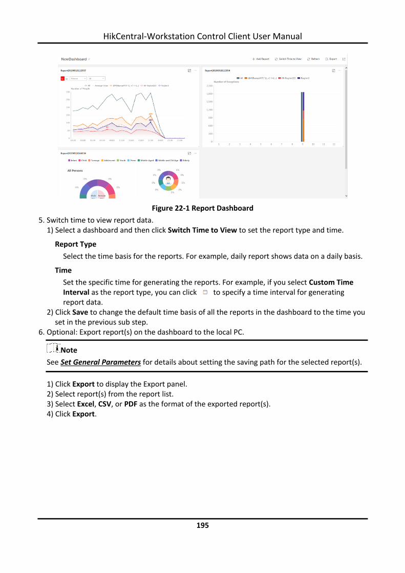
HikCentral-Workstation Control Client User Manual
195
Figure 22-1 Report Dashboard
5. Switch time to view report data. 1) Select a dashboard and then click Switch Time to View to set the report type and time.
Report Type
Select the time basis for the reports. For example, daily report shows data on a daily basis.
Time
Set the specific time for generating the reports. For example, if you select Custom Time Interval as the report type, you can click to specify a time interval for generating report data.
2) Click Save to change the default time basis of all the reports in the dashboard to the time you set in the previous sub step.
6. Optional: Export report(s) on the dashboard to the local PC.
Note
See Set General Parameters for details about setting the saving path for the selected report(s).
1) Click Export to display the Export panel. 2) Select report(s) from the report list. 3) Select Excel, CSV, or PDF as the format of the exported report(s). 4) Click Export.

HikCentral-Workstation Control Client User Manual
196
22.2 Generate People Counting Report
You can manually generate an entry & exit counting report to view the entry & exit statistics in a line chart or histogram. You can also export the report to the local PC.
Before You Start
Make sure you have properly configured the camera with a people counting rule for the required area. To configure the people counting rule, refer to the user manual of people counting camera.
Steps
1. In the top left corner of the Client, select → All Modules → Intelligent Analysis → People Analysis → People Counting.
2. Select the analysis type.
People Counting for One Camera
A people counting report based on the data from the cameras you select will be generated. You can compare the data of different cameras.
People Counting in One Region
A people counting report based on the data from the people counting groups you select will be generated. You can compare the data of different groups.
Note
Make sure you have added people counting groups. For details, refer to the User Manual of HikCentral-Workstation Web Client.
3. Select people counting camera(s) or people counting group(s) based on the analysis type you set in the previous step. – Select Camera(s):
1. Click .
Note
Only people counting cameras and people counting groups will be displayed here.
2. Check the people counting camera(s) for statistics and click any position outside the selection region to go back to the Camera list.
3. Check the cameras in the Camera list.
Note
Up to 20 people counting cameras can be selected for statistics at the same time.
– Select Group(s): Check the added people counting group(s) for statistics.
4. Set the report type to daily report, weekly report, monthly report, annual report, or customize the time interval for a report.

HikCentral-Workstation Control Client User Manual
197
Daily Report
The daily report shows data on a daily basis. The system will calculate the number of people in each hour of one day.
Weekly Report, Monthly Report, Annual Report
As compared to daily report, weekly report, monthly report, and annual report can be less time-consuming, since they are not to be submitted every day. The system will calculate the number of people in each day of one week, in each day of one month, and in each month of one year.
Custom Time Interval
Users can customize the days in the report to analyze the number of people in each day or month of the custom time interval.
5. In the Time field, set the time or time period for statistics.
Note
For custom time interval report, you need to set the start time and end time to specify the time period.
6. Click Generate Report.
Figure 22-2 People Counting Report (Entry & Exit)
The statistics of all the selected item(s) are displayed in the right panel. 7. Optional: Perform the following operation(s) after generating the people counting report.
Show/Hide Certain Data
Click the legend to show or hide the data of a certain element, such as a certain camera.

HikCentral-Workstation Control Client User Manual
198
View Entered/Exited/Both Entered and Exited Statistics
Select Enter, Exit, or Enter and Exit from the drop-down list. The total statistics and all the selected cameras' statistics are displayed and marked with different colors.
View Both Entered and Exited Statistics of a Camera or Group
Click the camera or group name on the page below to view the chart of a camera or group.
View Linked Video For line chart, if the selected report type is daily report, weekly report, or monthly report, click the line on the line chart to play the linked video. For histogram, if the selected report type is daily report, click the rectangle on the histogram to play the linked video.
Switch Between Line Chart and Histogram
Select or on the upper-left corner to switch between line chart (displaying the trend for the number of people on different time points) and histogram (for comparison).
8. Optional: Export the report to the local PC.
Note
See Set General Parameters for details about setting the saving path for the selected report(s).
1) Click Export. The Export panel will display camera selected and time configured according to the range you defined previously.
2) (Optional) Select the camera or group and set the report type and report time if needed. 3) Select shorter time period to view more detailed data of each camera.
Example
For example, if you select Daily Report, you can select By Day or By Hour, and it will export 1or 24 records respectively for each camera.
Note
If you select By Minute, the records amount depends on the configuration on the device. For example, if the device reports people counting data to the system every minute, it will export 24*60 records for each camera.
4) Set the format of the exported file as Excel, CSV, or PDF. 5) Click Export and the task will be displayed in the Download Center.

HikCentral-Workstation Control Client User Manual
199
22.3 Generate Heat Analysis Report
You can generate a heat analysis report to track consumer movements and analyze the visit times and dwell time in a configured area.
Before You Start
● Add a heat map network camera to the platform and properly configure the camera with heat map rule for the required area. To add a heat map network camera, please refer to the User Manual of HikCentral-Workstation Web Client. To configure the heat map rule, please refer to the user manual of heat map network camera.
● Add the camera to a static map. For details about how to add a camera to the static map, refer to User Manual of HikCentral-Workstation Web Client.
Steps
1. In the top left corner of the Client, select → All Modules → Intelligent Analysis → People Analysis → Heat Analysis.
2. Select analysis type.
Heat Analysis for One Camera
A heat analysis report based on the data from the selected cameras will be generated. The data of different cameras will be displayed and you can compare the data of different cameras.
Heat Analysis in One Region
A heat analysis report based on the data from the selected heat analysis groups will be generated. The data of different groups will be displayed and you can compare the data from different groups.
Note
You should have added heat analysis group(s). For details, refer to the User Manual of HikCentral-Workstation Control Client.
3. Select heat analysis camera(s) or heat analysis group(s) for statistics. 1) Click .
Note
● Only the online heat analysis camera(s) or heat analysis group will be displayed here. ● Up to 20 heat analysis cameras can be selected for statistics at the same time.
2) Check the heat analysis camera(s) or heat analysis group(s) for statistics. 4. Set the report type to daily report, weekly report, monthly report, annual report, or customize
the time interval for a report.
Daily Report

HikCentral-Workstation Control Client User Manual
200
Daily report shows data on a daily basis. The platform will calculate the number of people or people dwell time in each hour of one day.
Weekly Report, Monthly Report, Annual Report
As compared to daily report, weekly report, monthly report, and annual report can be less time-consuming, since they are not to be submitted every day. The platform will calculate the number of people or people dwell time in each day of way week, in each day of one month, and in each month of one year.
Custom Time Interval
Users can customize the days in the report to analyze the number of people or people dwell time in each day or month of the custom time interval.
5. Optional: Set the time or time period in the Time field for statistics.
Note
For custom time interval report, you need to set the start time and end time to specify the time period.
6. Set the analysis type.
Dwell Time
The minutes that the people stay at the same location during each time period for each camera.
People Amount
The number of people detected during each time period for each camera.
Note
This analysis type is only supported by the second generation of heat analysis cameras.
Average Dwell Time
The average dwell time for the each person stay at the same location during each time period for each camera.
7. Click Generate Report.

HikCentral-Workstation Control Client User Manual
201
Figure 22-3 Static Map of Selected Cameras
The static maps of the selected cameras will appear. 8. Click the map to view the detailed heat data of the cameras on the map. You can view each
camera's field of view, and the fields are color coded. The red color block (255, 0, 0) indicates the most welcome region (most persons detected or longest dwell time), and blue color block (0, 0, 255) indicates the less-popular region (least persons detected or shortest dwell time).
Note
Move the cursor to the field of view to view the detected value, including people amount or dwell time.
9. Optional: Click the camera icon on the page below to view heat analysis of a camera.

HikCentral-Workstation Control Client User Manual
202
Figure 22-4 Heat Map of a Camera
The image of the camera is color coded. The red color block (255, 0, 0) indicates the most welcome region (most persons detected or longest dwell time), and blue color block (0, 0, 255) indicates the less-popular region (least persons detected or shortest dwell time). You can drag the slider on the upper-right to adjust the range of the heat value. The heat data out of the range will not be displayed.
10. Optional: Click to switch among heat map, histogram, line chart to view the details.

HikCentral-Workstation Control Client User Manual
203
Figure 22-5 Line Chart of Heat Analysis
11. Optional: Export the report to the local PC.
Note
See Set General Parameters for details about setting the saving path for the selected report(s).
1) Click Export. The Export panel will display with camera selected and time configured according to the range you defined previously.
2) (Optional) Select the camera, and set the analysis type and report time if needed. 3) Select shorter time period to view more detailed data of each camera.
Example
For example, if you select Daily Report, you can select By Day or By Hour, and it will export 1, 24 records respectively for each camera.
4) Set the format of the exported file as Excel, CSV, or PDF. 5) Click Export and the task will be displayed in the Download Center.
22.4 Generate Person Feature Analysis Report
The platform supports saving features (including age and gender) of recognized human faces and

HikCentral-Workstation Control Client User Manual
204
generating reports in various time periods. The reports tells the percentage and number of people of different gender and age groups in different time period. It can be used in places such as shopping mall to analyze interests of people in different gender and age.
Before You Start
Make sure you have added a person feature analysis group if you want to perform feature analysis in one region. See User Manual of HikCentral-Workstation Web Client for details about adding a person feature analysis group.
Steps
1. In the top left corner of the Client, select → All Modules → Intelligent Analysis → People Analysis → Person Feature Analysis.
2. Select analysis type.
Feature Analysis for One Camera
Compare percentage and number of people of different gender and age groups detected by specified camera(s).
Feature Analysis in One Region
Compare percentage and number of people of different gender and age groups detected by the cameras in specified person feature analysis group(s) of multiple regions.
3. Select camera(s)/person feature analysis group(s).
Note
● Only online cameras will be displayed. ● Up to 20 cameras/groups can be selected for statistics at the same time.
4. Select the report type as daily report, weekly report, monthly report, annual report, or customize the time interval for a report, and the platform will generate statistics of the selected camera(s)/group(s) of the current day/week/month/year or the customized period.
5. Set the time or time period in the Time field for statistics.
Note
For custom time interval report, you need to set the start time and end time to specify the time period.
6. Click Generate Report.

HikCentral-Workstation Control Client User Manual
205
Figure 22-6 Person Feature Analysis
The statistics of all the selected cameras/groups are displayed on the right panel. 7. Optional: Click Add to Dashboard to display the report on the Dashboard. 8. Optional: Export the report to the local PC.
Note
See Set General Parameters for details about setting the saving path for the selected report(s).
1) Click Export. The Export panel will display with camera selected and time configured according to the range you defined previously.
2) (Optional) Select the camera or group and set the report type and report time if needed. 3) Select shorter time period to view more detailed data of each camera.
Example
For example, if you select Daily Report, you can select By Day or By Hour, and it will export 1or 24 records respectively for each camera.
4) Set the format of the exported file as Excel, CSV, or PDF. 5) Click Export and the task will be displayed in the Download Center.

HikCentral-Workstation Control Client User Manual
206
22.5 Generate Skin-Surface Temperature Analysis Report
You can generate the skin-surface temperature analysis report to view the variation trend of the number of people with abnormal skin-surface temperature.
Before You Start
● Make sure you have added devices that support temperature screening to HikCentral-Workstation.
● Make sure you have enabled temperature screening on the device. For details, see the user manual of the device.
Steps
1. In the top left corner of the Client, select → All Modules → Intelligent Analysis → People Analysis → Skin-Surface Temperature.
2. Select the analysis type.
Temperature Screening Point
A skin-surface temperature report based on data from temperature screening points (e.g. cameras and visitor terminals) you select will be generated.
Person Group
A skin-surface temperature report based on the data from the person groups you select will be generated.
3. Select temperature screening point(s) or person group(s) for analysis. – Select Temperature Screening Point:
1. Click to open the camera list panel.
Note
Only the online cameras will be displayed.
2. (Optional) Check Include Sub-Area to select the sub-areas of the area that you have selected.
3. Select an area in the area list to show the related temperature screening points. 4. Check the temperature screening point(s) for screening. 5. Select temperature screening point(s) for the report in the temperature screening point
list. – Select Person Group:
Check the person group(s) for screening.
Note
You can check Select Sub-Groups to select the sub-groups of the person group that you have selected.
4. Set the report type to daily report, weekly report, monthly report, or customize the time interval for a report.

HikCentral-Workstation Control Client User Manual
207
Daily Report
The daily report shows data on a daily basis. The platform will calculate the peak amount of people appeared in the images of the camera in each hour of one day.
Weekly Report, Monthly Report
Compared to generating the daily report, generating the weekly report and monthly report can be less time-consuming. The platform will calculate the peak amount of people on each day of one week and on each day of one month respectively.
Custom Time Interval
Users can customize the days in the report to analyze the peak amount of people in each day or month of the custom time interval.
5. In the Time field, select a predefined time period or customize a time period for search. 6. Click Generate Report.
Figure 22-7 Skin-Surface Temperature Analysis Report
The statistics of the selected item(s) will be displayed. 7. Optional: Perform the following operations if required.
Show/Hide Certain Data
Click the legend to show or hide the data of certain element, such as certain camera.
View Abnormal Temperature or No Mask Statistics
In the top left corner of the chart, select Abnormal Temperature or No Mask from the drop-down list to display the statistics of people with abnormal temperature and without wearing face mask, respectively.
Switch Between Line Click / to switch between line chart and histogram.

HikCentral-Workstation Control Client User Manual
208
Chart and Histogram Note
Daily report only supports histogram.
Add a Report to Dashboard
1. Click Add to Dashboard in the upper-right corner of the page. 2. Create a report name. 3. Select a dashboard. Or click New to create a new board and then
select it. 4. Click OK or Add and Go to Dashboard.
8. Optional: Export the report to the local PC.
Note
See Set General Parameters for details about setting the saving path for the selected report(s).
1) Click Export. 2) Optional: Select the temperature screening point(s) or person group(s) and set the report
type and report time if needed. 3) Select shorter time period to view more detailed data of each camera.
Example
For example, if you select Daily Report, you can select By Day or By Hour, and it will export 1or 24 records respectively for each camera.
4) Set the format of the exported file as Excel, CSV, or PDF. 5) Click Export and the task will be displayed in the Download Center.

HikCentral-Workstation Control Client User Manual
209
Chapter 23 Maintenance
The Control Clientallows you to monitor resource health status and search resource logs. The data of resource health status and resource logs, which is of especially importance for maintenance of the system, helps you locate the source of exceptions and determine methods for troubleshooting.
23.1 Health Monitoring
Health monitoring provides both near-real-time and history information about the status of the SYS and added resources. It is critical to multiple aspects of operating the servers or devices and is especially important for maintenance. When a resource exception occurs, you can enter this module to check the resource status and find out the abnormal device(s) and view the exception details.
23.1.1 Real-Time Health Status Overview
Inthe Health Monitoring module, you can view the real-time health status of the devices, servers, and resources managed on the platform. If there is no network transmission devices added, the Real-Time Overviewpage provides an at-a-glance view of the health status with charts and basic data of resource status. In the top left corner of the client, select → All Modules → Maintenance → Health Monitoring and then click Real-Time Overview on the left. Click Real-Time Overview tab at the top to enter the Real-Time Overview page.

HikCentral-Workstation Control Client User Manual
210
Figure 23-1 Real-Time Health Status Overview
Table 23-1 Real-Time Health Status Page
Section Description
Resource Status
View the abnormal data of different resources (e.g., cameras, doors, or alarm inputs) added to areas of Central System in the graphical way. You can click the numbers and status types on the chart to view the real-time status details of resources.
System Management Server Status
View the network health status and server running status. Click in the upper right corner of System Management Server
panel to view the running status details of the server, including CPU usage, RAM usage, etc.

HikCentral-Workstation Control Client User Manual
211
Section Description
Figure 23-2 System Management Server Status Details
Server Status
View the status (i.e., exception, warning, normal) of servers added on Central System. You can click the numbers and status types on the chart to view the real-time status details of servers.
Device Status
View the abnormal data of different devices (e.g., encoding devices, decoding devices, or access control devices) added on Central System. You can click the numbers on the chart to view the real-time status details of devices.
If the icon appears at the top of device picture, it indicates
that the device firmware should be upgraded. For upgrading the firmware, refer to HikCentral-Workstation Web Client User Manual.
Refresh
● Manually Refresh: Click Refresh in the upper right corner of Real-Time Overview page to manually refresh the resource status on the page.
● Auto Refresh: Management → System → Health Monitoring to set the interval for automatically refreshing the resource status on the page. See details in Set Health Status Parameters.
Export Overview Page or Exception Data
Click Export in the upper right corner of Real-Time Overview page to export the page in PDF format. Or you can check Export Exception Data to export the exception data in Excel/CSV format.

HikCentral-Workstation Control Client User Manual
212
Section Description
Figure 23-3 Export Overview Page or Exception Data
Display on Smart Wall Click to display the overview page on the smart wall if you have added and configured smart walls on the platform .
23.1.2 Real-Time Health Status Overview (Topology)
In the Health Monitoring module, you can view the real-time health status of the devices, servers, and resources managed on the platform. If there are network transmission devices managed on the platform, the Real-Time Overview page provides a topology of the managed devices. Topology is a figure that displays the connection relations among network transmission devices, surveillance devices, etc. It is mainly used for network maintenance.
Note
● Make sure the network transmission devices have been added to the platform. ● If a network transmission device can not be recognized by the platform, it will be displayed as
an unknown device. ● The topology does not support body cameras, but supports ticket dispensers.
In the top left corner of the client, click → All Modules → Maintenance → Health Monitoring → Real-Time Overview. Click Topology tab at the top to enter the Topology page.

HikCentral-Workstation Control Client User Manual
213
Figure 23-4 Topology Overview
Table 23-2 Topology Page
Section Description
Device Status
View the abnormal data of different devices (e.g., encoding devices, decoding device, or access control devices) added on the Central System. You can click the number to locate the abnormal device in the topology or view the devices' real-time status.
If the icon appears beside the device type name, it indicates that the device firmware should be upgraded. For upgrading the firmware, refer to HikCentral-Workstation Web Client User Manual.
Resource Status
View the abnormal data of different resources (e.g., cameras, doors, or alarm inputs) added to the areas of the Central System. You can click the number to view the real-time status details of resources.
Topology Details View the relationships among devices, device information, link status, alarm information, etc. See details in Topology Details.
Network Performance View the current network performance (i.e., poor or good) of the System Management Server.
System Management Server View the network health status and server running status. Click

HikCentral-Workstation Control Client User Manual
214
Section Description
Status in the upper right corner of the System Management Server panel to view the running status details of the server, including its CPU usage, RAM usage, etc.
Figure 23-5 System Management Server Status Details
Server Status View the status (i.e., exception, warning, normal) of servers added on the Central System.
Generate Topology Again Click Refresh → Generate Topology Again to draw the network topology again.
Refresh
● Manual Refresh: Click Refresh in the upper right corner of the Real-Time Overview page to manually refresh the resource status on the page.
● Auto Refresh: Management → System → Health Monitoring to set the interval for automatically refreshing the resource status on the page. See details in Set Health Status Parameters.
Export Topology or Exception Data
Click Export in the upper right corner of Topology page and select the export type as Default or Only Topology to export the topology in PDF format or the exception data in Excel/CSV format.
Note
● If the export type is selected as Default, the whole displayed information (topology and exception data) on the Health Monitoring page will be exported.
● If the export type is selected as Only Topology, only the

HikCentral-Workstation Control Client User Manual
215
Section Description
topology will be exported in PDF format.
Figure 23-6 Export Topology
Display on Smart Wall Click to display the overview page on the smart wall if you have added and configured smart walls on the platform .

HikCentral-Workstation Control Client User Manual
216
Topology Details
The topology of devices will display the hierarchical relationships among the devices, device information, link status, alarm information, etc.
Figure 23-7 Topology Details
Device Node
The device nodes are displayed by icons, including the System Management Server, network transmission device, encoding device, access control device, video intercom device, network bridge, fiber converter, etc. Each device node displays the device name and IP address.
Note
● When the device information (device name, IP address, online/offline status) changes, you should manually refresh to generate the topology again or set auto-refresh.
● When the device hierarchy or physical connection changes, you should manually refresh to generate the topology again.
● If the node icon is displayed in red, it indicates that the device is abnormal or alarms are triggered. You can view the reason for device exception or alarm details.
● For the added online devices, the displayed device alias is the same as the device IP address.
View Device Details
Click the device node in the topology and click Details in the drop-down list. You can view the device details, including the basic information (i.e., device name, IP address and device model), device usage (e.g., RAM usage, CPU usage, PoE power), arming status and disk array (for encoding device), live video (if the device is linked with a camera), linked lane name / entrance direction / entrance & exit name / barrier control status (if the entrance and exit is linked with a camera), device panel status (i.e., ports and ports usage), and port information (i.e., port name,

HikCentral-Workstation Control Client User Manual
217
and peer device type, peer device IP address, and peer device name).
Figure 23-8 View Device Details
Note
The device details vary with different device models.
Link
The color of link indicates the utilization rate of network bandwidth (red: congested, yellow: busy, gray: fluent). And the shape of link indicates the link type (wireless, network link, optical fiber).
View Link Details

HikCentral-Workstation Control Client User Manual
218
Move the cursor to the link between nodes to display the link details. You can view the upstream rate and downstream rate to determine whether the network status is normal or not. You can also view the connected device type, IP address, port name, and port status.
Figure 23-9 View Link Details
View Connection Path
If there is a data transmission failure between the devices, you can view the connection path to judge which link is disconnected, so as to restore the link as quickly as possible. Click the device node and in the topology and click Show Connection Path in the drop-down list. According to the information presented in the prompt window, click Common Unknown Node or Select Node to select the peer node, and then click OK. After that, the connection path between the two nodes will be displayed.
Remote Configuration
Click the device node in the topology and click Remote Configuration in the drop-down list to configure the device parameters, including system settings, network and port configuration. You can configure the network parameters and device port according to the network usage. For

HikCentral-Workstation Control Client User Manual
219
details, refer to the user manual of the device.
Note
This function should be supported by the device.
View Device Logs
When a device failure happens or trouble shooting is required, you can view the device's logs to know the alarms, notifications, operations and events of the device. Click the device node in the topology and click View Device Logs in the drop-down list to enter the Device Logs page, and you can set the conditions to search the device logs.
Note
This function should be supported by the device.
Set as Root Node
When you need to adjust the topology structure, you can click the device node in the topology and click Set as Root Node in the drop-down list to set the node as the root node.
Note
Only the switch, wireless network bridge, and fiber converter can be set as root node.
Zoom In/Zoom Out
Click or to zoom in or zoom out the device node(s) and the subsidiary device node(s). You can scroll the mouse wheel to zoom in or zoom out the topology.
Adjust Topology
Click the background of the topology to move the topology in up, down, right, or left direction.
Full Screen
Click on the upper-right corner of the topology to display the topology in full-screen mode.
Adaptive View
Click on the upper-right corner of the topology to adapt the topology to the current window, to help you know the whole topology hierarchy quickly.
Search
By entering the device name or IP address in the search box, you can quickly locate the device on the topology.
23.1.3 Historical Health Data Overview
You can view the historical online rate of resources and devices, or the recording integrity rate. In the top left corner of Control Client, select → All Modules → Maintenance → Health Monitoring and then click History Status Overview on the left.

HikCentral-Workstation Control Client User Manual
220
Figure 23-10 Historical Health Data Overview
Table 23-3 Historical Health Data Page
Section Description
Filter Data Select a time period from the drop-down list in the upper right corner of each section for filtering data by day, week, or month.
Resource Online Rate
● On the line chart, you can perform the following operations: ○ Move the cursor on the line chart to view the camera
online rate and the number of offline cameras at specific time points.
○ Click the a dot on the line to go to Resource Log page to view the detailed network status of cameras at that time point.
● On the doughnut chart, you can perform the following operations: ○ Move the cursor to red part of the doughnut chart to view
the number of the cameras which once were offline and the offline rate during the time period you select.
○ Move the cursor to the green part of the doughnut chart to view the number of the cameras which stay online and the online rate during the time period you select.
● On the table, you can do one of the followings: ○ Click Total Offline Duration to rank the cameras in terms
of total offline duration within the time period you select. ○ Click Offline Times to rank the cameras in terms of offline
times within the time period you select.

HikCentral-Workstation Control Client User Manual
221
Section Description
Device Online Rate
● On the line chart, you can do one of the followings. ○ Move the cursor on the line chart to view the device
online rate and the number of offline devices at specific time points.
○ Click the a dot on the line to go to Device Log page to view the detailed network status of devices at that time point.
● On the doughnut chart, you can perform the following operations. ○ Move the cursor to red part of the doughnut chart to view
the number of the devices which once were offline and the offline rate during the time period you select.
○ Move the cursor to the green part of the doughnut chart to view the number of the devices which stay online and the online rate during the time period you select.
● ● On the table, you can do one of the followings.
○ Click Total Offline Duration to rank the devices in terms of total offline duration within the time period you select.
○ Click Offline Times to rank the devices in terms of offline times within the time period you select.
Recording Integrity Rate
On the line chart, you can move the cursor to view the recording integrity rate at specific time points. Click the a dot on the line to go to Device Log page to view the detailed resource status of devices at that time point.
Refresh
● Manually Refresh: Click Refresh in the upper right corner of History Overview page to manually refresh the data on the page.
● Auto Refresh: Management → System → Health Monitoring to set the interval for automatically refreshing the data on the page. See details in Set Health Status Parameters.
Export Overview Page or Exception Data
Click Export in the upper right corner of History Overview page to export the page in PDF format. Or you can check Export Exception Data to export the exception data in Excel/CSV format.

HikCentral-Workstation Control Client User Manual
222
Section Description
Figure 23-11 Export Overview Page or Exception Data
23.2 Resource Status
You can monitor the status of the added resources, such as cameras, encoding devices, etc., which helps you find out and maintain the abnormal resources in time, ensuring the smooth running of the platform to the greatest extent. On the top left corner of the client, select → All Modules → Maintenance → Resource Status, and select a resource type on the navigation panel on the left.
Camera Status
On the camera status page, you can view camera status, such as network status, arming status, and recording status. You can also perform the following operations. ● Click the camera name to view its status and basic information. ● Click the IP address to view the status of the device to which the camera is related. ● Click in the Operation column to go to the Web Client to configure the parameters of the
specified camera. ● Click in the Operation column to view the online/offline records of the specified camera.
For details, see Search for Online/Offline Logs of Resource. ● Click in the Operation column to view the recording status of the camera. For details, see
Search for Recording Status of Resource. ● Click View Camera with Abnormal Image to view the videos of cameras with abnormal images.
And you can also export the image diagnosis results of selected camera(s) or all cameras in PDF format.
● Select the device type(s) from the first drop-down list on the top to filter the camera status by device type.
● Check the check box and select the exception type from the second drop-down list on the top to filter the camera status by exception type.

HikCentral-Workstation Control Client User Manual
223
Note
Contact the admin user to edit the abnormal configurations of camera's event or alarm via the Web Client if an icon appears near the camera name.
Door Status
On the door status page, you can view the information such as the network status of related devices and door status.
Note
For the door linked to the video intercom device, the door status is not available to be displayed.
You can also perform the following operations. ● Click the door name to view the status details and basic information. ● Click the device name to view the status of the device to which the door is related. ● Click in the Operation column to go to the Web Client to configure the parameters of the
specified door. ● Click in the Operation column and select a control type from the drop-down list to control
the door status. ○ Unlock: When the door is locked, unlock the door and it will be open. After the open duration
(configured via the Web Client), the door will be closed and locked again automatically. ○ Lock: When the door is unlocked, lock the door and it will be closed. The person who has the
access permission can access the door with credentials. ○ Remain Unlocked: The door will be unlocked (no matter closed or open). All the persons can
access the door with no credentials required (free access).
Note
For the door linked to video intercom device, setting its status to remain unlocked is not available.
○ Remain Locked: The door will be closed and locked. No person can access the door even if he/she has the authorized credentials, except the super users.
● Check the check box and select the exception type from the drop-down list on the top to filter the door status by exception type.
Alarm Input Status
You can view the alarm input status including resource usage status (online or offline), arming status, bypass status, fault status, alarm status, detector connection status, battery status, and so on. You can also perform the following operations. ● Click the device name to view the status of the device to which the alarm input is related. ● Select the device type(s) from the first drop-down list on the top to filter the alarm input status
by device type.

HikCentral-Workstation Control Client User Manual
224
● Check the check box and select the exception type from the second drop-down list on the top to filter the alarm input status by exception type.
Encoding Device Status
You can view the encoding device status including the recording status, HDD usage, arming status, default stream (it refers to the default stream type for accessing the resources of the encoding device), etc. You can perform the following operations. ● Click the device name to view the status and basic information of the encoding device and the
related cameras. ● Click the status in Recording Status column to view the recording status of channels configured
to store the video files on this encoding device. ● Click in the Operation column to go to the Web Client to configure the parameters of the
specified encoding device. ● Click to wake up the encoding device if it is in sleep mode. ● Click in the Operation column to view the online/offline records of the encoding device. For
details, see Search for Online/Offline Logs of Device. ● Click Switch Device Access Mode to switch the access mode for the Control Client to access the
devices. ○ Restore Default: Restore the device access mode as configured in the System → Device
Access Mode on the Web Client. ○ Automatically Judge: Judge the device access mode according to the current network. ○ Directly Access: Access the device directly, not via HikCentral-Workstation Streaming Service.
Note
When the encoding device is in the same LAN with the SYS server, the Direct Access mode is not available.
○ Proxy: Access the device via HikCentral-Workstation Streaming Gateway and HikCentral-Workstation Management Service. It is less effective and less efficient than accessing directly.
● Select the encoding device(s) and click Switch Stream to switch the stream type. When starting live view, the Control Client will get this default stream to start the live view of the encoding device's resources. ○ Main Stream: Main stream provides higher quality video, higher resolution, but brings about
higher bandwidth usage. ○ Sub-Stream: Sub stream can save on bandwidth, but the video quality is lower than main
stream. ○ Smooth Stream: This stream type is usually used in low-bandwidth situation. After switching
to smooth stream, the live view and playback will be smoother in slow network performance, but the image quality will be lower accordingly.
○ Default Stream Type: If you select Default Stream Type, the stream type for accessing the selected encoding device(s) will be restored to the global stream type you set in System → Video → Network.

HikCentral-Workstation Control Client User Manual
225
● Check the check box and select the exception type from the drop-down list on the top to filter the encoding device status by exception type.
Access Control Device Status
You can view the status and information such as network status and battery status of the added access control devices. If the device is turnstile, you can view the status of master lane controller, slave lane controller, and component. You can perform the following operations. ● Click the device name to view the status and basic information of the access control device, and
the related doors and cameras. ● Click in the Operation column to go to the Web Client to configure the parameters of the
specified access control device. ● Check the check box and select the exception type from the drop-down list on the top to filter
the Access Control Device status by exception type.
Video Intercom Device Status
You can view the status information of the video intercom device such as network status, arming status, and the status of calling center from device (whether the device is able to call the surveillance center of the platform). You can perform the following operations. ● Click All Devices and then select a device type to display the device status of selected type only. ● Click the device name to view the status and basic information of the video intercom device,
and the related doors and cameras. ● Click in the Operation column to go to the Web Client to configure the parameters of the
specified video intercom device. ● Select the device type(s) from the first drop-down list on the top to filter the video intercom
device status by device type. ● Check the check box and select the exception type from the second drop-down list on the top to
filter the video intercom device status by exception type.
Security Control Device Status
You can view the managed devices' network status, battery status, and so on. You can perform the following operations. ● Click All Devices and then select a device type to display the device status of selected type only. ● Check the check box and select the exception type from the drop-down list on the top to filter
the security control device status by exception type. ● Click the device name to view the status and basic information of the security control device,
and the related alarm inputs and cameras. ● Click in the Operation column to go to the Web Client to configure the parameters of the
specified security control device.
Network Transmission Device
You can view the network transmission devices' CPU usgae, RAM usage, PoE usage, occupied ports,

HikCentral-Workstation Control Client User Manual
226
and so on. You can perform the following operations. ● Click All Devices and then select a device type to display the device status of selected type only. ● Check the check box and select the exception type from the drop-down list on the top to filter
the network transmission device status by exception type. ● Click the device name to view the basic information, device usage, and port information of the
network transmission device. ● Click in the Operation column to go to the Web Client to configure the parameters of the
specified network transmission device.
Decoding Device Status
You can view the status information such network status, first added time, and checking time. You can perform the following operations. ● Click the device name to view the status and basic information of the decoding device. ● Click in the Operation column to go to the Web Client to configure the parameters of the
specified decoding device.
Common Operations
You can perform the following operations for different resource types. ● Check Include Sub-area to display the resources of child areas. ● Check the checkbox in the top right of status display page to select exception types from the
drop-down list to filter the resource status. ● Click Export to export the status data as CSV or Excel to the local PC. ● Click in the Operation column to refresh the status of the specified resource, or click
Refresh to refresh the status of all resources displayed on the page.
Note
The resource status will be automatically refreshed in a specified interval (see details in Set Health Status Parameters).
23.3 Log Search
Three types of log files are provided: server logs, device logs, and resource logs. The server logs refer to the logs files stored in the SYS server; The device logs refer to the log files stored on the connected devices, such as encoding device and security control device; The resource logs refers the logs about camera recording status and online status. You can search the log files, view the log details and backup the log files.
23.3.1 Search for Server Logs
You can search for server logs, which contain error logs, warning logs and information logs. Server logs contain historical user and server activities. You can search for the logs and then check the

HikCentral-Workstation Control Client User Manual
227
details.
Steps
1. In the top left corner, select → All Modules → Maintenance → System Log → Server Logs.
Figure 23-12 Search for Server Logs
2. In Type, select one or multiple log types and sub types.
Note
Error logs record failures or errors. Warning logs record license expiration events. Information logs refer to other general logs which record successful or unknown operation results.
3. In Source, select user and server to set the source of the logs that you want to search for. 4. Optional: In Resource Name, enter the name of a resource to search the logs of the resource. 5. In Time, select the time range of this search.

HikCentral-Workstation Control Client User Manual
228
Note
You can select Custom Time Interval to set a precise start time and end time.
6. Click Search. All matched logs are listed with details on the right.
7. Optional: Check all or specific logs, click Export, and then select a file format (i.e., Excel or CSV) to download the searched logs as a single file to your local PC.
23.3.2 Search for Online/Offline Logs of Device
You can search for the online/offline logs of encoding devices, security inspection devices, and mobile devices. The online/offline logs provide information on the current device status (online or offline), latest offline time, total offline duration, etc.
Steps
1. In the top left corner, select → All Modules → Maintenance → System Log → Device Logs.
Figure 23-13 Search for Device Online/Offline Logs
2. In Type, select Online/Offline Log as the log type. 3. Select a device type and check the devices you want to search. 4. In Time, specify the time range of this search.

HikCentral-Workstation Control Client User Manual
229
Note
You can select Custom Time Interval to set a precise start time and end time.
5. Optional: If there are a large number of devices, check Filter Condition to set a range of total offline times during the specified time range to filter the devices, or set a total offline duration to filter the devices.
6. Click Search. The offline/online log of each device are listed on the right. You can check the name, IP address, current status (online/offline), latest offline time, total offline times, and total offline duration of each device.
7. Optional: Perform further operations after searching for device logs.
View Offline History Click on device name to view history online duration (displayed as a line chart) and status (displayed as a list) of the device. You can perform the following operations. ● Filter Data: Select a time period and a status (online, offline or all)
from the drop-down lists respectively to filter the data. ● View Details: Move the cursor to the line chart to view the detailed
offline and online duration at each time point.
View Device Logs Click in the Operation column to view the logs stored on the device.
Export Logs Click Export and then select a file format (i.e., Excel or CSV) to download the searched logs as a single file to your local PC.
23.3.3 Search for Logs Stored on Device
You can search for the logs stored on encoding devices, security control devices, decoding device, access control devices, and network transmission devices.
Steps
1. In the top left corner, select → All Modules → Maintenance → System Log → Device Logs.

HikCentral-Workstation Control Client User Manual
230
Figure 23-14 Search for Logs Stored on Device
2. Select Log on Device as the log type. 3. Select a device type and select the device you want to search. 4. Select the main event as Normal or Battery Information and check the sub event(s) to be
searched for. 5. Specify the time range of this search.
Note
You can select Custom Time Interval to set a precise start time and end time.
6. Click Search. All matched logs are listed with details on the right.
7. Optional: Click Export and then select a file format (i.e., Excel or CSV) to download the searched logs as a single file to your local PC.

HikCentral-Workstation Control Client User Manual
231
23.3.4 Search for Online/Offline Logs of Resource
You can search for the online/offline logs of cameras. The online/offline logs provide information on the current device's status (online or offline), latest offline time, total offline duration, etc.
Steps
1. In the top left corner, select → All Modules → Maintenance → System Log → Resource Logs.
Figure 23-15 Search for Resource Online/Offline Logs
2. In Type, select Online/Offline Log. 3. Click to show the area list and then select the cameras whose logs are to be searched for. 4. Optional: Modify your selection in the selected camera list.

HikCentral-Workstation Control Client User Manual
232
Remove a Camera Click to remove the camera from the list.
Remove All Cameras Click to remove all cameras in the list.
5. In Time, specify the time range of this search.
Note
You can select Custom Time Interval to set a precise start time and end time.
6. Optional: If there are a large number of resources, check Filter Condition to set a range of total offline times during the specified time range to filter the resources.
7. Click Search. The offline/online log of each resource are listed on the right. You can view the name, IP address, current status (online/offline), latest offline time, total offline times, and total offline duration of each resource.
8. Optional: Perform further operations after searching fro resource logs.
View Offline History Click resource name to view history online duration (displayed as a line chart) and status (displayed as a list) of the resource. You can perform the following operations. ● Filter Data: Select a time period and a status (online, offline or all)
from the drop-down lists respectively to filter data. ● View Details: Move the cursor to the line chart to view the detailed
offline and online duration at each time point.
View Device Online/Offline Logs
Click the IP address to view the online/offline logs of the device where the resource is linked.
Export Logs Click Export and then select a file format (i.e., Excel or CSV)to download the searched logs as a single file to your local PC.
23.3.5 Search for Recording Status of Resource
You can search for the recording status of cameras. The recording status includes the recording integrity rate, total time length abnormal recording, times of recording interruptions, etc.
Steps
1. In the top left corner of the Client, select → All Modules → Maintenance → System Log → Resource Logs.

HikCentral-Workstation Control Client User Manual
233
Figure 23-16 Search for Resource Recording Status
2. In Type, select Recording Status. 3. Click to show the area list and then select the cameras whose logs are to be searched for. 4. Optional: Modify your selection in the selected camera list.
Remove a Camera Click and then click to remove a camera from the list.
Remove All Cameras Click and then click to remove all cameras in the list.
5. In Time, specify the time range of this search.

HikCentral-Workstation Control Client User Manual
234
Note
You can select Custom Time Interval to set a precise start time and end time.
6. Optional: If there are a large number of resources, check Filter Condition and set the filter conditions.
Retention Duration (Days)
Set a range of the retention duration of the recorded video footage to filter the cameras.
Recording Integrity Rate
Set a range of the recording integrity rate to filter cameras. The recording integrity rate refers to the percentage obtained from dividing the actual recording duration by the scheduled recording time.
Note
For details about recording schedule, refer to the HikCentral-Workstation Web Client User Manual .
7. Click Search. Recording status of each camera are listed on the right, including camera name, camera IP address, area where the camera belong, video storage type, etc.
Start Time
The time when the camera started recording.
End Time
The latest time when the camera was recording.
Retention Duration (Days)
The retention duration (unit: day) of the recorded video footage refers to the duration between Start Time and End Time.
Total Length
The total time length of video storage.
Abnormal Total Length
The total time length of the video loss within the scheduled time.
Recording Interruption
The total times of recording interruption within the scheduled time.
8. Optional: Check historical recording status. 1) Optional: Click Rule in the top right corner to view the analytical rules for history videos.

HikCentral-Workstation Control Client User Manual
235
Figure 23-17 Analytical Rules for History Video
2) Click a camera name to open the History Recording Status panel.

HikCentral-Workstation Control Client User Manual
236
Figure 23-18 History Recording Status
Note
The blue parts on the time bars represent the time periods during which video footage were recorded. The orange parts on the time bars represent the time periods during which video loss occurred or the time periods during which no recording schedule existed.
3) Select a time period and a status (exception or all) from the drop-down lists respectively to filter data.
4) Optional: Select the number of records displayed on each page of the History Recording Status panel from the drop-down list at the lower-left corner of the panel.
5) Optional: Move the cursor to the time bar to show the 24 hours on it, and click one hour to view recording status details within the hour.

HikCentral-Workstation Control Client User Manual
237
Figure 23-19 Recording Status Details within One Hour
9. Optional: Click Export and then select a file format (i.e., Excel or CSV) to download the recording status as a single file to your local PC.

HikCentral-Workstation Control Client User Manual
238
Chapter 24 Tools
The Control Client provides multiple tools: Smart Wall, Arming Control, Video Intercom, VSPlayer, Two-Way Audio, Broadcasting, Alarm Output.
Smart Wall
Play the live view or playback on smart wall. See Manage Smart Wall (Decoding Device) for details.
Arming Control
Arm or disarm the hot spots via the arming control function. After arming the device, the current Control Client can receive the triggered alarm information from the hot spot.
Video Intercom
Call the person's related indoor station.
VSPlayer
Run the player and play the video files stored on the local PC.
Two-way Audio
Enable the voice talk between the Control Client and devices, See Perform Two-Way Audio for details.
Broadcast
Distribute audio content to the added device if the device has an audio output. See Broadcast to Connected Devices for details.
Alarm Output
Enable alarm output to control the connected external devices by events or alarms, or manually by client. See Control Alarm Output for details.
24.1 Play Video via VSPlayer
You can run the VSPlayer software and play the video files stored in the local PC via the software.
Perform this task when you need to play video via VSPlayer.
Steps
1. In the top left corner of Control Client, select → Tool → VSPlayer to run the VSPlayer. The available video files are listed on the playlist.
2. Double-click the video to play. 3. Optional: Click in the upper-right corner of the VSPlayer page and select User Manual to
view the VSPlayer's user manual for more detailed operations.

HikCentral-Workstation Control Client User Manual
239
24.2 Perform Two-Way Audio
The two-way audio function enables the voice talk between the Control Client and devices. You can get and play not only the live video but also the real-time audio from the device in the Control Client, and the device can also get and play the real-time audio from the Control Client.
Perform this task when you need to perform the two-way audio function.
Steps
1. In the top left corner of Control Client, select → Tool → Two-Way Audio to open the Two-Way Audio window.
2. Select the camera in the area. 3. Select Device Talk or IP Talk.
Device Talk
Start two-way audio with the device (camera, NVR, DVR, or entrance/exit station).
Note
● When the selected camera is directly connected to the system, the audio goes between the system and the camera.
● When the camera is connected to the system via an NVR, DVR, or entrance/exit station, and you select Device Talk, the two-way audio goes between the system and the NVR, DVR, or entrance/exit station.
IP Talk
Start two-way audio with the camera.
Note
● When the camera is directly connected to the system, IP Talk can not be selected. ● When the camera is connected to the system via an NVR, DVR, or entrance/exit station,
and you select IP Talk, the two-way audio goes between the camera and the system.
4. Click Start to start the two-way audio. 5. Optional: Click to adjust the microphone volume, click to adjust the speaker volume, and
click to start recording.
24.3 Broadcast to Connected Devices
Perform the broadcast function to distribute audio content to the added device if the device has an audio output.
Note
● Make sure the PC has available microphone for broadcasting audio to the device. ● If the client is performing two-way audio with the device's camera, you cannot start

HikCentral-Workstation Control Client User Manual
240
broadcasting with the device, and vice versa. ● The Cloud P2P device supports broadcasting if it enables DDNS.
1. In the top left corner of Control Client, select → Tool → Broadcasting → By Device. 2. Select an existing device group or click to add a device group if needed, and then click Add
to select the device(s) to broadcast to. Start or stop broadcasting.
Start All
Click Start All to start broadcasting to the selected device(s).
Note
You can view the real-time broadcast status.
Stop All Click Stop All to stop broadcasting to the selected device(s).
24.4 Control Alarm Output
An alarm output is an output on the device that can be connected to an peripheral device, such as a light, a barrier, etc. Device can send signal to control the connected external device, e.g., turn on light, open the barrier gate. The connected peripheral device can be controlled automatically by events or alarms, or manually by client, and here we introduce the process for controlling alarm output remotely by client. In the top left corner of the Control Client, select → Tool → Alarm Output Control. Select the alarm output(s) that you want to enable/disable and click Open/Close them one by one. Or you can click Open All/Close All to enable/disable all alarm outputs.
24.5 Record Screen
You can record the PC screen.
Steps
1. In the top left corner of the Control Client, select → Tool → Record. 2. Select the screen you want to record. 3. Click Start Recording. 4. Click Stop Recording. 5. Click Open Folder to open the folder which the record is saved to.

HikCentral-Workstation Control Client User Manual
241
Chapter 25 System Settings
The System page contains general settings, basic video settings, alarm sound settings, health monitoring settings, screen position management, receipt printing settings, home page mode settings, and calling settings.
25.1 Set General Parameters
You can set the frequently-used parameters, including the network performance, display mode, file saving path, etc.
Steps
1. In the top left corner of Control Client, select → Management → System → General to enter the general settings page.
2. Configure the general parameters.
Network Timeout
The default waiting time for the Control Client. The operations will be regarded as failure if no response within the configured time. The minimum default waiting time of the interactions between the Control Client and SYS server is 30s, the minimum time between SYS server and devices is 5s, and the minimum time between the Control Client and devices is 5s.
Maximum Mode
Select Maximize or Full Screen as the maximum mode. For selecting Maximize, the client will be maximized and the task bar will display. For selecting Full Screen, the client will be displayed in full-screen mode.
Time Zone
Device Time
The Control Client will adopt the time of the time zone where the device locates in.
Client Time
The Control Client (except the Video Analysis modules) will adopt the time of the time zone where the PC running the Control Client locates in.
Time Difference
If enabled, the time zone information will be displayed on the time. For example, 2018-12-12 12:12:12 +8:00.
Auto-Login
The system will remember the user name and password and log in to the Control Client automatically when you start the PC running the Control Client.

HikCentral-Workstation Control Client User Manual
242
After Starting Client, Open
Automatically open the home page, last interface, or view after launching the client.
Home Page
Automatically display the control panel of the client after launching the client.
Last Interface
Restore the interface last opened when you run the client next time.
Specified View
Automatically display the specified view you set after launching the client.
Note
● You can click Show Screen No. to show the screen number of current PC running the Control Client. And you can select the specified view(s) according to your requirement. For details about setting view, refer to Manage View.
● Supports displaying the specified view on the auxiliary screen or on the smart wall (graphic card).
● For displaying on the smart wall (graphic card), you should set displaying contents on smart wall (graphic card) in smart wall mode. (See Display Contents on Smart Wall in Smart Wall Mode for details)
● For displaying on the smart wall (graphic card), when you select the specified view, the view should be displayed on the smart wall (graphic card) at the same time, and then the view will be displayed on the smart (graphic card) after launching the client next time, otherwise the view will be displayed on the auxiliary screen after launching the client next time.
Large-Scale Display Mode
To improve the resource operation efficiency, if there is one resource type with more than 512 resources, you can switch on Large-Scale Display Mode. In this mode, the resources in the system will not be loaded when launching the Control Client for time saving reason, so it will cost time when searching a device in the resource list.
Note
● For the platform in the free version, you cannot switch on the Large-Scale Display Mode. By default, it is in large-scale display mode.
● Areas without resources will be displayed and selecting all resources at a time is not supported.
● By default, the large-scale display mode is disabled.
File Saving Path
Set the saving paths for the files you downloaded to your computer (manual recorded or downloaded video files, captured pictures, and package files).

HikCentral-Workstation Control Client User Manual
243
Report Auto Refresh Interval
Automatically refresh reports after the set interval to display the latest statistics. 3. Click Save.
25.2 Set Video Parameters
You can set network parameters, picture file format, image parameters, people counting display parameters, icons on live view and playback toolbar, and shortcuts for keyboard and joystick.
25.2.1 Set Network Parameters
You can set global stream type for live view and window divisions for main stream.
Steps
1. In the top left corner of Control Client, select → Management → System → Video. 2. Select Network tab to enter network settings page. 3. Configure network parameters.
Global Stream
Select the default stream type for live view for global usage. If the network is in good condition, select main stream or sub-stream. If the network is in poor condition, select smooth stream. If the device doesn't support smooth stream, it will use sub-stream. If the device doesn't support sub-stream, it will use main stream. If you don't want to adopt global stream settings for certain encoding device, you can go to Maintenance → Health Monitoring → Encoding Device and switch its stream type (refer to Resource Status for details). The Control Client will get this stream type to start live view of the encoding device's resources.
Window Divisions for Main Stream
When the number of divided windows is smaller than the number you set, the live video will be displayed by main stream.
Note
This parameter is invalid for playback.
Bandwidth
Set the bandwidth upper limit for downloading video. 4. Click Save.

HikCentral-Workstation Control Client User Manual
244
25.2.2 Set File Parameters
You can set the file format of pictures captured during live view and playback. In the top-left corner of the Control Client, select → Management → System → Video → File to enter the file settings page. Select the file format for pictures captured during live view or playback. Switch on Visual Tracking Video to automatically record the video during visual tracking.
Note
When you use the visual tracking function for the first time, you will be prompted to select whether to automatically record the video during visual tracking. If you want to change the settings afterwards, you need to log in to the Control Client and switch on/off Visual Tracking Video.
Click Save to save the settings.
25.2.3 Set Display Parameters
You can set display parameters, including view scale, video caching, etc.
Steps
1. In the top left corner of Control Client, select → Management → System → Video. 2. Select Display tab to enter the display settings page. 3. Configure the display parameters.
View Scale
The image display mode in each display window in live view or playback.
Window Scale
The scale of the video in live view or playback. You can set it set as 4:3 or 16:9.
Display Window No.
Display the No. of each window in Monitoring module.
Display VCA Rule
When On, displays the VCA rule in the live view and playback.
Video Caching
Larger frame caching will result in better video performance. It is determined based on network performance, computer performance, and bit rate.
Continuous Decoding
Decode continuously when switching window division between one window and multiple windows.
Enable Highlight
Enable this function to mark the detected objects with green rectangles in live view and

HikCentral-Workstation Control Client User Manual
245
playback.
Overlay Transaction Information
When On, displays the transaction information on the live view and playback image.
Note
It is not supported when GPU hardware decoding is enabled.
Overlay Temperature Information
When On, displays the temperature information on the live view and playback image.
GPU Hardware Decoding
When On, enables the GPU decoding for live view and playback to save CPU resources. When the performance of the graphic card is good, you can enable GPU decoding to lower the computer's performance consumption. It is not recommended to enable this function if the graphic card's performance is poor.
Note
● Your computer must support GPU decoding. ● After enabling GPU decoding, restart live view and playback for GPU decoding to take
effect. ● If the client shows a blurred screen after enabling GPU decoding, disable GPU decoding. ● If GPU decoding is enabled, overlaying transaction information on live view and playback
image is not supported.
Real-Time People Counting Display Configuration
Set the text overlaid on the real-time people counting window when the status is Allowed to Enter or Not Allowed to Enter. You can switch on Bilingual to enable bilingual text display and enter the second language text.
4. Click Save.
25.2.4 Set Audio Parameters
During playback, the audio of the video is turned off by default. You can set the audio parameters to automatically turn on the audio during video playback. In the top-left corner of the Control Client, select → Management → System → Video → Audio to enter the audio settings page. Check Enable and click Save to enable this function. You can also click Default, select Current Page, and click OK to restore the audio parameters to default settings.

HikCentral-Workstation Control Client User Manual
246
25.2.5 Set Keyboard and Joystick Parameters
You can set shortcuts for the following hardware for quick and convenient access to the commonly used actions: PC keyboard, USB joystick, and USB keyboard.
Steps
1. In the top left corner of Control Client, select → Management → System → Video. 2. Select Shortcut tab to enter the keyboard and joystick settings page. 3. Select a function, and select the compound key number from the drop-down list to set it as the
shortcut for the function.
Example
You can set Backspace key on the PC keyboard as the shortcut to stop live view. After that, you can press Backspace on the PC keyboard connected to the computer that runs the Control Client to quickly stop live view.
4. Click Save.
25.3 Set Linkage Action Parameters
You can customize the linkage information displayed in the Alarm Center by setting the linkage action parameters, including whether to display the related video, picture, or map, the priority content type to be displayed in the video window, and the default stream type for live view and playback. In the top-left corner of the Control Client, select → All Modules → Management → System → Alarm Center → Linkage Action. Select from the drop-down list to set the following parameters:
Display Linkage Information
The window(s) of the linkage information to be displayed in the Alarm Center. You can select to display the Related Video & Picture window, the Map window, or both for viewing the linkage information of an alarm.
Priority Display of Video Window
The priority content type to be displayed in the Related Video & Picture window. For example, if you set Priority Display of Video Window to Related Picture, the captured picture of the alarm will be firstly displayed in the Related Video & Picture window in the Alarm Center.
Note
This parameter is valid only when the Display Linkage Information is Display Related Video and Related Map or Display Related Video Only.
Default Stream Type of Linkage Video
The default stream type for live view and playback of the alarm in the Related Video & Picture

HikCentral-Workstation Control Client User Manual
247
window. By default, it is the sub-stream. After setting the above parameters, click Save to save the settings.
25.4 Set Alarm Sound
When an alarm (e.g., a motion detection alarm, video exception alarm, etc.) is triggered, you can set the client to give an audible warning, and you can configure the sound of the audible warning for different priority levels.
Steps
1. In the top-left corner of the Control Client, select → Management → System → Alarm Center → Alarm Sound to enter the alarm sound settings page.
2. Select the alarm sound type. – If you select Voice Engine, the computer will play the voice text configured on the Web Client
when the alarm is triggered.
Note
The Voice Engine function should be supported by the operating system of your computer.
– If you select Local Audio Files, perform the following steps: 1. Click and select audio files from the local computer for different alarm levels.
Note
● For configuring the priority level, refer to the User Manual of HikCentral-Workstation Web Client.
● The audio file can only be in WAV format.
2. Optional: Click to test the audio file.
3. Optional: Switch on Play the Audio Repeatedly and select the times of playing from the drop-down list.
4. Click Save.
25.5 Customize Icons on Alarm Center
You can customize the icons shown in the Operation column of the Alarm Center and adjust the icon order as needed.
Steps
1. In the top-left corner of the Control Client, select → All Modules → Management → System → Alarm Center → Alarm List.
2. Customize the icons shown in the Operation column of the Alarm Center. – Click an icon in the list to add it to the gray frame below to hide the icon. Icons in the gray
frame will be hidden in the Operation column of the Alarm Center.

HikCentral-Workstation Control Client User Manual
248
– Click the icon in the gray frame to add it back to show it in the Operation column of the Alarm Center.
3. Drag the icons in the icon list to adjust the icon order.
Table 25-1 Icons in Operation Column
View Linked Content
Start live view or playback of the related cameras of the alarm and view the captured pictures.
Two-Way Audio Start two-way audio with the alarm source.
Forward Forward the alarm to other users for acknowledgment.
Ignore Alarm
Ignore the alarm so that the Control Client will not receive the alarm during the ignorance duration even though it is triggered.
Event & Alarm Search Search alarms by setting conditions in the Event & Alarm Search page.
Export
Export the alarm details, including the alarm information, alarm picture, linked video, linked map, etc., to the local PC.
Disable Alarm
Disable the alarm so that the platform cannot receive and record the alarm during the disabling duration even though it is triggered.
Display Alarm on Smart Wall
Display the alarm video on the smart wall. See Manage Smart Wall (Decoding Device) for details.

HikCentral-Workstation Control Client User Manual
249
Note
The icons shown in the Operation column of the Alarm Center will vary with the device's capabilities.
4. Click Save to save the above settings.
What to do next
Restart the Control Client or switch users to apply the settings.
25.6 Set Health Status Parameters
You can configure the interval for automatically refreshing the resource status. In the top-left corner of the Control Client, select → Management → System → Health Status to enter the health status settings page. Select 30s, 1min, 3min, 5min, 10min, or 15min from the drop-down list to set as the auto-refresh interval. Click Save.
25.7 Set Screen Position
For users adopting expanded screen during live view/playback or smart wall (graphic card), you need to set the screen position according to their real layout in order to switch screen by a network keyboard conveniently. In the top left corner of Control Client, select → Management → System → Screen Position to display the current screen position on the right panel. You can hover the cursor on a screen to make sure the corresponding screens of the displayed windows. Drag a window to another window to change the relative position of the windows so that the controlling direction by joystick will also change.
25.8 Enable Printing Parking Free Receipts
You can enable printing parking receipts when the final charge is 0 for parking . In the top left corner of Control Client, select → Management → System → Vehicle to enter the receipt printing settings page. Switch on the Print Receipt. In Print Receipt for Parking Free of Charge field, you can select Print or Not Print according to the actual need. Click Save.

HikCentral-Workstation Control Client User Manual
250
25.9 Switch Home Page Mode
The Home page can be displayed in Menu Mode and Visualization Mode. For Visualization Mode, the frequently used or important modules are displayed in a visual way via a control panel, and you can customize and arrange the modules on the control panel as you desired. For Menu Mode, all modules are displayed and arranged in a menu format on the Home page. In the top left corner of Control Client, select → Management → System → Home Page Mode to enter the mode settings page. Click a mode and click Save to switch the mode of Home page. The settings will take effect after the Control Client is relaunched.
25.10 Set Ringtone for Calling
You can set ringtone for callings from access control devices, video intercom devices, and barrier gates in the parking lot. In the top left corner of Control Client, select → Management → System → Calling to enter the ringtone settings page. Switch on the Ringtone for Calling. You can click to select an audio file from local PC, and click to start playing the ringtone. Click Save.