Interactive Music Workstation
42
iS40 iS50 Interactive Music Workstation Service Manual
-
Upload
khangminh22 -
Category
Documents
-
view
4 -
download
0
Transcript of Interactive Music Workstation

iS40iS50InteractiveMusicWorkstation
Service Manual
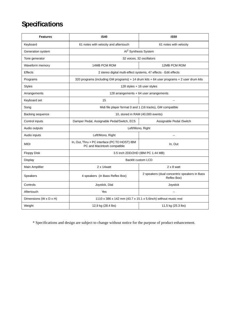
Specifications
* Specifications and design are subject to change without notice for the purpose of product enhancement.
Features iS40 iS50
Keyboard 61 notes with velocity and aftertouch 61 notes with velocity
Generation system AI
2
Synthesis System
Tone generator 32 voices, 32 oscillators
Waveform memory 14MB PCM ROM 12MB PCM ROM
Effects 2 stereo digital multi-effect systems, 47 effects - Edit effects
Programs 320 programs (including GM programs) + 14 drum kits + 64 user programs + 2 user drum kits
Styles 128 styles + 16 user styles
Arrangements 128 arrangements + 64 user arrangements
Keyboard set 15 --
Song Midi file player format 0 and 1 (16 tracks), GM compatible
Backing sequence 10, stored in RAM (40,000 events)
Control inputs Damper Pedal, Assignable Pedal/Switch, EC5 Assignable Pedal /Switch
Audio outputs Left/Mono, Right
Audio inputs Left/Mono, Right --
MIDIIn, Out, Thru + PC interface (PC TO HOST) IBM
PC and Macintosh compatibleIn, Out
Floppy Disk 3.5 inch 2DD/2HD (IBM PC 1.44 MB)
Display Backlit custom LCD
Main Amplifier 2 x 14watt 2 x 8 watt
Speakers 4 speakers (in Bass Reflex Box)2 speakers (dual concentric speakers in Bass
Reflex Box)
Controls Joystick, Dial Joystick
Aftertouch Yes --
Dimensions (W x D x H) 1110 x 386 x 142 mm (43.7 x 15.1 x 5.6inch) without music rest
Weight 12,9 kg (28.4 lbs) 11,5 kg (25.3 lbs)


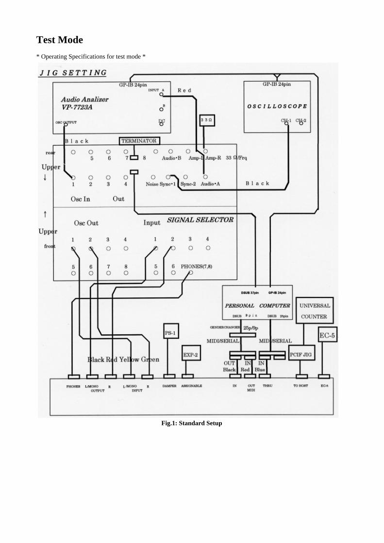
Test Mode
* Operating Specifications for test mode *
Fig.1: Standard Setup

• Press one of the following combinations of switches, and then turn the power switch on. This makes the test mode start.
GLOBAL + ARR. PLAY: Ordinary testGLOBAL + SONG PLAY: Test mode excluding the Internal test
• Switches to be used in test mode:
CURSOR > : Go to the next test step PROGRAM 8 : Go to the next test step (iS50)KEYBOARD SET 5 : Go to the next test step (iS40)CURSOR < : Return to the previous test step PAGE + : Go to the next test item PAGE - : Return to the previous test item
* Floppy disk drive test *
The number shows the type of a happened error.
0: OK 1: Drive not Ready 2: Data Error 3: Verify Error 4: No File 5: Same File 7: Disk Full 10: Soft Protect 12: Hard Protect 17: Disk Type 18: Media Type • Turn the power switch ON by pressing [GLOBAL] and [SONG PLAY] simultaneously.• Press [PAGE -].• Insert the test disk (a 2HD disk formatted with iS40) and press [PROGRAM 1] to start the test.• When [PROGRAM 2] is pressed, a checking disk format type will be skipped, but the test can be continued even usingan unformatted disk.
* Internal test *
• Turn the power switch ON by pressing [GLOBAL] and [ARR.PLAY] simultaneously.• Hook up all the terminals for INPUT L/MONO, INPUT R, OUTPUT L/MONO, OUTPUT R, MIDI IN, MIDI OUT,ASSIGNABLE, (MIDI THRU, TO HOST, PEDAL SW, EC5 only on iS40) with the plug inserted.
1. System ROM Check 1.1. Checksum test
2. Flash ROM Check2.1.Write/Read check (before preload from disk) -2.2.Checksum test
3. Internal RAM Check 3.1. 00000h~3FFFFh 3.2. 40000h~7FFFFh
4. LCD RAM Check 4.1. Write/Read check
5. FPS I/F Check 5.1. Communication command Send & Receive
6. FKS I/F Check 6.1. Communication command Send & Receive

7. TGL I/F Check 7.1. All voices on/off check, TGL voice flag 7.2. VDA & VDF register Write/Read
8. MIDI loop back Check 8.1. Check MIDI OUT/IN data (Check MIDI THRU data only on iS40)
9. PC I/F Check (only on iS40) - 9.1. Check PCIF OUT/IN data
10. PCM Verification 10.1 Data bus check 10.2. Address bus check BANK 0&1 PCM 10.3. Address bus check BANK 2&3 PCM 10.4. Address bus check BANK 4&5 PCM 10.5. Address bus check BANK 6&7 PCM (only iS40)
11. Style Verification 11.1. Data bus check 11.2. Address bus check
12. HeadPhone Check Check headphone connection
* External test *
1. Key Type check
Check keyboard type iS40 = TP9 iS50 = TP7
2. PCI (TO HOST) Clock out check (only iS40)2.1. Check that the output clock is 995k ~ 1,005kHz with a universal counter.
995.000 kHz ≤ clock ≤ 1005.000 kHz
[CURSOR >]
3. Panel Switch & LED
3.1. Check that all the LEDs are litInsert the preload disk (a 2DD disk) to the FDD, and check that the access lamp is lit.Eject the disk.Insert the preload disk again to preload the background.

[CURSOR >]
3.2. Check that all the LEDs are lit
ARR_PLAY B_SEQ SMF_PLAY SONG_EDIT GLOBAL PROG CHORD_HOLD SOUND_HOLD B_INVERSION SPLIT_POINT TEMPO_LOCK SINGLE_TCH ARR_BANK_A ARR_BANK_B ARR_BANK_U ARR_1 ARR_2 ARR_3 ARR_4 ARR_5 ARR_6 ARR_7 ARR_8 FADE_INOUT VARIATION1 VARIATION2 VARIATION3 VARIATION4 FILL1 FILL2 INTRO_ENDING1 INTRO_ENDING2 DRUM_UP PERC_UP BASS_UP ACC1_UP ACC2_UP ACC3_UP KBD1_UP KBD2_UP DRUM_DOWN PERC_DOWN BASS_DOWN ACC1_DOWN ACC2_DOWN ACC3_DOWN KBD2_DOWN KBD1_DOWN TR_SELECT RESET TAP TEMPO (iS40) START_STOP(G) START_STOP(R) SYNC_START (iS40) SYNC_STOP REC_WRITE PAGE - PAGE + CURSOR < CURSOR > TEMPO/VALUE - TEMPO/VALUE + EXIT/NO ENTER/YES TRANSPOSE b TRANSPOSE # OCTAVE_DOWN OCTAVE_UP CHORD SCAN LOW CHORD SCAN UP KEY ASS LOW KEY ASS UP2 KEY ASS UP1 ENSEMBLE SUSTAIN KB MODE M.DRUM KB MODE SPLIT KB MODE FULL PROG BANK A PROG BANK B PROG BANK C PROG BANK D PROG BANK E PROG BANK F PROG 1 PROG 2 PROG 3 PROG 4 PROG 5 PROG 6 PROG 7 PROG 8
(iS40 only)KB SET BANK A KB SET BANK B KB SET BANK C KB SET 1 KB SET 2 KB SET 3 KB SET 4 KB SET 5
[CURSOR >]
4. LCD Check 4.1. Check that all the segments of the LCD are lit and the back light lamps are lit. (See Fig.2)
Fig.2: LCD Display

[CURSOR >]
4.2. Check that the LCD screen is completely blank.
[CURSOR >]
5. MDE Check * Set the master volume at middle. OSCILLOSCOPE 1V/DIV, 2mS/DIV, DC
5.1. Check that the waveform from the OUTPUT L/MONO is normal (see Fig.3). Observe for a 2sec.
Fig.3: Waveform
[CURSOR >]
5.2. Check that the output waveform level is 0 with an oscilloscope.
[CURSOR >] 5.3. Check that the waveform at the OUTPUT L/MONO is normal (see Fig.3). Observe for a 2sec.
[CURSOR >]
6. LINE IN Check (only iS40)* Set the master volume at MAX. OSCILLOSCOPE 1V/DIV, 0.2mS/DIV, DC
6.1. Put a signal (1kHz/-10dBu sin waveform) into the INPUT L/MONO, and measure the output level of OUTPUTL/MONO. Check that the waveform according to the test range indicated in the table below and the output frequency isnormal. Check that the observed waveform is normal without distortion.
[CURSOR >]
6.2. Test INPUT R - OUTPUT R likewise.
OUTPUT L/MONO: 1kHz, 3.9dBu ≤ level ≤ 7.9dBu OUTPUT R: 1kHz, 3.9dBu ≤ level ≤ 7.9dBu

[CURSOR >]
7. Level Check * Set the master volume at MAX.
Measure the level at the PHONE L and PHONE R under a load of 33 ohms. OSCILLOSCOPE 1V/DIV, 0.5mS/DIV, DC
7.1. Check that the level is within the test range indicated in the table below and the output frequency is normal. Check that the observed wave form is normal without distortion.
7.2. Check likewise OUTPUT R,PHONE L and PHONE R. OUTPUT L/MONO: 488Hz, 7.3dBu ≤ level ≤ 9.5dBu
[CURSOR >]
OUTPUT R: 412Hz, 7.3dBu ≤ level ≤ 9.5dBu
[CURSOR >]
Headphone L: 549Hz, 2.4dBu ≤ level ≤ 4.6dBu (1 V RMS ≤ level ≤ 1.3 V RMS)
[CURSOR >]
Headphone R: 610Hz, 2.4dBu ≤ level ≤ 4.6dBu (1 V RMS ≤ level ≤ 1.3 V RMS)
[CURSOR >]
8. Noise Check
* Set the master volume at MAX. OSCILLOSCOPE 1V/DIV, 0.5mS/DIV, DC
8.1. Measure the noise level of OUTPUT L/MONO. Check that the level is within the test range indicated in the table below. Check that the output wave form level is 0 with an oscilloscope. 8.2. Check likewise OUTPUT R, PHONE L and PHONE R. OUTPUT L/MONO: level ≤ -84dBu
[CURSOR >]
OUTPUT R : level ≤ -84dBu
[CURSOR >]
Headphone L : level ≤ -88dBu
[CURSOR >]
Headphone R : level ≤ -88dBu
[CURSOR >]
9. Speaker Check 9.1. Check the sound from the middle range speaker L. Check that the output sound has no distortion, also check that no sound comes out from the middle range speaker R.
[CURSOR >]
9.2. Check the middle range speaker R, the tweeter L and the tweeter R likewise.

10. A/D converter
* Pay attention not to touch the joystick when starting this test.
10.1. Rotary Encoder (only iS40)
10.1.1.• Turn the rotary encoder and set the finger hook to the top position • Slowly turn the rotary encoder clockwise four (4) times.• When the fourth (4th) tern is completed (the finger hook is positioned at the top), check that
"|****0" appears. 10.1.2. • Slowly turn the rotary encoder clockwise four (4) times. • When the fourth (4th) left tern is completed (the finger hook positioned at the top), check that "0****|" appears.
[CURSOR >]
10.2. Acc Slider VRMove the ACC slider from MIN to MAX and check that the maximum and minimum value 00 to 7F appears. “0” will appear when the value reaches MAX and /or MIN.
10.3. Joystick X (Left/Right test: horizontal movement) (↔) This indication appears when reaching the maximum (minimum) value. [CURSOR >]
10.4. Joystick Y (Up/Down test: vertical movement) (↕) This indication appears when reaching the maximum (minimum) value. [CURSOR >]
10.5. Assignable Pedal
Operate respectively from MIN to MAX and check that the maximum and minimum values (00 to 7F) appear. When the value reaches MAX and MIN, “0” will appear.
10.6. EC5 (A, B, C, D, E) & Damper pedal (only iS40)
Press the A to E (EC5) ON and OFF individually, turn up and down Damper pedal, and check that “0” appears. 10.7. After Touch (only iS40)
Hit D#4 key and check that the value changes smoothly. It reaches 7F when pressed strongly.Hit C2 key and check that the value changes smoothly. It reaches 7F when pressed strongly.Hit C7 key and check that the value changes smoothly. It reaches 7F when pressed strongly.
11. Keyboard
• Hit the keyboard from the highest key to the lowest, and check that the note hit is indicated on the LCD screen. • The velocity value must be within the range from 43 to 73 in order to proceed to the next key. • When the lowest key was hit, press it for the next step.
12. Preload and 2DD mode disk check • If there is the background preload error, retry the preload.• When the preload data were loaded, check that the screen displays “ARR: ”.• Press the C3key, then press [Start/Stop] to check the playing.• Move Master Volume from MAX to MIN and check that the output sound changes smoothly without noise.• Withdraw the disk and the cables, and turn the power switch OFF for the test.
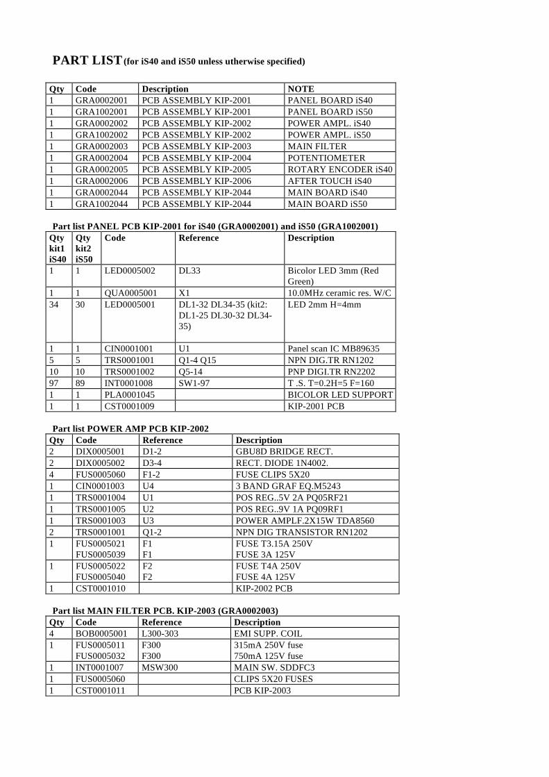
PART LIST (for iS40 and iS50 unless utherwise specified)
Qty Code Description NOTE1 GRA0002001 PCB ASSEMBLY KIP-2001 PANEL BOARD iS401 GRA1002001 PCB ASSEMBLY KIP-2001 PANEL BOARD iS501 GRA0002002 PCB ASSEMBLY KIP-2002 POWER AMPL. iS401 GRA1002002 PCB ASSEMBLY KIP-2002 POWER AMPL. iS501 GRA0002003 PCB ASSEMBLY KIP-2003 MAIN FILTER1 GRA0002004 PCB ASSEMBLY KIP-2004 POTENTIOMETER1 GRA0002005 PCB ASSEMBLY KIP-2005 ROTARY ENCODER iS401 GRA0002006 PCB ASSEMBLY KIP-2006 AFTER TOUCH iS401 GRA0002044 PCB ASSEMBLY KIP-2044 MAIN BOARD iS401 GRA1002044 PCB ASSEMBLY KIP-2044 MAIN BOARD iS50
Part list PANEL PCB KIP-2001 for iS40 (GRA0002001) and iS50 (GRA1002001)Qtykit1iS40
Qtykit2iS50
Code Reference Description
1 1 LED0005002 DL33 Bicolor LED 3mm (RedGreen)
1 1 QUA0005001 X1 10.0MHz ceramic res. W/C34 30 LED0005001 DL1-32 DL34-35 (kit2:
DL1-25 DL30-32 DL34-35)
LED 2mm H=4mm
1 1 CIN0001001 U1 Panel scan IC MB896355 5 TRS0001001 Q1-4 Q15 NPN DIG.TR RN120210 10 TRS0001002 Q5-14 PNP DIGI.TR RN220297 89 INT0001008 SW1-97 T .S. T=0.2H=5 F=1601 1 PLA0001045 BICOLOR LED SUPPORT1 1 CST0001009 KIP-2001 PCB
Part list POWER AMP PCB KIP-2002Qty Code Reference Description2 DIX0005001 D1-2 GBU8D BRIDGE RECT.2 DIX0005002 D3-4 RECT. DIODE 1N4002.4 FUS0005060 F1-2 FUSE CLIPS 5X201 CIN0001003 U4 3 BAND GRAF EQ.M52431 TRS0001004 U1 POS REG..5V 2A PQ05RF211 TRS0001005 U2 POS REG..9V 1A PQ09RF11 TRS0001003 U3 POWER AMPLF.2X15W TDA85602 TRS0001001 Q1-2 NPN DIG TRANSISTOR RN12021 FUS0005021
FUS0005039F1F1
FUSE T3.15A 250VFUSE 3A 125V
1 FUS0005022FUS0005040
F2F2
FUSE T4A 250VFUSE 4A 125V
1 CST0001010 KIP-2002 PCB
Part list MAIN FILTER PCB. KIP-2003 (GRA0002003)Qty Code Reference Description4 BOB0005001 L300-303 EMI SUPP. COIL1 FUS0005011
FUS0005032F300F300
315mA 250V fuse750mA 125V fuse
1 INT0001007 MSW300 MAIN SW. SDDFC31 FUS0005060 CLIPS 5X20 FUSES1 CST0001011 PCB KIP-2003

Part list ROTARY ENCODER PCB KIP-2005 for iS40 (GRA0002005)Qty Code Reference Description1 INT0001006 RE500 ROT. ENC. EC16B1 CST0001012 PCB KIP-2005
Part list SLIDE POTENTIOMETER PCB KIP-2004 (GRA0002004)Qty Code Reference Description1 POT0001003 VR400 SLID.POT. 10KX2 W D.C.1 POT0001004 VR401 SLID.POT.10KX1 W D.C.1 CST0001013 PCB KIP-2004
Part list MAIN BOARD PCB KLM-2044 for iS40 (GRA0002044) and iS50 (GRA1002044)QtyKIT2iS50
QtyKit1iS40
Code Parts name
2 2 219401400 EMI FILTER SDST310 92D223S5039 53 40400500 CHIP INDUCTOR SBLM21B102SPT1 1 304000070 TRANSISTOR2SA812-T1B (M5-7)6 6 304020230 TRANSISTOR 2SC3661-TA/TB (3K)1 1 304030140 COMPOUND TRANSISTOR FN1A4M-T1B1 1 304050120 COMPOUND TRANSISTOR FP1A4M-T1B1 1 314001400 DIODE RLS-73 TE-111 9 315000500 W DIODE MC-2840-T12-11 1 314029300 ZENER DIODE HZK5A1 1 320001529 IC(MAIN CPU) uPD70433GD-16-5BB (V55PI)1 1 320003217 IC(KEYSCAN) TMP87C847U-44581 1 320004538 IC(FDC) HD63266F1 1 320012181 IC(TGL2A) MB87A104APF-G-BND1 1 320012216 IC(SYSTEM) MBM29F400BA-90(9709**)1 1 320004029 IC(STYLE) MX23C1610PC-10-STY is V110 0 320006038 IC(STYLE) MSM27C1602CZ-NRS(9708**)1 1 320012216 IC(BACK UP) MBM29F400BA-901 1 320040017 IC(PCM1) MX23C3210MC-15 X790ROMA1 1 320040018 IC(PCM2 MX23C3210MC-15 X790ROMB1 1 320040019 IC(PCM3) MX23C3210MC-15 X790ROMC0 1 320040019 IC(PCM4) MX23C1610MC-15 X790ROMD1 1 320043002 IC(4x64K DRAM) uPD41464CF-100 0 320043001 IC(4x256KDRAM) IN41464P-101 1 324005003 IC(16x64KDRAM) LC321664BJ-10/800 0 324003006 IC(16x64KDRAM) TC511664A-80J (Substitution)0 0 324006001 IC(16x64KDRAM) MSM51166AJ-80-TRM
(Substitution)1 1 324011035 IC(256Kx16DRAM) M5M44170CJ-7 L21 1 324003010 IC(LOGIC) TC7WU04F2 2 324004003 IC(LOGIC) HD74HC139FPER0 0 324004006 IC(LOGIC) HD74HC00FPER2 2 324004007 IC(LOGIC) HD74HC573FPER1 1 324004012 IC(LOGIC) HD74HC08FPER1 1 324004050 IC(LOGIC) HD74HC138FPER3 3 324004059 IC(LOGIC) HC74HC157FPER1 1 324004176 IC(LOGIC) HD74HC05FPER2 2 324001016 IC(OP-AMP)uPC4574G1 1 324011004 IC(OP-AMP)M5216FP-600C1 1 324009004 IC(REG) NJM78L05UA-TE22 2 324009019 IC(OP-AMP)NJM2115M-TE21 1 324011012 IC(RESET) M51953BFP-600C0 1 324011021 IC(PC I/F) M5M34050FP-42A1 1 324038002 IC(DAC) TDA1305T/N2-T

1 1 334000600 PC PC-410K1 1 335400128 X-TAL SMD49 32MHz1 1 335400117 CERAMIC RESONATOR CSTCS8.00MT-TC1 1 343020440 PCB KLM-2044
Other Erectric PartsQtyKIT2iS50
QtyKit1iS40
Parts Code Parts name
1 1 FDD0002001 CUSTOM LCD ASSEMBLY1 1 FDD0001003 JOYSTICK ASSEMBLY1 1 FDD0001001 LOW NOISE F.D.D.0 1 TAS0001004 61 KEY TP9 FATAR KEYBOARD WITH A. TOUCH1 0 TAS0001005 61 KEY TP7 FATAR KEYBOARD1 0 TRA0001004 POWER TRANSFORMER 38VA0 1 TRA0001003 POWER TRANSFORMER 50VA0 2 ALT0001004 WOOFER SPEAKER 104MM0 2 ALT0001005 TWEETER SPEAKER 50MM2 0 ALT0001006 DUAL CONE 104MM SPEAKER
111
111
RIL0001040RIL0001071RIL0001072
AC MAINS CORDSEUUSUK
1 1 FDD0001004 ACCESSORY DISK

PART CODE: MAN0001030
AddressKORG ITALY SpaVia Cagiata, 85I-60027 Osimo (An)Italy
Web serverswww.korg.itwww.korg.netwww.korg.com