"Safety Analysis Rept for Shipment of Radioactive Matl in CNS 8 ...
Upload
khangminh22Category
view
1download
0
r
. .
U.S. NUCLEAR REGULATORY COMMISSION
REGION III
Report No. 50-373/0L-85-01
Dockets No. 50-373; 50-374 License Nos. NPF-11; NPF-18
Licensee: Commonwealth Edison CompanyPost Office Box 767Chicago, IL 60690
Facility Name: LaSalle County Nuclear Station
Examinatinn Administered At: LaSalle County Nuclear Station
Examination Conducted: May 20-24 and June 12-13, 1985
Y /Examiner (s): T. Lang g f- n - S >
Date
%
L. Dimmock 9 ~ 12 WDate
\\tt)"C. Kvamme D I//1/f I
Date
Mbk -
('M. King #f//l/ /$Date'
lwr Wu/ne
Approved By: ef 7// ;/f3.
Operating Licensing Section Date /
Examination Summary
Examination administered on May 20-24 and June 12-13, 1985 (Report,
j No. 50-373/0L-85-01)Thirteen candidates took the written, oral, and simulator examinations and one'
candidate took the written and oral examinations.,
Results: Twelve candidates passed the examination.'
|
8509200011 850916DRg ADOCK 05000373
PDR
- - .- - - - - . - - _ - . -. -_ -.-.~.-.- -- - . _ --
!
. .
i
| REPORT DETAILS! '
1. Examiners:
j C. Kvamme, EG&G-
| M. King, EG>. Lang, Region III;
i L. Dimmock, Region III*| E. Plettner, Region III .;.
,
* Chief Examiner i
2. Examination Review Meeting |,
!
; The review of the examinations resulted in numerous comments which weret directed to the answer key. The comments and their resolution are listed
in Attachment A for the RC , Attachment B for the SR0 and Attachment C forthe SRO limited.
3. Exit Meetingi .
-
| Duri,ng the exit meetings on May 21 and on June 13, 1985, the facility wasinfoFmed that all the candidates except one had clearly passed the
3 simulator and/or oral examinations that they had been administered. '
,
i
I'
I
i i
f
! <
| I;
ii
!
'
!'
i
h|
ii
k
|t
|.
t
I*
,
;
i
!
2 i,
. . . - . . . , - , , . - - - - - - - - . . _ - , , . - ~ . , . - . - - - - , , - ~ .. - , - . , , - . , , . , - , . - . , - . . . .

. _. . . . . _ . _ _ _ _ . . . . _ _ . _ . . - . . - _ - . - _ . _ _ _ _ _ _ _ _ . _ _ . _ _ _ _-
. .
l:!
Attachment A,
-t
!
| RESOLUTION TO COMMENTS TO THE LASALLE RO EXAM 0F 5/20/85
!
j QUESTION 1.01 c. ;
i ,
: FACILITY COMMENT:
!
Transient period -- even though key is a direct quote from the lesson plan, it!
still does not directly answer the question. Credit should be given to any;' logical explanation of transient period, i.e., the rapid increase in neutron| flux imediately after rod withdrawal due to prompt neutrons (or before; delayed neutrons are produced).! ;
( RESOLUTION: ;i .
| Agree with coment. Credit will be given for any answer which deals with
]prompt neutrons or the rate of reactivity addition. '
i QUESTION 1.11 r
'i
FACILITY COPNENT:i
3Answer key was wrong in calc. (should have been 36002 instead of 3600 )..
! RESOLUTION:i
{ Agree with coment. Answer key had typing error in single step of calculationj but answer was correct.
QUESTION 1.12i
| Answer key corrected even though no coment received. Answer changed from345 sec. to 310.7 sec.
QUESTION 2.01!I FACILITY COMMENT:
, The FCV physically will not close all the way (approximately 10% open). Do ;
! not take off for this answer. (Ref.: Chapter 8, Systems Manual.),
'
i
! RESOLUTION:I
| Agree with coment. Credit will not be taken off for stating that the valve; does not close completely.
!
|
l;
'
__._ _ _ _ .. _ -.__-.. _ _.__ _ _-__ _,_ - _._.._...- _ _ ., _-__.- - ..__,~,, - - - . _
. _ . . _ - __ . _ .- _ _ _ _ _ _ _ _ _. _ _ _ . _ . _ _ _ . _ _ . . _
,.
. .,
:
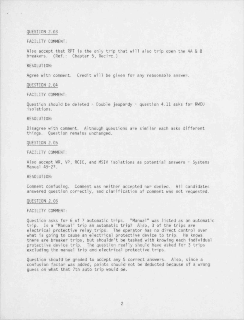
QUESTION 2.03
FACILITY COMENT:!' Also accept that RPT is the only trip that will also trip open the 4A & B; breakers. (Ref.: Chapter 5, Recirc.)
. RESOLUTION:1
J Agree with comment. Credit will be given for any reasonable answer.'
QUESTION 2.04i
FACILITY COMENT:!
Question should be deleted - Double jeopardy question 4.11 asks for RWCU<
' isolations.
RESOLUTION:i
j Disagree with comment. Although questions are similar each asks differentj things. Question remains unchanged.
QUESTION 2.05
FACILITY COMMENT:,
i Also accept WR, VP, RCIC, and MSIV isolations as potential answers - Systems| Manual 49-27.i
,RESOLUTION: i
4
j Comment confusing. Comment was neither accepted nor denied. All candidatesanswered question correctly, and clarification of comment was not requested.'
QUESTION 2.06
FACILITY COMMENT:
| Question asks for 6 of 7 automatic trips. " Manual" was listed as an automatictrip. Is a " Manual" trip an automatic trip? Also, 3 of the trips are:
j electrical protective relay trips. The operator has no direct control overi what is going to cause an electrical protective device to trip. He knowsi there are breaker trips, but shouldn't be tasked with knowing each individual
protective device trip. The question really should have asked for 3 trips'
! excluding the manual trip and electrical protective trips.!
! Question should be graded to accept any 5 correct answers. Also, since a! confusion factor was added, points should not be deducted because of a wrong
guess on what that 7th auto trip would be.
2
. , _ _ - . - _ - . -. -- . . - -- ._-_.- - - - . . . - - -
--. .. . - . _ - . _ - . _ - -_ -. - .- _ ~ ..
. .,
:
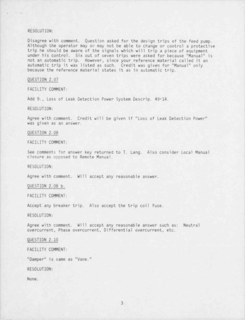
i RESOLUTION: '
Disagree with comment. Question asked for the design trips of the feed pump.Although the operator may or may not be able to change or control a protectivetrip he should be aware of the signals which will trip a piece of equipment
i under his control. Six out of seven trips were asked for because " Manual" isnot an automatic trip. However, since your reference material called it an
i automatic trip it was listed as such. Credit was given for " Manual" onlybecause the reference material states it as in automatic trip.;
!
QUESTION 2.07
FACILITY COMENT:,
| Add 9., Loss of Leak Detection Power System Descrip. 49-14.
| RESOLUTION:
Agree with comment. Credit will be given if " Loss of Leak Detection Power"' was given as an answer.
QUESTION 2.08
FACILITY COMENT:1
i See comments for answer key returned to T. Lang. Also consider Local Manual| closure.as opposed to Remote Manual. |
| RESOLUTION:,
! Agree with comment. Will accept any reasonable answer.:
QUESTION 2.08 b.
FACILITY COMENT:
; Accept any breaker trip. Also accept the trip coil fuse.
RESOLUTION:;
I Agree with comment. Will accept any reasonable answer such as: Neutralovercurrent, Phase overcurrent, Differential overcurrent, etc.
QUESTION 2.10'
FACILITY COMENT:
" Damper _" is same as " Vane."i
RESOLUTION:
!j None.
Iii
t 34
I
_ _ . . . . _ , . . . , ., - . _ _ . . , - _ , _ , . , , , - , . _ , , _ _ _ _ , . _ _ _ _ . , , _ _ . . - _ _ . - . . ~,._ _ _ _ _ . . . . _
. . . . _ . _ __ __ .. ._ . __ _ _ ~ ~ . . - _. . -
. .
.
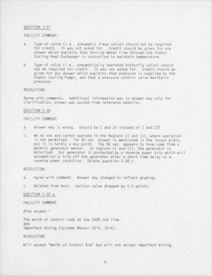
QUESTION 3.01
| FACILITY COMMENT:
Answer d. is wrong; no scram occurs. Answer e is wrong; 1/2 scram -Systems Manual 21-30.
RESOLUTION:
Agree with comment. Answer key changed to show correction.
QUESTION 3.03 a.
FACILITY COMMENT:
Accept - 129" for Level 1;"
12.5" for Level 3
RESOLUTION:
i Agree with comment. Will accept actual set points of level.
QUESTION 3.03 b.
FACILITY COMMENT:
Don't . require " Loss of power" for credit. Give credit for any assumedconditions the examinee states which would reset timer in accordance with'
answer key.!'
RESOLUTION:
Agree with comment in regards to loss of power; however, disagree with commentregarding accepting any assumed condition. Will not take credit off.if answerdoes not include loss of power to logic channel.
QUESTION 3.04-|'
FACILITY COMMENT:
[ First of all, this question references the Systems Manual, Chapter 43 - DCSystems - there is no basis for the questions or the answers in this lessonplan.
{- a. "two methods" is vague. Also accept -| Normal Charger Operation| Alternate Charger Operation (or other unit charger cross tie
or
i
l
4

. -. . . . - - . . . . _ _ _ _ _ _ . . . . . - = _ - . _. _- . _ - __ ~ ___ . . . . . . . ..
. .
One charger carryirg both unit divisional batteries (both are in" float" then). These are all " methods" of charging batteries,
b. First of all, there is no basis in our lesson plans, procedures,surveillances for this question and answer.
J
Point 1 procedures do not address putting chargers in parallel; equalize operation.Ii Point 2 - There is not a reference in our procedures or lesson
plans which even mention the " rectifiers" in the battery chargers,
as limiting components.'!
Unless this question is deleted, give credit for any answer thatdeals with procedures, etc. , above, or other " reasonable" responses.
1 RESOLUTION:,
Agree with comment in regards to accepting other answers which came from otherreasonable interpretation. Credit will be given for other interpretations of
j " methods" of charging. The basis for question is that there is a D.C. systemand its operation should be understood.
QUESTION 3.05 c.4
i
FACILITY COMMENT:!f Also accept Tech Spec numbers for SDV rod block and scram -t el.' 765' 5 1/4" Rod Block
el.' 767' 5 1/4" Scram
RESOLUTION:~
;
! Agree with comment. Credit will always be given for a correct set point inlieu of a parameter.;
IQUESTION 3.06;
| FACILITY COMMENT:'
See T. Lang answer key for comments.
i RESOLUTION:
i Comment only rephrased answer key. Credit will be given as stated.|-,
5
|. ..- .. . - - _ . - _ . - . - - . - - - . . _ _ , . . , ., . .. --. . , - - . , __
__ _ . _ . -_____ _ _ _ _ _ _ _ - _ - . _ _ .
t
r . .
t
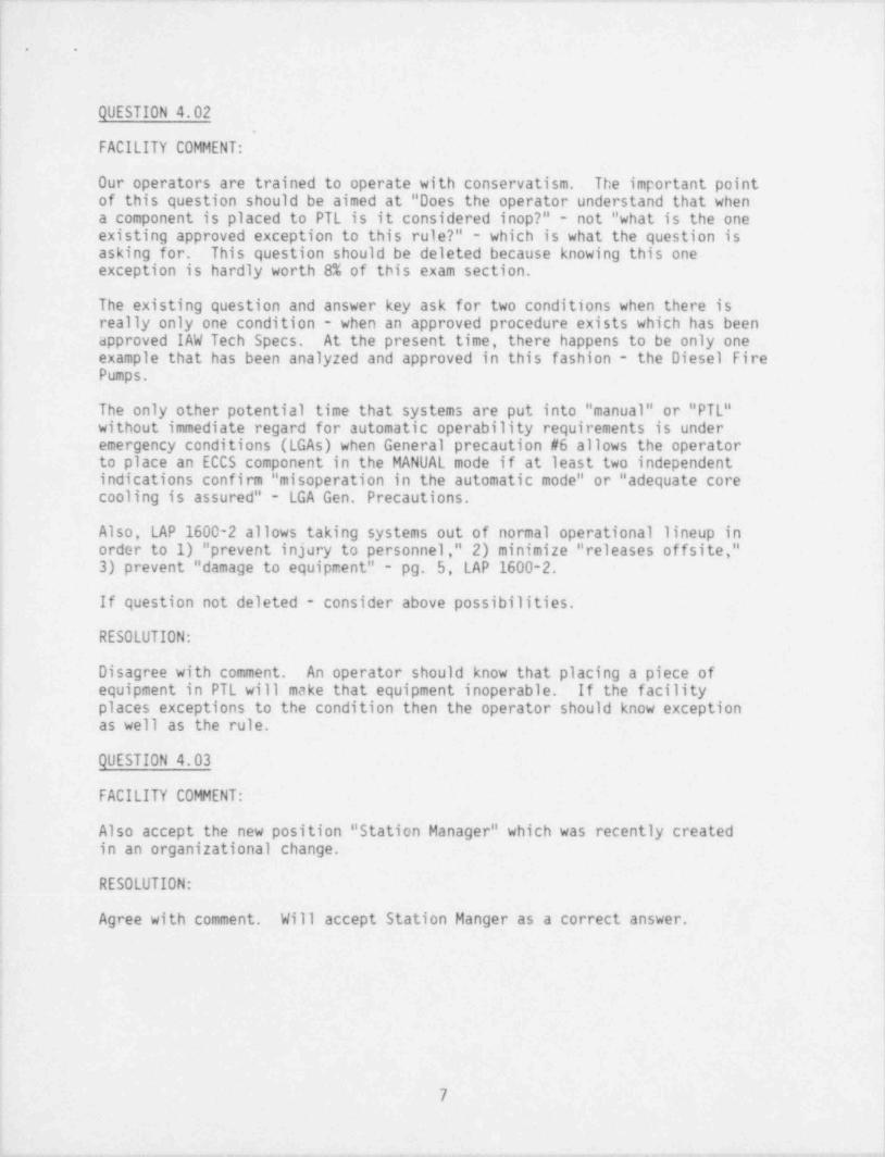
QUESTION 3.07.
FACILITY COMMENT:,
a. Type of valve (i.e., pneumatic 3-way valve) should not be requiredfor credit. It was not asked for. Credit should be given for any4
answer which explains that Service Water Flow through the Stator'
i
Cooling Heat Exchanger is controlled to maintain temperature.
b. Type of valve (i.e., pneumatically operated butterfly valve) shouldnot be required for credit. It was not asked for. Credit should begiven for any answer which explains that pressure is supplied by theStator Cooling Pumps, and that a pressure control valve maintains
! pressure.4
RESOLUTION:
'
Agree with comments. Additional information was in answer key only fori
clarification, answer was quoted from reference material.
i QUESTION 3.08 i
i
FACILITY COMMENT:i'
Answer key is wrong. Should be I and IV instead of I and II!a.
c. We do not and cannot operate in the Regions II and III, where operationis not permitted. The 90 sec. answer is mentioned in the lesson plans,
j but it is hardly a key point. The 90 sec. appears to have come from ageneric generator manual. In regions II and III, the generator is,
| motorized. Our generator is protected by a reverse power trip which will! automatically trip off the generator after a short time delay on a! reverse power condition. Delete question 3.08 c.
j RESOLUTION:
i a. Agree with comment. Answer key changed to reflect grading.|'
c. Deleted from test. Section value dropped by 0.5 points.
QUESTION 3.09 a.
FACILITY COMMENT:
Also accept -
The worth of control rods at the 100% rod line.andImperfect mixing (Systems Manual 10-5,10-6).
RESOLUTION:
Will accept " Worth of Control Rod" but will not accept imperfect mixing.
6
-. . _ . . _ . , , - -- - . _-- - - - - . - - . - . - . . _ _ _ _
.__ . _ _ _ _ _ _ _ _- _ _ _ _ __ _ . - _ ___ _ _ ._
. .
1|
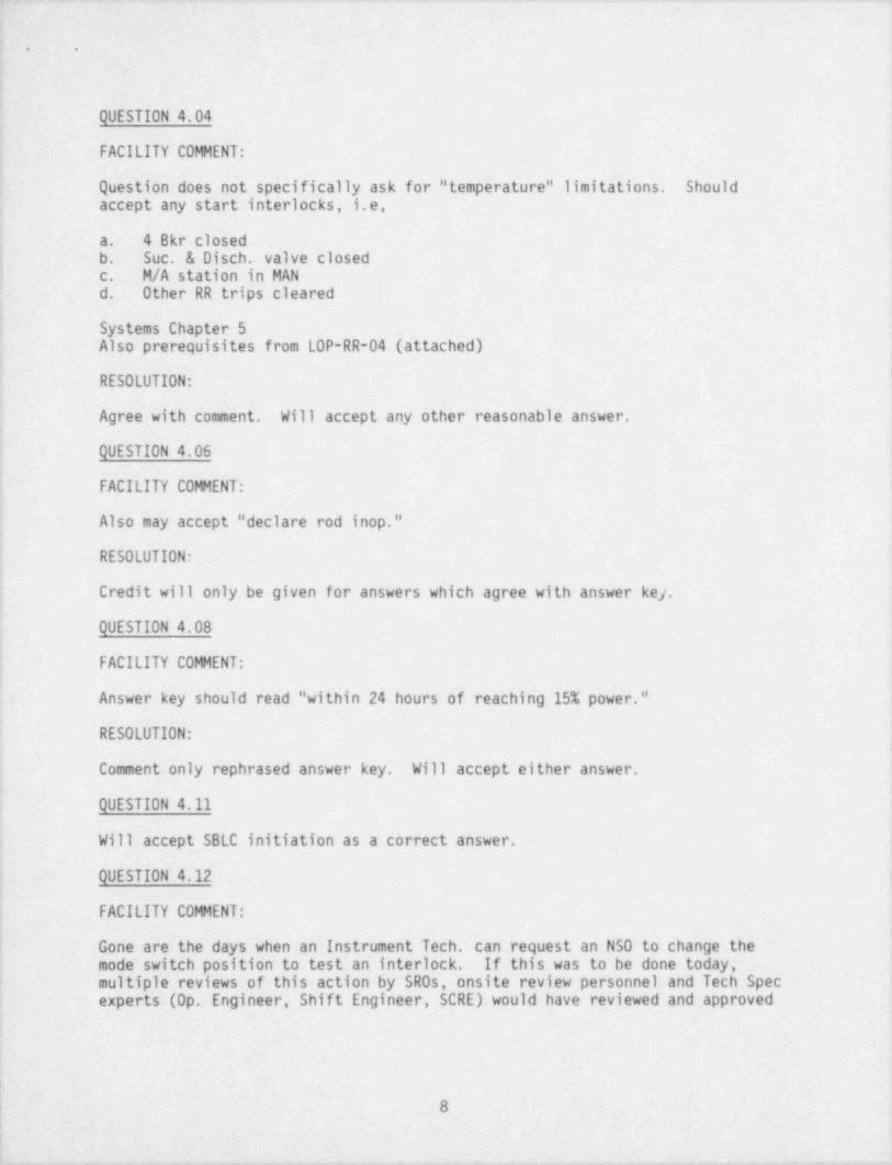
| QUESTION 4.021 -
| FACILITY COMMENT:
| Our operators are trained to operate with conservatism. The important pointof this question should be aimed at "Does the operator understand that whena component is placed to PTL is it considered inop?" - not "what is the oneexisting approved exception to this rule?" - which is what the question is
i asking for. This question should be deleted because knowing this one! exception is hardly worth 8% of this exam section.
The existing question and answer key ask for two conditions when there isreally only one condition - when an approved procedure exists which has beeni
i approved IAW Tech Specs. At the present time, there happens to be only one' example that has been analyzed and approved in this fashion - the Diesel Fire
Pumps.
! The only other potential time that systems are put into " manual" or "PTL"without.immediate regard for automatic operability requirements is underemergency conditions (LGAs) when General precaution #6 allows the operatorto place an ECCS component in the MANUAL mode if at least two independentindications confirm "misoperation in the automatic mode" or " adequate corecooling is assured" - LGA Gen. Precautions,
j Also, LAP 1600-2 allows taking systems out of normal operational lineup ini order to 1) " prevent injury to personnel," 2) minimize " releases offsite,"|
3) prevent " damage to equipment" pg. 5, LAP 1600-2.
f If question not deleted - consider above possibilities.
RESOLUTION:
4 Disagree with comment. An operator should know that placing a piece ofequipment in PTL will make that equipment inoperable. If the facilityplaces exceptions to the condition then the operator should know exception
| as well as the rule.
QUESTION 4.03i
I FACILITY COMMENT:!
Also accept the new position " Station Manager" which was recently createdi in an organizational change.!
| RESOLUTION:i
! Agree with comment. Will accept Station Manger as a correct answer.
3
!
!:!
l
7
i
|
__. _ _ _ _ _ , . _ - . _ ..-., .- _ . _ . , _ _ _ _ - _ . , , . , . _ _ _ _ _ _ _ . _ . _ _ _ _ - , . - . - _ , _ , - , - -
-. . . . - - - - - - _ . - - . - . . . . - - - . - - _ - . - . . . - _ _ - - . - . ~ . -
,J
*. .
; -
t
) QUESTION 4.04 |1 ,
! FACILITY COMENT: i
I~ Question does not specifically ask for " temperature" limitations. Should; accept any start interlocks, i.e,! a. 4 Bkr closedi b. Suc. & Disch. valve closed| c. M/A station in MAN ;
; d. Other.RR trips cleared,
: Systems Chapter 5Also prerequisites from LOP-RR-04 (attached) ,
i !
RESOLUTION: !
l Agree with comment. Will accept any other reasonable answer.i
'
i QUESTION 4.06 I
!
j FACILITY COMENT: I
, e
l Also may accept " declare rod inop."I
i RESOLUTION: ,
i
| Credit will only be given for answers which agree with answer ke/..
!
l QUESTION 4.08 If
| FACILITY COMENT:!
Answer key should read "within 24 hours of reaching 15% power." i
i'
RESOLUTION:;
,4
! Comment only rephrased answer key. Will accept either answer.
f QUESTION 4.11 ;
I
Will accept SBLC initiation'as a correct answer. !,
|I
QUESTION 4.12 ;
FACILITY COMENT:
Gone are the days when an Instrument Tech can request an NSO to change the;
; mode switch position to test an interlock. If this was to be done today,! multiple reviews of this action by SR0s, onsite review personnel and Tech Spec !
experts (Op. Engineer, Shift Engineer, SCRE) would have reviewed and approved
ir
r
r 8
!|~ .- . .- - - - - . . . . . - . - - . - - _ - _ - - . . _ - . . . - - - . . . . -

-._ . _ _ _ _ -- - - . . . - _ - - - - - -
. .
this action using the Tech Spec. With no spec to reference this question, itis not really applicable for an SR0 much less an R0 candidate. If this actionwere really to be done, the following reviews would be done:
, 1. A special test procedure or an LIS or LTS would need to be writteni and approved by onsite review.
2. The Shift Supervisor would have to approve the test to be done.
3. The SCRE would have to approve the action, since it affectssafety-related components.
4. A massive research effort would have been completed since potentialactual ESF actuations would need to be jumpered to avoid an unnecessary" red phone" notification to the NRC.
5. The NSO would be instructed to take the action by his supervisor andwould probably demand that the supervisor justify exactly what would
i happen and why.
This question is hardly a Reactor Operator level question. The question dealswith a " footnote" to a table of Operational Conditions contained in thedefinitions section of Tech. Specs. NUREG 1021, page 4 of 4 of ES-402 statesthat the "... candidate is not expected to memorize the exact details, numbers,,
~
and surveillance requirements contained therein." This statement was relatedto the Tech Specs and their bases. Also, in Generic Letter 82-13 from
| D. G. Eisenhut, dated June 17, 1982, stated, "...that Tech Spec questionsconcentrate on understanding of the bases, general knowledge of what actionsare required immediately (within one hour) and why, and what systems haveTech Spec limits and why." As this question does not comply with theseguidelines, the question is an unfair test question and should be thrown out.
RESOLUTION:1
! Question deleted. Section point vclue changed to reflect change.!
|
1|
9
_ _ _ -_ ._ .-- _ _ - . . . . - - - - - . - - - _ _ _ ._- _ - _ ,
,
. .
4
,
ATTACHMENT B :,
,
RESOLUTION OF COMMENTS TO THE LASALLE SRO EXAM OF 5/20/85i
! QUESTION 5.02
i FACILITY COMENT:
! b. The question does not state as to when during the transient the changei in fuel pin centerline temperature should be evaluated. For a
depressurization transient such as lowering of the Pressure Set, fuel;
i centerline temperature will initially decrease due to power drop causedby increased voiding. Subsequently, power will increase as EHC responds'
to decreased reactor pressure. As such, either increase or decreaseshould be considered as acceptable answers.
; c. Question wording is incorrect, and thus misleading for the answeri desired. The question should have said, "... exceeded DNB," instead i
i of reaching DNB. DNB, or more correctly, OTB, is defined in the LaSalle'
,Thermal Hydraulics Lesson Plan (74LPSDL, page 9) as "...when a !
; temperature swing (on the cladding surface) of 25 F is detected." Theseswings will also cause corresponding increases and decreases in fuel pin.
centerline temperature. Therefore, for the wording used in the question,i either increase or decrease, or remains the same should be acceptable.l| RESOLUTION:|
| b. Even if the fuel centerline temperature first decreased and thenj increased, it would stabilize at a lower temperature so decrease isi the correct answer. No change to answer key.,
. c. As an element reaches DNB the first response of centerline fuell temperature to the steam layer on the clad would be a temperaturei increase. No change to answer key.
QUESTION 5.03,
!FACILITY COMENT: |
j a. LGP 3-1 does not give specific guidance for soak consideration wheninterrupting ramp rates. Neither does Lesson Plan 74 LPSOL. LGP 3-1,
i Power Changes, on page 5 tells the operator: ,
j "If it is necessary to interrupt the power ramp or soak fora load reduction, the unit may be returned to a higher power,
! level, as recommended by the Nuclear Engineer."
In addition, LGP 3-1 on page 5 also states, "After terminating the loadincrease, a soak time of 12 hours at the new power level may be required'
for the fuel to be pre-conditioned at that power level.",
r
. _ , - - _ . _ , . _ _ - _ _ _ , _ , . - . _ - - _ _ _ _ _ - . _ _ __ - .- _ __._ _ r_ -- -- _ , _ _ _ _ _ _ _ _ . - - _ . . . _ . . _ _ _ . - . - ._

. .
"Back-fitting" pre-conditioned envelopes based on previous power rampsduring the previous 12 hours is an interpretation of PCIOMR guidelinesbased on considerable control room experience and in accordance withNuclear Engineer recommendations. In this light and based on theguidance provided in LGP 3-1, an acceptable alternative answer wouldbe one where the student stated a more conservative pre-conditionedlevel (such as 11.0 kw/ft) was in effect.
b. This question did not offer a correct answer. The load drop was to12.0 kw/ft and the question asks for the time to return power to13.0 kw/ft at 0.1 kw/ft/hr. The correct answer would be 10 hourswhich is not part of the answers listed.
RESOLUTION:
a. It is felt that a SR0 should have a good knowledge of pre-conditioningand how it is accomplished. No change to the answer key.
b. Agree with comment. Examinees were told to put their answer down if noanswer was correct so either number 3 or 10 hours will be given credit.
QUESTION 5.09 b.
FACILITY COMMENT:
The question asked only why the reactivity that must be added to achieveprompt critical conditions varies with core life. This is due to the changein Beta fraction over core life. The question does not ask for why Betafraction changes and thus should not be required for full credit.
RESOLUTION:
The answer key is felt to be an adequate response to " explain why." Anythingless will only receive partial credit. No change to answer key.
QUESTION 5.11 a.
FACILITY COMMENT:
Loss of backpressure portion of answers should not be required for fullcredit. A turbine-driven reactor feedwater pump could experience "run out"due to a controller failure causing turbine speed to increase drastically.This "run-out" condition is not directly caused by a " loss of backpressure";therefore, the loss of backpressure should not be required for full credit.Any answer stating that system / pump flow exceeds design considerations shouldbe acceptable.
Other potential adverse consequences of pump run-out exist other thar ir.atorelectrical damage. Some of these include cavitation, loss of pump c30 ling,and coupling failure. Attached are pages from a Westinghouse PWR documentthat describes these possibilities. Therefore, these answers should be countedas acceptable alternative answers to damage to motor windings.
2
._ _ _- .-. . _ ___.
. .
RESOLUTION:
Agree. Answer key changed to reflect this.
QUESTION 6.01 a.
FAC LITY COMMENT:
The question asked does not deal with problems associated with having too highof a water level in the downcomer. Instead, the question only asks why wehave vacuum reliefs. Therefore, the only answer that should be necessary forfull credit is to "... prevent drawing water up into the downcomer as theexhaust condenses from a previous relief." Grading of this question shouldreflect this.
RESOLUTION:
The answer key is felt to be an adequate response to the question. Anythingless will only receive partial credit. No change to answer key.
QUESTION 6.02
FACILITY COMMENT:;
Slow closure of the MSIVs during " test" and normal operation is performed by,
i slowing bleeding air pressure off the operating piston and allows springtension ONLY to close the valve. For this reason, a or c should be acceptableanswers. Reference: Main Steam L.P., pages 33-34.-
-
| RESOLUTION: ,.
Comment not accepted. Normal operation is considered to be with the controlswitch for opening or closing the valve. No mention is made in proceduresabout using the test switch for closing. Answer stays as is.
I QUESTION 6.05
|FACILITY COMMENT:
| Answer "b" is also acceptable as the turbine speed is controlled duringnormal startup by using the M/A station /EAP in MANUAL greater than 2000 RPM.
; Reference: LOP-FW-04, Step F.9.!
! Also for answer "d", the use of the solenoid number "SV-7" causes confusioni and is a needless application of detail. The question was intended to ask| how handjack operation effects FAP control of the turbine. By listing the
| solenoid number (which is not used in procedure or panel I.D.) to identify thei handjack could confuse the student. As to whether this solenoid must be
energized or de-energized has little or no impact on an operator's ability tosafely operate the plant. Grading of this question must consider theconfusion and irrelevance of this question.
| 3
!
-. . . .. . . , -- - - - - . - - - . -

.- -... .. - - . . - . _ . - . - - - . . - . - . . - -._ . . . . . . . -.
. .
,
RESOLUTION:
; The term startup is normally used to mean for the beginning or in this case.! zero speed. Therefore, answer d.is the correct answer and no change to
answer key. The use of the solenoid number came right out of the lesson plansi
! and was used to reduce confusion.
! QUESTION 6.06
. FACILITY COMMENT:i .
''Also should accept the~ voltage regulator and governor as separate required; auxiliary systems for this question.
,
!
' RESOLUTION:
Agree. Answer key changed.,
! QUESTION 6.07i
j FACILITY COMENT:
i These are not the only high speed permissives. The following should also be' counted:|
j a. 4 Breaker closed ,
b. Suction and discharged valve closed4
c. M/A station in MANUAL,
d. Any other RR pump trip signal clear4
;
: In addition, 2 of the answer in the key contain multiple interlocks whichj should be counted separately:!
I a. FCV position and 30% feedwater are separate interlocks-2 b. For RPT this can be initiated bv Turbine Control Valve fast closurej or Turbine stop valve closure and should be accepted as separate
answers.
Ref.: LaSalle System Description,- Chapter 5, pages 39 and 46'
LaSalle Electrical Schematic IE-1-4205AR; ,
RESOLUTION:
!- a, b, and d are not accepted as these are start permissives for slow speed '
i also and are not just.high speed permissives. Answer key changed to accept c.Also, agree with the second part_of the' comment and answer key _ changed.<
!
i;
;
i
!
;
! 4
!_ . _ . . - ._ _.., .. _ _ _ _ .-._- .. . . . . . __._._._:.._.__.__. _ _ _
- - . . = - . . .- , .- . . - _ - .- . - - _ . .
. .
.
QUESTION 6.08
; FACILITY COMMENT:
a. Should also accept charging header pressure as an alternate answer. The !
only time it does not come into play is during scram time testing whenthe HCU is intentionally isolated from the charging header.
! b. Answer #3 should' be basically the same as answer #2. LaSalle lessonplans for CRD nechanics and hydraulics do not include the information .
; listed in the answer key. LaSalle Lesson FTin, Chapter 7, page 29does state:
"S. Normal scram (accumulator plus reactor pressure).;Normal scrams are accomplished using a combinationof accumulator and reactor pressures (accumulator
4
pressure at the beginning of the stroke and accumulator!
i plus reactor pressure once the accumulator pressurei decays for reactor pressure)."I RESOLUTION:
i a. Charging water pressure will be accepted in place of accumulator pressurej but not in place of vessel water.
| b. The candidate should recognize some distinction between 2 and 3.Reasonable explanations that do recognize these differences will ,
,
be given credit.'
i-! QUESTION 6.09 b.
FACILITY COMMENT:;
i Valve numbers should not be necessary for full credit.'
RESOLUTION:
Agree. Answer key changed. |; i
QUESTION 6.11
#2.b also accept closure of 2, 3 or 4 turbine control valves which will alsosatisfy the logic.
Ref.: LaSalle Electrical Schematic 1E-1-4215AH
RESOLUTION:
Two valves may not cause scram. Will accept any explanation that shows theequivalent of one'out of two twice.
!
!t
I
5
.__. . .-- . . - - .-. - .-.- . - - -. - - - . - - - - - . . . - - - . .
_ _ _ _ _ _ _ _ _ _ _ _ _ _ _ _ _ - _ _ _ _ _
. .
QUESTION 7.05
FACILITY COMMENT:
Tech Spec 3.4.1.1 also requires that the recirculation flow control system isplaced in MASTER MANUAL. This should be counted as an acceptable alternate
- answer. Also for answers d and e - both consist of multiple requirements thatshould be counted as separate acceptable answers."
RESOLUTION:
Agree. Answer key changed.
QUESTION 7.06
FACILITY COMMENT:
Per T.S. 3.9.2, the following should also be counted as separate acceptablealternate answers:
a. Shorting links removedb. Continuous indication available in the Control Room
i
RESOLUTION: l
Agree. Answer key changed.
QtlESTION 7.07
FACILITY COMMENT:
a. Also acceptable other answers such as use of the full core display,selecting rods and checking the 4 rod display.
Ref.: LGP 3-2, F.26
b. Also accept that the Mode Switch will provide another alternatescram signal.
Ref.: LaSalle System Description, Chapter 20, RPS
RESOLUTION:
a. F.26 is completed later in the procedure and is not solely for thepurpose of verifying rods are in after a scram. No change to answerkey.
b. This is not the reason stated in the procedure. No change to answerkey.
,
6
u_._______ __________ _ _ ____ __ . . . .

. .. .. .-_. - - _ - .. . - _ - - _ - . . . - -. . . . _ _ _ . .
a
-. ..
T
QUESTION 7.08
[ ' FACILITY COMMENT:1
j Should also accept other means such as RT rejection and operation, and MS line{ drains.4
J
: . RESOLUTION:1
Not per procedure. No change to answer key.
QUESTION 7.10
i FACILITY COMMENT:
| For answer #2, " insert cram arrays" should be sufficient as it isintuitive / generally understood that they are part of CRSP and are selectedsuch that RWM/RSCS won't interfere with-rod motion.
1
Also accept manual scram if feedwater temperature drops 100 F.
Ref. : LOA-FW-011
; RESOLUTION:
I Agree. Answer key changed.;
: QUESTION 7.11i
; FACILITY COMMENT:|
| Also accept "... prior to rod motion affecting power distribution" ini the core.i
; Ref.: LOA-IN-01i
i RESOLUTION:
; We assume they mean LOA-1A-01. Agree. Answer key changed.'1
QUESTION 8.02 i
: FACILITY COMMENT:!
! a. Also accept'the following as alternative answers:|| 1) Checking " stall flow"| 2) Use of full-out lights to verify couplingI 3) Use of 4 rod display indication position indication,
goes blank and -then returns during coupling checkst'
b. .For an immovable rod - if it is caused by mechanical interferenceor excessive friction - each answer should be counted separately.
7
_ _ _ _ _ _ _ . _ _ _ _ _ . _ . . . . ~ . _ _ . _ . . _ _ , _ _ . _ _ . . , _ . _ _ . _ . . - . . _ --

. .
Also a rod that is movable but not trippable is considered inoperable.
Ref. : T.S. 3.1.3.1
Also for faulty RPIS indication - failure of full-in/ full out switchesshould be counted as a separate answer from regular RPIS positionswitches as Tech. Specs. separates actions for these conditions.
Ref.: T.S. 1.3.7
RESOLUTION:
a. One has nothing to do with rod coupling. 2 and 3 are methods ofdetermining overtravel. No change.
b. Agree. Answer key changed plus other answers added.
QUESTION 8.C3
FACILITY COMMENT:
a. LAP 900-4 specifies that a temporary lift is an acceptable action for thecondition described in the question. The student should only be requiredto state that a " Temporary Lift" be performed - not describe physically
' how a temporary lift is performed.
b. Partial clearances of outages as described in answer #1 are authorized byLAP 900-4, page 13. For outages of limited extent, this is a permissibleand relatively common occurrence at the station.
RESOLUTION:
Agree to a. Answer key changed. For b #3 is the best answer. No change toanswer key.
QUESTION 8.05
l Added suppression pool temperature and pressure.
QUESTION 8.07
FACILITY COMMENTS:
The question here deals with a " footnote" to a table of Operational Conditionscontained in the definitions section of Tech Specs. NUREG 1021, page 4 of 4of ES-402 states that the "... candidate is not expected to memorize the exactdetails, numbers, and surveillance requirements contained therein." Thisstatement was related to the Tech Specs and their bases. Also in GenericLetter 82-13 from D. G. Eisenhut dated June 17, 1982 stated, "...that TechSpec questions concentrate on understanding of the bases, general knowledge,
| of what actions are required immediately (within one hour) and why, and what
8
_ _ _ _ _ _ -_ ___ __
. .
systems have Tech Spec limits and why." As this question does not complywith these guidelines, the question is an unfair test question, and should bethrown out.
RESOLUTION:
Agree. Question deleted.
QUESTION 8.09
FACILITY COMMENT:
Should also accept answers that state that an exception would be whenstation procedures direct as these procedures are approved IAW TechnicalSpecifications.
RESOLUTION:
Agree. Answer key changed.
QUESTION _8.11
FACILITY COMMENT:
LOP-HP-04 states that " stable and under control" could also mean "...if theseparameters are following expected trends." This should also be an acceptablealternate answer.
RESOLUTION:
Agree. Answer key changed.
QUESTION 8.12
FACILITY COMMENT:i
i A recent change occurred at LaSalle which hasn't been reflected in the CompanyRad Standards. Under this change, Operating Supervision may or may not berequired to make shiftly reviews of an active (Type 2) RWP depending on thenature of the work. Determination of this review is done by the ShiftEngineer / Shift Supervisor during initial RWP approval. Student answersto this procedure should also be acceptable.
Ref.: LAP 100-22, page 2 and 7 (attached)
RESOLUTION:
Agree. Answer key changed.
;
9
_. _ _ . - _.____ _ _ _ . _ _ . _ _ . . _ _ . . ,._ .

. .
ATTACHMENT C
RESOLUTION OF COMMENTS TO THE LASALLE LIMITED SR0 EXAM OF 6/12/85
..
QUESTION M.01
FACILITY COMMENT:
Should also accept RHR rejection to radwaste or main condenser during shutdowncooling operation.
Ref.: LOP-RH-07
RESOLUTION:
Accepted. Answer key modified.
QUESTION M.05
FACILITY COMMENT:
Should also accept a description that states there are 2 " zones" of orificing- central and peripheral.
Ref.: LaSalle System Description, Chapter 2, page 24
RESOLUTION:
Not accepted. Question asked for types of orificing. No change to answerkey.
QUESTION M.07
FACILITY COMMENT:
Question is a little ambiguous enrichment variance and poison loadingshould be acceptable answers.
Ref. : LaSalle System Description, Chapter 4, pages 20-21
RESOLUTION:
Comment accepted. Answer key modified.
QUESTION N.02
FACILITY COMMENT:,
| .
Should also accept that the surge tank is designed such that the fuel poolcannot be completely drained and the fuel uncovered by a break in the fuel'
pool cooling piping.
|

. .
Ref.: LaSalle System Description, Chapter 66, page 32
RESOLUTION:
This is a fuel pool design and not a purpose of the surge tank. No change toanswer key.
QUESTION N.08
FACILITY COMMENT:
The question assumes a water level above +55" but does not state such. Shouldalso accept if says it would initiate on -50"
RESOLUTION:
Do not accept. During actual refueling which is what this license exam isfor, water level would be above +55". No change to answer key.
QUESTION N.09
FACILITY COMMENT:
Setpoints should not be included as there is no refuel floor indication forRx level (in inches) and drywell pressure.
RESOLUTION:
The limited SRO should still have a knowledge of the setpoints even thoughi
this is no direct indication of them on the refuel floor. He can obtainthe current reading and trend from the control room. No change to answerkey.
QUESTION 0.01
FACILITY COMMENT:
Also accept use of dummy fuel bundles.;
RESOLUTION:
Comment accepted. Answer key modified.(
QUESTION 0.03!
| FACILITY COMMENT:|
| Should also accept Nuclear Materials Custodian as he has a sign-off onLTP-1600-26, Attachment C, Approval Sheet.
| 2
:
___ .- . .-. . - - . . _ _ -
. .
RESOLUTION:
Comment accepted. Answer key modified.
-QUESTION 0.06
FACILITY COMENT:
Should also accept other surveillance requirements as question did not specifythe same (i.e., signal-to noise ratio, countrate, etc.).
RESOLUTION:
Accepted. _ Answer key modified.
QUESTION 0.08
FACILITY COMENT:
Due to ambiguous nature of the question the second half of the question neednot b:. required for full credit. Either answer should be acceptable.
RESOLUTION:
Comment accepted. Answer by modified.
QUESTION 0.09
FACILITY COMMENT:
Second half of the answer is not asked for by the question and should not berequired for full credit.
The question as a whole is very confusing and does not make it clear whatanswer is being solicited. As such the test weight is a reasonable answer butthe fuel shipping cask is not. This confusion is compounded by the use of
| the term " storage area" which implies the fuel storage racks and may misleadi the candidate to search for a non-existent second' weight limit. Also the| critical "L" path limits the travel of the cask and prevents it from traveling! over the spent fuel racks.
RESOLUTION:^
First part of the comment is accepted and answer key changed. Second part ofcomment-is not accepted.
QUESTION 0.114
FACILITY COMENT:
'
LAP-240-6 and Control of Temporary System Changes are exclusively duties of theShift Engineer, Unit Shift Foreman holding full SR0 licenses. As it is not a
,
duty of the Limited SRO, the question is not valid and should be thrown out.i
!
3
-..
_ _ _ _ _ - _ _ _ _ _ _ _ _ _ _ _ _ _ _ _ _ _ _ _ _ _ _ _ _ _ _ _ _ _ _ _ _ _ _ _ _ _ _ _ - _ _ _ _ _ _ _ _ _ _ _ _ _ _ _ _ _ _ _ _ _ _ _ _ _ _ - _ _ _ _ _ _ _ _ _ _ _ _ _ _ _ _ _ _ _ _ _ _ _ _ _ _ _ _ _ _ _ _ _ _ _ _ - _ _ _
. .
RESOLUTION:
Comment accepted. Question deleted.
QUESTION P.02
FACILITY COMMENT:
Setpoints should not be required as they are not requested.
.RESOLUTION:
1
Accepted. Answer key modified.
QUESTION P.05:
FACILITY COMMENT:
GSEP EAL exact classifications - are not required knowledge of full SR0license holders. The intent is to be able to utilize the EALs to makeclassifications and to memorize generic GSEP classes and class descriptionsnot specific EALs. Question should be thrown out. A general knowledge ofGSEP should be expected of a fuel handling foreman but not an exactmemorization of GSEP Emergency Action levels.
RESOLUTION:
Comment accepted. Question deleted.
QUESTION Q.03,
i FACILITY COMMENT:
Use of the cattle chute should also be considered an acceptable answer as it, prevents dropping of the fuel bundle which could cause high radiation levels! in the drywell.i
Page 52 of Chapter 67, System Description'
! RESOLUTION:
Comment accepted. Answer key modified.
|
4
. _ . , , _ _ . -. _ _ . . _ - _ _ -. . _ - _ _ .- . - - -
- _ - _ _ _ _ _ _ _ _ _ _ _ _ _ _ _ _ _ _
'
f)']/) S TisL.
Lv. ,
5*
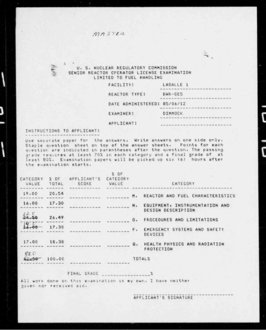
wp? U. S. NUCLEAR REGULATORY COMMISSION?; SENIOR REACTOR CPERATOR LICENSE EXAMINATION'
LIMITED TO FUEL HANDLING
FACILITY: LASALLE 1_________________________
REACTOR TYPE: BWR-GES_________________________
DATE ADMINISTERED: 85/06/12_________________________
EXAMINER: DIMMOCK_________________________
APPLICANT: _________________________
INSTRUCTIONS TO APPLICANT:__________________________
Use separate paper for the answers. Write answers on one side only.Staple question sheet on top of the answer sheets. Points for eachquestion are indicated in parentheses after the question. The passinggr ade requires at least 70% in each category and a final grade of atleast 80%. Exaniination papers will be picked up six (6) hours afterthe exaniination starts.
% OF*
CATEGORY % OF APPLICANT'S CATEGORYVALUE TOTAL SCORE VALUE CATEGORY
________ ______ ___________ ________ ___________________________________
19.00 20 54 ________ H. REACTOR AND FUEL CHARACTERISTICS________ ______ ___________
16.00 17.30 ________ N. EQUIPMENT, INSTRUMENTATION AND________ ______ ___________
DESIGN DESCRIPTIONg*^ 26.49_ '_ ' ~ ___ ________ 0. PROCEDURES AND LIMITATIONS~
______ ___________
- 17 30________ P. EMERGENCY SYSTEMS AND SAFETY
________ ______ ___________
DEVICES
17.00 18.38________ 0. HEALTH PHYSICS AND RADIATION
________ ______ ___________
PROTECTIONfr. oE?e&F~ 100.00 TOTALS
________ ______ ___________ ________
FINAL GRADE _________________%All work done o re this exanination is niy own. I have neithergiver not received aid.
EPPL5C5Ui~5~5EGUEiURE-~~~~~~~~~~~~~
-
M. REACTOR AND FUEL CHARACTERISTICS PAGE 2
________5,____________________________
$kQUESTION 'M.01 (2.00)
During refueling the CRD system will normally be imputtingopproximately 63 spm into the reactor.well. How is thisoxcess water normally removed? (List two methods) (2.0)
DUESTION M.02 (2.00)
What would be the results of a 1/M plot if the detector was locatedtoo close to the source? Explain your answer. (2.0)
GUESTION P.03 (2.00)
Por your core verification procedure LTP 1700-1, what are thefour (4) criteria to be used to detersiine proper fuel elenie ntorientation. (2.0)
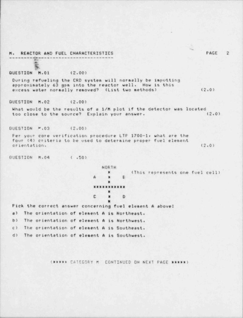
DUESTION M.04 ( .50)
NORTH,
* (This represents one fuel cell)A a B
*
| XEERREMERIXa
C a Da
Pick the correct answer concerning fuel element A above:
a) The orientation of element A is Northeast.
b) The orientation of element A is Northwest.
| c) The orientation of elesient A is Southeast.
d) The orientation of element A is Southwest.
(ananz CATEGORY M CONTINUED ON NEXT PAGE ****n)
.
L
.
.
'
M. REACTOR AND FUEL CHARACTERISTICS PAGE 3-------------y---------------------- .
c4
TGUESTION "M.05 (3.50)
c) What is the reason for having orificing in fuel support pieces? (2.0)
b) What are the different types of fuel orificing found at Lasalle?t (exact size of orifices is not needed.) (1.5)
DUESTION M.06 (1.00)
What is the purpose of the finger springs on the fuel bundles?
DUESTION M.07 (1.50)
What are the three types of fuel rods to be found in a bundle? (1.5)
DUESTION M.08 (1.50)
What are three (3) purposes of the fuel channel? (1.5)
OUESTION M.09 (1.00)
What are two (2) reasons for adding sadolinia to the fuel? (1.0)
DUESTION M.10 (4.00)
o) What is a reactivity coefficient? (1.0)
b) Name the three (3) reactivity coefficients that are of mostcignificance in your reactor? (1.5)
c) Do these coefficients help or hinder control of your reactor?Explain your answer. (1.5)
(mzurs END OF CATEGORY M suxxx)
.
-
_
'~
. .. _
|~
|-I %g'
~
PAGE 4N. EQUIPMENT, INSTRUMENTATION AND DESIGN DESCRIPTION________gy-__i--_______________--__------___--______- -
e
k-DUESTION N.01 (1.00)
| In the event of an accident that drains the reactor vesselduring refueling with the fuel pool gates removed, what
,
; provents uncovering the fuel in the storage pool? (1.0)
GUESTION N.02 (3.00)
What are the three purposes for the Skimmer Surge Tanks?
00ESTION N.03 (1.00)3
What prevents the fuel pool from draining through the diffuserfill lines in the event that a pump discharge line were tobreak? (1.0)
DUESTION N.04 (2 00)
hakeup to the fuel pool will occasionally be required due to| evaporation.'
a. How is water normally made up to the fuel pool? (1.'0)*
| b. What would happen if makeup water was not isolated andthe fuel pool continued to fill? (1.0)'
QUESTION N.05 (2.00)
What are the 4 types of storage racks located in the fuel pool? (2.0)
i'
OUESTION N.06 (2.50)|
The interlock status display modulee located in the operator'scob above the console controlse displays a number of indications.What conditions must exist for the following indications? De sureto include all conditions.
o) Backup Hoist Limit light is on. (1.0)b) Monorail Auxiliary Hoist Interlock light is on. (1.5)
(arm ** CATEGORY N CONTINUED ON NEXT PAGE mus**)
.
;
I
,_ _ __ _ . _ _ . . _ _ _ _ . _ _ . . . . _ _ _ _ _ , - ...___ _ ___
-
.
N. EQUIPMENT, INSTRUMENTATION AND DESIGN DESCRIPTION PAGE 5------- ,.------------------------------------------- .
! ?' '
IQUESTION N.07 ( .50)
Onewer True or False. Secondary containment must be brokenin order to bring the Fuel Shipping Cask (IF-300) into therocetor building. (.5)
GUESTION N.08 (2.00)
If during refueling, the HPCS system were to get an inadvertentinitiation signal (one sensor in each channel), wouldyou expect HPCS to start and inject? Explain your answer. (2.0)
OUESTION N.09 (2.00)
What are the two automatic initiation signals for the LPCSSystem? Include setpoints. (2.0)
*,
i
!
.
(*mann END OF CATECORY N marum)i
e
r
i*
i
|
!
t
<
.
O. PROCEDUR(S AND LIMITATIONS PAGE 6,
______________________________-
, , .
4a
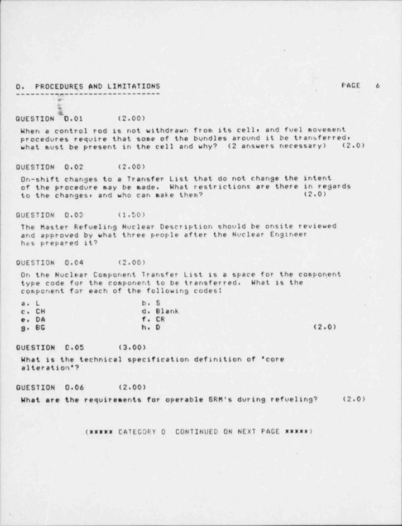
GUESTION D.01 (2.00)
Whan a control rod is not withdrawn from its cell, and fuel movementprecedures require that some of the bundles around it be transferredeuhot must be present in the cell and why? (2 answers necessary) (2.0)
OUESTION 0.02 (2.00)
On-shift changes to a Transfer List that do not change the intentof the procedure may be made. What restrictionf, are there in regardsto the changes, and who can make them? (2.0)
QUESTION 0.03 (1.50)
Tho Master Refueling Nuclear Description should be onsite reviewedand approved by what three people after the Nuclear Engineerhas prepared it?
DUESTION 0.04 (2.00)
On the Nuclear Component Transfer List is a space for the component ,
type code for the component to be transferred. What is theesoponent for each of the following codest
c. L b. S ,
c. CH d. Blanko. DA f. CRg. BG h. D (2.0)
i
j OUESTION 0.05 (3.00)
! Whot is the technical specification definition of ' core| olteration*?
DUESTION 0 06 (2.00)
WhOt are the requirements for operable SRM's during refueling? (2.0)
!
| (assus CATEGORY 0 CONTINUED ON NEXT PAGE *****)
; .
|
|1
|*
,
.
.
..
O. PROCEDURES AND LIMITATIONS PAGE 7-------
37--------------------.
V5
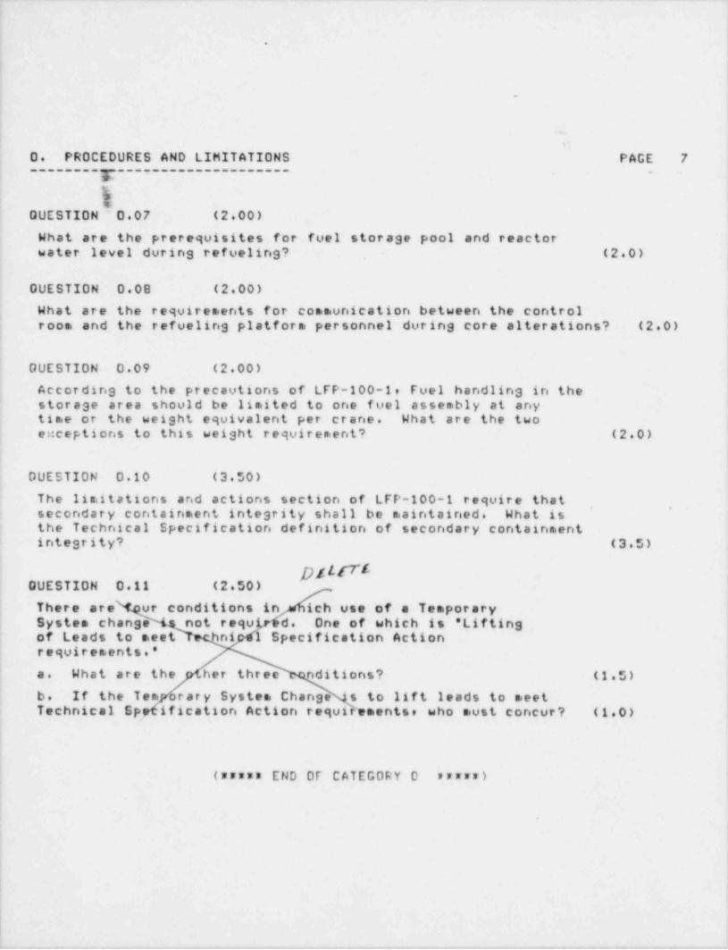
OUESTION 0.07 (2.00)
Whot are the prerequisites for fuel storage pool and reactoreoter level during refueling? (2.0)
GUESTION 0.08 (2.00)
What are the requirements for communication between the control; rece and the refueling platform personnel during core alterations? (2.0)
DUESTION 0.09 (2.00)
According to the precautions of LFP-100-1, Fuel handling in theotorage area should be limited to one fuel assembly at anytice or the weight equivalent per crane. What are the twoo::ceptions to this weight requirement? (2.0)
DUESTION 0.10 (3.50)
The limitations and actions section of LFP-100-1 require that* '
cocondary containment integrity shall be maintained. What isthe Technical Specification definition of secondary containmentintegrity? (3.5)
GUESTION 0.11 (2 50)
! Thore are ur conditions in ich use of a TemporarySystem change not requLr d. One of which is ' Liftingcf Leads to meet -
ni 1 Specification Actionroquirements.'
o. What are the her three nditions? (1.5)
b. If the Tem rary System Change s to lift leads to meetTcchnical Sp ification Action requirements, who must concur? (1 0)
!
(***** END OF CATEGORY 0 arrra)
'.
,
i
|I
-- _ - - . _ . . - ___

. _ _ _ _ _ _ _ _ _ _ _ _ _ _ _ _ _ _ _ _ - _ - _ _ _ _ _ _ _ _ _ _ _ - _ _ _ _ _ _ - _ - _ _ _ - _ _ _ _ _ _ _ _ _ _ _ _ _ _ _ _ _ _ _ _ _ _ _ _ _
.
*
P. EMERGENCY SYSTEMS AND SAFETY DEVICES PAGE 8---------------------------------------- -
\$!EQUESTION P.01 (3.00)
Vontilation ducts are located around the perimeter of all threepools, cask well, and transfer canals.just above the skimmer weirs.
,
c. What are the purposes of having the vent ducts located there?(list two) (2.0)
b. What two ventilation systems can this air be routed to? (1.0)
DUESTION P.02 (4.00)
o. What is the purpose of the Critical L Path for the overheadcrone? (2.0)
b. How is the Critical L Path put into effect? (0.5)
c. What interlocks are in effect when the crane is in theCritical L Path o. ode? (1.5)
DUESTION P.03 (4.50)
What are the refuelins rod blocks? (4.5) ,
; OUESTION P.04 (2.00)
; What is the purpose of the control rod velocity limiter and howdcos it perform its intended function? (2.0)
I*
GUESTION P.05 (2 00)pf t t rr'
i A fuel handling acciWent (repdrt of damage to irradiated fueloosenblies and fuel paa e haust monitor > 100 mR/hr) is listed inyour LSCS emergency act levels as one of two classificationse,
| Copending on certain p) nt qditions. What are the two action
| lovels and the plant-tonditions, connected with each? (2.0)
!
||
(rsyrw CATEGORY P CONTINUED ON NEXT PAGE mummm);
.
- -
.
.
&
$,
P. EMERGENCY SYSTEMS AND SAFETY DEVICES PAGE 9---------------------------------------- _ .
e
s#
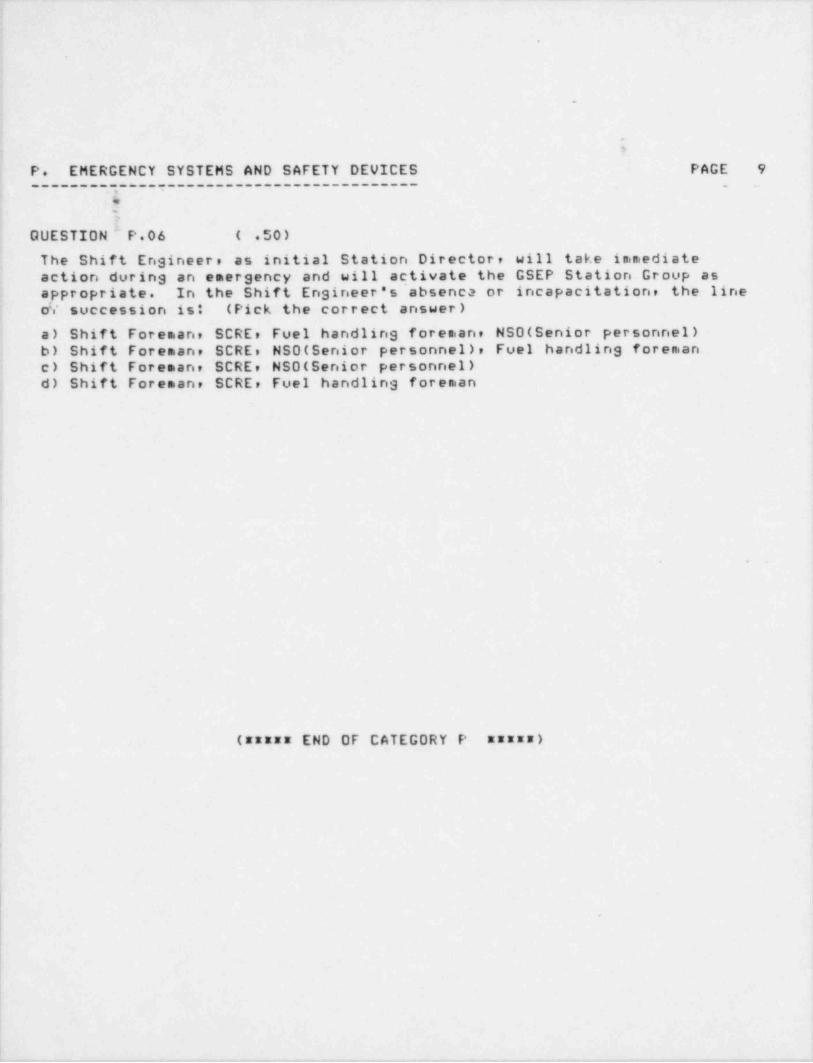
QUESTION P.06 ( .50)
Tha Shift Engineer, as initial Station Director, will take immediatecetion durins an emergency and will activate the GSEP Station Group ascppropriate. In the Shift Engineer's absenca or incapacitation, the lineo!.' succession ist (Pick the correct answer),
o) Shift Foreman, SCRE, Fuel handlins foreman, NSO(Senior personnel)b) Shift Foreman, SCRE, NSO(Senior personnel), Fuel handling foremanc) Shift Foreman, SCRE, NSO(Senior personnel)d) Shift Foreman, SCRE, Fuel handling foreman
:a
i
.
3
(m**xx END OF CATEGORY P **mus)
.
Y
|!
, - - ., . - . - - - , . ,,, . , , - . _ . - . , , , . . - - - . . - , ,,. .. , . - , _ . _ , . - . _ . . - - - . - .-

.-...---..----u----.:--- =: -- - .--. -. :- : .- .
.
.
.
D. HEALTH PHYSICS AND RADIATION PROTECTION PAGE 10
g.
QUESTION' O.01 (4.00)
In the design basis for the fuel pool cooling system it isetated that the RHR system will maintain the fuel poolbalow 150 degrees F in the event of an emergency heat' load. What would be the result (s) of the fuel pool exceedingthis temperature? Include any consequences of these result (s)? (4.0)
OUESTION Q.02 (1.00)4
What is the cause of Cerenkov radiation? (1.0)
OUESTION 0.03 (2.00)
What prerequisites s.ust be siet concerning the upper level of thedrywell during refueling to insure that excessive exposures topersonnel do not occur? (2.0)
,
QUESTION 0.04 (2.00) |'
,
How is norsial personnel access to the refueling floor limited du' ring *
rofueling? (Consider during normal refueling operations and notduring testing.) (2.0)
i
OUESTION Q.05 (2.00) |,
What precautions are taken concerning personnel during !
o) Open vessel subcritical checks? (1.0)
b) Shutdown margin tests, critical checks, and other multiplerod withdrawals with the head removed? (1.0)
P
!
!
(***** CATEGORY 0 CONTINUE 0 ON NEXT PAGE mummm)
'
i.
b
-- -- . - - - - - .. . . - - - . . . . - .

1
1;
.
l
I.
G. HEALTH PHYSICS AND RADIATION PROTECTION PAGE 11
Lt
QUESTION Q.06 (3.00)
What is the definition of:
a) Radiation area? (2.0)' b) High radiation area? (1.0)
OUESTION Q.07 (1.00)
When radiation work involves raising radioactive materials in thefuol pools above established limits, what must be done prior tothe work? (1.0)
QUESTION 0.08 (2.00)
Your Radiation Protection Standards, LRP-1000-1 list eight (8)conditions when a worker should leave the controlled area asquickly as possible, consistent with safety. What are four (4)of these? (2.0)
. .
i
|
!
.
! (m *** END OF CATEGORY Q mamma)| (mmmmmmmmmmman END OF EXAMINATION **mmmmmmmmmmmmm)I
!t
11
.
P
O
i
,
L
|
_. _ . - _ _ . . . , - . . , , , , . . , _ . , . _ _ , _ , _ . -

*.
yyyy}J7f A.
_
M. REACTOR _AND FUEL CHARACTERISTICS PAGE 12_________5g_________________________ .
ANSWERS WhptASALLE 1 -85/06/12-DIMHOCKy
ANSWER M.01 (2.00)
Tpis water is rejected by either the reactor water cleanupsystem drain flow regulator or the fuel pool coolingreject line to the condensate storage tank. (2.0)
REFERENCEFuel Pool lesson plan, pg. 18.
ANSWER M.02 (2.00)
The operator would overpredict the number of fuel bundles necessaryto go critical. (Or the reactor would so critical on less bundlesthen predicted.) This is because most neutrons seen by thedatector during the early portion of fuel load are from thesource. The neutrons from fuel will have an effect only inthe later portions of the graph. (2.0)
REFERENCEFuel Handling lesson plan, pg 32.
, ,
ANSWER M.03 (2.00)
1. The channel's spring clip is located at the corner of the fuelassembly adjacent to the corner of the control rod. (.5)
2. The boss (protrusion) on the fuel assembly bail points towardthe adjacent control rod. (.5)
*
3. The fuel assembly identification numbers on the fuel assembly bailare all readable from the direction of the center of the controlcell. (.5)
4. The fuel channel spacer buttons are on the fuel channel wallsadjacent to the control rod. (.5)
REFERENCELTP 1700-1, pgs 1-2.
i|
\
-. --. ,. - -

- _ _ _ . -. . - _ _ .
.
M. REACTOR AND FUEL CHARACTERISTICS PAGE 13_
ANSWERS LASALLE -85/06/12-DIMMOCK
g-
ANSWER M.04 ( .50)
c.
7EFERENCELTP 1700-1, pas 2 and attachment A.
CNSWER M.05 (3.50)
o) More cooling is required in higher powered bundles. When the twophase flow is increased in a bundle there is more resistance to flow.This tends to reduce the flow in the nigher powered bundles andincrease the flow in the lower powered bundles. The orifices in thefoal support pieces have a larger pressure drop than the fuel, andtherefore any change in pressure drop across the fuel results ininsignificant change to the core flow pattern. (2.0)b)Four lobed central zone orificing, (largest orifices), four lobedperipheral zone orificins, (next largest), and peripheral fuel supportorificing. (These are the smallest orifices.)
REFERENCE - -
Rocetor Vessel lesson plans, pgs 22-24 and figure 2-18.
ANSWER H.06 (1.00)
The finger springs maintain a constant byp, ass flow at theinterface of the channel and fuel bundle lower tie plate. (1.0)
REFERENCEFual lesson plan, pg 11.
ANSWER M.07 (1.50)
! Tio rodt. (.5)
! Water spacer capture rods. (.5)'
Stcndard rods. (.5)
REFERENCEFool lesson plane pg 11.
| 4" r y<+ dkpl- t, .)
j ,ch; y 3.4 hJn.14
:
I__ _ . , . . _ _ . _ . - . . . . , _ __ , _ _ _ _ .

_- --- =_- . . _ _ _ -
.
_
M. REACT.OR AND FUEL CHARACTERISTICS F' AGE 14,
ANSWERS LASALLE 1 -85/06/12-DIMHOCK
.
ANSWER M.08 (1.50)
Cny 3 at .5 ea. -
1. Channels the coolant flow upward through the fuel bundle.; 2. Provides a bearing surface for the control rod blades.
3. Provides protection for the fuel rods during fuel handling.4. Provides the primary resistance to lateral acceleration'
looding on the fuel assembly.5. Insures correct control rod passage clearance by the use ofctoinless steel buttons at the top of the channel.
REFERENCEFool lesson plane pgs 9-10.
_
ANSWER M.09 (1.00)'
1. To provide reactivity control (extend core life) (.5)2. Distributed axially to flatten axial power distribution. (.5)
REFERENCE, ,
Fual lesson plane pg 19.
6 >$ANSWER M.10 (4.00)
c) The change in reactivity associated with a positive unit changein a specified plant parameter. (1.0)
| b) Moderator temperaturee fuel temperature (Doppler), and voids. (1 5)'
c) They help in control of the reactor. Any increase in the measuredunit will cause a negative reactivity insertion which will preventon uncontrolled power excursion. (1 5)
REFERENCEILPRT
_
h
|
|,
_ .- .. .. . -- - -_ ,
_ _ _ _ - _ ___ _ _ _ _ _ _ _ _ _ _
_
,
:N. EQUIPMENT, INSTRUMENTATION AND DESIGN DESCRIPTION PAGE 15
--------- =------------------------------------------- . .
CNSWERS' LASALLE 1 -85/06/12-DIMMOCK
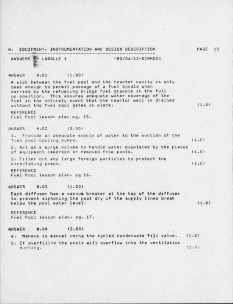
CNSWER N.01 (1.00)
A clot between the fuel pool and the reactor cavity is onlyd3GP enough to permit passage of a fuel bundle whencorried by the refueling bridge fuel grapple in the fullup position. This assures adequate water coverage of thefool in the unlikely event that the reactor well is drainedeithout the fuel pool gates in place. (1.0)
REFERENCEFool Fool lesson plan pg. 15.
ANSWER N.02 (3.00)
1. Provide an adequate supply of water to the suction of thefoal pool cooling pumps. (1.0)
2. Act as a surge volume to handle water displaced by the piecesof equipment ime.ersed or removed from pools. (1.0)
3. Filter out any large foreign particles to protect the, ,
cireviating pumps. (1.0),
REFERENCEFuol Pool lesson plan, pg 16.
ANSWER N.03 (1.00)
Ecch diffuser has a vacuum breaker at the top of the diffuserto prevent siphoning the pool dry if the supply lines break *
,
balow the pool water level. (1.0);,
REFERENCEFual Pool lesson plan, pg. 17.
CNSWER, N.04 (2 00)
O. Makeup is manual using the cycled condensate fill valve.. (1 0)
b. If overfil17d the pools will overflow into the ventilationducting. (1.0)
:
|
|
-_ _ _ _ _ _ _ _ _ _ _ _ _ _ _ _ _ _ _ _ _ _ _ _ _ _ _ _ _ _ _ _ _ _ _ _ _ _ _ _ _ _ - _ _ _ _ _ _ _ _ _ _ _ _ _
.
1
N. EQUIPMENT, INSTRUMENTATION AND DESIGN DESCRIPTION - PAGE 16_ _
________;;___________________________________________CNSWERSjg- LASALLE 1 -85/06/12-DIMHOCK
' YfREFERENCEFual Fool lesson plan, pg. 33.
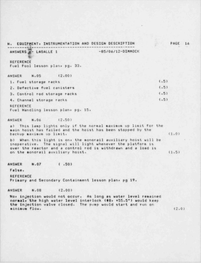
ANSWER N.05 (2 00)
1. Fuel storage racks (.5)
2. Defective fuel canisters (.5)
3. Cont'rol rod storage racks (.5)
4. Channel storage racks (.5)
; REFERENCEFool Handling lesson plane pg. 15.
CNSWER N.06 (2.50)
o) This lamp lights only if the normal maximum up limit for thecoin hoist has failed and the hoist has been stopped by thebockup maximum up limit. (1.0)
b) When this light is one the monorail auxiliary hoist will be -
! inoperative. The signal will light whenever the platform isevor the reactor and a control rod is withdrawn and a load isen the monorail auxiliary hoist. (1.5)
CNSWER N.07 ( .50)
j Folse.'
REFERENCEPrimary and Secondary Containment lesson plan, pg 19.>
ANSWER N.08 (2 00)
ND, injection would not occur. As long as water level remainedn:rmale'the high water level interlock (48, +55.5') would keep
,
th] injection valve closed. The pump would start and run on'
oinimum flow. (2.0)
|
||
I
. - - - . _ , - _- _ - - . . .,, . - _ . ._. - _. ._-

_ _ _ _ _ _ _ _ _ _ _ _ .- . _ _ _ _ _ _ _ _ _ _ _ _ _ _ _ _ _ _ _ _ _ _ _ _ _ - _ _ _ . _ _ _ _ _
-;
N. EQUIPMENTe INSTRUMENTATION AND DESIGN DESCRIPTION . PACE 17
: C.NSWERS- LASALLE 1 -85/06/12-DIMHOCK -
*
; . p'- i..
I
C.NSWER N.09 (2.00),
High drywell pressure (+1.694) and'or (1.0)
Lee reactor water level (-129') (1.0)
REFERENCELPCS lesson plans, pg 12.
e
I
i
!
|i
J
e 6
|
I
!
>
|n
Mi
f
,
I
*
t
.
.
4
0. PROCEDURES AND LIMITATIONS PAGE 18,
ANSWERS' LASALLE 1 -85/06/12-DIMMOCKt
.
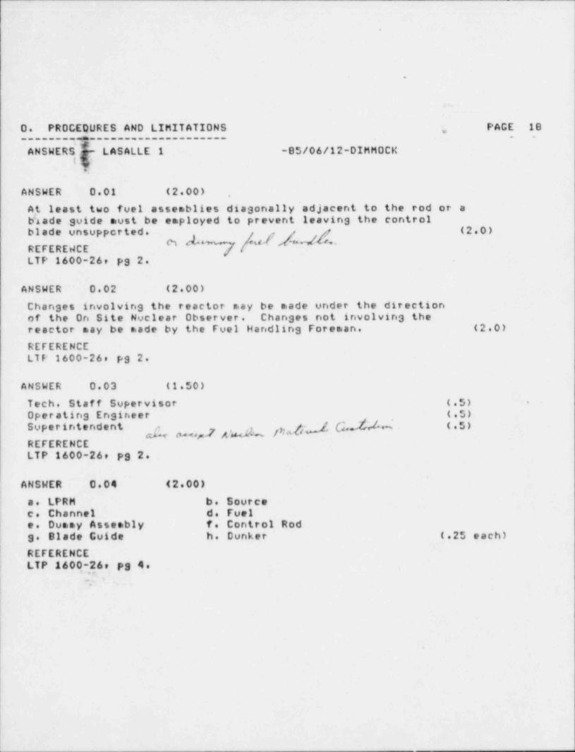
ANSWER 0.01 (2.00) ,
A,t least two fuel assemblies diagonally adjacent to the rod or ab'Acde guide must be employed to prevent leaving the controlb1cde unsupported. p (2.0)
REFEREWCE ] ''
LTP 1600-26, pg 2.
ANSWER D.02 (2 00)
Changes involving the reactor may be made under the directionof the On Site Nuclear Observer. Changes not involvin3 theroactor may be made by the Fuel Handling Foreman. (2 0)
REFERENCELTP 1600-26, pg 2.
ANSWER 0.03 (1.50)
Toch. Staff Supervisor (.5) *
Oporating Engineer (.5)
7,g,_f C,.fM (.5)Superintendent3y ,
REFERENCELTP 1600-26, pg 2.
ANSWER 0.04 (2.00)
i c. LPRM b. Source: e. Channel d. Fueli o. Dummy Assembly f. Control Rod
) 3. Blade Guide h. Dunker (.25 each)
REFERENCE; LTP 1600-26, pg 4.i a. ..
:
|
.
'_

1i
i
I
-
t
- . -
D. PRO,C,EDURES AND LIMITATIONS PAGE 19________ ____.________________ _
ANSWER $ -- LASALLE 1 -85/06/12-DIMMOCK
;.
ANSWER 0.05 (3.00)
The addition, removal, relocation or movement of fuele sources,incore instruments or reactivity controls within the reactorpressure vessel with the vessel head removed and fuel in thevossel. (3.0)
REFERENCETcchnical Specification definition 1.7, pg 1-2.
ANSWER 0.06 (2.00)
At least two source range monitor channels shall be OPERABLE andfully inserted during CORE ALTERATIONS. One of the OPERABLE SRMchannel detectors shall be located in the core quadrant whereCORE ALTERATIONS are bein3 Performed and one shall be locatedin an adjacent quadrant. (2.0)
,
REFERENCELFP-100-1, Ps 2.
- -
ANSWER 0.07 (2.00)
As a minimum, 23 feet of water shall be maintained over the topof active fuel in irradiated fuel assemblies seated in the spentfuel storage pool racks. (1 0)
Ao a minimune 22 feet of water shall be maintained over the topof the reactor pressure vessel flange. (1.0)
REFERENCELFP-100-1, pg 2.
I'
.
.
t
O. PROCEDURES AND LIMITATIONS PAGE 20________ ,_____________________ _ _
CNSWERS*-- LASAI.LE 1 -85/06/12-DIMHOCK
$?a-
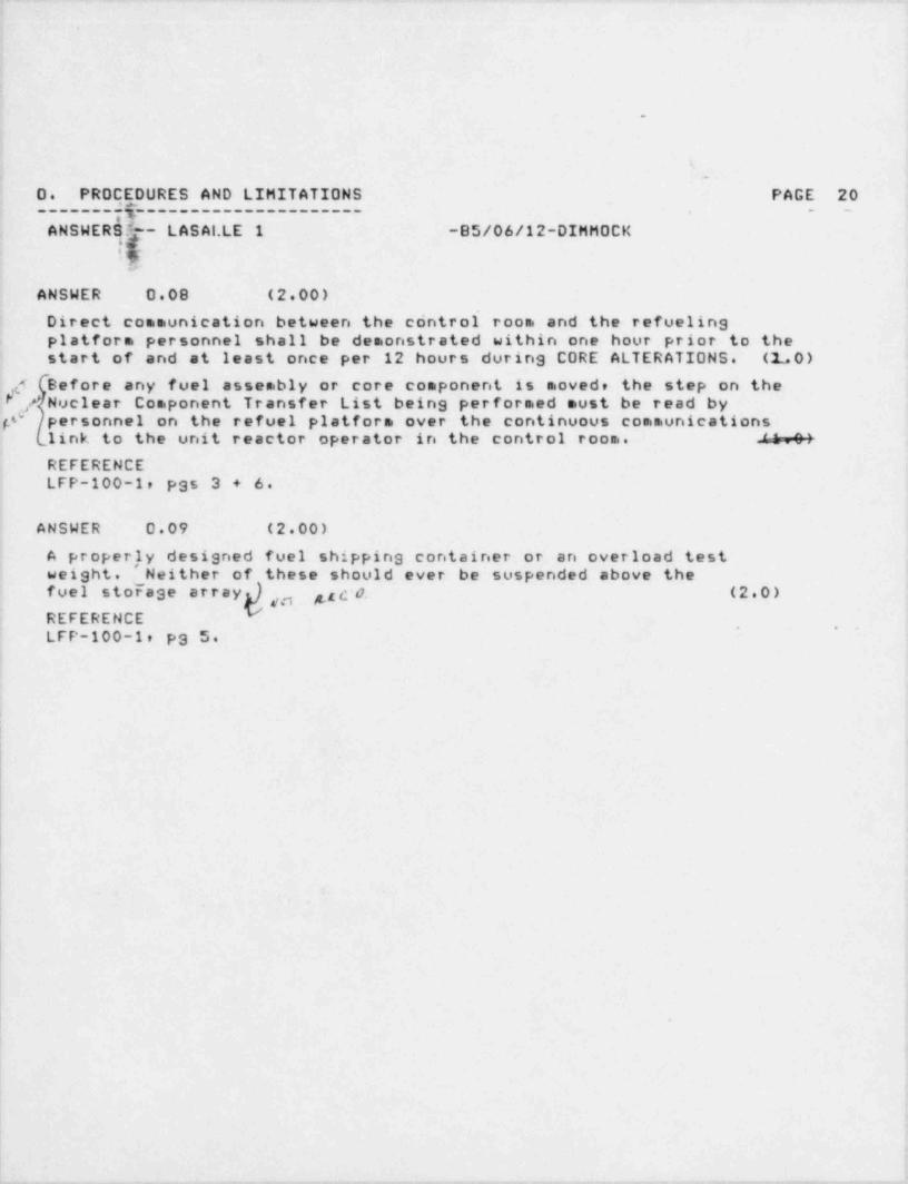
ANSWER 0.08 (2.00)
Direct communication between the control' room and the refuelinsplotform personnel shall be demonstrated within one hour prior to thestort of and at least once per 12 hours durins CORE ALTERATIONS. (1,0)
g5 Bafore any fuel assembly or core component is moved, the step on theP
p'j NuclearComponent Transfer List being performed must be read by
parsonnel on the refuel platform over the continuous communicationslink to the unit reactor operator in the control room. 'i.01
REFERENCELFP-100-1, pas 3 + 6.
ANSWER 0.09 (2.00)
A proper,1y designed fuel shipping container or an overload testw21sht. Neither of these should ever be suspended above the
storasearray),, g g c N0. (2.0)fuel
REFERENCE, , .
LFP-100-1, ps 5.
|
,
-
P
. :
:,
,
,-.-.,,e.- . - . . - - . . . - . , . - - , - ,-
o
s
.
..
O. PROCEDURES AND LIMITATIONS PAGE 21_______2y____.________________ _ _
ANSWERSI - LASALLE 1 -85/06/12-DIMMOCK
!=
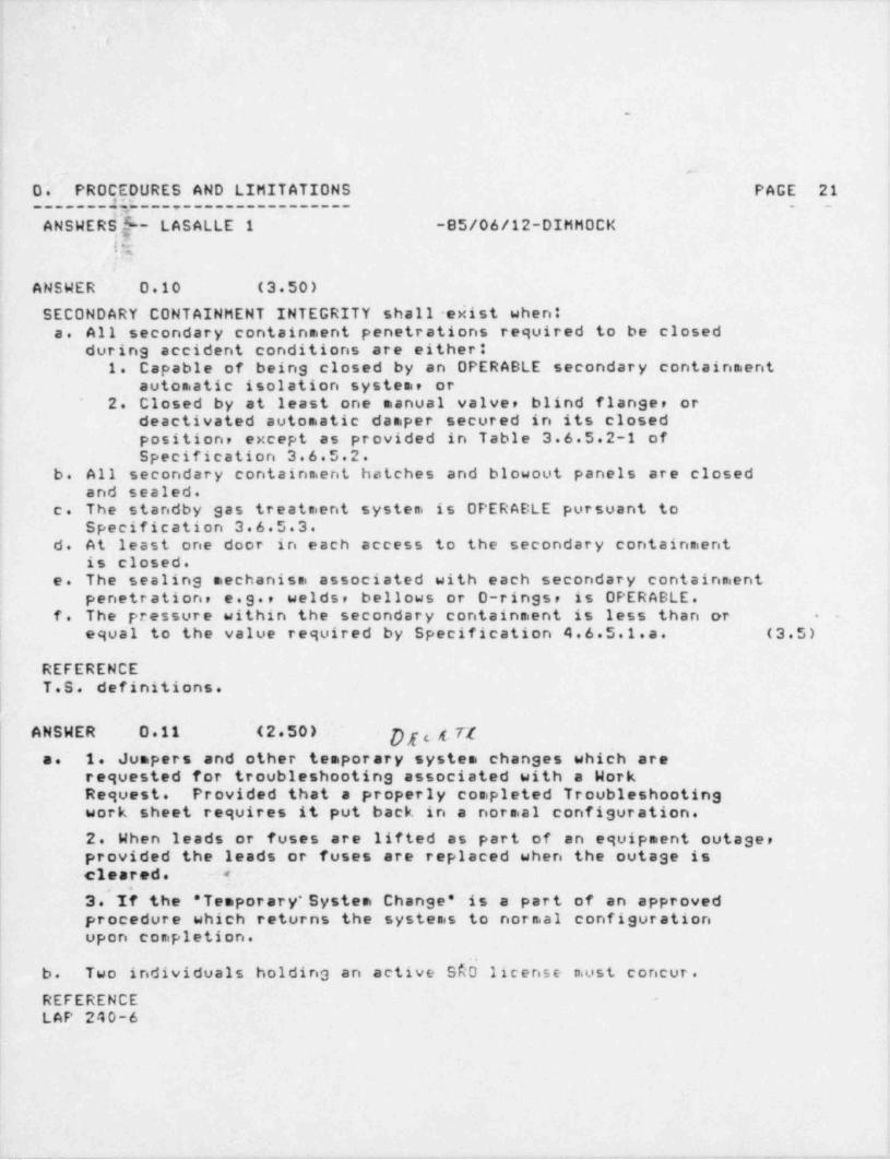
ANSWER 0.10 (3.50)
SECONDARY CONTAINMENT INTEGRITY shall -esist when:c. All secondary containment penetrations required to be closed
during accident conditions are either*1. Capable of being closed by an OPERABLE secondary containment
automatic isolation system, or' 2. Closed by at least one manual valve, blind flanger or
deactivated automatic damper secured in its closedposition, except as provided in Table 3.6.5.2-1 ofSpecification 3.6.5.2.
b. All secondary containment hatches and blowout panels are closedand sealed.
c. The standby gas treatment system is OPERABLE pursuant toSpecification 3.6.5.3.
d. At least one door in each access to the secondary containmentis closed.
e. The sealing mechanism associated with each secondary containmentpenetration, e.g., welds, bellows or 0-rings, is OPERABLE.
f. The pressure within the secondary containment is less than or - -
| equal to the value required by Specification 4.6 5 1.a. (3.5)
REFERENCEi T.S. definitions.l
ANSWER 0.11 (2.50) g o 4 r/c. 1. Jumpers and other temporary system changes which are
requested for troubleshooting associated with a WorkRequest. Provided that a properly completed Troubleshootingwork sheet requires it put back in a normal configuration.
( 2. When leads or fuses are lifted as part of an equipment outager| provided the leads or fuses are replaced when the outage isI cleared. 5'
4, .
| 3. If the " Temporary * System Change' is a part of an approvedprocedure which returns the systems to normal configurationupon completion.
b. Two individuals holding an active S$b license must concur.
REFERENCELAP 240-6
_ _ _ _ _ _ - . -- _ .

-
.
--
P. EMERGENCY SYSTEMS AND SAFETY DEVICES PAGE 22------------- ----------------------- .. . -
ANSWERS' L-- LASALLE 1 -85/06/12-DIMMOCK*
(7;-I '
ANSWER P.01 (3.00)
a. Evacuate air from directly over'the surface of the pools to.
keep airborne radiation levels to a minimum and to keep therefueling floor relative humidity as low as possible. (2.0)
b. The reactor building ventilation system or the Standby GasTreatment system. (1.0)
REFERENCEFuel Pool lesson plan, pg 18.
ANSWER P.02 (4.00)
o. The Critical L Path is a restricted movement mode of operationfor the overhead crane. The purpose is to keep the spent fuel caskfrom traveling over the spent fuel storage pool and to allow thecask to travel only over structural members that can support acask drop. (2.0)
b. It is put into effect by a key-operated switch (Normal-Cask) ,
in the crane's cab. (0.5)_
c. In the ' cask' mode crane travel is limited to 18.5 FPM,The spent fuel cask may only be 6" off the refuel floor or
; traverses by the crane will be prevented.The bridge / trolley will not operate simultaneously. (1.5)'
li REFERENCE
Fual Handling lesson plan, pas 11,12.!
.
i
_ _ _ _ _ _ _ . - , - _ - - - -
.
.
P. EMEqGENCY SYSTEMS AND SAFETY DEVICES PAGE 23_____________.__________________________ . _
ANSWER $I-- LASALLE 1 -85/06/12-DIMHOCK1r4-
t*
ANSWER P.03 (4.50)-
A rod block will result whenever any of the following groups ofconditions are satisfied.1) If the mode switch is in start-up andi
a) The refueling platform is near or over the core, orb) If the service platform hoist is loaded. (1.5)
2) If the mode switch is in refuel andia) A second rod is selected for withdrawal when all rods are
not full in, or
b) The service platform hoist is loaded, orc) The refueling platform is near or over the core and one or
sore of the following existi(1) Trolley mounted hoist loaded. '
(2) Frame mounted hoist loaded.(3) Fuel grapple loaded. (3.0)
REFERENCEFuel HandlinS lesson plan, pas 19-20.
, _
!
ANSWER P.04 (2.00)
Its purpose is to limit the free fall rate of the blade in the event'
,that a control rod should become uncoupled from its drive mechanism.,
| .This will limit the rate at which reactivity is , inserted into the, core, and prevent fuel damage during a rod drop accident. The falling
~
l action of the blade creates a large pressure drop across the velocitylioiter due to the multiple directional change of flow. The small
, radial clearances between the velocity limiter and the CRD guide'
tube also restricts the rate of fall. (2.0)
REFERENCECRD Mechanism lesson plan, pg 8.
,
! -
|ANSWER P.05 (2.00) pp.f q
| It is an ALERT if the standby gas treatment system is operable, (1.0)| c- it is a EITE EMERGENCY if standby gas treatment system is NOT
cperable. (1.0)
.
. _ - _ _ _ - - . - - - - . _ -
=- - - - - . .
_ _ _ _
.
i
.
-
P. EMEQGENCY SYSTEMS AND SAFETY DEVICES PAGE 24_______3________________________________ __ _
LASALLE 1 -85/06/12-DIMMDCKANSWER --
g g-
REFERENCE'
LZP-1200-1, pg 11.-
.
ANUWER P.06 ( .50)-
c
REFERENCEGSEP plan, section 4.2, pg 6.
!
. . _i
j
* 9
|
.~.
& M N
*
|
|.
. . - - .. -_ .. . . _ _ _ _ _ _ _ _. _- _
.
.
.
.
Q. HEALTH PHYSICS AND RADIATION PROTECTION PAGE 25-------- ,---------------------------------- . -
ANSWERS 5-- LASALLE 1 -85/06/12-DIMHOCK?:
ANSWER 0.01 (4.00)
Local boiling would occur at a pool outl'et temperatureof approximately 150 degrees F. The resulting turbulence.ould knock loose crud and greatly increase pool activity.At higher temperatures the cation resin would break down.This would release activity back into the pool. A later effectwould be the release of sulphates which would lead to dis-solution of crud from fuel assemblies and increasedactivity in the pool. In addition, airborne activitywould increase because of more evaporation and becauseradioactive iodine and noble gases would come out of solutionrapidly. (4.0)
REFERENCEFuel Pool lesson plan, pgs 9-10.
ANSWER 0.02 (1.00)
This light is caused by high speed particles passing through the - -
water at a speed greater than the speed of light in water. (1.0)
REFERENCEFual Handling lesson plan, pg 33.
.
ANSWER G.03 (2.00) -
..
| Th9 upper level of the drywell aust be monitored by Rad Protection| or roped off and access prohibited during CORE ALTERATIONS. (2.0)
A LS O M > TA t c on d 0; c a mt. chu rLREFERENCELFP-100-1, pg 3.
| ANSWER G.04 (2.00)
Parsonnel access to the refueling floor,will be limited to asingle door at the refuel floor elevation and all remainingdoors and elevator access shall be locked. (2.0)
:
e
l

.
i
e
|
|-
!
l .
IO. HEALTH PHYSICS AND RADIATION PROTECTION PAGE 26_______a5____._____________________________ _ _
IANSWERS -- LASALLE 1 -85/06/12-DIMMOCKda
REFERENCELFP-100-1, ps 3.
-
.
ANSWER 0.05 (2.00)
e) All personnel shall remain outside of the line of sight of thecore during open vessel suberitical checks. (1.0)i
b) During shutdown margin tests, critical checks, and other multiplerod withdrawals, with the head removed, all personnel are prohibitedentry to the refueling floor. (1.0)
REFERENCELFP-100-1, ps 5.
I ANSWER 0.06 (3.00)
a) Any area accessible to personnel in which there exists radiation;
l at such levels that a major portion of the body could receive in anyone hour a dose in excess of 5 millilrem, or in any 5 consecutive dayso dose in excess of 100 millites.. ( 2. 0 ) --
b) Any area accessible to personnel in which there exists radiationat such levels that a major portion of the body could receive in anycna hour a dose in excess of 100 millirem. (1.0)
REFERENCELRP 1000-1e ps 8.
ANSWER G.07 (1.00)
Tha Radiation-Chemistry Department shall be informed and/or consulted! before the fact so that a radiological evaluation can be made. (1.0)
REFERENCELRP.1000.1r"P'S 11*
~ '
:.4. sg - : - - ._
. -- -.-
a
, , . - . , . , , . ,. , , . , , - . - . .- - , - , . , . . , . -

,
t
.
G. HEA(TH PHYSICS AND RADIATION PROTECTION PAGE 27------ ,----------------------------------- . .
ANSWERS, -- LASALLE 1 -85/06/12-DIMHOCKli.
ANSWER Q.08 (2.00)~
Any four (4) at .5 es. -
a) When instructed or signaled to do so by the Radiation-Chemistrydepartment.
b) Failure or suspected failure of personal protective equipment.c) Unexpected deterioration of radiological conditions.d) In the event that the worker's current accumulated dose equivalent
status becomes uncertain for any reason or dose equivalent is equalto the exposure authorized for the job.
o) " Assembly" sirens sound practice or actual.f) Completion of work assignment.3) Injuryh) Unexpected area radiation monitor alarm and the area dose rate i s
unknowr..
REFERENCELRP-1000-1, pgs 12 and 13.
. . .
o
O
||
Y \o
-- ,
0
!l
.
- _ _ - , _ . , . , . , _. -. . - . _ _ . _ - , - , ,.-, . . _ . , , _ . - . _ . , . . _ , - .- -
. _ _ _ _ _ - _ _ _ _ _ _- _ _ _ _ _ _ _ _ _ ._ __ _ _ _ _ _ _ _ _ _ _ _ _ _ _ _ _ _ _ - _ _
'
gi' ;Qg zu
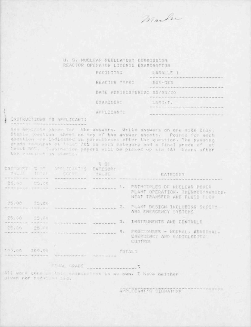
U. S. NUCLEAR REGULATORY C0tiMISSIOt1REACTOR OPERATOR LICENGE EXAMINATION
FACILITY: LASALLE 1_----___ _____-______-___
REACTOR TYPE: BWR-GES__--____-__-----__-_ ____
DATE ADMINISTERCD: 05/05/20-
_________-___-___________
EXAMIt!ER: LANG,T.----____---__--___--____-
!. APPLICANT:_______-____-___-__-____-
n
| INCTRUCTIONS TO APPLICANT:_--___---___----______-__
Ue s o _. .- : t n papar for the answers. Write answers on one side only.S t a p l -e ," c. tion cheat on top of the answer shent.. Points for eacho,ves t ion ;re indiented in parentheses after the questicn. The pansinsg r a ct o r > t u. r e - at 1 ,,t. 70% in tach category and a fiorl grndo a# atlenst '? c - w ::, t r. c '. t o n papers will be pickod up sin (6) hours afterti,e -: ' : ':en tartc..
% OFC A T '' ". r R Y % "~ li T '_ :C WT ' S CATEG00Yr
" c. . J ' Tr't! '' C r ' _ ' _ _ _ _ _ _ _) A!.UE CATEGORY___-____ -_--__ ___-____-__ ______ ___ __--____________________ne r, n -c er
_ _ " _ " _ ' - _ ' _ _ - _ ' _ " _ _ ' _ ' 1. PRINCIPLES Or NUCLEAR POUER' *
_ _ _ _ _ _ _ _ . . _ _ ________
PLANT OPERATION, THERMODYNAMICS,HEAT TRANSFER AND FLUID FLOW
"" *00 '" *Or_-_"_____ _ _ " " _ _ _ ' 2. Pl. ANT Dr.SICN INCLUDING S/,FETY
'
_ _____--_-__ __-_____
AND EMERGENCY SYSTEttS,
-e - ,e ., -
_ ' ' "_ _ _" n___-_"-__ 3. INSTRUMENTS AND CONTROLS* ~ * * *
_ - __-___ ____ -__-____
-- , ., .
_ Z Zo_-_ _ ' " _ .' Ec 4. PROCCDURES - NORMAL, ADNORMAl,_ ___________ ________
EMEPGENCY At'D RADIOLOGIC A'CONTROL
.
: i 9 ^>. 0 0 100.00 TOTAL ^.t--__ --- -__--- __._ _____- ____-___
~ 9 ". , .,.,7>.- .'6" c'
i _____-___ _______1
i *): wore d e, n e c r. t h;: e .* a m i n .-.f .' o n is nv own. I have neither.
| yivan .id.nor rec n .
!t
| ______-_____-__-________-_____-____| APPi. IC AN T ' S CICHATMPc
|

1. PRINCIPLES OF NUCLEAR POWER PLANT OPERATION, PtGE 2
~~~~ 55EE66YUdU5C57 5EIT ~TREU5E55' DUD fL 5D fL6UT- ~
____________________________________________
| QUESTION 1.01 (3.00)|
Preifly explain or define the following terms:
a. Thermal neutron. (1.0)
b. Reactivity. (If an equation is used in your ar swer then explainthe equs*ien.) (1.0)
c.Ternsient period. (1.0)
n ?
42 #
fOUESTION 1.02 (2.00) =w''' ~'
Enplain how and wn/ Rod Worth changes for the following conditions.a. Rod vorth of s center rod compared to a peripharal rod. (1.0)
b. Rod worth when p .1 3nt conditior.s change fron cold to hot at 1%power. (1.0)
c . Rod wor th when plant cor.ditions change fron hot at 1% powartn hot 7t 100": Power. (1.0)
OUESTICN 1.03 ( .00)
Which of the fallaving mtstenents best describes the behavior of Menonand samarium.
a . f.f t e r e reactor sermo occurs, , anon concentration initiallyi increawr and s a m ts r iu m decreases.
b.After reactor scram occurs, nenon will eventusily decay to ar,
'
xenon 1:e condition but s sanarium free condition will not occurunt.il sfter the nout refueling outage.
c.The anon and samari um peak concentration following a scram occursat - .'an independan'. of the previous power leve'.
d.Xen3n o rc en t r a t i on mav increawe or decrease when taking tha plantr
f e r, ,,- Pat Standby 1 0 full power but =smarium will c1 ways decreased u r : ". 3 this transiont after the core's equalibriui., samerium hasb.u c. .cwhod.'
'~:frr CATEGORY 01 CONTINUED ON *JEXT PAGF ***xx)
{!
I
1. PRINCIPLES O'- NUCLE A't POWER PLAN 1 OPERATION, PAGE 3
~~~~ UEE50390.IUIC5~~UE5Y~TE5U5E55~5UD'ELU56~ELOUT---------------------------.-----------------
GUZETION 1.0a (1.00)
A ::,o d e r s t o r is nece=sary to slow neutrons down to thermal energies.Which of the following is the most correct reason for opreating withthernal instead of fait neutrons.
c. Increased nautron efficiency s i n c .-- thermal noutrons are less likelyto leak out of the ccre than fast neutrons.
b. Reactors operating primarily on fast neutrons are inherentlyunstable and have a higher r i s t. of going prompt critical.
c.The fissian c r o -: s section of the fuel is much higher for thermalneutrons than for fast neutrons.
d.30?pler and ooderator ternar atur e coefficients become positivece neutron enercy increat.es.
O'ESTION 1.05 (1.00)
Ubich of *he "n11 hin-: c t a t e ;:.e n t s best describes the c o n d i t i t n k n o i..' n e r,Cond.'neal.e C erer,sicn"?
a.Can lead *o cond:nsate p u re e r.v i t = t i o n if condensu'_e depr essi on in.
t,oo grrvt.
b.Docreacec a= he'vell level r isee ,
c. Reduces Pan! ine ._ycle efficiency,
d.Increaees as condensate temperature increases.
t.
G '.t : S T I O.J 1.04 (1.00)
'J h i c h of th . Following statementn most correctly completes the following,entence: C'.aparture frcn nuc?<-ate boiling is the point uhere,
a . 'J o i c ' r : tion .que1s one.
b.lbs io at tr ,ns.fr, mechanico chrnges from nucleate boiling io singlephase convection.
c . R. o t e heat ' -nrfer becomes i r.;ign i f i c a nt .',
d.The h a r. t * r ant f. r r,te au-tainable with nucleate boiling reachen.
| t s m a z.it o n .
c:rx: r.TEGORY 01 COHTIt!UED Oh NCXT tAGE ms)
|
. , _ - .,
.
1. PRINCIPLIS OF Nt! CLEAR POWER PL ANT OPERATION, PACZ 4________________________________________________
T H E R t:C D Y N At'IC S , HEAT TRANSFER AND FLUID FLOW____________________________________________
GUESTION 1.07 (1.00)
Which of the following s t a t e ru e n t s is NOT correct concerning decay heat?
a.Is the heat produced by the energy released from the radioactivedecay of fission products.
b.Can be determined by the reading on the SRM's when the reactor isshutdown.
c.Is spproximately 4% of the total energy released from fission.
d.In still a sisciificant contributor to the energy in the reactor corefor approximstely two hours after the reactor has been shutdown.
QUESTION 1.00 (1.00)
Which of the follouing is NOT one of the four contributors or factorsthat establish equilibrium xenon?
'
a.Dir ect prodt'ction from fission.
b. Decay of Iodine.
c.Cecay of 'enon t. o Sa.
d. Decay of ; 9 ci a n to Cs.
QUESTIO." 1.Oo (1.00)
Figure 1.12 is a representation of how the resonance peaks of U-20G"fistten out' or Dorpler broaden as fuel teropor atur o increases. 'J h i c hof the foll utn3 are the correct labels for the n and y a:tes'
a.X is neu'ron Flux, and Y is interaction rate.
b . '' is neutron enersy. and Y is microscopic capture cross section.
c.X it :r t u c, densttu of U-200- and Y is neutron f i tn .
d.'/ intm actior, cate, and Y is neutron density._,
(nx** C AT E';0RY 0: CCNT rNirED ON NEXT PAGE *rrav)
|!
|
|
|i!
-- -- -- _ _

-. . _ ..__- . .
1. PRINCIPLES OF NUCLEAR POWER PLANT OPERATION, PAGE 5
~~~~iEEE566YU555C5I~EE5I TE555EER AR5 FE0i5 FE60-
____________________________________________
GUECTION 1.10 (1.00)
Th, rstic of Pu-207 and Pu-240 atoms to U-235 atoms changes over corelife. Which of the pairs of parameters listed below are most affectedby this change?
I a.hoderator temperature coefficient and doppler coefficient.
b. Doppler coefficient and beta,
c. Beta and moderator temperaturer coefficient.
d. Moderator t e n.p e r a t u r e coefficient and neutron generation time.
GUESTI0tt 1.11 (2.00)
A centrif" gal pomp is operating at 3600 RPM with a pump head of 160 FT.Pump speed is then reduced so that pump head is 100 FT. What is the newpump speed? Shcw all w o r t:. .
GUISTION 1.12 t3.00)
{ Reactor power s 'eing increased on s 50 second period._.
,i . Mow long doa: 't tske to incres.e power from 2kw to imo? (1.0)
b.What reactt nty is associated with the 50 second pnriod? (1.0)
e c.What is the !;eff durin3 the power increase? (1.0)1
i GUESTIPN 1.13 (1.00)-
\
Srior to s tar tup 'cIl rods in) the SRM count rate is 20 CPG and l' eff.is 0.96. T' the control rods are pulled to give a d e l t r. It o f +0.035 whnt,
! count rato on the SRM's could be expected when the, period becomet infinite?
r. . 10
[ b. 160 -
c. 00
d. 120
(rvirI CATZCDPY 01 CCNTINUED Ot' NFXT PAGE xxxrr)
i,
I
l
||
l
i
|_ . _ _ _ _ _ _ , , . , .___..x,. _ -. . .-_ , - - . . - . - - . - . _ - - - - , - m.---- - - -i ,
1. PRINCIPLES OF NUCLEAR POWER PLANT OPERATION, PAGE 6
~~~~555EUUb UIU5E5~~5Eh5"TR5U5EEk~ DUD fEU53 EL6U~
____________________________________________
GUESTION 1.14 (1.00)
Following an toto initiation of RCIC at a pressure of 800 psig., reactorpressure decrotres to 400 pris. Assume the RCIC is operating'at designed
*woich of the f ollowing statenients best describe the paranieter changes inthe RCIC.
a.The RCIC floo to the reactor i n c r e a s e r. RCIC pump discharge headremains ccnctant and RCIC turbine speed increases.
b.The RCIC flow to the reactor rem ins constant, RCIC pump dischargehesd decrassar and the RC!C turbine speed decreases.
c .The ::CIC f':u to the reactor remains constant, RCIC pump discharschead rems:ms constant and RCIC turbine speed remains constant,
d.Ti.e RCIC T' m ,a the reactor decreases, RCIC pump discharge headincreas+s ;nc the turbine speed rensins constant.
DUESTIPN 1.:" I?.00)
f:c i l i n 3 v a t c+ r- a: s are designed to have "under modersted cores *,Which s t s t c n u..t OZr describes under moderated?
a.Thr ra';o ' ' soderator to fuel is such that the t e mp r: r a tur e andvold coefficient will both oe the same(both positive or bothnegitiva).
; b.The ratio of moder r. tor /f uel is such that increasing moderatordensit- increases M eff.
I. c.The r.ntio of modarctor to fuel is such that the s m o o rit of under
n.oder r t a n .i r c r e n s e L during core 1ife.
d.The r ' 10 of fuel t o r.io d e r s t o r is such thzt incr easi ng moder 1. torI dens >'. ail; d e- c r a s, s e || eff.
I
|*
||,
(:nn C AT E r,UT: ( 01 CONTINUED ON ttXT PAGC **xxx)
l
l
_ _ _ _ _ - - - _

.- -- - _ . .. _
4
1. PRINCIPLES OF t/UCLEAR POWER PLANT OPERAT10tle PAGE 7
~~~~55EEEU6 E555C5I"5E55"TEEU5EEE~5UU~ELU56~ELUU'
--------------------------------------------.
CUESTION 1.16 (0.00)
. Giva the effect (Increase, Decrease, or No Charige ) and the reason for| the effect of the following on Critical Power.
a. Increase in reactor prossure. (Include pressures above and below800 psia, in your answer.) (1.0)
b. Increase in inlet subcooling. (1.0)
c. Increase in coolant flow. (1.0).
:
.
.
!.,
2
.
Iv7tvr END OF CATEGORY 01 *****)
i
.
J
9
I
E
1
.
--- <- , , - - , ,n.---o. -- , - , . r . , . - - - , , - - , , , , - - - -, , - .,
- ._ , . - . - . .. -. . ~ . - . - .__ . _. - -. . - -
4
,
!
!
2. PLANT DESIGN INCLUDING SAFETY AND EMERGENCY SYSTEMS PAGE 8-------------------------------------------------------
i
i
QUESTION 2.01 (2.00)1
| In regards to the CRD system:
a.How does the on-line flow control valve respond following a scram?(1.0)4
; 'b.Cretfly e::pl a in the operational consequences of the scram inletvalve sticking shut on a scram. Consider the followins two situationsand the effect(s) on 3 single CRD HCU'mechaninm. (1.0 |
| 1.At 200 psig. Reactor Pressure.] 2.At 000 esi 3 Reactor Pressure.i
j GUESTION 2.02 (2.50) '
! L'h a t a r e fivo indications you could check to verify Standby Liquid Controli init:stion? (0.5 each)i
L
,
) QUEOTION 2.02 (2.50)<; Answer the fcilowing in regards to the RPT system,.00 NOT confuse i t
with the ATWS trip,
a. Fill i r. th9 follow 2ng staten,entj 'The RPT s y s t e n, is requirad to trip ________________from the 60'
Hert: power source within 190 msec. after a_______________ori when reactor pouar is _________________%* (1.0)--_---_-------.
| b.How is 3 t.'ip due to an overcurrent condition different than ani RPT. system trip? (0.5)
c.phat is the source of the initiatins signals for an fiPT .(Two, j
.
,
required for full credit.) (1 0)|
|
!
(i
|*
(r**** CATFCORY 02 CONTINUED ON NEXT PAGE *m:*:)
!
i
- - - - . > _ . . . . _. . ._. ,., _ . , - - , . . . . , ,.,m. _ - . . - . , , , . , , . . . - _. ..._,m.,.. _m,__, , , . . m . _ . . _ , - , - , . , , . , . , _ . .
._ . . _ - . ._ _ _ - _ - - - - .. ~ ~ _ . .
,
2. PLANT DESIGN INCLUDING SAFETY AND EMERGENCY SYSTEMS PAGE 9-------------------------------------------------------
4
QUESTION 2.04 (1.50)
Answer the following in regards to the RWCU system:
a.0f the signals listed below, which will cause the F004 valve toclone? (0.5)
b.Of the signals listed below, which will cause the F001 valve toclose? (0.5)
c.0f the signcis listed below, which will cause the F033 valve to'
close? (0.5)
1.NRHX inlet temperature high.2.SDI.C initistion.3. Low r e a c '. o r water level.
4. :4 i gh p r e :'s u r e from the leak detection system.5. Lou pressure downstrease of the F033 valve.
; 6.High pressure downstream of the F033+
GUESTIGN 2.05 (2.00)
The p1=.nt is oper ating at 100% power. APRM channels A and Chave Psiled hish. Instrument technici,sns are investigatingwhile you rasearch Technical Specificationn. A plant av:: ilia r yo,, f r s t o r vart; ,o zi.if t RPS O power supply t. o its alternatepower supp', rcr training. Would you let him? E::plein uhy or- .w act. Sirect your answer toward sys^em response instead ofe d a,1 r. n t t 9 t i v e require w nt.s.
.
. 90ESTION ?.M (0.00)!
T%re are m en(7) automatic trips for the Motor Driven Fe'edwr> tor Pumpi listed in .out lesson plans. What. are s i >-( 6 ) of the seven(7)?
:
.
J
(***** C A T E CC|i'Y 02 CONTTNUED ON NEVT PAGE Irs )|i
I
i
,
,,. g. 3 e -ww g ~ ~ - ' - *'-

.
*
.
.
. .
- . . --
-. . .
..
.
2. PLANT,* DESIGN INCLUDING SAFETY AND EMERGENCY SYSTEMS PAGE 10_______________________________________________________
OUESTION 2.07 (4.00)
A spurious group I has occurred.
a.What initiating signals could have been the cause of theisolation? ( si:: of eight required for full credit. Include setpoints when applicable)
' (3.0)
b.If the cause of the isolation is reset will the.hSIV'sauton.aticly r e-open. If not, what nivst be done to re-opent h e n> ? (1.0)
DUESTION 2 . 0 8 .- J(3.50)
a.LaSalle Station has a power transfer scheme designed to insure poweris available to specific equipn.ent. There are three methods of powertr ansf er , one of which is MANUAL. What.are the other t wo n.et hods and
(2.0)how do they pe'rform. the transfer?b.What are three forms or types of over current protection at LcSclle
which will auton eticly open to protect mejor pun.p n.otor s ?i (NOT E :Ma jor n.otors would be RHR,ROCCW etc. Also, RELAYS WILL N01 DE
EXCEPTED AS AN ANSWER) (1 5)
00ESTION 2.09 (2.00)
a. Assuming a recire loop break has'oc' curred, why does the high drywellpressure signal lock the discharge block valve in the open position?
. (1.0)
b.Is the suction valve interlocked to close? If the answer is no thenexaplain why. (1.0).
,
.
.
QUESTION 2.10 (2.00)
Regarding the Standby Gas Treatnent Systen.:
| a. How is flow controlled in a SGT train? (1.0)1'
b. Following con.pletion of a primary containment purge why issecondary air then drawn at a low flow rate through the unitand discharged? (1.0)
{ <rurnn END OF CATEGORY 02 mzurn)
t
30 INSTRutiENTS AND CONTROLS PAGE 11----------------------------
GUESTI0t1 3.01 (2.50)
For each of the following, state whether a ROD DLOCl(, HALF-SCRAM,FULL SCRAM. or NO PROTECTIVE ACTION is generated for that condition.NOTE * IF two or ruote actions are generated, i.e. rod block and ahalf-scram, state the most severe, i.e. half-scran.
a. APRM D Downscale, Mode Switch in RUN (0.C)b. 12 LPRM inputs to APRM C, Mode Switch in STARTUP (0.5)c. Flow Units A and B Upsesle (>100% flow), Mode Switch in RUN (0.5)d. Reactor water level 58*, Reactor power 10%, Mode Switch in RUN (0,5)e. Main Steam Lines D and D ISOLATED, ficde Switch in RUN (0.5)
GUESTIO'l 3.02 (2.00)
If the following alLrm where to annunciate
xx>:::',::',, 's,:>:n :-
x APRM hn FLOW DIAS :,
OFF tiML x..
>: :::, ,, , , e ::::..,,:,
s.Mhat er.r : d b e thr.'e (?) pocsible signcls which would cause this alarmto ,nner- i !e? (1.5)
5 . W h e t, ir any are the automatic actions associated with this alarm? (0 5)
DUESTIO1 3.03 (3.00)
3.What are the APS .. o t, n tn a t i c initiation signals? De specific in your.
answer include :1: setpoints and time delays. (2.0)~
;
5.If the intomatic :ritation signal clears prior to any of the ADO,
"a l v -s op ning, u;;l the tinier reset? Explain your answer. (1.0)i
.
!
' : T r z :" P AT FCCRY O'1 CCNTINt:CD ON Hr'.'T P AGE :=xxx)
|
|
-- .- . _ _ . _ - _. .- . . _ - _ . _ _ _ . -, .. .

_ _ _. _ _
*
.
..
. .*
_- ,- . . - '.
' *.
3. INSTRUMENTS AND CONTROLS PAGE 12-------- -------------------
DUESTION 3.04 (3.00)
In regards to the 125VDC systeni '
a.What are the two niethods of charging the batteries, and when wouldeach method be used? (2.0),
b.It is estimated that it will take 24 hours to recharge the batteries*
following a capacity test. It is suggested that the charging timecan be reduced to 12 hours if both chargers are placed in parallel.
~~
Would you pern.it this operation, explain your answer. (1.0)
DUESTION 3 . 0 5 ,. .-( 3. 50 )
Regar dirig the RPS systeni *
a.Ir dicate weather the soler oids associated with the f ollowing valvesare energized or de-energized. A s s onie a SCRAM signal is present.;. Pilot Scrani Valves. (0.5)2. Pa ct. Up Scran. Va3ves. (0.5)3.Scrar Discharge Vent arid Dr ain Valves. (0.5)
b.V: thin the RPS trip systen. the pilot sc r a ni valves solenoids aredevided into 4 groups (8 total). What indication is avalable to theoperrtor that power is available and each group of solenoids ise r.c r g i z e d? (0.5)
c.What a3 arms and/or trips are associated with the Scram Dischargewater level? Set points required for full credit. (1.0)
d.Specifiely, where is (are) the sensor (s) located for thevariable "W" in the APRM Scran Set Point formula .66W +50? (0.5)
*
TDUESTION 3.06 (2.00).
You over hear en operacur candidate telling is second operator candidateof his superior p e r f o r nia nc e in the NRC simulator e x a ni .
-
'They gave n.e a loss of seal water to:the cire. pumps and then failedthe auton,atic cire. punip trip on sie. It was easy to tell because I hadto n.anually trip the cire. pump. Also, latter on I could not start itwith the low flow seal water alarm up, which told sie that it wasiriter lock ed off.'.
What if ,- w hins did you f i r.d h e did correctly or incorrectly? Twoanswers f a c.v ; t e d for f ull credit. False assumptions he made.will count as3 r.s w C ? s I: LG33 E? Corfect or i rsC or r ec t actions.
' tin ** CATEGORY 03 CONTINUED ON NEXT PAGE xrrrr)
-- - - - - - .- . . , . -

3. INSTRtlME!!TS AND CONTROLS PAGE 13----------------------------
|
GUISTION 3.07 (2.00)
Both pressure and temperature are maintained in the Stator CoolingSystem.
a.How is tec.perature maintained? (1.0)
b.How is pressure maintained? (1.0)
:
|
|
||
l
I
I
|
|
|1,
l
|
|
( m :2 CATEGORY 03 CONTINUED ON NEXT PAGE rrux) i'
;
i
l
6
t 1.
Ii
. _ . -,
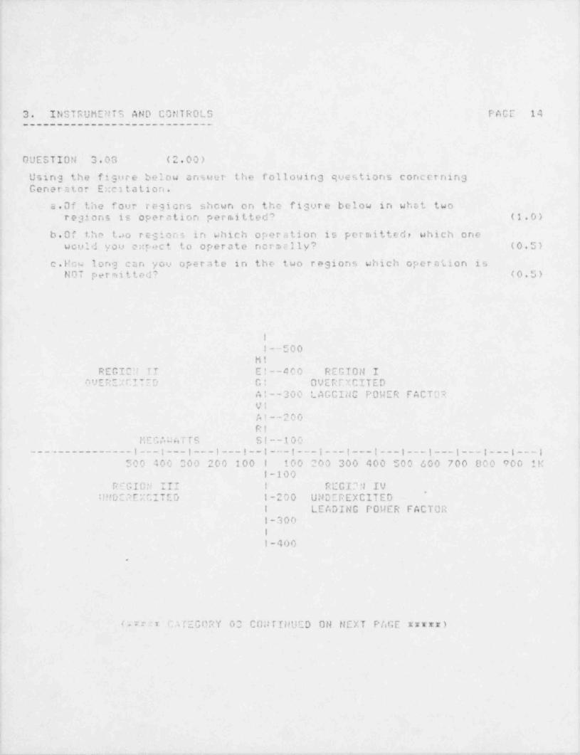
________ _ _ _ _ _ _ _ _ _ _ _ - _ _ _ _ _ _ _ _ _ _ _ _ _ - _ _ _ _ _ _ _ _ _ _ _ _ _ _ _ _ _ _ _ _ _ _ _ _ _ _ _ _ _ _ _ _ _ _ _ _ _ _ _ _ _ _ _ _ _ _ _ _ _ _ _ _ _ _ _ _ _ _ _ _ _
3. INSTRUMENTS AND CONTROLS PAGE 14____________________________
GUESTION 3.03 (2.00)
Using the figure below answer the following questions concernin3Generator E::c i t a t i on .
a.Of the four regions shown on the figure below in whst tworegions is operation permitted? (1.0)
b.0f the t,uo regions in which operation is permitted, which onewould you e::pec t to operate normslly? (0.5)
c.How long can you operate in the two regions which operation isNOT permitted? (0.5)
1
I--500Mi
REGICN II El--400 REGION I0'J ERE g r IT E D G: OVEREXCITED
Al--300 LAGCING POWER FACTO?VIAI--200RI
MEGAunTTS SI--100___.___________g___i___g___;___|__i___t___j___|___;___g___g___;___g___;___
500 400 000 200 100 1 100 200 300 400 500 600 700 800 900 1Mi-100
REGION III I REGI'' N IV!!MDE2 EXCITED l-200 UNDEREXCITED
~
l LEADING POWER FACTORI-3001
I-400
.
(Irr:t GATEGORY 00 CONTINUED ON NEXT PAGE xxxxx)
1
i!
_ . _ _ . _ _ _ _ _ _ . _ _ _ _ _ _ _ _ _ _ __ - - . , . - -
.... _. ._ . . .. - _ - -
3. INSTRUhENTS AND CONTROLS PAGE 15____________________________
GUESTION 3.09 (3.50)
a.Whst are si: of the seven positive reactivity effects SDLC musto ve r c ou.e if used at 100% power? (3.0)
b. Initiation of GDLC will automaticly isolate another system. Whatis this other system? (0.5)
GUESTION 3.10 (1.50)
For the following components in the off gas system signify which areupstream and which are downstream of the holdup volume (30 min.)
a.After filter, d.Preheater.b. Of f g<:s condensar. e.Recombinar.c.Electrte Reheater. f. Cooler condenser.
4
i
4
i
,
! .
1
'
(***xr END OF CATEGORY 03 **xtr)!
j,
,
.
- - - - - - _ , _w.-n-- _ s-- - m-- - - - - ,e-- -, p. 44 a - em,e g_,---

. _ - - - - -
.
.'~
.'
".- .~ -.
' *
.
4. PROCEDURES - NORMAL, ADNORMAL, EMERGENCY AND PAGE 16'~~~~ E65UL6556EL 66UTR6LR
- ~~~~~~~~~~~~~~~~~~~~~~~~
____________________ .
.
QUESTION 4.01 (2.00) - - - - - - . . _.
Which of the followins statements are True and which are False in'
j regards to the use of Caution Cards.a. Caution cards can be used to direct attention to any special
condition of an operatins system where a hazard to personnel,
n.sybe involved.
b. Caution cards can be used to inform personnel that i nst r u n.e n tindication requires a correction factor.
c. Caution ca.rds mdst be authorized by the NSO and lossed in thecaution card los.
d. Caution cards inform personnel of required notification priorto usins equipc.ent.
.
DUESTION 4.02 (2.00),
Equipnient placed in P.T.L., Cypass, or m.ade unable to initiate on'anauto initiation signal shall be considered inoperable, e:-: cept f or twoconditions. What ire the two conditions? i
--- .-
DUESTION 4.03 (3.00)_
According to LAP 1100-12 *Contro'1 Room Access", unlin.ited access isallowed to personnel who hold eleven positions.
a.What are eight of these positions? (2.0)
b.Who has the authority to exclude non-essential personnel whentheir pressence is hamperins operations. (1.0)
DUESTION 4.04 (3.00)
a.What are the Linitations for startins an idle Reactor RecirculationPump? (2.0)
b.For two pump operation, the Recirculation Loop Miss.atch must beosintained within specific linits. What are these liniits? (1.0)
| (sarrr CATEGORY 04 CONTINUED ON NEXT PAGE rrarz)
|
|
__ _ ,_ _-
.- . . . - , _ - .
.
1
4. PROCEDURES - NORMAL, ADNORMAL, EMERGENCY AND PAGE 17~~~~
Rkb56L655C5[~66biRU[~~~~~~~~~~~~~~~~~~~~~~~~_________________ __
GUESTION 4.05 (1.00)
Select the ststement below which best describes the operation of theECONOMIC GENERATION CONTROL system.
3. Operation of the unit with the EGC system in Automatic flow controlis permissible when g r e s t,e r than 4G% steam flow.
b. Operation of the unit with the EGC system in Au t o rr a t ic can be doneonly when t.he unit is greater than 20% power and core flow less than65%.
c.The ECC syste enn be use' in Automatic flow control when greaterr
then 201 pou+c snd in the range of 45-100% core flow.
d.Thn CGI s y s t ._ a c:n be used i n Au t o r.i c t i c flow control between 20%, and 55'; pouar.
O t'E '3 T I Oi' 4.06 (?.00)
tJhat tier. m e. 3 t 5.- tden when mote than one withdrawn control rod hcs,
' an i n e p e r a b l. e m e r c r:. accumulstor?
iP_'EST U U 4.0~ (0.00)
Follcsing critic:.lity the NSO is required to notify the L.D. and logfcur p a r a c e +. e r :, in tha unit log book. !Jh it are these four parameters?
C L'2 S T IO N 4.03 (1.50)
3 . D u s i n ', - normal unit startup when should the Prin.ary ContainmentOxygere concantration be chect.ed? (1.0)
b.Wh.4t e:500. d the concentr a tion be to cor.. ply with Tech. Specc.? (0,5)~
,
,
b
DUESTICU ..Sc , - '.2.00)
cnllowing - scram. you notice that, several control rods failed to go fullin. tih : t criteria uou?u you use t. o :.3 t e r r. i n e if the injection of GDLCis necem ,r y?
' / urr: CfTrGORY 04 CONTINUED ON NEXT PAGE *****)
.
>
|
_ . . _ _ . _ _ . , . . ., .- -~ .- -- - - - - - - - - - - - - - - - - - - - - - - - - -
._.
4. PRCCEDURES - NORMAL, ADNORMAL, ENERGENCY AND ? AGE 18'
~~~~R5656LUU5C5L 56U5RUL''~~~~~~~~~~~~~~~~~~~~~~~
____________________
b
OUECTION 4.10 (2.50)
What are five (5) entry conditions for LGA -03 ' Containment Control'?Ir.clude set pointr.
DUESTION 4.1: (2.00)
What are four(4) conditions which will cause the RWCU system to isolate?
OUESTION 4.12 (2.00)
Your reactor is ir, cold shutdcun with all rods full in. Maintenance hasjust finished won i.13 on MSL 1ow pressure interlocks. They ask you to sointo "Run* to ver .y correct operation of the interlock. Assuraine thereit no other work in progress, what Tech. Spec. restrictions apply to themode ;uitch change?
1
i
.
I
(xx:rx END OF CATECORY 04 *****)
(*frs;:::x***** END OF EXAMINATION ********2rr****)
,
.- - _ _ _ __
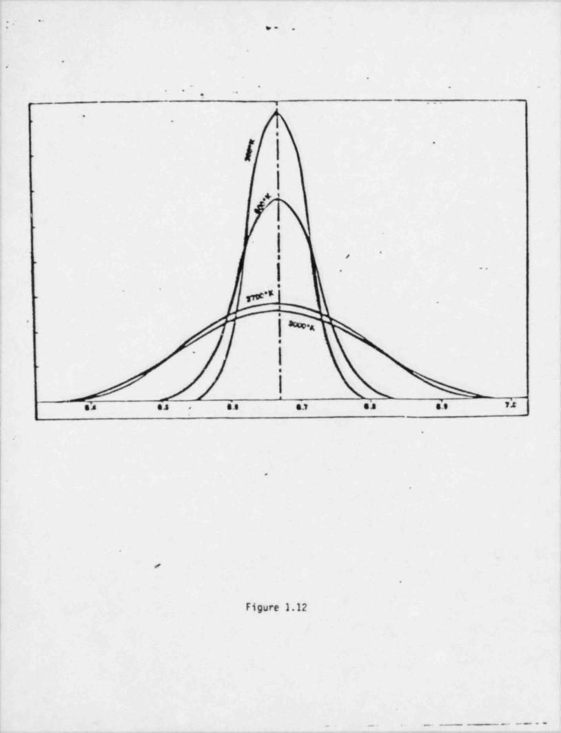
_ _ ___ _ _ _ _ _ _ _ . _ _ _ _ _ _ _ _ _ _ _ _ _. _
...,
- - ,. .
.
..
.
, - - . . -, ,
e. ...
.- .
.
l.
f
>
e
.
*/
$"I
|'
.
-
, ,.
=.
.'
.
p *E._
_
.
_ | aco,.,'
..
.
.
a
s'e e.s s'.s a.1 e's s'.e n,;,
i
.
i
.
.
.
.
-
.
Figure 1.12
1.
._. .- - _ - - _ _ . _ _ _ . _ .. _ _ _ - - _ . .- _ - _ _ _ - - - - - -- - - - - .. . . .-

~
/
gyp)V4
1. PRINCIPLES OF NUCLEAR POWER PLANT CPERATION, PAGE 19
~~~~iUEEE06Ytl3h5C5-~5Edi~iE305EER~dU6~ELU56~EL6'2____________________________________________
ANSWERS -- LASALLE 1 -85/05/20-LANG,1.
ANSWER 1.01 (3.00)
s. Thermal neutron, are neutrons in thernial equalibriure with the s t o r..sin the s u r r o n d i n g th e d i u::. . (1.0)
b.Resetivity siciply relates the strte of the reactor with re pect tocriticalit.y or a a.e c s u r e of the deviation f r o rn criticality. (1.0)
c.During r, contro tod withdrawal (or sny action changing recctivity)the rate of chen ie of reactivity also effects recctor per iod. (1.0)
e _ :. .. - r - -.~. a w- an-.
s.ILPRT -age ''
L..IL P :T page 10c.!LPRT page 30
"N39IR 1.02 (3.00)
s . C .; r. '. r o l rod- nt t h .? c o r.t e r of ^he c o r .:. are enposed tc c highe- t h r i n. e l.
# 1 m. +hrn tho_e c. t tim p e r i p h c- r - e n c' therefore have r prect,3t north.(1.0).
c. . A ..;odert'.cr t catr ent ure. inc<t:;en, neutron ledage fecm tLe fim! cellto t;.e v o l u ... c. s c o n : r: the c c nl .>I rod increcses. Thur the control red-- e:: p o s ed to a h _ S. ; . e r ther :nal flu: and rod worth increases. (1.0)
! c o r i ig c;p e r s t i ., r. in this pouer band void f or n;ati on occur s . Tha v c, i d s*
vrurting at a r z: of hight.. thermal f lu; depresses the t h e r re :.1 n t u t t o r."lo; p e r, F . *ber,for+, y control rod in this cr: a is e::p o r o d to l e r. c.#i o. ? % r, i; wou'd uithout volds and the control rod worth decreunee.
|-
().0)
.. r e- ,. E r, - ._.
ILpp* F . . r, " 43,a4
M5uER '.03- (1.OGi_
| anw.D
( c'EFEPENCE| IL?RT pa y "6
L

-. _ _ _
_
1. PRINCIPLES Or NUCLEAR POWER PLANT OPERATI0tle PAGE 20
~~~~ EE5566YUEE5C57 5EEI TRER5FE5 ED5 FLUi5 Ft50T3 ,
____________________________________________
ANSWERS -- LASALLE. 1 -85/05/20-LAt1G,T.
ANSWER 1. M (1.00).
Ens.c
. ;- - . m - > . e --t' . s s fswun
"tsndcrd nicler, principles
A E WE F: 1.05 (1.00)
ns.c.
R=-_.. th.:..
r .
f.L:rm ,r d t h e r ni r.1 hydisol:.c prir.ciples
AN3'1EP 1.Cc (1.00)
ans.D.
c. . c t.- '. n. . e. s; e r_ . .ww
Ct6ni~TI nucle? Piir.ciple"
A s>l r. ,d . m .s**s< ** r ef. .V * s
.i L. s
E. . 5 . e,a.4
i. .. - E F. _ . , r -. r..a, S tar.d n r d mie l e a prin:: pies-
|.
|
; ;U-ID 1.08 (1.00) .,
, ,, n .s . c .l
. e . n , d e_ .-.n,I r r t. .-t.
ClahdFT #. ' C l (* c i' prinCif 105.
4
I
t:li1
I
?
I,

1. PRINCIPLES OF t10 CLEAR P0l!ER PLAill DPERATION, PAGE 21
~~~~iU5Eb6 UIU5C5"I!535 TRdU5EER EUU EEU56~fE6U~
____________________________________________
ANSWERS -- LASA!t.E 1 -35 /05 /20-L A!!O ,1.
A N'3 '-: Z ? 1.00 (*.00)_
ans.D.
. r..esu~e,_ _. w_
S *. s n d s t e ; nu c l .t u ,a r : n c i p l e s .
All 3 W F 5- 1.10 (1.00)
nn .O.
Q C_ ~r !. T. . n f.' 7__t .
5t:rc>r.~ not: ,er 2r.ciples.i,
-. . ,, f. -. . f. fs I-.' A ... 6 JV
T r 3p0r I .0' c I tC REMg . 6
+. d i- r c p .ci r t . n c , ; to R P .9 :m.nred.~* '~ ? f O ,'> '') P i Q' 1 10 R If. C l.1 { Ca d e. .
* ' 7 ' . tJ _ .*1 s,t' ^ ^ (. :- p t. r*i .nA v..) 1v - 6 . . . .i
-__-_- --__ - ____ -_________
h. "2.2
( 3 3 r, j 37" (y)
, ,
_ ~
1C0(3600) 160 V=
r,y.05nn) -4a- -- u~s
____________ - y,
'40______-_______ ___
. -
. u
., ,. n, o t, s' /_. n. o '.
!-------- . e ." .- 2 9 t! 6 R P i'...I.G)
': FEF:ENCE-
i e s. . -* .~n t *e, R n C' r 5 s. t
.
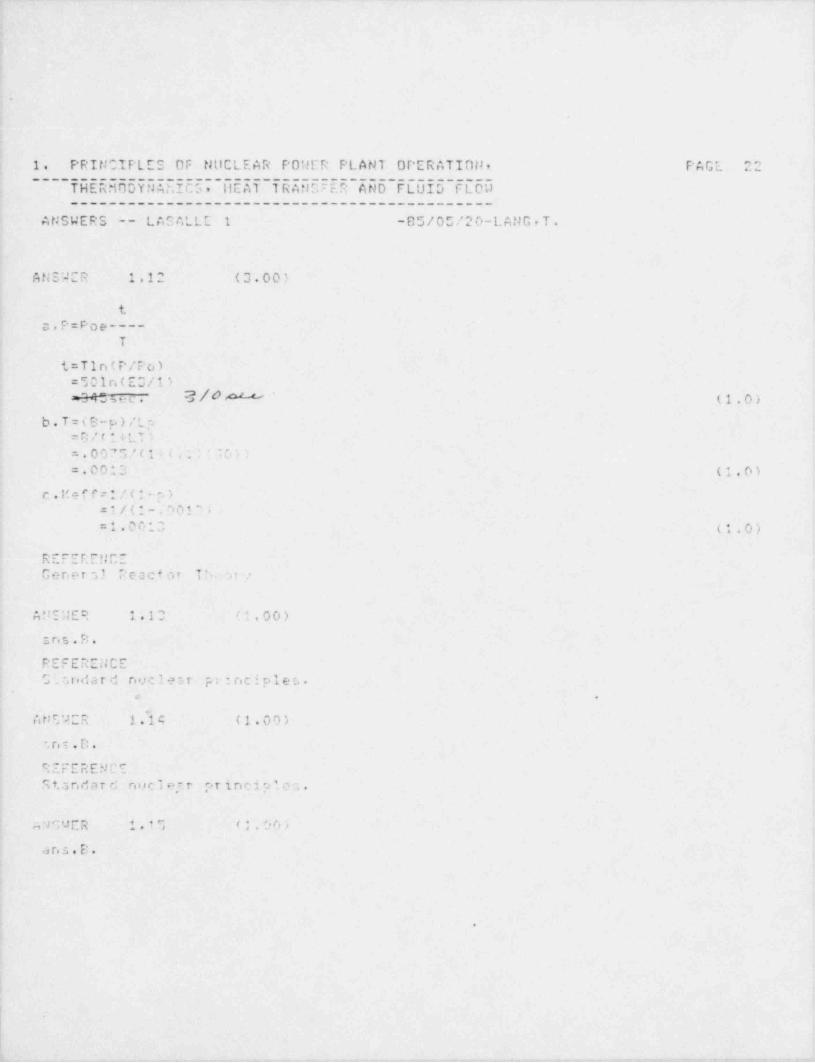
.
1. PRIt10!PLES OF tJttCLE AR POWER PL AN1 OPERATIni4, PAGE. 22________________________________________________
THERMODYt4Ar.ICS. IlE AT 1 rat 10 E.P At1D FLUID FLOW____________________________________________
ANSWERS -- LASALLE 1 -85 / 0 5 / 2 0-L A!1G . T .
AtiS2CR 1.12 (3.00)
tc.p=Poe____
T
t = T i n ( P / P c, )_e 1n(enc. s / 1,i- av
.
= M .,s e c . 3 / 4.^' '- (1.0).
b . T = ( E: p ) / L pe r; / r 1 r ti s
. n , , e, J .,,.... . , ,.
V /- *A * ! ?df4
=.0013 (1.0)
c . I'e f P r i / ( : - . )/(1 .001'i=
1.00*3 (*.0)=-
e. e e r. f. r.. f C -. ~ . . . _
Gener3 1 Peac+ot T !, u -
A U I ',l E:' 1.13 (;.00)
2. n s . F: .
pm .e - . r . . C er timie -
C . .ridar d nuc lest p : i n c i p l e t. ..o .
~
AN5'tCR 1.14 (1.00)
.ns.D.
t. r ; .r. . r kf r e_r .. - .
9 t,5 n d a r d ns! C I o.' t "> T i D C i p l. 0 3 ..
aquCR 1. * 'l '* .06)
a n r. . E: .
.
I
||
1. PRIt! CIT *LES OF NilCLE AR POWEP PL ANT OPERATION, PAGE 23
~~~~T U E EE U 6 Y 5555 C 5 I ~UE d 7 ~ 5 R 3.E 5''ER '5 U 5 ~ E L U 56 ~EL U U--------------------------------------------
ANSWERS -- LASALLE 1 -85/05/20-LANG,T.
e, e e. r. is. e._ .hc. e,- < .
S '. o d e,r d nuclect principles.
8
AN?2ER 1.16 (3.00)
a .. : r :. u e r n f; 00 .i n d 1400 psic. . < _ piest. ore iricreases eritic:J power
nround.c'Phdactonces. At pre. cures louer thcr. 600 p;ia. the affeet turnn
b. Critical power i ric. ea s es as subcooling increase.. C r e a t.c r a n.o u n t ofsubcooling mc-rns higher bundle powers before boiling begins-.
c Aa ficw incr e4 =, critical pour: increases. As flow increaser c o o l i n c,i: luprovad a r. . , , .ticci p e u .. r increases.
c. . c .- ,. . . (. ...we i. e s s ..
,3. a. e-, %.. - r.s M. .' a;Pm Mo 6 4
.
!
|
li
- - _ - . - .,. - - - ,. , - , . , . - , -- -- .n.
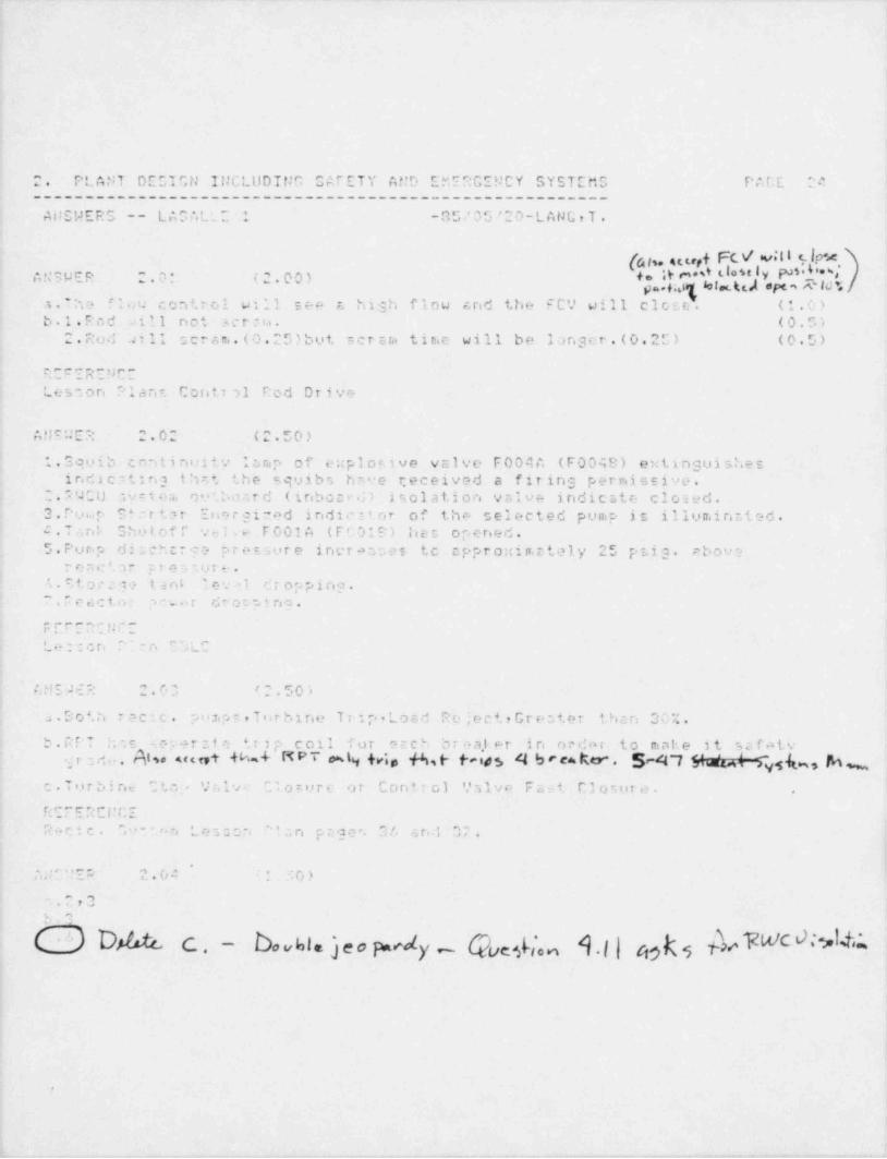
. _ -
2. PLANT DECTGN INCLUDINC CAFETY At'D EMERGENCY SYSTEMG PALE 24_______________________________________________________
ANSWERS -- LAGALL: 1 -35,' 05 / 2 0-L A N G , T .
I(atu seurt FLV 'v:II % P'A,4''
+ = .I Y '' * d'.,t * ' ' Ip. ,;q bl koiepe,''&lo'tY P'" y' 3 p e c. -*0* (''*004
.- -'" - '
a.Tha ' .i u control will see 7. hish flow and the F C',' w i l l c l o s e . (1.0)b.1. Rod will not s c r ui . ( 0 . U 's
2. Rod aill scram.(0.25)but s e r s ta tin e will be longer.(0.25) (0.5)
R cERENCELesson *lant Coritt al Rod Drive
ANSUER 2.02 (2.50)
| 1. Squib continnity i t., m p of e;;ploc.tve valve F004A (F0048) e:< t i n g u i s he sind2c' ting th.t the squibs have 7:eceived a firing permissive.
2 . P 'J C U .s v = t e a. o v',b o r.r d (inboar.;) isolation valve indicate closed.
3.rui.P S*ntter Energined indicitnr of the selected pump is illuminr.ted.c. Tank Shutoff .sla F001A (FC010) ines opened.5.Purp di:.chcrge pre =.sure increases tc cppr o::iiv,e tely 25 psig. ebove
r e a C '. 3 r 9 7 e 9 7, u r e .-
. . e, t o r mM tanL le. al diopping."
".Peacto: ;, w r dro: ping.
rm. c e. r . p r. -.. _
"'Le::cn n "0LC,.
M!S M R 2.03 '2.50);;
a . S o '. h recic, p o a.p s , T o r h i n e Trip Load RejectrGreater thcn 30%.b.RPT h .s seper :t e tr 2 p coil for ecch br ea).er in order to make it safotv
.g r - d g. . Atw meet h4 MPT mtg (f , g g. p , g y h rea k . 5 -el7 E 4 4 @ b M ~c.Turdine "' t, . , , hiv- Clo=ure or Contrc,1 Valve Fsst C3osure. .
r c. r. e .\ c e < t. er.r _.
+. i
R o r_ i c . " " - ra n L e 3 ., O n c'l s n p a g e r, 3/, 3r j 07,, -
'
A A' ':Ep 2.04 : -; 0 )
3_'.u7v
f .7
0 DM C . - bo vhls j e o wd - Quefian 1.l | c,9k s b d #'O ^'kYS'
y -
.
, , _ . . _ . - . - , - e - - - - --
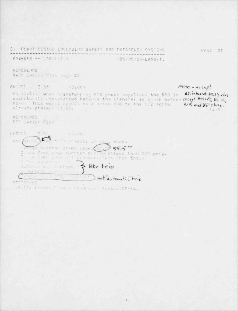
2. T'LANT D E S I r,t' I;JCL':DI:m SAFETY AND EtiERCENCY S Y G l E t!S PAG 25_______________________________________________________
AtJSWEF S -- IASALLI 1 -05,'05/20-LANGrT.
e e. r .e N C er_ n-
RUC'L.. .- t 1 : r, , v3 25
Alo-at(efffi t: . . r . . 0 m- r._ oO),
S
tra ( 's . 5 ) . U h ., r . S srisferrire, D"S r.ower rip ali es , the R T'S is M I' 0**'d PC l'a vl,5n.o nc e i s t in 31 y _isv. 31 rad bnbe: t h e, t.rancfhr is br ork beforo daccff M 4 Q E'cic,t-
c. P T;ii s we.... .e nit i r. a r u r at. due to the 1/2 , c t n... W R W (/[> c lo s e ,
alt:.ady pre ei.. $;. (2.0)*
r. r - . _ c. . . ,,' .- .ni - t s
E E' ~ _aa~ ~- .3 ."4 b' 1 i F*
^la
.4 ,.,ra.
t . f .. t ' e'' "^
r. - ** . .. s n, e'
% si
:. c. . , : ... .. ,cc.. .
T5' $-'- ari 7; 1-t..7 L r v o I ' ^ . "i *.. ;.
2 . . u .,- ," e e 2 :. i , : :, ex * 1 b r. pr - i. ira: 1ers than 2 E. O prig.
't r ., F ., i, 1 - ' gr -- - 4 h i r, 5[.;i0,. e .; , J r'. - ,. .
- ., . . , , - -,
-
8tr frap1.c: , ,, .reri.; . .otr -
_r ,_
*.
' ' ' ' '~he Ap IO% k*e [ h.' '
. _ - _ . . . , , , -'
e
-
,'
e L .- - c . c.- r...,:u , .; c.g.- < , .. " ? - 1 6 ..
\
|
,
I
!
e

.
_
. PLMT DESIO: INCLt: DING G AFE~Y At!D EliERGENCY S Y S T C t's PAO 26-------------------------------------------------------
AN5t!ERS -- L ASalt.L 1 - 8 5 / 0 5,'2 0 -- L A N G . T .
M'34CP E.0' '. 4 . 0 0 )
s .1, n y for full cradil,
1. M i n ctean 1 1, . .' hijh fica. 2 0 t".
2. Low resetcr w ter leve: -503. Low MSL p ' s: su" o wi th moc'e switch in Run. C S /' 15:.<! . ri.ie n s e r 'ou v s.c n n m '7'H;._
G.ir,L high rv.. 'O' no r r.ia l6. fi3 L tuntia' h : 1:h tcmperature. 140 dag.7.MSL high .12"fa entirl temy:-r c tur e . 24 deg.
2 13nuni7. Leo f- L en,t; Oc 4g e.li o Pgf '5E6 W S l f 35a ba.
b . P '. s c e 'hs c .m i . c m _ r. u i t c . n e -. f ci the inbocrd cad outbottd Mt.IV's in-
j the clozao a.vi':on. a r. d d e ,r-. e r ; the inhnarc n 'l c u ti c a r d isolati,n,-
i ressi puGbe n .
REFEREtT:a.PCIC Ler=an P ' ;r. pages 10 ar. . *r,
n LGi.-f E-O-
......v.' 7. c. -. 3, - -- . - _ _ _
* : .v - .. .-____
j ; A 15 t -- ic ' r nd e. < ns wh. u v+ r all cooi : e Sr ehr t +n a bus. . - . t ' . e}-are ope -t er;t onc c .;i ne it F.vailable to th" but at t h r- time
ource bie: ai- -- c o u of e . If more than one source i3 i% rui:di lic'
| c, v a l i a b * .. t ;i , t t *. T or SAT is gr mn orioriLy.fA L 1 o .; aut c:ic Lie trsnifer-
ac wr , e "..< v al: sourec b ookers to a bus are open. snd a fast auto,transfar h .: r : ., t ocuorred due to all sources not being sveilable to thebus. Aftri 1. + :lV relay; h=ve tripped the bus brea ers f=neting motors
| if a :, cur.s L-com-s evcileble c ' t. e r land shed the D/r, br eaker will.
I close.
f b. Creak.er .f; 1 0 ve r l o a ris . A u t ..,. t i c or m o t o r i c c.d d i s c e.n n.' c * n will also'f be encest 1.t
REFEFEDCC.AC distr bo* ,n I e - :. o r . P lan, p r: g n 10.
! b.St,andard elo u ic31 .;c t 2 ?n .|L
j kh4 sU requyed 4. <n w u ve ON . %+ -fmSr - f mms | -wpply,a . w. ,u, . ~ . wpm, %., % ).
,
M O$ [ $ O ( $
- .
, r
Il
!
j_
,...
- . . , _ . --
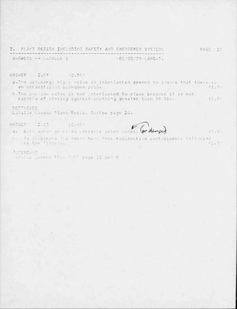
_ _ _ _ _ _ _ . _ _ _ _ _ _ _ _ _ _ _ _ _ _ _ _ _ _ _ _ _ _ _ _ _
2. PL At'T DESIGti INCLUD!!'C S AF ET'r AND EMERGENCY SYSTEMS PAGL 27________________________________________.-______________
AtJSWERS -- LnSALLE 1 - S U ' 0 5.' 2 0 - L A tJ C , T .
n N. , .,4 c R, . . 0 ,. ( ,,. 0 v ). .-
:
s.Thie dir,chstga bicuh v:1ve in i nterlocked opened to irisure that ther e inan ont astr ic t c L lovdouri p ; t. h . (1.0)
5.The s r e c ', e n valve i , not ir.terlocked to close because it is not
cap at ? + of cl oc ing eg o i r.I t snything grester thtr. 50 lbs. (*.0)
r._.. .u..-..c. c . - ..u-
Ls321:e Lesson c'Isns Rec c. Cy=teri. page 26.
n l . . . c ., ...e (. . G u, .>, , .
. .r . . .
d4epc)ri . W . t '- riot r ; r 'ed . r i at le irile t vanes. ( .1 .03
To .f i : s i p : 1 - 9c v he-t 'ron radior.ctive cont.ainani., en]l :c t sd.. . , , ; _ ' ' e
- ,
in .,l*i . L. . . c... ,
. .
t ,- .- e -
*_ ''; c ' .
_ _ .L ...c.,.+e; I' * .. ,
**
if*f.=.** p . s' *{g o# '"' *# d
. , g -. - *
Ii
|
||
i
||
e
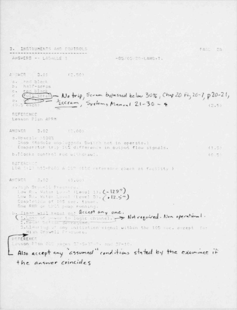
,_ .-
3. INSTRUMENTS AND CONTROLS PAOL 28----------------------------
ANSWERS -- L A'. ALLE i -0 5 / 0 5 / 2')-L AN G . T .
A"7WER 3.0: (2.50)-
.od bloci+. '
b. half ,cron.
c. r e ' b i a r t-ser d. - Aj, b;p, SC~~ hiw5 Sed be.lw 30"4 Ch f 0 Fi 16'7, p 20-2 l2c' - fu1' g ji
}-e. r. - $ y
(O.5 9Sch) / .Y H h9"v9 I 2 L '3 0 - % (2.5)__
REFERENCELewon P'en APRM
ANSWER 3.02 (2.00)
2: . U p s c , l e s100%Inop (nodule unp v.0,d, Suitch not in opercte.)Corap c r e tor tr.p 1C differetica in output flow signals. (1.5)
b.Diock.c control red wi'Pdiawl. (e.5)
REFE s C!::-LDA liL) M C - F 4 ~ ', A 2's'' (Old r e f e r s r.r e chect at fecility )
A F C 'A E t ;' . r 3 (3.00)
a . :-t i a h D r . . r: 11 Pre: or._.
1 ) . (~ (2.9 NL o C R . : . ' '. ' ,2 t .+ r L .. - ! (Lovel~4 . t e r L .. , .a tLevel 3). { 2, f *)Law R,. t
C o a.p i r t : ta of 105 sec. t i u e- r .,
One RHP or U C , por.,p ri. inning.
W5 J1 O r, . CCCPi A^y OWCe| b. fi, m r
*
,is 1|,19 = t.
c h u,ne l ;' .,. >p M d retukecj . S o , pe ut=.~. 1 -; : . tov .,..c to 10 3 i t_-
~r:e:3> _. u r r._an a. y m , 4. e n .,
2. -
i| 0.LI ,ar: ig .' -. n y .nitiat en eignal within the 105 sec. m: cept f.,r*
j Hi an Or vwnl! Te -: > ore.hFFEEEufi
'
tesson n un m . n.y - , -5 e r = . e n.: ,7-te.
/ Also atcepk 6 a y 4 ')$ u rtec/ (andNih3 $dsb b/ bC CX4 W s C.C Icrialde s+he a n er
|
. . -- , _ . ~ , _,
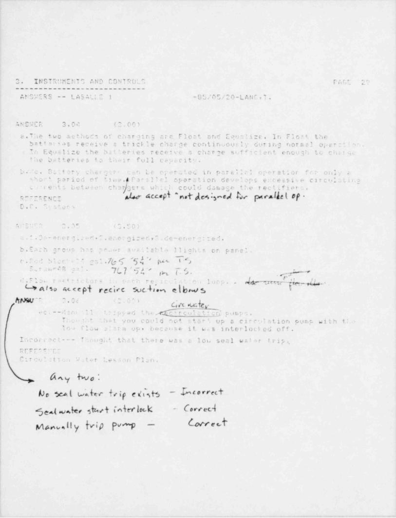
. .
.
3. INS T'It!!i:N T AND CONTROL, PAGE 2 r1______________'_____________"_AN3*e'E95 -- LA5ALLI 1 -GL/O";/20-LANC,T.
ANC'JCR 3.04 (0,00)
a.The t w o . Tie t h o d s or ch:;r ging tr e Float and Equalize. I r. Flort theb=tt mies receive a trickle char ge continuous ly during nornial oper:.; m.In Equalize the batteries reenive a chtrge sifficient enough to chatgethe betteries f.a their full eppt. city.
| b. 'c. Os tt ery .'h e r 3 a r . can Le o p e r :2 t e d in p a r E. i l c oPeratior f r, r o ril y c
D oP I ??riCd Of t]oe. Par 3'cl operation deVrlops e!Ce5Si%e CirCU10tihgi
cri ent; betw+en char 3 cts wh;c h could dansase the rectifiern.M8 eYdc4 3acM har ycAb( #f *grr r.ENCE
D.I. " stees
. ..%.. . r- . m. 3. r ga,; , e p, ).
--1 ; es - w e es
L.: 0 c -or,e r g !. eri . 2. ene r g i:e r', P . de-e ner C : :ed .
b . E a c h g r c u p h - c. p r...o r avr.iIsbla 31ightr> on panel.c . 7:c d 5 1 c c ' z '_ ? c a l .7(; T '5 d '' pet Y5
E.c r a s.. r .* S p'. .t.*
~7w J ' 9 .>, st-
.
eh ( s pre loop. Mqc ws,/ I|, .' _/!,..d . F 1 a s- r "+rictars :: ecch
L3PAiso e,u e py pgejfe $vc4,r 2 c e ; e,t : o ie { b,,s 3'
4.
~
,n
MMiLI' ?.H (; O3) gy,-
,
e c i --d a r.* 11 1'ipped t h( 4 r c ol n t i cR puriipc .T;.v.*i..' 'ht you could not star' up s circulation pump with 1;..-.
109 flou 2: tra op. because it wes interlocked off.
Incort act--- Thought thzt thare was c lou seal walor 1. rip.T.'E F E S I!'C EC r cul :t i co 'A., t + r Lest,an P 1 :.: n .
1
f
h.
W e $c4| t. M ee trip e $ b - b arrec+
5ea te, 3b+ Merl*k - Correcil
bed! hv.Ily Mp PW -
!
i
, - -. - . , .
- , , , . - - _ . ~ , . _ . , .
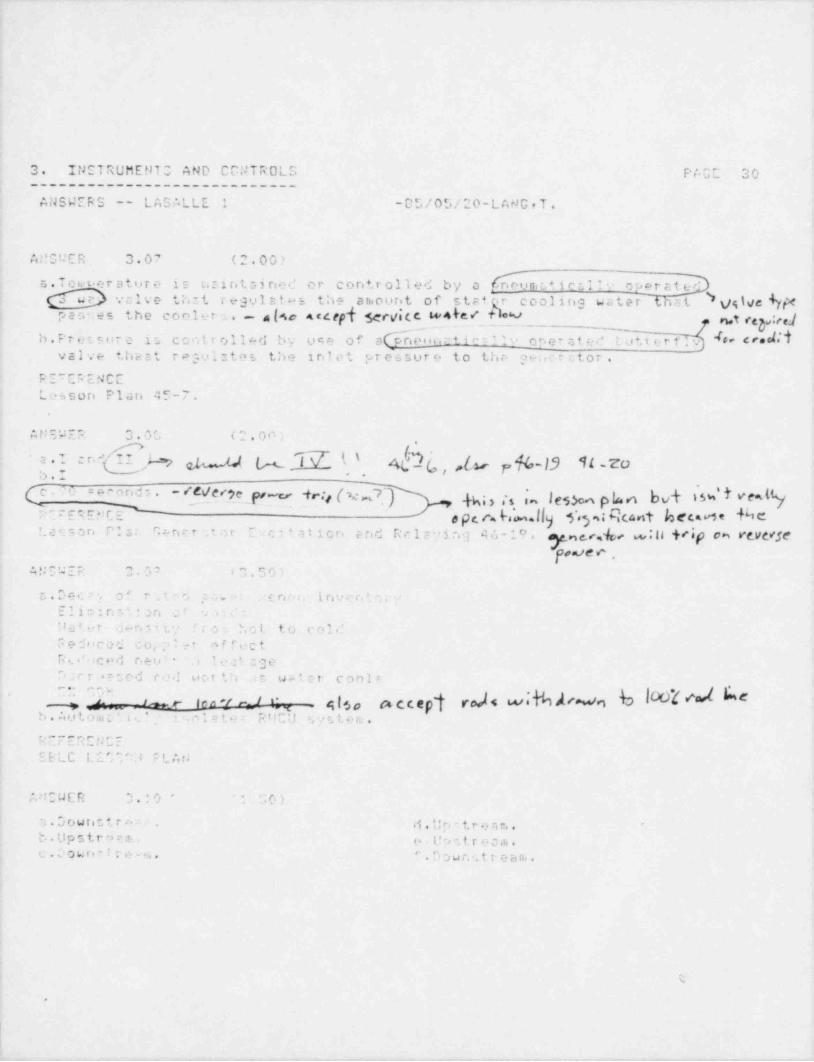
- - _ _
3. Ii1ETRUMENTO AND C0!JTROLS PACE 30____________________________
ANSWERS -- LASALLE 1 - 0 *J / 0 5 / 2 0 - L A rJ G , T .
At' SUER 3.07 (2.00)
s.Teut er atur e is t. i rit s i ried o r controlled by a h un,L+icti'' oparathvalve th:t regulstes the a ri.o uri t of stat coolirig water'that 5 t/g hie hfe
t h e c o o l e t u . - a l4c A c c ept servic.c i+4 &c < *qrivpast:es .t < p:w4
b.Pr etsirr e is conttolled by use of s h oncti" 'lo o r.e r si e r' tutterf.v # ' d r* d''I8
valve thast ragul:tes the inlet pr essur e to thr- geacrator.
RE~ERENCE"
Lessori Plari 45-7.
ANSWER 3 . 0 f., (2.00;,
j . } c r.' W gj J g Q (_ (,,[3, %-f3 H .zo4 7. . . .
(C . .'' O c e F orid s . - /C jg (4 bd 33NI VL%(pe y -f,.;j [ ag m~/*
. ,^
hrt::ENCP ,pce hb.lly $.y, %nt kcce %ei.e u ,n r:s c, e n . r : eor E w atior. ene Rc12>in3 46-19. n , ,, 0 . :n +<ip o~ resc<se
NO O .' ,NSWER 0.02 s0.50)
"
c.Dece. c' rut o paw c nc i. i riv e r, 'o;.
Elio:.n:':an o r s. -
Dattr j a n 3 ' t */ 't0- hot to col.?,
Fe duced coi; l : t offuct' R ,_ .' s c e d n e v i - it at ;3e.i
Darr**;ed ro.' uct th t e. we ter cool:
' n o- ten 't e 1 C , . t; Iso t% CC tyk YN 4 E '***'nW*b. Aut.omc'.t..', . n l e t .f r R f lC U s y s. t e ru .4
REFERENCEEBLC L U;"^11 F L Ar!
At!:WER 0. : 0 - ': 70)
's.OoWTi0tTre- d , 'jp-tpg7,g,,. ,
b.Upstr9en.. . . . p o .- t r e 0,i. .'' . D h u n s t t- e a ni .c . D owr,t ! t e - .a .
t.
e
. _ _ . _ . _ -
1
r
3 ,,L- ,. e,.. , u rJ; T a Atje C u > ., T e. . 0. nonA. ..
. F. . , . ,,-r. . v.
____________________________
n y: . a . . - c. . c --- et. .
t.. e . , , .. ..mn_uc .- -85/0G/20-LANGrT.c -
|
!. r. -. e n : n c_,-- - _. t,
CrF CAS LESEC'4 plt,t!
.
<
.
s
,
e
f
i
|1
i
.
- - , . . . - , _ _ - . . - _ ,. -- , .. . _ _ . _ - . . . -_ ._.m. _- - _ - . - _ - - -
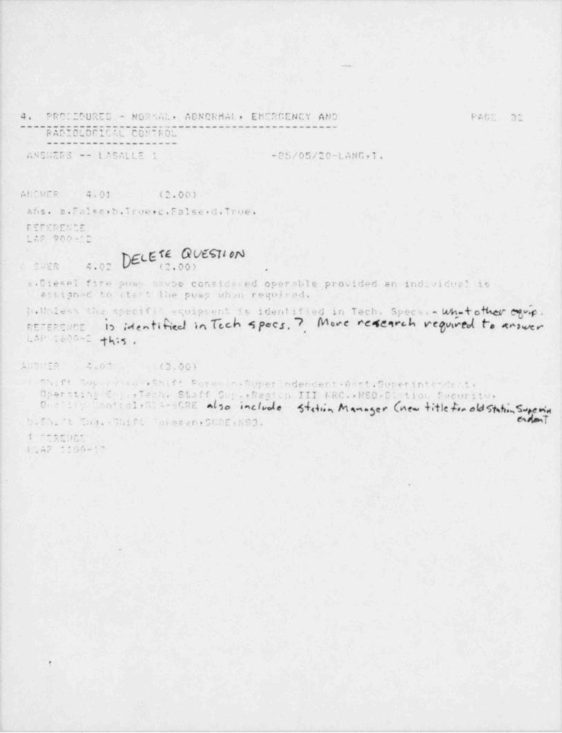
. __ .._ _ . . _ . _ - _ _ _ .. . . _.
i
, _
4. PR0"'200RE3 - NOP ;AL. ADNCRr1A1 , EMERGENCY AND PAGE 324
--- EI555E5EiEIL c5siE5E-------------------------
____________________,
ANS;4ERS -- t ,' S ALLE -05/05/20-LANG,T.,
1
ANCUER 4.01 (2.00)
a /i s . a. False,b.Troe.c. False.d.True.
if. e_ : e.5 e. .e. . . ..
I 1.AP 900 '.2
G fl 0 M QIONSUER 4.02 (2.00)]
..
; s.Dieant ' ira pine 'cvbo con v id a r ed oper al l e providad an i nct i s i d u e l is; e.t s i g n : d to itcrt Ihe pump uh m r e g o ,i r e d .
,1..Unless th: specifi- -quipment is ider t ified in Tech. Spec s . - Ms-t o%er cgh .i
b ta otihed in Tech S P-e.r. 7 More N4&'breg4M P.4r wntrantuct c ,
. . , . . . . v, - -ga ..... ao .
;.t:r se 4.c- c3.00>,
"n t r e 7. i;_ - . . . . . e h i. f t Furen'r. tupe r i nderider.t A = e t . Guper i nt e n k .s t .Oper.ta*.; 'I - ,Trch. Staff Oup.,Regica III URC..HSO.Ct.ntiot. Securitv.4
On ': . ' On4 ; a 1,"' A - 6CRE algo incIJ, 3-{ g ,,g N ,,3 , , h e 4 tje p, , eld % b*., % ,e 4$ . E S .' t '!:q . - lhi r t ' oi e n a n ,0Cr:E , N S 3. ^M '; , _ .. .*,. . I b '8 ii
I. A2 * 3 '.'k (8 - 1 '.
.
9
+,4
e
i
I
e
9
I
.
!
?
J
~ _ . - - - . . , . - . . - . . .- - - - , - - - . - . , . . . . - - . - , . - - , , - - - - - ~-

. . . .- - _. _ _ _ . . _ - . . - _ - . _ _ _ - . - . . - . . _ _ .
4
5
r
.
i
4. PROC':.DilRIO - 140RM AL . ABNORMAL, EMERGENCY AND PAGE. 33.'
--------------------------------------------- --
R ADICL OGIC AL CONT'RCL, -_------------------
,
. ANSWIRC -- LAS,'.L W 1 -05/0E/20-LANG,T..
& & y l CV-Rb OA . $ WM M M.(0.00)% $ p f e! AN5'tF5 4.0
1a 11e loop tems.:rstire nust be within 50 dess. of either t h a- t e m p o t a *.o r e
i'
of the coolent in the Reactor wi.an both purps hevo bean idle or th= 1
temperatore o' the oper st ing loop.;' Reacter b e ;. t c' n ha?.d dr ain te p''esture n.ntt be within 1"5 dess. of th'I
t e in p a r a t u r e ci ;'i. ccolant in ths. Reetter Steeru Dome. l,
'
b.5% of r:t ad racir:ulation i'cu uit.h core flow > or equal to -' 0 % 1 tndi c s; c f i r .. .!
3 1 * *: cf e-ti- scicculstior. rios with care flow ; 70% rato1 core flow.;
. . . m. . c g -.
u.o
j- ? q . c.:
; t
! . '. 7 m 4...5 . c o ',.
| . .,, ,
; :. - - . e , n ~ .-.
. -
., . . . , .!
!!
r. . . e..c.- ..ue s -. s e, .
s 0v., . , m
jI
{ T r .. d : :- t e l y w.r i 5;.-t at l e a s '., c n e C P D p o n.p is operatin3 by :r.rnrting1 . east one .a . i h * n u n c o n '.f r.1 rud it least one notch by driva u ? l or
-'
m i e- v: o r e u ~ '. : r. norm,1 ranys or place the rea< tor mode suitch to thet.butdown ,.;. .:on. (*Qlgo cccept de c.kre eeAIAJ0P)
~
*
5 '. ? I"< E U C ';co 0-1 ,m z , .2
''
,
4
ii .'. N'W C P .? , r0 , t ". 0 0 ',!
'Time, pn.. ror: tion. Coola.nt Temp =rrtorr., and Rorcti>r Perind.-
| 'eEFEFEur,E! *0P 1-1.
1
I
.
5
4 e
k'
_ _ _ . . _ . , _ - _ _ _ . _ . . . - . . _ _ . , . . _ .. _ - . . . - . _ . _ _ _ _ _ _ _ - _ . . . _ _ . _ . . _ _ _ _ . _ . _ . _ _ _ _

i
.
4. PROCEDUREE - t10 R h t.t . A D N 0lc h t,L , E tie R G E N C '; A tJ D P A r;' 30
~~~~E8656L55iE3E c5Bil5E------------------------____________________
At'5WERC -- L AS Al ' E 1 - B S . ' O S / 2 0 -- L A N f; , 7
ANSWER 4.0" (1.50)
kcwM *E ' Oa.24 h o u r M t .' r. .c h irig 1 5 '' t he r nia l p c, t. e r . e### "If Alb "$ lb |b.C by volut.e.
F E ' " R C '. ' 7LGP 1-1
AMSWER 4 . .' - ( '' . 0 0 )
If f3vo 's4 or aor> v. ; 3 4.. e n t r o . i .3 cre not irit or ted to at lent notr. >
"! at ';petition (30) or r:o r e rodt cv- riot ire v ' ed to rintrii> *
p o : *. i. . i n T ".;i ur 'J e :<f' 'J : t e ' Lme: c:c,ri not he r.. u i n : ,3 3 r. c d a b < . s,'
.
!2.5' or p r .. . c . . n p r. 01 '. o r i p .; r t o r e r oar % , 110 r'aj;..
r.. r. e t. t r. a r -. i.
inA fm- c
v. . . r . . . c s..- <..,m.s. . , ,. s
c .. .
c . Sur > < - :on pc o! . . .- : :- r t e rip a r r t.o r o 100 d79I.b.Drfa.'' - I a .3 - p ') .e r - t o ;q e r :, t o r e 135 degt.'
C . ** T s o s ! ! pr* une - I.7 psig,d . 5 0 .c r e : r... por1 w-ter 1 ,. 9 ) -+3 (26ft,toin.i.
e."a:p't.-stion p ..e l u ter leve1 T-4.5 g ft.52n. TbEt 9.Tp .
p. e r. .o r. ; c e.. . ..
LC A O?.
til' ,W E P 4.1: (:.00)>
1.High 2 ril . t t r-c. p e r a t u r r. to puCU fill.cr gro,t.er tinn er eqo41 to 1.i . ,k 5'
2.H gh rn t e .tg. .. r c, t o r e or venti 1: 1 ion difforanti.a' t. c tr. p e i , torr .' ;e| RWCU Irs. 2 ; e o ,1 . t i o n Pong , of Mc7t E..ch:4ngeru.i 0.High RuCU s.,et>m di f f cir anti a l flow gra-ter then 60 .r. r.. .,
.
! 4. Low Reattcr u. tor L*.s1i
.
6 :.c E R E t K "
| '.04-RT-n'. '
.gr.
it
;
1
I
l
;
_ _ _ _ _ _
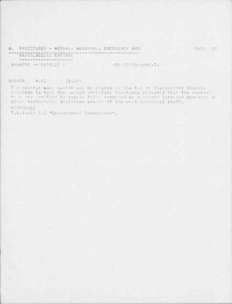
3r.
.
4. PROC DURES - NORMAL, ABNORMAL, EMERGENCY AND T' A G E 35
~~~~E3UIUEUU5 EEL EUETEUE~~~~~~~~~~~~~~~~~~~~~~~~~
____________________
ANSWERS -- LASALLE 1 -85.'0 5 '20-L ANG , T .
ANEWER 4.12 (2.00)
T*? r e r.e t o r mode switch n.av be placed in the R o r, or Stortop/ Mot StandbyFcsition to t ent the switch interlock functions pr ovided that the controlr. *= a r .2 ..-r i f" .-.! to remsir, ful!v insert,ed by a s e t ored licer sed opor ator oro tlic- r technically q u c.1 : f l e d m e n. b e r of the unit technical staff.RE~EPENCET.S. Table 1.2 'Oparational Conditsons'.
S
e
O
I
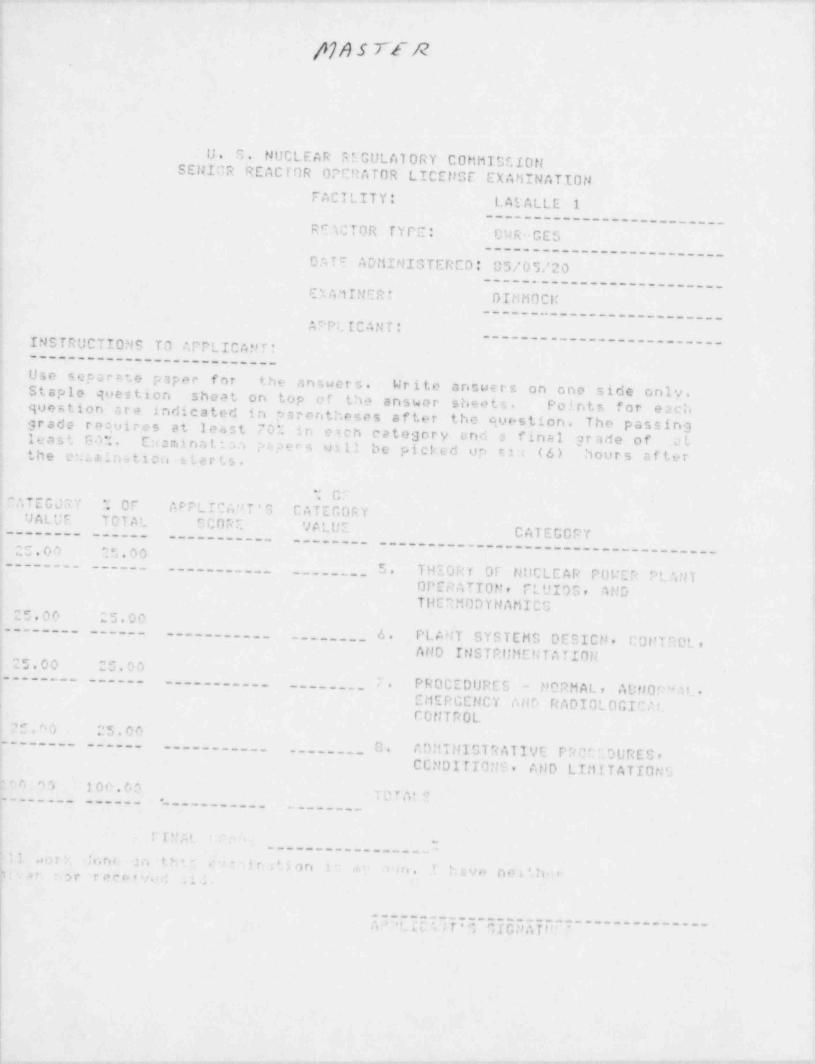
p)Asrt'R.
U. S.NUCLEAR REGULATORY COMMTSE.I0tt
SENICR REAcr0R OPERATOR LICEtJGE EXAMINATIONFACILITY: LAEALLE 1
----___--_---_------ ----RCTC10R TYPE: CWR -GES
__----______--___----_-__DATC ADMINIGTERED: 05/05/20
__---. .__---_-___-----_-D. A '1 IN ER : DIMt10CM
---- ..___-------__-_ _-.APPLICANT:
----___ ____--__--__---__INSTRUCTIONS TO APPLIC A*' r '---_---___------__----_---Use separrte p1per for the answers. Write answers on one side only.Staple question sheat on top of t. h e answer sheets. Points for eachquestion cra indicated in parentheses after the question. The passinggrade r o c,o i r e s at least 707. in esch category end 3 final gr ade of atleast Sai . E:w mi n a t. : S c. p :1 .we s util be picked up r): (6) hours a f' t e rthe e :.:.a.i a , t i o n sLerts.
* C'"ATEGJR7 ". OF APPLICA"T'S CATECORY
.
UALUF TDTAt. ': C O R r. '# L U E CATECCPY-------- --_--- ----_-__-_ --------
25.00 ^5.00.
--_----------_-_--_.------------.
----- 5. THIORY OF NitCLEAR POWEP P! ANT--__---- - - _ . - - - --------__- _
OPERATTON, P!. t'I D S , ANDTHCOMODYNAMICC
25.00 25.00__--_--- --_-- 6. PLANT SYSTEMS DESICN. C 0i!T DOL ,__--__--_-_ __- -- _
AND Iris TRIHiEN T A TIONe . eJ O - c . c, o--s .s s
--.-_ --__-_--____ ;. PROCEDURE 5 - NORMAL, ADNor" R ,
_--__.________
EMERGENCY ADB RADIOLOGIC.*!i -
CONTROL, . - . r, c.> .n e . n e,.. a
--____ -0. ADMIN 1GT'< A11VE P C' '.90RES ,. ---- ..-_.---___ ____ -_
C CND I TIO N'i . AND LIMITATIONS'. r . n , t oe ,6 ,
icin; e
r [ N;,1-
,-
. -------_-- . --d pd N/ 0 , | -
t , e I. I9' at .r T e r* ra i - * . t i ; ;u . ''p .
I
l
-
.__---_
j A;''!.20",tiIi~~R,',3iti.-~'--------------
,
|.
i
|
. _ . --
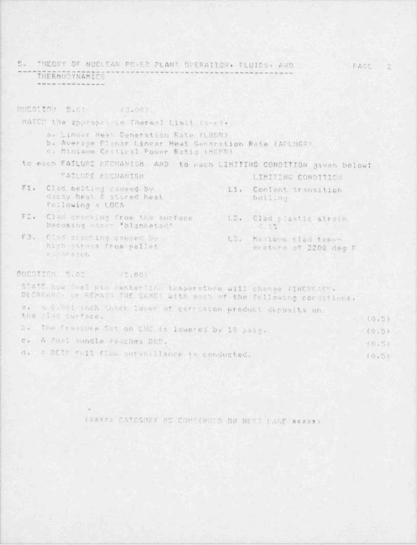
. . _ _ _ _ _ - - - . _ . . . _ - _ . . _ _ . - _ - - . _ _ . ._ . _ _ . - _ . _ _ _ _ _ _ _ . ~ . . . - _ . . _ _
i
} |1
|,
t5. THECRY OF NUCLEAR POVER PLANT UPERATION, FLUIDS, AND PAGE ' '
>~~~~
UEEEUDYUdE5C5~~~~~~~~~~~~~~~~~~~~~~~~~~~~~~~~~~~~~'j T 't
; ______________
!4
ii
' DNCGTI'Uf 5.Ci (3.00)
MATC!' the appr opr i. te Thermal Limit (a-c).
; a. Lines.r Heat' Generation Rate (LHGR) !! b. Average P: rria r Lineer. Heat Generation Rate (APLMGP)
i
I c. Mini. tium Critical C'o u e r Ratio (MCPR) '
i
! to each FAILURE McCHANISM AND to each LIMITING CONDITION given below*i
! cAILUPE LCCHANISH LIMITING CONDITIONF1. Clad c.eltin3 caused by Lt. Coolant transition
; d2 cay heat 2 stored heat boiling| following a LOCA
!
FC. Clad cr:,cking from t, h e surface L2. Clad plastic strainbecoming aper ' b l e:nk e t o d ' : 1 *: j
F3. C'.56 cracting csuced by L3. M a u i ra u n, clad t e r<. p - '
hijh strav, from pellet eratore of 2200 des F |e : ; , r s .t c r.
,
a ;
i
| OUESTIC't 5 . 0 '' /2.00)i
i| STATE how fuel pin c i-n t e r I i n . temperatore will chcnge ( INC P E AS'72 DECROMI- or REMAI7 THE CAMC' with each of the f oll owing coralit ions.I :
a. J. 0.001 inch thtch layer of corrosion product dt. posits onthe clad nurface. (0.G) ,
b. The Pt m ure Sct on CHC is lowered by 10 psig. (0.5) (c. A fuel Sundle ceaches DMD. (0.G) [d. ? RCIC full flou curveillance i< conducted. (0,5) .
t
i.-
6e
( ::* n CATEGORY 05 CONTINUCD ON Hn:T IAGE xxxxt)
i!
I
D
!L--_.,_._- -- - . - - -- - -- ------- - - " ' ~ ~ ~ ~ ~ ~ " " '

, _ _ _ _ . _ . _ . . _. - __
l
S. THEORY OF HUCLEAR POWER PLANT OPERATION, FLUIDS, AND PAGE 3-
________________________________________________ _______T HEP riODY t4 AMIC3____________ _
. OllCGTION S.00 (2.00)s
Concarning Cenatal Electric's Precond tioning Interim OperatingManagement Recocaaendctions (PCIOMR):
a. Stcrting with the fuel at a threshold of 11.0 Lu/ft. a m n::i m umramp increase is begun at time 0000 and the final desir'd power of
j 13 0 kw/ft is achieved at 2000. At this time, the required soak isperforned FOR 10 MINUTES, at which tioie the load dispatcher directs'
i c power reduction that taken nodal powar doun to 12.0 kw/ft. SELECTthe valid preconditioned value for this node.
! ASSUME THE (IAXINUM Rf,MP RATE IS .10 Ke/ft/hr (1.0)i
1) 11.0 Lw/ft2) 11.8 ko/ft3) 17.", Lu/ft4) 13.0 ku/rt)
j b. SELECT the minimon, time which w o u l .1 be required to raise power'
back to 13.0 Iu/ft, given the above m a:< i mu m raa.p rnte. (1.0)1) Inmediste (Raise to 13.0 kw/ft, w/o restrictions)2) 5 hour,
j 3) 12 hours4) 20 hoor:
1
;
i
i
-
.
i
:
(arxtr CATECORY 03 CONTIlluCD ON t1 EXT PACC *****)
!i
!
I
!
.
|
|
I
,
l
l- - , - . . - , - . , . - - . - - . . . . . . . - - - - . - . - - - .- -

.
So THEORY OF NilCLEAR POUER PLANT OPERATION, FLUIDS, AND P o r,t 4---- - --------------------------------------
--------------
QUESTION 5.04 (1.00)1
Which of the following statements best describes the operatingchar;cteristics of an LPRM detector?
a. Depletion of the detector's Uranium coating causes both theneutron and the samma sensitivity to DECREASE with detector agei
. the resulting neutron to gamna signal ratio remains relatively'
COHSTANT.
b. Since the detector functions as an ionization chamber and theArgon ga: pressure remains relatively CONSTANT, DOTH the neutronmed the samma sensitivity, as well as the neutron to sammasignal ratic, remain relatively CONSTANT as the detector ages.
c. Deple;.Lon of the detector's Uranium coating causes neutronsentitivity to DECREASE, but has an IllSIGNIFICANT effect on
,
;>ua sencitivity; this results in a neutron to gamma signaltr.tio DECREACE as the detector agec,
d. Depletion of the de tec to 's Ur anium coa ting has an I?'SIGNIFIC ANT: off'et on neutr on sensitivity, but causes gamma sensitivity to DECREASE:'
!- h i - .esults in 3 neutron to gamma signal ratio INCRIAGE as thedetect:r ages.
!
005:TIOi,' .35 (2.00)"
,
As part of the scr am procedure, the operator is dirocted toinsett * i.e SRit ' s and D M ' 1.,
Folloaing s sevoro LOCA, EXPLAIN how these systems could be2 .
used to dr*ect gross core dcmage. (1.0;
! b. E Y P ' .t ' " !.cw these 'vstemr. could be used to provide a crudei ndicati.>n af water i *vn t if Invel could not be confirmed byn o r s. u ! i n ; t i is.e n t a t i on . (1.0)
)|
I
ie
)
Ii
'
'r t i rr "ATEGORY O '- CCtlT T MilED ON tlEXT PAGE rz***),
I
l1
!|
t
1
_ ,. _ _ _ _ . _ _ _ _ _. - -. ._ , - - - - ~ - ~ ~ - - -_
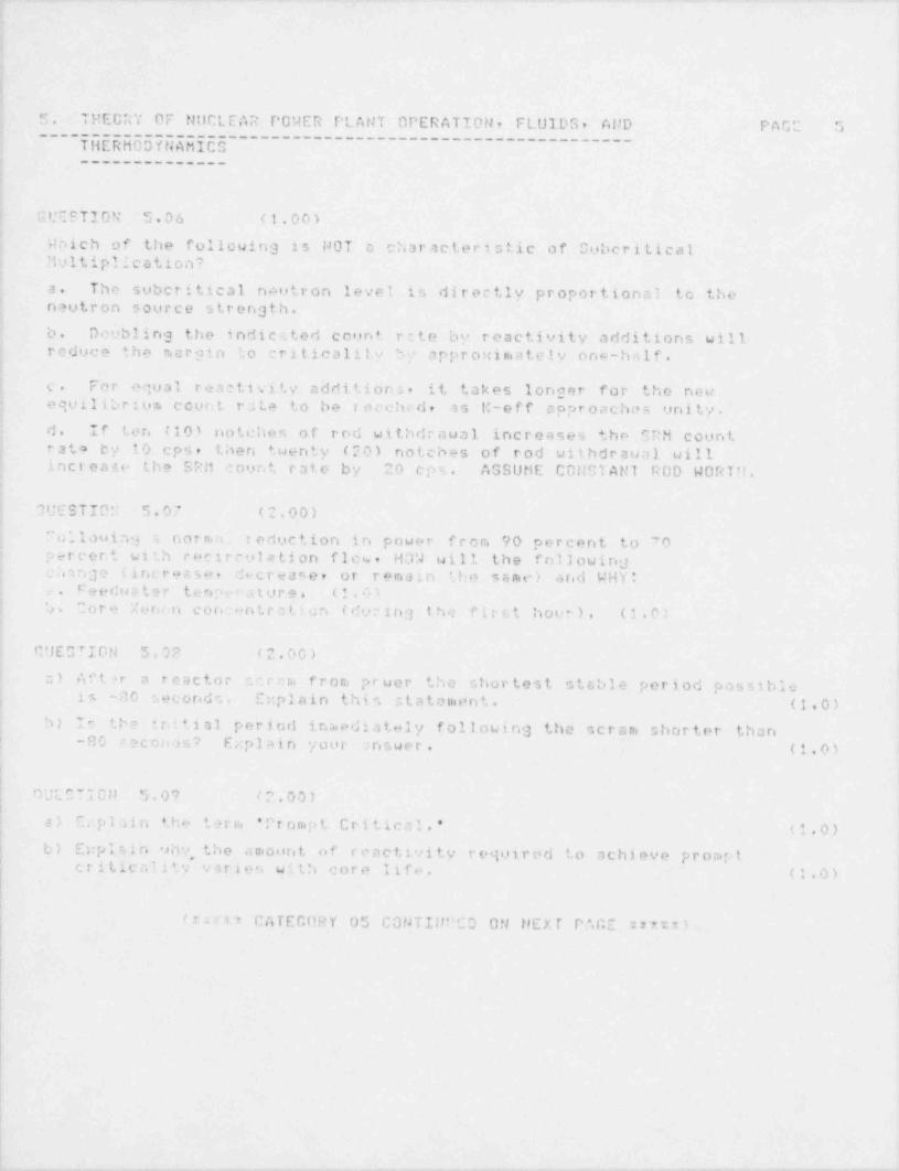
. -. _.
5. THEORY OF NUCLEAR POWER PLAT 4T OPERAT10tl, FLUIDS, AND PAGE ,"
_________________________________________________ __ ___THERMODYNAMICC,
: ______________
|
G I.'E C T I O N' 5.06 (1.00)
Which of the following is NOT c characteristic of Cuberitical!iultiplication?
a. The suberitical neutron level is directly proportional to theneutron source strength.
b. Doubling the indicated count rete by reactivity additions willreduce the margin to criticality by appr or:imately nna -half .
,
! c. For equal reactivity additions, it takes longer for the newequilibrius. count rate to be recched, as M-eff approaches unity.d. If ten (10) notches of rod withdrawal increases thn SRM count
~) rata by 10 cps, then tuenty (20) notches of rod wit hdrawal willincrease the SRM count rate by 20 cps. ASSUME CONSTANT ROD WORT't.
;
'1U E S T ID" 5.07 (2.00)
"u :. l o u i n.3. s norma reduction in power from 90 percent to 70p e r c e r.t w 2 r.h rec ir c ul a ti on flow. H39 will the fn110 wins
; eMnge (ince.sa w , decrease, or remain the same) eind WHY*Feedesstar tenpeoature. (1.0).
! :) . Core Xormn concentr a tion (during the first hour). (1.0)
i CUESTION 5.03 (2.00),
a) Aft 3r a reactor s c r c r., froni prwer the shortest stable period possible'is -80 secondc. E:: plain thi c. 2.tatement. (1-.0)
; b) 10 the it.i t i a l period ina.ediat+41y f oll owi ng the scr am shor ter thanj -80 ceconds? Explain your .nswer. (1.0):
DUESTION 5.0? I". 00)|
a) F,:p l a i n the term " Prompt Critical.' (1.0)( b) E::pl a i n . shy, the amount of reactivity required to achieve prompt| triticality v a r i e r, with core l i f .. . (;,o)|||
! (I m1 CATEGORY 05 CONTIN!'CD ON HEXT PAGE **t )Ii
!
||
_ _ _ _ _ _. _ . _ _ _ . _ . . - . . _ _ _ _ . _ . _ _ _ . . . . _ _ _ . . ~ - . .
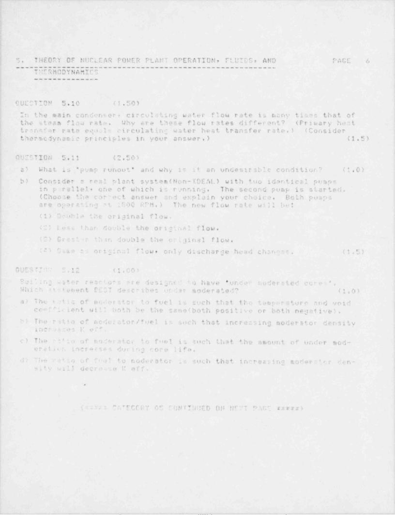
- - - -- _ - ._ .
;
,
4
'5 . THEORY OF NUCLEAR POWER PLANT OPERATION, FLUIDS, AND PAGE 6 .
--------------------------------------------------------
TMERMCDYNAMICS-------_------
2
I GUCCTIOM 5.10 (1.50)
In the main condent.er, circulating water flow rate i s r.any times that ofthe steam flou rate . Why sre these flow rates different? (Priraary heattrsnnfer rate equals circulating water heat transfer rate.) (Consider
,
thermcdynamic principles in your answer.) (1.5)
I
QUESTION 5.11 (2.50);
s) What Is " pump runout' and why is it an undesirable condition? (1.0)I
b) Consider s real plant system (Non-CDEAL) with tuo identical pumpsin parallel- one of which is r nnins. The second pump is started.(Choo.Te the correct answer and explain your choice. Do th pinpsare operating ct 1G00 RPM.) The new flow rate will bo*
(1) Dnnhia the original flow.4
?2; Lew than double the original flow.
(3) Grts'ur ? h 3 r. double tha oriainal flow.3
'"i t a. e s original flow, only discharge head ch,ng7 . (1.5)
GUESTIn' C.12 (1.00)
Sei';n; , iter reactors e r e d e s ; g n r. < ' 4 0 have 'unden modersted coro=*.
Which st: tenent EECT describe: un4: ar moderated? (1.0)
a) The r tic of vinderater to fuel is such that the temporatore and voidcro!' tic ient vill both be the cane (both positive or both negative).
b) The ratio of moderator / fuel i r, such that increasing moderstor densityiner 5r..n 1: e .' ' .
c) The ':':., of madcratcr to fuel in toch !.h a t the amount of under mod-ereti.r, incroEsmi during core life.
d) The >'1o of f n.? to noderator :. s such that increasing moderr# rr den-. .
M i 4, V Will deCredSe I: eff.
.
( : n .: ' ?,','ECCRY 05 r ep r!N:'En gli nr' T P.W; um)
_ - _ . _ __ .__ . . _ _ . . . . _ _ _ _ _ - _ _... .., . _ - , _ _, ___
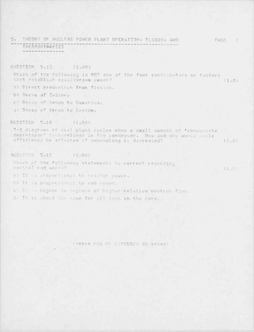
!
_ _ _ - _ _ _ - . _ _ - . _ _ _ _ , . . _ _ _ _ _ _ _ _ _ _ . _ . . - . - .. . ._ _ __ ..- _ ___ _ ._ -
i
!
4
.! 5. THEORY OF NUCLFAR POWER PLANT OPERATION, FLUIDS, AND PAGE 7__________________________________________________ ____
i - THERMODYNAMICS1
; ______________
J
;
# CUESTION 5.13 (1.00) !
Mbich of-the following is NOT ons of the four contributors or factorsthat cctablich equilibrium xenon? (1.0),
4
I a) Direct producticn from fission.i
j. b) Decay of Iodine.4
| c) Deccy of Xenon to Samaritn. [it
j d) Decay cf Xer.on to Casium. '
,
i GUEST 10N 5.14 (1.00),
i T-S diagrams of real plant cycles show a small amount of " condensate i; depression' (cubceoling) in t;no condenser. llow and uhy would evele{ efficiency be affected if subcooling is decreased? (1.0)|!
1UESTIPfl 5.15 (1.00)4
i .Which of the following statements 15 correct rey,rdingj .
'
j control rod worth? (1.0)
a) It : s ;.> r o p o r t. i c n a l to reactor power. 1
b) It :s proport.i r.c1 to rod e p. ed.,
I c .' l '.
'
highor li egions of higher relative n e'> t r e r- flou.'-
d) It in sbotit the 3 :,n e for all ocd; in the core.
I
(?rrx* GD GF C '.T E G O P Y 0 5 * n * * ).
{
.,
,
. - . . - , . - . - . . _ . - , _ _ , _ - , _ . , _ . _ - . , _ - . , - - . - , - - . _ _ - - . _ _ . . _ _ _ _ _ _ _ . . _ . _ , - . . , . - - ~ _ _ , . . _ _ _ , . _ . - . . . - , _ . , - , - - - - - . . . _ , - _ . , . - -.

. .- - - _ , . - - . . - ~ _. _ .- - . . _ _. - ...- - - _ - - -. .~
-.!
i'
.
I
L
4. PtANT SYSTEMS DESIGil, C0tlTROL. A tJ D INGIRL PAGr a1_____________________________________________'MENTATI0t1___._____
i-
Of.;ESTION 6.01 ( ~' . 5 0 ).
A. What is the tsasan t h a t, the safaty/reliof valvo discharga f!'
' i r.e a y r e e.a v i p p M u i +. h vacoon rellef valve'' (i.5).
I E. OTATE how i r:CRi ASE, DECREA::. REMAIN TlE SAM) Drevall T're:suc-| would be e:,pec t ed to respond to ar. CRV discharge line .acuun..
j r71ief valva STIC1'T"G OPEN during ar tuation of the SRV.,
j EXPLAIN YO"E C|'0 ICE. (*.0)'
I C''TOTION 4.02 ( 1 0 ') ) l
i Which one of the follcuins is TRUE regardirig the operation of the1 Main Stesa. Isolation Valves (MSIV's)?!
; c. Air pressura is used to nota. ally open the MCIV's and only >;pring,'
pressure nottally will close t h e r. . !
b. A c c u r u 1 M.c r 2, wpply nor raal , n e o ra t,i c prescure for v t '. /
| operation, '.;'.,- !. h e pirnt rir cistem providing e backup source.' c G.1 ..a i d :1vas contr01 th? ednissiori o" pneumatic pi" -ure toi each MSN 5 .' t only OrlE solenoic' rm d be enereired to L. cop the ,
i F.T V y an.t
1
j d. On t r, .t' close sisnn' the it is vented from the b c. ' * < ra or-
'
} the o; * r.g pitton to tha top 'o allow the valve t c. close rapidly.!
OUET'T'' .03 (5.00),
Th ,'t:n; 2; opo r ; * : ng not n :s I ly ,t roll poucr uith the FoC'~ .n TIIREE- ,
ELEriTt'' CD 'J T ROL . '! a a of the ul n stoamline flow im?ots into the FUCG |fwi'' uch that l' to imputt.ng cra flow for that e, t e a m l i n e .
A . . i n.. a th = t t h.> 1r .- t o '- doos r . r. * tcrcm.A '' t *# r '' p t a r. ' :ttain: cteady-state candition, will the (0,5): . '
" ins. ,.ctor level is r. HIGil? R . LOWER, or thn SAf1E at initially?*
^ ,,eto the . i-on.es of th+ '~UCG to this transient. (Include .2.5). *
c.m, col gwl .i :nc.2 s and * ' . r. couponent rotpon e to thesor. p.r. t ,, inc lu.le til the r.1 |' e c t u .var, g n .
. .
.
rrav CATEri"f 02 00:21I!JitCD Oil JrXT PACF *ns z )
i
I,
k- 6.
|,
t
~ - - - - . - - , , - - , - - - ~ ---m.<w-wne,n~~,,-n,, ,, -. . . . - , , .,,-e,---,.
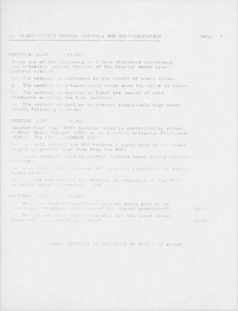
- - _ _ _ _ _ _ _ _ _ _ _ - _ _ _ - _ - _ _ _ _ _ _ _ _ - _ _ _ _
t
h!
,
iid
.
4 |1 4. PLANT c,YSTEllS DESIGN, CONTRCL. AND INSTRUMENTATION PAGE 94
4
I ,,
UUESTION 6.04 (1.00)
! Which one of the fellowing i e- a trua statement concerning.
i
t she cotomatic setback feature of the Reactor Water Level) Control system?
,
1
| a. The setbcck is initiated as the result of every scram.
b. The setbr,rk ti automatically reset when the scram is reset. :>
Ic. The setback 4 9 applied t. o limit the an.ount of coldreadwater entwing the F.W. nor les..
d. The setback in opplied to prevent excessively high water.;
i levels followins , scram,i +
i |GUESTION 4.05 (1.00)1
!
! Reactor Fee d "o:ip (RFP) turbino speed in controlled by eitherj a Motor Speed Ch::n j e r (MSC) or are Electric Autor atic Positioner! (EAP). The FAP ..(CM00GE ONE) '
.
) will control the RFP turbine's speed only if its speed ic. ...
signal is grerter than that from the MCC. *
S. . . . i s, normall" ned 1, o contrcl turbine speed during turbluemttrtop.
!
u nli:.e F, N 4 40, d o +., HOT h.;ve the capa'illt" of nano:1c. .... oi speed control.1' c. ...aill not c ant.r ;i tho turbine in t u t o ni a t i c if the GV-7
nelenoid v21vo na r gi:M shot,.,
i
| nyt3TIap r, , q (4,90) '
:
| c. W i . c. t. .re rive (G) cio:tl,tc,7 . c. y s ', 7 m e, which most be in i
; y .> r a t i .m J..r prop *r oper7fion of the diesel genera tor s? ( ;' . G )1
be ble" I li} 7.et O f 't . n C "/ i n i I. ) . i t i gJ n Ld n # i a l'' O the L|l['t' e eik O S H 1| [ f' n d t ' *,0 0 a p t, "1111 in ,ffetti (1.0),a .
i
!
Ii,
i ruer CATICOPY 06 CONTIDMCD ON NEXT r.,r,c n yn)
I -
i <
..
f
!^
t
f !| t
I
i ,
'r
I
| rF .- _ .. _ _- .--._ , - - - , . , , - , . , . , - . - . ______-,,m.. , ,~ ,_ ,, _ .,.,,, - o-__.,---,,,..,..--,,.,,.,--,---y_ .-

_. - . ._ _ , _ _ _ _ _ _ _ _ _ _ . _ . _ _ _ _ . _. _ _. . _ _ _ . . ._ _
iu
1i
I
e
i
6. PLANT SYGTEMS DESIGN, C f1N T R O L , AtlD INSTRUtiENTATION PAGE 10--------------------------------------------- -------
f.
OUECTTON 6.07 (2.00)4
What are the four (4) hi:3h speed permissives that need to '
be met in order to transfer the recirculation punp speensfrom 51ou to fast? Include setpoints where appropriate. (2.0) 5
,
i
i
OUESTION 6.00 (2.50)d
a. INDICATC the TWO (2) scurceu of contr01 rod seram hydraulic (1.0)1
pressure.;
|'Lb. DISCUSS HOW thee,e two sources (in "a* above) ate effective in
cr u ins a ceran. at'4
s
| (1) Zero reactor pressure (0.5); (2) 650 psig reactor pressure (0.3)
(3) 1000 psig reactor pre %ure (0.5)i
ii !
i GUESTIO:t c.07 (4.00)1
] a. Desciibe the riou path for " vel pool water when the Ri'R system (1.5)--
is beirig o >ed to assist, the fuel pcol c o o l i n g s y s t e r.. . ( Ai drw:.9iw. be used but 1 .- not neconsary)
j b D o r e n s '. h '. , a. o . ! , o f 0 7. ~ : s. (fuel pool cool 2nc). a enim (1.01 !; bicc' .t u s t be in-tsiisr. to prevont roe ,ntonetat f u n e +. i o n ;j " '-. d e :'.t r r i t r3 in the ANP Iysten. What 2 c t :. o n 09es thit! . ' ;y pe r:v eret?
i c. List fi-' l o c ,1 fiont tbc: ., h e RHR pump c;n dischar9 to other (1.5)i then t' ceactor vessa! inj9ction nornleo. and the fuel pool4 .,
t 0 k| * r %g e . . '
.
.
-
C UN I T O!' '2 . I Q (7.00's'
9 hat h . .a c r y C e n t a i or..e n t n . t r o.nontati c n in available 'or your use''
j cn mee t i shotdoun pan 937 Give 3 indications and do not includoj 'U. : " ' * ' C ', o t' /esiel [ .~p 's i c J t i o q t; .-
!
F
|*
.
| 'nixx- r *T r " "rP/ I: ' *0NTINUED ON !!r"T i 'd;E rvrxx)si
1
Ib n
;
i!
,I
I
L .
|j +
1
_. ____ _,. , _ _ _ - . - - _ . . _ ___ _ __ _ _ . . _ . - . _ . _ . , _ _ _ . . _ _ _ _ _ . _ . _ _ _ . ~ . _ _ . . _ _ _ _ _ _ . _ _ _ _ _.

6. F l.n ?ti 9YS7 E:13 DESIGN r CONTROL, AND INSTRUMENTATION PAGE 11------------------------------------------------------
QUESTION 6.21 (3.00)
For the indicated s c r a rn s. list th" follouing:
a. Ceram c;;nal setpoint |
b. S c r s e. logic (or number of initiatins events r < equi r ed tocau2e a cecm)
c. When scrac, is bypassedF
Screm signal,:1. Turbine Stop Valve Clocore (1.5)2. Tucbine Control UcIve O - *. Closure. ( 1. T; )
(: :r END C: Cf!EGDPY 0 6 u n * *. )
.

.__ _ _ . _ . . _ - - - - . . _ . .- _ _ _ _ _ _ _ . _ _ . ._ . _ __._m-
.
I
!I
'i
i-
t
7. PROCEDURES - NORt1ALr A D N 0 9 ti A L , EMERGEtK.Y AND PAGE 12,4
~~~~EED50L5556AE~EUI!I56L~~~~~~~~~~~~~~~~~~~~~~~~
____________________
4
i
!, OUECTION 7.01 (1.50)
| The LCA's refer you to LOA-RD-07, Simultaneous Operation of both CRD: pumper ,* s a way to .taninine injection into the vessel. If you seej using the CRD pur:ips to maintain level. should you reset the s e r e nt?
t
| Explain. '
i
! DUESTION 7.02 (0.00)
i If an AT'AS condition exisi,2, when must you start and inject SBLC?:
)i GUESTION 7.03 (1.50) >
>
Regarding LGP 1-1, Pornial Unit Otartup*! '4hnt crn bo done to mini.1ine fanduater no :le, sparger. nd header
thermal hycraulic stres s at l u.. frad flow conditions (in lieu of usingi the f aedcar ^1ush lina to rego19 e feeduater header p.#ssure)?
DUCCTIC" 7.04 (2.00)
STATC hi r ! CA (01-05) would have an entry condition of t. h efal'. win-3: (An answer rm be 4.wd for note than onecondition.)
j a. erU u t.o r leve : .u then 12.5' (.5)j b. C o,a: + -ton pool t eroper u t ore equal to i05 degreen F. (.,)
c. An ,silnion condition exist 5 which initiates a reactor s e r a ni . (.D),
d. Dryunt1 pecssore greater thari 1.69 psig. (.r3|
|:
| 01E'TICH 7.05 (4.00)i
hactor , . o u .s r operation with CNE recirculation pump it permitte.d,
p r o v i d.= d ''ct (6) 31; c on d i t ioris are tr: e t . List four (4) of the*
s
.
2i, ( /. ) m. . d i L l o r e :. .i
|
1 *i
i
i n * ** P ATICORY 0- 0 0ilT INI'':0 Di4 NEXT PACE r * * :.: '.I
Ii
I e
l
!
i
, - ~ . . , - . _ . . ,.-w-. ., -.. - -. -....,,-,-,,,_.,,---n.... . . , , . , , , - - . . , , . . --,,yn.--,,,,.v ., .-n,..- -
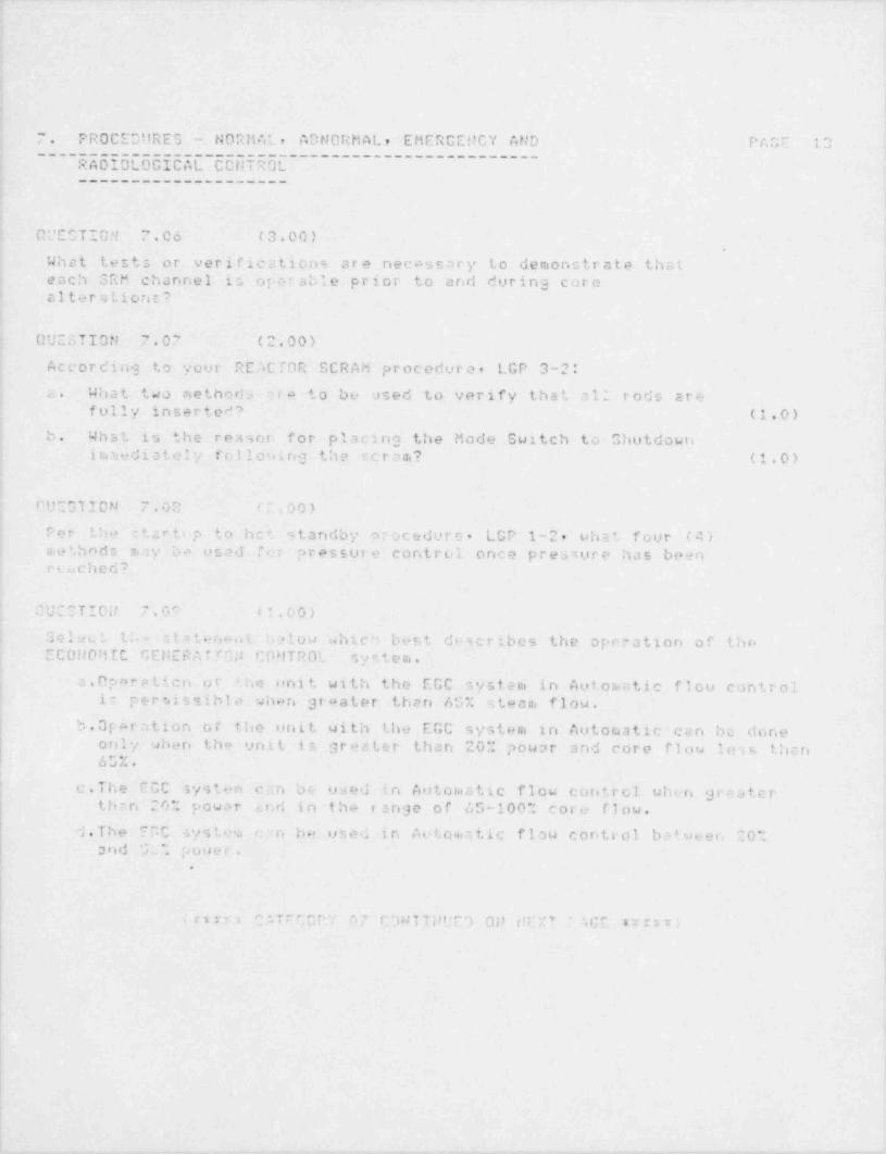
_. __.- - . __
7. PROCEOi!RES - NORMAL, ADNORMAL, EMER0ENCY AND PAGE 10
~~~~5dD56[6556dL 555TE5L- ------------------------
____________________
OL'CCTION 7.06 (3.00).
What tests or verifications are necassary to demonntrate thateach SRM channel is operable prior to and during core4
alterationt?
QUESTION 7.07 (2.00)
According to your REACTOR SCRAM procedure, LGP 3-2:,
; a. What two nethods era to be used to verify that cli rods are"
fully inserted? (1.0)
b. What is the reason for placing the Mode Switch to Ohutdown,
i ron edi a t el y follouing the scram? (1.0)
OUE31 ION 7.02 /2,00)
Per the ctcrtop to hct standby procedure. LGP 1-2, what four (4).
! methnds may ba used ." e r pressui e control once pressure has beenreached?
OUCSTICU 7.07 (1.00)
SelucL th- c L a t e n.- i t ..alou which best describes the operation of theECONOMIC r.EHERATTON CDMTROL syetem.
a.Operatico or the unit with the ECC system in Aut ornatic fl ou control,
1 is p e r tei s s i b l o when graater than 65% steam flow.b. Operation of the unit with the EGC system in Autoraatic can be done
only when the unit is greater than 20% power and core flow loss than65%.
' c.The ECC systen can be used in Autoinatic flow coretrol wh e r. greaterthan 20% power e. n d in the range of 65-100% core flow.
d.The FCC ystea c.'n be used in Aetoriatic flow control batween 20%and GL% pouer.
.
;
( rin Cf Trr;0rr. 07 C3N T TUUE') 00 FEXT " AGE arrit;
!
L
, , .- -
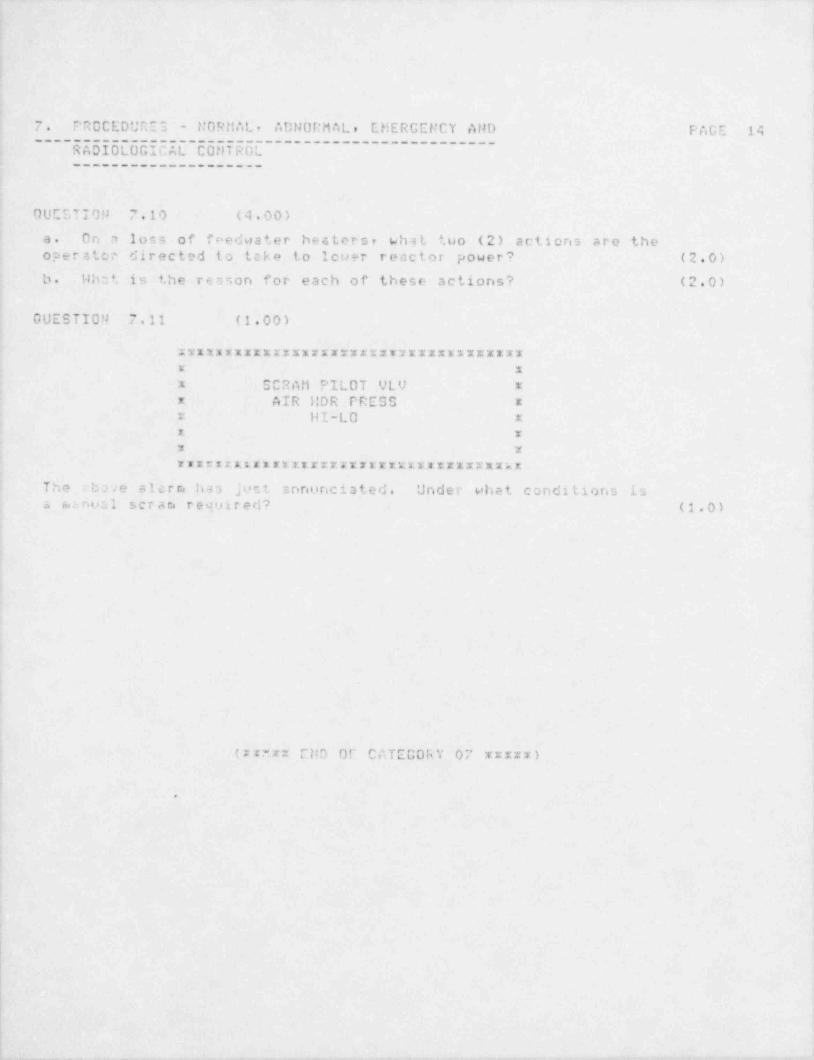
_ _ _ _ - _ _ - _ _ - _ _ _ _ _ _ _ _ _ _ _ _ _ - _ _ _ - _ _ _ _ _ _ _ _ _ _ _ _ _ _ _ _ _ _ _ _ _ _ _ _ - _ _ _ _ _ _ _ _ _ _ _ _ _ _ _ _ _ _ _ _ _ _ _ _ _ _ _ _ _ _ _ __ _ _ _ - _ _ _ _ _ _ _ _ - _ -
|
7. PROCEDURE 3 - N O R it A L , ADN DI:M A L , EMERGENCY AND PAGE 14
~ ~s5055L65ECdl C5 sis 5E------------------------~
____________________
OUCSTION 7.10 (4 00)
a. On a loss of fnedwater besterst what tuo (2) actions are theoperator directed to tcke to louer reactor power? (2.0)
b. Wh::t is the re:ison for each of these actions? (2.0)
GUESTION 7.11 (1.00)
xxxxxxxxxxxxxxxxxxxxxxvwxxxxxxxxxxxxx xx SCRAti PILOT VLV x* AIR 1:DR PRESS ** HI-LO xx xx xrarrxxxxxxxsxxxxxxxxxxxxxxxxxxxxxxxx
The ebne alcrm has just snnunciated. Under what conditions isa canon 1 scram required? (1.0)
,
I
(x cxx CDD OF CATEGORY 07 xxxxx)
.
I
e
5
!
_ _ - _ _ _ -- . - . -. _ ._ . - . _ . ,_

.-. .- . - -. - - - . _ _ _ _ _ -
S. ADMINISTRATI''E PROCEDURES, CONDITIONS, AND LIMITATIONS PAGE 15----------------------------------------------------------
t
GUCCYION 8.01 (1.00)
Unit 1 is in COLD SHUTDOW durins a reactor strartup with noou tstanc'ing defi ciencies . Drywell and Suppression Chamber
dHf rogen Recombiner A beconies INOP. It is anticipated thatrepairs will be complete within twenty-four (24) hours.
i
The Shift Supervisor determines thct the requiaad action (s) perthe Unit 1 Technical Specification: is(are) (CHOOSE ONE)...
4
a. ... Operational Condition 4 must be maintainnd (Entry intoOperational Condition 5 is acceptable)
be . . .S tar Lup activities may continue; Operational Condition3 may be entered, but not c::ceeded.
c. ...Startup setivities may continue: Operational Condition 2j nay be entered, but not excaeded: Oxygen concentration shall bc; c.a ln ta in ed < C v.'c .i
d. ...Startup activit.ies m r. y continua) Operational Condition 1cnd/or 2 mcy be entered. hot the Recombiner must be rsturned toan OrTRABLE status within 30 days.
NOTE: APFLICABLE TS's ARE ENCLOCED FOR REFERENCE
0:i:CTICN n.02 (4.00i
a. 'Ahat are the two nethods to be used to insure that a control rod ,
'is coupled to its drive? (1.0)
b. What are .i: (6; conditions which would cause a control rodto be considered inoparable por the Technical Spscifiestions? (0.0),
I
I
(~we rr CATECP,0Y 00 00NTUUED 09 NOT PACE n n .: )
f. .
*
|
|
.!
! - - . . _ - , .. . -. . . .,.

4
3. A 9 MI T '' C T 'i' A T T F. F RO C E"'.m E O , CON 0!TICMG, AND L1hITATI'1NC iAGE 14__________________________________________________________
-*c+' . t . * . rhu, eJ . .., e> .- '. . a_ c .. . . .
a. I- it r.ecncscrv to . lear 'n entire outage if a teston a c:ngle c o m p a n =e n t t:._t i t, part of that outaae is tobe m a r f o r ra e d ? Erplain cour cnswer. (1.0)
b. .4 a s i n t e n -i n c e fore.2n wishes to clear his turbine outaseexcept 'cr the M S I'.' ' s which arn closed ar d tass +d cut ofnrvice for othnts as well as hinself. Select the statementbelow which bast dnscribec the action which should be taken. (1.0)
1. Pull 'll ends e' cept for t h sc Master and tha aut ofservica c r.ic on the M S I'.' ' s .
7. Ov11 c.1 1 cstda e: cept for the ones on the MGI'J's. writea nw out.se ero hang a riou n. a s t e r .
5. "' u l ; a': 'h> .; r +. and hang a new nota.'e on the ;iSI'/ ' s .,
1 Tr or, er 'e = :rt 42 h.ing on th> MSIt''s to cna of tho otherfore 19n .nd .c l .i a r 'he rencinder af the out . y,
O'i]OITON C , '' . ( 2 . C ') ',
' - ' re cra " 3 .i r r .- i n +, i c r, - in o.ich o+e of a Temporary_ .3 t m c'r .'a 11 n.n ro'.. - One of o h .i t h it " L .:. f t i n g
Lesde ~ .c h n i e 3 '_ 'a ; - c. i f i c a t i o n i .c ', i o n'.,
, v ; i a r.. e n ', 2 . *4
Jh : t 'r: * : c ', r . e r th. - condit:anr? ..S).
b. If ' :ia , m; -cy S :t C h e r.n e is to lift lead- to ..m o !T sc: icai 57.c+.. . tion ( . a o ri r e c o i r e r.i e n t s , who cost conent ? (1.0)
es s . ". ;~ a r t . u> * c . ' ' c- g , r- (J f". - -- .;-.;
6., a
f- 'I. 8 b* b _, [ ! 4, 6_) ~
\. ,Q G a: '1 >er 3 o Ta s * -' r .' o r c. A 0 (* n() t40 31' $ 0 l ta l y ,ctor es; 4 1 . 4, y p jeyvel indjrat(Ons fnp in c a s t i . ! !r- *
,
ionu r ti.g i 1.s n '. ; 5: e s 1. : - os irig all redone' ant and ovoc-.' i.
'
., . n q 1e el i r. : .- i ' n e n t -- t i o ri and levol alarms, o t h .- r .e a r a ni e t. e rr
,,
,, f e hfI $ $ I) ' ! l ,I d |5 b8 e | ., s |' f 4 '8If g) 1.h , ) t' N h ,, I T [ 5 $' I ') ,hI(.
;; mold :w .- .|.* ', .
< cr7 ,,7<;- y; rr r I; pier) 0;i p;:4 T f i,G.: n r::: ''
_ - _ _ _ _ _ _ _ _ _ _ - _ - -
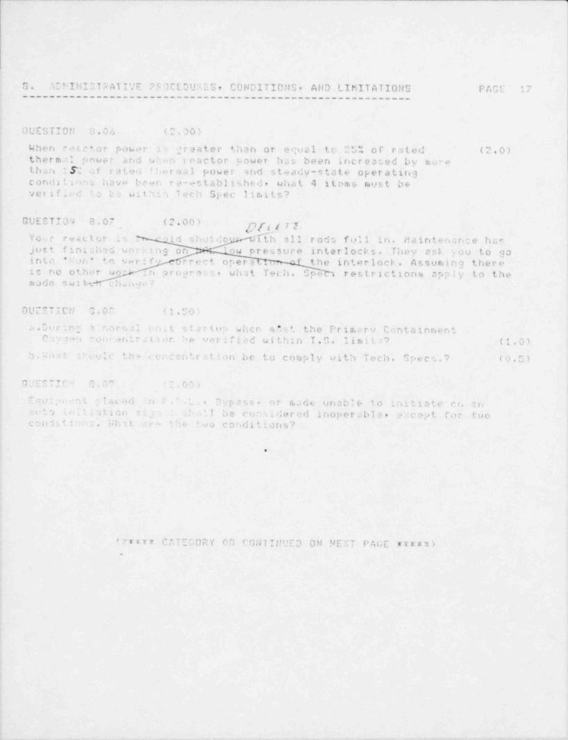
G. ACFINISTPATI. CONDITIONS, AllD LIMITATIONS PAGE 17_ _ _ _ _ _ _ _ _ _ _ _ _ _ _ _ '_' E P G O C E D U ;i E S ,_________________________________________
GUESTION 3.04 (2.00)
When emetor power i- ;teater than or equal to 2 5': of rated (2.0)therm.11 pouer and u:en ieactor power has been increated by morethan 1.9: of rated t lier ma l power and steady-state operatingcondittons havo been re .*ctablished, what 4 items must beverified 1. 0 be within Tech Spec limits?
GUESTION 8.07 (2.00) xf?f t I i e -Your r-setor im ,ld :; h u t d o o - tth all rods full in. Maintenance harjust finiched uorking on '
ou pressure interlocks. They ask you to gainto * Fun * to v-rif" .. rrect opers ' the interlock. Assuming there,
ic no other uo ' :n :a r o g r e 3 0 , what Tech. Spe restrictions apply to the.
made swih. chu n p '
OU~ETICN '1. 0 C (1.50;
i.Dorinc , noctal io. t startoo whcn .Tn* s t the Primary Containnenti
C , mn non .+ntretior. he verified ui thin T.G. l i m i i =, ? (1.0)
b . W h =; t Revic th- .: e e c e n t.r a t ' o n be to comply uith Tech. Speen.? (0.5)
GUESTIf" 3.07 ' : . 0 0 ~)
Equi;>.. n t claced 'n T ' . t. - 3ypass- or n.ade unable to initiate en anant , in.'.stion r ig i _ :- ,1 be considered inoperable, a. cept for tuocondatiin . S h 3 t- =c- the Wo conditions?
.
(7r*rr CATECORY 00 CONT!!!UED ON NEXT P A4;E mn ).
-_

.- .- . .
8. ADMINISTRATIVE PROCEDURES, CONDITIONS, AND LIMITATIONS PAGE 10__________________________________________________________
.
QUESTION 8.10 (2.00)
Which of the following statements are True and which are False inPesard to the use of Caution Cards.
a.Cantion cards can he used to direct attention to any specialcondition of an operating s y s t ,ri where a ha std to personneln.?y be involved.
b. Caution cards can be used to inform personnel that instrumentIndication requires a correction factor.
c.Csution cseds must be authorized by the NSO and logged in thecaution card 109,
4. Caution cards inform personnel of required notification priorto using equipment.
QUESTICM G.11 (2.00)
Per jour a d c. ; m e t e r, t i v e procedure =,. when are t,h e conditicns of',
'
wnd under ecntrol' consid-r..d to existo (2.0).
" | C'10U 8.12 (1.50)
Uhst w3 t be ;one t the beginning o' v,ch :;hift in regard toRadi:t;on Nor'x P e r r.a t s and who has the responsibility for this? (1.5)
4
( r "~;;: END OF CATEGORY 08 x x x x:x )( : x: u ? r u EiiD OF CXAMI:!ATION xxn =2::xxxxxva)
.
I
r
.-- - - . - - .
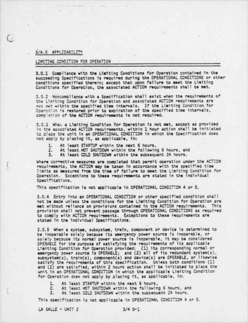
. _ _ _ _ . _ _ _ _ _ ___ _ .- _ ._
. . . . . . . . . . . . ._
l -
, .
,
. .
. .,
.
.
b.' .,
"
i
3'/4.0 APPLICABILITY..
- LIMITING CONDITION FOR OPERATION -
l
3.0.1 Compliance with the Limiting Conditions'for Operation contained in thesucceeding Specifications is required during the OPERATIONAL CONDITIONS or other
i conditions specified therein; except that upon failure to meet the Limiting ;'
; Conditions for Operation, the associated ACTION requirements shall be met.
3.0.2 Noncompliance with a Specification shall exist when the requirements ofthe Limiting Condition for Operation and associated ACTION requirements arenot .reet within the specified time intervals. If the Limiting Condition. for
~ C::arsti:n is restored prior to expiration of the specified time intervals,i coepistien of the ACTION requirements is not required.
3.0.3 Wher. a Limiting' Condition "for Operation is not met, except as providedin the associated ACTION requirements, within 1 hour action shall be initiatedt placa the unit in an CPERATIONAL CONDITION in which the Specification doesnot acply by placing it,'as applicab.le, in:
*
1. At least STARTUP within the next 6 hours.2. At Teast HOT SHUTDOWN within the following 6 hours, and3. At least COLD SHUTDOWN within the subsequent 24 hours.
! g. Where corrective sensures are completed that permit operation under the ACTIONA. requirements, .the ACTION any be' taken in accordance with the specified time^
| limits as measured from the time of failure to meet the Limiting Condition forOperation. Exceptions to these requirements are stated in the individuali
Specifications. y,
,,,
This specification is not applicable in CPERATIONAL CONDITION 4 or 5.
3.0.4 Entn into an CPERATIONAL CONDITION or other specified condition shallnot be made unless the conditions for the Limiting Condition for Operation aremet without reliance on provisions contained in the ACTION requirements. This ,
provision shall not prevent passage through OPERATIONAL CONDITIONS as required~,
to comply with ACTION requirements. Exceptions to these requirements arestated in the individual Specifications.
~
3.0.5 When a sy' stem, subsystem, train, component or device is detemined to ..
be inoperable solely because its emergency power source is inoperable, orsolely because its nomal power source is inoperable, it may be consideredOPERABE for the purpose of satisfying the requirements of its applicableLimiting Condition for Operation provided: (1) its corresponding nomal oremergency power source is OPERABLE; and (2) all of its redundant system (s),subsystem (s), train (s), component (s) and device (s) are OPERABLE, or likewise '
satisfy the requirements of this specification. Unless both conditions (1)and (2) are satisfied, within 2 hours action shall be initiated to place theunit in an OPERATIONAL CONDITION in which the applicable Limiting Conditionfor Operation does not apply by placing it, as applicable, in:
1. At least STARTUP within the next 6 hours,
; e 2. At least HOT SHUTCOWN within the following 6 hours, andk 3. At least COLD SHUTDOWN within the subsequent 24 hours.<
This specification is not applicable in OPERATIONAL CONDITION 4 or 5.
LA SALLE - UNIT 2 3/4 0-1
_ _ _ _ _ _ _ _ _ _ _ .__ - _ _ _ _ _ _ _ _ - _ . . - - - . . _ _ _ _ _ . . _,

-- _ _ . _ _ . . . -- _ _ _ _ _ . . - _
-
''
_' . _ ^ ''. :
.,
.
**
. .
.
;- .
. .
-, .
" CONTAINMENT SYSTEMS -
3/4.6.6 PRIMARY CONTAINMENT ATNOSPHERE CONTROL
DRYWELL AND SUPPRESSION CHAM 9ER NYDROGEN RECOMBINER SYSTEMS -. . _
.. . . _ _ .
LIMITING CONOITION FOR OPERATION
3. 6. 6.1 Two independent drywell' and suppression chamber hydrogen recombiner,
systans shall be OPERA 8LE.i,
APPLICA81LITY: OPERATIONAL CONDITICNS 1 and 2.i
ACTION:*
With one drywell and/or suppression chs-bar hydrogen recombiner system inoperable, '
restore the inoperable systas to OPERA 3LE status within 30 days or be in at leastHOT SHUTDOWN within the next 12 hours.
,
SURVEILLANCE REQUIREMENTS
. 4. 6. 6.1 Each drywell and suppression chamber hydrogen recombiner system shallbe demonstrated CPERA8LE:
! 'At least once per 92 days by cycling each flow control valve anda.. recirculation valve through at least one completa cycle of full
f' travel.,
'
b. At least once per 6 months by verifying, during a recombiner systas,
functional tast: -
L That the heaters are OPERA 8LE by dataraining that the currentin each phase differs by less than or equal to 51 from the
! oth'er phases and is within 5% of the value observed in the| original acceptance test, corrected for line voltage differences.
2. That the reaction chamber gas temperature increases to 1200 2 25'F|
- within 2 hours.i
At least once per b months by:.
j c-.
L Performing a CHANNEL CALIBRATION of all recombiner operatingj instrumentation and control circuits. .
2. Verifying the integrity of all heater electrical circuits by. .
perfoming a resistance to ground test within 30 minutes following~
the above required functional test. The resistance to ground fori
I any heater phase shall be greater than or equal to 100,000 ohms.!
d. By measuring the leakage rata:L As a part of the overall integrated leakage rata test required
||
by Specification 3.6.L2, or1 -
2. By seasuring the leakage rate of the systes outside of thecontainment isolation valves at P,, 39.6 psig, on the schedulerequired by Specification 4.6.1.2 and including the measured. .
leakage as a part of the leakage determined in accordance with'
Specification 4.6.L2.
LA 5'LLE - UNIT 2 3/4 6-46A-. - - - _ _ - - _ _ . - - _ _ _ _ - - . , , .

- - - - - - - - - - . - - _ - - _ . .- -_ -. = = -
,
i N,.,,
.
:
STEAM TABLE!
! '
PROPERTIES OF SATURATED STEAM AND SAWRATED WATER (TLMPERAWRE)
Volume, ft AD Entha4py. Stu AD Entrop[. Stu/ID a F3
1
water Even Steem W eter Eve , Steam water hvec Steam*Te s.
s, s, |'t % v h h h sq o*
e q og e,
32 0.08859 0.01602 3305 3305 -0.02 1075.5 1075.5 0.0000 2.1873 2.1873 32*
i
35 0.09991 0.01602 2948 2948 3.00 1073.8 1076.8 0.0061 2.1706 2.1767 35
40 0.12163 0.01602 2446 2446 8.03 1071.0 1079.0 0.0162 2.1432 2.1594 40
4 45 0.14744 0.01602 2037.7 2037.8 13.04 1068.1 1081.2 0.0262 2.1164 2.1426 45
| 50 0.17796 0.01602 1704.8 1704.8 18.05 1065.3 1083.4 0.0361 2.0901 2.1262 to
I 60 0.2561 0.01603 1207.6 1207.6 28.06 1059.7 1087.7 0.0555 2.0391 2.0946 60
70 0J629 0.01605 868.3 868.4 38.05 1054.0 1092.1 0.0745 1.9900 2.0645 70
| 80 0.5068 0.01607 6333 633.3 48.04 1048.4 1096.4 0.0932 1.9426 2.0359 80
; 90 0.6981 0.01610 468.1 ,468.1 58.02 1042.7 1100.8 0.1115 1.8970 2.0C86 to
100 0.9492 0.01613 350.4 350.4 68.00 1037.1 1105.1- 0.1295 1.8530 1.9825 100
110 1.2750 0.01617 265.4 265.4 77.98 1031.4 1109.3 0.1472 1.8105 1.9577 110'
f 120 1.6927 0.01620 203.25 203.26 87.97 1025.6 1113.6 0.1646 1.7693 1.9339 120
130 2.2230 0.01625 157J2 157.33 97.96 1019.8 1117.8 0.1817 1.7295 1.9112 130
140 2.8892 0.01629 122.98 123.00 107.95 1014.0 1122.0 0.1985 1.6910 1.8895 140,
i 150 3.718 0.01634 97.05 97.07 117.95 1008.2 1126.1 0.2150 1.6536 1.8686 150
160 4.741 0.01640 77.27 77.29 127.96 1002.2 1130.2 0.2313 1.6174 1.8487 160
170 5.993 0.01645 62.04 62.06 137.97 996.2 1134.2 0.2473 1.5822 1.8295 170
180 7.511 0.01651 50.21 50.22 148.00 990.2 1138.2 0.2631 1.5480 1.8111 180'
i 190 9.340 0.01657 40.94 40.96 158.04 984.1 1142.1 0.2787 1.5148 1.7934 190
j 200 11.526 0.01664 33.62 33.64 168.09 977.9 1146.0 0.2940 1.4824 1.7764 200 *
210 14.123 0.01671 27.80 27.82 178.15 971.6 1149.7 03091 1.4509 1.7600 210'
212 14 696 0.01672 26.78 26.80 180.17 970J 1150.5 0.3121 1.4447 1.7568 212
{ 220 17.186 0.01678 23.13 23.15 188.23 965.2 1153.4 03241 1.4201 1.7442 220
230 20.779 0.01685 19.364 19.381 198.33 958.7 1157.1 03388 1.3902 1.7290 230* 240 24 968 0.01693 16304 16.321 208.45 952.1 1160.6 03533 1.3609 1.7142 240
'
250 29.825 0.01701 13.802 13.819 218.59 945.4 1164.0 0.3677 1.3323 1.7000 250;
260 35.427 0.01709 11.745 11.762 228.76 938.6 1167.4 03819 1.3043 1.6862 260
270 41.856 0.01718 10.042 10.060 238.95 931.7 1170.6 03960 1.2769 1.6729 270,
200 49.200 0.01726 8.627 8.644 249.17 924.6 1173.8 0.4098 1.2501 1.6599 280
290 57 550 0.01736 7.443 7.460 259.4 917.4 1176.8 0.4236 1.2238 1.6473 290
30C 67.005 0.01745 6.448 6.466 269.7 910.0 1179.7 0.4372 1.1979 1.6351 300
310 77.67 0.01755 5.609 5.626 280.0 902.5 1182.5 0.4506 1.1726 1.6232 310
1 320 49.64 0.01766 4.896 4.914 290.4 894.8 1185.2 0.4640 1.1477 1.6116 320
340 117.99 0.01787 3.770 3.788 311.3 878.8 1190.1 0.4902 1.0990 1.5892 340'
360 153.01 0.01811 2.939 2.957 332.3 862.1 1194.4 0.5161 1.0517 1.5678 360
380 195.73 0.01836 2.317 2.335 353.6 844.5 1198.0 0.5416 1.0057 1.5473 380 s
| 400 247.26 0.01864 1.8444 1.8630 375.1 825.9 1201.0 0.5667 0.9607 1.5274 400
420 308.78 0.01894 1.4808 1.4997 396.9 806.2 1203.1 0.5915 0.9165 1.5080 420
440 381.54 0.01926 1.1976 1.2169 419.0 785.4 1204.4 0.6161 0.8729 1.4890 4404
0.0196 0.9746 0.9942 441.5 763.2 1204.8 0.6405 0.8299 1.4704 460| 460 466.9 .
i 480 566 2 0.0200 0.7972 0.8172 464.5 739.6 1204.1 0.6648 0.7871 1.4518 480
t
i 500 680.9 0.0204 0.6545 0.6749 487.9 714.3 1202.2 0.6890 0.7443 1.4333 500
520 812.5 0.0209 0.5386 0.5596 512.0 687.0 1199.0 0.7133 0.7013 1.4146 520*
'
.540 962.8 0.0215 0.4437 0.4651 536.8 657.5 1194.3 0.7378 0.6577 1.3954 540
560 1133.4 0.0221 03651 03871 562.4 625.3 1187.7 0.7625 0.6132 1.3757 560
+ 580 * 1326.2 0.0228 0.2994 0.3222 589.1 589.9 1179.0 0.7876 D.5673 1.3550 580,
800 1543.2 0.0236 0.2438 0.2675 617.1 550.6 1167.7 0.8134 0.5196 1.3330 600
; 620 1786.9 0.0247 0.1962 0.2208 646.9 5063 1153.2 0.8403 0.4689 1.3092 620.
f 640 2059 9 0.0260 0.1543 0.1802 679.1 454.6 1133.7 0.8686 0.4134 1.2821 640 -
660 2365.7 0.0277 0.1166 0.1443 714.9 392.1 1107.0 08995 9.3502 1.2498 660 ,
680 2708.6 0.0304 0.0808 0.1112 758.5 310.1 1068.5 0 9365 0.2720 1.2086 Eso f'
700 30943 0.0366 0.0386 0.0752 822.4 172.7 995.2 0.9901 0.1490 1.1390 700 ;
705.5 3208.2 0.0508 0 0 0508 906.0 0 906.0 1.0612 0 1.0612 705.5i
i h*
+
. _ - . . - . - , . . - . m m..-- ,- . . . - ~ _ . . - . , . - , . __...,-,._m,. ,~ -..e.._ , . _ . . _ . ,.c_.-
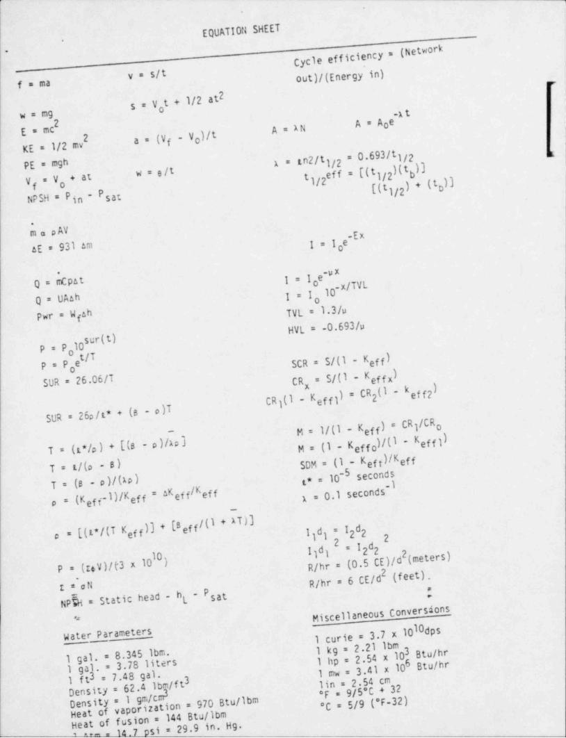
>.
,
EQUATION SHEET-
Cycle efficiency = (Network..
y = s/t out)/(Energy in)f a ma ,-
25 = V t + 1/2 atow a mg ~
2 A=AoeA = ANE = mca = (Vf V )/to
KE = 1/2 mvA = zn2/tjjp = 0.693/t1/2
PE = m9h w = e/t eff = [(t1/2)(t ))t bV = V ,+ at 1/2f [(t1/2) * {t )]D
NPSH = P in - Psat
*
m a p AV
I=Ie"*AE = 931 am g
Q = [nCpat I*le"~
o10-x/TR
Q = UAah I=I o
Pwr = W ah TVL = 1.3/ufHVL = -0.693/u
sur(t)P = P l0o
P = P e /T SCR = S/(1 Keff)o
SUR = 26.06/T CR = S/(1 Keffx)
CRj(1 Keffl) = CR (1 keff2)x
2
SUR = 26p/t* + (s - o)TM = 1/(I Keff) = CR /CRj o
T = (t*/a) + [(8 - o)/Ao] M = (I Keffo)/(I * Keffl)T = t/(o - 8) SDM = (1 Keff)/Keff
= 10-5 secondsT = (8 - p)/(to) (* ~
/Keff 1 = 0.1 secondsa = (Keffl)/Kef f = AKeff
/ + AT)]c = [(t*/(T Keff)3 * E8 eff ( 1 d; = 1 d22j
I)d) 2 = I dg2P = (I6V)/f3 x 1010) R/hr =-(0.5 CE)/d (meters)I = oN R/hr = 6 CE/d2 (feet).
P ;
NPhi = Static head - hg sat
Miscellaneous Conversions.*
10dps' Water Parameters I curie = 3.7 x 10
1 kg = 2.21 lbm 3 Btu /hr1 gal. = 8.345 lbm. 'I hp = 2.54 x 10⁶ Btu /hr1 gal. = 3.78 liters 1 mw = 3 41 x 101 ft3 = 7.48 gal. 3 lin = 2.54 cmDensity = 62.4 lbg/f t *F = 9/5'C + 323
- Density = 1 gm/cmHeat of vaporization = 970 Btu /lbm*C = 5/9 (*F-32)i 144 Btu /lbm
' % eat of~fus on =si = 29.9 in. Hg.-H

f}A JJ t g- .
5. THICRY OF tl0 CLEAR POWER PLANT OPERATION, FLUIDS, AND PAGE 1?________________________________________________________
THERMODYNAh1C3______________
ANSWERG -- LA3ALL'. 1 -GS/0L/20-DIMMOCK
AllSWER 3.0: (3.00)
F1. bF2. eF3. aL1. cL2. a
LO. b (.50 etch)
REFEREt?CE-*4LPCDL pgs 20 26, and 30
ANSWER G.00 (2.00)
a. I!1 CREASEb. DECRGCIc, I N C P '-:ASIrj . REMAIU T;iE S t- 'r
iEFERE!rcc ' a n e' , , , ' ' 9 t c.o d' - ,.i e LN:crv.
A!'3WER 5 . G '; * ~. C O )^
a.
b. 3 (Cr. vi appr .cic!- for answer g ) ve> ri in (a))
P E.= Ef: 9 t! C E :lwx 8 L' I'% / 0 |~ ?> n /C * -* " b |', 7f LPEDL, pas 42 F 3", p, cms /-
At!SWER 5.04 '1.00)-
e
REFEL:E ICE'_ | ' R leston plan P3 ~0-t%
| -
1
.
_ _ _ _ _ _ _ . . _ _ . _ _ _ _ _ _ _ _ _ _ _ __

,- ._ - __ _ _ - - - - - ._ .. ..
t
1
5. THEORY OF MUCLEAR POWER PLANT OPERATION, FLUIDS, AND PAGE 20____ ___ _________________ ________________
I_____________
ANSWERS -- LASA1.LE 1 -85/05/EO-DIMMOCK ;;
$
!ANSWER 5.05 (2.00).>
a. By observing the Full-in and Full-out travel lights (the '
: operator could determine if geometric distortion had occured.I,u bility to conduct full detector movement would indicatethat internc1 micconfiguration had occured). (1.0)b. By observing the neutron level while moving the nuclearinstrumen' ation. A significantly HIGHE? (approximately 300
,
jtilises) count rate would be seen for the UNVOIDED steas of the :icore as opposed to the VOIDED. (1.0) {
a
i
REFERENCE IiSRM lesson pie.ns and Standard Nuclear Theory. "
|
i ANSWER C.06 (1.00).
:';
d i'
IREFERE:TE
/,S t an4 c d ?!v e l e ,r Theoryi.
IANSWER 5.07 (2.00)
.
1.
3. MCP ASE5 due to less extr. action steani from the turbine to (1.0)ti
heat the feedwaterb. INCRE?iSEO du..- to burnout decr easing while production by Io line (1.0) i
i
'
is eti]1 at higher power rate
REFERENCE '
Stsndard Reactor Thaorv.|
'
i.
rAUSPEP 5.03 (2.00) t!
a) After the initial prompt drop, power cannot decrease f :1 s t e r than3
| the longee,t livad delayed neutron apperts. (1.0)|
.
't 'b ) Yes. The 1.nitial drop in pouer uill only be due.to the p r o: iip t '
neutrons.'l 0- :
) '
|',
'i
!,
i ii-
,
| *
i r
[
*
.r'
,o
_ _ _ _ . _. . - - . . - ~ . _ _ - . . . , ,-. _ - - , _ _ , _ __ .
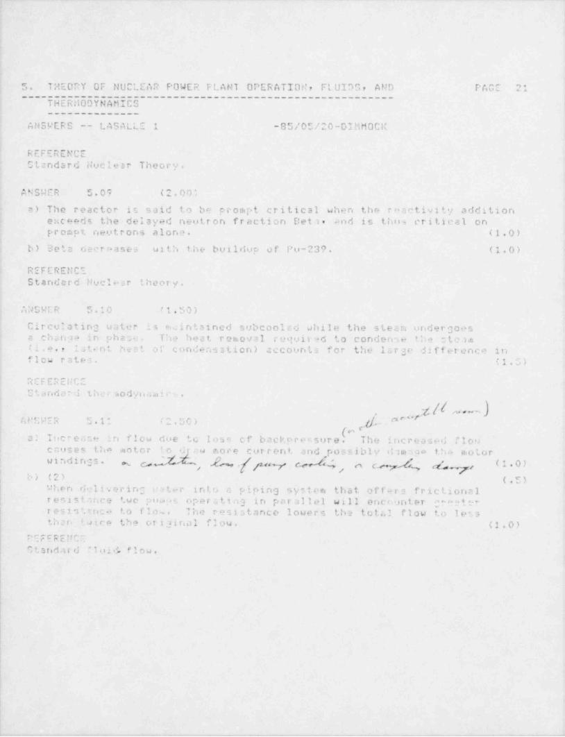
5. THEORY OF NUCLEAR POWER FLANT OPERATION, FLUIDS, AND PAGE 21
~~~~ 5E5EIODYU555C5-~ ~ ~ ~ ~ ~ ~ ~~ ~ ~ ~~ ~ ~ ~~ ~ ~T______________
ANSWERS -- LASALLE 1 -85/05/20-DIMMOCl(
REFERENCEStandard Nuclest Theory.
ANSWER 5.07 (2.00;
a) The reactor is said to be prompt critical when the roactivity additione:< c e e d s the delayed neutron fraction Deta. and is ti o n, critical onPrompt neutrons alone. (1.0)
b) Beta decenases with the buildup of Pu-239. (1.0)
REFERENCEStandard Nuclear theory.
ANS9ER 5.10 /1.50)
Circulating uater :s rocintained subcoolcd while the stesn undergoesa changa in phase. The heat r e n.o v a l required to condenw the stehn(i.e., lat nt heat of condensation) cecounts for the Isrse difference inflow rates. (1.G)
REFERENCEStandard thcc.odynaaii.- .
d"'" f k -., - )-
,
usesR s.11 c .00)e, ''
backpressure (.al Tucrease in flow due to loss of The increased flowcauses tho iuotor io d au more current, and possibly dimage iha motorwindings.
'
&, eM4 44 (1.0)% o _.,, jwy n c ,,
b) (2), (.5)( 4 hen delivering ueter i n t. o a piping sy-tt'm that off-ra frictional! resistance two po a:,s operctin3 in parallel will e n e r, u n t e r craeterI r e s i 3 ',r n c .2 to flow. The resistance lowers the total flow to less
then lui.ce the original flow. (1.0)
C'E F E R E N C F
"tandard "loid, flow.>
||
l
1
1
I
|
._ _ _. . _ . . - _ _ _ _ - - _ - .
5. TH20RY OF NUCLEAR POWER PLAT 1T OPERATIOil, FLUIDS, AND PAGE 22>
---- -- --------------------------------------
-_-_---__-----
ANSWERS -- LASALLE 1 -05/05/20-DIMMOCK
ANSWER 5.12 (1.00)
b
REFEREN!:EStsndard f4uclear theory.
,
,
! ANSWER 5.13 (1 00)
c.
t
REFEREtsCE,
Standard Nuclear theory.
!
At1SWEP 5.14 (1 00)
Cycle cr'iciency would be i n e r t- a s ed by a decrease in subcooling. A: 1emtheat ' ejected to the co n de n me r , the r etur r.i ng conden se t.a requires le , |
:
i reec*nt heat to p oduce stean. Therefore cycle efficiency will increase.'
. (1 0)!
i
F. e . c. . ., - .-._.o ._ ,
| S t;i..' u i T her >aodynamic pre.ciples.:
!
ANSWER 5 . i' . . ; . 0 0 '.,
cw
i REFEFEi:CE!
| St: nr:c td Nucl e a r theory.
!
!
>
-
O
>
>
F
h,
>
!I
h
[
I .
t >
' it
e
|
|*
iI.
|i
, , - - - - - - - - - . , , , .- ,. - , . - - -e _ , , . - , - , , - , . - , , , . , - , , , - . - - , -

. __. - - . ._ . .. -. _ .
,
,
| 6. PL AiJT GYS7 EMS DEG1GM, CONTROL, AND INSTRUMENTATION PAGE 20--------------------------------------------------- .
!
ANSWERG -- LASALLC 1 -05 / 05 / 20-DIMt10 CIC
:
i ANGNER 6.01 (2.50)
A. To prevent drawing water into the line au the e::haus t condensesfrom a previous relief. uster a feu feet up the dischargo line couldinhibit.'.he relief disetesece and cause danas.e due to water h;o.mer. (1.5)
D. IMCREAGE. The vacouni breaker providen a direet path to theDrywell. (1.0)
REFEREMCCM t. i n O '. - c. S y n t e .n L e s s o r. "Izns. 21-7,G.
i!
i ANS'4ER 4.02 (1 00'
e
R"rCRENCEMain St..:n. Syste.n le> san ,1ans. pg 21-33.>
;.
M!Ot!ER i.03 (0.00)
L..ul would be-the u n. e . (.5)
E ic,< e ri m ured r,'.e n, floo i' lest t h -: n feeduster flou . nn (2.5)rv ; , .; o a l i s _4 <:ner a %d shici- ' o n d t, to decrease P P.
c:eoc A louer vacel i * v 11 generatt+s .:n oppocite orror.
j t i g r. a ' b ;ch tendi t. inc r ec n" ~@P speed. The inte,ralporiion of the Dyni nic Co.i. pens a tor ( e:t ac t tern. not nee-ssary)'
o:11 c .s a. c, . t 's output up sintil the level error returnc to zero.| This uili return 15201 to its originc] satpoint,
e. ,_ -.I-'V. L C u t \ u . % s,
$ '' c) C L D f' N ? 5, *1 P * if V t* 1 C Uit k i O I U !, S (e n [# ) r4 rt 7 [# /* '*4 O U-14! '
fiMONER s . ') 4 (1,CGiI
$ ij*
e.r e, -.L i .. h L y l. ee. c
[-' d ' d C k O r k e V O ) ~ b *i n f. I ' % 1 1 t* 3 $ oIt f* $ n [s ] , ) ,$ "" 1 Sts ''i *,, ..
I
ti
!
I-I
t
I!i
, , - - - , - - - - - , . , - - , . . . - - . . - , , - - - . ,-..r... ..,,-,n -,.-,.,.w.-,..- ,.+,w.enr-- .. - - . . . , -.,w,,n,, ,
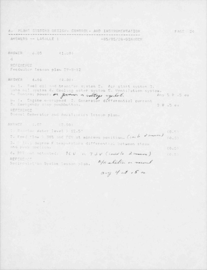
- - _ _ - _ .-____________ ______
6. PLANT 3'/3TEMS DESIGN. CONTROL, AND INSTRUMENTATION P a r," 24______________________________________________________
At!SWERS -- LAcALLE 1 -85/05/20-DlhMCCM-
ANSWER 6.05 (1.00)
d
. _ r- c. .c,. c b. l .-sa . .
Feedwater lesson plan 27-3-12
ANSWER 6.06 (4.00)
3 1. ' vel oi' -i t r a rd e r '= y s t e r, 2. Air start s y c t m. 3._vhe r,i l s y s t 9 3. 4. Cooling wat.2r systen 5. Ventilation system.4 6ntro; power. m % a .ggy- . f.g Any 5P .5 ea
^
b. 3. Engine er r; peed 2. Generator differential currentC. Em e r :p: n cy :.cp pushbuttan. 39 .5 e8
R E F 2 P C h'CZ
Dicael C e n . r s t ._ c and A o u l ' i t: rit s lesson plan.
...em
. ,- , , ,n a ... g :,. s,, t ,_ . n ,.) 3,
',
I :: - 'n Wst~r level 12.5' (0.5-.
,? w- ). position. b " |'2. E n r. ' " low 10L : o r' " C '! at minimon, (0.G)
3. l' '. hiree F t . am e r : 4 vro dip'ereof.131 between ste :a3 r. fi p :_ p ;UC11Ln. (0.C)
7 J v & ~v /, 2 %.,3 ,,) ( c . c. ,4. U. o' , c t ; a t .f , 7 c t/ et
p. _ .- . c ._
$5/j Y dm %u.-.s e e l t c .3 2 , o c. f, n , .,
_ 3y s, m eS3an .> 1 a n ..- .
p. f ch s $ Jav .
.
I,
l
1
6. ^ L A F' T C Y M N . '' ;) E S I Gi! . CUNTNCL, AND ll4STRUMEin f lIOi! P A r.; c ',--------- ------------------- ------.---------- -------
ANSWIR3 -- LASALLC 1 -05/0L/20-01MMOC
n b. r . h. r- .e. 0. p, ( .< ,*,a. a
a. CPD ? c c u s v i c. t o r prer. ur, (.5)Vese.el vater (.5)
b. 1. At low reactor p r e s ". o r e , t h .: /essel ha un i ri t ti.a 1 effect end (.S):.c r c. c. i s a c c o a.p l i. h a c' only by I hc a c c u p.v ] a l o t .
' ' . As the v.ssel p r .. - core rises, the a c c u rn u l a t o r 2. 5 assisted on (.5)the u v.eur ond of t. i . o r, t r o l o by roccLor pressor . An us*or 17..
b , 0i t ) .I ,Ih ) . |4 .% b I 4 0 !.. I ' - k - a
rosctor pt esmo e and enous the b ..: 1 1 c h o e l: w t- !. o o;eco2110 w i r. j r .> .a c t o r pce.sure to comp et. the m r a >n ..
O. Oy 1000*. tha neciimulator is not noreusary sod i"actur pr meuro(.5)s;11 pca . ::o enov h hydrnelic p r e t. w r c to vo? . c r n a, inrortion! ; n. o. I ! 'Ost'a|i i!a 1 C C UrristI a I,0 r d ri c ? Ice lp
~
" t ', r t d. i 6 E d r 4. V ido. . , e
p g g g e.- -
,, , , , , , ,
, ' I, b) . tr - ) ' h I 4 9. V | |
A U ",1,' C o.09 ;A.DO)
* * c mi r i r e :r, t'.o ri. ' p c,01 t. o th. . i niaw r ;iir 3t t A n k. * r hrough- '
-
. .ub . 'J I ,e q O ! ,s i ti f I lIiri i Ug| t t . .n e,f tige 'C' |'';R pt.tl#[ [ i) ;' no
;;, t: " " * ' '"|| l of b ip v < .tvo), thr ci Ti remc, .ble.-
il p t..c e . c i- to th- fuel pocl t.hrcogh it- own diffvwr. (1.G)L. . -o: 3 1 ; , 1. . c. of t ' . c- * r: RI P o u m r> when bo,th F0009 n rid F69 M:"-.
. . i ,
,> ,1 ed. A l.a _ /.A. / m,6 / (1.0):v ,p.. , ton p o a ! ( a. . i , fiew and te ;L 1.i n r. i.;.
S o "- p r 6 * ' i C t . POOL 9 p r "; y Cr.. .- :oc,n.
6.. c i f a rondereret.. , +g.rt -;i ; 8. 4 ) 4 . ' "/ ? . .* . . . '*ai
$ 1 -f a l | .. ? ? 't
$ ** '[ t f f ' i 1 ; i ' i Ii ? ' 1 T r ;i. 1 ( e ( ) ,{f J7*/ i3 | g , P ". (* .s ;. *
,.a
,
k r r m.:E 9 C E~
:nd Fo-1 F -! C0011o3 0 ; t.>.i le '0n pw.'
.
1
. _ . _ - _ . _ . _ _ _ _ . - - -

6. "' L A N T S 'I' S T E M S !"lS I G N . CONTR01., At'D INGTRUMENTATION PACE 26------------------------ ---.-------------------------
ANSUEPS -- LASALLF. 1 -05/05/20-DIMMOCl
ANSWER 6.30 (1.00)
Any 3 for f'u l l c r e<h t . 1/3 pain t- ea.Sur;,r',5)on Pool l e v.a lGiipp r e i or. FooJ t e ri p e r s t t i ' -.
D r y u e l :. ' r a c s o r raD,yWe11 t e m p H -' a t O r e
r.,. . . e r r. r s . r_e . s.w.
ic . + t e C h u t rj o u r, fn: l i. ,y o n c 1., n .
ANSWER 6.11 (0.00)
" , *. C lC 0i;r 9 I.5)3. G.. v s ., v - sor logic ..r awing ) (..,o>
, _, .
:.. . .,.
t. 30% - oser o i' (1: ? , ' 2 9 - p r im u t r e* <l40 paie) (.5)-
2. c. OCS ,'
i .3 f. rip r. 2 2 ^ect l o '.. (RE f 5) (,5),
:. t i e ou: of two t w i c. logic = (.5).
30% ,ra'ea" Or (lit i l d +j e p r e G : U r r; 3.40 [isig) (.U)i
r. c ,r - ,''"( .#..,4*. . . , , .
') * ' 1+= .en[s {s).'[i
.

7. PROCEDURES - N O R l1 A L , ADNORMAL, El'.E R G E N C't AND P t.C E 27
~~~~E5656Lb55C5L ~ 5ETE5L------~~----------------
C____________________
ANS9ERS -- LASALLE 1 -SD / 05 / 20-DIlitiC Cl
ANSL'ER 7.01 (1.50)
tio . the s e r i t, should not be resetr because doing so would closo thes c r a n, volves causing a greater restriction to flow into L. h o racctorvessel.
p, e r. e " >J r' _.-nt m-
L f; . ' 3-2
ANSWER 7.02 (3.00)
If five 5) or note adjacent rods are not inserted to at leastnotch pnition 06 or thirty (CO) or more rods are not i n r.e r t e dto at .-+st notch position 04 Ai!D reactor vessel water level cannot'
be maintained nove 412.G' or sup:,r es s i on pr,ol temperature r Nche s110 degr+es F.
REFERENCELCA NO-o''
A N C'J E ? ?.00 (1.50)
11;nus: 1., t h r o t t. l e the FRV inlet : top (FV003) and i.ia i n t c i n the Rt!'TJretcrn Ilow as hl . r4 ponible.
n E .r n . u r. r_-r .
-
LGF 1-1
Al:C 'A E P ".04 (2.00);
s. Level Cor. rel (01)
b, C a r ' .; 3 ,.:.a n t Contro! IOC)
c. L= vel Control (01)
d. * eval !:ont r ol (Gli. :nd Cantain.wnt Control (03)..
i1 :rtr~. - . r p. p.~-
,
L S A * ':
i
i
I.
h
_ _ _ _ _ _ _ ---
7. PROCEDUPES - NORMAL, ADHORMAL, EMERGENCY AND PAGE. 20~~ RED 5UEbG56 L c5sT R6E----------
-
____________________
A N S t4E R S -- LASALLE 1 -85/05/20-DIMM0rl'
ANSWER 7.05 ' (4.00)
a. The steady state thermal power doesn't e >:c e e d 50% of rated.
b. The Mininon. Criticcl Power Ratio (MCPR) Safety Lin.it (T.S.2.1.2) and Operating Lin,it (T.S. 3.2.3) are increa ed b'>0.01.
c. The MAPLPCP limits cre reduced by a factor of 04 35.
d. The APRM flou-biased s e r e n, and rod block setpoints crereduced by 5.0*;.
e. The AP5'M f'le: noise is not greater than 5% peck-to p.:.k andcore plcte d '' c noise is not greater than 1 ?ti ? " 7 k - t.1 -p e 2 .(T.C. 0/4.0 1.1).
f. RP P U Fr p s i r ' ' '- Go .' 'hF Gctive l. O O p dO f r T.Q t e ,:c a _ c 30375 CPh#'
- 7 e; ; .n t v '' '"- ggs rtat s any a (1 1.n e2
i.._,_.,. r_ r : , : - , r, -_
L C'' t". pg "
A: T r'ic '.06 .>G\' ' ',
f chann*' I o n c t,: c n ' ' test (7 days', and cP innel check 12 hrq) must.
be r o , .. <,73)
5. 'wr .fying tnat thn " y. cae,t rate : '- at least .7 cps or 3.0 ces.
if ci 3nal ,c noise r a t. ,. a is less than 2: 1. (.'75).
c. 'J e r i f *. .j that a da'.wtor of an operable SRM is located in,
( the core qurdrant wh e r .- core .<. l t e r c t i o n s are bein3 perfornied andone operable ,SRM channel i; located in an adjacent qundrsnt and
i that the d.etectors .ra f u l l >/ inserted. (.7S)i1
.r . w e e.-e, e s s es *-- sc.we g,
! " F ~' *00-1 Me"!* soy (,#_}~
y r s 3. 9. 3 5LA)Bi" c c A' ~' '
an. a ..aa ~ ~1
!l
11
_ ._- .. _ - _ . . . _ _.-
7. PROCEDURES - NORMAL. ADNORMALr EMERGENCY AND PAGE 29~~~~ d65CE655 EEL EUUiRUE~~~~~~~~~~~~~~~~~~~~~~~~R
~
____________________
AN3!4ERS -- LAS ALLE 1 -85/05/20-DIMMOC:'
'
AN St4ER 7.07 (2.00)
a. Rod Sequence Control Matri:: (.5)Conputer progran, 0D-7 (.5)
b. To prevent an isolation when reactor pressure decreases toG54 psig. (1.0)
w e r. e n.c n. e c.m _ - m
LGP 0-2
A:tSWER 7.00 (2.00)
1. Contr.;; rods .5 each
2. RCIC - but do net i r. ) ,+ c t
3. Steem condensing aeode o' RMR
4 Relie' valveu nry ba ramr.u s11y oper ated'
REFERENCEt
t mp a ns ua L"L
4
ANCHER '.0? t " 0 0 '-
ans.*c''
REFE,?E!JCE
LCP 3-1;
$
6
e
t
:
.. . _ . . - _ _ . _ .. _ . . . _ _ ._ . _ _
7 PROCEDURES - NORf1AL, ADNORMAL, EtlERGEl1CY A TID PAGE 00
~~~~RUU5UEUU5UIL'UUU5RUL~~~~~~~~~~~~~~~~~~~~~~~~
____________________
A'!SWERS -- L AS ALLE 1 -85 / 05 / 20-DIliM C C:(
At.tCUER 7.10 (4,00)
c. 1. Rediicr. tots' core Flow approx.tmately 5 > 10^6 lb/hr for every10 degree: F thct the f>aduatar ten.percture drops. (1.0)
2. In'ert CRAM arrays (oer the Control Rod Sequer.ce packagc ifallowed by the rod wor th rainiminer/ Rod Sequence Control Systen.) (1.0)
Pe s(c u c ejnz a.aa fl a t i o rca .6 /5. R e c i r c6.. f ow is reduced to limit puwer rise inthe lower cot o ragion t, o help ruaintain PCIOi1R l i r.. i t s to preventeladding dams 3e. (1.0)
The CRAM arrays are innerted to clear any APRM Hi's that mayh6ve come in OR they cre inserted to lover bulk recetor power tooffset the reactisitv sddition due to the colder feedwster. (1.0)
un r.w 7g & 4 / CO ' f.'c .
v.. r . . c. . ., e.e. . . . c,...:
LOA-FW-01
A '' TJ E P .it (1.00)^
''
o .c l - .1 + r o.-f d r i f t s / s c r a m s 3 r ., e .;p a r i e n c e d , SCRAM the reactor,
LO [MA y) f ''+< s p 9 ym
.
3. A Dli I N I S T R A T I V E P N G C C D t:R E S . CONDITIONG, AffD LIMITATIONS PAGE 01__________________________________________________________
A NS'A ERS -- LASALLE 1 -85/05/20-DIMHOCl(
AN9uCR P.v1 (1.00)
b
REFERENCELasalle TSr 0.0.4r J.6.a.'
A N S'J E R 8.02 (4.00)
a. 1. During notnal operat:an a check in to be made forproper nuclear i rn t r u m e n t r e s :,o n s e to n o v e r.s e n t . (0.5)
2. When fully withdraur, the operator will attempt to withdravto the overtravel pocil, ion. (0.5)b. 1. Im n.o v a b l e cod 2. 9e"- nsertion time, from full out to /Notch 5, 3reater th a n @n ci r4 3. th coupled rod 4. More than Y ej ,,,. ..
'so n r- ac cus.ul s t a r inorore.1 sr the associated control rods are uinopero!,i- . G. D r. e .r ur- rod positior. indication" "noperative..'3 . Accur el ater ;i.op > 0 .o00-1 control rod inop. 7. E. lower thsnavers]e ods i n : 4 by 4 7tecy whon t, h e a ci ,y averag- is 1.+ s s thanallcuabl+.
3 Jj /s p .B / a'J ,, Any 6 6! .5 e6(;^ $gd v s .' ) n'W - nggy/ _ , ,,
2:n m R 3.03 2.on3 9dr "
,
r, . H r, . All 7 '.r u nt,a l p r a t e c '.1 r card 4 r the tiaster Dot of "79.-,. .y [/'/2I w ace ( m, he . de 1 ' s *2 C If 4.5 b oO o NNrv b (* (bY b o f4 E.
cot:1pp.F s| LO h- ? -tar' S U -.: l., U O.' ptil l O d . Ihd r e Ria illi ng C 3 r d'.;can stcy i r, place,
b. O
R E F E R Et! C E
L t. ! ' 7 0 0 a.
.
|,
!
_.
8. ADMI::ISTR ATI'JE OROCCOURES . C0i1DITIO!1Sr AND LIMITATIONS PACE 32--------------------- -----------------.-------.------------
ANSWERC -- *ASALLE i -05/05/20-DI!1 MOCK.
ANSWER 8.04 (2.50)
a. 1. Jumpers and other tempersry system changes which arerequested for troublochooting associated 5.ith a WorkRequent. Provided th-:t a properly completed Troubleshootingw o ? '' Ihast r e c,iti r e s it put back in a normal configuietion,
2. When leads or "uses are lifted es part of an equipt.ent outager,
provided the lands or f i..i z e 4 are replaced when the outage iscl e: r ed.
3. If the ' Temporary Systea Change' in a pait of an approvedp r G!.eLur e bhiCh ret. Urns lhe Gyu'5tGm3 to normi,1 Configulation
*
o p c.n t;omplet;en.
D. IWO i n d i '/10 + 31, holding an active 3RO license nu3t C o n C 8..t r .ri:. r .. r s rc . L r,- . , . , ,
-
LA''"'0-6
A ' ''. *> E R 0.00 (2.50)
Recetor pressureClean Plowre e d.a a t a r flouDrywell t o i.p e r a t u r -Drywell pressore f*,tfJ rDrywel'. tediction lav.la
.
T/M ', ,
W e u t o r, ';un i n c i c 3 r, i o r. ,,, /'C ' ' any 5 0 .5 ea#REFER' ;'CI /h' 5 '
LAP 1600-2, pg 6
AUCWER 3.06 (2.00)
bbb |CSA P C:M r.d black and vi% setpoint adjustmentFlC P R
bMCP.
?EFEpENC,~' GP i-1_
i
|
I
? ~
!
|.
w - - -, ,.

.
3. ADt1It11STRATIVE PROCEDURES, CONDITI0tlSr AND LIMITATI0t1S PAGE 33__________________ _______________________________________
ANSWERO -- LASALLE 1 -85/05/20-DIMMOCK
MANSWER 8.07 (2.00)
The reactor node s . u. s y be plap4'1?IThe Ron or Startup/ Hot Standbyposition to test the switci, ' lock functions provided that the controlcods are verified to rfuesn fully-irn '' bv a second licensed operator orother technically.e d ified ra e n b e r of the unit . c emd~c a l ntaff.-
REFEREllCET.S. Table 1.2 ' Operational Condit i aris ' .
ANG!4ER G.08 (1.GO)
a.24 hours after reaching 15% thermal power.
b.4~ by vo'umn.
REFERENCELGP 1-1
0"S!'ER C.07 (2.00)
a. Diesel fire pump maybe considered operable provided an individual is7.r. s i g n e d to stert the p u n.p when requirad.
b.U.less the s p e c i f i. c equipmant t1 identified in T e c ;, . '3 p e c s .
"'~' MREFEREi4CE ^ r ' ''8"''' P ~~
L t.P 1600--:
A !' C'4 E R O.10 ( 2. 0') )
cas. a.Palse,b.Troerc. False.d.True.
TrEPEf!CEAP 90c 12
.
I
I'||
1
-. . . .-
_______ _ _ - . _ _ _ _ _ _ . _
.
8. ADMINISTRATIVE PROCEDilRES, CGilDITI0tlS e Af!D LIMITAT10tfS P A c r. 3a__________________________________________________________
AtJSWERG -- L ASM LE 1 -85 /05 / 2 0 -DIM MOCl'
ANRWER 0.11 (2.00)
1. If 'he radintion 1-vels and ',he pressure and t e ra p e r a t u r e inthe ; rim'ry co..? si nwrit are s t. ~ b l e . '1.0)
2. If there i r. adeqoste core cooling as indicated by stablerasetor coolant systea, preeruros, temperatures sad levels. (1.0)
# '.; c"REl!CF
L F-1600-2, ps O
Ai:C'!ER 8.12 (1.50)
The "hif* Engineer or the respective operat,ing unit supervisor shall-
read and .ign cli cctive RWP's wh,n he begine his shift. (1.5)
RCTERENC" c1 4 ew? $ f( 4) / ,cea. dea,j ,~. _,wLRP 10 M- 1, pg 15
<
a
Copyright © 2022 FDOKUMEN