"Reactor Protection Sys Single Failure Analysis."
509
SAN ONOFRE NUCLEAR GENERATING STATION UNIT 1 REACTOR PROTECTION SYSTEM SINGLE FAILURE ANALYSIS March 1987 PDR ADR
-
Upload
khangminh22 -
Category
Documents
-
view
0 -
download
0
Transcript of "Reactor Protection Sys Single Failure Analysis."

SAN ONOFRE NUCLEAR GENERATING STATION
UNIT 1
REACTOR PROTECTION SYSTEM
SINGLE FAILURE ANALYSIS
March 1987
PDR ADR
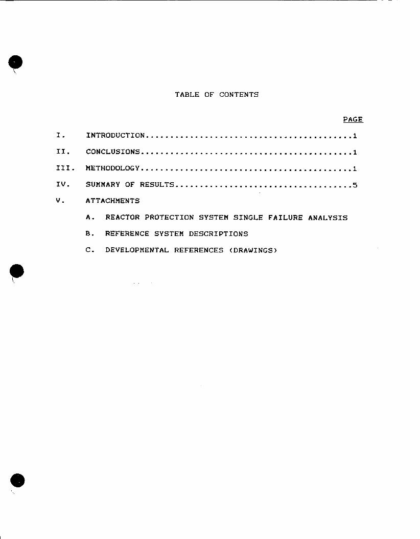
TABLE OF CONTENTS
PAGE
I. INTRODUCTION .......................................... I
II. CONCLUSIONS.................1.......................1
III. METHODOLOGY.................................................1
IV. SUMMARY OF RESULTS.. .................................... 5
V. ATTACHMENTS
A. REACTOR PROTECTION SYSTEM SINGLE FAILURE ANALYSIS
B. REFERENCE SYSTEM DESCRIPTIONS
C. DEVELOPMENTAL REFERENCES (DRAWINGS)
REACTOR PROTECTION SYSTEM SINGLE FAILURE ANALYSIS
I. INTRODUCTION
On July 29 and 30, 1986, a failure of main steam pressure transmitter PT-459 at San Onofre Nuclear Generating Station Unit 1 (SONGS 1) caused a transient in all three channels of the Feedwater Control System and concurrent inoperability of all three channels of the Steam/Feedwater Flow Mismatch Scram. In response to this event, SCE initiated several actions including a Single Failure Analysis to determine the susceptibility of the SONGS 1 Reactor Protection System to common-cause failures.
II. CONCLUSIONS
The SONGS 1 Reactor Protection System meets the applicable single failure criteria of IEEE 279-1971, including control/protection system interaction (multiple failure) criteria, sub3ect to the reduced setpoint of the High Pressurizer Level Scram as documented per the submittal to the NRC of Proposed Change Number 165 to the San Onofre Unit 1 Technical Specifications by SCE letter dated November 12, 1986.
III. METHODOLOGY
A. SCOPE
The Single Failure Analysis of the SONGS 1 Reactor Protection System (RPS) was performed per the applicable criteria of IEEE Standard 279-1971, including control/protection system interaction (multiple failure) criteria, in four sequential, overlapping, parts:
o A single failure analysis of each scram function including interfaces and power supply dependencies
o A single failure analysis of the scram matrix and breakers, including the manual scram function
o A single failure analysis of the channelized vital and regulated bus system common to the scram functions, and
o A control/protection system interaction evaluation which analyzed the effect of initiating plus concurrent (ie. multiple) failures.
1
B. CRITERIA
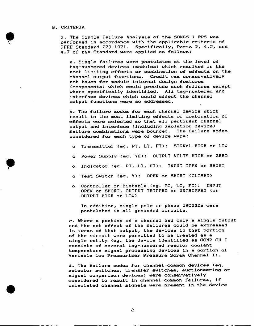
1. The Single Failure Analysis of the SONGS 1 RPS was performed in accordance with the applicable criteria of IEEE Standard 279-1971. Specifically, Parts 2, 4.2, and 4.7 of the Standard were applied as follows:
a. Single failures were postulated at the level of tag-numbered devices (modules) which resulted in the most limiting effects or combination of effects on the channel output functions. Credit was conservatively not taken for module internal design features (components) which could preclude such failures except where specifically identified. All tag-numbered and interface devices which could affect the channel output functions were so addressed.
b. The failure modes for each channel device which result in the most limiting effects or combination of effects were selected so that all pertinent channel output and interface (including isolation device) failure combinations were bounded. The failure modes considered for each type of device were:
a Transmitter (eg. PT, LT, FT): SIGNAL HIGH or LOW
o Power Supply (eg. YE): OUTPUT VOLTS HIGH or ZERO
o Indicator (eg. PI, LI, FI): INPUT OPEN or SHORT
o Test Switch (eg. Y): OPEN or SHORT (CLOSED)
a Controller or Bistable (eg. PC, LC, FC): INPUT OPEN or SHORT, OUTPUT TRIPPED or UNTRIPPED (or OUTPUT HIGH or LOW)
In addition, single pole or phase GROUNDs were postulated in all grounded circuits.
c. Where a portion of a channel had only a single output and the net effect of the failures could be expressed in terms of that output, the devices in that portion of the circuit were permitted to be treated as a single entity (eg. the device identified as COMP CH I consists of several tag-numbered reactor coolant temperature signal processing devices in a portion of Variable Low Pressurizer Pressure Scram Channel I).
d. The failure modes for channel-common devices (eg. selector switches, transfer switches, auctioneering or signal comparison devices) were conservatively considered to result in channel-common failures, if
9 unisolated channel signals were present in the device
2
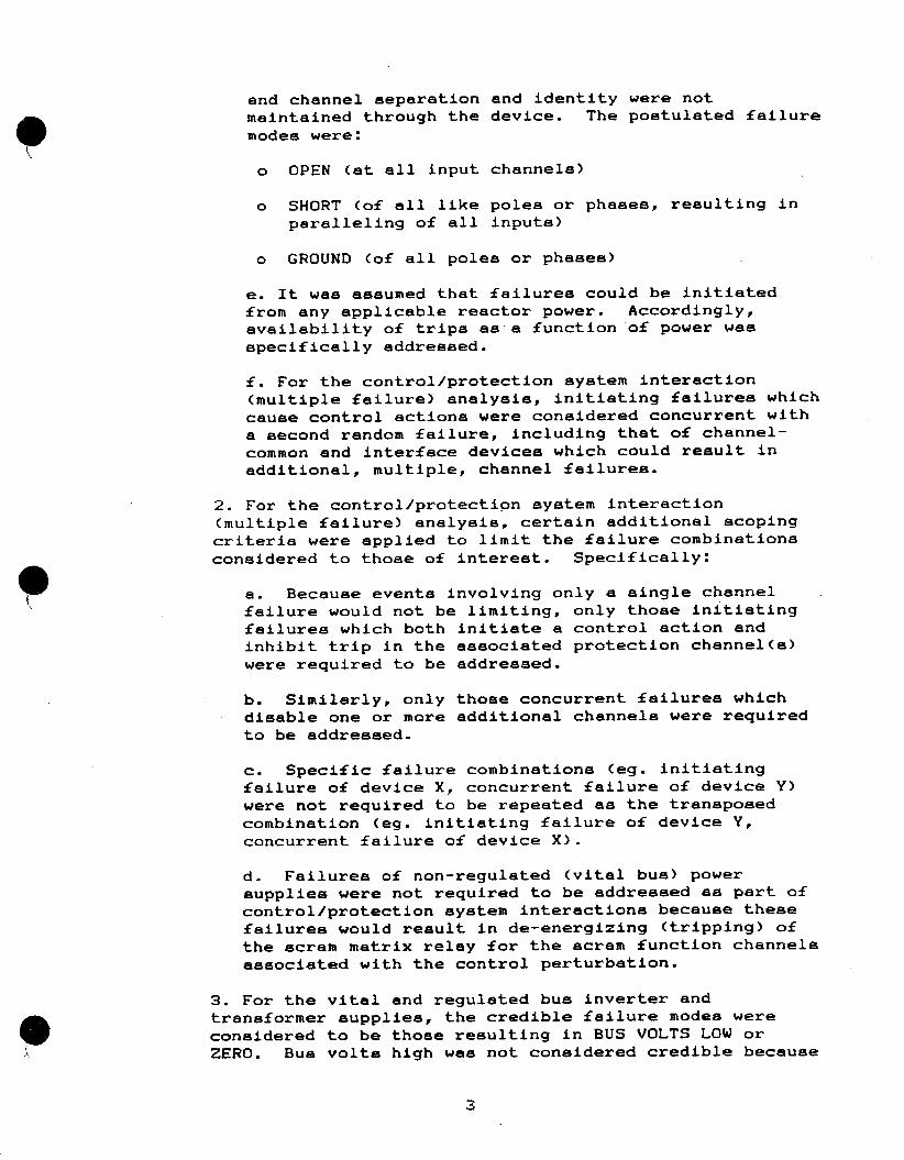
and channel separation and identity were not maintained through the device. The postulated failure
modes were:
o OPEN (at all input channels)
o SHORT (of all like poles or phases, resulting in paralleling of all inputs)
o GROUND (of all poles or phases)
e. It was assumed that failures could be initiated from any applicable reactor power. Accordingly, availability of trips as a function of power was
specifically addressed.
f. For the control/protection system interaction
(multiple failure) analysis, initiating failures which
cause control actions were considered concurrent with
a second random failure, including that of channel
common and interface devices which could result in
additional, multiple, channel failures.
2. For the control/protection system interaction
(multiple failure) analysis, certain additional scoping
criteria were applied to limit the failure combinations
considered to those of interest. Specifically:
a. Because events involving only a single channel failure would not be limiting, only those initiating
failures which both initiate a control action and
inhibit trip in the associated protection channel(a)
were required to be addressed.
b. Similarly, only those concurrent failures which
disable one or more additional channels were required
to be addressed.
c. Specific failure combinations (eg. initiating
failure of device X, concurrent failure of device Y)
were not required to be repeated as the transposed combination (eg. initiating failure of device Y,
concurrent failure of device X).
d. Failures of non-regulated (vital bus) power
supplies were not required to be addressed as part of
control/protection system interactions because these
failures would result in de-energizing (tripping) of
the scram matrix relay for the scram function channels
associated with the control perturbation.
3. For the vital and regulated bus inverter and
transformer supplies, the credible failure modes were
considered to be those resulting in BUS VOLTS LOW or
ZERO. Bus volts high was not considered credible because
multiple failures in the same channel (eg. inverter and regulator) would be required to produce such an effect and single channel failures were not limiting.
4. Existing breaker and fuse coordination were credited for preventing the propagation of faults into the vital and regulated power supply system.
C. NOTATION
1. Each single failure and control/protection system interaction failure pair was assigned a unique identifying number to facilitate compilation and review of the analysis.
a. The item numbers in Tables 1 through 8 of the analysis consist of :
<section #>.<channel #>.<device>.<failure mode>
Channel-common devices were assigned channel numbers one larger than the number of channels, so as to follow the channel-specific devices.
b. The item numbers in Table 9 of the analysis consist of:
<9>.<section #>.<failure mode>.<device 1>.<device 2>
where <section #> is the Table number corresponding to the applicable control/protection system instrumentation, <device 1> is the initiating failure and <device 2> is the concurrent failure.
2. Actuation at the channel level is referred to as a TRIP, and that at the system level as a SCRAM.
3. The notation used for scram function logic in the analysis is number of channels TRIPPED for SCRAM, over total number of channels of that function (eg. 2/3).
D. REVIEW
1. In addition to the required Quality Assurance review process, all sections of the single failure analysis were reviewed by the Station personnel familiar with the equipment, to ensure the validity of the applicable documentation and equipment response described.
2. The interface, power supply and control/protection system interaction evaluations were performed in part utilizing automated sorting of the individual scram function analyses with data-base management software, to ensure that all potential common-cause interactions were bounded.
4

IV. SUMMARY OF RESULTS
All scram functions and permissives were found to be acceptable with the following exceptions or amplifications:
A. Relative to the single failure analysis criteria described above:
1. For the Steam/Feedwater Flow Mismatch Scram, the steam and feedwater flow analog amplifier (OPTIMAC) system was, in addition to the PT-459 instrument loop, found to contain potential common-cause failures of all three Steam/Feedwater Flow Mismatch Scram channels due to the channel-common signal path and power supply configuration. However, at least two channels of the High Pressurizer Level Scram (with reduced setpoint per Proposed Change Number 165 to the San Onofre Unit 1 Technical Specifications) or Variable Low Pressurizer Pressure Scram would remain available to initiate a reactor scram under all applicable failure scenarios.
2. For the Pressurizer Pressure Scrams, certain control/protection system interactions (multiple failures) could result in loss of all three channels of pressurizer pressure for the Reactor Protection System and Safeguards Load System Sequencer #1 (SEQ #1). However, the electrically and physically separate pressurizer pressure input channels for SEQ #2 would remain unaffected. For pressurizer pressure instrumentation control/protection interactions involving low pressure (eg. PORVa opened), SEQ #2 would remain available to initiate a low pressurizer pressure scram and safety injection, if required. For pressurizer pressure instrumentation control/protection interactions involving high pressure (eg. pressurizer heaters energized), automatic protective action would not be required and SEQ #2 would remain available to provide unaffected channels of indication to permit operator action as credited after 30 minutes.
3. For the Pressurizer Level Scram, certain control/protection system interactions (multiple failures) involving inter-channel failures of the channel-common level recorder selector switch were predicted to result in loss of all three channels of control room indication concurrent with an uncontrolled increase in level. Inter-channel failures of channelcommon recorder selector switches, which were found to have acceptable consequences in all other cases analyzed, were conservatively postulated in the single failure analysis due to the presence of unisolated channel signals and loss of channel identity at the selector switch output. However, these switches have been previously evaluated by Systematic Evaluation Program
5

Topic VII-I.A and determined to provide adequate
separation to preclude such failures.
B. A review was also made of the acceptability of
the spatial (RCS loop or steam generator) distribution of
inputs to the RPS for loop-specific events not covered by
the control/protection system interaction evaluation. The
loop-distributed inputs and associated scram functions (RCS
T-average and Delta-T inputs to the Variable Low Pressurizer
Pressure Scram; RCS low flow input to the RCS Low Flow
Scram; and the steam and feedwater flow inputs to the
Steam/Feedwater Flow Mismatch Scram) were found to be
acceptable with the following exceptions or amplifications:
1. For the Steam/Feedwater Flow Mismatch Scram, a
feedwater line break downstream of the associated feed
flow element (resulting in high indicated feed flow to
the ruptured line) with concurrent single failure of the
feed flow transmitter or associated mismatch scram
channel for either of the two intact feedwater lines,
would result in disabling of this two-out-of-three scram
function independently of any HELB zone of influence or
environmental effects. However, unaffected channels of
the Variable Low Pressure Scram and High Pressurizer
Level Scram (with reduced setpoint per Proposed Change
Number 165 to the San Onofre Unit 1 Technical
Specifications) would provide adequate protection for
* such events.
2. For the RCS Low Flow Scram, the one channel provided
per RCS loop is backed up by the Reactor Coolant Pump
(RCP) breaker auxiliary contact scram for any loss of
flow event in the FSA design basis and for the RCP locked
rotor event (evaluated under Systematic Evaluation
Program Topic XV-7), because bus under-voltage, motor
overcurrent or other causes of breaker trip would occur.
However, for a sheared RCP shaft event, RCP breaker trip
would not occur and single failure of the RCS flow
transmitter or associated scram channel in the affected
RCS loop would disable the single loop loss of flow
protection of the RPS. Because of this single failure
susceptibility, the sheared RCP shaft event has been
reanalyzed assuming loss of the RCS Low Flow Scram.
Above the P-8 permissive setpoint (50% power), the power
to-flow mismatch and fuel heat-up in this event would be
terminated by the High Pressurizer Level, Variable Low
Pressure (in unaffected loops) or Fixed High Pressure
Scrams. With the conservative assumption that scram
occurs on Variable Low Pressure, following transport
delay in the unaffected loops, it was determined that
peak RCS pressure and fuel clad temperature would remain
within the applicable acceptance criteria. Below the P-8
permissive setpoint, the single loop loss of flow scrams
are bypassed and automatic protection for this event is
not required.
E

ATTACHMENT A
REACTOR PROTECTION SYSTEM SINGLE FAILURE ANALYSIS
TABLE 1: PRESSURIZER PRESSURE SCRAMS
TABLE 2: PRESSURIZER LEVEL SCRAM
TABLE 3: TURBINE TRIP SCRAM
TABLE 4: NIS SCRAMS AND PERMISSIVES
TABLE 5: RCS LOW FLOW SCRAM
TABLE 6: STEAM/FEEDWATER FLOW MISMATCH SCRAM
TABLE 7: SCRAM MATRIX AND BREAKERS
TABLE 8-1: POWER SUPPLIES
TABLE 8-2: SORT BY RACK POWER SUPPLY
TABLE 9: CONTROL/PROTECTION SYSTEM INTERACTIONS
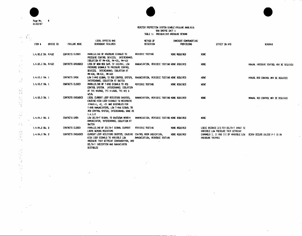
TABLE 1: PRESSURIZER PRESSURE SCRAMS
REFERENCES: A. SYSTEM DESCRIPTIONS: SD-SO1-390 PRIMARY PROCESS INSTRUMENTATION SD-SO1-400 ROD CONTROL SYSTEM SD-SO1-570 REACTOR PROTECTION SYSTEM AND PERM. SD-SO1-590 SEQUENCER SYSTEM
B. DRAWINGS: 63716 63720
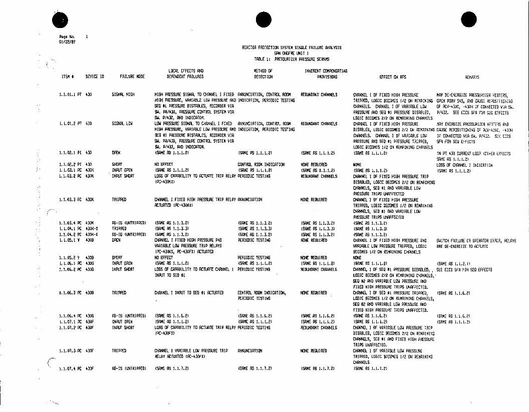
Page No. 1 01/22/87
REACTOR PROTECTION SYSTEM SINGLE FAILURE ANALYSIS SAN OGFRE UNIT I
TABLE 1: PRESSURIZER PRESSURE SCRAMS
LOCAL EFFECTS AND METHOD OF INHERENT COMPENSATING ITEM # DEVICE ID FAILURE MODE DEPENDENT FAILURES DETECTION PROVISIONS EFFECT ON APS REMARMS
1.1.01.1 PT 430 SIGNAL HIGH HI6H PRESSURE SIGNAL TO CHANNEL I FIXED ANNUNCIATION, CONTROL ROOM REDUNDANT CHANNELS CHANNEL I OF FIXED HIGH PRESSURE MAY DE-ENERGIZE PRESSURIZER HEATERS, HIGH PRESSURE, VARIABLE LOW PRESSURE AND INDICATION, PERIODIC TESTING TRIPPED, LOGIC BECOMES 1/2 ON REMAINING OPEN PORY 545, AND CAUSE REPOSITIONING SEQ #1 PRESSURE BISTABLES, RECORDER VIA CHANNELS. CHANNEL I OF VARIABLE LOW OF PCV-430C, -430H IF CONNECTED VIA SW. SW. PR/430, PRESSURE CONTROL SYSTEM VIA PRESSURE AND SEQ #1 PRESSURE DISABLED, P/432. SEE ECCS SFA FOR SEG EFFECTS SW. P/432, AND INDICATOR. LOGIC BECOMES 2/2 ON REMAINING CHANNELS
1.1.01.2 PT 430 SIBNML LOW LOW PRESSURE SIGNAL TO CHANNEL I FIXED ANNUNCIATION, CONTROL ROOM REDUNDANT CHANNELS CHANNEL I OF FIXED HIGH PRESSURE MAY ENERGIZE PRESSURIZER HEATERS AND HIGH PRESSURE, VARIABLE LOW PRESSURE AND INDICATION, PERIODIC TESTING DISABLED, LOGIC BECOMES 2/2 ON REKAINING CAUSE REPOSITIONING OF PCV-430C -430H SEO #1 PRESSURE BISTABLES, RECORDER VIA CHANNELS. CHANNEL I OF VARIA3LE LOW IF CONNECTED VIA SW. P/432. SEE ECES SW. PR/430, PRESSURE CONTROL SYSTEM VIA PRESSURE AND SEQ #1 PRESSURE TRIPPED, SFA FOR SEQ EFFECTS SW. P/432, AND INDICATOR. LOGIC BECOMES 1/2 ON REMINING CHANNELS
1.1.02.1 P1 430 OPEN (SAME AS 1.1.1.2) (SAME AS 1.1.1.2) (SAME AS 1.1.1.2) (SAME AS 1.1.1.2) IN PT 430 CURRENT LOOP (OTHER EFFECTS SAE AS 1.1.1.2)
1.1.02.2 PI 430 SHORT NO EFFECT CONTROL ROOM INDICATION NONE REQUIRED NONE LOSS OF CHANNEL I INDICATION 1.1.03.1 PC 430K INPUT OPEN (SAME AS 1.1.1.2) (SAME AS 1.1.1.2) (SAME AS 1.1.1.2) (SAME AS 1.1.1.2) (SAME AS 1.1.1.2) 1.1.03.2 PC 430K INPUT SHORT LOSS OF CAPABILITY TO ACTUATE TRIP RELAY PERIODIC TESTING REDUNDANT CHANNELS CHANNEL I OF FIXED HISH PRESSURE TRIP
(PC-430K) DISABLED, LOGIC BECOMES 2/2 ON REMAINING CHANNELS, SEQ #1 AND VARIABLE LOW PRESSURE TRIPS UNAFFECTED
1.1.03.3 PC 430K TRIPPED CHANNEL I FIXED HIGH PRESSURE TRIP RELAY ANNUNCIATION NONE REQUIRED CHANNEL I OF FIXED HIGH PRESSURE ACTUATED (PC-430KX) TRIPPED, LOGIC BECOMES 1/2 ON REMAINING
CHANNELS, SEQ #1 AND VARIABLE LOW PRESSURE TRIPS UNAFFECTED
1.1.03.4 PC 430K AS-IS (UNTRIPPED) (SAME AS 1.1.3.2) (SAKE AS 1.1.3.2) (SAME AS 1.1.3.2) (SAME AS 1.1.3.2) 1.1.04.1 PC 430K-X TRIPPED (SAME AS 1.1.3.3) (SAME AS 1.1.3.3) (SAME AS 1.1.3.3) (SAME AS 1.1.3.3) 1.1.04.2 PC 430K-X AS-IS (UNTRIPPED) (SAME AS 1.1.3.2) (SAME AS 1.1.3.2) (SAME AS 1.1.3.2) (SAME AS 1.1.3.2) 1.1.05.1 Y 430B OPEN CHANNEL I FIXED HIGH PRESSURE AND PERIODIC TESTING NONE REQUIRED CHANNEL I OF FIXED HIGH PRESSURE AND SWITCH FAILURE OR OPERATOR ERROR, RELAYS
VARIABLE LOW PRESSURE TRIP RELAYS VARIABLE LOW PRESSURE TRIPPED, LOGIC ARE DE-ENERGIZE TO ACTUATE (PC-430K1, PC-430FX) ACTUATED BECOMES 1/2 ON REMAINING CHANNELS
1.1.05.2 Y 430 SHORT NO EFFECT PERIODIC TESTING NONE REQUIRED NONE 1.1.06.1 PC 430G INPUT OPEN (SAME AS 1.1.1.2) (SAME AS 1.1.1.2) (SAME AS 1.1.1.2) (SAME AS 1.1.1.2) (SAME AS 1.1.2.1) 1.1.06.2 PC 430G INPUT SHORT LOSS OF CAPABILITY TO ACTUATE CHANNEL I PERIODIC TESTING REDUNDANT CHANNELS CHANNEL I OF SEQ #1 PRESSURE DISABLED, SEE ECCS SFA FOR SED EFFECTS
INPUT TO SED R1 LOGIC BECOMES 2/2 ON REMAINING CHANNELS, SEQ #2 AND VARIABLE LOW PRESSURE AND FIXED HIGH PRESSURE TRIPS UNAFFECTED,
1.1.06.3 PC 4306 TRIPPED CHANNEL I INPUT TO SED #1 ACTUATED CONTROL ROOM INDICATION, NONE REQUIRED CHANNEL I OF SED #1 PRESSURE TRIPPED, (SAME AS 1.1.6.2) PERIODIC TESTING LOGIC BECOMES 1/2 ON REMAINING CHANNELS,
SEQ #2 AND VARIABLE LOW PRESSURE AND FIXED HIGH PRESSURE TRIPS UNAFFECTED.
1.1.06.4 PC 4306 AS-IS (UNTRIPPED) (SAME AS 1.1.6.2) (SAME AS 1.1.6.2) (SAME AS 1.1.6.2) (SAME AS 1.1.6.2) (SAME AS 1.1.6.2) 1.1.07.1 PC 430F INPUT OPEN (SAME AS 1.1.1.2) (SAME AS 1.1.1.2) (SAME AS 1.1.1.2) (SAME AS 1.1.1.2) (SRME AS 1.1.1.2) 1.1.07.2 PC 430F INPUT SHORT LOSS OF CAPABILITY TO ACTUATE TRIP RELAY PERIODIC TESTING REDUNDANT CHANNELS CHANNEL I OF VARIABLE LOW PRESSURE TRIP
(PC-430FX) DISABLED, LOGIC BECOMES 2/2 ON REMAINING CHANNELS, SEQ #1 AND FIXED HIGH PRESSURE TRIPS UNAFFECTED.
1.1.07.3 PC 430F TRIPPED CHANNEL I VARIABLE LOW PRESSURE TRIP ANNUNCIATION NONE REQUIRED CHANNEL I OF VARIABLE LOW PRESSURE RELAY ACTUATED (PC-430FX) TRIPPED, LOGIC BECOMES 1/2 ON REMAINING
CHANNELS
1.1.07.4 PC 430F AS-IS (UNTRIPPED) (SAME AS 1.1.7.2) (SAME AS 1.1.7.2) (SAME AS 1.1.7.2) (SAME AS 1.1.7.2)
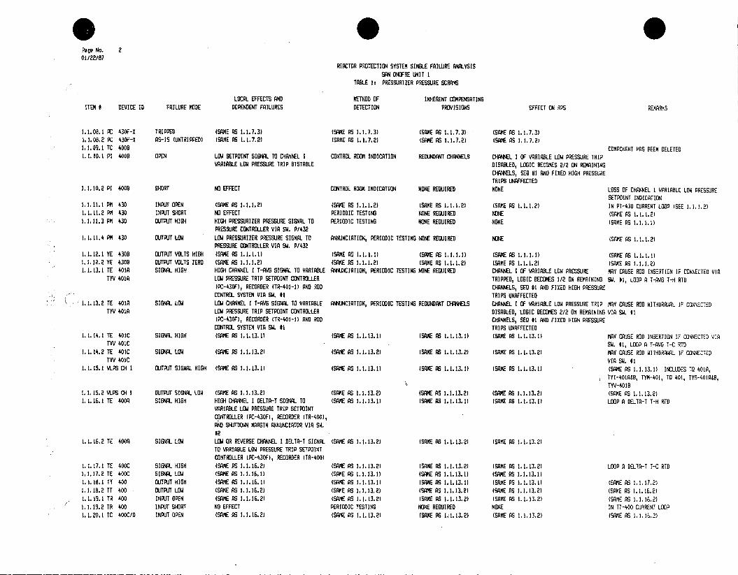
Page No. 2 01/22/87
REACTOR PROTECTION SYSTEM SINLE FAILURE ANALYSIS SAN ONOFRE UNIT I
TABLE 1: PRESSURIZER PRESSURE SCRAMS
LOCAL EFFECTS AND KETHOD OF INHERENT COMPENSATING ITEM # DEVICE ID FAILURE MODE DEPENDENT FAILURES DETECTION PROVISIONS EFFECT ON RPS REMARNS
1.1.08.1 PC 430F-X TRIPPED (SAME AS 1.1.7.3) (SAME AS 1.1.7.3) (SAME AS 1.1.7.3) (SAME AS 1.1.7.3) 1.1.08.2 PC 430F-X AS-IS (UNTRIPPED) (SAME AS 1.1.7.2) (SAME AS 1.1.7.2) (SAME AS 1.1.7.2) (SAME AS 1.1.7.2) 1.1.09.1 TC 4003 COMPONENT HAS BEEN DELETED 1. 1. 10.1 PI 4008 OPEN LOW SETPOINT SIGNAL TO CHANNEL I CONTROL ROOM INDICATION REDUNDANT CHANNELS CHANNEL I OF VARIABLE LOW PRESSURE TRIP
VARIABLE LOW PRESSURE TRIP BISTABLE DISABED, LOGIC BECOMES 2/2 ON REMAINING CHANNELS, SEQ #1 AND FIRED HIGH PRESSURE TRIPS UNAFFECTED
1.1.10.2 PI 4003 SHORT NO EFFECT CONTROL ROOM INDICATION NONE REQUIRED NONE LOSS OF CHANNEL 1 VARIABLE LOW PRESSURE SETPOINT INDICATION
1.1.11.1 PM 430 INPUT OPEN (SAME AS 1.1.1.2) (SAME AS 1.1.1.2) (SAME AS 1.1.1.2) (SAYZ AS 1.1.1.2) IN PT-430 CURRENT LOOP (SEE 1.1.12) 1.1.11.2 PM 430 INPUT SHORT NO EFFECT PERIODIC TESTING NONE REQUIRED NONE (SAME AS 1.1.1.2) 1.1.11.3 PM 430 OUTPUT HIGH HIGH PRESSURIZER PRESSURE SIGNAL TO PERIODIC TESTING NONE REQUIRED NONE (SAME AS
PRESSURE CONTROLLER VIA SW. P/432 1.1.11.4 PM 430 OUTiPUT LOW LOW PRESSURIZER PRESSURE SIGNAL TO ANNUNCIATION, PERIODIC TESTING NONE REQUIRED NONE (SAME AS 1.1.1.2)
PRESSURE CONTROLLER VIA SW. P/432 1.1.12.1 YE 4303 OUTPUT VOLTS HIGH (SAME AS 1.1.1.1) (SAME AS 1.1.1.1) (SAME AS 1.1.1.1)(SAME S (SAME AS 1.1.12.2 YE 430B OUTPUT VOLTS ZERO (SAME AS 1.1.1.2) (SAME AS 1.1.1.2) (SAME AS 1.1.1.2)(SAME AS (SE AS 1.1.1.2) 1.1.13.1 TE 401A SIGNAL HIGH HIGH CHANNEL I T-AVG SIGNAL TO VARIABLE ANNUNCIATION, PERIODIC TESTING NOIE REQUIRED CHANNEL I BE VARIABLE LOW PRESSURE MAY CAUSE ROD INSERTION IF CONNECTED VIA
TYV 401A LOW PRESSURE TRIP SETPOINT CONTROLLER TRIPPED, LOGIC BECOMES 1/2 ON REMAINING SW. #1, LOOP A T-AVG T-H RID (PC-430F), RECORDER (TR-401-1) AND ROD CHANNELS, SEQ #1 AND FIXED HIGH PRESSURE CONTROL SYSTEM VIA SW. I1 TRIPS UNAFFECTED
1.1.13.2 TE 401A SIGNA LOW LOW CHANNEL I T-AVG SIGNAL TO VARIABLE ANNUNCIATION, PERIODIC TESTING REDUNDANT CHANNELS CHANNEL I OF VARIABLE LOW PRESSURE TRIP MAY CAUSE ROD WITHDRAWAL IF CONNECTD TYV 401A LOW PRESSURE TRIP SETPOINT CONTROLLER DISABLED, LOGIC RECOPES 2/2 ON REMAINING VIA SW. 41
(PC-430F), RECORDER (TR-401-1) AND ROD CHANNELS, SEQ #1 AND FIXED HIGH PRESSURE CONTROL SYSTEM VIA SW. *1 TRIPS UNAFFECTED
1.1.14,1 TE 401C SIGNAL HIGH (SAME AS 1.1.13.1) (SAME AS 1.1.13.1( (SAME AS 1.1.13.1) (SAME PS 1.l.13.1) MAY CAUSE ROD INSERTION IF CONNECTED VIA TYV 401C SW. #1, LOOP A F-AVG T-C RTD
1.1.14.2 TE 401C SIGNAL LOW (SAME AS 1.1.13.2) (SAME AS 1.1.13.2) (SAME AS 1.1.13.2) (SAM AS 1.1.13.21 MAY CAUSE ROD WITHDRAWAL IF CONNECTED TYV 401C VIA SW. #1
1.1.15.1 VLPS CH I OUTPUT SIGNAL HIGH (SAME AS 1.1.13.1) (SAME AS 1.1.13.1) (SAME AS 1.1.13.1) (SAME PS 1.1.13.1) (SAME AS 1.1.13.1) INCLUDES TO 401A, TYI-G.1.B, T-4, TO 401, TYS-EIA00, TYV- 2 1T
1.1.15.2 TEPS CH I OUTPUT SIGNL LOW (SAME S 1.1.13.2) (SAME PS 1.0.13.2 (SAME AS 1.1.13.2) (SAME AS 1.1.13.2) (SAME AS 1.1.13.2 1.1.16.1 TE 400 SIGNAL HIGH HIGH CHANNEL I DELTA-T SIG TO (SAME AS 1.1.13.1) (SAME AS 1.1.13.1) (SAME AS 1.1.13.1) LOOP A DELTA-T T-H RID
VARIABLE LOW PRESSURE TRIP SETPOINT CONTROLLER (PC-430F), RECORDER (TR-400), AND SHUTDOWN MARGIN ANNUNCIATOR VIA SW. #2
1.1.16.2 TO 400A SIGNAL LOW LOW OR REVERSE CHANNEL I DELTA-T SIGNAL (SAME AS 1.1.13.2) (SAME AS 1.1.13.2) (SAME AS 1.1.13.2) TO VARIABLE LOW PRESSURE TRIP SETPOINT CONTROLLER (PC-430F), RECORDER (TR-400)
1.1.17.1 FE 40CC SIGNAL HIGH (SAME AS 1.1.16.2) (SAME AS 1.1.13.2) (SAME AS 1.1.13.2) (SAME AS 1.1.13.2) LOOP A DELTA-T T-C RID 1.1.17.2 TE 400C SIGNAL LOW (SAME AS 1.1.16.1) (SAME AS 1.1.13.1) (SAME PS 1.1.13.1) (SAME AS 1.1.13.1)
11UT 400 OUTPUT HIGH (SAME AS 1.1.16.1) (SAME AS 1.1.13.1) (SAME AS 1.1.13.1) (SAME AS 1.1.13.1) (SAME AS 1.1.17.2) 1.1.18.2 TT 400 OUTPUT LOW (SAME AS 1.1.16.2) (SAME AS 1.1.13.2) (SAM AS 1.1.13.2) (SAME AS 1.1.13.2) (SAME AS 1.1.16.2)
.9 FR 400 INPUT OPEN (SAME AS 1.1.16.2) (SAME PS 1.1.13.2) (SAME AS 1.1.13.2) (SAME AS 1.1.13.2) (SAME AS 1.1.16.2) 1.1.19.2 TR 400 INPUT SHORT NO EFFECT PERIODIC TESTING NONE REQUIRED NONE IN TI-400 CURRENT LOOP 1.1.20.1 TC 40OC/D INPUT OPEN (SAME AS 1.1.16.2) (SAME AS1.1.13.2) (SAME AS 1.1.13.2) (SAME AS 1.1.13.2) (SAME AS 1.1.16.2)

0 . * * Page No. 3 01/22/87
REACTOR PROTECTION SYSTEM SINGLE FAILURE ANALYSIS SAN ONFRE UNIT I
TABLE 1: PRESSURIZER PRESSURE SCRAMS
LOCAL EFFECTS AND METHOD OF INHERENT COMPENSATING ITEM # DEVICE ID FAILURE MODE DEPENDENT FAILURES DETECTION PROVISIONS EFFECT ON RPS REMARKS
1.1.20.2 TC 400C/D INPUT SHORT NO EFFECT PERIODIC TESTING NON REDJIRED NONE IN TT-400 CURRENT LOOP 1.1.21.1 TI 400 INPUT OPEN (SAE AS 1.1.16.21 (SAME AS 1.1.13.2) (SAME AS 1.1.13.21 (SINE AS 1.1.13.2) (SAME AS 1.1.16,2) 1.1.21.2 TI 400 INPUT SHORT ND EFFECT CONTROL ROOM INDICATION NONE REQUIRED NONE IN TT-400 CURRENT LOOP 1.1.22.1 REG SUPL I VOLTS ZERO OR (SAME AS 1.1.10.1) (SAKE AS 1.1.10.1) (SAME AS 1.1.10.1) (SAME AS 1.1.10.11
(RI/R2) GROUNDED 1.1.23.1 NON-REG SUPL I VOLTS ZERO OR LOSS OF CHANNEL I (LOOP Al T-AVG AND PERIODIC TEST NONE REQIRED NONE
(R1/R2) GROUNDED OELTA-T ANNUNCIATION 1.1.24.1 RED SUPL I VOLTS ZERO OR (SAME AS 1.1.1.2) ANNUNCIATION, CONTROL ROOM REDUNDANT CHANELS (SAME AS (SAKE AS 1.1.1.2)
(R3/R4) GROUNDED INDICATION 1.1.25.1 NON-RES SUPL I VOLTS ZERO OR CHANNEL I FIXED HIGH PRESSURE AND ANbUNCIATION, PERIODIC TESTING NONE REWIRED CHANNEL I OF FIXED HIGH PRESSURE AND RELAYS ARE DE-ENERGIZE TO ACTUATE
(R3/R4) GROUNDED VARIABLE LOW PRESSURE TRIP RELAYS VARIABLE LOW PRESSURE TRIPPED LOGIC ACTUATED BECOMES 1/2 ON REMAINING CHANNELS
1. 2. 01.1 PT 431 SIGNAL HIGH HIGH PRESSURE SIGNAL TO CHANNEL 11 FIXED ANNUNCIATION, CONTROL ROOM REDUNANT CHANNELS CHANNEL 11 OF FIXED HIGH PRESSURE MAY DE-ENERGIZE PRESSURIZER HEATERS AND HIGH PRESSURE, VARIABLE LOW PRESSURE AND INDICATION, PERIODIC TESTING TRIPPED, LOGIC BECOMES 1/2 ON REMAINING OPEN PORV 546 IF CONNECTED VIA SW. SE)] 01 PRESSURE BISTABLES, RECORDER VIA CHANNELS. CHANNEL 11 OF VARIABLE LOW P/432. SEE ECCS SFA FOR SEQ EFFECTS. SW. PRN430, PRESSURE CONTROL SYSTEM VIA PRESSURE AND SEQ. NE PRESSURE DISABLED, S. PR/432, AND INDICATOR. FIRED HOH LOGIC BECOMES 212 ON REMAINING CHANNELS. PRESSURE TRIP RELAY ACTUATED.
1.2.01.2 PT 431 SIGM LOW LOW PRESSURE SIGNAL TO CHANNEL FIXED ANNUNCIATION, CONTROL ROOM REDUNDANT CHANNELS DWREL 11 OF FIED HIGH PRESSURE MAY ENERGIZE PRESSURIZER HEATERS AND HIGH PRESSURE, VARIABLE LOW PRESSURE AND INDICATION, PERIODIC TESTING DISaED, LOGIC BECOMES 2/2 ON REMAINING CAUSE REPOSITIONINR OE PCV-43QR, -430 SEV B LO PRESSURE BISTABLES, RECORDER VIA CHANNELS. CLAYNEL S1 OF VARIABLE LOW IF CONNECTED VIA SA. P/432. SEE ECCS SW. PR/430, PRESSURE CONTROL SYSTEM VIA PRESSURE AND SEQ. N T PRESSURE TRIPPED, SFA FOR SEQ EFFECTS. SW. PR/432, AND INDICATOR. VARIABLE LOW LOIC BECOMES 1/2 ON REMAINING CHANNELS. PRESSURE TRIP RELAY ACTUATED.
1.2.02.1 P1 431 OPEN (SAME AS 1.2.1.2) (SAME AS 1.2.1.2) (SAME AS 1.2.1.2) (SAME AS 1.2.1I.2) IN PT-431 CURRENT LOOP (OTHER EFFECTS SAKE AS 1212
1.2.02.2 P1 431 SLORT NO EFFECT CONTROL ROM INDICATION NONE REWIRED NONE LOSS OF CHANNEL R N INDICATION 1.2.03.1 PC 431H INPUT OPEN (SANE AS 1.2.1.21 (SAME AS 1.2. 1.21 (SAME AS 1.2.1.2) (SANE AS 1.2.1.2) (SAME AS 1.2.1.2) 1. 2.03.2 PC 431H INPUT SPORT LOSS OF CAPABILITY TO ACTUATE TRIP RELAY PERIODIC TESTING REDUNDANT CHANNELS CHANNEL T I OF FIRED HIGH PRESSURE TRIP
(PC-431HS ) DISABLED, LOGIC BECOMES 2/2 ON REMAINING CHANNELS, SE P N N AND VARIABLE LOW PRESSURE TRIPS UNAFFECTED
1.2.03.3 PC 431H TRIPPED CHANNEL 11 FlIXED HIGH PRESSURE TRIP ANNUJNCIATION NONE REGUIRED CHANNEL 11 OF FIRED HIGH PRESSURE RELAY ACTUATED (PC-431HX) TRIPPED, LOGIC BECOMES 1/2 ON1 REMAINING
CHANNELS, SEQ #1I AND VARIABLE LOW PRESSURE TRIPS UNAFFECTED
1.2.03.4 PC 431H AS-IS (UNTRIPPED) (SAME AS 1.2.3.2) (SAME AS 1.2.3.2) (SAME AS 1.2.3.2) (SANE AS 1.2.3.2) 1.2.04.1 PC 431K-I TRIPPED (SANE AS 1.2.3.3) (SAME AS 1.2.3.31 (SANE AS 1.2.3.31 (SAME AS 1.2.3.31 1.2.04.2 PC 431H-I AS-IS OLNTRIPPED (SAME AS 1.2.3.2) (SAME AS 1.2.3.2) (SAME AS 1.2.3.2) (SAME AS 1.2.3.2) 1.2.05.1 Y 431B OPEN CHANNEL II FIRED HIGH PRESSURE AND PERIODIC TESTING RONE REWNIRED CHANNEL OF FIED HIGH PRESSURE AND SWITCH FAILURE OR OPERATOR ERROR, RELAYS
RARIABLE LOW PRESSURE TRIP RELAYS VARIABLE LOW PRESSURE TRIPPED, LOGIC ARE DE-ENERGIZE TO ACTUATE (PC-431HX, PC-43101 ACTUATED BECOMES 1/2 ON REAINING CHANNELS
1.2.05.2 Y 431B SHORT NO EFFECT PERIODIC TESTING NONE REQUIRED NONE 1.2.06.1 PC 431E INPUT OPEN (SAME AS 1.2.1.2) (SAME AS 1.2.1.2) (SAME AS 1.2.1.2) (SA AS 1.2.1.2) (SPKE AS 1.2.2.1) 1.2.06.2 PC 431E INPUT SORT LOSS OF CAPABILITY TO ACTUATE CHANNEL II PERIODIC TESTING REDUNDANT CHANNELS CHANNEL 1 OF SEG #1 PRESSURE DISABLED, SEE EELS SFA FOR SEQ EFFECTS
INPUT TO SE)] #1 LOGIC BECMES 2/2 ON REMAINING CHANNELS, SE)] #2 AND VARIABLE LOW PRESSUE A FIRED HIGH PRESSURE TRIPS UNAFFECTED

* 0 Page No. 4 01/22/67
REACTOR PROTECTION SYSTEM SINGLE FAILURE ANALYSIS SAN ONOFRE UNIT I
TABLE 1: PRESSURIZER PRESSURE SCRAMS
LOCAL EFFECTS AND METHOD OF INHERENT COMPENSATING ITEM # DEVICE ID FAILURE MODE DEPENDENT FAILURES DETECTION PROVISIONS EFFECT ON RPS REMARKS
1.2.06.3 PC 431E TRIPPED CHANNEL II INPUT TO SEQ #1 ACTUATED CONTROL ROOM INDICATION, NONE REQUIRED CHANNE 11 OF SEQ i1 PRESSURE TRIPPED, (SAKE AS 1.2.6.2) PERIODIC TESTING LOGIC BECOMES 1/2 ON REMAINING CHANNELS,
SEQ 12 AND VARIABLE LOW PRESSURE AND FIRED HIGH PRESSURE TRIPS UNAFFECTED
1.2.06.4 PC 431E AS-IS (UNTRIPPED) (GAME AS 1.2.6.2) (SAME AS 1.2.6.2) (SAME AS 1.2.6.2) (SAME AS 1.2.6.2) (SRAE AS 1.2.6.2) 1.2.07.1 PC 431D INPUT OPEN (SAME AS 1.2.1.2) (SAME AS 1.2.1.2) (SAME AS 1.2.1.2) (SAME AS 1.2.1.2) (SAVE AS 1.2.1.21 1.2.07.2 PC 4310 INPUT SHORT LOSS OF CAPABILITY TO ACTUATE TRIP RELAY PERIODIC TESTING REDUNDANT CHANNELS CHANNEL 11 OF VARIABLE LOW PRESSURE TRIP (SAME AS 1.2.1.2)
(PC-431D) DISABED, LOGIC BECOMES 2/2 ON REMAINING CHANNELS, SEQ *1 AND FIXED HIGH PRESSURE
TRIPS UNAFFECTED 1.2.07.3 PC 431D TRIPPED CHANNEL II VARIABLE LOW PRESSURE TRIP ANNUNCIATION NONE REQUIRED CHANNEL II OF VARIABLE LOW PRESSURE
RELAY ACTUATED (PC-431DI) TRIPPED, LOGIC BECOMES 1/2 ON REMAINING CHANNELS
1.2.07.4 PC 4310 AS-IS (LJNTRIPPED) (SAME AS 1.2.7.2) (SAME AS 1.2.7.2) (SAME AS 1.2.7.2) (SAKE AS 1.2.7.2) 1.2.08.1 PC 431D-X TRIPPED (SAME AS 1.2.7.3) (SAME AS 1.2.7.3) (SAME AS 1.2.7.3) (SAKE AS 1.2.7.3) 1.2.08.2 PC 4310-I AS-IS (UNTRIPPED) (SAME AS 1.2.7.2) (SAME AS 1.2.7.2) (SAME AS 1.2.7.2) (SAKE AS 1.2.7.2) 1.2.09.1 TC 410 COMPONENT HAS EEN DELETED 1.2.10.1 P1 4109 OPEN LOW SETPOINT SIGNAL TO CHANNEL II CONTROL ROOM INDICATION REDUNDANT CHANNELS CAEL 11 OF VARIABLE LOW PRESSURE TIRP
VARIABLE LOW PRESSURE TRIP BISTABLE DISABED, LOGIC BECOMES 2/2 ON REMAINING CHANNELS, SEQ #1 AND FIXED HIGH PRESSURE TRIPS UNAFFECTED
1.2.10.2 PI 410B SHORT NO EFFECT CONTROL ROOM INDICATION NONE REQUIRED NONE LOSS OF CHANNEL IT VARIABLE LOW PRESSURE SEIPOINT INDICATION
1.2.11.1 PM 431 INPUT OPEN (SAME AS 1.2.1.21 (SAME AS 1.2.1.2) (SAME AS 1.2.1.2) (SAME AS 1.2.1.2) IN PT-431 CURRENT LOOP (SEE 1.2.1.2) 1.2.11.2 PM 431 INPUT SHORT NO EFFECT PERIODIC TESTING NOW REWIRED NONE (SAME AS 1.2.1.2) 1.2.11.3 PM 431 OUTPUT HIGH HIGH PRESSURIZER PRESSURE SIGNAL TO A CIATION, PERIODIC TESTING NONE REQUIRED NONE (SAME AS 1.2.1.)
PRESSURE CONTROLLER VIA SW. P/432 1.2.11.4 PM 431 OUTPUT LOW LOW PRESSURIZER PRESSURE SIGNAL TO ANCIATION, PERIODIC TESTING NOWE REQUIRED NONE (SAFE AS 1.2. 1.2)
PRESSURE CONTROLLER VIA SW. P/432 1.2.12.1 YE 4319 OUTPUT VOLTS HIGH (SAME AS 1.2.1.1) (SAME AS 1.2.1.1) (SAME AS 1.2.1.1) (SAME AS 1.2.1.1) (SAME AS 1.2.1.) 1.2.12.2 YE 4319 OUTPUT VOLTS ZERO (SAME AS 1.2.1.2) (SAME AS 1.2.1.2) (SAME AS 1.2.1.2) (SAME AS 1.2.1.2) (SANE AS 1.2.1.2) 1.2.13.1 TE 411A/TYV SIGNAL HIGH HIGH CHANNEL I T-AVG SIGNAL TO VARIALE ANNNIATION, PERIODIC TESTING NOE REQUIRED CHANNEL 11 OF VARIABLE LOW PRESSURE MAY CAUSE BOO INSERTION IF CONNECTED VIA
411A LOW PRESSURE TRIP SETPOINT CONTROLLER TRIPPED, LOGIC BECOMES 1/2 ON REMAINING SW. 111, LOOP B T-AVG T-H RTD (PC-431D), RECORDER (TR-401-2) AND ROD CHANNELS, SEQ #I AND FlIXED HIGH PRESSURE
CONTROL SYSTEM VIA SW. #1 TRIPS UNAFFECTED 1.2.13.2 TE 411A/TYV SIGNAL LOW LOW CHANNEL lIT-AVG SIGNAL TO VARIABLE ANNUNCIATION, PERIODIC TESTING REDUNDANT CHANNELS CHANNEL 11 OF VARIABLE LOW PRESSURE TRIP MAY CAUSE ROD WITHDRAWAL IF CONNECTED
411A LOW PRESSURE TRIP SETPOINT CONTROLLER DISABLED, LOGIC BECOMES 2/2 ON REMAINING VIA SW. 11 (PC-431D), RECORDER (TR-401-2( AND ROD CHANNELS, SEQ #1 AND FIXED HIGH PRESSURE
CONTROL SYSTEM VIA SW. it TRIPS UNAFFECTED 1.2.14.1 TO 411C/TYV SIGNAL NIGH (SAME AS 1.2.13.1) (SAME AS (.2.13.1) (SAME AS 1.2.13.1) ISAM AS 1. 2. 13. 1) MAY CAUSE ROD INSERTION IF CONNECTED VIA
411C SW. #1, LOOP B T-AVG 1-C RID 1.2._14.2 TO 4110/TYV SIGNAL LOW (SAME AS 1.2.13.2) (SAME AS 1.2. 13.2) (SAME AS 1.2.13.2) (SAME AS 1.2.13.2) MAllY CAUSE ROD WITHIRALAL IF CONNECTED
411C VIA SW. #( 1..1.1RPS C4) 11 OUTPU(T SIGNAL HIGH (SAME AS (.2.13.1) (SAME AS 1. 2. 13. 1) (SAME AS 1.2.13.1) (SAME AS 1.2.13.)) (SAFE AS 1.2.13.1) INCLUDES TO 411A,
TYI-.214.B, TYM-21l, TO 4IT, TYS-1CAYB, TYV-41
1. 2. 15.2 PS CH 11 IUTPUT SIGNAL LOW (SAME AS 1.2.1.2)(SAME AS 1.2.13.2) (SAME AS .2.13.2) SAME AS 1.2.3.2) (SAE AS 1.2.13.2) ..TO 410 SIGNAL HIGH HIGH CHANNEL I DELTA-T SIGNAL TO (SAME AS 1.2.(3.1) (SAME AS 1.2.13.1) (SAME AS 1.2.(3.1) LOOP B DELTA-T I-H RTO
VARIABLE LOW PRESSURE TRIP SEPOINT CONTROLLER (PC-431D, RECOAER (TR-400,
N IND SHUTDOWN MARGIN ANNUNCIATION VIA SW. 42
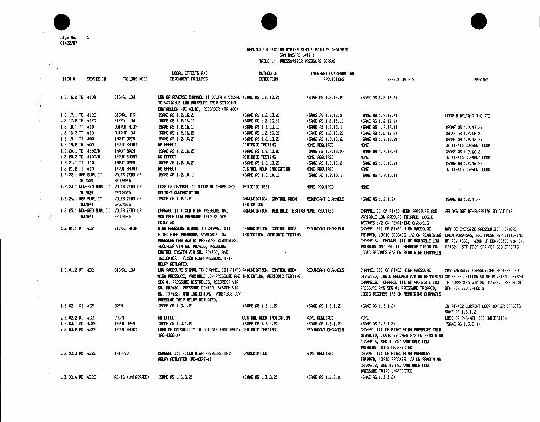
Pane No. 5 01/22/87
REACTOR PROTECTION SYSTEM SINGLE FAILURE ANALYSIS SAN ONOFRE UNIT I
TABLE 1: PRESSURIZER PRESSURE SCRAMS
LOCAL EFFECTS AND METHOD OF INHERENT COMPENSATING ITEM I DEVICE 10 FAILURE MODE DEPENDENT FAILURES DETECTION PROVISIONS EFFECT ON RPS REMARKS
1.2.16.2 TE 410A SIGNAL LOW LOW OR REVERSE CHANNEL II DELTA-T SIGNAL (SAME AS 1.2.13.2) (SAME AS 1.2.13.2) (SAME AS 1.2.13.2) TO VARIABLE LOW PRESSURE TRIP SETPOINT CONTROLLER (PC-431D), RECORDER (TR-400)
1.2.17.1 TE 412C SIGNAL HIGH (SAME AS 1.2.16.2) (SAME AS 1.2.13.2) (SANE AS 1.2.13.2) (SAME AS 1.2.13.2) LOOP B DELTA-T T-C RTD 1.2.17.2 TE 412C SIGNAL LOW (SAN AS 1.2.16.1) (SAE AS 1.2.13.1) (SAME AS 1.2.13.11 (SAME AS 1.2.13.1) 1.2.18.1 TT 410 OUTPUT HIGH (SAME AS 1.2.16.1) (SAME AS 1.2.13.1) (SAME AS 1.2.13.1) (SAME AS (SAME AS 1.2.17.2) 1.2.18.2 TT 410 OUTPUT LOW (SAME AS 1.2.16.2) (SAME AS 1.2.13.2) (SAME AS 1.2.13.2) (SAME AS (SANE AS 1.2.16.2) 1.2.19.1 TR 400 INPUT OPEN (SAME AS 1.2.16.2) (SAME AS 1.2.13.2) (SAME AS 1.2.13.2) (SA AS 1.2.13.2) (SAME AS 1.2.16.2) 1.2.19.2 TR 400 INPUT SHORT NO EFFECT PERIODIC TESTING NONE REQUIRED NONE IN TT-410 CURRENT LOOP 1.2.20.1 TC 410C/D INPUT OPEN (SAME AS 1.2.16.2) (SAME AS 1.2.13.2) (SAME AS 1.2.13.2) (SAME AS 1.2.13.21 (SAME AS 1.2.16.2) 1.2.20.2 TC 410C/D INPUT SHORT NO EFFECT PERIODIC TESTING NOE REQUIRED NONE IN TT-4ID CURRENT LOOP 1.2.21.1 TI 410 INPUT OPEN (SAME AS 1.2.16.2) (SAME AS 1.2.13.2) (SAME AS 1.2.13.2) (SAME AS 1.2.13.2) (SAME AS 1.2.16.2) 1.2.21.2 TI 410 INPUT SHORT NO EFFECT CONTROL ROOM INDICATION NONE REQUIRED NONE IN TI-4ID CURRENT LOOP 1.2.22.1 REG SUPL II VOLTS ZERO OR (SAME AS 1.2.10.1) (SAME AS 1.2.10.1) (SAME AS 1.2.10.1) (SAM AS 1.2.(0.1)
(RI/R2) GROUNDED 1.2.23.1 NON-REG SUPL II VOLTS ZERO OR LOSS OF CHANNEL II (LOOP B) T-AVG AND PERIODIC TEST NONE REQUIRED NONE
(RI/R2) GROUNDED DELTA-T ANNUNCIATION 1.2.24.1 RED SUPL II VOLTS ZERO OR (SAKE AS 1.2.1.2) ANNUNCIATION, CONTROL ROOM REDUNDANT CW ELS (SAME AS 1.2.1.2) (SAME AS
(R3/R4) GROUNDED INDICATION 1.2.25.1 NON-REG SUPL II VOLTS ZERO OR CHANNEL II FIXED HIGH PRESSURE AND ANNUNCIATION, PERIODIC TESTING NONE REQUIRED CHANNEL 11 OF FIXED HIGH PRESSURE AND RELAYS ARE XE-ENERGIZE TO ACTUATE
(R3/R4) GROUNDED VARIABLE LOW PRESSURE TRIP RELAYS VARIABLE LOW PRESURE TRIPPED, LOGIC ACTUATED BECOMES 1/2 ON REMAINING CHANNELS
1.3.01.1 PT 432 SIGNAL HIGH HIGH PRESSURE SIGNAL TO CHANNEL III ANNUNCIATION, CONTROL ROOM REDUNDANT CHANNELS CHANNEL III OF FIXED HION PRESSURE NAY BE-ENERGIZE PRESSURIZER HEATERS, FIXED HIGH PRESSURE, VARIABLE LOW INDICATION, PERIODIC TESTING TRIPPED, LOGIC BECOMES (/2 ON REMAINING OPEN PORV-545, AND CAUSE REPOSITIONING PRESSURE AND SEQ 41 PRESSURE BISTABLES, CHANNELS. CHANNEL III OF VARIABLE LOW OF PCV-430C, -430H IF CONNECTED VIA SW. RECORDER VIA SW. PR/430, PRESSURE PRESSURE AND SED it PRESSURE DISABLED, P/432. SEE ECES SIR FOR STI EFFECTS CONTROL SYSTEM VIA SW. PR/432, AND LOGIC BECOMES 2/2 ON REMAINING CHANNELS INDICATOR. FIXED HIGH PRESSURE TRIP RELAY ACTUATED.
J.3.01.2 PT 432 SIGNAL LOW LOW PRESSURE SIGNAL TO CHANNEL III FIXED ANNUNCIATION, CONTROL ROOM REDUNDANT CHANNELS CHANEL III OF FIED HIGH PRESSURE MAY ENERGIZE PRESSURIZER HEATERS AND HIGH PRESSURE, VARIABLE LOW PRESSURE AND INDICATION, PERIODIC TESTING DISABLED, LOGIC BECOMES 2/2 ON REMAINIG CAUSE REPOSITIONING OF PCY-430C, -430H SEQ It PRESSURE BISTABLES, RECORDER VIA CHANNELS. DROEL III OF VARIABLE LOW IF CONNECTED VIA SW. P/432. SEE ECES SW. PR/430, PRESSURE CONTROL SYSTEM VIA PRESSURE AND SEQ #1 PRESSURE TRIPPED, SFA FOR SEQ EFFECTS SW. PR/432, AND INDICATOR. VARIABLE LOW LOGIC BECOMES 1/2 ON REMAINING CHANNELS PRESSURE TRIP RELAY ACTUATED.
1.3.02.1 PI 432 OPEN (SAME AS 1.3.1.2) (SAME AS 1.3.1.21 (SAXE AS 1.3.1.2) (SAME AS 1.3.1.2) IN PT-432 CURRENT LOOP (OTHER EFFECTS SAME AS 1.3.1.2)
1.3.02.2 PI 432 SHORT NO EFFECT CONTROL ROOM INDICATION NONE REQUIRED NONE LOSS OF CHANNEL III INDICATION 1.3.03.1 PC 432E INPUT OPEN (SAME AS 1.3.1.2) (SAME AS 1.3.1.2) (SAME AS 1.3.1.2) (SAME AS 1.3.1.2) (SAME AS 1.3.2.1) 1.3.03.2 PC 432E INPUT SHORT LOSS OF CAPABILITY TO ACTUATE TRIP RELAY PERIODIC TESTING REDUNDANT CHANNELS CHANNEL III OF FIXED HIGH PRESSURE TRIP
(PC-432E-X) DISABLED, LOGIC BECOMES 2/2 ON REMAINING CHAINNELS, SEQ #1 AND VARIABLE LOW PRE SSU RE TRIPS UNAFFECTED
1.3.03.3 PC 432E TRIPPED CHANNEL III FIXED HIGH PRESSURE TRIP ANNUNCIATION NONE REQUIRED CHANNEL III OF FIXED HIGH PRESSURE RELAY ACTUATED (PC-432E-X) TRIPPED, LOGIC BECOMES (/2 ON REMAINING
CHANNELS, SEQ #1 AND VARIABLE LOW PRESSURE TRIPS UNAFFECTED
1.3.03.4 PC 432E AS-IS (UNTRIPPED) (SANE AS 1.3.3.2S (SAME AS 1.3.3.2) (SAME AS 1,3.3.2) (SAME AS 1.3.3.2)
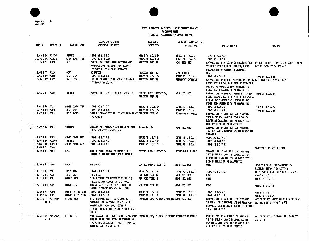
Page No. S 01/22/87
REACTOR PROTECTION SYSTEM SINGLE FAILURE ANALYSIS SAN ONOFRE UNIT I
TABLE 1: PRESSURIZER PRESSURE SCRAMS
LOCAL EFFECTS AND METHOD OF INHERENT COMPENSATING ITEM DEVICE ID FAILURE MODE DEPENDENT FAILURES DETECTION PROVISIONS EFFECT ON RPS REMARKS
1.3.04.1 PC 432E-X TRIPPED (SAME AS 1.3.3.3) (SAME AS 1.3.3.3) (SAME AS 1.3.3.3) (SAME AS 1.3.3.3) 1.3.04.2 PC 432E-X AS-IS (UNTRIPPED) (SAKE AS 1.3.3.2) (SAME AS 1.3.3.2) (SAME AS 1.3.3.2) (SAME AS 1.3.3.2) 1.3.05.1 Y 4328 OPEN CHANNEL III FIXED HIGH PRESSURE AND PERIODIC TESTING NONE REQUIRED CHANNEL III OF FIRED HIGH PRESSURE AND SWITCH FAILURE OR OPERATOR ERROR, RELAYS
VARIABLE LOW PRESSURE TRIP RELAYS VARIABLE LOW PRESSURE TRIPPED, LOGIC ARE DO-ENERGIZE TO ACTUATE (PC-432E-I, PC-432B-2) ACTUATED BECOMES 1/2 ON REMAINING CHANNELS
1.3.05.2 Y 4328 SHORT NO EFFECT PERIODIC TESTING NONE REQUIRED NONE 1.3.06.1 PC 432C INPUT OPEN (SAME AS 1.3.1.2) (SAKE AS 1.3.1.2) (SAME AS 1.3.1.2) (SANE AS 1.3.1.2) (SANE AS 1.3.2.1) 1.3.06.2 PC 432C INPUT SHORT LOSS OF CAPABILITY TO ACTUATE CHANNEL PERIODIC TESTING REDUNDANT CHANNELS CHANNEL III OF SEQ 11 PRESSURE DISABLED, SEE ECCS SFA FOR SEQ EFFECTS
III INPUT TO SEQ #1 LOGIC BECOMES 2/2 ON REMAINING CHANNELS, SEQ 42 AND VARIABLE LOW PRESSURE AND FIXED HIGH PRESSURE TRIPS UNAFFECTED
1.3.06.3 PC 432C TRIPPED CHANNEL III INPUT TO SEQ #1 ACTUATED CONTROL ROOM INDICATION, NONE REQUIRED CHANNEL III OF SEQ #1 PRESSURE TRIPPED, (SANE AS 1.3.6.2) PERIODIC TESTING LOGIC BECOMES 1/2 ON REMAINING CHANNELS,
SEQ #2 AND VARIABLE LOW PRESSURE AND FIRED HIGH PRESSURE TRIPS UNAFFECTED
1.3.06.4 PC 432C AS-IS (UNTRIPPED) (SAME AS 1.3.6.2) (SAME AS 1.3.6.2) (SAME AS 1.3.6.2) (SAME AS 1.3.6.2) (SANE AS 1.3.6.2) 1.3.07.1 PC 4320 INPUT OPEN (SAME AS (.3.1.2) (SAM AS 1.3.1.2) (SAME AS 1.3.1.2) (SAME AS 1.3.1.2) (SAKE AS 1.312 1.3.07.2 FC 4328 INPUT SHORT, LDSS OF CAPABILITY TO ACTUATE TRIP RELAY PERIODIC TESTING REDUNDANT CHAWNELS HAEL III OF VARIABLE LOW PRESSURE
(PC-4329-1) TRIP DISABLED, LOGIC BECOMES 2/2 ON REMAINING CHANNELS, SEQ #I AND FIXED HIGH PRESSURE TRIPS UNAFFECTED
1.3.07.3 PC 4328 TRIPPED CHANNEL III VARIABLE LOW PRESSURE TRIP ANNUNCIATION NONE REQUIRED CHANEL III OF VARIABLE LOW PRESSURE RELAY ACTUATED (PC-432B-I) TRIPPED, LOGIC BECOMES 1/2 ON REMAINING
CHANNELS 1.3.07.4 PC 4328 AS-IS (UNTRIPPED) (SAME AS 1.3.7.2) (SAME AS 1.3.7.2) (SAVE AS 1.3.7.2) (SAME AS 1.3.7.2) 1.3.08.1 PC 4328-X TRIPPED (SAME AS 1.3.7.3) (SAME AS 1.3.7.3) (SAME AS 1.3.7.3) (SAME AS 1.3.7.3) 1.3.08.2 PC 4328-I AS-IS (UNTRIPPED) (SAME AS 1.3.7.2) (SAME AS 1.3.7.2) (SAME AS 1.3.7.2) (SAM AS 1.3.7.2) 1.3.09.1 TC 4208 COMPONENT HAS BEEN DELETED 1.3.10.1 PI 420B OPEN LOW SETPOINT SIGNAL TO CHANNEL III CONTROL ROOM INDICATION REDUNDANT CHA*ELS CHANNEL III OF VARIABLE LOW PRESSURE
VARIABLE LOW PRESSURE TRIP BISTABLE TRIP DISABLED, LOGIC BECONRES 2/2 ON REMAINING CHANELS, SEQ #1 AND FIRED HIGH PRESSURE TRIPS UNAFFECTED
1.3.10.2 PI 4208 SHORT NO EFFECT CONTROL ROOM INDICATION NONE REQUIRED NONE LOSS OF CHANNEL III VARIABLE LOW PRESSURE SETPOINT INDICATION
1.3.11.1 PM 432 INPUT OPEN (SAME AS 1.3.1.2) (SAME AS 1.3.1.2) (SAME AS 1.3.1.2) (SAME AS 1.3.1.2) IN PT-432 CURRENT LOOP (SEE 1.3.1.2) 1.3.11.2 PM 432 INPUT SHORT NO EFFECT PERIODIC TESTING NONE REQUIRED NONE (SANE AS 1.3.1.2) 1.3.11.3 PM 432 OUTPUT HIGH HIGH PRESSURIZER PRESSURE SIGNAL TO PERIODIC TESTING NONE REQUIRED NONE (SAFE AS 1.3.1.1)
PRESSURE CONTROLLER VIA SW. P/432 1.3.11.4 PM 432 OUTPUT LOW LOW PRESSURIZER PRESSURE SIGNAL TO PERIODIC TESTING NONE REQUIRED NONE (SANE AS 1.3.1.2)
PRESSURE CONTROLLER VIA SW. P/432 1.3.12.1 YE 432 DUTPUT VOLTS HIGH (SAME AS 1.3.1.1) (SAME AS 1.3.1.1) (SAME AS 1.3.1.1) (SAM AS 1.3.1.1) (SAME AS 1.3.1.1) 1.3.12.2 YE 4328 QUTPUT VOLTS ZERO (SAME AS 1.3.1.2) (SAME AS 1.3.1.2) (SAME AS 1.3.1.2) (SAME AS 1.3.1.2) (SAME AS 1.3.1.2) 1.3.13.1 TE 421A/TYV SIGNAL HIGH HIGM CHANNEL III T-AV SIGNAL TO ANNUNCIATION, PERIODIC TESTING NOE REQUIRED ClOWL III OF VARIABLE LOW PRESSURE MAY CAUSE ROD INSERTION IF CONNECTED VIA
421A VARIABLE LOW PRESSURE TRIP SETPOINT TRIPPED, LOGIC BECOMES 1/2 ON REMAINING SW. #1, LOOP C T-AVG T-H RTD CONTROLLER (PC-432B), RECORDER CHANNELS, SEQ #1 AND FIXED HIGH PRESSURE (TR-401-3) AND ROD CONTROL SYSTEM VIA TRIPS UNAFFECTED SW. 11
1.3.13.2 TE 421A/TYV SIGNAL LOW LOW CHANNEL III T-AVG SIGNAL TO VARIABLE ANNUNCIATION, PERIODIC TESTING REDUNDANT CHANNELS CHANNEL III OF VARIABLE LOW PRESSURE MAY CAUSE ROD WITHDRAWAL IF CONNECTED 421A LOW PRESSURE TRIP SETPOINT CONTROLLER TRIP DISABLED, LOGIC BECOMES 2/2 ON VIA SW. #I
(PC-432B), RECORDER (TR-401-3) AND ROD REMAINING CHNNLS, SEQ 41 AND FIXED CONTRCL SYSTEMN VIA SW. #1 HIGH PRESSURE TRIPS UNAFFECTED

Page No. 7 01/22/87
REACTOR PROTECTION SYSTEM SINGLE FAILURE ANALYSIS SAN ONOFRE UNIT I
TABLE 1: PRESSURIZER PRESSURE SCRAMS
LOCAL EFFECTS AND METHOD OF INHERENT COMPENSATING ITEM N DEVICE ID FAILURE MODE DEPENDENT FAILURES DETECTION PROVISIONS EFFECT ON RPS REMARKS
1.3.14.1 TE 421CITYV SIGNAL HIGH (SAME AS 1.3.13.1) (SAME AS 1.3.13.1) (SAKE AS 1.3.13.1) (SAKE AS 1.3.13.1) MAY CAUSE ROD INSERTION IF CONNECTED VIA 421C SW. #I, LOOP C T-AVO T-C RTD
1.3.14.2 TE 42IC/TYV SIGNAL LOW (SAME AS 1.3.13.2) (SAME AS 1.3.13.2) (SAME AS 1.3.13.2) (SAME AS 1.3.13.2) MAY CAUSE ROD WITHDRAWAL IF CONNECTED 421C VIA SW. U
1.3.15.1 VLPS CH III OUTPUT SIGNAL HIGH (SANE AS 1.3.13.1) (SAME AS 1.3.13.)) (SAME AS 1.3.13.1) (SANE AS 1.3.13.1) (SANE AS 1.3.13.1) INCLUDES TO A21A, TYI-AIB, TYM-421, TO 421, TYS-421A&D, TYV-421B
1.3.15.2 VLPS CH III OUTPUT SIGNAL LOW (SAME AS 1.3.13.2) (SAME AS 1.3.13.2) (SAME AS 1.3.13.2) (SANE AG 1.3.13.2) (SAME AS 1.3.13.21 1.3.16.1 TE 420A SIGNAL HIGH HIGH CHNEL III DELTA-T SIGNAL TO (SAME AS 1.3.13.1) (SAME AS 1.3.13.1) (SAME AS 1.3.13.1) LOOP C DCLTA-T TN RTO
VARIABLE LOW PRESSURE TRIP SETPOINT CONTROLLER (PC-432B), RECORDER (TR-400), AND SHUTDOWN MARGIN ANNUNCIATION VIA SW. 82
1.116.2 TE 420A SIGNAL LOW LOW OR REVERSE CHANNEL III DELTA-T (SAME AS 1.3.13.2) (SAME AS 1.3.13.2) (SA AS 1.3.13.2) SIGNAL TO VARIABLE LOW PRESSURE TRIP SETPOINT CONTROLLER (PC-4328), RECORDER (TR-400)
1.3.17.1 TE 420C SIGNAL HIGH (SAME AS 1.3.16.2) (SAME AS 1.3.13.2) (SAE AS 1.3.13.2) (SAME AS 1.3.13.2) LOOP C DCLTA-T T-C RID 1.3.17.2 TE 420C SIGNAL LOW (SANE AS 1.3.16.1) (SAME AS 1.3.13.1) (SAME AS 1.3.13.1) (SANE AS 1.3.13.1) 1.3.18.1 TT 420 OUTPUT HIGH (SAME AS 1.3.16.1) (SME AS 1.3.13.1) (SAE AS 1.3.13.1) (SAME AS 1.3.13.1) (SAKE AS 1.3.17.2) 1.3.18.2 TT 420 OUTPUT LOW (SAME AS 1.3.16.2) (SAME AS 1.3.13.2) (SAME AS 1.3.13.2) (SAME AS 1.3.13.2) (SAME AS 1.3.16.2) 1.3.19.1 TR 400 INPUT OPEN (SAME AS 1.3.16.2) (SANE AS 1.3.13.2) (SAME AS 1.3.13.2) (SAME AS 1.3.13.2) (SAKE AS 1.3.16.2) 1.3.19.2 TR 400 INPUT SHORT NO EFFECT PERIODIC TESTING NONE REQUIRED NONE IN TT-420 CURRENT LOOP 1.3.20.1 TC 420C/D INPUT OPEN (SAME AS 1.3.16.2) (SAME AS 1.3.13.2) (SAME AS 1.3.13.2) (SANE AS 1.3.13.2) (SAVE AS 1.3.16.2) 1.3.20.2 TC 420C/D INPUT SHORT NO EFFECT PERIODIC TESTING NONE REQUIRED NONE IN TT-420 CURRENT LOOP 1.3.21.1 TI 420 INPUT OPEN (SANE AS (.3.16.2) (SAME AS 1.3.13.2) (SANE AS 1.3.13.2) (SAME AS 1.3.13.2) (SAME AS 1.3.16.2) 1.3.21.2 TI 420 INPUT SHORT NO EFFECT CONTROL ROOM INDICATION NONE REQUIRED NONE IN TT-420 CURRENT LOOP 1.3.22.1 REG SUPL III VOLTS ZERO OR (SANE AS 1.3.10.1) (SAKE AS 1.3.10.1) (SAME AS 1.3.10.1) (SAME AS 1.3.10.)
(R(/R2) GROUNDED 1.3.23.1 NON-REG SUPL III VOLTS ZERO OR LOSS OF CHANNEL III (LOOP C) T-AVG AND PERIODIC TEST NONE REQUIRED NONE
(R1/R2) GROUNDED DELTA-T ANNUNCIATION 1.3.24.1 PEG SUPL III VOLTS ZERO OR (SAME AS 1.3.1.2) ANNUNCIATION, CONTROL ROOM REDUNDANT CHANNELS (SAME AS 1.3.1.2) (SAME AS 1.3.1.2)
(R3/R4) GROUNDED INDICATION 1.125.1 NDON-REG SUPL III VOLTS ZERO OR CHANNEL III FIXED HIGH PRESSURE AND ANNUNCIATION, PERIODIC TESTING NONE REQUIRED CHANNEL III FIXED HIGH PRESSURE ANI RELAYS ARE XE-ENERGIZE TO ACTUATE
(R3/4) GROUNDED VARIABLE LOW PRESSURE TRIP RELAYS VARIABLE LOW PRESSURE TRIPPED, LOGIC CTUATED BECOMES 1/2 ON REMAINING CHANNELS
1.4.01.1 SW. PR/430 CONTACTS OPEN LOW SIGNAL TO PRESSURIZER PRESSURE CONTROL ROOM INDICATION, NONE REUIRED NONE RECORDER PERIODIC TESTING
1.4.01.2 SW. PR/430 CONTACTS CLOSED PARALLELING OF PRESSURE SIGNAL CURRENT PERIODIC TESTING NONE LOGIC BECOMES 3/3 FOR FIXED HIGH LOOPS ACROSS LOOP RESISTORS PRESSURE, VARIABLE LOW PRESSURE AND GIG
#I PRESSURE TRIPS 1.4.01.3 SW. PR/430 CONTACTS GROUNDED CURRENT LOOP RESISTORS SHORTED, CAUSING CONTROL ROOM INDICATION, NONE REUIRED REACTOR TRIP ON 3/3 PRESSURIZER FIXED (SANE AS
HIGH LOOP SIGNALS TO TRIP BISTABLES, ANNUNCIATION, PERIODIC TESTING HI PRESSURE CHANNELS PRESSURE CONTROLS VIA SW. P/432. LOW SIGNAL TO RECORDER.
1.4.02.1 SW. P/432 CONTACTS OPEN LOW PRESSURE SIGNAL TO PRESSURE CONTROL ANNUNCIATION, PERIODIC TESTING NONE REUIRED NONE MANUAL PRESSURE CONTROL MAY K REGUIREX DEVICES, INTERCHANNEL ISOLATION AT SW. P/432
* 0 Page No. B 01/22/87
REACTOR PROTECTION SYSTEM SINGLE FAILURE ANALYSIS SAN ONOFRE UNIT I
TABLE 1: PRESSURIZER PRESSURE SCRAMS
LOCAL EFFECTS AND METHOD OF INERENT COMPENSATING ITEM I DEVICE ID FAILURE MODE DEPENDENT FAILURES DETECTION PROVISIONS EFFECT ON RPS REMARKS
1.4.02.2 S. P/432 CONTACTS CLOSED PARALLELINB OF PRESSURE SIGNALS TO PERIODIC TESTING NONE REQUIRED NONE PRESSURE CONTROL DEVICES. INTERCHANNEL ISOLATION AT PM-430, PM-431, PM-432
1.4.02.3 SW. P/432 CONTACTS GROUNDED LOSS OF NDN-REG SUPL IV (R3/R4), LOW ANNUNCIATION, PERIODIC TESTING NONE REQUIRED NONE MANUAL PRESSURE CONTROL MAY BE REQUIRED PRESSURE SIGNALS TO PRESSURE CONTROL DEVICES. INTERCHANNEL ISOLATION AT PW-430, PM-431, PM-432
1.4.03.1 SW. 1 CONTACTS OPEN LOW T-AYS SIGNAL TO ROD CONTROL SYSTEM, ANNUNCIATION, PERIODIC TESTING NONE REQUIRED NONE MANUAL ROD CONTROL MAY BE REQUIRED INTERCHANNEL ISOLATION AT SWITCH
1.4.03.2 SW. 1 CONTACTS CLOSED PARALLELING OF T-AVG SIGNALS TO ROD PERIODIC TESTING NONE REQUIRED NONE CONTROL SYSTEM. INTERCHANNEL ISOLATION AT TYI 401AB, TYI 411A8B, TYI 421 & 421A.
1.4.03.3 SW. 1 CONTACTS GROUNDED LOCAL CURRENT LOOP RESISTORS SHORTED, ANNUNCIATION, PERIODIC TESTING NONE REQUIRED NONE MAML ROD CONTROL MAY BE REQUIRED CAUSING HIGH LOOP SIGNALS TO RECORDERS (TR401-1, -2, -3) AND BISTABLES FOR T-AVS ANNUNCIATORS, LOW T-AVG SIGNAL TO ROD CONTROL SYSTEM, INTERCHANNEL SAME AS 1.4.3.2
1.4.04.1 S. 2 CONTACTS OPEN LOW DELTA-T SIGNAL TO SHUTDOWN MARGIN ANNUNCIATION, PERIODIC TESTING NONE REQUIRED NONE ANNUNCIATOR, INTERCHANNEL ISOLATION AT SWITCH
1.4.04.2 SW. 2 CONTACTS CLOSED PARALLELINB OF DELTA-T SIGNAL CURRENT PERIODIC TESTING NONE REQUIRED LOGIC BECOMES 3/3 FOR DELTA-T INPUT TO LOOPS ACROSS RESISTORS VARIABLE LOW PRESSURE TRIP SETPOINT
1.4.04.3 SW. 2 CONTACTS GROUNDED CURRENT LOOP RESISTORS SHORTED, CAUSING CONTROL ROOM INDICATION, NONE REQUIRED CHANNELS I, II AND III OF VARIABLE LOW SCRAM OCCURS UNLESS P-7 IS ON HIGH LOOP SIGNALS TO VARIABLE LOW ANMCIATION, PERIODIC TESTING PRESSURE TRIPPED PRESSURE TRIP SETPOINT COMPENSATION, AND DELTA-T INDICATION AND ANNUNCIATOR BISTABLES

TABLE 2: PRESSURIZER LEVEL SCRAM
REFERENCES: A. SYSTEM DESCRIPTIONS: SD-SO1-390 PRIMARY PROCESS INSTRUMENTATION SD-SO1-570 REACTOR PROTECTION SYSTEM AND PERM.
B. DRAWINGS: 63717
9
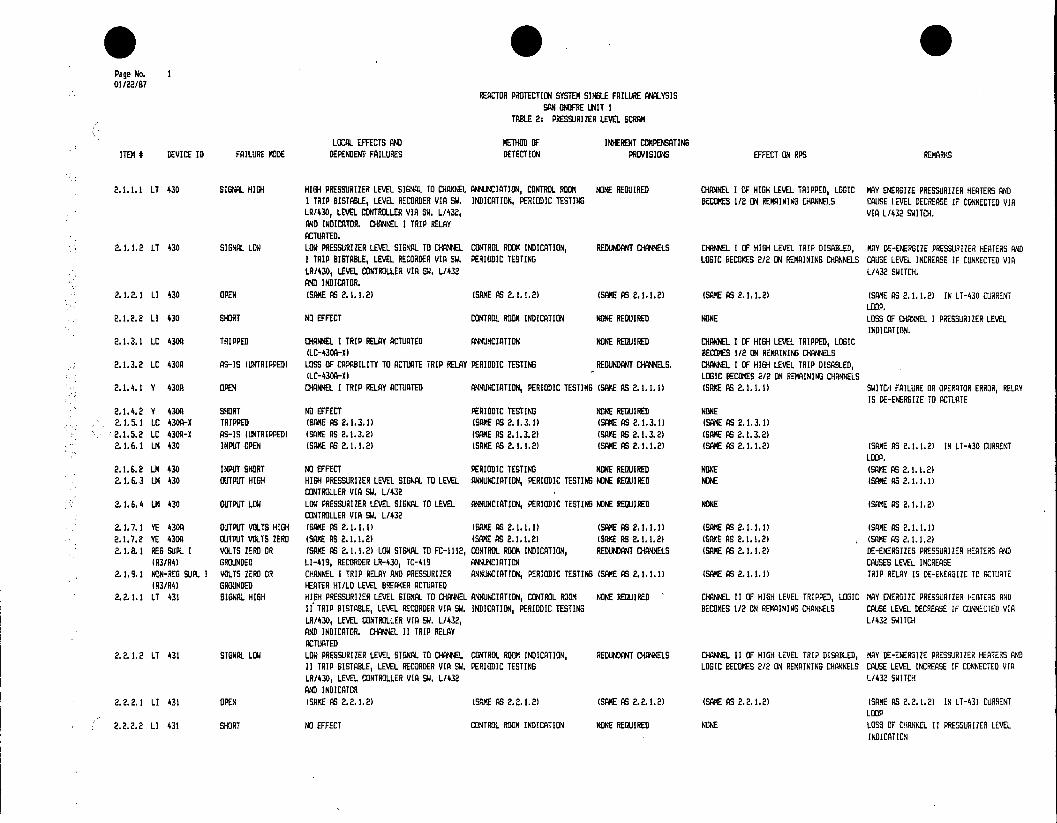
* Page No. I 01/22/87
REACTOR PROTECTION SYSTEM SINLE FAILURE ANALYSIS SAN ONFRE UNIT I
TABLE 2: PRESSURIZER LEVEL SCRAM
LOCAL EFFECTS AND METHO OF INHERENT COMPENSATING ITEM # DEVICE ID FAILURE MODE DEPENDENT FAILURES DETECTION PROVISIONS EFFECT ON RPS REMARKS
2.1.1.1 LT 430 SIGNAL HIGH HISH PRESSURIZER LEVEL SIGNAL TO CHANNEL ANNUNCIATION, CONTROL ROOM NONE REQUIRED CHANNEL I OF HIGH LEVEL TRIPPED, LOGIC MAY ENERGIZE PRESSURIZER HEATERS AND I TRIP BISTABLE, LEVEL RECORDER VIA SW. INDICATION, PERIODIC TESTING BECOMES 1/2 ON REMAINING CHANNELS CAUSE LEVEL DECREASE IF CONNECTED VIA LR1430, LEVEL CONTROLLER VIA SW. L/432, VIA L/432 SWITCH. AND INDICATOR. CHANNEL I TRIP RELAY ACTUATED.
2.1.1.2 LT 430 SIGNAL LOW LOW PRESSURIZER LEVEL SIGNAL TO CHANNEL CONTROL ROOM INDICATION, REDUNDANT CHANNELS CHANNEL I OF HIGH LEVEL TRIP DISABLED, MAY DE-ENERSIZE PRESSURIZER HEATERS AND I TRIP BISTABLE, LEVEL RECORDER VIA SW. PERIODIC TESTING LOGIC BECOMES 2/2 ON REMAINING CHANNELS CAUSE LEVEL INCREASE IF CONNECTED VIA LR/430, LEVEL CONTROLLER VIA SW. L/432 L/432 SWITCH. AND INDICATOR.
2.1.2.1 LI 430 OPEN (SAME AS 2.1.1.2) (SAME AS 2.1.1.2) (SAME AS 2.1.1.2) (SAME AS 2.1.1.2) (SAME AS 2.1. 1.2) IN LT-430 CURRENT LOOP.
2.1.2.2 LI 430 SHORT NO EFFECT CONTROL ROOM INDICATION NONE REQUIRED NONE LOSS OF CHANNEL I PRESSURIZER LEVEL INDICATION.
2.1.3.1 LC 430A TRIPPED CHANNEL I TRIP RELAY ACTUATED ANNUNCIATION NONE REQUIRED CHANNEL I OF HIGH LEVEL TRIPPED, LOGIC (LC-430A-X) BECOMES 1/2 ON REMAINING CHANNELS
2.1.3.2 LC 430A AS-IS (LNTRIPPED) LOSS OF CAPABILITY TO ACTUATE TRIP RELAY PERIODIC TESTING REDUNDANT CHANNELS. CHANNEL I OF HIGH LEVEL TRIP DISABLED, ILC-430A-I LOGIC BECOMES 2/2 ON REMAINING CHANNELS
2.1.4.1 Y 430A OPEN CHANNEL I TRIP RELAY ACTUATED ANNUNCIATION, PERIODIC TESTING (SAME AS 2.1.1.1) (SAME AS 2.1.1.1) SWITCH FAILURE OR OPERATOR ERROR, RELAY IS DE-ENERGIZE TO ACTUATE
2.1.4.2 Y 430A SHORT NO EFFECT PERIODIC TESTING NONE REQUIRED NONE 2.1.5.1 LC 430A-X TRIPPED (SAME AS 2.1.3.1) (SAME AS 2.1.3.1) (SAME AS 2.1.3.1) ISAME AS 2.1.3.1) 2.1.5.2 LC 430A-I AS-IS (UNTRIPPED) (SAME AS 2.1.3.2) (SAME AS 2.1.3.2) (SAME AS 2.1.3.2) (SAME AS 2.1.3.2) 2.1.6.1 LM 430 INPUT OPEN (SAME AS 2.1.1.2) (SAME AS 2.1.1.2) (SAME AS 2.1.1.2) (SAME AS 2.1.1.2) (SANE AS 2.1.1.2) IN LT-430 CURRENT
LOOP. 2.1.6.2 LM 430 INPUT SHORT NO EFFECT PERIODIC TESTING NONE REQUIRED NONE (SAME AS 2.1.1.2) 2.1.6.3 LM 430 OUTPUT HIGH HIGH PRESSURIZER LEVEL SIGNAL TO LEVEL ANNUNCIATION, PERIODIC TESTING NONE REQUIRED NONE (SAME AS 2.1.1.1)
CONTROLLER VIA SW. L/432 2.1.6.4 LM 430 OUTPUT LOW LOW PRESSURIZER LEVEL SIGNAL TO LEVEL ANNUNCIATION, PERIODIC TESTING NONE REQUIRED NONE (SAME AS 2.1.1.2)
CONTROLLER VIA SW. L/432 2.1.7.1 YE 430A OUTPUT VOLTS HIGH (SAME AS 2.1.1.1) (SAME AS 2.1.1.1) (SAME AS 2.1.1.1) (SAME AS 2.1.1.1) (SAME AS 2.1.1.1) 2.1.7.2 YE 430A OUTPUT VOLTS ZERO (SAME AS 2.1.1.2) (SAME AS 2.1.1.2) (SAME AS 2.1.1.2) (SAME AS 2.1.1.2) (SAME AS 2.1.1.2) 2. 1.8.1 REG SUPL I VOLTS ZERO OR (SME AS 2.1.1.2) LOW SIGNAL TO FC-1112, CONTROL ROOM INDICATION, REDUNDANT CHANNELS (SAME AS 2.1.1.2) DE-ENERGIZES PRESSURIZER HEATERS AND
(R3/R4) GROUNDED LI-419, RECORDER LR-430, TC-419 ANNUNCIATION CAUSES LEVEL INCREASE 2.1.9.1 NON-REG SUPL I VOLTS ZERO OR CHANNEL I TRIP RELAY AND PRESSURIZER ANNUNCIATION, PERIODIC TESTING (SAME AS 2.1.1.1) (SAME AS 2.1.1.1) TRIP RELAY IS DE-ENERSIZE TO ACTUATE
(R3/R4) GROUNDED HEATER HI/LO LEVEL BREAKER ACTUATED 2.2.1.1 LT 431 SIGNAL HIGH HIGH PRESSURIZER LEVEL SIGNAL TO CHANNEL ANNUNCIATION, CONTROL ROOM NONE REQUIRED CHANNEL II OF HIGH LEVEL TRIPPED, LOGIC MAY ENERGIZE PRESSURIZER HEATERS AND
11 TRIP BISTABLE, LEVEL RECORDER VIA SW. INDICATION, PERIODIC TESTING BECOMES 1/2 ON REMAINING CHANNELS CAUSE LEVEL DECREASE IF CONNECTED VIA LR/430, LEVEL CONTROLLER VIA SW. L/432, L/432 SWITCH AND INDICATOR. CHANNEL II TRIP RELAY ACTUATED
2. 21.2 LT 431 SIGNAL LOW LOW PRESSURIZER LEVEL SIGNAL TO CHANNEL CONTROL ROOM INDICATION, REDUNDANT CHANNELS HANNEL II OF HIGH LEVEL TRIP DISABLED, MAY DE-ENERGIZE PRESSURIZER HEATERS AND 11 TRIP BISTABLE, LEVEL RECORDER VIA SW. PERIODIC TESTING LOGIC BECOMES 2/2 ON REMAINING CHANNELS CAUSE LEVEL INCREASE IF CONNECTED VIA LR/430, LEVEL CONTROLLER VIA SW. L/432 L/432 SWITCH AND INDICATOR
2.2.2.1 LI 431 OPEN (SAME AS 2.2.1.2) (SAME AS 2.2.1.2) (SAME AS 2.2.1.2) (SAME AS 2.2.1.2) (SAME AS 2.2.1.2) IN LT-431 CURRENT LOOP
2.2.2.2 LI 431 SHORT NO EFFECT CONTROL ROOM INDICATION NONE REQUIRED NONE LOSS OF CHANNEL II PRESSURIZER LEVEL INDICATION

* 0 Page No. 2 01/22/87
REACTOR PROTECTION SYSTEM SINGLE FAILURE ANALYSIS SAN ON0FRE UNIT 1
TABLE 2: PRESSURIZER LEVEL SCRAM
LOCAL EFFECTS AND METHOD OF INHERENT COMPENSATING ITEM # DEVICE ID FAILURE %ODE DEPENDENT FAILURES DETECTION PROVISIONS EFFECT ON RPS REMARKS
2.2.3.1 LC 431A TRIPPED CHANNEL II TRIP RELAY ACTUATED ANNUNCIATION NONE REQUIRED CHANNEL II HIGH LEVEL TRIPPED, LOGIC (LC-431A-X) BECOMES 1/2 ON REMAINING CHANNELS
2.2.3.2 LC 431A AS-IS (UNTRIPPED) LOSS OF CAPABILITY TO ACTUATE TRIP RELAY PERIODIC TESTING REDUNDANT CHANNELS CHANNEL II OF HISH LEVEL TRIP DISABLED, (LC-431A-I) LOGIC BECOMES 2/2 ON REMAINING CHANNELS
2.2.4.1 Y 431 OPEN CHANNEL II TRIP RELAY ACTUATED ANNUNCIATION, PERIODIC TESTING (SAME AS 2.2.1.1) (SANE AS 2.2.1.1) SWITCH FAILURE OR OPERATOR ERROR, RELAY IS DE-ENERGIZE TO ACTUATE
2.2.4.2 Y 431A SHORT NO EFFECT PERIODIC TESTING NONE REQUIRED NONE 2.2.5.1 LC 431A-X TRIPPED (SAME AS 2.2.3.1) (SAME AS 2.2.3.1) (SAME AS 2.2.3.1) (SAME AS 2.2.3.1) 2.2.5.2 LC 431A-I AS-IS (UNTRIPPED) (SAME AS 2.2.3.2) (SAME AS 2.2.3.2) (SAME AS 2.2.3.2) (SAME AS 2.2.3.2) 2.2.6.1 LM 431 INPUT OPEN (SAME AS 2.2.1.2) (SAME AS-2.2.1.2) (SAME AS 2.2.1.2) (SAME AS 2.2.1.2) (SAME AS 2.2.1.2) IN LT-431 CURRENT
LOOP 2.2.6.2 LM 431 INPUT SHORT ND EFFECT PERIODIC TESTING NONE REQUIRED NONE (SAME AS 2.2.1.2) 2.2.6.3 LM 431 OUTPUT HIGH HIGH PRESSURIZER LEVEL SIGNAL TO LEVEL ANNUNCIATION, PERIODIC TESTING NONE REQUIRED NONE (SAME AS 2.2.1.1)
CONTROLLER VIA SW. L/432 2.2.6.4 LM 431 OUTPUT LOW LOW PRESSURIZER LEVEL SIGNAL TO LEVEL ANNUNCIATION, PERIODIC TESTING NONE REQUIRED NONE (SAME AS 2.2.1.2)
CONTROLLER VIA SW. L1432 2.2.7.1 YE 431A OUTPUT VOLTS HIGH (SAME AS 2.2.1.1) (SAE AS E AS 2.2.1.PE AS 2.2.1.1) (SANE AS 2.2.1.1 (SAME AS 2.2.1.1) 2.2.7.2 YE 431A OUTPUT VOLTS ZERO (SAME AS 2.2.1.2) (SAME AS 2.2.1.2) (SANE AS 2.2.1.2) (SAME AS 2.2.1.2) (SAME AS 2.2.1.2) 2.2.8.1 RED SUPL II VOLTS ZERO OR (SAME AS 2.2.1.2) LOW SIGNAL TO RECORDER CONTROL ROOM INDICATION, REDUNDANT CHANNELS (SAME AS 2.2.1.2) MAY DE-ENERGIZE PRESSURIZER HEATERS AD
(R3/R4) GROUNDED TR-405-1 VIA TC-419 ANNUNCIATION CAUSE LEVEL INCREASE IF CONNECTED VIA L/432 SWITCH
2.2.9.1 NON-RED SUPL II VOLTS ZERO OR CHANNEL II TRIP RELAY ACTUATED, LOSS OF ANNUNCIATION, PERIODIC TESTING (SAME AS 2.2.1.1) (SAME AS 2.2.1.1) TRIP RELAY IS DE-ENERGIZE TO ACTUATE (R3/R4) GROUNDED CAPABILITY TO ACTUATE PRESSURIZER HEATER
LO-LO CUTOFF 2.3.1.1 LT 432 SIGNAL HIGH HIGH PRESSURIZER LEVEL SIGNAL TO CHANNEL ANNUNCIATION, CONTROL ROOM NONE REQUIRED CHANNEL III OF HIGH LEVEL TRIPPED, LOGIC MAY ENERGIZE PRESSURIZER HEATERS AND
III TRIP BISTABLE, LEVEL RECORDER VIA INDICATION, PERIODIC TESTING BECOMES 1/2 ON REMAINING CHANNELS CAUSE LEVEL DECREASE IF CONNECTED VIA SW. LR/430, LEVEL CONTROLLER VIA SW. L/432 SWITCH L/432, AND INDICATOR. CHANNEL III TRIP RELAY ACTUATED
2.11.2 LT 432 SIGNAL LOW LOW PRESSURIZER LEVEL SIGNAL TO CHANNEL CONTROL ROOM INDICATION, REDUNDANT CHANNELS CHANNEL III OF HIGH LEVEL TRIP DISABLED, MAY DE-ENERSIZE PRESSURIZER HEATERS AND III TRIP BISTABLE, LEVEL RECORDER VIA PERIODIC TESTING LOGIC BECOMES 2/2 ON REMAINING CHANNELS CAUSE LEVEL INCREASE IF CONNECTED VIA SW. LR/430, LEVEL CONTROLLER VIA SW. L/432 SWITCH L/432 AND INDICATOR
2.12.1 LI 432 OPEN (SAME AS 2.3.1.2) (SAME AS 2.3.1.2) (SAME AS 2.3.1.2) (SANE AS 2.3.1.2) (SAME AS 2.3.1.2) IN LT-432 CURRENT LOOP.
2.3.2.2 LI 432 SHORT NO EFFECT CONTROL ROOM INDICATION NONE REQUIRED NONE LOSS OF CHANNEL III PRESSURIZER LEVEL INDICATION
2.3.3.1 LC 432A TRIPPED CHANNEL III TRIP RELAY ACTUATED ANNUNCIATION NONE REQUIRED CHANNEL III OF HIGH LEVEL TRIPPED, LOGIC (LC-432A-X) BECOMES 1/2 ON REMAINING CHANNELS
2.3.3.2 LC 432A AS-IS (LNTRIPPED) LOSS OF CAPABILITY TO ACTUATE TRIP RELAY PERIODIC TESTING REDUNDANT DHANELS CHANNEL III OF HIGH LEVEL TRIP DISABLED, (LC-432R-X) LOGIC BECOMES 2/2 ON REMAININO CHANNELS
2.3.4.1 Y 432A OPEN CHANNEL III TRIP RELAY ACTUATED ANNUNCIATION, PEIODIC TESTING (SAME AS 2.3.1.1) (SAME AS 2.3.1.1) SWITCH FAILURE OR OPERATOR ERROR, TRIP RELAY IS DE-ENERGIZE TO ACTUATE
2.3.4.2 Y 4329 SHORT NO EFFECT PERIODIC TESTING NONE REQUIRED NONE 2.3.5.1 LC 432A-X TRIPPED (SAME AS 2.3.3.1) (SAME AS 2.3.3.1) (SAME AS 2.3.3.1) (SAME AS 2.3.3.1) 2.3.5.2 LC 432A- AS-IS (UNTRIPPED) (SAME AS 2.3.3.2) (SAME AS 2.3.3.2) (SAME AS 2.3.3.2) (SAVE AS 2.3.3.2) 2.3.6.1 LM 432 INPUT OPEN (SAME AS 2.3.1.2) (SAME AS 2.3.1.2) (SAME AS 2.3.1.2) (SAME AS 2.3.1.2) (SAME AS 2.3.1.2) IN LT-432 CURRENT
LOOP

*0 0 Page No. 3 01/22/87
REACTOR PROTECTION SYSTEM SINGLE FAILURE ANALYSIS SAN ONOFRE UNIT I
TABLE 2: PRESSURIZER LEVEL SCRAM
LOCAL EFFECTS AD METHOD OF INHERENT COMPENSATING ITEM # DEVICE ID FAILURE MODE DEPENDENT FAILURES DETECTION PROVISIONS EFFECT ON RPS REMARKS
2.3.6.2 LM 432 INPUT SHORT NO EFFECT PERIODIC TESTING NONE REQUIRED NONE (SAME AS 2.3.1.2) 2.3.6.3 LM 432 OUTPUT HIGH HIGH PRESSURIZER LEVEL SIGNAL TO LEVEL ANNUNCIATION, PERIODIC TESTING NONE REQUIRED NONE (SAME AS 2.3.1.1)
CONTROLLER VIA SW. L/432 2.3.6.4 LM 432 OUTPUT LOW LOW PRESSURIZER LEVEL SIGNAL TO LEVEL ANNUNCIATION, PERIODIC TESTING NONE REQUIRED NONE (SAME AS 2.3.1.2)
CONTROLLER VIA SW. L/432 2.3.7.1 YE 432A OUTPUT VOLTS HIGH (SAME AS 2.3.1.1) (SAME AS 2.3.1.1) (SAME AS 2.3.1.1) (SAME AS 2.3.1.1) (SAME AS 2.3.1.1) 2.3.7.2 YE 432A OUTPUT VOLTS ZERO (SAME AS 2.3.1.2) (SAME AS 2.3.1.2) (SAME AS 2.3.1.2) (SAME AS 2.3.1.2) (SAME AS 2.3.1.2) 2.3.8.1 REG SUPL III VOLTS ZERO OR (SAME AS 2.3.1.2) CONTROL ROOM INDICATION, REDUINDANT CHANNELS (SAME AS 2.3.1.2) MAY DE-ENERGIZE PRESSURIZER PEATERS AND
(R3/R4) GROUNDED ANNUNCIATION CAUSE LEVEL INCREASE IF CONNECTED VIA L/432 SWITCH
2.3.9.1 NON-REG SUPL III VOLTS ZERO OR CHANNEL III TRIP RELAY ACTUATED ANNUNCIATION, PERIODIC TESTING (SAME AS 2.3.1.1) (SAME AS 2.3.1.1) TRIP RELAY IS DE-ENERGIZE TO ACTUATE (R3/R4) GROUNDED
2.4.1.1 SW. LR/430 CONTACTS OPEN LOW SIGNA TO PRESSURIZER LEVEL RECORDER CONTROL ROOM INDICATION NONE REQUIRED NONE 2.4.1.2 SW. LR/430 CONTACTS CLOSED PARALLELING OF LEVEL SIGNAL CURRENT PERIODIC TESTING NONE LOGIC BECOMES 3/3 FOR PRESSURIZER HIGH
LOOPS ACROSS LOOP RESISTORS LEVEL TRIP 2.4.1.3 SW. LR/430 CONTACTS GROUNDED CURRENT LOOP RESISTORS SHORTED, CAUSING CONTROL ROOM INDICATION, NONE REQUIRED REACTOR TRIP ON 3/3 PRESSURIZER HIGH (SAME AS 2.1.1.1)
HIGH LOOP SIGNALS TO TRIP BISTABLES, ANNUNCIATION, PERIODIC TESTING LEVEL TRIP CHANNELS LEVEL CONTROLS VIA SW. L1432. LOW SIGNAL TO RECORDER
2.4.2.1 SW. L/432 CONTACTS OPEN LOW SIGNAL TO LEVEL CONTROL DEVICES AND ANNUNCIATION, PERIODIC TEST NONE REQUIRED NONE MANUAL LEVEL CONTROL REQUIRED PRESSURIZER HEATER BREAKER CONTROLS, INTERCHANNEL ISOLATION AT SWITCH L/432
2.4.2.2 SW. L/432 CONTACTS CLOSED PARALLELING OF LEVEL SIGNALS TO LEVEL PERIODIC TEST NONE REQUIRED NONE CONTROL DEVICES AND PRESSURIZER HEATER CONTROLS, INTERCHANNEL ISOLATION AT LM-430, LM-431, LM-432
2.4.2.3 SW. L/432 CONTACTS GROUNDED LOSS OF NON-REG SUPL IV (R3/R4). LOW ANNUNCIATION, PERIODIC TEST NONE REQUIRED NONE MANUAL LEVEL CONTROL MAY BE REQUIRED. SIGNALS TO LEVEL CONTROL DEVICES AND. PRESSURIZER HEATER BREAKER CONTROLS. INTERCHANNEL ISOLATION AT LM-430, LM-431, LM-432

TABLE 3: TURBINE TRIP SCRAM
REFERENCES: A. SYSTEM DESCRIPTIONS: SD-SO1-270 TURBINE CONTROL SYSTEM SD-SO1-570 REACTOR PROTECTION SYSTEM AND PERM.
B. DRAWINGS: N1541 Sh 2 5112259

* 0 Page No. I 01/22/87
REACTOR PROTECTION SYSTEM SINGLE FAILURE ANALYSIS SAN ONOFRE UNIT 1 .
TABLE 3: TURBINE TRIP SCRAM
LOCAL EFFECTS AND METHOD OF INHERENT COMPENSATING ITEM 8 DEVICE ID FAILURE MODE DEPENDENT FAILURES DETECTION PROVISIONS EFFECT ON RPS REMARKS
3.1.1.1 PS-113 CONTACTS OPEN DE-ENERGIZES CHANNEL I TRIP RELAY PERIODIC TESTING NONE REQUIRED CHANNEL I OF TURBINE TRIP SCRAM ACTUATED, LOGIC BECOMES 1/2 ON REMAINING CHANNELS
3.1.1.2 PS-113 CONTACTS CLOSED UNRBLE TO DETECT DECREASING AUTO-STOP PERIODIC TESTING REDUNDANT CHANNELS CHANNEL I OF TURBINE TRIP SCRAM (AS-IS) OIL PRESSURE IN CHANNEL I DISABLED, LOGIC BECOMES 2/2 ON REMAINING
CHANNELS 3.1.2.1 63X-1 TRIPPED (SAME AS 3.1.1.1) (SAME AS 3.1.1.1) (SAME AS 3.1.1.1) (SAME AS 3.1.1.1) 3.1.2.2 63X-1 NOT TRIPPED (AS-IS) (SAME AS 3.1.1.2) (SAME AS 3.1.1.1) (SAME AS 3.1.1.2) (SAME AS 3.1.1.2) 3.2.1.1 PS-33 CONTACTS OPEN DE-ENERSIZES CHANNEL II TRIP RELAY (SAME AS 3.1.1.1) NONE REQUIRED CHANNEL II OF TURBINE TRIP SCRAM
ACTUATED, LOGIC BECOMES 1/2 ON REMAINING CHANNELS
3.2.1.2 PS-33 CONTACTS CLOSED UNABLE TO DETECT DECREASING AUTD-STOP (SAME AS 3.1.1.1) REDUNDANT CHANNELS CHANNEL II OF TURBINE TRIP SCRAM (AS-IS) OIL PRESSURE IN CHANNEL II DISABLED, LOGIC BECOMES 2/2 ON REMAINING
CHANNELS 3.2.2.1 63X-2 TRIPPED (SAME AS 3.2.1.1) (SAME AS 3.1.1.1) (SAME AS 3.2.1.1) (SAME AS 3.2.1.1) 3.2.2.2 631-2 NOT TRIPPED (AS-IS) (SME AS 3.2.1.2) (SAME AS 3.1.1.1) (SAME AS 3.2.1.2) (SAME AS 3.2.1.2) 3.3.1.1 PS-112 CONTACTS OPEN DE-ENERSIZES CHANNEL III TRIP RELAY (SAME AS 3.1.1.1) NNE REQUIRED CHANNEL III OF TURBINE TRIP SCRAM
ACTUATED, LOGIC BECOMES 1/2 ON REMAINING CHANNELS
3.3.1.2 PS-112 CONTACTS CLDOSED UNABLE TO DETECT DECREASING AUTO-STOP (SAME AS 3.1.1.1) REDUNDANT CHANNELS CHANNEL III OF TURBINE TRIP SCRAM (AS-IS) OIL PRESSURE IN CHANNEL III DISABLED, LOGIC BECOMES 2/2 ON REMAINING
CHANNELS 3.3.2.1 631-3 TRIPPED (SAME AS 3.3.1.1) (SAME AS 3.3.1.1) (SAME AS 3.3.1.1) (SAME AS 3.3.1.1) 3.3.2.2 53X-3 NOT TRIPPED (AS-IS) (SAME AS 3.3.1.2) (SAME AS 3.3.1.1) (SAME AS 3.3.1.2) (SAME AS 3.3.1.2) 3.4.1.1 125VDC BUS #1 VOLTS ZERO DE-ENERGIZES CHANNEL I, II AND III TRIP ANNUNCIATION NONE REQUIRED CHANNELS I, II AND III OF TURBINE TRIP TRIP BLOCKED IF P-7 IS ON. HOWEVER,
RELAYS REACTOR SCRAM ACTUATED SCRAM OCCURS VIA UNDERVOLTAGE RELAYS IRRESPECTIVE OF TURBINE TRIP SIGNAL
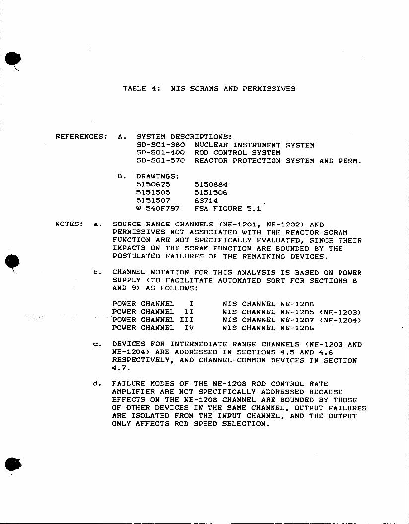
TABLE 4: NIS SCRAMS AND PERMISSIVES
REFERENCES: A. SYSTEM DESCRIPTIONS: SD-SOI-380 NUCLEAR INSTRUMENT SYSTEM SD-SO1-400 ROD CONTROL SYSTEM SD-SOl-570 REACTOR PROTECTION SYSTEM AND PERM.
B. DRAWINGS: 5150625 5150884 5151505 5151506 5151507 63714 W 540F797 FSA FIGURE 5.1
NOTES: e. SOURCE RANGE CHANNELS (NE-1201, NE-1202) AND PERMISSIVES NOT ASSOCIATED WITH THE REACTOR SCRAM FUNCTION ARE NOT SPECIFICALLY EVALUATED, SINCE THEIR IMPACTS ON THE SCRAM FUNCTION ARE BOUNDED BY THE POSTULATED FAILURES OF THE REMAINING DEVICES.
b. CHANNEL NOTATION FOR THIS ANALYSIS IS BASED ON POWER SUPPLY (TO FACILITATE AUTOMATED SORT FOR SECTIONS 8 AND 9) AS FOLLOWS:
POWER CHANNEL I NIS CHANNEL NE-1208 POWER CHANNEL II NIS CHANNEL NE-1205 (NE-1203) POWER CHANNEL III NIS CHANNEL NE-1207 (NE-1204) POWER CHANNEL IV NIS CHANNEL NE-1206
c. DEVICES FOR INTERMEDIATE RANGE CHANNELS (NE-1203 AND NE-1204) ARE ADDRESSED IN SECTIONS 4.5 AND 4.6 RESPECTIVELY, AND CHANNEL-COMMON DEVICES IN SECTION 4.7.
d. FAILURE MODES OF THE NE-1208 ROD CONTROL RATE AMPLIFIER ARE NOT SPECIFICALLY ADDRESSED BECAUSE EFFECTS ON THE NE-1208 CHANNEL ARE BOUNDED BY THOSE OF OTHER DEVICES IN THE SAME CHANNEL, OUTPUT FAILURES ARE ISOLATED FROM THE INPUT CHANNEL, AND THE OUTPUT ONLY AFFECTS ROD SPEED SELECTION.

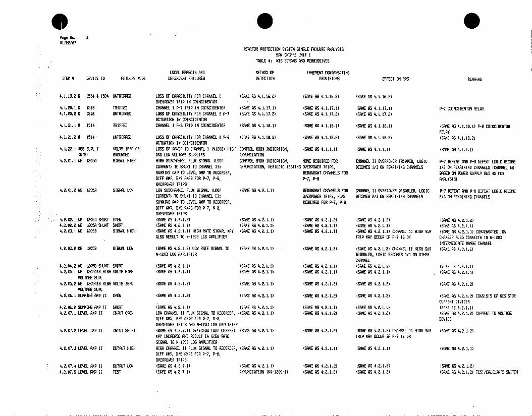
* * Page No. 1 01/22/87
REACTOR PROTECTION SYSTEM SINGLE FAILURE ANALYSIS SAN DNOFRE UNIT I
TABLE 4: NIS SCRAMS AND PERMISSIVES
LOCAL EFFECTS AND METHOD OF INHERENT COMPENSATING ITEM # DEVICE ID FAILURE MODE DEPENDENT FAILURES DETECTION PROVISIONS EFFECT ON RPS REMARKS
4.1.01.1 NE 1208A SIGNAL HIlH H1IH SUBCHANNEL FLUX SIGNAL (LOOP CONTROL ROOM INDICATION, NONE REQUIRED FOR CHANNEL I OVERPOWER TRIPPED, LOGIC P-7 DEFEAT AND P-8 DEFEAT LOGIC BECOME CURRENT) TO SHUNT TO CHANNEL 1: SUMMING ANNUNCIATION, PERIODIC TESTING OVERPOWER TRIPS, BECOMES 1/3 ON REMAINING CHANNELS 1/3 ON REMAINING CHANNELS (CHANNEL MS AMP TO LEVEL AMP TO RECORDER, DIFF AMP, REUNDANT CHANNELS FOR BASED ON POWER SUPPLY BUS #S FOR B/S AMPS FOR P-7, P-8, OVERPOWER TRIPS. P-7, P-8 ANALYSIS) HIGH RATE SIGNAL MAY ALSO BE SENT TO ROD CONTROL SYSTEM VIA N-1208 DIFFERENTIATOR.
4.1.01.2 NE 1208A SIGNAL LOW LOW SUSCHAMEL FLUX SIGNAL (LOOP (SAME AS 4.1.1.1) REDUNDANT CHANNELS FOR CHA#EL I OVERPOWER DISABLED, LOGIC P-7 DEFEAT AND P-8 DEFEAT LOGIC BECOME CURRENT) TO SHUNT TO CHANNEL I SUMMING OVERPOWER TRIPS, NONE BECOMES 2/3 ON REMAINING CHANNELS 2/3 ON REMAINING CHANNELS AMP TO LEVEL AMP TO RECORDER, DIFF AMP, REQJIRED FOR P-7, P-8 B/S AMPS FOR P-7, P-8, OVERPOWER TRIPS
4.1.02.1 NE 1208A SHUNT OPEN (SAME AS 4.1.1.2) (SAME AS 4.1.1.1) (SAME AS 4.1.1.2) (SAME AS 4.1.1.2) (SAME AS 4.1.1.2) 4.1.02.2 NE 1208A SHUNT SHORT (SANE AS 4.1.1.1) (SAME AS 4.1.1.1) (SAME AS 4.1.1.1) (SAME AS 4.1.1.1) (SAME AS 4.1.1.1) 4.1.03.1 NE 12088 SIGNAL HISH (SAME AS 4.1.1.1) (SAME AS 4.1.1.1) (SAME AS 4.1.1.1) (SANE AS 4.1.1.1) (SAME AS 4.1.1.1) 4.1.03.2 NE 1208B SINAL LOW (SAME AS 4.1.1.2) (SAME AS 4.1.1.1) (SAME AS 4.1.1.2) (SAME AS 4.1.1.2) (SAME AS 4.1.1.2) 4.1.04.1 NE 1208B SHUNT OPEN (SANE AS 4.1.1.2) (SME AS 4.1.1.1) (SAME AS 4.1.1.2) (SAME AS 4.1.1.2) (SAME AS.4.1.1.2) 4.1.04.2 NE 1208 SHUNT SHORT (SAME AS 4.1.1.1) (SAME AS 4.1.1.1) (SAME AS 4.1.1.1) (SANE AS 4.1.1.1) (SAME AS 4.1.1.1) 4.1.05.1 ME 1208R5B HI6H VOLTS HIGH (SAME AS 4.1.1.1) (SAME AS 4.1.1.1) (SAME AS 4.1.1.1) (SAME AS 4.1.1.1) (SAME AS 4.1.1.1)
VOLTAGE SUPL 4.1.05.2 NE 1208B HIGH VOLTS ZERO (SAME AS 4.1.1.2) (SAME AS 4.1.1.1) (SAME AS 4.1.1.2) (SAME AS 4.1.1.2) (SAME AS 4.1.1.2)
VOLTAGE SUPL 4.1.06.1 SUMMING AMP I OPEN (SAME AS 4.1.1.2) (SAME AS 4.1.1.1) (SAME AS 4.1.1.2) (SAME AS 4.1.1.2) (SAME AS 4.1.1.2) CONSISTS OF RESISTOR
CURRENT DIVIDER 4.1.06.2 SUMNING AMP I SHORT (SAME AS 4.1.1.1) (SAME AS 4.1.1.1) (SAME AS 4.1.1.1) (SAME AS 4.1.1.1) (SAME AS 4.1.1.1) 4.1.07.1 LEVEL AMP I INPUT OPEN LOW CHANNEL I FLUX SIGNAL TO RECORDER, (SAME AS 4.1.1.1) (SAME AS 4.1.1.2) (SAME AS 4.1.1.2) (SAME AS 4.1.1.2) CURRENT TO VOLTAGE
DIFF AMP, B/S AMPS FOR P-7, P-8 DEVICE OVERPOWER TRIPS
4.1.07.2 LEVEL AMP I INPUT SHORT (SAME AS 4.1.7.1) DETECTOR LOOP CURRENT (SAME AS 4.1.1.1) (SAME AS 4.1.1.2) (SAME AS 4.1.1.2) (SAME AS 4.1.1.2) MAY INCREASE, SENDING HIGH RATE SIGNAL TO ROD CONTROL SYSTEM VIA N-1208 DIFFERENTIATOR
4.1.07.3 LEVEL AMP I OUTPUT HIGH HIGH CHANNEL I FLUX SIGNAL TO RECORDER, (SAME AS 4.1.1.1) (SAME AS 4.1.1.1) (SAME AS 4.1.1.1) (SAME AS 4.1.1.1) DIFF AMP, B/S AMPS FOR P-7, P-8 OVERPOWER TRIPS
4.1.07.4 LEVEL AMP I OUTPUT LOW (SAME AS 4.1.7.1) (SAME AS 4.1.1.1) (SAME AS 4.1.1.2) (SME AS 4.1.1.2) (SAME AS 4.1.1.2) 4.1.07.5 LEVEL AMP I TEST (SAME AS 4.1.7.1) ANNUNCIATION INA-1200-1) (SAME AS 4.1.1.2) (SAME AS 4.1.1.2) (SAME AS 4.1.1.2) TESTICALIBRATE SWITCH 4.1.08.1 NI 1208 INPUT OPEN LOSS OF % FP INDICATION FOR NE-1208 CONTROL ROOM INDICATION NONE REQUIRED NONE 4.1.08.2 NI 1208 INPUT SHORT (SAME AS 4.1.7.1) (SAME AS 4.1.1.1) (SAME AS 4.1.1.2) (SAME AS 4.1.1.2) (SAME AS 4.1.1.2) BOUNDS SHORT IN INJT
OF ANY OTHER CHANNEL I DEVICES ON LEVEL AMP OUTPUT
4.1.09.1 NM 1208-3-1 TRIPPED CHANNEL I LOW-RANGE OVERPOWER TRIP ANNUNCIATION, PERIODIC TESTING NONE REQUIRED IF LOW RANGE SELECTED, CHANNEL I 0-10% POWER RANGE OVERPOWER BISTABLE AMP SIGNAL TO RELAYS NK-1213-7 AND NK-1213-8 OVERPOWER TRIPPED, LOGIC BECOMES 1/3 ON VIA RANGE SWITCH NCS-1200-1 REMAINING CHANNELS. IF MID OR HI RANGE,
NO EFFECT 4.1.09.2 NM 1208-3-1 UNTRIPPED LOSS OF CAPABILITY TO TRIP RELAYS PERIODIC TESTING IF LOW RANGE SELECTED, IF LOW RANGE SELECTED, CHANNEL I
NK-1213-7 AND NK-1213-8 WHEN NCS-1200-1 REDUNDANT CHANIELS. IF OVERPOWER DISABLED, LOGIC BECOMES 2/3 ON IS IN LOW RANGE MID OR HI RANGE, NONE REMAINING CHANNELS. IF MID OR HI RANGE,
REQUIRED NO EFFECT

Page No. 2 01/22/87
REACTOR PROTECTION SYSTEM SINGLE FAILURE ANALYSIS SAN ONOFRE UNIT I
TABLE 4: NIS SCRAMS AND PERMISSIVES
LOCAL EFFECTS AND METHOD OF INHERENT COMPENSATING ITEM 0 DEVICE ID FAILURE MODE DEPENDENT FAILURES DETECTION PROVISIDNS EFFECT ON RPS REMARKS
4.1.10.1 NM 1208-3-2 TRIPPED CHANNEL I MID-RANGE OVERPOWER TRIP ANNUNCIATION, PERIODIC TESTING NONE REQUIRED IF MID RANGE SELECTED, CHANNEL 1 10-70% POWER RANGE OVERPOWER BISTABLE SIGNPL TO RELAYS NK-1213-7 AND NK-1213-8 OVERPOWER TRIPPED, LOGIC BECOMES 1/3 ON AMP VIA RANGE SWITCH NCS-1200-1 REMAINING CHANNELS. IF LOW OR HI RANGE,
NO EFFECT 4.1.10.2 NM 120B-3-2 UNTRIPPED LOSS OF CAPABILITY TO TRIP RELAYS PERIODIC TESTING IF MID RANGE SELECTED, IF MID RANGE SELECTED, CHANNEL I
NW-1213-7 AND NK-1213-8 WHEN NCS-1200-1 REDUNDANT CHANNELS. IF OVERPOWER DISABLED, LOGIC BECOMES 2/3 ON IS IN MID RANGE LOW OR HI RANGE, NONE REMAINING CHANNELS. IF LOW OR HI RANGE,
REQUIRED NO EFFECT 4.1.11.1 NM 1208-3-3 TRIPPED CHANNEL I HI-RANGE OVERPOWER TRIP SIGNAL ANNUNCIATION, PERIODIC TESTING NONE REQUIRED IF HI RANGE SELECTED, CHANNEL 1 70-100% POWER RANGE OVERPOWER BISTABLE
TO RELAYS NM-1213-7 AND NK-1213-8 VIA OVERPOWER TRIPPED, LOGIC BECOMES 1/3 ON AMP RANGE SWITCH NCS-1200-1 REMAINING CHANNELS. IF LOW OR MID
RANGE, NO EFFECT 4.1.11.2 NM 1208-3-3 UNTRIPPED LOSS OF CAPABILITY TO TRIP RELAYS PERIODIC TESTING IF HI RANGE SELECTED, IF HI RANGE SELECTED, CHANNEL I
NK-1213-7 AND NK-1213-8 WHEN NCS-1200-1 REDUNDANT CHANNELS. IF OVERPOWER DISABLED, LOGIC BECOMES 2/3 ON IS IN HI RANGE LOW OR MID RANGE, NONE REMAINING CHANNELS. IF LOW OR MID
REQUIRED RANGE, NO EFFECT 4.1.12.1 NM 1208-3-4 TRIPPED CHANNEL I P-7 RELAY NK-1213-I ACTUATED ANNUNCIATION REDUNDANT CHANNELS FOR P-7 DEFEAT LOGIC BECOMES 2/3, ALL SCRAM P-7 BISTABLE AMP
P-7 DEFEAT FUNCTIONS REMAIN UNAFFECTED 4.1.12.2 NM 1208-3-4 UNTRIPPED LOSS OF CAPABILITY TO ACTUATE N(K-1213-16 PERIODIC TESTING REDUNDANT CHANNELS FOR P-7 DEFEAT LOGIC BECOMES 1/3, ALL SCRAM
P-7 SUR SCRAM CUT-IN FUNCTIONS REMAIN UNAFFECTED 4.1.13.1 NM 1208-3-5 TRIPPED CHAWNEL I P-8 RELAY NK-1213-20 ACTUATED ANNUNCIATION REDUNDANT CHANNELS FOR P-8 DEFEAT LOGIC BECOMES 2/3, ALL SCRAM P-8 BISTABLE AMP
P-8 DEFEAT FUNCTIONS REMAIN UNAFFECTED 4.1.13.2 NM 1208-3-5 UNTRIPPED LOSS OF CAPABILITY TO ACTUATE NK-1213-20 PERIODIC TESTING NONE REQUIRED P-B DEFEAT LOGIC BECOMES 1/3, ALL SCRAM
FUNCTIONS REMAIN UNAFFECTED 4.1.14.1 N 1208 LOW VOLTS HIGH (SAME AS 4.1.7.3) (SAME AS 4.1.1.1) (SAME AS 4.1.1.1) (SAME AS 4.1.1.1) (SAME AS 4.1.1.1)
VOLTAGE SUPL 4.1.14.2 N 1208 LOW VOLTS ZERO LOSS OF POWER TO CHANNEL I OVERPOWER, ANNUNCIATION (SAME AS 4.1.1.1) (SAME AS 4.1.1.1) (SAME AS 4.1.1.1)
VOLTAGE SUPL P-7, P-B BISTABLES, DE-ENERGIZATION OF OUTPUT RELAYS FOR CHANNEL I OVERPOWER, P-7, P-8
4.1.15.1 NK 1213-7 TRIPPED CHANNEL I OVERPOWER TRIP SIGNAL TO ANNUNCIATION NONE REQUIRED NONE PARTIAL TRIP ANNUNCIATOR NA-1200-9 VIA 1/4 COINCIDENTOR
4.1.15.2 NK 1213-7 UNTRIPPED LOSS OF CAPABILITY TO ANNUNCIATE CHANNEL PERIODIC TESTING NONE REQUIRED NONE I OVERPOWER TRIP ON NA-1200-9
4.1.16.1 NK 1213-8 TRIP CHANNEL I OVERPOWER TRIP SIGNAL TO ANNUNCIATION (NCS-1200-6) NONE REQUIRED CHANNEL I OVERPOWER TRIPPED, LOGIC COINCIDENTOR BECOMES 1/3 ON REKAININ3 CHANNELS
4.1.1W.2 NK 1213-8 UNTRIPPED LOSS OF CAPABILITY FOR CHANNEL I PERIODIC TESTING REDUNDANT CHANNELS CHANNEL I OVERPOWER DISABLED, LOGIC OVERPOWER TRIP TO COINCIDENTOR BECOMES 2/3 ON REMAINING CHANNELS
4.1.17.1 NK 1213-16 TRIPPED CHANNEL I P-7 ACTUATION SIGNAL TO (SAME AS 4.1.12.1) (SAME AS 4.1.12.1) (SAME AS 4.1.12.1) P-7 RELAY COINCIDENTOR
4.1.17.2 NK 1213-16 UNTRIPPED LOSS OF CAPABILITY FOR CHANNEL I P-7 (SAME AS 4.1.12.2) (SAME AS 4.1.12.2) (SAME AS 4.1.12.2) ACTUATION TO COINCIDENTOR
4.1.18.1 NK 1213-20 TRIPPED CHANNEL I P-8 ACTUATION SIGNAL TO (SAME AS 4.1.13.1) (SAME AS 4.1.13.1) (SAME AS 4.1.13.1) P-8 RELAY COINCIDENTOR
4.1.18.2 NK 1213-20 UNTRIPPED LOSS OF CAPABILITY FOR CHANNEL I P-8 (SAME AS 4.1.13.2) (SAME AS 4.1.13.2) (SAME AS 4.1.13.2) ACTUATION TO COINCIDENTOR
4.1.19.1 K 1514 & 1504 TRIPPED CHANNEL I OVERPOWER TRIP IN COINCIDENTOR (SAME AS 4.1.16.1) (SAME AS 4.1.16.1) (SAME AS 4.1.16.1) BOTH OVERPOWER SCRAM COINCIDENTOR RELAYS MUST TRIP FOR CHANNEL TRIP TO OCCUR
* S Page No. 3 01/22/87
REACTOR PROTECTION SYSTEM SINGLE FAILURE ANALYSIS SAN ONOFRE UNIT 1
TABLE 4: NIS SCRAMS AND PERMISSIVES
LOCAL EFFECTS AND METHOD OF INHERENT COMPENSATING ITEM # DEVICE ID FAILURE MODE DEPENDENT FAILURES DETECTION PROVISIONS EFFECT ON RPS REMARKS
4.1.19.2 K 1514 4 1504 UNTRIPPED LOSS OF CAPABILITY FOR CHANNEL I (SAME AS 4.1.16.2) (SAME AS 4.1.16.2) (SAME AS 4.1.16.2) OVERPOWER TRIP IN COINCIDENTOR
4.1.20.1 K 1518 TRIPPED CHANNEL I P-i TRIP IN COINCIDENTOR (SANE AS 4.1.17.1) (SA AS 4.1.17.1) (SAME AS 4.1.17.1) P-i COINCIDENTOR RELAY 4.1.20.2 K 1518 UNTRIPPED LOSS F CAPABILITY FOR CHANNEL I P-i (SANE AS 4.1.11.2) (SAME AS 4.1.17.2) (SAME AS 4.1.17.2)
ACTUATION IN COINCIDENTOR 4.1.21.1 K 1514 TRIPPED CHANNEL I P-S TRIP IN COINCIDENTOR (SANEAS 4.1.18.11 (SAME AS (SAME AS 4.1.18.11 (SAKE AS 4.1.18.1) P-8 COINCIDENTOR
RELAY 4.1.21.2 K 1514 UNTRIPPED LOS F CAPABILITY FOR CHNE I P-8 (SANE AS 4.1.18.2) (SAME AS 4.1.18.2) (SAME AS 4.1.18.2) (SANE AS 4.1.18.2)
ACTUIATION IN COINCIDENTOR 4.1.22.1 RE6 SUM. I VOLTS ZEROR LOSS OF POWER TO CHANEL I (N1208) HIGH CONTROL ROO INDICATION, (SAME AS 4.1.1.1) (SAME AS 4.1.1.1) (SANE AS 4.1.1.1)
(NIS) GROUNDED AND LOW VOLTAGE SUPPLIES ANNUNCIATION 4.2.01.1 NE 1205A SIGNAL HIGH HIGH SUCIdL FLUX SIGNAL (LOOP CONTROL ROOM INDICATION, HONE REGUIRED FOR CHNL II OVERPOWER TRIPPED, LOGIC P-i DEFEAT AND P-8 DEFEAT LOGIC BECOME
CURRENT) TO SHUJNT TO CHANNEL 11: ANNUNCIATION, PERIODIC TESTING OVERPOWER TRIPS, BECOMES 1/3 ON REMAINING CHANNELS 1/3 OH REMAINING CHANNELS (CHANNEL IS SUMMINHG AMP TO LEVEL AMP TO RECORDER, REDUNDANT CHANNELS FOR BASED ON POWER SUPPLY BUS #S FOR 00FF AMP, B/S AMPS FOR P-7, P-L, P-, P-6 ANALYSIS) OVERPOWER TRIPS
4.2.01.2 NE 1205A SIGNAL LTPE LOW SUBCANMEL FLUX SIGNAL (LOOP (SANE AS 4.2.1.1) REDUNDANT CHANNELS FOR C2OEL II OVERPOWER DISABLED, LOGIC P-i DEFEAT AND P-8 DEFEAT LOGIC BECOME CURRENT) TO SHUNT TO CHANNEL 4 : OVERPOWER TRIPS, NO2 BECOMES 2/3 REMAINING CHANNELS 2/3 ON REKAINING CHANNELS SUMING AMP TO LEVEL AMP TO RECORDER, REGUIRED FOR P-i, P-B 01FF AMP, B/S AMPS FOR P-7, P-8, OVERPOWER TRIPS
4.2.03.1 A SUT P (SAME AS 4.2.1.2) (SAME AS 4.2.1.2) (SANE AS 4.2.1.2)
4.2.03.2 NE 125 EINL LOKWS42..)(AE S4212
4.2.02.2 NE 1205A SHUNT SHORT (SAME AS 4.2.1.1) (SAME AS 4.2.1.1) (SANE AS 4.2.1.1) (SANE AS 4.2.1.1) (SANE AS 4.2.1.1) 4.2.03.1 NE 12058 SIGNAL HIGH (SAME AS 4.2.1.1) HIGH RATE SIGNAL MAY (SANE AS 4.2.1.11 (SANE AS 4.2.1.1) (SAME AS 4.2.1.1) CHANNEL 11 HIGH SUR (SAME AS 4.2.1.1) COMPENSATED ION
ALSO RESULT TO N-1203 LOG AMPLIFIER TRIP MAY OCCUR IF P-i IS ON 1MBER ALSO CONNECTS TO N-1203 INTERMEDIATE RANGE CHANNEL
4.2.03.2 NE (2059 SIGNAL LOW (SANE AS 4.2.1.2) LOW RATE SIGNAL TO (SAME AS 4.2.1.11 (SAME AS 4.2.1.21 (SAME AS 4.2.1.2) CHANNEL SO HIGH SUR (SAME AS 4.2.1.2) N-1203 LOG AMPLIFIER DISABLED, LOGIC BECOES 1/1 ON OTHER
CHIANNEL 4.2.04.2 NE V 1E SHUNT SHORT (SAME AS 4.2.1.1) (SANE AS 4.2.1.11 (SAME AS 4.2.1.1) (SAME AS 4.2.1.1) (SAE AS 4.2.1.1) 4.2.05.1 WE 1205A4L HIGH VOLTS NIGH (SAME AS 4.2.1.1 F (SAME AS 4.2.1.1) (SAME AS 4.1.1) (SAME AS 4.2.1.1) (SAKE AS 4.2.1.1)
VOLTAGE SUPL 4.2.05.2 NE I2OCAHB HIGH VOLTS ZERO (SANE AS 4.2.1.2) (SAME AS 4.2.1.1) (SAME AS 4.2.1.2) (SAME AS 4.2.1.2) (SANE AS 4.2.1.2)
VOLTAGE SUP. 4.2.06.1 SUMING AMP II OPEN (SAME AS 4.2.1.2) (SAME AS 4.2.1.1) (SAME AS 4.2.1.2) (SAE AS 4.2.1.2) (SAKE AS 4.2.1.2) CONSISTS OF RESISTOR
CURRENT DIVIDER 4.2.06.2 SUMMING AMP 11 SHORT (SANE AS 4. 2. 1. 1) (SAME AS 4.2.1.1) (SAME AS 4.2.1.1) (SAME AS 4.2.1.1) (SANE AS 4.2.1.1) 4.2.07.1 LEVEL ANP 11 INPUT OPEN LOW CHANNEL ]I FLUX SIRNAL TO RECORDER, (SANE AS 4.2.1.1) (GAME AS 4.2.1.2) (SANE AS 4.2.1.2) (SAKE AS 4.2.1.2) CURRENT TO VOLTAE
01FF AMP, B/S AMPS FOR P-7, P-8, DEVICE OVERPOWER TRIPS AND N-1203 LOG AMPLIFIER
4.2.07.2 LEVEL AMP 11 INPUT SHORT (SAME AS 4.2.7.1) DETECTOR LOOP CURRENT (SANE AS 4...)(SANE AS 4.2.1.2) (SAME AS 4.2.1.2) CH(ANNEL 11 HIGH SUR (SAK'E AS 4.2.1.2) MAY INCREASE AND RESELT IN HIGH RATE TRIP MAY OCCUR IF P-i IS ON SIGNAL TO N-1203 LOG AMPLIFIER
4.2.07.3 LEVEL AMP 11 OUTPUT HIGH HIGH CHANNEL 11 FLU) SIGNAL TO RECORDER, (SAME AS 4.2.1.1) (SANE AS (SAE AS 4.2.1.1) (SANE AS DIFF AMP, B/S AMPS FOR P-7, P-8, OVERPOWER TRIPS
4.2.07.4 LEVEL AMP 11 OUTPUT LOW (SANE AS 4.2.7.1) (SAME AS 4.2.1.1) (SANE AS 4.2.1.2) (SANE AS 4.2.1.2) (SANE AS 4.2.1.2) 4.2.07.5 LEVEL AMP 11 TEST (SAMVE AS 4.2.7.1) ANNUNCIATION (NA-1200-I) (SAME AS 4;2.1.2) (SAVE AS 4.2.1.2) (SAME AS 4.2.1.2) TESTCALIDATE SWITCH

* 0 0 Page No. 4 01/22/87
REACTOR PROTECTION SYSTEM SINGLE FAILURE ANALYSIS SAN ONOFRE UNIT I
TABLE 4: NIS SCRAMS AND PERMISSIVES
LOCAL EFFECTS AND METHOD OF INHERENT COMPENSATING ITEM # DEVICE ID FAILURE MODE DEPENDENT FAILURES DETECTION PROVISIONS EFFECT ON RPS REMARKS
4.2.08.1 NI 1205 INPUT OPEN LOSS OF % FP INDICATION FOR NE-1205 CONTROL ROOM INDICATION NONE REQUIRED NONE 4.2.08.2 NI 1205 INPUT SHORT (SAME AS 4.2.7.1) (SAME AS 4.2.1.1) (SAME AS 4.2.1.2) (SAME AS 4.2.1.2) (SAME AS 4.2.1.2) BOUNDS SHORT IN INPUT
OF ANY OTHER CHANNEL II DEVICES ON LEVEL ANP OUTPUT
4.2.09.1 NM 1205-3-1 TRIPPED CHANNEL II LOW-RANGE OVERPOWER TRIP ANNUNCIATION, PERIODIC TESTING NONE REQUIRED IF LOW RANGE SELECTED, CHANNEL II 0-10% POWER RANGE OVERPOWER BISTABLE AMP SIGNAL TO RELAYS NK-1213-1 AND NK-1213-2 OVERPOWER TRIPPED, LOGIC BECOMES 1/3 ON VIA RANGE SWITCH NCS-1200-1 REMAINING CHANNELS. IF MID OR HI RANGE,
NO EFFECT 4.2.09.2 NM 1205-3-1 UNTRIPPED LOSS OF CAPABILITY TO TRIP RELAYS PERIODIC TESTING IF LOW RANGE SELECTED, IF LOW RANGE SELECTED, CHANNEL II
NW-1213-1 AND NK-1213-2 WHEN NCS-1200-1 REDUNDANT CHANNELS. IF OVERPOWER DISABLED, LOGIC BECOMES 2/3 ON IS IN LOW RANGE MID OR HI RANGE, NONE REMAINING CHANNELS. IF MID OR HI RANGE,
REQUIRED NO EFFECT 4.2.10.1 NM 1205-3-2 TRIPPED CHANNEL II MID-RANGE OVERPOWER TRIP ANNUNCIATION, PERIODIC TESTING NONE REQUIRED IF MID RANGE SELECTED, CHANNEL II 10-70% POWER RANGE OVERPOWER BISTABLE
SIGAL TO RELAYS NK-1213-1 AND NK-1213-2 OVERPOWER TRIPPED, LOGIC BECOMES 1/3 ON AMP VIA RANGE SWITCH NCS-1200-1 REMAINING CHANNELS. IF LOW OR HI RANGE,
NO EFFECT 4.2.10.2 NM 105-3-2 UNTRIPPED LOSS OF CAPABILITY TO TRIP RELAYS PERIODIC TESTING IF MID RANGE SELECTED, IF MID RANGE SELECTED, CHANNEL II
W-1213-1 AND NK-1213-2 WHEN NCS-1200-1 REDUNDANT CHANNELS. IF OVERPOWER DISABLED, LOGIC BECOMES 2/3 ON IS IN MID RANGE LOW OR HI RANGE, NONE REMAINING CHANNELS. IF LOW OR HI RANGE,
REQUIRED NO EFFECT 4.2.11.1 NM 1205-3-3 TRIPPED CHANNEL II HI-RANGE OVERPOWER TRIP ANNUNCIATION, PERIODIC TESTING NONE REQUIRED IF HI RANGE SELECTED, CHANNEL II 70-120% POWER RANGE OVERPOWER BISTABLE
SIGNAL TO RELAYS NK-1213-1 AND NK-1213-2 OVERPOWER TRIPPED, LOGIC BECOMES 1/3 ON AMP VIA RANGE SWITCH NCS-1200-1 REMAINING CHANNELS. IF LOW OR MID
RANGE, NO EFFECT 4.2.11.2 NM 1205-3-3 UNTRIPPED LOSS OF CAPABILITY TO TRIP RELAYS PERIODIC TESTING IF HI RANGE SELECTED, IF HI RANGE SELECTED, CHANNEL II
NK-1213-1 AND NK-1213-2 MHEN NCS-1200-1 REDUNDANT CHANNELS. IF OVERPOWER DISABLED, LOGIC BECOMES 2/3 01 IS IN HI RANGE LOW OR MID RANGE, NONE REMAINING CHANNELS. IF LOW OR MID
REQUIRED RANGE, NO EFFECT 4.2.12.1 NM 1205-3-4 TRIPPED CHANNEL II P-7 RELAY NK-1213-13 ACTUATED ANNUNCIATION REDUNDANT CHANNELS FOR P-7 DEFEAT LOGIC BECOMES 2/3, ALL SCRAM P-7 BISTABLE AMP
P-7 DEFEAT FUNCTIONS REMAIN UNAFFECTED 4.2.12.2 NM 1205-3-4 UNTRIPPED LOSS OF CAPABILITY TO ACTUATE NK-1213-13 PERIODIC TEST REDUNDANT CHANNELS FOR P-7 DEFEAT LOGIC BECOMES 1/3, ALL SCRAJ
P-7 SUR SCRAM CUT-IN FUNCTIONS REMAIN UNAFFECTED 4.2.13.1 NM 1205-3-5 TRIPPED CHANNEL I P-8 RELAY NK-1213-17 ACTUATED ANNUNCIATION REDUNDANT CHANNELS FOR P-8 DEFEAT LOGIC BECOMES 2/3, ALL SCRAM P-8 BISTABLE AMP
P-8 DEFEAT FUNCTIONS REMAIN UNAFFECTED 4.2.13.2 NM 1205-3-5 UNTRIPPED LOSS OF CAPABILITY TO ACTUATE NK-1213-17 PERIODIC TESTING NONE REQUIRED P-8 DEFEAT LOGIC BECOMES 1/3, ALL SCRAM
FUNCTIONS REMAIN UNAFFECTED 4.2.14.1 N 1205 LOW VOLTS HIGH (SAME AS 4.2.7.3) (SAKE AS 4.2.1.1) (SAME AS 4.2.1.1) (SAME AS 4.2.1.1) (SANE AS 4.2.1.1)
VOLTAGE SUPL 4.2.14.2 N 1205 LOW VOLTS ZERO LOSS OF POWER TO CHANNEL II OVERPOWER, ANNUNCIATION (SAME AS 4.2.1.1) (SAME AS 4.2.1.1) (SAME AS 4.2.1.1)
VOLTAGE SUPL P-7, P-8 BISTABLES, DE-ENERGIZATION OF OUTPUT RELAYS FOR CHANNEL II OVERPOWER, P-7, P-8
4.2.15.1 NK 1213-1 TRIPPED CHANNEL II OVERPOWER TRIP SIGNAL TO ANNUNCIATION NONE REQUIRED NONE PARTIAL TRIP ANNUNCIATOR NA-1200-9 VIA 1/4 COINCIDENTOR
4.2.15.2 NK 1213-1 UNTRIPPED LOSS OF CAPABILITY TO ANNUNCIATE CHANNEL PERIODIC TESTING NONE REQUIRED NONE II OVERPOWER TRIP ON NA-1200-9
4.2.16.1 NK 1213-2 TRIPPED CHANNEL II OVERPOWER TRIP SIGNAL TO ANNUNCIATION (NCS-1200-6) NONE REQUIRED CHANNEL II OVERPOWER TRIPPED, LOGIC COINCIDENTOR BECOMES 1/3 ON REMAINING CHANNELS
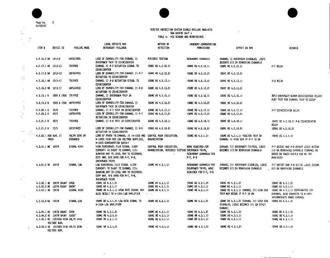
* 0 0 Page No. 5 01/22/87
REACTOR PROTECTION SYSTEM SINGLE FAILURE ANALYSIS SAN ONOFRE UNIT I
TABLE 4: NIS SCRAMS AND PERMISSIVES
LOCAL EFFECTS AND METHOD OF INHERENT COMPENSATING ITEM # DEVICE ID FAILURE MODE DEPENDENT FAILURES DETECTION PROVISIONS EFFECT ON RPS REMARKS
4.2.16.2 NK 1213-2 UNTRIPPED LOSS OF CAPABILITY FOR CHANNEL 11 PERIODIC TESTING REDUNDANT CHANNES CHANNEL I] OVERPOWER DISABLED, LOGIC OVERPOWER TRIP TO COINCIDENTOR BECOMES 2/3 ON REMAINING CH{ANNELS
4.2.17.1 NK 1213-13 TRIPPED CHANNEL 11P-7 ACTUATION SIGNAL TO (SAME AS 4.2.12.1) (SAME AS 4.2.12.1) (SAME AS 4.2.12.1) P-7 RELAY COINCIDENTOR
4.2.17.2 NK 1213-13 UNTRIPPED LOSS OF CAPABILITY FOR CANNEL 11 P-7 (SAME AS 4.2.12.21 (SAME AS 4.2.12.2) (SAME AS 4.2.12.2) ACTUATION TO COINCIDENTOR
4.2.18.1 N 1213-17 TRIPPED CHANNEL 11P-8 ACTUATION SIG TO (SAME AS 4.2.13.1) (SANE AS 4.2.13.0 (SE AS 4.2.13.1) P-8 RELAY COINCIDENTOR
4.2.18.2 NK 1213-17 UNTRIPPED LOSS OF CAPABILITY FOR DRIMEL lIP-8 (SAME AS 4.2.13.2) (SAME AS 4.2.13.2) (SAME AS 4.2.13.2) ACTUATION TO COINCIDENTOR
4.2.19.1 K 1505 & 1506 TRIPPED CHANNEL II OVERPOWER TRIP IN (SANE AS (SAME AS 4.2.16.1) (SArt AS 4.2.16.11 BOTH OVERrUER SCRAM COINEIDENTOR RELAYS COINCIDENTOR MUST TRIP FOR CHANNEL TRIP TO OCCUR
4.2.19.2 K 1505 & 1506 UNTRIPPED LOSS OF CAPABILITY FOR CHANNEL II (SAME AS 4.2.16.2) (SAME AS 4.2.16.2) (SAM AS 4.2.16.2) OVERPOWER TRIP IN COINCIDENTOR
4.2.20.1 K 1519 TRIPPED CHANNEL 1IP-7 TRIP IN COINCIDENTOR (SAME AS 4.2.17.1) (SAME AS 4.2.17.1) (SAME AS 4.2.17.1) P-7 COINCIDENTIR RELAY 4.2.20.2 K 1515 UNTRIPPED LOSS OF CAPABILITY FOR CHANNEL II P-7 (SAME AS 4.2.17.21 (SAME AG 4.2.17.2) (SAME AS 4.2.17.21
ACTUATION IN COINCIDENTOR 4.2.21.1 K 1515 TRIPPED CHANNEL 11 P-B TRIP IN COINCIDENTOR (SAME AS 4.2.18,1) WSAE AS 4.2.18.1) (SAME AS 4.2.18.1) (SAME AS 4.2.18.1) P-B COINCIDENTOR
RELAY 4.2.21.2 K 1515 UNTRIPPED LOSS OF CAPABILITY FOR CHANNEL 11 P-B (SAME AS 4.2.18.2) (SAME AS 4.2.18.2) (SAME AS 4.2.18.2) (SAVE AS 4.2.18.2)
ACTUATION IN COINCIDENTOR 4.2.22.1 REG SUPL II VOLTS ZERO OR LOSS OF P R TO CHANNEL 11 (N-1203 AND CONTROL ROOM INDICATION, (SAME AS 4.2.1.1) (SAME AS 4.2.1.1) REACTOR TRIP ON (SAME AG 4.2.1.1)
(NIS) GROUNDED N-1205) HIGH AND LOW VOLTAGE SUPPLIES, ANNUNCIATION CHANNEL 11 HIGH SUR IF P-7 IS ON N-1203 COMPENSATION SUPPLY
4.3.01.1 NE 1207A SIGNAL HIGH HI6H SUBCRANNEL FLUX SIGNAL (LOOP CONTROL ROOM INDICATION, NONE REUIRED FOR CHANNEL III OVERPOWER TIIGPED, LOGIC P-i DEFEAT AND P-B DEFEAT LOGIC BECOME CURRENT) TO SHUNTTO CHANNEL III: ANNUNCIATION, PERIODIC TESTING OVERPOWER TRIPS, BECOMES 1/3 ON REMAINING CHANNELS 1/3 ON REMAINING CHANNELS (CHANNEL HS SU.0ING AMP TO LEVEL AMP TO RECORDER, REDUNDANT CHANNELS FOR BASED ON POWER SUPPLY S # FOR 30FF AMP, B/S AMPS FOR P-H, P-I, P-, P-B ANALYSIS) OVERPOWER TRIPS
4.3.01.2 NE 1207A SIGNAL LOW LOW SUBCHANNEL FLUX SIGNAL (LOOP (SAME AS 4.3.1.1) REDDANT CHANNELS FOR CHANNEL III OVERPOWER DISABLED, LOGIC P-i DEFEAT AND P-B DEFEAT LOGIC OEComE CURRENT) TO SHUNT TO CHANNEL III: OVERPOWER TRIPS, NONE BECOMES 2/3 ON REMAINING CHANNELS 2/3 N REAINING CHANNELS SUMMING AMP TO LEVEL AMP TO RECORDER, REQUIRED FOR P-7, P-B 01FF AMP, B/S AMPS FOR P-i, P-B, OVERPOWER TRIPS
4.3.02.1 NE 1207A SHUNT OPEN (SAME AS 4.3.1.2) (SAME AS 4. 3. 1.1) (SAME AS 4.3.1.2) (SAME AS 4.3.1.2) (SAME AS 4.3.1.2) 4.3.02.2 NE 1207A SHUNT SHORT (GAME AS 4.3.1.1) (SAME AS 4.3.1.1) (SAME AS 4.3.1.1) (SAME AS 4.3.1.1) (SAM AS 4. 3. 1.1) 4.3.03.1 NE 1207C SIGNAL HIGH (SAME AS 4.3.1.1) HIGH RATE SIGNAL MAY (SANE AS 4.3.1.1) (SAME AS (SAME AS 4.3.1.1) CHANNEL III HIGH SUR (GAME AS 4.3.1.1 COMPCTTNIATED ION
ALSO RESLT TO N-1204 LOS AMPLIFIER TRIP MAY OCCUR IF P-i IS ON CHAMBER, ALSO CONNECTS TO N-1204 INTERMEDIATE RAG B CHANNEL
4.3.03.2 NE 12078 SIGNAL LOW (SAME AS 4.3.1.2) LOW RATE SIGNAL TO (SAME AS 4.3.1.1) (SAME AS 4.3.1.2) (SAME AS 4.3.1.2) CHANNEL III HIGH SUR (SAME AS 4.3.1.2) N-1204 LOG APLIFIER DISABLED, LOGIC BECOMES 1/1 P8 OTHER
CHANNEL 4.3.04.1 NE 12078 SHUJNT OPEN (SAME AS 4.3.1.2) (SAME AS 4.3.1.1) (SAME AS 4.3.1.2) (SAME AS 4.3.1.2) (SAME AS 4.3.1.2) 4.3.04.2 NE 1207B SHUNT SHORT (SAME AS 4.3.1.1) (SAME AS 4.3.1.1) (SAME AS 4.3.1.1) (GAME AS 4.3.1.1) (SAME AS 4.3.1.1) 4.3.05.1 NE 1207AB HIGH VOLTS HIGH (SAME AS 4. 3. 1.1) (SAME AS 4.3.1.1) (SAME AS 4.3.1.1) (SAME AS 4.3.1.1) (SAME AS 4.3.1.1)
VOLTAGE SUPL 4.3.05.2 NE 12O7A&B HIGH VOLTS ZERO (SAME AS 4.3.1.2) (SAME AS 4.3.1.1) (SAME AS 4.3.1.2) (SAME AS 4.3.1.2) (SANE AS 4.3.1.2)
VOLTAGE SUPL

Page No. 6 01/22/87
REACTOR PROTECTION SYSTEM SINGLE FAILURE ANALYSIS SAN ONOFRE UNIT I
TABLE 4: NIS SCRAMS AND PERMISSIVES
LOCAL EFFECTS AND METHOD OF INHERENT COMPENSATING ITEM # DEVICE ID FAILURE MODE DEPENDENT FAILURES DETECTION PROVISIONS EFFECT ON RPS REMARKS
4.3.06.1 SUMMING AMP III OPEN (SAME AS 4.3.1.2) (SAVE AS 4.3.1.1) (SAME AS 4.3.1.2) (SAME AS 4.3.1.2) (SAME AS 4.3.1.2) CONSISTS OF RESISTOR CURRENT DIVIDER
4.3.06.2 SUMMING AMP III SHORT (SAME AS 4.3.1.1) (SAME AS 4.3.1.1) (SANE AS 4.3.1.1) (SAME AS 4.3.1.1) (SAME AS 4.3.1.1) 4.3.07.1 LEVEL AMP III INPUT OPEN LOW CHANNEL III FLUX SIGNAL TO RECORDER, (SAME AS 4.3.1.1) (SAME AS 4.3.1.2) (SAME AS 4.3.1.2) (SPME AS 4.3.1.2) CURRENT TO VOLTAGE
DIFF AMP, B/S AMPS FOR P-7, P-8, DEVICE OVERPOWER TRIPS
4.3.07.2 LEVEL AMP III INPUT SHORT (SAME AS 4.3.7.1) DETECTOR LOOP CURRENT (SAME AS 4.3.1.1) (SAME AS 4.3.1.2) (SAME AS 4.3.1.2) CHANNEL III HIGH SUR (SAME AS 4.3.1.2) MAY INCREASE AND RESULT IN HIGH RATE TRIP MAY OCCUR IF P-7 IS ON SIGNAL TO N-1204 LOG AMPLIFIER
4.3.07.3 LEVEL AMP III OUTPUT HIGH HIGH CHANNEL III FLUX SIGNAL TO (SAME AS 4.3.1.1) (SAME AS 4.3.1.1) (SAME AS 4.3.1.1) (SAME AS 4.3.1.1) RECORDER, DIFF AMP, B/S AMPS FOR P-7, P-8, OVERPOWER TRIPS
4.3.07.4 LEVEL AMP III OUTPUT LOW (SAME AS 4.3.7.1) (SAME AS 4.3.1.1) (SAME AS 4.3.1.2) (SAME AS 4.3. 1.2) (SAME AS 4.3.1.2) 4.3.07.5 LEVEL PMP III TEST (SAME AS 4.3.7.1) ANNUNCIATION (NA-1200-1) (SAME AS 4.3.1.2) (SAME AS 4.3.1.2) (SAME AS 4.3.1.2) TEST/CALIBRATE SWITCH 4.108.1 NI 1207 INPUT OPEN LOSS OF % FP INDICATION FOR NE-1207 - CONTROL ROOM INDICATION NONE REQUIRED NONE 4.3.08.2 NI 1207 INPUT SHORT (SAME AS 4.3.7.1) (SAME AS 4.3.1.1) (SAME AS 4.3.1.2) (SME AS 4.3.1.2) (SRKE AS 4.3.1.2) POUNDS SHORT IN INPUT
OF ANY OTHER CHANNEL III DEVCES GN LEVEL fMP OUTPUT
4.3.09.1 NM 1207-3-1 TRIPPED CHANNEL III LOW-RANGE OVERPOWER TRIP ANNUNCIATION, PERIODIC TESTING NONE REQUIRED IF LOW RANGE SELECTED, CHANNEL III 0-10% POWER RANGE OVERPOWER BISTABLE MP SIGNAL TO RELAYS NK-1213-5 AND NK-1213-6 OVERPOWER TRIPPED, LOGIC BECOMES 1/3 ON VIA RANGE SWITCH NCS-1200-1 REMAINING CHANNELS. IF MID OR HI RANGE,
NO EFFECT 4.3.09.2 NM 1207-3-1 UNTRIPPED LOSS OF CAPABILITY TO TRIP RELAYS PERIODIC TESTING IF LOW RANGE SELECTED, IF LOW RANGE SELECTED, CHANNEL III
N-1213-5 AND NK-1213-6 "HEN NCS-1200-1 . REDUNDANT CHANNELS. IF OVERPOWER DISABLED, LOGIC BECOMES 2/3 O4 IS IN LOW RANGE MID OR HI RANGE, NONE REMAINING CHANNELS. IF MID OR HI RANGE,
REQUIRED NO EFFECT 4.3.10.1 NM 1207-3-2 TRIPPED CHANNEL III MID-RANGE OVERPOWER TRIP ANNUNCIATION, PERIODIC TESTING NONE REQUIRED IF MID RANGE SELECTED, CHANNEL III 10-70% POWER RANGE OVERPOWER BISTABLE
SIGNAL TO RELAYS NK-1213-5 AND NK-1213-6 OVERPOWER TRIPPED, LOGIC BECOMES 1/3 0C4 AMP VIA RANGE SWITCH NCS-1200-1 REMAINING CHANNELS. IF LGW OR HI RANGE,
NO EFFECT 4.3.10.2 NM 1207-3-2 UNTRIPPED LOSS OF CAPABILITY TO TRIP RELAYS PERIODIC TESTING IF MID RANGE SELECTED, IF MID RANSE SELECTED, CHANNEL III
NK-1213-5 AND NK-1213-6 WHEN NCS-1200-1 REDUNDANT CHANNELS. IF OVERPOWER DISABLED, LOGIC BECOMES 2/3 ON IS IN MID RANGE LOW OR HI RANGE, NONE REMAINING CHANNELS. IF LOW OR HI RANGE,
REQUIRED NO EFFECT 4.3.11.1 NM 1207-3-3 TRIPPED CHANNEL III HI-RANGE OVERPOWER TRIP ANNUNCIATION, PERIODIC TESTING NONE REQUIRED IF HI RANGE SELECTED, CHANNEL III 70-120% POWER RANGE OVERPOWER BISTABLE
SIGNAL TO RELAYS NK-1213-5 AND NK-123-6 OVERPOWER TRIPPED, LOGIC BECOMES 1/3 ON AlP VIA RANGE SWITCH NCS-1200-1 REMAINING CHANNELS. IF LOW OR MID
RANGE, NO EFFECT 4.3.11.2 N) 1207-3-3 UNTRIPPED LOSS OF CAPABILITY TO TRIP RELAYS PERIODIC TESTING IF HI RANGE SELECTED, IF HI RANGE SELECTED, CHANNEL III
NK-1213-5 AND NK-1213-5 WHEN NCS-1200-1 REDUNDANT CHANNELS. IF OVERPOWER DISABLED, LOGIC BECOMES 2/3 ON IS IN HI RANGE LOW OR MID RANGE, NONE REMAINING CHANNELS. IF LOW CR MID
REQUIRED RANBE, NO EFFECT 4.3.12.1 NM 1207-3-4 TRIPPED CHANNEL III P-7 RELAY NK-1213-15 ANNUNCIATION REDUNDANT CHANNELS FOR P-7 DEFEAT LOGIC BECOMES 2/3, ALL SCRAM P-7 BISTABLE AMP
ACTUATED P-7 DEFEAT FUNCTIONS REMAIN UNAFECTED 4.3.12.2 NM 1207-3-4 UNTRIPPED LOSS OF CAPABILITY TO ACTUATE NK-1213-15 PERIODIC TESTING REDUNDANT CHANNELS FOR P-7 DEFEAT LOGIC BECOMES 1/3, ALL SCRAM
P-7 SUR SCRAM CUT-IN FUNCTIONS REMAIN UNAFFECTED 4.3.13.1 NM 1207-3-5 TRIPPED CHANNEL III P-8 RELAY NK-1213-19 ANNUNCIATION REDUNDANT CHANNELS FOR P-6 DEFEAT LOGIC BECOMES 2/3, ALL SCRAM P-8 BISTABLE AMP
ACTUATED P-8 DEFEAT FUNCTIONS REMAIN UNAFFECTED

Page No. 7 01/22/87
REACTOR PROTECTION SYSTEM SINGLE FAILURE ANALYSIS SAN ONOFRE UNIT I
TABLE 4: NIS SCRAMS AN PERMISSIVES
LOCAL EFFECTS AND METHOD OF INHERENT COMPENSATING ITEM # DEVICE ID FAILURE MODE DEPENDENT FAILURES DETECTION PROVISIONS EFFECT ON RPS REMARKS
4.3.13.2 NM 1207-3-5 UNTRIPPED LOSS OF CAPABILITY TO ACTUATE NK-1213-19 PERIODIC TESTING NONE REQUIRED P-8 DEFEAT LOGIC BECOMES 1/3, ALL SCRAM FUN1CTIONS REMAIN UNAFFECTED
4.3.14.1 N 1207 LOW VOLTS HIGH (SAME AS 4.3.7.3) (SAME AS 4.3.1.1) (SAME AS 4.3.1.1) (SAE AS 4.3.1.11 (SAME AS 4.3.1.1) VOLTAGE SUPL
4.3.14.2 N 1207 LOW VOLTS ZERO LOS OF POWER TO CHANNEL III OVERPOWER, ANNNCIATION (SAME AS 4.3.1.1) (SAME AS 4.3.1.1) (SAME AS 4.3.1.1) VOLTAGE SUPL P-7, P-8 BISTABLES, DE-ENERGIZATION OF
(IJTPU1 RELAYS FOR CHANNEL I II OVERPOWER, P-7, P-8
4.3.15.1 NK 1213-5 TRIPPED CONL III OVERPOWER TRIP SIG.. TO ANNUNCIATION NONE REQUIRED NONE PARTIAL TRIP ANNUINCIATOR NA-1200-9 VIA 1/4 COINCIDENTOR
4.115.2 NK 1213-5 UNTRIPPED LOSS OF CAPABILITY TO ANNUNCIATE CHANNEL PERIODIC TESTING NONE REQUIRED NONE III OVERPOWER TRIP ON NA-1200-3
4.3.16.1 NK 1213-6 TRIPPED CHANNEL III OVERPOWER TRIP SIGNA TO AM NCIATION (NCS-1200-G( NONE REQUIRED CHANNEL III OVERPOWER TRIPPED, LOGIC COINCIDENTOR BECOMES 113 ON REMAINING CHANNELS
4.3.16.2 NK 1213-6 UNTRIPPED LOS OF CAPABILITY FOR CHANNEL III PERIODIC TESTING REDUNDANT CHANNELS CHANNEL III OVERPOWER DISABLED, LOGIC OVERPOWER TRIP TO COINCIDENTOR BECOMES 2/3 ON REMAINING CHANNELS
4.3.17.1 NK 1213-15 TRIPPED CHANNEL III P-7 ACTUATION SIGNAL TO (SAME AS 4.3.12.1) (SAME AS 4.3.12.1) (SAME AS 4.3.12.0 P-7 RELAY COINCIDENTOR
4.3.11.2 NK 1213-15 UNTRIPPED LOSS OF CAPABILITY FOR CHANNEL III P-7 (SAME AS 4.3.12.2) (SAME AS 4.3.12.21 (SAXE AS 4.3.(2.2) ACTUATION TO COINCIDENTOR
4.3.18.1 NK 1213-19 TRIPPED CHANNEL III P-B ACTUATION SIGNAL TO (SAME AS 4.3.13.1) (SAME AS 4.3.13.1) (SAE AS 4.3.13.1) P-8 RELAY COINCIDENTOR
4.3.18.2 NK 1213-19 UNTRIPPED LOSS OF CAPABILITY FOR CHANNEL III P-B (SAME AS 4.3.13.21 (SAME AS 4.3.13.2) (SA AS 4.3.13.2) ACTUATION TO COINCIDENTOR
4.3.19.1 K 1207 & 1508 TRIPPED CHANNEL III OVERPOWER TRIP IN (SAME AS 4.3.16.1) (SAME AS 4.3.16.11 (SAME AS 4.3.16.1 BOTH OVERPOWER SCRAM COINEIDENTOR RELAYS COINCIDENTOR MUST TRIP FOR CHANNEL TRIP TO OCCUR
4.3.19.2 K 1507 1508 UNTRIPPED LOS OF CAPABILITY FOR CHANNEL III (SAME AS 4.3.16.2) (SAME AS 4.3.16.2) (SAME AS 4.3.16.21 OVERPOWER TRIP IN COINCIDENTOR
4.3.20.1 K 1520 TRIPPED CHANNEL III P-7 TRIP IN COINCIDENTOR (SAME AS 4.3.17.11 (SAME AS 4.3.17.1) (SAME AS 4.3.17.1) P-7 COINCIDENTOR RELAY 4.3.20.2 K 1520 UNTRIPPED LOSS OF CAPABILITY FOR CHANNEL III P-7 (SAME AS 4.3.17.21 (SAME AS 4.3.17.2) (SAME AS 4.3.17.21
ACTUATION IN COINCIDENTOR 4.3.21.1 K) 1516 TRIPPED CHANNEL III P-B TRIP IN COINCIDENTOR (SAME AS 4.3. 18.11 (SAME AS 4.3. 18. 1) (SAME AS 4.3. 18.11 (SAME AS 4.3. 18.1) P-B COINCIIENTIR
RELAY 4.3.21.2 K 1516 UNTRIPPED LOSS OF CAPABILITY FOR CHANNEL III P-B (SAME AS 4.3.O18.2 (SAME AS 4.3.18.2) (SAME AS 4.3.18.21 (SAE AS 4.3.18.2)
ACTUATION IN COINCIDENTOR 4.3.22.1 REG BU(L III VOLTS ZERO OR LOSS OF POWER TO CHANNEL III (N-1204 AND CONTROL ROOM INDICATION, (SAME AS 4.3.1.1) (SAME AS 4.3.1.1) REACTOR TRIP ON (SAME AS 4.3.1.1)
INIS) GROUNDED N-1207 HIGH AND LOW VOLTAGE SUPPLIES, ANNUNCIATION CHANNEL III IGH SR IF P- IS ON N-1204 COMPENSATION SUPPLY
4.4.01.1 NE 1206A SIGNAL HIGH HIGH SUBCHANNEL FLUX SIGNAL (LOOP CONTROL ROOM INDICATION, NONE REQUIRED FOR CHANNEL IV OVERPOWER TRIPPED, LOGIC P-7 DEFEAT AND P-B DEFEAT LOGIC BECOME CURRENT) TO SHUNT TO CH NNE L IV: ANNUNCIATION, PERIODIC TESTING OVERPOWER TRIPS, BECOMES 1/3 ON REMAINING CHANNELS 1/ONRMINGCAEL HNELS
QUPU REL/Y FOR CHMANNEL IIINEL OVERNNOLER,
SUMMING AMP TO LEVEL ALMP TO RECORDER, REDUNDANT CHANNELS FOR BASED ON POWER SUPPLY BUS #S FOR P-FF AMP, B/S AMPS FOR P-, P-, P-7, P-8 ANALYSIS) OVERPOWER TRIPS
4.4.01.2 NEP 1206A SIGNAL LOW LOW SUBCTNNEL FLUX SIGNAL (LOOP (SAM AS 4.4.1.1 REDUNDANT CHANNELS FOR CHANNEL IV OVERPOWER DISABLED, LOGIC P- DEFEAT AND P- DEFEAT LOGIC IAEJYC CURRENT) TO SHUNT TO CHANNEL IV: OVERPOWER TRIPS, NONE BECOMES 2/3 ON REMAINING CHANNELS 2/3 ON REMAINING CHA.NNELS SSNNING AMP TO LEVEL AMP TO RECORDER, REQUIRED FOR P-7, P-B
IFF AIMP, B/S AMPS FOR P-7, P-, OVERPOWER TRIPS
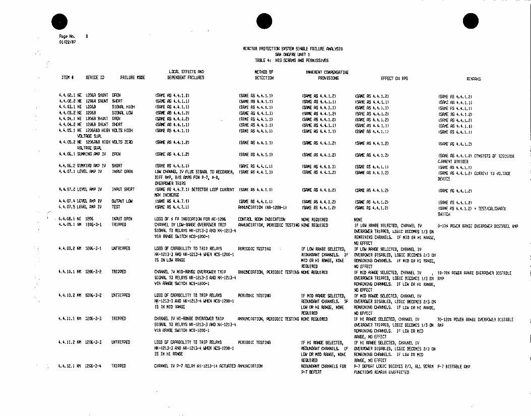
Page No. 8 01/22/87
REACTOR PROTECTION SYSTEM SINGLE FAILURE ANALYSIS SAN ONOFRE UNIT I
TABLE 4: NIS SCRAMS AND PERmISSIVES
LOCAL EFFECTS AND METHOD OF INHERENT COMPENSATING ITEM # DEVICE ID FAILURE MODE DEPENDENT FAILURES DETECTION PROVISIONS EFFECT ON RPS REMARKS
4.4.02.1 NE 1206A SHUNT OPEN (SAME AS 4.4.1.2) (SAME AS 4.4.1.1) (SAME AS 4.4.1.2) (SAME AS 4.4.1.2) (SAME AS 4.4.1.2) 4.4.02.2 NE 1206A SHUNT SHORT (SAME AS 4.4.1.1) (SAME AS 4.4.1.1) (SAME AS 4.4.1.1) (SAME AS 4.4.1.1) (SAE AS 4.4.1.1) 4.4.03.1 NE 12068 SIGNAL HIGH (SAME AS 4.4.1.1) (SAKE AS 4.4.1.1) (SAME AS 4.4.1.1) (SAME AS 4.4.1.1) (SAME AS 4.4.1.1) 4.4.03.2 NE 1206B SIGNAL LOW (SAME AS 4.4.1.2) (SAE AS 4.4.1.1) (SAME AS 4.4.1.2) (SAME AS 4.4.1.2) (SAME AS 4.4.1.2) 4.4.04.1 NE 12063 SHUNT OPEN (SAME AS 4.4.1.2) (SAME AS 4.4.1.1) (SAME AS 4.4.1.2) (SAME AS 4.4.1.2) (SAME AS 4.4.1.2) 4.4.04.2 NE 12063 SHUNT SHORT (SAME AS 4.4.1.1) (SAME AS 4.4.1.1) (SAME AS 4.4.1.1) (SANE AS 4.4.1.1) (SAME AS 4.4.1.1) 4.4.05.1 NE 120R&B HIGH VOLTS HIGH (SAME AS 4.4.1.1) (SAME AS 4.4.1.1) (SAME AS 4.4.1.1) (SAME AS 4.4.1.1) (SAME AS 4.4.1.1)
VOLTAGE SUPL 4.4.05.2 NE 1206A&B HIGH VOLTS ZERO (SAME AS 4.4.1.2) (SAME AS 4.4.1.1) (SAME AS 4.4.1.2) (SAME AS 4.4.1.2) (SAME AS 4.4.1.2)
VOLTAGE SUPL 4.4.06.1 SUMMING AMP IV OPEN (SAME AS 4.4.1.2) (SAME AS 4.4.1.1) (SAME AS 4.4.1.2) (SAME AS 4.4.1.2) (SAME AS 4.4.1.2) CONSISTS OF RESISTOR
CURRENT DIVIDER 4.4.06.2 SUMMING AMP IV SHORT (SAME AS 4.4.1.1) (SAME AS 4.4.1.1) (SAME AS 4.4.1.1) (SAME AS 4.4.1.1) (SAME AS 4.4.1.1) 4.4.07.1 LEVEL AMP IV INPUT OPEN LOW CHANNEL IV FLUX SIGNAL TO RECORDER, (SAME AS 4.4.1.1) (SAME AS 4.4.1.2) (SAME AS 4.4.1.2) (SAME AS 4.4.1.2) CURRENT TO VOLTAGE
DIFF AMP, B/S AMPS FOR P-7, P-B, DEVICE OVERPOWER TRIPS
4.4.07.2 LEVEL AMP IV INPUT SHORT (SAME AS 4.4.7.1) DETECTOR LOOP CURRENT (SAME AS 4.4.1.1) (SAME AS 4.4.1.2) (SAME AS 4.4.1.2) (SAME AS 4.4.1.2) MAY INCREASE
4.4.07.4 LEVEL AMP IV OUTPUT LON (SAME AS 4.4.7.1) (SAME AS 4.4.1.1) (SAME AS 4.4.1.2) (SAME AS 4.4.1.2) (SAME AS 4.4.1.2) 4.4.07.5 LEVEL AMP IV TEST (SAME AS 4.4.7.1) ANNUNCIATION (NA-1200-1) (SAME AS 4.4.1.2) (SAME AS 4.4.1.2) (SAME PS 4.4.1.2) + TEST/CALIBRATE
SWITCH 4.4.08.1 NI 1206 INPUT OPEN LOSS OF % FP INDICATION FOR NE-1206 CONTROL ROON INDICATION NONE REQUIRED NONE 4.4.09.1 NM 1206-3-1 TRIPPED CHANNEL IV LOW-RANGE OVERPOWER TRIP ANNUNCIATION, PERIODIC TESTING NONE REQUIRED IF LOW RANGE SELECTED, CHANNEL IV 0-10% POWER RANGE OVERPOWER BISTABEL AMP
SIGNAL TO RELAYS NK-1213-3 AND NK-1213-4 OVERPOWER TRIPPED, LOGIC BECOMES 1/3 ON VIA RANGE SWITCH NCS-1200-1 REMAINING CHANNELS. IF MID OR HI RANGE,
NO EFFECT 4.4.03.2 NM 1206-3-1 UNTRIPPED LOSS OF CAPABILITY TO TRIP RELAYS PERIODIC TESTING IF LOW RANGE SELECTED, IF LOW RANGE SELECTED, CHANNEL IV
NK-1213-3 AND NK-1213-4 WHEN NCS-1200-1 REDUNDANT CHANNELS. IF OVERPOWER DISABLED, LOGIC BECOMES 2/3 ON IS IN LOW RANGE MID OR HI RANGE, NONE REMAINING CHANNELS. IF MID OR HI RANGE,
REQUIRED NO EFFECT 4.4.10.1 NM 1206-3-2 TRIPPED CHANNEL IV MID-RANGE OVERPOWER TRIP ANNUNCIATION, PERIODIC TESTING NONE REQUIRED IF MID RANGE SELECTED, CHANNEL IV 10-70% POWER RANGE OVERPOWER BISTABLE
SIGNAL TO RELAYS NK-1213-3 AND NK-1213-4 OVERPOWER TRIPPED, LOGIC BECOMES 1/3 ON AMP VIA RANGE SNITCH NCS-1200-1 REMAINING CHANNELS. IF LOW OR HI RANGE,
NO EFFECT 4.4.10.2 NM 1206-3-2 UNTRIPPED LOSS OF CAPABILITY TO TRIP RELAYS PERIODIC TESTING IF MID RANGE SELECTED, IF MID RANGE SELECTED, CHANNEL IV
N-1213-3 AND NK-1213-4 WHEN NCS-1200-1 REDUNDANT CHANNELS. IF OVERPOWER DISABLED, LOGIC BECOMES 2/3 ON IS IN MID RANGE LOW OR HI RANGE, NONE REMAINING CHANNELS. IF LOW OR HI RANGE,
REQUIRED NO EFFECT 4.4.11.1 NM 1206-3-3 TRIPPED CHANNEL IV HI-RANGE OVERPOWER TRIP ANNUNCIATION, PERIODIC TESTING NONE REQUIRED IF HI RANGE SELECTED, CHANNEL IV 70-120% POWER RANGE OVERPOWER BISTABLE
SIGNAL TO RELAYS NK-1213-3 AND NK-1213-4 OVERPOWER TRIPPED, LOGIC BECOMES 1/3 ON AMP VIA RANGE SWITCH NCS-1200-1 REMAINING CHANNELS. IF LOW OR MID
RANGE, NO EFFECT 4.4.11.2 NM 1206-3-3 UNTRIPPED LOSS OF CAPABILITY TO TRIP RELAYS PERIODIC TESTING IF HI RANGE SELECTED, IF HI RANGE SELECTED, CHANNEL IV
NW-1213-3 AND N(-1213-4 WHEN NCS-1200-1 REDUNDANT CHANNELS. IF OVERPOWER DISABLED, LOGIC BECOMES 2/3 ON IS IN HI RANGE LOW OR MID RANGE, NONE REMAINING CHANNELS. IF LOW OR MID
REQUIRED RANGE, NO EFFECT 4.4.12.I NM 1206-3-4 TRIPPED CHANNEL IV P-7 RELAY NK-1213-14 ACTUATED ANNUNCIATION REDUNDANT CHANNELS FOR P-7 DEFEAT LOGIC BECOMES 2/3, ALL SCRAM P-7 BISTABLE AMP
P-7 DEFEAT FUNCTIONS REMAIN UNAFFECTED

Page No. 9 01/22/87
REACTOR PROTECTION SYSTEM SINGLE FAILURE ANALYSIS SAN ON0FRE UNIT I
TABLE 4: NIS SCRAMS AND PERMISSIVES
LOCAL EFFECTS AND METHOD OF INHERENT COMPENSATING ITEM # DEVICE ID FAILURE MODE DEPENDENT FAILURES DETECTION PROVISIONS EFFECT ON RPS REMARKS
4.4.12.2 NM 1206-3-4 UNTRIPPED LOSS OF CAPABILITY TO ACTUATE N-1213-14 PERIODIC TESTING REDUNDANT CHRAELS FOR P'-7 DEFEAT LOGIC BECOMES 1/3, ALL SCRAM P-7 SJR SCRAM COT-IN FUNCTIONS REMAIN UNAFFECTED
4.4.13.1 NM 1206-3-5 TRIPPED CHA*EL IV P-B RELAY NK-1213-18 ACTUATED ANNUNCIATION REDUNDANT CHANNELS FOR P-8 DEFEAT LOGIC BECOMES 2/3, ALL SCRAM P-B BISTADLE AMP P-8 DEFEAT FUNCTIONS REMAIN UNOAFFECTED
4.4.13.2 NM 1206-3-5 INTRIPPED LOSS OF CAPABILITY TO ACTUATE NK-l2I3-lB PERIODIC TESTING NONE REQUIRED P-B DEFEAT LOGIC BECOMES 1/3, ALL SCRAM FUNCTIONS REMAIN 4N5AFFECTED
4.4.14.1 N 1206 LOW VOLTS HIGH (SAFE AS 4.4.7.3) (SAME AS 4.4.1.1) (SAFE AS 4.4.1.1) (SE AS 4.1.1.1) (SAF AS 4.1.1.1) VOLTAGE SUPL
4.4.14.2 N 1206 LOW VOLTS ZERO LOSS OF POWER TO CMNEL IV OVERPOWER, ANNUNCIATION (SAME AS 4.4.1.1) (SAME AS 4.4.1.1) (SAME AS 4.4.1.1) VOLTAGE SUPL P-7, P-B BISTABLES, DE-ENERSIZATION OF
(OUTPUT RELAYS FOR CHANNEL IV OVERPOWER, P-7, P-8
4.4.15.1 NK 1213-3 TRIPPED CHANNEL IV OVERPOWER TRIP SIGNAL TO A.%NIATION NONE REQUIRED NOE PARTIAL TRIP ANNUNCIATOR NA-120D-9 VIA 1/4 COINCIDENTOR
4.4.15.2 NK 1213-3 UNTRIPPED LOSS OF CAPABILITY TO ANNUNCIATE CHANNEL PERIODIC TESTING NONE RE(IIRED NONE IV OVERPOWER TRIP ON NA-1200-9
4.4.16.1 NK 1213-4 TRIPPED CHANNEL IV OVERPOWER TRIP SIGNAL TO ANNUNCIATION (NCS-1200-6) NONE REQUIRED CHANNEL IV OVERPOWER TRIPPED, LOGIC COINCIDENTOR BECOMES 1/3 ON REMAINING CHANNELS
4.4.16.2 NK 1213-4 UNTRIPPED LOSS OF CAPABILITY FOR CHANNEL IV PERIODIC TESTING REDUNDANT CHANNELS CHW4EL IV OVERPOWER DISABLED, LOGIC OVERPOWER TRIP TO COINCIDENTOR BECOMES 2/3 ON REMAINING CHANNELS
4.4.17.1 NK 1213-14 TRIPPED CHANNEL IV P-7 ACTUATION SIG TO (SAME AS 4.4.12.1) (SAME AS 4.4.12.1) (SAME AS 4.4.12.0 P-7 RELAY COINCIDENTOR
4.4.17.2 NK 1213-14 UNTRIPPED LOSS OF CAPABILITY FOR CHANNEL IV P-7 (SAME AS 4.4.12.2) (SANE AS 4.4.12.2) (SAM AS 4.4.12.2) ACTUATION TO COINCIDENTOR
4.4.18.1 NK 1213-18 TRIPPED CHANNEL IV P-B ACTUATION SIGNAL TO (SAME AS 4.4.13.1) (SAME AS 4.4.13.1) (SAME AS 4.4.13.1) P-B RELAY COINCIDENTOR
4.4.19.1 K 1501 & 1502 TRIPPED CHANNEL TV OVERPOWER TRIP IN (SANE AS 4.4.16.1) (SAME AS 4.1)) (SA AS 4.4.16.1) BOTH OVERPOWER SCRAM COINCIDENTOR RELAYS COINCIDENTOR MUST TRIP FOR CHANNEL TRIP TO OCCUR
4.4.19.2 K 1501 & 1502 UNTRIPPED LOSS OF CAPARILITY FOR CHANNEL IV (SAME AS 4.4,16.2) (SAM AS 4.4.16.2) (SME AS 4.4.16.2) OVE RPOWER TRIP IN COINCIDENTOR
4.4.20.1 K 1517 TRIPPED CHANNEL IV P-7 TRIP IN COINCIDENTOR (SA AS 4.4.17.1) (SAME AS 4.4.17.1) (SAME AS 4.4.17.1) P-7 COINCIDENTOR RELAY 4.4.20.2 K 1517 UNTRIPPED LOSS OF CAPABILITY FOR CHANNEL IV P-7 (SAME AS 4.4.17.2) (SAME AS 4.4.17.2) (SAME AS 4.4.17.2)
ACTUATION IN COINCIDENTOR 4.4.21.1 K 1513 TRIPPED CHANNEL IV P-STRIP IN COINCIDENTOR (SAME AS 4.4.18.1) (SAME AS 4.418.1) (SAME AS 4.4.18.1) (SAME AS 4.4.18.1) P- COINCIDENTOR
RELAY 4.4.21.2 K 1513 UNTRIPPED LOSS OF CAPABILITY FOR CHANNEL IV P-B (SE AS 4.4.18.2) (SAME AS 4.4.18.2) (SAME AS 4.4.18.2) (SAME AS 4.4.18.2)
ACTUATION IN COINCIDENTOR 4.4.22.1 RES SIR. IV VOLTS ZERO OR LOSS OF POWER TO CHANNEL IV (N-1206 CONTROL ROOM INDICATION, NONE REWIRED REACTOR TRIP ON 4/4 OVERPOWER (IF P-7 SUPPLY TO N-1206 AND COINCIDENTOR 1213
(NISC GROUNDED HIGH AND LOW VOLTAGE SUPPLIES AND ALL ANNUNCIATION OFF) OR 2/2 HIGH SUR (IF P-7 ON) COINCIDENTOR K-RELAYS
4.5.01.1 NE 12058 COMP VOLTS HIS) NE-l205D OVERCOMPENSATED, CAUSING LOSS CONTROL ROOM INDICATION, REDUNDANT CHANNELS AT LOW CHAOEL 11 HIGH OUR DISABLED AT LOW HIGH OUR ROD STOP LOGIC BECOMES 1/1 ON VOLTAGE SUP) OF CHANNEL II REPSON E AT LOW FLUX AND PERIODIC TESTING FLUX, NONE REQUIRED AT FLUX, LOGIC BECOMES 1/I ON REMAINING REMAINING CHANNEL AT LOW FLUX, N-l2O3
HIGH SUR SIGNA ABOVE COMPENSATION HIGH FLU CHANNEL. REACTOR TRIP ABOVE USES -012050 DETECTOR AND HIGH VOLTAGE THRESHOLD. NO EFFECT IN POWER RANGE COMPENSATION THRESHOLD IF P- IS ON UPPLY
4.5.01.2 NE 1205B COMP VOLTS LOW NE-12DLOS O ERCOMPENSATED, CAUSING HIGH CONTROL ROOM INDICATION, REDUNDANT CHANNELS AT LOW CHANNEL 11 HIGH SUR DISABLED AT LOW (SAME AS 4.5.1.1) VOLTAGE SUP). CHANNEL I LEVEL RESPONSE AND LOW SUR PERIODIC TESTING FLUX, NONE REQIRED AT FLUR, LOGIC BECOMES 1/1 ON REMAINING
RESPONSE AT LOW FLUX HIGH FLU CHANNEL. NO EFFECT AT HIGHER FLUX

* * * Page No. 10 01/22/87
REACTOR PROTECTION SYSTEM SINGLE FAILURE ANALYSIS SAN ONOFRE UNIT I
TABLE 4: NIS SCRAMS AND PERMISSIVES
LOCAL EFFECTS AND METHOD OF INHERENT COMPENSATING ITEM # DEVICE ID FAILURE MODE DEPENDENT FAILURES DETECTION PROVISIONS EFFECT ON RPS REXARKS
4.5.02.1 LOG AMP II INPUT OPEN (SAME AS 4.2.7.1) (SAME AS 4.2.1.1) (SAME AS 4.2.1.2) (SAME AS 4.2.1.2) (SAME AS 4.2.1.2) 4.5.02.2 LOS AMP II INPUT SHORT LOW CHANNEL II LOG POWER SIGNAL TO CONTROL ROOM INDICATION, REDUNDANT CHANNELS CHANNEL 11 HIGH SUR DISABLED, LOGIC HIGH SUR ROD STOP LOGIC BECOMES 1/1 ON
RECORDER, RATE AMP, N-1201 HIGH VOLTAGE PERIODIC TESTING BECOMES 1/1 ON REMAINING CHANNEL REMAINING CHANNEL, CURRENT TO VOLTAGE PERMISSIVE, INDICATION. DETECTOR LOOP DEVICE CURRENT MAY INCREASE TO LEVEL AMP II
4.5.02.3 LOS AMP I O OUTPUT HIGH HIH CHANNEL II LOG POWER SIGNAL TO (SAME AS 4.5.2.2) (SAME AS 4.5.2.2) (SAME AS 4.5.2.2) REACTOR TRIP PAY OCCUR (SAME AS 4.5.2.2) HIGH SUR ROD STOP MAY RECORDER, RATE AMP, N-1201 HIGH VOLTAGE DURING FAILURE TRANSIENT IF P-7 IS ON OCCUR DURING FAILURE TRANSIENT IF P-7 IS PERMISSIVE, INDICATION. HIGH RATE ON SIGNAL MAY OCCUR DURING FAILURE TRANSIENT
4.5.02.4 LOG AMP II OUTPUT LOW (SAME AS 4.5.2.2) (SAME AS 4.5.2.2) (SAME AS 4.5.2.2) (SAME AS 4.5.2.2) (SAME AS 4.5.2.2) 4.5.02.5 LOS AMP II TEST (SAME AS 4.5.2.2) ANNUNCIATION )NA-1200-1) (SAME AS 4.5.2.2) (SAME AS 4.5.2.2) (SAKE AS 4.5.2.2) TEST/CALIBRATE SWITCH 4.5.03.1 NI 1203 (LOS) INPUT OPEN LOSS OF CHANNEL II INTERMEDIATE MANSE CONTROL ROOM INDICATION, NONE REQUIRED NONE
POWER INDICATION PERIODIC TESTING 4.5.03.2 NI 1203 (LOS) INPUT SHORT (SAME AS 4.5.2.2) (SAME AS 4.5.2.2) (SAME AS 4.5.2.2) (SAME AS 4.5.2.2) (SAME AS 4.5.2.2) 4.5.04.1 RATE AMP II INPUT OPEN LOW CHANNEL II RATE SI6NAL TO CONTROL ROOM INDICATION REDUNDANT CHANNELS CHANNEL II HI6H SUR DISABLED, LOGIC HIGH SUR ROD STOP LOGIC BECOMES 1/1 ON
INDICATION, 8/S AMPS FOR HIGH SUR TRIP BECOMES 1/1 ON REMAINING CHANNEL REMAINING CHANNEL AND HIGH SUR ROD STOP
4.5.04.2 RATE AMP II INPUT SHORT (SAME AS 4.5.2.2) (SAME AS 4.5.2.2) (SAME AS 4.5.2.2) (SAME AS 4.5.2.2) (SAKE AS 4.5.2.2) 4.5.04.3 RATE AMP II OUTPUT HIGH HIGH CHANNEL II RATE SIGNAL TO CONTROL ROOM INDICATION, NOE REQUIRED HIGH SUR REACTOR TRIP IF P-7 IS ON HIGH SUR ROD STOP IF P-7 IS EN
INDICATION, B/S AMPS FOR HIGH SUR TRIP ANNUNCIATION, PERIODIC TESTING AND HIGH SUR ROD STOP
4.5.04.4 RATE AMP II OUTPUT LOW LOW CHANNEL II RATE SIGNAL TO CONTROL ROOM INDICATION, REDUNDANT CHANNEL CHANNEL II HIGH SUR DISABLED, LOGIC CHANNEL ID HIGH SUR ROD STOP DISABLED, INDICATION, B/S AMPS FOR HIGH SUR TRIP PERIODIC TESTING BECOMES 1/1 ON REMAINING CHANNEL LOGIC BECOMES 1/1 ON REMAINING CHANNEL AND HIGH SUR ROD STOP
4.5.05.1 NI 1203 (SUR) INPUT OPEN LOSS OF CHANNEL II SUR INDICATION CONTROL MOOM INDICATION, NONE REUIRED NONE PERIODIC TESTING
4.5.05.2 NI 1203 (SUR) INPUT SHORT (SAME AS 4.5.4.4) (SAME AS 4.5.4.4) (SAME AS 4.5.4.4) (SAME AS 4.5.4.4) (SAME AS 4.5.4.4) BOUNDS CASE OF SHORT ON INPUT OF BISTABLE AMPS
4.5.06.1 NM 1203-3 TRIPPED CHANNEL II HIGH SUR TRIP SIGNAL TO ANNUNCIATION, PERIODIC TESTING NONE REQUIRED HIGH SUR REACTOR TRIP IF P-7 IS ON RELAYS NK-1213-9, NW-1213-10
4.5.06.2 NM 1203-3 UNTRIPPED LOSS OF CAPABILITY TO TRIP RELAYS PERIODIC TESTING (SAME AS 4.5.4.4) (SAME AS 4.5.4.4) NK-1213-9 AND NK-1213-10
4.5.07.1 N 1203 LOW VOLTS HIGH (SAME AS 4.5.4.3) (SAME AS 4.5.4.3) (SAME AS 4.5.4.3) (SAME AS 4.5.4.3) (SAME AS 4.5.4.3) VOLTAGE SUPL
4.5.07.2 N 1203 LOW VOLTS ZERO LDSS OF POWER TO CHANNEL II (N-1203) ANNUNCIATION (SAME AS 4.5.4.3) (SAME AS 4.5.4.3) (SAME AS 4.5.4.3) VOLTAGE SUPL HIGH SUR TRIP AND ROD STOP BISTABLES,
DE-ENERGIZATION OF OUTPUT RELAYS FOR CHANNEL II HIGH SUR TRIP AND ROD STOP
4.5.08.1 NK 1213-9 TRIPPED CHANNEL II HIGH SUR TRIP SIGNAL TO (SAME AS 4.5.6.1) (SAME AS 4.5.6.1) (SAME AS 4.5.6.1) NK 1213-10 COINCIDENTOR
4.5.08.2 NK 1213-9 UNTRIPPED LOSS OF CAPABILITY FOR CHANNEL II HIGH PERIODIC TESTING (SANE AS 4.5.4.4) (SAME AS 4.5.4.4) NK 1213-10 SUR TRIP TO COINCIDENTOR
4.5.09.1 K 1511 & 1512 TRIPPED CHANNEL II HIGH SUR TRIP IN COINCIDENTOR (SAME AS 4.5.6.1) (SAME AS 4.5.6.1) (SAME AS 4.5.6.1) BOTH HIGH SUR SCRAM COINCIDENTOR RELAYS MUST TRIP FOR CHANNEL TRIP TO OCCUR
4.5.09.2 K 1511 1 1512 UNTRIPPED LOSS OF CAPABILITY FOR CHANNEL II HIGH (SANE AS 4.5.6.2) (SAME AS 4.5.6.2) (SAME AS 4.5.6.2) SUR TRIP IN COINCIDENTOR
4.6.01.1 NE 12079 COMP VOLTS HIGH NE-1207B OVERCOMPENSATED, CAUSING LOSS CONTROL ROOM INDICATION, REDUNDANT CHANNELS AT LOW CHANNEL III HIGH SUR DISABLED AT LOW HIGH SUR ROD STOP LOGIC BECOMES 1/1 ON VOLTAGE SUPL OF CHANNEL III RESPONSE AT LOW FLUX AND PERIODIC TESTING FLUX, NONE REQUIRED AT FLUX, LOGIC BECOMES 1/1 ON REMAINING REMAINING CHANNEL AT LOW FLUX, N-1204
HIGH SUR SIGNAL ABOVE COMPENSATION HIGH FLUX CHANNEL. REACTOR TRIP ABOVE USES N-1207B DETECTOR AND HIGH VOLTAGE THRESHOLD. NO EFFECT IN POWER RANGE COMPENSATION THRESHOLD IF P-7 IS ON SUPPLY

Pane No. 11 01/22/87
REACTOR PROTECTION SYSTEM SINGLE FAILURE ANALYSIS SAN ONFRE UNIT I
TABLE 4: NIS SCRAMS AND PERMISSIVES
LOCAL EFFECTS AND METHOD OF IIHERENT COMPENSATINS ITEM # DEVICE ID FAILURE MODE DEPENDENT FAILURES DETECTION PROVISIONS EFFECT ON RPS REMARKS
4.6.01.2 NE 12079 COMP VOLTS HIGH NE-1207B UNDERCOMPENSATED, CAUSING HIGH CONTROL ROOM INDICAITON, REDUNDANT CHANNELS AT LOW CHANNEL III HIGH SUR DISABLED AT LOW (SAME AS 4.6.1.1) VOLTAGE SUPL CHANNEL III LEVEL RESPONSE AND LOW SUR PERIODIC TESTING FLUX, NONE REQJIRED AT FLUX, LOGIC BECOMES 1/1 ON REMAINING
RESPONSE AT LOW FLUX HIGH FLUX CHANNEL. NO EFFECT AT HISHER FLUX 4.6.02.1 LOG AMP III INPUT OPEN (SAME AS 4.3.7.1) (SAME AS 4.3.1.1) (SAME AS 4.3.1.2) (SAME AS 4.3.1.2) (SAME AS 4.3.1.2) 4.6.02.2 LOG AMP III INPUT SHORT LOW CHANNEL III LOG POWER SIGNAL TO CONTROL ROOM INDICATION, REDUNDANT CHANNELS CHANNEL III HIGH SUR DISABLED, LOGIC HIGH SUR ROD STOP LOGIC BECOMES 1/1 ON
RECORDER, RATE AMP, N-1201 HIGH VOLTAGE PERIODIC TESTING BECOMES 1/1 ON REMAINING CHANNEL REMAINING CHANNEL, CURRENT VOLTAGE PERMISSIVE, INDICATION. DETECTOR LOOP DEVICE CURRENT MtY INCREASE TO LEVEL AMP III
4..02.3 LOG AMP III OUTPUT HIGH HIGH CHANNEL III LDS POWER SIGNAL TO (SAME AS 4.6.2.2) (SAME AS 4.6.2.2) (SAME AS 4.6.2.2) REACTOR TRIP MAY OCCUR HIGH SUR ROD STOP MAY OCCUR DURING RECORDER, RATE AMP, N-1201 HIGH VOLTAGE DURING FAILURE TRANSIENT IF P-7 IS ON FAILURE TRANSIENT IF P-7 IS ON PERMISSIVE, INDICATION. HIGH RATE SIGNAL MAY OCCUR DURING FAILURE TRANSIENT
4.6.02.4 LOS AMP III OUTPUT LOW (SAME AS 4.6.2.2) (SAME AS 4.6.2.2) (SAME AS 4.6.2.2) (SAME AS 4.6.2.2) (SAME AS 4.6.2.2) 4.6.02.5 LOG AMP III TEST (SAME AS 4.6.2.2) AN NCIATION (NA-1200-1) (SAME AS 4.6.2.2) (SAME AS 4.6.2.2) (SAME AS 4.6.2.2) TEST/CALIBRATE SWITCH 4.6.03.1 NI 1204 (LOX) INPUT OPEN LOSS OF CHANNEL III INTERMEDIATE RANGE CONTROL ROOM INDICATION, NONE REQUIRED NONE
POWER INDICATION PERIODIC TESTING 4.6.03.2 NI 1204 (LOG) INPUT SHORT (SAME AS 4.6.2.2) (SAME AS 4.6.2.2) (SAME AS 4.6.2.2) (SAME AS 4.6.2.2) (SAIE AS 4.6.2.2) 4.6.04.1 RATE AMP III INPUT OPEN LOW CHANNEL III RATE SIGNAL TO CONTROL ROOM INDICATION REDUNDANT CHANNELS CHANNEL III HIGH SUR DISABLED, LOGIC HIGH SUR ROD STOP LOGIC BECOMES 1/1 ON
INDICATION, B/S AMPS FOR HIGH SUR TRIP BECOMES 1/1 ON REMAINING CHANNEL REMAINING CHANNEL AND HIGH SUR ROD STOP
4.6.04.2 RATE AMP III INPUT SHORT (SAME AS 4.6.2.2) (SAME AS 4.6.2.2) (SAME AS 4.6.2.2) (SAME AS 4.6.2.2) (SAME AS 4.6.2.2) 4.6.04.3 RATE AMP III OUTPUT HIGH HIGH CHANNEL III RATE SIGNAL TO CONTROL ROOM INDICATION, NONE REQUIRED HIGH SUR REACTOR TRIP IF P-7 IS ON HIGH SUR ROD STOP IF P-7 IS ON
INDICATION, B/S AMPS FOR HIGH SUR TRIP ANNUNCIATION, PERIODIC TESTING AND HIGH SUR ROD STOP
4.6.04.4 RATE AMP III OUTPUT LOW LOW CHANNEL III RATE SIGNAL TO CONTROL ROOM INDICATION, REDUNDANT CHANNEL CHANNEL III HIGH SUR DISABLED, LOGIC CHANNEL III HIGH SUR ROD STOP DISABLED, INDICATION, B/S AMPS FOR HIGH SUR TRIP PERIODIC TESTING BECOMES 1/1 ON REMAINING CHANNEL LOGIC BECOMES 1/1 ON REMAINING CHANNEL AND HIGH SUR ROD STOP
4.6.05.1 NI 1204 (SUR) INPUT OPEN LOSS OF CHANNEL III SUR INDICATION CONTROL ROOM INDICATION, NONE REOUIRED NONE PERIODIC TESTING
4.6.05.2 NI 1204 (SUR) INPUT SHORT (SAME AS 4.6.4.4) (SAME AS 4.6.4.4) (SAME AS 4.6.4.4) (SAME AS 4.6.4.4) 1 (SANE AS 4.6.4.4) BOUNDS CASE OF SHORT ON INPUT OF BISTABLE AMPS
4.6.06.1 NM 1204-3 TRIPPED CHANNEL III HIGH SUR TRIP SIGNAL TO ANNUNCIATION, PERIODIC TESTING NONE REGUIRED HIGH SUR REACTOR TRIP IF P-7 IS ON RELAYS NK-1213-11, NK-1213-12
4.6.06.2 NM 1204-3 UNTRIPPED LOSS OF CAPABILITY TO TRIP RELAYS PERIODIC TESTING (SAME AS 4.6.4.4) (SAME AS 4.6.4.4) (-1213-11, NK-1213-12
4.6.07.1 N 1204 LOW VOLTS HIGH (§AME AS 4.6.4.3) (SAME AS 4.6.4.3) (SAME AS 4.6.4.3) (SAME AS 4.6.4.3) (SAME AS 4.6.4.3) VOLTAGE SUPL
4.6.07.2 N 1204 LOW VOLTS ZERO LOSS OF POWER TO CHANNEL III (N-1204) ANNUNCIATION (SAME AS 4.6.4.3) (SAME AS 4.6.4.3) (SAME AS 4.6.4.3) VOLTAGE SUPL HIGH SUR TRIP AND ROD STOP BISTABLES,
DE-ENEROIZATION OF OUTPUT RELAYS FOR CHANNEL III HIGH SUR TRIP AND ROD STOP
4.6.08.1 NK 1213-11 TRIPPED CHANNEL III HIGH SUR TRIP SIGNAL TO (SAME AS 4.6.6.1) (SAME AS 4.6.6.1) (SAME AS 4.6.6.1) NK 1213-12 COINCIDENTOR
4.6.08.2 NK 1213-11 UNTRIPPED LOSS OF CAPABILITY FOR CHANNEL III HIGH PERIODIC TESTING (SAME AS 4.6.4.4) (SAME AS 4.6.4.4) NK 1213-12 SUR TRIP TO COINCIDENTOR
4.6.09.1 K 1509 £ 1510 TRIPPED CHANNEL III HIGH SUR TRIP IN (SAME AS 4.6.6.1) (SAME AS 4.6.6.1) (SAME AS 4.6.6.1) BOTH HIGH SUR SCRAM COINCIDENTOR RELAYS COINCIDENTOR MUST TRIP FOR CHANNEL TRIP TO OCCUR

Page No. 12 01/22/87
REACTOR PROTECTION SYSTEM SINGLE FAILURE ANALYSIS SAN ONOFRE UNIT I
TABLE 4: NIS SCRAMS AND PERMISSIVES
LOCAL EFFECTS AND METHOD OF IERENT COMPENSATING ITEM B DEVICE ID FAILURE MODE DEPENDENT FAILURES DETECTION PROVISIONS EFFECT ON RPS REMARXS
4.6.09.2 K 1509 & 1510 UNTRIPPED LOSS OF CAPABILITY FOR CHANNEL III HIGH (SAME AS 4.6.6.2) (SAME AS 4.6.6.2) (SAME AS 4.6.6.2) SUR TRIP IN COINCIDENTOR
4.7.01.1 PT 415 SIGNAL HIGH HIGH FIRST STAGE TURBINE PRESSURE TO CONTROL ROOM INDICATION, PC-415-X (WILL INTERRUPT REDUCED REDUNDANCY AGAINST HIGH SUR TRIP P-7 AND P- DEFEATED UNTIL TURBINE P-7, P8, INPUT BISTABLES, ROD CONTROL PERIODIC TESTING CURRENT LOOP UPON TURBINE BYPASS (UN-P7), ALL SCRAM FUNCTIONS TRIPPED SYSTEM (T-REF) AND INDICATOR TRIP) FOR UN-P7 DEFEAT REMAIN OPERABLE AS REQUIRED
4.7.01.2 PT 415 SIGNAL LOW LOW FIRST STAGE TURBINE PRESSURE TO P-7, CONTROL ROOM INDICATION, NIS CHANNELS FOR P-7, P-8 REDUCED REDUNDANCY FOR P-7, P-8 DEFEAT, P-8 INPUT BISTABLES, ROD CONTROL SYSTEM PERIOIDIC TESTING DEFEAT, NONE REQUIRED FOR ALL SCRAM FUNCTIONS REMAIN OPERABLE AS (T-REF) AND INDICATOR UN-P7 DEFEAT REQUIRED
4.7.02.1 0I 415 INPUT OPEN (SAME AS 4.7.1.2) CONTROL ROOM INDICATION (SAME AS 4.7.1.2) (SAME AS 4.7.1.2) IN PT-415 CURRENT LOOP 4.7.02.2 0I 415 INPUT SHORT LOSS OF FIRST STAGE PRESSURE INDICATION (SAKE AS 4.7.1.2) NONE REQUIRED NONE 4.7.03.1 PC 415-XI ON (SAME AS 4.7.1.2) (SAME AS 4.7.1.2) (SAME AS 4.7.1.2) (SAME AS 4.7.1.2) ENERGIZED ON 2/3 LOW TURBINE AUTOSTOP
OIL PRESSURE 4.7.03.2 PC 415-Xl OFF NO EFFECT. NORMAL POSITION DURING PERIODIC TESTING PT-415 (WILL PROVIDE LOW (SAME AS 4.7.1.1)
TURBINE OPERATION SIGNAL) FOR UN-P7 DEFEAT 4.7.04.1 TC 415 INPUT OPEN (SANE AS 4.7.1.2) CONTROL ROOM INDICATION (SAME AS 4.7.1.2) (SAME AS 4.7.1.2) IN PT-415 CURRENT LOOP. PROVIDES T-REF
SIGNAL TO ROD CONTROL SYSTEM 4.7.04.2 TC 415 INPUT SHORT NO EFFECT CONTROL ROOM INDICATION NONE REQUIRED NONE LOSS OF T-REF INPUT TO ROD CONTROL
SYSTEM 4.7.05.1 OC 415A TRIPPED LOW FIRST STAGE TURBINE PRESSURE ANNUNCIATION, PERIODIC TESTING NIS CHANNELS FOR UN-P7 (SANE AS 4.7.1.1) ON (AS-IS DURING POWER OPERATION)
CONTACTS OPENED FOR AP4A, AP4C (P-7), DEFEAT, NONE REQUIRED FOR CLOSED FOR AP4B, RP4D (UN-P7). P-7 DEFEAT
4.7.05.2 DC 415A UNTRIPPED LOW FIRST STAGE TURBINE PRESSURE PERIODIC TESTING NIS CHANNELS FOR P-7 REDUCED REDUNDANCY FOR P-7 DEFEAT, ALL OFF CONTACTS CLOSED FOR AP4A, AP4C (P-7), DEFEAT, NONE REQUIRED FOR SCRAM FUNCTIONS REMAIN OPERABLE AS OPENED FOR AP4B, AP4D (UN-P7) UN-P7 DEFEAT REQUIRED
4.7,06.1 (C 415A-I TRIPPED (SAME AS 4.7.5.1) (SAME AS 4.7.5.1) (SAME AS 4.7.5.1) (SANE AS 4.7.5.1) ENERGIZED (AS-IS DURING POWER OPERATION) 4.7.06.2 IC 415A-X UNTRIPPED (SAME AS 4.7.5.2) (SAME AS 4.7.5.2) (SAME AS 4.7.5.2) (SAME AS 4.7.5.2) DE-ENERGIZED 4.7.07.1 DC 415C/D INPUT OPEN (SAME AS 4.7.1.2) CONTROL ROOM INDICATION (SAME AS 4.7.1.2) (SAVE AS 4.7.1.2) IN PT-415 CURRENT LOOP 4.7.07.2 QC 415C/D INPUT SHORT NO EFFECT PERIODIC TESTING NONE REQUIRED NONE 4.7.06.1 DC 415E TRIPPED LOW FIRST STAGE PRESSURE CONTACTS OPENED ANNUNCIATION, PERIODIC TESTING NONE REQUIRED P-8 DEFEATED, 1/3 LOW RCS FLOW TRIP ON (AS-IS DURING FULL POWER OPERATION)
FOR API0A, APIOC (P-8) REMAINS OPERABLE (CANNOT BE BYPASSED), ALL OTHER SCRAM FUNCTIONS REMAIN OPERABLE AS REQUIRED
4.7.08.2 DC 415E UNTRIPPED LOW FIRST STAGE PRESSURE CONTACTS CLOSED PERIODIC TESTING NIS CHANNELS FOR P-B REDUCED REDUNDANCY FOR P-8 DEFEAT, ALL OFF FOR APIA, APIOC (P-8) DEFEAT SCRAM FUNCTIONS REMAIN OPERABLE AS
REQUIRED 4.7.09.1 OC 415E-1 TRIPPED (SAME AS 4.7.8.1) (SAME AS 4.7.8.1) (SANE AS 4.7.8.1) (SANE AS 4.7.8.1) ENERGIZED (AS-IS DURING POWER OPERATION) 4.7.09.2 NC 415E-X UNTRIPPED (SAME AS 4.7.8.2) (SAME AS 4.7.8.2) (SAME AS 4.7.8.2) (SAME AS 4.7.8.2) DE-ENERGIIED 4.7.10.1 YE 415 VOLTS HIDH (SAME AS 4.7.1.1) (SAME AS 4.7.1.1) (SAME AS 4.7.1.1) (SAME AS 4.7.1.1) (SAME AS 4.7.1.1) 4.7.10.2 YE 415 VOLTS ZERO (SAME AS 4.7.1.2) (SAME AS 4.7.1.2) (SAME AS 4.7.1.2) (SAME AS 4.7.1.2) 4.7.11.1 AP4A ON ONE OF TWO SETS OF CONTACTS ACTUATED FOR ANNUNCIATION REDUNDANT RELAY (AP4C) REDUCED REDUNDANCY FOR P-7 DEFEAT, ALL
P-7 BYPASS OF NON-NIS SCRAMS SCRAM FUNCTIONS REMAIN OPERABLE AS REQUIRED
4.7.11.2 AP4A OFF LOSS OF CAPABILITY FOR P-7 BYPASS OF PERIODIC TESTING NONE REQUIRED P-7 DEFEATED, NON-NIS SCRAMS CANNOT BE UN-P7 (HIGH SUR SCRAM PERMISSIVE) AND NON-NIS SCRAMS BYPASSED EXCEPT 1/3 LOW RCS FLOW (P-8) P-8 UNAFFECTED
4.7.12.1 AP4B ON ONE OF TWO SETS OF CONTACTS ACTUATED FOR ANNUNCIATION REDUNDANT RELAY (AP4D) REDUCTED REDUNDANCY FOR UN-P7 DEFEAT, UN-P7 BYPASS OF HIGH SUR SCRAM ALL SCRAM FUNCTIONS REMAIN OPERABLE AS
REQUIRED 4.7.12.2 AP4B OFF LOSS OF CAPABILITY FOR UN-P7 BYPASS OF PERIODIC TESTING NONE REQUIRED HIGH SUR CHANNELS REMAIN OPERABLE DURING
HIGH SUR SCRAM POWER OPERATION, ALL OTHER TRIP FUNCTIONS REMAIN OPERABLE AS REQUIRED

Page No. 13 01/22/87
REACTOR PROTECTION SYSTEM SINGLE FAILURE ANALYSIS SAN ONOFRE UNIT I
TABLE 4: NIS SCRAMS AND PERMISSIVES
LOCAL EFFECTS AND METHOD OF INHERENT COMPENSATING ITEM I DEVICE ID FAILURE MODE DEPENDENT FAILURES DETECTION PROVIS10NS EFFECT ON RPS REMARKS
4.7.13.1 RP4C ON (SAME AS 4.7.11.1) (SAME AS 4.7.11.1) REDUNDANT RELAY (AMA) (SAME AS 4.7.11.1) 4.7.13.2 AP4C OFF (SME AS 4.7.11.2) (SAME AS 4.7.11.2) (SAME AS 4.7.11.2) (SAMEAS 4.7.11.2) 4.7.14.1 AP4D ON (SANE AS 4.7.12.1) (SAME AS 4.7.12.1) REDUNDANT RELAY (AP4B) (SANE AS 4.7.12.1) 4.7.14.2 AP4D OFF (SAME AS 4.7.12.2) (SAME AS 4.7.12.2) (SANE AS 4.7.12.2) (SAME AS 4.7.12.2) 4.7.15.1 N 1215 INPUT OPEN LOSS OF CONNEL DEVIATION ALARM PERIODIC TESTING NONE REUIRED NONE
(COMPARATOR) (ONE AMPLIFIER) CAPABILITY FOR ONE OF SIX POSSIBLE PAIRIN6S OF CHANNELS, NO EFFECT ON IS CHANNELS THEMSELVES
4.7.15.2 N 1215 INPUT SHORT AFFECTED PAIR OF NIS CHANNELS PERIODIC TESTING REDUNDN CHANNELS OVERWER TRIP LOGIC BECOMES 2/3 (OR SIX COMPARATOR INPUT AMPLIFIERS (ONE FOR (COMPARATOR) (ONE AMPLIFIER) PARALLELED, LOSS OF CHANNEL DEVIATION 3/4). P-7, P-8 DEFEAT LOGIC BECOMES 4/4 EACH POSSIBLE CHANNEL PAIR), ISOATION
CAPABILITY FOR ONE OF SIX POSSIBLE PROVIDED BY INPUT APLIFIERS PAIRINGS OF CHANNELS
4.7.15.3 N 1215 INPUT GROUNDED LOW SINAL INPUT TO P-7, P-8 AND CONTROL ROOM INDICATION, REDUNA CHANNELS AFFECTED PAIR OF OVERPOWER CHANNELS (COMPARATOR) (ONE AMPLIFIER) OVERPOWER BISTABLES FOR AFFECTED PAIR OF ANNUNCIATION DISABLED, OVERPOWER TRIP AND P-7, P-8
MJLEAR POWER CHANNELS DEFEAT LOGIC BECO 2/2 ON REMAINING
4.7.16.1 NLR 1200-1 INPUT OPEN LOSS OF CHANNEL RECORDING CAPABILITY FOR CONTROL ROOM INDICATION NOE REGIIRED NONE ONE CHANNEL, NO EFFECT ON NIS CHANNELS
4.7.16.2 NLR 1200-1 INPUT SHORTED (SAME AS 4.7.16.1) (SANE AS 4.7.16.1) (SAME AS 4.7.16.1) (SAN AS 4.7.16.1) CHANNEL OUTPUT RESISTORS PREVENT SHORT OF CHANNEL
4.7.16.3 NLR 1200-1 INPUT GROUNDED (SAME AS 4.7.16.1) (SANE AS 4.7.16.1) (SAVE AS 4.7.16.1) SM AS 4.7.16.1) (SAME AS 4.7.16.2) 4.7.17.1 NLR 1201 INPUTS OPEN LOSS OF OVERPOWER RECORDING CAPABILITY, (SAME AS 4.7.16.1) (SANE AS 4.7.16.1) (SAME AS 4.7.16.)) OVERPOWER RECORDER NORMALLY VONITORS
NO EFFECT ON NIS CHANNELS N1206 AND N1208 4.7.17.2 NLR 1201 INPUTS SHORTED (SANE AS 4.7.16.1) (SAME AS 4.7.16.1) (SA AS 4.7.16.1) (SANE AS 4.7.16.0 (SAME AS 4.7.16.2) 4.7.17.3 NLR 1201 INPUTS GROUNDED (SAME AS 4.7.16.1) (SAME AS 4.7.16.1) (SAME AS 4.7.16.1) (SAME AS 4.7.16.1) (SAME AS 4.7.16.2) 4.7.18.1 ICS 1200-1 INPUTS OPEN BISTABLE OUTPUT TO ONE CHANNEL OF ANNUNCIATION NON REOUIRED AFFECTED CHANNEL TRIPPED, OVERPOWER ONE CHANNEL PER SWITCH DECK
(MODE SWITCH) (ONE DECK) OVERPOWER COINCIDENTOR INTERRUPTED, LOGIC BECOMES 1/3 ON REMAINING CHANNELS DE-ENERSIZING CHANNEL K-RELAYS
4.7.18.2 NCS 1200-1 INPUTS SHORTED BISTABLE OUTPUTS TO ONE CHANNEL OF PERIODIC TESTING REDUNDANT CHANNELS AFFECTED CHANNEL SETPOINT BECOMES (MODE SWITCH) (ONE DECK) OVERPOWER COINCIDENTOR PARALLELED (I-RANGE VALUE. LOGIC UNCHANGED IN
IHI-RANE, BECOMES 2/3 ON REMAINING CHANNELS IN LOW OR MID-RANGE
4.7.18.3 NCS 1200-1 INPUTS GROUNDED (SAME AS 4.7.18.1) (SAME AS 4.7.18.1) (SAME AS 4.7.18.1) (SAME AS 4.7.18.1) (MODE SWITCH) (ONE DECK)
4.7.18.4 NCS 1200-1 RANGE HIGH OVERPOWER TRIP SETPOINT SELECTED FOR ANNUNCIATION MINE OVERPOWER TRIP SETPOINT ON ALL FOUR PRECLUDED BY STRICT ADMINISTRATIVE (MODE SWITCH) WRONG RANGE ON ALL FOUR CHANNELS (WORST CHANNELS TOO HIGH TO PREVENT DNB FOR CONTROL
CASE HIGH RANGE WHEN BELOW LOW RANGE REACTIVITY ADDITION EVENTS FROM LOW SELECT VALUE) POWER
4.7.19.1 REG SUPL IV VOLTS ZERO OR (SAME AS 4.7.1.2) (SAME AS 4.7.1.2) (SANE AS 4.7.1.2) (SAME AS 4.7.1.2) STEAM DUMP (TEMPERATURE CONTROL MODE (IRS) GROUNDED ONLY) AND ROD INSERTION MAY OCCUR DUE TI
MISMATCH BETWEEN T-AVG AND INDICATED T-REF (PT-415N AND DECREASE IN INDICATED MWE (PT-4)7)
4.7. 20.1 NON-REG SUPL IV VOLTS ZERO OR OC-415A-X, OC-41SE-X DE-ENERGIZED, ANNUNCIATION NIS CHAORES FOR P-7, P-B REDUCED REDUNDANCY FOR P-7, P-B DEFEAT. STEAM DUMP (TEMPERATURE CONTROL MODE) (RS) GROUNDED CLOSING CONTACTS IN AP4A, AP4C (P-7), DEFEAT, NONE REQUIRED FOR HIGH SUR SCRAM REMAINS OPERABLE (UN-P7 AND AUTO ROD CONTROL DISABLED
AND APIOA, AP1OC (P-8) CIRCUITS AND UN-P7 DEFEAT DEFEATED, SCRAM CANNOT BE BYPASSED), ALL OPENING IN AP4B, APD (LR-P7) CIRCUITS OTHER SCRAM FUCTIONS REMAIN OPERABLE AS
REOUIRED

* S S Page No. 14 01/22/87
REACTOR PROTECTION SYSTEM SINGLE FAILURE ANALYSIS SAN ONOFRE UNIT I
TABLE 4: NIS SCRAMS AND PERMISSIVES
LOCAL EFFECTS AND METHOD OF INHERENT COMPENSATING ITEM # DEVICE ID FAILURE MODE DEPENDENT FAILURES DETECTION PROVISIONS EFFECT ON RPS REMARKS
4.7.21.1 72-141 (BREAKER) TRIPPED LOSS OF POWER TO AP4A, AP4D, AP4C, AP4D, ANNUNCIATION NONE REQUIRED P-7, P-8 DEFEATED, UN-P7 CANNOT BE 125 VDC SUPPLY TO PERMISSIVE RELAYS APiDA, AP1OC DEFEATED. ALL SCRAM FUNCTIONS REMAIN
OPERARLE

TABLE 5: RCS LOW FLOW SCRAMS
REFERENCES: A. SYSTEM DESCRIPTIONS: SD-SO1-390 PRIMARY PROCESS INSTRUMENTATION SD-SO1-570 REACTOR PROTECTION SYSTEM AND PERM.
B. DRAWINGS: 63714
NOTES: a. REACTOR COOLANT PUMP BREAKER AUXILIARY CONTACTINITIATED SCRAMS ARE ADDRESSED IN SECTION 7 OF THIS ANALYSIS

Page No. I 01/22/67
REACTOR PROTECTION SYSTEM SINGLE FAILURE ANALYSIS SAN ONOFRE UNIT I
TABLE 5: RCS LOW FLOW SCRAMS (RCP BRKR SCRAMS IN SECTION 7)
LOCAL EFFECTS AND METHOD OF INHERENT COMPENSATING ITEM I DEVICE ID FAILURE MODE DEPENDENT FAILURES DETECTION PROVISIONS EFFECT ON RPS REMARKS
5.1.1.1 FT 400 SIGNAL HIGH HIGH FLOW SIGNAL TO FI-400 AND LOOP A CONTROL ROOM INDICATION, REDUNDANT CHANNELS CHANNEL I OF LOW FLOW TRIP DISABLED, SEE SECTIONS 4 AND 7 FOR EVALCATION OF (CHANNEL I) TRIP BISTABLES AND RELAYS PERIODIC TESTING LOGIC BECOMES 1/2 (NO P7 OR PB) OR 2/2 P7, P8. P8 BLOCKS 1/3 LOW FLOW TRIPS.
(P8 BUT NO P7) ON REMAINING CHANNELS. P7 BLOCKS 2/3 LOW FLOW TRIPS. PL04P BREAKER (LOW FLOW) TRIP UNAFFECTED
5.1.1.2 FT 400 SIGNAL LOW LOW FLOW SIGNAL TO FI-400 AND LOOP A CONTROL ROOM INDICATION, NONE REQUIRED CHANNEL I OF LOW FLOW TRIP ACTUATED. (SAKE AS 5.1.1.1) ICHANNEL 1) TRIP BISTABLES AND RELAYS. ANNUNCIATION, PERIODIC TESTING REACTOR TRIP WILL OCCUR (NO P7 OR P8),
ENERGIZES LOW FLOW CONTACTS ON 1/3 AND OR LOGIC WILL BECOME 1/2 (P8 BUT NO P7) 2/3 TRIP CIRCUITS AND ANNUNCIATOR FOR LOW FLOW IN REMAINING CHANNELS CIRCUITS
5.1.2.1 FI 400 OPEN (SAME AS (SAME AS 5.1.1.2) (SANE AS 5.1.1.2 (SAME AS 5.1.1.2 LOSS OF INDICATION 5.1.2.2 FI 400 SHORT NO EFFECT CONTROL ROOM INDICATION, (SAME AS 5.1.1.1) NONE LOSS OF INDICATION
PERIODIC TESTING 5.1.3.1 FC 400 TRIPPED LOW FLOW TRIP SIGNAL TO FC-4001 AND ANNUNCIATION (SAME AS 5.1.1.2)(SAE AS 5.1.1.2 (SAE AS 5.1.1.1)
FC-400X2 AND TRIP MATRICES 5.1.3.2 FC 400 UNTRIPPED (AS-IS) LOSS OF CHANNEL I LOW FLOW TRIP FUNCTION PERIODIC TESTING (SAME AS 5.1.1.1)(SAME AS (SAE AS 5.1.1.1) 5.1.4,1 YE 400 OUTPUT VOLTS HIGH (SAME AS 5.1.1.1) (SAME AS 5.1.1.1) (SAME AS 5.1.1.1)( E AS 5.1.1.1) (SAE AS 5.1.1.1) 5.1.4.2 YE 400 OUTPUT VOLTS ZERO (SANE AS 5.1.1.2) (SAME AS 5.1.1.2) (SAME AS 5.1.1.2) (SAME AS 5.1.1.2) (SANE AS 5.1.1.1) 5.1.5.1 FC 4001 TRIPPED CHANNEL I LOW FLOW TRIP ACTUATED IN 2/3 ANNUNCIATION, PERIODIC TESTING NONE REQUIRED CHANNEL I OF LOW FLOW TRIPPED IN 2/3 (SAME AS 5.1.1.1)
MATRIX MATRIX, LOGIC BECOMES 112 ON REMAINING CHANNELS (NO P7), 1/3 LOW FLOW TRIP AND PUMP BREAKER TRIPS VNAFECTED
5.1.5.2 FC 4001 UNTRIPPED (AS-IS) LOSS OF CAPABILITY FOR CHANNEL I LOW PERIODIC TESTING REDUNDANT CHANNELS CHANNEL I OF LOW FLOW TRIP TO 2/3 MATRIX (SAXE AS 5.1.1.1) FLOW TRIP IN 2/3 MATRIX DISABLED, LOGIC BECOMES 212 ON REMAINING
CHANN(ELS (NO P7), 1/3 LOW FLOW TRIP AND PUMP GREANER TRIPS UNAFFECTED
5.1.6.1 FC 40002 TRIPPED CHANNEL I LOW FLOW TRIP ACTUATED IN 1/3 ANNUNCIATION, PERIODIC TESTING NONE REQUIRED CHANNEL I OF LOW FLOW TRIPPED IN 1/3 (SAME AS 5.1.1.1) SCRAM WILL OCCUR IF M4ATRIX MATRIX, 2/3 LOW FLOW TRIP AND PUMP P-B IF OFF
MRTANER TRIPS UNAFFECTED 5.1.6.2 FC 40012 UNTRIPPED (AS-IS) LOSS OF CHANNEL I LOW FLOW TRIP IN 1/3 PERIODIC TESTING REDUNDANT CHANNELS CHANNEL 11/3 LOW FLOW TRIP DISABLED, (SEE AS 5.1.1.1)
MATRIX LOGIC BECOMES 1/2 ON REMAINING CHANNEL$ (NO P7 OR PB), 2/3 LOW FLOW TRIP AND PUMP BREAKER TRIPS UNAFFECTED
5.1.7.1 REG SUPL I VOLTS ZERO OR (SAME AS 5.1.1.2) (SAME AS 5.1.1.2) (SANE AS 5.1.1.2) (SANE AS 5.1.1.2) (SANE AS 5.1.1.1) (R5) GROUNDED
5.1.8.1 NON-REG SUPL I VOLTS ZERO OR (SAME AS 5.1.5.2 AND 5.1.6.2) ANNUNCIATION, PERIODIC TESTING (SANE AS 5.1.5.2) CHANNEL 11/3 AND 2/3 LOW FLOW TRIPS (SAME AS 5.1.1.1) TRIP RELAYS ARE (RS) GROUNDED DISABLED, LOGIC BECOMES 1/2 AND 2/2 ENERGIZE TO ACTUATE
RESPECTIVELY ON REMAINING CHANNELS (NO P-7 OR P-TI, PUMP BREAKER TRIPS UNAFFECTED
5.2.1.1 FT 410 SIGNAL HIGH HIGH FLOW SIGNAL TO FI-410 AND LOOP B CONTROL ROOM INDICATION, REDUNDANT CHANNELS CHANNEL 1 OF LOW FLOW TRIP DISABLED, SEE SECTIONS 4 AND 7 FOR EVALUATION OF (CHANNEL 11) TRIP BISTABLES AND RELAYS PERIODIC TESTING LOGIC BECOMES 1/2 (NO P7 OR PB) OR 2/2 P7, PB. P8 BLOCKS 1/3 LOW FLOW TRIPS.
(P8 BUT NO P7) ON REMAINING CHANNELS. P7 BLOCKS 2/3 LOW FLOW TRIPS. RCP PUMP BREAKER TRIPS UNAFFECTED BREAKER TRIPS ADDRESSED IN SECTION 7.
5.2.1.2 FT 410 SIGNAL LOW LOW FLOW SIGNAL TO Fl-40 AND LOOP B CONTROL ROOM INDICATION, NONE REQUIRED CHANNEL II OF LOW FLOW TRIP ACTUATED. (SAME AS 5.2.1.1) (CHANNEL 11) TRIP BISTABLES AND RELAYS. ANA.JNICIATION, PERIODIC TESTING REACTOR TRIP WILL OCCUR (NO P7 OR PS), ENERGIZES LOW FLOW CONTACTS ON 1/3 AND OR LOGIC WILL BECOME 1/2 (P8 BUT NO P7) 2/3 TRIP CIRCUITS AND ANNUNCIATOR FOR LOW FLOW IN REMAINING CHANNELS C IRCUITS

Page No. 2 01/22/87
REACTOR PROTECTION SYSTEM SINGLE FAILURE ANALYSIS SAN ONOFRE UNIT I
TABLE 5: RCS LOW FLOW SCRAMS (RCP BRKR SCRAMS IN SECTION 7)
LOCAL EFFECTS AND METHOD OF INHERENT COMPENSATING ITEM # DEVICE ID FAILURE MODE DEPENDENT FAILURES DETECTION PROVISIONS EFFECT ON RPS REMARKS
5.2.2.1 FI 410 OPEN (SAME AS 5.2.1.2) (SAME AS 5.2.1.2) (SAME AS 5.2.1.2) (SAME AS 5.2.1.2) LOSS OF INDICATION 5.2.2.2 Fl 410 SHORT NO EFFECT CONTROL ROOM INDICATION, (SAME AS 5.2.1.1) NONE LOSS OF INDICATION
PERIODIC TESTING 5.2.3.1 FC 410 TRIPPED LOW FLOW TRIP SIGNAL TO FC-410X1 AND ANNUNCIATION (SAME AS 5.2.1.2) (SAVE AS 5.2.1.2) (SAME AS 5.2.1.1)
FC-41012 AND TRIP MATRICES 5.2.3.2 FC 410 UNTRIPPED (AS-IS) LOSS OF CHANNEL II LOW FLOW TRIP PERIODIC TESTING (SAME AS 5.2.1.1) (SAME AS 5.2.1.1) (SAME AS 5.2.1.1)
FUNCTION 5.2.4.1 YE 410 OUTPUT VOLTS HIGH (SAME AS 5.2.1.1) (SAME AS 5.2.1.1) (SAME AS 5.2.1.1) (SAME AS 5.2.1.1) (SAME AS 5.2.1.1) 5.2.4.2 YE 410 OUTPUT VOLTS ZERO (SAME AS 5.2.1.2) (SAME AS 5.2.1.2) (SAME AS 5.2.1.2) (SAME AS 5.2.1.2) (SAME AS 5.2.1.1) 5.2.5.1 FC 410X1 TRIPPED DNEL II LOW FLOW TRIP ACTUATED IN 2/3 ANNUNCIATION, PERIODIC TESTING NONE REQJIRED CHANNEL II OF LOW FLOW TRIPPED IN 2/3 (SAME AS 5.2.1.1)
MATRI MATRIX, LOGIC BECOMES 1/2 ON REMAINING CHANNELS (NO P7), 1/3 LOW FLOW TRIP AND PUMP BREAKER TRIPS UNAFFECTED
5.2.5.2 FC 4101 UNTRIPPED (AS-IS) LOSS OF CAPABILITY FOR CHANNEL II LOW PERIODIC TESTING REDUNDANT CHANNELS CHANNEL II OF LOW FLOW TRIP TO 2/3 (SAME AS 5.2.1.1) FLOW TRIP IN 2/3 MATRIX MATRIX DISABLED, LOGIC BECOMES 2/2 ON
REMAINING CHANNELS (NO P7), 1/3 LOW FLOW TRIP AND PUMP BREAKER TRIPS UNAFFECTED
5.2.6.1 FC 41002 TRIPPED CHANNEL II LOW FLOW TRIP ACTUATED IN 1/3 ANNUNCIATION, PERIODIC TESTING NONE REQUIRED CHANNEL II OF LOW FLOW TRIPPED IN 1/3 (SAME AS 5.2.1.1) SCRAM WILL OCCUR IF MATRIX MATRIX, 2/3 LOW FLOW TRIP AND PUMP P-8 IS OFF
BREAKER TRIPS UNAFFECTED 5.2.6.2 FC 410X2 UNTRIPPED (AS-IS) LOSS OF CHANNEL II LOW FLOW TRIP IN 1/3 PERIODIC TESTING REDUNDANT CHANNELS CHANNEL 11 1/3 LOW FLOW TRIP DISABLED, (SAME AS 5.2.1.1)
MATRIX LOGIC BECOMES 1/2 IN REMAINING CHANNELS (NO P7 OR PB), 2/3 LOW FLOW TRIP AND PUMP BREAKER TRIPS UNAFFECTED
5.2.7.1 RES SUPL II VOLTS ZERO OR (SAME AS 5.2.1.2) (SAME AS 5.2.1.2) (SAME AS 5.2.1.2) (SAME AS 5.2.1.2) (SAME AS 5.2.1.1) (R5) GROUNDED
5.2.8.1 NON-REG SUPL II VOLTS ZERO OR (SAME AS 5.2.5.2 AND 5.2.6.2) ANNJNCIATION, PERIODIC TESTING (SAME AS 5.2.5.2) DANNEL 11 1/3 AND 2/3 LOW FLOW TRIPS (SAME AS 5.2.1.1) TRIP RELAYS ARE (R5) GROUNDED DISABLED, LOGIC BECOMES 1/2 AND 2/2 ENERGIZE TO ACTUATE
RESPECTIVELY ON REMAINING CHANNELS (NO P-7 OR P-B), PUMP BREAKER TRIPS UNAFFECTED
5.3.1.1 FT 420 SIGNAL HIGH HIGH FLOW SIGNAL TO FI-420 AND LOOP C CONTROL ROOM INDICATION, REDUNDANT CHANNELS CHANNEL III OF LOW FLOW TRIP DISABLED, SEE SECTIONS 4 AND 7 FOR EVALUATION OF (CHANNEL III) TRIP BISTABLES AND RELAYS PERIODIC TESTING LOGIC BECOMES 1/2 (ND P7 OR PB) OR 2/2 P7, P8. P8 BLOCKS 1/3 LOW FLOW TRIPS.
(P8 BUT NO P7) ON REMAINING CHANNELS. P7 BLOCKS 2/3 LOW FLOW TRIPS. RCP PUMP BREAKER (LOW FLOW) TRIP UNAFFECTED BREAKER TRIPS ADDRESSED IN SECTION 7.
5.3.1.2 FT 420 SIGNAL LOW LOW FLOW SIGNAL TO FI-420 AND LOOP C CONTROL ROOM INDICATION, NONE REQUIRED CHANNEL III OF LOW FLOW TRIP ACTUATED. (SAME AS 5.3.1.1) (CHANNEL III) TRIP BISTABLES AND RELAYS. ANNUNCIATION, PERIODIC TESTING REACTOR TRIP WILL OCCUR (NO P7 OR PS), ENERGIZES LOW FLOW CONTACTS ON 1/3 AND OR LOGIC WILL BECOME 1/2 (P8 BUT NO P7)
2/3 TRIP CIRCUITS AND ANNUNCIATOR FOR LOW FLOW IN REMAINING CHANNELS CIRCUITS
5.3.2.1 FI 420 OPEN (SAME AS 5.3.1.2) (SAME AS 5.3.1.2) (SAME AS 5.3.1.2) (SAME AS 5.3.1.2) LOSS OF INDICATION 5.3.2.2 FI 420 SHORT NO EFFECT CONTROL ROOM INDICATION, (SAME AS 5.3.1.1) NONE LOSS OF INDICATION
PERIODIC TESTING 5.3.3.1 FC 420 TRIPPED LOW FLOW TRIP SIGNAL TO FC-420X1 AND ANNUNCIATION (SAME AS 5.3.1.2) (SAME AS 5.3.1.2) (SAME AS 5.3.1.1)
FC-420X2 AND TRIP MATRICES 5.3.3.2 FC 420 UNTRIPPED (AS-IS) LOSS OF CHANNEL III LOW FLOW TRIP PERIODIC TESTING (SAME AS 5.3.1.1) (SAME AS 5.3.1.1) (SAME AS 5.3.1.1)
FUNCTION

* Page No. 3 01/22/87
REACTOR PROTECTION SYSTEM SINGLE FAILURE ANALYSIS SAN ONOFRE UNIT I
TABLE 5: RCS LOW FLOW SCRAMS (RCP BRKR SCRAMS IN SECTION 7)
LOCAL EFFECTS AND METHOD OF IMERENT COMPENSATING ITEM N DEVICE ID FAILURE MODE DEPENDENT FAILURES DETECTION PROVISIONS EFFECT ON RPS REMARKS
5.3.4.1 YE 420 OUTPUT VOLTS HIGH (SAME AS 5.3.1.1) (SAME AS 5.3.1.1) (SAME AS 5.3.1.1) (SAME AS 5.3.1.1) (SANE AS 5.3.1.1) 5.3.4.2 YE 420 OUTPUT VOLTS ZERO (SAME AS 5.3.1.2) (SAME AS 5.3.1.2) (SAME AS 5.3.1.2) (SANE AS 5.3.1.2) (SAXE AS5.3.1.1) 5.3.5.1 FC 4201 TRIPPED CHANNEL III LOW FLOW TRIP ACTUATED IN ANNUNCIATION, PERIODIC TESTING NONE REQUIRED CiANNEL III OF LOW FLOW TRIPPED IN 2/3 (SANE AS 5.3.1.1)
2/3 MATRIX MATRIX, LOGIC BECOMES 1/2 ON REMAINING CHANNELS (NO P7), 1/3 LOW FLOW TRIP AW PUMP BREAKER TRIPS UNAFFECTED
5.3.5.2 FC 42011 UNTRIPPED (AS-IS) LOSS OF CAPABILITY FOR CHANNEL III LOW PERIODIC TESTING REDUNDANT CHANNELS CHANNEL III OF LOW FLOW TRIP TO 2/3 (SAME AS 5.3.1.11 FLOW TRIP IN 2/3 MATRIX MATRIX DISABLED, LOGIC BECOMES 2/2 ON
REMAINING CHANNELS (NO P7), 1/3 LOW FLOW TRIP AND PUMP BREAK{ER TRIPS UNAFFECTED
5.3.6.1 FC 42012 TRIPPED CHANNEL III LOW FLOW TRIP ACTUATED IN ANNUNCIATION, PERIODIC TESTING NONE REQUIRED CHANNEL III OF LOW FLOW TRIPPED IN 1/3 (SANE AS 5.3.1.1) SCRAM WILL OCCUR IF 1/3 MATRIl MATRIX, 2/3 LOW FLOW TRIP AND PMP P-8 Is EF
DREAKER TRIPS UNAFFECTED 5.3.6.2 FC 42002 UNTRIPPED (AS-IS) LOSS OF CHANNEL III LOW FLOW TRIP IN 1/3 PERIODIC TESTING REDUNDANT CHANNELS CHANNEL 11 1/3 LOW FLOW TRIP DISABLED, (SEE AS 5.3.1.11
MATRIX LOGIC BECS 1/2 ON REMAINING CHANNELS (NO P7 OR PB), 2/3 LOW FLOW TRIP AND PUMP BREAKER TRIPS UNAFFECE
5.3.7.1 REB SUPL III VOLTS ZERO OR (SAME AS 5.3.1.2) (SAME AS 5.3.1.2) (SAKE AS 5.3.1.2) (SANE AS 5.3.1.2) (SAME AS 5.3.1.11 (05) GROUNDED
5.3.8.1 NON-RES SUPL III VOLTS ZERO OR (SAME AS 5.3.5.2 AND 5.3.6.2) ANNUNCIATION, PERIODIC TESTING (SAME AS 5.3.5.2) CHNNEL 111 1/3 AND 2/3 LOW FLOW TRIPS (SANE AS 5.3.1.1) (R5) GROUNDED DISABLED, LOGIC BECOMES 1/2 AND 2/2
RESPECTIVELY (NO P-7 OR P- ) ON REMAINING CHANNELS, PUMP DREAKER TRIPS UNAFFECTED

TABLE 6: STEAM/FEEDWATER-FLOW MISMATCH SCRAM
REFERENCES: A. 'SYSTEM DESCRIPTIONS: SD-SO1-260 FEEDWATER CONTROL SYSTEM SD-SO1-570 REACTOR PROTECTION SYSTEM AND PERM.
B. DRAWINGS: 63714 455116 5112259 5129817
NOTES: a. CHANNEL POWER ALIGNMENT FOR STEAM GENERATOR LEVEL INSTRUMENTATION IS AS FOLLOWS: S/G NARROW RANGE WIDE RANGE A I II B II III C III I
b. HIGH STEAM GENERATOR LEVEL ENERGIZES A TURBINE TRIP RELAY FOR THE ASSOCIATED CHANNEL. COINCIDENT RELAY TRIP FOR THE NARROW AND WIDE RANGE CHANNELS IN THE SAME STEAM GENERATOR INITIATES TURBINE TRIP ON 1/3 STEAM GENERATORS.

Page No. 1 01/22/87
REACTOR PROTECTION SYSTEM SINGLE FAILURE ANALYSIS SAN ONOFRE UNIT I
TABLE 6: STEAM/FEED FLOW MISMATCH SCRAM
LOCAL EFFECTS AND METHOD OF INHERENT COMPENSATINS ITEM # DEVICE ID FAILURE MODE DEPENDENT FAILURES DETECTION PROVISIONS EFFECT ON RPS REMARKS
6.1.01.1 FT 460 SIGNAL HISH HIGH STEAM FLOW SIGNAL TO STEAM CONTROL ROOM INDICATION NONE REGUIRED CHNNEL I OF STEAM/FEED FLOW MISMATCH UPWARD LEVEL TRANSIENT MAY OCCUR IN GENERATOR A FEEDWATER CONTROL SYSTEM, TRIPPED, LOGIC BECOMES 1/2 ON REMAINING STEAM GENERATOR A CHANNEL I STEAM/FEED FLOW MISMATCH TRIP CHANNELS AND RECORDER (YR-456)
6.1.01.2 FT 460 SIGNAL LOW LOW STEAM FLOW SIGNAL TO STEAM GENERATOR CONTROL ROOM REDUNDANT CHANNELS CHANE I OF STEAM/FEED FLOW MISMATCH DOWNWARD LEVEL TRANSIENT MAY OCCUR IN A FEEDWATER CONTROL SYSTEM, CHANNEL I INDICATION/ANNUNCIATION DISABLED, LOGIC BECOMES 2/2 ON REMAINING STEAM GENERATOR A STEAM/FEED FLOW MISMATCH TRIP AND CHANELS RECORDER (YR-456)
6.1.02.1 FM 460 OUTPUT HIGH ISAME AS 6.1.1.11 (SAME AS 6.1.1.1) (SAME AS 6.1.1.1) (SAME A(SAE AS 6.1.1.1) 6.1.02.2 FM 460 OUTPUT LOW (SAV AS 6.1.1.2) (SAME AS 6.1.1.21 (SAME AS 6.1.1.2) (SAME AS 6.1.1.2) (SAME AS 6.1.1.2 6.1.02.3 FM 460 INPUT OPEN (SAME AS 6.1.1.2) CONTROL ROOM INDICATION, REDUNDANT CHANNELS (SAME As (SAME AS 6.1.1.2)
PERIODIC TESTING 6.1.02.4 FM 460 INPUT SHORT STEA4 RLOW SIGNAL IN CHANNEL I AND CONTROL ROOM INDICATION, HIGH PRESSURIZER LEVEL LOSS OF ALL 3 CHANNELS OF STM/FEED FLOW DOWNWJARD LEVEL TRANSIENT MAY OCCUR IN
DENSITY SIGNAL IN ALL 3 FEEDWATER PERIODIC TESTING TRIP (IF SETPOINT HAS MISMATCH TRIP ALL 3 STEAM GENERATORS CONTROL/MISMATCH TRIP CHANNELS FAIL TO BEEN REDUCED ACCORDINGLY) ZERO
6.1.03.1 YE 460 OUTPUT VOLTS HIGH (SAME AS 6.1.1.1) (SAME AS 6.1.1.1)(SAE AS 6.1.1.1 (SAME AS 6.1.1.1 (SAE AS 6.1.03.2 YE 460 OUTPUT VOLTS LOW (SAVE AS 6.1.1.2) (SAE AS 6.1.1.2) (SAME AS 6.1.1.2) (SAVE AS 6.1.1.2) (SANE AS 6.1.1.2) 6.1.04.1 FT 456 SIGNAL HIGH HIGH FEED FLOW SIGNAL TO STEAM GENERATOR CONTROL ROOM INDICATION, REDUNDANT CHANNELS (SAME AS 6.1.1.21 (SANE AS 6.1.1.2)
A FEEDWATER CONTROL SYSTEM, CHANNEL I PERIODIC TESTING STEAM/FEED FLOW MISMATCH TRIP AND RECORDER (YR-456)
6.1.04.2 FT 456 SIGNAL LOW LOW FEED FLOW SIGNAL TO STEAM GENERATOR CONTROL ROOM INDICATION, NONE REDUIRED (SAM AS (SA As 6.1.1.11 A FEEDWATER CONTROL SYSTEM, CHANNEL I PERIODIC TESTING STEAM/FEED FLOW MISMATCH TRIP AND RECORDER (YR-456)
6.1.05.1 FM 456A OUTPUT HIGH (SAVE AS 6.1.4.1) (SAME AS 6.1.4.1) (SAME AS 6.1.4.11 (SAME AS 6.1.1.2) (SANE AS 6.1.1.2) 6.1.05.2 FM 456A OUTPUT LOW (SAME AS 6.1.4.2) (SAME AS 6.1.4.2) (SAME AS 6.1.4.2) (SANE AS 6.1.1.1) (SANE AS 6.1.1.1) 6.1.05.3 FM 456A INPUT OPEN (SANE AS 6.1.4.21 (SAM AS 6.1.4.21 (SAME AS 6.1.4.2) (SAME AS 6.1.4.2) (SANE AS 6.1.4.2 6.1.05.4 FM 456A INPUT SHORT (SAME AS 6.1.4.2) (SAME AS 6.1.4.2) (SAVE AS 6.1.4.21 (SAME AS 6.1.4.2) (SAME AS 6.1.4.2) 6.1.06.1 YE 456 OUTPUT VOLTS HIGH (SAME AS 6.1.4.1) (SAME AS 6.1.4.1) (SAME AS 6.1.4.1) (SAME AS 6.1.4.1) (SAME AS 6.1.4.1) 6.1.06.2 YE 456 OUTPUT VOLTS LOW (SAME AS 6.1.4.2) (SAME AS 6.1.4.2) (SAME AS 6.1.4.21 (SAME AS 6.1.4.21 (SAME AS 6.1.4.2) 6.1.07.1 FC 456A INPUTS OPEN LOSS OF STEAM, FEED AND LEVEL SIGNALS TO CONTROL ROOM INDICATION NONE REQUIRED NONE UPWARD LEVEL TRANSIENT MAY OCCUR IN
FEEDWATER CONTROL FOR STEAM GENERATOR A STEAM GENERATOR A 6.1.07.2 FC 456A INPUTS SHORTED LOSS OF STEAM, FEED SIGNALS TO CHANNEL I CONTROL ROOM INDICATION, REMtRANT CHNNELS CHANNEL I OF STEAM/FEED FLOW MISMATCH (SANE AS 6.1.7.1)
MISMATCH TRIP COMPARATOR (SAME AS PERIODIC TESTING DISABLED, LOGIC BECOMES 2/2 ON REMAINING 6.1.7.1) CHANELS
6.1.08.1 FM 456B TRIPPED CHANNEL I OF STEAM/FEED FLOW MISMATCH ANNUNCIATION NONE REDIIRED CHANE I OF STEAM/FEED ROW MISMATCH TRIP COMPARATOR TRIPPED TRIPPED, LOGIC BECOMES 112 ON R:MAINIG
CHANNELS 6.1.08.2 FM 456 UNTRIPPED (AS-IS) CHANNEL I OF STEAM/FEED FLOW MISMATCH PERIODIC TESTING REDUNDANT CHANNELS (SANE AS 6.1.7.2)
DISABLED 6.1.09.1 FM 4568-X TRIPPED (SANE AS 6.1.8.11 (SAME AS 6SAME AS (SAME AS 6.1.8.1) 6.1.09.2 FM 456B-I UNTRIPPED (AS-IS) (SANE AS 6.1.8.21 (SAME AS 6.1.8.2) (SAME AS 6.1.8.2) (SANE AS 6.1.8.21 6.1.10.1 YR 456 INPUTS OPEN LOSS OF RECORDING FOR STEAM GENERATOR A CONTROL ROOM INDICATION NOW REOUIRED NE
FEED FLOW, STEAM FLOW AND LEVEL 6.1.10.2 YR 456 INPUTS SPERTED (SAME AS 6.1.7.2) (SAME AS 6.1.7.2) (SAME AS 6.1.7.21 (SAME AS 6.1.7.2) 6.1.11.1 REG SUPL I VOLTS ZERO OR LOSS OF STM GEN A STEAM, FEED AND LEVEL CONTROL BOOM INDICATION, REDUNDANT POWER SUPPLY TO (SAME AS 6.1.7.2) STM GEN A FEEDWATER FLOW
(RI/Rh) GROUNDED SIGNALS AND I OUT OF 2 POWER SUPPLIES TO ANNUNCIATION OPTIMA COMPUTER, CONTROLLER/VALVE AND NR LEVEL REVERSE OPTIMAC COMPUTER REDUNDANT CHANNELS ACTING, VALVE FAILS OPEN, BUT HIGH LEVEL
TURDINE TRIP DISABLED BY LOSS IF POWER TO NR LEVEL TRIP RELAY

* Page No. 2 01/22/87
REACTOR PROTECTION SYSTEM SINGLE FAILURE ANALYSIS SAN ONOFRE UNIT 1
TABLE 6: STEAM/FEED FLOW MISMATCH SCRAM
LOCAL EFFECTS AND METHOD OF INHERENT COMPENSATING ITEM 8 DEVICE ID FAILURE MODE DEPENDENT FAILURES DETECTION PROVISIONS EFFECT ON RPS REMARKS
6.1.12.1 NON-RES SUPL I VOLTS ZERO OR CHANNEL I STEAM/FEED FLOW MISMATCH TRIP ANNUNCIATION NONE REQUIRED (SANE AS RELAY IS DE-ENERS17E TO TRIP (RIO/RI1) GROUNDED RELAY DE-ENERGIZED
6.2.01.1 FT 461 SIGNAL HIGH HIGH STEAM FLOW SIGNAL TO STEAM CONTROL ROOM INDICATION, NONE REGUIRED CHANNEL ]I OF STEAM/FEED MISMATCH UPWARD LEVEL TRANSIENT MAY OCCUR IN GENERATOR B FEEDWATER CONTROL SYSTEM, PERIODIC TESTING TRIPPED, LOGIC BECOMES 1/2 ON REMAINING STEAM GENERATOR CHANNEL II OF STEAM/FEED MISMATCH TRIP CHANNELS AND RECORDER (YR-457)
6.2.01.2 FT 461 SIGN[AL LOW LOW STEAM FLOW SIGNAL. TO STEAM GENERATOR CONTROL ROOM INDICATION, REDUNDANT CHANNELS CHANNEL 11 OF STEAM/FEED MISMATCH TRIP DOWNWARD LEVEL TRANSIENT PAY OCCUR IN B FEEDWATER CONTROL SYSTEM, CHANNEL II PERIODIC TESTING DISABLED, LOGIC BECOMES 2/2 ON REMAINING STEAM GENERATOR OF STEAM/FEED MISMATCH TRIP AND RECORDER CHANNELS (YR-457)
6.2.02.1 FM 461 OUTPUT HIGH (SAME AS 6.2.1.1) CONTROL ROOM INDICATION, NONE REOUIRED (SAME AS 6.2.1.1) (SANE AS 6.2.1.1) PERIODIC TESTING
6.2.02.2 FM 461 OUTPUT LOW (SAME AS 6.2.1.2) CONTROL ROOM INDICATION, REDUND CHANNELS (SAM AS 6.2.1.2) (SAME AS 6.2.1.2) PERIODIC TESTING
6.2.02.3 FM 461 INPUT OPEN (SAME AS 6.2.1.2) CONTROL ROOM INDICATION, REDUNDAT CHANNELS (SA AS 6.2.1.21 (SAME AS 6.2.1.2) PERIODIC TESTING
6. 2.02. 4 FM 461 INPUT SHORT STEAM FLOW SIGNAL IN CHANEL 11 AND CONTROL ROOM INDICATION, HIGH PRESSURIZER LEVEL LOSS OF ALL 3 STM/FEED FLOW MISMATCH DOWNWARD LEVEL TRANSIENT MAY OCCUR IN DENSITY SIGNAL IN ALL 3 FEEDWATER PERIODIC TESTING TRIP (IF SETPOINT HAS TRIP CHANNES ALL 3 STEAM GENERATORS CONTROL/MISMATCH TRIP CHANNELS FAIL TO BEEN REDUCED ACCORDINGLY) ZERO
6.2.03.1 YE 461 OUTPUT VOLTS HIGH (SAME AS 6.2.1.1) (SAME AS 6.2.1.1) (SAME AS (SAE AS 6.2.1.1) (SAME AS 6.2.1.1) 6.2.03.2 YE 461 OUTPUT VOLTS LOW (SAME AS 6.2.1.2) (SAME AS 6.2.1.2) (SAME AS 6.2.1.2) (SAVE AS 6.2.1.2) (SAME AS 6.2.1.2) 6.2.04.1 FT 457 SIGNAL HIGH HIGH FEED FLOW SIGNAL TO STEAM GENERATOR CONTROL ROOM INDICATION, REDUNDANT CHANNELS (SAME AS 6.2.1.2) (SAME AS 6.2.1.2)
B FEED CONTROL, CHANNEL II STEAM/FEED PERIODIC TESTING TRIP AND RECORDER (YR-457)
6.2.04.2 FT 457 SIGNAL LOW LOW FEED FLOW SIGNAL TO STEAM GENERATOR CONTROL ROOM INDICATION, NONE REQUIRED (SAME AS 6.2.1.1) (SAME AS 6.2.1.1) B FEED CONTROL, CHANNEL II STEAM/FEED PERIODIC TESTING TRIP AND RECORDER (YR-457)
6.2.05.1 FM 457A OUTPUT HIGH (SAME AS 6.2.4.1) (SAME AS 6.2.4.1) (SAME AS 6.2.4.11 (SAME AS 6.2.1.2) (SA AS 6.2.1.2) 6.2.05.2 FM 457A OUTPUT LOW (SAKE AS 6.2.4.2) (SAME AS 6.2.4.2) (SAME AS 6.2.4.2) (SAME AS (SAME AS 6.2.1.1) 6.2.05.3 FM 457A INPUT OPEN (SAME AS 6.2.4.2) (SAME AS 6.2.4.2) (SAME AS 6.2.4.2) (SAME AS 6.2.4.21 (SAME AS 6.2.4.2) 6.2.05.4 FM 457A INPUT SHORT (SAME AS 6.2.4.2) (SAME AS 6.2.4.2) (SAME AS 6.2.4.2) (SANE AS 6.2.4.2) (SAME AS 6.2.4.2) 6.2.06.1 YE 457 OUTPUT VOLTS HIGH (SAME AS 6.2.4.1) (SAME AS 6.2.4.1) (SAME AS 6.2.4.1) (SAME AS 6.2.1.2) (SAME AS 6.2.1.2) 6.2.06.2 YE 457 OUTPUT VOLTS LOW (SAME AS 6.2.4.21 (SANE AS 6.2.4.2) (SAME AS 6.2.4.2) (SAME As 6.2.1.1) (SAME AS 6.2.07.1 FC 457A INPUTS OPEN LOSS OF STEAM, FEED AND LEVEL SIGNALS TO CONTROL ROOM INDICATION NONE REQUIRED NONE UPWARD LEVEL TRANSIENT MAY OCCUR IN
FEED CONTROL FOR STEAM GENERATOR B STEAM GENERATOR B 6.2.07.2 FC 457A INPUTS SHORTED LOSS OF STEAM/FEED SIGNALS TO CHANNEL II CONTROL ROM INDICATION, REDUNDANT CHAONELS CHANNEL 11 OF STEAM/FEED MISMATCH TRIP (SAME AS 6.2.7.1)
MISMATCH TRIP (SAKE AS 6.2.7.1) PERIODIC TESTING DISABLED, LOGIC BECOMES 2/2 ON REMAINING CHANNELS
6.2.08.1 FM 457B TRIPPED CHANNEL II OF STEAM/FEED MISMATCH ANNUNCIATION NONE REQUIRED CHANNEL II OF STEAM/FEED MISMATCH TRIP COMPARATOR TRIPPED TRIPPED
6.2.08.2 FM 4570 UNTRIPPED (AS-IS) CHANNEL II OF STEAM/FEED MISMATCH PERIODIC TESTING REDUNDANT CHAELS (SAME AS 6.2.7.2) DISABLED
6.2.09.1 FM 4578-X TRIPPED (SAME AS 6.2.8.1) (SAME AS 6.2.8.1) (SAME AS 6.2.8.1) (SAME AS 6.2.8.1) 6.2.09.2 FM 4570-X UNTRIPPED (AS-IS) (SAME AS 6.2.8.2) (SAME AS 6.2.8.2) (SAME AS 6.2.8.2) (SAVE AS 6.2.8.2) 6.2.10.1 YR 457 INPUTS OPEN LOSS OF STEAM GENERATOR B STEAM, FEED CONTROL ROOM INDICATION NONE REQUIRED NONE
AND LEVEL RECORDING 6.2.10.2 YR 457 INPUTS SHORTED (SAME AS 6.2.7.2) CONTROL ROOM INDICATION, (SAME AS 6.2.7.2) (SAME AS 6.2.7.2) (SAME AS 6.2.7.1)
PERIODIC TESTING
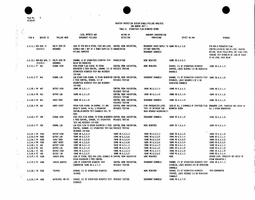
Page No. 3 01/22/87
REACTOR PROTECTION SYSTEM SINGLE FAILURE ANALYSIS SAN ONOFRE UMIT I
TABLE 6: STEAM/FEED FLOW MISMATCH SCRAM
LOCAL EFFECTS AND METHOD OF INHERENT COMPENSATING ITEM 8 DEVICE ID FAILURE MODE DEPENDENT FAILURES DETECTION PROVISIONS EFFECT ON RPS REMARKS
6.2.11.1 RES SUPL II VOLTS ZERO OR LOSS OF STM GEN B STEAM, FEED AND LEVEL CONTROL ROOM INDICATION, REDUNDANT POWER SUPPLY TO (SAVE AS 6.2.7.2) Sm GEN B FEEDWATER FLOW (RIO/Rl) GROUNDED SIGNALS AND 1 OUT OF 2 POWER SUPPLIES TO ANNUNCIATION OPTIMAC COMPUTER, CONTROLLER/VALVE AND NR LEVEL REVERS
OPTIMAC COMPUTER REDUNDANT CHAOES ACTING, VALVE FAILS OPEN, BUT HIGH LEVEL TURBINE TRIP DISABLED BY LOSS OF POSER TO NR LEVEL TRIP RELAY
6.2.12.1 NON-REQ SUPL II VOLTS ZERO OR CHANNEL 11 OF STEAM/FED MISMATE) TRIP ANNUNCIATION NONE REQUIRED (SANE AS 6.2.8.11 (RIO/RI) GROUNDED RELAY DE-ENERGIZED
6.3.01.1 FT 462 SIGNAL. HIGH HIGH STEAM FLOW SIGNAL TO STEAM CONTROL ROOM INDICATION, NONE REQUIRED CHANNEL III OF STEAM/FEED MISMATE)) (SAME AS 6.2.1.1) GENERATOR C FEED CONTROL, CHANNEL III OF PERIODIC TESTING TRIPPED, LOGIC BECOMES 1/2 EN REMAINING STEAM/FEED MIS6ATCH TRIP AND RECORDER CHIGHLS (YR-ASRI
6.3.01.2 FT 462 SIGNAL LOW LO STEAM FLOW SIG TO STEAM GENERATOR CONTROL ROOM INDICATION, REDUNDANT CHANNELS HIAHEL III OF STEAM/FEED MISMATCH TRIP ISAME AS 6.2.1.2) C FEED CONTROL, CHANNEL III OF PERIODIC TESTING DISALE, LOGIC BECOMES 2 OF 2 ON STEAM/FEED MISMATCH TRIP AND RECORDER REMAINING CHANNELS (YR-45.)
6.3.02.1 FM 462 OUTPUT HIGH (SAM AS 6.3.1.11 CONTROL ROOM INDICATION, (SAME AS 6.3.1.1) (SAME AS 6.3.1.1) (SAIE AS 6.2.1.1) PERIODIC TESTING
6.3.02.2 FM 462 OUTPUT LOW (SAME AS 6.3.1.2) CONTROL ROOM INDICATION, (SAXE AS 6.3.1.2) (SAME AS 6.3.1.2) (SAME AS 6.2.1.2) PERIODIC TESTING
6.3.02.3 FM 462 INPUT OPEN (SAME AS 6.2.1.2) CONTROL ROOM INDICATION, REDUNDANT CHANNELS (SAKE AS 6.3.1.2) (SANE AS 6.2.1.2) PERIODIC TESTING
6.3.02.4 FM 462 INPUT SHORT STEAM FLOW SIGNAL IN CHANNEL III AND CONTROL ROOM INDICATION, HIGH PRESSURIZER LEVEL LOSS OF ALL 3 CHANNELS OF STM/FEED FLOW DOWNWRD LEVEL TRANSIENT MAY OCCUR IN DENSITY SIGNAL IN ALL 3 FEEDWATER PERIODIC TESTING TRIP (IF SETPOINT HAS MISMATCH SCRAM ALL 3 STEAM GENERATORS CONTROL/MISMATCH TRIP CHANNELS FAIL TO BEEN BEDUED ACCORDINGLY) ZERO
6.3.03.1 FT 458 SIGNAL HIGH HIGH FEED FLOW SIG TO STEAM GENERATOR CONTROL ROOM INDICATION, REDUNDANT CHANNELS (SAME AS 6.3.1.2) (SAME AS 6.2.1.2) C FEED CONTROL, CHANNEL III STEAM/FEED PERIODIC TESTING TRIP AND RECORDER IYR-ZED )
6.3.03.2 FT 458 SIGNAL LOW LOW FEED FLOW TO STEAM GENERATOR C FEED CONTROL ROOM INDICATION, NONE REUIRED (SAOLE AS .3.1.1 (SAME AS CONTROL, CHANNEL III STEAM/FEED TRIP A PERIODIC TESTING RECORDER (YR-ASS)
6.3.04.1 FM 458A OUJTPUT NIGH (SAME AS 6.3.3.1) (SADIE AS 6.3.3.1) (SAME AS 6.3.3.1) (SAME AS 6.3.1.2) (SAME AS 6.3.1.2) 6.3.04.2 FM A58A OUTPUT LOW (SAME AS 6.3.3.2) (SAME AS 6.3.3.2) (SAME AS 6.3.3.2) (SAME AS 6.3.1.1) (SAME AS 6.3.1.1) 6.3.04.3 FM 4IA INPUT OPEN (SAKE AS 6.3.3.2) (SAME AS 6.3.3.2) (SAME AS 6.3.3.2) (SAME AS 6.3.3.2) (SAME AS 6.3.3.2) 6.3.04.4 FM 458A INPUT SHORT (SAKE AS 6.3.3.2) (SAME AS 6.3.3.2) (SAME AS 6.3.3.2) (SANE AS 6.3.3.2) (SADE AS 6.3.3.2) 6.3.05.1 YE 462 OUTPUT HI1GH (SAME AS 6.3.1.1) (SAME AS 6.3.1.11 (SAME AS 6.3.1.11 (SAME AS 6.3.1.1) (SAME AS 6.3.1.1) 6.3.05.2 YE 462 OUTPUT LOW (tAME AS 6.3.1.2) (SAME AS 6.3.1.2) (SAME AS 6.3.1.2) (SAKE AS 6.3.1.2) (SAME AS 6.3.1.2) 6.3.06.1 YE AS8 OUTPUT NIGH (SAME AS 6.3.3.11 (SANE AS 6.3.3.1) (SAME AS 6.3.3.1) (SAME AS 6.3.1.2) (SAME AS 6.3.1.2) 6.3.06.2 YE 458 OUTPUT LOW (SAME AS 6.3.3.2) (SAME AS 6.3.3.21 (SADIE AS 6.3.3.2) (SAME AS 6.3.1.1) (SAME AS 6.3.1.1) 6.3.07. 1 FE 458A INPUJTS OPEN LOSS OF STEAM, FEED AND LEVEL SI S TO CONTROL ROOM INDICATION NOE REUIRED NONE UPWARD LEVEL TRANSIENT MAY OCCUR IN
STEAM GENERATOR C FEED CONTROL STEAM GENERATOR C 6.3.07.2 FE A58A INPUTS SHORTED LOSS OF STEAM/FEED MISMATCH TRIP CONTROL ROOM INDICATION, REDUNDANT CHA'ONELS CHANNEL III OF STEAM/FEED MISMATCH TRIP (SAME AS 6. 3.7. 1)
COMPARATOR (SAME AS 6.3.7.1) PERIODIC TESTING DISABLED, LOGIC BECOMES 2/2 ON REMAINING CHANNELS
6.3.08.1 FM 458B TRIPPED CHANNEL III OF STEAM/FEED MISMATCH ANNUNCIATION NONE REQUIRED CHANNEL III OF STEAM/FEED MISMATCH TRIP COMPARATOR TRIPPED TRIPPED, LOGIC ECOMES 1/2 ON REMAINING
CHANNELS
6. 3.08.2 FM 4588 UNCTRIPPED (AS-IS CHANNEL III OF STEAM-FEED MISMATCH TRIP PERIODIC TESTING REDUNDAT CHANNELS (SAME AS 6.3.7.2) DISABLED

* Page No. 4 01/22/87
REACTOR PROTECTION SYSTEM SINGLE FAILURE ANALYSIS SAN ONOFRE UNIT I
TABLE 6: STEAM/FEED FLOW MISMATCH SCRAM
LOCAL EFFECTS AND METHOD OF INHERENT COMPENSATING ITEM N DEVICE ID FAILURE MODE DEPENDENT FAILURES DETECTION PROVISIONS EFFECT ON RAS RAGKS
6.3.09.1 FM 4588-I TRIPPED (SAME As 6.3.8.1) (SAME AS 6.3.8.11 (SAME AS 6.3.8.1) (SAME AS 6.3.8.1) 6.3.09.2 FM 4588-X UNTRIPPED (AS-IS) (SAME AS 6.3.8.2) (SAME AS 6.3.8.2) (SAME AS 6.3.8.2) (SAME AS 6.3.8.2) 6.3.10.1 YR 457 INPUTS OPEN LOSS OF RECORDING FOR STEAM GENERATOR C CONTROL ROOM INDICATION NONE REQUIRED NONE
FEED, STEAM FLOW AND LEVEL 6.3.10.2 YR 457 INPUTS SHORTED (SAME AS 6.3.7.2) (SAME AS 6.3.7.2) (SAME AS 6.3.7.2) (SAME AS 6.3.7.2) 6.3.11.1 REG SUPL III VOLTS ZERO OR LOSS OF STM GEN C STEAM, FEED AND LEVEL CONTROL ROOM INDICATION, REDUNDANT CHANNELS (SAME AS 6.3.7.2) STh SEN C FEEDWATER FLOW
(RI1/Ri1) GROUNDED SIGNALS ANNUNCIATION CONTROLLER/VALVE AND NR LEVEL REVERSE ACTING, VALVE FAILS OPEN, BUT HIGH LEVEL TURBINE TRIP DISABLED BY LOSS OF POWER TO NR LEVEL TRIP RELAY
6.3.12.1 NON-REG SUPL III VOLTS ZERO OR CHANNEL III STEAN/FEED FLOW MISMATCH ANNUNCIATION NONE REQUIRED CHANNEL III OF STEAM/FEED MISMATCH RELAY IS DE-ENERGIZE TO TRIP (RIO/RI)) GROUNDED TRIP RELAY DE-ENERSIZED TRIPPED, LOGIC BECOMES 1/2 ON REMAININGS
6.4.01.1 PT 459 SIGNAL HIGH HIGH MAIN STEAM HEADER PRESSURE SIGNAL CONTROL ROOM INDICATION (PI NONE REQUIRED INCREASES CALCULATED STEAM MASS FLOW INPUT (ALONG WITH T-AVG AND T-REF) TO TO STEAM DUMP OPERATIONAL MODE SELECTOR 459), ANNUNCIATION (MISMATCH INPUT TO MISMATCH TRIP CHANNELS, CAUSING DUMP, POTENTIAL FOR STERN DUMP SWITCH, CONTROL ROOM INDICATION, AND ALARM) 3/3 MISMATCH TRIP (IF INITIATED ABOVE ACTUATION, WILL ALSO CAUSE TRANSIENT STEAM DENSITY CORRECTION INPUT TO ALL APPROXIMATELY 35% REACTOR POWER) INCREASE IN FEEDWATER FLOW TO ALL THRE THREE FEEDWATER CONTROL/MISMATCH TRIP STEM GENERATORS CHANNELS
6.4.01.2 PT 459 SIGNAL LOW LOW MAIN STEAM HEADER PRESSURE SIGNAL TO (SAME AS 6.4.1.1) HIGH PRESSURIZER LEVEL LOSS OF ALL 3 STEAM/FEED FLOW MISMATCH DOWNWARD LEVEL TRANSIENT MAY OCCUR IN STEAM DUMP OPERATIONAL MODE SELECTOR TRIP (IF SETPOINT HAS TRIP CHANNELS ALL 3 STEAM GENERATORS SWITCH, CONTROL ROOM INDICATION, AND BEEN REDUCED ACCORDINGLY) STEAM DENSITY CORRECTION INPUT TO ALL THREE FEEDWATER CONTROL/MISMATCH TRIP CHANNELS
6.4.02.1 PC 418A OUTPUT HIGH HIGH MAIN STEAM HEADER PRESSURE TO STEAM ANNUNCIATION, PERIODIC TESTING NONE REQUIRED NONE DUMP OPERATIONAL MODE SELECTOR SWITCH
6.4.02.2 PC 418A OUTPUT LOW LOW MAIN STEAM HEADER PRESSURE TO STEAM PERIODIC TESTING NONE REQUIRED NONE DUMP MODE SELECTOR SWITCH
6.4.02.3 PC 418A INPUT OPEN (SAME AS 6.4.2.2) (SAME AS 6.4.2.2) (SAME AS 6.4.2.2) (SAME AS 6.4.2.2) 6.4.02.4 PC 418A INPUT SHORT (SAME AS 6.4.1.2) (SAME AS 6.4.1.1) (SAME AS 6.4.1.2) (SAME AS 6.4.1.2) 6.4.03.1 PM 459 OUTPUT HIGH HIGH MAIN STERM DENSITY SI&NAL TO ALL PERIODIC TESTING, ANNUNCIATION NONE REQUIRED (SAME AS 6.4.1.1)
THREE FEEDWATER CONTROL/MISMATCH TRIP CHANNELS
6.4.03.2 PM 459 OUTPUT LOW LOW MAIN STEAM DENSITY SIGNAL TO ALL PERIODIC TESTING (SAME AS 6.4.1.2) (SAME AS 6.4.1.2) THREE FEEDWATER CONTROL/MISMATCH TRIP CHANNELS
6.4.03.3 PM 459 INPUT OPEN (SAME AS 6.4.3.2) (SAME AS 6.4.3.2) (SAME AS 6.4.1.2) (SAME AS 6.4.1.2) 6.4.03.4 PM 459 INPUT SHORT (SAME AS 6.4.1.2) (SAME AS 6.4.1.2) (SAME AS 6.4.1.2) (SAME AS 6.4.1.21 6.4.04.1 YE 459 OUTPUT VOLTS HIGH (SE AS 6.4.1.1) (SAME AS 6.4.1.1) (SAME AS 6.4.1.1) (SAME AS 6.4.1.1) POWER SUPPLY FOR PT-459 CURRENT LOOP 6.4.04.2 YE 459 OUTPUT VOLTS LOW (SAME AS 6.4.1.2) (SAME AS 6.4.1.2) (SAME AS 6.4.1.2) (SAME AS 6.4.1.2) 6.4.05.1 PI 459 INPUT OPEN MAIN STEAM HEADER PRESSURE INDICATION CONTROL ROOM INDICATION NONE REQUIRED NONE VOLTAGE-SENSING DEVICE ACROSS PT-459
FAILS LOW CURRENT LOOP RESISTOR 6.4.05.2 PI 459 INPUT SHORT (SAME AS 6.4.1.2) CONTROL ROOM INDICATION, (SAME AS 6.4.1.2) (SAME AS 6.4.1.2)
PERIODIC TESTING 6.4.06.1 REG SUPL IV VOLTS ZERO OR (SAME AS 6.4.1.2) (SAME AS 6.4.1.2) (SAME AS 6.4.1.2) (SAME AS 6.4.1.2) LOSS OF T-REF (PT-415) AND MWE (PT-417)
(R5) GROUNDED SIGNALS TO ROD CONTROL AND STEAM DUMP SYSTEMS
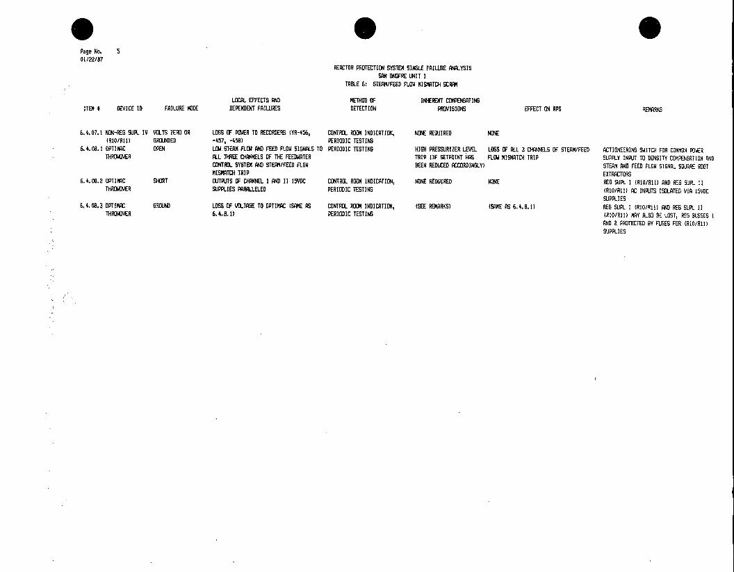
* Page No. 5 01/22/87
REACTOR PROTECTION SYSTEM SINGLE FAILURE ANALYSIS SAN ONOFRE UNIT I
TABLE 6: STEAM/FEED FLOW MISMATCH SCRAM
LOCAL EFFECTS AND METHOD OF INHERENT COMPENSATING ITEM # DEVICE ID FAILURE MODE DEPENDENT FAILURES DETECTION PROVISIONS EFFECT ON RPS REMARKS
6.4.07.1 NON-RES SUPL IV VOLTS ZERO OR LOSS OF POWER TO RECORDERS (YR-456, CONTROL ROOM INDICATION, NONE REQUIRED NONE (RI/RI1) GROUNDED -457, -458) PERIODIC TESTING
6.4.08.1 OPTIMAC OPEN LOW STEAM FLOW AND FEED FLOW SIGNALS TO PERIODIC TESTING HIH PRESSURIZER LEVEL LOSS OF ALL 3 CHANNELS OF STEAM/FEED ACTIONEERING SWITCH FOR COMMON POWER THROWOVER ALL THREE CHANNELS OF THE FEEDWATER TRIP (IF SETPOINT HAS FLOW MISMATCH TRIP SUPPLY INPUT TO DENSITY COMPENSATION AND
CONTROL SYSTEM AND STEAM/FEED FLOW BEEN REDUCED ACCORDINGLY) STEAM AND FEED FLOW SIGNAL SQUARE ROOT MISMATCH TRIP EXTRACTORS
6.4.08.2 OPTIMAC SHORT OUTPUTS OF CHANNEL I AND II I5VDC CONTROL ROOM INDICATION, NONE REQUIRED NONE REG SUPL I (RI/Ru1) AND REG SUPL II THROWOVER SUPPLIES PARALLELED PERIODIC TESTING (RI/Rh1) AC INPUTS ISOLATED VIA 15VDC
SUPPLIES 6.4.08.3 OPTIMAC GROUND LOSS OF VOLTAGE TO OPTIMAC (SAME AS CONTROL ROOM INDICATION, (SEE REMARKS) (SAME AS 6.4.8.1) REQ SUPL I (RI/RI) AND REQ SUPL II
THRDWOVER 6.4.8.1) PERIODIC TESTING (RIO/RI!) MAY ALSO BE LOST, RE BUSSES I AND 2 PROTECTED BY FUSES FOR (RIO/RI1) SUPPLIES

KI
TABLE 7: SCRAM MATRIX AND BREAKERS
(INCLUDING MANUAL AND RCP BREAKER SCRAMS)
REFERENCES: A. SYSTEM DESCRIPTIONS SD-SO1-570 REACTOR PROTECTION SYSTEM AND PERM.
B. DRAWINGS, 5112259 5150410 (N1545 Sh 102)
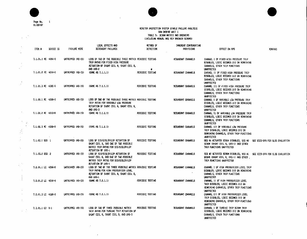
* 1 * Page No. I 01/22/87
REACTOR PROTECTION SYSTEM SINGLE FAILURE ANALYSIS SAN ONDFRE UNIT I
TABLE 7: SCRAM MATRIX AND BREAKERS (INCLUDING MANUAL AND RCP BREAKER SCRAS)
LOCAL EFFECTS AND METHOD OF INHERENT COMPENSATING ITEM # DEVICE ID FAILURE MODE DEPENDENT FAILURES DETECTION PROVISIONS EFFECT ON RPS REMARKS
7. 1.01.1 PC 430K-X UNTRIPPED (AS-IS) LOSS OF TWO OF THE POSSIBLE THREE MATRIX PERIODIC TESTING REDUNDANT CHANNELS CHANNEL I OF FIXED HIGH PRESSURE TRIP TRIP PATHS FOR FIXED HIGH PRESSURE DISABLED, LOGIC BECOMES 2/2 ON REMAINING ACTUATION OF SHIT COIL A, SUNT COIL B, CHANNELS, OTHER TRIP FUNCTIONS AND UVS-2 4 UNAFFECTED
7.1.01.2 PC 431H-X UNTRIPPED (AS-IS) (SAME AS 7.1.1.1) PERIODIC TESTING REDUNDANT CHANNELS CHANNEL II OF FIXED HIGH PRESSURE TRIP DISABLED, LOGIC BECOMES 2/2 ON REMAINING CHANNELS, OTHER TRIP FUNCTIONS UNAFFECTED
7.1.01.3 PC 432E-X UNTRIPPED (AS-IS) (SAME AS 7.1.1.1) PERIODIC TESTING REDUNDANT CHANNELS CHANNEL III OF FIXED HIGH PRESSURE TRIP DISABLED, LOGIC BECOMES 2/2 ON REMAINING CHANNELS, OTHER TRIP FUNCTIONS UNAFFECTED
7.1.02.1 PC 430A-X UNTRIPPED (AS-IS) LOSS OF TWO OF THE POSSIBLE THREE MATRIX PERIODIC TESTING REDUNDANT CHANNELS CHANNEL I OF VARIABLE LOW PRESSURE TRIP TRIP PATHS FOR VARIABLE LOW PRESSURE DISABLED, LOGIC BECOMES 2/2 ON REMAINING ACTUATION OF SHUNT COIL A, SHUNT COIL B, CHANNELS, OTHER TRIP FUNCTIONS AND UVS-3 UNAFFECTED
7.1.02.2 PC 431D-I UNTRIPPED (AS-IS) (SAME AS 7.1.2.1) PERIODIC TESTING REDUNDANT CHANNELS CHANNEL II OF VARIABLE LOW PRESSURE TRIP DISABLED, LOGIC BECOMES 2/2 ON REMAINING CHANNELS, OTHER TRIP FUNCTIONS UNAFFECTED
7.1.02.3 PC 432B-X UNTRIPPED (AS-IS) (SAME AS 7.1.2.1) PERIODIC TESTING REDUNDANT CHANNELS CHANNEL III OF VARIABLE LOW PRESSURE TRIP DISABLED, LOGIC BECOMES 2/2 ON REMAINING CHANNELS, OTHER TRIP FUNCTIONS UNAFFECTED
7.1.03.1 SEQ 1 UNTRIPPED (AS-IS) LOSS OF SIS/SISLOP/LOP ACTUATION OF PERIODIC TESTING REDUNDANT CHANNELS SEQ #1 ACTUATED SCRAM DISABLED, SED #2 SEE ECCS-SFA FOR SLSS EVALUATION SHUNT COIL B, AND DNE OF TWO POSSIBLE SCRAM (SHUNT COIL A, UVS-1) AND OTHER MATRIX TRIP PATHS FOR SIS/SISLOP/LOP TRIP FUNCTIONS UNAFFECTED ACTUATION OF UVS-I
7.1.03.2 SEX 2 UNTRIPPED (AS-IS) LOSS OF SIS/SISLOP/LOP ACTUATION OF PERIODIC TESTING REDUNDANT CHANNELS SEQ #2 ACTUATED SCRAM DISABLED, SED #1 SEE ECCS-SFA FOR SLSS EVALUATION SHUNT COIL A, AND ONE OF TWO POSSIBLE SCRAM (SHUNT COIL B, UVS-1) AND OTHER MATRIX TRIP PATHS FOR SIS/SISLOP/LOP TRIP FUNCTIONS UNAFFECTED ACTUATION OF UVS-1
7.2.01.1 LC 43OA-X UNTRIPPED (AS-IS) LOSS OF TWO OF THE THREE POSSIBLE MATRIX PERIODIC TESTING REDUNDANT CHANNELS CHANNEL I OF HIGH PRESSURIZER LEVEL TRIP TRIP PATHS FOR HIGH PRESSURIZER LEVEL DISABLED, LOGIC BECOMES 2/2 ON REMAINING XTUATION OF SHUNT COIL A, SHUNT COIL B, CHANNELS, OTHER TRIP FUNCTIONS AND UVS-I UNAFFECTED
7.2.01.2 LC 431A-X UNTRIPPED (RS-IS) (SAME AS 7.2.1.1) PERIODIC TESTING REDUNDANT CHANNELS CHANNEL II OF HIGH PRESSURIZER LEVEL TRIP DISABLED, LOGIC BECOMES 2/2 ON REMAINING CHANNELS, OTHER TRIP FUNCTIONS UNAFFECTED
7.2.01.3 LC 432A-X UNTRIPPED (AS-IS) (SAME AS 7.2.1.1) PERIODIC TESTING REDUNDANT CHANNELS CHANNEL III OF HIGH PRESSURIZER LEVEL TRIP DISABLED, LOGIC BECOMES 2/2 ON REMAINING CHANNELS, OTHER TRIP FUNCTIONS UNAFFECTED
7.3.01.1 63 X-1 UNTRIPPED (AS-IS) LOSS OF TWO OF THREE POSSIBLE MATRIX PERIODIC TESTING REDUNDANT CHANNELS CHANNEL I OF TURBINE TRIP SCRAM TRIP TRIP PATHS FOR TURBINE TRIP ACTUATION OF DISABLED, LOGIC BECOMES 2/2 ON REMAINING SHUNT COIL A, SHUNT COIL B, AND UVS-3 CHANNELS, OTHER TRIP FUNCTIONS
UNAFFECTED

* 0S Page No. 2 01/22/87
REACTOR PROTECTION SYSTEM SINLE FAILURE ANALYSIS SAN ONOFRE UNIT I
TABLE 7: SCRAM MTRIX AND BREAKERS (INCLUDING MANIAL AND RCP BREAKER SCRAS)
LOCAL EFFECTS AND METHOD OF INHERENT COMPENSATING ITEM I DEVICE ID FAILURE MODE DEPENDENT FAILURES DETECTION PROVISIONS EFFECT ON RPS REMARKS
7.3.01.2 63 X-2 LZTRIPPED (AS-IS) (SAME AS 7.3.1.1) PERIODIC TESTING REDUNDANT CHANNELS CHANEL 11 OF TURBINE TRIP SCRAM TRIP DISABLED, LOGIC BECOMES 2/2 ON REMAINING CHANNELS, OTHER TRIP FUNRCTIONS UNAFFECTED
7.3.01.3 63 X-3 UNTRIPPED (AS-IS) (SAME AS 7.3.1.1) PERIODIC TESTING REDUNDANT CHANNELS CHANEL III OF TURBINE TRIP SCRAM TRIP DISABLED, LOGIC BECOMES 2/2 ON REMAINING CHANNELS, OTHER TRIP FUNCTIONS UNAFFECTED
7. 4.01.1 AP4A ON LOSS OF 1 OF 2 POSSIBLE OUTPUT PATHS ANNUNCIATION, PERIODIC TESTING REDUNDANT OUTPUT PATHS TO REDUCED REDUNDANCY AGAINST BYPASS OF 2/3 SEE SECTION 4 FOR NIB SCRAMS AND FRON 2/3 RCS LOW FLOW, 2/3 RCP B.REAKER, SHUNT COILS VIA AP4C, RCS LOW FLOW, 2/3 REP BREA.KER, VARIABLE PERMISSIVES, APA ENERGIZED WHEN P-7 IS VARIABLE LOW PRESSURE AND TURBINE TRIP ADDITIONAL OWV BYPASS LOW PRESSURE AND TURBINE TRIP SCRUBS, NO ON SCRNN MATRICES TO SHUNT COIL A AND SHUNT CONTACT AP4C LOSS OF ANY SCRAM FUNCTION COIL B, LOSUE 0F I OF 2 CONTACTS NEEDED TO BYPASS LNS-3 AND 11/5-4 OUTPUT TO (N COILS A & B
7.4.01.2 AP4A OFF LOS OF CAPABILITY TO BYPASS VARIABLE PERIODIC TESTING NONE REQUIRED NONE (P-7 OFF), REACTOR TRIP IF VARIABLE LOW PRESSURE, 2/3 RES LOW FLOW, 2/3 RCP LOW PRESSURIZER PRESSURE, 2/3 ROD FLOW, BREAKER AND TURBINE TRIP SCRAMS 2/3 REP BREAKER OR TURBINE TRIP SCRAM
SIGNALS PRESENT (P-7 ON) 7. 4.02.1 AP4B ON LOSS OF I OF 2 POSIBLE OUTPUT PATHS FOR A)2E(IATION, PERIODIC TESTING REDUNDANT OUTPUT PATHS TO ROMXCE REDUNDANCY AGAINST BYPASS OF SUR APAB ENERGIZED WHEN P-7 IS OFF
SUR SCRAM TO SHINT COIL A AND 6111ff COIL SHUNTV COILS VIA AP4D, SCRAM, NO LOSS OF ANY SCRAM FUNCTION B, CLOSURE IF I OF 2 CONTACTS NEEDED TO ADDITIONAL IV BYPASS
7 0BYPASS SR SCRAN TO 4-2 CONTACT APP 7.4.02.2 AP4 OFF LOSS OF CAPABILITY TO BYPASS SIR SCRAM PERIODIC TESTING NONE EGUIRED NONE (P-7 ON), REACTOR TRIP IF SUR SCRAM
SIGNAL PRESENT (P-7 OFF) 7.4.03.1 AP4C ON (SAME AS 7.4.1.1) (SAME AS 7. 4.1. 11 (SAME AS 7.4.1.1) (SAME AS 7.4.1.1) AP4C ENERGIZED WHEN P-7 IS ON 7.4.03.2 AP4C OFF (SAME AS 7.4.1.2) (SAME AS 7.4.1.2) (SAME AS 7.4.1.2) (SAME AG 7.4.1.2) 7.4.04.1 AP4D ON (SANE AS 7.4.2.1 (SAME AS 7.4.2.1) (SAME AS 7.4.2.1) (SANE AS 7.4.2.1) AP ENERGIZED WHEN P-7 IS OFF 7.4.04.2 AP4D OFF (SAME AS 7.4.2.2) (SAME AS 7.4.2.2) (SAME AG 7.4.2.2) (SAME AS 7.4.2.2) 7. 4.05.1 APIOA ON LOSS OF I OF 2 POSSIBLE OUTPUT PATHS FOR ANNUNCIATION, PERIODIC TESTING REDUNDANT OUTPUT PATHS TO REDUCED REDUNDANCY AGAINST P-B BYPASS PF AP1OA ENERGIZED WHEN P-B IS ON
1/3 LOW RCS FLOW AND 1/3 REP BREAKER SHUNT COILS VIA APlOC, 1/3 LOW RES FLOW AND 1/3 REP BR!EAKER SCRAM MATRICES TO SHINT COIL A, SHUNT ADDITIONAL OW BYPASS SCRAMS, NO LOSS OF ANY SCRAM FUNCTION COIL B, AND 7 0 1-2 CONTACT APIOC
7.4.05.2 APIA OF LOSS IF CAPABILITY TO BYPASS 1/3 LOW PERIODIC TESTING NONE REUIRED NONE IP- OFF), REACTOR TRIP OF 1/3 LOW FLOW AND 1/3 RCP BREAKER SCRANS DCS FLOW OR RCP BREAER OPEN SIGNAL
PRESENT (P-8 ON) 7.4.06.1 APIOC ON (SAVE AS 7.4.5.1) (SAME AS 7.4.5.1) (SAKE AS 7. 4.5. 1) (SAME AS 7.4.5. 1) APIOC ENERGIZED WHEN P-B IS ON 7.4.06.2 APlOC OFF (SAME AS 7.4.5.2) (SAME AS 7.4.5.2) (SAME AS 7.4.5.2) (SAME AS 7.4.5.2) 7.5.01.1 FC 400-XI INTRIPPED (AS-IS) LOSS OF LOOP A LOW FLOW INPUT TO 2/3 PERIODIC TESTING LOOP A RCP BREAKER INPUT LOSS IF REDUDANCY FOR 2/3 LOSS OF RCS RELAY IS ENERGIZE TO TRIP
TRIP MATRIX FOR SHUNT COIL A, SHUNT COIL TO 2/3 MATRIX FLOW EVENTS INVOLVING LOOP A, TRIP LOGIC B, AND UVS-3 UNAFFECTED
7.5.01.2 FC 410-XI UNTRIPPED (AS-IS) LOSS OF LOOP B LOW FLOW INPUT TO 2/3 PERIODIC TESTING LOOP BE RP BREAKER INPUT LOSS IF RED ANCY FOR 2/3 LOSS OF RCS (SAME AS 7.5.1.1) TRIP XATRIX FOR SHUNT COIL A, 541/NT COIL TO 2/3 MATRI FLOW EVENTS INVOLVING LOOP B, TRIP LOGIC B, AND 115-3 UNAFFECTED
7.5.01.3 FC 420-I UNTRIPPED (AS-IS) LOSS OF LOOP C LOW FLOW INPUT TO 2/3 PERIODIC TESTING LOOP C RCP BREAKER INPUT LOSS OF REDUNDANCY FOR 2/3 LOSS OF 2CS (SAME AS 7.5. .O TRIP MATRIC FOR SHUT COIL A, SHUNT COIL TO 2/3 MATRI FLOW EVENTS INVOLVING LOOP C, TRIP LOGIC B AND UVBS-3 UNAFFECTED

* 0 Page No. 3 01/22/87
REACTOR PROTECTION SYSTEM SINGLE FAILURE ANALYSIS SAN ONOFRE LNIT I
TABLE 7: SCRAM MATRIX AND BREAKERS (INCLUDING MANUAL AND RCP BREAKER SCRAMS)
LOCAL EFFECTS AND METHOD OF INHERENT COMPENSATING ITEM D DEVICE ID FAILURE MODE DEPENDENT FAILURES DETECTION PROVISIONS EFFECT ON RPS REMARKS
7.5.02.1 FC 400-X2 UNTRIPPED (AS-IS) LOSS OF LOOP A LOW FLOW INPUT TO 1/3 PERIODIC TESTING LOOP A REP BREAKER INPUT LOSS OF REDUNDANCY FOR 1/3 LOSS OF RCS RELAY IS ENERGIZE TO TRIP TRIP MATRIX FOR SHUJNT COIL A, SHUNRT COIL TO 1/3 MATRIX FLOW EVENTS INVOLVING LOOP A, TRIP LO6IC B, AND LPWS-2 UNAFFECTED
7.5.02.2 FC 410412 UNTRIPPED (AS-IS) LOSS OF LOOP B LOW FLOW INPUT TO 1/3 PERIODIC TESTING LOOP B RCA BREAKER INPUT LOSS OF REDUNDANCY FOR 1/3 LOSS OF RCS (SAME AS 7.5.2.1) TRIP MATRIX FOR SHUNIT COIL A, SHUNT COIL TO 1/3 MATRIX FLOW EVENTS INVOLVING LOOP B, TRIP LOGIC B, AND UIVS-2 UNAFFECTED
7. 5. 02.3 FC 42012I UNTRIPPED (AS-IS) LOSS OF LOOP C LOW FLOW INPUT TO 1/3 PERIODIC TESTING LOOP C RCP BREAKER INPUT LOSS OF REDUNACY FOR 1/3 LOSS OF RCS (SAME AS 7.5.2.1) TRIP MATRIX FOR SHUNT COIL A, SHUNT COIL TO 1/3 MATRIX FLOW EVENTS INVOLVING LOOP C, TRIP LOGIC B, AND UVS-2 UNAFFECTED
7.5.03.1 b/152-I U1 OPEN (AS-IS) LOSS OF LOOP A REP BREAKER INPUT TO 1/3 PERIODIC TESTING LOOP A LOW FLOW CHNEL LOSS OF REDUNDANCY FOR LOSS OF RCS FLOW BREAKER OR B-AUXILIARY SWITCH AND 2/3 LOW FLOW TRIP MATRICES FOR SHUNT Q) INPUT TO SHUNT COIL EVENTS INVOLVING LOOP A, TRIP LOGIC MALFUNCTION COIL A AND SRINT COIL B A, SHUNT COIL B, UVS-2 UNAFFECTED
(1/3 ONLY) AN 8,S-3 (2/3 ONLY) MATRICES
7.5.03.2 b/152-11002 OPEN (AS-IS) LOSS OF LOOP B RCP BREAKER INPUT TO 1/3 PERIODIC TESTING LOOP B LOW FLOW CHANNEL LOSS OF REDUNDANCY FOR LOSS OF RCS FLOW (SAVE AS 7.5.3.1) AND 2/3 LOW FLOW TRIP MATRICES FOR SHUNT (11) INPUT TO SHUNT COIL EVENTS INVOLVING LOOP B, TRIP LOGIC COIL A AND SHUNT COIL B A, SHUNT COIL B, UVS-I UNAFFECTED
(1/3 OLY AND -) SO-3 (2/3 INN2) MATRICES
7.5.03.3 b/152-11A03 OPEN (AS-IS) LOSS OF LOOP C RCP BREAKER INPUT TO 1/3 PERIODIC TESTING LOOP C LOW FLOW CHANNEL LOSS OF REDUNDANCY FOR LOSS OF RCS FLOW (SAKE AS 7.5.3.1) AND 2/3 LOW FLOW TRIP MATRICES FOR SHUNT (1) INPUT TO SHUNT COIL EVENTS INVOLVING LOOP C, TRIP LOGIC COIL A AND SHUNT COIL B A, SHUNT COIL B, LIVS-I UNAFFECTED
(1/3 O7LY) AND /5 1-3 (2/3 ONLY) MATRICES
7.5.04.1 a/152-I1A01 CLOSED (AS-IS) LOSS OF LOOP A REP BREAKER INPUT TO LOW PERIODIC TESTING (SAN AS 7.5.3.1) (SANE AS 7.5.3.1) BREAKER OR A-AUXILIARY SWITCH FLOW TRIP MATRICES FOR (1/5-2 (1/3) AND MALFUNCTION UVS-4 (2/3)
7.5.04.2 a/152-11R02 CLOSED (AS-IS) LOSS OF LOOP B REP BREAKER INPUT TO LOW PERIODIC TESTING (SAME AS 7.5.3.2) (SAME AS 7.5.3.2) (SAME AS 7.5.4.1) FLOW TRIP MATRICES FOR INS-I (1/3) AND (1/5-4 (2/3)
7.5.04.3 a/152-11A03 CLOSED (AS-IS) LOSS OF LOOP C RCP BREAKER INPUT TO LOW PERIODIC TESTING (SAME AS 7.5.3.3) (SAME AS 7.5.3.3) (SAME AS 7.5.4.1) FLOW TRIP MATRICES FOR INS-2 (1/3) AND UVS-4 (2/3)
7.&. 01.1 EM 456B-X (CTRIPPED (AS-IS) LOSS OF 5/ A (CHANNEL I P) PERIODIC TESTING REDUNDANT CHANNELS FOR CHANEL I (SIG A) OF STEAM/FEENATER CTEAL/FEEDWATER FLOW MISMATCH INPUT TO COMPLETE L O FW FLOW MISMATCH TRIP DISABLED, LOGIC 2/3 TRIP MATRICES FOR S-2 COIL A, EVENTS, NONE FOR EVENTS BECOMES 2/2 ON REMAINING NDNELS (S/ B SHNT COIL B AND UVS/-2 INVOLVING ONLY SIG A AND S/0 C)
7.6.01.2 FM 457B-I UNTRIPPED (AS-IS) LOSS OF 5/6 B (CHANNEL 11) PERIODIC TESTING REDUNDANT CANELS FOR CHANNEL 11 (SI B) IF STEAN/FEEDWATER STEAM/FEEDWATER FLOW MISMATCH INPUT TO COMPLETE LOSS OF F) FLOW MISMATCH TRIP DISABLED, LOGIC 2/3 TRIP MATRICES FOR SHUNT COIL A, EVENTS, NOE FOR EVENTS BECOMES 212 ON REMAININ3 CHANNELS (SIG A SHUNT COIL B AND UVS-2 INVOLVING ONLY S/G B AND S/G C)
7.6.01.3 EM 45BB-X UNTRIPPED (AS-IS) LOSS OF S/6 C (CHANNEL III) PERIODIC TESTING REDUNDANT CHANNELS FOR CHANNEL III (SI C) OF STEA/FEEDQATER STEAN/FEEDWATER FLOW MISMATCH INPUT TO COMPLETE LOSS OF F) FLOW MISMATCH TRIP DISABLED, LOGIC 2/3 TRIP MATRICES FOR SMUNT COIL A, EVENTS, NONE FOR EVENTS BECOMES 2/2 ON REMAINING CHANNELS (S/S A SHUNT COIL B AND UVS-2 INVOLVING ONLY S/S C AND S/G B)
7.7.01.1 1/SPB I TRIPPED ACTUATION OF SHUNT COIL A, SHUNT COIL B, CONTROL ROM INDICATION, NONE REGUIRED REACTOR TRIP AND UV COILS A AND B VIA UVS-I ANNUNCIATION

Page No. 4 01/22/87
REACTOR PROTECTION SYSTEM SINGLE FAILURE ANALYSIS SAN ONOFRE UNIT I
TABLE 7: SCRAM MATRIX AND BREAKERS (INCLUDING MANUAL AND RCP BREAKER SCRAMS)
LOCAL EFFECTS AND METHOD OF INHERENT COMPENSATING ITEM I DEVICE ID FAILURE MODE DEPENDENT FAILURES DETECTION PROVISIONS EFFECT ON RPS REMARKS
7. 7.01.2 ISPB I (INTRIPPED (AS-IS) LOSS OF I OF 2 MANU0AL SCRAMI PATHS IN PERIODIC TESTING REDUNDANT SWITCH (lISPB LOSS OF REDUNDANCY FOR MANUAL SCRAM, NO SHUINT COIL A, SHliNT COIL B, AND UVS-I 2) LOSS OF ANY SCRAM FUNCTION
7.7.02.1 1/SPB 2 TRIPPED (SAME AS 7.7.1.1) (SAE AS 7.7.1.1) (SANE AS 7.7.1.1) (SAME AS 7.7.1.1) 7.7.02.2 1/SPB 2 UNTRIPPED (AS-IS) (SAME AS 7.7.1.2) (SAME AS 7.7.1.2) (SAME AS 7.7.1.2) (SAME AS 7.7.1.2) 7.7.03.1 286 613-1 O(N LOSS OF CAPABILITY TO BYPASS VARIABLE ANNUNCIATION, PERIODIC TESTING NONE REOURIED NONE (P-7 OFF), REACTOR TRIP IF VARIABLE 286 G13-1 ENERGIZED BY LOVATS UPON 4 KV
LOW PRESSUR)E, 2/3 RCS LOW FLOW, 2/3 RCP LOW PRESSURIZER PRESSURE, 2/3 RCS LOW BUS IC, 2C UNDERVOLTAGE IF MAIN BREAKER, AND TURBINE TRIP SCRM FLOW, 2/3 REP BREAKER OR TURBINE TRIP GENERATOR DISCONNECT SWITCl) IS CLOSED
SCRAM SIGNAL PRESENT (P-7 ON) 7. 7.03.2 266 613-) OFF (AS-IS) LOSS OF CAPABILITY TO OVRRIDE P-7 PERIODIC TESTING SEQ I AND SEQ 2 TRIP NONE (P-7 OFF), REDUCED REDUNDANCY FOR SEE ECCS STA FOR SEQ I, SEQ 2 DISCUSSION
BYPASS OF VARIABLE LOW PRESSURE, 2/3 RCS OUJTPUTS ACTUJATED ON BUS REACTOR TRIP ON BUS IC, 2C UNDERVOLTAGE LOW FLOW, 2/3 RCP BREAKER AND TURBINE IC, 2C LINDER VOLTAGE (P-7 ON) TRIP SCRAMS UPON LOVATS ACTUATION (LOP)
7.7.04.1 UVS 1 INPUT OPEN LOSS OF IlS-I HOLD-IN FORCE, CONTROL BOOM INDICATION, NONE REQUIRED REACTOR TRIP INTERRUPTING CURRENT TO IN COIL A AND UIV PERIODIC TESTING COIL 0
7.7.04.2 UIVS I INPUT SHORT (SAME AS 7.7.4.1) MAY ALSO BLOW FUSES IN (SAME AS 7.7.4.1) (SAME AS 7.7.4.1) (SWN AS 7.7.4.1) FUSES FROM EACHI POLE OF 125 VO-C SUPPLY COMMON UPd COIL SUPPLY PREVENT LOSS OF SHUINT TRIP
7.7.04.3 WNS I TRIPPED CURRENT INTERRUPTED TO LI COIL A D LIV (SAME AS 7.7.4.1) (SAME AS 7.7.4.1) (SAME AS 7.7.4.1) COIL B
7.7.04.4 UVS I UNTRIPPED (AS-IS) LOSS OF MANUAL, SEQ 1, SEQ 2, HIS AND PERIODIC TESTING SUNT TRIPS A AND B REDCD REDUDANCY FOR MANUAL, SEQ 1, PRESSURIZER HIGH LEVEL TRIP CAPABILITY SEQ 2, HIS AND PRESSURIZER HIGH LEVEL FOR UV) COIL A AND IN COIL B SCRAMS, NO LOSS OF ANY SCRAM FUNCTION
7.7.05.1 UVS 2 INPUT OPEN LOSS OF LIVS-2 HOLD-IN FORCE, CONTROL BOON INDICATION, N REQUIRED REACTOR TRIP INTERRUPTING CURRENT TO UIV COIL A AND (NV PERIODIC TESTING COIL B
7.7.05.2 UVS 2 INPUT SHORT (SAME AS 7.7.5.1) MAY ALSO BLOW FUSES IN (SAME AS 7.7.5.1) (SA AS 7.7.5.1) (SAME AS 7.7.5.1) (SAKE AS 7.7.4.2) COMMON UIV COIL SUPPLY
7.7.05.3 WS 2 TRIPPED CURRENT INTERRUPTED TO IN COIL A AND UV (SAM AS 7.7.5.1) (SAME AS 7.7.5.1) (SAME AS 7.7.5.1) COIL B
7.7.05.4 UIVS 2 UNTRIPPED (AS-IS) LOSS OF 1/3 LOW BMG FLOW, 1/3 R P PERIODIC TESTING SUNNT TRIPS A WD B REDUCED RE ANCY FOR 1/3 LOW ACE FLOP, BREAKER, STEAM/FEEDWATER FLOW MISMATCH, 1/3 RCP BREAKER, STEAM/FEEDWATER FLOW FIXED HIGH PRESSURE AND HIS (SUR) TRIP MISMATCH, FIRED HIGH PRESSURE AND IS CAPABILITY FOR I COIL A AND IN COIL B (UA) SCRAMS, NO LOSS OF ANY SCRAM
FUNCTION 7.7.06.1 UVS 3 INPUT OPEN LOSS OF UVS-3 HOLD-IN FORCE, CONTROL BOON INDICATION, HON REQUIRED REACTOR TRIP
INTERRUPTING CURRENT TO IN COIL A AND UV PERIODIC TESTING COIL B
7.7.06.2 INS 3 INPUT S!HORT (SAME AS 7.7.6.1) AY ALSO BLOW FUSES IN (SAME AS 7.7.6.11 (SAME AS 7.7.6.1 (SAME AS 7.7.6.) (SAME AS 7.7.4.2) COMUON IN COIL SUPPLY
7.7.06.3 L(VS 3 TRIPPED CURRENT INTERRUPTED TO I COIL A AND IV (SANE AS 7.7.6.1) (SAME AS 7.7.6.1) (SAME AS 7.7. .1) COIL B
7.7.06.4 INS 3 UNTRIPPED (AS-IS) LOSS OF 2/3 LOW BCE FLOW, VARIABLE LOW PERIODIC TESTING SHRUNT TRIPS A AND B REDUCED REDUNANCY FOR 2/3 LOW RCS FLOW PRESSURE AND TUR7INE TRIP CAPABILITY FOR VARIABLE LOW PRESSURE AND TURBINE TRIP IN COIL A ANM D M V COIL B SCRAMS, NO LOSS OF ANY SCRAM FUNCTION
7.7. 07.1 UVS 4 INPUT OPEN LOSS OF UIVS-4 HOLD-IN FORCE, CONTROL ROOM INDICATION, NONE REQUIRED REACTOR TRIP INTERRUPTING CURRENT TO UV COIL A 4ND UV PERIODIC TESTING COIL B

*** Page No. 5 01/22/87
REACTOR PROTECTION SYSTEM SINGLE FAILURE ANALYSIS SAN ONOFRE UNIT I
TABLE 7: SCRAM MATRIX AND BREAMERS (INCLUDING MANUAL AND RCP BREAKER SCRAMS)
LOCAL EFFECTS AND METHOD OF INHERENT COMPENSATING ITEM # DEVICE ID FAILURE MODE DEPENDENT FAILURES DETECTION PROVISIONS EFFECT ON RPS REMARKS
7.7.07.2 UVS 4 INPUT SHORT (SAME AS 7.7.7.1) MAY ALSO BLOW FUSES IN (SANE AS 7.7.7.1) (SAME AS 7.7.7.1) (SAE AS 7.7.7.1) (SAE AS 7.7.4.2) COVMON UL COIL SUPPLY
7.7.07.3 LVS 4 TRIPPED CURRENT INTERRUPTED TO WV COIL A AND LIV (SAME AS 7.7.7.1) (SE AS 7.7.7.1) (SAME AS 7.7.7.1) COIL B
7.7.07.4 UVS 4 UNTRIPPED (AS-IS) LOSS OF 2/3 ACA BRAKER TRIP CAPABILITY PERIODIC TESTING SHUNT1 TRIPS A AND B REDUCED REDNDANCY FOR 2/3 RIP BREAXER VARIABLE HIGH PRESSURE TRIP PERkNAN:ENTLY FOR U COIL A AND IN COIL B SCRAMS, NO LOSS OF ANY SCRAM FUNCTION BYPASSED IN THIS CIRCUIT
7.7.08.) SHLNT COIL A OPEN LOSS OF SCRAN BREAKER A SHJNT TRIP CONTROL ROOM INDICATION, VWDERYOLTAOE TRIP, LOSS OF REDUNANCY FOP SCRAM BREAKER A VARIABLE HIGH PRESSURE TRIP PERYA.NENTLY CAPABILITY PERIODIC TESTING REDUNDANT BREAKER ACTUATION, ALL TRIP FUNCTIONS UNAFFECTED BYPASSED IN THIS CIRCUIT
7.7.08.2 SHLNT COIL A SHORT LOSS OF SCRAM BREAKER A SHUNT TRIP CONTROL ROOM INDICATION, (SAME AS 7.7.8.1) (SAME AS 7.7.8.1) FUSES FROM EACH POLE OF 125 VDC SUPPLY CAPABILITY PERIODIC TESTING PREVENT LOSS OF REDUNDANT BREAKER SHUNT
TRIP 7.7.08.3 SHUNT COIL A GROUND NONE BUS GROUND INDICATION NONE REQIRED NONE DC SUPPLY IS UNGROUNDED, GROUND OF THIS
COIL BOUNDS CASE OF GROUND IN ANY INPUT TO THIS COIL
7.7.09.1 SHUNT COIL B OPEN LOSS OF SCRAM BREAKER 8 SHUNT TRIP CONTROL ROOM INDICATION, UNDERVOLTAGE TRIP, LOSS OF REDUNDANCY FOR SCRAM BREAKER B CAPABILITY PERIODIC TESTING RED ANT BREAKER ACTUATION, ALL TRIP FUNCTIONS UNAFFECTED
7.7.09.2 SHUNT COIL B SHORT LOSS OF SCRAM BREAKER B SHUNT TRIP CONTROL ROOM INDICATION, (SAE AS 7.7.9.1) (SANE AS 7.7.9.1) FUSES FROM EACH POLE OF (E2 VDC SUPPLY CAPABILITY PERIODIC TESTING PREVENT LOSS OF REDUNDANT BREAKER SHUNT
TRIP 7.7.09.3 SHUNT COIL B GROUND NONE BUS GROUND INDICATION NONE REWIRED NONE DC SUPPLY UNGROUNDED, GROUND OF THIS
COIL BOUNDS CASE OF GROUND IN ANY INPUT TO THIS COIL
7.7.10.1 UV COIL A OPEN LOSS OF WJ COIL A HOLD-IN FORCE, CONTROL ROOM INDICATION, NONE REWIRED REACTOR TRIP ACTUATING SCRAM BREAKER A PERIODIC TESTING
7.7.10.2 UY COIL A SHORT (SANE AS 7.7.10.1) IV COIL B MAY ALSO BE (SAME AS 7.7.10.1) (SANE AS 7.7.10.1) (SAME AS 7.7.10.1) FUSES FROM EACH POLE OF 125 VOC SUPPLY DE-ENERGIZED IF COMMON UV COIL SUPPLY PREVENT LOSS OF SHUNT TRIP CAPABILITY FUSES BLON DUE TO SHORT
7.7.10.3 W COIL A GROUND NONE BUS GROUND INDICATION NONE REQUIRED NONE DC SUPPLY UNGROUNDED, GROUND OF UV COIL BOUNDS CASE OF GROUND IN ANY INPUT TO THIS COIL
7.7.11.2 LV COIL B OPEN LOSS OF UN COIL B HOLD-IN FORCE, CONTROL ROOM INDICATION, NONE REQUIRED REACTOR TRIP ACTUATING SCRAM BREAKER B PERIODIC TESTING
7.7.11.2 UIV COIL B SHORT (SAE AS 7.7.11.1) UN COIL A MAY ALSO BE (SAME AS 7.7.11.1) (SAME AS 7.7.11.1) (SAME AS 7.7.11.1) (SAME AS 7.7.10.2) DE-ENERGIZED IF COMON UN COIL SUPPLY Fl)SES BLOW DUE TO SHORT
7. 7.11.3 UN COIL B GROUND NONE BUS GROUND INDICATION NON REQIRED NONE (SAME AS 7.7.10.3) 7.7.12.1 72/SCRAM A TRIPPED INTERRUPTS BOTH POLES OF 125 VDC POWER ANNUNCIATION NONE REWIRED REACTOR TRIP
(BREAKER) TO CONTROL ROD (RCCA) DRIVE MECHANISMS 7.7.12.2 12/SCRAM A UNTRIPPED (AS-IS) LOSS OF I OF 2 SCRAM BREAKERS PERIODIC TESTING REDUJNDANT BREAKER LOSS OF REDUNDANCY IN FINAL ACTUATION 125 VOC POWER TO CONTROL ROD (RECA)
(BREAKER) DEVICE FOR REACTOR SCRAM DRIVE 2ESCANISRS CAN ALSO BE INTERRUPTED AT 125 VEC BREAKER 72-14K
7.7.13.1 72/SCRAM B TRIPPED (SAME AS 7.7.12.1) (SANE AS 7.7.12.1) (SE AS 7.7.12.1) (SAFE AS 7.7.12.1) (BREAKER)
7.7. 13.2 72/SCRAM B UNTRIPPED (AS-IS) (SAME AS 7.7.12.2) (SAME AS 7.7.12.2) (SAME AS 7.7.12.2) (SANE AS 7.7.12.2) (SANE AS 7.7.12.21 (BREAKER)
7.8.01.1 72/141 (BREAKER) TRIPPED INTERRUPTS BOTH POLES OF 125 VDC POWER CONTROL ROOM INDICATION, NONE REWIRED REACTOR TRIP TO SCRAM BREAKER CONTROLS, CONTROL ROD ANNUNCIATION (RCCA) SEGUENCING CONTROLS, AND CONTROL
ROD (RCCA) DRIVE (ESHANISYS
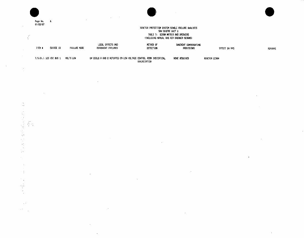
* 0 Page No. 6 01/22/87
REACTOR PROTECTION SYSTEM SINGLE FAILURE ANALYSIS SAN ONOFRE UNIT I
TABLE 7: SCRAM MATRIX AND BREAKERS (INCLUDING MANUAL AND RCP BREAKER SCRAMS)
LOCAL EFFECTS AND METHOD OF INHERENT COMPENSATING ITEM * DEVICE ID FAILURE MODE DEPENDENT FAILURES DETECTION PROVISIONS EFFECT ON RPS REMARKS
7.9.01.1 125 VDC BUS I VOLTS LOW UV COILS A AND B ACTUATED 01 LOW VOLTAGE CONTROL ROOM INDICATION, NONE REQUIRED REACTOR SCRAM ANNUNCIATION
q

TABLE 8-1: POWER SUPPLIES
REFERENCES: A. SYSTEM DESCRIPTIONS: SD-SO1-140 125VDC SYSTEM SD-SO1-150 MAINTAINED 120VAC SYSTEM
B. DRAWINGS: 5102173 5102174 5149348
NOTES: e. THIS SECTION EVALUATES FAILURES IN THE CHANNELIZED VITAL AND REGULATED BUS SYSTEM COMMON TO THE SCRAM FUNCTIONS. IT WAS DEVELOPED IN PART USING THE SORT OF TABLES 1 - 7 FOR RACK POWER SUPPLY DEPENDENCY WHICH IS PROVIDED AS TABLE 8-2.
b. THE CREDIBLE FAILURE MODES FOR THE VITAL AND REGULATED BUS INVERTER AND TRANSFORMER SUPPLIES WERE CONSIDERED TO BE THOSE RESULTING IN BUS VOLTS LOW OR ZERO. BUS VOLTS HIGH WAS NOT CONSIDERED CREDIBLE BECAUSE MULTIPLE FAILURES IN THE SAME CHANNEL (eg. INVERTER AND REGULATOR) WOULD BE REQUIRED TO PRODUCE SUCH AN EFFECT AND SINGLE CHANNEL FAILURES WERE NOT LIMITING.:
c. EXISTING BREAKER AND FUSE COORDINATION WERE CREDITED FOR PREVENTING THE PROPAGATION OF FAULTS INTO THE VITAL AND REGULATED POWER SUPPLY SYSTEM.

* Page No. 2 01/22/87
REACTOR PROTECTION SYSTEM SINGLE FAILURE ANALYSIS SAN ONOFRE UNIT I
TABLE 8-1: POWER SUPPLIES
LOCAL EFFECTS AND METHOD OF INHERENT COMPENSATING ITEM I DEVICE ID FAILURE MODE DEPENDENT FAILURES DETECTION PROVISIONS EFFECT ON RPS REMARKS
8.1.10.1 REBILATOR I INPUT OPEN (SAME AS 8.1.9.1) (SAME AS 8.1.9.1) (SAME AS (SAME AS B.1.9.1) (SAME AS (TWINCO)
8.1.10.2 REGULATOR 1 INPUT SHORT (SAME AS 8.1.9.1) (SAME AS 8.1.9.1) (SAME AS 8.1.9.1) (SAME AS (SAME AS 8.1.9.1) (TWINCC)
8.1.10.3 REGULATOR I OUTPUT VOLTS ZERO (SA AS 8.1.9.1) (SAME AS 8.1.9.1) (SAME AS 8.1.9.1) (SAME AS BOUNDS OUTPUT SHORT OR GROUND (TWINCO)
8.1.11.1 8-11R2 OPEN LOSS OF REG SUPL I (R1/R2) CONTROL ROM INDICATION REDUNDANT CHANNELS CHANNEL I OF VARIABLE LOW PRESSURE SEE ITEM 1.1.22.1 (FUSr) DISABLED, LOGIC BECOMES 2/2 ON REMAINING
CHANNELS, SEQ -1 AND FIED HIGH PRESSURE TRIPS UNANFECTED
8.1.12.1 8-1IR4 OPEN LOSS OF REG SUPL I (R3/R4) CONTROL ROOM INDICATION, REDUNDANT CHANNELS CHANNEL I OF FIXED HIGH PRESSURE AND SEE ITEMS 1.1.22.1 AND 2.1.8.1 (FUSE) ANNUNCIATION HIGH PRESSURIZER LEVEL DISABLED, LOGIC
BECOMES 22 ON REMAINING CHANNELS. CHANNEL I OF VARIABLE LOW PRESSURE AND SEQ #1 PZR PRESSURE TRIPPED, LOGIC BECOMES 1/2 ON1 REMAINING CHANNELS
8.1.13.1 8-11R3 OPEN LOSS OF REG SUPL I (85) CONTROL ROOM INDICATION, NOW REQUIRED CHANNEL I OF RCS LOW FLOW TRIPPED, SCRAM DEE ITEM 5.1.7.1 (FUSE) ANNUNCIATION, PERIODIC TEST OCCURS (NO P-8) OR LOGIC BECOMES 1/2 (NO
P-7) ON REMAINING CHANNELS 8.1.14.1 7-IIRI OPEN LOSS OF RED DUL I (R1D/RIIO CONTROL ROOM INDICATION, REDUNDANT CHANNES CHANNEL I OF STEAM/FEED FLOW MISMATCH SEE ITEM 6.1.11.1
U(FUSE) ANNUNCIATION DISABLED, LOIC BECOMES 2/2 SU REMAINING CHANNELS
8.1.15.1 8-133 OPEN LOSS OF REG UAL I (NI) CONTROL RO0M INDICATION, NONE REQUIRED FOR CHANNEL I OF NIS OVERPOWER AND NIGH SUR SEE ITEM 4.1.22.1 (FUSE) ANNUNCIATION OVERPOWER OR HIGH SUR TRIPPED, SCRAM OCCURS (P- ON) OR LOGIC
TRIPS, REDUNDANT CHANNELS BECOMES 1/3 (P-7 OFF) ON REMAINING FOR P-7 AND P-8 CHANNELS
8.2.01.1 72-136 INPUT SHORT LOSS OF BC BUD 1. INTERRUPTION OF POWER CONTROL ROOM INDICATION, NONE REQlUIRED REACTOR TRIP ON DC BUS I UNDEAVOLTASE 125 I/DC BUS I BREAKER FOR VITAL BUS 2 TO VITAL BUSSES 1, 2, 3, 3A, REGULATED ANNUNCIATION INVERTE. DC SYSTEM IS UNGROUNDED BUSSES 1, 2, 3, AND REGUJLATED SUPPLY 4 TO NIS DURING AUTOTRANSFER TO 37.5 NR 3FMR OUTPUT.
8.2.01.2 72-136 TRIPPED LOSS OF VITAL BUD 2 INVERTER, CONTROL ROOM ANNUCIATION, NONE REWUIRED CHANNIEL 11 MAY TRIP IN ALL SCRAM REQ SUPL 11 AND NON-RED SUPL 11 FOR INTERRUPTION OF POWER TO VITAL BUS 2 AND LOCAL INDICATION FUNCTIONS EXCEPT RES LOW FLOW AND RI/R2, R3/R4, R5, RIO/RI AND NIS REGULATED BUS 2 DURING AUTOTRANSFER TO TURABINE TRIP DURING INPUT VOLTAGE INTERRUPTED FOR 1-2 CYCLES OCRIN3 37.5 kVA IFMR OUTPUT TRANSIENT TRANSFER
8.2.02.1 INVERTER 2 INPUT OPEN (SANE AS 6.2.1.2) (SAME AS 8.2.1.2) (SAME AS 8.2.1.21 (SAME AS 8.2.1.2) (SAME AS 8.2.1.2) 8.2.02.2 INVERTER 2 INPUT SHORT (ME AS 8.2.1.2) (DAME AS 8.2.1.2) (SAME AS 8.2.1.21 (DANE AS 8.2.1.21 (SAME AS 8.2.1.2) 8.2.02.3 INVERTER 2 OUTPUT VOLTS ZERO (SAME AS 8.2.1.2) (SANE AS 8.2.1.2) (SAME AS 8.2.1.2) (SAME AS 9.2.1.2) (DAME AS 8.2.02.4 INVERTER 2 OUTPUT SHORT OR (SAME AS 8.2.1.2) (SAKE AS 8.2.1.2) (SAME AS 8.2.1.2) (SE AS 8.2.1.2) (SAME AS 8.2.1.2)
GROUND
8.2.03.1 AUTO TRANS SW 2 CONTACTS OPEN LOSS OF VITAL BUS 2 AND REGULATED BUS 2 CONTROL ROOM INDICATION, REP BREAKER SCRAMS FOR CHANNEL 11 TRIPPED FOR ALL SCRAM RED DUAL II AND NON-REQ SJPL I! FOR ANNUNCIATION RCA LOW FLOW, NONE FUNCTIONS EXCEPT RCS LOW FLOW AND 81/R2, R3/R4, R5, R10/Rh AND NIS LOST.
REWUIRED FOR OTHER SCRAM TURBINE TRIP. CHASNEL II OF RCA LOW SEE ITEMS 1.2.22.1, 1.2.23.1, 1.2.24.1, FUNCTIONS FLOW DISABLED, REP BREAKER SCRAIMS 1.2.21.1, 2.2.8.1, 2.2.9.1, 4.2.22.1,
UNFFECTED 5. 2. 7. , 5. 2.8. 1, 6. 2. 11. 1 AND 6. 2. 1. 1 8.2.03.2 AUTO TRANS SW 2 CONTACTS CLOSED INVERTER 2 AND BACKUP SOURCE FROM MCC2 PERIODIC TESTING, LOCAL NONE REQUIRED NONE (SAME AS
PARALLELED. IF OUT OF PHASE, INVERTER INDICATION MAY CURRENT LIMIT AND TRIP INTERNALLY, LEAVING VITAL BUS 2 AND REGULATED BUS 2 ON RC2

*0 Page No. 1 01/22/87
REACTOR PROTECTION SYSTEM SINGLE FAILURE ANALYSIS SAN ONOFRE UNIT I
TABLE B-1: POWER SUPPLIES
LOCAL EFFECTS AND METHOD OF INHERENT COMPENSATING ITEM # DEVICE ID FAILURE MODE DEPENDENT FAILURES DETECTION PROVISIONS EFFECT ON RPS REMARKS
8.1.01.1 72-135 INPUT SHORT LOSS OF BC BUS 1. INTERRUPTION OF POWER CONTROL ROOM INDICATION, NONE REDUIRED REACTOR TRIP ON DC BUS I UNDERVOLTAGE 125 VDC BUS I BREAKER FOR VITAL BUS I TO VITAL BUSSES 1, 2, 3, 3A, REGULATED ANNUNCIATION INVERTER. DC SYSTEM IS UNGRONDED BUSSES 1, 2, 3, AND REGULATED SUPPLY 4 TO NIS DURING AUTOTRANSFER TO 37.5 kYA IFMR OUTPUT
8.1.01.2 72-135 TRIPPED LOSS OF VITAL BUS I INVERTER, CONTROL ROOM ANNUN.0CIATION, NONE REQUIRED CHANNEL I MAY TRIP IN ALL SCRAM BEG SUP). I ALD NON-REG SUPL I FOR RIR2, INTERRUPTION OF POWER TO VITAL BUS I AND LOCAL INDICATION FUNCTIONS EXCEPT RCS LOW FLOW AND R3/R4, (5, RIO/RiI AND NIS INTERRUPTED REGULATED BUS I DURING AUTOTRANSFER TO TURBINE TRIP DURIN INPUT VOLTAGE FOR 1-2 CYCLES DURING TRANSFER 37.5 kVA XFMR OUTPUT TRANSIENT
B.1.02.1 INVERTER 1 INPUT OPEN (SAME AS .1.1.2) (SAME AS . 1.1.2)AS .1.1.2) (SANE AS .1.1.2) (SAE AS B.1.1.2) 8.1.02.2 INVERTER I INPUT SHORT (SAME AS B.1.1.2) (SAME AS B.1.I.2) (SAME AS .1.1.2) (SANE AS (SAME AS 8.1.1.2) B.1.02.3 INVERTER I OUTPUT VOLTS ZERO (SAME AS 8.1.1.2) (SAME AS 8.1.1.2 (SAE AS B.1.1.2) (SAME AS .1.1.2 (SANE AS B.1.1.2) 8.1.02.4 INVERTER I OUTPUT SHORT OR (SAME AS B.1.1.2) (SAME AS 0.1.1.2) (SAME AS 8.1.1.2) (SAME AS B.1.1.2) (SAME AS 8.1.1.2)
GROUND 0. 1. 03. 1 AUTO TRANS SW I CONTACTS OPEN LOSS OF VITAL DUG I AND REGULTED BUS I CONTROL ROOM INDICATION, RCP BREAKER SCRAM4S FOR CHANNEL I TRIPPED FOR ALL SCRAM REG SUPL I AND NON-REG SUJ2L I FOR RI/R2,
ANNNCIATION RCS LOW FLOW, NONE FUNCTIONS EXCEPT RCS LOW FLOW AND 1 E3/L4, 115, DC/RC AND IG LIST. SEE REQUIRED FOR OTHER SCRAM TURBINE TRIP. C((ANWEL I RCS LOW FLOW ITEMS 1.21,1.1.23.1, 1.1.24.1, FUNCTIONS DISABLED, RC BREAKER SCRAS UNAFFECTED 1.1.25.1, 2.1.0.1, 2.1.9.1, 4.1.22.1,
5.1.7.1, 5.1..1, 6.1.11.1 ANDTTN1CTTLO 0.1.03.2 AUTO TRANS SW 1 CONTACTS CLOSED INVERTER 1 AND BACKUP SOURCE FROM MCC2 PERIODIC TESTING, LOCAL NONE REQUIRED NONE (SAME AS 0.1.3.1)
PARALLELED. IF OUT O8 PHASE, INERTER INDICATION MAY CURRENT LIMIT AND TRIP INTERNALLY, LEAVING VITAL BUS 1 AND REGLATED BUS I ON MCC2
0. 1. 03. 3 AUTO TRANS SW I CONTACTS GROUNDED LOSS OF VITAL BUS I AND REGULATED BUS 1. CONTROL ROOM INDICATION, REDIAN CHANNELS (SANE AS 0.1.3.1) IN ADDITION, CHANNEL (SANE AS 8.1.3.1) BOUNDS CASE OF GROUND VOLTAGE DIP MAY OCCUR ON VITAL BUS 4 ANNNCIATION IV STEAM DENSITY INPUT TO ALL 3 ON ANY VITAL BUS I DEVICE. SEE ITEMS (7.5 VA XFMR OUTPUD AND REGULATED BUS STEAM/FEED FLOW MISMATCH CHANNELS AY BE 4.4.22.1, 6.4.6.1 4 (EXCEPT NIS) DUE TO RESULTANT FAULT ON DECALIBRATED LOW 37.5 kVA TMR OUTPUT
8.1.04.1 VITAL BUS I AC INPUT SHORT (SAME AS V .1.3.31 AUTO TRANS TW I WILL (SAME AS 0.1.3.3) (SAME AS .1.3.3) (SAME AG 8.1.3.3) PROPAGATE SNORT TO 37.5 kVA OFMR OUJTPUT
8.1.04.2 VITAL BUS I ACB TRIPPED LOSS OF VITAL BUS 1 AND REGULATED BUS I (SANE AS 0.1.3.3) (SAE AS 1.1.3.3) (SAME AS 1.1.3.3) B. 1.05.1 B-1103V TRIPPED LOSS OF NON-RES SUAL I 1111/12) PERIODIC TEST NONE REQUIRED NONE SEE ITEM 112.
(BREAKER) 1.1.06.1 1-1101V TRIPPED LOSS OF NON-BPG GUVL I (R3/R4 ANNUNCIATION, PERIODIC TEST NONE REUIRED CNNEL I OF FIXED HIGH PRESSURE, SEE ITEMS 1.1.25.1 AND 2.1.9.1
(BREA(ER7 VARIABLE LOW PRESSURE AND HIGH PRESSURIZER LEVEL TRIPPED, LOGIC BECOrz.S 1/2 ON REMAINING CHANNELS
8.1.07.1 B-1106V TRIPPED LOSS OF NON-EG SUP. I (51 ANITNCIATION, PERIODIC TEST REDNT CAELS AND CHANNEL I OF RCS LOW FLOW DISABLED IN SEE ITEM 5.1.83.1 (BREALER) RCA BREAKER SCRAMS 1/3 AND 2/3 MATRICES, LOGIC BECOES 1/2
(NO P-B) AND 2/2 (NO A-R) RESPECTIVELY IN REMAINING CHANNELS. RCA BREAER
SCRAMS UNAFFECTED 8.1.08.1 B-1105V TRIPPED LOSS OF NON-REG SUPL I (110/111) ANNUNCIATION, PERIODIC TEST NONE REQUIRED CHANNEL I OF STEAM/FEED FLOW MISMATCH SEE ITEM 6.1.12.1
(BREAKER) TRIPPED, LOGIC BECOMES 1/2 ON REMAINING CHANNELS
0.1.09.1 B-1107V TRIPPED LOSS OF REGULATED BUS I (REG SUPL I TO CONTROL ROOM INDICATION, REDUNDANT CHANNELS FOR CXL I OF FIXED HI PRESS, VAR LO PRESS, SEE ITEMS 1.1.24.1, 2.1.1.1, (BREAKER) 111/12, R3/R4, R5, RIO/RI), NIS RACKS) ANNUNCIATION FIXED HIGH-PRESSURE, HI PZR LEVEL RHO STM/FEED MISMATCHi 4.1.22.1, 5.1.7.1 AND 611.
VARIABLE LOW PRESSURE, DISABLED, LOGIC BECOMES 2/2 ON REM HIGH PRESSURIZER LEVEL CHNLS. CHNN. I OF SEX #I, IIS OVRPWR AND AND STEAM/FEED FLOW RCS L FLOW TRIPPED. SCRAM OCCURS (NO MISMATCH TRIPS P-B) OR LOGIC BECOMES 1/2, 1/3 AND 1/2
RESE ON REM CHNLS

* Pace No. 3 01/22/87
REACTOR PROTECTION SYSTEM SINGLE FAILURE ANALYSIS SAN ONGFRE UNIT I
TABLE 8-1: POWER SUPPLIES
LOCAL EFFECTS AND METHOD OF INHERENT COMPENSATING ITEM # DEVICE ID FAILURE MDDE DEPENDENT FAILURES DETECTION PROVISIONS EFFECT ON RPS REMARKS
8.2.03.3 AUTO TRANS SW 2 CONTACTS GROUNDED LOSS OF VITAL BUS 2 AND REGULATED BUS 2. CONTROL ROOM INDICATION, REDUNDANT CMELS (SAME AS a.2.3.1) IN ADDITION, CHANNEL BOUNDS CASE OF GROUND ON ANY ViTAL BUS 2 VOLTA8E DIP MAY OCCR ON VITAL BUS 4 AW IATION IV STEAM DENSI T INPUT TO ALL 3 DEVICE 2AME AS .. 2.3.1)
(7.5 kVA XFMR OUTPUT) AND REGULATED BUS STEAM/FEED FLOW MISMATCH CHANNELS MAY BE 4 (EXCEPT NIS) DUE TO RESULTANT FAULT ON DECALIBRATED LOW 37.5 kVA IFMR OUTPUT
8.2.04.1 VITAL BUS 2 ACB INPUT SHORT (SAM AS 8.2. 3.31 AUTO TRANS SW 2 WILL (SAME AS 8.2.3.3) (SAME AS 8.2.3.3) (SA?.E AS 8.2.3.3) PROPAGATE SHORT TO 37.5 kVA XFMR OUTPUT
8.2.04.2 VITAL BUS 2 CB TRIPPED LOSS OF VITAL BUS 2 AND REGULATED BUS a (SE AS 8.2.3.3) (SAME AS 8.2.3.3) (SAME AS 8.2.3.3) 8.2.05.1 B-1203V TRIPPED LOSS OF NON-RED SUPL 11 (R1/P2) PERIODIC TEST NONE REQUIRED NONE SEE ITEM 1.2.23.1
(BREAKER) 8.2.&.1 8-1201V TRIPPED LOSS OF NON-REG SUP. II (R3/R4( ANNUNCIATION, PERIODIC TEST NONE REQUIRED CHANNEL 11 OF FIXED HIGH PRESSURE, SEE ITEMS 1.2.25.1 AND 2.2.9.1
(BREAKER) VARIABLE LOW PRESSURE AND HIGH PRESSURI8ER LEVEL TRIPPED, LOGIC BECOMES 1(2 ON REMAINING CHANNELS.
8.2.07.1 8-1206V TRIPPED LOSS OF NON-REG MUP 11 IRS) ANNUNCIATION, PERIODIC TEST REDUNDANT OCNGELS AND CHANNEL 11 OF RCS LOW FLOW DISABLED IN SEE ITEM 5.2.6.1 (BREAKER) RCP TREAIER SCRS 1/3 AND 2/3 MATRICES, LOGIC BECOMES 1/2
(NO P-8) AND 2/2 (NO P-7) RESPECTIVELY ON REMAINING CHANNELS. REP BREAKER SCRAMS UNAFFECTED
8.2.08.1 8-1205V TRIPPED LOSS OF NON CHANNEL II OF STEAM/FEED FLOW MISMATCH SEE ITEM 6.2.12.1 (BREAKER) TRIPPED, LOGIC BECOMES 1/2 ON REMAINING
CHANELS 8.2.09.1 B-1207V TRIPPED LOSS OF REGULATED BUS 1 (REG SUPL II TO CONTROL ROOM INDICATION, REDUNDANT Cl#LS FOR 0-It II OF FIED HI PRESS, VAR LO PRESS, SEE ITEMS 12221 1.2.24.1, 2.2.8.1,
(BREAKER) RI/R2, R3/A4, AS, RIO/All, NIS RACKS) ANNUJNCIATION FIXED HIGH PRESSURE, HI POR LEVEL AM), STM/FEED MISMATCH 4.2.22.1, 5.2.7.1 AND 6.2.11.1 VARIABLE LOW PRESSURE, DISABLED, LOGIC BECOMES 2/2 ON REM HIGH PRESSURIZER LEVEL CHNLS. CHlOG 11 OF SEQ #I, NIS OVRPWR AND AND MISMATCH SCRAMS. RCS LO FLOW TRIPPED. SCRAM OCCURS (NO NONE REOUIRED FOR OTHER P-8) OR LOGIC BECOMES 1/2, 1/3 AND 1/2 FUNCTIONS (NO P-7) RESP ON REM
8.2.1(0.1 REGULATOR 2 INPUT OPEN (SAUE AS B. 2.S. 1) (SAME AS 8.2.9.1) (SAME AS 8. 2. 9.1) (SAME AS 8. 2. 9.1) (SAME AS 8.2.9.1) (TWINCO)
8.2.10.2 REGULATOR 2 INPUT SHORT (SAE AS 8.2.9.1) (SAME AS 8.2.9.1) (SAME AS 8.2.9.1) (SAME AS 8.2.9.1) (SAME AS B.2.9.1) (TWINCO)
8.2.10.3 REGULATOR 2 OUTPUT VOLTS ZERO (SAKE AS 8.2.9.1) (SAME AS 8.2.9.1) (SAME AS 8.2.9.1) (SA AS 8.2.9.1) (SAE AS 8.2.9.1) BOUNDS OUTPUT SHORT (TWINCO) OR GROUND
8.2.11.1 8-12R2 OPEN LpSS OF RED SUPL IT (RI/AZ) CONTROL ROOM INDICATION REDUNDANT CANLS CHANNEL IT OF VARIABLE LOW PRESSURE SEE ITEM 1.2.2.1 (FUSE) DISABLED, LOGIC BECOMES 2/2 ON REMAINING
CHANNELS. SEQ #1 AND FIXED HIGH PRESSURE TRIPS UNAFFEETED
8.2.12.1 8-12R4 OPEN LOSS OF RED SUPL 21 (R3R4) CONTROL ROOM INDICATION, REDUNDANT CHANNELS CHANNEL 1S OF FIXED HIGH PRESSURE AND SEE ITEMS 1.2.24.1, 2.2.8.1 (FUSE) YANNUNCIATION HIGH PRESSURIZER LEVEL DISABLED, LOGIC
BECOMES 2/2 OIN REMAINING CHANNELS. CHANNEL ( T OF VARIABLE LOW PRESSURE AND SEQ 3. PZR PRESSURE TRIPPED, LOGIC
BECOMES 1/2 ON REMAINING CHANNELS
8.2. 13.1 8-12R6 OPEN LOSS OF RED SUPL II (2) CONTROL ROOM INDICATION, NONE REQUIRED CHANNEL 11 OF RCS LOW FLOW TRIPPED, SEE ITEM 5.2.7.1 (FUSE) ANNUNCIATION SCRAM OCCURS (NO P-T) OS LOGIC BECOMES
1/2 (NO P-NE ON REMAINING CHANIS
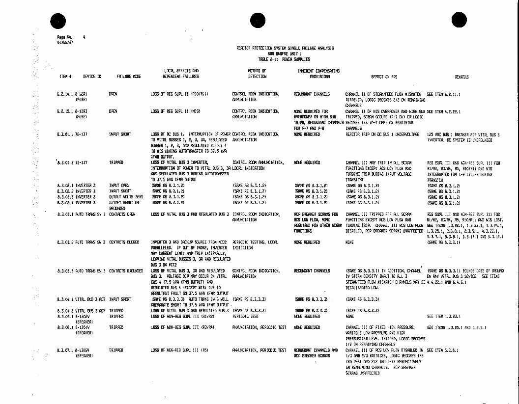
Page No. 4 01/22/87
REACTOR PROTECTION SYSTEM SINGLE FAILURE ANALYSIS SAN ONGFRE UNIT 1
TABLE 8-1: POWER SUPPLIES
LOCAL EFFECTS AND METHOD OF INHERENT COMPENSATINS ITEM I DEVICE ID FAILURE MODE DEPENDENT FAILURES DETECTION PROVISIONS EFFECT ON RPS REMARKS
8.2.14.1 8-12RI OPEN LOSS OF REG SUPL 11 (RIO/RII) CONTROL ROOM INDICATION, REDUNDANT CHANNELS CHNEL 11 OF STEAM/FEED FLOW MISMATCH SEE ITEM 6.2.11.1 (FUSE) ANNUNCIATION DISABLED, LOGIC BECOIES 2/2 ON REMAINING
CHANNELS 8.2. 15.1 8-12R3 OPEN LOSS OF REG SUPL 11 (NIS) CONTROL ROOM INDICATION, NONE REQUIRED FOR CHANNEL 11 OF NIS OVERPOWER AND HIGH SUR SEE ITEM 4.2.22.1
(FUSE) ANNUNCIATION OVERPOWER OR HIGH SUR TRIPPED, SCRAM OCCURS (P-7 ON) OR LOGIC TRIPS, REDUNDANT CHANNELS BECOMES 1/3 (P-7 OFF) ON REMAINING FOR P-7 AND P-I CHAOELS
8.3.01.1 72-137 INPUT SHORT LOSS OF DC BUS 1. INTERRUPTION OF POWER CONTROL ROOM INDICATION, NOPE REQUIRED REACTOR TRIP ON DC BUS 1 NDERVOLTAGE 125 VDC BUS I BREAKER FIR VITAL BUS B TO VITAL BUSSES 1, 2, 3, 3A, REGUATED ANNUNCIATION INVERTER. DC SYSTEM IS UNRUNED BUSSES 1, 21E3, AND RETLATED SUPPLY ST TO 8IS DURING ATTOTRANSFER TO 37.5 TVA XFP(R OUTPUT.
8.3.01.2 72-137 TRIPPED LOSS OF VITAL BUS 3 INVERTER, CONTROL ROOM CLNECIATION, NONE REQUIRED CHANNEL III MY TRIP IN ALL SCRA. REG SUPL III AND NON-EG SUPL III FOR INTERRUPTION OF POWER TO VITAL BUS 3, 3A LOCAL INDICATION FUNCTIONS EXCEPT RCS LOW FLOW AND RI/R2, R3/R4, RAS, RIO/RI) AND NIS AND RE~l-ATED BUS 3 DURING RUTOTRANSFER TURBIPNE TRIP DURING INPUT VOLTAGE INTERRUPTED FOR 1-2 CYCLES DURING TO 37.5 kVA UFMR OUTPUT TRANSIENT TRANSFER
8.3.02.1 INVERTER 3 INPUT OPEN (SAE AS 8.3.1.2) (SAME AS 8.3.1.2) (SAME AS (SAE PS 8.3.1.2) (SAME AG 8.3.02.2 INVERTER 3 INPUT SHORT (SA AS 8.3.1.2) (SAVE AS 8.3.1.2) (ME AS 8.3.1.2) CSABE AS 8.3.1.2) (SAME AS 8.3.1.2) 8.3.02.3 INVERTER 3 OUTPUT VOLTS ZERO (SAMvE AS 8.3.1.2) (SAME AS 8.3.1.2) (SAKE PS 8.3.1.2) (SAME AS 8.3.1.2) (SAME AS 8.3.1.21 8.3.02.4 INVERTER 3 OUTPUT SHORT OR (SAME AS 8.3.1.2) (SAE AS 8.3.1.2) (SAME AS 8.3.1.2) (SAE AS 8.3.1.2) (SAME AS 8.3.1.2)
GROUNDED 8.3.03.1 AUTO TRANS SW 3 CONTACTS OPEN LOSS OF VITAL BUS 3 AND REGULATED BUS 3 CONTROL ROOM INDICATION, RCP BREAKER SCRAMS FOR CHANNEL III TRIPPED FOR ALL SCRAM REG SUPL III AND NON-REG SUP.. III FOR
ANNUNCIATION RCS LOW FLOW, NOWE FUNCTIONS EXCEPT RCS LOW FLOW AND R1/R2, R3/R4, R5, RIO/All AND NIS LOST. REQUIRED FOR OTHER SCRAM4 TURBINE TRIP. CHANNEL III RCS LOW FLOW SEE ITEMS 1.3.22.1, 1.3.23.1, 1.3.24.1, FUNCTIONS DISABLED, RCP BEAKER SCRAMS UNAFFECTED E.3.25.1, 2.3.8.1, 2.3..1, 4.3.22.1,
5.3.7.1, 5.3.8.1, 6.3.1.1 AND 6.3.12.1 8.3.03.2 AUTO TRANS SW 3 CONTACTS CLOSED INVERTER 3 AND BACKUP SOURCE FROM MCC2 PERIODIC TESTING, LOCAL NONE REQUIRED NONE (SAME AS 8.3.3.)
PARALLELED. IF OUT OF PHASE, INVERTER INDICATION MAY CURRENT LIMIT AND(TRIP INTERNALLY, LEAVING VITAL BUSSES 3, 3A AND REGULATED BUS 3 ON MCC2
8.3.03.3 AUTO TRANS SW 3 CONTACTS GROUNDED LOSS OF VITAL BUS 3, 3A AND REGULATED CONTROL RDON INDICATION, REDUNDANT CHANNELS (SAME AS 8. 3.3.1) IN ADDITION, CHANNEL (SAME AS 8.3.3.I) TEUNDS CASE OF GRUND BUS 3. VOLTAGE DIP YAY OCCUR ON VITAL ANNUNCIATION IV STEAM DENSITY INPUT TO ALL 3 ON ANY VITAL BUS 3 DEVICE. SEE ITEMS BUS 4 (7.5 (VA XFMR OUTPUT) AND STEAM/FEED FLOW MISMATC O ANNELS MAY BE 4.4.22. AND 6.4.6.1 REGULATED BUS 4 (EXCEPT VIS) DUE TO DECALIBRATED LOW. RESULTANT FAULT CN 37.5 kVA XFMR OUTPUT
8.3.04.1 VITAL BUS 3 ACE INPUT SHORT (SAT E AS 8.3.3.3) AUTON TRANS SW 3 WILL (SAME AS 8.3.3.3) (SAKE AS 8.3.3.3 ( E AS 8.3.3.3) PROPAGATE SHORT TO 37.5 VVA IFMR OUTPUT
8.3.04.2 VITAL BUS 3 ACB TRIPPED LOSS OF VITAL BUS 3 AND REGULATED BUS 3 (SAME AS 8.3.3.3) (SAME AS 8.3.3.3) (SAME AS 8.3.3.3) 8.3.05.1 8-1303V TRIPPED LOSS OF NON-REG 83 PL III (RI/.2) PERIODIC TEST NONE REQUIRED NOE SEE ITEM 1.3.23.1
(BREAKER) 8.3.06.1 B-1301V TRIPPED LOSS OF NON-REG S P III ER3/R4) ANNUNCIATION, PERIODIC TEST NONE REQUIRED CHANNEL III OF FlIED HIGH PRESSURE, SEE ITEMS (.3.25.1 AND 2.3.9.(
(BREAKER) VARIABLE LOW PRESURE AND HIGH PRESSURIZER LEVEL TRIPPED, LOGIC BECOMES
1/2 ON REMAINING CHANNELS
-13PRTRILLEL ED. IFUT OFI PHRSE ISVRTE INDICATION.
8.3.07.1 8-3V TIPE LOSS OF NONRE PLII(( ANNUNCIATION, PERIODIC TEST REDUNDANT CHANNELS AND) CHANNEL III OF RCS LOW FLOW DISABLED IN SEIE ... (BREAMER) REP BREAKER SCRAMS 1/3 AND 2/3 MATRICES, LOGIC BECOMES 1/2
(NO P-L) AND 2/2 (NO P-73 RESPECTIVELY ON REMAINING CHANNELS. RCP BREAKER SCRAMS UNAFFECTED

Page No. 5 01/22/87
REACTOR PROTECTION SYSTEM SINGLE FAILURE ANALYSIS SAN ON0FRE UNIT 1
TABLE 8-1: POWER SUPPLIES
LOCAL EFFECTS AND METHOD OF INHERENT COMPENSATING ITEM I DEVICE ID FAILURE MODE DEPENDENT FAILURES DETECTION PROVISIONS EFFECT ON RPS REMARKS
8.3.08.1 8-1305V TRIPPED LOSS OF NON-RES SUPL III (RID/RI)) ANNUNCIATION, PERIODIC TEST NONE REOUIRED CHANNEL III OF STEAM/FEED FLOW MISMATCH SEE ITEM 6.3.12.1 (BREAKER) TRIPPED, LOGIC BECOMES 1/2 ON REMAINING
CHANNELS 8.3.03.1 B-1307V TRIPPED LOSS OF REGUL.ATED BUS III (REG SUPL III CONTROL RO1DM INDICATION, REDUN(DANT CHNtS FOR FIXED CHN. III OF FIXED HI PRESS, VAR LOW SEE ITEMS 1.3.22.1, 1.3.24.1, 2.3.8.1,
(BREAKER) TO RI/R2, R3/RA, R5, RIO/RlI1, NIS RACKS) ANNUNCIATION HI PRESSURE, VARIABLE LO PRESS, HI P28 LEVEL AND STM/FEED 4.3.22.1, 5.3.7.1 AND 6.3.11.1 PRESSURE, HlIGH PZ8 LEVEL MISMATCH DISABLED, LOGIC BECOMES 2/2 ON AND STEAM/FEED FLOW REM C)R8.S. CiN.. III OF SEQ 41, NIS MISMATCH. NONE REQUIRED OVRPWR AND BES LO FLOW TRIPPED. SCRAM FOR MTIR SCRAM FUNCTIONS OCCURS (NO P-8I OR LOGIC BECOMES 112,
1/3 AND 1/2 (ND P-7R REEP 8.3.10.1 REGILATOR 3 INPUT OPEN (SAME AS 8.3.9.1) (SAME AS 8.3.9.11 (SAME AS 8.3.9.11 (SAME AS (SANE AS 8.3.9.11
(TWINCO) 8.3.10.2 REGULATOR 3 INPUT SHORT (SAME AS 8.3.9.1) (SAME AS 8.3.9.11 (SAME AS 8.3.9.1) (SAME AS 8.3.9.1) (SAME AS 8.3.9.1)
(TWINCOJ 8.3.10.3 REGULATOR 3 OUTPUT VOLTS ZERO (SAME AS 8.3.9.1) (SAME AS 8. 3.9. 1) (SAME AS 8. 3.9. 1) (SAME AS 8.3.9.1) (SAME AS 8.3.9.1) BOUNDS OUTPUT SHORT
(TWINCO) OR GROUND 8.3.11.1 8-13R2 OPEN LOSS OF REG SUPL III (RI/RE) CONTROL ROOM INDICATION REDUNDANT CHANNELS CHANNEL III OF VARIABLE LOW PRESSURE SEE ITEM 1.3.22.1
(FUSE) DISABLED, LOGIC BECOMES 2/2 ON REMAINING CANNELS. SEQ 38 AND FIXED HIGH PRESSURE SCRAM UNAFFECTED
8.3.12.1 8-13R4 OPEN LOSS OF REG SUPL III (R3/R4) CONTROL BOON INDICATION, REDUNDANT ClHANWLIS CHANNEL III OF FIXED HI1)) PRESSURE AND SEE ITEMS 1.3.24.1 AND 2.3.8.1 (FUSE) ANNUNCIATION HIGH PRESSURIZER LEVEL DISABLED, LOGIC
BECOMES 2/2 ON REMAINING CHANNELS. CHANNEL III OF VARIABLE LOW PRESSURE AND SEQ (1 PZR PRESSURE TRIPPED, LOGIC BECOMES 1/2 ON REMINING CHANNELS
8.3.13.1 8-1386 OPEN LOSS OF BEG SUPL III R5) CONTROL ROOM INDICATION, NONE REQUIRED CHANNEL III OF RCS LOW FLOW TRIPPED, SEE ITE 5.3.7.1 (FUSE) ANNCIATION, PERIODIC TEST SCRAM OCCURS (ND P-8) OR LOGIC BECOMES
1/2 (NO P-7) ON REMAINING CHANNELS 8.3. 14.1 -13R OPEN LOSS OF REQ SUPL III RIO/Il) CONTROL ROOM INDICATION, REDUNDANT CHANNELS CHANNEL III OF STEAM/FEED FLOW MISMATCH SEE ITEM 6.3.11.1
(FUSE) ANNTNCIATION DISABLED, LOGIC BECOMES 2/2 ON REMINING CHANNELS
8.3.15.1 8-1383 OPEN LOSS OF REG SUPL III (NIS) CONTROL ROOM INDICATION, N REQUIRED FOR HIS CHANNEL III OF NIS OVERPOWER AND HIGH SEE ITEM 4.3.22.1 (FUSE) ANNUNCIATION OVERPOWER OR HIGH SUB SUB TRIPPED, SCRAM OCCURS (P- ON) OR
TRIPS, REDUNDANT CHANNELS LOGIC BECOMES 1/3 (P- OFF) ON REMAINING FOR P- AND P-F CHANNELS
8.4.01.1 8-1238 INPUT SHORT LOSS OF MCC2. LOSS OF BACKUP SOURCE CONTROL ROOM INDICATION, REDUNDANT CHANNELS FOR LOSS OF ALL 3 STEAM/FEED FLOW MISMATCH 480 VAC VCC2 BREAKER TO MAN TRALNS SwJ 7. (37.5 kVA XFMR) FOR VITAL BUSSES 1, 2, *ANUNCIATION P-7, P-S DEFEAT. HIGH CHANNELS VIA LOSS OF CMON STEAM BREWKER COORDINATION PREVENTS 3, 3A, AND REGULATED BUS 4 NIS ONLY). PRESSURIZER LEVEL (IF DENSITY INPUT. HIGH SUR SCRAM BYPASS PROPAGATION TO 480 VAC ED.C 2. LOSS OMF NORMAL AND BACRUP SOURCE FOR SEFOINT HAS BEEN REDUCED (UN-P) DEFEATED CAPABILITY FOR AUTOMATIC ROD CONTROL VITAL BUS 4 AND REGULATED BUS 4 (EXCEPT ACCORDINGLY) FOR LOST. SEE ITEMS 4.7.19.1, 6.4.6. AN NIS). LOSS OF ROD CONTROL SYSTEM POWER. STEAM/FEED FLOW MISMATCH 6.4.7.1
8.4.01.2 O-1238 TRIPPED LOSS OF BACKUP SOURCE (37.5 kVA XFMR) CONTROL ROOM INDICATION SAME AS 8.4.1.1 SAME AS 8.4.1.1 CAPABILITY FOR AUTMTIC ROD CONTROL FOR VITAL BUSSES 1, 2, 3, 3A, AND LOST. SEE ITEMS 4.7.19.1, 6.4.6.1 A RENNLATED BUS 4 UNIS ONLY). LOSS OF 6.4.7.1 NOSML AND BACKUP SOURCE FOR VITAL BUS 4 AND REGULATED BUS 4 (EXCEPT NIS). LOSS OF ROD CONTROL SYSTEM POWER.

PaDe No. 6 01/22/87
REACTOR PROTECTION SYSTEM SINGLE FAILURE ANALYSIS SAN ONOFRE UNIT I
TAKE 8-1: POWER SUPPLIES
LOCAL EFFECTS AND METHOD OF INHERENT COMPENSATING ITEM # DEVICE ID FAILURE MDE DEPENDENT FAILURES DETECTION PROVISIONS EFFECT ON RPS REMARKS
8.4.02.1 MAN TRANS SW 7 CONTACTS OPEN (SAME AS 8.4.1.2) (SAME AS 8.4.1.1) (SPIE AS 8.4.1.1) (SAME AS 8.4.1.1) YCCI BREAKER TO MAN TRANS SW 7 IS LOCKED OUT
8.4.02.2 MAN TRANS SW 7 CONTACTS CLOSED (SAME AS 8.4.1.2) (SAME AS 8.4.1.1) (SAME AS (SAME AS 8.4.02.3 MAN TRANS SW 7 CONTACTS GROUNDED (SAME AS 8.4.1.2) (SAME AS 8.4.1.1) (S AS 8.4.1.1) (SAME AS 8.4.1.1) 8.4.03.1 XFMR (7.5 kVA) INPUT OPEN INTERRUPTION OF POWER TO VITAL BUS 4 AND CONTROL ROOM ANNUNCIATION, NOW REQUIRED P-7, P-8 AND HIGH SUR TRIP BYPASS SEE ITEMS 4.7.19.!, 6.4.6.1 AND 6.4.7.1
REGULATED BUS 4 (EXCEPT NIS) DURING LOCAL INDICATION (UN-P7) MAY BE DEFEATED CURING INPUT AUTOTRANSFER TO BACKUP SOURCE (37.5 kWA VOLTAGE TRANSIENT TRANSFORMER)
8.4.03.2 IFMR (7.5 kVA) INPUT SHORT (SWM AS 8.4.3.1) VOLTAGE DIP MAY ALSO (SAME AS B.4.3.1) NONE REQUIRED (SAME AS 8.4.1.1) (SAME AS 8.4.1.1) OCCUR ON 37.5 kVA IFMR UNTIL 7.5 kVA XFMR INPUT FUSE SLOWS
8.4.03.3 IFMR (7.5 kVA) OUTPUT VOLTS HIGH NONE. REGULATOR 4 (7.5 kVA) MAINTAINS PERIODIC TESTING NONE REQUIRED NONE VOLTAGE TO VITAL BUS 4
8.4.03.4 XFMR (7.5 kVA) OUTPUT VOLTS ZERO (SAKE AS 8.4.3.1) (SAME AS 8.4.3.1) (SAME AS 8.4.3.1) (SAME AS 8.4.3.1) (SANE AS 8.4.3.1) BOUNDS OPEN IN REGULATOR 4)f7.5 kVA)
8.4.03.5 XFMR (7.5 kWA) OUTPUT SHORT OR (SAME AS 8.4.3.2) (SANE AS 8.4.3.1) (SAME AS 8.4.3.1) (SANE AS 8.4.3.1) BOUNDS SHORT DR GROUND IN RESULATOR 4 GROUND (7.5 kVA)
8.4.04.1 REGULATOR 4 OUTPUT VOLTS ZERO (SAME AS 8.4.3.1) (SAME AS 8.4.3.1) (SANE AS 8.4.3.1) (SAME AS 8.4.3.1) (SAME AS 8.4.3.11 OPEN SHORT OR GROUND (7.5 kVA) BOUNDED BY 8.4.5.1, B.4.5.2 AND B.4.5.3,
RESPECTIVELY 8.4.05.1 AUTO TRANS SW 4 CONTACTS OPEN LOSS OF VITAL BUS 4 AND REBULATED BUS 4 (SAME AS 8.4.1.2) (SE AS 8.4.1.1) (SANE AS 8.4.1.1) (SAME AS 8.4.3.1)
(EXCEPT NIS) 8.4.05.2 AUTO TRANS SW 4 CONTACTS CLOSED 7.5 kYA AND 37.5 kVA XFMR OUTPUTS CONTROL ROOM INDICATION, NONE REQUIRED NONE (SAME AS 8.4.3.1)
PARALLELED, CAUSING LOSS OF VOLTAGE PERIODIC TESTING REGULATION ON VITAL BUS 4
8.4.05.3 RUTO TRANS SW 4 CONTACTS GROUNDED LOSS OF BACKUP SOURCE (37.5 kVA XFMR) (SAME AS 8.4.1.2) (SAME AS 8.4.1.1) (SANE AS 8.4.1.1) (SANE AS 9.4.1.21 FOR VITAL BUSSES 1,2,3,3A AND REB BUS 4 (NIS ONLY) AND NORMAL AND BACKUP SOURCE
FOR VITAL BUS 4 AND REG BUS 4 (EXCEPT NIS). VOLTAGE DIP MAY ALSO OCCUR ON MAN TRANS SW 7 OUTPUT TO ROD CONTROL UNTIL XFMR FUSE BLOWS
8.4.06.1 VITAL BUS 4 ACB INPUT SHORT (SAME AS 8.4.5.3) AUTO TRANS Sd 4 WILL (SAME AS 8.4.1.2) (SAME AS 8.4.1.1) (SANE AS 8.4.1.1) (SANE AS 8.4.1.2) PROPAGATE SHORT TO 37.5 kWY IFVR OUTPUT
8.4.06.2 VITAL BUS 4 ACB TRIPPED (SAME AS 8.4.5.1) (SAME AS 8.4.1.2) (SANE AS 8.4.1.1) (SAME AS 8.4.1.1) (SANE AS 8.4.1.2) 8.4.07.1 8-1403V TRIPPED LOSS OF NON-REG SUPL IV (81/82) CONTROL ROOM INDICATION, NONE REQUIRED NON LOSS OF RECORDER POWER
(BREAKER) PERIODIC TEST 8.4.08.1 8-1401V TRIPPED LOSS OF NON-REQ SUPL IV (R3/R4) CONTROL ROOM INDICATION, NONE REQUIRED NONE LOSS OF RECORDER POWER
(BREAKER) PERIODIC TEST 8.4.09.1 B-1406V TRIPPED LOSS OF NON-RES SUPL IV (85) ANNUNCIATION NIS O4ANNELS FOR P-7 AND REDUCED REDUNDANCY FOR P-7 AND P-8 SEE ITEX 4.7.19.
(BREAKER) P-8 DEFEAT, NONE FOR DEFEAT. HIGH SUR SCRAM REMAINS OPERABLE UN-Pl DEFEAT (UN-Al CANNOT BE DEFEATED)
8.4.10.1 8-1408V TRIPPED LOSS OF RESULATED BUS 4 (REQ SUPL IV TO CONTROL ROOM INDICATION, HIGH PRESSURIZER LEVEL LOSS OF ALL 3 CHANNELS OF STEAM/FEED SEE ITEM 6.4.6.1 (BREAKER) R1/R2, R3/R4, R5). NIS REG SUPL IV ANNUNCIATION SCRAM IF GETPOINT HAS FLOW M(SKATCH DUE TO LOSS OF COMMON
PRIMARY SOURCE UNAFFECTED. BEEN REDUCED ACCORDINGLY STEAM DENSITY INPUT 8.4.11.1 REGULATOR 4 INPUT OPEN (SAME AS .4.10.1) (SAME AS 8.4.10.1) (SANE AS S.4.10.1) (SAME AS 8.4.10.1) (SAKE AS 8.4.10.11
(TWINCO) 8.4.11.2 REGULATOR 4 INPUT SHORT (SAME AS 8.4.10.11 (A AS 8.4.'10. 1) (SME AS 8.4.10.1) (SANE AS 8.4.10.11 (ME AS 8.4. 10. 1)
(TWINCO)

* 0 0 Page No. 7 01/22/87
REACTOR PROTECTION SYSTEM SINGLE FAILURE ANALYSIS SAN ONDFRE UNIT I
TABLE 8-1: POWER SUPPLIES
LOCAL EFFECTS AND METHOD OF INERENT COMPENSATING ITEM I DEVICE ID FAILURE MODE DEPENDENT FAILURES DETECTION PROVISIONS EFFECT ON RPS REMAiS
8.4.11.3 REGULATOR 4 OUTPUT VOLTS ZERO (SA PS 8.4.10.11 (SAME AS 8.4.10.1) (SAME AS 8.4.10.1 (SAME AS 8.4.10.1 BOUNDS OUTPUT SHORT OR GROUND (TWINCO)
8.4.12.1 8-14R2 OPEN LOSS OF RES SUPL IV (11/R2) CONTROL ROOM INDICATION NONE REQUIRED MINE LOSS OF RECORDER POWER (FUSE)
8.4.13.1 8-14R4 OPEN LOSS OF REQ SUPL IV (R3/R4) CONTROL ROOM INDICATION NONE REQUIRED NONE LOSS OF RECORDER POWER (FUSE)
8.4,14.1 8-1486 OPEN LOSS OF REG SUPL IV (R5) (SAME AS 8.4.10.1) (SAME AS 8.4.10.1) (SAME AS 8.4.10.1) (SAME AS 8.4.10.1) (FUSE)
8.4.15.1 72-133 INPUT SHORT LOSS OF DC BUS 1. INTERRUPTION OF POWER CONTROL ROOM INDICATION, NONE REQUIRED REACTOR TRIP ON DC BUS 1 (NOERVOLTAGE 25 VOC BUS I BREAKER FOR INVERTER 4. DC TO VITAL BUSSES 1, 2, 3, 3A, REGULATED ANNUNCIATION SYSTEM IS UNGROUNDED BUSSES 1, 2, 3 AND REG1LATED SUPPLY 4 TO NIS DURING AUTOTRANSFER TO 37.5 kVA XFMR OUTPUT. REGULATED SUPL IV (RI/R2, R3/R4, 85) UNAFFECTED.
8.4.15.2 72-133 TRIPPED LOSS OF REB SUPL IV (NIS) INVERTER, PERIODIC TEST NDE REQUIRED SCRAM MAY OCCUR ON NIS OVERPOWER (P-7 SEE ITEM 4.4.22.1 INTERRUPTION OF REG SUPL IV (NIS) DURING OFF) OR HIGH SUR (P-7 ON) DUE TO DROP lJTOTRANSFER TO REG BUS 4 (VIA FUSE OUT OF COINCIDENTOR K-RELAYS DURING
8-1483) TRANSFER 8.4.16.1 INVERTER 4 INPUT OPEN (SAME AS 8.4.15.2) (SAME AS 8.4.15.2) (SAME AS 8.4.15.2) (SAME AS 8.4.15.2) (SAME AS 8.4.15.2) 8.4.16.2 INVERTER 4 INPUT SHORT (SAME AS 8.4.15.2) (SAME AS 8.4.15.2) (SAME AS 8.4.15.2) (E AS 8.4.15.2) (SAME AS 8.4.15.2) 1 8.4.16.3 INVERTER 4 OUTPUT VOLTS ZERO (SAME AS 8.4.15.2) (SAME AS 8.4.15.21 (SME AS 8.4.15.2) (SAME AS 8.4.115.2 (SAME AS 8.4.11..2 8.4.16.4 INVERTER 4 OUTPUT SHORT OR (SAME AS 8.4.15.2) (SAME AS 8.4.15.2) (SAME AS 8.4.15.2) (SAME AS 8.4.15.2) (SAME AS 8.4.15.2)
GROUND 8.4.17.1 AUTO TRANS SW 5 CONTACTS OPEN LOSS OF REQ SUPL IV (NIS) (SANE AS 8.4.15.2) (SAME AS 8.4.15.2) (SAME AS 8.4.15.2) (SAME AS 8.4.15.2) 8.4.17.2 AUTO TRANS SW 5 CONTACTS CLOSED INVERTER 4 AND BADUP SOURCE FROM RES (SAME AS 8.4.15.2) (SAME AS 8.4.15.2) (SAM AS 8.4.15.2) FUSE 8-14R3 PROTECTS REG BUS 4 FROM NIB
BUS 4 PARALLELED. IF OUT OF PHASE, SUPPLY FAULTS. SEE ITEM 4.4.22.1 POSSIBLE LOSS OF POWER TO REG SUPL IV (NIS). VOLTAGE DIP MAY OCCUR ON RES BUS 4 UNTIL FUSE 8-14R3 BLOWS.
8.4.17.3 AUTO TRANS SW 5 CONTACTS (ROUNDED LOSS OF REG SUPL IV (NIS) CONTROL ROO INDICATION, NONE REQUIRED SCRAM ON MIS OVERPOWER (P-7 OFF) OR HIS? (SAME AS 8.4.17.2) SEE ITEM 4.4.22.1 ANNUNCIATION SUR (P-7 0.N) DUE TO DROP-OUT OF
COINCIDENTOR K-RELAYS 8.4.18.1 8-14V3 OPEN LOSS OF REQ SUPL IV (NIS) (SAME AS 8.4.17.3) (SAME AS 8.4.17.3) (SAME AS 8.4.17.3) (SAKE AS 8.4.17.3)
(FUSE)

TABLE 8-2: SORT BY RACK POWER SUPPLY
REFERENCES: (SEE TABLES 1 7)
NOTES: a. THIS TABLE IS AN AUTOMATED SORT OF TABLES 1 - 7 FOR RACK POWER SUPPLY DEPENDENCY, PREPARED TO FACILITATE DEVELOPMENT AND REVIEW OF TABLE 8-1.

Page 40. 1 01/22/87
REACTOR PROTECTION SYSTEM SINGLE FAILURE ANALYSIS SAN ON0FRE UNIT 1
TABLE 8-2: SORT BY RACK POWER SUPPLY
LOCAL EFFECTS AND METHOD OF INHERENT COMPENSATING ITEM i DEVICE ID FAILURE MODE DEPENDENT FAILURES DETECTION PROVISIONS EFFECT ON RPS REMARKS
1.1.23.1 NON-REG SUPL I VOLTS ZERO OR LOSS OF CHANNEL I (LOOP A) T NONE REQUIRED NONE (RI/R2) GROUNDED DELTA-T ANNUNCIATION
6.1.12.1 NON-REG SUPL I VOLTS ZERO OR AEL I STEAM/FEED FLOW MISMATCH TRIP ANNCIATION NOE REQUIRED (SAME AS .RELAY IS DE-ENERGIZE TO TRIP (R1O/RII) GROUNDED RELAY BE-ENERGIZER
2.1.9.1 NON-REG SJPL I VOLTS ZERO OR CHANEL I TRIP RELAY AD PRESSURIZER ANNUNCIATION, PERIODIC TESTING (SAME AS 2.1.1.1) (SAME AS 2.1.1.11 TRIP RELAY IS DE-ENEROIZE TO ATTUATE (R3/R4) GROUNDED HEATER HI/LO LEVEL BREAKER ACTUATED
1.1.25.1 NON-RES SUPL I VOLTS ZERO OR CANL I FIXED HIGH PRESSURE AN ANNUNCIATION, PERIODIC TESTING NONE REQUIRED CHANNEL I OF FIXED HIGH PRESSURE AND RELAYS ARE BE-ENEROIZE TO ACTUATE (R3/R4) GROUNDED VARIABLE LOW PRESSURE TRIP RELAYS VARIABLE LOW PRESSURE TRIPPED, LOGIC
ACTUATED BECOMES 1/2 ON REMAINING CHANNELS 5.1.8.1 NON-REG SUPL I VOLTS ZERO OR (SAME AS 5.1..2 AND 5.1.6.2) ANNUNCIATION, PERIODIC TESTING (SAME AS 5.1.5.2) CHANNE 1 1/3 AND 2/3 LOW FLOW TRIPS (SAME AS 5.1.1.1) TRIP RELAYS ARE
(05) GROUNDED DISABLED, LOGIC BECOMES 1/2 AND 2/2 ENERGIZE TO ACTUATE RESPECTIVELY ON REMAINING CHANNELS (NO P-7 OR P-B), PUMP BREAKER TRIPS UNAFFECTED
1.2.23.1 NON-REG SUPL II VOLTS ZERO DR LOSS OF CHANNEL 1 (LOOP B) T-AVG AND PERIODIC TEST NONE REQUIRED NONE (RI/R1) GROUNDED BELTA-T ANNUNCIATION
6.2.12.1 NON-RES SUPL II VOLTS ZERO OR CHANNEL II OF STEAM/FEED MISMATCH TRIP ANNUNCIATION NONE REQUIRED (SAME AS 6.2.8.1) (R3O/RI) GROUNDED RELAY BE-ENERGIZED
2.29.1 NON-RES SUPL II VOLTS ZERO OR CHANEL 11 TRIP RELAY ACTUATED, LOSS OF ANUNCIATION, PERIODIC TESTING (SAME AS 2.2.1.1) (SAME AS 2.2.1.11 TRIP RELAY IS XE-ENERGIZE TO ACTUATE (R3/R4) GROUNDED CAPABILITY TO ACTUATE PRESSURIZER HEATER
LO-LO CUTOFF 1.2.25.1 NON-REG SUPL II VOLTS ZERO OR CHANNEL II FIXED HIGH PRESSURE AND ANNUNCIATION, PERIODIC TESTING NE REQUIRED CHANNEL 11 OF FIXED HIGH PRESRE AND RELAYS ARE DE-ENERGIZE TO ACTUATE
(R3/R4) GROUNDED VARIABLE LOW PRESSURE TRIP RELAYS VARIABLE LOW PRESURE TRIPPED, LOGIC ACTUATED BECOMES 1/2 ON REMAINING CHANE LS
5.2.8.1 NON-REG SUPL II VOLTS ZERO OR (SAVE AS 5.2.5.2 AND 5.2.6.2) ANNCIATION, PERIODIC TESTING (SAME AS 5.2.5.2) CHANNEL 111/3 AND 2/3 LOW FLOW TRIPS (SAME AS 5.2.1.1) TRIP RELAYS ARE (R/) GROUNDED DISABLED, LOGIC BECOMES 1/2 AND 2/2 ENERGIZE TO ACTUATE
RESPECTIVELY ON REMAINING CHANNELS (NO P-i OR P-B), PUMP BREAKER TRIPS UNAFFECTED
1.3.23.1 NON-RED SUPL III VOLTS ZERO OR LOSS OF CHANNEL III (LOOP C) T-AVG AND PERIODIC TEST NONE REQUIRED NONE (RI/R4) GROUNDED OELTA-T ANNUNCIATION
6.3.12.1 NON-REG SUPL III VOLTS ZERO OR CHANNEL III STEAM/FEED FLOW MISYATCR AM.CIATION NONE REQUIRED CHANNEL III OF STEAM/FEED XISMATC RELAY IS GE-EERGIZE TO TRIP (RI/RI) GROUNDED TRIP RELAY DE-ENERGIZED TRIPPED, LOGIC BECOMES 1/2 ON REMAINING
CHANNELS 2.3.B.1 NON-REB SUPL III VOLTS ZERO OR CHANNEL III TRIP RELAY ACTUATED ANNNCIATION, PERIODIC TESTING (SANE AS 2.3.1.1) (SAME AS 2.3.1.1) TRIP RELAY IS OE-ENERGIZE TO ACTUATE
(R3/R4) GROUNDED 1.3.25.1 NON-REB SUPL Il VOLTS ZERO DR CHANEL Ill FIRED HIGH PRESSURE AND ANNUNCIATION, PERIODIC TESTING NONE REQUIRED CHANNEL III FIXED HIGH PRESSURE AND RELAYS ARE BE-ENERGIZE TO ACTUATE
(R3/R4) GROUNDED VARIABLE LOW PRESSURE TRIP RELAYS VARIABLE LOW PRESSURE TRIPPED, LOGIC ACTUATED BECOMES 1/2 ON REMAINING CHANNELS
5.3.8.1 NON-REG SUPL IVl VOLTS ZERO DR (SAME AS 5.3.5.2 AND 5.3.6.2) ANIATION, PERIODIC TESTING (SAME AS 5.3.5.2) CHANEL 111 1/3 AND 2/3 LOW FLOW TRIPS (SAME AS 5.3.1.1) (RS) GROUNDED DISABLED, LOGIC BECOMES 1/2 AND 2/2
RESPECTIVELY (NO P-7 DR P-8) ON REMAINING CHANNELS, PUMP BREAKER TRIPS UNAFFECTED
6.4.07.1 NCN-REG SUPL IV VOLTS ZERO DR LOSS OF POWER TO RECORDERS YR-456, CONTROL ROOM INDICATION, NONE REQUIRED NONE (RIO/NL) GROUNDED -457, -458) PERIODIC TESTING
4.7.20.1 NON-REG SUP. IV VOLTS ZERO OR GC-415A-R, OC-41SE-X DE-ENERGIZED, ANNUNCIATION NIS C08lIELS FOR P-7, P-8 REDUCED REDUNDANCY FOR P-7, P-8 DEFEAT. STEAM DUMP (TEMPERATURE CONTROL murDE) (RS) GROUNDED CLOSING CONTACTS IN AP4A, APNC (P-il, DEFEAT, NONE REQUIRED FOR HIGH SUR SCRAM REMAINS OPERABLE (UN-P AND ATO ROD CONTROL DISACLET
AND APIRA, APIOC (P-R) CIRCUITS AND UN-P7 DEFEAT DEFEATED, SCRAM CANNOT BE BYPASSED , ALL OPENING IN AP4B, AP4D (UN-Pi) CIRCUITS OTHER SCRAM FUNCTIONS REMAIN OPERABLE AS
REGUIRED

* 0 0 Pace No. 2 01/22/87
REACTOR PROTECTION SYSTEM SINGLE FAILURE ANALYSIS SAN ONOFRE UNIT I
TABLE 8-2; SORT BY RACK POWER SUPPLY
LOCAL EFFECTS AND KETHOD OF INHERENT COMPENSATINB ITEX # DEVICE ID FAILURE MODE DEPENDENT FAILURES DETECTION PROVISIONS EFFECT ON RPS REKARKS
4.1.22.1 REG SUPL I VOLTS ZERO OR LOSS OF POWER TO CHARNEL I (N1208) HIGH CONTROL ROOM INDICATION, (SAME AS 4.1.1.1) (SAME AS 4.1.1.1) (SAME AS 4.1.1.1) (NIS) GROUNDED AND LOW VOLTAGE SUPPLIES ANNUNCIATION
1.1.22.1 REG SUPL I VOLTS ZERO OR (SAME AS 1.1.10.1) (SAME AS 1.1.10.1) (SAME AS 1.1.10.1) (SAME AS 1.1.10.1) (RI/R2) GROUNDED
6.1.11.1 REG SUP. I VOLTS ZERO OR LOSS OF STM GEN A STEAM, FEED AND LEVEL CONTROL ROOM INDICATION, REDUNDANT POWER SUPPLY TO (SAME AS 6.1.7.2) STM GEN A FEEDWATER FLOW (RIO/A1l) GROUNDED SIGNALS AND I OUT OF 2 POWER SUPPLIES TO ANNUNCIATION OPTIMAC COMPUTER, CONTROLLERIVALVE AND NR LEVEL REVERSE
OPTIMAC COMPUTER REDUNDMT CHANNELS ACTING, VALVE FAILS OPEN, BUT HIGH LEVEL TURBINE TRIP DISABLED BY LOSS CF POWER TO NR LEVEL TRIP RELAY
2.1.8.1 REG SUPL I VOLTS ZERO OR (SAME AS 2.1.1.2) LOW SIGNAL TO FC-1112, CONTROL ROOM INDICATION, REDUNDANT CHANNELS (SAVE AS 2.1.1.2) DE-ENERGIZES PRESSURIZER HEATERS AND (R3/R4) GROUNDED LI-419, RECORDER LR-430, TC-419 ANNUNCIATION CAUSES LEVEL INCREASE
1.1.24.1 RED SUPL I VOLTS ZERO OR (SAME AS 1.1.1.2) ANNUNCIATION, CONTROL ROOM REDUNDANT CHANNELS (SAME AS 1.1.1.2) (SAKE AS 1.1.1.2) (R3/14) GROUNDED INDICATION
5.1.7.1 REG SUPL I VOLTS ZERO OR (SAME AS 5.1.1.2) (SAlE AS 5.1.1.2) (SAXE AS 5.1.1.2) (SAKE AS 5.1.1.2) (SAME AS 5.1.1.1) (RS) GROUNDED
4.2.22.1 REG SUPL II VOLTS ZERO OR LOSS OF POWER TO CHANNEL II )N-1203 AND CONTROL ROOM INDICATION, (SAME AS 4.2.1.1) (SAME AS 4.2.1.1) REACTOR TRIP ON (SAME AS 4.2.1.1) (NIS) GROUNDED N-1205) HIGH AND LOW VOLTAGE SUPPLIES, ANNUNCIATION CHANNEL II HISH SUR IF P-7 IS ON
N-1203 COMPENSATION SUPPLY 1.2.22.1 REG SUPL II VOLTS ZERO OR (SAME AS 1.2.10.1) (SAME AS 1.2.10.1) (SAME AS 1.2.10.1) (SA.YE AS 1.2.10.1)
(A1/R2) GROUNDED 6.2.11.1 REG SUPL II VOLTS ZERO OR LOSS OF STM GEN B STEAM, FEED AND LEVEL CONTROL ROOM INDICATION, REDUNDANT POWER SUPPLY TO (SAME AS 6.2.7.2) STM GEN B FEEDWATER FLOW
(RIO/il) GROUNDED SIGNALS AND I DUT OF 2 POWER SUPPLIES TO ANNUNCIATION OPTIMAC COMPUTER, CONTROLLER/VALVE AND NR LEVEL REVERSE OPTIMAC COMPUTER REDUNDANT CHANNELS ACTING, VALVE FAILS OPEN, BUT HIGH LEVEL
TURBINE TRIP DISABLED BY LOSS OF POWER TO NR LEVEL TRIP RELAY
2.2.8.1 RES SUPL II VOLTS ZERO OR (SAME AS 2.2.1.2)'LOW SIGNAL TO RECORDER CONTROL ROOM INDICATION, REDUNDANT CHANNELS (SAME AS 2.2.1.2) KAY DE-ENERGIZE PRESSURI2ER HEATERS AND (R3/R4) GROUNDED TR-405-1 VIA TC-419 ANNUNCIATION CAUSE LEVEL INCREASE IF CONNECTED VIA
L/432 SWITCH 1.2.24.1 RED SUPL II VOLTS ZERO OR (SAME AS 1.2.1.2) ANNUNCIATION, CONTROL ROOM REDUNDANT CHANNELS (SAME AS 1.2.1.2) (SAME AS 1.2.1.2)
(R3/R4) GROUNDED INDICATION 5.2.7.1 RES SUPL II VOLTS ZERO OR (SAME AS 5.2.1.2) (SAME AS 5.2.1.2) (SAME AS 5.2.1.2) (SAME AS 5.2.1.2) (SAME AS 5.2.1.1)
(RS) GROUNDED 4.3.22.1 REG SUPL III VOLTS ZERO OR LOSS OF POWER TO CHANNEL III (N-1204 AND CONTROL ROOM INDICATION, (SAME AS 4.3.1.1) (SAME AS 4.3.1.1) REACTOR TRIP ON (SAME AS 4.3.1.1)
(NIS) GROUNDED N-1207) HIGH AND LOW VOLTAGE SUPPLIES, ANNUNCIATION CHANNEL III HIGH SUR IF P-7 15 ON N-1204 COMPENSATION SUPPLY
1.3.22.1 REG SUPL III VOLTS ZERO OR (SME AS 1.3.10.1) (SAME AS 1.3.10.1) (SAME AS 1.3.10.1) (SAME AS 1.3.10.1) (Ri/R2) GROUNDED
6.3.11.1 REG SUPL. III VOLTS ZERO OR LOSS OF STM GEN C STEAM, FEED AND LEVEL CONTROL ROOM INDICATION, REDUNDANT CHANNELS (SAKE AS 6.3.7.2) STM GEN C FEEDWATER FLEA (RIO/11) GROUNDED SIGNALS ANNUNCIATION CONTROLLER/VALVE AND NR LEVEL REVERSE
ACTING, VALVE FAILS OPEN, BUT HIGH LEVEL TURBINE TRIP DISABLED BY LOSS OF POWER TO NR LEVEL TRIP RELAY
2.3.8.1 RES SUPL III VOLTS ZERO OR (SAME AS 2.3.1.2) CONTROL ROOM INDICATION, REDUNDANT CHANNELS (SAME AS 2.3.1.2) KAY DE-ENERGIZE PRESSURIZER HEATERS AND (R3/R4) GROUNDED ANNUNCIATION CAUSE LEVEL INCREASE IF CONNECTED VIA
L/432 SWITCH 1.3.24.1 RES SUPL III VOLTS ZERO OR (SAKE AS 1.3.1.2) ANNUNCIATION, CONTROL ROOM REDUNDANT CHANNELS (SAME P.S 1.3.1.2) (SAME AS 1.3.1.2)
(R3/R4) GROUNDED INDICATION 5.3.7.1 REG SUPL III VOLTS ZERO OR (SAME AS 5.3.1.2) (SAME AS 5.3.1.2) (SAME AS 5.3.1.2) (SAME AS 5.3.1.2) (SAME AS 5.3.1.1)
(RS) GROUNDED

* 0 Page No. 3 01/22/87
REACTOR PROTECTION SYSTEM SINGLE FAILURE ANALYSIS SAN ONKFRE UNIT I
TABLE 8-2: SORT BY RACK POWER SUPPLY
LOCAL EFFECTS AND METHOD OF INHERENT COMPENSATINS ITE I DEVICE ID FAILURE MODE DEPENDENT FAILURES DETECTION PROVISIONS EFFECT ON RPS REXA45
4.4.22.1 BEG SUPL IV VOLTS ZERO OR LOSS OF POWER TO CHANNEL IV (N-1206) CONTROL ROOM INDICATION, NONE REQUIRED REACTOR TRIP ON 4/4 OVERPOWER (IF P-7 SUPPLY TO N-1206 AND CGINCIDEN70 1213 (NIS) GROUNDED HI6H AND LOW VOLTAGE SUPPLIES AND ALL ANNUNCIATION OFF) OR 2/2 HiGH SUR (IF P-7 ON)
COINCIDENTOR K-RELAYS 6.4.06.1 REG SUPL IV VOLTS ZERO OR (SAME AS 6.4.1.2) (SAME AS 6.4.1.2) (SE AS 6.4.1.2) (SAME AS 6.4.1.2) LOSS OF T-REF (PT-415) RIO ?NME (PT-417)
(0S) GROUNDED SIGNALS TO ROD CONTROL AND SThE DUMP SYSTEMS
4.7.19.1 REG SUPL IV VOLTS ZERO OR (SAME AS 4.7.1.2) (SAME AS 4.7.1.2) (SAME AS 4.7.1.2) (SAME AS 4.7.1.2) STEAN DUMP (TEMPERATURE CONTROL MODE (R5) GROUNDED ONLY) AND ROD INSERTION KAY OCCUR CEJ TO
MISMATCH BETWEEN T-AV6 AND INDICATED T-REF (PT-415) AND DECREASE IN INDICATED MWE (PT-417)
TABLE 9: CONTROL/PROTECTION SYSTEM INTERACTIONS
(MULTIPLE FAILURE ANALYSIS)
REFERENCES: (SEE SECTIONS 1 - 8)
NOTES: e. THIS SECTION EVALUATES THE CAPABILITY OF THE RCPS TO INITIATE A SCRAM IN RESPONSE TO CONTROL SYSTEM TRANSIENTS INITIATED BY A SINGLE RANDOM FAILURE IN THE PROTECTION SYSTEM CONCURRENT WITH AN ADDITIONAL SINGLE RANDOM FAILURE.
b. BECAUSE EVENTS INVOLVING ONLY A SINGLE SCRAM CHANNEL FAILURE ARE NOT LIMITING, ONLY THOSE INITIATING FAILURES WHICH BOTH INITIATE A CONTROL ACTION AND INHIBIT TRIP IN THE ASSOCIATED PROTECTION CHANNEL(S) ARE CONSIDERED. SIMILARLY, ONLY THOSE CONCURRENT FAILURES WHICH DISABLE ONE OR MORE ADDITIONAL SCRAM CHANNELS ARE CONSIDERED.
c. IN SOME CASES, THE LIMITING CHANNEL FAILURE FOR A CONTROL/PROTECTION SYSTEM INTERACTION IS A SPECIFIC ON-SCALE FAILURE HIGH OR LOW (DENOTED BY HIGH* AND LOW*) RATHER THAN AN UNSPECIFIED FAILURE HIGH OR LOW (WHICH INCLUDES OFF-SCALE FAILURES) AS ANALYZED IN SECTIONS 1 - 8.
d. FOR BREVITY, ALL DEVICES IN A GIVEN INSTRUMENT LOOP ARE TREATED AS A SINGLE ENTITY (eg. PT-430 LOOP). THUS, POWER SUPPLY FAILURES ARE EXPLICITLY CONSIDERED ONLY WHERE THEY AFFECT THE ASSOCIATED CONTROL SYSTEMS DIRECTLY.
e. FOR BREVITY, A SPECIFIC COMBINATION OF INITIATING AND CONCURRENT FAILURES IS NOT REPEATED WITH THE FAILURES TRANSPOSED (eg. THE COMBINATION PT-430 LOOP/PT-431 LOOP IS NOT REPEATED AS PT-431 LOOP/PT-430 LOOP).
f. FAILURES OF NON-REGULATED (VITAL BUS) POWER SUPPLIES ARE NOT ADDRESSED BECAUSE THESE RESULT IN DEENERGIZING (TRIPPING) THE SCRAM MATRIX RELAY FOR THE SCRAM FUNCTIONS ASSOCIATED WITH THE CONTROL PERTURBATION.
g. THE TURBINE RUN-BACK HAS BEEN DISABLED.

Page No. 1 01/22/87
REACTOR PROTECTION SYSTEM SINGLE FAILURE ANALYSIS SAN ONOFRE UNIT I
TABLE 9: CONTROL/PROTECTION SYSTEM INTERACTIONS (MULTIPLE FAILURE ANALYSIS)
INITIATING CONCURRENT CONTROL SYSTEM INHERENT COMPENSATING PROTECTION SYSTEM ITEM I FAILURE FAILURE MODE FAILURE FAILURE NODE EFFECTS PROVISIONS EFFECTS REYAMiS
9.1.1.1.01 PT 430 LOOP HIGH* PT 431 LOOP HIGH* PORVS 545, 546, PRESSURIZER SPRAY VALVES SEO #2 LOW P2R PRESSURE 2/3 FIXED HIS PRESSURE, VARIABLE LOW BOUNDED BY LOCA ANALYSES. PT-432 MAY FE PCV 430C, 430H OPEN, CAUSING DECREASE IN SCRAM PRESSURE AND SEQ #1 PZR PRESSURE SUBSTITUTED FOR PT-430 GR PT-431 VIA 5W. RCS PRESSURE CHANNELS DISABLED. SEG #2 UNAFFECTED. P/432
9.1.1.1.02 PT 430 LOOP HIGH* PT 432 LOOP HIGH* PORY 545, PRESSURIZER SPRAY VALVES PCV (SAME AS 9.1.1.1.1) (SAME AS 9.1.1.1.1) (BOUNDED BY 9.1.1.1.1) 430C, 430H OPEN, CAUSING DECREASE IN RCS PRESSURE
9.1.1.1.03 PT 430 LOOP HI6H; SW. PR/430 CONTACTS CLOSED (SAME AS 9.1.1.1.1) (SAME AS 9.1.1.1.1) 3/3 FIXED HIGH PRESSURE, VARIABLE LOW BOUNDED BY LOCA ANALYSES PRESSURE AND SEG #1 PZR PRESSURE CHANNELS DISABLED. SED #2 UNAFFECTED
S.1.1.2.01 PT 431 LOOP HIGH* PT 432 LOOP HIGH; PORV 546 OPENS, CAUSING DECREASE IN RCS (SAME AS 9.1.1.1.1) (SAME AS 9.1.1.1.1) (BOUNDED BY 9.1.1.1.1) PRESSURE
9.1.1.2.02 PT 431 LOOP HIGH* SW. PR/430 CONTACTS CLOSED (SAME AS 9.1.1.1.1) (SAME AS 9.1.1.1.1) (SAME AS 9.1.1.1.3) (SAME AS 9.1.1.1.3) 9.1.2.1.01 PT 430 LOOP LOW* PT 431 LOOP LOW* ALL PRESSURIZER HEATERS ENERGIZED AND PRESSURIZER SAFETY VALVES 2/3 FIXED HIGH PRESSURE, VARIABLE LOW PT-432 MAY EE SUBSTITUTED FOR PT-430 VIA
PZR SPRAY VALVES AND PORVS COMMANDED PRESSURE AND SEQ #1 PZR PRESSURE SW. P/432. EVENT TERMINATED BY 0PERATOR SHUT (BY CHANNEL 1) CHANNELS DISABLED ACTION AFTER 30 KINUTES
9.1.2.1.02 PT 430 LOOP LOW* PT 432 LOOP LOW* (SAME AS 9.1.2.1.1) (SAME AS 9.1.2.1.1) (SAME AS 9.1.2.1.1) EVENT TERMINATED BY OPERATOR ACTION AFTER 30 MINUTES
9.1.2.1.03 PT 430 LOOP LOW* SW. PR/430 CONTACTS CLOSED (SME AS 9.1.2.1.1) (SAME AS 9.1.2.1.1) 3/3 FIXED HIGH PRESSURE, VARIABLE LOW (SAME AS 9.1.2.1.2) PRESSURE AND SEQ 81 PIR PRESSURE CHANNELS DISABLED
9.1.3.1.01 TYI 401A LOW* TYI 411A LOW* CONTROL RODS WITHDRAW DUE TO LOW T-AVG NIS OVERPOWER OR HIGH SUR 2/3 VARIABLE LOW PRESSURE CHANNELS LOOP A AND B T-AVO TO VARIABLE LOW TYI 401B TYI 411B SIGNAL VIA SW. 1 AND TM-405A SCRAMS DISABLED (VIA LOW SETPOINT). NIS SCRAMS PRESSURE SCRAM AND ROD CONTROL VIA SW.
UNAFFECTED 1. ABOVE P-7 POWER, HIGH SUR SCRAM BYPASSED AND VARIABiLE LOW PRESSURE SCRAY ENABLED. EVENT BOUNDED BY ROD WITHDRAWAL ACCIDENT =ROY LOW POWER
9.1.3.1.02 TYI 401A LOW* TYI 421 LOW# (SAME AS 9.1.3.1.1) (SAME AS 9.1.3.1.1) (SAME AS 9.1.3.1.1) LOOP A AND C T-RVG TO VARIABLE LEW TYI 401B TYI 421A PRESSURE SCRAM AND ROD CONTROL VIA S. I
9.1.3.2.01 TYI 411A LOW* TYI 421 LOW* (SAME AS 9.1.3.1.1) (SAME AS 9.1.3.1.1) (SAYE AS 9.1.3.1.1) LOOP 8 AND C T-AV3 TO VARIABLE LOW TYI 4118 TYI 421A I PRESSURE SCRAM AND ROD CONTRO. VIA SW, I
9.1.4.1.01 TYI 401A HIGH* TYI 411A HIGH* CONTROL RODS INSERT DUE TO HIGH T-AV NONE REQUIRED INCREASE IN SETPOINT OF 2/3 VARIABLE LOW EVENT TERMINATED BY OPERATOR ACTION TYI 4010 TYI 411B SIGNAL VIA SW. I A1D1) TM-405A, STEAM DUMP PRESSURE CHANNELS AFTER 30 MINUTES
INHIBITED BY LACN OF CONCURRENT LOAD REJECTION
9.1.4.1.02 TYI 401A HIGH; TYI 421 HIGH* (SAVE AS 9.1.4.1.1) (SAME AS 9.1.4.1.1) (SAME AS 9.1.4.1.1) (SAME AS 9.1.4.1.1) TYI 4010 TYI 421A
9.1.4.2.01 TYI 411A HIGH# TYI 421 HIGH (SAME AS 9.1.4.1.1) (SAME AS 9.1.4.1.1) (SME AS 9.1.4.1.1) (SAE AS 9.1.4.1.1) TYI 4119 TYI 421A
9.2.1.1.01 LT 430 LOOP LOW LT 431 LOOP LOW FCV-1112 OPENS (VIA SIGNAL FROM SW. NONE REQUIRED 2/3 HIGH PRESSURIZER LEVEL CHANNELS LT-432 MAY BE SUBSTITUTED FOR LT-430 OR
L/432), CAUSING INCREASE IN PRESSURIZER DISABLED -431 VIA SW. L/432. EVENT TERAINATED DY LEVEL OPERATOR ACTION AFTER 30 KINUTES BASED
ON UNAFFECTED LEVEL CHANNEL 9.2.1.1.02 LT 430 LOOP LOW LT 432 LOOP LOW (SAFE AS 9.2.1.1.1) (SAKE AS 9.2.1.1.1) (SAME AS 9.2.1.!.1) (SAME AS 9.2.1.1.1) 9.2.1.1.03 LT 430 LOOP LOW SW. LR/430 CONTACTS CLOSED (SAME AS 9.2.1.1.1) PRESSURIZER SAFETY VALVES 3/3 HIGH PRESSURIZER LEVEL CHANNELS (SAXE AS 9.2.1.1.1) HOWEVER, AS NO
DISABLED PRESSURIZER LEVEL CHANNELS REAIN
OPERABLE IN CONTROL G0O, PRESSURIZER MAY G0 SOLID PRIOR TO DISCOVERY, AND MONITORING OF LT-435 AT RVCTE SHUTDOWN PANEL MAY BE REQUIRED FOR EVENT RECOVERY
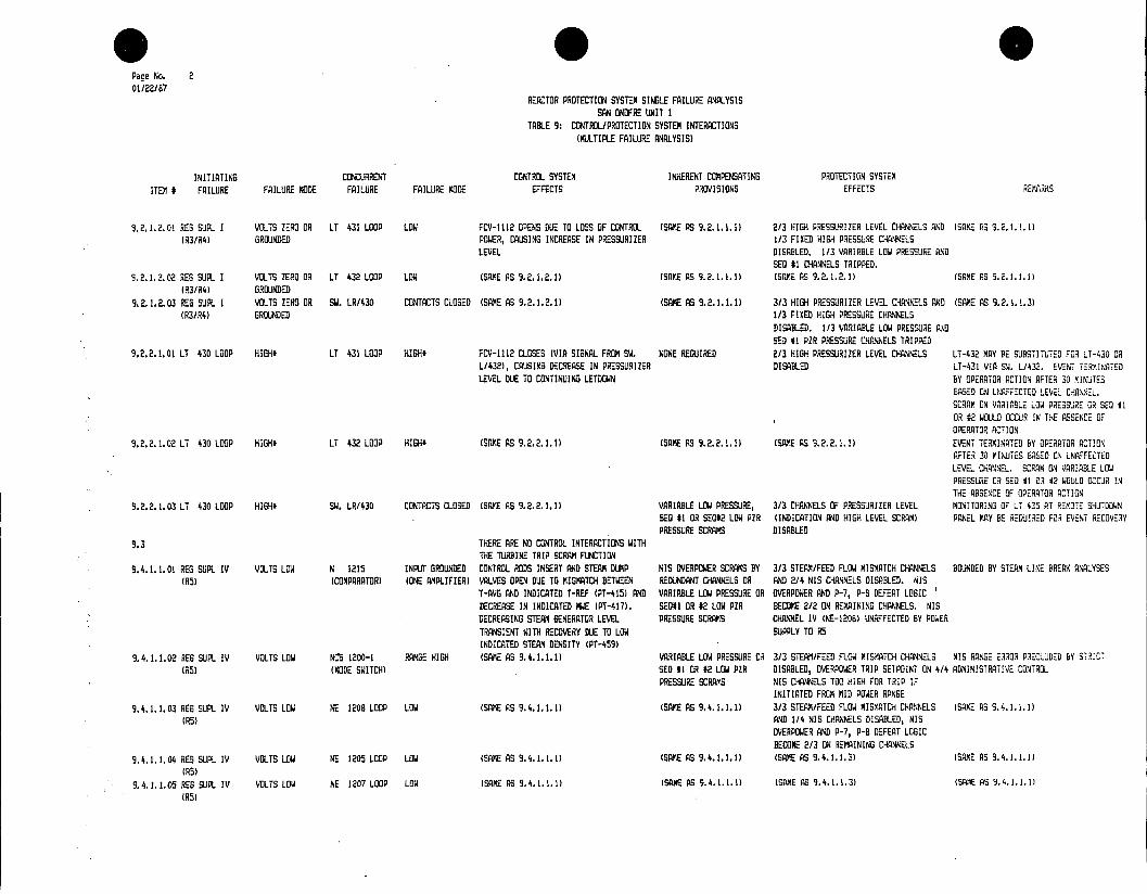
* 0 Pace No. 2 01/22/87
REACTOR PROTECTION SYSTEM SINBLE FAILURE ANALYSIS SAN ONDFRE UNIT I
TABLE 9: CONTROL/PROTECTION SYSTEM INTERACTIONS (MULTIPLE FAILURE ANALYSIS)
INITIATING CONCURRENT CONTROL SYSTEM INHERENT COMPENSATING PROTECTION SYSTEX ITEM # FAILURE FAILURE MODE FAILURE FAILURE MODE EFFECTS PROVISIONS EFFECTS REMARKS
9.2.1.2.01 REG SJPL I VOLTS ZERO OR LT 431 LOOP LOW FCV-1112 OPENS DUE TO LOSS OF CONTROL (SANE AS 9.2.1.1.1) 2/3 HIGH PRESSURIZER LEVEL CHANNELS AND (SAME AS 9.2.1.1.) (R3/I4) GROUNDED POWER, CAUSING INCREASE IN PRESSURIZER 1/3 FIXED HIGH PRESSURE CHANNELS
LEVEL DISABLED. 1/3 VARIABLE LOW PRESSURE AND SED #1 CHANNELS TRIPPED.
5.2.1.2.02 REG SUPL I VOLTS ZERO OR LT 432 LOOP LOW (SANE AS 9.2.1.2.1) (SAVE AS 9.2.1.1.1) (SAE AS 9.2.1.2.1) (SAME AS 9.2.1.1.1) (R3/R4) GROUNDED
9.2.1.2.03 RES SUPL I VOLTS ZERO OR SW. LR/430 CONTACTS CLOSED (SAME AS 9.2.1.2.1) (SANE AS 9.2.1.1.1) 3/3 HIGH PRESSURIZER LEVEL CHANNELS AND (SAME AS 9.2.1.1.3) (R3/R4) GROUNDED 1/3 FIXED HIGH PRESSURE CHANNELS
DISABLED. 1/3 VARIABLE LOW PRESSURE RAD SEQ #1 PZR PRESSURE CHANNELS TRIPPED
9.2.2.1.01 LT 430 LOOP HIGH* LT 431 LOOP HIGH* FCV-1112 CLOSES (VIA SIGNAL FROM SW. NONE REQUIRED 2/3 HIGH PRESSURIZER LEVEL CHANNELS LT-432 MAY BE SUBSTITTED FOR LT-430 OR L/432), CAUSING DECREASE IN PRESSURIZER DISABLED LT-431 VIA SW. L/432. EVENT T:R9INATED LEVEL DUE TO CONTINUING LETDOWN BY OPERATOR ACTION AFTER 30 XINUTES
BASED GN UNAFFECTED LEVEL CHANNEL. SCRAM ON VARIABLE LOW PRESSURE CR SE #1 0R #2 WOULD OCCUR IN THE ABSENCE OF OPERATOR ACTION
9.2.2.1.02 LT 430 LOOP HIGH* LT 432 LOOP HIGH, (SAPE AS 9.2.2. 1.1) (SAME AS 9.2.2.1.1) (SAME AS 9.2.2. 1. 1) EVENT TERMINATED BY OPERATOR ACTION AFTER 30 MINUTES BASED CN UNAFFECTED LEVEL CHANNEL. SCRAM ON VARIABLE LOW PRESSURE OR SEQ l1 0. 42 WOULD OCCUR IN THE ABSENCE OF OPERATOR ACTION
9.2.2.1.03 LT 430 LOOP HIGH* SWI. LR/430 CONTACTS CLOSED (SAME AS 9.2.2.1.1) VARIABLE LOW PRESSURE, 3/3 CHANNELS OF PRESSURIZER LEVEL MONITORING OF LT 425 AT REMOTE SHUTDOWN SEG 11 OR SEQ02 LOW PZR (INDICATION AND HIGH LEVEL SCRAM) PANEL KAY BE REQUIRED FOR EVENT RECOVERY PRESSURE SCRAMS DISABLED
9.3 THERE ARE NO CONTROL INTERACTIONS WITH THE TURBINE TRIP SCRAM FUNCTION
9.4.1.1.01 REG SUPL IV VOLTS LOW N 1215 INPUT GROUNDED CONTROL RODS INSERT AND STEAM DUMP NIS OVERPOWER SCRAMS BY 3/3 STEAM/FEED FLOW MISMATCH CHANNELS BOUNDED BY STEAM LINE BREAK ANALYSES (R5) (COMPARATOR) (ONE AMPLIFIER) VALVES OPEN DUE TO MISMATCH BETWEEN REDUNDANT CHANNELS OR AND 2/4 NIS CHANNELS DISABLED. NIS
T-AVG AND INDICATED T-REF (PT-415) AND VARIABLE LOW PRESSURE OR OVERPOWER AND P-7, P-8 DEFEAT LOGIC DECREASE IN INDICATED MWE (PT-417). SalI OR #2 LOW PZR BECOME 2/2 ON RMAINING CHANNELS. NIS DECREASING STEAM GENERATOR LEVEL PRESSURE SCRAMS CHANNEL IV (NE-1206) UNAFFECTED BY POWER TRANSIENT WITH RECOVERY DUE TO LOW SUPPLY TO A5 INDICATED STEAM DENSITY (PT-459)
9.4.1.1.02 REG SUPL IV VOLTS LOW NCS 1200-1 RANGE HIGH (SAME AS 9.4.1.1.1) VARIABLE LOW PRESSURE OR 3/3 STEAM/FEED FLOW MISMATCH CHANNELS NIS RANGE ERROR PRECLUDED BY STRICT (05) (MODE SWITCH) SEQ #1 OR #2 LOW PZR DISABLED, OVERPOWER TRIP SETPGINT ON 4/4 ADMINISTRATIVE CONTROL
PRESSURE SCRAMS NIS CHANELS TOO HIGH FOR TRIP IF INITIATED FROM MID POWER RANGE
9.4.1.1.03 RES SUPL IV VOLTS LOW NE 1208 LOOP LOW (SANE AS 9.4.1.1.1) (SAKE AS 9.4.1.1.1) 3/3 STEAM/FEED FLOW MISMATCH CHANNELS (SAVE AS 9.4.1.1.1)
(R5) AMD 1/4 NIS CHANNELS DISABLED, NIS OVERPOWER AND P-7, P-B DEFEAT LOGIC BECOME 2/3 ON REMAINING CHANNELS
9.4.1.1.04 REG SUPL IV VOLTS LOW NE 1205 LOOP LOW (SAME AS 9.4.1.1.1) (SAME AS 9.4.1.1.1) (SAME AS 9.4.1.1.3) (SAME AS 9.4.1.1.1) (R5)
9.4.1.1.05 RES SUPL IV VOLTS LOW NE 1207 LOOP LOW (SAME AS 9.4.1.1.1) (SAME AS 9. 4. 1. 1. 1) (SAME AS 9. 4. 1. 1. 3) (SPME AS 9. 4. 1. 1. 1)
CR5)
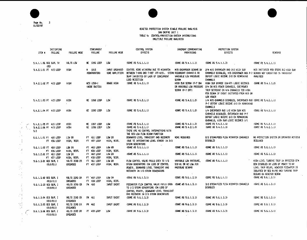
Page No. 3 01/22/87
REACTOR PROTECTION SYSTEM SINGLE FAILURE ANALYSIS SAN ONOFRE UNIT I
TABLE 9: CONTROL/PROTECTION SYSTEM INTERACTIONS (MULTIPLE FAILURE ANALYSIS)
INITIATING CONCURRENT CONTROL SYSTEM INHERENT COMPENSATING PROTECTION SYSTEM ITEM # FAILURE FAILURE MODE FAILURE FAILURE MODE EFFECTS PROVISIONS EFFECTS REMARKS
9.4.1.1.06 REG SUPL IV VOLTS LOW NE 1206 LOOP LOW (SAME AS 9.4.1.1.1) (SARE AS 9.4.1.1.1) (SAME AS 9.4.1.1.3) (SAME AS 9.4.1.1.1) (85)
9.4.2.1.01 PT 415 LOOP HIGH N 1215 INPUT GROUNDED CONTROL RODS WITHDRAW DUE TO MISMATCH NIS OVERPOWER SCRAMS BY 2/4 NIS OVERPOWER AND 2/2 HIGH SUR NIS INITIATED ROD STOPS AND HIGA SUR (COMPARATOR) (ONE AMPLIFIER) BETWEEN T-AVG AND T-REF (PT-415). STEAM REDUNDANT CHANNELS OR CHANNELS DISABLED, NIS OVERPOWER AND P-7 SCRAMS NOT CREDITTED IN TRANSIENT
DUMP INHIBITED BY LACK OF CONCURRENT VARIABLE LOW PRESSURE DEFEAT LOGIC BECOME 2/2 ON REMAINING ANALYSES LOAD REJECTION SCRAM CHANNELS
9.4.2.1.02 PT 415 LOOP HIGH NCS 1200-1 RANGE HIGH (SAME AS 9.4.2.1.1) HIGH SUR SCRAM (P-7 ON) HIGH SUR BYPASS (UN-P7) LOGIC BECOMES (SAME AS 9.4.1.1.2) (MODE SWITCH) OR VARIABLE LOW PRESSURE 2/4 ON NIS POWER CHANNELS, OVERPOWER
SCRAM (P-7 OFF) TRIP SETPOINT ON 4/4 CHANNELS TOO HIGH FOR SCRAM IF EVENT INITIATED FROM MID OR LOW POWER
9.4.2.1.03 PT 415 LOOP HIGH NE 1208 LOOP LOW (SAME AS 9.4.2.1.1) (SAME AS 9.4.2.1.2) 1/4 NIS CHONNLS DISABLED, OVERPOWER AND (SAME AS 9.4.2.1.1) P-7 DEFEAT LOGIC BECOME 2/3 ON REMAINING CHANNES
3.4.2.1.04 PT 415 LOOP HIGH NE 1205 LOOP LOW (SAME AS 9.4.2.1.1) (SAME AS 9.4.2.1.2) 1/4 OVERPOWER AND 1/2 HIGH SUR NIS (SAY.E AS 9.4.2.1.1) CHANNELS DISABLED, OVERPOWER AND P-7 DEFEAT LOGIC BECOME 2/3 ON REMAINING CHANNELS, HIGH SUR LOGIC BECOMES 1/1
9.4.2.1.05 PT 415 LOOP HIGH NE 1207 LOOP LOW (SAE AS 9.4.2.1.1) (SAME AS 9.4.2.1.2) (SAVE AS 9.4.2.1.4) (SAME AS 9.4.2.1.1) 9.4.2.1.06 PT 415 LOOP HIGH NE 1206 LOOP LOW (SAME AS 9.4.2.1.1) (SAME AS 9.4.2.1.2) (SAME AS 9.4.2.1.3) (SAME AS 9.4.2.1.1)
9.5 THERE ARE NO CONTROL INTERACTIONS WITH THE RCS LOW FLOW SCRAM FUNCTION
9.6.1.1.01 FT 460 LOOP LOW OR FT 461 LOOP LOW OR DOWNWARD LEVEL TRANSIENT AND RECOVERY NONE REQUIRED 2/3 STEAM/FEED FLOW MISMATCH CHANNELS NO PROTECTION SYSTEM OR OPERATOR ACTIONS FT 456 LOOP HIGH, RESP. FT 457 LOOP HIGH, RESP. (DUE TO INTEGRATING LEVEL ERROR) IN 2/3 DISABLED REQUIRED
STEAM GENERATORS 9.6.1.1.02 FT 460 LOOP LOW OR FT 462 LOOP LOW OR (SAME AS 9.6.1.1.1) (SAME AS 9.6.1.1.1) (SAME AS 9.6.1.1.1) (SAME AS 9.6.1.1.)
FT 456 LOOP HIGH, RESP. FT 458 LOOP HIGH, RESP. 9.6.1.2.01 FT 461 LOOP LOW 0R FT 462 LOOP LOW OR (SAME AS 9.6.1.1.1) (SAME AS 9.6.1.1.1) (SAME AS 9.6.1.1.1) (SAME AS 9.6.1.1.1)
FT 457 LOOP HIGH, RESP. FT 458 LOOP HIGH, RESP. 9.6.1.3.01 REG SUPL I VOLTS ZERO OR FT 461 LOOP LOW OR FLOW CONTROL VALVE FAILS OPEN TO 1/3 VARIABLE LOW PRESSURE, (SAME AS 9.6.1.1.1) HIGH LEVEL TURBINE TRIP IN AFFECTED STM
(Ri1/Ri1) GROUNDED FT 457 LOOP HIGH, RESP. STEAM GENERATORS (ON LOSS OF CONTROL SEQ I1 OR 12 LOW PIR GEN DISABLED BY LOSS OF POWER TO NR POWER), DOWNWARD LEVEL TRANSIENT AND PRESSURE SCRAMS LEVEL TRIP RELAY, HOWEVER FEEDWATER IS RECOVERY IN 1/3 STEAM GENERATORS ISOLATED BY SES 81/12 AND TURBINE TRIP
OCCURS ON REACTOR SCRAM
9.6.1.3.02 RES SUPL I VOLTS ZERO OR FT 462 LOOP LOW OR (SAXE AS 9.6.1.3.1) (SAME AS 9.6.1.3.1) (SAME AS 9.6.1.1.1) (SAME AS 9.6.1.3.1) (RI/All) GROUNDED FT 458 LOOP HIGH, RESP.
9.6.1.3.03 RED SUPL. I VOLTS ZERO 0. FM 460 INPUT SHORT FEEDWATER FLOW CONTROL VALVE FAILS OPEN (SAME AS 9.6.1.3. 3/3 STEAM/FEED FLOW MISMATCH CHANNELS (SAME AS 9.6.1.3.1) (RIO/il) GROUNDED TO 1/3 STEAM GENERATORS (ON LOSS OF DISABLED
CONTROL POWER), DOWNWARD LEVEL TRANSIENT AND RECOVERY IN 2/3 STEAM GENERATORS
9.6.1.3.04 REG SUP. I VOLTS ZERO OR FM 461 INPUT SHORT (SAME AS 9.6.1.3.3) (SAME AS 9.6.1.3.1) (SAME AS 9.6.1.3.3) (SAME AS 9.6.1.3.1) (RID/Ri) GROUNDED
9.6.1.3.05 REG SUPIL I VOLTS ZERO OR FM 462 INPUT SHORT (SAME AS 9.6.1.3.3) (SAME AS 9.6.1.3.1) (SAME AS 9.6.1.3.3) (SAME AS 9.6.1.3.1) (RIO/i) GROUNDED
9.6.1.106 RES SUPL I VOLTS ZERD OR PT 459 LOOP LOW (SAME AS 9.6.1.3.3) (SAME AS 9.6.1.3.1) (SAME AS 9.6.1.3.3) (SAME AS 9.6.1.3.1) (810/All) GROUNDED

Page No. 4 01/22/87
REACTOR PROTECTION SYSTEM SINGLE FAILURE ANAL..YSIS SAN ONOFRE UNIT I
TABLE 9: CONTROL/PROTECTION SYSTEM INTERACTIONS (MULTIPLE FAILURE ANALYSIS)
INITIATING CONCURRENT CONTROL SYSTEM INHERENT COMPENSATING PROTECTION SYSTEM ITEM # FAILURE FAILURE MODE FAILURE FAILURE MODE EFFECTS PROVISIONS EFFECTS REMARKS
9.6.1.3.07 RES SUPL I VOLTS ZERO OR OPTIMAC OPEN OR GROUND (SAVE AS 9.6.1.3.3) (SAKE AS 9.6.1.3.1) (SAME AS 9.6.1.3.3) (SAFE AS 9.6.1.3.1) (RIO/RIl) GROUNDED THROWOVER
9.6.1.3.08 REG SUPL I VOLTS ZERO OR RES SUPL II VOLTS ZERO OR FEEDWATER FLOW CONTROL VALVES FAIL OPEN (SAME AS 9.6.1.3.1) (SAFE AS 9.6.1.3.3) LOSS OF 3/3 STEAM/FEED FLOW MISMATCH (RI/Rl1) GROUNDED (RIO/RI1) GROUNDED TO 2/3 STEAM GENERATORS (ON LOSS OF CHANNELS VIA LOSS OF POWER TO OPTIN.
CONTROL POWER) HIGH LEVEL TURBINE TRIP IN AFFECTED S/6 DISABLED BY LOSS OF POWER TO NR LEVEL TRIP RELAY, HOWEVER FEEDWATER IS ISOLATED BY SED 81/#2 AND TURBINE TRIP WILL OCCUR ON REACTOR SCRAN
9.6.1.3.09 RES SUPL I VOLTS ZERO OR REG SUPL III VOLTS ZERO OR (SAME AS 9.6.1.3.8) (SAME AS 9.6.1.3.1) (SAME AS 9.6.1.1.1) (SAME AS 9.6.1.3.1) (R1O/R11) GROUNDED (R1O/R1II) GROUNDED
9.6.1.4.01 REG SUP.L II VOLTS ZERO OR FT 460 LOOP LOW OR (SAME AS 9.6.1.3.1) (SAME AS 9.6.1.3.1) (SAME AS 9.6.1.1.1) (SAKE AS 9.6.1.3.1) (RIO/All) GROUNDED FT 456 LOOP HIGH, RESP.
9.6.1.4.02 RES SUPL II VOLTS ZERO OR FT 462 LOOP LOW OR (SAME AS 9.6.1.3.1) (SAME AS 9.6.1.3.1) (SAME AS 9.6.1.1.1) (SAME AS 9.6.1.3.1) (RIO/A1) GROUNDED FT 458 LOOP HIGH, RESP.
9.6.1.4.03 RES SUPL II VOLTS ZERO OR FM 460 INPUT SHORT (SAME AS 9.6.1.3.3) (SAME AS 9.6.1.3.1) (SAME AS 9.6.1.3.3) (SAME AS 9.6.1.3.1) (1O/Rl) GROUNDED
9.6.1.4.04 RES SUPL II VOLTS ZERO OR FM 461 INPUT SHORT (SAME AS 9.6.1.3.3) (SAME AS 9.6.1.3.1) (SAME AS 9.6.1.3.3) (SAME AS 9.6.1.3.1) (RIO/All) GROUNDED
9.6.1.4.05 RES SUPL II VOLTS ZERO OR FM 462 INPUT SHORT (SAME AS 9.6.1.3.3) (SAME AS 9.6.1.3.1) (SAME AS 9.6.1.3.3) (SAME AS 9.6.1.3.1) (RIO/All) GROUNDED
9.6.1.4.06 REG SUPL II VOLTS ZERO OR PT 459 LOOP LOW (SME AS 9.6.1.3.3) (SAME AS 9.6.1.3.1) (SAME AS 9.6.1.3.3) (SAME AS 9.6.1.3.1) (RiO/1l) GROUNDED
9.6.1.4.07 RES SUPL II VOLTS ZERO OR OPTIMAC OPEN OR GROUND (SAME AS 9.6.1.3.3) (SAME AS 9.6.1.3.1) (SANE AS 9.6.1.3.3) (SAME AS 9.6.1.3.1) (R1O/Rh1) GROUNDED THROWOVER
9.6.1.4.08 RES SUPL II VOLTS ZERO OR REG SUPL III VOLTS ZERO OR (SAME AS 9.6.1.3.8) (SAME AS 9.6.1.3.1) (SAME AS 9.6.1.1.1) (SAME AS 9.6.1.3.1) (RIO/All) GROUNDED (RIO/A11) GROUNDED
9.6.1.5.01 FS SUPL III VOLTS ZERO OR FT 460 LOOP LOW 03 (SAKE AS 9.6.1.3.1) (SAME AS 9.6.1.3.1) (SAME AS 9.6.1.1.1) tSAME AS 9.6.1.3.1) (RIO/Al1) GROUNDED FT 456 LOOP HIGH, RESP.
9.6.1.5.02 RES SUPL III VOLTS ZERO OR FT 461 LOOP LOW OR (SAME AS 9.6.1.3.1) (SAME AS 9.6.1.3.1) (SAME AS 9.6.1.1.1) (SAME AS 9.6.1.3.1( (RI/RII) GROUNDED FT 457 LOOP HIGH, RESP.
9.6.1.5.03 REG SUPL III VOLTS ZERO OR FM 460 INPUT SHORT (SAME AS 9.6.1.3.3) (SAME AS 9.6.1.3.1) (SAME AS 9.6.1.3.3) (SAME AS 9.6.1.3.1) (A1O/RI1) GROUNDED
9.6.1.5.04 REG SUPL III VOLTS ZERD OR FM 461 INPUT SHORT (SAME AS 9.6.1.3.3) (SAME AS 9.6.1.3.1) (SAME AS 9.6.1.3.3) (SAME AS 9.6.1.3.1) (RIO/A11) GROUNDED
9.6.1.5.05 RES SUPL III VOLTS ZERO OR FM 462 INPUT SHORT (SAME AS. 9.6.1.3.3) (SAME AS 9.6.1.3.1) (SAME AS 9.6.1.3.3) (SAME AS 9.6.1.3.1) (A1O/Rl1) GROUNDED
9.6.1.5.06 RES SUPL III VOLTS ZERO OR PT 459 LOOP LOW (SAME AS 9.6.1.3.3) (SAME AS 9.6.1.3.1) (SAME AS 9.6.1.3.3) (SAME AS 9.6.1.3.1) (RIO/A1l) GROUNDED
9.6.1.5.07 RES SUPL III VOLTS ZERO OR OPTIMAC OPEN OR GROUND (SAME AS 9.6.1.3.3) (SAME AS 9.6.1.3.1) (SAME AS 9.6.1.3.3) (SAME AS 9.6.1.3.1) (RiO/Ri1) GROUNDED THROWOVER
9.6.1.6.01 PC 418A INPUT SHORT N 1215 INPUT GROUNDED STEAM DUMP VALVES OPEN (PRESSURE CONTROL NIS OVERPOWER SCRAM BY 3/3 STEAM/FEED FLOW MISMATCH, 2/4 NIS BOUNDED BY STEAM LINE BREA) ANALYSES. (COMPARATOR) (ONE AMPLIFIER) MODE ONLY) AND DOWNWARD LEVEL TRANSIENT REDUNDANT CHANNELS OR OVERPOWER AND 2/2 HIGH SUR CHANNELS STEAM DUMP PRESSURE CONTROL MODE
WITH RECOVERY OCCURS IN 3/3 STEAM VARIABLE LOW PRESSURE OR DISABLED. NIS OVERPOWER LOGIC BECOMES APPLICABLE UP TO 20% POWER, WHICH GENERATORS SEQ #1 OR #2 LOW PZR 2/2 ON REMAINING CHANNELS INCLUDES RANGE IN WHICH HIGH SUR SCRAM
PRESSURE SCRAMS MAY 6E BYPASSED

Pace No. 5 01/22/87
REACTOR PROTECTION SYSTEM SINGLE FAILURE ANALYSIS SAN ONOFRE UNIT I
TABLE 9: CONTROL/PROTECTION SYSTEM INTERACTIONS (MULTIPLE FAILURE ANALYSIS)
INITIATING CONCURRENT CONTROL SYSTEM INHERENT COMPENSATING PROTECTION SYSTEM ITEM I FAILURE FAILURE MODE FAILURE FAILURE MODE EFFECTS PROVISIONS EFFECTS REMARKS
9.6.1.6.02 PC 418A INPUT SHORT NCS 1200-1 RANGE HIGH (SAME AS 9.6.1.6.1) VARIABLE LOW PRESSURE OR 3/3 STEAM/FEED FLOW MISMATCH CHANNELS NIS RANSE ERROR PRECLUDED BY STRICT (MODE SWITCH) SEO #1 OR 02 LOW PZR DISABLED. OVERPOWER TRIP SETPOINT ON ADMINISTRATIVE CONTROL
PRESSURE SCRAMS 4/4 NIS CHANNELS TOO HIGH FOR TRIP IF INITIATED FROM MID POWER RANGE
9.6.1.6.03 PC 418A INPUT SHORT NE 1208 LOOP LOW (SAME AS 9.6.1.6.1) (SAKE AS 9.6.1.6.1) 3/3 STEAM/FEED FLOW MISMATCH AND 1/4 NIS CHANNELS DISRBLED, NIS OVERPOWER LOGIC BECOMES 2/3 ON REMAINING CHANNELS
9.6.1.6.04 PC 418A INPUT SHORT NE 1205 LOOP LOW (SAME AS 9.6.1.6.1) (SAME AS 9.6.1.6.1) (SAME AS 9.6.1.6.3) 9.6.1.6.05 PC 418A INPUT SHORT NE 1207 LOOP LOW (SAME AS 9.6.1.6.1) (SAME AS 9.6.1.6.1) (SAME AS 9.6.1.6.3) 9.6.1.6.06 PC 418A INPUT SHORT NE 1206 LOOP LOW (SAKE AS 9.6.1.6.1) (SAME AS 9.6.1.6.1) (SAME AS 9.6.1.6.3) 9.7 THERE ARE NO CONTROL INTERACTIONS WITHIN
THE SCRAM MATRIX, BREAKERS, MANUAL OR RCP BREAKER SCRAMS. DUE TO INTERNAL SEPARATION, FAILURE OF THE SCRAM-INITIATING AUXILIARY CONTACTS IN THE RCP BREAKERS CANNOT CREDIBLY CAUSE A LOSS OF RCS FLOW
9.8. 1.1.01 REG SUS I VOLTS ZERO OR REG SUPL II VOLTS LOW PRESSURIZER HEATERS ENERGIZED, CONTROL SEX #1 OR #2 LOW PZR 2/3 VAR LO PRESS, 1/3 FIXED HI PRESS, HI PROCEDURES REQUIRE MANUAL SCRAM IN GROUNDED (RI/R2) RODS WITHDRAW, FCV-1112 OPENS PRESSURE SCRAMS PZR LEVEL AND STM/FD FLO MISKATCH RESPONSE TO A LOSS OF VITAL OR REGULATED
(INCREASING PRESSURIZER LEVEL) AND DISABLED. 1/3 SED I, RCS LO FLO AND BUS. HI LEVEL TURBINE TRIP IN AFFECTED FEEDWATER FLOW CONTROL VALVE FAILS OPEN 1/4 NIS DVRPWR TRIPPED. SCRAM OCCURS S/B DISABLED BY LOSS OF POWER TO NR TO 1/3 STEAM GENERATORS (P- OFF) OR LOGIC BECOMES 2/2 (PRESS, LEVEL TRIP RELAY, HOWEVER FW ISOLATED BY
LEVEL OR MISMATCH), 1/2 AND 1/4 SEX *1/H2 AND TURBINE TRIP OCCURS ON RESPECTIVELY REACTOR SCRAM
9.8.1.1.02 REG BUS I VOLTS ZERO OR RED SUPL II VOLTS LOW (SAME AS 9.8.1.1.1) VARIABLE LOW PRESSURE 2/3 HI PZR LEVEL, 1/3 FIXED HI PRESS, (SAME AS 9.8.1.1.1) GROUNDED (R3/R4) SCRAM BY REDUNDANT VAR LA PRESS AND STM/FD FLO MISMATCH
CHANNELS OR SEX #1 OR 12 DISABLED. 1/3 SEQ #1, RCS LO FLO AND LOW PZR PRESSURE SCRAMS 1/4 NIS OVRPWR TRIPPED. SCRAM OCCURS
(P-B OFF) OR LOGIC BECOMES 2/2 (PRESS OR MISMATCH), 1/2, 1/2 AND 1/4 RESPECTIVLY
9.8.1.1.03 RED BUS 1 VOLTS ZERO OR REG SUPL Ii VOLTS LOW (SAME AS 9.8.1.1.11 (SAME AS 9.8.1.1.2) 1/3 FIXED HI PRESS, VAR LO PRESS, HI P7R (SAME AS 9.8.1.1.1) GROUNDED (R5) LEVEL AND STM/FD FLO MISYATCH DISABLED.
1/3 SED #1, 2/3 RCS LO FLO AND 1/4 NIS OVRPWR TRIPPED. SCRAM OCCURS (P-7 OFF) OR LOGIC BECOMES 1/2 (EXCEPT NIS) AND 1/3 (NIS)
9.8.1.1.04 REG BUS I VOLTS ZERO OR REG SUPL II VOLTS LOW PRESSURIZER HEATERS ENERGIZED, CONTROL (SME AS 9.8.1.1.2) 3/3 STM/FD MISMATCH, 1/3 FIXED HI PRESS, (SAKE AS 9.8.1.1.1( RESULTS IN LOSS OF GROUNDED (RI/Ill) RODS WITHDRAW, FCV-1112 OPENS VAR LO PRESS AND HI PZR LEVEL DISABLED. 3/3 STEAM/FEED MISMATCH CHANNELS VIA
(INCREASING PRESSURIZER LEVEL), AND 1/3 SEQ #1, RCS LX FLO, 1/4 NIS TRIPPED. LOSS OF POWER TO OPTIMAC FEEDWATER FLOW CONTROL VALVES FAIL OPEN SCRAM OCCURS (P-8 OFF) OR LOGIC BECOMES TO 2/3 STEAM GENERATORS 2/2 (FIXED HI PRESS, VAR LO PRESS, HI
PZR LEVEL), 1/2 (SEX 81, RCS LD FLO), 1/3 (NIS)
9.8.1.1.05 RED BUS I VOLTS ZERO OR REG SUPL II VOLTS LOW (SAME AS 9.8.1.1.1) (SAME AS 9.8.1.1.2) 1/3 FIXED HI PRESS, VAR LO PRESS, HI PIR (SAKE AS 9.8.1.1.1( GROUNDED (NIS) LEVEL AND STM/FD MISMATCH DISABLED. 1/3
SEX #1 AND RCS LO FLO TRIPPED. SCRAM OCCURS ON 2/4 OVERPOWER (P-7 OFF) OR 1/2 HIGH SUR (P-7 ON)

Page No. 6 01/22/87
REACTOR PROTECTION SYSTEM SINGLE FAILURE ANALYSIS SAN ONOFRE UNIT I
TABLE 9: CONTROL/PROTECTION SYSTEM INTERACTIONS (MULTIPLE FAILURE ANALYSIS)
INITIATING CONCURRENT CONTROL SYSTEM INHERENT COMPENSATING PROTECTION SYSTEM ITEM # FAILURE FAILURE MODE FAILURE FAILURE MODE EFFECTS PROVISIONS EFFECTS REMARKS
9.8.1.1.06 RED BUS 1 VOLTS ZERO OR REG SUPL III VOLTS LOW (SAME AS S.8.1.1.1) (SAME AS 9.8.1.1.1) (SAME AS 9.8.1.1. 1 (SAME AS 9.8.1.1.1) GROUNDED (RI/R2)
9.8.1.1.07 REG BUS I VOLTS ZERO OR REG SUPL III VOLTS LOW (SME AS 9.8.1.1.1) (SAME AS 9.8.1.1.2) (SAME AS 9.8.1.1.2) (SAME AS 9.8.1.1.1) GROUNDED (R3/R4)
9.8.1.1.08 RED BUS 1 VOLTS ZERO OR REG SUPLI IlI VOLTS LOW (SAME AS 9.8.1.1.1) (SAME AS 9.8.1.1.2) (SAME AS 9.8.1.1.3) (SAME AS 9.8.1.1.1) GROUNDED (R5)
9.8. 1.1.09 RED BUS I VOLTS ZERO OR RED SUPL III VOLTS LOW (SAME AS 9.8.1.1.4) (SAME AS 9.8.1.1.2) 2/3 STM/FD MISMATCH, 1/3 FIXED HI PRESS, (SAME AS 9.8.1.1.1) GROUNDED (RIO/All) VAR LO PRESS, HI PZR LEVEL DISABLED.
1/3 SEQ #I, RCS LD FLO, 1/4 NIS TRIPPED. SCRAM OCCURS (P-8 OFF) OR LOGIC BECOMES 2/2 (FIXED HI PRESS, VAR LO PRESS, HI PZR LEVEL), 1/2 (SEQ #1, RCS LO FLO) AND 1/3 (NIS)
9.8.1.1.10 RED BUS I VOLTS ZERO OR RED SUPL III VOLTS LOW (SAME AS 9.8.1.1.1) (SAME AS 9.8.1.1.2) (SAME AS 9.8.1.1.5) (SAKE AS 9.8.1.1.1) GROUNDED (NIS)
9.8.1.1.11 REG BUS 1 VOLTS ZERO OR RED SUPL IV VOLTS LOW PRESSURIZER HEATERS ENERGIZED, CONTROL (SAME AS 9.8.1.1.2) 3/3 STEAM/FEEDWATER FLOW MISMATCH AND (SAME AS 9.8.1.1.1) GROUNDED (A5) RODS WITHDRAW, FCV-1112 OPENS 1/3 VAR LO PRESS CHANNELS DISABLED. 1/4
(INCREASING PZR LEVEL), STEAM DUMP NIS CHANNELS TRIPPED, LOGIC BECOMES 2/2 VALVES OPEN, FEEDWATER FLOW CONTROL FOR VAR LU PRESS, 1/3 FOR OVERPOWER VALVE FAILS OPEN TO 1/3 STM DEN AND SCRAM AND 2/3 FOR P-7 AND P-8 DEFEAT ON DOWNWARD LEVEL TRANSIENT WITH RECOVERY REMAINING CHANNELS OCCURS IN 2/3 STM GEN
9.8.1.1.12 RED BUS I VOLTS ZERO OR RES BUS 4 VOLTS LOW (SAME AS 9.8.1.1.11) (SAME AS 9.8.1.1.2) (SAME AS 9.8.1.1.11) (SAME AS 9.8.1.1.1) GROUNDED (EXCEPT NIS)
9.8.1.2.01 RED BUS 2 VOLTS ZERO OR REG SUPL I VOLTS LOW (SAME AS 9.8.1.1.1) (SAME AS 9.8.1.1.1) (SAME AS 9.8.1.1.1) (SAME AS 9.8.1.1.1) GROUNDED (RI/R2)
9.8.1.2.02 RE BUS 2 VOLTS ZERO OR RED SUPL I VOLTS LOW (SAME AS 9.8.1.1.1) (SAME AS 9.8.1.1.2) (SAME AS 9.8.1.1.2) (SAME AS 9.8.1.1.1) GROUNDED (R3/R4)
9.8.1.2.03 RED BUS 2 VOLTS ZERO OR RED SUPL I VOLTS LOW (SAME AS 9.8.1.1.1) (SAME AS 9.8.1.1.2) (SAME AS 9.8.1.1.3) (SAME AS 9.8.1.1.1) GROUNDED (R5)
9.8.1.2.04 RED BUS 2 VOLTS ZERO OR REG SUPL I VOLTS LOW (SAME AS 9.8.1.1.4) (SAME AS 9.8.1.1.2) (SAME AS 9.8.1.1.4) (SAME AS 9.8.1.1.4) GROUNDED (RIO/RI)
9.8.1.2.05 RED BUS 2 VOLTS ZERO OR RED SUPL I VOLTS LOW (SAME AS 9.8.1.1.1) (SAME AS 9.8.1.1.2) (SAME AS 9.8.1.1.5) (SAME AS 9.8.1.1.1) GROUNDED (NIS)
9.8.1.2.06 RED BUS 2 VOLTS ZERO OR RED SUPL III VOLTS LOW (SAME AS 9.8.1.1.1) (SAME AS 9.8.1.1.1) (SAME AS 9.8.1.1.1) (SAME AS 9.8.1.1.1) GROUNDED (RI/R2)
9.8.1.2.07 REG BUS 2 VOLTS ZERO OR RED SUPL III VOLTS LOW (SAME AS 9.8.1.1.1) (SAME AS 9.8.1.1.2) (SAME AS 9.8.1.1.2) (SAME AS 9.8.1.1.1) GROUNDED (R3/R4)
9.8.1.2.08 RED BUS 2 VOLTS ZERO OR RED SUPL III VOLTS LOW (SAME AS 9.8.1.1.1) (SAME AS 9.8.1.1.2) (SAME AS 9.8.1.1.3) (SAE AS 9.8.1.1.1) GROUNDED (R5)
9.8.1.2.09 RED BUS 2 VOLTS ZERO OR RED SUPL III VOLTS LOW (SAME AS 9.8.1.1.4) (SAME AS 9.8.1.1.2) (SAME AS 9.8.1.1.9) (SAME AS 9.8.1.1.1) GROUNDED (RIO/RII)
9.8.1.2.10 RED BUS 2 VOLTS ZERO OR RED SUPL III VOLTS LOW (SAME AS 9.8.1.1.1) (SAME AS 9.8.1.1.21 (SAME AS 9.8.1.1.5) (SAME AS 9.8.1.1.1) GROUNDED (NIS)
9.8.1.2.11 RED BUS 2 VOLTS ZERO OR RED SUPL IV VOLTS LOW (SAME AS 9.8.1.1.11) (SAME AS 9.8.1.1.2) (SAME AS 9.8.1.1.11) (SAME As 9.8.1.1.1) GROUNDED (RS)
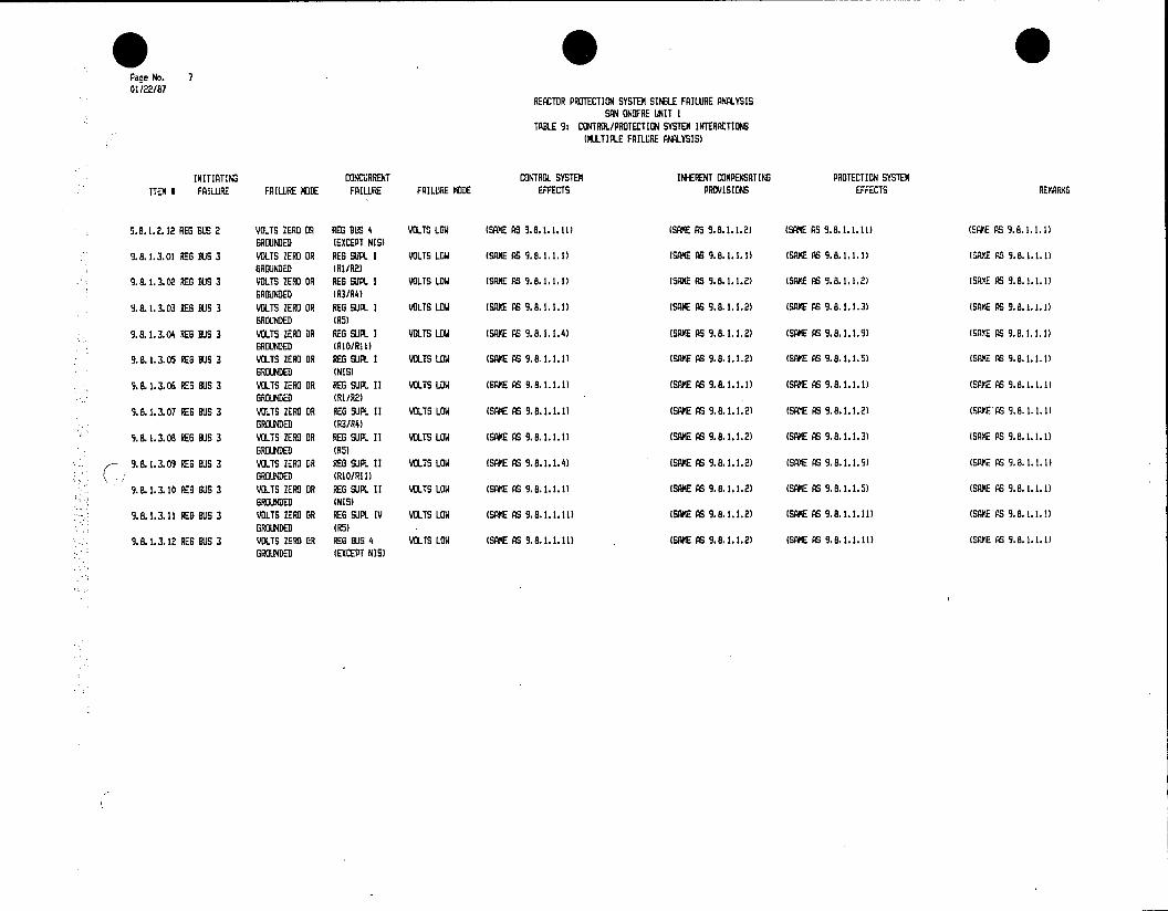
*0 00 Page No. 7 01/22/87
REACTOR PROTECTION SYSTEM SINGLE FAILURE ANALYSIS SAN ONOFRE UNIT I
TABLE 9: CONTROL/PROTECTION SYSTEM INTERACTIONS (MULTIPLE FAILURE ANALYSIS)
INITIATING CONCURRENT CONTROL SYSTEM INHERENT COMPENSATING PROTECTION SYSTEM ITEM I FAILURE FAILURE MODE FAILURE FAILURE MODE EFFECTS PROVISIONS EFFECTS RErARKS
9.8.1.2.12 REG BUS 2 VOLTS ZERO OR REG BUS 4 VOLTS LOW (SAME AS 9.8.1.1.11) (SAME AS 9.8.1.1.2) (SAME AS .8.1.1.11) (SAME AS 9.a.1.1.1) GROUNDED (EXCEPT NIS)
9.8.1.3.01 RES BUS 3 VOLTS ZERO OR REG SUPL I VOLTS LOW (SAME AS 9.8.1.1.1) (SAME AS 9.8.1.1.1) (SAME AS 9.6.1.1.1) (SAME AS 9.8.1.1.1) GROUNDED (RI/R2)
9.8.1.3.02 REG BUS 3 VOLTS ZERO OR REG SUPL I VOLTS LOW (SAME AS 9.8.1.1.1) (SAME AS 9.8.1.1.2) (SAME AS 9.8.1.1.2) (SAME AS 9.8.1.1.1) GROUNDED (R3/R4)
9.8.1.3.03 RES BIS 3 VOLTS ZERO OR ES SUPL I VOLTS LOW (SME AS 9.8.1.1.1) (SAME AS 9.8.1.1.2) (SAME AS 9.8.1.1.3) (SAME AS 9.8.1.1.1) GROUNDED (R5)
9.8.1.3.04 ES BUS 3 VOLTS ZERO OR RES SUPL I VOLTS LOW (SAME AS 9.8.1.1.4) (SME AS 9.8.1.1.2) (SAME AS 9.8.1.1.9) (SANE AS 9.8.1.1.1) GROUNDED (RIO/R11)
9.8.1.3.05 RES BUS 3 VOLTS ZERO OR RES SUPL I VOLTS LOW (SAME AS 9.8.1.1.1) (SANE AS 9.8.1.1.2) (SAKE AS 9.8.1.1.5) (SAME AS 9.8.1.1.1) GROUNDED (NIS)
9.8.1.3.06 RES BUS 3 VOLTS ZERO OR RES SUPL 11 VOLTS LOW (SAME AS 9.8.1.1.1) (SAME AS 9.8.1.1.1) (SAME AS 9.8.1.1.1) (SAME AS 9.8.1.1.1) GROUNDED (R1/R2)
9.8.1.3.07 EG BUS 3 VOLTS ZERO O RES SJPL 11 VOLTS LOW (SAME AS 9.8.1.1.1) (SAME AS 9.8.1.1.2) (SAME AS 9.8.1.1.2) (SAEAS 9.8.1.1.1) GROUNDED (R3/R4)
9.8.1.3.08 RE BUS 3 VOLTS ZERO OR REG SUL II VOLTS LOW (SAME AS 9.8.1.1.1) (SAME AS 9.8.1.1.2) (SAME AS 9.8.1.1.3) (SAME AS 9.8.1.1.1) GROUNDED (R5)
9.8.1.3.09 RES BUS 3 VOLTS ZERO OR REG SUPL II VOLTS LOW (SAME AS 9.8.1.1.4) (SAME AS 9.8.1.1.2) (SAME AS 9.8.1.1.9) (SAE AS 9.8.1.1.1) GROUNDED (RIO/RI11
9.8.1.3.10 REG BUS 3 VOLTS ZERO OR REG SUPL II VOLTS LOW (SAME AS 9.8.1.1.1) (SAME AS 9.8.1.1.2) (SAME AS 9.8.1.1.5) (SAME AS 9.8.1.1.1) GROUNDED (NIS)
9.8.1.3.11 RES BUS 3 VOLTS ZERO OR REG SUPL IV VOLTS LOW (SAME AS 9.8.1.1.11) (SAME AS 9.8.1.1.2) (SAME AS 9.8.1.1.11) (SANE AS 9.8.1.1.!) GROUNDED (R5)
9.8.1.3.12 REG BUS 3 VOLTS ZERO OR REG BUS 4 VOLTS LOW (SAME AS 9.8.1.1.11) (SAME AS 9.8.1.1.2) (SAME AS 9.8.1.1.11) (SAME AS 9.8.1.1.1) GROUNDED (EXCEPT NIS)
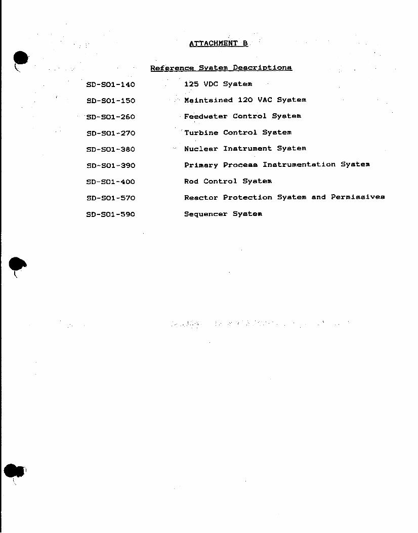
ATTACHMENT B
Reference System Descriptions
SD-SO1-140 1225 VDC System
SD-SO1-150 Maintained 120 VAC System
SD-SO1-260 Feedwater Control System
SD-SO1-270 Turbine Control System
SD-SO1-380 Nuclear Instrument System
SD-SOl-390 Primary Process Instrumentation System
SD-SO1-400 Rod Control System
SD-SO1-570 Reactor Protection System and Permissives
SD-SOl-590 Sequencer System

NUCLEAR GENERATION SITE SYSTEM DESCRIPTION SD-SOI-140 UNIT 1. REVISION 0 PAGE 16 OF 29
125 VDC SYSTEM
2.0 DESCRIPTION (Continued)
2.2.12 Inverter for Security (UPS)
INVERTER FOR UPS TO SECURITY
1 TYPE: Silicon Controlled Rectifier
1 LOCATION: South of Main Generator Exciter
I OUTPUT: 10 CFR 2.790 Material - withhold from public disclosure
The inverter provides power for operation of the Security system. The normal source of power to the inverter is the DC feed from the battery charger.
In the event that the inverter is unavailable for service the Security system can be supplied from MCC 3 by operating the charger manual bypass switch.
The inverter consists of 3 SCR inverters which provide 3 phase power to operate the Security system.. AC output from the inverter is supplied via circuit breaker CB2.
Local indication of the inverter is as follows:
* AC amps, 0-200
* AC volts, 0-150
2.2.13 Circuit Breakers
Locally operated circuit breakers with rating from 20 to 1600 amps are used in the four DC systems.
The distribution circuit breaker in each system are toggle switches with thermal magnetic trips.
The 125 VDC System No. 1 uses four Westinghouse 1600 amp type 0850 ACBs. The breakers are:
* 72-141, Control Rods Mechanism
* 72-142, Battery Charger B
* 72-143, Battery Charger A
* 72-144, Battery No. 1

NUCLEAR GENERATION SITE SYSTEM DESCRIPTION SD-SO1-140 UNIT I REVISION 0 PAGE-17 OF 29
125 VOC SYSTEM
2.0 DESCRIPTION (Continued)
2.2.13 Circuit Breakers (Continued)
These breakers have overcurrent trips. Overcurrent trips alarms are also installed however, they are not connected to an annunciator.
The 125 VOC System No. 1 uses one 600 amp and five 400 amp Westinghouse type DB25 DE ION Circuit Breakers with Tri Pacs. The circuit breakers have Struther-Dunn relays for undervoltage trip alarms. The breakers are:
* 72-140, Lighting Switchboard (600 amp)
* 72-135, Inverter No. 1
* 72-136, Inverter No. 2
* 72-137, Inverter No. 3
* 72-138, Seal Oil Emergency Oil Pump
* 72-139, Bearing Emergency Oil Pump
The 125 VOC System No. 1 also uses 100 amp ACBs. The breakers are provided with Struther-Dunn relays for undervoltage trip alarms. The breakers are:
* 72-101, Reheater Steam Dump Control
* 72-102, Annunciator Turbine Plant
* 72-103, 4160 Switchboard Bus 1A, IC and 1B
* 72-104, Annunciator Reactor Plant
* 72-105, Diesel Gen. 1 Exciter Field Flashing
* 72-106, Area Load Frequency Control
* 72-107, 480 V ACB and 4160V ACB Test Panel
* 72-108, Gen. and Transf. Relay Bus
* 72-109, Hydrogen Control Panel
* 72-110, Oscillograph
* 72-111, Turbine Control
* 72-112, 480V Switchgear No. I

NUCLEAR GENERATION SITE SYSTEM DESCRIPTION SD-SO1-140 UNIT 1 REVISION 0 PAGE 18 OF 29
125 VDC SYSTEM
2.0 DESCRIPTION (Continued)
2.2.13 Circuit Breakers (Continued)
* 72-113, Turbine Protection
* 72-114, Emerg. Gen. No. I Fuel Oil Standby Pump
* 72-115, Generator Field Control
* 72-116, 480V Switchgear No.3
* 72-117, D.G. Bldg. South Room Emerg. Lighting
* 72-118, SIS/LOP L.O. Relays
* 72-119, D.G. No. 1, SPG-1/MCR and ELP-1 Right Feed
* 72-120, RCP Thermal Barrier Pump
* .72-121, Chemical Control Board
* 72-122, SV600, CV537, CV533
* 72-123, Sphere Isolation Valve
* 72-124, Sequencer System 1
* 72-125, Portable Exciter Control
* 72-126, D.G. No. 1, ELP-1 Left Feed, GLP-1
* 72-127, Heating and Vent Control Board
* 72-128, Steam Dump Control
* 72-129, Radwaste Control Board Annunicator
* 72-130, HV851B, HV852B, HV853B, HV854B, MOV850B and Misc. Valve Control
* 72-132, Gen. Bus Disconnect Switch
* 72-133, Inverter No. 4
The 125 VDC System No. 2 uses an 800 amp "Square 0" ACB from the Battery No. 2 to the DC Bus No. 2. The Battery Chargers C & D use a 300 amp "Square D" ACBs to the DC Bus No. 2. The breakers are:
* 72-201, Battery No. 2
* 72-202, Battery Charger C
* 72-203, Battery Charger 0
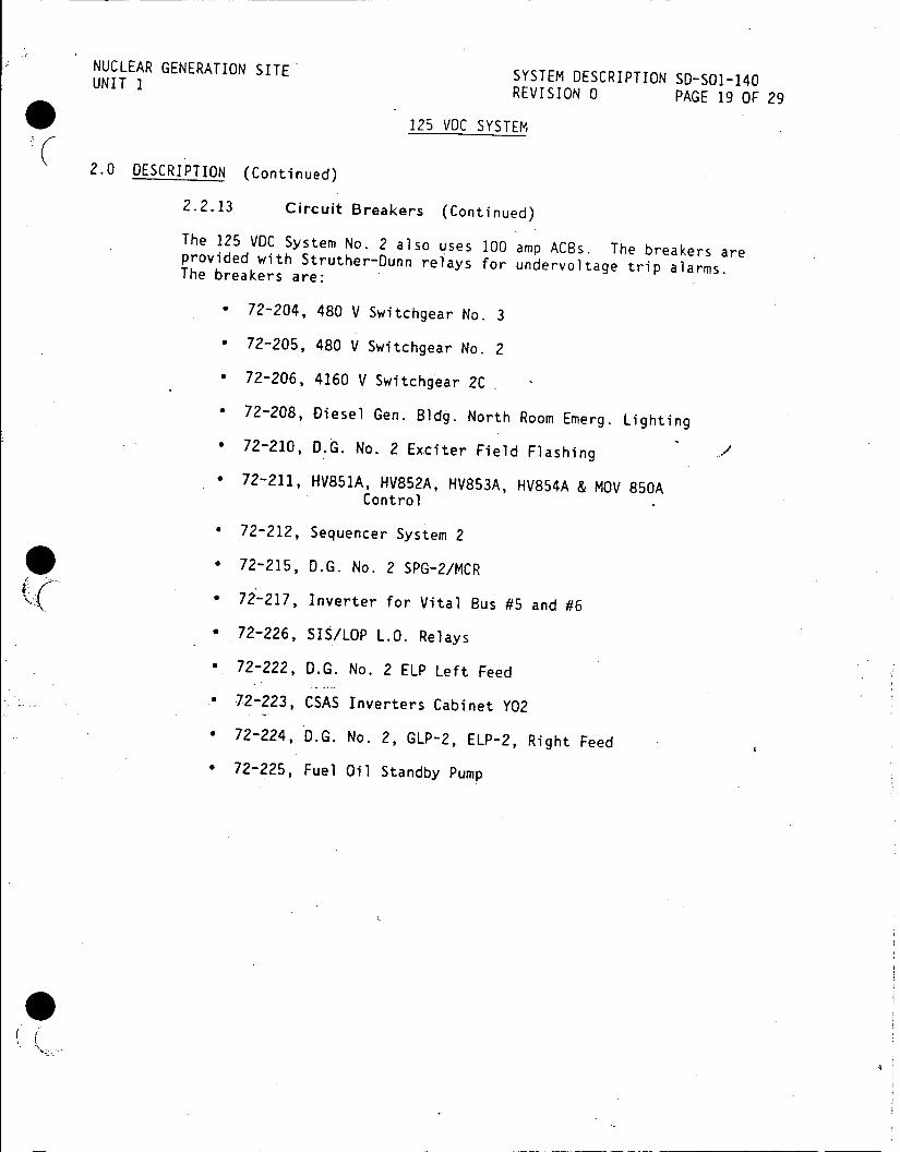
NUCLEAR GENERATION SITE SYSTEM DESCRIPTION SD-SOI-140 UNIT 1 REVISION 0 PAGE 19 OF 29
125 VDC SYSTEM
2.0 DESCRIPTION (Continued)
2.2.13 Circuit Breakers (Continued)
The 125 VOC System No. 2 also uses 100 amp ACBs. The breakers are provided with Struther-Dunn relays for undervoltage trip alarms. The breakers are:
* 72-204, 480 V Switchgear No. 3
* 72-205, 480 V Switchgear No. 2
* 72-206, 4160 V Switchgear 2C
* 72-208, Diesel Gen. Bldg. North Room Emerg. Lighting * 72-210, D.G. No. 2 Exciter Field Flashing
* 72-211, HV851A, HV852A, HV853A, HV854A & MOV 850A Control
* 72-212, Sequencer System 2
* 72-215, D.G. No. 2 SPG-2/MCR
* 72-217, Inverter for Vital Bus #5 and #6
* 72-226, SIS/LOP L.O. Relays
* 72-222, D.G. No. 2 ELP Left Feed
* 72-223, CSAS Inverters Cabinet Y02
* 72-224, D.G. No. 2, GLP-2, ELP-2, Right Feed
* 72-225, Fuel Oil Standby Pump
(Ill

NUCLEAR GENERATION SITE SYSTEM DESCRIPTION S0-S01-140 UNIT 1 REVISION 0 PAGE 20 OF 29
125 VDC SYSTEM
3.0 OPERATION
3.1 125 VOC System No. 1 and No. 2
The 125 VDC systems No. 1 and No. 2 are normally floating systems. The positive and negatives buses are insulated from ground. Voltage from each bus to ground will be one half the voltage from bus to bus (one half the voltage is 65 VDC).
The systems can be grounded either positive or negative bus without affecting the operation of the power supply. If however, another ground is applied to the opposite bus the system functions could be affected. If a ground occurs on a DC system, it is prudent to .locate the ground and restore the system to its floating condition.
If a ground occurs on the DC system the voltmeters on the system will show an imbalance between voltages from positive to ground and from negative to ground. The difference between the two voltages divided by the bus to bus voltage equals the percent ground on the system. The ground is located on the bus with the lower voltage measured to ground. At 10% ground an annunciator will be initiated.
System Bus Annunciator
125 VDC No. 1 DG No. 1 Window 44 "DC Bus #1 Ground"
125 VDC No. 2 DG No. 2 Window "DC Bus #2 Ground"
To locate a ground on the DC system it is necessary to isolate the. circuit with the grounded component. This is accomplished by opening the main DC distribution panel switches to determine which is affected.- After the main is located each of the components it feeds can be isolated, pinpointing the ground.
Each DC Bus is-also provided with annunciator for low voltage.
System Bus Annunciator
125 VDC No. 1 DG No. 1 Window "DC Bus #1 Low Voltage"
125 VDC No. 2 DG No. 2 Window "DC Bus #2 Low Voltage"
Low voltage can be due to Battery Charger Failure and/or loss of power to the DC Bus.
Each DC Bus is provided with local voltage and amperes indication. Local indication is given on the distribution panels.

NUCLEAR GENERATION SITE UNIT SYSTEM DESCRIPTION SD-Sol-140 REVISION 0 PAGE 21 OF 29
125 VDC SYSTEM
3.0 OpERATION (Continued)
3.1 125 VDC System No. 1 and No. 2 (Continued) If AC Power to the station is lost the batteries will supply emergency Power to their respective buses. Per Reference 4.3.1 the following equipment will be started: *Turbine Generator DC Emergency Seal oil Pump Generator DC Emergency Seal Oil pump *DC RCP Thermal Barrier Pump
If after one hour the AC Power can not be restored, DC loads and AC restart loads must be reduced. The system's battery chargers are also isolated.
Upon loss of DC Bus No. I the following will occur: * Reactor - Turbine Trip * Low Voltage DC Bus No. I Alarm * Automatic transfer of Vital Buses 1, 2, 3 and NIS channel 1201 and 1206 to their backup supply Steam driven Auxiliary Feedwater Pump starts and AFW Pump discharge valve opens
Upo loss noe a l DC.Bus No. Upon loss of DC Bus No. 1 the station annunciators except 0.G.
With the loss of DC Bus No. 1 there is no control power for breaker operation. Local operation of breakers are required.
If DC Bus No. loses power an attempt is made to restore the bus from the standby Battery Charger.
DC Control Power to 480 V Bus No. 3 is also established by placing the DC Control Power Selector Switch (to be supplied from 125 VDC Bus No. 2) SS-1 in the "OFF" position and SS-2 in the "ON" position. Upon the availability of DC power to the 480 V Bus No. 3 the bus interties between the 480 V Bus 2 and Bus 3 is closed and the intertie between the 480 V Bus 1 and Bus 2 is openeda t Per procedure D.G. No. 2 is started Then various buses are stripped, D.G. No. 2 is tied in and then the buses are re-energized with selective loads.
C II
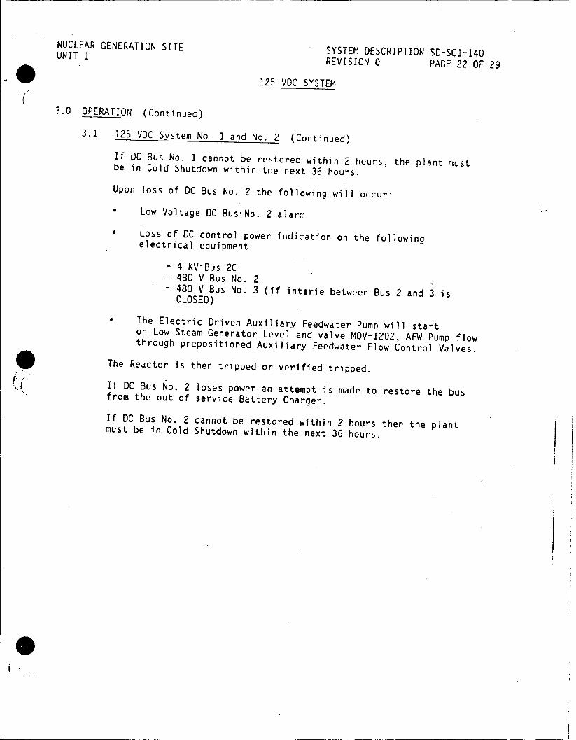
NUCLEAR GENERATION SITE SYSTEM DESCRIPTION 50-501-140 UNIT 1 REVISION 0 PAGE 22 OF 29
125 VDC SYSTEM
3.0 OPERATION (Continued)
3.1 125 VDC System No. 1 and No. 2 (Continued)
If DC Bus No. 1 cannot be restored within 2 hours, the plant must be in Cold Shutdown within the next 36 hours.
Upon loss of DC Bus No. 2 the following will occur:
* Low Voltage DC BusNo. 2 alarm
* Loss of DC control power indication on the following electrical equipment
- 4 KV-Bus 2C - 480 V Bus No. 2 - 480 V Bus No. 3 (if interie between Bus 2 and 3 is CLOSED)
The Electric Driven Auxiliary Feedwater Pump will start on Low Steam Generator Level and valve MOV-1202, AFW Pump flow through prepositioned Auxiliary Feedwater Flow Control Valves.
The Reactor is then tripped or verified tripped.
If DC Bus No. 2 loses power an attempt is made to restore the bus from the out of service Battery Charger.
If DC Bus No. 2 cannot be restored within 2 hours then the plant must be in Cold Shutdown within the next 36 hours.

NUCLEAR GENERATION SITE UNIT 1 SYSTEM DESCRIPTION 50-501-140 REVISION 0 PAGE 23 OF 29
125 VDC SYSTEM
4.0 REFERENCES
4.1 Single Line
4.1.1 5146828 Main One Line Diagram (N1540 Sheet 1) 4.1.2 5102173 One Line Diagram 125 Volt DC System 1
(N1540 Sheet 17)
4.1.3 5149348 One Line Diagram 125 Volt DC System 2 (N1540 Sheet 178)
4.2 Elementary Diagram
4.2.1 455768 Elementary Diagram - 125 VDC Switchboard 2 UV and Ground Detector Ckts. (N1546 Sheet 55) 4.2.2 5151906 Elementary Diagram - 480 V Swgr 3 125 VDC
Control (N1546 Sheet 50)
4/2/3 455516 Elementary Diagaram MOV-850C, Safety Inj. to Loop "C" (N1542 Sheet 6A)
4.3 Procedures
4.3.1 S01-1.0-60 Loss of All AC Power
4.3.2 SO1-1.0-61 Loss of All AC Power Recovery
4.3.3 501-2.6-4 Loss of DC Bus
4.3.4 S01-9-12 Battery Charger Operation
4.3.5 SO1-12.3-8 Testing DC Lighting
4.3.6 S01-12.3-17 Electrical Transfer Switches Alignment Check 4.4 Technical Manuals
4.4.1 BSO-3571-8-0 (K6601075-12-30) Westinghouse Instr. Book, Silicon Thyristor Regulated Rectomatic Battery Charger (Chargers A & B)
4.4.2 1810AA086MOO03 Switchgear Equipment, page 273-294L, Low Voltage Power Circuit Breakers
4.4.3 1810AA086M0008 Westinghouse Instr. Book, Low Voltage Metal - Enclosed Switchgear for OB-50
*4.5 Technical Specification
4.5.1 The following Technical Specification pertains to the 125 VDC System: 4.4
KBiihler:3228i
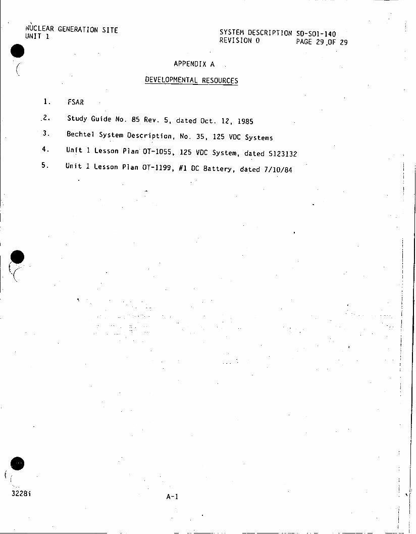
NUCLEAR GENERATION SITE SYSTEM DESCRIPTION SD-S01-140 UNIT 1 REVISION 0 PAGE 29.OF 29
APPENDIX A
DEVELOPMENTAL RESOURCES
1. FSAR
.2. Study Guide No. 85 Rev. 5, dated Oct. 12, 1985
3. Bechtel System Description, No. 35, 125 VOC Systems
4. Unit 1 Lesson Plan OT-1055, 125 VDC System, dated 5123132
5. Unit 1 Lesson Plan OT-1199, #1 DC Battery, dated 7/10/84
3228i A-1
NUCLEAR GENERATION SITE SYSTEM DESCRIPTION SD-S01-140 UNIT 1JAIL281986 CDM REVISION 0 PAGE 1 OF 29
125 VDC SYSTEM
TABLE OF CONTENTS
SECTION PAGE
1.0 FUNCTIONS/DESIGN BASES 2
2.0 DESCRIPTION 3 2.1 System Overview 3 2.2 Components 4
3.0 OPERATION 20
4.0 REFERENCES 23 4.1 Single Line pr - 23 4.2 Elementary Diagram 23 4.3 Procedures 23 4.4 Technical Manuals 23 4.5 Technical Specification
FIGURES 24 1A 125 VDC System One Line 24 1B UPS for MOV 850 C 25 IC UPS for Security 26 2 Battery Charger A or B 27 3 Battery Charger C or D 28
APPENDIX 29 A Developmental Resources 2
This System Description is approved per SO-123-0-44, System Description Revision and Approval. Contact CDM to verify revision information.
PREPARED BY: o 0 Date
APPROVED BY: Manager, p rati ns e
3228i

NUCLEAR GENERATION SITE SYSTEM DESCRIPTION SD-S01-140 UNIT 1 REVISION 0 PAGE 2 OF 29
125 VOC SYSTEM
1.0 FUNCTIONS/0ESIGN BASES
1.1 The 125 VDC System has the following main functions:
1.1.1 Provides a reliable source of power for primary and secondary plant critical functions.
1.1.2 Provides normal power to operate the SCE Security equipment.
1.2 The 125 VDC System has the following design bases:
1.2.1 Provides sufficient power for all loads encountered during normal plant operation including control power for a11 circuit breaker operations, all relaying associated with turbine-generator facilities, and power for reactor control rod operation.
1.2.2 In the event that all AC power to the station is lost the 125 VDC system will supply emergency power to the turbine generator seal oil emergency oil pump, the turbine generator bearing emergency oil pump, emergency generator No. 2 exciter field flashing, auxiliary equipment and control, emergency lighting, control, relaying, and switching loads for a period of 90 minutes at a minimum of 105 volts.
Two independent 125 VDC systems are installed in order to maintain separation of the station load trains and meet the single failure criteria.

NUCLEAR GENERATION SITE SYSTEM DESCRIPTION SD-SO1-140 UNIT I REVISION 0 PAGE 3 OF 29
125 VDC SYSTEM
2.0 DESCRIPTION
2.1 System Overview
2.1.1 125 VDC System No. I and No. 2 (Figure IA)
Each system provides a source of DC power for one of the two independent load trains. Each system contains a battery and two chargers. One charger from each system provides power from an AC train to an associated 125 VDC bus. Each system is associated with the Diesel Generator and Sequencer of a load train.
2.1.2 MOV 850C UPS (Figure IB)
A 125 VOC system is provided as the "third train" power supply for safety injection as discussed in System Description SD-SOI-580, Safety Injection, Spray and Recirculation System. The Safety Injection Valve MOV 850A and B are supplied by load trains 2 and 1 respectively. Valve MOV 850C is supplied by an independent uninterrupted power supply (UPS) in order to insure that-at least two safety injection valves are operable at all times. The UPS system contains a battery, charger, and inverter.
2.1.3 Security UPS (Figure IC)
A 125 VDC system provides a reliable power supply to the SCE Security System. The system provides power to security loads only, with the exception of one non-security load. The non-security load is the DC feed from the security UPS to the Emergency Power Transformer Switchgear 810 which supplies the control power for Breakers 810-1, 810-2, 810-4 and 52-1200. The security UPS system contains a battery, charger, and inverter.

NUCLEAR GENERATION SITE SYSTEM DESCRIPTION SD-SO1-140 UNIT 1 REVISION 0 PAGE 4 OF 29
125 VDC SYSTEM
2.0 DESCRIPTION (Continued)
2.2 Components
2.2.1 Battery No. 1
BATTERY NO. 1
PURPOSE: To provide the ability to operate the plant safely during any credible DC equipment failure
LOCATION: DC Battery Room
I TYPE: Lead-Acid type with 58 cell
I VOLTAGE 1 FLOAT: 130 VDC 1 RECHARGING: 139.2 VDC
I CAPACITY: 2550 AH for 8 hours
The Station Battery No. 1 is connected in parallel with a constant voltage charger fed by an AC power supply. The charger maintains the required constant voltage at the battery terminals and also supplies the normal load to DC Bus No. 1. The arrangement sustains the battery in a fully charged condition and also makes it available to assume the energy power requirements, in the event that the AC power to the charger is interrupted or the charger fails.
The battery is floated at a voltage of 130.0 VDC. If the voltage or specific gravity between the cells of the battery become non-uniform an equalizing charge is given to the battery. An equalizing charge of 139.2 VOC is given to restore all the cells to a fully charged condition. The battery voltage must be greater than or equal to 129 volts on float charge to be considered operable.

NUCLEAR GENERATION SITE SYSTEM DESCRIPTION SD-SO1-140 UNIT 1 REVISION 0 PAGE 5 OF 29
125 VDC SYSTEM
2.0 DESCRIPTION (Continued)
2.2.2 Battery Chargers A & B (Figure 2)
BATTERY CHARGERS A & B
PURPOSE: The conversion of AC power into DC to maintain the battery in a fully charged state and to provide power to the 125 VDC Bus No. 1.
I TYPE: Silicon Thyristor Regulated Rectomatic Battery Chargers
MANUFACTURER/SUPPLIER: Westinghouse
RATING: 125 kW
OUTPUT: 130 V + 1%, no load to full* load
POWER SUPPLIES CHARGER A: 480 V Bus 1, Breaker 52-1110 CHARGER B: 480 V Bus 2, Breaker 52-1210
LOCATION: D.C. Room #1, South wall
There are two battery chargers associated with the 125 VOC No. 1 Battery.
The battery charger is a silicon controlled rectifier (SCR) assembly, controlled by a transistorized regulator:
The rectifier is made up of thyristor and silicon cells.
The regulator has a constant voltage section and a current limit section.
The magnitude of the DC output of the charger determines when the thyristors are turned on. A decrease in the output voltage will turn on the thyristors earlier in their conducting cycle. An increase in output of DC voltage will turn off the thyristors earlier in their conducting cycle. A change in the DC or AC voltage will have the same effect. The rated output of DC voltage is 130.
Potential transformers provide a feedback voltage to the regulator which is directly proportional to the charger current. When the charger current approaches 125% of rated capacity, the current limit will take precedence over the constant voltage section.

9 4
NUCLEAR GENERATION SITE SYSTEM DESCRIPTION SD-SOl-140 UNIT I
REVISION 0 PAGE 6 OF 29
125 VDC SYSTEM
2.0 DESCRIPTION (Continued)
2.2.2 Battery Chargers A & B (Continued)
As stated above, the battery charger limits DC current or. overloads to 125% of rated capacity. The overload limit has a time limit of 2 hours. At the end of the 2 hour period, the overload must be removed and should not be applied again until the temperatures of the DC Filter Reactor and Power Transformers have been reduced to their rated load value of operation at no more than rated current for 2 hours.
The charger has a manually operated toggle switch for equalizing the charger with a cabinet mounted timer. The 0 to 24 hour equalizing charger timer is used to set an equalizing voltage by manually turning the timer to the desired equalizing charger time from zero to 24 hours. At the end of the preset time period, the charger will automatically revert to the normal or float charger voltage.
The charger is provided with protection against battery discharge into the rectifiers upon loss of AC power. Automatic resumption of ) j charging occurs when the AC power supply to the charger is restored. When energ.izing the Battery Charger the Battery Bus must be connected to the Battery Chargers before the AC circuit breaker is closed. To prevent damage to current limiting fuses due to excessive inrush of DC current, the regulator has a soft start or slow turn-on feature.
The soft start or slow turn-on feature controls the rate of rise of the output voltage when the unit is first energized.
Current limiting fuses are provided to protect the rectifiers and fuses from damage due to an internal short circuit. The chargers also have trigger fuses paralleled to the current limiting fuses. The trigger fuses turn on an amber light at the charger, sound an alarm to indicate fuse failure, and provides visual indication to show which of the fuses has blown. The Charger must be taken out of service as soon as possible if a fuse has blown.
Only one battery charger is in service to the 125 VDC Bus No. 1 at a time. Charger A is normally in service. Battery Charger B may be placed in service during maintenance activities on Charger A.

NUCLEAR GENERATION SITE SYSTEM DESCRIPTION SD-SO1-140 REVISION 0 PAGE 7 OF 29
125 VDC SYSTEM
2.0 DESCRIPTION (Continued)
2.2.2 Battery Chargers A & B (Continued)
Local indication provided for each charger is:
* AC amps, 0-400
* DC amps, 0-1500
* DC volts, 0-150
* fuse failure - amber light
* battery charger on - red light
* 480 V breaker:
open - green light
closed - red light
An AC safety switch is mounted on each Charger cabinet. This safety switch is in series with the 480 V ACB supplying the Charger and is normally closed.
The charger cabinets are ventilated by a self-starting fan powered by the AC supply to the charger. This fan must be in service whenever the charger is operating.
If Battery Charger A or B fails annunciation is given on DG No.1 Annunciator Window 34, "Battery Charger Failure A or B."
2.2.3 125 VDC System No. 1 Switchboard
A switchboard for the 125 VDC System is located in the DC Switchgear Room. The switchboard contains the circuit breaker for the battery chargers (output) and the battery and feeder breakers for the DC Bus No. 1. The switchboard also contains the DC ground relay, DC undervoltage relay, and the DC feeder undervoltage relays. The DC feeder undervoltage relays are Struther-Dunn relays which provide Control Room indication upon trip of a breaker. The indication is a common alarm for low voltage given on annunciator DG. No. 1, Window 54.
The Struther-Dunn relays must be pulled out before opening a DC feeder breaker when hanging a clearance. If this is not done, the common alarm would be in as long as the breaker was open and there would be no indication if another feeder had opened.

NUCLEAR GENERATION SITE SYSTEM DESCRIPTION SD-SOI-140 UNIT 1 REVISION 0 PAGE 8 OF 29
125 VDC SYSTEM
2.0 DESCRIPTION (Continued)
2.2.4 Battery No. 2
BATTERY NO. 2
PURPOSE: To provide the ability to operate the plant safely during any credible DC equipment failure.
LOCATION: D.G. Building Battery Room
I TYPE: Lead Calcium with 60 cells
VOLTAGE FLOAT: 130 VDC
RECHARGING: 139.2 VDC
CAPACITY: 660 AH for 8 hours
The station battery No. 2 is connected in parallel with a constant voltage charger fed by an AC power supply. The charger maintains the required constant voltage at the battery terminals and also supplies the normal load to the DC Bus No. 2. The arrangement sustains the battery in a fully charged condition and also makes it available to assume the energy power requirements, in the event that the AC power to the charger is interrupted or the charger fails. The battery is floated at a voltage of 130.0 VDC. If the voltage or specific gravity between the cells of the battery become non-uniform an equalizing charge is given to the battery. An equalizing charge of 139.2 VDC is given to restore all the cells to. a fully charged condition. The battery voltage must be greater than or equal to 129 volts on float charge to be considered operable.
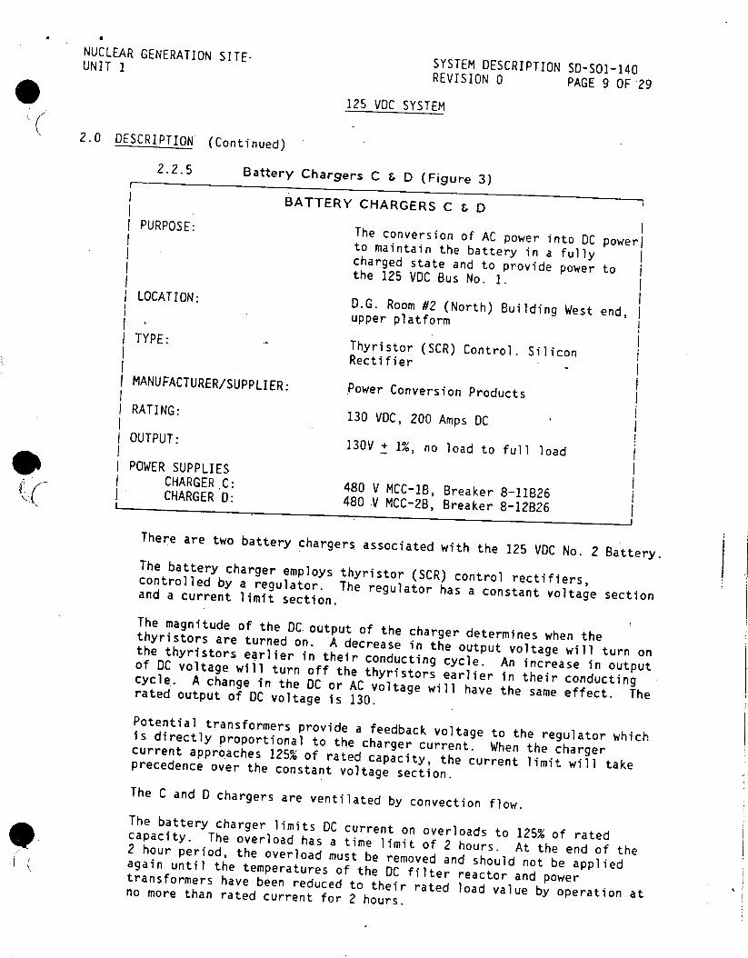
NUCLEAR GENERATION SITEUNIT SYSTEM DESCRIPTION SD-SO1-140
REVISION 0 PAGE 9 OF 29
125 VOC SYSTEM
2.0 DESCRIPTION (Continued)
2.2.5 Battery Chargers C & D (Figure 3)
BATTERY CHARGERS C & D PURPOSE: The conversion of AC power into DC powerl to maintain the battery in a fully charged state and to provide power to the 125 VDC Bus No. 1. LOCATION: D.G. Room #2 (North) Building West end,
upper platform TYPE: Thyristor (SCR) Control. Silicon
Rectifier
MANUFACTURER/SUPPLIER: Power Conversion Products RATING: 130 VDC, 200 Amps DC OUTPUT: 130V + 1%, no load to full load POWER SUPPLIES
CHARGER C: 480 V MCC-1B, Breaker 8-11B26 ( CHARGER D: 480 V MCC-2B, Breaker 8-12B26
There are two battery chargers associated with the 125 VDC No. 2 Battery. The battery charger employs thyristor (SCR) control rectifiers, controlled by a regulator. The regulator has a constant voltage section and a current limit section.
The magnitude of the DC output of the charger determines when the thyristors are turned on. A decrease in the output voltage will turn on the thyristors earlier in their conducting cycle. An increase in output of DC voltage will turn off the thyristors earlier in their conducting cycle. A change in the DC or AC voltage will have the same effect. The rated output of DC voltage is 130.
Potential transformers provide a feedback voltage to the regulator which is directly proportional to the charger current. When the charger current approaches 125% of rated capacity, the current limit will take precedence over the constant voltage section.
The C and 0 chargers are ventilated by convection flow. The battery charger limits DC current on overloads to 125% of rated 9capacity. The overload has a time limit of 2 hours. At the end of the 2 hour period, the overload must be removed and should not be applied again until the temperatures of the DC filter reactor and power transformers have been reduced to their rated load value by operation at no more than rated current for 2 hours.

NUCLEAR GENERATION SITE SYSTEM DESCRIPTION 50-501-140 UNIT I REVISION 0 PAGE 10 OF 29
125 VOC SYSTEM
2.0 DESCRIPTION (Continued)
2.2.5 Battery Chargers C & D (Continued)
Upon loss of AC power, the charger is provided with protection so that the battery will not discharge through the charger. The charging function will resume when the AC power is restored.
When energizing the Battery Charger the Battery Bus must be connected to the Battery Chargers before the AC circuit breaker is closed. To prevent damage to the current limiting fuses due to excessive inrush of DC current, the regulator has a soft start or slow turn-on feature. The soft start or slow turn-on feature controls the rate of rise of the output voltage when the unit is first energized-.
Only one battery charger is in service to the 125 VDC Bus No. 2 at a time. Charger D is normally in service. Charger C may be placed in service during maintenance activities on Charger 0.
Local indication for each charger is provided as follows:
* DC volts, 0-150
* DC amps, 0-1500
* AC On, Red light
* Hi DC volts, Red light
* Low DC volts, Red light
* Charger Failure, Red light
* Reverse Current, Red light
A toggle switch is provided on each charger for float or equalizing charge.
The Chargers are ventilated by convection flow.
Circuit Breakers are provided on the Charger as follows: * CB1 - Incoming AC Supply
* CB2 - DC Output
If Battery Charger C or 0 fails indication is provided on DG No. 2 Annunciator Window 34, "Battery Charger Failure C or D."

NUCLEAR GENERATION SITE SYSTEM DESCRIPTION SD-SOI-140 UNIT 1 REVISION 0 PAGE 11 OF 29
125 VOC SYSTEM
2.0 DESCRIPTION (Continued)
2.2.6 125 VDC System No. 2 Switchboard
A switchboard for the 125 VOC System is located in the DG No. 2 (North) Building West end. The switchboard contains the circuit breaker for the battery chargers C & D (output), the No. 2 battery and the feeder breakers for the DC Bus No. 2. The switchboard also contains the DC Ground Relay, DC undervoltage relays and the DC feeder undervoltage relay. The DC feeder undervoltage relays are Struther-Dunn relays which provide Control Room indication upon breaker trip. The indication is a common alarm on DG No. 2 Annunciator, Window 54, "DC Bus 2 DC ACB Trip and/or Low Voltage."
The Struther-Dunn relays must be pulled before opening a DC feeder breaker when hanging a clearance. If this is not done, the common alarm would be in as long as the breaker was open and there would be no indication if another feeder had opened.
2.2.7 Battery for MOV 850C (UPS)
BATTERY FOR UPS FOR MOV 850C
PURPOSE: To provide an uninterrupted power ((source (UPS) to operate MOV 850 C. 1 LOCATION: North of the Hydrogen Seal Oil Station
TYPE: Lead Calcium
VOLTAGE: 130 VDC
CAPACITY: 240 AH for 8 hours
MANUFACTURER: C & 0
The station battery for the UPS to MOV 850C is connected in parallel with a constant voltage charger fed by an AC power supply. The charger maintains the required constant voltage at the battery terminals and also supplies MOV 850C. The arrangement sustains the battery in a fully charged condition and also makes it available to assume the power requirements of MOV 850C in the event that AC power to the charger is interrupted.
9II
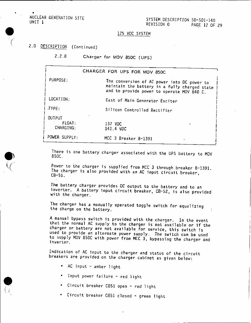
NUCLEAR GENERATION SITE SYSTEM DESCRIPTION SD-SOI-140 UNIT 1 REVISION 0 PAGE 12 OF 29
125 VDC SYSTEM
2.0 DESCRIPTION (Continued)
2.2.8 Charger for MOV 850C (UPS)
CHARGER FOR UPS FOR MOV 850C
PURPOSE: The conversion of AC power into DC power to maintain the battery in a fully charged state and to provide power to operate MOV 840 C.
LOCATION: East of Main Generator Exciter
.TYPE: Silicon Controlled Rectifier
I OUTPUT FLOAT: 137 VDC
CHARGING: 141.4 VDC
I POWER SUPPLY: MCC 3 Breaker 8-1391
There is one battery charger associated with the UPS battery to MOV 850C.
Power to the charger is supplied from MCC 3 through breaker 8-1391. The charger is also provided with an AC input circuit breaker, CB-51.
The battery charger provides DC output to the battery and to an inverter. A battery input circuit breaker, CB-52, is also provided with the charger.
The charger has a manually operated toggle switch for equalizing the charge on the battery.
A manual bypass switch is provided with the charger. In the event that the normal AC supply to the charger is not available or if the charger or battery are not available for service, this switch is used to provide an alternate power supply. The switch can be used to supply MOV 850C with power from MCC 3, bypassing the charger and inverter.
Indication of AC input to the charger and status of the circuit breakers are provided on the charger cabinet as given below:
* AC input - amber light
* Input power failure - red light
* Circuit breaker CB51 open - red light
* Circuit breaker CB51 closed - green light
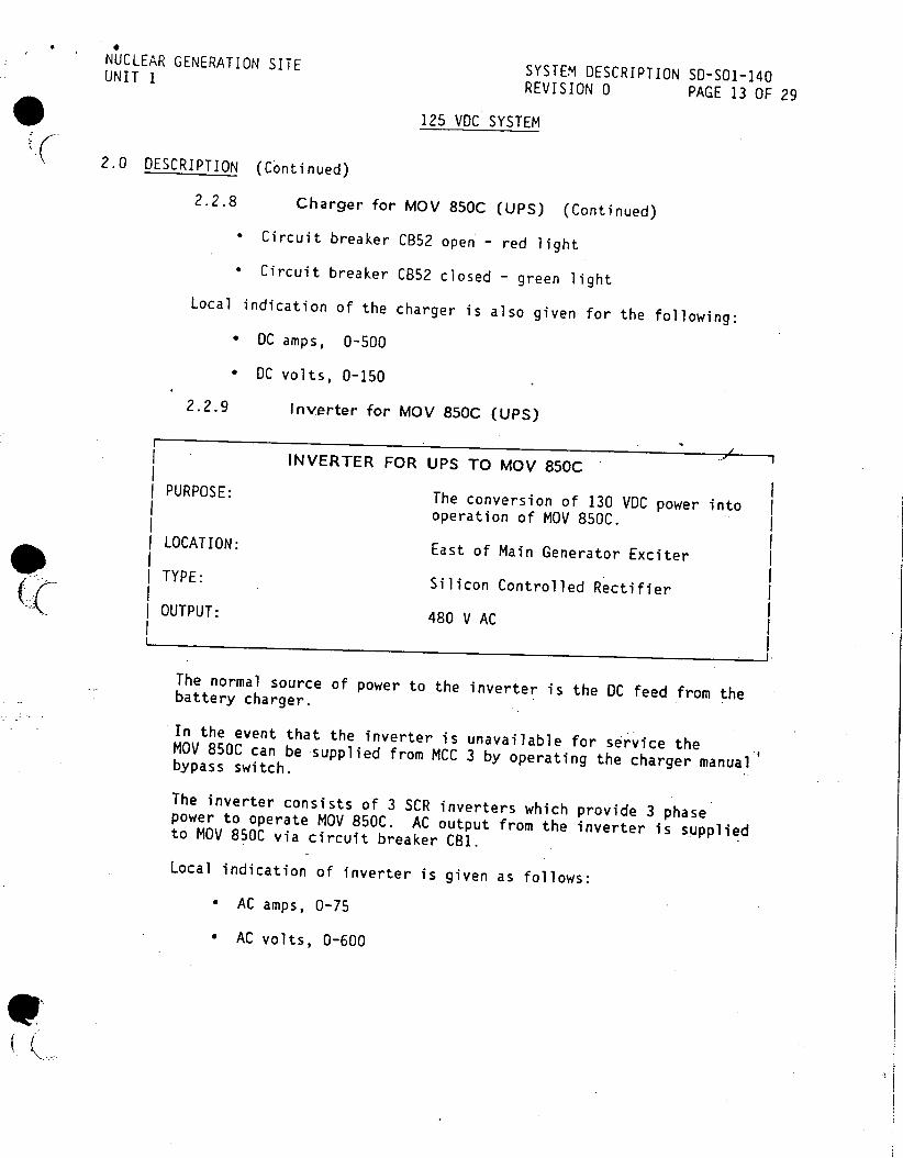
NUCLEAR GENERATION SITE SYSTEM DESCRIPTION SD-SOl-140 UNIT I
REVISION 0 PAGE 13 OF 29
125 VOC SYSTEM
2.0 DESCRIPTION (Continued)
2.2.8 Charger for MOV 850C (UPS) (Continued) * Circuit breaker CB52 open - red light
* Circuit breaker CB52 closed - green light
Local indication of the charger is also given for the following: * DC amps, 0-500
* DC volts, 0-150
2.2.9 Inverter for MOV 850C (UPS)
INVERTER FOR UPS TO MOV 850C
PURPOSE: The conversion of 130 VDC power into operation of MOV 850C.
LOCATION: East of Main Generator Exciter
TYPE: Silicon Controlled Rectifier OUTPUT: 480 V AC
The normal source of power to the inverter is the DC feed from the battery charger.
In the event that the inverter is unavailable for service the MOV 850C can be supplied from MCC 3 by operating the charger manual bypass switch.
The inverter consists of 3 SCR inverters which provide 3 phase power to operate MOV 850C. AC output from the inverter is supplied to MDV 850C via circuit breaker CB1.
Local indication of inverter is given as follows:
* AC amps, 0-75
* AC volts, 0-600
(I
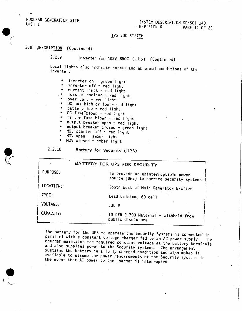
NUCLEAR GENERATION SITE SYSTEM DESCRIPTION SD-SOI-140 UNIT 1 REVISION 0 PAGE 14 OF 29
125 VOC SYSTEM
2.0 DESCRIPTION (Continued)
2.2.9 Inverter for MOV 850C (UPS) (Continued)
Local lights also indicate normal and abnormal conditions of the . inverter.
* inverter on - green light * inverter off - red light * current limit - red light * loss of cooling - red light * over temp - red light * DC bus high or low - red light * battery low - red light * DC fuse'blown - red light * filter fuse blown - red light * output breaker open - red light * output breaker closed - green light * MOV starter off - red light * MOV open - amber light * MOV closed - amber light
2.2.10 Battery for Security (UPS)
I BATTERY FOR UPS FOR SECURITY
PURPOSE: To provide an uninterruptible power source (UPS) to operate security systems.1
LOCATION: South West of Main Generator Exciter I I TYPE: Lead Calcium, 60 cell
VOLTAGE: 130 V
I CAPACITY: 10 CFR 2.790 Material - withhold from public disclosure
The battery for the UPS to operate the Security Systems is connected in parallel with a constant voltage charger fed by an AC power supply. The charger maintains the required constant voltage at the battery terminals and also supplies power to the Security systems. The arrangement sustains the battery in a fully charged condition and also makes it available to assume the power requirements of the Security systems in the event that AC power to the charger is interrupted.
0II
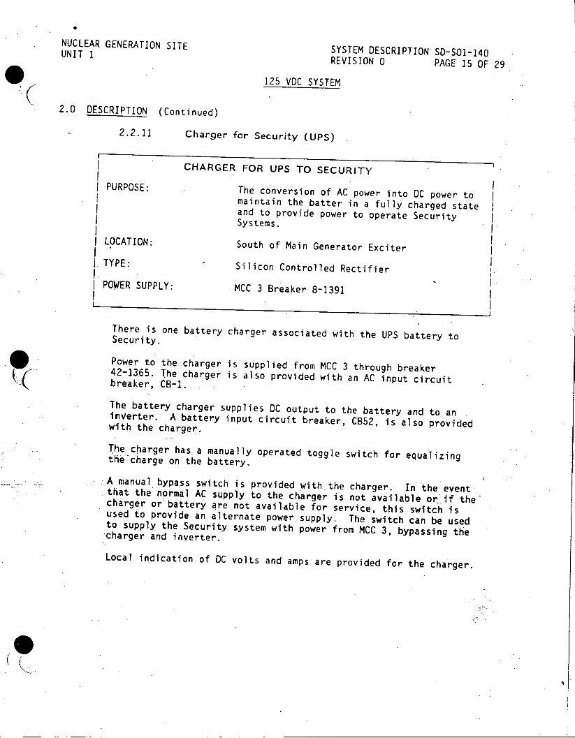
NUCLEAR GENERATION SITE SYSTEM DESCRIPTION 50-501-140 UNIT 1 REVISION 0 PAGE 15 OF 29
125 VDC SYSTEM
2.0 DESCRIPTION (Continued)
2.2.11 Charger for Security (UPS)
CHARGER FOR UPS TO SECURITY
PURPOSE: The conversion of AC power into DC power to maintain the batter in a fully charged state and to provide power to operate Security Systems.
LOCATION: South of Main Generator Exciter
TYPE: Silicon Controlled Rectifier
I POWER SUPPLY: MCC 3 Breaker 8-1391
There is one battery charger associated with the UPS battery to Security.
Power to the charger is supplied from MCC 3 through breaker 42-1365. The charger is also provided with an AC input circuit breaker, CB-1.
The battery charger supplies DC output to the battery and to an inVerter. A battery input circuit breaker, CB52, is also provided with the charger.
The charger has a manually operated toggle switch for equalizing the charge on the battery.
A manual bypass switch is provided with the charger. In the event that the normal AC supply to the charger is not available or if the charger or battery are not available for service, this switch is used to provide an alternate power supply. The switch can be used to supply the Security system with power from MCC 3, bypassing the charger and inverter.
Local indication of DC volts and amps are provided for the charger.
NUCLEAR GENERATION SITE SYSTEM DESCRIPTION SD-SO1-150 UNIT I- REVISION 0 PAGE 1 OF 38
B 4 1986 Ctf
MAINTAINED 120 VAC SYSTEM
TABLE OF CONTENTS
SECTION PAGE
1.0 FUNCTIONS/DESIGN BASES 2
2.0 DESCRIPTION 3 2.1 System Overview 3 2.2 Components 4 2.3 Power Supplies RECEIVED CDM 24
3.0 OPERATION FEB 4 1986 26 3.1 Emergency Operations .C26 3.2 Other Operations SITE FILE COPY 28
4.0 REFERENCES 29 4.1 Single Line 29
4.2 Elementary Diagram 29
V 4.3 Procedures 29 4.4 Technical Manuals 29 4.5 Technical Specifications 29
FIGURES 1 Maintained 120VAC System - One Line 30 2 Master Transfer Switch No. 7 31 3 VB4 Voltage Regulator 32 4 Inverter 1, 2 or 3 33 5 Inverter 5 34 6 Vital Bus 1, 2, 3 or Utility Bus 35 7 VB4 Feeder 36 8 Inverter 4 37
APPENDICES A Developmental Resources. 38
This System Description is approved per S0123-0-44, System Description Revision and Approval. Contact CDM to verify revision information.
PREPARED BY: th Dte
APPROVED BY: I Man br, O era ons Date
3318i NOT QA PROGRAM AFFECTING

NUCLEAR GENERATION SITE SYSTEM DESCRIPTION SD-SO1-150 UNIT I REVISION 0 PAGE 2 OF 38
MAINTAINED 120 VAC SYSTEM
1.0 FUNCTIONS/DESIGN BASES
1.1 The Maintained 120 VAC System has the following main functions:
1.1.1 Provides a reliable, regulated, and redundant source of 120 volt, 60 cycle, single phase power for critical plant controls and instrumentation.
1.2 The Maintained 120 VAC System has the following design basis:
1.2.1 Provides a 120 V maintained AC control power to vital reactor instrumentation and relay systems for core monitoring on loss of station AC power.
1.2.2 Provides a source of power for non-critical plant controls and instrument and backup power supply in the event that regulated power to critical plant controls and instrumentation is lost.
01
NUCLEAR GENERATION SITE SYSTEM DESCRIPTION SD-S01-150 UNIT 1 REVISION 0 PAGE 3 OF 38
MAINTAINED 120 VAC SYSTEM
2.0 DESCRIPTION
2.1 System Overview
2.1.1 Regulated 120VAC power is provided to Vital Bus #4 from the normal 480VAC distribution system through a 480/120V transformer and voltage regulator (see Figure 1). Vital Bus #4 feeds regulated bus #4 and also provides backup power to the NIS instruments 1201 & 1206. The NIS instruments 1201 and 1206 are normally powered from a regulated supply through Inverter #4. The Inverter #4 is supplied from 125 VDC Bus #1 (See System Description SD-SO1-140, "125 VDC System")
The normal regulated 120VAC power supply to the other Vital Buses is supplied from their respective inverters, powered from either 125VDC Bus No. I or 2 (see Figure 1). Vital Bus #1, 2 and 3 supply power to their respective Regulated Bus.
2.1.2 The source of power to the Utility Bus is from 1 of 2 normal 480V distribution-systems through a 480/120V AC transformer and a transfer switch (see Figure 1). In the event that the 480V power sources to the utility are lost, power can be supplied from the lighting switchgear. The lighting switchgear is powered from a 4160/12.0 VAC Transformer. (See System Description SD-S01-160, "Station Lighting Systems")
Prior to the transfer switch and after.the 480/120 VAC transformer for the Utility Bus, backup power may be supplied to Vital Buses 1, 2, 3 and 3A or 4. In addition backup power may be supplied through an auto transfer switch to Vital Bus 5 and 6 through an independent 480VAC power supply from a 480V/120V transformer.
NUCLEAR GENERATION SITE SYSTEM DESCRIPTION SD-SO1-150 UNIT 1. REVISION 0 PAGE 4 OF 38
MAINTAINED 120 VAC SYSTEM
2.0 DESCRIPTION (Continued)
2.2 Components
2.2.1 Master Transfer Switch No. 7 (Figure 2)
The 37.5 KVA and 7.5 KVA transformers can be supplied from the 480V System MCC 1 or MCC 2. The manually operated Master Transfer Switch No. 7 is positioned to provide the source of power to the transformers. The Master Transfer Switch is located in the 4KV Room east end, in the Transfer Switch Cabinet.
The transformers are normally supplied from MCC-2 (Breaker 8-1238), with MCC-1 (Breaker 8-1181) preferred as the backup source of power.
Indication of the power supply and transfer switch position is given as follows:
* power from MCC-1, amber lamp
* power from MCC-2, white lamp
The Selector Switch for the Transfer Switch No. 7 is used to manually position the switch to the desired power source.
Three ACB's are located on the load side of Transfer Switch No. 7. ACB 1 is rated at 40 amps and supplies the Rod Drive Control System. ACB 2 and 3 are spares.
Upon loss of power from MCC-2 the Master Transfer Switch No. 7 selector switch is manually positioned to the MCC-1 power supply. The loss of MCC-2 will result in the loss of Vital Bus No. 4 therefore, prompt action is required to transfer the power supply from MCC-2 to MCC-1. Upon loss of power to Vital Bus No. 4 the reactor must be manually tripped.
II
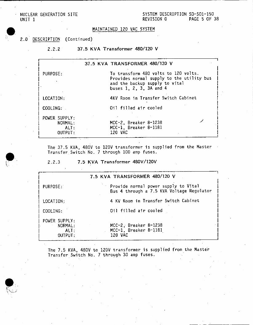
NUCLEAR GENERATION SITE SYSTEM DESCRIPTION SD-S01-150 UNIT 1 REVISION 0 PAGE 5 OF 38
MAINTAINED 120 VAC SYSTEM
2.0 DESCRIPTION (Continued)
2.2.2 37.5 KVA Transformer 480/120 V
37.5 KVA TRANSFORMER 480/120 V
PURPOSE: To transform 480 volts to 120 volts. Provides normal supply to the utility bus and the backup supply to vital buses 1, 2, 3, 3A and 4
LOCATION: 4KV Room in Transfer Switch Cabinet
COOLING: Oil filled air cooled
POWER SUPPLY: NORMAL: MCC-2, Breaker 8-1238
ALT: MCC-1, Breaker 8-1181 OUTPUT: 120 VAC
The 37.5 KVA, 480V to 120V transformer is supplied from the Master Transfer Switch No. 7 through 100 amp fuses.
2.2.3 7.5 KVA Transformer 480V/120V
7.5 KVA TRANSFORMER 480/120 V
PURPOSE: Provide normal power supply to Vital Bus 4 through a 7.5 KVA Voltage Regulator
LOCATION: 4 KV Room in Transfer Switch Cabinet
| COOLING: Oil filled air cooled
I POWER SUPPLY: I NORMAL: MCC-2, Breaker 8-1238
ALT: MCC-1, Breaker 8-1181 OUTPUT: 120 VAC
The 7.5 KVA, 480V to 120V transformer is supplied from the Master Transfer Switch No. 7 through 30 amp fuses.
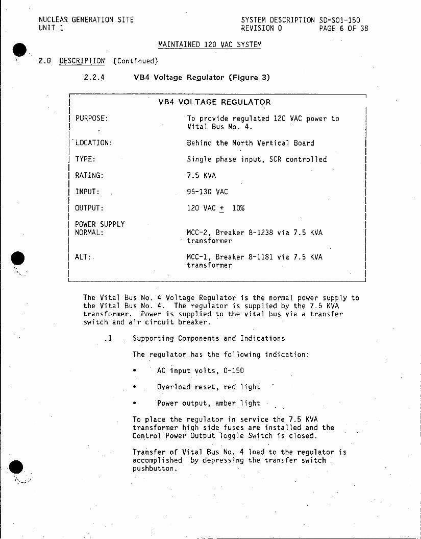
NUCLEAR GENERATION SITE SYSTEM DESCRIPTION SD-SO1-150 UNIT 1 REVISION 0 PAGE 6 OF 38
MAINTAINED 120 VAC SYSTEM
2.0 DESCRIPTION (Continued)
2.2.4 VB4 Voltage Regulator (Figure 3)
VB4 VOLTAGE REGULATOR
PURPOSE: To provide regulated 120 VAC power to Vital Bus No. 4.
I'LOCATION: Behind the North Vertical Board
TYPE: Single phase input, SCR controlled
RATING: 7.5 KVA
INPUT: 95-130 VAC
| OUTPUT: 120 VAC + 10%
| POWER SUPPLY | NORMAL: MCC-2, Breaker 8-1238 via 7.5 KVA
transformer
ALT:. MCC-1, Breaker 8-1181 via 7.5 KVA transformer
The Vital Bus No. 4 Voltage Regulator is the normal power supply to the Vital Bus No. 4. The regulator is supplied by the 7.5 KVA transformer. Power is supplied to the vital bus via a transfer switch and air circuit breaker.
.1 Supporting Components and Indications
The regulator has the following indication:
* AC input volts, 0-150
* Overload reset, red light
* Power output, amber light
To place the regulator in service the 7.5 KVA transformer high side fuses are installed and the Control Power Output Toggle Switch is closed.
Transfer of Vital Bus No. 4 load to the regulator is accomplished by depressing the transfer switch pushbutton.

NUCLEAR GENERATION SITE SYSTEM DESCRIPTION SD-SO1-150 UNIT 1 REVISION 0 PAGE 7 OF 38
MAINTAINED 120 VAC SYSTEM
2.0 DESCRIPTION (Continued)
2.2.5 Inverters 1, 2 and 3 (Figure 4)
INVERTERS 1, 2 and 3
| PURPOSE: To convert DC power into AC power and supply vital buses 1, 2, 3 and 3A.
ILOCATION: DC Room #1
RATING: 5 KVA
I INPUT: 105 - 140 VDC
| OUTPUT: 120 VAC, single phase, 60 Hertz
I VOLTAGE REGULATION: 120 VAC + 1%
| COOLING: Two 500 CFM-Blowers @ top of Inverter
I POWER SUPPLIES: INVERTER #1: 125 VDC Bus No. 1, Bkr. 72-135
| INVERTER #2: 125 VDC Bus No. 1, Bkr. 72-136 | INVERTER #3: 125 VDC Bus No. 1, Bkr. 72-137
In the event that the inverter is unavailable for service the vital buses can be supplied from the 480V MCC-2 (or MCC-1) by a transfer switch.
The inverters consist of a switching regulator and an inverter section. The switching regulator regulates the DC voltage fed to the inverter. The AC output of the inverter is proportional to the DC voltage fed to it by the switching regulator. The inverter section consists of a Silicon Controlled Rectifier (SCR) bridge configuration which produces AC square waves. An output filter produces the square waves into AC sine waves.
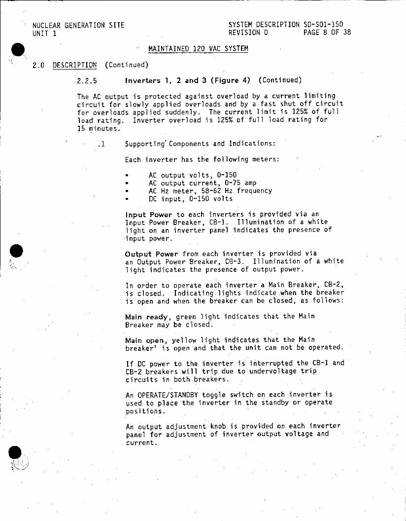
NUCLEAR GENERATION SITE SYSTEM DESCRIPTION SD-SO1-150 UNIT 1 REVISION 0 PAGE 8 OF 38
MAINTAINED 120 VAC SYSTEM
2.0 DESCRIPTION (Continued)
2.2.5 Inverters 1, 2 and 3 (Figure 4) (Continued)
The AC output is protected against overload by a current limiting circuit for slowly applied overloads and by a fast shut off circuit for overloads applied suddenly. The current limit is 125% of full load rating. Inverter overload is 125% of full load rating for 15 minutes.
.1 Supporting'Components and Indications:
Each inverter has the following meters:
* AC output volts, 0-150 * AC output current, 0-75 amp * AC Hz meter, 58-62 Hz frequency * DC input, 0-150 volts
Input Power to each inverters is provided via an Input Power Breaker, CB-1. Illumination of a white light on an inverter panel indicates the presence of input power.
Output Power from each inverter is provided via an Output Power Breaker, C8-3. Illumination of a white light indicates the presence of output power.
In order to operate each inverter a Main Breaker, CB-2, is closed. Indicating lights indicate .when the breaker is open and when the breaker can be closed, as follows:
Main ready, green light indicates that the Main Breaker may be closed.
Main open, yellow light indicates that the Main breaker' is open and that the unit can not be operated.
If DC power to the inverter is interrupted the CB-1 and CB-2 breakers will trip due to undervoltage trip circuits in both breakers.
An OPERATE/STANDBY toggle switch on each inverter is used to place the inverter in the standby or operate positions.
An output adjustment knob is provided on each inverter panel for adjustment of inverter output voltage and current.

NUCLEAR GENERATION SITE SYSTEM DESCRIPTION SD-SO1-150 UNIT 1 REVISION 0 PAGE 9 OF 38
MAINTAINED 120 VAC SYSTEM
2.0 DESCRIPTION (Continued)
2.2.5 Inverters 1, 2 and 3 (Figure 4) (Continued)
.1 (Continued)
The inverters have a local trouble alarm horn and indicating lights which indicate the following:
Current limit, yellow light illuminated if inverter is in current limit mode of operation.
Overload, red light illuminated if inverter is in overload protection mode.
Fuse open, red light illuminates if main inverter fuse opens, system shuts down.
Fan failure, red lamps illuminates if a cooling fan fails, system does not shut down.
Overtemp, red light illuminates if temperature exceeds 1800 F, system shuts down.
* A pushbutton horn stop is provided to silence the trouble alarm horn. The horn stop pushbutton is illuminated (red light) to indicated that the horn has been silenced.
Inverter trouble due to current limit, overload, fuse open, fan failure and/or over temperature is also indicated on the Electrical Annunciator Window No. 38, "Trouble Vital Bus 1, 2, 3A, 3, 4 or.Utility Bus."
2.2.6 Inverter No. 4.(Figure 8)
INVERTER NO. 4
PURPOSE: To convert DC power into AC power to supplyl the NIS rack channels 1201 and 1206.
LOCATION: Behind the North Vertical Board
INPUT: 105 -140 VDC
OUTPUT: 120 VAC power, single phase
POWER SUPPLY: 125 VDC Bus No. 1, Breaker 72-133
The Inverter No. 4 consists of three major sections.The sections include the low power oscillator, the parallel inverter, and the non-linear magnetic output stage.

NUCLEAR GENERATION SITE SYSTEM DESCRIPTION SD-SO1-150 UNIT 1 REVISION 0 PAGE 10 OF 38
MAINTAINED 120 VAC SYSTEM
2.0 DESCRIPTION (Continued)
2.2.6 Inverter No. 4 (Continued)
The low power oscillator produces frequency stabilized square waves from the DC power supply and supplies them to the parallel inverter.
The silicon controlled rectifiers and other components of the parallel inverter produces the output from the oscillator into square wave AC voltage.
The AC voltage is fed to the non-linear magnetic stage where it is changed from a square wave to an AC sine wave.
The non-linear magnetic stage also regulates the inverter output against load and line changes and protects the inverter by limiting the output current. The current output limit is 150% of rated value.
The NIS Channels 1201 and 1206 are normally powered by the Inverter No. 4 via a 30 amp transfer switch. Upon inverter trouble or failure the transfer switch will automatic switch the NIS channels to a backup power source. The backup .power source is the Regulated Bus No. 4. The Inverter No. 4 output breaker should remain closed if the plant is on line since this switch supplies the NIS Channels 1201 and 1206 under all conditions.
To transfer the NIS Rack Channels 1201 and 1206 back to the inverter, the "Transfer to Inverter" pushbutton is depressed.
A "Transfer to Line" pushbutton is also provided for manually transferring the NIS Rack Channels 1201 and 1206 to the backup power supply.
.1 Supporting Components and Indications:
DC power is supplied to the inverter via the Inverter DC Breaker (input breaker). The breaker is positioned to close to place the inverter in.service.
AC power is supplied from the inverter via the Inverter AC Breaker. The breaker is closed in order to provide AC output from the inverter.
A frequency adjustment knob is provided on the inverter panel in order to adjust the inverter frequency output.
The inverter has the following meters:
D.C. Voltmeter, 0 - 150
*_ D.C. Ammeter, 0 - 10
Frequency meter, 56 - 64 cps

NUCLEAR GENERATION SITE SYSTEM DESCRIPTION SD-SO1-150 UNIT 1 REVISION 0 PAGE 11 OF 38
MAINTAINED 120 VAC SYSTEM
2.0 DESCRIPTION (Continued)
2.2.6 Inverter No. 4 (Continued)
.1 (Continued)
* A.C. Ammeter, 0 - 10
* A.C. Voltmeter, 0 - 150
The inverter has the following indication:
* Inverter Power Supply,,white light illuminated when inverter is in service.
* Line Power Supply, amber light illuminates when backup power supply is used. /
2.2.7 Inverter No. 5 (YV-29) (Figure 5)
INVERTER NO. 5
* PURPOSE: To convert DC power into AC power and supply vital buses 5 and 6.
LOCATION: 480V Room, Southeast end.
RATING: 7.5 KVA
INPUT: 105 - 140 V
I OUTPUT: 120 VAC + 2%, single phase
I POWER SUPPLY: 125 VDC Bus No. 2, Breaker 72-217
The inverter consists of an SCR bridge and associated commutation circuitry that converts DC power to multiple pulse AC power.
An output filter reduces the output AC harmonics and supplies a fundamental sine wave voltage to the output.
Control logic circuitry provides the proper firing of the SCR bridge to precisely control output voltage and protect against overloads.
Alarm circuitry senses abnormal conditions and-provides local indication and remote alarm for conditions such as overload, sync loss, etc.

NUCLEAR GENERATION SITE SYSTEM DESCRIPTION SD-SO1-150 UNIT 1 REVISION 0 PAGE.12 OF 38
MAINTAINED 120 VAC SYSTEM
2.0 DESCRIPTION (Continued)
2.2.7 Inverter No. 5 (YV-29) (Figure 5) (Continued)
An input DC power circuit breaker, CB-1, applies DC input to the inverter. This breaker, cannot be closed until DC voltage is applied to the inverters internal DC bus via a pre-charge breaker and two pre-charge fuses. This is accomplished by pushing a pre-charge pushbutton, S103, located on the inverter panel.
The Static Switch electronic solid state assembly is used to transfer the vital bus loads without interruption. The loads can be transferred from the Inverter (INV) to a backup power supply (BYPASS) and back again. If the switch is in the FORWARD POSITION the loads are supplied by the inverter. If the switch is in the REVERSE POSITION the loads are supplied by a backup power supply from MCC-2 Breaker 1268A. When the vital bus load is being supplied by the backup power supply the inverter system is in the BYPASS position.
If the switch is in the FORWARD POSITION when the inverter fails or overload occurs, the static switch logic circuits will automatically transfer to the REVERSE POSITION, and the load will be supplied by the backup power supply.
The loads can be switched to either source by manually pushing the FORWARD TRANSFER (S101) or REVERSE TRANSFER (S102) pushbuttons located on the inverter control panel.
A Manual Transfer Switch (SI) is also available to .switch the load manually between the inverter and the backup power supply. The Manual Transfer Switch is located on the output side of the Static Switch.
.1 Supporting Components and Indications:
The inverter has the following meters:
* AC output current, 0-100 amps
* AC output voltage, 0-150
* .Output frequency, 55-65 Hz
The inverter has the following indications:
Overload, red light illuminated if inverter output is overloaded (load excess-100% of rating).
Overheat, red light illuminated if inverter is overheated
Battery low, red light illuminated when DC bus voltage is below 110 volts DC.

NUCLEAR GENERATION SITE SYSTEM DESCRIPTION 50-501-150 UNIT 1 REVISION 0 PAGE 13 OF 38
MAINTAINED 120 VAC SYSTEM
2.0 DESCRIPTION (Continued)
2.2.7 Inverter No. 5 (YV-29) (Figure 5) (Continued)
.1 (Continued)
Sync loss, red light illuminated when:
a) Loss of Sync when alternate supply is present. b) Alternate supply is not present. c) Alternate supply is present but out of frequency
tolerance.
Fuse Open - Bypass, indicate that the Static Switch protection (bypass leg) is open.
Fuse Open - Pre-Charge, indicates that one of the pre-charge fuses is open.
Reverse Transfer, indicates that the static switch is in the "bypass" position.
Forward Transfer, indicates that the static switch is in the "inverter" position.
Upon loss of the inverter an indication is given in the control room on the Electrical Annunciator window 37, "Trouble VTL BUS 5, or INV YV-29."
2.2.8 Transfer Switches
120 VOLT TRANSFER SWITCHES
PURPOSE: Provide the ability to transfer the vital buses and utility bus to a backup power supply
I RATING: 60 AMP
TYPE: .2 Pole, Single Phase
The 120 volt transfer switches provide the ability to automatically transfer the following:
* Vital buses 1, 2, 3 and 3A, transfer from the 5 KVA inverters to the 37.5 KVA transformer power supply.
* Vital bus 4, transfers from the regulated 7.5 KVA Supply to the 37.5 KVA transformer power supply.

NUCLEAR GENERATION SITE SYSTEM DESCRIPTION SD-SO1-150 UNIT 1 REVISION 0 PAGE 14 OF 38
MAINTAINED 120 VAC SYSTEM
2.0 DESCRIPTION (Continued)
2.2.8 Transfer Switches (Continued)
.1 (Continued)
* Utility bus transfers from the 37.5 KVA transformer to the lighting switchgear power supply.
* -Vital buses 5 and 6 transfer from a 5 KVA inverter t6 a 15 KVA transformer power supply.
The transfer switches will transfer to a backup supply automatically if voltage or frequency of the normal power supply deviates beyond preset limit. The transfer switches will operate if the power supply falls below 114 volts for more than 10 milliseconds.
The transfer speed of the switches is less than 50 milliseconds.
The transfer switches are located at the vital and utility buses. Meters on the output side of the transfer switches indicate voltage, amps and frequency.
Indicating lights at the transfer switch show the status of the switch.
* Closed to normal supply, white lamp
* Closed to backup supply, amber lamp (Utility bus, red lamp)
Automatic transfer is annunciated on the Electrical Annunciator in the Control Room as follows:
Window 38, "Trouble VTL Bus 1, 2, 3, 3A, 4 or UTL Bus"
Transfer from backup to normal power supply is manually initiated
by a local transfer pushbutton at the transfer switch.
The transfer switch for Vital Buses 5 and 6 is discussed in Section 2.2.7.

NUCLEAR GENERATION SITE SYSTEM DESCRIPTION SD-SO1-150 UNIT 1 REVISION 0 PAGE 15 OF 38
MAINTAINED 120 VAC SYSTEM
2.0 DESCRIPTION (Continued)
2.2.9 Vital Buses (Figure 6)
VITAL BUSES
PURPOSE: Provides 120 VAC regulated power to plant vital controls and instrumentation
I LOCATION V.B. 1,2,3,3A and 4: Behind the North Vertcal Board V.B. 5: South wall of CR behind and to-the right
| of the relay panel | V.B. 6: 480V Room, North wall, east end
Indication for the vital buses 1, 2, 3, 3A and 4 is provided at the output of the vital buses' associated transfer switch as follows:
* AC amps, 0-100 * AC volts, 110-130 * Cycles, 56-62
Indication for the vital buses 5 and 6 is provided at the output of the manual transfer switch on the Inverter 5 panel as follows:
* AC current, 0-100 amps * Frequency, 55 - 65 CPS * AC volts, 0-150
Power is provided to the vital buses from the associated transfer switches via 100 amp main ACB's.
When the bus is in service a Bus Potential Power Indicating light is illuminated.
Additional indication is also provided at Vital Bus No. 4 for power supply as follows:
* Power supply from MCC-1, amber light
* Power supply from MCC-2, white light
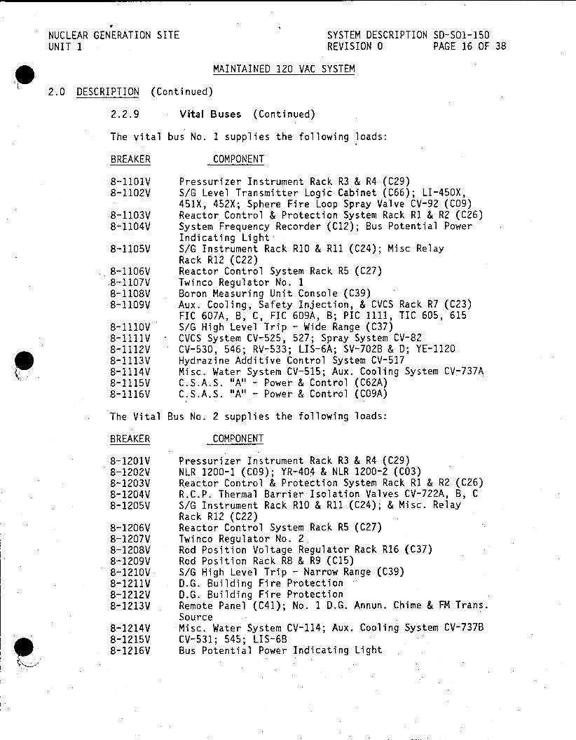
NUCLEAR GENERATION SITE SYSTEM DESCRIPTION SD-SO1-150 UNIT 1 REVISION 0 PAGE 16 OF 38
MAINTAINED 120 VAC SYSTEM
2.0 DESCRIPTION (Continued)
2.2.9 Vital Buses (Continued)
The vital bus No. 1 supplies the following loads:
BREAKER COMPONENT
8-1101V Pressurizer Instrument Rack R3& R4 (C29) 8-1102V S/G Level Transmitter Logic Cabinet (C66); LI-450X,
451X, 452X; Sphere Fire Loop Spray Valve CV-92 (C09) 8-1103V Reactor Control & Protection System Rack RI & R2 (C26) 8-1104V System Frequency Recorder (C12); Bus Potential Power
Indicating Light8-1105V S/G Instrument Rack R1O & R1 (C24); Misc Relay
Rack R12 (C22) 8-1106V Reactor Control System Rack R5 (C27) 8-1107V Twinco Regulator No. 1 8-1108V Boron Measuring Unit Console (C39) 8-1109V Aux. Cooling, Safety Injection, & CVCS Rack R7 (C23)
FIC 607A, B, C, FIG 609A, B; PIC 1111, TIC 605, 615 8-1110V S/G High Level Trip - Wide Range (C37) 8-1111V CVCS System CV-525, 527; Spray System CV-82 8-1112V CV-530, 546; RV-533; LIS-6A; SV-702B & D; YE-1120 8-1113V Hydrazine Additive Control System CV-517 8-1114V Misc. Water System CV-515; Aux. Cooling System CV-737A 8-1115V C.S.A.S. "A" - Power & Control (C62A) 8-1116V C.S.A.S. "A" - Power & Control (CO9A)
The Vital Bus No. 2 supplies the following loads:
BREAKER COMPONENT
8-1201V Pressurizer Instrument Rack R3 & R4 (C29) 8-1202V NLR 1200-1 (C09); YR-404 & NLR 1200-2 (C03) 8-1203V Reactor Control & Protection System Rack R1 & R2 (C26) 8-1204V R.C.P. Thermal Barrier Isolation Valves CV-722A, B, C 8-1205V S/G Instrument Rack RIO & R11 (C24); & Misc. Relay
Rack R12 (C22) 8-1206V Reactor Control System Rack R5 (C27) 8-1207V Twinco Regulator No. 2 8-1208V Rod Position Voltage Regulator Rack R16 (C37) 8-1209V Rod Position Rack R8 & R9 (C15) 8-l2iOV. S/G High Level Trip - Narrow Range (C39) 8-1211V D.G. Building Fire Protection 8-1212V D.G. Building Fire Protection 8-1213V Remote Panel (C41); No. 1 D.G. Annun. Chime & FM Trans.
Source 8-1214V -Misc. Water System CV-514; Aux. Cooling System CV-737B 8-1215V CV-531; 545; LIS-6B 8-T216V Bus Potential Power Indicating Light

NUCLEAR GENERATION SITE SYSTEM DESCRIPTION SD-S01-150 UNIT 1 REVISION 0 PAGE 17 OF 38
MAINTAINED 120 VAC SYSTEM
2.0 DESCRIPTION (Continued)
2.2.9 Vital Buses (Continued)
The Vital Bus No. 3 supplies the following loads:
BREAKER COMPONENT
8-1301V Pressurizer Instrument Rack R3 & R4 (C29) 8-1302V Events Recorder (C05) 8-1303V Reactor Control Protection System Rack R1 & R2 (C26) 8-1304V Emergency D.C. Thermal Barrier Pump Pressure
Transmitter - PT612 8-1305V S/G Instrument Rack.RIO & R1 (C24); Misc Relay
Rack R12 (C22) 8-1306V Reactor Control System Rack R5 (C27) 8-1307V Twinco Regulator No. 3 8-1312V Bus Potential Indicating Light 8-1314V C.S.A.S. "A" - Power & Control (C62A)
Vital Bus No. 3A supplies the following loads:
BREAKER COMPONENT
8-3307V Stack Effluent High Radiation Alarm/Automated Alert 8-3308V Rad. Monitor Sample Conditioner, Containment High Range
Radiation Monitor, Steam Line Radiation Monitor 8-3309V Reactor Subcooling Monitor System (C71) 8-3310V Containment Pressure PT-2001, Containment Isolation
Valve SV-2004 Containment Water Level Ind., Containment Hydrogen Ind. A1-H 2-2001
8-3311V Containment Isolation Valves - CV-948, 951, 953, 962 8-3312V Reactor Head Vent (FUTURE) 8-3314V Containment Isolation Valves CV-955, *956 8-3315V Aux. Feedwater System 8-3316V R.M.S. Detector Skid 8-3324V Bus Potential Indicating Light

NUCLEAR GENERATION SITE SYSTEM DESCRIPTION SD-SO1-150 UNIT 1 REVISION 0 PAGE 18 OF 38
MAINTAINED 120 VAC SYSTEM
2.0 DESCRIPTION (Continued)
2.2.9 Vital Buses (Continued)
The Vital Bus No. 4 supplies the following loads:
BREAKER COMPONENT
8-3324V Bus Potential Indicating Light 8-1401V Pressurizer Instrument Rack R3 & R4 (C29)
(SPARE-NOT USED) 8-1402V Control Board Pak 3 & 4 Reactor Section (C09) 8-1403V Reactor Control & Protection System R1 & R2 (C26) 8-1404V Control Console CL47 & 48 - Reactor Section (C03) 8-1405V Bus Potential Power Indicating Light 8-1406V Reactor Control System Rack R5 (C27) 8-1407V Reactivity Computer Rack (C32)-(SPARE-NOT USED) 8-1408V Twinco Regulator No. 4 8-1409V Rod Deviation Rack R15 (C36) 8-1410V Radiation Monitor Rack RH1200-1 (C11) 8-1411V Boric Acid Blend Control System - Console (C03) 8-1412V FIA 1113A, B, C 8-1413V Steam Dump Control CS53 & 54; Flux Feedback 8-1414V Misc. Relay Rack R13 (C22) 8-1415V Misc. Relay Rack R12 (C22) 8-1416V LT 1100C, FT 1102B, TIC 1108, 1110, CVCS Rack R6 (C25) 8-1417V Rod Step Control (D07) 8-1418V FIC 1116A, B, C
The Vital Bus No. 5 supplies the following loads:
BREAKER COMPONENT
8-2901V Containment Hi Pressure PT 1121A, B, C (C37); Foxboro Panel1 (0C0); Aux. Feed Panel (C71)
8-2903V Recirc. Safety Injection Flow FI-3114A (C09) Sub-Cooling Monitoring System (C71)
8-2905V Containment Pressure PT-3001, Containment Isolation Valve SV-3004 Containment Water Level Ind., Containment Hydrogen Ind. AI-H -3001
8-2906V A.F.W. Pump Control 8-2907V Containment High Range Radiation Monitor; Steam Line
Radiation Monitor 8-2908V. Pressurizer Safety Valve Position Indication RV-532 8-29B0V Main/Aux. Feed Flow Indication Fl 2004 A, B and C 8-2924V Bus Potential Indicating Light
Mic'9lyRakR3.C2
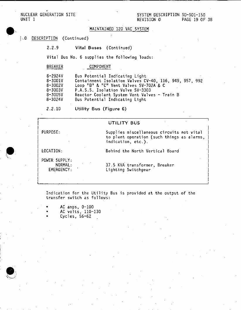
NUCLEAR GENERATION SITE SYSTEM DESCRIPTION SD-SO1-150 UNIT 1 REVISION 0 PAGE 19 OF 38
MAINTAINED 120 VAC SYSTEM
0 DESCRIPTION (Continued)
2.2.9 Vital Buses (Continued)
Vital Bus No. 6 supplies the following loads:
BREAKER COMPONENT
8-2924V Bus Potential Indicating Light 8-3001V Containment Isolation Valves CV-40, 116, 949, 957, 992 8-3002V Loop "B" & "C" Vent Valves SV-702A & C 8-3003V P.A.S.S. Isolation Valve SV-3303 8-3005V Reactor Coolant System Vent Valves Train B 8-3024V Bus Potential Indicating Light
2.2.10 Utility Bus (Figure 6)
UTILITY BUS
PURPOSE: Supplies miscellaneous circuits not vital to plant operation (such things as alarms, indication, etc.).
LOCATION: Behind the North Vertical Board
| POWER SUPPLY: | NORMAL: 37.5 KVA transformer, Breaker | EMERGENCY: Lighting Switchgear
I I
Indication for the Utility Bus is provided at the output of the transfer switch as follows:
* AC amps, 0-100 * AC volts, 110-130 * Cycles, 56-62
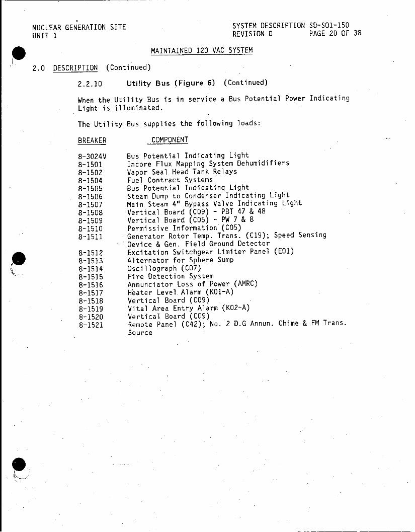
NUCLEAR GENERATION SITE SYSTEM DESCRIPTION SD-SO1-150 UNIT 1 REVISION 0 PAGE 20 OF 38
MAINTAINED 120 VAC SYSTEM
2.0 DESCRIPTION (Continued)
2.2.10 Utility Bus (Figure 6) (Continued)
When the Utility Bus is in service a Bus Potential Power Indicating Light is illuminated.
The Utility Bus supplies the following loads:
BREAKER COMPONENT
8-3024V Bus Potential Indicating Light 8-1501 Incore Flux Mapping System Dehumidifiers 8-1502 Vapor Seal Head Tank Relays 8-1504 Fuel Contract Systems 8-1505 Bus Potential Indicating Light 8-1506 Steam Dump to Condenser Indicating Light 8-1507 Main Steam 4" Bypass Valve Indicating Light 8-1508 Vertical Board (C09) - PBT 47 & 48 8-1509 Vertical Board (C05) - PW 7 & 8 8-1510 Permissive Information'(CO5) 8-1511 Generator Rotor Temp. Trans. (C19); Speed Sensing
Device & Gen. Field Ground Detector 8-1512 Excitation Switchgear Limiter Panel (EO1) 8-1513 Alternator for Sphere Sump 8-1514 Oscillograph (C07) 8-1515 Fire Detection System 8-1516 Annunciator Loss of Power (AMRC) 8-1517 Hater Level.Alarm (KO1-A) 8-1518 Vertical Board (C09) 8-1519 Vital Area Entry Alarm (K02-A) 8-1520 Vertical Board (C09) 8-1521 Remote Panel (C4?); No. 2 D.G Annun. Chime & FM Trans.
Source
InoeFu0apn Sse euiiir
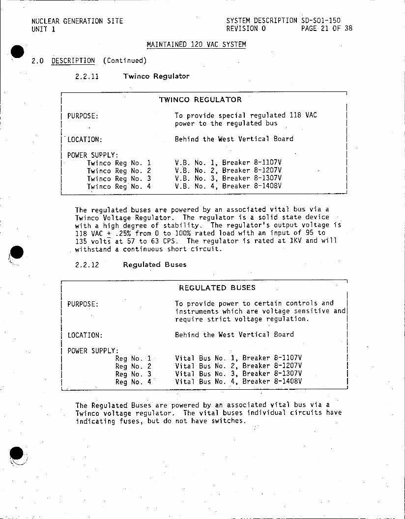
NUCLEAR GENERATION SITE SYSTEM DESCRIPTION SD-SO1-150 UNIT 1 REVISION 0 PAGE 21 OF 38
MAINTAINED 120 VAC SYSTEM
2.0 DESCRIPTION (Continued)
2.2.11 Twinco Regulator
TWINCO REGULATOR
PURPOSE: To provide special regulated 118 VAC power to the regulated bus
I'LOCATION: Behind the West Vertical Board
POWER SUPPLY: Twinco Reg No. 1 V.B. No. 1, Breaker 8-1107V
| Twinco Reg No. 2 V.B. No. 2, Breaker 8-1207V Twinco Reg No. 3 V.B. No. 3, Breaker 8-1307V
I Twinco Reg No. 4 V.B. No. 4, Breaker 8-1408V
The regulated buses are powered by an associated vital bus via a Twinco Voltage Regulator. The regulator is a solid state device with a high degree of stability. The regulator's output voltage is 118 VAC + .25% from 0 to 100% rated load with an input of 95 to 135 volts at 57 to 63 CPS. The regulator is rated at 1KV and will withstand a continuous short circuit.
2.2.12 Regulated Buses
REGULATED BUSES
PURPOSE: To provide power to certain controls and instruments which are voltage sensitive andi require strict voltage regulation.
LOCATION: Behind the West Vertical Board
POWER SUPPLY: Reg No. 1 Vital Bus No. 1, Breaker 8-1107V Reg No. 2 Vital Bus No. 2, Breaker 8-1207V Reg No. 3 Vital Bus No. 3, Breaker 8-1307V Reg No. 4 Vital Bus No. 4, Breaker 8-1408V
The Regulated Buses are powered by an associated vital bus via a Twinco voltage regulator. The vital buses individual circuits have indicating fuses, but do not have switches.

NUCLEAR GENERATION SITE SYSTEM DESCRIPTION SD-SO1-150 UNIT 1 REVISION 0 PAGE 22 OF 38
MAINTAINED 120 VAC SYSTEM
2.0 DESCRIPTION (Continued)
2.2.12 Regulated Buses (Continued)
The Regulated Bus No. 1 supplies the following loads:
BREAKER COMPONENT
8-11R1 S/G Instrument Rack R10 & R11 (C24) 8-11R2 Reactor Control & Protection System Rack R1 & R2 (C26) 8-11R3 N.I.S. Rack (C1O) - Comp. -Diff., N1208, N1212, PS1503 8-11R4 Pressurizer Instrument Rack R3 & R4 (C29) 8-11R5 Aux. Cooling, S.I., C.V.C.S. Rack R7 (C23) 8-11R6 Reactor Control System Rack R5 (C27) 8-11R7 Reactor Instrumentation CN15 & 16 (C03)
The Regulated Bus No. 2 supplies the following loads:
BREAKER COMPONENT
8-12R1 S/G Instrument Rack R10 & R11 (C24) 8-12R2 Reactor Control & Prbtection System Rack RI & R2 (C26) 8-12R3 N.I.S. Rack (C1O) - Sphere Evac. Horn, PS1504, N1203,
N1205 8-12R4 Pressurizer Instrument Rack R3 & R4 (C29) 8-12R5 Spare 8-12R6 Reactor Control System Rack R5 (C27)
The Regulated'Bus No. 3 supplies the following loads:
BREAKER COMPONENT
8-13R1 S/G Instrument Rack R10 & R11 (C24) 8-13R2 Reactor Control & Protection System Rack R1 & R2 (C26) 8-13R3 N.I.S. Rack (C1.0) - Audio Count Rate, PS1505, N1204,
N1207 8-13R4 Pressurizer Instrument Rack R3 & R4 (C29) 8-13R5 Spare 8-13R6 Reactor Control System Rack R5 (C27)
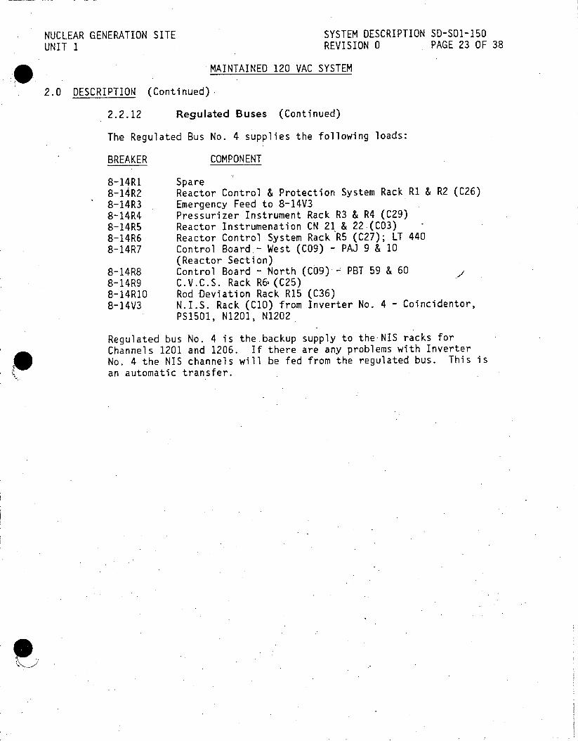
NUCLEAR GENERATION SITE SYSTEM DESCRIPTION 50-501-150 UNIT 1 REVISION 0 PAGE 23 OF 38
MAINTAINED 120 VAC SYSTEM
2.0 DESCRIPTION (Continued)
2.2.12 Regulated Buses (Continued)
The Regulated Bus No. 4 supplies the following loads:
BREAKER COMPONENT
8-14R1 Spare 8-14R2 Reactor Control & Protection System Rack R1 & R2 (C26) 8-14R3 Emergency Feed to 8-14V3 8-14R4 Pressurizer Instrument Rack R3 & R4 (C29) 8-14R5 Reactor Instrumenation CN 21 & 22(C03) 8-14R6 Reactor Control System Rack R5 (C27); LT 440 8-14R7 Control Board.- West (C09) - PAJ 9 & 10
(Reactor Section) 8-14R8 Control Board - North (C09) PBT 59 & 60 8-14R9 C.V.C.S. Rack R6(C25) 8-14RI0 Rod-Deviation Rack R15 (C36) 8-14V3 N.I.S. Rack (CO) from Inverter No. 4 - Coincidentor,
PS1501, N1201, N1202
Regulated bus No. 4 is thebackup supply to theNIS racks for Channels 1201 and 1206. If there are any problems with Inverter No. 4 the NIS channels will be fed from the regulated bus. This is an automatic transfer.
Coto9ord-Nrh(C9.,B 5 0,
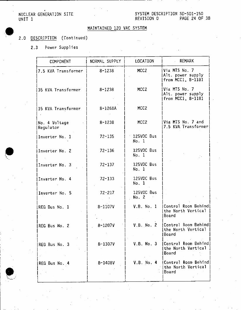
NUCLEAR GENERATION SITE SYSTEM DESCRIPTION SD-SO1-150 UNIT 1 REVISION 0 PAGE 24 OF 38
MAINTAINED 120 VAC SYSTEM
2.0 DESCRIPTION (Continued)
2.3 Power Supplies
COMPONENT NORMAL SUPPLY LOCATION I REMARK
17.5 KVA Transformer I 8-1238 1 MCC2 IVia MTS No. 7 jAlt. power supply Ifrom MCC1, 8-1181
135 KVA Transformer 1 8-1238 1 MCC2 IVia MTS No. 7 I |Alt. power supply I Ifrom MCC1, 8-1181 |
115 KVA Transformer I 8-1268A I MCC2 I I . I I
INo. 4 Voltage | 8-1238 | MCC2 IVia MTS No. 7 and I |Regulator I 17.5 KVA Transformeri II I jInverter No. 1 | 72-135 I 125VDC Bus I
I I INo.
lInverter No. 2 I 72-136 1 125VDC Bus I No. 1
I I lInverter No. 3 | 72-137 I 125VDC Bus I
I I No.1 I I
lInverter No. 4 1 72-133 1 125VDC Bus I | No. 1
I I lInverter No. 5 I 72-217 125VDC Bus
I - I No.2 II II IREG Bus No. 1 | 8-1107V I V.B. No. 1 |Control Room Behindi
III Ithe North Vertical I I. I * IBoard I III IREG Bus No. 2 8-1207V I V.B. No. 2 IControl Room Behind|
Ithe North Vertical I I I|Board I
SI I I IREG Bus No. 3 8-1307V I V.B. No. 3 IControl Room Behindl
I Ithe North Vertical I I 1IIIBoard I
IREG Bus No. 4 8-1408V I V.B. No. 4 IControl Room Behindl I tIthe North Vertical I I |Board
I I__ _ _ _ _ _ _ _ _ _ _ _ _ _ _ _ _ _ _ _j_ _ _ _ _ _ _ _

NUCLEAR GENERATION SITE SYSTEM DESCRIPTION SD-SO1-150 UNIT 1 REVISION 0 PAGE 25 OF 38
MAINTAINED 120 VAC SYSTEM
2.0 DESCRIPTION (Continued)
2.3 Power Supplies (Continued)
COMPONENT | NORMAL SUPPLY ALTERNATE
V.B. No. 1 Inverter No. 1 MCC-2 via MTS No. 7 and 37.5 KVA Transformer
IV.B. No. 2 Inverter No. 2 MCC-2 via MTS No. 7 and 37.5 KVA Transformer
I I V.B. No. 3 & 3A Inverter No. 3 MCC-2 via MTS No. 7 and
37.5 KVA Transformer
V.B. No. 4 Inverter No. 4 MCC-2 via MTS No. 7, 7.5 KVA Transformer and No. 4 Voltage Regulator
V.B. No. 5 & 6 Inverter No. 5 MCC-2 via 15 KVA I Transformer
Utility Bus MCC-2 via 37.5 Lighting Switchgear ) KVA Transformer Breaker
_ __I _ __

NUCLEAR GENERATION SITE SYSTEM DESCRIPTION SD-S01-150 UNIT 1 REVISION 0 PAGE 26 OF 38
MAINTAINED 120 VAC SYSTEM
3.0 OPERATION
NOTE: The vital bus or utility bus power supply to an instrument on the control board can be determined by using the Dot method. A colored dot on the instrument will indicate which bus it is powered by. The location of the dot on the instrument will indicate where it will fail upon loss of power. The colored dots associated with each bus are as follows:
Bus Color
V.B.1 Red V.B.2 Orange V.B.3 Blue V.B.3A White and Blue V.B.4 Green V.B.5 Brown V.B.6 White and Brown Utility Bus Yellow
3.1 Emergency-Operations
3.1.1 Loss of Vital Bus No. 1
Upon loss of power to vital bus No. 1 the following will occur:
* Bus Potehtial Power Indicating Light extinguished for Vital Bus No. 1.
* Vital Bus 1, 2, 3, 3A, 4 and Utility Bus Trouble Alarm.
* Automatic Transfer to Backup Supply to Vital Bus No. I on Inverter Failure.
* Turbine load runback will occur due to loss of NIS Channel N-1208.
A detailed description of operator actions and.equipment affected upon loss of vital bus No. 1 is given in the Operating Instructions (see Reference 4.3.1).

NUCLEAR GENERATION SITE SYSTEM DESCRIPTION SD-S01-150 UNIT 1 REVISION 0 PAGE 27 OF 38
MAINTAINED 120 VAC SYSTEM
3.0 OPERATION (Continued)
3.1.2 Loss of Vital Bus No. 2
Upon loss of power to vital bus No. 2 the following will occur:
* Bus Potential Power Indicating Light extinguished for Vital Bus No. 2.
* Vital Bus 1, 2, 3, 3A, 4 and Utility Bus Trouble Alarm.
* Automatic Transfer to Backup Supply to Vital Bus No. 2 on Inverter Failure.
* Turbine load runback will occur due to loss of NIS Channel N-1205.
A detailed description of operator actions and equipment affected upon loss of vital bus No. 2 is given in the Operating Instructions (see Reference 4.3.1).
3.1.3 Loss of Vital Bus No. 3 and 3A
Upon loss of power to vital bus No. 3 the following will occur:
* Bus Potential Power Indicating Light extinguished for Vital Bus No. 3.
* Vital Bus 1, 2, 3, 3A, 4 and Utility Bus Trouble Alarm.
* Automatic Transfer to Backup Supply to Vital Bus No. 3 on Inverter Failure.
* Turbine load runback will occur due to loss of NIS Channel N-1207.
A detailed description of operator actions and equipment affected upon loss of vital buses No. 3 and 3A is given in the Operating Instructions (see Reference 4.3.1).
3.1.4 Loss of Vital Bus No. 4
Upon loss of power to vital bus No. 4 the following will occur:
* Bus Potential Power Indicating Light extinguished for Vital Bus No. 4.
* Vital Bus 1, 2, 3, 3A, 4 and Utility Bus-Trouble Alarm.
* Automatic Transfer to Backup Supply to (37.5 KVA Transformer) Vital Bus No. 4 on Primary Supply Failure (7.5 KVA Transformer).
A detailed description of operator actions and equipment affected upon loss of vital bus No. 4 is given in the Operating Instructions (see Reference 4.3.1).
NUCLEAR GENERATION SITE SYSTEM DESCRIPTION SD-SO1-150 UNIT 1 REVISION 0 PAGE 28 OF 38
MAINTAINED 120 VAC SYSTEM
3.0 OPERATION (Continued)
3.1.5 Loss of Vital Bus No. 5
Upon loss of power to vital bus No. 5 the following will occur:
* Bus Potential Power Indicating Light extinguished for Vital Bus No. 5.
* Vital Bus 5, 6 and YV-29 (Inverter 5) Trouble Alarm.
* Automatic Transfer to backup supply to Vital Bus No. 5 and 6 on Inverter failure (bus No. 5 and No. 6 are in parallel at the terminals of the transfer switch).
A detailed description of operator actions and equipment affected upon loss of vital bus No. 5 and No. 6 is given in the Operating Instructions (see Reference 4.3.1).
3.1.6 Loss of the Utility Bus
Upon loss of power to the Utility Bus the following will occur:
* Bus Potential Power Indicating Light extinguished for the Utility Bus.
* Vital Bus 1, 2, 3, 3A, 4 and Utility Bus Trouble Alarm.
* Automatic Transfer to Backup Supply to the Utility Bus on 37.5 KVA Transformer failure.
A detailed description of operator actions and equipment affected upon loss of the Utility Bus is given in the Operating Instructions (see Reference 4.3.1).
3.1.7 Loss of MCC-2
The loss of MCC-2 will result in the loss of Vital Bus No. 4, therefore, prompt action is required to transfer the 37.5 KVA .transformer source, Master Transfer Switch No. 7, from MCC-2 to MCC-1. Loss of Vital Bus No. 4 requires that the reactor be manually tripped.
3.2 Other Operations
Preplanning and care must be exercised when testing or maintenance is to be performed on an inverter, 120 VAC vital bus or the utility bus. A misoperation could result in loss of power to a vital or utility bus.

NUCLEAR GENERATION SITE SYSTEM DESCRIPTION SD-SO1-150 UNIT I REVISION 0 PAGE 29 OF 38
MAINTAINED 120 VAC SYSTEM
4.0 REFERENCES
4.1 Single Line
4.1.1 5102174 One Line Diagram 120 Volt AC System (N 1540 Sheet 18)
4.1.2 5159826 One Line Diagram 120 VAC Vital Bus System Train B (N 1540 Sheet 18A)
4.1.3 39473 120V Non Safety Related Panel Schedule (N 1540 Sheet 18B)
4.1.4 5180715 Load Schedule 120 VAC Vital Bus 3A Train A (N 1540 Sheet 38)
4.1.5 5180713 Load Schedule 120 VAC Vital Bus 5 & 60 Train B (N 1540 Sheet 37)
4.2 Elementary Diagram
4.2.1 5180716 Elementary Diagram Indication & Annunciation 120 VAC Vital Buses 3, 3A, 5 and 6 (N 1546 Sheet 31)
4.2.2 5180727 Elementary Diagram Indication & Annunciation 120 VAC Vital Buses 1, 2, 4 & Utility (N 1546 Sheet 36)
4.3 Procedures
4.3.1 S01-2.6-3 Loss of Vital or Utility Bus
4.3.2 SO1-9-13 Inverter and Vital Bus Operation
4.3.3 S01-12.2-6 Electrical Distribution Surveillance
4.3.4 S01-12.3-17 Electrical Transfer Switches Alignment Check
4.4 Technical Manuals
4.4.1 1810-AB370-MOO1 AVTEL Inverter Instr. Manual
4.4.2 Elgar Instruction Manual, Inverter,752-1-101
4.4.3 1810-AC492-M001 Gould Invert-A-Stat Instr. Manual
4.4.4 BSO-3569 Western Switchboard
4.5 Technical Specifications
4.5.1 The following Technical Specifications pertain to the Maintained 120 VAC System: 3.7
KBuhler:3318i

NUCLEAR GENERATION SITE SYSTEM DESCRIPTION SD-SO-150 UNIT 1 REVISION 0 PAGE 31 OF 38
FIGURE 2: MASTER TRANSFER SWITCH 7
ROD DRIVE CONTROL SYSTEM FEEDER
ACB-2 ACB-1 ACB-3
POWER POWER FROM LEAVE SELECT FROM
MCC-1 SWITCH TO MCC-2 MCC-2
POSITION FOR NORMAL OPS
MCC-1 MCC-2
8-1181 62 8-1238
3318i

NUCLEAR GENERATION SITE SYSTEM DESCRIPTION SD-SO1-150 UNIT 1 REVISION 0 PAGE 32 OF 38
FIGURE 3: VB4 VOLTAGE REGULATOR
0 150
AC VOLTS CONTROL
VOLTAGE OVERLOAD POWER POWER ADJUST RESET O FUSE OUTPUT
R NOFF A
3318i

NUCLEAR GENERATION SITE SYSTEM DESCRIPTION SD-SO1-150
UNIT 1 REVISION 0 PAGE 33 OF 38
FIGURE 4: INVERTER 1, 2, OR 3
OUTPUT
VOLTAGE CURRENT
FREOUENCY
0 150 0 75
AC VOLTS 60 ACMPS
INPUT VOLTAGE
0 150
DC VOLTS ALARM
FAN OVLD FAIL
Y R _R R R 1
CURRENT FUSE OVER R LIMIT OPEN TEMP.
HORN STOP
OUTPUT STATUS CONTROLS
POWER
wIW -1G Y
INPUT MAIN MAIN w POWER READY OPEN
OUTPUT ADJUST OPERATE VOLTS CURRENT
LIMIT STANDBY
UV FUSE FAN FUSES
CB-1 CB-2 CB-3
33181
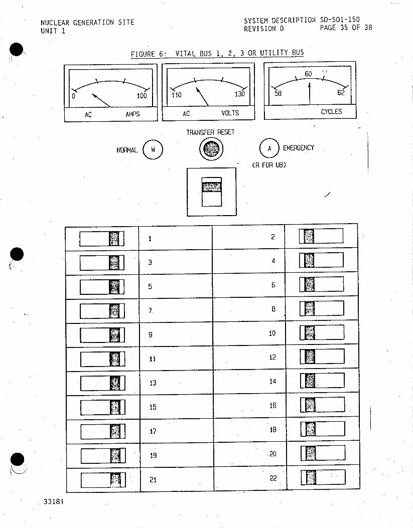
NUCLEAR GENERATION SITE SYSTEM DESCRIPTION SD-SO1-150
UNIT 1 REVISION 0 PAGE 35 OF 38
FIGURE 6: VITAL BUS 1, 2, 3 OR UTILITY BUS
60
0 100 110 130 58 62
AC AMPS AC VOLTS CYCLES
TRANSFER RESET
NORMAL EMERGENCY (R FOR UB)
3 4
5 6
8
g 10
12
13 14
15 16
g9 20
21 22
3318i

SYSTEM DESCRIPTION SD-SO1-150
UNITA REVISION 0 PAGE 36 OF 3 W
FIGURE 7: VB FEEDER
VB4 FEEDER
60
130 5862
AC AMPS AC VOLTS CYCLES
POWER SUPPLY POWER SUPPLY AFROM MCC-2
FROM MCC-10
VITAL BUS NO. 4
NAQEMERGY BtS IV
TRFER RESET
11 2
I I
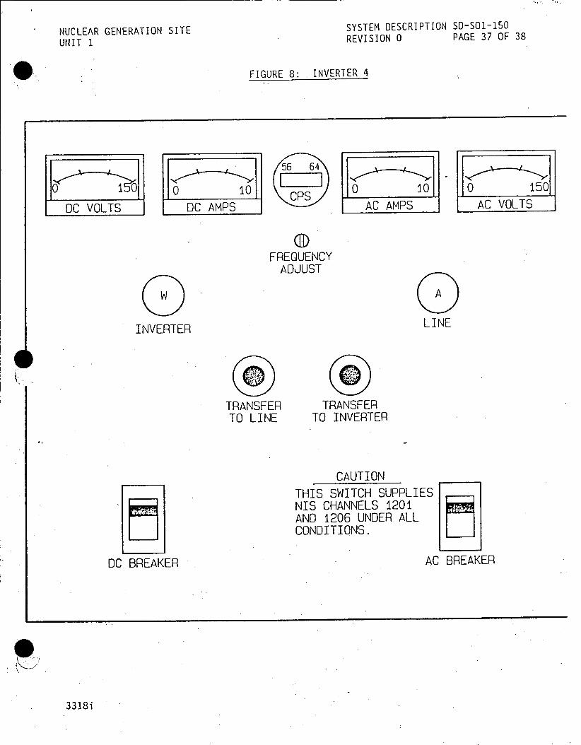
NUCLEAR GENERATION SITE SYSTEM DESCRIPTION SO-SO1-150
UNIT 1 REVISION 0 PAGE 37 OF 38
FIGURE 8: INVERTER 4
55 64
0 0 0 10 CPSII 0 10 0 150 CPS
DC VOLTS DC AMPS AC AMPS AC VOLTS
FREQUENCY ADJUST
INVERTER LINE
TRANSFER TRANSFER TO LINE TO INVERTER
CAUTION
THIS SWITCH SUPPLIES NIS CHANNELS 1201 AND 1206 UNDER ALL CONDITIONS.
DC BREAKER AC BREAKER
3318i

NUCLEAR GENERATION SITE SYSTEM DESCRIPTION SD-SO1-150 UNIT 1 REVISION 0 PAGE 38 OF 38
APPENDIX A
DEVELOPMENTAL RESOURCES
1. FSAR Section 3.2.6
2. Study Guide No. 84, Rev. 5
3. Bechtel System Description, No. 36, 120 VAC System
4. Unit 1 Lesson Plan OT-1056, Maintained 120 VAC System
A-1
3318i
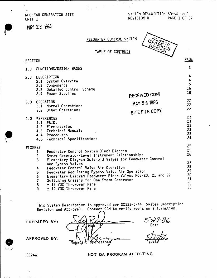
NUCLEAR GENERATION SITE SYSTEM DESCRIPTION SD-501-260 UNIT 1 REVISION 0 PAGE 1 OF 37
FEEDWATER CONTROL SYSTEM
TABLE OF CONTENTS 04
SECTION PAGE
1.0 FUNCTIONS/DESIGN BASES 3
2.0 DESCRIPTION 4 2.1 System Overview 4 2.2 Components 5 2.3 Detailed Control Scheme 16 2.4 Power Supplies RECEIVED CDM 18
3.0 OPERATION iMi 2 gg 1986 22 3.1 Normal Operations 22
3.2 Other Operations SITE FILE COPY 22
4.0 REFERENCES 23 4.1 P&IDs 23 4.2 Elementaries 23 4.3 Technical Manuals 23 4.4 Procedures 23 4.5 Technical Specifications 24
FIGURES 25 1 Feedwater Control System Block Diagram 25 2 Steam Generator/Level Instrument Relationships 26 3 Elementary Diagram Solenoid Valves for Feedwater Control
And Bypass Valves 27 4 Feedwater Control Valve Air Operation 28 5 Feedwater Regulating Bypass Valve Air Operation 29 6 Elementary Diagram Feedwater Block Valves MOV-20, 21 and 22 30 7 Switching Chassis for One Steam Generator 31 8 + 15 VDC Throwover Panel 32 9 + 10 VDC Throwover Panel 33
This System Description is approved per S0123-0-44, System Description Revision and Approval. Contact CDM to verify revision information.
PREPARED BY: ,52- -r Date
APPROVED BY: Ma a , pe tioat
0224W NOT QA PROGRAM AFFECTING

CEA ESYSTEM DESCRIPTION SD-SO1-260
NUCLEAR GENERATION SITE REVISION 0 PAGE 2 OF 37
UNIT 1
FEEDWATER CONTROL SYSTEM
TABLE OF CONTENTS (Conti nued)
PAGE
SECTION
APPENDICES 34
A Developmental Resources 36
B Annunciators
0224W

NUCLEAR GENERATION SITE SYSTEM DESCRIPTION SD-SO-260
UNIT I REVISION 0 PAGE 3 OF 37
FEEDWATER CONTROL SYSTEM
1.0 FUNCTIONS/DESIGN BASES
1.1 The Feedwater Control System has the following main function:
1.1.1 Compares steam and feedwater flow with level deviation from level setpoint, to automatically regulate the feedwater flow to the individual Steam Generators.
1.2 The Feedwater Control System has the following additional functions:
1.2.1 Provides input signals for Turbine Trip and Reactor
Trip.
1.2.2 Receives signals from the Sequencer System.
1.2.3 Receives signals from the Turbine Trip circuitry, the Feedwater Pump Breakers, and the Auxiliary Feedwater System circuitry.
6*
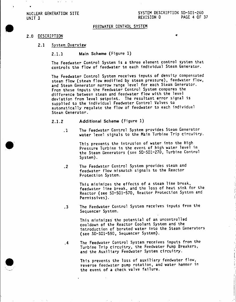
NUCLEAR GENERATION SITE SYSTEM DESCRIPTION SD-SOl-260 UNIT .1 REVISION 0 PAGE 4 OF 37
FEEDWATER CONTROL SYSTEM
2.0 DESCRIPTION
2.1 System Overview
2.1.1 Main Scheme (Figure 1)
The Feedwater Control System is a three element control system that controls the flow of feedwater to each individual Steam Generator.
The Feedwater Control System receives inputs of density compensated steam flow (steam flow modified by steam pressure), feedwater flow, and Steam Generator narrow range level for each Steam Generator. From these inputs the Feedwater Control System compares the difference between steam and feedwater flow with the level deviation from level setpoint. The resultant error signal is supplied to the individual Feedwater Control Valves to automatically regulate the flow of feedwater to each individual Steam Generator.
2.1.2 Additional Scheme (Figure 1)
.1 The Feedwater Control System provides Steam Generator water level signals to the Main Turbine Trip circuitry.
This prevents the intrusion of water into the High Pressure Turbine in the event of high water level in the Steam Generators (see SD-SO1-270, Turbine Control System).
.2 The Feedwater Control System provides steam and feedwater flow mismatch signals to the Reactor Protection System.
This minimizes the effects of a steam line break, feedwater line break, and the loss of heat sink for the Reactor (see SD-SO1-570, Reactor Protection System and Permissives).
.3 The Feedwater Control System receives inputs from the Sequencer System.
This minimizes the potential of an uncontrolled cooldown of the Reactor Coolant System and the introduction of borated water into the Steam Generators (see SD-S01-590, Sequencer System).
.4 The Feedwater Control System receives inputs from the Turbine Trip circuitry, the Feedwater Pump Breakers, and the Auxiliary Feedwater System circuitry.
This prevents the loss of auxiliary feedwater flow, 0 reverse feedwater pump rotation, and water hammer in the event of a check valve failure.

NUCLEAR GENERATION SITE SYSTEM DESCRIPTION S-SOI-260
UNIT 1 REVISION 0 PAGE 5 OF 37
FEEDWATER CONTROL SYSTEM
2.0 DESCRIPTION (Continued)
2.2 Components
2.2.1 Steam Flow Measurement (Figure 1)
.1 Flow Elements FE-460, 461, and 462 are Dall Flow Tubes and are installed in the steam outlet lines of Steam Generators A, B and C respectively. The flow elements are-compact flow tubes designed for use in flow measurements where a high differential pressure is developed with the lowest possible head loss.
.2 Differential Pressure Transmitters FT-460, 461 and 462 for Steam Generators A, B and C respectively, are Barton Differential Transmitters. The transmitters measure steam flow as a function of differential pressure across their respective flow element. The flow transmitters provide an output signal of 0 to 2.5 x 10' lbs/hr to the Steam Flow Computers FM-460, 461 and 462.
.3 Steam Flow Computers FM-460, 461 and 462 are located in the racks behind the West Vertical Board and
extract the square root of the differential pressure
signals provided by FT-460, 461 and 462 respectively. The Steam Flow Computers then multiply this signal by a correction factor that is a function of steam pressure
supplied by pressure transmitter PT-459 (i.e., Density Compensated Signals).
The Steam Flow Computers provide an output signal of
+1 to +9 volts DC and represents true steam flow. The
output signals are transmitted to Feedwater Flow Controllers FC-456A, 457A and 458A, Steam/ Feedwater Flow Comparators FM-456B, 4576 and 458B, and Steam Generator Level Recorders YR-456, 457 and 458.

NUCLEAR GENERATION SITE SYSTEM DESCRIPTION SD-S01-260
UNIT 1 REVISION 0 PAGE 6 OF 37
FEEDWATER CONTROL SYSTEM
2.0 DESCRIPTION (Continued)
2.2.2 Steam Pressure Measurement (Figure 1)
.1 PT-459 is a Foxboro Pressure Transmitter and is located on the east Main Steam Header upstream of the
24 inch block valve. PT-459 transmits a 0 - 1000 psig
signal to the Density Correction Ranging Amplifier
(PM-459) of the Steam Flow Computers. It also provides
a signal to PI-459 located on the West Vertical Board. (PT-459 also provides an input to Steam Dump Controller PC-418A, see SD-SOI-190, Main Steam Systems).
As steam is compressible, the same measured mass steam flow rate will be different for various steam
pressures. Therefore, to indicate a true steam flow
rate, the steam flow is corrected for the different steam pressures encountered over the full operating range.
The Density Correction Ranging Amplifier provides a
compensation factor in the form of an electronic signal to the Steam Flow Computers to correct steam flow for
pressure variations.
2.2.3 Feedwater Flow (Figure 1)
.1 Differential Pressure Transmitters FT-456, 457 and 458 are Foxboro Differential Pressure Transmitters and are located on the Feedwater Mezzanine. The transmitters measure the feedwater flow as a function
of differential pressure developed across Flow Elements FE-456, 457 and 458. The pressure transmitters provide
an output signal of 0 to 2.5 x 10' lbs/hr to the Feedwater
Flow Computers FM-456A, 457A and 458A.
.2 Feedwater Flow Computers FM-456A, 457A and 458A are located in the racks behind the West Vertical Board and extract the square root of the differential
pressure signals provided by FT-456, 457 and 458
respectively. The Feedwater Flow Computers provide an
output signal of +1 to +9 VDC that is a linear function of feedwater flow (i.e. as feedwater flow increases the
output voltage signal increases correspondingly). The
output signals are transmitted to Feedwater Flow Controllers FC-456A, 457A and 458A, Steam Generator Recorders YR-456, 457, 458 and Steam/ Feedwater Flow
Comparators FM-456B, 457B and 458B.
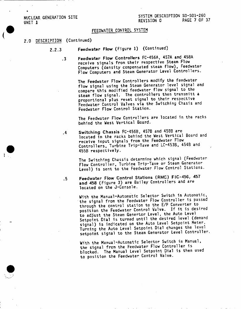
NUCLEAR GENERATION SITE SYSTEM DESCRIPTION SD-S01-260
UNIT 1 REVISION 0 PAGE 7 OF 37
FEEDWATER CONTROL SYSTEM
2.0 DESCRIPTION (Continued)
2.2.3 Feedwater Flow (Figure 1) (Continued)
.3 Feedwater Flow Controllers FC-456A, 457A and 458A receive signals from their respective Steam Flow
Computers (density compensated steam flow), Feedwater Flow Computers and Steam Generator Level Controllers.
The Feedwater Flow Controllers modify the feedwater flow signal using the Steam Generator level signal and
compare this modified feedwater flow signal to the
steam flow signal. The controllers then transmitt a
proportional plus reset signal to their respective Feedwater Control Valves via the Switching Chasis and Feedwater Flow Control Station.
The Feedwater Flow Controllers are located in the racks
behind the West Vertical Board.
.4 Switching Chassis FC-456B, 4578 and 4588 are located in the racks behind the West Vertical Board and
receive input signals from the Feedwater Flow Controllers, Turbine Trip-Tave and LC-453B, 454B and
455B respectively.
The Switching Chassis determine which signal (Feedwater Flow Controller, Turbine Trip-Tave or Steam Generator
Level) is sent to the Feedwater Flow Control Stations.
.5 Feedwater Flow Control Stations (RMC) FIC-456, 457 and 458 (Figure 3) are Bailey Controllers and are located on the J-Console.
With the Manual-Automatic Selector Switch in Automatic, *the signal from the Feedwater Flow Controller is passed through the control station to the E/P Converter to
position the Feedwater Control Valve. If it is desired
to adjust the Steam Genertor Level, the Auto Level
Setpoint Dial is turned until the desired level (demand
signal) is indicated on the Auto Level Setpoint Meter.
Turning the Auto Level Setpoint Dial changes the level
setpoint signal to the Steam Generator Level Controller.
With the Manual-Automatic Selector Switch in Manual, the signal from the Feedwater Flow Controller is
blocked. The Manual Level Setpoint Dial is then used
to position the Feedwater Control Valve.
0

NUCLEAR GENERATION SITE SYSTEM DESCRIPTION SD-S01-260
UNIT I REVISION 0 PAGE 8 OF 37
FEEDWATER CONTROL SYSTEM
2.0 DESCRIPTION (Continued)
2.2.3 Feedwater Flow (Figure 1) (Continued)
.5 (Continued)
The Null Meter indicates the difference between the
Manual Level Setpoint and the Auto Level Setpoint. The Null Meter is normally maintained at 0 (Manual
Signal = Auto Signal) by the adjustment of the Manual Level Setpoint Dial when the control station is in Auto
or by the adjustment of the Auto Level Setpoint Dial
when the control station is in Manual. By maintaining the Null Meter at 0, a "bumpless" transfer can be made
between Manual and Auto, and vice versa.
Also, with the control station in Manual, adjusting the Auto Level Setpoint Dial to a null condition will indirectly indicate the Manual Level Setpoint on the
Auto Level Setpoint Meter.
.6 Feedwater Regulating Bypass Valve Control Stations RMC-142, 143 and 144 (Figure 3) are Bailey Controllers
and are located on the J-Console and the Dedicated Safe
Shutdown System Panel.
A two position, Normal-Override, selector switch on the
Dedicated Safe Shutdown Panel is used to select which
controller (Normal, J-Console; Override, Dedicated Safe
Shutdown Panel) has control of the bypass valves.
The Manual CV Positioner Dial allows the operator to
remotely position the bypass valve.
The position demand signal (0-100%), to the E/P
Converter at the bypass valve, is indicated on the CV
Demand Meter.
NOTE: The indication is NOT the bypass valve
position - it is the demand signal to the
bypass valve. This is because the bypass valve is nonlinear.
Indication Valve Position
0% 0% 50% 25%
100% 100%

NUCLEAR GENERATION SITE SYSTEM DESCRIPTION SD-SO-260
UNIT 1 REVISION 0 PAGE 9 OF 37
FEEDWATER CONTROL SYSTEM
2.0 DESCRIPTION
2.2.3 Feedwater Flow (Figure 1) (Continued)
.7 Steam/Feedwater Flow Comparators FM-456B3, 457B and 458B generate control signals for the two out of three Reactor Trip relay matrix by comparing steam flow
to feedwater flow. If two out of three Steam
Generators produce a steam flow that exceeds feedwater
flow by 25% of Full Load Steam Flow, the comparator
generates a signal to actuate the Reactor Trip circuitry.
.8 Feedwater Flow Integrator is mounted on the West Vertical Board and totalizes the electrical inputs from
the Feedwater Flow Computers. The display is a digital readout of total feedwater flow in pounds per hour.
2.2.4 Steam Generator Level Measurement (Figures 1 and 2)
.1 Narrow Range Level is measured by LT-453, 454 and 455 for Steam Generators A, B and C respectively. The
level transmitters have a signal range of +9 VDC to +1
VtC corresponding to a 0 to 100 percent level at 800
psig and 520 f (Hot Calibrated). These signals are
transmitted to the Steam Generator Level Controllers
LC-453A, 454A and 455A; LC-453B, 454B and 455B; LC-453C, 454C and 455C and Steam Generator Level
Recorders YR-456, 457 and 458.
.2 Steam Generator Level Controllers LC-453A, 454A and 455A are located in the racks behind the West
Vertical Board. The controllers compare the Narrow
Range level signal with a level setpoint, originating from the Feedwater Flow Control Stations on the
J-Console (FIC-456, 457 and 458), to generate a level
error signal.
The level error signal is transmitted to the Feedwater
Flow Controllers FC-456A, 457A and 458A, where the
level error signal is used to modify the Feedwater Flow
Signal.
The level signals are transmitted to the Steam
Generator Level Recorders YR-456, 457 and 458.
.3 Steam Generator Level Controllers LC-453B, 454B and 455B are located in the racks behind the West
Vertical Board. The controllers transmit signals to
the Switching Chassis FC-456B, 457B and 458B, and S.I.
hOverride Defeat Relays.

NUCLEAR GENERATION SITE SYSTEM DESCRIPTION SD-S01-260
UNIT I REVISION 0 PAGE 10 OF 37
FEEDWATER CONTROL SYSTEM
2.0 DESCRIPTION (Continued)
2.2.4 Steam Generator Level Measurement (Figures 1 and 2) (Continued)
.4 Steam Generator Level Controllers LC-453C, 454C, 455C, 450C, 451C and 452C are located in the racks behind the West Vertical Board. The controllers generate the control signals for the 2 out of 2 and 1 out of 3 Turbine Trip relay matrix. If both the Wide and Narrow Range Level Instruments on any one of the
three Steam Generators reaches 85%, a Turbine Trip will occur.
.5 Wide Range Level is measured by LT-450, 451 and 452 for Steam Generators A, B and C respectively. The
level transmitters have a signal range of +1 VDC to +9
VDC corresponding to a 0" to 318" level at 80*F (Cold Calibrated). These signals are transmitted to LI-450A, 451A and 452A on the North Vertical Board; LI-450B, 451B and 452B at Feedwater Mezzanine area; LI-450B, 451B and 452B at the Dedicated Safe Shutdown Panel; and at the Emergency Feed Station.
2.2.5 Recorders
.1 Steam Generator Recorders YR-456A, 457A and 458A are located on the J-console. Each recorder is a three
pen recorder that records the following:
Red Pen - density compensated Steam flow with a
range of 0 - 2.5 x 10' lbs/Hr.
Blue Pen - Feedwater flow with a range of 0 - 2.5 x 10' lbs/Hr.
Green Pen - Steam Generator narrow range level with a range of 0 - 100% (233 to
318 inches)
NOTE: All Steam Generator Narrow Range indication is Hot Calibrated, and all Steam Generator Wide Range indication is Cold Calibrated.

NUCLEAR GENERATION SITE SYSTEM DESCRIPTION s-S01-260
UNIT 1 REVISION 0 PAGE 11 OF 37
FEEDWATER CONTROL SYSTEM
2.0 DESCRIPTION (Continued)
2.2.6 Feedwater Control Valves (FCV-456, 457 and 458)
FEEDWATER CONTROL VALVES (FCV's 456, 457 & 458)
PURPOSE: To regulate feedwater flow during power operations to maintain proper
steam
generator water level
SLOCATION: Feedwater Mezzanine, above the Main Lube
Oil Reservoir
I VALVE TYPE: Double disc, ported, direct acting
globe valve
VALVE SIZE: 8"
FAIL POSITION: Open
OPERATOR TYPE: Pneumatic diaphragm
FLOW CHARACTERISTICS: Linear flow through full length travel
DESIGN PRESSURE: 985 psig
DESIGN TEMPERATURE: 403 0 F
DESIGN MATERIAL: Chrome molebdenum steel
POSITION INDICATION: J-Console
CONTROLLER LOCATION: J-Console, Local
.1 Supporting Components and Indications (See Figures 3
and 4)
Electric to Pneumatic (E/P) Converters (YM-456B,
457B and 458B) are provided for each valve to
receive control signals. The converters function to
convert a -1 to -9 VDC electrical input signal to a
proportional pneumatic signal of 6 to 30 psig
respectively. The pneumatic signal positions the
diaphragm on the control valve. A signal decreasing
toward 6 psig will open the valve and a signal
approaching 30 psig will close the valve.
The E/P Converter is integral with a Bailey Feedwater
Flow Control Station (RMC) for each valve. The
pneumatic signal can originate from the Bailey controller, on the J-Console, or manually at the local
controller by placing the handle to HAND-OPEN or
HAND-CLOSE.

NUCLEAR GENERATION SITE SY ESCRIPTION S0-SO1-260
UNIT REVISi.tN 0 PAGE 12 OF 37
FEEDWATER CONTROL SYSTEM
2.0 DESCRIPTION (Continued)
2.2.6 Feedwater Control Valves (FCV-456, 457 and 458) (Continued)
.1 (Continued)
The valves close, after a 20 second time delay, on a
Sequencer actuation (SIS and SISLOP) by the opening action of a solenoid valve, in the air control lines, that supplies full control air pressure (30 psig) to the Feedwater Control Valve. If the respective Steam
Generator level is high, then the Feedwater Control
Valve will close without the 20 sec. time delay.
The valves will also close when both Feedwater Pump
Breakers are NOT closed, a Turbine Trip has occurred
and either Auxiliary Feedwater System has actuated.
The above actions are indicated by the Red backlit
SIS/Aux Trip Reset pushbuttons, above the Feedwater
Regulating Bypass Valve Controllers, illuminating.
To regain control of the Feedwater Control valves after
a Sequencer Actuation, the appropriate Sequencer must
be Reset and the appropriate Red backlit SIS/Aux Trip
Reset pushbuttons must be depressed.
To regain control of the Feedwater Control Valves after
both Feedwater Pumps have tripped, the Turbine has
tripped and either Auxiliary Feedwater System has
actuated; any initiating signal must be Reset (if both
AFW Systems have actuated, then both must be Reset) and the appropriate Red backlit SIS/Aux Trip Reset
pushbuttons must be depressed.
FCV-456 receives its SI signal from Sequencer 1, while
FCV-457 and 458 receive their SI signal from Sequencer 2.

SYSTEM DESCRIPTION SD-SO1-260 NUCLEAR GENERATION SITE REVISION 0 PAGE 13 OF 37 UNIT 1
* FEEUWATER CONTROL SYSTEM
2.0 DESCRIPTION (Continued)
2.2.7 Feedwater Regulating Bypass Valves (CV-142, 143 &
144)
FEEDWATER REGULATING BYPASS VALVES (CV-142, 143 & 144)
PURPOSE: To control feedwater flow during startup, cooldown and emergency conditions.
LOCATION: Feedwater Mezzanine, above the Main Lube
Oil Reservoir
VALVE TYPE: Globe
FAIL POSITION: Closed
OPERATOR TYPE: Pneumatic
FLOW CHARACTERISTICS: Nonlinear
DESIGN PRESSURE: 985 psig
DESIGN TEMPERATURE: 4030 F
POSITION INDICATION: J-Console
CONTROLLER LOCATION: J-Console, Local
.1 Supporting Components and Indications (see Figures 3
and 5)
Electric to Pneumatic (E/P) Converters are
provided for each valve to receive control signals.
The converters function to convert a -1 to -9 VC
electrical input signal to a proportional pneumatic
signal of 3 to 15 psig respectively. The pneumatic
signal positions the diaphragm on the bypass valve.
A signal decreasing toward 3 psig will close the valve
and a signal approaching 15 psig will open the valve.
The E/P Converter is integral with a Bailey Control
Station for each valve. The pneumatic-signal can
originate from the Bailey controller on the 3-Console,
or the Bailey Controller on the Dedicated Safe Shutdown
Panel, or manually at the local controller by placing
the handle to HAND-OPEN or HAND-CLOSE.

NUCLEAR GENERATION SITE SYSTEM DESCRIPTION 50-501-260
UNIT I - REVISION 0 PAGE 14 OF 37
FEEDWATER CONTROL SYSTEM
2.0 DESCRIPTION (Continued)
2.2.7 Feedwater Regulating Bypass Valves (CV-142, 143 & 144) (Continued)
.1 (Continued)
The valves close, after a 20 second time delay, on a
Sequencer actuation (SIS and SISLOP) by the opening action of a solenoid valve, in the air control lines, that vents the control air to atmosphere. If the
respective Steam Generator level is High, then the
Feedwater Regulating Bypass Valve will close without
the 20 sec. time delay.
The valves will also close when both Feedwater Pump breakers are not closed, a Turbine Trip has occurred and either Auxiliary Feedwater System has actuated.
The above actions are indicated by the Red backlit
SIS/Aux Trip Reset pushbuttons above the Feedwater
Regulating Bypass Valve Controllers.
To regain control of the Feedwater Regulating Bypass Valves after a Sequencer Actuation, the appropriate
Sequencer must be Reset and the appropriate Red
backlit SIS/Aux Trip Reset pushbuttons must be
depressed.
To regain control of the Feedwater Regulating Bypass valves after both Feedwater Pumps have tripped, the Turbine has tripped and either Auxiliary Feedwater
System has actuated, any initiating signal must be Reset (if both AFW Systems have actuated, then both
must be reset) and the appropriate Red backlit SIS/Aux
Trip Reset pushbuttons must be depressed.
CV-142 receives its SI signal from Sequencer 1, while CV-143 and 144 receive their SI signal from Sequencer 2.
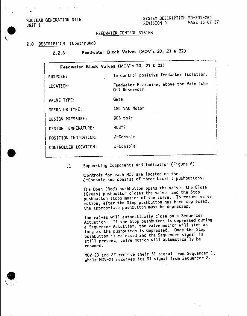
NUCLEAR .GENERATION SITE SYSTEM DESCRIPTION 50-501-260
UNIT 1 REVISION 0 PAGE 15 OF 37
FEEDWATER CONTROL SYSTEM
2.0 DESCRIPTION (Continued)
2.2.8 Feedwater Block Valves (MOV's 20, 21 & 22)
Feedwater Block Valves (MOV's 20, 21 & 22)
PURPOSE: To control positive feedwater isolation.
LOCATION: Feedwater Mezzanine, above the Main Lube 011 Reservoir
VALVE TYPE: Gate
OPERATOR TYPE: 480 VAC Motor
DESIGN PRESSURE: 985 psig
DESIGN TEMPERATURE: 403 0 F
POSITION INDICATION: J-Console
I CONTROLLER LOCATION: J-Console
.1 Supporting Components and Indication (Figure 6)
Controls for each MOV are located on the J-Console and consist of three backlit pushbuttons.
The Open (Red) pushbutton opens the valve, the Close
(Green) pushbutton closes the valve, and the Stop
pushbutton stops motion of the valve. To resume valve
motion, after the Stop pushbutton has been depressed, the appropriate pushbutton must be depressed.
The valves will automatically close on a Sequencer
Actuation. If the Stop pushbutton is depressed during
a Sequencer Actuation, the valve motion will stop as
long as the pushbutton is depressed. Once the Stop
pushbutton is released and the Sequencer signal is
still present, valve motion will automatically be resumed.
MOV-20 and 22 receive their SI signal from Sequencer 1,
while MOV-21 receives its SI signal from Sequencer 2.

NUCLEAR GENERATION SITE SYSTEM DESCRIPTION SD-SO1-260
UNIT I REVISION 0 PAGE 16 OF 37
(W FEEDWATER CONTROL SYSTEM
2.0 DESCRIPTION (Continued)
2.3 Detailed Control Scheme
2.3.1 Automatic Feedwater Valve Control
With the Feedwater Control Stations FIC-456, 457 and 458 in
automatic, the Feedwater Control Valve position is controlled by the respective Feedwater Flow Controllers, FC-456A, 457A and 458A,
which compare the steam flow signal with combined feedwater flow
and Steam Generator level signals. The steam flow signal acts as
the master setpoint for valve positioning.
If the Steam Generator level signal is above the setpoint, the +5 VDC Normal level signal received from LC-453A, 454A or 455A, will increase. This will raise the combined feedwater flow and
level signal, and if greater than the steam flow signal, will cause the Feedwater Control to re-position the Feedwater Control Valve
toward the closed position.
If the Steam Generator level signal is below the setpoint, the
+5 VDC Normal level signal output from LC-453A, 454A or 455A will
decrease. The effect on the Feedwater Control Valve will be the
reverse of the action described above.
Any error between the steam flow signal and the combined feedwater flow and Steam Generator level signals causes the respective Feedwater Flow Controller to generate a proportional plus reset
output signal (i.e., the magnitude of the input is proportional to
the output) which causes the respective FCV-456, 457 or 458 to open
or close.
2.3.2 Feedwater Switching Chassis Control (Figure 7)
The Feedwater Switching Chassis contains three Magnetic Amplifier
Level Relays LC-453B, 454B and 4558, Control Relay RY2, six Adjustable Potentiometers R2, R3, R5, R6, R8 and R9 and three
Inline Load Resistors R1, R4 and R7. (Level Relay - LR,
potentiometers R2 and R3, and Resistor R1 shown are typical for one
Steam Generator.)
Relay RY2 is common to all three Feedwater Control Systems and
energizes when Tave is less than 5450F and a Turbine Trip has
occurred.
When Tave is less than 545*F and a Turbine Trip has occurred, Relay RY2 energizes and the Switching Chassis interrupts
the
automatic signal between the Feedwater Flow Controller and the
Feedwater Flow Control Station (contact 1 opening). A signal from
R3 will cause the FCV to close to approximately 5% (contact 2
i. closing). The Automatic Signal is sent to ground (contact 3
closing).
NUCLEAR GENERATION SITE SYSTEM DESCRIPTION SD-501-260
UNIT 1 REVISION 0 PAGE 17 OF 37
FEEDWATER CONTROL SYSTEM
'2.0 DESCRIPTION (Continued)
2.3.2 Feedwater Switching Chassis Control (Continued)
In the event the Steam Generator level rises above 85%, the circuit
set up by Relay RY2 contacts will be overridden. This is
accomplished by Relay LR de-energizing which closes contact 4 and
opens contacts 5 and 6. Contact 4 closure re-establishes the
direct path between the Feedwater Flow Controller and the Feedwater Control Station. Contact 5 opening interrupts the signal from R3
and contact 6 opening removes the signal from ground. Thus, control of the Feedwater Control Valve reverts to Automatic and
with the Steam Generator level high the Feedwater Control Valve
will go closed.
In the event of a high Tave (> 5450F) and a Turbine Trip, the Feedwater Control Valves will remain under Automatic Control.
In any of the above events it is possible to manually position the Feedwater Control Valve by turning the Manual-Automatic Selector
Switch on the Feedwater Flow Control Station to Manual and then
rotating the Manual Level Setpoint Dial to achieve the desired
Feedwater Control Valve position.

NUCLEAR GENERATION SITE SYSTEM DESCRIPTION SD-SO1-260
UNIT 1 REVISION 0 PAGE 18 OF 37
(W FEEDWATER CONTROL SYSTEM
2.0 DESCRIPTION (Continued)
2.4 Power Supplies
COMPONENT BREAKER | LOCATION
I. I I S/G Level Transmitter I I Logic Cabinet I 8-1102 V I Vital Bus #1
| S/G Instrumentation I I I Rack R-10 & R-11 I 8-1105 V I Vital Bus #1
IIII I S/G High Level Trip I I (Wide Range) | 8-1110 V I Vital Bus #1
I II I S/G Instrument Rack I I I RIO & R11 I 8-1205 V I Vital Bus #2
I I I ( S/G High Level Trip 8 V (Narrow Range) I 8-1210 V | Vital Bus #2
II I I S/G Instrument Rack I I I R-10 & R-11 I 8-1305 V I Vital Bus #3
I I Misc. Relay Rack R-13 I 8-1414 V | Vital Bus #4
I. I I S/G Instrument Rack R B R-10 & R-11 8-11R1 I Regulated Bus #1
S/G Instrument Rack R-10 & R-11 8-12R1 Regulated Bus #2
S/G Instrument Rack R B R-10 & R-11 8-13R1 Regulated Bus #3
MOV-20 42-1197 MCC-1
MOV-21 42-1242 MCC-2
MOV-22 42-1387 MCC-3
NUCLEAR GENERATION SITE SYSTEM DESCRIPTION SD-SO1-260 UNIT I REVISION 0 PAGE 19 OF 37
FEEDWATER CONTROL SYSTEM
2.0 DESCRIPTION (Continued)
2.4.1 Feedwater Control System Power (Figures 8 and 9)
The Feedwater Control System is provided with four Vital Bus 120 VAC, 60 cycle power sources and four Regulated 120 VAC, 60 cycle power supplies. The power supplies are located in the racks behind the West Vertical Board.
Three of the four Vital Bus power supplies supply the three Foxboro Deviation Bistables mounted in the Steam/Feedwater Flow Comparators. Vital Bus 1, 2 and 3 go to the Steam/Feedwater Flow Comparators for Steam Generators A, B, and C respectively.
The fourth Vital Bus power supply (Vital Bus 4) supplies convenience outlets on the racks and has no interconnections with any part of the Feedwater Control System.
The four Regulated power supplies are used in all other components of the system where 120 VAC, 60 cycle power is required.
.1 + 15V DC Power Supplies
Primary + 15V DC power is developed by a Technipower unit associated with the Steam Flow Computer. The output of this unit is delivered to the +15V DC Throwover Chassis.
Primary -15V DC power is developed by Technipower unit associated with the Feedwater Flow Computer. The output of this unit is also delivered to the + 15V DC Throwover Chasis.
Separate +15V DC and -15V DC Technipower units deliver backup supplies to the +15V DC Throwover Chassis.
The Steam Flow Computer also has -10V DC reference supplies which are used in both the Steam Flow and Feedwater Flow Computers.
When initially energized, the +15V DC Throwover Chassis operates on the backup power supply. The availability of backup +15V DC power is indicated by two green lights and two voltage meters on the + 15V DC Throwover Panel, one for +15V DC and one for -15V DC. A red light on the Throwover-Panel indicates that backup power is on line.

NUCLEAR GENERATION SITE SYSTEM DESCRIPTION SD-SO1-260
UNIT 1 REVISION 0 PAGE 20 OF 37
( ) FEEDWATER CONTROL SYSTEM
2.0 DESCRIPTION (Continued)
2.4.1 Feedwater Control System Power (Continued)
.1 (Continued)
The availability of the primary +15V DC supply is indicated by two green lights on the Throwover Panel, however, its voltage is not indicated when the supply not on line.
To place the primary +15V DC Supply in operation, the Primary Reset button on the Throwover Panel is pushed. The Throwover Relay then puts the primary supply in
operation in place of the backup supply. The two green
lights of the primary supply remain lit and the voltage level is now indicated by the two meters on the Throwover Panel. The Backup On Line red light is
extinguished and the Primary On Line white light is
illuminated to indicate the use of the primary supply.
While operating on the primary supply, a 30 volt signal is supplied to the Throwover Relay. If the 120 VAC, 60
cycle power supply to the primary supply or the primary
supply itself fails, the 30 volt signal will decrease and the Throwover relay will automatically switch to
the backup supply.
In order to return to the primary supply, the availability of power must be indicated by the green
lights on the panel and the Primary Reset button is
used to make the transfer.
The transfer from backup supply to primary supply
cannot be made automatically.
.2 + 10 VDC Power Supplies
Primary +1OV DC and -10V DC power is developed by QB -Nobatron units that deliver their output to the +10V
DC Throwover Chassis. Separate QB Nobatron units
develop the backup +10V DC and -10V DC power supplies and also supply the +10V DC Throwover Chassis.
When initially energized, the +10V DC Throwover Chasis
operates on backup power supply. The availability of backup + 10V DC power is indicated by two red lights and two voltage meters on the +10V DC Throwover Panel,
one for the + 10V DC and one for the -10V DC.
The availability of the primary + 10V DC supply is indicated by two green lights on the Throwover Panel,
however, its voltage is not indicated when the supply is not on line.

NUCLEAR GENERATION SITE SYSTEM DESCRIPTION S-SO1-260 UNIT I REVISION 0 PAGE 21 OF 37
FEEDWATER CONTROL SYSTEM
2.0 DESCRIPTION (Continued)
2.4.1 Feedwater Control System Power (Continued)
.2 (Continued)
To place the primary + 10V DC power supplies in operation, the two Reset pushbuttons - one for each supply, must be pushed. Each supply can be switched independently. When the primary supplies are on line, a red light is illuminated for each supply and the meters indicate the voltage level.
Should there be a power failure affecting the primary supplies, the +10V DC or -10V DC supply will automatically be switched over to the backup supply. When either one or both supplies switch, the appropriate Red light will illuminate, the green light will extinguish and the associated voltage meter will show the voltage supplied. Upon restoration of one or both primary supplies there will be no automatic return. The Green light(s) showing that it is permissible to shift to the primary power will be illuminated. The reset can then be made and the Red
light and voltage meter will show that the primary power is on line.
Should the backup power supplies fail in any way, the Red lights indicating that the backup supplies are operable will be extinguished.
11)

NUCLEAR GENERATION SITE SYSTEM DESCRIPTION SD-SOl-260
UNIT 1 REVISION 0 PAGE 22 OF 37
FEEDWATER CONTROL SYSTEM
3.0 OPERATION
3.1 Normal Operations
3.1.1 Startup Operations
Steam Generator Level is initially established at approximately 50% as observed on narrow range level indication by the Auxiliary Feedwater System (see SD-S01-620 Auxiliary Feedwater System) and Steam Generator Level is maintained at - 50% when Tave is at
5350 F. All control of feedwater to the Steam Generators is
accomplished manually by using the bypass CV's as necessary and the
operator is cautioned to be particularly aware of S/G actual
level. Due to possible blowdown or Tave changes that could cause
the feedring to become uncovered. When increasing power from
minimum load to full power the appropriate Feedwater Flow Control Stations are manually operated to open the Feedwater Control Valves
slowly while simultaneously closing the appropriate Feedwater
Regulating Bypass Valves.
At approximately 20% load the Feedwater Flow Control Stations are
switched to automatic when level is observed to be stable. Steam
Generator level is then reduced to - 40% narrow range and the
Feedwater Flow Control Stations are nulled after switching to
automatic. Feedwater flows and Steam Generator levels are closely
monitored to ensure stability. Unit load is then increased to
approximately 23% power, Steam Generator levels are reduced to the
normal operating level of 30% and automatically maintained at 30%
during escalation to 100% power.
3.1.2 Shutdown Operations
Prior to reducing load to 33%, the level in the Steam Generators is
increased to 40%. When level stabilizes or automatic control
becomes erratic, due to low flow conditions, the Feedwater Flow
Control Stations are taken to manual. Steam flows, feed flows, and
S/G levels are closely monitored to ensure stability. Steam
Generator levels are then slowly increased to 50% narrow range
where they are maintained until hot standby is reached.
3.2 Other Operations
3.2.1 Automatic to Manual Transfer of the Feedwater Flow Control Stations
The Manual Level Setpoint Dial (lower knob) is adjusted until the
Null Meter indicates a null (zero) reading. The Manual-Automatic
Selector Switch is then placed in Manual.
3.2.2 Manual to Automatic Transfer of the Feedwater Flow Control Stations
The Auto Level Setpoint Dial (upper knob) is adjusted until the
Null Meter indicates a null (zero) reading. The Manual-Automatic
Selector Switch is then placed in Automatic.

NUCLEAR GENERATION SITE SYSTEM DESCRIPTION SD-SO1-260 UNIT 1 REVISION 0 PAGE 23 OF 37
FEEDWATER CONTROL SYSTEM
4.0 REFERENCES
4.1 P&IDs
4.1.1 5178205, Feedwater System Sh. 1
4.1.2 5178206, Feedwater System Sh. 2
4.1.3 5178207, Feedwater System Sh. 3
4.1.4 5178225, Main Steam System Sh. 1
4.2 Elementaries
4.2.1 5129817-3, (N1543 02) Feedwater Control Diagram
4.2.2 0455379, (N1543 20) MOV's 20, 21 and 22 Feedwater Block Valves
4.2.3 449408, (N1543 26) Sol. Valves FCV-456, 457 and 458 Feedwater Control & Bypass
4.2.4 5147125-2, (N1543 31) Generator Level Control
4.3 Technical Manuals
4.3.1 Hagan Controls Corp., 40000422
4.4 Procedures
4.4.1 S01-1.0-30, Loss of Secondary Coolant
4.4.2 SOI-1.0-40, Steam Generator Tube Rupture
4.4.3 S01-1.3-2, Response to Steam Generator High Level
4.4.4 S01-1.3-3, Response to Steam Generator Low Level
4.4.5 S01-3-1, Plant Startup From Cold Shutdown to Hot Standby
4.4.6 S01-3-2, Plant Startup From Hot Standby to Minimum Load
4.4.7 S01-3-3, Plant Operation From Minimum Load to Full Power
4.4.8 501-3-4, Plant Shutdown From Full Power to Hot Standby
4.4.9 S01-3-5, Plant Shutdown From Hot Standby to Cold Shutdown
4.4.10 S01-7-24, Steam Generation System Alignment
NUCLEAR GENERATION SITE SYSTEM DESCRIPTION SD-SO1-260 UNIT I REVISION 0 PAGE 24 OF 37
FEEDWATER CONTROL SYSTEM
4.0 REFERENCES (Continued)
4.4.11 SO1-7-2, Main Feedwater System Operations
4.4.12 S01-13-3, Reactor Plant No. 2 Annunciator
4.4.13 SO1-13-6, Reactor Plant First Out Annunciator
4.4.14 S01-13-7, Reactor Plant Matrix Partial Trip Annunciator
4.5 Technical Specifications
4.5.1 3.5.1, Reactor Trip System Instrumentation
4.5.2 3.5.6, Accident Monitoring Instrumentation
0
0224W
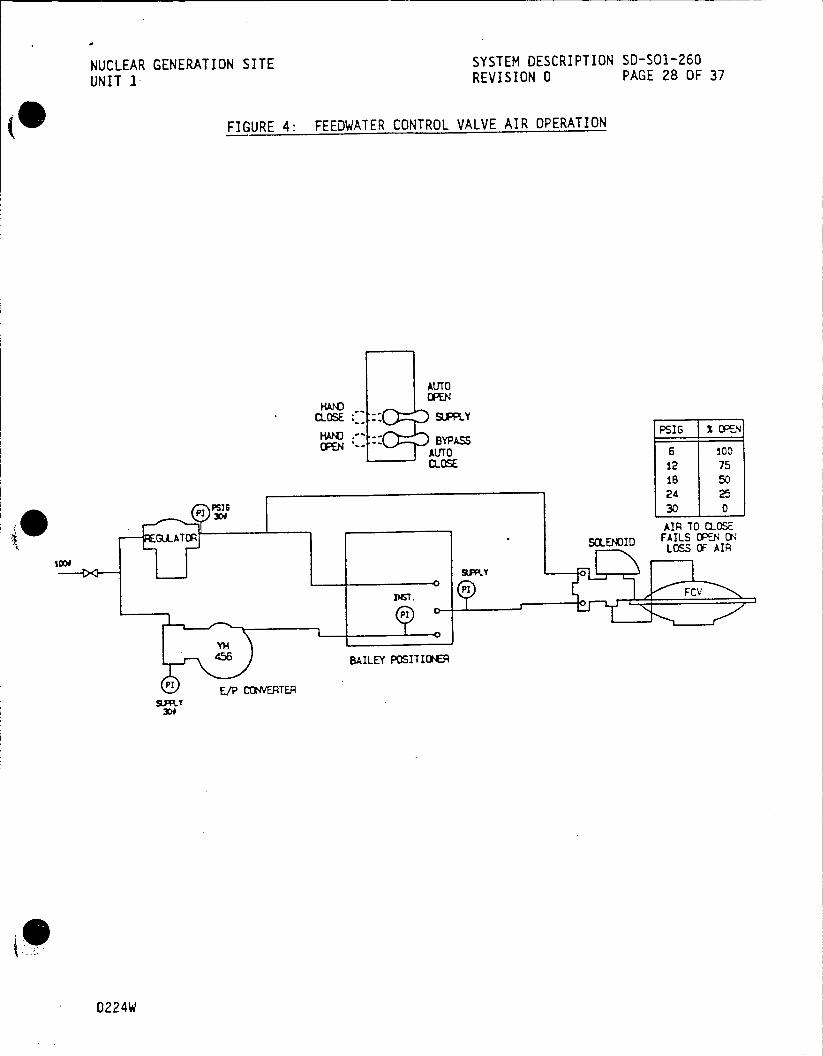
NUCLEAR GENERATION SITE SYSTEM DESCRIPTION S0-SO1-260 UNIT 1 REVISION 0 PAGE 28 OF 37
FIGURE 4: FEEDWATER CONTROL VALVE AIR OPERATION
AUTO OPEN
CLOSE :SUPPLY
BYAS PSIG T i OPEN
AUTO 6 100 CLOSE 12 75
18 50 24 25
PPSIG 30 0
AIR TO (105E GLATOR * 5LEDID FAILS OPEN ON
LOSS OF AIR
456 ~ BAILEY POSITIONE
pi E/P CONVERTER S.PRY
0224W
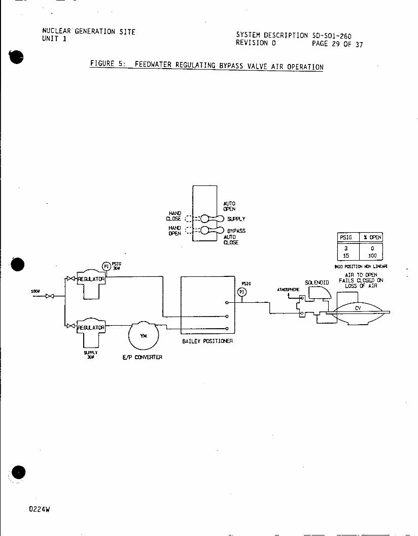
NUCLEARGENERATION SITE SYSTEM DESCRIPTION SD-SOl-260 UNIT 1 REVISION 0 PAGE 29 OF 37
FIGURE 5: FEEDWATER REGULATING BYPASS VALVE AIR OPERATION
AUTO OPEN
H"t CLOSE :,: D SUPPLY
OPENU -- BYPASS AUTO PSIGI% PEN CLOSE
30 15 100
BAILEY POSITI " LDE P1 3DOAIR
TO OPEN. GRATOR PSIls SOLENOID FAILS CLOSED ON
SON t TOR i AU91 LOSS OF AIR
D Ir GULATORo
YM BAILEY POSITIONER
E/P CONVERTER
0224W

SYSTEM DESCRIPTION SD-SO1-260 NUCLEAR GENERATION SITE REVISION 0 PAGE 34 OF 37
UNIT 1
APPENDIX A
DEVELOPMENTAL RESOURCES
REFERENCES
P&IDs
5178205, Feedwater System Sh. 1
5178206, Feedwater System Sh. 2
5178207, Feedwater System Sh. 3
5178225, Main Steam System Sh. 1
Elementaries
5129817-3, (N1543 02) Feedwater Control Diagram
0455379, (N1543 20) MOV's 20, 21 and 22 Feedwater Block Valves
449408, (N1543 26) Sol. Valves FCV-456, 457 and 458 Feedwater
Control & Bypass
5147125-2, (N1543 31) Generator Level Control
Technical Manuals
Hagan Controls Corp., 40000422
Procedures
S01-1.0-30, Loss of Secondary Coolant
S01-1.0-40, Steam Generator Tube Rupture
S01-1.3-2, Response to Steam Generator High Level
SO-1.3-3, Response to Steam Generator Low Level
SO1-3-1, Plant Startup From Cold Shutdown to Hot Standby
S01-3-2, Plant Startup From Hot Standby to Minimum Load
501-3-3, Plant Operation From Minimum Load to Full Power
S01-3-4, Plant Shutdown From Full Power to Hot Standby
S01-3-5, Plant Shutdown From Hot Standby to Cold Shutdown
S01-7-24, Steam Generation System Alignment
A-1
NUCLEAR GENERATION SITE SYSTEM DESCRIPTION SD-SO1-260 UNIT I REVISION 0 PAGE 35 OF 37
APPENDIX A
DEVELOPMENTAL RESOURCES (Continued)
Procedures (Continued)
SOI1-7-2, Main Feedwater System Operations
SO1-13-3, Reactor Plant No. 2 Annunciator
S01-13-6, Reactor Plant First Out Annunciator
S01-13-7, Reactor Plant Matrix Partial Trip Annunciator
Technical Specifications
3.5.1, Reactor Trip System Instrumentation
3.5.6, Accident Monitoring Instrumentation
Bechtel System Descriptions
20, Feedwater and Condensate System
FSAR
3.1.5, Feedwater and Condensate System
5.5, Steam Generator Level Control System
Lesson Plans
1045, Steam Generator Water Control
1064, STA/SRO Steam Generator Water Level Control
Study Guides
62, Steam Generator Level Control System
0224W A-2

NUCLEAR GENERATION SITE SYSTEM DESCRIPTION SD-SO1-260 UNIT 1 REVISION 0 PAGE 36 OF 37
APPENDIX B
ANNUNCIATORS
Reactor Plant No. 2
WINDOW NAME INPUT SETPOINT
(NUMBER)
Alert SW F.W. Control to QC-415B-X 15% of Full Load Manual (17)
Steam Generator Hi Level YR-456 70% Loop A (18)
Steam Generator Hi Level | YR-457 70% Loop B (19)
Steam Generator Hi Level YR-458 I 70% Loop C (20)
Steam Generator Lo Level YR-456 26% Loop A (38) I
Steam Generator Lo Level YR-457 26%
I Loop B (39)
j Steam Generator Lo Level | YR-458 26%
Loop C (40) I
Steam Gen. Level Cont. CR-1, 3, 5 through 8 Fault in Output Power Supply Malfunction RY-2, 3 and 4
(58)
Reactor Plant First Out
| WINDOW NAME | INPUT SETPOINT
j (NUMBER) I
Steam/Feedwater Flow FM-456B-X I Steam Flow ] Mismatch (23) FM-457B-X I Feedwater Flow I
FM-458B-X I by 25% of Full Load Steam Flow
B-1
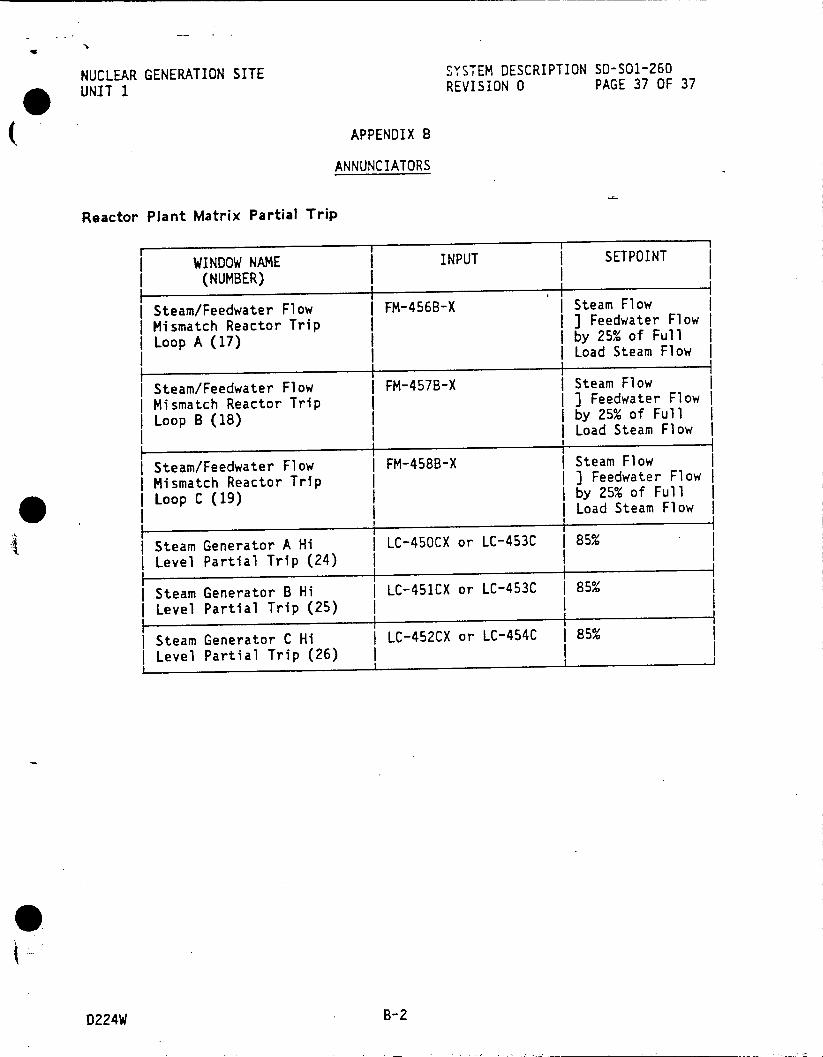
NUCLEAR GENERATION SITE SYSTEM DESCRIPTION SO-S01-260
UNIT 1 REVISION 0 PAGE 37 OF 37
APPENDIX B
ANNUNCIATORS
Reactor Plant Matrix Partial Trip
WINDOW NAME INPUT I SETPOINT
(NUMBER) _
I Steam/Feedwater Flow FM-456B-X Steam Flow
I Mismatch Reactor Trip | ] Feedwater Flow
Loop A (17) I by 25% of Full | | Load Steam Flow I
Steam/Feedwater Flow I FM-457B-X I Steam Flow Mismatch Reactor Trip I I ] Feedwater Flow I Loop B (18) | by 25% of Full
I Load Steam Flow I
I Steam/Feedwater Flow FM-458B-X I Steam Flow | Mismatch Reactor Trip | ] Feedwater Flow
I Loop C (19) I by 25% of Full I I Load Steam Flow
Steam Generator A Hi LC-450CX or LC-453C 85% I Level Partial Trip (24) I
I I I Steam Generator B Hi LC-451CX or LC-453C I 85% Level Partial Trip (25)
Steam Generator C Hi LC-452CX or LC-454C 85%
Level Partial Trip (26) I
D224W B-2

NUCLEAR GENERATION SITE SYSTEM DESCRIPTION SD-S01-270
UNIT 1 RREVISION 0 PAGE 1 OF 45
'MAR 896 TURBINE CONTROL SYSTEM
TABLE OF CONTENTS
SECTION PAGE
1.0 FUNCTIONS/DESIGN BASES 2
3 2.0 DESCRIPTION3
2.1 System Overview 4 2.2 Components 26 2.3 Detailed Control-Scheme 27 2.4 Power Supplies 27
3.0 OPERATIONS RECEIVED CDM 28 3.1 Normal Operations 29 3.2 Other Operations MAR08 b1982
4.0 REFERENCES SITE FILE COCPY 30
4.1 P&IDs 30 4.2 Elementaries 30
4.3 Technical Manuals 31
4.4 Procedures 31
* FIGURES 32
I Turbine Control System 32
2 Stop Valve 33
3 Stop Valve Bypass Valve Control 34
4 Governor Valve and Stop Valve Control 35
5 Control Block Assembly . 36
6 Load Limit Valve 37
7 Governor Overspeed Trip Device 38
8 Protective Trip Assembly 40 9 Turbine Controls Layout
41 APPENDICES 41
A Developmental Resources 43 . Annunciators
This System Description is approved per SO-123-0-44, System Description
Revision and Approval. Contact CDM to verify revision information.
PREPARED BY: - Date t r Date
thr
APPROVED BY:
3329i NOT QA PROGRAM AFFECTING
SYSTEM DESCRIPTION S-SO1-270 PUCLEAR GENERATION SITE REVISION 0 PAGE 2 OF 45 UNIT 1
TURBINE CONTROL SYSTEM
1.0 FUNCTIONS/DESIGN BASES
1.1 The Turbine Control System has the following main functions:
1.1.1 The Turbine Control System controls Turbine speed
during Turbine startup, shutdown, and maintains Turbine
speed/load during normal operation.
1.1.2 The Turbine Control System provides Turbine Trips and
Runbacks during potentially hazardous operating
conditions.
*I

-NUCLEAR GENERATION SITE SYSTEM DESCRIPTION SO-SO1-270
bNIT 1 REVISION 0 PAGE 3 OF 45
TURBINE CONTROL SYSTEM
.0 DESCRIPTION
2.1 System Overview
2.1.1 Main Flow Path (Figure 1)
The oil supply to the Turbine Control System is from the Main Oil
Pump when the Turbine is at or above 90% rated speed, or the AC
Auxiliary Oil Pump (see SD-S01-200, Main Turbine Systems).
From the oil pump(s), the oil passes through two Cuno Filters and
then to the supply header.
The oil is supplied and controlled at various pressures to
accomplish a unified system of Turbine speed and emergency control
through regulators, servomotors, and trip devices.
2.1.2 General Control Scheme
.1 High Pressure Oil System
The High Pressure Oil System supplies 320-380 psig oil
for the following functions:
1. Operating the Turbine Sto p and Governor Valves.
2. Supplies the Governor Control Oil System via the
Smoothing Orifice, Relief Valve, and the Governor
Oil Impeller. 3. Supplies the Auto Stop Oil System.
4. Operating and Testing the Governor Overspeed Trip
Device. 5. Operating and Testing the Thrust
Bearing Wear
Trip Device.
6. Supplies the Protective Trip Assembly via the
Governor Overspeed Trip Device.
7. Backup for the Generator Hydrogen Seal Oil System
(see SO-S01-100, Main Generator Systems).
.2 Governor Oil Impeller Discharge System
The Governor Oil Impeller Discharge System establishes
an operating medium between the Governor Oil Impeller
and the Governor Speed Changer which has control
functions over the Turbine Governor Valves.
The Governor Oil Impeller Discharge System is supplied
by the High Pressure Oil System through a manually
Adjustable Orifice.

SYSTEM DESCRIPTION SD-SO1-270 NUCLEAR GENERATION SITE REVISION 0 PAGE 4 OF 45
UJNIT 1
TURBINE CONTROL SYSTEM
O DESCRIPTION (Continued)
2.1.2 General Control Scheme (Continued)
.3 Governor Control Oil System
The Governor Control Oil System allows Turbine speed
(Governor Valves) -to be controlled by the Governor Speed Changer, Load Limit Control, Auxiliary Governor
and the Auto Stop System Dump Valves.
The Governor Control Oil System is supplied by the High
Pressure Oil System through a Filter, and the same
Smoothing Orifice and Relief Valve that supplies the
Governor Oil Impeller.
.4 Auto Stop Oil System
close the Stop Valves, Governor Valves, and Non-Return
Valves when any of the Turbine Protection Devices
operate.
The Auto Stop Oil System is supplied by the High
Pressure Oil System through two parallel manually
Adjustable Orifices.
2.2 Compnents.
2.2.1 Stop Valves (PV-1650-Left Side, PV-1651-Right Side)
(Figures 2 T.4)
STOP VALVES .
PURPOSE: Prevents Turbine overspeed should
the
Governor Valves fail to close when the
Overspeed Trip Device operates.
SIZE: 24 inch
OPERATOR TYPE: Oil to OPEN O T YSpring to CLOSE
VALVE TYPE: Swing Check
FAIL POSITION: Closed
LOCATION: Left and Right Sides of the High
PressureI
LCTO:Turbine
I OSITION INDICATION: J-Console in the Main Control Room.
*The Stop Valves consist of a disc suspended from a Shaft by a Disc
Arm that is keyed to the Shaft. The Shaft is connected to an oil
operated Piston Rod by an Operating Lever and Links.
SYSTEM DESCRIPTION S0-S01-270
NUCLEAR GENERATION SITE REVISION 0 PAGE 5 OF 45
'UNIT 1I
TURBINE CONTROL SYSTEM
0 DESCRIPTION (Continued)
2.2.1 Main Stop Valves (PV 1650-Left Side, PV-1651-Right
Side) (Figures 2 & 4) (Continued)
The valve Disc and Disc Arm (Figure 2) are shown in the clos.ed
With the Overspeed Trip Device tripped, the Auto Stop Oil chamber
above the Relay Valve Piston is connected to drain via the Auto
Stop Oil System and the Relay Valve Piston opens due to the
Compression Spring pressure (Figure 4).
With the Relay Valve Piston in the open position, the High Pressure
Oil supply to Chamber A is connected to drain and the chamber
beneath the Piston Rod, which is connected to Chamber A through a
drilled passage (not shown), is also connected to drain. The
Closing Springs pressure on the Piston Rod maintains the
Stop Valve
closed.
When the Overspeed Trip Device 'is latched, Auto Stop Oil pressure
is established above the Relay Valve Piston. The Auto Stop Oil
pressure overcomes the Compression Spring, moving the Relay Valve
Piston to the closed position, hus isolating Chamber A from the
drain passage.
Since Chamber A is connected to the chamber below the Piston Rod
through a drilled passage (not shown), the High Pressure Oil
pressure will increase and overcome the force of the Closing
Springs and move the Piston Rod upward. Upward movement of the
Piston Rod rotates the Shaft and Disc to its open position against
the stop.
A Limit Swi tch, attached to a lever connected to the
Operating
Lever, is used to indicate the position of the Stop Valve.
ARelief Valve is provided to limit the Auto Stop Oil pressure in
the chamber above the Relay Valve Piston.
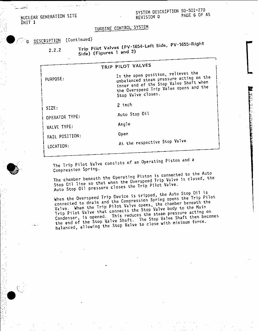
SYSTEM DESCRIPTION S-S01-270
NUCLEAR GENERATION SITE REVISION 0 PAGE 6 OF 45
ONIT 1
TURBINE CONTROL SYSTEM
0 DESCRIPTION (Continued)
2.2.2 Trip pilot Valves (PV-1654-Left Side, pV-1655-Right
Side) (Figures 1 and 2)
TRIP PILOT VALVES
PURPOSE: unbalanced steam pressure acting on te
inner end of the Stop Valve Shaft when .
the Overspeed Trip Valve opens and the
Stop Valve closes.
SIZE: 2 inch
OPERATOR TYPE: Auto Stop Oil
VALVE TYPE: Angle
FAIL POSITION: Open
SLOCATION: At the respective Stop Valve
The Trip Pilot Valve consists of an Operating Piston and a
Compression Spring.
The chamber beneath the Operating Piston is connected to the Auto
Stop Oil line so that when the Overspeed Trip Valve is closed, the
Auto Stop Oil pressure closes the Trip Pilot Valve.
When the Overspeed Trip Device is tripped, the Auto Stop Oil is
connected to drain and the Compression Spring opens the Trip Pilot
Valve. When the Trip Pilot Valve opens, the chamber beneath the
Trip Pilot Valve that connects the Stop Valve body to the Main
Condenser, is opened. This reduces the steam
pressure acting on
the end of the Stop .alve Shaft. The Stop Valve Shaft then becomes
balanced, allowing the Stop Valve to close with minimum force.
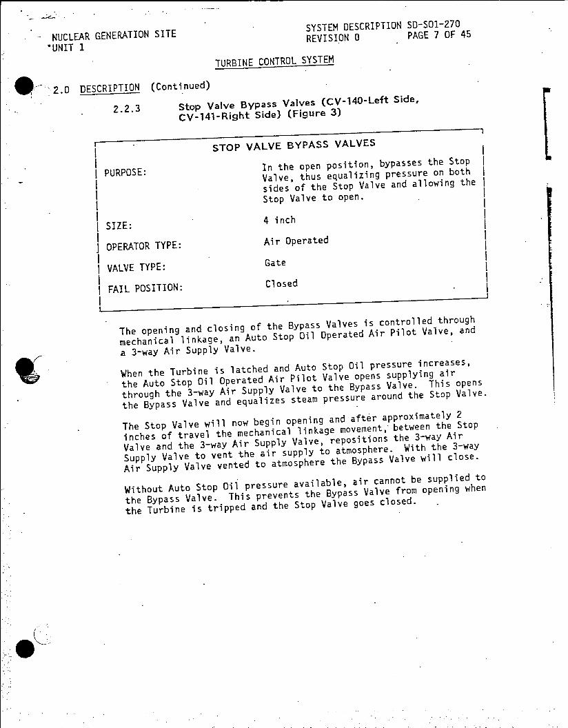
SYSTEM DESCRIPTION SD-SOl-270 NUCLEAR GENERATION SITE REVISION 0 PAGE 7 OF 45
'UNIT 1
TURBINE CONTROL SYSTEM
2.0 DESCRIPTION (Continued)
2.2.3 Stop Valve Bypass Valves (CV-140-Left Side,
CV-141-Right Side) (Figure 3)
STOP VALVE BYPASS VALVES
In the open position, bypasses the Stop PURPOSE: Valve, thus equalizing pressure on both
sides of the Stop Valve and allowing the
Stop Valve to open.
SIZE: 4 inch
OPERATOR TYPE: Air Operated
VALVE TYPE: Gate
FAIL POSITION: Closed
The opening and closing of the Bypass Valves is
controlled through
mechanical linkage, an Auto Stop Oil Operated Air Pilot Valve, and
a 3-way Air Supply Valve.
When the Turbine is latched and Auto Stop Oil pressure increases,
the Auto Stop Oil Operated Air Pilot Valve opens supplying air
through the 3-way Air Supply Valve to the Bypass Valve. This opens
the Bypass Valve and equalizes steam pressure around the Stop
Valve.
The Stop Valve will now begin opening and after approximately 2
inches of travel the mechanical linkage movement, between the Stop
Valve and the 3-way Air Supply Valve, repositions the 3-way Air
Supply Valve to vent the air supply to atmosphere. With the 3-way
Air Supply Valve vented to atmosphere the Bypass Valve will close.
Without Auto Stop Oil pressure available, air cannot be supplied to
the Bypass Valve. This prevents the Bypass Valve from opening when
the Turbine is tripped and the Stop Valve goes closed.

NUCLEAR GENERATION SITE SYSTEM DESCRIPTION SD-SO1-270
'UNIT 1 REVISION 0 PAGE 8 OF 45
TURBINE CONTROL SYSTEM
2.0 DESCRIPTION (Continued)
2.2.4 Governor Valves and Servomotors (GV-1-Right Lower, GV-2-Left Lower, GV-3-Right Upper, GV-4-Left Upper) (Figure 4)
GOVERNOR VALVES
PURPOSE: Controls the steam flow to the High Pressure Turbine
| SIZE: 16 inch
I OPERATOR TYPE: Oil
| VALVE TYPE: Single Seat
FAIL POSITION: Closed
LOCATION: Right and Left sides of the High Pressurel Turbine
POSITION INDICATION: J-Console in the Main Control Room
I
The Governor Valve bodies are welded to the Stop Valve bodies (2 for
each Stop Valve). The Governor Valve outlets are connected to the
High Pressure Turbine Inlet Chambers through piping in the Turbine
Casing Base and Cover (see SD-SO1-200, Main Turbine Systems Part I).
Each Governor Valve is a single seated valve mounted on a valve stem. When the valve is in the closed position, Compression Springs hold the valve tightly on its seat.
The valve stem packing consists of a close fitting bushing and is
provided with a leak off connection to the Gland Steam Condensers.
A valve, formed on the valve stem, seats in a bushing when the
Governor Valve is in its fully open position. This forms the stop
.in the opening directing and reduces steam leakage along the valve
stem.
A Steam Strainer, cylindrical in shape, fits around the Governor
Valve. Its lower end fits in a groove machined in the body and is
* clamped at the top by the valve bonnet. The strainer prevents
foreign materials from entering the Turbine Blading.
Each Governor Valve is operated by a Se--vomotor through a Followup Lever.
SYSTEM DESCRIPTION S-SO1-270 NUCLEAR GENERATION SITE REVISION 0 PAGE 9 OF 45
UNIT 1IRVSO
TURBINE CONTROL SYSTEM
2.0 DESCRIPTION (Continued) 2.02.2.4
2.2.4 Governor Valves and Servomotors (GV--Right Lower,
GV-2-Left Lower, GV-3-Right Upper, GV-4-Left Upper)
(Figure 4) (Continued)
Each Servomotor consists of a Servomotor Piston that is controlled
by a pressure responsive Relay Plunger contained in the Servomotor
Cylinder. The Relay Plunger admits High Pressure Oil to the
chamber beneath the Servomotor Piston to open the valves, and
releases it to drain to permit the Compression Springs mounted on
the Governor Valve to close them.
The Servomotor consists of the Servomotor Piston, the Relay Piston
with ports machined in the stem, the Relay Plunger, and the
Followup Lever. A small drilled hole in the Relay Plunger connects
the High Pressure Oil inlet to the chamber above the Relay
Plunger. The central hole through the entire length of the Relay
Plunger connects the chamber above the Relay Plunger to drain by
way of four ports in the stem of the Relay Piston.
The orificed High Pressure Oil is supplied by the small drilled
hole to the chamber above the Relay Plunger. The pressure in this
chamber is maintained by the ports in the Relay Piston Stem so that
the force of the spring and the force due to the oil pressure
are
balanced.
Since there is a continuous flow of oil through the small drilled
hole to the chamber above the Relay Plunger, there will also be a
continuous flow through the ports in the stem of the Relay
Piston
to drain in order to maintain a balanced Relay Plunger.
Upward movement of the Relay Piston increases the flow through
the
ports to drain thereby decreasing the pressure above the Relay
Plunger until it also moves upward. Conversely, downward movement
of the Relay Piston decreases the flow through the ports to drain
thereby increasing the pressure above the Relay Plunger until it
also moves downward.
These pressure changes above the Relay Plunger, together with
the
spring force below it, cause the Relay Plunger to follow
all
movements of the Relay Piston.
The Governor Control Oil is admitted to the chamber above the Relay
Piston and exerts a force tending to move the Relay Piston
downward. This force is opposed by the tension of a spring which
tends to draw the Relay Piston upward. Therefore, any change in
control oil pressure unbalances the forces on the Relay Piston and
causes the Relay Piston to move until the spring force again
balances the control oil pressure. This movemTent of the Relay
Piston in turn produces a corresponding movement of the Relay
Plunger.

SYSTEM DESCRIPTION SD-S01-270 NUCLEAR GENERATION SITE REVISION 0 PAGE 10 OF 45 UNIT I
TURBINE CONTROL SYSTEM
2.0 DESCRIPTION (Continued)
2.2.4 Governor Valves and Servomotors (GV-1-Righi Lower, GV-2-Left Lower, GV-3-Right Upper, GV-4-Left Upper)
(Figure 4) (Continued)
When the Relay Plunger moves .downward in response to an increase in
Governor Control Oil pressure, High Pressure Oil will flow through
the ports to the chamber beneath the Servomotor Piston, causing the
Piston to move upward to open the Governor Valves.
In case of a decrease in Governor Control Oil pressure, the Relay
Piston will move upward due to the spring pressure. The Relay
Plunger will also move upward due *to the Compression Spring and
drop the oil pressure in the chamber above the Relay Plunger. This
opens the passage for the High Pressure Oil beneath the Servomotor
Piston to go to drain, thus allowing the Servomotor Piston to move
downward until the Relay Bushing has been repositioned by the
Followup Lever to control the Servomotor Piston in a new position.
In order not to overload the drain when the Servomotor is closed
rapidly, an internal passage permits the oil from beneath the
Servomotor Piston to discharge through the Relay Plunger and
bushing to an area above the Servomotor Piston as well as through
the drain.
2.2.5 Governor Valve Servomotor Test Valve (Figure 4)
The Governor Valve Servomotor Test Valve is provided to test the
Governor Valve stem freedom during norMal operation of the Turbine.
The valve which is mounted on the Governor Valve Servomotor
Cylinder is connected through drilled passages to the chamber
beneath the Servomotor Relay Piston and to the drain chamber in the
Servomotor Cylinder.
It consists of a spring loaded Cup Valve secured to a Diaphragm.
An Adjusting Spindle is supplied with a drive motor so that the
spring load on the Cup Valve may be changed from the test
pushbuttons on the J-Console in the Main Control Room.

SYSTEM DESCRIPTION SD-SO-270 NUCLEAR GENERATION SITE REVISION 0 PAGE 11 OF 45
UNIT 1
TURBINE CONTROL SYSTEM
2.0 DESCRIPTION (Continued)
2.2.5- Governor Valve Servomotor Test Valve (Figure 4)
(Continued)
Spindle Stop Pins limit the travel of the Adjusting Spindlet A pin
engages one of the lugs on the stop and prevents further rotation
of the Adjusting Spindle. When the motor drive is used and the pin
on the Stop contacts the lug on the Stop, Clutch Plates will slip
until the motor is stopped.
Switches mounted on a bracket are adjusted
to indicate when the
Adjusting Spindle reaches either limit of its travel.
During normal operation of the Turbine, the Test Valve Adjusting
Spindle and Cup Valve are in the position shown and therefore there
is no restriction to the-flow of oil from the chamber beneath the
Governor Valve Servonotor Relay Piston to drain. With the test
valve in this position the Governor Valve Servomotor is positioned
by the Governor.
To test the Governor Valve Servomotor, the handwheel is turned in
the clockwise direction, either manually or by the motor. The
increase in compression on the spring closes down on the Cup
Valve. The oil flow to drain is thus restricted and a back
pressure is maintained on the Servomotor Relay Piston. The
Governor Valve closes in proportion to the back pressure.
Turning the Adjusting Spindle in the opposite
direction, releases
the back pressure and the Governor Valves open.
The Governor Valves are operated and tested from pushbuttons
located on the J-Console in the Main Control Room. The Governor
Valves operate sequentially with the No. Governor Valve opening
first and closing last.
Open, Close and Percent Valve Position indications are provided on
the J-Console in the Main Control Room.
2.2.6 Governor Oil Impeller
The Governor Oil Impeller is located between Main Lube Oil Pump and
the Overspeed Trip Device on the Turbine Extension Shaft.
The Governor Oil Impeller is used to supply Governor Control Oil at
29-31 psig at a Turbine speed of 1800 rpm.
The Governor Oil Impeller consists of a'hollow cylindr-cal body
with a series of radially inserted tubes connecting the inner
Chamber and the outer Impeller Chamber.
A manually Adjustable Orifice admits High Pressure Oil to the
outer
chamber of the Governor Oil Impeller Seal Sleeve to maintain about
15 gpm flow through the Impeller holes to the drain chamber.
The drain chamber is connected to the inner chamber by a series
of
radial holes.

RUNIT 1E SYSTEM DESCRIPTION SD-SOl-270 NUCLEAR GENERATION SITE REVISION 0 PAGE 12 OF 45
*UNIT 1I
TURBINE CONTROL SYSTEM
2.0 DESCRIPTION (Continued)
2.2.6 Governor Oil Impeller (Continued)
As the Impeller rotates, the centrifugal force of the oil in the
radial tubes opposes the flow of oil through the holes and maintains a pressure in the Governor
Oil Impeller discharge
cavity. The pressure in the discharge cavity varies as the square
of Turbine speed.
As Turbine speed increases, Impeller discharge pressure increases.
As Turbine speed decreases, Impeller discharge pressure decreases.
The Impeller acts as a rotating relief valve, maintaining a
pressure corresponding to the centrifugal force of the column of
oil in the Impeller holes and bypassing to drain any excess
oil
above that required to maintain pressure in the Impeller discharge
chamber around the seal sleeve.
Any pressure changes produced are directly transmitted to the
Governor Transformer which controls the Governor Valves Servomotors.
2.2.7 Governor Transformer and Speed Changer (Figure 5)
The Governor Transformer and Speed Changer are combined
in a single
* housing and are connected through passages and internal piping to
the Governor Valves Servomotors.
The Governor Transformer and Speed Changer Mechanism im in reality
a pressure transformer which magnifies the relatively small
Governor Impeller discharge pressure changes sufficiently to
operate the relays of the Governor Valve Servomotors.
The Governor Transformer consists of a Flexible Metal Bellows, a
Compression Spring and a Cup Valve. Oil at Governor Impeller
discharge pressure enters the chamber around and below the bellows
thus exerting an upward force on the area of the plate which forms
its lower support. This force is opposed by the downward force of
the Compression Spring.
A Cup Valve mounted on a Lever, controls the Governor Control Oil
* pressure. High Pressure Oil is admitted through an orifice to the
control chamber of the Cup Valve seat. The force exerted on the
Cup Valve varies the flow of oil from this chamber to drain and
thus determines the Governor Control Oil pressure existing in the
central chamber of the seat. Since this force is equal to the
* difference between the force on .the bellows and the spring load, a
variation in either will cause a change in the Governor Control Oil
pressure. This Governor Control Oil pressure is transmitted to the
chamber above the Servomotor Relay Piston and Valve.
The effective area of the bellows is five times as great as the
area of the Cup Valve, therefore an increase of one psig Governor
Impeller discharge pressure below the bellows would cause a
decrease of five psig in the Governor Control Oil pressure existing
in the central chamber of the Cup Valve seat.

SYSTEM DESCRIPTION SD-SO1-270
NUCLEAR GENERATION SITE RVSO0PAE1OF45
UNITREVISION 0 PAGE 13 OF
TURBINE CONTROL SYSTEM
DESCRIPTION (Continued)
2.2.7 Governor Transformer and Speed Changer
(Figure 5) (Continued)
With a fixed setting of the Speed Changer Compression Spring, the
Governor Control Oil pressure varies in accordance with the Turbine
*speed. With a fixed speed, the Governor Control Oil pressure
depends upon the setting of the Speed Changer Compression
Spring.
The position of the Speed Changer determines the spring force
acting on the Transformer Cup Valve. A change will occur in either
Turbine speed or Governor Control Oil pressure for every change in
Speed Changer setting.
If the Turbine Generator is not synchronized with the system, then
a movement of the Speed Changer brings about a change in Governor
Control Oil pressure, a corresponding change in the position of the
Governor Valves and a change in steam flow through the Turbine.
This change in steam flow, if an increase, causes the Turbine speed
to increase until the Governor Impeller discharge pressure balances
the increased spring force of Compression Spring. For such
operations the Speed Changer changes the Turbine speed.
For parallel operation the Turbine speed is controlled by the
electrical tie of the Generators. Under such operating condition,
the Speed Changer actually becomes a Load Changer. This is true
because changing the steam flow through the Turbine can only change
the torque while the speed of the Turbine is scarcely affected.
Accordingly then, there is a different load for every position of
the Speed Changer. Mechanically, this means that the Governor
Impeller discharge pressure remains constant so that for every
Speed Changer position there is a different Governor Control Oil
pressure necessary to keep the forces on the Cup Valve in
equilibrium. For every value of Governor Control Oil pressure
there is a definite Governor Valve position and consequently a
definite electrical load if the system frequency remains constant.
A Spring Loaded Relief Valve provides a pressure
limit for the
Governor Control Oil pressure to a maximum of 60 psig.
As the Governor Speed Changer varies the compression of the Speed
Changer Spring, it can be seen that increasing the compression of
the Speed Changer Spring increases the Turbine speed or load and
decreaing the compression of this spring decreases the Turbine
speed or load.
The principal parts of the Speed Changer are the Handwheel the
Shaft, the Worm, and the Wormwheel. The Shaft is threaded through
a bushing and when the Handwheel is rotated, the Shaft is rotated,
thereby changing the compression of the Speed Changer Spring. When
the Speed Changer is motor operated, the Worm and Wormwheel drives
the Shaft through a Friction Clutch.

GENERATION SITE SYSTEM DESCRIPTION SD-S01-270
UNIT 1 UNCLEA REVISION 0 PAGE 14 OF 45
TURBINE CONTROL SYSTEM
2.0 DESCRIPTION (Continued)
2.2.7 Governor Transformer and Speed Changer
(Figure 5) (Continued)
The Speed Changer travel in the Decrease direction is limited by a
Stop Pin contacting a Stop Screw. In the Increase direction, the
travel is limited by Stop Screw contacting a stop pin.
When either travel limit is reached the clutch will slip until the
Speed Changer Motor is stopped.
A contact in the raise circuitry of the Speed Changer prevents
raising Turbine load when an Overpower-Rod stop condition occurs.
2.2.8 Governing Emergency Trip Valve (Figure 5)
the Governor Control Oil line to drain when the Overspeed Trip
Valve opens, thus releasing the Governor Control Oil pressure.
This valve consists of a housing and a spring loaded Cup Valve.
The housing is divided by a horizontal partition into an upper and
lower chamber with drilled holes in the partition to provide for an
oil passage between the two chambers. The spring loaded Cup Valve
drilled holes in the partition.
In normal operation, the Overspeed Trip Valve is closed and the Cup
Valve is seated thus preventing the flow of oil from the Auto Stop
Oil line to the Governor Control Oil System.
When the Overspeed Trip Valve opens, connecting the Auto Stop Oil
to drain, the Cup Valve opens due to the differential in pressure
and releases the Governor Control Oil pressure thus closing the
Servomotors.
The differential pressure at which this valve opens is determined
by the load on the compression spring.
2.2.9 Auxiliary Governor (Figure 5)
The Auxiliary Governor contains a pressure transformer which is
a
duplicate of the transformer in the Governor Speed Changer, but
unlike the Governor Speed Changer, it is not motor operated. It
also contains an acceleration response feature and a Dump Valve.
The Auxiliary Governor does not control or limit the load on the
unit in normal operation, but will act as a result of complete loss
of load or loss of sufficient load to produce an acceleration in
excess of 3% per second.
5< The normal steady state setting of the Auxiliary Governor is beyond
the range of the Governor and Speed Changer, but will limit the no
load maximum speed of the unit to approximately the same speed as
the Governor Speed Changer.

SYSTEM DESCRIPTION SD-S01-270 -NUCLEAR GENERATION SITE REVISION 0 PAGE 15 OF 45
UNIT 1
TURBINE CONTROL SYSTEM
.0 DESCRIPTION (Continued)
2.2.9 Auxiliary Governor (Figure 5) (Continued)
The principal components of the Auxiliary Governor are: the
Transformer, the Acceleration Response Section, the Dump Valve
and
a Test Device.
The Transformer magnifies the relatively small changes in Governor
Oil Impeller discharge pressurainao FpexoibeMeall Baellwsr
changes. Its principal parts are a Flexible Metal Bellows, a
Compression Spring and a Cup Valve. Governor Impeller Oil
surrounds the Bellows and exerts an upward force. This force is
opposed by the Compression Spring.
The Cup Valve controls the Auxiliary Governor Control Oil
pressure. High Pressure Oil is admitted through an orifice located
in the Governor Control Block to the chamber beneath the Cup
Valve. The force exerted on the cup, determines the pressure of
the oil beneath the cup. The force on the cup is equal to the
differnce between the force on the bellows and the spring load. A
variation in either force will cause a change -in the oil pressure.
The Transformer is designed with a transformation ratio of 5 to 1.
The Governor Impeller Oil pressure is approximately 30 psig at
rated speed and varies as the square of the speed, and would
therefore change 0.6 for a 1% speed change, or 1 psig for 30 rpm.
A speed change of 60 rpm will therefore produce an Auxiliary
Governor control pressure change of 5 psig. The cup is so arranged
that an increase in speed which produces an increase in impeller
pressure, causes a reduction in control oil pressure.
The Acceleration Response Feature consists of a Diaphragm, Stem and
two Accumulator Bellows.
Control oil is applied to both sides of the Diaphragm. The top of
the Diaphragm is exposed to the control oil chamber under the Cup
Valve and any changes in oil pressure are felt immediately. The
control oil under the diaphragm is restricted by an orifice and the
changes in pressure are delayed by the combination of the Orifice
and the Accumulator Bellows.
Under steady state conditions the oil pressure on both sides of the
Diaphragm is equal. Should a speed rise occur at a rate to exceed
approximately 3%/sec. and continue for a total speed rise of more
than 2%, the control oil pressure on top of the Diaphragm is
immediately reduced by an amount proportional to the speed rise.
The pressure under the Diaphragm is delayed in its reduction
because of the accumulation action of the Bellows and the Orifice.
This creates an unbalance on the Diaphragm which overcomes the
force of the Compression Spring and pushes the Stem up and unseats
the Cup Valve and dumps the control oil to drain.

NUCLEAR GENERATION SITE SYSTEM DESCRIPTION SD-SO1-270
-UNIT 1 REVISION 0 PAGE 16 OF 45
TURBINE CONTROL SYSTEM
2.0 DESCRIPTION (Continued)
2.2.9 Auxiliary Governor (Figure 5) (Continued)
The Governor Valve Servomotors close on failing control oil
pressure, so they would all close rapidly as a result of this
action.
As the pressure differential across the Diaphragm becomes balanced
again, the Stem returns to neutral and the Cup Valve regulates the
pressure again at a new value corresponding. to the new speed.
The size of the Orifice determines the acceleration rate required
to activate the Acceleration Respo .nse section. The length of time
the Auxiliary Governor takes over' control is a secondary function of the Orifice and the time is normally 2 to 5 seconds. The amount
of pre-load is designed to require at least 2% change in speed
before the Diaphragm can unseat the Cup Valve. This feature
prevents false action due to system frequency changes.
The Dump Valve is held on its seat by the Auxiliary Governor
control overcoming the force of the Compression Spring. It dumps
the Governor Control Oil from the Servomotors to drain when the
Auxiliary Governor has control of the unit.
* On a load rejection the Auxiliary Governor control pressure will
decrease rapidly because -of the Acceleration Response Feature. The
Compression Spring will lift the Cup Valve and the control oil
pressure from the Servomotors will spill to drain, thus causing
rapid closing of the Governor Valve Servomotors.
The Test Device consists of a Handle Telescoping Valve and Guide.
The acceleration feature of the Auxiliary Governor is designed to
function at acceleration rates of 3%/sec. or faster. The unit
cannot be accelerated at this rate without actually rejecting load,
so the Test Device is provided.
Movement of the Handle forces the Telescoping Valve in to seal off
the Impeller oil passage. Further movem .ent of the Guide builds up
the Impeller pressure under Bellows at a rate fast enough to
simulate a fast speed rise of the Turbine and will operate the
Acceleration Response section of the Auxiliary Governor momentarily.
A Relief Valve is provided to limit the Auxiliary Governor Control
Oil pressure (55-60 psig) when the unit is at rest or at low speed
with the Auxiliary Oil Pump in operation.
2.2.10 Load Limit Valve (Figures 5 and 6)
The Load Limit Valve is an oil pressure regulating valve which
limits load by controlling the maximum opening of the Governor
Valves.

NUCLEAR GENERATION SITE SYSTEM DESCRIPTION SD-SO1-270
UNIT 1 REVISION 0 PAGE 17 OF 45
TURBINE CONTROL SYSTEM
II 2.0 DESCRIPTION (Continued)
2.2.10 Load Limit Valve (Figures 5 and 6) (Continued)
In the Governing System an increase in the Governor Control Oil
pressure opens the Governor Valves and the steam flow varies with this pressure change. When the Governor Control Oil pressure rises
above the Load Limit control pressure, a check valve opens permitting the Load Limit control pressure to replace the Governor Control Oil pressure, thereby, preventing the Governor from further
opening the Governor Valves. Therefore, the system with the lower
pressure will control the Governor Valves.
Auto Stop Oil is admitted to the common control oil line through Passage B and through an orifice.
When the Auto Stop is latched, oil will flow into the controller through Passages A and B. The oil will then flow through the
center of the Cup Valve and to drain with a minimum pressure being maintained in Passage A.
To reset the controller, the handwheel is turned counterclockwise and the shaft moves downward. As the shaft approaches the Cup Valve it will impede the oil flow through the Load Limit Valve and
the pressure will gradually rise until the Cup Valve moves up against the shaft at Seat X.
At this pressure the Control Valve Piston will move upward and as
the stem holds the Cup Valve in a given position, oil will flow
around the periphery of Cup Valve at Seat Y and through the holes
in the Control Valve Piston to drain. As the Control Valve Piston
moves upward, the Cup Valve port opening is increased and the
Control Valve Piston will move only far enough to balance the
pressure under the Control Valve Piston against the load of the
Outer Spring.
Rotating the handwheel in a clockwise direction will allow the
Shaft to move upward and the Cup Valve will follow because of the
pressure unbalance. The upward movement restricts the flow of oil
through the Cup Valve and increases the oil pressure beneath the Control Valve Piston which moves upward and away from Cup Valve.
As the Control Valve Piston moves upward it compresses the Outer
Spring which increases the downward force on the Control Valve Piston. Therefore, in order to move the Control Valve Piston
upward, the pressure under the Control Valve Piston must increase.
If the Auto Stop is tripped, all oil supply to the controller is
dumped to drain. The Control Valve Piston forces the oil in the
contvoller initially out through a orifice until the center portion
of Cup Valve clears the Spring Seat. At this point the remaining oil is dumped to drain through the center hole in the Cup Valve Seat X.
SYSTEM DESCRIPTION SD-SO1-270 NUCLEAR GENERATION SITE REVISION 0 PAGE 18 OF 45 -UNIT 1
. TURBINE CONTROL SYSTEM
2.0 DESCRIPTION (Continued)
2.2.10 Load Limit Valve (Figures 5 and 6) (Continued)
When the Auto Stop is relatched, it will establish flow to the
controller but pressure cannot be built uip until the handwheel is
first rotated in the counterclockwise direction and the shaft is
returned to the valve closed position. The Inner Spring is used'
only to counterbalance the forces on the Cup Valve and to reduce
the loading on the threads of the shaft.
Two Runbacks are provided to limit Turbine load. The Runbacks are
as follows:
1. When Turbine load is >380 MWe, as indicated by
First Stage Pressure Transmitter PT-417, and
frequency drops to 58 Hz, a relay (LR) is
energized in the Load Limit Motor circuitry and
the Load Limit Motor runs back the Turbine load to
<380 MWe.
2. When Turbine load is >315 MWe, as indicated by
First Stage Pressure Transmitter PT-417, and a
Control Rod drops, a relay (LR) is energized in
the Load Limit Motor circuitry and the Load Limit
Motor runs back the Turbine Load to 315 MWe.
A Dropped Rod Turbine Runback Defeat Switch, located on the
Auxiliary Board behind the South Vertical Board, is provided to
disable the Dropped Rod Turbine Runback. Switch position
indication and Runback arming indication is also provided on the
Auxiliary Board.
Once the Turbine has Runback to the appropriate setpoint, the relay
(LR) is de-energized and the Runback stops.
When the initiating cause of the Runback is reset, an Amber light
illuminates to indicate the Reset.
Red and Green light indications are provided to indicate when the
Load Limit is at the High and Low Limits Control settings.
A Tracking Circuit is provided to maintain the differential
pressure between the Governor Speed Changer Oil pressure and the
Load Limit Oil pressure at the equivalent of 45 MWe (=2.5 psig
as indicated on the J-Console in the Main Control Room.) By
maintaining the Load Limit Oil pressure above the Governor Speed
Changer Oil pressure the Tracking Circuit prevents any large rapid
rurbine Load increases as the circuit with the lower oil pressure
will control thQ Governor Valves.
The Tracking Circuit is placed In and Out of Service using the Red
5 7 (In) and Green (Out) backlit pushbuttons on the 3-Console in the
Main Control Room.

NUCLEAR GENERATION SITE SYSTEM DESCRIPTION SD-SO1-270 NIT 1 REVISION 0 PAGE 19 OF 45 UNIT 1
TURBINE CONTROL SYSTEM
2.0 DESCRIPTION (Continued)
2.2.10 Load Limit Valve (Figures 5 and 6) (Continued)
When the Tracking Circuit is In Service and the Governor Speed
Changer Oil pressure changes, PS-110 closes the appropriate
contacts in the Load Limit circuitry to change the Load Limit Oil pressure accordingly.
When the Tracking Circuit is In Service and a Runback occurs, the
Runback Relay, LR, disables the Tracking Circuit.
2.2.11 Governor Overspeed Trip Device (Figure 7)
The function of the Governor Overspeed Trip Device is to stop the
flow of steam into the Turbine should the speed increase to a
predetermined amount above normal.
The Governor Overspeed Trip body is threaded on the end of the
Turbine Rotor Extension Shaft with a thread opposite to the
direction of Turbine rotation and is locked in place by a set screw.
A Trip Weight is carried in a transverse hole in the body, with its
center of gravity offset from the axis of rotation so that
centrifugal force tends to move it outward at all times. Normally
0 0 this weight is held in its inner position by a Compression Spring
and a Weight Spring Retainer.
If the speed of the Turbine increases to the point which the
mechanism is set to operate, the increased centrifugal force
overcomes the compression of the Compression Spring, and the Weight
moves outward. In this outer position, the Weight strikes the Trip
Trigger, rotating it on the Fulcrum Pin, moving the Trip Valve
Relay toward the Cover and the Cup Valve away from the Retainer.
High Pressure Oil from Chamber X *is released to drain through the
hole drilled in the Retainer. Simultaneously, as the pressure in
Chamber X decays, Auto Stop Oil pressure causes the Overspeed Trip
Valve Piston to move off its seat, connecting the Auto Stop Oil to
drain.
The Governor Overspeed Trip Valve can be tripped manuallyby moving
the Manual Trip and Reset Lever, located on the fr 'ont of the
Bearing Pedestal, from the Normal to the Tripped position. This
lever rotates the Reset Shaft until the Latch Link mounted on the
end of the Shaft forces the Trigger to move the Trip Relay toward
the Cover. This allows the Overspeed Trip Valve to open in the
same manner as described above.
After the Governor Oversp-ed Trip Device has tripped, it can be
Reset manually by moving the Manual Trip and Reset Lever to the
Reset position after the Turbine speed has decreased to the speed
where the Trip Weight returns to its normal position. This speed
occurs about 2% above normal speed.

SYSTEM DESCRIPTION SD-SOl-270 NUCLEAR GENERATION SITE REVISION 0 PAGE 20 OF 45 UNIT 1
TURBINE CONTROL SYSTEM
2.0 DESCRIPTIOR (Continued)
2.2:11 Governor Overspeed Trip Device (Figure 7)
(Continued)
When the Manual Trip and Reset Lever is placed in the Reset position, the Trip Valve Relay moves away from the Cover
and the Cup Valve closes. High Pressure Oil pressure then increases
in Chamber X forcing the Overspeed Trip
Valve Piston closed. This
allows the Auto Stop Oil pressure below the piston to be restored.
The Governor Overspeed Trip Device can be.remotely reset using the
Automatic Latch Assembly. The Automatic Latch Assembly is
activated by depressing the Amber backlit Auto Stop Latch Reset
pushbutton located on the J-Console in the Main Control Room.
The Automatic Latch Assembly consists of an Air Cylinder, with air
admission controlled by a four-way solenoid valve. The Air
Cylinder is mounted on a bracket which is bolted to the Bearing
Pedestal Wall. A Cable Link, on the end of the Air Cylinder
Piston, contacts the Lever which is pinned to the Governor
Overspeed Trip Device Reset Handle Shaft.
To Reset the Governor Overspeed Trip Device, the solenoid valve is
energized, admitting air to one end of the Air Cylinder and
releasing air from the opposite end to atmosphere. As air is
admitted to the cylinder, its piston and the Cable Link moves down,
thus rotating the Reset Lever and closing the Overspeed
Trip Device.
After the piston has reached the end of its stroke, the solenoid is
deenergized and air is admitted to the opposite end of the 'cylinder
returning the piston and link to the Normal position. The Reset
Lever also returns to the Normal position and remains in this
position as long as the Governor Overspeed Trip Device remains
latched.
Once Auto Stop Oil pressure is established, Pressure Switch PS-112
will cause the Amber Auto Stop Latch Reset pushbutton to illuminate.
A Test Handle is provided for testing the Governor Overspeed Trip
Device without actually overspeeding the Turbine.
The test can be' made wi thout taki ng the. uni t of f the i ne or
removing the load by holding *the Test Handle in the Test position,
and opening the Hand Valve to admit oil to the inside of the Trip
Weight and noting the oil pressure required to move the weight
*outward.
A Test Nozzle, which is located at the center-of the rotor, is
connected with a High Pressure Oil -upply which directs this oil
into a corresponding passage in the end of the Governor Overspeed
Device body.
The nozzle is always directed toward the end of the body so that
when the Hand Valve is gradually opened, oil pressure is
established inside the Governor Overspeed Trip Weight.

SYSTEM DESCRIPTION SD-SO1-270 NUCLEAR GENERATION SITE REVISION 0 PAGE 21 OF 45
-UNIT 1
TURBINE CONTROL SYSTEM
z 0 DESCRIPTION (Continued)
2.2.11 Governor Overspeed Trip Devire (Figure 7)
(Continued)
A pressure gauge is provided at the Front BearingrPedestal toWeight. indicate the pressure required
to operate
2.2.12 Protective Trip Assembly (Figure 8)
In addition to the Governor Overspeed Trip Device the Turbine is
provided with safeguards against various possible contingencies
that might cause damage to the unit if it were not promptly taken
out of service.
The Protective Trip Assembly includes a Low Vacuum Trip, a Low
Bearing Oil Pressure Trip, a Thrust Bearing Trip and a Solenoid
Actuated Trip.
These devices operate independently and are arranged to actuate
the
Governor Overspeed Trip Device. The Protective Trip Assembly
body
is mounted on the Bearing Pedestal Base.
The Protective Trip Devices consist of three Spring Loaded
Diaphragms each clamped on its outer edge between the Bodyand a
Diaphragm Flange. -Each Diaphragm is clamped in the center between
a Retainer and a Plate. Any motion of the Diaphragm due to a
change in pressure acting on the lower side of the Diaphragm is
transmitted through its Trip Rod and Trip Rod Seat to the Operating
Plate which is fulcrumed on a Pin mounted in the support which
is
bolted andidoweled to the Body.
A Trip Valve Is connected to the Operati ng P ate through a Link so
that counterclockwise rotation of the Operating Plate raises the
Trip Valve, thus releasing the pressure in the chamber above the
Overspeed Trip Valve to drain. Release of this pressure allows
the
Overspeed Trip Valve to open releasing the Auto Stop Oil to drain
thus shutting down the Turbine.
A Test Handle is provided to test the Protective Trip Devices.
When the Test Handle is in the Test position the H.P. Oil to the
Trip Valve is blocked, thus when the Trip Valve opens the H.P. Oil
will not be realsed to drain. The trips must be reset before the
Test Handle .is returned to Normal.
The Low Bearing Oil Pressure and Solenoid Trip are situated on one
side of the Fulcrum Pin so that downward movement of their trip
rods opens the Trip Valve, while the Thrust Bearing Trip and Vacuum
Trip are located on the other side of the Fulcrum Pin so that
upward motion of their trip rods opens the Trip Valve.

SYSTEM DESCRIPTION SD-S0l-270
NUCLEAR GENERATION SITE REVISION 0 PAGE 22 OF 45
UNIT 1
TURBINE CONTROL SYSTEM
4.0 DESCRIPTION (Continued)
2.2.12 Protective Trip Assembly (Figure 8) (Continued)
.1 Low Vacuum Trip.
The Low Vacuum Trip Device is designed to shut down the
Turbine in case of a serious rise in exhaust pressure.
A Spring Loaded Diaphragm is exposed to exhaust
pressure in the Condenser through suitably drilled
passages in the block. When the exhaust pressure rises
above a preset value, the Diaphragm moves upward
opening the Trip Valve thus shutting down the unit.
A Trip Latch is provided to prevent tripping the unit
during startup when the vacuum may be less than the
trip setting. When in the latched position a cam on
the end of the Latch contacts a groove in the lower end
of the Latch Rod thus holding the Operating Plate down
against the Spring Retainer, thereby preventing the
action of the Compression Spring from operating the
Vacuum T .rip. However, the Vacuum Trip will operate
when latched if the exhaust pressure exceeds 2 to
3 psig.
The latch will disengage when the vacuum has reached a
value of 24 to 27 inches- of Mercury, and the Trip
Handle will drop to the unlatched position. With the
handle in the unilatched position, the Vacuum Trip will
shut down the unit when the vacuum decreases to 18 to
22 inches of mercury.
A Test Valve located on the end of the Bearing Pedestal
is opened slowly to atmosphere allowing exhaust
pressure to build up slowly beneath the Vacuum Trip
Diaphragm while watching the test gauge to see that the
trip operates at 18 to 22 inches of Mercury.
.2 Low Bearing Oil Pressure Trip
The Low Bearing Oil Pressure Trip is designed to shut
down the unit should the bearing oil pressure decrease
to 5-7 psig during operation.
A Spring Loaded diaphragm is exposed to Bearing Oil
pressure through suitably drilled passages in the
block. When the Bearing Oil oressure decreases to the
preset value the diaphragm moves downward thus opening
the Trip Valve shutting down the unit.
Bearing Oil pressure acting on the diaphragm can be
reduced by means of a Test Valve on end.of Bearing
Pedestal. A pressure gauge is provided on the Bearing
Pedestal to ensure that the trip operates at
approximately 5-7 psig.

SYSTEM DESCRIPTION SD-501-270 NUCLEAR GENERATION SITE REVISION 0 PAGE 23 OF 45 UNIT 1
TURBINE CONTROL SYSTEM
2.0 DESCRIPTION (CoRtinued)
2.2.12 Protective Trip Assembly (Figure 8) (Continued)
.3 Thrust Bearing Trip
The Thrust Bearing Trip Device is designed to shut down
the unit when the Thrust Bearing Trip Control pressure
rises to 80-90 psig.
The Thrust Bearing Trip Device consists of two Nozzles
screwed into the Protective Trip Assembly Block each
being retained by a Locking Pin. Each nozzle 9
discharges High Pressure Oil against one face of the
Thrust Collar.
During normal operation, the clearances between the
Thrust Collar and Nozzles are nearly constant and thus
the pressure is constant. However, if the Thrust
Bearing Collar should move closer to either Nozzle
Face, the normal flow from the Nozzle will be restricted and the oil pressure to that Nozzle, through
its Orifice Plug will increase.
When it rises to 35 psig, Pressure Switch PS-38, will
sound a Pre-Trip Alarm. Should the clearance continue
to decrease and the pressure rise to 80-90 psig, the
oil pressure will build up through the Ball Check Valve
beneath the Trip Plunger Diaphragm. The Diaphragm moves upward thus opening the Trip Valve shutting down
the unit.
To test the Thrust Bearing Trip, pressure is gradually
increased beneath the Diaphragm by admitting High Pressure Oil through the Test Valve.
The pressure gauge on the Bearing Pedestal is checked
to ensure that the trip operates at 80-90 psig.
0
NUCLEAR GENERATION SITE SYSTEM DESCRIPTION SD-SO1-270
UNIT 1 REVISION 0 PAGE 24 OF 45
TURBINE CONTROL SYSTEM
2.0 DESCRIPTION (Continued)
2.2.12 Protective Trip Assembly (Figure 8) (Continued)
.4 Solenoid Operated Trip
When the Solenoid Operated Trip Coil is energized, its
Pin moves downward rotating the Operating Plate which
opens the Trip Valve thus shutting down the unit.
The Solenoid Operated Trip Coil is energized by any of the following:
a) Generator Differential
b) Negative Sequence Current c) Generator Stator Ground d) Generator Loss of Field e) Unit Differential f) Auxiliary Transformer "A" Differential or
18KV Overcurrent. g) Auxiliary Transformer "B" Differential or
18KV Overcurrent. h) Auxiliary Transformer "C" Differential,
Overcurrent, or Sudden Pressure (if supplying 4kV Buses IC and 2C)
i) Auxiliary Transformer "A" & "B" 4KV Overcurrent
j) Auxiliary Transformer "A" or "B" Sudden Pressure
k) Main Transformer Sudden Pressure 1) Generator Out of Step m) Turbine Overspeed n) Loss of 4KV Buses IC and 2C
o) Generator Anti-Motoring (No Load Trip)
p) Generator Breaker 1 and 2 Backup Breaker
Protection q) Either Scram Breaker Open r) Overspeed Protection Controller s) 2 out 3 High Steam Generator Levels
2.2.13 No Load Trip
The No Load Trip operates from Governor Control Oil Pressure Switch
PS-45. PS-45 actuates at a no steam flow setting of 18 psig oil
pressure. The trip occurs after a one minute time delay.
For this trip to be active the Generator Output Breakers and
Disconnect Switches must be closed.

SYSTEM DESCRIPTION SD-501-270 NUCLEAR GENERATION SITE REVISION 0 PAGE 25 OF 45 UNIT 1
TURBINE CONTROL SYSTEM
2.0. DESCRIPTION (Continued)
2.2.14 Turbine Backup Overspeed Trip
The Turbine Backup Overspeed Trip operates from a speed sensitive
General Electric Relay. The-Relay actuates at 104.5% (1882 rpm) of
rated Turbine speed provided the In or Out of Service Selector
Switch is in the In Service position.
The In or Out of Service Selector Switch is located on the
Auxiliary Board behind the South Vertical Board in the Main Control
Room.
2.2.15 Auto Stop Oil. Pressure Trip
The Auto Stop Oil Pressure Trip operates from Pressure Switches
PS-33, PS-112 and PS-113. When 2 out of 3 switches sense a loss of
oil pressure (45 psig) and power is >10%, it will cause a Reactor
Trip along with the Turbine Trip.
Tripping the Reactor above 10% ensure the Reactor is not operated
without a large Heat Sink.
2.2.16 Overspeed Protection Controller
The Overspeed Protection Controller operates from a Power Relay and
a Low Pressure Turbine Steam Inlet Pressure Switch.
The Overspeed Protection Controller acts as a Load Drop Anticipator
System that anticipates a Generator load drop condition and trips
the Turbine to reduce Turbine overspeed.
The Overspeed Protection Controller actuates when the Low Pressure
Turbine Steam Inlet Pressure is >50% of full steam flow pressure,
as sensed by OPC Relay 63, and Generator Load is <20% of full load,
as sensed by Generator Power Relay 237.
When the Overspeed Protection Controller actuates', Solenoid Valves
in the oil lines to the Stop and Governor Valves open, connecting
the oil lines to drain thus rapidly closing the Stop and Governor
Valves. The Overspeed Protection Controller also actuates the
Solenoid Operated Trip.
The following light indication is provided on the J-Console in the
Main Control Room:
1. Green - indicates when the Overspeed Protection
Controller is On
2. Amber - indicates when power is <20% 3. White - indicates when Low Pressure.Turbine Steam Inlet
Pressure is >50%.
NUCLEAR GENERATION SITE SYSTEM DESCRIPTION SD-SO1-270
UNIT REVISION 0 PAGE 26 OF 45
TURBINE CONTROL SYSTEM
2.0 DESCRIPTION (Continued)
2.3 Detailed Control Scheme
When the Governor Control Oil pressure increases, the Relay Plunger in
the Governor Valve Servomotor moves downward admitting High Pressure Oil
beneath the Servomotor Piston, causing the piston to move upward. When
the piston moves upward the Governor Valve, through the connecting
linkage, opens.
As the Control Oil pressure is raised the Governor Valves will
sequentially open. The No. 1 Governor Valve will start to open at
=20 psig and is fully open at =36 psig, the No. 2 Governor
Valve will start to open at =24 psig and is fully open at =37
psig, the No. 3 Governor Valve will start to open at =28 psig and is fully open at =39.5 psig, and the No. 4 Governor Valve will
start to open at =32.5 psig and is fully open at =41 psig.
At =1750 rpm the Governor Speed Changer will assume control of the
Governor Valves due to its lower oil pressure. Turbine speed is now
increased to 1800 rpm using the Governor Speed Changer pushbutton on the
J-Console.
Once the desired load is obtained, any fluctuations in load is
transmitted by the Governor Oil Impeller to the Governor Transformer.
The Governor Transformer then changes the Governor Control Oil pressure
which in turn opens or closes the Governor Valves to maintain the desired
load.
When the Governor Control Oil pressure is lowered, the Relay Piston of
the Governor Valve Servomotor moves upward opening the passage for the
High Pressure Oil to drain thereby allowing the Spring pressure of the
Governor Valve to close the Governor Valve by the proper amount. The
Governor Valves will close in the reverse order they opened.
Should any of the trips occur, the Auto Stop Oil and High Pressure Oil
are opened to drain thus allowing spring pressure to close the Stop and
Governor Valves, shutting off steam to the Turbine.

NUCLEAR GENERATION SITE SYSTEM DESCRIPTION SO-SO1-270
UNIT 1 REVISION 0 PAGE 27 OF 45
TURBINE CONTROL SYSTEM
2.0 DESCRIPTION (Continued)
2.4 Power Supplies
COMPONENT BREAKER LOCATION
Turbine Control Trips 72-113 125 VDC Bus No. 1
and Alarms
Governor Speed Changer 72-111 125 VDC Bus No. 1
and Load Limit Control
Governor and Stop Valve 8-102 120 VAC MCC-1
Indication and Test Control
Bypass Valve Indication 8-1507 120 VAC Utility Bus
Iall

NUCLEAR GENERATION SITE SYSTEM DESCRIPTION SD-SO1-270 UNU A G I REVISION 0 PAGE 28 OF 45 UNIT 1
TURBINE CONTROL SYSTEM
3.0 OPERATION
3.1 Normal Operations
3.1.1 Turbine Startup
With the Turbine on the Turning Gear and the Lube Oil System in
operation, Sealing Steam on the seals and Condenser Vacuum
established; the Load Limit Valve is run to the full close position
by operating the Lower pushbutton for the Load Limit Device on the
J-Console. An amber light indicates that Governor Oil pressure is
at a point where the Auto Stop Oil may be established. This
ensures that all Governor Valves will stay closed after the unit is
latched. The Governor Speed Changer is run to the minimum load
position by operating the Speed Changer on the J-Console.
The Auto Stop is latched either from the J-Console or the Turbine
Front Pedestal, establishing Auto Stop Oil pressure, and the two
Stop Valves will open.
By means of the Load Limit Valve the Turbine is rolled with steam.
The Load limit, when run in the open direction, will cause the
Governor Valves to sequentially open and admit steam to the Turbine.
Turbine speed is increased to 200-400 rpm and the Exciter Field
Breaker is closed.
The Turbine is now checked for unusual noises and vibrations, if
any problems are suspected the Turbine is manually tripped and placed on the Turning Gear.
Once the Turbine check is completed at 200-400 rpm speed is
increased to 600-900 rpm and the check is repeated.
The operator will continue to accelerate the unit using the Raise
pushbutton for the Load Limit Device on the J-Console, operating the Load Limit Valve, until the speed approaches 1750 rpm at which
time Governor Speed Changer will assume control of the Turbine.
At this time the Load Limit Valve is raised above the Governor
Control Oil pressure or the automatic Tracking Device is put In
Service by pressing the Tracking System In Service pushbutton on
the J-Console.
The operator then increases the speed of the Turbine with the
Governor Speed Changer to 1800 rpm and the Turbine-Generator is
ready to synchronize the Generator with the electrical system.
3.1.2 Turbine Shutdown
Once Turbine load has been reduced to below 20% load, using the Governor Speed Changer, the Turbine Drain Valves are opened and the
Auxiliary Oil Pump is started.
SYSTEM DESCRIPTION SD-SO1-270 NUCLEAR GENERATION SITE REVISION 0 PAGE 29 OF 45 UNIT 1
TURBINE CONTROL SYSTEM
3.0 OPERATION (Continued)
3.1.2 Turbine Shutdown (Continued)
Turbine load is now reduced to zero, using the Low Load Limit and
after 60 seconds the Turbine will trip. If the Turbine has not
tripped, it should be tripped manually.
3.2 Other Operations
3.2.1 Governor and Stop Valve Testing
Turbine load is first reduced to 345 MWe, this ensures the Stop
Valve and Governor Valves not being tested will have sufficient
opening capacity to maintain the required steam flow.
The Load Limit is then lowered, using the Lower pushbutton on the
J-Console, until a slight drop in MWe is observed. The Governor
Speed Changer is then raised, using the Raise pushbutton on the
J-Console, to the full open position.
The No. 4 Governor Test Close pushbutton, on the J-Console, is
depressed until the Closed light is On and the Open light is Off. The No. 2 Governor Test Close pushbutton, on the J-Console,
is then
depressed and held. Once the No. 2 Governor Valve is closed the
left Stop Valve will close.
After the Stop Valve is verified closed, the No. 2 Governor Valve
Test Close pushbutton is released and the Stop Valve will then
reopen.
The No. 2 Governor Test Open pushbutton, on the J-Console, is
intermittently depressed until the No. 2 Governor Valve is Open,
the No. 4 Governor Valve Test Open pushbutton, on the J-Console, is
then intermittently depressed until the No. 4 Governor Valve is
Open.
The above sequence is now repeated for the No. 1, No. 3 Governor
Valves and Right Stop Valve using the appropriate pushbuttons on
the J-Console.
Once all valves are teste, the Governor Speed Changer is lowered
until a slight drop in MWe is observed.
-The Load Limit Oil pressure is then raised to just above that of
the Governor Speed Changer Oil pressure as observed by the pressure
indication on the J-Console or the Tracking Circuit is placed In
Service to automatically maintain Load Limit Oil pressure above
Governor Speed Changer Oil pressure.
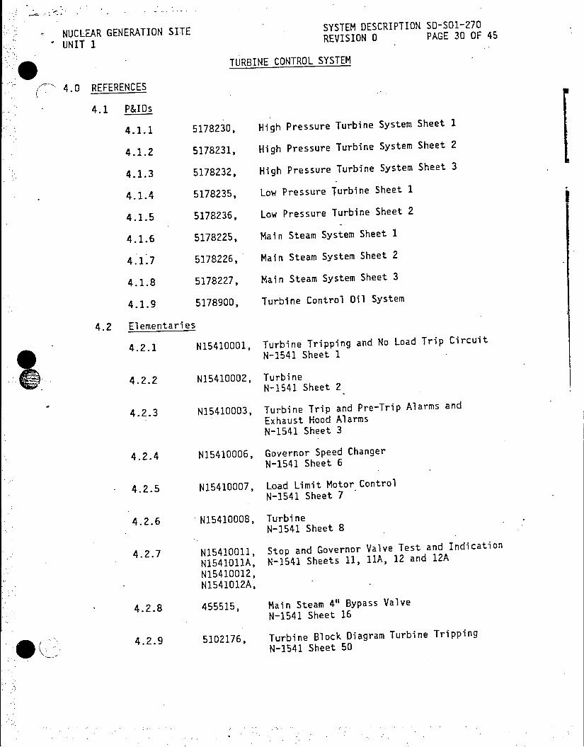
SNUCLEAR GENERATION SITE SYSTEM DESCRIPTION SO-SO1-270
UNIT REVISION 0 PAGE 30 OF 45
TURBINE CONTROL SYSTEM
4.0 REFERENCES
4.1 P&IDs
4.1.1 5178230, High Pressure Turbine System Sheet 1
4.1.2 5178231, High Pressure Turbine System Sheet 2
4.1.3 5178232, High Pressure Turbine System Sheet 3
4.1.4 5178235, Low Pressure Turbine Sheet 1
4.1.5 5178236, Low Pressure Turbine Sheet 2
4.1.6 5178225, Main Steam System Sheet 1
4.1.7 5178226, Main Steam System Sheet 2
4.1.8 5178227, Main Steam System Sheet 3
4.1.9 5178900, Turbine Control Oil System
4.2 Elementaries
4.2.1 N15410001, Turbine Tripping and No Load Trip Circuit
N-2541 Sheet 1
4.2.2 N15410002, Turbine N-1541 Sheet 2
4.2.3 N15410003, Turbine Trip and Pre-Trip Alarms and Exhaust Hood Alarms N-1541 Sheet 3
4.2.4 N15410006, Governor Speed Changer N-1541 Sheet 6
4.2.5 N15410007, Load Limit Motor Control N-1541 Sheet 7
4.2.6 N15410008, Turbine N-1541 Sheet 8
4.2.7 N15410011, Stop and Governor Valve Test and Indication
N1541011A, N-1541 Sheets 11, 11A, 12 and 12A
N15410012, N1541012A,
4.2.8 455515, Main Steam 4" Bypass Valve
N-1541 Sheet 16
4.2.9 5102176, Turbine Block Diagram Turbine Tripping N-1541 Sheet 50
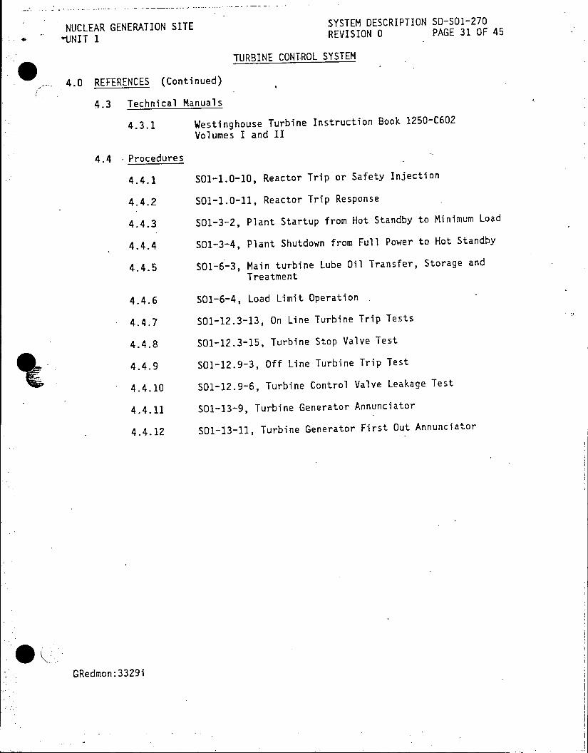
NUCLEAR GENERATION SITE SYSTEM DESCRIPTION SD-SO1-270
-UINIT 1 REVISION 0 PAGE 31 OF 45
TURBINE CONTROL SYSTEM
4.0 REFERENCES (Continued)
4.3 Technical Manuals
4.3.1 Westinghouse Turbine Instruction Book 1250-C602 Volumes I and II
4.4 Procedures
4.4.1 501-1.0-10, Reactor Trip or Safety Injection
4.4.2 SO1-1.0-11, Reactor Trip Response
4.4.3 501-3-2, Plant Startup from Hot Standby to Minimum Load
4.4.4 S01-3-4, Plant Shutdown from Full Power to Hot Standby
4.4.5 S01-6-3, Main turbine Lube Oil Transfer, Storage and Treatment
4.4.6 SO1-6-4, Load Limit Operation
4.4.7 SO1-12.3-13, On Line Turbine Trip Tests
4.4.8 501-12.3-15, Turbine Stop Valve Test
4.4.9 SO1-12.9-3, Off Line Turbine Trip Test
4.4.10 S01-12.9-6, Turbine Control Valve Leakage Test
4.4.11 S01-13-9, Turbine Generator Annunciator
4.4.12 501-13-11, Turbine Generator First Out Annunciator
GRedmon:33291

SYSTEM DESCRIPTION SD-SO-270 NUCLEAR GENERATION SITE REVISION 0 PAGE 37 OF 45 UNIT 1
FIGURE 6: LOAD LIMIT VALVE
HANDWHEEL.
CONTROL VALVE PISTON
VALVE
TRAVEL
VIEW SHOWING TRIP VALVE SHAFT FEATURES IN THE
OPEN POSITION WORM WHEEL
CLUTCH SPRING
OUTER SPRING SEAT X
CONTROL VALVE SEAT Y PISTON
INNER SPRING AUTO STOP OIL (PASSAGE B)
CUP VALVE--DRI
CHECK VALVE
PASSAGE A
CONTROL BLOCK COMMON CONTROL OIL

NUCLEAR GENERATION SITE SYSTEM DESCRIPTION SD-501-270
UNIT 1 REVISION 0 PAGE 38 OF 45
FIGURE 7: GOVERNOR OVERSPEED TRIP DEVICE
OVERSPEED TRIP TRIGGER
DRAIN - TRIP RELAY
CUP VALVE
OPJFICE CHAMBER X HIGH PRESSURE OIL
GAUGE CONN.
OVERSPEED TRIP VALVE PISTON
DRAIN DRAlN
AUTO STOP' AUTO STOP
OIL OIL

NUCLEAR GENERATION SITE SYSTEM DESCRIPTION SD-SO1-270 UNIT I REVISION 0 PAGE 41 OF 45
APPENDIX A
DEVELOPMENTAL RESOURCES
P&IDs
5178230, High Pressure Turbine System Sheet 1
5178231, High Pressure Turbine System Sheet 2
5178232, High Pressure Turbine System Sheet 3
5178235, Low Pressure Turbine Sheet 1
5178236, Low Pressure Turbine Sheet 2
5178225, Main Steam System Sheet 1
5178226, Main Steam System Sheet 2
5178227, Main Steam System Sheet 3
5178900, Turbine Control Oil System
Elementaries
N15410001, Turbine Tripping and No Load Trip Circuit * IN-1541 Sheet I
N15410002, Turbine. N-1541 Sheet 2.
N15410003, Turbine Trip and Pre-Trip Alarms and Exhaust Hood Alarms N-1541 Sheet 3
N15420006, Governor Speed Changer N-1541 Sheet 6
N15410007, Load Limit Motor Control N-1541 Sheet 7
N15410008, Turbine N-1541 Sheet 8
N15410011, Stop and Governor Valve Test and Indication N1541011A, N-1541 Sheets 11, 11A, 12 and 12A N15410012, N1541012A,
455515, Main Steam 4" Bypass Valve N-1541 Sheet 16
5102176, Turbine Block Diagram Turbine Tripping N-1541 Sheet 50
A-1

SYSTEM DESCRIPTION SD-SO-270 NUCLEAR GENERATION SITE REVISION 0 PAGE 42 OF 45 UNIT 1
APPENDIX A
DEVELOPMENTAL RESOURCES (Continued)
Technical Manuals
Westinghouse Turbine Instruction Book 1250-C602 Volumes I and II
Procedures
So1-1.0-10, Reactor Trip or Safety Injection
501-1.0-11, Reactor Trip Response
SO-3-2, Plant Startup from Hot Standby to Minimum Load
SO1-3-4, Plant Shutdown from Full Power to Hot Standby
SO1-6-3, Main turbine Lube Oil Transfer, Storage and Treatment
SO1-6-4, Load Limit Operation
SOI-12.3-13, On Line Turbine Trip Tests
501-12.3-15, Turbine Stop Valve Test
501-12.9-3, Off Line Turbine Trip Test
S01-12.9-6, Turbine Control Valve Leakage Test
501-13-9, Turbine Generator Annunciator
501-13-11, Turbine Generator First Out Annunciator
Study Guides
Study Guide 51, Turbine Control Mechanism, Bearing Oil Systems, and
Turbine Turning Gear.
Lesson Plans
1003, Turbine and Turbine Auxiliaries
1039, Turbine Governor and Control Oil
Bechtel System Descriptions
16, Turbine - Generator and Auxiliary Systems
FSAR
Section 2.1.3, Turbine Cycle System
Section 3.1.1, General Description
Section 3.1.2, Turbine - Generator
3329i A-2

NUCLEAR GENERATION SITE .SYSTEM DESCRIPTION SD-SO1-270
UNIT 1 REVISION 0 PAGE 43 OF 45
APPENDIX B
ANNUNCIATORS
Turbine Generator First Out
WINDOW NAME INPUT SETPOINT (NUMBER)
Thrust Bearing PS-38 and 35 psig
( Failure Trip PS-33 (Trip at I 80-90 psig)I
Steam Generator JS/G "A" LC-450 & LC-4531 85%
High Level or
Turbine Trip lS/G "B" LC-451 & LC-4541 85% or
lS/G "C" LC-452 & LC-4551 85% (2) 1 1 1
Turbine Bearing PS-40 and 10 psig Oil Low Pressure Trip PS-33 I(Trip at 5-7 psig)l
(3)
Condenser Low PS-39 and 22 Hg
Vacuum Trip PS-33 j(Trip at (4) 1 1 18-22" Hg) I
I I Turbine No Load Trip I PS-45 18 psig for I
(5) 1 minute
I I Emergency I PS-45 and I 35 psig Overspeed I PS-33 I(Trip at 60 psig Trip (6) and 1890 rpm)
- .1 Stop Valves I 33-VL or I Valve Closed Closed I 33-SVR
(7) I . 1 Thrust Bearing PS-38 35 psig Failure
(8)I B 1
I
I _____________________"A"____ LC____ 450_____&___LC-453J ________85%_______
oB-i
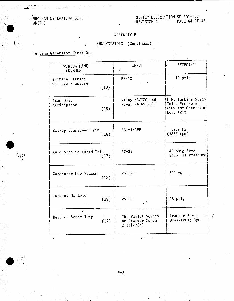
NUCLEAR GENERATION SITE SYSTEM DESCRIPTION SD-SO1-270
UNIT.1 REVISION 0 PAGE 44 OF 45
APPENDIX B
ANNUNCIATORS (Continued)
Turbine Generator First Out
WINDOW NAME INPUT SETPOINT
(NUMBER)
Turbine Bearing PS-40 . 10 psig . Oil Low Pressure
(10)
Load Drop Relay 63/OPC and IL.R. Turbine Steaml I Anticipator | Power Relay 237 lInlet Pressure I
(15) 1 j>50% and Generatorl I ILoad <20% 1
II I I
Backup Overspeed Trip 281-1/CFF 62.7 Hz
(16) 1(1882 rpm)
Auto Stop Solenoid Trip PS-33 40 psig Auto (17) Stop Oil Pressurel
1 I I II
Condenser Low Vacuum I PS-39 | 24" Hg (18)
I
Turbine No Load (19) PS-45 18 psig
Reactor Scram Trip "B" Pallet Switch I Reactor Scram I (37) on Reactor Scram I Breaker(s) Open I
Breaker(s) I.
B-2
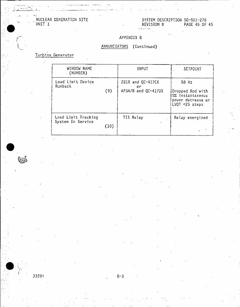
NUCLEAR GENERATION SITE SYSTEM DESCRIPTION SD-SO1-270 UNIT I REVISION 0 PAGE 45 OF 45
APPENDIX B
ANNUNCIATORS (Continued)
Turbine Generator
WINDOW NAME INPUT I SETPOINT .(NUMBER)
| Load Limit Device I 281X and QC-417CX 58 Hz Runback or
(9) AP3A/B and QC-417DX IDropped Rod with 15% instantaneous 1power decrease orj ILVDT <25 steps
1t II I Load Limit Tracking I TIS Relay . Relay energized | System In Service
(10)I
3329i B-3

NUCLEAR GENERATION SITE SYSTEM DESCRIPTION SD-501-380
UNIT 1E GE E AT O SIT REVISION 0 PAGE 1 O F 40
UNT1FEB 20 1986 CDM
* NUCLEAR INSTRUMENTATION SYSTEM
TABLE OF CONTENTS
PAGE SECTION
1.0 FUNCTIONS/DESIGN BASES 2
2.0 DESCRIPTION 2.1 System Overview 2.2 Components RECEIVED CDM 4
3.0 OPERATIONS FEB20 1986 12 3.1 Normal Operations 12
3.2 Abnormal Operations 'SITEFILECOP 13
3.3 Other Operation 1
4.0 REFERENCES 15
4.1 One Line Diagrams 15
4.2 Procedures 15
S FIGURES
18
1. Nuclear Instr'umentation Range Comparator Chart 19
2. BF 3 Proportional Counter 1
3. Source Range Nuclear Instrumentation 20
4. Detector Location 21
5. Detector Orientation 22
6. Source Range 23
7. Compensated Ion Chamber 24
8. Intermediate Range Nuclear Instrumentation 25
9. Intermediate Range 26
10. Power Range Nuclear Instrumentation 27
11. Uncompensated Ion Chamber 26
12. Power Range 29
13. NIS J-Console 30
14. NIS Recorder Start-up 3
15. NIS Recorder Shut-down 32
16. Gas-Filled Detector Characteristic Curve 33
17. K02 Rack
18. CAOMS Panel 35
APPENDICES 36
A. Annunciators 36
B. Developmental Resources 38
C. General Detector Theory
This System Description is approved per SO-223-1044, System Description
Revision and Approval. ntact CM to verify revision information.
PREPARED BY: - -lI r i RDate
. APPROVED BY: PowerRangeNuclAer Itru tatio n
3230 NOTQA RGRAMAFFET23

NUCLEAR GENERATION SITE SYSTEM DESCRIPTION SD-SO1-380
UNIT 1 REVISION 0 PAGE 2 OF 40
NUCLEAR INSTRUMENTATION SYSTEM
1.0 FUNCTIONS/DESIGN BASES
1.1 The Nuclear Instrumentation System has the following main functions:
1.1.1 Monitors and provides indication of neutron flux and
rate of change of neutron flux from reactor shutdown/refueling conditions to 120% full power.
1.2 The Nuclear Instrumentation System has the following additional
functions relating to Reactor Control and Protection:
1.2.1 High Start-up Rate Rod Stop P-6
1.2.2 High Start-up Rate Reactor Trip
1.2.3 Over Power Rod Stop P-1
1.2.4 Over Power Trip P-7, P-8
1.2.5 Input to Rod Control System
1.2.6 Audible Countrate in the Control Room and inside the
Containment during Shutdown/Refueling
1.2.7 Drop Rod - Rod Stop P-3
1.3 The Nuclear Instrumentation System has the following Design Basis:
1.3.1 The Goal of the Nuclear Instrumentation System is to
provide reliable indication of reactor power from the
Source Range up to 120% full power. This is
accomplished with the use of multiple instrument
channels for each range of detection such that a single failure will neither cause or prevent a Reactor Trip.
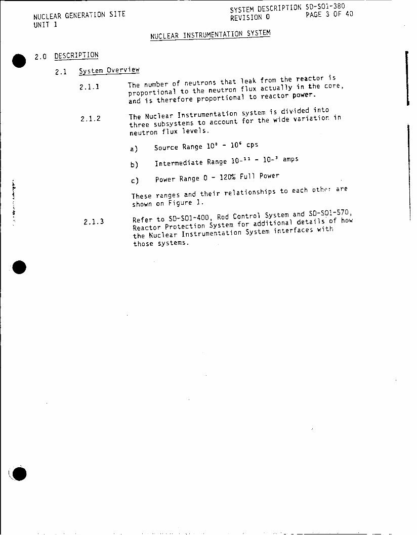
SYSTEM DESCRIPTION SO-SO1-380 NUCLEAR GENERATION SITE REVISION 0 PAGE 3 OF 40
UNIT 1
NUCLEAR INSTRUMENTATION SYSTEM
* 2.0 DESCRIPTION
2.1 System Overview
2.1.1 The number of neutrons that leak from the reactor is
proportional to the neutron flux actually in the core,
and is therefore proportional to reactor power.
2.1.2 The Nuclear Instrumentation system is divided into
three subsystems to account for the wide variation in
neutron flux levels.
a) Source Range 10' - 10' cps
b) Intermediate Range 10_11 - 10-1 amps
c) Power Range 0 - 120% Full Power
These ranges and their relationships to each other are
shown on Figure 1.
2.1.3 Refer to SD-SOI400, Rod Control System and
SD-SO570,
Reactor Protection System for additional details of how
the Nuclear Instrumentation System interfaces with
those systems.
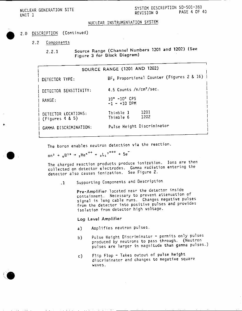
NUCLEAR GENERATION SITE SYSTEM DESCRIPTION SD-SOI-380
UNIT 1 REVISION 0 PAGE 4 OF 40
NUCLEAR INSTRUMENTATION SYSTEM
2.0 DESCRIPTION (Continued)
2.2 Components
2.2.1 Source Range (Channel Numbers 1201 and 1202) (See
Figure 3 for Block Diagram)
SOURCE RANGE (1201 AND 1202)
DETECTOR TYPE: BF, Proportional Counter (Figures 2 & 16)
DETECTOR SENSITIVITY: 4.5 Counts /n/cm'/sec.
RANGE: 100 -10' CPS -1 - +10 DPM
DETECTOR LOCATIONS: Thimble 1 1201
(Figures 4 & 5) Thimble 6 1202
GAMMA DISCRIMINATION: Pulse Height Discriminator
The boron enables neutron detection via the reaction.
on + 6 3o 2He' + 3 L,7 + 5e
The charged reaction products produce ionization. Ions are then
collected on detector electrodes. Gamma radiation entering the
detector also causes ionization. See Figure 2.
.1 Supporting Components and Description
Pre-Amplifier located near the detector inside
containment. Necessary to prevent attenuation of
signal in long cable runs. Changes negative pulses
from the detector into positive pulses and provides
isolation from detector high voltage.
Log Level Amplifier
a) Amplifies neutron pulses.
b) Pulse Height Discriminator - permits only pulses
produced by neutrons to pass through. (Neutron
pulses are larger in magnitude than gamma pulses.)
c) Flip Flop - Takes output of pulse height discriminator and changes to negative square
waves.

NUCLEAR GENERATION SITE SYSTEM DESCRIPTION SD-SO1-380
UNIT I REVISION 0 PAGE 5 OF 40
NUCLEAR INSTRUMENTATION SYSTEM
( 2.0 DESCRIPTION (Continued)
2.2.1 Source Range (Channel Numbers 1201 and 1202) (See
Figure 3 for Block Diagram) (Continued)
.1 (Continued)
d) Log Integrator - Produces a signal proportional
to the logarithm of the frequency Of pulses,
determines count rate.
e) Count Rate Amplifier - produces an output suitable for recorders, indicators, audible count
rate.
Start-Up Rate (SUR) Amplifier derives SUR from
output of Log Level Amplifier. Provides output for
meters and bi-stable amplifier.
Bi-Stable Amplifier provides Hi SUR annunciator
and input to Reactor Protection System for Hi SUR Rod
Stop, P-6.
Each channel has two power supplies:
a) High Voltage for detector
b) Low Voltage for drawer components. Fed from a
common instrumentation power supply.
Audio Count Rate
Audible indication of count rate during shutdown,
refueling and reactor startup in the Control Room and
inside the Containment. Ranges 100, 101, 101, 10', 10' cps.
Indications
a) Drawer Figure 6
Neutron Level 100 - 10' cps
High Voltage 0 - 2500 VDC
SUR -1 - +10 DPM
b) J-Console Figure 3
Neutron Level 10' - 10' cps
SUR -0.5 - +5 DPM
c) Power Recorder - selectable

NUCLEAR GENERATION SITE SYSTEM DESCRIPTION SD-SOI-380
NUE G REVISION 0 PAGE 6 OF 40
UNIT 1 NUCLEAR INSTRUMENTATION SYSTEM
2.0 DESCRIPTION (Continued)
2.2.1 Source Range (Channel Numbers 1201 and 1202) (See
Figure 3 for Block Diagram) (Continued)
.1 (Continued)
During testing, operation of the Test Selector switch
wili cause NIS Channel Test alarm, and allow simulation
of various count rates and start-up rates to test
drawer circuitry as follows:
Level Position
102 A 10, B 10' C 105 D
SUR Position
1.5 A
2.5 B 5 C
10 0
2.2.2 Intermediate Range (Channel Numbers 1203 and 1204)
See Figure 8 for Block Diagram
INTERMEDIATE RANGE (1203 AND 1204)
DETECTOR TYPE: Compensated Ion Chamber (Figures 7 & 16)
DETECTOR SENSITIVITY: 4.0 x 10 -' Amp/n Km2 /sec.
RANGE: 1011 - 10-' Amps -1 - +10 DPM
DETECTOR LOCATIONS: Thimble 2 1203
(Figures 4 & 5) Thimble 5 1204
GAMMA DISCRIMINATION: Compensating Voltage
The detector used is a Compensated Ion Chamber.
a) Two Concentric Detector Cans
b) The outer can is lined with boron, which results in an output
current produced from neutron and gamma interactions (see
neutron-boron reaction on page 4).

NUCLEAR GENERATION SITE SYSTEM DESCRIPTION SO-SOI-380
UNIT 1 REVISION 0 PAGE 7 OF 40
NUCLEAR INSTRUMENTATION SYSTEM
* 2.0 DESCRIPTION (Continued)
2.2.2 Intermediate Range (Channel Numbers 1203 and 1204)
See Figure 8 for Block Diagram (Continued)
c) The inner can has no boron coating. Therefore, its output
current is due to gamma interactions only.
The current from the Outer Can (gamma + on') and the current
from the Inner Can (gamma only) are subtracted, and the
resultant output is independent of gamma flux variations.
e) The voltage applied to the inner can is called compensating
voltage.
.1 Supporting Components and Description
Log Level Amplifier derives a level signal
proportional to the Logarithm of the current signal
from the Compensated Ion Chamber detector. Provides
output for Control Room indicators and annunciators.
Start-up Rate Amplifier derives an output
proportional to the start-up rate based on rate of
change of signal. Provides output for Control Room
indicators and annunciators.
Bi-Stable Amplifier Provides output to Reactor
Protection System and annunciators.
Hi SUR Rod Stop P-6 Hi SUR Trip
Source Range Hi Voltage Cut-off automatically turns off high voltage to Source Range Instruments at
approximately 2 x 10-' amps
1203 turns off 1201
1204 turns off 1202
Indications
a) Drawer (See Figure 9)
Neutron Level 10-1' - 10-3 amps
SUR -1 - +10 OPM
b) J-Console (See Figure 13)
Neutron Level 10-" -* 10-' amps
SUR -0.5 - +5 DPM
c) Power Recorder - selectable
NUCLEAR GENERATION SITE SYSTEM DESCRIPTION SD-SO-380
UNIT 1 REVISION 0 PAGE 8 OF 40
NUCLEAR INSTRUMENTATION SYSTEM
2.0 DESCRIPTION (Continued)
- 2.2.2 Intermediate Range (Channel Numbers 1203 and 1204)
See Figure 8 for Block Diagram (Continued)
.1 (Continued)
During testing, operation of the Test Selector switch
will cause NIS Channel Test alarm, and will allow
simulation of various power levels and start-up rates
to test drawer circuitry, as follows:
Level Position i-1O-T A
10_2. B 10-' C 10- D
SUR Position 1.5 A 2.5 B 5 C
10 D
Also, any test position selected on the Intermediate
Range drawer will energize the High Voltage Cutoff for
the associated Source Range NI.
The following drawer indicating light/alarms must be
pressed to reset during testing or actual alarms.
- Intermediate Range Scram Reset

SYSTEM DESCRIPTION SD-SO1-380
NUCLEAR GENERATION SITE REVISION 0 PAGE 9 OF 40
UNIT 1
NUCLEAR INSTRUMENTATION SYSTEMi
2.0 DESCRIPTION (Continued)
2.2.3 Power Range (Channel Numbers 1205, 1206, 1207, 1208)
(See Figure 10 for Block Diagram)
POWER RANGE (1205, 1206, 1207 AND 1208)
Compensated and Uncompensated Ion DETECTOR TYPE: Chambers. (CIC's shared with IR).
(Figures 7, 11, & 16)
DETECTOR SENSITIVITY (UIC): 4.4 x 10-" Amp/n/cm2/sec
RANGE: 0 - 120% Full Power
DETECTOR LOCATIONS: Thimble 2 1205 OOThimble 4 1206
Thimble 5 1207 Thimble 8 1208
GAMMA DISCRIMINATION: Not needed
The detectors used are a combination of Compensated
and
Uncompensated Ion Chambers.
a) Power Range 1205 and IR 1203 share one detector (lower).
b) Power Range 1207 and IR 1204 share one detector (lower).
c) Compensation is not used in the power range because:
1) Gamma current = 1/100 neutron current in the
power range.
2) Gamma current is proportional to power in the power
range.
d) Boron lining inside ion chamber enables detection
of neutrons.
e) Two detectors per channel, (for channels 1205 and 1207e the
detectors shared with the IR channels are the lower detectors)
stacked in one thimble, to cover entire axial length of active
core.
NUCLEAR GENERATION SITE SYSTEM DESCRIPTION SD-SO1-380
UNIT 1 REVISION 0 PAGE 10 OF 40
NUCLEAR INSTRUMENTATION SYSTEM
2.0 DESCRIPTION (Continued)
2.2.3 Power Range (Channel Numbers 1205, 1206, 1207, 1208)
(See Figure 10 for Block Diagram)
.1 Supporting Components and Description
Summing Amplifier sums output from both detectors
to derive a total channel output.
Level Amplifier derives a power level signal proportional to the total channel output from the
Summing Amplifier. Provides output to Control Room
meters, recorders, and annunciators.
Differentiator (1214) (Channel 1208 only) signal fed to Rod Control for rate of change of Power.
Comparator (1215) compares 4 Power Range channels
with each other and provides the following at a 5%
deviation:
* Nuclear Dropped Rod Rod Stop.
* Auto Rod Withdrawal Prohibit.
* Turbine Runback to 70% (If initially above
70% power and the Defeat Switch behind the South
Vertical board not in "Defeat".)
The purpose of this is to protect the fuel in the event
of a dropped rod.
Coincidentor (1213) provides logic for Reactor
Protection System.
The Power Range NIS signals are fed to three bistables
whose setpoints correspond to the Low, Mid, and High
Overpower Trip setpoints. The Mode of Operation switch
on the J-Console selects which bistables are in service
to the Reactor Protection system.
In each position, 2 out of 4 channels at or above
setpoint will result in an overpower Reactor Trip.
The Intermediate Range instruments provide an output
from the 5 DPM bistable and 1 out of 2 Intermediate
Range channels at or above setpoint will result in a
High Startup Rate Reactor Trip. See SD-S01-570 Reactor
Protection and Permissives.
NUCLEAR GENERATION SITE SYSTEM DESCRIPTION 50-501-380
UNIT 1 REVISION 0 PAGE 11 OF 40
NUCLEAR INSTRUMENTATION SYSTEM
2.0 OESCRIPTION (Continued)
2.2.3 Power Range (Channel Numbers 1205, 1206, 1207, 1208)
(See Figure 10 for Block Diagram)
(Continued)
Indications
a) Drawer (See Figure 12)
1) Upper and Lower detector individual
micro-arnp indication ("A" or "B")
2) Power Level 0-120% Full Power
b) J-Console (See Figure 13)
1) 0-120% Full Power
c) Power Recorder - Selectable
During testing, placing the Test-Operate switch in test
enables the Test Pot to simulate various powers up to
the test of Over Power Trip. Also brings in NIS
Channel Test annunciator. Failure to reset the "Scram
Reset" will cause a Reactor Trip if, after that channel
is returned to "Operate", a second channel is taken to
Test and a trip signal inserted.
Placing more than one Power Range Channel in test will
return both channels to Operate.
The following drawer indicating lights/alarms must be
pressed to reset during testing or actual alarms.
- Power Range Scram Reset
- Power Range drop Rod - Rod Stop Reset
- J-Console Auto Rod Withdrawal Prohibit Reset
2.2.4 Power Recorder
Can be used to record any two NIS channels.
Two Speed
At power, normally selected to record Channels 1205 and 1207.
Receives power from VB #2.
2.2.5 Overpower Recorder
Records channels 1206 and 1208 Range 0 - 120%.

NUCLEAR GENERATION SITE SYSTEM DESCRIPTION SD-SOI-380
UNU A G I REVISION 0 PAGE 12 OF 40
UNIT 1 NUCLEAR INSTRUMENTATION SYSTEM
0 2.0 DESCRIPTION (Continued)
2.2.6 Excore Axial Offset Monitors (Figure 17 and 18)
Detectors are uncompensated Ion Chambers, similar to power range
detectors.
Circuitry is similar to power range drawers, with exception that
signals are not summed. Individual detector outputs displayed a.t
the CAOMS drawer.
Excore Axial Offset is calculated by the formula:
EAO = A - B A Upper Power A + B B Lower Power
EAO displayed on meters on J-Console.
Provides alarm for "Delta Flux Limit," whose setpoint is adjustable
at the indicators on the J-console.
Location of detectors - Thimble #3 and Thimble #7
NOTE: Thimble #3 also contains a fission chamber detector for
the Auxiliary Control Panel. Thimble #7 also contains
a spare BF, detector which is used during refueling
for an additional source range instrument.
Indication provided as follows:
.1 In the CAOMS racks behind the West Vertical board. Two
drawers, one for Thimble 3 and one for Thimble 7.
Each drawer has two meters for top and bottom detector,
0-200%. This % indication is not equal to Reactor power,
only used to indicate the relative difference between
detector outputs.
.2 Recorder in the K02 rack (AFR-1) (Same as Reactor Coolant
Pump Vibration Recorder).
.3 J-Console, EAO (Figure 13), + 20%.

NUCLEAR GENERATION SITE SYSTEM DESCRIPTION SD-SO1-380
UNIT 1 REVISION 0 PAGE 13 OF 40
NUCLEAR INSTRUMENTATION SYSTEM
2.0 DESCRIPTION (Continued)
2.3 Power SuppLies
POWER SUPPLIES
COMPONENT I BREAKER LOCATION
NIS CHANNEL Source 1201 8-14V3 Fused RB #4, from Inv #4
1202 8-11R3 RB #1
Intermediate 8-12R3 RB #2 1203 81R B#
1204 8-13R3 RB #3
IPower 1205 8-12R3 RB #2
1206 8-14V3 lFused on RB #4, from Inv #4j
1207 8-13R3 RB #3
1208 8-11R3 1 RB #1
Coincidentor 1214 8-14V3 Fused on RB #4, from In #4
Differential 1214 8-11R3 RB #1
Comparator 8-11R3 RB #1
Audio Count Rator 8-13R3 RB #3
Sphere Evac Horn 8-12R3 RB #2
* .

SYSTEM DESCRIPTION SD-SO1-380
NUCLEAR GENERATION SITE REVISION 0 PAGE 14 OF 40
UNIT 1
NUCLEAR INSTRUMENTATION SYSTEM
3.0 OPERATION
3.1 Normal Operations
Reactor Startup
With all preparations made and required testing completed for
Mode 2, the Operator is ready to take the reactor critical. The
Operator begins withdrawing Control Bank rods while observing the
Source Range Nuclear Instrumentation. The Power Recorder may be
selected to record one SR and one IR channels, or both SR channels.
Initial count rate prior to withdrawing control rods will vary and
depends on the length of the shutdown, previous power history, and
whether or not a refueling has been performed.
Reactor criticality is verified when a stable positive Startup Rate
3 exists with no control rod motion, and depending on initial
countrate, criticality may occur in either the Source or
Intermediate Ranges, so the positive startup rate may be observed
on the IR or SR SUR meters.
For this discussion, assume that criticality occurs midrange
on the
Source Range NI's. A stable positive SUR is maintained by
adjusting Control Rod position and reactor power is increased.
When the Source Range channels are indicating approximately
hen cps, the Intermediate Range NI should begin to increase.
When the IR indicates approximately 2 x 10-' Amps, the
operator should verify that the automatic Source Range Hi Voltage
cut off occurs or be pirepared to turn off the SR Hi Voltage
manually in the drawer.
Once the Source Range NI's have been secured, both IR instruments
are selected on the Power Recorder. Reactor Power is raised to
approximately 10-' to 10-' Amps where Reactor Power is
leveled to take critical data.
Once critical data is recorded, a positive start up rate is again
achieved by withdrawing control rods and reactor power is raised to
2 x 10- Amps, or the point at which nuclear heat maintains
Tave.
Preparations are then made to enter Mode 1. When all
requirements
and tests are complete, Reactor power is increased to less than 10%
and the turbine and the remainder of the Secondary plant are
started up. When ready, the Generator is synchronized on line, and
then reactor power can be raised above 10%.
As power is increased, the Overpower Rod stops are increased from
20%10 to 80%1 and finally to 106%. Also, as prompted by annunciators
"Alert Switch NIS Mode to Mid (High)", the NIS overpower trip
setpoints are raised consistent with plant power with the
NIS mode
selector switch on the J-Console.

NUCLEAR GENERATION SITE SYSTEM DESCRIPTION SD-SU-3U
UNU A G I REVISION 0 PAGE 15 OF 40
UNIT 1 NUCLEAR INSTRUMENTATION SYSTEM
3.0 OPERATION (Continued)
3.1 Normal perations (Continued)
With the plant at its final desired power level, further Operator
manual operations are limited to a daily calibration performed on
the Mid Shift from a secondary calorimetric, and periodic
monitoring and surveillance.
3.2 Abnormal Operation
The Intermediate Range Nuclear Instruments are very sensitive to
the amount of compensation voltage. See Figure 14 and 15.
Under Compensated:
- During startup this condition will result in higher indicated
power than actual.
- On shutdown/trip, Source Range High Voltage will be turned on
late or not at all.
Over Compensated:
- During a reactor startup, the Intermediate Range Log Level
circuitry will not respond at all until the neutron and gamma
current of the outer can overcomes the excessive gamma current
of the inner can. Once this point is reached, a further
increase in neutron flux level will cause the rate circuitry
to generate a very high Startup Rate which will cause a High
SUR Reactor Trip.
- On shutdown/trip, Source Range High Voltage will
be turned on
too soon, perhaps resulting in SR detector damage.
3.3 Other Operations
The Power range NIS together with the Excore Axial Offset Monitors
are used to monitor axial power distribution in the core.
Excore Axial Offset (EAO) is monitored for a number of reasons
including Technical Specifications and fuel economics.
EAO is defined as EAO A - B x 100
-A+ B
where A = Upper Detector Current B = Lower Detector Current

NUCLEAR GENERATION SITE SYSTEM DESCRIPTION SD-501-380
UNIT 1 REVISION 0 PAGE 16 OF 40
NUCLEAR INSTRUMENTATION SYSTEM
3.0 OPERATION (Continued)
3.3 Other Operations '(Continued)
Factors that affect Excore Axial Offset include
- Control Rod position: pulling control rods causes power to
shift to the upper part of the core which causes EAO to trend
positive, inserting control rods causes power to shift to the
bottom of the core which causes EAO to trend negative.
- Boron Concentration - Borating causes EAO to trend positive,
diluting causes EAO to trend negative.
- Xenon Concentration - EAO trends positive and negative during
Xenon oscillations.
NUCLEAR GENERATION SITE SYSTEM DESCRIPTION SD-501-380
UNIT 1 REVISION 0 PAGE 17 OF 40
NUC.LEAR INSTRUMENTATION SYSTEM
4.0 REFERENCES
4.1 One Line Diagrams
4.1.1 1542 Sh. 50, Reactor Block Diagram, Reactor Scram
5102177
4.1.2 1542 Sh. 102A, Schematic Diagram, Reactor Protection
System S mLr Signals, 5112259-6
4.1.3 1542 Sh. 131B, Instrumentation System, Neutron Detector
Orientation and Location 5147124-4
4.1.4 1542 Sh. 105 Permissive Relay Circuits for Scram Bkr.
Trip Annunciator and Event Recorder 5151820-3
4.1.5 1542 Sh. 103 E/D Rod Control Sh. 2 5150411-4
4.1.6 1542-103B, E/D Rod Drive Mechanism 5150625
4.1.7 1540 Sh. 18 One Line Diagram 120 Volt AC System 5102174
4.2 Procedures
4.2.1 SO1-12.3-3,
4.2.2 SO1-12.3-4,
4.2.3 SO1-12.3-44,
4.3 Technical Specifications
JMcCann:3230i
SYSTEM DESCRIPTION S 1101-I0 NUCLL. ENERATION SITE REVISION 0 , PAGE 18 OF 110 UINIT 11
IGURE 1;. NUCLEAR INSTRUMENTATION RANGE COMPARTOR HART
NUCLEAR INSTRUMENTATION RANGE COMPARTOR CHART
UNIT 1
10 10 10 10 10 10s 10 CPS
4X 10 NV TO 4 X 10 NV
10 10-to 10 10 10" 10 10 10- 10-3 AMPS
2 2. 5 X 10 NV TO 2.5 X 10 NV
I2XF
0.1 120% FP
2.5 X 10 NV TO 2.5 X 10't NV
FIGURE I SO-SOI-390-1-0
3230i
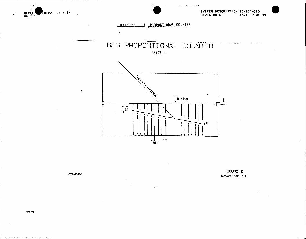
NUCLF !' NERATION SITE SYSTEM DESCRIPTION S0-01-380 UNIT 1 REVISION 0 PACE 19 or t0
FIGURE 2 BF PROPORTIONAL COU(TE 3
BF3 PROPORTIONAL COUNTER LIT I
soB ATOM
FIGURE 2 S-SO1-380-2-0
330

0 SYSTEM DESCRIPTION SD-SOI-P90 NUI-1.r GrNERAT ION SITF REVISION 0 PACE 20 OF 110
UN IT 1
FIGURE 3s soRC RAIENCERISRUMENTAflO0
I.A. .. VITAL CH{At,t- TEST/CALBu
AWIO P-R
H.V. LV
1 : E C?(B/S.
LOCAL (CPS) INJICAT ION'
j-PAN~EL (CPS)
CONTpOL. PoO'
EVAC. KFa7!
32301
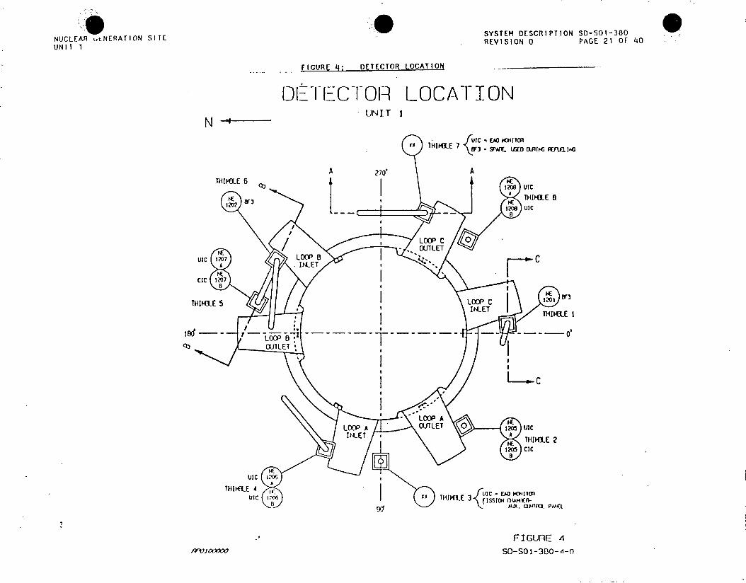
SYSTEM DESCRIPTION SD-SOI-380 NUCLEAR utNERATION SITE RVSO AE2 F4 UNIT I EIIN0PG 1O 4
FIGURE 4: DETECTOR LOCATION _______
OFDETECT1OR LOCATION N UNIT I
I H P E U IC E M wi d I
THIPhLE 6
(bTII1E fI A 101VIC
w A FIRE 8i 1SO-S B1-3120-'1IC

NUCLEAR .'-q TO SITE SYSTEM DESCRIPTION SDi-SOI-380W (INI T 1 REVISION 0 PAGE 22 OF 4iO
FIGURE 5: DETECTOR ORIENTATION
DETECTOR ORIENTATION UNIT I
12 1TP M LINE
fI3/4 CIA( LINE N
112 CtTFL I NE so U4E12'ACTVE Wtl
72'MIN.
TH191LES 4 C 7L THIMI4LES 5C 6 rrilPES 1.Z 3C 8
SO-sot -380-5-0
32301

NUCLAR GNER~ IONSITESYSTEM DESCRIPTION SO-SOI-330O
UIT A 1 E E AT O SI E EVIS.ON 0 PAGE 23 O)F i nO
FIGURE 6: SOURCE RANG~
SOURCE- RANGE UNIT I
0oo 10' 0 25D 1
,a0 E 2 0 0) o2 )(
IT "J LEVEL. HICH w1-IAcE STITm-W tv
?flrO4 LEVEL VOLTAGE STmIT-&p FAILLFIE PATE
019TE LEVEL A A L
VOLTAE HIGH VCIJAGE TET__ EI FAILLFI
FIGIFr 6 so-sol-380-6-O
323n!
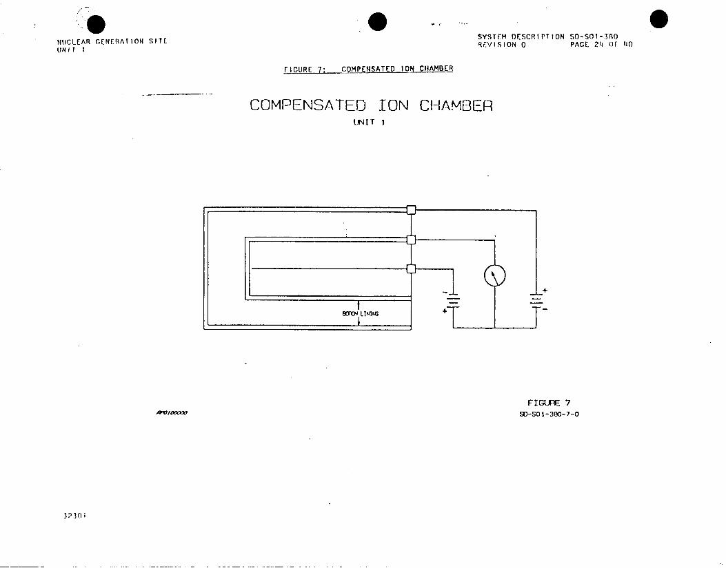
NUCLEAR GENERATION SITESYTMOCRPINDSI-0 UNIT I RFVISION 0 PAGE 24 OF 40
rJ9VRE 7' OMPENSATED 10q CAMBER
COMPENSATED ION CHAMBER LR'JIr I
F I GUFE 7 SO-SOI-380-7-O
32,3n0

SYSTEM DESCRIPTION SD-SOl-380 NUCLEAR GENERATION SITE REVISION 0 PAGE 25 OF 110 UNIT 1
IIGQRL _ NEMDIT AO NUCLEAR INSTRUMENAJO!
SouX:CE RAI'~ffHI VOL.TAGE CUJTOFF
PECCDER
J. PA?~L TEST suc ~'3 .~'
SJ~P~..YCAL. LOCAL (AW.S)
.AAOL
DLSA
STO POWES R"~*E D-ANa1 I.. vN F~~POpwEqR ANGE aW4NL
31-301
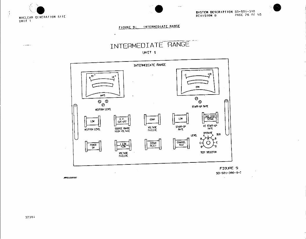
SYSTEM DESCRIPT ION SO-SOI-3-90
NUCLEAR G(NERATION SIIE REVISION 0 PACE 26 OF 110
FIGURE 9: INTERMEDIATE.RA N9E
INTERMEDIATE RANGE UN~IT i
INTG*fDIATE RANE
-I
(v 0 0 0lm~ WE
I10ro LEVEL.5ATPRE
HIGI VOLIAQC FAILUIE PATE PATE
LEVEL A A
FAILLUT
FIGURE 9
3230i

NUCLFE ERATION SITE SYSTEM DESCRIPTION SO-SOI-360 UNIT REVISION 0 PAGE 27 OF 110
FIGURE 10: POWER RANGE NUCLEAR INSTRUMENTATION
ROO DROP II B/SO0 STOP
HV TEST B/S P7 CAL COMPARATOR
- LOCAL (AMPS) DIFFERENTIATOR B/S PB
VITAL 4 L I NEAR Bus LOCAL (AMPS) AMP
LO * 8 /S REACTOR
UIC RECORDER TIP
HV LOCAL (% PWR)
< SHNT -MID SUPPLYB/S REACTOR
CIC J - PANEL (% PWR) TRIP 1205/7 UIC HI
1206/8 OVER POWER B/S REACTOR -__LV RECDRDER IP
SUPPLY
FIGURE 10 /9-o0oooo SD-SO1-380-10-0

SYSTEM DESCRIPTION SO-SOI-380
falCL.EAR Cr[NIIAIION SIIE FTVISION 9 PAGE 28 OF 110
FiGURE 11: UNCoMNST ED IoN CHAMI3,_
UNCOMPENSATED TON CHAMBER Ut4 IT I
FIGUR~E I11 SO-SO 1 -380-1
3 23 0 i
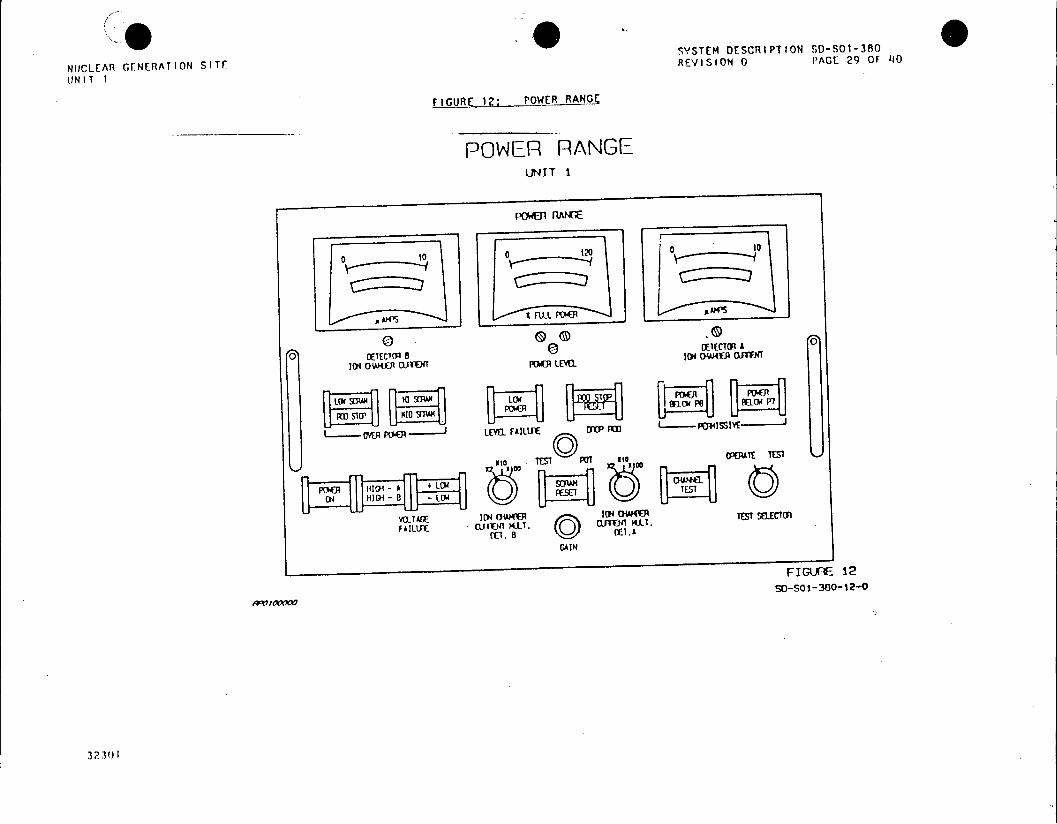
SYSTEM DESCRIPT ION SD-SOI-380
NUCLEAR GENERATION SITE REVISION 0 PAGE 29 OF 11
FIGURE 12j' POWER RANGE
POWER RANGE UNIT 1
powmJ RqIGE
0 00 120 10
00 GEE~ (D ~ETG 0
j D o TEC)l011 1 ro LEwi alma(U W ~
Io TEST~' P Itio OPOUAE TEST
04~,% HI04 -W~ B OW (DM
GAIN
FIGURE- 12
SO-SO 1-380-12-0
3231
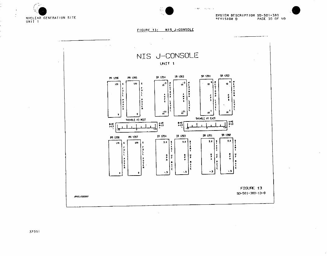
SYSTEM DESCRIPTION SD-S01-380 NUCLEAR GENERATIoN SITE FVISION 0 PACE 30 OF 140 UNIT I
FIGURE 13: NIS J-CONSOLE
NIS J-CONSOLE UNIT I
S1206 1205 I 1204 I 1203 M 1201 9 1202
o a 0to t t to to t
r u U u u
A 0l l 0 0 1 1
UU u LL
K K K AC t c
L L L U 0 U
FIUR 13
3230Y iV
A L
0 0 10 10 10 10
w THIKX1E 03 AWST A4(IIIKIE 07 EAST
A410 v 1 £4 -01r 7 A 4
PA 1208 PA1I207 In 1204 in 1203 SR1201 91 120?
t? 3 ? .0 5 5. 50 S 5. 3
L. L u 0 u u U 0
0 0KKK
FIGU)F* 13 SO-SOt -300-13-0
3230i'
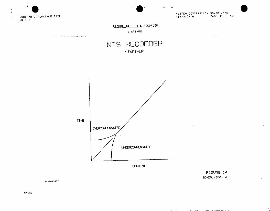
SyUIf DESCRIPTION SD-SOl-380 %.-VIO 0PAGE 31 OF 110
NUCLEAR GENERATION SITE IO0 UNIT I
FIGU-RE-14: NIS RECORIDER
START-UP
MIS RECORDER 9 TART -UP
TIM4E
OvERCOMPENSATED
IN F CC4--E?'SATED
CIMENT
FIGURE 14
SD-S01-360-1 4-O
323n i
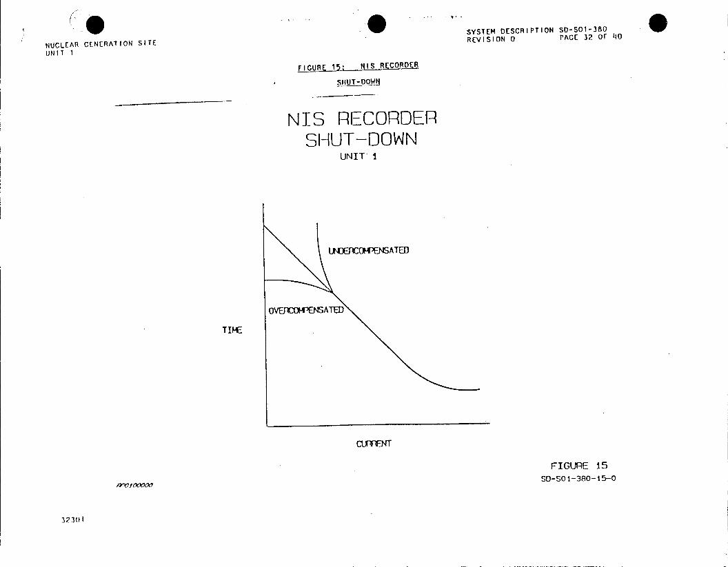
SYSTEM DESCRIPTION SD-SO1-380
NUCLEAR GENERATION SITE REVISION 0 PAGE 32 OF 110
UNIT 1
FIGURE 15: MISRECORDER
SHUT-DOW
NIS RECORDER SHUT-DOWN
UNIT I
LNDERCOMPENSATED
OVERCOMPENSATED
TIME
CUrnET
FIGURE 15 SO-SOI-380-15-0
32301

SYS7EM DESCRIPTION SD-SOI-380
NUCLEAR GENERATION SITE R.VISION 0 PACE 33 OF 110
UNIT 1
FIGURE i6:ASFIL DEECORCARACTERISTIC CURYE
GAS FIILED DETECTOR
CHARACTERISTIC CURVE UNIT I
0 V, IL V I
gvl* VOTG TO I
G*- IIE O ICTI
32301
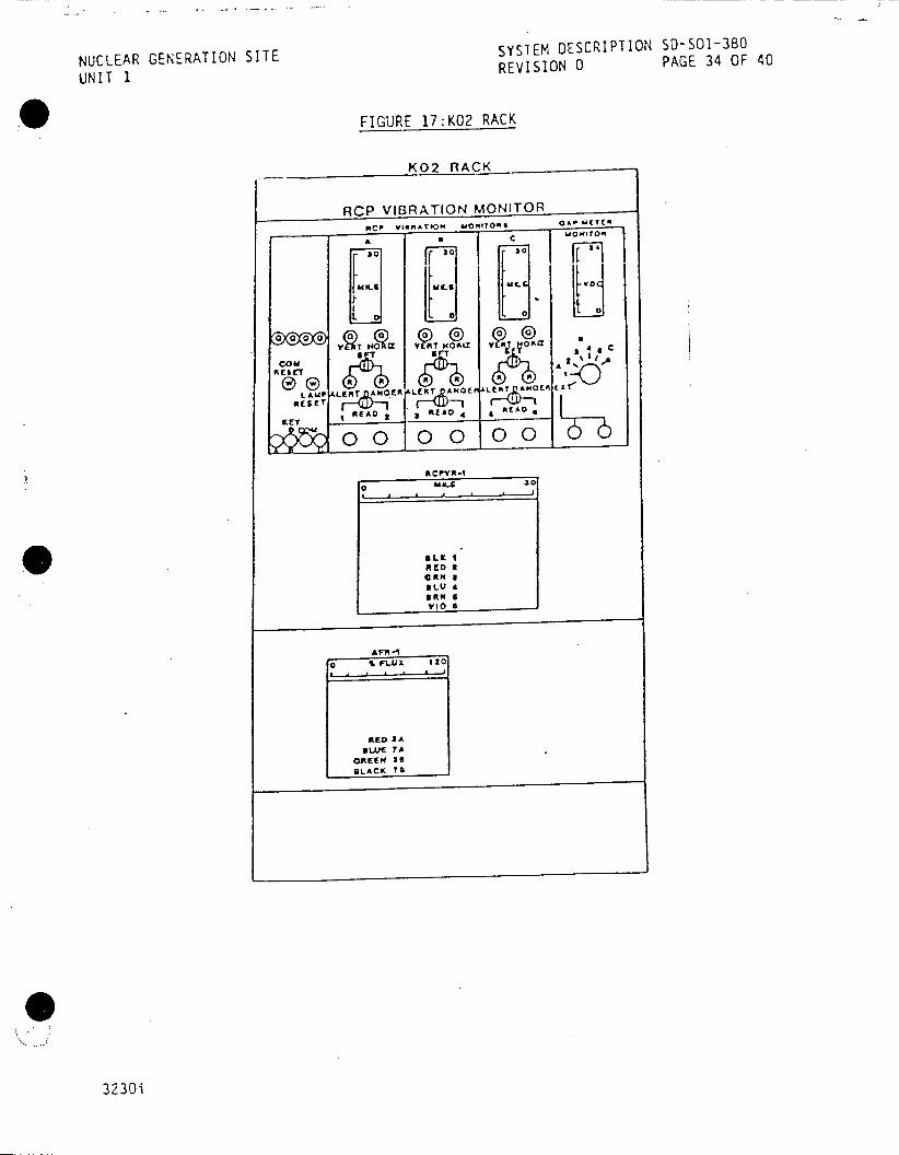
NUCLEAR GENERATION SITE SYSTEM DESCRIPTION SD-SOl-380
UNIT 1 REVISION 0 PAGE 34 OF 40
FIGURE 17:KO2 RACK
KO2 RACK
ACP VIBRATION MONIT RCo vIeORN0 MON:ITORICA f m
A c e WOWeTOR
30 30 s
00 00 0
LAM AL. ER T HOL AN EF J L 1 00 E
RCFYR-1
ifLr II
RED 2 gRN a
RED SA LUE 7A
GREEN RE BLACK 7I
3230i
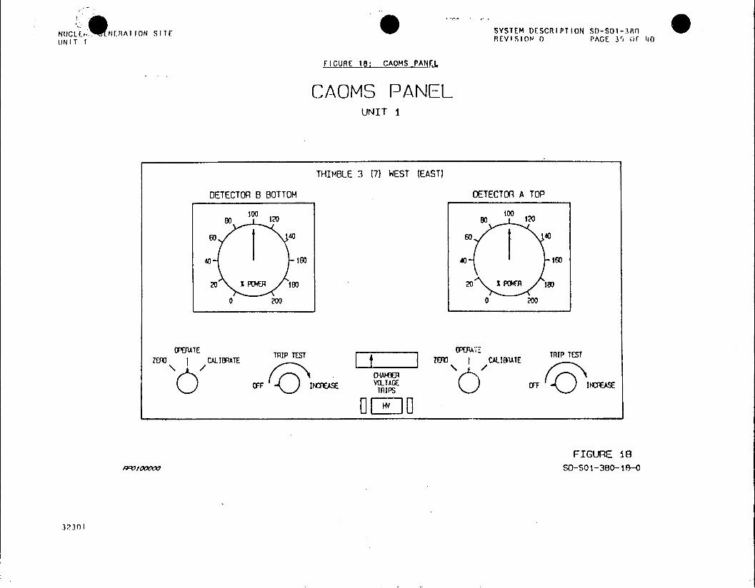
NUCb, *NERAT ION SITE SYSTEM DESCRIPTION 50-501-3R0 UNIT I REVISION 0 PACE 35 OF 1N0
FIGURE 18: CAOMS PANEl
CAOMS PANEL UNIT I
THIMBLE 3 (7) WEST (EAST)
DETECTOR B BOTTOM DETECTOR A TOP
go 0 20 o 100
40 160 40 160
20 % POER 100 20 WPOWER 180
0 200 0 200
IE~E CTRIP TEST [CTRIP TEST ZEAD CALIBRTE ZEu CALIBRATE
CFF IPS
FIGURE 18 Arwm 0 SO-SO1-380-18-0
3230 I

SYSTEM DESCRIPTION SD-SO-380 NUCLEAR GENERATION SITE REVISION 0 PAGE 36 OF 40
UNIT 1
APPENDIX A
ANNUNCIATOR LIST
Reactor Plant No 2 Annunciator
WINDOW NAME INPUT SETPOIN'T
Source High Startup K1531, K1532 2 DPM
Rate Rod Stop (51)
Alert Switch NIS Mode QC-415C-X, MSX1b 70% Full Power
to Hi Range (14)
NIS Channel Test Any NIS Channel Test N/A
(15) Calibrate Sw.
K1521 - K-1524 NIS Comp. bistable Nuclear Dropped Rod K12 .K12 actuation Rod Stop (32)
Alert Switch NIS Mode QC-415D.-X, MSX-2 72% Full Power
to Mid Range (34) decreasnq
Source Range Shutdown K-1533, K-1534 2X Base Count;
High Flux Level (35) operator.
Inter Range High K-1529, 1530 2 DPM
Startup Rate Stop (52)
NIS Power Range K1301 Comparator 50/
Deviation (54) Diff. Drawer
Reactor Plant No 1 Annunciator
Delta Flux Limit (64) CADMS CHANNEL 3, 7 Adjustable by Operator
Permissive Information Display Annunciator
Operation Mode Switch NCS-1200- 6 NA
in Lo Range (1)
At Power Reactor AP4A, AP4C, P-7 10% Full Power
Trips Defeated (3)
Startup Rate Reactor AP4B, AP4D, P-7 10% Full Power
Trips Active (4)
Dropped Rod Runback Knife Switch behind Defeat
* Defeated (6) Vertical Boards
Automatic Rod Control QC-412 B-X1
Blocked Lo Power (7) P-2
A-1
o

NUCLEAR GENERATION SITE SYSTEM DESCRIPTION SD-SOI-380
UNIT REVISION 0 PAGE 37 OF 40
APPENDIX A
ANNUNCIATOR LIST (Continued)
Reactor Plant No 2 Annunciator
WINDOW NAME INPUT SETPOINT (Number) -N-UT------
Reactor Plant First Out Annunciator
Intermediate Range High K-1509 through > 5 DPM
Start-up Rate Reactor K-1512 IR NIS
Trip (4)
Power Range Over Power K-1501 through Low 25%
Reactor Trip (14) K-1508 Hig 8 5 1% High 10800' l%
2/4 PR NIS
Power Range Over Power K-1525 through Lw 280
Rod Stop (18) K-1528 High 106%
Any PR NI, adjustable by the operator.
Reactor Plant Matrix Partial Trip Annunciator
Overpower Reactor Trip K-1501 & K-1502 or Low 25%
Partial Trip (29) K-1503 & K-1504 or Mid 8 5 K-1505 & K-1506 or High 108% K-1507 & K-1508 Any I PR NI
Sphere Heting and Ventilating Annunciator
Reactor Cavity Neutron R-9 Sw. #6 150aF
Detector High Temp. (6) (Point 14) TE-86
3230i . A - 2

SYSTEM DESCRIPTION 50-501-380
NUCLEAR GENERATION SITE REVISION 0 PAGE 38 OF 40
UNIT 1
APPENDIX B
DEVELOPMENTAL RESOURCES
FSAR Section 5.1
Lesson Plan OT 1139
Student Handout - Excore Nuclear Instrumentation System (Drawings)
Study Guide #32
Study Guide #36
WCAP 2713 Westinghouse
Tech Manual "Nuclear Instrumentation System
for Southern California Edison San Onofre
Unit 1" 3246-W-3 11-63-A.
3230i 8-1

SYSTEM DESCRIPTION S-SO1-380 NUCLEAR GENERATION SITE REVISION 0 PAGE 39 OF 40
UNIT 1
APPENDIX C
General Detector Theory (-igure- 16)
Eac; of the types of detectors; BF3 Proportional Counters, Compensated and
Uncompensated Ion Chambers used in the excore system utilize the same basic
detection principles:
* Relate measurement of neutron flux leakage from the core to
reactor power.
* Devel-op charged reaction products from the
incidence of neutrons with the
neutron sensitive material within the detector.
* Use these reaction products to ionize the fill gas.
* Apply high voltage to electrodes for ion collection in the form of an
electrical charge.
* Equate this electrical charge as a function of neutron flux.
The function that equates electrical charge collected on the detector to the
neutron flux is a complicated one with the generated curve being shown in Figure 16.
eThis curve is called the gas amplification curve and has six distinct regions.
These regions and what they mean are discussed below:
* Recombination Region
Region 1 is between 0 and V. volts. The number of ion pairs collected
per
radiation event gradually increases until it reaches a saturation
value. At
the voltage Vet, the field strength between the detector cathode
and anode is
sufficient to ensure complete collection of all the ions produced within the
detector by the ionizing event. At voltages less than V, the ions move
slowly toward the electrodes, and as a result, the ions then to recombine to
form neutral atoms or molecules. Consequently, the pulse height will be less
than if all the originally formed ion pairs succeeded in reaching the
electrodes. Gas ionization instruments such as those used in the excore system
are not operated in this region of response.
Ionization Region
Region II is the region extending from V0, to V volts, and
there is no
appreciable increase in the number of ion pairs collected as the voltage is
increased. In this region, the field strength is more tend adequate to ensure
collection of all of the ions produced, but is insufficient to cause any
increase in the number of ion pairs, due to gas amplification. The voltage
range over which the pulse height remains constant depends on many factors such
as the nature and pressure of the gas, and the physical characteristics of the
detector. (Fission chambers and UIC's operate in this region.)
C - 1

NUCLEAR GENERATION SITE SYSTEM DESCRIPTION SD-SO1-380
UNIT 1 REVISION 0 PAGE 40 OF 40
APPENDIX C (Continued)
* Proportional Region
Region III is between voltages V, and V,. The number of ion
pairs collected increases smoothly as the voltage increases. The voltage now
has become sufficiently high to produce a large potential gradient near the
central anode. This voltage imparts a very high velocity to the electrons
produced by direct ionization of the gas. The velocity of these electrons is
great enough to cause secondary ionization of other gas molecules. The
electrons so produced may cause further ionization, and so on. This
multiplication effect is termed gas amplification, and is referred to as a
Townsend avalanche. The gas amplification factor A varies in this region from
slightly greater than 1 to as high as 10'. Region III is called the
proportional region, since the gas amplification factor A is proportional to
the applied voltage. Alpha and beta particle proportional counters such as
the BF, counters operate in this region.
* Limited Proportional Region
Region IV is between voltage V, and V,, and additional
processes leading to increased ionization occur. The strong field effects
cause increased electron velocities which result in excited states or higher
energies, which in turn are capable of stripping more electrons from the gases
in the detector (called gas amplification). These events cause the Townsend
avalanche to spread along the central anode. The positive ions, which move
much more slowly than the electrons, remain near where they originate, and
reduce the electric field to a point where further avalanches are impossible.
Because this reduced field effect is dependent on the specific ionization of
the particle causing the ionization, Region IV has been designated as the
limited proportional region.
* Geiger-Mueller Region
Region V is the region between V, and V, volts. The number of
ions collected is independent of the type of radiation causing the initial
ionizing events. The field strength has become so great that the discharge,
once ignited, will continue to spread until further amplification cannot occur
because of a dense positive ion sheath surrounding the central anode. The gas
amplification factor A is much greater than 1 and may vary at any one voltage
in this region. The actual value of the gas amplification factor A depends on
the specific ionization of the radiation detected. The voltage V, is
called the Geiger-Mueller threshold.
* Continuous Discharge Region
Region VI is the region above V. In this region, a steady discharge
current flows. The applied voltage is so high that, once ionization takes
place in the gas, there is a continuous discharge of electricity - arcing - so
that the detector cannot be used for radiation detection. The voltage V
is called the breakdown voltage.
3230i C-2

*IUCLEAR GENERATION SITE SYSTEM DESCRIPTION 50-501-390
UNIT 1 REVISION 0 PAGE 1 OF 65
APR 211986 CDM ISSUED TO
CONTROLLED PRIMARY PROCESS INSTRUMENTATION SYSTEMS LOCATION
TABLE OF CONTENTS
SECTION PAGE
1.0 FUNCTIONS/DESIGN BASES 2
2.0 DESCRIPTION 3 2.1 System Overview 3 2.2 Components 2 2.3 Detailed Control Scheme 22 2.4 Power Supplies RECEIVED CDM 23
3.0 OPERATIONS 26 3.1 Normal Operations APR 195 26 3.2 Other Operations 26
SITE FILE COPY 4.0 REFERENCES 29
4.1 P&IDs 29 4.2 Elementaries 29 4.3 Technical Manuals 30 4.4 Procedures 31 4.5 Technical Specifications
FIGURES 32
1A Reactor Coolant System Temperature Instrumentation 32
1B Reactor Coolant System Flow Instrumentation 33
IC Pressurizer Pressure, Level and Temperature Instrumentation 34
2 Reactor Coolant System Temperature and Flow Instrumentation 35
3 Loop A TAVE and Ave TAVE Development 36 4 Loop A AT and Average AT Development 37 5 Pressurizer Pressure Instrumentation 38
6 PC-430J Controller Output 39 7 Pressurizer Level Instrumentation 40 8 Sub-cooling Monitoring System Train A(B) 41
9 Shutdown Margin Computer 42 10 Overpressure Mitigation System 43 11 TAVE Program 44
APPENDICES 45 A Developemental Resources 45 B Annunciators 48 C Instrumentation 56
This System Descripti is approved per SO-123-O-44, System Description
Revision and Approv . onta CDM to verify revision information.
PREPARED BY:
APPROVED BY: Man gO A P
3346i NOT QA PROGRAM AFFECTING

NUCLEAR GENERATION SITE SYSTEM DESCRIPTION SD-SO1-390
UNIT 1 REVISION 0 PAGE 2 OF 65
PRIMARY PROCESS INSTRUMENTATION SYSTEMS
1.0 FUNCTIONS/DESIGN BASES
1.1 The Primary Process Instrumentation Systems have the following main
functions:
1.1.1 The Reactor Coolant System Temperature Instrumentation
monitors, indicates, records and annunciates the
temperature of the Reactor Coolant System.
1.1.2 The Reactor Coolant System Flow Instrumentation monitors, indicates, records and annunciates the flow
of the Reactor Coolant System.
1.1.3 The Pressurizer Instrumentation monitors, indicates, records and annunciates the pressure, level and
temperature of the Pressurizer.
1.1.4 Provides temperature, flow, pressure, and level inputs to the Rod Control System (SD-S01-400), the Reactor
Protection System (SD-S01-570), and various other
control systems to ensure safe operation of the Plant.
(II
NUCLEAR GENERATION SITE SYSTEM DESCRIPTION SD-SO1-390 NIT 1 RREVISION 0 PAGE 3 OF 65
UI PRIMARY PROCESS INSTRUMENTATION SYSTEMS
2.0 DESCRIPTION
2.1 System Overview
2.1.1 Main Scheme
.1 Reactor Coolant System Temperature Instrumentation
(Figure 1A)
The Reactor Coolant System Temperature Instrumentation uses
Resistance Temperature Detectors (RTDs) in the Hot Legs, Intermediate Legs, and Cold Legs of each Reactor Coolant Loop to
indicate, record, and annunciate the individual Loop Temperatures,
Loop Average Temperatures, and Loop Differential Temperatures.
Each Reactor Coolant System loop supplies a Hot Leg (Th) and a Cold
Leg (Tc) signal to a Loop Tave Computer for individual Loop Tave
computation.
The individual Loop Tave Computers supply signals to the Tave
Recorder, the individual Loop Variable Low Pressure Trip (VLPT)
Bistables in the Reactor Protection System (Reactor Protection
System and Permissives, SD-SO1-570), the individual loop High-Low
Tave Annunciators, and an Ave Tave Summing Computer via a Tave
Defeat Switch.
The Ave Tave Summing Computer supplies signals to the Ave Tave
Minus Tref Computer for the Steam Dump System (see SD-501-570),
Ave Tave and Tref Deviation Recorder and Annunciator, Pressurizer
Program Level Setpoint, Feedwater Control (see SD-S01-260,
Feedwater Control System), Control Rod Drive Summing Computer (see
SD-SO1-400, Rod Control and Instrumentation Systems), Shutdown
Margin Computers, and Reactivity Computer.
Each Reactor Coolant System loop also supplies a Hot Leg (Th) and
Cold Leg (Tc) signal to a loop AT Computer for individual
Loop AT computation.
The individual Loop AT Computers supply signals to the AT Recorder,
the individual loop Variable Low Pressure Bistables in the Reactor
Protection System, the individual Loop AT Indications, the High
AT Annunciators, the Reverse AT Interlock, and the AT Summing Computer
via a AT Defeat Switch.
The AT Summing Computer supplies signals to the Shutdown Margin
Computer and Reactivity Computer.
2.1.2 Reactor Coolant System Flow Instrumentation (Figure 1B)
The Reactor Coolant System Flow Instrumentation uses Differential
Pressure Transmitters, located in each Hot Leg (Th) elbow just
prior to the Steam Generators, to indicate and annunciate the
individual loop flows.

N1UCLEAR GENERATION SITE SYSTEM DESCRIPTION SD-SO1-390
UNIT 1 REVISION 0 PAGE 4 OF 65
PRIMARY PROCESS INSTRUMENTATION SYSTEMS
2.0 DESCRIPTION (Continued)
2.1.2 Reactor Coolant System Flow Instrumentation (Figure 18) (Continued)
Each Reactor Coolant System Flow Instrument supplies an individual
Flow Controller.
The individual Flow Controllers supply signals to the Loss of Flow
circuitry in the Reactor Protection System, the individual flow
indicator, and the Loss of Flow Annunciators.
2.1.3 - Pressurizer Instrumentation (Figure IC)
The Pressurizer Pressure Instrumentation uses Pressure Transmitters
to indicate , record and annunciate the Pressurizer Pressure; and
control the pressure in the Pressurizer.
The Pressurizer Pressure Transmitters supply signals to the Reactor
Protection System (SD-501-280), the Sequencer System (SD-SO1-590),
the Sub-Cooling Monitor, the Residual Heat Removal System
(SD-SO1-320), the Power Operated Relief Valves, the Pressurizer
Spray Valves, the Pressurizer Heaters (Pressurizer Components are
in SD-S01-280, Reactor Coolant System), the Overpressure Mitigation
System and the Rod Control System (SD-501-400).
The Pressurizer Level Instrumentation uses Differential Pressure
Transmitters to indicate, record and annunciate the Pressurizer
Level; and control the level in the Pressurizer.
The Pressurizer Level Differential Pressure Transmitters supply
signals to the Reactor Protection System, the Chemical and Volume
Control System (SD-SO1-310), the Pressurizer Heaters, and the Rod
Control System (SD-501-400).
The Pressurizer Temperature Instrumentation uses Resistance
Temperature Detectors (RTDs) to indicate, record and annunciate the
temperature in the Pressurizer steam and water spaces.
(~I
NUCLEAR GENERATION SITE SYSTEM DESCRIPTION SD-SO1-390
UNIT 1 REVISION 0 PAGE 5 OF 65
PRIMARY PROCESS INSTRUMENTATION SYSTEMS
2.0 DESCRIPTION (Continued)
2.2 Components
2.2.1 Reactor Coolant System Loop A Temperature Instrumentation (Figure 2)
.1 Hot Leg TE-402A
- Output to TI-5402A on the Dedicated Shutdown Panel
- Indicated Range is 100-700 0 F
.2 Hot Leg TE-3402A
- Output to Sub-cooling Monitor System Train A
- Output to TI-3401 on AFW Panel
- Indicated Range is 100-7000 F
.3 Hot Leg TE-2401A
-Output to Sub-cooling Monitor System Train B
- Output to TI-3402 on AFW Panel
- Indicated Range is 100-700 0 F
.4 Hot Leg TE-401A
- Output to TT-401 for Loop Tave development
.5 Hot Leg TE-400A
- Output to TT-400 for Loop AT development
.6 Intermediate Leg TE-402B
- Output to LI-402B on the Dedicated Shutdown Panel
- Indicated Range is 100-600 0 F
.7 Cold Leg TE-400C
- Output to TT-400 for Loop AT development
.8 Cold Leg TE-401C
- Output to TT-401 for Loop Tave development
.9 Cold Leg TE-402C
- Output to TR-402 on J-Console
- Indicated Range is 100-6000 F

NUCLEAR GENERATION SITE SYSTEM DESCRIPTION 50-501-390
UNIT 1 REVISION 0 PAGE 6 OF 65
PRIMARY PROCESS INSTRUMENTATION SYSTEMS
2.0 DESCRIPTION (Continued)
2.2.2 Reactor Coolant System Loop B Temperature Instrumentation (Figure 2)
.1 Hot Leg TE-412A
- Output to TI-5412A on Dedicated Shutdown Panel
- Indicated Range is 100-700'F
.2 Hot Leg TE-2412A
- Output to Sub-cooling Monitor System Train A
- Output to TI-2412A on AFW Panel
- Indicated Range is 100-700oF
.3 Hot Leg TE-3411A
- Output to Sub-cooling Monitor System Train B
- Output to TI-3411A on AFW Panel
- Indicated Range is 100-7001F
.4 Hot Leg TE-411A
- Output to TT-411 for Loop Tave development
.5 Hot Leg TE-410A
- Output to TT-410 for Loop AT development
.6 Intermediate Leg TE-411B
- Output to TR-402 on J-Console
- Indicated Range is 100-600oF
.7 Intermediate Leg TE-412B
- Output to LI-412B on the Dedicated Shutdown Panel
- Indicated Range is 100-600oF
.8 Cold Leg TE-411C
- Output to TT-401 for Loop Tave development
.9 Cold Leg TE-412C
- Output to TT-410 for Loop AT development

SYSTEM DESCRIPTION SD-SO-390
NUCLEAR GENERATION SITE REVISION 0 PAGE 7 OF 65
PUNIT Iig gg SgRu MENATION SY -STEMS PRIMARY PROCESS INSTUETTO YTM
2.0 DESCRIPTION (Continued)
2.2.3 Reactor Coolant System Loop C Temperature
Instrumentation (Figure 2)
.1 Hot Leg TE-422A
- Output to TI-5422A on Dedicated Shutdown Panel
- Indicated Range is 100-700aF
.2 Hot Leg TE-2422A
- Output to Sub-cooling Monitor System Train A
- Output to TI-2422A on AFW Panel
- Output to TI-2009 on AFW Panel
- Indicated Range is 100-700*F
.3 Hot Leg TE-3421A
SOutput to Sub-cooling Monitor System Train B
- Output to TI-3412 on AFW Panel
- Output to TI-3009 on AFW Panel
- Indicated Range is 100-7000 F
.4 Hot Leg TE-421A
- Output to TT-411 for Loop Tave development
.5 Hot Leg TE-420A
- Output to TT-420 for Loop AT development
.6 Intermediate Leg TE-422B
- Output to LI-422B Dedicated Shutdown Panel
- Indicated Range is 100-600oF
.7 Cold Leg TE-422C
- Output to TR-402 on J-Console
Indicated Range is 100-600'F
.8 Cold Leg TE-421C
- Output to TT-411 for Loop Tave development

i!UCLEAR GENERATION SITE SYSTEM DESCRIPTION SD-SO1-390
UNIT 1 REVISION 0 PAGE 8 OF 65
PRIMARY PROCESS INSTRUMENTATION SYSTEMS
2.0 DESCRIPTION (Continued)
2.2.3 Reactor Coolant System Loop C Temperature Instrumentation (Figure 2) (Continued)
.9 Cold Leg TE-420C
- Output to TT-420 for Loop AT development
2.2.4 Reactor Coolant System Flow Instrumentation
(Figure 2)
.1- Loop A FT-400
- Output to FC-400 which outputs to the Reactor
Protection System, Low Flow Annunciator, and
FI-400
- Indicated Range is 0-100%
.2 Loop B FT-410
- Output to FC-410 which outputs to the Reactor
Protection System, Low Flow Annunciator, and
FI-410
- Indicated Range is 0-100%
.3 Loop C FT-420
- Output to FC-420 which outputs to the Reactor
Protection System, Low Flow Annunciator, and
FI-420
- Indicated Range is 0-100%
2.2.5 Tave Defeat Switch (Figure 3)
The Tave Defeat Switch, located in Instrument Rack R-1, is a four
position switch that allows one of the Loop Tave signals to be
defeated during testing or RTD failure.
Depending upon the position of the Tave Defeat Switch, the Loop
Tave signals are supplied to the Ave Tave Summing Computer. The
Ave Tave Summing Computer calculates the Average Tave using the
following formulas:
1. Operate - Output = (A + B + C)/3
2. Loop A - Output = (2B + C)/3
3. Loop B - Output = (A + 2C)/3
4. Loop C - Output = (2A + B)/3

SYSTEM DESCRIPTION s0-So1-390
NCLEAR GENERATION SITE REVISION 0 PAGE 9 OF 65
PRIMARY PROCESS INSTRUMENTATION SYSTEMS
2.0 DESCRIPTION (Continued)
2.2.6 AT Defeat Switch (Figure 4)
The AT Defeat Switch, located in Instrument Rack R2ignaas
four position switch that allows one of
the Loop ATsinl
to be defeated during testing or RTD failure.
Depending upon the position of the AT Defeat Switch,
the Loop
AT signals are supplied to the AT Summing Computer. n
The AT Summing Computer calculates the Average AT using
the following formulas:
1. Operate - Output (A + B + C)3
2. Loop A Output (2B + C)3
3. Loop B -output =(A + 2C)/3
4. Loop C -output (2A + B133
2.2.7 Reactor Coolant System Temperature Recorders
.1 Loop AT Recorder, TR-400
- Located in Rack R-2 behind the West Vertical Board
- 3 Pen Recorder; Red Pen - Loop A, Green Pen
Loop B, Blue Pen - Loop C
- Range in -15 to +60aF
.2 Loop Tave Recorder, TR-401
- Located on J-Console
3 Pen Recorder; Red Pen - Loop A, Green Pen
Loop B, Blue Pen - Loop C
- Range is 525 to 6000 F
.3 Loop Tc Recorder, TR-402
- Located on J-Console
- 3 Pen Recorder; Red Pen - Loop A, Green Pen
Loop B, Blue Pen - Loop C
- Range is 100 to 600OF
.4 Tave - Tref Recorder, TR-405
- Located on J-Console
2 Pen Recorder; Red Pen - Tave, Green Pen - Tref
- Range is 525 - 600aF

SYSTEM DESCRIPTION SD-SO1- 390
NUCLEAR GENERLATION SITE REVISION 0PAE1OF6
UNIT 1PRIMARY PROCESS INSTRUMENTATION SYSTEMS
2.0 DESCRIPTION (Continued)on(iue5
2.2.8 Pressurizer Pressure Instrumentation (Figure 5)
.1 P-3 PT-430 output to P-430 on North Vertical Board
- Output to Variable Low Pressure Trip Bistable
.(DSO1tS70a Reactor Protection System and
Permissives) V Board (VLPT
- Output to PI-4008 on North Vertica
Setpoint)
- Output to Fixed High Pressure Trip
Bistable
(S0-s01-570, Reactor Protection System and
Permissives)
Output to Unblock Safety Injection Bistable
(S050VS1t59o, Sequencer System)
- Output to Safety Injection Signal
Bistable
(50501-$5903 Sequencer System)
output to PR-430 on J-Console .
S Normally outputs, 4 orough Switc Hh V
cV-S~ Bstable; PC-430 J to input the Hg
Pressure Alarm, Spray Valve
uP i ztra er
Spray Valve pC-430H B' stable,n Pressurizer
Control Group Heater Bistables,anPrsuie
Backup Group Heater Bistables
(SD-sol280 ,
Reactor Coolant system)
- Indicated Range is 1600 - 2400 psig
.2 PT-431 output to p-431 On North Vertical Board
OLow Pressure Trip Bistable
5ptS017 0o arecolr Protection
System and
Permissives) d (VLPT
- Output to PI-410B on North Vertical Boar
Setpoint) Bistable
S output to Fixed High Pressure Trip m and
(So0SO1570, Reactor Protection
System n
Permissives) Bistable
output to Unblock Safety Inje
(OSDS5tS90, Sequencer System)
SYSTEM DESCRIPTION S-SO1-390 NUCLEAR GENERATION SITE REVISION 0 PAGE 11 OF 65 UNIT 1
PRIMARY PROCESS INSTRUMENTATION SYSTEMS
2.0 DESCRIPTION (Continued)
2.2.8 Pressurizer Pressure Instrumentation (Figure 5) (Continued)
.2 (Continued)
- Output to Safety Injection Signal Bistable
(SD-S01-590, Sequencer System)
- Output to PR-430 on J-Console
- Normally outputs, through Switch P/432, to PORV
CV-546 Bistable, Low Pressure Alarm Bistable, and
Alert Block Safety Injection Bistable
(SD-S01-280, Reactor Coolant System)
- Indicated Range is 1600 - 2400 psig
.3 PT-432
- Output to PI-432 on North Vertical Board
- Output to Variable Low Pressure Trip Bistable
(SD-501-570, Reactor Protection System and
Permissives)
- Output to PI-420B on North Vertical Board (VLPT
Setpoint)
.Output to Fixed High Pressure Trip Bistable
(SD-O-570, Reactor Protection System and
Permissives)
- Output to Unblock Safety Injection Bistable
(SD-501-590, Sequencer System)
- Output to Safety Injection Signal Bistable
(SD-SO1-590, Sequencer System)
- Output to PR-430 on J-Console
- Can also output, through Switch P/432, to PORV
CV-545 Bistable; PC-430J to control the High
Pressure Alarm, Spray Valve PC-430C Bistable,
Spray Valve PC-430H Bistable, Pressurizer SCR
Control Group Heater Bistables, and Pressurizer
Backup Group Heater Bistables (SD-SO1-280,
Reactor Coolant System)
OR
- PORV CV-546 Bistable, Low Pressure Alarm
Bistable, and Alert Block Safety Injection
Bistable (SD-501-280, Reactor Coolant System)
- Indicated Range is 1600 - 2400 psig

NJCLEAR GENERATION SITE SYSTEM DESCRIPTION SD-S01-390
UNIT 1 REVISION 0 PAGE 12 OF 65
PRIMARY PROCESS INSTRUMENTATION SYSTEMS
2.0 DESCRIPTION (Continued)
2.2.8 Pressurizer Pressure Instrumentation (Figure 5)
(Continued)
.4 PT-425
- Output to PR-425 on J-Console (0-3000 psig and
0-600 psig)
- Output to interlock for MOV-813 and MOV-814
(SD-501-320, Residual Heat Removal System)
- Output to Sub-cooling Monitor System Train A for
Tsat computation
- Indicated Range is 0-3000 psig
.5 PT-425-X1
- Output to Overpressure Mitigation System for ARM
PORV, Pressure Transient in Progress, and OMS
High Pressure annunciators
- Output to Sub-cooling Monitor System Train B for
Tsat computation
.6 PT-425-X2
- Output to Overpressure Mitigation System for ARM
PORV, Pressure Transient in Progress, and OMS
High Pressure annunciators
- .Output to Sub-Cooling Monitor System Train A for
Tsat computation
.7 PT-434 and 434A
- Output to PI-434 on North Vertical Board
- Output to PI-434A on Dedicated Shutdown Panel
- Indicated Range is 0-2500 psig
.8 DPT-434
- One side is connected to the Pressurizer, the
other side to a Dead Weight Tester.
- Used to check calibration of other Pressurizer
Pressure Transmitters
.9 PT-3000A, B, C
- Outputs (one per transmitter) to the Sequencer
System Train B (SD50PI590, Sequencer System)
NUCLEAR GENERATION SITE SYSTEM DESCRIPTION SD-S01-390 UNIT 1 REVISION 0 PAGE 13 OF 65
PRIMARY PROCESS INSTRUMENTATION SYSTEMS
2.0 DESCRIPTION (Continued)
2.2.9 Pressurizer Pressure Transmitter Selector Switch, P/432 (Figure 5)
The Pressurizer Pressure Transmitter Selector Switch, P/432, is a three position switch located on the North Vertical Board. P/432 is used during channel testing or transmitter failure to transfer the controlling functions of PT-430 or PT-431 to PT-432.
Normal Position
Each pressure transmitter supplies its normal functions as described in 2.2.8.1, 2.2.8,2 and 2.2.8.3
PT-430 Position
PT-432 supplies its normal functions and PORV CV-545 Bistable; PC-430J to control the High Pressure Alarm, Spray Valve PC-430C Bistable, Spray Valve PC-430H Bistable, Pressurizer SCR Control Group Heater Bistables, and Pressurizer Backup Group Heater Bistables
PT-431 Position
PT-432 supplies its normal functions, and PORV CV-546 Bistable, Low Pressure Alarm Bistable, and Alert Block Safety Injection Bistable
2.2.10 Pressurizer Pressure Transmitter Test Switches
The three Pressurizer Pressure Transmitter Test Switches, one for each pressure transmitter, are two position switches and are located in the racks behind the North Vertical Board.
When a pressure transmitter fails, the appropriate Test Switch is placed in the Test position. This installs a trip signal in the Safety Injection and Reactor Trip circuitry.
2.2.11 Pressurizer Pressure Controllers
.1 Main Pressure Controller, PC-430J (Figure IC and 6)
Main Pressure Controller, PC-430J, is a Proportional plus Rate plus Setpoint Controller.
PC-430J is the .pressure controller that normally controls the Pressurizer Pressure, by controlling the operation of the Pressurizer Spray Valves and Heaters when their controllers are in automatic.

SYSTEM DESCRIPTION SD-SO1-390
NUCi 1ERGNRAINST
REVISION 0 PAGE 14 OF 65
NUNIERGENERATION SITE UPRIMAR PROCESS INSTRUMENTATION SYSTEMS
2.0 DESCRIPTION (Continued) 2.2.11 Pressurizer Pressure Controlle (continued) 2.2.11
.1 (Continued) from pT-430,
PC-4303 normaly reee jnput from T-43
however, it can receive its iptfo
T4 2 I
selected by Switch P/432.
is located on the JConsole and is equipped
PCt4h3 Manuaocued Switch, a Manual Adjust
Dial and an
Auto Adjust Dial. p ssurizer
In Auto, PC-430J compares th act inal re shietpo
Presuresignal to the setPOint
sga. Test~n
signal is established using the Auto Ad Dgnal that is
PC-4303 s pC-430 0 will then teranPssure Signal thae is
pootional to the PressurizerPesr inl h
peopoat which the pressure is changing p and the length
of time the pressure has been of it5setsin
In manual, the Manual Adjust Dial is used
to establish
the output of pC-43 0J. stem (P minus
pC430 0 Outputs to the R ntol the Sp ayi s
prfthe High Pressure Annuncito, theoSpra
Vealers,
via their controlr)teSRCnrlGupHars and the Backup Heaters.
.2 Spray Valve Controller, pC43OC (pCV430C)
Spray Valve Controller, pC-430C, is located on
the
SpCaysle and is equipped with a Ma nualAuto Switch,
a
Manual Adjust Dial and a s o ated using the Manual
In Manual, the Spray Valve is oper
Adjust Dial. from PC-430J to
In Auto, PC-430C receives
operate the Spray Valve.PC-430 is a to
The relationship between PC-43OC andcorrel tes t o s
4 ato. Th t is 0-100% on C-430CC co r la est 4 ratio. That and of 25%. For example, if Pwhe
se a 3%heSpayd Vavewol start to open when PC-43 0J output re Valve would t a Valve would be
st at 30% the Spray 30%/ and the SprayV
pe-43 oe wutpt pC-430J output reaches 55%.
full open when usd to adjust the
In Auto the Auto Adjust Dial is used t aratet at
output~~~ ~~
oPC 0Csthat the Spray Valveoprtsa
tet desre sepCot This enables the operator to
ohe desred opetpoing setPOint of the Spray ah would
wi a eth patingth setpoint Of pC 430 J whic wo l
ahot chang th e setposetpofthe other functions
alsupo hange PC-430.
E GSYSTEM DESCRIPTION SD-SO1-390
NUCLEAR GENERATION SITE REVISION 0 PAGE 15 OF 65
W UNIT 1 PRIMARY PROCESS INTUEAIO SYEM
2.0 DESCRIPTION (Continued)
2.2.11 Pressurizer Pressure Controllers (Continued)
.3 Spray Valve Controller, PC-430H (PCV-430H)
Spray Valve Controller, PC-430H is the same and
operates the same as PC-430C (2.2.11.2).
2.2.12 Pressurizer Pressure Recorders
.1 Wide Range Pressurizer Pressure Recorder, PR-425
- Located on J-Console
- 2 Pen Recorder, Red Pen - Full Range Pressure,
Green Pen - Low Range Pressure
- Range is: 0-3000 psig (Red) 0-600 psig (Green)
.2 Pressurizer Pressure Recorder, PR-430
- Located on J-Console
3 Pen Recorder; Red Pen - Pressurizer Pressure,
Green Pen - VLPT Setpoint, Blue Pen - Not Used
S 3 position selector switch on J-Console, selects
which Pressurizer Pressure Transmitter output is
to be recorded
- Range is 1600 to 2400 psig
2.2.13 Pressurizer Level Instrumentation (Figure 7)
.1 LT-430
- Output to LI-430 on North Vertical Board
- Output to High Level Trip Bistable (S-S501-570,
Reactor Protection System and Permissives)
- Output to a spare bistable
- Output to LR-430 on J-Console
- Normally outputs through Switch L/432, to:
Pressurizer SCR Control Group and Backup Group
Heater Bistables to turn on all heaters on a High
Level and to turn off all heaters on a Low Level,
LC-430F for FCV-1112 (SD-S01-310, Chemical and
Volume Control System), Low Level Annunciator
Bistable, and Letdown isolation (SD-SO-310,
Chemical and Volume Control System)
SYSTEM DESCRIPTION S0-SO1-390 NUCLEAR GENERATION SITE REVISION 0 PAGE 16 OF 65
)UNIT 1
PR IMARY PoRCES INSTRUMENTATION SYSTEMS
2.0 DESCRIPTION (Continued)
2.2.13 Pressurizer Level Instrumentation (Figure 7)
(Continued)
.1 (Continued)
- Indicated range is 0-100% (4.7 to 37.2 ft)
.2 LT-431
- Output to LI-431 on North Vertical Board
- Output to High Level Trip Bistable (S0-01-570,
Reactor Protection System and Permissives)
- Output to a spare bistable
- Output to LR-430 on J-Console
- Normally outputs through Switch L/432, to:
Pressurizer SCR Control Group and Backup Group
Heater Bistables to turn off all heaters on a Low
Level, and Letdown Isolation (SD-SO13lO0 Chemical
and Volume Control System)
- Indicated range is 0-100% (4.7 to 37.2 ft)
.3 LT-432
- Output to LI-432 on North Vertical Board
- Output to High Level Trip Bistable (50-501-570,
Reactor Protection System and Permissives)
- Output to a spare bistable
- Output to LR-430 on J-Console
- Can also output through Switch L/432, to:
Pressurizer CR Control Group and Backup Group
Heater Bistables to turn on all heaters on a High
Level and to turn off all heaters on a Low Level,
LC-430F for FCV-1112 (50-501-310, Chemical and
Volume Control System), Low Level Annunciator
Bistable, and Letdown Isolation (50-S01-310,
Chemical and Volume Control System)
OR
Pressurizer SCR Control Group and Backup Group
Heater Bistables to turn off all heaters on a Low
Level, and Letdown Isolation (SD-501-31O,
Chemical and Volume Control System)
- Indicated range is 0-100% (4.7 to 37.2 ft)

SYSTEM DESCRIPTION S-SOl-390
NUCLEAR GENERATION SITE REVISION 0 PAGE 17 OF 65
. UNIT 1 PRIMARY RESSINTRMETAIO YSTM
2.0 DESCRIPTION (Continued)
2.2.13 Pressurizer Level Instrumentation (Figure 7)
(Continued)
.4 LT-430A
- Output to LI-430A on the Dedicated Shutdown Panel
- Indicated range is 0-100% (4.7 to 37.2 ft)
.5 LT-435
- Output to LI-435 on the North Vertical Board
- Cold calibrated (800F) used when RCS is cooled
down due to the density difference between Hot
and Cold conditions
- Indicated range is 0-100% (4.7 - 37.2 ft)
2.2.14 Pressurizer level Transmitter Selector Switch, L/432
(Figure 7)
The Pressurizer Level Transmitter Selector Switch,
L/432, is a three position switch located on the North
Vertical Board. L432 is used during channel testing
or transmitter failure to transfer the controlling
functions of LT-430 or LT-431 to LT-432.
Normal Position
Each level transmitter supplies its normal functions as
described in 2.2.13.1, 2.2.13.2, and 2 .2.13.3
LT-430 Position
LT-432 supplies its normal functions and Pressurizer
SCR Control Group and Backup Group Heater Bistables to
turn on all heaters on a High Level and to turn off all
heaters on a Low Level, LC-430F for FCV-1112
(SD-S-30 Chemical and Volume Control System), Low
Level Annunciator Bistable, and Letdown Isolation
(50-501-310, Chemical and Volume Control System).
LT-431 Position
LT-431 supplies its normal functions and Pressurizer
SCR Control Group and Backup Group Heater Bistables to
turn off all heaters on a Low Level and Letdown
Isolation (SD-S0le300o Chemical and Volume Control
System).

SYSTEM DESCRIPTION SO-SO1-390
NUCLEAR GENERATION SITE REVISION 0 PAGE 18 OF 65
UNIT 1
PRIMARY PROCES INSTRUMENTATION SYSTEMS
2.0 DESCRIPTION (Continued)
2.2.15 Pressurizer Level Transmitter Test Switches
The three Pressurizer Level Transmitter Test Switches,
one for each level transmitter, are two postiOn
switches and are located in the racks behind the North
Vertical Board.
When a level transmitter fails, the appropriate Test
Switch is placed in the Test position. This installs a
trip signal in the Reactor Trip circuitry.
2.2.16 Pressurizer Level Controller, LC-430F
The Pressurizer Level Controller, LC-430F, is located
on the 3-Console and is equipped with a Manual-Auto
switch, a Manual Adjust Dial, and an Auto Adjust Dial.
In Auto, LC-430F receives an input signal from Ave
Tave, this provides the Program Level setpoint when
LC-430F is in Cascade. When LC-430F is in Man-Set, the
Auto Adjust Dial provides the Program Level Setpoint.
LC-430F compares the Program level setpoint to the
actual Pressurizer Level. LC-430F then supplies a
cascade signal to FC-1112 (50-501-310, Chemical and
Volume Control System) to adjust the charging flows as
necessary to match actual Pressurizer Level to the
Program Level.
In Manual, the Manual Adjust Dial provides the Program
Level setpoint.
2.2.17 Pressurizer Level Recorder, LR-430
- Located on J-Console
- 2 Pen Recorder; Red pen - Actual level, Green
pen - Program Level setpoint
- 3 position selector switch on -Console, selects
which Pressurizer Level Transmitter output is to
be recorded
- Range is 0 to 100% (4.7 to 37.2 ft)
2.2. 18 Pressurizer Temperature Instrumentation
(Figure 1C)
.1 TE-430A
- Output to High Liquid Temperature Annunciator
- Output to TI-430A on the North Vertical Board

NUCLEAR GENERATION SITE SYSTEM DESCRIPTION SD-SO1-390
UNIT 1 REVISION 0 PAGE 19 OF 65
PRIMARY PROCESS INSTRUMENTATION SYSTEMS
2.0 DESCRIPTION (Continued)
2.2.18 Pressurizer Temperature Instrumentation (Figure IC) (Continued)
.1 (Continued)
- Output to TR-430 on West Vertical Board
- Indicated range is 0 - 7001F
.2 TE-430B
- Output to High Vapor Temperature Annunciator
- Output to TI-430B on North Vertical Board
- Output to TR-430 on West Vertical Board
- Indicated range is 0 - 7000 F
2.2.19 Pressurizer Temperature Recorder, TR-430A
- Located on West Vertical Board
- 2 Pen Recorder, Red pen - Liquid Temperature, Green pen - Vapor Temperature,
- Range is 0-7000 F
2.2.20 Pressurizer Instrument Cabinet Heaters
There are two 300 watt Pressurizer Instrument Cabinet Heaters located in the Pressurizer Instrument Cabinet at El. 14' 0" inside Containment, outside the Secondary Shield Wall, North Side.
The heaters maintain the cabinet in a warm, dry condition as to
preclude transmitter failure.
The heaters are turned Off or placed in Auto using the two position
Handswitch behind the North Vertical Board.
In Auto the heaters are controlled by TIC-3014A, located behind the
North Vertical Board, and control at 130 + 60F.
TIC-3014B, located behind the North Vertical Board, is used to
control the Alarm functions and is set to alarm at 1501F - Hi and
100 0 F - Low.
NUC LEAR GENERATION SITE SYSTEM DESCRIPTION S-SO1-390
UNIT 1 REVISION 0 PAGE 20 OF 65
PRIMARY PROCESS INSTRUMENTATION SYSTEMS
2.0 DESCRIPTION (Continued)
2.2.21 Sub-Cooling Monitoring System (Figure 8)
The Sub-cooling Monitoring System calculates, indicates, and
annunciates the Margin to Saturation of the Reactor Coolant System.
The Sub-cooling Monitoring System consists of two trains identified
as Train A and Train B.
Each train of the Sub-cooling Monitoring System receives signals
from four Incore Thermocouples via individual toggle switches (one
per Core quadrant), three RCS Hot Leg (Th) RT~s, and three
Pressurizer Pressure Transmitters to calculate the Margin to
Saturation.
The two trains are identical with the exception of the Pressurizer
Pressure inputs. Train A receives two pressure inputs of which the
lowest is selected. Train B receives one pressure input. A
Function Generator, for each train, generates the saturation
temperature for the input pressure.
The Incore Thermocouple and RCS Hot Leg RTD signals, for each
train, are auctioneered high with the highest signal subtracted
from the generated saturation temperature to indicate the Margin to
Saturation for each train.
The Sub-cooling Monitoring System indicates the individual RCS Hot
Leg RTDs, the highest of the Incore Thermocouples or RCS Hot Leg
RT~s, the generated saturation temperature for the Pressurizer
Pressure, and the Margin to Saturation on the Auxiliary Feedwater
Panel; and annunciates the approach to saturation.
2.2.22 Shutdown Margin Computer (Figure 9)
The Shutdown Margin Computer calculates, records, and annunciates
the Control Rod Insertion Limits.
The Shutdown Margin Computer receives signals from Average Tave and
AT to calculate the proper Control Rod Insertion Limits for
Control Banks I and 2.
The calculated Control Rod Insertion Limits are compared to the
actual Control Bank positions. If the actual position is outside
the calculated position, then the Shutdown Margin Computer will
cause the appropriate annunciator in the Main Control Room to
illuminate.
The Shutdown Margin Computer calculated Control Rod Insertion
Limits are recorded on the Control Rod Position Recorder on the (.) J-Consol e.
NUCLEAR GENERATION SITE SYSTEM DESCRIPTION SD-SO1-390
UNIT I REVISION 0 PAGE 21 OF 65
PRIMARY PROCESS INSTRUMENTATION SYSTEMS
2.0 DESCRIPTION (Continued)
2.2.22 Shutdown Margin Computer (Figure 9) (Continued)
The Control Rod Insertion Limits ensure the following:
1. An acceptable core power distribution during power operation.
2. Core subcriticality after a Reactor Trip.
3. A limit of potential reactivity addition on a hypothetical Rod
Ejection Accident.
2.2.23 Overpressure Mitigation System (Figure 10)
The Overpressure Mitigation System protects the Reactor Coolant
System against overpressurization during solid water operations and
low pressure conditions.
The Overpressure Mitigation System uses the Pressurizer Power
Operated Relief Valves (CV-545 and CV-546) and two Disable/Enable
Control Switches (CS-3A and CS-6 respectively) to reduce the PORV
opening setpoint pressure.
The Overpressure Mitigation System supplies signals to four
annunciators to indicate the status of the Overpressure Mitigation
System, the Power Operated Relief Valves and the Power Operated
Relief Valve Isolation Valves.
The Disable/Enable Control Switches, CS-3A and CS-6 (PORVs CV-545
and CV-546 respectively) are two position switches, located on the
North Vertical Board.
In the Disable Position, the PORVs will operate at their normal
setpoints. In the Pull for Enable position, the PORVs will operate
at the reduced pressure, If the PORV control switches are in Pull
for Auto.
SYSTEM DESCRIPTION S0-S01-390
NUCLEAR GENERATION SITE REVISION 0 PAGE 22 OF 65
)PRIMARY PROCESS INSTRUMENTATIONSYSTEMS
2.0 DESCRIPTION (Continued)
2.3 Detai Control Scheme
2.3.1 Tave and Ave Tave Development (Figure 3)
Each Reactor Coolant System Loop supplies a Hot Leg (Th)
and a Cold
Leg (Tc) signal to a Loop Tave Computer.
Each Loop Tave Computer adds the Loop Th and vc signals together
and then divides by 2, to provide the Loop Average
Temperature.
The output of each Loop Tave Computer is supplied to the Variable
Low Pressure Trip Bistables, High and Low Tave Annunciators, Tave
Recorder and Ave Tave Summing Computer via the Tave Defeat Switch.
The output of the Ave Tave Summing Computer is supplied to the
Steam Dump Control System, Pressurizer Level Program, Tavelref
Annunciator, Tave-Tref Recorder, Feedwater Control System, Rod
Control System for the Tave Program (Figure 13), Shutdown Margin
Computer, and Reactivity Computer.
2.3.2 AT and Average AT Development (Figure 4)
Each Reactor Coolant System Loop supplies a Hot Leg (Th) and a Cold
Leg (Tc) signal to a Loop AT Computer.
Each Loop AT Computer subtracts the Loop Tc from the Loop Th
to provide the loop differential temperature.
The output of each Loop AT Computer is supplied to an
individual loop temperature indicator, AT Recorder. High
AT Annunciator, Reverse AT Interlock, Variable Low
Pressure Trip Bistables, and AT Summing Computer via the
AT Defeat Switch.
The output of the AT Summing Computer is supplied to the
Reactivity Computer and the Shutdown Margin Computer.
2.3.3 Tref Controller, TC-415 and Tref Development
(Figure 3)
Tref Controller, TC-415 is located on the 3-Console and
is equipped
with a Manual-Auto Switch and a Manual Adjust Dial.
In auto, the Tref signal is derived by TM-415 from PT-415, Turbine
First Stage Pressure which correlates to Turbine Load.
In Manual, the Tref signal is controlled by the Manual Adjust Dial.
The Tref signal is supplied to the Steam Dump Control System
(SD-S01-190, Main Steam Systems) Tave Tref Annunciator, Tave
Tref Recorder on the J-console, and the Rod Control System
(SD-SO1-400, Rod Control System).

UC LEAR GENERATION SITE SYSTEM DESCRIPTION SD-SO1-390
NE G REVISION 0 PAGE 23 OF 65 PMUNIT
1
2.0 DESCRIPTION (Continued)
2.4 Power Supplies
2.4.1 North Vertical Board Instrumentation
COMPONENT BREAKER LOCATION
Loop A AT, TI-400A 8-1103V 120VAC Vital Bus #1
Loop B AT, TI-400B 8-1203V 120VAC Vital Bus #2
Loop C AT, TI-400C -1303V
Pressurizer Liquidre
STemperature, TI-430A -1101V 10VAC Vital Bus #1
Pressurizer Vaporue Temperature, TI-430B
8-1201 I 120VAC Vital Bus #2
Hig PessreTrip, P-400A1 8-1101V I120VAC Vital Bus #1
High Pressure TrIp -40B
Low Pressure Trip, PI-40B
Pressurizer Pressure, PI-430
IHigh Pressure Trip, 1I-411AI 8-1201VI 120VAC Vital Bus #2 I
Low Pressure Trip, PI-410B
Pressurizer Pressure, VA i a u
I -431
IHigh Pressure Trip, PI-421AI 8-1301V 120VAC Vital Bus #3 I
ILow Pressure Trip, PI-420B IPressurizer Pressure , I -432
Pressurizer Pressure, 1 120VAC Vital Bus #4
PIA-434 Fl owA
VF
Pressurizer Level, LI-435 8-1401V I120VAC Vital Bus #4
IPressurizer Level, LI-430 8-1101V I120VAC Vital Bus #1
Presurizr Leel, I-43 I 8120W12VAC Vital Bus #2 I
IPressurizer Level , Ll-432 I -130 1V I2VCitlBs# I
IPressurizer Program Level I
Setpont, 14981401V I12VAC Vital Bus #4 I
I oo AFlwFI40 I 8-1103V 2VAC Vital Bus #1 I

NUCLEAR GENERATION SITE SYSTEM DESCRIPTION SD-SOI-390 UNIT I REVISION 0 PAGE 24 OF 65
PRIMARY PROCESS INSTRUMENTATION SYSTEMS
2.0 DESCRIPTION (Continued)
2.4.1 North Vertical Board Instrumentation (Continued)
COMPONENT | BREAKER LOCATION I
| Loop B Flow, FI-410 8-1203V | 120VAC Vital Bus #2
Loop C Flow, FI-420 | 8-1303V | 120VAC Vital Bus #3
| Indicating Lights for 8-1508 120VAC Utility Bus I P/432 & L/432
2.4.2 J-Console Recorders
I COMPONENT BREAKER LOCATION
Pressurizer Pressure & VLPTI 8-1404V I 120VAC Vital Bus #4 | Setpoint, PR-430 | Wide Range Pressurizer | | Pressure, PR-425 | Pressurizer Pressure & | I Program Level Setpoint, | LR-430 RCS Loop A, B & C
I RCS Loop A, B & C Cold I Leg, TR-402
I RCS Average Temperature & | Reference Temperature, I TR-405 RCS Loop A, B & C Average Temperature, TR-401
2.4.3 J-Console Controllers
COMPONENT BREAKER | LOCATION
IPressure Controller, PC-430J| 8-11R7 I 120VAC Reg. Bus #1 |Spray Valve PCV-430C I IController, PC-430C I ISpray Valve PCV-430H I IController, PC-430H I IPressurizer Level I (Controller, LC-430F I
|Reference Temperature IController, TC-415 8-14R5 I 120VAC Reg. Bus #4

NULER GEERAION ITESYSTEM DESCRIPTION SD-SOJ-390
PRIMARY PROCESS INSTRUMENTATION SYSTEMS
2.0 DES.CRIPTION (Continued)CaieHatran
2.4.4 Pressurizer InstrumentCaieHatran Controllers
COMPONENT BEKRLCTO
IPressurizer Transmitter 4 120 VAC Panel Y21
ICabinet Heaters and II
IControllers TIC-3014A&B
2.4.5 West Vertical Board Recorder
COMPONENT BREAKER
LOCATION
IPressurizer Liquid & Vapor II
ITemperature, TR-430 I
2.4.6 Rack R2 Recorder
I COMONENTBREAE LOCATION
ILoop 0T, TR-400 1 -43 2VCVtlBs#
2.4.7 Subcooling Monitor System
COMPONENT BREAKER LOCATION _
Subc~oll. Moio System 8-3309V I120VAC Vital Bus #3A
Train A I
....I
Subcooling Monitor System, B -2904V I120VAC Vital Bus #5
Train BII
2.4.8 Overpressure Mitigation System
COMPONENT BREAKER
LOCATION
PORV CV-545 Logic I 8-1215V12VC
itlBs#
I 12OnvAC, Vital Bus #2
IPORV CV546 Logic 81112V I120VAC Vital Bus #1 I

NUCLEAR GENERATION SITE SYSTEM DESCRIPTION SD-S01-390
UNIT 1 REVISION 0 PAGE 26 OF 65
PRIMARY PROCESS INSTRUMENTATION SYSTEMS
3.0 OPERATION
3.1 Normal Operations
3.1.1 Enabling the Overpressure Mitigation System
The Overpressure Mitigation System is Enabled prior to going above 50% Pressurizer Level during a fill of the Reactor Coolant System after a drain down, or between 475 and 425 psig during cooldown.
The Overpressure Mitigation System is Enabled by: .closing the PORV's, placing the PORV control switches in Pull for Auto, opening the PORV Block Valves, and placing the Disable/Enable control switches in Pull for Enable.
3.1.2 Disabling the Overpressure Mitigation System
The Overpressure Mitigation System is Disabled prior to going above
400 psig and after Pressurizer Level has been reduced to less than 50%.
The Overpressure Mitigation System is disabled by placing Disable/Enable control switches in the Disable position.
3.2 Other Operations
3.2.1 Removing a Loop Tave Circuit from Service
Should a Loop Tave Circuit fail or if it is desired to test a Loop Tave circuit, the affected Loop Tave is removed from service.
The affected Loop Tave is removed from service by: placing Reactor
control in Manual, placing the Tave Defeat Switch in the affected
Loop position and opening the appropriate VLPT Bistable Knife
Switch.
Reactor control can be returned to Auto, if desired, after Tave has
stabilized, and Tave and Tref are within +20F.
3.2.2 Returning a Loop Tave Circuit to Service
The affected Loop Tave circuit is returned to service by: placing the Reactor control in Manual, closing the appropriate VLPT Bistable Knife Switch, verifying normal output, and placing the Tave Defeat Switch in the Operate position.
Reactor control can be returned to Auto, if desired, after Tave has
stabilized, and Tave and Tref are within +2oF.
SYSTEM DESCRIPTION SD-SO-390
__ NUCLEAR GENERATION SITE RVSO AE2 F6
UNIT 1 REVISION 0 PAGE 27 OF 65
PRIMARY PROCS INTUMNATO YSTEMS
3.0 OPERATION (Continued)
3.2.3 Removing a Loop AT Circuit from Service
Should a Loop AT circuit fail or if it is desired to test a
Loop AT circuit, the affected Loop AT is removed from
service.
The affected Loop AT is removed from service by: placing the
AT Defeat Switch in the affected Loop position, and opening
the appropriate VLPT Bistable Knife Switch.
3.2.4 Returning a Loop AT Circuit to Service
The affected Loop AT circuit is returned to service by:
Closing the appropriate VLPT Bistable knife switch, verifying
normal output, and placing the AT Defeat Switch in the
Operate position.
3.2.5 Removing a Pressurizer Pressure Channel from
Service
Should a Pressurizer Pressure Channel fail or if it is desired to
test a Pressurizer Pressure Channel, the affected Pressurizer
Pressure Channel is removed from service.
The affected Pressurizer Pressure Channel is removed from service
by: placing the PORV's in a non-automatic condition, placing
PC-430J in Manual, placing the Pressurizer Pressure Transmitter
Selector Switch in a non-affected position and placing the
appropriate Pressurizer Pressure Transmitter Test Switch in
the
Test position.
The PORV's and PC-430J can now be returned to Auto, if desired.
3.2.6 Returning a Pressurizer Pressure Channel to
Service
The affected Pressurizer Pressure Channel is returned to service
by: placing the appropriate Pressurizer Pressure Transmitter Test
Switch in the Operate position, verifying normal output, placing
the PORV's in a non-automatic condition, placing PC-430J in Manual,
and placing the Pressurizer Pressure Transmitter Selector
Switch in
Normal.
The PORV's and PC-430J can now be returned to Auto, if desired.
SYSTEM DESCRIPTION SD-SO1-390 NUCLEAR GENERATION SITE REVISION 0 PAGE 28 OF 65
UI 1PRIMARY PROCESS INSTRUMENTATIONSYSTEMS
3.0 OPERATION (Continued)
3.2.7 Removing a Pressurizer Level Channel from Service
Should a Pressurizer Level Channel fail or if it is desired to test
a Pressurizer Level, the affected Pressurizer Level Channel is
removed from service.
The affected Pressurizer Level Channel is removed from service by:
placing LC-430F in Manual, placing the Pressurizer Heaters in
Manual, placing FC-1112 in Manual, placing the Pressurizer Level
Transmitter Selector switch in a non-affected position, and placing
the appropriate Pressurizer Level Transmitter Test Switch in the
Test position.
LC-430F, the Pressurizer Heaters and FC-1112 can now be returned
to
Auto, if desired.
3.2.8 Returning a Pressurizer Level Channel to Service
The affected Pressurizer Level Channel is returned to service by:
placing the appropriate Pressurizer Level Transmitter Test Switch
in the Operate position, verifying normal output, placing LC-430F
in Manual, placing the Pressurizer Heaters in Manual, placing
FC-1112 in Manual, and placing the Pressurizer Level Transmitter
Selector Switch in Normal.
LC-430F, the Pressurizer Heaters and FC-1112 can now be returned
to
Auto, if desired.

NUCLEAR GENERATION SITE SYSTEM DESCRIPTION SD-501-390
UNIT 1 REVISION 0 PAGE 29 OF 65
PRIMARY PROCESS INSTRUMENTATION SYSTEMS
4.0 REFERENCES
4.1 P&IDs
4.1.1 5178100, Reactor Coolant System
4.1.2 5178105, Pressurizer and Pressurizer Relief Tank
4.2 Elementaries
4.2.1 5102174, (N1540 18) 120 Volt AC System
4.2.2 5150338, (N1542 16) Press. Htrs Group A&B ACB's (Control Group)
4.2.3 5150339, (N1542 17) Press. Htrs Group C&D ACB's (Backup Group)
4.2.4 0456316, (N1542 20A) Press. Power Relief CV-545 & 546
4.2.5 5154617, (N1542 20M) Reactor Overpressure Mitigation System
4.2.6 N15420052, (N1542 52) Reactor Auxiliaries
4.2.7 5130359, (N1542 53) Vertical Board Instr. Pwr. Supply-Vital Bus
4.2.8 N15420054, (N1542 54) Reactor Auxiliaries
4.2.9 5151907, (N1542 55) Vertical Board Instrument Pwr. Supply
4.2.10 Y-20929, (N1542 102C) Reactor Control & Protection System
4.2.11 0063714, (N1542 132) Reactor Coolant System
4.2.12 0063716, (N1542 133) Pressurizer Pressure System
4.2.13 5126359, (N1542 133A) Pressurizer Cont. Sys. Block Diagram
4.2.14 0063717, (N1542 134) Pressurizer Level System
NUCLEAR GENERATION SITE SYSTEM DESCRIPTION SD-SOl-390 UNIT 1 REVISION 0 PAGE 30 OF 65
PRIMARY PROCESS INSTRUMENTATION SYSTEMS
4.0 REFERENCES (Continued)
4.2 Elementaries (Continued)
4.2.15 451399, Loop Diagram - Heated Pressurizer Pressure Cabinet No. 4
4.2.16 5180721, (N1542 173) 120 Volt AC Space Heaters Pressure Transmitter Cabinet
4.3 Technical Manuals
4.3.1 Westinghouse, Reactor Control & Protection System
4.4 Procedures
4.4.1 501-2.1-11, Overpressurization Mitigation System Actuation
4.4.2 S01-2.3-3, Abnormal Pressurizer Pressure
4.4.3 S01-2.3-4, Abnormal Pressurizer Level
4.4.4 S01-3-1, Plant Startup from Cold Shutdown to Hot Standby
4.4.5 501-3-3, Plant Operation from Minimum Load to Full Power
4.4.6 S01-3-4, Plant Shutdown from Full Power to Hot Standby
4.4.7 501-3-5, Plant Shutdown from Hot Standby to Cold Shutdown
4.4.8 501-4-1, Filling and Venting the Reactor Coolant System
4.4.9 SO-4-21, Core Monitoring Systems Operations
4.4.10 S01-13-3, Reactor Plant No. 2 Annunciator
4.4.11 S01-13-4, Reactor Plant No. 1 Annunciator
4.4.12 SO1-13-5, Permissive Information Display Annunciator
4.4.13 501-13-6, Reactor Plant First-Out Annunciator
4.4.14 501-13-7, Reactor Plant Matrix Partial Trip Annunciator
4.4.15 501-13-19, Auxiliary Feedwater Annunciator
ITE SYSTEM DESCRIPTION SO-SO1-390 NUCLEAR GENERATION SI REVISION 0 PAGE 31 OF 65
UNIT 1 W PRIMARY PnRCES INSTRUMENTATION SYSTEM
4.0 REFERENCES (Continued)
4.5 Technical Specifications
4.5.1 Section 3.5.1, Reactor Trip System Instrumentation
4.5.2 Section 3.5.6, Accident Monitoring Instrumentation
GRedmon:3346i

NUCLEAR GENERATION SITE SYSTEM DESCRIPTION SD-SO1-390
UNIT 1 REVISION 0 PAGE 39 OF 65
PC-430J CONTROLLER OUTPUT UNIT I
100% 50
87.5 45
75 40
62.5 35
56.25 32.5
50 30
37.5 25
25 20
12.5 15
6.25 12.5
0% 10
FIGURE 6
/Ro0ooooo SD-SO1-390-6-0
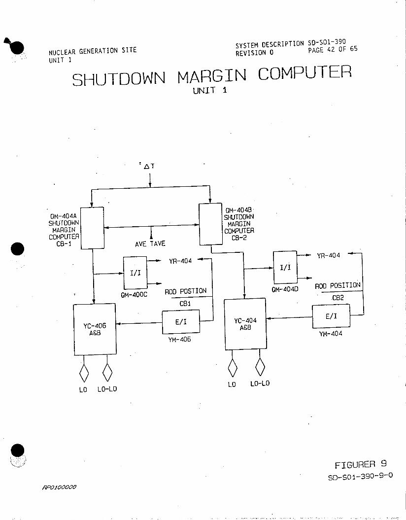
SYSTEM DESCRIPTION 50-501-390
NUCLEAR GENERATION SITE REVISION 0 PAGE 42 OF 65
SHUTDOWN MARGIN COMPUTER UNIT 1
OM-404AM-404B SHUT-W
SHUTDOWN
COMPUTER CMUE
CB-1 AVE TAVE
YR-404 --- YR-404
OM-00C ROD POSTION OM-404D R00 POSITION
CM4 0 C6_ _ _ _ C B 2
YC-4 06 __ __ - - YC-4 04 E/I A
YM-406 YM-404
LO LO-LO LO LO-LO
FIGURER 9
P001 00000SD-SO1-390-9-0

NUCLEAR GENERATION SITE SYSTEM DESCRIPTION SD-SO-390
UNIT 1 REVISION 0 PAGE 44 OF 65
TAVE PROGRAM UNIT I
TEMPERATURE F
580
575- - 575 575 (597.3)
570
565
560
555 Illy ~
555t. 550 (575.1)
545
54053
535
531 (553)
525
520
0 15 50 100 POWER %
DESIGN TEMPERAIURES - SEE S-SOI-280 REACTOR COOLANT SYSTEM
FIGURE 1i
AOOO 0000SD-SO 1-390-11-0

NUCLEAR GENERATION SITE SYSTEM DESCRIPTION SD-SOl-390
N A G I REVISION 0 PAGE 45 OF 65
UNIT 1
APPENDIX A
DEVELOPMENTAL RESOURCES
P&IDs
5178100, Reactor Coolant System
5178105, Pressurizer and Pressurizer Relief Tank
Elementaries
5102174, (N1540 18) 120 Volt AC System
5150338, (N1542 16) Press. Htrs Group A&B ACB's (Control GrouD)
5150339, (N1542 17) Press. Htrs Group C&D ACB's (Backup Group)
0456316, (N1542 20A) Press. Power Relief CV-545 & 546
5154617, (N1542 20M) Reactor Overpressure Mitigation System
N15420052, (N1542 52) Reactor Auxiliaries
5130359, (N1542 53) Vertical Board Instr. Pwr. Supply-Vital Bus
N15420054 , (N1542 54) Reactor Auxiliaries
5151907, (N1542 55) Vertical Board Instrument Pwr. Supply
Y-20929, (N1542 102C) Reactor Control & Protection System
0063714, (N1542 132) Reactor Coolant System
0063716, (N1542 133) Pressurizer Pressure System
5126359, (N1542 133A) Pressurizer Cont. Sys. Block Diagram
0063717, (N1542 134) Pressurizer Level System
451399, Loop Diagram - Heated Pressurizer Pressure Cabinet No. 4
5180721, (N1542 173) 120 Volt AC Space Heaters - Pressure Transmitter
Cabinet
A-1

NUCLEAR GENERATION SITE SYSTEM DESCRIPTION SD-SO1-390
UNIT I REVISION 0 PAGE 46 OF 65
APPENDIX A
DEVELOPMENTAL RESOURCES (Continued)
Technical Manuals
Westinghouse, Reactor Control & Protection System
Procedures
S01-2.1-1, Overpressurization Mitigation System Actuation
SO1-2.3-3, Abnormal Pressurizer Pressure
.SOI-2.3-4, Abnormal Pressurizer Level
SO1-3-1, Plant Startup from Cold Shutdown to Hot Standby
S01-3-3, Plant Operation from Minimum Load to Full Power
SO-3-4, Plant Shutdown from Full Power to Hot Standby
S01-3-5, Plant Shutdown from Hot Standby to Cold Shutdown
S01-4-1, Filling and Venting the Reactor Coolant System
SO1-4-21, Core Monitoring Systems Operations
S01-13-3, Reactor Plant No. 2 Annunciator
O-13-4, Reactor Plant No. 1 Annunciator
S01-13-5, Permissive Information Display Annunciator
S01-13-6, Reactor Plant First-Out Annunciator
S01-13-7, Reactor Plant Matrix Partial Trip Annunciator
501-13-19, Auxiliary Feedwater Annunciator
Technical Specifications
Section 3.5.1, Reactor Trip System Instrumentation
Section 3.5.6, Accident Monitoring Instrumentation
A-2
NUCLEAR GENERATION SITE SYSTEM DESCRIPTION SD-S01-390
UNIT 1 REVISION 0 PAGE 47 OF 65
APPENDIX A
DEVELOPMENTAL RESOURCES (Continued)
Study Guides
3, Reactor Coolant System
6, Overpressurization Mitigating System
7, Reactor Coolant System Instrumentation
11, Primary System Pressure and Level Control and Pressurizer Relief Tank
12, Reactor Control and Protection System
Bechtel System Descriptions
10, Reactor Control and Protection System
FSAR
Section 2.5, Reactor Coolant System
Section 5.2, Reactor Control and Protection System
Lesson Plans
1001, Reactor Coolant Instrumentation
1028, Reactor and Protection System
1077, Reactor Control (Portion of RCPS)
1105, Press. and Press. Relief Tank Press. and Level Control
1158, Reactor Coolant System Instrumentation
Sub-cooling Monitoring System
Student Handouts
Reactor Control System
Pressurizer and Pressurizer Relief Tank and Pressure Control
A-3
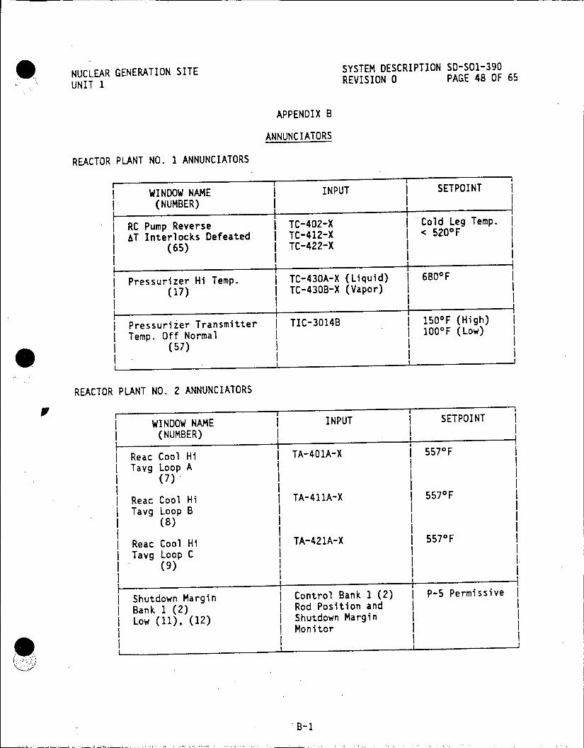
NUCLEAR GENERATION SITE SYSTEM DESCRIPTION SD-SO1-390
UNIT 1 REVISION 0 PAGE 48 OF 65
APPENDIX B
ANNUNCIATORS
REACTOR PLANT NO. 1 ANNUNCIATORS
WINDOW NAME INPUT SETPOINT
(NUMBER)
RC Pump Reverse TC-402-X Cold Leg Temp. AT Interlocks Defeated I TC-412-X < 520*F
(65) I TC-422-X
Pressurizer Hi Temp. TC-430A-X (Liquid) 680'F
(17) TC-430B-X (Vapor)
Pressurizer Transmitter | TIC-3014B 150OF (High)
Temp. Off Normal 100OF (Low)
(57)
REACTOR PLANT NO. 2 ANNUNCIATORS
WINDOW NAME INPUT SETPOINT
(NUMBER)
Reac Cool Hi TA-401A-X 5570F
Tavg Loop A (7)I
Reac Cool Hi TA-411A-X 557 0 F
Tavg Loop B (8)
Reac Cool Hi TA-421A-X 557 0F
Tavg Loop C I (9)
Shutdown Margin I Control Bank 1 (2) I P-5 Permissive
Bank 1 (2) Rod Position and LowB ( 12) Shutdown Margin I
L 1Monitor I
B-1
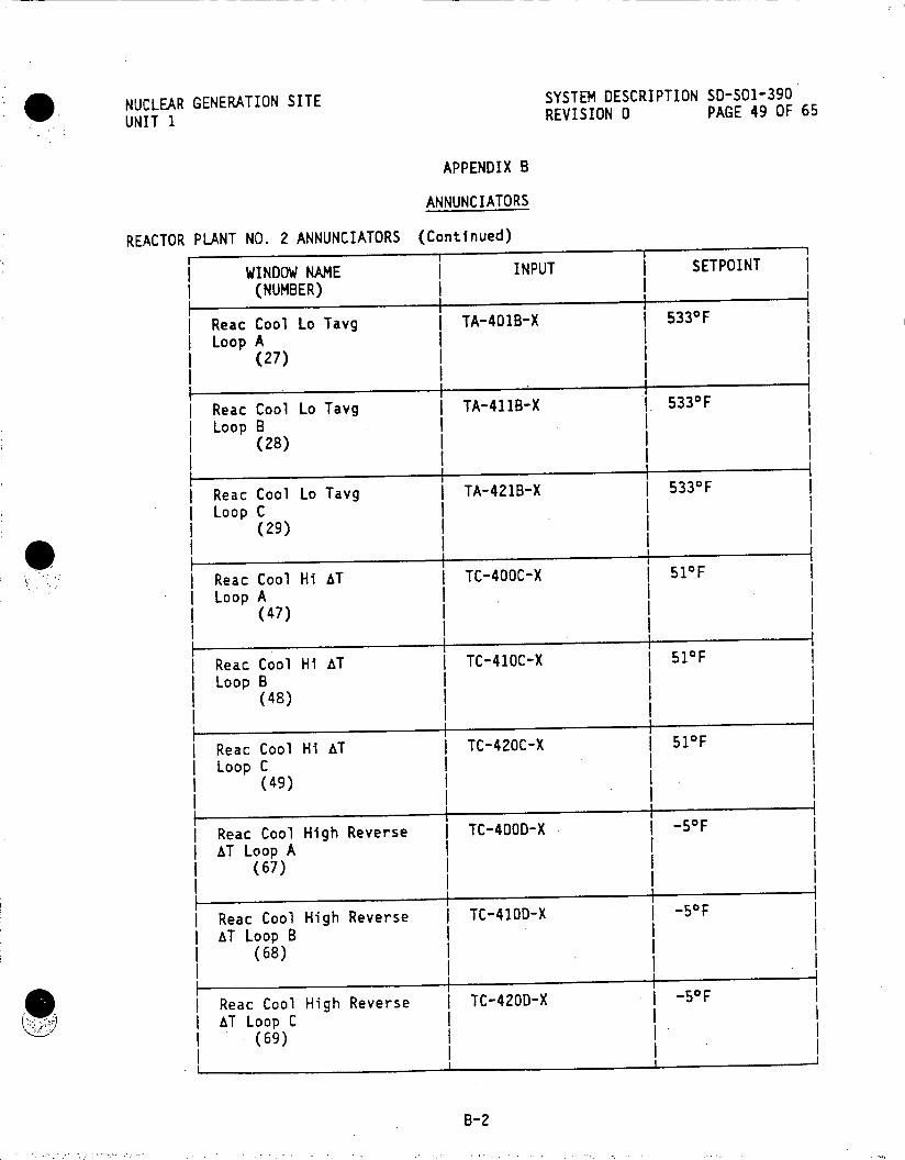
NUCLEAR GENERATION SITE SYSTEM DESCRIPTION SD-501-390
UNIT I REVISION 0 PAGE 49 OF 65
APPENDIX B
ANNUNCIATORS
REACTOR PLANT NO. 2 ANNUNCIATORS (Continued)
WINDOW NAME INPUT SETPOINT
(NUMBER)
Reac Cool Lo Tavg | TA-401B-X 5330F
LoopA I (27)
Reac Cool Lo Tavg TA-411B-X 5330F
Loop B 1 (28)
I.I _ _ _ __ _ I1 Reac Cool Lo Tavg I TA-421B-X | 5330F
Loop C (29)
| Reac Cool Hi AT TC-400C-X 510F I LoopA I I (47) I
Reac Cool Hi AT TC-410C-X 510 F Loop B
(48)
Reac Cool Hi AT TC-420C-X | 51oF Loop C
(49)
| Reac Cool High Reverse TC-400D-X -50F
| AT Loop A (67)
I. I Reac Cool High Reverse TC-410D-X -50F
AT Loop B (68)
Reac Cool High Reverse TC-420D-X -50F AT Loop C
B(69)
B- 2

NUCLEAR GENERATION SITE SYSTEM DESCRIPTION SD-SO1-390
UNIT 1 REVISION 0 PAGE 50 OF 65
APPENDIX B
ANNUNCIATORS
REACTOR PLANT FIRST OUT ANNUNCIATORS
WINDOW NAME INPUT SETPOINT
(NUMBER)
Pressurizer Hi Level LC-430A 2 out of 3s i IReac. Trip ILC-431A I> 70% Pressurizerl
Reac.(1) LC-432A Level
Ra.Col Reduced Pwr j C40X 2 out of 3 ReacloCoeaeudPw FC-400-X1 85% RCS3Loop
ILo Flow Reac. Trip FC-410-XI 5 RSLo
(3) I FC-420-X1 I Flow I RCP"A"-152b I RCP Breaker Open I RCP"B"-152b I I RCP"C"-152b I
Pressurizer High-Level LC-430B-X +4% of Heaters On Programmed Level
I (6)I
Pressurizer High PC-430D-X I 56.25% of
Pressure H I PC-430J Output (7)
Reac Cool Avg TA-405A-X 5 SoF
Tavg Deviation TA-4058-X (8)
Pressurizer Fixed PC-430K 2 out of 3I Hi Press Reac. Trip PC-431H 2200 psig
(11) PC-432E
Reac. Cool Full PWR I FC-400-X2 1 out of 3Lo Lo Flow Reac. Trip I FC-410-X2 < 85% RCS Loop I(13) IFC-420-X2 7I Fow
(13)I RCP"A"-152b RCP Breaker Open j RCP"B"-152b I RCP"C"-152b
Pressurizer Low-Level I LC-430C-X P4%grammed Level (16) .. Pgm L .
Pressurizer Low-Pressure I PC-431C-X 2035 psig
I (17)
B-3
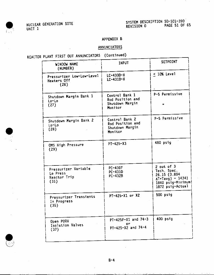
NUCLEAR GENERATION SITE SYSTEM DESCRIPTION SD-S01-390
UNIT 1 REVISION 0 PAGE 51 OF 65
APPENDIX B
ANNUNCIATORS
REACTOR PLANT FIRST OUT ANNUNCIATORS (Continued)
WINDOW NAME INPUT SETPOINT
I (NUMBER)
Pressurizer Low-Low-Level LC-430D-X < 10% Level
I Heaters Off LC-431BX (26)
I 1
I Shutdown Margin Bank 1 Control Bank 1 P-5 Permissive I I Lo-Lo Rod Position and j(27) Shutdown Margin
I I MonitorI
Shutdown Margin Bank 2 . Control Bank 2 P5 Permissive Lo-Lo Rod Position and (28) Shutdown Margin
I I MonitorI
OMS High Pressure PT-425-X3 480 psig
(29)
III
I Pressurizer Variable 2 out of 3
I Lo Press PC-431D Tech. Spec.
I Reactor Trip PC-432B 26.15 (0.894
(31) &T+Tavg) - 14341 I1840 psig-Minimumrl I1872 psig-ActualI
Pressurizer Transients PT-425Xl or X2 500 psig In Progress
I (35)
Open PORV PT-425F-XI and 74-3 400 psig Isolation Valves or
I INPU II (37) ~ ~ LC-40D-X2ad7
B-4
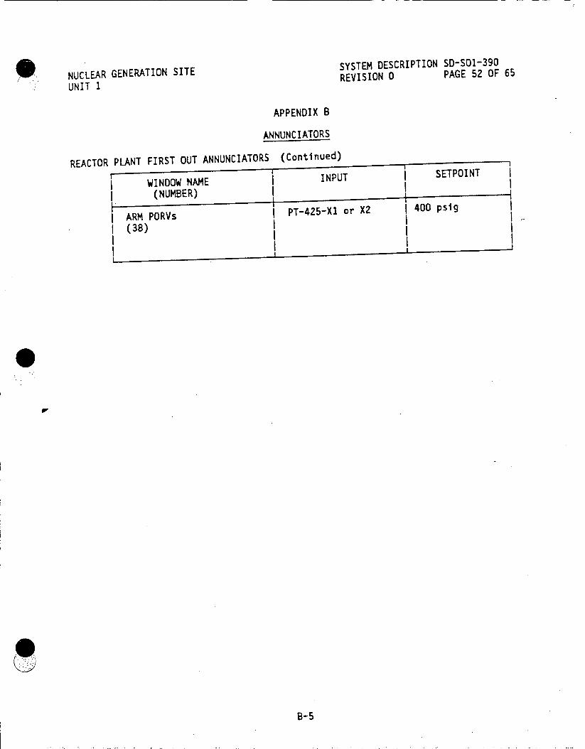
SYSTEM DESCRIPTION SD-SO1-390 NUCLEAR GENERATION SITE REVISION 0 PAGE 52 OF 65 UNIT 1
APPENDIX B
ANNUNCIATORS
REACTOR PLANT FIRST OUT ANNUNCIATORS (Continued) INUTI SEPIN
WINDOW NAME INPUT
(NUMBER)
PT-425-X1 or X2 400 psig ARM PORVs
((38)
I-5 I I
B-5

SYSTEM DESCRIPTION SD-SO1-390 NUCLEAR GENERATION SITE REVISION 0 PAGE 53 OF 65 UNIT 1
APPENDIX B
ANNUNCIATORS
REACTOR PLANT MATRIX PARTIAL TRIP ANNUNCIATORS
Pressurizer Hi Level ILC-430A I> 70% Pressurizerl
Reac. Trip jLC-431A Ilevel I
IChannel I, II, III ILC-432A > 70% Pressurizerl
(1)evel Pres sur iz < 70% Pressurizerl
I I Ilevel
Reac. Cool. Lo Flow IFC-400 I< 85% RCS Loop I Reac. Trip I FC-410 Flow
nLoop A, B, C I FC-420 A<85% RCS Loop
(7), (8), (9) IFlow I~ I1 85% RCS Loop I I I I Flow
I Pesurzer Fixed IPC-430K I2200 psigI Rec Pressure I PC-431H 2200 psig
Reactor Trip | PC-432E
Channel I, II, IIII (11), (12), (13)
Pressurizer Lo Pressure PT-430G
Safety Injection Train I PT-3000A
A, B Channel I (14, () (
II
Pressurizer Lo Pressure I PT-431E,
Safety Injection Train I PT-3000B
A, B Channel II (15, 5)
Pressurizer Lo Pressure PC-430F < 1735 psig
Safety Ijection Train PC-431D
A, B Channel II I PC-432B (16, 6) A, 8Ihne I C42
Pressurizer Variable Low I PC-430F Tech. Specs.
Pressure Reactor Trip PC-431D 26.15(0.894AT +
Channel I, II, III I PC-432B Tavg) - 14341
(31), (32), (33) I1840 psigMinimuml I 1872 psigActual
B -I I
B-60%Pesuie
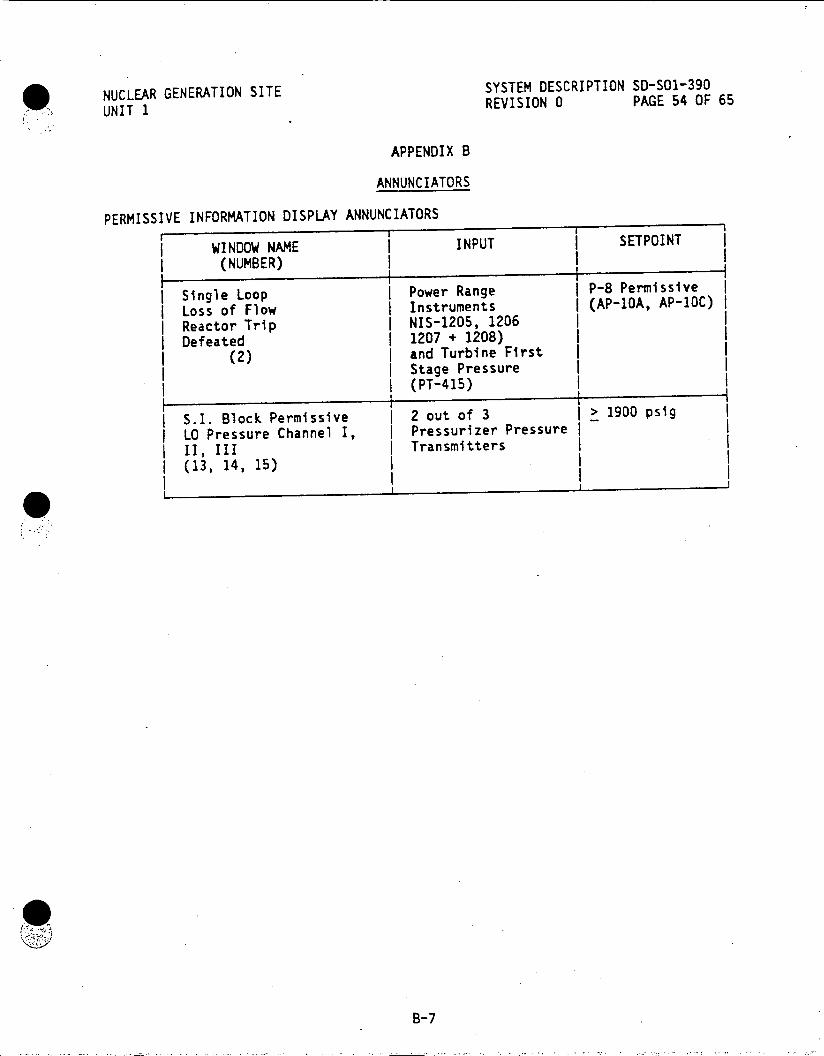
NUCLEAR GENERATION SITE SYSTEM DESCRIPTION SD-SO1-390
UNIT 1 REVISION 0 PAGE 54 OF 65
APPENDIX B
ANNUNCIATORS
PERMISSIVE INFORMATION DISPLAY ANNUNCIATORS
WINDOW NAME INPUT SETPOINT
(NUMBER)
I Single Loop j Power Range P-8 Permissive I I Loss of Flow Instruments | (AP-10A, AP-10C) I | Reactor Trip I NIS-1205, 1206 I
Defeated | 1207 + 1208) I (2) and Turbine First I
Stage Pressure (PT-415)
S.I. Block Permissive 2 out of 3 > 1900 psig LO Pressure Channel I, Pressurizer Pressure
II, III Transmitters (13, 14, 15)
II''
B-7

NUCLEAR GENERATION SITE SYSTEM DESCRIPTION SD-SO1-390 UNIT 1 REVISION 0 PAGE 55 OF 65
APPENDIX B
ANNUNCIATORS
AUXILIARY FEEDWATER ANNUNCIATOR
WINDOW NAME I INPUT SETPOINT (NUMBER) I
| Train A Margin to I TYB-2010 I 40OF Saturated Condition Below
I 41*F I (3) 1 1I I 1 I Train B Margin to TYB-3010 j 40aF I Saturated Condition Below I 41OF I , (8) I I Subcooling Monitoring TS-2001, 2002, Loss of Input | System Temp Signal Loss | 2003, & 2004 I
Train A * I (13)
II II I Subcooling Monitoring | TS-2001, 2002, | Loss of Input
System Temp Signal Loss I 2003, & 2004 I I Train B I I (18) I I
3346i B-8

-NUCLEAR GENERATION SITE .SYSTEM DESCRIPTION SD-S011-390'
UNIT 1 REVISION 0 PAGE 56 OF 65
APPENDIX C
INSTRUMENTATION
REACTOR COOLANT SYSTEM INSTRUMENTATION
INSTRUMENT INSTRUMENT I OUTPUT I NAME | FUNCTION (RANGE) I
I 4 I II I I
TE-402A HOT LEG A (Th) I Dedicated I TI-5402B | . I Shutdown Panel I (100-700aF) I
I I II I
TE-3402A HOT LEG A (Th) Sub-cooling I TI-3402A I Monitoring I (100-7000F) I System A
TE-401A HOT LEG A (Th) Taverage I TT-401 I Calculation I (100-7000 F) I
TE-2401A HOT LEG A (Th) Sub-cooling TI-2401A I Monitoring (100-700 0 F) I System B
TE-400A HOT LEG A (Th) AT I T-400 Calculation | (100-700 0F) I
FT-400 Loop A Flow I Reactor FI-400 I Protection I (0-100%) I I System
II I I
TE-400B Intermediate ( Spare I (100-6000F) I LegA I
II I
TE-401B Intermediate I Spare (100-600aF)
Leg A
C-1
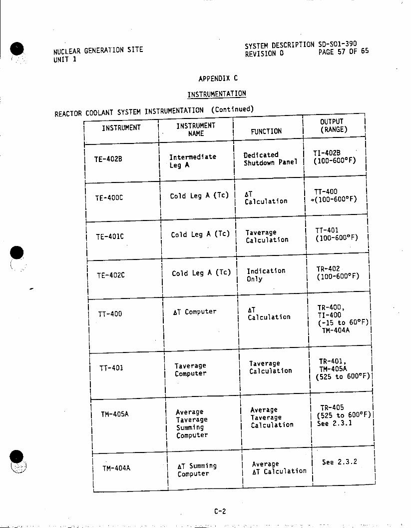
NUC'LEAR GENERATION SITE SYSTEM DESCRIPTION SD-SO1-390
UNIT 1 REVISION 0 PAGE 57 OF 65
APPENDIX C
INSTRUMENTATION
REACTOR COOLANT SYSTEM INSTRUMENTATION (Continued) I.
I INSTRUMENT INSTRUMENT OUTPUT
I V NAME I FUNCTION (RANGE)
IIE-02 I T-40B IIntermediate IDedicated TI-402BI
TE-02 Leg A IShutdown Panel I(100-6000F)
j TE-400C Cold Leg A (Tc) AT TT-400 I I Calculation I .(1006000F) I
TE-401C Cold Leg A (Tc) Taverage TT-401
I I ICalculation I(100-6000F)
TE-402C Cold Leg A (Tc) Indication TR-402
I I Only I(100-6000F)
TT-400 AT Computer AT TR400, I ICalculation TI-400
I I(-15 to 600F)I
TTM-404A
III I TT-401 Taverage Taverage TR401,
Computer Calculation TM-405A I I I(525 to 6000F)I
INSTRUMENTATION. (Continued)
NAM FNCTON I (RNE
ITMn45A Average DAverage I TR-405
Taverage Taverage I (525 to 6000F)I
dSumming A Calculation See 2.3.1
ATComputer A
TM AT Summing Averagelo See 2.3.2
Computer AT Calculation
C-2

NUCLEAR GENERATION SITE SYSTEM DESCRIPTION SD-S01-390
UNU A G I REVISION 0 PAGE 58 OF 65
UNIT 1
APPENDIX C
INSTRUMENTATION
(CONTINUED)
REACTOR COOLANT SYSTEM INSTRUMENTATION
INSTRUMENT INSTRUMENT OUTPUT
NAME I FUNCTION I (RANGE)
TE-412A Hot Leg B (Th) Dedicated TI-5412A
I I IShutdown Panel I(100-7000F) I
I TE-2412A Hot Leg B (Th) 'Sub-cooling TI-2412A IMonitoring I(100-7000F)
I System A I
I
) TE-411A Hot Leg B (Th) Taverage TI-411
I I ICalculation I(100-700F)
TE-3411A Hot Leg B (Th) Sub-cooling TI-3411A
I I Monitoring I(100-7000F) I I SystemI
TE-410AHo TE40Io Leg B (Th) I T Calculation ITT-410
I I I I(100-7000F)
IIFT-41 I1 IFT-410 ILoop B Flow IReactor IFI-410I
IProtection I(0-100%) ISystem
I
I NSRMET I OUTPU
HoTE-410B L BIntermediate j Spare (100-6000F)
H tLeg 8 (T )Oa eu l on (1001 00 F)
-LegB ( I TE411LoopI In er ed wt Reoteoction F0T -40%)
InermediatenSpar (100-6000F)
C- 3
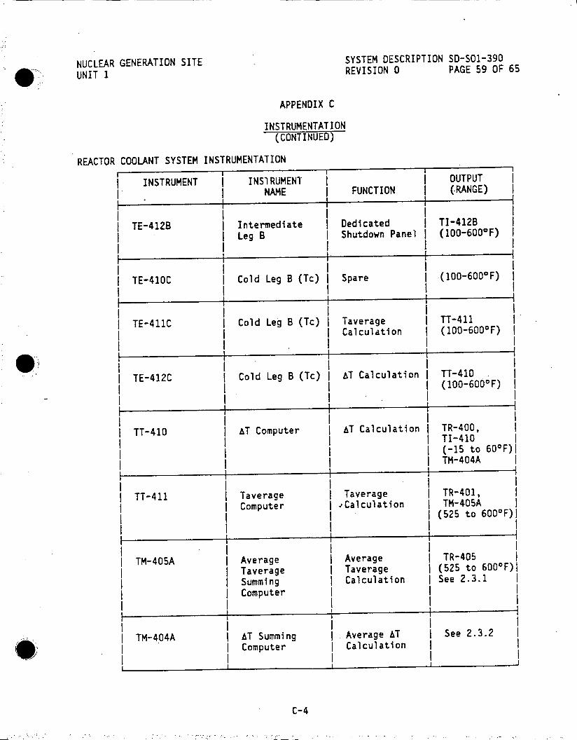
NUCLEAR GENERATION SITE SYSTEM DESCRIPTION SD-SOI-390
UNIT 1 REVISION 0 PAGE 59 OF 65
APPENDIX C
INSTRUMENTATION (CONTINUED)
REACTOR COOLANT SYSTEM INSTRUMENTATION
INSTRUMENT INSIRUMENT I OUTPUT
I NAME FUNCTION | (-RANGE)
TE-412B Intermediate I Dedicated TI-412B I Leg B | Shutdown Panel (100-6000 F) I
I II
I I I I TE-410C Cold Leg B (Tc) Spare I (100-6000F)
TE-411C Cold Leg B (Tc) | Taverage | TT-411 I j Calculation I (100-600 0 F)
IIII
| TE-412C Cold Leg B (Tc) | AT Calculation I TT-410 I (100-600aF) I
- I I.I .I I
I I I TT-410 1 AT Computer I AT Calculation | TR-400,
I TI-410 I I (-15 to 60'F)I |ITM-404A I
TT-411 Taverage I Taverage | TR-401, I Computer | -Calculation j TM-405A
(525 to 600aF)1 1I II
TM-405A | Average | Average | TR-405 Taverage I Taverage I (525 to 600 0F)I Summing | Calculation I See 2.3.1 Computer I
I II F 4 I I I
TM-404A I AT Summing Average AT I See 2.3.2
| Computer I Calculation I
C-4

NUCLEAR GENERATION SITE SYSTEM DESCRIPTION SD-SOl-390
UNIT 1 REVISION 0 PAGE 60 OF 65
APPENDIX C
INSTRUMENTATION (CONTINUED)
REACTOR COOLANT SYSTEM INSTRUMENTATION
INSTRUMENT INSTRUMENT OUTPUT I NAME FUNCTION (RANGE) I
I I I I I TE-422A I Hot Leg C (Th) I Dedicated I TI-5422A I
I Shutdown Panel | (100-700*F) I I I. I
III I I TE-2422A I Hot Leg C (Th) I Sub-cooling I TI-2422A I
I Monitoring I (100-7000F) I SystemA
IIII
TE-421A | Hot Leg C (Th) j Taverage TT-421 Calculation (100-7000 F)
TE-3421A Hot Leg C (Th) I Sub-cooling I TI-3421A I Monitoring I (100-7000F) I System B I
TE-420A Hot Leg C (Th) AT Calculation j TT-420 I I (100-7000F)
I II I I I I
FT-420 Loop C Flow I Reactor I FI-420 I Protection j (0-100%) I System I
I
II II TE-420B I Intermediate I Spare .(100-600 0 F) I
I Leg C
TE-I1BI 1 ________I II II
TE-421B Intermediate I Spare I (100-6000 F) I Leg C
C-5

NUCLEAR GENERATION SITE SYSTEM DESCRIPTION SD-501-390
UNIT 1 REVISION 0 PAGE 61 OF 65
APPENDIX C
INSTRUMENTATION (CONTINUED)
REACTOR COOLANT SYSTEM INSTRUMENTATION
INSTRUMENT INSTRUMENT OUTPUT NAME I FUNCTION I (RANGE) I
II TE-422B Intermediate Dedicated TI-422B
I ILeg C IShutdown Panel I(100-6000F) I
I .
I TE-422C Cold Leg C (Tc) Indication TR-402
I I IOnly I(100-6000F) I
TE-421C Cold Leg C (Tc) Taverage TT-421
I I Calculation I(100-6000F) I
- T-42C jCol Le C Tc)I T Calculation ITT420 TE-420C (10-6000F)
TT-420 ( T Computer AT Calculation TR-400,
1TI-420 I I(-15 to 600F)I TM-404A
ITT-421 Taverage ITaverage TR-4.O1,I IComputer ICalculation TM-405A Co d L g C( c(525 to 6000F)
TM-405A IAverage Average TR-405I Taverage C Taverage (525 to 6000F)l
SSumming C Calculation 0See 2.3.1
Computer T i T
TM-404A AT Summing Average AT See 2.3.2
Computer Calculation
C-6

NUCLEAR GENERATION SITE SYSTEM DESCRIPTION SD-SOl-390
UNIT 1 REVISION 0 PAGE 62 OF 65
APPENDIX C
INSTRUMENTATION (CONTINUED)
PRESSURIZER PRESSURE INSTRUMENTATION
INSTRUMENT | INSTRUMENT I (UTPUT) j NAME FUNCTION
I I I
| PT-430 | Pressurizer Reactor Pro- I-430 I Pressure tection System, (1600-2400
IControl through psig)
IP/432,and PR-430 ISequencer I(1600-2400 I ISystem A Ipsig)I
IPI-400B
I I I I(1600-2400 I IPsig) 4.I II
I IIII I PT-431 | Pressurizer Reactor Pro- PI-430
I Pressure tection System, (1600-2400 I IControl through Ipsig)
P/432, and PR-430 I I ISequencer I(1600-2400 I
I ISystemA Psi) PI-410B (1600-2400
Ipsig)
PT-432I Pressurizer Reactor Pro- I-430 |4Pressure tection System, (1600-2400
IP432, and I-430 I Sequencer I(1600-2400 I I I System A Ipsig)I I I-420B
I(1600-2400 Ipsig) II 4
I II
PT-425 | Wide Range MOV-813 & 814 PR-425 I Pressurizer Interlock, and (0-600 psig) j Pressure Sub-cooling (0-3000 psig)
I I Monitoring I I ~ System AI II T4
I PT-425-X1 I Pressurizer Used to Sub-cooling j Pressure Generate Monitoring
ISaturation System B ITemperature
C-7
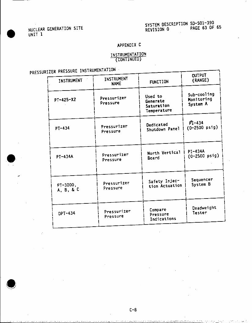
SYSTEM DESCRIPTION SD-SO1-390 NUCLEAR GENERATION SITE REVISION 0 PAGE 63 OF 65
UNIT 1
APPENDIX C
INSTRUMENTATION (CONTINUED)
PRESSURIZER PRESSURE INSTRUMENTATION
INSTRUMENT I INSTRUMENT F OOUTPUT
I.I NAME FUNCTION (RANGE)
U d to ISub-cooling PT-425-X2 Pressurizer Used to Monitoring
Pressure Saturation System A
I I Temperature
PT-434 Pressurizer Dedicated ( 2434 i Pressure Shutdown Panel (0-2500 psig)
PT-434A Pressurizer INorth Vertical PI-434A
P-4Pressure Board (0-2500 psig)
PT-3000, Pressurizer safety Injec- Sequencer
-A, B, & C Pressure tion Actuation System B
DPT-434 I Pressurizer Compare Deadweight
DP-44Pressure Pressure Tester Indications
C-8

NUCLEAR GENERATION SITE SYSTEM DESCRIPTION SD-SO1-390
UNIT 1 REVISION 0 PAGE 64 OF 65
APPENDIX C
INSTRUMENTATION (CONTINUED)
PRESSURIZER LEVEL INSTRUMENTATION
INSTRUMENT INSTRUMENT I NAME FUNCTION (RANGE)
IIII LT-430 Pressurizer Reactor Pro- LI-420
Level tection System; (0-100%) IControl and LR-430 Chemical and (0-100%)
Volume Control (4.7-37.2 ft)I ISystem through
L/432 I
I I
II
LT-431 | Pressurizer Reactor Pro- LI-431 I Level tection System, (0-100%)
I I and Control ILR-430I I I through LU432 I(0-100%) I
I(4.7-37.2 ft)j
LT-432 I Pressurizer Reactor Pro- I-L432 Level tection System; (0-100%)
| Control, and LR-430 I Chemical and (0100%) I Volume Control (4.7-37.2 ft)I I System through I L/432
+ ~I
LT-430A IPressurizer IAuxiliary ILI-430AI ILevel IControl Panel I(0-100%)
I 1 (4.7-37.2 ft)I
I I I I
LT-435 IPressurizer INorth Vertical ILI-435I ILevel IBoard (Cold I(0-100%) I
ICalibrated 1 (4.7-37.2 ft)j f for Cooldown
I Indication)
__I Rectrro
C- 9
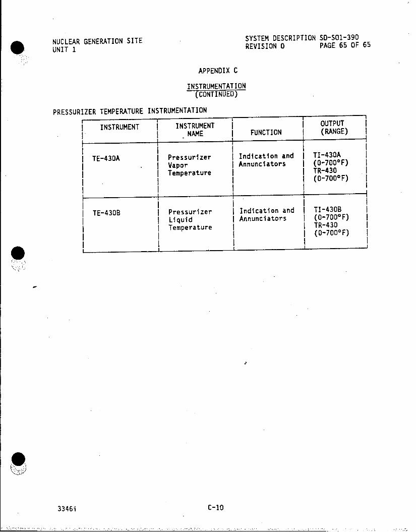
NUCLEAR GENERATION SITE SYSTEM DESCRIPTION SD-S01-390
UNIT 1 REVISION 0 PAGE 65 OF 65
APPENDIX C
INSTRUMENTATION (CONTINUED)
PRESSURIZER TEMPERATURE INSTRUMENTATION rI
INSTRUMENT INSTRUMENT OUTPUT . NAME FUNCTION (RANGE) I
I I I II TE-430A I Pressurizer I Indication and | TI-430A
. Vapor I Annunciators I (0-7000 F) Temperature TR-430 I
I Tee I I (o-7000F)
I I .I II II
TE-4308 I Pressurizer I Indication and I TI-430B I I Liquid I Annunciators I (0-7000F) I ( Temperature I TR-430 I
I (0-700 0F) I 3346 i II
3346i C-10

NUCLEAR GENERATION SITE SYSTEM uESCRIPTION SD-SO1-400 UNIT I REVISION 0 PAGE 1 OF 53
DEC1j (I CDM
ROD CONTROL SYSTEM
TABLE OF CONTENTS
SECTION PAGE
1.0 FUNCTIONS/DESIGN BASES 2
2.0 DESCRIPTION 3 2.1 System Overview 3 2.2 Components 6 2.3 Detailed Control Scheme 20 2.4 Power Supplies 27
3.0 OPERATION 28 3.1 Normal Operations 28 3.2 Other Operations RECEIVED CDM 29
4.0 REFERENCES DEC 10 1985 30 4.1 Elementaries 30 4.2 Technical Manuals SITE FILE COPY 31 4.3 Procedures 31 4.4 Technical Specifications 32
FIGURES I Simplified Rod Control System 33 2 Control Rod Drive Mechanism 34 3 Simplified Block Diagram - Rod Control System 35 4 Rod Position Indication System 36 5 Rod Control Program 37 6 Simplified Control and Shutdown Rod Sequencing Circuit 38 7 Simplified Shutdown Group Control Circuit 39 8 Simplified Shutdown Group Sequencing Circuit 40 9 Simplified Control Bank Rod Control 41
10 Pulse Generator and Master Cycler 42 11 Simplified Control Bank Sequencing Circuit 43 12 J Console - West Portion 44
APPENDICES A Physical Arrangement and Control Hardware in 4 KV Room 45 B Local Rod Controls 48 C Annunciators 49 D Developmental Resources 51
This System Description is approved per S0123-0-44, System Description Revision and Approva . ontac M to verify revision information.
PREPARED BY:
APPROVED BY:. t z Man #-r, perati s a
32191i
NUCLEAR GENERATION SITE SYSTEM DESCRIPTION SD-SO1-400 UNIT 1 REVISION 0 PAGE 2 OF 53
ROD CONTROL SYSTEM
1.0 FUNCTIONS/DESIGN BASES
1.1 The Rod Control System has the following main functions:
1.1.1 The Rod Control System controls the proper sequencing of DC power to the Control Rod Drive Mechanisms as required for the various modes of plant operation.
1.1.2 The Control Rod Drive Mechanisms (CRDM) translate the electrical signal from the Rod Control System into a mechanical force to move the Control Rods up, down, or hold the Control Rods in a stationary position.
1.1.3 The Rod Position Indication System detects the position of each Control Rod and each Control Rod Group, and provides the indication and control signals required for safe plant operation.

NUCLEAR GENERATION SITE SYSTEM DESCRIPTION SD-SO1-400 UNIT I REVISION 0 PAGE 3 OF 53
ROD CONTROL SYSTEM
. - 2.0 DESCRIPTION
2.1 System Overview
2.1.1 Rod Control System (Figure 1)
The Rod Control System controls the proper sequencing of DC power to the 45 Control Rod Drive Mechanisms.
The Rod Control System is divided into two Shutdown Groups and two Control Banks.
Each Shutdown Group consists of eight Control Rod Drive Mechanisms.
Control Bank I consists of twelve Control Rod Drive Mechanisms and is further divided into four Sub-groups consisting of 2, 2, 4 & 4 Control Rod Drive Mechanisms per Sub-Group.
Control Bank 2 consists of seventeen Control Rod Drive Mechanisms and is further divided into four Sub-groups consisting of 4, 4, 5 & 4 Control Rod Drive Mechanisms per Sub-group.
Each Control Rod Drive Mechanism consists of a Pressure Vessel, a Latch Assembly, an Operating Coil Stack, a Drive Shaft Assembly, and a Position Indicator Coil Stack.
Each C.ntrol Rod Drive Mechanism is an independent unit that can be dismantled or assembled separately.
Each Control Rod Drive Mechanism is threaded into an adaptor on top of the Reactor Vessel and is connected to a Control Rod by means of a grooved Drive Shaft. The Drive Shaft is held by the latches of the Control Rod Drive Mechanism. The latches operate sequentially to cause rod motion.
Reactor Coolant fills the Pressure Vessel parts of the Control Rod Drive Mechanism. All working components of the mechanism and the drive shaft are immersed in the Reactor Coolant and depend upon it for lubrication of sliding parts.
Three magnetic coils, which surround the Pressure Vessel, operate the working components. The coils are arranged in a stack, which forms a removable electrical unit, that is separated from the Reactor Coolant System environment by the Pressure Vessel walls.
Power to the Control Rod Drive Mechanisms is supplied from the 125VDC System via the two Scram Breakers. Before any rod motion can take place, both Scram Breakers must be closed.
Interruption of power to the Control Rod Drive Mechanisms occurs if either one of the two Scram Breakers is opened. This causes all coils to de-energize, allowing the Control Rods to drop into the Core by gravity.

NUCLEAR GENERATION SITE SYSTEM DESCRIPTION SD-SO1-400 UNIT I REVISION 0 PAGE 4 OF 53
ROD CONTROL SYSTEM
2.0 DESCRIPTION (Continued)
2.1.1 Rod Control System (Continued)
The group or groups to be operated is selected by the Group Selector Switch and the Overlap Control Switch on the J-Console. Operation of Control Group(s) is either manual by the operator using the IN-HOLD-OUT Switch or automatically by the Primary and Nuclear Instrumentation Systems (see SD-S01-390 and 380). Operation of a Shutdown Group is manual only, using the IN-HOLD-OUT Switch.
Under manual control, the Control Group(s) and Shutdown Group(s) move at a fixed speed (15"/minute). Under automatic control the Control Group(s) only, move at variable speeds (5"/minute up to 15"/minute) depending upon the Tavg-Tref mismatch signal.
Operation of each Control Rod Drive Mechanism is controlled by sequencing the Movable Gripper Cofl, the Stationary Gripper Coil and the Lift Coil of the operating Coil Stack. When the coils are energized in sequence, the Drive Mechanisms move the Control Rods. The sequence is obtained by means of a Slave Cycler Unit, which consists of a motor, cam-operated switches, and a clutch unit between the motor and the switches.
The Slave Cycler Unit rotates the cam switch through 360 degrees when the clutch unit is pulsed. Power is sequentially supplied to the Control Rod Drive Mechanism Coils causing the Control Rod to insert or withdraw one step. The stepping rate is proportional to the frequency of the pulses to the coupling unit.
A Pulse Generator and Master Cycler produce the output pulses at a frequency proportional to a variable DC voltage, representative of a variable speed and direction signal from the Tavg-Tref mismatch (Control Groups only, the Shutdown Groups have a separate Control Cycler and do not use the Pulse Generator or Master Cycler).
The motor of the Slave Cycler Unit runs at a constant speed of 41 rpm, corresponding to a rod withdrawal or insertion speed of slightly greater than 15 inches per minute. The maximum frequency of the Pulse Generator is 40 pulses per minute, or 15 inches per minute of rod movement. If rod motion is to occur at the maximum rate, the slave cycler is continuously re-engaged. However, when slower rod motion is desired, the clutch disengages after each revolution and waits for the next pulse.
If a Slave. Cycler fails to complete a full revolution when pulsed, all automatic rod withdrawal motion stops and an annunciator illuminates in the Main Control Room.
The Rod Position Indication System consists of an Analog Detection System (Actual) and a Digital Detection System (Demand).
NUCLEAR GENERATION SITE SYSTEM DESCRIPTION SD-SO1-400 UNIT 1 REVISION 0 PAGE 5 OF 53
ROD CONTROL SYSTEM
2.0 DESCRIPTION (Continued)
2.1.1 Rod Control System (Continued)
The Analog Detection System consists of a Linear Variable Differential Transformer (LVDT) with its primary and secondary coils mounted around the Pressure Housing of the Control Rod Drive Shaft. The transformer senses the position of the Control Rod Drive Shaft for any given Control Rod Drive Shaft position.
The output AC voltage of the LVDT is sent to an AC-DC Analog Converter. The DC output is proportional to the position of the Control Rod and is sent to a Multi-point Recorder, a Rod Bottom Device and a Rod Deviation Monitor.
The Digital Detection System consists of digital indicators which are solenoid operated Digital Step Counters.
The Digital Step Counters are operated by the same contactors that activate the Lift Coils of the Control Rod Drive Mechanisms.
Each closing of the contactor corresponds to one step of the Control Rod Drive Mechanism and pulses the Digital Step Counter one count.
2.1.2 General Control Scheme (Figures 1 and 3)
.2 Rod Control System
In automatic operation the Rod Control System receives inputs from Tave, Tref, Nuclear Flux (NIS-1208), and Pressurizer Pressure P minus Pref (from PC 430J). These signals are used to develop a programmed rod control signal.
The Tave and Tref signals are used for direction and speed control. The dn/dt (rate of change of Nuclear Flux) and P-Pref signals are used strictly for speed compensation and have a minor effect on the Rod Control System.
The P minus Pref and dn/dt can be placed in or out of service at the J-Console.
The Rod Control System maintains Tave at its programmed value by comparing Tave with Tref. When Tave differs from Tref by greater than or equal to + 2oF the rods will start to move in or out as necessary to bring Tave within + 20F of the Tref value.
VI
NUCLEAR GENERATION SITE SYSTEM DESCRIPTION SD-SO1-400
UNIT I REVISION 0 PAGE 6 OF 53
ROD CONTROL SYSTEM
2.0 DESCRIPTION (Continued)
2.1.2 General Control Scheme (Continued)
The rods will start to move in or out as necessary at 5"/minute. Rod speed is maintained at 5"/minute from + 20 F to + 80 F mismatch, from + 80 F mismatch to + 120 F mismatch rod speed increases (2.5"/min./oF) from 5"/minute to 15"/minute which is its upper limit. Any mismatch greater than + 12oF will still result in a rod
speed of 15"/minute (Figure 5).
In manual operation the Control Rods receive their In or Out motion signal from .the In-Hold-Out Switch on the J-console and their speed signal from manual speed controller HC-413 located in Rack R-1 behind the West Vertical Board. The speed signal is required to always be set at 15"/minute.
The group or bank to be moved is determined by.-the
position of the Group Selector Switch and the Overlap Control Switch. Both switches are located on the J-console.
2.2 Components
2.2.1 Control Rod Drive Mechanism (See Figure 2)
Three magnets in each drive mechanism move two sets of latches
which lift or lower the grooved Drive Shaft. The three magnets are
turned on and off in a fixed sequence by the Rod Control System.
Each cycle moves the Drive Shaft and attached Control Rod 3/8 inch
(one step length). The sequencing of the magnets by the Rod
Control System produces a step motion over the entire length of
Control Rod travel.
The mechanism is capable of developing a litting force of 400 lbs.
at 15 inches/minute. The force is directly applied the Drive Shaft
by either set of latches. For rod insertion, the force of gravity is used to allow the rod to lower under its own weight.
The mechanism internals (inside the Pressure Vessel) are designed to operate in water at 650 0 F and 2500 psig. The temperature at the
Reactor Vessel Head adaptor will be approximately 5501F because it
is located in a region where there is not a flow of water from the
Reactor Core. The pressure, however, is the same in the mechanism as it is in the Reactor Vessel.
The heat generated in.the operating coils is removed by forced air
cooling to keep the conductor temperature below the design maximum
temperature of 200 0 C (see SD-SO1-450, Heating, Ventilating, and Air
Conditioning Systems).

NUCLEAR GENERATION SITE SYSTEM DESCRIPTION SD-SO1-400 UNIT 1 REVISION 0 PAGE 7 OF 53
ROD CONTROL SYSTEM
2.0 DESCRIPTION (Continued)
2.2.1 Control Rod Drive Mechanism (See Figure 2) (Continued)
The Control Rod Drive Mechanism consists of the following components:
.1 Pressure Vessel
The Pressure Vessel consists of the Pressure Housing and the Rod Travel Housing.
The Pressure Housing is the lower portion of the vessel and contains the Latch Assembly.
The Rod Travel Housing is the upper portion of the vessel. It provides space for the Drive Shaft during its upward movement as the Control Rod is withdrawn from the Core.
All Pressure Vessel materials are made of 304 Stainless Steel.
.2 Latch Assembly
The Latch Assembly contains the mechanical components which withdraw and insert the Drive Shaft and attached Control Rod. It is located within the Pressure Vessel where it is exposed to Reactor Coolant System environment.
The Latch Assembly consists of the pole pieces for three electromagnets that actuate two sets of latches which engage the grooved section of the Drive Shaft. The upper set of latches move up or down to raise or lower the Drive Shaft 3/8 inch for each mechanism cycle. The lower set of latches, when engaged, have a 1/32 inch axial movement to shift the weight of the Drive Shaft and Control Rod from one set of latches to the other. This holds the Drive Shaft stationary while the upper set is repositioned for the next 3/8 inch step.
The magnetic poles are made of 410 stainless steel. The remaining material in the Latch Assembly is 304 Stainless Steel with both sets of latches having Stellite tips.

NUCLEAR GENERATION SITE SYSTEM DESCRIPTION SD-SOl-400
UN'iT 1 REVISION 0 PAGE 8 OF 53
ROD CONTROL SYSTEM
2.0 DESCRIPTION (Continued)
2.2.1- Control Rod Drive Mechanism (See Figure 2) (Continued)
.3 Operating Coil Stack
The Operating Coil Stack is an independent unit consisting of three Operating Coils and is installed on the Control Rod Drive Mechanism by sliding it over the outside of the.Pressure Housing. It rests on the base of the Pressure Housing without any mechanical attachment and can be removed and installed while the Reactor is pressurized and at temperature.
The three Operating Coils are identified as the Lift Coil, the Movable Gripper Coil and the Stationary Gripper Coil.
The three Operating Coils are made of round copper wire which is insulated with a double layer of filament type glass yarn to form a molded coil spool.
The Lift Coil is the uppermost coil and provides the motive force for lifting the Control Rod Drive Shaft. When the Lift Coil is energized it pulls the Lift Armature and the Movable Gripper up 3/8 of an inch (one step).
The Movable Gripper Coil is the middle coil of the three Operating Coils. When the Movable Gripper Coil is energized it causes the Movable Gripper to latch the Control Rod Drive Shaft. The Movable Gripper Coil and Gripper are used to latch the Control Rod Drive Shaft during Hold conditions and at various stages during Control Rod movement.
Half power is supplied to the Movable Gripper Coil during Hold conditions to prevent burning up the coil. Full power is supplied to the Movable Gripper Coil during Control Rod Movement. If full power was not supplied during Control Rod movement the Control Rod might drop.
The Stationary Gripper Coil is the bottom coil of the three Operating Coils. When the Stationary Gripper Coil is energized it causes the Stationary Gripper to latch the Control Rod Drive Shaft. The Stationary Gripper Coil and Gripper are used to latch the Control Rod Drive Shaft while the Movable Gripper and/or Lift Coil Armature are in transient conditions during Control Rod movement, thus preventing the Control Rod from dropping.

NUCLEAR GENERATION SITE SYSTEM DESCRIPTION SD-SO1-400
U'NIT 1 REVISION 0 PAGE 9 OF 53
ROD CONTROL SYSTEM
2.0 DESCRIPTION (Continued)
2.2.1 Control Rod Drive Mechanism (See Figure 2) (Continued)
.4 Drive Shaft Assembly
The Drive Shaft Assembly transmits the Control Rod Drive Mechanism motion to the Control Rod. The Drive Shaft Assembly consists of a 410 Stainless Steel Drive Rod, made of 1-3/4 inch diameter tubing with grooves machined on the outside diameter to receive the latches of the Latch Assembly.
The grooves have 450 angle sides to match the tooth form on the Movable and Stationary Gripper Latches. The
grooves are spaced 3/8-inch apart to coincide with the Control Rod Drive Mechanism step length.
.5 Position Indicator Coil Stack
The Position Indicator Coil Stack slides over the Rod Travel Housing section of the Pressure Vessel. It detects Drive Rod Position by means of a cylindrically wound differential transformer that spans the 120-inch
length of rod travel.
.6 Control Rod Drive Mechanism Withdrawal
The Control Rod is withdrawn by repeating the following sequence which starts with the Control Rod in a Hold condition and only the Movable Gripper Coil energized at 1/2 power:
.6.1 Movable Gripper Coil on at Full Power, white HOLD Light off.
.6.2 Lift Coil - ON, Movable Gripper Coil - ON, Stationary
Gripper Coil - OFF. The 3/8" gap between the Lift Armature and the Lift Pole closes and the Drive Shaft raises one step length (3/8").
.6.3 Lift Coil - ON, Movable Gripper Coil ON, Stationary Gripper Coil - ON
The Stationary Gripper Armature raises and closes the gap below the Stationary Gripper Pole. The links, pinned to the Stationary Gripper Armature, swing the Stationary Gripper Latches into a Drive Shaft groove. The latches contact the Drive Shaft and lift it (and the attached Control Rod) 1/32 inch. The 1/32 inch vertical Drive Shaft movement transfers the Drive Shaft load from the Movable Gripper Latches to the Stationary Gripper Latches.

NUCLEAR GENERATION SITE SYSTEM DESCRIPTION SD-SOI-400 UNIT 1 REVISION 0 PAGE 10 OF 53
ROD CONTROL SYSTEM
2.0 DESCRIPTION (Continued)
2.2.1 Control Rod Drive Mechanism (See Figure 2) (Continued)
.6.4 Lift Coil - ON, Movable Gripper Coil - OFF, Stationary Gripper Coil - ON,
The Lift Armature separates from the Movable Gripper Armature under the force of a spring and gravity. The links, pinned to the Movable Gripper Armature swing the Movable Gripper Latches out of the Drive Shaft groove.
.6.5 Lift Coil - OFF, Movable Gripper Coil - ON, stationary Gripper Coil - OFF.
The gap between the Lift Armature and Lift Pole opens, causing the Movable Gripper Latches to drop 3/8-inch.
.6.6 Lift Coil - OFF, Movable Gripper Coil - ON, Stationary Gripper Coil - ON
The Movable Gripper Armature raises and swings the Movable Gripper Latches into a Drive Shaft groove. A 1/32-inch axial clearance exists between the latch teeth and Drive Shaft.
.6.7 Lift Coil - OFF, Movable Gripper Coil - ON, Stationary Gripper Coil - OFF
The force of gravity, acting upon the Drive Shaft and attached Control Rod, causes the Stationary Gripper Latches and Stationary Gripper Armature to move downward 1/32-inch until the load of the Drive Shaft and attached Control Rod is transferred to the Movable Gripper Latches. The Stationary Gripper Armature continues to move downward and swings the Stationary Gripper Latches out of the Drive Shaft groove.
.6.8 If additional rod movement is called for, the sequence is repeated; if not, the Movable Gripper Coil goes to 1/2 power after 10 seconds and the white HOLD Light illuminates.
.7 Control Rod Drive Mechanism Insertion
The Control Rod is inserted by repeating the following sequence which starts with the Control Rod in a Hold condition and only the Movable Gripper Coil energized at 1/2 power:
.7.1 Movable Gripper Coil ON at Full Power, White HOLD Light OFF

N1ICLEAR GENERATION SITE SYSTEM DESCRIPTION SD-SO1-400 UNIT 1 REVISION 0 PAGE 11 OF 53
ROD CONTROL SYSTEM
2.0 DESCRIPTION (Continued)
2.2.1 Control Rod Drive Mechanism (See Figure 2) (Continued)
.7.2 Lift Coil - OFF, Movable Gripper Coil - ON, Stationary Gripper Coil - ON
The Stationary Gripper Armature raises and closes the gap below the Stationary Gripper Pole. The links, pinned to the Stationary Gripper Armature swing the Stationary Gripper Latches into a Drive Shaft groove. The latches contact the Drive Rod and lift it (and the attached control rod) 1/32-inch. The 1/32-inch vertical Drive Shaft movement transfers the Drive Shaft load from the Movable Gripper Latches to the Stationary Gripper Latches.
.7.3 Lift Coil - OFF, Movable Gripper Coil - OFF, Stationary Gripper Coil - ON
The Lift Armature separates from the Movable Gripper Armature under the force of a spirng and gravity. The links,*pinned to the Movable Gripper Armature, swing the Movable Gripper Latches out of the Drive Shaft groove.
.7.4 Lift Coil - ON, Movable Gripper Coil - OFF, Stationary Gripper Coil - ON
The 3/8-inch gap between the Lift Armature and Lift Pole Closes. The Movable Gripper Latches are raised to a position adjacent to a Drive Shaft groove.
.7.5 Lift Coil ON, Movable Gripper Coil - ON, Stationary Gripper Coil - ON
The Movable Gripper Armatures raises and swings the Movable Gripper Latches into a Drive Shaft groove. A 1/32-inch axial clearance exists between the latch and the Drive Shaft.
.7.6 Lift Coil - ON, Movable Gripper Coil - ON, Stationary Gripper Coil - OFF.
The force of gravity, acting upon the Drive Shaft and attached Control Rod, causes the Stationary Gripper Latches and Stationary Gripper Armature to move downward 1/32-inch until the load of the Drive Rod and attached Control Rod is transferred to the Movable Gripper Latches. The Stationary Gripper Armature continues to move downward and swings the Stationary Gripper Latches out of the Drive Shaft groove.

NUCLEAR GENERATION SITE SYSTEM DESCRIPTION SD-SO1-400 UNIT 1 REVISION 0 PAGE 12 OF 53
ROD CONTROL SYSTEM
2.0 DESCRIPTION (Continued)
2.2.1 Control Rod Drive Mechanism (See Figure 2) (Continued)
.7.7 Lift Coil - OFF, Movable Gripper Coil - ON, Stationary Gripper Coil - OFF
The force of gravity separates the Lift Armature from the Lift Pole and the Drive Shaft and attached Control Rod drop down 3/8 inch.
.7.8 If additional rod movement is called for, the sequence is repeated; if not, the Movable Gripper Coil goes to 1/2 power after 10 seconds and the White HOLD Light illuminates.
2.2.2 Rod Control System (See Figures 1 and 3)
.1 Pulse Generator
The Pulse Generator receives an analog input from the T - T mismatch controller TM-413 to produce a avg ref
variable pulsed output of up to 40 pulses per minute (15 inches per minute).
The Pulse Generator provides the rod speed signal to the Master Cycler for Control Bank movement during Automatic operation.
The Pulse Generator is located in Logic Cabinet LA in the 4KV Room.
.2 Master Cycler
The Master Cycler receives the spced pulses from the Pulse Generator and the direction signal from the Control Operating Circuitry, then sequentially distributes the speed and direction to the Control Bank Sub-groups.
The Master Cycler also keeps track of Control Rod movement. When a change in direction is commanded, the Master Cycler actuates the selected Control Rods in the reverse order of the last movement.
Example: If the last Control Rod movement was 1-2-3-4, then the reverse movement would be 4-3-2-1, and etc.
The Master Cycler is located in Logic Cabinet LA in the 4KV Room.
NUCLEAR GENERATION SITE SYSTEM DESCRIPTION SD-SO1-400 UN'IT 1 REVISION 0 PAGE 13 OF 53
ROD CONTROL SYSTEM
2.0 DESCRIPTION (Continued)
2.2.2 Rod Control System (See Figures 1 and 3) (Continued)
.3 Slave Cyclers
The eight Slave Cyclers, four for Control Bank-1 and four for Control Bank - 2, receive the pulses from the Master Cycler as determined by the Group Selector Switch.
Each Slave Cycler is a 1/4 Hp, 120 VAC, constant speed motor that operates a Solenoid Actuated Clutch through a reduction gear that mechanically limits rod speed to 41 rpm.
Each time a Slave Cycler receives a pulse, the Slave Cycler Clutch engages a-Cam Switch Assembly and rotates the Cam Switch Assembly one revolution, moving the Control Rods 3/8".
Should any Slave Cycler fail to complete a full revolution, an alarm will illuminate in the Main Control Room and automatic rod motion will stop, however, Manual Rod Control is still available. A faulty Slave Cycler can be replaced or substituted with the Rod Control Sys-tem in operation by using the appropriate Cycler Removal Switches and Cable Assembly.
The Slave Cyclers are located in Cycler Unit Cabinets YA (Control Bank-1) and YB (Control Bank -2) in the 4KV Room.
.4 Shutdown Groups Control Cycler
The Shutdown Groups Control Cycler is identical to the Control Bank Slave Cyclers and is interchangable with them.
The Shutdown Groups Control Cycler receives its signal from the IN-HOLD-OUT switch on the J-Console in the Main Control Room.
There is one Shutdown Groups Control Cycler for both Shutdown Groups. The group to be moved is determined by the Group Selector Switch from the Command Circuitry to the Shutdown Operating Circuitry.
The Shutdown Groups Control Cycler is located in Cycler Unit Cabinet YA.

NUCLEAR GENERATION SITE SYSTEM DESCRIPTION SD-SO1-400
UrIT 1 REVISION 0 PAGE 14 OF 53
ROD CONTROL SYSTEM
2.0 DESCRIPTION (Continued)
2.2.2 Rod Control System (See Figures 1 and 3) (Continued)
.5 Group Selector Switch
The Group Selector Switch is located on the J-Console-in the Main Control Room.
The Group Selector Switch is a five position switch. Four of the positions are used for Automatic, Manual, and Shutdown Groups 1 and 2 when the switch is in the pull out position.
In Automatic, the Tavg - Tref mismatch signal is sent to the Control Bank selected by the Overlap Control Switch, to move the Control Rod-s at the proper speed and direction to restore Tavg.
In Manual, the IN-HOLD-OUT Switch signal is sent to the Control Bank selected by the Overlap Control Switch. The Control Bank will move at the rate selected by HC-413 (Manual Rod Speed Controller) (set at 15 inches
per minute).
In Position 1 or Position 2 and with the switch pulled out, full power is applied to Shutdown Group 1 or Shutdown Group 2, respectively. The selected group will move as directed by the IN-HOLD-OUT Switch at 15 inches per minute. If the Switch is not pulled out, full power will not be applied to the Shutdown Group, and the 1/2 power will be maintained, keeping the rods in a Hold
-condition.
The fifth position is not used.
.6 Overlap Control Switch and Overlap Circuit
The Overlap Control Switch is a three position,switch used to select which Control Bank(s) is to be moved. The switch is located on the J-Console in the Main Control Room.
In Bank 1 only Control Bank - 1 will move in Automatic or Manual Control.
In Bank 2 only Control Bank - 2 will move in Automatic or Manual Control.
In Bank 1 and 2 both Control Banks will move in an overlap fashion as determined by the Overlap Circuit in Automatic or Manual Control.

NUCLEAR GENERATION SITE SYSTEM DESCRIPTION SD-SO1-400 UNIT 1 REVISION 0 PAGE 15 OF 53
ROD CONTROL SYSTEM
2.0 DESCRIPTION (Continued)
2.2.2 Rod Control System (See Figures 1 and 3) (Continued)
.6 Overlap Control Switch and Overlap Circuit (Continued)
The Overlap Circuit tracks the movement of the Control Banks to provide control of both banks. When Control Bank - 1 is stepped out to a 240 steps, as determined by Control Bank - 1 Step Counter, Control Bank - 2 will start to step out simultaneously.
The reverse is true in the inward direction. When Control Bank - 2 is stepped in to a 80 steps, as determined by Control Bank - 2 step counter, Control Bank - 1 will start to step in simultaneously.
Control Bank Overlap is not normally used, however, when used it provides a more even overall Integral Control Bank Rod worth.
.7 IN-HOLD-OUT Switch
The IN-HOLD-OUT Switch is a three position spring return to HOLD switch, and is located on the J-Console in the Main Control Room.
The IN-HOLD-OUT Switch is used to control the direction of the Shutdown Groups or the Control Banks when the Control Banks are in manual.
In the OUT position, the selected group or bank will step out.
In the.HOLD position, all rods will remain stationary.
In the IN position, the selected group or bank will step in.
.8 Reactor Trip Pushbuttons
The Reactor Trip Pushbuttons, when either of the two pushbuttons is depressed, energize the Shunt Trip Coil and de-energize the Undervoltage Coil of both Scram Breakers. This removes power from the Control Rod Drive Mechanisms allowing the Control Rods to drop into the Core by gravity.
Both Reactor Trip pushbuttons are located in the Main Control Room, with one Pushbutton on the J-Console, and the other on the North Vertical Board.
NUCLEAR GENERATION SITE SYSTEM DESCRIPTION SD-SO1-400 UNIT 1REVISION 0 PAGE 16 OF 53
ROD CONTROL SYSTEM
2.0 DESCRIPTION (Continued)
2.2.2 Rod Control System (See Figures 1 and 3) (Continued)
.9 Reactor Trip Reset Pushbutton
The Reactor Trip Reset Pushbutton, located on the J-Console, when depressed with no trip signals present, will close both Scram Breakers.
.10 Auto Rod Withdrawal Prohibit Reset Switch
The Auto Rod Withdrawal Prohibit Reset Switch, located on the J-Console, when depressed resets the Dropped Rod Circuit Permissive Relays after the Dropped Rod condition has been cleared by the Rod Drop Reset Pushbuttons, additinal-ly-the switch allows automatic Control Bank control when depressed if power is > 15%.
.11 Rod Drop Reset Pushbuttons
The Rod Drop Reset Pushbuttons, one on each of the four Power Range Channels, are used to clear the Rod Drop Signal from their respective Power Range Channel.
These switches are used in conjunction with the Auto Rod Withdrawal Prohibit Reset Switch to clear the Dropped Rod signal to allow Automatic Rod Control.
.12 Lift Coil Disconnect Switches
The Lift Coil Disconnect Switches are located in Shutdown Cabinets SA and SB and Control Cabinets CA, CB, CC and CD in the 4KV Room.
The Lift Coil Disconnect Switches are two position switches used to disconnect power to the respective Lift Coil.
There are 48 switches; 16 are for the Shutdown Groups, 29 are for the Control Banks, and 3 are spares.
The switches are used when it is necessary to leave some of the rods stationary in that group or bank.
Example: If only one rod in Control Bank - 1 is to be moved, then the Lift Coil Disconnect Switches for the other 11 Lift Coils would be placed in the Disconnect position.
NUCLEAR GENERATION SITE SYSTEM DESCRIPTION SD-SO1-400 UNIT 1 REVISION 0 PAGE 17 OF 53
ROD CONTROL SYSTEM
2.0 DESCRIPTION (Continued)
2.2.2 Rod Control System (See Figures 1 and 3) (Continued)
.13 Cycler Removal Switches
The Cycler Removal Switches are located in Cycler Cabinets YA and YB.
The nine Cycler Removal Switches, one for each of the 8 Control Bank Slave Cyclers and one for the Shutdown Groups Control Cycler, are two position toggle switches used to remove or replace a faulty cycler.
When the toggle switch is placed in the ON position a local white light indication illuminates above the switch. The Movable Gripper Coils for the affected Control Rod Drive Mechanisms are placed in a Hold condition, no matter the position of the cycler. The cycler can then be removed without dropping the associated Control Rods.
After the cycler is replaced, the toggle switch is returned to the OFF position (see 3.2.1 for more details).
2.2.3 Rod Position Indication System (Figure 4)
.1 Linear Variable Differential Transformer (Analog Detection System)
Each Linear Variable Differential Transformer (LVDT) consists of two independent coils wound around a single tubular form approximately 120 inches long. The coils fit over the Control Rod Drive Shaft Pressure Housing.
As the Control Rod Drive Shaft is stepped out, the top of the shaft moves further up the housing, increasing the coupling in the LVDT. The output of the LVDT goes up as does the indicated actual position of the Control Rod.
The opposite ocurrs as the Control Rod Drive Shaft is stepped in.
The output of the LVDT is an AC voltage rectified to a DC voltage which is proportional to the position of the Control Rod Drive Shaft. The DC voltage is sent to a Multi-point.Recorder, a Rod Bottom Device, and a Rod Deviation Monitor.
The coils of the LVDT are designed to operate under conditions of 50 to 300aF, and 0 to 100% Humidity.

NUCLEAR GENERATION SITE SYSTEM DESCRIPTION SD-SO1-400 UNIT 1 REVISION 0 PAGE 18 OF 53
ROD CONTROL SYSTEM
2.0 DESCRIPTION (Continued)
2.2.3 Rod Position Indication System (Figure 4) (Continued)
.2 Multi-Point Recorder (YR-404)
The Multi-Point Recorder is a Honeywell, 24 point, variable speed recorder and is located on the "J" Console in the Main Control Room.
The Multi-point Recorder records the selected bank or group Analog Rod position as determined by the Multi-point Recorder Selector Switch; and always records the Control Bank-1 Digital (demand) signal, Control Bank-2 Digital (demand) signal, Control Bank-1 Shutdown Margin, and Control Bank-2 Shutdown Margin.
The recorder is equipped with Bypass Switches, located on top the recorder, for bypassing faulty indication.
The recorder is also equipped with Chart Speed Selector Switches, located on the left side of the recorder, for changing chart speed.
Mercury Wetted Relays are used in switching from one rod group to another. These relays are DC operated, hermetrically sealed, constant resistance, high speed relays.
There are two 24 V DC power supplies, a normal and back-up, with a manual transfer switch and indicating lights to indicate which power.supply is selected.
.3 Multi-Point Recorder Selector Switch
The Multi-Point Recorder Selector Switch, located on the "J" console, is a four position switch used to select the inputs to the Multi-point Recorder.
In the OFF position the recorder is Off.
In the Control Bank - 1 position, the LVDT outputs (Analog) of the 12 Control Rods in Control Bank - 1 are recorded.
In the Control Bank - 2 position, the LVDT outputs (Analog) of the 17 Control Rods in Control Bank - 2 are recorded.
In the Shutdown Group 1 and 2 position, the LVDT outputs (Analog) of the 16 Control Rods in Shutdown Groups 1 and 2 are recorded.
NUCLEAR GENERATION SITE SYSTEM DESCRIPTION SD-SO1-400 UNIT 1 REVISION 0 PAGE 19 OF 53
ROD CONTROL SYSTEM
2.0 DESCRIPTION (Continued)
2.2.3 Rod Position Indication System (Figure 4) (Continued)
.4 Rod Bottom Device
Each Rod Bottom Device, located behind the West Vertical Board in the Main Control Room, receives .a signal from its respective LVDT.
Each Rod Bottom Device provides a signal to the Rod Control System (for Dropped Rod runback), to its respective Rod Bottom light on its device and Core Display Map on the North Vertical Board in the Main Control Room.
The Rod Bottom Device i-s a bistable amplifier with an adjustable trip setpoint which is normally set at approximately 25 steps.
.5 Rod Deviation Monitor
The Rod Deviation Monitor is a bistable amplifier that compares the actual rod position signal from the LVDTs (Analog) to the Bank or Group demand (Digital) position.
The monitor for each of the Control Bank Rods will alarm if the actual rod position varies by approximately +25 steps from the Control Bank demand position.
The monitor for each of the Shutdown Group Rods will alarm if the actual rod position is below approximately 300 steps.
The Rod Deviation Monitor System consists of 29 Analog Deviation Bistable Units for monitoring the Control Bank Rods and 16 conventional analog bistables for monitoring the Shutdown Group Rods.
The Rod Deviation Monitor System has an overall accuracy of approximately 6 3/8 inches (±17 steps) which is within 5% and meets the Rod Control System Requirements.
NUCLEAR GENERATION SITE SYSTEM DESCRIPTION SD-SOl-400 UNIT 1 REVISION 0 PAGE 20 OF 53
ROD CONTROL SYSTEM
2.0 DESCRIPTION (Continued)
2.2.3 Rod Position Indication System (Figure 4) (Continued)
.6 Digital Indications (Digital Detection System)
The Digital Indicators are solenoid operated Step Counters that are operated by the same contactors that actuate the Lift Coils of the Control Rod Drive Mechanisms.
There are 10 Digital Indicators; eight indicators are used for the Control Bank Sub-groups, the other two are used for the Shutdown Groups.
Each Digital Indicator has a white light adjacent to it that illuminates when 1/2- power is applied to the Movable Gripper Coils for that group.
Each digital indicator has a reset pushbutton that will reset the indicator to zero and a knob to adjust the indicator reading.
A Master Reset Pushbutton, located on the "J" console, is used to reset the Digital Indicators at the Logic Rack and the Rod Position Rack.
Control Bank-1 Sub-group-1 and Control Bank-2 Sub-group 5 provide demand position signals to two locally mounted Digital Indicators and to the Multi-point Recorder.
2.3 Detailed Control Scheme
2.3.1 Manual Shutdown Group 1 Withdrawal (Figures 6, 7 & 8)
Starting with all AC and DC Rod Control System Circuits energized, the Scram Breakers closed and the Group Selector Switch ii the Shutdown Group 1 position and pulled out, the following sequence will command Shutdown Group 1 to the out direction one step:
1. The IN-HOLD-OUT Switch is placed and held in the OUT direction, energizing the SO Relay which causes:
a. SO contact (1) in the Seal In Circuit closes b. SO contact (2) in the SI circuit opens C. SO contact (3) in the Red withdrawal light circuit
closes, energizing the Red withdrawal light. d. SO contact (4) in the CC Circuit closes energizing the
CC Relay (5) which closes the CC contact (6) energizing the Shutdown Group Slave Cycler Clutch.
NUCLEAR GENERATION SITE SYSTEM DESCRIPTION SD-SO1-400 UNIT I REVISION 0 PAGE 21 OF 53
ROD CONTROL SYSTEM
2.0 DESCRIPTION (Continued)
2.3.1 Manual Shutdown Group 1 Withdrawal (Continued)
2. The Cycler Cam starts to rotate from 3520 + 5o
3. At 0 Index A Switch (7) closes to seal in the SO Relay (this would have been almost instantaneous).
4. At 0 Index B Switch (8) closes to energize 1G1 Relay (9).
a. IGI contact (10) closes to seal in the IGI Relay and it will remain sealed in until the Group Selector Switch is changed.
b. IGI contact (11) opens in the 2G Relay Circuit. c. If the Group Selector Switch was pushed in, the 1G1 Relay
would remain energized through Index B until the cycle was complete.
d. 1GI contact (12) closes in-the Stationary Gripper Relay, Movable Gripper Relay, and Lift Coil Relay circuits.
e. One IGI contact (13) closes, one 1G1 contact (14) opens (make before break scheme) to transfer the Movable Gripper Relay Circuit from the Hold bus to the Running bus (Cam Operated Circuit) through the closed SI contact (15) and the closed MGO Cam Switch.
f. 1GI contact (17) closes in the Lift Coil Circuit. g. 1GI contact (18) closes to energize the 1SK1 Relay (19),
closing the 1SK1 contact (20), bypassing the Movable Gripper Resistance Circuit and turning off the White Hold Light by Siep Counter on the J-Console.
h. A Lift Coil contact closes in the Counter circuit, this normally open contact prevents backfeeding the counter when the other group is operating and vice-versa.
5. At 00 the LO Cam Switch (21) closes to energize the Lift Coils Rod moves up one step, and the Counter circuit operates one step positive.
6. At 750 the SGO Cam Switch (22) closes to energize the Stationary Gripper Coils. Mechanism engages and raises the rod = 1/32 of an inch.
7. At 157.50 the MGO Cam Switch (16) opens to ,de-energize the Movable Gripper Coils.
9. At 1800 the LO.Cam Switch (21) opens to de-energize the Lift Coils.
9. At 2400 the MGO Cam Switch (16) closes to energize the Movable Gripper Coils.
10. At 3060 the SGO Cam Switch (22) opens de-energizing the Stationary Gipper Coils. The rod drops 1/32 of an inch.
NUCLEAR GENERATION SITE SYSTEM DESCRIPTION SD-SO1-400 UNIT 1 REVISION 0 PAGE 22 OF 53
ROD CONTROL SYSTEM
2.0 DESCRIPTION (Continued)
2.3.1 Manual Shutdown Group 1 withdrawal (Continued)
11. At 3300 Index A Switch (7) opens to de-energize the SO Relay . through the seal in circuit.
12. At 3300 Index B Switch opens, returning the Movable Gripper Coils to Half Power.
13. An internal circuit allows the cam to operate to 3520 + 50, at which time the Slave Cycler Clutch will be de-energized and the cam stops.
2.3.2 Automatic Control Bank - 1 Withdrawal (Figures 9, 10, and 11)
Starting with the Group Selector -Switch in Automatic, Power > 15%, the Overlap Control Switch in Bank 1-2 or Bank-1, and the Rods Out Relay AP-8 is energized by TM-413; the following sequence will command Control Bank-1 to the out direction:
1. AP-8 contacts (1) close to energize the TDO Relay (2), through the closed TDI contacts (3) .
2. Energizing the TDO Relay (2); closes the TDO contact(4), energizing the CO Relay (5) through the closed CI contact (6), and opens the TDO contact (7) in the TDI Relay Circuit (8).
When the CO Relay energizes the following occurs:
a. CO contact (9) opens in the CI Relay Circuit b. CO contact closes to energize the Red rod withdrawal
light (Figure 6). C. CO contacts close in the Overlap Circuit d. CO contact closes to energize the Step Counter Circuit. e. CO contact (10) closes to energize the COX4 Relay (11)
which closes the Out C04X contact (16), enabling the Master Cycler Out Gate.
f. CO contact (12) closes to energize, the DA Relay (13) which closes the DA contact (14) energizing the DAX Relay (15).
g. The DAX Relay closes the DAX contact (17).
3. The DAX contact (17) closure initiates the Move signal in the Pulse Generator.
NUCLEAR GENERATION SITE SYSTEM DESCRIPTION SD-SO1-400 UNIT 1 REVISION 0 PAGE 23 OF 53
ROD CONTROL SYSTEM
2.0 DESCRIPTION (Continued)
2.3.2 Automatic Control Bank - 1 Withdrawal (Continued)
4. Pulse Generator Relay K2 (18) energizes, closing the K2 contact (19), this sends a Shift Pulse Signal via KI Relay contact (20) 14-8 to energize Relay K109 (21) of the Master Cycler, if no error exists.
5. Relay K109 contact (22) 1-11 closes, energizing Pulse Generator
KI Relay (23).
6. Relay KI contact (24) 24-9 closes, sealing in KI Relay (23).
7. Pulse Generator Relay Ki contact (25) 3-12 opens, removing the short across Integrating Capacitor C-i, allowing it to begin charging (counting).
8. When the output of Integrator G1 (26) reaches approx. -6 volts, Level Detector G2 (27) output goes positive; turning on Driver Q1 (28) , turning off Driver Q2 (28), thus putting a positive signal on KI Relay Coil term. 7, de-energizing K1 Relay (23).
KI contact (25) 3-12 closes to discharge Integrating Capacitor C1, resetting Integrator G1 (26), causing GI output to return to zero volts. The other K1 contacts also shift to their original position.
9. Whenever K109 (21) is energized it energizes K101 through K108 (29), depending on the position of the Overlap Control Switch.
10. When K101 Relay (29) energizes:
a. K101 contact (30) 10-11 opens, de-energizing Relay ITRi (31).
b. Relay ITR1 'b" contact (32) closes instantaneously, energizing - Power Contactor iCK1 (33), closing ICKi contact (34) putting full power on the Moverable Gripper Coils.
C. K101 contact (35) 6-13 closes when K101 Relay (29) was energized. When - Power Contactor iCKi (33) was energized, a iCK1 contact (36) closed, energizing the Slave Cycler Clutch Coil (38).
11. The Slave Cycler Cam starts to rotate at 3520 ± 50.

NUCLEAR GENERATION SITE SYSTEM DESCRIPTION SD-SO1-400 UNIT 1 REVISION 0 PAGE 24 OF 53
ROD CONTROL SYSTEM
2.0 DESCRIPTION (Continued)
2.3.2 Automatic Control Bank - 1 Withdrawal (Continued)
12. At 00 the Slave Cycler Cam closes Index A and B Switches.
a. Index A (39) completes a seal in circuit for the withdrawal CO Relay (5). This ensures the contacts will remain in position until the Slave Cycler has completed its cycle.
b. Index B completes a parallel circuit for the Slave Cycler Clutch Solenoid (49).
13. At 00 LO Cam Switch (40) closes to energize the Lift Coil Relay (41).
a. 1LC1 Contact (41) closes to energize the Lift Coils of the rods in this group.
b. The rods move out 3/8 inch.
c. The Overlap Counter Circuit operates the equivalent of one step.
d. The Step Counting Circuit will add 1 positive step to the Digital Indicator.
e. The remote Stepping Circuit will be energized to operate the remote Digital Indicator and potentiometer circuit for rod position functions.
14. At 750 SGO Cam Switch (43) closes to energize the Stationary Gripper Coil Relay (44).
a. 15C1 contact (45) closes to enercize the Stationary Gripper Coils of the rods.
b. The rods move out 1/32 inch.
15. At 157.50 MGO Cam Switch (46) opens to de-energize the Movable Gripper Relay (47).
a. 1MC1 contact (48) opens to de-energize the Movable Gripper Coils of the rods.
16. At 1800 LO Cam Switch (40) opens to de-energize the Lift Coil Relay (41).
a. ILCI contact (42) opens to de-energize the Lift Coils of the rods.
b. The Movable Gripper Latches move down for the.next operation.
NUCLEAR GENERATION SITE SYSTEM DESCRIPTION SD-SO1-400 UNIT 1 REVISION 0 PAGE 25 OF 53
ROD CONTROL SYSTEM
@. 2.0 DESCRIPTION (Continued)
2.3.2 Automatic Control Bank - 1 Withdrawal (Continued)
17. At 2800 MGO Cam Switch (46) closes to energize the Movable Gripper Coil Relay (47).
a. 1MC1 contact (48) closes to energize the Movable Gripper Coils of the rods.
18. At 3060 SGO Cam Switch (43) opens to de-energize the Stationary Gripper Relay (44).
a. 1SCI contact (45) opens to de-energize the Stationary Gripper Coils of the rods.
b. The rods move down 1/32 inch.
19. At 3300 the Slave Cycler Cam opens Index A and B switches.
a. Index A (39) opens the withdrawal TO Relay (2) seal in circuit; all CO Relay Contacts return to their original position, the Red Withdrawal light goes off, and the Master Cycler proceeds to the next stopping point.
b. Index B (49) opens a switch to de-energize the Slave Cycler Clutch Solenoid (37) but internal circuitry :eals it in until 3520 ± 50 is reached.
20. If another move signal is received, Pulse Generator Relay K1 contact 14-8 closes, sending another 28 volt shift pulse to the Master Cycler, energizing K109 again.
21. K101 (29) will remain energized until the Slave Cycler reaches home. When K101 de-energizes, 1TR1 Relay (31) energizes, then 10 seconds later 1TR1 contacts (32) open, de-energizing ICKI (33) and restoring - power to the Movable Gripper Coils and the White Hold lights illuminate.

NUCLEAR GENERATION SITE SYSTEM DESCRIPTION SD-SO1-400 UNIT I REVISION 0 PAGE 26 OF 53
ROD CONTROL SYSTEM
2.0 DESCRIPTION (Continued)
2.3.3 Coil Sequencing
The coil sequencing for Rod Withdrawal and Insertion is as follows:
Withdrawl MG SG LC
8 On 1/2 Power, if no further Rod motion is demanded within 10 seconds
7 On Off Off 6 On On Off 5 Off On On 4 Off On On 3 On On On 2 On Off On 1 On Full Power Off Off
Insertion MG SG LC
1 On Off Off 7 2 On On Off 6 3 Off On Off 5 4 Off On On 4 5 On On On 3 6 On Off Off t 2 7 On Off Off Out 1 8 On 1/2 Power, if no further rod motion is
demanded within 10 seconds
2.3.4 Fault Detection (Figure 10)
In the event a fault is detected, neither K109 (21) or K1 (23) will pick
up, resulting in a shift pulse that cannot be terminated (see Figure 10).
If the shift pulse remains on longer than 500ms (+ input); the timer output changes to positive; the Inverting Driver (26) output changes to minus, allowing K1.10 (30) to energize and K110 contacts (51) 10-11 open, terminating shift pulse. The timer will reset in 180ms.
KI10 contacts (52) 12-4 also close; energizing K111 (53) which seals in through its own contacts (55) until the Master Cycler Alarm Reset Pushbutton is operated. K111 also prevents auto rod withdrawal and initiates the associated alarms.
Auto rod withdrawal prohibit is accomplished by K111 contacts (54) 5 and 13 (see Figure 9) being open, preventing the DA Relay (13) from being energized via the "Rods Out" logic string. Rod motion "out" can be accomplished manually; while rod motion "in" can be accomplished either manually or automatically.
NUCLEAR GENERATION SITE SYSTEM DESCRIPTION SD-S01-400
UNIT 1 REVISION 0 PAGE 27 OF 53
ROD CONTROL SYSTEM
2.0 DESCRIPTION (Continued)
2.4 Power Supplies
2.4.1 Rod Control System
COMPONENT BREAKER | LOCATION
Scram Breaker Control 72-141 125V DC Bus I Circuits
Reactor Trip DC Undervoltage System
Shutdown and Control Group Contactors
|Rod In/Rod Out & Permissive 8-1238 MCC 2
IRelay, Shutdown & Control (preferred) I lGroup Movable Gripper Coil 8-1181 I MCC 1
lResistance Circuits ( power I (alternate) |circuits), Pulse Generator, (Through Trans- I |Slave Cyclers, Master Cycler, Ifer Switch 7 in
*Shutdown and Control Group I 4KV Room) Control Relays
2.4.2 Rod Position Indication System
COMPONENT BREAKER LOCATION
LVDT Operating Coils, 8-1208V 120V AC Vital Bus 2
Dropped Rod Circuit, Normal and Backup Power Supplies to Rod Position Recorder Switching Relays
Digital Step Counter Reset 8-1417V "120V AC Vital Bus 4 and Counting Circuits
Rod Position Deviation 8-1409V 120V AC Vital Bus 4 Alarm Relays
Rod Position Deviation 8-14R10 120V AC Regulated Bistables and Pulse to Bus 4 Analog Circuit
Multi-point Recorder 8-1202V 120V AC Vital Bus 2
Rod Position Rack C-15, R-8 8-1209V 120V AC Vital Bus 2
and R-9
Rod Position Rack Blowers Switch 26 Lighting Panel L-5

NUCLEAR GENERATION SITE SYSTEM DESCRIPTION SD-SO1-400
UNIT 1 REVISION 0 PAGE 28 OF 53
ROD CONTROL SYSTEM
3.0 OPERATIONS
3.1 Normal Operations
3.1.1 Automatic Operations
Tavg.-Tref mismatch signal is sent to the Pulse Generator which converts the analog input to pulsed output voltages. The pulse rate increases as the mismatch increases, thus increasing the rod speed up to a maximum of 15 inches/minute.
The Pulse Generator output is sent to the Master Cycler, which distributes the pulses to Control Bank-1 and/or Control Bank-2 Slave Cyclers as selected by the Overlap Control Switch when the pulse signal exceeds +20 F.
When the Slave Cycler receives the signal from the Master Cycler, the Slave Cycler Clutch is engaged and its rotary cam stack is rotated through 3600 of travel. After 3600 of travel, one of the
cam operated switches disengages the clutch, stopping the cam stack rotation.
As a Slave Cycler Cam Stack goes through its single rotation, it
operates switch contacts which sequentially operate DC contactor circuits in the feeders to its Control Bank Sub-group's CRDM Coil Stacks. The sequential order in which the signals are developed is the order required by the direction signal to restore Tavg to within 2oF of the Tref signal.
3.1.2 Manual Control Bank Operation
Placing the Group Selector Switch in manual replaces the Tavg-Tref mismatch signal to the Pulse Generator with a constant speed signal from HC-413. HC-413 is set at 15 inches/minute.
Rod motion is controlled by the IN-HOLD-OUT switch, which operates the same cyclers and contactors that were operated by the Tavg-Tref mismatch signal.
The manual position places only the Control Bank(s) at the command of the IN-HOLD-OUT switch. The Control Bank(s) that move are determined by the Overlap Control Switch.
3.1.3 Manual Shutdown Group Operation
Placing the Group Selector Switch in Position 1 (Shutdown Group 1) or Position 2 (Shutdown Group 2) allows the selected group to be moved using the IN-HOLD-OUT switch. The selected rods will move at a constant speed of 15 inches/minute.
The command and sequencing circuitry of the Shutdown Groups is
separate from Control Bank Circuitry and it does not use the Pulse Generator or the Master Cycler.

NUCLEAR GENERATION SITE SYSTEM DESCRIPTION S0-SO1-400
UNIT 1 REVISION 0 PAGE 29 OF 53
ROD CONTROL SYSTEM
3.0 OPERATIONS (Continued)
3.1.3 Manual Shutdown Group Operation (Continued)
The command from the IN-HOLD-OUT switch is applied directly to the
Slave Cycler for the Shutdown Group selected.
The operation of the Shutdown Groups Cycler is now the same as that of the Control Bank Slave Cyclers.
3.2 Other Operations
3.2.1 Slave Cycler Removal
If necessary to remove a Control Bank Sub-group Slave Cycler, the Slave Cycler Removal Toggle Switch for that Slave Cycler, is placed in the ON position. The associated White Cycler Removal Indication
light will illuminate to indicate a-safe removal.
If the Shutdown Groups Control Cycler is to temporarily take over the function of the affected Slave Cycler, then the Shutdown Groups Control Cycler Removal Toggle Switch is placed in the ON position and its associated White Cycler Removal Indication light will illuminate.
The Motor Starters for the affected cyclers are now turned Off and
the respective connector plugs are removed.
The Adaptor Connector Assembly is connected between the Shutdown Groups Control Cycler and the affected Slave Cycler.
The Motor Starter and the Cycler Removal Toggle Switch for the affected Sub-group Cycler are now turned On. The associated White
Cycler Removal Indication light will extinguish.
The Cycler Removal Toggle Switch for the Shutdown Group is left in the On position.
The faulty Slave Cycler can now be removed for repairs and the affected Sub-group will operate from the Shutdown Groups Control Cycler.
3.2.2 Single Control Rod Movement
If it becomes necessary to move a single control rod, then the Lift Coil Disconnect Switches for the remaining rods in that Group or
Sub-group are placed in the Disconnect position.
The single rod can now be moved without the other rods in the Group or Sub-group moving.
Placing the Lift Coil Disconnect Switches back to normal will allow movement of the remaining Group or Sub-group rods.

NUCLEAR GENERATION SITE SYSTEM DESCRIPTION SD-SO1-400 UNIT 1 REVISION 0 PAGE 30 OF 53
ROD CONTROL SYSTEM
. 4.0 REFERENCES
4.1 Elementaries
4.1.1 5150410 Reactor Scram Breakers N1542 Sheet 102
4.1.2 5112259 Reactor Protection System Scrams N1542 Sheet 102A
4.1.3 5150411 Control Rod Drive and Direction Auxiliary Relays, Rod Position and Counter Relays N1542 Sheet 103
4.1.4 5150624 Control Rod Drive System Sheet 1 N1542 Sheet 103A
4.1.5 5150625 Control Rod-Drive System Sheet 2 N1542 Sheet 103B
4.1.6 0448597 Rod Position Chassis N1542 Sheet 103C
4.1.7 5107776 Control Rod - Permissive Circuitry N1542 Sheet 104
4.1.. 5107777 Control Rod - Indicating Circuitry N1542 Sheet 106
4.1.9 5151821 Control Rod - Programming Circuitry I N1542 Sheet 107
4.1.10 5151822 Control Rod - Programming Circuitry II N1542 Sheet 108
4.1.11 5107778 Control Rod - Programming Circuitry III N1542 Sheet 109
4.1.12 5151823 Control-Slave Cycler Circuitry N1542 Sheet 110
4.1.13 5151824 Control Rod - Sequencing I N1542 Sheet 111
4.1.14 5107779 Control Rod - Sequencing II N1542 Sheet 112
4.1.15 5107780 Control Rod - Sequencing III N1542 Sheet 113
4.1.16 5151825 Control Rod - Sequencing IV N1542 Sheet 114

NUCLEAR GENERATION SITE SYSTEM DESCRIPTION SD-SO1-400 UNIT I REVISION 0 PAGE 31 OF 53
ROD CONTROL SYSTEM
4.0 REFERENCES (Continued)
4.1 Elementaries (Continued)
4.1.17 5107781 Control Rod - Sequencing V N1542 Sheet 115
4.1.18 5107782 Control Rod - Sequencing VI N1542 Sheet 116
4.1.19 5107783 Shutdown Rod - Seqeuncing Circuitry I N1542 Sheet 117
4.1.20 5107784 Shutdown Rod - Seqeuncing Circuitry II N1542 Sheet 118
4.2 Technical Manuals
4.2.1 Westinghouse, Rod Control System
4.2.2 Westinghouse, Control Rod Drive Mechanism
4.3 Procedures
4.3.1 S01-2.3-1, Control Rod System Malfunctions
4.3.2 S01-3-1, Plant Startup from Cold Shutdown to Hot Standby
4.3.3 SO1-3-2, Plant Startup from Hot Standby to Minimum Load
4.3.4 SO1-3-3, Plant Operation from Minimum Load to Full Power
4.3.5 SOI-3-4, Plant Shutdown from Full Power to Hot Standby
4.3.6 SO1-3-5, Plant Shutdown from Hot Standby to Cold Shutdown
4.3.7 SO1-4-35, Control Rod Drive System
4.3.8 S01-12.1-5, Control Rod Position Verification
4.3.9 S01-12.3-24, Monthly Control Rod Exercises
4.3.10 S01-13-3, Reactor Plant No. 2 Annunciator
4.3.11 S01-13-5, Permissive Information Display Annunicator
4.3.12 S01-13-6, Reactor Plant First-Out Annunciator

NUCLEAR GENERATION SITE SYSTEM DESCRIPTION SD-SO1-400
UNIT 1 REVISION 0 PAGE 32 OF 53
ROD CONTROL SYSTEM
4.0 REFERENCES (Continued)
4.4 Technical Specifications
4.4.1 Section 3.5.2, Control Group Insertion Limits
4.4.2 Section 3.5.3, Control and Shutdown Rod Misalignment
4.4.3 Section 3.5.4, Rod Position Indicating System
GRadmon:3219i
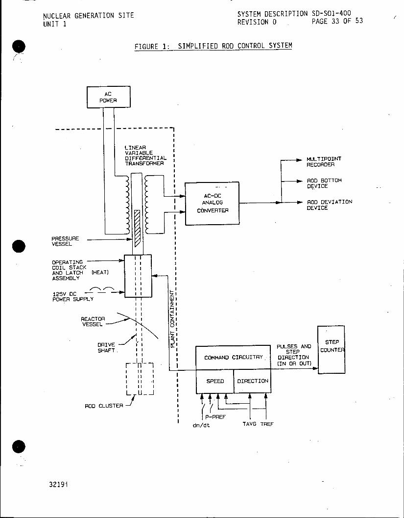
NUCLEAR GENERATION SITE SYSTEM DESCRIPTION SD-SO1-400
UNIT 1 REVISION 0 PAGE 33 OF 53
S)FIGURE 1: SIMPLIFIED ROD CONTROL SYSTEM
AC POWER
-------------------- -----------
LINEAR VARIABLE DIFFERENTIAL __ MULTIPOINT TRANSFORMER RECORDER
I ____--___ROD BOTTOM
DEVICE
AC-OC
ANALOG ROD DEVIATION
CONVERTER DEVICE
PRESSURE VESSEL
OPERATING s COIL STACK I AND LATCH (HEAT) I ASSEMBLY
125V DC --- I POWER SUPPLY lI
III III
REACTOR I Z: VESSEL 1 0r
II I t. SE
DRIVE II PULSES AND SHAFT- 1STEP COUNTEF
COMMAND CIRCUITRY. DIRECTION
Fr- I (IN OR OUT) I I
SPEED DIRECTION
L U -J
ROO CLUSTER I
I IP-PREF
dn/dt TAVG TREF
3219i

NUCLEAR GENERATION SITE SYSTEM DESCRIPTION SD-SOI-400 UNIT 1 REVISION 0 PAGE 34 OF 53
FIGURE 2: CONTROL ROD DRIVE MECHANISM
GUIDE TUBE
LIFT COIL
LIFT POLE FLUX RING F RING
MOVABLE ARMATURE RETURN * SPRING FLUX RING
LIFT * ARMATURE
MOVABLEM GRIPPERG COIL *
LATCH
* MO BLEMOVABLE LATCH LINK MOVABLE
GRIPPER ARMATURE (SHOWN CLOSED)
FLUX RING STATIONARY GRIPPER POLE
STATIONARY GRIPPER COIL STATIONARY
ARMATURE RETURN SPRING
LATCH RETURN SPRING FLUX RING (FOR LOAD TRANSFER)
STATIONARY STATIONARY GRIPPER LATCH ARMATURE LINK
STATIONARY GRIPPER LATCH
DRIVE ROD
3219i
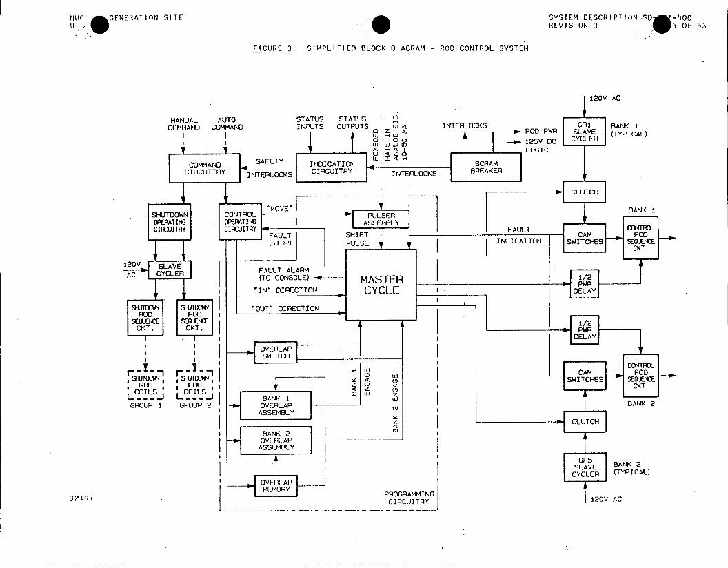
140r GENERATION SITE SYSTEM DESCRIPTION 0 -1100 REVISION 0 5OF 53
FIGURE 3: SIMPLIFIED BLOCK DIAGRAM - ROD CONTROL SYSTEM
120V AC
MANUAL AUTO STATUS STATUS COMMAND COMMAND INPUTS OUTPUTS 4 INTERLOCKS GR1 BANK I
|0 ROO PWR SLAVE (TYPICAL) G oo 125V DC CYCLER
I J x I o LOGIC
COMMAND SAFETY IINDICATION : C SCRAM CIRCUITRY INTERLOCKS CIRCUITRY INTERLOCKS BREAKER
INTER b CLUTCH
"MOVE"I BANK 1 SHUTDOWNI CONTROL * PULSER OPERATING OPERATING ASSEMBLY CIRCUITRY CIRCUITRY F FAULT CONTROL
FAULT SHIFT CAM _q ROD (STOP) PULSE .. INDICATION SWITCHES SEGUENCE
120V SLAV I ICKT.
AC CACLER FAULT ALARM (To CONSOLE) MASTER 1/2 >PWF
"IN' DIRECTION CY'CLE DELAY
SDRADOWN) "OUT" DIRECTION ROD R00
SEF SENC 1/2 CKT CK.a PWR
;& DELAY
SMDOW <-n :I -SWIT~CHES SEROENCE ROD ODf z 0 <CK
COIS<CILS0 ---- - - BANK 1 Zj GROUP I GROUP 2 - OVERLAP ------ BANK 2
ASSEMBLY >CLUTCH
BANK 2 mn -OVERLAP
ASSE-MBLY
SGR5E BANK 2
31'1 i POGRAMINGCYCLER
(TYPICAL)
3219iCICTR 1120V AC
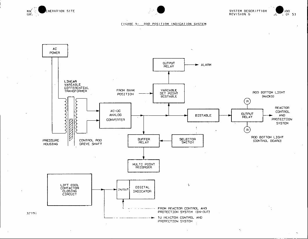
NU1 ENERATION SITE SYSTEM DESCRIPTION * 100 UN REVISION 0 t OF 53
FIGURE ': ROD POSITION INDICATION SYSTEM
AC POWER
OUTPUT ALARM RELAY
LINEAR VARIABLE DIFFERENTIAL TRANSFORMER FROM BANK VARIABLE ROD BOTTOM LIGHT
POSITION STPITRDBTO IH BISTABLE (RACKS)
REACTOR AC-DC CONTROL ANALOG I - BISTABLE -UTPUT AND
7 CONVERTER R PROTECTION SYSTEM
/ ROD BOTTOM LIGHT PRESSURE CONTROL ROD BUFFER SELECTOR (CONTROL BOARD) HOUSING DRIVE SHAFT RELAY SITCH
MULTI POINT RECORDER
LIFT COIL CONTACTOR I IN/OUT DIGITAL CLOSING INDICATOR CIRCUIT
FROM REACTOR CONTROL AND
3?19i PROTECTION SYSTEM (IN-OUT)
----- TO REACTOR CONTROL AND PROTECTION SYSTEM

NUCLEAR GENERATION SITE SYSTEM DESCRIPTION SD-SO1-400 UNIT I REVISION 0 PAGE 37 OF 53
FIGURE 5: ROD CONTROL PROGRAM
ROD SPEED 15
(INCHES/MIN.) - 14
13
12
11
10
-9
-- 8
-- 7
-- 6
-- 5
4
-- 3
-2
12 11 10 9 8 7 6 5 4 3 2 1 1 2 3 4 5 6 7 8 9 10 11 12
NEGATIVE ERROR (TAVG<TREF) POSITIVE ERROR (TAVG>TREF)
3219i

N E OS .SYSTEM DESCRIPTION Sr 0 N *ERATION SIrEF
FIGURE 7: SIMPLIFIED SHUTOOWN GROUP CONTROL CIRCUIT
CLOSED WHEN GROUP CLOSED SELECTOR SWITCH AT INDEX B
cc IN GROUP I OR 2 T (B) (6) AND PULLED OUT
C CLWT SWTCH s.iIT Hr S HIN GROUP. I
AND PULLED A DPULLED CU GOU GOT'
2G1 SG1E
I >~ "~L I ITCH (9)IT
3( 21)
I 1G1 .1 -6 (10))
3Z19i
NUCLEAR GENERATION SITE SYSTEM DESCRIPTION SD-S01-400 UNIT 1 REVISION 0 PAGE 45 OF 53
APPENDIX A
PHYSICAL ARRANGEMENT AND CONTROL HARDWARE IN 4KV ROOM
Breaker Cabinet, BA
1. Scram Breakers A & B
a. Switchgear
b. Control Relays
Shutdown Rod Unit, SA & SB
1. Sequencing Circuitry
a. DC Contactors d. Resistor Banks
b. AC Relays e. Rod Coil Fuses
c. Disconnect Switches f. System Fuses
2.- Cabinet SA - Group 1 Shutdown Control Switchgear.
3. Cabinet SB - Group 2 Shutdown Control Switchgear.
Suppressor Unit, UA and UB
1 I. Surge suppression of Control and Shutdown Control.Rod Drive Mechanism Coils.
2. Suppressor Cabinet UA - Line Step-down Transformer, Diode Ass'ys, Volt Traps.
3. Suppressor Cabinet UB - Diode Ass'ys and VoltzTraps.
Control Rod Unit, CA, CB, CC, CD
1. Sequencing Circuitry
a. DC Contactors d. Disconnects
b. DC Relays e. Resistor Banks
c. DC Timers f. Rod Coil Fuses
g. System Fuses
2. Control Cabinet CA - Sub-group 1 & 2 Control Rod Switchgear.
3. Control Cabinet CB - Sub-group 3 & 4 Control Rod Switchgear.
4. Control Cabinet CC - Sub-group 5 & 6 Control Rod Switchgear.
5. Control Cabinet CD - Sub-group 7 & 8 Control Rod Switchgear.
A-1

NUCLEAR GENERATION SITE SYSTEM DESCRIPTION SD-SO1-400 UNIT 1 REVISION 0 PAGE 46 OF 53
APPENDIX A
PHYSICAL ARRANGEMENT AND CONTROL HARDWARE IN 4KV ROOM (Continued)
Cycler Unit
1. Cabinets YA & YB
a. Command Control
b. Control Group Rod Sequencing
c. Slave Cycler Motor Circuitry
d. Fault Detection Circuitry
e. Cycler Removal Circuitry
f. Overlap Memory
2. Cabinet YA
a. AC & DC Control Relays
b. Slave Cyclers Group 1 thru 4
c. Shutdown Group Cycler Assembly
d. Fuses
e. Cycler Removal Indications and Switches
f. Test points
3. Cabinet YB
a. AC & DC Control Relays
b. Slave Cyclers Group 5 thru 8
c. Fuses
d. Cycler Removal Indications and Switches
e. Test points
f. Auxiliary Cable (Cycler Removal)
A-2

NUCLEAR GENERATION SITE SYSTEM DESCRIPTION SD-SO1-400 UNIT 1 REVISION 0 PAGE 47 OF 53
- APPENDIX A
PHYSICAL ARRANGEMENT AND CONTROL HARDWARE IN 4KV ROOM (Continued)
Logic Unit
1. Cabinets LA, LB
a. Command Control
b. Indication
c. Programming
d. Fault Detection
e. Overlap Memory
2. Logic Unit consists of:
a. AC and DC Control Relays
b. Pulse Generator
c. Master Cycler Assemblies
d. DC Power Supplies
3219i A-3

NUCLEAR GENERATION SITE SYSTEM DESCRIPTION SD-SO1-400 UNIT 1 REVISION 0 PAGE 48 OF 53
APPENDIX B
LOCAL ROD CONTROLS
CONTROL LOCATION FUNCTION
Overlap Control Switch Logic Cabinet LA Select both Control Banks or
(OC) individual Control Bank operation
Manual Set-In Overlap Control Assembly Initially set the Overlap Circuitry '
(Logic Cabinet LA) to the correct start count (In direction)
Manual Set-Out Overlap Control Assembly Initially set the Overlap Circuitry (Logic Cabinet LA) to the correct start count (Out
direction)
Bank Trip Overlap Control Assembly Allows Control Bank engagement at
(Thumbwheel SW) (Logic Cabinet LA) any count from 1 through 999
Manual Reset Master Cycler Manually resets the Master Cycler (Logic'Cabinet LA) to start counting at GRI and GR5
Count Preset Master Cycler Advances the count in the Master (Logic Cabinet LA) Cycler by one for each actuation
of the switch
Alarm Reset Master Cycler Resets the alarm memory internal (Logic Cabinet LA) to the Master Cycler
Cycler Removal Cycler Cabinet YA & YB To remove faulty cycler from the Switches system
Lift Coil Disconnect Shutdown Cabinets SA & Permit disconnection of Lift Coils Switches SB, Control Cabinets from circuit during maintenance or
CA, CB, CC & CD rod adjustment operation
3219i B-1

NUCLEAR GENERATION SITE SYSTEM DESCRIPTION SD-SO1-400 UNIT 1 REVISION 0 PAGE 49 OF 53
I APPENDIX C
ANNUNCIATORS
Reactor Plant No. 2 Annunciator
| WINDOW NAME INPUT SETPOINT (NUMBER)
Rod Position Deviation I RDX-1 + 25 steps | Cont. Bk. 1 (10)
| Shutdown Margin Bank 1 Lo YC-406A-X 309 steps I (11)
Shutdown Margin Bank 2 Lo YC-404A-X | variable (12)
Rod Withdrawal Bank 2 Hi | YA-404B-X 310 steps (13)
Rod Position Deviation RDX-2 ± 25 steps Cont. Bk. 2 (30)
* Rod Position Rod Bottomed CBX-1-1, 1-2, 2-1, Rod on Bottom (31) 2-2; SDX-1-1, 2-1
Shutdown Rods Not RDX-3 300 steps Withdrawn (50)
Rod Position Rack Blower YC-R8, YC-R9 Vane Switches Malfunction (70) Lo Flow
Rod Drive Slave Cycler K-111 Cycler not Failure Rod Stop (71) . at Home
Reac Trip Breaker Power UXA, UXB < 100 VDC Failure (72)
C-1
NUCLEAR GENERATION SITE SYSTEM DESCRIPTION SD-SO1-400 UNIT 1 REVISION 0 PAGE 50 OF 53
APPENDIX C
ANNUNCIATORS (Continued)
Permissive Information Display Annunciator
WINDOW NAME | INPUT SETPOINT
(NUMBER)
Automatic Rod Control . QC-415B-X P-2, > 15% Power Blocked Lo Power (7)
Auto Rod Withdrawal Not AP3A & B Auto Rod WithReset (8) | "b" contacts drawal Prohibit
Circuit Not Resetl
Rod Group Selector.Switch Group Selector Switch Group Selector Not in Auto (11) Contact Swith Not in Auto!
I Shutdown Margin Bank 1 YC-406B-X 288 steps Low-Low (27)
Shutdown Margin Bank 2 YC-404B-X . Variable
* Low-Low (28) 1
3219i C-2

NUCLEAR GENERATION SITE SYSTEM DESCRIPTION SD-SO1-400 UNIT 1 REVISION 0 PAGE 51 OF 53
APPENDIX D
DEVELOPMENTAL RESOURCES
Elementaries
5150410 Reactor Scram Breakers N1542 Sheet 102
5112259 Reactor Protection System Scrams N1542 Sheet 102A
5150411 Control Rod Drive and Direction Auxiliary Relays Rod Position and Counter Relays N1542 Sheet 103
5150624 Control Rod Drive System Sheet 1 N1542 Sheet 103A
5150625 Control Rod Drive System Sheet 2 -N1542 Sheet 103B
448597 Rod Position Chassis N1542 Sheet 103C
5107776 Control Rod - Permissive Circuitry N1542 Sheet 104
5107777 Control Rod - Indicating Circuitry N1542 Sheet 106
5151821 Control Rod - Programming Circuitry I N1542 Sheet 107
5151822 Control Rod - Programming Circuitry II N1542 Sheet 108
5107778 Control Rod - Programming Circuitry III N1542 Sheet 109
5151823 Control Slave Cycler Circuitry" N1542 Sheet 110
5151824 Control Rod - Sequencing I N1542 Sheet 111
5107779 Control Rod - Sequencing II N1542 Sheet 112
5107780 Control Rod - Sequencing III N1542 Sheet 113
D-1
NUCLEAR GENERATION SITE SYSTEM DESCRIPTION SD-S01-400 UNIT 1 REVISION 0 PAGE 52 OF 53
APPENDIX D
DEVELOPMENTAL RESOURCES (Continued)
Elementaries (Continued)
5151825 Control Rod - Sequencing IV N1542 Sheet 114
5107781 -Control Rod - Sequencing V N1542 Sheet 215
5107782 Control Rod - Sequencing VI N1542 Sheet 216
5107783 Shutdown Rod - Seqeuncing Circuitry I N1542 Sheet 217
5107784 Shutdown Rod - Seqeuncing Circuitry II N1542 Sheet 118
Technical Manuals
Westinghouse, Rod Control System
Westinghouse, Control Rod Drive Mechanism
Procedures
S01-2.3-1, Control Rod System Malfunctions
S01-3-1, Plant Startup from Cold Shutdown to Hot Standby
SO1-3-2, Plant Startup from Hot Standby to Minimum Load
S01-3-3, Plant Operation from Minimum Load to Full Power
S01-3-4, Plant Shutdown from Full Power to Hot Standby
501-3-5, Plant Shutdown from Hot Standby to Cold Shutdown.
S01-4-35, Control Rod Drive System
S01-12.1-5, Control Rod Position Verification
S01-12.3-24, Monthly Control Rod Exercises
S01-13-3, Reactor Plant No. 2 Annunciator
S01-13-5, Permissive Information Display Annunicator
501-13-6, Reactor Plant First-Out Annunciator
D-2
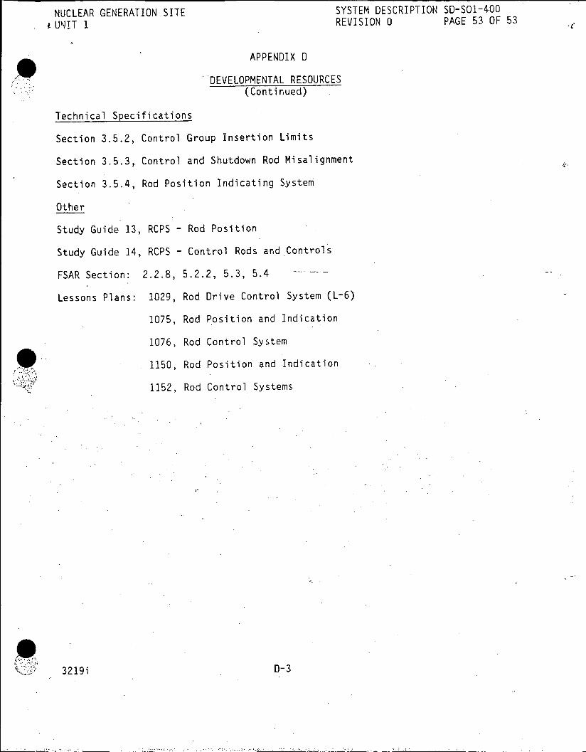
NUCLEAR GENERATION SITE SYSTEM DESCRIPTION SD-SO1-400
. UNIT 1 REVISION 0 PAGE 53 OF 53
APPENDIX D
DEVELOPMENTAL RESOURCES (Continued)
Technical Specifications
Section 3.5.2, Control Group Insertion Limits
Section 3.5.3, Control and Shutdown Rod Misalignment
Section 3.5.4, Rod Position Indicating System
Other
Study Guide 13, RCPS - Rod Position
Study Guide 14, RCPS - Control Rods and Controls
FSAR Section: 2.2.8, 5.2.2, 5.3, 5.4
Lessons Plans: 1029, Rod Drive Control System (L-6)
1075, Rod Position and Indication
1076, Rod Control System
1150, Rod Position and Indication
1152, Rod Control Systems
3219i 0-3

NUCLEAR GENERAQ-SITE -' TE" DS"RI"'N )157v UNIT 1 REVISION 0 PAGE 1 OF 37
DEC10 1985 CDM
REACTOR PROTECTION SYSTEM AND PERMISSIVES
TABLE OF CONTENTS
SECTION PAGE
1.0 FUNCTIONS/DESIGN BASES 2
2.0 DESCRIPTION 3 2.1 System Overview 3 2.2 Components 5 2.3 Reactor Trips Detailed Control Scheme 6 2.4 Permissives Detailed Control Scheme 16 2.5 Power Supplies 23
3.0 OPERATION RECEIVED CDM 23
4.0 REFERENCES DEC 10 1985 24 4.1 P&IDs 24 4.2 Elementaries SITE FILE COPY 24 4.3 Technical Manuals 25 4.4 Procedures 25 4.5 Technical Specifications 25
FIGURES. 1 Reactor Protection System, Sheet 1 26 1 Reactor Protection System, Sheet 2 27 2 Permissive Logic Circuits 28 3 Permissive P-7 29
APPENDICES A Annunciators 30 B Developmental Resources 35
This System Description is approved per S0123-0-44, System Description Revision and Approval. Contact CDM to verify revision information.
PREPARED BY: 2?ik 5 ho Date
APPROVED BY: Map r, ratios e 3199i
NUCLEAR GENERATION SITE SYSTEM DESCRIPTION SD-SO1-570 UNIT 1 REVISION 0 PAGE 2 OF 37
REACTOR PROTECTION SYSTEM AND PERMISSIVES
1.0 FUNCTIONS/DESIGN BASES
1.1 The Reactor Protection System (RPS) has the following main functions:
1.1.1 The RPS monitors the primary and secondary plant for abnormal conditions and alerts the operator, where possible, to take corrective actions to prevent a Reactor Trip.
1.1.2 The RPS provides Reactor Trip functions to protect the Core against Departure from Nucleate Boiling (DNB), and to protect the Reactor Coolant System (RCS) against overpressurization.
1.2 The Reactor Protection System has-the following Design Basis:
1.2.1 The Reactor Protection System is designed to maintain the Reactor Coolant System integrity and to prevent the release of excessive fission products to the Reactor Coolant by automatically tripping the Reactor prior to exceeding any Safety Limits.
1.2.2 The Reactor Protection System is designed with Manual Reactor Trip capabilities.
1.3 The Permissives have the following main function:
1.3.1 The main function of the Permissives is to provide compatibility between control systems, increase reliability and equipment protection.

NUCLEAR GENERATION SITE SYSTEM DESCRIPTION SD-SO1-570 UNIT 1 REVISION 0 PAGE 3 OF 37
REACTOR PROTECTION SYSTEM AND PERMISSIVES
2.0 DESCRIPTION
2.1 System Overview
2.1.1 Reactor Protection System Description (Figure 1, Sheets 1 and 2).
The two Reactor Scram Breakers supply 125 VDC power to the Control Rod Drive Mechanisms and are opened by the Reactor Protection System. Opening either of the Reactor Scram Breakers interrupts the 125 VDC supply to the Control Rod Drive Mechanisms allowing the Control Rods drop into the Core.
The Reactor Protection System monitors various nuclear and non-nuclear parameters to anticipate and prevent exceeding plant design limits by limiting the plant transients.
The monitored inputs to the Reactor Protection System are:
1. Reactor Power (Intermediate and Power Ranges) 2. Pressurizer Pressure 3. Pressurizer Level 4. Reactor Coolant Flow 5. Reactor Coolant Pump Breaker Positions 6. Reactor Coolant System AT 7. Reactor Coolant System Taverage 8. Feedwater Flow 9. Main Steam Flow 10. Safeguard Load Sequencing System 11. Turbine Auto Stop Oil Pressure 12. Bus IC & 2C Voltage 13. 125 VDC Bus 1 Voltage (Undervoltage Coils only)
The manual inputs to the Reactor Protection System are:
1. Manual Reactor Trip Pushbuttons 2. Unit .Trip Pushbutton via the Turbine Trip
The Reactor Protection System is designed to be fully functional with a certain number.of monitored instrumentation channels in Test or Out-of-Service.
2.1.2 Permissive Description (Figure 2)
The Permissives monitor various nuclear and non-nuclear parameters to block and unblock various controls, and to cause annunciation of the Permissives.
The Permissives provide compatibility between the control systems, increased reliability and equipment protection.

NUCLEAR GENERATION SITE SYSTEM DESCRIPTION SD-SO1-570 ,UNIT 1 REVISION 0 PAGE 4 OF 37
REACTOR PROTECTION SYSTEM AND PERMISSIVES
2.0 DESCRIPTIONS (Continued)
2.1.2 Permissive Description (Figure 2) (Continued)
The inputs to the Permissives are:
1. Reactor Power (Source, Intermidiate and Power Ranges)
2. Main -Turbine First Stage Pressure
3. Analog Rod Position Indication
4. RCS Taverage and AT
The outputs of the Permissives are:
.1 Block Auto and/or Manual Control Rod withdrawal
.2 Block and unblock various Reactor Trips
.3 Block and unblock Automatic Steam Dump Control
.4 Annunciate Shutdown Margin Alarms
2.2.3 General Control Scheme
The Reactor Protection System normally functions as a 1 out of 2, 2 out of 3, or 2 out of 4 logic system. This arrangement provides a high degree of reliability because a single component failure will not cause a trip, or prevent a trip from occurring.
Examples: If the parameter has two inputs to the Logic Matrices, then one input exceeding the setpoint will cause the Scram Breakers to open (denoted 1/2 Logic).
If the parameters has three inputs to the Logic Matrices, then two inputs exceeding the setpoint will cause the Scram Breakers to open (denoted 2/3 Logic).
If the parameter has four inputs to the Logic Matrices, then two inputs exceeding the setpoint will cause the Scram Breakers to open (denoted 2/4 Logic).
In order to provide a high degree of reliability that the Reactor will trip when required, the Reactor Protection System operates both the Shunt Trip Circuit and the Undervoltage.Trip Circuit of both Scram Breakers.
The Shunt Trip Circuit is an energize-to-trip circuit which means an input signal -exceeding its setpoint will close a contact in the Logic Matrix. When the logic for that parameter is satisfied, the Shunt Trip Coil is energized and the Scram Breaker opens.

NUCLEAR GENERATION SITE SYSTEM DESCRIPTION SD-S01-570 UWIT 1 REVISION 0 PAGE 5 OF 37
REACTOR PROTECTION SYSTEM AND PERMISSIVES
2.0 DESCRIPTIONS (Continued)
2.1.3 General Control Scheme (Continued)
The Undervoltage Trip Circuit is a de-energize-to-trip circuit which means an input signal exceeding its setpoint will open a contact in the Logic Matrix. When the logic for that parameter is satisfied, the Undervoltage Coil is de-energized and the Scram Breaker.opens.
De-energizing the Undervoltage Coil also closes a contact in the Shunt Trip Circuit, energizing the Shunt Trip Coil.
2.2 Components
2.2.1 Reactor Scram Breakers
The two Reactor Scram Breakers are 125 VDC, Westinghouse type DB-50 breakers. Each breaker is equipped with two independent trip mechanisms; a Shunt Trip Coil and an Undervoltage Trip Coil.
Both breakers are closed from the Main Control Room by the Reactor Trip Reset pushbutton located on the J-Console below the Nuclear Power Recorder NRL-1201. Depressing the button energizes the X Coil of each breaker which in turn energizes the Closing Coil of each breaker. Energizing the Closing Coil causes the Trip Lever to be latched against spring pressure, thus keeping the breakers closed.
Both breakers are opened by either energizing the Shunt Trip Coil or de-energizing the Undervoltage Coil of each breaker. Energizing the Shunt Trip Coil or de-energizing the Undervoltage Coil causes the Trip Lever to release, allowing spring pressure to open the breakers.
The Scram Breakers are automatically opened by various Reactor Trip signals, as discussed in Section 2.3.
The Scram Breakers can be manually opened from the Main Control Room by depressing either of two Reactor Trip pushbuttons. One pushbutton is located on the J-Console above the Rod Position Recorder YR-404, the other pushbutton is located on the North Vertical Board above the Nuclear Power Recorder NRL-1201.
The Scram Breakers can also be manually opened from the Main Control Room by depressing the Unit Trip pushbutton. The Unit Trip pushbutton is located on the J-Console above the Governor Valve Position indicators.
Each Scram Breaker can be manually opened locally at the breaker.
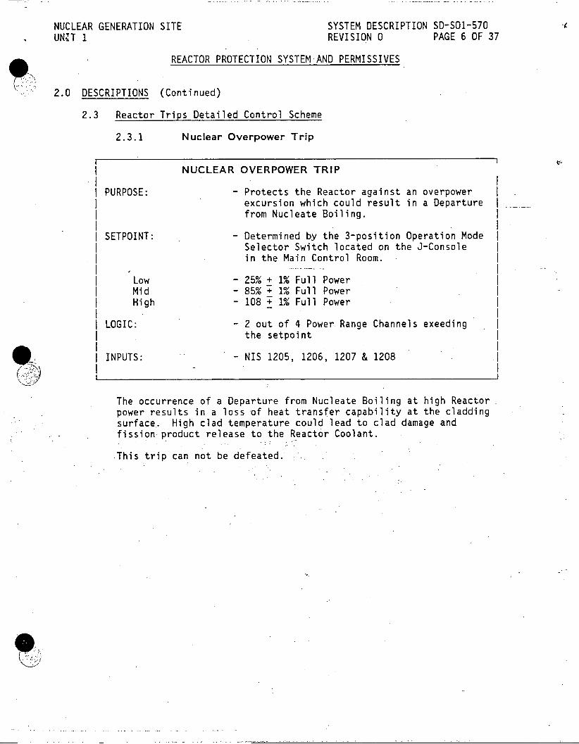
NUCLEAR GENERATION SITE SYSTEM DESCRIPTION SD-SO1-570 UNUT 1 REVISION 0 PAGE 6 OF 37
REACTOR PROTECTION SYSTEM AND PERMISSIVES
2.0 DESCRIPTIONS (Continued)
2.3 Reactor Trips Detailed Control Scheme
2.3.1 Nuclear Overpower Trip
NUCLEAR OVERPOWER TRIP
PURPOSE: - Protects the Reactor against an overpower excursion which could result in a Departure from Nucleate Boiling.
| SETPOINT: - Determined by the 3-position Operation Mode Selector Switch located on the J-Console in the Main Control Room.
| Low - 25% + 1% Full Power | Mid - 85% + 1% Full Power I High - 108 + 1% Full Power
I LOGIC: - 2 out of 4 Power Range Channels exeeding the setpoint
| INPUTS: - NIS 1205, 1206, 1207 & 1208
The occurrence of a Departure from Nucleate Boiling at high Reactor power results in a loss of heat transfer capability at the cladding surface.. High clad temperature could lead to clad damage and fission product release.to the Reactor Coolant.
This trip can not be defeated.
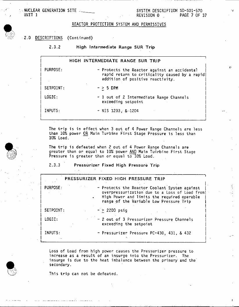
NUCLEAR GENERATION SITE SYSTEM DESCRIPTION SD-SO1-570 UNIT 1 REVISION 0 PAGE 7 OF 37
REACTOR PROTECTION SYSTEM AND PERMISSIVES
2 0 DESCRIPTIONS (Continued)
2.3.2 High Intermediate Range SUR Trip
HIGH INTERMEDIATE RANGE SUR TRIP
PURPOSE: - Protects the Reactor against an accidental | rapid return to criticality caused by a rapidi addition of positive reactivity.
I SETPOINT: - > 5 DPM
| LOGIC: - I out of 2 Intermediate Range Channels exceeding setpoint
| INPUTS: - NIS 1203, &--1204
I I
The trip is in effect when 3 out of 4 Power Range Channels are less than 10% power OR Main Turbine First Stage Pressure is less than 10% Load.
The trip is defeated when 2 out of 4 Power Range Channels are greater than or equal to 10% power AND Main Tuirbine First Stage Pressure is greater than or equal to 10% Load.
2.3.3 Pressurizer Fixed High Pressure Trip
PRESSURIZER FIXED HIGH PRESSURE TRIP
PURPOSE: - Protects the Reactor Coolant System against overpressurization due to a Loss of Load froml High Power and limits the required operable range of the Variable Low Pressure Trip
SETPOINT: - > 2200 psig
LOGIC: - 2 out of 3 Pressurizer Pressure Channels exceeding the setpoint
INPUTS: - Pressurizer Pressure PC-430, 431, & 432 j
Loss of Load from high power causes the Pressurizer pressure to increase as a result of an insurge into the Pressurizer. The insurge is due to the heat imbalance between the primary and the secondary.
This trip can not be defeated.

NUCLEAR GENERATION SITE SYSTEM DESCRIPTION SD-SO1-570 UNIT 1 REVISION 0 PAGE 8 OF 37
9 REACTOR PROTECTION SYSTEM AND PERMISSIVES
2.0 DESCRIPTIONS (Continued)
2.3.4 High Pressurizer Level Trip
HIGH PRESSURIZER LEVEL TRIP
| PURPOSE: - Protects the Reactor Coolant System against overpressurization due to a Loss of Load from High Power
| SETPOINT: - > 70% Pressurizer Level (27.3 feet)
| LOGIC: - 2 out of 3 Pressurizer Level Channels exceeding the setpoint
INPUTS: - Pressurizer-Level LC-430, 431, & 432
Loss of Load from high power causes an insurge into the Pressurizer due to the increase in Reactor Coolant System temperature.
This trip can not be defeated.
)l
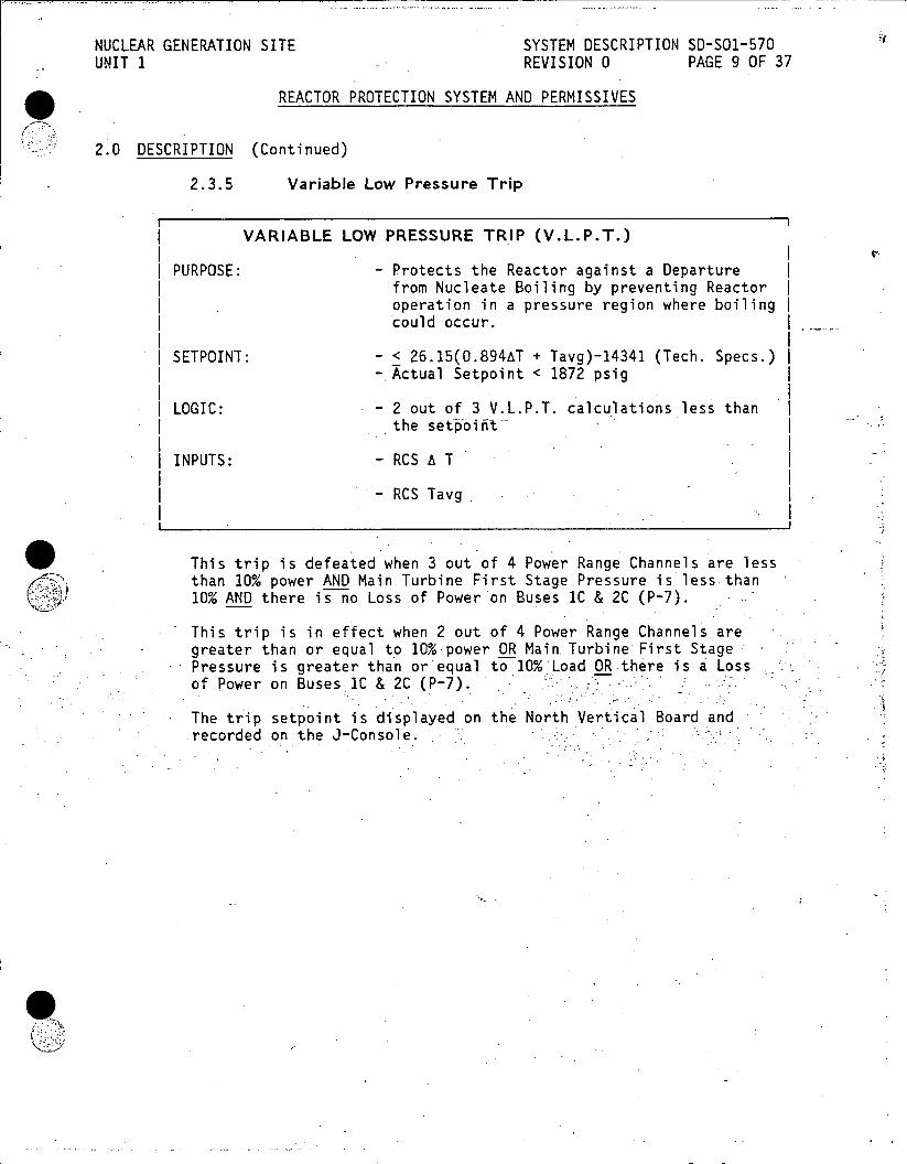
NUCLEAR GENERATION SITE SYSTEM DESCRIPTION SD-SO1-570 UNIT 1 REVISION 0 PAGE 9 OF 37
REACTOR PROTECTION SYSTEM AND PERMISSIVES
2.0 DESCRIPTION (Continued)
2.3.5 Variable Low Pressure Trip
VARIABLE LOW PRESSURE TRIP (V.L.P.T.)
PURPOSE: - Protects the Reactor against a Departure | from Nucleate Boiling by preventing Reactor I operation in a pressure region where boiling | could occur.
SETPOINT: - < 26.15(0.894AT + Tavg)-14341 (Tech. Specs.) -.Actual Setpoint < 1872 psig
LOGIC: * 2 out of 3 V.L.P.T. calculations less than the set'obift
INPUTS: -RCSAT . I
- RCS Tavg
'This trip is defeated when 3 out of 4 Power Range Channels are less than 10% power AND Main Turbine First Stage Pressure is less than 10% AND there is no Loss of Power on Buses IC & 2C (P-7).
This trip is in effect when 2 out of 4 Power Range Channels are greater than or equal to.10% power OR Main.Turbine' First Stage Pressure is greater than or equal to 10% Load OR there is a Loss of Power on Buses 1C & 2C (P-7).
The trip setpoint is displayed on the North Vertical Board and recorded on the J-Console.

NUCLEAR GENERATION SITE SYSTEM DESCRIPTION SD-S01-570 UNIT 1 REVISION 0 PAGE 10 OF 37
REACTOR PROTECTION SYSTEM AND PERMISSIVES
2.0 DESCRIPTION (Continued)
2.3.6 Loss of Flow Reactor Trips
SINGLE LOOP LOSS OF FLOW TRIP
PURPOSE: - Protects the Reactor against a Departure from Nucleate Boiling due to the increase in RCS temperature as a result of the reduced RCS Flow.
SETPOINT: - < 85% RCS Loop Flow OR
- RCP Breaker Open position
LOGIC: - 1 out of 3 1RCS Flow Channels less than the setpoint
OR - 1 out of 3 RCP Breakers Open
INPUTS: - RCS FC-400, 410, & 420
- RCP "A", "B" & "C" 152b Breaker contacts
This trip is defeated when 3 out of 4 Power Range Channels are less than 50% power AND Main Turbine First Stage Pressure is less than 50% Load.
This trip is in effect when 2 out of 4 Power Range Channels are greater than or equal to 50% power OR Main Turbine First Stage Pressure is greater than or equal .to 50% Load.

NUCLEAR GENERATION SITE SYSTEM DESCRIPTION SD-S01-570 UNT 1 REVISION 0 PAGE 11 OF 37
REACTOR PROTECTION SYSTEM AND PERMISSIVES
2.0 DESCRIPTION (Continued)
2.3.6 Loss of Flow Reactor Trips (Continued)
TWO LOOP LOSS OF FLOW TRIP
PURPOSE: - Protects the Reactor against a Departure from Nucleate Boiling due to the increase in RCS temperature as a result of the reduced RCS Flow.
SETPOINT: - < 85% RCS Loop Flow OR
- RCP Breakers Open position
LOGIC: - 2 out of 3 RCS Flow Channels less than the setpoint
OR 2 out of 3 RCP Breakers Open
INPUTS: - RCS FC-400, 410, & 420
- RCP "A", "B" & "C" 152b Breaker contacts
This trip is defeated when 3 out of 4 Power Range Channels are less than 10% power AND Main Turbine First -Stage pressure is less than 10% AND there is no Loss of Power on Buses IC & 2C (P-7).
This trip is in effect when 2 out of 4 Power Range Channels are greater than or equal to 10% power OR Main Turbine First Stage Pressure is greater than or equal to 10% Load OR there is a Loss of Power on Buses IC & 2C (P-7).
2.3.7 Feedwater Flow/Steam Flow Mismatch Trip
| FEEDWATER FLOW/STEAM FLOW MISMATCH TRIP
| PURPOSE: - Anticipatory trip that protects the Reactor against a Feedwater Line or Steam Line break
| SETPOINT: -'Feedwater Flow less than Steam Flow by 25% of Full Load value
LOGIC: - 2 out of 3 Mismatch Channels exceeding the setpoint
INPUTS: - FM-456Bx, 457Bx & 458Bx
This trip can not be defeated.
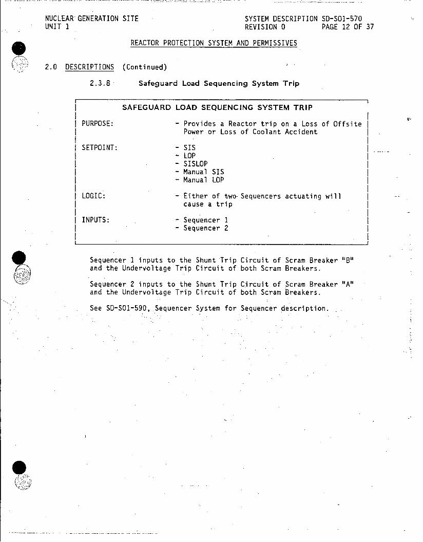
NUCLEAR GENERATION SITE SYSTEM DESCRIPTION SD-SO1-570 U.NIT 1 REVISION 0 PAGE 12 OF 37
REACTOR PROTECTION SYSTEM AND PERMISSIVES
2.0 DESCRIPTIONS (Continued)
2.3.8 Safeguard Load Sequencing System Trip
| SAFEGUARD LOAD SEQUENCING SYSTEM TRIP
I PURPOSE: - Provides a Reactor trip on a Loss of Offsite Power or Loss of Coolant Accident
SETPOINT: - SIS - LOP
- SISLOP - Manual SIS - Manual LOP
LOGIC: - Either of two-Sequencers actuating will cause a trip
I INPUTS: - Sequencer I - Sequencer 2
Sequencer 1 inputs to the Shunt Trip Circuit of Scram Breaker "B" and the Undervoltage Trip Circuit of both Scram Breakers.
Sequencer 2 inputs to the Shunt Trip Circuit of Scram Breaker "A" and the Undervoltage Trip Circuit of both Scram Breakers.
See SD-S01-590, Sequencer System for Sequencer description.

NUCLEAR GENERATION SITE - SYSTEM DESCRIPTION SD-S01-570 UNIT 1 REVISION 0 PAGE 13 OF 37
REACTOR PROTECTION SYSTEM AND PERMISSIVES
2.0 DESCRIPTION (Continued)
2.3.9 Turbine Trip/Reactor Trip
TURBINE TRIP
I PURPOSE: - Provides a Reactor Trip when power is > 10% to protect the Reactor against a Loss of Heat Sink Accident
SETPOINT: - < 45 psig Auto Stop Oil Pressure
LOGIC: - 2 out of 3 Auto Stop Oil Pressure Channels less than the setpoint
INPUTS: - AST-63-X1, X2 & X3
IJ
If the Reactor did not trip the resultant increase in RCS temperature could result in a Departure from Nucleate Boiling.
This trip is defeated when 3 out of 4 Power Range Channels are less than 10% power AND Main Turbine First Stage Pressure is less than 10% AND there is no Loss of Power on Buses 1C & 2C (P-7).
This trip is in effect when 2 out of 4 Power Range Channels are greater than or equal to 10% power OR Main Turbine First Stage Pressure is greater than or equal to 10% Load OR there is a Loss of Power on Buses IC & 2C (P-7).
01

NUCLEAR GENERATION SITE SYSTEM DESCRIPTION SD-SO1-570 UNIT1 REVISION 0 PAGE 14 OF 37
REACTOR PROTECTION SYSTEM AND PERMISSIVES
2.0 DESCRIPTIONS (Continued)
2.3.10 Loss of 125 VDC Bus 1 Voltage Trip
LOSS OF 125 VDC BUS 1 VOLTAGE TRIP
PURPOSE: - Anticipatory trip that protects the Reactor I against Departure from Nucleate Boiling due | to Flux Tilts resulting from Control Rods I indiscriminately dropping into the Reactor I as voltage decreases.
SETPOINT: - < 100 VDC (De-energize Under voltage coils only)
LOGIC: - 1 out of I
INPUTS: - 125 VDC Bus Voltage
A minimum voltage of 102 VDC is required to hold the Control Rods and a minimum voltage of 112.5 VDC is required to move the Control Rods.
2.3.11 Manual Trip
MANUAL TRIP
PURPOSE: - Allows the Operator to manually open the Scram Breakers any time the rods are desired in the Core or in anticipation of an automatic trip and as a backup to the automatic trip.
I I SETPOINT: - Depressing either of the two Reactor Trip
Pushbuttons
LOGIC: - 1 out of 2
INPUTS: - Reactor Trip Pushbuttons
Active any time the Scram Breakers are closed.
4lit

NUCLEAR GENERATION SITE SYSTEM DESCRIPTION SD-SO1-570 UNIT 1 REVISION 0 PAGE 15 OF 37
REACTOR PROTECTION SYSTEM AND PERMISSIVES
2.0 DESCRIPTIONS (Continued)
2.3.12 Unit Trip
UNIT TRIP
PURPOSE: - Allows the Operator to manually trip the Generator Output Breakers and Turbine which in turn trips the Reactor.
SETPOINT: - Depressing the Unit Trip Pushbutton
LOGIC: - 1 out of 1
INPUTS: - Unit Trip Pushbuttons
The Unit Trip pushbutton trips the Turbine which in turn trips the Reactor via the low Auto Stop Oil pressure.
This trip is defeated when 3 out of 4 Power Range Channels are less than 10% power AND Main Turbine First Stage Pressure is less than 10% AND there is no Loss of Power on Buses IC & 2C (P-7).
This trip is in effect when 2 out of 4 Power Range Channels are greater than or equal to 10% power OR Main Turbine First Stage Pressure is greater than or equal to 10% Load OR there is a Loss of Power on Buses 1C & 2C (P-7).
-11
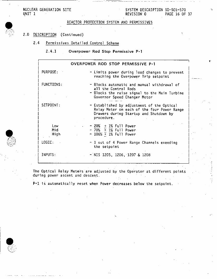
NUCLEAR GENERATION SITE SYSTEM DESCRIPTION SD-SO1-570 UNIT 1 REVISION 0 PAGE 16 OF 37
REACTOR PROTECTION SYSTEM AND PERMISSIVES
2.0 DESCRIPTION (Continued)
2.4 Permissives Detailed Control Scheme
2.4.1 Overpower Rod Stop Permissive P-1
r I OVERPOWER ROD STOP PERMISSIVE P-1
PURPOSE: - Limits power during load changes to prevent I reaching the Overpower Trip setpoint I
FUNCTIONS: - Blocks automatic and manual withdrawal of I all the Control Rods
- Blocks the raise signal to the Main Turbine I Governor Speed Changer Motor
SETPOINT: - Established by adjustment of the Optical Relay Meter on each of the four Power Range Drawers during Startup and Shutdown by procedure.
Low - - 20% + 1% Full Power | Mid - 70% + 1% Full Power
High - 106% + 1% Full Power
LOGIC: - 1 out of 4 Power Range Channels exeeding the setpoint
INPUTS: - NIS 1205, 1206, 1207 & 1208
The Optical Relay Meters are adjusted by the Operator at different points during power ascent and descent.
P-1 is automatically reset when Power decreases below the setpoint.
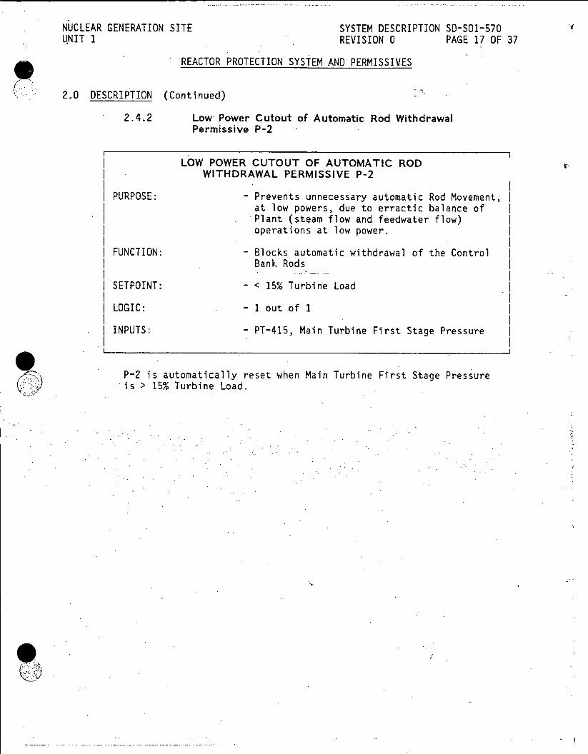
NUCLEAR GENERATION SITE SYSTEM DESCRIPTION SD-SO1-570 UNIT 1 REVISION 0 PAGE 17 OF 37
REACTOR PROTECTION SYSTEM AND PERMISSIVES
2.0 DESCRIPTION (Continued)
2.4.2 Low Power Cutout of Automatic Rod Withdrawal Permissive P-2
LOW POWER CUTOUT OF AUTOMATIC ROD WITHDRAWAL PERMISSIVE P-2
PURPOSE: - Prevents unnecessary automatic Rod Movement, at low powers, due to erractic balance of Plant (steam flow and feedwater flow) operations at low power.
FUNCTION: - Blocks automatic withdrawal of the Control Bank Rods
SETPOINT: - < 15% Turbine Load
LOGIC: - 1 out of 1
| INPUTS: - PT-415, Main Turbine First Stage Pressure
P-2 is automatically reset when Main Turbine First Stage Pressure is > 15% Turbine Load.
Q!3

NUCLEAR GENERATION SITE SYSTEM DESCRIPTION SD-SO1-570 INIT 1 REVISION 0 PAGE 18 OF 37
REACTOR PROTECTION SYSTEM AND PERMISSIVES
2.0 DESCRIPTION (Continued)
2.4.3 Rod Drop Rod Stop Permissive P-3
ROD DROP ROD STOP PERMISSIVE
PURPOSE: - Prevents automatic Control Rod withdrawal | with a dropped rod, which could lead to I abnormal Core power distribution. The abnormal Core power distribution could I cause fuel damage.
FUNCTION: - Blocks automatic withdrawal of the Control I Bank Rods
- Initiates a Main Turbine Runback to 70% Load |
SETPOINT. - 5% instantaneous decrease in power OR
- Analog Rod Bottom Position Indication at =25 steps
LOGIC: - 1 out of 4 Power Range Channels exceeding the setpoint
- I out of 45 Analog Rod Position Indications .-exceeding the setpoint
INPUTS: - NIS-1205, 1206, 1207 & 1208 OR
- Analog Rod Position Indication (LVDT)
The Turbine Runback can be defeated using the Rod Drop Runback Knife Switch located on the Auxiliary Relay Board behind the South Vertical Board.
The Power Range part of P-3 is reset at the individual Power Range Drawers and by depressing the Automatic.Rod Withdrawal Prohibit pushbutton, located.on the J-Console, when power is > 15% Load and the condition has cleared.
The Analog Rod Bottom Position Indication part of P-3 is automatically reset when all the Control Rods are above 25 steps.
9'11

NUCLEAR GENERATION SITE SYSTEM DESCRIPTION SD-SO1-570 UNIT 1 REVISION 0 PAGE 19 OF 37
REACTOR PROTECTION SYSTEM AND PERMISSIVES
2.0 DESCRIPTION (Continued)
2.4.4 Steam Dump Automatic Mode Cutout. Permissive P-4
STEAM DUMP AUTOMATIC MODE CUTOUT PERMISSIVE P-4
PURPOSE: - Prevents unnecessary steam dump actuation during small transients.
FUNCTION: - Blocks automatic Steam Dump Control
SETPOINT: - Tavg-Tref deviation of 50 F not accompanied by a 10% step load decrease in power in less than 10 seconds
LOGIC: - 1 out of 2'-
INPUTS: - Tavg - Tref - PT-417, Main Turbine First Stage Pressure
2.4.5 Shutdown Margin Alarm Permissive P-5
SHUTDOWN MARGIN ALARM PERMISSIVE P-5
PURPOSE: - Ensures that sufficient Shutdown Margin is . maintained.by warning the operator that the
rods are approaching their:lower limits.
FUNCTION: - Provides the Shutdown Bank Low and Low-Low Alarms
SETPOINT: | CONTROL BANK 1 LOW - 309 steps
CONTROL BANK 1 LOW-LOW - 288 steps I CONTROL BANK 2 LOW - 21 steps above Insertion Limit (variable) | CONTROL BANK 2 LOW-LOW - At Insertion Limit (variable)
LOGIC: - 1 out of 1
INPUTS: - Analog Rod Position Indication - Tavg - AT

NUCLEAR GENERATION SITE SYSTEM DESCRIPTION SD-SO1-570 UNIT 1 REVISION 0 PAGE 20 OF 37
9ll REACTOR PROTECTION SYSTEM AND PERMISSIVES
2.0 DESCRIPTION (Continued)
2.4.6 High Startup Rate Rod Stop Permissive P-6
HIGH STARTUP RATE ROD STOP PERMISSIVE P-6
| PURPOSE: - Prevents unnecessary Reactor Trip by precluding continued Control Rod withdrawal which could lead to a High Startup Rate Trip.
| FUNCTION: - Blocks automatic and manual withdrawal of all the Control Rods
I SETPOINT: - 2 DPM
LOGIC: - I out of 2-Source Range Channels exceeding the setpoint
OR - 1 out of 2 Intermediate Channels
exceeding the setpoint
INPUTS: - NIS-1201 & 1202 (Source Range) - NIS-1203 & 1204 (Intermediate Range) - PT-415, Main Turbine First Stage Pressure
P-6 is in effect when 3 out of 4 Power Range Channels are less than 10% power OR Main Turbine First Stage Pressure is less than 10% Load.
P-6 is defeated when 2 out of 4 Power Range Channels are greater than or equal to 10% power AND Main Turbine First Stage Pressure is greater than or equal to 10% Load.
(II)
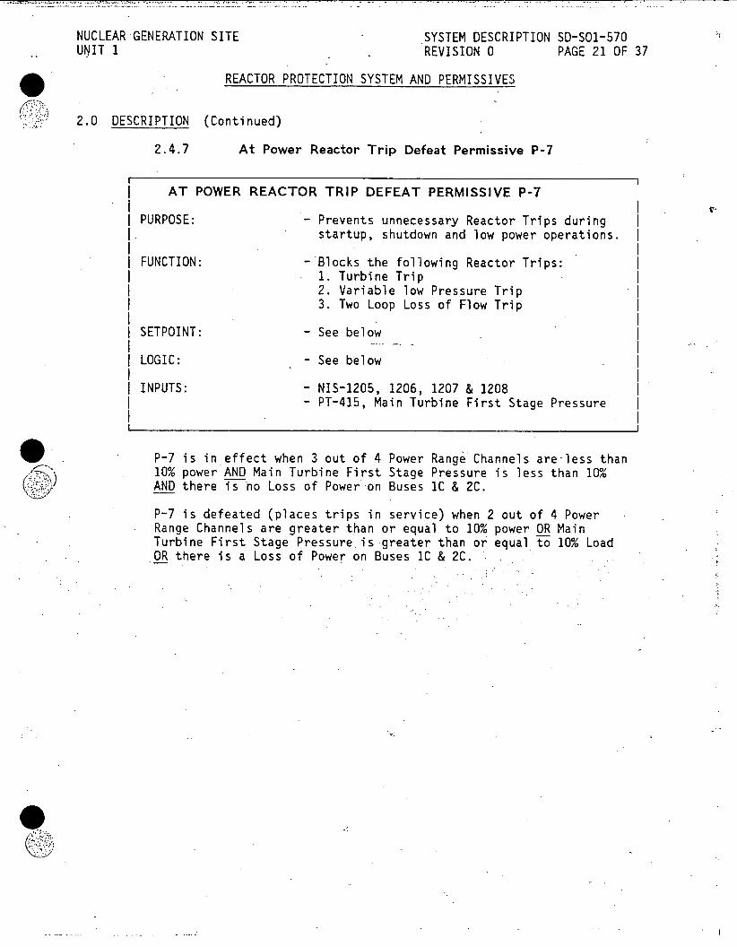
NUCLEAR GENERATION SITE SYSTEM DESCRIPTION SD-SO1-570 UNIT 1 REVISION 0 PAGE 21 OF 37
REACTOR PROTECTION SYSTEM AND PERMISSIVES
2.0 DESCRIPTION (Continued)
2.4.7 At Power Reactor Trip Defeat Permissive P-7
AT POWER REACTOR TRIP DEFEAT PERMISSIVE P-7
PURPOSE: -Prevents unnecessary Reactor Trips during startup, shutdown and low power operations.
FUNCTION: - Blocks the following Reactor Trips: 1. Turbine Trip 2. Variable low Pressure Trip 3. Two Loop Loss of Flow Trip
I SETPOINT: - See below
LOGIC: - See below
INPUTS: - NIS-1205, 1206, 1207 & 1208 - PT-415, Main Turbine First Stage Pressure
P-7 is in effect when 3 out of 4 Power Range Channels are-less than 10% power AND Main Turbine First Stage Pressure is less than 10% AND there is no Loss of Power on Buses IC & 2C.
P-7 is defeated (places trips in service) when 2 out of 4 Power Range Channels are greater than or equal to 10% power OR Main Turbine First Stage Pressure.is-greater than or equal to 10% Load OR there is a Loss of Power on Buses IC & 2C.

NUCLEAR GENERATION SITE SYSTEM DESCRIPTION SD-SO1-570 UNIT 1 REVISION 0 PAGE 22 OF 37
REACTOR PROTECTION SYSTEM AND PERMISSIVES
2.0 DESCRIPTION (Continued)
2.4.8 Single Pump Loss of Flow Reactor Trip Defeat Permissive P-8
| SINGLE PUMP LOSS OF FLOW REACTOR TRIP DEFEAT PERMISSIVE P-8
PURPOSE: - - Prevents unnecessary Reactor Trip during | startup, shutdown and low power operation.
| FUNCTION: - Blocks the Single Loop Loss of Flow Trip |
| SETPOINT: - See below |
| LOGIC: - See below
INPUTS: - NIS-1205, 1206, 1207 & 1208 INPUTS; - PT-415, Main Turbine First Stage Pressure
P-8 is in effect when 3 out of 4 Power Range Channels are less than 50% power AND Main Turbine First Stage Pressure is less than 50% Load.
P-8 is defeated (places trip in service) when 2 out of 4 Power Range Channels are greater than or equal to 50% power OR Main Turbine First Stage Pressure is greater than or equal to 50% Load.
NUCLEAR GENERATION SITE SYSTEM DESCRIPTION SD-SO1-570 UNIT I REVISION 0 PAGE 23 OF 37
REACTOR PROTECTION SYSTEM AND PERMISSIVES
2.0 DESCRIPTIONS (Continued)
2.5 Power Supplies
COMPONENT BREAKER I LOCATION
| Reactor Protection 72-141 | 125 VDC Bus #1 | System Contacts (Control Rods | | and Relays Breaker) 1
8-1181 (Normal) MCC-1 I Permissive (Vital bus xfer I | Relays Switch #7) I
1 8-1238 (Alternate)I MCC-2 (Vital bus xfer Switch #7) 72-141 125 VDC Bus #1 (Control Rods | Breaker)
II 3.0 OPERATION
A Reactor Trip is an actual command signal to shutdown the Reactor. The command is generated manually by an operator or automatically when certain setpoints for plant operating parameters are exceeded.
On a Reactor Trip signal, the Reactor Scram Breakers open, the Control Rods Coils are de-energized allowing the Control Rods to drop into the Core.
Several automatic actions follow the occurrence of Reactor Trip. The immediate actions of the Reactor Trip or Safety Injection procedure specify the verification of some of these automatic actions and prescribes a list of other actions which do not occur automatically. Steps aimed at assuring Core Flux Monitoring and effective Core Decay Heat Removal following the Reactor Trip are provided by this procedure.
An input channel failure to the RPS, in the trip state, or an actual channel input indicative of an impending trip, will cause an annunciator to illuminate in the Main Control Room on the Reactor Plant Matrix Partial Trip Annunciator Panel.
A channel failure will effectively change the Logic Matrix for that parameter.
Example: If one Pressurizer Level Channel fails high, then the 2 out of 3 logic would become a 1 out of 2 logic, because one of the inputs is in a tripped state.
The same Logic effect occurs when an input channel is placed in a test condition.

NUCLEAR GENERATION SITE SYSTEM DESCRIPTION SD-S01-570 UNIT I REVISION 0 PAGE 24 OF 37
REACTOR PROTECTION SYSTEM AND PERMISSIVES
4.0 REFERENCES
4.1 P&IDs
4.1.1 Reactor Coolant System, 5178100
4.1.2 Pressurizer and Pressurizer Relief Tank, 5178105
4.1.3 Turbine Control Oil System, 5178900
4.1.4 Turbine System Sheet 1, 5178240
4.2 Elementaries
4.2.1 5102173, 125 VDC System 1 N1540 017
4.2.2 N15410002, Turbine N1541 002
4.2.3 N15410006, Governor Speed Changer N1541 006
4.2.4 N15410007, Load Limit Motor Control N1541 007
4.2.5 5150410, Rod Control Sheet 1 N1542 102 (Scram Breakers)
4.2.6 5112259, Reactor Protection System Scram Signals N1542 102A
4.2.7 5150623, Reactor Scram Breakers "A"l & "B" N1542 102B
4.2.8 Y-20929, Reactor Protection and Control System N1542 102C
4.2.9 5150625, Rod Drive Mechanism Control System Sheet 2 N1542 103B
4.2.10 5107776, Permissive Circuitry I and Command Control Circuitry II N1542 104
4.2.11 5151820, Permissive Relay Circuits for: Scram Breaker Trip Annunciator and Event Recorder N1542 105
4.2.12 0063714, Reactor Coolant System Sheet 1 N1542 132
NUCLEAR GENERATION SITE SYSTEM DESCRIPTION SD-S01-570 UNIT 1 REVISION 0 PAGE 25 OF 37
REACTOR PROTECTION SYSTEM AND PERMISSIVES
4.0 REFERENCES (Continued)
4.2.13 0063716, Pressurizer Pressure System Sheets 1 and 2 N1542 133
4.2.14 5126359, Pressurizer Cont. System Block Diagram Sheets 1 N1542 133A
4.2.15 0063717, Pressurizer Level System Sheet 4 N1542 134
4.2.16 5149180, Sequencer Logic Diagram N1542 137M
4.3 Technical Manuals
4.3.1 Westinghouse, Reactor Control & Protection System
4.4 Procedures
4.4.1 501-1.0-10, Reactor Trip or Safety Injection
4.4.2 501-1.0-11, Reactor Trip Response
4.4.3 501-3-1, Plant Startup from Cold Shutdown to Hot Standby
4.4.4 501-3-2, Plant Startup from Hot Standby to Minimum Load
4.4.5 501-3-3, Plant Operation from Minimum Load to Full Power
4.4.6 501-3-4, Plant Shutdown from Full Power to Hot Shutdown
4.4.7 501-3-5, Plant Shutdown from Hot Standby to Cold Shutdown
4.4.8 501-13-3, Reactor Plant No. 2 Annunciator
4.4.9 501-13-5, Permissive Information Display Annunciator
4.4.10 501-13-6, Reactor Plant First-Out Annunciator
4.4.11 501-13-7, Reactor Plant Matrix Partial Trip Annunciator
4.5 Technical Specifications
4.5.1 Section 2.1
4.5.2 Section 3.1.2
4.5.3 Section 3.5.1
GRedmon:3199i
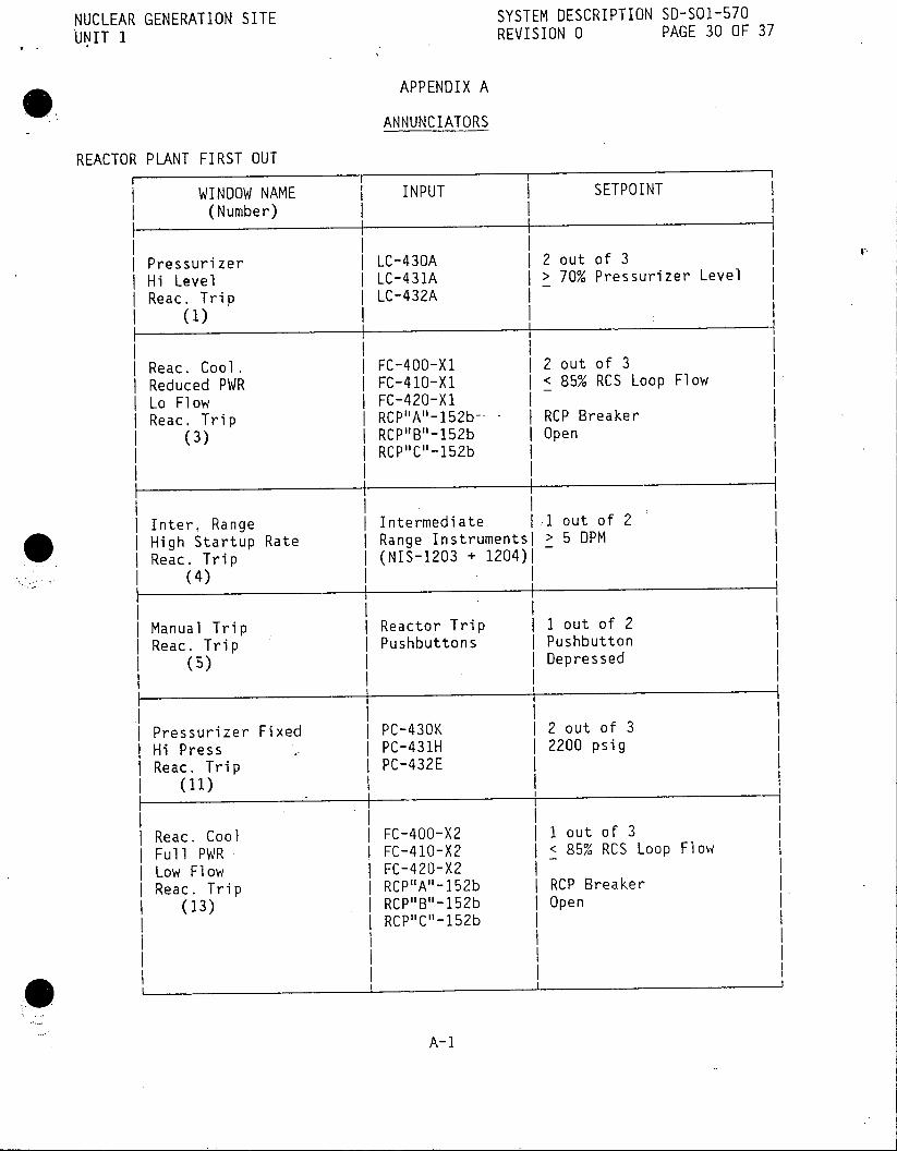
NUCLEAR GENERATION SITE SYSTEM DESCRIPTION SD-SO1-570
UNIT 1 REVISION 0 PAGE 30 OF 37
APPENDIX A
ANNUNCIATORS
REACTOR PLANT FIRST OUT
WINDOW NAME INPUT SETPOINT (Number)
| Pressurizer LC-430A 2 out of 3 Hi Level LC-431A > 70% Pressurizer Level Reac. Trip LC-432A
(1)
Reac. Cool. FC-400-XI 2 out of 3 Reduced PWR FC-410-Xl < 85% RCS Loop Flow Lo Flow FC-420-Xl Reac. Trip RCP"A"-152b-- RCP Breaker
(3) RCP"B"-152b Open RCP"C"-152b
Inter, Range Intermediate 1 out of 2 * High Startup Rate Range Instrumentsl > 5 DPM Reac. Trip (NIS-1203 + 1204)1
(4)
Manual Trip Reactor Trip I out of 2 Reac. Trip Pushbuttons Pushbutton
(5) Depressed
Pressurizer Fixed PC-430K 2 out of 3 Hi Press PC-431H 2200 psig Reac. Trip PC-432E
(11)
Reac. Cool FC-400-X2 I out of 3 Full PWR FC-410-X2 < 85% RCS Loop Flow Low Flow FC-420-X2 Reac. Trip RCP"A"-152b RCP Breaker
(13) RCP"B"152b Open IRCP"C"-152b
A-1

NUCLEAR GENERATION SITE SYSTEM DESCRIPTION SD-SO1-570 UNIT 1 REVISION 0 PAGE 31 OF 37
* APPENDIX A
ANNUNCIATORS (Continued)
REACTOR PLANT FIRST OUT
WINDOW NAME INPUT (Number)
I. I
Power Range Power Range 2 out of 4 Over PWR Instruments Low - 25% ±1% Full Power Reac. Trip (NIS-1205, 1206, Mid - 85% ±1% Full Power
. (14) 1207 and 1208) High - 108 ±1% Full Power
Turbine Trip AST-63-XI 2 out of 3 Reac. Trip AST-63-X2 < 45 psig
| (15) AST-63-X3 Auto Stop Oil I I Pressure II
Power Range Power Range P-i Permissive Over Power Instruments Rod Stop (NIS-1205, 1206,
(18) 1207 + 1208)
Steam/FW FM-456B 2 out of 3 Flow Mismatch FM-457B Feedwater Flow < Steam Reac. Trip FM-458B Flow by 25% offull Load
(23) value
Shutdown Control Bank 1 P-5 Permissive Margin Rod Position
| Bank 1 and | Lo-Lo Shutdown Margin I (27) Monitor
Shutdown Control Bank 2 P-5 Permissive Margin Rod Position
| Bank 2 and | Lo-Lo Shutdown Margin I (28) Monitor
I Pressurizer PC-430F 2 out of 3 Variable PC-431D Tech. Spec.
* Lo Press PC-432B 26.15(0.894 AT+Tavg)-143411 Reactor Trip 1840 psig-Minimum
w(31) R1872 psig-Actual
1207And1208) I Hg _10 _%FulPw
A-I

NUCLEAR GENERATION SITE SYSTEM DESCRIPTION SD-SO1-570 UNIT 1 REVISION 0 PAGE 32 OF 37
* APPENDIX A
ANNUNCIATORS (Continued)
REACTOR PLANT MATRIX PARTIAL TRIP F ~I WINDOW NAME INPUT SETPOINT (Number)
I
Pressurizer LC-430A > 70% Pressurizer Level Hi Level LC-431A > 70% Pressurizer Level Reac. Trip LC-432A > 70% Pressurizer Level Channel I, II, III (1), (2), (3)
| Reac. Cool. FC-400 <85% RCS Loop Flow Lo Flow FC-410 <85% RCS Loop Flow Reac. Trip FC-420 <85% RCS Loop Flow Loop A, B, C (7), (8), (9)
I Pressurizer Fixed | PC-430K 2200 psig I Hi pressure PC-431H 2200 psig . Reactor Trip PC-432E 2200 psig I Channel I, II, III I (11), (12), (13)
I+ I Steam/Feedwater Flow FM-456B Feedwater Flow | Mismatch Reactor Trip FM-457B < .Steam Flow by 25% of
I Loop A, B, C FM-458B Full Load value | (17), (18), (19)
Over Power Reactor Power Range Low - 25% ±1% Full Powerl
Trip Partial Trip Instruments Mid 7 85% +1% Full Power (29) I (NIS-1205, 1206, High - 108% ±1% Full Powerl
1207 + 1208)
Pressurizer PC-430F | Tech. Specs. Variable Low PC-431D I 26.15(0.894 AT+Tavg)-143411 Pressure Reactor PC-432B I 1840 psig-Minimum Trip Channel I, II, III 1872 psig - Actual (31), (32), (33)
Turbine Trip AST-63-X1 < 45 psig | Channel I, II, III | AST-63-X2 Auto Stop I (37), (38), (39) I AST-63-X3 I Oil Pressure
A-3

NUCLEAR GENERATION SITE SYSTEM DESCRIPTION SD-SO1-570 JNIT 1 REVISION 0 PAGE 33 OF 37
APPENDIX A
ANNUNCIATORS (Continued)
REACTOR PLANT ANNUNCIATOR NO. 2
WINDOW NAME INPUT . SETPOINT (Number)
| Shutdown | Control Bank 1(2)1 P-5 Permissive | Margin | Rod Position Bank 1 (2) | and Low | Shutdown Margin (11), (12) | Monitor
Nuclear Power Range | P-3 Permissive | Dropped Rod Instrument-s and Rod Stop Analog Rod
(32) Position Indication
| Source (Inter) Range Source Range 2 DPM High (NIS-1201, 1202) Startup Rate and 2 DPM Rod Stop Intermediate (51), (52) 1 Range Instrumentsl
(NIS-1203, 1204)
| Reac. Trip UXA < 100 volts | Breaker | UXB | < 100 volts I Power Failure I (72)
PERMISSIVE INFORMATION DISPLAY
| WINDOW NAME INPUT SETPOINT I (Number)
Operation Operation Mode Low Position | Mode Switch Selector Switch in Lo Range
A-4

NUCLEAR GENERATION SITE SYSTEM DESCRIPTION SD-SOl-570 UNIT 1 REVISION 0 PAGE 34 OF 37
APPENDIX A
ANNUNCIATORS (Continued)
PERMISSIVE INFORMATION DISPLAY I II
WINDOW NAME INPUT SETPOINT (Number)
Single Loop Power Range | P-8 Permissive Loss of Flow Instruments | (AP-1OA, AP-10C) Reactor Trip (NIS-1205, 1206 Defeated 1207 + 1208)
(2) | and Turbine First! I Stage Pressure | (PT-415)
At Power | Power Range P-7 Permissive I Reactor Trips | Instruments (AP-4A, AP-4C) Defeated | (NIS-1205, 1206 (3) | 1207 + 1208)
I and Turbine Firstl | Stage Pressure | (PT-415)
| Startup Rate Power Range P-7 Permissive | Reactor Trips Instruments (AP-4B, AP-4D) | Active | (NIS-1205, 1206
(4) | 1207 + 1208) |-and Turbine First! I Stage Pressure I I (PT-415) |
| Dropped Rod I Dropped Rod Knife Switch in
I Runback I Runback Defeat Defeat Position I Defeated | Switch . I (6) I I
Automatic Turbine First | P-2 Permissive | Rod Control Stage Pressure I | Blocked Low | (PT-415) | Power
(7)
I I I Rod Control Automatic Rod I Pushbutton not Withdrawal Withdrawal | Depressed when Not Reset I Prohibit |> 15% Full Load
(8) I Pushbutton I
3199i A-5

NUCLEAR GENERATION SITE SYSTEM DESCRIPTION SD-SO1-570 UIT 1 REVISION 0 PAGE 35 OF 37
APPENDIX B
DEVELOPMENTAL RESOURCES P&IDs
Reactor Coolant System, 5178100
Pressurizer and Pressurizer Relief Tank, 5178105
Turbine Control Oil System, 5178900
Turbine System Sheet 1, 5178240
Elementaries
5102173, 125 VDC System 1 N1540 017
N15410002, Turbine N1541 002
N15410006, Governor Speed Changer N1541 006
N15410007, Load Limit Motor Control N1541 007
5150410, Rod Control Sheet 1 (Scram Breakers) N1542 102
5112259, Reactor Protection System Scram Signals N1542 102A
5150623, Reactor Scram Breakers "A" & "B" N1542 102B
Y-20929, Reactor Protection and Control System N1542-102C
5150625, Rod Drive Mechanism Control System Sheet 2 N1542 103B
5107776, Permissive Circuitry I and Command Control Circuitry II N1542 104
5151820, Permissive Relay Circuits for: Scram Breaker Trip Annunciator and Event Recorder N1542 105
0063714, Reactor Coolant System Sheet 1 N1542 132
0063716, Pressurizer Pressure System Sheets 1 and 2 N1542 133
B-1

NUCLEAR GENERATION SITE SYSTEM DESCRIPTION SD-SO1-570 J9NIT 1 REVISION 0 PAGE 36 OF 37
APPENDIX B
DEVELOPMENTAL RESOURCES (Continued)
Elementaries (Continued)
5126359, Pressurizer Cont. System Block Diagram Sheets 1 N1542 133A
0063717, Pressurizer Level System Sheet 4 N1542 134
5149180, Sequencer Logic Diagram N1542 137M
Technical Manuals
Procedures
S01-1.0-10, Reactor Trip or Safety Injection
501-1.0-11, Reactor Trip Response
S01-3-1, Plant Startup from Cold Shutdown to Hot Standby
SO1-3-2, Plant Startup from Hot Standby to Minimum Load
SO1-3-3, Plant Operation from Minimum Load to Full Power
SO1-3-4, Plant Shutdown from Full Power to Hot Shutdown
SO1-3-5, Plant Shutdown from Hot Standby to Cold Shutdown
SO1-13-3, Reactor Plant No. 2 Annunciator
SOI-13-5, Permissive Information Display Annunciator
SO1-13-6, Reactor Plant First-Out Annunciator
SO1-13-7, Reactor Plant Matrix Partial Trip Annunciator
Technical Specifications
Section 2.1
Section 3.5.1
Study Guides
12, Reactor Control and Protection System
15, RCPS - Trips
B-2

NUCLEAR GENERATION SITE SYSTEM DESCRIPTION SD-SO1-570 .UVIT 1 REVISION 0 PAGE 37 OF 37
APPENDIX B
DEVELOPMENTAL RESOURCES (Continued)
FSAR
Section 5.2
Bechtel System Description #10, Reactor Control and Protection System
Lesson Plans
1028, Reactor and Protection System
1074, Reactor Protection System
1170, Reactor Protection, Permissive Review
Student Handout
Reactor Protection System (Protection Portion of RCPS)
3199i B-3

NUCLEAR GENERATION SITE SYSTEM DESCRIPTION SD-SO1-590 UNIT 1 REVISION 0 PAGE 1 OF 42 NOV15 19R5 CDM
SAFEGUARD LOAD SEQUENCING SYSTEM
TABLE OF CONTENTS
SECTION PAGE
1.0 FUNCTIONS/DESIGN BASES 3
2.0 DESCRIPTION 4 2.1 System Overview 4 2.2 Components 6 2.3 Detailed Logic and Indications 10 2.4 Power Supplies 16
3.0 OPERATION 17 3.1 Normal Operation 17 3.2 Safety Injection Signal (SIS) with 220 kV Source
of Offsite Power Available 17 3.3 Loss of Offsite Power (LOP) from the 220 kV System 18 3.4 Loss of 4160 V Bus (LOB) 19 3.5 Simultaneous Occurrence of Safety Injection and Loss of
Offsite Power from 220 kV System (SISLOP) 19 3.6 Safety Injection with Safety Injection Signals (SIS)
Returning to Normal, Followed by Loss of Offsite Power from 220 kV System 20
3.7 Safety Injection followed by Safety Injection Block System Initiation followed by Loss of Offsite Power from 220 kV System 21
3.8 De-energizing and Energizing the Sequencer 21
4.0 REFERENCES 22 4.1 Elementaries 22 4.2 Technical Manuals 23
.4.3 Procedures . 23 4.4 Technical Specifications 23
FIGURES 1 Basic Sequencer Logic 24 .2 Safeguard Load Sequencing System 25 3 Safety Injection Signal (SIS) 26 4 Loss of Offsite Power (LOP) 27 5 Diesel Generator (D/G) 28 6 Loss of 4160 V Bus (LOB) 29 7 Load Group Sequencing 30 8 Remote Surveillance Panel 31 9 Sequencer Test Panel 32
10 Sequencer Power Supply Circuits 33 11 Card Rack 34 12 Input Buffer Card 35 13 Logic Card 36 14 Relay Driver Card 37
3185i

NUCLEAR GENERATION SITE SYSTEM DESCRIPTION SD-SO1-590 UNIT 1 REVISION 0 PAGE 2 OF 42
SAFEGUARD LOAD SEQUENCING SYSTEM
TABLE OF CONTENTS (Continued)
SECTION PAGE
APPENDICES A Safeguard Load Sequencing System Signals 38 B Safeguard Load Sequencing System Alarms 39 C Developmental Resources 41
This System Description is approved per 50123-0-44, System Description Revision and Approval. Contact CDM to verify revision information.
PREPARED BY: Date
APPROVED BY: NA) Ma ag )0i at ns
3185i

NUCLEAR GENERATION SITE SYSTEM DESCRIPTION SD-S01-590 UNIT 1 REVISION 0 PAGE 3 OF 42
SAFEGUARD LOAD SEQUENCING SYSTEM
1.0 FUNCTIONS/DESIGN BASES
1.1 The Safeguard Load Sequencing System has the following main functions:
1.1.1 The main function of the Safeguard Load Sequencing System (SLSS) is to detect and react to Low Pressurizer Pressure, High Containment Pressure and 4160 V Bus IC and/or 2C Undervoltage Signals. The SLSS actuates and sequences the various Emergency Safeguard Features in the event of a Safety Injection System signal (SIS), Loss of Offsite Power (LOP), Loss of 4160 V Bus 1C/2C (LOB), or Safety Injection System and Loss of Offsite Power (SISLOP).
1.2 The Safeguard Load Sequencing System has the following additional functions:
1.2.1 The Safeguard Load Sequencing System provides: Manual Actuation of the SIS and/or LOP Signals, Manual Blocking of the SIS Signal, and Manual Resetting of the SIS and/or LOP Signal(s).
1.3 The Safeguard Load Sequencing System has the following Design Basis:
1.3.1 The Safeguard Load Sequencing System is designed to ensure proper load sequencing of the Emergency Safeguard Features to mitigate postulated accidents.
1.3.2 The Safeguard Load Sequencing System is designed to ensure proper loading of the Emergency Safeguard Features onto the Electrical Safety Buses such that an overload condition on the buses does not occur.
1.3.3 The Safeguard Load Sequencing System is designed to support Online Testing to ensure the system and/or components are capable of performing the main function.

NUCLEAR GENERATION SITE SYSTEM DESCRIPTION SD-S01-590 UNIT 1 REVISION 0 PAGE 4 OF 42
SAFEGUARD LOAD SEQUENCING SYSTEM
2.0 DESCRIPTION
2.1 System Overview
2.1.1 Safeguard Load Sequencing System Automatic Actions
The Safeguard Load Sequencing System actuates the Safety Injection System upon receipt of a Safety Injection System (SIS) signal. In the event of an SIS, the Safeguard Load Sequencing System automatically starts the Diesel Generators, but does not automatically close the Diesel Generator Output Breakers and simultaneously loads the Emergency Safeguards Features onto their respective buses.
In the event of a Loss of Offsite Power (LOP) condition without a SIS, the Safeguard Load Sequencing System automatically starts the Diesel Generators but does not automatically close the Diesel Generator Output Breakers and does not load the Emergency Safeguards Features onto their respective buses.
In the event of a Loss of 4160 V Bus IC or 2C (LOB), the Safeguard Load Sequencing System automatically starts the Diesel Generator associated with the lost bus but does not automatically close the Diesel Generator Output Breaker and does not load the Emergency Safeguards Features onto the bus.
In the event a SIS and a LOP (SISLOP) occur together, the Safeguard Load Sequencing System trips and/or locks out certain loads (see 2.3.2), automatically starts the Diesel Generators, places the Diesel Generators onto the 4160 V Buses and sequentially loads the Emergency Safeguards Equipment onto their respective buses.
The Safeguard Load Sequencing System also trips the Reactor on a SIS and/or LOP and sends logic actuation signals to the Containment Isolation and Containment Spray Systems on a SIS or a SISLOP.
2.1.2 Safeguard Load Sequencing System
The Safeguard Load Sequencing System (SLSS) is composed of two independent and redundant Sequencer Trains which are identified as Sequencer 1 and Sequencer 2.
Sequencer 1 provides the actuation and sequencing signals for the Safety Injection System Train A components. Sequencer 1 also provides an actuation input signal to the Containment Spray System Train A Logic and the Containment Isolation System Train A Logic.
Sequencer 2 provides the actuation and sequencing signals for the Safety Injection System Train B components. Sequencer 2 also provides an actuation input signal to the Containment Spray System Train B Logic and the Containment Isolation System Train B Logic.
NUCLEAR GENERATION SITE SYSTEM DESCRIPTION SD-SO1-590 UNIT 1 REVISION 0 PAGE 5 OF 42
SAFEGUARD LOAD SEQUENCING SYSTEM
2.0 DESCRIPTION (Continued)
2.1.2 Safeguard Load Sequencing System (Continued)
Each Sequencer is composed of two subchannels which are identified as Subchannel X and Subchannel Y. The subchannels are independent of each other, but share the common input signals of Pressurizer Pressure, Containment Pressure, 4160 V Bus 1C and 2C Undervoltage, Diesel Generator Volts/Freq, Diesel Generator Output Breaker Status, and Sequencer in Test Conditions, through Isolation Circuits.
EXAMPLE: Subchannel X and Y for Sequencer 1, each receive the same pressure signal input from Pressurizer Pressure Bistable Controllers PC-430GX, PC-431EX and PC-432CX, while Subchannel X and Y, for Sequencer 2, each receive the same pressure input signal from Pressurizer Pressure Bistable Controllers PC-3000A, PC-3000B and PC-3000C (see Figure 2).
Each Sequencer initiates six Load Groups, A through F; the groups, timing sequences and components operated are identified in Section 2.3.2. The timing sequences are initiated only on a SISLOP actuation.
The Remote Surveillance Panels, one for each Sequencer, input four manual signals to its respective Sequencer Cabinet. These signals are: SIS Trip, SIS Reset, LOP Trip and LOP Reset.
2.1.3 Safeguard Load Sequencing System Manual Functions
.1 Manual Actuation of SIS or LOP is accomplished at the Remote Surveillance Panel by depressing the Trip pushbutton and turning the Trip/Reset Switch to Trip, for the appropriate actuation signal and Sequencer. The requirement that both the pushbutton and the switch be operated at the same time prevents an inadvertent actuation.
.2 Manual Blocking of SIS allows the SIS signal to be blocked during normal plant cooldown.
.3 Manual Resetting of SIS or LOP/LOB is accomplished at the Remote Surveillance Panel by depressing the Reset pushbutton and turning the Trip/Reset switch to Reset for the appropriate actuation signal and Sequencer. The requirement that both the pushbutton and the switch be operated at the same time prevents an inadvertent reset.

NUCLEAR GENERATION SITE SYSTEM DESCRIPTION SD-SO1-590 UNIT 1 REVISION 0 PAGE 6 OF 42
SAFEGUARD LOAD SEQUENCING SYSTEM
2.0 DESCRIPTION (Continued)
2.1.3 Safeguard Load Sequencing System Manual Functions (Continued)
.4 Testing the Safeguard Load Sequencing System is accomplished at the Sequencer Test Panel and/or the Input Buffer Modules in the Sequencer Cabinet Card Racks, for the appropriate Sequencer.
The Sequencer Logic is designed such that an output from both Subchannel X and Y is required for Sequencer operation. Thus the design, for each Sequencer, creates a dual path for all input signals and requires an AND Logic of both subchannels for the final Sequencer actuation signal. Because both subchannels are required for Sequencer actuation, this design allows for Online Testing of an individual subchannel without an actual actuation and prevents a spurious actuation due to a subchannel failure.
Testing a Sequencer does not prevent the Sequencer from performing its main function. If an actuation signal occurs while in Test, the actuation signal will perform the required function, essentially overriding the test signal.
2.2 Components
The Safeguard Load Sequencing System utilizes two Sequencer Systems, Sequencer 1 and Sequencer 2. Each Sequencer System is made up of one Logic Cabinet, one Termination Cabinet, two Cable Assemblies and one Remote Surveillance Panel. The Logic and Termination Cabinets are bolted together and are referred to as a Sequencer Cabinet. The Sequencer Cabinets are located behind the Main Control Room South Vertical Board.
2.2.1 Logic Cabinet
The Logic Cabinet, right hand cabinet of the Sequencer Cabinet, contains: four Power Supply Assemblies; the Card Rack which contains the Input Buffer Cards, the Logic Cards and the Relay Driver Cards for Subchannels X and Y; the Sequencer Test Panel and a Ventilation Fan.
.1 Power Supply Assemblies (Figure 10) -'located in the bottom of the cabinet, receive 125 VDC input and converts it to the 15 VDC and 48 VDC necessary for the operation of the Safeguard Load Sequencing System.

NUCLEAR GENERATION SITE SYSTEM DESCRIPTION SD-SO1-590 UNIT 1 REVISION 0 PAGE 7 OF 42
SAFEGUARD LOAD SEQUENCING SYSTEM
2.0 DESCRIPTION (Continued)
2.2.1 Logic Cabinet (Continued)
.2 Card Rack (Figure 11) - located above the Power Supply Assemblies, is made up of two rows of modules with 16 modules per row. The Card Rack is split vertically between slots 8 and 9 which is the division between Subchannel X and Subchannel Y. A sliding lexan door, 8 slots wide, makes inadvertent simultaneous access to both Subchannel X and Subchannel Y impossible.
.2.1 Input Buffer Cards (Figure 12) - receive the following input signals: Pressurizer Pressure, Containment Pressure, 4160 V Bus Undervoltage, Diesel Generator Volts & Freq., Diesel Generator Output Breaker Status, and Sequencer in Test Conditions, and Sequence Block Status.
The Input Buffer Cards isolate the Safeguard Load Sequencing System from voltage spikes, filters out noise and false signals, and provides an output signal to the logic circuitry indicative of the status for the input parameters.
Each Input Buffer Card is equipped with pushbuttons to provide test capability of the individual Input Buffer Relays.
Each Input Buffer Card has solid state LED Test Lamp indication which will extinguish when the buffer contacts are not in their normal condition.
The Input Buffer Cards occupy slots 1 through 6 (Subchannel X) and 9 through 14 (Subchannel Y) in the Card Racks' upper row.
.2.2 Logic Cards (Figure 13) - receive the various outputs from the Input Buffer Cards, determine the logic input and supply appropriate outputs to the Relay Driver Cards. The Logic Cards also provide the instantaneous outputs or the timing outputs to the Relay Driver Cards.
The Logic Cards occupy slots 7 (Subchannel X) and 15 (Subchannel Y) in the Card Racks' upper row.
.2.3 Relay Driver Card (Figure 14) - receive the logic command from the Logic Cards to drive the Relay Driver 48 VDC Relays which provide actuation of some component function. The Relay Driver Cards maintain isolation between the input from the Logic Cards and the 48 VDC Relay Circuitry. It de-energizes the 48 VDC Relays regardless of the input logic state when the 15 VOC voltage decreases below a minimum value, and current limits each Relay Driver Circuit. Each Relay Driver Card has four independent circuits, each circuit can drive up to five 48 VDC Relays.

NUCLEAR GENERATION SITE SYSTEM DESCRIPTION SD-SO1-590 UNIT 1 REVISION 0 PAGE 8 OF 42
SAFEGUARD LOAD SEQUENCING SYSTEM
2.0 DESCRIPTIONS (Continued)
2.2.1 Logic Cabinet (Continued)
.2.3 (continued)
The Relay Driver Cards occupy slots 8 (Subchannel X) and 16 (Subchannel Y) of the Card Racks' upper row and Slots 1-8 (Subchannel X) and 9-16 (Subchannel Y) of the Card Racks' lower row.
.3 Sequencer Test Panel (Figure 9) - located above the Card Rack, is equipped with one Normal/Test toggle switch, two Test Select switches and one Reset/Operate/Test switch.
.3.1 Reset-Operate-Test Switch: This switch is used for overall control of testing the Subchannels. There is one common switch for each Sequencer.
Once a test on a particular Sequencer has been performed, this switch must be placed in the Reset position. If not, the trip stays latched, and when the next Subchannel is tested a SIS or LOP may be initiated.
* .3.2 Test Select Switch: This switch selects which of the Sequencer inputs is tested. There is a separate switch for each subchannel in the Sequencer with following positions:
Operate - Normal position
SIS-PRPZ - Simulates 2/3 Low Pressurizer Pressure
SIS-CONT - Simulates 2/3 High Containment Pressure
SIS-PRPZ and CONT - Simulates 2/3 Low Pressurizer Pressure and 2/3 High Containment Pressure
LOB-1C - Simulates Undervoltage on 4160 V Bus 1C
LOB-2C - Simulates Undervoltage on 4160 V Bus 2C
LOP - Simulates Undervoltage on 4160 V Buses 1C and 2C
SIS and LOP - Simulates SIS and LOP inputs
.3.3 Normal-Test Toggle Switch: This switch is common for each Sequencer. The function of this switch is to change tie normal logic circuitry of the Sequencer for Safety Ijection Actuation from a two out of three Pressurizer Pressure "OR" two out of three Containment Pressure to a two out of three Pressurizer Pressure "AND" two out of three Containment Pressure inputs.

NUCLEAR GENERATION SITE SYSTEM DESCRIPTION SD-SO1-590 UNIT 1 REVISION 0 PAGE 9 OF 42
SAFEGUARD LOAD SEQUENCING SYSTEM
2.0 DESCRIPTIONS (Continued)
2.2.1 Logic Cabinet (Continued)
This feature allows testing the Containment Isolation System Actuations Signal without initiating a SIS signal. This may occur since the Pressure Transmitters for Containment Pressure are common to SIS and CIS.
.4 Ventilation Fan - located in the top of the Logic Cabinet provides ventilation for the Logic and Termination Cabinets.
The fan is not required for Sequencer operation, however, it will improve electronic component life by reducing internal cabinet temperatures.
2.2.2 Termination Cabinet
The Termination Cabinet, left hand cabinet of the Sequencer Cabinet, contains all the Input/Output Terminal boards for the Sequencer Cabinet.
The Termination Cabinet also contains the two 48 VDC Relay Panels.
The upper 48 VDC Relay Panel contains Subchannel X and Y Relay Drivers which cause or prevent some actions, Subchannel X and Y Test Lamps, and the Load Monitoring Lamps (Section 2.3.3.1) for Load Group A.
The lower 48 VDC Relay Panel contains Subchannel X and Y Relay Drivers which cause or prevent some actions, Subchannel (X and Y) Test Lamps, and the Load Monitoring Lamps (Section 2.3.3.1) for Load Groups B through F.
The 48 VDC Relays, for Subchannels X and Y, each have two sets of contacts (see Figure 10). One set of contacts is for the Control Circuit, the other set of contacts is for the Amber Test Lamps.
2.2.3 Remote Surveillance Panel (Figure 8)
The two Remote Surveillance Panels, one for each Sequencer, are mounted in the Main Control Room on their associated Diesel Generator Control Board (SPG).
Each Remote Surveillance Panel contains the SIS Manual Initiation and Reset pushbuttons and switch, the LOP Manual Initiation and Reset pushbuttons and switch, and eight Status Lamps as described in Section 2.3.5.

NUCLEAR GENERATION SITE SYSTEM DESCRIPTION SD-SO1-590 UNIT 1 REVISION 0 PAGE 10 OF 42
SAFEGUARD LOAD SEQUENCING SYSTEM
2.0 DESCRIPTION (Continued)
2.2.4 Safety Injection System Block Switch
The two Safety Injection System Block Switches, one for each Sequencer, are mounted in the Main Control Room on the Nuclear Control Auxiliary Panel (North Main Vertical Board).
If 2 out of 3 Pressurizer Pressure Bistables are < 1900 psig, placing the switch in the Block position prior to a SIS actuation will prevent the SIS latch from being set on that Sequencers' Subchannels, thus preventing the SIS actuation.
If the SIS actuation occurs prior to placing the switch in the Block position, then placing the switch in the Block position will have no effect on the logic (see Section 3.1).
2.3 Detailed Logic and Indications
2.3.1 Safeguard Load Sequencing System Summary
Each Sequencer will respond to certain combinations of input signals reaching their respective setpoints. These combinations, logics and setpoints are summarized below:
NOTE: Each Sequencer has its own set of bistable inputs.
Event Signal/Logic/Setpoint Basic Response
Safety Low Pressurizer Pressure/ Reactor Trips, D/Gs Injection 2 out of 3 channels/1735 psig start but their System or Output Breakers do (SIS) High Containment Pressure/ not close onto the Actuation 2 out of 3 channels/1.4 psig 4160 V Buses and all
Sequencer outputs for Safety Injection Loads are initiated without time delay.
NOTE: With the Normal - Test Toggle Switch in Test, the logic changes, requiring both a 2 out of 3 Pressurizer Pressure Signal AND a 2 out of 3 Containment Pressure Signal to cause an actuation.
The Normal - Test Toggle Switch is placed in Test when testing both the High Containment Pressure and the Low Piessurizer Pressure signals at the same time (using simulated signals), and when testing the Containment Isolation System using the Containment Pressure Transmitters.
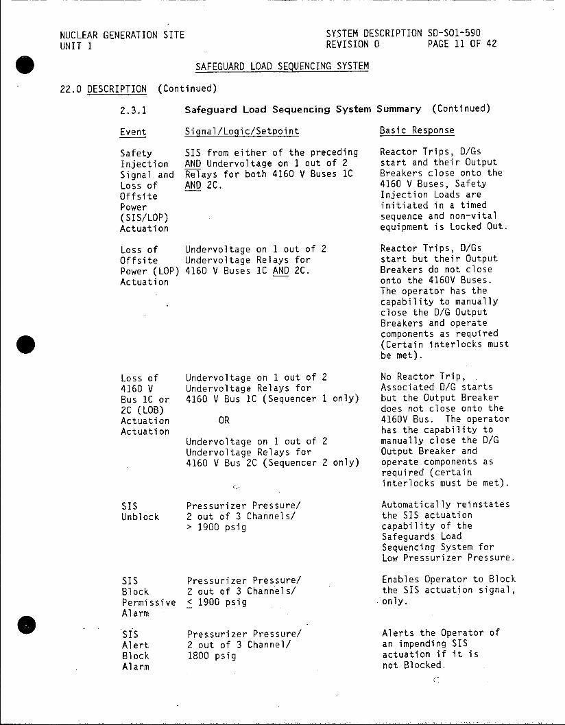
NUCLEAR GENERATION SITE SYSTEM DESCRIPTION SD-S01-590 UNIT 1 REVISION 0 PAGE 11 OF 42
SAFEGUARD LOAD SEQUENCING SYSTEM
22.0 DESCRIPTION (Continued)
2.3.1 Safeguard Load Sequencing System Summary (Continued)
Event Signal/Logic/Setpoint Basic Response
Safety SIS from either of the preceding Reactor Trips, D/Gs Injection AND Undervoltage on 1 out of 2 start and their Output Signal and Relays for both 4160 V Buses 1C Breakers close onto the Loss of AND 2C. 4160 V Buses, Safety Offsite Injection Loads are Power initiated in a timed (SIS/LOP) sequence and non-vital Actuation equipment is Locked Out.
Loss of Undervoltage on 1 out of 2 Reactor Trips, D/Gs Offsite Undervoltage Relays for start but their Output Power (LOP) 4160 V Buses 1C AND 2C. Breakers do not close Actuation onto the 4160V Buses.
The operator has the capability to manually close the D/G Output Breakers and operate components as required (Certain interlocks must be met).
Loss of Undervoltage on 1 out of 2 No Reactor Trip, 4160 V Undervoltage Relays for Associated DIG starts Bus 1C or 4160 V Bus 1C (Sequencer 1 only) but the Output Breaker 2C (LOB) does not close onto the Actuation OR 4160V Bus. The operator Actuation has the capability to
Undervoltage on 1 out of 2 manually close the D/G Undervoltage Relays for Output Breaker and 4160 V Bus 2C (Sequencer 2 only) operate components as
required (certain interlocks must be met).
SIS Pressurizer Pressure! Automatically reinstates Unblock 2 out of 3 Channels! the SIS actuation
> 1900 psig capability of the Safeguards Load Sequencing System for Low Pressurizer Pressure.
SIS Pressurizer Pressure! Enables Operator to Block Block 2 out of 3 Channels! the SIS actuaton signal, Permissive < 1900 psig only. Alarm*
SIS Pressurizer Pressure! Alerts the Operator of Alert 2 out of 3 Channel! an impending SIS Block 1800 psig actuation if it is Alarm not Blocked.
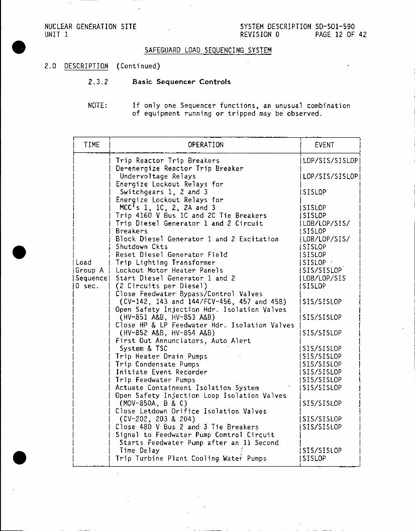
NUCLEAR GENERATION SITE SYSTEM DESCRIPTION SD-SO1-590 UNIT 1 REVISION 0 PAGE 12 OF 42
SAFEGUARD LOAD SEQUENCING SYSTEM
2.0 DESCRIPTION (Continued)
2.3.2 Basic Sequencer Controls
NOTE: If only one Sequencer functions, an unusual combination of equipment running or tripped may be observed.
TIME OPERATION EVENT
Trip Reactor Trip Breakers ILOP/SIS/SISLOPI De-energize Reactor Trip Breaker | Undervoltage Relays |LOP/SIS/SISLOPI
Energize Lockout Relays for I Switchgears 1, 2 and 3 ISISLOP
Energize Lockout Relays for | MCC's 1, 1C, 2, 2A and 3 ISISLOP
Trip 4160 V Bus IC and 2C Tie Breakers ISISLOP | Trip Diesel Generator 1 and 2 Circuit (LOB/LOP/SIS/ I
I Breakers ISISLOP Block Diesel Generator 1 and 2 Excitation (LOB/LOP/SIS/ I Shutdown Ckts ISISLOP Reset Diesel Generator Field ISISLOP
|Load I Trip Lighting Transformer ISISLOP I Group A I Lockout Motor Heater Panels ISIS/SISLOP I Sequencel Start Diesel Generator 1 and 2 |LOB/LOP/SIS I
10 sec. | (2 Circuits per Diesel) ISISLOP | | Close Feedwater Bypass/Control Valves I
(CV-142, 143 and 144/FCV-456, 457 and 458) ISIS/SISLOP I Open Safety Injection Hdr. Isolation Valves I (HV-851 A&B, HV-853 A&B) ISIS/SISLOP I
Close HP & LP Feedwater Hdr. Isolation Valves I (HV-852 A&B, HV-854 A&B) ISIS/SISLOP I
First Out Annunciators, Auto Alert | | System & TSC ISIS/SISLOP I | Trip Heater Drain Pumps ISIS/SISLOP I Trip Condensate Pumps ISIS/SISLOP I | | Initiate Event Recorder ISIS/SISLOP I I Trip Feedwater Pumps ISIS/SISLOP I | | Actuate Containment Isolation System ISIS/SISLOP | I Open Safety Injection Loop Isolation Valves I | | (MOV-850A, B & C) ISIS/SISLOP I | | Close Letdown Orifice Isolation Valves I I (CV-202, 203 & 204) ISIS/SISLOP I | Close 480 V Bus 2 and 3 Tie Breakers ISIS/SISLOP I | | Signal to Feedwater Pump Control Circuit I
I Starts Feedwater Pump after an 11 Second I I Time Delay ISIS/SISLOP I | Trip Turbine Plant Cooling Water Pumps ISISLOP

NUCLEAR GENERATION SITE SYSTEM DESCRIPTION SD-SO1-590 UNIT 1 REVISION 0 PAGE 13 OF 42
SAFEGUARD LOAD SEQUENCING SYSTEM
2.0 DESCRIPTION (Continued)
2.3.2 Basic Sequencer Controls (Continued)
TIME OPERATION EVENT
|Load I Close Diesel Generator 1 and 2 Circuit IGroup A I Breakers ISISLOP ISequencej(Note: Breaker closure will occur when the DG I 110 sec. is at rated voltage and frequency, 10 secs. is I I Ithe maximum allowable time.)
ILoad I Open Charging Line Flow Control IGroup B I Valve (FCV-1112) ISIS/SISLOP I Sequencel Start Safety Injection Pumps ISIS/SISLOP I Ill sec. I Open Feedwater Recirc. System
Valves (CV-875 A&B) ISIS/SISLOP I Open Refueling Water to Charging Pump Suction I Valves (MOV-1100 B&0) ISIS/SISLOP I
Start Emergency Siren ISIS/SISLOP I Close Main Feedwater Isolation Valves (MOV-20, 21 & 22) ISIS/SISLOP I
Block Overload Trips for Safety Injection I ) Pumps and Feedwater Pumps ISIS/SISLOP I Trip Reactor Coolant Pumps "A", "B" & "C" ISIS/SISLOP I (NOTE: occurs 1 sec. after DG Breaker closes)
Load I Close Feedwater Pump Miniflow Valves IGroup C I Valves (CV-36 & 37) ISIS/SISLOP I ISequencej (Note: occurs 2 secs. after DG Breaker closes)l 112 sec.
fLoad I Start Charging Pumps ISIS/SISLOP | Group D I Start Component Cooling Water Pumps ISIS/SISLOP I Sequencel Start Saltwater Cooling Pumps ISIS/SISLOP 1 121 sec. Safety Injection Signal to Containment I I I Spray System ISIS/SISLOP I I I(NOTE: occurs 11 secs. after DG Breaker closes) |
iI I I Load ISpare ISIS/SISLOP Group E I ISequence I IVariable I
ILoad I Spare ISIS/SISLOP I Group F I ISequencel IVariablel
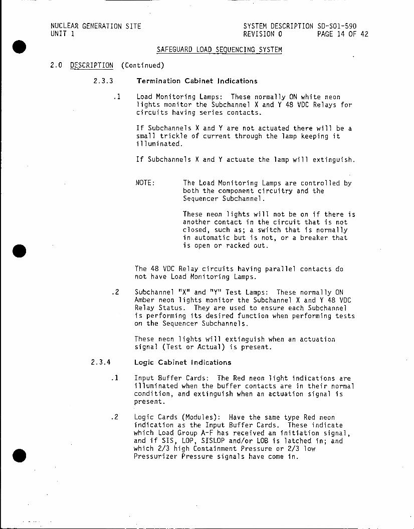
NUCLEAR GENERATION SITE SYSTEM DESCRIPTION SD-SO1-590 UNIT 1 REVISION 0 PAGE 14 OF 42
SAFEGUARD LOAD SEQUENCING SYSTEM
2.0 DESCRIPTION (Continued)
2.3.3 Termination Cabinet Indications
.1 Load Monitoring Lamps: These normally ON white neon lights monitor the Subchannel X and Y 48 VDC Relays for circuits having series contacts.
If Subchannels X and Y are not actuated there will be a small trickle of current through the lamp keeping it illuminated.
If Subchannels X and Y actuate the lamp will extinguish.
NOTE: The Load Monitoring Lamps are controlled by both the component circuitry and the Sequencer Subchannel.
These neon lights will not be on if there is another contact in the circuit that is not closed, such as; a switch that is normally in automatic but is not, or a breaker that is open or racked out.
The 48 VDC Relay circuits having parallel contacts do not have Load Monitoring Lamps.
.2 Subchannel "X" and "Y" Test Lamps: These normally ON Amber neon lights monitor the Subchannel X and Y 48 VDC Relay Status. They are used to ensure each Subchannel is performing its desired function when performing tests on the Sequencer Subchannels.
These neon lights will extinguish when an actuation signal (Test or Actual) is present.
2.3.4 Logic Cabinet Indications
.1 Input Buffer Cards: The Red neon light indications are illuminated when the buffer contacts are in their normal condition, and extinguish when an actuation signal is present.
.2 Logic Cards (Modules): Have the same type Red neon indication as the Input Buffer Cards. These indicate which Load Group A-F has received an initiation signal, and if SIS, LOP, SISLOP and/or LOB is latched in; and which 2/3 high Containment Pressure or 2/3 low Pressurizer Pressure signals have come in.
NUCLEAR GENERATION SITE SYSTEM DESCRIPTION SD-SO1-590 UNIT 1 REVISION 0 PAGE 15 OF 42
SAFEGUARD LOAD SEQUENCING SYSTEM
2.0 DESCRIPTION (Continued)
2.3.4.3 There are power supply lights in the power supply portion of this cabinet. These lights will extinguish when power is removed and an annunciator will illuminate in the Main Control Room.
2.3.5 Remote Surveillance Panel Indications
.1 The Remote Surveillance Panel has a load sequencing light indication for each load group. The lights are normally illuminated and will extinguish when their respective group is sequenced on.
.2 Also, there is a normally illuminated lamp indicating power available. If this lamp extinguishes, it is an indication of power supply failure.
.3 The other indication for the Sequencer is a "Door Closed" indication. If any of the four (4) Sequencer doors are opened, this light will extinguish.
2.3.6 Remote Surveillance Panel Controls
.1 SIS Trip - This function is performed by holding the SIS "Trip/Reset Switch" in the "Trip" position while at the same time depressing the "SIS Manual Trip" button.
This manually sets the SIS latches on Subchannels X and Y. This signal is processed by the logic regardless of the current logic or system status.
..2 SIS Reset - This function is performed by holding the SIS "Trip/Reset Switch" in the "Reset" position while at the same time depressing the "SIS Manual Reset" button.
This resets the SIS latches on Subchannels X and Y. It is locked out until the End of Sequence latch is set. It is independent of the accident inputs returning to normal.
.3 LOP Trip - This function is performed by holding the "LOP Trip/Reset Switch" in the "Trip" position while at the same time depressing the "LOP Manual Trip" button.
This manually sets the LOP latches on Subchannels X and Y. This signal is processed by the Logic regardless of the current logic or system status.

NUCLEAR GENERATION SITE SYSTEM DESCRIPTION SD-SO1-590 UNIT 1 REVISION 0 PAGE 16 OF 42
SAFEGUARD LOAD SEQUENCING SYSTEM
2.0 DESCRIPTION (Continued)
2.3.5 Remote Surveillance Panel Indications (Continued)
.4 LOP Reset - This function is performed by holding the "LOP Trip/Reset Switch" in the "Reset" position while at the same time depressing the "LOP Reset" button.
This Resets the LOP latches on Subchannels X and Y. It is locked out until the End of Sequence latch is set. It is independent of the accident inputs returning to normal.
2.4 Power Supplies
COMPONENT | BREAKER LOCATION
Sequencer 1 72-124 125 VDC Bus No.
Sequencer 2 I 72-212 125 VDC Bus No. 2
Ventilation Fan No. 4 L06 (120 VAC)
The power supplies to:the Sequencers are train-separated as shown. Loss of a 125 VDC Bus will result in the inability of the associated Sequencer to perform its intended function, however, the design of the SLSS is that one operable Sequencer is sufficient to operate the necessary components to place the Plant in a safe condition.
NOTE: Opening and then reclosing these breakers may start the associated Diesel Generator (see yellow placard on Diesel Generator Bus).
NUCLEAR GENERATION SITE SYSTEM DESCRIPTION SD-SO1-590 UNIT 1 REVISION 0 PAGE 17 OF 42
SAFEGUARD LOAD SEQUENCING SYSTEM
3.0 OPERATION
3.1 Normal Operations
During Plant Startup, the Safeguard Load Sequencing System (the SIS actuation remains Blocked) is placed in service prior to increasing RCS temperature above 2001F. When the RCS pressure reaches 1900 psig the SIS actuation is automatically Unblocked as indicated by the Block Permissive annunciators extinguishing and the SIS Override LEDs illuminating in the Card Rack.
During Plant cooldown, the Automatic Safety Injection System Signal due to Low Pressurizer Pressure is manually blocked, prior to reducing pressure below the SIS setpoint. This prevents an inadvertent actuation of Safety Injection. Activation of the Block signal is indicated by annunciators and the extinguishing of the SIS Override LED's in the Card Rack.
The permissive to allow blocking the SIS signal is enabled when 2 out of 3 Pressurizer Pressure bistables are < 1900 psig.
The Pressurizer Pressure Bistables generate an alarm signal which illuminates the SI Block Permissive annunciator (1900 psig) and the Alert Block annunciator (1800 psig) in the Main Control Room, to advise the operator that the Safety Injection System should be manually blocked as pressure is intentionally reduced. If no manual block occurs, there will be an inadvertent actuation of the Safety Injection System. Should system actuation be required after blocking, manual actuation of both Safety Injection trains is possible by the manual initiation switches and pushbuttons on both Remote Surveillance Panels. The individual components will be under operator control after the Sequencer is reset by using the manual Reset Switch and pushbuttons on the Remote Surveillance Panel.
The Block signal only blocks the SIS signal, it has no effect on the LOP or LOB signals.
3.2 Safety Injection Signal (SIS) with 220 kV Source of Offsite Power Available (See Figure 3)
The Safety Injection Signal (SIS) is derived from Low Pressurizer Pressure or High Containment Pressure bistable elements as described in Section 2.3.1. Each Sequencer has its own bistable channel inputs and the contacts from each of the bistable output relays are supplied to its Sequencer X and Y Subchannels.
Under normal conditions (Normal/Test Toggle Switch in Normal), the Sequencer will generate a Safety Injection Signal when any two out of three Pressurizer Pressure bistable output relays are actuated, "OR" when any two out of three Containment Pressure bistable output relays are actuated. The two out of three logic function for Pressurizer Pressure and Containment Pressure signals is performed within each Sequencer on a Subchannel basis.
NUCLEAR GENERATION SITE SYSTEM DESCRIPTION SD-SO1-590 UNIT 1 REVISION 0 PAGE 18 OF 42
SAFEGUARD LOAD SEQUENCING SYSTEM
3.0 OPERATION (Continued)
3.2 (Continued)
During certain testing of pressure inputs and Sequencer Channel tests, the Sequencer logic is manually changed to generate a Safety Injection Signal when any two out of three Pressurizer Pressure bistable output relays are actuated in coincidence with actuation of any two out of three Containment Pressure bistable output relays. This feature is accomplished via a toggle switch located on each Sequencer Test Panel. The test switch changes the Sequencer "OR" logic to an "AND" logic.
3.2.1 Safety Injection SLSS Actions
.1 Initiation of the Safety Injection Signal will result in a Reactor Trip and a Unit Trip.
.2 The Safety Injection Signal will also initiate the starting of the Emergency Diesel Generators of both trains. The Diesel Generators will be running in a standby mode (output breakers open).
.3 The Safety Injection Signal will cause the Sequencer to actuate all of the Safety Injection loads without any
- timing sequence.
3.3 Loss of Offsite Power (LOP) From the 220 kV System (See Figure 4)
Each Sequencer monitors the availability of offsite power by means of the input signals it receives from redundant undervoltage relays associated with each of the 4160 V Buses 1C and 2C. Each Sequencer had its own Auxiliary UV Relays and generates a reliable undervoltage signal for its internal use by combining signals from Buses IC and 2C in an "AND" configuration.
LOP occurs when 1 out of 2 UV Relays on 1C AND 1 out of 2 UV Relays on 2C show both 4160 V Buses have a loss of power supply.
3.3.1 Loss of Offsite Power SLSS Actions
.1 The Loss of Power signal will result in a Reactor Trip and a Unit Trip.
.2 The LOP signal will also initiate starting of the Emergency Diesel Generators for both trains. The Diesel Generators will be running in a standby mode. The operator will have the capability to manually close the Diesel Generator output breakers, if required.

NUCLEAR GENERATION SITE SYSTEM DESCRIPTION SD-SO1-590 UNIT 1 REVISION 0 PAGE 19 OF 42
SAFEGUARD LOAD SEQUENCING SYSTEM
3.0 OPERATION (Continued)
3.4 Loss of 4160 V Bus (LOB) (See Figure 6)
Loss of Bus signal to each Sequencer is generated by its associated 4160 V Bus Undervoltage Relay input signal.
An LOB occurs when 1 out of 2 UV Relays (same Relays as used for LOP) show its 4160 V Bus to have lost power.
3.4.1 Loss of Bus SLSS Actions
.1 Loss of Bus signal will initiate the starting of its associated Emergency Diesel Generator unit. The Diesel Generator will be running in a standby mode.
3.5 Simultaneous Occurrence of Safety Injection and Loss of Offsite Power from 220 kV System (SISLOP) (See Figures 3 and 4)
3.5.1 Safety Injection Signal with Loss of Offsite Power Signal
.1 Upon initiation of the SISLOP Signal, the Reactor and Unit will Trip.
.2 The SISLOP also initiates the starting of the Emergency Diesel Generators.
.3 A SISLOP signal will result in tripping 4160 V and 480 V loads.
.4 The SISLOP will place the Emergency Diesel Generators online by automatically closing the output breakers when rated voltage and frequency are reached and initiates load sequencing as described in 2.3.2 and 3.5.2.
3.5.2 Load Sequencing (See Figure 7)
Load sequencing will be initiated automatically, as soon as the Emergency Diesel Generators are online. The Safety Injection loads will be sequentially actuated in groups as specified below. During load sequencing, the operator will not be able to select the loads. Manual load selection may resume, up to 4725 Kw, when sequencing is completed and the Sequencers are reset by the operator.

NUCLEAR GENERATION SITE SYSTEM DESCRIPTION SD-SO1-590 UNIT 1 REVISION 0 PAGE 20 OF 42
SAFEGUARD LOAD SEQUENCING SYSTEM
3.0 OPERATION (Continued)
3.5.2 Load Sequencing (See Figure 7) (Continued)
.1 Load Group A - Time 0 secs. - This load group performs its function immediately and it is not connected to any timing circuitry.
NOTE: There is a 10 second allowance for the Diesel Generators to reach rated volts and frequency before 3.5.3.2, 3, 4 & 5 can take place.
.2 Load Group B - Time 11 secs. - This Load Group is designed to come on one second after the Diesel Generator has reached proper speed and voltage with the Diesel Generator Output Breaker closed.
.3 Load Group C - Time 12 secs. - This Load Group is designed to come on 2 secs. after the Diesel Generator Output Breaker is closed to limit the starting current strain on the Diesel Generators.
.4 Load Group D - Time 21 secs. - This Load Group is designed to come on 11 secs. after the Diesel Generator Output Breaker is closed to limit the starting current strain on the Diesel Generator.
.5 Load Groups E and F are spares and are not used.
3.6 Safety Injection with Safety Injection Signals (SIS) Returning to Normal, Followed by Loss of Offsite Power from 220 kV System (See Figures 3 and 4)
3.6.1 Safety Injection Signal
.1 After reaching their associated setpoints, the Pressurizer Pressure or Containment Pressure initiate Safety Injection and the Sequencer functions normally as in 3.2 above.
.2 If Pressurizer Pressure and/or Containment Pressure return to normal levels or fluctuate about their Safety Injection setpoints, the Safety Injection System will continue to function normally (unless reset and rearmed).
Once reset by the Operator, SI would reactivate if armed and the setpoint is reached.
NUCLEAR GENERATION SITE SYSTEM DESCRIPTION SD-SO1-590 UNIT 1 REVISION 0 PAGE 21 OF 42
SAFEGUARD LOAD SEQUENCING SYSTEM
3.0 OPERATION (Continued)
3.6.2 Loss of Power Signal
.1 A Loss of Power signal following actuation of normal SIS results in Sequencer operation as if a simultaneous Safety Injection System and Loss of Offsite Power (SISLOP) has occurred as in 3.5 above.
.2 If the Sequencers have been Reset by the operator after Safety Injection initiation but prior to the occurrence of the Loss of Offsite Power, and Pressurizer Pressure or Containment Pressure are restored to normal, the Sequencer will operate as if Loss of Offsite Power (LOP) only had occurred.
3.7 Safety Injection Followed by Safety Injection Block Initiation Followed by Loss of Offsite Power from 220 kV System (See Figures 3 and 4)
3.7.1 . Safety Injection Signal
.1 After reaching their associated setpoints, the Pressurizer Pressure or Containment Pressure initiates Safety Injection. The Sequencer functions normally as in 3.2 above.
.2 After Safety Injection initiation, the Sequencer Safety Injection Block Signal is initiated per station procedures. The Safety Injection System will continue to function normally.
3.7.2 Loss of Power Signal
.1 Upon occurrence of a Loss of Offsite Power, the Sequencer will neglect the Safety Injection Block and operate as if a simultaneous Safety Injection Signal and Loss of Offsite Power (SISLOP) had occurred.
3.8 De-energizing and Energizing the Sequencer
3.8.1 De-energizing the Sequencer(s)
The Sequencer(s) are normally de-energized by opening both Subchannel Y power supply breakers and then opening both Subchannel X power supply breakers. This allows the Sequencer(s) to be properly re-energized as described below.
The Sequencer(s) can also be de-energized by opening the main power breaker at the appropriate 125 VDC Panel, however, if this is done the individual breakers should then be opened to prevent an inadvertent SIS actuation when the main breaker is reclosed.

NUCLEAR GENERATION SITE SYSTEM DESCRIPTION SD-SOl-590 UNIT 1 REVISION 0 PAGE 22 OF 42
SAFEGUARD LOAD SEQUENCING SYSTEM
3.0 OPERATION (Continued)
3.8.2 Energizing the Sequencer(s)
When Subchannels X and Y, for each Sequencer, are energized they may be in a TRIPPED condition, therefore failure to properly energize or failure to Reset the Tripped condition as required may result in an advertent SIS actuation.
Sequencer 1 is energized by first verifying that both Subchannel X power supply breakers are open and that both Subchannel Y power supply breakers are open and then closing the 125VDC main power supply breaker. Subchannel Y is energized by closing both power supply breakers, then Subchannel Y is Reset to remove any Trip condition. Subchannel X is now energized by closing both power supply breakers, then Subchannel X is Reset to remove any Trip condition.
Sequencer 2 is energized in the same manner as Sequencer 1.
When actually performing the above, the LED's in the Card Rack and the annunciators in the Main Control Room should be checked to verify proper system indications.
4.0 REFERENCES
4.1 Elementaries
4.1.1 5149180, Sequencer Logic Diagram 1542 Sheet 137M
4.1.2 5149957, Safety Injection Sequencer No.1 1542 Sheet 139
4.1.3 5150875, Safety Injection, Sequencer No. 2 1542 Sheet 137A
4.1.4 5149170, Load Sequence Schedule Load Train No. 1 1542 Sheet 140
4.1.5 5149179, Load Sequence Schedule Load Train No. 1 1542 Sheet 141
4.1.6 5149181, Load Sequence Schedule Load Train No. 2 1542 Sheet 143
4.1.7 5149182, Load Sequence Schedule Load Train No. 2 1542 Sheet 144
4.1.8 515r0158, SIS/SP Lockou. Relays 1545 Sheet 54
NUCLEAR GENERATION SITE SYSTEM DESCRIPTION SD-SO1-590 UNIT 1 REVISION 0 PAGE 23 OF 42
SAFEGUARD LOAD SEQUENCING SYSTEM
4.0 REFERENCES (Continued)
4.1 Elementaries (Continued)
4.1.9 5102173, 125 VDC System No. 1 1540 Sheet 17
4.1.10 5149348, 125 VDC System No. 2 1540 Sheet 17B
4.2 Technical Manuals
4.2.1 Consolidated Controls Corp. Technical Manual 9N33, Safeguard Load Sequencing System
4.3 Procedures
4.3.1 S01-4-17, Safety Injection System Operations
4.3.2 S01-1.0-12, SI Termination following Spurious SI
4.3.3 S01-1.0-21, SI Termination following Loss of Reactor Coolant
4.3.4 SO1-1.0-31, SI Termination following Loss of Secondary Coolant
4.3.5 S01-3-1, Plant Startup from Cold Shutdown to Hot Standby
4.3.6 S01-3-5, Plant Shutdown from Hot Standby to Cold Shutdown
4.3.7 501-12.0-4, Operations Surveillance Requirements for Mode Changes
4.3.8 S01-12.3-7, Monthly Sequencer Test
4.3.9 SO1-13-5, Permissive Information Display Annunciator
4.3.10 S01-13-6, Reactor Plant First-Out Annunciator
4.3.11 S01-13-7, Reactor Plant Matrix Partial Trip Annunciator
4.3.12 501-13-10, Electrical Annunciator
4.4 Technical Specifications
4.4.1 Section 3.5.5
4.4.2 Section 4.1.4
4.4.3 Section 3.7.I.A.5
4.4.4 Section 4.4.E and F
DRiley:3185i

NUCLEAR GENERATION SITE SYSTEM DESCRIPTION SD-SO1-590 UNIT 1 REVISION 0 PAGE 26 OF 42
FIGURE 3: SAFETY INJECTION SIGNAL (SIS)
CONTAINMENT PRESSURE
PRESSURE 1120 1120 1120
430 431 432 A B C
2/3 2/3
TEST
AUTO UNBLOCK
BLOCK
MANUALL
RESET
SIS LATCH
LOP
FROM OTHER SUB CHANNEL>
F"EACTOR ENERGIZE TRIP START ANNUNCIATORS
TRIP ALL LOADS LOADS O/G (NO TIMING)
3185i

NUCLEAR GENERATION SITE SYSTEM DESCRIPTION SD-SO1-590
UNIT I REVISION 0 PAGE 27 OF 42
FIGURE 4: LOSS OF OFFSITE POWER (LOP)
S .MANUAL FROM
MANUAL LS P
RESET ~UV BUS ic
UV BUS 2C
SIS
FROM OTHER ,SUBCHANNEL
LOP TRIP LOADS
SIS LOLOADS
LOB -- m FROM OTHER
SIS LOP TRIP LOAOS
IFROM OTHER
ANNUNCIATORS
O/r~ IS O LOROM
SIS LOP
OERSBCHANNEL TRIP
O/O VOSO. FROM
OHRSUBCHANNEL
TRIP
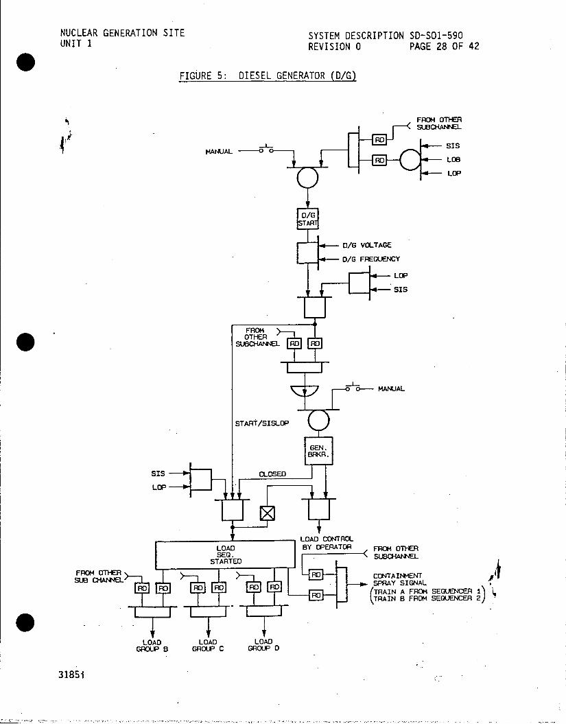
NUCLEAR GENERATION SITE SYSTEM DESCRIPTION SD-SO1-590 UNIT 1 REVISION 0 PAGE 28 OF 42
FIGURE 5: DIESEL GENERATOR (D/G)
FROM OTHER
MANUAL Ss RD LOB
LOP
D/G STAR
D/G VOLTAGE
D/G FREQUENCY
LOP
SIS
FROM OTHER
o-MANUAL
START/SISLOP
GEN.
BRKR.
SIS BCLOSED
LOP
LOAD CONTROL LOAD BY OPERATOR FROM OTHER SEG.
STARTED
FROM OTE - 01 CNAINMN
(RAIN A FROM SEQUENCER 1) RD TRAIN B FROM SEQUENCEA 2)
LOAD LOAD LOAD. GRO)UP B GROUP C GROUP D
31851

NUCLEAR GENERATION SITE SYSTEM DESCRIPTION SD-S01-590 UNIT 1 REVISION 0 PAGE 29 OF 42
FIGURE 6: LOSS OF 4160 V BUS (LOB)
LOP/LOB UV RELAY
MANUAL RESET UV RELAY
LOP LOP
SISLOP SIS
FROM OTHER (FROM OTHER
SUB CHANNEL) SUBCHANNEL
RD RD RDC R
TRIP START LOADS D/G
31851

NUCLEAR GENERATION SITE SYSTEM DESCRIPTION SD-SO1-590 UNIT 1 REVISION 0 PAGE 30 OF 42
FIGURE 7: LOAD GROUP SEQUENCING
- /G STARTED
- SISLOP
SISLOP D/G BREAKER CLOSED
LOAD SIS LOP
SEQUENCING STARTED
FROM OTHER SUBCHANNEL
RD RD RD RD RD RD RD RD RD RD
LOAD LOAD LOAD LOAD LOAD GROUP B GROUP C GROUP D GROUP E GROUP F
(SPARE) (SPARE)
31851

NUCLEAR GENERATION SITE SYSTEM DESCRIPTION SD-SO1-590 UNIT 1 REVISION 0 PAGE 31 OF 42
FIGURE 8: REMOTE SURVEILLANCE PANEL
SIS LOP
G OGROUP A POWER SUPPLY
FAILURE SIS LOP GROUP B MANUAL MANUAL TRIP TRIP
GROUP C
RESET RESET O O () GROUP D
NORMAL NORMAL GROUP E
DOOORS TRIP RESET TRIP RESET
CLOSED 1 pTI EE 6 GROUP F
SIS LOP TRIP/RESET TRIP/RESET'%

NUCLEAR GENERATION SITE SYSTEM DESCRIPTION SD-SO1-590 UNIT 1 REVISION 0 PAGE 32 OF 42
FIGURE 9: SEqUENCER TEST PANEL
NORMAL TEST
SUBCHANNEL RESET OPERATE TEST SUBCHANNEL x 1
OPERATE OPERATE
SIS-PRPZ- SIS-PRPZ
SIS-CONT -- SIS-CONT
SIS-PRPZ & CONT /-- SIS-PRPZ & CONT
-- LOB-IC LOB-1C
-0L-2C - LOB-2C
- LOP - LOP
-- SIS & LOP - SIS & LOP
TEST SELECT TEST SWITCH TEST SELECT SWITCH SWITCH

NUCLEAR GENERATION SITE SYSTEM DESCRIPTION SD-SO1-5 UNIT 1 REVISION 0 PAGE 33 OF '42
FIGURE 10: SEQUENCER POWER SUPPLY CIRCUITS
SEOUENCER I OUTPUT RELAY INPUT BUFFER MODULE LOGIC MODULE RELAY DRIVER MODULE 125 VDC
0 0 10 T T 48 VDC 15 VC15 VDC 15 VDC TO TO
9 , @CONTROL TEST BISTABLE CIRCUIT LAMP
INPUT
OUTPUT DERIVED FROM "HIGH' INPUT LOSS OF 15 VDC OR 48 VOC TO INPUT BUFFEA MODULE GIVES A "LOW. (NORMAL) OUTPUT.
LOSS OF 15 VDC TO SEQUENCER/LOGIC MODULE WOULD GIVE "LOW* OUTPUT TO RELAY DRIVER MODULE CAUSING RELAY DRIVER RELAYS TO ENERGIZE IF 15 VDC AND 48 VOC ARE AVAILABLE TO RELAY DRIVER MODULE.
48 VDC POWER SUPPLY OUTPUT DERIVED FROM "LOW" INPUT LOSS OF 15 VDC OR
48 VDC TO RELAY DRIVER MODULE GIVES A *LOW* (NORMAL) OUTPUT..
15 VDC POWER
SUPPLY
12s V ---- o'C POWEACSUPPLY
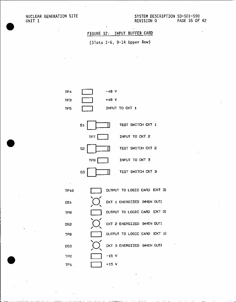
NUCLEAR GENERATION SITE SYSTEM DESCRIPTION SD-SO1-590 UNIT 1 REVISION 0 PAGE 35 OF 42
FIGURE 12: INPUT BUFFER CARD
(Slots 3-6, 9-14 Upper Row)
TP4 -48 V
TP3 +48 V
TP5 INPUT TO CKT I
si ZI I TEST SWITCH CKT I
TP7 INPUT TO CKT 2
S2 Imf TEST SWITCH CKT 2
TP9 INPUT TO CKT 3
S3 TEST SWITCH CKT 3
TP10 OUTPUT TO LOGIC CARD (CKT 3)
DS1 CKT I ENERGIZED (WHEN OUT)
TPe OUTPUT TO LOGIC CARD (CKT 2)
Ds) CKT 2 ENERGIZED (WHEN OUT)
TP6 OUTPUT TO LOGIC CARD (CKT i)
1 /
DS3 CKT 3 ENERGIZED (WHEN OUT)
TP2 -15 V
TPI +15 V

NUCLEAR GENERATION SITE SYSTEM DESCRIPTION SD-S01-590 UNIT 1 REVISION 0 PAGE 36 OF 42
FIGURE 13: LOGIC CARD
(Slots 7 and 15 Upper Row)
TPI OSI LOAD GROUP A
TP2 ) DS2 LOAD GROUP B /\
TP3 DS3 LOAD GROUP C
TP4 DS4 LOAD GROUP D 1/
TP5 DS5 LOAD GROUP E
TP6 DS6 LOAD GROUP F
1 /
TP13 DS7 SIS LATCHED IN
TP7 ( DS8 LOP LATCHED IN
TPB ) DS9 SIS-LOP LATCHED IN 1 /
TP9 C DS10 LOSS OF BUS /\
TPIO0 DS11
TP11 ( DS12 2 OUT OF 3 PRESSURIZER /Q PRESSURE CONTROLLER
TPI2
NOTES: 1. TP-13 IS COMMON (NEGATIVE)
2. 0 THIS IS A TEST POINT STUD
3. THIS IS A TEST POINT JACK
4. THIS IS AN LED

NUCLEAR GENERATION SITE SYSTEM DESCRIPTION 50-501-590 UNIT 1 REVISION 0 PAGE 37 OF 42
FIGURE 14: RELAY DRIVER CARD
(Slots 8 and 16 Upper Row, Slots 1-16 Lower Row)
TP2 -48 V
TPi +48 V
TPi6 OUTPUT SIGNAL TO RELAY CKT
TPi3 OUTPUT SIGNAL TO RELAY CKT
TPiO OUTPUT SIGNAL TO RELAY CKT
TP7 OUTPUT SIGNAL TO RELAY CKT
TP15 OUTPUT SIGNAL OF Ui CKT
TPi4 INPUT SIGNAL CKT
TP12 OUTPUT SIGNAL OF UI CKT
TP11 INPUT SIGNAL CKT
TP9 OUTPUT SIGNAL OF Ul CKT
TPS INPUT SIGNAL CKT
TP6 OUTPUT SIGNAL OF UI CKT
TP5 INPUT SIGNAL CKT
TP3 +15 V
TP4 -15 V
NOTES: 1. LII THIS IS A TEST POINT JACK

NUCLEAR GENERATION SITE SYSTEM DESCRIPTION SD-SOl-590 UNIT 1 REVISION 0 PAGE 38 OF 42
APPENDIX A
SAFEGUARD LOAD SEQUENCING SYSTEM SIGNALS
Inputs to each Sequencer
.1 Pressurizer Pressure
a. Sequencer No. 1 Sequencer No. 2
PC-430G PC-3000A PC-431E PC-3000B PC-432C PC-3000C
.2 Containment Pressure
PC-1120A PC-1121A PC-1120B PC-1121B PC-1120C PC-1121C
.3 Undervoltage Signal from 4160 V Bus 1C and 4160 V Bus 2C.
.4 Safety Injection Block
.5 Emergency Diesel Generation "Voltage Frequency Signal" and "Output Breaker Position Signal"
.6 Test Switch
Sequencers 1 and 2 output to:
.1 4160 V Breakers
.2 480 V Breakers
.3 480 V Motor Control Centers
.4 Lockout Relays
.5 Emergency Diesel Generators
.6 Safety Injection System
.7 Containment Spray System
.8 Containment Isolation System
3185i A-1

NUCLEAR GENERATION SITE SYSTEM DESCRIPTION SD-SO1-590 UNIT 1 REVISION 0 PAGE 39 OF 42
APPENDIX B
SAFEGUARD LOAD SEQUENCING SYSTEM ALARMS
PERMISSIVE ANNUNCIATOR ALARMS
WINDOW NAME (Number) | INPUT | SETPOINT
| S.I. Block Permissive | 2 out of 3 Pressurizer < 1900 psig | LO Pressure Channel I, II, III I Pressure Transmitters | (13, 14, 15)
I I * | Automatic Safety Injection | Safety Injection | Switch in | "A", "B" Circuit Blocked Block Switch "BLOCK" position | | (9, 10)
REACTOR PLANT FIRST OUT ANNUNCIATOR ALARMS
| WINDOW NAME (Number) INPUT SETPOINT
Safety Injection 2 out of 3 Pressurizer | < 1735 psig (2) Pressure Transmitters
OR OR 2 out of 3 Containment Pressure Transmitters | 1.4 psig
Alert Block Auto 2 out of 3 Pressurizer < 1800 psig Safety Injection Pressure Transmitters |
(36)
B-1
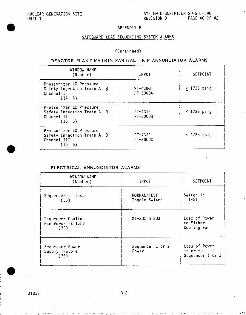
NUCLEAR GENERATION SITE SYSTEM DESCRIPTION SD-SO1-590 UNIT 1 REVISION 0 PAGE 40 OF 42
) APPENDIX B
SAFEGUARD LOAD SEQUENCING SYSTEM ALARMS
(Continued)
REACTOR PLANT MATRIX PARTIAL TRIP ANNUNCIATOR ALARMS
WINDOW NAME (Number) | INPUT SETPOINT
Pressurizer LO Pressure Safety Injection Train A, B PT-430G, < 1735 psig Channel I PT-3000A
(14, 4)
I Pressurizer LO Pressure I Safety Injection Train A, B PT-431E, < 1735 psig I Channel II PT-3000B | (15, 5)
I Pressurizer LO Pressure Safety Injection Train A, B PT-432C, < 1735 psig
| Channel III PT-3000C | (16, 6)
ELECTRICAL ANNUNCIATOR ALARMS
WINDOW NAME (Number) INPUT SETPOINT
| Sequencer In Test NORMAL/TEST | Switch in | (36) Toggle Switch I TEST
Sequencer Cooling K1-SO2 & S03 Loss of Power Fan Power Failure to Either
(33) Cooling Fan
Sequencer Power Sequencer 1 or 2 Loss of Power Supply Trouble Power in or to
(35) Sequencer 1 or 21
3185i B-2

NUCLEAR GENERATION SITE SYSTEM DESCRIPTION SD-SO1-590 UNIT 1 REVISION 0 PAGE 41 OF 42
APPENDIX C
DEVELOPMENTAL RESOURCES
Elementaries
5149180, Sequencer Logic Diagram 1542 Sheet 137M
5149957, Safety Injection Sequencer No.1 1542 Sheet 139
5150875, Safety Injection, Sequencer No. 2 1542 Sheet 137A
5149170, Load Sequence Schedule Load Train No. 1 1542 Sheet 140
5149179, Load Sequence Schedule Load Train No. 1 1542 Sheet 141
5149181, Load Sequence Schedule Load Train No. 2 1542 Sheet 143
5149182, Load Sequence Schedule Load Train No. 2 1542 Sheet 144
5150158, SIS/SP Lockout Relays 1545 Sheet 54
5102173, 125 VDC System No. 1 1540 Sheet 17
5149348, 125 VDC System No. 2 1540 Sheet 17B
Technical Manuals
Consolidated Controls Corp. Technical Manual 9N33, Safegurad Load Sequencing System.
Procedures
S01-4-17, Safety Injection System Operations
S01-1.0-12, SI Termination following Spurious SI
S01-1.0-21, SI Termination following Loss of Reactor Coolant
S01-1.0-31, SI Termination following Loss of Secondary Coolant
S01-3-1, Plant Startup from Cold Shutdown to Hot Standby
S01-3-5, Plant Shutdown from Hot Standby to Cold Shutdown
3185i C-1
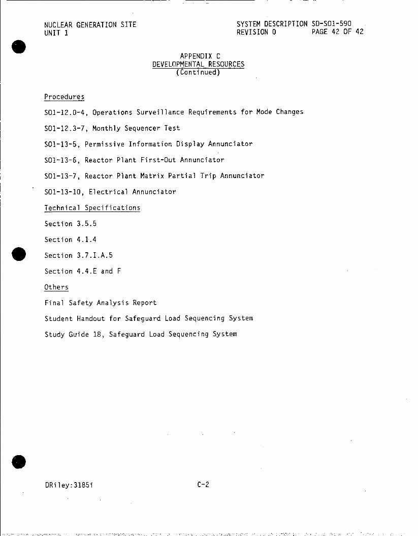
NUCLEAR GENERATION SITE SYSTEM DESCRIPTION SD-SO1-590 UNIT 1 REVISION 0 PAGE 42 OF 42
APPENDIX C DEVELOPMENTAL RESOURCES
(Continued)
Procedures
SO1-12.0-4, Operations Surveillance Requirements for Mode Changes
S01-12.3-7, Monthly Sequencer Test
501-13-5, Permissive Information Display Annunciator
S01-13-6, Reactor Plant First-Out Annunciator
S01-13-7, Reactor Plant Matrix Partial Trip Annunciator
SO1-13-10, Electrical Annunciator
Technical Specifications
Section 3.5.5
Section 4.1.4 . Section 3.7.I.A.5
Section 4.4.E and F
Others
Final Safety Analysis Report
Student Handout for Safeguard Load Sequencing System
Study Guide 18, Safeguard Load Sequencing System
DRiley:3185i C-2

ATTACHMENT C
Reference Drawings
Number Description
63714 Reactor Coolant System Elementary
63716 Pressurizer Pressure System Elementary
63717 Pressurizer Level System Elementary
63720 Reactor Control and Protection Loop Diagram
455116 Elementary Diagram Main Steam Dump
5102173 One Line Diagram 125 VDC System 1
5102174 One Line Diagram 120 VAC System
5112259 Schematic Diagram Reactor Scram Signals
5129817 Feedwater Control Diagram
5149348 One Line Diagram 125 VDC System 2
5150410 Elementary Diagram Rod Control System sh 1
5150625 Elementary Diagram Rod Control System sh 2
5150884 Schematic Diagram NIS Power Range Drawer
5151505 Schematic Diagram Coincidentor sh 1
5151506 Schematic Diagram Coincidentor sh 2
5151507 Schematic Diagram Coincidentor sh 3
N1541 sh 2 Elementary Diagram Turbine
W540F797 sh 9 Tripping Block Diagram
FSA Fig. 5.1 Functional Block Diagram NIS Drawers

. NUCLEAR GENERATION SITE SYSTEM DESCRIPTION S-SO1-260 UNIT I REVISION 0 PAGE 26 OF 37
FIGURE 2: STEAM GENERATOR/LEVEL INSTRUMENTATION RELATIONSHIPS
MANNAY- SRFACE BLOWDOWN CO44ECTION
N WIDE RANGE
381
3j8'
85% - - HIGH LEVEL TRIP -- 305' HIGH LEVEL TRIP
70% - - HGH LEVEL -- 292.5' HIGH LEVEL ALAa4 ALAAMBSH
30% -- NOAL LEVEL 258.5' NOLAL LEVEL 26% TOP OF -- 256' TOP OF FEEDRING
FEEDRING
U233 lETCABRTO 4 0% ma HT CLIBRTIO - 227' TOP OF TUBE StNL
FEEDWATEIR INL.ET
NUTE : THE LPPER TAP FOR PT-3400B IS AT 305'.
NOTE : COLD S/G. 31 GALLONS / INCH HDT S/G. 24 GALLONS / INC HDT S/G, 20.5 GALLONS /%
HADHOLE COVER
COLD CALIBRATION 1LONDOWNCOETN
(NOT USED) =-,9(I CRI
FIGURE 2
A09oo00oo 50-S01-260-2-0
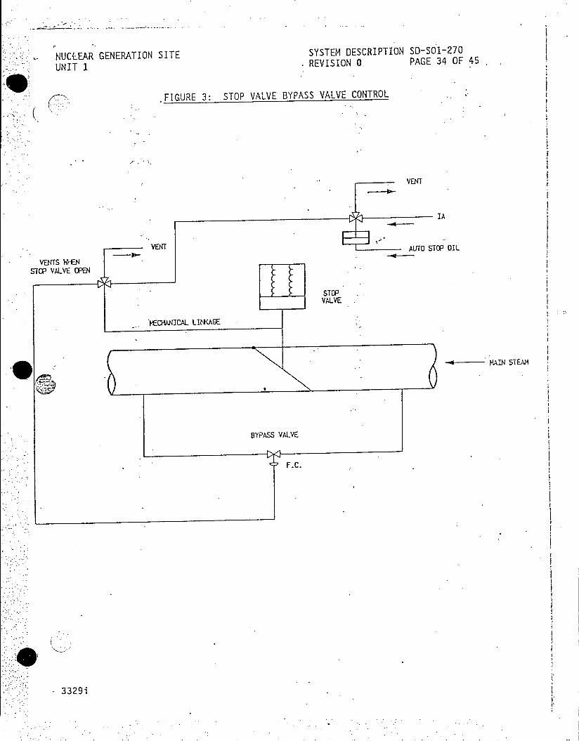
NUCL~EAR GENERATION SITE SYSTEM DESCRIPTION SD-SOl-270
UNIT 1 . REVISION 0 PAGE 34 OF 45.
FIGURE 3: STOP VALVE BYPASS VALVE CONTROL
. . VENT
IA
VENT VENTf AUT STOP OIL
VENTS WHEN STOP VALVE OPEN
STOP VALVE
?ECHANICAL l<AGE
RAIN STEAM
BYPASS VALVE
F.C.
3329i

NUCLEAR GENERATION SITE SYSTEM DESCRIPTION SD-SO1-390
UNIT 1 REVISION 0 PAGE 36 OF 65
LOOP A TAVE GAVE TAVE DEVELOPMENT UNIT I
HOT LEG RTO TE TE COLD LEG RTD
RANGE 525OF - 625'F 401C 401A RANGE 525 0F - 625cF
TT-401 LOOP TAVE Th - Tc COMPUTER
2 (TYPICAL)
TO VARIABLE TA-401 TAVE HIGH.- 557oF LOW PRESSURE A&B LOW - 533'F TRIP BISTABLES (RPS)
-] T RECORDER B TR-401 AVE
525'F - 600OF
0 OP A B C
TAVE DEFEAT TO F.W. CONTRO. SW-1 - SYSTEM
AVE TAVE SUMMING COMPUTER TO RO CONTROL
4tE = B TM-405A -SYSTEM 3
SHJTOOWN MARGIN
TAVE - TREF COMPUTER
TH-417 TH-405C TR-405 RECORDER
TO REACTIVITY
TO AETAVE AVE TAVE COMPUTER
TO STEAM DUMP PROGRAM TA-405 TREF TO R00 CONTROL
CONTROL SYSTEM TAVE -. TREF A&B SYSTEM ALARM +51F
mTE i TREF
- TM-415 TE TREF TREF
COMPUTER
1 MWE FIGUREI 3 HTREE WE lqlo~f 000 COTROLE TS-415 ES)-SOI-390-3-0
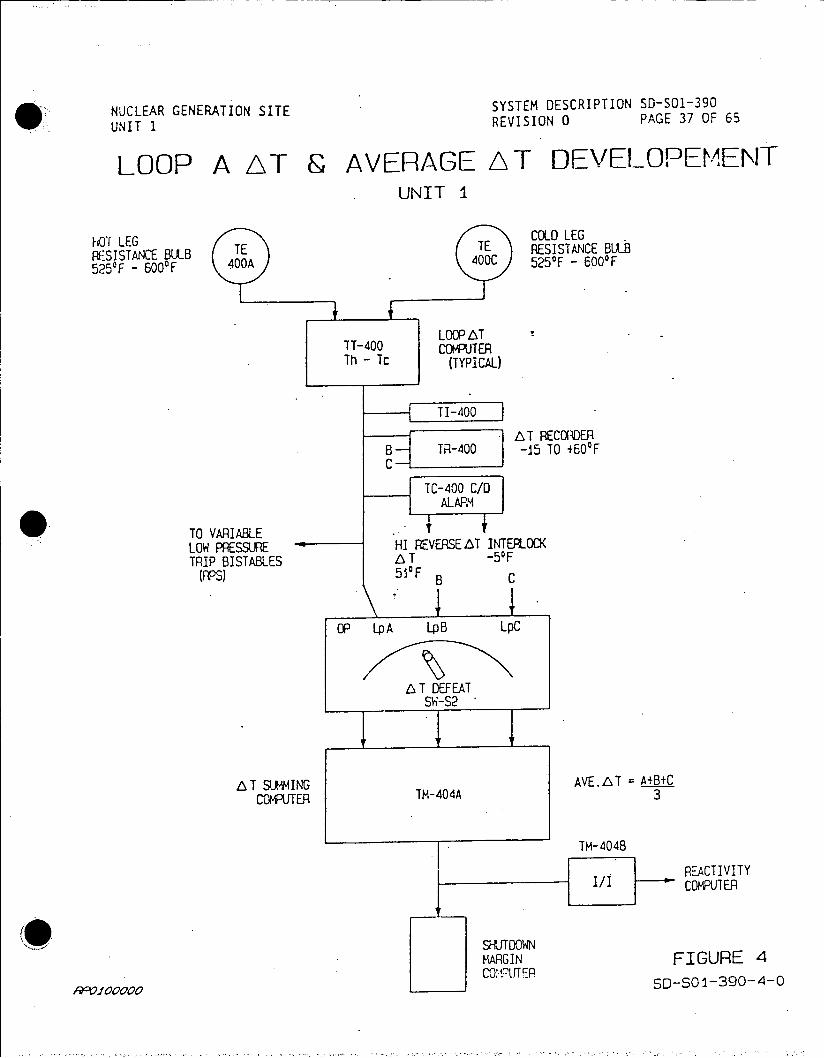
NUCLEAR GENERATION SITE SYSTEM DESCRIPTION 50-501-390
UNIT 1 REVISION 0 PAGE 37 OF 65
LOOP A AT & AVERAGE A T DEVELOPEMENT UNIT I
hOT LEG COLD LEG
RESISTANCE BULB TE TE RESISTANCE BULB 525'F -600'F 400A 400C 525OF - 6.00 0 F
LOOPA T TT-400 COMPUTER
.Th -Tc (TYPICAL)
------TI-400
- AT RECO1ioEA B TR-400 -15 TO +600F C
TC-400 C/D ALARM
TO VARIABLELOW PRESSURE HI REVERSE AT INTERLOC( TRIP BISTABLES LT -50F
(pPyS) 51'F B C
P [PA [pB LpC
L T DEFEAT SW-S2
AT SUMMING AVE.LT = A+B+C COMPJTER TM-404A 3
TM-4048
REACTIVITY COMPUTER
MARGIN FIGURE 4 COY.R O-OIT ER04
Roo~foooo5S-501-390-4-0

CONFGURTION CHAGE S~F EDM USE ONLY SH- CC No.
DAT2
REQUESTED BYTL SPECIFICATION L5ORAWIN N U PROCEDURE UINSTRUICTIONi
R -, UMBER kl7L7fl l t REVISION 2 CLASS
TITLE PRE qjAzz A R LJ q E S-T 7 /72 SUPPLIER _______________
ECHEETEL CEDISON
DESCRIPTION OF CHANGE .O O ____________
IQE~~oEAT~~ PC<-~~!E'B NO. ___________
P4CAT IF R LI LO.O.NO
pal
01A4Q -8-1?32
EVALATIO
OTHER AFFECTED COCURENTS DRAWINGS
DOCUMENT CHANGE REQUIRED FOR 0 CONSTRUCTION '"AS BUILT OTHER Per.-Re IS I Y%
- FIELD APPROVALS DESIGN APPROVALS
Nt ,tPIE 'DATE CONSTR. SUPDR. DATE RESPONSIRLE ENG4. INDEPENDENT REVIEW EIOR.
U ADII ... TURAL A.1E UJ MEIAI ATI
U CIVt.I T-UTURAL -AT U -U-A lATI
*ENGR./ DISCIPLINE DATE G.A. fif ATE U CO.T.-L ACRE 1--11 U AlY . AI I.AE RTE
U -LETRIAL RATE ROCT.ERE DATE
ENGR./ DISCIPLINE SATE STATION RIIPTPOWER DATE UCOh*al-IC RATE U C,.CERA-1.1OTICEI AT SUPPLY(REORD REV.)
74 417~I.
A ____ _____51Rill V I44; 6
C-I UV4..~T4~. I '~T7r
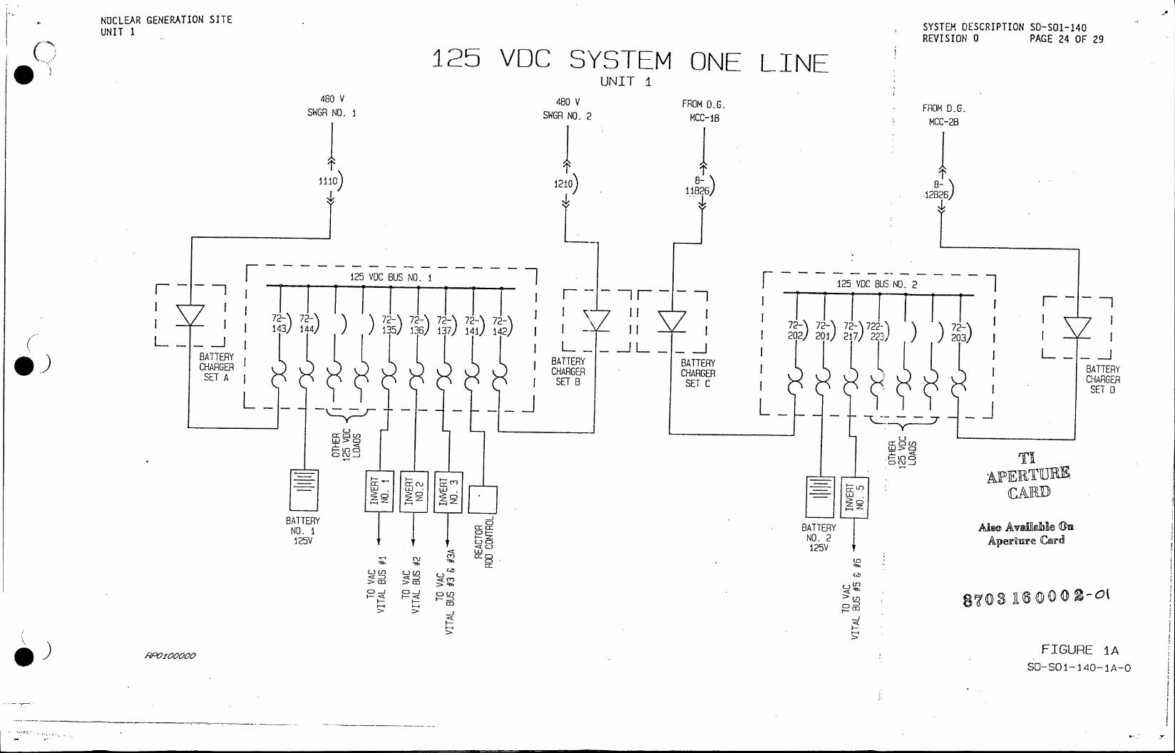
NUCLEAR GENERATION SITE UNIT 1 SYSTEM OESCRIPTION SO-SO1-140
REVISION 0 PAGE 24 OF 29
125 VDC SYSTEM ONE LINE UNIT I
480 V 480 V FROM D. GF SWGR NO. I SWGR NO. 2 MCC-18 FROM D.G.
111) 120 8) .12826
F ~~~~125 VDC BUS NO. 1712VCBUNO2] -- - 125 VO BUS NO 2BS-O
L-F 72- 72-) 72- 72- 72- 72 1 721 72 h 7 -172- ~~ 7
j 143) 144) )35) 136)137) 14) 12) I - 7 20/2- 217/22-)~ /23/)
)J A2 A0; A77 0 BATTERY BATTERYBATRBTEY CAGRCHARGER CARERYICARE
SET A RSETB SETC CHAGER SEI 8 SET
L L_
cr-c) tJ
F- un c:
F---- -P T
LU LU- c~i r - CA R D
BATTERY BATTERY Also Availlale On 125V o NO. 2 Aperture Card
15 125V C.JLI)m C) ) cm~c
twD CD LO
---D >.C ccc
)* FIGURE 1A
RA4100000
SOS1-471-
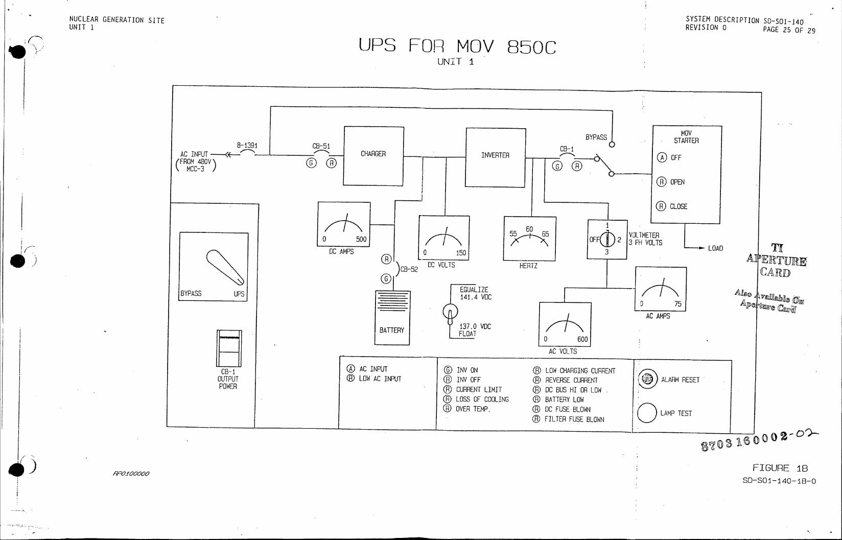
NUCLEAR GENERATION SITE SYSTEM DESCRIPTION 50-S01-140 UNIT 1 REVISION 0 PAGE 25 OF 29
UPS FOR MOV 850C UNIT I
MOV BYPASS STARTER
8-2391 CB-51 CB-10STRE AC INPUT CHARGER INVERTER OFF (FR~OM 8V)
OPEN
CLOSE
55F~ 206 VOLT METERLODif 0 5005 OFF 2 3P VO VLTS DC AMPS 0 DC 50O3TLOAD0 3
DCBVOLT HERTZ A E T R [cesaCARD BYPASS UPS C UAo ZE
AC AMPS 137.0 VDC
BATTERY Lo FLOAT
0 600
AC VOLTS
CB-1 AC INPUT ® INV ON ® LOW CHARGING CURRENT OUrTPUT @ LOW AC INPUT @ INV OFF (D REVERSE CURRENT ALARM RESET POWER ® CURRENT LIMIT ®R DC BUS HI OR LOW
LOSS OF COOLING @ BATTERY LOW OVER TEMP. (D OC FUSE BLOWN LAMP TEST
FILTER FUSE BLOWN
PP08
100006?
FIGURE 18 SD-SO1-a40-1i8-0

NUCLEAR GENERATION SITE SYSTEM DESCRIPTION 50-S01-140 UNIT 1 REVISION 0 PAGE 26 OF 29
UPS FOR SECURITY UNIT I
UNINTERUPTED POWER SUPPLY
C81 r-=
SC83 ALTINPUT(L I)PRE AC -. 42 117] AC IINV ..STATIC BYPASS IOPUT INV
SWITCH OIVPTCBI1 C83 INPUT POWER----' - CHARGER OC--MP 300 INVERTER '-42-1305 () DC AMPS G FWD
CB2 CLSO CLSD
FLOAT EOUAL CHARGER OUTPUT
BATTERY 134.5 141.5 CURRENT UPS
INPUT UVOC VC ALT UPSI20
58BYPASS AC AMPS 200 MAIN 0200 DCGV( SWITCH
BYPASS DC VOLTS FREG ALT SWITCH AO
OUTPUT CURRET DC BUS VOLTS FREO C~RE"
CB6 INV/CHARGER STATUS VLCLSD ***S2 INV ONC2
--- OUTPUT CKT. #3 ( __INV OFF VOLTMETER
PANEL Y25 ( CURRENT LIMIT/VLD SELECT1? OUTPUT CKT. #1 _ IN/OUT BREAKER TRIP STATIC TRANSF 0A<5
PANEL Y24 [** ®)OVER TEMPERATURE SWITCH STATUS 150 CB7 () FUSE BLOWN eVITAL ON NORM --- SEC AC VOLTS
UPS E HCBS f J ®() CHARGER FAIL ® VITAL ON ALT BATT __so____a___ber()
CB5 OUTPUT CKT. () AC INPUT FAIC (P) ALT SOURCE LOST AC OUTPUT VOLTS ._1)FAN FAIL ® SYNC
OUTPUT CKT. #2 FDR TO XFMER X39
OC CONTR. 125V __ _'()__ _ _ __ _ _ _()_()_()__ _--__)__ >
TO 480V B10-1, 2. 4, 52-120C
FIGURE IC SD-SO1-140-1C-0o
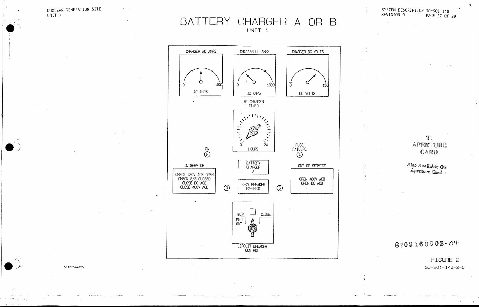
NUCLEAR GENERATION SITE
UNIT 1 SYSTEM uESCR~Iu~S-O-4 UNIT 1 ~~REVISION 0PAE2 OF 9
BATTERY CHARGER A OR B UNIT 1
CHARGER AC AMPS CHARGER DC AMPS CHARGER DC VOLTS
0 40C 0 1800 0 15C
AC AMPS DC AMPS DC VOLTS
HI CHARGER TIMER
24 FUSE APERURE ON HOURS FAILURE
IN SERVICE CARER OUT OF SERVICE Also Ayrale O SA Alperture Cagg CHECK 480V ACB OPEN
CHECK S/S CLOSED OPEN 480V ACB CLOSE DC ACB 480V BREAKER OPEN DC ACB CLOSE 480V ACB 52-1110
TRIP CLOSE PUL OUT
CIRCUIT BREAKER 8 CONTROL
FIGURE 2 RPO.I90000 SD-SO 1-140-2-0

NUCLEAR GENERATION SITE SYSTEM OE UNIT 1 REVISION 0 PAGE 28 OF 29
BATTERY CHARGER C OR D UNIT I
125V BATTERY
i CHARGER 0 150 300
DC VOLTS DC AMPS
AC HI DC LOW OC CHARGER REVERSE ON VOLTS VOLTS FAILURE CURRENT
TI
FLOAT EQUALIZING C=0~
Aso Available on
INCOMING AC SUPPLY DC OUTPUT
870316020
SSO-SOI-140-3-0
noo~rooloFIGURE ~3
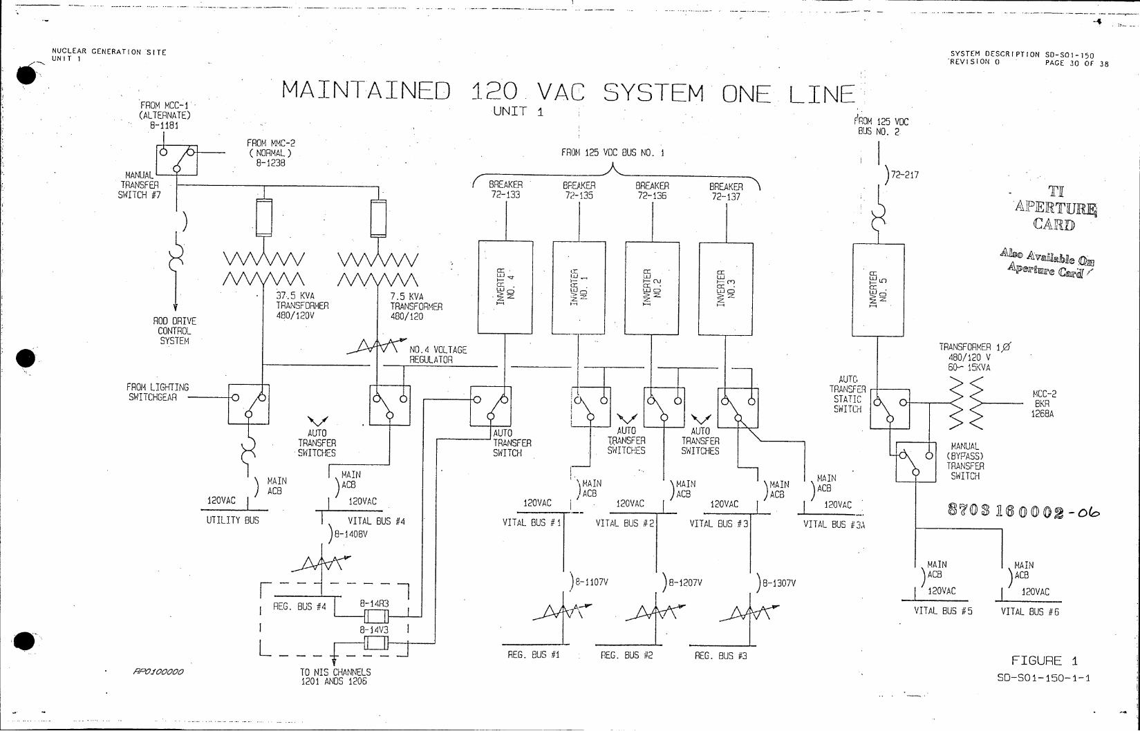
NUCLEAR CENERATION SITE SYSTEM OESCRIPTION SD-SO1-150 NUCL AR G NERA ION ITEREVISION. 0 PA E 30 OF 38 UNIT 1 'E I I
MAINTAINED 120 VAC SYSTEM ONE LINE FROM MCC-1' FROM UNITI (ALTERNATE) rJNIT 1
8-118'ROM 125 VOC BUS NO. 2.
FROM MMC-2 (NORMAL) FROM 125 VOC BUS NO. I
8-1238 MANUAL 72-217 TRANSFER BREAKER BREAKER BREAKER BREAKER SWITCH 7 72-133 72-135 72-136 72-137
APETU
jA CAR
-C .. cr_ C-- -E Cl uiLU LU CD uJ C CD CDU F
37.5 KVA 7.5 KVA . CD
TRANSFORMER TRANSFORMER ROO DRIVE 480/120V 480/120 CONTROL
NO.4 VOLTAGE TRANSFORMER 10 REGULATOR 480/120V
60- 15KVA
FROM LIGHTING TRANSFER SWITCHGEAR 0 CO) STAO2
AUTO AUTO AUTO AUTO TRANSFER TRANSFER TRANSFER TRANSFER MANUAL SWITCHES SWITCH SWITCHES SWITCHES 0 (BYPASS)
TRANSFER
AIN MAIN AIN MAIN MAIN SWITCH ACBACB \MAIN \MAIN \MAIN \ACB
2 ACB ACB }ACB }ACB ) 120VAC 12VAC 120VAC 120VAC 120VAC 120VAC UTILITY BUS VITAL BUS #4 VITAL BUS # 1 VITAL BUS #2 VITAL BUS #3 VITAL BUS 3A
8-1408V
MAIN MAIN )ACB ACB
---- - - -- - - 8-1107V 8-1207V 8-1307V AC F-120VAC 10A
REG. BUS #4 B13 VITAL BUS #5 VITAL BUS #6
I B8-14V3
L REG. BUS #1 REG. BUS #2 REG. BUS #3 FIGURE 1 -POf 00o TO NIS CHANNELS
1201 ANDS 1206 S0-S01-150-1-1
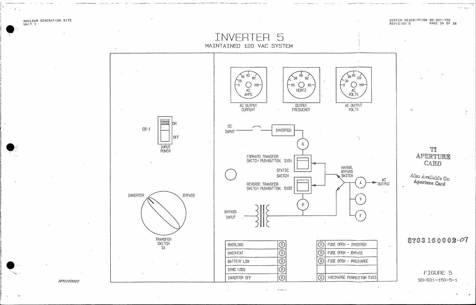
NUCLEAR GENERATION SITE SYSTEM DESC UNIT 1 REVISION 0PAE3OF38
INVERTER 5 MAINTAINED 120 VAC SYSTEM
o60 60 90
80 58 62 i20 030 Q 100 55 0 so Q so AC HERTZ AC
AMPS . VOLTS
AC OUTPUT OUTPUT AC OUTPUT CURRENT FREOUENCY VOLTS
ON DC
CB-1 INPUT INVERTER
OFF INPUTG POWER 'lf
FORWARD TRANSFER SWITCH PUSHBUTTON, SiO1
MANUAL STATIC BYPASS
SWITCH SWITCHACV ld () 0 AC REVERSE TRANSFER A OUTPUT SWITCH PUSHBUTTON, S102
INVERTER BYPASS V
R
BYPASS
INPUT
TRANSFER8 0316000 -7 SWITCH OVERLOAD FUSE OPEN - INVERTER
Si
OVERHEAT FUSE OPEN - BYPASS
BATTEIY LOW FUSE OPEN - PRECHARGE
SYNC LOSS F
INVERTER OFF PRECHARGE PUSHBUTTON S103 19100o1SDSO115050

* UCLEAR GENERATION SITE. a ~~~~~~SYSTEM ECITONS-O-6 ii ~UNIT 1 E I I N 0P G 5 O
A FEEIPWATER CONTROL SYSTEMI BLOCK DIA\jGRAM LOOP A STEA1 '-EACfAE SSY- L~cP B
STEMI FEEDWATER STA GET. 7TEjm FEEGWATER ST.IPEMAESTkCf. 4. I .. FLOl FLF. EE L' LOW . LEVEL . LWFLODWLEV
FT- Fr- LT R ITR FT F~T-LT . L
TA6 f~4* LEVEL RZCe P55 45 R4 FLWRANS-ICT~l TO STA 454
4ITTER .. : HI EHITTE RIER~ Pi- .. .-. ...
4559U
4559
STEA P1+ LC FLOW FLOWLO SG LVLL
C5. ffE__ 455.
RECJTR ~ rCECLE
FH- LC- HI LEVFM4 -O LC-.. I LO CC 1LR 456A 43 tf-F 5-7 m M
ruFW Fa
POINTN 1U1N 457 2
0,E4TE WTWF COSSVLETV<ST4
COWA&ATC 45 PE4578. ~.,. - 5
CV- 6A FLO MIMCCV4 PV LEVE L CV- 4AL
V 4LVE 'HIT .. OVE/E C [4578.1 TYPAS TO CSET VALVE~t V,.VEOV-I 'ii~C LO P ALO P 56H EVE LOLVE A 45Ta~N VA V
S.G.12 141CC RN C- EVE INCTOI R1N..
\,4fD) FATETE
MICT- STEJi/PSTATION
'E PT F/R I A L. F .P , FBOAVPO C1- AI~ I.S OSAE .. C
F .. ,9~ H..J OC,, PN~ L L!
_____ A O DE AV
AV EDTSI V'_~ EFW OC A. -P- 45 -ENS VALVE1
j.: .....................................................

EUAR GENERATION SITESYTM ECRP ON O- l20
uW REVISION01PG 7O
ELEMENTARY DIAGRAM SOLENOID VALVE DR FEEDV4ATER CONTROL BYPASS VALVE:'
_______ ___ ___ ____ ___ ______Al soA al
-~ . . . . . F V-46 *; .. *.. CV -457sr
.. .*.~. WEST) -EAST4
S>.AUTO-LEVEL
~FXP A SETPOINT DIAL . .1 0 I
FWP E~lk AUTO LEVEL
is NOT CLOSED SETPOIN'T
f CLOSESE E T R WI C TOE AN0
LC-4538-X2ACUTO
LK5 42456. CLS ONVd5 -IN 126-7 EH L~~ITG
REE TEE EE
CCV
CV24 V 4 C-43 . ..
O'ERMIGUR 3OS-5

'NULEA GE'NER ATION SITEc SYSTEMOSRPII O.O-6 f UNIT IREVIIN0MG 0O~
FEEDWIATER BLOCK VALVES
.MOV-2C) 2 1 E 22
A 480V BUS T OCE
cZZ- CENAC CLOSE & LS
VALVE POSITTal
b - N.O. - NCR't\LLY PNCCTC '1' 'Th 1'C-:: a - N.C. - lN C 4LLY LSD OTC
LIMIT SWITCH AFRAG.EN O XOV-20
CG C W . CGTCTDV
.STOP - - - - - - -- STCP LS-1
42 LS-;,
IT 42C '~42 'a
-1? 417-CLS b
'I . LS-e.
4,ULS-;' -.
LS-E rz
OPEN I M EPRED1A
CLOSC000

NUCLEAR GENERATION SITE UNIT I
SYS TI DE C I T O S - O1 2 O
ST A GENERATOR......N
.j *. . STEAAM GENERA O
LEVEL RELAY i~i
_________________________ _______(NOF NALLY ENERGIZED) :-j (DE-ENERGIZE HIGH LEVEL)
P-415-XZ CLOSE ON TURBINE TRIP
*.: - S A 7 7 L R F E ED W A TER
(6)9 FLOW TT2 SPARE TC-07
S P A R EP A R R Y- *-. O :R (3))
()FEEOWATR OS. 'YOR FLOWCOTOLE.
RISSPAR LECO V '-'cT
RI'
LOW TAVE CLOSES __PIQE .. F.M. VALVE TO 5X.' .
____30 PSIG CLOS,
FEEDWATER
lWV 00 FIGURE 7 P%100100000
:. SUPLY-SOI-260--O

... ... ...... .
I. .
SYSTEM DECITO0S-O-6
GENERATION SITE REVISION 0 PAGE 32 OF 37
UNIT 1
-15 HOVOVER PANEL.
RESET
-15 V.D.C. +15 V.0.C.
.H APRIMARY HAGANPUSHBUTTON
POhR MAG
TMEEROLMETR VOLTETE]R .VOLTMETER
. . .FIGUR B
BACK-UP +15 V.D.C. -15 V.D.C. PRIMARYAR +PRIMARY1 V0..
ON LINE BACKI-UP BACK-UP ON LINE PRAY PIAR
. RP JOO OO
A6~ OWd
V ~r
qpoIGUREo8

NUCLEAR GENERATION SITE UNIT 1
SYSTEM OESCRIPTION SD-SO1-260 REVISION 0 PAGE 33 OF + 10 IDO IRO1 iOVE" PANEL
-10 V.D.C. .. +10 V.D.C.
HAGAN RESET POWR MAG PUSHBUTTON PUSET
PUSHBUTTON
VOLTMETER 0LMET
PR Y K TO RESET BACK- UPRIMARY K TO RESET BACK-UP ON LINE PRIMARY OPERABLE ON LINE PRIMARY OEAL
8703160002s
I t ,J O OF GE
SO
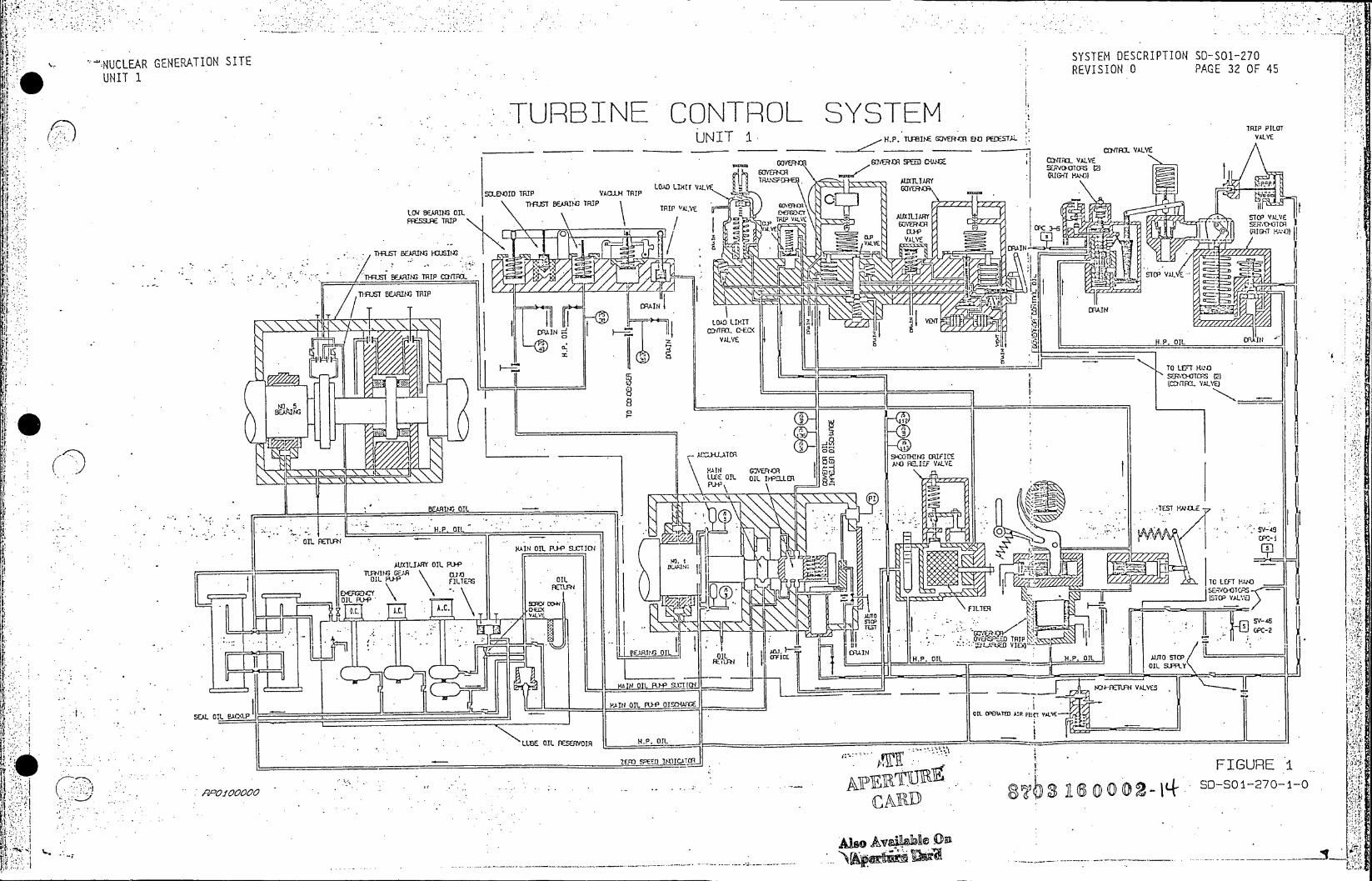
NUCLEAR GENERATION SITE SYSTEM DESCRIPTION S-O-7
UNIT 1 REVISION 0PAE3OF4
* URBINE CONTROL SYSTEM U N I T I H.. 1 u s w GO E R I DR I PILO T
~~E1~~WTRO TRPALVE RI G91EK fl-RE 2EARI- TRIPE
LO'LOA LIHA~tr VAL SfLEWID TRIPALL TI
-~-c ..- .- .. NG T RIPE? T ~ R I C )(~ T RI -A.W WT
IG {IJC
UEY
Ef -. DRAINA
(fs BEAM~arE TRP ALa VEPvm/
1B-11 TRI -TES r-a
T T T i DIAIN LRC R)4 STIL
ALVALVE$1 OIL OIL
IEI,
HOVrM OIL R14'E VA[VE
KAIN~OI OILK-aLIERJ~
.~~~~~~~p N ooooL&OLFSEVI I . z~ .n ;;' OO BEA...........ST F.f

NUCLEAR GENERATION SITE UNITi1 REVISION 0 PAGE 33 OF 45
FIGURE 2: STOP VALVE
STOP PIN
SHAFT
-PVAVVALVE DISC
DISC ARM .D.
KEYS
STE AMFSTEA "NI..ET OUTLET
EVER !_EVERab
BYPASS g A IT HP LEAKOFF CO0N N EC TIONSj
STOP VALVE TRIP PIL.OT VALVE CONNECT)3 TO
. . . TRIP FtLOT VALVE
0 DISC ARM XLINK.
STAMOPEN S A
. VALVE DISC
CLOSEo O VENT
LP LEAKOFF . . . SPRING.
FO/SPRINGS*. RELIEFVAV.. CONTROL VAV .
CD- PISTON ROD- TO P VLV CONTROL OIL TPlO AV
_-FROM AUTO STOP STOP VALVE COTRL I LIMIT SWITCHFO UOSO
-HP OIL SUPPLY -- ..-- H OL -DRAIN.REAVLE
n ~DRAIN PSO
' ISTO~p CHAMBER R00 A
Vo isc os.
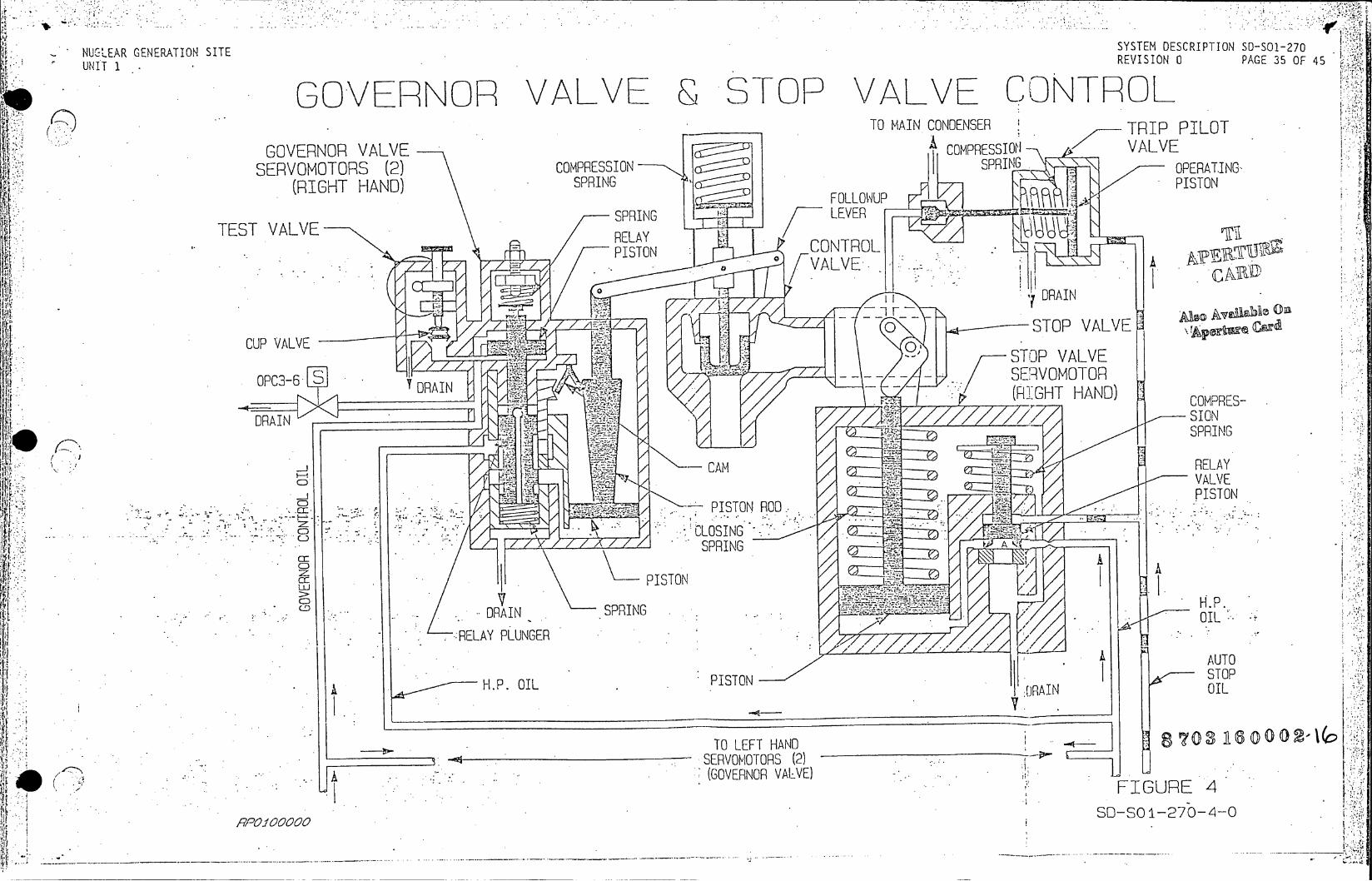
NUGLEAR GENERATION SITE SYSTEM DESCRIPTION S0-S01-270
UNIT 1 REVISION 0 PAGE 35 OF 45
GOVERNOR VALVE STOP VAVE CONTROL TO MAIN CONDENSER TRIP PILOT
GOVERNOR VALVE COMPRESSION VALVE SERVOMOTORS (2) COMPRESSION SPRIN OPERATING
(RIGHT HAND) SPRING PISTON FOLLOWUP
SPRING LEVER TEST VALVE RELAY
.. PISTON CONTEOL e
DRAIN
0 STOP VALVE eAec CUP VALVEO io'. STOP VALVE
SEIRVOMOTOR OPC . DRAIN(RIGHT HAND) COMPRES
DAIN .SO
CLOSINN
(SPRINGRING
-PISTON
. . DRAIN.SPRIN
jIj
O
cPISTON ROADTO
H.P. OIL INORAIN OIL
TO LEFT HAND P0 1 -. ..- SERVOMOTORS (2)
(GOVERNOR VALVE) FG R
RELAIGUR 4LNE
P'Oifooooo SO-SQO1-27O-4-0.
H.P.~.. OI ISO ( -.---------- ____ ___
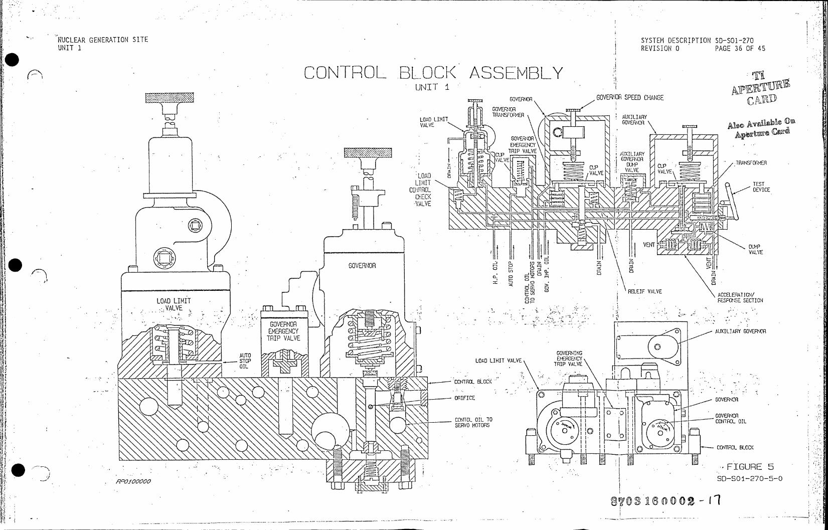
RUCLEAR GENERATION SITE SYSTEM DESCRIPTION SD-SO1-270 UNIT 1 REVISION 0 PAGE 36 OF 45
CONTROL BLOCK ASSEMBLY UNIT i
GOVEPNOR GOVERIOR SPEED CHANGE GOVEFNCR
TWACXER AUXTLIARY V0ALIMI GOVEFuNOR e A ilbeO
GOVERNOR EMERGENCY .
RIP VAL t GALVEO GOVERJOR
CO) CEP
RELEF VALVE
ACELP~E ETI/ LOAD LIMIT
GOVERNOR GVENO
ALOAD LIMIT VALVE
. .L.\ CCNTROL. BLOC<.
- - ORIFICEG
.CCTOL OIL TOC .SERVO MOTORS0Oo
o OC TR .BL K
.l FIGURE 5
R~OIOOOOOSD-SO 1-270-5-0
8M03160002 1

f4
NUCLEAR GENERATION SITE SYSTEM DESCRIPTION SD-501-270 UNIT R REVISION 0 PAGE 39 OF 45
FROTECTIVE TRIP ASSEMiB Y LOW BEARING OIL SOLENOID THRUST BEARING VACUUM LATCH UNIT I PRESSURE TRIP TRIP TRIP TRIP HANDLE
ol, TRIP VALVE
TO ATMOSPHERE DRAIN
40 a---- GOVERNOR OIL LATCH-TRIP
VALVEMAINLUBEIMPELLER DISCHARGE
THRUT BERINGGOVERNOR OIL
. IPELEROVERSPEED -. TEST HANDLE
- Ti T .
- ORIFICE .
GOVERNNOR OVERSPEED TRIP
- ~a ~ .. .H.P. OIL FIUR.
IGUR 8C
AUTO STOP DIL R9AVo a00 SD-SO 1-270-8-0

1*
NUCLEAR GENERATION SITE SYSTEM DESCRIPTION
UNIT 1 REVISION 0
FIGURE 9: TURBINE CONTROLS LAYOUT
GENERATOR END
ZERO SPEED INDICATOR
DIFFERENTIAL EXPANSION-. PICK-UP
CONTROCOILOR
SPEED SENSING PICK-UP
VACUUM CONNECTION TO PROTECTIVE TRIP ASSEMBLY
VENT FOR STEAM " 7,
CHEST SERVOMOTOR-
CONTROL OIL TO GOVERNOR VALVE
AUTO STOP OIL
DACA CONTROLLER
THROTTLE PRESSURE REGULATOR0
,-S.TEAM CONNECTION' G
OGOVERNOR END
GAUGE CONNE.CTION PROT TIVE GOVERNOR OVERSPEED GAUGE CONNECTIO . AUXILIARY GOV TRIP ASSEMBLY OIL IMPELLER TRIP DEVICE
S-.---.. -----.--.-....-.-... --..-. ..... ..... .-.. ~-SYSTEM-..D.ESCRIPTION-...50-..01-270. REVIION PAG 40 F 4

NUCLEAR GENERATION SITE . SYSTEM DESCRIPTION SD-501-390 UNIT 1 REVISION 0 PAGE 32 OF 65
REACTOR COOLANT SYSTEM TEMPERATURE INSTRUMENTATI TH TC TH TC TH TC UNITI T T TC TH TC
401 411 1 421 1400 UNIT y 420 LOOP A LOOP 8 LOOP C LOOP A LOOP 8 LOOP c TAVE TAVE TAVE A T T nT
COMPUTER* COMPUTER COMPUTER COMPUTER COPUTER COMPUTER
TAVE AT RECORDER RECORDER
TAVE TAVE TAVE HI - LO HI - LO HI - LO AS-T T
ALARM ALARM ALARM -INDICATION INDICATION IN
T T T TAVE DEFEAT LOOP C LOOP B LOOP A HI A T ALARM HI A T ALARM SWITCH 1 VLPT VLPT VLPT REV BISTABLE BISTABLE BISTABLE REVERSE A T REVERSE A T REV
(RPS) (RPS) (RPS) INTERLOCK INTERLOCK
AVE TAVE T T T _ SUMMING I COMPUTER SETPOINT SETPOINT EFEAT
Sj.WITTC.- 2
AVE TAVE AVE TAVE PRESS FEEDWATER T & TREF DEVIATION LEVEL CV RECORDER ALARM SET POINT CONTROL E COM'-!U]ER
P-PqEF I___________
REACTIVITY ES F BUPLE NUCLEAR FLUX- CONTROL ROD SHUT00IN COiMPUTER COMPUTER _________________ DRIVE COM',PUTER COM'-PUT-ER COMPUTER
SUMMINS COCRPUTER
T BANK.iRODNKA CARD
ROD ~ooPOSITION . POSITIrON POSITION H RR CO R RECORDERAL DIRECTIONI SPEED INDICATION INCAT CONTROL] CONTROL'
TO LSOFLO A TIA LR IA LR IA LR
)EMIDUMPCCNN COTPUTER AUTO. LOELOR
COPUTRO-UTE
T _ MANUAL GPOUP S LLECTICN SWITCH FIGUREAIK
I 3A~~~I l< AK2 SHSTOWNSTUAGW
CV'S PT 417 H.P. TUR. PT 4150 STEMSSUE SPMPD
LOSSUR OFEED

NUCLEAR GENERATION SITE UNIT1 SYSTEM DESCRIPTION 50-501-390
REVISION 0 PAGE 33 OF 65
REACTOR COOLANT SYSTEM FLOW INSTRUMENTATION UNIT i
L
A REACTOR PROTECTION SYSTEM
T FC 400400 400
TH
L
B . REACTOR PROTECTION SYSTEM
GENERATORS )FCl
FCCO 4e -E RE CTOR PROTECTION SYSTrEM
FT FC1OO-420. 420
FIGURE 18 JSD-SO 1-390- 1 8-0

NUCLEAR GENERATION SITE UNIT 1 .SYSTEM DESCRIPTION 50-S01-390
REVISION 0PAE3OF6 PRESSURIZER PRESSURE, LEVEL E TEMPERATURE INSTRUMENTATON MOV-813, 814-
TR TI INTERLOCK 430 4306 SCM PC T RAIN A 425
TC 4 0A430 A. . 430B
PR DPT
434 PT 425
PTP PT 430B 3000
434 PT PT
430 431
L LT LT PT L 431 430 432 435
434 1 CARD
PT T 13 4 3 0 0 0 6
PTPT D 1 1 I~rueC 425 LT.I
434A X I 2P
. 1 1.42 I------ M ( 1 II I I 45 - - - - - M - II I EI I I SCM 434 Ii .i3A TRAIN A 434Ab T
I SCM 4c01
TRAIN B4
TRII I I
430I I I7 PZR .SEG 2 .'---
CONTROL PZR SYSTEM Ti CONTROL P9430A SYSTEM FIGURE SYSTEMSD-SO 1-390- 1C-0

NUCLEAR GENERATION SITE SYSTEM DESCRIPTIO UNIT 1 REVISION 0 PAGE 35 OF 65
REACTOR COOLANT SYSTEM TEMPERATURE FLOW INSTRUMENTATION
TAVE AT
STEAM 410C .1 412C.GE RAO
R . C . P .
T E L O P AST E M O .G
OGENERATOR TC SPARE TAVE .SCM-B
TE LOCAL E. .E
4122 4118 410
LOOP B SESCH-8H
TR. A ATGENERATOR.
E SPARE TTAVE SCM-8 WLOCAL L O T E T
LOW1 FLO 4412 241? FTT
co~~ T o A7 60002-9
LL:L A TAVE C LAL ((RPS
42 410 423 'T
TM LOOP 4- STEAM
SFIUR
2
T TE ~ T T9oE SD-SO A -390-2-0
ARS SA LO
RT TL :R Fll~O 40
7T1 TONEAFO LO030
TA00 FLOW1- SC M- (b T
TE TE FIGURE 2
SLOCA-L0240k' 40A 2 42 3402 TVE T
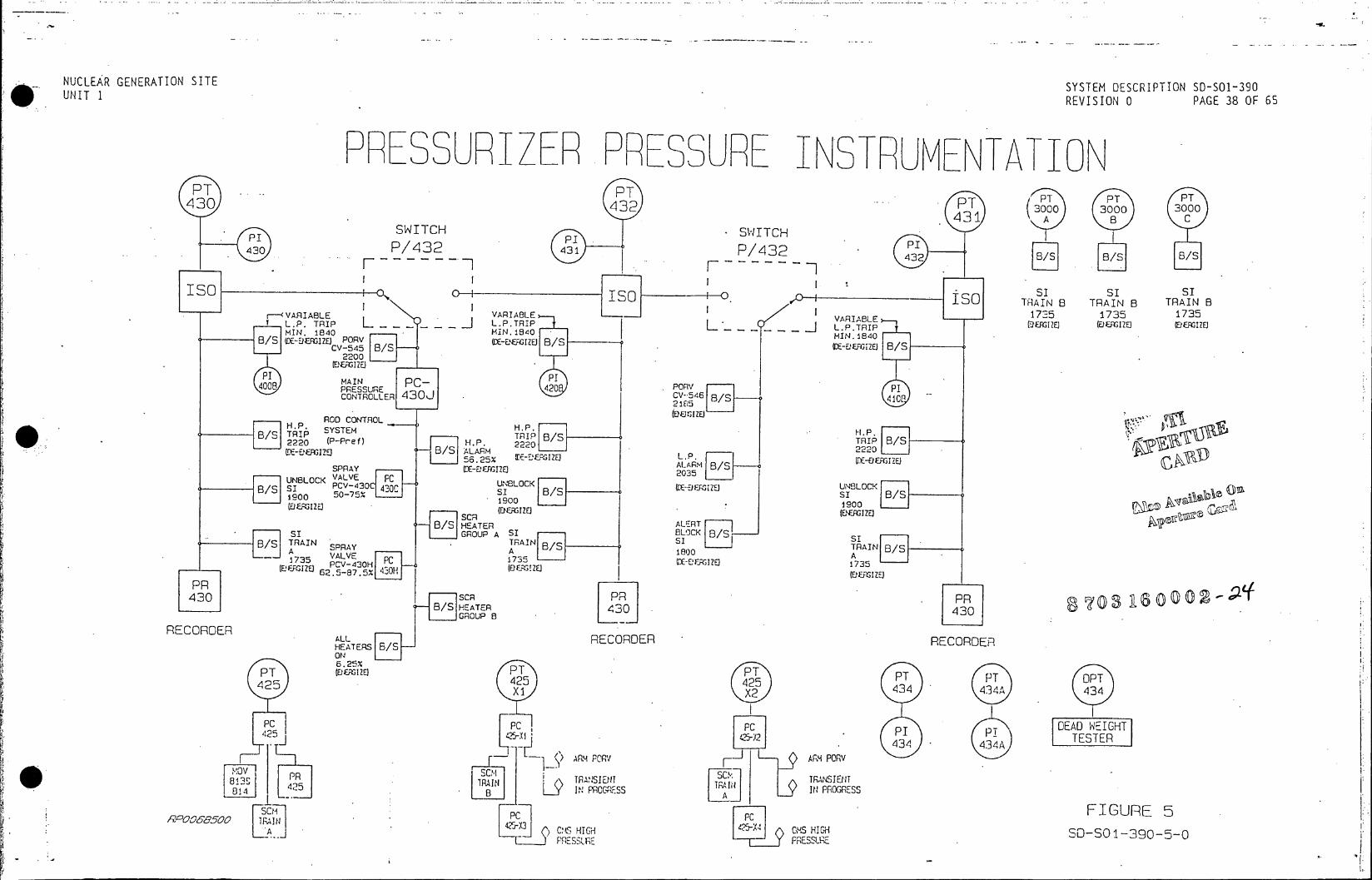
NUCLEAR GENERATION SITE SYSTEM DESCRIPTION 50-S01-390 UNIT 1 REVISION 0 PAGE 38 OF 65
PRESSURIZER PRESSURE INSTRUMENTATION PT PT PT PT
430 432 0T 0o 3000 30 431 B
SWITCH . ST 43PP43 PI SWITCH 42L /
/8/ 43 432 11 [6
. I I S IS ISO o a IS si st s ISO e I . ISO TRAIN B TRAIN B TRAIN B 0 VAIBL .VARIABLE 1 VAIBE1735 1735 13 r - - <RVR I A B L V A R I B L E
LPL.PR TRIP L.P.TRIP L . IP (DFIGIZE (EFIZ (Ef Z HIN. 840MIN. 1840 I HIN1840 B/S TE-EFJIZEc PORV CE--E&GIZO B/S .- E-EFGue B/S
2200 1/ . (FXNE)120
8 PSURE PORV P CONTROLLER 30 546 B/S 4IC
21fis5 /
ROD CONTROL HH.P S"T SYSTM HPH.P. T4 B/STRIP B/S 2220 (P-Pref) 222022, S ,_E
ALA ges~ieB/S ARM
2220.
SPRAY -E:F-GIZE)2035
UNBLOCK VALVEOCK E m UNBLOCK B/s I PCVA43 430C B/S V*P MR j SIA
(DattleB/ SCR R(,IOg /SHEATER ALSR
SI GROUP A SI BLOCK 8/ TRAIN SPNTRAIN
00 / 1 VALVE A 5735 PCV-430HPC73
62.5-87.5% 3H(U~ZJ13
SCR PR B/S HEATER 430 430
H GROUP B .430
RECORDER ALLRECORDER RECORDER HEATERS B/S
ON45P P 6.25% PT (&FrsuE PT
425 425 PT PT OPT X2 X2 434 434A 434
c PC PC DEAD WEIGHT P2 2- PTESTER .434 434A
ARM peav ARM PORv 5 .ss5-2P43G4ss
o s 5 . s TRANSIS 9T
4 ,2 5T AI ~1 IUG,; ' lf PROGRESS B A L2 POGRES PCFIGURE 5
A OO585O HIGH GS HIGH SD-SO 1-390-5--C I llj p 1E s s LrE FE$
vI

NUCLEAR GENERATION SITE UNIT 1 SYSTEM DESCRIPTION SD-S01-390
REVISION 0 PAGE 40 OF 65
PRESSURIZER EVE- INS RUMEN A ION LT LT
430 4LT.43 432
LI LI 4L/432 432 32 431
I.SO o-I-SO ISo ISO
HIGH
B LEVEL EVLALL HEATERS HIGH AVE TAVE HEATERS TRIP OFF HIB/S LEE ON +4% 70% LETDOWN B/S 70% (ENERGIZE) (DE-ENERGIZE) ISOLATION TRIP
(DE-ENERGIZE)qe 70% P (D19 - OTC (oE-ENERGIZE) 1.0% r a 70% (DE-ENER- L
1112 430F. B/S SPARE . SPARE B/S
SPARE. B/S
LOW LEVEL
ALL HEATERS OFF LETDOWN B/S (0E-ENEAGIZE)
- ISOLATION 820 0
(DE-ENERGIZE) 10% LR 4----- 430
430A 435 RECORDER RECORDER RECORDER
LI DEDICATED LI 80'OF SHTONCAL B FIGURE7 430A P ANEL .43 FOR S/U
SD-SO1-390-7-0

NUCLEAR GENERATION SITE UNIT 1 SYSTEM DESCRIPTION 50-S01-390
REVISION 0 PAGE 41 OF 65
SUB-COOLING MONITORING SYSTEM TRAIN A (B)
TS 2001 (3001) UNIT 1 - - .TCI
* latRGIN 10 SATURATION
TC2 INCORE
TI-2010 TO 1500F COUPLE AUCTIONEERED T HOT (3010) ONE PER HIGH CUADRANT TS 2003 (3003)
100-700OF
TS 2004 (3004)
TI-340 'A
RTD LOOP A ( )SAT -H APPROACHING . ~TI-2412A AUCTIONEERED STRTO
HOT1A) HIGH TsATURATION -L l HOT*LO8 LE. pT-222 TI-2425X2ar
TEPP TI-422A(2425xi) (3421A)
TOLOOP C JO70
PT LOW F0UN0CTN 425 . EETS!EAOR
PZR PRSLrE TRAIN A
03 16 (D0 002P7PT
PSSURE 425N
FIGURE 8 SD-SCS-39!0-8-0
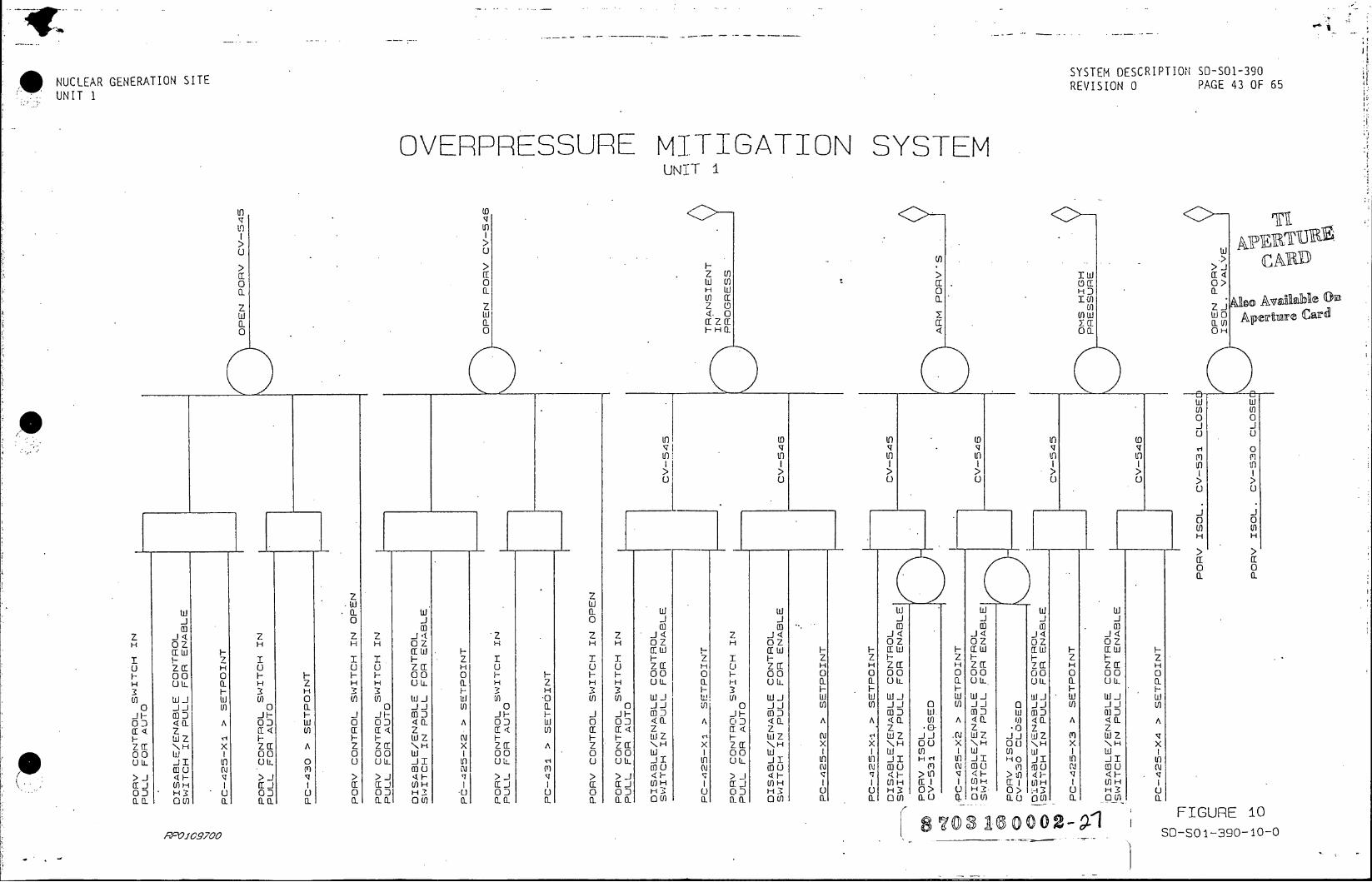
NUCLEAR GENERATION SITE SYSTEM DESCRIPTION DSO-9 UNIT 1 ~~REVISION 0PAE4OF6
OVERPRESSURE MITIGATION SYSTEM UNIET I
to (D
0 0 w c o(
0
z z 20 Lo d wU 4. 0 U)W wO A~rr cr 0- a-c azr ff 1Ycc a 0 0 0 CaLO
0 0 C
w w
1~~ 0 10111
I- z zzzF
00 001 00 0 0 0 00 00 0 00 0
H 02L H z H H 02L ( H z H H 0U HL 02 UZ LL(OUIZI 02 02a- UL (
3F 3 H 3 3F- 3 H 3 3: F . ) WIl w Uf) 0 U) U) wI (n .0 U) Lo wI Id W ) (l wi d WI w w w i wI d WI w w
0 1i J o U) 0 0 11 (n 0 (1 0) 11 II 0 11~ (nOji U) o i i Uf) IF (0 D IF F I IF .03 IF F I- I-I Fi 03 1F- (03 D 0D W. 0)D Do II (3 a
03D < 0- A 03 D w 0 03D <(I A 03 D 0 03D < a- A 03 D . ( A A <a I U() A <a P- 1) 40 A < I A CE< z (< a: C E< z c[ c< (n Cc (c < 2 m < * 0- z -0Z z
F Z2 ' F F F WZ w' F F F cu' wZ zJ i WZ II .JZ Aiw z m Wz z2CC \NH x z (I A 2 1: \H X- x 2C( A Z Za H X CC \F4 x z N H x x \ H 00 x \H 00 NH x N H x 00 wd 1 00 0 00 wi 1 00 0 00 wd 1 00 w I I wI U) Iw (n) w I w I Un. L i I T) U LL 0u U IL i I T) U LL u U OLL iI U) Utt LL I In 0) jI H'- LOJI 1J11 JI U 1: 11)
Nu (r) m2 C) cu (no C(u in0 u) (u N 2 (a) uU2 m n ) 0 ( ( muN >1 <F '4 >1 '4 > >1 <F '4 >1 ' > >J < ' 1 F' <4 <F >0 '4F U4F ' < F .
<L ~ - I>Ja ri U) I al a U)H I (n1 H) If IH C: 1 U)61(H I O
0D H3 u 03 D 0 0 OD )03 U 0 03D HI 3 03 H 0 U H 3 0 > 0 0> u H H3:
ILa 1U a (n a ai (LL oU in a- a1 a u) a.) 00 (L0)aa U a WU 0U an (1) a
plsas ~~O2- 1 FIGUE-1 RP1f09700 ____S-O13O~-
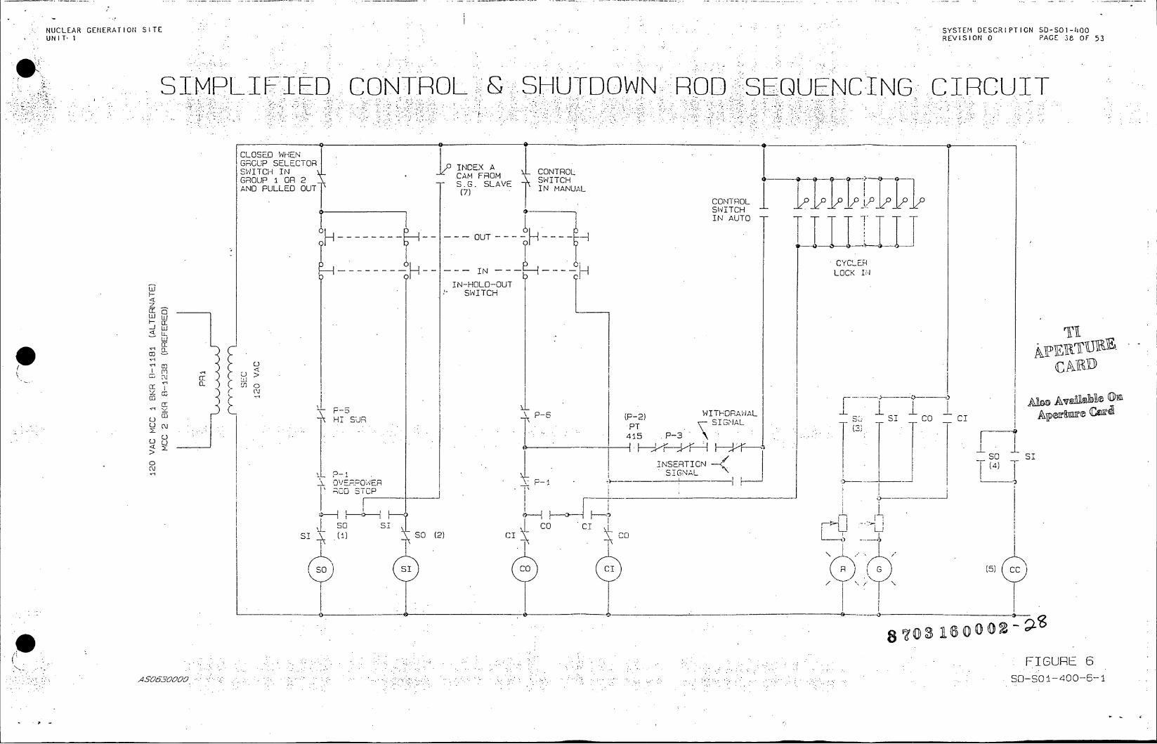
NUCLEAR GENERATION SITE SYSTEM DESCR UNIT 1REVISION 0 PAGE 38 OF 53
SIMPLIFIED. CONTROL' --.SHUTDOWN.*: ROD SEUNIGCIRCUI
CLOSED WHEN GRGUP SELECTOR SWITCH IN INDEX A CONTROL GROUP I DR 2 C FROM SWITCH AND PULLED OUT S.G. SLAVE IN MANUAL
SWITCH
- - - - OUT----H---- + IN AUTO T 0 CYCLERI
n N- - - - - - - LC IN CCE
IN-HOLD-OUT SWITCH
Als Avilbl O
w o:
co 4u
SO SI
CL,
CE I
cc
(nH_ SUR P-6 (P-2) WITHDRAWAL I cI
INSERTICN ( s S - S I G N A LC O
OVEPPONER P-4 --
SO0 STCP
sot ssoo
S (' SO () CI C
S SI CO CI R G (5)
8 0o3 16000D
4 0FIGURE 6
4SO830000 SD-SO4-400-6-1
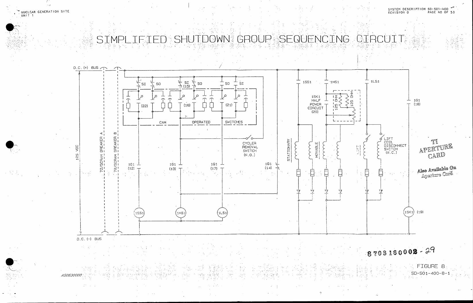
NUCLEAR GENERATION SITE SYSTEM DESCRIPTION SO-S1-L00
NUCLAR GNERAION ITEREVISION 0 PAGE l00 OF 53 UNIT I
SIMPLIFIED SHUTDOWN GROUP-SEQUENCING CCUT
D.C. (+) BUS
so s' so so - s "ms 1LS1 15)
7j6 I~SK1 2 HALF o - 101
(22)( 6 (21) TO E - :0 POER6)16
1(2 1T T( 6T 1(T CIRCUIT c (20)
CAM OPERATED SWITCHES L------
< E CCLFT
REMOVAL DISNNECT
>1 C SWI4TCH .- ilr SWITCH C)> (N. C.D.
.IG: <ciI I GIi * ~
a1 a
S, .
Ms IL
1I1I-161 G ---
I DS I
I I '.M1 .±S1 SKI (19)
D.C. (-) BUS
0 3 Asooos
FIGURE 8
ASOSOOG SO--SOI-400-8-1

NUCLEAR GENERATION SITE SYSTEM DES IPAG 0 1-O00
UNIT 1 REVISION 0
SIMPLIFIED CONTRO BANK ROO CONTROL;
Age±ecad 120 VAC
C1 J GS
C12 TC-4135 CLOSE ON K12 GS 26V0C TOGSYTAVG-TREF 01 MANUAL ONLY 2 CLOSE ON 012 CLO EOY Pi L L12 CLOSE ON
Ds MANUAL ONLY AUC22 C2 OPEN ON PULLOUT AUTO ONLY C22 C22 P12T _ ONLY (SD BK I S 2)
.RO CRIVE1 OO DRIVE1
PS PB PB CLOSED L I1 01 OUT OUT D CC-41EB PB 8K 2 01 OU I ICLOSE ON 15% PO I9
SLAVE CYCLER COSN1 I OUT POSITION PB- INDEX A - PB TURB. OST. STG
CLOSE AT IN AP7 PB PRESS. INC. 'G 6 (301
P6 (39) rr(5 SUR ROD AP L L 13 3 STOP API P AP7 Kl
SOURCE I, T RODS ROOS MSTR. CYCL. . (IN,.T.)PRAN-E OC-4158al IN FAILURE
5 (54) AP CLCSE CLOSED
AP3A AP3R APS AP7 CLOSE ON 15% PERM. 6I82 NIS O'F CROPPED F~coS PC, 5 TURB .. 15T. STG.S ROPC. e
900 ST OCS CUT IN PRESS. INC.' G \TOU +
.N)APSA I NT-TEOPEN CN K AE
0.30 SEC. ROD TOO/DE INSTR. CLOSE . APJ
ICI CO CICOC)- TOO -OU.T
--) TOI (1) co DA
T(( 2) ( .)
0 30 0.30 SEC. TOCC OE - P INSTR. OPEN ISTR. OPEN - CO
(3) (7)
(PWR. RANGE) (15) DA I X 1
OTOO TCOX4 COC A
FIGURE 9
3s06oc500
70 Qs' A O(-00 2--30 OO-0--

NUCLEAR GENERATION SITE UNIT 1 SYSTEM DESCRIPTION 50-S01-400
REVISION 0 PAGE 42 OF 53
PULSE GENERATOR AND MASTERCCYCLER TC-413A (25)..
TP1 r---~-- --- ------ - ------HI-LO LIMITER f i T2 P P
TM-413 K1 SHIFT MASTER CYCLEA FOX8CRO G:l20..
0 - 4 9 .4 M A 5 G 1 0 /O 7 f -P U EL S I N L GI
(2(23 7() 2LG
HCVOV .- OV 9 AMPLIFIER MANU0 MT
=5.4-0.37 SEC."S DAXFRE ATK -
(MOVE) K 6 NU 2)- HF 0 +214VPULSE CUTINVERTER
FROM 9 9 14
(17)2
POWER . K2 s l (0 SUPPLY (18)
o8SOLID STATE 1 =O+VRG.
,O L OV OR GRD.
SHIFT PLSE GENERATOR -, PULSE RELAYS 1 = +28V
10-12 MS 0 = OV R GFO.
+2EV EK.1 -~ MASTER CYCLER pAT O
KilWITHDRAW - L US GP.1 + KEFEAT NAND G TE -2O -. OE. CI-109 C0 AL (N4T UH F
E +8 CD-C9-1 ETCTOR INV. ALL " Na -C3 '-P CD10 - D(IVE 1 C1(1 1UTPUT
POWER NO EBRO 20P)t IPORA SUPPL OR1A8)
<BO0 8 ANNUNC OUTPUT 2L THRUP 8 10 Kill ROO ORIVE ELAVE
N2N GATE CYCLER FAL00SC LOGIC COMMON CDNS GRS +V 7 PET
Ki00- .L K- i e
0 0E 0 \S (UO ) ( 5 3 )K i+ 2 CD-lOg <l EO2 (55) K 0 DS9
v..o. 2 I . ,. *,REE T 7
I ~--'r -'-----e
NN13 GEANK '
C NT CEALE IN I'0" 0" Kl10 (2! 22 --. -o AND0(29) 2 CL1*
S ET CROU NT (S.I.)UNC
rn(.r
C)CAL LOPEOS25 CLOED 126 M
+28V TO K RE-KS DG
PS0 =5500 .l I ~111FGR .
(29):5N SD-SOI-400-1O-1 12
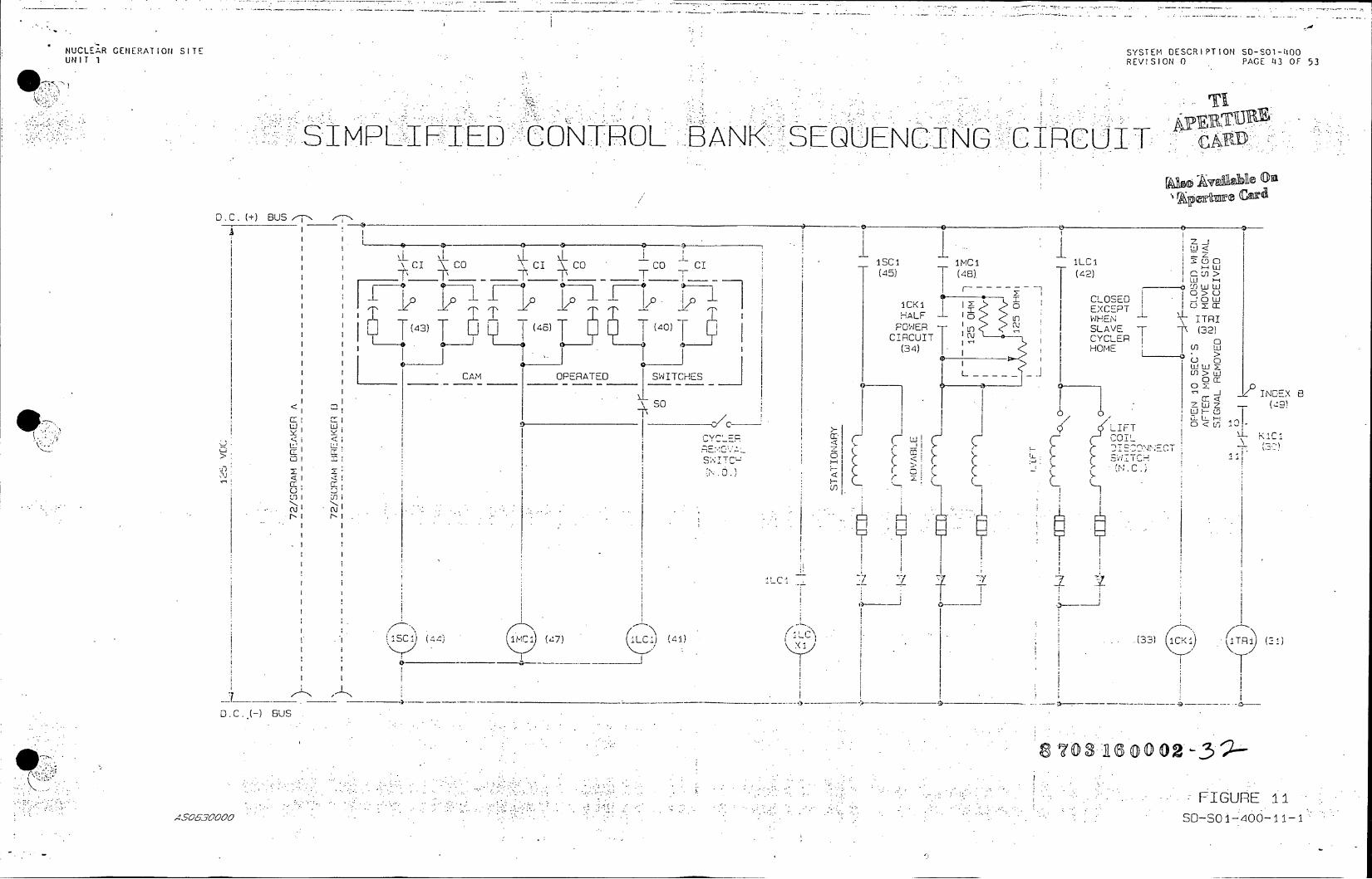
DE C I T O .......... O
NUCLEAR GENERATION SITE SSE E UNIT 1 VISIO
-- S-IMPRLFITEDP :CONTROL *.:BANK .. SEQUENCINO 'CIRCUI T
D.C.(+ BUS,-N ,
C OCc A s IM I _____
I~ CO
/D ICK 1- 1 COE
17,, pCK - ~ EXCEPT -~~~~' A L HAF I Ln HN ~ R -- T LLT (46 (40)P U) SLAVE
I I I I (34) HOME L I~ I W
C__ - ___ __OPERATED SWITCHESL----- -
S T I ATC
x. ~- M. S TC.,
E CE
LI- C IC
D. C. H- Bus
70-6 00
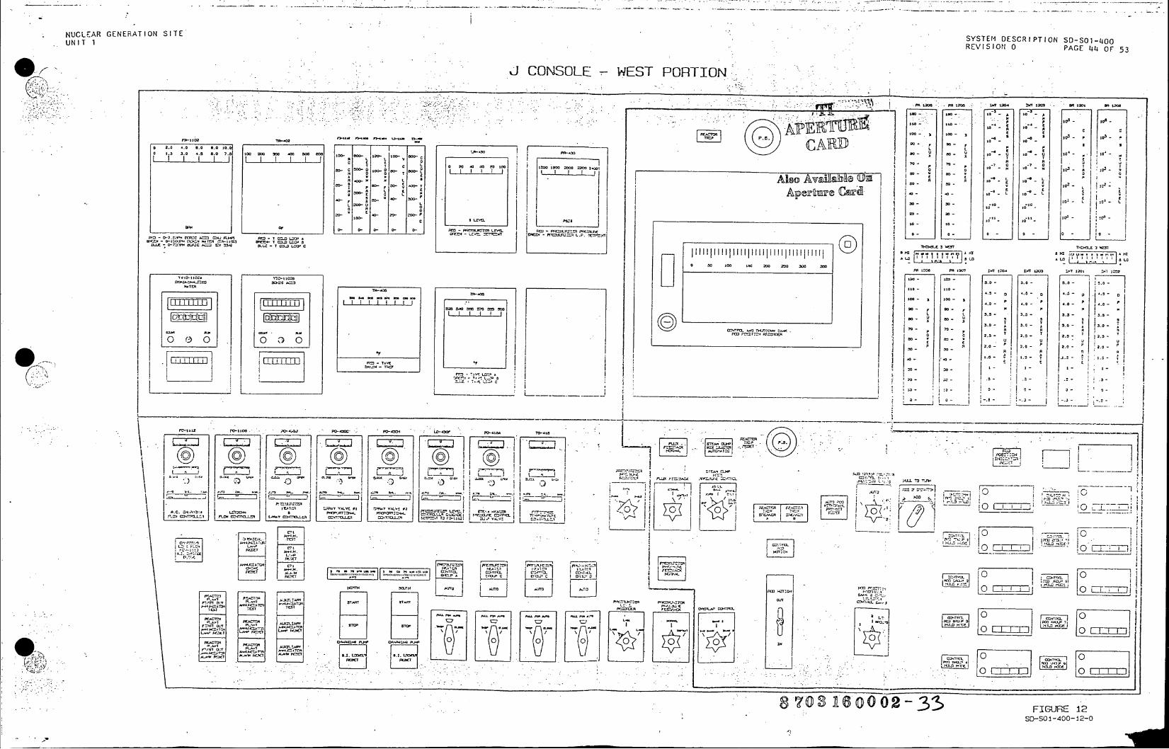
NUCLEAR GENERATION SITESYTMDCRPINS-O-O UNIT 1 ~~REVISION0PAELOF5
JCONSOLE -WEST PORTION.
IX. . P10 0 0 A 0
01~~~~~ ~~ w- FJU 0 I131O U 0 - 0
2.0 -. 0 0.0 6.0 mot CAR L L2
as. 1. .0. ..a 8. 7. lo 3w T 7 m C
A?- L I (car Ls 0 c 0 L s 0
0 ~0 C 0 ~ 20-n -- f0.5- 203- CI M3 -0 C=
1 s- - 4.10 058 sO.. 00EL M_ _ _ _ _ _ _ _
0 -L
3 U U - C3a
14 0-I0 tl- a II 5.0
*0 I --- I. ~ ~ ~ 3.0 A IiIIIII~in -I~ I p 700 - p 0
S 20 -o
Lb - tM _ _ _ _ _ _ _ _ _ _ _ _ _ I, oso~~ 05 :
-M-W' 0l~ * 0 I I~ ITm
_ _ _ _ _ _ _ _ l i I I I .. s
.07u .. -- . LL _ "X m i -- ,I
S J !l-~.~.±-J 1 ,u0 10
O ~ ~ ~ ~ F (- ()_ LI1 -FIPWT'
I I . ILM .2~ ~ ~~T ___-j -I*0, '
-~ ~ J w J L ~ J I~ ~ *T ..- 'N RI I 7 , tI '.V AJT
F I I Iw 7 Y-~i _
ILL,,, wv ~cv~*0 5 .)4.41 L P~~.-l4.220. el .040~ ~-~:-~ - -- I ;_ _
Ii I ____ I Z7 E':'<' C-It
I £5130. A -777.i.44 .. . z ~ z 3 L200 C' L'~ -s 0U£0
0~4.k.276S A60002-350

NUCLEAR GENERATION SITE . SYSTEM DESCRIPTION S0-S01-570 UNIT 1 REVISION 0 PAGE 26 OF 37
REA TOR PROTECTI ON. SYSTEM (SHOW-ENERGIZED AND >SO%:POWER).
CLDSD CLOSED CLOSED
(1.N ./ .R 5
2/4 P.R. ON >K 50% OR IS FM Tax 510% OR BUSES SJ PE I PRSST 2C AN>10% (P-7) exFEDLO
P R E S LCv . O FT
CCLOSED ED CLOSED 431 .,32 ~ WHEN 2/44546
2/4 AT P.R. >50 K S)0 O TT ~22. PSIG OR iST STGI
PRESS >50%'_T_ PES 5 FIXED (P-) - 210%A(P-7) 8X HIGH CLOSE PC~~L~
LUPRESS UE PR SPC E T CL WHE 432 *C I
PRESS 1 PR.S2
a:. Z c.P PC CLOSED FMC
S (r Z 4313 430 WHEN 2/4.2 a:LS LLJA P 5 BX . TRIP
HIG CLS PC PC
0 UV.L.P.T.
<c L LlJ 430 431 i
Ni(N u1/3 S 2/3 RCS
tLOW FLO LOW FLOW I H, T 63-X1I 53-X2
FC 152b 152b u H I FC 10CPRCP
400 A 63X
Fd F FC 152T2bbs 1520I j_152b 152b I IG
REACTOR . - *. 400 410 420 RCPA1 RCPB ACPC mFC ~ T PRCPj .CNAT
STURBINE CLE I LLTRIP L L 91 RESETCLOSE 53-XI
TCONTACT43 T40 I ~<45 PSIGI
LOSS OF A.S. OIL I cWER cr I63-X2 I
b I d
TF6 T~c 57 457
T STEAMISLOW
POWFEE FLOWv
x 8X
(s1 A OnA56
A (B
a 7 ( 3, R5 0 432 3(f
SD-SO 70% A5CONTACTS

NUCLEAR GENERATION SITE UNIT 1 Y SYSTEM DESCRIPTION S0-501-570
REVISION 0 PAGE 27 OF 37
.. REACTOR PROTECTION SYSTEM (SHOWN ENERGIZED AND >50% POWER)
FROM SHEETI
CLOSED AT 152a ' 3/4 P.R. <50%./ 152a <CC R AND RCPA CLOSE WHEN 152a -e- 0 RCP BREAKER CLOSE WHEN cL q PT-415 <50% l ~152a 1 8 is CLOSED -2 AUTO STOP OIL
152aPCPA LOW FLOW CcRC 45 P52aIGP TRIN
CLOSED FC-400 63-X2
RCS FC-410 152a 152a BREAKER z FLOW 85% FC-400 RCPA R
SEI PC-430F PC-4326 SEOQ2
UVSI FM-456 FMN-45U STEAM FLOW UVS2 SEM-257 FEED FLOW VS. STM. FEED FLOW. .
\0. \F PC-43LF PC-43CD FM-456 FM-458 STEAMlFLOW COECLOSE WHEN FEED FLW<S1SM0FEFO
UVS4 C. N ONFM-C4560FM-457-42
LOSS ±S2CBUS. I' A N D\ PC -435 P!C - 4 3 0
E, IT H-X l' H-X
PC-432 FC-4P0 C2
H-X
uv 'CLOSED WHEN 0c LC-430 LC-432 - - N 3/4 P.R.' >10%
SUR SCRAM AND /2 " P-415 >10%
LC-430 LC-431
UVIS- I< UVS-2 UVS-4 UvS-3
SHEET
W
SBFIGURE1 S 4S26SO0-SO 1-570-1-SH
ISCCSD63X
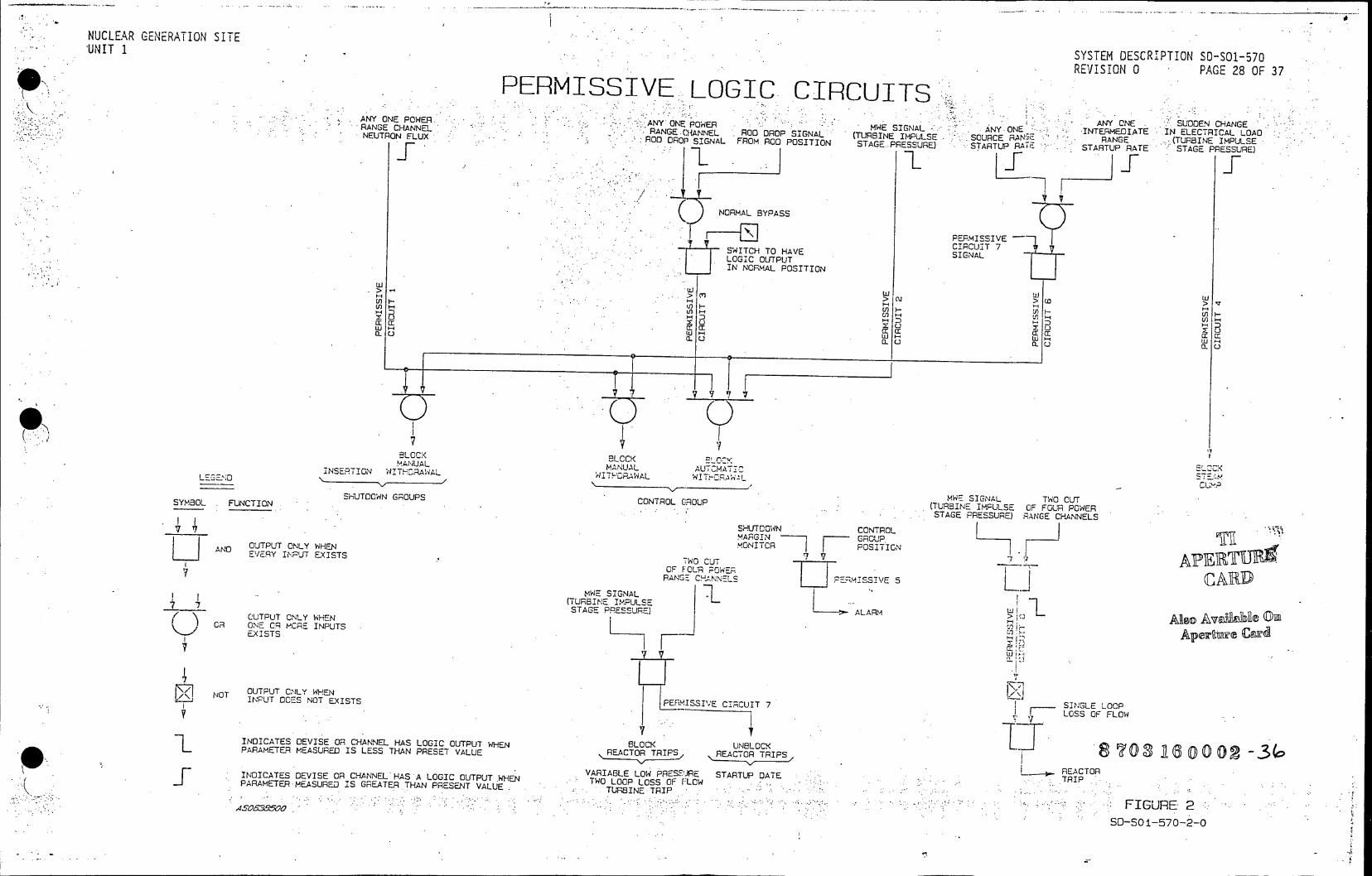
NUCLEAR GENERATION SITE 'UNIT 1 SYSTEM DESCRIPTION 50-501-570
REVISION 0 PAGE 28 OF 37
PERMISSIVE LOGIC CIRCUITS
ANY ONE POWER ANY ONE SUDDEN CHANGE RANGE CHANNEL RANGE-0ANNEL ROD DROP SIGNAL: (TURBINE IMPULSE SOURCE 0 RA E (TRIE LSE .NROD DROP SIGNAL FROM ROD POSITION STAGE -PRESSURE) STARTUP RAu STARTUP RATE STE ESUR
NORMAL BYPASS
PERMISSIVE
CFCIRCUIT 7 SWITCH TO HAVE SIGNAL
LOGIC OUTPUT IN NORMAL POSITION
Enn - > in n V -
UOO L
ELOCK BLCCK 'v INSETION INA
NAL GOMANUAL AU LEGEND OUTPUT ONLY WHENAWAL O OTSITIGNc
WE SIGNAL T.C N NSHUTDOWN GOUPS CONTROL GROUP (TURBINE IMPULSE OF FOUR POWER STAGE RANGE CHANNELS
SHUTDOWN CONTROL MARGIN ON . GROUPG
AND OUTPUT ONLY WHEN MONITCR POSITION , NUEVERY INPT EXISTS IWO CUT
LOF FOUR POWEOF
RANGAOE C 'N.\S U DATEEACTOR OWE SIGNAL LOSO-L
(TURBINE IMPULSE STAGE PRESSURE) ARM
iR ONE CR MORE INPUTS
7
NT OUTPUT CNLY WHEN N T I N P U T O CE S N O T E X I S T S P F - I S V l : C I I G E L C I LOSS OF FLOW
INDICATES DEVISE OR CHANNEL HAS LOGIC OUTPUT WHEN BLC UNBLOCK I]-01 l ' -PARAMETER MEASURED IS LESS THAN PRESET VALUE REACTOR TRIPS REACTOR TRIPS r -INDCATS EVIE O -VARIABLE LOW PRESFURE STARTUP DATE REACTOR IDCTSDVSORCHANNEL'HAS A LOGIC OUTPUT.WHEN - TWO LOOP LOSS OF FLOW TRI .P - .JPARAMETER MEASURED IS GREATER THAN PRESENT VALUE TBN TRI " *
A S C 6 3 9 5 0 0 S O - S O I - 5 7 0 - O

NUCLEAR GENERATION SITE UNIT 1 SYSTEM DESCRIPTION SO-501-570
REVISION 0 PAGE 29 OF 37
PERMISSIVE P-7 (SHOWN >10% POWER AND LOAD)
1208 7-
120 5 - - - - - - - - - - - _ _ _ - - - - - - - - - - -- - - - - - - -- - - - - --207 ------ ---------- - ------ ---I TEMNA ELoC I Also Avil abl On
____- A- Aperture Cad 120V AC
POWER (SPARE) SUPPLY 125V
L +0C
ON WHEN POWER AP4A EELOW P7
AP4C TUBINE TUSINE (OC"415AX) (OC415AX) 1ST STAGE 1ST STAGE
PRCLOS. T1 PRESS. CLOSED 210 CLOSED >10% PO;ER A2 POWER
AP2A AP2B AP4A ENIER. AP4C AP48 A6 ENER. TO AP TO \ DEFEAT
DEFEAT / .- SUR TRIP-
120V AC - -T.PS
-125V C - --
AP2A-BLOCK ANN. & EVENTS REC FOR: APA7-BLOCK HIGH SUR TRIP 0 AP2B LOW FLOW TRIP & P.R. BKR. TRIP AP4D BLOCK EVENTS REC.
VARIABLE HIGH & LOW PRESS. TRIP . BLOCK HIGH SUR ROD STOP ANN. WINDOW(52) INTER. RANGE TURBINE TRIP BLOCK HIGH SUR TRIP 1ST OUT ANN. WINDOW(4)
AP4A-PERMISSIVE DISPLAY WINDOW (3) AP4XB-PERMISSIVE DISPLAY WINDOW (4) AP4C BLOCK TRIPS FOR: SAME AS ABOVE APAXD BLOCK HIGH SUR ROD STOP ANN. WINDOW(51) SOURCE RA: GE
SD-SO1570
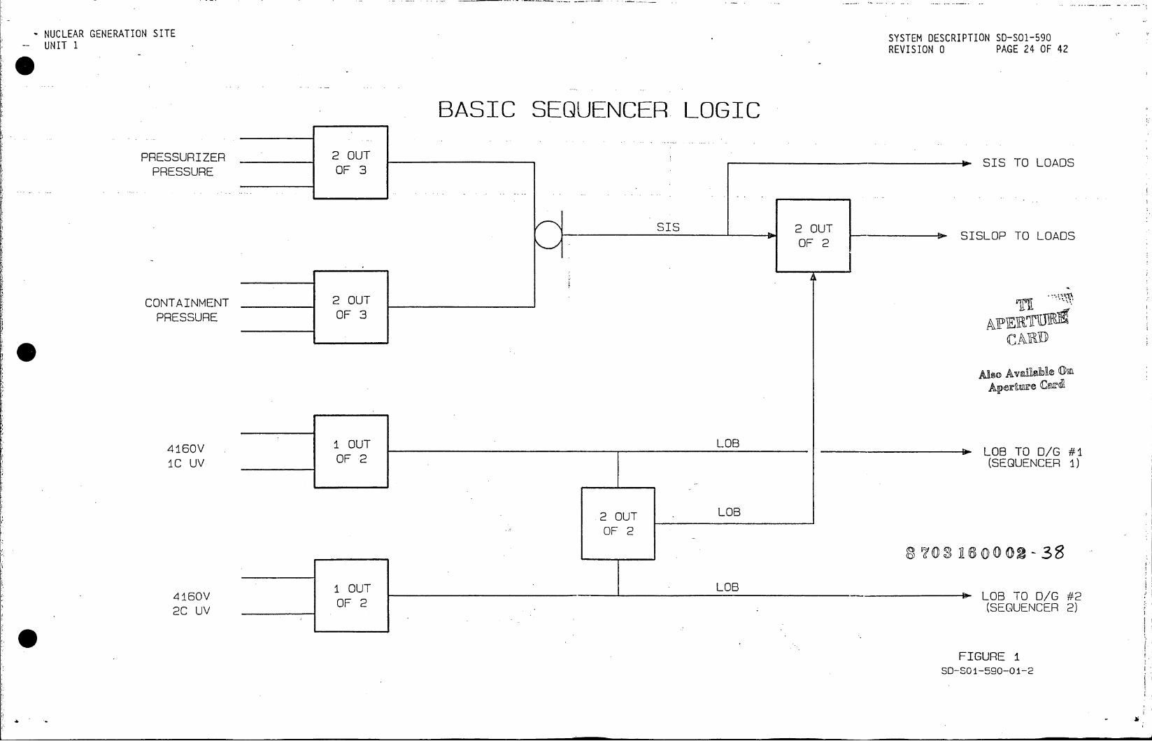
NUCLEAR GENERATION SITE SYSTEM DESCRIPTION S0-501-590 UNIT I REVISION 0 PAGE 24 OF 42
BASIC SEQUENCER LOGIC
PRESSURIZER 2 OUT SI
PRESSURE OF 3
SIS 2 OUT IL SIS 2OUT> SISLOP TO LOADS OF 2
CONTAINMENT 2 OUT
PRESSURE OF 3
AR
4160V I OUT LOB __________LOBTCOG#
2OUT LOB
OF 2
1 OUT LOB 4160V O LOB TO D/G #2
OOF 2
2C UV (SEQUENCER 2)
FIGURE 1 SD-SOi-590-01-2
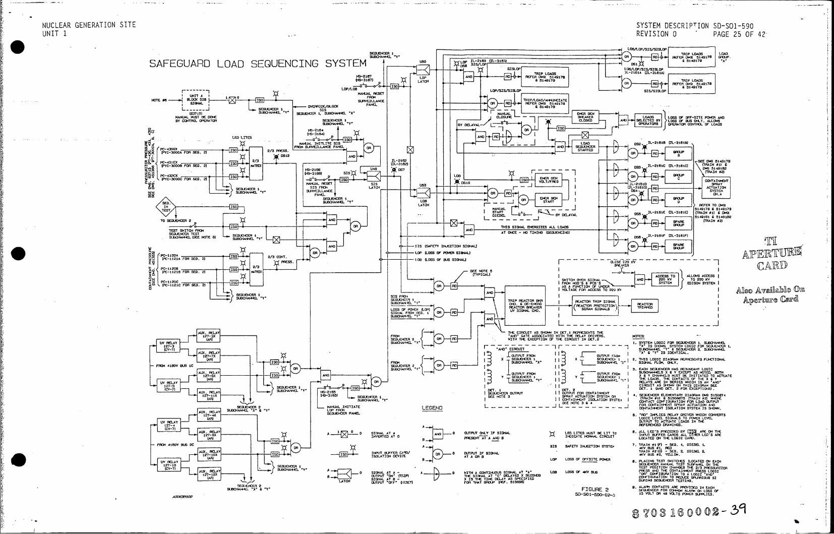
NUCLEAR GENERATION SITE SYSTEM DESCRIPTION SD-O-9 UNIT 1 REVISION 0 PAGi 5 F4
SEME I -TRIP LOADS OA
SAFEGUARD LOAD SEQUENCING SYSTEM *i op-1~ 62191
-. L- LACH (R s REFER D~ 197
NOTE 05 -4* L OX SIB FO
QiC300 F- ISO. 21VILAC MATMIDA"2CI
SW4MAEDU. 1.E 94TE GEN *,.
SUC~4E Y.iII ANT SEQ. 2)fhI jp iar
KoIIH TIELIT EXCPTS IL211 TIECIRJITIN ET
PC-430GXL ISO 2/. PRSS LORIM SUVIL~C PANEL*z£ OR AND
(PYC-3DO6 FORXJCE SEG 2) OR F GROU
OS12 ANrDIAN La
FYC-30006 FO . D 2) SECiEI I I S3 L-2161EC O4T CrFC TI 0
oJA3C W-3LA6M IR IOS SERE XP III AAA
0-YC-300C FEESEG.TE IS ISOA TISOD SYSTE GE OR SE CR CLI1TI oIA ONT51587
SEOUENCGIC LEE SIDAL TOO LATEH LEVEL2~iSP WT381)PJT T ACTUATELAS NI
L REEE4E SUCHN4L .WLI-r3L3S. S
BEG SUSSENNE ATT0 A _ OR] STR LREATE TOTE OI C 7. ISAI MAJA 51A17 6 5E.I ISL1
TES 57F 515- SL-FETY M-316100 (TRAIN #1) 1~# E
ISOTD EIE TA0 YFRC'T ORP.I IHI SIGNAL ENEAINE ALLG LOD RL .DISL2
BR LOP LOSS OF POWERT PIGNLER
PC-1121A~~~__ FOR SEG. TIE PRETM .*N PRESS OF B S S G ALOGIC - - - - -a~s g - - - - -
PC11T7 8 ]so TEST yO ITD 0-W XE TE /3 PREN
PC-112i FOR SEG.J 2) (TpTp) 0 E NIH O 1£T T 5 I4LA ALG LG 4 C ~'AIA~ OI
FIGURE212FO. SEG. 2) OR DTAS A FEtCV ONDOF LHDE
AND VOLTAT FO ACES TOLT P22E) KVIS
LCS3 OFY

NUCLEAR GENERATION SITE SYSTEM DESCRIPTION SD-O-9 UNIT 1 REVISION 0 PAE3 O12
0 ~~~CARD RACK__ _____
_______________________CHANNEL "X' ____________________ CHANNEL 'Y 0 c~j Ct q n-. I
cu IT) in tlo m''I
H~F F- F - F- F 0 o 0 0 0 0 0 0 0 0 0 0 0 0cU) U) U) U) (n En U) C(n C) (nU) U) U) U)
o -48V 0 -48V 0 -46V 0 -48V 0 -46V 0 -48V 0 0 -48V 0 -46V 0 -48SV 0 -48SV 0 -48V, 0 -IV 0 -'ISv 00
0G4V 4V 48 48 P+8 A48 0 +46V 0 +48V 0 +48Sv 0 +48V 0 +48V 0. +48V 0 +48V 1PAQ+V
0 ~ ~~~~~ 0 0T000 C12A RP -Oy0 TI PC40PC- I120A TRIP i-VTRIP SEG. 102 LOA PC-430 P-2ATIP" K RI"KSEO. 1 (2) LA
(P-00A JC121 i LOP' IN TEST GRU B 0 Q-C(C3000A) (PC-1121A) J I LOP IN TEST ~ i o c
0> 0~~ - LG-F 0o..0>QL'>C4i 'PC-1120B OEE Ct E .G. V/Fa LOAD PC-3 PC- 11208 R ESET 2CU /ToRST0 .V
C-3O0O0 ,JPC-11218) 0 i S'S 0 0/P 0C~ 0 0(1-A P-OO (PC-11218) ~ s ® J2-U LOPE DG /Fb
PC-1120 SI 3CCK W) ®jg~~a~)% JOT-O J C42 3 PC-1120C SIS 3 IC-AN LOB~3 2C-IN 3)0UV~LA ED~ (P-00C D P0J2C G O LO) D CLSD&UPa0 ( (PC-3000C) (PC-1i21C) OVR) G OLc1 09 COED ~~
')UI ~LOAD
ZJ RP FF
0 0 -15V 0
0LATCHON AOED IN
'-d SIS-LCP 0 C42 0 P-10 I cwLOB 0 - 0 .G.C. B. JLAT>ED IN PC-432 PC-1120C 0 SIS0 iC-IN L(8 0rCU .G .. C
QP-00) (C12C VD(O)COSED CK-CPC-3000C) ~ PC-1121C) Q (LOB) CLOSE SC40P-i2A n TI CU TRIP SEQ. IN 0 PC-430 PC-1120A TRIP iCU RPSEG. IN L
PC-300A 0 PC-112A) ,X TIP cu X. LOP >...(TEST LOB..~ 0 PC-3000A) ( A PC-1121A) SIS LOP( ....( .. TEST
PC-i431 0 PC- I120B EE SU .G / 0 (1-C PC-431 PC- I 206 RESET C2CUv PESETD. G. V/F <(30008) (PC-il2lB) )i SLOS QJLP 0./ 3>f (PC-3000B) (PC-11216) 0) SLOS LOP/3Cr~T 0)
o PC-430 0 PC-li2OA 0 TRIP 0 lC-U.V 0 TRIP 0SEQ. 1 (2] 0J- PRES 0 PC-430 0 PC-IM2A Q TRIP 0 iC-uv 0 TRIP 0 SEG. 1 (2) F (PC-3000A) (PC-1121A sis LOP IN TEST 0 LG-F (PC-3000A) (PC-11liA) SIS LOP IN TEST L
PC42P-10 i C-VLB 2C-UV0.GC.B0 ) PC- 432 PC- I120C SIS lC-UVLC 2C-UV 0.6.-C.S. .jO A PC-3000C) (PC-112iC) OVO (LB CLOSED ' 2/3 0(- (PC-3000C) .>..- PC-1121C) X.(OVRD LOB)( CL...(~ ~ OSED
0- 15V 0-i5V 0' - 15V 0-15V 0-15V 0~ -15V 00 + 15V 0 -15V 0 -15V 0 -15V 0 -15V 0 - 15V 0 -15V c15
o + 15V 0 +15v 0 +15V 0 + 15V 0 +15v 0 + 15V 0 -15V 0 +15V 0 415V 0 + 15V 0 + 15V 0 + 15V 0 +15V0
LiL L Li LL LL LL >i Li LLL LiL Li LL <E
IL L LLL L iL LL. L) I--LU.- LL LL LL LLC Z) :D Z) Z)2 ) cc D D) D) )2 ) D)CE
(3 (n co ca L)c 0 (r) C13 a] 03 (a 0
Z: ) 2)2)232 0 <) D) D) D) D c) a a a-1 a- aL aL a- a a0 zz z z z z w z z z z z zw
FIGURE I
4S0638500 70 5 0 2 +)SD-SO 1-590-C -

a0 3 A £ & 7 8 1 ' I 13 4 IS A /7 A A 2/ 21 2J 24 MJ 27 2 29 3 31 32 33 14 3 3637 3 39 VO 4/ op fVl 441 O5f 4* 47 40 5455 5 57 5
TO SUBC004/HI
. ,La n - a i ~ ~ a..an .L, I
" vs71 s:
REAC7?R VESEFLNG LY
0 NS +--ZA sv a 7d ra o
r Awlt 1 t II
tos or cr
r Fir
i,~~~aLOS r - _ ~ ALL OWn j - ~
refSRIff aID RAEASrf.U
1' 551/AV1.. / Efl~ REN /EF AN o0sus 53S R'ER EL/E - P 7 .. Sff/ /SUFFPlE ,rt ff3/DU4 EA 1*4rr ** t~ -
r Orr E-is P Ay FN ESRZR EOf lLO s s T 4o
- CRO t
- .. I .cot.. E cupameo a ut -- 1 -i -- 7. 7
STAALA1L
'1I K.J 143 rls____R9NP M4. .,~~~~~~._ -
oari'o izLlzc)fJa ts ANL.- ~ U-U44 ' AQWH'YD Art 17eZC
fl~1 4N,. nowI tt
Iif,111l ef 14 4SV'n A
i~iII
PFSS'AZ Z I'f,& TAK MPFRA fere- VAREz
4r.tVflP' e
"cite it A t 14 - - L 'bi-',410-L
_ h-11
Citete 12Z AMIA Nt' * 0 ~ ~ - J i 4 1II- ~L-i L$FT
-z ZW VA F--II_ a,'e'-.rt z
454' H aetA,. ~e n-cleI n-s
Lena~~SAET REAE FXEi AS N4) A. (At .~21'
*~G 2 R G G I
05F __ _ _ __ _ _ __ _ - -e, A ... .
i J s--RA~ ESLfA~LVF ~i~h~~e,~Z( ~ .
£ ~ ~~~~~~~ AVAILABLE4{iU~ ~s.~~~e~

9 10 f/ / 00 #4 #r 47 Ow 09 fo / f2 53 54 S5 _C S7 59 60/ cf 61 4 45 656 67 6 69 70 71 71 73 74 75 76 77 71 79 60 di 01 013 S41I 0687 86 89 0
-Lcr
Mssur Ss
.,4 r.. (P-5a~.
~CAR
R /L/EFEK lVEL'5Fd ' Vso/Available
S4tffl " .... j 11 -e?_ A ,. - awY A
VD P/V T/rYa OA dCOLD EG TEMP a sme aCNYCIt W ID
-~_ I iP J (CARD.r o'
SA5~FETV JAVEM527EMP a sue
so Ir assI , rus a ,sa
f-lj~ vr roadr rU&M,0e ntwaeir
QD s r wco acy Cc. Do s
5 WY,
S45UILT.,NtFoN4cN9
J3
2a.Aeett.,4 147s r tE .ves .1. .I D A
o REVISIONS
aa.. a 1*4,"
,~~~~~J h.oese? roc
*** asas -- cave eas f re1 ros L/eesa
,,,a,,-a L0Pa mCLD EG t-eseta.... ire-pc
LE s3aeoe SAFEvT,1NV/c1.r7 vNo SAFETY RELATEDEXCEPTASNO
seems , , we o ls a
,"JS ' I, t.t REACTOR COATSSE
.edn'"coif "&0- ELEMENTARY SETW
C/47re C/RCIS wS CiEsomp srovs <<wareROO COA'TAOL vePD SrOl HWOD TAW 3r
JPERTOR a/4V7 ebV IVIW /
SAFETY RELATED EXCEPT AS NOTED
... t. . ..- al --- - _ age
a45ST AVAILABLE.C
rt -1,1 -. Ce~c ecar taraeaa~ I~~j~j tatal SO~lR14--
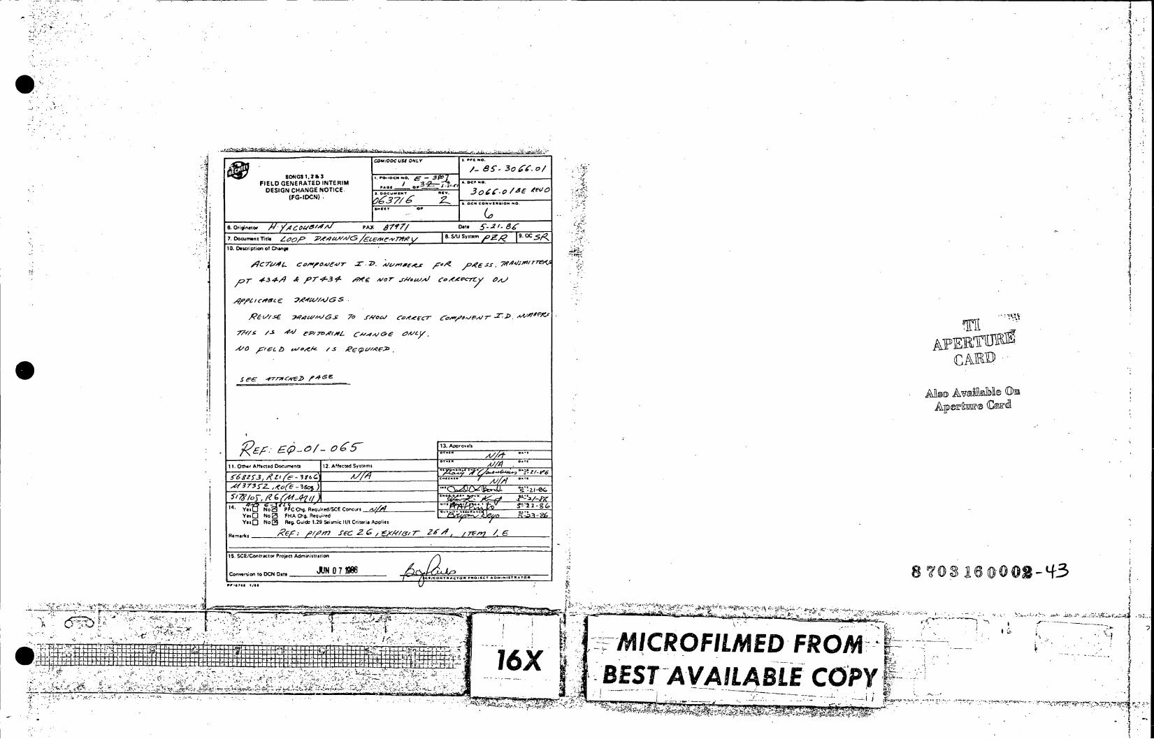
COAWOOC st OLY .c .0
30 0/
SONGS . 2 3-9 10 .4 0.
____________________________________PAX _______#_____lf_____l______________
7.Dou e Tti 0P P^q CIA0 -Zem,O/C&S 7 NLY S. Stu Sytm 10.________ DescriptioofChang - So~S1.23 'K
FIEL GEEAc INTERIM r4,fe-7 -2-P cc. Mr
10. 0Othrfcp t e Do cuet 12 Afctd ytes
7YOS 6 *rVCA-Ef/
Y" ~ ~ ~ ~ ~ ~ 3 C)No2 FACh.Reure Jls e
V.10 No[3 Reg. Guido 1.29 Seismic 11/1 Criteria A4)plies
q~~~~~nwkt~~~RO6 ADML2~'~ 1-12-T..4/, .6 ,, /
15. CE/O~tfacte Prjec Admstrco0
* ~~ ~.. L I~~C I MICROFILMED- FROM( '-.-.i
16X ~BST AVAILABLE COPY, .3 B,
£ 4 -~- ~-77

FIELD GENERATED INTERIM .. FIELD GENERATED INTERIM DOFNIN -v -H -T DESIGN CHANGE NOTICE o ' DESIGN CHANGE NOTICE
(FG-IDCN) O"" '""* (FG-IDCN)
SUPPLEMENTAL PAGE SUPPLEMENTAL PAGE
Fe-ocuNNo. E- S9o7 PAGE OF3 PAGES PG-IDCN NO. PAGE OF PAGE
DATE: 5-2/ DY V_ _ _ _ _ /FDATE: ByA
.. MT..1C..j:DESCRIPTION OF CHANGEj
BEFORE
.... ......... LJ .
-t"
XT.
AFTERAFTER
... ws ..... AperTurR car
..4, 8.0.1.00
-6X BS L
............................. .... ............ ............................... K
__ _ _ _ _ _ _ _ _ _ _ _ _ _ MICROFILMED R ... u
-B " -V- AB E-C PY
7

I -,-I I - -_ I , '- -, -Iq4,.- , - . _ - , -' ,,, _p, 1- ,- Al _t . ,, - -,,, '-CA ,--'_ , -,- , '.. '. 1_ .I Lt. - 1. I I , I,- - ,'- - - , - , t---_., U, - - - 1 - _, '4- ", ' _ 't ,-,., -,- -.-- _ . ",., il.,llj _ -: , -I ', 'A-' , I z: , I , .11, - T - .' . , , ' ,: ,, "; . , * - - - - , _ _ - 11 I - . I , , , - r , , - . , . :, -1 I - ";' -- , . "', ,,,, 1 4; -.C . - . ... r, 1. . , tF, . - 11, 1. - - -, 7 , :.;W , ,J, _ A -- 1"i'-. -_ - ,b - zz-A - -4t," - --, '4 1 _1* i,-;7 ,ljii ;- .-,- _lj , _.. Y _, , I -., - - - - -1 I , .
- , ,. , ,-_: , - ; , ,e . I , -: -- - - _1
t: Vl _ ,-", I
; ,-.- -, , , , ., .._ .; - --) '.1, ', -' t, -i ', _ "__ _,It",- . ; - - -1 I li
_ __ - 1, -7 - - . -j,; , - ;.4. t -1 - ", - ', i4_L- 'r, , , ,l - -. , - 'fl, -:,kt .,' . - -1 - il , -1 z , ,, , - _,_: - ,O -,, -, , - - , 4", 1; ,! .- , :- , : " ,v , i , , . -,. 54,J, . I , - - i. . - -- - , - - ': -, "' -- -- ."', 11 . ,N ; ,.,I - litc:,A , V51, Y', .i , ! . . , , , , ; ,,, --_ -_- :3 - I ,q -f- f, -, i t 7, ,T: : 's .4, " , , f1l, I , -s ': ' - 1. R
Ix ' ' 1 , -, - , t -",T-- ,, 11, ,
- c , z-,-.f' -, - --_. -- Z - -, ,-, " I , .. - -_ .*- . , , - , - A 1-1;- I Z-,,_ 7 111 A :, ;. - Vi ' - ',', ,; ,:", ;,ci , , 3i r', 2.", _;-:, .. , "', ^- , _-' , ,_ I - , - - ,- , " - . , --- 'vl"-,*, , . . .;.
11 11 "
-. L ., ,.' , .. , ,,A .1 I , , xf "l- ,, . . - , I .. _ . . , I .: , __ , I .1 1 rll _, - . ,,_. . -1 - I I I I- , - - _ I I _ ll .. I I . , -: , ,-, " t( ,- , I I - , -Atr ,_ _ 1. .V7, 4 , !_ - , f , ,,' , ,e ', _ - " , - , , , _A -ii ", . Tl? ,4t, j,,- , - - . , - -X k .m:"_ , -l .e i , -, -1 I '-- ' I" t", "I. - - -, -,- ' - , - -. ,4. 'k - - - ;%, -- -, - - - ., " 4' l l - - i i, "- _- , , jo, tr: ," : , -, ; - I X - ' - ,.,: . , .1 _- - _ - ; - , L_, , . , I "'. - j, , - - *-- , _3', I ""', ,,, .1, - . . -sr" - .,z , . ; .- I .7 ,
_ -: ,i ',!'I' Tt - ,7 , , , - - . -, , - " ,: ,r -'t,.l l ,.11 ,, 7 , ,, i = - y, t , - - , 1 --'- ' , ?'-, - , ,9 - ,
,
, , t' - , _.-,', - , 1;., J - , -k , - _ - , , _ , '4 F 45:;_ I - l- _., . , .lt-,: -. ;t,. , .7 .' ,
. v _.- I, t 1, _ - , ":, -, A 4, ,,"' '. &+; -_% -' -;-"-" '- - 1_ - ' X _ , - ,,: ,, -, ,i,;-' - - - , ., , ,_-l -- MV-7,IJ:, 't .7 , ". .. .," , - . 'r - - , . . , , .
," _ - ." .
- .. -!;
, .;c ,, - - . - -;-- t. - ,, -, . "r i ,.,, ,,: , .: , . -16 11 1, -1 ," __ . Mo
.- - , ,
nE - , , " - " ,, ,
,
_ -11.
"A;
-
., _
" , ,Z:, -i; ,, , lz" ,I,, 3 - c ,, ,", -9 -, - - - , l -.. 1L ,.,'- -V--'l- - .. -','- 4, S-ltl-:, f '_r, " , -- _?'4- J-1,71, -. ,,, - ll ."", i -d-F-, - y " ,,, 't IIA4 -_:-, . . , - , , - ,..I ., , , , "'; ...
., A ..
' I - - '! , , - - . . , , "
, - - - - , ; .I.z A's lqil ;, -. ',, (.,,',', _ z pvi , z , ", "- ,---- j--- -'- - " -
- , , _ w _ * - , , .;'_); -, _, - ,, -,,,- ? -_, -.- '.',, "I . - - - , 7i . . t , . .%,: -, .. , . , - - , .
. - 1-1 -1
le.1, _1 " 1 .1 -" , -; , -%'. - ,4 , - A .1 , "I -"I :,4e
, - . I . _ -, .f - _c -, , . ;V , .- , , ,4, -- t- - - t:"- , ;;%, " i.-.! ,' . I -. I , -. '. ,. .1, .it ,'_-IZ-, L,6 , . - 'A- - ,, .'-_' t *,; _, - .. I- , - ,,_ - , ,l ,__ ., '- -1 ,--, ." L.'; Vl -,'4_ : ', ,.- _7 - -Z -_ -l -1 7 7 --:Z.?f W... - , - - *, --- , :, ,, *T -- - '. ;,.'-_, -_-.:.- 1'_ , - Z_ - .'..1-1 - 7 , -_ . - ."'." .. ". ,
. ., , :t' , - , - , -
- I ., , , ",
' ,;,,!. . - .. " . -,-_- - . , ', , .. ,
- . . .
"'..,
-;:, L, I " . .
- - .. " l-
_
_1 2
.1,
". , - -- ,
,
, l
-
-
- - r 17
, "I , 11 . 1, "
- , .. W --.
"' -c -
--
. ! I _-, , i ,-. ", I _ _: . - , . i : ". .. . Y. ., , ." " .: - - , - , , , ... __ . I - ". .- ,: , - ,!;,, _ _
._ - . - . .'e - - - 4-r _. _ " I
- ,
- , 1, - " , . , . ": ," " - - -. - ...
_ _ -, - - - -.., , , - -, ,: ; I., _4 - , - " - 'i-l',', ;-7- . --- , . -- --. - -- - . - 4-1-j. - . , -- .1 -jrL, , - .W.;. I, . . i .:* , t . , ,; - , , '. I - _ , -t- , _ '. ; . ;, -* ,
.,, ', , , , A, - - - '. , .. . - .- .; j- T - ; - ,,e__,_ ;, ,c - . r - I , c " . 4..
.
..
"
,_ ,
r
"",
- -
, '. , o,- -
tt,
. ,,i.
, -
': .4; .'_, - , ,-,
_ - 1 -- ,.;, "" A I - -. r __ - Xri;,' _ fk . - 1 " ,;- 1 11 - - .:f ,.
, . i, ,_ , , - * , , , ;-, , , , , -, - '47 , o --, '. I, -, - ". , - - , , - , - , -, - 7 f, - , , . .. - - I - I-A, -1 :- -"z t '. , , .' o,-. - , , - "J, _ , -- .. ; .t- I,. - ,r,4- _! . - . tt ,, _. , AL', , . *
- .
p ,
-"?,* , _ .; ,'t,
, i, I
, I- - " 1- ,,y. _- . 11 - , -, . , .. . '. .:: ,,l .1 , :,. , "': 'L !'..4 '
, J- ,e,:-!. -
- _'_t-, .i - ;
. - - - -, - .
' --, ,'I , - --- ; i,,-*7 -,:J. , .. " , i- %-,";-z , ,,-;,-, lv__ -.1, : , - ,, ,- i :i,"- , ." t '. = 1 ;:'.l - - -t. ,_ _ i , "T 1. --- 7 , , -, , - ". , t; .: , , 6. ,_ , - 1, - .J, , , , _'J. I L: _. r." - 1 11,1 , '. , 1c, t l '- W- ; ,, -, -, -. ! , ., ' - !r.,:,,, .- 7',f ,;, 1 . - ", , . . , I , - -- .. . - " ,, _ ., , ; : I- . ", - , . X , -, 'p. -, ., - -, - - & , Z,' " * - , t, . .- "ita - I- , f- , t t j ., - - , I - -- ; - 2, ... - P _ , " .1. ... T !,41, , ,-7 -ttl.t - _" ; , I ", I. , j- ;l -- . - - tl , t -1 - _ . - , - , ., ._,.*. . " ;v l i- ,': t 1 t ;, , .'k _ 1, ., w .. ; _ . - '! ; .. -: ; , .... - "', -l. . -- , - - . -% 47 .T, '_j;tt.
- ".: -_.4 ,' ... ll%,, ,- -', _;2 . _ . , ,, I !; --- i; . , t .. : l -- 1. iX
L_ _- , _: , : '-, -, - .-j .-; '. -,',,- _ ,7 "I - - - -- - I - , . 'I, -- , .,ir - - - -, ,,'-;- t',- ': -, [ %,' - _ -A , ". I , l .. 't. . . . - . , " .. , -_ -, -, , - - ( :. ." ff . L- '. ', ' _' . , ', -. , , , .- I'l --I- - I , , - , - , - , In, , , , , '- --. - - - :,.,- - -, ' - I. . .. -, - . , : I ? . . . , .. ., ,-;k ' -_ , , - w '. . ! 11 . . Ij , - , - - , ...*-,.. _j I 1 __ , I I .. , . , ' , ' i - 1 1. I . , . t , , . ,_ iT-,- t"-.z " ( ": , 1. "; 1: -, .lg _ , ", - . , C I I - I , , , _ - - - - - > - l . _ -, , . , ... 4t ; . - . * , , . i, - . -- 1 " -'4-- ., .-- t". . , jF- -21. , , tl Wi<.ll . _. ? i - .,< , , , z " , . - , ", .. 3:. , _: _ :, j, , ', 1 ,.J ,- , I - ,*A-5 -,; - -,- , - ,_ . -71 , l .-,- , , ,,, I _ _ 11 , __ " Y11-1 l 14 : J. 1 1 '11 - I l
-" -, -, --, -- t _ , .1
, . .:
4 ,. - _d - - . - - , - : ., , .....- , . - -, _ wt, ___lf._ _ : L ;4 . . . ; jW c , - , , ,',',-, " .!" . . - - - .. -, , . . ',- ; - - ,. . , _V, . %,,-% . -, , - ! - -, '_ -- , , ", -11.4 ., - " ,,, V " , : --- ;,4r 7 1. , , - , , , - 1 1 -- ., - -, :-,, .-. '. - . 4 - . :, ,,, . , , . ,4 1. V, , -,!,_,,j
k, o I'll , - -11 .11 . I z f ir, - - 4 _ , 01 5 11: , ;, ,, ", , I , , "' - - I - . - , - -",, , , , , , - ", -,,, .1 , - ,..;. I It -; - - -, , . ., , , *? :,: I., - " , j,:, , ,_ -, ,e' ,, _ ", . - - , ", -. r_; : 14 ',- &"' -. -1" .- it * ,%, .- - - 4 , ,-,,;, " - : ,, -:, . jj'i , , Z"e,: ' .-, ',f ', : , " ,.' --,' :. , -V' - , - , I , , _ -: ',. -, . t ,z -, , t , . _ 1 I - - '. ,- % . t, -,, , - - i,:
'd, ", _,,:-J,, ,7-2 - . ,, - - -,, , : F "' . , EEI . - "I .1, ". - - , -, " R ; ,tY if , - " !f ,,'t , ;: ' ,' , -- , ; : , 1 1- - _ - ,Ili :. , I - *1 ,jz- I 1. _ - - . - , L -, 4 ,,Z - t. - , i, - ," , . - IT,' ' '_ , , '. -: -Z;,. t :, ',-i , , . & -, J i -1. - " !, t-,- ', ,.-_" ,!,,", ", - , -1 -, Y ,,I' ' :.,t ,, , -4. ". , , -. 1-1 -- - I ,I ;; Pl 1 1 '.,
,.- -,T.-.-,'N7,
-,- -,
., , 4-1
......
-1 -
-- 1: - -1 --
'
-, ,% z, -K,
,, " ; ,
-
.
.
, .
, , , ,.i
-1
f 4, '& _ . _ """ '_ _, , - - '-L-.' ' , .1,t,',_" It- I ;S .,; Z". - - , , , 4, - -4 , ,,, .- r
,-
,Z- ' *;E.
-
I .. I
. --_ , , ., -"_-', I;:;
, ' 'i; "', Z_'
; - , " I - .. :, It ; -'.
': 1- _;-
", - ,:i -z
-1 -, .. ,Z ;, _ ,
11 * -,
-'- ; .- ', _'..' I
', _ -,
,
4
-- z'_
Z'. ,,* _, , I- , 4 ,_Jt I, :, z , , . . . ., _ , , ,, ,^., , , A . , ; 1 4. - ;. f, - , , . - f - -7 -- -. - - I . I T'll -, .-" - - , - - .,"r : - 1- -, - , I - - . - c -1
I , .. - - - - -V -z -. - , "....", , '. ... ,- I .. sr7, , . -' l * , ... , - - _. . ..; . -_ _ , f 'r. . ; -, , _
- . . - . - - -- :,- I , ".z -7 - ' " , _- - " " , , . .. -- .', ; 5 * , I , ,_ . . tt - , .. , . ., t - - - . - 4- - e '. L .r., -I n. .. -. :3; - , , i . , ; , . r " . , " - -- Pf- ' 2L',-S, , . " , . - - - - - ,,". -. . 'f .,- -_ ;, 'I", , ,; I , - .t' ,kk l- -_ - " ,-t "",--s-, , , , , , , - , .- , ,44Le "-?Z -,,, _'.1; 1: ,-- _ ; , - ,,, , .. -- -, . . -, 11 '_ ' ' : ! ' " , ;- -; -- -, t -, i -- -- :,-. o " t ,-, _ :_ - I , I -__ - -,.,L;,.- : " '. - , .. .;"i-,,,, ,; _ , _ . ., ;, ' ' ' - ;, ---': ; ,-. : ,- - -4 4-,',-,, - ,j , , , - '.'. ,Z - -!. , ', . - , % 11 . - :. -. , .. - , 1 ,., I - ml -
.1 I' , '. .- .w I " _-,: , 1. ". I . I ;,;,:, 1'f, .: - , 0 ,_. ", .. ." 11 1. - '! - -,
., ,.-: - !" - - _k" -. .11-1 .. I - - , : - - -, " , ...... i_ ... - ': 1, 11., . I _ ' l 1, - _ , - --;' -- . - - -r, 11 4 ,7, -- - - - I "C - - . -mr; - -- I 1. Z- . . - .. -_ . .. , _ , , -- , -" ' . , ", ,-)f"
- .. , r, - 4 -- f--- ,, -
- j!:- .. - , ,, , --
_- , . , - .
*;,,C -7. -, '. -11
N -
.f
.. - , , ., " - - .? , - c -, , j " Y- , ,-'- - ", l ,, , r , - - - : -_' ' ;, v-' ,Xt -, . ,V 44 - 111%11 . . , -1 . . . . -,!!, .I 1_1 --l-, -.1- .,' l.:,7;'.--. - _ -_4 , _ t.,7,,._7"X_ -_ , , .- ;I - .'f' - , -, , :-, - ,; , -, . , _ - .. _. -, ,!-_ '. 1, , , . - j , "". " , - " - 1 , ,;: . ., - -. " . " _. , . - . . I , - , ..
,- - . -- , , _,. -' ,_ .,. , , '--',---' - ',. i., -k.4', ' ' , _
-1 j- ., - - ., a , - ,; , - '-, . .- " - , - . - " , ,_ - - "; , " - - ' - - -, I . , , e. t. , ,,..-I - --. , - . . , , .. - -i' - "', - , , , -- - , .. , - - .. I. I _-, .,.i .. - - -. 1, , ,z _' . , , " ,,
'i , -, , ."_ ,. :. , . I ". I., " I l - I -1 1-- .j t l ,!A;- "qQlt- I 11. - .. I,- -, - , J.- 't, -, , " ' A - -,,, , I , ", -_ , - . , 1, .,. : "' - ,-7,4- ..'. .: ,. - 1: . % , ,,_,, -,_f,,, , , . . " ; .z-j _, , , ,
'_- . ...7 --; 1_ -. - ,, 1, , .'j, , ,4 : 11'. - ,7 I. 1,, , . - tt ,,'_ ,,,, - ., : - , -, I- , j-y - ie, , I ., c I , , , .' -V , .., * -'I _,J , - - . --, , ;;,- , ,.,ix t - - , . ; -, -- .- _ ? I , , , ,F,; 1, r, , ,I ,!" I , . ". . _,,,: .1 ; . - . , ,',' - -!, .- - , " , - ,, _: - , ;_- , -
. tf. , - ,
. z , - - -- -, t - - '3 4,,-.- ..
l - - 't- - - . '. , , .-. ;-.-,-Z_ - ,"-, - - ", " 'r z - - - ; - - , :, . . , . 14 , ,
--
-4, ' ,'; :- . ... - , - . ---- "
-I'
, I .-
; -1;
.- ,
. r
ttt, eA I 'p- 7- -, _- _ , '.J, . tl. 'r., - ,_ . . - I -, . ". - - F "':,:_', .,'-,7; .,.,.-:i . , 1,, -, ,_- ._ t ; ., . - - - , . -e _. . 4!_' t; "Itr _,:7- i - " ,, a . ., ,_l - - - C, A_ - , , , t , -- _;. ., '. _ ., _ ; I - l _'. ,_, - I - - i" - - -, - .J7 '- ' _. :, -1
-
,; . , ;* a . -1 T., , Z :-- , .. , - -z , - - 0 _;_ -, - , - - I . - ,, ._ L l : ; ,_,- '- ,- , . , - , - - " , - , - - - -4 .:, - _-
t '. I , . . , : \ - - , ;,rc , tr. , . I., . .
! - - 1, - , '.. _t'll-, -. - -11 -- - -'r -1- " 'VO 0 4 1_ -7 - "T , I - _-, , , " , ,: - I , , , , ..- - - ... -,_ - - , - , ,It - "', , _lj ! ; - 1 1 , ti j . 'l e p , "! ,,, - ;- I " ._ W
. __ . I 1_4 1, , . - __ ___ r, ., , I ,, , -- , -- , _ ... - ,-' -;l -- 4. , I ,
;r ". , I . - -1 -- -,
, , -i 1 _-tl I I _- - - .1,;,.l'!, -"-,-', %;-,z; - V i - ., : , , , . , n ,. . -t , . , "If 4 - -; _ . , .4 . . : i - -,] ;-T- ,. - - - -. ,f ...'I , , - -1,-c., -_--i: I , - .z '., , , . ,. I . , -_ ..... .... , l It , , f - 'r" ',k ,_ . . 51, 1 1 1 , , .. ". ., _. . _ . , , ,-;,, , I I
* , - - , -,, --k - - , ,
'l , , - -,, -, : I 11 c- ,; " - - - v - -, _,
- ., . N l 1'- -, , .. " - ! ,,, - " . , - I 1. _. ,t ., .-, , ._ - . -,, ,: . . , -,,,,-, ".- I. - * . fl_ _' ' ,_Izl, C_ k ,zli -,: L _ -'. I 1. . r '. . ' !, 4 - ": ,_-t - . -I -" , : 1, - .. , , I ,qN ." . 4 ",
.,E, . , -, - ,t - - t_ w, 1 1 -'-' -. , , -. , - - ,
. , '. I -1 -, I , . , - , _ _.111 .. .... " .r - . _ - . ,:, _'. -,- , - -, , "" _ . . , , v - ", -, It, I'- _%_ . -il , . z - " - . . , - " f .. : - .- ,-f,-, ,4.. ..
.' ,,.,j , , , -i- .,-, - ,.' ' ,
I
l I -1 .
,
, - d6, ,
11
I -
; I
'.1
if -1
, - . r I I , ,. ,. , . 11 - , _ -. T -. Z., - - ., _ .1 .
. .. 4 ,,,,. - - -:- , -.- -. ,; , , -1, - - I - - , -
'. , .. - . - -. I
: a: I " , "" -, -- - __ 1, I
-- : 11
, t, V, - - _ - , - .. " - , m - .__ . - t?" -- _' _ "".., . .t ", . I . __
_, , 11 -. , , - - _.- , ,1- , _ 4 I , ,:,. . " A;,.- ,
I - '. " - - - , . , . . I - - " .. -:- - . . .,'I : ", ,.,;,. ,-' ! ;! , . "I.., 1 .
. 1.z.. -7
.
1 , -=,., . , , :,. 4 - _ ,-;;., - , _. ,' .. l !!;: -- , i , ., ':lt' , I.-.,- . __ %,; - "., Li i "' I'. - L% _-
l _l
W! ,2 - . , , .. 1, ,; 11 , -- !, ; - ; ,;V
-, I , _' - --- ' i 1, 1,
. , : .!-- . I - , . - ._ . ., 1. . _', t ' ;-'.. i ",,,
. , _. - . - " .. , . , t" _. ; ,_ ; I " - - .. - _1 , - , , . : :,' :-__ ;"n; -,:'--_ : - ,- , . " . _ r-_ - , " . 1_- -. - , .! ,,- ,-, : .- - " " , , -. 4 - ."'. , . .- r - - 1. . , . ; -. * . , : ; "_ - - j
I , , _ . , - ... _ - - - I .1
- .. lt. c I .. , - - - _,Z I 11 .- , , - - -- - - ,_- --- . , , - : _', - ., i . . -: I, '. f - : ,_ '.
__r. .. , , . I lle-A. , ,',;, I - , - , ,' , . - I . - : , - - - - . _ , , - .1 7- ,-,.: -I lo; ., T _%_ ,-
': * ! t - - " .. , - ", - ' , '. - '' ,_1 - . " " - ,
, , .
" -,q. I " . . - , - '. - I , .. - ., ,, "'. - - '_ . , : 4 .,; t ,. - -
, . -1 . - . , - ': 1: -.-..,! ,,-,- - t. ;-, _- .. , . . _ :* , -, .! - .tF _ , .-, . 7 :C.,;ll 4 1 _ . . I ." . _ -, ,
_'
_fDM USE ON LY ,
, - 1 , , ., _- , . ;,-.
,. ', .,
7,
"'N.- I l .... I
. .IA7 -10 1_;lvt
_ - __ 11
_ ,,;.-
v 1-7 '. I'
; - , % .. . , ._
.
, -
--
. " :
I - , , -.--
',
.... I :I.-. 1- 1 , 'Ll, ; ti l - - _' -I . 'C . . - -1 I- . -.- . % _ . - - I * .* : . - ." _ . -. " .. _
I SHEET
. , , I :.. . . .. , - : ,__ , -1 , . __ _
, - '_ t; ,:- - I . . _ 1 -, . i - .. , q, .- , , - .,
_. 1. - , , - * :
, , , '... , ". - t(- , - _. - , , , - . . . . w , - - _ - - I , , - - , . . I _1 - , I - , _ -, , . . ., % __ - , , _., . z . , " , _. I ., , .11 -1-1 I, : I . 'e-1 - . , , -, I - , '- . - l .. . I ;_1 _ . z .- .. . -_ . .. - I I - . I . ' - w: , ., I . * , - : . - . -" : .,-, . I "'t - , .:f., , . C-W , t t. . . I I - . . I , .. t- __ - CONFIGURATION CHANGE , :- -I * - 1 , _- .. I .i _ 1.4,.,_, ,_'-Jf_'.,. _. - I .... . , - . , . . -, , I ,,, --j - xtk6 I- _ , ,- - -,---, " _;i_ 1, : - _, ,JF' - ::, ".. , ;Y I , ' " ' : _- t'. ., 1 1 - :,... ; "' , , , J." ,--' '' .- .... ,_-_,_,,.. .,::, _ 2-rl 1-1 -". , , - ,; " - . ' " -" -- i: : 1 - *'-. : .:, :w , -, -, .., 74;. 1-1 - , , , " t- . .. __ - 1, - , - ., . '. . 11 I I_-, ti - - - 1 . , ,: _ - -, _ _19 - , ---- ,- - . _&3 _" " - - -"' ,-
, : , , : '. . __ I W e UL , . , .- -.1 , 1:, 11., . I I . . .'' 4 ; _ -- :, __ -V, ., : ,'. 4 : .--j . . _ , - . . : , _ ;l _-_t. tl "' . .: . I . . i 4. _ Z _" , - ."".., . . " , - . I : : . . I . - . . I . . I . - . . . - . . .1. , r , _ , ? . I I , - - , I - . .1 - I - - , , t'.
'. - : ,
I
11. - - t . . . - . i , .:I . , , - . I - , .,
,'_'.l- . . I _ ::i-,:- . % - . , .. .- 1%, :i . .. .1 -, . , - . - . . I . -I . : .. . . - '. . .. ; . f; 1, .. :,* - I . ; , .: - ." I. It ,.i . - I , . . - r, 4 . ,. - 1. .- -1 . I , - ,: - - -, . 4_, - t , - ,. '. - .. . I - " . , . . - , REW11IT11) BY .", I " - A . . I I 2 , : '. _, '. . I . I . '! _ .Q I - . I I '. rt - - , , - -- - I - I , - -)
u SM IFICATION w -- ,-I.. - Zi- . u -- vlr -._". - -.- . , 1. . 1. I . , . . : _-- -_ - " . . .
1, -. , : , .. . I - '. . - .:, '. - " C.A. GAEDTKE. - - . - - I I - . I 'r, 1_ ; . - . I ,tl. f. : '"' ,_-'.
4 , - . . _.'_ . .. . - , , -j. 6 . I * , . - 11. - -, e, : , '. ,_ . . ", , -, 7' ̂ . - ,- l I - . - - - - I . .. __ _. 1, -, .. . -I , -, mumult 63716 . navisiom 2 - . . . I - . . . . , - . .. ,; - . . ___ , . ,_ .. - - I ,.- . :--.. ,-, I I 11 . I . . I -, - .
", - - -- . . . . .. _ 1. I - .. . - :1 - , ; : I~ , .- .. - -, :. .1i : " .4 .,
' , -; - -
!_ , 1: - _ -
, - , .
-. I
_ , :, -1
, " , . -. : , " . , : . % .: , , , : .. -,!C
_. 1, , '- 1 7- Lt - - -, -'jp - ' , . " - I - ' , TIrL.9 SSSURE I , . . _ - . - . - . - : i ." . " . _1 .1
, , - I .. .- . :-..'- -- , Z: . ,: tl . I L , ", " .. , I : l ., . - , - .1, W, ., _ 1. - . . . . .1 I -4 ,- -- --. - -,
, - , . - ,, 1. . . '. - " ". - ' I -_ , . __Ll I __,- - .. I , - . , 6. ' .. . I 1; _ .*, , , 1. - , SYsTem , . I , " : . . . , I . - . .. :.;-.!. - . . 1. : - .. " '.. . .. . 7, , " , , '-,-, ":,
904110" . , - - - . '-. , . , , , -
I I , . , _. . V I 1, . " - __ - __ [39WNTIL , , ; - . I . I . * 'I , ". I I L. _ , 11 ELFMFNTARY GHEM NO.! 1 1 4 11 ' .. : ' I i I : 'I ,' - _ .- - , _ - , - -- I - . ,,
, . ,_ :, , . .. - -. --- . -, - I . , ., . ,.-;, - . - ;, . ! :- -, , . , . " " - , , j14 j7 . ' - -_ , t: , .", , , L ! - , . , . -, .. '. . 11 , .- .: ", :
[a - I - I .. - , - ,,, 1_ ,___ , id;_ :, _' :' . -1 _ - _:: . , I .,- - - , - . I - " _- f, - - , '_ ' ,; " ;: __ .1-A , - - - '% _,
- j . :- _ ' ,,: . --.-- _ , - : __ . . . - - , : - , . . .1 .1 - _- , - &-_ - --. ' ". §, -- - W..-l, . -_.. __ _ , - . . - . . , ,_ , , .._ i z . : - , .. 1. Revisso INSTRUMENT TAGh NUMEIEF:&FOI? pFtgSSURF- INDICATORS - 4 , -, - , : . v - , .- - .;..,.,-, - ,r- - 1 %- - : ,-. - ", , . . - , - - _ ,_ - __ . - . , - ... . " ,- , _, , am sm 8144 . :_ :, - 1 . .: .. -- , " " - '. I' - * , " -",*: - V __ . : ,&. 1. I .i!-. j . , 11 .- 1, ; I! - . . VLO. en . ,- : . . . - . , , . . - _ , __ . - . _ 1. I. .: .. ,. -, , - -P " z -, . .- . --, , r- . . I! , ,, , : , . . , , , - i , - .. . . .;, .; , . - I - ,,, ;"I :., ., ,I - , . . ,.I, " - .: -, - ., , - , :-, , - t , " , IN THE PRESSUP12ER PRESSURE CHA INEL Ir LOOP .1 - . __ - , '. .'. I .1 . . ,,. , .-- , ,:,;,_.,,- , "t .. - '_! ,
'. , , ,,, - .
, I , I I . .- 1. I- - , . - 1 'i - " - - - - : --' -_- .1 - - j ,- - " .
t. ; , , , * . - , . !, I I , , - - I -j ,_. . " - . : _-,: I - ,,,_ L, . , , , , , ' , , , ' , --- , - I .? . , - I . . ._ (P I - -4 31 st PI - 4 lo 8) . - I *- . I ;, , . . .1 . . , , - . . . , , " ., . . , , - . - . , -- -, . . :1 . . , - - _ - _ . ,
1 I 1* -. !: - .. : ,.- - _ -
-. , __ _, - , : . - I . , . I '. -F l - . .,
i: , , .. - "' - .- I -i , I. ': , l - , . : - , , . I , - , , - . , '. , .. . . I I . - . .1 . . , . : , , . ., - , n
1. -. . ". ,,, -: -I , - . - . : , .t, . . , '- .. w ... - . :, I _. : -
I .- I. ", , . ,,
I" - - . . I . , . , - . , " '. , ,,- % ', - , I . I , . - .- . , -I , -:- * " - . , . - ,, . - .- % . -1 I '. . . , - , - .. ., , ..- , , - - , .. -; I . , , , I . , ,1: . I I ., _:; 7. ' ... I , . _ - 1 I - . I . , " . .
,
.1 - . 1. . I " " I ' _ * .L; I .L . . , .. :, . ,: ' , . . . . . . , , . . , - , ": 44 . . 1 . 11
;. ,
-
.I
, . .: .
.. .. . .
.. , , -.
.
I- I , -.
. .
?, -. _ I ..
. . . . . . . . el 1. " . , I l I ; I :
c -. i'.._. . . - i: . - . . : . . .- - . . . . .. I.z . - . , -, 1 , - - _1 T . . . - ! I . .. . I . I . . -1 - . - I . . . , f
. . __ , _ - , I - . - t , __ I . ; C' - L ' ' . I , i . , - - , I .1 -_ -, . I I _. . I I :. .. . T ,
, - ., .. . . . - , . . . - . . .. I - _,,, , - , - Z I - ""I ., _ - . . . .1 . .: I . . . :, . - - . I . . . c I ., . -
"', I . -1, I.: . , . -1. , . I . I . - , . I . . . I , 1. - , . , -
. . , , .
7 , I I- I . . I - _ : I I - . - I 11. - , , , ,' .1-il , .,
.. . .. I.. . .1 1 . . I . 'I . l . . I . . . . - I - " .
. . .: : -1 c .Z . . - I . . . I . . 1. , . ; , - ,.. , - .1 . . I . .
I- .. 1:, . .r
1 L , . L_ . ' - I . . , .- * : ,; , , . . .. - . . . I :
i . . . . - . I I . - - . . . .
.. I . . . . . . 1. . . . w . I I .
- . . I . . , . I
I . . I ; . .. I - , q : . I " . . . , - I " IV. . . I . .
. : * I . . ; I . . . - : .. : . ... . . . . '9 . .. . .
. . c . . 0 . I : I I . I : - . . . . - . . . .
. I . - . , I I , . 1. . - - . ; .1., .1 I . I ! V
. . 1. . 1: , - ! ., - . . , . . .. . i , , '. . 1 _ ll . I
. . . ,; . T . . - , , - -r . I- I I
. . .,Y . , W. po sz-or.3 CP410 VFRIFICATiON) " . 'k? ? . . I _ F-FFFCTIVF- DATE ifiMEDIATFLY -, . . -EF,
. . .,-. . I . * - .. . . .. . " . . W , rn. 3a 9_3 I . . . . , I c . ., ., lm l ". 1 '. ' ,f' . , ; . . .I . I f, JUBTIFCATION t . . . . . . I : : _ , .1 . - 1. . . . __ .1 .
. . ", - - . I . - "I TO INCORPORATE PREVIOUSLY ASSICmrb TAi2i Nume ERs.
1XI
-,-.. , ' * : . ? I .I .I . - . . ", .. . - . . I . I I : . 1 . I . . . . . , I . 7 " . . . I . .
. i . . I I . . I I . .
. . - .. .
- i I . - 'uo :;, . . 10 . . I . . . . 1. . . ! . . e I .. kpelTa*r : :..,, :. , . :.. , . . ... "I _ - - , I I Ll . . Z.l . . . . I .. . , - .'*"' L tp'I'l _- I 1 ; - ., , :: , , t __ , , I I - . I . I . . . . , , " , . ., - -1- 11 . ltd. _ .' I , ,'!,- , -,;
, , , __ , , , -, I EVALUATION I " . -, , , 11 , __ ', - 't , . . , " I , _i I _,,'' - . , --' :, , :, . , _ _,_ , .- - , - , - - __ ''. ,,.,;, -'_-', T ( - l t , _', ". I I - .. ' I ;. , , , l7z - _, ._ I . r 1- ..
11 ,. .__ - I " I I - - _____ . ,- . .
I !_ . : , . , . OrNIER AFFIECTIC D*Ck=ZMTB / DRAWIN" , 1,40WE I I
I . . , . - - . DOCUMENT CHARGE REQUIRED FOR : AEF ctz .1 I . 11 (] CONSTRUCTION 0 AS BULT C@ OTHER INFORMATION .
..
..
I - I - -- '- .-I FIELD APPROVALS I 11 "'. I ... 11 ',' .!- I DESIGN APPROVALS [, - . tt _, ll- '- .
., , . . .. ! . . I rL )ele ._7 ;pN VZ 1;04gz W . I .
l - I amen. / DOCIPLINI DATC CONSM supast DATW 2lEXfflwN0CWT R." , . .
. 11 . : , .-, . . I i . .
I .i
MIT EV
,I -- ir - _ .. . .
. - I I.. ..w RTF U - _ iA--T-. X., . . I .
.-
.
. I .. , .I
.- I . * . . I .CL U ,
-. . ..
:-% . . . amen./ oisctpt.ljlg OATI *.A. *11P. DATE ; I : - ..
'"
- . " - - 19-.14-As -:, I I 0) q (a em- a .- , . " , 'kL " ' . , . . . . . . Ld '00- ts WU- J ,#mvt "'. . . lt .
. . , . . - .. I I . - I 1
I _ . . I ,
:;. - " - - : : J- .-- DAT9 11 AT _- I I . I . I ,
.. . . . ': I ..
- . .,
.__
. "
j . . - .
' -, -, , . . 1'. 1". . -.1 - . . I - a z z lIll9k 1")03 ; . . . . . I
, I . ", " , i t ,_ . . . .
INGIL/Disciruill DATI grxr*N % am I
-
"
: - 1_., 1. I mv., U Tv. U.76 U- _(. .uf W. . . . I .
-
..
.I
1. 1-
,
I ..
.
sx9u
1
1
, "
"
11
I
.
. I . ! I .* ..
1 -Y 1, I ". " - '. . ,. I , .
I- t-1, . I I . 1.
_,: a . - Am au". - P. 0. - , , . . . I - : . .- , - . I L
.. . , . 17.:. ." , , .- . . . . . , . .m I-I.- - - t - "'t ''. - . . . I . .
e_,,_ __, , ..
A M
.
.. . . . I
. -I - I . . I . . I ..
-, , I. - , - , - -I .
I L . I - . . -1
", -%, ,- ,
.-
...'..
-.".
I , I
.-
-
4
. .
I .
-
.- ,
..
I ..
, .1% 7L 1 " , , , . . - ,: . . . . - . . . - , ...
7 , - -- ,_ - - $ . ." I , I - - . 1 - -- -,
-, - . _ . - . - * . , 11
1,_j p I - . I. . % I -1, . - . I - " .. , : , , .. I - . . ; , , '. -11 I . . . I - :. , - .1. .
_., . - ___T= I __ , ,q ,-t - 4 , .1 . . , , . -,
... ---- __ -. - _ -. *, .."
.-
1, , I I "
p
1
, ,, , 4 . ;= : ,4 , , t , ,, : , f t, 4 -, ",: i . I , a __ - - - -- t-_,,- '- M ,- ,t - I - - I , , _ - -:c , ,!E ._, __: t: q- e.- , - - - - , . I -, _. __, .I , 1. .
"I - , - . - - -71 - _P . . - 77 . . 1
, 4, - - ,,_ i , _ , 7 -1 _. , - , . . 0 ._ - l 'o ,,..,
:1- _e , , - ': ,. _ - I ,:Z_ I -I I , , . . ,, . , . , - , I , $. __ , L, . I . %1
I , . I , . I I I _ ,- -1- 1, . . 4, _ - , _. ."m - I I - __ - . -1 -_.:
,, ,
, , __ I J. I .., i J - .'. , - - -_-- - --
_- , - , I ,:' - "
. itt --_- __R7 - ., % i'l, _ -, '
, _ _ _ , I !, .1 . 1 4 " . j'_ . __ - L , , - _-4--;zI - - - , _: f, , . - , p . I.' 11, ., I 1. I I , . I . "I " , , " '.-., .1 - , . , , .- I , _J; . I .
-], __=a_=m_,.;4 , .

r.- 71a 2:'f, - a
1. a., A.1
MJ L
L -- Ja, -- t ..F
l Ia o t - - -
A.
a.- dAJ~ :jza.
.u o.- pn~a I M;; 71
A 'c
4 .law.
I d
Aa A
'-'-Y"
-'va
. *4J AA
L-,.4 tvI
ILI
a.gidC a r
.. .t .. - aw --4
r I'MI
,-=aw w-...a,..
P E R T
_ - - - A
4= A 1V 1r==
eS Dwg.
£#
I I. a.. a
r w'-Ia'
-Awjj
A-a ,. IT .
I-.I--A.,LL w, .
Aiw~ a.-4 F.
ro,
.4
-Sh
of3
w ,w.~
AM. 1 ii. a._
__j ~in
-- * aZS A.~A
S A - a. -Aw"A -. o -" a-.mrl aa
-g .
-_ Cw
V BEFORE[
1* iE .Dwg. 6 3716a
4: I Sh. 2. _ 3
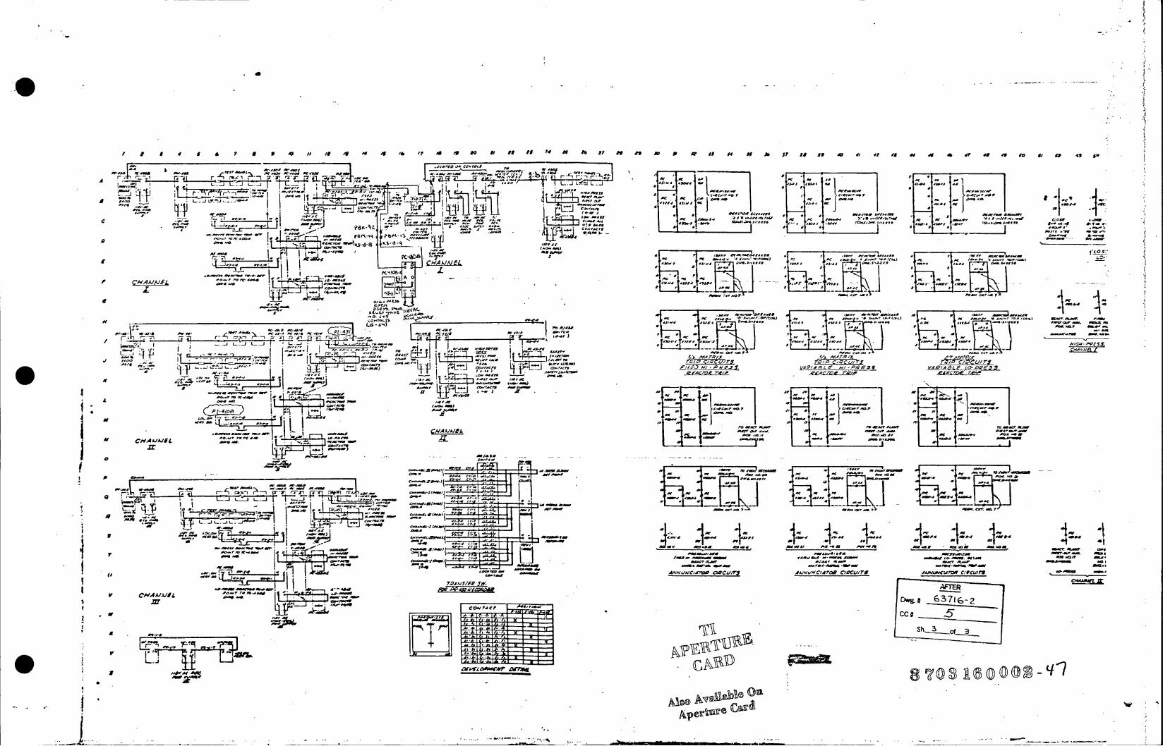
/ 8 4 S 6 P 5 9 4 it i0 4 4 4 /6 /F As 4 1 H f i I Ap N II i 0 IN A 3? Is to 4 $1 4 i Is 4? 4 4It I i& & 9J
r . . ''' I 7't;... h" .. _f__
A_ t1 -L_ 1 II .. TP I
Ame a as--AC a -9A '
r- ar
Ir --a AN ~ ,0
J ~
CHAMMIL4
CHA~l".co r '.rr
.ZI ZZ w.
L LAjY- a....l.j9f ZO 3 .
a~ee j Jr. .ct
IV -Me u
A. FM"
75
'W. '-, 'cAC *.A I H 1. Z Z
'I Al _ _4I4 A
A( iAP4 cet C4,r'
r rr- t..? 1
AC I a
5' wC 5G .
7 1M U
ra;
CHAAJV~N4 IH-,~P.S..
AOO.~~~~ I : 15 '
~w Dwg. 6371 G-2
c#
Sh- 3 ,
Oili
e Als@ A2 eo
9O~~- emssn t -mAta a'd? fAS
H ___________________________ ~~~~~~~~~A r Cr 0J *a ~. .SC*?r,(~ c a. .a.. saca li a ~ i

/ AO It 4t IV o As op 0o as t It? M A-9 06 If :04 A ? o s 0A f 0 w
CrC
-- *-7~I-. .. l i _I I 4 d o"
L.J L..JL.O.. an 4 ~* '3.1 ~440 *1
a0 couraw want
- *ereeI' -F * t.,asl r t C
11 AP & &P .. If dd ofI & 7 I 8 4 / .0t A 4 4 4 49 SW BI SW O SW.
lo-IrI
o.." crr- W ~ as/ t4-j * M
' j fea-*
a I.~'p~-ten -m so
a : ,. a - w V 4Apt .N-P S -/-.. * C. i. aS 1040 S54-tF, 45) Mra/ .n~4 a asrqanP rocree reLa tc De 7 ePl
H - - Al Z,0e-r.Pt , l TQXV M TI t r.
mt..
le -e .1.
aC /X=
r5r a dM t -i 7'
o..L. aU PC - j
ann- n
- - a S - asa ass saace-use (4£ at)eacariL
~ A~4,IW -ct..
at-.i ~ ~ ~ ~ CIAAJA14EL - a S
a dues a tel-Son
r1 -c -4-'--i F i
tAar" ecsW N#a I
Ape
CAMS. A()Ii- A '1 a'S -J L1-.Ja- OW~f 1
I1A~ cAc Tis.-'r AIAAa-arO la.C~ ____ ~' I . . r 1 -tIn ~e aa~ w 4* JI L. 1. a- 0. 4 0 *'S_ __ __ __ __ _ __ __ __ __ _ __ __ __ __ _
_____ __ a ~ salj AS* A/UE SSE
~~~.,~~~C #aU. L A j z ~r FeW- 5.Wi 'n ___f/* V5asIa-teanas 0 ma
4*444_ Alsos
~~43_ 434 I0 Nn Gs ~r a ~ ~ ~ 1
. "---~ ~ - isANtJ*-C W ncurs A,/udI~r~eCIU UIT AtJ44CJr~C/Sull71__________ST_
-'-- O~fl 7 ii.4 s -_ _ _ _ _ _ --- . E

p tC,#
IM_ _ L -j
-a IT 1 II I
j30.-I I- II
I vV
f.7 Its
oIr -,3z
Tew
to Ali
e . N./ .1 1 4;0 -s II 7
A. .W
st s ass.5,4-a5.4 .o g,,4c st ns tsEse
4-/4I 4r 4r
asp~c d a dftK
W .Oma. .... W. ' so
A1 -1 1 1 1fry=
'ft --I * I,-w
aAIIto AAeer mdesar
' sL awL rr I masor -uaa 'nes-sss-a-ag
55
St".r7: 10 06 752 "#6 77
.- r a*,t50tA.tS.r 4 - r KJ.-I4 I4
00S A/4r rr- Igaear d-oaD
'C 5'- t fLOI-____E__
d~n -at A 50 * iOSI £054IJHIGH- PRESS.
.iE~i te ________ CaUS /01*
#4AT~ ~ 7'-/ 4-5fl0 -05's ra.T I
*0Apertur Cardn
nra
Ore? 5-- I
. .m. . 2
fin. -w -d .iLi sc rM
- .erwr-Arians
taca.s-- to sctart -e5v .T-VM 4 -4
~" - sn, Cvaca
~ Wi4 C ar4181

S0 4 5 7 9 t / /4 t / 7 it ft 2 t J9 s 5 i s4 5 37 9 3 40 47
lA ll -. af -0,-~rfr~C~~
I K K-I r-era cmc
-~~~w r, q II Rr
A CHAA/A/EL__
Lf -. 4-, . -.4 Ai'
r~~~vol~ r7e -r - cIl
nn L L . j .. p -.
0.4 -- - P-S ./f - A'Sa,.
66 1 /s I Iry
revo ,w t C rs)LQ
r ,5 -1c I'd v-A
L ______________________j eC
CC Z11 13 42/ IT4C aoar 0' 6 (N3.5 L
L'. L.
Ins
A. -C4* 3/ 4A l- P/C
LNs c
14 IFC
1T7,
//8-lxC
v~C AJA/EL15
Cte/4so
~~~~~~~~~~~c 1. 11 _x 4 A )OAt
'4( _ _ _ _ _ _ _ _I ~ C SxCl t c." (4 30 /
s Xre
. /c VC tCxL j d c o
c, aroCt3
asbl Oa crGe ( (
tLda M O M
BES AV4APA2ECO-DER
CoTr0er3
AC'S/A' II [s>d 'mc'. 'wa-C
PCSO 0IfIS44 35CC7 # 9 0 /
/44 440F
4 0 7o n-tv)nei - o /
a,-o.-. a
05.0 5 / 43, p.-,, ,-ret Clt41 ' 4 24 ' CSC ,30 15 17 s
I As-AS* ,~, CO~A//tL/lY/C/Ar CO C/ 5CL//0S
[4 I / /4 .4 4 2 2,0 A . t/ C~ t/2 ~ t~t A ~ t t 5 / 4 5 /t"
4 - P PPC-*4.I.. C L -- ie vI pr
AS ~ * ~ ~ j 1
-0 0
, 5
[ ~ J 44'. 0A) z ( 4 4 { ! ~ .. i l... 0 4d 55 II Itri 1 1 VA 2att r..og /0 /0 s 2/ C C C t. 4 0 0 . 0 ,,, / 0 ~ 4 " - -t ~ -( 4/3 0./ C O ) s r -e
r A 'a t d2 -v e/ - 4 / so n-.-s00M4r d.4"'g "I. / tb-a CC/IAAJMUAC/ATOR C/PC/.// SaxHC ,
II. a~ aAOJC Ct-At/Nt '.00/ 4CA~bO/0tS *4~t/-X /I4 /t/* 4328-x0 2CC ~ lO~ O // CO~/C/A 3045AA'S 04 3/ 4 0. 301 0 4 1, /5 A' 004 303 tt0 A C S Wgg 4 445 O t
t~ lt ~ N. ~ , _ _ _ _ _ _ _ _ _ _ _ _ _ _ _ _ _ _ _ _ _ _ _ _ _ _ _ _ _ _ _ _ _ _ _ _ _ _ _ _ _ _ __f_ r PO0/C2A' 0/CA VA M VAt CoP 20S.4"Sff44 * ~ - /AC2444/CCOCf~sr., AS P C A/C ~ t.A'30 e flir ~ 464 r I~t/t 20/ ot Cdt/Srt x -w 't-3 0C AO4A S 0 ? y- O
402.00/C AA/NUL'A'ATORQ C/RCUIlS
/C t4 2.St tt~ 3/P AC SA / 0/Ca/A0
4V 2t O O S
4./0/44Of*
CS/C 4.0. Ct-A.4FtC
*~~~~M Z prC4/( 9
2 4 M IC R O IL M E D F R O
~ _ I HIBE S TAPES-

/ 2 3 4 S 6 7 9 /0 H /2 /3 id /5 / /7 /8 19 20 z/ 2! 2324 215 ?s 27 20 29 30 J, 32 33 34 35 36 37 38 39 40 41 42 43 dd 5 49 47 48 49 50.5/ 53 5 d 55 56 575 5 -19
A'A"
L ' J L.* -J L. J~.
-1~~ ~ -3La--.Uic
t/l r-7.
C"Al~v- -i --Ai
TU Ai4MT el IPfl 1 (.a.aw Cl 05, Cr AWUCr
(L 0) Ic LiER
Aperturow
ass a ,is a s 1= COcMM
rw mror e s raRz/ ron I .s acr r A
r rr sr cc r -re cr) r
CCARD
r
AT c,~-
(A1.
SeE 1 .4
* ,~ Also Avalilable On
dN~aAperture Cardr
rAuAH/ SLEHL63L1VEL .11AVHtA/A//A dt C/RUIT
N.'ATERS ClAf/ C/Pt/75 I/-L.V(L
fa:!!!! IFT. - .ar
- ' - r e r r
Poe LJ4.5,-DP , u-aV 7
7 FR 581 ' 70 -. Oc 3 53A.33 L..me
!kJ~ LT.4Owg. 1037173-3
if 43* ___ ~ ~( ~,ACC #A
'3-3''i"'rA~ste 5V/Sh
. /64 ~-3OICO~4
. .4 : . . 11r ' ( a 4 : 26XO
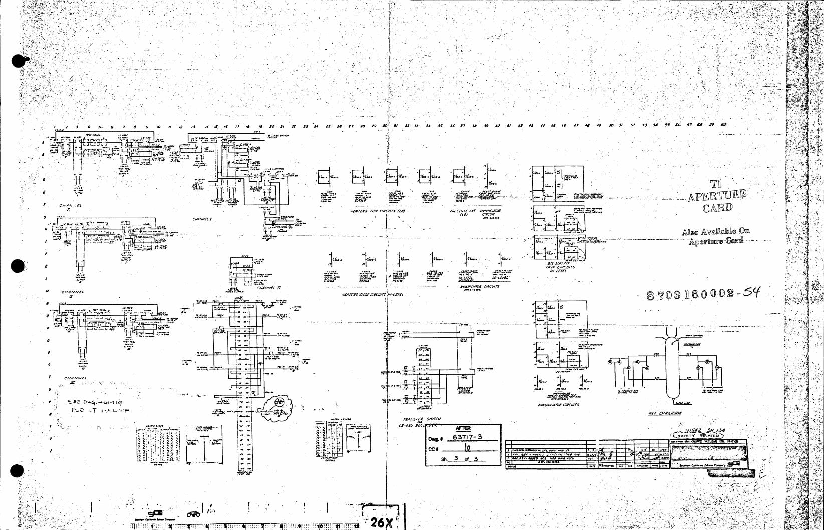
A~A
2 -6 7 1 9 /0~ 12 /3 /4 /S '6 i7 a 19 J-0 21 23 . 24 .5 26 2? 20 Z9 0~ 31 M- 3J34 3S is6 -9 is 39 do 4/ 42 43 41 4S is 47 44 49 jr 5/ Vi 53545 56- 57 5* 5~ 0
L.JL---JL.J C. ;, ' "' '..
LAP
-m- - a s U o o A v g
-A-S'. A( -SY
ft~~~I . Z-e&vMl
r -i - r it
-L . - 1. i d I 96I
--- C.t .L h a
LTlC 4-,C- 'CC CIi 1
C.C C - C4 CALUC-'
0 r~-~ ,'Arr1 FR. W MM
2: CC IV 7
owow1
' £ i-i, I
cmIC
777T'~.CS jG'CC ! V!! 6
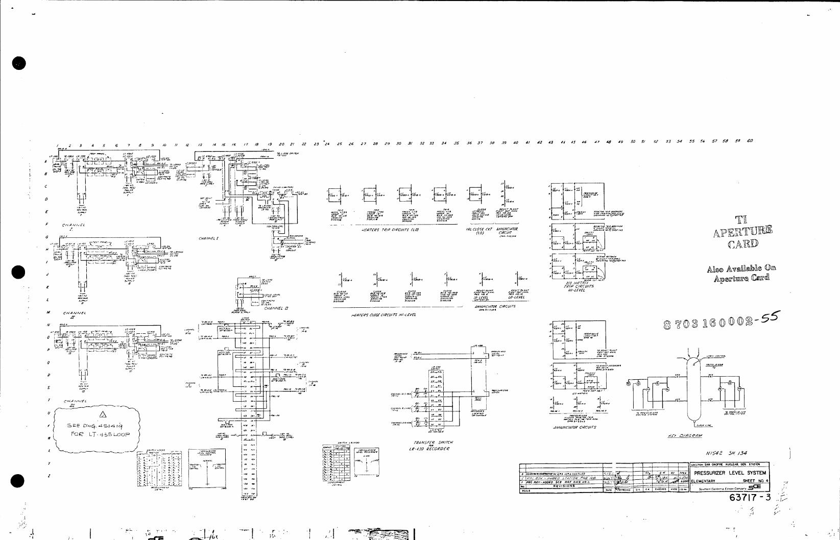
2 3 4 5 6 7 e 9 /0 HI 4f 13 14 /S 16 17 18 19 20 21 22 2324 25 26 27 26 29 .30 3/ M233 34 35 36 37 38 39 40 41 .42 43 ff145 46 47 4,9 4.9 505/5 52 5354d 55356 57 Sd 9 £
r Lz
I I-1 IT " I 4 O
-. c
(to _____ r~ n~tr.
110~'.OO0f4 003 .00**
V, -7o,~. _________________ ----7,4 [2 11/ CIC II(ci10.C0S~CT Av/31 0
,-7//L 1) /C/T. ~1~,IIW~
L4o~Nf "~oll.e~t®.O
______ VE Z7'/ CISCUC17'O CrS~
L CHA""E434"3 0/000/0
___________________~~~~T 3___ a (D_- . 4MNC4~ /CIT
11
cbeal0
tv LT-4 E/4.0F
TJf L ECRE
S-
AN~ ChFR N*0~d0 00r0 ' I /3004.0330'~' I ~ ~ " .J~0PC$A
F--., P0-- [2 -m
-",,
I PCUVADDSS FDd-AEEETR
REV1C1ONs
? 0 c~' T.~-~WOFOK
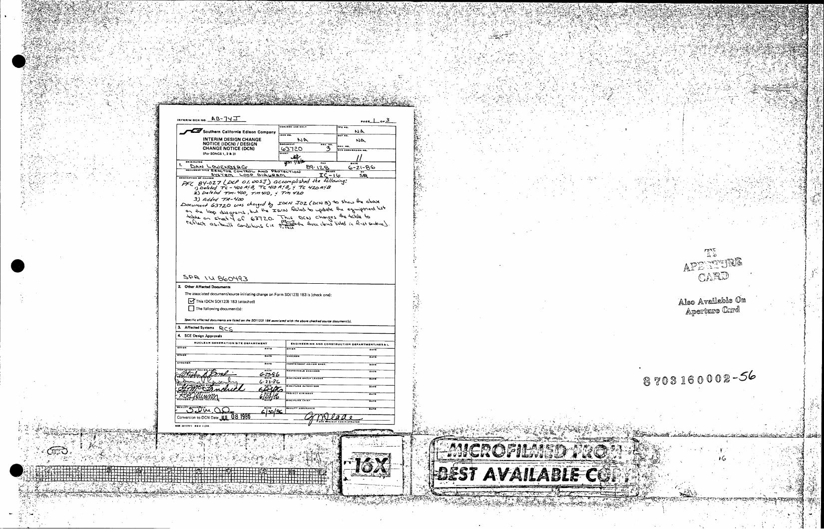
V~4~4 ^z _
4 4t ..
4- V' 4.~4 n ~ t2
-. . ~ 4 4 .. 4 4 .
.. 5.%
cl~
' ... .Z.
'~-'1~'Jr
Suthern California Edison Company k.
INTERIM DESIGN CHANGE . NOTICE (IDCN) If DESIGN ... .4
CHANGE NOTICE (DCN) ( 0 3 .. .... (For SONGS 1. 2 &3)
1. ~/S- Z -~ 'O 0A -r0 9/ S* 7 13~ 44 -- MsOO-43, _Tm 'Y'1O 9 A ', 7zo -r- 'V
12 /f3 7-WV,
2. Other Affectad Docunats 1 The associated documentisource initiating change on Form S0(123) 183 is (check one): .t A inS .ahI ) 4
(This I DCN SOO 23) 183 (attached) As v Ej] The following docI.tnent(s): '
3. Affected Systems 4,
4. SCE Design Apsprovl%
-1 .U .SA . . . . . C454. -A.-*IeTr .... NC .R5 . Ace... CONSTRUCTION D6PARrM5,4r/ss I.
.... ...
Conversion to ONDt U 81 ~ .
--a. 77:7-lC~ -1- 4'~- 4444. 4.4 .
~ 1L _________________________________4tZ
~ 4 . 4 1 1 4 Z ~ t 4 4 t t b j i t ~I ' _ _ _ _ _ _ _ _ _ _ _ _ _ _ _ _ _ _ _ _
'4,.
V)

T''
t4 .....
FFotenCalifornia Edison Company c~EI 0MM
So ots 1.2&3
CHNENTC DCN) I..*..CHANGE NOTICE (DCN) UBL SUPPLEMENTAL PAGE SUPPL EMENTrAL PA GEI Dats P.,.\~)0 of, Data P. 31f1 t
DESCRIPTION OF CHANGE DESCRIPTION OF CHANGE PT "
0 a
0 0.0 o?.v.,I5. .. ~
3 ~4.
It er 41* 0
__ Ii __ 1 12 4. .
0.. _______ 3~5 1 N .
~~14, 7,55 c a'
5- ~ c .A~tnar (Ov h ,. I7-4 *5~ S
Hl 11 41
IT f. II _
R~
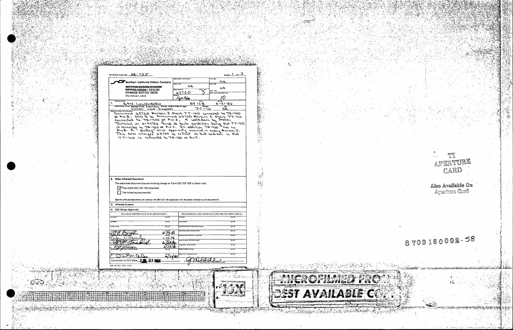
M, w-1,
'U
d*w. 4
Vt. -. 3
INYVIM 50. _____________A
SWtenClfri Eio opn
tNT~lIM tCI~~ C I~t~C I,7"
rtr 111EmI SE16 k I S
Ne+W,& Z DEIG ..... ~ ~
Wo SONG 1.O~' 2.Al &o5.,. 31. .... 'sao
TT-" ~ ~ ~ ~ ~ (1 -. 7-t~~ce t~t~ o
2. 051w Aft aca Docunnti
The associated dlocument/source initiating change on Form SO(123) 183 is (checkt one~: "t~
[DThis I DCN SOO 23) 183 (attached)
rl ho following document(s): (i~l
SPenil ffi n 40-d dea,,es ae finrd em the SO(123) 184 mid.d wnim te jbo ac~k~d sano. don rs.
-1 3. Affootd Systems 4. SCE Design Apparoes
NUCLOCARG-Sse*-IapS OTCLIRPAR-INT U NGIN-tRiNOG AN CONT.ReUCTIONt DEP*MRTNIENTINK9a,
ona.
".16 80
Connnrsion to DCN Date F 74a 'ao.I
"-.7.
RN 'l
*~S lip . l

i .,;4 4- -":4 "";,z: 1-1 I '. , '-!'* . ;:,,,7 1,,,,_- ,- '- 7. .,,- - -A .. "'.. II,- .- *, - .,Z,., ; - , - - . - -- .- ,: -, ",.,"L.-7,;; '-- ;*..irl l"..i l:z-t-,.-.-., 4- *u-. -- Z-,.;,,,, - . ',, ',- ,;,;Iz:hi"- ,-,,.,' "--,- ,;F ".., -, - 1 . - I -.- : t .,.Z -X ,,f.-; ': ,, ; - f - , 'T ." - -" -- - - -11. , .; -*,. 1*..?.Y'11-- - _- _ _ . ... ., , ,.,, :- - - 7. "I-. - - . - - - -, -14 .. 1,7 - - , -:, " I . . , . . , ' ' " '. -,--- t1.A-' , -, I..;.- , , , - , -, - . I " - -11 - -- -1 -'. ,- ,:, - , . I , , , . , , ". - - ) . I I 0 1.4 - I 1-' .-,;", I, - . ' . -- - - " -. _-:1, * - , . , ..... - ". .q,4 -;,,-- - - , -', . - , ". .- . , . - ,
,
, ., - -1-. , F 72 -,t , ,:k - , , ,., . 4 ,
-,r , - ,-,,- - - - - -- v. " -, "I - ,
-- - - -" - - *, '- : '- -' -il', - 1 , ' - - - ,7 - , " , ,:, , .- ",! . ,, , ,, . .11, -- k -, -: I .. , - , " , I " . - I -f ,- , .41 -, , - ;; , "'. - - - . . . , - , % i . . . -- - , - , . j , - , , Z. A - .'I.. , -,- , , - .4 " '-- ' - - ", 1',,,=,n--"t-;:zcj- - - I *, 1,,, ;- .0'. - " ., , , I . ,- -- r-I.-A , ", j . . - - , :.. , '. 't , , , .. - ;-;', . 11 , - , - ? 1 1 m- I , - - , , f:, "-%: j: ., I4, '- - - , - * - -"- . . .- -. : .,- 1 1' ;,,,, , :-4 ,--,',; - -,, - ,,- , . , - - -,;;t ." , .. '. 11 ., ,i! -, q- " -, v "',-w -.- .:,;-,. ", - - -,. .. , , . , 1, " " - C-- - 4- , -- ;- -- .", -- :. - - , --- - I.,. , - , , , . '.
' -j:-, , Ar i " 1 7 , '- . " %. -, - , , ., , ,!- - , 7 ; -.% " , -;, '.,
- .- - 1 , . '11, .. , 1 j ',, , , " ,- , - . . %'. -.- - , e
!" is iW., -,;- , 1.1 -- k ,,- , --1 . - : , , ; . , .: - ; .1, I - . ,. .5-1 I "I I 1 - ,," . , -! . , , ,,, , A..- - - , . : '_ , . , ", - ., .',', , e.-' r -.-. -4 - -1,- , - . - , I ". I k I . - I '. -,,- , - , -, -,
-,. v -1, - I' , . ,4, , . . .. . : . , . . , . - , . -V c. " : -., -iA' 4 '-,,;;:F, , , --,.. ,.- : 't , , - .- ,. , ,.--,: , - - 0 .. - - I -,, " -z. - - zl , - - - 11;-. ; .- f, . 1-11, ,'-,",,- -: - -. . ... * , , - , , , , ,- , ., "".'n. 4r,!:t_, F ',T -, : ,' -, - , ,_,, , tn.,I'- - - -L:. I " I - . ,' ,, &4 , : ,
, - . , -, . , ,:, , , , "Y' i , , , , - " ,,I , - , , , 4 , - - ,-k Ee , , ,. . - I -. "i , :, st -. ..r ,-,..,.,--- ., , . --,,.k - -)" -,.I l d' , ,-, ": ;, , - . . , , , , , I - - -- , , , - * - , , - , ,-,%, ",I, - I , " i: - '. ,' ' : ,'. "'. , '. - , ; , - t - ,., ,, , , , I I , 1-. . 1 .- . . -- - . " - - - , I , -,
-' ', :. t I 11 ̂ r!" : , , 7 --, :": : ," .. - . " . . '. ; , -- ,,, -.11 . , . -- , , I 4 -. , -I- 11 -" 1 '- . , - - - ;,,., - - , - , - .-T - , , - -k., _-jj- ('' "r , , , e-, . - - I ..., I , , , . , , , - -. . -, "', " ,--,-- , ,-, -, , - - - " L" -, ; -- : ; , .. ,- ', -L ....... , - "... -- - ,, , - ,,. .'; -' , 713 ;, .f.f. W " - - Y'. -'. _ , -, " . . , >
, -,, - ', .--& !,,, ,:,;',' -v:,-4- , . - : , . - - - - _;. ,--. . .- -- ,.-,'X- 11,11- I - - - , , , .. .... V 4 -- .., ,- . - -7 '.',.-.I , -, - --"- r - -: - - , , , .V, 4 " . -- -- - -- . :,Z I ,?r ' -J),"; I- - -1 ,,I- I- , i i , - -: . - -- , . . .. I. .. ".., " ' 1:1 - , - . . . I- --.t .-, ., ' - -, - , 'A. e., : - ., - . -- , . - , I - " - '- .
- ,w4r . I -, . . . ', , ., Z ,* Q- , 111 .'. I, , .
'- -1-1 4 , , " - -, -- , - - , , I , . . ." , , ,; , :-. - -, .,- " , -1 1 - . - ,,
.,,:. - . ,,, ,* ,1 --, :. _.- , '. t , i .. ,,'-'---' :, -,; . , . --- ,4,-'. , , 1 4 11 ,., : , -i.21 .11. - ,-; -',. - - ,--' - - . " , . _ .. . - ; , . . , ,'-' , , -e. , .,r _ ': , 1-4 ..... .- . . i .- "L-,;- , , -! , . , -" - ': ,- . , . 1! -- : . ,Iw .ql- I.: , :-, , - ., ,., . .1, : .. -. - , , - , '. .. -,--. -J -' - , , - - .,-: , ..i z _,. ,,' " -, " '. . 'Jj j- 1, , .j " , - - - ..,. -;L,,.. 4 r . , I . -:Z: ,,-- -, -- , I -. I .,-..: , . , . -1 ." - -E. I . , - -,-. -- -* - , , -4 _-- * ", -- i '- -1. ,.'. , - , . ,, - - -' :.'-', I I . - -'! ".,C-. , 7 1. '., , -, -.. Z I .. .;. , , , . .1 , . . . ;- , -- - -:" I " -- Z7 .- . . . I -, '. , 1". . . I , - , .'r. .. , , 4 -,
- - - , , , -:, , -. - .-, ;. 'i - . , '. .r, ,,,,;,,f,, , - - ' - -t.-.. - ---- ,-,, ... - . '. . , - - - .. - ; . - , .:. , . , ... I , - , . ... - - - jt ;,It- ', - , ,Z- - -1 - ,. . rl , 11 I- .. - - . . z x , , - ;.. '", , : - . "d , ,- - ,,,, . , , , .qc , . .; ',.% I,- ;:r7j, 'V.; * ..". , , " " -, - , -- ,,, ,- -:, , - , ; :-- - - . , , -- , - ,., , . 1 -. 1 , , --, --. .. ' -.,- - f. .; . , , -:- , ) . . . - -,,----. t-l , , - ; , , r- ---.- , ;- . . ,:- ,V , , . . . . . - - . . , I -- , ;. . . , , , .,;
-,, ,, , .- -- -. - ' - '--" , - ..". , - , . ... , t , , , ., , - ,-, - - . - -'. . - - . - - , . . . I . . , , , . , - . , 'r
'e : - . I I - , , ': , * : , - -, . - , . .- . . . . , , ': - , - :. , - - - " .. , 7.1. 'r I- . , ;. " - , ; - --- ,-, .. , , , ".;,I", -11 w . 3- . . , I ,-.1 I - . .,..' .1. . . . , . . z - I -- -1, - - * '. - :. : - , - , ,, . 4-I, i --, --.' - , - . , , . :, , .. ,-. , . . .- , , I . - , - - - . - ; :'.' I I , I, - . 11 '. . , - " - ,, ; - ,-i -,-' ; .- r, I - . . . . . , - .. " - , -. - -
-,." -;. 41 .:",. ., - , :'*.;- -,:.-, ,, i - -- , - . . . - - . . .1 -, - '. . - - , ". , - - - , , , . ! . - . .- . , , . L :, f': - . : 1. -.. , , . .* , , . 1 .- , , I , . 4 - , : - ; , , - , 1' , - , " ! , , , , . - : , , . . .11- ', .. 14 . :. - . v. . . . - " , " , I.- : ' , .. -, :*! , -, -- . , -*. - - ,- ,. .I -
. , - -. , '.
.. . . - , " -, , , ., , - - -,, - , ,,-, - ., :- k - .. .,- , - vl' '-" , , -- -1 - -11 ; . - - : ,-,-
.- , , .
,
: " , 9-: ., - '. I , . ..z,. . - I -- - . , - , . - . ,.,: . - , . , , . - - - :, I I - i ". J. I : 1. ; A . - . . 1 ' . - I - . ...
-: ,, - I. , , , - -- - I I - - . , .. . -. ,- ,;. . I t'-' ,- *.* . - . . . I I . , . - ---- , - . . - , , , , . . , . . 4, .. - . - . - - . ., - . . .. -, . , I -: , : ,. . . . , .. - - " - ,,' -, V- ,, ' -- I- - , - , . . i 114 .. ,;-.. - -. 1 . , . . t . - . - I - - ': : "
" . , . - . - . .. i, .r . , , . . . I - - , , , , . , * I - .,- ,. . I "- , , - - - - . I - . I , 1. - . 1, " : , ., - - - " :, - -.", .:1 ;1 - - - . , - , -.1 * .- , , - - , - , - "; - , -er , ".", . ,* . , . . . , . - , - . ... . , . I , . , - - -, , .1
,; , -,. ,,- I , , -, * . '. % . . .. , - . . - . - , Z. , I - . , " , 4 , .... I ,,t- ,r - . , - , - - , , ., ". , . . : - t , ,: - , , , , . - -, - - , - - - - - -. , , . *. 'L -,4 . .1 , . : -, , , . , . . . , --. , , . . t . - - - ;1, I I -,;._, . -- , , , . - "! " ; ! ". . , ,-. ", . - - - I ' ,'- .- f,,
-- - 1. . ... , - '- : r -:11 .. , . ,_,. - - , . . , . , ,_ --: Z, - -. ,_- , ,, ,. . , , .. , - . . r .".-. -.- - " .v I , - - . - , . .. . - - , - -..- - - - , . - , -, - -. :, - , - ., . . . .: , . .. . - . . . - , . 1 , : -1 . . . , . . ., . . - . - - j " - --' - - - - - - - - - .- . , - . . - - -. 1 -1 ..
. - . .. , . -
- . , . , - - , *, - . . - I % -
...
. .- I
, , -- - ,- .. - - , , - - ", , . . - .. - 1-,:-
-.- --
I .;. , ,
. .;
, 1, -- :- f , 1. : . .. I - - , %, . . . , , - , '. , , -t ,, . - - . . . - - I I , . . I . - - : , . . . I., .1. I , -" . z 4 -; -,, - . '.. I - " , !, : .q " :-- :- ..--; :%. .- t " * -_-- . , , - . - . - - - - 1 .. ,%. : . . ... I - r . .. " -,- .. - - -,... - :
, , , , . , , ,41
., , , - - - -- . - . . : - , , - . . . , , , , . I . - I - , - * , . . - .. -- - , I - - - . -!. .. , . .. - . --,-- - . -- . -, , I , - . z . .-- - . - . , ". -, . .. : - - , . , , . - .1 . . .1 .. :.- , - - - 7 - . ,. .* -- ' --: - - .. , 7%- , - .,,.- ;;". , : , ", ,' r: . , . -
. - - - , .-;:. , I ': " , , - - - r , ._. ,'.'
It .1 t -, ., ''. 11 . . - , . - . - - 4 . . . . . T , . . - -: 71 . . . : - - . .1 - , , :-z--, ,!.. - 1. , , - , , , - , , 1,t-, -' .--- , .1 - -,- -.c., -. -, :, - a. .
- -, - . . , , I . , .-, . , - 1. . . -'. " . " - . ", .-. , , :. --- - I . I ;e ........ .. , ; * ,--"
I* - , :.- . -_,* , , , . ." , . - ! . . . . . . , - I . , '. , 'rl . - , -, - - - . - ; '. - - ". -, , ._:--, - - . -, -- --- - -,, . ,. -Ik". -. : : . , , -, . - , . . . . ,,. , . L -. . . -,-,."'. ,I,,- - * , , ,
-', '- , '. -. I 1. , 11 - - . , , " .,' , -5 1'- -,, .. .' - - I - . . 1. , - , . . . " .- , . : - - , - --, - - .-.- - , , - - - ., - I. ,,- - %, - - - -- i -.. : - , -., , ., .4 , . " ... . . , .- - I , , . -11 I-- - . * , ,
. I I -'..- ' , - '.- "I -,-. - ,:e-., :, - -- , .-., - - , , . .'-
. . .
,-, -.I -1 I - -:v - . , , - - -,. , .. .
. ., . ., , .. ;--e..., , . . , -, , , , - . , I- . _
: I - -"; , , -
., ".
-A
-P-1 .i. .. -, - I . - 1. - . , . W- ;.r - . . ". . '. , - : , . .- , . I . . . * - . - I i - I 11 - .. - - I I I , ,- z, ,, - ';-- ,, ,.; - ,-*,----,4%-' , ,. , , . , . - .; , . . : . , - , , - t I I - - - - -1 I ; 11
-:,.
*. !
I-
."
-,
..
,
.
..
_
, r
-
,
*
-r,
,
.:.
, ,,.
'!
.
, -
.".
-
-
,
.
,-
-
, . .
,r.-.-
-.-- , J 4,------,-- .: I'll ..... - -,- ". * -- - .. .:
-1 I-, ": I -1--4- . , ! -, , , , - I . I ., I . ,. ... '10 - - ,1 - 7 t , -, j , , - , -, ' r-- -. ,,. "I 7 - , , I , , , , . - . , ,,- ; - . - - . , , -. I -: . -, . : , . . - I - _1 , ' -:," - -. .. , " -- . --.. " ( ,; , , . " - . .. - , S", 1 , . ---:- . -,.:,. " V- - "' -., , . , . I I , . . I : , * , ' ,;,, , , , - . ,- --, '-. , ,,, .,,- I . - - . - ,.:,i - , . . - I - . . . ...... , , - ---,7-." .Y- .', -- - -- - - - - ' , , - ; :
- - - , -. r" - - , . , '. , , - , -, -Z , -"
, , , , -, , -, " . 1'. - . . . .. . 11 - .:, . , . I I
. , , , ! - -. . ,
- . , -, I
. . , I - -?. - - --:- .. " - , ,- . , : - ; . . I . : , - - ,. . ' .
., ---
- , 1, .
I .. ,
.
-
- - .. .: , .
, - - ,
- -,. ,,.; 'c
. "
,
.,
- , - - , I -
. ;. V .
-
-..' .--
;
.: . _ - ..,
, _ : :' '.., .
.-
*
.7
* , .
. .-
: " -
.. % , . .
, -": -
.--. . ,
-- -. .
. ,
- - , - , , . . . ":. . - -.-*,-"" - . . . - - I , , , : L , ": .. . , . ., '.-,
, . . : .,
; - , . . I . I - :, , , ;. I' , , 5- *.-',..%-,-. . W. , . , , . - : . , ... .. 11 . - -- * .. X, .
., . , ;., " - . - . - - " - - - . , 1. , .7, . . . " . . , . * - ... , . - . , - I- , , . . - : , - - - - -,:. - -- ,
, , , *
-.
. -. -
. .
-
I I I
-
I .
I --
- -. -
, - . - .
: .
, . 1. . . . , . . . .. . - - :, - - , - , , * , -,,-, : - - , - . - I . - - . I . . - I - - 11 I - . . . . I . , . -- - , -.,.*. -,, , '- ,- - .", : ,, ., . ,,,
- . . . . , I . . - . - , - . I . .. -- . - '. - . . - . I '.. : . I " " . * I , - , 3 .. , . . , . .. , , - I, -. I'll .. , e- - - . -:- . . ,- - - - . " - , . , -i .. I ,., , , , . . J- -- ',;,-. *.- . I - - - ;' - - z - , .7 --. 11 I -1. -... : -. - . I . - , . . . . ;'- - '. -.'- , 1 - - .i -, - , - , a. - . - -- ., ; - " , ,-, ,-, 4"".,-7: . , I . .,. I . . . I .. , I I . . - . . .. . . - - - - 1:- 11 I - '.. I , t- - ,:. , . . . . i I - , I - . _ . :- - . -I - Z-4 I" 1, -,;_1 -- -,. - "r e- .. -- -- - , . : 1, I Z1,11. :--1-1' . - . , . -.. .. ' L I ,. - t',, 1 . - -, . . I . - ,,'. ,I' . , - 1 z . , . - . . . . .;.,.. -, _ . I-,, , , ' . . - 1. -, . I . 1: I I . .. - . ,-, .. -,4 ; -, - ---, r .- '-- - , , , - I : :, " , - . '. . ,-., , , , , , " , , - , , - ; , ,., ;-.-, ' -_' --. , -, , -,.
- % - -, % "'. .1 . , . , . -' - , I - ,j'.1 . .. 5- 1 , , . 1 1, . .. . . I . . - - . " - , 4 . .- -
-- , - - - , - .. , , - - I -,- - '. -, ..
.. , -, " . , -, . . '. 11:,-,- ., , . - , 1, - - - . I, - , :, -. . ^ : - , . :1, . , - - ... ;-,-,-- 1 1' . , ... . I I . . , -jL-,, -.. * ". . . - ,--.;:'I-,,- ,:, - " -:. . .1 -, I . '. - " , . I , -';,-,, i I . -, - , . , 7 '%I - - ^ , ' * . - - .. I , , 1. -, - 1,
;, : , - . ,,, , ., , 1- -111. .. - . . - ., ,L* _-, ," I '. , m , -, , -, "; . _ " . . . , I . I I . - , - I ' I .: --. . . ., - I : , . . . . . . , . , , . - , :..";, " - , . - I . . - I , '. I . ., - : 1- ' .. ., . . - - ,, -- -,. - - , , -,, , -:,.,, -Y'_ '-. .1 : .. , . - - - , - :, : -, " , ; %,%, : ',' .,' -, , - - .. I - - I _: - - - , : I . c I - . -:,,-' , -, - - ,., -,", , _, .- .: .. el - I ;. ; - ,, , . . _,. , 7 , . - , , ", - . 01 41 - - . _ 1. , - , " , - ,' _ '. I ,,-e - I . I . . , . .
, - ,,..f . , ,, , , . , I . . , I - , ,' - , . t" , . . . , " -t - . - - "
,
, "-'
" 1, I , .. - -
1 -,,1,7 , 1. 11.
. , ,
,
, , ,-. t
'. '; , , -
, :*...
- --
.1 .- '- - - , ;,
; - , -, -,; - ,
-1 -
-
, -
- - - ."4, - , -
.
-
-
.,--: ,:,-".
-i. -
-Z"'-
.. . , ,
. ,
I I
.
' -3;" , , . ,- ,4 .. ..... . , , , - " . :, , : I I" -, '..:- - -w- :-, . - - ; : - . - , , , - -. -,. , - - , .1 - . - --. , '. , ', " ,--. - , , - - ." --. ., ,
. . , . .- , -- ., , - " 2'..e. " i
.. . - , - - . - - -: : : , - -- , , - , . - - , , , - , . , :: , - - -A - - I - ,. ,,, .- , - -
- -':
-
- z -
-,
I
,. - ",
- , -, -
,11--
- i-,,,; -
---, , %.-
- :, 1 ,-
-t
.
-.
11 "..
. -: .,-
-,
I I
-311 , -; I 11 .
I -_ . ....
-.,, ..
.. ,
, ."...
, T
-I.-
.. ", - ,
-- ..
-- .. , - i , : -'. I . --. - * . -.. . :. ' ., f -- - I , , , - - .- , - -. i ,'!-,; , - , - .. .- , t , --- - - . - ,- - ... -I , . - - ,,;, -; ;71 ,, - -. ', .1 - . - i - . - , , -, -; - , , , "t ..
. .. , .. - I ., . -
"
, . . - - -, - , -- -', ,,, ,,i-I 1- - , , , - -;- ., * - '. .
I
- - -.
.. -- ;, ,I ,, , I ,, ." -, - . - -- ,,.-,- -,- - ,
I .. '! ' ,_ .
, -. :11 11 ), - - - - - - -1,
, .,-'.' - ,
:. , , - , , , - . -_ - , - , ,:.,7 . , , _ z - , I .. -, . ":. -- .- . . . , . - .
-- . 111 - 'I 1-1 , -ke- ,. ,: .. . . . - . , _ 'L Qt L- F- , - .
.-,, : 4 , -:",f . 1. .- . :7" - - - -- " -. 7 1 I., I . .- - .- : - , I . . I - ,I -.. ; . . . , . . -.-. - . I . . -.. . , . . .:...- . - .
; 7, ',-,- :_ , :* - .: - : , . . :- , -, . . - . I - : ... , I . '. , - " _ . , . -, , -1 -. I - , , , - . I -I f -, I - . . . - .1 . I I -. - . . ... I - . I . - . . . .
... I . I z .I . . I ' ' . . - - - --- 1 I., . .I . . - I , -r lcr Southern California Edison Company F---Ts---------- ,.vi - I . I-, - - 11 . - . . . . .. . - Songs 1, 2 & 3 . -4 1 !
... . I I .... . , ;. : I 1 . .? ". ,:7 . .
. ; - . . . I
1. -'s...... - - i .
1 - , - . -.
- M F dis.n Company F m T I ,
a. :- -,"*-!'.. , - I . .. 1. . . - INTERIM DESIGN CHANGE -. / SoUthe(n California E . . ,
I 1. , ; .I
.- .. 11
NOTICE (IDCN)/DESIGN
- ----- ---..
MCI
So ... is
'.1 - I.. - . . . . . . I - F- - - -. 11 I 10,P -73A- ; 4. -, - .. . . . - - - . . I
- . I . --.. . . . CHANGE NOTICE (DCN) ... Z... '""' ""' 9 -- INTERIM DESIGN CHANGE : 1'. , , .,. . , - t -, . . ., -- . . . I -- 1. I - -- --- -- ft1A SUPPLEMENTAL PACE I - "" -I- - ... I ill.
. -1 . - . - - . I . I - I - .. . NOTICE ( DCN)/DESIGN --- --- -- . 1 -- - * - I . . . I . I I - - . . . I -. . I
,-- --- ---,Jfuun -- ...
- . - .. . . ., CHANGE NOTICE (DCN) ........ - .1 ... " "" . - . - .. '. . . - ' . 1 ' SUPPL EMEN rA L PA rE .. . - -" L . . . I ( [--..-[ ...... ;. I - ... I. - . . I ..J 031?-o : .1. I s I1 I . ,. - ;-, - , -,; --_ ". * .. . L . . .- , , . I I L-11 . .. I . --- - I ? _ , , I
I
, I .1. 1. .
. L I , ., -- -: :,;. -: - - :-. - , . . . , - . , -Af-3- -- 3-LO-Ln- -, -., . , . .I ,-, . , , z . . . - I . ,; S ,' -, , . . . v I . Date (0 - 7 k - . (oY 7 2 0 -ot . : -,
. -. ..
r I . .. . I .. I.. - 24 I . . . .
- ,
'-.- . . .-' I . : . I . I.. -. . 1: "S' 4 - qmll [ 1, Z ,Z",' - , I - . . I _ . :-,
By I-
-,%,
-Ct-2%S1Ya,-?.7
,(-7
Date
G - 7- 1 -B G
. page --a --Of
.a --
.. ii
7.:, -- -. .- .,
-- " . - - . _; I : -1 . .. . I DESCRIPTION OF CHANGE :. ." I , . . I " -, .E-vL .. I ; , . - I . . I I E -(:)I ,F- 1, By c," L-Qw-w -ev L . - - - 1 .
-, . i" , - - -I . I DESCRIPTION OF CHANGE %. rl . . . I -il :, L I I . " . , I . ..- . . - - . . .. - : . . ; I 0-\Fv= R " - . - . , . - - . .-,t 1. dr - 448014 1. ., - , z!11 .. . I - I . . 1. I" - --. I: . . . - - ,. . - - .... - . I ---- - .11 P 4. . --. I . ::, - , -* --,- -z - . 1. .: - 1. I ..., 1. - . ., ,- , ".. -- . .. L.' I t- . I ,Z: . , .:1 .
- ,V.: I .. .. .- , -L .. -1 I -' ' . ' L '. - . : - W': - - . ?. .. I . . . . I ., . - , . :; , I :. L - 11 . I I- , - , ,:. ".- ', !! ,. I i. -- - . -., * .j , , L ."I. I . ... . I - .1. ... - , . - 11 .1. .. - -?*-K ---7 I 11- I - ,2 , - , - - I I . I 1.
... . , - .- - - : az & ,T&f!2 24 - 3 -. .' ,. . .. - . - I--, , - .. . I, - .? 45 - - . . . .q..-, L, 1-rn -f .. I . I I . ..
.. - or' -) . . -,.c-.:., - ,--, -- . I ; ... .-- , , . . . .. I .. :, .. . .. + = .. - ! - - I ... ..
.. . 00 34-S . 77r-Io l bl.:_,; . - .... : M , .- I- . . : . :: ,:7y - . . . . :11: . .. .1 :.1 .. .. L , ... '+ L .. - ,- -- I .
. . 0( t AW .3 4 45 ... .. . + L +,: , .- . ... . - .. . I : IRI?- a a 0 1 . I 11 O& I ..
. R13. TO .. . - . - . 'L . a 00 -0 * 5 I , P,
, ; 11
c- -I .
a 0 a 1 : 11 4111-&
-'. Ix
.. I 3 0 3 J* 1 1
. - . , -- - ..- - 11 0 f-HO 1, j 4 S .: C :0 1 q- 4-1 1 - .-. - - .. -
R2
0 , .. . I-- x1/1* . - -.. 142 21. TO -1 - I I . . '! , . 4: . - .! r -... ---- I . ". -I- -- .. I .
...- .,- " A ,- , -. 4;- . . . 44 , Ii! 7 . --- A M -, - ' I .. . If-or Tz' A#%QQWW-PAC + : ... ... = .. .; . . " -, I L. -11 ..., 1, . WW PAC + : ' MIRR - --- PVJC ::: . --...- i R - ". I L, .. .., I . -.. ":- + igj ff-, -, - ---- - - "....'w- I - . ;
L . .' v
- L
' . - . I - , L.4"Alff - - --,-, ... .. i.. 141 - -- i -." -, - .- .- -... .: CAM lrx .: L' . . ' +,.. .1 .. . I , .. .. . -- , .. . -) .. 1, -11%1 t , -,- .
Am" , . - -. c. - w 6 I , .
. i.. M.5 - , V
.. 11,
, 0-j . . . .. . I - . . I , + V .",-_ . .;* .-, . ; . A-7 ft .. .-.... I = 3 , .; - - .. ...... ': - , ; - .
1= .'...,- ..:: : .. .. . ... - I 4 ii ; i i ': . 'U S(D j .: . .. ", . r -il 1. I. i . . ME AXW4r" . . ...... ...... .. .. . ' . , .... .. . 1: -f- --." 1, . * I , I -1, - - - .
, . 11 , . . '-- , ... . - . . r -. : . L . . . I . . +: .
: : I . . .. . ., . -, - - .. I - n c+--.Zvll I R1111M + A-f- . . ... - . + . . . .. .. - +- .. . - - :. .. . . -. -1 ~ a--, . I , . . . _0 A T e ! . - .. . . . . . , '.
.. . . . = - . . .- . . .. ; +:.*, '00.- . I .. . . .11 ., -.1 ! ,. ; : . . .. . 1 -.: . -1 +. : is:,M'jil-1-11..
S-Z ' ' ... . , :Q-. .. %.... ,- w .. : .!r .. +: --- . , ,; : .. ... - - - ... - . . 1.1, -"s ,, ", L. : . ... t, - I . _... . , . . , . . - e - -- , I . :,."..:". -1-1 ,. - .; ." .j;- '..-. ": . m: . .. .1 ,. - - 1 . I . - ,,'f-:,-,. ; - - : I ... r). " PW S .- + . . .-.. :- : - J, 40 1, I . . . - ni .'.;,: " * + I- .. . .
.; I ! r 191," . . 1. .i, ., W
.. . I . I - ... : - --:i : L
L I . .+ .- ; . AM% - rr 7r- IjOC. I . .. . " - . , .- r:. . ,g ., :-I r Z7 .- _,: r. -..--e:23T ; - -- r .. -:-j- O-Z . . .- . . . .. + ... 0-41 10 . Tq, I
.*-,- +- ! +.,.- 7,-, ;-, ;... . .
-- . - .. . I .. I - - - - I . - . L .1. - . . , - . + . . I ... - - - r . . ; ... . I ., i .. , , .-+. , .. . I -J . . . . 7w- + :., .,- k'" , - . .I. .If L--/,e. -i : L-- I - I
.' ' ,
. : - . r). I" - ,j,-?WtY' A"Vzl.,---% , - I xj . . 11'L . . . II' .. L ... . .. - '. "w"'d . .
-- C-P- 7 .. ." * : & d-4 & I. *71-) . --- .7:'4 i ,-
. . .: , , ""L - r : -i ,r- --- i f-- -- T- ,-,
..L. I 0-% / + . - , . +. ,. 467 . - . . I - . %%-. :. , . .. I . . . .. * ./V-
.
/,n ...
vrow. . I . I . ! . I , , ' L , . ,,+.+-.' ".1c N +. I I * L-- -j L- -- j L---A . ... .
AM , All . . 1, I %.,. . J-17111' ... 'i " ;;, . Moto I a -V " ,- ... .. . :--, 9" I" &I . . , 41") , -- A / I :,
= ; .+ ... r I ; -, - t , r. "' 11i ,W*V .. .
... - i . .. .- . . . . -- ' , , : W.rc* - /-,r . I I . , I I .
+ . I . - . .... .. . 7 -,.. 157 ;- %1. 'E", Z.Vi'. .111:12110, :.. -4' .. - f-il I i . - 11=8 49-4 jv . . . . i: I.. . I I I
, , " - . 1. I I I . .L . .:rj ,.-.,,;,_... I ,. JIIW-, ., AT
r.
-. I ; . :' ,: ,-'- , I 1- --- r I I .. , . 11--k-A .... 49-J 1 ' . I . ' 7. 1 '... L Ir IL
.. . I ro.;
-
- ,-.. ..
. . . . . . . . . . . as ;1 ..,+ .% . . .
..
, , i . .; : I .
i§ I t-i I I . . I .. ...... . . 11 ;- I : 21 10 . ' . . er- I i I. . . . .. :. ;L: "r..I.I... .- + I -4
.... . I ". , .*,..,. I . .. ... , - .. . -. L .1 49's . , 'I - . - . , - T .,':.
'S . .. -1 -:: I : I ,. _ I ,. . . I . 0 IW IZ
. *. 491 if, I,, ,+,t 1. '- ::: I I ... . I - '
. . : .1 Mor 14111I .;, . "WIPAC .. - . I (lew's.), . I 4hiiii4can ', . :-, ..
44~1-ftv -.
.. .. . 191WIC w" Nnl
. .:... - :. , .
': . .. . . + . *3 . . 1 . .. 2 1-11a . . . -1 . 1, 11 1... . , . . . .. *+ - + zr ....'I
fl.Zz 1 -+'.,/,POC zll . .L, . I . .. . ! L I , - .- .1.1.. b e . 1 . . .
. I .- 1-la'0 >-W- ,OZ-/ - . I .. . . : L ", . . . tAWWCaf 't. I . r,417 7 ".1 ~ &L42 11 . IVIWA $410- I . I . 1, L . . Jr I , . . , I L . Jr+ - . ..
L * 11 .1 4ap . . . - - . . . .1 ................................ -- .... - - .... ... ,. , , ,.,I - : - '. . .. _ : ....
".,..L: "I.: ... .. .- -,. . . , ...... . . . ... ' L ! .. .. . . I ...
....
, I I 1 - ,:: . I
"'.""..'" I I I - I , I"
-"
. I. - : " . 11 %', -.'..-' - ,jL. ' ': - - ...... ... .% , .... -- -11 ". %, , 1- L -- ; I -- ji , L _ , - . .. , -,n;,. & - - - Y x , .. , -±--:i 1 - - ; - - : .Z -14-CI41I 1114 - - I - - . - I . - - - --. .I - _ _ _ _ _ -- i-! : - , - - -- 7 - - i-,--7-21L: = i , - ... .. I , - .. -
I . I . t-,: Z .- ,-- - " f -7 -, - -, 7. . -, -V _--- I I -- p- - . , Z - --- = -: '-'- , ---- -0--'.:. " , :, 7-* - Z ,. -1 - - -.. . . ,; . . -V ;---. ---:,-,.-":",. . - :, 7' . , - - . . , V-, - .,. . - -. :. " , I; - i - 1, - - ,,- -- : t - - . - I ,L . . - I 1. Tz, l ,
- I., .1 . . ,,L . - " . .. I I , . ., - . . L.- , .i , I .14 . j + - " - _ ____, _, , - , - - I , , 1; -- L - - ' - 't ":' . -- _ I .
1. _ - _ ", _ , ,, -1-- -- -L- ,., 4 - I ,! ' , r , , . "'. I " - , - it ,z,,--, , - ... ,-' " .--. -',- i ,il - , - , 1,Cx,, ,.' - - - , , - -f L I , * A " -',-.- . " ' I ., ' -, 1. , ,, '., I . . --- _ 2 I, , L - '-' ^ - 4A M - - -,,, , . _ . '. , . , , ., ,' - 1. _ - I ,_ '. - ,, . , , --,: - -, I, : , = I ", , . , I . 1. , . .- . - - + -- 5 - , -. /I - " , * ?* % . . .
I . I I - I . Zj , _jl j - , 'Jj , r, /-: ; - j ; - "-.- ' , "" , , , '..
I - I - . . I . . I , I , ., . I I I - - - - - , I r, - . , . , .: -, L - - - . , , ', , 1- J - ' '' , - . . - I I.., - ; 'f ' - . L 'i , I"
: il' 'jL- - -- - , i : I , , ' ' ' - ' ' - : . , , , . i - - --- " , I ,P-,' 'o ,F:. L N * k -- ', , A - , , Y, ,
, , L 4
- -2
-. - , . , - , . - . , . M 4 I : __, - . I - I , 4 : . iiii -- .- , I - L , .. t . .. C , "' r - : - . L I - , , , . - -1 . , -. 11 .. k - :. -0 ,-- , 4 ,a, -, , . " I -0 . . I - F 1- - - 1Iiii 11% '2. 1 1 4 , .i -. - . . , '. . , -- -V 14 1
,:_ 1. _--I , . , . . . - , -, -i , - .. % -.- -0 -1 V . - , .- . -, I ? , . . . - . , . ,- - . _ _ . - . . - . . w ,,, - , -, - - -. - '. , I - - .A 1 -, , .. I .. - . , - I E I I - --- 7 -- , , . - :_ -I-
. . -, - g
: i
.1 .. .: - , , , , ,.,
- - - __ _-_ 7
27--, - , - , ,
t - - - ,: - - t . j . L " - - .,. f. : - , * 'f 7, -, - . - - , I .- I , , . I , . . I I . - I I r , - , . - , ."L,
- , . - I I . I . . I - I . I I ,* - .- . 1, . v , - - . .1 I , . . - . I", L I I ), . , _-r I r-5 - - , r, . - % , .- [ , , - ,.,, , -,,-k - " I , !, -. An - I I I . - . . . - I
" " '
.- - 4- ;-- !'- 4- -', '. I'M It I :j t III I I, ', - , . " . . . , I . '' I i -"W .. .11 11 '"M IL 3-, , 1 $ -1 :' " U 11. . -m- .7e,". , - -- ' 'Z _- - . - .
71--tiff- - , +:Thl- "") - 41 7T: 'L I . "I . - . - - -_-, .;11.. . " .. - , , " - , , ' " - 4 L.. % -_- L - , I , _ ,.AL , 1 - I L_ B; i . I , , "I M'§
-. -I 1i . . I - -- '9 . L' U . - . ":"4,- . --- - t A VAIL-A 11 .. It,
I - .. I L . - 11 1L.'A I I - - -.
7 .r,--I"f , I I 1-ij-11 f I't 1: I . . I- .

:'7.
... ... 4
REFERENCE: S0123-V-4.20 ENCODE: AAODC
DESIGN CHANGE NOTICE (DCN)to.
Southern California Edison Company _5C2
Nefi F eWelE SIGNY4X CHANGE NOTICE IOCNI
61-1 Z-0 51ss
MC .. m,!- 3/S
~~COe62 4 7y'cV
~~~~r~e C\4aV (-e.., WAXc Tcv P
?10 )Ile cN-\- r__Aloe___ __
/e
....... Z7. -.
c .... ... ,
. ....................
6. C n~otin C~Lot't.
I< - 1 .
1 -- 3;-V t jI
I16
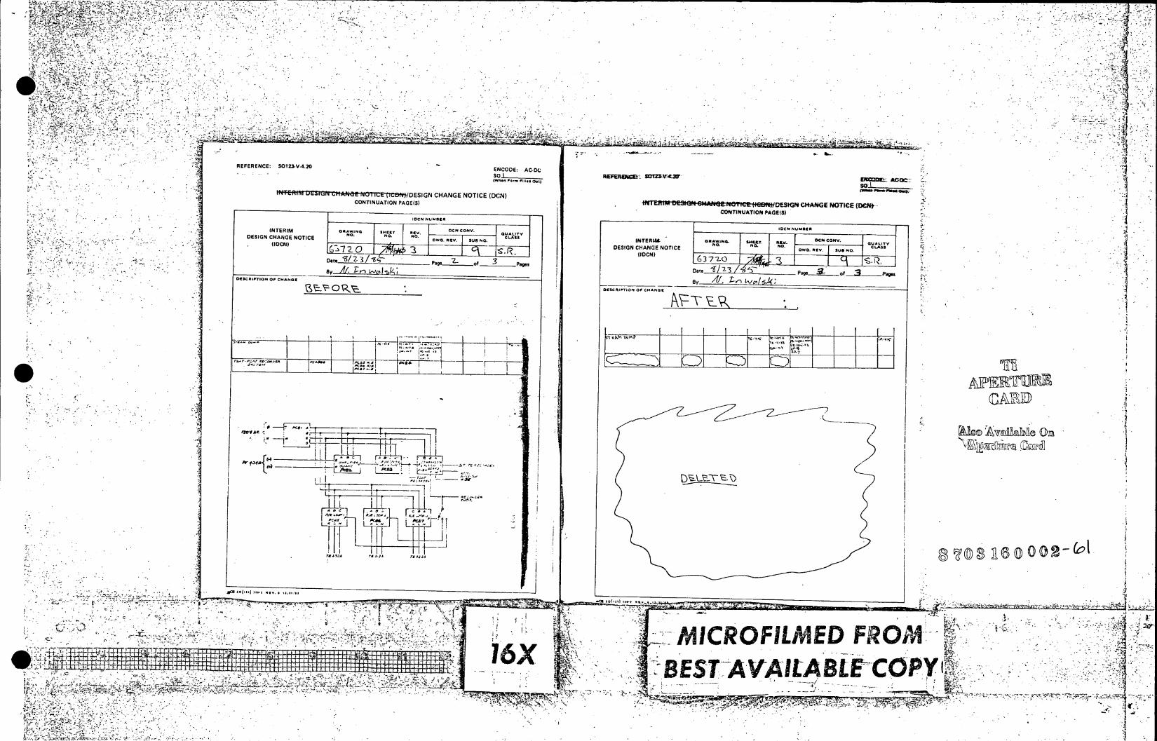
t'3
-41:.
&~ -Nz
,Vco "-'
w
REFERENCE: So'n.V.20 ENCODE: AC-DC
(W..F lm 11.4 Out) EXCMRW- Afc=-.
CONTINUATION PAGE(S) #Wi nrn. u~3It* hG.u T I DMOEG~N C)+AtGE NOTICIE (DC* CONTINUATION PAGE(S)
21~OC N0JOESRa
INTERIM4 DNAiO. oMLT CU34 MY.C v
QUALITY
DESIGN CHANGE NOTICE NO. No. ri. ~ ~ v ~.~ CLASS TZ0(IDCN) 372o/i
Dat I C..3i~ ________Paw_ -I rs~~r..z~~_ o 3t a.oo a",CSa, 8
.4""3,"No
I Date *~~3 _2
Pages__ _ _ _ _ _ _ _ _
CMESCIPTIN Of HAN x A/.T n i g3 6 *~ T~
I___ r LIZZ-.'V
iii ___,7
!0-~ L k -T_
*c~DZ
'ci2& Zz., , 6e4 4 r~,
to(~i( tI C3 C .. ,.) -~ CO~ti I C3~54 ' ~ "ICROFUME FR"'u"'
3 a ~ j - - -m I~ h . K ' rI L r K I m 44_ _ __ _ _ __ _ _ _ IQA- EST*-AVAILABLE COPY . . .
. ~ 3;-
i ts
t
" , ,~ 3
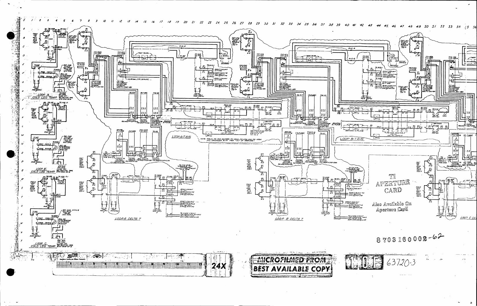
4 5 6 7 11 9 /o 1Z / S 14 /5 /6 /7/ Id/ 20 1/ 22 23 24 25 26 27 Z&2 9 3,0 31/32 JS 34 35 36 37 3,9 9 4,1)41/42 43 ~5 4 6 17 46 3 5 / 5? 5 4 h 5
wf
C-0 -4~
81 .-
A- Al;- K 0 ~
-- Y -
J -'J L
V L/co
,oI j~v ~ *" O /A
as)A M AC
C0s A -9 - * n - O 0 5 ~ S C.-. -P4a 0.17Seo OC/C 1-0-411 Lz] .!SC 0 w ~ r~
CL- C- rA J45 F i
45/0/4 - -L-.- L -- L I~L i LL 1- _ 4y 4.CCUe 4n 345
Li - __ ,y,,0 ~ ~~:J,' ~ ~-1 ~ . ~- .. '~ rc-o 4,50 745r- oarmCo , tg0'2SAC -n4-455 (
0.7w 1/L -ZC-OY 58 x O P - ACL i _____________~~~ ~ ~ ~ L_____ ________ ________
L-- **R-W'
_ _ I CyS S /- 4 C /c. O S S A E S J O E e-
_ _ _ _ _ _ _ -~ p ~cyOr P2- /
0 [fi m F 0 ~? ~ ~ fs'~~5F5Xk0D 5OA FOX40*-2AS~s I 1s~ *~O(4413O/ETR/0 ~ ?~~l~~/E*0lAtU ,,115OOA
sw-A45 I'll0
r o-sme0. .:g
055 C 74VPI
StY04,r? Cj ~ S /* . ~ t * , 4 4 U - I ~ . Ye
a- F5-CoE S/ - i,,I ~ -/ 700
J ' * * *- , s u m 1 1 15 / 4 / 5 A ? L 0-).. M OsAI& r~OX
A--- --
g--- -
rCoo-oor C-S I tES' CTS R5
11A i i V-L
i~-i~~ I..S-~ oC4sC~ 5,Q IS, 5! 05/'00. ~ z /o I II I
_____ -4.C4) 7 M
"'W T 5 5 5' 7 I 5 /i V '5 54F IraC A 0 Ces~s-e~sn
005L-- wn,~a aa55 554 (5~
1A6 ___ L il S C A/044 L 0ve~- .
4500065 5450
CYO 407~LO As'O L~ TV/ L 0 C i
_ _ _ _ _ _ _
-
4C/5/S CS
ySarc 8.
7~2 T~ Itt~:
__ .4, ___O7
LLLLLLL~~~~ ~~~~~ ~~~~~ ~ IA L I / L L L/ L /,L LL L L L Ol- o L LL L L a.L*
________________~~~~~S _________________ C OP_______________________

7 36Y J9 40 41 42 43 44 45. 46 47 4a 49 50 51 5? 53 54 55 .56 57 58 M9 60 6/ 60 6.3 64 65 66 67 69 69 70 7/ 72 73 74 75 76 77 78 79 .90 81 8? 83 84 8S 86878 990/ 934
C-0vr~
0t A.r .V
*~~~ to-; C"
a 4 ___T-w w4 -00 4.s
Li I Ir uL I i 72,,L,~lL
r~
ANI "
jTQ MI J - L '_
~ ____________________ -~~SD-6_
345~ ~~~~~~~~~ "'LJV'.- ______ Ia~.-f'
':__ __ _ Z; '7 LW '-
L.4 -c-, LYL Pi r- - -
jj _ _ _' L- I
LOO P C- A G- -T 1 I£W T N 1 .t
425-.1 _______
44: ______________ _____ _______ _______s
1010cORF -
L. a" 1"54cj ,5
~-ecrrcsr
move Cor 77s"'; 2
27. l " 05-Ai~e-ps.- 2 7 ' cSrtS
s-SM-~CG ~ s c -F_ __
I I 44I050
0 7 0 .' 3 2 ~ r D (
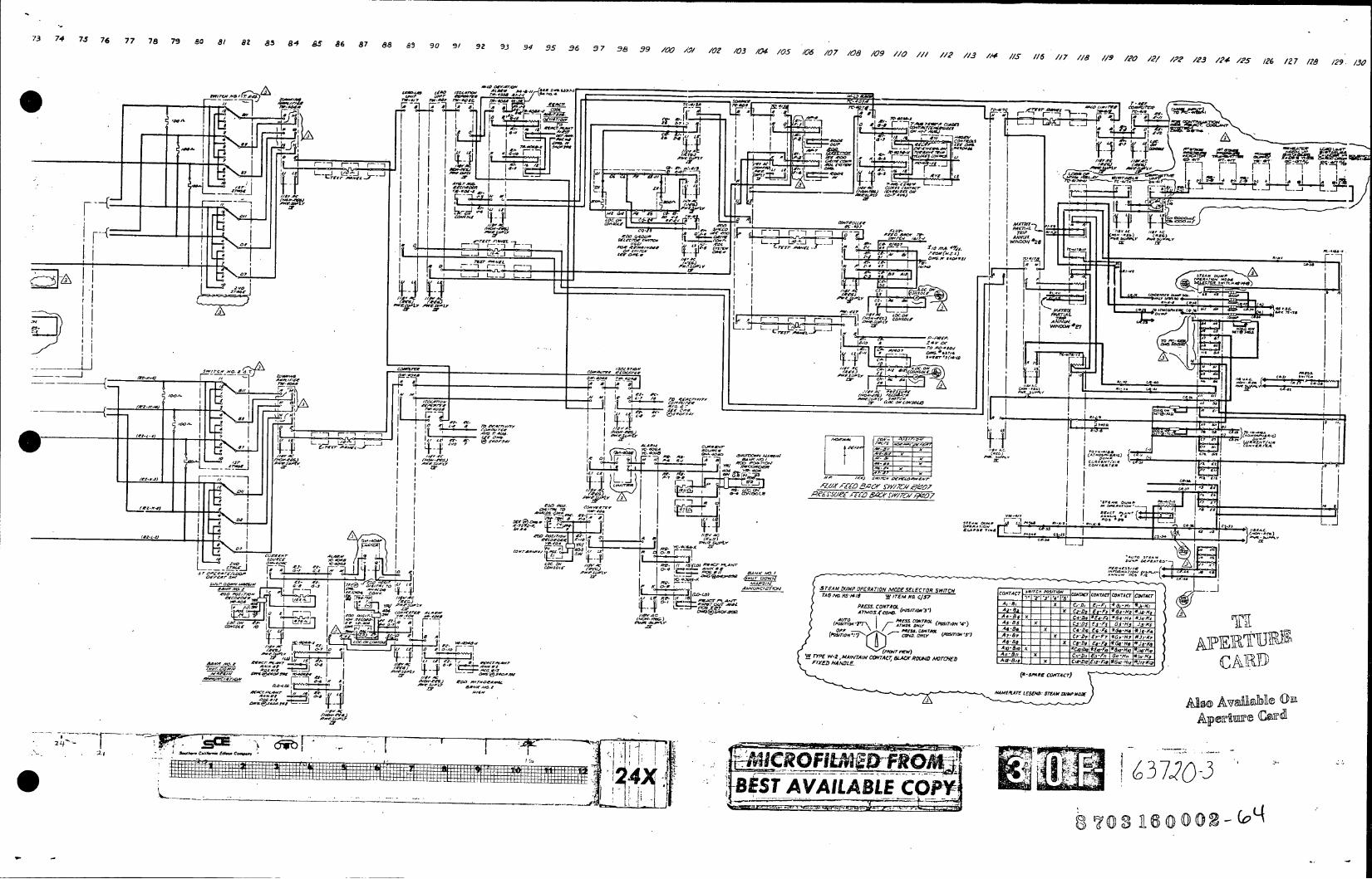
73 74 7 J 7 6 77 7 8 79 80 8 1 82 83 84 85 6 87 8 95 9 0 go / 92 93 4 95 6 7 3 6 -9 16V 47/i /0 Z 03 0 4 /05 /06 /07 08 /09 /0 // 1 / A S 1 1 6 1 7 18 /9 /20 12 1 / ,P,2?/ 4 / 5 2 27 / 8 /2 . h
.AI zA ~ff,
- -M
-J~~~T a C__ -aT O5A
z44 4-174,4aa 0 CI~
C'~ .04 - L... - n-a 0 ~ * C- owOAr 7-9A ' ' . , ~,
IC_ W,_ F -1 r- -
_ _ _ _ _ _~~ _ _ _ 'f 030I J
L.~~3* -:jACO Z
-L~ P-404 __jMn.
I L I A ____~~~IZ w _ _ . II ___y g A__ .11 ~I~~!" ' C.Ak'IMtsk C~
-~ II- f-]~f ~ . {F E~rcmJ ,j0 ~ VCJ I 44AMCcPP'tr 004-_ I c~t--a)~ f~1 I t~7 T~- tO PC4A . CASO ov , .W CAII CA.' r C
1--P I I 0~~~~~~~~~~~~- . ccsA '~0c 00 MtCP l~,AOT *A "ii~~~~ , "I AAIC.* _ _ _ _ _ __ _ _ _ _ _ _ _ _ -4-- tA A .W-.CGlP A _ _ _ _ _ _ _ _ _ RAIN ODSLETO W~ (4044)L trsi'I M'P AP CaM Al lA 0tr~oaMAr5 4ATA -. C
~, -~ Vt, *AACCOraA
tavec7-)Y_~ I EIF *6AC. JY,
(A0w0 Y~c-tO x~A~ .00 -~c~ 'Al.
rrs -P W ZPWc , 14A /In V *VC07 VDWr _ g- *,
M'KCr kPC SPA RE K CcnOOT SrA D/PCOTC C) 4TCNAC OTC
24 4 - 'o-a.-I,. oo IK C-. aF ~-Ia1'~ 04$ 1. AL~lUC?4 ESTcAVAILABLEACOPYC0T 44) A-s
4 8N -0 N- ~ -

/4/05 /106 /0 7 /08 /09 //0 /112 113 114 /5 /16 117 //A 119 /?0 /2/ 12? 123 124 /25 /26 /27 /?8 /29 1.30
-- I? 00.' =1717- I 9%..4.I FuNC 7ION LOCATION /4-blEATM EO~ O~f COMPIITER ALRf RLAY NU L3L LIMITERR AUX N .L muE w rrEs A"' n. r-'- _1 Atoml M" A.! PI
T, am -smfA Fl
r~±. J F E ~ O C T a - -- I7 F CC C
A1-1 00 '. a r
11A II'TO 1- .1. -13S -~
Q-a A -1 aATM 400-d ________ __ __ O~ L7 Ic I-r AA A77/P ~ ~~1~ ~ 9
ANNC TAO AA11PRno T I~0M 2 ~ ' - ~I - L, ~tO. CR*M VY42~I T,.ASS TAAM~ TA#28o a ~ A p r -Ao o 1-T d t 7 r l r NOtA_ _ 0 0 0 0 4 0 r O A d E T A T . M M0'* O R C - C MAV_ __o_ _ _ _ P0T 0 ) ~ ~ M f - eO Ot ATTAA~ T-Tph
:3 _ _ _ _ _ _ _ _ _ _ 0-00T A A Co, .
CO~~~~~t-
------ T-OA3-r-oo ct
-g~~~~~P& 41, _________________ LA O~l 4' 0V ...... I I _ ________ OMC IeAO AA.O0_
4047-CTPc~ Al- T A
0.3-a~/2 VAC a.. . ~ -, * TTR TO OS _
c TOT I T
T8
I TAT A0 C CA
PgJ A T,
_T'' CtO T~l TO LAORCARW-AOC~oOP
AM'I Ij A. " A7
-LL -M10C4w~
rL~~H AAC AtKZ I0T4 _ _ _ _ _ _ _ _ _ _ _ _ _ _ _~~~ ~ ~ ~ ~ Si 0 -0 4 O M A r T 0 4 0 e 0 ' .
r 48 A0. 604-0 C C51 A-Oe AUC. 040 R~C~ &q S00 1Z-1 -? V -7 40 (500 tO A 8 8 0 419 ,v I C C~~rA 40A0 L0 0 04PC06. Lo~~~~~~~t~ L M ct 'R ,I I oh$f0 4-f.O
0-4) ~ 0E I I - {4000/00 50 T A 0 -T C AAC CTA COA 0MA- 1t
WA-A -1 I n"? T R'2:'~O ,14'400ROtd 4 0.
T90A rf42 i41 7-OR -~ L
AOA'LACOAIOOI.5 TAM 0/IMP OPERATION MOVE SELECTOR SWIT'CH CONTAoCT COTC "A' Cn O NTAcCTorc CONIACT CONTACT TIAlaNO5NM8/ W ITEMNO, C137 AY 40 ST 11 '' A,-8, I AX C-o E,9, *O,-Il -K, -Afl PRESS C0NTR (O s,,0 -8 I I I l EM-" IA OAME JI-Ki
AT0.=&A#-4 xf 1FoC 1I/ CigN
7)y hy- CD . S/TIATA 4) A, D, -II- ±1t tf l 94u *5.-. S SAFETY EAE
ooallo * Rlv - C -M -hR
Vf TYPE W-2, MAINTAIN COYTACr SLACK NO, o NOTO'9tAW 0 o 055, V _Z2 1-91,I Ni/~ SANOR NU00/ CLEAAOR A G!. FIXE'D 4AIME. II
(*-jAfAR! coNTAcr) CAI '$ao,'sOp005400CS#so-p co is REAC TOR COTL
gVCORe.-C . CC, *Ii~~~ VO t'IAOeo AND PROTECTION AAf"LT( eOEN 5MANDAM)2 REVISIONS 'Q k22 c LOOP DIAGRAM I?
SCALl 1 -5 ATTOS ... N .' A0(01 00 L.0_-5 ~0A~c 5..
637
. --.---- B~EST AVAILABLE CO0PY,
[r______
00 TO____ (

70R)AeL PCINT'3 /OO~~c
OPAA14EL kET / I z__ No__
W/I420P51 V4Z VE Ax / 0-W---A1k--o42
INSTRUMENT x 5 0-1_ -AI UPY0 x 7o--- -W-o 8~0 TV-TE A. X, 9_0_
ZoA, P- Ops>I 8F 12 *F 3 __ _ __ _ _ __ _ __ _Z/OA, 01 0 PS/ x__e
Ale .34otz h/3MA h,3P/- - - # --- -- SwITcN, oevFLoPASNT #ssl76 A's-14/dA4 PRS. 418A cs A4 41Z BIZ Z--MA 0-1 o s CV77TWRUfCV73P
PS/ ,38 #S-141849 M-N ,S
0-AB 7D 4/A--tC38 cgs 0 00 00 oT4/eX&,
TRAP. 340JZalR. 8 -Y701 t'LJMP~~~~~-o COT4O. -o-S 5/3'9----
~JZ./?A1I I -. 29 / j I I
rC- 17BXR L I ) p PS1V~wp VAVESaC4/IAI =O
TC-4/71783Z P4: .,C/C m :j YC4/7A~~~~V 77H~ '~~ C C8
A~~kV'C - L. ST -F-417XAT-473X
TC-417AD-yi~~~~P-48~-Xs IEAI 1A7MAIV 00 0 K r.T7 UI E9A UN.UPOL 1PA-4i7- TTJE A
AN 'L P E 1/M 4/
-4rW7C-0/'169
ON .7170 .
SET~ IOC419- F-54?O . K5T~
~~4T7E~~LA5E /2,VC AET RLAE AIR
AS NOTED GM SUMCSp
ALIX AIRA' LO/SC .RI S5.5 IAS~t C-AI9, FAI,**Z- 5,0,L//'DS.EC~3o9 0£82 6li7-0 ,LM l/S~I OD.8A M SH R 5 &/LT- A 1RCCCINC. .Y4 QUI.A CRE3V1.fII E,________________II VCII,~Ed.~
3'', - EC PEV. _DE S74 FIL 455A16-6, 50 T7-Z-ro1. RESIVCp- EEETR IGA

_______ ______ _____CO AlTACT /S TO
'005 ToOA 64/.Al? R'11II
L161/T.W0 571M411 30AT OA0 /004 7vAT A loIA O'
7Z-144_____ Z// //4 /0wo 51OATZ OW 53 9 7Z 100 720 274TT
PERL' yA N 004 0,t -' A, ,LA I V 1A/O f2~4 /C_____,4
480i(o' IOO7A /0 /0 70A r
/g. 4,4.0 V ACS
71M44 4004/926 I -- (tL.5NIVC7 /.5~ 72-I0OS 7Z-1,01- // /0/2.
2SA04 48045.1 /04 '0 0
(111. 1 A I.4
72A3 OL 0./AP740// 72-107 70-108 LAOWC -55/5 1
PER6 IV-13 H. 3) 72 - 05 7zrr -/ 0 (DW6?M4 -5102182-)~r
TIM
00AZ- INS TTAUMA'OOA OUNT
i0 480~ 7V/m ."I 2-W 7 . / OPWO. 55 1+) ./
5C'3) . ..... 3OA 404 OT /004 OO/ 004 04 ___ ___ ___ ___ ___ ___ __ Z:0/44.04C31M
13. -~zE~rOJ 7Z113 7-/D5o5/,-/ 7z 13 Z-V541 H /7) P05744/W$S SX/T/ S.Y n---J- /E LF Et
61t "H/INIA 72 7 70-6S 71lS~5 5~ 77zI2A --- f
72-ei 101. 72/35 (70A0 TI27 ~ C~TO 0 -~ <----i)-- 1:)Cs ,'ALF 0/775/- _
400 A 20A 7 A 00A 2o:
rl"E~~~~7 ISO.* 5E OLI 4EQ. S3, RO 5119o. .0 A4Ai,-6SOTAA0SAV-2F
I-I/ U /O VOL TAOA2 53/
40036£ A 1.5041' -30ATw100A 1VOA 20A
/9 ~ ~ ~ ~ ~ ~ ~ ~ C3 J040/ T-ACO /00 1004 .3. rCNAX'2'D) i- ~OELN IGA q:__ 150LATDC.rONE IAV EUD~eSS7A
No-/99 5'0fi/ 7.1? 63717 NA54 H57506702f)2 ~~~~ ... '4 ' - - .59 -)

TO 61-,161 '772 -/1/ 2_44 ./ / 7) '2 VOLfZ6 5/0,/7,
1 'DC"IV MMA 4-4N/, 1W .l 4#,4 'L,JA. AOM~r
AC -3-1 ;I A44V 20 sP TAl IOI,'2P
7 1 AF NOT S4441//A 11/C 1/0 23 )ACI~l/l~PAA ~ . 744 220y/'A-AVR 74y42*34 95) 5lV614V L -;q- z rYVA X-22442 S '~ ,02 -4V /0).A4 .4o 5 0 O 2I .. .575 <VA 75'9 / /0 . .. /4/VA~ /dSI C~~O~O5 A. 2P-5 r 245114/ ./p,2 2/2.142 /4) 315 6,42?A..QCI I4 /2)s 2'4e'CV ~ 0'72/ 84/- ~1/0 SPAC P2( o~,rn,,c, 3/C CoD4,12/52. - AU70MArs TIC~ A2 0 4J,-0~ -A,4 4DT C~o R4 /./20 240451 472 g~~~~o~~~~r ~~/Z s/41IZ~~2/42/ ,o 2 4.; s6 Z ~ A, '~ 4y~~ IV .41C I -04 n ,V.P4,: C-2 I42 c0/ C,0/ z o Jc. PG.1 N I/ISO -1117-C, A10/I/C IVOY -1 46-.-r ,~,,-. ,-zr. A74- -'I- 52/70 cONT'O 5/.522VIAJ4C-1234' .0Ci 474-IC/C~~~~~~~~~~~~~ IV/A),,,~ ,,,.45 .52'223/CC/TSS x, 1027 "p.57 4"161 0TC/ 0g0(2) __T 00-I2SA 6 pA
153W 1 -__- 1110 -45 V5'07 6-4 S
(CIf 100A2/lN ITA 144 /l-43P1/3 lf-f sn/os C's2641/8 __ _ 2272 eIAZw-aosA~ga7 0C 111, 2P,/ 0-1.4 C/AI C.5V )1O, A04:21 C,-52
V/4-7 564L r67Sd'24CY0.-lI C1,144,1l< 45 3.9335.QC4 r O1 /C /7/ J5041541209---- - 3-F-.,:?4 (4/ SYSS ~ LS FfR A/C 45 I(/13 ,5 1/ DC(12I1,1/6' -/,4T *AC Z3 42C2 -'_50 3-J 2 32
'O KI~~V 4 9 6 9 5 1 Y I 3 0 -,d S/TA 6cS I/JO'Sc," t50'2 5 04 L ___- - M - e0,/ 5:5'.77+-y
L7) 3.25 C-04OV 8-504 'ON r. ela T OV.I. rovg v 5(. C-~ . si2 (-/. 4,/3 027/9/ -erCL6AO(Cp 4 --e 1 f v s 2 s s 6 0 ;,67,0 v0 7 4 V .. ' / 27 ' 47 - -1 30 V - 06 5 .C 7 6A -lacTO RVT OW.195 I-1W// 4e-E/ sP . 56/8 eT57 51AIV 4I5/A -2/011 648;C MN RN'SYSTEMS 'D -OVMQ A
1 1 7 -ul , l IIR II -A /l/3 (4 6 /2 0 P 1 III I V/l44e5l &.15, 3s -4--- Y5zl (12 V5/S1 S0P4Y f-/A1 0I,,V)I'4/ 4/ .,53 )"O32s~ I8<SV 85// C01A6 SPRAY 60 I. 3-S IW C,4114'2,TOR It42 SWV1eV ,,A V 5- I 737 I0 - 4 V/2/ //C/C.//AT Y7 A'5 " Xl -C W- I 44) !c..'l~~..44.7" 5-/5 -- OSIPRAIC 3 ,1
,22 -I-/ ~ V/_ 117A422 .l eI~ _-5,. 8-3 2 .-54 _I 5 A.4R3 -2/C ev I-2' "/-5-//335 V2410-8524 Bi-'~ R 1/ 7330 9)1/4 /124/ allJ.~;~ 04..~L1 O 4421/.- -.2-1/244181(57 ~ s-u~s~ 3-2.4 A6542 5214 5y4o'~ /I- -. -,2 5C4/8PCO /5,RAR' //I k~ ,0, ~2 - / 2IC2~z i/5.15 -, C _ 4.52 11)822 -SI 1 5 IA 80 RtR~ S, IA 4644 74
/2/5/ eai -, 3j a,5/ I4h Z44 /4/45~l- 3.5RA X -R0 . A 9U25 3,4AEr 4-;2'zv 1,/ If --224 " /42 - " 04 'SPARE 3.A4 dIA C C.6 .,5LA V;. dIV S ARS ATD AfS 2-, (W' i. 'v DW4 8/54 SALSF VSI/ACfPlA' 4/0)FIR m4WG 75
T7 ~~f~j ~ ~ -;~-' -. ,- -alll 10 r46 IAY-15074 - -- >. LOl)a- YIIFY ZIM AID Al.: OR)"
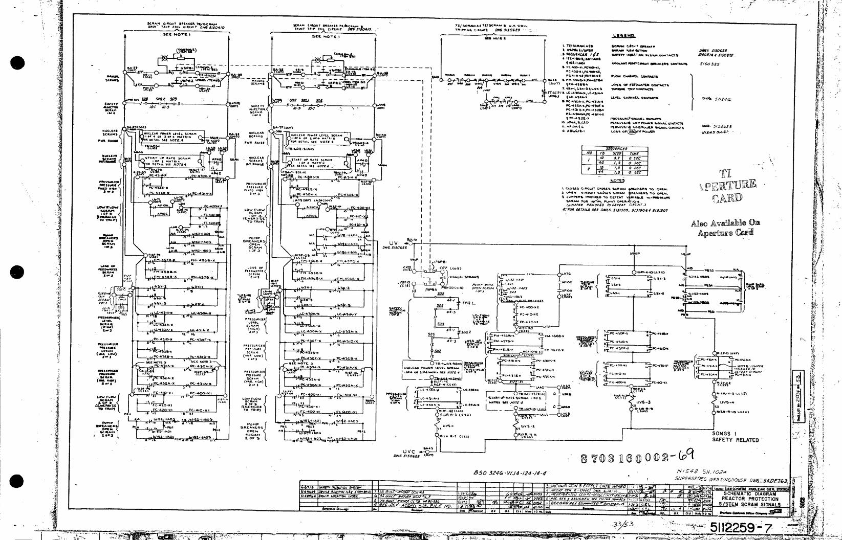
SCRAM C.Rw SAKU.IJ I~c,.- KR" C o.~fdI li t c~ 2/CAAA71SCA .C1 SOWn TRI*P OI1L GICISI smMr 5/0101 RiURU UWiA2I co ~cuir .. w 5/504/4w A "Vd l D"5150U6v m_
5222?o-r IRI Z C R a NOTI 1 I '411 1RP,~:~1 P IO
,,~~ Ft* P4w- mpC -1' v b2I c
CtC1 11C0b,1
15 =4 W7 "i I '_. .&.7d-%t'FA" PA ef'5"2so
P4R~AM& .4 &1I . 4..& CRUV .1 W~IA" 1"p R Cok A O
- 4~~ ss. 2 e0 14,O A P - 4Zt- X
2a 2 PC 2 221TI''_4. -~v 0 0 LA11r SEW 2Of amIME 5f-.tg IA46-7CR~/I ii ~rq /0- AP 0 C41
.6- .14 PCM 43 E -u v :6 'A~ C WAL -eQ
m.jSfE 5L3 . AAm
NUCLIA %CRAMS A E n~;
SCAM M.LrR',.~~ %&mon10 OfII $lmrt4N
L'GA Af4 OA- Rc 5L. 44-c,-o~
A'Ust NO r
.1 1.
STARTV. R.' A *fll 4 Z $9102 NOT 4C. IUC4IA. RThAM.1~T ,.,Ls I.L .... U
A-I,-C 0e~ SO G
.1
P O T S 1 11 m b i r~~~~~~O ~ J isA E z i1 L S b C ~ u f C X S : L ) k V t -SI~%C
70 o S FE Y EL TE. -'ISzO 32OPJ4/2 -/- C*C% /V/5i% SS ' t" ZCO..
FWD 144M !GHU~ W 4,Z _________________________7.mv II ______~ Al
I3 P,~
I T".E./MDS' ~ ~Aop~NA ~ AP" .4(> AE0.~ 1Mrf03, F- '40 1I _4Fy DE L SetTE SCR6kI SIGNALS/156 10 lo. IF LOI
@2. P) 77.7: 44 'r %p M~~5 I2 - j>T.Th5 .~ . .~ 4
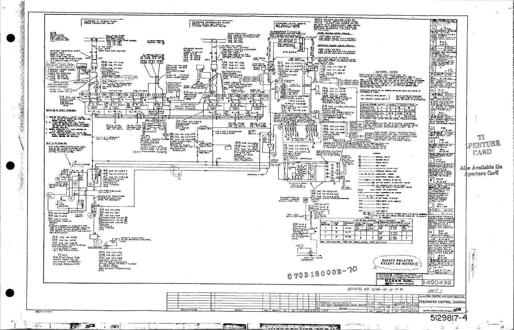
SARA58 TILPAM JTLOW 1IICA1,5 P11084-Ar~p _0_O 1-1E~ LIFE A05-*AOO1i T I I. O ^dIP1IAVU VALVE ^5041 a L% "' pGI04l AMWI~?. O Vg Iii-in. . ARE IAA.. D Pon AEL
CLS VOOUTAMVLVRRika I S Co E AT. VA6S R
PWARR87(040 PlIMS.-8417A
.. ' x.,0 , A LE.E 00A~ We. - Av OUA 5 ,$us " A I
1 144 PC ASE -:F10. tow L S8'~C 080 40 07TAG r7 9-,' 44. 1 St sri. CI A NA RO R .81 L Y~ g 5.* *, Y G i7f oo w 77~~~~~~~I to4 Pact *we,~ AV". ofE ~ sea~u ~445 I04 aiE 7-O 'Td Sao (/" Pid A .S87C M'.C G$D4p lox dWRO OVSr It 01*80.n,,fa3 AN VI ai.04-c"
TAG S PO ,Lne- MdAG Low Win, TV*",d TAGAl PT9S 73 SA, P.4 84, RMC8.5TA .- 1
117AAI 'LowJ TWNSMAr 07. AIM 0.7452 TAGf 'V0487VG1 . I .Y.CO I$. A
HIGH PATSIAUI771 1614. P4158. Co... .8
C4 LCpI4lC.458~ r815015
88. o-b
*t.; or4s
is. Toam
7714F4 IPM 7A TAG r--.i FOR AL/RA /C~ aso~t,000 00488 'Q REFR 7 A/re/ a, ~ *P*T~TAATT80CTO8 8.7.00070008408800885./6.LR8*E0 A-E
P T4. 0 1 7 8 7870 L r . 4 y
.009,~~~~~Swl flOM~r~ AFR RA,& 42 01")0 17C55 110.5005 T-,.Szx,00.05 C1SIT00J GS-.I8.O. 012SIO (A a''a up PMWItm LcBA 14A .O* 081 .~~~~f (,vc'A',.o CLOCED 541-A .4 41 ITEA aol-A-A~j jA T7o)3 , V S E ~ . ~I 8 88 3* 10 4017 151 171 88 : ,o A II*FI &E. 4 ,C1A M E O e Co s- E~f ~ 4 ' ~ P - A 7 1 0J / 5 0/ E /L Q , ( C L 0 0 A O I O ) o II N 8 ASC 4 4 5 0
1100CArO 08.537407-8 U880CSLfr5 F.0 08~408
SO 1.4. 171600-1 ICAG P0-1. 1 403 OR
Or~O BeI6 OMN TRMID IC-rTN 60 C t.-CIn ,'OR 7 C lA I 1 .1 18 W.V 08 78 A.Vlg 4. - . 0 BAe. . -4 5 8 8 1 LE E A G A NDAfO E N / C ( TIOO I 0 -~~~~P S 510810 3XIE00"
1057m..FO O 8 ,.WLtC 4,P 4 7 0~ AZ 4II~(I SAT/T - .. 758~~~ME r.'C1 No1.807 re,0 AL0W 18
976..00.5 *4
MA 00 ~ 0 801 00. I5T .*0 P{S CM . I 198 rAG LI-1-45 LT45 C HIIIJ1 4 0 'CC T/R AL C1 R P 00..OCIT "44"
- ocr*140 111 *,, AWCos WWR (PM) & / LEV OIT -IF POOLS L V"4/ d O TIS .8,0E I Fd/ O T012C5- DNCK T , , A TECo.00O0 "MC OE W0- APA AA I'm A_:G 1C-1, go~3(0 L8VE(S TC~ A L WR 0A rA A pw4c W _ 3 6 1 1 T8 S C TC fIt1 Y I
STEAM ZA- '- M 5.071707 C.-A/ 5.0-5845. VP 1
C.
vu.4. 44 -.i I
aA I*. -L-
I 2AT
4 4 4 13 5V . . 8 00L T - 1
;;m dA 0/07-AL 03C '. j13,1. QIR7 A
94 TAG_ age08 434 HF 87TTA 5 448 _T114 TAGA :459 &1 VITA,
1 1 " I W L - c 000 0- . 0 * IS t 0o F A C I P T W 0 % 6 51 9 E E 103 r r , I L.11 %Ilion 31 L~ ~ TCLO. I__
3AIAG P - 5G A-FA -1 AL"" 1.1Rt A 1MO 11110.01 27A0T150*8178 S!,W 0*1R ' *rc 2. 11 -ep ~ e OL-W -.-- I.
200U /LLI(4. 81008178 To6 "Id C05' -t AW4. L18 A.rRo 'ACE 200~ ~ ~ ~~_E A A.,- L 0507- ADDTPSAI(0 20Too~s A- 7.8 l4 70. ,,4 17 01 C. 07 3 492391 88 4000 10 CO /8 /O-1 Hs 11 Z C
I~~5 PlanM IRELAY.7" L
L71AN OLT 1 A +IV: 1.4-.14. "FgaLf g/00 i)o )- 5IA V A / . 8 / 4 ;_ ,
0 0 0 I A V N or5-
4 0 7 FILiE rRL.U~0 r~r, AA-As WID -AC -C E TA-ii Si 4. niYf= S1V~f.I. ALFS IOL .V A 0,r LAS NrIOWN 145C IN C EXO C EPT5 O A S CNTOLTPAEL. /1/80 0
6'EC -O~e I. _e .'..''. . . -- 5 2 8 7
MAY LC Of-FIEN.8O 1A TAG MA04 rsA "CTo 7 4L& AU,4c -r. 'I us2

IW 77X 74 AC
'V 72-201 6A I
600A CARD I hI1UI-~ _____ _ * IA~i1iih60,9Ah CWARDE0 AV o7 ESS Io r /6 4
*'5D4 N7
72 Z" Z6 04
va g e
IDe#A _ _ _ _ __ _ _ _
27FL0 2.18A 722D ~ -SP R
I 0-SPA
R 14C 100 72-0A
f So 72 -Z-11+ 724057 0-- NEerA4 25~ G , / 00 10A 20A (OEO 2510 OY./j54 2)4- NPCT/ Izr 72-20o SPARC I/~~/2 ~3NCA55~V A'/2C~Y ICIN
A1R2 qm --- o 0r0 SARE--7lE 6 SLhERE CA/I O44'G4436 4. L.
0y/1/yEA 9/ OC A Nll W6 vorgsc.-Cla
(P5 lV4,0,5~' 06 C..g-A 647EY~2 s'i~rCO 2.21 2:1 VAVEO3(3U' IWS 3 .76 4'EAY AND720 D1/~ /5AV RELAYT 4LA,4fP //e /5/2/ YT
C04r4?0 I/C 0 Q5~. C7'pUP/ ,b
*..~~~~0 3..3. 45 3,?r 27, ,.Md .. N.S..A/ NE01 ~ o ~ V D Y T M N .
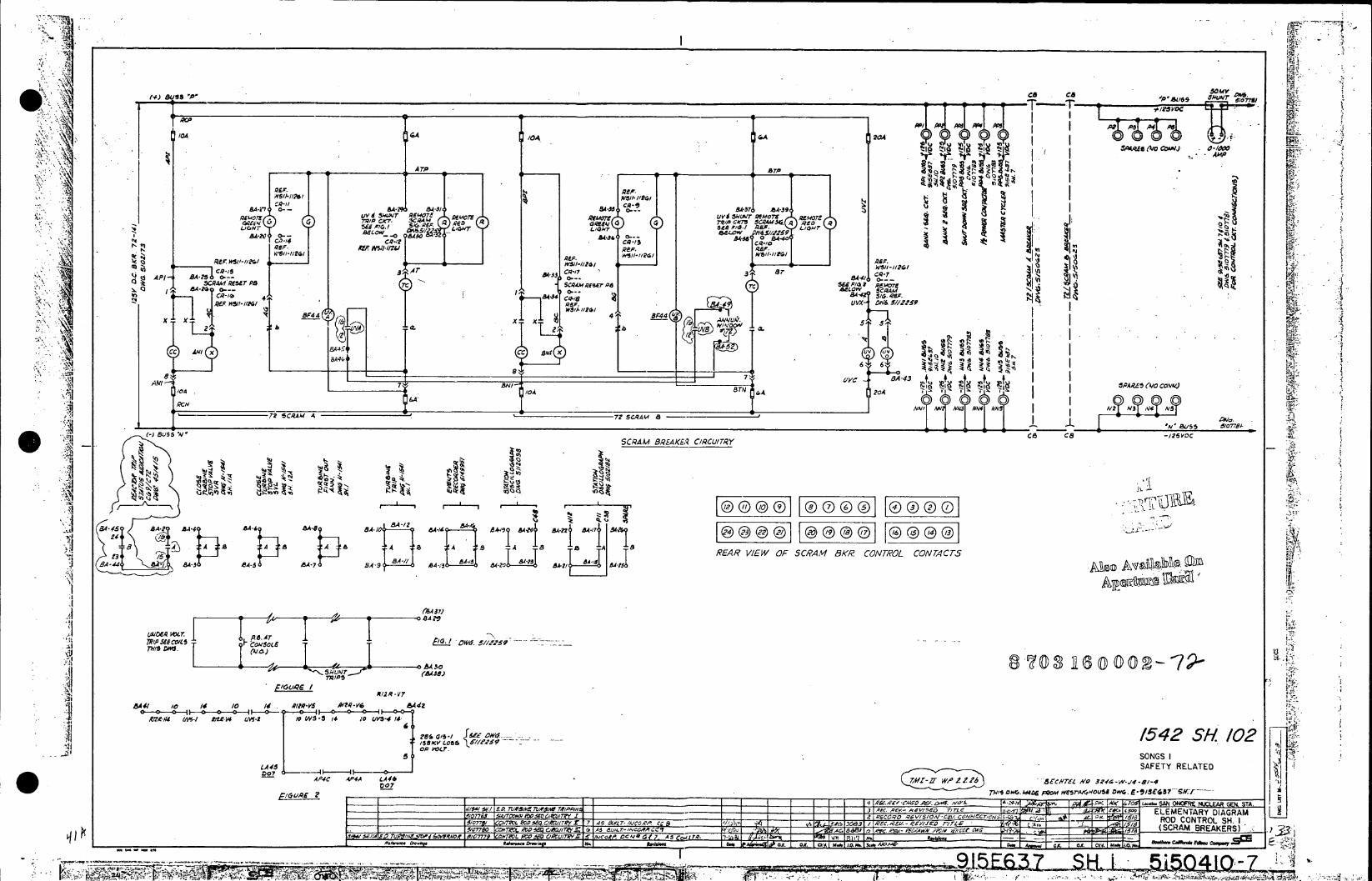
'v,~
'11 ICA W4
c, Q
'A 'CAA20
U-V 0-4e(~0~J - O1 *IA- - *7 143
7V/ C~ . LA- 4- 43 7T, ? $1-5A RED b ~,.g REMOTI U0,1 rI -1 !~eWs ~~~1
8.4-25.4-10
t 8A-? . /d AW3I..I rC
95P.. l3 I.II I1 B84 44 SP4
cc__ __ _ AW X'e CW BUS X
72 SRAM4 7?SCRM 8 ~f' ~0 6,RA 4RA & /C/~
£1y 8 7 -0
AN ae A 4 u5PRZ A/ C~le ~io BTN. /046A2o 6A0
1.3 18 7Z, SCAT8_ N 43 SUS SA'Al'-4~ ER IWO SCRAM BKRAE~ CONTROLR CONTACTS5V
84-3BA / 54-5 ~ 4-in
A (£43Z
4.6 48 11,4 8A. /0( Q/?.-YS ,QQV A8-4G 402(
14)4
BAu~ - 440A - ., -1 1LMNA, IGA B4-1 A'A .1 G SA 44P flIAA& 1.~ 7U 5.4~t 3A 'o". BA/ -ARGOr~e- 8
41 1
A oSA29~ UAI&C M~r.AB94

72/CR4cA7r~wv~zGE- -. 72b/ 72/b I 7 VAL VE N Dfl~~~ 5/1259- sgM SC9*W A -. to54
AP IV UVS-2 -~~4nA AS~e NCA1 06~ &4.'WI23 X5MIJV74@6W31R5T7 PAESPR
AC N (f A 720 -'&W- £- AP4Ax x A VA A'
Tr 40 WI _q NS- 8643-1 A~6 h UVX
cc x b a;!x b a .. AAII /Z2v CIRcu
ArN STNV T T TUI
72/ 7 / I I I I - UBN ,S rro R CA , 7 2 S R M
C A M E R A a L .I L 7 2 41VN T k c ~
49951RA AAET 72SCA 8 v SSCARW 21.5
IL Eld~ a~Z. iC/ 1ra
ATOFP ARr0F PARTO LDBLWiA OE 51 ~ ~ O PWRLVL~' AGEf- r/4-6 /7ESSTAE ToRA' +/25v. a E
5/4//A 7L77Pi 316444L'~
TURBINOURC PR.LR TRI TRIPe NE P
-7srr,_- 7z-*---' 7V~~r& ruNNAL 0~~ ~~ ?O AII AN VMRDC PR
N5 TI AP30~r _ 497 L dW -P4 FOD 1Z LW"O
2320 so Sf O Cl AM T_ T_ ~ -C4A }~ {ijLCL SRM- w'f
070~~~~7 .P EDV. .4N~ 7yp5f$* VfORAr0'd477__ APII TRS AN4 EM1V .PS .. ~V/O
AIPI SCRAMr ZrC "clE06 PU ADAP4 SC
51I 1 To T SIOOA AND CON r E1 2112 4 'NL
_AO00Z IV V 30012 SPEEOE
rRU CON IWA TORW ANDSz~ 51 TO PE MSSV CI CT ;!CO0 TC-413 SPEED zIET/N 4afR& SZ,r aL w -n PROM o r RODW AMSeN P VWr .a .7 OW1O
[ r [ FOR.E BANKM MP0 SCCa7 AAN NO A- RECT R A ela.4.
CONTACT14 CON 19C) DO43A -4~ LIP -~m D/ApCTOA S0,-A COTC3)A~MNTP, OA/ OVELA O/ C54T1O j4IX AND 5FOR s
FOR 6O AC 1 AC 1? VD - crsC M O P
CO CI COMSSV CI CIlr
RODFe cO 84Vf SNUTROL W UPCONR 0-CYCLER a
I~~~ ~ E~f'5 R M Al/4YCATO 1ROL/ SLAECYCERC
WN.llc VRA , O7O CONTS OAIr FOR4 SI/lOSS.DE1V 8CA'TERL__C~ A/a 3ZCSWJ LC4C 7RIPP76r RI/S rll.S
721SRAM- lE ?ZWS/N TRIAN LT 5C- W1~f ./LA~.- ~ O M#CHN4 S 13/g~ NOC 0A. DICN(2O2*pfy I-/-~z0+.-76/-IC C47C ~1 '-S~ioLSSE
.. I D fIT C Ep ,CNR S/f .CISAl /ARM 45 8cz I/lc C / so Sr4 PO414 ~4 AEM' .
I -IM

Rd0S C g4 FOLRIPOWR. R46 E M2 T P Twk& R;ROPD
Q405R RN 97 (A) I R 04
t ____________________________________ ____________________________ ___________________2)V6_____,___97 _
2A9 697 C
29KFA 65 /00 2.5K A S rA/00
R0VO7 245 -RR29
R438 R943 R4 C V 4 0/ ' _ C R4_ 0 R4 I4 3.3K ~ s
2"407312 2A9 040 60 I 34
9701 38.3
R40 Cr, 25 MI I2 6PWR
(E14 47a 47
R441hi 943 2- 26L51
167LO0' - 7-41
LLA44N4t MIDU14
IDA 11 1.34RLYoj 31 OZgBLWP RVR
99,0 06 6_91DO941
N 0, 0
z1 F
1040
mWOZN(j KPC
cr115V rnR423
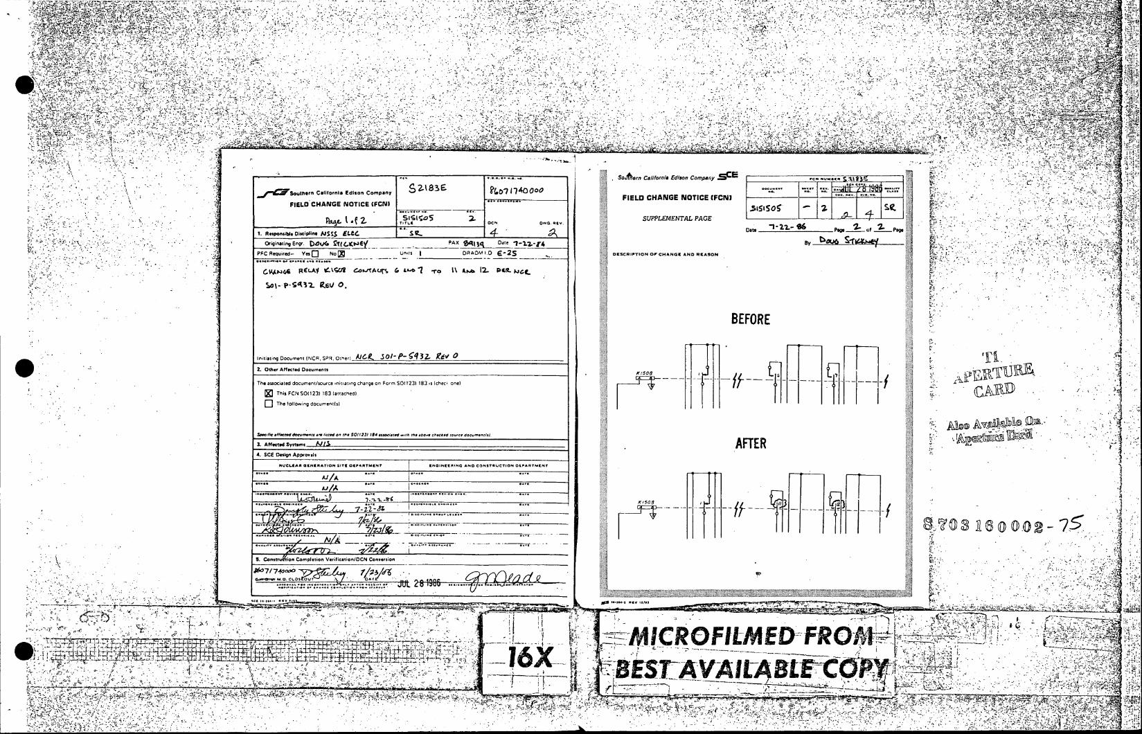
WV~' H1 7
I2
'j,.en a/ona dsnCopn C * - Z183 ~ d
h~Su~ef aionaEio opn IL HNENTC FN
SCposideiciiil Calori Edlaon ______________ Data Pag .... S .
FIL 'H NGE NOTICE__ '.0N FI .4 E LT D CHANGE NOTC REAS N
Tit. oc, oo .9,
Th Rqired FCNt 501123 83.0tacndi
Intatn Th e n(NR SPR.nin Oth~nenl _K 3si
2.Ot Affec d Douents.~.A 4. SC Desin AX1503i
The EA assocAated douet souc itEain chPangUe on FormEKCN ACD 1231183ITIO ss (che one
X3/ Thi .... SO12)18111a~e)
SCis ..... r- t listed on Me--13-14----0---~ j-ciNk~ ou -m
........ K10
5. Constnugion Completion Vetlfictlion/DCN Conversion h
0-- ______R
______.-_'.LC- -~ ' IVt lIK Pr1 .1 . 1.U00
I aiL 4- P-,4444VI XO ~ .Y-7 <;l~~~~~~>~~~~~ 2.RL~ ;:-'~'h- q~___.l
177l~,
~. *i=;.- 71 ?7
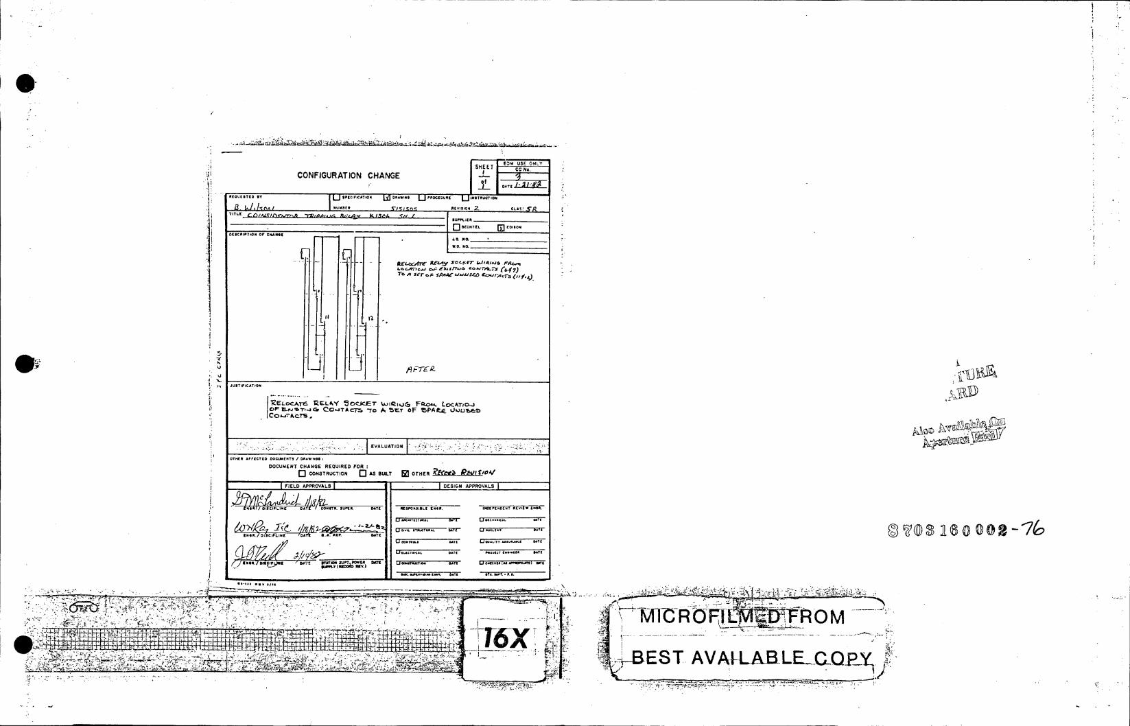
CC N o. CONFIGURATION CHANGE SKET Em US E ONLY S
OAll
REQUES1TED IT SPECIFICATION L4 DAWING U PMOCIOURE INSTRUCTION
0 SCO30TION Of 1044001
1.0. NO,_____________
Th> A 1" A IJu40£.Ojri
JUSTFICTIO
JABEVALUATION
OF,..C] COTRUCIO 0 A BUIT 0OTHE ZAtrYL UL
FIELD APPROVALS DEOSIGN APPROVALS
4' 101/ DISCIPLINE DATE f ONSTR. 044010. ATF RESPONASILE 114411 INDPENDENT REVIEW* t41IR.
U 6-LT U MSNCALA OT.
U DOT. AS UCALT AAAC ATE
bOA.h*TOAA O~l. 0447 57 NT. - P. a
44.4
in "Y" 4 AVAWXBEKLOP'L
'1~ ~~~~ ~ D R ' M p.~~.~.. 44*

0S5 SCRAA ld
K150 2 34 75O'c
ON
K1505/
2 3 4. -7
K1503 X1502 /- _ _5
EAOALL WIESLSE T NT
T ~CONVAIECTRLr
3. ALL R,15OS 5,1M /LS
4. ALL AC.44 .VILES P~fo 2 13- [7 H/ED.
9S 5OE~ C.PA1 L l .34 PCS
9v/ 05 C PA*CI. OA TE ONRL STR
J103 DEC L- . 1503 .1/504 Li COI 7RPCIL5 z) TRIP COL TRC OI RPEE VORDER UN E.Q VOL A E -5C R AM4 CHAN EL TRIP C A NNVEL RA E R ?7
H1CV msCOILs #I l'2 ANNIUNCATI/ON ANNUNCIATION CAN~TI
~ 3 :~MV; 5O .. C MCD A-C6 IN,2~ 2 CZN1 -I 1cceAN111C171~
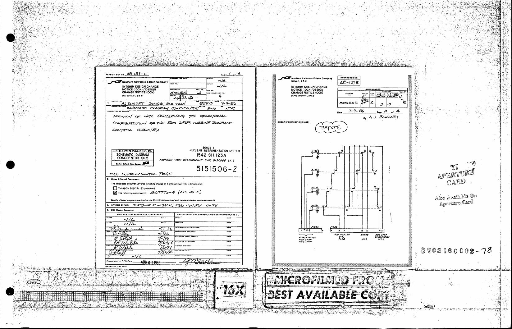
A13- 137-EPG
c.
'11 EdsnCopn
INE RNTERI DESIG CHANG INEI DEIG CHANG
NOTICE VIDCN) / DESIGN .- il NOTIC (IDC). -. G CHANGE NOTICE (DCN) CHANGE NOTIC (C. ior SONGSI1,2 &31 SUM. 4MNT AG
1. AJ &WA-IA- .. 50A.Jc,5, .57-4- 7rZcd 867a3 7-86
~4e i~~ .4 d 1 OM JZ)~A7D ~ :Do't 7 Page of
~ 7 7sd ~ . 7L~/A/ ~DESCRIPTION OF CHANGE
SONGS I
SCHEMAT1C DIAGRAM 1542 SR. 123A OOINCIDENTOR SH.2 E~ gM$ATNhufOG /E6 ~
Z Othver Affected Doassnwnt I jThe associated documentls-jrce initiating change ont Form SO) 123) 183 is (check one):
LiThis iOCN SO(l 23i1183 (attached)2
The following document (s): -5/0-777G~-4 ~-4-E -F--< Spae ,e fiecmdd - &,..o.- heid o dwS 20(23) 164 a-lared orh the *a hor wekodsoe. do-o h.i.1
3. Aft seted Systems 7-ip / 1^ 4CEk -- ,, j C- 'A -( .
4. SCE Design Ajprovals
N1.EA U ....... T OEPA.VMC- ENGI NEERING AN0 CONSTRUT/OR 09PARTM tTiNESACL
...... 1502__ _ M
Roo .fro,. rqln .SPWAX ROO .2,o .... pA) iwoA0VAr t R..,oo STop C
. ...... Roo ..I
.~~~~.. ........ - A V L I.
.3' ~ ~ ~ ~ ~ ~ oneso to -CN Date . _____________ AVG 6/l-g4--4-1
00MwI

a%
.0PlI1ISouthwn~ Caifonia Edison Comipany / C ouhrCairnaEsnCmpy
INTERIM DESIGN CHANGE NOTICE fIDCN)/DESIGN INTERIM DESIGN CHANGE...k.. CHANGE NOTICE (DCN) - , CHANGE NOTICE (DCN)..
SUPPEMETAL ACESUPPLEMENTAL PAGE
Date 7 -t. Pg. 4 of 7
DECRPTO OF CHANG By 4 lZ4~ESRIPI0 07CHNGEOZCRIPTION 0F CHANGEv,
A Br
MItTES.,
A4 AL WIRE *20 IMJAC5 0rW#Wij hCr=
K~~ isl00" AC I .ALS LAP W ,,f US~gaG M
G ~~.A Al RK1/S TORS 2 w., to u/L is$
5S CAAAACITOR &4OW/T10 d,. q&LAYS
4 'XRlf Y3 fX -C~wOf-.ZA~ro#Or 51LA4 A 14. S/OWN Y XE4CdlTo
Kwrm ~ ~ ~W~4 mCJMAL I AGP1Q4?/NS CoLO/LEoicrR LAY
PIL 2f eli.elr ALL R17/r " z 10% 6111413S
AC BC6 -~ --
3JT C.1JCr &ION TO A4 A YS2 G.W f LV R A~wf-L AN 5/- 6
Of~ A#A I~ o~rR rV. /V
Z.,,., com.4 "owoq .
DA 1's?
~~~~~~~~ '7 N Nh IS AIA L C M1'K *, ~4~ ROO TCAIWA 3P.44'ROO37ol -J:.PE-4
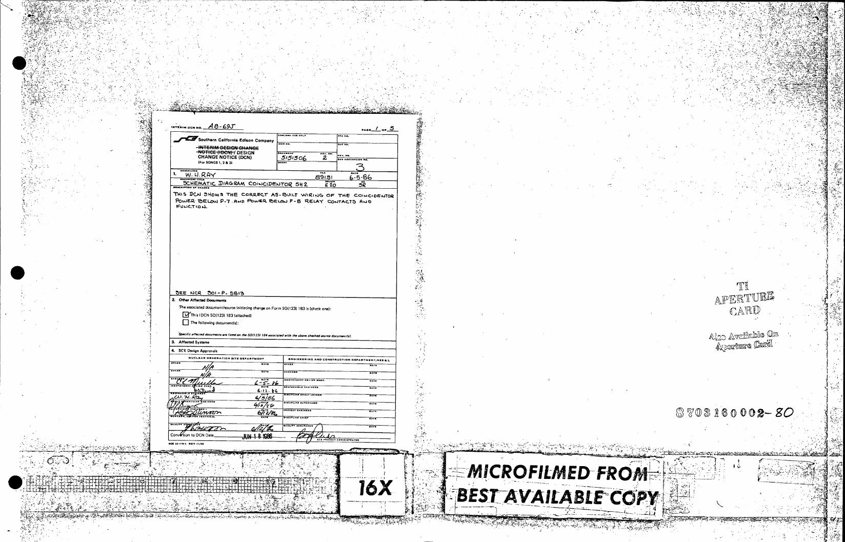
-7 , 2L,
.......... ,
- Yfh4~~ A 6-69J. PAGE- OF
J'K..wSouthern California Edison Company
-N8:FeE 1$et D1ESIGN CHANGE NOTICE (DCN) i.,o 2 ... ..... iWor SONGS 1. 24 3)
j" CHEMATiC DIAGIZAM C0IwaCXED,..0-o SH2 :20 T141S JXAI 31-1V41 THE Co.pMIFx A-15UILT vWi~iQ~
7 OF THE COw~CiDEijTOR POWSI 'bELOW~ P-7 .A..ao PlOWIRM eELcui P-5 RELA-f COFJTAC-T5 Aj t
ZEE KICR 301 - 5815 Z. 0th Affecte Documents
The associated document/source initiating change on Form SO(1231 183 is (check one):
a Th is I DCN S00123) 183 (attached)
The following d. .,en(,):
Sef t fee&wd - t do ""er.- 'dw ee ( SOI?23) 704 .melpd ith (he.b.- Oweked-ye dao-nf). &~
3. Affected Systems
4. SCE Design App,o~als
NU CLEAR C UNgeATI* .. T .1-T ...ATMN ENINKCRING *74 CO.r-rT.O. -CA.T...re &I
1,
.................................
Cony (ion to OCN Date JUN 18 1O'MM.
C-. ;77'-- A * 7 _ _ _ _ _ _ _ _ _ _ _ _ _ _ _ _ _ _ _ 'M I C R O F I L M E U -F X
16X<

Songs 1,.2 & 3 .. otenCalifornia Edison Company SSS 05
-Nefe~1te~t/ESIN 00 n~.a I~T~MDEIGN~ elb*NGcE CHANGE NOTICE (DCN) .TC ( C ):
SUPPLEMENTAL PAGE CHANG SPEMNTCAE 5556~
6-.8 p, 2- of-8 5
Daa a[)o ara 6- -8 Pa0g - of 3__ Ely W. 0 8,Y BW. .RAY
DECIPTION OF CHANGE IE O DESCRIPTION OF CHANGEAF E
Z f f~' & .
N
zt Q -I
S I _4
_ Alias
S 0
L0~r--~ -A
. ....... '
- -. 77
*U-4
________ 4 -j----ILo.LD
IR FR -- r
16X ~V BESTA-VAILABLEBES w , f 1111

-A
. ... . ...
,""c '5osth ni California Edison Company [~ 3 M n o ." 'ou hr ClfonaEio Cmp y I T' ' 1
ASongs.& I ~is 1.2 & 3Lj§ jIj1 ~ ~ ~ ~ ~ ~ ~ ~o g , 2 & 3 _ _ _ _ _ _ _ _ _ _ _ _ _ '
DESCRIPTI-RI OPIG CHAOCEEBNWG4E
C H N G O T C N -
C1
-
13 59
N AM
i ~In
I iAF
NN~ .
Ap
'A r"A ~" ~ j.AlAjA A A A AA ~ ''
t ZIA 'W" ' AAA ' N
N3 x" C)
NN~l~A~ ' ~/ <'M. 4%:;
-lit
1:'
A1
n4P
Z~ F

A-86 7 _ 91 k 1524
K1519/ 2 3 A 8 5K1523 A52
I A K12
ACIS17
A 8 / 12 - - - - - - R152SE
J/5J150 VTU1 NR 0i
P NPM C'0 52 ______ 0 _____ 1504 X502 0S5 ~ ,PI',SV PERM1531VE MC5 Pg/M1SSYE- RO TPTI SAE ROSOPRbSO PAE PDSO
POWER RANGE 41AI/ UNRIP (P 7) TRIP (P 7) ANNUN11CIAdTION ROOs J7AN10 7R11) A//A4R/CI RO O N poSRAG 70ANUCA POWER L EvEL lCa POE RACS (P3) 4VNC1Ar1 RO 370C . SARE AC SCRAM C41T-I,(P-7) RO0 DTOP MC6m6maPRO RAGTOPP P
POWER ahELoI
0 P152 5 34 5 K1514 L124567__ 8A i I 7 A -5 -6
A'8151151
A EIs 7, K151 8 At 5 - - NOTES: 1. ALL WIRE
2. PLACE IN54L I/GSEVI.GOE 6OT/I EACAO L IRStSOT
-L--Ik ~~~~1ITERCONNC EL S
(L51 I K1514 TIR WS 107(
4. A4L OAPACITR 0~ULS
5 CAPACITOR A NE NRLY
TY,- 34 PLA P1509 / z 5 6 __ _ Y-P1513 ,, 7,. Ys~E/~ML~OEAIG OL
* ~~L 5 -- I-- -IV 8r___ CA________
TRIPCOIL (/TRPCOI SPARE EVENTSORE AN14CA11 UOER LT 05150 PERMI1SSIVE PERMISSI~VE MC8 PEIRMS5.lVE 7 Ji. Q30 -121/(1 ,) OERRNG6V N-TrRIP (P ) TRIP(P) ANNUNCIATION 7T
. AI5 r4 9/ r- 1.R4r. (MCB) (AMCB) POWER RA//GE SCRAM
SCRAM CUT-INCROp) V..1
POWER SONGSI SELOW .0 NUCLEAR INSTRUMNTAINSSE ~
1542 SH. 13 REORAWN FROM WESTIV69OU-SE DWG. 5O5Sh2
I I& SAN OR ULA E r
/ S.S5- I TLYI4o SCHEMAi IGA I4510 COACV%. CAW9/", -A,50 A/~ ~ - - ,~ ONIETR S 51CF1501 CO/ICSTR SC/e 4
COI0N.Av.cswg~s~occ~" ~ ~~'~ R~ft,.~,.D,,A.., N l~*N 0. 2x. F, 7d Med.10 AA. kk NONES o. o. ck. AbA J. 8.- C48.,.1MCo.
1.-- ________________________-_______________________________________
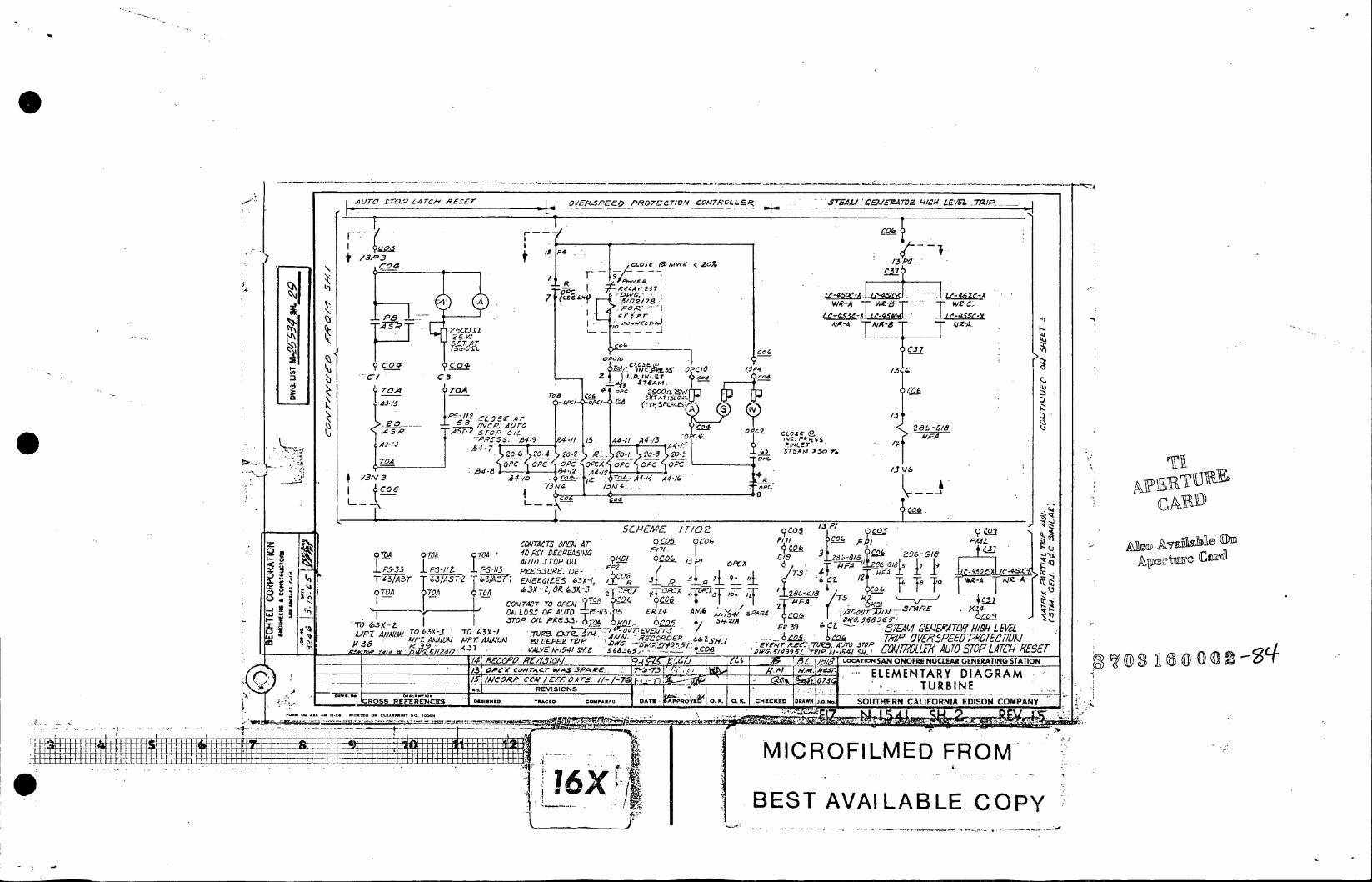
qurai sroQA' L4 tc-e Acf~r OVEASPEE0 P~R07ECr C0N7 -L~EP,- .STEA/ '4EEZATM7 kHf:4 1EEL
C04!<
9 P4-I /5 4/ 4/3 % ~ J/P
+ 131=3 o se tamw 2Z13p
OTA A 40- zS 3 6/a c2~-I ~ ~ 4
F0 50 _aX- -1 ._0
OA ~ ~ ~ ~ ~ ~ ~ ~ ~ ~ - 7A"* J ____~ TT RA A~I COATACT O OPEI j2T~rc7u-PAE OFl LOS O AUT Pi1 1 . INR&S AM6c/ '-',' 0
C3 zeO .I. INLET5 q? C r4i5~3~ /TAM Etu~~-5A&LEI'T/iI/WE A,*IAJLA 21~X- _r 2 0TRPOVA'PEaROEC!D
414/~d147 UAUAr&edE T/ (SW 6EM335 4co K38 51/24/7 b( ~ 7 VALVE /J-4 r/9, £ TY5,---. 3LC S) I ~lrR~7~.ATO~SO AC- Z 0_____ SC./59~~J Aa/-S 7'_________
S /43 VCA,*LUfl0- 2,3ILJ 67 Z 0/ BL i/'LCTO A NFR ULA EEAIGSA I (f) 0(02 - 5 /A'C iQ. srav ole 0AP c Z, CLOS
4.6- - A41?4
ALY1J I0 BES AVAIABL COPY Ly 4.
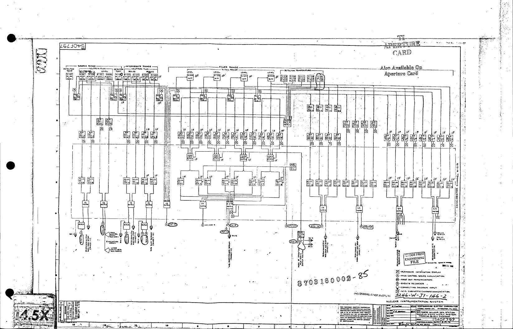
* JECIO Ttm - -U
PA C- -- U- P- AD M RQ
A2A
I)r- IF I F I r F I F I F IA F r
!a - Z 744; I F I F i K I
'IIF
i~ IF j~i~*IF IF IF ~
IF I
m4w RP4 34
'''(6.41
F- FILE.
c NU4..A '7Eao NU r4P. A T K3
-0 2 n-s CU 2 4p,% U % w-Tw " ~ C C A .P
-~~~~~~~r (D*** (D±x
11
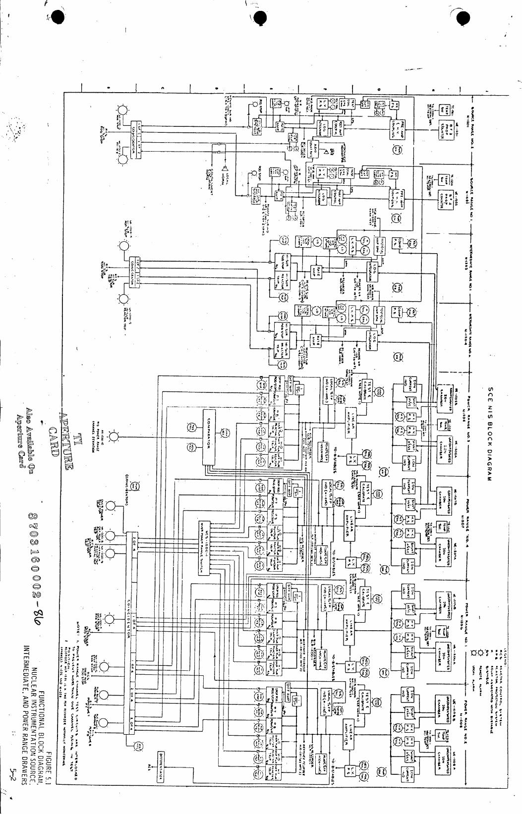
r '4
0.
~~iu,
00L
cr .0
'~ It
j. ,fl- 0.1
____ ____ ___ ____ ___ ____ _ 2
17, 0 *o .