exclusion zones for small modular reactors - University of ...
118
EXCLUSION ZONES FOR SMALL MODULAR REACTORS A Thesis Submitted to the Faculty of Graduate Studies and Research In Partial Fulfillment of the Requirements For the Degree of Master of Applied Science in Industrial Systems Engineering University of Regina by Bradley Edward Rudolph Lulik Regina, Saskatchewan March 2020 Copyright 2020: B.E.R. Lulik
-
Upload
khangminh22 -
Category
Documents
-
view
0 -
download
0
Transcript of exclusion zones for small modular reactors - University of ...

EXCLUSION ZONES FOR SMALL MODULAR REACTORS
A Thesis
Submitted to the Faculty of Graduate Studies and Research
In Partial Fulfillment of the Requirements
For the Degree of
Master of Applied Science
in
Industrial Systems Engineering
University of Regina
by
Bradley Edward Rudolph Lulik
Regina, Saskatchewan
March 2020
Copyright 2020: B.E.R. Lulik
UNIVERSITY OF REGINA
FACULTY OF GRADUATE STUDIES AND RESEARCH
SUPERVISORY AND EXAMINING COMMITTEE
Bradley Edward Rudolph Lulik, candidate for the degree of Master of Applied Science in Industrial Systems Engineering, has presented a thesis titled, Exclusion Zones for Small Modular Reactors, in an oral examination held on March 27, 2020. The following committee members have found the thesis acceptable in form and content, and that the candidate demonstrated satisfactory knowledge of the subject material. External Examiner: Dr. Irfan Al-Anbagi, Electronic Systems Engineering
Co-Supervisor: Dr. Esam Hussein, General Engineering
Co-Supervisor: Dr. David deMontigny, Industrial Systems Engineering
Committee Member: Dr. Adisorn Aroonwilas, Industrial Systems Engineering
Committee Member: Dr. Golam Kabir, Industrial Systems Engineering
Chair of Defense: Dr. Christopher Yost, Department of BIology All Participated via ZOOM
ii
Abstract
The objective of this thesis is to estimate the size of the exclusion zone around a
small modular reactor (SMR). The aim of such zone is to provide an atmospheric space
sufficient to dilute any radioactive releases during an accident, to a level below the safe
regulated radiation dose for the public. A hypothetical severe accident is considered for a
generic SMR, and the whole-body radiation dose associated with the accident was
estimated at various distances and reactor power levels. The results were verified against
those of a more complex model for a typical CANDU reactor. The obtained results were
then employed to estimate the radius of the exclusion zone, by determining the distance
at which the dose is at or slightly below the permitted dose to a member of the public.
The method first estimates the quantity and type of radioactive materials available
for release to the environment following a nuclear accident, known as the Source Term.
This thesis employed a simplified approach for estimating the Source Term, utilizing the
magnitude of the fission product yields, radionuclide release fractions, and reactor
thermal power.
The estimated Source Term values were then used as input to an atmospheric
plume dispersion model, to determine the radiation dose at various distances after
dilution. The HotSpot Health Physics code was employed to estimate the radiation dose,
because it is a convenient and efficient tool for the many calculations associated with the
numerous radionuclides that would be released during a postulated reactor accident.
In addition to the effect of atmospheric dilution of radionuclides, the thesis also
examined how the size of the exclusion zone is influenced by technical regulations and
standards, reactor design and safety features, and by the presence of engineered barriers.

iii
Further, this thesis presents a survey of SMR designs currently in development and a
review of their unique safety features.

iv
Acknowledgements
I wish to acknowledge my co-supervisor, mentor, and friend Dr Esam Hussein.
During my time at the University of Regina, I have had the privilege of learning from Dr
Hussein. I am immensely grateful for his continued guidance, support, encouragement,
and patience. The Faculty of Engineering and Applied Science is blessed to have Dr
Hussein as Dean.
I would like to express my appreciation to my co-supervisor Dr David
deMontigny. Over the past eight years, both as an undergraduate and graduate student, it
has been a privilege to work with Dr deMontigny. His commitment to the quality of
education being provided by the Faculty of Engineering and Applied Science is beyond
compare.
To the Silvia Fedoruk Canadian Centre for Nuclear Innovation’s Board of
Directors, thank you for seeing the value in developing Saskatchewan’s technical
capacity related to the siting of Small Modular Reactors. I am grateful for the monetary
support that has allowed me to complete my work and appreciative of the opportunity to
participate on this multidisciplinary project.

v
Dedication
To my wife, Justine, for her unconditional love, support, and patience throughout
this endeavour and others.
To my parents, Debbie and Emil, for their love, encouragement, and continued
interest in my studies.

vi
Table of Contents
Abstract ........................................................................................................................................... ii
Acknowledgements ....................................................................................................................... iv
Dedication ....................................................................................................................................... v
Table of Contents .......................................................................................................................... vi
List of Tables ............................................................................................................................... viii
List of Figures ................................................................................................................................ ix
CHAPTER 1: INTRODUCTION ................................................................................................ 1 1.1 Small Modular Reactors ........................................................................................................ 1 1.2 Canadian Regulations ............................................................................................................ 3 1.3 Exclusion Zone ...................................................................................................................... 5 1.4 Thesis Objectives and Outline ............................................................................................... 7
CHAPTER 2: SOURCE TERM .................................................................................................. 9 2.1 Introduction ............................................................................................................................ 9 2.2 Source Term ......................................................................................................................... 10 2.3 Approximation ..................................................................................................................... 11 2.4 Source Term Verification .................................................................................................... 12 2.5 Sensitivity Analysis ............................................................................................................. 14 2.6 Conclusions .......................................................................................................................... 18
CHAPTER 3: RADIOACTIVITY DISPERSION AND EXCLUSION ZONE .................... 19 3.1 Introduction .......................................................................................................................... 19 3.2 HotSpot ................................................................................................................................ 20 3.3 Verification .......................................................................................................................... 23 3.4 Exclusion Zone for SMRs .................................................................................................... 28 3.5 Sensitivity Analysis ............................................................................................................. 29 3.6 Conclusions .......................................................................................................................... 33
CHAPTER 4: REDUCING EXCLUSION ZONE THROUGH DESIGN .............................. 34 4.1 Introduction .......................................................................................................................... 34 4.2 The Exclusion Zone ............................................................................................................. 35 4.3 Inherent and Passive Safety ................................................................................................. 37 4.4 Reactor Material................................................................................................................... 39 4.5 Engineered Features and Barriers ........................................................................................ 41 4.6 Conclusions .......................................................................................................................... 43
CHAPTER 5: CONCLUSIONS ................................................................................................. 45 5.1 Summary .............................................................................................................................. 45 5.2 Conclusions .......................................................................................................................... 47 5.3 Contribution to Knowledge .................................................................................................. 48 5.4 Recommendations for Future Work ..................................................................................... 48

vii
REFERENCES ............................................................................................................................. 51
Appendix A: Review of Small Modular Reactors ................................................................... A-1 A.1 Introduction ....................................................................................................................... A-1 A.2 Water Cooled Reactors ..................................................................................................... A-2
A.2.1 Light Water Reactors ................................................................................................. A-2 A.2.2 Heavy Water Reactors ............................................................................................. A-19
A.3 Gas Cooled Reactors ....................................................................................................... A-24 A.4 Molten Salt Reactors ....................................................................................................... A-28 A.5 Fast Neutron Spectrum Reactors ..................................................................................... A-39 A.6 Summary ......................................................................................................................... A-50
viii
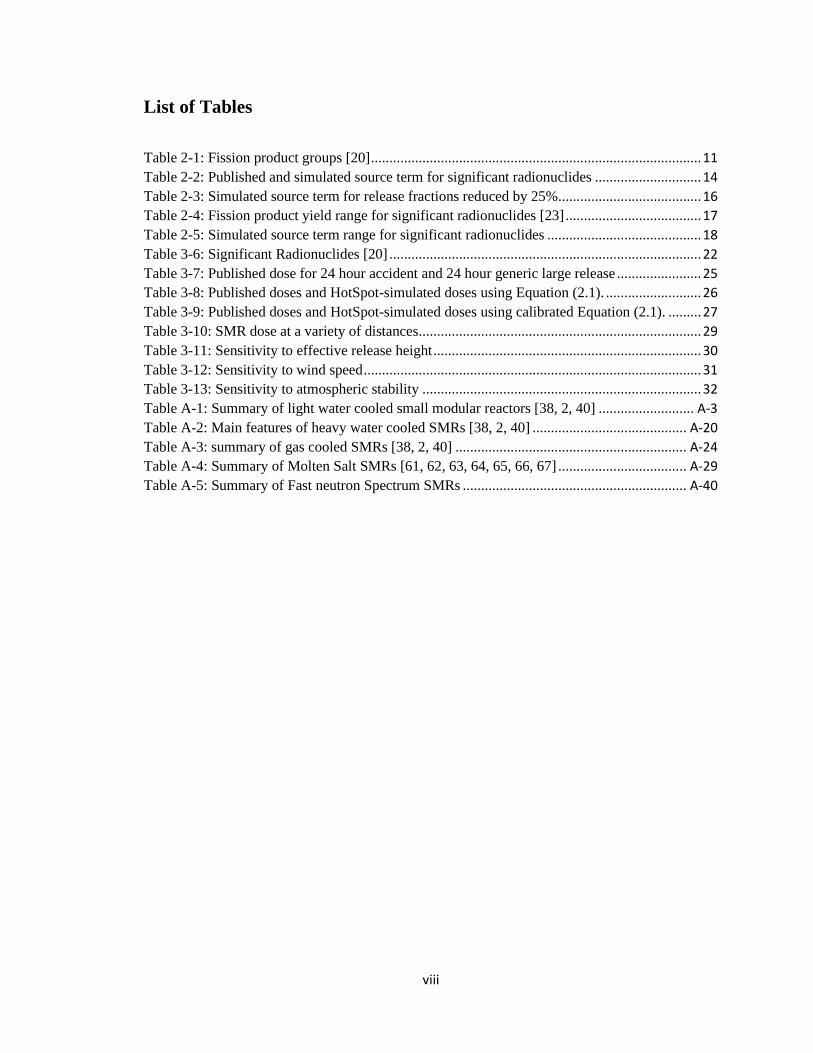
List of Tables
Table 2-1: Fission product groups [20] .......................................................................................... 11
Table 2-2: Published and simulated source term for significant radionuclides ............................. 14
Table 2-3: Simulated source term for release fractions reduced by 25%....................................... 16
Table 2-4: Fission product yield range for significant radionuclides [23] ..................................... 17
Table 2-5: Simulated source term range for significant radionuclides .......................................... 18
Table 3-6: Significant Radionuclides [20] ..................................................................................... 22
Table 3-7: Published dose for 24 hour accident and 24 hour generic large release ....................... 25
Table 3-8: Published doses and HotSpot-simulated doses using Equation (2.1). .......................... 26
Table 3-9: Published doses and HotSpot-simulated doses using calibrated Equation (2.1). ......... 27
Table 3-10: SMR dose at a variety of distances ............................................................................. 29
Table 3-11: Sensitivity to effective release height ......................................................................... 30
Table 3-12: Sensitivity to wind speed ............................................................................................ 31
Table 3-13: Sensitivity to atmospheric stability ............................................................................ 32
Table A-1: Summary of light water cooled small modular reactors [38, 2, 40] .......................... A-3
Table A-2: Main features of heavy water cooled SMRs [38, 2, 40] .......................................... A-20
Table A-3: summary of gas cooled SMRs [38, 2, 40] ............................................................... A-24
Table A-4: Summary of Molten Salt SMRs [61, 62, 63, 64, 65, 66, 67] ................................... A-29
Table A-5: Summary of Fast neutron Spectrum SMRs ............................................................. A-40

ix
List of Figures
Figure 3-1: Procedure for the Verification of HotSpot .................................................................. 23
Figure 3-2: Three levels of verification ......................................................................................... 28
Figure A-1: A schematic of FBNR Fuel [41] .............................................................................. A-4
Figure A-2: A schematic of KLT-40S Fuel Assembly [42] ......................................................... A-5
Figure A-3: An overview of a VBER-3000 SMR [43] ................................................................ A-6
Figure A-4: An overview of a VVER-600 SMR [44] .................................................................. A-8
Figure A-5: A schematic of VVER-640 SMR [47] ..................................................................... A-9
Figure A-6: A schematic of an IMR SMR [47] ......................................................................... A-11
Figure A-7: A schematic of a NuScale SMR [48] ..................................................................... A-12
Figure A-8: A schematic of a SMART SMR [49] ..................................................................... A-13
Figure A-9: A schematic of a ACP-100 SMR [2] ...................................................................... A-14
Figure A-10: A schematic of a mPower SMR [2] ..................................................................... A-15
Figure A-11: A schematic of Westinghouse SMR [2] ............................................................... A-16
Figure A-12: A schematic of SMR-160 [2] ............................................................................... A-18
Figure A-13: Fuel Cycle for AHWR [50] .................................................................................. A-21
Figure A-14: Spherical Fuel Elements [56] ............................................................................... A-25
Figure A-15: PBMR Fuel Element Design [57] ........................................................................ A-26
Figure A-16: Prismatic HTR reactor schematic [58] ................................................................. A-27
Figure A-17: MK1PB-FHR reactor schematic [61] ................................................................... A-30
Figure A-18: ThorCon reactor schematic [69] ........................................................................... A-31
Figure A-19: IMSR-400 core schematic [70] ............................................................................ A-32
Figure A-20: MSTW optimal configuration principle [64] ....................................................... A-33
Figure A-21: MSR-FUJI reactor schematic [65] ....................................................................... A-34
Figure A-22: SSR reactor core module [72] .............................................................................. A-35
Figure A-23: SmAHTR vessel schematic [73] .......................................................................... A-37
Figure A-24: SmAHTR vessel schematic [87] .......................................................................... A-42
Figure A-25: CLEAR-I reactor schematic [89] ......................................................................... A-43
Figure A-26: ALFRED vessel schematic [80] ........................................................................... A-44
Figure A-27: ELFR vessel schematic [90] ................................................................................. A-45
Figure A-28: PEACER core arrangement [91] .......................................................................... A-46
Figure A-29: BREST-OD-300 Schematic [83] .......................................................................... A-47
Figure A-30: SVBR-100 Schematic [84] ................................................................................... A-48
Figure A-31: G4M plant layout [85] .......................................................................................... A-49

1
CHAPTER 1: INTRODUCTION
1.1 Small Modular Reactors
Interest in small modular reactors (SMRs) has recently grown, as they are viewed
as a tool to reduce CO2 and other green-house-gas emissions if they replace traditional
power generating facilities, such as aging coal-fired units. SMRs can also be integrated
with renewable-energy electrical generators to create hybrid energy systems [1]. An SMR
is distinguished from a conventional nuclear power station by a number of features. An
SMR has an electrical output of 30 MWe to 300 MWe [2]. Conventional power reactors
produce higher power levels, e.g. the CANDU Bruce B Nuclear Generating Station in
Ontario is rated at 817 MWe per unit [3], while pressurized water reactors (PWRs)
operating today produce between 300 to 1,660 MWe [4]. Another feature of SMRs is that
they are to be produced in modules in a factory, to shorten construction timelines and
lower initial capital expenditure [1]. Moreover, the smaller power levels permit the
installation of SMRs in a serial manner, permitting units to be installed sequentially, as
required, to meet demand [1].
The smaller size and the modular nature of SMRs allows for flexible application
for a wide range of uses, whereas conventional commercial reactors are limited to
electricity production. SMRs can serve off-grid locations, such as remote jurisdictions
and industrial sites, while on-grid installation can be accommodated in smaller grids.
There is also a possibility to use SMRs for district heating and seawater desalination
because of their small size [2]. Methanol production, petroleum refining, thermochemical
hydrogen production, and coal gasification are other potential uses of SMRs.

2
While, many SMR designs have been proposed, the International Atomic Energy
Agency (IAEA) lists forty-eight SMR designs at varying stages of development [2]:
eighteen land-based water-cooled, seven marine-based water-cooled, nine high-
temperature gas-cooled, six fast neutron spectrum, and eight molten salt. Some of these
designs incorporate a number of novel safety features. Appendix A reviews some of these
designs and features. Of the forty-eight SMRs discussed, two Russian KLT-40S 35 MW
floating reactors were launched in August 20191, the Indian IPHWR 200 have been in
operation for many years, and the Chinese HTR-PM is currently under construction.
With the understanding that existing regulatory frameworks and licensing
processes are largely devised for conventional power reactors [5], efforts are undergoing
to revisit these regulations and examine their suitability for the emerging SMR designs,
during normal operation and more importantly in the event of accidents. In the Canadian
context, the Canadian Nuclear Safety Commission (CNSC) has released a discussion
paper on the licensing of SMRs, indicating that existing regulations are mostly suited for
the SMR technologies, and that the licensing process assesses risk regardless of the
specific reactor technology or size [5]. However, the CNSC’s discussion paper also
acknowledges that while “the licensing process is risk-informed and independent of
reactor technology or size, [the] CNSC is interested in understanding where
enhancements can be made” [5]. Below is a summary of the regulatory process in
Canada.
1 Russia launches 'floating Chernobyl' plant across Arctic, https://www.cnn.com/2019/08/23/europe/russia-arctic-floating-nuclear-power-station-launch-intl/index.html, accessed January 19, 2020.

3
1.2 Canadian Regulations
Licenses for nuclear facilities in Canada are granted by the Canadian Nuclear
Safety Commission (CNSC). The regulatory document to support an application for the
licensing of SMR facilities is referred to as REGDOC-1.1.5 [6]. It addresses the licensing
process for selecting and preparing a site, constructing a reactor, and operating it.
Additional regulatory documents for use in conjunction with REGDOC-1.1.5, include
REGDOC-1.1.1 [7], RD/GD-369 [8], and REGDOC-1.1.3 [9]. REGDOC-1.1.1
establishes requirements for site evaluation and preparation of new reactor facilities [7].
RD/GD-369 identifies the specific information required to support an application for
construction [8]. REGDOC-1.1.3 sets out the requirements for an application to obtain a
license to operate [9]. These three documents pertain to all reactor facilities and not
SMRs specifically. As such, REGDOC-1.1.5 is the focus of this section.
The CNSC’s approach to regulation is technology-neutral, meaning that
applicants are required to make a compelling case in order to show that their design
meets the intent of the requirements [6]. This is also known as a graded approach, which
in part states that the level of justification provided by the applicant is commensurate
with the potential risks to health, safety, security, and environment [6]. The CNSC
determines if the potential risks are adequately addressed by the applicant when
considering regulatory requirements, regulatory information, third-party research,
Indigenous perspectives, stakeholders, and supporting documentation provided by the
applicant. The CNSC’s graded approach creates a critical component of the licensing
process for SMRs. Alternative approaches to regulation are also permitted by the CNSC,
if the approach will result in an equivalent level of safety [6].
4
The content of a license application to the CNSC addresses safety and control
areas (SCAs) [6]. REGDOC-1.1.5 references fourteen SCAs: management systems,
human performance management, operating performance, safety analysis, physical
design, fitness for service, radiation protection, conventional health and safety,
environmental protection, emergency management and fire protection, waste
management, security, safeguards and non-proliferation, and packaging and transport [6].
Many of the SCAs are concerned with provisions in the design that reduce risk to the
environment, community, and individual. Management systems ensure that the
organization’s approach to meeting safety objectives are established in company
processes and programs. Human performance management ensures that an adequate
number of people with the skills, knowledge, tools, and procedures are available to carry
out the required responsibilities [6]. Operating performance includes a review of license
activity conduct to ensure effective performance of the reactor [6]. When documenting
management systems, human performance management, and operating performance, the
applicant is to directly address the “number and type of physical, engineered, or
administrative barriers” [6]. This plays an important role in determining the probability
for a release of radioactive materials to the environment. Safety analysis is the evaluation
of potential hazards against “the conduct of a proposed activity or facility and considers
the effectiveness of preventative measures and strategies in reducing the effects” [6].
Physical design refers to the ability of components, systems, and structures to maintain
and meet the intended design parameters [6]. Radiation protection ensures that proper
monitoring and controls are employed to maintain adequate protection that aligns with
the relevant radiation protection regulations [6]. Safety analysis, physical design, and
5
radiation protection are directly concerned with SMR failure probability and the resulting
consequences and health considerations. One regularity feature that may be revisited is
the size of the exclusion zone, also called the emergency planning zone, surrounding a
nuclear power plant, which is discussed below.
1.3 Exclusion Zone
The Canadian Nuclear Safety Commission (CNSC) established that license
applications, other than a license to abandon, shall contain provisions for an exclusion
zone [10]. Class I Nuclear Facilities Regulations, an associated regulation of the Nuclear
Safety and Control Act (NSCF) [11], describe an exclusion zone as “a parcel of land
within or surrounding a nuclear facility on which there is no permanent dwelling and over
which a licensee has the legal authority to exercise control”. The Canadian perspective on
exclusion zones is consistent with both the American and International perspectives. The
United States Nuclear Regulatory Commission (USNRC) defines an exclusion area as
“the area surrounding the reactor where the reactor licensee has the authority to
determine all activities, including exclusion or removal of personnel and property” [12].
Similarly, the International Atomic Energy Agency (IAEA) describes the exclusion zone
as “the area around the reactor that is controlled by the operating organization. In this
area the operating organization has the full power to implement all necessary measures”
[13].
When determining an adequate size for the exclusion zone, there must be
consideration of the evacuation needs, land usage needs, security requirements, and
environmental factors [10]. Rather than prescribing the size of the exclusion zone, the
designer must demonstrate to the regulator that the distance they are proposing is

6
acceptable and addresses the above factors. Evacuation needs refers to emergency
response requirements. Land usage accounts for any potential future expansion of the
reactor facilities. Security requirements considers threat assessment, external hazards, and
available resources in the event of an incident. While evacuation needs, land usage needs,
and security requirements are undoubtedly crucial to determining the size of an exclusion
zone, they are not within the scope of this thesis as they do not impact the dose received
by an individual at the boundary of the exclusion zone. The fourth, environmental factors,
has a direct influence on the dose received by an individual at the boundary of the
exclusion zone. Environmental factors, such as meteorological conditions and terrain, are
to be carefully considered when determining the size of an exclusion zone.
The exclusion zone is an important component of defence in depth barriers, which
are intended to mitigate radiological consequences following a postulated release of
radioactivity, and ensures that regulated dose limits are not exceeded for members of the
general public [10]. The Canadian Radiation Protection Regulations state that an
individual at the boundary of the exclusion zone shall not receive an effective dose
greater than 1 mSv over a one year period during normal operating conditions [14]. The
effective dose limit for an anticipated operational occurrence (AOO) and design basis
accident (DBA) shall be 0.5 mSv and 20 mSv, respectively, over a 30-day period
following the analyzed event [10].
Prior to the current regulatory approach, Canadian nuclear power plant exclusion
zones were defined as 914 meters (1000 yards) from the reactor building [10]. This was a
conservative approach that accounted for uncertainties within the nuclear industry at the
time [15]. As the industry’s ability to use atmospheric dispersion modeling to analyze

7
postulated severe accidents grew, the regulator allowed license applicants to propose
alternative solutions [10]. Existing regulatory requirements for an exclusion zone are
applied to large nuclear power plants. The objective of this thesis is to revisit the existing
regulatory requirements of an exclusion zone in view of SMR’s reduced power output,
and the likelihood that some of them may be installed in locations where the traditional
one-kilometre exclusion zone are not practical; e.g. when used for district heating of a
building complex or for producing process heat for an industrial site.
1.4 Thesis Objectives and Outline
The primary objective of this thesis is to addresses SMR exclusion zone sizing.
This is to be achieved in part through the development of a simple method for
determining the whole-body dose from a hypothetical severe SMR accident at various
distances and power levels.
This thesis also examines how the size of the exclusion zone is influenced by
technical regulations and standards, reactor design and safety features, and by the
presence of engineered barriers.
This thesis began by examining in Section 1.2, existing technical regulations and
standards relating to dose limits and the reactor exclusion zone, the goal of which is to
dilute any radioactive releases prior to reaching the public. A review of SMR designs
currently in development and a survey of their unique safety features are reported in
Appendix A. A method for determining the whole-body dose from a hypothetical severe
reactor accident at various distances and power levels is introduced in Chapter 2. The
method first estimates the radioactivity (Source Term) of released radionuclides. Source

8
Term refers to the quantity and type of radioactive materials available for release to the
environment following a nuclear accident [16]. Three levels of verification for the
proposed method are discussed. In Chapter 3, the dispersion in a plume from a reactor
following a postulated accident is modeled to estimate the radiation dose associated with
the accident. The obtained results are verified against published data. Following
independent verification of the empirical approach for Source Term estimation and
dispersion modeling, the two methods are combined and verified against those of more
complex models. The methodology is then applied to estimate the exclusion zone for a
variety of SMRs. Results of the study are compared to existing technical regulations to
ensure that the dose permitted at the boundary of the exclusion zone is not
exceeded. Following review of the developed method for determining whole-body dose,
innovations in SMRs are discussed in Chapter 4, including their inherent/passive safety
systems, developments in reactor materials, and developments in engineered barriers, to
determine how these features can further reduce the size of the exclusion zone or even
eliminate the need for it. Chapter 5 provides the conclusions and recommendations for
this thesis.

9
CHAPTER 2: SOURCE TERM
This chapter is adapted from two conference papers published in the proceedings
of the 38th Annual Conference of the Canadian Nuclear Society [17] and of the 42nd
Annual CNS/CNA Student Conference [18].
2.1 Introduction
The Source Term refers to the quantity and type of radioactive materials available
for release to the environment following a nuclear accident [16]. The released
radioactivity is dispersed into the atmosphere, determining the radiation impact of the
accident. The Source Term is often estimated using comprehensive computer codes, such
as the Modular Accident Analysis Program (MAAP4-CANDU), which simulates the
radiological consequences of postulated severe accident sequences [19]. The Canadian
Nuclear Safety Commission (CNSC) employed MAAP4-CANDU to approximate the
Source Term in a study that addressed a hypothetical nuclear reactor accident [20] in an
878 MWe (2809 MWth) CANDU unit. This chapter presents a simplified approach for
Source Term approximation, utilizing parameters such as: fission product yields, fuel
composition, radionuclide release fractions, and reactor thermal power. The simplicity of
the model enables readily calculating the Source Term for the parametric study employed
in this work to determine the size of the exclusion zone.
In this chapter, the simplified empirical approach is presented and verified against
CNSC published data to confirm that the method is capable of accurately approximating
the Source Term. The verified model is used for approximating a Small Modular
Reactor’s (SMR) Source Term following a hypothetical accident in Chapter 3.

10
2.2 Source Term
The Source Term is measured in becquerels (Bq), representing the inventory of
radionuclides available for release into the environment. Section 50.2 of Title 10 of the
United States Code of Federal Regulations (10 CFR) [16] defines the Source Term as:
“…the magnitude and mix of the radionuclides released from the fuel, expressed as
fractions of the fission product inventory in the fuel, as well as their physical and
chemical form, and the timing of their release.” The Source Term approximation must
consider the fission product yield, the fractions of radionuclide release, airborne fractions,
and the reactor thermal power (i.e. the reactor’s rate of heat generation).
Fission product yields depend on the fuel type, composition, and degree of
burnup, since these factors determine the type and amount of fissionable materials
present and each isotope has its own characteristic fission yield [21]. However, for the
purpose of estimating the Source Term, these factors are not as important as is devising a
refueling scheme, since the fission yields for all fissionable materials are reasonably close
in value to each other [21].
Following a nuclear reactor accident, only a fraction of the inventory of the
radioactive materials are released to the atmosphere [19]. The remaining portion might
have decayed or remained within the confines of the reactor due to physical (defense in
depth) barriers [10]. Table 2-1 lists the fission product groups, the number of
radionuclides within each group, and their corresponding release fractions. This
information can be obtained using the United States Department of Energy’s MACCS2
code [22]. A release fraction is the fraction of the total Source Term, for a particular
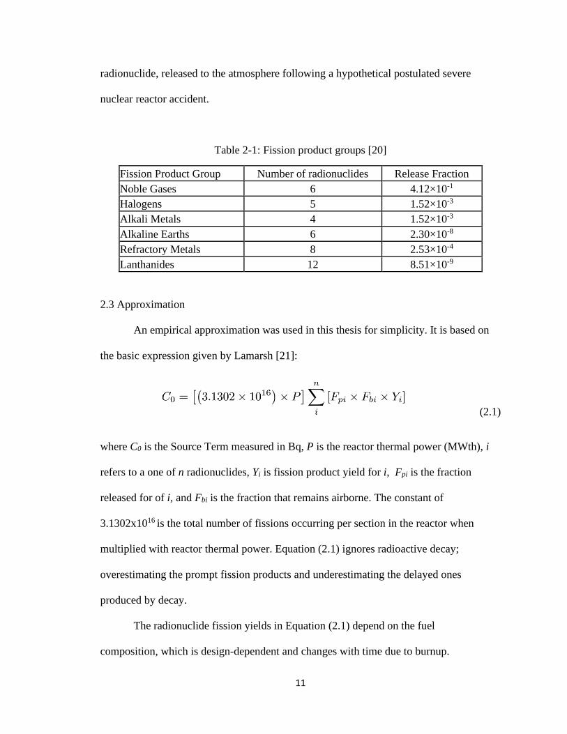
11
radionuclide, released to the atmosphere following a hypothetical postulated severe
nuclear reactor accident.
Table 2-1: Fission product groups [20]
Fission Product Group Number of radionuclides Release Fraction
Noble Gases 6 4.12×10⁻¹
Halogens 5 1.52×10⁻³
Alkali Metals 4 1.52×10⁻³
Alkaline Earths 6 2.30×10⁻⁸
Refractory Metals 8 2.53×10⁻⁴
Lanthanides 12 8.51×10⁻⁹
2.3 Approximation
An empirical approximation was used in this thesis for simplicity. It is based on
the basic expression given by Lamarsh [21]:
(2.1)
where C0 is the Source Term measured in Bq, P is the reactor thermal power (MWth), i
refers to a one of n radionuclides, Yi is fission product yield for i, Fpi is the fraction
released for of i, and Fbi is the fraction that remains airborne. The constant of
3.1302x10¹⁶ is the total number of fissions occurring per section in the reactor when
multiplied with reactor thermal power. Equation (2.1) ignores radioactive decay;
overestimating the prompt fission products and underestimating the delayed ones
produced by decay.
The radionuclide fission yields in Equation (2.1) depend on the fuel
composition, which is design-dependent and changes with time due to burnup.
12
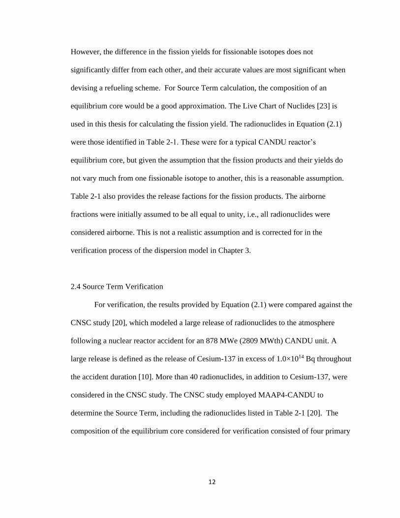
However, the difference in the fission yields for fissionable isotopes does not
significantly differ from each other, and their accurate values are most significant when
devising a refueling scheme. For Source Term calculation, the composition of an
equilibrium core would be a good approximation. The Live Chart of Nuclides [23] is
used in this thesis for calculating the fission yield. The radionuclides in Equation (2.1)
were those identified in Table 2-1. These were for a typical CANDU reactor’s
equilibrium core, but given the assumption that the fission products and their yields do
not vary much from one fissionable isotope to another, this is a reasonable assumption.
Table 2-1 also provides the release factions for the fission products. The airborne
fractions were initially assumed to be all equal to unity, i.e., all radionuclides were
considered airborne. This is not a realistic assumption and is corrected for in the
verification process of the dispersion model in Chapter 3.
2.4 Source Term Verification
For verification, the results provided by Equation (2.1) were compared against the
CNSC study [20], which modeled a large release of radionuclides to the atmosphere
following a nuclear reactor accident for an 878 MWe (2809 MWth) CANDU unit. A
large release is defined as the release of Cesium-137 in excess of 1.0×10¹⁴ Bq throughout
the accident duration [10]. More than 40 radionuclides, in addition to Cesium-137, were
considered in the CNSC study. The CNSC study employed MAAP4-CANDU to
determine the Source Term, including the radionuclides listed in Table 2-1 [20]. The
composition of the equilibrium core considered for verification consisted of four primary

13
nuclides: 5.65% of Uranium-238, 49.19% of Uranium-235, 43.64% of Plutonium-239,
and 1.32% of Plutonium-241, representing an equilibrium CANDU core [24].
The total Source Term determined by applying the empirical approach was
6.97×10¹⁸ Bq, while the total Source Term listed in the CNSC published data is 4.50×10¹⁸
Bq. The two approaches are comparable in magnitude. The listed radionuclides in Table
2-2 were the ones deemed significant by the CNSC. Significance was likely determined
by the greatest fission product yields, release fractions, airborne fractions, or radiological
impact. In total, more than 40 radionuclides were considered for this thesis. The
discrepancy between the published and simulated Source Term values in Table 2-2 can
be attributed to assigning unity airborne fractions in the empirical model and ignoring
radioactive decay. A calibration factor can be used to correct for the overestimation, as
discussed further in Chapter 3. The underestimated Source Terms were for radionuclides
with low values, and therefore their effect on the overall Source Term is negligible. The
empirical method overestimated the overall Source Term value.

14
Table 2-2: Published and simulated source term for significant radionuclides
Radionuclide Published Source
Term (Bq) [20]
Empirical Source
Term (Bq)
Release
Fractions [20]
Fission Product
Yield (%) [23]
Ba-140 8.14×10¹¹ 1.18×10¹¹ 2.30×10⁻⁸ 5.84186
Cs-134 3.21×10¹³ 4.02×10¹¹ 1.52×10⁻³ 0.00030
Cs-137 1.02×10¹⁴ 8.50×10¹⁵ 1.52×10⁻³ 6.35827
Ce-141 2.40×10¹¹ 4.16×10¹⁰ 8.51×10⁻⁹ 5.55156
Ce-144 8.17×10¹⁰ 3.48×10¹⁰ 8.51×10⁻⁹ 4.64968
I-131 3.93×10¹⁵ 4.37×10¹⁵ 1.52×10⁻³ 3.26932
I-132 5.80×10¹¹ 6.33×10¹⁵ 1.52×10⁻³ 4.73788
I-133 2.79×10¹⁵ 9.03×10¹⁵ 1.52×10⁻³ 6.75244
I-135 2.50×10¹⁴ 8.50×10¹⁵ 1.52×10⁻³ 6.35500
Ru-103 1.00×10¹⁵ 1.11×10¹⁵ 2.53×10⁻⁴ 4.98560
Ru-106 1.14×10¹⁴ 5.01×10¹⁴ 2.53×10⁻⁴ 2.25011
Xe-133 1.99×10¹⁸ 2.45×10¹⁸ 4.12×10⁻¹ 6.76383
Total 4.50×10¹⁸ 6.97×10¹⁸
As Table 2-2 shows, the total source term for the empirical approach is of the
same order of magnitude as the published data and can be corrected using a calibration
factor, as discussed in Chapter 3. This demonstrates that the simplified empirical
approach is capable of reasonably approximating the Source Term.
2.5 Sensitivity Analysis
The sensitivity of the model of Equation (2.1) to changes is analyzed via the four
(4) variables that define the Source Term. The first variable is the reactor thermal power,
P, which is the driving force of the Source Term, i.e. the higher the power the larger the
Source Term. However, the Source Term should be evaluated at the nominal (maximum)
reactor power, not a lower power used during the reactor operation. The second variable
in Equation (2.1) is the airborne fractions, which were initially given the highest possible
value of unity. This is not a realistic assumption and is corrected for as discussed in
15
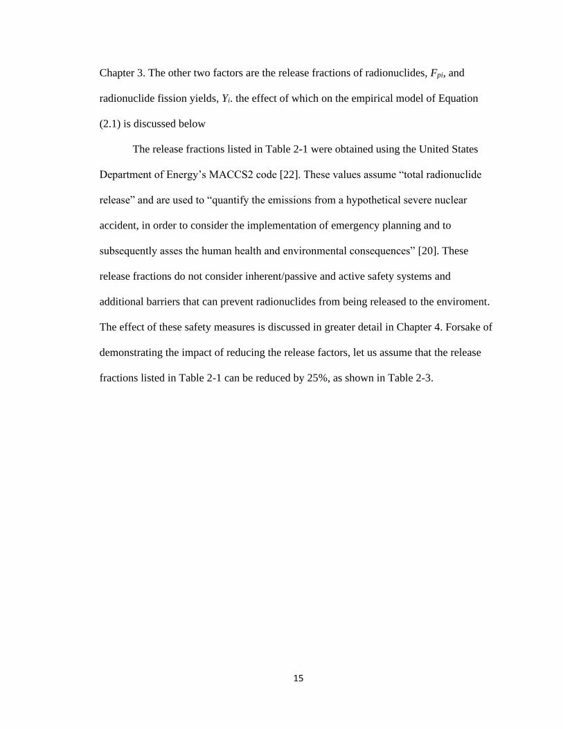
Chapter 3. The other two factors are the release fractions of radionuclides, Fpi, and
radionuclide fission yields, Yi. the effect of which on the empirical model of Equation
(2.1) is discussed below
The release fractions listed in Table 2-1 were obtained using the United States
Department of Energy’s MACCS2 code [22]. These values assume “total radionuclide
release” and are used to “quantify the emissions from a hypothetical severe nuclear
accident, in order to consider the implementation of emergency planning and to
subsequently asses the human health and environmental consequences” [20]. These
release fractions do not consider inherent/passive and active safety systems and
additional barriers that can prevent radionuclides from being released to the enviroment.
The effect of these safety measures is discussed in greater detail in Chapter 4. Forsake of
demonstrating the impact of reducing the release factors, let us assume that the release
fractions listed in Table 2-1 can be reduced by 25%, as shown in Table 2-3.

16
Table 2-3: Simulated source term for release fractions reduced by 25%
Radionuclide Published
Release
Fractions [20]
Original Empirical
Source Term
(Bq)
Reduced
Release
Fractions [20]
Reduced Empirical
Source Term
(Bq)
Ba-140 2.30×10⁻⁸ 1.18×10¹¹ 1.73×10⁻⁸ 8.89×10¹⁰
Cs-134 1.52×10⁻³ 4.02×10¹¹ 1.14×10⁻³ 3.01×10¹¹
Cs-137 1.52×10⁻³ 8.50×10¹⁵ 1.14×10⁻³ 6.38×10¹⁵
Ce-141 8.51×10⁻⁹ 4.16×10¹⁰ 6.38×10⁻⁹ 3.12×10¹⁰
Ce-144 8.51×10⁻⁹ 3.48×10¹⁰ 6.38×10⁻⁹ 2.61×10¹⁰
I-131 1.52×10⁻³ 4.37×10¹⁵ 1.14×10⁻³ 3.28×10¹⁵
I-132 1.52×10⁻³ 6.33×10¹⁵ 1.14×10⁻³ 4.75×10¹⁵
I-133 1.52×10⁻³ 9.03×10¹⁵ 1.14×10⁻³ 6.77×10¹⁵
I-135 1.52×10⁻² 8.50×10¹⁵ 1.14×10⁻³ 6.37×10¹⁵
Ru-103 2.53×10⁻⁴ 1.11×10¹⁵ 1.90×10⁻⁴ 8.33×10¹⁴
Ru-106 2.53×10⁻⁴ 5.01×10¹⁴ 1.90×10⁻⁴ 3.76×10¹⁴
Xe-133 4.12×10⁻¹ 2.45×10¹⁸ 3.09×10⁻¹ 1.84×10¹⁸
Total 6.97×10¹⁸ 5.23×10¹⁸
The 25% reduction in the release factors, as shown in Table 2-3, results in an
overall lowering of the Source Term from 6.97×10¹⁸ Bq to 5.23E×1018 Bq. This reflects
the expected linear and direct effect of the release fractions on the Source Term as
expressed by Equation (2.1).
As indicated in Section 2.2, fission yields depend on the fuel composition, which
is design-dependent and changes with time due to burnup. The cumulative fission yield,
i.e. the total number of atoms produced over time after one fission, is provided not as a
static number, but instead as a range. The results of Table 2-2 were completed using the
mean cumulative fission yields from the IAEA’s Live Chart of Nuclides [23]. Table 2-4
lists the same mean values shown in Table 2-2, but also the low-range and high-range
values, which were found using the IAEA Live Chart [23]. As can be seen, there is a
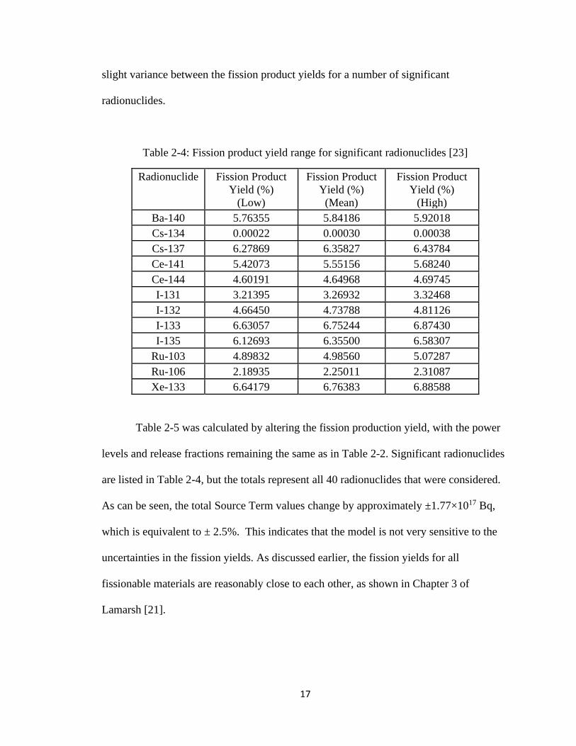
17
slight variance between the fission product yields for a number of significant
radionuclides.
Table 2-4: Fission product yield range for significant radionuclides [23]
Radionuclide Fission Product
Yield (%)
(Low)
Fission Product
Yield (%)
(Mean)
Fission Product
Yield (%)
(High)
Ba-140 5.76355 5.84186 5.92018
Cs-134 0.00022 0.00030 0.00038
Cs-137 6.27869 6.35827 6.43784
Ce-141 5.42073 5.55156 5.68240
Ce-144 4.60191 4.64968 4.69745
I-131 3.21395 3.26932 3.32468
I-132 4.66450 4.73788 4.81126
I-133 6.63057 6.75244 6.87430
I-135 6.12693 6.35500 6.58307
Ru-103 4.89832 4.98560 5.07287
Ru-106 2.18935 2.25011 2.31087
Xe-133 6.64179 6.76383 6.88588
Table 2-5 was calculated by altering the fission production yield, with the power
levels and release fractions remaining the same as in Table 2-2. Significant radionuclides
are listed in Table 2-4, but the totals represent all 40 radionuclides that were considered.
As can be seen, the total Source Term values change by approximately ±1.77×10¹⁷ Bq,
which is equivalent to ± 2.5%. This indicates that the model is not very sensitive to the
uncertainties in the fission yields. As discussed earlier, the fission yields for all
fissionable materials are reasonably close to each other, as shown in Chapter 3 of
Lamarsh [21].

18
Table 2-5: Simulated source term range for significant radionuclides
Radionuclide Empirical Source
Term (Bq)
(Low)
Empirical Source
Term (Bq)
(Mean)
Empirical Source
Term (Bq)
(High)
Ba-140 1.17×10¹¹ 1.18×10¹¹ 1.20×10¹¹
Cs-134 2.96×10¹¹ 4.02×10¹¹ 5.07×10¹¹
Cs-137 8.39×10¹⁵ 8.50×10¹⁵ 8.61×10¹⁵
Ce-141 4.06×10¹⁰ 4.16×10¹⁰ 4.25×10¹⁰
Ce-144 3.44×10¹⁰ 3.48×10¹⁰ 3.52×10¹⁰
I-131 4.30×10¹⁵ 4.37×10¹⁵ 4.45×10¹⁵
I-132 6.24×10¹⁵ 6.33×10¹⁵ 6.43×10¹⁵
I-133 8.86×10¹⁵ 9.03×10¹⁵ 9.19×10¹⁵
I-135 8.19×10¹⁵ 8.50×10¹⁵ 8.80×10¹⁵
Ru-103 1.09×10¹⁵ 1.11×10¹⁵ 1.13×10¹⁵
Ru-106 4.87×10¹⁴ 5.01×10¹⁴ 5.14×10¹⁴
Xe-133 2.41×10¹⁸ 2.45×10¹⁸ 2.50×10¹⁸
Total 6.79×10¹⁸ 6.97×10¹⁸ 7.15×10¹⁸
It should be emphasized that if different parameters are used in the model of
Equation (2.1), the verification process of Section 2.5 should be repeated.
2.6 Conclusions
This chapter demonstrated that a simplified empirical approach to determining
reactor Source Term following a hypothetical postulated nuclear reactor accident
provided adequate overall values, after calibrating against independent data obtained
using more sophisticated modelling. Sensitivity analysis showed that as expected, the
model is linearly sensitive to its variables, which facilitates the calibration process.
Therefore, this simplified empirical approach is used to approximate the Source Term in
the remainder of this work. The validity of this simple model was enabled through
calibration with a more complex model, as discussed in Section 3.3

19
CHAPTER 3: RADIOACTIVITY DISPERSION AND EXCLUSION
ZONE
This chapter is adapted from two conference papers published in the proceedings
of the 38th Annual Conference of the Canadian Nuclear Society [17] and of the 42nd
Annual CNS/CNA Student Conference [25].
3.1 Introduction
Atmospheric dispersion modeling assists with the analysis of radionuclide
releases following a postulated nuclear reactor accident. Exclusion zone sizing for
nuclear reactors is enabled through dispersion modeling and indicates that radioactive
materials are diluted to levels which do not exceed regulatory limits [20]. The dose
received by an individual at varying distances from the reactor is typically determined
with detailed simulations, using codes such as the United States of America Department
of Energy’s MACCS2 code [22]. A reactor’s Source Term can also be predicted using
codes capable of simulating severe accident sequences, such as MAAP4-CANDU [19].
This chapter presents a simplified approach to the above methods that can be applied to a
variety of nuclear reactors, and more specifically Small Modular Reactors (SMRs), and
enables the quick determination of the size of the exclusion zone for various SMR power
levels.
The HotSpot Health Physics Code [26] is a tool which uses a Gaussian
distribution for a first-order approximation of the dispersion of radionuclides in air. In
this chapter, HotSpot is verified against published data to confirm that the simulation
code is capable of accurately estimating radiation dose. The estimated doses were

20
determined as a function of downwind distance from the origin of the accident site and
allows for the determination of the radius of the exclusion zone [20]. Following
verification, the simulation code is used to approximate the radiation dose received by an
individual following a hypothetical postulated severe accident for an SMR. The
simulation code is then used to estimate the exclusion zones for generic SMRs at various
power levels. The next section provides a description of the HotSpot simulation code.
3.2 HotSpot
The HotSpot simulation code, hereinafter referred to as HotSpot or code, serves as
a conservative, but realistic, means for the estimation of the radiation dose associated
with the atmospheric release of radionuclides [26]. Development and ongoing
maintenance of HotSpot has been funded by the United States Department of Energy
since the code was originally distributed in 1988. The initial purpose of the code was to
equip emergency personnel with the ability to quickly examine an incident involving the
release of radionuclides [26]. Overtime, HotSpot has grown to include a variety of
atmospheric dispersion models, which are capable of approximating the doses received
by an individual at varying distances from a radionuclide release [26]. The code is
intended for near-surface releases, short-term durations, and short-range dispersion [26].
In this thesis, a general plume and normal (Gaussian) distribution were used for
the analysis of radioactive materials and their respective impact on the atmosphere. The
Gaussian plume model “is the most widely used computational model for atmospheric
diffusion assessment” [27]. HotSpot uses the Gaussian distribution to help determine the

21
time-integrated atmospheric concentration of radionuclides within the areas surrounding
the reactor [26]:
(3.1)
where is time-integrated atmospheric concentration (Bq-s)(m3), Q is Source Term (Ci),
H is effective release height (m), λ is radioactive decay constant (S-1), x is downwind
distance (m), y is crosswind distance (m), z is vertical axis distance (m), sy is standard
deviation of integrated concentration distribution in crosswind direction (m), sz is
standard deviation of integrated concentration distribution in vertical direction (m), s is
average wind speed at the effective release height (m/s), and DF(x) is plume depletion
factor [26].
The HotSpot code uses the time-integrated atmospheric concentration, along with
a variety of additional inputs, to determine the dose received by an individual at varying
distances from the origin of the accident [26]. This is the total effective dose equivalent
(TEDE) and includes the inhalation, submersion, ground shine, and resuspension
components following a hypothetical nuclear reactor accident [26].
The fission products used to assemble the activities for the CNSC study were
compiled through the use of MAAP4-CANDU [19], a code capable of simulating severe
accident sequences, and REGDOC-2.5.2 [10], a regulatory document which provides
designers with a reference point for defining severe accidents for reactor facilities. The

22
more than 40 radionuclides considered within the CNSC study [20] were classified by
their similarities as shown in Table 2-1. The fission product groups in the Table allow for
the determination of each individual radionuclides’ activity (Bq), which combine to form
a reactor’s Source Term.
Although it is known that some radionuclides contribute to radiation dose more
than others, each radionuclide associated with the CNSC study was assigned an activity.
A summary of the radionuclides and their respective activities, deemed to be the most
critical, are listed in Table 3-6. HotSpot employs standard dose conversion factors
(coefficients) of activities for acute inhalation of radionuclides. The coefficients,
described in federal guidelines report #11 (FGR-11) [28], were used in this work to
convert our time-integrated atmospheric concentrations into doses.
Table 3-6: Significant Radionuclides [20]
Radionuclide Fission Product Release (Becquerel)
Ba-140 8.14×10¹¹
Cs-134 3.21×10¹³
Cs-137 1.02×10¹⁴
Ce-141 2.40×10¹¹
Ce-144 8.17×10¹⁰
I-131 3.93×10¹⁵
I-132 5.80×10¹¹
I-133 2.79×10¹⁵
I-135 2.50×10¹⁴
Ru-103 1.00×10¹⁵
Ru-106 1.14×10¹⁴
Xe-133 1.99×10¹⁸

23
3.3 Verification
The verification process consisted of three levels. The first level, which was
discussed in Chapter 2, validated the simplified empirical approach for the source-term
approximation against an independent simulation code. The second level validated the
HotSpot dispersion code against published data, using the source term found in the CNSC
study [20]. The third level verified the combined use of the HotSpot code and the
empirical source term. The latter level is used to find a calibration factor, which aligns
the dose determined using the simplified approach with that provided by independent
data.
HotSpot was verified against independent data for a hypothetical severe nuclear
accident published in the CNSC study [20], which modeled a large release of
radionuclides to the atmosphere following a hypothetical failure of a CANDU reactor at
the Darlington Nuclear Generating Station. Figure 3-1 shows the verification process,
which involves using the published activities, found in the CNSC study [20], as an input
to HotSpot and comparing the simulated doses to the published doses, also found in the
CNSC study [20].
Figure 3-1: Procedure for the verification of HotSpot

24
The CNSC analyzed a variety of different accident conditions, including a 24-
hour severe postulated nuclear accident followed by a 24-hour generic large release
(GLR), a 24-hour accident and 1-hour GLR, and a 24-hour accident and 72-hour GLR.
The same verification process discussed in this paper can be applied to any of the three
(3) scenarios in the CNSC study. However, the 24-hour accident and 24-hour GLR was
selected as it demonstrates an emergency situation, which is realistic but still
conservative. Table 3-7 lists the published dose found in the CNSC study, which
corresponds to the published dose block in Figure 3-1.
Table 3-6 lists several of the published activities that were used to estimate the
published doses in Table 3-7. Only activities for radionuclides that were deemed critical
are listed in Table 3-6. The remaining activities can be found in the CNSC study. The
data contained in the published dose column of Table 3-7 was estimated in the CNSC
study using MACCS2 [22], a code based on a straight-line Gaussian plume model,
similar to that of the HotSpot code. As such, the verification of HotSpot against the
CNSC published data is in fact a verification against MACCS2.
Where possible, the CNSC study was used to assist with defining input variables
to ensure consistency. However, additional data was required, such as: effective release
heights, damage ratios, wind speed and direction, atmospheric stability ratings, exposure
length, weathering correction factor, resuspension factor, surface roughness, et cetera. All
additional variable which were not discussed in the CNSC study were determined using
HotSpot default values [26].
The simulated dose column in Table 3-7 lists the dose that was determined using
the HotSpot code and corresponds to the simulated dose in Figure 3-1. Similar to the

25
published dose column, the simulated dose column serves as the dose to an individual at
varying distances from the origin of the accident. Table 3-7 corresponds to the last step in
Figure 3-1.
The published dose and simulated dose at 1 km from the accident origin were
estimated to be approximately equal, as shown in Table 3-7. From 3 to 50 km, the
published dose exceeds the simulated dose. Conversely, the simulated doses surpass the
published doses between 70 and 90 km. The HotSpot code is intended for short distances
[26], however, these short distances are difficult to verify as the CNSC study does not
examine distances less than 1 km. As the distances double in Table 3-7, the simulated
dose approximately decreases with the inverse-squared distance, but the published data
does not. This implies that the HotSpot code considers the source as a point source.
Nevertheless, the published and simulated results are on the same order of magnitude and
are therefore comparable.
Table 3-7: Published dose for 24 hour accident and 24 hour generic large release
Distance from origin
(km)
Published dose
(mSv) [20]
HotSpot Simulated
dose
(mSv)
1 2.54×101 2.6×101
3 4.50×100 3.2×100
6 1.75×100 8.8×10⁻¹
12 6.70×10⁻¹ 2.6×10⁻¹
20 3.10×10⁻¹ 1.1×10⁻¹
28 1.80×10⁻¹ 8.5×10⁻²
36 1.30×10⁻¹ 7.2×10⁻²
50 7.00×10⁻² 5.9×10⁻²
70 4.00×10⁻² 4.8×10⁻²
90 3.00×10⁻² 4.1×10⁻²

26
The empirical approach to calculate Source Term and the atmospheric dispersion
model were verified independent of each other. The third level of verification combines
both processes. Table 3-8 lists the published [20] and simulated doses, with the source
term calculated using Equation (2.1). The two values are not significantly different,
demonstrating the validity of the methods of Chapters 2 and 3. However, the simulated
doses were adjusted by an “overall calibration” factor, determined by dividing the
published dose by the simulated dose. This factor accounts for ignoring radioactive decay
and using airborne fractions of unity in Equation (2.1).
Table 3-8: Published doses and HotSpot-simulated doses using Equation (2.1)
Distance from origin
(km)
Published dose
(mSv) [20]
HotSpot Simulated
dose
(mSv)
1 2.54×101 6.10×101
3 4.50×100 7.30×100
6 1.75×100 2.00×100
12 6.70×10⁻¹ 5.90×10⁻¹
20 3.10×10⁻¹ 2.50×10⁻¹
28 1.80×10⁻¹ 2.00×10⁻¹
36 1.30×10⁻¹ 1.70×10⁻¹
50 7.00×10⁻² 1.40×10⁻¹
70 4.00×10⁻² 1.10×10⁻¹
90 3.00×10⁻² 9.50×10⁻²
The exclusion zone for a CANDU reactor is typically equal to one km [2]. The
exclusion zone radius for SMRs is expected to be smaller, given their lower power.
Therefore, the smallest distance in Table 3-8 (1 km) was used to determine the calibration
factor. This resulted in a calibration factor of 0.42 (=25.4/61.0), which is used to adjust
the overestimated simulated source term in subsequent calculations. It should be noted

27
though that the doses reported in the CNSC study [20] are for a hypothetical severe
accident. Table 3-9 represents the adjusted doses using the 0.42 calibration factor.
Table 3-9: Published doses and HotSpot-simulated doses using calibrated Equation (2.1)
Distance from origin
(km)
Published dose
(mSv) [20]
Simulated dose
(mSv)
1 2.54×101 2.6×101
3 4.50×100 3.1×100
6 1.75×100 8.5×10⁻¹
12 6.70×10⁻¹ 2.5×10⁻¹
20 3.10×10⁻¹ 1.0×10⁻¹
28 1.80×10⁻¹ 8.3×10⁻²
36 1.30×10⁻¹ 7.0×10⁻²
50 7.00×10⁻² 5.7×10⁻²
70 4.00×10⁻² 4.7×10⁻²
90 3.00×10⁻² 4.0×10⁻²
Results from the three levels of verification discussed in Chapters 2 and 3 are
summarized in Figure 3-2. The first level of verification, discussed in Chapter 2,
concluded that the simplified empirical approach to determining reactor Source Term
following a hypothetical postulated nuclear reactor accident provided adequate overall
values. The second level of verification concluded that the HotSpot code is able to
approximate dose limits comparable to those of the published doses. The third and final
level of verification provided a calibrated value for the airborne fraction when employing
the empirical approach for Source Term calculation, which was initially assumed to be
unity.

28
Figure 3-2: Three levels of verification
3.4 Exclusion Zone for SMRs
The calibrated method presented above was applied to various SMRs with powers
ranging from 50 to 300 MWe, adjusted to thermal power using a factor of 3.2, reflecting
a typical efficiency of 30% converting heat to electricity. Table 3-10 lists the doses for all
SMRs considered in this study at distances ranging from 0.1 km to 1.0 km. These values
were calculated over a 30-day period to match the CNSC dose limit of 20 mSv for a
design basis accident [10]. The exclusion zone radius for each power level is the distance
at which the dose is equal to or slightly below the 20 mSv limit. These values are
highlighted (boldfaced) in Table 3-10. As can be seen, the radius of the exclusion zone
for an SMR is estimated to vary from less than 0.4 km for a 50 MWe reactor to 0.8 km
for a 300 MWe reactor. If a reactor is buried underground or encased in a thick concrete
container, the exclusion zone can be further reduced. Chapter 4 discusses the effect of
such an enclosure on the size of the exclusion zone. It should be noted though that the

29
doses reported in the CNSC study [20] are for a hypothetical severe accident, while the
size of the exclusion zone is determined for a design basis accident (DBA). As such the
doses reported in Table 3-10 are overestimated for a DBA.
Table 3-10: SMR dose at a variety of distances
Distance from
origin (km)
50 MWe 100 MWe 150 MWe 200 MWe 250 MWe 300 MWe
30-day Dose (mSv)
0.1 1.8×10² 3.6×10² 5.4×10² 7.2×10² 9.0×10² 1.1×10³
0.2 5.0×101 1.0×10² 1.5×10² 2.0×10² 2.5×10² 3.0×10²
0.3 2.3×101 4.5×101 6.8×101 9.1×101 1.1×10² 1.4×10²
0.4 1.3×101 2.6×101 3.9×101 5.1×101 6.4×101 7.7×101
0.5 8.3×100 1.7×101 2.5×101 3.3×101 4.1×101 5.0×101
0.6 5.8×100 1.2×101 1.7×101 2.3×101 2.9×101 3.5×101
0.7 4.3×100 8.5×100 1.3×101 1.7×101 2.1×101 2.6×101
0.8 3.3×100 6.6×100 9.8×100 1.3×101 1.6×101 2.0×101
0.9 2.6×100 5.2×100 7.8×100 1.0×101 1.3×101 1.6×101
1.0 2.1×100 4.2×100 6.4×100 8.5×100 1.1×101 1.3×101
3.5 Sensitivity Analysis
The sensitivity of the HotSpot code to changes is analyzed via three (3) variables
that were determined using HotSpot’s default values. As discussed previously, the CNSC
study was used to define most input variables for the HotSpot simulations. However,
additional variables were found using HotSpot recommendations, including effective
release heights, wind speed, and atmospheric stability.
The first variable is the effective release heights. The rise of radioactive plumes is
impacted by velocity and temperature differential between the surrounding air and stack
effluent [26]. As the effective release height increases, the integrated concentrations at
the ground level decrease [26]. The value was assumed to be 10 meters for the purposes

30
of this thesis. For the sake of demonstrating the impact of reducing/increasing the
effective release hieght, let us assume that the original value of 10 meters was reduced to
either 0 meters (ground-level) or increased to 20 meters. Using the simulated dose limits
shown in Table 3-9 as a reference, Table 3-11 lists simulated dose limits using 0, 10, and
20 meter effective release heights.
Table 3-11: Sensitivity to effective release height
Distance from origin
(km)
Simulated dose
0-meter effective
release height
(mSv)
Simulated dose
10-meter effective
release height
(mSv)
Simulated dose
20-meter effective
release height
(mSv)
1 2.8×101 2.6×101 2.4×101
3 3.4×100 3.1×100 2.9×100
6 9.4×10⁻¹ 8.5×10⁻¹ 8.1×10⁻¹
12 2.7×10⁻¹ 2.5×10⁻¹ 2.4×10⁻¹
20 1.1×10⁻¹ 1.0×10⁻¹ 9.9×10⁻¹
28 9.2×10⁻² 8.3×10⁻² 7.9×10⁻²
36 7.8×10⁻² 7.0×10⁻² 6.7×10⁻²
50 6.3×10⁻² 5.7×10⁻² 5.5×10⁻²
70 5.2×10⁻² 4.7×10⁻² 4.5×10⁻²
90 4.4×10⁻² 4.0×10⁻² 3.8×10⁻²
At 1 km, for example, the simulated dose varies approximately ±2.0 mSv (± 8%)
when using 0 meters and 20 meters as the effective release height rather than 10 meters.
This indicates that the model is moderately sensitive to change as the effective release
height is altered.
The second variable is wind speed. Wind speed was selected to be 3.0 meters per
second throughout this thesis. To demonstrate how increased/decreased wind speed
impacts the simulated dose, let us assume that the value of 3.0 meters was decreased to
0.1 meters and increased to 6 meters. Using the simulated dose limits shown in Table 3-9

31
as a reference, Table 3-12 lists simulated dose limits using 0.1, 3 and 6 meters per
second.
Table 3-12: Sensitivity to wind speed
Distance from origin
(km)
Simulated dose
0.1 meters per
second
(mSv)
Simulated dose
3 meters per
second
(mSv)
Simulated dose
6 meters per
second
(mSv)
1 5.6×10² 2.6×101 1.3×101
3 5.7×101 3.1×100 1.6×100
6 1.4×101 8.5×10⁻¹ 4.3×10⁻¹
12 3.6×100 2.5×10⁻¹ 1.3×10⁻¹
20 1.3×100 1.0×10⁻¹ 5.3×10⁻²
28 1.0×100 8.3×10⁻² 4.2×10⁻²
36 8.2×10⁻¹ 7.0×10⁻² 3.6×10⁻²
50 6.3×10⁻¹ 5.7×10⁻² 2.9×10⁻²
70 4.8×10⁻¹ 4.7×10⁻² 2.4×10⁻²
90 4.0×10⁻¹ 4.0×10⁻² 2.1×10⁻²
As shown, varying wind speed can have a significant impact on doses. In general,
meterological conditions have a significant impact on the model. While meterological
conditions were not a primary focus of this thesis, average values were selected to
represent normal conditions. The model was then calibrated using published CNSC data.
The third variable is atmospheric stability. Hotspot interprets atmospheric stability
using a matrix that considers various meterological conditions, including wind and solar
[26]. These categories from least severe to most severe are: moderately stable, slightly
stable, neutral, slightly unstable, moderately unstable and extremely unstable. For the
purposes of this thesis, extremely unstable was used, which correlates to a wind speed of
3 meters per second when the sun is high in the sky. To demonstrate how this impacts the
simulated dose, let us assume that slightly unstable was instead selected, which also

32
correlates to a wind speed of 3 meters per second, but when the sun is low in the sky.
Table 3-13 lists the simulated dose limites for both extremely unstable and slightly
unstable.
Table 3-13: Sensitivity to atmospheric stability
Distance from origin
(km)
Simulated dose
Extremely
unstable
(mSv)
Simulated dose
Slightly
unstable
(mSv)
1 2.6×101 1.4×10²
3 3.1×100 1.9×101
6 8.5×10⁻¹ 6.2×100
12 2.5×10⁻¹ 2.2×100
20 1.0×10⁻¹ 1.1×100
28 8.3×10⁻² 7.2×10⁻¹
36 7.0×10⁻² 5.3×10⁻¹
50 5.7×10⁻² 3.6×10⁻¹
70 4.7×10⁻² 2.4×10⁻¹
90 4.0×10⁻² 1.8×10⁻¹
As shown in Table 3-13, similar to varying wind speed, varying atmospheric
stability can have a reasonably significant impact on dose limits. As atmospheric stability
increases, so does the “intensity of turbulence, and subseqently, the diffusion process”
[29]. To compensate for the effects of the atmospheric stability parameter, the model was
calibrated in section 3.3 against published data for a hypothetical severe nuclear reactor
accident.
There are several other variables the HotSpot dose calculations are sensitive to,
including damage ratios (fraction of the Source Term that is actually impacted in the
release scenario [26]), weathering correction factors (dose rate reduction as a function of
time after surface contamination [30]), resuspension factors (ratio of the air concentration

33
of radionuclides to the ground concentration [26]), surface roughness (“the surface
roughness height is approximately equal to the physical height divided by 10, e.g., a
surface roughness height of 3 cm would be associated with a field of objects with an
average physical height of 30 cm” [26]), et cetera. Where possible, the CNSC study was
used to specify HotSpot input variables to ensure consistency. For the remaining
variables, such as surface roughness, HotSpot recommended values were used [26]. If
input values deviate from the ones employed in the validation process of section 3.3, the
code should be re-calibrated to correct for the effect of the selected parameters.
3.6 Conclusions
The results of this Chapter demonstrate that HotSpot is able to approximate the
exclusion zone and dose following postulated severe accidents for nuclear reactors.
Independent data was used to verify that the HotSpot code is capable of atmospheric
dispersion modeling, compared to codes such as MACCS2. The method allows for a
quick estimation of the exclusion zone radius for Small Modular Reactors (SMRs). In the
next chapter, methods to further reduce the exclusion zone radius for SMRs are explored.

34
CHAPTER 4: REDUCING EXCLUSION ZONE THROUGH DESIGN
4.1 Introduction
In Chapters 2 and 3, a method was developed to determine the exclusion zone as a
function of reactor power, under conservative assumptions. It was shown, as one would
expect, that the size of the exclusion zone decreases with reactor power, which makes the
size of the exclusion zone smaller than that required for conventional larger reactors.
Given that SMRs may be built nearby populated areas, e.g. to provide power off-grid in
an isolated community, the question arises: is it possible to reduce or eliminate exclusion
zones for SMRs?
A recent discussion paper [5] by the Canadian Nuclear Safety Commission
(CNSC) seems to indicate that the regulators are open to the idea of significantly
reducing the size of the exclusion zone. Referring to exclusion zones as Emergency
planning zones (EPZ), it states [5]:
"There are no legislative or regulatory requirements for EPZ sizing in Canada and
therefore no restrictions currently in place on minimum EPZ size. EPZ and other
planning actions should be undertaken in relation to the risks associated with the
specific technology. As such, results from safety analyses (i.e., the probabilistic
safety analysis) in combination with the protection strategy used by offsite
planners will determine the EPZ size. This is consistent with the overall
methodologies documented by the IAEA."
Given the above regulatory position and the inherent and passive safety of SMRs,
which allows for decreased likelihood of a release of radionuclides, this chapter examines

35
the possibility of reducing or eliminating the exclusion zone for SMRs, taking advantage
of their inherent safe nature. The chapter starts by re-examining the concept of the
exclusion zone, including how different regulatory jurisdictions view the exclusion zone
and how its radius is determined. Examples of inherent and passive safety features in
SMR designs that can assist in reducing the size of the exclusion zone are then given,
followed by a discussion of suitable materials that can be used to retain radioactive
material within the reactor, further lowering the need for a large exclusion zone. Finally,
employing engineered barriers in several designs, in lieu of the exclusion zone, is
presented. The chapter concludes by commenting on whether the exclusion zone can be
eliminated entirely.
4.2 The Exclusion Zone
In Chapter 2, the quantity of released radionuclides from an SMR following a
severe reactor accident was estimated. The results were then used to model the
atmospheric dispersion and approximate the required exclusion zone radius in Chapter 3.
Current regulatory and legislative requirements do not prescribe a method for emergency
planning zone sizing or a minimum size [5]. Instead, “results from safety analyses in
combination with the protection strategy used by offsite planners” are together used to
determine the appropriate size for an emergency planning zone [5]. That is, the risk
associated with the selected technology is used to determine an appropriate size [5]. The
safety analysis involves the full range of potential accidents, as well as their respective
probabilities, and the degree of passive and inherent safety features employed within the
design [5]. The Canadian description of an exclusion zone is “a parcel of land within or
surrounding a nuclear facility on which there is no permanent dwelling and over which a
36
licensee has the legal authority to exercise control” [11]. The American definition is “the
area surrounding the reactor where the reactor licensee has the authority to determine all
activities, including exclusion or removal of personnel and property” [12]. The
International definition is “the area around the reactor that is controlled by the operating
organization. In this area the operating organization has the full power to implement all
necessary measures” [13]. The three definitions, from three (3) independent regulatory
bodies, do not suggest that the exclusion zone can be eliminated. Instead, each regulatory
body provides guidance for exclusion zones that ensures radioactive releases are diluted
to a level that does not exceed regulatory limits. For instance, from the Canadian
perspective, during normal operating conditions, an individual at the boundary of the
exclusion zone shall not receive an effective dose greater than 1 mSv over a one (1) year
period [14]. The CNSC also defines acceptable dose criteria for an anticipated
operational occurrence (AOO) and design-basis accident (DBA). The AOO and DBA
dose limit shall be 0.5 mSv and 20 mSv, respectively, over a 30-day period following the
analyzed event. Therefore, one can conclude that current regulations do not suggest that
an exclusion zone can be eliminated entirely, but they do allow a licensee to justify a
smaller exclusion zone radius. While it is understood that an exclusion zone cannot be
eliminated, research reactors built within university campuses do not have exclusion
zones, e.g. the McMaster Nuclear Reactor [31]. The McMaster Nuclear Reactor is a 5
MWe research reactor located on the McMaster University campus. The reactor is within
a reinforced concrete building and the core is submerged in pool water, which is used to
passively cool and provide shielding. These features and the small size of the reactor
mean that in the unlikely event of an accident, radioactive materials will be contained.

37
The CNSC does not define the acceptable dose criteria for a severe nuclear
reactor accident for a nuclear power plant (NPP). Therefore, in this thesis, the dose limit
for a design basis accident (DBA) was used in lieu of the beyond design basis accident
(BDBA). The DBA is defined as “accident conditions for which an NPP is designed
according to established design criteria, and for which damage to the fuel and the release
of radioactive materials are kept within regulatory limits” [32]. While the probability of a
DBA remains low, it is still greater than that of a BDBA, which is defined by the CNSC
as “accident conditions less frequent and more severe than a design basis accident” [32].
The CNSC does define a BDBA but does not assign an acceptable dose limit. For
example, following a DBA, the CNSC has determined that the acceptable dose criteria is
20 mSv over a 30 day period. In the previous chapter, the methodology for approximating
SMR exclusion zones was verified using data from a published CNSC study that
modelled the hypothetical failure of a CANDU reactor. The data represented a release
following a BDBA and was compared against the regulatory dose limit for a DBA in
order to approximate the size of the exclusion zone. While conventional reactors, such as
the CANDU reactors, share many similarities with SMRs, there is value in completing a
similar study that hypothesizes a DBA for an SMR. Due to the many different varieties of
SMRs, including their fuel compositions, safety systems, and configurations, such studies
will inevitably be carried out, but they are not reported in the open literature at the time of
writing this thesis.
4.3 Inherent and Passive Safety
Inherent safety refers to “the achievement of safety through the elimination or
exclusion of inherent hazards through the fundamental conceptual design choices made

38
for the nuclear plant”, while passive safety means reliance is “placed on natural laws,
properties of materials and internally stored energy” [33]. Typically, passive safety refers
to the ability of a reactor to dissipate heat via passive heat removal systems that function
independent of mechanical means or external input [34], while inherent safety allows a
reactor to fail safe by reducing power and decay heat levels without human or computer
intervention [35]. There are many different inherent and passive safety systems serving
the different varieties of SMRs. Almost all SMR designs claim a negative temperature
coefficient of reactivity [2], which reduces the reactor power as temperature increases;
lowering the fuel temperature and preventing it from melting and releasing its radioactive
content. Several SMRs, such as the NuScale design [2], are surrounded by water pools
that serve as a large heat sink to remove heat in the event of an accident. Many SMR
designs have an integrated design, in which the primary coolant system or most of its
components are installed within the reactor pressure vessel; eliminating the possibility of
a large pipe break with the coolant leaving the reactor [2]. For example, in the SMART
system, the reactor pressure vessel houses the core, steam generators, coolant pumps, and
control rod mechanisms [2]. Several reactors operate at atmospheric pressure and are not
subject to depressurization that result in coolant boiling. For instance, the DHR reactor is
a pool type reactor designed to operate at a low temperature and at atmospheric pressure,
which precludes the undesirable effects of depressurization events that may take place in
high-pressure systems [2]. Many SMRs have passive residual heat removal systems that
cool the reactor during shutdown, and emergency core cooling systems that inject coolant
into the core if needed. For example, the SC-HTGR design employs a passive decay heat
removal system that relies on natural circulation and thermal radiation to transfer heat

39
from the reactor core to the surrounding reactor vessel [2]. The Lead-Cooled Fast Reactor
Amphora-Shaped (LFR-AS-200) and the Lead-Cooled Fast Reactor Transportable Long-
Lived (LFR-TL-X) SMRs use heat removal systems consisting of air coolers, which are
passively actuated by core thermal expansion as a result of temperature rise [2].
4.4 Reactor Material
Judicious choice of the fuel, cladding, and coolant enables some SMRs to retain
radionuclides within the system, lowering the magnitude of the Source Term and in turn
the size of the exclusion zone. For example, TRISO (tristructural-isotropic) coated fuel
particles are employed by high-temperature gas-cooled reactors (HTGR) [36]. As shown
in Figure A-15 in the SMR review section (Appendix A), each TRISO fuel particle is
coated with a ceramic layer of silicon carbide, which improves the retention of fission
products within the fuel particles [36]. Forming the fuel in small particles also increases
the heat transfer (by increasing the surface-to-volume ratio of the fuel), reducing the
probability of temperature rise leading to fuel melting and the associated release of
fission products [36]. Several HTGR designs, including the Pebble Bed Modular Reactor
(PBMR), employ spherical graphite pebbles, each comprised of thousands of TRISO
coated fuel particles [36]. Another barrier against the release of radioactive materials is
provided by the fuel cladding, i.e. the sheath in which the fuel is enclosed. Maintaining
the integrity of the cladding material during reactor operation is essential to preventing
the release of fission products from the fuel, which is most often comprised of corrosion-
resistant material, such as zirconium or steel [36]. However, new cladding materials are
being developed, e.g., the designers of the energy multiplier module (EM2) reactor are
40
currently developing a silicon carbide cladding material that has a high melting point and
meets design criteria for an accident condition [36]. In the integrated modular water
reactor (IMR) design, a Zr–Nb alloy is used as a cladding to maintain fuel integrity at a
high temperature [2]. In the UNITHERM design, the gap between the fuel-containing
matrix and its zirconium cladding is filled with silumin (a high-strength aluminum alloy)
to improve the fuel’s resistance to radiation damage [2].
The type of reactor coolant also has an effect on the source term, hence the size of
the exclusion zone. For example, a reactor with a coolant that operates at low pressure is
more immune to the effect of depressurization-induced accidents. In this regard, the
Sustainable Proliferation-Resistance Enhanced Refined Secure Transportable
Autonomous Reactor (SUPERSTAR) uses lead, a low-pressure coolant, which eliminates
the need for the reactor to have a significant pressure retention capability, and reduces the
risks associated with release of radioactive materials to the atmosphere following an
accident [2]. Coolants that are not subject to phase change, e.g. boiling, are not prone to
the adverse effects of such changes. For example, the HTGR employs helium for its
coolant, which prevents variations in decay heat removal capacity as it is not prone to
phase change [2]. The higher temperature tolerances of helium allows the coolant to
operate more effectively at increased temperatures than conventional water-cooled
reactors, thus reducing the risks associated with increased fuel temperatures [2]. Coolant
phase change can also be avoided by using a coolant with a high boiling point. For
example, the Super Safe, Small, and Simple liquid metal cooled reactor (4S-LMR) and
the Small, Sealed, Transportable, Autonomous Reactor (SSTAR) and Secure,
Transportable, Autonomous Reactor – Liquid Metal variant (STAR-LM) are sodium

41
cooled and lead-cooled, respectively, both of which have high boiling points, which
makes it difficult for reactor over pressurization to occur [2].
The choice of the reactor core structure material can also assist in reducing the
Source Term. Reactors that employ graphite as a structure material, such as the high-
temperature gas-cooled reactor pebble-bed module (HTR-PM), High Temperature
Modular Reactor (HTMR-100), and Liquid Fluoride Thorium Reactor (LFTR), have an
increased heat capacity, resulting in an improved ability to dissipate heat via conduction
and radiation. This assists with maintaining the integrity of the reactor during accidents,
retaining the fission products within [2].
In summary, the lower power of SMRs reduces the amount of radioactivity that
would be released following a severe accident. Moreover, the associated reduction in the
physical size of SMRs enables the introduction of further engineered barriers to the
release of radioactivity. Both of these aspects lead to reducing the risk associated with
severe reactor accidents, which reduces the need for a large exclusion zone.
4.5 Engineered Features and Barriers
SMR designs incorporate design features that improve reactor safety [37]. Many
SMRs, including the NuScale and mPower, have an integrated design in which all
primary reactor systems are contained within a single vessel [37]. This increases the
overall size of the pressure vessel, but yields a higher amount of water per unit of power
than a conventional power plant, which reduces the rate at which reactor temperature
increases and provides operators with more time to respond following a disturbance [37].
The larger reactor vessels per unit power also facilitate improved natural convection
42
cooling, which serves to remove decay heat from the reactor core and vessel [37]. SMRs
are able to more effectively manage decay heat as the overall pressure vessel surface area
increases considerably in comparison to conventional systems [37]. Further, integrated
designs such as the NuScale and mPower are intended to minimize the number of
penetrations between the primary (nuclear) side and the secondary (heat exchanger) side.
In the event of a leak, it will be contained within the vessel. Another safety feature is
introduced in the International Reactor Innovative and Secure (IRIS) SMR design, in
which the relative pressurizer volume increased. The pressurizer serves as an expansion
(surge) tank to accommodate pressure variances in the primary coolant circuit, which
provides additional time for operators to respond to reactor disturbances [37].
Some SMR designs are equipped with special barriers to prevent the release of
radionuclides to the atmosphere following a loss of coolant accident [2]. For example, the
Advanced Heavy Water Reactor (AHWR) includes a double containment cylindrical
concrete structure that is roofed by two (2) concrete domes and is the first SMR design to
actively claim that an exclusion zone is not required [2]. Similarly, the LFR-AS-200 and
LFR-TL-X both employ concrete containment structures and, together with additional
inherent and passive safety systems, strive to eliminate the need for an emergency
preparedness zone [2]. Concrete is one example of an engineered barrier, but water,
metal, lead, and soil are all materials that could be used. It is also possible to combine
multiple materials together. For example, the VBER-300 has an inner steel containment
and an outer reinforced concrete containment structure that can accommodate a beyond
design basis accident [2]. Similarly, the CANDU 300 containment structure employs the
use of reinforced concrete and a steel liner to improve leak-tightness [38]. An epoxy

43
lining can be used in lieu of a steel liner/containment [33]. Locating a reactor below
grade adds an additional barrier, as in the AHWR design. Similarly, water is employed in
several reactor designs, e.g. the China Advanced Passive Pressurized Water Reactor
(CAP200) and NuScale [12].
The introduction of engineered barriers allows for a more reliable method of
preventing the dispersion of radioactivity that is not influenced by external factors, such
as weather conditions. Further, as engineered barriers are added, the exclusion zone may
be further reduced. From the perspective of sustainability, there are elements of
economic, environmental, and social impact associated with a reduced exclusion zone.
The ability to minimize an exclusion zone frees land for normal uses and development
around a reactor. Engineered barriers reduce the quantity of radioactive materials released
to the environment following an accident. Reducing the size of the exclusion zone should
also increase the public’s comfort with the technology, removing the apprehension
around an installation surrounded by a large isolation zone. Minimizing the size of the
exclusion zone also allows members of the general public to familiarize themselves with
the reactor facility, which may result in them becoming more comfortable with the
technology.
4.6 Conclusions
One of the shared design objectives of many SMRs is to employ new technology
and innovation in lieu of conventional exclusion zones, or to reduce their size. Passive
and inherent safety features, innovations in reactor materials, and engineered barriers
have allowed SMR designers to justify the reduction or the elimination of exclusion

44
zones. In order to justify a minimal exclusion zone to the regulator, provisions must be
made such that if an SMR fails, no release of radioactive materials to the atmosphere
occurs. The AHWR claims that no exclusion zone is required on account of its advanced
safety systems and double containment. Designers of the LFR-AS-200 and LFR-TL-X
state that their “ultimate goal is the elimination of the need of an emergency preparedness
zone” [2]. The SC-HTGR claims that regulatory limits are met at an exclusion boundary
of a few hundred meters [2]. The 4S-LMR “foresee no measures needed beyond the plant
boundary in response to any severe accidents. [36]. The SSTAR and STAR-LM designers
envision that the exclusion zones may be “reduced in size as a result of inherent safety
features and the expected low probability of radioactive material release relative to light
water reactor designs with a similar power level” [36]. Designers are considering
requesting the regulator to have the IRIS’ emergency planning zone largely reduced or
eliminated [36]. The AHWR, LFR-AS-200, LFR-TL-X, SC-HTGR, 4S-LMR, SSTAR,
STAR-LM, and IRIS’ overall objective is to reduce the possibility of radioactive
materials being released to the environment, thus justifying a reduced exclusion zone.
Passive and inherent safety systems result in a reduction of the release probability for
radioactive materials to the environment. The source term that is available for release to
the environment, and that remains airborne following release to the atmosphere, is also
reduced as the release fractions become lower. While it is understood that current
regulatory requirements do not explicitly allow the elimination of the exclusion zone,
they seem to be willing to consider its minimalization [5]. As such, detailed analysis is
required for each SMR reactor type, so that conclusions specific to each reactor can be
made.

45
CHAPTER 5: CONCLUSIONS
5.1 Summary
The attention paid to small modular reactors (SMRs) has recently grown, as they
are viewed as a credible alternative to fossil fuel plants which are to be decommissioned
to reduce CO2 and other green-house-gas emissions. SMRs have an electrical output of
30 MWe to 300 MWe [2] and are produced in modules in a factory to shorten
construction timelines and the initial capital expenses [1]. The smaller electrical output
and the modular nature of SMRs allows for flexibility with applications. SMRs can
service off-grid locations, be used for district heating, seawater desalination, methanol
production, petroleum refining, thermochemical hydrogen production, and coal
gasification [2]. Therefore, an SMR may be installed in close proximity to occupied or
populated areas, such as an isolated community, an industrial operation, or an office
complex. This necessaires re-examination of the traditional one-kilometer exclusion zone
employed in traditional power plants, within which no permanent dwelling is allowed.
The objective of this thesis was to address the sizing of an SMR’s exclusion zone.
Chapter 1 examined the definition of the exclusion zone and the associated
national and international regulations and standards. It was shown that the purpose of the
exclusion zone is to provide atmospheric space to allow any radionuclides released from
a reactor during normal or accidental conditions to be diluted to a level that does not
deliver an unacceptable dose to the public residing at the periphery of the zone. This dose
limit is defined by the Canadian regulations as an effective dose greater than 1 mSv over
a one-year period during normal operating conditions [14], and 0.5 mSv and 20 mSv
over a 30-day period following, respectively, an anticipated operational occurrence
46
(AOO) and design basis accident (DBA) [10]. To be conservative, this work used the
whole-body dose from a hypothetical severe reactor accident, instead of the design basis
accident to determine the size of the exclusion zone. This requires estimating the Source
Term (the quantity and type of radioactivity released during a sever accident [16]) and the
degree of atmospheric dispersion following such release.
In Chapters 2 and 3, a simplified method for determining the whole-body dose
from a hypothetical severe reactor accident was presented. The simplicity of this method
allowed the determination of the dose at various distances and power levels. Chapter 2
presented and validated an empirical approach for estimating the Source Term. Since
there are many SMR designs [2], this work considered a generic reactor to estimate the
Source Term, with the view that the distribution of fission produces is not strongly
dependant on the type of fuel used. Chapter 3 modelled the dispersion in a plume from a
reactor following a postulated accident to estimate the radiation dose received at varying
distances. Three levels of verification for the method described in Chapters 2 and 3 were
performed. Following verification, the methodology was then applied to estimate the
exclusion zone for SMRs at various power levels.
The radiation dose estimated by the methods of Chapters 2 and 3 did not take into
account any innovations in reactor designs to limit the radiation dose. These design and
safety features were discussed in Chapter 4, including inherent safety features, new
reactor materials and additional engineered barriers. These features should further reduce
the size of the exclusion zone and may even eliminate it altogether. In doing so, a review
of SMR designs currently in development and a survey of their unique safety features
were performed and reported in Appendix A.

47
The methodology presented in this thesis has several limitations. The empirical
approach to determine Source Term ignores radioactive decay; overestimating the prompt
fission products and underestimating the delayed ones produced by decay. For the
HotSpot code, if input values deviate from the ones employed in the validation process,
the code should be re-calibrated to correct for the effect of the selected parameters. The
methodology has been calibrated using published data for a hypothetical severe accident,
which is a conservative approach as the size of the exclusion zone is determined for a
less-severe design basis accident.
5.2 Conclusions
It was demonstrated in Chapter 2 that a simplified empirical approach to
determining reactor Source Term following a hypothetical postulated nuclear reactor
accident provided adequate overall values. Following completion of a sensitivity analysis,
the model was shown to have a linear sensitivity to its variables, which was to be
expected.
It was shown in Chapter 3 that HotSpot, though a health physics code designed to
provide “emergency response personnel and planners with a fast, field-portable set of
software tools for evaluating incidents involving radioactive material” [26], can be used
to approximate the radiation dose following postulated severe accidents for nuclear
reactors. By using the empirical approach described in Chapter 2 as an input to the
HotSpot code, the exclusion zone radius for SMRs of differing power levels was quickly
estimated. It was found that the calculated exclusion zones for SMRs are less than the
914 meters (1,000 yards) traditionally employed in Canadian nuclear power plants.

48
Passive and inherent safety features, innovations in reactor materials, and
engineered barriers can result in a reduction of the release probability for radioactive
materials to the environment, as discussed in Chapter 4. This will allow SMR designers
to justify a reduction or elimination of the exclusion zone. While it is understood that
current regulatory requirements do not explicitly allow the elimination of the exclusion
zone, they seem to be willing to consider its minimization [5].
5.3 Contribution to Knowledge
This thesis built on previously available information regarding Source Term
estimation and exclusion zone sizing for conventional nuclear reactors, while
contributing new knowledge pertaining specifically to SMRs. In doing so, the use of a
simplified empirical relation to estimate the Source Term was validated against published
data from a detailed analysis. Further, this is the first time HotSpot, a health physics code,
was used to assess the dose following postulated severe accidents for nuclear reactors,
instead of more complex codes often used to complete atmospheric dispersion modeling,
such as the United States of America Department of Energy’s MACCS2 code [22]. The
empirical approach to estimate Source Term and use of HotSpot combine to create a
simplified tool that enables the quick examination of different conditions and provides a
way to perform a parametric study to determine the exclusion zone for various SMR
power levels. It should be noted though that these simplified models need to be
recalibrated when significantly different parameters and conditions are employed.
5.4 Recommendations for Future Work
Moving forward from this thesis, there are several recommendations for future
work, including:

49
1) A similar study to the CNSC study [20] should be completed for a design based
accident (DBA). The CNSC study [20] used to calibrate the models in this work
included data for a hypothetical severe accident, i.e. beyond design basis accident
(BDBA), while the exclusion zone is defined for a design basis accident (DBA)
[10]. As such, proposed exclusion zone sizes for SMRs at varying power levels
presented in Chapter 3 are overestimated.
2) It is recommended that the release fractions contained in the method developed in
Chapters 2 and 3 be adapted to account for new fuel compositions, since the one
used in this work resembled those used for a CANDU reactor [20].
3) The study should be repeated for specific SMR designs, in to order to incorporate
the effect of fuel type and composition, reactor materials devised to retain fission
products, and special barriers to the release of radioactivity. In Chapter 3, the
methodology for approximating SMR exclusion zones was verified using data
from a published CNSC study [20] that modelled the hypothetical failure of a
CANDU reactor. While conventional reactors, such as the CANDU reactors,
share many similarities with SMRs, the difference in nature and design can be
sufficiently significant to alter the value of the Source Term at a given power
level.
4) It is recommended that various engineered barriers be evaluated to determine their
effectiveness in reducing the quantity of radioactive materials released to the
environment following a reactor accident. The software used within this work,
HotSpot, is only suited for modeling atmospheric dispersion. Therefore, different

50
modelling methods will need to be used to measure the effectiveness of
engineered barriers.
51
REFERENCES
[1] H. Supki, M. Kim, K. Park, Susyadi, M. Ricotti and C. Zeliang, "Design Safety Considerations for Water-
cooled Small Modular Reactors: As reported in IAEA-TECDOC-1785," March 2016. [Online]. Available:
https://nucleus.iaea.org/sites/gsan/act/CN-251/presentations/H.%20Subki.pdf. [Accessed March 2018].
[2] International Atomic Energy Agency (IAEA), "Advances in Small Modular Reactor Technology
Developments | A Supplement to: IAEA Advanced Reactors Information System (ARIS)," 2018. [Online].
Available: https://aris.iaea.org/Publications/SMR-Book_2018.pdf. [Accessed March 2018].
[3] SNC Lavalin, "Bruce Nuclear Generating Station," 2018. [Online]. Available:
http://www.snclavalin.com/en/projects/bruce-nuclear.aspx. [Accessed March 2018].
[4] World Nuclear Association, "Reactor Database Search: Nuclear Power Economics | Nuclear Energy Costs,"
2018. [Online]. Available: www.world-nuclear.org/information-library/facts-and-figures/reactor-database-
data/reactor-database-search.. [Accessed March 2018 ].
[5] Canadian Nuclear Safety Commission (CNSC), "Small Modular Reactors: Regulatory Strategy, Approaches,
and Challenges | Discussion Paper DIS-16-04," May 2016. [Online]. Available:
http://www.nuclearsafety.gc.ca/eng/pdfs/Discussion-Papers/16-04/Discussion-paper-DIS-16-04-eng.pdf.
[Accessed March 2018].
[6] Canadian Nuclear Safety Commission, "REGDOC-1.1.5, Licence Application Guide: Small Modular Reactor
Facilities," 18 07 2018. [Online]. Available: http://www.nuclearsafety.gc.ca/eng/acts-and-
regulations/consultation/comment/regdoc1-1-5.cfm. [Accessed August 2018].
[7] Canadian Nuclear Safety Commission (CNSC), "REGDOC-1.1.1, Site Evaluation and Site Preparation for
New Reactor Facilities," 19 June 2018. [Online]. Available: http://www.nuclearsafety.gc.ca/eng/acts-and-
regulations/regulatory-documents/published/html/regdoc-1-1-1/index.cfm. [Accessed September 2018].
[8] Canadian Nuclear Safety Commission (CNSC), "RD/GD-369: Licence Application Guide, Licence to
Construct a Nuclear Power Plant," 3 February 2014. [Online]. Available:
http://www.nuclearsafety.gc.ca/eng/acts-and-regulations/regulatory-
documents/published/html/rdgd369/index.cfm. [Accessed September 2018].
[9] Canadian Nuclear Safety Commission (CNSC), "REGDOC-1.1.3: Licence Application Guide: Licence to
Operate a Nuclear Power Plant," 28 September 2017. [Online]. Available:
http://www.nuclearsafety.gc.ca/eng/acts-and-regulations/regulatory-
documents/published/html/regdoc1-1-3/index.cfm. [Accessed September 2018].
[10] Canadian Nuclear Safety Commisssion (CNSC), "REGDOC-2.5.2, Design of Reactor Facilities: Nuclear Power
Plants," 2014. [Online]. Available: http://nuclearsafety.gc.ca/eng/acts-and-regulations/regulatory-
documents/published/html/regdoc2-5-2/index.cfm. [Accessed March 2018].

52
[11] Canadian Nuclear Safety Commission (CNSC), "Nuclear Safety and Control Act: Class I Nuclear Facilities
Regulations, SOR/2000-204," 31 May 2000. [Online]. Available:
https://laws.justice.gc.ca/eng/regulations/sor-2000-204/page-1.html. [Accessed March 2018].
[12] United States Nuclear Regulatory Commission (U.S.NRC), "Glossary," 10 April 2017. [Online]. Available:
https://www.nrc.gov/reading-rm/basic-ref/glossary.html. [Accessed March 2018].
[13] International Atomic Energy Agency (IAEA), "Safety Reports Series No.55: Safety Analysis for Research
Reactors," August 2008. [Online]. Available: https://www-
pub.iaea.org/MTCD/Publications/PDF/Pub1321_web.pdf. [Accessed March 2018].
[14] Canadian Nuclear Safety Commission (CNSC), "Nuclear Safety and Controls Act: Radiation Protection
Regulations, SOR/2000-203," 31 May 2000. [Online]. Available: https://laws-
lois.justice.gc.ca/eng/regulations/SOR-2000-203/FullText.html. [Accessed March 2008].
[15] N. Allison, "Overview of the Historical and Regulatory Basis for Exclusion Zone Sizing in Canada," in 42nd
Annual CNS/CNA Student Conference, Saskatoon, 2018.
[16] U.S.NRC, "United States Nuclear Regulatory Commission: 50.2 Definitions," 29 August 2017. [Online].
Available: https://www.nrc.gov/reading-rm/doc-collections/cfr/part050/part050-0002.html. [Accessed
March 2018].
[17] B. Lulik, D. deMontigny and E. Hussein, "Is An Exclusion Zone Needed For A Small Modular Reactor?," in
38th Annual Conference for the Canadian Nuclear Society, Saskatoon, 2018.
[18] B. Lulik, D. deMontigny and E. Hussein, "Simplified Approach to Source Term Estimation for SMRs," in
42nd Annual CNS/CNA Student Conference, Saskatoon, 2018.
[19] S. M. Petoukhov and P. M. Mathew, "MAAP4-CANDU Analysis of a Generic CANDU 6 Station:," Atomic
Energy of Canada Limited: Containment Analysis Branch, Chalk River, 2018.
[20] Canadian Nuclear Safety Commission (CNSC), "Study of Consequences of a Hypothetical Severe Nuclear
Accident and Effectiveness of Mitigation Measures," Measures 2015. [Online]. Available:
http://nuclearsafety.gc.ca/eng/pdfs/health-studies/Severe-Nuclear-Accident-Study-eng.pdf. [Accessed
March 2018].
[21] J. Lamarsh and A. Baratta, Introduction to Nuclear Engineering, 3rd ed., Hoboken, NJ: Pearson Education,
2001.
[22] U.S. Department of Energy, "MACCS2 Computer Code Application Guidance for Documented Safety
Analysis," June 2004. [Online]. Available:
https://www.energy.gov/sites/prod/files/2013/07/f2/Final_MACCS2_Guidance_Report_June_1_2004.pdf.
[Accessed March 2018].

53
[23] International Atomic Energy Agency (IAEA), "Live Chart of Nuclides: nuclear structure and decay data,"
2018. [Online]. Available: https://www-nds.iaea.org/relnsd/vcharthtml/VChartHTML.html.. [Accessed
March 2018].
[24] B. Rouben, "Fuel Management in CANDU," December 1997. [Online]. Available:
https://canteach.candu.org/Content%20Library/20043404.pdf. [Accessed March 2018].
[25] B. Lulik, D. deMontigny and E. Hussein, "Using HotSpot for Estimating Radiation Dose Following A
Postulated SMR Accident," in 42nd Annual CNS/CNA Student Conference, Saskatoon, 2018.
[26] S. Homann and F. Aluzzi, "HotSpot: Health Physics Code," National Atmospheric Release Advisory Center,
Livermore, 2014.
[27] B. Cao, W. Cui, C. Chen and Y. Chen, "Development and uncertainty analysis of radionuclide atmospheric
dispersion modeling codes based on Gaussian plume model," January 2020. [Online]. Available:
https://www.sciencedirect.com/science/article/abs/pii/S0360544220300323. [Accessed January 2020].
[28] U.S. Environmental Protection Agency , "Federal Guidance Report No 11: Limiting Values of Radionuclide
Intake and Air Concentration and Dose Conversion Factors for Inhalation, Submersion, and Ingestion,"
1988.
[29] K. S. Essa, M. M. Embaby, A. Kozae, F. Mubarak and I. Kamel, "Estimation of Seasonal Atmospheric
Stability and Mixing Height by Using Different Schemes," November 2006. [Online]. Available:
https://inis.iaea.org/collection/NCLCollectionStore/_Public/38/092/38092987.pdf. [Accessed November
2019].
[30] United States Nuclear Regulatory Commission, "Reactor Safety Study: An Assessment of Accident Risks in
U,s, Commercial Nuclear Power Plants," October 1975. [Online]. Available:
https://www.nrc.gov/docs/ML0706/ML070600389.pdf. [Accessed November 2019].
[31] McMaster University, "McMaster Nuclear Reactor," 2019. [Online]. Available:
https://nuclear.mcmaster.ca/facility/nuclear-reactor/. [Accessed November 2019].
[32] Canadian Nuclear Safety Commission , "REGDOC-3.6, Glossary of CNSC Terminology," December 2016.
[Online]. Available: https://nuclearsafety.gc.ca/eng/acts-and-regulations/regulatory-
documents/published/html/regdoc3-6/l.cfm. [Accessed January 2019].
[33] I. A. E. Agency, "IAEA-TECDOC-626: Safety related terms for advanced nuclear plants," September 1991.
[Online]. Available: https://www-pub.iaea.org/MTCD/publications/PDF/te_626_web.pdf. [Accessed
November 2019].
[34] S. Melhem, "Investigation of performance of Passive heat removal system for advanced nuclear power
reactors under severe conditions," in IAEA International Conference on Topical Issues in Nuclear
Installation Safety, Jordan, 2017.

54
[35] H. Sekimoto, "Design and Safety Aspect of Small Lead-/Lead-Bismuth-Cooled Fast Reactors," [Online].
Available: https://inis.iaea.org/collection/NCLCollectionStore/_Public/29/029/29029694.pdf. [Accessed
November 2019].
[36] International Atomic Energy Agency, "NP-T-2.2: Design Features to Achieve Defence in Depth in Small and
Medium Sized Reactors," June 2009. [Online]. Available: https://www-
pub.iaea.org/MTCD/Publications/PDF/Pub1399_web.pdf. [Accessed March 2018].
[37] D. Ingersoll, "An Overview of the Safety Case for Small Modular Reactors," February 2012. [Online].
Available: https://asmedigitalcollection.asme.org/SMR/proceedings-
abstract/SMR2011/54730/369/352344. [Accessed November 2019].
[38] Atomic Energy of Canada Limited, "The CANDU 3 Containment Structure," [Online]. Available:
https://inis.iaea.org/collection/NCLCollectionStore/_Public/29/030/29030513.pdf?r=1&r=1.. [Accessed
November 2019].
[39] M. K. Rowinski, T. J. White and J. Zhao, "Small and Medium sized Reactors (SMR): A review of technology,"
Renewable and Sustainable Energy Reviews, vol. 44, no. April, pp. 643-656, 2015.
[40] International Atomic Energy Agency (IAEA), "Nuclear Power Reactors: Water cooled reactors," 2013.
[Online]. Available: https://www.iaea.org/topics/water-cooled-reactors. [Accessed 2019].
[41] International Atomic Energy Agency (IAEA), "Advanced Reactors Information System (ARIS)," 2013.
[Online]. Available: https://aris.iaea.org/sites/general.html. [Accessed June 2018].
[42] International Atomic Energy Agency, "Fixed Bed Nuclear Reactor (FBNR)," January 2011. [Online].
Available: https://aris.iaea.org/PDF/FBNR.pdf. [Accessed June 2018].
[43] International Atomic Energy Agency (IAEA), "KLT-40S," April 2013. [Online]. Available:
https://aris.iaea.org/PDF/KLT-40S.pdf. [Accessed June 2018].
[44] International Atomic Energy Agency (IAEA), "VBER-300," April 2011. [Online]. Available:
https://aris.iaea.org/PDF/VBER-300.pdf. [Accessed June 2018].
[45] International Atomic Energy Agency (IAEA), "VVER-600," July 2011. [Online]. Available:
https://aris.iaea.org/PDF/VVER-600(V-498).pdf. [Accessed June 2018].
[46] A. Morozov and A. Soshkina, "Passive Core Cooling Systems for Next Generation NPPs: Characteristics and
State of the Art," in International Youth Nuclear Congress, Interlaken, 2008.
[47] International Atomic Energy Agency (IAEA), "VVER-640," August 2011. [Online]. Available:
https://aris.iaea.org/PDF/VVER-640(V-407).pdf. [Accessed June 2018].
[48] International Atomic Energy Agency (IAEA), "Integrated Modular Water Reactor (IMR)," July 2011.
[Online]. Available: https://aris.iaea.org/PDF/IMR.pdf. [Accessed June 2018].

55
[49] International Atomic Energy Agency, "NuScale Power Modular and Scalable Reactor," July 2013. [Online].
Available: https://aris.iaea.org/PDF/NuScale.pdf. [Accessed June 2018].
[50] International Atomic Energy Agency (IAEA), "System-Integrated Modular Advanced Reactor (SMART),"
April 2011. [Online]. Available: https://aris.iaea.org/PDF/SMART.pdf. [Accessed June 2018].
[51] International Atomic Energy Agency (IAEA), "Advanced Heavy Water Reactor (AHWR)," June 2013.
[Online]. Available: https://aris.iaea.org/PDF/AHWR.pdf. [Accessed June 2018].
[52] T. Inbanthan, B. Gera, A. Dutta and V. Verma, "Preliminary evaluation of effect of Engineered Safety
Features on source term for AHWR containment," Kerntechnik, vol. 76, no. 5, pp. 324-336, 2011.
[53] United States Nuclear Regulatory Commission, "A Review of the Effects of Radiation on Microstructure
and Properties of Concretes Used in Nuclear Power Plants," November 2013. [Online]. Available:
https://www.nrc.gov/docs/ML1332/ML13325B077.pdf. [Accessed October 2019].
[54] Atomic Energy of Canada Limited, "The CANDU 3 Containment Structure," [Online]. Available:
https://inis.iaea.org/collection/NCLCollectionStore/_Public/29/030/29030513.pdf?r=1&r=1. [Accessed
June 2018].
[55] International Atomic Energy Agency, "Indian 220 MWe PHWR (IPHWR-220)," April 2011. [Online].
Available: https://aris.iaea.org/PDF/IPHWR-220.pdf. [Accessed June 2018].
[56] International Atomic Energy Agency, "Nuclear power reactors: Gas cooled reactors," 2013. [Online].
Available: https://www.iaea.org/topics/gas-cooled-reactors. [Accessed June 2018].
[57] International Atomic Energy Agency (IAEA), "High Temperature Gas Cooled Reactor - Pebble-Bed Module
(HTR-PM)," August 2011. [Online]. Available: https://aris.iaea.org/PDF/HTR-PM.pdf. [Accessed June 2018].
[58] International Atomic Energy Agency (IAEA), "Pebble Bed Modular Reactor (PBMR)," August 2011. [Online].
Available: https://aris.iaea.org/PDF/PBMR.pdf. [Accessed June 2018].
[59] International Atomic Energy Agency (IAEA), "General Atomics' Prismatic Modular High Temperature Gas
Cooled Reactor," [Online]. Available: https://aris.iaea.org/PDF/PrismaticHTR.pdf. [Accessed June 2018].
[60] Bright Hub Engineering, "Types of Nuclear Power Plants - Gas Cooled Reactors," [Online]. Available:
https://www.brighthubengineering.com/power-plants/2498-gas-cooled-reactors-in-nuclear-plants/.
[Accessed June 2018].
[61] International Atomic Energy Agency (IAEA), "Nuclear power reactors: Molten salt reactors," [Online].
Available: https://www.iaea.org/topics/molten-salt-reactors. [Accessed June 2018].
[62] International Atomic Energy Agency (IAEA), "Mark 1 Pebble-Bed Fluoride-Salt-Cooled High-Temperature
Reactor," July 2016. [Online]. Available: https://aris.iaea.org/PDF/Mk1%20PB-FHR%20ARIS%20final.pdf.
[Accessed June 2018].

56
[63] International Atomic Energy Agency (IAEA), "ThorCon," July 2016. [Online]. Available:
https://aris.iaea.org/PDF/ARISThorCon9.pdf. [Accessed June 2018].
[64] Terrestrial Energy Inc., "How it works," Terrestrial Energy, [Online]. Available:
https://www.terrestrialenergy.com/technology/how-it-works/. [Accessed June 2019].
[65] International Atomic Energy Agency (IAEA), "MSTW," July 2016. [Online]. Available:
https://aris.iaea.org/PDF/MSTW.pdf. [Accessed June 2018].
[66] International Atomic Energy Agency (IAEA), "MSR-FUJI," July 2016. [Online]. Available:
https://aris.iaea.org/PDF/MSR-FUJI.pdf. [Accessed June 2018].
[67] International Atomic Energy Agency (IAEA), "SSR-U," July 2016. [Online]. Available:
https://aris.iaea.org/PDF/SSR.pdf. [Accessed June 2018].
[68] International Atomic Energy Agency (IAEA), "LFTR," July 2016. [Online]. Available:
https://aris.iaea.org/PDF/LFTR.pdf. [Accessed June 2018].
[69] Thorcon USA Inc., "ThorCon: The Do-able Molten Salt Reactor," January 2018. [Online]. Available:
http://thorconpower.com/docs/domsr20180119.pdf. [Accessed June 2018].
[70] J. Conca, "ThorCon Advanced Nuclear Reactor -- More Than Worth Its Weight In Salt," Forbes, May 2019.
[Online]. Available: https://www.forbes.com/sites/jamesconca/2019/05/31/thorcon-advanced-nuclear-
reactor-more-than-worth-its-weight-in-salt/#46f3a7887694. [Accessed 2019 June].
[71] International Atomic Energy Agency (IAEA), "IMSR-400," July 2016. [Online]. Available:
https://aris.iaea.org/PDF/IMSR400.pdf. [Accessed June 2018].
[72] International Atomic Energy Agency (IAEA), "IAEA-TECDOC-1536: Status of Small Reactor Designs Without
On-Site Refuelling," January 2007. [Online]. Available: https://www-
pub.iaea.org/MTCD/Publications/PDF/te_1536_web.pdf. [Accessed June 2018].
[73] Moltex Energy, "An Introduction to the Moltex Energy Technology Portfolio," January 2018. [Online].
Available:
https://www.moltexenergy.com/learnmore/An_Introduction_Moltex_Energy_Technology_Portfolio.pdf.
[Accessed June 2018].
[74] International Atomic Energy Agency (IAEA), "SmAHTR," July 2016. [Online]. Available:
https://aris.iaea.org/PDF/SmAHTR.pdf. [Accessed June 2018].
[75] Oak Ridge National Laboratory, "ORNL/TM-2010/199: Pre-Conceptual Design of a Fluoride-Salt-Cooled
Small Modular Advanced High-Temperature Reactor (SmAHTR)," December 2010. [Online]. Available:
https://info.ornl.gov/sites/publications/files/Pub26178.pdf. [Accessed June 2018].
[76] World Nuclear Association, "Fast Neutron Reactors," World Nuclear Association, September 2019.
[Online]. Available: https://www.world-nuclear.org/information-library/current-and-future-
generation/fast-neutron-reactors.aspx. [Accessed October 2019].

57
[77] International Atomic Energy Agency (IAEA), "Nuclear power reactors: Fast reactors," IAEA, [Online].
Available: https://www.iaea.org/topics/fast-reactors. [Accessed June 2018].
[78] International Atomic Energy Agency (IAEA), "Fast Reactors and Related Fuel Cycles: Next Generation
Nuclear Systems for Sustainable Development (FR17)," June 2017. [Online]. Available:
https://www.iaea.org/publications/13414/fast-reactors-and-related-fuel-cycles-next-generation-nuclear-
systems-for-sustainable-development-fr17. [Accessed June 2018].
[79] International Atomic Energy Agency (IAEA), "EM2," [Online]. Available: https://aris.iaea.org/PDF/EM2.pdf.
[Accessed June 2018].
[80] International Atomic Energy Agency (IAEA), "CLEAR-I," [Online]. Available:
https://aris.iaea.org/PDF/CLEAR-I.pdf. [Accessed June 2018].
[81] International Atomic Energy Agency (IAEA), "ALFRED," [Online]. Available:
https://aris.iaea.org/PDF/ALFRED.pdf. [Accessed June 2018].
[82] International Atomic Energy Agency (IAEA), "ELFR," [Online]. Available: https://aris.iaea.org/PDF/ELFR.pdf.
[Accessed June 2018].
[83] International Atomic Energy Agency (IAEA), "PEACER," [Online]. Available:
https://aris.iaea.org/PDF/PEACER.pdf. [Accessed June 2018].
[84] International Atomic Energy Agency (IAEA), "BREST-OD-300," [Online]. Available:
https://aris.iaea.org/PDF/BREST-OD-300.pdf. [Accessed June 2018].
[85] International Atomic Energy Agency (IAEA), "SVBR-100," [Online]. Available:
https://aris.iaea.org/PDF/SVBR-100.pdf. [Accessed June 2018].
[86] International Atomic Energy Agency (IAEA), "G4M," [Online]. Available:
https://aris.iaea.org/PDF/G4M.pdf. [Accessed 2018 June].
[87] International Atomic Energy Agency (IAEA), "MYRRHA," [Online]. Available:
https://aris.iaea.org/PDF/MYRRHA.pdf. [Accessed June 2018].
[88] D. T. Ingersoll, Small Modular Reactor (SMRs) for Producing Nuclear Energy: International Developments,
Woodhead Publishing Series in Energy, 2015, pp. 27-60.
[89] Y. Wu, "Design and R&D Progress of China Lead-Based Reactor for ADS Research Facility," Engineering,
vol. 2, no. 1, pp. 124-131, 2016.
[90] Y. Wu, "CLEAR-S: an integrated non-nuclear test facility for China lead-based research reactor,"
International Journal of Energy Research, vol. 40, no. 14, 2016.
[91] M. Frogheri, A. Alemberti and L. Mansani, "The Lead Fast Reactor: Demonstrator (ALFRED) And ELFR
Design," in International Conference on Fast Reactors and Related Fuel Cycles: Safe Technologies and
Sustainable Scenarios (FR13), Paris, 2013.
58
[92] I. Hwang, S. Jeong, B. Park, W. Yang, K. Suh and C. Kim, "The concept of proliferation-resistant,
environment-friendly, accident-tolerant, continual and economical reactor (PEACER)," Progress in Nuclear
Energy, vol. 37, no. 1-4, pp. 217-222, 2000.
[93] SMR Roadmap Technology Working Group, "Canadian SMR Roadmap: Technology Working Group
Report," October 2018. [Online]. Available: https://smrroadmap.ca/wp-
content/uploads/2018/12/Technology-WG.pdf. [Accessed October 2019].

A-1
Appendix A: Review of Small Modular Reactors
A.1 Introduction
There are currently more than fifty SMR designs and technologies at varying
stages of development, with interest continuing to grow amongst the international
community. The smaller physical size and power output allows for SMRs to be
incrementally employed, as required, to meet electrical demand [39]. The small size is
also attractive for jurisdictions with smaller populations, such as the Province of
Saskatchewan, as conventional nuclear reactors are not practical due to the large power
outputs, physical size, and capital expenditure. There are a number of applications for
SMRs beyond traditional power generation, including seawater desalination, district
heating, and hydrogen generation [40]. Another potential application is to use an SMR as
a replacement for existing coal-fired power plants that are being decommissioned [40].
The modularity of SMRs enables major reactor components to be mass-manufactured in a
factory setting and then assembled on site. This reduces the capital expense associated
with construction and allows for a more efficient construction timeline [2]. The
proceeding sections provide an overview of the technology, including: the nature of
modular construction, a description of prominent designs, and proposed applications.
A-2
A.2 Water Cooled Reactors
Of the countries currently developing SMRs, nearly all have committed to some
form of water cooled reactor. In total, fifteen water cooled SMRs are being designed [39].
This is consistent with conventional nuclear power plants, where water cooled reactors
account for more than 95% of all operating reactors [40]. Water cooled reactors can be
classified into two (2) major categories: light water cooled and heavy water cooled.
Moreover, light water cooled reactors can be further differentiated as pressurized water or
boiling water [2]. The following section provides brief summaries of light water reactors
currently under development.
A.2.1 Light Water Reactors
Light water reactors and pressurized water reactors consist of two coolant loops.
The primary loop removes energy that is produced via fission and transfers it to the
secondary coolant system, where the energy is then used to heat water and produce steam
[39]. Most SMRs are designed using an integrated design, which means that the steam
generators, pressurizer, and primary coolant system are located within the reactor
pressure vessel. Ultimately, this results in the elimination of the potential for coolant to
be released from the reactor vessel [39]. While conventional safety measures such as
control rods, shut down rods, and poison injection are still used by reactors, light water
SMRs also employ natural circulation, which reduces the reliance on mechanical
elements during accident conditions [39]. Table A-1 provides a summary of the main
features of light water SMRs.

A-3
Table A-1: Summary of light water cooled small modular reactors [39, 2, 41]
Reactor name: FBNR KLT-40S VBER-300 VVER-600 IMR NuScale
Electric power
(MWe):
72 70 325 600 350 540
Thermal power
(MWth):
218 300 917 1,600 1,000 1,920
Fuel type: CERMET UO2 UO2 UO2 & Gd UO2 UO2
Enrichment (%): 5 13 4.95 <5 4.8 4.95
Fuel configuration: Sphere Pellet Pellet Pellet Pellet Pellet
Neutron spectrum: Thermal Thermal Thermal Thermal Thermal Thermal
Development stage: Concept Construct Concept Concept Concept Develop
Country of origin: Brazil Russia Russia Russia Japan USA
Reactor Name: SMART ACP-100 mPower W-SMR SMR-160 DMS
Electric power
(MWe):
100 100 195 225 160 300
Thermal power
(MWth):
330 310 575 800 525 840
Fuel type: UO2 UO2 UO2 UO2 UO2 UO2
Enrichment (%): 4.8 2.4 to 4.0 <5 <5 <4.95 <5
Fuel assembly type: Pellet Pellet Pellet Pellet Pellet Pellet
Neutron spectrum: Thermal Thermal Thermal Thermal Thermal Thermal
Development stage: Concept Concept Develop Concept Concept Concept
Country of origin: Korea China USA USA USA Japan
Fixed Bed Nuclear Reactor (FBNR): The FBNR is a Brazilian light water
cooled and moderated thermal reactor with a 72 MWe (218 MWth) capacity [42]. The
reactor fuel consists of 5% enriched UO2 spheres covered in zirconium cladding, which is
referred to as CERMET fuel [2]. Figure A-1 shows a schematic of a CERMET fuel
element. The spherical shaped fuel also serves as an inherent safety feature as this allows
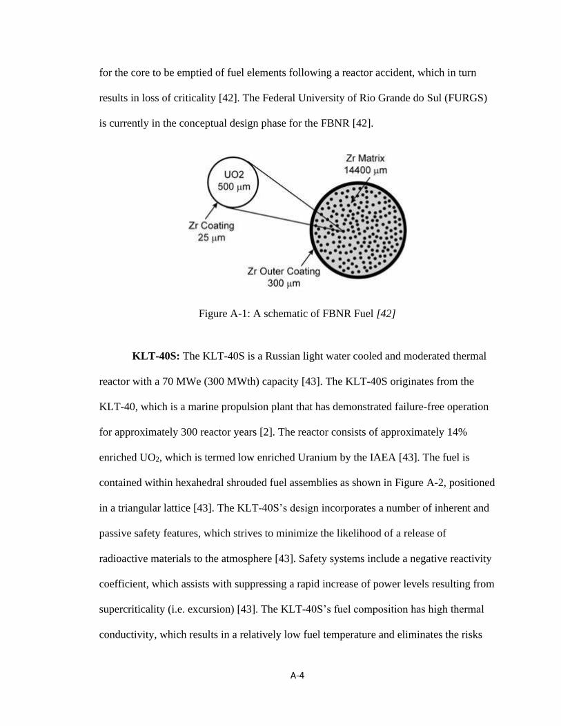
A-4
for the core to be emptied of fuel elements following a reactor accident, which in turn
results in loss of criticality [42]. The Federal University of Rio Grande do Sul (FURGS)
is currently in the conceptual design phase for the FBNR [42].
Figure A-1: A schematic of FBNR Fuel [42]
KLT-40S: The KLT-40S is a Russian light water cooled and moderated thermal
reactor with a 70 MWe (300 MWth) capacity [43]. The KLT-40S originates from the
KLT-40, which is a marine propulsion plant that has demonstrated failure-free operation
for approximately 300 reactor years [2]. The reactor consists of approximately 14%
enriched UO2, which is termed low enriched Uranium by the IAEA [43]. The fuel is
contained within hexahedral shrouded fuel assemblies as shown in Figure A-2, positioned
in a triangular lattice [43]. The KLT-40S’s design incorporates a number of inherent and
passive safety features, which strives to minimize the likelihood of a release of
radioactive materials to the atmosphere [43]. Safety systems include a negative reactivity
coefficient, which assists with suppressing a rapid increase of power levels resulting from
supercriticality (i.e. excursion) [43]. The KLT-40S’s fuel composition has high thermal
conductivity, which results in a relatively low fuel temperature and eliminates the risks

A-5
associated with a core-meltdown [43]. Further, adequate natural circulation within the
primary systems minimizes the reliance on mechanical systems to remove reactor decay
heat, thus preventing over pressurization of the reactor core [43]. Finally, the KLT-40S
has a high heat storage capacity, which accommodates increases in reactor pressure [43].
Afrikantov OKB Mechanical Engineering is currently supervising the construction of a
KLT-40S unit [43].
Figure A-2: A schematic of KLT-40S Fuel Assembly [43]
VBER-300: The VBER-300, as schematically shown in Figure A-3, is a Russian
light water cooled and moderated thermal reactor with a 325 MWe (917 MWth) capacity
[44]. The reactor consists of 5% enriched UO2 fuel in the form of pellets [44]. The
VBER-300 design is a result of nearly 6,500 reactor-operating years of experience with
marine propulsion systems. As a result, the main design is quite similar to that of a
marine-based reactor and is intended to be used as either a ground-based reactor or
marine-based [2]. The VBER-300 includes inherent safety features that are capable of

A-6
safely shutting down the reactor and limiting the amount of energy released [44]. For
example, the VBER-300 has a negative reactivity coefficient that assists with suppressing
reactor excursion, which is a rapid increase of power levels resulting from supercriticality
[44]. The VBER-300 also employs natural circulation, which allows for decay heat
removal following reactor shutdown regardless of if mechanical systems are not
functioning. The inherent safety features result in the simplification of conventional
safety requirements. The manufacturer claims that the inherent safety features are stable
against any disturbances, including personnel errors and terrorist interference [44].
Afrikantov OKB Mechanical Engineering is currently completing the conceptual design
for the VBER-300 [44].
Figure A-3: An overview of a VBER-3000 SMR [44]
VVER-600: The VVER-600 is a Russian light water cooled and moderated
thermal reactor with a 600 MWe (1,600 MWth) capacity [45]. The reactor consists of 5%
enriched UO2 and UO2Gd fuel, which is contained in a hexahedral fuel assembly [2]. The
A-7
addition of gadolinium oxide (Gd2O3) is unique to the VVER-600 and is used as an
integrated burnable absorber. Similar to other SMRs, passive safety systems that are used
to manage beyond design basis accidents are employed. These include a core passive
flooding system and a steam generator passive heat removal system [45]. Following a
loss of coolant accident, the passive flooding system will flood the pressure vessel of the
VVER-600 with water from the hydroaccumulators [46]. The hydroaccumulators are
separated from the reactor by check valves. When the reactor pressure drops below the
design threshold the cheque valves open, allowing the water supply to enter the reactor
[46]. The VVER-600 consists of several natural circulating circuits, each connected to the
stream generator. As heat from the reactor core is released, it generates steam. This steam
then condenses, which rejects the heat to the ambient air [46]. Passive systems are to
operate in tandem with the active safety systems to maintain an acceptable safety level
[45]. Figure A-4 shows a schematic of the equipment arrangement for the VVER-600.
The VVER-600 is currently in the conceptual design phase, which is being managed by
Gidropress [45].

A-8
Figure A-4: An overview of a VVER-600 SMR [45]
VVER-640: The VVER-640 is a Russian light water cooled and moderated
thermal reactor with a 645 MWe (1,800 MWth) capacity [47]. The reactor consists of
UO2 pellets, with initial enrichment level for the fuel averaging at 1.72% [2]. The low
enrichment results in fuel-cost reduction. The VVER-640 is equipped with passive safety
systems that remove all decay heat from the reactor [2]. The ECCS hydro-accumulator
injects cooling water into the reactor core during a loss of coolant accident [47]. As the
primary reactor vessel’s pressure decreases, check valves allow cooling water to enter the
core [47]. Following a loss of coolant accident or failure of active safety systems, decay
heat is removed from the steam generator via the passive heat removal system and the
containment heat removal system. Both systems are designed for long-term removal of
reactor decay heat through the removal of heat from the steam systems [47]. It is the

A-9
intention to have all design basis accidents controlled via the passive systems, where
active systems are only employed to further mitigate an accident scenario [47]. Figure A-
5 is a schematic for the VVER-640 reactor that is currently being designed by Gidropress
[47].
Figure A-5: A schematic of VVER-640 SMR [48]
Integrated Modular Water Reactor (IMR): The IMR is a Japanese light water
cooled and moderated thermal reactor with a 350 MWe (1,000 MWth) capacity [48], a

A-10
schematic of which is shown in Figure A-6. The reactor consists of UO2 fuel, with an
enrichment averaging 4.80% [2]. While there are 349 fuel rods with the uranium dioxide
fuel, there are also 32 rods that contain gadolinium, which assists with balancing
reactivity within the core by managing fuel burn-up [48]. The IMR is equipped with a
number of inherent safety features, such as: the hybrid heat transport system to eliminate
loss of flow and an in-vessel control rod drive mechanism to eliminate control rod
ejection [48]. The hybrid heat transport system is able to employ natural circulation
through the use of reactor decay heat and the steam generator. As heat is generated, the
coolant begins to boil at the bottom of the reactor, which results in the coolant bubbling
and rising via a channel to the top of the reactor, where it is then cooled via the steam
generator [48]. The in-vessel control rod drive mechanism is contained entirely within the
reactor vessel. This eliminates the possibility of the control rod assembly being ejected
due to difference in reactor vessel and ambient air pressure following a mechanical
failure [48]. The conceptual design phase has been completed by the designer, Mitsubishi
[48].

A-11
Figure A-6: A schematic of an IMR SMR [48]
NuScale: The NuScale Power Modular and Scalable Reactor, as shown in Figure
A-7, is an American light water cooled and moderated thermal reactor with a 540 MWe
(1,920 MWth) capacity [49]. The reactor consists of UO2 ceramic pellets with an
enrichment of less than 4.95% [2]. The fuel is encased in an array of fuel assemblies that
are shorter in length than that of other SMRs and allow for a compact reactor size [49].
This is one of the characteristics that distinguish the NuScale from other SMR designs.
Another is that the reactor has a smaller fuel inventory than other SMRs, which would
result in an accidental release of radioactivity well below that of conventional nuclear
reactors [49]. The core is cooled via natural circulation and the reactor has a modular
containment rather than the traditional cast in-place design [49]. NuScale is equipped
with two redundant passive safety systems and does not require external power to actuate
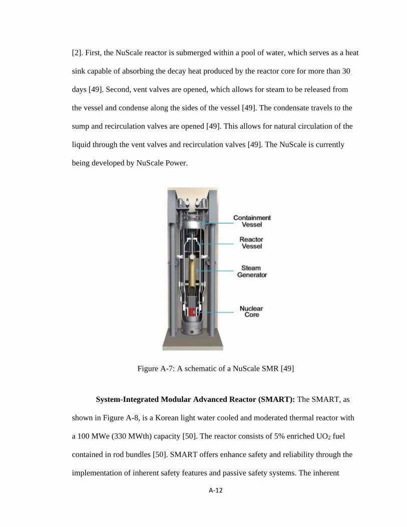
A-12
[2]. First, the NuScale reactor is submerged within a pool of water, which serves as a heat
sink capable of absorbing the decay heat produced by the reactor core for more than 30
days [49]. Second, vent valves are opened, which allows for steam to be released from
the vessel and condense along the sides of the vessel [49]. The condensate travels to the
sump and recirculation valves are opened [49]. This allows for natural circulation of the
liquid through the vent valves and recirculation valves [49]. The NuScale is currently
being developed by NuScale Power.
Figure A-7: A schematic of a NuScale SMR [49]
System-Integrated Modular Advanced Reactor (SMART): The SMART, as
shown in Figure A-8, is a Korean light water cooled and moderated thermal reactor with
a 100 MWe (330 MWth) capacity [50]. The reactor consists of 5% enriched UO2 fuel
contained in rod bundles [50]. SMART offers enhance safety and reliability through the
implementation of inherent safety features and passive safety systems. The inherent

A-13
safety features include an integral coolant system and improvements to the natural
circulation of the reactor [2]. The passive safety features introduced in the SMART
design include the installation of a residual heat removal system that mitigates loss of
coolant accidents [50]. During an accident condition, the passive residual heat removal
system will prevent the over pressurization of the primary system via natural circulation,
which removes decay heat produced in the reactor core via the steam generator.
Conceptual designs for the SMART are currently being completed by KAERI.
Figure A-8: A schematic of a SMART SMR [50]
ACP-100: The ACP-100 is a Chinese light water cooled and moderated thermal
reactor with 100 MWe (310 MWth) capacity [2], a schematic is shown in Figure A-9.
The UO2 fuel is enriched between 2.4% to 4% and contained within squared fuel
assemblies [2]. The ACP-100 is to be buried underground to mitigate the likelihood of a

A-14
radioactive release to the atmosphere [2]. The reactor is designed to eliminate the
possibility of a loss of coolant accident due a number of passive safety systems, including
a decay heat removal system and passive emergency core cooling system [2]. The decay
heat removal system is designed to prevent a reactor core meltdown following a beyond
design basis accident. The decay heat is removed via a heat sink that is naturally
circulated [2]. Following a loss of coolant accident, the passive emergency core cooling
system condenses the steam located within the reactor vessel. This results in a release of
heat from the steam, which is removed from the reactor vessel via conduction [2]. Basic
designs for the ACP-100 have been completed and are being led by the China National
Nuclear Corporation [2].
Figure A-9: A schematic of a ACP-100 SMR [2]
mPower: The mPower reactor, as shown in Figure A-10, is an American light
water cooled and moderated thermal reactor with 195 MWe (575 MWth) capacity [2].
The UO2 fuel pellets are enriched up to 5% [2]. The reactor is equipped with a steel
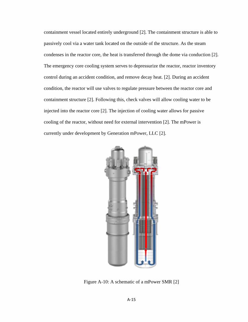
A-15
containment vessel located entirely underground [2]. The containment structure is able to
passively cool via a water tank located on the outside of the structure. As the steam
condenses in the reactor core, the heat is transferred through the dome via conduction [2].
The emergency core cooling system serves to depressurize the reactor, reactor inventory
control during an accident condition, and remove decay heat. [2]. During an accident
condition, the reactor will use valves to regulate pressure between the reactor core and
containment structure [2]. Following this, check valves will allow cooling water to be
injected into the reactor core [2]. The injection of cooling water allows for passive
cooling of the reactor, without need for external intervention [2]. The mPower is
currently under development by Generation mPower, LLC [2].
Figure A-10: A schematic of a mPower SMR [2]

A-16
Westinghouse SMR: The Westinghouse SMR is an American light water cooled
and moderated thermal reactor with 225 MWe (800 MWth) capacity [2]. The reactor
employs 89 fuel assemblies using UO2 pellets enriched to less than 5% [2]. The SMR
design is based on Westinghouse’s larger AP-1000 reactor, which further builds on the
concepts of simplicity and passive safety [39]. The SMR is entirely modular which limits
the size of primary components and allows for ease of transportation [2]. The passive
safety features employ gravity and natural circulation in order to mitigate accidents [2].
This means that the reactor itself is not reliant on external power to perform safety
functions [2]. Conceptual designs for the Westinghouse, shown schematically in Figure
A-11, have been completed by the Westinghouse Electric Company LLC [2].
Figure A-11: A schematic of Westinghouse SMR [2]
SMR-160: The SMR-160, also referred to as the Holtec SMR, is an American
light water cooled and moderated reactor with 160 MWe (525 MWth) capacity [2],
A-17
shown schematically in Figure A-12. The reactor has 4.95% enriched UO2 fuel pellets
and employs a square array of fuel assemblies [2]. The SMR-160 is described as having a
simplistic design, with fewer valves, pumps, heat exchangers, and instrumentation [2].
This results in a lower likelihood of mechanical system failures. There are a number of
unique safety features within the passive core cooling systems, which include: a primary
heat removal system, the secondary decay heat removal system, the automatic
depressurization system, and the passive make-up water system. The primary heat
removal system rejects heat from the primary coolant to the secondary loop via heat
transfer [2]. The automatic depressurization system is designed to regulate the reactor’s
cooling system pressure, which allows for make-up cooling water to be injected into the
reactor vessel during an accident condition [2]. While the reactor is intended to be used
for electricity production, it is also capable of hydrogen generation, district heating, and
seawater desalination [2]. Another potential application is to use the SMR-160 as a
replacement for existing coal-fired power plants that are being decommissioned [2].

A-18
Figure A-12: A schematic of SMR-160 [2]
DMS: The DMS is a Japanese light water cooled and moderated reactor with a
300 MWe (840 MWth) capacity. The DMS uses UO2 fuel pellets that are enriched up to
5% [2]. Similar to other SMRs, natural circulation of the coolant is used to remove heat
produced in the core, which eliminates the need for recirculation pumps [2]. The pressure
vessel is simplified, which results in the volume of the unit being significantly reduced.
The reduced reactor pressure vessel size results in the reduction of the construction,
manufacturing, and transportation timelines. The reactor is currently being designed by
Hitachi-GE Nuclear Energy [2]. While all SMRs are intended to produce electricity, the
DMS is also suitable for remote regions with less developed grid infrastructure. The

A-19
DMS is also capable of district heating, oil sand extraction, steam assisted gravity
drainage, and desalination [40].
A.2.2 Heavy Water Reactors
Heavy water reactors account for nearly 50 nuclear power plants worldwide and
are the second most common reactor design [39]. Heavy water is used as the moderator
and the fuel is natural uranium due to the moderator’s low absorption of neutrons [39].
The coolant for a heavy water reactor is dependent on the design, but is either heavy
water or light water [39]. In heavy-water SMR designs, natural circulation is used to
remove heat during normal operating conditions, as well as during accident conditions.
Similar to the above described light water cooled reactors, this results in a reduced
reliance on mechanical systems, such as pumps. The calandria, which contains the heavy
water moderator, is at a near-ambient temperature and atmospheric pressure and is
equipped with a series of passive cooling system. The passive cooling systems will be
discussed in greater detail below. This results in decreased leakage of tritium, which is
produced by neutron absorption of the heavy-water’s deuterium, to the atmosphere. The
following provides a summary of the main features of heavy water SMRs, see also Table
A-2.
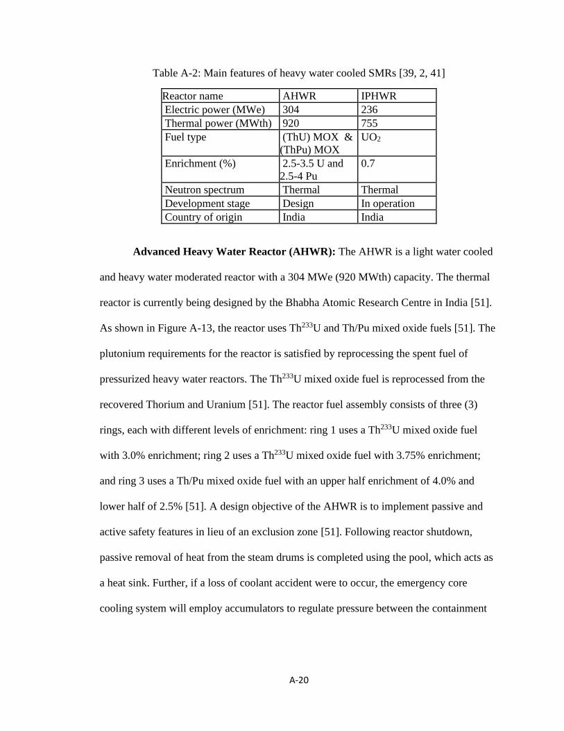
A-20
Table A-2: Main features of heavy water cooled SMRs [39, 2, 41]
Reactor name AHWR IPHWR
Electric power (MWe) 304 236
Thermal power (MWth) 920 755
Fuel type (ThU) MOX &
(ThPu) MOX
UO2
Enrichment (%) 2.5-3.5 U and
2.5-4 Pu
0.7
Neutron spectrum Thermal Thermal
Development stage Design In operation
Country of origin India India
Advanced Heavy Water Reactor (AHWR): The AHWR is a light water cooled
and heavy water moderated reactor with a 304 MWe (920 MWth) capacity. The thermal
reactor is currently being designed by the Bhabha Atomic Research Centre in India [51].
As shown in Figure A-13, the reactor uses Th233U and Th/Pu mixed oxide fuels [51]. The
plutonium requirements for the reactor is satisfied by reprocessing the spent fuel of
pressurized heavy water reactors. The Th233U mixed oxide fuel is reprocessed from the
recovered Thorium and Uranium [51]. The reactor fuel assembly consists of three (3)
rings, each with different levels of enrichment: ring 1 uses a Th233U mixed oxide fuel
with 3.0% enrichment; ring 2 uses a Th233U mixed oxide fuel with 3.75% enrichment;
and ring 3 uses a Th/Pu mixed oxide fuel with an upper half enrichment of 4.0% and
lower half of 2.5% [51]. A design objective of the AHWR is to implement passive and
active safety features in lieu of an exclusion zone [51]. Following reactor shutdown,
passive removal of heat from the steam drums is completed using the pool, which acts as
a heat sink. Further, if a loss of coolant accident were to occur, the emergency core
cooling system will employ accumulators to regulate pressure between the containment

A-21
structure and the reactor core. This allows for cooling water to be injected into the core,
which serves as a means to passively cool the core for approximately 7 days [51].
Figure A-13: Fuel Cycle for AHWR [51]
The primary containment is surrounded by the secondary containment and both
are designed to withstand the effects of a Loss-of-Coolant Accident (LOCA), which
results from a loss of coolant following a break in the primary heat transport system [52,
32]. The primary containment is 48 meters wide, 75.5 meters high, 21 meters below
grade, and contains a number of advanced safety systems that are intended to control the
release of radioactivity and remove heat from the containment atmosphere during an
accident condition [52]. The primary containment is 40” thick and is constructed of
prestressed cement concrete with an epoxy liner. Prestressed cement concrete is made of
heavy concrete, which has increased density and allows for the shielding of neutron and
gamma radiation [53]. The use of prestressed concrete also eliminates the tensile stresses
at the inside face by using high tensile strength steel wires [54]. This allows for increased
tensile stress resistance and minimizes the risk of cracking, whereas heavy concrete alone

A-22
is often employed to resist compressional forces rather than tension [54]. The pre-stressed
concrete containment structure resembles the design of the CANDU 600 reactor. The
secondary containment is 57 meters wide, 72 meters high, 21 meters below grade, 32”
thick, and is constructed of reinforced cement concrete. [52] Reinforced concrete is
permeable and, unlike prestressed concrete, it is normal for small cracks to exist due to
tension. As a result, a steel liner is installed to eliminate the risks associated with
radionuclide leakage. [54]. The steel liner is considered to be a superior form of barrier,
with a higher reliability over the epoxy lining employed by prestressed concrete. The
reinforced concrete containment structure resembles the design of the CANDU 300
reactor. While the safety systems employed by the AHWR resemble those of the
CANDU 300 and 600 reactors, the unique design characteristic is the use of double
containment, which is not employed by either CANDU reactor. Due to the smaller size of
the AHWR when compared to the CANDU, it is feasible to construct the double concrete
containment structure. The double concrete containment and advanced safety systems are
designed to eliminate or minimize the need for an exclusion zone, combining design
characteristics from both the CANDU 300 and 600. SMRs are defined as a reactor less
than 350 MWe, making the AHWR a large SMR. If the AHWR containment structure is
able to effectively eliminate the required exclusion zone then this same containment
structure and equivalent advanced safety systems can be applied to smaller reactors to
achieve the same result [17].
Indian PHWR (IPHWR): The IPHWR is an Indian heavy water cooled and
moderated reactor with natural UO2 fuel and a capacity of 236 MWe (755 MWth) [55].
The IPHWR reactor is in operation and was designed by the Nuclear Power Corporation
A-23
of India (NPCIL) [55]. There are 16 PHWR units of similar size in India, providing
considerable operating experience [55]. India’s first two (2) units, referred to as RAPS-1
and RAPS-2, are of Canadian design and are modelled after the Douglas Point CANDU
reactor [55]. In fact, most of the equipment used to construct RAPS-1 was imported from
Canada and construction of the unit was made possible through collaboration between
Indian and Canadian officials [55]. Through the use of an emergency core cooling system
(ECCS), high pressure heavy water (D2O) or medium pressure light water (H2O) is
injected into the reactor in case of a major loss-of-coolant accident. In the event that the
accident demands additional water supply, the ECCS activates an additional low-pressure
recirculation pumps and heat exchangers. As a last resort, fire water can be injected into
the reactor.

A-24
A.3 Gas Cooled Reactors
Gas cooled reactors account for approximately 3% of all operating nuclear power
plants worldwide [56]. The fuel is in the form of tri-structural isotropic particle fuel
(TRISO), rather than conventional pellets [39]. Tri-structural isotropic particle fuel is
spherical and has a plutonium or uranium core and a graphite and silica coating [39]. Gas
cooled reactors employ Helium (He) or carbon dioxide (CO2) as the coolant with graphite
often being used as the moderator [39]. Neither helium nor carbon dioxide experience
phase change, avoiding the changes in cooling capacity associated with boiling of water
coolants [2]. This allows the fuel to tolerate higher temperatures without damage [2]. The
following provides an overview of gas cooled SMRs, with Table A-3 serving as a
summary.
Table A-3: summary of gas cooled SMRs [39, 2, 41]
Reactor name: HTR-PM PBMR P-HTR
Electric power (MWe): 211 165 150
Thermal power (MWth): 500 400 350
Fuel type: UO2 TRISO UO2 TRISO UO2 TRISO
Enrichment (%): 8.5 9.6 15.5
Neutron spectrum: Thermal Thermal Thermal
Development stage: Demonstrate Conceptual Conceptual
Country of origin: China South Africa USA
High Temperature GCR - Pebble-Bed Module (HTR-PM): The HTR-PM is a
helium cooled and graphite moderated thermal reactor with a 211 MWe (500 MWth)
capacity [57]. The SMR is currently being designed by Tsinghua University in China

A-25
[57]. The HTR-PM uses a UO2 tri-structural isotropic particle fuel with an enrichment
level of 8.5%, which is shown in Figure A-14.
Figure A-14: Spherical Fuel Elements [57]
The HTR-PM demonstrates a variety of inherent safety features [57]. For
example, the HTR-PM structure employs a large quantity of graphite, which has a high
heat capacity. As such, during accident conditions, decay heat will be rejected from the
reactor core to the reactor vessel via conduction and radiation [57]. Further, the reactivity
coefficient is negative, which will result in the reactor suppressing rapid increases in
reactor power levels [57]. The intent of the HTR-PM design is to eliminate the
possibility of an accident that results in the release of radionuclides to the atmosphere
[57].
Pebble Bed Modular Reactor PBMR: The PBMR is a helium cooled and
graphite moderated thermal reactor with a capacity of 165 MWe (400 MWth) [58].
Originating in South Africa, the PBMR is currently being designed by Pebble Bed
Modular Reactor (Pty) Limited [58]. UO2 tri-structural isotropic particle fuel is used,

A-26
shown in Figure A-15, which has an enrichment level ranging between 5% to 20% and
temperature limits exceeding 1,600 ℃ [58]. Even as temperatures approach 1,600 ℃, the
fission products are contained within the fuel particle, which is one of the unique safety
features of the PBMR. The higher temperature allowance also results in improved
thermodynamic efficiency [58]. The reactor’s design allows for the passive rejection of
decay heat from the reactor core to the reactor cavity cooling system, which is a heat
sink, via convection and conduction. This passive feature reduces the reliance on
traditional mechanical equipment [58]. In fact, the only major mechanical equipment in
the primary reactor system is the circulator and steam generator [58].
Figure A-15: PBMR Fuel Element Design [58]
Prismatic Modular High Temperature GVR (Prismatic HTR): The Prismatic
HTR, shown in Figure A-16, is a helium cooled and graphite moderated thermal reactor
with a capacity of 150 MWe (350 MWth) [59]. The Prismatic HTR uses UO2 fuel
enriched to 15.5% [59]. It includes a number of inherent safety characteristics, including
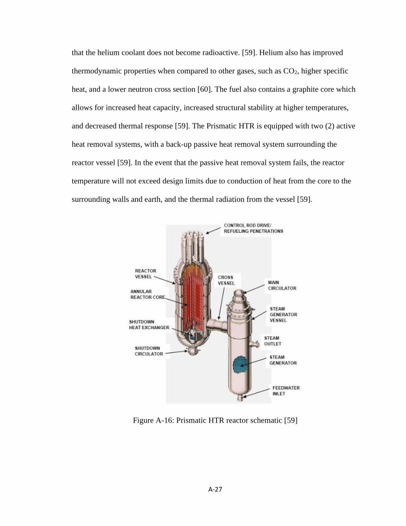
A-27
that the helium coolant does not become radioactive. [59]. Helium also has improved
thermodynamic properties when compared to other gases, such as CO2, higher specific
heat, and a lower neutron cross section [60]. The fuel also contains a graphite core which
allows for increased heat capacity, increased structural stability at higher temperatures,
and decreased thermal response [59]. The Prismatic HTR is equipped with two (2) active
heat removal systems, with a back-up passive heat removal system surrounding the
reactor vessel [59]. In the event that the passive heat removal system fails, the reactor
temperature will not exceed design limits due to conduction of heat from the core to the
surrounding walls and earth, and the thermal radiation from the vessel [59].
Figure A-16: Prismatic HTR reactor schematic [59]
A-28
A.4 Molten Salt Reactors
Molten salt reactors were originally developed in the 1950s [61], but are re-
emerging as candidates for SMRs [61]. Molten salt allows for increased operating
temperatures, which result in improved thermal efficiencies [61]. The increased
temperatures are ideal for electricity generation, but also for a number of process heat
applications [61]. Molten salt reactors also operate at lower coolant pressures, mitigating
the risks associated with, and the likelihood of, a loss of coolant accident, thereby serving
as a distinct safety characteristic [2] [61]. Although dependent on the particular design, a
number of designs don’t require solid fuel, eliminating the risks associated with
manufacturing and disposal [2] [61]. The reactor is rather flexible and can also be used
with a variety of fuel types, including uranium-plutonium and thorium-uranium cycles
[61]. The proceeding sections describe the features of a number of molten salt SMR
designs currently under development, with Table A-4 serving as a summary.

A-29
Table A-4: Summary of Molten Salt SMRs [62, 63, 64, 65, 66, 67, 68]
Reactor name: MK1PB-FHR ThorCon IMSR-400 MSTW
Electric power (MWe): 100 250 194 115
Thermal power (MWth): 236 557 400 270
Fuel type: TRISO NaF-BeF2-
ThF4-UF4
UF4 in
diluent
fluorides
Sodium-
actinide
fluoride
Enrichment (%): 19.8 19.7 Start-up: 2-3
Makeup: 5-
19
1.1
Neutron spectrum: Thermal Thermal Thermal Thermal
Development stage: Concept Design Design Concept
Country of origin: USA International International Denmark
Reactor name: MSR-FUJI SSR-U SmAHTR LFTR
Electric power (MWe): 200 300 N/A 250
Thermal power (MWth): 450 750 125 600
Fuel type: Molten salt
with thorium
and uranium
Molten
fluoride salt
TRISO Uranium-233
derived from
Thorium
Enrichment (%): 2.0 <15 8 N/A
Neutron spectrum: Thermal Thermal Thermal Thermal
Development stage: Concept Concept Design Concept
Country of origin: Japan UK USA USA
Mark 1 Pebble-Bed Fluoride-Salt-Cooled High Temperature Reactor
(MK1PB-FHR): This is a fluoride salt cooled and graphite moderated thermal reactor
with a capacity of 100 MWe (236 MWth) [62]. The reactor, schematically shown in
Figure A-17, uses tri-structural isotropic particle fuel coated uranium fuel particles
enriched to 19.8% [62]. Similar to the PBMR, the reactor fuel is spherical with the
internal tri-structural isotropic particle fuel particles encased in several graphite coatings
[62]. The design incorporates a number of passive safety features. The reactor core heat
removal system is controlled using passive check valves [62]. Following a loss of coolant
accident, the check valves will allow for water to enter the reactor core [62]. This results
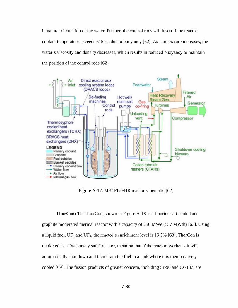
A-30
in natural circulation of the water. Further, the control rods will insert if the reactor
coolant temperature exceeds 615 °C due to buoyancy [62]. As temperature increases, the
water’s viscosity and density decreases, which results in reduced buoyancy to maintain
the position of the control rods [62].
Figure A-17: MK1PB-FHR reactor schematic [62]
ThorCon: The ThorCon, shown in Figure A-18 is a fluoride salt cooled and
graphite moderated thermal reactor with a capacity of 250 MWe (557 MWth) [63]. Using
a liquid fuel, UF3 and UF4, the reactor’s enrichment level is 19.7% [63]. ThorCon is
marketed as a “walkaway safe” reactor, meaning that if the reactor overheats it will
automatically shut down and then drain the fuel to a tank where it is then passively
cooled [69]. The fission products of greater concern, including Sr-90 and Cs-137, are

A-31
chemically bound to the salt [69]. This means that draining the fuel from the reactor also
reduces the possibility of harmful radionuclides being released into the atmosphere
following an accident [69]. One of the ThorCon’s unique design features is that the
operator is unable to prevent draining of the fuel or cooling of the reactor following
overheating [69]. The reactor is buried 15 meters below grade, contains three (3) physical
containment barriers, and operates at a positive pressure to mitigate risks associated with
a rupture of the primary loop [63]. Similar to other SMRs, the Thorcan reactor is modular
and manufactured in blocks which are then shipped to site for assembly.
Figure A-18: ThorCon reactor schematic [70]
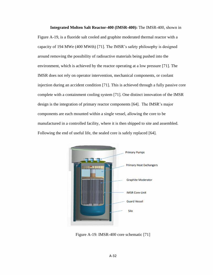
A-32
Integrated Molten Salt Reactor-400 (IMSR-400): The IMSR-400, shown in
Figure A-19, is a fluoride salt cooled and graphite moderated thermal reactor with a
capacity of 194 MWe (400 MWth) [71]. The IMSR’s safety philosophy is designed
around removing the possibility of radioactive materials being pushed into the
environment, which is achieved by the reactor operating at a low pressure [71]. The
IMSR does not rely on operator intervention, mechanical components, or coolant
injection during an accident condition [71]. This is achieved through a fully passive core
complete with a containment cooling system [71]. One distinct innovation of the IMSR
design is the integration of primary reactor components [64]. The IMSR’s major
components are each mounted within a single vessel, allowing the core to be
manufactured in a controlled facility, where it is then shipped to site and assembled.
Following the end of useful life, the sealed core is safely replaced [64].
Figure A-19: IMSR-400 core schematic [71]

A-33
Molten Salt Thermal Wasteburner (MSTW): The MSTW is a molten salt
cooled and graphite moderated thermal reactor with a capacity of 115 MWe (400 MWth)
[65]. Under abnormal operating conditions, control of the MSTW reactor does not require
any active measures, meaning that the reactor does not require human intervention [65].
The MSTW is designed to operate at an optimized configuration, whereby any deviation
would lead to the system moving away from the optimum and result in a reactor
shutdown if not alleviated [65]. This is further demonstrated in Figure A-20, which
indicates that the core is over-moderated to ensure negative temperature and void
reactivity coefficients [65]. Negative temperature coefficient means that the reactor
deviates down from criticality (reactivity) when the temperature increases, while a
negative void coefficient means that the reactivity decreases as the void content
increases.
Figure A-20: MSTW optimal configuration principle [65]
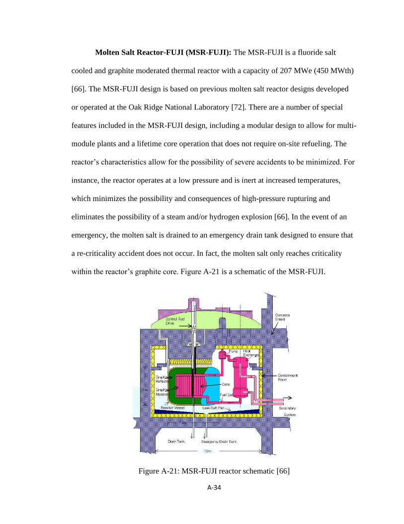
A-34
Molten Salt Reactor-FUJI (MSR-FUJI): The MSR-FUJI is a fluoride salt
cooled and graphite moderated thermal reactor with a capacity of 207 MWe (450 MWth)
[66]. The MSR-FUJI design is based on previous molten salt reactor designs developed
or operated at the Oak Ridge National Laboratory [72]. There are a number of special
features included in the MSR-FUJI design, including a modular design to allow for multi-
module plants and a lifetime core operation that does not require on-site refueling. The
reactor’s characteristics allow for the possibility of severe accidents to be minimized. For
instance, the reactor operates at a low pressure and is inert at increased temperatures,
which minimizes the possibility and consequences of high-pressure rupturing and
eliminates the possibility of a steam and/or hydrogen explosion [66]. In the event of an
emergency, the molten salt is drained to an emergency drain tank designed to ensure that
a re-criticality accident does not occur. In fact, the molten salt only reaches criticality
within the reactor’s graphite core. Figure A-21 is a schematic of the MSR-FUJI.
Figure A-21: MSR-FUJI reactor schematic [66]
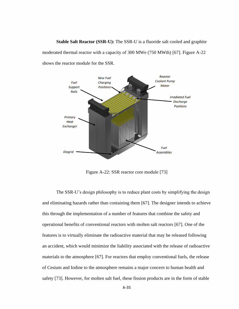
A-35
Stable Salt Reactor (SSR-U): The SSR-U is a fluoride salt cooled and graphite
moderated thermal reactor with a capacity of 300 MWe (750 MWth) [67]. Figure A-22
shows the reactor module for the SSR.
Figure A-22: SSR reactor core module [73]
The SSR-U’s design philosophy is to reduce plant costs by simplifying the design
and eliminating hazards rather than containing them [67]. The designer intends to achieve
this through the implementation of a number of features that combine the safety and
operational benefits of conventional reactors with molten salt reactors [67]. One of the
features is to virtually eliminate the radioactive material that may be released following
an accident, which would minimize the liability associated with the release of radioactive
materials to the atmosphere [67]. For reactors that employ conventional fuels, the release
of Cesium and Iodine to the atmosphere remains a major concern to human health and
safety [73]. However, for molten salt fuel, these fission products are in the form of stable

A-36
salts that are unable to be dispersed as gasses through the air [73]. The designer has
theorized that this has the potential to reduce the volatile radioactive material by up to six
orders of magnitude when compared with a traditional oxide fueled reactor [73]. Through
this, it is believed that the exclusion zone can be reduced or possibly eliminated entirely
[73].
Small fluoride salt-cooled High Temperature Reator (SmAHTR): The
SmAHTR, shown in Figure A-23, is a fluoride salt cooled and graphite moderated
thermal reactor with a capacity of 125 MWth [74]. The reactor employs tri-structural
isotropic particle fuel, enriched to 8%. The coated fuel is coated with a series of
protective layers and is embedded with graphitic material, which has an increased
thermal failure point and serves as a barrier to assist with preventing the release of fission
products to the atmosphere [75]. The SmAHTR design shares a number of key design
features of other SMRs, including a large negative reactivity coefficient, natural
convection for passive decay heat removal, and numerous inherent safety design features
[75]. The SmAHTR is ideal for remote applications as the passive decay heat removal
system is non-reliant on off-site power [75]. The inherent safety features combined with a
reduced source term will allow the designer to justify a smaller emergency preparedness
zone to the regulator [75]. The core and primary components are all contained within the
reactor vessel, eliminating the likelihood of a loss of coolant accident [75]. In fact, there
are several barriers preventing the release of radioactive materials to the atmosphere,
including the coated particle fuel mentioned above, graphite moderator, reactor guard
vessel, and the physical containment structure [75].

A-37
Figure A-23: SmAHTR vessel schematic [74]
Liquid Fluoride Thorium Reactor (LFTR): The LFTR is a fluoride salt cooled
and graphite moderated thermal reactor with a capacity of 250 MWe and 600 MWth [68].
It uses U-233 fuel derived from Thorium [68]. The LFTR has four (4) main design
principles demonstrated. The first which is an inherently safe reactor that operates at a
low-pressure [68]. The reactor is self-controlling as any increase to operating temperature
results in a decrease to the fuel salt density, which will inherently stabilize the reactor
without the need for human intervention or mechanical systems [68]. Further, the fuel is
not pressurized, which eliminates the ability for large amounts of radionuclides to be

A-38
dispersed following an accident [68]. The second is a simplistic design that is intrinsically
stable and self-regulating [68]. Similar to other fluoride salt reactors, the fission products
of greatest radiological concern are retained in the overall salt mixture and are not
dispersed to the atmosphere following a nuclear reactor accident [68]. The third is the
design of an efficient nuclear reactor and the fourth is to produce far less waste [68]. The
LFTR is able to capture the energy content of thorium at an efficiency approaching
100%, by utilizing thorium fuel in a thermal (low energy) neutron spectrum where the
fission probability is highest, which results in a high operating efficiency and minimizes
waste products [68].

A-39
A.5 Fast Neutron Spectrum Reactors
Since 1950, approximately 20 fast neutron spectrum reactors have been designed
and operated [76]. Fast reactors use Uranium-238 more deliberately and offer a more
efficient use of uranium resources [76]. Further, fast reactors burn actinides, which are
otherwise high-level nuclear wastes [76]. Currently being developed are lead and lead-
bismuth cooled and gas cooled fast reactors, but sodium cooled remains the most mature
fast-reactor technology [77]. Fast reactors present a number of key advantages over
thermal (slow-neutron) reactors with respect to waste management and sustainability,
with increased efficiency resulting in a reduction of radioactive waste [78]. Fast reactors
use no moderator and instead rely on fast neutrons to cause fission. In an effort to avoid
neutron moderation and ensure a highly efficient heat transfer medium, the coolant is a
molten liquid (lead or lead-bismuth). The following sections discuss fast neutron
spectrum SMRs, with Table A-5 serving as a summary.

A-40
Table A-5: Summary of Fast neutron Spectrum SMRs
[79, 80, 81, 82, 83, 84, 85, 86, 87]
Reactor name: EM2 CLEAR-I ALFRED
Electric power (MWe): 240 N/A 125
Thermal power (MWth): 500 10 300
Fuel type: U-Pu-MA UO2 MOX
Enrichment (%): 1 19.75 30
Neutron spectrum: Fast Fast Fast
Development stage: Concept Design Concept
Country of origin: USA China Italy
Reactor name: ELFR PEACER BREST-OD-300
Electric power (MWe): 630 300 300
Thermal power (MWth): 1,500 850 700
Fuel type: MOX U-TRU-Zr PuN-UN
Enrichment (%): 13.5
Neutron spectrum: Fast Fast Fast
Development stage: Concept Concept Design
Country of origin: Italy Korea Russian
Reactor name: SVBR-100 G4M MYRRHA
Electric power (MWe): 101 25 N/A
Thermal power (MWth): 280 70 100
Fuel type: UO2 Uranium Nitride MOX
Enrichment (%): 16.5 19.75
Neutron spectrum: Fast Fast Fast
Development stage: Design Concept Concept
Country of origin: Russia USA Belgium
Energy Multiplier Module (EM2): This is a helium cooled fast neutron
spectrum reactor with a capacity of 240 MWe (500 MWth) [79]. EM2, shown in Figure
A-24, utilizes uranium carbide pellets with an approximate enrichment of 14.5% [2]. The
pellets have a high thermal conductivity and melting point [2]. The EM2’s design
includes provisions to include passive safety systems that allow for sustained protection
in the event of a severe accident [2]. Further, the reactor strives to optimize fuel

A-41
utilization in an effort to minimize waste and optimize efficiency [2]. The safety design
includes three barriers against the release of radionuclides [2]. The first barrier is the fuel
cladding that encompasses the pellets, which is able to maintain its strength at
temperatures far exceeding normal operating conditions [2]. The second barrier is the
primary vessel, which encompasses the reactor [2]. The barrier serves as a traditional
concrete barrier to prevent the release of radioactive materials to the atmosphere
following an accident [2]. The design leakage rate for the barrier is less than 0.2% per
day [2]. The third barrier is the below-grade containment, which will serve as an
additional physical barrier to the release of radioactive materials [2]. In addition to
physical barriers, there exists passive safety systems, including the direct reactor
auxiliary cooling system [2]. The cooling system is able to operate during normal
shutdown and accident conditions and will passively remove heat without need for
external power [2].
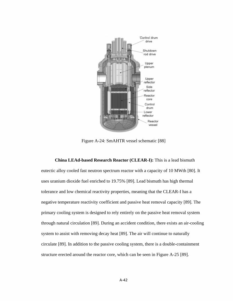
A-42
Figure A-24: SmAHTR vessel schematic [88]
China LEAd-based Research Reactor (CLEAR-I): This is a lead bismuth
eutectic alloy cooled fast neutron spectrum reactor with a capacity of 10 MWth [80]. It
uses uranium dioxide fuel enriched to 19.75% [89]. Lead bismuth has high thermal
tolerance and low chemical reactivity properties, meaning that the CLEAR-I has a
negative temperature reactivity coefficient and passive heat removal capacity [89]. The
primary cooling system is designed to rely entirely on the passive heat removal system
through natural circulation [89]. During an accident condition, there exists an air-cooling
system to assist with removing decay heat [89]. The air will continue to naturally
circulate [89]. In addition to the passive cooling system, there is a double-containment
structure erected around the reactor core, which can be seen in Figure A-25 [89].

A-43
Figure A-25: CLEAR-I reactor schematic [90]
Advanced Lead Fast Reactor European Demonstrator (ALFRED): This is a
lead cooled fast neutron spectrum reactor with a capacity of 125 MWe (300 MWth) [81].
ALFRED uses mixed oxide fuel with maximum plutonium enrichment of 30% [81]. The
reactor itself is a pool-type, with all components being easily removable [81]. The reactor
is equipped with two redundant shutdown systems [81]. The first consists of rods that are
passively inserted by buoyancy from the bottom of the core and the second consists of
rods that are passively inserted via depressurization of a pneumatic system from the top
of the core [81]. The reactor is also equipped with two redundant passive heat removal
systems [81]. Figure A-26 shows a schematic of the reactor [81].

A-44
Figure A-26: ALFRED vessel schematic [81]
European Lead Fast Reactor (ELFR): ELFR, shown in Figure A-27, is a lead
cooled fast neutron spectrum reactor with a capacity of 630 MWe (1,500 MWth) [82].
The ELFR reactor shares many similarities with ALFRED. ALFRED was designed to
demonstrate that a lead fast reactor is capable of being used in commercial power plant
applications [91]. As such, the ELFR also uses a mixed oxide fuel, has two (2) redundant
safety rod systems, and contains two redundant passive heat removal systems [91].
Similar to ALFRED, the first safety rod system is inserted upwards using the buoyancy
force of the reactor core [91]. The second safety rod system is inserted downward
through the use of a pneumatic system [91]. The first heat removal system is composed of
four isolation condenser systems connected to four steam generators [82]. The second
system is composed of four isolation condenser systems connected to four dip coolers
[82].

A-45
Figure A-27: ELFR vessel schematic [91]
Proliferation-resistant Environment-friendly Accident-tolerant Continuable
and Economical Reactor (PEACER): This is a lead bismuth eutectic alloy cooled
reactor with a capacity of 300 MWe (850 MWth) [83]. The reactor, shown in Figure A-
28, employs uranium transuranic zirconium alloy fuel [92]. The lead-bismuth coolant has
a high temperature tolerance, which allows the coolant to remain a liquid over a wide
range of temperatures and pressures. This allows for the natural circulation of coolant to
continue at increased temperatures and pressures [92]. One of the distinguishing features
of the PEACER is the reactor vessel air cooling system, which will provide passive
cooling capabilities for decay heat [83].
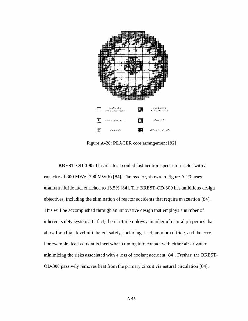
A-46
Figure A-28: PEACER core arrangement [92]
BREST-OD-300: This is a lead cooled fast neutron spectrum reactor with a
capacity of 300 MWe (700 MWth) [84]. The reactor, shown in Figure A-29, uses
uranium nitride fuel enriched to 13.5% [84]. The BREST-OD-300 has ambitious design
objectives, including the elimination of reactor accidents that require evacuation [84].
This will be accomplished through an innovative design that employs a number of
inherent safety systems. In fact, the reactor employs a number of natural properties that
allow for a high level of inherent safety, including: lead, uranium nitride, and the core.
For example, lead coolant is inert when coming into contact with either air or water,
minimizing the risks associated with a loss of coolant accident [84]. Further, the BREST-
OD-300 passively removes heat from the primary circuit via natural circulation [84].

A-47
Figure A-29: BREST-OD-300 Schematic [84]
SVBR-100: This is a lead bismuth eutectic allow cooled fast neutron spectrum
reactor with a capacity of 101 MWe (280 MWth) [85]. The reactor, shown in Figure A-
30, uses uranium dioxide fuel enriched to 16.5% [85]. The SVBR-100 meets the IAEA
standards for inherent safety and prevention of severe accidents [85]. In doing so, the
reactor contains both passive and active emergency safety systems and a passive residual
heat removal system [85]. For example, the lead bismuth coolant is chemically inert,
which contributes towards mitigating the likelihood of a loss of coolant accident [85].
Further, all primary reactor equipment is located within a single vessel and the reactor
operates at near atmospheric pressure, which further assists with mitigating an accident,
including radioactive releases to the atmosphere [85].

A-48
Figure A-30: SVBR-100 Schematic [85]
Gen4 Module (G4M): This is a lead bismuth eutectic alloy cooled fast neutron
spectrum reactor with a capacity of 25 MWe (70 MWth) [86]. The design philosophy of
the Gen4 Module reactor, which is shown in Figure A-31, includes ensuring the
protection of the facility and surrounding environment [86]. This is achieved through a
sealed core, reactor simplicity, mechanical components, and separation between the
power producing sections and conversion sections [86]. While the reactor does not
employ emergency safety systems, residual heat is removed passively from the core
through heat transfer during the naturally circulation of coolant in the primary and
secondary loops [86]. Further, the reactor contains two independent control system to
assist with control of reactivity [86].

A-49
Figure A-31: G4M plant layout [86]
Multi-purpose hYbrid Research Reactor for High-tech Applications
(MYRRHA): This is a lead bismuth eutectic alloy cooled fast neutron spectrum reactor
with a capacity of 100 MWth [87]. The primary cooling system consists of two pumps
and four heat exchangers [87]. The secondary cooling system consists of a water cooling
system for the primary heat exchangers [87]. The tertiary cooling system is an air cooling
system [87]. In the event of a loss of flow, the primary, secondary, and tertiary cooling
systems are designed to manage decay heat passively via natural convection [87]. As heat
is generated, the coolant increases in temperature, which results in the coolant rising to
the top of the reactor core, where the fluid is cooled via convection from the core via the
primary, secondary, and tertiary cooling systems.

A-50
A.6 Summary
Thirty-six prominent SMRs are detailed above. Readers can refer to the IAEA’s
Advanced Reactors Information System [41] and Advances in Small Modular Reactor
Technology Developments [2] for additional information. The review of SMRs included
a summary of the passive and inherent safety systems that allow for improved safety.
While there are numerous safety systems in the thirty-six SMRs discussed above, among
the most common for water-cooled, gas-cooled, molten-salt and fast-neutron spectrum
reactors are the decay heat removal system and the emergency core cooling system, both
of which minimize the probability of a loss of coolant accident via the passive removal of
decay heat from the reactor core when mechanical components are not operational.
Additionally, there are a number of SMRs that employ multiple containment structures,
which will assist with preventing the release of radionuclides to the atmosphere following
an accident. As a result, the inherent/passive safety systems and multiple containment
structures contribute towards the reduction and/or elimination of the exclusion and
emergency planning zones.
The Canadian Nuclear Association commissioned a report to discuss if SMRs are
able to play a role in Canadian energy production [93]. This review discusses that, “as
part of the design process, an emergency planning zone should be as small as possible.
Utilizing a dose/distance approach, it may be possible to show that SMRs could have a
planning zone that is coincident with the site boundary” [93]. The inherent/passive safety
systems described above, combined with the resulting doses/distances and other
innovative design features of SMRs, allows for the designer to engage with the regulator
to justify the elimination or reduction of the exclusion and emergency planning zones.