
Bubble assemblage model for fluidized bed catalytic reactors
19
ChenucalEngmeermgSclence, 1969,Vol 24,pp 1351-1369 Pergamon Press Prmted m Great Bntam Bubble assemblage model for fluidized bed catalytic reactors K KATO and C Y WEN Department of Chemical Engmeenng, West Vlrgma Umverslty, Morgantown, W V 26505, U S A (Fwst recewed 20 September 1968, m rewedform 30 December 1968) Abstract-A new model for catalytic reactlon m flmdlzed beds IS developed Ths model called the “Bubble Assemblage Model” IS based on multiple bubbles of varymg sizes with Interchange of gas takmg place between the bubble phase and the emulsion phase Smce the model needs no adJustable parameters, It IS beheved that the model IS useful for study m scale-ups The model proposed 1s also convement for computer slmulatlons Expenmental data from various mvestlgators were used to test the vah&ty of this model It was found that the conversions predlcted using this model agree reasonably well with the actual performance of the flm&zed beds INTRODUCTION EVER SINCE the flurdtzed bed techmque was first apphed to the makmg of syntheses gas from coal by the Wmkler generator and to the catalyttc cracking of petroleum, flmdized beds have been used for a number of other chenucal processes, particularly m catalyttc synthesis Some of the flutdtzed bed catalytic processes are the catalytic reforming of naphthas, the phthahc anhydnde production, the catalytic oxtdatton of ethylene, the productton of alkyl chlorides, the synthesis of acetomtnle from acetylene and ammonia, etC Just to mentiOII a few However, owing to the complex gas flow and sohd particle movement within the fluidized bed, design procedure of catalytic fluidtzed bed reac- tors has not been well established m spite of the fact that a number of models for flmdized bed reactors have been suggested There have been a number of mvesttgations on the gas flow behavior m a flmdized bed. InJectmg a tracer gas mto the bed and exammmg the behavior of the tracer gas by high speed photography, comparmg the reactant conversion m both the fluidtzed bed and the fixed bed under the same operatmg conditions for well defined catalytic reactions, and observing bubbles nsmg m the bed have been some of the techniques employed to determme the gas flow behavior Based on the results of these observattons, Kum~ and Levensptel[22,23] recently proposed a gas flow model which they called the “Bubbling Bed Model” for explanation and predtctlon of flmdtzed bed behaviors asserting that only the effective size of bubble 1s needed to supply adequate descnptlon of the flow of gas through the bed Although the concept developed certainly contnbuted consrderably to the understandmg of flutdized bed behavior, to use an effective bubble diameter to represent an assemblage of bubbles of varying sizes seems to be somewhat an oversimplification In this paper we shall present a new model the “Bubble Assemblage Model” based on multiple bubbles of varying sizes for design and scale-up purposes The “Bubble Assemblage Model” contains essentially no adJustable para- meter and is convenient for computer simulations The experimental data available m hterature on first order catalytic reaction systems m flutdized beds are used to test the vahdity of the proposed model Unless specified, the equations appearing m this paper are all based on C.G S. units PREVIOUS INVESTIGATIONS An attempt to find the gas flow behavior m a flmdized bed usmg tracer technique was first 1351 CES Vol 24 8-K
Transcript of Bubble assemblage model for fluidized bed catalytic reactors

ChenucalEngmeermgSclence, 1969,Vol 24,pp 1351-1369 Pergamon Press Prmted m Great Bntam
Bubble assemblage model for fluidized bed catalytic reactors
K KATO and C Y WEN
Department of Chemical Engmeenng, West Vlrgma Umverslty, Morgantown, W V 26505, U S A
(Fwst recewed 20 September 1968, m rewedform 30 December 1968)
Abstract-A new model for catalytic reactlon m flmdlzed beds IS developed Ths model called the “Bubble Assemblage Model” IS based on multiple bubbles of varymg sizes with Interchange of gas takmg place between the bubble phase and the emulsion phase
Smce the model needs no adJustable parameters, It IS beheved that the model IS useful for study m scale-ups The model proposed 1s also convement for computer slmulatlons Expenmental data from various mvestlgators were used to test the vah&ty of this model It was found that the conversions predlcted using this model agree reasonably well with the actual performance of the flm&zed beds
INTRODUCTION
EVER SINCE the flurdtzed bed techmque was first apphed to the makmg of syntheses gas from coal by the Wmkler generator and to the catalyttc cracking of petroleum, flmdized beds have been used for a number of other chenucal processes, particularly m catalyttc synthesis
Some of the flutdtzed bed catalytic processes are the catalytic reforming of naphthas, the phthahc anhydnde production, the catalytic oxtdatton of ethylene, the productton of alkyl chlorides, the synthesis of acetomtnle from acetylene and ammonia, etC Just to mentiOII a few
However, owing to the complex gas flow and sohd particle movement within the fluidized bed, design procedure of catalytic fluidtzed bed reac- tors has not been well established m spite of the fact that a number of models for flmdized bed reactors have been suggested
There have been a number of mvesttgations on the gas flow behavior m a flmdized bed. InJectmg a tracer gas mto the bed and exammmg the behavior of the tracer gas by high speed photography, comparmg the reactant conversion m both the fluidtzed bed and the fixed bed under the same operatmg conditions for well defined catalytic reactions, and observing bubbles nsmg m the bed have been some of the techniques employed to determme the gas flow behavior
Based on the results of these observattons, Kum~ and Levensptel[22,23] recently proposed a gas flow model which they called the “Bubbling Bed Model” for explanation and predtctlon of flmdtzed bed behaviors asserting that only the effective size of bubble 1s needed to supply adequate descnptlon of the flow of gas through the bed
Although the concept developed certainly contnbuted consrderably to the understandmg of flutdized bed behavior, to use an effective bubble diameter to represent an assemblage of bubbles of varying sizes seems to be somewhat an oversimplification
In this paper we shall present a new model the “Bubble Assemblage Model” based on multiple bubbles of varying sizes for design and scale-up purposes The “Bubble Assemblage Model” contains essentially no adJustable para- meter and is convenient for computer simulations
The experimental data available m hterature on first order catalytic reaction systems m flutdized beds are used to test the vahdity of the proposed model Unless specified, the equations appearing m this paper are all based on C.G S. units
PREVIOUS INVESTIGATIONS
An attempt to find the gas flow behavior m a flmdized bed usmg tracer technique was first
1351
CES Vol 24 8-K

K KATO and C Y WEN
made by Gdhland and Mason[9] who measured change coefficient between the two phases Table the concentratton variation of a tracer gas 1 summartzes the results of mvesttgatron usmg InJected mto a flurdrzed bed. A model, usually the tracer technique Since the parameters the drspersron model or the two phase model, determmed by this manner are m a sense adjust- IS presupposed m the analysrs and the flow able, unless the model selected can descnbe behavror 1s represented m terms of model para- flow behavior reasonably accurately, the meters such as drspersron coefficient or mter- mformatron obtained IS of httle use for scale-up
Table 1 Expenmental mvestlgatlon of model parameters (A) Tracer method
Authors Model Expenmental con&tlons Expenmental results
Gdhland and Mason[9]
Dlsperslon model Steady state method gas an tracer He particle F C C , glass DR=25- 114cm
Much1 et al [33]
Winter[44]
Dispersion model
Dlsperslon model
Kobayashl et al [ 193 Two phase model D,=O
l&=&f
De Grout [6] Two phase model De=0
ll,=l&
lwasakl et al [ 141 Contact time drstnbutlon
Kato et al [15]
Steady state method gas mr tracer NH, particle sand, glass DR=5- 15cm
Residence time curve gas air tracer He particle glass DR=20- 13 5cm
Residence time curve gas air tracer He parhcle silica gel DR=84cm
Residence time curve gas air tracer He particle sihca DR = 10 - 150 cm
Residence time curve gas ar,Hq tracer I-L, M-L GH, particle silica-alumna DR=508-763cm
Two phase model up = 0
Residence time curve gas air, Hz, N, tracer H2~CP& CIHl particle slhca-alumina,
glass DR= lOcm,D,= 1- 3cm
E, IS affeCted by u,,,,
E, = 1Oe - 101 (cm*/sec)
EJv = 100{N,,/l -E}O~
at 15 < N&l-e < 50 EJv = 18O{N,,/l -e}oa at50< NRep/l-~ < 200
E, = C* d,’ p exp(-o *dp’ O/u) wherew* = 3 5 x 10⁵
C* = 3 6x 10’
F0 = 11/D*
HK=067DRoPSLo5 where L = bed height (m) Hx = u/F,,, u(m/sec)
Converslon of reactant m fluldlzed bed IS expressed by
x = 1- o E(4) exp (-@W/F) d~$ P
contact time distribution E(6) IS obtained from residence time curve of adsorbed and non- adsorbed tracer gas on solid
F0 = 5 - 3 llsecfor ulu*=2- 30
M=O4-02l/secfor u/u,~= 2 - 30
1352

Bubble assemblage model
purposes. In addition d the model mvolves more pute either the Interchange coefficrent between than two parameters, the analysis could become the two phases or the fractron of catalyst present hopelessly difficult in the bubble phase. The results of studies using
Another technique useful for the search of thrs techmque are summarrzed m Table 2. flow behavior m a flurdlzed bed is to compare the Although the parameters obtained by this conversion obtamed m a flmdlzed bed reactor technique may satisfactorily represent the wrth that obtamable m a fixed bed reactor under mdivrdual experimental results, it IS doubtful the same operating conditions. This technique that these parameters have any physical slgmfi- Initiated by Shen and Johnstone[37] also needs cance under other operating conditions for a presupposed model for evaluation of model flmdized beds of complex flow patterns. parameters Experimental data are used to com- So far most of the experimental data on
Table 2 Expenmental mvestlgatlon of model parameters (B) Reactlon method
Authors Parameter assumed Expenmental condltlons
Parameter and expenmental results
Shen and Johnstone [37]
Masslmda and Johnstone [29]
Mathls and Watson[30]
Lews et al [26]
Orcutt et al [34]
Gomezplata and Shuster [ 101
Kobayashl et al [20]
Kobayashl et al [21]
Ishu and Osberg[ 131
Kato[l6]
a=0 U,=U~
D,=Oorm
a=0 I(,=linf
D,=O
D,=O 1(,=&f
u, = 0 D,=Oorm
a=0 u, = 0
a=0 ll,=I(mf
D,=O
l4,=lI* D,=O
u,=l& D,=O
Dlsperslon model
IA,=&/ D,=O
Decomposmon of mtrous oxide DR= 114cm,L,=26-32cm dp = 60 - 200 mesh
Parameter F0 k=006- 005(l/sec)
OxnUon of NH3 DR= 114,L,=26- 54cm dp = 100 - 325 mesh
Parameter F0 k = 0 071 (l/set)
Decomposltron of cumene DR=5- 102cm,L,=lO- 31cm dp = 100 - 200 mesh
Parameter FO, u k=064(1/sec)
Hydrogenation of ethylene DR=5 2cm,Lw= ll- 53cm d,=OOOl- 0003cm
Decomposltlon of ozone DR=lO- lScm,L,=30- 6Ocm d,=OOOl- 0003cm
Parameter FO, a k= 1 1 - 15 6(l/sec) a=005 - 0 18,F=04- 08
k = 0 1 - 3 0 (l/set)
Decomposltlon of cumene DR=76Lw=38-20cm dp = 100 - 200 mesh
Parameter FO, a k=O75(l/sec)
Decomposltlon of ozone Parameter a DR=83cm,Llllr=10- 100cm k=O.l - 0 8(l/sec) dp = 60 - 80 mesh a = 15 (L/Lw- 1)
Decomposltlon of ozone D,=20cm,L&=lO- 1OOcm dp = 60 - 80 mesh
Parameter a k = 0 2 - 3 5 (l/se@ a=Ol-03
Packed fluldlzed bed ISO- menzatlon of cycle-propane DR=42- 12cm,L,,,,=15- 50cm dp=lOO-200mesh,Dp=1-25cm
k=05- 2 l(l/sec)
Packed flmdlzed bed hydro- genatlon of ethylene DR=87cm,Lw=10- 30cm dp= IOO- 200mesh,Dp= 1- 3cm
Parameter a k=l l-33(1/set) a=035 -045
1353

K KATO and C Y WEN
kmettc study m fluidized beds were fitted on the two phase model. A general expression of the two phase model can be given as
+F&b--cC,)+F,y = 0 (1)
+ FdCe-- cd +.6-Y = 0. (2)
Most of the mvestigators used a simplified form
of the two phase model by either assuming or estimatmg some of the terms m Eq. (1) and/or (2) In Table 3 the results of the theoretical development of the two phase model are sum- martzed.
As has been observed, numerous studies have tried to explam the flow pattern of gas m fluidlzed beds, the main dtfficulty seems to revolve about obtaining a sattsfactory flow model which will fit the observed conversion in fluuhzed beds under a wide range of cot&tons. Thus a new flow model taking mto account the presence of an assemblage of bubbles seems to be needed
Table 3 TheoretIcal study of the two-phase model
Authors Parameter assumed Method aorF, Remarks
Van Deemter[41] a=0 u, = 0
D,=D,
Much1 [32] l&=&f O<D,<m
Mamuro and &.=uw Much1[28] a=0
Van Deemter[42] De=0
Kuml and Levensptel[22]
u, = 0
Davldson and Harnson[S]
D,=Ooro: Estunatlon of conversions a=0 for a first order reactlon
Kobayashl and Ara1[17]
u, = 0 De=0
A steady-state analysis of gas back-nuxmg and residence time curve and first order reaction by two phase model
HA& k
I(
Hk=OS-25 a=0
Parameter, F,, IS not related to the bubble movement m the bed
A study of effect of Fo, a, No relation between D,, u, on conversion of a bubble movement and first order reaction parameters
Analysis of a first order reaction based on the two- phase cell model
Analysis of back nuxmg, residence time curve of tracer gas and the first order reactlons
$I = shape factor of bubble
F0=04- 12(l/sec) Parameters a, F,,, IA, are not related to the bubble growth m the bed
Analysis of vanous phen- omena m fluldlzed beds by the “bubbling bed model”
Parameter DB model IS characterized by a single effective size of the bubble
A study of the effect of k, a, D, and F,, on con- version of a first order reaction
c,,,,Dub “% F,,=678 -
( ) DB
F II
= 5 85D1’2g”4 Dp
; 45und DS
Parameter DB model does not account for bubble growth m the bed
Parameters a, FO. D, are not related to the bubble movement
1354

Bubble assemblage model
BUBBLE ASSEMBLAGE MODEL
In developing a model for the flow of gas through a fluidized bed based on an assemblage of bubbles, the followmg simplifying assumptions are made
(1) A fluidtzed bed may be represented by “n” numbers of compartments m senes The hetght of each compartment IS equal to the size of each bubble at the correspondmg bed height This assumption not only makes it possible for the mtroduction of bubbles of multiple sizes into the flow model but also makes It convement for computer calculations
(2) Each compartment is considered to con- sist of the bubble phase and the emulsion phase The gas flowing through the bubble phase and the emulsion phase is considered to be com- pletely mixed within each phase
(3) The void space withm the emulsion phase is considered to be equal to that of the bed at mctpient fluidizmg condttions. The upward velocity of the gas m the emulston phase IS at
U, (4) The bubble phase IS assumed to consist of
spherical bubbles surrounded by spherical clouds. The diameter of the bubbles and that of cloud are given by Davidson [4] as
( > Rc 3= ub + k&n.f
R1, (3)
ub- kn.fknf
ub 3 hnfknf
Under normal operating comhtions, &, is much larger than u,&~ In this region cloud forma- tion around the bubble can be observed How- ever, when large particles are used for fluidiza- non, umf is correspondmgly large and therefore, the bubble velocity can become smaller than I(,,&~ The calculation presented here based on the proposed model would not be apphcable to this range of operation. The voidage withm the cloud is assumed to be the same as that m the emulsion phase
(5) The total volume of the gas bubbles wtthm the bed may be expressed as (L - L,) S
(6) Gas interchange takes place between the
two phases. Overall interchange coefficient per umt volume of gas bubbles is given by
Fd = F,+K’M (4)
(7) The bubbles are considered to grow con- tmuously while passing through the bed until they reach the maximum stable size or reach the diameter of the bed column Harrison et al. [l l] showed that the maximum stable bubble diameter is attamed when the upward flowing velocity becomes the termmal velocity of particles The maximum stable bubble diameter, &, can be found from
(8) Smce the effective thermal ddfusivny and the heat transfer coefficient [43] m a fluidized
(5)
bed have been shown to be very large, the bed is assumed to be operating under isothermal condrttons The maJonty of experimental data reported are also obtained under isothermal conditions
Bubble me The studres on bubble growth are numerous,
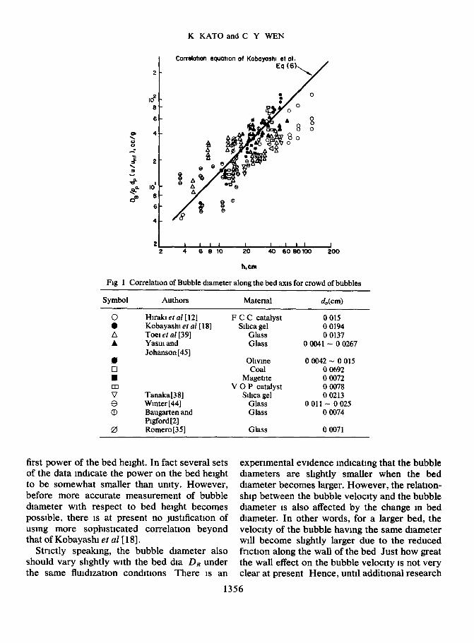
among them the works of Yasm and Johanson [45], Toei et a1.[39], Hu-ski, Yoshida and Kunu [ 121, Kobayasht, Arai and Shiba[ 181 and Baugarten and Ptgford[2] are noteworthy Their expenmental data are plotted m Fig. 1, followmg Kobayashi ef a/.[ 181, m terms of D,/ppdp(u/u,) and the bed height, h In this figure some addi- tional data were Incorporated mto the ongmal plot of Kobayshi et al.[ 181 Although some scattenng of the data IS seen, the bubble diameter and the distance from the distributor can be approximately related by the correlation equa- tion of Kobayashi et al [ 181 as
h
Exammation of Fig 1 reveals that the bubble diameter IS not necessarily proportional to the
1355
K KATO and C Y WEN
IO2 . 6
CormlotIon equatlon of Kobayoshl et al I
22 2 4 6 6 IO 20 40 606OKx) 200
h,cm
Fig 1 Correlation of Bubble diameter along the bed axis for crowd of bubbles
Symbol Authors Matenal d&m)
Hnxkletal[12] Kobayashl et al [ 181 Toe] et al 1391 Yasm and Johanson [45]
Tanaka[38] Winter [44] Baugarten and Plgford [2] Romero[35]
F C C catalyst Sihca gel
Glass Glass
Ohvme Coal
Magetlte V 0 P catalyst
Sihca gel Glass Glass
Glass
0 015 0 0194 0 0137
0 0041 - 0 0267
0 0042 - 0 015 0 0692 0 0072 0 0078 0 0213
0 011 - 0 025 0 0074
0 0071
first power of the bed height. In fact several sets expenmental evidence mdlcatmg that the bubble of the data indicate the power on the bed height diameters are shghtly smaller when the bed to be somewhat smaller than umty. However, diameter becomes larger. However, the relatlon- before more accurate measurement of bubble ship between the bubble velocity and the bubble diameter with respect to bed height becomes diameter 1s also affected by the change m bed possible, there 1s at present no Justification of diameter. In other words, for a larger bed, the using more sophlstlcated correlation beyond velocity of the bubble having the same diameter that of Kobayashl et al [ 181. will become shghtly larger due to the reduced
Stnctly speaking, the bubble diameter also fnctlon along the wall of the bed Just how great should vary slightly with the bed dla DR under the wall effect on the bubble velocity is not very the same fluldlzatlon condltlons There IS an clear at present Hence, until additional research
1356

Bubble assemblage model
is made to provrde more refined relattonshtp between the bubble veloctty and the bed dta- meter, Eqs. (6) and (8) are believed to be most reliable today.
The above correlation IS based on the data obtained using porous plates as the distributor. For perforated plates the size of bubbles at the surface of the dtstnbutor are substantial and therefore must be taken mto constderatton.
According to Cooke et a/.[31 the bubble srze at the surface of a perforated plate havmg no number of holes, can be calculated from (SC/W)” 4/ g” 2 based on the work of Davidson and Harrison [5] where G = (U-U&/Q,. Therefore, m general, the diameter of bubbles m a fluidized bed can be approxtmated by
where
D, = 1’4ppdp h+D,, (7)
The validity of Eq (7) IS tested usmg the expen- mental data of Cooke et a1.[3] and 1s shown m Table 4.
Equation (7) can be used to compute local average bubble diameter along the axis of the flmdtzed bed.
Voidage dmtrlbutlon and bubble velocity
In developing the gas flow model, rt is neces- sary to know the votdage distribution within the flmdlzed bed The study of Bakker[l] and that
of Fan, Lee and Baihe[8] m&cate the voidage up to the bed height corresponding to L, can be considered approxnnately umform and that the votdage above L, increases along the bed height. For an approxrmatlon, rt is assumed that above the bed height correspondmg to Lw, (1 -E) decreases linearly wtth respect to the bed height. It is further assumed that the average bed height reported m the experiments can be considered as an arithmetic average of the maxi- mum bed height correspondmg to E = 1 and Lw.
Following Davidson and Harnson[5], the velocity of nse of a crowd of bubbles through a fluidtzed bed can be calculated by
u;, = ~~--/.++0~711(gD~)“~. (8)
Now, rf the charactenstrc bubble diameter 1s taken as that correspondmg to the bubble situated at L,,,,/2, from Eqs. (7) and (8) and assumption (5), the bed expansion ratio can be expressed as
(L-L,)/L,= (u-u~)/{0~711(g~~)~‘~} (9)
where & is an average bubble dtameter of the bed given by
u Lmf & = 1’4ppdp - T+ DO. ( > k
(10)
In Fig 2, the bed expansions calculated from Eq (9) are compared with the experimental data of Leva et al [25], Lewis, Gilhland and Bauer
Table 4 Companson of expenmental bubble diameter with calculated values usmg Eq (7)
Condltlon (cmkec) ulu, h (cm) Dsobst D B Cal
(cm) (cm)
ud = 5 cm/set 36 36 24
pp= 14&c 24 perforated plate 18 n, = 0 l/cm* 18
18 DR=30cmX12cm 18
tBased on data from Cooke et al [3 ]
72 20 15 16 2 72 40 24 27 4 48 20 12 5 11 5 48 40 21 0 19 3 36 20 98 91 36 40 160 14 8 36 60 22 20 4 36 80 27 26 0
1357

K KATO and C Y WEN
Fig 2 Companson of expenmental bed expansion with calculated bed expansion
Symbol Authors Matenal & (cm) D&m)
Leva et al [25]
Lewis et al 1271 Tanaka[38]
Round sand Round and sharp sand
Fisher-Tropsch Cat Glass-beads Sihca gel
0 0063 - 0 0381 6 3.5 0 00775 6 35 - 10 15
0 00705 - 0 0385 10 15 0 0102 - 0 056 635- 114
0 021 20 0
[27], and Tanaka[38] As seen from the figure, the ratios of calculated bed herght to expen- mental bed he&t are wtthm + 10 per cent of 1 0 mdtcatmg a favorable agreement. Thus, m model development, Eq (9) may be used to compute the bed he&t with reasonable accuracy Once the bed expansion ratio 1s known, the votdage from the distributor up to a height correspond- mg to Ld and that from Lti to the top of the bed can be computed, respectively, as
I--E=+(l-eti) for h< Lti (11)
and
for ,
Lmfs h =s L,+2(L-LL,)
Gas velocity m emulsion phase Since the knowledge of the upward velocrty
of the gas flowmg in the emulsion phase, u,, IS still a controversial subJect, we shall assume that
for large U/U&, U, 1s neghgrbly small This 1s a reasonable assumptron m vtew of the fact that the experimental findmgs of May [3 l] and Kunu and Levensptel[22] mdtcate the emulston gas may reverse its dtrectton m vtgorously bubbhng beds According to Kunn and Levensptel[22], the velocity of gas flowmg m the emulsion phase m the axial direction can be expressed as
where (Y 1s the ratio of the volume of emulsion transported upward behind a bubble (1 e volume of wake) to the volume of a bubble. The value of (Y is approx 0.2 - O-3 according to the expen- mental study of Rowe and Partndge[36] There- fore, under normal expenmental condrtrons, Eq (13) yields u,/umf = 0 5 for u/uW = 3, and u,/ umf = 0 for U/Q= 5 - 6 Latham, Hamilton and Potter[24] also studied using a tracer gas to locate the velocity at which the emulsion gas will reverse its dlrectton (u, = 0) and found that
1358

Bubble assemblage model
u, = 0 when u/uW= 2.7 - 6-O. Based on the above expenmental findings and the argument presented by Levensplel and Kunn[23], it would be reasonable to assume u, = 0 under most of the normal operating condltlons
Interchange coeficlent
The gas interchange between the bubble phase and emulsion phase mvolves direct interchange of gas m bubbles and m emulsion, and mdu-ect interchange due to adsorbed gas on the surface of mterchangmg particles Since no expen- mental data are available for the particle mter- change rate, M, and adsorption equlhbrmm constant, K’, for the reacting gas on particle surfaces, the analysis presented here will neglect gas interchange due to adsorbed gas on mter- changing particles. Therefore, Eq (4) 1s reduced to Fd = F0 As to the direct gas interchange, semi-theoretical studies by Zenz [46], Davidson and Harnson[S] and Kuml and Levensplel[22] as well as an analysis based on the stlmulus- response curve from tracer data using the two phase model by Kobayashl, Aral and Sunagawa [19] are available Most of these studies agree on one point that the interchange coefficient, FO, IS approximately inversely proportional to the bubble diameter Therefore, the followmg equation based on the expenmental work of Kobayashl et al [ 191 will be used
F,, = 11/I&. (14)
In a recent study, Toe1 et al [40] injected a single CO, bubble mto a fluldlzed bed and measured the vanatlon of CO, concentration within the bubble They calculated the gas mter- change coefficient based on these measurements and found that F,, which IS somewhat affected by the particle diameter, can be approximated
by 310~ - 6/DB Since their study pet-tams to a single bubble, the effects of bubble colhslons and coalescence are not taken into conslderatlon It IS therefore not unreasonable to assume that m a vigorously fluldlzmg bed, the interchange coefficient IS more closely represented by Eq
(14)
CALCULATION PROCEDURE BASED ON BUBBLE ASSEMBLAGE MODEL
Let the height of n-th compartment be Ah,, where n = 1, 2, 3,. Based on an anthmetlc average of bubble size, the height of mltlal com- partment immediately above the dlstnbutor becomes
Ah = Do+ (*hl+DO) or 1 2
where I?Z = 1 4pPdP (u/u~) , a proportlonahty constant relating the bubble diameter for a given operating con&tlon The height of the second compartment then becomes,
and that of n-th compartment becomes,
Ah, = 2Do (;;f-$;’ (15)
The number of bubbles m the n-th compartment becomes,
(16)
The volume of cloud m the n-th compartment can be computed from Eq (3) as,
V = Nr(AU3 cn 6 (17)
where,
&, = 0*711(gAh,)“2.
The total volume of the bubble phase and that of the emulsion phase m the n-th compartment are, respectively,
v = N~@hd3 ub+2hfhf bn 6 ub - kfknf >
(18)
v,,, = SAh, - v,, (19)
1359

The drstance from the distributor to the n-th compartment is
h, = 2 Ahf (20) f=l
The gas interchange coefficient based on unit volume of bubbles from Eq. (3) can be shown as
tub - &&mf) ” = Fan (&, + 2&&Q) *
(21)
Hence, the matenal balance for the gaseous reactant around the n-th compartment becomes, for the bubble phase,
(sucb)n-I = {F;,‘vb(cb - c,> )n
+ (rbvc)n+ (such), (22)
and for the emulsion phase,
{F:,Vb(Cb- C,)), = (rev,),, (23)
where rb and r, are the reaction rates per unit volume for the bubble phase and emulston phase respectively For example, tf the rate of reaction 1s a first order with respect to reactant gas, they become; rb = kc,, and r, = kc,
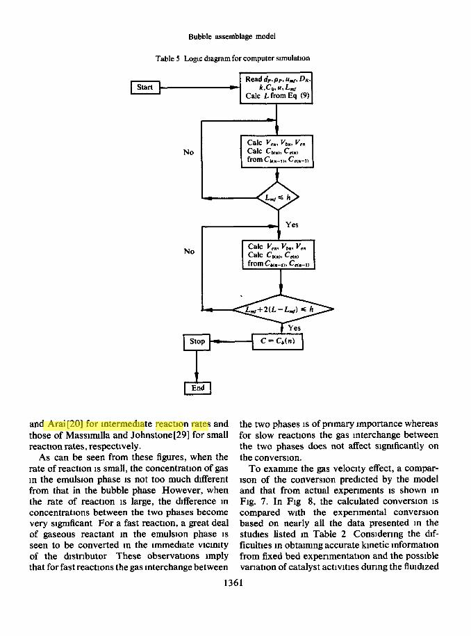
The computattonal procedure for converston and concentration profile m a flutdtzed reactor is gtven below when the operatmg conditions such as particle size, d,, parttcle denstty, pP, mtmmum flutdtzatlon veloctty, umf, gas velaclty, u, dtstnbutor arrangement, column diameter, DR, mctptent bed height, LW, the reaction rate constant, k, and order of reactton are known. Note that this model requues no adjustable parameter
First, Eqs. (8) and (9) are used to calculate the expanded bed height, L Next, Eq (15) 1s used to compute the size of the n-th com- partment. Using Eqs. (17-19), the volume of cloud, that of the bubble phase, and the emulsion phase for the n-th compartment are then calcu- lated Cbn and C,, are computed from (Cb),_, and (C,)._l usmg Eqs (22) and (23) The cal- culations are repeated from the dlstnbutor unttl the bed height equivalent to Lw IS reached For
K KATO and C Y WEN
bed height above Lw, the voulage IS adjusted by Eq. ( 12) and Vm, vb”, and V,, are obtamed using the same procedure as that shown for the height smaller than Lw The calculatton 1s repeated until the bed height reaches L,+ 2(L- L,,J. A computer logtc dtagram based on thrs procedure 1s shown m Table 5.
RESULTS OF CALCULATIONS
Smce most of the experimental data were obtained using porous plates, the bubble size at the surface is very dtfficult to estimate There- fore, the height of mmal compartment, Ah1, 1s assumed. It becomes necessary to test the effect of size of Ah, on the conversion m order to show the soundness of this assumption. For a com- paratively small flurdtzed bed reactor, say column dia. of 5 cm - 20 cm and bed height of less than 100 cm, we should expect the sizes of bubbles formmg on the surface of a porous plate to be quite small. It 1s therefore logical to assume that the height of the first compartment would be no more than a few centtmeters. In Fig. 3, the effect of Ah, on conversion 1s exammed for cases where reaction rate is comparatively fast (1 e for large k). It 1s quote obvious that for slow reactions, the size of compartment 1s of httle significance on overall converston and 1s there- fore not examined. As can be seen from the figure, the mmal height of the compartment, Ah,, does not affect greatly on overall conversion even for fast reactions In actual calculation therefore, Ah, = 1 0 cm 1s used
For a large fluubzed bed reactor which has a perforated plate distributor, Eq (15) together with mformatton on the number and the size of holes must be used to calculate the he&t of initial compartment
In order to demonstrate the vahdtty of the proposed model, conversions m flutdtzed beds based on the kmettc mformatlon given m Table 2 are calculated. The results of calculatton are then compared with actual expenmental converstons In Figs. 4-6 the extent of conversion along the bed height are shown for three sets of data; those of Lewis, Gllhland and Glass[26] for compara- tively large reaction rates, those of Kobayashl
1360
MEHRZAD
Highlight
MEHRZAD
Highlight
MEHRZAD
Highlight
MEHRZAD
Highlight
MEHRZAD
Highlight
Bubble assemblage model
Table 5 Logic diagram for computer slmulahon
Read dP.pP, u+ DR. Start r k,Co.u.L,,,,
Calc L from Eq (9)
No
No
& End
and Arai [20] for intermediate reactton rates and the two phases IS of prtmary importance whereas those of Massmnlla and Johnstone[29] for small for slow reactions the gas interchange between reactron rates, respectrvely. the two phases does not affect stgntficantly on
As can be seen from these figures, when the the converston. rate of reactron 1s small, the concentratton of gas To examme the gas velocity effect, a compar- m the emulston phase 1s not too much different lson of the conversron predrcted by the model from that in the bubble phase However, when and that from actual expenments IS shown m the rate of reactron IS large, the difference m Fig. 7. In Fig 8, the calculated conversion IS concentratrons between the two phases become compared with the expenmental converston very stgmficant For a fast reaction, a great deal based on nearly all the data presented in the of gaseous reactant m the emulston phase 1s studres listed m Table 2 Consrdenng the dlf- seen to be converted m the rmmedrate vrcmtty ticultres m obtarmng accurate kinetic mformatton of the drstnbutor These observations imply from tied bed expenmentatlon and the posstble that for fast reacttons the gas interchange between vanatron of catalyst acttvtttes dunng the flutdrzed
1361
MEHRZAD
Highlight

K KATO and C Y WEN
IO- 6 15
-I2 6 194
06 -256
470
06 D,=52an x Ld24cm
k-87 I/bet 04 hf= 0 73cmAec
Parameter *U/Q
I I I I I I IO 14 18 22 26 30
Ah,, cm
x 06 73
IO 14 I8 22 26 30
Ah, ,cm
Fig 3 Effect of AhI on the converslon
bed operation, the agreement must be regarded to be quite remarkable.
DISCUSSION
The computation using the “Bubble Assem- blage Model” Indicates that for most of the expenmental condmons tested, the number of compartments are usually greater than ten. This means, m terms of the flow pattern, the gas passing through the bubble phase IS close to plug flow This IS probably a reasonable con- clusion. The flow pattern of gas m the emulsion phase may be also regarded to be close to plug flow although m the actual computatton, because u, = 0 IS used, tt turns out to be a dead space mterchangmg gas with the bubble phase This may invite an argument since some investigators regard the flow m this phase to be close to com- plete nuxmg However, as Lewis et al [26] and Muclu[32] pointed out that under normal operattons, the calculation of converston m a flutdtzed bed reactor based on the two phase model IS not affected stgmficantly by the flow patterns m the emulston phase, whether tt IS assumed to be plug flow or completely mixed. The important aspect of a flow model for a flutd- tzed bed IS to correctly account for the bubbhng phenomena and assoctatmg gas interchange between the two phases. Using probes, Tanaka
- Bubble phase
-- - - - Emulrlon phase
Parameter = u/u,, (6-j
Fig 4 Relation between the concentration profile and bed height when the reaction rate constant 1s large Lews et al [26] (DR =
52cm,L,=242cm,k=87sec-‘)
1362
MEHRZAD
Highlight

Bubble assemblage model
-Bubble phosr
-- - - - - Emulrlon phaw Pornmeter =u/u,
Fig 5 Relation between the concentration profile and bed height for an mte.rme&ate rate constant Kobayasb et al [21] (& =
20 cm, LW = 67 cm, k = 0 7 se0
----c-Em&ion phone
‘QL,
Rg 6 Relation between the concentration profile and bed hetght when the reaction rate constant IS small Massmulla et al [29]
(& = 11 4 cm, 15~ = 54 3 cm, k = 0 0707 l/set)
[38], recently measured the concentration pro- tlons predxted by the model usmg the followmg file along axial dlrectlon in a 20 cm dla column relation. for the decomposlhon of ozone Since the con- centration obtained by the probe IS an average &L--L, for h s L, (24) between the emulsron phase and the bubble LLf
C*++“’
phase, It may be compared with the concentra- Frgure 9 shows this companson. The agreement
1363

K KATO and C Y WEN
^^I0 2 4 6 6 IO 20 40 60
k L&l
Fig 7 Companson of expenmental conversion with calculated results 0 - Lewrs et al [26] k = 8 7 l/set, Lw = 24 2 cm, DR = 5 2 cm, 0 - Kobayashl et al [2 l] k = 0 7 llsec, Lti = 67 cm, DR = 20 0 cm, A - Massrmdla and Johnstone[29] k = 0 0707 llsec, Lti = 54 3
cm,D,= 114cm
agam seems to be remarkable. Notice that the reaction progresses very rapidly just above the distributor. The profile calculated from a model characterized by a smgle effective bubble size IS unlikely to exhibit such a trend
The foundation of the proposed “Bubble Assemblage Model” lies on the knowledge of variation m bubble diameters along the bed axis Hence more accurate measurement of bubble growth is necessary to ascertain the bubble diameter correlation presented here In addition the knowledge of gas interchange between the two phases is also a very important factor particularly for fast reactions and there- fore should be further mvestlgated The charac- teristics of the proposed model is its versatlhty and adaptability for varying situations. This is believed to be due to the fact that the model is developed based on an assemblage of multiple bubbles which grow as they nse through the bed The scale-up constderation is now possible with fair amount of confidence m the accuracy of the results The model is also convenient for
computer stmulatlon and can handle rather easily even cases involving complex reaction rate expressions One of the weaknesses of this model as m any other model is the uncertainty of knowledge of gas velocity m the emulsion phase, u, It can be shown that the conversion calculated based on this model is rather m- sensitive to the value of u,, nevertheless, further mvestlgatton on this subject is needed The model can be extended to include solid parttcle mixing pattern which may be used to develop a flmdtzed bed reactor model for a non-catalytic solid-gas reacting system. This ~111 be presented m another paper
CONCLUSION
The catalytic conversion measured by expen- ments of others can be predicted by the “Bubble Assemblage Model” in terms of the reported kinetic constants and the operating condl- ttons The model needs no adJustable parameters and 1s useful for design and scale-up of the flutdized bed reactor The correct grasp of the
1364

Sym
bol
Aut
hor
IO-
08-
06-
OS-
x _
04- ;E
, ,
, , , , ,
, 01
02
03
04
0506
08
IO
Exp
erlm
tnto
l co
nver
sion
, x
Fig
8 C
ompa
nson
of
exp
enm
enta
l co
nver
slon
w
ith c
alcu
late
d co
nver
slon
: A
0 0 v A
0 n
V
Lew
is e
t al
[26
] K
obay
ashl
et
al
[20]
M
assm
ulla
an
d Jo
hnst
one
[29]
Sh
en a
nd
John
ston
e[37
] K
obay
ashl
et
al
[21]
O
fcut
t et
al
[34]
M
athl
s an
d W
atso
n[30
] E
chlg
oya
et a
l [7
] G
omez
plat
a an
d Sh
uste
r[lO
] Is
hu a
nd O
sber
g[l3
]
d&m
) P
Pkf
W
D&
m)
0 01
22
0 93
52
0
0194
1
25
83
0 01
05
206
114
0008
06
1 91
11
4
0 01
94
1 25
20
0
0003
8-
0004
2 1
14
15 2
5 -
10 1
5 0
0103
12
8
07
0 01
22
1 15
53
0
0105
0
98
76
0 00
88
1 65
15
2
45-2
6 03
1-
15
L&m
) k(
lls
ec)
24 -
46
14
-87
19-
loo
08-0
2 18
1 -
54
0 07
07
27 -
54
0
022
- 0
0068
34 -
67
02
- 14
61
-
29 4
02
-30
10 -
50
0 65
5-
17
40-8
4
- 20
0
775
3 8
-

K KATO and C Y WEN
I%- 1,,=345cm =237 Vsec /q&l 9
00 I I I L I
00 02 04 06 06 IO
Fig 9 Companson of expenmental concentration profile with calculated values - Bubble phase concentration, ----- Average concentration based on Eq (24), ------Emulsion phase concentration, 0 Expenmental
daia[38]
bubbling phenomena together with the knowl- edge of bed expanston, votdage dtstnbutton, gas interchange between bubbles and the emulston phase, are the key to the success of the development of this model It IS hoped that models devoloped will promote further mvestt- gattons so that a more accurate and versattle model can be developed
Acknowledgments-The authors express then gratitude to D the Office of Coal Research, Department of the Intenor, & Washmgton, DC for financial support The authors also wish to acknowledge the help of L Y WeI on the computer calculations Db
a
C
cb
NOTATION D, fraction of flutdtzed parttcles m bubble
phase DIJ concentration of reactant, g-mol./cc DP concentratron of reactant m bubble phase,
g-mol./cc DR
1366
concentration of reactant in emulsion phase, g-mol /cc
concentratron of reactant m bubble phase at n-th compartment g-mol./cc
concentration of reactant in emulsion phase at n-th compartment, g-mol./cc
average concentratron of reactant defined in Eq (23), g-mol./cc
dtffustvtty of reactant gas, cm2/sec bubble diameter at surface of dtstrtbutor,
cm axial dispersion coefficient of reactant m
bubble phase, cm2/sec axial dispersion coefficient of reactant m
emulsion phase, cm2/sec effective bubble diameter, cm packing diameter m packed flutdtzed bed,
cm bed diameter, cm

Bubble assemblage model
DS
DT 4 ES
F
Fd
FO
F on
F’ on
F8
f
f,
g h
Ah
h,
K’ k L
Lti
L Cal Lob
M
axial solid drspersron coefficrent in emul- sion phase, cm%ec
maximum stable bubble diameter, cm fluidized particle diameter, cm axial gas drspersron coefficient m the bed,
cm2/sec volumetnc fractron of gas in the bubble
phase overall gas interchange coefficient per
unit volume of gas bubble, llsec gas interchange coefficient per unit
volume of gas bubble, l/set gas Interchange coefficient at the n-th
compartment, l/set gas interchange coefficient at the n-th
compartment based on the unit volume of bubbles, llsec
volumetric fractron of sohd m bubble phase, llsec
volumetric fraction of gas in emulsron phase, llsec
volumetnc fraction of solids m emulsion phase, l/set
gravitational acceleration, cm/sec2 distance from the dlstnbutor, cm length of the n-th compartment, cm drstance between the distributor and n-th
compartment, cm absorption equrhbrmm constant reaction rate constant, l/set bed height, cm bed height at nnmmum flurdlzed velocity,
cm bed height calculated from Eq (9), cm observed bed height m the flutdrzed bed,
cm solid interchange coefficient between the
bubble phase and the emulsron phase per umt volume of bubble, l/set
N
NRCP n0
RC &
r
rb
re
s t u
ub
4
UC?
uT
V bn
VC,
V en
X
i-x
E
EP %f
ZJ
PP
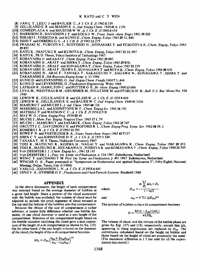
REFERENCES
number of bubbles m n-th compartment particle Reynold’s number number of holes per unit surface area of
drstributor, l/cm2 radms of cloud, cm radms of bubble, cm reaction rate per unit volume of catalyst,
g-molelsec cc reaction rate m bubble phase per umt
volume of cloud, g-mole/set cc reactron rate m emulsion phase per umt
volume of cloud, g-molelsec cc cross sectional area of the bed, cm2 time, set superficial gas velocny, cm/set bubble nsmg velocrty, cm/set bubble nsing velocrty based on fixed axls,
cmlsec super&la1 gas velocrty at muumum flmd-
izatron velocity, cm/set superfictal gas velocity m the emulsion
phase, cmAec termmal velocrty of flurdlzed partrcles,
cmlsec volume of the bubble phase at the n-th
compartment, cc volume of the cloud at the n-th compart-
ment, cc volume of the emulsron phase at the n-th
compartment, cc conversion of the reactant gas ratio of the volume of wake to volume of
bubble void fraction vord fraction of fixed packing void fraction at umf kmematrc vrscoslty particle density, cm2/sec
[l] BAKKER P J , Chem Engng Scr 1960 12 260 [2] BAUGARTEN P K. and PIGFORD R L ,A I Ch E .I1 19606 115 131 COOKE M J , HARRIS W , HIGHLEY J and WILLIAMS D F , Trrpartrte Chem Engng Conf, Symp on Flurdts-
atzon I. pp 14-20, Montreal 1968 [4] DAVIDSON J F , Trans Instn them Engrs 196139 230 [5] DAVIDSON J F and HARRISON D , Flurdrzed Part&es Cambndge Umverslty Press 1967 [6] DEGROOTJ H ,Proc lnt Symp on Flurdzzatron,pp 348-361 1967 [73 ECHIGOYA E , IWASAKI M , KANETOMO T and NIYAMA H , Chem Engng, Tokyo 196832 571
1367
CES Vol 24 8-L
K KATO and C Y WEN
FAN L T , LEE C J and BAILIER C ,A I Ch E Jll962 8 239 GILLILAND E R and MASON E A , Ind Engng Chem 1949 416,119l GOMEZPLATA A and SHUSTER W W ,A I Ch E Jll960 6 454 HARRISON D , DAVIDSON J F and KOCK J W , Tram Znstn them Enars 196139 202 HIRAKI I , YOSHIDA K and KUNII D , Chem Engng, Tokyo 1965 29 11, ii46 ISHII T and OSBERG G L .A I CH E Jll965 11279 IWASAKI M , FURUOYA ‘I , SUEYOSHI H , SHIRASAKI T and ECHIGOYA E , Chem Engng, Tokyo 1965 29 892
;z; HOI 1111 WI 1131 [I41
WI [161 u71 [181 u91 WI @II
WI WI t241 WI
LX1 P71
E r301 1311
‘,::z
gz; [W [371
KATO K , IMAFUKU K and KUBOTA H , Chem Engng, Tokyo 196731 10,967 KATO K , Ph D Thesis, Tokyo Institute of Technology 1967 KOBAYASHI H and ARAI F , Chem Engng, Tokyo 1965 29 885 KOBAYASHI H , ARAI F and SHIBAT , Chem Engng, Tokyo 1965 29 858. KOBAYASHI H , ARAI F and SUNAGAWA T , Chem Engng, Tokyo 1967 31239 KOBAYASHI H , ARAI F , ISAWA S , SUNAGAWA T and MIYA K , Chem Engng, Tokyo 196630 656 KOBAYASHI H , ARAI F , TANAKA T , SAKAGUCHI Y , SAGAWA N , SUNAGAWA T , SHIBA T and TAKAHASHI K ,6th Reactron Engng Symp p 13 1966 KUNII D and LEVENSPIEL 0 , Znd Engng Chem Fundls 1968 7 3,446 KUNII D and LEVENSPIEL 0 , Flurdlzatlon Engrneenng Wdey 1969 LATHAM R , HAMILTON C andPOTTER 0 E , Br them Engng 1968 13 666 LEVA M , WEINTRAUB M , GRUMMER M , POLLCHIK M and STORCH H H , Bull US Bur Mmes No 504 1949 LEWIS W K , GILLILAND E R and GLASS W , A I Ch E Jll959 5 419 LEWIS W K ,GILLILANDE K andBAUERW C .Znd EnanaChem 194941 1104 MAMURO T. and MUCH1 I , J md Chem 1965 68 126 - - MASSIMILLA L and JOHNSTONE H F , Chem Engng Scr 196116 105 MATHISJ F andWATSONC C,A Z Ch E J119562518 MAY W G , Chem Engng Prog 1959 55 49 MUCH1 I , Mem Fat Engng Nagoya Umv 1965 17 1,79 MUCH1 I , MAMURO T and SASAKI K , Chem Engng, Tokyo 196125 747 ORCUTTJ C , DAVIDSON J E and PIGFORD R L , Chem Engng Prog Symp Ser 1962 58 38,1 ROMERO J B ,A I Ch E Jll965 11595 ROWE P N and PARTRIDGE B A, Truns Znstn them Engrs 1965 43 T157 SHEN C Y andJOHNSTONE H F ,A Z Ch E Jll955 1349
[38] TANAKA T , M S Thesis, Hokkado Umverslty 1967 [39] TOE1 R , MATSUNO R , KOJIMA H , NAGAI Y and NAKAGAWA K , Chem Engng, Tokyo 1965 29 851 [40] TOE1 R , MATSUNO R , MIYAKAWA H , NISHIYA K and KOMAGAWA Y , Chem Engng, Tokyo 1968 32 565 [41] VAN DEEMTER J J , Chem Engng Scr ,196113 143 [42] VAN DEEMTER J J , Proc Znt Symp on Flwdrzatron, p 334 1967 Eldenhoven, Netherland [43] WEN C Y and CHANG T M Proc Znt Symp on Fludrzatlon, p 491 1967 Eldenhoven, Netherland [44] WINTER 0 H , Paper presented at “Symposium on fundamental and apphed flus&zation I”, Fifty-Eighth NatIonal
Meetmg, Dallas, Texas, Feb 6 ( 1966) [45] YASUI G , JOHANSON L N ,A Z Ch E Jll9584445 [46] ZENZ F A , OTHMER 0 F , Fluldlzatlon and Flu&Partrcle Systems Remhold 1960
APPENDIX In the above &scusslon, the height of each compartment
was selected based on the average diameter of bubbles at a gven bed he&t Since a portion of the cloud associated with the bubble was excluded, the volume of cloud must be adjusted to include the small segments of cloud situated at the top and the bottom of the bubbles mto that compartment
Because the choice of the size of compartment 1s rather arbitrary, it makes httle ddference whether one bubble &a- meter, or one cloud diameter 1s used as a umt height of the compartment Selection of the compartment height based on the bubble diameter excludmg the cloud gave a neat expres- sion of the height of n-th compartmept as shown by Eq (15) On the other hand, If the unit height 1s based on the diameter of the cloud, the height of the n-th compartment becomes
Ah. = De, Ub + 2&J&f 1’3
Ubn - %k,,, >
where
and &,” = 0 711 (gD,,)“”
The number of bubbles m the n-th compartment becomes
N_6S(L sLDj,
The volume of cloud, and the volume of the bubble phase are gven by Eqs (17) and (18), respectively, except that Ah, appeanng m these expressions are replaced by Dgn The converslons calculated based on the he& on bubble and those based on the height of cloud are practically the same (The maximum tierence 1s 1 5 per cent for all the expen- mental data tested )
1368

Bubble assemblage model
R&um& Un nouveau modble de r6actlon catalytique sur couches flmd~s&s est dCveloppC Le prmclpe de ce mod&le, appelC le “ModBle d’assemblage de bulles”, repose sur une multitude de bulles de ddT&entes grosseurs, un tchange de gaz ayant lem entre la phase bulle et la phase Cmulslon
Le modkle de demandent aucun parambtre r&&e, 11 apparait pmcuh&ement utde pour 1’6tude des crolssances d’tchelles Le mod&le proposC convlent aussl pour les slmulatlons de calcul La vabQtC de ce mod&le a Ctt test& & partlr des don&es expknmentales de ddfirents chercheurs On a trouvC que les converstons prkvues utdlsant ce modtle s’accordent assez blen avec la performance actuelle des couches flm&sbes
Zusammenfassung-Es wlrd em neues Model1 fur die katalytlsche Reaktion m der Wlrbelschlcht entwrckelt Dleses als “Blasenaufbaumodell” bezelchnete Model1 baslert auf emer Vlelzahl von Blasen verschledener Grosse, wobel zwlschen der Blasenphase und der Emulslonsphase Gasau- stausch stattfindet
Da&eses Model1 keme veranderhchen Parameter benotlgt, wlrd angenommen, dass es zur Unter- suchung massstabhcher Vergrosserungen geelgnet 1st Das vorgeschlagene Model1 1st femer fur Slmuherung auf Rechnem verwendbar Es wurden Versuchsergebmsse emer Relhe von Forschern herangezogen urn &e Gultq$elt &eses Modelles nachzuwelsen Es wurde festgestellt, dass der unter Anwendung des Modelles vorausgesagte Umsatz recht gut mlt der tatsachhchen Lelstung der Wlrbel- schlcht uberemstlmmt
1369