Membrane separation process—Pervaporation through zeolite membrane
17
Separation and Purification Technology 63 (2008) 500–516 Contents lists available at ScienceDirect Separation and Purification Technology journal homepage: www.elsevier.com/locate/seppur Review Membrane separation process—Pervaporation through zeolite membrane Shin-Ling Wee, Ching-Thian Tye, Subhash Bhatia ∗ School of Chemical Engineering, Universiti Sains Malaysia, Engineering Campus, Seri Ampangan, 14300 Nibong Tebal, Seberang Perai Selatan, Pulau Pinang, Malaysia article info Article history: Received 7 June 2008 Received in revised form 14 July 2008 Accepted 14 July 2008 Keywords: Pervaporation Zeolite membrane Membrane synthesis Alcohol dehydration Organic/organic separation abstract Membrane separation process has become one of the emerging technologies that undergo a rapid growth for the past few decades. Pervaporation is one of the membrane separation processes that have gained increasing interest in the chemical and allied industries. It is an effective and energy-efficient technology that carries out separations, which are difficult to achieve by conventional separation processes. Inorganic membrane such as zeolite membranes with uniform, molecular-sized pores offer unique type of pervapo- ration membrane for a number of separation processes. This review presents the role of zeolite membrane and its progress in the pervaporation process. The fundamental aspects of pervaporation over different types of membranes are reviewed and compared. The focus of this review is on zeolite membrane cov- ering: (a) synthesis of zeolite membranes; (b) membrane characterization; (c) pervaporation studies; (d) its applications in alcohol dehydration, organic/organic separations and acid separations. The transport mechanism during pervaporation is discussed and the issues related with pervaporation are addressed. Innovation and future development of zeolite membrane in pervaporation are also presented. © 2008 Elsevier B.V. All rights reserved. Contents 1. Introduction ......................................................................................................................................... 501 2. Role of membranes in pervaporation ............................................................................................................... 502 2.1. Polymeric membranes ....................................................................................................................... 502 2.2. Inorganic membranes ....................................................................................................................... 503 2.3. Composite membranes ...................................................................................................................... 504 3. Zeolite membrane synthesis ........................................................................................................................ 504 3.1. Hydrothermal synthesis ..................................................................................................................... 504 3.2. Secondary growth method .................................................................................................................. 505 3.3. Continuous flow synthesis method ......................................................................................................... 505 3.4. Microwave synthesis ........................................................................................................................ 506 4. Membrane characterization ........................................................................................................................ 506 5. Pervaporation studies ............................................................................................................................... 508 6. Transport mechanism during pervaporation ....................................................................................................... 510 7. Pervaporation applications .......................................................................................................................... 511 7.1. Alcohol dehydration .......................................................................................................................... 511 7.1.1. Isopropanol–water system.......................................................................................................... 511 7.1.2. Ethanol–water system .............................................................................................................. 511 7.2. Organic/organic separations ................................................................................................................. 511 7.2.1. Xylene isomers ..................................................................................................................... 512 7.3. Acid separations ............................................................................................................................. 513 7.4. Industrial applications ....................................................................................................................... 513 8. Issues, innovation and future developments ....................................................................................................... 514 9. Conclusions .......................................................................................................................................... 515 Acknowledgements ................................................................................................................................. 515 References ........................................................................................................................................... 515 ∗ Corresponding author. Tel.: +60 4 5996409; fax: +60 4 5941013. E-mail address: [email protected] (S. Bhatia). 1383-5866/$ – see front matter © 2008 Elsevier B.V. All rights reserved. doi:10.1016/j.seppur.2008.07.010
-
Upload
independent -
Category
Documents
-
view
3 -
download
0
Transcript of Membrane separation process—Pervaporation through zeolite membrane

Separation and Purification Technology 63 (2008) 500–516
Contents lists available at ScienceDirect
Separation and Purification Technology
journa l homepage: www.e lsev ier .com/ locate /seppur
Review
Membrane separation process—Pervaporation through zeolite membrane
Shin-Ling Wee, Ching-Thian Tye, Subhash Bhatia ∗
School of Chemical Engineering, Universiti Sains Malaysia, Engineering Campus, Seri Ampangan, 14300 Nibong Tebal, Seberang Perai Selatan, Pulau Pinang, Malaysia
a r t i c l e i n f o
Article history:Received 7 June 2008Received in revised form 14 July 2008Accepted 14 July 2008
Keywords:PervaporationZeolite membraneMembrane synthesis
a b s t r a c t
Membrane separation process has become one of the emerging technologies that undergo a rapid growthfor the past few decades. Pervaporation is one of the membrane separation processes that have gainedincreasing interest in the chemical and allied industries. It is an effective and energy-efficient technologythat carries out separations, which are difficult to achieve by conventional separation processes. Inorganicmembrane such as zeolite membranes with uniform, molecular-sized pores offer unique type of pervapo-ration membrane for a number of separation processes. This review presents the role of zeolite membraneand its progress in the pervaporation process. The fundamental aspects of pervaporation over differenttypes of membranes are reviewed and compared. The focus of this review is on zeolite membrane cov-ering: (a) synthesis of zeolite membranes; (b) membrane characterization; (c) pervaporation studies; (d)
Alcohol dehydrationOrganic/organic separation its applications in alcohol dehydration, organic/organic separations and acid separations. The transport
mechanism during pervaporation is discussed and the issues related with pervaporation are addressed.Innovation and future development of zeolite membrane in pervaporation are also presented.© 2008 Elsevier B.V. All rights reserved.
Contents
1. Introduction . . . . . . . . . . . . . . . . . . . . . . . . . . . . . . . . . . . . . . . . . . . . . . . . . . . . . . . . . . . . . . . . . . . . . . . . . . . . . . . . . . . . . . . . . . . . . . . . . . . . . . . . . . . . . . . . . . . . . . . . . . . . . . . . . . . . . . . . . 5012. Role of membranes in pervaporation . . . . . . . . . . . . . . . . . . . . . . . . . . . . . . . . . . . . . . . . . . . . . . . . . . . . . . . . . . . . . . . . . . . . . . . . . . . . . . . . . . . . . . . . . . . . . . . . . . . . . . . . . . . . . . . 502
2.1. Polymeric membranes . . . . . . . . . . . . . . . . . . . . . . . . . . . . . . . . . . . . . . . . . . . . . . . . . . . . . . . . . . . . . . . . . . . . . . . . . . . . . . . . . . . . . . . . . . . . . . . . . . . . . . . . . . . . . . . . . . . . . . . 5022.2. Inorganic membranes . . . . . . . . . . . . . . . . . . . . . . . . . . . . . . . . . . . . . . . . . . . . . . . . . . . . . . . . . . . . . . . . . . . . . . . . . . . . . . . . . . . . . . . . . . . . . . . . . . . . . . . . . . . . . . . . . . . . . . . 5032.3. Composite membranes . . . . . . . . . . . . . . . . . . . . . . . . . . . . . . . . . . . . . . . . . . . . . . . . . . . . . . . . . . . . . . . . . . . . . . . . . . . . . . . . . . . . . . . . . . . . . . . . . . . . . . . . . . . . . . . . . . . . . . 504
3. Zeolite membrane synthesis . . . . . . . . . . . . . . . . . . . . . . . . . . . . . . . . . . . . . . . . . . . . . . . . . . . . . . . . . . . . . . . . . . . . . . . . . . . . . . . . . . . . . . . . . . . . . . . . . . . . . . . . . . . . . . . . . . . . . . . . 5043.1. Hydrothermal synthesis . . . . . . . . . . . . . . . . . . . . . . . . . . . . . . . . . . . . . . . . . . . . . . . . . . . . . . . . . . . . . . . . . . . . . . . . . . . . . . . . . . . . . . . . . . . . . . . . . . . . . . . . . . . . . . . . . . . . . 5043.2. Secondary growth method . . . . . . . . . . . . . . . . . . . . . . . . . . . . . . . . . . . . . . . . . . . . . . . . . . . . . . . . . . . . . . . . . . . . . . . . . . . . . . . . . . . . . . . . . . . . . . . . . . . . . . . . . . . . . . . . . . 5053.3. Continuous flow synthesis method . . . . . . . . . . . . . . . . . . . . . . . . . . . . . . . . . . . . . . . . . . . . . . . . . . . . . . . . . . . . . . . . . . . . . . . . . . . . . . . . . . . . . . . . . . . . . . . . . . . . . . . . . 5053.4. Microwave synthesis . . . . . . . . . . . . . . . . . . . . . . . . . . . . . . . . . . . . . . . . . . . . . . . . . . . . . . . . . . . . . . . . . . . . . . . . . . . . . . . . . . . . . . . . . . . . . . . . . . . . . . . . . . . . . . . . . . . . . . . . 506
4. Membrane characterization . . . . . . . . . . . . . . . . . . . . . . . . . . . . . . . . . . . . . . . . . . . . . . . . . . . . . . . . . . . . . . . . . . . . . . . . . . . . . . . . . . . . . . . . . . . . . . . . . . . . . . . . . . . . . . . . . . . . . . . . 5065. Pervaporation studies . . . . . . . . . . . . . . . . . . . . . . . . . . . . . . . . . . . . . . . . . . . . . . . . . . . . . . . . . . . . . . . . . . . . . . . . . . . . . . . . . . . . . . . . . . . . . . . . . . . . . . . . . . . . . . . . . . . . . . . . . . . . . . . 5086. Transport mechanism during pervaporation . . . . . . . . . . . . . . . . . . . . . . . . . . . . . . . . . . . . . . . . . . . . . . . . . . . . . . . . . . . . . . . . . . . . . . . . . . . . . . . . . . . . . . . . . . . . . . . . . . . . . . . 5107. Pervaporation applications . . . . . . . . . . . . . . . . . . . . . . . . . . . . . . . . . . . . . . . . . . . . . . . . . . . . . . . . . . . . . . . . . . . . . . . . . . . . . . . . . . . . . . . . . . . . . . . . . . . . . . . . . . . . . . . . . . . . . . . . . . 511
7.1. Alcohol dehydration . . . . . . . . . . . . . . . . . . . . . . . . . . . . . . . . . . . . . . . . . . . . . . . . . . . . . . . . . . . . . . . . . . . . . . . . . . . . . . . . . . . . . . . . . . . . . . . . . . . . . . . . . . . . . . . . . . . . . . . . . . 5117.1.1. Isopropanol–water system. . . . . . . . . . . . . . . . . . . . . . . . . . . . . . . . . . . . . . . . . . . . . . . . . . . . . . . . . . . . . . . . . . . . . . . . . . . . . . . . . . . . . . . . . . . . . . . . . . . . . . . . . . 5117.1.2. Ethanol–water system . . . . . . . . . . . . . . . . . . . . . . . . . . . . . . . . . . . . . . . . . . . . . . . . . . . . . . . . . . . . . . . . . . . . . . . . . . . . . . . . . . . . . . . . . . . . . . . . . . . . . . . . . . . . . . 511
7.2. Organic/organic separations . . . . . . . . . . . . . . . . . . . . . . . . . . . . . . . . . . . . . . . . . . . . . . . . . . . . . . . . . . . . . . . . . . . . . . . . . . . . . . . . . . . . . . . . . . . . . . . . . . . . . . . . . . . . . . . . . 5117.2.1. Xylene isomers . . . . . . . . . . . . . . . . . . . . . . . . . . . . . . . . . . . . . . . . . . . . . . . . . . . . . . . . . . . . . . . . . . . . . . . . . . . . . . . . . . . . . . . . . . . . . . . . . . . . . . . . . . . . . . . . . . . . . 512
7.3. Acid separations . . . . . . . . . . . . . . . . . . . . . . . . . . . . . . . . . . . . . . . . . . . . . . . . . . . . . . . . . . . . . . . . . . . . . . . . . . . . . . . . . . . . . . . . . . . . . . . . . . . . . . . . . . . . . . . . . . . . . . . . . . . . . 513
7.4. Industrial applications . . . . . . . . . . . . . . . . . . . . . . . . . . . . . . . . . . . . . . . . . . . . . . . . . . . . . . . . . . . . . . . . . . . . . . . . . . . . . . . . . . . . . . . . . . . . . . . . . . . . . . . . . . . . . . . . . . . . . . . 5138. Issues, innovation and future developments . . . . . . . . . . . . . . . . . . . . . . . . . . . . . . . . . . . . . . . . . . . . . . . . . . . . . . . . . . . . . . . . . . . . . . . . . . . . . . . . . . . . . . . . . . . . . . . . . . . . . . . 5149. Conclusions . . . . . . . . . . . . . . . . . . . . . . . . . . . . . . . . . . . . . . . . . . . . . . . . . . . . . . . . . . . . . . . . . . . . . . . . . . . . . . . . . . . . . . . . . . . . . . . . . . . . . . . . . . . . . . . . . . . . . . . . . . . . . . . . . . . . . . . . . . 515
Acknowledgements . . . . . . . . . . . . . . . . . . . . . . . . . . . . . . . . . . . . . . . . . . . . . . . . . . . . . . . . . . . . . . . . . . . . . . . . . . . . . . . . . . . . . . . . . . . . . . . . . . . . . . . . . . . . . . . . . . . . . . . . . . . . . . . . . 515References . . . . . . . . . . . . . . . . . . . . . . . . . . . . . . . . . . . . . . . . . . . . . . . . . . . . . . . . . . . . . . . . . . . . . . . . . . . . . . . . . . . . . . . . . . . . . . . . . . . . . . . . . . . . . . . . . . . . . . . . . . . . . . . . . . . . . . . . . . . 515
∗ Corresponding author. Tel.: +60 4 5996409; fax: +60 4 5941013.E-mail address: [email protected] (S. Bhatia).
1383-5866/$ – see front matter © 2008 Elsevier B.V. All rights reserved.doi:10.1016/j.seppur.2008.07.010
S.-L. Wee et al. / Separation and Purificati
Nomenclature
AW adsorption coefficient of component i (mol/m3 Pa)DS
iMaxwell–Stefan diffusivity of component i (m2/s)
DSij
Maxwell–Stefan micropore counter-sorption diffu-
sivity between component i and component j (m2/s)DS
ivMaxwell–Stefan surface diffusivity (m2/s)
D′iM
Maxwell–Stefan micropore diffusivity of compo-nent i in the membrane (m2/s)
DSi(0) Maxwell–Stefan diffusivity at zero loading (m2/s)
l thickness of the selective layer (m)lZA thickness of zeolite layer (m)Ji flux of component i (g/cm2 s)Li coefficient of proportionality of component im mass of permeate (g)M molecular weight (kg/mol)Ni molar flux of component i (mol/m2 s)NS
iflux across the membrane (kg/m2 h)
p partial pressure (Pa)p∗
ipartial equilibrium vapor pressure of component i(Pa)
qi molar loading of component i (mol/kg)qM saturation molar loading, (mol/kg)qT total molar loading (mol/kg)Qi dimensionless fluxR ideal gas constant (8.314 J/mol k)S membrane surface area (cm2)t permeation time (s)T temperature (K)ui velocity of the diffusing component i (m/s)vi molar volume of component ixi mole fraction of component i in the feed (mol/mol)yi mole fraction of component i in the permeate
(mol/mol)z distance of diffusion (m)
Greek letters˛i separation factor for the component i with respect
to component j� i activity coefficient (mol/mol)� dimensionless membrane thicknessε porosity�i chemical potential of component i (J/mol)�i fractional surface occupancy of component i�n+1 fraction of unoccupied site�s density of zeolite NaA (1900 kg/m3)
Subscripts/superscriptsa alcoholi component ij component jM membrane
1
hast
imtomnitpdm
osvotfsattrptttmiottsptbi
ftiptures [4,5]. It can be used for breaking azeotropes, dehydration ofsolvents and other volatile organics, organic/organic separationssuch as xylene isomers separations, acid separations and wastewa-ter purification [4,6]. Recently pervaporation has gained increasing
W waterp permeate side
. Introduction
During the past few decades, membrane separation process
as become one of the emerging technologies that underwentrapid growth. It has drawn the attention of researchers in theeparation technology field with its better performance comparedo the conventional separation technology. Membrane separation
on Technology 63 (2008) 500–516 501
nvolves partially separating a feed containing a mixture of two orore components by using a semipermeable barrier (membrane)
hrough which one or more of the species moves faster than orther species. A membrane is a thin sheet of natural or syntheticaterial that covers a surface and is permeable to a certain compo-
ent in the solution. The main membrane separation technologiesnclude microfiltration, ultrafiltration, reverse osmosis and nanofil-ration, electrodialysis, gas-separation and pervaporation [1]. Therinciple of membrane separation process, type of membrane used,riving forces and examples of the application of the establishedembrane separation technologies are presented in Table 1.Most of the membrane separation technologies are well devel-
ped and established. Among these technologies, pervaporation istill a rapidly developing membrane separation technology [1]. Per-aporation is a process that has elements in common with reversesmosis and membrane gas separation. It also has many similari-ies with vapor permeation, which uses gaseous components on theeed side of the membrane. However, the vapor permeation fluxestrongly depend on feed pressure whereas the pervaporation fluxesre independent of the feed pressures [2]. Pervaporation is used forhe separation of water from organic liquids by partial vaporizationhrough a porous membrane. The membrane acts as a selective bar-ier between the two phases, the liquid phase feed and the vaporhase permeate. It allows the desired components of the liquid feedo transfer through it by vaporization [3]. Separation by pervapora-ion is almost independent of the vapor liquid equilibrium, becausehe transport resistance depends on the sorption equilibrium and
obility of the permeate components in the membrane. A vacuums kept on the permeate side of the membrane while the feed sidef the membrane is kept at atmospheric or elevated pressure sohat a pressure difference is created over the membrane in ordero maintain the driving force for the pervaporation process. Fig. 1hows the overview of the pervaporation process. The desired com-onent in the feed which is in the liquid form permeates throughhe membrane and evaporates while passing through the mem-rane because the partial pressure of the permeating component
s kept lower than the equilibrium vapor pressure.Pervaporation is a mild process; therefore, it is very effective
or separation of those mixtures which cannot be subjected tohe harsh conditions of distillation. Pervaporation has advantagesn terms of low energy consumption. No entrainer is required inervaporation, thus there is no contamination of the original mix-
Fig. 1. Overview of the pervaporation process for aqueous organic mixtures.

502 S.-L. Wee et al. / Separation and Purification Technology 63 (2008) 500–516
Table 1Summary of the established membrane separation technologies [1]
Process Principle Type of membrane Initial or feedphase
Driving forces Industrial applications
Microfiltration Separation of organic and polymericcompounds with micropore ranges of0.1–10 �m
Finely microporous 0.1–10 �m Liquid or gas Pressure difference35–350 kPa
Removal of suspended solids,bacteria in pharmaceutical,electronics industries
Ultrafiltration Separation of water and microsolutesfrom macromolecules and colloids
Finely microporous 1–100 nm Liquid Pressure difference140–700 kPa
Removal of colloidal material fromwastewater, food process streams
Reverse osmosis Passage of solvents through a densemembrane that is permeable tosolvents but not solutes
Dense solution-diffusion Liquid Pressure difference700–7000 kPa
Drinking water from sea, brackish orgroundwater; production ofultra-pure water for electronics andpharmaceutical industries
Electrodialysis Ions are transported through amembrane from one solution toanother under the influence of anelectrical potential
Electrically charged films Liquid Voltage difference1–2 V
De-ionized water from conductivespacers, recovery of organic acidsfrom salt, heavy metal recovery
Gas separation Component of mixture of gaseous isremoved through a pressure gradient
Dense solution-diffusion Vapor of gas Pressure difference700–7000 kPa
Removal of nitrogen from air,hydrogen frompetrochemical/refinery vents,carbon dioxide from natural gas,propylene and VOCs from
P on
iedbt
pbitpmtbi
tpabmcTibtdrtp
2
aowptmc
tcdDoamacsuto
2
aaPdapscbitheir water-permselectivity and high permeation fluxes [25]. Poly-acrylonitrile [26] and polytetrafluoroethylene [25] were reportedusing as support layers for these polymeric membranes. SulzerChemtech, Germany [27] developed polymeric membrane thathave a cross-linked poly(vinyl alcohol) selective layer and a porous
ervaporation Component of a mixture diffusesthrough, evaporates under a lowpressure and is removed by a vacuum
Dense solution-diffusi
nterest on the part of the chemical industry as an effective andnergy-efficient technology to carry out separations which wereifficult to achieve by conventional means [7]. This technology hasetter separation capacity and energy efficiency which could leado 40–60% energy reductions [8].
Different types of membranes are being used for pervaporation:olymeric membranes, ceramic membranes, and composite mem-ranes. Over the last decades considerable efforts have been put
n the development of ceramic membranes for pervaporation ashese membranes show better resistance toward harsher chemical,ressure and thermal conditions [9]. An example of the ceramicembranes is the zeolite membranes that have the unique proper-
ies of zeolite in a film-like configuration. Zeolite membranes haveeen widely used for pervaporation both laboratory studies and
ndustrially [7,10–13].In this review, a critical assessment of what has been achieved in
he past few years in the development and roles of membrane in theervaporation process is reported. The present review may lead tobetter understanding of the fundamental aspects of separationsy pervaporation through different types of membranes. Severalethods used for the synthesis and characterization of inorganic
eramic membrane especially zeolite membrane are presented.he theory for the transport mechanism in pervaporation whichs essential not only for a better understanding of the process itselfut also for design purposes is also reviewed. Current and poten-ial applications of pervaporation through zeolite membrane areiscussed. Moreover, common problems encountered and issueselated with pervaporation are addressed. Finally, an outlook ofhe innovation and future development of zeolite membrane inervaporation is presented.
. Role of membranes in pervaporation
Membranes have gained importance in chemical industries andre used in a broad range of applications. The systematic studiesf membrane were traced as early as in the eighteen centuries
hen membranes were only used as laboratory tools to develophysical or chemical theories and had no commercial or indus-rial applications [1]. A membrane is a discrete, thin interface thatoderates the permeation of a certain chemical species that is inontact with it. This interface may be molecularly homogeneous
petrochemical ventsLiquid Vapor pressure
7–70 kPaDehydration of solvents, separationof azeotropic mixtures
hat is completely uniform in composition or structure or physi-ally heterogeneous, for example containing holes or pores of finiteimensions or consisting of some form of layered structure [1].ifferent types of membranes are used for the pervaporation ofrganic compounds from aqueous solution. Three major categoriesre used. They are (a) organic membrane, broadly covers polymericembranes, (b) inorganic membrane, covers ceramic membranes
nd (c) composite membrane, also called hybrid membrane andovers polymeric as well as inorganic membrane. Fig. 2 shows thechematic representation of a supported membrane morphologysed in the pervaporation process. The membrane which acts ashe separating layer is coated on top of a porous support and allowsnly certain species to permeate through it selectively.
.1. Polymeric membranes
Most pervaporation membranes that are used in industrialpplications are of polymeric type. Polymeric membranes arettractive because they are relatively economical to fabricate [14].olymers such as poly(vinyl alcohol) [6,15–17], poly(vinylideneifluoride) [18], poly(acrylic acid) [19] and polyurethane [20]re some of the materials used for preparing polymeric perva-oration membrane for the dehydration of alcohol and otherolvents. Apart from that, chitosan [21–24] is also one of theommonly used materials for polymeric membrane preparationecause of its good film forming properties and chemical stabil-
ty. [23]. These polymeric membranes are good candidate owing to
Fig. 2. Schematic representation of a supported membrane morphology.

rificati
pfiaamaemctccdtmbafasmg
2
feTcptphs
a[tibmebiroa
tal[riZ5TlipsPs2wb9mnpmmtstaczbm
tptpthmsh
TC
SSC
P
CA
M
S.-L. Wee et al. / Separation and Pu
olyacrylonitrile supporting layer cast on a polyphenylene sul-de non-woven fabric which are marketed for the dehydration ofqueous system. Hyder et al. [17] prepared crosslinked poly(vinyllcohol) membranes using two methods: (a) heating at 398 K (ther-ally crosslinked) and (b) chemical reaction with glutaraldehyde
t room temperature (chemically crosslinked). The pervaporationxperiments of the ethanol–water mixture showed that the ther-ally crosslinked membrane gave a higher flux compared to the
hemically crosslinked membrane. However, the selectivity of thehermally crosslinked membrane was lower as compared to thehemically crosslinked membrane. Anjali Devi et al. [21] suc-essfully crosslinked chitosan membrane having 84% degree ofeacetylation with toluene 2,4-diisocyanate and tested the syn-hesized membrane for the dehydration of isopropanol–water
ixture. The results showed that the crosslinked chitosan mem-rane appears to have a good potential in breaking the aqueouszeotrope solutions of 87.5 wt.% isopropanol with a high separationactor of 472 and a substantial water flux of 0.39 kg/m2 h. However,major drawback of these polymeric membranes is their limited
olvent and temperature stability [28]. Swelling that occur in poly-eric membranes also tends to alter the membrane properties and
enerally leads to higher permeability and lower selectivity [10,14].
.2. Inorganic membranes
Inorganic membranes, also called as ceramic membranes maderom silica, alumina or zeolite are of high solvent-resistant prop-rties, high temperature stability and free of swelling [10,29].herefore, these membranes can be used for broad range of appli-ations and at the same time have both high selectivity andermeability. The industrial use of ceramic membranes could leado a higher product quality and broaden the application range ofervaporation. In particular, porous inorganic membranes exhibitigh permeabilities relative to dense membranes and high thermaltability relative to organic membranes [30,31].
Silica is known as a highly porous material and is preferable forhigh flux inorganic membrane but it is not stable against water
32]. The addition of oxides such as ZrO2 and TiO2 is able to improvehe stablility of silica membrane toward water and alkali. Compos-te SiO2–ZrO2 can be put into thin porous membranes which haveeen found quite effective for the separation of aqueous organicixtures by pervaporation [33]. Yang et al. [34] prepared five differ-
nt types of microporous SiO2–ZrO2 (ZrO2: 50 mol.%) membranes
y the sol–gel techniques and studied the pervaporation character-stics of aqueous solutions of organic chemicals. The pervaporationesults suggested that the separation performance depends largelyn the pore size and also on the interaction between the moleculesnd the pore wall.tmtmt
able 2haracteristics of the zeolite applied in membrane and an example of its application in pe
Zeolite
A Y
tructure type LTA FAUi/Al ratio 1 2.3ations Na Na, Ca
ore size[1 0 0] 0.41 nm × 0.41 nm[0 1 0][0 0 1][1 1 1] 0.74 nm × 0.74 nm
hannel network Three-dimensional Three-dimensionalpplication Dehydration of organic mixture Separation of MeOH/MTBE mix
eOH: methanol; MTBE: methyl-tert-butylether.
on Technology 63 (2008) 500–516 503
Zeolite membrane have been widely studied in pervapora-ion due to their unique characteristic such as pore structure,dsorption properties and their mechanical, chemical and bio-ogical stability [11,35]. Several zeolite structures such as ZSM-59,36], zeolite A [13,37], mordenite [38,39], zeolite Y [40,41] areeported as membranes used for pervaporation. The character-stics of these zeolite structures are summarized in Table 2.hou et al. [42] studied the pervaporation properties of ZSM-type membranes in the separation of water–alcohol mixtures.
he synthesized membrane consisted of about 40 �m thick zeo-ite layer and exhibited high pervaporation selectivity of watern methanol, ethanol, and isopropanol–water mixtures. The higherformance silicalite-1 membranes were successfully synthe-ized by Chen et al. [43] by using the ‘solution-filling’ method.ervaporation experiments were carried out using the synthe-ized silicalite-1 membranes for methanol–water, ethanol–water,-propanol–water and 1-propanol–water mixtures respectively. Itas found out that the average total flux of membranes synthesizedy using the ‘solution-filling’ method could be improved by about0%. Zeolite membranes offer several advantages over polymericembranes. One of the advantages is that zeolite membranes do
ot swell. Zeolites membranes have uniform and molecular-sizedores that cause significant differences in transport rate for someolecules, and allow molecular sieving in some cases. Besides,ost of the zeolite membranes are chemically and thermally stable
han polymeric membranes, thus allowing the separation of strongolvents or low pH mixtures at high temperature [2]. However, cer-ain zeolite membranes cannot be used for low pH mixtures suchs NaA-type zeolite membranes which are sensitive toward acidicondition. Silicalite-1 [44], mordenite [45] and ZSM-5 [36] typeeolite membranes are some of the zeolite membranes that hadeen used for low pH mixture such as the separation of acetic acidixtures by pervaporation.Zeolites are alumino-silicates with a broad range of aluminium
o slilicon ratio. They form crystalline structure with well-definedores in the range of several nanometers (nm). At high aluminiumo silicon ratio, the crystal and especially the inner lumen of theore is hydrophilic with a preferential sorption of water insidehe pores [47]. In particular, NaA-type zeolites are extremelyydrophilic and the pores of crystals are accessible for waterolecules only, hence NaA-type zeolite membranes are widely
tudied as pervaporative membranes for the dehydration of alco-ol or other solvents [11–13,48]. Van Hoof et al. [37] compared
he dehydration performance of a commercial NaA-type zeoliteembrane with the polymeric membranes for dehydration ofhe binary mixtures isopropanol–water, acetonitrite–water and
ethylethylketone(MEK)–water. For all the solvents that wereested, the polymeric membranes show the best dehydration prop-
rvaporation [46]
ZSM-5 Mordenite
MFI MOR8–∞ 4Na Na
0.51 nm × 0.55 nm 0.65 nm × 0.70 nm0.53 nm × 0.56 nm 0.34 nm × 0.48 nm
0.26 nm × 0.57 nm
Three-dimensional One-dimensionalture Separation of xylene isomers Separation of benzene/p-xylene mixture

5 rificati
est
2
tmpctts[acctommiSifs3mim[
vmvpmiawmphr
3
sczmobpsmsapa00c
mt[
3
cct[ssfmutfapsipt4
tcpmethod usually needs long crystallization time of a few hours to afew days. The long crystallization time usually result in formationof impure zeolites [62]. For example in the synthesis of NaA zeolitemembrane, by-products such as gmelinite, chabazite and faujasiteare formed [63]. Apart from that, due to the low heating rate and
04 S.-L. Wee et al. / Separation and Pu
rties at the azeotrope, however the NaA-type zeolite membraneshow the best separation properties at low water concentra-ions.
.3. Composite membranes
A novel membrane morphology emerging with the poten-ial of future application is the composite membrane. Composite
embranes are prepared by casting hydrophilic polymers onorous substrates [25]. The porous support provides mechani-al strength and the casting layer provides separation efficiencyo the membrane. The introduction of cross-linked structureo hydrophilic membranes can significantly suppress excessivewelling of membranes in order to retain a high selectivity15]. The formation of organic–inorganic hybrid shows certainchievement on membrane stabilization in terms of thermal,hemical and mechanical properties [15,25]. These membranesombine the superior separation performance of rigid adsorp-ive inorganic materials and ideal membrane forming propertyf organic materials [49]. Okumus et al. [50] reported that per-eation flux in the poly(acrylonitrile) (PAN)-based zeolite-filledembranes is increased about nine-fold with a loss of selectiv-
ty about seven-fold relative to homogeneous PAN membranes.un et al. [49] prepared H-ZSM-5 filled chitosan membranes byncorporating H-ZSM-5 into chitosan. Improved pervaporation per-ormance was reported (permeation flux of 230.96 g/m2 h andeparation factor of 153 for 90 wt.% aqueous ethanol solution at53 K) compared with the chitosan control membrane with a per-eation flux of 54.18 g/m2 h and separation factor of 158 under
dentical experimental conditions. However the reduction of per-eation flux is usually accompanied with the modified membranes
15,25].Membrane plays an important role in pervaporation since per-
aporation is a membrane separation process. Different kinds ofembranes have its’ own advantages and disadvantages. If per-
aporation is used for the purpose of breaking an azeotrope, theolymeric membranes would be preferred since the polymericembranes are cheaper and show higher fluxes and selectiv-
ties for azeotrope [37]. However, if low water concentrationnd harsh environment are involved, the inorganic membranesould be more preferred. For the successful implementation ofembrane in industrial process, both membrane selectivity and
ermeability are important. Thus, the development of high flux,igh selectivity and defect-free membranes is an important area ofesearch.
. Zeolite membrane synthesis
Zeolite membranes that are synthesized so far have shown goodeparation performance, but the permeance is too low for practi-al application [51]. One of the challenges for the preparation ofeolite membrane is to prepare zeolite membrane with high per-eance while maintaining high separation selectivity. In order to
btain a better separation performance, zeolite membrane shoulde preferably made of pure zeolite crystals with uniform and smallarticle size. Several preparation methods are reported for theynthesis of zeolite membranes [52–55]. Majority of the zeoliteembranes prepared are supported, due to their greater structural
tability. The most frequently used supports are generally aluminand stainless steel tubes or discs. Alumina supports typically have
ore diameters between 5 nm (�-Al2O3) and 200 nm (�-Al2O3),nd stainless steel supports pore diameters are typically between.5 and 4.0 �m [2]. Titania (TiO2) with a mean pore diameter of.12 �m is also used as support by some of the researchers [56]. Tworitical stages occurred during the formation of supported zeoliteFm
on Technology 63 (2008) 500–516
embrane namely nucleation on the support followed by crys-al growth to form a continuous zeolite film covering the support57].
.1. Hydrothermal synthesis
Conventional hydrothermal synthesis [52,58,59] is the mostommon method for zeolite membrane preparation and researcharried out in recent years has resulted in improvements aimedo reduce the amount of defects in the synthesized membranes35]. In this method, the porous support is immersed into theynthesis solution. Membrane is formed on the surface of theupport by direct crystallization. Bowen et al. [60] success-ully synthesized high-quality, boron-substituted ZSM-5 zeolite
embrane on Al2O3-coated SiC multi-channel monolith supportssing the hydrothermal crystallization method. It was reportedhat the membranes effectively removed alcohols and acetonerom 5 wt.% organic-water binary feeds by pervaporation over
temperature range of 303–333 K. Zah et al. [61] studied theervaporation properties of the NaA zeolite membrane synthe-ized by conventional hydrothermal synthesis with a variationn the crystallization time. The flow diagram for the membranereparation is presented in Fig. 3. It was reported that a fully crys-alline membrane can be obtained at the crystallization time ofh.
The hydrothermal synthesis method is easier to operate, buthe synthesized membrane properties significantly depend on theharacteristic of the support surface. It is usually difficult to pre-are denser zeolite membrane by hydrothermal synthesis [51]. This
ig. 3. Flow diagram of the in situ crystallization method for the synthesis of zeoliteembrane [52].

S.-L. Wee et al. / Separation and Purificati
F[
tfs
3
heTtazhmltdszsLzFts
twaNgbdamfa2tcp
tocpsp
3
roipttsscibas compared to a batch process at the same production rate; (3)produces a more uniform product because of the readily con-trolled operating conditions [73]. Pera-Titus et al. [13] studied thesynthesis of NaA zeolite membrane on the inner side of porous
ig. 4. Schematic representation of the rotating synthesis device. Adapted from Ref.65].
he inhomogeneous heating, zeolite crystals formed are not uni-orm in size as the zeolite nuclei do not form on the support surfaceimultaneously [62].
.2. Secondary growth method
Coating the zeolite seeds on the support surface beforeydrothermal synthesis (secondary growth method) is also anffective method to synthesize a high quality zeolite membrane.he secondary growth method exhibits advantages such as bet-er control over membrane microstructure (thickness, orientation)nd higher reproducibility [51,64]. Therefore, the preparation ofeolite films using secondary growth of precursor particle layersas attracted considerable interest as a possible route to zeoliteembrane synthesis [53,65–68]. In this method loosely packed
ayer of zeolite seeds are attached on the support surface beforehe hydrothermal treatment. During the hydrothermal synthesis,ense membrane is being formed from the regrowth of the zeoliteeeds. Until now, several methods have been practiced to depositeolite seeds on the support surface such as vacuum seeding [53],lip-coating [65], rub-seeding [66], and dip-coating [67]. Tiscareno-
echuga et al. [65] presented a new system for the synthesis ofeolite membrane in the lumen of tubular support as shown inig. 4. Two methods were employed to seed the inside of theubular supports prior to the hydrothermal synthesis which arelip-coating and rubbing with seeds. Zeolite membrane with con-Fb
on Technology 63 (2008) 500–516 505
inuous, uniform zeolite layer and good fluxes and separation factoras successfully synthesized under the centrifugal force field cre-
ted by the system. Sato and Nakane [69] reported that high-fluxaA zeolite membrane could be developed by using the secondaryrowth method with dip-coat seeding. The synthesized NaA mem-ranes exhibited high water flux (5.6 kg/m2 h) for the pervaporativeehydration of 90 wt.% ethanol–water mixture at 348 K. Kyotani etl. [12] studied the membrane surface morphologies of NaA zeoliteembrane synthesized by secondary growth method by using dif-
erent characterization method such as Fourier transform infraredttenuated total reflectance method (FTIR-ATR), grazing incidence� scan X-ray diffraction analysis (GIXRD) and transmission elec-ron microscopy (TEM) and scanning electron microscopy (SEM)ombined with a focused ion beam (FIB) cross-section specimenreparation technique.
Although the secondary growth method enables improved con-rol of nucleation site location and density, by rendering the naturef support less importance for membrane growth with growth pro-eeding from a layer of seed crystals covering the support [57], thisreparation method is complicated being involved in multi-stepynthesis and in some cases the use of binder might affect the layerroperties [11,51].
.3. Continuous flow synthesis method
In recent years, the continuous flow synthesis method has beeneported [54,70,71] as an alternative technique in the synthesisf inner-side zeolite membrane. Growing a layer of membranen the inner side of the support is a challenging task for thereparation of zeolite membrane due to the low accessibility tohe lumen of tubular supports [72]. In the continuous flow syn-hesis method, the reactants are continuously supplied to theupport surface. A continuous process is desirable for the rea-ons: (1) it is energy efficient by eliminating the high energyonsumption that is required for repeated heat-up and cool downn batch crystallizers; (2) requires smaller equipment and possi-ly lower capital costs that are inherent in a continuous process
ig. 5. Scheme of the continuous flow system used for inner-side NaA zeolite mem-rane synthesis. Adapted from Ref. [13].

506 S.-L. Wee et al. / Separation and Purificati
Fm
tsstsse1
3
scaspttttetzatalambYmwsPceamtt
4
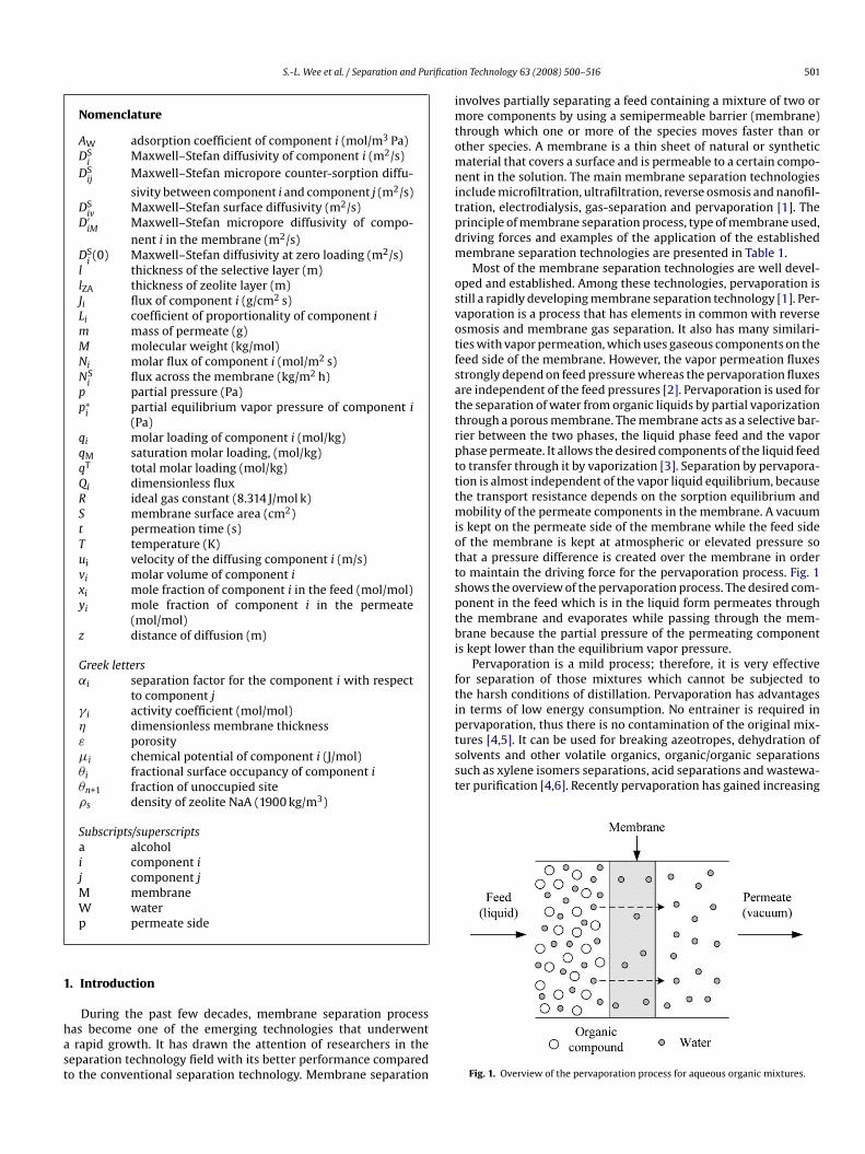
qaMmtrbeszammfXpsmsstZycdtbobtained from N2 adsorption experiments on three different kindsof mordenite powder prepared by Navajas et al. [38]. As shown inFig. 9, the mordenite powder with no post-synthetic treatmentspresent only a small contribution in the mesopore zone whereas
ig. 6. Schematic diagram for synthesis of NaA zeolite membrane together withicrowave heating and conventional heating method. Adapted from Ref. [77].
itania (rutile) asymmetric tubular supports in a flow system. Thecheme for the experimental set-up used for the zeolite membraneynthesis is shown in Fig. 5. In this experimental set-up, the syn-hesis gel was continuously circulated in the lumen of the tubularupport under the action of gravity. The synthesized membranehowed great ability to dehydrate ethanol–water mixtures (92 wt.%thanol) at 323 K with separation factor up to 8500 and fluxes of.2 kg/m2 h.
.4. Microwave synthesis
Recently, the microwave synthesis has been reported for theynthesis of zeolite membranes [55,74–76]. Compared with theonventional hydrothermal synthesis, microwave synthesis has thedvantages of short synthesis time, broad synthesis composition,mall zeolite particle size, narrow particle size distribution and highurity [62,77]. In microwave processing, energy is supplied by elec-romagnetic field directly to the material, thus is more efficient inransferring thermal energy to a volume of material than conven-ional thermal processing which transport heat through surface ofhe material by convection, conduction and radiation [78]. How-ver, only few studies on microwave synthesis have been reportedo date. For instance, Li et al. [10] studied the synthesis of LTAeolite membrane (NaA zeolite membrane) by using the “in situging – microwave synthesis” method. Before microwave heating,he autoclave with support and synthesis mixture was put in anir-oven for aging. It was reported that the synthesized LTA zeo-ite membranes failed in pervaporation at high water concentrationlthough they possessed excellent long-term stability in vapor per-eation. It was also found that the damage of LTA zeolite membrane
y water mainly occurred in the grain boundary layer. Huang andang [77] successfully prepared uniform and dense NaA zeoliteembrane by using the hydrothermal synthesis method togetherith microwave heating and conventional heating. Fig. 6 shows the
chematic diagram for the membrane preparation. Bonaccorsi androverbio [78] obtained pure NaA zeolite membrane in a total pro-essing time of 1 h by exposing the reaction mixture to a microwave
lectromagnetic field under atmospheric pressure. Table 3 presentsn overview of the synthesis of zeolite membrane using differentethods. It was shown that zeolite membrane with a membranehickness ranging from 1.0 to 20.0 �m could be obtained by usinghese methods.
Ft
on Technology 63 (2008) 500–516
. Membrane characterization
Membrane characterization is essential in order to evaluate theuality of the synthesized membrane. Zeolite membranes are char-cterized by using some of the methods described in this article.icrostructure, crystal size and membrane thickness are deter-ined by using scanning electron microscope (SEM). Membranes
hickness ranging from 0.5 �m to approximately 500 �m has beeneported [2]. A qualitative measure of the continuity of the mem-rane layer can also be examined using SEM. Fig. 7 shows anxample of the SEM images of the NaA zeolite membrane synthe-ized by Ahn et al. [82]. It was shown that the synthesized NaAeolite crystals were randomly grown to the size of 1–2 �m withzeolite layer thickness of about 5 �m. Apart from SEM, surfaceorphology and crystallinity can also be determined by trans-ission electron microscope (TEM). Zeolite phase identification,
ramework structure and relative crystallinity were determined by-ray diffraction (XRD). The phases formed are identified by com-aring the d spacing and relative intensities of the samples withtandard reference data. Fig. 8 shows the XRD pattern of the com-ercially available ZSM-5 powder and ZSM-5 zeolite membrane
ynthesized by Li et al. [36]. The diffraction pattern for the synthe-ized membrane and ZSM-5 powder was identical which indicatedhat the crystals formed on the support surface have MFI-topology.eolite composition is measured using electron probe microanal-sis (EPMA). EPMA is an analytical tool used to determine thehemical composition of small volumes of solid materials withoutestroying the materials. The BET surface area, pore size distribu-ion, micropore and mesopore volume and isotherm are examinedy using N2 adsorption. Fig. 9 shows the pore size distribution
ig. 7. SEM images of the NaA zeolite membrane: (a) a cross-sectional view; (b) aop view. Adapted from Ref. [82].

S.-L.Wee
etal./Separation
andPurification
Technology63
(2008)500–516
507
Table 3Synthesis methods of thin, high-flux zeolite membranes and the system tested
Synthesis method Zeolite type Composition of the synthesis solution Synthesis temperature andtime/cycles
Support Membranethickness (�m)
System Ref.
Hydrothermal synthesisIn situ hydrothermal synthesis withvacuum-assisted method
NaA 50Na2O:Al2O3:5SiO2:1000H2O 363 K, 1–24 h/1 �-Al2O3 tube 12.0 IPA/H2O [11]
In situ hydrothermal synthesis (addition ofTMAOH)
NaA 49Na2O:(TMA)2:Al2O3:5SiO2:980H2O 333–373 K, 1–24 h/1 �-Al2O3 tube 5.0 IPA/H2O [51]
In situ crystallization NaA 49Na2O:Al2O3:5SiO2:980H2O 358 K, 2–4 h/2 �-Al2O3 tube 6.3 EtOH/H2O [61]In situ hydrothermal synthesis Silicalite TPABr:0.25Na2O:10SiO2:800H2O 453 K, 28 h/1 Silica tube 20.0 EtOH/H2O [79]In situ crystallization H-ZSM-5 1.0TPAOH:0.0162Al2O3:19.46SiO2:438H2O 458 K, 48 h/2 �-Al2O3 tube NA n-Hexane/2,2-DMB [80]
Secondary growth methodIn situ crystallization with vacuum seeding NaA 50Na2O:Al2O3:5SiO2:1000H2O 333 K, 24 h/1 �-Al2O3 tube 6.0 IPA/H2O [53]Hydrothermal synthesis in centrifugal forcefield with slip-coat and rub seeding
NaA 3.6Na2O:Al2O3:1.8SiO2:270H2O 373 K, 3 h/1 �-Al2O3 tube 7.0–10.0 EtOH/H2O [65]
Hydrothermal synthesis with rub-seeding Mordenite SiO2:0.05Al2O3:0.76NaOH:40H2O 443 K, 24 h/1 �-Al2O3 tube NA EtOH/H2O [68]Hydrothermal synthesis with dip-coat seeding NaA 2Na2O:Al2O3:2SiO2:150H2O 353–373 K, 3–5 h/1 �-Al2O3 tube NA EtOH/H2O [69]Hydrothermal synthesis with dip-coat seeding Mordenite 10Na2O:0.15Al2O3:36SiO2:440H2O 453 K, 2 h/1 �-Al2O3 tube 1.0 IPA/H2O [45]
Continuous flow synthesis methodContinuous flow synthesis method withbrush-seeding
NaA 3.9Na2O:Al2O3:1.8SiO2:270H2O 353–363 K, 3–7 h/1 TiO2 tube 10.0–20.0 EtOH/H2O [13]
Semi-continuous method with rub-seeding NaA 3.9Na2O:Al2O3:1.8SiO2:273H2O 363 K, 5 h/1 �-Al2O3 tube NA EtOH/H2O [81]
Microwave synthesisTwo stage synthesis with microwave heating NaA 50Na2O:Al2O3:5SiO2:1000H2O 363 K, 25 min/2 �-Al2O3 tube 5.0 EtOH/H2O [75]Microwave heating with mesoporous to playercoated on the supports
NaA 3Na2O:Al2O3:2SiO2:200H2O 363 K, 10–45 min �-Al2O3 disc 6.0–7.0 H2/C3H8 [76]
Hydrothermal synthesis with microwaveheating (MH) and conventional heating (CH)
NaA 50Na2O:Al2O3:5SiO2:1000H2O 363 K, 25 min (MH) and 4 h (CH)/1 �-Al2O3 tube 10.0 IPA/H2O [77]
DMB, dimetylbutane; EtOH, ethanol; H2O, water; IPA, isopropanol; TMAOH, tetramethylammonium hydroxide; TPABr, tetrapropylammonium bromide; TPAOH, terapropylammonium hydroxide; NA, not available.
508 S.-L. Wee et al. / Separation and Purification Technology 63 (2008) 500–516
Fig. 8. XRD patterns for (a) ZSM-5 powder; (b) surface of a zeolite membrane growno
tlAgilmht
Fi
5
s
n a seeded �-Al2O3 support. Adapted from Ref. [36].
he mordenite powder with post-synthetic treatments under alka-ine condition leads to the formation of both meso and macropores.nother common method of membrane characterization is throughas permeation. Single gas permeation such as nitrogen permeation
s used to evaluate the possible presence of large pores in the zeoliteayer. Permeation depends on adsorption and diffusion, howeverolecules with similar size or larger than the zeolite pore sizeave difficulty entering the zeolite channels. Table 4 summarizeshe different types of methods for membrane characterization.
rbb[a
Fig. 10. Schematic representation o
ig. 9. Pore size distribution obtained from N2 adsorption experiments on morden-te powder with and without post-synthetic treatments. Adapted from Ref. [38].
. Pervaporation studies
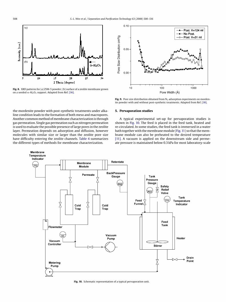
A typical experimental set-up for pervaporation studies ishown in Fig. 10. The feed is placed in the feed tank, heated and
e-circulated. In some studies, the feed tank is immersed in a waterath together with the membrane module (Fig. 11) so that the mem-rane module can also be preheated to the desired temperature11]. A vacuum is applied on the downstream side and perme-te pressure is maintained below 0.3 kPa for most laboratory-scalef a typical pervaporation unit.

S.-L. Wee et al. / Separation and Purification Technology 63 (2008) 500–516 509
Table 4Membrane characterization methods
Methods Properties
Scanning Electron Microscope (SEM) Microstructure, crystal size,membrane thickness
Transmission Electron Microscope (TEM) Surface morphology and cystallinityX-ray Diffraction (XRD) Zeolite phase identification,
framework structure and orientation,crystallinity
Electron Probe Microanalysis (EPMA) Zeolite compositionN2 Adsorption BET surface area, pore size
distribution, micropore and mesoporevolume and isotherm
Fi
sfnttmmbpo(mfvhpeoi
m
Fc61
Fm
l[aftitwto
p
ig. 11. Experimental apparatus for pervaporation unit with membrane modulemmersed in water bath. Adapted from Ref. [11].
tudies. However for commercial-scale systems, the requirementor vacuum pump to create vacuum at the permeate side wouldot be feasible proposition. Therefore, an alternative way to coolhe permeate vapor to condense the liquid will be required so thathe condensation of the liquid will spontaneously generate the per-
eate side vacuum [1]. Water is continuously separated from feedixtures through the membrane. Permeate that leaves the mem-
rane as vapor is condensed by the two cold traps that are set inarallel allowing the experiment to be carried out in a continu-us mode. Some studies used a sweep gas on the permeate sideFig. 12) instead of vacuum. A nitrogen gas stream was introduced,
ixed with the permeated gas and sent to the gas chromatographor analysis. Similar permeation result was obtained as when usingacuum [68]. This mode of operation is preferred if the permeateas no value and can be discarded without condensation. For exam-le in the pervaporative dehydration of an organic solvent withxtremely water-selective membrane where the permeate contain
nly water plus a trace of organic solvent and could be discharge orncinerated at low cost [1].During pervaporation, membrane is sealed in a membraneodule. Typically, two types of membrane are used in the
ig. 12. Experimental set-up with sweep gas on the permeate side: 1, stainless steelylinder; 2, pump; 3, heating coil; 4, membrane module; 5, liquid nitrogen cold trap;, vacuum pump; 7, gas cylinder; 8, mass-flow controller; 9, mass-flow control unit;0, gas chromatograph; 11, thermostatic silicon bath. Adapted from Ref. [68].
iwstracTr
f
J
˛
wmcp
ig. 13. Cross-section sketches of modules for (a) disc-shaped and (b) tubular zeoliteembrane.
aboratory-scale studies, which are the disc-shaped membranes76] and tubular membranes [11–13,35]. Disc-shaped membranesre usually sealed between two plates as shown in Fig. 13(a). Theeed is usually on the zeolite side of the support so that the concen-ration polarization is minimized. An example of tubular membranes shown in Fig. 13(b). At each end of the support, O-rings are usedo seal the membrane. Tubular membrane modules are operatedith the feed either in the inside or outside of the tube, but as with
he disc-shaped membrane, the feed is typically on the certain sidef the membrane which is coated with the zeolite layer.
The effects of various process variables on membrane separationerformance were studied in terms of: (1) fluxes and permeances of
ndividual components, and (2) separation factor and selectivity ofater to the organic compound. Pervaporation fluxes in lab-scale
tudies are usually measured by weighing permeate collected inhe cold traps during a given period of time. Fluxes are typicallyeported in kg/m2 h because these units are used in industrial sep-rations. However, molar fluxes in mol/m2 h are more useful inomparing the components with different molecular weight [2].he compositions of the samples are analyzed using gas chromatog-aphy in order to obtain the separation factor.
The fluxes and separation factors can be calculated using theollowing relations [83]:
i = m
St(1)
i =(
yi/yj
xi/xj
)(2)
here Ji is the flux of component i, m the mass of permeate, S theembrane surface area, t the permeation time, yi the weight of
omponent i in the permeate and yj the weight of component j in theermeate, xi the weight of component i in the feed and xj the weight
5 rificati
oc
6
g[
(
(
(
brtocmacbfs
J
wTpcbflic
d
wapnFt‘[
toaomT
−
isidc
jbfM
D
immatLmseg
Q
wtdo
Q
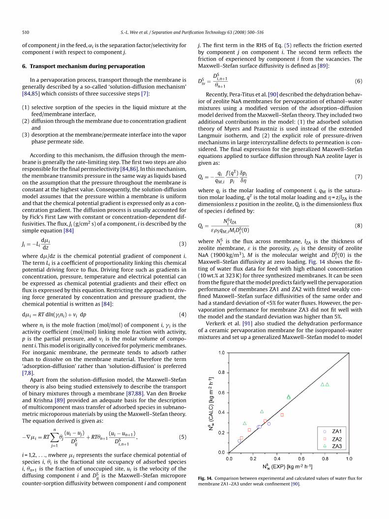
wzNMt(fpfihvaporation performance for membrane ZA3 did not fit well withthe model and the standard deviation was higher than 5%.
Verkerk et al. [91] also studied the dehydration performanceof a ceramic pervaporation membrane for the isopropanol–watermixtures and set up a generalized Maxwell–Stefan model to model
10 S.-L. Wee et al. / Separation and Pu
f component j in the feed, ˛i is the separation factor/selectivity foromponent i with respect to component j.
. Transport mechanism during pervaporation
In a pervaporation process, transport through the membrane isenerally described by a so-called ‘solution-diffusion mechanism’84,85] which consists of three successive steps [7]:
1) selective sorption of the species in the liquid mixture at thefeed/membrane interface,
2) diffusion through the membrane due to concentration gradientand
3) desorption at the membrane/permeate interface into the vaporphase permeate side.
According to this mechanism, the diffusion through the mem-rane is generally the rate-limiting step. The first two steps are alsoesponsible for the final permselectivity [84,86]. In this mechanism,he membrane transmits pressure in the same way as liquids basedn the assumption that the pressure throughout the membrane isonstant at the highest value. Consequently, the solution-diffusionodel assumes that the pressure within a membrane is uniform
nd that the chemical potential gradient is expressed only as a con-entration gradient. The diffusion process is usually accounted fory Fick’s First Law with constant or concentration-dependent dif-usivities. The flux, Ji (g/cm2 s) of a component, i is described by theimple equation [84]
i = −Lid�i
dz(3)
here d�/dz is the chemical potential gradient of component i.he term Li is a coefficient of proportionality linking this chemicalotential driving force to flux. Driving force such as gradients inoncentration, pressure, temperature and electrical potential cane expressed as chemical potential gradients and their effect onux is expressed by this equation. Restricting the approach to driv-
ng force generated by concentration and pressure gradient, thehemical potential is written as [84]:
�i = RT dln(�ini) + vi dp (4)
here ni is the mole fraction (mol/mol) of component i, � i is thectivity coefficient (mol/mol) linking mole fraction with activity,is the partial pressure, and vi is the molar volume of compo-
ent i. This model is originally conceived for polymeric membranes.or inorganic membrane, the permeate tends to adsorb ratherhan to dissolve on the membrane material. Therefore the termadsorption-diffusion’ rather than ‘solution-diffusion’ is preferred7,8].
Apart from the solution-diffusion model, the Maxwell–Stefanheory is also being studied extensively to describe the transportf binary mixtures through a membrane [87,88]. Van den Broekend Krishna [89] provided an adequate basis for the descriptionf multicomponent mass transfer of adsorbed species in subnano-etric microporous materials by using the Maxwell–Stefan theory.
he equation derived is given as:
∇�i = RT
n∑j=1
�j(ui − uj)
DSij
+ RT�n+1(ui − un+1)
DSi,n+1
, (5)
= 1,2, . . ., nwhere �i represents the surface chemical potential ofpecies i, �i is the fractional site occupancy of adsorbed species, �n+1 is the fraction of unoccupied site, ui is the velocity of theiffusing component i and DS
ijis the Maxwell–Stefan micropore
ounter-sorption diffusivity between component i and componentFm
on Technology 63 (2008) 500–516
. The first term in the RHS of Eq. (5) reflects the friction exertedy component j on component i. The second term reflects theriction of experienced by component i from the vacancies. The
axwell–Stefan surface diffusivity is defined as [89]:
Siv =
DSi,n+1
�n+1(6)
Recently, Pera-Titus et al. [90] described the dehydration behav-or of zeolite NaA membranes for pervaporation of ethanol–water
ixtures using a modified version of the adsorption–diffusionodel derived from the Maxwell–Stefan theory. They included two
dditional contributions in the model: (1) the adsorbed solutionheory of Myers and Praustniz is used instead of the extendedangmuir isotherm, and (2) the explicit role of pressure-drivenechanisms in large intercrystalline defects to permeation is con-
idered. The final expression for the generalized Maxwell–Stefanquations applied to surface diffusion through NaA zeolite layer isiven as:
i = − qi
qM,i
f (qT)pi
ıpi
ı�(7)
here qi is the molar loading of component i, qM is the satura-ion molar loading, qT is the total molar loading and � = z/lZA is theimensionless z position in the zeolite, Qi is the dimensionless fluxf species i defined by:
i = NSilZA
ε�SqM,iMiDSi(0)
(8)
here NSi
is the flux across membrane, lZA is the thickness ofeolite membrane, ε is the porosity, �S is the density of zeoliteaA (1900 kg/m3), M is the molecular weight and DS
i(0) is the
axwell–Stefan diffusivity at zero loading. Fig. 14 shows the fit-ing of water flux data for feed with high ethanol concentration10 wt.% at 323 K) for three synthesized membranes. It can be seenrom the figure that the model predicts fairly well the pervaporationerformance of membranes ZA1 and ZA2 with fitted weakly con-ned Maxwell–Stefan surface diffusivities of the same order andad a standard deviation of <5% for water fluxes. However, the per-
ig. 14. Comparison between experimental and calculated values of water flux forembrane ZA1–ZA3 under weak confinement [90].

rificati
tw
N
N
wcD
bmpsTfmtv
7
t1ftaia
7
7
fwtmvrept(wrlctioidtauaTebtt
zitt0To
7
rtsfstftdtdttaitia9iaa1UnFvKocvrawatf
fpz1milst
7
S.-L. Wee et al. / Separation and Pu
he fluxes. By making a few assumptions, the following equationas developed:
W = − DSaWD′
WM
xaD′WM + DS
aW
AW
l(p∗
W − ppW) (9)
a = −D′aMAa
l(p∗
a − ppa ) + xaD′
aMDs
aWNW (10)
here Ni is the molar flux of component i, Ai is the adsorptionoefficient of component i, l is the thickness of the selective layer,Sij
is the Maxwell–Stefan micropore counter-sorption diffusivityetween component i and component j, D′
iMis the Maxwell–Stefan
icropore diffusivity of component i in the membrane, p∗i
is theartial equilibrium vapor pressure of component i at the retentateide, pp
iis the partial pressure of component i at the permeate side.
he values of various Maxwell–Stefan diffusivities were estimatedrom the experimental data. With a better understanding of the
ass transfer in pervaporation membranes under different condi-ions, a more improved membrane and pervaporation process inarious applications can be designed.
. Pervaporation applications
The largest industrial applications of pervaporation are used forhe removal of water from organic solvents and solvent mixtures. In988, the first plant started its operation in the chemical industryor the dehydration of an ester [47]. Soon after that, other applica-ions for dewatering followed, covering a broad range of solventsnd solvent mixtures. The current applications of pervaporationnclude alcohol dehydration, organic/organic separations, acid sep-rations and industrial applications are discussed in this review.
.1. Alcohol dehydration
.1.1. Isopropanol–water systemRemoval of water from alcohol–water solutions in the industry is
requently sought but faces difficulties in the separation especiallyhen an azeotrope is involved. The concentration and purifica-
ion of isopropanol from its aqueous solution are necessary forany chemical processes. Isopropanol is used as a cleaning sol-
ent in modern semiconductor and electronic industries, whereecovery of waste isopropanol is essential from environmental andconomical point of view [92]. Pervaporative dehydration of iso-ropanol can also be combined with an esterification reaction inhe production of isopropyl fatty acid ester via reactive distillationRD). In the conventional method, the unreacted isopropanol andater are being recycled back into the RD column which greatly
educes the reaction conversion as esterification is equilibrium-imited. However, by recycling pure isopropanol back into the RDolumn, the reaction conversion can be greatly increased and thushe yield of isopropyl fatty acid esters can also be increased. Thesopropanol–water mixture forms an azeotrope at 87.4–87.7 wt.%f isopropanol at atmospheric conditions [93]. The separation ofsopropanol–water mixture could be performed through azeotropicistillation or extractive distillation. When applying azeotropic dis-illation either di-iso-propyl-ether or cyclohexane is added as anuxiliary agent [94]. In extractive distillation ethylene glycol issed as an entrainer [95]. In both cases, three distillation columnsre needed with the result of a high energy consuming process.
he auxiliary agent and entrainer generally cause unfavorable sideffects. Therefore, this appears to be a niche application for mem-rane pervaporation to separate and recover the isopropanol fromhe aqueous solutions. The dehydration of isopropanol–water sys-em using pervaporation is studied by various researchers usingwFb[
on Technology 63 (2008) 500–516 511
eolite membrane [11,30,37,96]. Shah et al. [87] conducted exper-ments with various alcohol–water mixtures over a wide range ofemperature (298–343 K) and solvent concentrations (0–100%). Theotal flux for isopropanol–water mixtures was found to vary from.21 to 2 kg/m2 h at 333 K as the solvent concentration increased.he separation factor was observed to lie between 1000 and 5000ver a wide range of solvent concentration.
.1.2. Ethanol–water systemBio-ethanol is one of the potential biofuel as it is being used to
eplace methyl t-butyl ether as a fuel oxygenate, and it has poten-ial to reduce pollution as well as dependence on non-domesticources of petroleum [97]. Bio-ethanol is generally produced fromermentable raw materials containing sugar or starch, such asugar cane molasses and cornstarch, cellulose, as well as indus-rial waste products [98]. The production of bio-ethanol fromermentation route produces aqueous ethanol solutions. In ordero obtain absolute ethanol from the aqueous ethanol solution, theehydration process is normally carried out using azeotropic dis-illation due to the formation of ethanol–water azeotrope. Theifficulty of separating an azeotropic mixture is encountered inhis step. Recently, Cardona Alzate and Sanchez Toro [98] reportedhat if pervaporation is used as dehydration method instead ofzeotropic distillation, further energy savings could be obtainedn the bio-ethanol production plant. From the simulation studies,hey reported that the energy cost of pervaporation unit is approx-mately 1/5 of those for azeotropic distillation column. Kaminski etl. [99] made a comparison of the cost of ethanol dehydration to9.8 wt.% by different techniques for several systems with a capac-
ty of 30 tonnes/day each. The different techniques investigatedre vapor permeation, pervaporation, distillation and adsorptionnd the total operating cost reported for each technique are US$5.75/tonnes, US$ 12.6–16.6/tonnes, US$ 31.95–45.65/tonnes andS$ 36.3/tonnes respectively. This shows that pervaporation tech-ique is the most advantageous with the lowest total operating cost.or the past few years, several researches are reported for the per-aporative dehydration of ethanol–water mixtures [7,42,66,70,72].ondo et al. [100] prepared NaA zeolite membrane on the surfacesf porous tubular supports composed of mullite, �-alumina and/orristobalite using the hydrothermal synthesis. They obtained per-aporation fluxes and separation factor of 2.35 kg/m2 h and 5100espectively for pervaporation of 95 wt.% ethanol–water mixturest 95 ◦C. Algieri et al. [101] conducted pervaporation experimentsith thin MFI zeolite membranes synthesized by in situ nucleation
nd secondary growth at 70 ◦C and 9.4 wt.% ethanol–water mix-ures. They obtained high fluxes (2.1 kg/m2 h) and low separationactor (˛(EtOH/H2O) = 1.3).
Several studies for the pervaporative dehydration of alcoholrom aqueous mixtures using different types of zeolite membrane isresented in Table 5. The fluxes and separation factor for NaA typeeolite membrane varies from 0.23 to 5.60 kg/m2 h and 3600 to0,000 relatively. The fluxes and separation factor for these zeoliteembranes are generally higher than the silicalite and morden-
te type zeolite membranes. This is because the pore diameters arearger for these zeolite membranes, which means that they are lessize selective for water and they are also less hydrophilic comparedo NaA type zeolite membrane.
.2. Organic/organic separations
The separation of organic mixtures is gaining great importanceith the application of pervaporation in the chemical industry.
or the separation of organic/organic mixtures, inorganic mem-rane such as silicalite [104], NaX [105], NaY [40], and ZSM-580,106,107] are widely reported in literature by various researchers

512 S.-L. Wee et al. / Separation and Purification Technology 63 (2008) 500–516
Table 5Overview for the pervaporative dehydration of alcohol from alcohol–water mixtures using zeolite membrane
Zeolite type Support Organic Water in feed (wt.%) T (K) Permeate pressure (kPa) Membrane performance Ref.
Flux (kg/m2 h) ˛
NaA TiO2 tube Ethanol 10 323 0.2 0.80–1.00 8500 [13]NaA �-Al2O3 tube Isopropanol 5 343 NA 1.67 4700 [51]NaA �-Al2O3 tube Isopropanol 5 343 NA 1.67 >10000 [53]NaA �-Al2O3 tube Ethanol 5 318 0.4 0.23 8300 [61]NaA �-Al2O3 tube Ethanol 9.2 366 0.5 2.5 130 [65]NaA �-Al2O3 tube Ethanol 10 348 0.7 5.60 >5000 [69]NaA �-Al2O3 tube Ethanol 10 323 0.2 0.50 16000 [70]NaA �-Al2O3 tube Isopropanol 5 343 NA 1.44 10000 [77]NaA �-Al2O3 tube Ethanol 10 398 0.05 3.80 3600 [81]
NaA �-Al2O3 tube Ethanol 10 353 NA 0.54 >10000 [102]Isopropanol 10 353 1.16 >10000
Silica �-Al2O3 disc Ethanol 10 353 0.6–0.8 1.00 800 [8]Butanol 5 353 1.00 1000
Silica �-Al2O3 tube Isopropanol 5 343 0.8 2.00 NA [96]10 343 3.20 NA
Silica Ceramic hollow fibre n-Butanol 5 353 1.0 2.9 1200 [103]Silicalite Silica tube Ethanol 3 333 NA 0.37 70 [79]MM
S
smmzereveTtommala
7
tt
aa[2dsatioasd[tbs
TO
M
N
N
H
SZ
S
ordenite �-Al2O3 tube Ethanol 10ordenite Al2O3 tube Ethanol 15
S: Stainless Steel; NA: Not available.
ince their pore sizes are similar to the size of small organicolecules. Bowen et al. [108] measured the diffusion rates of water,ethanol, ethanol, 2-propanol and acetone through a Ge-ZSM-5
eolite membrane by using isotopic-transient pervaporation. Forthanol/methanol mixtures, the presence of ethanol affected theate of methanol diffusion and methanol increased the rate ofthanol diffusion. The flux for ethanol and methanol in the per-aporation of ethanol–methanol mixtures at 313 K with 95 wt.%thanol in the feed solutions was 3.8 and 0.2 mol/m2 h respectively.able 6 shows the organic/organic separations by pervapora-ion using different types of zeolite membranes. Among all therganic/organic mixtures so far studied, the methanol/MTBE andethanol/benzene mixtures were the most successfully separatedixtures by pervaporation through zeolite membrane. The fluxes
nd selectivities for the organic/organic separation are obviouslyower than the fluxes and selectivities for the dehydration of alcohols shown in Table 5.
.2.1. Xylene isomersThe recovery of p-xylene from xylene isomers is an impor-
ant step in the large-scale synthesis of petrochemical. Amonghe xylene isomers, p-xylene has the largest commercial market
icesw
able 6verview for the organic/organic separation by pervaporation using zeolite membrane
embrane Support Mixture (A/B)a Concentration (A wt.%)
aY Ceramic MeOH/MTBE 10MeOH/benzene 10MeOH/DMC 50EtOH/benzene 10EtOH/cyclohexane 10EtOH/ETBE 10
aX Ceramic MeOH/MTBE 10
-ZSM-5 SS n-Hexane/2,2-DMB 50�-Al2O3
ilica �-Al2O3 MeOH/MTBE 9eolite Beta SS 2MP/2,2-DMB 50
S, stainless steel; MTBE, methyl-tert-butylether; MP, methylpentane; DMC, dimethylcycla Component A is selectively removed.
423 0.5 0.16 139 [35]363 0.2 0.06 60 [68]
s it is an important chemical stock for synthesis of terephthaliccid, which is used in the production of polyester resin and fibres109]. Global demand for p-xylene is around 32 million tonnes in006, essentially all of this p-xylene has gone to the polyester pro-uction for fibre and films [110]. The conventional methods foreparating the xylene isomers are crystallization, distillation anddsorption. Separation of these mixtures is poorly achieved by dis-illation process due to the similar volatility and boiling point whichs 411.5 K (p-xylene), 412 K (m-xylene) and 417.5 K (o-xylene). More-ver, separation of these mixtures by crystallization or throughdsorption processes is usually complex and very energy inten-ive [111]. Pervaporation is a promising technique since this processoes not depend on the difference in volatility. Kanezashi et al.112] reported the pervaporation of p- and o-xylene binary mixturehrough MFI-type zeolite membrane. The MFI-type zeolite mem-rane was synthesized on alumina and zirconia coated aluminaupports by template-free seeded growth method in order to min-
mize defects and intercrystalline gaps that are formed during thealcination step required for template removal. The pervaporationxperiments were conducted at 25 ◦C with p-xylene partial pres-ure of 1.1 kPa. The p-xylene flux and p/o-xylene selectivity obtainedere 7.6 × 10⁻⁴ and 22 mol/m2 s respectively. It was also shownTemperature (K) Membrane performance Ref.
Flux (kg/m2 h) ˛
323 1.70 5300 [40]323 1.02 7000323 1.53 480333 0.22 930333 0.27 1000323 0.21 1200
323 0.46 10000 [40]
300 0.37 10 [80]
308 0.04 19 [113]303 0.03 1.53 [114]
ohexane; ETBE, ethyl-tert-butylether; DMB, dimethylbutane.
rification Technology 63 (2008) 500–516 513
tp
7
atcrtwimpAagbrscmsbpta
7
zmCi
Fa
F
S.-L. Wee et al. / Separation and Pu
hat the pervaporation offers much higher p-xylene flux and lower/o-xylene separation factor than the vapor permeation.
.3. Acid separations
For the past few years, several studies are reported for thecid recovery by pervaporation such as acetic acid–water sys-em [36,86,115]. Acetic acid is an important basic chemical in thehemical industry. Acetic acid containing water below 5 wt.% isequired in various chemical processes, such as productions oferephthalic acid and butane-di-ol [44]. The relative volatility ofater to acetic acid is close to unity [36], therefore, much energy
s required for distillation to separate acetic acid from aqueousixtures. Consequently, pervaporation is regarded as one of the
otential processes for separation of aqueous acetic acid mixtures.s far as concern, polymeric membranes cannot be used in thecetic acid solution due to low tolerance against acid, thus inor-anic membranes, such as zeolite membranes, are considered toe a good candidate for such application. Masuda et al. [44] car-ied out a study on the preparation of hydrophilic and acid-proofilicalite-1 zeolite membrane for the separation of water from con-entrated acetic acid–water solution by pervaporation. The zeoliteembrane was successfully prepared by repeating hydrothermal
ynthesis of silicalite-1 layer on an alumina ceramic filter followedy a liquid phase oxidation method with H2O2 to remove tem-late molecules. It was reported that only water molecules passedhrough the membrane in the pervaporation of concentrated aceticcid (30–98 wt.%).
.4. Industrial applications
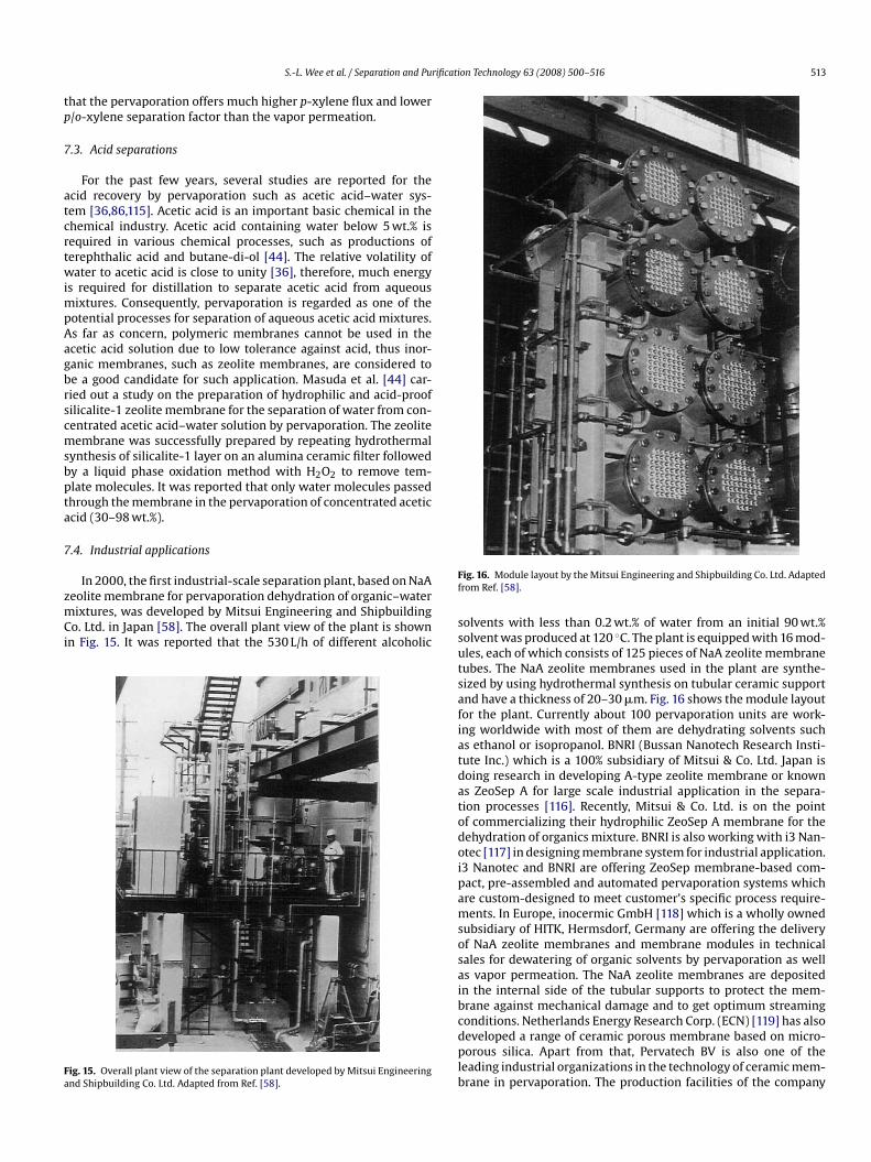
In 2000, the first industrial-scale separation plant, based on NaAeolite membrane for pervaporation dehydration of organic–waterixtures, was developed by Mitsui Engineering and Shipbuilding
o. Ltd. in Japan [58]. The overall plant view of the plant is shownn Fig. 15. It was reported that the 530 L/h of different alcoholic
ig. 15. Overall plant view of the separation plant developed by Mitsui Engineeringnd Shipbuilding Co. Ltd. Adapted from Ref. [58].
f
ssutsafiatdatodoipamsosaibcdplb
ig. 16. Module layout by the Mitsui Engineering and Shipbuilding Co. Ltd. Adaptedrom Ref. [58].
olvents with less than 0.2 wt.% of water from an initial 90 wt.%olvent was produced at 120 ◦C. The plant is equipped with 16 mod-les, each of which consists of 125 pieces of NaA zeolite membraneubes. The NaA zeolite membranes used in the plant are synthe-ized by using hydrothermal synthesis on tubular ceramic supportnd have a thickness of 20–30 �m. Fig. 16 shows the module layoutor the plant. Currently about 100 pervaporation units are work-ng worldwide with most of them are dehydrating solvents suchs ethanol or isopropanol. BNRI (Bussan Nanotech Research Insti-ute Inc.) which is a 100% subsidiary of Mitsui & Co. Ltd. Japan isoing research in developing A-type zeolite membrane or knowns ZeoSep A for large scale industrial application in the separa-ion processes [116]. Recently, Mitsui & Co. Ltd. is on the pointf commercializing their hydrophilic ZeoSep A membrane for theehydration of organics mixture. BNRI is also working with i3 Nan-tec [117] in designing membrane system for industrial application.3 Nanotec and BNRI are offering ZeoSep membrane-based com-act, pre-assembled and automated pervaporation systems whichre custom-designed to meet customer’s specific process require-ents. In Europe, inocermic GmbH [118] which is a wholly owned
ubsidiary of HITK, Hermsdorf, Germany are offering the deliveryf NaA zeolite membranes and membrane modules in technicalales for dewatering of organic solvents by pervaporation as wells vapor permeation. The NaA zeolite membranes are depositedn the internal side of the tubular supports to protect the mem-rane against mechanical damage and to get optimum streaming
onditions. Netherlands Energy Research Corp. (ECN) [119] has alsoeveloped a range of ceramic porous membrane based on micro-orous silica. Apart from that, Pervatech BV is also one of theeading industrial organizations in the technology of ceramic mem-rane in pervaporation. The production facilities of the company
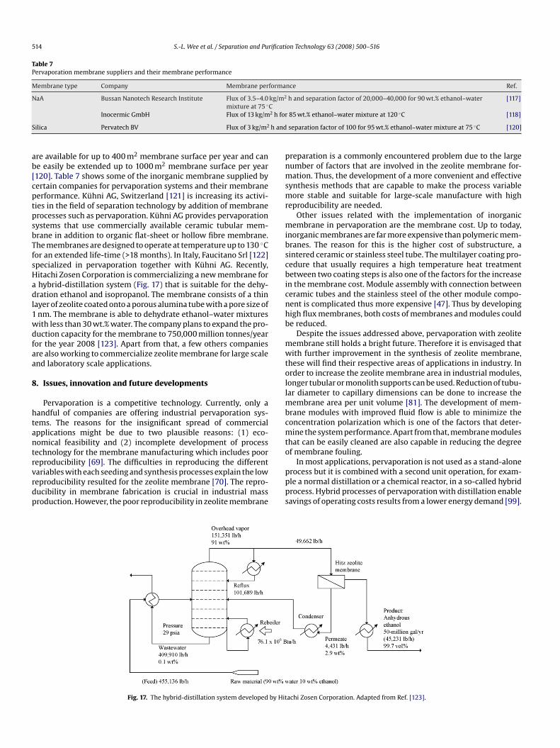
514 S.-L. Wee et al. / Separation and Purification Technology 63 (2008) 500–516
Table 7Pervaporation membrane suppliers and their membrane performance
Membrane type Company Membrane performance Ref.
NaA Bussan Nanotech Research Institute Flux of 3.5–4.0 kg/m2 h and separation factor of 20,000–40,000 for 90 wt.% ethanol–water◦C
[117]
2 h for
S h and
ab[cptpsbTfsHadl1wdfaa
8
htantrvrdp
pnmsmr
mibscbicnhb
mwtollmbcmto
mixture at 75Inocermic GmbH Flux of 13 kg/m
ilica Pervatech BV Flux of 3 kg/m2
re available for up to 400 m2 membrane surface per year and cane easily be extended up to 1000 m2 membrane surface per year120]. Table 7 shows some of the inorganic membrane supplied byertain companies for pervaporation systems and their membraneerformance. Kühni AG, Switzerland [121] is increasing its activi-ies in the field of separation technology by addition of membranerocesses such as pervaporation. Kühni AG provides pervaporationystems that use commercially available ceramic tubular mem-rane in addition to organic flat-sheet or hollow fibre membrane.he membranes are designed to operate at temperature up to 130 ◦Cor an extended life-time (>18 months). In Italy, Faucitano Srl [122]pecialized in pervaporation together with Kühni AG. Recently,itachi Zosen Corporation is commercializing a new membrane forhybrid-distillation system (Fig. 17) that is suitable for the dehy-ration ethanol and isopropanol. The membrane consists of a thin
ayer of zeolite coated onto a porous alumina tube with a pore size ofnm. The membrane is able to dehydrate ethanol–water mixturesith less than 30 wt.% water. The company plans to expand the pro-uction capacity for the membrane to 750,000 million tonnes/yearor the year 2008 [123]. Apart from that, a few others companiesre also working to commercialize zeolite membrane for large scalend laboratory scale applications.
. Issues, innovation and future developments
Pervaporation is a competitive technology. Currently, only aandful of companies are offering industrial pervaporation sys-ems. The reasons for the insignificant spread of commercialpplications might be due to two plausible reasons: (1) eco-omical feasibility and (2) incomplete development of processechnology for the membrane manufacturing which includes poor
eproducibility [69]. The difficulties in reproducing the differentariables with each seeding and synthesis processes explain the loweproducibility resulted for the zeolite membrane [70]. The repro-ucibility in membrane fabrication is crucial in industrial massroduction. However, the poor reproducibility in zeolite membraneppps
Fig. 17. The hybrid-distillation system developed by Hit
85 wt.% ethanol–water mixture at 120 ◦C [118]
separation factor of 100 for 95 wt.% ethanol–water mixture at 75 ◦C [120]
reparation is a commonly encountered problem due to the largeumber of factors that are involved in the zeolite membrane for-ation. Thus, the development of a more convenient and effective
ynthesis methods that are capable to make the process variableore stable and suitable for large-scale manufacture with high
eproducibility are needed.Other issues related with the implementation of inorganic
embrane in pervaporation are the membrane cost. Up to today,norganic membranes are far more expensive than polymeric mem-ranes. The reason for this is the higher cost of substructure, aintered ceramic or stainless steel tube. The multilayer coating pro-edure that usually requires a high temperature heat treatmentetween two coating steps is also one of the factors for the increase
n the membrane cost. Module assembly with connection betweeneramic tubes and the stainless steel of the other module compo-ent is complicated thus more expensive [47]. Thus by developingigh flux membranes, both costs of membranes and modules coulde reduced.
Despite the issues addressed above, pervaporation with zeoliteembrane still holds a bright future. Therefore it is envisaged thatith further improvement in the synthesis of zeolite membrane,
hese will find their respective areas of applications in industry. Inrder to increase the zeolite membrane area in industrial modules,onger tubular or monolith supports can be used. Reduction of tubu-ar diameter to capillary dimensions can be done to increase the
embrane area per unit volume [81]. The development of mem-rane modules with improved fluid flow is able to minimize theoncentration polarization which is one of the factors that deter-ine the system performance. Apart from that, membrane modules
hat can be easily cleaned are also capable in reducing the degreef membrane fouling.
In most applications, pervaporation is not used as a stand-alonerocess but it is combined with a second unit operation, for exam-le a normal distillation or a chemical reactor, in a so-called hybridrocess. Hybrid processes of pervaporation with distillation enableavings of operating costs results from a lower energy demand [99].
achi Zosen Corporation. Adapted from Ref. [123].

rificati
PehphttoOtit
9
btaematavawiothzznep
A
v((
R
S.-L. Wee et al. / Separation and Pu
ervaporation integrated with a chemical reactor will be able tonhance the reactor performance [124]. Recently, some researchesave been focusing on the coupling of esterification reaction withervaporation [125]. Esterification of carboxylic acids with alco-ols is a typical example of an equilibrium-limited reaction. Withhe continuous separation of the water as a reaction product fromhe reaction medium by means of pervaporation, the conversionf reactants for the esterification reaction can be greatly enhanced.ver the next few years, pervaporation will be used increasingly
o purify feed or separate reaction products. Therefore furthermprovement should still be endeavored to introduce pervapora-ion through zeolite membrane into large-scale application.
. Conclusions
Pervaporation has advantages in separating azeotropes, close-oiling point mixtures and thermally sensitive compounds. Thisechnology will be more economical compared to conventional sep-ration processes, such as distillation or adsorption since it is morenergy efficient than distillation. In addition, it is more environ-ental friendly because unlike in distillation, no third component is
dded. On the other hand, zeolite membrane has additional advan-ages in separating mixtures with molecular sieve differences,dsorption differences and high or low pH mixtures. Therefore, per-aporation with zeolite membrane has attracted great interest forpplication in many important industrial processes. Pervaporationith zeolite membrane has been more successful in dehydrat-
ng organic compounds than separating organic compounds fromrganic mixtures mainly because of the high hydrophilicity of A-ype zeolite membrane. For the past decade, significant progressas been made in the understanding of separation mechanisms ofeolite membrane and the synthesis of thin, high flux, defect-freeeolite membrane. New methods of preparation, modification andew materials have been widely reported in the literature. How-ver, more studies are needed to facilitate the wide introductionervaporation using zeolite membrane into industrial practice.
cknowledgements
The author would like to acknowledge the financial support pro-ided by Universiti Sains Malaysia under Short Term Research GrantAccount No.: 6035235) and Research University Grant under FRGSAccount No.: 811043) to support this project.
eferences
[1] R.W. Baker, Membrane Technology and Applications, 2nd ed., John Wiley &Son, England, 2004.
[2] T.C. Bowen, R.D. Noble, J.L. Falconer, J. Membr. Sci. 245 (2004) 1–33.[3] R. Mallada, M. Menendez, Inorganic Membranes: Synthesis, Characterization
and Applications, Elsevier Science, Amsterdam, 2008.[4] Wikipedia, Pervaporation [cited 2007 June 26], available from:
http://en.wikipedia.org/w/index.php?title=Pervaporation&oldid=176546135.[5] M. Kumar, Pervaporation: An Overview [cited 2007 June 26], available from:
http://www.cheresources.com/pervaporation.shtml.[6] S. Xiao, R.Y.M. Huang, X. Feng, J. Membr. Sci. 286 (2006) 245–254.[7] M. Pera-Titus, J. Llorens, J. Tejero, F. Cunill, Catal. Today 118 (2006) 73–84.[8] J. Sekulic, J.E.t. Elshof, D.H.A. Blank, J. Membr. Sci. 254 (2005) 267–274.[9] F.T. de Bruijn, L. Sun, Z. Olujic, P.J. Jansens, F. Kapteijn, J. Membr. Sci. 223 (2003)
141–156.[10] Y. Li, H. Zhou, G. Zhu, J. Liu, W. Yang, J. Membr. Sci. 297 (2007) 10–15.[11] A. Huang, W. Yang, J. Liu, Sep. Purif. Technol. 56 (2007) 158–167.[12] T. Kyotani, T. Mizuno, Y. Katakura, S. Kakui, N. Shimotsuma, J. Saito, T. Nakane,
J. Membr. Sci. 296 (2007) 162–170.
[13] M. Pera-Titus, M. Bausach, J. Llorens, F. Cunill, Sep. Purif. Technol. 59 (2008)141–150.[14] V.V. Namboodiri, L.M. Vane, J. Membr. Sci. 306 (2007) 209–215.[15] M.L. Gimenes, L. Liu, X. Feng, J. Membr. Sci. 295 (2007) 71–79.[16] W. Zhang, Y. Fang, X. Wang, J. Membr. Sci. 303 (2007) 173–182.[17] M.N. Hyder, R.Y.M. Huang, P. Chen, J. Membr. Sci. 283 (2006) 281–290.
on Technology 63 (2008) 500–516 515
[18] K. Srinivasan, K. Palanivelu, A. Navaneetha Gopalakrishnan, Chem. Eng. Sci. 62(2007) 2905–2914.
[19] C. Hu, B. Li, R. Guo, H. Wu, Z. Jiang, Sep. Purif. Technol. 55 (2007) 327–334.[20] S.-L. Huang, P.-H. Chang, M.-H. Tsai, H.-C. Chang, Sep. Purif. Technol. 56 (2007)
63–70.[21] D. Anjali Devi, B. Smitha, S. Sridhar, T.M. Aminabhavi, J. Membr. Sci. 262 (2005)
91–99.[22] P. Kanti, K. Srigowri, J. Madhuri, B. Smitha, S. Sridhar, Sep. Purif. Technol. 40
(2004) 259–266.[23] W. Won, X. Feng, D. Lawless, J. Membr. Sci. 209 (2002) 493–508.[24] C. Hu, R. Guo, B. Li, X. Ma, H. Wu, Z. Jiang, J. Membr. Sci. 293 (2007) 142–150.[25] Y.-L. Liu, C.-H. Yu, K.-R. Lee, J.-Y. Lai, J. Membr. Sci. 287 (2007) 230–236.[26] X.-P. Wang, Z.-Q. Shen, F.-Y. Zhang, Y.-F. Zhang, J. Membr. Sci. 119 (1996)
191–198.[27] X. Qiao, T.-S. Chung, W.F. Guo, T. Matsuura, M.M. Teoh, J. Membr. Sci. 252
(2005) 37–49.[28] H.M. van Veen, Y.C. van Delft, C.W.R. Engelen, P.P.A.C. Pex, Sep. Purif. Technol.
22–23 (2001) 361–366.[29] K. Li, Ceramic Membranes for Separation and Reaction, Wiley, Chichester,
England, 2007.[30] A.W. Verkerk, P. van Male, M.A.G. Vorstman, J.T.F. Keurentjes, Sep. Purif. Tech-
nol. 22–23 (2001) 689–695.[31] A.J. Burgraaf, L. Cot, Fundamentals of Inorganic Membrane Science and Tech-
nology, Elservier, Amsterdam, 1996.[32] M. Asaeda, S. Yamasaki, Sep. Purif. Technol. 25 (2001) 151–159.[33] A. Urtiaga, C. Casado, M. Asaeda, I. Ortiz, Desalination 193 (2006) 97–102.[34] J. Yang, T. Yoshioka, T. Tsuru, M. Asaeda, J. Membr. Sci. 284 (2006) 205–213.[35] A. Navajas, R. Mallada, C. Tellez, J. Coronas, M. Menendez, J. Santamaria, J.
Membr. Sci. 299 (2007) 166–173.[36] G. Li, E. Kikuchi, M. Matsukata, J. Membr. Sci. 218 (2003) 185–194.[37] V. Van Hoof, C. Dotremont, A. Buekenhoudt, Sep. Purif. Technol. 48 (2006)
304–309.[38] A. Navajas, R. Mallada, C. Tellez, J. Coronas, M. Menendez, J. Santamaria, J.
Membr. Sci. 270 (2006) 32–41.[39] G. Li, X.-h. Su, R.-s. Lin, Mater. Lett. 61 (2007) 4576–4578.[40] H. Kita, K. Fuchida, T. Horita, H. Asamura, K. Okamoto, Sep. Purif. Technol. 25
(2001) 261–268.[41] K. Sato, K. Sugimoto, T. Nakane, J. Membr. Sci. 310 (2008) 161–173.[42] L. Zhou, T. Wang, Q.T. Nguyen, J. Li, Y. Long, Z. Ping, Sep. Purif. Technol. 44
(2005) 266–270.[43] H. Chen, Y. Li, W. Yang, J. Membr. Sci. 296 (2007) 122–130.[44] T. Masuda, S.-h. Otani, T. Tsuji, M. Kitamura, S.R. Mukai, Sep. Purif. Technol. 32
(2003) 181–189.[45] G. Li, E. Kikuchi, M. Matsukata, Sep. Purif. Technol. 32 (2003) 199–206.[46] C. Baerlocher, W.M. Meier, D.H. Olson, Atlas of Zeolite Framework Types, 5th
ed., Elsevier, Amsterdam, 2001.[47] S.P. Nunes, K.-V. Peinemann, Membrane Technology in Chemical Indus-
try, 2nd ed., WILEY-VCH Verlag GmbH & Co. KGaA, Weinheim, Germany,2006.
[48] T. Gallego-Lizon, E. Edwards, G. Lobiundo, L. Freitas dos Santos, J. Membr. Sci.197 (2002) 309–319.
[49] H. Sun, L. Lu, X. Chen, Z. Jiang, Sep. Purif. Technol. 58 (2008) 429–436.[50] E. Okumus, T. Gurkan, L. Yilmaz, J. Membr. Sci. 223 (2003) 23–38.[51] A. Huang, W. Yang, Sep. Purif. Technol. 61 (2008) 175–181.[52] J. Zah, H.M. Krieg, J.C. Breytenbach, Microporous Mesoporous Mater. 93 (2006)
141–150.[53] A. Huang, Y.S. Lin, W. Yang, J. Membr. Sci. 245 (2004) 41–51.[54] P.Z. Culfaz, A. Culfaz, H. Kalipcilar, Microporous Mesoporous Mater. 92 (2006)
134–144.[55] J. Motuzas, A. Julbe, R.D. Noble, A. van der Lee, Z.J. Beresnevicius, Microporous
Mesoporous Mater. 92 (2006) 259–269.[56] A.W.C. van den Berg, L. Gora, J.C. Jansen, M. Makkee, T. Maschmeyer, J. Membr.
Sci. 224 (2003) 29–37.[57] E.E. McLeary, J.C. Jansen, F. Kapteijn, Microporous Mesoporous Mater. 90
(2006) 198–220.[58] Y. Morigami, M. Kondo, J. Abe, H. Kita, K. Okamoto, Sep. Purif. Technol. 25
(2001) 251–260.[59] M. Kazemimoghadam, T. Mohammadi, Sep. Purif. Technol. 47 (2006) 173–178.[60] T.C. Bowen, H. Kalipcilar, J.L. Falconer, R.D. Noble, J. Membr. Sci. 215 (2003)
235–247.[61] J. Zah, H.M. Krieg, J.C. Breytenbach, J. Membr. Sci. 284 (2006) 276–290.[62] X. Xu, Y. Bao, C. Song, W. Yang, J. Liu, L. Lin, Microporous Mesoporous Mater.
75 (2004) 173–181.[63] S. Yamazaki, K. Tsutsumi, Microporous Mesoporous Mater. 37 (2000) 67–80.[64] L.C. Boudreau, J.A. Kuck, M. Tsapatsis, J. Membr. Sci. 152 (1999) 41–59.[65] F. Tiscareno-Lechuga, C. Tellez, M. Menendez, J. Santamaria, J. Membr. Sci. 212
(2003) 135–146.[66] H. Ahn, H. Lee, S.-B. Lee, Y. Lee, Desalination 193 (2006) 244–251.[67] X. Xu, Y. Bao, C. Song, W. Yang, J. Liu, L. Lin, J. Membr. Sci. 249 (2005) 51–64.
[68] L. Casado, R. Mallada, C. Tellez, J. Coronas, M. Menendez, J. Santamaria, J.Membr. Sci. 216 (2003) 135–147.[69] K. Sato, T. Nakane, J. Membr. Sci. 301 (2007) 151–161.[70] M. Pera-Titus, R. Mallada, J. Llorens, F. Cunill, J. Santamaria, J. Membr. Sci. 278
(2006) 401–409.[71] H. Richter, I. Voigt, G. Fischer, P. Puhlfur, Sep. Purif. Technol. 32 (2003) 133–138.

5 rificati
[
16 S.-L. Wee et al. / Separation and Pu
[72] M. Pera-Titus, J. Llorens, F. Cunill, R. Mallada, J. Santamaria, Catal. Today 104(2005) 281–287.
[73] J. Ju, C. Zeng, L. Zhang, N. Xu, Chem. Eng. J. 116 (2006) 115–121.[74] X. Xu, W. Yang, J. Liu, L. Lin, Sep. Purif. Technol. 25 (2001) 241–249.[75] Y. Li, H. Chen, J. Liu, W. Yang, J. Membr. Sci. 277 (2006) 230–239.[76] X. Chen, W. Yang, J. Liu, L. Lin, J. Membr. Sci. 255 (2005) 201–211.[77] A. Huang, W. Yang, Mater. Lett. 61 (2007) 5129–5132.[78] L. Bonaccorsi, E. Proverbio, J. Cryst. Growth 247 (2003) 555–562.[79] H. Chen, C. Song, W. Yang, Microporous Mesoporous Mater. 102 (2007)
249–257.[80] C.L. Flanders, V.A. Tuan, R.D. Noble, J.L. Falconer, J. Membr. Sci. 176 (2000)
43–53.[81] M.P. Pina, M. Arruebo, M. Felipe, F. Fleta, M.P. Bernal, J. Coronas, M. Menendez,
J. Santamaria, J. Membr. Sci. 244 (2004) 141–150.[82] H. Ahn, H. Lee, S.-B. Lee, Y. Lee, J. Membr. Sci. 291 (2007) 46–52.[83] R.D. Noble, S.A. Stern, Membrane Separation Technology: Principles and
Applications in Membrane Science and Technology Series, Elservier, Amster-dam, 1995.
[84] J.G. Wijmans, R.W. Baker, J. Membr. Sci. 107 (1995) 1–21.[85] P. Schaetzel, C. Vauclair, Q.T. Nguyen, R. Bouzerar, J. Membr. Sci. 244 (2004)
117–127.[86] T.C. Bowen, S. Li, R.D. Noble, J.L. Falconer, J. Membr. Sci. 225 (2003) 165–176.[87] D. Shah, K. Kissick, A. Ghorpade, R. Hannah, D. Bhattacharyya, J. Membr. Sci.
179 (2000) 185–205.[88] J.E. ten Elshof, C.R. Abadal, J. Sekulic, S.R. Chowdhury, D.H.A. Blank, Microp-
orous Mesoporous Mater. 65 (2003) 197–208.[89] L.J.P. Van Den Broeke, R. Krishna, Chem. Eng. Sci. 50 (1995) 2507–2522.[90] M. Pera-Titus, C. Fite, V. Sebastian, E. Lorente, J. Llorens, F. Cunill, Ind. Eng.
Chem. Res. (2008).[91] A.W. Verkerk, P. van Male, M.A.G. Vorstman, J.T.F. Keurentjes, J. Membr. Sci.
193 (2001) 227–238.[92] L.Y. Jiang, T.-S. Chung, R. Rajagopalan, AIChE J. 53 (2007) 1745–1757.[93] H.F. Mark, R.E. Kirk, D.F. Othmer, Encyclopedia of Chemical Technology, John
Wiley & Sons, 1984.[94] V. Van Hoof, L. Van den Abeele, A. Buekenhoudt, C. Dotremont, R. Leysen, Sep.
Purif. Technol. 37 (2004) 33–49.[95] S. Sommer, T. Merlin, Ind. Eng. Chem. Res. 43 (2004) 5248–5259.[96] C. Casado, A. Urtiaga, D. Gorri, I. Ortiz, Sep. Purif. Technol. 42 (2005) 39–45.[97] T.C. Bowen, R.G. Meier, L.M. Vane, J. Membr. Sci. 298 (2007) 117–125.
[98] C.A. Cardona Alzate, O.J. Sanchez Toro, Energy 31 (2006) 2447–2459.[99] W. Kaminski, J. Marszalek, A. Ciolkowska, Chem. Eng. J. 135 (2008) 95–102.100] M. Kondo, M. Komori, H. Kita, K.-i. Okamoto, J. Membr. Sci. 133 (1997) 133–141.[101] C. Algieri, P. Bernardo, G. Golemme, G. Barbieri, E. Drioli, J. Membr. Sci. 222(2003) 181–190.
[102] Y. Li, H. Chen, J. Liu, H. Li, W. Yang, Sep. Purif. Technol. 57 (2007) 140–146.
on Technology 63 (2008) 500–516
[103] T.A. Peters, J. Fontalvo, M.A.G. Vorstman, N.E. Benes, R.A.v. Dam, Z.A.E.P.Vroon, E.L.J.v. Soest-Vercammen, J.T.F. Keurentjes, J. Membr. Sci. 248 (2005)73–80.
[104] T. Sano, M. Hasegawa, Y. Kawakami, H. Yanagishita, J. Membr. Sci. 107 (1995)193–196.
[105] S. Li, V.A. Tuan, J.L. Falconer, R.D. Noble, Microporous Mesoporous Mater. 53(2002) 59–70.
[106] T. Matsufuji, N. Nishiyama, M. Matsukata, K. Ueyama, J. Membr. Sci. 178 (2000)25–34.
[107] K. Wegner, J. Dong, Y.S. Lin, J. Membr. Sci. 158 (1999) 17–27.[108] T.C. Bowen, J.C. Wyss, R.D. Noble, J.L. Falconer, Microporous Mesoporous
Mater. 71 (2004) 199–210.[109] X. Gu, J. Dong, T.M. Nenoff, D.E. Ozokwelu, J. Membr. Sci. 280 (2006) 624–633.[110] Wikipedia, P-xylene [cited 2008 March 12], available from:
http://en.wikipedia.org/w/index.php?title=P-Xylene&oldid=114524137.[111] S.J. Lue, T.-h. Liaw, Desalination 193 (2006) 137–143.[112] M. Kanezashi, J. O’Brien, Y.S. Lin, J. Membr. Sci. 286 (2006) 213–222.[113] R.W. van Gemert, F. Petrus Cuperus, J. Membr. Sci. 105 (1995) 287–291.[114] M.L. Maloncy, A.W.C. van den Berg, L. Gora, J.C. Jansen, Microporous Meso-
porous Mater. 85 (2005) 96–103.[115] T. Sano, S. Ejiri, K. Yamada, Y. Kawakami, H. Yanagishita, J. Membr. Sci. 123
(1997) 225–233.[116] BNRI, Research & Development, Bussan Nanotech Research Institute Inc. [cited
2008 May 26], available from: http://www.xnri.com/English/rd/index.html.[117] i3 Nanotec, ZeoSep A Membrane [cited 2008 July 10], available from:
http://www.i3nanotec.com/Products/AMemb.html.[118] Inocermic, NaA-zeolite membrane for the dewatering of organic sol-
vents [cited 2008 May 27], available from: http://www.inocermic.de/en/prod zeolite e.html.
[119] ECN, Inorganic Membrane Technology [cited 2008 July 10], avail-able from: http://www.ecn.nl/en/eei/rd-programme/molecular-separation-technology/inorganic-membrane-technology/.
[120] B.V. Pervatech, Ceramic Pervaporation Membrane, Company Pro-file [cited 2008 April 16], available from: http://www.mamut.net/pervatechbv/default.htm.
[121] A.G. Kühni, Unit Operation Process Equipment [cited 2008 July 10], availablefrom: http://www.kuhni.ch/pages/uope.html.
[122] Faucitano Srl. Pervaporation [cited 2008 July 10], available from:http://www.faucitano.it/index.php?sku=80409&a=p&skup=85159.
[123] G. Ondrey, New ceramic-membrane system doubles rate and slashes cost fordehydrating ethanol [cited 2008 March 10], available from: http://www.che.com/news/3682.html.
[124] N. Wynn, Pervaporation Comes of Age, CEP Magazine, AIChE, 2001, pp. 66–72.[125] O. de la Iglesia, R. Mallada, M. Menendez, J. Coronas, Chem. Eng. J. 131 (2007)
35–39.