
"Exam of Garter Springs from CANDU Reactors."
38
nu n ! jf , x - AECL-8767 x h, ' f., q ' ATOMIC ENERGY L'sNERGIEATOMl0UE 0F CANADA LIMITED DU CANADA LIMITEE - $ : .4 3 1 '[[ t ' j j. i- ' EXAMINATION OF GARTER SPRINGS FROM CANDU REACTORS ' L'examen des jarretibres s ressort des rsacteurs CANDU , E.F. IBRAHIM ,. 1 j . : . Chalk River Nuclear Laboratories Laboratoires nuctsaires de Chalk River , i Chalk River, Ontario 4 November 1985 novembre ' 9407220153 940719 i PDR PROJ 679A PDR { ,,[ e r , _, > r , ... _,
-
Upload
khangminh22 -
Category
Documents
-
view
3 -
download
0
Transcript of "Exam of Garter Springs from CANDU Reactors."
. .
nu
n !
jf ,
x -
AECL-8767xh, '
f.,q'
ATOMIC ENERGY L'sNERGIEATOMl0UE
0F CANADA LIMITED DU CANADA LIMITEE-
$: .4
3 1
'[[ t ' jj.i-
'
.
EXAMINATION OF GARTER SPRINGSFROM CANDU REACTORS '
L'examen des jarretibres s ressort des rsacteurs CANDU
,
E.F. IBRAHIM
,.
1 j.
:. .
Chalk River Nuclear Laboratories Laboratoires nuctsaires de Chalk River ,
iChalk River, Ontario 4
November 1985 novembre
'
9407220153 940719i PDR PROJ
679A PDR { ,,[e r
, _,> r , ...
._,

T'
|
| ATOMIC ENERGY OF CANADA LIMITEDi,
1
|1
,I
EXAMINATION OF GARTER SPRINGS FROM CANDU REACTORS-
byL
l
i
E.F. Ibrahim'
|.
1t
1
Metallurgical Engineering Branch |Chalk River !!uclear Laboratories
Chalk River, Ontario K0J IJO Canada1985 tjovember
.
Q
e
AECL-8767
A - ,.-_,.- - -,..y.. ,.y.-.-,_-_._,_,..,. . _ _ _, _.
,

. - .
L'ENERGIE ATOMIQUE DU CANADA, LIMITEE
L'examen des jarretiBres 3 ressort des r6acteurs CANDU
par
- E.F. Ibrahim
;
R6 sum 6
L'espace annulaire entre les tubes de force et les tubes de cuve dans lesreacteurs CANDU est maintenu par des jarretihres. h ressort autour . des tubesde force. Ces jarretibres h ressort sont habituellement fait de Zr-2.5%Nb-05.% Cu tremp6 et ag6. Les jarretieres a ressort enlev6es des 'r6acteursde Pickering-4 aprBs 2 ans, Bruce-2 aprBs 5 ans et Pickering-1, ~-2, -3 e t -4apres 12 ans de service ont 6tn examin6es. L'examen a inclus: un examenvisuel, m6tallurgique, essais de broyage, de fatigue et de tension, analyse i
d'hydrogLne et de deut 6rium et mesure d'ovalit6. ' Tout ceci a d6montr6 :
qu' apres 12 ans de service:||
i) les ressorts ont demeur6 indemne, !!i
11) l'hydrogsne/ deut 6rium a 6migra aux points de contact' lh on les ressorts6taient en contact charg6 avec les tubes de cuve,
iii) la ductilit6 et la puissance de broyage et de fatigue ont rest 6beaucoups plus qu'ad6 quat,
iv) la concentration d'hydrogene n'a pas chang 6 depuis l' installation, et
v) le rapt de deut 6rium a 6t6 plus 61ev6 aux bouts qu'au milieu d'unressort correctement' orient 6 et peut Gtre jusqu'A 240 ppm*'
(240 x 10-4 pd%)..
D6partement de l'Ing6nieric M6tallurgiqueLaboratoires nucl&aires de Chalk River
Chalk River, Ontario K0J lJO,
1985 novembre
AECL-8767
-h- - _ - . - ~

-
ATOMIC ENERGY OF CANADA LIMITED
EXAMINATION OF GARTER SPRINGS FROM CANDU REACTORS
.
! by
L
E.F. Ibrahim
ABSTRACT
The annular space between pressure and calandria tubes in CANDU reactorsis maintained by coil springs around the pressure tubes. These garter springs
: are usually Zr-2.5% Nb-0.5% Cu in a quenched and aged condition. Garter springsi removed from Pickering-4 after 2 years, Bruce-2 after 5 years, and Pickering-1,j -2, -3 and -4 reactors after 12 years' operation have been examined. The exami-| nation included: visual examination, metallography, crush tests, fatigue tests,
tension tests, hydrogen and deuterium analysis and ovality measurement. This,
showed that af ter 12 years' service:
(i) the springs remained intact,
(ii) hydrogen / deuterium migrated to the contact areas where the springs were| in loaded contact with the calandria tubes,t
(iii) ductility, crush and fatigue strength remained much more than adequate,
(iv) hydrogen concentration was unchanged from installation, and
-(v) deuterium pickup was much greater at the ends than the middle of
correctly oriented springs and could be up to 240 ppm (240 x 10-4 wt%).;,
'le
Metallurgical Engineering BranchChalk River Nuclear Laboratories
Chalk River, Ontario K0J IJO Canada1985 November
it
q AECL-8767i
.
1 v. - - -m , - - - - , _ ___ _

-
i'
:.
-
i
;
i -l.
| '' TABLE OF CONTENTSl
I
page|
| 1. INTRODUCTION............................................................ 1
|1:',
|{ 2. HISTORICAL SUMMARY...................................................... 3
2.1 NPD and Kanupp Reactors............................................ 32.2 Dougl a s Poi nt to B ruce-7 Reac tors . . . . . . . . . . . . . . . . . . . . . . . . . . . . . . . . . . 3
[ 2.3 Bruce-8, Cernavoda and Darling ton Reac tors . . . . . . . . . . . . . . . . . . . . . . . . . 5 p,
i
!i
I 3. DESIGN & TESTING OF UNIRRADIATED PICKERING-A AND BRUCE-182 GARTER"
SPRINGS................................................................. 8 ]3.1 Design............................................................. 812 Op e ra ti n g Tempe ra t u re . . . . . . . . . . . . . . . . . . . . . . . . . . . . . . . . . . . . . . . . . . . . . . 83.3 Z r-2.5% Hb-0.5% . Cu Al l oy P ro pe r ti e s . . . . . . . . . . . . . . . . . . . . . . . . . . . . . . . . 83A Wear and Fatigue Tests............................................. 83.5 C r u s h i n g Te s t s . . . . . . . . . . . . . . . . . . . . . . . . . . . . . . . . . . . . . . . . . . . . . . . . . . . . 113.6 Hy d ro g e n M i g r a t i o n . . . . . . . . . . . . . . . . . . . . . . . . . . . . . . . . . . . . . . . . . . . . . . . . 1 1
|' 4. EXAMINATION OF GARTER SPRINGS FROM PICKERING-A AND BRUCE-2 REACTORS.... 11 ;
i14.1 Examination of Pickering-4 Garter Spring after!Two Years' 0peration.............................................. 12 1
4.2 Examination of Bruce-2 Garter Springs Af ter Five Years' Opera- *
tion and Pickering-A Garter Spring After Twelve Years' Operation.. 14
4.2.1 V i s u al Ex ami n a t i o n . . . . . . . . . . . . . . . . . . . . . . . . . . . . . . . . . . . . . . . . . 164.2.2 Neutron Radiography........................................ 164.2.3 Me tal l og ra phi c Ex ami nati on . . . . . . . . . . . . . . . . . . . . . . . . . . . . . . . . . 16
.4.2.4 Crushing Tests..............................................-22 14.2.5 Crush Fatigue Tests........................................ 26 '
; 4.2.6 Tension Tests.............................................. 26 i
! 4.2.7 Hy d ro g e n An a l y s i s . . . . . . . . . . . . . . . . . . . . . . . . . . . . . . . . . . . . . . . . . . 2 8! 4.2.8 De u te r i um An a l y s i s . . . . . . . . . . . . . . . . . . . . . . . . . . . . . . . . . . . . . . . . . 3 0
| 4.2.9 0vality.................................................... 30 ,L IL- '
| S. SUMMARY................................................................ 31 i; -
!I
k
| 6. C0nCouS10NS............................................................ 31 iI
I
|
7. ACKN0WLEDGEMENTS....................................................... 311
8. REFERENCES............................................................. 31 I
o!
r
wu. -p._ .. .v- , , ~ mm i ,, >= - ~= =4w"mw- u, t , __t .-
.
q
-1-
|
EXAMINATION OF GARTER SPRINGS FROM CANDU REACTORS'
by
E.F. Ibrahim
1. INTRODUCTION
The fuel channels in CANDU-PHW* nuclear reactors are horizontal, and eachconsists of:, . ,
!
,
- (1)|, a zirconium alloy pressure tube which contains the natural uranium fuel,
and heavy water coolant at a pressure of about 10 MPa and a temperature,
''
of $25 to 585 K,4
(ii) stainless steel end fittings which are attached to the pressure tube byrolled joints,
|
(iii) a Zircaloy-2 (except NPD) calandria tube outside the pressure tube which_ is in contact with the heavy water moderator and operates at 343 to 373 K.
(iv) garter spring spacers which are designed to retain the gas-filled gap, between the pressure tube and the calandria tube.l
E
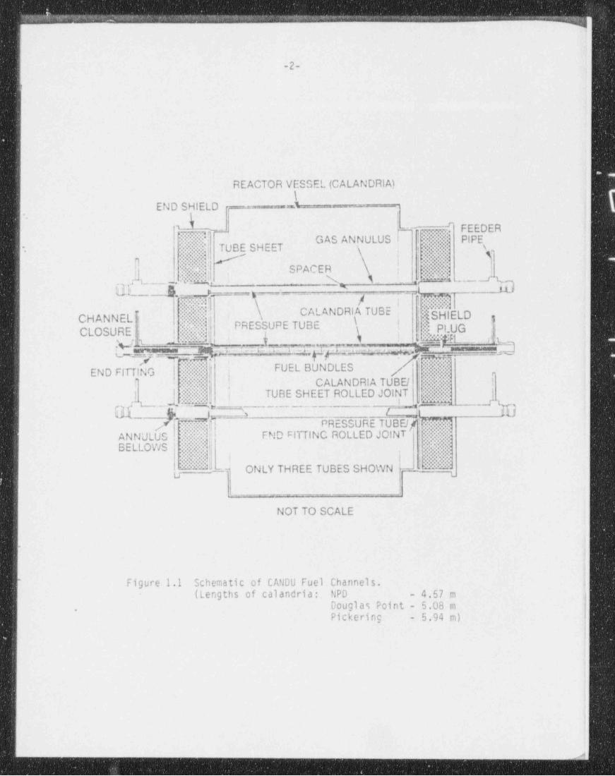
A schematic diagram of a fuel channel is shown in Figure 1.1. I,
The gas filling the gap between the pressure tube and calandria tube isair for NPD and Douglas Point reactors, nitrogen for Pickering A reactors, and
> ,
carbon dioxide for all subsequent reactors. The purpose of this annular gap isto insulate the hot pressure tube from the cold calandria tube and heavy watermoderator. Many spacer designs were considered, and the following were importantcomponents in selecting spacers:
(a) Adequate strength to carry the loads imposed, and thus maintain the,
|j separation of the tubes. ,
''!.;
'
(b) Low neutron capture cross-section. :
(c) Allow axial movement between the pressure tube within the calandria tube,
(from differential thermal expansion). -
-
(d) Allow the gas in the annulus to pass by freely.
1
* Canada Deuterium Uranium - Pressurized Heavy Water_
. '
|
L
kggwmer:rmm774 ons : m ~mm, +-- ~~ ---^
d''i,
t
2 ji
'i.
Ii
,
f
1
' REACTOR VESSEL (CALANDRIA) 4-.i
\'
END SHIELD -
\
l..}...p- < h9.m'' FEEDER |'
'-
.i- GAS ANNULUS I !..
:
:'PIPE I
! !- .s, j..?| TUBE SHEET !
- .
[1 . . iij!! # |*'
:!,. . .' :. .;
. ss SPACER.! AtM61:
* ,
Y.. .M;|- A:td: , I N4a.__es0(a.; - ..
./. -.. .. ---A"
q!5ElELDj !-
Ymig!Ii
.. Ij:CALANDRIA TUBE ;CHANNELU : I
,
PRESSUPE TUBE ! | $ PLUG .YCLOSURE || ' . Njjf!, t { k ! jmpgg _ ,$ q
,
-n_9 7 suer _g !L_.=j_ 4 g$idfi~ E UE h G9VE:
|-END FITTING FUEL BUNDLES 7 ;.'.|
' - ,,
,
I.. ! CALANDRIA TUBE / h i
J"i:. .L: ty - i| I .. ::: | TUBE SHEET ROLLED JOINT :
r t_.__ L:& %{ 'b_ . . _ _ _ _ .
k N / it/ 4] PRESSURE TUBElf; |
is , '
END FITTING ROLLED JOINTANNULUS H. ' ' .
''
BELLOWS .-.
. ,.
i s ...
"'A. . " ONLY THREE TUBES SHOWN JN,J L
|_ _ _ _ _ _ _ _ ___.___ i
NOT TO SCALE1
.(4.
<
* Figure 1.1 Schematic of CANDU Fuel Channels.(Lengths of calandria: NPD - 4.57 m
Douglas Point - 5.08 m.
Pickering - 5.94 m)
,
. . . . _ . . . . _ . . . . . . . . _ . _ _ _ _ _ _ . . . _ . . . _ ._

< l
-3-
(e) Not corrode in the annulus environment.
(f) Minimum heat transfer from the coolant to the moderator.
(g) Allow the pressure tube to creep circumferentially.
(h) Not damage the pressure tube or calandria tube significantly by wear orfretting.
(i) Be easy to install.
More recent requirements for the spacers were that (i) in the event of a LOCA,.'
there would be sufficient contact between the pressure tube and calandria tube(by sagging or bulging between the spacers) to enable the moderator to act as a
)heat sink, (ii) the spacer must not move out of position, and (iii) that the iposition of the spacer in the fuel channel could be verified.
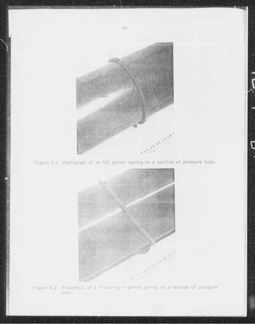
Many concepts have been considered for spacers including pads, ring's,indented calandria tubes, continuous strips, circumferential bellows and circum-ferential springs. The circumferential spring, called garter spring, has beenused as the fuel channel spacer for all CANDU reactors (see Figures 2.1 and 2.2in the next section).
2. HISTORICAL SUMMARY
2.1 NPD Reactor & KANUPP Reactors
The first CANDU reactor, NPD, had one garter spring in the centre of eachchannel separating the 91 Em OD cold-drawn Zircaloy-2 pressure tubes from the102 mm ID aluminum alloy 57S (AA5052) calandria tubes. The garter springs weremade from Inconel X750 (approximate composition, wt%, Ni 72, Cr 16, Fe 7,Ti 2.5, A10.7, Nb 1.0) and were hooked together at the ends to fit tightlyaround the pressure tubes, with the hooked ends at the top of the pressure tube(Figure 2.1). The Inconel X750 wire was supplied in the No.1 temper, i.e.15 to20% cold-worked. After coiling, the springs were heat-treated in a vacuum for16 h at 1005 K and furnace-cooled.
.
The garter springs for the KANUPP reactor were similar to NPD.
2.2 Douglas Point to Bruce-7 Reactors.
For all CANDU reactors from Douglas Point to Bruce-7, both the materialand the design were changed. The material was changed to Zr-2.5 wt% Nb-0.5 wt%Cu. A zirconium alloy was chosen to reduce the thermal neutron capture cross-section. The Zr-2.5% Nb-0.5% Cu alloy was selected over Zircaloy-2 andZr-2.5% Nb since, in the heat-treated condition, it had the best combination ofstrength, hydride orientation and resistance to corrosion in moist annulus gas.The springs were coiled with the material in an annealed condition and thenheat-treated on a mandrel as follows:
1130 K for 15 min in a salt bath-water quench-age at 810 K for 6 h in a vacuum.
,
_ _ . _ _
, . . _
-4-i
I;.wf ^
NC \r h.%; 6/v.qr, &
MN_fklW" > lN l
g $ < %g M S W M .>
F$edikp .;, n.d h. A fr ._ m .y; Q w w p p g(p.e hm. . .
a .
h:hhh;hIh_pQiy:gne.p d^f r
b'0 Iap%me e . $".
;gQ.R.t.G M ,gg. 3Au ..a.6(. v v-g .
.y; .e,. A.1 e.a -.,j '
O+% .n %n. s.
t,1
.:h1:4 ^,'Oy ' .%y; ':%:*r.q:. s ) .|.~wtu c. .v e. y
i O . p:". , .,.p2, s, x,,eoa .c Js y . . ,?a. n ,
"al(p%;O )4, #g.a %'}D@;yGWT9'f:)- ,
; .
. VIQQ vpf.QQ'*,12, ?* ' s
Mr% W t'J I }s$idf 9yd /',O
MU${&iQ$h4$:#,V"$.c F,
e 43 J-294
%ht:9ay? s' )tl.@. . -u 'Wp,| ,,.g.e;b:h,~,Q 4W 'y s
, en * s%.in, W. >sy2..hk pw s$,.
-. p1 . n
Q) g:g;r t.Q,',1i ,
%j $ yr|.-
ng- s .
,, ..-
.c ,N. / :$.
.:.
)i[ i-
I Figure 2.1 Photograph of an f;PD garter spring on a section of pressure tube. [I'
a p:an:u: w[, Q:er- L|. ,w= O [f1-rv
'w:
V J d @ Wi M @y %- o . M.r~';A&::n,:,' h,@*+ ,_ ym. f. o: 1
> ,
7 ,
1., Q.4* ||,
fQ$'
'&$$fQh$fhkf.k 6;fi ,1bMa~py;,%w&g@py,v4p,:;%:|a#o,i''r$-} .
;wqrWN A,
, , -:n.. w
J n u .. w w,y m ;i w ' m,,a n.Q<". a :.:b.a.. - - 4),.-
h: , , . :.a.. m
u q,ym,p.,. n -. -
7g .
m 5 { t 1; y 1 +3.ww ,3 -( .q , J~7 co ,ys
d (f b3,c ,13 /. ! J. ,; v.. 3 *4,- g .
/ d! @Rq w/'gj' W lu,, v - %;i$W/ ;. A s ,J - te
bf. d .. i $ . . .cr.4 .pn y
3
a
k,..yd Q; Q @;& ff _ . j
ii ,'
6 ff;f'. y .; |%, qty.
.:y
NG%@O).%Q|WW j@%8d @: ;% c W9. i 's,f}; y 4 :o ,
,ym(~ , ., AM &g,e. a.MWpgy gggg;,j..
)..[ fYN,NN$0?hhf:y;h%k@xw$y** f (I\'
. ;
hfq u :q ', a. p.4 ; n W:L 1y" wp'-vs. , ,
'y; ~ y.s %gik .. T 4? W:' i' ';: fLi.;:,.qi, W r ;N.%,+.,,.w j?.s y, ma.; .
'|bi h* 8,
'a J u, , n &- 5 ,. s
~r
. f'
' " c
-j m.v.q[,ry ., v ,.w. W ., . %.q. vp y.. ,. ,
N,. [$Y { ?. 55 f)>: ? YE', .? '
..:d;;. y); ; ,,+w. cp , < ,ie g .., s 3 ., ,a
a 'd.,; : .;1. *.; ^ i s ' ,;49 % ig, .v _ t. ,; .( ,y s 9<;, ,
t, % ;- 7 ,s :,.,
9 3, -,
,' - @+ zpF s ' ,, !.
;- <p \oby.c
Figure 2.2 Photograph of a Pickering-A garter spring on a section of pressure' tube.
i
1
1 .... -___ _ _ _ _ _ _ _ _ _ _ .
. _ ,-

- -
1
-5-
The springs were then held in a circular shape with a girdle wire of annealedZ i rc al oy-2. This wire was spot-welded together at the ends which had beenflattened (2 welds) (Figure 2.3). The resultant garter spring assenblies were avery loose fit over the nressure tubes, and an interference fit in the calandriatubes. The fit of these assemblies is illustrated in Figures 2.2 and 2.3.Douglas Point to Bruce-2 reactors had two garter springs per channel and laterreactors had four per channel.
2.3 Bruce-8, Cernavoda and Darlington Reactors
. A belated discovery was the susceptibility of the loose garter springsto moving along the channels away f rom their design positions, particularlyduring building and coamissioning. The pressure tubes sag from the weight ofthe fuel and heavy water coolant, and rely on the garter springs to maintain a.
gap between the pressure tubes and calandria tubes. When a garter spring issignificantly out of position, contact can occur after a period of operation,between the pressure and calandria tubes. This contact results in steeptemperature gradients in the tubes which, if sufficient hydrogen / deuterium ispresent in the pressure tube, can cause hydrogen to nigrate to the cold point ofcontact until solid hydride is formed at this point. This occurred inPickering-2 channel G16 and a crack initiated at a brittle solid hydride, andcaused a rupture of tne pressure tube [1]. Solid hydrides have now beenobserved on Zircalcy-2 pressure tubes from Pickering-1 and -2 reactors wherethere has been contact between the pressure and calandria tubes. However, aZr-2.50 !!b pressure tube removed from Pickering-3 reactor did not show any signsof hydrogen migration, even though contact had occurred with the calandria tube.This was because the hydrogen pickup was 25 to 50 times less, resulting in amuch lower hydrogen / deuterium content. Contact may, therefore, not have thesame ccnsequences for Zr-2.5' bb pressure tubes. !!evertheless, the hydrogenlevel n.ay not remain low for the whole lifetime of a pressure tube, and gartersprings should remain in their design position.
Af ter it was realizea that the loose garter spring design could move, thefirst reactor which could have a new spacer design was Bruce-8. Laboratory testsshowed that a tightly-fitting spring with the ends hooked together (as used intJPD ana K At;UPP) did not move with any conceivable fuel channel vibration. Therewas concern that the hooked ends of a Zr-2.5% fib-0.51 Cu spring would have radialhydrides because the hooks could not be made af ter the heat-treatment. InconelX750 garter springs were chosen, but because of the time schedule, a veryconservative design was chosen. A more optimum design, which was much less.
material, has been chosen for Cernavoda, Darlington and the new channels inPickering-1 and -2 reactors. Unwelded Zircaloy-2 girdle wires are within these ,
'
- springs (lk revolutions) to allow their position to be located by an eddycurrent method.
1
Table 2.1 summarizes the garter spring design data for CAfiDU reactors.! Note that all Inconel X750 garter springs have the ends hookea together, and are
a tight fit around the pressure tube; all Zr-Nb-Cu springs are a loose fitaround the pressure tube.
|
|
||
1
{
1%.-,-._ - _ _._ ~ ~ ~ ----,--- ---. - - --- ~1

7){|
-6-
TO P oiraiewire/UCalandrio Tube ._
ENDS.
%'
.
/- Pressure ' Tube t-
i
3
e
7
4. _
|MIDDLE2,,, .
''' ' ' '
i.,,,.,,,,,,,,,
__ hw -
BOTTOM !1
i
!|Figure 2.3 Cross-section of a Pickering Fuel Channel showing the fit of the !|garter spring between the pressure tube and the calandria tube.
|!
i|
|<
r
:- - - - - _ _ _ _ _ _ _ _ _ _ _ _ _ _ _ _ _ _ _ _ _ _ _ _ _ _ _ _j

p . .. .
I
i
b
lI1
iL}
.
ll i1
$ TABLE 2.1 CANDU REACTOR GARTER SPRING INFORMATION
1IIJ PEE 55URE IUEE CALANDRIF TUBE GARIER SPRING 5 GIEDLE WIEEi Wire Size
3 Location from Before Cooling Coil Coilj 0.0. I.D. No. per Reactor C/L Depth / Width 0.D. Pitch Dia.
1 REACTOR Material m Material m channel m Material m m m m Welded,
4 'e
$ NPD C.W. Zircaloy-2 91.0 AA5052 101.9 1 0 Inconel X750 1.0/0.5 4.75 1.0 - -
j AAhUPP H.l. Zr-2.5% Nb 90.8 Zircaloy-Z IDI.0 2 0.63 Inconel XI50 1.0/0.5 4.32 1.0 - -
j Douglas Pt.
1 RAPP 182 C.W. Zircaloy-2 90.5 Zi rcaloy-2 107.7 2 0.60 Zr-2.5tNb-0.51Cu 1.9/1.0 7.52 1.3 1.2 yes
g Gentilly I H.l. Zr-2.0% hb 108.4 Zircaloy-2 116.3 1 0 Zr-2.5thb-0.5tCu 1.//1.0 6.81 1.3 1.2 yes a
; Pickering 1&2 C.W. Zircaloy-Z 113.3 Zircalcy-2 130.8 2 0.95 Z r-2.5 t t.b-0.5 t Cu 1.7/1.0 6.81 1.3 1.2 yes yi Pickering 3&4 C.W. Zr-Z.5thb 111.5 Zircaloy-2 130.8 2 0.95 Zr-2.5thb-0.5%Cu 1.7/1.0 6.81 1.3 1.2 yes
| Bruce 1&2 C.W. Zr-2.5 L kb 111.5 Zircaloy-Z 179.0 2 0.91 Zr-2.51'hb-0.51Cu 1.//1.0 6.81 1.3 1.2 yesI bruce 3 C.W. Zr-2.5% tt 111.5 Zircaloy-2 129.0 4 0.51,1.55 Zr-2.51hb-0.Sicu 1.6/1.0 6.81 1.3 1.2 yes
| Bruce 4 C.W. Zr-2.5% kb 111.5 Zircaloy-2 Tl9.0 4 0.51,1.55 Z r-2.51t.b-0.51Co 1.6/1.0 5.59 1.3 0.9 yes
Gentilly-2Embalse
l't. Lepreauwolsung-1 C.W. Zr-2.5% Hb 111.8 Zircaloy-2 129.0 4 0.51,1.55 Zr-2.5 Nb-0.5tCu 1.6/1.0 5.59 1.3 0.9 yesEruce 5,b,7 C.W. Zr-2.51 Nb 111.6 Zircaloy-2 729.0 4 0.51,1.55 Zr-2.5thb-0.51Cu 1.6/1.0 5.59 1.3 0.9 yes
Bruce 8 C.W. Zr-2.5% kb 111.6 Zircaloy-2 129.0 4 0.51,1.55 Inconel Xibo 1.0/1.0 4.83 1.2 0.9 no
Cernavoda C.W. Zr-2.51 Nb 111.8 Zircaloy-Z 129.0 4 0.51,1.55 Incorel A/50 0.8/0.8 4.63 1.6 0.9 noI' Darlington C.W. Zr-2.5% hb 111.8 7t rcal oy-Z 129.0 4 0.51.1.55 Inconel X750 0.8/0.8 4.83 1.6 0.9 no
Fickering 1&2Retubed C.W. Zr-2.5% Nb 111.8 Zircaloy-2 130.8 4 0.51,1.55 Incenel X750 0.8/0.8 4.83 1.6 0.9 no
1
,
1--__ . _ . . _ . - . . - . - _ . . - . . .-- .. . - . - . - . - -. - - _ _ _ _ -___-_

_. __ _ . . .- . _ _ . .
l
.g. )
Ii
|
| 3. DESIGN AND TESTING OF UNIRRADIATED PICKERING-A AND BRUCE-182 GARTER .
SPRINGS |
i3.1 Design j
t
\
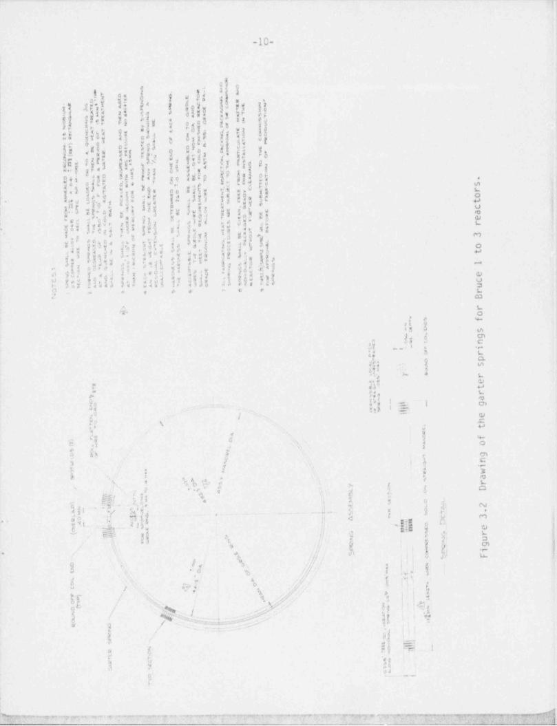
| The designs of the Pickering-A'and Bruce-182 garter springs were very|
similar with the same wire and coil dimensions, but slight differences in otherdimensions because of the small difference in calandria tube diameter. Drawings'
for the two assemblies are shown in Figures 3.1 and 3.2. The design load foreach spring was 1380 N for 2 springs per channel which is spread over a number'
,.
of coils. (This was later raised to 1550 N.) The peak load per coil wasestimated at 22 N.
3.2 Operating Temperature
| A Douglas point garter spring was electrically heated (to simulate gamma; heating) and held between a hot section of pressure tube and a cold section of| calandria tube. The temperature of the garter spring was estimated using| indicating paints and miniature thermocouples. These experiments indicated that| the temperature of garter springs was almost constant and about equal to the| pressure tube temperature [2]. Thin sheets of mica were,however,used to
electrically insulate the spring from both the pressure and _calandria tubes, soit is unlikely that local cold spots, where coils contacted the calandria tube,would be produced.
3.3 Zr-2.5% Nb-0.5% Cu Alloy Properties
The Zr-2.5L Nb-0.5% Cu alloy was examined to find a satisf actory treatmentfor strength and hydride orientation. The optimum mechanical properties aredeveloped after water-quenching from about 40 K below the p-transus and aging at810 K for 6 h. In this condition, it was found that straining the wire to makesprings resulted in hydrides which were unf avourably (i.e. radially) oriented ;
[3]. Thus, it was recommended that all heat treatment be done af ter making the !
springs. Tensile tests on heat treated specimens after irradiations up to i
3 x 1024 n/(m2.s) (> l MeV) showed the following effects of irradiation [4,5]- |
(a) yield strength increased about 25%;(b) reduction of area was not affected;
- (c) uniform elongation was reduced. |
3.4 Wear and Fatigue Tests -
,
Garter springs were tested for fatigue and wear in rigs made up from Hsections of pressure tubes (at 565 K) and calandria tubes. The loads imposed onthe garter springs were up to 4700 N, i.e. more than three times design load,and the pressure tube sections moved relative to the calandria tube by 12.5 mmI
!for 1500 cycles [6]. Metallurgical examination of the garter springs showed nodistortion, wear, or change in hardness with testing. Wear marks were apparent ,
|
f- on the bottom hal f of both the pressure and calandria tube sections. The- '
maximum depth of marks observed were 0.06 mm on the pressure tube, and 0.19 mmon the calandria tube, and the average depths from all the tests (regardless ofL
| load) were 0.04 mm and 0.07 mm, respectively.;
|
4

.. -
| !
l
|
|
j -9-
!._ _, g, _ ,; ,_
5 ..g se 99,o oze 6r 5' Y i
5 :.- 54u.; as Ed g "3 3 j {s e{| ! ;J' ,
|rs5C *e33'9*! 3g
f, j .4 g| f o3 je !!! f = s e 9 !, is a
*t s r, b$i 'vi 3f s ii O g % we!-
$I # $ !!w!| E|s d dsli!a;fi E*b53 "d ad5
!$ !.$! 0 !! |i g $ 0 ;og'-d
W | |( i 8 2
-ti W )a ua5[ag2-s i!sw$-, .
1fiiag haaES =gf 2' " c o.3< so.3 < s * sf r 5 .i qua re se e
a!Y i5Eo
j53 5ok$$5 o osh.1rtuag,d 34IQ $ ,#'
0" g E ,2
4 ,1 s < "so-
<Eg2 *#s4.2eo.
a '9 y 9 " dt- g 3du *d5
* 2'' d31e "*a 93~o" a "i o2 g
a .e B < c 5 2s
5 i ' e' t ? 2 5o
$5;5.i$dd" ->
135|g.yt? 83 i3 y5- i 1 pe a
gid d s ' jg f g 8 s, s a d 3 :.aaSg*e 2
g''a(D*!,jfg3g 3 0 a'3 6 a 8 33, sj ox ge m. , .
- *5a'e nyi Cai 'i 2E' ' y % j "dS -<
f*$2 5 .y j d<?'d 2,d s 'ao t oo=*3o o r t, a s o,s<r c$2 W ii - s e w
= o -
u.sx. w3es2ou sG-s- w ,2{ s
y. x ,-
52 b*i -.,t8J k 6
[1 "' ti & aff 4 6 a3 61"
.
M 'EW,Fg o.,
I Isamowww AwsGuAs no c ewis oass aanwes anat A4 .tabhl1 8e '|! t I
| | m i, ,l '-, ,
o_,
_,________g______, ;.________ ,,
|> r ______ g_____. >__._______._4 g o
, , ,
\ ht| {' i i ,1 -
a
m. S; f a me | *! .r ~/ a. .,.I J, p. c,| . - 6 . . -
g:! o s urg,, ,
ih: ! 8-
-
; te Nt ,-
-\ h,s | w$5|& |
% i~ ~~ <
;
tb t' :d N :
%[c / , -[d,[n-:)( ~
\, . , . . .
h|, \ ja
\ ; :O' j'/ y \1
', '/ N< ,. ,
l'., \ 5s
g L\re[y,
, 3s ,g , s
\ \: it\ 2>
N \:o, 5 os
t w (.{ o r >. x
.P,I _.[. s }%[$ __.%d._ . _. m. j 2
!'d,'"
.
|'
/ <,1 3 f .9 p %. l' ; e Wn, z %
,i, _g sy
// @9 f'.'
' f'S y.g,%*
g yog e i 1., 9e
-
,/y o ,-
'I c\,e
yea,ft y, \ i, I
$ %~ i|
,
N ''| | 1i
\T .s & >) 5 'f //g'a N. A eL -F , , ,
g ),, . '[, /
, s. .- , 4o
/
2 w. -vA R Q W _ ~ j.2'
| ',
A .- -- - ..: - - - _. _ ,_, ,
.i-a .- m.am.am- m g,..m & 4sk-4.A. da-e4 -.-4 ,e.c;- /. 4 a .#4_ L. 4 _. ., ..
.-
!i:l',
4
-10-
r,
i
I
'
eD IJ
gov! |I:g.
air ., 5/ p;opi 2: {<.
si r .ii -** , t
] h*r 4 *S ; o,a4 s; 21 gg,
d.. L( Jg'
U ! ! *oI b
.3 'a a s g8 -
|p*1 y 5,s,p 3.'F
ij 1
,f%e3:- e5 3
f5$5 $y8E4 P'E
...s 3 .j7 ;
s11 u
d.O} aji! s?!$
''3,
16 c |10 g!NaI3 D .
e p,
15 .Io't Lp: jw! e: :d|s[I:fji18c. i .s g- -t
!~ 2 3 d'li" ,3sI'
erJ.s|u
os f 3 y3,g.E j3
i.!! 6!h a i;i!!!!,|>1Sih3!$!L v
n su (-u "- - sNw l PML,|f,b!'r j?o
.
ji s f * . j'j J ,e 5 or# :of3y" o -,4.
f**iasta,',0$p,'1 g ! 'd h fi ( > *> y$3%o.', g . cl ,4!03 in
s, j ? y!,1i - !
w( /.-
-
,n y i a
I $$5 I!a,i$ $2! $lhi $I Nk 5 i 'Ih!:!!$ 8s<u .,o .
g ,
9- . , . . - . .'w
A %Y o
,
>
$r '
.i s v.
$.*
ag . .-...1: 3 L
th } $%! ' 'L a '.!
$1' h.
s:4 'r ,o t
mQ \ cn,u
a , . m:..- 2 == - .5 =;
/ j ,g c\p A
1
hu $/ <
,yx - %o - i
E ,1 * Oa Ae f y -3
c3 ab Cn%3 %,- | e c
5 . < y+
**=j./ 2
u. e 3:*
,s s
kb
u g o 8 . 3 o*
,1y,.
5e
E .p1, . _.h,g*. . .. _ _ , . . _ . . . - _ . - - - . _ _ ..._ o g ,h. ; N. ;
* P 1 y p ;o%
' y .2
4 h i ^ ^ '' ,
|Mq' 3 f. $,.4,,n
s =...i= ow$,L_= m$6
.. 2j' Ria $
40-
'g' f h ig " '~
ii J $ j; *s k o. en/
,/ w(' J / @ 6 G * * *
9 \l 8 ,: 5, y ./ I "! @f.
g ';
, t,
,,5 . y $,? "./ b.,
;
l,. ,g > .o j. <: .w d / ,/ 8 j .
b.,
gr 8; ' 'i 's / :/ i >.
Q . . . / ;t =
q, o!3 / ~e=f-
l'5 /
6 s, MR, 1 ,= .,
v n .$1 ! II
$ 't BJ ;
n,'I'
i
P
NNM'9* 7 *1* 7 Pap * 4'-P=5pW',t*** newtasp TP e-ar =7 *y v qw ype.g getem-pan.gpwayry y _

I|
-11- I
|Rolling wear tests on broken Douglas Point garter springs showed that ithey still performed satisfactorily [7].
3.5 Crushing Tests
Sections of garter spring, 90 mm long, were crushed at room temperaturebetween mandrels that had the same curvatures as the inside of a calandria tubeand the outside of a pressure tube [8]. The tests showed that these sectionsbecame unstable at loads greater than about 45 000 N (although maximum loads ofup to 110 000 N were achieved) with the coils starting to tilt sideways(operating loads are up to a maximum of 1550 N).
.
3.6 Hydrogen Migration
Pieces of garter springs were placed between Zr-2.5% Nb plates, one at-
about 610 K and the other at about 345 K. Af ter only 9 days' exposure, a solidhydride was seen at the point of coils where they touched the cold plate [93There was no simulation of gamma heating in the coils, so that the temperaturegradients were not the same as in a garter spring in service.
Some similar tests on Douglas Point garter springs placed springs whichhad been hydrided up to 500 ppatbetween Zircaloy-2 faces at 566 K and 333 K atloads of up to 270 N per coil for up to 2 months [7]. Some of these springswith the highest hydrogen and loads failed during exposure af ter 150 to 200 h.However, springs with 100 ppm hydrogen and loaded at 180 N per coil were intactaf ter 1500 h; crush testing these springs showed the failure load had onlydecreased 15%.
,
4. EXAMINATION OF GARTER SPRINGS FROM PICKERING-A AND BRUCE-2 REACTORS
Garter springs have been examined which were removed when pressure tubeswere changed in Pickering-3 and -4 reactors af ter 2 years' operation, Bruce-2af ter 5 years' operation, and Pickering-1,-2,-3 and -4 af ter about 12 years' |
ope ra ti on. The operating times are listed in Table 4.1 below.
TABLE 4.1 OPERATING TIMES FOR GARTER SPRINGS EXAMINED. !|
h, Reactor Removal Date Operating Time (EFPH*)
F. Pickering-3 1974 August 12850 |'
Pickering-4 1975 May 15140Br';;e-2 lop October 40535**Pickering-1 . U November 88900 !,
Pickering-2 L m % gust 86885Pickering-3 1984 April 83758
,
I Pickering-4 1984 September 82670 i
;
ii
| * effective full power hours; ** full power taken as 2515 MW (i.e. design)..500 x 10 4 wtS
w .. + ,. . , , - , gn .,s____
-N
-12- 1!
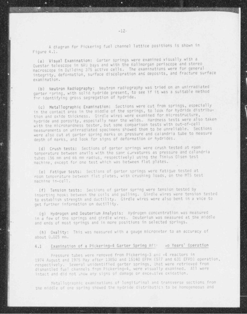
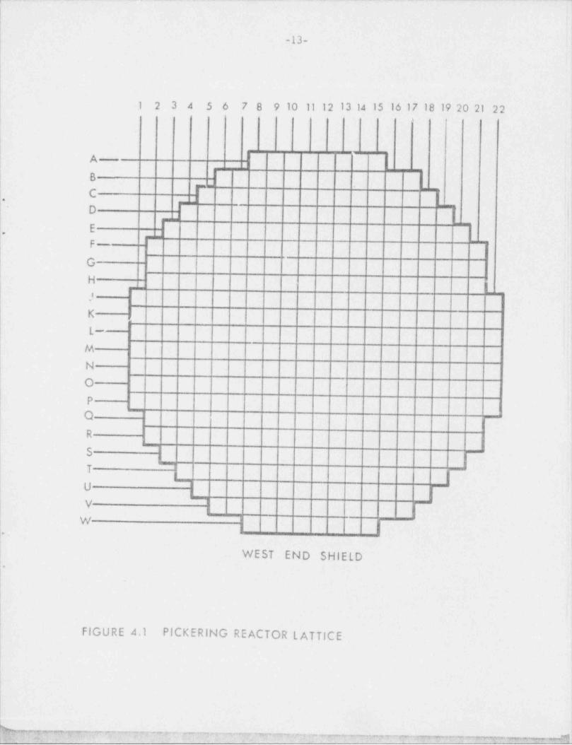
A diagram for Pickering fuel channel lattice positions is shown inFigure 4.1.
(a) Visual Examination: Garter springs were examined visually with aQuestar telescope in NRU bays and with the Kollmorgan periscope and stereomacroscope in Building 375 active cells. The examinations were for generalintegrity, deformation, surf ace discoloration and deposits, and fracture surface*
examination.
(b) Neutron Radiography: Heutron radiography was tried on an unirradiated*
garter epring, with solid hydride present, to see if it was a suitable method )jfor identifying gross segregation of hydride. ||
L|,
- ''
(c) Metallographic Examination: Sections were cut from springs, especiallyin the contact area in the middle of the springs, to look for hydride distribu-tion and oxide thickness. Girdle wires were examined for microstructure, ,
!hydride and porosity, especially near the welds. Hardness tests were also takenwith the microhardness tester, but some comparison tests with out-of-cell 'lmeasurements on unirradiated specimens showed them to be unreliable. Sections 1
were also cut at garter spring marks on pressure and calandria tube to measure -|
depth of marks, and look for signs of deformation or hydrides. .|!!
(d) Crush tests: Sections of garter springs were crush tested at room 3|
temperature between anvils with the same CJrvatures as pressure and calandriatubes (56 mm and 66 mm radius, respectively) using the Tinius Olsen test'
machine, except for one test which was between flat plates. !|-
(e) Fatigue tests: Sections of garter springs were fatigue tested atroom temperature between flat plates, with crushing loads, on the MTS testmachine in-cell .:
(f) Tension tests: Sections of garter spring were tension tested byinserting hooks between the coils and pulling. Girdle wires were tension testedto establish strength and ductility. Girdle wires were also bent in a vice toget further information on ductility.
(g) Hydrogen and Deuterium Analysis: Hydrogen concentration was measuredin a few of the springs and girdle wires. Deuterium was measured at the middle ,
and ends of most springs and in more positions.in selected springs."
(h) Ovality: This was measured with a gauge micrometer to an accuracy of k$'about 0.025 mm. (4.1 Examination of a Pickering-4 Garter Spring Af te Lwo Years' Operation
Pressure tubes were removed from Pickering-3 and -4 reactors in1974 August and 1975 May after 13850 and 15140 EFPH (577 and 631 EFPD) operation,respectively. Several unidentified garter springs, that were retrieved fromdismantled fuel channels from Pickering-4, were visually examined. All wereintact and did not ahcw any signs of damage or excessive oxidation.
Metallographic examinations of longitur'inal and transverse sections fromtne middle or one spring snowed the hydride distributica to be homogeneous and
,
._ -
'
,
I
|i
-13- !
1 2 3 4 5 6 78 910 1112131415161718192021 22| '
i|
A,
B'
| .--
C.
D
E..t
p-t
1<
G
HI
' ~
.
I
K,
;.I .,
| L- i.I
l<y <
N
O
P !
O|
1R
1,
| 5;
7| || U
V '
(
! Ir.| WEST END SHIELD!.
t, -
FIGURE 4.1 PICKERING REACTOR L ATTICE||
l
!i
M 6*"9 y w n 7 *7+a w & +c - --~mine-e yym.e. ,e. g., g.y , , .;. s. , , , , , , ___
- m
-14-
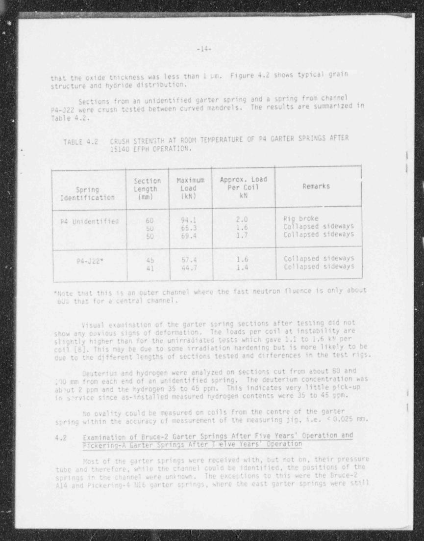
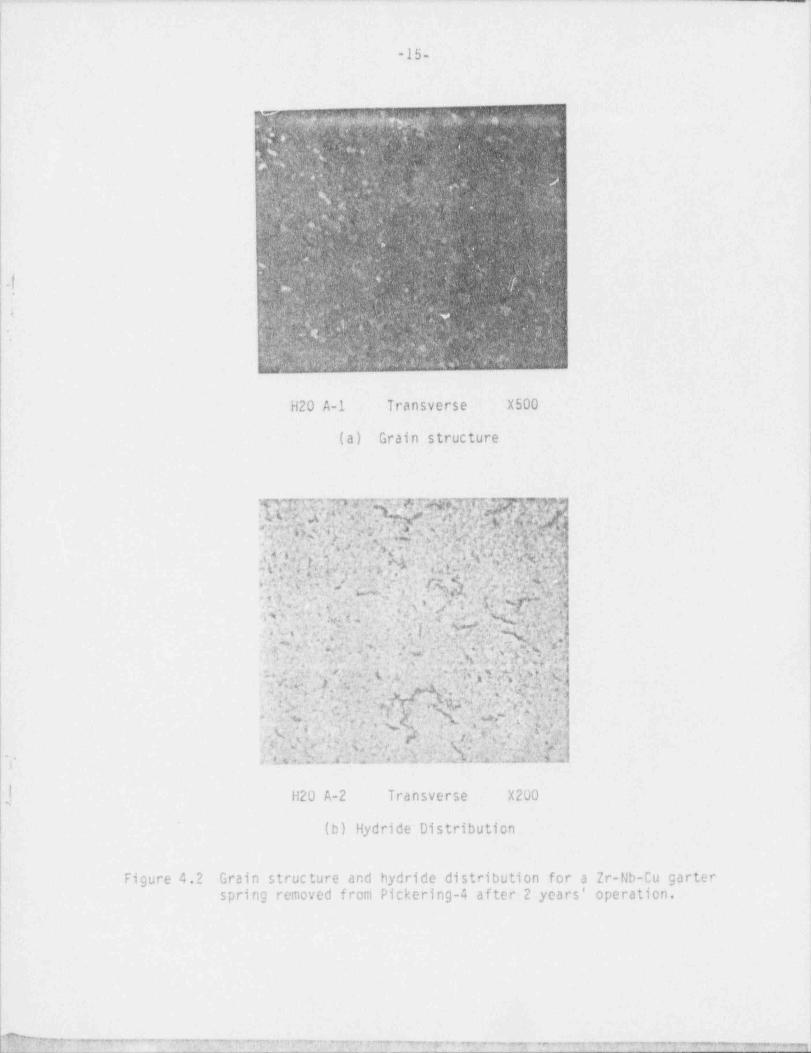
that the oxide thickness was less than 1 pm. Figure 4.2 shows typical grainstructure and hydride distribution.
Sections from an unidentified garter spring and a spring from channelP4-J22 were crush tcsted between curved mandrels. The results are summarized inTable 4.2.
TABLE 4.2 CRUSH STREtGTH AT ROOM TEMPERATURE OF P4 GARTER SPRINGS AFTER15140 EFPH OPERATION.
, 1
- |Section Maximum Approx. Load
Spring Length Load Per Coil Remarks
Identification (mm) (kN) kN
P4 Unidentified 60 94.1 2.0 Rig broke50 65.3 1.6 Collapsed sideways50 69.4 1.7 Collapsed sideways
P4-J 22* 45 57.4 1.6 Collapsed sideways41 44.7 1.4 Collapsed sideways
* Note that this is an outer channel where the fast neutron fluence is only about001 that for a central channel.
Visual examination of the garter spring sections af ter testing did notshow any covious signs of deformation. The loads per coil at instability areslightly higher than for the unirradiated tests which gave 1.1 to 1.6 kt> percoil [8]. This may be due to some irradiation hardening but is more likely to bedue to the djfferent lengths of sections tested and dif ferences in the test rigs.
Deuterium and hydrogen were analyzed on sections cut from about 80 and- 100 mm from each end of an unidentified spring. The deuterium concentration was
ab'ut 2 ppm and the hydrogen 35 to 45 ppm. This indicates very little pick-up ,
in vrvice since as-installed measured hydrogen contents were 35 to 45 ppm. I'
.
!No ovality could be measured on coils from the centre of the garterspring within the accuracy of measurement of the measuring jig, i.e. < 0.025 mm.
4.2 Examination of Bruce-2 Garter Springs Af ter Five Years' Operation andPickering-A Garter Springs Af ter T,'elve Years' Operation
Most of the garter springs were received with, but not on, their pressuretube and therefore, while the channel could be identified, the positions of thesprings in the channel were unknown. The exceptions to this were the Bruce-2A14 and Pickering-4 N16 garter springs, where the east garter springs were still )
.__ _ _ ____ 3
_ . - - _ _ _ _ _ _ _ _ _ _
|! ,
i
1
-15- .
1
1
1
w :w. $ ... nA % e #k a 1 4 ,s .o
. .
.. e ' W. %.s..u. .
.. ..1- -
, 24.> / ,
nn V. ,.. . .,
n.. . .q ' gp JNy:. .[: ' ? L . . .
.;s
. .4.. , . . - '. c .6 .. .
N [ p . 4,,, d. :
'
v ;x.
..f. -[ -. :.A ..
( - . w. ,4.,. *... .. ..
yp,. ,.. ; . 7. , . . . ..
.. o . .. . . , . <y 4 g
f. .y .,%uV| .y, '. , ' * . y ,? -;.
. *N** s
- M r.
'
, $.,f .
.''*
? |4 ' . , .'|.
. ',.. , , _ . . . .f.
*: |y
4 , ;[.
. .
c%. . . a . i, , e, .. ..
's .. ,f; 6.,
ag y. e r .. :,,. . . . ~ -.. \ .
e
p .k '$ . '5 ' ,N8.
.
[M
$ '.
H2O A-1 Transverse X500
(a) Grain structure ||
wy! v.4 +[u ih v..,s,f;q r)t ,, g';m. t q . v.
g:* y: pv,ep -; Y ; f. ,'i.g,y.+; , ppp,Ap$wW=f|,7,7.|g:.
Mf, g 'cN Qgi',
.-
. w n: d'in, g, t n . . :3.d F M :c.vf,.A, m :c amj. , 54v '; .; . M , n * ,,..c . . r ;s. c .Q, .m .
.tu , +,- u ,rs . . .
gf ,. h~r,7+.s , ., y,
- ' we. ;*~.
n ,"1 :,a n, . ; , : c a,',e. wn, z ,.4.,fj>;-a*4., ; ,e,,
# T. . k'y% a >. ; c. .. r ..
.1s.
*,
7 , . Q, A*; ' , ,g' n.g , y* ..e g .p.,
rn.x, ,-
O. m.. :
-..=* m?*-isr >. 7,
.g -. to j Q , y* -| .2;,.j}'@y | ,h ,,#.rN y??()|,-| &,. >4'*A
,
y4 L A*
N ;'.t. t +,,| ' |i. , *-4
*< ,
&<|y,qr, 9 q e-;V .%4,yo,. s q: |.,_'
.. w . m .). iq q .g. pg;;j ,<,r, 4,;; ; i .,,,4 ,,
gv, A*y. ,P. q!;,i, ..y,
...qe~.% ,%. ,,,.4 f ;g:r.w m, W.. *
.,
K*. |; a. .y. e
, n,WD % ;j ?.m, s.t9g.;, ',3&. t. i. e.y , o.c ~.,O~. ..w. m.m, , w. . .
. ;
,s;>m,;3 3,:e . ..,.
q,p%n.4:;m . ?n| .:.
, .f. .'.. \ e,i.., .. ,
..
. m ....
e'E, ~h,. ;:;w;,..
,
r. u Qm ra c.::;qg&... _. .' Q:'M3i6"-f, </
. ' .Rh.2:kM... ' j * k'}f.f 's K.'. u L L,. L 's.LV Z,a? A;.:n! ,
G~f
ij H2O A-2 Transverse X200
.(b) Hydride Distribution
Ii
Figure 4.2 Grain structure and hydride distribution for a Zr-Nb-Cu garterspring removed from Pickering-4 af ter 2 years' operation.
i*.w3 m+,% .. _ . - - - . . . . == m ,,. m. - a, r , e v.w y y.ye, 7 . e r- . p y y, w , ,.y., , ... ,,,,, . ,.w w, w. w e pe- ,+s ,*7 ww-se,ewomwi. . _ _,

_ -
I
! )'
-16-'
,
on the pressure tubes, Pickering-2 J15, where the garter springs were supposedto be correctly identified, and Pickering-1 P14 garter springs, where the gartersprings were received with end fittings. Thus, except for these four channels,garter springs have been numbered 1 and 2 for identification. The garter springs |from the channel P2-G16 were received in many broken and deformed pieces. Most
,
of this damage was believed to have occurred from the rupture of the pressure |tube but further damage may have occurred when removing the pressure tube.
4.2.1 Visual,Examinatign 1
<,
'Most of the garter springs received (~ 70%) were completely. intact, i.e.- '4
,
unbroken and undeformed. Some garter springs were deformed and a few werebroken and deformed. We believe that all. the deformation and breakages were due ;
- to handling and shipping damage after service in the reactors (except forP2-G16). Most of the garter springs were shipped in the same cavity in theshipping flask as the pressure tube pieces, and one spring, P1-G16 [2], wasjammed on the end of a pressure tube section; it was deformed but not broken.Figure 4.3 shows photographs of an undamaged spring, a deformed spring and a :broken and deformed spring. A summary of the condition of the springs is given
j in Table 4.3. No hydride blisters were visible on any of the springs, and oxide ;
; appeared to be thin with different interference colours. The spring from B2-A14 ;
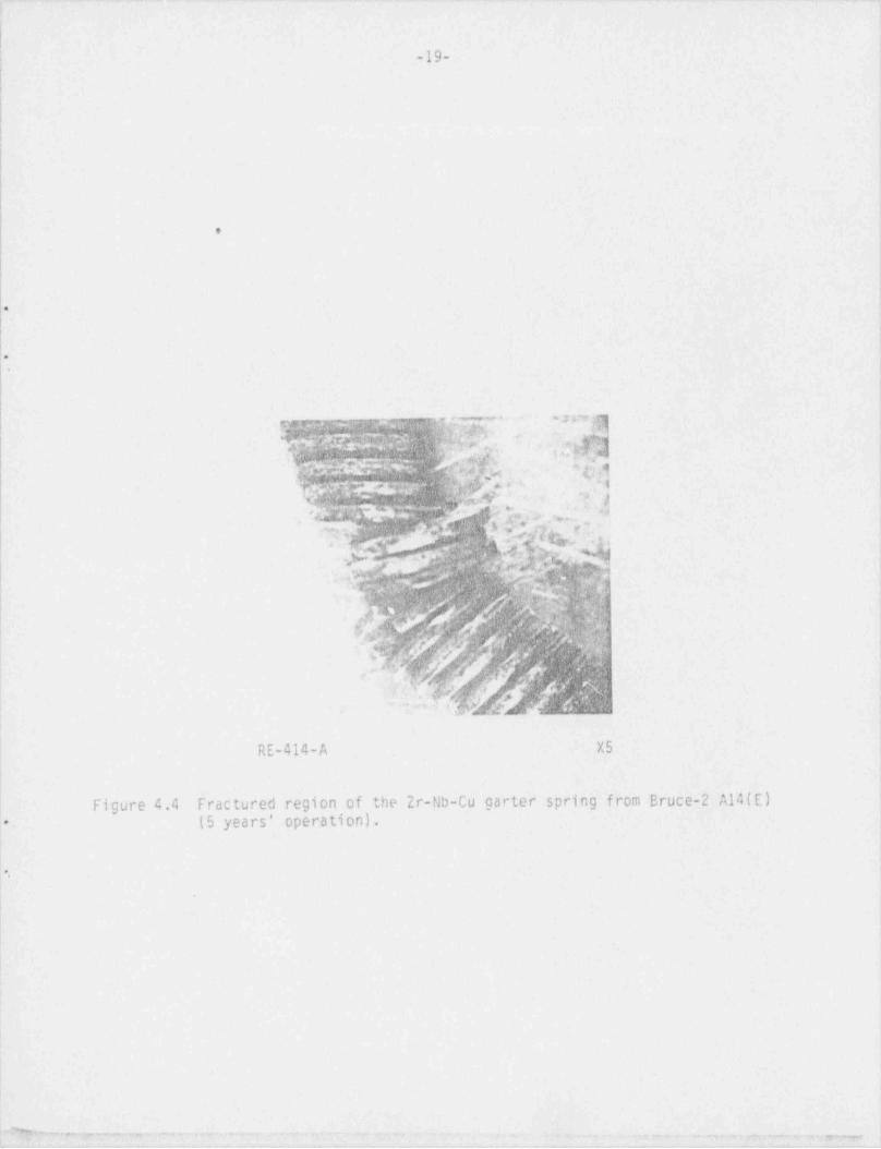
| showed the least signs of deformation at its fractures and photographs are shown;
; in Figure 4.4. All other fractured springs showed much more deformation close i
! to the fractures.! !,
4.2.2 NeutrgnRagggraphy
1
Neutron radiography was tried on an unirradiated garter spring which hadhad a temperature gradient imposed to give solid hydride on the surface. This,' ,
technique proved to be unsuitable for detection of hydrides in garter springs,because the resolution was insufficient to detect solid surface hydrides of the ;
size which have been observed. '
4.2.3 ge,ta}}ggnaphig,[xamjgaMgg.
(a) Garter Springs: Most sections of coils from the middle of springs| showed migration of hydride to the outside of the coil where there had been
contact with the calandria tube. In the few springs where this migration wasnot observed, the deuterium concentration in the spring usually suggested that-
-; >
] the spring had not operated with the middle at the bottom (see Section 4.2.8).i The garter springs in P1-P14 operated very near the ends of the channel and
*
probably did not have any portion squeezed between the pressure and calandriatubes; the observed absence of solid hydrides would therefore be expected.Figure 4.5 shows examples of solid surface hydrides of different sizes.Table 4.4 summarizes the dimensions of observed solid surface hydrides; notethat the size range is unlikely to be real because we probably did not section
; through the largest hydride all the time. Note that garter springs P1-G20(1): and P3-J09(2) showed more than one solid hydride on a middle coil, which indi-, cates that the contact points between these garter springs and the calandriaJ
i.
4
J
~u __ ~~ e ~~"""~ ~~ ~ " ~~~~~""*''Y% ._.~., _ _ _ _,._,_ - , - , - , ~ ~ ~ ~ --~rn

!!- -
-17-
..
.-
t 6
! e
i
' . . i
t i,
i~
. .
. - t
!.
,!
,
PlK18(2)- m,--
37f-
gr- ;|
;
GV !'
,
i i
I|
i .j '
) ' I ;i
.
\
k
!: |
!!
|.. . .
..-rj. w w:t ..
| w.m
P1G16(2)any p .e. , .,,',y4!'s5'Y j . .
k ,
., %: *c.gjs 4 ._ \ E s
,
$ $Y.. ;;- y,.
-, -
.e ....
.
q...
(,
c,,,
.!.
h4
c % g %' '''s 2;7Q q* i
4 !t-'
gc**1 Q\.
.-_
P2K13(1)
Fi ure 4.3 Examples of the dif ferent conditions that Pickering-A garter springs9were received in at CRNL (12 years operation).
py; ,y.y.ym.p.- rw-~ r - .. ,-.rm.--r mr ~--- rt<-~ ~_pg. >i. , _ . _ _ _ .
. -- --, - -- -.,-~ r 3 ~ !4,.
- - - - -

, a
-18-|'
J
TABLE 4.3 SUMMARY OF VISUAL EXAMINATIONS OF PICKERING A AND BRUCE-2 GARTERSPRINGS *
SpringIdentification Garter Spring and Girdle Wire Condition
B2 A14(E) (outlet) Spring broken near middle (5 fractures), deformedelsewhere/ girdle wire intact
B2 A14(W) Spring / girdle wire intact ;*
'
P1 G14(1) Spring / girdle wire intact i
,
,
L P1 G14(2) Spring broken and deformed / girdle wire broken ;~
P1 G16(1) Spring intact / girdle wire broken |P1 G16(2) Spring intact but deformed / girdle wire broken
i P1 G20(1) Spring intact / girdle wire brokenP1 G20(2) Spring intact / girdle wire broken ,
: P1 K05(1) Spring / girdle wire intact Ik P1 K05(2) Spring intact but deformed / girdle wire intact'
iii !
q P1 K18(1) Spring / girdle wire intact i
j P1 K18(2) Spring / girdle wire intact14 P1 P14(E) ( outlet) Spring / girdle wire intacti P1 P14(W) Spring / girdle wire intact |
f P2 G07(1) Spring intact but deformed / girdle wire broken i" P2 G07(2)|
Spring broken and deformed / girdle wire broken'
) P2 J15(E) Spring / girdle wire intact| P2 J15(W) (outlet) Spring / girdle wire intacti
! P2 K11(1) Spring / girdle wire intactj P2 K11(2) Spring / girdle wire intact
P2 K13(1) Spring broken in 2 places and deformed / girdle wire brokenj.. P2 K13(2) Spring / girdle wire intactJ
i P2 G16 Spring / girdle wire broken into many pieces and deformed;?
! P2 V09(1) Spring / girdle wire intact!
P2 V09(2) Spring / girdle wire intact i
P3 JO9(1) Spring / girdle wire intactP3 JO9(2) Spring / girdle wire intact
!
,
P4 N16(E) (outlet) Spring / girdle wire intactP4 N16(W) Spring broken in 2 places and deformed / girdle wire broken
"""E= . , . . _ . . . _ , .. .x: --"
.. . - - . . - .-. . ..-- . .-
1
I ,
-19- :,
! -
!i !
|l'
;
i
;
1
|I *
l.
;
i
-[e,
!.
= ,
i
!
!~
gyf>;, pf%'H/' . 5fh 's, *\ueg; W&- \;i e
(Ak \,
A.:g*;~. 44y'?,; , ~Ch\
- n, \.
**~,\. biw..:-
,
c.3f.,s
' ,a ~. ,
, ~
.:. e h_
Ynkr: e,, s
Whfig bynhy .
' h g:agh8
.
\ '
\ ;
s'
!6
t
RE-414-A X5
i .)! <
Figure 4.4 Fractured region of the Zr-Nb-Cu garter spring from Bruce-2 A14(E) j1. (5 years' operation). |
|t
i
[ *.'
t .
,
! !i :|
|
l
1:
| -% ~ ._ _ .._-.-._r..,._ , ,. ,. . . . _ ._,_,.y..,...,.;,_,,.

. _ . . __ __ _ _ . . . . _
i
|
-20-
.
TABLE 4.4 HYDRIDE OBSERVATIONS IN THE MIDDLE OF GARTER SPRINGS AT THE OUTSIDEOF THE COILS *
|
,
p
Spring Identification Surface Solid Hydride Dimensions, depth x width, mm
B2 A14(E) 0.15 x 0.80 i9 B2 A14(W) No solid hydride
Pi G14(1) 0.06 x 1.05 |:*
P1 G14(2) 0.06 x 0.38 '
l P1 G16(1) 0.03 x 1.80 !P1 G16(2) 0.11 x 1.35 |
P1 G20(1) 0.03 x 0.40 + 0.03 x 0.30| P1 G20(2) Not sectioned '
P1 K05(1) 0.04 x 0.90P1 K05(2) Not sectioned
,
| P1 K18(1) 0.10 x 2.30 i! P1 K18(2) 0.10 x 1.25|
| P1 P14(E) No solid hydride !'
P1 P14(W) No solid hydride *
P2 G07(1) 0.05 x 1.45 (P2 G07(2) 0.10 x 1.50
| P2 J15(E) 0.03 x 1.20| P2 J15(W) 0.05 x 1.70 ;
P2 K11(1) No solid hydride, some concentration i( P2 K11(2) 0.10 x ? (width not known - at fracture)I
P2 K13(1) No solid hydride, some concentration*-
P2 K13(2) No solid hydride in middle, 0.10 x 1.3 at end*
P2 G16 Unable to determine middle on pieces retrieved
P2 V09(1) 0.02 x >0.95P2 V09(2) 0.06 x 0.50
P3 J09(1) 0.05 x 0.95P3 JO9(2) 0.05 x 0.80 + 0.03 x 0.60 + 0.02 x 1.10
P4 N16(E) No solid hydrideP4 N16(W) No solid hydride
I i
)1
| |.
,
-~#,-. s. u -

.. .o c..
:-
.41)a
.
l.-1
] MilMQ$@['
''
d4Nk * Y- - -
25 \QbS?SN$$$Md~ h*'
Q ' [ |% ~ ~ %; , % '' .| .!R.$b%.;.
. , . _
. ,' d~ : n ~.~ ''
.-QWF M|d[ mA ..yy - ., - ~ _
, , - . ' .- z,- . - .-
~Jgg...w- ge..%y .Qp'x:-R_. s ' ' -.% ~ . , '
. ,. a,..
t '
.ap Y- .' b Y''Y :: . _'f 'K ~~ ' Z _ | ^ ' . ' '' .
~ r..a . ~~% ;- 6F n
.,s , . . . . , - - .r -r <
.I ... -5- q... . . . ., .
..
5 <.s. ,.,
'~ - . |_ , , _ _ O . . h bh,
* * *-, , ,_
'
. < < ;Q' _?. .._ . .:, .;.' v,;e-;jt,M,wA6'; : ;,. t ':.:, 'r %-.. ~ .%. - ; ?,
. . .,~ ~ ~ -
- - . .; r,%' *, . - - -
.,
- - -... . ... < r .. , -
- .-w.- > , . ,.,v _.,_ s. . 2 , , . , .. .~ - .: . . .
-s +. .m. . - ... . . .. - -n
.
', . [. - ' _-
.. s_ -- e ' ' .
K a. .. a.2; 3_ym%. . ~ . , . . , ..- ;.. , . ,. %. --- s. .4 s.-, ;. 3 . -
., . ,r,c m.. , ,- . .-
*3 .. y -.
it ' ,..g~ ~- , . -.
- s. -., ,
,..,,'ax.i., v. . .
-. . s_ . . . . . .s. . . . . .,,
.-- z , _-< - ~...
!
: C48B1-3 X100i Garter spring PlKl8(1) showing large surface hydride layers.
b,'-
...i . .., . .- - . .a_ .> . . , . 4~, .
. . -m.._ _em, . - .-. - , . . %.,.. -
~ . - . [;* 1,.. u.a . * . . ...., m -c ,... . . . . - -. . , ,,_ ; .,,. q . .- .- e c - 1_ - - ',
; . . _u m-.
,. . .
. - . , --
4. , y- . .,
r _. -( . ,. ,= . .w,.*
:-..,''' k ' --* -
. .- p:: 31_,
; ,,.
-, .2- f + n.
,. /-v. - .- .*
,
. ,
, n. , . .,- ,.. . .s
. - , ,, . ,- - ..s
. .n . . ', r-9,* < -! , ... - . .
, .. n9- .- -
..e ~ y w. .. .
,.y/ . .,
*-- s - . _.- - . . +:
, .- .
.
,)d- , ,- . ~ * .c ,8. ,. ., _
-: n- . ~ - .
,.3-
-, :- ,
., c. c. .
C48F1 x100Garter spring P1G20(1) showing small surface hydride layer.
# Figure 4.5 Examples of surface hydride layers on garter springs where they have been in contact with the cold; calandria tube.:
k44
I.
-
4
4
_ . _ _ _ _ _ . _ _ . _ . _ _ _ _ _ _ _ _ _ _ _ _ _ _ _ _ _ _ _ _ _ _ _ _ =

-
-22-
|
| tubes changed slightly during service. Garter spring P2-K13(2) which showed nosolid hydride in the middle, and deuterium concentrations at the middle and endsopposite to the usual, showed a solid surface hydride at one end; this confirmsthat the spring operated upside down.
The oxide thickness on all springs was about 1 um.
(b) Girdle Wires: Girdle wires from garter springs B2-A14E, P2-J15E,P2-J15W, P3-J09(1), P3-J09(2) and P4-N16(E) have been metallographically examined.
.
The general structure of the wires was equiaxed a grains about 0.04 mm-
across, with some voids within the wire (Figure 4.6(a)). All the welds appearedto be in good condition, but with more voids in this region (Figure 4.6(b))..
,
The oxide thicknesses on the specimens from girdle wires are summarizedbelow:
OX1DE THICKNESS, umWeld Area Away from Weld
! Bruce-2 A14(E) h to 3 b to 2Pickering-2 J15(E) 4 to 2 4 to 3
J15(W) h to 3 h to 2Pickering-3 J09(1) 10 to 30-
J09(2) - 8 to 24Pickering-4 N16(E) 1 to 2 8 to 14
N16(W) 1 to 2 7 to 11
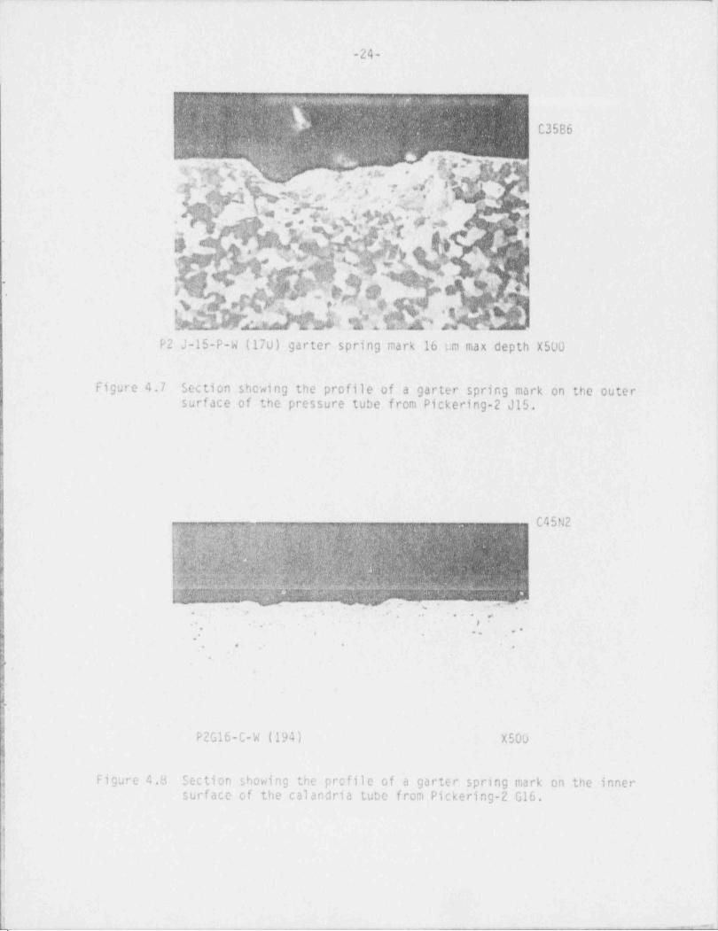
(c) Pressure Tube: .A section was cut through the pressure tube fromchannel P2-J15 at the west (outlet side) garter spring mark (note that thegarter springs in this channel were in the design position during operation).The mark had a maximum depth of 16 um and showed a deformed layer under the markand some twinning in the surrounding matrix (see Figure 4.7). There was no signof hydride migration to the garter spring mark. The garter spring marks on thepressure tube from P3-J09 appear to be a little different than previouslyobserved. The oxide on the pressure tube appeared to have worn away. However,metallography of the west (outlet) mark showed oxide throughout the mark whichwas thicker than on the rest of the surface, with no hydride associated with themark; the depth of the mark was very small and could not really be separatedfrom normal surface variations on the microsection.
(d) Calandria Tube: A section was cut through the calandria tubefrcm channel P2-G16 at the west (inlet side) garter spring mark. The westgarter spring was in the design position in this channel, but the east one was
; over one metre inboard. The load on the west garter spring would, therefore, beless than if both springs had been in the correct position. Figure 4.8 shows'
the profile of the mark which has a maximum depth of 2 um. There was no hydrideconcentration near the mark.
4.2.4 Rus_t1ing, Tests
Sections 40-45 mm long from the ends and middles of springs were crushtested at room temperature, mostly between curved mandrels. The crosshead speedwas about 4 um/s. The results are summarized as follows:

nii
i
|
-23-
-. . . - . . - ,,- -...
w &qypo g _gs ..D;wQp u g mog y m :n w .
. ,
gi4;4. %meswse .pf
>.
381, g:ym}w.yLM.w%%f.gy,f:.q gp +n .
y kypf;. sn
-u$
ew.a.~, W .~,,. x,v W R.3 .u - 6 4 %/',
.;
w%.+N 4 b Rh Y 'b.I' '' ' ",". ,N s qf,;:- b,Q 3,/,;p-
St1 % Q:'*Q M g,(,f
h;~;!;.tgQ & %i}.t%nK%WMsA*s n
% ::M ws
-
%@My.w@f' _ .
$hf6'
.m.,
CM ,|,
i '
y'" q:n .
o yt.
h( c j&ibf8 %. 4 'QgM'
X f.
. A s, w h: w',.i4s;p i -;.cp W, s.1 9 , M.4 p, Lkg.fu%*. : .mA . y,f?)ggy. yy -,
,a ,a x.
; <pWg-
rwpq*g% 3;z;Q .y-e ,. % 2 -_g n
(g :&%;;W@/d|CM@9&w , &w$Y"pu,. Y'fsy,,QMm.
..m% +AbYf.
b ,. Wh:4, Yh!,f?+hS.$. #t*:f. f$
<R ..cY.wq sag &.
pp k An :5f N.W,'.xs.y?%wht
'RM 3 h Hg h M e,%s?p,
h,u &,g m . 4. Q W.7 v,..:y#.Q Q@m.; w, e ?) w- p,n.a m &p'
i kM M hht Na y;w pm ycx.y v n4e4
n wm4 pyn s yw gw,w m m ;
'.
C3611 typical structure of 100Xgirdle wires.
, v . .~. - . 3 m . gy . mn y. .
h kjkY,w;hyd%(.pQm,?;
k - ffy.n w] e r q y;,9;~. T
. M @q@w m p;a n w w +)y%y$, c! w f q: $,y &j,
nw&LGtGW ggd
Mk h44.
L s :4g.4 m yjgg sq&s . xfpyn.Mm,m Gm|%s A@4,rQ,N, ng, s@pg97 a pc . a
S. W.W,Mj$QgMdQTdh Ewt es
f ,9 ~ ,r..e2 %n $n...Mdfkk@MMENyydhN% sv@;ym p weg; m m egm % mi
,
kh hh.hb4 M@s,. @v,w% m c. h h, m a % ~ % q, pht| g m . .po -
. .u
@qs| f;% g % 94 5 M ;p,;f|+% g f 4cG{.pq;&wQRn>NM
h,
(q;'.,Qw.ym %e , ,;n. .n.s : t,4 2,g. :w> wA>}r y.wf . g g &I %.t| .u
y [jQ.[4]+;ty y }r ---
,.3 Q,.. .gq pf, y:QgQ,
%y#.e A b v; ~ xn%p N.w &,ey.o.r .;,(qu9ai .,.pw.y m.. j
| - yy$ m aJ D,% g.ym.
f f Q $ &e g$n$$v'.
" O;d Q i% vhjMy
$my%%w%s%;&pQ i eg:p 4,y ty,;. M.3w p.)! Mu ;
\ 4 pwpfjf < ;p;: ,,
q' W f ;; M d ih Q h ' M % k %.pyg
>L:g$yM id N N:.7.nQ .''%.tp p J M 4'*gyi ,np
.pd j
g(@?$y+N?$?$$$hk'hhhYW|M$fhh,
M. w u m_.z. :.: vg',: u w mm. e
;
N) j|
C3612 typical structure at 100Xweld area of girdlewires (showing voids)
:
| Figure 4.6 Typical metallurgical structure in girdle wires both away from theI weld and in the weld area (P2J15).| ||
g ,y.r r. .- - m v.r--m **-'7'-r - -~~-+-m'- T>'--- -- --~-~~~-~~*---*--*m.--r~a*|3
aj|
11
-24-!!
1
C35B6
.g ,,.;, r sv, JrwsQyEM3 W'?:..Q' ' .7 , . } / * ?? , ,
,/'g(V g **,}-1 k iijAjj,[ %]' 4. .
.g ;.
he f ''hQk h* '|'
A$ft%(|' S[}}'9(y$ dry- ' Q 6 '
. ;,
yQbotELTO%N[%. ~ p|-Kk|saiG LX' u .&g4r/ vf<gy
,
qf '
% ;g:
P2 J-15-P-W (170) garter spring mark 16 pm max depth X500
Figure 4.7 Section showing the profile of a garter spring mark on the outersurf ace of the pressure tube from Pickering-2 J15.
1,.
I
l C4SN2e w.m'; :;dn%:1, pMY% gg. .@ %. ,.j f
m.
b;|q&" "fiy&|'&&|bjyj |b';Wf;hh|;),NbI$ $ h h,'
f ;QMW;i|$:i?9%# QMh?h] P$6"Offf:3 E M G W % T M u :' Es w . .c. ..
.
.,. -
. .
. ,
. .. . .. . o'
, .. ..,.
. .. .
*,
)
1
$.,
h
a
P2G16-C-W (194) X500,
k
l |.| Figure 4.8 Section showing the profile of a garter spring mark on the inneri surf ace of the calandria tube from Pickering-2 G16.ii
4
(
#1
|
I
[ . _ _ _ . - ---
- . . . .
(
-25- !|
|
.|
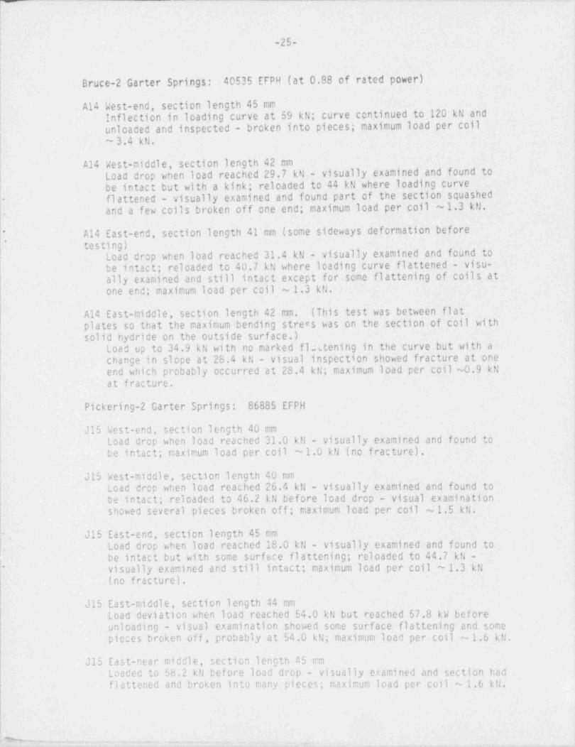
Bruce-2 Garter Springs: 40535 EFPH (at 0.88 of rated power)
A14 West-end, section length 45 mmInflection in loading curve at 59 kN; curve continued to 120 kN and -
unloaded and inspected - broken into pieces; maximum load per coil ;
~ 3.4 kN. ;
A14 West-middle, section length 42 mmLoad drop when load reached 29.7 kN - visually examined and found tobe intact but with a kink; reloaded to 44 kN where loading curveflattened - visually examined and found part of the section squashed ,
-
and a few coils broken off one end; maximum load per coil ~1.3 kN.,
A14 East-end, section length 41' mm (some sideways deformation before*
* testing)Load drop when load reached 31.4 kN - visually examined and found to .
be intact; reloaded to 40.7 kN where loading curve flattened - visu- !
ally examined and still intact except for some flattening of coils at[one end; maximum load per coil ~ 1.3 kN.,
A14 East-middle, section length 42 mm. (This test was between flatplates so that the maximum bending stress was on the section of coil with '
solid hydride on the outside surface.) .
Load up to 34.9 kN with no marked flutening in the curve but with a '
change in slope at 28.4 kN - visual inspection showed fracture at one'end which probably occurred at 28.4 kN; maximum load per coil ~0.9 kN
at fracture.
| Pickering-2 Garter Springs: 86885.EFPH
J15 West-end, section length 40 mmLoad drop when load reached 31.0 kN - visually examined and found to
tbe intact; maximum load per coil ~1.0 kN (no fracture).
J15 West-middle, section length 40 mm ;
Load drop when load reached 26.4 kN - visually examined and found to .
be intact; reloaded to 46.2 kN before load drop - visual examination i
showed several pieces broken off; maximum load per coil ~ 1.5 kN. |
- J15 East-end, section length 45 mmLoad drop when load reached 18.0 kN - visually examined and found tobe intact but with some surf ace flattening; reloaded to 44.7 kN -visually examined and still intact; maximum load per coil ~ 1.3 kN"
(no fracture).
J15 East-middle, section length 44 mmLoad deviation when load reached 54.0 kN but reached 57.8 kW before .
unloading - visual examination showed some surface flattening and some |pieces broken off, probably at 54.0 kN; maximum load per coil ~ 1.6 kN.
J15 East-near middle, section length 45 mm .
Loaded to 58.2 kN before load drop - visually examined and section had |flattened and broken into many pieces; maximum load per coil ~ 1.6 kN.
l
i
1
- - .,. -- - . _ - .. ~. . - - .~y .,_ _ _
., ,,
-26-
t
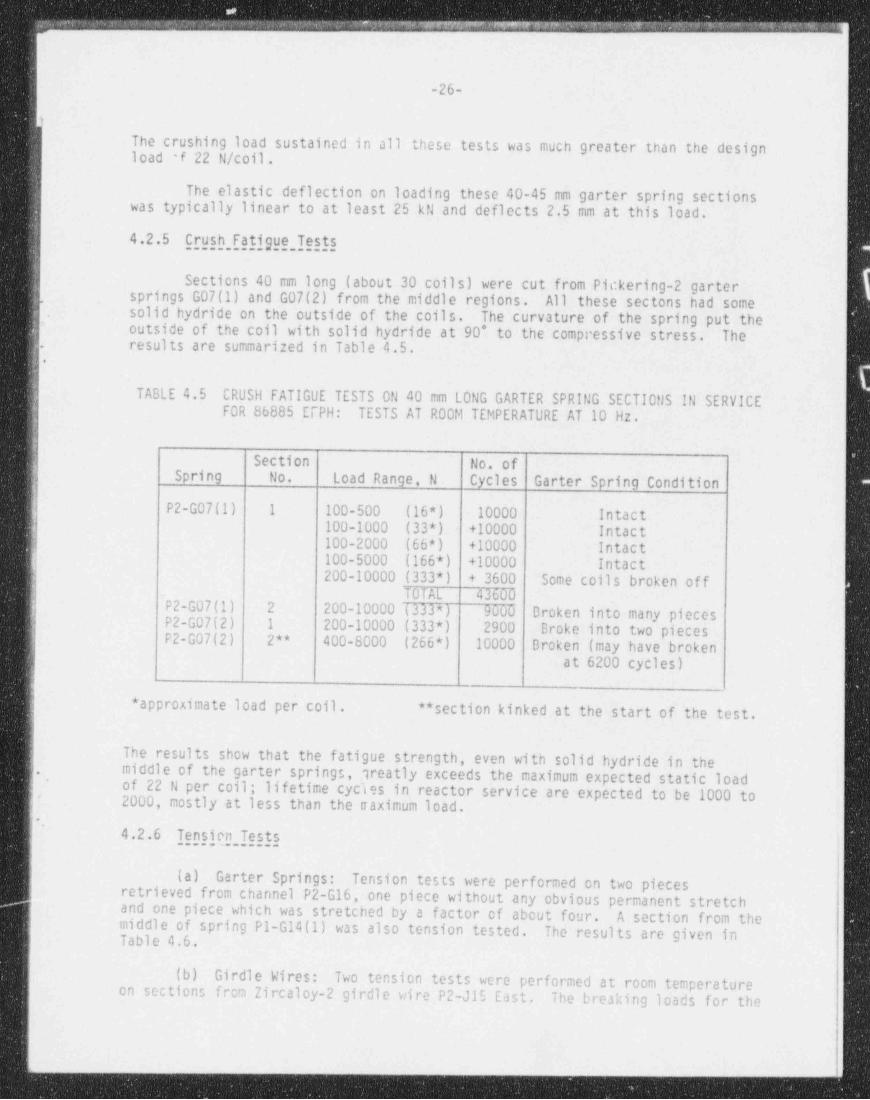
The crushing load sustained in all these tests was much greater than the designload f 22 N/ coil .
The elastic deflection on loading these 40-45 nm garter spring sectionswas typically linear to at least 25 kN and deflects 2.5 mm at this load.
4.2.5 Crush, Fatigue, Tests
Sections 40 mm long (about 30 coils) were cut from Pickering-2 garter. springs G07(1) and G07(2) from the middle regions. All these sectons had some
solid hydride on the outside of the coils. The curvature of the spring put theoutside of the coil with solid hydride at 90* to the compressive stress. Theresults are summarized in Table 4.5.-
.
'TABLE 4.5 CRUSH FATIGUE TESTS ON 40 mm LONG GARTER SPRING SECTIONS IN SERVICE
| FOR 86885 EIPH: TESTS AT ROOM TEMPERATURE AT 10 Hz.!
l Section No. ofSpring No. Load Range, N Cycles Garter Spring Condition
P2-G07(1) 1 100-500 (16*) 10000 Intact100-1000 (33*) +10000 Intact100-2000 (66*) +10000 Intact100-5000 (166*) +10000 Intactj200-10000 (333*) + 3600 Some coils broken off
TOTAL 43600P2-G07(1) 2 200-10000 (333*) 9000 Broken into many piecesP2-G07(2) 1 200-10000 (333*) 2900 Broke into two piecesP2-G07(2) 2** 400-8000 (266*) 10000 Broken (may have broken '
at 6200 cycles).i
1 * approximate load per coil . **section kinked at the start of the test.|
! The results show that the fatigue strength, even with solid hydride in the,i , middle of the garter springs, greatly exceeds the maximum expected static load~
of 22 N per coil; lifetime cycies in reactor service are expected to be 1000 to2000, mostly at less than the naximum load.
.'
4.2.6 Tensign, TestsI
(a) Garter Springs: Tension tests were performed on two piecesretrieved from channel P2-G16, one piece without any obvious permanent stretchand one piece which was stretched by a factor of about four. A section from themiddle of spring P1-G14(1) was also tension tested. The results are given inTable 4.6.
(b) Girdle Wires: Two tension tests were performed at room temperatureon sections from Zircaloy-2 girdle wire P2-J15 East. The breaking loads for the
_- -
-- . .- - .
.
-27- 1
:
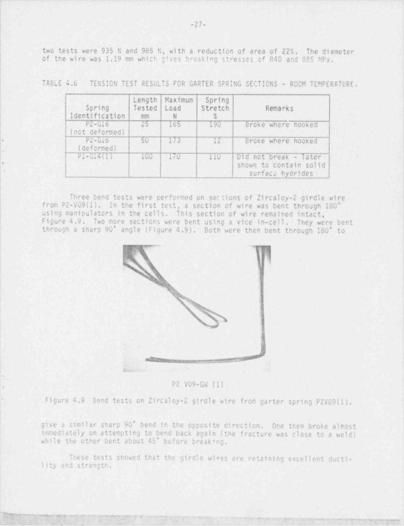
ltwo tests were 935 N and 985 N, with a reduction of area of 22%. The diameter i
of the wire was 1.19 mm which gives breaking stresses of 840 and 885 MPa.
I
TABLE 4.6 TENSION TEST RESULTS FOR GARTER SPRING SECTIONS - ROOM TEMPERATURE.
Length Maximum SpringSpring Tested Load Stretch Remarks
,
Identification mm N %'
P2-G16 25 165 190 Broke where hooked(not deformed)
P2-G16 50 173 12 Broke where hooked-
,- (deformed)P1-G14(1)- 100 170 110 Did not break - later
shown to contain solid i-
* surface hydrides;
Three bend tests were performed on sec tions of Zircaloy-2 girdle wirefrom P2-V09(1). In the first test, a section of wire was bent through 180*using manipulators in the cells. This section of wire remained intact,Figure 4.9. Two more sections were bent using a vice in-cell. They were bentthrough a sharp 90* angle (Figure 4.9). Both were then bent through 180* to
717
s i
!
'4
'%,[
,.
I,
s
j J; e _i
u, ,m
P2 V09-GW (1),
;- Figure 4.9 Bend tests on Zircaloy-2 girdle wire from garter spring P2V09(1).
| |
| give a similar sharp 90* bend in the opposite direction. One then broke almost; immediately on attempting to bend back again (the fracture was close to a weld)while the other bent about 45* before breaking.
1
These tests showed that the girdle wires are retaining excellent ducti-ility and strength.|
' ", 3 y ~ p " r,,-" T v ?"~7 > vy - ~ ~ - 7 ,~ ww , ---, .ng-,, ,7, .,,,,
-28-
)
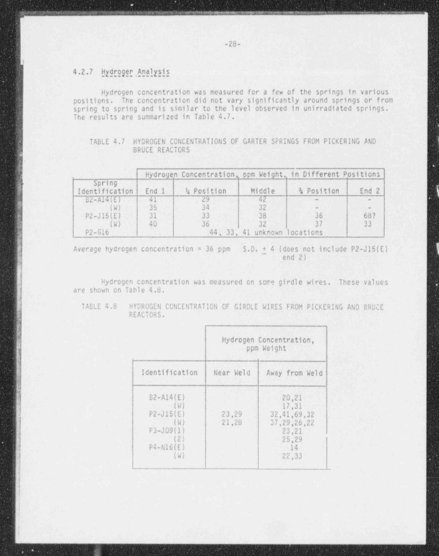
4.2.7 Hydroger , Analysis
Hydrogen concentration was measured for a few of the springs in variouspositions. The concentration did not vary significantly around springs or fromspring to spring and is similar to the level observed in unirradiated springs.
| The results are summarized in Table 4.7.
TABLE 4.7 HYDROGEN CONCENTRATIONS OF GARTER SPRINGS FROM PICKERING ANDBRUCE REACTORS
s
Hydrogen Concentration, ppm Weight, in Different Positionsr Springi Identification End I h Position Middle % Position End 2
B2-A14(E) 41 29 42 - -
5 (W) 35 34 32 - -
a P2-J15(E) 31 33 38 36 68?j (W) 40 36 32 37 33
'
P2-G16 44, 33, 41 unknown locations
Average hydrogen concentration = 36 ppm S.D. + 4 (does not include P2-J15(E)',
~
end 2)
Hydrogen concentration was measured on some girdle wires. These valuesare shown on Table 4.8.
TABLE 4.8 HYDROGEN CONCENTRATION OF GIRDLE WIRES FROM PICKERING AND BRUCEREACTORS.
| Hydrogen Concentration,jj ppm Weightli:!|| Identification Near Weld Away from Weld'
! B2-A14(E) 20,21 I
(W) 17,31P2-J15(E) 23,29 32,41,69,32
. (W) 21,28 37,29,26,22l P3-JO9(1) 23,21
(2) 25,29P4-N16(E) 14
(W) 22,33
)
s
#:l
_ - _ _ _ _ - _ _ _ _ _ _ - _ _ _ _ _ _ _-
__ - . . ._ _
|
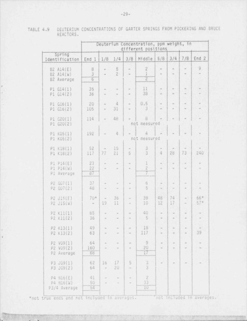
-29-
TABLE 4.9 DEUTERIUM CONCENTRATIONS OF GARTER SPRINGS FROM PICKERING AND BRUCEREACTORS.
l
Oeuterium Concentration, ppm weight, in ]different positions .
Spring ;
Identi fication End 1 1/8 1/4 3/8 Middle 5/8 3/4 7/8 End 2 |
I
9 |B2 A14(E) 8 - 5 - 2 - - -
1 - - - -2-B2 A14(W) 3 --
B2 Average 6 2
.'
P1 G14(1) 35 - - - 11 i- - - -
38 - - - -P1 G14(2) 36*
- - -
.
P1 G16(1) 20 - 4 - 0.5 - - - --
3 - - - -P1 G16(2) 105 - 31 -
P1 G20(1) 114 48 - 8- - - - -
P1 G20(2) not measured
4P1 K05(1) 192 - 4 - - - --
P1 K05(2) not measured j
P1 K18(1) 52 - 15 - 3 - - - -
P1 K18(2) 117 77 21 5 3 4 28 73 240
| P1 P14(E) 23 - - - 1 - - - -
P1 P14(W) 22 - - - 2 - - - -
P1 Average 87 7i
P2 G07(1) 37 - - - 6 - - - -
P2 G07(2) 48 - - - 5 - - - -
;
|t
39 48 74 - 66*P2 J15(E) 70* - 36 -
19 11 - 10 12 17 57*P2 J15(W) --,
P2 K11(1) 85 - - - 40 - - - -
iP2 K11(2) 36 - - - 5 - - - -
P2 K13(1) 49 - - - 18 - - - - -
.
39- - - 117 - - -P2 K13(2) 63e
9 - - - - ;- P2 V09(1) 64 - - -
P2 V09(2) 160 - - - 20 - - - -
P2 Average 68 17
P3 JO9(1) 62 16 17 5 3 - - - - .
3 !P3 JO9(2) 64 - 20 -
l
P4 N16(E) 41 - - - 2 |
P4 U16(W) 50 - - - 33P3/4 Average 54 10
*not true ends and not incluced in averages. 'not included in averages. ,
1
. .&
}<& $'~' d[EQ w , ' ' 'f< ' ' e s' T ?[*V''[ ~ ~ ~~ T~ ~"~''"fT * " T '7f W'*R7'f***"'WW:*"ry7=m} |

(|,
!
-30-
4.2.8 Deuterium, Analysis
The results of deuterium analyses from different positions around thegarter springs are summarized in Table 4.9. The results show that, with twoexceptions, the deuterium concentrations are higher at the ends of springs than
,
in the middle. The only exception with a much larger deuterium concentration inl the middle than the ends (P2-K13(2)), showed solid hydride at the end, rather| than the middle during the metallographic examination (4.2.3).|
'. The deuterium concentrations of the Bruce-2 springs are much lower thanfor the Pickering A springs, which is probably due to both carbon dioxide in the,
annulus in Bruce compared to nitrogen in Pickering A, and to the shorter opera-'
ting time.
The difference in deuterium concentration between the middle and ends was| less in Pickering-2 springs than for other Pickering-A springs. This may| indicate that the annulus gas was less stagnant in Pickering-2 than the others,! thus not allowing deuterium to segregate as much to the top of the channels.
Deuterium concentration was measured for the girdle wires from somechannels. The results are summarized in Table 4.10.
TABLE 4.10 DEUTERIUM CONCENTRATIONS FOR GIRDLE WIRES-| !
Deuterium Concentration, !ppm weight, ;
|in different positions >
i Near Weld Away from Weld
B2-A14(E) - 24,23(W) 17,14-
P2-J15(E) 15,15 31,52,25,25,
'
(W) 18,18 25,27,26,25,
| P3-J O9(1) - 55,56'
(2) - 81,78P4-N16(E) - 47,36,370?
(W) - 48,42c.
,
. 4.2.9 Ovality
The diameter of the coils in the middle of springs B2-A14E, B2-A14W,, P1-J15E and P2-J15W were measured with a micrometer to an accuracy of about1 0.025 mm. No ovality could be detected.
L|
._.. _ . _ _ . _ _ . ~ . . . . _ _ _ . . _ . . _ . . . . _ - - - - -
-31-
5. SUMMARY
(1) The garter springs were probably all intact after service up to 12 yearsin-reactor; any broken springs showing signs of heavy deformationindicated handling damage, either when removing from the reactor orduring shipping.
(2) All garter springs, which operated with the ends at the top, showed solidsurface hydride on the outside coils in the middle of the springs (wherethey contacted the cold calandria tube).
(3) Crush, crush fatigue and stretch tests show that the garter springs-
,- retain strength, f atigue resistance and ductility af ter 12 years',
operation that is much greater than is required in service, even with', solid surf ace hydride present.
(4) Hydrogen concentrations are unchanged by in-reactor service.,
(5) Deuterium concentrations of up to 240 ppm were observed on springs fromPickering A. The deuterium was much greater at the ends of the springsthan the niddle. The concentrations were much lower for the Bruce-2springs than Pickering-A.
(6) 0xide thickness on the garter springs was about 1 pm.
(7) The Zircaloy-2 girdle wires retained excellent strength and ductilityaf ter reactor service.
i(8) Oxide thicknesses of up to 30 pm were observed on girdle wires.
6. CONCLUSIONS
The garter springs from Pickering-A and Bruce-2 showed good strength and ;
ductility, despite some solid surface hydrides, and show negligible corrosionafter up to 12 years' service.
7. ACKNOWLEDGEMENTS .
|
l' I would like to thank J.P. Gravelle for help with all the mechanical |!, testing, Fuel Materials Branch active cells staff for visual examinations, i| cutting and metallography, and General Chemistry Branch staff for hydrogen and |'' deuterium analyses. ||i
8. REFERENCES
| [1] G.J. Field, J.T. Dunn and B. A. Cheadle, " Analysis of the Pressure Tube| Failure at Pickering NGS 'A' Unit 2", Atomic Energy of Canada Limited.
Report AECL-8335,1984 June.
[2] D.G. Dalrymple, Unpublished work CRNL,1962 December.
|,37 -,m-.-..-,-.,--.,.~7..m-.-_ ,..,_,.m.,_,...__.,_ _ , , , . _ , ,- - - . _
, .. . . . , .. ... . ,
..
;
-32-
,
[3] G.W. Parry, " Strain-Induced Directionality of Zirconium HydridePrecipitates in Zr-2.5% Nb-0.5% Cu Alloy", Atomic Energy of CanadaLimited, Report AECL-1888, 1963 December.
[4] C.E. Ells and A. Sawatzky, "The Effect of Neutron Irradiation andHydrogen Concentration on Tensile Properties of the CANDU Coolant TubeSpacer Alloy", Atomic Energy of Canada Limited, Report AECL-2272,
'
1965 June.
[5] C.E. Ells and A. Sawatzky, "The Effect of Neutron Irradiation on theTensile Properties of Zr-2.5% Nb 0.5% Cu Alloy", Trans. Met. Soc. AIME,*
e' 233 (1965) p.2041.
[6] L. Fallis, unpublished data AECL Toronto, 1973..
[7] D.G. Dalrymple and W. A. Cra90, Unpublished work CRNL 1962-1964.i
[8] E.G. Price, unpublished work, AECL Toronto,1974 May.
[9] G.D. Moan, unpublished work, AECL Toronto,1983.
I
ii
I
!
!
,
S
.
- - - - - - _ . _ - _ _ _ _ _ . _ _ _ _ _ _ _ _ __

;y. <s.~ 7_ .. _ g - . .. : r . ..<~p- -,,:,.- . . . , ,,
!
];
II. !
ji ISSN 0067-0367 ISSN 0067-0367
| To identify individu al documents in the series Pour identifier les rapports iadividuels f aisantwe have assigned an AECL- numberto each, partie de cette s6rie nous avons assign 6u
O un num6ro AECL- A chacun.3-
Please referto the AECL- numberwhen re. Veuillez faire mention du numero AECL- sij questingadditionalcopiesof thisdocument vous demander d'autres exemplaires de ce j,
rapport !'l 5'
l' from au
I:Scientific Document Distribution Office Service de Distribution des Documents Officiels .II
Atomic Energy of Canada Limited L'Energie Atomique du Canada Limitse ||'# Chalk River, Ontario, Canada Chalk River, Ontario, Canada ||J K0J 1JO K0J1JO {|1
i
Price: $3.00 per copy Price: $3.00 per copyi ; i.yA
l j
i,
8
4'i
i i
;l"a
?. |,,
J
9CAT')MIC ENERGY OF CANADA LIMITED,1985,
+
|
1 0248-86 l'
l
1
,
11
_ _ - - - - - - - - - - - - -.