SV22 Programming Manual (Advanced Synchronous Control ...
312
-
Upload
khangminh22 -
Category
Documents
-
view
3 -
download
0
Transcript of SV22 Programming Manual (Advanced Synchronous Control ...


A - 1
SAFETY PRECAUTIONS (Please read these instructions before using this equipment.)
Before using this product, please read this manual and the relevant manuals introduced in this manual carefully and pay full attention to safety to handle the product correctly. These precautions apply only to this product. Refer to the Q173D(S)CPU/Q172D(S)CPU Users manual for a description of the Motion controller safety precautions. In this manual, the safety instructions are ranked as "DANGER" and "CAUTION".
DANGER
Indicates that incorrect handling may cause hazardous conditions, resulting in death or severe injury.
CAUTION
Indicates that incorrect handling may cause hazardous conditions, resulting in medium or slight personal injury or physical damage.
Depending on circumstances, procedures indicated by CAUTION may also be linked to serious results. In any case, it is important to follow the directions for usage.
Please save this manual to make it accessible when required and always forward it to the end user.
A - 2
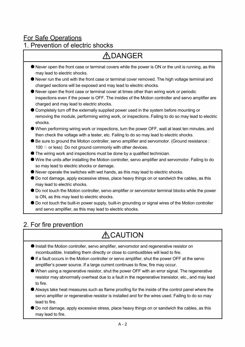
For Safe Operations 1. Prevention of electric shocks
DANGER Never open the front case or terminal covers while the power is ON or the unit is running, as this may lead to electric shocks.
Never run the unit with the front case or terminal cover removed. The high voltage terminal and charged sections will be exposed and may lead to electric shocks. Never open the front case or terminal cover at times other than wiring work or periodic inspections even if the power is OFF. The insides of the Motion controller and servo amplifier are charged and may lead to electric shocks.
Completely turn off the externally supplied power used in the system before mounting or removing the module, performing wiring work, or inspections. Failing to do so may lead to electric shocks. When performing wiring work or inspections, turn the power OFF, wait at least ten minutes, and then check the voltage with a tester, etc. Failing to do so may lead to electric shocks. Be sure to ground the Motion controller, servo amplifier and servomotor. (Ground resistance : 100 or less) Do not ground commonly with other devices. The wiring work and inspections must be done by a qualified technician. Wire the units after installing the Motion controller, servo amplifier and servomotor. Failing to do so may lead to electric shocks or damage. Never operate the switches with wet hands, as this may lead to electric shocks. Do not damage, apply excessive stress, place heavy things on or sandwich the cables, as this may lead to electric shocks. Do not touch the Motion controller, servo amplifier or servomotor terminal blocks while the power is ON, as this may lead to electric shocks. Do not touch the built-in power supply, built-in grounding or signal wires of the Motion controller and servo amplifier, as this may lead to electric shocks.
2. For fire prevention
CAUTION Install the Motion controller, servo amplifier, servomotor and regenerative resistor on incombustible. Installing them directly or close to combustibles will lead to fire.
If a fault occurs in the Motion controller or servo amplifier, shut the power OFF at the servo amplifier’s power source. If a large current continues to flow, fire may occur. When using a regenerative resistor, shut the power OFF with an error signal. The regenerative resistor may abnormally overheat due to a fault in the regenerative transistor, etc., and may lead to fire. Always take heat measures such as flame proofing for the inside of the control panel where the servo amplifier or regenerative resistor is installed and for the wires used. Failing to do so may lead to fire. Do not damage, apply excessive stress, place heavy things on or sandwich the cables, as this may lead to fire.

A - 3
3. For injury prevention
CAUTION Do not apply a voltage other than that specified in the instruction manual on any terminal. Doing so may lead to destruction or damage. Do not mistake the terminal connections, as this may lead to destruction or damage. Do not mistake the polarity ( + / - ), as this may lead to destruction or damage. Do not touch the heat radiating fins of controller or servo amplifier, regenerative resistor and servomotor, etc., while the power is ON and for a short time after the power is turned OFF. In this timing, these parts become very hot and may lead to burns.
Always turn the power OFF before touching the servomotor shaft or coupled machines, as these parts may lead to injuries.
Do not go near the machine during test operations or during operations such as teaching. Doing so may lead to injuries.
4. Various precautions
Strictly observe the following precautions.
Mistaken handling of the unit may lead to faults, injuries or electric shocks.
(1) System structure
CAUTION Always install a leakage breaker on the Motion controller and servo amplifier power source. If installation of an electromagnetic contactor for power shut off during an error, etc., is specified in the instruction manual for the servo amplifier, etc., always install the electromagnetic contactor. Install the emergency stop circuit externally so that the operation can be stopped immediately and the power shut off. Use the Motion controller, servo amplifier, servomotor and regenerative resistor with the correct combinations listed in the instruction manual. Other combinations may lead to fire or faults. Use the Motion controller, base unit and motion module with the correct combinations listed in the instruction manual. Other combinations may lead to faults. If safety standards (ex., robot safety rules, etc.,) apply to the system using the Motion controller, servo amplifier and servomotor, make sure that the safety standards are satisfied. Construct a safety circuit externally of the Motion controller or servo amplifier if the abnormal operation of the Motion controller or servo amplifier differ from the safety directive operation in the system. In systems where coasting of the servomotor will be a problem during the forced stop, emergency stop, servo OFF or power supply OFF, use dynamic brakes. Make sure that the system considers the coasting amount even when using dynamic brakes. In systems where perpendicular shaft dropping may be a problem during the forced stop, emergency stop, servo OFF or power supply OFF, use both dynamic brakes and electromagnetic brakes.

A - 4
CAUTION The dynamic brakes must be used only on errors that cause the forced stop, emergency stop, or servo OFF. These brakes must not be used for normal braking.
The brakes (electromagnetic brakes) assembled into the servomotor are for holding applications, and must not be used for normal braking.
The system must have a mechanical allowance so that the machine itself can stop even if the stroke limits switch is passed through at the max. speed. Use wires and cables that have a wire diameter, heat resistance and bending resistance compatible with the system. Use wires and cables within the length of the range described in the instruction manual. The ratings and characteristics of the parts (other than Motion controller, servo amplifier and servomotor) used in a system must be compatible with the Motion controller, servo amplifier and servomotor. Install a cover on the shaft so that the rotary parts of the servomotor are not touched during operation. There may be some cases where holding by the electromagnetic brakes is not possible due to the life or mechanical structure (when the ball screw and servomotor are connected with a timing belt, etc.). Install a stopping device to ensure safety on the machine side.
(2) Parameter settings and programming
CAUTION Set the parameter values to those that are compatible with the Motion controller, servo amplifier, servomotor and regenerative resistor model and the system application. The protective functions may not function if the settings are incorrect.
The regenerative resistor model and capacity parameters must be set to values that conform to the operation mode, servo amplifier and servo power supply module. The protective functions may not function if the settings are incorrect. Set the mechanical brake output and dynamic brake output validity parameters to values that are compatible with the system application. The protective functions may not function if the settings are incorrect. Set the stroke limit input validity parameter to a value that is compatible with the system application. The protective functions may not function if the setting is incorrect. Set the servomotor encoder type (increment, absolute position type, etc.) parameter to a value that is compatible with the system application. The protective functions may not function if the setting is incorrect. Set the servomotor capacity and type (standard, low-inertia, flat, etc.) parameter to values that are compatible with the system application. The protective functions may not function if the settings are incorrect. Set the servo amplifier capacity and type parameters to values that are compatible with the system application. The protective functions may not function if the settings are incorrect. Use the program commands for the program with the conditions specified in the instruction manual.

A - 5
CAUTION Set the sequence function program capacity setting, device capacity, latch validity range, I/O assignment setting, and validity of continuous operation during error detection to values that are compatible with the system application. The protective functions may not function if the settings are incorrect.
Some devices used in the program have fixed applications, so use these with the conditions specified in the instruction manual. The input devices and data registers assigned to the link will hold the data previous to when communication is terminated by an error, etc. Thus, an error correspondence interlock program specified in the instruction manual must be used. Use the interlock program specified in the intelligent function module's instruction manual for the program corresponding to the intelligent function module.
(3) Transportation and installation
CAUTION Transport the product with the correct method according to the mass. Use the servomotor suspension bolts only for the transportation of the servomotor. Do not transport the servomotor with machine installed on it.
Do not stack products past the limit. When transporting the Motion controller or servo amplifier, never hold the connected wires or cables.
When transporting the servomotor, never hold the cables, shaft or detector. When transporting the Motion controller or servo amplifier, never hold the front case as it may fall off.
When transporting, installing or removing the Motion controller or servo amplifier, never hold the edges.
Install the unit according to the instruction manual in a place where the mass can be withstood. Do not get on or place heavy objects on the product. Always observe the installation direction. Keep the designated clearance between the Motion controller or servo amplifier and control panel inner surface or the Motion controller and servo amplifier, Motion controller or servo amplifier and other devices.
Do not install or operate Motion controller, servo amplifiers or servomotors that are damaged or that have missing parts.
Do not block the intake/outtake ports of the Motion controller, servo amplifier and servomotor with cooling fan.
Do not allow conductive matter such as screw or cutting chips or combustible matter such as oil enter the Motion controller, servo amplifier or servomotor.
The Motion controller, servo amplifier and servomotor are precision machines, so do not drop or apply strong impacts on them.
Securely fix the Motion controller, servo amplifier and servomotor to the machine according to the instruction manual. If the fixing is insufficient, these may come off during operation.

A - 6
CAUTION Always install the servomotor with reduction gears in the designated direction. Failing to do so may lead to oil leaks. Store and use the unit in the following environmental conditions.
Conditions Environment
Motion controller/Servo amplifier Servomotor
Ambient temperature
According to each instruction manual. 0°C to +40°C (With no freezing)
(32°F to +104°F)
Ambient humidity According to each instruction manual. 80% RH or less
(With no dew condensation) Storage temperature
According to each instruction manual. -20°C to +65°C (-4°F to +149°F)
Atmosphere Indoors (where not subject to direct sunlight).
No corrosive gases, flammable gases, oil mist or dust must exist
Altitude 1000m (3280.84ft.) or less above sea level Vibration According to each instruction manual
When coupling with the synchronous encoder or servomotor shaft end, do not apply impact such as by hitting with a hammer. Doing so may lead to detector damage. Do not apply a load larger than the tolerable load onto the synchronous encoder and servomotor shaft. Doing so may lead to shaft breakage. When not using the module for a long time, disconnect the power line from the Motion controller or servo amplifier. Place the Motion controller and servo amplifier in static electricity preventing vinyl bags and store. When storing for a long time, please contact with our sales representative. Also, execute a trial operation.

A - 7
(4) Wiring
CAUTION Correctly and securely wire the wires. Reconfirm the connections for mistakes and the terminal screws for tightness after wiring. Failing to do so may lead to run away of the servomotor.
After wiring, install the protective covers such as the terminal covers to the original positions. Do not install a phase advancing capacitor, surge absorber or radio noise filter (option FR-BIF) on the output side of the servo amplifier. Correctly connect the output side (terminal U, V, W) and ground. Incorrect connections will lead the servomotor to operate abnormally. Do not connect a commercial power supply to the servomotor, as this may lead to trouble. Do not mistake the direction of the surge absorbing diode installed on the DC relay for the control signal output of brake signals, etc. Incorrect installation may lead to signals not being output when trouble occurs or the protective functions not functioning.
DICOM
RAControl outputsignal
DOCOM
Servo amplifier24VDC
Control outputsignal
DICOM
DOCOM
Servo amplifier
RA
24VDC
For the sink output interface For the source output interface Do not connect or disconnect the connection cables between each unit, the encoder cable or PLC expansion cable while the power is ON. Securely tighten the cable connector fixing screws and fixing mechanisms. Insufficient fixing may lead to the cables combing off during operation. Do not bundle the power line or cables.
(5) Trial operation and adjustment
CAUTION Confirm and adjust the program and each parameter before operation. Unpredictable movements may occur depending on the machine.
Extreme adjustments and changes may lead to unstable operation, so never make them.
When using the absolute position system function, on starting up, and when the Motion controller or absolute value motor has been replaced, always perform a home position return.
Before starting test operation, set the parameter speed limit value to the slowest value, and make sure that operation can be stopped immediately by the forced stop, etc. if a hazardous state occurs.

A - 8
(6) Usage methods
CAUTION Immediately turn OFF the power if smoke, abnormal sounds or odors are emitted from the Motion controller, servo amplifier or servomotor.
Always execute a test operation before starting actual operations after the program or parameters have been changed or after maintenance and inspection. Do not attempt to disassemble and repair the units excluding a qualified technician whom our company recognized. Do not make any modifications to the unit. Keep the effect or electromagnetic obstacles to a minimum by installing a noise filter or by using wire shields, etc. Electromagnetic obstacles may affect the electronic devices used near the Motion controller or servo amplifier. When using the CE Mark-compliant equipment, refer to the User's manual for the Motion controllers and refer to the corresponding EMC guideline information for the servo amplifiers, inverters and other equipment. Use the units with the following conditions.
Item Conditions
Input power According to each instruction manual. Input frequency According to each instruction manual. Tolerable momentary power failure According to each instruction manual. (7) Corrective actions for errors
CAUTION If an error occurs in the self diagnosis of the Motion controller or servo amplifier, confirm the check details according to the instruction manual, and restore the operation.
If a dangerous state is predicted in case of a power failure or product failure, use a servomotor with electromagnetic brakes or install a brake mechanism externally. Use a double circuit construction so that the electromagnetic brake operation circuit can be operated by emergency stop signals set externally.
ServomotorRA1 EMG
24VDC
Shut off with servo ON signal OFF,alarm, electromagnetic brake signal.
Shut off with theemergency stopsignal (EMG).
Electromagneticbrakes
If an error occurs, remove the cause, secure the safety and then resume operation after alarm release.
The unit may suddenly resume operation after a power failure is restored, so do not go near the machine. (Design the machine so that personal safety can be ensured even if the machine restarts suddenly.)

A - 9
(8) Maintenance, inspection and part replacement
CAUTION Perform the daily and periodic inspections according to the instruction manual. Perform maintenance and inspection after backing up the program and parameters for the Motion controller and servo amplifier. Do not place fingers or hands in the clearance when opening or closing any opening. Periodically replace consumable parts such as batteries according to the instruction manual. Do not touch the lead sections such as ICs or the connector contacts. Before touching the module, always touch grounded metal, etc. to discharge static electricity from human body. Failure to do so may cause the module to fail or malfunction.
Do not directly touch the module's conductive parts and electronic components. Touching them could cause an operation failure or give damage to the module. Do not place the Motion controller or servo amplifier on metal that may cause a power leakage or wood, plastic or vinyl that may cause static electricity buildup.
Do not perform a megger test (insulation resistance measurement) during inspection. When replacing the Motion controller or servo amplifier, always set the new module settings correctly. When the Motion controller or absolute value motor has been replaced, carry out a home position return operation using one of the following methods, otherwise position displacement could occur. 1) After writing the servo data to the Motion controller using programming software, switch on the
power again, then perform a home position return operation. 2) Using the backup function of the programming software, load the data backed up before
replacement. After maintenance and inspections are completed, confirm that the position detection of the absolute position detector function is correct. Do not drop or impact the battery installed to the module. Doing so may damage the battery, causing battery liquid to leak in the battery. Do not use the dropped or impacted battery, but dispose of it. Do not short circuit, charge, overheat, incinerate or disassemble the batteries. The electrolytic capacitor will generate gas during a fault, so do not place your face near the Motion controller or servo amplifier. The electrolytic capacitor and fan will deteriorate. Periodically replace these to prevent secondary damage from faults. Replacements can be made by our sales representative. Lock the control panel and prevent access to those who are not certified to handle or install electric equipment. Do not burn or break a module and servo amplifier. Doing so may cause a toxic gas.

A - 10
(9) About processing of waste
When you discard Motion controller, servo amplifier, a battery (primary battery) and other option articles, please follow the law of each country (area).
CAUTION This product is not designed or manufactured to be used in equipment or systems in situations that can affect or endanger human life. When considering this product for operation in special applications such as machinery or systems used in passenger transportation, medical, aerospace, atomic power, electric power, or submarine repeating applications, please contact your nearest Mitsubishi sales representative. Although this product was manufactured under conditions of strict quality control, you are strongly advised to install safety devices to forestall serious accidents when it is used in facilities where a breakdown in the product is likely to cause a serious accident.
(10) General cautions
All drawings provided in the instruction manual show the state with the covers and safety partitions removed to explain detailed sections. When operating the product, always return the covers and partitions to the designated positions, and operate according to the instruction manual.
A - 11
REVISIONS
The manual number is given on the bottom left of the back cover. Print Date Manual Number Revision Sep., 2012 IB(NA)-0300198-A First edition
Japanese Manual Number IB(NA)-0300193
This manual confers no industrial property rights or any rights of any other kind, nor does it confer any patent licenses. Mitsubishi Electric Corporation cannot be held responsible for any problems involving industrial property rights which may occur as a result of using the contents noted in this manual.
© 2012 MITSUBISHI ELECTRIC CORPORATION

A - 12
INTRODUCTION
Thank you for choosing the Mitsubishi Motion controller Q173DSCPU/Q172DSCPU. Before using the equipment, please read this manual carefully to develop full familiarity with the functions and performance of the Motion controller you have purchased, so as to ensure correct use.
CONTENTS
Safety Precautions .........................................................................................................................................A- 1 Revisions ........................................................................................................................................................A-11 Contents .........................................................................................................................................................A-12 About Manuals ...............................................................................................................................................A-15
1. OVERVIEW 1- 1 to 1-10
1.1 Overview................................................................................................................................................... 1- 1 1.2 Overview of Synchronous Control........................................................................................................... 1- 4 1.3 Performance Specifications ..................................................................................................................... 1- 5 1.4 Restrictions by the Software's Version.................................................................................................... 1- 9 1.5 Programming Software Version............................................................................................................... 1-10
2. STARTING UP THE SYSTEM 2- 1 to 2- 6
2.1 Starting Up the Advanced Control System ............................................................................................. 2- 1 2.2 Starting/Ending for Synchronous Control................................................................................................ 2- 2 2.3 Stop Operation of Output Axis................................................................................................................. 2- 5
3. SYNCHRONOUS CONTROL MODULE 3- 1 to 3- 4
3.1 List of Synchronous Control Module ....................................................................................................... 3- 1
4. POSITIONING DEDICATED SIGNALS 4- 1 to 4-40
4.1 Internal Relays ......................................................................................................................................... 4- 3 4.2 Data Registers.......................................................................................................................................... 4-20 4.3 Motion Registers (#)................................................................................................................................. 4-37 4.4 Special Relays (SM) ................................................................................................................................ 4-39 4.5 Special Registers (SD)............................................................................................................................. 4-40
5. INPUT AXIS MODULE 5- 1 to 5-50
5.1 Servo Input Axis ....................................................................................................................................... 5- 1 5.1.1 Overview of servo input axis ............................................................................................................. 5- 1 5.1.2 Servo input axis parameters ............................................................................................................. 5- 4 5.1.3 Servo input axis monitor data ........................................................................................................... 5- 8
5.2 Command Generation Axis ..................................................................................................................... 5-10 5.2.1 Overview of command generation axis ............................................................................................ 5-10 5.2.2 Command generation axis parameters ............................................................................................ 5-15 5.2.3 Command generation axis control data............................................................................................ 5-17 5.2.4 Command generation monitor data.................................................................................................. 5-20

A - 13
5.3 Synchronous Encoder Axis...................................................................................................................... 5-26 5.3.1 Overview of synchronous encoder axis............................................................................................ 5-26 5.3.2 Setting method for synchronous encoder ........................................................................................ 5-29 5.3.3 Synchronous encoder axis parameters............................................................................................ 5-34 5.3.4 Synchronous encoder axis control data ........................................................................................... 5-40 5.3.5 Synchronous encoder axis monitor data.......................................................................................... 5-45
6. CAM FUNCTION 6- 1 to 6-10
6.1 Control Details for Cam Function ............................................................................................................ 6- 1 6.2 Create Cam Data ..................................................................................................................................... 6- 8
6.2.1 Memory configuration of cam data ................................................................................................... 6- 8 6.2.2 Cam data operation by Motion SFC program .................................................................................. 6-10
7. SYNCHRONOUS CONTROL 7- 1 to 7-60
7.1 Main Shaft Module ................................................................................................................................... 7- 1 7.1.1 Overview of main shaft module ........................................................................................................ 7- 1 7.1.2 Main shaft parameters ...................................................................................................................... 7- 2 7.1.3 Main shaft clutch parameters............................................................................................................ 7- 5 7.1.4 Main shaft clutch control data ........................................................................................................... 7-13
7.2 Auxiliary Shaft Module ............................................................................................................................. 7-14 7.2.1 Overview of auxiliary shaft module................................................................................................... 7-14 7.2.2 Auxiliary shaft parameters ................................................................................................................ 7-15 7.2.3 Auxiliary shaft clutch parameters...................................................................................................... 7-18 7.2.4 Auxiliary shaft clutch control data ..................................................................................................... 7-26
7.3 Clutch........................................................................................................................................................ 7-27 7.3.1 Overview of clutch ............................................................................................................................. 7-27 7.3.2 Control method for clutch.................................................................................................................. 7-27 7.3.3 Smoothing method for clutch ............................................................................................................ 7-34 7.3.4 Use example of clutch....................................................................................................................... 7-38
7.4 Speed Change Gear Module................................................................................................................... 7-39 7.4.1 Overview of speed change gear module.......................................................................................... 7-39 7.4.2 Speed change gear parameters ....................................................................................................... 7-40
7.5 Output Axis Module.................................................................................................................................. 7-42 7.5.1 Overview of output axis module........................................................................................................ 7-42 7.5.2 Output axis parameters..................................................................................................................... 7-44
7.6 Synchronous Control Change Function .................................................................................................. 7-49 7.6.1 Overview of synchronous control change function .......................................................................... 7-49 7.6.2 Synchronous control change control data........................................................................................ 7-49
7.7 Synchronous Control Monitor Data ......................................................................................................... 7-54
8. AUXILIARY AND APPLIED FUNCTIONS 8- 1 to 8-30
8.1 Phase Compensation Function ............................................................................................................... 8- 1 8.2 Relationship between the Output Axis and Each Function .................................................................... 8- 3 8.3 Speed-Torque Control ............................................................................................................................. 8- 4 8.4 Synchronous Control Initial Position........................................................................................................ 8-11 8.5 Synchronous Control Initial Position Parameters ................................................................................... 8-16

A - 14
8.6 Cam Axis Position Restoration Method................................................................................................... 8-20 8.6.1 Cam axis current value per cycle restoration ................................................................................... 8-20 8.6.2 Cam reference position restoration .................................................................................................. 8-24 8.6.3 Cam axis current feed value restoration........................................................................................... 8-25
8.7 Synchronous Control Analysis Mode ...................................................................................................... 8-26 8.8 Cam Position Calculation Function ......................................................................................................... 8-28 8.9 Method to Restart Synchronous Control ................................................................................................. 8-29
APPENDICES APP- 1 to APP-78
APPENDIX 1 Error Codes Stored Using the Motion CPU.....................................................................APP- 1 APPENDIX 1.1 Servo program setting errors (Stored in SD517) .......................................................APP- 4 APPENDIX 1.2 Minor errors .................................................................................................................APP- 9 APPENDIX 1.3 Major errors .................................................................................................................APP-23 APPENDIX 1.4 Servo errors.................................................................................................................APP-36
APPENDIX 2 Setting Range for Indirect Setting Devices........................................................................APP-37 APPENDIX 3 Processing Times of the Motion CPU ...............................................................................APP-39 APPENDIX 4 Sample Program of Synchronous Control.........................................................................APP-40 APPENDIX 5 Differences..........................................................................................................................APP-43
APPENDIX 5.1 Differences with virtual mode switching method ........................................................APP-43 APPENDIX 6 Device List ..........................................................................................................................APP-46

A - 15
About Manuals
The following manuals are also related to this product.
In necessary, order them by quoting the details in the tables below.
Related Manuals
(1) Motion controller
Manual Name Manual Number (Model Code)
Q173D(S)CPU/Q172D(S)CPU Motion controller User's Manual This manual explains specifications of the Motion CPU modules, Q172DLX Servo external signal interface
module, Q172DEX Synchronous encoder interface module, Q173DPX Manual pulse generator interface
module, Power supply modules, Servo amplifiers, SSCNET cables and Synchronous encoder, and the
maintenance/inspection for the system, trouble shooting and others.
IB-0300133 (1XB927)
Q173D(S)CPU/Q172D(S)CPU Motion controller Programming Manual (COMMON) This manual explains the Multiple CPU system configuration, performance specifications, common
parameters, auxiliary/applied functions, error lists and others.
IB-0300134 (1XB928)
Q173D(S)CPU/Q172D(S)CPU Motion controller (SV13/SV22) Programming Manual (Motion SFC)
This manual explains the functions, programming, debugging, error lists for Motion SFC and others.
IB-0300135 (1XB929)
Q173D(S)CPU/Q172D(S)CPU Motion controller (SV13/SV22) Programming Manual (REAL MODE)
This manual explains the servo parameters, positioning instructions, device lists, error lists and others.
IB-0300136 (1XB930)
Q173D(S)CPU/Q172D(S)CPU Motion controller (SV22) Programming Manual (VIRTUAL MODE)
This manual explains the dedicated instructions to use the synchronous control by virtual main shaft,
mechanical system program create mechanical module, servo parameters, positioning instructions, device
lists, error lists and others.
IB-0300137 (1XB931)
Q173DSCPU/Q172DSCPU Motion controller (SV22) Programming Manual (Advanced Synchronous Control)
This manual explains the dedicated instructions to use the synchronous control by synchronous control
parameters, device lists, error lists and others.
IB-0300198 (1XB953)
Q173D(S)CPU/Q172D(S)CPU Motion controller Programming Manual (Safety Observation) This manual explains the details, safety parameters, safety sequence program instructions, device lists
and error lists and others for safety observation function by Motion controller.
IB-0300183 (1XB945)
Motion controller Setup Guidance (MT Developer2 Version1) This manual explains the items related to the setup of the Motion controller programming software
MT Developer2.
IB-0300142 ( — )

A - 16
(2) PLC
Manual Name Manual Number (Model Code)
QCPU User's Manual (Hardware Design, Maintenance and Inspection) This manual explains the specifications of the QCPU modules, power supply modules, base units,
extension cables, memory card battery, and the maintenance/inspection for the system, trouble shooting,
error codes and others.
SH-080483ENG (13JR73)
QnUCPU User's Manual (Function Explanation, Program Fundamentals) This manual explains the functions, programming methods and devices and others to create programs
with the QCPU.
SH-080807ENG (13JZ27)
QCPU User's Manual (Multiple CPU System) This manual explains the Multiple CPU system overview, system configuration, I/O modules,
communication between CPU modules and communication with the I/O modules or intelligent function
modules.
SH-080485ENG (13JR75)
QnUCPU User's Manual (Communication via Built-in Ethernet Port) This manual explains functions for the communication via built-in Ethernet port of the CPU module.
SH-080811ENG (13JZ29)
MELSEC-Q/L Programming Manual (Common Instruction) This manual explains how to use the sequence instructions, basic instructions, application instructions and
micro computer program.
SH-080809ENG (13JW10)
MELSEC-Q/L/QnA Programming Manual (PID Control Instructions) This manual explains the dedicated instructions used to exercise PID control.
SH-080040 (13JF59)
MELSEC-Q/L/QnA Programming Manual (SFC) This manual explains the system configuration, performance specifications, functions, programming,
debugging, error codes and others of MELSAP3.
SH-080041 (13JF60)
I/O Module Type Building Block User's Manual This manual explains the specifications of the I/O modules, connector, connector/terminal block
conversion modules and others.
SH-080042 (13JL99)

A - 17
(3) Servo amplifier
Manual Name Manual Number (Model Code)
SSCNET /H interface MR-J4- B Servo amplifier Instruction Manual This manual explains the I/O signals, parts names, parameters, start-up procedure and others for
MR-J4- B Servo amplifier.
SH-030106 (1CW805)
SSCNET /H interface Multi-axis AC Servo MR-J4W- B Servo amplifier Instruction Manual This manual explains the I/O signals, parts names, parameters, start-up procedure and others for Multi-
axis AC Servo MR-J4W - B Servo amplifier.
SH-030105 (1CW806)
SSCNET interface MR-J3- B Servo amplifier Instruction Manual This manual explains the I/O signals, parts names, parameters, start-up procedure and others for
MR-J3- B Servo amplifier.
SH-030051 (1CW202)
SSCNET interface 2-axis AC Servo Amplifier MR-J3W- B Servo amplifier Instruction Manual
This manual explains the I/O signals, parts names, parameters, start-up procedure and others for 2-axis AC Servo Amplifier MR-J3W- B Servo amplifier.
SH-030073 (1CW604)
SSCNET Compatible Linear Servo MR-J3- B-RJ004 Instruction Manual This manual explains the I/O signals, parts names, parameters, start-up procedure and others for Linear
Servo MR-J3- B-RJ004 Servo amplifier.
SH-030054 (1CW943)
SSCNET Compatible Fully Closed Loop Control MR-J3- B-RJ006 Servo amplifier Instruction Manual
This manual explains the I/O signals, parts names, parameters, start-up procedure and others for Fully
Closed Loop Control MR-J3- B-RJ006 Servo amplifier.
SH-030056 (1CW304)
SSCNET interface Drive Safety integrated MR-J3- B Safety Servo amplifier Instruction Manual
This manual explains the I/O signals, parts names, parameters, start-up procedure and others for safety
integrated MR-J3- B Safety Servo amplifier.
SH-030084 (1CW205)

A - 18
MEMO

1 - 1
1 OVERVIEW
1
1. OVERVIEW
1.1 Overview
This programming manual describes synchronous control parameters and positioning dedicated devices required to execute the synchronous control in the Motion controller (SV22 advanced synchronous control). The following positioning control is possible in the Motion controller (SV22 advanced synchronous control).
Applicable CPU Number of positioning control axes
Q173DSCPU Up to 32 axes Q172DSCPU Up to 16 axes
In this manual, the following abbreviations are used.
Generic term/Abbreviation Description Q173D(S)CPU/Q172D(S)CPU or Motion CPU (module)
Q173DSCPU/Q172DSCPU/Q173DCPU/Q172DCPU/Q173DCPU-S1/ Q172DCPU-S1 Motion CPU module
Q172DLX/Q172DEX/Q173DPX/ Q173DSXY or Motion module
Q172DLX Servo external signals interface module/ Q172DEX Synchronous encoder interface module(Note-1)/ Q173DPX Manual pulse generator interface module/ Q173DSXY Safety signal module
MR-J4(W)- B Servo amplifier model MR-J4- B/MR-J4W- B MR-J3(W)- B Servo amplifier model MR-J3- B/MR-J3W- B
AMP or Servo amplifier General name for "Servo amplifier model MR-J4- B/MR-J4W- B/MR-J3- B/ MR-J3W- B"
QCPU, PLC CPU or PLC CPU module QnUD(E)(H)CPU Multiple CPU system or Motion system Abbreviation for "Multiple PLC system of the Q series"
CPUn Abbreviation for "CPU No.n (n= 1 to 4) of the CPU module for the Multiple CPU system"
Operating system software General name for "SW7DNC-SV Q /SW8DNC-SV Q "
SV13 Operating system software for conveyor assembly use (Motion SFC) : SW8DNC-SV13Q
SV22 Operating system software for automatic machinery use (Motion SFC) : SW8DNC-SV22Q
Programming software package General name for MT Developer2/GX Works2/GX Developer/MR Configurator
MELSOFT MT Works2 Abbreviation for "Motion controller engineering environment MELSOFT MT Works2"
MT Developer2(Note-2) Abbreviation for "Motion controller programming software MT Developer2 (Version 1.00A or later)"
GX Works2 Abbreviation for "Programmable controller engineering software MELSOFT GX Works2 (Version 1.15R or later)"
GX Developer Abbreviation for "MELSEC PLC programming software package GX Developer (Version 8.48A or later)"
MR Configurator (Note-2) General name for "MR Configurator/MR Configurator2"
MR Configurator Abbreviation for "Servo setup software package MR Configurator (Version C0 or later)"
MR Configurator2 Abbreviation for "Servo setup software package MR Configurator2 (Version 1.01B or later)"
Manual pulse generator or MR-HDP01 Abbreviation for "Manual pulse generator (MR-HDP01)"

1 - 2
1 OVERVIEW
Generic term/Abbreviation Description
Serial absolute synchronous encoder or Q171ENC-W8/Q170ENC
Abbreviation for "Serial absolute synchronous encoder (Q171ENC-W8/ Q170ENC)"
SSCNET /H(Note-3) SSCNET (Note-3)
High speed synchronous network between Motion controller and servo amplifier
SSCNET (/H)(Note-3) General name for SSCNET /H, SSCNET
Absolute position system General name for "system using the servomotor and servo amplifier for absolute position"
Battery holder unit Battery holder unit (Q170DBATC)
Intelligent function module Abbreviation for "CC-Link IE module/CC-Link module/ MELSECNET/10(H) module/Ethernet module/Serial communication module"
(Note-1) : Q172DEX can be used in SV22. (Note-2) : This software is included in Motion controller engineering environment "MELSOFT MT Works2". (Note-3) : SSCNET: Servo System Controller NETwork
REMARK
For information about each module, design method for program and parameter, refer to the following manuals relevant to each module.
Item Reference Manual
Motion CPU module/Motion unit Q173D(S)CPU/Q172D(S)CPU Motion controller User’s Manual
PLC CPU, peripheral devices for sequence program design, I/O modules and intelligent function module
Manual relevant to each module
Operation method for MT Developer2 Help of each software • Multiple CPU system configuration • Performance specification • Design method for common parameter • Auxiliary and applied functions (common)
Q173D(S)CPU/Q172D(S)CPU Motion controller Programming Manual (COMMON)
• Design method for Motion SFC program • Design method for Motion SFC parameter • Motion dedicated PLC instruction
Q173D(S)CPU/Q172D(S)CPU Motion controller (SV13/SV22) Programming Manual (Motion SFC)
• Design method for positioning control program in the real mode
• Design method for positioning control parameter
Q173D(S)CPU/Q172D(S)CPU Motion controller (SV13/SV22) Programming Manual (REAL MODE)
SV13/SV22
• Design method for safety observation parameter
• Design method for user made safety sequence program
Q173D(S)CPU/Q172D(S)CPU Motion controller Programming Manual (Safety Observation)
SV22 (Virtual mode)
• Design method for mechanical system program
Q173D(S)CPU/Q172D(S)CPU Motion controller (SV22) Programming Manual (VIRTUAL MODE)

1 - 3
1 OVERVIEW
CAUTION When designing the system, provide external protective and safety circuits to ensure safety in the event of trouble with the Motion controller. There are electronic components which are susceptible to the effects of static electricity mounted on the printed circuit board. When handling printed circuit boards with bare hands you must ground your body or the work bench. Do not touch current-carrying or electric parts of the equipment with bare hands. Make parameter settings within the ranges stated in this manual. Use the program instructions that are used in programs in accordance with the conditions stipulated in this manual. Some devices for use in programs have fixed applications: they must be used in accordance with the conditions stipulated in this manual.

1 - 4
1 OVERVIEW
1.2 Overview of Synchronous Control
"Synchronous control" can be achieved using software instead of controlling mechanically with gear, shaft, speed change gear or cam etc. "Synchronous control" synchronizes movement with the input axis (servo input axis, command generation axis, synchronous encoder axis), by setting "the parameters for synchronous control" and starting synchronous control on each output axis.
(Note-1): It is possible to drive the servo input axis except the positioning control (home position return, manual control, speed-torque control, synchronous control). Refer to the "Q173D(S)CPU/Q172D(S)CPU Motion controller (SV13/SV22) Programming Manual (REAL MODE)" for details on the positioning control, home position return, the manual control and the speed-torque control.(Note-2): Speed change gear can be arranged on two of "Main shaft side", "Auxiliary shaft side" or "After composite auxiliary shaft gear".
Servoamplifier
Servomotor
Axis 3
Axis 2
Cam
Compositeauxiliaryshaft gear
Main shaftclutch
Speedchangegear (Note-2)
Speedchangegear (Note-2)
Output axis
Servoamplifier
Servomotor
Composite mainshaft gear
Auxiliaryshaftgear
Auxiliaryshaftclutch
Auxiliaryshaft axis
Main shaftgear
Positioning start
Positioning controlServo program
Synchronous encoderaxis parameter
Synchronous encoderaxis
Servo input axisparameterServo input axis
Synchronous encoder
Manual pulse generator/Synchronous encoder input
Main shaftmain input axis
Main shaftsub input axis
Speed changegear (Note-2)
Synchronous parameter
Servoamplifier
Servomotor
Servoamplifier
Servomotor
Synchronous control startSynchronous control start
Synchronous control start
Axis 1
Positioning controlServo program
Axis 4
Positioning start
Command generationaxis parameter
Command generationaxis
Commandgenerationaxis
(Note-1)Other axisinput

1 - 5
1 OVERVIEW
1.3 Performance Specifications
(1) Motion control specifications Item Q173DSCPU Q172DSCPU
Number of control axes Up to 32 axes Up to 16 axes
Operation cycle (default)
SV22 0.44ms/ 1 to 6 axes 0.88ms/ 7 to 16 axes 1.77ms/17 to 32 axes
0.44ms/ 1 to 6 axes 0.88ms/ 7 to 16 axes
Interpolation functions Linear interpolation (Up to 4 axes), Circular interpolation (2 axes), Helical interpolation (3 axes)
Control modes
PTP(Point to Point) control, Speed control, Speed-position control, Fixed-pitch feed, Constant speed control, Position follow-up control, Speed control with fixed position stop,
Speed switching control, High-speed oscillation control, Speed-torque control, Synchronous control (SV22 advanced synchronous control method)
Acceleration/deceleration control Trapezoidal acceleration/deceleration, S-curve acceleration/deceleration,
Advanced S-curve acceleration/deceleration Compensation Backlash compensation, Electronic gear, Phase compensation (SV22) Programming language Motion SFC, Dedicated instruction Servo program capacity 16k steps Number of positioning points 3200 points (Positioning data can be designated indirectly)
Peripheral I/F USB/RS-232/Ethernet (Via PLC CPU)
PERIPHERAL I/F (Motion CPU) Proximity dog type (2 types), Count type (3 types), Data set type (2 types), Dog cradle type,
Stopper type (2 types), Limit switch combined type, Scale home position signal detection type Home position return function Home position return re-try function provided, home position shift function provided
JOG operation function Provided Manual pulse generator operation function
Possible to connect 3 modules (Q173DPX use) Possible to connect 1 module (Built-in interface in Motion CPU use) (Note-1)
Synchronous encoder operation function (Note-2)
Possible to connect 12 module (SV22 use) (Q172DEX + Q173DPX + Built-in interface in Motion CPU + via device)
M-code function M-code output function provided, M-code completion wait function provided
Limit switch output function Number of output points 64 points × 2 settings
Output timing compensation Watch data: Motion control data/Word device
ROM operation function Provided
External input signal Q172DLX, External input signals (FLS/RLS/DOG) of servo amplifier,
Built-in interface in Motion CPU (DI), Bit device High-speed reading function None (It can be substituted by the mark detection function.)
Forced stop Motion controller forced stop (EMI connector, System setting),
Forced stop terminal of servo amplifier
Number of I/O points Total 256 points
(Built-in interface in Motion CPU (Input 4 points) + I/O module) Mark detection mode setting
Continuous detection mode, Specified number of detection mode, Ring buffer mode
Mark detection signal
Built-in interface in Motion CPU (4 points), Bit device, DOG/CHANGE signal of Q172DLX Mark detection function
Mark detection setting
32 settings
Clock function Provided Security function Provided (Protection by software security key or password) All clear function Provided Remote operation Remote RUN/STOP, Remote latch clear

1 - 6
1 OVERVIEW
Motion control specifications (continued)
Item Q173DSCPU Q172DSCPU
Digital oscilloscope function Motion buffering method (Real-time waveform can be displayed)
Sampling data: Word 16CH, Bit 16CH
Absolute position system Made compatible by setting battery to servo amplifier.
(Possible to select the absolute data method or incremental method for each axis) Communication method
SSCNET /H, SSCNET SSCNET communication (Note-3) Number of
systems 2 systems (Note-4) 1 system (Note-4)
Q172DLX 4 modules usable 2 modules usable Q172DEX 6 modules usable
Number of Motion related modules Q173DPX 4 modules usable (Note-5)
(Note-1): When the manual pulse generator is used via the built-in interface in Motion CPU, the Q173DPX cannot be used. (Note-2): Any incremental synchronous encoder connected to the built-in interface in Motion CPU will automatically be assigned an
Axis No. one integer greater than the number of encoders connected to any Q172DEX modules and Q173DPX modules. (Note-3): The servo amplifiers for SSCNET cannot be used. (Note-4): SSCNET and SSCNET /H cannot be combined in the same system.
For Q173DSCPU, SSCNET or SSCNET /H can be set every system. (Note-5): When using the incremental synchronous encoder (SV22 use), you can use above number of modules.
When connecting the manual pulse generator, you can use only 1 module.

1 - 7
1 OVERVIEW
(2) Synchronous control specifications
Number of settable axes Item
Q173DSCPU Q172DSCPU
Servo input axis 32 axes/module 16 axes/module Command generation axis 32 axes/module 16 axes/module Input axis
Synchronous encoder axis 12 axes/module Composite main shaft gear 1/output axis Main shaft main input axis 1 axis/output axis Main shaft sub input axis 1 axis/output axis Main shaft gear 1/output axis Main shaft clutch 1/output axis Auxiliary shaft 1 axis/output axis Auxiliary shaft gear 1/output axis Auxiliary shaft clutch 1/output axis Composite auxiliary shaft gear 1/output axis Speed change gear 2/output axis Output axis (Cam axis) 32 axes/module 16 axes/module
(3) Cam specifications
Item Specification
Cam storage area 262144 bytes Memory capacity
Cam open area 1048576 bytes
Number of cam registration (Note-1) Up to 256
(Dependent on memory capacity, cam resolution and coordinate number)
Comment Up to 32 characters per cam data Cam resolution 256/512/1024/2048/4096/8192/16384/32768 Stroke ratio
data format Stroke ratio -214.7483648 to 214.7483647[%] Coordinate number 2 to 16384
Cam data Coordinate
data format Coordinate data Input value: 0 to 2147483647
Output value: -2147483648 to 2147483647 (Note-1): The maximum number of cam registration by the cam resolution is shown below (In
case it created by the same cam resolution). (a) Stroke ratio data format (b) Coordinate data format
Maximum number of cam registration Maximum number of cam registration Cam resolution Cam storage area Cam open area
Coordinate number Cam storage area Cam open area
256 256 256 128 256 256 512 128 256 256 128 256 1024 64 256 512 64 256 2048 32 128 1024 32 128 4096 16 64 2048 16 64 8192 8 32 4096 8 32 16384 4 16 8192 4 16 32768 2 8 16384 2 8

1 - 8
1 OVERVIEW
(4) Cam operation specifications
Item Specification
Operation method of cam data
(a) MT Developer2 Write/read/verify to cam storage area
(b) Motion SFC program (Synchronous control instruction) Write/read/verify to cam storage area and cam open area
Cam auto-generation function Automatically generate the cam for rotary cutter.
Cam position calculation function
Calculate the cam position by the Motion SFC program. Used to calculate the cam axis feed current value after calculating the cam axis current value per cycle for the synchronous control initial position before starting synchronous control.
(5) Synchronous encoder axis specifications
Item Specification
Number of control axes 12 Synchronous encoder axis type Synchronous encoder Pn/Via device
Control unit mm, inch, degree, PLS
(Possible to select the decimal places of position unit and speed unit)
Numerator -2147483648 to 2147483647
[Synchronous encoder axis position unit] Unit conversion
Denominator 1 to 2147483647
[PLS]
Length per cycle setting range 1 to 2147483647
[Synchronous encoder axis position unit]
Current value -2147483648 to 2147483647
[Synchronous encoder axis position unit] Current value range Current value per
cycle 0 to (Length per cycle - 1)
[Synchronous encoder axis position unit] Control instruction Current value change, Counter disable, Counter enable
Control method
Current value setting address
Address setting range: -2147483648 to 2147483647 [Synchronous encoder axis position unit]

1 - 9
1 OVERVIEW
1.4 Restrictions by the Software's Version
There are restrictions in the function that can be used by the version of the operating system software and programming software. The combination of each version and a function is shown in Table1.1.
Table 1.1 Restrictions by the Software's Version
Operating system softwareversion (Note-1), (Note-2)
Programming software version
MELSOFT MT Works2 (MT Developer2)
Function Q173DSCPU/Q172DSCPU
Q173DSCPU/Q172DSCPUMR Configurator2
Section of reference
Feed current value update command (M3212+20n) valid in speed control ( )
00B — — (Note-3)
External forced stop input ON latch (SM506)
00B — — (Note-4)
Operation method (SD560) 00B — — (Note-4)
Advanced synchronous control 00B 1.47Z — This manual Limit switch output function expansion 00B 1.47Z — (Note-4)
—: There is no restriction by the version.
(Note-1): SV13/SV22 is the completely same version. (Note-2): The operating system software version can be confirmed in the operating system software (CD-ROM), MT Developer2 or
GX Works2/GX Developer. (Refer to "Q173D(S)CPU/Q172D(S)CPU Motion controller Programming Manual (COMMON) Section 1.3, 1.4".)
(Note-3): Q173D(S)CPU/Q172D(S)CPU Motion controller (SV13/SV22) Programming Manual (REAL MODE) (Note-4): Q173D(S)CPU/Q172D(S)CPU Motion controller Programming Manual (COMMON)

1 - 10
1 OVERVIEW
1.5 Programming Software Version
The programming software versions supported to Motion CPU are shown below. MELSOFT MT Works2 (MT Developer2)
Motion CPU SV13/SV22 SV43
MR Configurator2 MR Configurator
Q173DSCPU 1.39R (Note-1) 1.10L Not support Q172DSCPU 1.39R (Note-1) 1.10L Not support
(Note-1): Use version 1.47Z or later to use advanced synchronous method.

2 - 1
2 STARTING UP THE SYSTEM
2
2. STARTING UP THE SYSTEM
The procedure for synchronous control positioning control is shown below. 2.1 Starting Up the Advanced Control System
The procedure to start up for synchronous control system is shown below.
Verify that it's during synchronous control in [St.380] Synchronous control (M10880+n).
Turn ON the [Rq.380] Synchronous control start signal (M12000+n) and start synchronous control by the program in STEP 2.
STEP 1
STEP 2
STEP 3
STEP 4
STEP 5
STEP 6
End of control
Write the program, which is created in STEP1and STEP2, to the Motion CPU. (Write thesequence program to the PLC CPU.)
Turn ON the synchronous control start signalof the axis that start synchronous control.
Set the cam data.
Set synchronous control parameters.([Pr.400] to [Pr.468], [Pr.490] to [Pr.493])
Stop the input axis. Stop the input axis by the program in STEP 2.
Operate the input axis by the program in STEP 2.
Operate the input axis.
Verify that it's during synchronous control.
Verify the output axis is stopped and turn OFFthe synchronous control start signal that stopsynchronous control.
Preparation
Start synchronouscontrol
Monitor the synchronouscontrolchange
Complete synchronouscontrol
System setting/Multiple CPU settings/Automatic refresh setting
Refer to the "Q173D(S)CPU/Q172D(S)CPU Motion controller (SV13/SV22) Programming Manual (REAL MODE)".
Set the following positioning parameter. Fixed parameters Servo parameters Parameter blocks Limit switch output data
Refer to the "Q173D(S)CPU/Q172D(S)CPU Motion controller Programming Manual (COMMON)".
Refer to Chapter 5.
Refer to the "Q173D(S)CPU/Q172D(S)CPU Motion controller Programming Manual (COMMON)".
Change the operation method to "Advancedsynchronous control method".
Set input axis parameters.([Pr.300] to [Pr.304], [Pr.320] to [Pr.329], [Pr.340] to [Pr.348])
Refer to Chapter 6.
Refer to Chapter 7. Refer to Section 8.5.
Reset the Multiple CPU system.
Create a program (Motion SFC program, sequence program, servo program) that executes to start/change control/stop synchronous control. (Set [Rq.380]Synchronous control start signal (M12000+n),start and stop the input axis operation)
Monitor the synchronous control operationstatus.Execute the change for the speed change orsynchronous control parameter.
Monitor using MT Developer2. Changing the control by the program in STEP 2.
Turn OFF the [Rq.380] Synchronous control start signal (M12000+n) to stop synchronous control by the sequence program in STEP 2.

2 - 2
2 STARTING UP THE SYSTEM
2.2 Starting/Ending for Synchronous Control
Set the parameters for synchronous control for each output axis to start synchronous control. The status changes to synchronous control after the parameters are analyzed at the start of synchronous control, and the output axes synchronize with input axis operations. The advanced synchronous control is started/ended by the operation of [Rq.380] Synchronous control start (M12000+n) ON/OFF.
t
t
t
Synchronous controlAnalyzing
Current feed value(D0+20n, D1+20n)
[Md.407] Cam axis current valueper cycle(D13612+30n, D13613+30n)
[Md.321] Synchronous encoderaxis current value per cycle(D13242+20n, D13243+20n)
[Rq.380] Synchronous controlstart (M12000+n)
[St.380] Synchronous control(M10880+n)
Start accept flag (M2001+n)
(1) Synchronous control system control data
Symbol Setting item Setting details Setting value Refresh
cycle Fetch cycle
Default value
Device No.
Rq.380 Synchronous control start
• Synchronous control begins if the target axis bit device is turned ON.
• Synchronous control ends if the bit device is turned OFF during synchronous control.
OFF : Synchronous control end
ON : Synchronous control start
Operation cycle
OFF M12000+n
Rq.381 Synchronous analysis request
If the target axis bit device is turned ON and synchronous control is started, the analysis is only executed and the control does not start.
OFF : Synchronous analysis not requested
ON : Synchronous analysis requested
At start of
the synchronous
control
OFF M12032+n
n: Axis No.-1
(2) Synchronous control system monitor data
Symbol Setting item Setting details Setting value Refresh
cycle Fetch cycle
Default value
Device No.
St.380 Synchronous control
The bit device turns ON during synchronous control.
OFF : Normal operation ON : Synchronous control
— M10880+n
St.381 Synchronous analysis complete
• The bit device turns ON when the synchronous control analysis is completed.
• The bit device turns OFF when [Rq.380] Synchronous control start (M12000+n) turns OFF to ON.
OFF : Synchronous control analysis not completed
ON : Synchronous control analysis completed
Operation cycle
— M10912+n
n: Axis No.-1

2 - 3
2 STARTING UP THE SYSTEM
(3) Starting method for synchronous control
Synchronous control can be started by turning [Rq.380] Synchronous control start (M12000+n) from OFF to ON after setting the parameters for synchronous control. Start accept flag (M2001+n) turns ON at the synchronous control start, and the parameters for synchronous control are analyzed. [St.380] Synchronous control start (M10880+n) turns ON after completion of analysis, and the synchronous control starts. Start the input axis operation after confirming that [St.380] Synchronous control start (M10880+n) of the output axis turns ON.
POINT When [St.381] Synchronous analysis complete (M10912+n) is ON at the synchronous control start, [St.381] Synchronous analysis complete (M10912+n) turns OFF by turning [Rq.380] Synchronous control start (M12000+n) OFF to ON. However, [St.381] Synchronous analysis complete (M10912+n) does not turn ON by the analysis completion at the synchronous control start. ([St.381] Synchronous analysis complete (M10912+n) turns ON by the analysis completion at the synchronous control analysis mode start.)
(4) Ending method for synchronous control Synchronous control can be ended by turning [Rq.380] Synchronous control start (M12000+n) from ON to OFF after the input axis operation is stopped. [St.380] Synchronous control start (M10880+n) turns OFF at the synchronous control end, and the start accept flag (M2001+n) turns OFF at the output axis stop. Synchronous control can also be ended by turning [Rq.380] Synchronous control start (M12000+n) from ON to OFF during the input axis operation. However, it is recommended to end the synchronous control after stopping the input axis operation since the output axis stops immediately. Refer to "Section 2.3" for the stop operation of output axis at the synchronous control end.
(5) Execute program No. storage device (D12+20n)
This register stores the starting program No. at the servo program starting. "FFEF" is stored in the execute program No. storage device (D12+20n) when starting advanced synchronous control.

2 - 4
2 STARTING UP THE SYSTEM
(6) Status when starting synchronous control
The following signal are turned OFF when starting synchronous control. • Automatic decelerating flag (M2128+n) • Positioning start complete (M2400+20n) • Positioning complete (M2401+20n) • Command in-position (M2403+20n) • Speed controlling (M2404+20n) • Speed/position switching latch (M2405+20n) • Home position return complete (M2410+20n)
(7) Restrictions
(a) If [Rq.380]Synchronous control start (M12000+n) is turned ON simultaneously in multiple axes, control is not started simultaneously since the analysis is processed for each axis in numerical order. When the multiple axes must be started simultaneously, start the input axis operation after confirming that all axes are configured for the synchronous control.
(b) If the input axis operates during the analysis at the synchronous control
start, the travel value of the input axis is reflected immediately after the synchronous control start. The output axis might suddenly accelerate depending on the travel value of the input axis. Start the input axis operation after confirming that are configured for synchronous control.
(c) The analysis process for synchronous control start might take time
depending on the parameter setting for synchronous control. (Up to 23 ms: In case of searching the cam (cam resolution: 32768) with the setting "0: Cam axis current value per cycle restoration" in [Pr.462] Cam axis position restoration object (D15102+150n).) Set "1: Cam reference position restoration" or "2: Cam axis current feed value restoration" in [Pr.462] Cam axis position restoration object (D15102+150n) to start synchronous control at high speed.
(d) When the synchronous control parameter is set to the value outside the
setting range, the synchronous control does not start, and the error code corresponding to each data of error axis is stored in the data register.

2 - 5
2 STARTING UP THE SYSTEM
2.3 Stop Operation of Output Axis
If the following causes occur in stopping the output axis during synchronous control, [St.380] Synchronous control (M10880+n) turns OFF, and stops processing for the output axis is completed. After that, the start accept flag (M2001+n) turns OFF, and the synchronous control is completed. Synchronous alignment must be executed for the output axis to restart the synchronous control. (Refer to Section 8.4.)
Stop cause Stop process
[Rq.380] Synchronous control start (M12000+n) is turned from ON to OFF. Main shaft gear/auxiliary shaft gear/speed change gear 1/speed change gear 2 operation overflow error occurrence Forced stop (Motion controller forced stop (EMI connector, System setting) Forced stop (Forced input terminal of servo amplifier) Servo error occurrence Servo amplifier power supply is turned from ON to OFF.
Immediate stop
Software stroke limit error occurrence External input signal (STOP/FLS/RLS) input (Stop processing on STOP input: Deceleration stop) The Motion CPU is turned from RUN to STOP The PLC ready flag (M2000) is turned from ON to OFF. Stop command input
Deceleration stop
External input signal (STOP/FLS/RLS) input (Stop processing on STOP input: Rapid stop) Rapid stop command input
Rapid stop
(1) Immediate stop
The operation stops without decelerate. The Motion CPU immediately stops the command, but the operation will coast for the droop pulses accumulated in the deviation counter of the servo amplifier.
t
t
t
Immediate stop
Synchronous controlAnalyzing
Current feed value(D0+20n, D1+20n)
[Md.407] Cam axis current valueper cycle(D13612+30n, D13613+30n)
[Rq.380] Synchronous controlstart (M12000+n)
[St.380] Synchronous control(M10880+n)
Start accept flag (M2001+n)
Command speed(#8004+20n, #8005+20n)
Immediate stop cause

2 - 6
2 STARTING UP THE SYSTEM
(2) Deceleration stop/rapid stop
The output axis stops with deceleration according to the stop and rapid stop conditions. The deceleration time and deceleration time for rapid stop are according to the parameter block conditions specified by [Pr.448] Synchronous control deceleration time parameter block No. (D15069+150n). When the synchronous control ends as the deceleration stop begins, the output axis monitor device is not updated, and only the monitor device for each axis is updated.
Deceleration stop/rapid stop
t
Synchronous controlAnalyzing
Current feed value(D0+20n, D1+20n)
[Md.407] Cam axis current valueper cycle(D13612+30n, D13613+30n)
[Rq.380] Synchronous controlstart (M12000+n)
[St.380] Synchronous control(M10880+n)
Start accept flag (M2001+n)
Command speed(#8004+20n, #8005+20n)
Deceleration stop/rapid stopcause
t
t
POINT (1) Since the synchronous control ends by the output axis stop, the current feed
value during deceleration stop draws the path regardless of the cam operation. Therefore, the input axis must be stopped when the output axis is in deceleration stop/rapid stop synchronizing with the input axis.
(2) Since the synchronous control ends by the output axis stop, [Rq.380] Synchronous control start (M12000+n) ON to OFF during output axis deceleration is invalid. During output axis stop, use the rapid stop command and forced stop.

3 - 1
3 SYNCHRONOUS CONTROL MODULE
3
3. SYNCHRONOUS CONTROL MODULE
3.1 List of Synchronous Control Module
The module is used in synchronous control as follows.
Synchronous encoderaxis parameter
Synchronous encoderaxis
CamOutput axis
Main shaftclutch
Composite mainshaft gear
Auxiliaryshaft gear
Auxiliaryshaft axis
Speedchangegear
Main shaftgear
Cam data
Main shaftmain input axis
Main shaftsub input axis
Compositeauxiliaryshaft gear
Output axismodule
Speed changegear module
Main shaft module
Auxiliary shaft module
Speedchangegear
Speed changegear module
Auxiliary shaftmodule
Speedchange gearmodule
Speedchangegear
Synchronous parameter
Auxiliaryshaftclutch
Input axis module
Synchronous encoderaxis parameter
Synchronous encoderaxis
Servo input axisparameterServo input axis
Command generationaxis parameter
Command generationaxis
Input axis module
Synchronous encoderaxis parameter
Synchronous encoderaxis
Servo input axisparameterServo input axis
Command generationaxis parameter
Command generationaxis
Input axis module
Command generationaxis parameter
Command generationaxis
Servo input axisparameterServo input axis
POINT (1) Input axis module can be set to one of servo input axis, command generation
axis or synchronous encoder axis. (2) Speed change gear can be arranged on two of main shaft side, auxiliary shaft
side or after composite auxiliary shaft gear. (3) Set the travel value of input axis module so large as possible to prevent the
speed fluctuation of output axis module in the synchronous control. If the travel value of input axis module is small, the speed fluctuation of output axis module may occur depending on the setting for synchronous parameter.

3 - 2
3 SYNCHRONOUS CONTROL MODULE
(1) Input axis
Maximum number of usable Number per module Classification Name Parts Function description
Q173DSCPU Q172DSCPU Number per axis
Reference
Servo input axis
—
• Used to drive the input axis with the position of the servomotor controlled by the Q173DSCPU/ Q172DSCPU.
32 16 — Section 5.1
Command generation axis
— • Used to drive the input axis with the
only position command generated in the servo program.
32 16 — Section 5.2Input axis module
Synchronous encoder axis
— • Used to drive the input axis with
input pulse from the synchronous encoder.
12 — Section 5.3

3 - 3
3 SYNCHRONOUS CONTROL MODULE
(2) Output axis
Maximum number of usable Number per module Classification Name Parts Function description
Q173DSCPU Q172DSCPU Number per axis
Reference
Main shaft main input axis
• The input axis on the main side of the main shaft module.
• The reference position on the main shaft.
32 16 1 Section 7.1
Main shaft sub input axis
• The input axis on the sub side of the main shaft module.
• It is used to compensate for the position of the main shaft main input axis.
32 16 1 Section 7.1
Composite main shaft gear
• The composite travel value of the main shaft main input axis and the main shaft sub input axis are transmitted to the main shaft gear.
32 16 1 Section 7.1
Main shaft gear
• The converting travel value after composite main shaft gear is transmitted by the setting gear ratio.
32 16 1 Section 7.1
Main shaft module
Main shaft clutch
• The main shaft travel value is transmitted by the clutch ON/OFF.
32 16 1 Section 7.1Section 7.3
Auxiliary shaft axis
• The input axis of the auxiliary shaft module.
32 16 1 Section 7.2
Auxiliary shaft gear
• The converting auxiliary shaft travel value is transmitted by the setting gear ratio.
32 16 1 Section 7.2
Auxiliary shaft clutch
• The auxiliary shaft travel value is transmitted by the clutch ON/OFF.
32 16 1 Section 7.2Section 7.3
Auxiliary shaft module
Composite auxiliary shaft gear
• The composite travel value of the main shaft and the auxiliary shaft are transmitted.
32 16 1 Section 7.2
Speed change gear module
Speed change gear
• It is used to change the speed by setting speed change ratio during the operation.
64 32 2 Section 7.4
Output axis module
Output axis
• The cam conversion is processed based on the input travel value and the setting cam data.
• The current feed value is output as the command to the servo amplifier.
32 16 1 Section 7.5
(3) Cam data
Maximum number of usable Classification Name Function description
Number per module Reference
Cam data Cam data
• It controls the operation pattern of the output axis (two-way operation and feed operation), which is corresponding to the input travel value of the output axis module.
Up to 256 Chapter 6

3 - 4
3 SYNCHRONOUS CONTROL MODULE
MEMO

4 - 1
4 POSITIONING DEDICATED SIGNALS
4
4. POSITIONING DEDICATED SIGNALS
The internal signals of the Motion CPU and the external signals to the Motion CPU are used as positioning signals.
(1) Internal signals
The following five devices of the Motion CPU are used as the internal signals of the Motion CPU. • Internal relay (M) ........................... M2000 to M3839 (1840 points)
M8192 to M12287 (4096 points) • Special relay (SM) ......................... SM0 to SM2255 (2256 points) • Data register (D) ........................... D0 to D799 (800 points)
D10240 to D19823 (9584 points) • Motion register (#) ......................... #8000 to #8751 (752 points) • Special register (SD) ..................... SD0 to SD2255 (2256 points)
(2) External signals
The external input signals to the Motion CPU are shown below. • Upper/lower limit switch input .......... The upper/lower limit of the positioning
range is controlled. • Stop signal ....................................... This signal makes the starting axis stop. • Proximity dog signal ......................... ON/OFF signal from the proximity dog. • Speed/position switching signal ....... Signal for switching from speed to position. • Manual pulse generator input .......... Signal from the manual pulse generator.
Note) : Device memory data : 1) = 2)
Multiple CPUhigh speedbus
Device memory
PLC controlprocessor
Motion module (Proximity dog signal, manualpulse generator input)
M
PLC CPUConfiguration between modules
Motion CPU1)
Multiple CPUhigh speedtransmissionmemory
Device memory
Motion controlprocessor
2)
Q series PLC system bus
Servoamplifier
Serv omotor
SSCNET (/H)
MPLC I/O module(DI/O)
PLC intelligentfunction module(A/D, D/A, etc.)
Multiple CPUhigh speedtransmissionmemory
Servo external input signals(FLS, RLS, DOG)
Fig.4.1 Flow of the internal signals/external signals
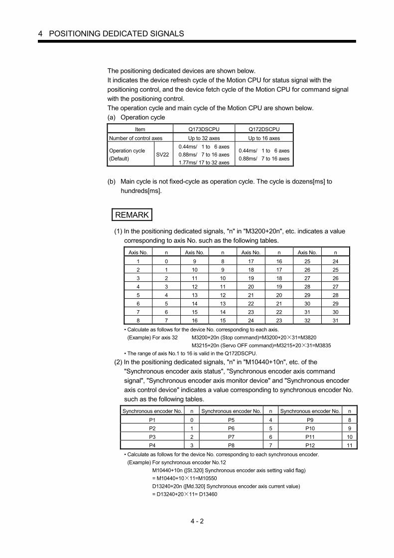
4 - 2
4 POSITIONING DEDICATED SIGNALS
The positioning dedicated devices are shown below. It indicates the device refresh cycle of the Motion CPU for status signal with the positioning control, and the device fetch cycle of the Motion CPU for command signal with the positioning control. The operation cycle and main cycle of the Motion CPU are shown below. (a) Operation cycle
Item Q173DSCPU Q172DSCPU
Number of control axes Up to 32 axes Up to 16 axes
Operation cycle (Default)
SV22 0.44ms/ 1 to 6 axes 0.88ms/ 7 to 16 axes 1.77ms/ 17 to 32 axes
0.44ms/ 1 to 6 axes 0.88ms/ 7 to 16 axes
(b) Main cycle is not fixed-cycle as operation cycle. The cycle is dozens[ms] to
hundreds[ms].
REMARK
(1) In the positioning dedicated signals, "n" in "M3200+20n", etc. indicates a value corresponding to axis No. such as the following tables.
Axis No. n Axis No. n Axis No. n Axis No. n
1 0 9 8 17 16 25 24 2 1 10 9 18 17 26 25 3 2 11 10 19 18 27 26 4 3 12 11 20 19 28 27 5 4 13 12 21 20 29 28 6 5 14 13 22 21 30 29 7 6 15 14 23 22 31 30 8 7 16 15 24 23 32 31
• Calculate as follows for the device No. corresponding to each axis. (Example) For axis 32 M3200+20n (Stop command)=M3200+20 31=M3820 M3215+20n (Servo OFF command)=M3215+20 31=M3835
• The range of axis No.1 to 16 is valid in the Q172DSCPU.
(2) In the positioning dedicated signals, "n" in "M10440+10n", etc. of the "Synchronous encoder axis status", "Synchronous encoder axis command signal", "Synchronous encoder axis monitor device" and "Synchronous encoder axis control device" indicates a value corresponding to synchronous encoder No. such as the following tables.
Synchronous encoder No. n Synchronous encoder No. n Synchronous encoder No. n
P1 0 P5 4 P9 8 P2 1 P6 5 P10 9 P3 2 P7 6 P11 10 P4 3 P8 7 P12 11
• Calculate as follows for the device No. corresponding to each synchronous encoder. (Example) For synchronous encoder No.12
M10440+10n ([St.320] Synchronous encoder axis setting valid flag) = M10440+10 11=M10550 D13240+20n ([Md.320] Synchronous encoder axis current value) = D13240+20 11= D13460

4 - 3
4 POSITIONING DEDICATED SIGNALS
4.1 Internal Relays
(1) Internal relay list SV22
Device No. Application
M0 to
User device (2000 points)
M2000 to
Common device (320 points)
M2320 to
Unusable (80 points)
M2400 to
Axis status (20 points 32 axes)
M3040 to
Unusable (32 points)
M3072 to
Common device (Command signal) (64 points)
M3136 to
Unusable (64 points)
M3200 to
Axis command signal (20 points 32 axes)
M3840 to
User device (4352 points)
M8192 (Note-1) to
System area (1608 points)
M9800 (Note-1) to
Command generation axis status (20 points 32 axes)
M10440 (Note-1) to
Synchronous encoder axis status (10 points 12 axes)
M10560 (Note-1) to
Output axis status (10 points 32 axes)
M10880 (Note-1) to
Synchronous control signal [St.380] (32 points)
M10912 (Note-1) to
Synchronous analysis complete signal [St.381] (32 points)
M10944 (Note-1) to
Unusable (16 points)
M10960 (Note-1) to M11599 (Note-1)
Command generation axis command signal (20 points 32 axes)

4 - 4
4 POSITIONING DEDICATED SIGNALS
Internal relay list (Continued)
SV22 Device No. Application
M11600 (Note-1) to
Synchronous encoder axis command signal (4 points 12 axes)
M11648 (Note-1) to
Unusable (32 points)
M11680 (Note-1) to
Output axis command signal (10 points 32 axes)
M12000 (Note-1) to
Synchronous control start signal [Rq.380] (32 points)
M12032 (Note-1) to
Synchronous analysis request signal [Rq.381] (32 points)
M12064 (Note-1) to M12287 (Note-1)
Unusable (224 points)
It can be used as an user device.
POINT (1) Total number of user device points
6352 points (2) (Note-1) : Do not set M8192 to M12287 as the latch range in advanced
synchronous control method. (3) This manual describes only details for internal relays used in the synchronous
control. If it is required, refer to the "Q173D(S)CPU/Q172D(S)CPU Motion controller (SV13/SV22) Programming Manual (REAL MODE)".

4 - 5
4 POSITIONING DEDICATED SIGNALS
(2) Axis status list
Axis No. Device No. Signal name
1 M2400 to M2419
2 M2420 to M2439
3 M2440 to M2459 Signal name Refresh cycle Fetch cycle
Signal direction
4 M2460 to M2479 0 Positioning start complete 5 M2480 to M2499 1 Positioning complete 6 M2500 to M2519 2 In-position 7 M2520 to M2539 3 Command in-position 8 M2540 to M2559 4 Speed controlling 9 M2560 to M2579 5 Speed / position switching latch 10 M2580 to M2599 6 Zero pass
Operation cycle
11 M2600 to M2619 7 Error detection Immediate 12 M2620 to M2639 8 Servo error detection Operation cycle 13 M2640 to M2659 9 Home position return request Main cycle 14 M2660 to M2679 10 Home position return complete Operation cycle 15 M2680 to M2699 11 FLS 16 M2700 to M2719 12 RLS 17 M2720 to M2739 13 STOP 18 M2740 to M2759 14
External signals
DOG/CHANGE
Main cycle
19 M2760 to M2779 15 Servo ready 20 M2780 to M2799 16 Torque limiting
Operation cycle
Status signal
21 M2800 to M2819 17 22 M2820 to M2839 18
Unusable — — —
23 M2840 to M2859 19 M-code outputting Operation cycle Status signal
24 M2860 to M2879 25 M2880 to M2899 26 M2900 to M2919 27 M2920 to M2939 28 M2940 to M2959 29 M2960 to M2979 30 M2980 to M2999 31 M3000 to M3019 32 M3020 to M3039
POINT (1) The range of axis No.1 to 16 is valid in the Q172DSCPU. (2) The device area more than 17 axes in the Q172DSCPU can be used as an user
device. However, when the project of Q172DSCPU is replaced with Q173DSCPU, this area cannot be used as an user device.
(3) Refer to the "Q173D(S)CPU/Q172D(S)CPU Motion controller (SV13/SV22) Programming Manual (REAL MODE)" for details of axis status.

4 - 6
4 POSITIONING DEDICATED SIGNALS
(3) Axis command signal list
Axis No. Device No. Signal name
1 M3200 to M3219
2 M3220 to M3239
3 M3240 to M3259 Signal name Refresh cycle Fetch cycle Signal direction
4 M3260 to M3279 0 Stop command 5 M3280 to M3299 1 Rapid stop command
Operation cycle
6 M3300 to M3319 2 Forward rotation JOG start command 7 M3320 to M3339 3 Reverse rotation JOG start command 8 M3340 to M3359 4 Complete signal OFF command
Main cycle
9 M3360 to M3379 10 M3380 to M3399
5 Speed/position switching enable command
Operation cycle
Command signal
11 M3400 to M3419 6 Unusable — — — 12 M3420 to M3439 7 Error reset command 13 M3440 to M3459 8 Servo error reset command
Main cycle
14 M3460 to M3479 At start 15 M3480 to M3499
9 External stop input disable at start command
Command signal
16 M3500 to M3519 10 17 M3520 to M3539 11
Unusable — — —
18 M3540 to M3559 19 M3560 to M3579
12 Feed current value update command At start Command
signal 20 M3580 to M3599 13 21 M3600 to M3619 14
Unusable — — —
22 M3620 to M3639 15 Servo OFF command Operation cycle 23 M3640 to M3659 16 Gain changing command 24 M3660 to M3679 17 PI-PID switching command
Operation cycle (Note-1)
25 M3680 to M3699 18 Control loop changing command 26 M3700 to M3719 19 FIN signal
Operation cycle
Command signal
27 M3720 to M3739 28 M3740 to M3759 29 M3760 to M3779 30 M3780 to M3799 31 M3800 to M3819 32 M3820 to M3839
(Note-1): Operation cycle 7.1[ms] or more: Every 3.5[ms]
POINT (1) The range of axis No.1 to 16 is valid in the Q172DSCPU. (2) The device area more than 17 axes in the Q172DSCPU can be used as an user
device. However, when the project of Q172DSCPUis replaced with Q173DSCPU, this area cannot be used as an user device.
(3) Refer to the "Q173D(S)CPU/Q172D(S)CPU Motion controller (SV13/SV22) Programming Manual (REAL MODE)" for details of axis command signal.

4 - 7
4 POSITIONING DEDICATED SIGNALS
(4) Command generation axis status list
Axis No. Device No. Signal name
1 M9800 to M9819
2 M9820 to M9839
3 M9840 to M9859 Symbol Signal name Refresh cycle Fetch cycle
Signal direction
4 M9860 to M9879 5 M9880 to M9899
0 St.340 Command generation axis positioning start complete
6 M9900 to M9919 7 M9920 to M9939
1 St.341 Command generation axis positioning complete
Operation cycle Status signal
8 M9940 to M9959 2 — Unusable — — — 9 M9960 to M9979 10 M9980 to M9999
3 St.342 Command generation axis command in-position
11 M10000 to M10019 12 M10020 to M10039
4 St.343 Command generation axis speed controlling
Operation cycle Status signal
13 M10040 to M10059 5 14 M10060 to M10079 6
— Unusable — — —
15 M10080 to M10099 16 M10100 to M10119
7 St.344 Command generation axis error detection
Immediate Status signal
17 M10120 to M10139 8 18 M10140 to M10159 9
— Unusable — — —
19 M10160 to M10179 20 M10180 to M10199
10 St.345 Command generation axis start accept flag
21 M10200 to M10219 22 M10220 to M10239
11 St.346 Command generation axis speed change accepting flag
23 M10240 to M10259 24 M10260 to M10279
12 St.347 Command generation axis speed change "0" accepting flag
25 M10280 to M10299 26 M10300 to M10319
13 St.348 Command generation axis automatic decelerating flag
Operation cycle Status signal
27 M10320 to M10339 14 28 M10340 to M10359 15 29 M10360 to M10379 16 30 M10380 to M10399 17 31 M10400 to M10419 18
— Unusable — — —
32 M10420 to M10439
19 St.349
Command generation axis M-code outputting
Operation cycle Status signal
POINT (1) The range of axis No.1 to 16 is valid in the Q172DSCPU. (2) The device area more than 17 axes in the Q172DSCPU can be used as an user
device. However, when the project of Q172DSCPU is replaced with Q173DSCPU, this area cannot be used as an user device.
(3) Refer to Section 5.2.4 for details of command generation axis status.

4 - 8
4 POSITIONING DEDICATED SIGNALS
(5) Command generation axis command signal list
Axis No. Device No. Signal name
1 M10960 to M10979
2 M10980 to M10999
3 M11000 to M11019 Symbol Signal name Refresh cycle Fetch cycle
Signal direction
4 M11020 to M11039 5 M11040 to M11059
0 Rq.341 Command generation axis stop command
6 M11060 to M11079 7 M11080 to M11099
1 Rq.342 Command generation axis rapid stop command
Operation cycle
8 M11100 to M11119 9 M11120 to M11139
2 Rq.343 Command generation axis forward rotation JOG start command
10 M11140 to M11159 11 M11160 to M11179
3 Rq.344 Command generation axis reverse rotation JOG start command
12 M11180 to M11199 13 M11200 to M11219
4 Rq.345 Command generation axis complete signal OFF command
Main cycle
Command signal
14 M11220 to M11239 5 15 M11240 to M11259 6
— Unusable — — —
16 M11260 to M11279 17 M11280 to M11299
7 Rq.346 Command generation axis error reset command
Main cycle Command
signal 18 M11300 to M11319 8 19 M11320 to M11339 9 20 M11340 to M11359 10 21 M11360 to M11379 11
— Unusable — — —
22 M11380 to M11399 23 M11400 to M11419
12 Rq.347 Feed current value update request command
At start Command
signal 24 M11420 to M11439 13 25 M11440 to M11459 14 26 M11460 to M11479 15 27 M11480 to M11499 16 28 M11500 to M11519 17 29 M11520 to M11539 18
— Unusable — — —
30 M11540 to M11559 31 M11560 to M11579
19 Rq.348 Command generation axis FIN signal
Operation cycle Command
signal
32 M11580 to M11599
POINT (1) The range of axis No.1 to 16 is valid in the Q172DSCPU. (2) The device area more than 17 axes in the Q172DSCPU can be used as an user
device. However, when the project of Q172DSCPU is replaced with Q173DSCPU, this area cannot be used as an user device.
(3) Refer to Section 5.2.3 for details of command generation axis command signal.

4 - 9
4 POSITIONING DEDICATED SIGNALS
(6) Synchronous encoder axis status list
Axis No. Device No. Signal name
1 M10440 to M10449
2 M10450 to M10459
3 M10460 to M10469 Symbol Signal name Refresh cycle Fetch cycle
Signal direction
4 M10470 to M10479 5 M10480 to M10489
0 St.320 Synchronous encoder axis setting valid flag
At power on
6 M10490 to M10499 7 M10500 to M10509
1 St.321 Synchronous encoder axis connecting valid flag
8 M10510 to M10519 9 M10520 to M10529
2 St.322 Synchronous encoder axis counter enable flag
10 M10530 to M10539 11 M10540 to M10549
3 St.323 Synchronous encoder axis current value setting request flag
Operation cycle
12 M10550 to M10559
4 St.324
Synchronous encoder axis error detection flag
Immediate
Status signal
5 — Unusable — — —
6 St.325 Synchronous encoder axis control complete flag
Immediate Status signal
7 8 9
— Unusable — — —
POINT Refer to Section 5.3.5 for details of synchronous encoder axis status.
(7) Synchronous encoder axis command signal list Axis No. Device No. Signal name
1 M11600 to M11603
2 M11604 to M11607
3 M11608 to M11611 Symbol Signal name Refresh cycle Fetch cycle
Signal direction
4 M11612 to M11615 5 M11616 to M11619
0 Rq.323 Synchronous encoder axis error reset
Main cycle
6 M11620 to M11623 7 M11624 to M11627
1 Rq.320 Synchronous encoder axis control request
Operation cycle
8 M11628 to M11631 9 M11632 to M11635
2 Rq.324 Connection command of synchronous encoder via device
Main cycle
Command signal
10 M11636 to M11639 3 — Unusable — — —
11 M11640 to M11643 12 M11644 to M11647
POINT Refer to Section 5.3.4 for details of synchronous encoder axis command signal.

4 - 10
4 POSITIONING DEDICATED SIGNALS
(8) Output axis status list
Axis No. Device No. Signal name
1 M10560 to M10569
2 M10570 to M10579
3 M10580 to M10589 Symbol Signal name Refresh cycle Fetch cycle
Signal direction
4 M10590 to M10599 0 St.420 Main shaft clutch ON/OFF status 5 M10600 to M10609 1 St.421 Main shaft clutch smoothing status 6 M10610 to M10619 7 M10620 to M10629
2 St.423 Auxiliary shaft clutch ON/OFF status
8 M10630 to M10639 9 M10640 to M10649
3 St.424 Auxiliary shaft clutch smoothing status
Operation cycle Status signal
10 M10650 to M10659 4 11 M10660 to M10669 5
— Unusable — — —
12 M10670 to M10679 13 M10680 to M10689
6 St.426 Control change complete Operation cycle Status signal
14 M10690 to M10699 7 15 M10700 to M10709 8 16 M10710 to M10719 9
— Unusable — — —
17 M10720 to M10729 18 M10730 to M10739 19 M10740 to M10749 20 M10750 to M10759 21 M10760 to M10769 22 M10770 to M10779 23 M10780 to M10789 24 M10790 to M10799 25 M10800 to M10809 26 M10810 to M10819 27 M10820 to M10829 28 M10830 to M10839 29 M10840 to M10849 30 M10850 to M10859 31 M10860 to M10869 32 M10870 to M10879
POINT (1) The range of axis No.1 to 16 is valid in the Q172DSCPU. (2) The device area more than 17 axes in the Q172DSCPU can be used as an user
device. However, when the project of Q172DSCPU is replaced with Q173DSCPU, this area cannot be used as an user device.
(3) Refer to Section 7.6.2 and Section 7.7 for details of output axis status.

4 - 11
4 POSITIONING DEDICATED SIGNALS
(9) Output axis command signal list
Axis No. Device No. Signal name
1 M11680 to M11689
2 M11690 to M11699
3 M11700 to M11709 Symbol Signal name Refresh cycle Fetch cycle
Signal direction
4 M11710 to M11719 0 Rq.400 Main shaft clutch command 5 M11720 to M11729 6 M11730 to M11739
1 Rq.401 Main shaft clutch control invalid command
7 M11740 to M11749 8 M11750 to M11759
2 Rq.402 Main shaft clutch forced OFF command
Operation cycle Command
signal
9 M11760 to M11769 3 — Unusable — — — 10 M11770 to M11779 4 Rq.403 Auxiliary shaft clutch command 11 M11780 to M11789 12 M11790 to M11799
5 Rq.404 Auxiliary shaft clutch control invalid command
13 M11800 to M11809 14 M11810 to M11819
6 Rq.405 Auxiliary shaft clutch forced OFF command
Operation cycle Command
signal
15 M11820 to M11829 7 — Unusable — — — 16 M11830 to M11839 17 M11840 to M11849
8 Rq.406 Control change request command Operation cycle Command
signal 18 M11850 to M11859 9 — Unusable
19 M11860 to M11869 20 M11870 to M11879 21 M11880 to M11889 22 M11890 to M11899 23 M11900 to M11909 24 M11910 to M11919 25 M11920 to M11929 26 M11930 to M11939 27 M11940 to M11949 28 M11950 to M11959 29 M11960 to M11969 30 M11970 to M11979 31 M11980 to M11989 32 M11990 to M11999
POINT (1) The range of axis No.1 to 16 is valid in the Q172DSCPU. (2) The device area more than 17 axes in the Q172DSCPU can be used as an user
device. However, when the project of Q172DSCPU is replaced with Q173DSCPU, this area cannot be used as an user device.
(3) Refer to Section 7.1.4, Section 7.2.4 and Section 7.6.2 for details of output axis command signal.

4 - 12
4 POSITIONING DEDICATED SIGNALS
(10) Synchronous control signal list
Axis No. Device No. Symbol Signal name Refresh cycle Fetch cycle Signal
direction
1 M10880 2 M10881 3 M10882 4 M10883 5 M10884 6 M10885 7 M10886 8 M10887 9 M10888 10 M10889 11 M10890 12 M10891 13 M10892 14 M10893 15 M10894 16 M10895 17 M10896 18 M10897 19 M10898 20 M10899 21 M10900 22 M10901 23 M10902 24 M10903 25 M10904 26 M10905 27 M10906 28 M10907 29 M10908 30 M10909 31 M10910 32 M10911
St.380 Synchronous control Operation cycle Status signal
POINT (1) The range of axis No.1 to 16 is valid in the Q172DSCPU. (2) The device area more than 17 axes in the Q172DSCPU can be used as an user
device. However, when the project of Q172DSCPU is replaced with Q173DSCPU, this area cannot be used as an user device.
(3) Refer to Section 2.2 for details of synchronous control signal.

4 - 13
4 POSITIONING DEDICATED SIGNALS
(11) Synchronous analysis complete signal list
Axis No. Device No. Symbol Signal name Refresh cycle Fetch cycle Signal
direction
1 M10912 2 M10913 3 M10914 4 M10915 5 M10916 6 M10917 7 M10918 8 M10919 9 M10920 10 M10921 11 M10922 12 M10923 13 M10924 14 M10925 15 M10926 16 M10927 17 M10928 18 M10929 19 M10930 20 M10931 21 M10932 22 M10933 23 M10934 24 M10935 25 M10936 26 M10937 27 M10938 28 M10939 29 M10940 30 M10941 31 M10942 32 M10943
St.381 Synchronous analysis complete Operation cycle Status signal
POINT (1) The range of axis No.1 to 16 is valid in the Q172DSCPU. (2) The device area more than 17 axes in the Q172DSCPU can be used as an user
device. However, when the project of Q172DSCPU is replaced with Q173DSCPU, this area cannot be used as an user device.
(3) Refer to Section 2.2 for details of synchronous analysis complete signal.

4 - 14
4 POSITIONING DEDICATED SIGNALS
(12) Synchronous control start signal list
Axis No. Device No. Symbol Signal name Refresh cycle Fetch cycle Signal
direction
1 M12000 2 M12001 3 M12002 4 M12003 5 M12004 6 M12005 7 M12006 8 M12007 9 M12008 10 M12009 11 M12010 12 M12011 13 M12012 14 M12013 15 M12014 16 M12015 17 M12016 18 M12017 19 M12018 20 M12019 21 M12020 22 M12021 23 M12022 24 M12023 25 M12024 26 M12025 27 M12026 28 M12027 29 M12028 30 M12029 31 M12030 32 M12031
Rq.380 Synchronous control start Operation cycle Command
signal
POINT (1) The range of axis No.1 to 16 is valid in the Q172DSCPU. (2) The device area more than 17 axes in the Q172DSCPU can be used as an user
device. However, when the project of Q172DSCPU is replaced with Q173DSCPU, this area cannot be used as an user device.
(3) Refer to Section 2.2 for details of synchronous control start signal.

4 - 15
4 POSITIONING DEDICATED SIGNALS
(13) Synchronous analysis request signal list
Axis No. Device No. Symbol Signal name Refresh cycle Fetch cycle Signal
direction
1 M12032 2 M12033 3 M12034 4 M12035 5 M12036 6 M12037 7 M12038 8 M12039 9 M12040 10 M12041 11 M12042 12 M12043 13 M12044 14 M12045 15 M12046 16 M12047 17 M12048 18 M12049 19 M12050 20 M12051 21 M12052 22 M12053 23 M12054 24 M12055 25 M12056 26 M12057 27 M12058 28 M12059 29 M12060 30 M12061 31 M12062 32 M12063
Rq.381 Synchronous analysis request At start of
synchronous control
Command signal
POINT (1) The range of axis No.1 to 16 is valid in the Q172DSCPU. (2) The device area more than 17 axes in the Q172DSCPU can be used as an user
device. However, when the project of Q172DSCPU is replaced with Q173DSCPU, this area cannot be used as an user device.
(3) Refer to Section 2.2 for details of synchronous analysis request signal.

4 - 16
4 POSITIONING DEDICATED SIGNALS
(14) Common device list
Device No.
Signal name Refresh cycle Fetch cycle Signal
direction Remark(Note-3)
Device No.
Signal name Refresh cycle Fetch cycle Signal
direction Remark(Note-3)
M2000 PLC ready flag Main cycle Command
signal M3072 M2061 Axis 1
M2001 Axis 1 M2062 Axis 2
M2002 Axis 2 M2063 Axis 3
M2003 Axis 3 M2064 Axis 4
M2004 Axis 4 M2065 Axis 5
M2005 Axis 5 M2066 Axis 6
M2006 Axis 6 M2067 Axis 7
M2007 Axis 7 M2068 Axis 8
M2008 Axis 8 M2069 Axis 9
M2009 Axis 9 M2070 Axis 10
M2010 Axis 10 M2071 Axis 11
M2011 Axis 11 M2072 Axis 12
M2012 Axis 12 M2073 Axis 13
M2013 Axis 13 M2074 Axis 14
M2014 Axis 14 M2075 Axis 15
M2015 Axis 15 M2076 Axis 16
M2016 Axis 16 M2077 Axis 17
M2017 Axis 17 M2078 Axis 18
M2018 Axis 18 M2079 Axis 19
M2019 Axis 19 M2080 Axis 20
M2020 Axis 20 M2081 Axis 21
M2021 Axis 21 M2082 Axis 22
M2022 Axis 22 M2083 Axis 23
M2023 Axis 23 M2084 Axis 24
M2024 Axis 24 M2085 Axis 25
M2025 Axis 25 M2086 Axis 26
M2026 Axis 26 M2087 Axis 27
M2027 Axis 27 M2088 Axis 28
M2028 Axis 28 M2089 Axis 29
M2029 Axis 29 M2090 Axis 30
M2030 Axis 30 M2091 Axis 31
M2031 Axis 31 M2092 Axis 32
Speed change accepting flag
Operation cycle Status signal
(Note-1), (Note-2)
M2032 Axis 32
Start accept flag Operation cycle Status signal
(Note-1), (Note-2)
M2093
M2033 M2094
M2034
Unusable (2 points)
— — — — M2095
M2035 Motion error history clear request flag
Main cycle Command
signal M3080 M2096
M2036 M2097
M2037
Unusable (2 points)
— — — — M2098
M2038 Motion SFC debugging flag At debugging mode
transition M2099
M2039 Motion error detection flag Immediate
Status signal
M2100
M2040 Speed switching point specified flag
At start Command
signal M3073 M2101
M2041 System setting error flag Operation cycle Status signal M2102
M2042 All axes servo ON command Operation cycle Command
signal M3074 M2103
M2043 M2104
M2044 M2105
M2045 M2106
M2046
Unusable (4 points)
— — — —
M2107
M2047 Motion slot fault detection flag Operation cycle Status signal M2108
M2048 JOG operation simultaneous start command
Main cycle Command
signal M3076 M2109
M2049 All axes servo ON accept flag Operation cycle Status signal M2110
M2050 Unusable — — — — M2111
M2051 Manual pulse generator 1 enable flag
M3077 M2112
M2052 Manual pulse generator 2 enable flag
M3078 M2113
M2053 Manual pulse generator 3 enable flag
Main cycle Command
signal
M3079 M2114
M2054 Operation cycle over flag Operation cycle Status signal M2115
M2055 M2116
M2056 M2117
M2057 M2118
M2058 M2119
M2059 M2120
M2060
Unusable (6 points)
— — — —
M2121
Unusable (29 points)
— — — —

4 - 17
4 POSITIONING DEDICATED SIGNALS
Common device list (Continued)
Device No.
Signal name Refresh cycle Fetch cycle Signal
direction Remark(Note-3)
Device
No. Signal name Refresh cycle Fetch cycle
Signal direction
Remark(Note-3)
M2122 M2194
M2123 M2195
M2124 M2196
M2125 M2197
M2126 M2198
M2127
Unusable (6 points)
— — — —
M2199
M2128 Axis 1 M2200
M2129 Axis 2 M2201
M2130 Axis 3 M2202
M2131 Axis 4 M2203
M2132 Axis 5 M2204
M2133 Axis 6 M2205
M2134 Axis 7 M2206
M2135 Axis 8 M2207
M2136 Axis 9 M2208
M2137 Axis 10 M2209
M2138 Axis 11 M2210
M2139 Axis 12 M2211
M2140 Axis 13 M2212
M2141 Axis 14 M2213
M2142 Axis 15 M2214
M2143 Axis 16 M2215
M2144 Axis 17 M2216
M2145 Axis 18 M2217
M2146 Axis 19 M2218
M2147 Axis 20 M2219
M2148 Axis 21 M2220
M2149 Axis 22 M2221
M2150 Axis 23 M2222
M2151 Axis 24 M2223
M2152 Axis 25 M2224
M2153 Axis 26 M2225
M2154 Axis 27 M2226
M2155 Axis 28 M2227
M2156 Axis 29 M2228
M2157 Axis 30 M2229
M2158 Axis 31 M2230
M2159 Axis 32
Automatic decelerating flag
Operation cycle Status signal
(Note-1), (Note-2)
M2231
M2160 M2232
M2161 M2233
M2162 M2234
M2163 M2235
M2164 M2236
M2165 M2237
M2166 M2238
M2167 M2239
Unusable (46 points)
— — — —
M2168 M2240 Axis 1
M2169 M2241 Axis 2
M2170 M2242 Axis 3
M2171 M2243 Axis 4
M2172 M2244 Axis 5
M2173 M2245 Axis 6
M2174 M2246 Axis 7
M2175 M2247 Axis 8
M2176 M2248 Axis 9
M2177 M2249 Axis 10
M2178 M2250 Axis 11
M2179 M2251 Axis 12
M2180 M2252 Axis 13
M2181 M2253 Axis 14
M2182 M2254 Axis 15
M2183 M2255 Axis 16
M2184 M2256 Axis 17
M2185 M2257 Axis 18
M2186 M2258 Axis 19
M2187 M2259 Axis 20
M2188 M2260 Axis 21
M2189 M2261 Axis 22
M2190 M2262 Axis 23
M2191 M2263 Axis 24
M2192 M2264 Axis 25
M2193
Unusable (34 points)
— — — —
M2265 Axis 26
Speed change "0" accepting flag
Operation cycle Status signal
(Note-1), (Note-2)

4 - 18
4 POSITIONING DEDICATED SIGNALS
Common device list (Continued)
Device No.
Signal name Refresh cycle Fetch cycle Signal
direction Remark(Note-3)
Device No.
Signal name Refresh cycle Fetch cycle Signal
direction Remark(Note-3)
M2266 Axis 27 M2293 Axis 22
M2267 Axis 28 M2294 Axis 23
M2268 Axis 29 M2295 Axis 24
M2269 Axis 30 M2296 Axis 25
M2270 Axis 31 M2297 Axis 26
M2271 Axis 32
Speed change "0" accepting flag
M2298 Axis 27
M2272 Axis 1 M2299 Axis 28
M2273 Axis 2 M2300 Axis 29
M2274 Axis 3 M2301 Axis 30
M2275 Axis 4 M2302 Axis 31
M2276 Axis 5 M2303 Axis 32
Control loop monitor status
Operation cycle Status signal
(Note-1), (Note-2)
M2277 Axis 6 M2304
M2278 Axis 7 M2305
M2279 Axis 8 M2306
M2280 Axis 9 M2307
M2281 Axis 10 M2308
M2282 Axis 11 M2309
M2283 Axis 12 M2310
M2284 Axis 13 M2311
M2285 Axis 14 M2312
M2286 Axis 15 M2313
M2287 Axis 16 M2314
M2288 Axis 17 M2315
M2289 Axis 18 M2316
M2290 Axis 19 M2317
M2291 Axis 20 M2318
M2292 Axis 21
Control loop monitor status
Operation cycle Status signal
(Note-1), (Note-2)
M2319
Unusable (16 points)
— — — —
(Note-1): The range of axis No.1 to 16 is valid in the Q172DSCPU. (Note-2): Device area of 17 axes or more is unusable in the Q172DSCPU. (Note-3): It can also be ordered the device of a remark column.
POINT Refer to the "Q173D(S)CPU/Q172D(S)CPU Motion controller (SV13/SV22) Programming Manual (REAL MODE)" for details of common device.

4 - 19
4 POSITIONING DEDICATED SIGNALS
(15) Common device list (Command signal)
Device No. Signal name Refresh cycle Fetch cycle Signal direction Remark
(Note-1), (Note-2)
M3072 PLC ready flag Main cycle M2000 M3073 Speed switching point specified flag At start M2040 M3074 All axes servo ON command
Operation cycle
Command signal
M2042 M3075 Unusable — — — — M3076 JOG operation simultaneous start command M2048 M3077 Manual pulse generator 1 enable flag M2051 M3078 Manual pulse generator 2 enable flag M2052 M3079 Manual pulse generator 3 enable flag M2053 M3080 Motion error history clear request flag
Main cycle Command signal
M2035 M3081
to M3135
Unusable (Note-3) (55 points)
— — — —
(Note-1): The state of a device is not in agreement when the device of a remark column is turned ON/OFF directly. In addition,
when the request from a data register and the request from the above device are performed simultaneously, the request from the above device becomes effective.
(Note-2): It can also be ordered the device of a remark column. (Note-3): Do not use it as an user device. It can be used as a device that performs automatic refresh because of area for the
reserve of command signal.
POINT The device of a remark column turns ON by OFF to ON of the above device, and turns OFF by ON to OFF of the above device. The command signal cannot be turned ON/OFF by the PLC CPU in the automatic refresh because the statuses and commands are mixed together in M2000 to M2053. Use the above devices in the case. And, it can also be turned ON/OFF by the data register. (Refer to the "Q173D(S)CPU/Q172D(S)CPU Motion controller (SV13/SV22) Programming Manual (REAL MODE)".)

4 - 20
4 POSITIONING DEDICATED SIGNALS
4.2 Data Registers
(1) Data register list SV22
Device No. Application
D0 to
Axis monitor device (20 points 32 axes)
D640 to
Control change register (2 points 32 axes)
D704 to
Common device (Command signal) (54 points)
D758 to
Unusable (42 points)
D800 to
User device (7392 points)
D8192 (Note-1) to
User device (2048 points)
D10240 (Note-1) to
System area (2040 points)
D12280 (Note-1) to
Servo input axis monitor device (10 points 32 axes)
D12600 (Note-1) to
Command generation axis monitor device (20 points 32 axes)
D13240 (Note-1) to
Synchronous encoder axis monitor device (20 points 12 axes)
D13480 (Note-1) to
Unusable (120 points)
D13600 (Note-1) to
Output axis monitor device (30 points 32 axes)
D14560 (Note-1) to
Unusable (40 points)
D14600 (Note-1) to
Servo input axis control device (2 points 32 axes)
D14664 (Note-1) to
Unusable (16 points)
D14680 (Note-1) to
Command generation axis control device (4 points 32 axes)
D14808 (Note-1) to D14819 (Note-1)
Unusable (12 points)
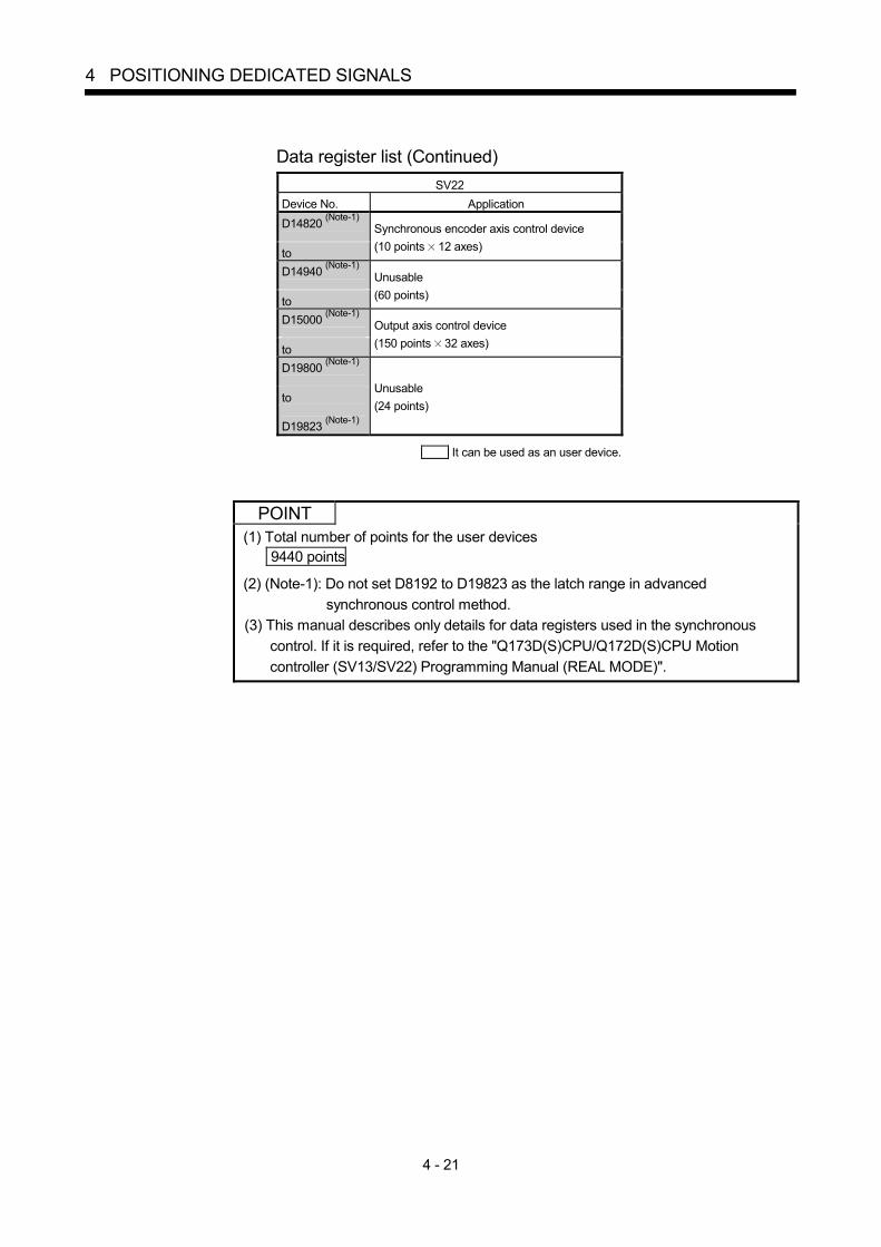
4 - 21
4 POSITIONING DEDICATED SIGNALS
Data register list (Continued)
SV22 Device No. Application D14820 (Note-1) to
Synchronous encoder axis control device (10 points 12 axes)
D14940 (Note-1) to
Unusable (60 points)
D15000 (Note-1) to
Output axis control device (150 points 32 axes)
D19800 (Note-1) to D19823 (Note-1)
Unusable (24 points)
It can be used as an user device.
POINT (1) Total number of points for the user devices
9440 points (2) (Note-1): Do not set D8192 to D19823 as the latch range in advanced
synchronous control method. (3) This manual describes only details for data registers used in the synchronous
control. If it is required, refer to the "Q173D(S)CPU/Q172D(S)CPU Motion controller (SV13/SV22) Programming Manual (REAL MODE)".

4 - 22
4 POSITIONING DEDICATED SIGNALS
(2) Axis monitor device list
Axis No. Device No. Signal name
1 D0 to D19
2 D20 to D39
3 D40 to D59 Signal name Refresh cycle Fetch cycle Signal direction
4 D60 to D79 0 5 D80 to D99 1
Feed current value
6 D100 to D119 2 7 D120 to D139 3
Real current value
8 D140 to D159 4 9 D160 to D179 5
Deviation counter value
Operation cycle
10 D180 to D199 6 Minor error code 11 D200 to D219 7 Major error code
Immediate
12 D220 to D239
8 Servo error code Main cycle
13 D240 to D259 9 Home position return re-travel value 14 D260 to D279
10
15 D280 to D299 11 Travel value after proximity dog ON
Operation cycle
16 D300 to D319
12 Execute program No. At start
17 D320 to D339 13 M-code 18 D340 to D359
14 Torque limit value
Operation cycle
19 D360 to D379 20 D380 to D399
15 Data set pointer for constant-speed control
At start/ during start
Monitor device
21 D400 to D419 16 22 D420 to D439 17
Unusable (Note-1) — — —
23 D440 to D459 18
24 D460 to D479 19 Real current value at stop input Operation cycle Monitor device
25 D480 to D499
26 D500 to D519 27 D520 to D539 28 D540 to D559 29 D560 to D579 30 D580 to D599 31 D600 to D619 32 D620 to D639
(Note-1): It can be used as the travel value change register. The travel value change register can be set to the device optionally in the servo program. Refer to the "Q173D(S)CPU/Q172D(S)CPU Motion controller (SV13/SV22) Programming Manual (REAL MODE)" for details.
POINT (1) The range of axis No.1 to 16 is valid in the Q172DSCPU. (2) The device area more than 17 axes in the Q172DSCPU can be used as an user
device. However, when the project of Q172DSCPU is replaced with Q173DSCPU, this area cannot be used as an user device.
(3) Refer to the "Q173D(S)CPU/Q172D(S)CPU Motion controller (SV13/SV22) Programming Manual (REAL MODE)" for details of axis monitor device.

4 - 23
4 POSITIONING DEDICATED SIGNALS
(3) Control change register list
Axis No. Device No. Signal name
1 D640, D641
2 D642, D643 3 D644, D645
Signal name Refresh cycle Fetch cycle Signal direction
4 D646, D647 0 5 D648, D649 1
JOG speed setting At start Command
device
6 D650, D651 7 D652, D653 8 D654, D655 9 D656, D657 10 D658, D659 11 D660, D661 12 D662, D663 13 D664, D665 14 D666, D667 15 D668, D669 16 D670, D671 17 D672, D673 18 D674, D675 19 D676, D677 20 D678, D679 21 D680, D681 22 D682, D683 23 D684, D685 24 D686, D687 25 D688, D689 26 D690, D691 27 D692, D693 28 D694, D695 29 D696, D697 30 D698, D699 31 D700, D701 32 D702, D703
POINT (1) The range of axis No.1 to 16 is valid in the Q172DSCPU. (2) The device area more than 17 axes in the Q172DSCPU can be used as an user
device. However, when the project of Q172DSCPU is replaced with Q173DSCPU, this area cannot be used as an user device.
(3) Refer to the "Q173D(S)CPU/Q172D(S)CPU Motion controller (SV13/SV22) Programming Manual (REAL MODE)" for details of control change register.

4 - 24
4 POSITIONING DEDICATED SIGNALS
(4) Servo input axis monitor device list
Axis No. Device No. Signal name
1 D12280 to D12289
2 D12290 to D12299
3 D12300 to D12309 Symbol Signal name Refresh cycle Fetch cycle
Signal direction
4 D12310 to D12319 0 5 D12320 to D12329 1
Md.300 Servo input axis current value
6 D12330 to D12339 2 7 D12340 to D12349 3
Md.301 Servo input axis speed
8 D12350 to D12359 4 9 D12360 to D12369 5
Md.302 Servo input axis phase compensation amount
10 D12370 to D12379 6 11 D12380 to D12389 7
Md.303 Servo input axis rotation direction restriction amount
Operation cycle Monitor device
12 D12390 to D12399 8 13 D12400 to D12409 9
— Unusable — — —
14 D12410 to D12419 15 D12420 to D12429 16 D12430 to D12439 17 D12440 to D12449 18 D12450 to D12459 19 D12460 to D12469 20 D12470 to D12479 21 D12480 to D12489 22 D12490 to D12499 23 D12500 to D12509 24 D12510 to D12519 25 D12520 to D12529 26 D12530 to D12539 27 D12540 to D12549 28 D12550 to D12559 29 D12560 to D12569 30 D12570 to D12579 31 D12580 to D12589 32 D12590 to D12599
POINT (1) The range of axis No.1 to 16 is valid in the Q172DSCPU. (2) The device area more than 17 axes in the Q172DSCPU can be used as an user
device. However, when the project of Q172DSCPU is replaced with Q173DSCPU, this area cannot be used as an user device.
(3) Refer to Section 5.1.3 for details of servo input axis monitor device.

4 - 25
4 POSITIONING DEDICATED SIGNALS
(5) Servo input axis control device list
Axis No. Device No. Signal name
1 D14600, D14601
2 D14602, D14603
3 D14604, D14605 Symbol Signal name Refresh cycle Fetch cycle
Signal direction
4 D14606, D14607 0 5 D14608, D14609 1
Pr.302 Servo input axis phase compensation advance time
Operation cycle Command
device
6 D14610, D14611 7 D14612, D14613 8 D14614, D14615 9 D14616, D14617 10 D14618, D14619 11 D14620, D14621 12 D14622, D14623 13 D14624, D14625 14 D14626, D14627 15 D14628, D14629 16 D14630, D14631 17 D14632, D14633 18 D14634, D14635 19 D14636, D14637 20 D14638, D14639 21 D14640, D14641 22 D14642, D14643 23 D14644, D14645 24 D14646, D14647 25 D14648, D14649 26 D14650, D14651 27 D14652, D14653 28 D14654, D14655 29 D14656, D14657 30 D14658, D14659 31 D14660, D14661 32 D14662, D14663
POINT (1) The range of axis No.1 to 16 is valid in the Q172DSCPU. (2) The device area more than 17 axes in the Q172DSCPU can be used as an user
device. However, when the project of Q172DSCPU is replaced with Q173DSCPU, this area cannot be used as an user device.
(3) Refer to Section 5.1.2 for details of servo input axis control device.
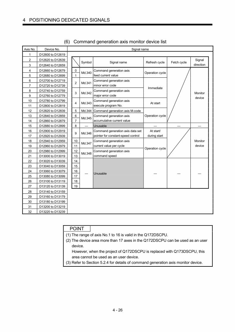
4 - 26
4 POSITIONING DEDICATED SIGNALS
(6) Command generation axis monitor device list
Axis No. Device No. Signal name
1 D12600 to D12619
2 D12620 to D12639
3 D12640 to D12659 Symbol Signal name Refresh cycle Fetch cycle
Signal direction
4 D12660 to D12679 0 5 D12680 to D12699 1
Md.340 Command generation axis feed current value
Operation cycle
6 D12700 to D12719 7 D12720 to D12739
2 Md.341 Command generation axis minor error code
8 D12740 to D12759 9 D12760 to D12779
3 Md.342 Command generation axis major error code
Immediate
10 D12780 to D12799 11 D12800 to D12819
4 Md.343 Command generation axis execute program No.
At start
12 D12820 to D12839 5 Md.344 Command generation axis M-code 13 D12840 to D12859 6 14 D12860 to D12879 7
Md.345 Command generation axis accumulative current value
Operation cycle
Monitor device
15 D12880 to D12899 8 — Unusable — — — 16 D12900 to D12919 17 D12920 to D12939
9 Md.346 Command generation axis data set pointer for constant-speed control
At start/ during start
18 D12940 to D12959 10 19 D12960 to D12979 11
Md.347 Command generation axis current value per cycle
20 D12980 to D12999 12 21 D13000 to D13019 13
Md.348 Command generation axis command speed
Operation cycle
Monitor device
22 D13020 to D13039 14 23 D13040 to D13059 15 24 D13060 to D13079 16 25 D13080 to D13099 17 26 D13100 to D13119 18 27 D13120 to D13139 19
— Unusable — — —
28 D13140 to D13159 29 D13160 to D13179 30 D13180 to D13199 31 D13200 to D13219 32 D13220 to D13239
POINT (1) The range of axis No.1 to 16 is valid in the Q172DSCPU. (2) The device area more than 17 axes in the Q172DSCPU can be used as an user
device. However, when the project of Q172DSCPU is replaced with Q173DSCPU, this area cannot be used as an user device.
(3) Refer to Section 5.2.4 for details of command generation axis monitor device.

4 - 27
4 POSITIONING DEDICATED SIGNALS
(7) Command generation axis control device list
Axis No. Device No. Signal name
1 D14680 to D14683
2 D14684 to D14687
3 D14688 to D14691 Symbol Signal name Refresh cycle Fetch cycle
Signal direction
4 D14692 to D14695 0 5 D14696 to D14699 1
Cd.340 Command generation axis JOG speed setting
6 D14700 to D14703 7 D14704 to D14707
2 Pr.348 Command generation axis JOG operation parameter block setting
At start of
JOG operation Command
device
8 D14708 to D14711 3 — Unusable — — —
9 D14712 to D14715 10 D14716 to D14719 11 D14720 to D14723 12 D14724 to D14727 13 D14728 to D14731 14 D14732 to D14735 15 D14736 to D14739 16 D14740 to D14743 17 D14744 to D14747 18 D14748 to D14751 19 D14752 to D14755 20 D14756 to D14759 21 D14760 to D14763 22 D14764 to D14767 23 D14768 to D14771 24 D14772 to D14775 25 D14776 to D14779 26 D14780 to D14783 27 D14784 to D14787 28 D14788 to D14791 29 D14792 to D14795 30 D14796 to D14799 31 D14800 to D14803 32 D14804 to D14807
POINT (1) The range of axis No.1 to 16 is valid in the Q172DSCPU. (2) The device area more than 17 axes in the Q172DSCPU can be used as an user
device. However, when the project of Q172DSCPU is replaced with Q173DSCPU, this area cannot be used as an user device.
(3) Refer to Section 5.2.2 and Section 5.2.3 for details of command generation axis control device.

4 - 28
4 POSITIONING DEDICATED SIGNALS
(8) Synchronous encoder axis monitor device list
Axis No. Device No. Signal name
1 D13240 to D13259
2 D13260 to D13279
3 D13280 to D13299 Symbol Signal name Refresh cycle Fetch cycle
Signal direction
4 D13300 to D13319 0 5 D13320 to D13339 1
Md.320 Synchronous encoder axis current value
6 D13340 to D13359 2 7 D13360 to D13379 3
Md.321 Synchronous encoder axis current value per cycle
8 D13380 to D13399 4 9 D13400 to D13419 5
Md.322 Synchronous encoder axis speed
10 D13420 to D13439 6 11 D13440 to D13459 7
Md.323 Synchronous encoder axis phase compensation amount
12 D13460 to D13479 8 9
Md.324 Synchronous encoder axis rotation direction restriction amount
Operation cycle
10 Md.327 Synchronous encoder axis minor error code
11 Md.326 Synchronous encoder axis major error code
Immediate
Monitor device
12 13 14 15 16 17 18 19
— Unusable — — —
POINT Refer to Section 5.3.5 for details of synchronous encoder axis monitor device.

4 - 29
4 POSITIONING DEDICATED SIGNALS
(9) Synchronous encoder axis control device list
Axis No. Device No. Signal name
1 D14820 to D14829
2 D14830 to D14839
3 D14840 to D14849 Symbol Signal name Refresh cycle Fetch cycle
Signal direction
4 D14850 to D14859 0 5 D14860 to D14869 1
Pr.326 Synchronous encoder axis phase compensation advance time
Operation cycle
6 D14870 to D14879 7 D14880 to D14889
2 Cd.320 Synchronous encoder axis control start condition
8 D14890 to D14899 9 D14900 to D14909
3 Cd.321 Synchronous encoder axis control method
10 D14910 to D14919 4 11 D14920 to D14929 5
Cd.322 Synchronous encoder axis current value setting address
At synchronous encoder axis control start
12 D14930 to D14939 6
7 Cd.325
Input value for synchronous encoder via device
Operation cycle
Command device
8 9
— Unusable — — —
POINT Refer to Section 5.3.3 and Section 5.3.4 for details of synchronous encoder axis control device.

4 - 30
4 POSITIONING DEDICATED SIGNALS
(10) Output axis monitor device list
Axis No. Device No. Signal name
1 D13600 to D13629
2 D13630 to D13659
3 D13660 to D13689 Symbol Signal name Refresh cycle Fetch cycle
Signal direction
4 D13690 to D13719 0 5 D13720 to D13749 1
Md.400 Current value after composite main shaft gear
6 D13750 to D13779 2 7 D13780 to D13809 3
Md.401 Current value per cycle after main shaft gear
8 D13810 to D13839 4 9 D13840 to D13869 5
Md.402 Current value per cycle after auxiliary shaft gear
10 D13870 to D13899 6 11 D13900 to D13929 7
Md.422 Main shaft clutch slippage (accumulative)
12 D13930 to D13959 8 13 D13960 to D13989 9
Md.425 Auxiliary shaft clutch slippage (accumulative)
14 D13990 to D14019 10 15 D14020 to D14049 11
Md.406 Cam axis phase compensation amount
16 D14050 to D14079 12 17 D14080 to D14109 13
Md.407 Cam axis current value per cycle
18 D14110 to D14139 14 19 D14140 to D14169 15
Md.408 Cam reference position
20 D14170 to D14199 16 21 D14200 to D14229 17
Md.409 Cam axis current feed value
22 D14230 to D14259 18 Md.410 Execute cam No.
Operation cycle Monitor device
23 D14260 to D14289 19 — Unusable — — — 24 D14290 to D14319 20 25 D14320 to D14349 21
Md.411 Execute cam stroke amount Operation cycle Monitor device
26 D14350 to D14379 22 27 D14380 to D14409 23 28 D14410 to D14439 24 29 D14440 to D14469 25 30 D14470 to D14499 26 31 D14500 to D14529 27 32 D14530 to D14559 28
29
— Unusable — — —
POINT (1) The range of axis No.1 to 16 is valid in the Q172DSCPU. (2) The device area more than 17 axes in the Q172DSCPU can be used as an user
device. However, when the project of Q172DSCPU is replaced with Q173DSCPU, this area cannot be used as an user device.
(3) Refer to Section 7.7 for details of output axis monitor device.

4 - 31
4 POSITIONING DEDICATED SIGNALS
(11) Output axis control device list
Axis No. Device No. Signal name
1 D15000 to D15149
2 D15150 to D15299
3 D15300 to D15449 Symbol Signal name
Refresh cycle
Fetch cycle Signal
direction
4 D15450 to D15599 0 Pr.400 Main input axis No. 5 D15600 to D15749 1 Pr.401 Sub input axis No.
At start of synchronous control
6 D15750 to D15899 2 Pr.402 Composite main shaft gear
Operation cycle
Command device
7 D15900 to D16049 3 — Unusable — — — 8 D16050 to D16199 4 9 D16200 to D16349 5
Pr.403 Main shaft gear: Numerator
10 D16350 to D16499 6 11 D16500 to D16649 7
Pr.404 Main shaft gear: Denominator
At start of synchronous control
12 D16650 to D16799 8 Pr.405 Main shaft clutch control setting Operation cycle 13 D16800 to D16949 14 D16950 to D17099
9 Pr.406 Main shaft clutch reference address setting
At start of synchronous control
15 D17100 to D17249 10 16 D17250 to D17399 11
Pr.407 Main shaft clutch ON address Operation cycle
17 D17400 to D17549 12 18 D17550 to D17699 13
Pr.408 Travel value before main shaft clutch ON
At completing clutch ON condition
19 D17700 to D17849 14 20 D17850 to D17999 15
Pr.409 Main shaft clutch OFF address Operation cycle
21 D18000 to D18149 16 22 D18150 to D18299 17
Pr.410 Travel value before main shaft clutch OFF
At completing clutch OFF condition
23 D18300 to D18449 18 Pr.411 Main shaft clutch smoothing method 24 D18450 to D18599 25 D18600 to D18749
19 Pr.412 Main shaft clutch smoothing time constant
At start of synchronous control
26 D18750 to D18899 20 27 D18900 to D19049 21
Pr.413 Slippage amount at main shaft clutch ON
At turning clutch ON
28 D19050 to D19199 22 29 D19200 to D19349 23
Pr.414 Slippage amount at main shaft clutch OFF
At turning clutch OFF
30 D19350 to D19499 31 D19500 to D19649
24 Pr.418 Auxiliary shaft axis No. At start of
synchronous control 32 D19650 to D19799 25 Pr.419 Composite auxiliary shaft gear Operation cycle
26 27
Pr.420 Auxiliary shaft gear: Numerator
28 29
Pr.421 Auxiliary shaft gear: Denominator
At start of synchronous control
30 Pr.422 Auxiliary shaft clutch control setting Operation cycle
31 Pr.423 Auxiliary shaft clutch reference address setting
At start of synchronous control
32 33
Pr.424 Auxiliary shaft clutch ON address Operation cycle
34 35
Pr.425 Travel value before auxiliary shaft clutch ON
At completing clutch ON condition
36 37
Pr.426 Auxiliary shaft clutch OFF address Operation cycle
38 39
Pr.427 Travel value before auxiliary shaft clutch OFF
At completing clutch OFF condition
Command device

4 - 32
4 POSITIONING DEDICATED SIGNALS
Output axis control device list (Continued)
Axis No. Device No. Signal name
1 D15000 to D15149
2 D15150 to D15299
3 D15300 to D15449 Symbol Signal name
Refresh cycle
Fetch cycle Signal
direction
4 D15450 to D15599 5 D15600 to D15749
40 Pr.428 Auxiliary shaft clutch smoothing method
6 D15750 to D15899 7 D15900 to D16049
41 Pr.429 Auxiliary shaft clutch smoothing time constant
At start of synchronous control
8 D16050 to D16199 42 9 D16200 to D16349 43
Pr.430 Slippage amount at auxiliary shaft clutch ON
At turning clutch ON
10 D16350 to D16499 44 11 D16500 to D16649 45
Pr.431 Slippage amount at auxiliary shaft clutch OFF
At turning clutch OFF
12 D16650 to D16799 46 Pr.434 Speed change gear 1 13 D16800 to D16949 14 D16950 to D17099
47 Pr.435 Speed change gear 1 smoothing time constant
At start of synchronous control
15 D17100 to D17249 48 16 D17250 to D17399 49
Pr.436 Speed change ratio 1: Numerator
17 D17400 to D17549 50 18 D17550 to D17699 51
Pr.437 Speed change ratio 1: DenominatorOperation cycle
19 D17700 to D17849 52 Pr.490 Speed change gear 2 20 D17850 to D17999 21 D18000 to D18149
53 Pr.491 Speed change gear 2 smoothing time constant
At start of synchronous control
22 D18150 to D18299 54 23 D18300 to D18449 55
Pr.492 Speed change ratio 2: Numerator
24 D18450 to D18599 56 25 D18600 to D18749 57
Pr.493 Speed change ratio 2: DenominatorOperation cycle
26 D18750 to D18899 27 D18900 to D19049
58 Pr.438 Cam axis cycle unit setting
At start of synchronous control
Command device
28 D19050 to D19199 59 — Unusable — — — 29 D19200 to D19349 60 30 D19350 to D19499 61
Pr.439 Cam axis length per cycle At start of
synchronous control 31 D19500 to D19649 32 D19650 to D19799
62 Pr.440 Cam No.
At start of synchronous control, At passing through the 0th point of cam
data
Command device
63 — Unusable — — —
64
65 Pr.441 Cam stroke amount
At start of synchronous control, At passing through the 0th point of cam
data
66 67
Pr.444 Cam axis phase compensation advance time
Operation cycle
68 Pr.445 Cam axis phase compensation time constant
69 Pr.448 Synchronous control parameter block No.
70 Pr.447 Output axis smoothing time constant
At start of synchronous control
Command device

4 - 33
4 POSITIONING DEDICATED SIGNALS
Output axis control device list (Continued)
Axis No. Device No. Signal name
1 D15000 to D15149
2 D15150 to D15299
3 D15300 to D15449 Symbol Signal name
Refresh cycle
Fetch cycle Signal
direction
4 D15450 to D15599 71 5 D15600 to D15749 72 6 D15750 to D15899 73 7 D15900 to D16049 74 8 D16050 to D16199 75 9 D16200 to D16349 76 10 D16350 to D16499 77 11 D16500 to D16649 78 12 D16650 to D16799 79 13 D16800 to D16949 80 14 D16950 to D17099 81 15 D17100 to D17249 82 16 D17250 to D17399 83 17 D17400 to D17549 84 18 D17550 to D17699 85 19 D17700 to D17849 86 20 D17850 to D17999 87 21 D18000 to D18149 88 22 D18150 to D18299 89 23 D18300 to D18449 90 24 D18450 to D18599 91 25 D18600 to D18749 92 26 D18750 to D18899 93 27 D18900 to D19049 94 28 D19050 to D19199 95 29 D19200 to D19349 96 30 D19350 to D19499 97 31 D19500 to D19649 98 32 D19650 to D19799 99
— Unusable — — —
100 Pr.460 Setting method of current value per cycle after main shaft gear
101 Pr.461 Setting method of current value per cycle after auxiliary shaft gear
102 Pr.462 Cam axis position restoration object
103 Pr.463 Setting method of cam reference position
104 Pr.464 Setting method of cam axis current value per cycle
At start of
synchronous control Command
device
105 — Unusable — — — 106 107
Pr.465 Current value per cycle after main shaft gear (Initial setting)
108 109
Pr.466 Current value per cycle after auxiliary shaft gear (Initial setting)
110 111
Pr.467 Cam reference position (Initial setting)
At start of
synchronous control Command
device

4 - 34
4 POSITIONING DEDICATED SIGNALS
Output axis control device list (Continued)
Axis No. Device No. Signal name
1 D15000 to D15149
2 D15150 to D15299
3 D15300 to D15449 Symbol Signal name
Refresh cycle
Fetch cycle Signal
direction
4 D15450 to D15599 112 5 D15600 to D15749 113
Pr.468 Cam axis current value per cycle (Initial setting)
At start of
synchronous control Command
device 6 D15750 to D15899 114 7 D15900 to D16049 115 8 D16050 to D16199 116 9 D16200 to D16349 117 10 D16350 to D16499 118 11 D16500 to D16649 119 12 D16650 to D16799 120 13 D16800 to D16949 121 14 D16950 to D17099 122 15 D17100 to D17249 123 16 D17250 to D17399 124 17 D17400 to D17549 125 18 D17550 to D17699 126 19 D17700 to D17849 127 20 D17850 to D17999 128 21 D18000 to D18149 129
— Unusable — — —
22 D18150 to D18299 23 D18300 to D18449
130 Cd.407 Synchronous control change command
24 D18450 to D18599 131 Cd.409 Synchronous control reflection time 25 D18600 to D18749 132 26 D18750 to D18899 133
Cd.408 Synchronous control change value
At requesting
synchronous control change
Command device
27 D18900 to D19049 134 28 D19050 to D19199 135 29 D19200 to D19349 136 30 D19350 to D19499 137 31 D19500 to D19649 138 32 D19650 to D19799 139
140 141 142 143 144 145 146 147 148 149
— Unusable — — —

4 - 35
4 POSITIONING DEDICATED SIGNALS
POINT
(1) The range of axis No.1 to 16 is valid in the Q172DSCPU. (2) The device area more than 17 axes in the Q172DSCPU can be used as an user
device. (3) Refer to Section 7.1.2, Section 7.1.3, Section7.2.3, Section7.4.2, Section7.5.2,
Section7.6.2 and Section8.5 for details of output axis control device.

4 - 36
4 POSITIONING DEDICATED SIGNALS
(12) Common device list
Device No.
Signal name Refresh cycle Fetch cycle Signal
direction
Device No.
Signal name Refresh cycle Fetch cycle Signal
direction
D704 PLC ready flag request D752 Manual pulse generator 1 smoothing magnification setting register
D705 Speed switching point specified flag request
D753 Manual pulse generator 2 smoothing magnification setting register
D706 All axes servo ON command request
Main cycle Command
device
D754 Manual pulse generator 3 smoothing magnification setting register
At the manual pulse generator enable flag
D707 Unusable — — — D755 Manual pulse generator 1 enable flag request
D708 JOG operation simultaneous start command request
Main cycle Command
device D756
Manual pulse generator 2 enable flag request
D709 Unusable — — — D757 Manual pulse generator 3 enable flag request
Main cycle
Command device
D710 D758
D711 D759
D712 D760
D713
JOG operation simultaneous start axis setting register
At start
D761
D714 D762
D715
Manual pulse generator axis 1 No. setting register D763
D716 D764
D717
Manual pulse generator axis 2 No. setting register D765
D718 D766
D719
Manual pulse generator axis 3 No. setting register D767
D720 Axis 1 D768
D721 Axis 2 D769
D722 Axis 3 D770
D723 Axis 4 D771
D724 Axis 5 D772
D725 Axis 6 D773
D726 Axis 7 D774
D727 Axis 8 D775
D728 Axis 9 D776
D729 Axis 10 D777
D730 Axis 11 D778
D731 Axis 12 D779
D732 Axis 13 D780
D733 Axis 14 D781
D734 Axis 15 D782
D735 Axis 16 D783
D736 Axis 17 D784
D737 Axis 18 D785
D738 Axis 19 D786
D739 Axis 20 D787
D740 Axis 21 D788
D741 Axis 22 D789
D742 Axis 23 D790
D743 Axis 24 D791
D744 Axis 25 D792
D745 Axis 26 D793
D746 Axis 27 D794
D747 Axis 28 D795
D748 Axis 29 D796
D749 Axis 30 D797
D750 Axis 31 D798
D751 Axis 32
Manual pulse generators 1 pulse input magnification setting register (Note-1), (Note-2)
At the manual pulse generator enable flag
Command device
D799
Unusable (42 points)
— — —
(Note-1): The range of axis No.1 to 16 is valid in the Q172DSCPU. (Note-2): Device area 17 axes of more is unusable in the Q172DSCPU.
POINT Refer to the "Q173D(S)CPU/Q172D(S)CPU Motion controller (SV13/SV22) Programming Manual (REAL MODE)" for details of common device.

4 - 37
4 POSITIONING DEDICATED SIGNALS
4.3 Motion Registers (#)
There are motion registers (#0 to #12287) in the Motion CPU. #8000 to #8639 are used as the monitor device, #8640 to #8735 are used as the Motion error history device and #8736 to #8751 are used as the product information list device. Refer to the "Q173D(S)CPU/Q172D(S)Motion Controller (SV13/SV22) Programming Manual (Motion SFC)" for details of the motion registers and Motion error history device.
(1) Monitor devices (#8000 to #8639)
Information for each axis is stored in the monitor devices. The details of the storage data are shown below.
Axis No.
Device No. Signal name
1 #8000 to #8019
2 #8020 to #8039 3 #8040 to #8059
Signal name Refresh cycle Signal direction
4 #8060 to #8079 0 Servo amplifier type When the servo amplifier power-on 5 #8080 to #8099 1 Motor current 6 #8100 to #8119 2 7 #8120 to #8139 3
Motor speed Operation cycle 1.7[ms] or less : Operation cycle Operation cycle 3.5[ms] or more : 3.5[ms]
8 #8140 to #8159 4 9 #8160 to #8179 5
Command speed Operation cycle
10 #8180 to #8199 6 11 #8200 to #8219 7
Home position return re-travel value
At home position return re-travel
12 #8220 to #8239 13 #8240 to #8259
8 Servo amplifier display servo error code
14 #8260 to #8279 9 Parameter error No. Main cycle
15 #8280 to #8299 10 Servo status1 16 #8300 to #8319 11 Servo status2 17 #8320 to #8339 12 Servo status3
Operation cycle 1.7[ms] or less : Operation cycle Operation cycle 3.5[ms] or more : 3.5[ms]
Monitor device
18 #8340 to #8359 13
19 #8360 to #8379 14
20 #8380 to #8399 15
21 #8400 to #8419 16
22 #8420 to #8439 17
23 #8440 to #8459 18
24 #8460 to #8479 19
Unusable — —
25 #8480 to #8499 26 #8500 to #8519 27 #8520 to #8539 28 #8540 to #8559 29 #8560 to #8579 30 #8580 to #8599 31 #8600 to #8619 32 #8620 to #8639
POINT
Refer to the "Q173D(S)CPU/Q172D(S)CPU Motion controller (SV13/SV22) Programming Manual (REAL MODE)" for details of monitor device.

4 - 38
4 POSITIONING DEDICATED SIGNALS
(2) Product information list devices (#8736 to #8751)
The operating system software version and serial number of Motion CPU is stored in ASCII code. The product information list devices are shown below.
Device No. Signal name Refresh cycle Fetch cycle Signal direction
#8736 to
#8743 Operating system software version
#8744 to
#8751 Motion CPU module serial number
At power on Monitor device
POINT Refer to the "Q173D(S)CPU/Q172D(S)CPU Motion controller (SV13/SV22) Programming Manual (REAL MODE)" for details of product information list device.

4 - 39
4 POSITIONING DEDICATED SIGNALS
4.4 Special Relays (SM)
There are 2256 special relay points of SM0 to SM2255 in the Motion CPU. Of these, devices in Table4.1 are used for the positioning control. The special relay list used for the positioning control is shown below. (Refer to "Q173D(S)CPU/Q172D(S)CPU Motion controller (SV13/SV22) Programming Manual (REAL MODE)" or "Q173D(S)CPU/Q172D(S)CPU Motion controller Programming Manual (COMMON)" for details of special relays.)
Table 4.1 Special relay list
Device No. Signal name Refresh cycle Fetch cycle Signal type
SM500 PCPU REDAY complete flag
SM501 TEST mode ON flag Main cycle
SM502 External forced stop input flag Operation cycle
SM503 Digital oscilloscope executing flag Main cycle
SM506 External forced stop input ON latch flag Ver.! Operation cycle
SM508 Amplifier-less operation status flag
SM510 TEST mode request error flag
SM512 Motion CPU WDT error flag
SM513 Manual pulse generator axis setting error flag
SM516 Servo program setting error flag
Main cycle
Status signal
Ver.! : Refer to Section 1.4 for the software version that supports this function.

4 - 40
4 POSITIONING DEDICATED SIGNALS
4.5 Special Registers (SD)
There are 2256 special register points of SD0 to SD2255 in the Motion CPU. Of these, devices in Table 4.2 are used for the positioning control. The special register list used for the positioning control is shown below. (Refer to the "Q173D(S)CPU/Q172D(S)CPU Motion controller (SV13/SV22) Programming Manual (REAL MODE)" or "Q173D(S)CPU/Q172D(S)CPU Motion controller Programming Manual (COMMON)" for details of special registers.)
Table 4.2 Special register list
Device No. Signal name Refresh cycle Fetch cycle Signal direction
SD200 State of switch Main cycle SD502 SD503
Servo amplifier loading information At power supply on/
operation cycle
SD508 SSCNET control (status) Main cycle SD510 SD511
Test mode request error information At test mode request
SD512 Motion CPU WDT error cause At Motion CPU
WDT error occurrence SD513 SD514 SD515
Manual pulse generator axis setting error information
At the manual pulse generator enable flag
SD516 Error program No. SD517 Error item information
At start
SD522 Motion operation cycle Operation cycle SD523 Operation cycle of the Motion CPU setting At power supply on SD524 Maximum Motion operation cycle Operation cycle SD550 SD551
System setting error information At System setting error
occurrence
SD560 Operation method Ver.! At power supply on
Monitor device
SD803 SSCNET control (command) Main cycle Command device
Ver.! : Refer to Section 1.4 for the software version that supports this function.

5 - 1
5 INPUT AXIS MODULE
5
5. INPUT AXIS MODULE
5.1 Servo Input Axis
5.1.1 Overview of servo input axis
The servo input axis is used to drive the input axis based on the position of the servomotor that is being controlled by the Motion CPU. The status of a servo input axis can be monitored even before the synchronous control start since the setting of a servo input axis is valid after Multiple CPU system's power supply ON. The following shows the relationship between the position of the servomotor and the servo input axis.
Current feed valueReal current valueServo command valueFeedback value
Servo motor position
Inputsmoothing processing
Rotation direction restriction
[Pr.301] Servo input axissmoothing time constant
[Pr.302] Servo input axis phasecompensation advance time[Pr.303] Servo input axis phasecompensation time constant
[Pr.304] Servo input axisrotation direction restriction
Current value ofservo input axis
[Md.303] Servo input axis rotationdirection restriction amount(D12286+10n, D12287+10n)
[Md.302] Servo input axis phasecompensation amount(D12284+10n, D12285+10n)
Phase compensation
processing
[Pr.300] Servo input axis type
[Md.300] Servo input axis current value(D12280+10n, D12281+10n)[Md.301] Servo input axis speed(D12282+10n, D12283+10n)
(1) Control method for servo input axis
All controls (including synchronous control) can be executed for a servo input axis. Refer to the "Q173D(S)CPU/Q172D(S)CPU Motion controller (SV13/SV22) Programming Manual (REAL MODE)" for the controls other than synchronous control.
POINT When the axis during speed control, torque control, or continuous operation to torque control or the synchronous control output axis is set to the servo input axis, the input axis is driven based on the position of an operation cycle before.

5 - 2
5 INPUT AXIS MODULE
(2) Restrictions
(a) If "1: Current feed value" or "2: Real current value" is set in [Pr.300] Servo input axis type, turn ON the feed current value update command (M3212+20n) to start the speed/position switching control. If the feed current value update command (M3212+20n) turns OFF, major error (error code: 1809) will occur and the control will not start.
(b) If [Pr.300] Servo input axis type is set to other than "0: Invalid", when the
speed control ( ) is started, the major error (error code: 1830) will occur and the control will not start.
(3) Units for the servo input axis
The position units and speed units for the servo input axis are shown below for the setting [Pr.300] Servo input axis type and "Unit setting" of fixed parameter.
Table 5.1 Servo input axis position units
Setting value of [Pr.300] Servo input axis type
Setting value of unit setting
Servo input axis position unit
Range
0: mm 10-4mm
(10-1μm) -214748.3648 to 214748.3647 [mm] (-214748364.8 to 214748364.7 [μm])
1: inch 10-5inch -21474.83648 to 21474.83647 [inch] 2: degree 10-5degree -21474.83648 to 21474.83647 [degree]
1: Current feed value 2: Real current value
3: PLS PLS -2147483648 to 2147483647 [PLS] 3: Servo command value 4: Feedback value
— PLS -2147483648 to 2147483647 [PLS]
Table 5.2 Servo input axis speed units
Setting value of [Pr.300] Servo input axis type
Setting value of unit setting
Servo input axis speed unit
Range
0: mm 10-2mm/min -21474836.48 to 21474836.47 [mm/min] 1: inch 10-3inch/min -2147483.648 to 2147483.647 [inch/min] 2: degree 10-3degree/min (Note-1) -2147483.648 to 2147483.647 [degree/min] (Note-1)
1: Current feed value 2: Real current value
3: PLS PLS/s -2147483648 to 2147483647 [PLS/s] 3: Servo command value 4: Feedback value
— PLS/s -2147483648 to 2147483647 [PLS/s]
(Noet-1): When Speed control 10 x multiplier setting for degree axis" is valid, this will be the speed unit " 10-2degree/min" (Range: -21474836.48 to 21474836.47 [degree/min]).

5 - 3
5 INPUT AXIS MODULE
POINT
(1) When "1: Current feed value" or "3: Servo command value" is set in [Pr.300] Servo input axis type, and the servo input axis becomes servo OFF by the servo error or forced stop, the amount of value change may be large. This can be prevented by setting "2: Real current value" or "4: Feedback value" in [Pr.300] Servo input axis type.
(2) When a home position return for the axis where "1: Current feed value" or "2: Real current value" is set in [Pr.300] Servo input axis type is performed, if the servo input axis operation during home position return is used as the input value, the input is stopped in the midway of home position return. When the servo input axis operation during home position return is used as the input value, set "3: Servo command value" or "4: Feedback value" in [Pr.300] Servo input axis type.

5 - 4
5 INPUT AXIS MODULE
5.1.2 Servo input axis parameters
Symbol Setting item Setting details Setting value Fetch cycle Default value
Device No.
Pr.300 Servo input axis type Set the current value type to be generated of the input value for the servo input axis.
0: Invalid 1: Current feed value 2: Real current value 3: Servo command value 4: Feedback value
0 —
Pr.301 Servo input axis smoothing time constant
Set to smooth the input value. 0 to 5000 [ms]
At power supply ON
0 [ms] —
Pr.302 Servo input axis phase compensation advance time
Set the time to advance or delay the phase.
-2147483648 to 2147483647 [μs]
Operation cycle
0 [μs] D14600+2n D14601+2n
Pr.303 Servo input axis phase compensation time constant
Set the time constant to affect the phase compensation.
0 to 65535 [ms] (Note-1) 10 [ms] —
Pr.304 Servo input axis rotation direction restriction
Set this parameter to restrict the input travel value to one direction.
0: Without rotation direction restriction
1: Enable only for current value increase direction
2: Enable only for current value decrease direction
At power supply ON
0 —
(1) [Pr.300] Servo input axis type
Set the current value type to be generated of the input value for the servo input axis. • 0: Invalid ..............................Servo input axis is invalid. • 1: Current feed value ..........Generate the input value based on Current feed
value (D0+20n, D1+20n). • 2: Real current value...........Generate the input value based on the real current
value, which is converted units of the encoder feedback pulses from the servo amplifier.
• 3: Servo command value....Generate the input value based on the command pulse (encoder pulse units) to the servo amplifier.
• 4: Feedback value...............Generate the input value based on the encoder feedback pulse from the servo amplifier.
1: Current feed value
4: Feedback value
Servoamplifier
3: Servo command value
2: Real current value
Motion CPU
Pulse Unit conversion
Unit Pulse conversion(Backlash compensation)

5 - 5
5 INPUT AXIS MODULE
(2) [Pr.301] Servo input axis smoothing time constant
Set the averaging time to execute a smoothing process for the input travel value from the servo input axis. The smoothing process can moderate speed fluctuation, when the "Real current value" or "Feedback value" is used as input values. The input response is delayed depending on the time corresponding to the setting by smoothing process setting.
t
t
Input value speedbefore smoothing
Input value speedafter smoothing
[Pr.301] Servo input axis smoothing time constant
[Pr.301] Servo input axis smoothing time constant
Averaging by smoothing time constant
(3) [Pr.302] Servo input axis phase compensation advance time (D14600+2n, D14601+2n) Set the time to advance or delay the phase (input response) of the servo input axis. Refer to Section 8.1 for the peculiar time delay of the system using the servo input axis. • 1 to 2147483647 [μs] ..........Advance the phase (input response) according to
the setting time. • 0 [μs]....................................Do not execute phase compensation. • -2147483648 to -1 [μs]........Delay the phase (input response) according to the
setting time. If the setting time is too long, the system experiences overshoot or undershoot at acceleration/deceleration of the input speed. In this case, set longer time to affect the phase compensation amount in [Pr.303] Servo input axis phase compensation time constant".

5 - 6
5 INPUT AXIS MODULE
(4) [Pr.303] Servo input axis phase compensation time constant
Set the time constant to affect the phase compensation amount for the first order delay. 63 [%] of the phase compensation amount are reflected in the time constant setting.
[Pr.302] Servo input axis phasecompensation advance time(D14600+2n, D14601+2n)
Speed before phasecompensation
t
t
t
t
Current value before phase compensationCurrent value after phase compensation
[Md.302] Servo input axisphase compensationamount(D12284+10n, D12285+10n)
Speed before phase compensation
Speed after phase compensation
Servo input axis currentvalue
63%63%
[Pr.303] Servo input axis phasecompensation time constant
[Pr.303] Servo input axis phasecompensation time constant
[Pr.302] Servo input axis phase compensation advance time(D14600+2n, D14601+2n)

5 - 7
5 INPUT AXIS MODULE
(5) [Pr.304] Servo input axis rotation direction restriction
Set this parameter to restrict the input travel value for the servo input axis to one direction. This helps to avoid reverse operation caused by machine vibration, etc. when "Real current value" or "Feedback value" is used as input values. • 0: Without rotation direction restriction ........................Rotation direction
restriction is not executed. • 1: Enable only for current value increase direction .....Enable only the input travel
value in the increasing direction of the servo input axis current value.
• 2: Enable only for current value decrease direction ....Enable only the input travel value in the decreasing direction of the servo input axis current value.
The input travel value in the opposite direction of the enable direction accumulates as a rotation direction restricted amount, and will be reflected when the input travel value moves in the enabled direction again. Therefore, the current value of servo input does not deviate when the reverse operation is repeated. The rotation direction restricted amount is set to 0 at the following timing. 1) At home position return complete 2) At current value change complete 3) At speed control ( ) complete (when the control is started by turning OFF the
feed current value update command (M3212+20n)) 4) At fixed-pitch feed control start 5) At servo amplifier connection/disconnection
t
t
t
The input travel value is accumulated as a rotation direction restricted amount, and will be reflected when the input travel value moves in the enable direction.
[Md.300] Servo input axis speed(D12280+10n, D12281+10n)(Speed after rotation directionrestriction)
[Md.303] Servo input axisrotation direction restrictionamount(D12286+10n, D12287+10n)
Speed before rotation directionrestriction
For "1: Enable only for current value increase direction" is set in [Pr.304] Servo input axisrotation direction restriction.

5 - 8
5 INPUT AXIS MODULE
5.1.3 Servo input axis monitor data
Symbol Monitor item Storage details Monitor value Refresh cycle Device No.
Md.300 Servo input axis current value
The current value for the servo input axis is stored.
-2147483648 to 2147483647 [Servo input axis position units] (Note-1)
D12280+10n D12281+10n
Md.301 Servo input axis speed The speed for the servo input axis is stored.
-2147483648 to 2147483647 [Servo input axis speed units] (Note-2)
D12282+10n D12283+10n
Md.302 Servo input axis phase compensation amount
The current phase compensation amount is stored.
-2147483648 to 2147483647 [Servo input axis position units] (Note-1)
D12284+10n D12285+10n
Md.303 Servo input axis rotation direction restriction amount
While the rotation direction is restricted, the accumulation for the input travel value in the opposite direction of the enable direction is stored.
-2147483648 to 2147483647 [Servo input axis position units] (Note-1)
Operation cycle
D12286+10n D12287+10n
(Note-1): Servo input axis position units (Refer to Section 5.1.1) (Note-2): Servo input axis speed units (Refer to Section 5.1.1)
(1) [Md.300] Servo input axis current value
(D12280+10n, D12281+10n) The current value for the servo input axis is stored in servo input axis position units (Refer to Section 5.1.1) as follows. The current value for the servo input axis is the value after processing the smoothing, the phase compensation and the rotation direction restriction.
Setting value of
[Pr.300] Servo input axis type Storage details
1: Current feed value 2: Real current value
• The accumulative current value started with Current feed value/Real current value for the connection to the servo amplifier is stored. It is also stored in the range from -21474.83648 to 21474.83647 [degree] for degree units.
• When the Current feed value/Real current value is changed by a home position return or a current value change, the value is changed to the new current value.
3: Servo command value 4: Feedback value
• When of the absolute position detection system setting is invalid, the accumulative current value that starts from 0 for the connected servo amplifier is stored.
• When of the absolute position detection system setting is valid, the accumulative current value that starts from the absolute position command/encoder feedback pulse for the connected servo amplifier is stored.
• The servo input axis current value will not change, even if a home position return or the current value is changed.
(2) [Md.301] Servo input axis speed (D12282+10n, D12283+10n)
The speed for the servo input axis is stored in servo input axis speed units (Refer to Section 5.1.1). The speed for the servo input axis is the value after processing smoothing, phase compensation, and rotation direction restriction.

5 - 9
5 INPUT AXIS MODULE
(3) [Md.302] Servo input axis phase compensation amount
(D12284+10n, D12285+10n) The phase compensation amount for a servo input axis is stored in servo input axis position units (Refer to Section 5.1.1). The phase compensation amount for a servo input axis is the value after processing smoothing and phase compensation.
(4) [Md.303] Servo input axis rotation direction restriction amount
(D12286+10n, D12287+10n) While the rotation direction is restricted for a servo input axis, the accumulation for input travel value in the opposite direction of the enabled direction is stored in servo input axis position units (Refer to Section 5.1.1) as follows.
Setting value of
[Pr.304] Servo input axis rotation direction restriction"
Storage details
1: Enable only for current value increase direction
A negative accumulation is stored during rotation direction restriction. 0 is stored if there is no restriction.
2: Enable only for current value decrease direction
A positive accumulation is stored during rotation direction restriction. 0 is stored if there is no restriction.
Rotation direction restriction is processed after phase compensation processing. Therefore, if undershoot occurs from phase compensation during deceleration stop, the rotation direction restriction amount might remain.

5 - 10
5 INPUT AXIS MODULE
5.2 Command Generation Axis
5.2.1 Overview of command generation axis
Command generation axis is the axis that performs only the command generation. It can be controlled independently with the axis to which the servo amplifier is connected. It is used to drive the input axis by the servo program or JOG operation. The command generation axis can be controlled or the state of command generation axis can be monitored after Multiple CPU system's power ON.
(1) Control method for command generation axis
The command generation axis uses the servo program within the range assigned to the command generation axis program with the command generation axis program allocation setting of MT Developer2. JOG operation can be executed with Forward rotation JOG command/Reverse rotation JOG command of command generation axis. The controls that can be used with command generation axis are shown below.
Control mode Servo instruction Usable/unusable
Linear control ABS-1 ABS-2 ABS-3 ABS-4
INC-1 ABS-2 INC-3 INC-4
Circular interpolation control ABS circular INC circular
Helical interpolation control ABS helical INC helical
Fixed-pitch feed FEED-1 FEED-2 FEED-3
Constant-speed control CPSTART1 CPSTART2
CPSTART3 CPSTART4
Speed control ( ) VF VR
Speed control ( ) VVF VVR
Speed/position control VPF VPR VPSTART
Position follow-up control PFSTART Speed control with fixed position stop
PVF PVR
Speed switching control VSTART
Simultaneous start START Individual start JOG operation Simultaneous start
Manual pulse generator operation High-speed oscillation OSC
Home position return ZERO Speed-torque control
: Usable, : Unusable
For the servo instruction data item of command generation axis, "torque limit value" and "deceleration processing on STOP input" cannot be set. The items other than that can be set. Refer to the "Q173D(S)CPU/Q172D(S)CPU Motion controller (SV13/SV22) Programming Manual (REAL MODE)" for details of servo instruction.

5 - 11
5 INPUT AXIS MODULE
(a) Servo program start request D(P).SVST instruction of command generation
axis When executing D(P).SVST instruction (Servo program start request) for the command generation axis, specify the axis No. with "Jn". The No. of servo program to be executed must be assigned to the range used by the command generation axis with the command generation axis program allocation setting.
(b) Command generation axis start accept flag (System area)
When the servo program start is executed by specifying "Jn" as axis No., the complete status of start accept flag is stored in the address of the start accept flag in the CPU shared memory for target CPU.
CPU shared memory address
( ) is decimal address Description
20EH(526) 20FH(527)
The command generation axis start accept flag for 32 axes are stored corresponding to each bit. As for a bit's actually being set,
• Q173DSCPU : J1 to J32 • Q172DSCPU : J1 to J16
OFF : Start accept enable ON : Start accept disable
b1b15
J16
J3220FH(527) address
20EH(526) address J2 J1
J18 J17
b0b14 b2
The following control change can be performed for the command generation axis. 1) Current value change
a) When CHGA instruction of servo program (Kn) is used CHGA instruction of servo program assigned to the range used by the command generation axis with the command generation axis program allocation setting is used.
b) When the current value changed is executed by Motion dedicated PLC instruction D(P).CHGAS instruction is used. (Example) The current value is changed to 1000 for the command
generation axis 3 of CPU No.2.
DP.CHGAS H3E1 "J3" K1000
2) Speed change a) When the speed changed is executed by Motion SFC program
CHGVS instruction is used. (Example) The speed is changed to 100000 for the command
generation axis 4. CHGVS(K4,K100000)

5 - 12
5 INPUT AXIS MODULE
b) When the speed changed is executed by Motion dedicated PLC
instruction D(P).CHGVS instruction is used. (Example) The speed is changed to 300000 for the command
generation axis 5 of CPU No.2.
DP.CHGVS H3E1 "J5" K300000
(c) Simultaneous start instruction of command generation axis program In simultaneous start instruction (START), the simultaneous start is not possible with real mode axis program and command generation axis program mixed. If the mixed programs are started with the programs mixed, the servo program setting error (error code: 19) will occur.
(2) Units for the command generation axis
The position units and speed units for the command generation axis are shown below for the setting [Pr.341] command generation axis type.
Table 5.3 Command generation axis position units
Setting value of [Pr.341] command
generation axis type
Command generation axis position unit
Range
0: mm 10-1μm -214748364.8 to 214748364.7 [μm] 1: inch 10-5inch -21474.83648 to 21474.83647 [inch] 2: degree 10-5degree -21474.83648 to 21474.83647 [degree] 3: PLS PLS -2147483648 to 2147483647 [PLS]
Table 5.4 Command generation axis speed units
Setting value of [Pr.341] command
generation axis type
Command generation axis position unit
Range
0: mm 10-2mm/min -21474836.48 to 21474836.47 [mm/min] 1: inch 10-3inch/min -2147483.648 to 2147483.647 [inch/min] 2: degree 10-3degree/min (Note-1) -2147483.648 to 2147483.647 [degree/min] (Note-1) 3: PLS PLS/s -2147483648 to 2147483647 [PLS/s]
(Noet-1): When [Pr.345] Speed control 10 multiplier setting for degree axis is valid, this will be the speed unit " 10-2degree/min" (Range: -21474836.48 to 21474836.47 [degree/min]).

5 - 13
5 INPUT AXIS MODULE
(3) Speed control with fixed position stop for command generation axis
Speed control with fixed position stop can be performed for the command generation axis. Speed control with fixed position stop is started using the PVF (forward rotation) or PVR (reverse rotation) of servo program instruction.
[Control details] (a) After starting of command generation axis, control at the specified speed is
executed until the fixed position stop command turns on. • PVF........ Forward rotation direction (Address increase direction) start • PVR ....... Reverse rotation direction (Address decrease direction) start
(b) When the fixed position stop command turns on, a positioning control to the
specified address is executed.
(c) Speed control with fixed position stop can be executed in the command generation axis with all the control units where [Pr.346] Command generation axis length per cycle-1 is set to 1 to 2147483647. When [Pr.346] Command generation axis length per cycle-1 is "0", the minor error (error code: 130) will occur, and the control will not start.
(d) Address setting range is 0 to ([Pr.346] Command generation axis length per
cycle-1) in the indirect setting of positioning address. If it is set outside the setting range, a servo program setting error [n03] occurs and it does not start. Positioning address is input at the program start.
(e) It is controlled in the fixed position stop acceleration/deceleration time set in
the servo program at positioning start, speed change request (CHGVS) and fixed position stop command ON. The fixed acceleration/deceleration time method is used as an acceleration/deceleration processing in this case.
(f) The setting range of fixed position stop acceleration/deceleration time is 1 to
65535[ms].
(g) In the case of indirect setting, the fixed position stop acceleration/deceleration time is input in the following timing. • Positioning start • Speed change request (CHGVS) • Fixed position stop command ON
(h) When the positioning to specified address completes, the [St.341] Command
generation axis positioning complete signal (M9801+20n) turns ON. It does not turn on at the time of stop by the [Rq.341] Command generation axis stop command (M10960+20n)/[Rq.342] Command generation axis rapid stop command (M10961+20n). The [St.341] Command generation axis positioning complete signal (M9801+20n) turns off at leading edge of [Rq.345] Command generation axis complete signal OFF command (M10964+20n) or positioning start.
(i) Speed change can be executed any number of times by the speed change
request (CHGVS) instruction during operation.

5 - 14
5 INPUT AXIS MODULE
(j) Deceleration speed by the [Rq.341] Command generation axis stop
command (M10960+20n)/[Rq.342] Command generation axis rapid stop command (M10961+20n) is controlled with fixed inclination (deceleration speed). Deceleration processing is executed using the speed limit value or deceleration/rapid stop deceleration time set in the parameter block.
(k) When the fixed position stop command turns on, the command in-position
check starts. When the absolute value of difference between the setting address and feed current value below the [Pr.344] Command generation axis command in-position range set in the command generation axis parameter, the [St.342] Command generation axis command in-position (M9803+20n) turns on. The [St.342] Command generation axis command in-position (M9803+20n) turns on by a positioning start.
(l) A positioning control is executed the speed specified with the speed limit
value when the fixed position stop command turns on with speed "0" (before PVF instruction execution/at speed change to speed "0" during PVF instruction execution).

5 - 15
5 INPUT AXIS MODULE
5.2.2 Command generation axis parameters
Symbol Setting item Setting details Setting value Fetch cycle Default value
Device No.
Pr.340 Command generation axis valid setting
Set the invalid/valid of command generation to be used.
0: Invalid 1: Valid
0 —
Pr.341 Command generation axis unit setting
Set the unit of command generation axis.
0: mm 1: inch 2: degree 3: PLS
3 —
Pr.342 Command generation axis upper stroke limit
Set the upper stroke limit of command generation axis.
-2147483648 to 2147483647 (degree: 0 to 35999999) [Command generation axis position units] (Note-1)
0 —
Pr.343 Command generation axis lower stroke limit
Set the lower stroke limit of command generation axis.
-2147483648 to 2147483647 (degree: 0 to 35999999) [Command generation axis position units] (Note-1)
0 —
Pr.344 Command generation axis command in-position range
Set the in-position range of command generation axis.
1 to 2147483647 [Command generation axis position units] (Note-1)
100 —
Pr.345
Command generation axis speed control 10×multiplier setting for degree axis
Set whether the positioning control is executed with a value 10×multiplier the speed of a command speed setting, when a control unit is degree axis.
0: Invalid 1: Valid
0 —
Pr.346 Command generation axis length per cycle
Set the length per cycle of command generation axis.
0: Invalid 1 to 2147483647 [Command generation axis position units] (Note-1)
0 —
Pr.347 Command generation axis JOG speed limit value
Set the speed limit value at the JOG operation of command generation axis.
1 to 2147483647 [Command generation axis speed units] (Note-2)
At power supply ON
20000 —
Pr.348
Command generation axis JOG operation parameter block setting
Set the parameter block No. to be used at the JOG operation of command generation axis.
1 to 64 At JOG
operation start
1 D14682+4n
(Note-1): Command generation axis position units (Refer to Section 5.2.1) (Note-2): Command generation axis speed units (Refer to Section 5.2.1)
(1) [Pr.340] Command generation axis valid setting
Set the invalid/valid of command generation axis. • 0: Invalid ..............Command generation axis is invalid. • 1: Valid ................Command generation axis is valid.
(2) [Pr.341] Command generation axis unit setting
Set the unit of command generation axis. Refer to "Section 5.2.1" for details.

5 - 16
5 INPUT AXIS MODULE
(3) [Pr.342] Command generation axis upper stroke limit
Set the upper limit for the command generation axis travel range. To invalidate the software stroke limit, set the setting value to "upper limit value = lower limit value".
(4) [Pr.343] Command generation axis lower stroke limit
Set the lower limit for the command generation axis travel range. To invalidate the software stroke limit, set the setting value to "upper limit value = lower limit value".
(5) [Pr.344] Command generation axis command in-position range
Set the output range for the in-position signal of command generation axis.
(6) [Pr.345] Command generation axis speed control 10×multiplier setting for degree axis Set whether the positioning control is executed with a value 10×multiplier the speed of a command speed setting, when a unit setting of control generation axis is degree.
Setting value of [Pr.345] Command generation axis speed control 10×multiplier
setting for degree axis
Command generation axis speed unit
Range
0: Invalid 10-3degree/min -2147483.648 to 2147483.647 [degree/min] 1: Valid 10-2degree/min -21474836.48 to 21474836.47 [degree/min]
(7) [Pr.346] Command generation axis length per cycle
Set the length per cycle for the command generation axis current value per cycle. The current value of command generation axis is stored in [Md.347] Command generation axis current value per cycle (D12610+20n, D12611+20n) at ring counter based on the setting value. The unit settings are in command generation axis position units (Refer to Section 5.2.1). When "0" is set, [Md.347] Command generation axis current value per cycle (D12610+20n, D12611+20n) is not updated.
(8) [Pr.347] Command generation axis JOG speed limit value
Set the maximum speed the JOG operation of command generation axis.
(9) [Pr.348] Command generation axis JOG operation parameter block setting Set the parameter block No. to be used at the JOG operation of command generation axis.

5 - 17
5 INPUT AXIS MODULE
5.2.3 Command generation axis control data
[Word device]
Symbol Setting item Setting details Setting value Fetch cycle Default value
Device No.
Cd.340 Command generation axis JOG speed setting
Set the JOG speed of command generation axis.
1 to 2147483647 [Command generation axis speed units] (Note-1)
At JOG operation
start 0
D14680+4n D14681+4n
(1) [Cd.340] Command generation axis JOG speed setting
(D14680+4n, D14681+4n) Set the JOG speed of command generation axis.
[Bit device]
Symbol Setting item Setting details Setting value Fetch cycle Default value
Device No.
Rq.341 Command generation axis stop command
Set the stop command of command generation axis.
ON : Stop requested OFF : Stop not requested
OFF M10960+20n
Rq.342 Command generation axis rapid stop command
Set the rapid stop command of command generation axis.
ON : Rapid stop requested
OFF : Rapid stop not requested
Operation cycle
OFF M10961+20n
Rq.343 Command generation axis forward rotation JOG start command
Set the forward rotation JOG start command of command generation axis.
ON : Forward rotation started
OFF : Forward rotation not started
OFF M10962+20n
Rq.344 Command generation axis reverse rotation JOG start command
Set the reverse rotation JOG start command of command generation axis.
ON : Reverse rotation started
OFF : Reverse rotation not started
OFF M10963+20n
Rq.345 Command generation axis complete signal OFF command
Set the complete signal OFF command of command generation axis.
ON : Complete signal is turned OFF.
OFF M10964+20n
Rq.346 Command generation axis error reset command
Set the error reset command of command generation axis.
ON : Error is reset.
Main cycle
OFF M10967+20n
Rq.347 Feed current value update request command
Set whether update the feed current value in speed control of command generation axis or not.
ON : Feed current value is updated.
OFF : Feed current value is 0 cleared and not updated at start
At start OFF M10972+20n
Rq.348 Command generation axis FIN signal
Set the FIN signal of command generation axis.
OFF to ON: M code outputting signal is turned OFF.
ON to OFF: Transition to the positioning of next block.
Operation cycle
OFF M10979+20n

5 - 18
5 INPUT AXIS MODULE
(1) [Rq.341] Command generation axis stop command (M10960+20n)
This command is a signal which stop a starting command generation axis from an external source and becomes effective at leading edge of signal.(A command generation axis for which the stop command is turning on cannot be started.) The operation at stop command input is the same as the stop command (M3200+20n) of each axis. Refer to the "Q173D(S)CPU/Q172D(S)CPU Motion controller (SV13/SV22) Programming Manual (REAL MODE)" for details of stop command (M3200+20n).
(2) [Rq.342] Command generation axis rapid stop command
(M10961+20n) This command stops a starting command generation axis rapidly from an external source and becomes effective at leading edge of signal. (A command generation axis for which the rapid stop command is turning on cannot be started.) The operation at rapid stop command input is the same as the rapid stop command (M3201+20n) of each axis. Refer to the "Q173D(S)CPU/Q172D(S)CPU Motion controller (SV13/SV22) Programming Manual (REAL MODE)" for details of rapid stop command (M3201+20n).
(3) [Rq.343] Command generation axis forward rotation JOG start
command (M10962+20n) JOG operation to the address increase direction is executed while [Rq.343] Command generation axis forward rotation JOG start command (M10962+20n) is turning on. When M10962+20n is turned off, a deceleration stop is executed in the deceleration time set in the parameter block. The operation at forward rotation JOG start command input is the same as the forward rotation JOG start command (M3202+20n) of each axis. Refer to the "Q173D(S)CPU/Q172D(S)CPU Motion controller (SV13/SV22) Programming Manual (REAL MODE)" for details of forward rotation JOG start command (M3202+20n).
(4) [Rq.344] Command generation axis reverse rotation JOG start
command (M10963+20n) JOG operation to the address decrease direction is executed while [Rq.344] Command generation axis reverse rotation JOG start command (M10963+20n) is turning on. When M10963+20n is turned off, a deceleration stop is executed in the deceleration time set in the parameter block. The operation at reverse rotation JOG start command input is the same as the reverse rotation JOG start command (M3203+20n) of each axis. Refer to the "Q173D(S)CPU/Q172D(S)CPU Motion controller (SV13/SV22) Programming Manual (REAL MODE)" for details of reverse rotation JOG start command (M3203+20n).

5 - 19
5 INPUT AXIS MODULE
(5) [Rq.345] Command generation axis complete signal OFF
command (M10964+20n) This command is used to turn off the [St.340] Command generation axis positioning start complete (M9800+20n) and [St.341] Command generation axis positioning complete (M9801+20n). The operation at complete signal OFF command input is the same as the complete signal OFF command (M3204+20n) of each axis. Refer to the "Q173D(S)CPU/Q172D(S)CPU Motion controller (SV13/SV22) Programming Manual (REAL MODE)" for details of complete signal OFF command (M3204+20n).
(6) [Rq.346] Command generation axis error reset command
(M10967+20n) This command is used to clear the [Md.341] Command generation axis minor error code (D12602+20n) and [Md.342] Command generation axis major error code (D12603+20n) storage register of a command generation axis for which the error detection signal has turn on (M9807+20n: ON), and reset the [St.344] Command generation axis error detection signal (M9807+20n).
(7) [Rq.347] Feed current value update request command
(M10972+20n) This signal is used to set whether the feed current value will be updated or not at the speed control of command generation axis. ON/OFF state is loaded at speed control start. • ON................. The feed current value is updated. • OFF ............... The feed current value is cleared at start and is not updated.
(8) [Rq.348] Command generation axis FIN signal (M10979+20n)
When a M-code is set in a servo program, transit to the next block does not execute until the FIN signal changes as follows: OFF ON OFF. Positioning to the next block begins after the FIN signal changes as above. It is valid, only when the FIN acceleration/deceleration is set and FIN signal wait function is selected. The operation at FIN signal input is the same as the FIN signal (M3219+20n) of each axis. Refer to the "Q173D(S)CPU/Q172D(S)CPU Motion controller (SV13/SV22) Programming Manual (REAL MODE)" for details of FIN signal (M3219+20n).

5 - 20
5 INPUT AXIS MODULE
5.2.4 Command generation monitor data
[Word devise] Symbol Monitor item Storage details Monitor value Refresh cycle Device No.
Md.340 Command generation axis feed current value
The feed current value for the command generation axis is stored.
-2147483648 to 2147483647 [Command generation axis position units] (Note-1)
Operation cycle
D12600+20n D12601+20n
Md.341 Command generation axis minor error code
The minor error code for the command generation axis is stored.
Refer to APPENDIX 1.2 for details of minor error code.
D12602+20n
Md.342 Command generation axis major error code
The major error code for the command generation axis is stored.
Refer to APPENDIX 1.3 for details of major error code.
Immediate
D12603+20n
Md.343 Command generation axis execute program No.
The execute program No. for the command generation axis is stored.
0 to 4095 : Servo program No.
-1(HFFFF) : JOG operation -256(HFF00) : Power supply
ON -32(HFFE0) : Current value
change execution by the Motion dedicated instruction
At start D12604+20n
Md.344 Command generation axis M-code
The M-code for the command generation axis is stored.
0 to 32767 D12605+20n
Md.345 Command generation axis accumulative current value
The accumulative current value for the command generation axis is stored.
-2147483648 to 2147483647 [Command generation axis position units] (Note-1)
Operation cycle D12606+20n
D12607+20n
Md.346 Command generation axis data set pointer for constant-speed control
The data set pointer for constant-speed control for the command generation axis is stored.
0 to 32767 At start/
during start D12609+20n
Md.347 Command generation axis current value per cycle
The current value per cycle for the command generation axis is stored.
0 to (Command generation axis length per cycle -1) [Command generation axis position units] (Note-1)
D12610+20n D12611+20n
Md.348 Command generation axis command speed
The command speed for the command generation axis is stored.
-2147483648 to 2147483647 [Command generation axis speed units] (Note-2)
Operation cycle
D12612+20n D12613+20n
(Note-1): Command generation axis position units (Refer to Section 5.2.1) (Note-2): Command generation axis speed units (Refer to Section 5.2.1)
(1) [Md.340] Command generation axis feed current value (D12600+20n, D12601+20n) The feed current value for the command generation axis is stored in command generation axis position units (Refer to Section 5.2.1).

5 - 21
5 INPUT AXIS MODULE
(2) [Md.341] Command generation axis minor error code
(D12602+20n) (a) This register stores the corresponding error code (Refer to APPENDIX 1.2.)
at the minor error occurrence of command generation axis. If another minor error occurs after error code storing, the previous error code is overwritten by the new error code.
(b) Minor error codes can be cleared by a [Rq.346] Command generation axis
error reset command (M10967+20n).
(3) [Md.342] Command generation axis major error code (D12603+20n) (a) This register stores the corresponding error code (Refer to APPENDIX 1.3.)
at the major error occurrence of command generation axis. If another major error occurs after error code storing, the previous error code is overwritten by the new error code.
(b) Major error codes can be cleared by a [Rq.346] Command generation axis
error reset command (M10967+20n).
(4) [Md.343] Command generation axis execute program No. (D12604+20n) This register stores the starting program No. of command generation axis at the servo program starting.
(5) [Md.344] Command generation axis M-code (D12605+20n)
This register stores the M-code set to the executed servo program of command generation axis at the positioning start. If M-code is not set in the servo program, the value "0" is stored.
(6) [Md.345] Command generation axis accumulative current value
(D12606+20n, D12607+20n) The accumulative current value for a synchronous encoder axis is stored in command generation axis position units (Refer to Section 5.2.1). For the axis where the unit setting is other than "degree", this will be "feed current value = accumulative current value".
(7) [Md.346] Command generation axis data set pointer for constant-
speed control (D12609+20n) This pointer is used in the constant-speed control of command generation axis when specifying positioning data indirectly and substituting positioning data during operation. The details operation is the same as the data set pointer for constant-speed control (D15+20n) of each axis. Refer to the "Q173D(S)CPU/Q172D(S)CPU Motion controller (SV13/SV22) Programming Manual (REAL MODE)" for details of data set pointer for constant-speed control (D15+20n).

5 - 22
5 INPUT AXIS MODULE
(8) [Md.347] Command generation axis current value per cycle
(D12610+20n, D12611+20n) The current value per cycle for a command generation axis is stored in the range from 0 to ([Pr.346] Command generation axis length per cycle-1). The unit is command generation axis position units (Refer to Section 5.2.1).
(9) [Md.348] Command generation axis command speed
(D12612+20n, D12613+20n) The command speed for a command generation axis is stored in command generation axis speed units (Refer to Section 5.2.1).

5 - 23
5 INPUT AXIS MODULE
[Bit devise] Symbol Monitor item Storage details Monitor value Refresh cycle Device No.
St.340 Command generation axis positioning start complete
The positioning start complete signal for the command generation axis is stored.
ON : Positioning start complete
OFF : Positioning start incomplete
M9800+20n
St.341 Command generation axis positioning complete
The positioning complete signal for the command generation axis is stored.
ON : Positioning complete OFF : Positioning incomplete
M9801+20n
St.342 Command generation axis command in-position
The command in-position signal for the command generation axis is stored.
ON : Less than the command in-position range
OFF : Outside the command in-position range
M9803+20n
St.343 Command generation axis speed controlling
The speed controlling signal for the command generation axis is stored.
ON : Speed control OFF : Control other than
speed control
Operation cycle
M9804+20n
St.344 Command generation axis error detection
The error detection signal for the command generation axis is stored.
ON : Error occurred OFF : No error
Immediate M9807+20n
St.345 Command generation axis start accept flag
The start accept flag for the command generation axis is stored.
ON : Starting OFF : Not started
M9810+20n
St.346 Command generation axis speed change accepting flag
The speed change accepting flag for the command generation axis is stored.
ON : Speed change accepting
OFF : Speed change not accepting
M9811+20n
St.347 Command generation axis speed change "0" accepting flag
The speed change "0" accepting flag flag for the command generation axis is stored.
ON : Speed change "0" accepting
OFF : Speed change "0" not accepting
M9812+20n
St.348 Command generation axis automatic decelerating flag
The automatic decelerating flag flag for the command generation axis is stored.
ON : Automatic deceleration OFF : No automatic
deceleration M9813+20n
St.349 Command generation axis M-code outputting
The M-code outputting flag for the command generation axis is stored.
ON : M code outputting OFF : M code not outputting
Operation cycle
M9819+20n
(1) [St.340] Command generation axis positioning start complete (M9800+20n) This signal turns on with the start completion for the positioning control of the command generation axis specified with the servo program. It does not turn on at the starting using JOG operation or speed control. It can be used to read a M-code at the positioning start. The details operation is the same as the data set pointer for positioning start complete (M2400+20n) of each axis. Refer to the "Q173D(S)CPU/Q172D(S)CPU Motion controller (SV13/SV22) Programming Manual (REAL MODE)" for details of positioning start complete (M2400+20n).

5 - 24
5 INPUT AXIS MODULE
(2) [St.341] Command generation axis positioning complete
(M9801+20n) This signal turns on with the completion of the positioning control for the command generation axis specified with the servo program. It does not turn on at the start or stop on the way using JOG operation or speed control. It does not turn on at the stop on the way during positioning. It can be used to read a M-code at the positioning completion. The details operation is the same as the data set pointer for positioning complete (M2401+20n) of each axis. Refer to the "Q173D(S)CPU/Q172D(S)CPU Motion controller (SV13/SV22) Programming Manual (REAL MODE)" for details of positioning complete (M2401+20n).
(3) [St.342] Command generation axis command in-position
(M9803+20n) This signal turns on when the absolute value of difference between the command position and feed current value becomes below the [Pr.344] Command generation axis command in-position range. This signal turns off in the following cases. • Positioning control start • Speed control • JOG operation
(4) [St.343] Command generation axis speed controlling (M9804+20n)
(a) This signal turns on during speed control of command generation axis, and it is used as judgement of during the speed control or position control.
(b) This signal turns off at the power supply on and during position control.
(5) [St.344] Command generation axis error detection (M9807+20n)
(a) This signal turns on with detection of a minor error or major error of command generation axis, and it is used as judgement of the error available/not available. The applicable error code (Note-1) is stored in the [Md.341] Command generation axis minor error code (D12602+20n) with detection of a minor error. The applicable error code (Note-1) is stored in the [Md.342] Command generation axis major error code (D12603+20n) with detection of a major error.
(b) This signal turns off when the [Rq.346] Command generation axis error reset
command (M10967+20n) turns on.
REMARK
(Note-1): Refer to APPENDIX 1 for the error codes with detection of major/minor errors.

5 - 25
5 INPUT AXIS MODULE
(6) [St.345] Command generation axis start accept flag (M9810+20n)
This flag turns on when the servo program of command generation axis is started. The start accept flag corresponding to an axis specified with the servo program turns on. The details operation is the same as the data set pointer for start accept flag (M2001+n) of each axis. Refer to the "Q173D(S)CPU/Q172D(S)CPU Motion controller (SV13/SV22) Programming Manual (REAL MODE)" for details of start accept flag (M2001+n).
(7) [St.346] Command generation axis speed change accepting flag
(M9811+20n) This flag turns on during speed change of command generation axis by the control change (CHGVS) instruction of the Motion SFC program or Motion dedicated PLC instruction (D(P).CHGVS).
(8) [St.347] Command generation axis speed change "0" accepting
flag (M9812+20n) This flag turns on while the command generation axis is accepting a speed change request to speed "0" or negative speed change request. The details operation is the same as the data set pointer for speed change "0" accepting flag (M2240+n) of each axis. Refer to the "Q173D(S)CPU/Q172D(S)CPU Motion controller (SV13/SV22) Programming Manual (REAL MODE)" for details of speed change "0" accepting flag (M2240+n).
(9) [St.348] Command generation axis automatic decelerating flag
(M9813+20n) This signal turns on while automatic deceleration processing is performed during the positioning control or position follow-up control of command generation axis. The details operation is the same as the data set pointer for automatic decelerating flag (M2128+n) of each axis. Refer to the "Q173D(S)CPU/Q172D(S)CPU Motion controller (SV13/SV22) Programming Manual (REAL MODE)" for details of automatic decelerating flag (M2128+n).
(10) [St.349] Command generation axis M-code outputting
(M9819+20n) (a) This signal turns on during M-code output of command generation axis.
(b) This signal turns off when the stop command, cancel signal, skip signal or
FIN signal are inputted.

5 - 26
5 INPUT AXIS MODULE
5.3 Synchronous Encoder Axis
5.3.1 Overview of synchronous encoder axis
The synchronous encoder is used to drive the input axis based on input pulse from a synchronous encoder that is connected externally. The status of a synchronous encoder axis can also be monitored after the Multiple CPU system power supply turns ON.
Input smoothingprocessing
[Pr.328] Synchronous encoder axisrotation direction restriction
[Pr325] Synchronous encoder axissmoothing time constant
[Md.320] Synchronous encoder axiscurrent value(D13240+20n, D13241+20n)[Md.321] Synchronous encoder axiscurrent value per cycle(D13242+20n, D13243+20n)[Md.322] Synchronous encoderaxis speed(D13244+20n, D13245+20n)
Unit conversion
Counter disable/Counter enable
[Md.324] Synchronous encoder axis rotation direction restriction amount(D13248+20n, D13249+20n)
Phase compensation processing
Rotation direction restriction
Current value of synchronous encoder axis
[Pr.324] Synchronous encoder axislength per cycle
[Pr.321] Synchronous encoder axisunit setting
[Pr.323] Synchronous encoder axisunit conversion: Denominator
[Pr.327] Synchronous encoderaxis phase compensationtime constant
Current value change
Input pulse of synchronous
encoder[Pr.320] Synchronous encoder axistype
[Md.323] Synchronous encoder axisphase compensation amount(D13246+20n, D13247+20n)
[Pr.322] Synchronous encoder axisunit conversion: Numerator
[Pr.326] Synchronous encoder axisphase compensation advance time(D14820+10n, D14821+10n)

5 - 27
5 INPUT AXIS MODULE
(1) Synchronous encoder axis type
The following 2 types of synchronous encoders can be used for the synchronous encoder axis. Refer to Section 5.3.2 for the setting method for each synchronous encoder axis.
Synchronous encoder axis type
Details
Synchronous encoder Pn The synchronous encoder (P1 to 12) controlled by Motion CPU is used as the synchronous encoder axis.
Via device The encoder value is loaded via Motion CPU device. Used to operate a gray code encoder that is connected to the input module as a synchronous encoder axis.
(2) Control method for synchronous encoder axis
The following controls can be executed for the synchronous encoder axis by using [Rq.320] Synchronous encoder axis control request (M11601+4n) and [Cd.321] Synchronous encoder axis control method (D14823+10n).
Setting value of [Cd.321] Synchronous encoder axis control method
(D14823+10n)
Control details
0: Current value change
[Md.320] Synchronous encoder axis current value (D13240+20n, D13241+20n) and [Md.321] Synchronous encoder axis current value per cycle (D13242+20n, D13243+20n) are changed based on the setting of [Cd.322] Synchronous encoder axis current value setting address (D14824+10n, D14825+10n).
1: Counter disable Input from the synchronous encoder is disabled. 2: Counter enable Input from the synchronous encoder is enabled.
(3) Units for the synchronous encoder axis
The position units and speed units for the synchronous encoder axis are shown below for the setting of [Pr.321] Synchronous encoder axis unit setting.
Table 5.5 Synchronous encoder axis position units
Setting value of [Pr.321] Synchronous encoder axis unit setting
Control unit Number of decimal places for position
Synchronous encoder axis position unit
Range
0 mm -2147483648 to 2147483647 [mm]
0: mm
9 10-9mm -2.147483648 to 2.147483647 [mm] 0 inch -2147483648 to 2147483647 [inch]
1: inch 9 10-9inch -2.147483648 to 2.147483647 [inch] 0 degree -2147483648 to 2147483647 [degree]
2: degree 9 10-9degree -2.147483648 to 2.147483647 [degree] 0 PLS -2147483648 to 2147483647 [PLS]
3: PLS 9 10-9PLS -2.147483648 to 2.147483647 [PLS]

5 - 28
5 INPUT AXIS MODULE
Table 5.6 Synchronous encoder axis speed units
Setting value of [Pr.321] Synchronous encoder axis unit setting
Control unit
Speed time unit
Number of decimal places for speed
Synchronous encoder axis speed unit
Range
0 mm/s -2147483648 to 2147483647 [mm/s]
0: sec
9 10-9mm/s -2.147483648 to 2.147483647 [mm/s] 0 mm/min -2147483648 to 2147483647 [mm/min]
0: mm
1: min 9 10-9mm/min -2.147483648 to 2.147483647 [mm/min] 0 inch/s -2147483648 to 2147483647 [inch/s]
0: sec 9 10-9inch/s -2.147483648 to 2.147483647 [inch/s] 0 inch/min -2147483648 to 2147483647 [inch/min]
1: inch
1: min 9 10-9inch/min -2.147483648 to 2.147483647 [inch/min] 0 degree/s -2147483648 to 2147483647 [degree/s]
0: sec 9 10-9degree/s -2.147483648 to 2.147483647 [degree/s] 0 degree/min -2147483648 to 2147483647 [degree/min]
2: degree
1: min 9 10-9degree/min -2.147483648 to 2.147483647 [degree/min]0 PLS/s -2147483648 to 2147483647 [PLS/s]
0: sec 9 10-9PLS/s -2.147483648 to 2.147483647 [PLS/s] 0 PLS/min -2147483648 to 2147483647 [PLS/min]
3: PLS
1: min 9 10-9PLS/min -2.147483648 to 2.147483647 [PLS/min]

5 - 29
5 INPUT AXIS MODULE
5.3.2 Setting method for synchronous encoder
(1) Incremental synchronous encoder Pn (a) Setting method
Connect the synchronous encoder to the synchronous encoder No.(Pn) assigned to built-in interface in Motion CPU, Q172DEX and Q173DPX set by the system setting. When the synchronous encoder axis connection is valid after Multiple CPU system's power supply ON to synchronous encoder type, "Synchronous encoder axis current value", "Synchronous encoder axis current value per cycle" and "Counter enabling status" will be as follows.
Connection method [Md.320] Synchronous encoder axis
current value (D13240+20n, D13241+20n)
[Md.321] Synchronous encoder axis current value per cycle
(D13242+20n, D13243+20n)
Counter enable/ Counter disable
Built-in interface in Motion CPU
0 0
Q172DEX
The current value is restored based on the synchronous encoder current value
at the last synchronous encoder disconnection.
The current value is restored based on the synchronous encoder current value
per cycle at the last synchronous encoder disconnection.
Q173DPX 0 0
Counter enable
(Note-1): When [St.323] Synchronous encoder axis current value setting request flag (M10443+10n) is ON at the last synchronous encoder
disconnection, the value is 0.

5 - 30
5 INPUT AXIS MODULE
(b) Setting example
The following shows an example for setting an incremental synchronous encoder No.P3 connected to Q173DPX as synchronous encoder axis 2.
Axis 1 Axis 2 Axis 3
Incremental synchronousencoder
Synchronous encoderaxis 2
Incremental synchronousencoder
Q172DEX(P1, P2)Q173DPX(P3 to P5)Q173DSCPU(P6)
Set the following in [Pr.320] Synchronous encoder axis type for the synchronous encoder axis 2 on the synchronous encoder axis parameter screen of MT Developer2. • Type .............................................. "1: Synchronous encoder Pn" • Synchronous encoder axis No. .... "3"

5 - 31
5 INPUT AXIS MODULE
POINT
(1) The counter value, etc. cannot be monitored for the synchronous encoder No.(Pn) that is not assigned to [Pr.320] Synchronous encoder axis type. However, when the manual pulse generator is connected to Q173DPX (first) installed to the lowest slot number of the main base, the manual pulse generator operation is possible for the synchronous encoder No.(Pn) that is not assigned to the synchronous encoder axis.
(2) When the synchronous encoder No.(Pn) that is not assigned to the system setting is set to [Pr.320] Synchronous encoder axis type, an error does not occur, but [St.320] Synchronous encoder axis setting valid flag (M10440+10n) turns OFF.
(3) When a communication error occurs because Q172DEX and the encoder are not connected at Multiple CPU system power's ON in the serial absolute synchronous encoder connected to Q172DEX, the major error (error code: 1820) will occur, and [St.321] Synchronous encoder axis connecting valid flag (M10441+10n) does not turn ON. Remove the error factor, and turn the Multiple CPU system's power again. (Be sure to connect the encoder at Multiple CPU system's power on.)
(4) When the major error (error code: 1810) occurs by the communication error in the serial absolute synchronous encoder connected to Q172DEX, [St.321] Synchronous encoder axis connecting valid flag (M10441+10n) turns OFF. When the error factor is removed, and [Rq.323] Synchronous encoder axis error reset (M11600+4n) is turned ON, [St.321] Synchronous encoder axis connecting valid flag (M10441+10n) turns ON.

5 - 32
5 INPUT AXIS MODULE
(2) Via device (Synchronous encoder value input of via device)
(a) Setting method Used to operate a gray code encoder that is connected to the input module of the Motion CPU control as a synchronous encoder axis. By setting "201: Via device" in [Pr.320] Synchronous encoder axis type, the synchronous encoder is controlled by the encoder value which is the input value of [Cd.325] Input value for synchronous encoder via device (D14826+10n, D14827+10n). The encoder value can be used as a cycle counter within the range from 0 to (Resolution of synchronous encoder via device - 1). Connection is invalid just after the system's power supply is ON. When "1" is set in [Rq.324] Connection command of synchronous encoder via device (M11602+4n), the synchronous encoder axis current value and the synchronous encoder axis current value per cycle are restored based on [Cd.325] Input value for synchronous encoder via device (D14826+10n, D14827+10n). Therefore, connection becomes valid, and will be on the counter enabling status. The synchronous encoder axis is controlled based on the amount of change of [Cd.325] Input value for synchronous encoder via device (D14826+10n, D14827+10n) while it is connecting.
(b) Setting example
The following shows an example for setting a synchronous encoder via device as synchronous encoder axis 4.
Gray codeencoder(Resolution 4096)
Synchronous encoderaxis 4
Axis 1 Axis 2 Axis 3
Q173DSCPU Input module
Set the following in [Pr.320]Synchronous encoder axis type and [Pr.329] Resolution of synchronous encoder via device of synchronous encoder axis 4 on the synchronous encoder axis parameter screen of MT Developer2. • Type........................................................................... "201: Via device" • Resolution of synchronous encoder via device. ....... "4096" Read the encoder value of the gray code encoder with a sequence program, and update [Cd.325] Input value for synchronous encoder via device (D14826+10n, D14827+10n) of the synchronous encoder axis 4 at every time.

5 - 33
5 INPUT AXIS MODULE
(c) Restrictions The synchronous encoder current value that is restored for the synchronous encoder connection gets restored into a converted value from the following range based on the synchronous encoder travel value on disconnection.
Setting value of
[Pr.329] Resolution of synchronous encoder via device
Range of restored synchronous encoder current value
1 or more
-(Resolution of synchronous encoder via device ÷ 2) to +(Resolution of synchronous encoder via device ÷ 2 - 1) [PLS] (Note): If the resolution of a synchronous encoder via device is an odd
number, round down a negative value after the decimal point, round up a positive value after decimal point.
0 -2147483648 to 2147483647 [PLS]

5 - 34
5 INPUT AXIS MODULE
5.3.3 Synchronous encoder axis parameters
Symbol Setting item Setting details Setting value Fetch cycle Default value
Device No.
Pr.320 Synchronous encoder axis type
Set the synchronous encoder axis type to be used.
0 : Invalid 1 to 12 : Synchronous encoder
Pn (Synchronous encoder No.: 1 to 12)
201 : Via device
0 —
Pr.321 Synchronous encoder axis unit setting
• Set the unit of the synchronous encoder axis.
• Set the position unit within the range from 1 to 10-9 [control unit].
• Set the speed unit within the range from 1 to 10-9 [control unit/s or control unit/min].
• Set in hexadecimal.
Number of decimal places 0 to 9
HControl unit 0: mm 1: inch 2: degree 3: PLS
Speed time unit 0: sec 1: minNumber of decimal placesfor speed 0 to 9
0003h —
Pr.322 Synchronous encoder axis unit conversion: Numerator
Set the numerator to convert the unit from the encoder pulse of the synchronous encoder axis into the synchronous encoder axis unit.
-2147483648 to 2147483647 [Synchronous encoder axis position units] (Note-1)
1 —
Pr.323 Synchronous encoder axis unit conversion: Denominator
Set the denominator to convert the unit from the encoder pulse of the synchronous encoder axis into the synchronous encoder axis unit.
1 to 2147483647 [PLS] 1 [PLS] —
Pr.324 Synchronous encoder axis length per cycle
Set the length per cycle of the synchronous encoder axis.
1 to 2147483647 [Synchronous encoder axis position units] (Note-1)
4000 —
Pr.325 Synchronous encoder axis smoothing time constant
Set the time to smooth for the input value.
0 to 5000 [ms]
At power supply ON
0 [ms] —
Pr.326
Synchronous encoder axis phase compensation advance time
Set the time to advance or delay the phase.
-2147483648 to 2147483647 [μs]
Operation cycle
0 [μs] D14820+10nD14821+10n
Pr.327
Synchronous encoder axis phase compensation time constant
Set the time constant to affect the phase compensation.
0 to 65535 [ms] 10 [ms] —
Pr.328 Synchronous encoder axis rotation direction restriction
Set this parameter to restrict the input travel value to one direction.
0: Without rotation direction restriction
1: Enable only for current value increase direction
2: Enable only for current value decrease direction
At power supply ON
0 —
(Note-1): Synchronous encoder axis position units (Refer to Section 5.3.1)

5 - 35
5 INPUT AXIS MODULE
Symbol Setting item Setting details Setting value Fetch cycle Default value
Device No.
Pr.329 Resolution of synchronous encoder via device
• Set the resolution of the synchronous encoder when the synchronous encoder axis type is set to synchronous encoder via device.
• If 0 is set, the input value of synchronous encoder via device is processed as 32-bit counter.
0 to 2147483647 [PLS] At power
supply ON 0 [PLS] —
(1) [Pr.320] Synchronous encoder axis type
Set the synchronous encoder type to be generated of the input value for the synchronous encoder axis. • 0: Invalid ..............................................Synchronous encoder axis is invalid. • 1 to 12: Synchronous encoder Pn ......Generate the input value based on the
synchronous encoder input of P1 to P12 assigned with the system setting.
• 201: Via device....................................Generate the input value with the value set in the [Cd.325] Input value for synchronous encoder via device (D14826+10n, D14827+10n) as the encoder value.
(2) [Pr.321] Synchronous encoder axis unit setting
Set the position and speed unit of the synchronous encoder axis. Refer to Section 5.3.1 for details.
(3) [Pr.322] Synchronous encoder axis unit conversion: Numerator,
[Pr.323] Synchronous encoder axis unit conversion: Denominator The input travel value of synchronous encoder is configured in encoder pulse units. The units can be arbitrarily converted through unit conversation with setting [Pr.322] Synchronous encoder axis unit conversion: Numerator and [Pr.323] Synchronous encoder axis unit conversion: Denominator. Set [Pr.322] Synchronous encoder axis unit conversion: Numerator and [Pr.323] Synchronous encoder axis unit conversion: Denominator according to the controlled machine.
[Pr.322] Synchronous encoder axis unit conversion: Numerator Synchronous encoder axis
travel value (Travel value after unit conversion)
=Synchronous encoder input travel value (Encoder pulse units) [Pr.323] Synchronous encoder axis unit
conversion: Denominator The travel value in pulses set in [Pr.323] Synchronous encoder axis unit conversion: Denominator is set in [Pr.322] Synchronous encoder axis unit conversion: Numerator in synchronous encoder axis position units (Refer to Section 5.3.1). The input travel value can be reversed by the setting negative values. Set [Pr.323] Synchronous encoder axis unit conversion: Denominator" based on encoder pulse units from the synchronous encoder. Set a value within the range from 1 to 2147483647.

5 - 36
5 INPUT AXIS MODULE
(4) [Pr.324] Synchronous encoder axis length per cycle
Set the length per cycle for the synchronous encoder axis current value per cycle. The current value of synchronous encoder axis is stored in [Md.321] Synchronous encoder axis current value per cycle (D13242+20n, D13243+20n) at ring counter based on the setting value. The unit settings are in synchronous encoder axis position units (Refer to Section 5.3.1). Set a value within the range from 1 to 2147483647.
(Example) Setting example of the unit conversion and the length per cycle.
The following shows an example a rotary encoder is connected which resolution is 4000[PLS/rev] to the motor axis side on the rotation table that drives by 1/5 pulley system, and the control unit is degree. • Position unit : 0.1 [degree] • Speed unit : 0.001 [degree/min] • Length per cycle : 360.0 [degree] (1 cycle of the rotation table)
Setting item Setting details Setting value
Control unit 2: degree Number of decimal places for position 1 Speed time unit 1: min
[Pr.321] Synchronous encoder axis unit setting Number of decimal places for speed 3
3112h
[Pr.322] Synchronous encoder axis unit conversion: Numerator
360.0 [degree] 1 3600 [ 0.1degree]
[Pr.323] Synchronous encoder axis unit conversion: Denominator
4000 [PLS] 5 20000 [PLS]
[Pr.324] Synchronous encoder axis length per cycle 360.0 [degree] 3600 [ 0.1degree]
t
t3600
t3600
t
[Md.322] Synchronous encoder axis speed(D13244+20n, D13245+20n)(Speed after unit conversion)
[Md.321] Synchronous encoder axis current value per cycle(D13242+20n, D13243+20n)
Synchronous encoderinput pulse
[Pr.322], [Pr.323]Synchronous encoder axis unit conversion
[Md.320] Synchronous encoder axis current value(D13240+20n, D13241+20n)
[ 0.001degree/min]
[ 0.1degree]
[ 0.1degree]
[Pr.324] Synchronous encoder axislength per cycle
[PLS]
40000
20000
7200

5 - 37
5 INPUT AXIS MODULE
(5) [Pr.325] Synchronous encoder axis smoothing time constant
Set the averaging time to execute a smoothing process for the input travel value from synchronous encoder. The smoothing process can moderate speed fluctuation of the synchronous encoder input. The input response is delayed depending on the time corresponding to the setting by smoothing process setting.
t
t
Input value speedbefore smoothing
Input value speedafter smoothing
[Pr.325] Synchonous encoder axis smoothing time constant
Averaging by smoothing time constant
[Pr.325] Synchonous encoder axis smoothing time constant
(6) [Pr.326] Synchronous encoder axis phase compensation advance
time (D14820+10n, D14821+10n) Set the time to advance or delay the phase (input response) of the synchronous encoder axis. Refer to Section 8.1 "Phase compensation function" for the peculiar time delay of the system using the synchronous encoder axis. • 1 to 2147483647 [μs] ..........Advance the phase (input response) according to
the setting time. • 0 [μs]....................................Do not execute phase compensation. • -2147483648 to -1 [μs]........Delay the phase (input response) according to the
setting time. If the setting time is too long, the system experiences overshoot or undershoot at acceleration/deceleration of the input speed. In this case, set a longer time to affect the phase compensation amount in [Pr.327] Synchronous encoder axis phase compensation time constant.

5 - 38
5 INPUT AXIS MODULE
(7) [Pr.327] Synchronous encoder axis phase compensation time
constant Set the time constant to affect the phase compensation amount for the first order delay. 63 [%] of the phase compensation amount are reflected in the time constant setting.
[Md.323] Synchronous encoder axis phase compensation amount(D13246+20n, D13247+20n)
Synchronous encoder axiscurrent value
Speed after phasecompensation
Speed before phasecompensation
63%
[Pr.327] Synchronous encoder axis phasecompensation time constant
[Pr.327] Synchronous encoder axis phasecompensation time constant
[Pr.326] Synchronous encoder axis phase compensation advance time(D14820+10n, D14821+10n)
Current value before phase compensationCurrent value after phase compensation
[Pr.326] Synchronous encoder axis phase compensation advance time(D14820+10n, D14821+10n)
Speed before phasecompensation
63%
t
t
t
t

5 - 39
5 INPUT AXIS MODULE
(8) [Pr.328] Synchronous encoder axis rotation direction restriction
Set this parameter to restrict the input travel value for the synchronous encoder axis to one direction. This helps to avoid reverse operation caused by machine vibration, etc. when "Real current value" or "Feed back value" is used as input values. • 0: Without rotation direction restriction ........................Rotation direction
restriction is not executed. • 1: Enable only for current value increase direction .....Enable only the input travel
value in the increasing direction of the synchronous encoder axis current value.
• 2: Enable only for current value decrease direction ....Enable only the input travel value in the decreasing direction of the synchronous encoder axis current value.
The input travel value in the opposite direction of the enable direction accumulates as a rotation direction restricted amount, and it will be reflected when the input travel value moves in the enabled direction again. Therefore, the current value of synchronous encoder axis does not deviate when the reverse operation is repeated. The rotation direction restricted amount is set to 0 at the synchronous encoder axis connection and current value change.
For "1: Enable only for current value increase direction" is set in [Pr.328] Synchronous encoderaxis rotation direction restriction.
t
t
t
The input travel value is accumulated as a rotation direction restricted amount, and will be reflected when the input travel value moves in the enable direction.
[Md.322] Synchronous encoderaxis speed(D13244+10n, D13245+10n)(Speed after rotation directionrestriction)
[Md.323] Synchronous encoderaxis rotation direction restrictionamount(D13248+10n, D13249+10n)
Speed before rotation directionrestriction
(9) [Pr.329] Resolution of synchronous encoder via device Set the resolution of connected synchronous encoder when "201: Via device" is set in [Pr.320] Synchronous encoder axis type. If 1 or more is set, [Cd.325] Input value for synchronous encoder via device (D14826+10n, D14827+10n) is processed as the cycle counter within the range from 0 to (resolution of synchronous encoder via device - 1). If 0 is set, [Cd.325] Input value for synchronous encoder via device (D14826+10n, D14827+10n) is processed as 32 bit counter within the range from 0 to 2147483647.

5 - 40
5 INPUT AXIS MODULE
5.3.4 Synchronous encoder axis control data
[Word device]
Symbol Setting item Setting details Setting value Fetch cycle Default value
Device No.
Cd.320 Synchronous encoder axis control start condition
• If set to "101 to 132", the synchronous encoder axis control starts based on the high-speed input request signal at synchronous encoder axis control request ON.
• In the case of other than the above, the control starts without any condition at synchronous encoder axis control request OFF to ON.
Other than below: Start without any condition
101 to 132: High-speed input request signal start (Signal 1 to 32)
0 D14822+10n
Cd.321 Synchronous encoder axis control method
Set the control method for the synchronous encoder axis.
0: Current value change 1: Counter disable 2: Counter enable
0 D14823+10n
Cd.322 Synchronous encoder axis current value setting address
Set a new current value for changing the current value.
-2147483648 to 2147483647 [Synchronous encoder axis position units] (Note-1)
At synchronous encoder axis control start
0 D14824+10nD14825+10n
Cd.325 Input value for synchronous encoder via device
Set a value to be used every time as the input value for the synchronous encoder for the synchronous encoder via device.
-2147483648 to 2147483647 [PLS]
Operation cycle
0 [PLS] D14826+10nD14827+10n
(Note-1): Synchronous encoder axis position units (Refer to Section 5.3.1)
(1) [Cd.320] Synchronous encoder axis control start condition
(D14822+10n) When [Rq.320] Synchronous encoder axis control request (M11601+4n) is turned ON, if set to other than "101 to 132", the synchronous encoder axis control starts without any condition. If set to "101 to 132", the synchronous encoder axis control starts based on the specified high-speed input request signal.

5 - 41
5 INPUT AXIS MODULE
(2) [Cd.321] Synchronous encoder axis control method (D14823+10n)
Set the control method for the synchronous encoder axis. • 0: Current value change .......... The synchronous encoder axis current value and
the synchronous encoder axis current value per cycle are changed as follows. Set the new current value in [Cd.322] Synchronous encoder axis current value setting address (D14824+10n, D14825+10n).
Item Change value [Md.320] Synchronous encoder axis current value
[cd.322] Synchronous encoder axis current value setting address (D14824+10n, D14825+10n)
[Md.321] Synchronous encoder axis current value per cycle
A value that is converted [Cd.322] Synchronous encoder axis current value setting address (D14824+10n, D14825+10n) into the range from 0 to [Pr.324] Synchronous encoder axis length per cycle-1".
• 1: Counter disable.................... Input from the synchronous encoder is invalid.
Smoothing processing, phase compensation processing and rotation direction restriction processing are continued. While these processes are valid, the input axis speed may not stop immediately when the counter disable is selected.
• 2: Counter enable .................... Input from the synchronous encoder is valid.
(3) [Cd.322] Synchronous encoder axis current value setting address (D14824+20n, D14825+20n) Set a new current value in synchronous encoder axis position units to apply to the current value change for the synchronous encoder axis (Refer to section 5.3.1).
(4) [Cd.325] Input value for synchronous encoder via device
(D14826+10n, D14827+10n) Use this data when "201: Via device" is set in [Pr.320] Synchronous encoder axis type. Set a value to be used every time as the input value for the synchronous encoder in encoder pulse units. If 1 or more is set in [Pr.329] Resolution of synchronous encoder via device, it is processed as a cycle counter within the range from 0 to (resolution of synchronous encoder via device - 1). (If the setting value is outside this range, it is converted to a value within the range from 0 to (resolution of synchronous encoder via device - 1).

5 - 42
5 INPUT AXIS MODULE
[Bit device]
Symbol Setting item Setting details Setting value Fetch cycle: Default value
Device No.
Rq.323 Synchronous encoder axis error reset
If turns ON for resetting minor error and major error for the synchronous encoder axis, the minor error code and major error code are cleared, and the error detection and warning detection bits status are turned OFF.
ON: Error reset request Main cycle
(Note-1) OFF M11600+4n
Rq.320 Synchronous encoder axis control request
If turns ON, the synchronous encoder axis control is started.
ON : Control request ON OFF : Control request OFF
Operation cycle
OFF M11601+4n
Rq.324 Connection command of synchronous encoder via device
• If turns ON, the synchronous encoder via device is connected.
• If turns OFF, the synchronous encoder via device is disconnected.
ON : Connect synchronous encoder via device
OFF : Disconnect synchronous encoder via device
Main cycle (Note-1)
OFF M11602+4n
(Note-1): With the exception of positioning control, main cycle processing is executed during the next available time.
(1) [Rq.323] Synchronous encoder axis error reset (M11600+4n)
This command is used to clear the [Md.327] Synchronous encoder axis minor error code (D13250+20n) and [Md.326] Synchronous encoder axis major error code (D13251+20n) of an axis for which the error detection signal has turn on (M2407+20n: ON), and reset the [St.324] Synchronous encoder axis error detection signal (M10444+10n).

5 - 43
5 INPUT AXIS MODULE
(2) [Rq.320] Synchronous encoder axis control request (M11601+4n)
When this signal is ON, if a value other than "101 to 132" is set to [Cd.320] Synchronous encoder axis control start condition (D14822+10n), the synchronous encoder axis control starts without any condition.
t
[Cd.320] Synchronous encoder axis control start condition (D14822+10n)
[Cd.321] Synchronous encoder axis control method (D14823+10n)[Cd.322] Synchronous encoder axis current value setting address(D14824+10n, D14825+10n)
[Md.320] Synchronous encoder axis current value(D13240+20n, D13241+20n)
0: Current value change
[Rq.320] Synchronous encoder axis control request (M11601+4n)
[St.325] Synchronous encoder axis control complete (M10446+10n)
100
OFFON
OFFON
100
0: Start without any condition
When this signal is ON, if "101 to 132" is set to [Cd.320] Synchronous encoder axis control start condition (D14822+10n), the synchronous encoder axis control starts based on the corresponding high-speed input request signal.
0: Current value change
100
OFFON
OFFON
t
[Md.320] Synchronous encoder axis current value(D13240+20n, D13241+20n)
100
[Cd.320] Synchronous encoder axis control start condition (D14822+10n)
[Cd.321] Synchronous encoder axis control method (D14823+10n)[Cd.322] Synchronous encoder axis current value setting address(D14824+10n, D14825+10n)
[Rq.320] Synchronous encoder axis control request (M11601+4n)
[St.325] Synchronous encoder axis control complete (M10446+10n)
High-speed input request signal 3
103: High-speed input request signal 3
Set the control method for the synchronous encoder axis in [Cd.321] Synchronous encoder axis control method. The [St.325] Synchronous encoder axis control complete flag (M10446+10n) turns ON at the after completion of the synchronous encoder axis control. When [Rq.320] Synchronous encoder axis control request (M11601+4n) is turned ON to OFF during waiting for the corresponding high-peed input signal accept, the synchronous encoder axis control is cancelled.

5 - 44
5 INPUT AXIS MODULE
(3) [Rq.324] Connection command of synchronous encoder via device
(M11602+4n) Use this data when "201: Via device" is set in [Pr.320] Synchronous encoder axis type. If turns ON, the synchronous encoder axis is connected. Once connected, the synchronous encoder current value is restored based on the [Cd.325] Input value for synchronous encoder via device (D14826+10n, D14827+10n). If turns OFF, the synchronous encoder axis is disconnected.

5 - 45
5 INPUT AXIS MODULE
5.3.5 Synchronous encoder axis monitor data
[Word device] Symbol Monitor item Storage details Monitor value Refresh cycle Device No.
Md.320 Synchronous encoder axis current value
The current value for the synchronous encoder axis is stored.
-2147483648 to 2147483647 [Synchronous encoder axis position units] (Note-1)
D13240+20n D13241+20n
Md.321 Synchronous encoder axis current value per cycle
The current value per cycle for a synchronous encoder axis is stored.
0 to (Synchronous encoder axis length per cycle-1) [Synchronous encoder axis position units] (Note-1)
D13242+20n D13243+20n
Md.322 Synchronous encoder axis speed
The speed for a synchronous encoder axis is stored.
-2147483648 to 2147483647 [Synchronous encoder axis speed units] (Note-2)
D13244+20n D13245+20n
Md.323 Synchronous encoder axis phase compensation amount
The phase compensation amount is stored.
-2147483648 to 2147483647 [Synchronous encoder axis position units] (Note-1)
D13246+20n D13247+20n
Md.324 Synchronous encoder axis rotation direction restriction amount
While the rotation direction is restricted, the accumulation for the input travel value in the opposite direction of the enable direction is stored.
-2147483648 to 2147483647 [Synchronous encoder axis position units] (Note-1)
Operation cycle
D13248+20n D13249+20n
Md.327 Synchronous encoder axis minor error code
The minor error code for the synchronous encoder axis is stored.
Refer to APPENDIX 1.2 for details of minor error code.
D13250+20n
Md.326 Synchronous encoder axis major error code
The major error code for the synchronous encoder axis is stored.
Refer to APPENDIX 1.3 for details of major error code.
Immediate D13251+20n
(Note-1): Synchronous encoder axis position units (Refer to Section 5.3.1) (Note-2): Synchronous encoder axis speed units (Refer to Section 5.3.1)
(1) [Md.320] Synchronous encoder axis current value (D13240+20n,
D13241+20n) The current value for the synchronous encoder axis is stored in synchronous encoder axis position units (Refer to Section 5.3.1). The synchronous encoder position for an incremental synchronous encoder is "0" immediately after the Multiple CPU system power supply ON.
(2) [Md.321] Synchronous encoder axis current value per cycle
(D13242+20n, D13243+20n) The current value per cycle for a synchronous encoder axis is stored in the range from 0 to ("Pr.324Synchronous encoder axis length per cycle"-1). The unit is synchronous encoder axis position units (Refer to Section 5.3.1).

5 - 46
5 INPUT AXIS MODULE
(3) [Md.322] Synchronous encoder axis speed (D13244+20n,
D13245+20n) The speed for a synchronous encoder axis is stored in synchronous encoder axis speed units (Refer to Section 5.3.1). If the speed for a synchronous encoder axis exceeds the monitor range (Refer to Section 5.3.1), minor error (error code: 882) will occur. In this case, use a smaller number of decimal places for the speed in [Pr.321] Synchronous encoder axis unit setting or set the speed time units to "sec".
(4) [Md.323] Synchronous encoder axis phase compensation amount
(D13246+20n, D13247+20n) The phase compensation amount for a synchronous encoder axis is stored in the synchronous encoder axis position units (Refer to Section 5.3.1). The phase compensation amount for a synchronous encoder axis is the value after smoothing processing and phase compensation processing.
(5) [Md.324] Synchronous encoder axis rotation direction restriction
amount (D13248+20n, D13249+20n) While the rotation direction is restricted for a synchronous encoder axis, the accumulation for input travel in the opposite direction of the enabled direction is stored in synchronous encoder axis position units (Refer to Section 5.3.1) as follows. Setting value of [Pr.328]
Synchronous encoder axis rotation direction restriction"
Storage details
1: Enable only for current value increase direction
A negative accumulation is stored during rotation direction restriction. 0 is stored if there is no restriction.
2: Enable only for current value decrease direction
A positive accumulation is stored during rotation direction restriction. 0 is stored if there is no restriction.
Rotation direction restriction is processed after phase compensation processing. Therefore, if undershoot occurs from phase compensation during deceleration stop, the rotation direction restriction amount might remain.
(6) [Md.327] Synchronous encoder axis minor error code
(D13250+20n) (a) This register stores the corresponding error code (Refer to APPENDIX 1.2.)
at the minor error occurrence of synchronous encoder axis. If another minor error occurs after error code storing, the previous error code is overwritten by the new error code.
(b) Minor error codes can be cleared by an [Rq.323] Synchronous encoder axis
error reset (M11600+4n).

5 - 47
5 INPUT AXIS MODULE
(7) [Md.326] Synchronous encoder axis major error code
(D13251+20n) (a) This register stores the corresponding error code (Refer to APPENDIX 1.3.)
at the major error occurrence of synchronous encoder axis. If another major error occurs after error code storing, the previous error code is overwritten by the new error code.
(b) Major error codes can be cleared by an [Rq.323] Synchronous encoder axis
error reset (M11600+4n).

5 - 48
5 INPUT AXIS MODULE
[Bit devise] Symbol Monitor item Storage details Monitor value Refresh cycle Device No.
St.320 Synchronous encoder axis setting valid flag
This flag turns ON when the setting of the synchronous encoder axis is valid.
ON : Setting valid OFF : Setting invalid
At power ON M10440+10n
St.321 Synchronous encoder axis connecting valid flag
This flag turns ON when the synchronous encoder axis connection is valid.
ON : Connection valid OFF : Connection invalid
M10441+10n
St.322 Synchronous encoder axis counter enable flag
This flag turns ON when input from the synchronous encoder is enabled.
ON : counter enable OFF : counter disable
M10442+10n
St.323 Synchronous encoder axis current value setting request flag
This flag turns ON when the current value of synchronous encoder axis is not set.
ON : Current value setting request
OFF : Current value setting not requested
Operation cycle
M10443+10n
St.324 Synchronous encoder axis error detection flag
This flag turns ON when an error occurs for the synchronous encoder axis.
ON : Error occurred OFF : No error
M10444+10n
St.325 Synchronous encoder axis control complete flag
This flag turns ON at the completion of synchronous encoder axis control.
ON : Control completed OFF : Control not completed
Immediate
M10446+10n
(1) [St.320] Synchronous encoder axis setting valid flag (M10440+10n)
At Multiple CPU system power supply ON, this flag turns ON when the setting of the synchronous encoder axis is valid. It is turned OFF when the setting is invalid.
(2) [St.321] Synchronous encoder axis connecting valid flag
(M10441+10n) At Multiple CPU system's power supply ON, this flag turns ON when the synchronous encoder connection is valid. This flag turns OFF when the connection is invalid. When setting an incremental synchronous encoder, this flag turns ON simultaneously the Multiple CPU system power supply turns ON regardless of the actual encoder connection.
(3) [St.322] Synchronous encoder axis counter enable flag
(M10442+10n) This flag turns ON when input from the synchronous encoder is enabled. If the counter disable control is executed, it is turned OFF, and input from the synchronous encoder becomes invalid. If the counter enable control is executed, it is turned ON, and input from the synchronous encoder becomes valid. Just after the synchronous encoder is valid to connect, the status is ON (enable).

5 - 49
5 INPUT AXIS MODULE
(4) [St.323] Synchronous encoder axis current value setting request
flag (M10443+10n) This flag turns ON, when a synchronous encoder axis current value change is never executed or when the synchronous encoder current value is lost by the battery error, etc. in the serial absolute synchronous encoder. If the current value setting request flag is ON for the synchronous encoder connection, the synchronous encoder axis current value starts counting with 0. This flag turns OFF when a synchronous encoder axis current value change is executed.
POINT For a system that needs alignment of synchronous encoder, confirm that [St.323] Synchronous encoder axis current value setting request flag (M10443+10n) is OFF.
(5) [St.324] Synchronous encoder axis error detection flag (M10444+10n) (a) This signal turns ON with detection of a minor error or major error of
synchronous encoder axis, and it is used as judgement of the error available/not available. The applicable error code (Note-1) is stored in the [Md.327] Synchronous encoder axis minor error code (M13250+20n) with detection of a minor error. (Refer to Section 3.2.1) The applicable error code (Note-1) is stored in the [Md.326] Synchronous encoder axis major error code (M13251+20n) with detection of a major error. (Refer to Section 3.2.1)
(b) This signal turns off when the [Rq.323] Synchronous encoder axis error
reset (M11600+4n) turns on.
REMARK
(Note-1): Refer to APPENDIX 1 for the error codes with detection of major/minor errors.
(6) [St.325] Synchronous encoder axis control complete flag (M10446+10n) This flag turns ON at the completion of synchronous encoder axis control. This flag turns OFF when [Rq.320] Synchronous encoder axis control request (M11601+4n) is turned ON to OFF.

5 - 50
5 INPUT AXIS MODULE
MEMO

6 - 1
6
6 CAM FUNCTION
6. CAM FUNCTION
6.1 Control Details for Cam Function
The output axis for synchronous control is operated with a cam. The following operations can be performed with cam functions. • Two-way operation : Reciprocating operation with a constant cam strokes range. • Feed operation : Cam reference position is updated every cycle. • Linear operation : Linear operation (cam No.0) in the cycle as the stroke ratio is
100%. The output axis is controlled by a value (current feed value), which is converted from the input value (cam axis current value per cycle) by cam data.
Cam axis current value per cycle
Current feed value
Cam conversionprocessing
Cam data
(User created cam)
t
t
t
t
t
t
Cam referenceposition(At 3rd cycle)
Cam referenceposition(At 2nd cycle)
Cam referenceposition(At 1st cycle)
Cam data
Two-way operation
(User created cam)
Feed operation
Linear operation
Cam referenceposition(At 3rd cycle)
Cam referenceposition(At 2nd cycle)
Cam referenceposition(At 1st cycle)
Stroke amount 100%
Cam axis current value per cycle
Current feed value
Cam conversionprocessing
Cam axis current value per cycle
Current feed value
Cam conversionprocessing
Cam data
(Linear cam: Cam No.0)

6 - 2
6 CAM FUNCTION
(1) Cam data
(a) Linear cam control When "0" is set for [Pr.440] Cam No. (D15062+150n), the cam data operates as a straight line with a 100% stroke ratio at the last point.
Cam axis current value per cycle
Current feed value
t
Cam referenceposition(At 1st cycle)
Cam referenceposition(At 2nd cycle)
Cam referenceposition(At 3rd cycle)
Stroke amount 100%
t
(b) Stroke ratio data format The stroke ratio data format is defined in equal divisions for one cam cycle based on the cam resolution, and configured with stroke ratio data from points within the cam resolution. Refer to Section 6.2 for setting methods for cam data.
Setting item Setting details Setting range Default value
(MT Developer2)
Cam No. Set the cam No. 1 to 256: User created cam 1 Cam resolution
Set the number of divisions for one cam cycle.
256/512/1024/2048/4096/8192/ 16384/32768
256
Cam data starting point
Set the cam data point corresponding to "Cam axis current value per cycle = 0".
0 to (Cam resolution - 1) 0
Stroke ratio data
Set the stroke ratio from the 1st to the last point. (The 0th point setting is not required. It is always 0%.)
-2147483648 to 2147483647 [ 10-7%] (Note-1)
(-214.7483648 to 214.7483647%) 0
(Noet-1): For setting the stroke ratio out of range ±100% with MT Developer2, check the "Display Advanced
Cam Graph Stroke" by selecting the [Cam Data] on the options screen displayed by the menu bar [Tools] - [Options].

6 - 3
6 CAM FUNCTION
Example) Cam resolution: 512
Stroke ratio [%] (Setting range: -214.7483648% to 214.7483647%)
(Cam reference position)
100.0000000
0
-100.0000000
At the 0th point At the 512th point(At the last point)
Cam axis length per cycle [Cam axis cycle units]
(c) Coordinate data format The coordinate data format is defined in coordinates of more than 2 points for one cam cycle. The coordinate data is represented as Input value and output value. • Input value : Cam axis current value per cycle. • Output value : Stroke position from cam reference position. With this format, [Pr.441] Cam stroke amount (D15064+150n, D15065+150n) of output axis parameter is ignored and output value of the coordinate data becomes cam stroke position. Refer to Section 6.2 for setting methods of cam data.
Setting item Setting details Setting range Default value
(MT Developer2)
Cam No. Set the cam No. 1 to 256: User created cam 1
Coordinate number
Set the number of coordinate points in one cam cycle. The coordinates are included at the 0th point.
2 to 16384 2
Cam data starting point
Setting is not required with coordinate data format.
— —
Coordinate data
Set all coordinate data (input value: Xn, output value: Yn). Required to set the coordinate data (X0, Y0) from the 0th point. The input value should be larger than the previous coordinate data (Xn<Xn+1).
Input value: 0 to 2147483647 [Cam axis cycle units]
Output value: -2147483648 to 2147483647 [Output axis position units]
0
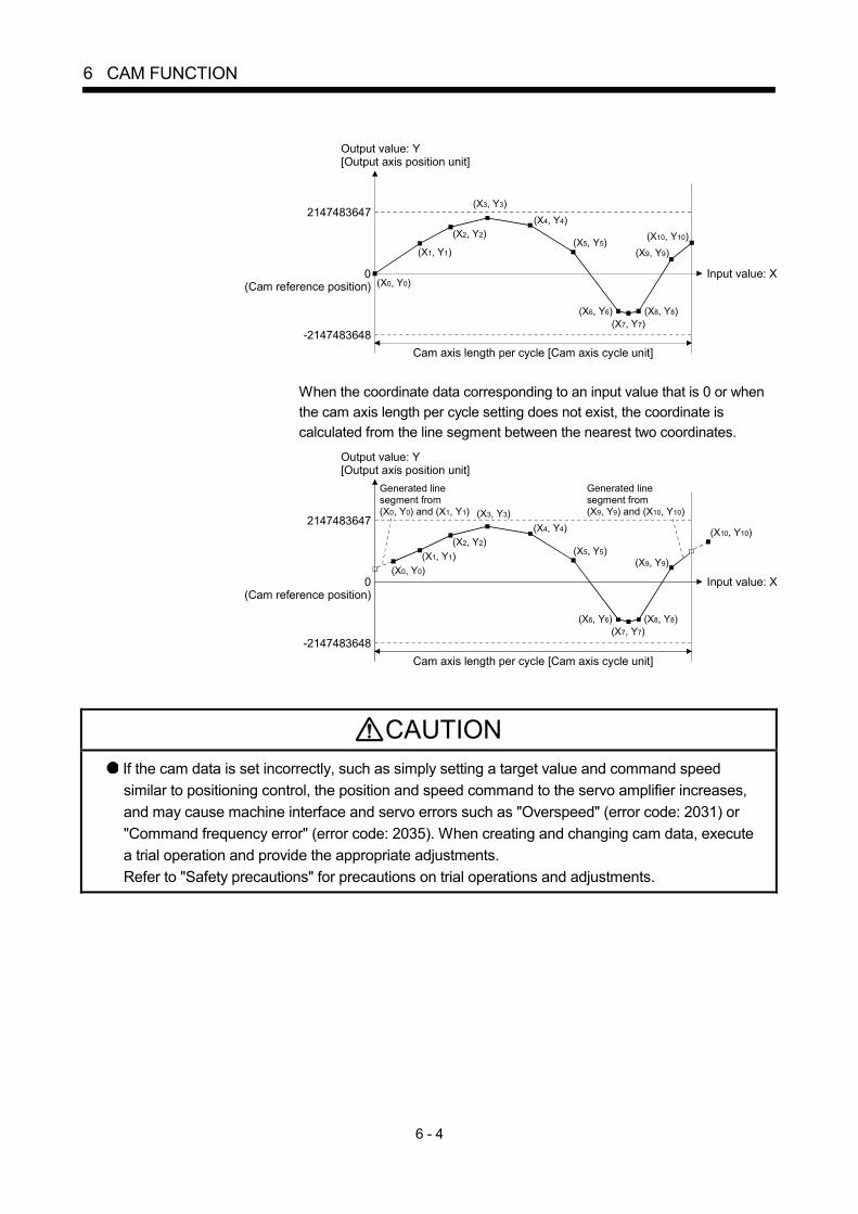
6 - 4
6 CAM FUNCTION
(X0, Y0)
(X1, Y1)
(X2, Y2)(X4, Y4)
(X5, Y5)
(X6, Y6)(X7, Y7)
(X8, Y8)
(X9, Y9)(X10, Y10)
Input value: X
Cam axis length per cycle [Cam axis cycle unit]
2147483647
-2147483648
0(Cam reference position)
Output value: Y[Output axis position unit]
(X3, Y3)
When the coordinate data corresponding to an input value that is 0 or when the cam axis length per cycle setting does not exist, the coordinate is calculated from the line segment between the nearest two coordinates.
(X9, Y9)
(X7, Y7)
(X4, Y4)
(X5, Y5)
(X6, Y6) (X8, Y8)
(X10, Y10)
(X0, Y0)(X1, Y1)
(X2, Y2)
(X3, Y3)
Cam axis length per cycle [Cam axis cycle unit]
2147483647
-2147483648
0(Cam reference position)
Output value: Y[Output axis position unit]
Input value: X
Generated line segment from(X9, Y9) and (X10, Y10)
Generated line segment from(X0, Y0) and (X1, Y1)
CAUTION If the cam data is set incorrectly, such as simply setting a target value and command speed similar to positioning control, the position and speed command to the servo amplifier increases, and may cause machine interface and servo errors such as "Overspeed" (error code: 2031) or "Command frequency error" (error code: 2035). When creating and changing cam data, execute a trial operation and provide the appropriate adjustments. Refer to "Safety precautions" for precautions on trial operations and adjustments.

6 - 5
6 CAM FUNCTION
(2) Current feed value of cam axis
The current feed value is calculated as shown below. (a) Stroke ratio data format
Current feed value
=Cam reference position
+Cam stroke amount
Stroke ratio corresponding to cam axis current value per cycle
(b) Coordinate data format
Current feed value
=Cam reference position
+Output value corresponding to cam axis current value per cycle
When the cam axis current value per cycle is in the middle of the defined cam data (Stroke ratio data/Coordinate data), the middle value is calculated from the nearest cam data.
Cam data
Cam axis currentvalue per cycle
1 resolution or between 2 coordinates
Calculate the middle valuefrom the nearest cam data.
(3) Cam reference position The cam reference position is calculated as shown below. (a) Stroke ratio data format
Cam reference position
=The preceding cam reference position
+Cam stroke amount
Stroke ratio at the last point
(b) Coordinate data format
Cam reference position
=The preceding cam reference position
+
Output value corresponding to "Input value = Cam axis length per cycle"
- Output value corresponding to "Input value = 0"
Cam axis current value per cycle
Cam referenceposition(At 1st cycle)
Cam referenceposition(At 2nd cycle)
Cam referenceposition(At 3rd cycle)
Current feed value
t
t
Stroke ratio data format: Cam stroke amount Stroke ratio at last pointCoordinate data format: (The output value corresponding to "Input value = Cam axis length per cycle") - (The output value corresponding to "Input value = 0")

6 - 6
6 CAM FUNCTION
Create cam data for two-way cam operation as shown below. (a) Stroke ratio data format
Create cam data so that the stroke ratio is 0% at the last point.
(b) Coordinate data format Create cam data with the same output value for the point where the input value is 0 and the input value is equal to the cam axis length per cycle.
Cam axis current value per cycle
Current feed value
t
t
Cam reference position(Does not change because of the stroke ratio 0% and output value = 0.)
(4) Cam data starting point
This setting is only valid for cam data using the stroke ratio data format. The cam data point corresponding to "Cam axis current value per cycle = 0" can be set as the cam data starting point. The default value of the cam data starting point is 0. (The cam axis is controlled with cam data starting from the 0th point (stroke ratio 0%).) When a value other than 0 is set for the cam data starting point, cam control is started from the point where the stroke ratio is not 0%. The cam data starting point is set for each cam data. The setting range is from 0 to (cam resolution - 1).
Cam axis currentvalue per cycle
Current feed value
Cam referenceposition(At 1st cycle)
Cam referenceposition(At 2nd cycle)
Cam referenceposition(At 3rd cycle)
t
t
Cam datastarting point
At 0th point At last point

6 - 7
6 CAM FUNCTION
(5) Timing of applying cam control data
(a) Stroke ratio data format If [Pr.440] Cam No. (D15062+150n) or [Pr.441] Cam stroke amount (D15064+150n, D15065+150n) is changed during synchronous control, the new value is accepted and applied when the cam axis current value per cycle passes through the 0th point of cam data, or is on the 0th point. The cam reference position is updated when the cam axis current value per cycle passes through the 0th point of cam data.
(b) Coordinate data format
If [Pr.440] Cam No. (D15062+150n) is changed during synchronous control, the new value is accepted and applied when the cam axis current value per cycle passes through 0, or is on 0. The cam reference position is updated when the cam axis current value per cycle passes through 0.

6 - 8
6 CAM FUNCTION
6.2 Create Cam Data
6.2.1 Memory configuration of cam data
Cam data is arranged in the following 2 areas. Memory
configuration Storage item Details Remark
Cam data
Data is written by the following operations. • Write with MT Developer2 • When executing cam data write (Cam storage area) instruction of Motion
SFC program. Cam storage area
Cam auto-generation data
Data is written when the cam auto-generation instruction of Motion SFC program is executed. (Cam auto-generation function)
• Data is preserved even when turning the power supply OFF.
Cam open area Cam data
• Cam data is transmitted from the cam storage area, when turning the Multiple CPU system power supply ON, writing to the cam storage area, or turning the PLC READY flag (M2000) OFF to ON.
• Writing to the cam open area is possible through the cam data operation function.
• Cam data that is generated by the cam auto-generation function is stored.
• Data is lost when turning the power supply OFF.
• The cam data that is used in cam control is stored.
Previously written cam data can be used after turning the power supply OFF by writing data in the cam storage area. Cam data should be written in the cam storage area for normal use. It is possible to write the cam data to the cam open area via the device specified by Motion SFC program when registering cam data that exceeds the memory capacity in the cam storage area, etc. Writing must be executed to the cam open area due to transmitting from the cam storage area when turning the Multiple CPU system power supply ON again, updating the cam storage area, or turning the PLC flag (M2000) OFF to ON.
Write (Cam storage area)/Cam auto-generation
(Note-1): Write/read/verify from MT Developer2 is executed toward cam storage area.(Note-2): The directly writing in cam open area is not transmitted to cam storage area. The data in cam open area will be returned as cam storage area such as the Multiple CPU system power supply ON again.
Cam control
Cam open area(1024k bytes)
Cam storage area(256k bytes)
Optional device
MT Developer2
1) Operation with MT Developer2
Transmit in the following timing. Multiple CPU system power supply turn ON Write to cam storage area PLC READY flag (M2000) OFF to ON
Write (Note-1)
Read/Verify (Note-1)
Write (CAMWR instruction)/Cam auto-generation(CAMMK instruction)
2) Operation with Motion SFC program
Write(CAMWR2 instruction) (Note-2)
Read (CAMRD instruction)

6 - 9
6 CAM FUNCTION
(1) Cam data operation with MT Developer2
Cam data can be modified while viewing the waveform with MT Developer2. The cam data is written/read/verified to the cam storage area with MT Developer2, however it cannot be executed to the cam open area. The waveform generated by the cam auto-generation function can be confirmed on the "Cam graph" of the "Cam data window" through reading with MT Developer2.
(2) Cam data operation with Motion SFC program
Cam data read/write operation, cam auto-generation and cam position calculation can be executed with the Motion SFC program. (Refer to Section 6.2.2)
(3) Cam data capacity
The size of the created cam data is shown below for the cam storage area/cam open area.
Operation method Data method/
Auto-generation type Cam storage area
(262144 bytes) Cam open area (1048576 bytes)
Stroke ratio data format Cam resolution 4 bytes Cam resolution 4 bytes Create with MT Developer2 Coordinate data format Coordinate number 8 bytes Coordinate number 8 bytes
Stroke ratio data format Cam resolution 4 bytes Cam resolution 4 bytes Create in cam storage area with Motion SFC program Coordinate data format Coordinate number 8 bytes Coordinate number 8 bytes
Stroke ratio data format Cam resolution 4 bytes Create in cam open area with Motion SFC program Coordinate data format
0 byte Coordinate number 8 bytes
Create with cam auto-generation in Motion SFC program
For a rotary cutter 36 bytes Cam resolution 4 bytes
When writing with the Motion SFC program or when the cam auto-generation function is executed, the writing area free capacity size may decrease since the size changes depending on the cam resolution change, etc. In this case, write the cam data with MT Developer2 or delete them once.
(4) Delete method of cam data
Write the empty data in the cam storage area with MT Developer2 to delete only cam data.
(5) Password protection for cam data
The cam data can be protected as shown below by password setting.
Registration condition Cam data operation with
MT Developer2 Cam data operation with
Motion SFC program
Write protection Cam data cannot be written without unlocking the password.
Writing cam data and cam data auto-generation is not operated.
Read/write protection Cam data cannot be read/written without unlocking the password.
Reading/writing cam data and generating cam data auto-generation is not operated.
Refer to the "Q173D(S)CPU/Q172D(S)CPU Motion controller Programming Manual (COMMON)" for details of the password protection.
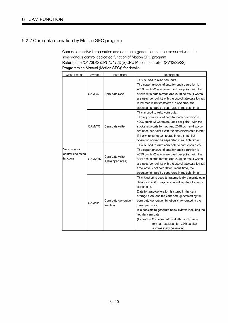
6 - 10
6 CAM FUNCTION
6.2.2 Cam data operation by Motion SFC program
Cam data read/write operation and cam auto-generation can be executed with the synchronous control dedicated function of Motion SFC program. Refer to the "Q173D(S)CPU/Q172D(S)CPU Motion controller (SV13/SV22) Programming Manual (Motion SFC)" for details.
Classification Symbol Instruction Description
CAMRD Cam data read
This is used to read cam data. The upper amount of data for each operation is 4096 points (2 words are used per point.) with the stroke ratio data format, and 2048 points (4 words are used per point.) with the coordinate data format.If the read is not completed in one time, the operation should be separated in multiple times.
CAMWR Cam data write
This is used to write cam data. The upper amount of data for each operation is 4096 points (2 words are used per point.) with the stroke ratio data format, and 2048 points (4 words are used per point.) with the coordinate data format.If the write is not completed in one time, the operation should be separated in multiple times.
CAMWR2Cam data write (Cam open area)
This is used to write cam data to cam open area. The upper amount of data for each operation is 4096 points (2 words are used per point.) with the stroke ratio data format, and 2048 points (4 words are used per point.) with the coordinate data format.f the write is not completed in one time, the operation should be separated in multiple times.
Synchronous control dedicated function
CAMMK Cam auto-generation function
This function is used to automatically generate cam data for specific purposes by setting data for auto-generation. Data for auto-generation is stored in the cam storage area, and the cam data generated by the cam auto-generation function is generated in the cam open area. It is possible to generate up to 1Mbyte including the regular cam data. (Example): 256 cam data (with the stroke ratio
format, resolution is 1024) can be automatically generated.

7 - 1
7
7 SYNCHRONOUS CONTROL
7. SYNCHRONOUS CONTROL
7.1 Main Shaft Module
7.1.1 Overview of main shaft module
For the main shaft module, the input value is generated as a composite value from two input axes (the main and sub input axis) through the composite main shaft gear. The composite input value can be converted by the main shaft gear that provides the deceleration ratio and the rotation direction for the machine system, etc. Refer to Section 7.1.2 and Section 7.1.3 for details on setting for the main shaft module.
[Pr.400] Main input axis No.(D15000+150n)
[Pr.403] Main shaft gear: Numerator(D15004+150n, D15005+150n)[Pr.404] Main shaft gear: Denominator(D15006+150n, D15007+150n)
[Pr.402] Composite main shaft gear(D15002+150n)
[Pr.401] Sub input axis No.(D15001+150n)
Main shaftsub input axis
[Md.400] Current value after composite main shaft gear(D13600+30n, D13601+30n)
Main shaftmain input axis
Composite main shaft gear
Main shaftgear
Speed change gear/Composite auxiliary shaft gear
(Note): Refer to Section 7.3
Main shaft clutch (Note)
[Md.401] Current value per cycleafter main shaft gear(D13602+30n, D13603+30n

7 - 2
7 SYNCHRONOUS CONTROL
7.1.2 Main shaft parameters
Symbol Setting item Setting details Setting value Fetch cycle Default value
Device No.
Pr.400 Main input axis No. Set the input axis No. on the main input side for the main shaft.
0 : Invalid 1 to 32 : Servo input axis
(Note-1) 201 to 232 : Command
generation axis (Note-2)
801 to 812 : Synchronous encoder axis
0 D15000+150n
Pr.401 Sub input axis No. Set the input axis No. on the sub input side for the main shaft.
0 : Invalid 1 to 32 : Servo input axis
(Note-1) 201 to 232 : Command
generation axis (Note-2)
801 to 812 : Synchronous encoder axis
At start of synchronous
control
0 D15001+150n
Pr.402 Composite main shaft gear
Select the composite method for input values from the main input axis and sub input axis.
• Set in hexadecimal.
Sub input method 0: No input 1: Input + 2: Input -
HMain input method 0: No input 1: Input + 2: Input -
Operation cycle
0001h D15002+150n
Pr.403 Main shaft gear: Numerator
Set the numerator for the main shaft gear.
-2147483648 to 2147483647 1 D15004+150nD15005+150n
Pr.404 Main shaft gear: Denominator
Set the denominator for the main shaft gear.
1 to 2147483647
At start of synchronous
control 1 D15006+150nD15007+150n
(Note-1): The range from 1 to 16 is valid in the Q172DSCPU. (Note-2): The range from 201 to 216 is valid in the Q172DSCPU.

7 - 3
7 SYNCHRONOUS CONTROL
(1) [Pr.400] Main input axis No. (D15000+150n), [Pr.401] Sub input
axis No. (D15001+150n) Set the main input axis No. and the sub input axis No. for the main shaft. • 0 : Invalid................................... The input value is always 0. • 1 to 32 : Servo input axis ................... Set the servo input axis (axis 1 to 32).
When the servo input axis is not set in the system setting, the input value is always 0. If the number is set to the same value as the output axis, the major error (error code: 1700, 1701) occurs and synchronous control cannot be started. (Note): The range from 1 to 16 is valid
in the Q172DSCPU. • 201 to 232 : Command generation axis .. Set the command generation axis (axis
1 to 32). When the command generation axis is invalid in the command generation axis parameter setting, the input value is always 0. As the command generation axis is used only for command generation, it is possible to set the same number as the output axis. (Note): The range from 201 to 216 is
valid in the Q172DSCPU. • 801 to 812 : Synchronous encoder axis.. Set the synchronous encoder axis
(axis 1 to 12). When synchronous encoder axis is invalid, the input value is always 0.
(2) [Pr.402] Composite main shaft gear (D15002+150n)
Set the composite method for input values from the main and sub input axes. The setting values for each axis are shown as follows. • 0: No input..... The input value from the input axis is calculated as 0. • 1: Input+ ........ The input value from the input axis is calculated as it is. • 2: Input- ......... The input value from the input axis is calculated with its opposite
sign. Operation assumes "0: No input" if the value is set out of the range from 0 to 2.
POINT The composite method for the composite main shaft gear can be changed during synchronous control. It is used as a clutch to switch input values between the main and the sub input axes.

7 - 4
7 SYNCHRONOUS CONTROL
(3) [Pr.403] Main shaft gear: Numerator (D15004+150n,
D15005+150n), [Pr.404] Main shaft gear: Denominator (D15006+150n, D15007+150n) Set the numerator and the denominator for the main shaft gear to convert the input value. The input value is converted as follows.
Input value after conversion = Input value before conversion Main shaft gear: Numerator Main shaft gear: Denominator
The input value direction can be reversed by setting a negative value in the numerator of the main shaft gear. Set the denominator of the main shaft gear to a value within the range from 1 to 2147483647. Example) Convert the cam axis per cycle to be controlled in intervals of 0.1[mm]
(0.00394[inch]). The cam axis synchronizes with a conveyer that moves 100[mm] (3.937[inch]) for every (360.00000[degree]) of the main shaft. Main shaft gear: Numerator : 1000[ 0.1mm] Main shaft gear: Denominator : 36000000[ 10-5degree]

7 - 5
7 SYNCHRONOUS CONTROL
7.1.3 Main shaft clutch parameters
Symbol Setting item Setting details Setting value Fetch cycle Default value
Device No.
Pr.405 Main shaft clutch control setting
Set the control method for the clutch.
• Set in hexadecimal. H
ON control mode 0: No clutch 1: Clutch command ON/OFF 2: Clutch command leading edge 3: Clutch command trailing edge 4: Address mode 5: High speed input requestOFF control mode 0: OFF control invalid 1: One-shot OFF 2: Clutch command leading edge 3: Clutch command trailing edge 4: Address mode 5: High speed input requestHigh speed inputrequest signal00 to 1F: High speed input request signal from signal 1 to 32
Operation cycle
0000h D15008+150n
Pr.406 Main shaft clutch reference address setting
Set the reference address for the clutch.
0: Current value after composite main shaft gear
1: Current value per cycle after main shaft gear
At start of synchronous
control 0 D15009+150n
Pr.407 Main shaft clutch ON address
• Set the clutch ON address for address mode. (This setting is invalid except during address mode.)
• If the address is out of the range from 0 to (Cam axis length per cycle - 1), the address is converted to a value within range.
-2147483648 to 2147483647 [Main input axis position units (Note-1), or cam axis cycle units (Note-2)
]
Operation cycle
0 D15010+150nD15011+150n
Pr.408 Travel value before main shaft clutch ON
• Set the travel value for the distance between the clutch ON condition completing and the clutch closing.
• Set a positive value when the reference address is increasing, and a negative value when it is decreasing.
-2147483648 to 2147483647 [Main input axis position units (Note-1), or cam axis cycle units (Note-2)
]
At completing clutch ON condition
0 D15012+150nD15013+150n
(Note-1): Main input axis position units (Refer to Chapter 5) (Note-2): Cam axis cycle units (Refer to Section 7.5.1)

7 - 6
7 SYNCHRONOUS CONTROL
Symbol Setting item Setting details Setting value Fetch cycle Default value
Device No.
Pr.409 Main shaft clutch OFF address
• Set the clutch OFF address for the address mode. (This setting is invalid except during address mode.)
• If the address is out of the range from 0 to (Cam axis length per cycle - 1), the setting address is converted to a value within range.
-2147483648 to 2147483647 [Main input axis position units (Note-1), or cam axis cycle units (Note-2)
]
Operation cycle
0 D15014+150nD15015+150n
Pr.410 Travel value before main shaft clutch OFF
• Set the travel value for the distance between the clutch OFF condition completing and the clutch opening.
• Set a positive value when the reference address is increasing, and a negative value when it is decreasing.
-2147483648 to 2147483647 [Main input axis position units (Note-1), or cam axis cycle units (Note-2)
]
At completing clutch OFF condition
0 D15016+150nD15017+150n
Pr.411 Main shaft clutch smoothing method
Set the clutch smoothing method.
0: Direct 1: Time constant method (Exponent) 2: Time constant method (Linear) 3: Slippage method (Exponent) 4: Slippage method (Linear)
0 D15018+150n
Pr.412 Main shaft clutch smoothing time constant
For smoothing with a time constant method, set the smoothing time constant.
0 to 5000 [ms]
At start of synchronous
control
0 D15019+150n
Pr.413 Slippage amount at main shaft clutch ON
For smoothing with a slippage method, set the slippage amount at clutch ON.
0 to 2147483647 [Main input axis position units (Note-1), or cam axis cycle units (Note-2)
]
At turning clutch ON
0 D15020+150nD15021+150n
Pr.414 Slippage amount at main shaft clutch OFF
For smoothing with a slippage method, set the slippage amount at clutch OFF.
0 to 2147483647 [Main input axis position units (Note-1), or cam axis cycle units (Note-2)
]
At turning clutch OFF
0 D15022+150nD15023+150n
(Note-1): Main input axis position units (Refer to Chapter 5) (Note-2): Cam axis cycle units (Refer to Section 7.5.1)

7 - 7
7 SYNCHRONOUS CONTROL
(1) [Pr.405] Main shaft clutch control setting (D15008+150n)
Set the ON and OFF control methods separately for the main shaft clutch. The clutch control setting can be changed during synchronous control, however, the setting "No clutch" (Direct coupled operation) cannot be selected during synchronous control after already selecting another setting. Refer to Section 7.3.2 for details on the clutch control. (a) ON control mode
• 0: No clutch ...................................... Execute direct coupled operation (Direct coupled operation) without clutch control.
• 1: Clutch command ON/OFF........... The clutch is turned ON/OFF by the operation of [Rq.400] Main shaft clutch command (M11680+10n) ON/OFF. (Setting in the OFF control mode are not applicable in the clutch command ON/OFF mode.)
• 2: Clutch command leading edge.... The clutch is turned ON when [Rq.400] Main shaft clutch command (M11680+10n) passes the leading edge (from OFF to ON).
• 3: Clutch command trailing edge..... The clutch is turned ON when [Rq.400] Main shaft clutch command (M11680+10n) passes the trailing edge (from ON to OFF).
• 4: Address mode.............................. The clutch is turned ON when the reference address (the current value after composite main shaft gear or the current value per cycle after main shaft gear) reaches [Pr.407] Main shaft clutch ON address (D15010+150n, D15011+150n). The travel value after passing through the ON address is calculated as the output travel value of the clutch based on the reference address passing through, thereby controlling the clutch with an accurate travel value.
• 5: High speed input request............. The clutch is turned ON when the high speed input request (DI/DOG/TREN) turns ON.
POINT Other clutch parameters are not applicable during direct coupled operation by setting "0: No clutch". [Rq.402] Main shaft clutch forced OFF command (M11682+10n) and the change of the clutch control setting are ignored during direct coupled operation.

7 - 8
7 SYNCHRONOUS CONTROL
(b) OFF control mode
• 0: OFF control invalid ....................... Clutch OFF control is not used. This setting is applicable only for execution with clutch ON control.
• 1: One-shot OFF .............................. The clutch is turned OFF after moving the distance [Pr.410] Travel value before main shaft clutch OFF (D15016+150n, D15107+150n) (One-shot operation) after the clutch command turns ON. If [Pr.410] Travel value before main shaft clutch OFF(D15016+150n, D15107+150n) is 0, [St.420] Main shaft clutch ON/OFF status (M10560+10n) does not turn ON in order to turn back OFF immediately.
• 2: Clutch command leading edge.... The clutch is turned OFF when [Rq.400] Main shaft clutch command (M11680+10n) passes the leading edge (from OFF to ON).
• 3: Clutch command trailing edge..... The clutch is turned OFF when [Rq.400] Main shaft clutch command (M11680+10n)passes the trailing edge (from ON to OFF).
• 4: Address mode.............................. The clutch is turned OFF when the reference address (the current value after composite main shaft gear or the current value per cycle after main shaft gear) reaches [Pr.409] Main shaft clutch OFF address (D15014+150n, D15015+150n). The travel value before passing through the OFF address is calculated as the output travel value of the clutch based on the reference address passing through, thereby controlling the clutch with an accurate travel value.
• 5: High speed input request............. The clutch is turned OFF when the high speed input request (DI/DOG/TREN) turns ON.

7 - 9
7 SYNCHRONOUS CONTROL
(c) High speed input request signal
Set the high speed input request signal No. for the "(a) ON control mode" and the "(b) OFF control mode" when using the setting "5: High speed input request".
Signal No.
Setting value (Hexadecimal)
Signal No.
Setting value (Hexadecimal)
Signal No.
Setting value (Hexadecimal)
Signal No.
Setting value (Hexadecimal)
1 00 9 08 17 10 25 18 2 01 10 09 18 11 26 19 3 02 11 0A 19 12 27 1A 4 03 12 0B 20 13 28 1B 5 04 13 0C 21 14 29 1C 6 05 14 0D 22 15 30 1D 7 06 15 0E 23 16 31 1E 8 07 16 0F 24 17 32 1F
(2) [Pr.406] Main shaft clutch reference address setting
(D15009+150n) Select the address type to be used as the reference address for clutch control. • 0: Current value after composite main shaft gear
.....................The clutch is controlled by using the current value after composite main shaft gear. Output after the clutch control is a converted travel value through the main shaft gear.
• 1: Current value per cycle after main shaft gear .....................The clutch is controlled by using the current
value per cycle after main shaft gear. Output after the clutch control is a travel value without conversion.
The setting units for the following parameters are in units based on the reference address setting. • [Pr.407] Main shaft clutch ON address (D15010+150n, D15011+150n) • [Pr.409] Main shaft clutch OFF address (D15014+150n, D15015+150n) • [Pr.408] Travel value before main shaft clutch ON (D15012+150n,
D15013+150n), [Pr.410] Travel value before main shaft clutch OFF (D15016+150n, D15017+150n)
• [Pr.413] Slippage amount at main shaft clutch ON (D15020+150n, D15021+150n), [Pr.414] Slippage amount at main shaft clutch OFF (D15022+150n, D15023+150n)

7 - 10
7 SYNCHRONOUS CONTROL
(3) [Pr.407] Main shaft clutch ON address (D15010+150n,
D15011+150n) Set the clutch ON address when address mode is configured for the ON control mode of the main shaft clutch. When the reference address is the current value per cycle after main shaft gear, the setting address is converted for control within the range from 0 to (Cam axis length per cycle - 1). Example) Cam axis length per cycle: 20000[PLS]
The ON address is controlled as 19000[PLS] when the setting value is -1000.
(4) [Pr.408] Travel value before main shaft clutch ON (D15012+150n,
D15013+150n) Set the travel value for the reference address with a signed number for the distance between the clutch ON condition completing and the clutch closing. • 1 to 2147483647 (Positive value) : Used when the reference address is
increasing in direction. • 0 : No movement (The clutch is immediately
turned ON with the clutch ON condition completing.)
• -2147483648 to -1(Negative value) : Used when the reference address is decreasing in direction.
[St.420] Main shaft clutch ON/OFF status(M10560+10n)
Travel value after clutch
Clutch ON condition is completed(Example: [Rq.400] Main shaft clutchcommand (M11680+10n) ON)
t
t
OFFON
OFFON
[Md.400] Current value after compositemain shaft gear (D13600+30n, D13601+30n)or[Md.401] Current value per cycle aftermain shaft gear (D13602+30n, D13603+30n) [Pr.408] Travel value before main shaft
clutch ON (D15012+150n, D15013+150n)(Positive value)
(5) [Pr.409] Main shaft clutch OFF address (D15014+150n, D15015+150n) Set the clutch OFF address when address mode is configured for the OFF control mode of the main shaft clutch. When the reference address is the current value per cycle after main shaft gear, the setting address is converted for control within the range from 0 to (Cam axis length per cycle - 1). Example) Cam axis length per cycle: 20000[PLS]
The OFF address is controlled as 60[PLS] when the setting value is 40060.

7 - 11
7 SYNCHRONOUS CONTROL
(6) [Pr.410] Travel value before main shaft clutch OFF (D15016+150n,
D15017+150n) Set the travel value for the reference address with a signed number for the distance between the clutch OFF condition completing and the clutch opening. • 1 to 2147483647 (Positive value) : Used when the reference address is
increasing in direction. • 0 : No movement. (The clutch is immediately
turned OFF with the clutch OFF condition completing.)
• -2147483648 to -1(Negative value) : Used when the reference address is decreasing in direction.
Clutch OFF condition is completed(Example: [Rq.400] Main shaft clutch command (M11680+10n) OFF)
OFFON
[St.420] Main shaft clutch ON/OFF status(M10560+10n)
Travel value after clutch
[Md.400] Current value after compositemain shaft gear (D13600+30n, D13601+30n)or[Md.401] Current value per cycle aftermain shaft gear (D13602+30n, D13603+30n) [Pr.410] Travel value before main shaft
clutch OFF (D15016+150n, D15017+150n) (Positive value)
OFFON
t
t
(7) [Pr.411] Main shaft clutch smoothing method (D15018+150n) Set the smoothing method for clutch ON/OFF. Refer to Section 7.3.3 for details. • 0: Direct.................................................. No smoothing • 1: Time constant method (Exponent) .... Smoothing with an exponential curve
based on the time constant setting. • 2: Time constant method (Linear) ......... Smoothing with linear acceleration/
deceleration based on the time constant setting.
• 3: Slippage method (Exponent) ............. Smoothing with an exponential curve based on the slippage amount setting.
• 4: Slippage method (Linear) .................. Smoothing with linear acceleration/ deceleration based on the slippage amount setting.
(8) [Pr.412] Main shaft clutch smoothing time constant (D15019+150n)
Set a time constant when the time constant method is set in [Pr.411] Main shaft clutch smoothing method (D15018+150n). The time constant setting applies for both clutch ON/OFF.

7 - 12
7 SYNCHRONOUS CONTROL
(9) [Pr.413] Slippage amount at main shaft clutch ON
(D15020+150n,D15021+150n) Set the slippage amount at clutch ON when the slippage method is set in [Pr.411] Main shaft clutch smoothing method (D15018+150n). The slippage amount is set in units based on the current value selected in [Pr.406] Main shaft clutch reference address setting (D15009+150n). If the set amount is negative, slippage amount at clutch ON is controlled as 0 (direct).
(10) [Pr.414] Slippage amount at main shaft clutch OFF
(D15022+150n,D15023+150n) Set the slippage amount at clutch OFF when the slippage method is set in [Pr.411] Main shaft clutch smoothing method (D15018+150n). The slippage amount is set in units based on the current value selected in [Pr.406] Main shaft clutch reference address setting (D15009+150n). If the set amount is negative, slippage amount at clutch OFF is controlled as 0 (direct).

7 - 13
7 SYNCHRONOUS CONTROL
7.1.4 Main shaft clutch control data
Symbol Setting item Setting details Setting value Fetch cycle Default value
Device No.
Rq.400 Main shaft clutch command
Set the clutch command ON/OFF.
OFF : Main shaft clutch command OFF
ON : Main shaft clutch command ON
OFF M11680+10n
Rq.401 Main shaft clutch control invalid command
Set the command disable the clutch control temporarily.
OFF : Main shaft clutch control valid
ON : Main shaft clutch control invalid
OFF M11681+10n
Rq.402 Main shaft clutch forced OFF command
Set the command to force the clutch OFF.
OFF : Main shaft clutch normal control
ON : Main shaft clutch forced OFF
Operation cycle
OFF M11682+10n
(1) [Rq.400] Main shaft clutch command (M11680+10n)
Use ON/OFF for the main shaft clutch command. This command is used with the following settings. • The clutch ON control mode is "1: Clutch command ON/OFF", "2: Clutch
command leading edge" or "3: Clutch command trailing edge". • The clutch OFF control mode is either "2: Clutch command leading edge" or "3:
Clutch command trailing edge". Status is considered as clutch command OFF just before starting synchronous control. If synchronous control is started while the clutch command is ON, the condition is established just after starting synchronous control, by setting "2: Clutch command leading edge". The condition is not established just after starting, by setting "3: Clutch command trailing edge".
(2) [Rq.401] Main shaft clutch control invalid command (M11681+10n)
The main shaft clutch control is invalid if ON is set. The previous clutch ON/OFF status remains before clutch control becomes invalid. Clutch control will not become invalid during movement by [Pr.408] and [Pr.410] before clutch ON and clutch OFF. Instead, clutch control will become invalid after movement is completed.
(3) [Rq.402] Main shaft clutch forced OFF command (M11682+10n)
Set ON to force the clutch OFF. The output value from the clutch becomes 0 immediately, even during clutch smoothing. The slippage (accumulative) amount is set to 0 if smoothing with a slippage method. Reset to OFF to restart the clutch control from the clutch OFF status after using the clutch forced OFF command.

7 - 14
7 SYNCHRONOUS CONTROL
7.2 Auxiliary Shaft Module
7.2.1 Overview of auxiliary shaft module
For the auxiliary shaft module, the input value is generated from the auxiliary shaft. The input value can be converted by the auxiliary shaft gear that provides the deceleration ratio and the rotation direction for the machine system etc. Refer to Section 7.2.2 and Section 7.2.3 for details on setting for the auxiliary shaft module.
(Note): Refer to Section 7.3
Auxiliary shaftclutch (Note)
Main shaft input/Speed change gear
Auxiliary shaftgear
Auxiliary shaftaxis
[Md.402] Current value per cycleafter auxiliary shaft gear(D13604+30n, D13605+30n)
Speed change gear/Output axis
Composite auxiliary shaft
gear
[Pr.420] Auxiliary shaft gear:Numerator(D15026+150n, D15027+150n)[Pr.421] Auxiliary shaft gear:Denominator(D15028+150n, D15029+150n)
[Pr.419] Composite auxiliary shaft gear(D15025+150n)
[Pr.418] Auxiliary shaft axis No.(D15024+150n)

7 - 15
7 SYNCHRONOUS CONTROL
7.2.2 Auxiliary shaft parameters
Symbol Setting item Setting details Setting value Fetch cycle Default value
Device No.
Pr.418 Auxiliary shaft axis No. Set the input axis No. for the auxiliary shaft.
0 : Invalid 1 to 32 : Servo input axis
(Note-1)
201 to 232 : Command generation axis (Note-2)
801 to 812 : Synchronous encoder axis
At start of synchronous
control 0 D15024+150n
Pr.419 Composite auxiliary shaft gear
Select the composite method for input values from the main shaft and the auxiliary shaft.
• Set in hexadecimal.
Auxiliary shaftinput method 0: No input 1: Input + 2: Input -
HMain shaft inputmethod 0: No input 1: Input + 2: Input -
Operation cycle
0001h D15025+150n
Pr.420 Auxiliary shaft gear: Numerator
Set the numerator for the auxiliary shaft gear.
-2147483648 to 2147483647 1 D15026+150nD15027+150n
Pr.421 Auxiliary shaft gear: Denominator
Set the denominator for the auxiliary shaft gear.
1 to 2147483647
At start of synchronous
control 1 D15028+150nD15029+150n
(Note-1): The range from 1 to 16 is valid in the Q172DSCPU. (Note-2): The range from 201 to 216 is valid in the Q172DSCPU.

7 - 16
7 SYNCHRONOUS CONTROL
(1) [Pr.418] Auxiliary shaft axis No. (D15024+150n)
Set the input axis No. for the auxiliary shaft. • 0 : Invalid................................... The input value is always 0. • 1 to 32 : Servo input axis ................... Set the servo input axis (axis 1 to 32).
When the servo input axis is not set in the system setting, the input value is always 0. If the number is set to the same value as the output axis, major error (error code: 1720) occurs and synchronous control cannot be started. (Note): The range from 1 to 16 is valid
in the Q172DSCPU. • 201 to 232 : Command generation axis .. Set the command generation axis (axis
1 to 32). When the command generation axis is invalid in the command generation axis parameter setting, the input value is always 0. As the command generation axis is used only for command generation, it is possible to set the same number as the output axis. (Note): The range from 201 to 216 is
valid in the Q172DSCPU. • 801 to 812 : Synchronous encoder axis.. Set the synchronous encoder axis
(axis 1 to 12). When synchronous encoder axis is invalid, the input value is always 0.
(2) [Pr.419] Composite auxiliary shaft gear (D15025+150n)
Set the composite method for input values from the main and auxiliary shafts. The setting values for each axis are shown as follows. • 0: No input..... The input value from the input axis is calculated as 0. • 1: Input+ ........ The input value from the input axis is calculated as it is. • 2: Input- ......... The input value from the input axis is calculated with its opposite
sign. Operation assumes "0: No input" if the value is set out of the range from 0 to 2.
POINT The composite method for the composite auxiliary shaft gear can be changed during synchronous control. It is used as a clutch to switch input values between the main and the auxiliary shafts.

7 - 17
7 SYNCHRONOUS CONTROL
(3) [Pr.420] Auxiliary shaft gear: Numerator (D15026+150n,
D15027+150n), [Pr.421] Auxiliary shaft gear: Denominator (D15028+150n, D15029+150n) Set the numerator and the denominator for auxiliary shaft gear to convert the input value. The input value is converted as follows.
Input value after conversion = Input value before conversion Auxiliary shaft gear: Numerator Auxiliary shaft gear: Denominator
The input value direction can be reversed by setting a negative value in the numerator of the auxiliary shaft gear. Set the denominator of the auxiliary shaft gear to a value within the range from 1 to 2147483647.

7 - 18
7 SYNCHRONOUS CONTROL
7.2.3 Auxiliary shaft clutch parameters
Symbol Setting item Setting details Setting value Fetch cycle Default value
Device No.
Pr.422 Auxiliary shaft clutch control setting
Set the control method for the clutch.
• Set in hexadecimal. H
ON control mode 0: No clutch 1: Clutch command ON/OFF 2: Clutch command leading edge 3: Clutch command trailing edge 4: Address mode 5: High speed input requestOFF control mode 0: OFF control invalid 1: One-shot OFF 2: Clutch command leading edge 3: Clutch command trailing edge 4: Address mode 5: High speed input requestHigh speed inputrequest signal00 to 1F: High speed input request signal from signal 1 to 32
Operation cycle
0000h D15030+150n
Pr.423 Auxiliary shaft clutch reference address setting
Set the reference address for the clutch.
0: Current value after composite auxiliary shaft gear
1: Current value per cycle after auxiliary shaft gear
At start of synchronous
control 0 D15031+150n
Pr.424 Auxiliary shaft clutch ON address
• Set the clutch ON address for address mode. (This setting is invalid except during address mode.)
• If the address is out of the range from 0 to (Cam axis length per cycle - 1), the address is converted to a value within range.
-2147483648 to 2147483647 [Auxiliary shaft position units (Note-1), or cam axis cycle units (Note-2)
]
Operation cycle
0 D15032+150nD15033+150n
Pr.425 Travel value before auxiliary shaft clutch ON
• Set the travel value for the distance between the clutch ON condition completing and the clutch closing.
• Set a positive value when the reference address is increasing, and a negative value when it is decreasing.
-2147483648 to 2147483647 [Auxiliary shaft position units (Note-1), or cam axis cycle units (Note-2)
]
At completing clutch ON condition
0 D15034+150nD15035+150n
(Note-1): Main input axis position units (Refer to Chapter 5) (Note-2): Cam axis cycle units (Refer to Section 7.5.1)

7 - 19
7 SYNCHRONOUS CONTROL
Symbol Setting item Setting details Setting value Fetch cycle Default value
Device No.
Pr.426 Auxiliary shaft clutch OFF address
• Set the clutch OFF address for the address mode. (This setting is invalid except during address mode.)
• If the address is out of the range from 0 to (Cam axis length per cycle - 1), the setting address is converted to a value within range.
-2147483648 to 2147483647 [Auxiliary shaft position units (Note-1), or cam axis cycle units (Note-2)
]
Operation cycle
0 D15036+150nD15037+150n
Pr.427 Travel value before auxiliary shaft clutch OFF
• Set the travel value for the distance between the clutch OFF condition completing and the clutch opening.
• Set a positive value when the reference address is increasing, and a negative value when it is decreasing.
-2147483648 to 2147483647 [[Auxiliary shaft position units (Note-1), or cam axis cycle units (Note-2)
]
At completing clutch OFF condition
0 D15038+150nD15039+150n
Pr.428 Auxiliary shaft clutch smoothing method
Set the clutch smoothing method.
0: Direct 1: Time constant method (Exponent) 2: Time constant method (Linear) 3: Slippage method (Exponent) 4: Slippage method (Linear)
0 D15040+150n
Pr.429 Auxiliary shaft clutch smoothing time constant
For smoothing with a time constant method, set the smoothing time constant.
0 to 5000 [ms]
At start of synchronous
control
0[ms] D15041+150n
Pr.430 Slippage amount at auxiliary shaft clutch ON
For smoothing with a slippage method, set the slippage amount at clutch ON.
0 to 2147483647 [Auxiliary shaft position units (Note-1), or cam axis cycle units (Note-2)
]
At turning clutch ON
0 D15042+150nD15043+150n
Pr.431 Slippage amount at auxiliary shaft clutch OFF
For smoothing with a slippage method, set the slippage amount at clutch OFF.
0 to 2147483647 [Auxiliary shaft position units (Note-1), or cam axis cycle units (Note-2)
]
At turning clutch OFF
0 D15044+150nD15045+150n
(Note-1): Main input axis position units (Refer to Chapter 5) (Note-2): Cam axis cycle units (Refer to Section 7.5.1)

7 - 20
7 SYNCHRONOUS CONTROL
(1) [Pr.422] Auxiliary shaft clutch control setting (D15030+150n)
Set the ON and OFF control methods separately for the auxiliary shaft. The clutch control setting can be changed during synchronous control, however the setting to "No clutch" (Direct coupled operation) cannot be selected during synchronous control after already selecting another setting. Refer to Section 7.3.2 for details on the clutch control. (a) ON control mode
• 0: No clutch ...................................... Execute direct coupled operation (Direct coupled operation) without clutch control.
• 1: Clutch command ON/OFF........... The clutch is turned ON/OFF by the operation of [Rq.403] Auxiliary shaft clutch command (M11684+10n) ON/OFF. (Setting in the OFF control mode are not applicable in the clutch command ON/OFF mode.)
• 2: Clutch command leading edge.... The clutch is turned ON when [Rq.403] Auxiliary shaft clutch command (M11684+10n) passes the leading edge (from OFF to ON).
• 3: Clutch command trailing edge..... The clutch is turned ON when [Rq.403] Auxiliary shaft clutch command (M11684+10n) passes the trailing edge (from ON to OFF).
• 4: Address mode.............................. The clutch is turned ON when the reference address (the auxiliary shaft current value or the current value per cycle after auxiliary shaft gear) reaches [Pr.424] Auxiliary shaft clutch ON address (D15032+150n, D15033+150n). The travel value after passing through the ON address is calculated as the output travel value of the clutch based on the reference address passing through, thereby controlling the clutch with an accurate travel value.
• 5: High speed input request............. The clutch is turned ON when the high speed input request (DI/DOG/TREN) turns ON.
POINT Other clutch parameters are not applicable during direct coupled operation by setting "0: No clutch". [Rq.405] Auxiliary shaft clutch forced OFF command (M11686+10n) and the change of the clutch control setting are ignored during direct coupled operation.

7 - 21
7 SYNCHRONOUS CONTROL
(b) OFF control mode
• 0: OFF control invalid ....................... Clutch OFF control is not used. This setting is applicable only for execution with clutch ON control.
• 1: One-shot OFF .............................. The clutch is turned OFF after moving the distance [Pr.427] Travel value before auxiliary shaft clutch OFF (D15038+150n, D15039+150n) (One-shot operation) after the clutch command turns ON. If [Pr.427] Travel value before auxiliary shaft clutch OFF (D15038+150n, D15039+150n) is 0, [St.423] Auxiliary shaft clutch ON/OFF status (M10562+10n) does not turn ON in order to turn back OFF immediately.
• 2: Clutch command leading edge ....The clutch is turned OFF when [Rq.403] Auxiliary shaft clutch command (M11684+10n) passes the leading edge (from OFF to ON).
• 3: Clutch command trailing edge......The clutch is turned OFF when [Rq.403] Auxiliary shaft clutch command (M11684+10n) passes the trailing edge (from ON to OFF).
• 4: Address mode ..............................The clutch is turned OFF when the reference address (the auxiliary shaft current value or the current value per cycle after auxiliary shaft gear) reaches [Pr.426] Auxiliary shaft clutch OFF address (D15036+150n, D15037+150n). The travel value before passing through the OFF address is calculated as the output travel value of the clutch based on the reference address passing through, thereby controlling the clutch with an accurate travel value.
• 5: High speed input request .............The clutch is turned OFF when the high speed input request (DI/DOG/TREN) turns ON.

7 - 22
7 SYNCHRONOUS CONTROL
(c) High speed input request signal
Set the high speed input request signal No. for the "(a) ON control mode" and the "(b) OFF control mode" when using the setting "5: High speed input request".
Signal No.
Setting value (Hexadecimal)
Signal No.
Setting value (Hexadecimal)
Signal No.
Setting value (Hexadecimal)
Signal No.
Setting value (Hexadecimal)
1 00 9 08 17 10 25 18 2 01 10 09 18 11 26 19 3 02 11 0A 19 12 27 1A 4 03 12 0B 20 13 28 1B 5 04 13 0C 21 14 29 1C 6 05 14 0D 22 15 30 1D 7 06 15 0E 23 16 31 1E 8 07 16 0F 24 17 32 1F
(2) [Pr.423] Auxiliary shaft clutch reference address setting
(D15031+150n) Select the address type to be used as the reference address for clutch control. • 0: Auxiliary shaft current value.......The clutch is controlled by using the current
value for the servo input axis/command generation axis/synchronous encoder axis that is set for the auxiliary shaft. Output after the clutch control is a converted travel value through the auxiliary shaft gear.
• 1: Current value per cycle after auxiliary shaft gear .....................The clutch is controlled by using the current
value per cycle after auxiliary shaft gear. Output after the clutch control is a travel value without conversion.
The setting units for the following parameters are in units based on the reference address setting. • [Pr.424] Auxiliary shaft clutch ON address (D15032+150n, D15033+150n) • [Pr.426] Auxiliary shaft clutch OFF address (D15036+150n, D15037+150n) • [Pr.425] Travel value before auxiliary shaft clutch ON (D15034+150n, D15035+150n), [Pr.427] Travel value before auxiliary shaft clutch OFF (D15038+150n, D15039+150n)
• [Pr.430] Slippage amount at auxiliary shaft clutch ON (D15042+150n, D15043+150n), [Pr.431] Slippage amount at auxiliary shaft clutch OFF (D15044+150n, D15045+150n)

7 - 23
7 SYNCHRONOUS CONTROL
(3) [Pr.424] Auxiliary shaft clutch ON address (D15032+150n,
D15033+150n) Set the clutch ON address when address mode is configured for the ON control mode of the auxiliary shaft clutch. When the reference address is the current value per cycle after auxiliary shaft gear, the setting address is converted for control within the range from 0 to (Cam axis length per cycle - 1). Example) Cam axis length per cycle: 20000[PLS]
The ON address is controlled as 19000[PLS] when the setting value is -1000.
(4) [Pr.425] Travel value before auxiliary shaft clutch ON
(D15034+150n, D15035+150n) Set the travel value for the reference address with a signed numbers for the distance between the clutch ON condition completing and the clutch closing. • 1 to 2147483647 (Positive value) : Used when the reference address is
increasing in direction. • 0 : No movement (The clutch is immediately
turned ON with the clutch ON condition completing.)
• -2147483648 to -1(Negative value) : Used when the reference address is decreasing in direction.
[St.423] Auxiliary shaft clutch ON/OFFstatus (M10562+10n)
Travel value after clutch
Clutch ON condition is completed(Example: [Rq.403] Auxiliary shaft clutch command (M11684+10n) ON)
t
t
OFFON
OFFON
Auxiliary shaft current value or[Md.402] Current value per cycle afterauxiliary shaft gear(D13604+30n, D13605+30n) [Pr.425] Travel value before auxiliary shaft
clutch ON (D15034+150n, D15035+150n)(Positive value)
(5) [Pr.426] Auxiliary shaft clutch OFF address (D15036+150n, D15037+150n) Set the clutch OFF address when address mode is configured for the OFF control mode of the auxiliary shaft clutch. When the reference address is the current value per cycle after auxiliary shaft gear, the setting address is converted for control within the range from 0 to (Cam axis length per cycle - 1). Example) Cam axis length per cycle: 20000[PLS]
The OFF address is controlled as 60[PLS] when the setting value is 40060.

7 - 24
7 SYNCHRONOUS CONTROL
(6) [Pr.427] Travel value before auxiliary shaft clutch OFF
(D15038+150n, D15039+150n) Set the travel value for the reference address with a signed numbers for the distance between the clutch OFF condition completing and the clutch opening. • 1 to 2147483647 (Positive value) : Used when the reference address is
increasing in direction. • 0 : No movement. (The clutch is immediately
turned OFF with the clutch OFF condition completing.)
• -2147483648 to -1(Negative value) : Used when the reference address is decreasing in direction.
OFFON
Travel value after clutch
[Pr.427] Travel value before auxiliary shaftclutch OFF (D15038+150n, D15039+150n) (Positive value)
OFFON
t
t
Clutch ON condition is completed(Example: [Rq.403] Auxiliary shaft clutch command (M11684+10n) ON) [St.423] Auxiliary shaft clutch ON/OFFstatus (M10562+10n)
Auxiliary shaft current value or[Md.402] Current value per cycle afterauxiliary shaft gear(D13604+30n, D13605+30n)
(7) [Pr.428] Auxiliary shaft clutch smoothing method (D15040+150n) Set the smoothing method for clutch ON/OFF. Refer to Section 7.3.3 for details. • 0: Direct.................................................. No smoothing. • 1: Time constant method (Exponent) .... Smoothing with an exponential curve
based on the time constant setting. • 2: Time constant method (Linear) ......... Smoothing with linear
acceleration/deceleration based on the time constant setting.
• 3: Slippage method (Exponent) ............. Smoothing with an exponential curve based on the slippage amount setting.
• 4: Slippage method (Linear) .................. Smoothing with linear acceleration/deceleration based on the slippage amount setting.
(8) [Pr.429] Auxiliary shaft clutch smoothing time constant
(D15041+150n) Set a time constant when the time constant method is set in [Pr.428] Auxiliary shaft clutch smoothing method (D15040+150n). The time constant setting applies for both clutch ON/OFF.

7 - 25
7 SYNCHRONOUS CONTROL
(9) [Pr.430] Slippage amount at auxiliary shaft clutch ON
(D15042+150n, D15043+150n) Set the slippage amount at clutch ON when the slippage method is set in [Pr.428] Auxiliary shaft clutch smoothing method (D15040+150n). The slippage amount is set in units based on the current value selected in [Pr.423] Auxiliary shaft clutch reference address setting (D15031+150n). If the set amount is negative, the slippage amount at clutch ON is controlled as 0 (direct).
(10) [Pr.431] Slippage amount at auxiliary shaft clutch OFF
(D15044+150n, D15045+150n) Set the slippage amount at clutch OFF when the slippage method is set in [Pr.428] Auxiliary shaft clutch smoothing method (D15040+150n). The slippage amount is set in units based on the current value selected in [Pr.423] Auxiliary shaft clutch reference address setting (D15031+150n). If the set amount is negative, the slippage amount at clutch OFF is controlled as 0 (direct).

7 - 26
7 SYNCHRONOUS CONTROL
7.2.4 Auxiliary shaft clutch control data
Symbol Setting item Setting details Setting value Fetch cycle Default value
Device No.
Rq.403 Auxiliary shaft clutch command
Set the clutch command ON/OFF.
OFF : Auxiliary shaft clutch command OFF
ON : Auxiliary shaft clutch command ON
OFF M11684+10n
Rq.404 Auxiliary shaft clutch control invalid command
Set the command to disable the clutch control temporarily.
OFF : Auxiliary shaft clutch control valid
ON : Auxiliary shaft clutch control invalid
OFF M11685+10n
Rq.405 Auxiliary shaft clutch forced OFF command
Set the command to force the clutch OFF.
OFF : Auxiliary shaft clutch normal control
ON : Auxiliary shaft clutch forced OFF
Operation cycle
OFF M11686+10n
(1) [Rq.403] Auxiliary shaft clutch command (M11684+10n)
Use ON/OFF for the auxiliary shaft clutch command. This command is used with the following settings. • The clutch ON control mode is "1: Clutch command ON/OFF", "2: Clutch
command leading edge" or "3: Clutch command trailing edge". • The clutch OFF control mode is either "2: Clutch command leading edge" or "3:
Clutch command trailing edge". Status is considered as clutch command OFF just before starting synchronous control. If synchronous control is started while the clutch command is ON, the condition is established just after starting synchronous control, by setting "2: Clutch command leading edge". The condition is not established just after starting, by setting "3: Clutch command trailing edge".
(2) [Rq.404] Auxiliary shaft clutch control invalid command
(M11685+10n) The auxiliary shaft clutch control is invalid if ON is set. The previous clutch ON/OFF status remains before clutch control becomes invalid. Clutch control will not become invalid during movement by [Pr.425] Travel value before auxiliary shaft clutch ON (D15034+150n, D15035+150n) and [Pr.427] Travel value before auxiliary shaft clutch OFF (D15038+150n, D15039+150n) before clutch ON and clutch OFF. Instead, clutch control will become invalid after movement is completed.
(3) [Rq.405] Auxiliary shaft clutch forced OFF command
(M11686+10n) Set ON to force the clutch OFF. The output value from the clutch becomes 0 immediately, even during clutch smoothing. The slippage (accumulative) amount is set to 0 if smoothing with a slippage method. Reset to OFF to restart the clutch control from the clutch OFF status after using the clutch forced OFF command.

7 - 27
7 SYNCHRONOUS CONTROL
7.3 Clutch
7.3.1 Overview of clutch
The clutch is used to transmit/disengage command pulses from the main/auxiliary shaft input side to the output module side through turning the clutch ON/OFF, which controls the operation/stop of the servomotor. A clutch can be configured for the main and auxiliary shafts.
7.3.2 Control method for clutch
Set the ON and OFF control methods separately in [Pr.405] Main shaft clutch control setting (D15008+150n) and [Pr.422] Auxiliary shaft clutch control setting (D15030+150n). Although the clutch control setting can be changed during synchronous control, however, the setting "No clutch" (Direct coupled operation) cannot be selected during synchronous control after already selecting another setting.
Setting item
Item Main shaft clutch Auxiliary shaft clutch
Setting details Setting value
Clutch control setting
[Pr.405] Main shaft clutch control setting (D15008+150n)
[Pr.422] Auxiliary shaft clutch control setting (D15030+150n)
Set the clutch control method.
• Set in hexadecimal. H
ON control mode 0: No clutch 1: Clutch command ON/OFF 2: Clutch command leading edge 3: Clutch command trailing edge 4: Address mode 5: High speed input requestOFF control mode 0: OFF control invalid 1: One-shot OFF 2: Clutch command leading edge 3: Clutch command trailing edge 4: Address mode 5: High speed input requestHigh speed inputrequest signal00 to 1F: High speed input request signal from signal 1 to 32
When the clutch ON condition and the clutch OFF condition are completed simultaneously within one operation cycle, both clutch ON and OFF processing are executed within one operation cycle. Therefore, the clutch is from OFF to ON and again to OFF at the clutch OFF status, and it is from ON to OFF and again to ON at the clutch ON status.
The ON and OFF control mode setting for clutch ON/OFF are shown on the next page.

7 - 28
7 SYNCHRONOUS CONTROL
(1) ON control mode
(a) No clutch (Direct coupled operation) Execute direct coupled operation without clutch control.
POINT Other clutch parameters are not applicable during direct coupled operation by setting "0: No clutch". "Clutch forced OFF command" and the change of the clutch control setting are ignored during direct coupled operation.
(b) Clutch command ON/OFF The clutch is turned ON/OFF by the operation of clutch command ON/OFF. (Setting in the OFF control mode are not applicable in the clutch command ON/OFF mode.)
t
Travel value after clutch
Current value before clutch
Clutch ON/OFF status
Clutch command OFFON
OFFON
t
Item Main shaft clutch Auxiliary shaft clutch
Clutch command [Rq.400] Main shaft clutch command (M11680+10n)
[Rq.403] Auxiliary shaft clutch command (M11684+10n)
Clutch ON/OFF status
[St.420] Main shaft clutch ON/OFF status(M10560+10n)
[St.423] Auxiliary shaft clutch ON/OFF status (M10562+10n)
(c) Clutch command leading edge
The clutch is turned ON when the clutch command passes the leading edge (from OFF to ON).
t
Travel value after clutch
Current value before clutch
Clutch ON/OFF status
Clutch command OFF
OFF
ON
ON
t

7 - 29
7 SYNCHRONOUS CONTROL
(d) Clutch command trailing edge
The clutch is turned ON when the clutch command passes the trailing edge (from ON to OFF).
t
Travel value after clutch
Current value before clutch
Clutch ON/OFF status
Clutch commandON
OFF
OFFON
t
(e) Address mode The clutch is turned ON when the reference address reaches "Clutch ON address". The travel value after passing through the ON address is calculated as the output travel value of the clutch based on the reference address passing through, thereby controlling the clutch with an accurate travel value.
t
Travel value after clutch
Clutch ON/OFF statusClutch ON address
Current value specified in clutch reference addresssetting
t
OFFON
Item Main shaft clutch Auxiliary shaft clutch
Reference address
The current value specified in [Pr.406] Main shaft clutch reference address setting (D15009+150n) ([Md.400] Current value after composite main shaft gear (D13600+30n, D13601+30n) or [Md.401] Current value per cycle after main shaft gear (D13602+30n, D13603+30n))
The current value specified in [Pr.423] Auxiliary shaft clutch reference address setting (M15031+150n) (Auxiliary shaft current value (servo input axis current value/synchronous encoder axis current value) or [Md.402] Current value per cycle after auxiliary shaft gear (D13604+30n, D13605+30n))
Clutch ON address
[Pr.407] Main shaft clutch ON address (D15010+150n, D15011+150n)
[Pr.424] Auxiliary shaft clutch ON address (D15032+150n, D15033+150n)
Clutch ON/OFF status
[St.420] Main shaft clutch ON/OFF status (M10560+10n)
[St.423] Auxiliary shaft clutch ON/OFF status (M10562+10n)

7 - 30
7 SYNCHRONOUS CONTROL
(f) High speed input request
The clutch is turned ON when the high speed input request (DI/DOG/TREN) turns ON. The following actions are required when using the high speed input request. • Set the signal No. for the "High speed input request signal" clutch control
setting. • Set the input signal to be used by high speed input request of system
setting.
t
Travel value after clutch
Current value before clutch
Clutch ON/OFF status
High speed input request(DI/DOG/TREN) OFF
OFF
ON
ON
t

7 - 31
7 SYNCHRONOUS CONTROL
(2) OFF control mode
(a) OFF control invalid Clutch OFF control is not used. This setting is applicable only for execution with clutch ON control.
(b) One-shot OFF
The clutch is turned OFF after moving the distance "Travel value before clutch OFF" (One-shot operation) after the clutch command turn ON. If "Travel value before clutch OFF" is 0, "Clutch ON/OFF status" does not turn ON in order to turn back OFF immediately.
t
Travel value after clutch
Current value before clutch
Clutch ON/OFF status
Clutch command
Travel value beforeclutch OFF
OFF
OFF
ON
ON
t
Item Main shaft clutch Auxiliary shaft clutch
Clutch command [Rq.400] Main shaft clutch command (M11680+10n)
[Rq.403] Auxiliary shaft clutch command (M11684+10n)
Clutch ON/OFF status
[St.420] Main shaft clutch ON/OFF status(M10560+10n)
[St.423] Auxiliary shaft clutch ON/OFF status (M10562+10n)
Travel value before clutch OFF
[Pr.410] Travel value before main shaft clutch OFF (D15016+150n, D15017+150n)
[Pr.427] Travel value before auxiliary shaft clutch OFF (D15038+150n, D15039+150n)
(c) Clutch command leading edge
The clutch is turned OFF when the clutch command passes the leading edge (from OFF to ON).
t
Travel value after clutch
Current value before clutch
Clutch ON/OFF status
Clutch command OFFON
ON
OFF
t

7 - 32
7 SYNCHRONOUS CONTROL
(d) Clutch command trailing edge
The clutch is turned OFF when the clutch command passes the trailing edge (from ON to OFF).
t
Travel value after clutch
Current value before clutch
Clutch ON/OFF status
Clutch commandON
ONOFF
OFF
t
(e) Address mode The clutch is turned OFF when the reference address reaches "Clutch OFF address". The travel value before passing through the OFF address is calculated as the output travel value of the clutch based on the reference address passing through, thereby controlling the clutch with an accurate travel value.
t
Travel value after clutch
Clutch ON/OFF statusClutch OFF address
Current value specified inclutch reference addresssetting
ONOFF
t
Item Main shaft clutch Auxiliary shaft clutch
Reference address
The current value specified in [Pr.406] Main shaft clutch reference address setting (D15009+150n) ([Md.400] Current value after composite main shaft gear (D13600+30n, D13601+30n) or [Md.401] Current value per cycle after main shaft gear (D13602+30n, D13603+30n))
The current value specified in [Pr.423] Auxiliary shaft clutch reference address setting (D15031+150n) (Auxiliary shaft current value (servo input axis current value/synchronous encoder axis current value) or [Md.402] Current value per cycle after auxiliary shaft gear (D13604+30n, D13605+30n))
Clutch OFF address
[Pr.409] Main shaft clutch OFF address (D15014+150n, D15015+150n)
[Pr.426] Auxiliary shaft clutch OFF address (D15036+150n, D15037+150n)
Clutch ON/OFF status
[St.420] Main shaft clutch ON/OFF status (M10560+10n)
[St.423] Auxiliary shaft clutch ON/OFF status (M10562+10n)

7 - 33
7 SYNCHRONOUS CONTROL
(f) High speed input request
The clutch is turned OFF when the high speed input request (DI/DOG/TREN) turns ON. The following actions are required when using the high speed input request. • Set the signal No. for the "High speed input request signal" clutch control
setting. • Set the input signal to be used by high speed input request of system
setting
t
Travel value after clutch
Current value before clutch
Clutch ON/OFF status
High speed input request (DI/DOG/TREN) OFF
ON
ON
OFF
t

7 - 34
7 SYNCHRONOUS CONTROL
7.3.3 Smoothing method for clutch
Set the clutch smoothing method in [Pr.411] Main shaft clutch smoothing method (D15018+150n) and [Pr.428] Auxiliary shaft clutch smoothing method (D15040+150n). The 2 types of clutch smoothing include the following.
• Time constant method smoothing • Slippage method smoothing
When not using clutch smoothing, set "0: Direct" in the clutch smoothing method. Setting item
Item Main shaft clutch Auxiliary shaft clutch
Setting details Setting value
Clutch smoothing method
[Pr.411] Main shaft clutch smoothing method (D15018+150n)
[Pr.428] Auxiliary shaft clutch smoothing method (D15040+150n)
Set the clutch smoothing method.
0: Direct 1: Time constant method (Exponent) 2: Time constant method (Linear) 3: Slippage method (Exponent) 4: Slippage method (Linear)
The operation of each smoothing method is shown below.
(1) Time constant method smoothing
Smoothing is processed with the time constant setting value in the smoothing time constant at clutch ON/OFF. After clutch ON smoothing is complete, smoothing is processed with the time constant setting value when the speed of the input values changes. The travel value between the clutch turning ON and OFF is not changed with smoothing.
Travel value after clutch smoothing = Travel value before clutch smoothing
Setting item
Item Main shaft clutch Auxiliary shaft clutch
Setting details Setting value
Clutch smoothing time constant
[Pr.412] Main shaft clutch smoothing time constant (D15019+150n)
[Pr.429] Auxiliary shaft clutch smoothing time constant(D15041+150n)
For smoothing with a time constant method, set the smoothing time constant.
0 to 5000 [ms]

7 - 35
7 SYNCHRONOUS CONTROL
(a) Time constant method exponential curve smoothing
Set "1: Time constant method (Exponential)" in the clutch smoothing method.
t63%
Speed after clutch smoothing
Speed before clutch processing
Clutch ON/OFF status
Clutch smoothing status
Clutch smoothing time constant
t63%
OFF
OFF
ON
ON
Item Main shaft clutch Auxiliary shaft clutch
Clutch ON/OFF status
[St.420] Main shaft clutch ON/OFF status(M10560+10n)
[St.423] Auxiliary shaft clutch ON/OFF status (M10562+10n)
Clutch smoothing status
[St.421] Main shaft clutch smoothing status (M10561+10n)
[St.424] Auxiliary shaft clutch smoothing status (M10563+10n)
(b) Time constant method linear acceleration/deceleration smoothing
Set "2: Time constant method (Linear)" in the clutch smoothing method.
t
Clutch smoothing time constant
t
OFF
OFF
ON
ON
Speed after clutch smoothing
Speed before clutch processing
Clutch ON/OFF status
Clutch smoothing status

7 - 36
7 SYNCHRONOUS CONTROL
(2) Slippage method smoothing
Smoothing is processed with the value in slippage at clutch ON when the clutch turns ON, and with slippage at clutch OFF when the clutch turns OFF. Smoothing is also processed with the slippage amount setting when the input speed to the clutch changes, therefore, positioning control at clutch ON/OFF is not affected by speed changes. Processing proceeds with direct operation after completing clutch ON smoothing. The travel value between the clutch turning ON and OFF is as follows after clutch smoothing.
Travel value after clutch smoothing
= Travel value before clutch smoothing
+ (Slippage amount at OFF - Slippage amount at ON)
Setting item
Item Main shaft clutch Auxiliary shaft clutch
Setting details Setting value
Slippage amount at clutch ON
[Pr.413] Slippage amount at main shaft clutch ON (D15020+150n, D15021+150n)
[Pr.430] Slippage amount at auxiliary shaft clutch ON (D15042+150n, D15043+150n)
For smoothing with a slippage method, set the slippage amount at clutch ON.
Slippage amount at clutch OFF
[Pr.414] Slippage amount at main shaft clutch OFF (D15022+150n, D15023+150n)
[Pr.431] Slippage amount at auxiliary shaft clutch OFF (D15044+150n, D15045+150n)
For smoothing with a slippage method, set the slippage amount at clutch OFF.
0 to 2147483647 [Main input axis position units (Note-1)/auxiliary shaft position units (Note-2) or cam axis cycle units (Note-3)
]
(Note-1): Main input axis position units (Refer to Chapter 5) (Note-2): Auxiliary shaft position units (Refer to Chapter 5) (Note-3): Cam axis cycle units (Refer to Section 7.5.1)
(a) Slippage method exponential curve smoothing
Set "3: Slippage (Exponential)" in the clutch smoothing method.
Speed after clutch smoothing
Speed before clutch processing
Clutch ON/OFF status
Clutch smoothing status
OFF
OFF
ON
ON
t
t
Slippage amount at clutch ON Slippage amount at clutch OFF
Item Main shaft clutch Auxiliary shaft clutch
Clutch ON/OFF status
[St.420] Main shaft clutch ON/OFF status(M10560+10n)
[St.423] Auxiliary shaft clutch ON/OFF status (M10562+10n)
Clutch smoothing status
[St.421] Main shaft clutch smoothing status (M10561+10n)
[St.424] Auxiliary shaft clutch smoothing status (M10563+10n)

7 - 37
7 SYNCHRONOUS CONTROL
(b) Slippage method linear acceleration/deceleration smoothing
Set "4: Slippage method (Linear)" in the clutch smoothing method.
Speed after clutch smoothing
Speed before clutch processing
Clutch ON/OFF status
Clutch smoothing status
OFF
OFF
ON
ON
t
t
Slippage amount at clutch ON Slippage amount at clutch OFF
(c) Operation at input speed deceleration during slippage method smoothing When the speed before clutch processing decreases, the speed after clutch smoothing is controlled without exceeding the speed before clutch processing. If slippage amount remains when the speed before clutch processing becomes 0, the smoothing process will be continued. And when the speed before clutch processing gets faster than the speed after clutch smoothing, clutch smoothing takes place for the remainder slippage amount.
Slippage amountat clutch ON
Slippage amountat clutch OFFSpeed after clutch smoothing
Speed before clutch processing
Clutch ON/OFF status
Clutch smoothing status
t
t
Deceleration without exceeding the speedbefore clutch processing.
Clutch smoothing takes place for the remainder slippagesince the speed before clutchprocessing gets faster.
OFF
OFF
ON
ON

7 - 38
7 SYNCHRONOUS CONTROL
7.3.4 Use example of clutch
The following machine shows an example using clutch control for a flying shear cutting system that synchronizes off a start signal from a sensor input.
100mm(3.94inch)
Synchronousencoder
Main shaftgear
Main shaftclutch
Main shaftmain input axis(Synchronous encoder axis)
Output axis(Linear cam)
M
Output axis
Sensor positionWaiting position
Sensor input(High speed input
request (DI))
Main shaft clutch setting item Setting value
ON control mode 5: High speed input request OFF control mode 1: One-shot OFF
[Pr.405] Main shaft clutch control setting (D15008+150n) High speed input signal
(Specify the high speed input signal No., used for sensor input.)
[Pr.406] Main shaft clutch reference address setting (D15009+150n)
0: Current value after composite main shaft gear
[Pr.408] Travel value before main shaft clutch ON (D15012+150n, D15013+150n)
0[mm] (0[inch])
[Pr.410] Travel value before main shaft clutch OFF (D15016+150n, D15017+150n)
380[mm] (14.96[inch])
[Pr.411] Main shaft clutch smoothing method (D15018+150n)
4: Slippage method (Linear)
[Pr.413] Slippage amount at main shaft clutch ON (D15020+150n, D15021+150n)
100[mm] (3.94[inch]) (Distance between the sensor and the waiting position)
[Pr.414] Slippage amount at main shaft clutch OFF (D15022+150n, D15023+150n)
20[mm] (0.79[inch])
All travel value of output axis...380mm+(20mm-100mm)=300mm(14.96inch+(0.79inch-3.94inch)=11.81inch)
tSynchronous encoderaxis speed
Output axis speed
Clutch ON/OFF status
Clutch smoothing status
High speed input request (DI)
Cutting...After clutch smoothing
Synchronous encoder axis and output axis in synchronization
Slippage amount at clutch ON...Distance between the sensor and the waiting position (100mm(3.94inch))
Slippage amount at clutch OFF...Set as 20mm (0.79inch) to stop early.
Complete synchronous control andreturn to the waiting position by positioning control.(It can be returned by auxiliary shaftwithout changing synchronous control.)
OFFON
OFFON
OFFON
t

7 - 39
7 SYNCHRONOUS CONTROL
7.4 Speed Change Gear Module
7.4.1 Overview of speed change gear module
A speed change gear module is used to change the input speed from the main shaft/auxiliary shaft/composite auxiliary shaft gear during operation. When not using a speed change gear module, set "0: No speed change gear" in [Pr.434] Speed change gear1 (D15046+150n) and [Pr.490] Speed change gear2 (D15052+150n). With speed change from a speed change gear module, operation is executed with linear acceleration/deceleration based on the setting for the speed change gear smoothing time constant.
[Pr.493]Speed change ratio 2: Denominator(D15056+150n, D15057+150n)
[Pr.434]Speed change gear 1 (D15046+150n)[Pr.435]Speed change gear 1 smoothing timeconstant (D15047+150n)[Pr.436]Speed change ratio 1: Numerator(D15048+150n, D15049+150n)[Pr.437]Speed change ratio 1: Denominator(D15050+150n, D15051+150n)
Speed change
gear
Auxiliary shaftclutch
Output value
Input value
Speed change gear
[Arrangement the speed change gear]Arranged on one of "Main shaft side", "Auxiliary shaftside" or "After composite auxiliary shaft gear".
CamOutput axis
Speedchangegear
Compositeauxiliaryshaft gear
Speedchange gear
Main shaftclutch
[Pr.490]Speed change gear 2 (D15052+150n)[Pr.491]Speed change gear 2 smoothing timeconstant (D15053+150n)[Pr.492]Speed change ratio 2: Numerator(D15054+150n, D15055+150n)
100000 50000 -50000
100000 100000 100000
t
[Pr.435] Speed change gear 1 smoothingtime constant(D15047+150n)[Pr.491] Speed change gear 2 smoothingtime constant(D15053+150n)
[Pr.436] Speed change ratio 1: Numerator(D15048+150n, D15049+150n)[Pr.492] Speed change ratio 2: Numerator(D15054+150n, D15055+150n)
Input value speed after speed change
Input value speed before speed change
t
[Pr.435] Speed change gear 1 smoothingtime constant(D15047+150n)[Pr.491] Speed change gear 2 smoothingtime constant(D15053+150n)
[Pr.437] Speed change ratio 1: Denominator(D15050+150n, D15051+150n)[Pr.493] Speed change ratio 2: Denominator(D15056+150n, D15057+150n)

7 - 40
7 SYNCHRONOUS CONTROL
7.4.2 Speed change gear parameters
Symbol Setting item Setting details Setting value Fetch cycle Default value
Device No.
Pr.434 Speed change gear 1 Set the arrangement for the speed change gear 1.
0: No speed change gear 1: Main shaft side 2: Auxiliary shaft side 3: After composite auxiliary
shaft gear
0 D15046+150n
Pr.435 Speed change gear 1 smoothing time constant
Set the smoothing time constant for the speed change gear 1.
0 to 5000 [ms]
At start of synchronous
control
0[ms] D15047+150n
Pr.436 Speed change ratio 1: Numerator
Set the numerator for the speed change ratio 1.
-2147483648 to 2147483647
1 D15048+150nD15049+150n
Pr.437 Speed change ratio 1: Denominator
Set the denominator for the speed change ratio 1.
1 to 2147483647
Operation cycle
1 D15050+150nD15051+150n
Pr.490 Speed change gear 2 Set the arrangement for the speed change gear 2.
0: No speed change gear 1: Main shaft side 2: Auxiliary shaft side 3: After composite auxiliary
shaft gear
0 D15052+150n
Pr.491 Speed change gear 2 smoothing time constant
Set the smoothing time constant for the speed change gear 2.
0 to 5000 [ms]
At start of synchronous
control
0[ms] D15053+150n
Pr.492 Speed change ratio 2: Numerator
Set the numerator for the speed change ratio 2.
-2147483648 to 2147483647
1 D15054+150nD15055+150n
Pr.493 Speed change ratio 2: Denominator
Set the denominator for the speed change ratio 2.
1 to 2147483647
Operation cycle
1 D15056+150nD15057+150n
(1) [Pr.434] Speed change gear 1 (D15046+150n), [Pr.490] Speed change gear 2 (D15052+150n) Set the arrangement for the speed change gear 1 or speed change gear 2. The speed change gear 1 and speed change gear 2 cannot be set in the same arrangement. If they are set in the same arrangement, the major error (error code: 1748) occurs and the synchronous control cannot be started. • 0: No speed change gear ........................ Speed change is not processed, and
the input value is transmitted as is. • 1: Main shaft side..................................... Speed change is processed for input
value after main shaft clutch based on the speed change ratio settings.
• 2: Auxiliary shaft side ............................... Speed change is processed for input value after auxiliary shaft clutch based on the speed change ratio settings.
• 3: After composite auxiliary shaft gear .... Speed change is processed for input value after composite auxiliary shaft gear based on the speed change ratio settings.
7 - 41
7 SYNCHRONOUS CONTROL
(2) [Pr.435] Speed change gear 1 smoothing time constant
(D15047+150n), [Pr.491] Speed change gear 2 smoothing time constant (D15053+150n) Set the averaging time to execute a smoothing process for the speed change for the speed change gear. The input response is delayed depending on the time corresponding the speed change gear smoothing time constant. Speed is changed directly when "0" is set.
(3) [Pr.436] Speed change ratio 1: Numerator (D15048+150n,
D15049+150n), [Pr.437] Speed change ratio 1: Denominator (D15050+150n, D15051+150n), [Pr.492] Speed change ratio 2: Numerator (D15054+150n, D15055+150n), [Pr.493] Speed change ratio 2: Denominator (D15056+150n, D15057+150n) Set the numerator and the denominator for the speed change ratio. Speed change ratio: Numerator and Speed change ratio: Denominator can be changed during synchronous control. Input values for speed change are processed as follows.
Input value after change = Input value before change Speed change ratio: Numerator
Speed change ratio: Denominator
The input speed can be reversed by setting a negative value in Speed change ratio: Numerator. Speed change ratio: Denominator is set within the range from 1 to 2147483647.

7 - 42
7 SYNCHRONOUS CONTROL
7.5 Output Axis Module
7.5.1 Overview of output axis module
For the output axis module, the cam axis current value per cycle is calculated based on the input value (the output value from a speed change gear), and is converted based on the cam data settings as output commands to the servo amplifier.
[Md.407] Cam axis current value per cycle(D13612+30n, D13613+30n)[Md.408] Cam reference position(D13614+30n, D13615+30n)[Md.409] Cam axis current feed value(D13616+30n, D13617+30n)
[Md.406] Cam axis phase compensationamount(D13610+30n, D13611+30n)
[Pr.447] Output axis smoothing timeconstant(D15070+150n)
Current feed value(D0+20n, D1+20n)
Cam axis phasecompensation
processing
Input value
[Md.410] Execute cam No.(D13618+30n)[Md.411] Execute cam stroke amount(D13620+30n, D13621+30n)
Cam conversionprocessing
Output axissmoothingprocessing
Cam data
[Pr.438] Cam axis cycle unit setting(D15058+150n)(No influence on control)[Pr.448] Synchronous control parameterblock No.(D15069+150n)
[Pr.444] Cam axis phase compensationadvance time (D15066+150n, D15067+150n)[Pr.445] Cam axis phase compensationtime constant(D15068+150n)
[Pr.439] Cam axis length per cycle(D15060+150n, D1561+150n)[Pr.440] Cam No.(D15062+150n)[Pr.441] Cam stroke amount(D15064+150n, D1565+150n)

7 - 43
7 SYNCHRONOUS CONTROL
(1) Units for the output axis
The position units for the output axis are shown below based on the setting "Unit setting" of fixed parameter.
Table 7.1 Output axis position units
Setting value of Unit setting Output axis position unit Range
0: mm 10-1μm -214748364.8 to 214748364.7 [μm] 1: inch 10-5inch -21474.83648 to 21474.83647 [inch] 2: degree 10-5degree -21474.83648 to 21474.83647 [degree] 3: PLS PLS -2147483648 to 2147483647 [PLS]
Cam axis cycle units are shown below based on the setting [Pr.438] Cam axis cycle unit setting (D15058+150n).
Table 7.2 Cam axis cycle units
Setting value of [Pr.438] Cam axis cycle unit setting (D15058+150n)
Unit setting selection
Control unitNumber of
decimal places
Cam axis cycle unit
Range
0: Use units of main input axis
— —
Servo input axis position unit (Refer to Section 5.1.1) Command generation axis position unit (Refer to Section 5.2.1) Synchronous encoder axis position unit (Refer to Section 5.3.1)
0 mm -2147483648 to 2147483647 [mm]
0: mm 9 10-9mm -2.147483648 to 2.147483647 [mm] 0 inch -2147483648 to 2147483647 [inch]
1: inch 9 10-9inch -2.147483648 to 2.147483647 [inch] 0 degree -2147483648 to 2147483647 [degree]
2: degree 9 10-9degree -2.147483648 to 2.147483647 [degree] 0 PLS -2147483648 to 2147483647 [PLS]
1: Use units of this setting
3: PLS 9 10-9PLS -2.147483648 to 2.147483647 [PLS]

7 - 44
7 SYNCHRONOUS CONTROL
7.5.2 Output axis parameters
Symbol Setting item Setting details Setting value Fetch cycle Default value
Device No.
Pr.438 Cam axis cycle unit setting
• Set the units for the cam axis length per cycle.
• There is no influence on the control for the parameter for monitor display.
• Set in hexadecimal.
Number of decimal places 0 to 9
HControl unit 0: mm 1: inch 2: degree 3: PLS
b0: Unit setting selection 0: Use units of main input axis 1: Use units of this setting
0000h D15058+150n
Pr.439 Cam axis length per cycle
Set the required input amount with the cam per cycle.
1 to 2147483647 [Cam axis cycle units] (Note-1)
At start of synchronous
control
4194304 D15060+150nD15061+150n
Pr.440 Cam No. Set the cam No. 0 : Linear cam (Preset) 1 to 256 : User created cam
0 D15062+150n
Pr.441 Cam stroke amount
• Set the cam stroke amount corresponding to the stroke ratio 100% for cam with stroke ratio data format.
• This is ignored for cams using the coordinate data format.
-2147483648 to 2147483647 [Output axis position units] (Note-2)
At start of synchronous
control, At passing through the 0th point of cam data
4194304 D15064+150n D15065+150n
Pr.444 Cam axis phase compensation advance time
Set the time to advance or delay the phase of the cam axis.
-2147483648 to 2147483647 [μs]
Operation cycle
0 [μs] D15066+150nD15067+150n
Pr.445 Cam axis phase compensation time constant
Set the time constant to affect the phase compensation of the cam axis.
0 to 65535 [ms] 10 [ms] D15068+150n
Pr.448 Synchronous control parameter block No.
Set the parameter block No. for the synchronous control.
1 to 64 1 D15069+150n
Pr.447 Output axis smoothing time constant
Set to smooth the output axis. 0 to 5000 [ms]
At start of synchronous
control
0 [ms] D15070+150n
(Note-1): Cam axis cycle units (Refer to Section 7.5.1) (Note-2): Output axis position units (Refer to Section 7.5.1)

7 - 45
7 SYNCHRONOUS CONTROL
(1) [Pr.438] Cam axis cycle unit setting (D15058+150n)
Set the command units for the cam axis input per cycle to be used for cam control. These units are used for setting the cam axis length per cycle and the cam axis current value per cycle. There is no influence on the control for the parameter for monitor display. Refer to Section 7.5.1 for details.
(2) [Pr.439] Cam axis length per cycle (D15060+150n, D15061+150n)
Set the length per cycle of the cam axis to generate the cam axis current value per cycle. The unit settings are in the cam axis cycle units (Refer to Section 7.5.1). Set a value within the range from 1 to 2147483647.
(3) [Pr.440] Cam No. (D15062+150n)
Set the cam No. for cam control. Cam No.0 is preset in the Motion CPU, and it operates as a linear cam for 100% of its stroke ratio along the cam axis length per cycle. The cam No. can be changed during synchronous control. The value set in [Pr.440] Cam No. (D15062+150n) is valid when the cam axis current value per cycle passes through the 0th point of cam data, or is on the 0th point.
(4) [Pr.441] Cam stroke amount (D15064+150n, D15065+150n)
Set the cam stroke amount corresponding to a 100% stroke ratio in output axis position units (Refer to Section 7.5.1) for cam control using the stroke ratio data format. The cam stroke amount can be changed during synchronous control. The value set in [Pr.441] Cam stroke amount (D15064+150n, D15065+150n) is valid when the cam axis current value per cycle passes through the 0th point of cam data, or is on the 0th point. The setting value is ignored for a cam using the coordinate data format.
(5) [Pr.444] Cam axis phase compensation advance time
(D15066+150n, D15067+150n) Set the time to advance or delay the phase of the cam axis current value per cycle in the cam control. • 1 to 2147483647 [μs] : Advance the phase according to the setting time. • 0 [μs] : Do not execute phase compensation. • -2147483648 to -1 [μs] : Delay the phase according to the setting time. If the setting time is too long, the system experiences overshoot or undershoot at acceleration/deceleration of the input speed. In this case, set a longer time to affect the phase compensation amount in [Pr.445] Cam axis phase compensation time constant (D15068+150n).

7 - 46
7 SYNCHRONOUS CONTROL
(6) [Pr.445] Cam axis phase compensation time constant
(D15068+150n) Set the time constant to affect the phase compensation amount for the first order delay. 63 [%] of the phase compensation amount is reflected in the time constant setting.
63%
t
t
t
t
t
63%
[Pr.445] Cam axis phase compensationtime constant(D15068+150n)
[Pr.445] Cam axis phase compensationtime constant(D15068+150n)
Cam axis current value percycle
Cam axis current feed value
Input speed before phasecompensation
Input speed after phasecompensation
[Md.406] Cam axis phasecompensation amount(D13610+30n, D13611+30n)
Current value per cycle before phase compensation
Current value per cycle after phase compensation
[Pr.444] Cam axis phasecompensation advance time(D15066+150n, D15067+150n)
[Pr.444] Cam axis phasecompensation advance time(D15066+150n, D15067+150n)
Speed before phasecompensation

7 - 47
7 SYNCHRONOUS CONTROL
(7) [Pr.448] Synchronous control parameter block No. (D15069+150n)
Set the parameter block number to be used by output axis of during synchronous control. Used item for the parameter block is shown below.
Item Valid/invalid of setting value
Remarks
Interpolation control unit
Speed limit value (Note-1) The setting value is valid only at the synchronous control stop.
Acceleration time Deceleration time (Note-1) Rapid stop deceleration time (Note-1)
The setting value is valid only at the synchronous control stop.
S-curve ratio (Note-2)
Torque limit value
The setting value is changed to the torque limit value of output axis at the synchronous control start.
Deceleration processing on STOP input (Note-1)
The setting value is valid only at the synchronous control stop.
Allowable error range for circular interpolation
Acceleration/deceleration system (Note-1), (Note-3) Only "0: Trapezoid/S-curve" is valid.
Acceleration section 1 ratio Acceleration section 2 ratio Deceleration section 1 ratio
Advanced S-curve acceleration/ deceleration Deceleration section 2 ratio
: Valid, : Invalid (Note-1): The output axis during synchronous control synchronizes with the input axis. Therefore, the output
axis depends on the input axis operation and synchronous control parameter, and the setting value is invalid during the synchronous control. However, at synchronous control stop during output axis operation, the setting value is valid since the stop is processed after the synchronous control completion, and the output axis decelerates to stop with the following slope of deceleration.
Slope of deceleration = Sped limit value ÷ Rapid stop deceleration time (Note-2): The setting of S-curve ratio is invalid.
If a value other than 0% is set to the S-curve ratio, the stop processing is performed with trapezoidal acceleration/deceleration (S-curve ratio = 0[%]).
(Note-3): When "1: Adv. S-curve" is selected, the setting is invalid, and the stop processing is performed with trapezoidal acceleration/deceleration (S-curve ratio = 0[%]).

7 - 48
7 SYNCHRONOUS CONTROL
POINT
The actual deceleration time is longer than the set deceleration time if the output axis speed is larger than the speed limit value. • "Output axis speed > Speed limit value"
Deceleration stop
Rapid stop causeDeceleration stop cause
Rapid stop
Output axis speed Output axis speed
Speed limitvalue
Speed limitvalue
Stop deceleration timeof parameter block
Rapid stop decelerationtime of parameter block
Real decelerationtime
Real decelerationtime
(8) [Pr.447] Output axis smoothing time constant (D15070+150n) Set the averaging time to execute a smoothing process for the travel value of the output axis after cam data conversion. The smoothing process can moderate sudden speed fluctuation for cams using the coordinate data format, etc. The input response is delayed depending on the time corresponding to the setting by smoothing process setting.
t
[Md.407] Cam axis currentvalue per cycle(D13612+30n, D13613+30n)
Current feed value(D0+20n, D1+20n)
Command speed(#8004+20n, #8005+20n)
t
t
[Pr.447] Output axis smoothingtime constant (D15070+30n)
[Md.409] Cam axis currentfeed value(D13616+30n, D13617+30n)
Speed before smoothingSpeed after smoothing
Current feed value(D0+20n, D1+20n)

7 - 49
7 SYNCHRONOUS CONTROL
7.6 Synchronous Control Change Function
7.6.1 Overview of synchronous control change function
This function can be used to change the cam reference position, the cam axis current value per cycle and the current value per cycle after the main/auxiliary shaft gear during the synchronous control. The following 5 methods exist for the synchronous control change function. Refer to Section 7.6.2 for details on each change command.
Synchronous control change command
Application Output axis operation
Cam reference position movement Adjust the cam reference position by travel value. Operated Change cam axis current value per cycle
Change the cam axis current value per cycle. None
Change current value per cycle after main shaft gear
Change the current value per cycle after main shaft gear.
None
Change current value per cycle after auxiliary shaft gear
Change the current value per cycle after auxiliary shaft gear.
None
Cam axis current value per cycle movement
Adjust the phase of the cam axis by travel value. Operated
7.6.2 Synchronous control change control data
[Bit device]
Symbol Setting item Setting details Setting value Refresh
cycle Fetch cycle
Default value
Device No.
Rq.406 Control change request command
Set the control change command request command.
OFF : Control change not requested
ON : Control change requested
Operation
cycle OFF M11688+10n
St.426 Control change complete
The complete signal of control change request command processing is stored
OFF: Control change incomplete
ON : Control change complete
Operation cycle
— M10566+10n
(1) [Rq.406] Control change request command (M11688+10n)
Set ON to initiate [Cd.407] Synchronous control change command (D15130+150n). The [St.426] Control change complete (M10566+10n) turns ON at the after completion of the synchronous control change. This signal turns OFF at the synchronous control start.
(2) [St.426] Control change complete (M10566+10n)
This signal turns ON with the completion for control change. If the control change processing is stopped midway, the signal remains to be OFF.

7 - 50
7 SYNCHRONOUS CONTROL
[Word device]
Symbol Setting item Setting details Setting value Fetch cycle Default value
Device No.
Cd.407 Synchronous control change command
Set the synchronous control change command.
0: Cam reference position movement
1: Change cam axis current value per cycle
2: Change current value per cycle after main shaft gear
3: Change current value per cycle after auxiliary shaft gear
4: Cam axis current value per cycle movement
0 D15130+150n
Cd.408 Synchronous control change value
Set the change value for synchronous control change processing.
-2147483648 to 2147483647 (Refer to the detailed explanation on the next page for units.)
0 D15132+150n D15133+150n
Cd.409 Synchronous control reflection time
Set the reflection time for synchronous control change processing.
0 to 65535 [ms]
At requesting
synchronous control change
0 [ms] D15131+150n
(1) [Cd.407] Synchronous control change command (D15130+150n)
Set the synchronous control change command. • 0: Cam reference position movement ...........................................(a) • 1: Change cam axis current value per cycle .................................(b) • 2: Change current value per cycle after main shaft gear ..............(c) • 3: Change current value per cycle after auxiliary shaft gear.........(d) • 4: Cam axis current value per cycle movement............................(e) (a) Cam reference position movement
This command is executed to move the cam reference position through adding the setting travel value of [Cd.408] Synchronous control change value (D15132+150n, D15133+150n). The travel value to be added is averaged in [Cd.409] Synchronous control reflection time (D15131+150n) for its output. Set a long reflection time when a large travel value is used since the cam axis current feed value moves with the travel value.
[Rq.406] Control change requestcommand(M11688+10n)
[Cd.407] Synchronous controlchange command(D15130+150n)
[Md.407] Cam axis current valueper cycle(D13612+30n, D13613+30n)
[Md.408] Cam reference position(D13614+30n, D13615+30n)
[Md.409] Cam axis current feedvalue(D13616+30n, D13617+30n)(Current feed value)
[St.426] Control change complete(M10566+10n)
0: Cam reference position movement
OFFON
ONOFF
t
t
[Cd.408] Synchronous controlchange value(D15132+150n, D15133+150n)
[Cd.409] Synchronous controlreflection time (D15131+150n)
7 - 51
7 SYNCHRONOUS CONTROL
When [Rq.406] Control change request command (M11688+10n) is reset to OFF while executing the cam reference position movement command, operation is stopped midway. If the cam reference position movement command is executed again, the remainder travel value is not reflected, and the operation starts with [Cd.408] Synchronous control change value (D15132+150n,D15133+150n) to be used again. If synchronous control is stopped while the cam reference position movement command is being executed, operation also stops midway. If synchronous control is restarted, the remainder travel value is not reflected.
(b) Change cam axis current value per cycle
The cam axis current value per cycle is changed to [Cd.408] Synchronous control change value (D15132+20n, D15133+150n). The cam reference position will be also changed to correspond to the changed cam axis current value per cycle. This operation is completed within one operation cycle.
[Md.408] Cam reference position(D13614+30n, D13615+30n)
[Rq.406] Control change requestcommand(M11688+10n)
[Cd.407] Synchronous controlchange command(D15130+150n)
[Md.407] Cam axis current valueper cycle(D13612+30n, D13613+30n)
[Md.409] Cam axis current feedvalue(D13616+30n, D13617+30n)(Current feed value)
[St.426] Control change complete(M10566+10n)
OFFON
t
[Cd.408] Synchronous controlchange value(D15132+150n, D15133+150n)
OFFON
t
(After being changed)Changed to new reference position
(before being changed)
1: Change cam axis current value per cycle
(c) Change current value per cycle after main shaft gear
The current value per cycle after main shaft gear is changed to the value set in [Cd.408] Synchronous control change value (D15132+150n, D15133+150n). This operation is completed within one operation cycle.
Clutch control is not executed if the current value per cycle after main shaft gear (the value before being changed and after being changed) has already passed through the ON/OFF address in address mode.

7 - 52
7 SYNCHRONOUS CONTROL
(d) Change current value per cycle after auxiliary shaft gear
The current value per cycle after auxiliary shaft gear is changed to the value set in [Cd.408] Synchronous control change value (D15132+10n, D15133+150n). This operation is completed within one operation cycle.
Clutch control is not executed if the current value per cycle after the auxiliary shaft gear (the value before being changed and after being changed) has already passed through the ON/OFF address in address mode.
(e) Cam axis current value per cycle movement
This command is executed to move the cam axis current value per cycle through adding the setting travel value of [Cd.408] Synchronous control change value (D15132+20n, D1533+150n). The travel value to be added is averaged in [Cd.409] Synchronous control reflection time (D15131+150n) for its output. Set a long reflection time when a large travel value is used since the cam axis current feed value moves with the travel value.
[Rq.406] Control change requestcommand(M11688+10n)
[Cd.407] Synchronous controlchange command(D15130+150n)
[Md.407] Cam axis current valueper cycle(D13612+30n, D13613+30n)
[Md.408] Cam reference position(D13614+30n, D13615+30n)
[Md.409] Cam axis current feedvalue(D13616+30n, D13617+30n)(Current feed value)
[St.426] Control change complete(M10566+10n)
4: Cam axis current value per cycle movement
OFFON
t
[Cd.408] Synchronous controlchange value(D15132+150n, D15133+150n)
[Cd.409] Synchronous controlreflection time (D15131+150n)
t
OFFON
When [Rq.406] Control change request command (M11688+10n) is reset to OFF while executing the cam axis current value per cycle movement, operation is stopped midway. If the cam axis current value per cycle movement is executed again, the remainder travel value is not reflected, and the operation starts with [Cd.408] Synchronous control change value (D15132+150n, D15133+150n) to be used again. If synchronous control is stopped while the cam axis current value per cycle movement is being executed, operation also stops midway. If synchronous control is restarted, the remainder travel value is not reflected.

7 - 53
7 SYNCHRONOUS CONTROL
(2) [Cd.408] Synchronous control change value (D15132+150n,
D15133+150n) Set the change value for synchronous control change processing as follows.
[Cd.408] Synchronous control change value (D15132+150n,
D15133+150n)
[Cd.407] Synchronous control
change command
(D15130+150n) Setting range Unit Setting details
0: Cam reference position movement
Output axis position unit
• Set the travel value of the cam reference position.
• It moves within the range from -2147483648 to 2147483647.
1: Change cam axis current value per cycle
2: Change current value per cycle after main shaft gear
3: Change current value per cycle after auxiliary shaft gear
• Set the change current value per cycle.
• The setting value is converted within the range from 0 to (Cam axis length per cycle- 1).
4: Cam axis current value per cycle movement
-2147483648 to
2147483647 Cam axis cycle unit
• Set the travel value of the cam axis current value per cycle.
• It moves within the range from -2147483648 to 2147483647.
(3) [Cd.409] Synchronous control reflection time (D15131+150n)
Set the reflection time for synchronous control change processing as follows. [Cd.407] Synchronous control change command
(D15130+150n) Setting details for [Cd.409] Synchronous control
reflection time (D15131+150n)
0: Cam reference position movement The time to reflect the travel value to the cam reference position.
1: Change cam axis current value per cycle 2: Change current value per cycle after main shaft
gear 3: Change current value per cycle after auxiliary
shaft gear
Setting not required.
4: Cam axis current value per cycle movement The time to reflect the travel value to the cam axis current value per cycle.

7 - 54
7 SYNCHRONOUS CONTROL
7.7 Synchronous Control Monitor Data
Synchronous control monitor data is updated only during synchronous control. The monitor values ([Md.400] Current value after composite main shaft gear (D13600+30n, D13601+30n), [Md.401] Current value per cycle after main shaft gear (D13602+30n, D13603+30n), [Md.402] Current value per cycle after auxiliary shaft gear (D13604+30n, D13605+30n), [Md.407] Cam axis current value per cycle (D13612+30n, D13613+30n), [Md.408] Cam reference position (D13614+30n, D13615+30n), and [Md.409] Cam axis current feed value (D13616+30n, D13617+30n)) from the last synchronous control session are restored the next time the Multiple CPU system power supply turns ON. Restarting operation status from the last synchronous control session is possible through returning to the last position via positioning control. (Refer to Section 8.4). "The last synchronous control session" indicates status just before the last synchronous control session was stopped as follows. These are listed with the last synchronization status. • Just before [Rq.380] Synchronous control start (M12000+n) turns from ON to OFF. • Just before deceleration stop by a stop command or an error, etc. • Just before the Multiple CPU system power supply turned OFF.
[Word device] Symbol Monitor item Storage details Monitor value Refresh cycle Device No.
Md.400 Current value after composite main shaft gear
• The current value after combining the main input and sub input values from the main shaft is stored.
• Value is stored even after Multiple CPU system power supply OFF.
-2147483648 to 2147483647 [Main input axis position units]
(Note-1)
D13600+30n D13601+30n
Md.401 Current value per cycle after main shaft gear
• The current value per cycle after the main shaft gear is stored.
• One cycle is considered the cam axis length per cycle.
• Value is stored even after Multiple CPU system power supply OFF.
0 to (Cam axis length per cycle-1) [Cam axis cycle units]
(Note-2)
D13602+30n D13603+30n
Md.402 Current value per cycle after auxiliary shaft gear
• The current value per cycle after the auxiliary shaft gear is stored.
• One cycle is considered the cam axis length per cycle.
• Value is stored even after Multiple CPU system power supply OFF.
0 to (Cam axis length per cycle-1) [Cam axis cycle units]
(Note-2)
D13604+30n D13605+30n
Md.406 Cam axis phase compensation amount
• The current phase compensation amount is stored.
-2147483648 to 2147483647 [Cam axis cycle units]
(Note-2) D13610+30n D13611+30n
Md.407 Cam axis current value per cycle
• The current value per cycle is stored, which is calculated from the input travel value to the cam axis. (The value after phase compensation)
• Value is stored even after Multiple CPU system power supply OFF.
0 to (Cam axis length per cycle-1) [Cam axis cycle units]
(Note-2)
Operation cycle
(During synchronous control only)
D13612+30n D13613+30n
(Note-1): Main input axis position units (Refer to Chapter 5) (Note-2): Cam axis cycle units (Refer to Section 7.5.1)

7 - 55
7 SYNCHRONOUS CONTROL
Symbol Monitor item Storage details Monitor value Refresh cycle Device No.
Md.408 Cam reference position
• The current feed value as the cam reference position is stored.
• Value is stored even after system's power supply OFF.
-2147483648 to 2147483647 [Output axis position units]
(Note-3)
D13614+30n D13615+30n
Md.409 Cam axis current feed value
• The current feed value while controlling the cam axis is stored.
• Value is stored even after system's power supply OFF.
-2147483648 to 2147483647 [Output axis position units]
(Note-3)
D13616+30n D13617+30n
Md.410 Execute cam No. The executing cam No. is stored. 0 to 256 D13618+30n
Md.411 Execute cam stroke amount
The executing cam stroke amount is stored.
-2147483648 to 2147483647 [Output axis position units]
(Note-3)
D13620+30n D13621+30n
Md.422 Main shaft clutch slippage (accumulative)
The accumulative slippage of the main shaft clutch smoothing with slippage method is stored as a signed value.
-2147483648 to 2147483647 [Main input axis position units] (Note-1), or [Cam axis cycle units]
(Note-2)
D13606+30n D13607+30n
Md.425 Auxiliary shaft clutch slippage (accumulative)
The accumulative slippage on the auxiliary shaft clutch smoothing with slippage method is stored as a signed value.
-2147483648 to 2147483647 [Main input axis position units] (Note-4), or [Cam axis cycle units]
(Note-2)
Operation cycle
(During synchronous control only)
D13608+30n D13609+30n
(Note-1): Main input axis position units (Refer to Chapter 5) (Note-2): Cam axis cycle units (Refer to Section 7.5.1) (Note-3): Output axis position units (Refer to Section 7.5.1) (Note-4): Auxiliary shaft position units (Refer to Chapter 5)

7 - 56
7 SYNCHRONOUS CONTROL
(1) [Md.400] Current value after composite main shaft gear
(D13600+30n, D13601+30n) The current value after combining the main input and the sub input values going into the composite main shaft gear is stored as an accumulative value. Units are in position units of the main input axis (Refer to Chapter 5). The unit is PLS if the main input axis is invalid. The current value after composite main shaft gear will be changed when the following operations are executed in the main input axis during synchronous control.
Servo input axis Synchronous encoder axis Operation of main input axis (Before synchronous control
start)
Absolute position detection system
valid
Absolute position detection system
invalid
Command generation axis
Incremental synchronous
encoder
Absolute synchronous
encoder
Synchronous encoder via
device
Home position return Change method 1) — —
Current value change Change method 1) Restoration method 1)
Change method 1)
Speed control ( ) (Note-1) Change method 1) Restoration method 1)
—
Fixed-pitch feed control Change method 1) Restoration method 1)
—
Speed/position switching control (Note-2)
Change method 1) — —
Connection to servo amplifier Change method
2) Change method
1) — —
Connection to synchronous encoder
— — Change
method 1) Change method 2)
(Note-1): When it starts by turning OFF the feed current value update command (M3212+20n) or [Rq.347]
Feed current value update request command (M10972+20n). (Note-2): When it starts by turning OFF the feed current value update command (M3212+20n).
(a) Change method 1)
The new current value after composite main shaft gear is calculated based on the current value of the main input axis. Current value after composite main shaft gear
= Main input direction of composite main shaft gear (Input +/Input -/No input (0))
Main input axis current value
(b) Change method 2)
The travel value of the main input axis from the last synchronous control session is reflected to the current value after composite main shaft gear.
Current value after composite main shaft gear
=
Current value after composite main shaft gear at the last synchronous control session
+Main input direction of composite main shaft gear (Input +/Input -/No input (0))
Amount of change of travel value of main input axis from the last synchronous control session

7 - 57
7 SYNCHRONOUS CONTROL
(2) [Md.401] Current value per cycle after main shaft gear
(D13602+30n, D13603+30n) The input travel value after the main shaft gear is stored within the range from 0 to (Cam axis length per cycle - 1). The unit is in cam axis cycle units (Refer to Section 7.5.1). The value is restored according to [Pr.460] Setting method of current value per cycle after main shaft gear (D15100+150n) when starting synchronous control. (Refer to Section 8.4)
(3) [Md.402] Current value per cycle after auxiliary shaft gear
(D13604+30n, D13605+30n) The input travel value after the auxiliary shaft gear is stored within the range from 0 to (Cam axis length per cycle - 1). The unit is in cam axis cycle units (Refer to Section 7.5.1). The value is restored according to [Pr.461] Setting method of current value per cycle after auxiliary shaft gear (D15101+150n) when starting synchronous control. (Refer to Section 8.4)
(4) [Md.406] Cam axis phase compensation amount (D13610+30n,
D13611+30n) The phase compensation amount for the cam axis is stored with cam axis cycle units (Refer to Section 7.5.1). The phase compensation amount after smoothing processing with [Pr.445] Cam axis phase compensation time constant (D15068+150n) is stored.
(5) [Md.407] Cam axis current value per cycle (D13612+30n,
D13613+30n) The cam axis current value per cycle is stored within the range from 0 to (Cam axis length per cycle - 1). The current value after cam axis phase compensation processing can be monitored. The unit is in cam axis cycle units (Refer to Section 7.5.1). The value is restored according to [Pr.462] Cam axis position restoration object (D15102+150n) when starting synchronous control. (Refer to Section 8.4)
(6) [Md.408] Cam reference position (D13614+30n, D13615+30n)
The current feed value is stored as the cam reference position. The unit is in output axis position units (Refer to Section 7.5.1). When the unit is in [degree], a range from "0 to 35999999" is used. The value is restored according to [Pr.462] Cam axis position restoration object (D15102+150n) when starting synchronous control. (Refer to Section 8.4)
(7) [Md.409] Cam axis current feed value (D13616+30n, D13617+30n)
The current feed value of the cam axis is stored. The value is the same as Current feed value (D0+20n, D1+20n) during synchronous control.

7 - 58
7 SYNCHRONOUS CONTROL
(8) [Md.410] Execute cam No. (D13618+30n)
The executing cam No. is stored. When [Pr.440] Cam No. (D15062+150n) is changed during synchronous control, this is updated when the controlling cam No. switches.
(9) [Md.411] Execute cam stroke amount (D13620+30n, D13621+30n)
The executing cam stroke amount is stored. When [Pr.441] Cam stroke amount (D15064+150n, D15065+150n) is changed during synchronous control, this is updated when the controlling cam stroke amount switches.
(10) [Md.422] Main shaft clutch slippage (accumulative) (D13606+30n,
D13607+30n), [Md.425] Auxiliary shaft clutch slippage (accumulative) (D13608+30n, D13609+30n) The accumulative slippage amount with the slippage method is stored as a signed value. The absolute value of the accumulative slippage increases to reach the slippage at clutch ON during clutch ON. The absolute value of the accumulative slippage decreases to reach 0 during clutch OFF. Monitoring of the accumulative slippage is used to check the smoothing progress with the slippage method.

7 - 59
7 SYNCHRONOUS CONTROL
[Bit device] Symbol Monitor item Storage details Monitor value Refresh cycle Device No.
St.420 Main shaft clutch ON/OFF status
The ON/OFF status of main shaft clutch is stored.
OFF : Clutch OFF status ON : Clutch ON status
M10560+10n
St.421 Main shaft clutch smoothing status
The smoothing status of main shaft clutch is stored.
OFF : Not on clutch smoothing ON : On clutch smoothing
M10561+10n
St.423 Auxiliary shaft clutch ON/OFF status
The ON/OFF status of the auxiliary shaft clutch is stored.
OFF : Clutch OFF status ON : Clutch ON status
M10562+10n
St.424 Auxiliary shaft clutch smoothing status
The smoothing status of the auxiliary shaft clutch is stored.
OFF : Not on clutch smoothing ON : On clutch smoothing
Operation cycle
(During synchronous control only)
M10563+10n
(1) [St.420] Main shaft clutch ON/OFF status (M10560+10n),
[St.423] Auxiliary shaft clutch ON/OFF status (M10562+10n) The clutch ON/OFF status is stored.
(2) [St.421] Main shaft clutch smoothing status (M10561+10n),
[St.424] Auxiliary shaft clutch smoothing status (M10563+10n) The smoothing status of the clutch is stored. The status is updated by the clutch smoothing method as follows. • Time constant method : The status is always "1:On clutch smoothing" during the
clutch ON status. The status will be "0: Not on clutch smoothing" when the clutch is turned OFF and smoothing is completed.
• Slippage method : The status is "1:On clutch smoothing " till the clutch accumulative slippage amount reaches the slippage at clutch ON when the clutch is turned ON. The status will change to "0: Not on clutch smoothing " when the clutch accumulative slippage amount reaches the slippage at clutch ON. The status is "1:On clutch smoothing " till the clutch accumulative slippage amount reaches 0 when the clutch is turned OFF. The status will change to "0: Not on clutch smoothing " when the clutch accumulative slippage amount reaches 0.

7 - 60
7 SYNCHRONOUS CONTROL
MEMO

8 - 1
8
8 AUXILIARY AND APPLIED FUNCTIONS
8. AUXILIARY AND APPLIED FUNCTIONS
8.1 Phase Compensation Function
In synchronous control, delays in progresses, etc. cause the phase to deviate at the output axis motor shaft end with respect to the input axis (servo input axis or synchronous encoder axis). The phase compensation function compensates in this case so that the phase does not deviate. Phase compensation can be set for the input and the output axis. It is possible to compensate using the delay time peculiar to the system based on the servo input axis or the synchronous encoder axis on the input axis side. It is also possible to use a compensation delay time equivalent to the position deviation for each servo amplifier on the output axis side.
(1) Phase compensation on delay time of the input axis
Set delay time peculiar to the system in the phase compensation advance time of the input axis ([Pr.302] Servo input axis phase compensation advance time (D14600+n, D14601+n), [Pr.326] Synchronous encoder axis phase compensation advance time (D14820+10n, D14821+10n)). The command generation axis does not have the phase compensation function since the delay time specific to the system is 0. The delay time peculiar to the system is shown below. (a) Delay time peculiar to the system for a servo input axis
[Pr.300] Servo input axis type Operation cycle [ms] Current feed value Real current value
Command to servo amplifier
Feed back value
0.22 0 [μs] 945 [μs] 0 [μs] 945 [μs] 0.44 0 [μs] 1834 [μs] 0 [μs] 1834 [μs] 0.88 0 [μs] 3612 [μs] 0 [μs] 3612 [μs] 1.77 0 [μs] 3589 [μs] 0 [μs] 3589 [μs] 3.55 0 [μs] 8945 [μs] 0 [μs] 8945 [μs] 7.11 0 [μs] 19612 [μs] 0 [μs] 19612 [μs]
(b) Delay time peculiar to the system for a synchronous encoder axis
[Pr.320] Synchronous encoder axis type Operation cycle [ms] Incremental synchronous
encoder Absolute synchronous
encoder Synchronous encoder via device
0.22 695 [μs] 603 [μs] 695 + Input value refresh timing [μs] 0.44 1255 [μs] 1400 [μs] 1255 + Input value refresh timing [μs] 0.88 2578 [μs] 2717 [μs] 2578 + Input value refresh timing [μs] 1.77 4395 [μs] 4505 [μs] 4395 + Input value refresh timing [μs] 3.55 7947 [μs] 8061 [μs] 7947 + Input value refresh timing [μs] 7.11 18604 [μs] 18728 [μs] 18604 + Input value refresh timing [μs]

8 - 2
8 AUXILIARY AND APPLIED FUNCTIONS
(2) Phase compensation of delay time of the output axis
Set delay time equivalent to the position deviation on the servo amplifier in [Pr.444] Cam axis phase compensation advance time (D15066+150n, D15067+150n) for the output axis. The delay time equivalent to position deviation of the servo amplifier is calculated using the following formula.
Delay time [μs] = 1000000 Servo parameter "Model loop gain (PB07)"
(Note): When the feed forward gain is set, the delay time is set to a smaller value
than the value listed above.
The model loop gain will change when the gain adjustment method is auto tuning mode 1 or 2. The model loop gain must not be changed on the axis executing phase compensation through preventing change with the manual mode or interpolation mode setting.
(3) Setting example
When axis 1 is synchronized with an incremental synchronous encoder axis, the phase compensation advance time is set as follows. (If the operation cycle is as 1.77 [ms] and model loop gain of axis 1 is as 80.)
Setting item Setting value
[Pr.326] Synchronous encoder axis phase compensation advance time (D14820+10n, D14821+10n)
4395 [μs] (Reference: Delay time peculiar to system for a
synchronous encoder axis) [Pr.444] Cam axis phase compensation advance time (D15066+n, D15067+n)
100000080 = 12500 [μs]
When overshoot or undershoot occurs during acceleration/deceleration, set a longer time for the phase compensation time constant.

8 - 3
8 AUXILIARY AND APPLIED FUNCTIONS
8.2 Relationship between the Output Axis and Each Function
The relationship between the output axis of synchronous control and each function is shown below.
Function Output axis Details
Unit setting Number of pulses per rotation (AP) Travel value per rotation (AL) Backlash compensation amount
The same control as other methods.
Upper stroke limit
Lower stroke limit
The axis stops immediately when exceeding the software stroke limit range. To disable the software stroke limit, set the setting value so that "Upper limit value = Lower limit value".
Command in-position range — Setting is ignored.
Fixed parameter
Speed control 10 × multiplier setting for degree axis Reflected on monitor data.
Torque limit function
The torque limit value can be changed by torque limit value change request instruction (D(P).CHGT, CHGT) and torque limit value individual change request instruction (D(P).CHGT2, CHGT2).
Hardware stroke limit Controlled the same as positioning control. Forced stop The same control as other methods
Current value change — Speed change —
Control change
Target position change —
Ignored.
Absolute position system The same control as other methods M-code output function — M code is not able to output.
Operation setting for incompletion of home position return
Controlled the same as positioning control. For a system that needs alignment, start synchronous control after establishing a home position.
Servo ON/OFF request — Servo OFF request is ignored during synchronous control similar to positioning control.
: Valid, —: Invalid
POINT Functions for an input axis in synchronous control conform to the specification of each control (Home position return control, Positioning control, Manual control, Speed-torque control).

8 - 4
8 AUXILIARY AND APPLIED FUNCTIONS
8.3 Speed-Torque Control
Control mode can be switched for output axis during synchronous control. The control is performed with "speed-torque control data". Data that is needed to be set with speed-torque control during synchronous control is shown in Table 8.1
Table 8.1 Speed-torque control data
Setting necessity During control other than synchronous control During synchronous control
No. Setting item
Speed control Torque controlContinuous operation to
torque control Speed control Torque control
Continuous operation to
torque control
1 Control mode switching request device
2 Control mode setting device
3 Speed limit value at speed-torque control — — —
4 Torque limit value at speed-torque control
5 Speed command device — — —
6 Command speed acceleration time — — — —
7 Command speed deceleration time — — — —
8 Torque command device — —
9 Command torque time constant (positive direction)
— —
10 Command torque time constant (negative direction)
— —
11 Speed initial value selection at control mode switching — — — —
12 Torque initial value selection at control mode switching
— —
13 Invalid selection during zero speed at control mode switching
(Note): Refer to the "Q173D(S)CPU/Q172D(S)CPU Motion controller (SV13/SV22) Programming Manual
(REAL MODE)" for details of speed-torque control data.

8 - 5
8 AUXILIARY AND APPLIED FUNCTIONS
(1) Speed-torque control in output axis
(a) The speed-torque control can be executed for the output axis of the cam No.0 (linear cam) during synchronous control. When the control mode switching is executed for the output axis of cam other than cam No.0 or the output axis where synchronous control change function is being performed, the minor error (error code: 756) will occur, and the control mode is not switched. When the output axis where the speed-torque control is performed is set to other than cam No.0, the minor error (error code: 757) will occur, and it is not switched to the set cam No. When the mode is switched to position control, it is switched to the cam No. set at passing through the 0th point of cam data. When the motor is operating at control mode switching request, a minor error (error code: 6200) will occur, and the control mode is not switched. The mode can be switched to continuous operation to torque control mode even when the motor is operating.
(b) Turn OFF to ON the control mode switching request device after setting the
control mode (10: Speed control mode, 20: Torque control mode, 30: Continuous operation to torque control mode) in the control mode setting device to switch the control mode. The following shows the switching condition of each control mode. • Speed control/Torque control
1)
Position control mode
Speed control mode Torque control mode
2) 3)4)5)
6)
Switching operation Switching condition
1) Position control mode Speed control mode 2) Seed control mode Position control mode 3) Position control mode Torque control mode 4) Torque control mode Position control mode
During synchronous control (Note-1) and during motor stop (Note-2)
5) Speed control mode Torque control mode 6) Torque control mode Speed control mode
During synchronous control (Note-1)
(Note-1): The [St.380] Synchronous control (M10880+n) is ON. During the synchronous control mode switching analysis or during the synchronous control stop due to [Rq.380] Synchronous control start (M12000+n) ON to OFF or stop factor occurrence, the control mode switching request is ignored.
(Note-2): ZERO speed (b3) of Servo status2 (#8011+20n) is ON.
The control mode can be changed without checking the switching condition of "during motor stop" in Motion CPU by setting "1: Condition during zero speed at control mode switching: invalid" in "Invalid selection during zero speed at control mode switching". Set "1: Condition during zero speed at control mode switching: invalid" to switch the control mode without waiting for stop of servo motor.

8 - 6
8 AUXILIARY AND APPLIED FUNCTIONS
• Continuous operation to torque control
Torque control modeSpeed control modePosition control mode
1) 2) 3) 4) 5) 6)
Continuous operationto torque control mode
Continuous operationto torque control mode
Continuous operationto torque control mode
Switching operation Switching condition
1) Position control mode Continuous operation to torque control mode
During synchronous control (Note-1)
2) Continuous operation to torque control mode Position control mode
During synchronous control (Note-1) and during motor stop (Note-2)
3) Speed control mode Continuous operation to torque control mode
4) Continuous operation to torque control mode Speed control mode
During synchronous control (Note-1)
5) Torque control mode Continuous operation to torque control mode
6) Continuous operation to torque control mode Torque control mode
Switching not possible
(Note-1): The [St.380] Synchronous control (M10880+n) is ON.
During the synchronous control mode switching analysis or during the synchronous control stop due to [Rq.380] Synchronous control start (M12000+n) ON to OFF or stop factor occurrence, the control mode switching request is ignored.
(Note-2): ZERO speed (b3) of Servo status2 (#8011+20n) is ON.
The control mode can be changed without checking the switching condition of "during motor stop" in Motion CPU by setting "1: Condition during zero speed at control mode switching: invalid" in "Invalid selection during zero speed at control mode switching". Set "1: Condition during zero speed at control mode switching: invalid" to switch the control mode without waiting for stop of servo motor.
(c) The command speed at speed control is the speed command to the output
axis. The command speed at torque/continuous operation to torque control is the speed limit value.
(d) Command torque at torque control and continuous operation to torque
control are set in the "torque command device" of "speed-torque control data". The command torque is limited with "Torque limit value at speed-torque control". If the torque exceeds torque limit value is set, a minor error (error code: 316) will occur, the operation is controlled with torque limit value at speed-torque control. Torque limit value to servo amplifier can be changed within the range of "Torque limit value at speed-torque control" by torque limit value change request (CHGT, D(P).CHGT) or torque limit value individual change request (CHGT2, D(P).CHGT2). If the change outside the range of "Torque limit value at speed-torque control" is requested by torque limit value change request torque limit value individual change request, a minor error (error code: 319) will occur, and the torque limit value is not changed.

8 - 7
8 AUXILIARY AND APPLIED FUNCTIONS
(e) Values of [Md.407] Cam axis current value per cycle (D13612+30n,
D13613+30n), [Md.408] Cam reference position (D13614+30n, D13615+30n), and [Md.409] Cam axis current feed value (D13616+30n, D13617+30n) during speed-torque control are based on the command from the input axis. It is not based on the actual output axis position. [Md.407] Cam axis current value per cycle (D13612+30n, D13613+30n), [Md.408] Cam reference position (D13614+30n, D13615+30n), and [Md.409] Cam axis current feed value (D13616+30n, D13617+30n) are restored based on the actual output axis position at the position control mode switching.
(f) Phase compensation is valid during speed-torque control.
(g) Switching to speed control mode, torque control mode, or continuous
operation to torque control mode during synchronous control is not reflected on the scroll monitor.
(h) During synchronous control start analysis or during the synchronous control
stop due to [Rq.380] Synchronous control start (M12000+n) ON to OFF or stop factor occurrence, the control mode switching request is ignored. Take [Rq.380] Synchronous control start (M12000+n) in an interlock.
(i) The synchronous control change function cannot be used during speed-
torque control.
(2) Precautions at control mode switching (a) When using continuous operation to torque control mode, use the servo
amplifiers that are compatible with continuous operation to torque control. If servo amplifiers that are not compatible with continuous operation to torque control are used, a minor error (error code: 318) will occur at request of switching to continuous operation to torque control mode.

8 - 8
8 AUXILIARY AND APPLIED FUNCTIONS
(3) Stop cause
(a) Stop cause during speed control mode The operation for stop cause during speed control mode is shown below. The synchronous control ends by the stop cause occurrence.
Item Operation during speed control mode
The [Rq.380] Synchronous control start (M12000+n) turned OFF. (Note-1) The stop command (M3200+20n) turned ON.(Note-1) The rapid stop command (M3201+20n) turned ON. (Note-2) The external stop input turned ON. (Note-3)
The motor decelerates to speed "0" by setting value of parameter block set in [Pr.448] Synchronous control parameter block No. (D15069+150n) (Note-4). The mode is switched to position control mode when "Zero speed (b3)" of servo status2 (#8011+20) turns ON, and the operation stops.
The All axis servo ON (M2042) turned OFF.
The servo OFF command (M3215+20n) turned ON.
The servo OFF is not executed during synchronous control. (The synchronous control does not end.) When the synchronous control is ended and the mode is switched to position control mode, the command status at the time becomes valid.
The current value reached to software stroke limit. The position of motor reached to hardware stroke limit. (Note-3)
The PLC ready flag (M2000) turned OFF.
A minor error (error code: 200, 207) and major error (error code: 1101, 1102) will occur, and the motor decelerates to speed "0" by setting value of parameter block set in [Pr.448] Synchronous control parameter block No. (D15069+150n) (Note-4). The mode is switched to position control when "Zero speed (b3)" of servo status2 (#8011+20n) turns ON, and the operation stops.
The main shaft gear/auxiliary shaft gear/speed change gear 1/speed change gear 2 operation overflow error occurred. (Note-3)
The motor decelerates to speed "0" by setting value of parameter block set in [Pr.448] Synchronous control parameter block No. (D15069+150n) (Note-4). The mode is switched to position control when "Zero speed (b3)" of servo status2 (#8011+20n) turns ON, and the operation stops.
The forced stop input to Motion CPU. The emergency stop input to servo amplifier.
The servo error occurred.
The mode is switched to position control mode when the servo OFF (The servo ready signal (M2415+20n) turns OFF) is executed. (While the servo amplifier is servo OFF, even if the mode is switched to position control mode, the servomotor occurs to the free run. (The operation stops with dynamic brake.))
The servo amplifier's power supply turned OFF.
The motor occurs to the free run. (The operation stops with dynamic brake.) (The mode is to position control mode at the servo amplifier's power supply ON again.)
(Note-1): The motor stops based on the deceleration time. (Note-2): The motor stops based on the rapid stop deceleration time. (Note-3): The motor
stops based on the setting of "Deceleration processing on stop input" of parameter block. (Note-4): The setting of "S-curve ratio"

8 - 9
8 AUXILIARY AND APPLIED FUNCTIONS
(b) Stop cause during speed control mode
The operation for stop cause during torque control mode is shown below. The synchronous control ends by the stop cause occurrence.
Item Operation during torque control mode
The [Rq.380] Synchronous control start (M12000+n) turned OFF. The stop command (M3200+20n) turned ON. The rapid stop command (M3201+20n) turned ON.
The external stop input turned ON.
The mode is switched to position control mode when the speed limit command value is set to "0" and "Zero speed (b3)" of servo status2 (#8011+20n) turns ON, and the operation stops immediately. (Deceleration processing is not executed.) The value of command torque is not changed. It might take time to reach at the speed "0" depending on the current torque command value.
The All axis servo ON command (M2042) turned OFF.
The servo OFF command (M3215+20n) turned ON.
The servo OFF is not executed during synchronous control. (The synchronous control does not end.) When the synchronous control is ended valid when and the mode is switched to position control mode, the command status at the time becomes valid.
The current value reached to software stroke limit. The position of motor reached to hardware stroke limit
The PLC ready flag (M2000) turned OFF.
The minor error (error code: 200, 207) and major error (error code: 1101, 1102) will occur. The mode is switched to position control mode at current position, and the operation immediately stops. (Deceleration processing is not executed.) When the operation immediately stops, the motor will start hunting depending on the motor speed. Therefore, be sure not to reach to limit in high speed or do not turn OFF the PLC READY.
The main shaft gear/auxiliary shaft gear/speed change gear 1/speed change gear 2 operation overflow error occurred.
The mode is switched to position control mode at current position, and the operation immediately stops. (Deceleration processing is not executed.) When the operation immediately stops, the motor will start hunting depending on the motor speed.
The forced stop input to Motion CPU. The emergency stop input to servo amplifier.
The servo error occurred.
The mode is switched to position control mode when the servo OFF (The servo ready signal (M2415+20n) turns OFF) is executed. (While the servo amplifier is servo OFF, even if the mode is switched to position control mode, the servomotor occurs to the free run. (The operation stops with dynamic brake.))
The servo amplifier's power supply turned OFF.
The motor occurs to the free run. (The operation stops with dynamic brake.) (The mode is to position control mode at the servo amplifier's power supply ON again.)

8 - 10
8 AUXILIARY AND APPLIED FUNCTIONS
(c) Stop cause during continuous operation to torque control mode
The operation for stop cause during continuous operation to torque control mode is shown below. The synchronous control ends by the stop cause occurrence.
Item Operation during torque control mode
The [Rq.380] Synchronous control start (M12000+n) turned OFF. The stop command (M3200+20n) turned ON. The rapid stop command (M3201+20n) turned ON.
The external stop input turned ON.
The mode is switched to position control mode when the speed limit command value is set to "0" and "Zero speed (b3)" of servo status2 (#8011+20n) turns ON, and the operation stops immediately. (Deceleration processing is not executed.) The value of command torque is not changed. It might take time to reach at the speed "0" depending on the current torque command value.
The All axis servo ON command (M2042) turned OFF.
Servo OFF command (M3215+20n) turned ON.
The servo OFF is not executed during synchronous control. (The synchronous control does not end.) When the synchronous control is ended and the mode is switched to position control mode, the command status at the time becomes valid.
The current value reached to software stroke limit. The position of motor reached to hardware stroke limit
The PLC ready flag (M2000) turned OFF.
The minor error (error code: 200, 207) and major error (error code: 1101, 1102) will occur. The mode is switched to position control mode at current position, and the operation immediately stops. (Deceleration processing is not executed.) When the operation immediately stops, the motor will start hunting depending on the motor speed. Therefore, be sure not to reach to limit in high speed or do not turn OFF the PLC READY.
The main shaft gear/auxiliary shaft gear/speed change gear 1/speed change gear 2 operation overflow error occurred.
The mode is switched to position control mode at current position, and the operation immediately stops. (Deceleration processing is not executed.) When the operation immediately stops, the motor will start hunting depending on the motor speed.
The forced stop input to Motion CPU. The emergency stop input to servo amplifier.
The servo error occurred.
The mode is switched to position control mode when the servo OFF (The servo ready signal (M2415+20n) turns OFF) is executed. (While the servo amplifier is servo OFF, even if the mode is switched to position control mode, the servomotor occurs to the free run. (The operation stops with dynamic brake.))
The servo amplifier's power supply turned OFF.
The motor occurs to the free run. (The operation stops with dynamic brake.) (The mode is to position control mode at the servo amplifier's power supply ON again.)

8 - 11
8 AUXILIARY AND APPLIED FUNCTIONS
8.4 Synchronous Control Initial Position
The following synchronous control monitor data can be aligned to a set position when starting synchronous control, as the initial position for synchronous control. The alignment to a synchronous control initial position is useful for restoring a system based on the last control status along with restarting synchronous control after cancelling midway.
Synchronous control monitor data The position when starting synchronous control [Md.400] Current value after composite main shaft gear (D13600+30n, D13601+30n)
Restored to a position based on the main input axis of the main shaft.
[Md.401] Current value per cycle after main shaft gear (D13602+30n, D13603+30n)
Restored according to [Pr.460] Setting method of current value per cycle after main shaft gear (D15100+150n).
[Md.402] Current value per cycle after auxiliary shaft gear (D13604+30n, D13605+30n)
Restored according to [Pr.461] Setting method of current value per cycle after auxiliary shaft gear (D15101+150n).
[Md.407] Cam axis current value per cycle (D13612+30n, D13613+30n)
[Md.408] Cam reference position (D13614+30n, D13615+30n)
[Md.409] Cam axis current feed value (D13616+30n, D13617+30n)
Restored according to [Pr.462] Cam axis position restoration object (D15102+150n).
[Md.409] Cam axis current feedvalue(D13616+30n, D13617+30n)
[Md.408] Cam reference position(D13614+30n, D13615+30n)
[Md.407] Cam axis current valueper cycle(D13612+30n, D13613+30n)
[Md.402] Current value per cycleafter auxiliary shaft gear(D13604+30n, D13605+30n)
Composite main shaft
gearMain shaft
gear
Output axis
Auxiliary shaft gear
Composite auxiliary shaft gear
Auxiliary shaft clutch
[Md.400] Current value after composite main shaft gear(D13600+30n, D13601+30n)
[Md.401] Current value per cycle after main shaft gear(D13602+30n, D13603+30n)
[Prr.460] Setting method of current value percycle after main shaft gear(D15100+150n)
Main shaft clutch
[Pr.461] Setting method of current value per cycleafter auxiliary shaft gear(D15101+150n)
Main shaftmain input axis
Main shaftsub input axis
Auxiliaryshaft axis
0: Previous value1: Initial setting value of current value per cycle after main shaft gear2: Calculate from input axis
0: Previous value1: Initial setting value of current value per cycle after auxiliary shaft gear2: Calculate from input axis
[Pr.462] Cam axis positionrestoration object(D15102+150n)
0: Cam axis current value per cycle restoration1: Cam reference position restoration2: Cam axis current feed value restoration

8 - 12
8 AUXILIARY AND APPLIED FUNCTIONS
(1) Current value after composite main shaft gear when starting
synchronous control The current value after composite main shaft gear is restored as follows according to the main input axis operation executed before starting synchronous control.
Servo input axis Synchronous encoder axis Operation of main input axis (Before synchronous control
start)
Absolute position detection system
valid
Absolute position detection system
invalid
Command generation axis
Incremental synchronous
encoder
Absolute synchronous
encoder
Synchronous encoder via
device
Home position return Restoration method 1) — —
Current value change Restoration method 1) Restoration method 1)
Restoration method 1)
Speed control ( ) (Note-1) Restoration method 1) Restoration method 1)
—
Fixed-pitch feed control Restoration method 1) Restoration method 1)
—
Speed/position switching control (Note-2)
Restoration method 1) — —
Connection to servo amplifier Restoration method 2)
Restoration method 1)
— —
Connection to synchronous encoder
— — Restoration method 1)
Restoration method 2)
Others Restoration method 2) Restoration method 2)
Restoration method 2)
(Note-1): When it starts by turning OFF the feed current value update command (M3212+20n) or [Rq.347] Feed current value update request command (M10972+20n).
(Note-2): When it starts by turning OFF the feed current value update command (M3212+20n).
(a) Restoration method 1)
The new current value after composite main shaft gear is calculated based on the current value of the main input axis. Current value after composite main shaft gear
= Main input direction of composite main shaft gear (Input +/Input -/No input (0))
Main input axis current value
(b) Restoration method 2)
The travel value of the main input axis from the last synchronous control session is reflected to the current value after composite main shaft gear.
Current value after composite main shaft gear
=
Current value after composite main shaft gear at the last synchronous control session
+Main input direction of composite main shaft gear (Input +/Input -/No input (0))
Amount of change of main input axis current value from the last synchronous control session
The current value after composite main shaft gear at the last synchronous control session is restored when "0: Invalid" is set in [Pr.400] Main input axis No. (D15000+150n), or when a servo input axis or a synchronous encoder axis as the main input axis is not connected.

8 - 13
8 AUXILIARY AND APPLIED FUNCTIONS
REMARK
"The last synchronous control session" indicates status just before the last synchronous control session was stopped as follows. These are listed with the last synchronization status. • Just before [Rq.380] Synchronous control start (M12000+n) turns from ON to OFF. • Just before deceleration stop by a stop command or an error, etc. • Just before the Multiple CPU system power supply turned OFF.
(2) Current value per cycle after main shaft gear, current value per cycle after auxiliary shaft gear when starting synchronous control The current value per cycle after main shaft gear/current value per cycle after auxiliary shaft gear is restored as follows according to the main input axis/auxiliary shaft operation executed before starting synchronous control.
Servo input axis Synchronous encoder axis Operation of main input axis (Before synchronous control
start)
Absolute position detection system
valid
Absolute position detection system
invalid
Command generation axis
Incremental synchronous
encoder
Absolute synchronous
encoder
Synchronous encoder via
device
Home position return Restoration method 1) — —
Current value change Restoration method 1) Restoration method 1)
Restoration method 1)
Speed control ( ) (Note-1) Restoration method 1) Restoration method 1)
—
Fixed-pitch feed control Restoration method 1) Restoration method 1)
—
Speed/position switching control (Note-2)
Restoration method 1) — —
Connection to servo amplifier Restoration method 2)
Restoration method 1)
— —
Connection to synchronous encoder
— — Restoration method 1)
Restoration method 2)
Others Restoration method 2) Restoration method 2)
Restoration method 2)
(Note-1): When it starts by turning OFF the feed current value update command (M3212+20n) or [Rq.347] Feed current value update request command (M10972+20n).
(Note-2): When it starts by turning OFF the feed current value update command (M3212+20n).
(a) Restoration method 1)
The new value of the current value per cycle after main shaft gear/current value per cycle after auxiliary shaft gear is calculated based on the current value after composite main shaft gear/auxiliary shaft current value. [Main shaft] Current value per cycle after main shaft gear
= Main shaft gear ratio Current value after composite main shaft gear
[Auxiliary shaft] Current value per cycle after auxiliary shaft gear
= Auxiliary shaft gear ratio Auxiliary shaft current value

8 - 14
8 AUXILIARY AND APPLIED FUNCTIONS
(b) Restoration method 2)
The travel value from the last synchronous control session is reflected to the current value per cycle after main shaft gear/current value per cycle after auxiliary shaft gear. [Main shaft]
Current value per cycle after main shaft gear
=
Current value per cycle after main shaft gear at the last synchronous control session
+Main shaft gear ratio
Amount of change of current value after composite main shaft gear from the last synchronous control session
[Auxiliary shaft]
Current value per cycle after auxiliary shaft gear
=
Current value per cycle after auxiliary shaft gear at the last synchronous control session
+Auxiliary shaft gear ratio
Amount of change of auxiliary shaft current value from the last synchronous control session
The current value per cycle after main shaft gear/current value per cycle after auxiliary shaft gear at the last synchronous control session is restored when "0: Invalid" is set in [Pr.400] Main input axis No. (D15000+150n) / [Pr.418] Auxiliary shaft axis No. (D15024+150n), or when a servo input axis or a synchronous encoder axis as the main input axis/auxiliary shaft is not connected.

8 - 15
8 AUXILIARY AND APPLIED FUNCTIONS
(3) Cam axis position at synchronous control start
The cam axis position is composed of the relationship of 3 positions "Cam axis current value per cycle", "Cam reference position" and "Cam axis current feed value". One of positions can be restored by defining 2 positions when starting synchronous control.
Cam axis current feed value
Cam reference position
Cam axis current value per cycle
Select from 3 objects as follows in [Pr.462] Cam axis position restoration object (D15102+150n) which position is to be restored. (Refer to Section 8.6 for details on the restoration method.)
1) Cam axis current value per cycle restoration 2) Cam reference position restoration 3) Cam axis current feed value restoration
Various parameters need to be set for the cam axis position restoration as shown in Table 8.2. (Refer to Section 8.5 for the setting details.)
Table 8.2 Setting list for cam axis position restoration parameters
[Pr.462] Cam axis position restoration object (D15102+150n)
[Pr.463] Setting method
of cam reference position
(D15103+150n)
[Pr.467] Cam reference
position (Initial setting)
(D15110+150n, D15111+150n)
[Pr.464] Setting method
of cam axis current value
per cycle (D15104+150n)
[Pr.468] Cam axis current value per cycle(Initial setting)
(D15112+150n, D15113+150n)
Restoration processing details
0: Cam axis current value per cycle restoration
—
(Used as search starting point)
Restore "Cam axis current value per cycle" based on "Cam reference position" and "Cam axis current feed value".
1: Cam reference position restoration
— —
Restore "Cam reference position" based on "Cam axis current value per cycle" and "Cam axis current feed value".
2: Cam axis current feed value restoration
Restore "Cam axis current feed value" based on "Cam axis current value per cycle" and "Cam reference position".
: Required, :Required for initial setting value , —: Not required

8 - 16
8 AUXILIARY AND APPLIED FUNCTIONS
8.5 Synchronous Control Initial Position Parameters
Symbol Setting item Setting details Setting value Fetch cycle Default value
Device No.
Pr.460
Setting method of current value per cycle after main shaft gear
Select the setting method for the current value per cycle after main shaft gear.
0: Previous value 1: Initial setting value of current
value per cycle after main shaft gear ([Pr.465])
2: Calculate from input axis
0 D15100+150n
Pr.461
Setting method of current value per cycle after auxiliary shaft gear
Select the setting method for the current value per cycle after auxiliary shaft gear.
0: Previous value 1: Initial setting value of current
value per cycle after auxiliary shaft gear ([Pr.466])
2: Calculate from input axis
0 D15101+150n
Pr.462 Cam axis position restoration object
Select the object to restore the cam axis position.
0: Cam axis current value per cycle restoration
1: Cam reference position restoration
2: Cam axis current feed value restoration
0 D15102+150n
Pr.463 Setting method of cam reference position
• Select the setting method for the cam reference position.
• Set for the cam axis current value per cycle restoration or the cam axis current feed value restoration.
0: Previous value 1: Initial setting value of cam
reference position 2: Current feed value
2 D15103+150n
Pr.464 Setting method of cam axis current value per cycle
• Select the setting method for the cam axis current value per cycle.
• Set for the cam reference position restoration or the cam axis current feed value restoration.
0: Previous value 1: Initial setting value of cam axis
current value per cycle 2: Current value per cycle after
main shaft gear 3: Current value per cycle after
auxiliary shaft gear
0 D15104+150n
Pr.465
Current value per cycle after main shaft gear (Initial setting)
Set the initial value of the current value per cycle after main shaft gear.
0 to (Cam axis length per cycle - 1)[Cam axis cycle units] (Note-1)
0 D15106+150nD15107+150n
Pr.466
Current value per cycle after auxiliary shaft gear (Initial setting)
Set the initial value of the current value per cycle after auxiliary shaft gear.
0 to (Cam axis length per cycle - 1)[Cam axis cycle units] (Note-1)
0 D15108+150nD15109+150n
Pr.467 Cam reference position (Initial setting)
Set the initial value of the cam reference position.
-2147483648 to 2147483647 [Output axis position units] (Note-2)
0 D15110+150nD15111+150n
Pr.468 Cam axis current value per cycle (Initial setting)
• Set the initial value for the cam axis current value per cycle.
• The restoration value for the cam axis current value per cycle is searched from the setting value with the cam axis current value per cycle restoration.
0 to (Cam axis length per cycle - 1)[Cam axis cycle units (Note-1)]
At start of synchronous
control
0 D15112+150nD15113+150n
(Note-1): Cam axis cycle units (Refer to Section 7.5.1) (Note-2): Output axis position units (Refer to Section 7.5.1)

8 - 17
8 AUXILIARY AND APPLIED FUNCTIONS
(1) [Pr.460] Setting method of current value per cycle after main shaft
gear (D15100+150n) Select the setting method of [Md.401] Current value per cycle after main shaft gear (D13602+30n, D13603+30n) when starting synchronous control. • 0: Previous value......................... The current value per cycle after main shaft
gear from the last synchronous control session is stored.
• 1: Initial setting value of current value per cycle after main shaft gear ....................... The value set in [Pr.465] Current value per
cycle after main shaft gear (Initial setting) (D15106+150n,D15107+150n) is stored.
• 2: Calculate from input axis ........ The value calculated based on the current value after composite main shaft gear is stored.
(2) [Pr.461] Setting method of current value per cycle after auxiliary
shaft gear (D15101+150n) Select the setting method of [Md.402] Current value per cycle after auxiliary shaft gear (D13604+30n, D13605+30n) when starting synchronous control. • 0: Previous value......................... The current value per cycle after auxiliary shaft
gear from the last synchronous control session is stored.
• 1: Initial setting value of current value per cycle after auxiliary shaft gear ....................... The value set in [Pr.466] Current value per
cycle after auxiliary shaft gear (Initial setting) (D15108+150n, D15109+150n) is stored.
• 2: Calculate from input axis ........ The value calculated based on the auxiliary shaft current value is stored.
(3) [Pr.462] Cam axis position restoration object (D15102+150n)
Select the object to be restored from "Cam axis current value per cycle", "Cam reference position" or "Cam axis current feed value" when starting synchronous control. • 0: Cam axis current value per cycle restoration
....................... Restore the cam axis current value per cycle from "Cam reference position" and "Cam axis current feed value".
• 1: Cam reference position restoration ....................... Restore the cam reference position from "Cam
axis current value per cycle" and "Cam axis current feed value".
• 2: Cam axis current feed value restoration ....................... Restore the cam axis current feed value from
"Cam axis current value per cycle" and "Cam reference position".

8 - 18
8 AUXILIARY AND APPLIED FUNCTIONS
(4) [Pr.463] Setting method of cam reference position (D15103+150n)
Select the method for the cam reference position to be restored when [Pr.462] Cam axis position restoration object (D15102+150n) is set to "0: Cam axis current value per cycle restoration" or "2: Cam axis current feed value restoration". • 0: Previous value......................... The cam reference position from the last
synchronous control session is stored. The current feed value is stored when the cam reference position from the last synchronous control session is not saved.
• 1: Initial setting value of cam reference position ....................... The value set in [Pr.467] Cam reference
position (Initial setting) (D15110+150n, D15111+150n) is stored.
• 2: Current feed value .................. The value set in current feed value (D0+20n, D1+20n) is stored.
(5) [Pr.464] Setting method of cam axis current value per cycle
(D15104+150n) Select the method for the cam axis current value per cycle to be restored when [Pr.462] Cam axis position restoration object (D15102+150n) is set to "1: Cam reference position restoration" or "2: Cam axis current feed value restoration". • 0: Previous value......................... The cam axis current value per cycle from the
last synchronous control session is stored as is.
• 1: Initial setting value of cam axis current value per cycle ....................... The value set in [Pr.468] Cam axis current
value per cycle (Initial setting) (D15112+150n, D15113+150n) is stored.
• 2: Current value per cycle after main shaft gear ....................... The current value per cycle after main shaft
gear is stored. • 3: Current value per cycle after auxiliary shaft gear
....................... The current value per cycle after auxiliary shaft gear is stored.
(6) [Pr.465] Current value per cycle after main shaft gear (Initial
setting) (D15106+150n, D15107+150n) Set the initial setting value of the current value per cycle after main shaft gear when [Pr.460] Setting method of current value per cycle after main shaft gear (D15100+150n) is set to "1: Current value per cycle after main shaft gear (Initial setting)". The unit settings are in cam axis cycle units (Refer to Section 7.5.1). Set within the range from 0 to (Cam axis length per cycle - 1).

8 - 19
8 AUXILIARY AND APPLIED FUNCTIONS
(7) [Pr.466] Current value per cycle after auxiliary shaft gear (Initial
setting) (D15108+150n, D15109+150n) Set the initial setting value of the current value per cycle after auxiliary shaft gear when [Pr.461] Setting method of current value per cycle after auxiliary shaft gear (D15101+150n) is set to "1: Current value per cycle after auxiliary shaft gear (Initial setting)". The unit settings are in cam axis cycle units (Refer to Section 7.5.1). Set within the range from 0 to (Cam axis length per cycle - 1).
(8) [Pr.467] Cam reference position (Initial setting) (D15110+150n,
D15111+150n) Set the initial setting value of the cam reference position in output axis position units (Refer to Section 7.5.1) when [Pr.463] Setting method of cam reference position (D15103+150n) is set to "1: Cam reference position (Initial setting)".
(9) [Pr.468] Cam axis current value per cycle (Initial setting)
(D15112+150n,D15113+150n) Set a value according to the setting for [Pr.462] Cam axis position restoration object (D15102+150n). The unit settings are in cam axis cycle units (Refer to Section 7.5.1). Set within the range from 0 to (Cam axis length per cycle - 1).
[Pr.462] Cam axis position restoration
object (D15102+150n) Setting value
0: Cam axis current value per cycle restoration
Set the starting point for search processing to restore the cam axis current value per cycle. Set to restore the position on the return path in two-way cam pattern operation. Refer to Section 8.6.1 for details on search processing.
1: Cam reference position restoration
2: Cam axis current feed value restoration
Set the initial setting value for the cam axis current value per cycle when [Pr.464] Setting method of cam axis current value per cycle (D15104+150n) is set to "1: Cam axis current value per cycle (Initial setting)".

8 - 20
8 AUXILIARY AND APPLIED FUNCTIONS
8.6 Cam Axis Position Restoration Method
8.6.1 Cam axis current value per cycle restoration
If [Pr.462] Cam axis position restoration object (D15102+150n) is set to "0: Cam axis current value per cycle restoration" when starting synchronous control, the cam axis current value per cycle is restored based on the cam reference position and the cam axis current feed value. Select the method for the cam reference position to be restored. The current feed value when starting synchronous control is used as the cam axis current feed value. The cam axis current value per cycle is restored by searching for the corresponding value from the beginning to the end of the cam pattern. Set the starting point from where to search the cam pattern in [Pr.468] Cam axis current value per cycle (Initial setting) (D15112+150n, D15113+150n). (It is also possible to search the return path in a two-way cam pattern operation.)
[Md.408] Cam referenceposition(D13614+30n, D13615+30n)
The cam axis current value per cycle isrestored based on the cam referenceposition and cam axis current feed value.
[Md.407] Cam axis current valueper cycle(D13612+30n, D13613+30n)
[Md.409] Cam axis currentfeed value(D13616+30n, D13617+30n)
Current feed value (D0+20n, D1+20n)(At synchronous control start)
0: Previous value1: Initial setting value of cam reference position2: Current feed value
[Pr.463] Setting method of camreference position(D15103+150n)
Cam axis current feed value
Cam axis current value per cycle
Cam reference position
Search the cam pattern(It is also possible to search from the middle of the cam axis current value per cycle.)
(1) Restrictions
(a) With two-way cam pattern operation, if the corresponding cam axis current value per cycle is not found, "Major error (error code: 1768)" will occur and synchronous control will not be started.
(b) When starting synchronous control, the current feed value may change
slightly from its original position at starting synchronous control. This is due to the readjustment of the position based on the restored cam axis current value per cycle. This does not result in position displacement.
(c) With a feed operation cam pattern, if the corresponding cam axis current
value per cycle is not found on the first cycle, the cam reference position is changed automatically and the pattern is searched again.

8 - 21
8 AUXILIARY AND APPLIED FUNCTIONS
(d) If the cam resolution is large, search processing may take a long time when
starting synchronous control. (Cam resolution 32768: up to about 23ms)
(2) Cam axis current value per cycle restoration operation (a) With a two-way cam pattern operation
1) Search from "Cam axis current value per cycle = 0". (Cam data starting point = 0)
Cam axis current feed value(Current feed value)
Search from "Cam axis current value per cycle=0".
Restore to the first current feedvalue that matches.(Other values are not restored.)
Cam axis current value per cycle
Cam reference position
2) Search from a value in the middle of the cam axis current value per cycle. (Cam data starting point = 0)
Cam axis current value per cycle
Cam axis current feed value(Current feed value)
Cam reference position
Restore to the first current valuethat matches. (The restoration isdone on the second.)
[Pr.468] Cam axis current value per cycle (Initial setting)(D15112+150n, D15113+150n)
Search from the value in the middle. (Preceding values aresearched later.)
3) Search from a value in the middle of the cam axis current value per cycle. (Cam data starting point ≠ 0)
Cam axis current value per cycle
Cam axis current feed value(Current feed value)
Cam reference position
[Pr.468] Cam axis current value per cycle (Initial setting)(D15112+150n, D15113+150n)
Restore to the first current feed value that matches.
Cam data starting point
Search from the valuein the middle.

8 - 22
8 AUXILIARY AND APPLIED FUNCTIONS
4) The search fails.
Cam axis current value per cycle
Cam axis current feed value(Current feed value)
Cam reference position
Restoration fails. No matchis found for the current feed value within1 cycle.
(b) With a feed operation cam pattern 1) Search from "Cam axis current value per cycle = 0".
(Cam data starting point = 0)
Search from "Cam axis current value per cycle=0".
Cam axis current value per cycle
Cam axis current feed value(Current feed value)
Cam reference position
Restore to the first currentfeed value that matches.(Other values are not restored.)
2) Search from a value in the middle of the cam axis current value per
cycle. (Cam data starting point = 0)
Cam axis current value per cycle
[Pr.468] Cam axis current value per cycle (Initial setting)(D15112+150n, D15113+150n)
Cam axis current feed value (Current feed value)New cam reference position
Cam reference positionat starting the restoration
Update the cam reference position in the next cycle automatically.
Restore to the firstcurrent feed valuethat matches.

8 - 23
8 AUXILIARY AND APPLIED FUNCTIONS
3) Search from a value in the middle of the cam axis current value per
cycle. (Cam data starting point ≠ 0)
[Pr.468] Cam axis current value per cycle (Initial setting)(D15112+150n, D15113+150n)
Cam axis current value per cycle
Cam axis current feed value (Current feed value)
New cam reference position
Cam reference positionat starting the restoration
Update the cam reference position in the next cycle automatically. (Update the cam data on 0th point.)
Cam datastarting point
Restore to the firstcurrent feed valuethat matches.
Search from thevalue in the middle.
4) The first search is fails and a search begins for the second time.
Once the restoration fails in the first search, the new cam reference positionis automatically updated to the one within the feed stroke amount, which isequal to "Current feed value - New cam reference position", and the searchprocess starts again.
Restore to the first currentfeed value that is found inthe second search.
Cam axis current value per cycle
Cam axis current feed value (Current feed value)New cam reference position
Cam reference positionat starting the restoration
Feed stroke
POINT If the first search fails, a second search may not be processed on the next cycle for a cam pattern with a feed stroke that is smaller than 100% of the stroke as above. The intended cam axis current value per cycle can be found in the first search, by setting or positioning the cam reference position in advance.

8 - 24
8 AUXILIARY AND APPLIED FUNCTIONS
8.6.2 Cam reference position restoration
If [Pr.462] Cam axis position restoration object (D15102+150n) is set to "1: cam reference position restoration" when starting synchronous control, the cam reference position is restored based on the cam axis current value per cycle and the cam axis current feed value. Select the method for the cam axis current value per cycle to be restored. The current feed value when starting synchronous control is used as the cam axis current feed value.
The cam reference position is restored based on the cam axis current value per cycle and the cam axis current feed value.
0: Previous value1: Initial setting value of cam axis current value per cycle2: Current value per cycle after main shaft gear3: Current value per cycle after auxiliary shaft gear
[Md.407] Cam axis current valueper cycle(D13612+30n, D13613+30n)
[Md.409] Cam axis current feedvalue(D13616+30n, D13617+30n)
[Md.408] Cam reference position(D13614+30n, D13615+30n)
[Pr.464] Setting method of cam axiscurrent value per cycle(D15104+150n)
Current feed value(D0+20n, D1+20n)(At synchronous control start)
Cam axis current feed value
Cam axis current value per cycle
Cam reference position
Restored by the equation of "Current feed value - Cam axis current value per cycle"
(1) Example The following shows an example of restoring the cam reference position to start operation from a point (the current feed value and the cam axis current value per cycle are 0) in the cam when the cam data starting point is not 0.
Cam datastarting point
0
Cam axis current value per cycle
Cam axis current feed value
Cam dataCam reference position
0

8 - 25
8 AUXILIARY AND APPLIED FUNCTIONS
8.6.3 Cam axis current feed value restoration
If [Pr.462] Cam axis position restoration object (D15102+150n) is set to "2: cam current feed value restoration" when starting synchronous control, the cam axis current feed value is restored based on the cam axis current value per cycle and the cam reference position. Select the method for the cam axis current value per cycle and the method for the cam reference position to be restored.
0: Previous value1: Initial setting value of cam axis current value per cycle2: Current value per cycle after main shaft gear3: Current value per cycle after auxiliary shaft gear
[Md.407] Cam axis current valueper cycle(D13612+30n, D13613+30n)
[Pr.464] Setting method of cam axiscurrent value per cycle(D15104+150n)
0: Previous value1: Initial setting value of cam reference position2: Current feed value
[Pr.463] Setting method of cam reference position(D15103+150n)
[Md.409] Cam reference position(D13614+30n, D13615+30n)
[Md.409] Cam axis current feed value(D13616+30n, D13617+30n)
The cam axis current feed value isrestored based on the cam axis current value per cycle and the cam reference position.
Cam axis current value per cycle
Cam reference position
Cam axis current feed value
(1) Restrictions The cam axis current feed value moves to its restored value just after starting synchronous control when the cam axis current feed value to be restored is different from the current feed value at synchronous control start. If the difference is larger than "In-position width (PA10)" of servo parameter in pulse command units, "Major error (error code: 1769)" will occur and synchronous control cannot be started. Note that, if the setting value of "In-position width" is large, a rapid operation may occur.
POINT
With cam axis current feed value restoration, calculate the cam axis current feed value with the cam position calculation function (Refer to Section 8.8) or with synchronous control analysis mode (Refer to Section 8.7) before starting synchronous control. Then start synchronous control after positioning to the correct cam axis current feed value.

8 - 26
8 AUXILIARY AND APPLIED FUNCTIONS
8.7 Synchronous Control Analysis Mode
With synchronous control analysis mode, parameters are only analyzed for synchronous control when there is a command to start synchronous control. This mode is used to confirm the synchronous positions of the output axes in order to align axes with position control before starting synchronous control. If the target axis bit is ON in [Rq.381] Synchronous analysis request (M12032+n) when starting synchronous control (turning from OFF to ON for [Rq.380] Synchronous control start (M12000+n)), operation enters synchronous control analysis mode. When the synchronization position analysis is completed, the synchronous control monitor data ([Md.400] to [Md.402], [Md.406] to [Md.411], [Md.422], [Md.425], [St.420], [St.421], [St.423], [St.424] (Refer to Section 7.7)) is updated, and the target axis bit in [Rq.380] Synchronous control start (M12000+n) turns OFF to ON. The [St.380] Synchronous control (M10880+n) and start accept flag (M2001+n) is not turned ON during synchronous control analysis mode.
The last monitor value Monitor value at synchronouscontrol start
[Rq.380] Synchronous controlstart (M12000+n)
[St.380] Synchronous control(M10880+n)
[Rq.381] Synchronous analysisrequest (M12032+n)
[St.381] Synchronous analysiscomplete (M10912+n)
Start accept flag (M2001+n)
Servo program start
Synchronous control monitordata
OFFON
OFF
OFF
OFF
OFF
ON
ON
ON
ON
Analyzing
Analyzing
Monitor value at synchronous analysis complete
Start positioning on the [Md.409] Cam axis currentfeed value (D13616+30n, D13617+30n) at thebeginning after checking of [St.381] Synchronousanalysis complete (M10912+n) is OFF.
POINT (1) Since the synchronous control analysis mode is used for the synchronous
control initial position, a major error (error code: 1769) is not detected. Therefore, refer to [Md.409] Cam axis current feed value (D13616+30n, D13617+30n) that is updated by [St.381] Synchronous analysis complete (M10912+n) OFF to ON, and perform the synchronous alignment.
(2) When [St.381] Synchronous analysis complete (M10912+n) is ON at the synchronous control analysis mode start, [Rq.381] Synchronous control analysis mode request (M10912+n) is turned OFF by turning [Rq.380] Synchronous control start (M12000+n) OFF to ON.

8 - 27
8 AUXILIARY AND APPLIED FUNCTIONS
(1) Example
The following shows an example of aligning the synchronous position of an output axis that references the input axis.
1) Set the following values in the synchronous control initial position
parameters. Setting item Setting value
[Pr.460] Setting method of current value per cycle after main shaft gear (D15100+150n)
2: Calculate from input axis
[Pr.462] Cam axis position restoration object (D15102+150n)
2: Cam axis current feed value restoration
[Pr.463] Setting method of cam reference position (D15103+150n)
0: Previous value
[Pr.464] Setting method of cam axis current value per cycle (D15104+150n)
2: Current value per cycle after main shaft gear
2) Turn ON the target axis bit of [Rq.381] Synchronous analysis request
(M12032+n), and then turn from OFF to ON in [Rq.380] Synchronous control start (M12000+n) to start the synchronous control analysis mode.
3) Verify that [St.381] Synchronous analysis complete (M10912+n) is OFF, and execute positioning for the output axis to be updated to [Md.409] Cam axis current feed value (D13616+30n,D13617+30n).
4) Turn OFF [Rq.381] Synchronous analysis request (M12032+n), and then turn from OFF to ON [Rq.380] Synchronous control start (M12000+n) to start synchronous control.

8 - 28
8 AUXILIARY AND APPLIED FUNCTIONS
8.8 Cam Position Calculation Function
The cam position is calculated by the CAMPSCL instruction (Cam position calculation) of Motion SFC program with this function. This function can be used to calculate the cam position for the synchronous control initial position before starting synchronous control. Refer to the "Q173D(S)CPU/Q172D(S)CPU Motion controller (SV13/SV22) Programming Manual (Motion SFC)" for details of CAMPSCL instruction.
(1) Example
The following shows the procedure for synchronous position alignment, in a synchronous system where cam axes 2 and 3 are synchronized with the cam axis current value per cycle of axis 1.
1) Calculate the cam axis current value per cycle using this function based on
the current feed value and the cam reference position of axis 1. 2) Calculate the cam axis current feed value of axis 2 with this function based
on the cam axis current value per cycle that was calculated in 1). 3) Calculate the cam axis current feed value of axis 3 with this function based
on the cam axis current value per cycle that was calculated in 1). 4) Execute positioning on axis 2 to bring the cam to the cam axis current feed
value which was calculated in 2), and also on axis 3 to the cam axis current feed value which was calculated in 3).
5) Start synchronous control on axis 1, 2 and 3 with the current feed value restoration mode. Use the cam axis current value per cycle that was calculated in 1) for the cam axis current value per cycle (Initial setting).

8 - 29
8 AUXILIARY AND APPLIED FUNCTIONS
8.9 Method to Restart Synchronous Control
The relationship of the synchronous position for synchronous control is always saved in the Motion CPU module. Synchronous control can be restarted without returning all axes to their starting points by restoring the synchronized relationship through the synchronous control initial position parameters (Refer to Section 8.5). The reference axis used to restart synchronous control is different for each system. The following procedure shows an example of how to restore synchronized values based on the servo input axis as reference position. (1) Example
Restoring 2 output axes (axis 2, axis 3) based on the servo input axis (axis 1) as the reference position. (Press conveyance device)
Main shaftgear
Axis 3
Axis 1
Axis 2
Axis 1
Pressing position(Axis 1)
X axis of workpiececonveyance(Axis 2)
Y axis ofworkpiececonveyance(Axis 3)
Main shaftgear
(a) Procedure for synchronous control (first time) 1) Execute home position return for axis 1, 2 and 3, and position to the
synchronization starting point. 2) Set the synchronous control initial position parameters for axis 2 and 3
as follows. Setting item Setting value
[Pr.460] Setting method of current value per cycle after main shaft gear (D15100+150n)
2: Calculate from input axis
[Pr.462] Cam axis position restoration object (D15102+150n)
0: Cam axis current value per cycle restoration
[Pr.463] Setting method of cam reference position (D15103+150n)
2: Current feed value
[Pr.468] Cam axis current value per cycle (Initial setting) (D15112+150n, D15113+150n)
0
3) Turn ON the bit device for axis 2 and 3 in [Rq.380] Synchronous control
start (M12000+n) to start synchronous control.

8 - 30
8 AUXILIARY AND APPLIED FUNCTIONS
(b) Procedure for restarting synchronous control
1) Set the synchronous control initial position parameters for axis 2 and 3 as follows.
Setting item Setting value [Pr.460] Setting method of current value per cycle after main shaft gear (D15100+150n)
2: Calculate from input axis
[Pr.462] Cam axis position restoration object (D15102+150n)
2: Cam axis current feed value restoration
[Pr.463] Setting method of cam reference position (D15103+150n)
0: Previous value
[Pr.464] Setting method of cam axis current value per cycle(D15104+150n)
2: Current value per cycle after main shaft gear
2) Turn ON the bit device for axes 2 and 3 in [Rq.381] Synchronous analysis request (M12032+n), and then turn ON the bit device for axes 2 and 3 in [Rq.380] Synchronous control start (M12000+n) to execute the synchronous control analysis. The analyzed result is updated in Synchronous control monitor data ([Md.400] to [Md.402], [Md.406] to [Md.411], [Md.422], [Md.425], [St.420], [St.421], [St.423], [St.424] (Refer to Section 7.7)).
3) Position axes 2 and 3 to [Md.409] Cam axis current feed value (D13616+30n, D13617+30n) which has been updated in 2).
4) Turn OFF the bit device for axes 2 and 3 in [Rq.381] Synchronous analysis request (M12032+n), and then turn ON the bit device for axes 2 and 3 in [Rq.380] Synchronous control start (M12000+n) to start synchronous control.

APP - 1
APP.
APPENDICES
APPENDICES
APPENDIX 1 Error Codes Stored Using the Motion CPU
The following errors are detected in the Motion CPU. • Servo program setting error • Positioning error • Motion SFC error (Note-1) • Motion SFC parameter error (Note-1) • Multiple CPU related error (Note-2) (Note-1): Refer to the "Q173D(S)CPU/Q172D(S)CPU Motion controller (SV13/SV22) Programming Manual
(Motion SFC)" for details. (Note-2): Refer to the "Q173D(S)CPU/Q172D(S)CPU Motion controller Programming Manual (COMMON)"
for details.
(1) Servo program setting errors
These are positioning data errors set in the servo program, and it checks at the start of each servo program. They are errors that occur when the positioning data is specified indirectly. The operations at the error occurrence are shown below. • The servo program setting error flag (SM516) turns on. • The erroneous servo program is stored in the error program No. storage register
(SD516). • The error code is stored in the error item information register (SD517).
(2) Positioning error
(a) Positioning errors occurs at the positioning start or during positioning control. There are minor errors, major errors and servo errors. 1) Minor errors......... These errors occur in the Motion SFC program or servo
program, and the error codes 1 to 999 are used. Check the error code, and remove the error cause by correcting the Motion SFC program or servo program.
2) Major errors......... These errors occur in the external input signals or control commands from the Motion SFC program, and the error codes 1000 to 1999 are used. Check the error code, and remove the error cause of the external input signal state or Motion SFC program.
3) Servo errors......... These errors detected in the servo amplifier, and the error codes 2000 to 2999 are used. Check the error code, and remove the error cause of the servo amplifier side.

APP - 2
APPENDICES
(b) The error detection signal of the erroneous axis turns on at the error
occurrence, and the error codes are stored in the minor error code, major error code or servo error code storage register.
Table 1.1 Error code storage registers, error detection signals, error reset commands
Error code storage register Device Error class Axis 1 Axis 2 Axis 3 Axis 4 Axis 5 Axis 6 Axis 7 Axis 8
Error detection signal
Error reset command
Minor error D6 D26 D46 D66 D86 D106 D126 D146 Major error D7 D27 D47 D67 D87 D107 D127 D147
M2407+20n M3207+20n Servo input axis (Note-1)
Servo error D8 D28 D48 D68 D88 D108 D128 D148 M2408+20n M3208+20n Minor error D12602 D12622 D12642 D12662 D12682 D12702 D12722 D12742 Command
generation axis (Note-1) Major error D12603 D12623 D12643 D12663 D12683 D12703 D12723 D12743
M9807+20n M10967+20n
Minor error D13250 D13270 D13290 D13310 D13330 D13350 D13370 D13390 Synchronous encoder axis Major error D13251 D13271 D13291 D13311 D13331 D13351 D13371 D13391
M10444+10n M11600+4n
Error code storage register Device
Error class Axis 9 Axis 10 Axis 11 Axis 12 Axis 13 Axis 14 Axis 15 Axis 16 Error detection
signal Error reset command
Minor error D166 D186 D206 D226 D246 D266 D286 D306 Major error D167 D187 D207 D227 D247 D267 D287 D307
M2407+20n M3207+20n Servo input axis (Note-1)
Servo error D168 D188 D208 D228 D248 D268 D288 D308 M2408+20n M3208+20n Minor error D12762 D12782 D12802 D12822 D12842 D12862 D12882 D12902 Command
generation axis (Note-1) Major error D12763 D12783 D12803 D12823 D12843 D12863 D12883 D12903
M9807+20n M10967+20n
Minor error D13410 D13430 D13450 D13470Synchronous encoder axis Major error D13411 D13431 D13451 D13471
M10444+10n M11600+4n
Error code storage register Device
Error class Axis 17 Axis 18 Axis 19 Axis 20 Axis 21 Axis 22 Axis 23 Axis 24 Error detection
signal Error reset command
Minor error D326 D346 D366 D386 D406 D426 D446 D466 Major error D327 D347 D367 D387 D407 D427 D447 D467
M2407+20n M3207+20n Servo input axis (Note-1)
Servo error D328 D348 D368 D388 D408 D428 D448 D468 M2408+20n M3208+20n Minor error D12922 D12942 D12962 D12982 D13002 D13022 D13042 D13062 Command
generation axis (Note-1) Major error D12923 D12943 D12963 D12983 D13003 D13023 D13043 D13063
M9807+20n M10967+20n
Minor error Synchronous encoder axis Major error
M10444+10n M11600+4n
Error code storage register Device
Error class Axis 25 Axis 26 Axis 27 Axis 28 Axis 29 Axis 30 Axis 31 Axis 32 Error detection
signal Error reset command
Minor error D486 D506 D526 D546 D566 D586 D606 D626 Major error D487 D507 D527 D547 D567 D587 D607 D627
M2407+20n M3207+20n Servo input axis (Note-1)
Servo error D488 D508 D528 D548 D568 D588 D608 D628 M2408+20n M3208+20n Minor error D13082 D13102 D13122 D13142 D13162 D13182 D13202 D13222 Command
generation axis (Note-1) Major error D13083 D13103 D13123 D13143 D13163 D13183 D13203 D13223
M9807+20n M10967+20n
Minor error Synchronous encoder axis Major error
M10444+10n M11600+4n
(Note-1): The following range is valid. • Q172DSCPU: Axis No.1 to 16

APP - 3
APPENDICES
(c) If another error occurs after an error code has been stored, the existing error
code is overwritten, deleting it. However, the error history can be checked using MT Developer2.
(d) Error detection signals and error codes are held until the error reset
command (M3207+20n), servo error reset command (M3208+20n), [Rq.346] Command generation axis error reset command (M10967+20n) or [Rq.323] Synchronous encoder axis error reset command (M11600+4n) turns on.
POINTS (1) Even if the servo error reset (M3208+20n) turns on at the servo error
occurrence, the same error code might be stored again. (2) Reset the servo error after removing the error cause of the servo amplifier side
at the servo error occurrence.

APP - 4
APPENDICES
APPENDIX 1.1 Servo program setting errors (Stored in SD517)
The error codes, error contents and corrective actions for servo program setting errors are shown in Table 1.2. In the error codes marked with "Note" indicates the axis No. (1 to 32).
Table 1.2 Servo program setting error list
Error code stored in SD517
Error name Error contents Error processing Corrective action
1 Parameter block No. setting error
The parameter block No. is outside the range of 1 to 64.
Execute the servo program with the default value "1" of parameter block.
Set the parameter block No. within the range of 1 to 64.
(1) The address is outside the setting range at the positioning start for absolute data method.
Unit Address setting range
degree 0 to
35999999 10–5
[degree]
(1) If the control unit is [degree], set the address within the range of 0 to 35999999.
n03 (Note)
Address (travel value) setting error (Except the speed control and speed/position control.) (Setting error for linear axis at the helical-interpolation.) (2) The travel value is set to
-2147483648 (H80000000) at the positioning start for incremental data method.
(1) Positioning control does not start. (All interpolation control at the interpolation control.)
(2) If the error is detected during the speed- switching control or constant-speed control, a deceleration stop is made.
(3) If an error occurs in one servo program, all servo programs do not execute during the simultaneous start.
(2) Set the travel value within the range of "0 to (231-1)".
(1) The command speed is outside the range of 1 to the speed limit value.
(2) The command speed is outside the setting range.
Unit Speed setting range
mm 1 to
600000000 10-2
[mm/min]
inch 1 to
600000000 10-3
[inch/min]
degree 1 to
2147483647
10-3
[degree /min]
(Note-1)
PLS 1 to
2147483647[PLS/s]
4
Command speed error
(1) Positioning control does not start if the command speed is "0" or less.
(2) If the command speed exceeds the speed limit value, control with the speed limit value.
Set the command speed within the range of 1 to the speed limit value.
5 Dwell time setting error
The dwell time is outside the range of 0 to 5000.
Set the dwell time within the range of 0 to 5000.
6 M-code setting error The M-code is outside the range
of 0 to 32767.
Control with the default value "0".
Set the M-code within the range of 0 to 32767.
7 Torque limit value setting error
The torque limit value is outside the range of 1 to 1000.
Control with the torque limit value of the specified parameter block.
Set the torque limit value within the range of 1 to 1000.
(Note-1): When the "speed control 10 multiplier setting for degree axis" is set to "valid", the setting range is 0.01 to 21474836.47 [degree/min].

APP - 5
APPENDICES
Table 1.2 Servo program setting error list (Continued)
Error code stored in SD517
Error name Error contents Error processing Corrective action
(1) The auxiliary point address is outside the setting range at the positioning start for absolute data method.
Unit Address setting range
degree 0 to
35999999 10-5
[degree]
(1) If the control unit is [degree], set the auxiliary point address within the range of 0 to 35999999.
n08 (Note)
Auxiliary point setting error (At the auxiliary point-specified circular interpolation. ) (At the auxiliary point-specified helical interpolation.)
(2) The auxiliary point address is set to -2147483648 (H80000000) at the positioning start for incremental data method.
(2) Set the auxiliary point address within the range of 0 to (231-1).
(1) The radius is outside the setting range at the positioning control for absolute data method.
Unit Address setting range
degree 0 to
35999999 10-5
[degree]
(1) If the control unit is [degree], set the radius within the range of 0 to 35999999.
n09 (Note)
Radius setting error (At the radius-specified circular interpolation.) (At the radius-specified helical interpolation.)
(2) The radius is set to "0" or negative setting at the positioning start for incremental data method.
(2) Set the radius within the range of 1 to (231-1).
(1) The central point address is outside the setting range at the positioning start for absolute data method.
Unit Address setting range
degree 0 to
35999999 10-5
[degree]
(1) If the control unit is [degree], set the central point address within the range of 0 to 35999999.
n10 (Note)
Central point setting error (At the central point-specified circular interpolation.) (At the central point-specified helical interpolation.)
(2) The central point is set to -2147483648 (H80000000) at the positioning start for incremental data method.
Positioning control does not start.
(2) Set the central point address within the range of 0 to (231-1).
11 Interpolation control unit setting error
The interpolation control unit is set outside the range of 0 to 3.
Control with the default value "3".
Set the interpolation control unit within the range of 0 to 3.
12
Speed limit value setting error
The speed limit value is set outside the setting range.
Control with the default value 200000[PLS/s].
Set the speed limit value within the setting range. [For PLS]
1 to 2147483647[PLS/s] Acceleration time setting error
The acceleration time is set to "0". Set the acceleration time within the range of 1 to 65535.
FIN acceleration/ deceleration setting error
The FIN acceleration/deceleration time is set except 1 to 5000.
The FIN acceleration/ deceleration time within the range of 1 to 5000. 13
Fixed position stop acceleration/ deceleration time setting error
The fixed position stop acceleration/deceleration time is set to "0".
Set the fixed position stop acceleration/deceleration time within the range of 1 to 65535.
14 Deceleration time setting error
The deceleration time is set to "0".
Control with the default value "1000".
Set the deceleration time within the range of 1 to 65535.

APP - 6
APPENDICES
Table 1.2 Servo program setting error list (Continued)
Error code stored in SD517
Error name Error contents Error processing Corrective action
15 Rapid stop deceleration time setting error
The rapid stop deceleration time is set to "0".
Control with the default value "1000".
Set the rapid stop deceleration time within the range of 1 to 65535.
16 Torque limit value setting error
The torque limit value is outside the range of 1 to 1000.
Control with the default value "300[%]".
Set the torque limit value within the range of 1 to 1000.
The allowable error range for circular interpolation is outside the setting range. Unit Address setting range mm 10-1 [µm] inch 10-5 [inch]
degree 10-5
[degree] PLS
0 to 100000
[PLS]
17
Allowable error range for circular interpolation setting error
Control with the default value "100[PLS]".
Set the allowable error range for circular interpolation within the setting range.
18 Repeat count error The repeat count is outside the
range of 1 to 32767. Control the repeat count with "1".
Set the repeat count within the range of 1 to 32767.
(1) The servo program specified with the START instruction does not exist.
(1) Create the servo program specified with the START instruction.
(2) There is a START instruction in the specified servo program.
(2) Delete the servo program specified with the START instruction.
(3) The starting axis of the specified servo program overlap.
(3) Do not overlap the starting axis.
(4) The real mode program and virtual mode program are mixed.
(4) Do not allow mixture of the real mode program and virtual mode program.
19
START instruction setting error
(5) The real axis program and command generation axis program are mixed.
(5) Do not allow mixture of the real axis program and command generation axis program.
20 Point setting error Point is not specified in the
instruction at the constant-speed control.
Set a point between CPSTART and CPEND.
21
Reference axis speed setting error
The axis except interpolation axis is set as the reference axis at the linear interpolation of the reference axis speed-specified method.
Positioning control does not start.
Set one of the interpolation axes as the reference axis.
22 S-curve ratio setting error
S-curve ratio is set outside the range of 0 to 100[%] at the S-curve acceleration/deceleration.
Control the S-curve ratio with 0[%] (Trapezoidal acceleration/deceleration).
Set the S-curve ratio within the range of 0 to 100[%].
23
VSTART setting error
Not even one speed-switching point has been set between a VSTART and VEND instruction, or between FOR and NEXT instruction.
Set the speed switching point between the VSTART and VEND instructions or the FOR and NEXT instructions.
24 Cancel function start program No. error
The start program No. for the cancel function is set outside the range 0 to 4095.
Positioning control does not start.
Start after set the start program No. within the range of 0 to 4095.

APP - 7
APPENDICES
Table 1.2 Servo program setting error list (Continued)
Error code stored in D517
Error name Error contents Error processing Corrective action
25
High-Speed oscillation command amplitude error
Operation cannot be started because the amplitude specified with the high-speed oscillation function is outside the range 1 to 2147483647.
Start after set the command amplitude within the range of 1 to 214783647.
26
High-Speed oscillation command starting angle error
Operation cannot be started because the starting angle specified with the high-speed oscillation function is outside the range of 0 to 3599 ( 0.1[degree]).
Start after set the starting angle within the range of 0 to 3599 ( 0.1 [degree]).
27
High-Speed oscillation command frequency error
Operation cannot be started because the frequency specified with the high-speed oscillation function is outside the range of 1 to 5000[CPM].
Start after set the frequency within the range of 1 to 5000[CPM].
28 Number of helical interpolation pitches error
The specified number of pitches of helical interpolation is outside the range of 0 to 999.
Positioning control does not start.
Set the specified number of pitches within the range of 0 to 999.
41
Device error of the home position return data for indirect setting
Any unauthorized devices are set in the home position return data for indirect setting.
Positioning control does not start.
Review the devices of home position return data for indirect setting.
45 The acceleration section 1 ratio is outside the range of 0.0 to 100.0[%].
46 The acceleration section 2 ratio is outside the range of 0.0 to 100.0[%].
47 The deceleration section 1 ratio is outside the range of 0.0 to 100.0[%].
48 The deceleration section 2 ratio is outside the range of 0.0 to 100.0[%].
49 (Acceleration section 1 + Acceleration section 2) > 100.0[%]
50
Advanced S-curve acceleration/ deceleration setting error
(Deceleration section 1 + Deceleration section 2) > 100.0[%]
Control with acceleration section 1 ratio = 0.0 acceleration section 2 ratio = 0.0 deceleration section 1 ratio = 0.0 deceleration section 2 ratio = 0.0
Set the each ratio within the range of 0.0 to 100.0[%].
51
Rapid stop deceleration time setting error
The rapid stop deceleration time is bigger than the setting value of deceleration time.
Control the rapid stop deceleration time with the setting value of deceleration time.
Set the rapid stop deceleration time within the range of 1 to deceleration time setting value.
900 START instruction setting error
The servo program specified with the servo program start does not exist.
Set the correct servo program No.
901 START instruction setting error
The axis No. set in the servo program start is different from the axis No. set in the servo program.
Set the correct axis No.
902
Servo program instruction code error
The instruction code cannot be decoded. (A non-existent instruction code has been specified.)
Positioning control does not start.
Set the correct instruction code.

APP - 8
APPENDICES
Table 1.2 Servo program setting error list (Continued)
Error code stored in SD517
Error name Error contents Error processing Corrective action
903 Start error A virtual mode program was
started in the real mode.
904 Start error A real mode program was started
in the virtual mode.
Check the program mode allocation.
(1) Operation disable instructions (VPF, VPR, VPSTART, PVF, PVR, ZERO, VVF, VVR, OSC) was started in virtual mode.
(2) Operation disable instructions (ZERO, OSC, CHGA-C) was started in real mode axis.
Correct the servo program.
905
Start error
(3) Operation disable instructions (CHGA-C, CHGA-E) from the D(P).SVST instruction of Motion dedicated instruction was started.
Use the D(P).CHGA instruction of Motion dedicated instruction.
(1) Unused axis of the system setting is set in the servo program start.
(2) It was started by setting the real mode axis in the virtual servo program.
(3) It was started in the condition that the real mode axis had been mixed with virtual axis in the interpolation axis.
906
Axis No. setting error
(4) It was started by setting the virtual axis in the real mode program in virtual mode.
Set the axis No. set in the system setting or mechanical system program.
907 Start error It was started during processing
for switching from real mode to virtual mode.
908 Start error It was stated during processing for
switching from virtual mode to real mode.
Positioning control does not start.
Use M2043 (real mode/virtual mode switching request), M2044 (real mode/virtual mode switching status) as interlocks for start.

APP - 9
APPENDICES
APPENDIX 1.2 Minor errors
These errors are detected in the sequence program or servo program, and the error codes of 1 to 999 are used. Minor errors include the setting data errors, starting errors, positioning control errors and current value/speed/target position change errors, synchronous control output axis errors, synchronous control input axis errors and system errors. (1) Setting data errors (1 to 99)
These errors occur when the data set in the parameters for positioning control is not correct. The error codes, causes, processing, and corrective actions are shown in Table 1.3.
Table 1.3 Setting data error (1 to 99) list
Error code
Erroneous data
Check timing Error cause Error
processing Corrective action
21
Home position return start of the proximity dog, count, data set, dog cradle, stopper, limit switch combined and scale home position signal detection type
The home position address is outside the range of 0 to 35999999 ( 10–5[degree]) with degree axis.
Set the home position address within the setting range using MT Developer2.
22 The home position return speed is outside the range of 1 to speed limit value.
Set the home position return speed or less to the speed limit value using MT Developer2.
23
Home position return start of the proximity dog, count, dog cradle, stopper, limit switch combined and scale home position signal detection type
The creep speed is outside the range of 1 to home position return speed.
Set the creep speed below to the home position return speed or less using MT Developer2.
24 Home position return start of the count type
The travel value after the proximity dog ON is outside the range of 0 to (231-1) ( unit).
Set the travel value after the proximity dog ON within the setting range using MT Developer2.
25
Home position return start of the count, proximity dog, dog cradle, stopper, limit switch combined and scale home position signal detection type
The parameter block No. is outside the range of 1 to 64.
Set the parameter block No. within the setting range using MT Developer2.
26 Home position return start of the stopper type
Torque limit value at the creep speed is outside the range of 1 to 1000[%].
Set the torque limit value at the creep speed within the setting range using MT Developer2.
27
Home position return data
Home position return start of the usable retry function
Dwell time at the home position return is outside the range of 0 to 5000[ms].
Home position return is not started.
Set the dwell time at the home position return retry within the setting range using MT Developer2.
40 Parameter block
Interpolation control start
The interpolation control unit of the parameter block is different from the control unit of the fixed parameters.
Control with the control unit of the fixed parameters.
Set the same control unit of the fixed parameters and servo parameters.

APP - 10
APPENDICES
POINT
When the interpolation control unit of parameter block is different from the control unit of fixed parameters, an error code may not be stored with the combination of units. Refer to the "Q173D(S)CPU/Q172D(S)CPU Motion controller (SV13/SV22) Programming Manual (REAL MODE)" for details.

APP - 11
APPENDICES
(2) Positioning control start errors (100 to 199)
These errors are detected at the positioning control start. The error codes, causes, processing, and corrective actions are shown in Table 1.4.
Table 1.4 Positioning control start error (100 to 199) list
Control mode Command generation axis
Error code
Sync
hron
ous
cont
rol
Posi
tioni
ng
Fixe
d-pi
tch
feed
Spee
d
Con
stan
t-spe
ed
JOG
Posi
tion
follo
w-u
p co
ntro
l Sp
eed
cont
rol w
ith fi
xed
posi
tion
stop
Sync
hron
ous
enco
der
Serv
o in
put a
xis
Error cause Error
processing Corrective action
100 • The PLC ready flag (M2000) or
PCPU ready flag (SM500) is OFF.
• Set the Motion CPU to RUN. • Turn the PLC ready flag (M2000)
on.
• The start accept flag (M2001 to M2032) for applicable axis is ON.
• Take an interlock in the program not to start the starting axis. (Use the start accept flag OFF of the applicable axis as the starting condition).
101
• The command generation axis start accept flag (M9810+20n) for applicable axis is ON.
• Take an interlock in the program not to start the starting axis. (Use the start accept flag OFF of the applicable axis as the starting condition).
• The stop command
(M3200+20n) for applicable axis is ON.
• Turn the stop command (M3200+20n) off and start.
103
• The command generation axis
stop command (M10960+20n) for applicable axis is ON.
• Turn the command generation axis stop command (M10960+20n) off and start.
• The rapid stop command
(M3201+20n) for applicable axis is ON.
• Turn the rapid stop command (M3201+20n) off and start.
104
• The command generation axis rapid stop command (M10961+20n) for applicable axis is ON.
• Turn the command generation axis rapid stop command (M10961+20n) off and start.
105 (Note)
• The feed current value is outside the range of stroke limit at the start.
• Set within the stroke limit range by the JOG operation.
• Set within the stroke limit range by the home position return or current value change.
106 (Note)
• Positioning is outside the range
of stroke limit.
Positioning control does not start.
• Perform the positioning within the range of stroke limit.
(Note): These errors are stored the error codes of the all applicable interpolation axes at the interpolation operation.

APP - 12
APPENDICES
Table 1.4 Positioning control start error (100 to 199) list (Continued)
Control mode Command generation axis
Error code
Sync
hron
ous
cont
rol
Posi
tioni
ng
Fixe
d-pi
tch
feed
Spee
d
Con
stan
t-spe
ed
JOG
Posi
tion
follo
w-u
p co
ntro
l Sp
eed
cont
rol w
ith fi
xed
posi
tion
stop
Sync
hron
ous
enco
der
Serv
o in
put a
xis
Error cause Error
processing Corrective action
• The address that does not generate an arc is set at auxiliary point-specified circular interpolation or auxiliary point-specified helical interpolation.
Relationship between the start point, auxiliary point and end point.
• Correct the addresses of the servo program.
107 (Note)
• The auxiliary point-specified circular interpolation or auxiliary point-specified helical interpolation was started in the axis which is "stroke limit invalid".
• Make the stroke limit valid for the axis starts the auxiliary point-specified circular interpolation or auxiliary point-specified helical interpolation.
• The address that does not generate an arc is set at R (radius) specified circular interpolation or R (radius) specified helical interpolation.
Relationship between the start point, radius and end point.
• Correct the addresses of the servo program.
108 (Note)
• The radius-specified circular interpolation or radius-specified helical interpolation was started in the axis which is "stroke limit invalid".
• Make the stroke limit valid for the axis starts the radius-specified circular interpolation or radius-specified helical interpolation.
• The address that does not generate an arc is set at central point-specified circular interpolation or central point-specified helical interpolation.
Relationship between the start point, central point and end point.
• Correct the addresses of the servo program.
109 (Note)
• The central point-specified circular interpolation or central point-specified helical interpolation was started in the axis which is "stroke limit invalid".
Positioning control does not start.
• Make the stroke limit valid for theaxis starts the central point-specified circular interpolation or central point-specified helical interpolation.
(Note): These errors are stored the error codes of the all applicable interpolation axes at the interpolation operation.

APP - 13
APPENDICES
Table 1.4 Positioning control start error (100 to 199) list (Continued)
Control mode Command generation axis
Error code
Sync
hron
ous
cont
rol
Posi
tioni
ng
Fixe
d-pi
tch
feed
Spee
d
Con
stan
t-spe
ed
JOG
Posi
tion
follo
w-u
p co
ntro
l Sp
eed
cont
rol w
ith fi
xed
posi
tion
stop
Sync
hron
ous
enco
der
Serv
o in
put a
xis
Error cause Error
processing Corrective action
110 (Note)
• The difference between the end point address and ideal end point is outside the allowable error range for circular interpolation at the circular interpolation.
• Correct the addresses of the servo program.
• The setting JOG speed is "0".
Positioning control does not start.
• The setting JOG speed exceeded the JOG speed limit value.
Control with the JOG speed limit value.
• Set the correct speed (within the setting range).
116 • The setting JOG speed limit value exceeded the setting range.
Control with the maximum setting range of each control unit.
• Set the correct JOG speed limit value (within the setting range).
121
• When "Not execute servo program" is selected in the operation setting for incompletion of home position return, the home position return request signal (M2409+20n) turns on.
• Execute servo program after home position return.
• In the system which enables execution of servo program even if the home position return request signal (M2409+20n) turns on, set "Execute servo program" as "operation setting for incompletion of home position return".
130
• Speed control with fixed position stop was started in the axis which is not "stroke limit invalid".
• Set the stroke limit invalid "(Upper stroke limit value) equal to (lower stroke limit value)" in the axis which starts speed control with fixed position stop.
140
• The travel value of the reference axis is set at "0" in the linear interpolation for reference axis specification.
• Do not set axis of travel value "0"as the reference axis.
141 • The position command device of
position follow-up control is set the odd number.
Positioning control does not start.
• Set the even number for the position command device of position follow-up control.
(Note): These errors are stored the error codes of the all applicable interpolation axes at the interpolation operation.

APP - 14
APPENDICES
(3) Positioning control errors (200 to 299)
These are errors detected during the positioning control. The error codes, causes, processing and corrective actions are shown in Table 1.5.
Table 1.5 Positioning control error (200 to 299) list
Control mode Command generation axis
Error code
Sync
hron
ous
cont
rol
Posi
tioni
ng
Fixe
d-pi
tch
feed
Spee
d
Con
stan
t-spe
ed
JOG
Posi
tion
follo
w-u
p co
ntro
l Sp
eed
cont
rol w
i th fi
xed
posi
tion
stop
Sync
hron
ous
enco
der
Serv
o in
put a
xis
Error cause Error
processing Corrective action
200
• The PLC ready flag (M2000) turned off during the control by the servo program.
Deceleration stop (Immediate stop during torque control and continuous operation to torque control)
• Turn the PLC ready flag (M2000) on after all axes have stopped.
204
• The PLC ready flag (M2000) turned off to on again during deceleration by turning off the PLC ready flag (M2000).
No operation
• Turn the PLC ready flag (M2000) off to on after all axes have stopped. Turn the PLC ready flag
(M2000) off to on during deceleration is "no operation"
207
• The feed current value exceeded the stroke limit range during positioning control. Only the axis exceed the stroke limit range is stored at the circular/helical interpolation. All interpolation axes are stored in the linear interpolation.
Deceleration stop (Immediate stop during torque control and continuous operation to torque control)
208
• The feed current value of another axis exceeded the stroke limit value during the circular/helical interpolation control or simultaneous manual pulse generator operation. (For detection of other axis errors).
• Correct the stroke limit range or travel value setting so that positioning control is within the range of the stroke limit.
211
• During positioning control, an overrun occurred because the deceleration distance for the output speed is not attained at the point where the final positioning address was detected.
Deceleration stop • Set the speed setting so that
overrun does not occur. • Set the travel value so that
overrun does not occur.

APP - 15
APPENDICES
Table 1.5 Positioning control error (200 to 299) list (Continued) Control mode
Command generation axis
Error code
Sync
hron
ous
cont
rol
Posi
tioni
ng
Fixe
d-pi
tch
feed
Spee
d
Con
stan
t-spe
ed
JOG
Posi
tion
follo
w-u
p co
ntro
l Sp
eed
cont
rol w
ith fi
xed
posi
tion
stop
Sync
hron
ous
enco
der
Serv
o in
put a
xis
Error cause Error
processing Corrective action
• When the control unit is "degree" during the position follow-up control, the command address exceeded the range of 0 to 35999999.
• When the control unit is "degree", set the command address within the range of 0 to 35999999.
220
• The command address for the position follow-up control exceeded the stroke limit range.
• Set the address within the stroke limit range.
221
• During the speed control with fixed position stop, the setting address exceeded the range of 0 to 35999999 at the fixed position stop command device ON.
Deceleration stop
• Set the command address within the range of 0 to 35999999.
222
• During the speed control with fixed position stop, the fixed position acceleration/ deceleration time is "0" at the fixed position acceleration/ deceleration time input.
Control with the default value "1000".
• Set the acceleration/ deceleration time within the range of 1 to 65535.
• The speed at the pass point exceeded the speed limit value during constant-speed control.
Control with the speed limit value.
225 • The speed at the pass point is 0
or less. Control with the speed of last pass point
• Set the speed command value within the range of 1 to speed limit value.
• When the skip is executed in the constant-speed control, the next interpolation instruction is an absolute circular interpolation or absolute helical interpolation.
Immediate stop
230 • After the skip is executed in the constant-speed control, an absolute circular interpolation or absolute helical interpolation is executed while passing through only the positioning point for incremental method.
Deceleration stop
• If ABS arc or ABS helical interpolation is designated at a point after the skip designation point, set an ABS linear interpolation point in the interval.

APP - 16
APPENDICES
(4) Current value/speed/target position change errors (300 to 399)
These are errors detected at current value change, speed change or target position change. The error codes, causes, processing and corrective actions are shown in Table 1.6.
Table 1.6 Current value/speed/target position change error (300 to 399) list
Control mode Command generation axis
Error code
Sync
hron
ous
cont
rol
Posi
tioni
ng
Fixe
d-pi
tch
feed
Spee
d
Con
stan
t-spe
ed
JOG
Posi
tion
follo
w-u
p co
ntro
l Sp
eed
cont
rol w
ith fi
xed
posi
tion
stop
Sync
hron
ous
enco
der
Serv
o in
put a
xis
Error cause Error
processing Corrective action
• The current value was changed during positioning control of the applicable axis.
• The current value was changed for the axis that had not been started.
• The current value was changed for the servo OFF axis.
• Use the following devices as interlocks not to change the current value for the applicable axis. (1) The start accept flag (M2001
to M2032) OFF for applicable axis.
(2) The servo READY signal (M2415+20n) ON. 300
• The current value was changed during positioning control of the applicable command generation axis.
Current value is not changed.
• Use the following devices as interlocks not to change the current value for the applicable axis. (1) The command generation
axis accept flag (M9810+20n) OFF for applicable axis.
• The speed after speed change is
set outside the range of 0 to speed limit value.
• Set the speed after speed change within the range of 0 to speed limit value.
305
• The absolute value of speed after speed change is set outside the range of 0 to speed limit value.
Control with the speed limit value.
• Set the absolute value of speed after speed change within the range of 0 to speed limit value.
309
• The current value was changed outside the range of 0 to 35999999 ( 10-5 [degree]) for the degree axis.
Current value is not changed.
• Set the current value within the range of 0 to 35999999 ( 10-5[degree]).
310 • Change speed to negative
speed in the invalid axis of stroke limit.
Speed is not changed.
• Do not change speed to negative speed in the invalid axis of stroke limit.

APP - 17
APPENDICES
Table 1.6 Current value/speed/target position change error (300 to 399) list (Continued)
Control mode Command generation axis
Error code
Sync
hron
ous
cont
rol
Posi
tioni
ng
Fixe
d-pi
tch
feed
Spee
d
Con
stan
t-spe
ed
JOG
Posi
tion
follo
w-u
p co
ntro
l Sp
eed
cont
rol w
ith fi
xed
posi
tion
stop
Sync
hron
ous
enco
der
Serv
o in
put a
xis
Error cause Error
processing Corrective action
311
• The value outside the range of 1 to 1000[%] was set in the torque limit value change request (D(P).CHGT, CHGT).
• The forward direction torque limit value or the negative direction torque limit value outside the range of 0.1 to 1000.0[%] was set in the torque limit value individual change request (D(P).CHGT2, CHGT2).
• Set the change request within the range of 1 to 1000[%] in the torque limit value change request (CHGT).
• Set the change request within the range of 0.1 to 1000.0[%] for the forward direction torque limit value or the negative direction torque limit value in the torque limit value individual change request (CHGT2).
312
• The torque limit value change request (D(P).CHGT,CHGT) was made for the axis that had not been started.
• The torque limit value individual change request (D(P).CHGT2, CHGT2) was made for the axis that had not been started.
Torque limit value is not changed.
• Request the change for the starting axis.
• Request the torque limit change or the torque limit value individual change for the starting axis.
315
• During speed/torque control, the absolute value of the command speed is outside the range of 0 to the speed limit value in speed/torque control.
Control with the speed limit value at speed-torque control.
• Set the speed after speed change within the range of 0 to speed limit value in speed/torque control.
316
• During torque control or stopper control, the absolute value of the command torque is outside the range of 0 to the torque limit value in speed/torque control.
Control with the torque limit value at speed-torque control.
• Set the torque after torque change within the range of 0 to the torque limit value in speed/torque control.
317
• At the switching request to the stopper control, a control mode which cannot be switched is used.
The control mode is not switched.
• Request switching during the control which can be switched to the stopper control.
318
• Switching to the stopper control was requested to the servo amplifier which is not compatible with the stopper control.
Position control: Deceleration stop Speed control: The mode is switched to position control mode, and the operation stops immediately.
• Use the servo amplifier where the stopper control is available.

APP - 18
APPENDICES
Table 1.6 Current value/speed/target position change error (300 to 399) list (Continued)
Control mode Command generation axis
Error code
Sync
hron
ous
cont
rol
Posi
tioni
ng
Fixe
d-pi
tch
feed
Spee
d
Con
stan
t-spe
ed
JOG
Posi
tion
follo
w-u
p co
ntro
l Sp
eed
cont
rol w
ith fi
xed
posi
tion
stop
Sync
hron
ous
enco
der
Serv
o in
put a
xis
Error cause Error
processing Corrective action
319
• During the speed/torque control, the change value by the torque limit value change request (D(P).CHGT, CHGT) or torque limit value individual change request (D(P).CHGT2, CHGT2) exceeds the torque limit value in speed/torque control.
Torque limit value is not changed.
• Request changing within the range of torque limit value in speed/torque control.
330
• The target position change request (CHGP) was executed for the axis which was executing a servo instruction which was not compatible with target position change.
Target position is not changed.
• Change the target position for the axes operated by the following servo instructions. (1) Liner interpolation control (2) Fixed-pitch feed operation (3) Constant-speed control

APP - 19
APPENDICES
(5) Synchronous control output axis errors (700 to 799)
These are errors detected at the output axis during synchronous control. The error codes, causes, processing and corrective actions are shown in Table 1.7.
Table 1.7 Synchronous control output axis error (700 to 799) list
Control mode Command generation axis
Error code
Sync
hron
ous
cont
rol
Posi
tioni
ng
Fixe
d-pi
tch
feed
Spee
d
Con
stan
t-spe
ed
JOG
Posi
tion
follo
w-u
p co
ntro
l Sp
eed
cont
rol w
ith fi
xed
posi
tion
stop
Sync
hron
ous
enco
der
Serv
o in
put a
xis
Error cause Error
processing Corrective action
704
• The synchronous parameter "[Pr.405] Main shaft clutch control setting (D15008+150n)" was set to outside the setting range during the synchronous control.
• The synchronous parameter "[Pr.405] Main shaft clutch control setting (D15008+150n)" was set from a setting other than "No clutch" to "No clutch" during the synchronous control.
Synchronous control continues by the previous main shaft clutch control setting.
724
• The synchronous parameter "[Pr.422] Auxiliary shaft clutch control setting (D15030+150n)" was set to outside the setting range during the synchronous control.
• The synchronous parameter "[Pr.422] Auxiliary shaft clutch control setting (D15030+150n)" was set from a setting other than 'No Clutch' to 'No Clutch' during the synchronous control.
Synchronous control continues by the previous auxiliary shaft clutch control setting.
• Set a value within the range. • Do not change the settings other
than "No clutch" to "No clutch".
741
• The synchronous parameter "[Pr.437] Speed change ratio 1: Denominator (D15050+150n, D15050+150n)" is set to 0 or lower during synchronous control.
Synchronous control continues by the previous speed change ratio 1 (Denominator).
745
• The synchronous parameter "[Pr.493] Speed change ratio 2: Denominator (D15056+150n, D15057+150n)" is set to 0 or lower during synchronous control.
Synchronous control continues by the previous speed change ratio 2 (Denominator).
• Set a value within the range of 1 to 2147483647.

APP - 20
APPENDICES
Table 1.7 Synchronous control output axis error (700 to 799) list (Continued)
Control mode Command generation axis
Error code
Sync
hron
ous
cont
rol
Posi
tioni
ng
Fixe
d-pi
tch
feed
Spee
d
Con
stan
t-spe
ed
JOG
Posi
tion
follo
w-u
p co
ntro
l Sp
eed
cont
rol w
ith fi
xed
posi
tion
stop
Sync
hron
ous
enco
der
Serv
o in
put a
xis
Error cause Error
processing Corrective action
750
• The synchronous parameter "[Pr.440] Cam No. (D15062+150n)" is set to other than 0 to 256 during synchronous control.
• Set a value within the range of 0 to 256.
751
• When changing the synchronous parameter "[Pr.440] Cam No. (D15062+150n)", the cam data of the changed cam No. does not exist on the cam open area during synchronous control.
Synchronous control continues by the previous cam No.
• Specify the cam No. of an existing cam data.
754
• Phase compensation amount of cam axis is equal or lower than the minimum value (-2147483648), or exceeding the maximum value (2147483647).
The operation is controlled with the minimum or maximum value.
• Set a smaller cam axis phase compensation advance time.
• Decrease the cam axis input value speed.
• The synchronous parameter "[Pr.440] Cam No. (D15062+150n)" switch the control mode to speed/torque/ continuous operation to torque control for the output axis except 0 in synchronous control.
• Set the output axis to linear cam (cam No.0) when executes the speed-torque control during advanced synchronous control.
756 • Switch the control mode to
speed/torque/continuous operation to torque control for the output axis that is executing the synchronous control switching function.
The control mode is not switched. • Execute the request switching to
the control mode to speed/ torque/continuous operation to torque control after executed synchronous control switching function.
757
• The output axis synchronous parameter "[Pr.440] Cam No. (D15062+150n)" is set to other than 0 during speed-torque control.
Control continues by the linear cam (cam No.0).
• Set the output axis to linear cam (cam No.0) when executes the speed-torque control during advanced synchronous control.
770
• The "[Cd.407] Synchronous control change command (D15130+150n)" is set to other than 0 to 4 at control change request.
Control change is not requested.
• Set a value within the range.

APP - 21
APPENDICES
(6) Synchronous control input axis errors (800 to 899)
These are errors detected at the input axis during synchronous control. The error codes, causes, processing and corrective actions are shown in Table 1.8.
Table 1.8 Synchronous control input axis error (800 to 899) list Control mode
Command generation axis
Error code
Sync
hron
ous
cont
rol
Posi
tioni
ng
Fixe
d-pi
tch
feed
Spee
d
Con
stan
t-spe
ed
JOG
Posi
tion
follo
w-u
p co
ntro
l Sp
eed
cont
rol w
ith fi
xed
posi
tion
stop
Sync
hron
ous
enco
der
Serv
o in
put a
xis
Error cause Error
processing Corrective action
880
• Phase compensation amount of input axis is equal or lower than the minimum value (-2147483648), or exceeding the maximum value (2147483647).
• Set a smaller phase compensation advance time.
• Decrease the input axis speed.
881
• Rotation direction restriction amount of input axis is equal or lower than the minimum value (-2147483648), or exceeding the maximum value (2147483647).
• Confirm the enabled direction of the rotation direction restriction setting. (The setting may be reversed.)
• Check if the input axis moves to the reverse direction of the enabled direction.
882
• Monitor speed display of input axis is equal or lower than the minimum value (-2147483648), or exceeding the maximum value (2147483647).
The input axis operation continues. It is controlled with the minimum or maximum value.
• Set a lower value if the number of decimal places for speed command setting is available in the input axis setting.
• Switch the units from min to sec if the speed command time unit setting is available in the input axis setting.
• Decrease the input axis speed.
883 • Low voltage at Q172DEX. Operation is
continued. • Replace the battery.
884
• The "[Cd.321] Synchronous encoder axis control method (D14823+10n)" is set to other than 0 to 2 at synchronous encoder axis control request.
Synchronous encoder axis control does not start.
• Set a value within the range.

APP - 22
APPENDICES
(7) System errors (900 to 999)
These are errors detected at the power-on. The error codes, causes, processing and corrective actions are shown in Table 1.9.
Table 1.9 System error (900 to 999) list
Control mode Command generation axis
Error code
Sync
hron
ous
cont
rol
Posi
tioni
ng
Fixe
d-pi
tch
feed
Spee
d
Con
stan
t-spe
ed
JOG
Posi
tion
follo
w-u
p co
ntro
l Sp
eed
cont
rol w
ith fi
xed
posi
tion
stop
Sync
hron
ous
enco
der
Serv
o in
put a
xis
Error cause Error
processing Corrective action
901
• The motor travel value while the power is off exceeded the "System setting mode-allowable travel value during power off" set in the system settings at the turning on of the servo amplifier.
Further operation is possible.
• Check the position. • Check the battery of servo
amplifier.

APP - 23
APPENDICES
APPENDIX 1.3 Major errors
These errors occur by control command from the external input signal or Motion SFC program, and the error codes 1000 to 1999 are used. Major errors include the positioning control start errors, positioning control errors, absolute position system errors, system errors, synchronous control output axis errors and synchronous control input axis errors. (1) Positioning control start errors (1000 to 1099)
These errors are detected at the positioning control start. The error codes, causes, processing and corrective actions are shown in Table 1.10.
Table 1.10 Positioning control start error (1000 to 1099) list
Control mode Command generation axis
Error code
Sync
hron
ous
cont
rol
Posi
tioni
ng
Fixe
d-pi
tch
feed
Spee
d
Con
stan
t-spe
ed
JOG
Posi
tion
follo
w-u
p co
ntro
l Sp
eed
cont
rol w
ith fi
xed
posi
tion
stop
Sync
hron
ous
enco
der
Serv
o in
put a
xis
Error cause Error
processing Corrective action
1000 • The external STOP signal of the
applicable axis turned on. • Turn the STOP signal off.
1001
• The external signal FLS (upper limit LS) turned off at the forward direction (address increase direction) start.
• Move in the reverse direction by the JOG operation, etc. and set within the external limit range.
1002
• The external signal RLS (lower limit LS) turned off at the reverse direction (address decrease direction) start.
• Move in the forward direction by the JOG operation, etc. and set within the external limit range.
1004
• The applicable axis is not servo READY state. (M2415+20n: OFF). (1) The power supply of the
servo amplifier is OFF. (2) During initial processing after
turning on the servo amplifier.(3) The servo amplifier is not
mounted. (4) A servo error is occurred. (5) Cable fault. (6) Servo OFF command
(M3215+20n) is ON.
Positioning control does not start.
• Wait until the servo READY state (M2415+20n: ON).

APP - 24
APPENDICES
(2) Positioning control errors (1100 to 1199)
These errors are detected at the positioning control. The error codes, causes, processing and corrective actions are shown in Table 1.11.
Table 1.11 Positioning control error (1100 to 1199) list
Control mode Command generation axis
Error code
Sync
hron
ous
cont
rol
Posi
tioni
ng
Fixe
d-pi
tch
feed
Spee
d
Con
stan
t-spe
ed
JOG
Posi
tion
follo
w-u
p co
ntro
l Sp
eed
cont
rol w
ith fi
xed
posi
tion
stop
Sync
hron
ous
enco
der
Serv
o in
put a
xis
Error cause Error
processing Corrective action
1005
• The servo error detection signal of the applicable axis (M2408+20n) turned on.
Positioning control does not start.
• Eliminate the servo error, reset the servo error detection signal (M2408+20n) by the servo error reset command (M3208+20n), then start operation.
1101
• The external signal FLS (upper limit LS) turned off during the forward direction (address increase direction).
• Travel in the reverse direction by the JOG operation, etc. and set within the external limit range.
1102
• The external signal RLS (lower limit LS) turned off during the reverse direction (address decrease direction).
Deceleration stop by "Stop processing on STOP input" of the parameter block. (Deceleration stop during speed control, immediate stop during continuous operation to torque control mode)
• Travel in the forward direction by the JOG operation, etc. and set within the external limit range.
1104 • The servo error detection signal
turned on during positioning control.
Immediate stop without decelerating.
• Start after disposal at the servo error.
1105
• The power supply of the servo amplifier turned off during positioning control. (Servo not mounted status detection, cable fault, etc.)
• Home position return did not complete normally without stop within the in-position range of home position at the home position return.
Turn the servo READY (M2415+20n) off.
• Turn on the power supply of the servo amplifier.
• Check the connecting cable to the servo amplifier.
• Make the gain adjustment.

APP - 25
APPENDICES
Table 1.11 Positioning control error (1100 to 1199) list (Continued)
Control mode Command generation axis
Error code
Sync
hron
ous
cont
rol
Posi
tioni
ng
Fixe
d-pi
tch
feed
Spee
d
Con
stan
t-spe
ed
JOG
Posi
tion
follo
w-u
p co
ntro
l Sp
eed
cont
rol w
ith fi
xed
posi
tion
stop
Sync
hron
ous
enco
der
Serv
o in
put a
xis
Error cause Error
processing Corrective action
• Q172DEX or encoder hardware error.
• Check (replace) the Q172DEX or encoder.
• Disconnected encoder cable.
Immediate input stop
• Check the encoder cable. 1151 • A synchronous encoder set in
the system setting differs from a synchronous encoder actually connected.
Input from synchronous encoder does not accept.
• Set a synchronous encoder actually connected in the system setting.
1152 • Low voltage at Q172DEX. • Replace the battery.
1153 • No battery or disconnected
battery at Q172DEX
Operation is continued. • Replace the battery or check
(replace) the Q172DEX.

APP - 26
APPENDICES
(3) Absolute position system errors (1200 to 1299)
These errors are detected at the absolute position system. The error codes, causes, processing and corrective actions are shown in Table 1.12.
Table 1.12 Absolute position system error (1200 to 1299) list
Control mode Command generation axis
Error code
Sync
hron
ous
cont
rol
Posi
tioni
ng
Fixe
d-pi
tch
feed
Spee
d
Con
stan
t-spe
ed
JOG
Posi
tion
follo
w-u
p co
ntro
l Sp
eed
cont
rol w
ith fi
xed
posi
tion
stop
Sync
hron
ous
enco
der
Serv
o in
put a
xis
Error cause Error
processing Corrective action
1201
• The error causes why the home position return is required in the absolute position system are as follows: (1) The home position return has
never been executed after the system start.
(2) The home position return is started, but not completed correctly.
(3) Absolute data in the Motion CPU is erased due to causes such as a battery error.
(4) Servo error [2025] or [2143] occurred.
(5) Major error [1201], [1202], [1203] or [1204] occurred.
(6) "Rotation direction selection" of the servo parameter is changed.
Home position return request ON
• Execute the home position return after checking the batteries of the Motion CPU module and servo amplifier.
1202
• A communication error between the servo amplifier and encoder occurred at the turning on servo amplifier power supply.
Home position return request ON, servo error [2016] set. (Fully closed loop control servo amplifier use: Servo error [2070] is set.)
• Check the motor and encoder cables and execute a home position return again.
1205
• The following expression holds: "Encoder current value [PLS] feedback current value [PLS] (encoder effective bit number)" during operation. A continual check is performed (both of servo ON and OFF states) after the servo amplifier power has been turned on.
Operation continues. (Home position return signal does not turn ON.)
• Check the motor and encoder cables.

APP - 27
APPENDICES
(4) System errors (1300 to 1399)
These errors are detected at the power-on. The error codes, causes, processing and corrective actions are shown in Table 1.13.
Table 1.13 System error (1300 to 1399) list
Control mode Command generation axis
Error code
Sync
hron
ous
cont
rol
Posi
tioni
ng
Fixe
d-pi
tch
feed
Spee
d
Con
stan
t-spe
ed
JOG
Posi
tion
follo
w-u
p co
ntro
l Sp
eed
cont
rol w
ith fi
xed
posi
tion
stop
Sync
hron
ous
enco
der
Serv
o in
put a
xis
Error cause Error
processing Corrective action
1310
• Initial communication with the Multiple CPU system did not complete normally.
• Motion CPU fault.
Positioning control does not start.
• Replace the Motion CPU.

APP - 28
APPENDICES
(5) Synchronous control output axis errors (1700 to 1799)
These are errors detected at the output axis during synchronous control. The error codes, causes, processing and corrective actions are shown in Table 1.14.
Table 1.14 Synchronous control output axis error (1700 to 1799) list
Control mode Command generation axis
Error code
Sync
hron
ous
cont
rol
Posi
tioni
ng
Fixe
d-pi
tch
feed
Spee
d
Con
stan
t-spe
ed
JOG
Posi
tion
follo
w-u
p co
ntro
l Sp
eed
cont
rol w
ith fi
xed
posi
tion
stop
Sync
hron
ous
enco
der
Serv
o in
put a
xis
Error cause Error
processing Corrective action
1700
• Setting value of the synchronous parameter "[Pr.400] Main input axis No. (D15000+150n)" is outside the setting range.
• The same servo input axis No. as the output axis is set in the synchronous parameter "[Pr.400] Main input axis No. (D15000+150n)".
1701
• Setting value of the synchronous parameter "[Pr.401] Sub input axis No. (D15001+150n)" is outside the setting range.
• The same servo input axis No. as the output axis is set in the synchronous parameter "[Pr.401] Sub input axis No. (D15001+150n)".
• Set a value within the range. • Do not set up the same servo
input axis number as the output axis.
1702
• The synchronous parameter "[Pr.404] Main shaft gear: Denominator (D15006+150n, D15007+150n)" is set to less than 0 or lower.
Synchronous control does not start.
• Set a value within the range of 1 to 2147483647.
1703
• Overflow (sign reversion) occurred in input values, because the main shaft gear ratio is too large. Synchronous
control is immediately stopped.
• Set a smaller absolute value for the synchronous parameter "[Pr.403] Main shaft gear: Numerator (D15004+150n, D15005+150n)".
• Set a larger the synchronous parameter "[Pr.404] Main shaft gear: Denominator (D15006+150n, D15007+150n)".
• Decrease the input axis speed.
1704
• Setting value of the synchronous parameter "[Pr.405] Main shaft clutch control setting (D15008+150n)" is outside the setting range.
Synchronous control does not start.
• Set a value within the range.

APP - 29
APPENDICES
Table 1.14 Synchronous control output axis error (1700 to 1799) list (Continued)
Control mode Command generation axis
Error code
Sync
hron
ous
cont
rol
Posi
tioni
ng
Fixe
d-pi
tch
feed
Spee
d
Con
stan
t-spe
ed
JOG
Posi
tion
follo
w-u
p co
ntro
l Sp
eed
cont
rol w
ith fi
xed
posi
tion
stop
Sync
hron
ous
enco
der
Serv
o in
put a
xis
Error cause Error
processing Corrective action
1705
• Setting value of the synchronous parameter "[Pr.406] Main shaft clutch reference address setting (D15009+150n)" is outside the setting range.
1706
• Setting value of the synchronous parameter "[Pr.411] Main shaft clutch smoothing method (D15018+150n)" is outside the setting range.
1707
• Setting value of the synchronous parameter "[Pr.412] Main shaft clutch smoothing time constant (D15019+150n)" is outside the setting range.
• Set a value within the range.
1720
• Setting value of the synchronous parameter "[Pr.418] Auxiliary shaft No. (D15024+150n)" is outside the setting range.
• The same servo input axis No. as the output axis is set in the synchronous parameter "[Pr.418] Auxiliary shaft No. (D15024+150n)".
• Set a value within the range. • Do not set the same servo input
axis number of the output axis.
1722
• The synchronous parameter "[Pr.421] Auxiliary shaft gear: Denominator (D15028+150n, D15029+150n)" is set to 0 or lower.
Synchronous control does not start.
• Set a value within the range of 1 to 2147483647.
1723
• Overflow (sign reversion) occurred in input values, because the auxiliary shaft gear ratio is too large. Synchronous
control is immediately stopped.
• Set a smaller absolute value for the synchronous parameter "[Pr.420] Auxiliary shaft gear : Numerator (D15026+150n, D15027+150n)".
• Set a larger synchronous parameter "[Pr.421] Auxiliary shaft gear: Denominator (D15028+150n, D15029+150n)".
• Decrease the input axis speed.
1724
• Setting value of the synchronous parameter "[Pr.422] Auxiliary shaft clutch control setting (D15030+150n)" is outside the setting range.
Synchronous control does not start.
• Set a value within the range.

APP - 30
APPENDICES
Table 1.14 Synchronous control output axis error (1700 to 1799) list (Continued)
Control mode Command generation axis
Error code
Sync
hron
ous
cont
rol
Posi
tioni
ng
Fixe
d-pi
tch
feed
Spee
d
Con
stan
t-spe
ed
JOG
Posi
tion
follo
w-u
p co
ntro
l Sp
eed
cont
rol w
ith fi
xed
posi
tion
stop
Sync
hron
ous
enco
der
Serv
o in
put a
xis
Error cause Error
processing Corrective action
1725
• Setting value of the synchronous parameter "[Pr.423] Auxiliary shaft clutch reference address setting (D15031+150n)" is outside the setting range.
1726
• Setting value of the synchronous parameter "[Pr.428] Auxiliary shaft clutch smoothing method (D15040+150n)" is outside the setting range.
1727
• Setting value of the synchronous parameter "[Pr.429] Auxiliary shaft clutch smoothing time constant (D15041+150n)" is outside the setting range.
1740
• Setting value of the synchronous parameter "[Pr.434] Speed change gear 1 (D15046+150n)" is outside the setting range.
• Set a value within the range.
1741
• The synchronous parameter "[Pr.437] Speed change ratio 1: Denominator (D15050+150n, D15051+150n)" is set to 0 or lower.
• Set a value within the range of 1 to 2147483647.
1742
• The synchronous parameter "[Pr.435] Speed change gear 1 smoothing time constant (D15047+150n)" is set other than 0 to 5000.
Synchronous control does not start.
• Set a value within the range of 0 to 5000.
1743
• Overflow (sign reversion) occurred in input values, because the speed change ratio of speed change gear 1 is too large.
Synchronous control is immediately stopped.
• Set a smaller absolute value for the synchronous parameter "[Pr.436] Speed change ratio 1: Numerator (D15048+150n, D15049+150n).
• Set a larger the synchronous parameter "[Pr.437] Speed change ratio 1: Denominator (D15050+150n, D15051+150n)".
•Decrease the input axis speed.
1744
• Setting value of the synchronous parameter "[Pr.490] Speed change gear 2 (D15052+150n)" is outside the setting range.
Synchronous control does not start.
• Set a value within the range.

APP - 31
APPENDICES
Table 1.14 Synchronous control output axis error (1700 to 1799) list (Continued)
Control mode Command generation axis
Error code
Sync
hron
ous
cont
rol
Posi
tioni
ng
Fixe
d-pi
tch
feed
Spee
d
Con
stan
t-spe
ed
JOG
Posi
tion
follo
w-u
p co
ntro
l Sp
eed
cont
rol w
ith fi
xed
posi
tion
stop
Sync
hron
ous
enco
der
Serv
o in
put a
xis
Error cause Error
processing Corrective action
1745
• The synchronous parameter "[Pr.493] Speed change ratio 2: Denominator (D15056+150n, D15057+150n)" is set to 0 or lower.
• Set a value within the range of 1 to 2147483647.
1746
• The synchronous parameter "[Pr.491] Speed change gear 2 smoothing time constant (D15053+150n)" is set other than 0 to 5000.
Synchronous control does not start. • Set a value within the range of 0
to 5000.
1747
• Overflow (sign reversion) occurred in input values, because the speed change ratio of speed change gear 2 is too large.
Synchronous control is immediately stopped.
• Set a smaller absolute value for the synchronous parameter "[Pr.492] Speed change ratio 2: Numerator (D15054+150n, D15055+150n).
• Set a larger the synchronous parameter "[Pr.493] Speed change ratio 2: Denominator (D15056+150n, D15057+150n)".
•Decrease the input axis speed.
1748
• The setting value of synchronous parameter "[Pr.434] Speed change gear 1 (D15046+150n)" and "[Pr.490] Speed change gear 2 (D15052+150n)" is overlapping.
• Set the synchronous parameter "[Pr.434] Speed change gear 1 (D15046+150n)" differs from the "[Pr.490] Speed change gear 2 (D15052+150n)".
1750
• The synchronous parameter "[Pr.440] Cam No. (D15062+150n)" is set to other than 0 to 256.
• Set a value within the range of 0 to 256.
1751
• Cam data specified in the synchronous parameter "[Pr.440] Cam No. (D15062+150n)" does not exist on the cam open area.
• Specify the cam No. of an existing cam data.
1752
• The synchronous parameter "[Pr.439] Cam axis length per cycle (D15060+150n, D15061+150n)" is set to 0 or lower.
• Set a value within the range of 1 to 2147483647.
1753
• The synchronous parameter "[Pr.447] Output axis smoothing time constant (D15070+150n)" is set to other than 0 to 5000.
Synchronous control does not start.
• Set a value within the range of 0 to 5000.
APP - 32
APPENDICES
Table 1.14 Synchronous control output axis error (1700 to 1799) list (Continued)
Control mode Command generation axis
Error code
Sync
hron
ous
cont
rol
Posi
tioni
ng
Fixe
d-pi
tch
feed
Spee
d
Con
stan
t-spe
ed
JOG
Posi
tion
follo
w-u
p co
ntro
l Sp
eed
cont
rol w
ith fi
xed
posi
tion
stop
Sync
hron
ous
enco
der
Serv
o in
put a
xis
Error cause Error
processing Corrective action
1759
• The synchronous parameter "[Pr.448] Synchronous control parameter block No. (D15069+150n)" is set to other than 1 to 64.
• Set a value within the range of 1 to 64.
1760
• The synchronous parameter "[Pr.460] Setting method of current value per cycle after main shaft gear (D15100+150n)" is set to other than 0 to 2.
• Set a value within the range of 0 to 2.
1761
• The synchronous parameter "[Pr.465] Current value per cycle after main shaft gear (Initial setting) (D15106+150n, D15107+150n)" is other than 0 to (Cam axis length per cycle - 1).
• Set within the range of 0 to (Cam axis length per cycle - 1).
1762
• The synchronous parameter "[Pr.461] Setting method of current value per cycle after auxiliary shaft gear (D15101+150n)" is set to other than 0 to 2.
• Set a value within the range of 0 to 2.
1763
• The synchronous parameter "[Pr.466] Current value per cycle after auxiliary shaft gear (Initial setting) (D15108+150n, D15109+150n)" is other than 0 to (Cam axis length per cycle -1).
• Set within the range of 0 to (Cam axis length per cycle - 1).
1764
• The synchronous parameter "[Pr.462] Cam axis position restoration object (D15102+150n)" is set to other than 0 to 2.
1765
• The synchronous parameter "[Pr.463] Setting method of cam reference position (D15103+150n)" is set to other than 0 to 2.
Synchronous control does not start.
• Set a value within the range of 0 to 2.

APP - 33
APPENDICES
Table 1.14 Synchronous control output axis error (1700 to 1799) list (Continued)
Control mode Command generation axis
Error code
Sync
hron
ous
cont
rol
Posi
tioni
ng
Fixe
d-pi
tch
feed
Spee
d
Con
stan
t-spe
ed
JOG
Posi
tion
follo
w-u
p co
ntro
l Sp
eed
cont
rol w
ith fi
xed
posi
tion
stop
Sync
hron
ous
enco
der
Serv
o in
put a
xis
Error cause Error
processing Corrective action
1766
• The synchronous parameter "[Pr.464] Setting method of cam axis current value per cycle (D15104+150n)" is set to other than 0 to 3.
• "3: Current value per cycle after auxiliary shaft gear" is established when the auxiliary shaft does not exist.
• Set a value within the range of 0 to 3.
• Set other than "3: Current value per cycle after auxiliary shaft gear" when the auxiliary shaft does not exist.
1767
• The synchronous parameter "[Pr.468] Cam axis current value per cycle (Initial setting) (D15112+150n, D15113+150n)" is set to other than 0 to (Cam axis length per cycle - 1).
• Set within the range of 0 to (Cam axis length per cycle - 1).
1768
• Cam axis current value per cycle corresponding to the current feed value at synchronous control start could not be restored when the synchronous parameter "[Pr.462] Cam axis position restoration object (D15102+150n)" was "0: Cam axis current value per cycle restoration". (Occurs in reciprocated cam pattern)
• Start synchronous control after moving the current feed value as to fit within the stroke of two-way operation cam pattern.
• Set the cam reference position as to fit within the stroke of two-way operation cam pattern.
1769
• Restoration could not be completed when the synchronous parameter "[Pr.462] Cam axis position restoration object (D15102+150n)" was "2: Cam axis current feed value restoration", because the difference between the restored cam axis current feed value and the current feed value at synchronous control start (pulse command unit) was larger than the servo parameter "In-position range".
Synchronous control does not start.
• Start synchronous control after calculating the cam axis current feed value to be restored, using the cam position calculation function, and moving the current feed value.
• Set a larger setting value for the servo parameter "In-position range", if the current value is too small (such as 0)."

APP - 34
APPENDICES
(6) Synchronous control input axis errors (1800 to 1899)
These are errors detected at the input axis during synchronous control. The error codes, causes, processing and corrective actions are shown in Table 1.15.
Table 1.15 Synchronous control input axis error (1800 to 1899) list
Control mode Command generation axis
Error code
Sync
hron
ous
cont
rol
Posi
tioni
ng
Fixe
d-pi
tch
feed
Spee
d
Con
stan
t-spe
ed
JOG
Posi
tion
follo
w-u
p co
ntro
l Sp
eed
cont
rol w
ith fi
xed
posi
tion
stop
Sync
hron
ous
enco
der
Serv
o in
put a
xis
Error cause Error
processing Corrective action
1802
• The input axis parameter "[Pr.323] Synchronous encoder axis unit conversion: Denominator" is set to 0 or lower.
The setting becomes invalid for input axis.
• Set the "[Pr.323] Synchronous encoder axis unit conversion: Denominator" within the range of 1 to 2147483647 using (peripheral device).
1808
• Internal operation overflow occurred because the unit conversion ratio (unit conversion: Numerator ÷ unit conversion: Denominator) of the input axis is too large.
The input axis operation is immediately stopped, and a connection becomes invalid.
• Set a smaller unit conversion ratio (unit conversion: Numerator ÷ unit conversion: Denominator) of the input axis.
• Decrease the input axis speed.
1809
• When the input axis parameter "[Pr.300] Servo input axis type" is feed current value or real current value, the speed-position switching control is started with the "feed current value update command (M3212+20n)" is OFF.
The speed-position switching control does not start.
• Set "[Pr.300] Servo input axis type" to "servo command value" or "feedback value".
• Start the speed-position switching control after set the "feed current value update command" (M3212+20n) to ON
• A synchronous encoder set in the system setting differs from a synchronous encoder actually connected.
Input from synchronous encoder does not accept.
• Set a synchronous encoder actually connected in the system setting.
• Q172DEX or encoder hardware error.
• Check (replace) the Q172DEX or encoder.
1810
• Disconnected encoder cable.
Immediate input stop
• Check the encoder cable.
1811 • No battery or disconnected
battery at Q172DEX. Operation is continued.
• Replace the battery or check (replace) the Q172DEX.
• Q172DEX or encoder hardware error at the Multiple CPU system's power supply ON.
• Disconnected encoder cable at the Multiple CPU system's power supply ON. 1820
• A synchronous encoder set in the system setting differs from a synchronous encoder actually connected at the Multiple CPU system's power supply ON.
Input from synchronous encoder does not accept.
Turn on the power of multiple CPU system after confirmed the matters as follows. • Check (replace) the Q172DEX
or encoder. • Check the encoder cable. • Set a synchronous encoder
actually connected in the system setting.

APP - 35
APPENDICES
Table 1.15 Synchronous control input axis error (1800 to 1899) list (Continued)
Control mode Command generation axis
Error code
Sync
hron
ous
cont
rol
Posi
tioni
ng
Fixe
d-pi
tch
feed
Spee
d
Con
stan
t-spe
ed
JOG
Posi
tion
follo
w-u
p co
ntro
l Sp
eed
cont
rol w
ith fi
xed
posi
tion
stop
Sync
hron
ous
enco
der
Serv
o in
put a
xis
Error cause Error
processing Corrective action
1830
• Start speed control ( ) when input axis parameter "[Pr.300] Servo input axis type" is valid.
Speed control ( ) does not start.
• Set the "[Pr.300] Servo input axis type" invalid.(Make use of the speed-torque control function when operates the speed control that does not include the position loop.)

APP - 36
APPENDICES
APPENDIX 1.4 Servo errors
(1) Servo errors (2000 to 2999) These errors are detected by the servo amplifier, and the error codes are [2000] to [2999]. The servo error detection signal (M2408+20n) turns on at the servo error occurrence. Eliminate the error cause, reset the servo amplifier error by turning on the servo error reset command (M3208+20n) and perform re-start. (The servo error detection signal does not turn on because the codes [2100] to [2599] are for warnings.) (Note-1): As for the regenerative alarm (error code [2030]) or overload 1 or 2
(error codes [2050], [2051]), the state at the operation is held also for after the protection circuit operation in the servo amplifier. The memory contents are cleared with the external power supply off, but are not cleared by the reset signal.
(Note-2): If resetting by turning off the external power supply is repeated at the occurrence of error code [2030], [2050] or [2051], it may cause devices to be destroyed by overheating. Re-start operation after eliminating the cause of the error certainly.
The hexadecimal display of servo amplifier display servo error code (#8008+20n) is the same as the LED of servo amplifier. Refer to the "Q173D(S)CPU/Q172D(S)CPU Motion controller (SV13/SV22) Programming Manual (REAL MODE) for details of servo errors.

APP - 37
APPENDICES
APPENDIX 2 Setting Range for Indirect Setting Devices
Positioning address, command speed or M-code, etc. (excluding the axis No.) set in the servo program can be set indirectly by the word. (1) Device range
The number of device words and device range at indirect setting are shown below.
Item Number of
device words Device setting range Remarks
Parameter block No. 1 Address (travel value) 2
Command speed 2 Device Range
Dwell time 1 D 0 to 8191 (Note-1) M-code 1 W 0000 to 1FFF
Com
mon
Torque limit value 1 # 0 to 7999 Auxiliary point 2 U \G 10000 to (10000+p-1) (Note-2)
Radius 2 Central point 2 A
rc
Pitch 1 Control unit 1 Speed limit value 2 Acceleration time 1 Deceleration time 1 Rapid stop deceleration time 1 S-curve ratio 1
Acceleration/deceleration system 1
Acceleration section 1 ratio 1 Acceleration section 2 ratio 1 Deceleration section 1 ratio 1
Advanced S-curve acceleration/ deceleration
Deceleration section 2 ratio 1 Torque limit value 1 STOP input deceleration processing 1
Par
amet
er b
lock
Circular interpolation error allowance range 2 Command speed (Constant speed) 2 FIN acceleration/deceleration 1 Fixed position stop acceleration/deceleration time 1
Repetition condition (Number of repetitions) 1 Repetition condition (ON/OFF)
Cancel Device Range
Skip X 0000 to 1FFF (Note-3) WAIT ON/OFF Y 0000 to 1FFF Fixed position stop M 0 to 8191 (Note-1) B 0000 to 1FFF F 0 to 2047 U \G 10000.0 to (10000+p-1).F (Note-2)
Oth
ers
Bit
(Note-1): Synchronous encoder axis area cannot be set. (Note-2): "p" indicates the user setting area points of the Multiple CPU high speed transmission area for each CPU. (Note-3): The range of "PXn+4 to PXn+F" cannot be used (fixed at 0) for the input device (PXn+0 to PXn+F)
allocated to the built-in interface in Motion CPU (DI). (n: First input No.)

APP - 38
APPENDICES
POINT
(1) Be sure to set even-numbered devices of the items set as 2-word. Be sure to set as 32-bit integer type when the data is set in these devices using the Motion SFC programs. (Example : #0L, D0L)
(2) Refer to Chapter 2 of the "Q173D(S)CPU/Q172D(S)CPU Motion controller Programming Manual (COMMON)" for the user setting area points of the Multiple CPU high speed transmission area.
(2) Inputting device data Indirect setting device data is inputted by the Motion CPU at the servo program start. Do not change the applicable device before setting to device and start completion. The procedures by start method for setting data to devices and cautions are shown below.
Start method Setting method Notes
Start by the servo program Set data in indirect setting devices.
Start the servo program.
Do not change the indirect setting device before the "positioning start complete signal" of the starting axis turns on.
Set the loop (FOR - NEXT) point data for CPSTART instruction indirectly
Set initial command data in the indirect setting device.
Start using the servo program (or turn the cancel command device on).
Read the value of "data set pointer for constant-speed control" of the start axis, and update the data input by Motion CPU.
Refer to the positioning signal data register "Monitoring data area" for details.

APP - 39
APPENDICES
APPENDIX 3 Processing Times of the Motion CPU
The processing time of each signal and each instruction for positioning control in the Multiple CPU system is shown below. (1) Motion operation cycle [ms] (Default) Q173DSCPU Q172DSCPU Number of setting axes (SV22) 1 to 6 7 to 16 17 to 32 1 to 6 7 to 16
Operation cycle [ms] 0.44 0.88 1.77 0.44 0.88
(2) CPU processing time [ms]
The instruction processing time means the time until the content is reflected to servo amplifier side after each instruction is executed. (Including the transmission time between Motion controller and servo amplifier.)
Q173DSCPU/Q172DSCPU Operation cycle [ms] 0.22 0.44 0.88 1.77 3.55 7.11
"WAIT ON/OFF" + Motion control step
0.44 0.88 1.77 2.66 4.44 7.99
Only Motion control step 0.6 to 0.9 1.0 to 1.4 1.9 to 2.8 2.8 to 4.6 4.6 to 8.2 8.1 to 15.2 Servo program start processing time
(Note-1) Dedicated instruction (D(P).SVST) from the PLC CPU
1.4 to 2.3 2.2 to 3.1 3.5 to 4.4 5.3 to 6.2 8.8 to 9.7 16.0 to 16.9
Instruction (CHGV) from the Motion SFC
0.4 to 0.9 0.8 to 1.3 1.7 to 2.6 2.6 to 4.4 4.4 to 8.0 8.0 to 15.1 Speed change response time Dedicated instruction
(D(P).CHGV) from the PLC CPU 1.4 to 2.3 1.7 to 2.6 2.6 to 3.5 3.5 to 4.4 5.3 to 6.2 8.9 to 9.8
Instruction (CHGVS) from the Motion SFC
0.4 to 0.9 0.8 to 1.3 1.7 to 2.6 2.6 to 4.4 4.4 to 8.0 8.0 to 15.1 Command generation axis speed change response time
Dedicated instruction (D(P).CHGVS) from the PLC CPU
1.4 to 2.3 1.7 to 2.6 2.6 to 3.5 3.5 to 4.4 5.3 to 6.2 8.9 to 9.8
Instruction (CHGT) from the Motion SFC
0.4 to 0.9 0.8 to 1.3 1.7 to 2.6 2.6 to 4.4 4.4 to 8.0 4.4 to 11.5 Torque limit value change response time Dedicated instruction
(D(P).CHGT) from the PLC CPU 1.4 to 2.3 1.7 to 2.6 2.6 to 3.5 3.5 to 4.4 5.3 to 6.2 5.3 to 9.7
Instruction (CHGT2) from the Motion SFC
0.4 to 0.9 0.8 to 1.3 1.7 to 2.6 2.6 to 4.4 4.4 to 8.0 4.4 to 11.5 Torque limit value individual change response time Dedicated instruction
(D(P).CHGT2) from the PLC CPU 1.4 to 2.3 1.7 to 2.6 2.6 to 3.5 3.5 to 4.4 5.3 to 6.2 5.3 to 9.7
Target position change response time
Instruction (CHGP) from the Motion SFC
0.4 to 0.9 0.8 to 1.3 1.7 to 2.6 2.6 to 4.4 4.4 to 8.0 8.0 to 15.1
Time from PLC ready flag (M2000) ON to PCPU ready flag (SM500) ON
44 to 60
(Note-1): FEED instruction varies greatly depending on the condition (whether other axes are operating).

APP - 40
APPENDICES
APPENDIX 4 Sample Program of Synchronous Control
The following shows a sample program of executing synchronous control on the axis 1 with the axis 4 as an input axis. (1) Set MR-J4(W)-B on the axis 1 in the system setting.
(2) Set the axis 4 in the command generation axis parameter of synchronous control parameter.
Item Axis 4
Valid setting 1: Valid Unit setting 2: degree Command generation axis
JOG speed limit value 72000.000degree/min

APP - 41
APPENDICES
(3) Create t the cam data (cam No.1).
Section No. Start angle [degree] End angle [degree] Stroke [%] Cam curve
1 0.00000 90.00000 100.0000000 Constant speed 2 90.00000 270.00000 -60.0000000 Constant speed 3 270.00000 0.00000 50.0000000 Constant speed
(4) Set the synchronous parameter of the axis 1.
Item Setting value
Type 201: Command generation axis Main shaft
Main input axis Axis No. 4
Cam axis length per cycle 360.00000degree Cam stroke amount 100000PLS
Synchronous control module setting Output
axis Cam axis cycle unit
Cam No. 1

APP - 42
APPENDICES
(5) Create the Motion SFC program to start synchronous control.
(Executed after home position return completion)
[G1]M100*M10880 //M100 ON and axis 1 during synchronous control?
[F2]D14692L=72000000 //Command generation axis //JOG speed=72000.000degree/minSET M11022 //Command generation axis 4 //forward rotation JOG ON
[G2]!M100 //M100 OFF? (Synchronous control stop)
[F3]RST M11022 //Command generation axis 4//forward rotation JOG OFF
[G3]!M9870 //Command generation axis 4//start accept flag OFF?
END
sync_ax1
[F0]SET M2042 //All axes servo ON
[F1]SET M12000 //Axis 1 Synchronous control start
[F4]RST M12000 //Axis 1 synchronous control stop
[G0]M2415*!M2001//Axis 1 servo ready ON, start accept flag OFF?
[G0]M2415*!M2001//Axis 1 servo ready ON, start accept flag OFF?

APP - 43
APPENDICES
APPENDIX 5 Differences
APPENDIX 5.1 Differences with virtual mode switching method
Differences between virtual mode switching method and advanced synchronous control method are shown in Table 5.1 below.
Table 5.1 Differences between virtual mode switching method and advanced synchronous
control method Item Virtual mode switching method Advanced synchronous control method
Starting method The whole system is switched to the virtual mode by turning ON the real/virtual mode switching request bit.
The control is started for each axis by turning ON the synchronous control start bit for each axis.
General
Stopping method The whole system is switched to the real mode by turning OFF the real/virtual mode switching request bit.
The control is stopped for each axis by turning OFF the synchronous control start bit of each axis.
Number of settings per output axis
Total 3 axes of main shaft (2 axes) and auxiliary input (1 axis)
Total 3 axes of main shaft (2 axes) and auxiliary input (1 axis)
Virtual servo motor axis (Command generation axis)
• Virtual servo motor axis Q173DSCPU: 32 axes Q172DSCPU: 16 axes
• Command unit PLS
• Command generation axis Q173DSCPU: 32 axes Q172DSCPU: 16 axes
• Command unit mm, inch, degree, PLS
Servo input axis None
Use the servo amplifier as the drive module (input axis). • Command units
mm, inch, degree, PLS
Drive module
Synchronous encoder axis
Incremental/Absolute synchronous encoder (12 axes) • Axis No.
The axis 1 to axis 12 corresponds to P1 to P12. 1) Incremental synchronous encoder
Built-in interface in Motion CPU :4MPLS/s Q173DPX : 200kPLS/s
2) Absolute synchronous encoder Q172DEX: Connection to Q171ENC-W8
• Command unit PLS
Incremental/Absolute/Via device synchronous encoder (12 axes) • Axis No.
Input encoder of axis 1 to axis 12 is separately set. 1) Incremental synchronous encoder
Built-in interface in Motion CPU :4MPLS/s Q173DPX : 200kPLS/s
2) Absolute synchronous encoder Q172DEX: Connection to Q171ENC-W8
3) Via device synchronous encoder Encoder value is loaded via device.
• Command units mm, inch, degree, PLS
• The current value per cycle: Provided • Smoothing: Provided • Phase compensation: Provided • Rotation direction restriction: Provided

APP - 44
APPENDICES
Table 5.1 Differences between virtual mode switching method and advanced synchronous
control method (continued) Item Virtual mode switching method Advanced synchronous control method
Gear • Number of input side teeth : 1 to 65535 • Number of output side teeth : 1 to 65535 • Rotation direction : Forward/Reverse
• Numerator of gear : -2147483648 to 2147483647
• Denominator of gear : 1 to 2147483647 • Rotation direction : Set by a sign of the
numerator of gear
Clutch (Note-1)
• Clutch mode ON/OFF, Address 1, Address 2, One-shot, External input
• Smoothing Time constant (Exponential system), Slippage amount (Exponential system/Linear system)
• Clutch mode Clutch command ON/OFF, Clutch command leading edge, Clutch command trailing edge, One-shot OFF, Address mode, High speed input request. (Set mode for ON condition and OFF condition individually.)
• Smoothing Time constant (Exponential system/Linear system), Slippage (Exponential system/Linear system)
Speed change gear • Speed change ratio : 0 to 655.35% • Smoothing : Exponential system
• Numerator of speed change ratio: -2147483648 to 2147483647
• Denominator of speed change ratio: 1 to 2147483647
• Smoothing: Linear system
Transmission module
Differential gear Use main shaft and auxiliary input. (Main shaft side: +, Auxiliary shaft side: -)
Use composite main shaft gear and composite auxiliary shaft gear. (Select a composite method for each inputs from "Input+/Input-/No input (0)".)
Type Roller shaft, Ball screw shaft, Rotary table shaft, Cam shaft
Cam shaft only. (The linear cam can be controlled as same as the ball screw shaft etc.)
Phase compensation
• Advance time: -2147483648 to 2147483647[μs]• Time constant: 0 to 32767
[Number of operation cycle]
• Advance time: -2147483648 to 2147483647[μs]• Time constant: 0 to 65535 [ms]
Stroke limit operation
An error is detected by stroke limit. However, the operation is continued.
An error is detected by stroke limit and the operation is stopped.
Stop command Invalid Valid
Cam/ball screw switching
Provided (Operate the ball screw by inputting the command pulse from the drive axis.)
None (Operate the ball screw by the positioning control after the synchronous control stop of each axis.)
Output module
Cam axis starting point
1) Cam reference position setting ON Start from the point corresponding to "current value within 1 cam shaft revolution is 0".
2) Cam reference position setting OFF Restore the current value within 1 cam shaft revolution based on the current feed value.
Select the one which is restored, from "cam axis current value per cycle", "cam reference position" or "cam axis current feed value", in the parameter. (The initial setting is same as 1) in Virtual mode switching method.)

APP - 45
APPENDICES
Table 5.1 Differences between virtual mode switching method and advanced synchronous
control method (continued) Item Virtual mode switching method Advanced synchronous control method
Cam resolution/ Number of coordinate
• Cam resolution 256, 512, 1024, 2048 (Coordinate data format: None)
• Stroke ratio data format 256, 512, 1024, 2048, 4096, 8192, 16384, 32768
• Coordinate data format 2 to 16384
Number of cam Up to 256 Up to 256 Cam No. 1 to 64, 101 to 164, 201 to 264, 301 to 364 0 to 256 (0: Linear cam) Stroke ratio 0 to 32767 (32767: 100%) -214.7483648 to 214.7483647%
Cam mode • Two-way cam mode (Endpoint: 0% fixed) • Feed cam mode (Endpoint: 100% fixed)
None (No restrictions by a cam mode due to the possibility of freely setting the endpoint.)
Motion SFC program for cam data operation
BMOV instruction (New pattern cannot be added.)
CAMWR, CAMWR2, CAMMK instruction (New pattern can be added.) CAMRD instruction, CAMPSCL instruction
Cam auto-generation
None Cam pattern for rotary cutter can be generated automatically.
Cam function
Cam position calculation
None Cam axis current feed value and cam axis current value per cycle can be calculated before starting synchronous control.
Mixed function of virtual mode/real mode
Provided None (Synchronous control can be started and stopped for each axis.)
Operation status at servo error occurrence
It is possible to select to continue the virtual mode at a servo error occurrence. (All relevant systems stop even if a continuance is selected.)
No effect on axis operations except the axes that are detecting a servo error. (Use the user program for stopping another axes which are detecting an error.)
Others
Processing load of synchronous control
Even in the same configuration, the processing load is different for advanced synchronous control method and virtual mode switching method. When changing the operation method, confirm that the operation cycle time over (M2054 ON), etc. does not occur.
(Note-1): Clutch compatibility The following shows the control methods for the clutch setting in the advanced synchronous control method compared with those in the virtual mode switching method.
Virtual mode switching method Advanced synchronous control method Clutch mode ON control mode OFF control mode
ON/OFF mode 1: Clutch command ON/OFF — Address mode 4: Address mode 4: Address mode One-shot mode 2: Clutch command leading edge 1: One-shot OFF External input mode 5: High speed input request 3: Clutch command trailing edge

APP - 46
APPENDICES
APPENDIX 6 Device List
(1) Axis status list Axis No. Device No. Signal name
1 M2400 to M2419
2 M2420 to M2439
3 M2440 to M2459 Signal name Refresh cycle Fetch cycle
Signal direction
4 M2460 to M2479 0 Positioning start complete 5 M2480 to M2499 1 Positioning complete 6 M2500 to M2519 2 In-position 7 M2520 to M2539 3 Command in-position 8 M2540 to M2559 4 Speed controlling 9 M2560 to M2579 5 Speed / position switching latch 10 M2580 to M2599 6 Zero pass
Operation cycle
11 M2600 to M2619 7 Error detection Immediate 12 M2620 to M2639 8 Servo error detection Operation cycle 13 M2640 to M2659 9 Home position return request Main cycle 14 M2660 to M2679 10 Home position return complete Operation cycle 15 M2680 to M2699 11 FLS 16 M2700 to M2719 12 RLS 17 M2720 to M2739 13 STOP 18 M2740 to M2759 14
External signals
DOG/CHANGE
Main cycle
19 M2760 to M2779 15 Servo ready 20 M2780 to M2799 16 Torque limiting
Operation cycle
Status signal
21 M2800 to M2819 17 22 M2820 to M2839 18
Unusable — — —
23 M2840 to M2859 19 M-code outputting Operation cycle
24 M2860 to M2879 25 M2880 to M2899 26 M2900 to M2919 27 M2920 to M2939 28 M2940 to M2959 29 M2960 to M2979 30 M2980 to M2999 31 M3000 to M3019 32 M3020 to M3039
POINT (1) The range of axis No.1 to 16 is valid in the Q172DSCPU. (2) The device area more than 17 axes in the Q172DSCPU can be used as an user
device. However, when the project of Q172DSCPU is replaced with Q173DSCPU, this area cannot be used as an user device.
(3) Refer to the "Q173D(S)CPU/Q172D(S)CPU Motion controller (SV13/SV22) Programming Manual (REAL MODE)" for details of axis status.

APP - 47
APPENDICES
(2) Axis command signal list
Axis No. Device No. Signal name
1 M3200 to M3219
2 M3220 to M3239
3 M3240 to M3259 Signal name Refresh cycle Fetch cycle Signal direction
4 M3260 to M3279 0 Stop command 5 M3280 to M3299 1 Rapid stop command
Operation cycle
6 M3300 to M3319 2 Forward rotation JOG start command 7 M3320 to M3339 3 Reverse rotation JOG start command 8 M3340 to M3359 4 Complete signal OFF command
Main cycle
9 M3360 to M3379 10 M3380 to M3399
5 Speed/position switching enable command
Operation cycle
Command signal
11 M3400 to M3419 6 Unusable — — — 12 M3420 to M3439 7 Error reset command 13 M3440 to M3459 8 Servo error reset command
Main cycle
14 M3460 to M3479 At start 15 M3480 to M3499
9 External stop input disable at start command
Command signal
16 M3500 to M3519 10 17 M3520 to M3539 11
Unusable — — —
18 M3540 to M3559 19 M3560 to M3579
12 Feed current value update command At start Command
signal 20 M3580 to M3599 13 21 M3600 to M3619 14
Unusable — — —
22 M3620 to M3639 15 Servo OFF command Operation cycle 23 M3640 to M3659 16 Gain changing command 24 M3660 to M3679 17 PI-PID switching command
Operation cycle (Note-1)
25 M3680 to M3699 18 Control loop changing command 26 M3700 to M3719 19 FIN signal
Operation cycle
Command signal
27 M3720 to M3739 28 M3740 to M3759 29 M3760 to M3779 30 M3780 to M3799 31 M3800 to M3819 32 M3820 to M3839
(Note-1): Operation cycle 7.1[ms] or more: Every 3.5[ms]
POINT (1) The range of axis No.1 to 16 is valid in the Q172DSCPU. (2) The device area more than 17 axes in the Q172DSCPU can be used as an user
device. However, when the project of Q172DSCPU is replaced with Q173DSCPU, this area cannot be used as an user device.
(3) Refer to the "Q173D(S)CPU/Q172D(S)CPU Motion controller (SV13/SV22) Programming Manual (REAL MODE)" for details of axis command signal.

APP - 48
APPENDICES
(3) Command generation axis status list
Axis No. Device No. Signal name
1 M9800 to M9819
2 M9820 to M9839
3 M9840 to M9859 Symbol Signal name Refresh cycle Fetch cycle
Signal direction
4 M9860 to M9879 5 M9880 to M9899
0 St.340 Command generation axis positioning start complete
6 M9900 to M9919 7 M9920 to M9939
1 St.341 Command generation axis positioning complete
Operation cycle Status signal
8 M9940 to M9959 2 — Unusable — — — 9 M9960 to M9979 10 M9980 to M9999
3 St.342 Command generation axis command in-position
11 M10000 to M10019 12 M10020 to M10039
4 St.343 Command generation axis speed controlling
Operation cycle Status signal
13 M10040 to M10059 5 14 M10060 to M10079 6
— Unusable — — —
15 M10080 to M10099 16 M10100 to M10119
7 St.344 Command generation axis error detection
Immediate Status signal
17 M10120 to M10139 8 18 M10140 to M10159 9
— Unusable — — —
19 M10160 to M10179 20 M10180 to M10199
10 St.345 Command generation axis start accept flag
21 M10200 to M10219 22 M10220 to M10239
11 St.346 Command generation axis speed change accepting flag
23 M10240 to M10259 24 M10260 to M10279
12 St.347 Command generation axis speed change "0" accepting flag
25 M10280 to M10299 26 M10300 to M10319
13 St.348 Command generation axis automatic decelerating flag
Operation cycle Status signal
27 M10320 to M10339 14 28 M10340 to M10359 15 29 M10360 to M10379 16 30 M10380 to M10399 17 31 M10400 to M10419 18
— Unusable — — —
32 M10420 to M10439
19 St.349
Command generation axis M-code outputting
Operation cycle Status signal
POINT (1) The range of axis No.1 to 16 is valid in the Q172DSCPU. (2) The device area more than 17 axes in the Q172DSCPU can be used as an user
device. However, when the project of Q172DSCPU is replaced with Q173DSCPU, this area cannot be used as an user device.
(3) Refer to Section 5.2.4 for details of command generation axis status.

APP - 49
APPENDICES
(4) Command generation axis command signal list
Axis No. Device No. Signal name
1 M10960 to M10979
2 M10980 to M10999
3 M11000 to M11019 Symbol Signal name Refresh cycle Fetch cycle
Signal direction
4 M11020 to M11039 5 M11040 to M11059
0 Rq.341 Command generation axis stop command
6 M11060 to M11079 7 M11080 to M11099
1 Rq.342 Command generation axis rapid stop command
Operation cycle
8 M11100 to M11119 9 M11120 to M11139
2 Rq.343 Command generation axis forward rotation JOG start command
10 M11140 to M11159 11 M11160 to M11179
3 Rq.344 Command generation axis reverse rotation JOG start command
12 M11180 to M11199 13 M11200 to M11219
4 Rq.345 Command generation axis complete signal OFF command
Main cycle
Command signal
14 M11220 to M11239 5 15 M11240 to M11259 6
— Unusable — — —
16 M11260 to M11279 17 M11280 to M11299
7 Rq.346 Command generation axis error reset command
Main cycle Command
signal 18 M11300 to M11319 8 19 M11320 to M11339 9 20 M11340 to M11359 10 21 M11360 to M11379 11
— Unusable — — —
22 M11380 to M11399 23 M11400 to M11419
12 Rq.347 Feed current value update request command
At start Command
signal 24 M11420 to M11439 13 25 M11440 to M11459 14 26 M11460 to M11479 15 27 M11480 to M11499 16 28 M11500 to M11519 17 29 M11520 to M11539 18
— Unusable — — —
30 M11540 to M11559 31 M11560 to M11579
19 Rq.348 Command generation axis FIN signal
Operation cycle Command
signal
32 M11580 to M11599
POINT (1) The range of axis No.1 to 16 is valid in the Q172DSCPU. (2) The device area more than 17 axes in the Q172DSCPU can be used as an user
device. However, when the project of Q172DSCPU is replaced with Q173DSCPU, this area cannot be used as an user device.
(3) Refer to Section 5.2.3 for details of command generation axis command signal.

APP - 50
APPENDICES
(5) Synchronous encoder axis status list
Axis No. Device No. Signal name
1 M10440 to M10449
2 M10450 to M10459
3 M10460 to M10469 Symbol Signal name Refresh cycle Fetch cycle
Signal direction
4 M10470 to M10479 5 M10480 to M10489
0 St.320 Synchronous encoder axis setting valid flag
At power on
6 M10490 to M10499 7 M10500 to M10509
1 St.321 Synchronous encoder axis connecting valid flag
8 M10510 to M10519 9 M10520 to M10529
2 St.322 Synchronous encoder axis counter enable flag
10 M10530 to M10539 11 M10540 to M10549
3 St.323 Synchronous encoder axis current value setting request flag
Operation cycle
12 M10550 to M10559
4 St.324
Synchronous encoder axis error detection flag
Immediate
Status signal
5 — Unusable — — —
6 St.325 Synchronous encoder axis control complete flag
Immediate Status signal
7 8 9
— Unusable — — —
POINT Refer to Section 5.3.5 for details of synchronous encoder axis status.
(6) Synchronous encoder axis command signal list Axis No. Device No. Signal name
1 M11600 to M11603
2 M11604 to M11607
3 M11608 to M11611 Symbol Signal name Refresh cycle Fetch cycle
Signal direction
4 M11612 to M11615 5 M11616 to M11619
0 Rq.323 Synchronous encoder axis error reset
Main cycle
6 M11620 to M11623 7 M11624 to M11627
1 Rq.320 Synchronous encoder axis control request
Operation cycle
8 M11628 to M11631 9 M11632 to M11635
2 Rq.324 Connection command of synchronous encoder via device
Main cycle
Command signal
10 M11636 to M11639 3 — Unusable — — —
11 M11640 to M11643 12 M11644 to M11647
POINT Refer to Section 5.3.4 for details of synchronous encoder axis command signal.

APP - 51
APPENDICES
(7) Output axis status list
Axis No. Device No. Signal name
1 M10560 to M10569
2 M10570 to M10579
3 M10580 to M10589 Symbol Signal name Refresh cycle Fetch cycle
Signal direction
4 M10590 to M10599 0 St.420 Main shaft clutch ON/OFF status 5 M10600 to M10609 1 St.421 Main shaft clutch smoothing status 6 M10610 to M10619 7 M10620 to M10629
2 St.423 Auxiliary shaft clutch ON/OFF status
8 M10630 to M10639 9 M10640 to M10649
3 St.424 Auxiliary shaft clutch smoothing status
Operation cycle Status signal
10 M10650 to M10659 4 11 M10660 to M10669 5
— Unusable — — —
12 M10670 to M10679 13 M10680 to M10689
6 St.426 Control change complete Operation cycle Status signal
14 M10690 to M10699 7 15 M10700 to M10709 8 16 M10710 to M10719 9
— Unusable — — —
17 M10720 to M10729 18 M10730 to M10739 19 M10740 to M10749 20 M10750 to M10759 21 M10760 to M10769 22 M10770 to M10779 23 M10780 to M10789 24 M10790 to M10799 25 M10800 to M10809 26 M10810 to M10819 27 M10820 to M10829 28 M10830 to M10839 29 M10840 to M10849 30 M10850 to M10859 31 M10860 to M10869 32 M10870 to M10879
POINT (1) The range of axis No.1 to 16 is valid in the Q172DSCPU. (2) The device area more than 17 axes in the Q172DSCPU can be used as an user
device. However, when the project of Q172DSCPU is replaced with Q173DSCPU, this area cannot be used as an user device.
(3) Refer to Section 7.6.2 and Section 7.7 for details of output axis status.

APP - 52
APPENDICES
(8) Output axis command signal list
Axis No. Device No. Signal name
1 M11680 to M11689
2 M11690 to M11699
3 M11700 to M11709 Symbol Signal name Refresh cycle Fetch cycle
Signal direction
4 M11710 to M11719 0 Rq.400 Main shaft clutch command 5 M11720 to M11729 6 M11730 to M11739
1 Rq.401 Main shaft clutch control invalid command
7 M11740 to M11749 8 M11750 to M11759
2 Rq.402 Main shaft clutch forced OFF command
Operation cycle Command
signal
9 M11760 to M11769 3 — Unusable — — — 10 M11770 to M11779 4 Rq.403 Auxiliary shaft clutch command 11 M11780 to M11789 12 M11790 to M11799
5 Rq.404 Auxiliary shaft clutch control invalid command
13 M11800 to M11809 14 M11810 to M11819
6 Rq.405 Auxiliary shaft clutch forced OFF command
Operation cycle Command
signal
15 M11820 to M11829 7 — Unusable — — — 16 M11830 to M11839 17 M11840 to M11849
8 Rq.406 Control change request command Operation cycle Command
signal 18 M11850 to M11859 9 — Unusable
19 M11860 to M11869 20 M11870 to M11879 21 M11880 to M11889 22 M11890 to M11899 23 M11900 to M11909 24 M11910 to M11919 25 M11920 to M11929 26 M11930 to M11939 27 M11940 to M11949 28 M11950 to M11959 29 M11960 to M11969 30 M11970 to M11979 31 M11980 to M11989 32 M11990 to M11999
POINT (1) The range of axis No.1 to 16 is valid in the Q172DSCPU. (2) The device area more than 17 axes in the Q172DSCPU can be used as an user
device. However, when the project of Q172DSCPU is replaced with Q173DSCPU, this area cannot be used as an user device.
(3) Refer to Section 7.1.4, Section 7.2.4 and Section 7.6.2 for details of output axis command signal.

APP - 53
APPENDICES
(9) Synchronous control signal list
Axis No. Device No. Symbol Signal name Refresh cycle Fetch cycle Signal
direction
1 M10880 2 M10881 3 M10882 4 M10883 5 M10884 6 M10885 7 M10886 8 M10887 9 M10888 10 M10889 11 M10890 12 M10891 13 M10892 14 M10893 15 M10894 16 M10895 17 M10896 18 M10897 19 M10898 20 M10899 21 M10900 22 M10901 23 M10902 24 M10903 25 M10904 26 M10905 27 M10906 28 M10907 29 M10908 30 M10909 31 M10910 32 M10911
St.380 Synchronous control Operation cycle Status signal
POINT (1) The range of axis No.1 to 16 is valid in the Q172DSCPU. (2) The device area more than 17 axes in the Q172DSCPU can be used as an user
device. However, when the project of Q172DSCPU is replaced with Q173DSCPU, this area cannot be used as an user device.
(3) Refer to Section 2.2 for details of synchronous control signal.
APP - 54
APPENDICES
(10) Synchronous analysis complete signal list
Axis No. Device No. Symbol Signal name Refresh cycle Fetch cycle Signal
direction
1 M10912 2 M10913 3 M10914 4 M10915 5 M10916 6 M10917 7 M10918 8 M10919 9 M10920 10 M10921 11 M10922 12 M10923 13 M10924 14 M10925 15 M10926 16 M10927 17 M10928 18 M10929 19 M10930 20 M10931 21 M10932 22 M10933 23 M10934 24 M10935 25 M10936 26 M10937 27 M10938 28 M10939 29 M10940 30 M10941 31 M10942 32 M10943
St.381 Synchronous analysis complete Operation cycle Status signal
POINT (1) The range of axis No.1 to 16 is valid in the Q172DSCPU. (2) The device area more than 17 axes in the Q172DSCPU can be used as an user
device. However, when the project of Q172DSCPU is replaced with Q173DSCPU, this area cannot be used as an user device.
(3) Refer to Section 2.2 for details of synchronous analysis complete signal.

APP - 55
APPENDICES
(11) Synchronous control start signal list
Axis No. Device No. Symbol Signal name Refresh cycle Fetch cycle Signal
direction
1 M12000 2 M12001 3 M12002 4 M12003 5 M12004 6 M12005 7 M12006 8 M12007 9 M12008 10 M12009 11 M12010 12 M12011 13 M12012 14 M12013 15 M12014 16 M12015 17 M12016 18 M12017 19 M12018 20 M12019 21 M12020 22 M12021 23 M12022 24 M12023 25 M12024 26 M12025 27 M12026 28 M12027 29 M12028 30 M12029 31 M12030 32 M12031
Rq.380 Synchronous control start Operation cycle Command
signal
POINT (1) The range of axis No.1 to 16 is valid in the Q172DSCPU. (2) The device area more than 17 axes in the Q172DSCPU can be used as an user
device. However, when the project of Q172DSCPU is replaced with Q173DSCPU, this area cannot be used as an user device.
(3) Refer to Section 2.2 for details of synchronous control start signal.

APP - 56
APPENDICES
(12) Synchronous analysis request signal list
Axis No. Device No. Symbol Signal name Refresh cycle Fetch cycle Signal
direction
1 M12032 2 M12033 3 M12034 4 M12035 5 M12036 6 M12037 7 M12038 8 M12039 9 M12040 10 M12041 11 M12042 12 M12043 13 M12044 14 M12045 15 M12046 16 M12047 17 M12048 18 M12049 19 M12050 20 M12051 21 M12052 22 M12053 23 M12054 24 M12055 25 M12056 26 M12057 27 M12058 28 M12059 29 M12060 30 M12061 31 M12062 32 M12063
Rq.381 Synchronous analysis request At start of
synchronous control
Command signal
POINT (1) The range of axis No.1 to 16 is valid in the Q172DSCPU. (2) The device area more than 17 axes in the Q172DSCPU can be used as an user
device. However, when the project of Q172DSCPU is replaced with Q173DSCPU, this area cannot be used as an user device.
(3) Refer to Section 2.2 for details of synchronous analysis request signal.

APP - 57
APPENDICES
(13) Common device list
Device No.
Signal name Refresh cycle Fetch cycle Signal
direction Remark(Note-3)
Device No.
Signal name Refresh cycle Fetch cycle Signal
direction Remark(Note-3)
M2000 PLC ready flag Main cycle Command
signal M3072 M2061 Axis 1
M2001 Axis 1 M2062 Axis 2
M2002 Axis 2 M2063 Axis 3
M2003 Axis 3 M2064 Axis 4
M2004 Axis 4 M2065 Axis 5
M2005 Axis 5 M2066 Axis 6
M2006 Axis 6 M2067 Axis 7
M2007 Axis 7 M2068 Axis 8
M2008 Axis 8 M2069 Axis 9
M2009 Axis 9 M2070 Axis 10
M2010 Axis 10 M2071 Axis 11
M2011 Axis 11 M2072 Axis 12
M2012 Axis 12 M2073 Axis 13
M2013 Axis 13 M2074 Axis 14
M2014 Axis 14 M2075 Axis 15
M2015 Axis 15 M2076 Axis 16
M2016 Axis 16 M2077 Axis 17
M2017 Axis 17 M2078 Axis 18
M2018 Axis 18 M2079 Axis 19
M2019 Axis 19 M2080 Axis 20
M2020 Axis 20 M2081 Axis 21
M2021 Axis 21 M2082 Axis 22
M2022 Axis 22 M2083 Axis 23
M2023 Axis 23 M2084 Axis 24
M2024 Axis 24 M2085 Axis 25
M2025 Axis 25 M2086 Axis 26
M2026 Axis 26 M2087 Axis 27
M2027 Axis 27 M2088 Axis 28
M2028 Axis 28 M2089 Axis 29
M2029 Axis 29 M2090 Axis 30
M2030 Axis 30 M2091 Axis 31
M2031 Axis 31 M2092 Axis 32
Speed change accepting flag
Operation cycle Status signal
(Note-1), (Note-2)
M2032 Axis 32
Start accept flag Operation cycle Status signal
(Note-1), (Note-2)
M2093
M2033 M2094
M2034
Unusable (2 points)
— — — — M2095
M2035 Motion error history clear request flag
Main cycle Command
signal M3080 M2096
M2036 M2097
M2037
Unusable (2 points)
— — — — M2098
M2038 Motion SFC debugging flag At debugging mode
transition M2099
M2039 Motion error detection flag Immediate
Status signal
M2100
M2040 Speed switching point specified flag
At start Command
signal M3073 M2101
M2041 System setting error flag Operation cycle Status signal M2102
M2042 All axes servo ON command Operation cycle Command
signal M3074 M2103
M2043 M2104
M2044 M2105
M2045 M2106
M2046
Unusable (4 points)
— — — —
M2107
M2047 Motion slot fault detection flag Operation cycle Status signal M2108
M2048 JOG operation simultaneous start command
Main cycle Command
signal M3076 M2109
M2049 All axes servo ON accept flag Operation cycle Status signal M2110
M2050 Unusable — — — — M2111
M2051 Manual pulse generator 1 enable flag
M3077 M2112
M2052 Manual pulse generator 2 enable flag
M3078 M2113
M2053 Manual pulse generator 3 enable flag
Main cycle Command
signal
M3079 M2114
M2054 Operation cycle over flag Operation cycle Status signal M2115
M2055 M2116
M2056 M2117
M2057 M2118
M2058 M2119
M2059 M2120
M2060
Unusable (6 points)
— — — —
M2121
Unusable (29 points)
— — — —

APP - 58
APPENDICES
Common device list (Continued)
Device No.
Signal name Refresh cycle Fetch cycle Signal
direction Remark(Note-3)
Device
No. Signal name Refresh cycle Fetch cycle
Signal direction
Remark(Note-3)
M2122 M2194
M2123 M2195
M2124 M2196
M2125 M2197
M2126 M2198
M2127
Unusable (6 points)
— — — —
M2199
M2128 Axis 1 M2200
M2129 Axis 2 M2201
M2130 Axis 3 M2202
M2131 Axis 4 M2203
M2132 Axis 5 M2204
M2133 Axis 6 M2205
M2134 Axis 7 M2206
M2135 Axis 8 M2207
M2136 Axis 9 M2208
M2137 Axis 10 M2209
M2138 Axis 11 M2210
M2139 Axis 12 M2211
M2140 Axis 13 M2212
M2141 Axis 14 M2213
M2142 Axis 15 M2214
M2143 Axis 16 M2215
M2144 Axis 17 M2216
M2145 Axis 18 M2217
M2146 Axis 19 M2218
M2147 Axis 20 M2219
M2148 Axis 21 M2220
M2149 Axis 22 M2221
M2150 Axis 23 M2222
M2151 Axis 24 M2223
M2152 Axis 25 M2224
M2153 Axis 26 M2225
M2154 Axis 27 M2226
M2155 Axis 28 M2227
M2156 Axis 29 M2228
M2157 Axis 30 M2229
M2158 Axis 31 M2230
M2159 Axis 32
Automatic decelerating flag
Operation cycle Status signal
(Note-1), (Note-2)
M2231
M2160 M2232
M2161 M2233
M2162 M2234
M2163 M2235
M2164 M2236
M2165 M2237
M2166 M2238
M2167 M2239
Unusable (46 points) — — — —
M2168 M2240 Axis 1
M2169 M2241 Axis 2
M2170 M2242 Axis 3
M2171 M2243 Axis 4
M2172 M2244 Axis 5
M2173 M2245 Axis 6
M2174 M2246 Axis 7
M2175 M2247 Axis 8
M2176 M2248 Axis 9
M2177 M2249 Axis 10
M2178 M2250 Axis 11
M2179 M2251 Axis 12
M2180 M2252 Axis 13
M2181 M2253 Axis 14
M2182 M2254 Axis 15
M2183 M2255 Axis 16
M2184 M2256 Axis 17
M2185 M2257 Axis 18
M2186 M2258 Axis 19
M2187 M2259 Axis 20
M2188 M2260 Axis 21
M2189 M2261 Axis 22
M2190 M2262 Axis 23
M2191 M2263 Axis 24
M2192 M2264 Axis 25
M2193
Unusable (34 points)
— — — —
M2265 Axis 26
Speed change "0" accepting flag
Operation cycle Status signal
(Note-1), (Note-2)

APP - 59
APPENDICES
Common device list (Continued)
Device No.
Signal name Refresh cycle Fetch cycle Signal
direction Remark(Note-3)
Device No.
Signal name Refresh cycle Fetch cycle Signal
direction Remark(Note-3)
M2266 Axis 27 M2293 Axis 22
M2267 Axis 28 M2294 Axis 23
M2268 Axis 29 M2295 Axis 24
M2269 Axis 30 M2296 Axis 25
M2270 Axis 31 M2297 Axis 26
M2271 Axis 32
Speed change "0" accepting flag
M2298 Axis 27
M2272 Axis 1 M2299 Axis 28
M2273 Axis 2 M2300 Axis 29
M2274 Axis 3 M2301 Axis 30
M2275 Axis 4 M2302 Axis 31
M2276 Axis 5 M2303 Axis 32
Control loop monitor status
Operation cycle Status signal
(Note-1), (Note-2)
M2277 Axis 6 M2304
M2278 Axis 7 M2305
M2279 Axis 8 M2306
M2280 Axis 9 M2307
M2281 Axis 10 M2308
M2282 Axis 11 M2309
M2283 Axis 12 M2310
M2284 Axis 13 M2311
M2285 Axis 14 M2312
M2286 Axis 15 M2313
M2287 Axis 16 M2314
M2288 Axis 17 M2315
M2289 Axis 18 M2316
M2290 Axis 19 M2317
M2291 Axis 20 M2318
M2292 Axis 21
Control loop monitor status
Operation cycle Status signal
(Note-1), (Note-2)
M2319
Unusable (16 points)
— — — —
(Note-1): The range of axis No.1 to 16 is valid in the Q172DSCPU. (Note-2): Device area of 17 axes or more is unusable in the Q172DSCPU. (Note-3): It can also be ordered the device of a remark column.
POINT Refer to the "Q173D(S)CPU/Q172D(S)CPU Motion controller (SV13/SV22) Programming Manual (REAL MODE)" for details of common device.

APP - 60
APPENDICES
(14) Common device list (Command signal)
Device No. Signal name Refresh cycle Fetch cycle Signal direction Remark
(Note-1), (Note-2)
M3072 PLC ready flag Main cycle M2000 M3073 Speed switching point specified flag At start M2040 M3074 All axes servo ON command
Operation cycle
Command signal
M2042 M3075 Unusable — — — — M3076 JOG operation simultaneous start command M2048 M3077 Manual pulse generator 1 enable flag M2051 M3078 Manual pulse generator 2 enable flag M2052 M3079 Manual pulse generator 3 enable flag M2053 M3080 Motion error history clear request flag
Main cycle Command signal
M2035 M3081
to M3135
Unusable (Note-3) (55 points)
— — — —
(Note-1): The state of a device is not in agreement when the device of a remark column is turned ON/OFF directly. In addition,
when the request from a data register and the request from the above device are performed simultaneously, the request from the above device becomes effective.
(Note-2): It can also be ordered the device of a remark column. (Note-3): Do not use it as an user device. It can be used as a device that performs automatic refresh because of area for the
reserve of command signal.
POINT The device of a remark column turns ON by OFF to ON of the above device, and turns OFF by ON to OFF of the above device. The command signal cannot be turned ON/OFF by the PLC CPU in the automatic refresh because the statuses and commands are mixed together in M2000 to M2053. Use the above devices in the case. And, it can also be turned ON/OFF by the data register. (Refer to the "Q173D(S)CPU/Q172D(S)CPU Motion controller (SV13/SV22) Programming Manual (REAL MODE)".)

APP - 61
APPENDICES
(15) Axis monitor device list
Axis No. Device No. Signal name
1 D0 to D19
2 D20 to D39
3 D40 to D59 Signal name Refresh cycle Fetch cycle Signal direction
4 D60 to D79 0 5 D80 to D99 1
Feed current value
6 D100 to D119 2 7 D120 to D139 3
Real current value
8 D140 to D159 4 9 D160 to D179 5
Deviation counter value
Operation cycle
10 D180 to D199 6 Minor error code 11 D200 to D219 7 Major error code
Immediate
12 D220 to D239
8 Servo error code Main cycle
13 D240 to D259 9 Home position return re-travel value 14 D260 to D279
10
15 D280 to D299 11 Travel value after proximity dog ON
Operation cycle
16 D300 to D319
12 Execute program No. At start
17 D320 to D339 13 M-code 18 D340 to D359
14 Torque limit value
Operation cycle
19 D360 to D379 20 D380 to D399
15 Data set pointer for constant-speed control
At start/ during start
Monitor device
21 D400 to D419 16 22 D420 to D439 17
Unusable (Note-1) — — —
23 D440 to D459 18
24 D460 to D479 19 Real current value at stop input Operation cycle Monitor device
25 D480 to D499
26 D500 to D519 27 D520 to D539 28 D540 to D559 29 D560 to D579 30 D580 to D599 31 D600 to D619 32 D620 to D639
(Note-1): It can be used as the travel value change register. The travel value change register can be set to the device optionally in the servo program. Refer to the "Q173D(S)CPU/Q172D(S)CPU Motion controller (SV13/SV22) Programming Manual (REAL MODE)" for details.
POINT (1) The range of axis No.1 to 16 is valid in the Q172DSCPU. (2) The device area more than 17 axes in the Q172DSCPU can be used as an user
device. However, when the project of Q172DSCPU is replaced with Q173DSCPU, this area cannot be used as an user device.
(3) Refer to the "Q173D(S)CPU/Q172D(S)CPU Motion controller (SV13/SV22) Programming Manual (REAL MODE)" for details of axis monitor device.

APP - 62
APPENDICES
(16) Control change register list
Axis No. Device No. Signal name
1 D640, D641
2 D642, D643 3 D644, D645
Signal name Refresh cycle Fetch cycle Signal direction
4 D646, D647 0 5 D648, D649 1
JOG speed setting At start Command
device
6 D650, D651 7 D652, D653 8 D654, D655 9 D656, D657 10 D658, D659 11 D660, D661 12 D662, D663 13 D664, D665 14 D666, D667 15 D668, D669 16 D670, D671 17 D672, D673 18 D674, D675 19 D676, D677 20 D678, D679 21 D680, D681 22 D682, D683 23 D684, D685 24 D686, D687 25 D688, D689 26 D690, D691 27 D692, D693 28 D694, D695 29 D696, D697 30 D698, D699 31 D700, D701 32 D702, D703
POINT (1) The range of axis No.1 to 16 is valid in the Q172DSCPU. (2) The device area more than 17 axes in the Q172DSCPU can be used as an user
device. However, when the project of Q172DSCPU is replaced with Q173DSCPU, this area cannot be used as an user device.
(3) Refer to the "Q173D(S)CPU/Q172D(S)CPU Motion controller (SV13/SV22) Programming Manual (REAL MODE)" for details of control change register.

APP - 63
APPENDICES
(17) Servo input axis monitor device list
Axis No. Device No. Signal name
1 D12280 to D12289
2 D12290 to D12299
3 D12300 to D12309 Symbol Signal name Refresh cycle Fetch cycle
Signal direction
4 D12310 to D12319 0 5 D12320 to D12329 1
Md.300 Servo input axis current value
6 D12330 to D12339 2 7 D12340 to D12349 3
Md.301 Servo input axis speed
8 D12350 to D12359 4 9 D12360 to D12369 5
Md.302 Servo input axis phase compensation amount
10 D12370 to D12379 6 11 D12380 to D12389 7
Md.303 Servo input axis rotation direction restriction amount
Operation cycle Monitor device
12 D12390 to D12399 8 13 D12400 to D12409 9
— Unusable — — —
14 D12410 to D12419 15 D12420 to D12429 16 D12430 to D12439 17 D12440 to D12449 18 D12450 to D12459 19 D12460 to D12469 20 D12470 to D12479 21 D12480 to D12489 22 D12490 to D12499 23 D12500 to D12509 24 D12510 to D12519 25 D12520 to D12529 26 D12530 to D12539 27 D12540 to D12549 28 D12550 to D12559 29 D12560 to D12569 30 D12570 to D12579 31 D12580 to D12589 32 D12590 to D12599
POINT (1) The range of axis No.1 to 16 is valid in the Q172DSCPU. (2) The device area more than 17 axes in the Q172DSCPU can be used as an user
device. However, when the project of Q172DSCPU is replaced with Q173DSCPU, this area cannot be used as an user device.
(3) Refer to Section 5.1.3 for details of servo input axis monitor device.

APP - 64
APPENDICES
(18) Servo input axis control device list
Axis No. Device No. Signal name
1 D14600, D14601
2 D14602, D14603
3 D14604, D14605 Symbol Signal name Refresh cycle Fetch cycle
Signal direction
4 D14606, D14607 0 5 D14608, D14609 1
Pr.302 Servo input axis phase compensation advance time
Operation cycle Command
device
6 D14610, D14611 7 D14612, D14613 8 D14614, D14615 9 D14616, D14617 10 D14618, D14619 11 D14620, D14621 12 D14622, D14623 13 D14624, D14625 14 D14626, D14627 15 D14628, D14629 16 D14630, D14631 17 D14632, D14633 18 D14634, D14635 19 D14636, D14637 20 D14638, D14639 21 D14640, D14641 22 D14642, D14643 23 D14644, D14645 24 D14646, D14647 25 D14648, D14649 26 D14650, D14651 27 D14652, D14653 28 D14654, D14655 29 D14656, D14657 30 D14658, D14659 31 D14660, D14661 32 D14662, D14663
POINT (1) The range of axis No.1 to 16 is valid in the Q172DSCPU. (2) The device area more than 17 axes in the Q172DSCPU can be used as an user
device. However, when the project of Q172DSCPU is replaced with Q173DSCPU, this area cannot be used as an user device.
(3) Refer to Section 5.1.2 for details of servo input axis control device.

APP - 65
APPENDICES
(19) Command generation axis monitor device list
Axis No. Device No. Signal name
1 D12600 to D12619
2 D12620 to D12639
3 D12640 to D12659 Symbol Signal name Refresh cycle Fetch cycle
Signal direction
4 D12660 to D12679 0 5 D12680 to D12699 1
Md.340 Command generation axis feed current value
Operation cycle
6 D12700 to D12719 7 D12720 to D12739
2 Md.341 Command generation axis minor error code
8 D12740 to D12759 9 D12760 to D12779
3 Md.342 Command generation axis major error code
Immediate
10 D12780 to D12799 11 D12800 to D12819
4 Md.343 Command generation axis execute program No.
At start
12 D12820 to D12839 5 Md.344 Command generation axis M-code 13 D12840 to D12859 6 14 D12860 to D12879 7
Md.345 Command generation axis accumulative current value
Operation cycle
Monitor device
15 D12880 to D12899 8 — Unusable — — — 16 D12900 to D12919 17 D12920 to D12939
9 Md.346 Command generation axis data set pointer for constant-speed control
At start/ during start
18 D12940 to D12959 10 19 D12960 to D12979 11
Md.347 Command generation axis current value per cycle
20 D12980 to D12999 12 21 D13000 to D13019 13
Md.348 Command generation axis command speed
Operation cycle
Monitor device
22 D13020 to D13039 14 23 D13040 to D13059 15 24 D13060 to D13079 16 25 D13080 to D13099 17 26 D13100 to D13119 18 27 D13120 to D13139 19
— Unusable — — —
28 D13140 to D13159 29 D13160 to D13179 30 D13180 to D13199 31 D13200 to D13219 32 D13220 to D13239
POINT (1) The range of axis No.1 to 16 is valid in the Q172DSCPU. (2) The device area more than 17 axes in the Q172DSCPU can be used as an user
device. However, when the project of Q172DSCPU is replaced with Q173DSCPU, this area cannot be used as an user device.
(3) Refer to Section 5.2.4 for details of command generation axis monitor device.

APP - 66
APPENDICES
(20) Command generation axis control device list
Axis No. Device No. Signal name
1 D14680 to D14683
2 D14684 to D14687
3 D14688 to D14691 Symbol Signal name Refresh cycle Fetch cycle
Signal direction
4 D14692 to D14695 0 5 D14696 to D14699 1
Cd.340 Command generation axis JOG speed setting
6 D14700 to D14703 7 D14704 to D14707
2 Pr.348 Command generation axis JOG operation parameter block setting
At start of
JOG operation Command
device
8 D14708 to D14711 3 — Unusable — — —
9 D14712 to D14715 10 D14716 to D14719 11 D14720 to D14723 12 D14724 to D14727 13 D14728 to D14731 14 D14732 to D14735 15 D14736 to D14739 16 D14740 to D14743 17 D14744 to D14747 18 D14748 to D14751 19 D14752 to D14755 20 D14756 to D14759 21 D14760 to D14763 22 D14764 to D14767 23 D14768 to D14771 24 D14772 to D14775 25 D14776 to D14779 26 D14780 to D14783 27 D14784 to D14787 28 D14788 to D14791 29 D14792 to D14795 30 D14796 to D14799 31 D14800 to D14803 32 D14804 to D14807
POINT (1) The range of axis No.1 to 16 is valid in the Q172DSCPU. (2) The device area more than 17 axes in the Q172DSCPU can be used as an user
device. However, when the project of Q172DSCPU is replaced with Q173DSCPU, this area cannot be used as an user device.
(3) Refer to Section 5.2.2 and Section 5.2.3 for details of command generation axis control device.

APP - 67
APPENDICES
(21) Synchronous encoder axis monitor device list
Axis No. Device No. Signal name
1 D13240 to D13259
2 D13260 to D13279
3 D13280 to D13299 Symbol Signal name Refresh cycle Fetch cycle
Signal direction
4 D13300 to D13319 0 5 D13320 to D13339 1
Md.320 Synchronous encoder axis current value
6 D13340 to D13359 2 7 D13360 to D13379 3
Md.321 Synchronous encoder axis current value per cycle
8 D13380 to D13399 4 9 D13400 to D13419 5
Md.322 Synchronous encoder axis speed
10 D13420 to D13439 6 11 D13440 to D13459 7
Md.323 Synchronous encoder axis phase compensation amount
12 D13460 to D13479 8 9
Md.324 Synchronous encoder axis rotation direction restriction amount
Operation cycle
10 Md.327 Synchronous encoder axis minor error code
11 Md.326 Synchronous encoder axis major error code
Immediate
Monitor device
12 13 14 15 16 17 18 19
— Unusable — — —
POINT Refer to Section 5.3.5 for details of synchronous encoder axis monitor device.

APP - 68
APPENDICES
(22) Synchronous encoder axis control device list
Axis No. Device No. Signal name
1 D14820 to D14829
2 D14830 to D14839
3 D14840 to D14849 Symbol Signal name Refresh cycle Fetch cycle
Signal direction
4 D14850 to D14859 0 5 D14860 to D14869 1
Pr.326 Synchronous encoder axis phase compensation advance time
Operation cycle
6 D14870 to D14879 7 D14880 to D14889
2 Cd.320 Synchronous encoder axis control start condition
8 D14890 to D14899 9 D14900 to D14909
3 Cd.321 Synchronous encoder axis control method
10 D14910 to D14919 4 11 D14920 to D14929 5
Cd.322 Synchronous encoder axis current value setting address
At synchronous encoder axis control start
12 D14930 to D14939 6
7 Cd.325
Input value for synchronous encoder via device
Operation cycle
Command device
8 9
— Unusable — — —
POINT Refer to Section 5.3.3 and Section 5.3.4 for details of synchronous encoder axis control device.

APP - 69
APPENDICES
(23) Output axis monitor device list
Axis No. Device No. Signal name
1 D13600 to D13629
2 D13630 to D13659
3 D13660 to D13689 Symbol Signal name Refresh cycle Fetch cycle
Signal direction
4 D13690 to D13719 0 5 D13720 to D13749 1
Md.400 Current value after composite main shaft gear
6 D13750 to D13779 2 7 D13780 to D13809 3
Md.401 Current value per cycle after main shaft gear
8 D13810 to D13839 4 9 D13840 to D13869 5
Md.402 Current value per cycle after auxiliary shaft gear
10 D13870 to D13899 6 11 D13900 to D13929 7
Md.422 Main shaft clutch slippage (accumulative)
12 D13930 to D13959 8 13 D13960 to D13989 9
Md.425 Auxiliary shaft clutch slippage (accumulative)
14 D13990 to D14019 10 15 D14020 to D14049 11
Md.406 Cam axis phase compensation amount
16 D14050 to D14079 12 17 D14080 to D14109 13
Md.407 Cam axis current value per cycle
18 D14110 to D14139 14 19 D14140 to D14169 15
Md.408 Cam reference position
20 D14170 to D14199 16 21 D14200 to D14229 17
Md.409 Cam axis current feed value
22 D14230 to D14259 18 Md.410 Execute cam No.
Operation cycle Monitor device
23 D14260 to D14289 19 — Unusable — — — 24 D14290 to D14319 20 25 D14320 to D14349 21
Md.411 Execute cam stroke amount Operation cycle Monitor device
26 D14350 to D14379 22 27 D14380 to D14409 23 28 D14410 to D14439 24 29 D14440 to D14469 25 30 D14470 to D14499 26 31 D14500 to D14529 27 32 D14530 to D14559 28
29
— Unusable — — —
POINT (1) The range of axis No.1 to 16 is valid in the Q172DSCPU. (2) The device area more than 17 axes in the Q172DSCPU can be used as an user
device. However, when the project of Q172DSCPU is replaced with Q173DSCPU, this area cannot be used as an user device.
(3) Refer to Section 7.7 for details of output axis monitor device.

APP - 70
APPENDICES
(24) Output axis control device list
Axis No. Device No. Signal name
1 D15000 to D15149
2 D15150 to D15299
3 D15300 to D15449 Symbol Signal name
Refresh cycle
Fetch cycle Signal
direction
4 D15450 to D15599 0 Pr.400 Main input axis No. 5 D15600 to D15749 1 Pr.401 Sub input axis No.
At start of synchronous control
6 D15750 to D15899 2 Pr.402 Composite main shaft gear
Operation cycle
Command device
7 D15900 to D16049 3 — Unusable — — — 8 D16050 to D16199 4 9 D16200 to D16349 5
Pr.403 Main shaft gear: Numerator
10 D16350 to D16499 6 11 D16500 to D16649 7
Pr.404 Main shaft gear: Denominator
At start of synchronous control
12 D16650 to D16799 8 Pr.405 Main shaft clutch control setting Operation cycle 13 D16800 to D16949 14 D16950 to D17099
9 Pr.406 Main shaft clutch reference address setting
At start of synchronous control
15 D17100 to D17249 10 16 D17250 to D17399 11
Pr.407 Main shaft clutch ON address Operation cycle
17 D17400 to D17549 12 18 D17550 to D17699 13
Pr.408 Travel value before main shaft clutch ON
At completing clutch ON condition
19 D17700 to D17849 14 20 D17850 to D17999 15
Pr.409 Main shaft clutch OFF address Operation cycle
21 D18000 to D18149 16 22 D18150 to D18299 17
Pr.410 Travel value before main shaft clutch OFF
At completing clutch OFF condition
23 D18300 to D18449 18 Pr.411 Main shaft clutch smoothing method 24 D18450 to D18599 25 D18600 to D18749
19 Pr.412 Main shaft clutch smoothing time constant
At start of synchronous control
26 D18750 to D18899 20 27 D18900 to D19049 21
Pr.413 Slippage amount at main shaft clutch ON
At turning clutch ON
28 D19050 to D19199 22 29 D19200 to D19349 23
Pr.414 Slippage amount at main shaft clutch OFF
At turning clutch OFF
30 D19350 to D19499 31 D19500 to D19649
24 Pr.418 Auxiliary shaft axis No. At start of
synchronous control 32 D19650 to D19799 25 Pr.419 Composite auxiliary shaft gear Operation cycle
26 27
Pr.420 Auxiliary shaft gear: Numerator
28 29
Pr.421 Auxiliary shaft gear: Denominator
At start of synchronous control
30 Pr.422 Auxiliary shaft clutch control setting Operation cycle
31 Pr.423 Auxiliary shaft clutch reference address setting
At start of synchronous control
32 33
Pr.424 Auxiliary shaft clutch ON address Operation cycle
34 35
Pr.425 Travel value before auxiliary shaft clutch ON
At completing clutch ON condition
36 37
Pr.426 Auxiliary shaft clutch OFF address Operation cycle
38 39
Pr.427 Travel value before auxiliary shaft clutch OFF
At completing clutch OFF condition
Command device

APP - 71
APPENDICES
Output axis control device list (Continued)
Axis No. Device No. Signal name
1 D15000 to D15149
2 D15150 to D15299
3 D15300 to D15449 Symbol Signal name
Refresh cycle
Fetch cycle Signal
direction
4 D15450 to D15599 5 D15600 to D15749
40 Pr.428 Auxiliary shaft clutch smoothing method
6 D15750 to D15899 7 D15900 to D16049
41 Pr.429 Auxiliary shaft clutch smoothing time constant
At start of synchronous control
8 D16050 to D16199 42 9 D16200 to D16349 43
Pr.430 Slippage amount at auxiliary shaft clutch ON
At turning clutch ON
10 D16350 to D16499 44 11 D16500 to D16649 45
Pr.431 Slippage amount at auxiliary shaft clutch OFF
At turning clutch OFF
12 D16650 to D16799 46 Pr.434 Speed change gear 1 13 D16800 to D16949 14 D16950 to D17099
47 Pr.435 Speed change gear 1 smoothing time constant
At start of synchronous control
15 D17100 to D17249 48 16 D17250 to D17399 49
Pr.436 Speed change ratio 1: Numerator
17 D17400 to D17549 50 18 D17550 to D17699 51
Pr.437 Speed change ratio 1: DenominatorOperation cycle
19 D17700 to D17849 52 Pr.490 Speed change gear 2 20 D17850 to D17999 21 D18000 to D18149
53 Pr.491 Speed change gear 2 smoothing time constant
At start of synchronous control
22 D18150 to D18299 54 23 D18300 to D18449 55
Pr.492 Speed change ratio 2: Numerator
24 D18450 to D18599 56 25 D18600 to D18749 57
Pr.493 Speed change ratio 2: DenominatorOperation cycle
26 D18750 to D18899 27 D18900 to D19049
58 Pr.438 Cam axis cycle unit setting
At start of synchronous control
Command device
28 D19050 to D19199 59 — Unusable — — — 29 D19200 to D19349 60 30 D19350 to D19499 61
Pr.439 Cam axis length per cycle At start of
synchronous control 31 D19500 to D19649 32 D19650 to D19799
62 Pr.440 Cam No.
At start of synchronous control, At passing through the 0th point of cam
data
Command device
63 — Unusable — — —
64
65 Pr.441 Cam stroke amount
At start of synchronous control, At passing through the 0th point of cam
data
66 67
Pr.444 Cam axis phase compensation advance time
Operation cycle
68 Pr.445 Cam axis phase compensation time constant
69 Pr.448 Synchronous control parameter block No.
70 Pr.447 Output axis smoothing time constant
At start of synchronous control
Command device

APP - 72
APPENDICES
Output axis control device list (Continued)
Axis No. Device No. Signal name
1 D15000 to D15149
2 D15150 to D15299
3 D15300 to D15449 Symbol Signal name
Refresh cycle
Fetch cycle Signal
direction
4 D15450 to D15599 71 5 D15600 to D15749 72 6 D15750 to D15899 73 7 D15900 to D16049 74 8 D16050 to D16199 75 9 D16200 to D16349 76 10 D16350 to D16499 77 11 D16500 to D16649 78 12 D16650 to D16799 79 13 D16800 to D16949 80 14 D16950 to D17099 81 15 D17100 to D17249 82 16 D17250 to D17399 83 17 D17400 to D17549 84 18 D17550 to D17699 85 19 D17700 to D17849 86 20 D17850 to D17999 87 21 D18000 to D18149 88 22 D18150 to D18299 89 23 D18300 to D18449 90 24 D18450 to D18599 91 25 D18600 to D18749 92 26 D18750 to D18899 93 27 D18900 to D19049 94 28 D19050 to D19199 95 29 D19200 to D19349 96 30 D19350 to D19499 97 31 D19500 to D19649 98 32 D19650 to D19799 99
— Unusable — — —
100 Pr.460 Setting method of current value per cycle after main shaft gear
101 Pr.461 Setting method of current value per cycle after auxiliary shaft gear
102 Pr.462 Cam axis position restoration object
103 Pr.463 Setting method of cam reference position
104 Pr.464 Setting method of cam axis current value per cycle
At start of
synchronous control Command
device
105 — Unusable — — — 106 107
Pr.465 Current value per cycle after main shaft gear (Initial setting)
108 109
Pr.466 Current value per cycle after auxiliary shaft gear (Initial setting)
110 111
Pr.467 Cam reference position (Initial setting)
At start of
synchronous control Command
device

APP - 73
APPENDICES
Output axis control device list (Continued)
Axis No. Device No. Signal name
1 D15000 to D15149
2 D15150 to D15299
3 D15300 to D15449 Symbol Signal name
Refresh cycle
Fetch cycle Signal
direction
4 D15450 to D15599 112 5 D15600 to D15749 113
Pr.468 Cam axis current value per cycle (Initial setting)
At start of
synchronous control Command
device 6 D15750 to D15899 114 7 D15900 to D16049 115 8 D16050 to D16199 116 9 D16200 to D16349 117 10 D16350 to D16499 118 11 D16500 to D16649 119 12 D16650 to D16799 120 13 D16800 to D16949 121 14 D16950 to D17099 122 15 D17100 to D17249 123 16 D17250 to D17399 124 17 D17400 to D17549 125 18 D17550 to D17699 126 19 D17700 to D17849 127 20 D17850 to D17999 128 21 D18000 to D18149 129
— Unusable — — —
22 D18150 to D18299 23 D18300 to D18449
130 Cd.407 Synchronous control change command
24 D18450 to D18599 131 Cd.409 Synchronous control reflection time 25 D18600 to D18749 132 26 D18750 to D18899 133
Cd.408 Synchronous control change value
At requesting
synchronous control change
Command device
27 D18900 to D19049 134 28 D19050 to D19199 135 29 D19200 to D19349 136 30 D19350 to D19499 137 31 D19500 to D19649 138 32 D19650 to D19799 139
140 141 142 143 144 145 146 147 148 149
— Unusable — — —
APP - 74
APPENDICES
POINT
(1) The range of axis No.1 to 16 is valid in the Q172DSCPU. (2) The device area more than 17 axes in the Q172DSCPU can be used as an user
device. (3) Refer to Section 7.1.2, Section 7.1.3, Section7.2.3, Section7.4.2, Section7.5.2,
Section7.6.2 and Section8.5 for details of output axis control device.

APP - 75
APPENDICES
(25) Common device list
Device No.
Signal name Refresh cycle Fetch cycle Signal
direction
Device No.
Signal name Refresh cycle Fetch cycle Signal
direction
D704 PLC ready flag request D752 Manual pulse generator 1 smoothing magnification setting register
D705 Speed switching point specified flag request
D753 Manual pulse generator 2 smoothing magnification setting register
D706 All axes servo ON command request
Main cycle Command
device
D754 Manual pulse generator 3 smoothing magnification setting register
At the manual pulse generator enable flag
D707 Unusable — — — D755 Manual pulse generator 1 enable flag request
D708 JOG operation simultaneous start command request
Main cycle Command
device D756
Manual pulse generator 2 enable flag request
D709 Unusable — — — D757 Manual pulse generator 3 enable flag request
Main cycle
Command device
D710 D758
D711 D759
D712 D760
D713
JOG operation simultaneous start axis setting register
At start
D761
D714 D762
D715
Manual pulse generator axis 1 No. setting register D763
D716 D764
D717
Manual pulse generator axis 2 No. setting register D765
D718 D766
D719
Manual pulse generator axis 3 No. setting register D767
D720 Axis 1 D768
D721 Axis 2 D769
D722 Axis 3 D770
D723 Axis 4 D771
D724 Axis 5 D772
D725 Axis 6 D773
D726 Axis 7 D774
D727 Axis 8 D775
D728 Axis 9 D776
D729 Axis 10 D777
D730 Axis 11 D778
D731 Axis 12 D779
D732 Axis 13 D780
D733 Axis 14 D781
D734 Axis 15 D782
D735 Axis 16 D783
D736 Axis 17 D784
D737 Axis 18 D785
D738 Axis 19 D786
D739 Axis 20 D787
D740 Axis 21 D788
D741 Axis 22 D789
D742 Axis 23 D790
D743 Axis 24 D791
D744 Axis 25 D792
D745 Axis 26 D793
D746 Axis 27 D794
D747 Axis 28 D795
D748 Axis 29 D796
D749 Axis 30 D797
D750 Axis 31 D798
D751 Axis 32
Manual pulse generators 1 pulse input magnification setting register (Note-1), (Note-2)
At the manual pulse generator enable flag
Command device
D799
Unusable (42 points)
— — —
(Note-1): The range of axis No.1 to 16 is valid in the Q172DSCPU. (Note-2): Device area 17 axes of more is unusable in the Q172DSCPU.
POINT Refer to the "Q173D(S)CPU/Q172D(S)CPU Motion controller (SV13/SV22) Programming Manual (REAL MODE)" for details of common device.

APP - 76
APPENDICES
(26) Motion register list (#)
Axis No.
Device No. Signal name
1 #8000 to #8019
2 #8020 to #8039 3 #8040 to #8059
Signal name Refresh cycle Signal direction
4 #8060 to #8079 0 Servo amplifier type When the servo amplifier power-on 5 #8080 to #8099 1 Motor current 6 #8100 to #8119 2 7 #8120 to #8139 3
Motor speed Operation cycle 1.7[ms] or less : Operation cycle Operation cycle 3.5[ms] or more : 3.5[ms]
8 #8140 to #8159 4 9 #8160 to #8179 5
Command speed Operation cycle
10 #8180 to #8199 6 11 #8200 to #8219 7
Home position return re-travel value
At home position return re-travel
12 #8220 to #8239 13 #8240 to #8259
8 Servo amplifier display servo error code
14 #8260 to #8279 9 Parameter error No. Main cycle
15 #8280 to #8299 10 Servo status1 16 #8300 to #8319 11 Servo status2 17 #8320 to #8339 12 Servo status3
Operation cycle 1.7[ms] or less : Operation cycle Operation cycle 3.5[ms] or more : 3.5[ms]
Monitor device
18 #8340 to #8359 13
19 #8360 to #8379 14
20 #8380 to #8399 15
21 #8400 to #8419 16
22 #8420 to #8439 17
23 #8440 to #8459 18
24 #8460 to #8479 19
Unusable — —
25 #8480 to #8499 26 #8500 to #8519 27 #8520 to #8539 28 #8540 to #8559 29 #8560 to #8579 30 #8580 to #8599 31 #8600 to #8619 32 #8620 to #8639
POINT Refer to the "Q173D(S)CPU/Q172D(S)CPU Motion controller (SV13/SV22) Programming Manual (REAL MODE)" for details of monitor device.

APP - 77
APPENDICES
(27) Product information list devices
Device No. Signal name Refresh cycle Fetch cycle Signal direction
#8736 to
#8743 Operating system software version
#8744 to
#8751 Motion CPU module serial number
At power on Monitor device
POINT Refer to the "Q173D(S)CPU/Q172D(S)CPU Motion controller (SV13/SV22) Programming Manual (REAL MODE)" for details of product information list device.
(28) Special relay list Device No. Signal name Refresh cycle Fetch cycle Signal type
SM500 PCPU REDAY complete flag
SM501 TEST mode ON flag Main cycle
SM502 External forced stop input flag Operation cycle
SM503 Digital oscilloscope executing flag Main cycle
SM506 External forced stop input ON latch flag Ver.! Operation cycle
SM508 Amplifier-less operation status flag
SM510 TEST mode request error flag
SM512 Motion CPU WDT error flag
SM513 Manual pulse generator axis setting error flag
SM516 Servo program setting error flag
Main cycle
Status signal
Ver.! : Refer to Section 1.4 for the software version that supports this function.

APP - 78
APPENDICES
(29) Special register list
Device No. Signal name Refresh cycle Fetch cycle Signal direction
SD200 State of switch Main cycle SD502 SD503
Servo amplifier loading information At power supply on/
operation cycle
SD508 SSCNET control (status) Main cycle SD510 SD511
Test mode request error information At test mode request
SD512 Motion CPU WDT error cause At Motion CPU
WDT error occurrence SD513 SD514 SD515
Manual pulse generator axis setting error information
At the manual pulse generator enable flag
SD516 Error program No. SD517 Error item information
At start
SD522 Motion operation cycle Operation cycle SD523 Operation cycle of the Motion CPU setting At power supply on SD524 Maximum Motion operation cycle Operation cycle SD550 SD551
System setting error information At System setting error
occurrence
SD560 Operation method Ver.! At power supply on
Monitor device
SD803 SSCNET control (command) Main cycle Command device
Ver.! : Refer to Section 1.4 for the software version that supports this function.

WARRANTY Please confirm the following product warranty details before using this product. 1. Gratis Warranty Term and Gratis Warranty Range
We will repair any failure or defect hereinafter referred to as "failure" in our FA equipment hereinafter referred to as the "Product" arisen during warranty period at no charge due to causes for which we are responsible through the distributor from which you purchased the Product or our service provider. However, we will charge the actual cost of dispatching our engineer for an on-site repair work on request by customer in Japan or overseas countries. We are not responsible for any on-site readjustment and/or trial run that may be required after a defective unit is repaired or replaced.
[Gratis Warranty Term]
The term of warranty for Product is thirty six (36) months after your purchase or delivery of the Product to a place designated by you or forty two (42) months from the date of manufacture whichever comes first "Warranty Period". Warranty period for repaired Product cannot exceed beyond the original warranty period before any repair work.
[Gratis Warranty Range] (1) You are requested to conduct an initial failure diagnosis by yourself, as a general rule.
It can also be carried out by us or our service company upon your request and the actual cost will be charged. However, it will not be charged if we are responsible for the cause of the failure.
(2) This limited warranty applies only when the condition, method, environment, etc. of use are in compliance with the terms and conditions and instructions that are set forth in the instruction manual and user manual for the Product and the caution label affixed to the Product.
(3) Even during the term of warranty, the repair cost will be charged on you in the following cases; 1) A failure caused by your improper storing or handling, carelessness or negligence, etc., and a failure
caused by your hardware or software problem 2) A failure caused by any alteration, etc. to the Product made on your side without our approval 3) A failure which may be regarded as avoidable, if your equipment in which the Product is incorporated is
equipped with a safety device required by applicable laws and has any function or structure considered to be indispensable according to a common sense in the industry
4) A failure which may be regarded as avoidable if consumable parts designated in the instruction manual, etc. are duly maintained and replaced
5) Any replacement of consumable parts (battery, fan, etc.) 6) A failure caused by external factors such as inevitable accidents, including without limitation fire and
abnormal fluctuation of voltage, and acts of God, including without limitation earthquake, lightning and natural disasters
7) A failure generated by an unforeseeable cause with a scientific technology that was not available at the time of the shipment of the Product from our company
8) Any other failures which we are not responsible for or which you acknowledge we are not responsible for
2. Onerous Repair Term after Discontinuation of Production (1) We may accept the repair at charge for another seven (7) years after the production of the product is
discontinued. The announcement of the stop of production for each model can be seen in our Sales and Service, etc.
(2) Please note that the Product (including its spare parts) cannot be ordered after its stop of production. 3. Service in overseas countries
Our regional FA Center in overseas countries will accept the repair work of the Product; However, the terms and conditions of the repair work may differ depending on each FA Center. Please ask your local FA center for details.
4. Exclusion of Loss in Opportunity and Secondary Loss from Warranty Liability
Whether under or after the term of warranty, we assume no responsibility for any damages arisen from causes for which we are not responsible, any losses of opportunity and/or profit incurred by you due to a failure of the Product, any damages, secondary damages or compensation for accidents arisen under a specific circumstance that are foreseen or unforeseen by our company, any damages to products other than the Product, and also compensation for any replacement work, readjustment, start-up test run of local machines and the Product and any other operations conducted by you.
5. Change of Product specifications
Specifications listed in our catalogs, manuals or technical documents may be changed without notice.

6. Precautions for Choosing the Products
(1) For the use of our Motion controller, its applications should be those that may not result in a serious damage even if any failure or malfunction occurs in Motion controller, and a backup or fail-safe function should operate on an external system to Motion controller when any failure or malfunction occurs.
(2) Our Motion controller is designed and manufactured as a general purpose product for use at general industries. Therefore, applications substantially influential on the public interest for such as atomic power plants and other power plants of electric power companies, and also which require a special quality assurance system, including applications for railway companies and government or public offices are not recommended, and we assume no responsibility for any failure caused by these applications when used. In addition, applications which may be substantially influential to human lives or properties for such as airlines, medical treatments, railway service, incineration and fuel systems, man-operated material handling equipment, entertainment machines, safety machines, etc. are not recommended, and we assume no responsibility for any failure caused by these applications when used. We will review the acceptability of the abovementioned applications, if you agree not to require a specific quality for a specific application. Please contact us for consultation.
IB(NA)-0300198-A


HEADQUARTERS
EUROPEMITSUBISHI ELECTRIC EUROPE B.V.German BranchGothaer Straße 8D-40880 RatingenPhone: +49 (0)2102 / 486-0Fax: +49 (0)2102 / 486-1120
CZECH REP.MITSUBISHI ELECTRIC EUROPE B.V.-org.sl.Czech BranchAvenir Business Park, Radlická 714/113aCZ-158 00 Praha 5Phone: +420 - 251 551 470Fax: +420 - 251-551-471
FRANCEMITSUBISHI ELECTRIC EUROPE B.V.French Branch25, Boulevard des BouvetsF-92741 Nanterre CedexPhone: +33 (0)1 / 55 68 55 68Fax: +33 (0)1 / 55 68 57 57
IRELANDMITSUBISHI ELECTRIC EUROPE B.V.Irish BranchWestgate Business Park, BallymountIRL-Dublin 24Phone: +353 (0)1 4198800Fax: +353 (0)1 4198890
ITALYMITSUBISHI ELECTRIC EUROPE B.V.Italian BranchViale Colleoni 7I-20041 Agrate Brianza (MB)Phone: +39 039 / 60 53 1Fax: +39 039 / 60 53 312
POLANDMITSUBISHI ELECTRIC EUROPE B.V.Poland BranchKrakowska 50PL-32-083 BalicePhone: +48 (0)12 / 630 47 00Fax: +48 (0)12 / 630 47 01
RUSSIAMITSUBISHI ELECTRIC EUROPE B.V.52, bld. 3 Kosmodamianskaya nab 8 floorRU-115054 МoscowPhone: +7 495 721-2070Fax: +7 495 721-2071
SPAINMITSUBISHI ELECTRIC EUROPE B.V.Spanish BranchCarretera de Rubí 76-80E-08190 Sant Cugat del Vallés (Barcelona)Phone: 902 131121 // +34 935653131Fax: +34 935891579
UKMITSUBISHI ELECTRIC EUROPE B.V.UK BranchTravellers LaneUK-Hatfield, Herts. AL10 8XBPhone: +44 (0)1707 / 27 61 00Fax: +44 (0)1707 / 27 86 95
JAPANMITSUBISHI ELECTRIC CORPORATIONOffice Tower “Z” 14 F8-12,1 chome, Harumi Chuo-KuTokyo 104-6212Phone: +81 3 622 160 60Fax: +81 3 622 160 75
USAMITSUBISHI ELECTRIC AUTOMATION, Inc.500 Corporate Woods ParkwayVernon Hills, IL 60061Phone: +1 847 478 21 00Fax: +1 847 478 22 53
EUROPEAN REPRESENTATIVES
AUSTRIAGEVAWiener Straße 89AT-2500 BadenPhone: +43 (0)2252 / 85 55 20Fax: +43 (0)2252 / 488 60
BELARUSTECHNIKONOktyabrskaya 19, Off. 705BY-220030 MinskPhone: +375 (0)17 / 210 46 26Fax: +375 (0)17 / 210 46 26
BELGIUMESCO DRIVES & AUTOMATIONCulliganlaan 3BE-1831 DiegemPhone: +32 (0)2 / 717 64 30Fax: +32 (0)2 / 717 64 31
BELGIUMKoning & Hartman b.v.Woluwelaan 31BE-1800 VilvoordePhone: +32 (0)2 / 257 02 40Fax: +32 (0)2 / 257 02 49
BOSNIA AND HERZEGOVINAINEA RBT d.o.o.Aleja Lipa 56BA-71000 SarajevoPhone: +387 (0)33 / 921 164Fax: +387 (0)33 / 524 539
BULGARIAAKHNATON4, Andrei Ljapchev Blvd., PO Box 21BG-1756 SofiaPhone: +359 (0)2 / 817 6000Fax: +359 (0)2 / 97 44 06 1
CROATIAINEA RBT d.o.o.Losinjska 4 aHR-10000 ZagrebPhone: +385 (0)1 / 36 940 - 01/ -02/ -03Fax: +385 (0)1 / 36 940 - 03
CZECH REPUBLICAutoCont C.S. s.r.o.Technologická 374/6CZ-708 00 Ostrava-PustkovecPhone: +420 595 691 150Fax: +420 595 691 199
DENMARKBeijer Electronics A/SLykkegårdsvej 17DK-4000 RoskildePhone: +45 (0)46/ 75 76 66Fax: +45 (0)46 / 75 56 26
ESTONIABeijer Electronics Eesti OÜPärnu mnt.160iEE-11317 TallinnPhone: +372 (0)6 / 51 81 40Fax: +372 (0)6 / 51 81 49
FINLANDBeijer Electronics OYPeltoie 37FIN-28400 UlvilaPhone: +358 (0)207 / 463 540Fax: +358 (0)207 / 463 541
GREECEUTECO5, Mavrogenous Str.GR-18542 PiraeusPhone: +30 211 / 1206 900Fax: +30 211 / 1206 999
HUNGARYMELTRADE Kft.Fertő utca 14.HU-1107 BudapestPhone: +36 (0)1 / 431-9726Fax: +36 (0)1 / 431-9727
LATVIABeijer Electronics SIARitausmas iela 23LV-1058 RigaPhone: +371 (0)784 / 2280Fax: +371 (0)784 / 2281
LITHUANIABeijer Electronics UABSavanoriu Pr. 187LT-02300 VilniusPhone: +370 (0)5 / 232 3101Fax: +370 (0)5 / 232 2980
EUROPEAN REPRESENTATIVES
MALTAALFATRADE Ltd.99, Paola HillMalta- Paola PLA 1702Phone: +356 (0)21 / 697 816Fax: +356 (0)21 / 697 817
MOLDOVAINTEHSIS srlbld. Traian 23/1MD-2060 KishinevPhone: +373 (0)22 / 66 4242Fax: +373 (0)22 / 66 4280
NETHERLANDSHIFLEX AUTOM.TECHNIEK B.V.Wolweverstraat 22NL-2984 CD RidderkerkPhone: +31 (0)180 – 46 60 04Fax: +31 (0)180 – 44 23 55
NETHERLANDSKoning & Hartman b.v.Haarlerbergweg 21-23NL-1101 CH AmsterdamPhone: +31 (0)20 / 587 76 00Fax: +31 (0)20 / 587 76 05
NORWAYBeijer Electronics ASPostboks 487NO-3002 DrammenPhone: +47 (0)32 / 24 30 00Fax: +47 (0)32 / 84 85 77
PORTUGALFonseca S.A.R. João Francisco do Casal 87/89PT - 3801-997 Aveiro, EsgueiraPhone: +351 (0)234 / 303 900Fax: +351 (0)234 / 303 910
ROMANIASirius Trading & Services srlAleea Lacul Morii Nr. 3RO-060841 Bucuresti, Sector 6Phone: +40 (0)21 / 430 40 06Fax: +40 (0)21 / 430 40 02
SERBIAINEA SR d.o.o.Izletnicka 10SER-113000 SmederevoPhone: +381 (0)26 / 615 401Fax: +381 (0)26 / 615 401
SLOVAKIASIMAP s.r.o.Jána Derku 1671SK-911 01 TrencínPhone: +421 (0)32 743 04 72Fax: +421 (0)32 743 75 20
SLOVAKIAPROCONT, spol. s r.o. PrešovKúpelná 1/ASK-080 01 PrešovPhone: +421 (0)51 7580 611Fax: +421 (0)51 7580 650
SLOVENIAINEA RBT d.o.o.Stegne 11SI-1000 LjubljanaPhone: +386 (0)1 / 513 8116Fax: +386 (0)1 / 513 8170
SWEDENBeijer Electronics ABBox 426SE-20124 MalmöPhone: +46 (0)40 / 35 86 00Fax: +46 (0)40 / 93 23 01
SWITZERLANDOmni Ray AGIm Schörli 5CH-8600 DübendorfPhone: +41 (0)44 / 802 28 80Fax: +41 (0)44 / 802 28 28
TURKEYGTSBayraktar Bulvari Nutuk Sok. No:5TR-34775 Yukarı Dudullu-Ümraniye-İSTANBULPhone: +90 (0)216 526 39 90Fax: +90 (0)216 526 3995
UKRAINECSC Automation Ltd.4-B, M. Raskovoyi St.UA-02660 KievPhone: +380 (0)44 / 494 33 55Fax: +380 (0)44 / 494-33-66
EURASIAN REPRESENTATIVES
KAZAKHSTANTOO KazpromavtomatikaUl. Zhambyla 28KAZ-100017 KaragandaPhone: +7 7212 / 50 10 00Fax: +7 7212 / 50 11 50
MIDDLE EAST REPRESENTATIVE
EGYPTI.C. SYSTEMS LTD.23 Al-Saad-Al-Alee St.EG-Sarayat, Maadi, CairoPhone: +20 (0) 2 / 235 98 548Fax: +20 (0) 2 / 235 96 625
ISRAELSHERF Motion Techn. Ltd.Rehov Hamerkava 19IL-58851 HolonPhone: +972 (0)3 / 559 54 62Fax: +972 (0)3 / 556 01 82
LEBANONCEG INTERNATIONALCebaco Center/Block A Autostrade DORALebanon - BeirutPhone: +961 (0)1 / 240 430Fax: +961 (0)1 / 240 438
AFRICAN REPRESENTATIVE
SOUTH AFRICACBI Ltd.Private Bag 2016ZA-1600 IsandoPhone: + 27 (0)11 / 977 0770Fax: + 27 (0)11 / 977 0761
Mitsubishi Electric Europe B.V. /// FA - European Business Group /// Gothaer Straße 8 /// D-40880 Ratingen /// GermanyTel.: +49(0)2102-4860 /// Fax: +49(0)2102-4861120 /// [email protected] /// www.mitsubishi-automation.com
MITSUBISHI ELECTRIC