
Guidance Notes for Synchronous Generators
60
November 2020 | Guidance Notes for Synchronous Generators 0 Guidance Notes for Synchronous Generators EU Code Users - Issue 2 November 2020
-
Upload
khangminh22 -
Category
Documents
-
view
1 -
download
0
Transcript of Guidance Notes for Synchronous Generators

November 2020 | Guidance Notes for Synchronous Generators 0
Guidance Notes for Synchronous Generators EU Code Users - Issue 2 November 2020

November 2020 | Guidance Notes for Synchronous Generators 1
These Guidance Notes have been prepared by the National Grid Electricity System Operator (NGESO) to describe to Generators and other Users on the system how the Grid Code Compliance Processes is intended to work. Throughout this document NGESO refers to National Grid ESO and National Grid refers to the Transmission Owner part NGET.
These Guidance Notes are prepared, solely, for the assistance of prospective Generators connecting directly to the National Electricity Transmission System or Large Embedded Power Stations. In the event of dispute, the Grid Code and Bilateral Agreement documents will take precedence over these notes.
Small and Medium Embedded Power Stations should contact the relevant Distribution Network Operator (DNO) for guidance.
These Guidance Notes are based on the Grid Code, Issue 5, Revision 25, effective from the 07 September 2018. They have been developed from Issue 12 of the Guidance Note of September 2012 and reflect the major changes brought about by Grid Code revision to facilitate compliance with the European Requirements for Generator, as approved by the regulator Ofgem on 16 May 2018.
Definitions for the terminology used this document can be found in the Grid Code.
The Electricity Customer Connections Manager (see contact details) will be happy to provide clarification and assistance required in relation to these notes and on Grid Code compliance issues.
NGESO welcomes comments including ideas to reduce the compliance effort while maintaining the level of confidence. Feedback should be directed to the NGESO Electricity Connection Compliance team at:
Telephone: +44 (0)777 502 7428
Email: [email protected]
Biniam Haddish
Connections Compliance Manager
Faraday House, Warwick
Disclaimer: This document has been prepared for guidance only and does not contain all the information needed to comply with the specific requirements of a Bilateral Agreement with NGESO. Please note that whilst these guidance notes have been prepared with due care, NGESO does not make any representation, warranty or undertaking, express or implied, in or in relation to the completeness and or accuracy of information contained in these guidance notes, and accordingly the contents should not be relied on as such.
© National Grid 2018
Foreword

November 2020 | Guidance Notes for Synchronous Generators 2
Foreword ................................................................................................................ 1
Contents ................................................................................................................. 2
Abbreviations ......................................................................................................... 4
Guidance Notes ..................................................................................................... 6
Introduction ............................................................................................................ 8
New ECC Requirements ........................................................................................ 8
Compliance Process .............................................................................................. 9
Model ................................................................................................................... 10
Simulation Studies ............................................................................................... 10
Compliance Tests ................................................................................................ 11
National Grid ESO Data Recording Equipment .............................................................................. 12
Compliance Test Signals ................................................................................................................. 13
Compliance Test Logsheet .............................................................................................................. 13
Future Development of Compliance Testing ................................................................................... 14
Test Notification to Control Room ................................................................................................... 14
Model Validation .................................................................................................. 14
Protection Requirements ...................................................................................... 15
Islanding Protection.............................................................................................. 16
Pole Slipping Protection ....................................................................................... 16
Appendices .......................................................................................................... 18
Appendix A Reactive Capability ........................................................................... 20
Summary of Requirements .............................................................................................................. 20
Reactive Capability Testing ............................................................................................................. 20
Appendix B Voltage Control and PSS Testing ..................................................... 22
Summary of Requirements .............................................................................................................. 22
Open Circuit Tests ........................................................................................................................... 22
Power System Stabiliser Commissioning and Testing .................................................................... 22
Under Excitation (UEL) Testing ....................................................................................................... 23
Over Excitation Limiter (OEL) Testing ............................................................................................. 24
Appendix C Frequency Control ............................................................................ 26
Summary of Requirements .............................................................................................................. 26
Contents

November 2020 | Guidance Notes for Synchronous Generators 3
Modes of Frequency Control Operation .......................................................................................... 27
Governor / Load Controller .............................................................................................................. 28
Target Frequency ............................................................................................................................ 28
Operating Configurations ................................................................................................................ 29
Mechanical Flyball Governors ......................................................................................................... 31
Maintaining output with falling Frequency ....................................................................................... 31
Compliance Testing Requirements ................................................................................................. 33
Dual Fuelled and Bio-Fuelled Power Stations ................................................................................. 33
Test Following DCS Replacement .................................................................................................. 33
Tests for CC.6.3.3 functionality ....................................................................................................... 34
Preliminary Frequency Response Testing ...................................................................................... 34
National Grid ESO Witnessed Frequency Response Testing Schedule ......................................... 36
Generic Governor Frequency Response Test Procedure ............................................................... 37
Appendix D Test Signal Schedule and Logsheet ................................................. 46
Compliance Test Signal Schedules................................................................................................. 46
Compliance Test Logsheet .............................................................................................................. 47
Appendix E Fault Ride Through ......................................................................... 50
Summary of Grid Code Fault Ride Through (FRT) requirements ................................................... 50
Appendix F Compliance Process ......................................................................... 51
Flow charts ........................................................................................ Error! Bookmark not defined.
Appendix G Contacting National Grid .................................................................. 58
Contact Address: ............................................................................................................................. 58

November 2020 | Guidance Notes for Synchronous Generators 4
This section includes a list of the abbreviations that appear in this document.
Abbreviation Description
AVC Automatic Voltage Control (on transformers)
AVR Automatic Voltage Regulator
BA / BCA Bilateral Agreement / Bilateral Connection Agreement
BC Balancing Code
BM / BMU Balancing Mechanism / Balancing Mechanism Unit
CC / CC.A Connection Conditions / Connection Conditions Appendix
CCGT Combined Cycle Gas Turbine
CP Compliance Processes
CUSC Connection and Use of System Code
DCS Distributed Control System
DNO Distribution Network Operator
DMOL Design Minimum Operating Level
DPD Detailed Planning Data
DRC Data Registration Code
EDL/EDT Electronic Data Logging / Electronic Data Transfer
ELEXON Balancing and Settlement Code Company
FON Final Operational Notification
FRT Fault Ride Through
FSM Frequency Sensitive Mode
GB Great Britain
GCRP Grid Code Review Panel
GT Gas Turbine
ION Interim Operational Notification
LSFM Limited Frequency Sensitive Mode
LON Limited Operational Notification
MC Maximum Capacity
MEL Maximum Export Limit
MG Minimum Generation
MLP Machine Load Point
Abbreviations

November 2020 | Guidance Notes for Synchronous Generators 5
MRL Minimum Regulating Level
MSOL Minimum Stable Operating Level
NGESO National Grid Electricity System Operator
NGET National Grid Electricity Transmission
OC Operating Code
OCGT Open Cycle Gas Turbine
OEL Over Excitation Limiter
OFGEM Office of Gas and Electricity Markets
PC Planning Code
PSS Power System Stabiliser
PSSE Power System Simulation for Engineering software
RISSP Record of Inter System Safety Precautions
SEL Stable Export limit
SO System Operator (NGESO)
SPT Scottish Power Transmission
SHET Scottish Hydro Electric Transmission
ST Steam Turbine
STC System Operator Transmission Owner Code
TO Transmission Owner
TOGA Transmission Outages, Generation Availability
UDFS User Data File Structure
UEL Under Excitation Limiter

November 2020 | Guidance Notes for Synchronous Generators 6
Guidance Notes

November 2020 | Guidance Notes for Synchronous Generators 7

November 2020 | Guidance Notes for Synchronous Generators 8
Introduction
This document complements the European Compliance Processes (ECP) included in the Grid Code providing additional description of the technical studies and testing set out within the Grid Code.
To achieve Operational Notification, the Generator, the company owning and operating a generating unit or power generating module, must demonstrate compliance with the Grid Code and Bilateral Agreement. The Grid Code is a generic document which specifies requirements regardless of local conditions. The Bilateral Agreement is a site-specific document agreed by NGESO and the Generator, which for technical reasons, may specify additional/alternative requirements or specific parameters within a range indicated in the Grid Code. The total requirements placed on Generators are therefore the aggregation of those specified in the Grid Code and Bilateral Agreement.
This particular edition of the guidance notes has been written for conventional synchronous generation technologies. Separate documents exist for new generation technologies based on asynchronous plant referred to as power parks and HVDC converter equipment.
For existing connections (connected prior to 27 April 2019) the Generator will be deemed a GB User and the new ECC user requirements will not apply. The main changes to requirements in Grid Code to include the European requirements made in May 2018 include the operation in Limited Frequency Sensitive Mode which now is not only over-frequency but also under-frequency operation. Also, there is an additional requirement on providing Fault Ride Through studies which originally were only required from Power Park Modules and now synchronous modules as well.
Generators may, if they wish, suggest alternative tests or studies, which they believe will demonstrate compliance in accordance with the requirements placed on themselves and NGESO.
New ECC Requirements
The process for Generators to demonstrate compliance with the Grid Code and Bilateral Agreement is included for EU Code Users in the Grid Code European Compliance Processes (ECP) section. In addition to the process and details of the documentation that is exchanged to control the process, appendix 3 to the ECP section includes the technical details of the simulation studies that a Generator should carry out while appendix 4 provides the details of compliance test signals and appendix 5 covers the details of the compliance tests. The ECP cross references with other sections of the Grid Code, namely the Planning Code (PC), the European Connection Conditions (ECC) and Operating Code 5 (OC5).
The technical requirements for a power generating module is based on its size at the connection point. These are categorised as follows:
The final decision on whether a modification is deemed to apply EU Code User or GB User requirements in the event of dispute lies with the regulator, Ofgem.

November 2020 | Guidance Notes for Synchronous Generators 9
Category Boundaries
Type A 800W to 1MW connected below 110kV
Type B 1MW to 10MW connected below 110kV
Type C 10MW to 50MW connected below 110kV
Type D 50MW connected at 110kV or above
Table 1: European classification of Power Stations due to size
A Power Statin as defined under Grid Code would be classified as Large, Medium or Small Power Station. This could comprise of any combination of Type A, Type B, Type C or Type D power generating modules.
A power station consisting of multiple power generating modules of different sizes may require a different compliance process approach for each module. Where a customer choses, the process applicable to the largest module may be applied to smaller modules if this is agreed in advance with NGESO.
The PC sets out the data and information that a Generator is required to submit prior to connection and then maintain during the lifetime of the power station. The format for submission of the majority of this information is set out in the Data Registration Code (DRC).
.
The ECC sets out the majority of the generic performance requirements that a Generator is required to meet with site specific variations laid out in the Bilateral Agreement.
The ECP appendices set out the technical details of the simulations and tests which NGESO recommends to demonstrate compliance with the Grid Code.
.
Compliance Process
The process for Generators to demonstrate compliance with the Grid Code and Bilateral Agreement is included in the Grid Code European Compliance Processes (ECP) for EU Code Users. The technical details of the simulation studies that a Generator should carry out are included in ECP Appendix 3. The Compliance Processes cross reference with other sections of the Grid Code, namely the Planning Code (PC), the European Connection Conditions (ECC) and Operating Code 5 (OC5).
The PC sets out the data and information that a Generator is required to submit prior to connection and then maintain during the lifetime of the power station. The format for submission of majority of information is set out in the Data Registration Code (DRC)
November 2020 | Guidance Notes for Synchronous Generators 10
The ECC sets out majority of the technical design requirements that a Generator is required to meet with site specific variations laid out in the Bilateral Agreement.
The ECP Appendix 5 also sets out the technical details of the tests which NGESO requires Generators to demonstrate compliance with the Grid Code.
Model
The Generator is required to provide NGESO and the Transmission Owner (for sites in Scotland) with a model of their generating unit as detailed in PC.A.5.3.2 (a to f) of the Grid Code. The model data is to be provided as Laplace transfer functions in a block diagram format. Control systems with a number of discrete states or logic elements may be provided in flow chart format if a block diagram format does not provide a suitable representation.
The model structure and complexity must be suitable for NGESO to integrate into their power system analysis software (currently DigSilent). In cases where the model’s functionality cannot be correctly or satisfactorily represented within NGESO’s power system analysis software, the Generator may be required to liaise with NGESO to determine appropriate simplifications or changes in representation to produce an appropriate model.
All model parameters must be identified along with units and site-specific values. A brief description of the model should ideally be provided as ultimately this will save time and money for both parties.
The model representation provided should ideally be implemented on a power system analysis software package of the Generator’s choosing, as it is otherwise highly unlikely to produce valid results when compared with the test results from the real equipment. In the event the model does not produce the correct output, the data submission will be considered incorrect and not contractually compliant. NGESO will confirm the model accuracy. Validation of the model ins completed by the Generator following the compliance tests.
The model also needs to be suitable for integration into the power system analysis software used by the relevant Transmission Owner (NGET, SPT or SHET). Support may be required from the Generator to implement and, if necessary, modify the model representation for use on the Transmission Owner’s power system analysis software (ordinarily this will not be the case if the model has already been satisfactorily implemented by NGESO).
Simulation Studies
Simulation studies are required from the Generator to provide evidence that the plant and apparatus comply with the provisions of the Grid Code prior to connection. Section of the Grid Code ECP.A.3 describes the simulations studies which need to be carried out before any generating unit will be issued an Interim Operational Notification (ION) as indicated in ECP.6.3.
In general, simulation studies are required to:

November 2020 | Guidance Notes for Synchronous Generators 11
i) Demonstrate the model supplied is a true and accurate reflection of the plant as built
ii) Be based on the validated models supplied to NGESO in accordance with Grid Code Planning Code Appendix section 5.4.2 (PC.A.5.4.2)
.
ECP.A.3 outlines simulation studies that are required to verify compliance with Grid Code requirements. The simulations must be based on the models supplied to NGESO in accordance with Grid Code Planning Code Appendix section 5.3.2 (PC.A.5.3.2) except for the load rejection simulations in ECP.A.3.6 where a more complex model may be utilised if appropriate provided a validation study as specified in ECP.A.3.6.6 is also provided.
Simulations should be submitted in the form of a report (ECP.A.3.1.2) to demonstrate compliance in sufficient time to allow NGESO to review the content and validity of the report and models utilised prior to the planned synchronisation date (typically 3 -6 months).
Compliance Tests
Tests identified in ECP.A.5 of the Grid Code are designed to demonstrate where possible that the relevant provisions of the Grid Code and Bilateral Agreement have been met. However, if the test requirements described in ECP.A.5 are at variance with the Bilateral Agreement or the test requirements are not relevant to the plant type the Generator should contact NGESO to discuss and agree an alternative test program and success criteria.
For each test to be carried out the description and purpose of the test, results required, the relevant Grid Code clause(s) and criteria of assessment are given in OC5. The Generator is responsible for drafting test procedures for the power station as part of the compliance process prior to the issue of the ION. Grid Code OC5 and the appendices of these Guidance Notes provide outline test schedules which may assist the Generator with this activity.
NGESO may require further compliance tests or evidence to confirm site-specific technical requirements (in line with the Bilateral Agreement) or to address compliance issues that are of particular concern. Additional compliance tests, if required, will be identified following NGESO’s review of submissions of User Data File Structure (UDFS).
The tests are carried out by the Generator, or by their agent, and not by NGESO. However, NGESO will witness some of the tests as indicated in OC5 or as otherwise agreed during the compliance process. Tests should be completed following the test procedures supplied in the UDFS prior to the issue of the ION unless otherwise agreed by NGESO.
The Generator should also provide suitable digital monitoring equipment to record all relevant test signals needed to verify the synchronous generator performance in parallel with NGESO recording equipment.

November 2020 | Guidance Notes for Synchronous Generators 12
National Grid ESO Data Recording Equipment
NGESO will provide a digital recording instrument on site during the tests witnessed by NGESO. A generic list of signals to be monitored during NGESO witnessed tests is tabulated in OC5.A.1.2. This will be used to monitor all plant signals at the sampling rates indicated in ECC.6.6.3. The station should provide its own digital recording equipment to record the same plant variables. This will provide a back up to the test results should one of the recording instruments fail at the time of testing.
The station is responsible for providing the listed signals to the User's and NGESO's recording equipment. For NGESO purposes the signals provided are required to be in the form of dc voltages within the range -10V to +10V (see ECC.6.6.3). The input impedance of the NGESO equipment is in the region of 1MOhm and its loading effect on the signal sources should be negligible.
The station should advise NGESO of the signals and scaling factors prior to the test day. The form of a typical test signal schedule is shown below.
Signal Unit Voltage Range Signal Representation
Active Power Output
MW 0 to 8V 0 to Reg. Capacity
Reactive Power Output
Mvar -8V to +8V - Reg Capacity to +Reg Capacity
Terminal Voltage
kV 0 to 8V Nominal Voltage –10% to Nominal Voltage +10%
System Frequency
Hz -8V to 8V 48.0Hz – 52Hz
List of other signals
……
Table 2 : A typical test signal schedule
It may be appropriate for NGESO to set up the recording equipment on the day prior to the test date. The station representatives are asked to ensure that a 230V single phase AC power supply is available and that the signals are brought to robust terminals at a single sampling point. Examples of ideal connection points are shown in the following picture.

November 2020 | Guidance Notes for Synchronous Generators 13
Figure 1 – Example of Compliance Test Signal Connections
Compliance Test Signals
The Grid Code requires that a number of signals are provided from compliance tests to NGESO to allow assessment of the compliance. The list of these signals is set out in ECP.A.4 for EU Code Users.
Where these signals are provided to NGESO following witness tests or instead of witnessing there is a need to provide them in a consistent electronic format with a time stamp in a numerical format which can be interpreted in Excel. To facilitate efficient analysis the test results should include signals requested by NGESO set out in the columns order as indicated in the tables in Appendix D.
• Signals for non-witness tests should be provided in excel format and in the order and format presented in Appendix D unless otherwise agreed, in advance, with NGESO.
• Where any additional test signals to those indicated in the tables are presented these should only be added with the agreement of NGESO and be entered within the files as additional columns to the right of the required signals.
• Where a signal cannot be provided, and this has been agreed with NGESO in advance of the tests, a blank column should be retained within the data.
• Where additional signals are included or the signals are presented but not in the arrangement detailed above the data may be rejected and the customer will be asked to resubmit the data in the agreed format.
Compliance Test Logsheet
Where test results are completed without any NGESO presence but are relied upon as evidence of the compliance they should be accompanied by a logsheet. This sheet should be legible, in English and detail the items as indicated in Appendix D.

November 2020 | Guidance Notes for Synchronous Generators 14
Future Development of Compliance Testing
NGESO recognises that organising of witness site tests can lead to delays in progressing connections through the compliance process. We are looking at options to deliver the same confidence while reducing the need to attend site and witness tests in the future. This would require the support of manufacturers and owners in a number of areas which are summarised below:
1) A suitable interface which allows NGESO a view of the key test parameters graphically in real-time from the NGESO office in Warwick. This would effectively provide the view of tests currently achieved by NGESO connecting its recording equipment while at site.
2) Where NGESO has decided to allow testing without real-time witnessing for compliance testing with lower materiality, such as repeat tests. In such circumstances manufacturers or developers must provide all the test data to NGESO in the standard format set out in this guidance note complete with an appropriate test logsheet.
3) Where NGESO has decided that the design of a Generators plant and apparatus is standardised and the compliance can be evidenced by reference to a generic set of tests completed and accepted previously. This could be reference to Equipment Certificates where these have been accepted by NGESO. This process will be offered provided in NGESO’s opinion it does not pose a material risk in terms of the specific site installations.
NGESO will raise this during the compliance process and are open to suggestions from Developers. For manufacturers looking to suggest options or develop systems to facilitate remote witnessing please discuss with your compliance contact or contact NGESO using the details in this guidance note.
Test Notification to Control Room
The Generator is responsible for notifying the ‘NGESO Control Centre’ of any tests to be carried out on their plant, which could have a material effect on the National Electricity Transmission System. The procedures for planning and co-ordinating all plant testing with the ‘NGESO Control Centre is detailed in OC7.5 of the Grid Code (i.e. Procedure in Relation to Integral Equipment Tests). For further details relating to this procedure, refer to “Integral Equipment Tests - Guidance Notes” which can be found on National Grid’s Internet site in Grid Code, Associated Documents.
The Generator should be aware that this interface with NGESO transmission planning will normally be available in week-day working hours only. As best practice, the Generator should advise the ‘NGESO Control Centre’ and in Scotland the relevant Transmission Owner, or Distribution Network Operator (if embedded) of the times and nature of the proposed tests at the earliest stage possible. If there is insufficient notice or information provided by the Generator, then the proposed testing may not be allowed to proceed.
Model Validation
The results recorded during the compliance tests may be used to validate the model of the excitation control system and the frequency control system.

November 2020 | Guidance Notes for Synchronous Generators 15
The tests above may have proved that the generator and its control systems are compliant but the recorded behaviour tests may be different from the behaviour predicted by the simulation studies using the provided models. The differences may be due to the following reasons.
• The simulation conditions are different from the test conditions.
• The model supplied may be not accurate.
Following successful compliance tests the Generator should validate the performance of the submitted model by providing overlays of recorded tests with simulations replicating as far as reasonably practical the same conditions.
Simulation of the test under the test conditions should be carried out and the simulation results should be then compared with the test results. If the results are identical or matched very well, then the submitted model has been validated and accepted as the accurate model of the plant. If the results are different then the Generator, or the Generators agent, i.e. consultant or equipment manufacturer, should resubmit a modified model (ECP.A.3.7.5). This process will be repeated until there is close agreement with the test results and simulation results.
Protection Requirements
Under section ECC.6.2.2.2 of the Grid Code the Generator must meet a set of minimum protection requirements. As part of the User Data File Structure (UDFS) section 2 the Generator should submit a Generator Protection Settings report together with an overall trip logic diagram.
The Generator should provide details of all the protection devices fitted to the Power Station together with settings and time delays, including:
Protection Fitted Typical Information Required
Under / Over Frequency Protection Number of stages, trip characteristics, settings and time delays
Under / Over Voltage protection Number of stages, trip characteristics, settings and time delays
Over Current Protection Element types, characteristics, settings and time delays
Reverse Power Protection Number of stages, trip characteristics, settings and time delays
Control Trip Functions Functional Description, Control Characteristic and trip settings
Islanding Protection (see below) Type, description, settings and time delays

November 2020 | Guidance Notes for Synchronous Generators 16
Islanding Protection
If islanding protection is required, an inter-tripping scheme is recommended by G59/G99. If ‘Rate of Change of Frequency’ (ROCOF) trip relays are to be considered, there could be compliance implications which need to be discussed with NGESO at the earliest opportunity. NGESO does not require or desire Generators to fit ROCOF protection but needs to be consulted on the settings of any such protections in service. Vector Shift protection is no longer accepted.
For large deviations in system frequency consistent with islanding the requirements of ECC.6.3.7.3.5 (ii) are still applicable.
Pole Slipping Protection
NGESO does not generally ask for Pole Slipping Protection to be fitted to Generating units connected to the transmission system. However, if it is proposed to fit Pole Slip Protection by a Generator, the settings should be agreed with NGESO to reduce the risk of mal operation during the clearance of faults on the transmission system. In general the “reach” of the protection should not exceed the impedance based on the generating unit and the worst case impedance of the generating unit step up transformer. Where any setting looks beyond the Generator and Transformer impedance the slip counter setting must be greater than 1.

November 2020 | Guidance Notes for Synchronous Generators 17

November 2020 | Guidance Notes for Synchronous Generators 18
Appendices

November 2020 | Guidance Notes for Synchronous Generators 19

November 2020 | Guidance Notes for Synchronous Generators 20
Summary of Requirements
The reactive capability requirements for a generating unit are set out in ECC.6.3.2 (for Type B, C and D Power Generating Modules) of the European Grid Code, and for synchronous plant this establishes a power factor value which must be achievable at the Maximum MW value of the generating unit, both in terms of leading and lagging Mvars. This power factor value is 0.95pf for Type B synchronous power generating modules. For Type C and Type D Synchronous power generating modules this value is changes to 0.92pf. The delivery of this reactive power is required at the Grid Entry Point or User System Entry point if embedded.
In addition to the requirement in ECC.6.3.2.1 and ECC.6.3.2.3 the Grid Code ECC.6.1.4 also requires that a generating unit is capable to deliver the ECC.6.3.2 reactive capability across a variation in system voltage. The voltage variation on a 400kV system should remain within +/-5% of the nominal voltage in normal system conditions. For transmission system with voltages of 275kV, 132kV and 110kV the variation must stay between +/-10%. This capability is typically achieved for a synchronous generator by the application of an on load tapchanger in the generating unit step-up transformer. The tapchanger being capable of on-load changes in tap position and having sufficient taps to satisfy the combined requirements of ECC.6.3.2 and ECC.6.3.4.
Reactive Capability Testing
In order to demonstrate that a synchronous generating unit can satisfy the reactive capability requirements it is necessary to perform reactive capability tests as set out in ECP.A.5.7. The plant performance requirements can be found in ECC.6.3.2.1 for Type B power stations and ECC.6.3.2.3 for Type C and D power stations.
The test procedure is normally provided by the generator to NGESO via UDFS submission and it should include the tests as stated in the following table.
Test No Step Description Notes
1 • Increase Active Power output to Maximum Capacity
2
3
• Confirm AVR in control and PSS if fitted commissioned and in service
• Confirm AVR Voltage Setpoint set to 1 per unit
1 4
5
• Active power output maintained at Maximum Capacity
• Generating unit transformer tapped to generate maximum continuous leading Reactive Power and hold for 60 minutes.
2 6
7
• Active power output maintained at Maximum Capacity
• Generating unit transformer tapped to generate maximum continuous lagging Reactive Power and hold for 60 minutes.
Appendix A Reactive Capability

November 2020 | Guidance Notes for Synchronous Generators 21
8 • Reduce Active Power output to Minimum Stable Operating Level
9
10
• Confirm AVR in control and PSS if fitted commissioned and in service
• AVR Voltage Setpoint set to 1 per unit
3 11
12
• Active power output maintained at MSOL
• Generating unit transformer tapped to generate maximum continuous leading Reactive Power and hold for 60 minutes.
4 13
14
• Active power output maintained at MSOL
• Generating unit transformer tapped to generate maximum continuous lagging Reactive Power and hold for 60 minutes.
15 • Adjust Active Power output to level half way between Maximum Capacity and Minimum Stable Operating Level
16
17
• Confirm AVR in control and PSS if fitted commissioned and in service
• AVR Voltage Setpoint set to 1 per unit
5 18
19
• Active power output maintained at agreed part-load level
• Generating unit transformer tapped to generate maximum continuous leading Reactive Power and hold for 60 minutes.
6 20
21
• Active power output maintained at agreed part-load level
• Generating unit transformer tapped to generate maximum continuous lagging Reactive Power and hold for 60 minutes.

November 2020 | Guidance Notes for Synchronous Generators 22
Summary of Requirements
The synchronous generating units of type B, C and D are required to meet the requirements with regards to excitation control. Only type D power generating units are required to include PSS in voltage control system. The units of Type B and C are only required to have continuously acting AVR. The performance requirements for Automatic Voltage Regulator (AVR) and Power System Stabiliser (PSS) are set out in ECC.A.6.1 of the Grid Code and ECC.6.3.8. The details of the tests can be found in ECPA.5.4.3.
Open Circuit Tests
Prior to first synchronising a new generating unit (or one with a new excitation system) onto the system, the Generator should perform open circuit testing as required by ECP.6.2.4(b) and ECC.A.6.2.4. The details of the test are given in ECP.A.5.2 and the saturation characteristics can be found in ECP.A.5.3. The results should be presented to NGESO in the form of graphs with legible axes and scaling plus the data in a form which can readily be imported into Excel. NGESO will indicate acceptance of the open circuit tests in writing whereupon the Generator provided there are no other active restrictions may synchronise the relevant generating unit.
Power System Stabiliser Commissioning and Testing
The industry codes (Grid Code, CUSC etc.) in general, assume a generating unit is fully operational from the moment of connection. This is not practical as many systems will need on-load commissioning in order to ensure their correct operation. Some systems such as the power system stabiliser (PSS) have been identified as having significant potentially negative impacts on the security of the National Grid transmission system if incorrectly commissioned. The Grid Code BC2.11 prohibits commissioning of the PSS unless NGESO is in attendance.
Where a power station consists of multiple generating units which need to be fitted with PSS, an assessment of the risk associated with connection and commissioning of more than one generating unit simultaneously without the PSS in service will be made by NGESO. If the system risk is seen as significant a restriction on the maximum active power output, reactive power operating range or number of connected units may be placed within the ION until stabilisers have been commissioned successfully. The Generator will be informed of any such restrictions during the compliance process and ahead of the issue of the ION.
NGESO will not permit PSS commissioning until the tuning methodologies and study results used in any PSS settings proposal have been provided to NGESO. A report on the PSS tuning should be provided along with the proposed test procedure in the User Data File Structure (Part 3). Based on the information submitted, NGESO will meet with the Generator to discuss and agree the initial PSS settings for commissioning.
The suitability of the tuning of any PSS is checked in both the time and frequency domains. In the time domain testing is by small voltage step changes injected into the AVR voltage reference block. Comparisons are made between performance with and without the PSS in service.
For analysis in the frequency domain, a bandwidth-limited (200mHz-3Hz) random noise injection should be made to the AVR voltage reference. The generator should provide a suitable band limited (200mHz-3Hz) noise source to facilitate noise injection testing. The random noise injection will be carried out with and without the PSS in service to demonstrate damping. The PSS gain should be continuously controllable (i.e. not discrete components) during testing.
Appendix B Voltage Control and PSS Testing

November 2020 | Guidance Notes for Synchronous Generators 23
The stability of the PSS gain setting will also be assessed by increasing the gain in stages to 3x the proposed setting. This increase is carried out gradually while monitoring the generator for any signs of instability.
The tests will be regarded as supporting compliance of the PSS if:
• The PSS gives improved damping following a step change in voltage.
• Any oscillations are damped out within 2 cycles
• The PSS gives improved damping of frequencies in the band 300mHz – 2Hz.
• The gain margin test demonstrates no appreciable instability at 3x proposed gain
• The interaction of PSS with changes in Active Power shows less than 2% difference in reactive power output
An outline test procedure is provided in ECPA.5.4.3 to assist Generators in drawing up their own site specific procedures for the NGESO witnessed PSS Tests although NGESO will be happy to consider an alternative test procedure suggested by the Generator.
Under Excitation (UEL) Testing
This test is carried out to establish the setting of the limiter and to verify its correct operation including adequate damping. If the excitation control system includes a PSS, tests should be carried out with PSS switched on.
As discussed earlier in this Appendix NGESO may impose operating limitations on a generating unit prior to completed the PSS commissioning tests. Under these circumstances a Generator may be unable to confirm the correct operation of an under- excitation limiter at its true setting. However, a functional test at an operating point consistent with the restriction placed in the ION is possible and should be completed by the Generator. Prior to successful under excitation limiter testing it may be appropriate to apply temporary settings in order to reduce the risk of instability during the commissioning period. This should be discussed with the NGESO Compliance Engineer and agreed prior to issue of an ION.

November 2020 | Guidance Notes for Synchronous Generators 24
Figure B.1 Example of reducing UEL setting for functionality test
When the generator is operating near the UEL limit the stability margin is less than when it is operating at unity power factor. For safety, a preliminary set of tests are specified below with the UEL limit moved towards unity power factor line. If the preliminary tests are successful, then the UEL limit is moved to its design position and the tests are repeated.
The UEL action should be initiated by injecting a negative voltage step of -2% into the AVR voltage reference, with the generator initially operating near the UEL limit. The test procedure given below details the step injection method.
It may prove beneficial to perform an optional test with the PSS off, to understand the interaction between the PSS and limiter.
In addition, it is also useful to demonstrate the UEL control action by tapping the generating unit transformer to move the output of the unit into the limiter.
An outline test procedure is provided in ECP.A.5.5.5 to assist Generators in drawing up their own site specific procedures for the NGESO witnessed PSS Tests although NGESO will be happy to consider an alternative test procedure suggested by the Generator.
Over Excitation Limiter (OEL) Testing
The action of an OEL differs from that of an UEL so the OEL test requirements are normally discussed with NGESO prior to testing in order to establish a sensible test procedure, appropriate to the control system design.

November 2020 | Guidance Notes for Synchronous Generators 25
NGESO are particularly interested in ensuring the OEL is set as high as possible, whilst ensuring the machine design limits are not breached and that the machine protection will not operate before or whilst the OEL is active.
The OEL action is typically initiated by injecting a +2% to +10% positive voltage step into the AVR voltage reference. The OEL would normally be set at the maximum value within the design limit for the generating unit. Excitation at OEL setting is well above excitation at rated MVA. For this reason, the test is not typically carried out at the OEL setting. For the test, the OEL setting is typically reduced to a level equivalent to the maximum rated MVA position, i.e. rated MVA and maximum lagging MVAr. A positive step is then applied to the AVR Voltage reference or the generating unit step-up transformer is tapped to take the MVAr output higher. If the OEL is working correctly, the OEL should operate after sufficient time delay to bring back the excitation within limits.
The steady state accuracy of the limit level and any overshoot are of particular interest, as the Generator and NGESO may need to determine the limit level once the setting is restored and ensure that any protection does not operate.
If the OEL has multiple levels to account for heating effects, an explanation of this functionality will be necessary and if appropriate, a description of how this can be tested.
An outline test procedure is provided in ECP.A.5.6.3 to assist Generators in drawing up their own site specific procedures although NGESO will be happy to consider an alternative test procedure suggested by the Generator.

November 2020 | Guidance Notes for Synchronous Generators 26
Summary of Requirements
The National Electricity Transmission System is an island network with no AC connections to mainland Europe. In order to manage the system frequency within the normal operating range of 49.5 to 50.5Hz (ECC.6.1.2), NGESO requires generating units and power park modules to be able to continuously modulate their output in relation to frequency across this range. In order to maintain a stable system frequency, it is important that response from plant is achieved without undue delay.
The Grid Code sets out Frequency Control requirements in a number of separate places, notably the Glossary & Definitions (GD), the Connection Conditions (ECC) and Balancing Code (BC3). This section summarises the key requirements.
GD of the Grid Code defines Primary, Secondary and High frequency response including the requirement that the response is progressively delivered with increasing time.
ECC.6.3.3 of the Grid Code specifies that each generating unit must be capable of maintaining a minimum level of active power (see Figure 2 of ECC.6.3.3 in the frequency range 49.5Hz to 50.5Hz.
ECC.6.3.7 of the Grid Code specifies the minimum frequency control capability, in particular the frequency control must be:
• Stable over the entire operating range from 47Hz to 52Hz.
• Able to contribute to controlling the frequency on an islanded network to below 52Hz.
• Capable of a frequency droop of between 3 and 5%.
• Capable of providing frequency control against a target set in the range of 49.9Hz and 50.1Hz.
• Have a frequency control dead band of less than ±0.015Hz.
• Capable of delivering a minimum level of frequency response.
• Able to operate in limited Frequency Sensitive Mode (LFSM) both Over and Under Frequency.
The Grid Code Figure ECC.A.3.1 specifies a minimum requirement for frequency response of 10% of Registered Capacity achievable for Primary Secondary and High Frequency response. This minimum value is designed to ensure that plant provides a suitable contribution to maintain frequency correction when connected to the system and selected to Frequency Sensitive Mode (FSM) and response capability in excess of 10% is encouraged.
The speed of response is an important criterion and the Grid Code Figures ECC.A.3.2 and ECC.A.3.3 indicate typical responses from plant with no delay in response from the start of the frequency deviation. Practically there is a permissible deadband and NGESO accepts a delay of up to but not exceeding 2 seconds before measurable response is seen from a generating unit in response to a frequency deviation.
BC3 of the Grid Code specifies how plant should be operated and instructed to provide frequency response. The section also sets out the requirements on how all plant should respond to the system frequency rising above 50.4/50.5Hz, by progressively reducing output power.
Appendix C Frequency Control

November 2020 | Guidance Notes for Synchronous Generators 27
Details of the tests required for the preliminary and main governor response tests are provided in ECP.A.5.8.4 but additional guidance is provided in this Appendix including outline test procedures.
Modes of Frequency Control Operation
Balancing Code (BC3) of the Grid Code defines operation in Limited Frequency Sensitive Mode and Frequency Sensitive Mode. The ability to operate in Limited Frequency Sensitive Mode for over frequency applies to all Type B, Type C and Type D Power Generating Units
Limited Frequency Sensitive Mode – Underfrequency (LFSM-U) is used when not instructed by NGESO to provide Frequency Response Services. In this mode, the generating module is not required to provide any increase in active power output if frequency reduces below 50Hz and is only required to maintain active power output in accordance with ECC.6.3.3. However, the Power Plant is required to respond to low frequencies below 49.5Hz beyond which the Module must increase the active power output by a minimum of 2% of output for every 0.1Hz drop below 49.5 Hz (see figure C1). This is not an Ancillary Service, it is a Connection Conditions requirement for all generators which have this capability. The generating units are not expected to operate in inefficient manner solely to deliver LFSM-U. Only units with inherited ability need to comply.
Figure C.1 – Limited Frequency Sensitive Mode LFSM-U
Limited Frequency Sensitive Mode – Overfrequency (LFSM-O) is used when not instructed by NGESO to provide Frequency Response Services. In this mode, the generating module is not required to provide any decrease in active power output if frequency increases above 50Hz and is only required to maintain active power output in accordance with ECC.6.3.3. However, the Power Plant is required to respond to high frequencies above 50.4Hz beyond which the Module must decrease the active power output by a minimum of 2% of output for every 0.1Hz rise above 50.4Hz (see figure C2). This is not an Ancillary Service it is a connection condition requirement.

November 2020 | Guidance Notes for Synchronous Generators 28
Figure C.2 – Limited Frequency Sensitive Mode LFSM-O
Frequency Sensitive Mode is used when selected to provide frequency response services. In this mode, the synchronous module must adjust the active power output in response to any frequency change according to the agreed droop characteristic (between 3-5%). For the purposes of the Mandatory Services Agreement the frequency response performance is measured in terms of the response achieved after a given duration. When system frequency exceeds 50.5Hz the requirements of Limited Frequency Sensitive Mode apply so that the Generating Module must further reduce output by a minimum of 2% of output for every 0.1Hz rise above 50.5Hz).
Governor / Load Controller
The correct design and coordination of the governor and load controller (or module controller in the case of a Combined Cycle Gas Turbine (CCGT) plant) has been an important issue in compliance of the Grid Code and Mandatory Services requirements. The design details are site specific and there are many ways of meeting the requirements. This section helps to focus on the control issues and gives a simple description on the functional requirements which will help plant designers to appreciate the control needs.
Target Frequency
If a generating unit is required to have a Frequency control device as specified in ECC.6.3.7. It must also have the facility to accept and act upon Target Frequency instruction from NGESO. In order to adjust electric clock time the Grid Operator may instruct settings of 49.95Hz or 50.05Hz. However, under exceptional circumstances, the instructed settings could be outside this range. A minimum setting range from 49.90Hz to 50.10Hz is required.
Where there is concern on the implementation of this function a test may be suggested where target frequency is adjusted and the effect on active power output of the generating unit is recorded.

November 2020 | Guidance Notes for Synchronous Generators 29
Operating Configurations
Figure C.3 shows a simplified schematic diagram of a governor/load controller for a gas turbine. The same control concept applies to conventional thermal plant and CCGTs. With the appropriate setting of the Auto/Manual and Frequency Compensated switches, three basic operating configurations (Figures C..4A, C.4B and C.4C) can be obtained.
Figure C.3 Schematic Diagram of Gas Turbine Governor / Load Controller
Configuration 'A' (Figure C4A) corresponds to manual governor operation and the generator output can be altered by manually adjusting the speed/load reference setting. This operating configuration is unacceptable since the target frequency setting is unavailable and the secondary response is unreliable (Figure C3) and does not meet the Grid Code/Mandatory Services requirements.
Figure C.4A Governor without Load Controller
Figure E1 Schematic Diagram of Gas Turbine Governor/Load Controller
Figure E2A Governor without Load Controller Action
Figure E2A Governor without Load Controller Action

November 2020 | Guidance Notes for Synchronous Generators 30
Configuration 'B' (Figure C.4B) corresponds to automatic governor and load control. This configuration is unacceptable because of the unavailable target frequency facility and the unsustainable Secondary and High frequency responses (Figure C.3).
Figure C.4B Governor with MW Target Correction
Configuration 'C' (Figure C.4C) corresponds to an automatic governor with frequency compensated load control. This configuration satisfies both the Grid Code and Mandatory Services requirements.
Figure C.4C Governor with Frequency Compensated MW Target Correction
Figure E2B Governor with MW Target CorrectionFigure E2B Governor with MW Target Correction
Figure E2C Governor with Frequency Compensated MW Target Correction

November 2020 | Guidance Notes for Synchronous Generators 31
Figure C.5 Effect of Governor / Load Controller Configuration on Plant Response
Mechanical Flyball Governors
Pre-vesting (ex CEGB) conventional plant was originally designed using mechanical flyball governors. The governor acts directly on the primary relay to increase the governor oil pressure and hence open the governor valve. At the same time the load controller demands an increase in oil pressure by controlling the speeder gear motor.
In order to facilitate frequency response deviations correctly the variation will have to be injected to both the inner (flyball governor) and outer (load controller) control loops. Injecting a frequency deviation signal into a flyball governor is difficult but a response has been achieved by manually turning a handwheel. The effect of the handwheel on the output of the unit will need to be understood by the Generator prior to the tests to calibrate the response.
Coordination of the speeder gear and handwheel operation allows the correct implementation of the specified frequency changes into both control loops and successful frequency response tests have been achieved by this method.
Maintaining output with falling Frequency
For Limited Frequency Sensitive Operation, as specified in ECC.6.3.7.1 and ECP.A.5.9 the output of the generator must achieve the ECC.6.3.3 requirement up to 50.4Hz above which a minimum power reduction rate of 2% per 0.1Hz must be achieved. Below 50Hz and to 49.5Hz the generating unit is required to maintain output without influence from the reduction in system frequency.
Figure E3 Effect of Governor / Load Controller Configuration on Plant Response
Governor without
Load Controller
Action
Configuration
Governor / Load
Controller Operating
Mode
A(Figure E2A)
B(Figure E2B)
Governor with
Load Controller
On MW Target
Correction
Governor with
Load Controller
On
Frequency Compensated
MW Target
Correction
C(Figure E2C)
MW Response to Frequency Variations
Injected Frequency
Sustained by the Governor
droop characteristics
Level could drift depending on
plant / system conditions
Pull back by the
Load Controller
Sustained by the Frequency
compensated
K f = MW
MW TARGET
MW TARGET
MW TARGET
F
(Figure C2A)
(Figure C2B)
(Figure C2C)

November 2020 | Guidance Notes for Synchronous Generators 32
Below 49.5Hz the output is permitted to reduce but only at a rate not greater than pro-rata with the falling frequency. For example, a 1% fall in system frequency up to a 1% reduction in output is permissible. In an event when the system frequency drops to 47Hz, the MW output must not drop by more than 5%.
As specified in the ECC.6.3.3.1 minimum requirement applies up to ambient temperature of 25oC. Above this temperature any special measures employed to maintain the power output at 25°C, need to be kept in service, but the minimum requirement set out in ECC.6.3.3 should not be achieved.
Figure C.6 Profile Indicating Unacceptable Zones.
NGESO will require the User to demonstrate a generator unit performance in accordance with the above requirements. This should comprise providing suitable information prior to the connection of the generating unit in support of a Grid Code compliant design strategy, demonstration of capability where possible with functionality testing and ongoing continuous monitoring of performance.
The User will need to supply NGESO with information relating to the plants MW output, speed and ambient temperature performance characteristics and the relevant design methodology employed within the control system, to ensure the necessary correction to the plant output to meet the ECC.6.3.3 and ECC.6.3.7.1.3 requirements.
Following design of the control system, the User will propose and agree a test procedure with NGESO, which will demonstrate how the plant output power responds to changes in system frequency and ambient conditions (e.g. by frequency and temperature injection methods). This functionality test should be included in a test procedure. On satisfactory conclusion of the above, NGESO would consider the Users plant to be compliant.
90
95
100
105
47 47.5 48 48.5 49 49.5 50 50.5
Unacceptable
Zones
Frequency (Hz)
% o
f a
ctive
po
we
r o
utp
ut
CC.6.3.3. Profile
90
95
100
105
47 47.5 48 48.5 49 49.5 50 50.5
Unacceptable
Zones
Frequency (Hz)
% o
f a
ctive
po
we
r o
utp
ut
CC.6.3.3. Profile

November 2020 | Guidance Notes for Synchronous Generators 33
As part of the ongoing monitoring provision set out in ECC.6.6 the performance of a generating unit can be monitored by NGESO to confirm compliance with the Grid Code. Where a significant frequency incident occurs or NGESO suspects the performance of a generating unit is not maintaining compliance with ECC.6.3.3 the Generator may be asked to provide NGESO with output data from its generating units. NGESO will discuss any concerns with the User as part of the normal and ongoing liaison process.
Compliance Testing Requirements
The main objectives of the governor/load controller response tests are to establish the plant performance characteristics for compliance with the Grid Code technical requirements (including the validation of plant data/models). They are also required to derive a set of reliable plant response values that will form the basis of response matrices for the Mandatory Services Agreement.
It is required that a complete module is tested under normal operating mode (i.e. combined cycle) with the Gas Turbine Inlet Guide Vane (IGV) Control in operation. A frequency disturbance can be simulated by injecting the required frequency variation signals to both the governor speed reference point and the load controller target frequency set point (See Figure C.4). An overview of the generic test sequence is described in C.6. The test procedures are designed to be flexible to accommodate possible site operating conditions. However, any variations have to be agreed with NGESO.
If a CCGT station has more than one identical module, all tests will be carried out on one of the complete modules. It is an option to reduce the testing requirements on any subsequent units within the same power station where practical. It will be acceptable to use the test derived matrices to cover the other modules if they have the same design and control characteristics.
Signals should be raw i.e. taken directly from a transducer or signal source. Should there be any problem; NGESO should be informed immediately.
Dual Fuelled and Bio-Fuelled Power Stations
For any power stations, including CCGT, which are capable of running on alternative fuels, additional governor response tests will be required to demonstrate performance when running on these fuels. Depending on plant design, detailed tests will be agreed between NGESO and the User at the early stage of the compliance process. This could be a subset of the full set of tests
A power station that runs on bio-fuel all the time and large enough to require frequency response performance, should undergo the full set of governor tests shown in ECP.A.5.8.3. If bio-fuel is used as a supplement to the main fuel, then the tests are necessary if the frequency response performance change. This could be a subset of the tests indicated in ECP.A.5.8.3 and will be agreed between NGESO and the User
Test Following DCS Replacement
If the DCS (Distributed Control System) of an existing plant is replaced it will be necessary to do some frequency response testing following such replacement to confirm there has been no adverse impact on the previously tested performance. Assuming that there is no major change to response delivery, this could be a subset of the tests indicated in ECP.A.5.8 and should be discussed and agreed with NGESO prior to testing. If the response of the unit has been changed then the full set of response tests will be required.

November 2020 | Guidance Notes for Synchronous Generators 34
Tests for CC.6.3.3 functionality
Where additional action is taken to maintain output compliant with ECC.6.3.3 the manufacturers should propose tests that demonstrate the functionality by injection of a falling frequency into the control system. Where possible the generating unit control should be adjusted to simulate action as if the ambient conditions are 25oC. Where different control functionality acts at different levels of falling frequency separate injections should be proposed to demonstrate each separate functionality.
Where the functionality involves overfiring of the plant to achieve compliance it is permissible to limit the extent of overfiring to limit the adverse effects on the plant. This is explained in the test procedure and the level of response with limited overfiring is identified in advance.
Preliminary Frequency Response Testing
Past experience has demonstrated that significant delays can occur during testing because of problems associated with the governor/load controller set up or frequency injection method. Frequently this results in considerable lost time and additional expense for both parties. Consequently, this test has been drawn up and has been shown to help in preventing such situations arising.
Typical injection locations at the governor and load controller are shown in Figure C.7. In order to avoid the risk of re-testing, it is important that the injection method and the plant control are proved well in advance of the main tests by the station or site contractor. A preliminary test is therefore required to demonstrate that the plant responds in a generally correct manner and that the frequency injections can be made correctly.
At all times and for all tests, the target frequency selected on the generating plant is that instructed by the NGESO Control Centre. This should normally be 50.00Hz but may occasionally be set slightly high or low to correct electric clock time errors.

November 2020 | Guidance Notes for Synchronous Generators 35
Figure C.7 Governor with Frequency Compensated MW Target Correction
Tests are applied as ramp injections over 10 seconds, 1 second or as step injections depending upon the particular test. In addition, there are profile tests which aim to simulate the effect on the system frequency of a large loss. The simple ramp and more complex profile injection with multiple stages required for the preliminary frequency response tests are indicated in the diagram below.
The generic preliminary frequency response procedure is given in ECP.A.5.8.4 and in the following table.
Preliminary Frequency Response Tests
Test No
Frequency Injection Notes
8
• Inject -0.50Hz frequency fall over 10 sec
• Hold for a further 20 sec
• At 30 sec from the start of the test, Inject +0.30Hz frequency rise over 30 sec
• Hold until conditions stabilise
• Remove the injection signal as a ramp over 10 seconds
13
• Inject -0.50Hz frequency fall over 10 sec
• Hold until conditions stabilise
• Remove the injection signal as a ramp over 10 seconds
Figure F1 Governor with Frequency Compensated MW Target Correction
finj2
finj1

November 2020 | Guidance Notes for Synchronous Generators 36
14
• Inject +0.50Hz frequency rise over 10 sec
• Hold until conditions stabilise
• Remove the injection signal as a ramp over 10 seconds
H
• Inject -0.50Hz frequency fall as a stepchange
• Hold until conditions stabilise
• Remove the injection signal as a stepchange
I
• Inject +0.50Hz frequency rise as a stepchange
• Hold until conditions stabilise
• Remove the injection signal as a stepchange
The preliminary test results should be sent to NGESO for assessment at least two weeks prior to the final witnessed tests.
National Grid ESO Witnessed Frequency Response Testing Schedule
Grid Code ECP.A.5.8.8. Figure 1 and Figure 2 give the ramps and step frequency injection tests required at different loading levels (i.e. MLP6 to MLP1). The corresponding test sequence is outlined below with the initial test establishing the maximum steady state output condition of the plant (i.e. MLP6). A full generic procedure is provided in Appendix 0 as an example.
1. Establish Maximum Plant Capacity as Loading Point MLP6
(a) Switch GT governors to manual and raise load demand to confirm the maximum output level at the base settings.
(b) Record plant and ambient conditions.
2. Response Tests at Loading Point MLP6 (Maximum Output)
(a) Operate the plant at MLP 6
(b) Inject ramp/profiled frequency changes simultaneously into the GT governor and load controller (i.e. Tests 1-4 in ECP.A.5.8.8 Figure 1) and record plant responses.
(c) Inject the calculated frequency change simultaneously into the GT governor and load controller to simulate the load rejection (i.e. Tests BC1 in ECP.A.5.8.8 Figure 2) and record plant responses.
(d) Inject ramp rise in frequency over 30 seconds simultaneously into the GT governor and load controller (i.e. Test BC2 in ECP.A.5.8.8 Figure 2) and record plant responses.
3. Response Tests at Loading Point MLP6 (Maximum Output) in Limited Frequency Sensitive Mode (LFSM)
(a) Operate the plant at MLP 6
(b) Inject the calculated frequency change simultaneously into the GT governor and load controller to simulate the load rejection (i.e. Tests BC3 in ECP.A.5.8.8 Figure 2) and record plant responses.

November 2020 | Guidance Notes for Synchronous Generators 37
(c) Inject ramp rise in frequency over 30 seconds simultaneously into the GT governor and load controller (i.e. Test BC4 in ECP.A.5.8.8 Figure 2) and record plant responses.
4. Response Tests at Loading Point MLP5 (0.95 Maximum Output)
(a) Operate the plant at MLP5.
(b) Conduct tests 5-7 as shown in ECP.A.5.8.8 Figure 1 and record plant responses.
(c) Conduct test A as shown in ECP.A.5.8.8 Figure 2 to establish the robustness of the control system under simulated extreme disturbances (as could occur under system islanding or system split conditions).
5. Response Tests at Loading Point MLP4 (0.8 Maximum Output)
(a) Operate the plant at loading point 4 (MLP 4).
(b) Conduct tests 8-14 as shown in ECP.A.5.8.8 Figure 1 and record plant responses.
(c) Conduct tests D - I as shown in ECP.A.5.8.8 Figure 2 to establish the GT dead band, and step response characteristics for governor modelling purposes.
(d) Conduct test J as shown in Figure 2 to establish the robustness of the control system under simulated extreme disturbances (e.g., system islanding or system split).
6. Response Tests at Load Point MLP3 (0.7 Maximum Output)
(a) Operate the plant at MLP3.
(b) Conduct tests 15 to 17 as shown in ECP.A.5.8.8 Figure 1 and record plant responses.
7. Response Tests at Minimum Stable Operating Level MLP2 (MSOL)
(a) Operate the plant at MG.
(b) Conduct tests 18 - 22 as shown in ECP.A.5.8.8 Figure 1 and record plant responses.
8. Response Tests at Designed Minimum Regulating Level MLP1 (MRL)
(a) Operate the plant at MRL.
(b) Conduct tests 23 - 26 as shown in ECP.A.5.8.8 Figure 1 and record plant responses.
(c) Conduct test K as shown in ECP.A.5.8.8 Figure 2 to establish the step response characteristics for governor modelling purposes.
Generic Governor Frequency Response Test Procedure
Since the governor response tests described above are to be arranged and conducted by the Generator, it is their responsibility to propose a test programme to suit their site-specific requirements. A typical example of the test procedure based on ECP.A.5.8.8 Figures 1 and 2 is given below. This procedure is required to be submitted to NGESO for approval before an ION is issued.

November 2020 | Guidance Notes for Synchronous Generators 38
Initial Checks on Maximum Plant Capability at MLP6, Plant in LFSM
Step Actions
• Record plant MLP 6 condition including levels for GT's and ST and module MW output, ambient temperature, governor control signals and steam conditions.
• Change GT governor control to manual and increase output power demand to maximum.
• Record plant conditions when plant is thermally Stabilised.
• Reset governor to normal operating mode and allow MLP 6 condition to be established
Injection Tests at MLP6, Plant in FSM
Test No.
Action Frequency Injection
Notes
1
• Inject 0.10Hz frequency rise over 10 sec
• Hold until conditions stabilise3
• Remove the injection signal over 10 sec
• Hold until conditions stabilise at MLP 6
+0.10Hz
-0.10Hz
2
• Inject -0.20Hz frequency fall over 10 sec
• Hold until conditions stabilise3
• Remove the injection signal over 10 sec
• Hold until conditions stabilise at MLP 6
-0.20Hz
+0.20Hz
3
• Inject 0.20Hz frequency rise over 10 sec
• Hold until conditions stabilise3
• Remove the injection signal over 10 sec
• Hold until conditions stabilise at MLP 6
+0.20Hz
-0.20Hz
4
• Inject 0.50Hz frequency rise over 10 sec
• Hold until conditions stabilise3
• Remove the injection signal over 10 sec
• Hold until conditions stabilise at MLP 6
+0.50Hz
-0.50Hz
BC1
Plant in FSM
• Inject +2.0* Hz frequency rise over 1 sec
• Hold until conditions stabilise
• Remove the injection signal
• Hold until conditions stabilise at MLP 6
+2.0 Hz *
-2.0 Hz
Part of functionality test for islanding
ECC.6.3.7

November 2020 | Guidance Notes for Synchronous Generators 39
O
Plant in FSM
• Inject +0.5 Hz frequency rise as a step change
• Hold until conditions stabilise
• Remove the injection signal
• Hold until conditions stabilise at MLP 6
+0.5 Hz
-0.5 Hz
To assess step response characteristics of plant
BC2
Plant in FSM
• Inject +0.6 Hz frequency rise over 30 sec
• Hold until conditions stabilise
• Remove the injection signal
• Hold until conditions stabilise at MLP 6
+0.6 Hz
-0.6 Hz
Part of functionality test for BC.3.7.1
L
Plant in FSM
• Record normal system variation in frequency and active power of the generating unit over at least 10 minutes. Load setpoint at maximum.
No
injection
Check for live frequency measurement
See Note 1
Switch to Limited Frequency Sensitive Mode
BC3
Plant in LFSM
• Inject +2.0* Hz frequency rise over 1 sec
• Hold until conditions stabilise
• Remove the injection signal
• Hold until conditions stabilise at MLP 6
+2.0 Hz
-2.0 Hz
Part of functionality test for islanding
CC.6.3.7 (c)(i)
BC4
Plant in LFSM
• Inject +0.6 Hz frequency rise over 30 sec
• Hold until conditions stabilise
• Remove the injection signal
• Hold until conditions stabilise at MLP 6
+0.6 Hz
-0.6 Hz
Part of functionality test for BC.3.7.2
* This will generally be +2.0Hz unless an injection of this size causes a reduction in plant output that takes the operating point below Designed Minimum Operating Level in which case an appropriate injection should be calculated in accordance with the following:
For example 0.9Hz is needed to take an initial output 65% to a final output of 20%. Calculation of the injected step should be as shown in the example given below
Initial Output 65%
Designed Minimum Operating Level 20%
Frequency Controller Droop 4%
Frequency to be injected = (0.65-0.20) x 0.04 x 50 = 0.9Hz

November 2020 | Guidance Notes for Synchronous Generators 40
Injection Tests at MLP 5, Plant in FSM
5
• Inject -0.50Hz frequency fall over 10 sec
• Hold for 20 sec
• Inject 0.30Hz frequency rise over 30 sec
• Hold until conditions stabilise3
• Remove the injection signal over 10 sec
• Hold until conditions stabilise at MLP 5
-0.50Hz
+0.30Hz
+0.20Hz
6
• Inject 0.20Hz frequency fall over 10 sec
• Hold until conditions stabilise3
• Remove the injection signal over 10 sec
• Hold until conditions stabilise at MLP 5
-0.20Hz
+0.20Hz
7
• Inject 0.50Hz frequency rise over 10 sec
• Hold until conditions stabilise3
• Remove the injection signal over 10 sec
• Hold until conditions stabilise at MLP 5
+0.50Hz
-0.50Hz
A
• Inject 1.0Hz/sec frequency fall over 2 sec
• Hold until condition stabilise
• Remove the injection signal over 2 sec
• Hold until conditions stabilise at MLP 5
-2.0Hz
+2.0Hz
To assess plant performance under islanding and system split
Conditions
Injection Tests at MLP 4, Plant in FSM
8
• Inject -0.50Hz frequency fall over 10 sec
• Hold for 20 sec
• Inject 0.30Hz frequency rise over 30 sec
• Hold until conditions stabilise3
• Remove the injection signal over 10 sec
• Hold until conditions stabilise at MLP 4
-0.50Hz
+0.30Hz
+0.20Hz
9
• Inject -0.10Hz frequency fall over 10 sec
• Hold until conditions stabilise3
• Remove the injection signal over 10 sec
• Hold until conditions stabilise at MLP 4
-0.10Hz
+0.10Hz
10
• Inject 0.10Hz frequency rise over 10 sec
• Hold until conditions stabilise3
• Remove the injection signal over 10 sec
+0.10Hz
-0.10Hz

November 2020 | Guidance Notes for Synchronous Generators 41
• Hold until conditions stabilise at MLP 4
11
• Inject -0.20Hz frequency fall over 10 sec
• Hold until conditions stabilise3
• Remove the injection signal over 10 sec
• Hold until conditions stabilise at MLP 4
-0.20Hz
+0.20Hz
12
• Inject 0.20Hz frequency rise over 10 sec
• Hold until conditions stabilise3
• Remove the injection signal over 10 sec
• Hold until conditions stabilise at MLP 4
+0.20Hz
-0.20Hz
13
• • Inject -0.50Hz frequency fall over 10 sec
• • Hold until conditions stabilise3
• • Remove the injection signal over 10 sec
• • Hold until conditions stabilise at MLP 4
-0.50Hz
+0.50Hz
14
• • Inject 0.50Hz frequency rise over 10 sec
• • Hold until conditions stabilise3
• • Remove the injection signal over 10 sec
• • Hold until conditions stabilise at MLP 4
+0.50Hz
-0.50Hz
D
• Inject -0.02Hz frequency fall as a step change
• Hold until conditions stabilise
• Remove the injection signal
• Hold until conditions stabilise at MLP 4
-0.02Hz
+0.02Hz
To assess the governor deadband
E
• Inject 0.02Hz frequency rise as a step change
• Hold until conditions stabilise
• Remove the injection signal
• Hold until conditions stabilise at MLP 4
+0.02Hz
-0.02Hz
To assess the governor deadband
F
• Inject -0.20Hz frequency fall as a step change
• Hold until conditions stabilise
• Remove the injection signal
• Hold until conditions stabilise at MLP 4
-0.20Hz
+0.20Hz
To assess step response characteristics of plant
G
• Inject 0.20Hz frequency rise as a step change
• Hold until conditions stabilise
• Remove the injection signal
• Hold until conditions stabilise at MLP 4
+0.20Hz
-0.20Hz
To assess step response characteristics of plant
H • Inject -0.50Hz frequency fall as a step change
• Hold until conditions stabilise
-0.50Hz
To assess step response

November 2020 | Guidance Notes for Synchronous Generators 42
• Remove the injection signal
• Hold until conditions stabilise at MLP 4
+0.50Hz characteristics of plant
I
• Inject 0.50Hz frequency rise as a step change
• Hold until conditions stabilise at MLP 4
• Remove the injection signal
• Hold until conditions stabilise at MLP 4
+0.50Hz
-0.50Hz
To assess step response characteristics of plant
J
• Inject 1.0Hz/sec frequency fall over 2 sec
• Hold for 30 sec
• Remove the injection signal
• Hold until conditions stabilise at MLP4
-2.0Hz
+2.0Hz
To assess plant performance under islanding and system split conditions
M • Record normal system variation in frequency
and active power of the generating unit over at least 10 minutes
No
injection
See Note 1
Plant in LFSM
BC5
• Inject -0.50Hz frequency fall over 30 sec
• Hold until conditions stabilise
• Remove the injection signal over 30 sec
• Hold until conditions stabilise at MLP 4
-0.5Hz
+0.5Hz
To demonstrate LFSM-U capability.
BC6
• • Inject -1.0Hz frequency fall over 30 sec
• • Hold until conditions stabilise
• • Remove the injection signal over 30 sec
• Hold until conditions stabilise at MLP 4
-1.0Hz
+1.0Hz
To demonstrate LFSM-U capability.
N
• Record normal system variation in frequency and active power of the generating unit over at least 10 minutes
• Switch plant to Frequency Sensitive Mode
No
injection
See Note 2
Injection Tests at MLP 3, Plant in FSM
15
• Inject -0.50Hz frequency fall over 10 sec
• Hold for 20 sec
• Inject 0.30Hz frequency rise over 30 sec
• Hold until conditions stabilise3
• Remove the injection signal over 10 sec
• Hold until conditions stabilise at MLP 3
-0.50Hz
+0.30Hz
+0.20Hz
16 • Inject 0.50Hz frequency rise over 10 sec
• Hold until conditions stabilise3
+0.50Hz

November 2020 | Guidance Notes for Synchronous Generators 43
• Remove the injection signal over 10 sec
• Hold until conditions stabilise at MLP 3
-0.50Hz
17
• Inject -0.80Hz frequency fall over 10 sec
• Hold for 20 sec.
• Inject 0.30Hz frequency rise over 30 sec
• Hold until conditions stabilise3
• Remove the injection signal over 10 sec
• Hold until conditions stabilise at MLP 3
-0.80Hz
+0.30Hz
+0.50Hz
Injection Tests at MLP2, Plant in FSM
18
• Inject -0.50Hz frequency fall over 10 sec
• Hold for 20 sec
• Inject 0.30Hz frequency rise over 30 sec
• Hold until conditions stabilise3
• Remove the injection signal over 10 sec
• Hold until conditions stabilise at MLP 2
-0.50Hz
+0.30Hz
+0.20Hz
19
• Inject -0.20Hz frequency fall over 10 sec
• Hold until conditions stabilise3
• Remove the injection signal over 10 sec
• Hold until conditions stabilise at MLP 2
-0.20Hz
+0.20Hz
20
• Inject 0.20Hz frequency rise over 10 sec
• Hold until conditions stabilise3
• Remove the injection signal over 10 sec
• Hold until conditions stabilise at MLP 2
+0.20Hz
-0.20Hz
21
• Inject -0.50Hz frequency fall over 10 sec
• Hold until conditions stabilise3
• Remove the injection signal over 10 sec
• Hold until conditions stabilise at MLP 2
-0.50Hz
+0.50Hz
22
• Inject -0.80Hz frequency fall over 10 sec
• Hold for 20 sec
• Inject 0.30Hz frequency rise over 30 sec
• Hold until conditions stabilise3
• Remove the injection signal over 10 sec
• Hold until conditions stabilise at MLP 2
-0.80Hz
+0.30Hz
+0.50Hz

November 2020 | Guidance Notes for Synchronous Generators 44
P
• Inject -0.50Hz frequency fall as a step change
• Hold until conditions stabilise3
• Remove the injection signal
• Hold until conditions stabilise at MLP 2
-0.50Hz
+0.50Hz
To assess step response characteristics of plant
Q
• Inject 0.50Hz frequency rise as a step change
• Hold until conditions stabilise3
• Remove the injection signal
• Hold until conditions stabilise at MLP 2
+0.50Hz
-0.50Hz
To assess step response characteristics of plant
Injection Tests at MLP 1, Plant in FSM
23
• Inject -0.50Hz frequency fall over 10 sec
• Hold for 20 sec
• Inject 0.30Hz frequency rise over 30 sec
• Hold until conditions stabilise3
• Remove the injection signal over 10 sec
• Hold until conditions stabilise at MLP 1
-0.50Hz
+0.30Hz
+0.20Hz
24
• Inject -0.20Hz frequency fall over 10 sec
• Hold until conditions stabilise3
• Remove the injection signal over 10 sec
• Hold until conditions stabilise at MLP 1
-0.20Hz
+0.20Hz
25
• Inject 0.20Hz frequency rise over 10 sec
• Hold until conditions stabilise3
• Remove the injection signal over 10 sec
• Hold until conditions stabilise at MLP 1
+0.20Hz
-0.20Hz
26
• Inject -0.80Hz frequency fall over 10 sec
• Hold for 20 sec
• Inject 0.30Hz frequency rise over 30 sec
• Hold until conditions stabilise3
• Remove the injection signal over 10 sec
• Hold until conditions stabilise at MLP 1
-0.80Hz
+0.30Hz
+0.50Hz
K
• Inject -0.5Hz frequency fall as a step change
• Hold until conditions stabilise
• Remove the injection signal
• Hold until conditions stabilise at MLP 1
-0.5Hz
+0.5Hz
To assess plant
performance
under islanding
and system split conditions

November 2020 | Guidance Notes for Synchronous Generators 45
Note 1: Tests L and M in OC5.A.3.6 Figure 2 shall be conducted if in this range of tests the system frequency feedback signal is replaced by the injection signal rather than the injection signal being added to the system frequency signal. The tests will consist of monitoring the generating unit and CCGT Module in Frequency Sensitive Mode during normal system frequency variations without applying any injection.
Note 2: Test N in figure 2 shall be conducted in all cases. All three tests should be conducted for a period of at least 10 minutes.
Note 3: Hold period should be at least 90 seconds to permit full assessment of response in secondary timescales.

November 2020 | Guidance Notes for Synchronous Generators 46
Compliance Test Signal Schedules
Table 1 – Synchronous AVR/PSS, UEL/OEL Limiters Col 1 Col 2 Col 3 Col 4 Col 5 Col 6 Col 7 Col 8
1 Time
(10ms)
Active Power
Reactive Power
Terminal Voltage
Speed
/Frequency #
Freq
Injection #
Logic / Test Start
#
Field
Voltage
Col 9 Col 10 Col 11 Col 12 Col 13 Col 14 Col 15 Col 16
1 Field
Current
PSS
Output #
Noise
Injection #
# Columns may be left blank but the column must still be included in the files
Table 2 – Synchronous Governor Control Systems (1. CCGT & 2. Hydro) Col 1 Col 2 Col 3 Col 4 Col 5 Col 6 Col 7 Col 8
1
Time (100ms)
Active Power
Reactive Power
#
Terminal Voltage
#
Speed /Frequency
Freq Injection
Logic / Test Start
Fuel Demand
2 Guide Vane Setpoint
Col 9 Col 10 Col 11 Col 12 Col 13 Col 14 Col 15 Col 16
1 Inlet
Guide Vane
Exhaust
Gas Temp ST
Valve Pos
Fuel Valve Pos
HP Steam Valve Pos
IP Steam Valve Pos
LP Steam Valve Pos
2 Guide Vane
Position
Head
# Columns may be left blank but must still be included in the files
Appendix D Test Signal Schedule and Logsheet

November 2020 | Guidance Notes for Synchronous Generators 47
Compliance Test Logsheet
Where test results are completed without any NGESO presence but are relied upon as evidence of the compliance they should be accompanied by a logsheet. This sheet should be legible, in English and detail the items as indicated in Appendix D.:
• Time and Date of test
• Name of Power Station and module if applicable.
• Name of Test engineer(s) and company name.
• Name of Customer(s) representative and company name.
• Type of testing being undertake eg Voltage Control.
• Ambient Conditions eg. Temperature, pressure, wind speed, wind direction.
• Controller settings, eg Voltage slope, Frequency droop, Voltage setpoint.
For each test the following items should be recorded as relevant to the type of test being undertaken. Where there is uncertainty on the information to be recorded this should be discussed with NGESO in advance of the test.
Voltage Control Tests
• Start time of each test step.
• Active Power.
• Reactive Power.
• Connection Voltage.
• Voltage Control Setpoint, if applicable or changed.
• Voltage Control Slope, if applicable or changed.
• Terminal Voltage if applicable.
• Generator tap position or Grid Transformer tap position, as applicable.
• Number of Power Park Units in service in each Module, if applicable.
For Offshore Connections
• Offshore Grid Entry Voltage.
Example Voltage Control / PSS Logsheet
Test No.
Time Initial Conditions Noise inj
PSS in/out
PSS Gain
Description Saved File
MW MVAr Vt HV Tap

November 2020 | Guidance Notes for Synchronous Generators 48
Reactive Power Capability Tests
• Start time of test.
• Active Power.
• Reactive Power.
• Connection Voltage.
• Terminal Voltage if applicable.
• Generator tap position or Grid Transformer tap position as applicable.
• Number of Power Park Units in service in each Module, if applicable.
For Offshore Connections
• Offshore Grid Entry Voltage.
Example Reactive Capability Logsheet
Test No.
Time Initial Conditions Description Saved File
MW MVAr Vt HV Tap
Frequency Response Capability Tests
• Start time of test.
• Module Active Power.
• System Frequency.
• For CCGT modules, Active Power for the individual units (GT &ST).
• For Boiler plant, HP steam pressure.
• Droop setting of controller if applicable
• Number of Power Park Units in service in each Module, if applicable.
For Offshore Connections
• Offshore Grid Entry Point Active Power for each Power Park Module.
Example Frequency Response Logsheet
Time Test
No
Initial Conditions Description Saved File
GT
MW
GT
MW
ST
MW
Module
MW
Material changes during the test period should be recorded eg Units tripping / starting, changes to tapchange positions. Thought should be given as to whether such changes invalidate the test and a repeat test would be appropriate.

November 2020 | Guidance Notes for Synchronous Generators 49

November 2020 | Guidance Notes for Synchronous Generators 50
Summary of Grid Code Fault Ride Through (FRT) requirements
The Fault Ride Through requirement applies to Type B, Type C and Type D generating units. The details of the requirement are set out in ECC.6.3.15.1 and ECC.6.3.15.8. Every generating module is expected to remain connected and stable during fault conditions. To demonstrate this capability the user is required to provide simulation studies with 140ms (or longer if a synchronous module is subjected to Supergrid Voltage dips) fault applied to the system. The required simulated voltage changes are shown in Figures ECC.6.3.15.2 – ECC.6.3.15.7 and ECC.6.3.15.9 (a) of the European Code. The requirement and providing a Fault Ride through simulation study applies to all new units.
These requirements can be conveniently referred to in the context of two separate fault modes, A & B, which are respectively covered by ECC.6.3.15.1.1 and ECC.6.3.15.9.2 of the Grid Code, where A applies to faults lasting 140ms and B to faults in excess of 140ms. The FRT requirement for faults lasting over 140ms only applies to Type C and Type D modules.
The details of the simulation studies required can be found in ECP.A.3.5.1 section of Grid Code. The simulation studies requirement for 140ms unbalanced fault is set out in ECP.A.3.5.1 (ii) of the Grid Code. The simulation needs to be carried out at Rated MW and Maximum Leading Reactive Power. The simulation studies requirement for faults lasting longer than 140ms is set out in ECP.A.3.5.1(iii), this simulation needs to be carried out at full Active Power and unity power factor.
Appendix E Fault Ride Through

November 2020 | Guidance Notes for Synchronous Generators 51
The flow charts that are shown below provide a graphical view of the following:
• The compliance process users seeking to connect any of the four types of generation modules or an HVDC equipment to the network are required to follow to obtain a final operational notification.
• The compliance process new users carrying out on-site commissioning activities must follow to obtain an Energisation Operational Notification.
• The compliance process existing users operating under a final operational notification carrying out works on their plant to reinstate grid code compliance are expected to follow to obtain a Limited Operational Notification.
Figure F.1 – ECP.A.1.1 Energisation Process
Appendix F Compliance Process

November 2020 | Guidance Notes for Synchronous Generators 52
Figure F.2 – ECP.A.1.2 Type D Power Generating Module and HVDC Equipment Process
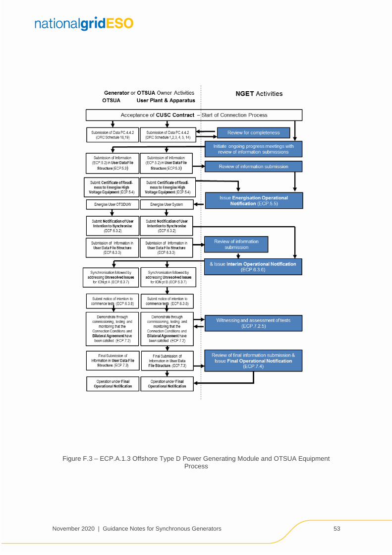
November 2020 | Guidance Notes for Synchronous Generators 53
Figure F.3 – ECP.A.1.3 Offshore Type D Power Generating Module and OTSUA Equipment Process

November 2020 | Guidance Notes for Synchronous Generators 54
Figure F.4 – ECP.A.1.4 Type B and Type C Power Generating Module Process

November 2020 | Guidance Notes for Synchronous Generators 55
Figure F.5 – ECP.A.1.5 Type A Power Generating Module Process

November 2020 | Guidance Notes for Synchronous Generators 56
Figure F.6 – ECP.A.1.6 Ongoing Compliance Process

November 2020 | Guidance Notes for Synchronous Generators 57
Figure F.7 – ECP.A.1.7 Modification or Change Process

November 2020 | Guidance Notes for Synchronous Generators 58
There are a number of different departments within National Grid that will be involved with this connection. The initial point of contact for National Grid will be your allocated Customer Connection Contract Manager for your Bilateral Agreement. If you are unsure of who your allocated Customer Connection Contract Manager is then the team can be contacted on [email protected].
For any correspondence relating to testing on the system following the Grid Code the IET process should be followed with notifications made to the ‘.Box.Tranreq’ email address for England and Wales connections and ‘.Box.TR.Scotland’ for all connections in Scotland.
Contact Address:
National Grid ESO, Faraday House, Warwick Technology Park, Gallows Hill, Warwick CV34 6DA
Appendix G Contacting National Grid

November 2020 | Guidance Notes for Synchronous Generators 59
Faraday House, Warwick Technology Park, Gallows Hill, Warwick, CV346DA
nationalgrideso.com