Operator Manual - Central States Diesel Generators
75
Operator Manual Generator Set with PowerCommand 2100 Controller DQHAA (Spec A−E) DQHAB (Spec A−E) English Original Instructions 9-2015 961−0123 (Issue 4)
-
Upload
khangminh22 -
Category
Documents
-
view
0 -
download
0
Transcript of Operator Manual - Central States Diesel Generators

Operator ManualGenerator Setwith PowerCommand 2100 Controller
DQHAA (Spec A−E)DQHAB (Spec A−E)
EnglishOriginal Instructions 9-2015 961−0123 (Issue 4)

Diesel engine exhaust and some of its constituents are known tothe State of California to cause cancer, birth defects, and otherreproductive harm.
Proposition 65 Warning
California

i
Table of Contents
SECTION TITLE PAGE
IMPORTANT SAFETY INSTRUCTIONS iii. . . . . . . . . . . . . . . . . . . . . . . . . . . . . . .
1 INTRODUCTION
General 1-1. . . . . . . . . . . . . . . . . . . . . . . . . . . . . . . . . . . . . . . . . . . . . . . . . . . . . . . .
How to Obtain Service 1-1. . . . . . . . . . . . . . . . . . . . . . . . . . . . . . . . . . . . . . . . . . .
2 SPECIFICATIONS 2-1. . . . . . . . . . . . . . . . . . . . . . . . . . . . . . . . . . . . . . . . . . . . . . . . .
3 CONTROL OPERATION
General 3-1. . . . . . . . . . . . . . . . . . . . . . . . . . . . . . . . . . . . . . . . . . . . . . . . . . . . . . . .
Prestart Checks 3-1. . . . . . . . . . . . . . . . . . . . . . . . . . . . . . . . . . . . . . . . . . . . . . . . .
Control Panel Power On/Off Modes 3-2. . . . . . . . . . . . . . . . . . . . . . . . . . . . . . . .
Front Panel 3-4. . . . . . . . . . . . . . . . . . . . . . . . . . . . . . . . . . . . . . . . . . . . . . . . . . . . .
Starting 3-5. . . . . . . . . . . . . . . . . . . . . . . . . . . . . . . . . . . . . . . . . . . . . . . . . . . . . . . .
Stopping 3-7. . . . . . . . . . . . . . . . . . . . . . . . . . . . . . . . . . . . . . . . . . . . . . . . . . . . . . .
Menu Display and Buttons 3-10. . . . . . . . . . . . . . . . . . . . . . . . . . . . . . . . . . . . . . .
Main Menus 3-12. . . . . . . . . . . . . . . . . . . . . . . . . . . . . . . . . . . . . . . . . . . . . . . . . . .
Adjusting Default Settings 3-15. . . . . . . . . . . . . . . . . . . . . . . . . . . . . . . . . . . . . . .
System Messages 3-15. . . . . . . . . . . . . . . . . . . . . . . . . . . . . . . . . . . . . . . . . . . . . .
Controller Configuration Menu 3-16. . . . . . . . . . . . . . . . . . . . . . . . . . . . . . . . . . . .
Engine Menu 3-18. . . . . . . . . . . . . . . . . . . . . . . . . . . . . . . . . . . . . . . . . . . . . . . . . . .
Alternator Menu 3-20. . . . . . . . . . . . . . . . . . . . . . . . . . . . . . . . . . . . . . . . . . . . . . . .
Adjust Menu 3-22. . . . . . . . . . . . . . . . . . . . . . . . . . . . . . . . . . . . . . . . . . . . . . . . . . .
Faults Menu 3-24. . . . . . . . . . . . . . . . . . . . . . . . . . . . . . . . . . . . . . . . . . . . . . . . . . .
System Menu 3-26. . . . . . . . . . . . . . . . . . . . . . . . . . . . . . . . . . . . . . . . . . . . . . . . . .
History Menu 3-28. . . . . . . . . . . . . . . . . . . . . . . . . . . . . . . . . . . . . . . . . . . . . . . . . . .
About Menu 3-30. . . . . . . . . . . . . . . . . . . . . . . . . . . . . . . . . . . . . . . . . . . . . . . . . . . .
-

ii
SECTION TITLE PAGE4 TROUBLESHOOTING
General 4-1. . . . . . . . . . . . . . . . . . . . . . . . . . . . . . . . . . . . . . . . . . . . . . . . . . . . . . . .
Safety Considerations 4-1. . . . . . . . . . . . . . . . . . . . . . . . . . . . . . . . . . . . . . . . . . . .
Status Indicators 4-2. . . . . . . . . . . . . . . . . . . . . . . . . . . . . . . . . . . . . . . . . . . . . . . .
Line Circuit Breaker (Optional) 4-2. . . . . . . . . . . . . . . . . . . . . . . . . . . . . . . . . . . .
Control and Diagnostics VIA Network or PC (Laptop) 4-2. . . . . . . . . . . . . . . . .
Fault Codes 4-4. . . . . . . . . . . . . . . . . . . . . . . . . . . . . . . . . . . . . . . . . . . . . . . . . . . . .
Fault Code Table 4-4. . . . . . . . . . . . . . . . . . . . . . . . . . . . . . . . . . . . . . . . . . . . . . . .
Troubleshooting Table 4-8. . . . . . . . . . . . . . . . . . . . . . . . . . . . . . . . . . . . . . . . . . . .
5 MAINTENANCE
General 5-1. . . . . . . . . . . . . . . . . . . . . . . . . . . . . . . . . . . . . . . . . . . . . . . . . . . . . . . .
Maintenance Schedule 5-2. . . . . . . . . . . . . . . . . . . . . . . . . . . . . . . . . . . . . . . . . . .
Generator Set Inspection 5-3. . . . . . . . . . . . . . . . . . . . . . . . . . . . . . . . . . . . . . . . .
Generator Set Maintenance (Battery Disconnected) 5-4. . . . . . . . . . . . . . . . . .
Lubrication System 5-5. . . . . . . . . . . . . . . . . . . . . . . . . . . . . . . . . . . . . . . . . . . . . .
Oil and Filter Change 5-5. . . . . . . . . . . . . . . . . . . . . . . . . . . . . . . . . . . . . . . . . . . .
Cooling System 5-6. . . . . . . . . . . . . . . . . . . . . . . . . . . . . . . . . . . . . . . . . . . . . . . . .
Change Air Cooler System 5-8. . . . . . . . . . . . . . . . . . . . . . . . . . . . . . . . . . . . . . . .
Fuel System 5-8. . . . . . . . . . . . . . . . . . . . . . . . . . . . . . . . . . . . . . . . . . . . . . . . . . . .
Air Cleaner 5-9. . . . . . . . . . . . . . . . . . . . . . . . . . . . . . . . . . . . . . . . . . . . . . . . . . . . .
Batteries 5-10. . . . . . . . . . . . . . . . . . . . . . . . . . . . . . . . . . . . . . . . . . . . . . . . . . . . . .
6 OPERATING RECOMMENDATIONS
No-Load Operation 6-1. . . . . . . . . . . . . . . . . . . . . . . . . . . . . . . . . . . . . . . . . . . . . .
Exercise Period 6-1. . . . . . . . . . . . . . . . . . . . . . . . . . . . . . . . . . . . . . . . . . . . . . . . .
Low Operating Temperature 6-1. . . . . . . . . . . . . . . . . . . . . . . . . . . . . . . . . . . . . .
High Operating Temperature 6-1. . . . . . . . . . . . . . . . . . . . . . . . . . . . . . . . . . . . . .
7 OPTIONAL ENCLOSURE FEATURES
General 7-1. . . . . . . . . . . . . . . . . . . . . . . . . . . . . . . . . . . . . . . . . . . . . . . . . . . . . . . .
External Receptacle 7-1. . . . . . . . . . . . . . . . . . . . . . . . . . . . . . . . . . . . . . . . . . . . .
Overfill Alarm 7-2. . . . . . . . . . . . . . . . . . . . . . . . . . . . . . . . . . . . . . . . . . . . . . . . . . .
External Emergency Stop Switch 7-2. . . . . . . . . . . . . . . . . . . . . . . . . . . . . . . . . .
AC Distribution Panel 7-3. . . . . . . . . . . . . . . . . . . . . . . . . . . . . . . . . . . . . . . . . . . .
Fuel Transfer Pump 7-4. . . . . . . . . . . . . . . . . . . . . . . . . . . . . . . . . . . . . . . . . . . . . .
External Alarm Panel 7-6. . . . . . . . . . . . . . . . . . . . . . . . . . . . . . . . . . . . . . . . . . . . .
External Fuel Fill Box 7-7. . . . . . . . . . . . . . . . . . . . . . . . . . . . . . . . . . . . . . . . . . . .

LS-16Liii
IMPORTANT SAFETY INSTRUCTIONS
SAVE THESE INSTRUCTIONS − This manual containsimportant instructions that should be followed duringinstallation and maintenance of the generator and batter-ies.
Before operating the generator set (genset), read theOperator’s Manual and become familiar with it and theequipment. Safe and efficient operation can beachieved only if the equipment is properly operatedand maintained. Many accidents are caused by failureto follow fundamental rules and precautions.
The following symbols, found throughout this manual,alert you to potentially dangerous conditions to the oper-ator, service personnel, or the equipment.
This symbol warns of immediatehazards which will result in severe personal in-jury or death.
WARNING This symbol refers to a hazard or un-safe practice which can result in severe person-al injury or death.
CAUTION This symbol refers to a hazard or un-safe practice which can result in personal injuryor product or property damage.
FUEL AND FUMES ARE FLAMMABLE
Fire, explosion, and personal injury or death can resultfrom improper practices.
DO NOT fill fuel tanks while engine is running, un-less tanks are outside the engine compartment.Fuel contact with hot engine or exhaust is a potentialfire hazard.
DO NOT permit any flame, cigarette, pilot light,spark, arcing equipment, or other ignition sourcenear the generator set or fuel tank.
Fuel lines must be adequately secured and free ofleaks. Fuel connection at the engine should bemade with an approved flexible line. Do not use zinccoated or copper fuel lines with diesel fuel.
Be sure all fuel supplies have a positive shutoffvalve.
Be sure battery area has been well-ventilated priorto servicing near it. Lead-acid batteries emit a highlyexplosive hydrogen gas that can be ignited by arc-ing, sparking, smoking, etc.
EXHAUST GASES ARE DEADLY
Provide an adequate exhaust system to properlyexpel discharged gases away from enclosed orsheltered areas and areas where individuals arelikely to congregate. Visually and audibly inspectthe exhaust daily for leaks per the maintenanceschedule. Make sure that exhaust manifolds are se-cured and not warped. Do not use exhaust gases toheat a compartment.
Be sure the unit is well ventilated.
Engine exhaust and some of its constituents areknown to the state of California to cause cancer,birth defects, and other reproductive harm.
MOVING PARTS CAN CAUSE SEVEREPERSONAL INJURY OR DEATH
Keep your hands, clothing, and jewelry away frommoving parts.
Before starting work on the generator set, discon-nect battery charger from its AC source, then dis-connect starting batteries, negative (−) cable first.This will prevent accidental starting.
Make sure that fasteners on the generator set aresecure. Tighten supports and clamps, keep guardsin position over fans, drive belts, etc.
Do not wear loose clothing or jewelry in the vicinity ofmoving parts, or while working on electrical equip-ment. Loose clothing and jewelry can becomecaught in moving parts.
If adjustment must be made while the unit is run-ning, use extreme caution around hot manifolds,moving parts, etc.
DO NOT OPERATE IN FLAMMABLE ANDEXPLOSIVE ENVIRONMENTS
Flammable vapor can cause an engine to overspeed andbecome difficult to stop, resulting in possible fire, explo-sion, severe personal injury and death. Do not operate agenset where a flammable vapor environment can becreated by fuel spill, leak, etc., unless the genset isequipped with an automatic safety device to block the airintake and stop the engine. The owners and operators ofthe genset are solely responsible for operating the gen-set safely. Contact your authorized Cummins PowerGeneration distributor for more information.

iv
ELECTRICAL SHOCK CAN CAUSESEVERE PERSONAL INJURY OR DEATH
Remove electric power before removing protectiveshields or touching electrical equipment. Use rub-ber insulative mats placed on dry wood platformsover floors that are metal or concrete when aroundelectrical equipment. Do not wear damp clothing(particularly wet shoes) or allow skin surface to bedamp when handling electrical equipment. Do notwear jewelry. Jewelry can short out electrical con-tacts and cause shock or burning.
Use extreme caution when working on electricalcomponents. High voltages can cause injury ordeath. DO NOT tamper with interlocks.
Follow all applicable state and local electricalcodes. Have all electrical installations performed bya qualified licensed electrician. Tag and lock openswitches to avoid accidental closure.
DO NOT CONNECT GENERATOR SET DIRECT-LY TO ANY BUILDING ELECTRICAL SYSTEM.Hazardous voltages can flow from the generator setinto the utility line. This creates a potential for elec-trocution or property damage. Connect onlythrough an approved isolation switch or an ap-proved paralleling device.
GENERAL SAFETY PRECAUTIONS
Coolants under pressure have a higher boiling pointthan water. DO NOT open a radiator or heat ex-changer pressure cap while the engine is running.To prevent severe scalding, let engine cool downbefore removing coolant pressure cap. Turn capslowly, and do not open it fully until the pressure hasbeen relieved.
Used engine oils have been identified by some stateor federal agencies as causing cancer or reproduc-tive toxicity. When checking or changing engine oil,take care not to ingest, breathe the fumes, or con-tact used oil.
Keep multi-class ABC fire extinguishers handy.Class A fires involve ordinary combustible materialssuch as wood and cloth; Class B fires, combustibleand flammable liquid fuels and gaseous fuels; ClassC fires, live electrical equipment. (ref. NFPA No. 10).
Make sure that rags or combustible material are notleft on or near the generator set.
Make sure generator set is mounted in a manner toprevent combustible materials from accumulatingunder or near the unit.
Remove all unnecessary grease and oil from theunit. Accumulated grease and oil can cause over-heating and engine damage which present a poten-tial fire hazard.
Keep the generator set and the surrounding areaclean and free from obstructions. Remove any de-bris from the set and keep the floor clean and dry.
Do not work on this equipment when mentally orphysically fatigued, or after consuming any alcoholor drug that makes the operation of equipment un-safe.
Substances in exhaust gases have been identifiedby some state or federal agencies as causing can-cer or reproductive toxicity. Take care not to breathor ingest or come into contact with exhaust gases.
Do not store any flammable liquids, such as fuel,cleaners, oil, etc., near the generator set. A fire orexplosion could result.
Wear hearing protection when near an operatinggenerator set.
To prevent serious burns, avoid contact with hotmetal parts such as radiator system, turbo chargersystem and exhaust system.
KEEP THIS MANUAL NEAR THE GENSET FOR EASY REFERENCE

1-1
1. Introduction
GENERAL
Each operator should read this manual before oper-ating the generator set (genset) for the first time. Agenset must be operated and maintained properly ifyou are to expect safe and reliable operation. Thismanual includes a troubleshooting guide and amaintenance schedule.
The engine owners manual is included with the gen-set. Where there is conflicting information, thismanual takes precedence over the engine ownersmanual.
WARNING Improper operation and mainte-nance can lead to severe personal injury or lossof life and property by fire, electrocution, me-chanical breakdown or exhaust gas asphyxi-ation. Read Important Safety Instructions andprecautions in this manual.
HOW TO OBTAIN SERVICE
When the generator set requires servicing, contactyour nearest Cummins Power Generation distribu-
tor. Factory-trained Parts and Service representa-tives are ready to handle all your service needs.
To contact your local Cummins Power Generationdistributor in the United States or Canada, call1-800-888-6626 (this automated service utilizestouch-tone phones only). By selecting Option 1(press 1), you will be automatically connected to thedistributor nearest you.
If you are unable to contact a distributor using theautomated service, consult the Yellow Pages. Typi-cally, our distributors are listed under:
GENERATORS-ELECTRIC orELECTRICAL PRODUCTS
For outside North America, call Cummins PowerGeneration, 1-763-574-5000, 7:30 AM to 4:00 PM,Central Standard Time, Monday through Friday. Or,send a fax to Cummins Power Generation using thefax number 1-763-528-7229.
When contacting your distributor, always supply thecomplete Model, Specification, and Serial Numberas shown on the generator set nameplate.
CAUTION
THIS GENERATOR SET REQUIRES LOW SULFUR HIGHWAY DIESEL FUEL (500 PPM MAXI-MUM). REFER TO CUMMINS ENGINE OWNERS MANUAL FOR DETAILED FUEL REQUIRE-MENTS.
WARNING
INCORRECT SERVICE OR PARTS REPLACEMENT CAN RESULT IN SEVERE PERSONAL IN-JURY, DEATH, AND/OR EQUIPMENT DAMAGE. SERVICE PERSONNEL MUST BE TRAINEDAND EXPERIENCED TO PERFORM ELECTRICAL AND/OR MECHANICAL SERVICE.
Copyright 2007 Cummins Power Generation. All rights reserved.
Cummins and PowerCommand are registered trademarks of Cummins Inc.

1-2
THIS PAGE LEFT INTENTIONALLY BLANK

2-1
2. Specifications
MODEL DQHAA, DQHAB
EngineCummins Diesel Series QSM11−G4
Generator kW Rating See Genset Nameplate
Engine Fuel ConnectionInlet/Outlet Thread Size Refer to Generator Outline Drawing
Electrical SystemStarting VoltageBattery
Group NumberCCA (minimum)
Cold Soak @ 0 F (-18 C)
24 Volts DCTwo, 12 Volt
8D
1400
Cooling SystemCapacity with Standard Radiator 8.9 Gal (36.72 L)
Lubricating SystemOil Capacity with FiltersOil Type*
38.8 Qts (36.7 L)
* Refer to Cummins engine Owners Manual for lubricating oil recommendations/specifications.
FUEL CONSUMPTION (STANDBY/FULL LOAD/60HZ)
MODEL DQHAA DQHAB
US gph (L/hr) 21.81 (82.56) 23.15 (87.63)
OIL PRESSURE/COOLANT TEMPERATUREWARNING AND SHUTDOWN LIMITS
Normal Oil PressureWarning LimitShutdown Limit
30-65 psi (207-448 kPa)27 psi (188 kPa)15 psi (100 kPa)
Idle Oil PressureWarning LimitShutdown Limit
10 psi (69 kPa)8 psi (55 kPa)5 psi (38 kPa)
Coolant TemperatureWarning LimitShutdown Limit
Normal/Idle212 F (100 C)230 F (110 C)

2-2
THIS PAGE LEFT INTENTIONALLY BLANK

3-1
3. Control Operation
GENERAL
The following describes the function and operationof the PowerCommand 2100 Control (PCC). All in-dicators, control switches/buttons and digital dis-play are located on the face of the control panel asillustrated in Figure 3-1.
This section covers prestart checks, starting andstopping and operating the generator set (genset).Each operator should read through this entire sec-tion before they attempt to start the generator set. Itis essential that the operator be completely familiarwith the generator set and the PCC control. Refer toSection 6 for operating recommendations.
Before starting, be sure the following checks havebeen made and the unit is ready for operation.
PRESTART CHECKS
Lubrication
Check the engine oil level. Keep the oil level as nearas possible to the dipstick high mark without overfil-ling.
Coolant
Check the engine coolant level. Refer to “CoolingSystems” in the Maintenance section of this manualfor proper procedure.
Fuel
Make sure the fuel tanks have sufficient fuel andthat fuel system is primed. Check to that there areno leaks and that all fittings are tight.
Ventilation
Make sure the generator set cooling inlet/outlet andexhaust ventilation openings are clear (not blocked)and operational.
Remove all loose debris from surrounding area ofgenerator set. Air flow from the radiator fan canblow loose items around and into ventilation open-ings.
Exhaust
Check to make sure entire exhaust system is tight,that no combustible materials are near system, andgases are discharged away from building openings.

3-2
CONTROL PANEL POWER ON/OFFMODES
The power on/off modes of the control panel and op-erating software are Power On, Screen Saver andSleep/Awake.
Power On Mode: In this mode, power is continu-ously supplied to the control panel. The control’soperating software and control panel LEDs/digitaldisplay will remain active until the Screen Savermode is activated.
Screen Saver Mode: Power to the digital display isremoved after 30 minutes (generator set not run-ning or running). The 30 minute timer resets and be-gins after each control panel action (any button orswitch selection) or signal received by the operatingsoftware. All LEDs on the control panel operate nor-mally during Screen Saver mode, indicating that theoperating software is active (Awake mode).
When a “Warning” signal is sensed by the PCC (forexample, low coolant temp), the control displays thewarning message.
Sleep/Awake Mode: In the Sleep mode, the con-trol’s operating software is inactive and the LEDsand the digital display on the control panel are all off.Sleep mode is a feature used to reduce batterypower consumption when the control is not being
used and the O/Manual/Auto switch is in the O posi-tion.
When all conditions are met (i.e., no unacknowl-edged faults and O/Manual/Auto switch is in the Oposition) the Sleep mode is activated.
The operating software is initialized and the digitaldisplay and control panel LEDs are turned on in re-sponse to moving/pressing the following controlpanel switch/buttons:
Off/Manual/Auto switch
Emergency Stop button
Fault Acknowledge/Reset button
Panel Lamp/Lamp Test button
To activate the control and view the menu displaywithout starting the generator set, press Fault Ac-knowledge or Panel Lamp button or move modeswitch from O to Manual.
The InPower service tool is required to enable ordisable the Sleep mode. When shipped from thefactory, Sleep mode is disabled. When disabled, theoperating software will always remain active(Awake mode). If the network feature is installed,the sleep mode is not available.
The InPower service tool is required to select the de-sired mode. Contact an authorized service center forassistance.

3-3
PANELLAMP(1 of 3)
CONFIGURABLEINDICATORS
MANUALRUN/STOPBUTTON
OFF/MANUAL/AUTO SWITCH
SHUTDOWNAND WARNING
STATUSINDICATORS
EMERGENCYSTOP PUSH
BUTTON(Pull to reset)
HOMEBUTTON
ANALOG ACMETERING
PANEL(OPTIONAL)
DIGITALDISPLAY
MENUSELECTION
BUTTON (1 of 4)
PREVIOUSMAIN MENU
BUTTON
FAULTACKNOWLEDGEMENT/
RESET BUTTON
RUNNING/REMOTESTART/NOT IN AUTO
INDICATORS
PANEL LAMPAND LAMP
TESTBUTTON
FIGURE 3-1. FRONT PANEL

3-4
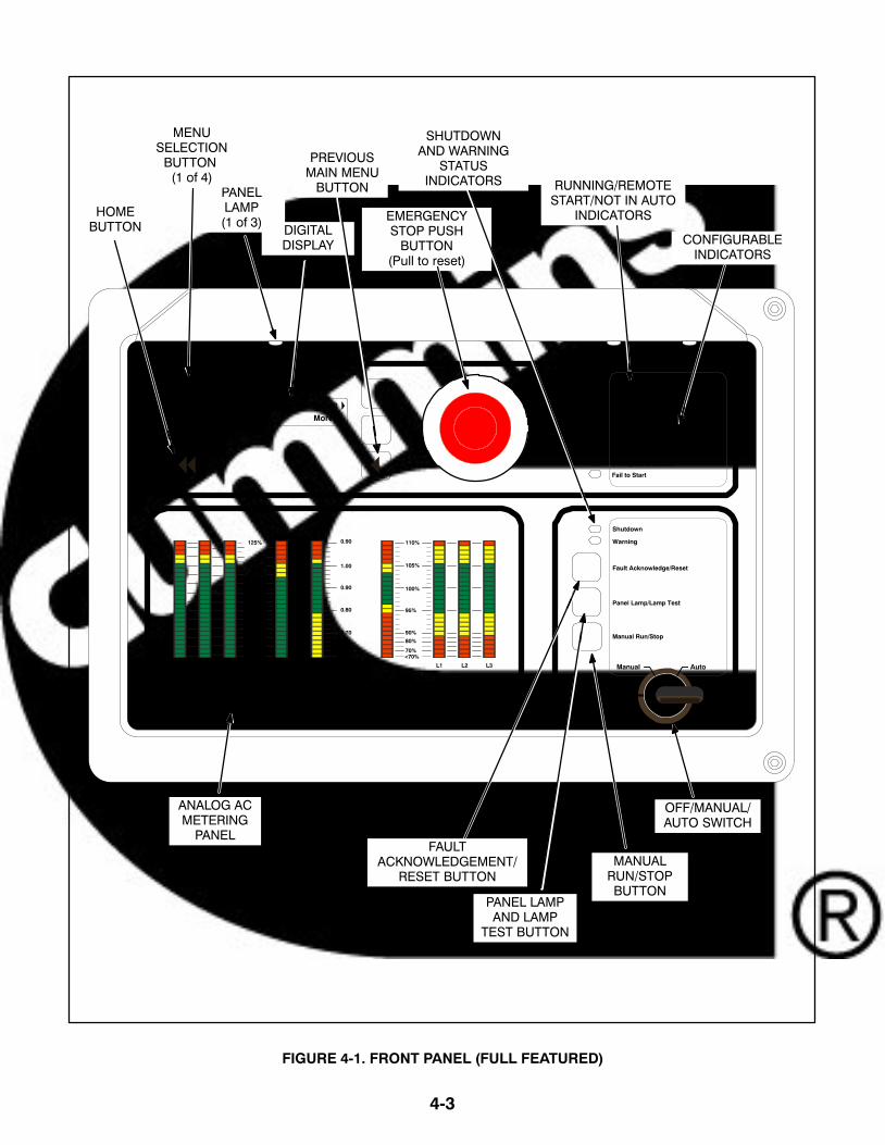
FRONT PANEL
Figure 3-1 shows the features of the front panel.
Digital Display: This two-line, 20-characters perline alphanumeric display is used to view menus ofthe menu-driven operating system. Refer to themenu trees later in this section. The display is alsoused to show warning and shutdown messages.
Display Menu Selection Buttons: Four momen-tary buttons—two on each side of the digital displaywindow—are used to step through the variousmenu options and to adjust generator set parame-ters. A green triangle ( or ), arrow ( , , , or ),>>, or plus/minus sign (+ or −) in the digital displayadjacent to the button is shown when the button canbe used (button is “active”). Refer to Menu DisplayAnd Buttons later in this section.
Home Button: Press this button ( ) to view theHome Menu. Refer to the menu trees later in thissection.
Previous Main Menu Button: Press this button ( )to view the previous Main Menu. All main menus in-clude both types of green triangles ( and ). Referto the menu trees later in this section.
NOTE: The up and down arrows ( and ) are usedto navigate between submenus.
Emergency Stop Button: Push this button in foremergency shutdown of the generator set. This willstop the generator set immediately and preventstarting of the generator set from any location (localand remote).
To reset:1. Pull the button and allow it to pop out.
2. Turn the O/Manual/Auto switch to O (Off).
3. Press the front panel Fault Acknowledge/Re-set button.
4. Return O/Manual/Auto switch to desired posi-tion.
Emergency Stop shutdown can be reset only at thePCC front panel.
Running Indicator: This green lamp is lit wheneverthe generator set is running.
Remote Start Indicator: This green lamp is litwhenever the control is receiving a remote start sig-nal.
Not in Auto Indicator: This red lamp flashes con-tinuously when the O/Manual/Auto switch is not inthe Auto position.
Analog AC Metering Panel (Optional): This panelsimultaneously displays (in percent of genset ratedoutput):
3-phase line-to-line AC current (A~) (L1, L2and L3); Single phase line-to-line (L1 and L2)
Kilowatts (kW)
Generator output frequency in hertz (Hz)
3-phase line-to-line AC volts (V~) (L1, L2 andL3); Single phase line-to-neutral (L1)
Power Factor (PF) (shown in 0.2 increments)
Shutdown Status Indicator: This red lamp is litwhenever the control detects a shutdown condition.The generator set cannot be started when this lampis on. After the condition is corrected, shutdown in-dicators can be reset by turning the O/Manual/Autoswitch to the O position and pressing the Fault Ac-knowledge/Reset button.
Warning Status Indicator: This yellow lamp is litwhenever the control detects a warning condition.After the condition is corrected, the warning indica-tors can be reset by pressing the Fault Acknowl-edge/Reset button. (The majority of faults can bereset without stopping the generator set.) In automode, the warning indicators can also be reset bycycling the remote reset input after the condition iscorrected.
Some warnings remain active after the condition iscorrected and the control reset button is pressed.This will require the genset to be shutdown to resetthe warning indicator.
Fault Acknowledge/Reset Button: Press this but-ton to acknowledge warning and shutdown mes-sages after the fault has been corrected. Pressingthis button clears the fault from the current fault list.
To acknowledge a Warning message, the O/Manu-al/Auto switch can be in any position. (It is not nec-essary to stop the generator set to acknowledge aninactive Warning condition.) To acknowledge ashutdown message with this button, the O/Manual/Auto switch must be in the O position.

3-5
Panel Lamp and Lamp Test Button: Press thisbutton to turn the control panel lamps on or off. Thelights will shut off after about ten minutes. Press andhold this button to test all front panel LEDs and me-ters. The meters will light one bar at a time. (Test canbe enabled during genset operation.)
Manual Run/Stop Button: This button starts andstops the generator set locally and will bypass TimeDelay to Start and Stop sequences. The O/Manual/Auto switch must be in the Manual position to en-able this button.
O/Manual/Auto Switch: The Manual position en-ables the use of the Manual Run/Stop button.
The Auto position enables start/stop control of theengine from a remote location. (It disables the useof the Manual Run/Stop button.)
The O (Off) position prevents the starting of the gen-erator set (local or remote). If the switch is set to Oduring generator set operation, the engine will im-mediately shut down (cool-down timers are by-passed). If possible, hot shutdown under loadshould be avoided to help prolong the life of the gen-erator set.
Configurable Indicators
The following configurable indicators (default val-ues shown) can be changed with the InPower ser-vice tool. The configurable items are: change gen-erator event and LED color (green, yellow or red),and enable/disable indicator.
The InPower service tool is required to select the de-sired settings. Contact an authorized service centerfor assistance.
Low Oil Pressure Warning Indicator: This yellowlamp indicates the oil pressure is lower than the nor-mal range of operation.
High Engine Temperature Warning Indicator:This yellow lamp indicates the engine temperatureis higher than the normal range of operation.
Low Oil Pressure Shutdown Indicator: This redlamp indicates the engine has shut down becauseof low oil pressure.
Overspeed Shutdown Indicator: This red lamp in-dicates the engine has shut down because of ex-cessive speed.
Fail to Start Indicator: This red lamp indicates theengine failed to start.
STARTING
The following headings cover the systems used tostart the generator set. Figures 3-2 and 3-3 providea flow chart for all start/run/stop sequences.
Before starting the generator set, make sure thatexhaust and fuel fittings are tight and that propermaintenance has been performed. See PrestartChecks in this section.
Starting at the Control Panel (ManualMode)
Turn the O/Manual/Auto switch to the Manual posi-tion and press the Manual Run/Stop button. Thiswill activate the engine control system and the start-ing system. The starter will begin cranking and, af-ter a few seconds, the engine will start and the start-er will disconnect.
The Warm−up At Idle feature is only available onsome models. If available, the InPower service tool isrequired to enable/disable the Warm-up At Idle fea-ture and to adjust the time-out. When shipped fromthe factory, this feature is disabled.
When the switch is in the Manual position, the con-trol will complete the Warm-up At Idle feature if en-abled. When the coolant reaches operating temper-ature or the warm-up time at idle time delay (0−300seconds) is reached, whichever occurs first, thegenerator set will ramp to the rated speed and volt-age.
When the switch is in the Manual position, the gener-ator set can be operated in the idle mode (used formaintenance, troubleshooting, etc.). Refer to Adjustmenu (Figure 3-10) to enable/disable the idle feature.
If the engine does not start, the starter will disen-gage after a specified period of time and the controlwill indicate an overcrank shutdown.

3-6
The generator can be configured for a number ofstarting cycles (1 to 7 cycles) with set times for crankand rest periods for all starting modes (manual/re-mote). The default setting is for 3 start cycles, com-posed of 15 seconds of cranking and 15 seconds ofrest.
To change the cycle number, and the crank and resttimes, contact an authorized service center for assis-tance.
To clear a Fail to Start shutdown, place the O/Manu-al/Auto switch in the O position and press the FaultAcknowledge/Reset button. Before attempting torestart, wait two minutes for the starter motor to cooland then repeat the starting procedure. If the enginedoes not run after a second attempt, refer to theTroubleshooting section.
Starting from a Remote Location (AutoMode)
Place the O/Manual/Auto switch in the Auto posi-tion. This allows the generator set to be started froma remote switch or device (e.g., transfer switch).
In response to the Remote Start, the control lightsthe Remote Start indicator and initiates the startingsequence as shown in Figure 3-3.
When the switch is in the Auto position, the controlwill complete the Time Delay To Start function.
Refer to the Adjust submenu in this section to enableand change the time delay start/stop settings.
Cold Starting with Loads
In accordance with NFPA 110, Cummins PowerGeneration recommends installing diesel standbygenerator sets (life safety systems) equipped withengine jacket water coolant heaters in locationswhere the minimum ambient temperature is above40F (4C). NFPA also requires that the engine beheated as necessary to maintain the water jackettemperature determined by the manufacturer forcold start and load acceptance for the type of sys-tem.
Although Cummins Power Generation generatorsets may start in temperatures below 40F (4C)when equipped with engine jacket water coolantheaters, it might take more than 10 seconds towarm the engine before a load can be applied andmay also require other supplemental starting aids.Refer to engine manual for specific engine require-ments.
The Low Coolant Temperature (Code 152) mes-sage, is provided to meet the requirements of NFPA110. The engine cold sensing logic initiates a warn-ing when the engine jacket water coolant tempera-ture falls below 70F (21C). In applications wherethe ambient temperature falls below 40F (4C), acold engine may be indicated even though the cool-ant heaters are connected and operating correctly.Under these conditions, although the generator setmay start, it may not be able to accept load within 10seconds. When this condition occurs, check thecoolant heaters for proper operation. If the coolantheaters are operating properly, other precautionsmay be necessary to warm the engine before apply-ing a load.

3-7
STOPPING
Before Stopping
Run the generator set at no load for three to fiveminutes before stopping. This allows the lubricatingoil and engine coolant to carry heat away from thecombustion chamber and bearings.
Emergency Stop
The emergency stop button is located near the cen-ter of the upper part of the control panel (Figure3-1). Push the button in for an emergency stop. Thered Shutdown status LED is lit and the emergencystop message is displayed.
To reset:1. Pull the emergency stop button out.2. Turn the O/Manual/Auto switch to O. 3. Press the front panel Fault Acknowledge/
Reset button.4. Return O/Manual/Auto switch to desired
position.
Emergency Stop shutdown status can be reset onlyat the operator control panel.
Stopping at Control Panel (Manual Mode)
If the generator set was started at the control panel(O/Manual/Auto switch in the Manual position),pressing the Manual Run/Stop button causes the
generator set to complete its normal (Local Start)shutdown sequence (Figure 3-2).
The generator set stops after the cool-down at idletimer (0 to 30 minutes) has timed out.
The InPower service tool is required to enable/dis-able the Cool-down At Idle feature. Contact an autho-rized service center for assistance.
Turning the O/Manual/Auto switch to the O positioncauses an immediate engine shutdown (bypassesCool-down At Idle). If possible, hot shutdown underload should be avoided to help prolong the reliabilityof the generator set.
Stopping from Remote Location (AutoMode)
If the control receives a remote stop signal, the gen-erator set completes its normal shutdown sequence(Figure 3-3). (The remote stop signal is actually theremoval of the remote start signal to the control.)
The generator set stops after completing the TimeDelay To Stop (0 to 600 seconds) and the cool-down at idle (0 to 30 minutes).
Refer to the Adjust submenu in this section to enableand change the Time Delay To Stop setting. The In-Power service tool is required to enable/disable theCool-down At Idle feature. Contact an authorizedservice center for assistance.

3-8
CONTROL RUNBUTTON
LOCAL START(Manual Mode)
RATED SPEED&VOLTAGE
STOP
1
NOTES:1. Timer expires.
CONTROL STOPBUTTON
COOL-DOWN@ IDLE
(0−30 min)
EMERGENCYSTOP BUTTON
WARM-UP @ IDLE(0-300 sec)
Engine Temperaturegreater than 100 F go
to Rated
1
RATED TO IDLEDELAY (0−10 sec)
1
FIGURE 3-2. STARTING AT THE CONTROL PANEL (MANUAL MODE)
3-9
EMERGENCYSTART
RATED SPEED&VOLTAGE
STOP
2
NOTES:1. Input from transfer switch, remote start switch, etc.2. Timer expires.
TIME DELAY TOSTOP (0−600 sec)
COOL-DOWN@ IDLE
(0−30 min)
REMOTE STARTCUST. CONNECT 1
TIME DELAY TOSTART (0−300 sec)
2
REMOTE STARTRemoved
2
RATED TO IDLEDELAY (0−10 sec)
2
EMERGENCYSTOP BUTTON
FIGURE 3-3. STARTING WITH CONTROL IN AUTO MODE

3-10
MENU DISPLAY AND BUTTONS
Figure 3-4 shows the digital display and the menuselection buttons.
Digital Display: The two-line, 20 characters perline, digital display is used to view the menus of themenu-driven operating system. Refer to the menutrees later in this section. The display is also used toshow fault messages.
Display Menu Selection Buttons: Four momen-tary buttons—two on each side of the digital displaywindow—are used to step through the variousmenu options and to adjust generator set parame-ters. The button is active when a symbol adjacent tothe button is displayed. The displayed symbol indi-cates the function of the button.
In the digital display for main menus (Figure3-5), the and symbols indicate that pressingthe adjacent button causes the operating pro-gram to go to the selected submenu (e.g., En-gine Menu in Figure 3-9).
In the digital display, the More>> symbol indi-cates that pressing the adjacent button causesthe operating program to go to the next mainmenu, as shown in Figure 3-5.
In the digital display, the or symbols indi-cate that pressing the adjacent button causesthe operating program to go to the next or pre-vious submenu, as shown in the menu dia-grams. Only the symbol is displayed in thefirst submenu. Only the is displayed in thelast submenu. Both symbols are displayed inthe rest of the submenus.
In the digital display, the plus or minus symbols(+ or −) indicate that pressing the adjacent but-ton can be used to change a parameter or val-ue shown on the display.
When there is a choice of two parameters, oneparameter is associated with the + symbol andthe other is associated with the − symbol.
When changing values, pressing the button ad-jacent to the + symbol increase the value andpressing the button adjacent to the − symboldecreases the value. Only one numeric char-acter of a field can be changed at a time.
In the digital display, the or symbol indicatesthat pressing the adjacent button causes theoperating program to move the cursor to thenext numeric character. The selected numericcharacter can then be changed by pressing thebuttons adjacent to the + and − symbols. Onlythe symbol is displayed when the cursor is onthe first character of a field that can bechanged. Only the is displayed when the cur-sor is on the last character. Both symbols aredisplayed when the cursor is on any other char-acter.
After adjusting values/parameters, pressingthe symbol results in the changes beingsaved. If the Home button or Previous MainMenu button is pressed before pressing the symbol, the changes are not saved.
Home Button: Pressing this button causes the op-erating system to show Main Menu 1 (Figure 3-5) inthe digital display.
Previous Main Menu Button: Pressing this buttoncauses the operating system to show the previousMain Menu in the digital display. All main menus in-clude both types of green triangles ( and ).

3-11
HOMEBUTTON
PREVIOUS MAINMENU BUTTON
2 LINE, 20 CHARACTERS PER LINE
MENU DISPLAY
DIGITAL DISPLAY
FIGURE 3-4. DIGITAL DISPLAY AND MENU SELECTION BUTTONS

3-12
MAIN MENUSFigure 3-5 shows the three major main menus avail-able to the user. Figure 3-5 also includes referencesto pages in this section where you can find addition-al information on submenus. When viewing a sub-menu, you can press the previous main menu but-ton at any time to view its main menu.
As shown in the illustration, each main menu canbranch into one of four directions. Press the buttonnext to “More>>” in the display to view the next Mainmenu. Main Menu 1 is redisplayed when you pressthe button next to “More>>” in the Main Menu 3 dis-play.

3-13
About SetupMore>>
FaultsSystem
HistoryMore>>
EngineAlternator
AdjustMore>>
Main Menu 1
Main Menu 2
Main Menu 3
PAGE3-19
PAGE3-21
PAGE3-23
PAGE3-25
PAGE3-27
PAGE3-29
SERVICEREP
PAGE3-31
FIGURE 3-5. MAIN MENUS

3-14
Main Menu 1
Main Menu 1 is also the Home menu. When viewingany of the other main menus or any submenu, youcan press the home button to view this menu.
To display engine parameters, such as coolant tem-perature, oil pressure, oil temperature, etc., pressthe button next to the word “Engine” in the display.Turn to the Engine menu diagram on page 3-19.
To display alternator parameters, such as line-to-line voltage, line-to-neutral voltage, amperage, fre-quency, etc., press the button next to the word “Al-ternator” in the display. Turn to the Alternator menudiagram on page 3-21.
To adjust generator parameters, such as idle start,voltage, frequency, start delay, and stop delay, pressthe button next to the word “Adjust” in the display.Turn to the Adjust menu diagram on page 3-23.
To view one of the other main menus, press the but-ton next to “More>>” in the display.
Main Menu 2
To display system faults, press the button next tothe word “Faults” in the display. Up to 20 of the mostrecent/current faults can be displayed. Turn to theFaults menu diagram on page 3-25.
To view network system parameters, such as on theautomatic transfer switch (ATS), Master, or Gensetsystem, press the button next to the word “System”in the display. Turn to the System menu diagram onpage 3-27.
To display historical engine parameters such asnumber of starts, engine hours, control hours, kilo-watt hours, and genset duty cycle, press the buttonnext to the word “History” in the display. Turn to theHistory menu diagram on page 3-29.
To view one of the other main menus, press the but-ton next to “More>>” in the display.
Main Menu 3
To view parameters on the generator, such as mod-el, standby rating, and software version, press thebutton next to the word “About” in the display. Turnto the About menu diagram on page 3-31.
Main Menu 3 also includes a link to the Setup me-nus. These menus can be viewed but changes tothese menus are restricted to service personnelwith the appropriate access code.
To view one of the other main menus, press the but-ton next to “More>>” in the display.

3-15
ADJUSTING DEFAULT SETTINGSThe Controller Configuration Menu can be used toadjust the following default settings: Language − Select from available loaded lan-
guages
Temperature Units − Fahrenheit or Centigrade
Fluid Pressure Units − kPA or PSI
For more information on adjusting these settings,turn to the Controller Configuration menu diagramon page 3-17.
SYSTEM MESSAGESA system message pop-up screen is displayedwhen the event it is displaying becomes active.These pop-up screens remain displayed until pre-empted by another pop-up screen or until any dis-play button is pressed. Once a button is pressed,the previous menu is redisplayed. To return to anactive pop-up screen from the previous menu, se-lect the following menu: Engine to redisplay Time Delay Idle Faults to redisplay Faults
Pop-up screens are displayed for the following:
Faults Time Delay − Start, Stop, and Idle
An example of a Time Delay Idle pop-up screen isshown in Figure 3-6. A countdown, in seconds, is in-cluded in the display.
TD Idle nnn Sec
FIGURE 3-6. TIME DELAY IDLE POP-UP SCREEN

3-16
CONTROLLER CONFIGURATION MENU
Figure 3-7 shows a block representation of the Con-troller Configuration menus. These menus are usedto change the default language, temperature units,and pressure units to be displayed in menus.
To view the first Controller Configuration menu,make sure Main Menu 1 is displayed and simulta-neously press the Home Menu and Previous MainMenu buttons.
As shown in the diagram, the Controller Configura-tion menu has three submenus.
Press the buttons next to the and symbols in thedigital display to navigate between the menus.
Press the button next to the symbol in the displayuntil the + and − symbols are displayed.
Press the button next to the + or − symbol to selectthe desired option.
After selecting option, pressing the symbol resultsin the changes being saved. If the Home button orPrevious Main Menu button is pressed beforepressing the symbol, the changes are not saved.
Language Selected submenu: Used to select de-sired language (default = English).
Temperature Units submenu: Used to selectFahrenheit or Centigrade for temperature readings.
Fluid Pressure Units submenu: Used to selectPSI or kPA for pressure readings.

3-17
CONTROLLER CONFIGURATION MENU
EngineAlternator
AdjustMore>>
+Language Selected− English
Language SelectedEnglish
Temperature UnitsDeg F +Temperature Units
− Deg C
Fluid Pressure UnitsPSI +Fluid Pressure Units
− kPa
Back
Back
Back
Main Menu 1
FIGURE 3-7. CONTROLLER CONFIGURATION MENU
3-18
ENGINE MENU
Figure 3-8 shows a block representation of the En-gine menu. If you press the button next to the word“Engine” in the display, the first Engine submenu isdisplayed.
As shown in the diagram, the Engine menu has fif-teen submenus. The data in the submenus will varyaccording to the type and number of sensors pro-vided with the engine.
Press the buttons next to the and symbols in thedigital display to navigate between the menus.Press the Home button or the Previous Main Menubutton to return to Main Menu 1.
Coolant Temperature submenu: This submenudisplays the engine coolant temperature which canbe viewed in degrees Fahrenheit or Centigrade(see Controller Configuration Menu in this section).
Oil Pressure submenu: This submenu displaysthe engine oil pressure which can be viewed in PSIor kPA (see Controller Configuration Menu in thissection).
Oil Temperature submenu (Only available onsome models): This submenu displays the engineoil temperature which can be viewed in degreesFahrenheit or Centigrade (see Controller Configu-ration Menu in this section).
Engine Speed submenu: This submenu displaysthe engine RPM.
Battery Voltage submenu: This submenu dis-plays the engine battery voltage.
Governor Torque Command submenu: Thissubmenu displays the governor torque levels in per-centage of maximum value.
Fuel Rate submenu: This submenu displays thefuel rate which can be displayed in gallons per houror liters per hour (see Controller ConfigurationMenu in this section).
Intake Manifold submenu: This submenu dis-plays the intake manifold temperature which can beviewed in degrees Fahrenheit or Centigrade (seeController Configuration Menu in this section).
Fuel Outlet Pressure submenu: This submenudisplays the fuel outlet pressure which can beviewed in PSI or kPA (see Controller ConfigurationMenu in this section).
Active Time Delay submenu: This submenu dis-plays the time delay that is currently active: warm−up, cool down, start or stop delays.

3-19
ENGINE MENU
EngineAlternator
AdjustMore>>
Coolant Temperaturennn Deg F
Oil Pressurennn PSI
Engine Speednnnn RPM
Battery Voltagenn.n VDC
Governor Trq Cmdnnn %
Main Menu 1
Oil Temperaturennn Deg F
Fuel Ratennn.nn Gal/hr
Intk Manifold Tempnnnn Deg F
Fuel Outlet Pressnnn PSI
Active Time DelayNone nnnn Sec
FIGURE 3-8. ENGINE MENU

3-20
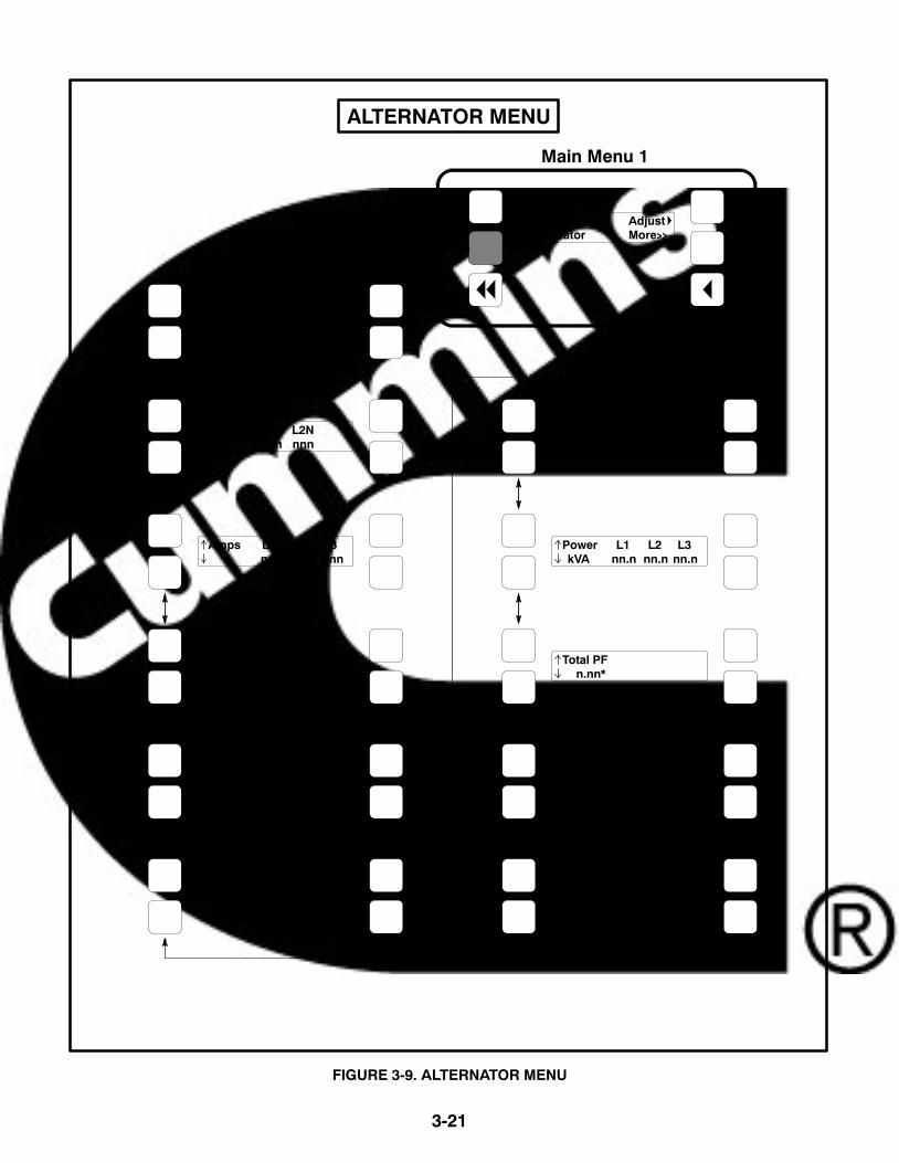
ALTERNATOR MENU
Figure 3-9 shows a block representation of the Al-ternator menu. If you press the button next to theword “Alternator” in the display, the first Alternatorsubmenu is displayed.
As shown in the diagram, the Alternator menu haseleven submenus.
Press the buttons next to the and symbols in thedigital display to navigate between the menus.Press the Home button or the Previous Main Menubutton to return to Main Menu 1.
Line-to-Line Voltage submenu: The voltagesLine-to-Line (L1, L2 and L3) are measured betweenL1 to L2, L2 to L3 and L3 to L1, respectively. (Singlephase − L1 to L2 only.)
Line-to-Neutral Voltage submenu: Note that theLine-to -Neutral menu will not be displayed for a 3phase/3 wire system. Single phase − L1 to N and L2to N.
Amps submenu: All phases. (Single phase − L1and L2 only.)
Frequency submenu: Generator set output fre-quency.
Total Real Power submenu: This submenu dis-plays the total amount of real power output, in kilo-watts (kW).
Real Power submenu: This submenu displays theamount of real power output for L1, L2, and L3, inkilowatts (kW). (Single phase − L1 and L2 only.)
Total Apparent Power submenu: This submenudisplays the total amount of apparent power output,in kilovolt amps (kVA).
Apparent Power submenu: This submenu dis-plays the amount of apparent power output for L1,L2, and L3, in kilovolt amps (kVA). (Single phase −L1 and L2 only.)
Total Power Factor submenu: This submenu dis-plays the power factor with leading/lagging indica-tion.
The PF reading will contain an asterisk if the powerfactor is leading (for example, Total PF 0.9 * ).
Power Factor submenu: This submenu displays apower factor value for L1, L2, and L3. (Singlephase − L1 and L2 only.)
The PF reading will contain an asterisk if the powerfactor is leading (for example, PF L1 0.9*).
AVR Duty Cycle submenu: This submenu dis-plays the voltage regulator (drive) level in percent-age of maximum. (Where maximum is 100% DutyCycle, software clamps Duty Cycle maximum to60% for PMG and 90% for shunt.)
3-21
ALTERNATOR MENU
EngineAlternator
AdjustMore>>
Volts L12 L23 L31 V nnn nnn nnn
Volts L1N L2N V nnn nnn
Amps L1 L2 L3 nnn nnn nnn
Frequency nn.n Hz
Power L1 L2 L3kW nn.n nn.n nn.n
Total Power nnn kW
Total Power nn.n kVA
Power L1 L2 L3 kVA nn.n nn.n nn.n
Total PF n.nn*
PF L1 L2 L3 *n.nn *n.nn *n.nn
AVR Duty Cyclennn %
Main Menu 1
FIGURE 3-9. ALTERNATOR MENU

3-22
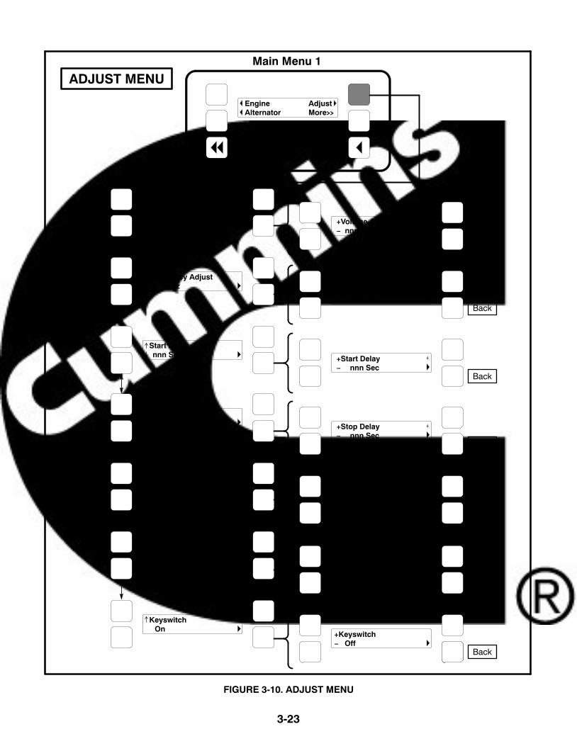
ADJUST MENU
Figure 3-10 shows a block representation of the Ad-just menu. If you press the button next to the word“Adjust” in the display, the first Adjust submenu isdisplayed.
As shown in the diagram, the Adjust menu has sixsubmenus. Each submenu includes a parameter orvalue that can be changed.
Press the buttons next to the and symbols in thedigital display to navigate between the menus.Press the Home button or the Previous Main Menubutton to return to Main Menu 1.
Adjusting Values/Parameters:
1. Press the button next to the symbol in the dis-play until the + and − symbols are displayed.
2. If necessary, press the button next to the or symbols to move to the numeric character youwish to change.
3. Press the button next to the + symbol to in-crease the value or select parameter; press thebutton next to the − symbol to decrease the val-ue or select parameter.
4. After adjusting values/selecting parameters,pressing the symbol results in the changesbeing saved. (When adjusting values, makesure the cursor is on the last numeric characterbefore pressing the symbol).
If the Home button or Previous Main Menu but-ton is pressed before pressing the symbol,the changes are not saved.
Voltage Adjust submenu: Voltage can be ad-justed to �5 percent of the nominal voltage. For ex-ample, if genset output voltage is 208 volts, the volt-age can be adjusted from 198 to 218 volts.
If the entered value is greater or less than the allowed(5%) range, the control will not accept the entry andwill return to the previous setting. Retry by entering asmaller change in one volt increments.
Frequency Adjust submenu: Frequency can beadjusted to �5 percent of the nominal frequency.For example, if the genset frequency is 60.0 Hz, thefrequency can be adjusted from 57.0 to 63.0 Hz.
Start Delay submenu: Start Delay can be set from0 to 300 seconds (default = 0). (Enter 1 or more toenable.) This function is bypassed during a manualstart/stop sequence.
Stop Delay submenu: Stop Delay can be set from0 to 600 seconds (default = 0). (Enter 1 or more toenable.) This function is bypassed during a manualstart/stop sequence and engine shutdown faults.
Rated To Idle: Rated To Idle delay can be set from 0to 10 seconds (default = 0). (Enter 1 or more to en-able.) Entering a non-zero delay will cause the gen-set to delay the transition to Cooldown At Idle.
Idle Start submenu (Only available on somemodels): Idle Start can be enabled or disabled (de-fault = Disable). This function can only be used inmanual mode and can be enabled or disabled be-fore or during genset operation.
Enabling Idle Start will cause the genset to run inidle mode until Idle Start is disabled. A warning isdisplayed if genset is left in idle more than 10 min-utes. Long periods of engine idling can eventuallyaffect engine performance and may void enginewarranty.
Keyswitch submenu: Used to turn Keyswitchpower to CM850 module on/off. To select OFF, gen-set speed must be zero.
The keyswitch on/off control is intended to aid or beused in downloads to the CM850 module, via InSite.
3-23
Voltage Adjustnnn V
Frequency Adjustnn.n Hz
Start Delaynnn Sec
+Voltage Adjust− nnn V
+Frequency Adjust− nn.n Hz
+Start Delay− nnn Sec
Back
Back
Back
ADJUST MENU
EngineAlternator
AdjustMore>>
Main Menu 1
Idle Start Disable
+Idle Start− Enable
Back
Stop Delaynnn Sec +Stop Delay
− nnn SecBack
Rated To Idle Delaynn Sec +Rated To Idle Delay
− nn SecBack
Keyswitch On
+Keyswitch− Off
Back
FIGURE 3-10. ADJUST MENU

3-24
FAULTS MENUFigure 3-12 shows a block representation of theFaults menu. Up to 20 of the most recent faults canbe viewed. An example of how a fault code is dis-played is shown in Figure 3-11.
The available menus are dependent on the numberof faults that have occurred. If there are no faults, the symbol next to the
word “Faults” is not displayed and no Fault me-nus are available.
If more than one fault has occurred, press thebutton next to the word “Fault” in the screen dis-play to view the Faults Main Menu. As shownin the diagram, the Faults Main Menu has twosubmenus. Press the Previous Main Menu but-ton to return to the Faults Main Menu. Press thePrevious Main Menu button a second time toreturn to Main Menu 2.
Press the Home button at any time to return to MainMenu 1.
History submenu: From the Faults Main Menu,press the button next to the word “History” in the dis-play to view up to twenty of the most recent ac-knowledged faults. Press the buttons next to the and symbols in the digital display to navigate be-tween the menus. Press the Previous Main Menubutton to return to the Faults Main Menu.
Current Fault submenu: From the Faults MainMenu, press the button next to the word “Current” inthe display to view up to twenty of the most recentunacknowledged faults. Press the Previous MainMenu button to return to the Faults Main Menu.
FAULTDESCRIPTION
W = WARNINGS = SHUTDOWN
ASTERISK =ACTIVE FAULT
HOUR FAULTOCCURRED
FAULTCODE
FIGURE 3-11. HISTORY/CURRENT FAULT SUBMENU

3-25
FaultsSystem
HistoryMore>>
FAULTS MENU
Main Menu 2
History
nnnnn @Hr nnnnn.nW xxxxxxxxxxxxxxxxxxxx
nnnnn @Hr nnnnn.nW xxxxxxxxxxxxxxxxxxxx
nnnnn @Hr nnnnn.nS xxxxxxxxxxxxxxxxxxxx
Fault 1
Fault 2
Fault 20
Faults Main Menu
Current
nnnnn @Hr nnnnn.nW xxxxxxxxxxxxxxxxxxxx
nnnnn @Hr nnnnn.nW xxxxxxxxxxxxxxxxxxxx
Fault 2
Fault 20
nnnnn @Hr nnnnn.nS xxxxxxxxxxxxxxxxxxxx
Fault 1
FIGURE 3-12. FAULTS MENU

3-26
SYSTEM MENU
Figure 3-13 shows a block representation of theSystem menu. If you press the button next to theword “System” in the display, the System MainMenu is displayed. This menu is displayed only ifthe network communications module (NCM) fea-ture is installed. The System Main Menu allows youto view the status and load of other PCC equipmentconnected on a common network with the PCC2100 control.
As shown in the diagram, the System Main Menuhas three submenus.
When viewing ATS and Genset System submenus,press the buttons next to the and symbols in thedigital display to navigate between the menus.Press the Previous Main Menu button to return tothe System Main Menu. Press the Previous MainMenu button a second time to return to MainMenu 2. Press the Home button to return to MainMenu 1.
ATS System submenus: From the System MainMenu, press the button next to the word “ATS” in thedisplay to view the first of up to 16 ATS System sub-menus. An ATS system must be available in the net-work to display this submenu.
The ATS submenu allows viewing of the transferswitch name (configured with InPower), kW load (ifmonitored by the ATS system), status (e.g., not inauto), and source connected and availability (ON =source connected, OK = source available, or NA =source not available).
Master System submenu: From the System MainMenu, press the button next to the word “Master” inthe display to view the Master System submenu. Amaster controller must be available in the networkto display this submenu.
The master submenu allows viewing of the mastercontroller name (configured with InPower), kW loadand operational state.
Genset System submenus: From the SystemMain Menu, press the button next to the word “Gen-set” in the display to view the first of up to 16 GensetSystem submenus. One genset must be availablein the network to display this submenu.
The genset submenu allows viewing of the gensetname (configured with InPower), kW load and op-erational state.

3-27
ATSMaster
Genset
FaultsSystem
HistoryMore>>
SYSTEM MENU
Main Menu 2
System Main Menu
ATSnameTag01>nnnnkWNon Auto S1=On, S2=On
ATSnameTag02>nnnnkWNonAut o S1=Ok, S2=NA
GensetName01>nnnnkWWarning Fail2Start
GensetName02>nnnnkWNonAuto Alarm
ATSnameTag16>nnnnkWNonAuto S1=Ok, S2=NA
ATS Menu 1
ATS Menu 2
ATS Menu 16
GensetName16>nnnnkWNonAuto Alarm
Genset Menu 1
Genset Menu 2
Genset Menu 16
Master>nnnn kWShutdwn N=On,E=NA
FIGURE 3-13. SYSTEM MENU

3-28
HISTORY MENU
Figure 3-14 shows a block representation of theHistory menu. If you press the button next to theword “History” in the display, the first History subme-nu is displayed.
As shown in the diagram, the History menu has fivesubmenus. This information is stored in non-volatilememory and will not be deleted due to loss of bat-tery power.
Press the buttons next to the and symbols in thedigital display to navigate between the menus.Press the the Previous Main Menu button to returnto Main Menu 2. Press the Home button to return toMain Menu 1.
Number of Starts submenu: This submenu showsthe number of engine starts.
Engine Hours submenu: This submenu showsthe number of operating hours for the engine.
Control Hours submenu: This submenu showsthe number of operating hours for the control.
Kilowatt Hours submenu: This submenu showsthe number of kilowatt (kW) or megawatt (MW)hours.
Genset Duty Cycle submenu: This submenushows the percent of genset operating hours thatare less than 30 percent of rated load and percent ofhours that are greater than 90 percent.

3-29
FaultsSystem
HistoryMore>>
HISTORY MENU
Main Menu 2
Number Startsnnnnn
Engine Hours nnnnn Hours
Control Hours nnnnn Hours
kW Hours nnnnn kW Hrs
Genset Duty Cycle Hr <30:nn% >90:nn%
FIGURE 3-14. HISTORY MENU

3-30
ABOUT MENU
Figure 3-15 shows a block representation of theAbout menu. If you press the button next to the word“About” in the display, the first About submenu isdisplayed.
As shown in the diagram, the About menu has threesubmenus.
Press the buttons next to the and symbols in thedigital display to navigate between the menus.Press the the Previous Main Menu button to returnto Main Menu 3. Press the Home button to return toMain Menu 1.
Model submenu: This submenu shows the gensetmodel.
Rating submenu: This submenu shows the rating(Standby or Prime and number of kilowatts (kW)).
Software Version submenu: This submenushows the software version level. This informationis required to service the generator set.

3-31
About SetupMore>>
ABOUT MENU
Main Menu 3
Modelxxxxxxxxxxxxxxx
RatingStandby nn.n kW
Software Versionnn.nnn
FIGURE 3-15. ABOUT MENU

3-32
THIS PAGE LEFT INTENTIONALLY BLANK

4-1
4. Troubleshooting
GENERAL
During genset operation, the PCC control continu-ously monitors engine sensors for abnormal condi-tions, such as low oil pressure and high coolanttemperature. If any of these conditions occur, thecontrol will light a yellow Warning lamp or a redShutdown lamp and display a message on the digi-tal display.
This section lists the warning and shutdown codes/messages (Table 4-1), and suggests troubleshoot-ing procedures (Table 4-2).
Displayed error codes that are not listed in Table 4-2will require an authorized service representative tocorrect the fault. Contact an authorized service cen-ter for assistance.
SAFETY CONSIDERATIONS
WARNING Contacting high voltage compo-nents can result in severe personal injury ordeath. Keep the output box covers in place dur-ing troubleshooting.
High voltages are present when the generator set isrunning. Do not open the generator output box whilethe set is running.
CAUTION Before disconnecting batterycable(s), press the Emergency Stop button andwait at least 30 seconds. Engine performancemay be affected (e.g., engine dying or hardstarting) if battery cable(s) is removed duringthe 30 second waiting period. Service person-nel may be required to correct fault.
WARNING Ignition of explosive battery gasescan cause severe personal injury or death. Arc-ing at battery terminals, light switch or otherequipment, flame, pilot lights and sparks can ig-nite battery gas. Do not smoke, or switchtrouble light ON or OFF near battery. Dischargestatic electricity from body before touching bat-teries by first touching a grounded metal sur-face.
Ventilate battery area before working on or nearbattery—Wear goggles—Stop genset and dis-connect charger before disconnecting batterycables—Disconnect negative (−) cable first andreconnect last.
CAUTION Disconnect battery charger from ACsource before disconnecting battery cables.Otherwise, disconnecting cables can result involtage spikes damaging to DC control circuitsof the generator set.
WARNING Accidental starting of the generatorset can cause severe personal injury or death.Prevent accidental starting by disconnectingthe negative (−) cable from the battery terminal.
When troubleshooting a set that is shut down, makecertain the generator set cannot be accidentally re-started as follows:
1. Move the O/Manual/Auto switch on the controlpanel to the O (off) position.
2. Turn off or remove AC power from the batterycharger.
3. Press the emergency Stop button and wait atleast 30 seconds before completing Step 4.
4. Remove the negative (−) battery cable from thegenerator set starting battery.

4-2
STATUS INDICATORS
Running Indicator: This green lamp is lit wheneverthe generator set is running (Figure 4-1).
Remote Start Indicator: This green lamp is litwhenever the control is receiving a remote run sig-nal.
Not in Auto Indicator: This red lamp flashes con-tinuously when the O/Manual/Auto switch is not inthe Auto position. (if in Auto position and the lamp isflashing, service is required.)
Configurable Indicators: Defaults for the confi-gurable indicators shown in Figure 4-1 can bechanged with the InPower service tool.
Shutdown Status Indicator: This red lamp is litwhenever the control detects a shutdown condition.The generator set cannot be started when this lampis on. After the condition is corrected, shutdown in-dicators can be reset by turning the O/Manual/Autoswitch to the O position and pressing the Fault Ac-knowledge/Reset button.
Warning Status Indicator: This yellow lamp is litwhenever the control detects a warning condition.After the condition is corrected, warning indicatorscan be reset by pressing the Fault Acknowledge/Reset button. (It may not be necessary to stop thegenerator set.) In auto mode, warning indicators
can also be reset by cycling the remote reset inputafter the condition is corrected.
Some warnings remain active after the condition iscorrected and the control reset button is pressed.This will require the genset to be shutdown to resetthe warning indicator.
Digital Display: This two-line, 20-characters perline alphanumeric display is used to view menus ofthe menu-driven operating system and to showwarning and shutdown messages.
LINE CIRCUIT BREAKER (OPTIONAL)
Optional line circuit breakers mount in the generatoroutput box. If the load exceeds the circuit breakercurrent rating, the line circuit breaker will open, pre-venting the generator from being overloaded. If thecircuit breaker trips, locate the source of the over-load and correct as necessary. Manually reset thebreaker to reconnect the load to the generator.
CONTROL AND DIAGNOSTICS VIANETWORK OR PERSONAL COMPUTER
(LAPTOP)
See your authorized Cummins Power Generationdealer regarding software, hardware and networkrequirements for control and diagnostics via net-work or personal computer.
4-3
PANELLAMP(1 of 3)
CONFIGURABLEINDICATORS
MANUALRUN/STOPBUTTON
OFF/MANUAL/AUTO SWITCH
SHUTDOWNAND WARNING
STATUSINDICATORS
EMERGENCYSTOP PUSH
BUTTON(Pull to reset)
HOMEBUTTON
ANALOG ACMETERING
PANEL
DIGITALDISPLAY
MENUSELECTION
BUTTON (1 of 4)
PREVIOUSMAIN MENU
BUTTON
FAULTACKNOWLEDGEMENT/
RESET BUTTON
RUNNING/REMOTESTART/NOT IN AUTO
INDICATORS
PANEL LAMPAND LAMP
TEST BUTTON
FIGURE 4-1. FRONT PANEL (FULL FEATURED)

4-4
FAULT CODES
The fault codes have been divided into five catego-ries to help you determine what corrective action totake for safe operation of the generator set. UseTable 4-1 to find the category (CTG) and fault de-scription for all codes. Gaps in the code numbersare for codes that do not apply to this gensetmodel. Also, some of the codes listed are de-pendent on installed options, and will not bedisplayed by this genset control.
Category A Fault Codes: Pertain to engine or al-ternator shutdown faults that require immediate re-pair by qualified service personnel (generator setnon-operational). The control prevents the genera-tor set from being restarted if the shutdown fault isnot corrected.
Category B Fault Codes: Consist of faults that canaffect genset performance or can cause engine, al-ternator, or connected equipment damage. Op-erate genset only when it is powering critical loads
and cannot be shut down. Requires repair by quali-fied service personnel.
Category C Fault Codes: Consist of faults that donot affect generator set performance but requirequalified service personnel to repair. These codesindicate a defective harness or wiring problem.
These codes can also indicate a defective enginesensor, leaving no engine protection. (Engine dam-age can occur without detection.) Continued op-eration may void generator set warranty if dam-age occurs that relates to fault condition.
Category D Fault Codes: Consist of faults that arerepairable by site personnel. Service will be re-quired by qualified service personnel if site person-nel cannot resolve the problem after taking the cor-rective actions suggested in Table 4-2.
Category E Fault Codes: Indicates non-critical op-erational status of generator set, external faults, orcustomer fault inputs. May require repair by quali-fied service personnel.
TABLE 4-1. FAULT CODES
CTG CODE LAMP FAULT DESCRIPTION
A 115 Shtdn Speed Signal Lost
C 122 Wrng Manifold air press sensor H
C 123 Wrng Manifold air press sensor L
B 124 Wrng Manifold air press warning
C 135 Wrng Oil pressure sensor H
C 141 Wrng Oil pressure sensor L
B 143 Wrng Low oil pressure
C 144 Wrng Coolant temp sensor H
C 145 Wrng Coolant temp sensor L
D 146 Wrng High coolant temp warning
D 151 Shtdn High coolant temp alarm
C 153 Wrng Manifold air temp sensor H
C 154 Wrng Manifold air temp sensor L
A 155 Shtdn Manifold air temp alarm
C 187 Wrng Sensor supply 2 L
D 197 Wrng Coolant level warning
CTG CODE LAMP FAULT DESCRIPTION
C 221 Wrng Air pressure sensor H
C 222 Wrng Air pressure sensor L
C 227 Wrng Sensor supply 2 H
A 234 Shtdn Overspeed
D 235 Shtdn Coolant level alarm
C 238 Wrng Sensor supply 3 L
C 239 Wrng ESP main supp high
C 249 Wrng OEM amb air tmp high
C 254 Shdtn FSO driver failed
C 255 Wrng High FSO voltage
C 256 Wrng OEM amb air tmp L
B 261 Wrng H eng fuel temp warn
C 271 Wrng H fuel pressure sol1 L
C 272 Wrng H fuel pressure sol1 H
B 281 Wrng Fuel pump stuck (mech)

4-5
TABLE 4-1. FAULT CODES (CONT.)
CTG CODE LAMP FAULT DESCRIPTION
C 285 Wrng J1939 time out error
C 286 Wrng J1939 config error
C 287 Wrng J1939 time out error
A 288 Shtdn J1939 time out error
C 295 Wrng Air press sens error
C 311 Wrng Injector sol 1 H current
C 312 Wrng Injector sol 5 H current
C 313 Wrng Injector sol 3 H current
C 314 Wrng Injector sol 6 H current
C 315 Wrng Injector sol 2 H current
C 321 Wrng Injector sol 4 H current
C 322 Wrng Injector sol 1 L current
C 323 Wrng Injector sol 5 L current
C 324 Wrng Injector sol 3 L current
C 325 Wrng Injector sol 6 L current
C 331 Wrng Injector sol 2 L current
C 332 Wrng Injector sol 4 L current
C 334 Wrng Cool tmp sensor error
A 342 Shtdn ECM calibration error
B 343 Wrng Internal ECM error
B 351 Wrng Bad injector pwr supply
C 352 Wrng Sensor supply 1 L
D 359 Shtdn Fail to start
C 386 Wrng Sensor supply 1 H
B 415 Shtdn Low oil pressure alarm
D 418 Wrng High H2O in fuel
C 422 Wrng Coolant level sen data error
D 427 Wrng CAN data link lost messages
C 434 Wrng ECM power lost
C 435 Wrng Oil pressure data error
D 441 Wrng Low battery voltage
D 442 Wrng High battery voltage
B 449 Wrng High fuel supply pressure
D 487 Wrng Either empty warning
CTG CODE LAMP FAULT DESCRIPTION
B 488 Wrng High intake manifold temp
C 546 Wrng Fuel pres sens high
C 547 Wrng Fuel pres sens low
B 559 Wrng Low fuel pump pressure
B 687 Wrng Low turbo 1 speed
B 689 Wrng Crankshaft sensor error
C 691 Wrng TRB in temp sen high
C 692 Wrng TRB in temp sen low
C 697 Wrng ECM internal temp sen H
C 698 Wrng ECM internal temp sen L
C 719 Wrng Crankcase press high
C 729 Wrng Crankcase press low
B 731 Wrng Cam/Crank misalignment
C 757 Wrng Persist data lost
C 778 Wrng Camshaft spd err
D 781 Shtdn CAN data link lost messages
E 1124 Wrng Delayed Shutdown
B 1244 Shtdn CAN - Eng normal shtdn
B 1245 Shtdn CAN - Engine shutdown
C 1246 Wrng CAN - Unknown eng fault
B 1247 Shtdn CAN - Eng unannounced flt
C 1248 Wrng CAN - Engine warning cond
E 1311 Shtdn/Wrng/None
Customer Input #1
E 1312 Shtdn/Wrng/None
Customer Input #2
E 1313−1316
Shtdn/Wrng/None
Network Fault 1 thru 4
E 1317 Shtdn/Wrng/None
Customer Input #3
E 1318 Shtdn/Wrng/None
Customer Input #4

4-6
TABLE 4-1. FAULT CODES (CONT.)
CTG CODE LAMP FAULT DESCRIPTION
C 1411 Wrng Gen freq adj high
C 1412 Wrng Droop pot adj high
C 1417 Wrng Powr Down Error
C 1418 Wrng Gain pot adj high
D 1433 Shtdn Emergency Stop
D 1434 Shtdn Remote E-Stop
D 1435 Wrng Low coolant temp
D 1438 Shtdn Fail To Crank
D 1442 Wrng Weak Battery
D 1443 Shtdn Battery Failed
B 1444 Wrng KW Overload
A 1445 Shtdn Short Circuit
A 1446 Shtdn High AC Voltage
A 1447 Shtdn Low AC Voltage
A 1448 Shtdn Under Frequency
A 1449 Wrng Over Frequency
A 1459 Shtdn Reverse Power
A 1461 Shtdn Loss Of Field
C 1466 Wrng Modem Failure
C 1468 Wrng Network Error
A 1469 Shtdn Speed/Hz Match
B 1471 Wrng Over Current
A 1472 Shtdn Over Current
C 1695 Wrng Sens supl 5 OOR high
C 1696 Wrng Sens supl 5 OOR low
D 1852 Wrng Water in fuel high
C 1866 Wrng EGR autozero err
C 1893 Wrng EGR comm timeout
CTG CODE LAMP FAULT DESCRIPTION
C 1894 Wrng VGT comm timeout
C 1896 Wrng EGR valve stuck
C 1899 Wrng EGR IR low error
C 1933 Wrng EGR dl voltage high
C 1934 Wrng DGR dl voltage low
C 1935 Wrng EGR dl comm error
C 1942 Wrng Autozero thd err
C 1961 Wrng CBR dens derate
A 1992 Shtdn Overspeed
B 2215 Wrng L fuel supl press
B 2249 Wrng Diesel low 2 pressure err
D 2263 Wrng Batt temp high
D 2264 Wrng Batt temp low
C 2265 Wrng Fuel priming pump cir high
C 2266 Wrng Fuel priming pump cir low
C 2272 Wrng EGR pos sens err
C 2273 Wrng EGR oor high
C 2274 Wrng EGR oor low
C 2292 Wrng Diesel flow high error
C 2293 Wrng Diesel flow low error
C 2311 Wrng EFC resistance error
E 2323−2326
Shtdn/Wrng/None
Network Fault 5 thru 8
A 2335 Shtdn Excitation Fault
A 2336 Shtdn Memory Error
B 2341 Wrng High Control Temp
E 2342 Wrng Too Long In Idle (10 min.)

4-7
TABLE 4-1. FAULT CODES (CONT.)
CTG CODE LAMP FAULT DESCRIPTION
C 2349 Wrng APC fuel low2 prs
C 2351 Wrng EGR dl motor shrt
C 2357 Wrng EGR dl motor lock
C 2359 Wrng EGR delta ir high
C 2373 Wrng Exhst prs cir high
C 2374 Wrng Exhst prs cir low
C 2375 Wrng Exhst rcir temp high
C 2376 Wrng Exhst rcir temp low
CTG CODE LAMP FAULT DESCRIPTION
C 2554 Wrng Exhst press keyon
C 2555 Wrng Intake air htr #1 circuit H
C 2556 Wrng Intake air htr #1 circuit L
C 2962 Wrng Unack fault warn
C 2968 Wrng AVR Fault
C 2969 Wrng LON Failure
A 2972 Shtdn Field Overload
C 2973 Wrng Intake mfld pressure sen err

4-8
Hazards present in troubleshooting can cause equipment damage, severe personalinjury or death. Only trained and experienced service personnel with knowledge of fuels, electric-ity, and machinery hazards should perform service procedures. Read Safety Precautions pageand observe all instructions and precautions in this manual.
WARNING
TABLE 4-2. WARNING AND SHUTDOWN CODES
FAULT CODE CORRECTIVE ACTION
143PRE-LOW OIL PRESLamp: Warning
Indicates engine oil pressure has dropped below the warning trip point. If genera-tor is powering critical loads and cannot be shut down, wait until next shutdownperiod and then follow code 415 procedure.
146PRE-HIGH COOL TMPLamp: Warning
Indicates engine is operating near cooling system capacity. Increase in load orhigher ambient temperature may cause High Coolant Temp (151) shutdown. Re-view 151 correction list for other possible causes.
151HIGH COOLANT TEMPLamp: Shutdown
Indicates engine has overheated (coolant temperature has risen above the shut-down trip point). Allow engine to cool down completely before proceeding with thefollowing checks:
a. Check coolant level and replenish if low. Look for coolant leaks and repair if nec-essary.
b. Check for obstructions to cooling airflow and correct as necessary.
c. Check fan belt and repair or tighten if necessary.
d. Check blower fan and circulation pumps on remote radiator installations.
e. Reset control and restart after locating and correcting problem.
197LOW COOLANT LEVELLamp: Warning(Optional)
Indicates engine coolant level has fallen below the warning trip point. If generatoris powering critical loads and cannot be shut down, wait until next shutdown peri-od, then follow code 235 procedure. If engine can be stopped, follow code 235procedure.
235LOW COOLANT LEVELLamp: Shutdown(Optional)
Indicates engine coolant level has fallen below the shutdown trip point. Allow en-gine to cool down completely before proceeding.
a. Check coolant level and replenish if low. Look for possible coolant leakagepoints and repair if necessary.
b. Reset control and restart after locating and correcting problem.
359FAIL TO STARTLamp: Shutdown
Indicates possible fuel system or air induction problem. (Engine cranks but fails tostart)
a. Check for empty fuel tank, fuel leaks, or plugged fuel lines and correct as re-quired.
b. Check for dirty fuel filter and replace if necessary.c. Check for dirty or plugged air filter and replace if necessary.d. Reset the control and restart after correcting the problem.
415LOW OIL PRESSURELamp: Shutdown
Indicates engine oil pressure has dropped below the shutdown trip point. Checkoil level. If oil level is low, replenish. Reset control and restart.
427CAN DATALINK LOSTMESSAGESLamp: Warning
O pressed on control during genset operation. (This is a nuisance fault only, not acritical fault.) Reset control by pressing Fault Reset button with O/Manual/Autoswitch in O (Off) position.

4-9
Hazards present in troubleshooting can cause equipment damage, severe personalinjury or death. Only trained and experienced service personnel with knowledge of fuels, electric-ity, and machinery hazards should perform service procedures. Read Safety Precautions pageand observe all instructions and precautions in this manual.
WARNING
TABLE 4-2. WARNING AND SHUTDOWN CODES (CONT.)
FAULT CODE CORRECTIVE ACTION
434ECM POWER LOSTLamp: Warning
Indicates that “Keyswitch” to the ECM was NOT removed for 30 seconds beforeremoving battery power to the ECM (removing connectors or battery cable). Toreset, place the O/Manual/Auto switch in the O position and press E-Stop and wait30 seconds. Remove E-Stop and press the Fault Reset button.
441LOW BAT VOLTAGELamp: Warning
Indicates battery voltage supply to the control is approaching a low level at whichunpredictable operation will occur.
a. Discharged or defective battery. Check the battery charger fuse. Recharge or replace the battery.
b. Poor battery cable connections. Clean the battery cable terminals and tighten allconnections.
c. Check battery charge voltage float level if applicable (raise float level).
442HIGH BAT VOLTAGELamp: Warning
Indicates battery voltage supply to the control is approaching a high level at whichdamage to the control can occur. Check float level on battery charger if applicable(lower float level).
781CAN DATALINK LOSTMESSAGESLamp: Shutdown
Communications lost between control and ECM. Reset control by pressing FaultReset button with O/Manual/Auto switch in O (Off) position. If “Keyswitch ResetRequired” is displayed after clearing fault, repeat control reset sequence.
1311, 1312, 1317, 1318CUSTOMER INPUT #1 − #4Lamp: Warning/Shutdown ornone for status message.
The nature of the fault is an optional customer selection. Example inputs: LowFuel Day Tank, Water In Fuel, Ground Fault, Low Starting Hydraulic Pressure,Low Starting Air Pressure, etc.
Each of the fault functions can be programmed (using service tool), as follows:
Enable/disable input (Default: enable)
Status, Warning or Shutdown (Default: #1−None, #2 thru #4−Warning)
Active closed or open (Default: closed [ground])
Change display name using up to 19 characters (Default: #1− Customer Fault 1,#2−Ground Fault, #3−Low Fuel, #4−Rupture Basin Fault)
1417POWER DOWN ERRORLamp: Warning
Indicates that the controller can not power down because of some unknown condi-tion. Possible drain on battery. Contact an authorized service center for service.
1433 / 1434E-STOP − LOCALE-STOP − REMOTELamp: Shutdown
Indicates local or remote Emergency Stop. Emergency Stop shutdown status canbe reset only at the local control panel.To reset the local/remote Emergency Stop button:
a. Deactivate (disable) emergency stop button.b. Move the O/Manual/Auto switch to desired position.c. Press the front panel Fault Acknowledge/Reset button.d. Return O/Manual/Auto switch to desired position.

4-10
Hazards present in troubleshooting can cause equipment damage, severe personalinjury or death. Only trained and experienced service personnel with knowledge of fuels, electric-ity, and machinery hazards should perform service procedures. Read Safety Precautions pageand observe all instructions and precautions in this manual.
WARNING
TABLE 4-2. WARNING AND SHUTDOWN CODES (CONT.)
FAULT CODE CORRECTIVE ACTION
1435LOW COOLANT TEMPLamp: Warning
Set is not operating. Warningoccurs when engine coolanttemperature is 70 F (21 C)or lower. NOTE: In applica-tions where the ambienttemperature falls below 40�F (4� C), Low Coolant Tempmay be indicated eventhough the coolant heatersare operating.
Indicates engine coolant heater is not operating or is not circulating coolant.Check for the following conditions:
a. Coolant heater not connected to power supply. Check for blown fuse or discon-nected heater cord and correct as required.
b. Check for low coolant level and replenish if required. Look for possible coolantleaks and repair as required.
1438FAIL TO CRANKLamp: Shutdown
Indicates possible fault with control, speed sensing or starting system. See code441 for corrective action.
1442WEAK BATTERYLamp: Warning
Indicates that during cranking, the battery voltage is at or below the weak batterywarning trip point for a time greater than or equal to the weak battery set time. Seecode 441 for corrective action.
1443BATTERY FAILEDLamp: Shutdown
Dead battery − engine will not start. See code 441 for corrective action.
2342TOO LONG IN IDLELamp: Warning
Indicates genset has been in Idle mode too long (10 minutes maximum).

5-1
5. Maintenance
GENERAL
Establish and adhere to a definite schedule formaintenance and service based on the applicationand severity of the environment. Table 5-1 coversthe recommended service intervals for a generatorset on STANDBY service. If the generator set will besubjected to extreme operating conditions, the timebetween service intervals should be reduced ac-cordingly. Some of the factors that can affect themaintenance schedule are the following:
Use for continuous duty (prime power) Extremes in ambient temperature Exposure to weather
Exposure to salt water Exposure to dust, sand or other airborne con-
taminates
Consult with your local Cummins Power Generationdistributor if the generator set will be subjected toany extreme operating conditions and determine asuitable schedule of maintenance. Note the hoursfrom the Engine Hours menu to keep an accuratelog of all service performed for warranty support.Perform all service at the time period indicated or af-ter the number of operating hours indicated, which-ever comes first. Use Table 5-1 to determine themaintenance required and then refer to the sectionsthat follow for the correct service procedures.

5-2
TABLE 5-1. MAINTENANCE SCHEDULE
SERVICE TIME
MAINTENANCE ITEMS Dailyor after8 Hours
Weeklyor after
50 Hours
Monthlyor after 100
Hours
Yearlyor after 250
Hours
Yearlyor after 500
Hours
General Genset Inspection X1, 2
Check Coolant Heater X
Check Oil Level X
Check Coolant Level X
Check Fuel Level X
Check Charge Air Piping X1
Check Air Cleaner X3
Check Battery Charging System X
Drain Fuel Filter(s) X1, 5
Drain Water and Sediment from Fuel Tank X5
Drain Exhaust Condensate Trap X
Check Starting Batteries X
Check Anti-freeze and DCA Concentration X1
Check Drive Belt X4
Check Radiator Hoses for Wear & Cracks X
Change Air Cleaner Element X3
Change Crankcase Oil and Filter X6
Change Coolant Filter X1
Change Fuel Filters X1
Clean Cooling System X1, 3
Test Rupture Basin Leak Detect Switch X8
Adjust Valve Lash After 4000 hours7
Inspect Alternator Bearings Inspect all sealed bearings every 4000 to 4500 hours.
Replace Alternator Bearings Replace all bearings every 30000 hrs / 5 years (or if necessary after10000 hrs / 2 years)
X1 Refer to Cummins Engine Owners Manual for maintenance information.
X2 Check for oil, fuel, cooling and exhaust system leaks. Check exhaust system audibly and visually with set running and repair anyleaks immediately.
X3 Perform more often in dusty conditions.
X4 Visually check belt for evidence of wear or slippage. Replace if hard or brittle.
X5 Drain 1 cup or more of fuel to remove water and sediment.
X6 If genset is used for standby applications, change oil every 12 months or 250 hours, whichever comes first. If used for prime powerapplication, refer to Cummins Engine Owners Manual for maintenance interval.
X7 Contact an authorized service center for service.
X8 Check leak detect switch in sub-base fuel tank of optional enclosure, once a year or as required by safety code. Contact yourauthorized service center.

5-3
GENERATOR SET INSPECTION
During operation, be alert for mechanical problemsthat could create unsafe or hazardous conditions.The following sections cover several areas thatshould be frequently inspected for continued safeoperation.
Exhaust SystemWith the generator set operating, inspect the entireexhaust system visually and audibly including theexhaust manifold, muffler and exhaust pipe. Checkfor leaks at all connections, welds, gaskets andjoints and also make sure that exhaust pipes are notheating surrounding areas excessively. If any leaksare detected, shut down the genset and have leakscorrected immediately.
WARNING Inhalation of exhaust gases can re-sult in severe personal injury or death. Be suredeadly exhaust gas is piped outside and awayfrom any windows, doors, vents or other inletsto building and not allowed to accumulate in in-habitable areas.
Fuel SystemWith the generator set operating, inspect the fuelsupply lines, return lines, filters and fittings forcracks and abrasions and make sure they are notrubbing against anything that could cause break-age. If any leaks are detected, have them correctedimmediately.
WARNING Ignition of fuel can cause severepersonal injury or death by fire or explosion. Donot permit any flame, cigarette, arcing switch orequipment, pilot light, or other igniter near thefuel system or in areas sharing ventilation.
AC Electric SystemCheck the following while the genset is operating.
Frequency/RPM (Alternator/Engine Menu): Thegenerator frequency should be stable under load
and the reading should be the same as the gensetnameplate rating (50 or 60 Hz/1500 or 1800 RPM).
AC Voltmeter (Alternator Menu): At no load, theline-to-line or line-to-neutral voltage(s) should bethe same as the genset nameplate rating.
AC Ammeter (Alternator Menu): At no load thecurrent ratings should be zero. With a load applied,each line current should be about the same.
Panel Lamp/Lamp Test Button: Press and holdthis button to test all front panel LEDs and meters.The meters will light one bar at a time. Make surethat all LEDs and meters are OK and then releasethe button.
DC Electrical System
Check the terminals on the batteries for clean andtight connections. Loose or corroded connectionscreate resistance which can hinder starting. Referto BATTERIES later in this section for cleaning andsafety precautions.
Engine
Monitor fluid levels and oil pressure and coolanttemperatures frequently. Most engine problemsgive an early warning. Look and listen for changesin engine performance, sound, or appearance thatcan indicate service or repair is needed. Some en-gine changes to look for are as follows:
Misfire Vibration Unusual noises Sudden changes in engine operating tempera-
tures or pressures Excessive exhaust smoke Loss of power An increase in oil consumption An increase in fuel consumption Fuel, oil, or coolant leaks.

5-4
GENERATOR SET MAINTENANCE(Battery Disconnected)
CAUTION Before disconnecting batterycable(s), press the Emergency Stop button andwait at least 30 seconds. Engine performancemay be affected (e.g., engine dying or hardstarting) if battery cable(s) is removed duringthe 30 second waiting period. Service person-nel may be required to correct fault.
WARNING Ignition of explosive battery gasescan cause severe personal injury or death. Arc-ing at battery terminals, light switch or otherequipment, flame, pilot lights and sparks can ig-nite battery gas. Do not smoke, or switchtrouble light ON or OFF near battery. Dischargestatic electricity from body before touching bat-teries by first touching a grounded metal sur-face.
Ventilate battery area before working on or nearbattery—Wear goggles—Stop genset and dis-connect charger before disconnecting batterycables—Disconnect negative (−) cable first andreconnect last.
CAUTION Disconnect battery charger from ACsource before disconnecting battery cables.Otherwise, disconnecting cables can result involtage spikes damaging to DC control circuitsof the set.
WARNING Accidental starting of the generatorset can cause severe personal injury or death.Prevent accidental starting by disconnectingthe negative (−) cable from the battery terminalbefore beginning maintenance procedures.
When performing the following maintenance proce-dures, make certain the generator set cannot be ac-cidentally restarted as follows:
1. Move the O/Manual/Auto switch on the controlpanel to the O (off) position.
2. Turn off or remove AC power from the batterycharger.
3. Press the emergency Stop button and wait atleast 30 seconds before completing Step 4.
4. Remove the negative (−) battery cable from thegenerator set starting battery.
Mechanical Inspection
With the generator set stopped, check for loosebelts and fittings, leaking gaskets and hoses, or anysigns of mechanical damage. If any problems arefound, have them corrected immediately.

5-5
LUBRICATION SYSTEM
Gensets are shipped with oil added. Be sure to checkoil level before initial start.
Oil API Classification
Refer to the Cummins engine Owners Manual forlubricating oil classification.
Oil Viscosity
Refer to the Cummins engine Owners Manual forlubricating oil recommendations/specifications.
Engine Oil Level
Check the engine oil level during engine shutdownperiods at the intervals specified in the Mainte-nance Table. The dipstick is stamped with high andlow marks to indicate the level of oil in the crank-
case. For accurate readings, shut off the engineand wait approximately 15 minutes before checkingthe oil level. This allows oil in the upper portion of theengine to drain back into the crankcase. The dip-stick, oil fill and oil filter shown in Figure 5-1.
WARNING Crankcase pressure can blow outhot oil and cause severe burns. Do NOT checkoil while the generator set is operating.
Keep the oil level as near as possible to the highmark on the dipstick. Remove the oil fill cap and addoil of the same quality and brand when necessary.Install the oil fill cap after adding oil.
CAUTION Do not operate the engine with theoil level below the low mark or above the highmark. Overfilling can cause foaming or aerationof the oil while operation below the low markmay cause loss of oil pressure.
COOLANTFILTER
OILFILL
OILDIPSTICK
OILFILTER
FIGURE 5-1. LUBRICATION SYSTEM

5-6
OIL AND FILTER CHANGE
Change the oil and filter at the intervals recom-mended in the maintenance table. Use oil thatmeets Cummins recommendations/specifications.
Engine Oil Change
Refer to the Cummins engine Owners Manual forlubricating oil and filter changing procedure. The oildrain valve/hose is shown in Figure 5-2. Refer toSpecifications in Section 2 of this manual for oil ca-
pacity. Use oil that meets Cummins recommenda-tions/specifications.
WARNING State or federal agencies have de-termined that contact with used engine oil cancause cancer or reproductive toxicity. Do notcontact oil or breath vapors. Use rubber glovesand wash exposed skin.
Used oil and filters must be disposed of proper-ly to avoid environmental damage and clean-upliability. Check all federal, state and local regu-lations for disposal requirements.
OIL DRAINVALVE
1/2 INCH OILDRAIN HOSE
FUEL FILTER/FUEL-WATERSEPARATOR
VALVE
FIGURE 5-2. FUEL-WATER SEPARATOR/OIL DRAIN LOCATIONS

5-7
COOLING SYSTEM
Gensets are shipped with coolant added. Be sure tocheck coolant level before initial start.
CAUTION The coolant heater must not be op-erated while the cooling system is empty orwhen the engine is running or damage to theheater will occur.
CAUTION Do not add cold coolant to a hot en-gine. Engine castings can be damaged. Allowthe engine to cool to below 120� F (50� C) beforeadding coolant.
Coolant Level
Check the coolant level during shutdown periods atthe intervals specified in the Maintenance Table.Check coolant level in radiator sight glass.
Refer to the Cummins engine Owners Manual forcoolant recommendations/specifications.
WARNING To prevent severe scalding, let en-gine cool down before removing coolant pres-sure cap. Turn cap slowly, and do not open it ful-ly until the pressure has been relieved.
CAUTION Loss of coolant can allow engine tooverheat without protection of shutdown de-vice and cause severe damage to the engine.Maintain coolant level for proper operation ofthe high engine temperature shutdown system.
Coolant Requirements
Heavy duty diesel engines require a balanced cool-ant mixture of water, antifreeze and coolant addi-tives.
Refer to the Cummins engine Owners Manual for allcooling system maintenance, such as, coolant re-quirements, filling of cooling system, coolant filterreplacement and flushing and cleaning.
Radiator
Inspect the exterior of the radiator for obstructions.Remove all dirt or foreign material with a soft brushor cloth. Use care to avoid damaging the fins. Ifavailable, use low pressure compressed air orstream of water (maximum of 35 psi/242 kPa), inopposite direction of normal air flow to clean radia-tor. If using water, protect the engine and the gener-ator from over spray.
COOLANTSIGHT GLASS
RADIATORCAP
FIGURE 5-3. RADIATOR SIGHT GLASS/FILL LOCATIONS

5-8
Coolant HeaterMake sure both ball valves are opened (closed onlyfor heater service). With ball valves closed, heatedcoolant will not circulate through the engine. Ex-tended operation with ball valve closed can damagecoolant heater.
Check the operation of the coolant heater by verify-ing that hot coolant is being discharged from theoutlet hose. Do not touch outlet hose − if heater isoperational, radiant heat should be felt with handheld close to outlet hose.
WARNING Contact with cooling system or en-gine can result in serious burns. Do not touchcooling system or engine during genset mainte-nance until they are cool.
CHARGE AIR COOLER SYSTEM
Refer to the Cummins engine Owners Manual forthe instructions to perform the charge air cooler sys-tem maintenance checks.
FUEL SYSTEM
This generator set requires low sulfur highway die-sel fuel (500 ppm maximum). Refer to the Cumminsengine Owners Manual for fuel recommendationsand fuel system maintenance, such as, draining ofthe fuel-water separator and fuel filter replacementinterval and procedure. See Figure 5-2 for fuel filterlocation.
BALL VALVE(OPEN POSITION
SHOWN)
INLET
OUTLET
DRAIN
FIGURE 5-4. TYPICAL COOLANT HEATER

5-9
AIR CLEANER
The filter element (standard or heavy duty) shouldbe replaced yearly or sooner if the service indicatorbutton pops up indicating air restriction.
CAUTION Holes, loose end seals, dented seal-ing surfaces and other forms of damage renderthe cleaner inoperative and require immediateelement replacement.
Inspect all components of the air filtering system in-cluding all ducts and hoses. Verify that all connec-tions and clamps are tight and inspect each compo-nent for cracks, dents, or other damage. Repair orservice as required.
CAUTION Filters should be handled with careto prevent damage. If the filter does becomedamaged, install recommended replacementpart.
The following procedure should be followed whenreplacing the element.
1. Release the cover retaining clip/fastener andremove the air cleaner cover.
2. Slowly remove the air filter from air cleanerhousing to reduce the amount of dust dis-lodged.
3. Wipe out the interior of the air cleaner housingand cover with a clean, damp cloth. Make suethat ALL dust is removed from ALL interior sur-faces of the air cleaner housing.
4. CLEAN: Tap air filter on a flat surface to re-move dirt. Place a light source inside filter andinspect for air passage. If necessary, apply alow pressure air source (30 psi) to the inside offilter to remove as much dirt as possible.NEW: Inspect new air filter for shipping dam-age. Do not install damaged filter.
5. Install air filter.6. Install the air cleaner cover and secure with re-
taining clip/fastener.
AIROUTLETCOVER/
FASTENER
SERVICEINDICATOR(TOP SIDE)
HEAVY DUTY
STANDARD
AIROUTLET
SERVICEINDICATOR
COVER
COVERRETAINING
CLIP
FIGURE 5-5. AIR CLEANER

5-10
BATTERIES
CAUTION Before disconnecting batterycable(s), press the Emergency Stop button andwait at least 30 seconds. Engine performancemay be affected (e.g., engine dying or hardstarting) if battery cable(s) is removed duringthe 30 second waiting period. Service person-nel may be required to correct fault.
WARNING Ignition of explosive battery gasescan cause severe personal injury or death. Arc-ing at battery terminals, light switch or otherequipment, flame, pilot lights and sparks can ig-nite battery gas. Do not smoke, or switchtrouble light ON or OFF near battery. Dischargestatic electricity from body before touching bat-teries by first touching a grounded metal sur-face.
Ventilate battery area before working on or nearbattery—Wear goggles—Stop genset and dis-connect charger before disconnecting batterycables—Disconnect negative (−) cable first andreconnect last.
CAUTION Disconnect battery charger from ACsource before disconnecting battery cables.Otherwise, disconnecting cables can result involtage spikes damaging to DC control circuitsof the set.
Check the condition of the starting batteries at theinterval specified in the Maintenance Table. To pre-vent dangerous arcing, always disconnect the neg-ative ground cable from the battery before workingon any part of the electrical system or the engine.Disregard the sections On Checking Specific Gravi-ty and Checking Electrolyte Level if using a “mainte-nance-free” battery.
Cleaning Batteries
WARNING Electrolyte is a dilute sulfuric acidthat is harmful to the skin and eyes. Do not getthe substance in your eyes or contact with skin.Wear goggles and protective, rubber glovesand apron when servicing batteries.
In case of contact, immediately wash skin withsoap and water. In case of contact, immediatelyflood eyes with large amounts of water for aminimum of 15 minutes. IMMEDIATELY CALL APHYSICIAN.
Keep the batteries clean by wiping them with adamp cloth whenever dirt appears excessive.
If corrosion is present around the terminal connec-tions, remove battery cables and wash the termi-nals with a solution consisting of 1/4 pound of bak-ing soda added to 1 quart of water. (This solution isalso used for washing down spilled electrolyte.)
Be sure the vent plugs are tight to prevent cleaningsolution from entering the cells.
After cleaning, flush the outside of the battery andsurrounding areas with clean water.
Keep the battery terminals clean and tight. Aftermaking connections, coat the terminals with a lightapplication of petroleum jelly or non-conductivegrease to retard corrosion.
Checking Specific Gravity
Use a battery hydrometer to check the specificgravity of the electrolyte in each battery cell.
Hold the hydrometer vertical and take the reading.Correct the reading by adding four gravity points(0.004) for every ten degrees the electrolyte tem-perature is above 80 F (27 C). A fully charged bat-tery will have a corrected specific gravity of 1.260.Charge the battery if the reading is below 1.215.
Checking Electrolyte Level
CAUTION Do not add water in freezing weatherunless the engine will run long enough (two tothree hours) to assure a thorough mixing of wa-ter and electrolyte.
Check the level of the electrolyte (acid and watersolution) in the batteries at least every 200 hours ofoperation.
Fill the battery cells to the bottom of the filler neck. Ifcells are low on water, add distilled water and re-charge. If one cell is low, check case for leaks. Keepthe battery case clean and dry. An accumulation ofmoisture will lead to a more rapid discharge andbattery failure.

5-11
Battery Replacement
Always replace the starting battery with the samenumber and type (vented, lead acid). Properly dis-pose of battery in accordance with local environ-mental agency requirements.
WARNING Electrolyte or explosion of batterycan cause severe personal injury or death. Donot mutilate or burn the battery in a fire for dis-posal.
Damage to case will release electrolyte which isharmful to the skin and eyes and is also toxic.Burning of battery may cause an explosion.
NiCad Batteries
NiCad (nickel-cadmium) battery systems are oftenspecified where extreme high or low ambient tem-perature is expected because their performance isless affected by temperature extremes than that oflead-acid batteries.
NiCad batteries require special battery chargers inorder to bring them to the full-charge level. Thesechargers must be provided with filter to reduce“charge ripple” which can disrupt engine and gener-ator control systems.

5-12
THIS PAGE LEFT INTENTIONALLY BLANK

6-1
6. Operating Recommendations
NO-LOAD OPERATION
Periods of no load operation should be held to aminimum. If it is necessary to keep the engine run-ning for long periods of time when no electric outputis required, best engine performance will be ob-tained by connecting a load bank of at least 30 per-cent of nameplate rating.
EXERCISE PERIOD
Generator sets on continuous standby must be ableto go from a cold start to being fully operational in amatter of seconds. This can impose a severe bur-den on engine parts.
Regular exercising keeps engine parts lubricated,prevents oxidation of electrical contacts and in gen-eral helps provide reliable engine starting.
Exercise the generator set at least once a month fora minimum of 30 minutes, under not less than 30percent of the nameplate rating.
LOW OPERATING TEMPERATURE
Use a coolant heater if a separate source of poweris available. The optional heater will help provide re-liable starting under adverse weather conditions.Be sure the voltage of the separate power source iscorrect for the heater element rating.
HIGH OPERATING TEMPERATURE
Refer to the genset nameplate for the maximumambient operating temperature, if applicable.

6-2
THIS PAGE LEFT INTENTIONALLY BLANK

7-1
7. Optional Enclosure Features
GENERAL
This section describes the function and operation ofthe optional enclosure features. Figure 7-1 showsthe location of the optional features within the enclo-sure.
EXTERNAL RECEPTACLEThis receptacle is located on the outside of the en-closure (Figure 7-1) and provides shore power at20A, 120 VAC. With the AC distribution panel pro-vided, this receptacle is GFCI protected. If power tothe external receptacle is lost, reset the GFCI re-ceptacle that is mounted to the side of the AC dis-tribution panel (Figure 7-4).
EMERGENCYSTOP SWITCH
120 VACEXTERNAL
RECEPTACLE
AC DISTRIBUTIONPANEL
OVERFILLALARM
MOTORIZEDINLET LOUVER
FUELFILL
FUEL SYSTEMCONTROL
FUEL ALARMPANEL
EXTERNALFUEL FILL BOX
FIGURE 7-1. OPTIONAL ENCLOSURE FEATURES (WEATHER ENCLOSURE SHOWN)

7-2
OVERFILL ALARM
The overfill alarm indicates that the fuel hasreached an abnormally high level (alarm sounds atapproximately 90% of fuel tank capacity). Immedi-ately stop adding fuel. The horn can be turned off bypressing the reset button (Figure 7-2).
Note: The automatic shutoff of a fuel truck nozzle isapproximately 95% of fuel tank capacity.
EXTERNAL EMERGENCY STOP SWITCH
Push this button in for emergency shutdown of thegenerator set. This will stop the generator set imme-diately and prevent starting of the generator setfrom any location (local or remote).
Emergency Stop shutdown can be reset only at thegenerator set control panel.
To reset:
1. Pull the button (external) and allow it to pop out.
2. Turn the O/Manual/Auto switch to O (Off).
3. Press the front panel Fault Acknowledge/Re-set button.
4. Select Manual or Auto, as required.
ALARMHORN
ALARMRESET
BUTTON
FIGURE 7-2. OVERFILL ALARM PANEL
EMERGENCYSTOP SWITCH
FIGURE 7-3. EXTERNAL EMERGENCY STOPSWITCH

7-3
AC DISTRIBUTION PANELThe AC distribution panel provides a centralizedpower source (120 VAC) for all optional enclosurefeatures. Figure 7-4 shows the locations of the cir-cuit breakers and optional feature connectionpoints.
GFCI RECEPTACLE: 120VAC/20A ground faultprotected outlet. For use by service personnel.(GFCI receptacle also supplies power to externalreceptacle.)
RECEPTACLES (J1−J4): For internal use only (notGFCI protected). 120VAC/20A outlets for optionalenclosure features.
WARNING Electrical shock can cause severepersonal injury or death. Receptacles J1through J4 are not GFCI protected and must notbe used by service personnel as a power sourcefor tools/lighting.
GFCI SERVICERECEPTACLE
COOLANT HEATERCONTROL AC SUPPLY
120VAC RECEPTACLESFOR OPTIONAL FEATURES
24 VACTRANSFORMERS
(LOUVER MOTORS)
1/3
5/7
2
4
6
8
CIRCUIT BREAKERS1/3: 100A MAIN
2: 20A J1/J2 RECEPTACLES
4: 20A J3/J4 RECEPTACLES
5/7: 40A COOLANT HEATERS
6: 20A INLET/OUTLET LOUVERS
8: 20A INTERNAL/EXTERNAL SERVICE RECEPTACLES
J1: ENGINE OIL HEATER
J2: BATTERY HEATER
J3: ALTERNATOR/CONTROLCABINET HEATERS
J4: BATTERY CHARGER/TRANS-FER PUMP CONTROLLER
J1 J2 J3 J4
FIGURE 7-4. AC DISTRIBUTION PANEL FEATURES

7-4
FUEL TRANSFER PUMP
The fuel transfer pump and control are available asan option when a sub-base fuel tank is provided.The automatic control operates the fuel pump tomaintain a reservoir of fuel in the sub-base tank.
This section explains functions of the control panellamps, components and operation of the day tankfuel control system. All red color lamps indicate afault condition.
Control Panel Switches and Indicators
The following paragraphs describe the operation of
the control switches and indicators.
Indicators:
FUEL LEVEL (green): indicates in percent theamount of fuel that is contained in the sub-basetank.
HIGH FUEL (red): indicates that the fuel hasreached an abnormally high level (approxi-mately (90%). It indicates a possible failure ofthe ”pump-off” float gauge in the sub-basetank. The lamp will turn off when the fuel leveldrops to normal.
FIGURE 7-5. TRANSFER PUMP CONTROL FRONT PANEL

7-5
LOW FUEL (red): indicates that the fuel levelhas dropped below low fuel level (approximate-ly 62%). This warning enables the operatortime to react to a potential problem before lowfuel shutdown occurs. It indicates a possibleempty main fuel tank, fuel line restriction, pumpfailure, or failure of the float gauge.
CRITICAL LOW FUEL (red): indicates that thefuel level has dropped to tank bottom. Thiswarning enables the operator time to shutdown generator set before fuel runs out, pre-venting loss of prime or engine damage. It indi-cates a possible empty main fuel tank, fuel linerestriction, pump failure, or failure of the floatgauge.
The control should be wired to shut down thegenset (optional) as continued operation will al-low air to enter the engine injection pump ne-cessitating bleeding to restart the engine. Thecontrol will reset after restoring the tank fuellevel. This will also restore engine operation ifthe tank control has been connected to shutdown the engine.
CAUTION Continued operation with aCRITICAL LOW FUEL fault can lead to a lowfuel shutdown if the fuel level float switchfails.
FUEL IN RUPTURE BASIN (red): indicatesthat the fuel has flooded the safety basin sur-rounding the fuel tank. The basin float switchturns off the fuel pump. The pump cannot func-tion again until the basin is drained of fuel. Pos-sible cause, leak in fuel tank.
PUMP (green): indicates that the fuel pump isrunning. It will come on and go off as fuel ispumped to maintain the fuel tank level.
ECM FUNCTIONAL (green): indicates nofaults are detected within the control circuitry(including float gauge). If a fault occurs, thelamp will go out and de-energize the controlrelay. It is suggested that the customer wire to
the normally closed contact to provide a signalif a fault does occur.
POWER ON (green): indicates that AC poweris available to the control.
Switches:
ON: This pushbutton activates the control afterthe OFF pushbutton has been pressed.
OFF: This pushbutton disables the control forroutine maintenance to the tank system withoutdisrupting the control. NOTE: This also de-ener-gizes the ECM FUNCTIONAL relay which will ac-tivate a customer alarm wired to this relay.
TEST: This pushbutton will test all front panellamps for three seconds and activate pump/motor for as long as the button is pressed. Allalarm relays will not activate but will maintaintheir original state.
Operation
The following steps describe how to operate the daytank controller.
NOTE: When power is applied to the control or is re-stored after a power interruption, the control will au-tomatically go to the power on mode (functions thesame as pressing the ON switch). The pump will startif the control detects low fuel in tank.
1. Press the control ON switch for automatic op-eration. The green PUMP light will come onand the pump will fill the tank. The level of fuel inthe tank will be automatically kept between aset of pump-on and pump-off float gauge.
When filling an empty tank, the red CRITICALLOW FUEL and LOW FUEL lights will come onwhen the control switch is pushed to the ONposition. This is normal. The red lights will turnoff as the tank is filled.
2. The green PUMP light indicates when thepump is running. It will come on and off as fuelis pumped to maintain the proper level in thetank.

7-6
EXTERNAL ALARM PANEL
The following paragraphs describe the operation ofthe external alarm panel components.
Overfill Indicator/Horn/Mute Button
The overfill alarm Indicates that the fuel hasreached an abnormally high level (95%). Immedi-ately stop adding fuel. It also indicates a possiblefailure of the “pump-off” float gauge for fuel systemsthat contain the fuel transfer pump.
The horn can be turned off by pressing the mute but-ton. The indicator will turn off when the fuel leveldrops to normal.
Fuel Gauge
Indicates the amount of fuel that is contained in thesub-base tank.
Solenoid Override Button
The Solenoid Override Button is only provided onthe Alarm Panel when the optional overflow preven-tive valve (Figure 5-7) is provided with the externalfill box feature.
This switch is used to release the delivery hosepressure caused by the closing of the overflow pre-ventive valve. This valve automatically closes dur-ing an overfill alarm, stopping the filling of the tankand creating pressure between the valve and thedelivery hose. Before disconnecting the deliveryhose, always press this button after an overfill warn-ing to release fuel back pressure into the sub-basetank.
Test Button
Press the TEST switch to test the indicator light andthe horn. The test will remain active for as long asthe button is pressed.
TEST BUTTON MUTE BUTTON
OVERFILLINDICATOR
HORN
FUELGAUGE
SOLENOID OVERRIDEBUTTON (OPTIONAL)
FIGURE 5-6. EXTERNAL ALARM PANEL

7-7
EXTERNAL FUEL FILL BOX
The external fuel fill box plumping may contain theoptional overflow preventive valve (OFPV), which isused to prevent the overfilling of the fuel tank. The
valve will energize (close) when a Critical High fuelcondition (95% full) is detected/displayed by the Ex-ternal Alarm panel (Figure 5-6). If this valve isinstalled, the External Alarm panel will contain theSolenoid Override button.
EXTERNALFUEL FILL BOX
OVERFLOWPREVENTIVEVALVE (OFPV)(OPTIONAL)
FIGURE 5-7. OPTIONAL FUEL (SPILL) FILL BOX


www.power.cummins.comCopyright � 2015 Cummins Power Generation Inc. All rights reserved.
Cummins Power Generation, the “C” logo, and Cummins are registered trademarks of
Cummins Inc. PowerCommand, AmpSentry, InPower and “Our energy working for you.”
are trademarks of Cummins Power Generation. Other company, product, or service names
may be trademarks or service marks of others. Specifications are subject to change without notice.